ACCESS NX PortAblE MANuAl - Comrex
157
Product Manual
-
Upload
khangminh22 -
Category
Documents
-
view
0 -
download
0
Transcript of ACCESS NX PortAblE MANuAl - Comrex

Product Manual
ACCESS NX PortAblE MANuAl
I. INtroduCtIoN 10
uNPACkINg ANd ChECkINg CoNtENtS 10
About ACCESS NX PortAblE 10
About CoMrEX 11
WArrANty ANd dISClAIMEr 11
II. CoNtrolS ANd CoNNECtIoNS 12
FIgurE 1 FroNt PANEl dIAgrAM ANd dESCrIPtIoNS 12
FIgurE 2 toP PANEl dIAgrAM ANd dESCrIPtIoNS 13
FIgurE 3 SIdE PANEl dIAgrAM ANd dESCrIPtIoNS 14
FIgurE 4 rEAr PANEl dIAgrAM ANd dESCrIPtIoNS 15
MoNo VS. StErEo 15
III. NX PortAblE QuICk StArt 16
IV. INtroduCtIoN to CroSSloCk 18
V. INtroduCtIoN to SWItChboArd 19
VI. gEttINg StArtEd WIth NX 20
PoWErINg uP NX 20
PoWErINg doWN NX 20
CoNtrollINg NX FroM thE touChSCrEEN 20
StAtuS bArS 23
ACCESS NX • December 2019

VII. MAkINg CoNNECtIoNS WIth NX (rEMotE CoNNECtIoNS SCrEEN) 27
CoNNECtIoNS WIth SWItChboArd 27
MANuAl CoNNECtIoNS WIthout CroSSloCk (lEgACy brIC-NorMAl ModE) 28
MANuAl CoNNECtIoNS WIth CroSSloCk 29
outgoINg CAllS 29
INCoMINg CAllS 29
VIII. NEtWork MANAgEr 30
EthErNEt 30
WI-FI 31
3g/4g 32
PotS 32
IX. WEb broWSEr 33
X. dAShboArd 34
XI. AudIo INPutS ANd outPutS 35
AudIo INPutS 35
lEVElS 35
MoNo/StErEo 36
buSSES 36
AudIo outPutS 36
WIth MIXEr AttAChEd 36
AudIo INPutS SEttINgS WIth MIXEr 37
AudIo outPut SEttINgS WIth MIXEr 37

XII. StAtIStICS MENuS 38
CroSSloCk StAtS 38
rEMotE StAtIStICS 39
ChANNEl StAtIStICS 40
XIII. ProFIlE MANAgEr MENu 41
dEFAult ProFIlE 42
VIEWINg ProFIlE dEtAIlS 42
EdItINg ANd AddINg ProFIlES 44
XIV. SyStEM SEttINgS MENu 45
CoNtACt CloSurE SEttINgS 47
SECurIty SEttINgS 48
SWItChboArd SEttINgS 49
AltErNAtE ModES 50
brIC NorMAl SEttINgS 50
ModEM 50
Ebu 3326/SIP 50
XV. CroSSloCk MENu 51
XVI. uSEr SEttINgS MENu 52
XVII. PINoutS 54
PINoutS - AudIo 54
PINoutS - SErIAl Port 54
PINoutS - CoNtACt CloSurE 55

XVIII. About thE AlgorIthMS 56
oPuS 56
lINEAr PCM 56
FlAC 56
g.722 57
AAC 57
hE-AAC 57
hE-AACV2 57
AAC-ld 57
AAC-Eld 57
XIX. SWItChboArd trAVErSAl SErVEr (tS) 60
CoNFIgurINg SWItChboArd 60
loggINg IN ANd SEttINg uP SWItChboArd 60
CrEAtINg uSErS 61
CoNtACt lIStS 62
ShArES 64
MANAgINg MultIPlE CoNtACt lIStS 65
bulk ACtIoNS For CoNtACt lIStS 67
SWItChboArd thEory ANd CoNCEPtS 69
XX. CroSSloCk dEtAIlS 73
CroSSloCk ANd SWItChboArd 74
MAkINg CroSSloCk CoNNECtIoNS VIA SWItChboArd 75
MAkINg CroSSloCk CoNNECtIoNS WIthout SWItChboArd 76
hotSWAP 76
XXI. dEVICE MANAgEr 77

uSINg dEVICE MANAgEr 77
XXII. toolboX 80
loCAtIoNS 81
CoNFIgurINg WI-FI 81
AdVANCEd NEtWork SEttINgS IN toolboX 83
XXIII. oPErAtINg NX IN A 24/7 ENVIroNMENt 84
SEttINg NX For 24/7 oPErAtIoN 85
XXIV. MAkINg Ebu 3326/SIP CoMPAtIblE CoNNECtIoNS 86
MorE About Ebu 3326 86
Ebu 3326 IN NX 86
Ebu 3326/SIP ModES 86
uNrEgIStErEd ModE 87
rEgIStErEd ModE 87
SIP SErVErS 87
SIP urIS 87
rEgIStErINg WIth A SErVEr 87
MAkINg SIP rEgIStErEd CAllS 89
SIP troublEShootINg 90
outgoINg CAll ISSuES 90
INCoMINg CAll ISSuES 90
SolutIoNS 90
StuNNINg SuCCESS 91
FIX oF lASt rESort 91
XXV. MultI-StrEAMINg 92
XXVI. IP MultICASt 94
MultICASt ProFIlES 94
SEttINg uP A MultICASt rEMotE 95
tIME-to-lIVE 95
ChANgINg Port NuMbErS For MultICASt 95
XXVII. StrEAMINg SErVEr FuNCtIoN 96
dECodINg AN httP StrEAM 96
SIMultANEouSly CoNNECtINg NX ANd StrEAMINg 96
XXVIII. PotS (PlAIN old tElEPhoNE SErVICE) CodEC CoNNECtIoNS 97
PotS CodEC SEt-uP For NX CoMPAtIbIlIty 97
uSINg NX WIth PotS 97
rAtE VS. rEtrAIN 98
troublEShootINg PotS CoNNECtIoN 99
XXIX. gAtEWAy oPErAtIoN 100
About gAtEWAy oPErAtIoN 100
CoNNECtINg AS A gAtEWAy 100
gAtEWAy SEtuP 101
XXX. AdVANCEd SEttINgS 102
AdVANCEd rEMotE SEttINgS 102
bACkINg uP A CoNNECtIoN 102
ProFIlE SEttINgS 104
loCAl & rEMotE SEttINgS 105
AdVANCEd ProFIlE SEttINgS 106
AdVANCEd SyStEM SEttINgS 109
AuXIlIAry SErIAl 109
CoNNECtIoNS 110
SECurIty 110
SWItChboArd SErVEr 111
brIC NorMAl SEttINgS 112
Ebu 3326/SIP SEttINgS 113
httP SEttINgS 115
ModEM SEttINgS 116
StANdArd rtP SEttINgS 117
tCP SEttINgS 118
CroSSloCk SEttINgS 119
hotSWAP 122
XXXI. AdVANCEd 3g/4g NEtWork SEttINgS 126
XXXII. lICENSE ANd WArrANty dISCloSurES For CoMrEX ACCESS NX 127
lICENSES 127
WArrANty 128
XXXIII. CoMrEX SWItChboArd trAVErSAl SErVEr uSE 130
APPENdIX A - IP CoMPAtIbIlIty 131
APPENdIX b - INForMAtIoN For It MANAgErS 133
INCoMINg SErVICES 133
outgoINg SErVICES 133
APPENdIX C - uSINg ACCESS oN uNIdIrECtIoNAl NEtWorkS 134

dECodE SIdE SEttINgS oNly 134
ENCodE SIdE SEttINgS oNly 134
Full-tIME or trIggErEd CoNNECtIoNS 134
APPENdIX d - uSINg CoMrEX ACCESS dECodEr doWNMIX 135
APPENdIX E - SPECIFICAtIoNS 137
CoNNECtIoNS 137
AudIo SPECIFICAtIoNS 137
PoWEr 137
PhySICAl 137
APPENdIX F - CoNNECtIoNS to MultIrACk 138
brIC NorMAl CoNNECtIoNS 138
MANuAl CroSSloCk CoNNECtIoNS 138
MAkINg CoNNECtIoNS WIth SWItChboArd 139
APPENdIX g - htMl5 WEb INtErFACE 140
Login 140
Interface Page Sections 140
Connections Tab 141
Dashboard Tab 141
Performance Tab 142
Profile Manager Tab 146
System Settings Tab 150
10
I. IntroductIon
Congratulations on purchasing the Comrex ACCESS NX codec system with CrossLock technology. Since ACCESS was introduced over a decade ago, it has become the world’s leading IP audio codec. And in that time, IP transmission technology has developed significantly. We’ve taken our world-class platform, along with the last decade of technical growth, and built a brand new platform for the future—ACCESS NX.
Designed from the ground up as a platform for CrossLock, our sophisticated custom reliability layer, ACCESS NX is the next step in innovative portable broadcasting.
unpackIngandcheckIngcontents
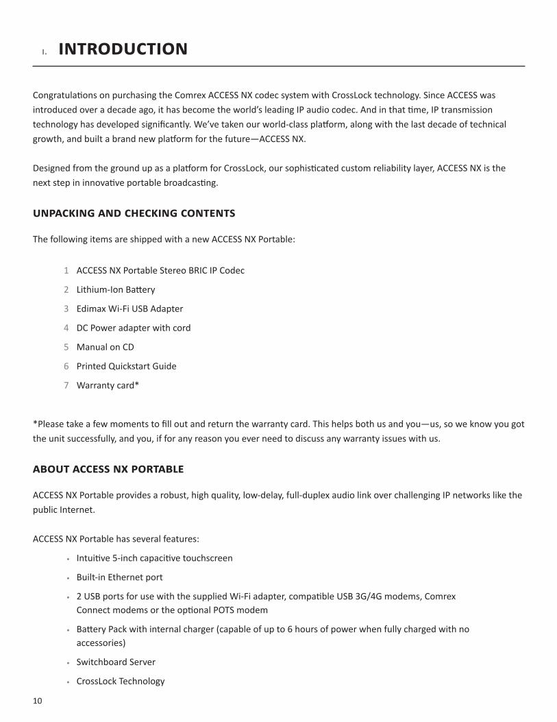
The following items are shipped with a new ACCESS NX Portable:
1 ACCESS NX Portable Stereo BRIC IP Codec
2 Lithium-Ion Battery
3 Edimax Wi-Fi USB Adapter
4 DC Power adapter with cord
5 Manual on CD
6 Printed Quickstart Guide
7 Warranty card*
*Please take a few moments to fill out and return the warranty card. This helps both us and you—us, so we know you got the unit successfully, and you, if for any reason you ever need to discuss any warranty issues with us.
aboutaccessnXportable
ACCESS NX Portable provides a robust, high quality, low-delay, full-duplex audio link over challenging IP networks like the public Internet.
ACCESS NX Portable has several features:
• Intuitive 5-inch capacitive touchscreen
• Built-in Ethernet port
• 2 USB ports for use with the supplied Wi-Fi adapter, compatible USB 3G/4G modems, Comrex Connect modems or the optional POTS modem
• Battery Pack with internal charger (capable of up to 6 hours of power when fully charged with no accessories)
• Switchboard Server
• CrossLock Technology
11
aboutcomreX
Comrex has been building reliable, high quality broadcast equipment since 1961. Our products are used daily in every part of the world by networks, stations and program producers.
Every product we manufacture has been carefully designed to function flawlessly, under the harshest conditions, over many years of use. Each unit we ship has been individually and thoroughly tested.
Comrex stands behind its products. We promise that if you call us for technical assistance, you will talk directly with someone who knows about the equipment and will do everything possible to help you.
You can contact Comrex by phone at +1 978-784-1776. Our toll-free number in North America is 800-237-1776. Product information along with engineering notes and user reports are available on our website at www.comrex.com. Our email address is [email protected].
WarrantyanddIsclaImer
All equipment manufactured by Comrex Corporation is warranted by Comrex against defects in material and workmanship for one year from the date of original purchase, as verified by the return of the Warranty Registration Card. During the warranty period, we will repair or, at our option, replace at no charge a product that proves to be defective, provided you obtain return authorization from Comrex and return the product, shipping prepaid, to Comrex Corporation, 19 Pine Road, Devens, MA 01434 USA. For return authorization, contact Comrex at +1 978-784-1776 or fax +1 978-784-1717.
This Warranty does not apply if the product has been damaged by accident or misuse or as the result of service or modification performed by anyone other than Comrex Corporation.
With the exception of the warranties set forth above, Comrex Corporation makes no other warranties, expressed or implied or statutory, including but not limited to warranties of merchantability and fitness for a particular purpose, which are hereby expressly disclaimed. In no event shall Comrex Corporation have any liability for indirect, consequential or punitive damages resulting from the use of this product.

12
II. ControlsandConneCtIons
FIgure1 FrontPaneldIagramanddesCrIPtIons
1 DISPLAY - Touchscreen display. This is where you initialize your broadcast from the NX to the studio unit (typically an ACCESS Rackmount), view and edit settings, and monitor connections.
2, 5 CH1andCH2LOCALOUTPUTcontrolknob-Adjusts the level of local audio to the corresponding headphone jack.
3, 6 CH1andCH2REMOTEOUTPUTcontrolknob-Adjusts the level of remote audio to the corresponding headphone jack.
4, 7 CH1andCH2INPUTcontrolknob- Use this knob to adjust the level of INPUTaudio (CH1 and CH2 XLR inputs that you are sending back to the studio).
8 POWERKEY-Hold this down for 3 seconds to turn the NX on or off.
9 F1&F2KEYS- Both the F1 and F2 keys are programmable. You can individually assign the keys to open a specific menu, cycle through menus, trigger one of the four Contact Closures or disable them.
10 DIRECTIONCURSORS&ENTERKEYS - May be used instead of touchscreen to navigate and select options in the user interface.
11 BACKKEY-Brings you to the previous screen on the interface.
12 MENUSELECTKEY-Opens the menu items on the interface.
13 HOMEKEY- Navigates to the RemoteConnections homepage.
13
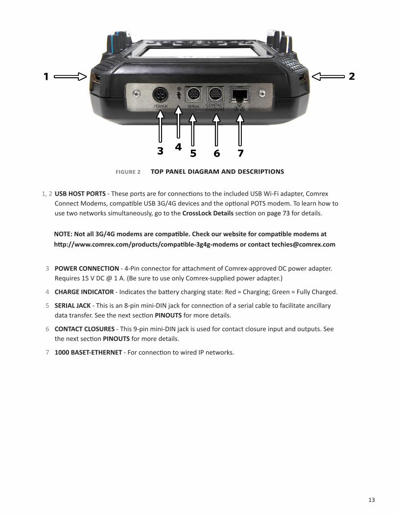
FIgure2 toPPaneldIagramanddesCrIPtIons
1, 2 USBHOSTPORTS - These ports are for connections to the included USB Wi-Fi adapter, Comrex Connect Modems, compatible USB 3G/4G devices and the optional POTS modem. To learn how to use two networks simultaneously, go to the CrossLockDetails section on page 73 for details.
NOTE:Notall3G/4Gmodemsarecompatible.Checkourwebsiteforcompatiblemodemsathttp://www.comrex.com/products/[email protected]
3 POWERCONNECTION - 4-Pin connector for attachment of Comrex-approved DC power adapter. Requires 15 V DC @ 1 A. (Be sure to use only Comrex-supplied power adapter.)
4 CHARGEINDICATOR - Indicates the battery charging state: Red = Charging; Green = Fully Charged.
5 SERIALJACK - This is an 8-pin mini-DIN jack for connection of a serial cable to facilitate ancillary data transfer. See the next section PINOUTS for more details.
6 CONTACTCLOSURES - This 9-pin mini-DIN jack is used for contact closure input and outputs. See the next section PINOUTS for more details.
7 1000BASET-ETHERNET - For connection to wired IP networks.

14
IMPORTANT: Make careful note of the direction you are plugging the power into the connector. The arrow on the connector should be facing down when connecting to the NX. The same applies to the Serial cable. The Contact Closure cable will have the flat section facing down.
FIgure3 sIdePaneldIagramanddesCrIPtIons
1 MIC/LINEIN - 3-pin female XLR connectors designed to accept a balanced, microphone or line level audio feed. This input level is adjustable via the INPUT control knob for each channel respectively. There are 3 input settings:Line,MicHI andMicLO. MicLOis for standard dynamic microphones.Condensermicsor “Sportscaster”headsets should use MICHI.
2 HEADPHONES - This 3-conductor 1/4” connector is designed to deliver audio to stereo headphones. The output audio can be user-adjusted by the LOCAL andRETURN knobs on the top of the unit.
3 LINEOUT-This 3-conductor 3.5 mm connector delivers unbalanced stereo output audio. The output is selectable in the software to be either Local, Return, or both.

15
FIgure4 rearPaneldIagramanddesCrIPtIons
1 BATTERYCOMPARTMENT- This internal battery compartment holds the supplied Lithium-ion battery.
2 ADJUSTABLESTRAP - Use this padded adjustable strap to carry the unit.
3 MIXERPORT - This connector is for docking to the optional 4 channel NX Mixer.
monoVs.stereo
Because NX can encode and/or decode in stereo and mono modes, it’s important to understand how the audioinputs and outputs are handled in each mode. There are separate mono/stereo settings for each input channel, as well as a setting to determine whether your audio encoder has one or two channels.
Inputs- When inputs are configured for mono mode, CH1 & CH2 (and 3-6 when mixer is attached) inputs are always delivered to both the left and right encoder inputs. This means that when you are encoding audio in stereo, these signals are sent to both channels equally. When using profiles with mono encoders, only the left channel of the stereo line input is delivered to the mono encoder.
Outputs - In stereo decoder modes, left and right channels are delivered to the LineOut and Headphoneconnectors separately. In mono decoder modes, mono audio is delivered to both sides of the line out and headphone connectors.

16
III. AsImpleNXremotebroAdcAst
In this example, we will show you how to set up a simple broadcast with an NX in a remote location using a compatible 4G Verizon adapter.
As shown below, the reporter has a microphone connected to the MIC/LINEIN XLR connector. Headphones are connected to the Headphoneoutput. The Verizon adapter is plugged into the USB port on the top of the NX.
Verizon 4G adapter
MIC Cable
Headphones
17
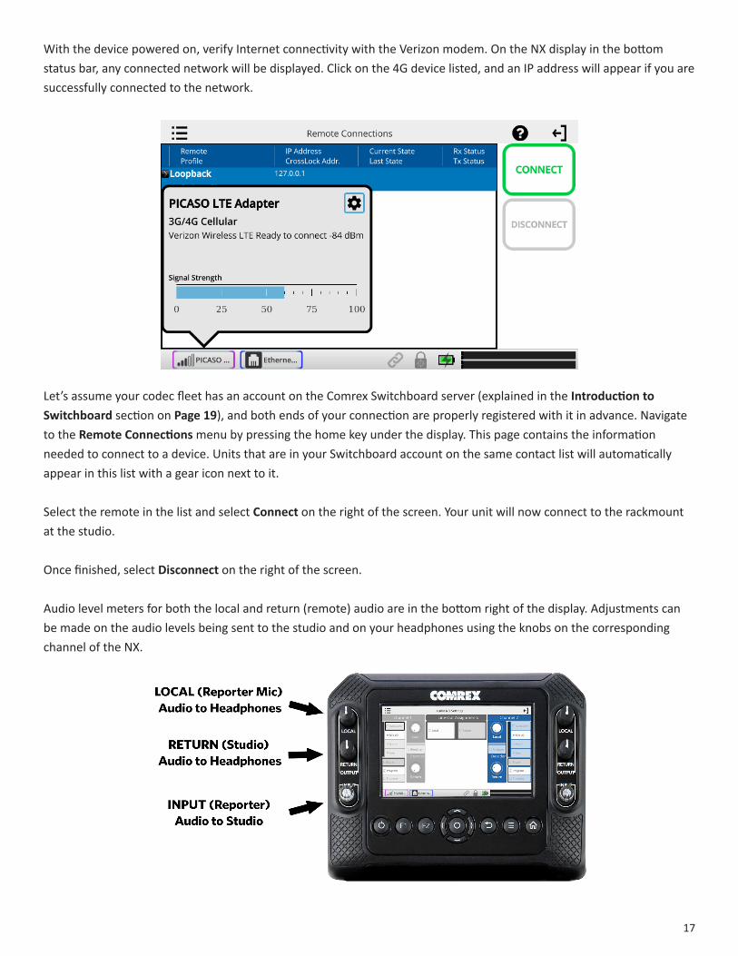
With the device powered on, verify Internet connectivity with the Verizon modem. On the NX display in the bottom status bar, any connected network will be displayed. Click on the 4G device listed, and an IP address will appear if you are successfully connected to the network.
Let’s assume your codec fleet has an account on the Comrex Switchboard server (explained in the IntroductiontoSwitchboard section on Page19), and both ends of your connection are properly registered with it in advance. Navigate to the RemoteConnectionsmenu by pressing the home key under the display. This page contains the information needed to connect to a device. Units that are in your Switchboard account on the same contact list will automatically appear in this list with a gear icon next to it.
Select the remote in the list and select Connecton the right of the screen. Your unit will now connect to the rackmount at the studio.
Once finished, select Disconnect on the right of the screen.
Audio level meters for both the local and return (remote) audio are in the bottom right of the display. Adjustments can be made on the audio levels being sent to the studio and on your headphones using the knobs on the corresponding channel of the NX.

18
IV. IntroductIontocrosslock
CrossLock is an enhanced reliability layer that can be added to links made between Comrex codecs. CrossLock is optional but recommended, and is available in all Comrex codecs running firmware 4.0 and higher. In the case of connecting to Comrex codecs with earlier firmware, CrossLock is not used.
Because CrossLock creates a VPN, it has its own rules. It can decide whether or not to resend information based on error correction. It can also handle preventative forward error correction (FEC). These decisions make up the “secret sauce” of Crosslock, and make it effective at navigating “bad” networks and avoiding networks that are “beyond repair”.
CrossLock can also signal encoders to “throttle down” their data rate if necessary. This reduces quality but maintains higher reliability.
The overall result of CrossLock’s function means a higher level of reliability for remotes. This goes a long way towards eliminating the frustration of dropouts and other failures during a broadcast.
In addition to carrying the audio media, CrossLock allows lots of other information to be shared between the endpoints, including information about network quality and far-end delay settings. This provides for much better delay management on both ends of the link.
One or both ends of a CrossLock connection can utilize multiple network interfaces. This can take the form of two Ethernet connections, or any mix of wired and wireless networks. A common usage scenario would be attaching two 3G/4G modems to NX. In the case of one network underperforming, the majority (or all) of the data will be sent on the good network.
For more information CrossLock, go to the CrossLockDetailssection on page 73.
19
V. IntroductIontoswItchboard
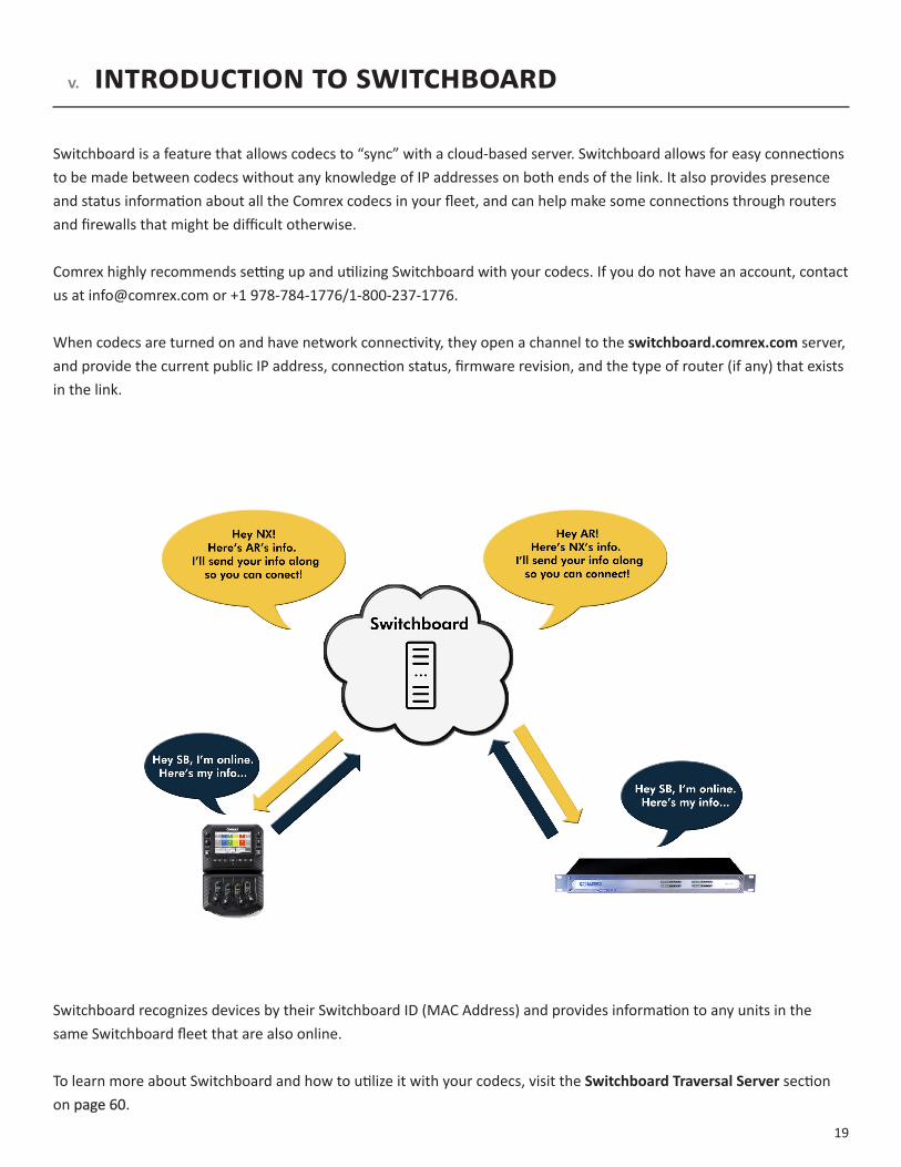
Switchboard is a feature that allows codecs to “sync” with a cloud-based server. Switchboard allows for easy connections to be made between codecs without any knowledge of IP addresses on both ends of the link. It also provides presence and status information about all the Comrex codecs in your fleet, and can help make some connections through routers and firewalls that might be difficult otherwise.
Comrex highly recommends setting up and utilizing Switchboard with your codecs. If you do not have an account, contact us at [email protected] or +1 978-784-1776/1-800-237-1776.
When codecs are turned on and have network connectivity, they open a channel to the switchboard.comrex.com server, and provide the current public IP address, connection status, firmware revision, and the type of router (if any) that exists in the link.
Switchboard recognizes devices by their Switchboard ID (MAC Address) and provides information to any units in the same Switchboard fleet that are also online.
To learn more about Switchboard and how to utilize it with your codecs, visit the SwitchboardTraversalServersection on page 60.
20
VII.gettIngstartedwIthnX
PowerIngUPnX
NX can be powered from its internal battery or an external supply. The internal battery has a low-voltage lockout function that prevents power-up if the battery voltage is too low.
Whenever the external supply is attached, regardless of the whether NX is turned on or off, the internal battery will be charging. The battery status is always available by looking at the rear-panel battery LED (red = charging, green = full).
Power up NX by pressing the recessed power button (left-most on the keypad) for three seconds. The display will “wink” when NX has accepted the keypress. NX takes approximately 30 seconds to boot, and the display will be blank for part of the boot cycle.
PowerIngdownnX
After use, NX is powered down by pressing the recessed power key (left-most on keypad) for three seconds. Note that if the internal battery is installed and charged, simply pulling the power cord from NX will not result in a shutdown, as the backup battery function will keep NX active.
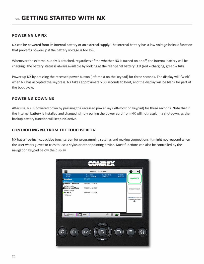
ControllIngnXfromthetoUChsCreen
NX has a five-inch capacitive touchscreen for programming settings and making connections. It might not respond when the user wears gloves or tries to use a stylus or other pointing device. Most functions can also be controlled by the navigation keypad below the display.

21
When a text entry is selected on the touchscreen, a virtual keyboard will automatically appear. The keyboard will close when you press enter, or select the close keyboard button in the bottom right. You can change the keyboard language by selecting the globe icon in the bottom left.
When first booted, NX displays the “RemoteConnections” screen as shown below. Remote Connections is one of the main screens available on NX, and is the default because connections are initiated and terminated from there. Remote Connections can be found easily by pressing the “Home” keypad button from any screen.
22
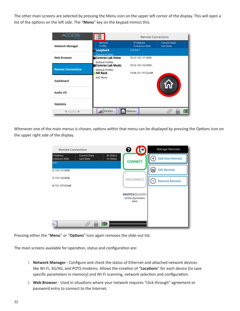
The other main screens are selected by pressing the Menu icon on the upper left corner of the display. This will open a list of the options on the left side. The “Menu” key on the keypad mimics this.
Whenever one of the main menus is chosen, options within that menu can be displayed by pressing the Options icon on the upper right side of the display.
Pressing either the “Menu” or “Options” Icon again removes the slide-out list.
The main screens available for operation, status and configuration are:
1 NetworkManager - Configure and check the status of Ethernet and attached network devices like Wi-Fi, 3G/4G, and POTS modems. Allows the creation of “Locations” for each device (to save specific parameters in memory) and Wi-Fi scanning, network selection and configuration.
2 WebBrowser - Used in situations where your network requires “click through” agreement or password entry to connect to the Internet.
23
3 RemoteConnections - Add, edit and delete connection destinations, show incoming connections, make outgoing connections, and check Switchboard status.
4 Dashboard - Designed to be active during a live feed, provides microphone mutes, control over contact closures, and shortcuts to other audio functions and levels.
5 AudioI/O- Configure the inputs for levels (Mic/Line), buss selection and mono/stereo. Adjust output levels and select sources for LineOut jack.
6 Statistics - A scrollable view of statistics during active connections. The Remote section provides detailed information regarding the decoder buffer manager’s functions transmit and receive delays, as well as frame loss and correction rates. The Channelsection provides real-time graphs of outgoing and incoming data rates. The CrossLock section displays a range of network statistics like jitter, packet loss, and error correction activity in each direction of the stream. Available only during active CrossLock connections.
7 ManageProfiles - Configure settings for outgoing calls like encoder/decoder and specialized configurations.
8 Systemsettings - Configure global NX parameters like Contact Closures, Switchboard, CrossLock, Security and incoming call support.
9 CrossLock - Configure CrossLock parameters for remotes utilizing CrossLock.
10 UserSettings- Configure key and touchscreen behaviors, audio input overlay, and enable/disable restricted user mode.
11 About - Displays information about NX firmware, licenses and internal temperature.
Along with the top and bottom status bars, these screens are each outlined in detail in the following sections.
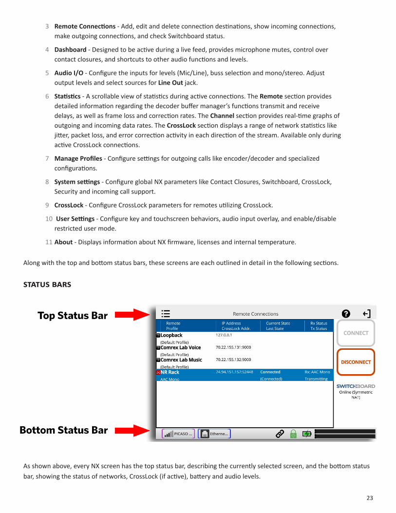
statUsBars
As shown above, every NX screen has the top status bar, describing the currently selected screen, and the bottom status bar, showing the status of networks, CrossLock (if active), battery and audio levels.

24
Each installed network has an icon that can be selected. Once selected, some basic network status will be displayed (e.g. Ethernet IP address), and a gear icon that will bring you to the configuration menu for that network when selected.
The CrossLock icon will light green when a CrossLock connection is active. Once selected, a popup menu will provide CrossLock status and CrossLock delay settings. You also can change between transmit and receive channels, access CrossLock configuration with the gear icon in the top right, and access the statistics with the graph icon. Note:CrossLockcansometimesbeactivebeforeorafteraremoteconnectionisactive.
25
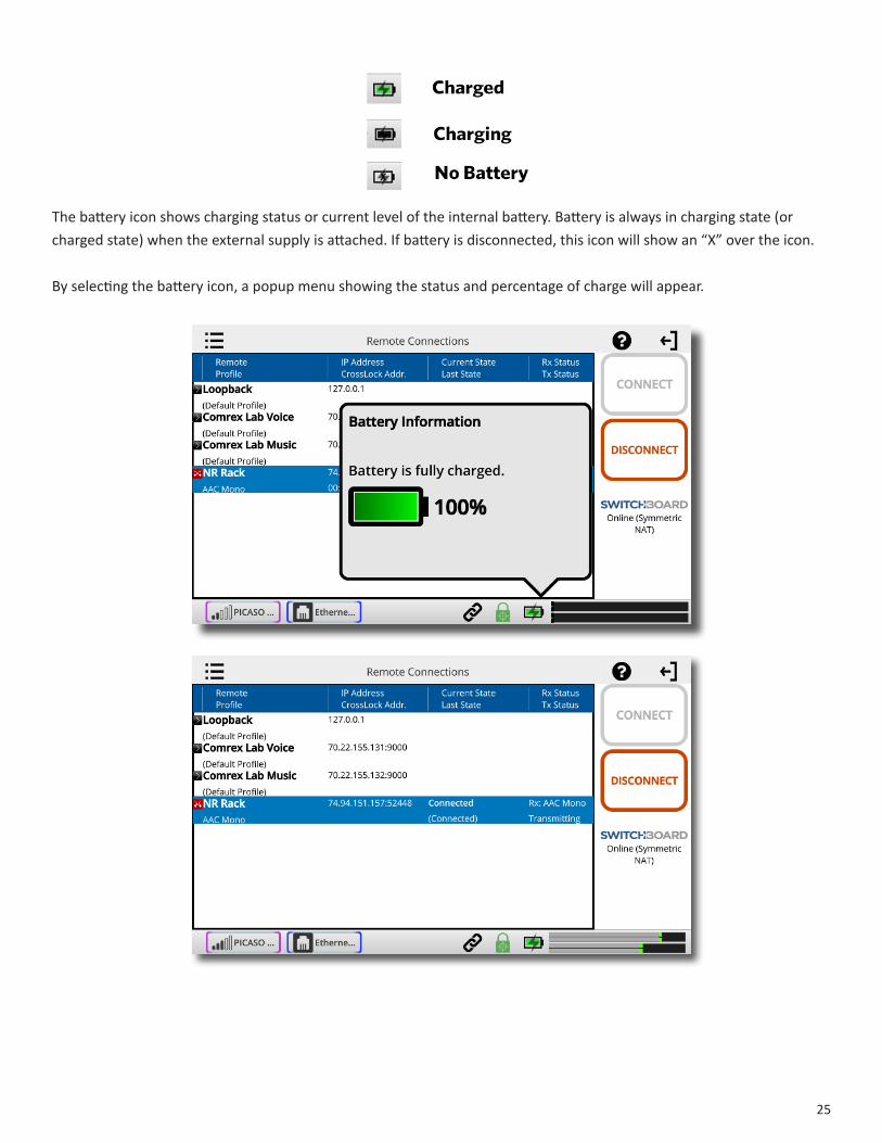
The battery icon shows charging status or current level of the internal battery. Battery is always in charging state (or charged state) when the external supply is attached. If battery is disconnected, this icon will show an “X” over the icon.
By selecting the battery icon, a popup menu showing the status and percentage of charge will appear.

26
The level meters show the current audio local input level (top) and the current return audio level (bottom). The meter is stereo, and mono sources reflect on both L&R channels. This is designed as a “peak” meter, and proper audio levels should remain below the right side of the meter.
The help icon will open a window providing explanations relevant to the current menu item.
27
VII.MakIngConneCtIonswIthnX(ReMoteConneCtIonssCReen)
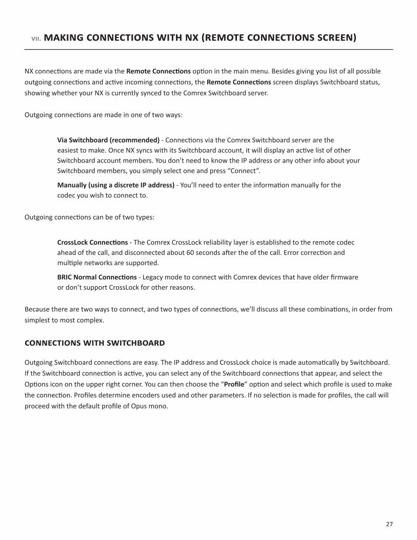
NX connections are made via theRemoteConnections option in the main menu. Besides giving you list of all possible outgoing connections and active incoming connections, the RemoteConnections screen displays Switchboard status, showing whether your NX is currently synced to the Comrex Switchboard server.
Outgoing connections are made in one of two ways:
ViaSwitchboard(recommended) - Connections via the Comrex Switchboard server are the easiest to make. Once NX syncs with its Switchboard account, it will display an active list of other Switchboard account members. You don’t need to know the IP address or any other info about your Switchboard members, you simply select one and press “Connect”.
Manually(usingadiscreteIPaddress) - You’ll need to enter the information manually for the codec you wish to connect to.
Outgoing connections can be of two types:
CrossLockConnections - The Comrex CrossLock reliability layer is established to the remote codec ahead of the call, and disconnected about 60 seconds after the of the call. Error correction and multiple networks are supported.
BRICNormalConnections - Legacy mode to connect with Comrex devices that have older firmware or don’t support CrossLock for other reasons.
Because there are two ways to connect, and two types of connections, we’ll discuss all these combinations, in order from simplest to most complex.
ConneCtIonswIthswItChboaRd
Outgoing Switchboard connections are easy. The IP address and CrossLock choice is made automatically by Switchboard. If the Switchboard connection is active, you can select any of the Switchboard connections that appear, and select the Options icon on the upper right corner. You can then choose the “Profile” option and select which profile is used to make the connection. Profiles determine encoders used and other parameters. If no selection is made for profiles, the call will proceed with the default profile of Opus mono.
28
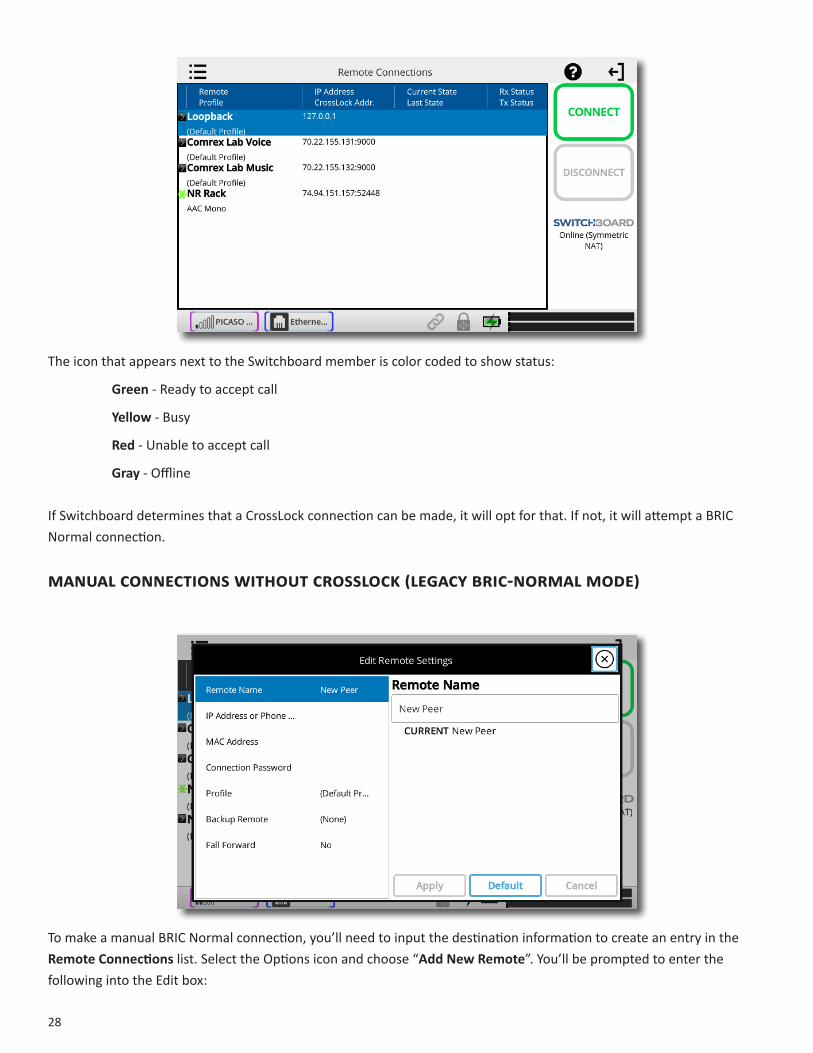
The icon that appears next to the Switchboard member is color coded to show status:
Green - Ready to accept call
Yellow- Busy
Red - Unable to accept call
Gray - Offline
If Switchboard determines that a CrossLock connection can be made, it will opt for that. If not, it will attempt a BRIC Normal connection.
ManualConneCtIonswIthoutCRossloCk(legaCybRIC-noRMalMode)
To make a manual BRIC Normal connection, you’ll need to input the destination information to create an entry in the RemoteConnections list. Select the Options icon and choose “AddNewRemote”. You’ll be prompted to enter the following into the Edit box:

29
RemoteName - Familiar name to call this entry.
IPAddressorPhonenumber - The public IP address of the destination (phone number for POTS calls). If using non-default ports, add the port number after a colon.
Profile - Select which profile is used to make the connection. (Profiles determine encoders used and other parameters—see the ProfileManagerMenu section on page41.) If no selection is made for profiles, the call will proceed with the default profile of Opus mono.
ManualConneCtIonswIthCRossloCk
Follow the directions above for Manual Connections without CrossLock, but in addition, add the Switchboard ID (MAC Address) of the codec you’ll be connecting to. This is an added security layer to ensure only authorized codecs connect via CrossLock. This is input when creating or editing a remote into the Switchboard ID field.
It’s important to note that in order to connect this way, the receiving codec must also have a matching entry including the Switchboard ID (MAC address) of the calling codec. This must be present as an outgoing entry (even if the entry is never actually used for outgoing calls). The Switchboard ID (MAC address) of the NX Portable can be located in About->NodeID. The Node ID is the MAC address and thus the Switchboard ID.
If these conditions aren’t met, or if the receiving codec is not CrossLock capable, a legacy BRIC Normal style connection will be attempted.
outgoIngCalls
Choose the manual or Switchboard entry desired and press the green “Connect” button. Call progress and status will appear on the entry. If a CrossLock connection is established, the “lock” icon on the status bar will light green.
InCoMIngCalls
No action is necessary to receive incoming calls on NX. Whether via Switchboard or manually, NX will automatically connect compatible incoming calls and show them in the remote list.
30
IX. networkmanager
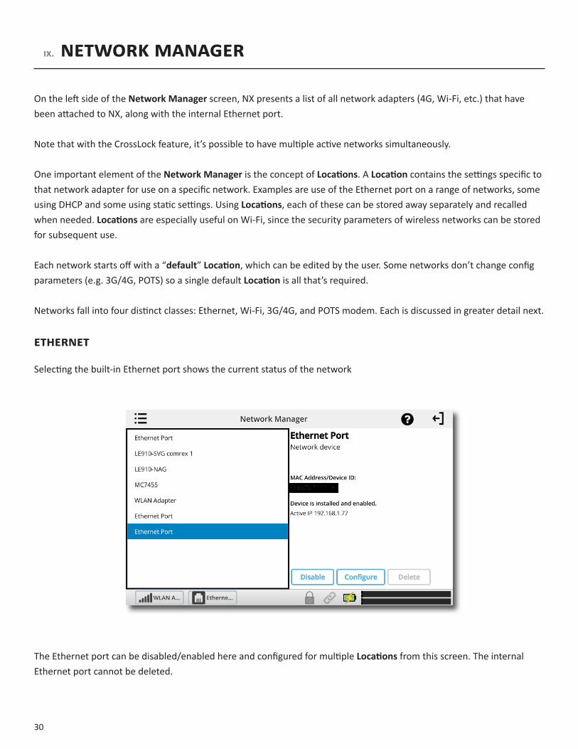
On the left side of the NetworkManager screen, NX presents a list of all network adapters (4G, Wi-Fi, etc.) that have been attached to NX, along with the internal Ethernet port.
Note that with the CrossLock feature, it’s possible to have multiple active networks simultaneously.
One important element of the NetworkManager is the concept ofLocations. A Location contains the settings specific to that network adapter for use on a specific network. Examples are use of the Ethernet port on a range of networks, some using DHCP and some using static settings. Using Locations, each of these can be stored away separately and recalled when needed. Locations are especially useful on Wi-Fi, since the security parameters of wireless networks can be stored for subsequent use.
Each network starts off with a “default” Location, which can be edited by the user. Some networks don’t change config parameters (e.g. 3G/4G, POTS) so a single default Location is all that’s required.
Networks fall into four distinct classes: Ethernet, Wi-Fi, 3G/4G, and POTS modem. Each is discussed in greater detail next.
ethernet
Selecting the built-in Ethernet port shows the current status of the network
The Ethernet port can be disabled/enabled here and configured for multiple Locations from this screen. The internal Ethernet port cannot be deleted.

31
Selecting Configure here will open the configuration pop-up.
For Ethernet, it’s recommended to leave the default network as-is (DHCP) for testing and upgrades, and to add static networks as additional Locations. To do this, select the arrow to the left of “NetworkLocations” to expand the Location list. You can then choose “AddLocation”.
You’ll then be able to select the new location, rename it, and apply the required information to use the Ethernet Port at the new location. The information required is:
• IP Address
• IP Netmask
• IP Gateway Address
• IP DNS (Primary and Secondary)
Once these are programmed and saved, choose the “ActiveNetworkLocation” option to change to the chosen Ethernet settings and back whenever required.
wI-FI
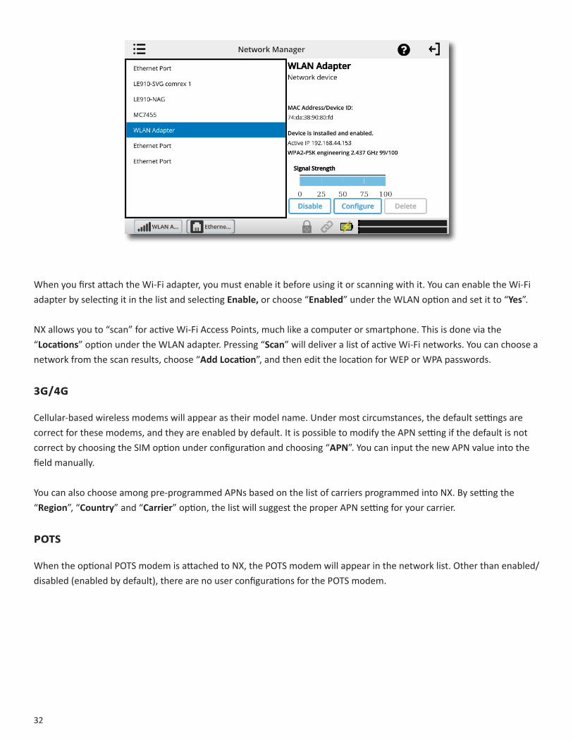
When the included Wi-Fi adapter is attached to one of the USB ports, a network entry of “WLANAdapter” will appear.
Selecting it will show the status, current IP address, MAC Address of the adapter, and network chosen (if any). The MAC Address of the WLAN adapter is different than the MAC Address of the NX Portable’s Ethernet Port. This WLAN MAC Address is often necessary for Port Forwarding and Whitelisting the NX Portable when connected to Wi-Fi Networks.
32
When you first attach the Wi-Fi adapter, you must enable it before using it or scanning with it. You can enable the Wi-Fi adapter by selecting it in the list and selecting Enable, or choose “Enabled” under the WLAN option and set it to “Yes”.
NX allows you to “scan” for active Wi-Fi Access Points, much like a computer or smartphone. This is done via the “Locations” option under the WLAN adapter. Pressing “Scan” will deliver a list of active Wi-Fi networks. You can choose a network from the scan results, choose “AddLocation”, and then edit the location for WEP or WPA passwords.
3g/4g
Cellular-based wireless modems will appear as their model name. Under most circumstances, the default settings are correct for these modems, and they are enabled by default. It is possible to modify the APN setting if the default is not correct by choosing the SIM option under configuration and choosing “APN”. You can input the new APN value into the field manually.
You can also choose among pre-programmed APNs based on the list of carriers programmed into NX. By setting the “Region”, “Country” and “Carrier” option, the list will suggest the proper APN setting for your carrier.
PotS
When the optional POTS modem is attached to NX, the POTS modem will appear in the network list. Other than enabled/disabled (enabled by default), there are no user configurations for the POTS modem.
33
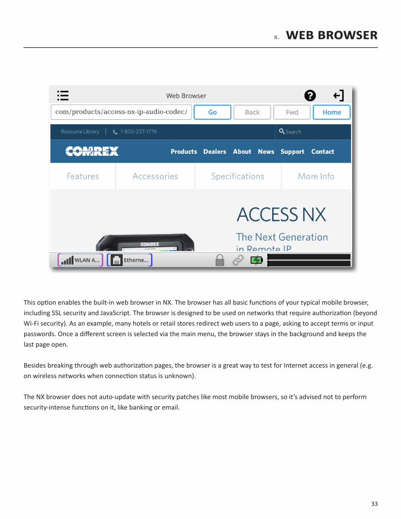
X. webbrowser
This option enables the built-in web browser in NX. The browser has all basic functions of your typical mobile browser, including SSL security and JavaScript. The browser is designed to be used on networks that require authorization (beyond Wi-Fi security). As an example, many hotels or retail stores redirect web users to a page, asking to accept terms or input passwords. Once a different screen is selected via the main menu, the browser stays in the background and keeps the last page open.
Besides breaking through web authorization pages, the browser is a great way to test for Internet access in general (e.g. on wireless networks when connection status is unknown).
The NX browser does not auto-update with security patches like most mobile browsers, so it’s advised not to perform security-intense functions on it, like banking or email.
34
XI. dashboard
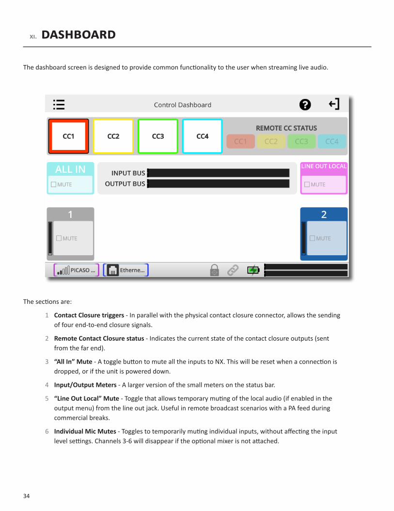
The dashboard screen is designed to provide common functionality to the user when streaming live audio.
The sections are:
1 ContactClosuretriggers- In parallel with the physical contact closure connector, allows the sending of four end-to-end closure signals.
2 RemoteContactClosurestatus - Indicates the current state of the contact closure outputs (sent from the far end).
3 “AllIn”Mute - A toggle button to mute all the inputs to NX. This will be reset when a connection is dropped, or if the unit is powered down.
4 Input/OutputMeters - A larger version of the small meters on the status bar.
5 “LineOutLocal”Mute - Toggle that allows temporary muting of the local audio (if enabled in the output menu) from the line out jack. Useful in remote broadcast scenarios with a PA feed during commercial breaks.
6 IndividualMicMutes - Toggles to temporarily muting individual inputs, without affecting the input level settings. Channels 3-6 will disappear if the optional mixer is not attached.

35
XII.AudIoInputsAndoutputs
AudIoInputs
NX has two adjustable mono audio input channels, and one fixed level stereo input. With the addition of the optional mixer, an additional four mono inputs are available. Each adjustable channel has a level indicator built into the input adjustment knob. The knob will light green (OK), yellow (hot), and red (limiting) on each channel. The audio input settings select the levels and destinations of each of these channels.
LeveLs
The Mic/Line input channels have three fixed preamp settings. MicLO is designed for dynamic microphones and other low level sources. MicHI is designed for use with condenser or other high level microphones. Line level is designed for sources at professional line levels. In addition to choosing the levels, each channel can selectively apply a 12 V phantom power source for condenser microphones (when in mic modes).
The two microphone options are available because many sportscasters use condenser-based headsets with a microphone placed very close to the mouth. This has a tendency to clip the high-gain preamplifiers designed for lower level mics.

36
Mono/stereo
Rather than a pair of mono inputs (which get mixed into both channels of stereo encoders), pairs of input channels can be configured as L & R stereo. This is possible on the combination of channels 1 & 2, and (with the optional mixer attached) channels 3 & 4 and channels 5 & 6. Choosing the “Stereo” option on either of the inputs will set both inputs to this mode.
In stereo mode, only the lower number channel has an active input level control. As an example, if channels 1 & 2 are configured for stereo, only channel 1 input control is used to control both channels. Channel 2 input control has no effect.
Busses
NX has two audio busses for input sources:
Program - Audio that is sent to the encoder for streaming to decoders
Producer - Audio that is available to the headphone feeds, but not to the encoders
Each adjustable input can be assigned to one or both of these busses using the buttons for those channels. The fixed line input can only be sent to the program bus.
AudIooutputs
The NX headphone outputs each have two control knobs, one to adjust level of the locally generated program (Local), and one to adjust level of the audio being decoded by NX (Return). The audio input and output screen gives an indication of the current setting of each of these knobs for each headphone out.
Each headphone output can be configured to add the “producer” bus to the return audio feed. If this is selected for a specific headphone, the producer feed sums together with the return audio at a fixed level. The “return” level control adjusts both audio feeds together.
The feed available to the fixed-level line output is selectable here as well. The port can output the Local audio, the Return audio, or a mix of both. The producer feed cannot be applied to the fixed line-level output.
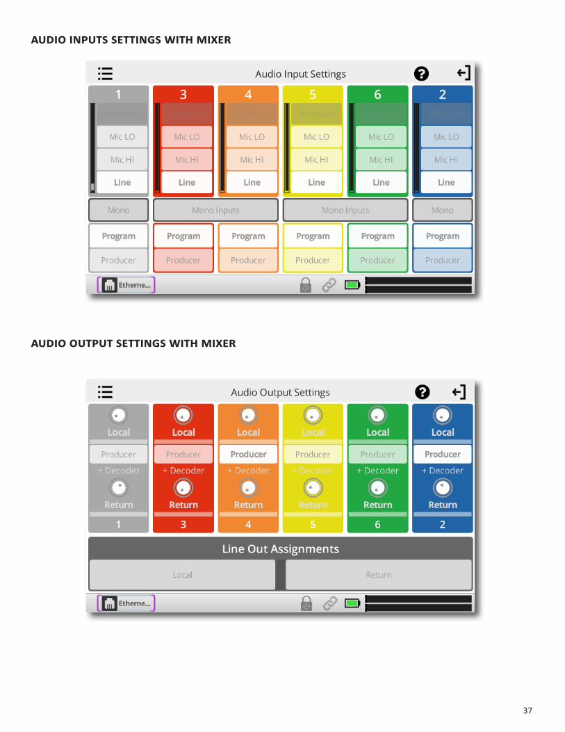
WIthMIXerAttAched
If the optional mixer is attached, the menu AudioI/O will “split” into two separate menues: AudioInputs and AudioOutputs. The AudioInputs menu will display only the Inputs, and the AudioOutputs menu will display only the Outputs.
37
AudIoInputssettIngsWIthMIXer
AudIooutputsettIngsWIthMIXer

38
XIII.StatIStIcSMenuS
There are three different sections available on the Statistics menu: CrossLock;Remote;andChannel.The different graphs are available by scrolling left and right. When making a CrossLock connection, it is best to refer to the CrossLock stats to analyze performance. The Remote and Channel graphs are also available during a CrossLock connection because the legacy BRIC Normal protocol is still running while a CrossLock connection is active. When you are not utilizing CrossLock, CrossLock graphs will be blank, and you should refer to the Remote and Channel graphs.
croSSLockStatS
The CrossLock graphsgive a real-time indication of network activity and quality during a CrossLock connection. You can determine how many networks are being utilized, the delay associated with both ends of the connection, loss and recovery of packets. It’s a powerful tool to help analyze system performance.
The first screen is the transmit performance screen. An identical screen showing receive performance is available by swiping this screen to the left.
The statistics screens are divided in half into two real-time histograms, moving from right (now) to far left (60 seconds ago).
39
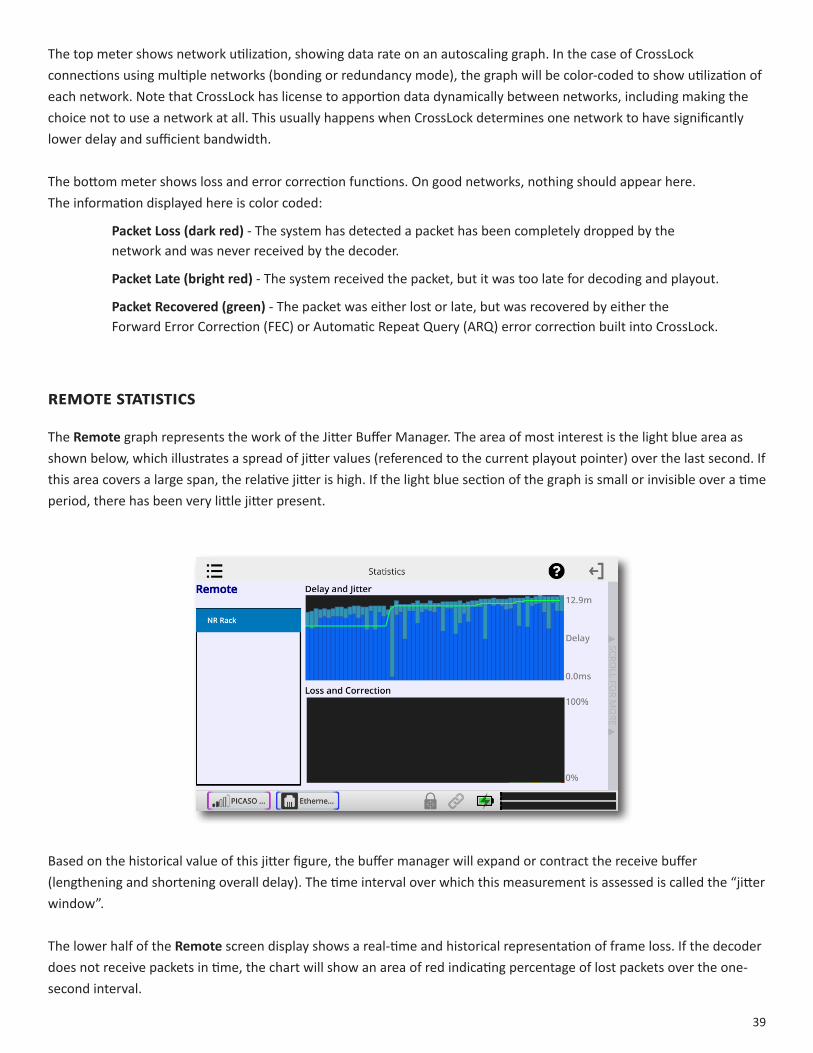
The top meter shows network utilization, showing data rate on an autoscaling graph. In the case of CrossLock connections using multiple networks (bonding or redundancy mode), the graph will be color-coded to show utilization of each network. Note that CrossLock has license to apportion data dynamically between networks, including making the choice not to use a network at all. This usually happens when CrossLock determines one network to have significantly lower delay and sufficient bandwidth.
The bottom meter shows loss and error correction functions. On good networks, nothing should appear here. The information displayed here is color coded:
PacketLoss(darkred) - The system has detected a packet has been completely dropped by the network and was never received by the decoder.
PacketLate(brightred) - The system received the packet, but it was too late for decoding and playout.
PacketRecovered(green) - The packet was either lost or late, but was recovered by either the Forward Error Correction (FEC) or Automatic Repeat Query (ARQ) error correction built into CrossLock.
reMoteStatIStIcS
The Remotegraph represents the work of the Jitter Buffer Manager. The area of most interest is the light blue area as shown below, which illustrates a spread of jitter values (referenced to the current playout pointer) over the last second. If this area covers a large span, the relative jitter is high. If the light blue section of the graph is small or invisible over a time period, there has been very little jitter present.
Based on the historical value of this jitter figure, the buffer manager will expand or contract the receive buffer (lengthening and shortening overall delay). The time interval over which this measurement is assessed is called the “jitter window”.
The lower half of the Remote screen display shows a real-time and historical representation of frame loss. If the decoder does not receive packets in time, the chart will show an area of red indicating percentage of lost packets over the one-second interval.

40
channeLStatIStIcS
The Channelscreen provides real-time graphs of outgoing and incoming packets. Each column represents one second of outgoing data, segmented into audio coding data (shown in blue) and overhead, such as IP/UDP headers, RTP headers and similar data (shown in light blue).
The first screen shows you the rates in real-time. By swiping the screen to the left, it will show you an average of both Transmit Rate and Receive Rate.
41
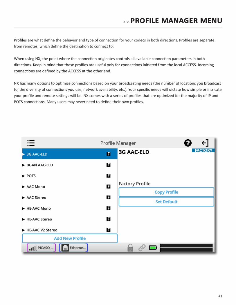
XIV.ProfIleManagerMenu
Profiles are what define the behavior and type of connection for your codecs in both directions. Profiles are separate from remotes, which define the destination to connect to.
When using NX, the point where the connection originates controls all available connection parameters in both directions. Keep in mind that these profiles are useful only for connections initiated from the local ACCESS. Incoming connections are defined by the ACCESS at the other end.
NX has many options to optimize connections based on your broadcasting needs (the number of locations you broadcast to, the diversity of connections you use, network availability, etc.). Your specific needs will dictate how simple or intricate your profile and remote settings will be. NX comes with a series of profiles that are optimized for the majority of IP and POTS connections. Many users may never need to define their own profiles.
42
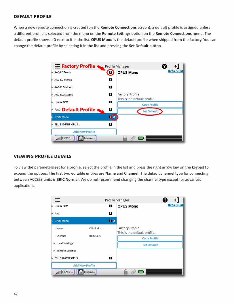
DefaultProfIle
When a new remote connection is created (on the RemoteConnections screen), a default profile is assigned unless a different profile is selected from the menu on the RemoteSettings option on the RemoteConnections menu. The default profile shows a D next to it in the list. OPUSMonois the default profile when shipped from the factory. You can change the default profile by selecting it in the list and pressing the SetDefaultbutton.
VIewIngProfIleDetaIls
To view the parameters set for a profile, select the profile in the list and press the right arrow key on the keypad to expand the options. The first two editable entries are Name and Channel. The default channel type for connecting between ACCESS units is BRICNormal. We do not recommend changing the channel type except for advanced applications.

43
Under the expanded profile, you will also see two additional folders named Local and Remote.
You’ll use the LocalSettings to determine how your NX behaves, and the RemoteSettings will determine how the ACCESS on the far end behaves.
The LocalSettings and RemoteSettings available are identical, so we will only cover the LocalSettings.
ConnectionTimeout - Under normal circumstances, a connection will be terminated on one end, and the other end will drop the connection. However, if a network failure occurs, or a connection is ended abruptly for some other reason, the system will drop the connection after a pre-determined time. The default is 60 seconds, but this can be shortened or lengthened here.
Encoder - Using this menu, you can select the encoder used to send audio from this NX (local) as well as the encoder used to send audio to this ACCESS (remote). The default value of the remote encoder is to follow the local encoder; that is, it will send exactly the same codec mode it receives. The display will show FollowLocalEncoder under the RemoteSettings folder when this mode is selected.
TransmitOn/Off - This option determines whether the selected encoder (local or remote) is actually sending any data. By default, all encoders are turned on, but there may be circumstances where one-way operation is desired. Selecting Off under TransmitOn/Off in the LocalSettings folder disables outgoing audio streaming. In the same way, selecting Off under TransmitOn/Off in the RemoteSettings folder disables the incoming audio streaming from the remote encoder.
44
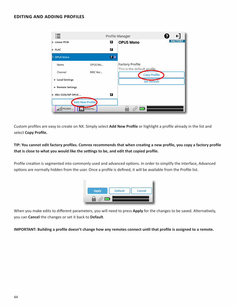
eDItInganDaDDIngProfIles
Custom profiles are easy to create on NX. Simply select AddNewProfile or highlight a profile already in the list and select CopyProfile.
TIP:Youcannoteditfactoryprofiles.Comrexrecommendsthatwhencreatinganewprofile,youcopyafactoryprofilethatisclosetowhatyouwouldlikethesettingstobe,andeditthatcopiedprofile.
Profile creation is segmented into commonly used and advanced options. In order to simplify the interface, Advanced options are normally hidden from the user. Once a profile is defined, it will be available from the Profile list.
When you make edits to different parameters, you will need to press Apply for the changes to be saved. Alternatively, you can Cancel the changes or set it back to Default.
IMPORTANT:Buildingaprofiledoesn’tchangehowanyremotesconnectuntilthatprofileisassignedtoaremote.

45
XV. systemsettingsmenu
System Settings define parameters that are not specific to a particular remote connection. Examples are how incoming (POTS and IP) calls are handled, global modem settings, and how the contact closures are assigned. Basic options are shown by default. Less used options are hidden until the Advanced option is selected.
The SystemSettings Menu has the following categories: Connections;ContactClosures;Security;SwitchboardServer;and AlternateModes.
When editing entries on the NX, you have 3 button options: Apply;Default;and Cancel. If you have changed an entry, the Apply button will become blue and will start pulsing. You must press this to save your changes. Default sets the entry back to default. Cancel discards any changes you made.

46
ConneCtionssettings
UnitName-Users are encouraged to name their codecs here. The default name of a codec is the unique MAC Address of the Ethernet port (Switchboard ID). When this is changed to something familiar and unique (such as “Roving reporter”, “Weather guy”, etc.), the new name is reflected in several places:
• In the Web-based Interface;
• In Comrex provided utility software such as DeviceManager and CodecCommander;
• In Switchboard Contact Lists (See the SwitchboardTraversalServersection on page 60).
IncomingConnectionPassword-Allows you to define a password that must be attached to all incoming connections before they are accepted. Units contacting you must know this password and apply it to their outgoing stream, or the connection will not be completed. Leaving the field blank will disable this function.

47
AlwaysConnectTo - This setting is available to designate a remote for “always-on” operation. This is useful in environments where a signal is required to be on 24 hours a day. To assign an “always-on” remote, pull down the menu and select which remote to designate as “always-on”. A connection will be made and sustained to the chosen remote.
ContaCtClosuresettings
CCConnectStatus- Alters the performance of output contact closure #4. Under normal circumstances the contact will close when commanded by the other end of the connection. If this option is enabled, that function is no longer available. This contact will be closed when a valid connection is present, and open when no connection is present.
ConnectonCC(1,2,3,4) - These choices define auto connect rules for remotes to be triggered by the four external input triggers available. NOTE:Theseinputsaresharedwiththeend-to-endcontactclosuresignals,soifaremoteisdesignatedasautoconnectonaclosure,thatclosuresignalisnotavailableforuseinthedirectionfromthisNX.
To assign a remote connection to a contact closure, pull down the menu box next to the desired closure and select the proper remote. A connection attempt will be made whenever the contact is triggered, and will disconnect whenever the contact is released.
48
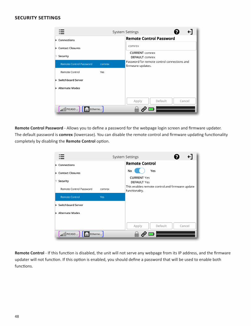
seCuritysettings
RemoteControlPassword - Allows you to define a password for the webpage login screen and firmware updater. The default password is comrex (lowercase). You can disable the remote control and firmware updating functionality completely by disabling theRemoteControloption.
RemoteControl - If this function is disabled, the unit will not serve any webpage from its IP address, and the firmware updater will not function. If this option is enabled, you should define a password that will be used to enable both functions.
49
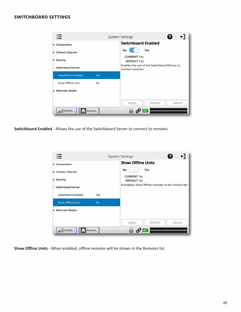
switChboardsettings
SwitchboardEnabled - Allows the use of the Switchboard Server to connect to remotes.
ShowOfflineUnits- When enabled, offline remotes will be shown in the Remotes list.

50
alternatemodes
briCnormalsettings
AcceptIncomingConnections - This determines if this NX is to be used for incoming normal IP connections. If this function is not enabled, NX will only support outgoing calls using BRIC Normal Mode.
modem
AcceptIncomingConnections - POTS calls must be answered automatically on NX. If this option is disabled, no POTS calls will be answered and only outgoing POTS connections can be made.
ebu3326/siP
Details for this mode are outlined in the MakingEBU3326/SIPConnections section on page 86.

51
XVI.CrossloCkmenu
These settings determine how the CrossLock reliability layer behaves. Most users should leave these settings as default.
Enable - Allow CrossLock connections in general. Default is yes. Note that this does not guarantee connections will be made with CrossLock. Other requirements (CrossLock capable codec on far end, compatible firmware, etc.) must be met for CrossLock to function.
RetransmitDelay - CrossLock automatically provides an extra “Retransmit Cushion” that provides some time to make ARQ error correction effective. The default amount of time is twice the measured round trip delay of the network (2xRTT). This has been shown to be most effective on most networks, but can be altered lower (1xRTT, none) or higher (3xRTT) using this menu.
RedundantTransmission - Default is off. Most users of portable codecs will prefer the default “Bonding” mode, which sums the capabilities of networks together. Redundancy disables that feature, and instead puts all network data simultaneously on all available networks. This is the preferred mode if your networks are of known high quality and unmetered. In the case of one network being completely lost, Redundant mode can result in less audio disruption (although in many cases Bonding mode achieves this as well).
EncoderThrottle - Allow CrossLock to signal that the local encoder should reduce data rate. Default is yes.

52
XVII. UsersettIngsMenU
The UserSettings menu is divided into two sections: KeypadSettings and UserExperience.
Under KeypadSettings, you can adjust the behavior of the F1 and F2 keys. If you have the Advanced options checked, you can also adjust the HomeKey (for both short and long press).
The F1 key opens up the Dashboard menu by default. You can change the menu it opens, take a screen capture (which will save to an attached USB dongle), cycle through screens, activate one of the four Contact Closures, or disable it.
The F2 key cycles through screens by default, but can be set to change the menu it opens, take a screen capture (which will save to an attached USB dongle), cycle through screens, or activate one of the four Contact Closures or disable it.
The Home Key opens the RemoteConnectionsscreen by default. You can either disable this behavior, switch to a different menu, or cycle through screens. The HomeKey(Long) entry shows the HelpPopup by default, but can be changed to disabled or set to open a menu.
Under UserExperience, KnobOverlayallows you to adjust the appearance and location of the audio overlay showing levels of the Local, Return and Input knobs.
53
If Advancedischecked,therewillalsobeentriesforRestrictedUserMode,OnlineHelp,and ListExpand/Collapse.
RestrictedUserModedisables or hides most of the screens and settings that allow unit configuration, leaving only the items required for basic operation. This is defaulted to Normal(all menus are available), but can be changed to Restricted for basic operation.OnlineHelpallows the built-in help button to be hidden from the title bar if desired. You will still have access to it via a keypad key, if assigned.
ListExpand/Collapse adjusts how sub-items expand/collapse when you click the category item. SingleTap(Toggle) is the default setting. The sub-items will expand and collapse on a single click. You can change it to DoubleTap(Toggle), or change it to an exclusive option. If either the SingleTap or DoubleTap(Exclusive) modes are selected, clicking on an expanded item category will not collapse it.

54
XVIII. pInouts
pInouts-AudIo
XLRPinout
Pin 1 GroundPin 2 Audio +Pin 3 Audio –
LineInPinout
Tip Left Channel OutRing Right Channel OutSleeve Ground
LineOutPinout
Tip Left Channel OutRing Right Channel OutSleeve Ground
pInouts-serIAlport
The serial port is pinned to match serial connections on older Macintosh computers, so commercially available adapter cables should have the proper pinning.
Pin# Function Direction1 CTS To NX2 RTS From NX3 RX Data To NX4 Ground5 TX Data From NX678 Ground

55
pInouts-ContACtClosure
Contact closures are available via the 9-pin mini-DIN connector on the top panel of the NX. Inputs are triggered by shorting the respective input to Pin9. Outputs consist of an open collector circuit which, when inactive, will offer a high-impedance path to Pin9 and, when active, will offer a low impedance path to Pin9. These outputs are capable of sinking up to 200 mA at a voltage up to 12 V. Do not switch AC mains power using these contacts.
Pin 1 Output #1Pin 2 Output #2Pin 3 Output #3Pin 4 Output #4Pin 5 Input #1Pin 6 Input #2Pin 7 Input #3Pin 8 Input #4Pin 9 Ground
Note:AdaptercablesfortheserialandcontactclosureportsareavailableforpurchasefromComrex—contactusformoreinformation.
56
XIX.ABOUTTHEALGORITHMS
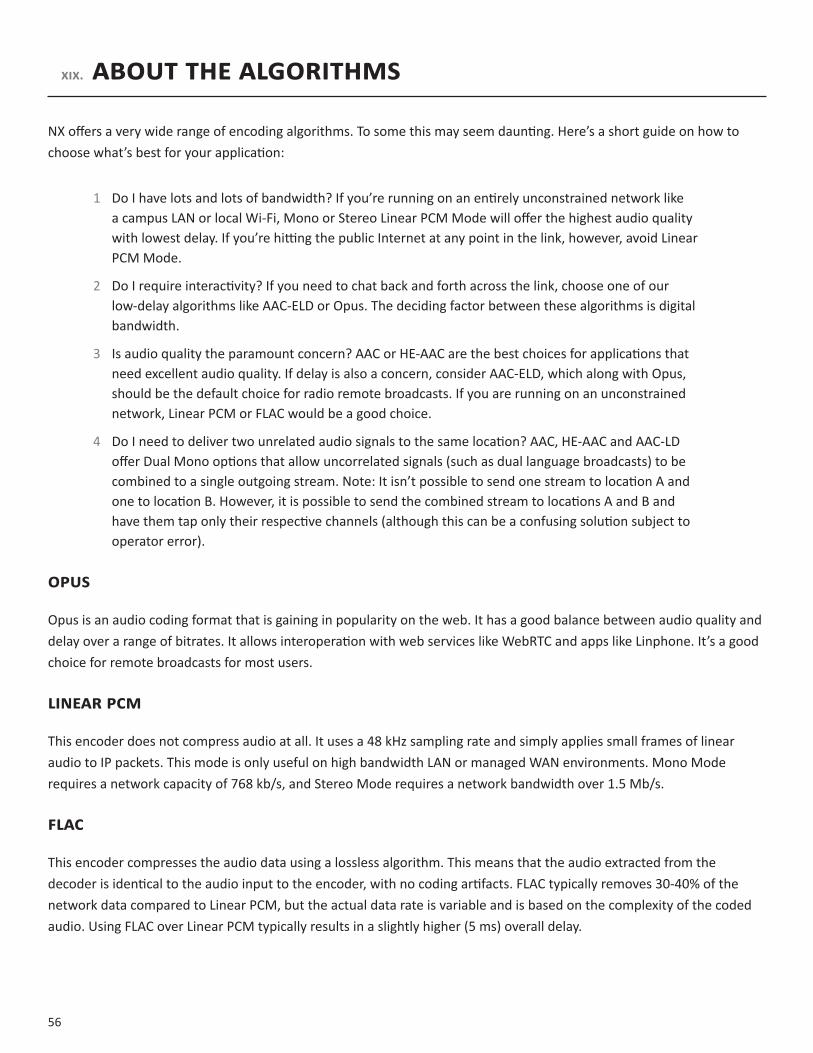
NX offers a very wide range of encoding algorithms. To some this may seem daunting. Here’s a short guide on how to choose what’s best for your application:
1 Do I have lots and lots of bandwidth? If you’re running on an entirely unconstrained network like a campus LAN or local Wi-Fi, Mono or Stereo Linear PCM Mode will offer the highest audio quality with lowest delay. If you’re hitting the public Internet at any point in the link, however, avoid Linear PCM Mode.
2 Do I require interactivity? If you need to chat back and forth across the link, choose one of our low-delay algorithms like AAC-ELD or Opus. The deciding factor between these algorithms is digital bandwidth.
3 Is audio quality the paramount concern? AAC or HE-AAC are the best choices for applications that need excellent audio quality. If delay is also a concern, consider AAC-ELD, which along with Opus, should be the default choice for radio remote broadcasts. If you are running on an unconstrained network, Linear PCM or FLAC would be a good choice.
4 Do I need to deliver two unrelated audio signals to the same location? AAC, HE-AAC and AAC-LD offer Dual Mono options that allow uncorrelated signals (such as dual language broadcasts) to be combined to a single outgoing stream. Note: It isn’t possible to send one stream to location A and one to location B. However, it is possible to send the combined stream to locations A and B and have them tap only their respective channels (although this can be a confusing solution subject to operator error).
OPUS
Opus is an audio coding format that is gaining in popularity on the web. It has a good balance between audio quality and delay over a range of bitrates. It allows interoperation with web services like WebRTC and apps like Linphone. It’s a good choice for remote broadcasts for most users.
LINEARPCM
This encoder does not compress audio at all. It uses a 48 kHz sampling rate and simply applies small frames of linear audio to IP packets. This mode is only useful on high bandwidth LAN or managed WAN environments. Mono Mode requires a network capacity of 768 kb/s, and Stereo Mode requires a network bandwidth over 1.5 Mb/s.
FLAC
This encoder compresses the audio data using a lossless algorithm. This means that the audio extracted from the decoder is identical to the audio input to the encoder, with no coding artifacts. FLAC typically removes 30-40% of the network data compared to Linear PCM, but the actual data rate is variable and is based on the complexity of the coded audio. Using FLAC over Linear PCM typically results in a slightly higher (5 ms) overall delay.

57
G.722
This is a well known 7 kHz (medium fidelity) algorithm used in some VOIP telephones and codecs. It is provided for compatibility purposes, but is not considered a superior algorithm for audio codecs.
AAC
This algorithm is a highly regarded standard for compressing audio to critical listening standards. It has been judged to produce “near transparent” audio at a coding rate of 128 kb/s stereo. The standard is a collaborative of several audio companies’ best efforts, and has become popular as the default audio codec of the Apple™ iTunes™ program. AAC should be considered the highest quality codec in NX; enhancements like HE-AAC and AAC-ELD attempt to maintain a similar quality and reduced bandwidth and delay.
HE-AAC
This is a newer version of AAC defined for increased efficiency. The goal of the algorithm is to produce AAC-comparable quality at a lower bit rate. It does this by encoding lower frequencies to AAC, and higher frequencies using Spectral Band Replication (SBR), a technique that partially synthesizes these high frequencies. HE-AAC is trademarked by other companies as AACPlus™. HE-AAC (and close derivatives) are often used as the main audio codec for digital radio and satellite networks.
HE-AACV2
This algorithm further increases the efficiency of HE-AAC by adding intensity stereo coding. This results in a lower bit rate for stereo signals. We also cluster a very reduced-rate HE-AAC mono into this category, although technically it does not contain v2 coding.
AAC-LD
This algorithm is an extension of AAC developed by the FhG IIS, who are the contributors to AAC and primary inventors of the MP3 algorithm. It’s quality is superior to MP3 at similar bitrates (64-128 kbps) but it exhibits very low delay (100 mS). This choice is best when reasonable network throughput is assured, near-transparent audio is required, and interactivity is needed.
AAC-ELD
This latest algorithm is a combination of the LD and HE-AAC variants. It provides the network-conserving benefits of SBR along with the dramatically reduced delay time of LD. For low delay applications, it’s usually the best choice.
58
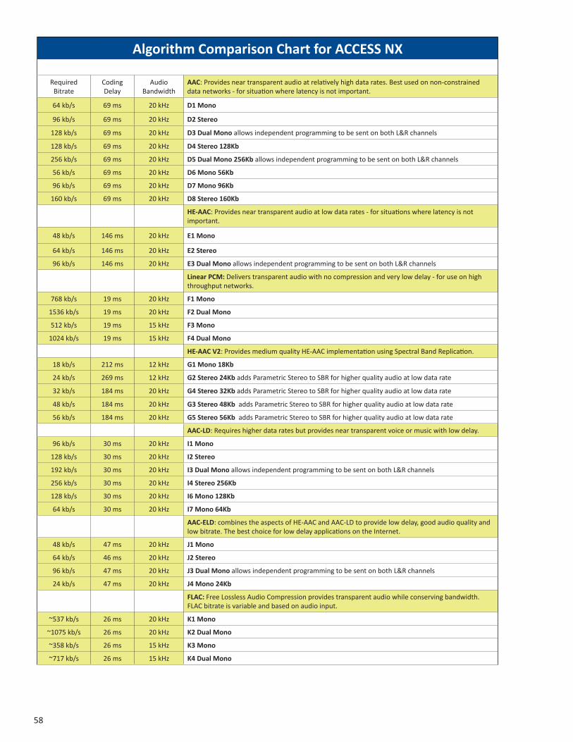
Algorithm Comparison Chart for ACCESS NX
Required Bitrate
Coding Delay
Audio Bandwidth
AAC: Provides near transparent audio at relatively high data rates. Best used on non-constrained data networks - for situation where latency is not important.
64 kb/s 69 ms 20 kHz D1 Mono
96 kb/s 69 ms 20 kHz D2 Stereo
128 kb/s 69 ms 20 kHz D3 Dual Mono allows independent programming to be sent on both L&R channels
128 kb/s 69 ms 20 kHz D4 Stereo 128Kb
256 kb/s 69 ms 20 kHz D5 Dual Mono 256Kb allows independent programming to be sent on both L&R channels
56 kb/s 69 ms 20 kHz D6 Mono 56Kb
96 kb/s 69 ms 20 kHz D7 Mono 96Kb
160 kb/s 69 ms 20 kHz D8 Stereo 160Kb
HE-AAC: Provides near transparent audio at low data rates - for situations where latency is notimportant.
48 kb/s 146 ms 20 kHz E1 Mono
64 kb/s 146 ms 20 kHz E2 Stereo
96 kb/s 146 ms 20 kHz E3 Dual Mono allows independent programming to be sent on both L&R channels
Linear PCM: Delivers transparent audio with no compression and very low delay - for use on high throughput networks.
768 kb/s 19 ms 20 kHz F1 Mono
1536 kb/s 19 ms 20 kHz F2 Dual Mono
512 kb/s 19 ms 15 kHz F3 Mono
1024 kb/s 19 ms 15 kHz F4 Dual Mono
HE-AAC V2: Provides medium quality HE-AAC implementation using Spectral Band Replication.
18 kb/s 212 ms 12 kHz G1 Mono 18Kb
24 kb/s 269 ms 12 kHz G2 Stereo 24Kb adds Parametric Stereo to SBR for higher quality audio at low data rate
32 kb/s 184 ms 20 kHz G4 Stereo 32Kb adds Parametric Stereo to SBR for higher quality audio at low data rate
48 kb/s 184 ms 20 kHz G3 Stereo 48Kb adds Parametric Stereo to SBR for higher quality audio at low data rate
56 kb/s 184 ms 20 kHz G5 Stereo 56Kb adds Parametric Stereo to SBR for higher quality audio at low data rate
AAC-LD: Requires higher data rates but provides near transparent voice or music with low delay.
96 kb/s 30 ms 20 kHz I1 Mono
128 kb/s 30 ms 20 kHz I2 Stereo
192 kb/s 30 ms 20 kHz I3 Dual Mono allows independent programming to be sent on both L&R channels
256 kb/s 30 ms 20 kHz I4 Stereo 256Kb
128 kb/s 30 ms 20 kHz I6 Mono 128Kb
64 kb/s 30 ms 20 kHz I7 Mono 64Kb
AAC-ELD: combines the aspects of HE-AAC and AAC-LD to provide low delay, good audio quality andlow bitrate. The best choice for low delay applications on the Internet.
48 kb/s 47 ms 20 kHz J1 Mono
64 kb/s 46 ms 20 kHz J2 Stereo
96 kb/s 47 ms 20 kHz J3 Dual Mono allows independent programming to be sent on both L&R channels
24 kb/s 47 ms 20 kHz J4 Mono 24Kb
FLAC: Free Lossless Audio Compression provides transparent audio while conserving bandwidth. FLAC bitrate is variable and based on audio input.
~537 kb/s 26 ms 20 kHz K1 Mono
~1075 kb/s 26 ms 20 kHz K2 Dual Mono
~358 kb/s 26 ms 15 kHz K3 Mono
~717 kb/s 26 ms 15 kHz K4 Dual Mono
Opus: A newer offering that combines low delay and low network utilization. Opus is included primarily for compatibility with softphone apps and Internet connections using WebRTC. (Special CBR modes are offered for compatibility with Tieline products - avoid these in other applications).
48Kb/s 41 ms 20 kHz N4.1 Mono 48kbps
56Kb/s 41 ms 20 kHz N4.2 Mono 56kbps
64Kb/s 41 ms 20 kHz N4.3 Mono 64kbps
64Kb/s 41 ms 20 kHz N5.1 Stereo 64kbps
96Kb/s 41 ms 20 kHz N5.2 Stereo 96kbps
128Kb/s 41 ms 20 kHz N5.3 Stereo 128kbps
48Kb/s 41 ms 20 kHz N6.1 CBR Mono 48kbps
64Kb/s 41 ms 20 kHz N6.3 CBR Mono 64kbps
64Kb/s 41 ms 20 kHz N7.1 CBR Stereo 64kbps
96Kb/s 41 ms 20 kHz N7.2 CBR Stereo 96kbps
128Kb/s 41 ms 20 kHz N7.3 CBR Stereo 128kbps
VoIP: G.722 coding algorithm for compatibility with SIP-style VoIP phones.
64 kb/s 35 ms 7 kHz X3 G.722
For more information, visit www.comrex.com

59
Algorithm Comparison Chart for ACCESS NX
Required Bitrate
Coding Delay
Audio Bandwidth
AAC: Provides near transparent audio at relatively high data rates. Best used on non-constrained data networks - for situation where latency is not important.
64 kb/s 69 ms 20 kHz D1 Mono
96 kb/s 69 ms 20 kHz D2 Stereo
128 kb/s 69 ms 20 kHz D3 Dual Mono allows independent programming to be sent on both L&R channels
128 kb/s 69 ms 20 kHz D4 Stereo 128Kb
256 kb/s 69 ms 20 kHz D5 Dual Mono 256Kb allows independent programming to be sent on both L&R channels
56 kb/s 69 ms 20 kHz D6 Mono 56Kb
96 kb/s 69 ms 20 kHz D7 Mono 96Kb
160 kb/s 69 ms 20 kHz D8 Stereo 160Kb
HE-AAC: Provides near transparent audio at low data rates - for situations where latency is notimportant.
48 kb/s 146 ms 20 kHz E1 Mono
64 kb/s 146 ms 20 kHz E2 Stereo
96 kb/s 146 ms 20 kHz E3 Dual Mono allows independent programming to be sent on both L&R channels
Linear PCM: Delivers transparent audio with no compression and very low delay - for use on high throughput networks.
768 kb/s 19 ms 20 kHz F1 Mono
1536 kb/s 19 ms 20 kHz F2 Dual Mono
512 kb/s 19 ms 15 kHz F3 Mono
1024 kb/s 19 ms 15 kHz F4 Dual Mono
HE-AAC V2: Provides medium quality HE-AAC implementation using Spectral Band Replication.
18 kb/s 212 ms 12 kHz G1 Mono 18Kb
24 kb/s 269 ms 12 kHz G2 Stereo 24Kb adds Parametric Stereo to SBR for higher quality audio at low data rate
32 kb/s 184 ms 20 kHz G4 Stereo 32Kb adds Parametric Stereo to SBR for higher quality audio at low data rate
48 kb/s 184 ms 20 kHz G3 Stereo 48Kb adds Parametric Stereo to SBR for higher quality audio at low data rate
56 kb/s 184 ms 20 kHz G5 Stereo 56Kb adds Parametric Stereo to SBR for higher quality audio at low data rate
AAC-LD: Requires higher data rates but provides near transparent voice or music with low delay.
96 kb/s 30 ms 20 kHz I1 Mono
128 kb/s 30 ms 20 kHz I2 Stereo
192 kb/s 30 ms 20 kHz I3 Dual Mono allows independent programming to be sent on both L&R channels
256 kb/s 30 ms 20 kHz I4 Stereo 256Kb
128 kb/s 30 ms 20 kHz I6 Mono 128Kb
64 kb/s 30 ms 20 kHz I7 Mono 64Kb
AAC-ELD: combines the aspects of HE-AAC and AAC-LD to provide low delay, good audio quality andlow bitrate. The best choice for low delay applications on the Internet.
48 kb/s 47 ms 20 kHz J1 Mono
64 kb/s 46 ms 20 kHz J2 Stereo
96 kb/s 47 ms 20 kHz J3 Dual Mono allows independent programming to be sent on both L&R channels
24 kb/s 47 ms 20 kHz J4 Mono 24Kb
FLAC: Free Lossless Audio Compression provides transparent audio while conserving bandwidth. FLAC bitrate is variable and based on audio input.
~537 kb/s 26 ms 20 kHz K1 Mono
~1075 kb/s 26 ms 20 kHz K2 Dual Mono
~358 kb/s 26 ms 15 kHz K3 Mono
~717 kb/s 26 ms 15 kHz K4 Dual Mono
Opus: A newer offering that combines low delay and low network utilization. Opus is included primarily for compatibility with softphone apps and Internet connections using WebRTC. (Special CBR modes are offered for compatibility with Tieline products - avoid these in other applications).
48Kb/s 41 ms 20 kHz N4.1 Mono 48kbps
56Kb/s 41 ms 20 kHz N4.2 Mono 56kbps
64Kb/s 41 ms 20 kHz N4.3 Mono 64kbps
64Kb/s 41 ms 20 kHz N5.1 Stereo 64kbps
96Kb/s 41 ms 20 kHz N5.2 Stereo 96kbps
128Kb/s 41 ms 20 kHz N5.3 Stereo 128kbps
48Kb/s 41 ms 20 kHz N6.1 CBR Mono 48kbps
64Kb/s 41 ms 20 kHz N6.3 CBR Mono 64kbps
64Kb/s 41 ms 20 kHz N7.1 CBR Stereo 64kbps
96Kb/s 41 ms 20 kHz N7.2 CBR Stereo 96kbps
128Kb/s 41 ms 20 kHz N7.3 CBR Stereo 128kbps
VoIP: G.722 coding algorithm for compatibility with SIP-style VoIP phones.
64 kb/s 35 ms 7 kHz X3 G.722
For more information, visit www.comrex.com
60
XX.SwitchboardtraverSalServer(tS)
The Switchboard Traversal Server is a service built and maintained by Comrex on the public Internet that provides users a directory of other users, in order to facilitate connections to devices that would normally have trouble accepting incoming IP connections. Use of Switchboard is free and comes activated from the factory.
The next section describes how to set up and configure Switchboard. For SwitchboardTheoryandConcepts, go to page 69.
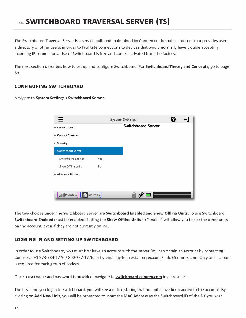
configuringSwitchboard
Navigate to SystemSettings->SwitchboardServer.
The two choices under the Switchboard Server are SwitchboardEnabled and ShowOfflineUnits. To use Switchboard, SwitchboardEnabledmust be enabled. Setting the ShowOfflineUnits to “enable” will allow you to see the other units on the account, even if they are not currently online.
logginginandSettingupSwitchboard
In order to use Switchboard, you must first have an account with the server. You can obtain an account by contacting Comrex at +1 978-784-1776 / 800-237-1776, or by emailing [email protected] / [email protected]. Only one account is required for each group of codecs.
Once a username and password is provided, navigate to switchboard.comrex.com in a browser.
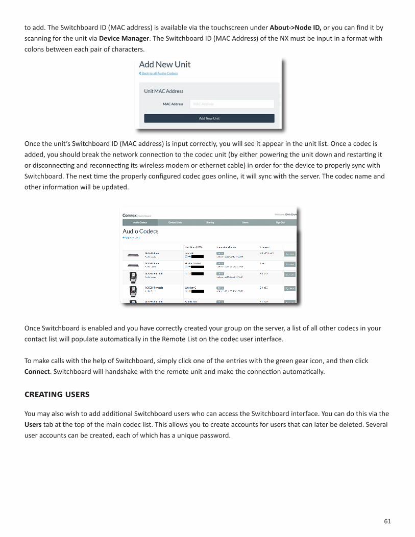
The first time you log in to Switchboard, you will see a notice stating that no units have been added to the account. By clicking on AddNewUnit, you will be prompted to input the MAC Address as the Switchboard ID of the NX you wish
61
to add. The Switchboard ID (MAC address) is available via the touchscreen under About->NodeID, or you can find it by scanning for the unit via DeviceManager. The Switchboard ID (MAC Address) of the NX must be input in a format with colons between each pair of characters.
Once the unit’s Switchboard ID (MAC address) is input correctly, you will see it appear in the unit list. Once a codec is added, you should break the network connection to the codec unit (by either powering the unit down and restarting it or disconnecting and reconnecting its wireless modem or ethernet cable) in order for the device to properly sync with Switchboard. The next time the properly configured codec goes online, it will sync with the server. The codec name and other information will be updated.
Once Switchboard is enabled and you have correctly created your group on the server, a list of all other codecs in your contact list will populate automatically in the Remote List on the codec user interface.
To make calls with the help of Switchboard, simply click one of the entries with the green gear icon, and then click Connect. Switchboard will handshake with the remote unit and make the connection automatically.
creatinguSerS
You may also wish to add additional Switchboard users who can access the Switchboard interface. You can do this via the Users tab at the top of the main codec list. This allows you to create accounts for users that can later be deleted. Several user accounts can be created, each of which has a unique password.

62
contactliStS
In some situations, it might not be desirable for each codec in your fleet to be able to see the Switchboard status of every other codec. To help filter what’s displayed on a codec’s interface, Switchboard has implemented ContactLists, which can each contain a subset of your codec fleet on your account. You can create multiple Contact Lists that consist of different subsets. With the exception of Shares (discussed below), only units within your Switchboard account may be assigned to Contact Lists.
By default, Switchboard creates a master Contact List that contains all of the codecs in your account. Every codec in your fleet uses this list. If you’re not interested in segregating codecs on your account any further, this default Contact List should be sufficient.
Each unit also has the ability to Follow a Contact List; this is a view-only function that allows a codec to see the status and presence of units in a Contact List. All units are set to Follow the master Contact List by default.
To Follow a Contact List on a codec, first click on the “Details” button for that codec on the main screen in Switchboard (as shown below).

63
Next, press the “Change” button near the middle of the following screen.
On the next screen, check the Contact List(s) that you want this codec to Follow, and press “Update Contact List”.
One important point to remember: Following a Contact List on a codec only determines which units get displayed on that codec’s own list. It has no impact on how that codec itself is displayed on other devices.
64
ShareS
If you want to allow users outside of your account to see the status of some of the devices in your fleet, Switchboard has implemented Shares—which, like Contact Lists, are also subsets of your codec fleet that you can define. You can invite other Switchboard accounts to add your Shares, and your codecs become visible to them.
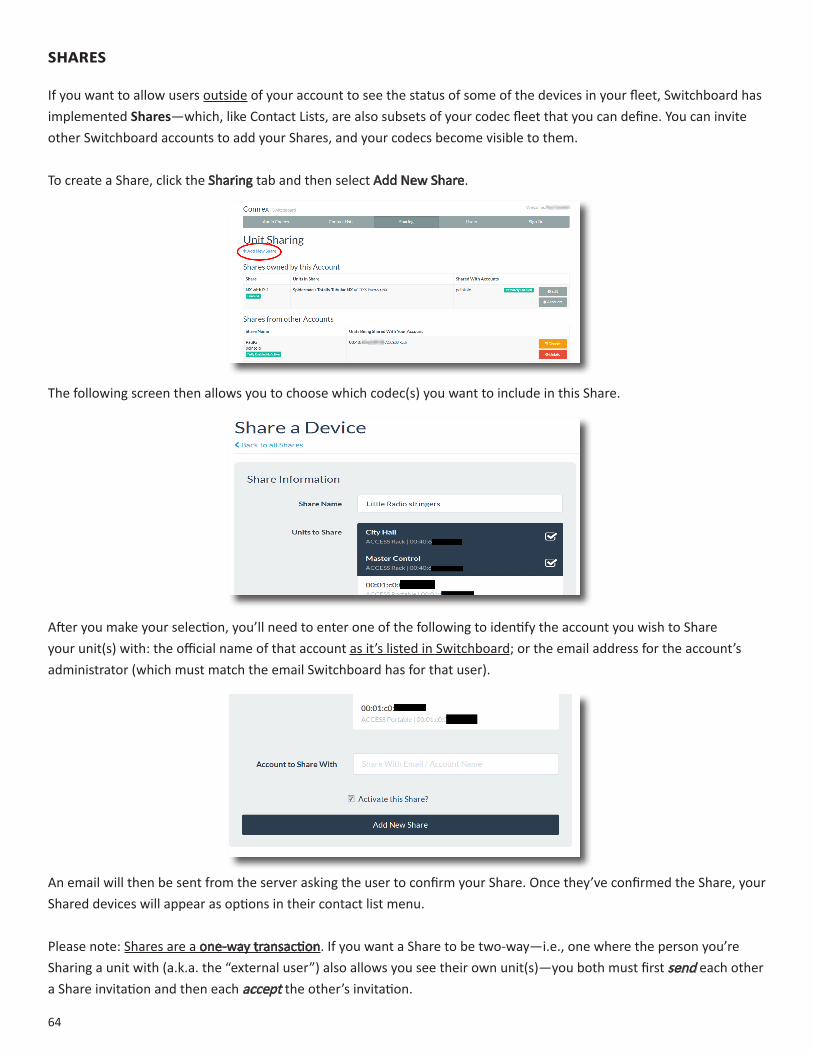
To create a Share, click the Sharing tab and then select Add New Share.
The following screen then allows you to choose which codec(s) you want to include in this Share.
After you make your selection, you’ll need to enter one of the following to identify the account you wish to Share your unit(s) with: the official name of that account as it’s listed in Switchboard; or the email address for the account’s administrator (which must match the email Switchboard has for that user).
An email will then be sent from the server asking the user to confirm your Share. Once they’ve confirmed the Share, your Shared devices will appear as options in their contact list menu.
Please note: Shares are a one-way transaction. If you want a Share to be two-way—i.e., one where the person you’re Sharing a unit with (a.k.a. the “external user”) also allows you see their own unit(s)—you both must first send each other a Share invitation and then each accept the other’s invitation.
65
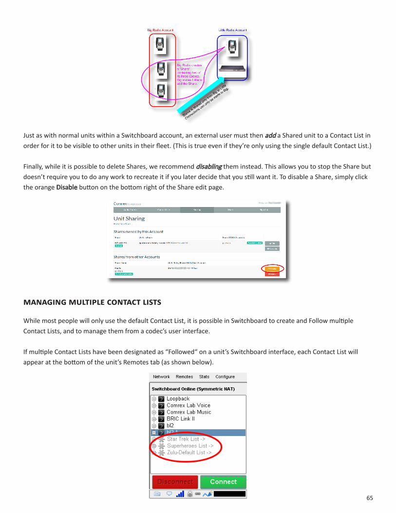
Just as with normal units within a Switchboard account, an external user must then add a Shared unit to a Contact List in order for it to be visible to other units in their fleet. (This is true even if they’re only using the single default Contact List.)
Finally, while it is possible to delete Shares, we recommend disabling them instead. This allows you to stop the Share but doesn’t require you to do any work to recreate it if you later decide that you still want it. To disable a Share, simply click the orange Disable button on the bottom right of the Share edit page.
ManagingMultiplecontactliStS
While most people will only use the default Contact List, it is possible in Switchboard to create and Follow multiple Contact Lists, and to manage them from a codec’s user interface.
If multiple Contact Lists have been designated as “Followed“ on a unit’s Switchboard interface, each Contact List will appear at the bottom of the unit’s Remotes tab (as shown below).
66
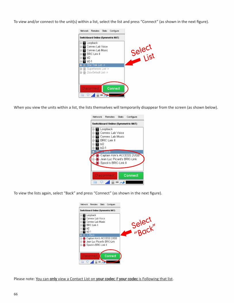
To view and/or connect to the unit(s) within a list, select the list and press “Connect” (as shown in the next figure).
When you view the units within a list, the lists themselves will temporarily disappear from the screen (as shown below).
To view the lists again, select “Back” and press “Connect” (as shown in the next figure).
Please note: You can only view a Contact List on your codec if your codec is Following that list.

67
bulKactionSforcontactliStS
It is also possible within Switchboard to perform an action that impacts all of the codecs in a given Contact List in a single step called a Bulk Action.
To do this, press the Bulk Action button in the bottom right corner of the Contact List tab.
The three steps to create a Bulk Action are:
1. Choose the type of action you want to perform;2. Select the codecs you’re targeting with this change;3. Identify the Contact List that will be impacted by the change.
Step 1: Choose the Action Type
First, you must select which of the four types of Bulk Actions you want to perform:
• ADD codecs to a Contact List.• REMOVE codecs from a Contact List.• SUBSCRIBE to a Contact List (i.e., have multiple codecs Follow that list).• UNSUBSCRIBE from a Contact List (i.e., have multiple codecs stop Following that list).
68
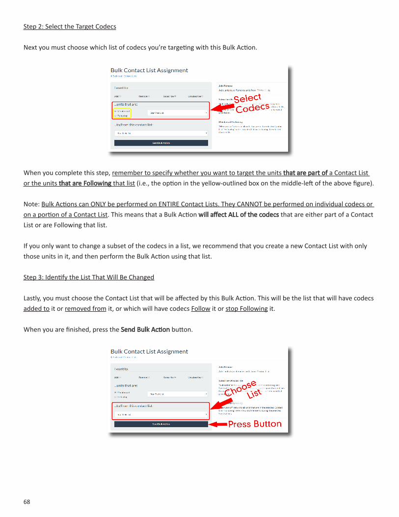
Step 2: Select the Target Codecs
Next you must choose which list of codecs you’re targeting with this Bulk Action.
When you complete this step, remember to specify whether you want to target the units that are part of a Contact List or the units that are Following that list (i.e., the option in the yellow-outlined box on the middle-left of the above figure).
Note: Bulk Actions can ONLY be performed on ENTIRE Contact Lists. They CANNOT be performed on individual codecs or on a portion of a Contact List. This means that a Bulk Action will affect ALL of the codecs that are either part of a Contact List or are Following that list.
If you only want to change a subset of the codecs in a list, we recommend that you create a new Contact List with only those units in it, and then perform the Bulk Action using that list.
Step 3: Identify the List That Will Be Changed
Lastly, you must choose the Contact List that will be affected by this Bulk Action. This will be the list that will have codecs added to it or removed from it, or which will have codecs Follow it or stop Following it.
When you are finished, press the Send Bulk Action button.
69
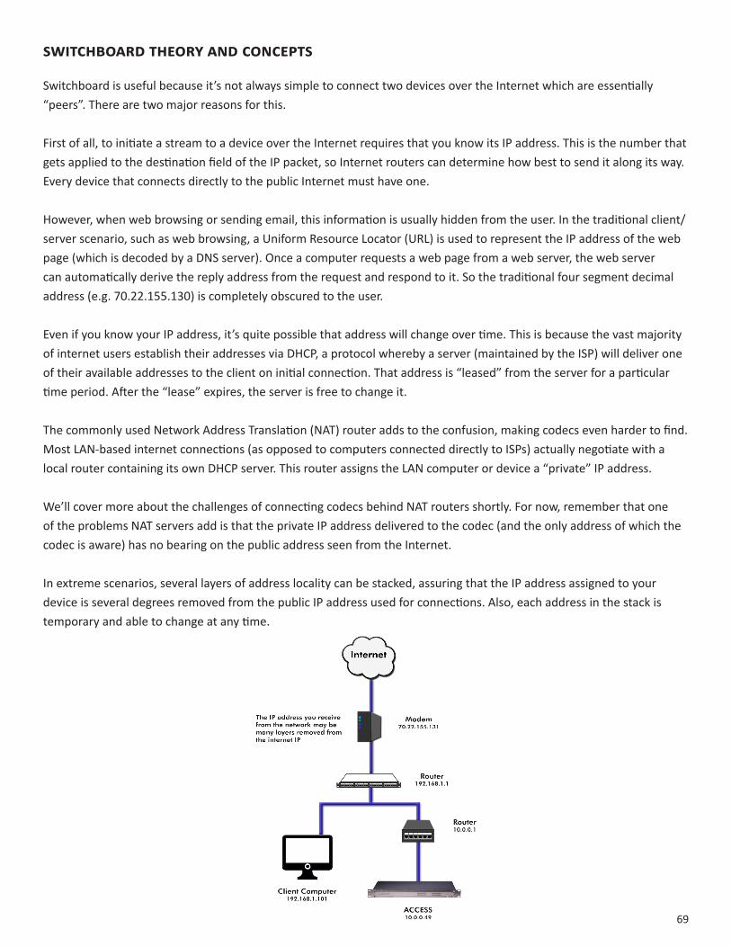
SwitchboardtheoryandconceptS
Switchboard is useful because it’s not always simple to connect two devices over the Internet which are essentially “peers”. There are two major reasons for this.
First of all, to initiate a stream to a device over the Internet requires that you know its IP address. This is the number that gets applied to the destination field of the IP packet, so Internet routers can determine how best to send it along its way. Every device that connects directly to the public Internet must have one.
However, when web browsing or sending email, this information is usually hidden from the user. In the traditional client/server scenario, such as web browsing, a Uniform Resource Locator (URL) is used to represent the IP address of the web page (which is decoded by a DNS server). Once a computer requests a web page from a web server, the web server can automatically derive the reply address from the request and respond to it. So the traditional four segment decimal address (e.g. 70.22.155.130) is completely obscured to the user.
Even if you know your IP address, it’s quite possible that address will change over time. This is because the vast majority of internet users establish their addresses via DHCP, a protocol whereby a server (maintained by the ISP) will deliver one of their available addresses to the client on initial connection. That address is “leased” from the server for a particular time period. After the “lease” expires, the server is free to change it.
The commonly used Network Address Translation (NAT) router adds to the confusion, making codecs even harder to find. Most LAN-based internet connections (as opposed to computers connected directly to ISPs) actually negotiate with a local router containing its own DHCP server. This router assigns the LAN computer or device a “private” IP address.
We’ll cover more about the challenges of connecting codecs behind NAT routers shortly. For now, remember that one of the problems NAT servers add is that the private IP address delivered to the codec (and the only address of which the codec is aware) has no bearing on the public address seen from the Internet.
In extreme scenarios, several layers of address locality can be stacked, assuring that the IP address assigned to your device is several degrees removed from the public IP address used for connections. Also, each address in the stack is temporary and able to change at any time.

70
Before deployment of Switchboard, the answer to this dilemma was to assure that the codec located in the studio has a fixed, public IP address. By fixed, we mean that the address is allocated exclusively by the ISP, and that address is entered manually into the configuration of the codec and not subject to change. This scenario works because IP “calls” are usually initiated from the field. As long as the field unit can find the fixed address of the studio unit and send a stream to it, a reverse channel can be created easily and automatically by the studio unit, using the source information contained in the incoming packets. Even in this scenario, the studio IP address must be memorized or input into each codec individually.
The first function Switchboard works around is the dynamic IP address problem by acting as a Directory Server. Codec users simply log in to the free server and are given an account name and password. Once logged in, it’s a simple process to input the details of each codec owned. On the codec itself, the user will input a familiar name by which the codec will be known within that group.
Once enabled, a codec in the group that is physically connected to the Internet will sync with the server. The current public IP address of the codec will be obtained by the server and the user directory will be updated with the new IP address.
In addition, the availability status of the codec is also updated. The codec will “ping” the server if anything changes (address, status, etc.). As we’ll see, this “ping” function will prove useful in other ways.
Once the codec has updated its status with the server, it’s time to download the directory. This process happens instantly. The update includes current addresses and status info for all codecs within the group. This information forms a sort of “Buddy List” that gets integrated into the codec’s connection address book. The list may still consist of entries made manually by IP address into the codec, but those are signified by a different icon. Current status of each codec is reflected by graying out entries which are not currently connected or that haven’t been synchronized to the server.
If IP addresses should change, the codec will re-sync with the server from the new address, and all will be updated automatically. Connections can be made by simply clicking on the correct name, without any updating on the part of the user.
The other roadblock provided by the use of NAT routers is the inability to accept unsolicited incoming connections from the Internet. Generally, this function acts as a rudimentary firewall and is a net positive for security, but it does cause headaches for codec users.
A router that receives a connection request doesn’t have a clue where to forward that stream unless it has specific instructions programmed into it. These instructions are known as “port forwarding.”
This can work well for fixed installations, but it’s not always an easy task to obtain that kind of security access on corporate routers. Also, forwarding functions are implemented differently on different hardware. You can easily imagine the complications of obtaining or managing port forwarding on the LAN when arriving at a new remote venue. You would likely encounter a large amount of resistance or confusion on the part of local IT staff. In describing NAT routing, it’s important to understand the concept of ports. These are numbers, like the source and destination IP addresses that are attached to each packet. They further qualify which application on a computer (or codec) is meant to send or receive a packet.
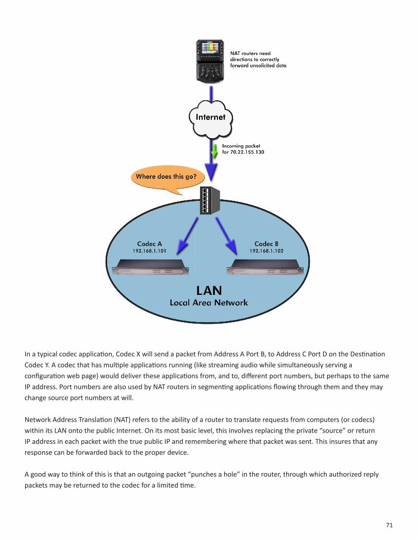
71
In a typical codec application, Codec X will send a packet from Address A Port B, to Address C Port D on the Destination Codec Y. A codec that has multiple applications running (like streaming audio while simultaneously serving a configuration web page) would deliver these applications from, and to, different port numbers, but perhaps to the same IP address. Port numbers are also used by NAT routers in segmenting applications flowing through them and they may change source port numbers at will.
Network Address Translation (NAT) refers to the ability of a router to translate requests from computers (or codecs) within its LAN onto the public Internet. On its most basic level, this involves replacing the private “source” or return IP address in each packet with the true public IP and remembering where that packet was sent. This insures that any response can be forwarded back to the proper device.
A good way to think of this is that an outgoing packet “punches a hole” in the router, through which authorized reply packets may be returned to the codec for a limited time.

72
Switchboard aids in breaking through these different types of routers for incoming calls. Because it is in constant contact with all subscribed codecs, it can send and receive test patterns to determine whether one or more NAT routers exist on a link and what type they are. It can then choose a connection method to be used to circumvent any issues. Switchboard can:
• Instruct the calling codec to make a normal connection (No NAT detected).
• Use the hole punched by connection to the Directory Server for incoming connections from other codecs.
• Instruct the called codec to make the connection in the reverse direction.
The second option, which utilizes the outgoing Directory Server “ping” described earlier, is very useful. The interval of this ping is adjustable, but defaults to about one minute, which is short enough to keep a hole punched through the majority of NAT routers.
These techniques are based loosely, with enhancements, on a generic Internet protocol called STUN (Simple Traversal of UDP through NAT). The system works well in all environments except one: when both users are sitting behind a symmetric NAT. In this situation, calls will fail even with Switchboard. The only option in that environment is to resort to port forwarding on one side of the link.

73
XX.CrossLoCkDetaiLs
As briefly described in the IntroductiontoCrossLocksection,CrossLock describes a new reliability layer that gets established between Comrex devices in advance of a connection. This layer takes the form of a Virtual Private network (VPN) between the devices. The ACCESS Media stream is carried within this VPN.
In addition to carrying the audio media, CrossLock allows lots of other information to be shared between the endpoint, including information about network quality and far-end delay settings. This provides for much better delay management on both ends of the link.
One or both ends of a CrossLock connection can utilize multiple network interfaces. This can take the form of two Ethernet connections, or any mix of wired and wireless networks. A common usage scenario would be attaching two 3G/4G modems to NX. In the case of one network underperforming, the majority (or all) of the data will be sent on the good network.
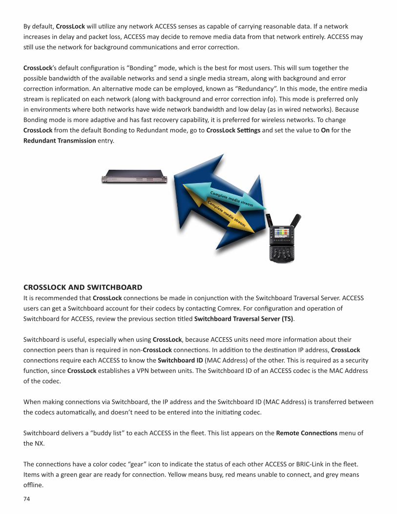
74
By default, CrossLock will utilize any network ACCESS senses as capable of carrying reasonable data. If a network increases in delay and packet loss, ACCESS may decide to remove media data from that network entirely. ACCESS may still use the network for background communications and error correction.
CrossLock’s default configuration is “Bonding” mode, which is the best for most users. This will sum together the possible bandwidth of the available networks and send a single media stream, along with background and error correction information. An alternative mode can be employed, known as “Redundancy”. In this mode, the entire media stream is replicated on each network (along with background and error correction info). This mode is preferred only in environments where both networks have wide network bandwidth and low delay (as in wired networks). Because Bonding mode is more adaptive and has fast recovery capability, it is preferred for wireless networks. To change CrossLock from the default Bonding to Redundant mode, go to CrossLockSettings and set the value to On for the RedundantTransmission entry.
CrossLoCkanDswitChboarDIt is recommended that CrossLock connections be made in conjunction with the Switchboard Traversal Server. ACCESS users can get a Switchboard account for their codecs by contacting Comrex. For configuration and operation of Switchboard for ACCESS, review the previous section titled SwitchboardTraversalServer(TS).
Switchboard is useful, especially when using CrossLock, because ACCESS units need more information about their connection peers than is required in non-CrossLock connections. In addition to the destination IP address, CrossLock connections require each ACCESS to know the SwitchboardID (MAC Address) of the other. This is required as a security function, since CrossLock establishes a VPN between units. The Switchboard ID of an ACCESS codec is the MAC Address of the codec.
When making connections via Switchboard, the IP address and the Switchboard ID (MAC Address) is transferred between the codecs automatically, and doesn’t need to be entered into the initiating codec.
Switchboard delivers a “buddy list” to each ACCESS in the fleet. This list appears on the RemoteConnectionsmenu of the NX.
The connections have a color codec “gear” icon to indicate the status of each other ACCESS or BRIC-Link in the fleet. Items with a green gear are ready for connection. Yellow means busy, red means unable to connect, and grey means offline.
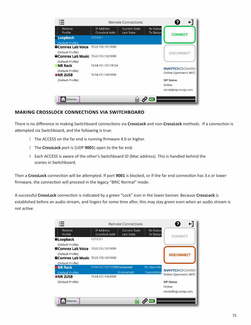
75
MakingCrossLoCkConneCtionsviaswitChboarD
There is no difference in making Switchboard connections via CrossLock and non-CrossLock methods. If a connection is attempted via Switchboard, and the following is true:
1 The ACCESS on the far end is running firmware 4.0 or higher.
2 The CrossLock port is (UDP 9001) open to the far end.
3 Each ACCESS is aware of the other’s Switchboard ID (Mac address). This is handled behind the scenes in Switchboard.
Then a CrossLock connection will be attempted. If port 9001is blocked, or if the far end connection has 3.x or lower firmware, the connection will proceed in the legacy “BRIC Normal” mode.
A successful CrossLock connection is indicated by a green “Lock” icon in the lower banner. Because CrossLock is established before an audio stream, and lingers for some time after, this may stay green even when an audio stream is not active.
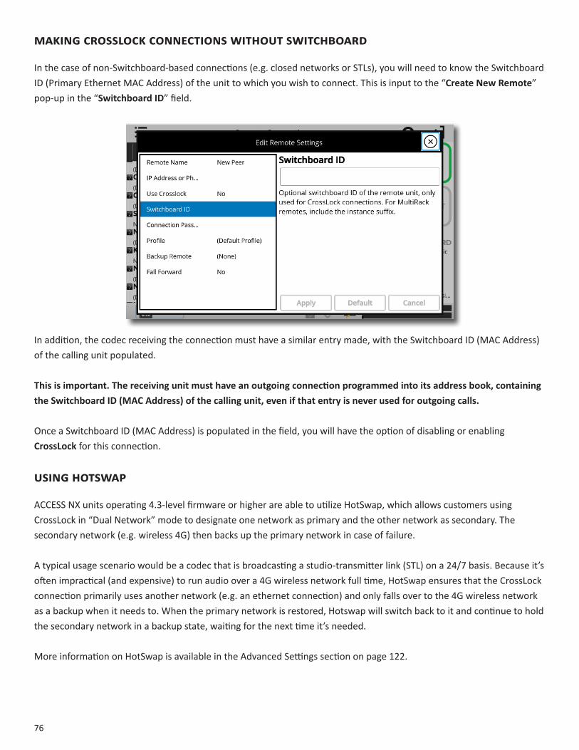
76
MakingCrossLoCkConneCtionswithoutswitChboarD
In the case of non-Switchboard-based connections (e.g. closed networks or STLs), you will need to know the Switchboard ID (Primary Ethernet MAC Address) of the unit to which you wish to connect. This is input to the “CreateNewRemote” pop-up in the “SwitchboardID” field.
In addition, the codec receiving the connection must have a similar entry made, with the Switchboard ID (MAC Address)of the calling unit populated.
Thisisimportant.Thereceivingunitmusthaveanoutgoingconnectionprogrammedintoitsaddressbook,containingtheSwitchboardID(MACAddress)ofthecallingunit,evenifthatentryisneverusedforoutgoingcalls.
Once a Switchboard ID (MAC Address) is populated in the field, you will have the option of disabling or enabling CrossLock for this connection.
usinghotswap
ACCESS NX units operating 4.3-level firmware or higher are able to utilize HotSwap, which allows customers using CrossLock in “Dual Network” mode to designate one network as primary and the other network as secondary. The secondary network (e.g. wireless 4G) then backs up the primary network in case of failure.
A typical usage scenario would be a codec that is broadcasting a studio-transmitter link (STL) on a 24/7 basis. Because it’s often impractical (and expensive) to run audio over a 4G wireless network full time, HotSwap ensures that the CrossLock connection primarily uses another network (e.g. an ethernet connection) and only falls over to the 4G wireless network as a backup when it needs to. When the primary network is restored, Hotswap will switch back to it and continue to hold the secondary network in a backup state, waiting for the next time it’s needed.
More information on HotSwap is available in the Advanced Settings section on page 122.

77
XXI.DevIceManager DeviceManager is a free program for both Windows and MAC that provides a simple and elegant interface for updating, configuring and managing your Comrex devices. With DeviceManager, you can configure the IP Networking details, update firmware, enable license features, copy and save configuration information, and more. DeviceManager was included on the CD sent with your Comrex equipment and can also be downloaded from our website at http://www.comrex.com/products/device-manager/.
UsIngDevIceManager
After DeviceManager is installed, open the program and simply click “ScanforDevices” to find any device that is on the same physical IP network as your computer. The list will include the unit MAC Address (Switchboard ID), the device type, and the unit name. Alternatively, if you know the public IP address of a Comrex device and TCP port 80 has been forwarded to that device, you can manually add the device and perform certain functions, such as updating firmware, from outside your network.
Once a unit is selected, five tabs appear on the right-hand pane.
The first tab is the Device tab. This tab will give you the current IP address and network settings. As a security measure, network settings may only be changed during the first 5 minutes of your Comrex product operation. If you wish to change your network settings, you will have to reboot your unit and make the changes right away.
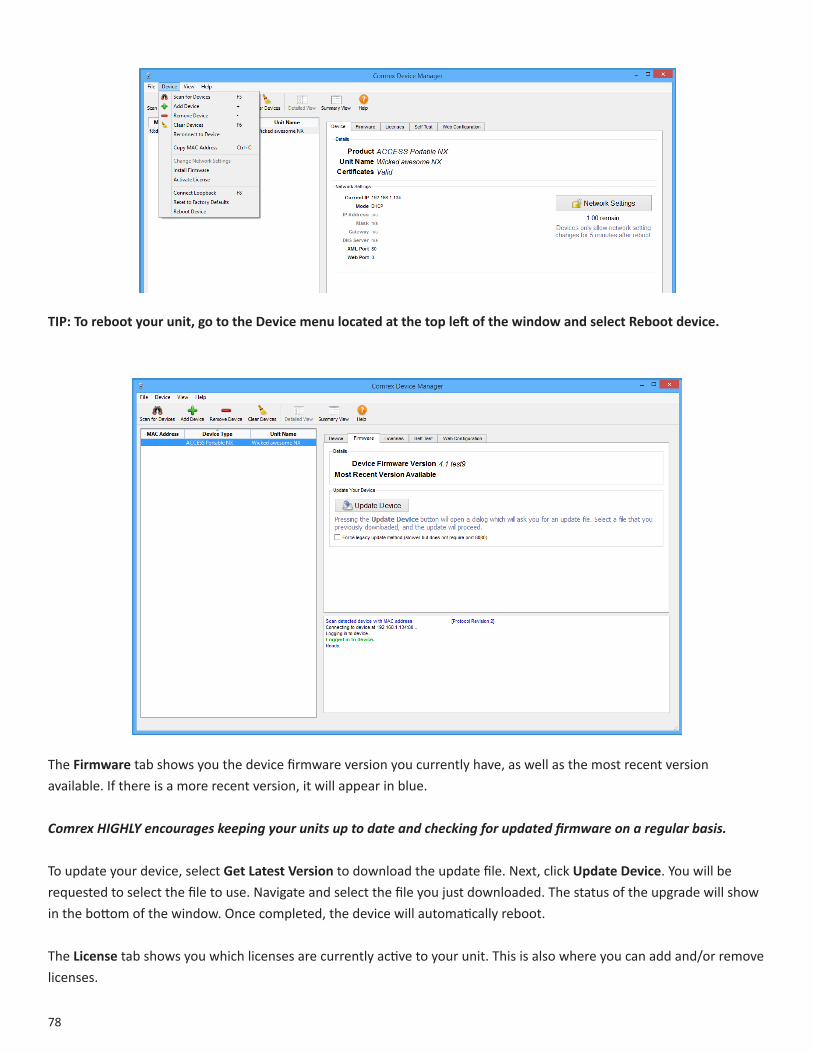
78
TIP:Torebootyourunit,gototheDevicemenulocatedatthetopleftofthewindowandselectRebootdevice.
The Firmwaretab shows you the device firmware version you currently have, as well as the most recent version available. If there is a more recent version, it will appear in blue.
Comrex HIGHLY encourages keeping your units up to date and checking for updated firmware on a regular basis.
To update your device, select GetLatestVersion to download the update file. Next, click UpdateDevice. You will be requested to select the file to use. Navigate and select the file you just downloaded. The status of the upgrade will show in the bottom of the window. Once completed, the device will automatically reboot.
TheLicense tab shows you which licenses are currently active to your unit. This is also where you can add and/or remove licenses.
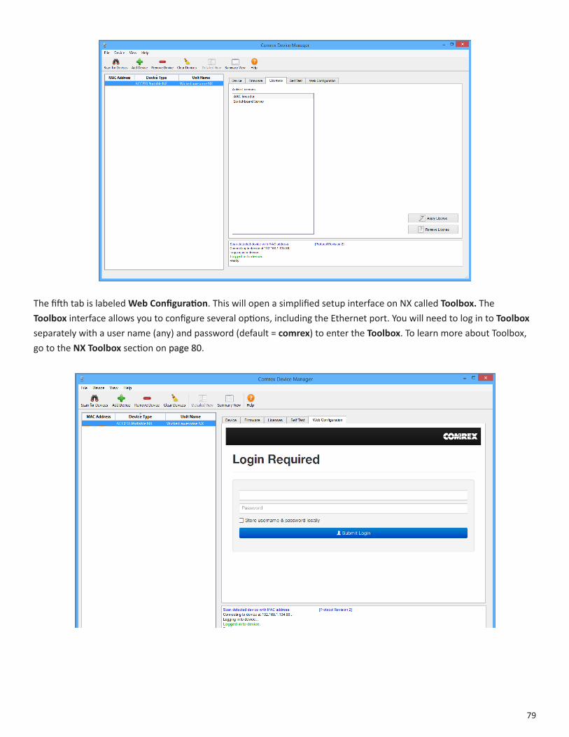
79
The fifth tab is labeled WebConfiguration. This will open a simplified setup interface on NX called Toolbox. The Toolbox interface allows you to configure several options, including the Ethernet port. You will need to log in to Toolbox separately with a user name (any) and password (default = comrex) to enter the Toolbox. To learn more about Toolbox, go to the NXToolboxsection on page 80.

80
XXII. ToolboX
Toolbox is anetwork manager that allows for easy network configuration. Typically you will be using your NX touchscreen to perform these operations as described in the section NetworkManager on page 30, but in some cases, it can be much easier to useToolbox.
You can log into Toolbox either via DeviceManager or through the IP address of the unit with /cfg appended to it (e.g. 192.168.0.34/cfg).
Once logged into Toolbox, choose the Network/Admin/CrossLock option and then choose SetupEthernetandWireless.
From here, you can select the device you would like to configure and then adjust the parameters for that device. You can edit the Name, if it is enabled or not, and the ActiveNetworkLocation.

81
loCaTIons
Locations are entries that are saved in your unit so that you can store network information for various environments and not need to enter it in every time. For example, if you are moving NX between venues and want to store the static IP information for each venue, you will define a new “Location” (giving it a unique name). Once multiple locations are defined, you can switch between them using the ActiveNetworkLocation option. Locations can be configured for any network device, including the Wi-Fi adapter. This can be useful in programming credentials for use in multiple Wi-Fi environments.
ConfIgurIngWI-fI
When setting up a Wi-Fi connection, you can scan for all available Wi-Fi networks using the “Scan” function.
Once selected, you can enter in the details for that network, including the network key, if needed.
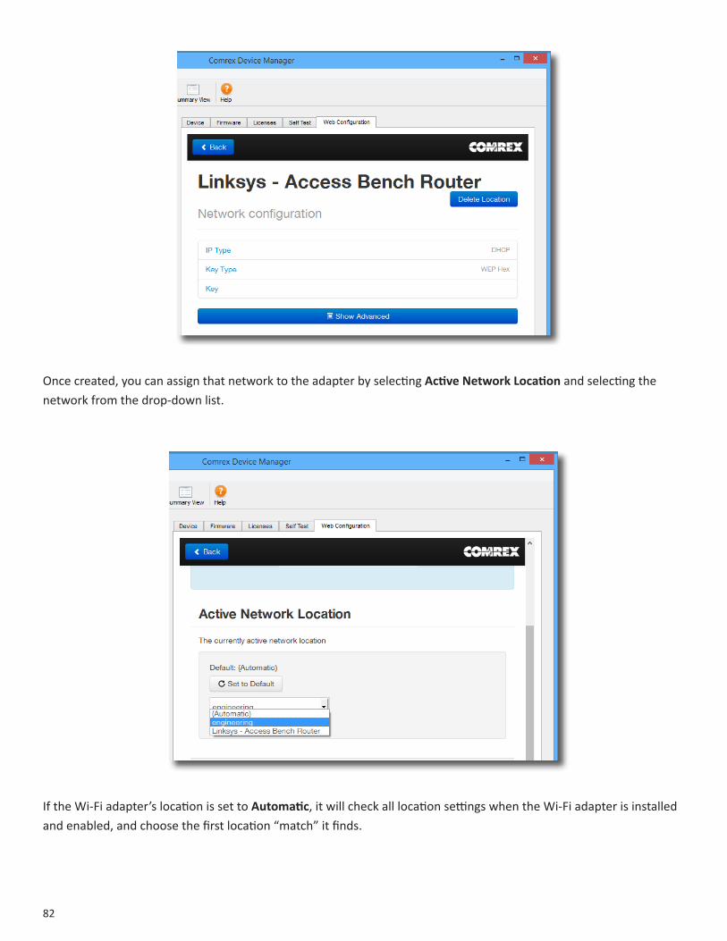
82
Once created, you can assign that network to the adapter by selecting ActiveNetworkLocation and selecting the network from the drop-down list.
If the Wi-Fi adapter’s location is set to Automatic, it will check all location settings when the Wi-Fi adapter is installed and enabled, and choose the first location “match” it finds.

83
advanCedneTWorkseTTIngsInToolboX
By choosing “ShowAdvanced” under any network, the following options appear:
PreserveafterReset - Normally, when NX is set back to factory defaults (via DeviceManager), all the network settings (including the main Ethernet) are erased. By setting this option to “yes”, the settings for this network will be preserved after factory reset. Caution should be used, as it’s possible to “lock yourself out” of the NX by setting the Ethernet parameters incorrectly.
UsewithCrossLock- Normally enabled, this option allows you to specify that this network port will not be utilized as part of a CrossLock connection. This may be valuable when using one port for control purposes only and a secondary port for CrossLock media.
BroadcastConfig- Normally enabled, this option instructs NX not to respond to the “Scan” function used by DeviceManager. Caution - without the “scan” function, NetworkRecoveryMode is disabled.
84
XXIII. OPERATINGNXINA24/7ENVIRONMENT
In BRIC Normal mode, the default mode of operation, NX transfers all its audio data via the UDP protocol. This is in contrast to most web-based connections, such as web browsing and e-mail. These use TCP protocol. UDP, unlike TCP, is not “connection oriented”; that is, no virtual connection actually exists in this protocol layer between the devices.
In UDP, the transmitter simply launches packets into the network with the correct address, hoping the network will deliver the packets in a timely fashion. Since there is no intelligent connection built between the codecs, there isn’t actually any connection to break in the event of network failure.
If a packet is delayed or lost, no error message is sent and no packets are retransmitted. It is up to the receiver to cover up any lost data, if it can. This allows delivery of the packets with the smallest amount of overhead and delay.
Therefore, the usability of the network is the important factor, not the existence of a physical connection. Loss of the remote will usually be due to a network failure. (If the network fails and is later restored, the packets stream will be restored to the decoder.)
For most applications, such as remote broadcasting, it’s useful to simulate a connection-oriented stream, so NX uses a low-bandwidth sub channel to deliver information back to the encoder about overall connection status. It does this in its “application layer”, rather than the “transport layer”, which is where UDP exists.
By default, it monitors the health of a connection. If no data is detected as received by the decoder during the preset user adjustable timeout, it “tears down” this connection and goes back to idle state. This can give an indication to the user that the network has failed and it’s time to look at the problem.
The good thing about having the connection protocol in the application layer is that its use is optional. For 24/7 operation, there’s no advantage to having the connection end if no data is received for a timeout interval.
To set NX for 24/7 operation, several parameters are changed:
1 The timeout value is set to infinity - the connection will never be torn down regardless of data.
2 NX is configured to re-establish the connection in the event of a power re-cycling.
3 The local Disconnect control is disabled. The Disconnect function on the receiving side is still en-abled, but will result in an immediate reconnection by the initiating side.
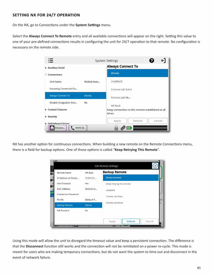
85
SETTINGNXFOR24/7OPERATION
On the NX, go to Connections under the SystemSettingsmenu.
Select the AlwaysConnectToRemote entry and all available connections will appear on the right. Setting this value to one of your pre-defined connections results in configuring the unit for 24/7 operation to that remote. No configuration is necessary on the remote side.
NX has another option for continuous connections. When building a new remote on the Remote Connections menu, there is a field for backup options. One of those options is called “KeepRetryingThisRemote”.
Using this mode will allow the unit to disregard the timeout value and keep a persistent connection. The difference is that the Disconnect function still works and the connection will not be reinitiated on a power re-cycle. This mode is meant for users who are making temporary connections, but do not want the system to time out and disconnect in the event of network failure.

86
XXIV. MAKINGEBU3326/SIPCOMPATIBLECONNECTIONS
Comrex codecs (and many other brands) have a set of protocols that allow easy IP connections between units. In general, when connecting between Comrex hardware, it’s best to use these proprietary modes to take the most advantage of the features of the product.
However, many users are concerned about getting “locked in” to a certain codec brand. Because of this, an international committee was formed by the European Broadcast Union called N/ACIP to hammer out a common protocol to interconnect codec brands. This committee resulted in the establishment of EBU 3326, a technical document which determined standards for codec compatibility.
EBU 3326 by and large establishes a set of features each codec should support, and then leaves most of the heavy lifting to other, previously agreed upon standards like SIP (IETF RFC 3261). Topics not yet covered by EBU 3326 include things like carrying ancillary data and contact closures from end-to-end, codec remote control and monitoring, and complex NAT traversal, which at this point are still left to the individual manufacturer’s discretion. This is why it’s best to stick to a single codec vendor and their proprietary protocols.
MOrEABOUTEBU3326
The Tech 3326 document defines several mandatory encoding algorithms, and the transport layer that could be used on them for compatibility. However, the most complex part of the standard was the decision on how to arrange Session Initialization, which is the handshake that takes place at the start of an IP codec call. The most commonly used protocol for this is called Session Initialization Protocol, or SIP. This is used extensively by VoIP phones and therefore was a logical choice. SIP carries the advantage of making NX compatible with a range of other non-broadcast products, like VoIP hardware, software, and even mobile phone apps.
EBU3326INNX
NX does not fully comply with EBU 3326, as it does not feature the mandatory MPEG Layer II codec. Aside from this, NX has been tested to be compatible with several other manufacturers’ devices using encoders supported by both products. When using EBU3326/SIPCompatible mode (this is how the user interface describes EBU 3326), ancillary data, contact closures, Switchboard TS, Multi-streaming, and Multicasting are not supported. Outgoing call profiles built with the EBU 3326/SIP channel may lack some advanced options, and cannot be set for different encoders in each direction (i.e. EBU 3326/SIP calls are always symmetrical).
EBU3326/SIPMOdES
A function of placing a SIP-style call is the ability to register with a SIP server. This is a server that exists somewhere on the network, usually maintained by a service provider. Several free servers exist that can offer registration like Onsip.com.
NX allows EBU 3326/SIP calls to be placed or received with or without registration on a SIP server. If registration is not enabled, connections are made directly to the compatible device by dialing its IP address, just like in BRICNormalmode.
87
UNrEGISTErEdMOdE
Placing a call in Unregistered EBU 3326/SIP mode is simple: just build a profile, but instead of choosing BRICNormal channel, choose EBU3326/SIP. This will make sure the call is initiated on the proper ports and with the proper signaling. The majority of system settings relating to EBU 3326/SIP relate to Registered mode.
rEGISTErEdMOdE
Registering with a SIP server in EBU3326/SIPmode can have some advantages. When using a SIP server:
• The server can be used to help make connections between codecs through routers.
• The remote codec can be dialed by its SIP URI instead of IP address.
• The SIP server can be used to find codecs on dynamic IP addresses.
SIPSErVErS
A SIP server exists in a domain. This domain is represented by a web-style URL like sipphone.com or iptel.org. A SIP server or proxy generally handles IP connections within its domain.
SIPUrIS
The SIP server assigns a fixed alphanumeric name to each subscribed account. For example, an Iptel user may be assigned the user name comrex_user. URIs consist of a SIP user name, followed by a domain, delineated with the @ symbol, like an email address. Our Iptel user’s URI would be [email protected]. Comrex devices do not use the designation “sip:” before a SIP address.
If a connection is to be made exclusively within a domain, the domain name can be left off. As an example, to make a call to this codec from another Iptel-registered codec, the dialing string can simply be comrex_user (with the domain being assumed).
rEGISTErINGWIThASErVEr
At a minimum, you will need the following information when registering NX with a SIP server:
1 The Internet address of your SIP proxy/server (e.g. proxy01.sipphone.com);
2 The username on the SIP account (this is usually the dialing address);
3 The password on the SIP account. Below shows where this information can be applied in the SystemSettingssection. You will also need to enablethe UseSIPProxy option in that menu.

88
Once this information is correctly entered, a new status line appears on the NX Remote Connections menu.
The status will reflect the progress of the registration process. When complete, this will display Online. If the box does not display Online after a short time, it usually means that registration attempt failed. It’s best to go back and carefully check the registration info. It might also be useful to check that your registration information is valid by using it to configure a VoIP phone or softphone.
SIP registration can be very simple with some servers, and others can require more advanced settings.
89
MAKINGSIPrEGISTErEdCALLS
When registered, calls made using an EBU 3326/SIP profile behave differently than normal. The address field, regardless of whether it is a SIP URI or an IP address, is forwarded to the server. No connection attempt is made until the server responds.
If the server accepts the address, the call will be attempted. If not, an error message will appear in the status line. There are many possible reasons for call rejection by a server. Some examples are:
1 The server does not support direct connection to IP addresses (if the address is in this format).
2 The server does not recognize the address.
3 The server does not forward calls beyond it’s own domain.
4 The server does not support the chosen codec.
5 The called device does not support the chosen codec.
6 The address is a POTS telephone number, and POTS interworking is not supported.
7 The address is a POTS telephone number, and no credit is available (most services charge for this).
The basic entries provided will allow support for the vast majority of EBU 3326/SIP-based applications. However, there are inevitably situations where the defaults don’t work. We’ve provided some advanced options that can help. As always, these options are located in the SystemsSettings and can be made visible by selecting the Advanced box.
IPPort - Universally, SIP connections are supposed to use UDP port 5060 to negotiate calls between devices (and between servers and devices). Note that this is only the negotiation channel—actual audio data is passed on the RTP ports. Changing this port number will change which incoming ports are used to initiate connections and to which ports connection requests are sent. Obviously, the change must be made on both devices, and this change will essentially make your codec incompatible with industry-standard VoIP devices.
RTPPort - This is one of two port numbers used for audio data transfer (the port number directly above this is used as well). Because this port number is negotiated at the beginning of a call (over the IP port), this port may be changed without breaking compatibility. Note that many SIP standard devices use port 5004 for this function. Due to the negotiation, it is not important that these numbers match on each end. Changing this port to 5004 can actually have an adverse effect, since 5004 is the default port for other services on Comrex codecs.
PublicIPOverride - See the next section, SIPTroubleshooting for more information.
UseSTUNServer - See the next section, SIPTroubleshooting for more information.
SIPProxyKeepalive - Only applies to Registered mode. This variable determines how often the codec “phones home” if registered with a SIP server. It’s important that the codec periodically “ping” the server, so the server can find the codec for incoming calls. It can be adjusted primarily to compensate for firewall routers that have shorter or longer binding timings, i.e., the router may have a tendency to “forget” that the codec is ready to accept incoming calls and block them.
90
SIPDomain - Only applies to Registered mode. This is the name of the network controlled by the SIP server. This parameter must be passed by the codec to the server. Under most circumstances, this is the same as the server/proxy address, and if this field is not populated, that is the default. If, for some reason, the domain is different than the server/proxy address, then this field is used.
SIPTrOUBLEShOOTING
In a nutshell, SIP establishes a communication channel from the calling device to the called device (or server) on port 5060. All handshaking takes place over this channel, and a separate pair of channels is opened between the devices: one to handle the audio; and the other to handle call control. The original communication channel is terminated once the handshaking is complete. Note that firewalls must have all three ports open to allow calls to be established correctly. Also, port forwarding may be required to accept calls if your codec is behind a router.
The main area where SIP complicates matters is in how an audio channel gets established once the handshake channel is defined. In the common-sense world, the call would be initiated to the destination IP address, then the called codec would extract the source IP address from the incoming data, and return a channel to that address. In fact, that’s how the default mode of Comrex codecs work, and it works well. But SIP includes a separate “forward address” or “return address” field, and requires that a codec negotiating a call send to that address only. This is important in the case of having an intermediate server. And this works fine as long as each codec knows what its public IP address is.
OUTGOINGCALLISSUES
A unit making an outgoing call must populate the ”return address” field. But any codec sitting behind a router has a private IP address, and has no idea what the public address is. So, naturally, it will put its private IP address (e.g. 192.168.x.xstyle) address into that “return address” field. The called codec will dutifully attempt to connect to that address and undoubtedly fail, since that can’t be reached from the Internet at large.
INCOMINGCALLISSUES
Incoming calls to codecs behind routers are complicated by the fact that ports on the router must be forwarded to the codec. In the case of SIP, this must be three discrete ports (For Comrex codecs these are UDP 5060, 5014 and 5015) <6014 and 6015 with 3.0 firmware>. And since even the “forward address” is negotiated in SIP, the incoming unit is likely to populate the “forward address” field with its private address as well.
SOLUTIONS
Many times the “return address” field issue is fixed by the SIP server (inRegistered mode) and no compensation measures are necessary. Often, in fact, the server insists on acting as a “proxy” and handles all the traffic itself—outgoing and incoming streams are relayed directly by the server, solving any router issues.
In point-to-point connections, this isn’t possible. All is not lost here, since we can find some hacks to make this work. The first place to look is your router, since many modern routers are aware of this issue and have taken steps to relieve the pain. If your router supports a SIP Application Layer Gateway (ALG), then enabling this option can fix the issue.
91
Essentially, the router will get smart enough to read your SIP handshake, find the outgoing address field, and replace it with your public IP. This is a pretty slick solution, but there may be environments where you are not aware whether this option is supported on your router, or you may not have the ability to enable it. So on to solution two:
STUNNINGSUCCESS
Another technique for working around the SIP-Router issue is by using a protocol called STUN. This can be enabled in Comrex codecs in the AdvancedEBU3326/SIP options and essentially allows for the codec to learn what its public IP address is. It does this by contacting a STUN server out on the Internet (the default one is maintained by Comrex) and simply asking. If this option is enabled, the codec itself will handle the address switching.
Be aware of the dreaded “battling workarounds” issue. In our simple description, we left out the fact that ports are being translated by the router as well as IP addresses. If the ALG-enabled router receives an unexpected result in the SIP address field (as it might if using STUN), it may not translate ports as expected, and it’s likely that the call will fail. When in doubt, the best technique is to try a SIP call with STUN turned off, and if the return channel fails, try enabling STUN.
FIXOFLASTrESOrT
Finally, there’s a brute-force option available on Comrex Codecs when STUN ports are blocked by a firewall, or can’t be used for some other reason. Under AdvancedSystemSettings, a field is available called PublicIPOverride. Any address put into that field will be pasted into the address SIP field. So if you know what your public IP address is (you can obtain it from many websites via a browser) you can manually paste it here. Keep in mind, this is often subject to change over time (and obviously if you use a different network), so it’s important to remember this change has been made on your codec.

92
XXV. MULTI-STREAMING
Note:ThissectiondealswithadvancedtopicsrelatingtoACCESScapabilities.
ACCESS supports the ability to run one encoder per unit, but this single encoder stream may be sent to up to nine destinations simultaneously. We call this capability “multi-streaming”, since the encoder creates a separate but identical outgoing stream to each decoder. Note:YourInternetconnectionmustbeabletosupportthesestreams. For example, if your encoder runs at 35 kbps network utilization, sending to two locations will require 70 kbps upload speed from your network.
Multi-streaming should not be confused with IP Multicast, which is described in the IP Multicast section on page 94.
Note:Multi-streamingisunsupportedwithCrossLockconnections.
Each ACCESS can also run only one decoder, so it’s important that in a multi-stream environment, a maximum of one stream is sent in the reverse direction. This means that users interested in hearing a multi-stream must turn off their encoders.
This can be a bit confusing because multi-streams can be initiated from either end of the link.
Below is an ACCESS multi-stream arrangement. User A is the multi-streamer, with users B, C and D listening to the same audio. Additionally, User B is sending a stream back to User A. In order to set up a multi-stream scenario, you will need to know how to turn ACCESS encoders Off. This must be done by building a profile with either the Local or RemoteTransmitter mode set to Off.

93
To turn the encoder off, expand the profile you will be using in the ProfileManager menu. Under each folder, both Local and Remote, there is a TransmitOn/Off option. By selecting this, you can then turn the transmit to Off.
We’ll give two examples of multi-streaming scenarios. The first is an environment where the user that is serving the multi-stream initiates the calls, and in the second the serving user accepts all its incoming connections.
In the “multi-streamer as caller” model, two different profiles will be built on User A. The first profile, labeled “Multi-Duplex,” will be defined as a normal, full-duplex connection. The encoder to be used will be selected in theLocalEncoder section, and the stream desired in return will be defined in the RemoteEncoder section.
The second profile is called “Multi-Simplex”, and in this profile theRemoteTransmitter is turned Off. Most otherselections in this profile are irrelevant.
User A will define remote connections for users B, C, and D. He will assign the “Multi-Duplex” profile to User B, and “Multi-Simplex” profile to the others. He will then establish a connection with user B first, followed by C and D.
In model number 2, where the serving user accepts all incoming connections, all the profiles are built on theRemoteReceivers. User B will use a simple profile by defining the encoders in each direction and assigning it to user A. Users C and D will each define a profile with their Local Encoders turned off. User B should connect first. When C and D connect, they will hear the same stream as B, regardless of how their remote encoders are set in their profiles.
In a multi-streaming environment, the first man wins. For example, the first connection made between units will determine the encoders used for all others. After the first full-duplex connection is made, all other attempts at full-duplex connections to either end will be rejected.
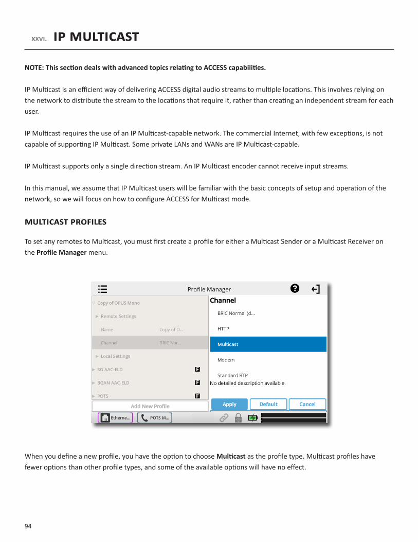
94
XXVI. IPMULTICAST
NOTE:ThissectiondealswithadvancedtopicsrelatingtoACCESScapabilities.
IP Multicast is an efficient way of delivering ACCESS digital audio streams to multiple locations. This involves relying on the network to distribute the stream to the locations that require it, rather than creating an independent stream for each user.
IP Multicast requires the use of an IP Multicast-capable network. The commercial Internet, with few exceptions, is not capable of supporting IP Multicast. Some private LANs and WANs are IP Multicast-capable.
IP Multicast supports only a single direction stream. An IP Multicast encoder cannot receive input streams.
In this manual, we assume that IP Multicast users will be familiar with the basic concepts of setup and operation of the network, so we will focus on how to configure ACCESS for Multicast mode.
MULTICASTProfILeS
To set any remotes to Multicast, you must first create a profile for either a Multicast Sender or a Multicast Receiver on the ProfileManagermenu.
When you define a new profile, you have the option to choose Multicast as the profile type. Multicast profiles have fewer options than other profile types, and some of the available options will have no effect.
95
The important settings for Multicast are:
• Sender/Receiver - Determines whether this particular ACCESS is designed to generate the IP Multicast stream (send) or decode one (receive).
• EncoderType- Determines the type of stream to be used by the Multicast Encoder (not relevant for decoders).
In addition to the basic options for IPMulticast profiles, clicking the Advanced box will allow setting of the same AdvancedOptionsavailable for NormalBRIC (Unicast) profiles.
SeTTIngUPAMULTICASTreMoTe
All Multicast connections are outgoing connections. A Multicast Sender must initiate an outgoing stream, and a Multicast Receiver must initiate an incoming one. These remotes are configured within a special address range known as a Multicast Block, typically 224.0.0.0 to 239.255.255.255. To establish a Multicast connection, simply define a remote as having an address within the IP Multicast Block, use an IP Multicast profile, and pressConnect.
TIMe-To-LIVe
Time-to-Live (TTL) is a variable set by Multicast encoders to determine how long a packet is processed before it is dropped by the network. The default value of TTL in ACCESS is 0, which limits its use to within a LAN environment. TTL may be manually changed on a Multicast Sender remote by configuring the IP address followed by a “/” (forward slash), followed by the TTL value.
As an example, a remote Multicast encoder could be set for the address 224.0.2.4/255, which would signify an address with the Multicast Block with a TTL of 255 (which is the max value available).
ChAngIngPorTnUMberSforMULTICAST
The default port of UDP 9000 may also be changed on Multicast remotes. The port number is assigned in the usual way, directly after the IP address, preceded by “:”, followed by the TTL. As an example, the IP address of a Multicast Sender on port 443 with a TTL of 100 would read:
224.0.2.4:443/100

96
XXVII. STREAMINGSERVERFUNCTION
ACCESS has the ability to act as a streaming server, delivering AAC and HE-AAC to compatible PC-based media players. Currently tested media players include WinAmp, VLC, iTunes, Windows Media 12, and Windows Media Player with Orban/CT HE-AAC plug-in.
By default, streaming server functionality is turned off. To enable it, go to the SystemSettings tab of the user interface and choose the HTTPSettings option. Under the first option, set AcceptIncomingConnections to Enabled.
Next you will need to choose an encoder for use by the streaming server. Only the encoder choices that are compatible with the players listed are shown in this menu. Choices span between a mono audio feed at 18 kb/s, up to a stereo feed at 128 kb/s.
Keep in mind that multiple streams will require this bandwidth along with around 25% overhead for each stream.
The Genre, InfoURL, andPublicoptions may be set for anything, or left alone. These options, if applied, will be embedded into the stream.
DECODINGANHTTPSTREAM
To decode a stream, open one of the supported players and find the option to open a URL-based stream. InWinamp and VLC, input the address of the ACCESS in the following format (the address is merely made up for this example and used for demonstration only):
http://192.168.0.75:8000(insert the real IP address, but always use port 8000)
In Windows media, input the address like this:
http://192.168.1.75:8000/stream.asx(using the actual IP address)
SIMUlTANEOUSlyCONNECTINGNXANDSTREAMING
ACCESS can stream while connected to another ACCESS in normal mode. If the BRIC connection is using an AAC algorithm supported by players, then when a stream is requested it will be delivered using the same encoder as the BRIC connection, regardless of the HTTP settings. If the ACCESS encoder is Linear or FLAC, the stream request will be rejected.

97
XXVIII.POTS(PLAINOLDTELEPHONESERVICE)CODECCONNECTIONS
NX is capable of connections over analog telephone lines with a modem (sold separately). This mode emulates the function of Comrex POTS codecs, which have been used for years to deliver high quality audio over normal, analog dial-up telephone lines. This mode provides for a point-to-point connection between the codecs. No Internet access is used, and the call is placed directly from one NX (or legacy codec) to the other. A POTS Zoom modem is available for purchase to use with your NX.
In the current firmware, NX is capable of connecting over dial-up phone lines to ACCESS Codecs, Comrex Matrix Codecs, Comrex BlueBox Codecs, and Comrex Vector Codecs. Note:BackwardcompatibilitytoHotlinecodecsisnotsupported.
POTSCODECSET-UPFORNXCOmPATIbILITy
The legacy codecs (Matrix, Vector or BlueBox) must be configured for operation in MusicMode, which will allow full-fidelity (up to 15 kHz) connections. Voice Mode is not supported by NX. All 4 Contact closures and ancillary data supported by legacy codecs are not supported by NX.
Note:Only1contactclosureisavailableduringaPOTSconnection.
When defining any outgoing connection, a profile must be assigned to it. For POTS Codec compatible connections, the factory default POTS profile should work best.
USINgNXWITHPOTS
To use NX on POTS, insert the Zoom USB POTS modem into one of the USB ports. Connect the phone cord to a normal, analog telephone jack.
WARNING:Undernocircumstancesshouldtherawextensionfromadigitalphonesystembeattachedtothisport—youwilllikelydamageNX,yourphonesystem,orboth.Youmustobtainatruetelephone-company-gradeline,ratherthananextensionfromyourdigitalphonesystem.
Once the POTS modem is installed, POTS Modem will appear as a new network option in the NetworkManager menu. This network option will remain in the NetworkManager menu unless it is deleted by the user.
To initiate calls from NX, simply create a remote connection with a telephone number as an address, rather than an IP address, in theRemoteConnectionsmenu. You must designate a POTS-based profile for this remote.

98
RATEVS.RETRAIN
When incoming or outgoing POTS calls are active, the RemoteConnections menu changes slightly. You will see two additional buttons appear: POTSRetrain; and POTSRateDrop. These are special functions applicable only to POTS calls, so they are not visible during IP connections.
These controls are similar in function to those provided on POTS codecs. NX will initially connect at the best data rate supported by the telephone line, and will display that connect rate on the RemoteConnectionsmenu. This value may be viewed by pressing the + next to the active connection. You can force the system to drop to the next lowest connect rate by clicking the RateDrop button at any time. Audio transfer will be interrupted momentarily while the units negotiate the new connect rate. Alternately, you can force the system to initiate the entire training sequence again (the “chat” sounds heard at the beginning of a call) by clicking the POTSRetrain button. You will lose audio for a longer time (approx. 7 seconds) but the modems will completely re-equalize the connection and audio will begin again once the retraining is finished.
Once NX has dropped to a lower rate, either by a rate drop or retrain command from either end, there is no way to force it to connect at a higher rate. If you want NX to try again for a higher connect rate, you will need to disconnect the call and dial again.

99
TROUbLESHOOTINgPOTSCONNECTION
There are dozens of factors that can affect the success or failure of a POTS codec call, some within the user’s control and some not. Here’s a short list of rules to follow for POTS codec connections:
1 Use the POTS codec on a direct telephone company line and avoid in-house phone systems. A line used by a fax machine usually provides this direct access. (Be sure to disconnect the fax machine before connecting the codec!)
2 Check to see that there are no extensions or modems on the line you are using—or at least arrange that no one uses these during your broadcast.
3 If there is call-waiting on your line, disable it by entering “*70” in front of the number you are dialing.
4 If possible, try the POTS codec out at the remote site before your actual broadcast at about the same time of day that you plan to use it. This will give you a good idea of expected connect rates and possible line problems.
5 At minimum, connect a few minutes before airtime to assess the connection quality. Setting a MaxRate on the POTS codec, based on your findings, is highly recommended. MaxRate usually should be set at a level or two below the maximum unrestricted rate. This will provide a “guard band” of sorts against noise and corruption which may cause errors on the line.
6 If operation starts to degrade after a long period of connection, it may be that the phone line parameters have changed. These parameters are affected by factors such as time of day, weather and geographic location. The modems should be given the opportunity to renegotiate for these new parameters.
7 If you experience low connection rates or errors, try redialing. If that does not help, dial from the other end. If the call is long distance, try forcing the call to another carrier. If a good connection is found, keep that line up.
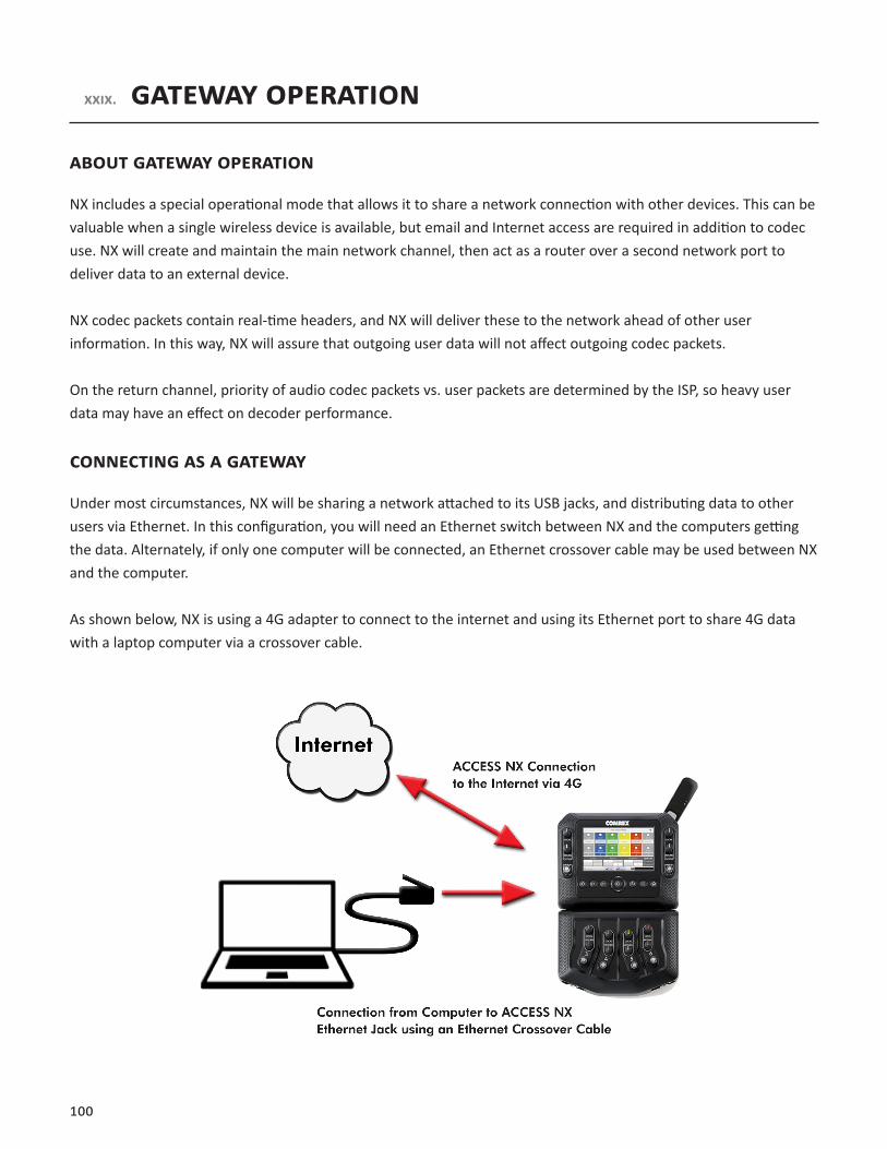
100
XXIX. GATEWAYOPERATION
ABOUTGATEWAYOPERATION
NX includes a special operational mode that allows it to share a network connection with other devices. This can be valuable when a single wireless device is available, but email and Internet access are required in addition to codec use. NX will create and maintain the main network channel, then act as a router over a second network port to deliver data to an external device.
NX codec packets contain real-time headers, and NX will deliver these to the network ahead of other user information. In this way, NX will assure that outgoing user data will not affect outgoing codec packets.
On the return channel, priority of audio codec packets vs. user packets are determined by the ISP, so heavy user data may have an effect on decoder performance.
CONNECTINGASAGATEWAY
Under most circumstances, NX will be sharing a network attached to its USB jacks, and distributing data to other users via Ethernet. In this configuration, you will need an Ethernet switch between NX and the computers getting the data. Alternately, if only one computer will be connected, an Ethernet crossover cable may be used between NX and the computer.
As shown below, NX is using a 4G adapter to connect to the internet and using its Ethernet port to share 4G data with a laptop computer via a crossover cable.
101
GATEWAYSETUP
Gateway Mode involves having two networks active and enabled on NX: the Internet side (usually a USB-based network) which is used to connect to the world at large; and the shared side (usually Ethernet), which is used to connect with other computers.
The only step to Gateway Mode is setting up your shared network side with the factory-default static IP address, network mask, and DHCP pool information. Navigate to NetworkManager. Select the EthernetPortfrom the list, select the Configure button, and then expand Location. Create a new location by selecting the AddLocation button, or edit the default location. Select IPType,press the Edit button, and select Gatewayfrom the dropdown menu.
In Gateway Mode, NX is acting as a DHCP server and router to the other devices. It will assign a dynamic address to all devices connected to it on the LAN. The static address assigned to the NX ethernet port is192.168.42.1. The pool of addresses assigned by the DHCP server is 192.168.42.128 - 192.168.42.192.

102
XXX. AdvAncedsettings
The following settings are considered advanced. Most users will never need to edit these.
In many of the menus, you can access advanced settings by selecting the Options icon in the top right and pressing the Advanced box. If the advanced items are turned off, the box will show a red line. If they are turned on, you will see a green line.
In some menus, there is also an option to view only the items that changes have been made to. This also reflects if it is on/off with the red or green line.
AdvAncedremotesettings
BAckingUpAconnection
NX features the ability to have an automatic backup to IP remote connections. The backup may be either another IP connection, or a POTS phone number.
If an IP connection fails, NX will sense this and wait the amount of time designated in the LocalTimeout parameter in the profile assigned to the primary connection. If the connection is restored in that amount of time, no backup will occur.
If the timeout period passes without restoration of the primary connection, ACCESS will automatically establish a connection (POTS or IP) to the designated backup. It will maintain that connection until it is manually disconnected.
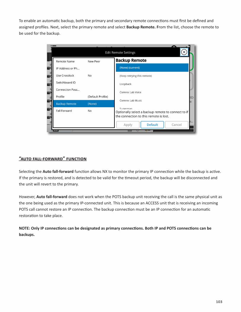
103
To enable an automatic backup, both the primary and secondary remote connections must first be defined and assigned profiles. Next, select the primary remote and select BackupRemote.From the list, choose the remote to be used for the backup.
“AUtofAll-forwArd”fUnction
Selecting the Autofall-forward function allows NX to monitor the primary IP connection while the backup is active. If the primary is restored, and is detected to be valid for the timeout period, the backup will be disconnected and the unit will revert to the primary.
However, Autofall-forward does not work when the POTS backup unit receiving the call is the same physical unit as the one being used as the primary IP-connected unit. This is because an ACCESS unit that is receiving an incoming POTS call cannot restore an IP connection. The backup connection must be an IP connection for an automatic restoration to take place.
NOTE:OnlyIPconnectionscanbedesignatedasprimaryconnections.BothIPandPOTSconnectionscanbebackups.

104
profilesettings
gloBAlprofilesettings
ProfileName - Allows you to name the new profile.
Channel - Here you can select whether this will be used as an IP connection (BRIC Normal), HTTP, Multicast, Modem (POTS connection) Standard RTP, TCP, or EBU 3326/SIP connection.
If you are connecting over an IP connection to other Comrex products, we recommend you use the BRIC Normal selection.

105
The EBU 3326/SIP channel mode allows connections to be made in accordance with the requirements of EBU technical specification Tech3326. In this mode, NX can make outgoing connections that are compatible with other manufacturer’s codecs.
When using the EBU 3326/SIP channel mode to connect to other codecs, you must also choose an encoder that is included in the Tech3326 spec. These include all AAC modes, 16-bit Linear PCM, G.711, and G.722.
These compatibility modes are provided on a “best effort” basis. They are not guaranteed to be compatible with other manufacturers’ implementations. ACCESS is not strictly compatible with Tech3326, because it does not support all mandatory encoders. For more information on EBU 3326/SIP, go to the MakingEBU3326/SIPConnections section on page86.
NOTE:It’simportanttodefinethechannelofaprofilefirst.Thechoicesinthesubsequentsectionswillvary,dependingontheChannelselection.
Make sure to press Apply to confirm your selection.
locAl&remotesettings
If you’ve chosen an IP-based channel (such as BRICNormal), you’ll have access to two sets of options:Local and Remote. You’ll use the LocalSettings to determine how your NX behaves, and theRemoteSettings to determine how the ACCESS on the far end behaves.
Each category lists identical options, so we’ll cover only the LocalSettings:
ConnectionTimeout - Under normal circumstances, a connection will be terminated on one end, and the other end will drop the connection. However, if a network failure occurs, or a connection is ended abruptly for some other reason, the system will drop the connection after a pre-determined time. The default is 60 seconds, but this can be shortened or lengthened here.
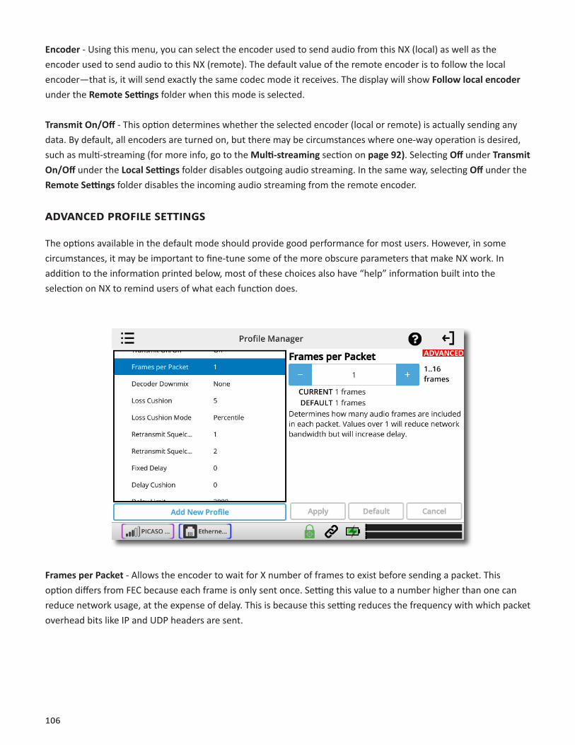
106
Encoder - Using this menu, you can select the encoder used to send audio from this NX (local) as well as the encoder used to send audio to this NX (remote). The default value of the remote encoder is to follow the local encoder—that is, it will send exactly the same codec mode it receives. The display will show Followlocalencoder under the RemoteSettings folder when this mode is selected.
TransmitOn/Off - This option determines whether the selected encoder (local or remote) is actually sending any data. By default, all encoders are turned on, but there may be circumstances where one-way operation is desired, such as multi-streaming (for more info, go to the Multi-streaming section on page92). Selecting Off under TransmitOn/Off under the LocalSettings folder disables outgoing audio streaming. In the same way, selecting Off under the RemoteSettings folder disables the incoming audio streaming from the remote encoder.
AdvAncedprofilesettings
The options available in the default mode should provide good performance for most users. However, in some circumstances, it may be important to fine-tune some of the more obscure parameters that make NX work. In addition to the information printed below, most of these choices also have “help” information built into the selection on NX to remind users of what each function does.
FramesperPacket - Allows the encoder to wait for X number of frames to exist before sending a packet. This option differs from FEC because each frame is only sent once. Setting this value to a number higher than one can reduce network usage, at the expense of delay. This is because this setting reduces the frequency with which packet overhead bits like IP and UDP headers are sent.

107
DecoderDownmix - This allows the decoded “stereo” (two-channel) audio that arrives at the receive end to be downmixed to a mono signal. The choices are None, MonoLeftOnly, MonoRightOnly, and MonoFull. Except for None, these are mainly used for sending two different mono streams to two different destinations at the same time.
LossCushion - This choice instructs the buffer manager to ignore a certain percentage of late packets in its calculation. The default value is 5%. Applications that are not at all delay-sensitive may wish to reduce this value to zero, while extremely delay-sensitive applications may prefer to have this closer to 25%. By eliminating packets that arrive extremely late, delays can be reduced greatly. The decoder error concealment does a very good job of hiding any losses that may result.
LossCushionMode - This mode ensures that the unit will show losses in terms of percentile of packets lost.
RetransmitSquelchTriggerandRetransmitSquelchMax - These options are used to determine how the buffer manager reacts to typical data dropouts, like those seen on some wireless networks. If the data protection causes retransmission of data packets during a signal fade, this can cause the network protection layer to “fight” the buffer manager, expanding the buffer and increasing the delay, with no real benefit.
The RetransmitSquelch capability allows the decoder to detect these events and avoid having the buffer manager react. These should normally be left where they are, but may be changed if dropouts are a problem.
The RetransmitTrigger function determines the amount of time the decoder must experience 100% packet loss before the RetransmitSquelch function is triggered. Default is one second.
The RetransmitSquelchMax function determines the longest period of data loss during which the squelch function is active. The default is two seconds. During the squelch period, the buffer manager will ignore the relative jitter experienced and will not adjust buffer size to compensate.
FixedDelay - This option simply sets the DelayCushion and DelayLimitat a similar value, so that the delay buffer is defined to the chosen value and will not increase or decrease significantly.
DelayCushion - The DelayCushion setting instructs the jitter buffer manager to not attempt to drive the delay below a certain value. For example, if the delay cushion is set to 500 mS, that amount of fixed delay will be added to the buffer. If the jitter manager needs to increase the buffer it will do so, but will not fall below the ½ second level.

108
DelayLimit - The DelayLimit instruct the jitter buffer manager to not “wind” the buffer out beyond a certain delay value, regardless of how many packets are lost. This is useful in applications where staying below a certain delay figure is essential. However, use of the delay limit can result in very poor performance if the network jitter dramatically exceeds the set limit.
JitterWindow - This parameter defines the amount of time (in minutes) that historical network performance is analyzed. The result is used to make the rest of the calculations. As an example, if the JitterWindow is set to the default of five minutes, and if a dramatic network event happens that causes the buffer to react by increasing the buffer size, the event will be included in the manager’s calculations for the next five minutes. If the network experiences improved performance, the manager may choose to wind the buffer back down after the five minutes has passed.
BufferManagementOn/Off - This option is available only as a troubleshooting tool. Turning the buffer manager off will result in eventual failure, since the manager compensates for clock skew between the encoder and decoder.
CrossLockManagedDelay - By default, the buffer manager finds its own delay target. The CrossLock layer also calculates a delay target that is generally more conservative, and this option allows that target number to be used. Our testing shows best results with the default delay target.
LogStatistics- This function is used in factory diagnostics and should be left disabled unless instructed to be changed by Comrex support.
CongestionAvoidance - Enabling this option allows the encoder to dynamically change the number of frames per packet sent, thereby reducing total data requirements. In addition, in most encode modes, enablingCongestionAvoidance provides the system with the ability to step down to a lower encode data rate if desired. This will happen automatically and with no audio interruption. NOTE: Step down congestion avoidance is not enabled in Linear PCM modes.

109
UDPReliability - UDP, the Internet protocol used by BRIC Normal connections, does not have any inherent error correction capability. UDPReliability adds an intelligent algorithm that requests packet resends only when appropriate. UDPReliability can be useful on some wireless connections that have unsatisfactory performance due to packet loss.
MaxRetransmissionRate- Allows setting of an upper limit on how much additional bandwidth is utilized by the BRUTE UDP reliability layer. The default setting is 100, which allows the error correction layer to use the same amount of bandwidth as the audio stream. As an example, if your audio stream is consuming 80 kb/s of network bandwidth, and UDP Max Retransmissions is set at 50%, up to 40 kb/s additional network bandwidth may be used for error correction.
AdvAncedsystemsettings
AUXiliAryseriAl
This allows you to set the parameters of the auxiliary serial data port. This port is always active during an IP connection and allows serial data transfer along the same path used for the audio data. It does not remove any audio data; the serial data is added to the packets and bandwidth is increased to support the additional data. For this reason heavy use of serial data can affect overall codec performance. Settings are available for BaudRate,DataBits,StopBits,FlowControl, and Parity. Most users will leave the defaults of 9600,8,1,NoFlowControl,and NoParity.

110
connections
DisableCongestionAvoidance - Turns “AvoidanceCongestion” feature off.
secUrity
RemoteDiagnostics - Enables Comrex support to connect to this unit using the SSH protocol for troubleshooting purposes. We recommend leaving this option enabled. Since SSH access requires a key value that is not disclosed by Comrex, generic SSH requests are rejected.
WebServerPort - In order to deliver the remote control web page, NX must “listen” on a certain Internet port number for a request from a web browser. By default, web page servers listen on port 80 for incoming requests.

111
In some environments, you may wish to remotely control NX through your router, and port 80 may already be utilized by another device. This setting gives you the ability to change the port where the system listens for and delivers web pages from.NOTE:Youwillnowneedtoenterthisnewportnumberintoyourbrowserinordertoseetheunit.Asanexample,iftheWebServerPortischangedfrom80to84,theaddressoftheunitmustbeenteredinabrowserinthefollowingmanner:http://192.168.1.142:84.
If this value is changed, there isn’t any need to change the way you get the remote web page—the change is automatically reported to the browser when the page is addressed.
The web server port is also used by the DeviceManager,CodecCommander,and RemoteControl software provided by Comrex, so if you change this value, you’ll want to make a note of it for the next time you update the unit’s firmware.
DHCPClientID - Allows entry of a client ID prefix for use with DHCP address selection capability.
UnsafeShutdown - This setting allows you to disable the Safe Shutdown feature. Ordinarily, the NX will spend approximately five seconds in powering down its systems safely. For the wellbeing of your equipment, we recommend Safe Shutdown enabled, and allowing this process to complete before disconnecting all power sources.
switchBoArdserver
SwitchboardAdd(Address) - shows the IP address of Switchboard.
STUNServer - Enables the unit to contact the STUN server maintained by Comrex to learn what its public IP address is.
SwitchboardPort - Allows selection of the TCP port of the Switchboard Server.
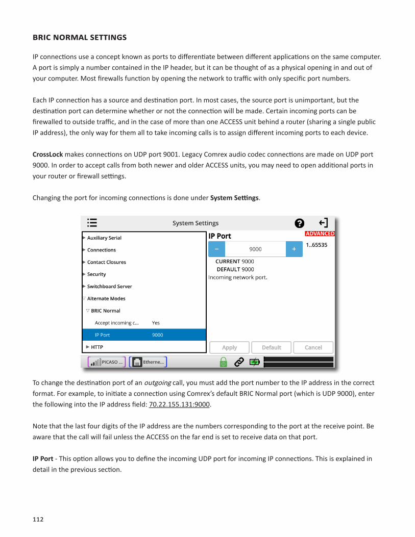
112
BricnormAlsettings
IP connections use a concept known as ports to differentiate between different applications on the same computer. A port is simply a number contained in the IP header, but it can be thought of as a physical opening in and out of your computer. Most firewalls function by opening the network to traffic with only specific port numbers.
Each IP connection has a source and destination port. In most cases, the source port is unimportant, but the destination port can determine whether or not the connection will be made. Certain incoming ports can be firewalled to outside traffic, and in the case of more than one ACCESS unit behind a router (sharing a single public IP address), the only way for them all to take incoming calls is to assign different incoming ports to each device.
CrossLock makes connections on UDP port 9001. Legacy Comrex audio codec connections are made on UDP port 9000. In order to accept calls from both newer and older ACCESS units, you may need to open additional ports in your router or firewall settings.
Changing the port for incoming connections is done under SystemSettings.
To change the destination port of an outgoing call, you must add the port number to the IP address in the correct format. For example, to initiate a connection using Comrex’s default BRIC Normal port (which is UDP 9000), enter the following into the IP address field: 70.22.155.131:9000.
Note that the last four digits of the IP address are the numbers corresponding to the port at the receive point. Be aware that the call will fail unless the ACCESS on the far end is set to receive data on that port.
IPPort - This option allows you to define the incoming UDP port for incoming IP connections. This is explained in detail in the previous section.

113
eBU3326/sipsettings
Acceptincomingconnections-EBU 3326/SIP calls must be answered automatically on NX. If this option is disabled, no EBU 3326/SIP calls will be answered and only outgoing EBU 3326/SIP connections can be made.
IncomingConnectionProfile- In some unusual circumstances, it’s necessary to define the profile used on incoming SIP/3326 connections to be something different than what is being received. This option allows that to be changed.
IPPort- Universally, SIP connections are supposed to use UDP port 5060 to negotiate calls between devices (and between servers and devices). Changing this port number will change which incoming ports are used to initiate connections, and to which ports connection requests are sent. The change must be made on both devices. NOTE:thischangewillessentiallymakeyourcodecincompatiblewithindustry-standardVoIPdevices.
UserAgentBlacklist - Allows entry of a list of SIP user agents that will not be allowed to communicate with this NX unit. Must be entered with names separated by commas.
VIP-QCPassword - Allows entry of password for VIP-QC connections.
RTPIPPort - Allows setting of RTP network port.
PublicIPOverride - Allows entry of override for Public IP port.
UseSTUNServer - Enables/disables use of the STUN server.
UseSIPProxy - Enables/disables registration with the SIP proxy to use for inbound and outbound calls.

114
SIPproxyKeepalive - Sets “keepalive” interval time for SIP connections.
SIPProxyAddress- Allows choosing proxy/registrar server to use for SIP calls.
SIPDomain - Used to authenticate SIP calls. If not set, the SIP proxy name will be used.
SIPUsername - Allows entry of SIP username.
SIPAuthUsername - Allows entry of SIP username for authentication.
SIPPassword - Allows entry of password for authentication.
SendRTPtosourceport - Enables/disables the ability to send RTP data to the remote port matching the source of the received RTP packets rather than the negotiated port.
SIPRouting - Enables routing of SIP messages. NOTE:MayadverselyaffecttheabilitytotraverseNATfirewalls.
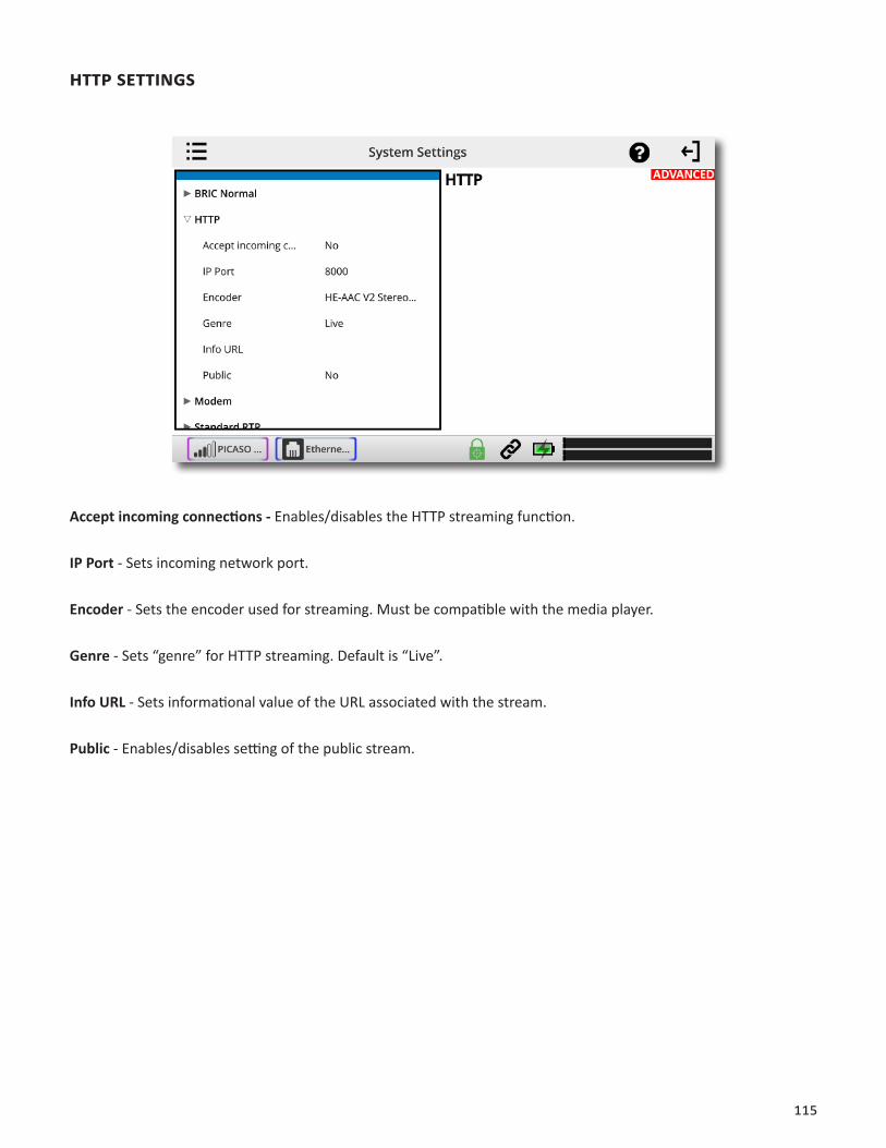
115
httpsettings
Acceptincomingconnections-Enables/disables the HTTP streaming function.
IPPort - Sets incoming network port.
Encoder- Sets the encoder used for streaming. Must be compatible with the media player.
Genre- Sets “genre” for HTTP streaming. Default is “Live”.
InfoURL - Sets informational value of the URL associated with the stream.
Public - Enables/disables setting of the public stream.
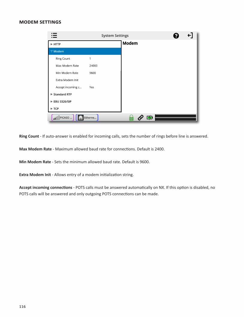
116
modemsettings
RingCount - If auto-answer is enabled for incoming calls, sets the number of rings before line is answered.
MaxModemRate- Maximum allowed baud rate for connections. Default is 2400.
MinModemRate - Sets the minimum allowed baud rate. Default is 9600.
ExtraModemInit- Allows entry of a modem initialization string.
Acceptincomingconnections - POTS calls must be answered automatically on NX. If this option is disabled, no POTS calls will be answered and only outgoing POTS connections can be made.

117
stAndArdrtpsettings
ACCESS NX uses the term “channel types” to differentiate between audio streaming modes that are incompatible with each other. One alternate mode is called “Standard RTP”, and this term is used to describe a very simple streaming protocol, with no real handshake or setup requirements.
Acceptincomingconnections-RTP calls must be answered automatically on NX. If this option is disabled, no RTP calls will be answered and only outgoing RTP connections can be made.
IPPort - Sets incoming IP port. Default is port 5004.
RTPCompatibilitymode - This option allows you to choose between several sub-options to be compatible with various equipment. The choices are:
Standard - The encoder will send simple RTP packets without regard to handshaking or status of the network. Useful mostly for experimenting against unknown gear.
LuciLive/Lite(default) - The encoder will adapt the RTP stream to be more compatible with the Luci brand smartphone app.
ZephyrXstream - The encoder will adapt the RTP stream to be compatible with the Zephyr Xstream ISDN codec in IP mode.
Standard RTP modes other than Luci are “experimental” and are not subject to support by Comrex support staff.
ReturnChannelEnabled- Enables a return channel to be sent back to the other unit.
ReturnChannelEncoder - Specifies the codec to be used for the return channel.
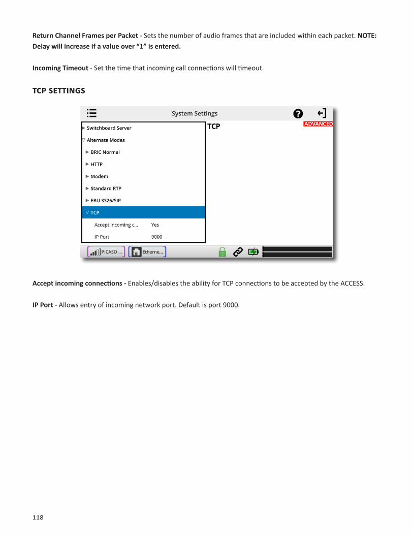
118
ReturnChannelFramesperPacket - Sets the number of audio frames that are included within each packet.NOTE:Delaywillincreaseifavalueover“1”isentered.
IncomingTimeout - Set the time that incoming call connections will timeout.
tcpsettings
Acceptincomingconnections-Enables/disables the ability for TCP connections to be accepted by the ACCESS.
IPPort- Allows entry of incoming network port. Default is port 9000.
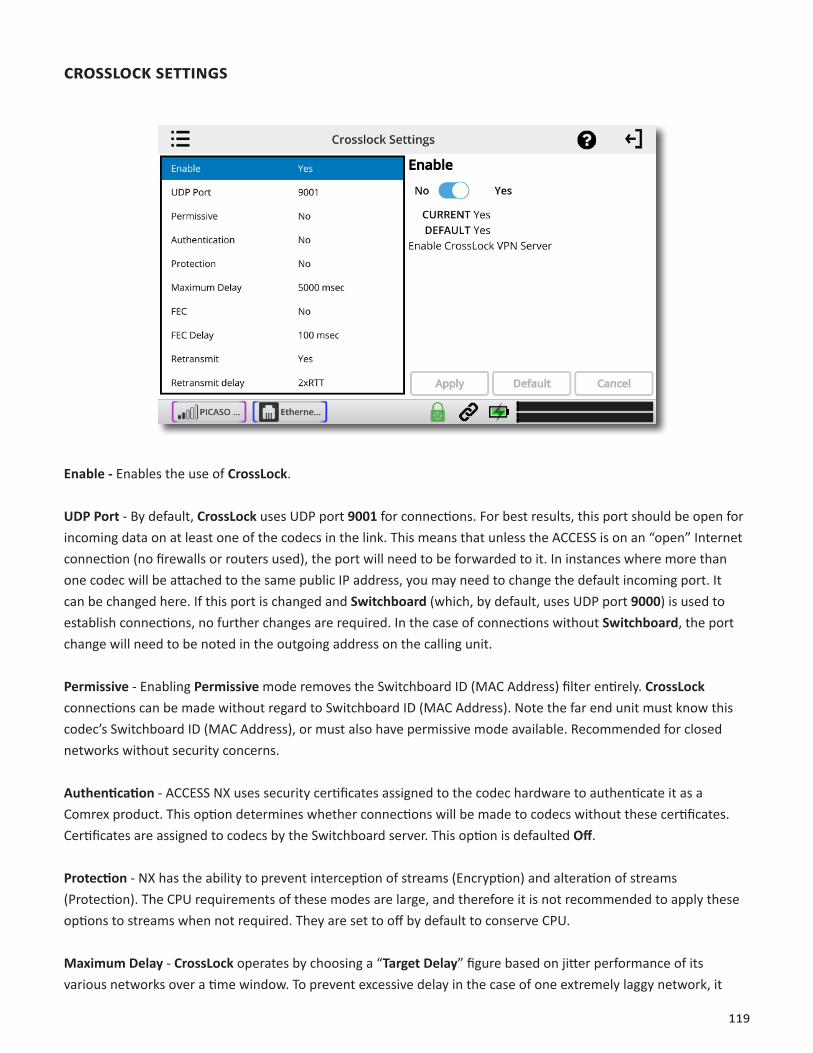
119
crosslocksettings
Enable- Enables the use of CrossLock.
UDPPort - By default, CrossLock uses UDP port 9001 for connections. For best results, this port should be open for incoming data on at least one of the codecs in the link. This means that unless the ACCESS is on an “open” Internet connection (no firewalls or routers used), the port will need to be forwarded to it. In instances where more than one codec will be attached to the same public IP address, you may need to change the default incoming port. It can be changed here. If this port is changed and Switchboard (which, by default, uses UDP port 9000) is used to establish connections, no further changes are required. In the case of connections without Switchboard, the port change will need to be noted in the outgoing address on the calling unit.
Permissive - Enabling Permissive mode removes the Switchboard ID (MAC Address) filter entirely. CrossLock connections can be made without regard to Switchboard ID (MAC Address). Note the far end unit must know this codec’s Switchboard ID (MAC Address), or must also have permissive mode available. Recommended for closed networks without security concerns. Authentication - ACCESS NX uses security certificates assigned to the codec hardware to authenticate it as a Comrex product. This option determines whether connections will be made to codecs without these certificates. Certificates are assigned to codecs by the Switchboard server. This option is defaulted Off.
Protection - NX has the ability to prevent interception of streams (Encryption) and alteration of streams (Protection). The CPU requirements of these modes are large, and therefore it is not recommended to apply these options to streams when not required. They are set to off by default to conserve CPU.
MaximumDelay - CrossLock operates by choosing a “TargetDelay” figure based on jitter performance of its various networks over a time window. To prevent excessive delay in the case of one extremely laggy network, it

120
has a maximum delay setting here. In the case of multiple networks with very high jitter figures, this setting can be increased from the default five seconds by the user.
FEC - CrossLock has a powerful Forward Error Correction algorithm that is enabled in the presence of multiple networks, using any excess network bandwidth to add in the parity required. Use of FEC is recommended, but it can be disabled here.
FECDelay - Controls both how much delay is introduced into the system by FEC , and also to an extent how effective the recovery is (which is dependent greatly on the packet rate). The default of 100 mS should only be altered on recommendation of Comrex support.
Retransmit- In addition to FEC, CrossLock utilizes an ARQ-style algorithm to allow retransmission of lost packets when time permits. This mode is recommended but can be disabled here.
RetransmitDelay - CrossLock automatically provides an extra “Retransmit Cushion” that provides some time to make ARQ error correction effective. The default amount of time is twice the measured round trip delay of the network (2xRTT). This has been shown to be most effective on most networks, but can be altered lower (1xRTT, none) or higher (3xRTT) using this menu.
HeaderCompression - The nature of Internet packets sometimes results in IP overhead (RTP headers and other info) actually using nearly as much bandwidth as the payload. CrossLock, by default, compresses some of these headers to conserve network bandwidth. In instances where the network rejects this, or packet inspection is required, this compression can be disabled.
RedundantTransmission-When using multiple networks, CrossLock defaults to “Bonding” mode, adding the capability (with dynamic allocation) across the networks. Loss of any network results in a very fast adaptation to the existing networks, but can result in short audio disruptions. In scenarios where all networks are unmetered and of known good quality, changing to redundant mode can result in less disruption during a network loss. All
121
data is delivered on all networks simultaneously. This is an outgoing parameter only—in order to provide two-way redundancy, this setting must be changed on both ends.
EncoderThrottle - Some encoders, like Opus, provide the ability to reduce outgoing data rate in the presence of network congestion. The default is to allow the CrossLock Manager license to throttle the encoder. This can be defeated by setting this value to “No”.
BaseFEC - This parameter applies a constant rate of FEC targeting recovery of the specified expected loss rate. It is measured in percent packet loss to be corrected. This is useful when retransmission is not effective (e.g. high delay network) and auto-FEC is not working as desired. It should be used on recommendation of Comrex support.
StunServer - CrossLock uses its own Cloud Server (STUN) to determine the NAT status of each codec before connection. This can be set to a different value than the main STUN server used to provide status to the RemoteConnections page. Default is always the Comrex server at stun.comrex.com.
AlwaysConnect - This option provides for CrossLock to be always connected to a destination. By its nature, CrossLock uses very little data, so the network utilization of this mode (when idle) is very small. If you only connect to one destination, having CrossLock always connected makes media connections faster, and provides an indication of network status between the devices (“ready” light or CrossLock status). Most users should leave this setting off. Note that this option is different than “AlwaysConnectTo” under SystemSettings. That option maintains an audio connection, not just a CrossLock session.

122
hotswAp
ACCESS NX units operating 4.3-level firmware or higher are able to utilize HotSwap, which allows customers using CrossLock in “Dual Network” mode to designate one network as primary and the other network as secondary. The secondary network (e.g. wireless 4G) then backs up the primary network in case of failure.
A typical usage scenario would be a codec that is attached 24/7 providing an STL link. Because it’s often impractical (and expensive) to run audio over a 4G wireless network full time, HotSwap ensures that the CrossLock connection primarily uses another network (e.g. an ethernet connection) and only falls over to the 4G wireless network as a backup when it needs to. When the primary network is restored, Hotswap will switch back to it and continue to hold the secondary network in a backup state, waiting for the next time it’s needed.
Please note: Codecs on both ends of the link must be running at least 4.3-level firmware in order to operate HotSwap.
Any any supported network (e.g. Ethernet, Wi-Fi, 4G wireless) can be designated as the primary or the backup network.
Because Hotswap is an alternate mode of the Comrex CrossLock reliability layer, connections between codecs must be established via CrossLock in order to use it.
DATA USAGE
It’s important to note that even when a network is in a backup state, a small amount of data is sent and received on it. (For 24/7 operation, this data will total less than 0.5 GB for a typical month of usage, assuming no Hotswap activity occurs. Of course, more data will be used if the Hotswap function engages.) Regardless of how Hotswap is used or set up, Comrex assumes no liability for data overage charges, even in the event of software bugs or any other failure of hardware or software. It is entirely the responsibility of the user to monitor any metered data usage.
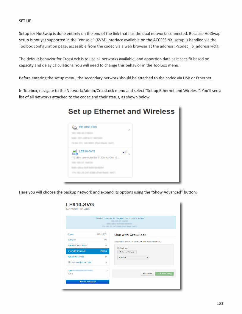
123
SET UP
Setup for HotSwap is done entirely on the end of the link that has the dual networks connected. Because HotSwap setup is not yet supported in the “console” (KVM) interface available on the ACCESS NX, setup is handled via the Toolbox configuration page, accessible from the codec via a web browser at the address: <codec_ip_address>/cfg.
The default behavior for CrossLock is to use all networks available, and apportion data as it sees fit based on capacity and delay calculations. You will need to change this behavior in the Toolbox menu.
Before entering the setup menu, the secondary network should be attached to the codec via USB or Ethernet.
In Toolbox, navigate to the Network/Admin/CrossLock menu and select “Set up Ethernet and Wireless”. You’ll see a list of all networks attached to the codec and their status, as shown below.
Here you will choose the backup network and expand its options using the “Show Advanced” button:

124
Find the option labeled “Use with CrossLock” and change the default from “yes” to “backup”.
Click “Save Settings”, then click “Back” until you get to the main “Network/Admin/CrossLock” menu.
Next choose “CrossLock VPN” and locate the entry labeled “Redundant Transmission” as shown below.
Change this from the default “Off” to “On”. Choose “Save Settings”.
Finally, you’ll want to set one of the contact closures to alarm you when the HotSwap function is engaged.
Still in the CrossLock settings, choose “HotSwap CC unit”. First choose whether you want the contact closure output to trigger on the local, remote, or both codecs. Select “Save Settings” then click “back”.

125
Next choose “HotSwap CC Indicator” and select which contact closure to trigger. This will override any previous settings you’ve made in the main configuration web page regarding contact closures.
Choose “Save Setting” and exit the Toolbox page.
MAKING AND BREAKING CONNECTIONS
Connections are made and broken via the web-based user interface. This is accessed via a web browser at the IP address of the codec. Connections can be made manually, with or without Switchboard, and can be set to “always connect” in the case of 24/7 operation. We recommend making manual connections for 24/7 operation, and not relying on Switchboard, as it unnecessarily introduces another point of possible failure.
As long as an incoming CrossLock call is possible on the primary network attached to a codec, the call be be initiated from the other end. As an example, at a transmitter site the primary network is a DSL line and port 9001 UDP is open from the public Internet. The backup network is a 4G modem, which on its own would not accept an incoming connect request. Even without using Switchboard, the connection can be initiated from the studio side, and the 4G modem will be automatically added to the CrossLock channel.
126
XXXI. AdvAnced3G/4GnetworksettInGs
3G/4G modems vary in their interface. Comrex is constantly updating drivers to work with the most popular devices. Please contact us for information about specific devices. We also keep an updated status page in the ACCESS NX Support section on our website.
If a device has driver support, it will appear as a WWAN Device. Select the icon for the device and click Configure.
Fields are available to fill in an outgoing phone number, a username, a password, and a modem init string. In many cases, NX is programmed to extract this information from the device and fill in these blanks automatically. Otherwise, you will need to consult our website to determine which fields should be filled in for each device.
Once the proper information is entered and the device is enabled, it should deliver an IP address within 60 seconds. If no IP address is obtained, the device will not function.
When using 3G adapters based on GSM standards (non-EVDO devices), you may or may not need to apply an APN (Access Point Name) in order to establish connections and get an IP address. When using 3G adapters and USB dongles in Windows laptops, this information is usually automatically supplied by the device manager software. In the NX Linux environment, this information may need to be manually entered.
The best possible way to get accurate APN information is to obtain it from the tech support at your 3G carrier. This, however, is not always possible or accurate, so ACCESS has provided the most commonly used APNs available in a pull-down list. If you select your region of the world followed by your country, a list of suggested APNs can be chosen by carrier.
This list is merely suggestions and many have not been verified. It’s important, if having connection issues, to verify the accuracy of the APN with your carrier.

127
XXXII. LICENSEANDWARRANTYDISCLOSURESFORCOMREXACCESSNX
LICENSES
MPEG-4audiocodingtechnologylicensedbyFraunhoferIIShttp://www.iis.fraunhofer.de/amm/
ACCESS NX uses proprietary and open-source software programs. Some of the open-source programs are licensed under the Gnu Public License (GPL). For more information on GPL see http://www.gnu.org.
As per the GPL, source code for this software is available on request from Comrex on CD-ROM or other electronic format. To obtain this software please contact our support department at +1 978 784 1776. We retain the right to charge a small handling fee for distribution of this software.
ACCESS NX makes use of open-source and/or free software with the following copyright restrictions:
ncursesCopyright © 1998, 1999, 2000, 2001 Free Software Foundation, Inc.See further Copyright notice below
dropbearCopyright © 2002-2004 Matt JohnstonPortions copyright © 2004 Mihnea StoenescuAll rights reserved.See further Copyright notice below
libxml2Copyright © 1998-2003 Daniel Veillard. All Rights Reserved.See Further Copyright notice below
Import code in keyimport.c is modified from PuTTY’s import.c, licensed as follows:
PuTTY is copyright 1997-2003 Simon Tatham
Portions copyright Robert de Bath, Joris van Rantwijk, Delian Delchev, Andreas Schultz, Jeroen Massar, Wez Furlong, Nicolas Barry, Justin Bradford, and CORE SDI S.A.
Furthercopyrightnoticeforncurses,dropbearPuTTYandlibxml2
Permission is hereby granted, free of charge, to any person obtaining a copy of this software and associated docu-mentation files (the “Software”), to deal in the Software without restriction, including without limitation the rights

128
to use, copy, modify, merge, publish, distribute, sublicense, and/or sell copies of the Software, and to permit per-sons to whom the Software is furnished to do so, subject to the following conditions:
The above copyright notice and this permission notice shall be included in all copies or substantial portions of the Software. LibpcaptcpdumpCopyright © 1988, 1989, 1991, 1994, 1995, 1996, 1997The Regents of the University of California. All rights reserved.
Redistribution and use in source and binary forms, with or without modification, are permitted provided that the following conditions are met:
1. Redistributions of source code must retain the above copyright notice, this list of conditions and the following disclaimer.2. Redistributions in binary form must reproduce the above copyright notice, this list of conditions and the follow-ing disclaimer in the documentation and/or other materials provided with the distribution.3. The names of the authors may not be used to endorse or promote products derived from this software without specific prior written permission.
THIS SOFTWARE IS PROVIDED “AS IS” AND WITHOUT ANY EXPRESS OR IMPLIED WARRANTIES, INCLUDING, WITH-OUT LIMITATION, THE IMPLIED WARRANTIES OF MERCHANTABILITY AND FITNESS FOR A PARTICULAR PURPOSE.
WARRANTY
All Equipment manufactured by Comrex Corporation is warranted by Comrex against defects in material and work-manship for one year from the date of original purchase, as verified by the return of the warranty registration card. During the warranty period, we will repair or, at our option, replace at no charge a product that proves to be defec-tive, provided you obtain a return authorization from Comrex and return the product, shipping prepaid to Comrex Corporation, 19 Pine Rd, Devens MA 01434 USA. For return authorization, contact Comrex at 800-237-1776 or 978-784-1776 or email [email protected] warranty does not apply if the product has been damaged by accident or misuse or as a result of service or modification performed by anyone other than Comrex Corporation.
The next two paragraphs apply to all software contained in this product:
WITH THE EXCEPTION OF THE WARRANTIES SET FORTH ABOVE, THE PRODUCT (MEANS COLLECTIVELY THE HARD-WARE AND SOFTWARE COMPONENTS) IS PROVIDED STRICTLY “AS-IS.” COMREX CORPORATION AND ITS SUPPLIERS MAKE NO WARRANTY, EITHER EXPRESS OR IMPLIED, INCLUDING BUT NOT LIMITED TO ANY IMPLIED WARRANTIES OF MERCHANTABILITY, FITNESS FOR A PARTICULAR PURPOSE OR WARRANTY AGAINST LATENT DEFECTS. COMREX CORPORATION AND ITS SUPPLIERS DO NOT WARRANT THAT THE PRODUCT IS ERROR-FREE, THAT ALL ERRORS MAY BE DETECTED OR CORRECTED, OR THAT THE USE OF THE PRODUCT WILL BE UNINTERRUPTED. IN NO EVENT WILL COMREX CORPORATION AND ITS SUPPLIERS BE LIABLE FOR INDIRECT, INCIDENTAL, SPECIAL OR CONSEQUENTIAL DAMAGE RESULTING FROM THE USE OF THE PRODUCT INCLUDING LOSS OF PROFITS, LOSS OF SAVINGS, LOSS OF USE OR INTERRUPTION OF BUSINESS EVEN IF COMREX CORPORATION OR ANY OF ITS SUPPLIERS HAS BEEN ADVISED OF THE POSSIBILITY OF SAME. IN NO EVENT SHALL COMREX CORPORATION AND/OR ITS SUPPLIERS’ TOTAL LIABILITY TO YOU REGARDLESS OF THE FORM OF ACTION EXCEED THE AMOUNT YOU PAID AS PART OF THE PURCHASE PRICE OF THIS PRODUCT. COMREX CORPORATION AND ITS SUPPLIERS MAKE NO WARRANTY, EITHER EXPRESSED OR IMPLIED, THAT ANY USE OF THE PRODUCT WILL BE FREE FROM INFRINGEMENT OF PATENTS, COPY-RIGHTS, OR ANY OTHER THIRD PARTY’S INTELLECTUAL PROPERTY RIGHTS.

129
THE SOFTWARE OWNED BY COMREX CORPORATION OR BY ITS SUPPLIERS RESIDING IN OR OTHERWISE ASSOCIATED WITH THIS PRODUCT ARE PROTECTED UNDER COPYRIGHT LAW AND INTERNATIONAL TREATIES. UNAUTHORIZED REVERSE ENGINEERING, REPRODUCTION AND/OR DISTRIBUTION OF THE PRODUCT OR ANY PORTION THEREOF, IS STRICTLY PROHIBITED AND MAY RESULT IN CIVIL AND CRIMINAL SANCTIONS, AND WILL BE PROSECUTED TO THE FULL EXTENT OF THE LAW. COMREX CORPORATION AND ITS SUPPLIERS OWNS AND SHALL RETAIN ALL RIGHT, TITLE AND INTEREST IN AND TO ANY SOFTWARE SUPPLIED TO YOU IN AND AS PART OF THE PRODUCT AND ALL INTELLEC-TUAL PROPERTY RIGHTS RELATED THERETO. THE SALE OF THE PRODUCT SHALL NOT BE CONSTRUED IN ANY MAN-NER AS TRANSFERRING ANY RIGHT OF OWNERSHIP IN ANY SUCH SOFTWARE.
XXXiii. ComreX SwitChboard traverSal Server USe
You have purchased a product from Comrex that uses the Switchboard TS (Traversal Server) to provide the ability to locate Comrex hardware via the Internet and to aid in the making of connections when certain types of NAT routers are involved in the link. Switchboard consists of two distinct elements: the firmware that functions within the codec hardware to enable use of the function; and a server deployed on the Internet which provides the services to the codec hardware.
The purchase you have made entitles you only to the firmware elements within your codec that utilize these functions. The functions of Switchboard, as implemented in your codec, are warranted to work as described (according to standard Comrex warranty terms found in your User Manual) when used with a properly functioning Traversal Server deployed on the Internet.
Comrex has deployed and provided you account details for a Switchboard account on our server, located at http://switchboard.comrex.com.
Comrex provides this service, free of charge and at will. As such, Comrex offers no warranty as to availability of this server or of its function. Comrex reserves the right to discontinue availability of this service at any time. Comrex also reserves the right to remove any account from the server at http://switchboard.comrex.com at any time for any reason. In no way shall Comrex be liable for this server’s malfunction, lack of availability, or any resultant loss therein.
The software that runs the Switchboard on the Internet is available from Comrex in an executable format, free of charge, with basic instructions on how to set it up. The address of the server used for these functions is configurable in the codec firmware. If you wish to deploy your own Traversal Server, contact Comrex for details on obtaining this software.
Comrex is not liable for training or support in setting up a TS server, and the software is available without warrantee or guarantee of suitability of any kind.
130
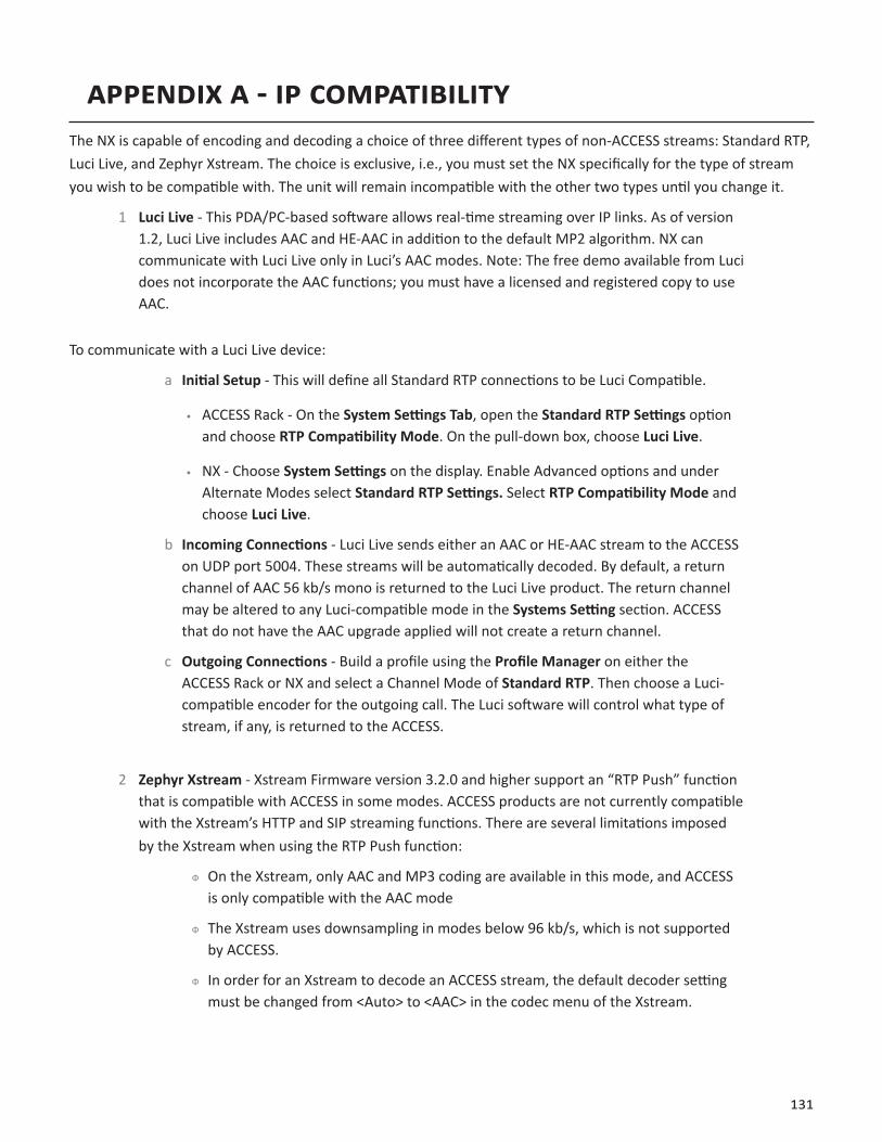
131
APPENDIX A - IP COMPATIBILITYThe NX is capable of encoding and decoding a choice of three different types of non-ACCESS streams: Standard RTP, Luci Live, and Zephyr Xstream. The choice is exclusive, i.e., you must set the NX specifically for the type of stream you wish to be compatible with. The unit will remain incompatible with the other two types until you change it.
1 Luci Live - This PDA/PC-based software allows real-time streaming over IP links. As of version 1.2, Luci Live includes AAC and HE-AAC in addition to the default MP2 algorithm. NX can communicate with Luci Live only in Luci’s AAC modes. Note: The free demo available from Luci does not incorporate the AAC functions; you must have a licensed and registered copy to use AAC.
To communicate with a Luci Live device:
a Initial Setup - This will define all Standard RTP connections to be Luci Compatible.
• ACCESS Rack - On the System Settings Tab, open the Standard RTP Settings option and choose RTP Compatibility Mode. On the pull-down box, choose Luci Live.
• NX - Choose System Settings on the display. Enable Advanced options and under Alternate Modes select Standard RTP Settings. Select RTP Compatibility Mode and choose Luci Live.
b Incoming Connections - Luci Live sends either an AAC or HE-AAC stream to the ACCESS on UDP port 5004. These streams will be automatically decoded. By default, a return channel of AAC 56 kb/s mono is returned to the Luci Live product. The return channel may be altered to any Luci-compatible mode in the Systems Setting section. ACCESS that do not have the AAC upgrade applied will not create a return channel.
c Outgoing Connections - Build a profile using the Profile Manager on either the ACCESS Rack or NX and select a Channel Mode of Standard RTP. Then choose a Luci-compatible encoder for the outgoing call. The Luci software will control what type of stream, if any, is returned to the ACCESS.
2 Zephyr Xstream - Xstream Firmware version 3.2.0 and higher support an “RTP Push” function that is compatible with ACCESS in some modes. ACCESS products are not currently compatible with the Xstream’s HTTP and SIP streaming functions. There are several limitations imposed by the Xstream when using the RTP Push function:
ˇ On the Xstream, only AAC and MP3 coding are available in this mode, and ACCESS is only compatible with the AAC mode
ˇ The Xstream uses downsampling in modes below 96 kb/s, which is not supported by ACCESS.
ˇ In order for an Xstream to decode an ACCESS stream, the default decoder setting must be changed from <Auto> to <AAC> in the codec menu of the Xstream.
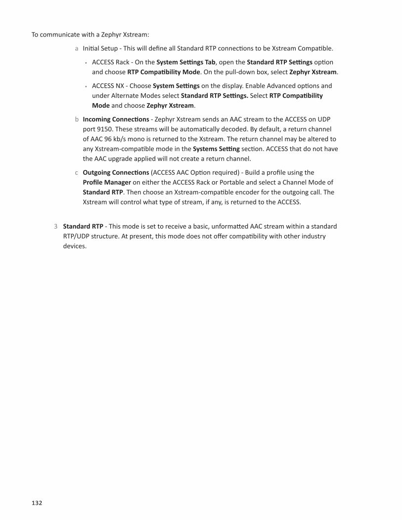
132
To communicate with a Zephyr Xstream:
a Initial Setup - This will define all Standard RTP connections to be Xstream Compatible.
• ACCESS Rack - On the System Settings Tab, open the Standard RTP Settings option and choose RTP Compatibility Mode. On the pull-down box, select Zephyr Xstream.
• ACCESS NX - Choose System Settings on the display. Enable Advanced options and under Alternate Modes select Standard RTP Settings. Select RTP Compatibility Mode and choose Zephyr Xstream.
b Incoming Connections - Zephyr Xstream sends an AAC stream to the ACCESS on UDP port 9150. These streams will be automatically decoded. By default, a return channel of AAC 96 kb/s mono is returned to the Xstream. The return channel may be altered to any Xstream-compatible mode in the Systems Setting section. ACCESS that do not have the AAC upgrade applied will not create a return channel.
c Outgoing Connections (ACCESS AAC Option required) - Build a profile using the Profile Manager on either the ACCESS Rack or Portable and select a Channel Mode of Standard RTP. Then choose an Xstream-compatible encoder for the outgoing call. The Xstream will control what type of stream, if any, is returned to the ACCESS.
3 Standard RTP - This mode is set to receive a basic, unformatted AAC stream within a standard RTP/UDP structure. At present, this mode does not offer compatibility with other industry devices.

133
appendix B - information for it managers
The purpose of this appendix is to describe all open ports and services available on the Comrex NX.
The Comrex NX is a device designed to move real-time, wideband audio over IP networks. The main network interface is 1000BaseT-Ethernet. The device contains an optimized version of Linux kernel. The IP parameters are set by a computer on the local LAN using a proprietary broadcast UDP protocol.
Comrex provides a Windows or MAC application (Device Manager) on the included CD, or available on our website at www.comrex.com, to perform this function on the local computer. Once the unit is powered on your NX, you have five minutes before this function is disabled.
IP parameters can also be changed online using the password-protected Toolbox interface at <ip-address>/cfg. Updates to the system are provided by a custom online updater utility. This update process is password protected and requires access to TCP 80 and TCP 8081. In addition to the password protection, the update data itself must have a valid cryptographic signature from Comrex, or else it is rejected.
incoming services
Port Service DefaultTCP 22 SSH* On (Off on products shipped after 1 July 2017)TCP 80 HTTP control OnTCP 443 TLS protected HTTP control OnTCP 8081 Firmware upload Open only during upgrade processUDP 9000 BRIC Normal Media OnUDP 9001 CrossLock Media OnUDP 5060, 6014, 6015 SIP OffUDP 5004, 5005 Standard RTP On (Off on products shipped after 1 July 2017)TCP 9000 BRIC Normal/TCP OffTCP 8000 HTTP Media Off
*Only SSH clients with an authorized DSA key can access SSH services on the device. Other forms of authentication are disabled. This key is kept confidentially by Comrex for factory diagnostics only. SSH services may be disabled completely via the user interface.
outgoing services
Service DestinationNTP 0.comrex.pool.ntp.org:123 (UDP)Switchboard switchboard.comrex.com:8090, switchboard.comrex.com:8081 (secondary) (TCP)STUN stun.comrex.com:3478 (UDP)DNS Lookup DNS Server:53 (TCP and UDP)
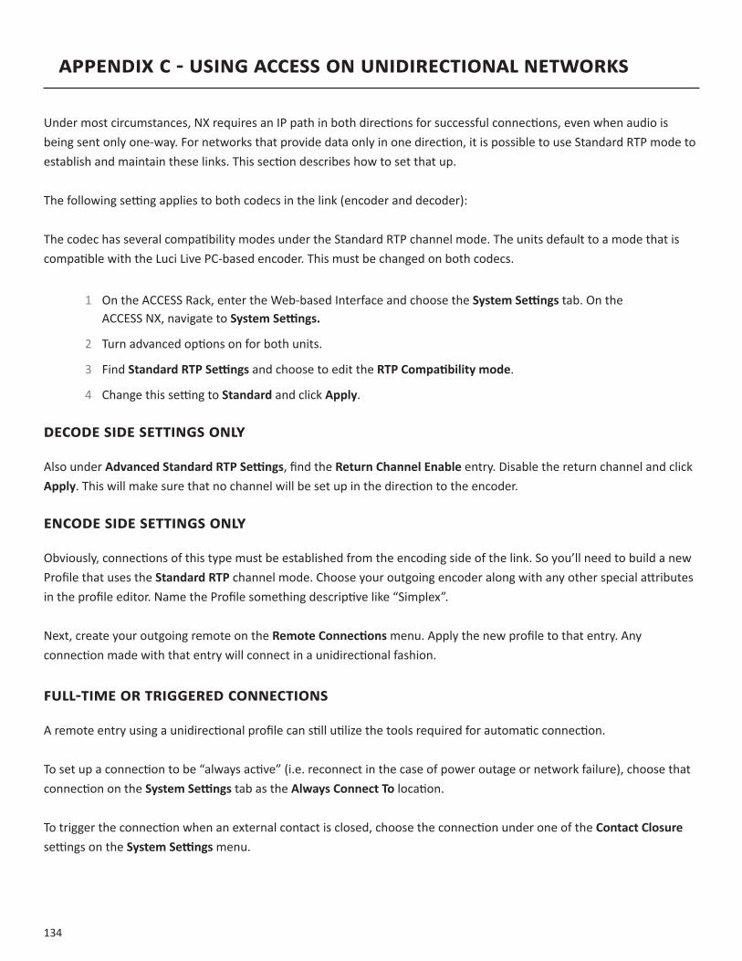
134
APPENDIX C - USING ACCESS ON UNIDIRECTIONAL NETWORKS
Under most circumstances, NX requires an IP path in both directions for successful connections, even when audio is being sent only one-way. For networks that provide data only in one direction, it is possible to use Standard RTP mode to establish and maintain these links. This section describes how to set that up.
The following setting applies to both codecs in the link (encoder and decoder):
The codec has several compatibility modes under the Standard RTP channel mode. The units default to a mode that is compatible with the Luci Live PC-based encoder. This must be changed on both codecs.
1 On the ACCESS Rack, enter the Web-based Interface and choose the System Settings tab. On the ACCESS NX, navigate to System Settings.
2 Turn advanced options on for both units.
3 Find Standard RTP Settings and choose to edit the RTP Compatibility mode.
4 Change this setting to Standard and click Apply.
DECODE SIDE SETTINGS ONLY
Also under Advanced Standard RTP Settings, find the Return Channel Enable entry. Disable the return channel and click Apply. This will make sure that no channel will be set up in the direction to the encoder.
ENCODE SIDE SETTINGS ONLY
Obviously, connections of this type must be established from the encoding side of the link. So you’ll need to build a new Profile that uses the Standard RTP channel mode. Choose your outgoing encoder along with any other special attributes in the profile editor. Name the Profile something descriptive like “Simplex”.
Next, create your outgoing remote on the Remote Connections menu. Apply the new profile to that entry. Any connection made with that entry will connect in a unidirectional fashion.
FULL-TIME OR TRIGGERED CONNECTIONS
A remote entry using a unidirectional profile can still utilize the tools required for automatic connection.
To set up a connection to be “always active” (i.e. reconnect in the case of power outage or network failure), choose that connection on the System Settings tab as the Always Connect To location.
To trigger the connection when an external contact is closed, choose the connection under one of the Contact Closure settings on the System Settings menu.

135
APPENDIX D - USING THE COMREX ACCESS DECODER DOWNMIX FUNCTION
NX has a feature that allows a stereo connection profile to instruct the ACCESS decoder to decode only one side of a stereo channel. This is useful in a scenario where two mono connections need to be sent to two different destinations simultaneously.
NX has the ability to run a single instance of an audio encoder. But the user can create multiple profiles using that encoder to change behavior of either end of the link. The new option instructs the decoder to selectively output only Left or Right channel of an incoming stereo feed. By applying at least two different profiles to the outgoing connections, the system can effectively send only Left channel audio to one destination, and only Right channel to another.
Use of the decoder downmix function has two drawbacks: As with all multi-streams in ACCESS, full duplex operation is only supported to one destination. Also, both channels of the stream are actually delivered to both destinations over the network, utilizing more incoming network bandwidth to the decoder than necessary.
The figure above shows a typical connection using the Decoder Downmix function from the encode site (A) to two decode sites (B and C). For clarity, no return audio channel is shown from either B or C (although one could exist from either but not both).
The user at site A builds two separate connection profiles, each using the same local stereo encode option. They will turn off the remote encoder on both profiles. On the profile labeled “Downmix L”, under advanced options, they will go to the remote connection side and select “downmix”. Here, the user will instruct the remote decoder to output only “Mono Left Only” through both Left and Right audio outputs.

136
The user will build corresponding “Downmix R” profile, selecting the “Mono Right Only” option in the same location.
On the Remotes list, the user at site A will apply the “Downmix L” profile to the remote connection targeted to receive the Left audio channel (site B), and the “Downmix R” profile to the other (site C).
Using this scenario, two independent channels can be sent to two independent locations using a single ACCESS codec on the transmitting end. This function can also be used in a “round-robin” contribution application, where mutliple remote reporters are all interested in adding to a conversation, and are still able to hear each other. This scenario is a bit more complex, but is aided greatly by use of the Vortex Hotswitch application. This is described in more detail in a separate technote, Round-Robin Remotes with Comrex ACCESS.
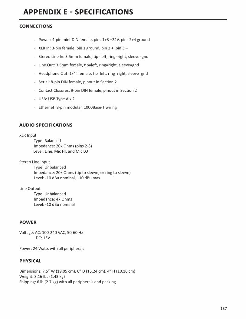
137
APPENDIX E - SPECIFICATIONSCONNECTIONS
• Power:4-pinmini-DINfemale,pins1+3+24V,pins2+4ground
• XLRIn:3-pinfemale,pin1ground,pin2+,pin3–
• StereoLineIn:3.5mmfemale,tip=left,ring=right,sleeve=gnd
• LineOut:3.5mmfemale,tip=left,ring=right,sleeve=gnd
• HeadphoneOut:1/4”female,tip=left,ring=right,sleeve=gnd
• Serial:8-pinDINfemale,pinoutinSection2
• ContactClosures:9-pinDINfemale,pinoutinSection2
• USB:USBTypeAx2
• Ethernet:8-pinmodular,1000Base-Twiring
AUDIO SPECIFICATIONS
XLRInput Type:Balanced Impedance:20kOhms(pins2-3)Level:Line,MicHI,andMicLO
StereoLineInput Type:Unbalanced Impedance:20kOhms(tiptosleeve,orringtosleeve) Level:-10dBunominal,+10dBumax
LineOutput Type:Unbalanced Impedance:47Ohms Level:-10dBunominal
POWER
Voltage:AC:100-240VAC,50-60Hz DC:15V
Power:24Wattswithallperipherals
PHYSICAL
Dimensions:7.5”W(19.05cm),6”D(15.24cm),4”H(10.16cm)Weight:3.16lbs(1.43kg)Shipping:6lb(2.7kg)withallperipheralsandpacking

APPENDIX F - CONNECTIONS TO MULTIRACK
The purpose of this appendix is to describe how to make connections to Comrex ACCESS MultiRack.
BRIC NORMAL CONNECTIONS
The Comrex ACCESS MultiRack allows users to make up to 5 separate AES67 connections. This feature allows additional setup including the assignment of separate UDP ports for each MultiRack Instance. UDP 9000 is the default port for BRIC Normal connections. Instance #1 on MultiRack will use the UDP 9000 port by default. Comrex generally recommends End Users with MultiRack then use UDP 9002-9005 for instances #2-5 respectively, leaving UDP 9001 open for Crosslock.
When making Remote Entries for MultiRack, each instance needs to be its own separate entry. For BRIC Normal connections, this is done by entering the Public IP Address the MultiRack is behind followed by “:9000” for instance #1, and “:9002”, “:9003”, “:9004, and “:9005” for instances #2-5 respectively. For example, Creating a BRIC Normal entry for instance #3 on a MultiRack would read: “<IP ADDRESS>:9003”.
MANUAL CROSSLOCK CONNECTIONS
Manual CrossLock connections require special configuration options on both sides of the link. This primarily involves programming the Switchboard ID for each unit (or primary Ethernet MAC Address) into the outgoing settings on the codec on opposite side of the link. This process for outgoing calls is described above. What isn’t mentioned is also important: the MAC/Switchboard ID of the outgoing unit must also be programmed into the unit receiving the call.
Note that MultiRack instances #2-5 have special Switchboard IDs consisting of the primary Ethernet MAC followed by a suffix (e.g., 00:01:0c:c0:78:19-4 for instance #4).
This is done by creating an outgoing connection describing the far-end unit, even if it is never actually used for outgoing calls. In the case of this “dummy” entry, it’s not actually important for the IP address field of the far-end unit to be correct. The entry must be enabled for CrossLock operation and it must have the correct Switchboard ID/MAC address of the far-end unit.
In the special circumstance where the default CrossLock port of UDP 9001 can not be used, (e.g., several MultiRack codecs sharing a single IP address) then manual CrossLock connections get extra complex. For more information on these settings, refer to the Technote “Making CrossLock connections on non-standard Ports.”
Note: Comrex Devices must be running at least Firmware version 4.5 to designate MAC Address suffixes when making Manual Crosslock Remote Entries.
138

MAKINg CONNECTIONS WITh SWITChBOARd
In order to use Switchboard, users must first have an account with the server. This account can be obtained by contacting Comrex at 978-784-1776 / 800-237-1776, or by emailing [email protected] / [email protected]. Only one account is required for each group of codecs. Once a user name and password is provided, navigate to switchboard.comrex.com in a web browser. When first accessing Switchboard, there will be a notice stating that no units have been added to the account. By clicking on Add New Unit, a dialogue box will ask for the Ethernet MAC address of the MultiRack.
When adding MultiRack to your Switchboard Account, each instance must be added individually as a separate device. The primary Ethernet MAC address is used here only for MultiRack instance #1. Each instance must be added to Switchboard individually. Instances 2-5 use the same MAC address with a suffix (e.g. -2, -3, -4, and -5)added to designate the instance.
As an example, if the primary Ethernet MAC Address is 00:01:40:c0:0d:15, that’s the ID input for MultiRack instance #1. Instance #2 is added as 00:01:40:c0:0d:15-2, instance #3 uses -3, etc.
FIgURE 75 MULTIRACK INSTANCE ENTRIES IN SWITChBOARd
139
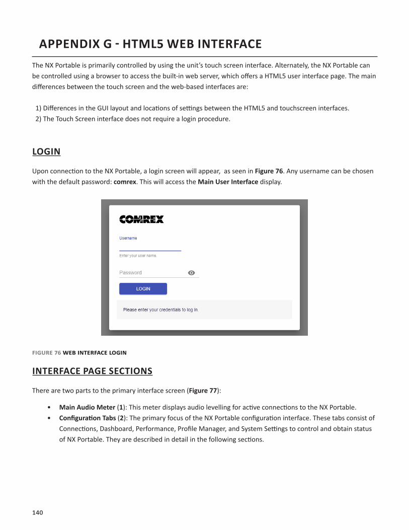
140
APPENDIX G - HTML5 WEB INTERFACEThe NX Portable is primarily controlled by using the unit’s touch screen interface. Alternately, the NX Portable can be controlled using a browser to access the built-in web server, which offers a HTML5 user interface page. The main differences between the touch screen and the web-based interfaces are:
1) Differences in the GUI layout and locations of settings between the HTML5 and touchscreen interfaces. 2) The Touch Screen interface does not require a login procedure.
LOGIN
Upon connection to the NX Portable, a login screen will appear, as seen in Figure 76. Any username can be chosen with the default password: comrex. This will access the Main User Interface display.
Figure 76 web interFace Login
INTERFACE PAGE SECTIONS
There are two parts to the primary interface screen (Figure 77):
• Main Audio Meter (1): This meter displays audio levelling for active connections to the NX Portable. • Configuration Tabs (2): The primary focus of the NX Portable configuration interface. These tabs consist of
Connections, Dashboard, Performance, Profile Manager, and System Settings to control and obtain status of NX Portable. They are described in detail in the following sections.

141
2
1
Figure 77 connections tab
CONNECTIONS TAB
The Connections Tab is the first window in the configuration interface. This allows for monitoring device connectivity and controlling connections. In this tab, the names and IP addresses of remote units can be saved. To add a new remote unit to the list, select the “+” icon on the right side of the list. A dialogue box will appear asking for a name for the unit, as well as its IP address. An algorithmic profile must be selected for the new codec unit. To get started, choose one of the default profiles provided. Custom profiles are possible and are covered in a later section. In the event that a stored unit is no longer desired, it can be deleted through the Trash Icon option.
The Connections tab will display Name and Status information of a remote Comrex codec when it has initiated a connection to the NX Portable. Information from units connected this way will only appear while the connection is active.
By default, three remotes appear on the list. These remotes are used for troubleshooting connectivity and include:
1. Loopback: Allows for localhost, testing the connection of the rack and remotes on the network. 2. Comrex Lab Voice: This provides a talk feed from the Comrex headquarters in Massachusetts, USA for
testing network connections.3. Comrex Lab Music: This provides a music feed from the Comrex headquarters in Massachusetts, USA for
testing network connections.
DASHBOARD TAB
The Dashboard Tab is designed to be open during active connections (Figure 78). It provides a quick view of some vital parameters for use during live streaming.

142
Figure 78 DashboarD tab
1. The audio level meters give a quick indication of send and receive levels.2. The Contact Closure section gives a visual indication of the state of each input (local) and output closure
(remote). The input closure boxes also function as buttons to trigger closures locally.3. The Active Connections section gives an indication of any currently active connections. If more than one
connection is active, they will display in a list here.4. Switchboard status, Public IP, and router information are displayed in the status box.5. A quick view of the codec’s receive stats are presented in the lower section. This is similar to the statistics
presented under the Performance->Active Connection described in the next section.
PERFORMANCE TAB
The Performance Tab includes information on data transmission and reception rates from NX Portable to active remote connections. This allows for real-time monitoring of network quality during connections.
ACTIVE CONNECTIONS
Clicking the header “Active Connection” will show a basic chart of real-time codec receive performance. Channel Statistics, as shown in Figure 79, will give numeric statistics for the current active call. If several calls are active (Multistreaming), each will appear in a separate section.
Figure 79 channeL statistics
Figure 80 displays a real-time graph. This shows only statistics for the incoming data of the local codec. If a connection does not use the optional CrossLock reliability layer, this graph will be the only real-time network graph available. CrossLock connections also display the CrossLock statistics graph, which has more information.
21
3
45

143
Figure 80 jitter/packet error graph
The left graph represents the work of the Jitter Buffer Manager. The area of most interest is the light blue area as shown in Figure 80, which illustrates a spread of jitter values (referenced to the current play out pointer) over the last second. If this area covers a large span, the relative jitter is high. If the light blue section of the graph is small or invisible over a time period, less jitter is present. Based on the historical value of this jitter figure, the buffer manager will expand or contract the receive buffer (lengthening and shortening overall delay). The time interval over which this measurement is assessed is called the “jitter window” and is adjustable in the Advanced Profile editor. The work of the Jitter Buffer Manager is shown by the yellow line, which is the target buffer delay that the system is trying to achieve, based on measurements calculated over the jitter window.
The right side of the display shows a real-time and historical representation of frame loss. If the decoder does not receive packets in time, the chart will show a red line indicating the percentage of lost packets over the one-second interval.
CODEC CHANNEL FIELD
Clicking on the Codec Channel field delivers information on the NX Portable’s total receive rate and transmit rate, including information for multiple connections when applicable. When multiple transmit connections are active, this will show an aggregate rate of all outgoing connections (Figure 81).
Figure 81 coDec channeL
crossLock FieLD
Clicking on CrossLock opens a set of real-time graphs which monitor the status of the optional CrossLock reliability layer. These fields will not appear when non-CrossLock connections are active. These stats are a powerful tool for monitoring and diagnosing the quality of connections, as well as for managing the delay settings during the connection.

144
The CrossLock Stats are similar to the information available on the Active Connections graph, which shows streaming performance without regard to the CrossLock layer. The CrossLock Stats show finer details about network performance in both directions than can be obtained through the Active Connections graph. CrossLock stats are shown for both the data being transmitted from the local codec and the data being received by the local codec. All relevant stats are available for both directions.
PACKET LOSS GRAPH
Figure 82 indicates, in percentage terms, what’s gone wrong on the network during each one-second window. Three different color-coded entries appear here: 1 Packet Loss (dark red) - The system has detected a packet has been completely dropped by the network and was never received by the decoder. 2 Packet Late (bright red) - The system received the packet, but it was too late for decoding and play out. 3 Packet Recovered (green) - The packet was either lost or late, but was recovered either by the Forward Error Correction (FEC) or Automatic Repeat Query (ARQ) error correction built into CrossLock.
Figure 82 packet Loss graph
UTILIZATION GRAPH
Figure 83 contains a graph of the outgoing (or incoming) utilization of the network. The bars indicate the average data rate used by the system during each one-second window. It is possible that the size of these bars will vary because CrossLock (in some modes) has control over data rate through a technique called “throttling”. Based on network feedback statistics, CrossLock will reduce or increase the utilization dynamically. If more than one network device is in use, the utilization graph will be color-coded, indicating the relative utilization of each network device. The color-code key for each network device appears on the under graph. Overlayed on the network utilization graph is a gray line. This is the encoder target rate, which reflects the bitrate chosen in the profile used in the connection. This is treated as a maximum value, so utilization should mostly remain below this line.
Figure 83 utiLization graph

145
CROSSLOCK SETTINGS
Clicking the CrossLock Settings field during an active connection will display the CrossLock sliders. There is a slider available for transmit and receive operation.
For most CrossLock connections, the sliders should be left at their default Automatic Delay Mode settings. But during connections on unusual networks, these sliders are designed to quickly adjust the current delay settings. The sliders will reset when a CrossLock connection ends.
Figure 84 DeLay sLiDer bars - automatic DeLay moDe
The most powerful way to stabilize any streaming connection is to have the decoder add a delay buffer to the connection. This compensates for changes in the rate packets are received (known as jitter). CrossLock uses a combination of decode delay buffering and error correction to keep connections stable.
At the start of a CrossLock connection, the sliders are in “Auto Delay” mode and the information on the sliders is purely for informational purposes. Clicking off the “Auto Delay” box sets the system to Manual Delay mode and allows the slider to be moved with a mouse. The entire slider is scalable, and the range of it from left to right will vary from one hundred milliseconds to several seconds depending on the range of delays currently being addressed. In either Auto or Manual mode, a series of color bars are overlayed on the slider, to signify delay “zones” of safety.
Figure 85 DeLay sLiDer bars - manuaL DeLay moDe
Furthest left is the red zone, which indicates a buffer level that is too low for stable transmission. The yellow zone indicates a delay buffer that may have stability issues, and the green zone indicates a buffer level that should
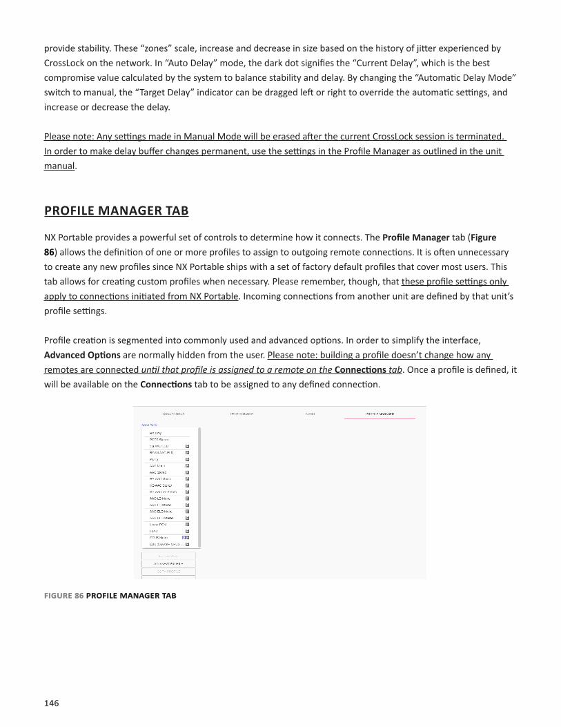
146
provide stability. These “zones” scale, increase and decrease in size based on the history of jitter experienced by CrossLock on the network. In “Auto Delay” mode, the dark dot signifies the “Current Delay”, which is the best compromise value calculated by the system to balance stability and delay. By changing the “Automatic Delay Mode” switch to manual, the “Target Delay” indicator can be dragged left or right to override the automatic settings, and increase or decrease the delay.
Please note: Any settings made in Manual Mode will be erased after the current CrossLock session is terminated. In order to make delay buffer changes permanent, use the settings in the Profile Manager as outlined in the unit manual.
PROFILE MANAGER TAB
NX Portable provides a powerful set of controls to determine how it connects. The Profile Manager tab (Figure 86) allows the definition of one or more profiles to assign to outgoing remote connections. It is often unnecessary to create any new profiles since NX Portable ships with a set of factory default profiles that cover most users. This tab allows for creating custom profiles when necessary. Please remember, though, that these profile settings only apply to connections initiated from NX Portable. Incoming connections from another unit are defined by that unit’s profile settings.
Profile creation is segmented into commonly used and advanced options. In order to simplify the interface, Advanced Options are normally hidden from the user. Please note: building a profile doesn’t change how any remotes are connected until that profile is assigned to a remote on the Connections tab. Once a profile is defined, it will be available on the Connections tab to be assigned to any defined connection.
Figure 86 proFiLe manager tab

147
BUILDING A PROFILE
To build a new profile, select Add New Profile (1 in Figure 87) and a new profile will appear on the list labelled New Profile. Select it to populate a set of options, starting with the profile Name (2 in Figure 87). Here, the profile can be renamed to something easier to remember.
Next is the Channel option (3 in Figure 87), which allows for selecting between a standard Comrex IP connection (BRIC normal) or one of the other connection modes offered by NX Portable. Note that when using the CrossLock reliability layer, BRIC Normal mode is chosen here, as this is the protocol that runs with the CrossLock VPN.
Other Channel options include a modem-based connection (which uses the telephone line rather than the Ethernet port), IP Multicast (a method to deliver audio to multiple locations), EBU3326/SIP for compatibility, and less often used protocols like standard RTP, TCP, and HTTP. Different aspects of these channel types are described in later sections.
Note: It’s important to define the channel of a profile before moving on to other options, since the choices in the subsequent sections will vary based on this choice. Make sure to press Apply Changes in order to confirm each change made.
1
2 3
Figure 87 proFiLe manager tab
proFiLe settings: LocaL & remote encoDers
When choosing an IP-based channel (i.e., BRIC Normal), users will be presented with two categories of options: Local and Remote. The Local Settings are used to determine how a transmitting ACCESS behaves, and the Remote Settings will determine how the receiving ACCESS on the far end behaves. Each category lists identical options, so only Local Settings will be covered.
Connection Timeout - Under normal circumstances, a connection will be terminated on one end and the other end will drop the connection in turn. However, if a network failure occurs or a connection is ended abruptly (e.g. because the power to one unit was unexpectedly killed), the system will drop the connection after a predetermined time. The default is 60 seconds, but this can be shortened or lengthened as desired.

148
Encoder - It is unnecessary to define any decoder types when using ACCESS because they automatically adapt to the incoming stream. Using this menu, users can select the encoder used to send audio from this ACCESS (local) as well as the encoder used to send audio to this ACCESS (remote). The default value of the remote encoder is to follow the local encoder (i.e., it will send exactly the same codec mode it receives). This is defined as Follow Mode in the remote encoder selection table.
Transmit On/Off - This option determines whether the selected encoder (local or remote) is actually sending any data. By default, Transmission and Reception on all encoders is turned on, but there may be circumstances where one-way operation is desired. Turning off the local encoder transmission disables outgoing audio and disabling the remote encoder transmission disables incoming audio.
ADVANCED LOCAL & REMOTE OPTIONS
The following advanced options apply to both the local and remote entries and largely deal with the performance of Jitter Buffer Manager. This is actually a very complex decision-making process involving many variables, and most of the time the default parameters should work well. These advanced options are a means of overriding these defaults, and Comrex recommends that users take care when changing them. Note that when it comes to settings that effect the jitter buffer manager, local settings affect the decoder on the local side, and remote settings affect the decoder on the remote end.
Frames per Packet - This function allows the encoder to wait for variable “X” number of frames to exist before sending a packet. This option differs from FEC because each frame is only sent once. Setting this value to a number higher than one can reduce network usage, at the expense of delay. This is because packet overhead bits like IP and UDP headers are sent less often.
Decoder Downmix - This option controls the method by which decoded stereo audio will be down-mixed to mono.
Loss Cushion - Packets may arrive at the decoder displaying a range of statistical properties. They may arrive in reasonably good timing and in order, or half may arrive quickly with the other half delayed significantly. In some cases, most of the packets arrive in a timely manner, but a small percentage of them may be extremely late. It is usually preferable to allow these late packets to be left out of the stream entirely and keep the delay lower. The decoder error concealment hides these packet losses. The Loss Cushion parameter instructs the buffer manager to ignore a certain percentage of late packets in its calculation. The default value is 5%. Applications that are not delay-sensitive may wish to reduce this value to zero, while extremely delay-sensitive applications may prefer to have this closer to 25%.
Retransmit Squelch Trigger - Retransmit Squelch options are used to determine how the buffer manager reacts to typical data dropouts like those seen on wireless networks. The Trigger option Determines the amount of time the decoder must experience 100% packet loss before the Retransmit Squelch function is triggered. Default is one second.
Retransmit Squelch Max - The longest period of data loss during which the squelch function is active (default is two seconds). During the squelch period, the buffer manager ignored the relative jitter experienced and does not adjustbuffer size to compensate.
149
Fixed Delay - This option simply sets the Delay Cushion and Delay Limit at a similar value, so that the delay buffer is defined to the chosen value and will not increase or decrease significantly.
Delay Cushion - The jitter buffer manager works to keep absolute delay to a minimum. Some applications are not delay sensitive and rely less on the jitter buffer manager. The Delay Cushion setting is a way to instruct the manager not to attempt to drive the delay below a certain value. (For example, if the delay cushion is set to 500 mS, this amount of fixed delay will be added to the buffer.) If the jitter manager needs to increase the buffer it will do so, but will not go below the 0.5 second level.
Delay Limit - The inverse of the Delay Cushion, this parameter instructs the manager not to wind the buffer out beyond a certain delay value, regardless of how many packets are lost. This is useful in applications where staying below a certain delay figure is essential, but use of the delay limit can result in very poor performance if the network jitter dramatically exceeds the limit.
Jitter Window - This parameter defines the amount of time (in minutes) that historical network performance is analyzed in order to make the rest of the calculations. As an example, if the Jitter Window is set to the default of five minutes, and if a dramatic network event happens and the buffer manager reacts (perhaps by increasing the buffer), the event will be included in the manager’s calculations for the next five minutes. If the network experiences improved performance over this period, the manager may choose to wind the buffer back down after the five minutes has passed.
Buffer Management On/Off - This is a diagnostic setting used to troubleshoot buffer manager performance by the factory. For usage, it should always remain “on”.
CrossLock Managed Delay - There are two ways NX Portable can calculate its target delay, and, therefore, how much decoder buffer to add. The first is the BRIC-Normal way, and is the default for non-CrossLock connections. Buffer size is set based on a histogram of past jitter performance. This will incur the shortest delay possible. For CrossLock connections, the buffer is increased to allow the use of error correction, so buffer is thus based on a combination of the jitter histogram, and the round-trip-delay as calculated by the system. This will generally result in bigger decode buffers (and higher delays). Because it is lower, the default setting is to use the jitter histogram for all connections. This setting allows the profile user to use alternately the CrossLock “error correction friendly” setting, for connections where delay is less important.
The following three settings are available to users in BRIC Normal mode. They are legacy settings for use in non-CrossLock connections. Most users should leave these settings as-is, as they can interfere with CrossLock connections. CrossLock settings now incorporate these functions.
Congestion Avoidance - Enabling this option allows the encoder to dynamically change the number of frames per packet sent, thereby reducing total data requirements. In addition, in most encode modes, enabling congestion avoidance provides the system a license to step down to a lower encode data rate if desired. This will happen automatically and with no audio interruption. Step down congestion avoidance is not enabled in the Linear PCM mode.
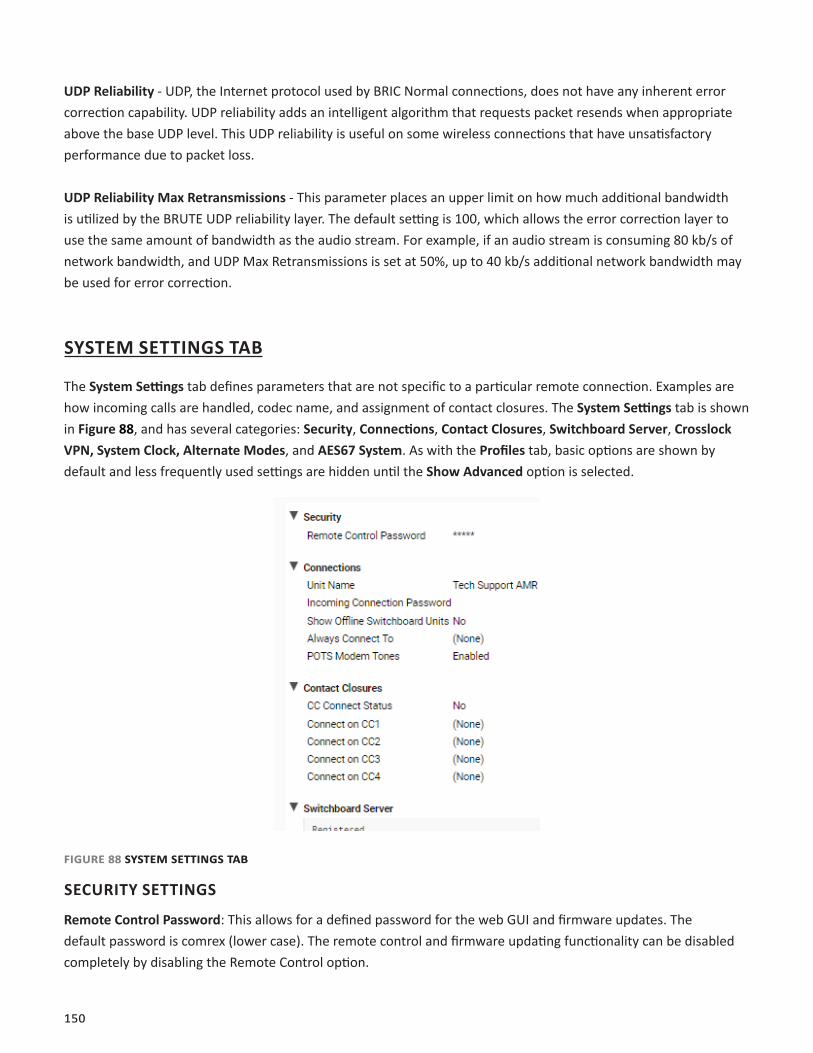
150
UDP Reliability - UDP, the Internet protocol used by BRIC Normal connections, does not have any inherent error correction capability. UDP reliability adds an intelligent algorithm that requests packet resends when appropriate above the base UDP level. This UDP reliability is useful on some wireless connections that have unsatisfactory performance due to packet loss.
UDP Reliability Max Retransmissions - This parameter places an upper limit on how much additional bandwidth is utilized by the BRUTE UDP reliability layer. The default setting is 100, which allows the error correction layer to use the same amount of bandwidth as the audio stream. For example, if an audio stream is consuming 80 kb/s of network bandwidth, and UDP Max Retransmissions is set at 50%, up to 40 kb/s additional network bandwidth may be used for error correction.
SYSTEM SETTINGS TAB
The System Settings tab defines parameters that are not specific to a particular remote connection. Examples are how incoming calls are handled, codec name, and assignment of contact closures. The System Settings tab is shown in Figure 88, and has several categories: Security, Connections, Contact Closures, Switchboard Server, Crosslock VPN, System Clock, Alternate Modes, and AES67 System. As with the Profiles tab, basic options are shown by default and less frequently used settings are hidden until the Show Advanced option is selected.
Figure 88 system settings tab
SECURITY SETTINGS
Remote Control Password: This allows for a defined password for the web GUI and firmware updates. The default password is comrex (lower case). The remote control and firmware updating functionality can be disabled completely by disabling the Remote Control option.
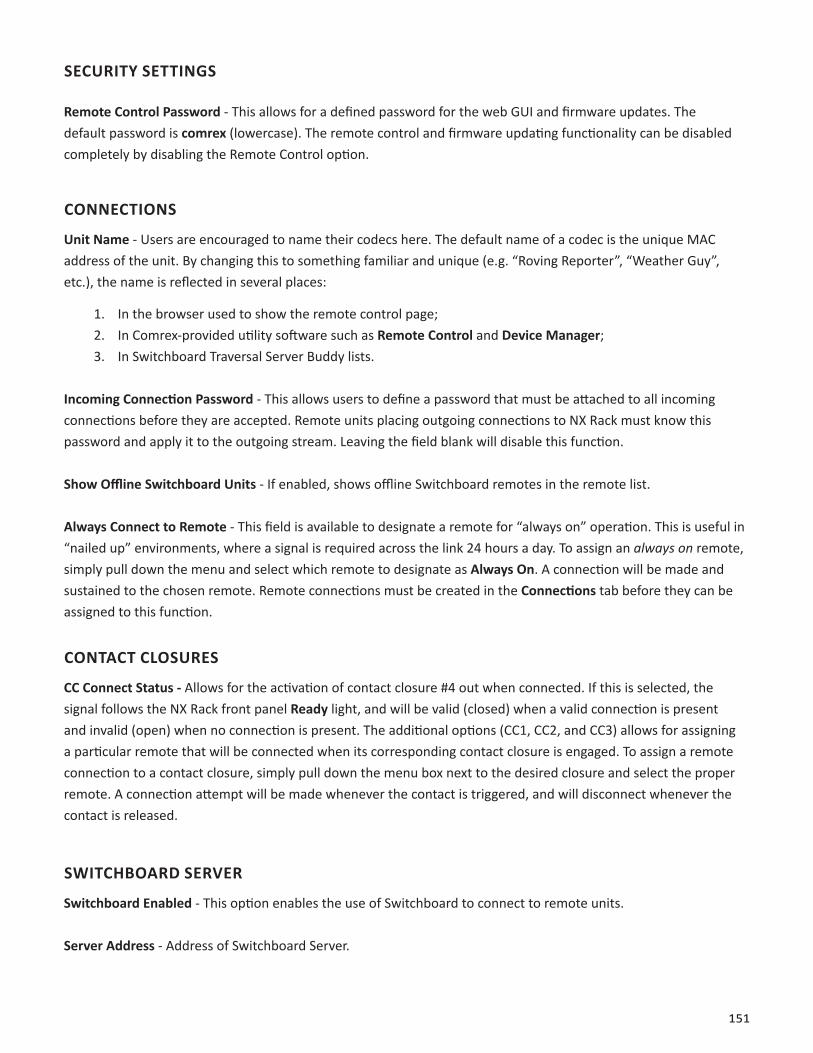
151
SECURITY SETTINGS
Remote Control Password - This allows for a defined password for the web GUI and firmware updates. The default password is comrex (lowercase). The remote control and firmware updating functionality can be disabled completely by disabling the Remote Control option.
CONNECTIONS
Unit Name - Users are encouraged to name their codecs here. The default name of a codec is the unique MAC address of the unit. By changing this to something familiar and unique (e.g. “Roving Reporter”, “Weather Guy”, etc.), the name is reflected in several places:
1. In the browser used to show the remote control page;2. In Comrex-provided utility software such as Remote Control and Device Manager;3. In Switchboard Traversal Server Buddy lists.
Incoming Connection Password - This allows users to define a password that must be attached to all incoming connections before they are accepted. Remote units placing outgoing connections to NX Rack must know this password and apply it to the outgoing stream. Leaving the field blank will disable this function.
Show Offline Switchboard Units - If enabled, shows offline Switchboard remotes in the remote list.
Always Connect to Remote - This field is available to designate a remote for “always on” operation. This is useful in “nailed up” environments, where a signal is required across the link 24 hours a day. To assign an always on remote, simply pull down the menu and select which remote to designate as Always On. A connection will be made and sustained to the chosen remote. Remote connections must be created in the Connections tab before they can be assigned to this function.
CONTACT CLOSURES
CC Connect Status - Allows for the activation of contact closure #4 out when connected. If this is selected, the signal follows the NX Rack front panel Ready light, and will be valid (closed) when a valid connection is present and invalid (open) when no connection is present. The additional options (CC1, CC2, and CC3) allows for assigning a particular remote that will be connected when its corresponding contact closure is engaged. To assign a remote connection to a contact closure, simply pull down the menu box next to the desired closure and select the proper remote. A connection attempt will be made whenever the contact is triggered, and will disconnect whenever the contact is released.
SWITCHBOARD SERVER
Switchboard Enabled - This option enables the use of Switchboard to connect to remote units.
Server Address - Address of Switchboard Server.

152
Secure - Enable secure connections to Switchboard Server.
Static CrossLock Peers - When using CrossLock without Switchboard, remote peers can be managed in this list.
CROSSLOCK VPN
Enable - This option enables the Crosslock VPN added reliability layer to connect to remote units.
Retransmit Delay - This section allows the selection of additional delay for the retransmission of lost packets when calculating auto-delay targets. The 2xRTT setting is selected by default.
Redundant Transmission - When calculating auto-delay target, allow enough additional delay for the retransmission of lost packets. The default setting is Off.
Encoder Throttle - This option will allow the system to reduce the bitrate of encoded media when network conditions deteriorate. Disabling this option will prevent the system from lowering the quality of the encoded media but will also significantly reduce the ability of the system to handle networks with variable performance. This setting is set to Yes by default.
Hotswap CC Indicator - When enabled, this setting will activate a selected contact closure when a CrossLock backup interface is configured and has become activated due to failure of the primary interface(s). This is set to Disabled by default.
Hotswap CC Unit - This setting allows users to select which unit to indicate HotSwap failover on. This is set to Remote by default and additionally includes a Local and Both selection.
SYSTEM CLOCK
NTP Enabled - Enables the use of NTP network time synchronization. This setting is set to Yes by default.
NTP Server - This allows users to set the address of the NTP server. This is set for 0.comrex.pool.ntp.org by default.
Timezone - Users can set their Timezone in this setting. This allows for inputting a User’s Timezone by Region, Country, and Timezone.
ALTERNATE MODES
BRIC Normal Settings• Accept Incoming Connections - This determines if this NX Rack is used for incoming normal IP
connections. If this function is not enabled, NX Rack will only support outgoing calls using BRIC Normal Mode.
Modem• Accept Incoming Connections - This allows an NX Rack to listen for and automatically answer incoming
calls.
EBU3266/SIP Settings
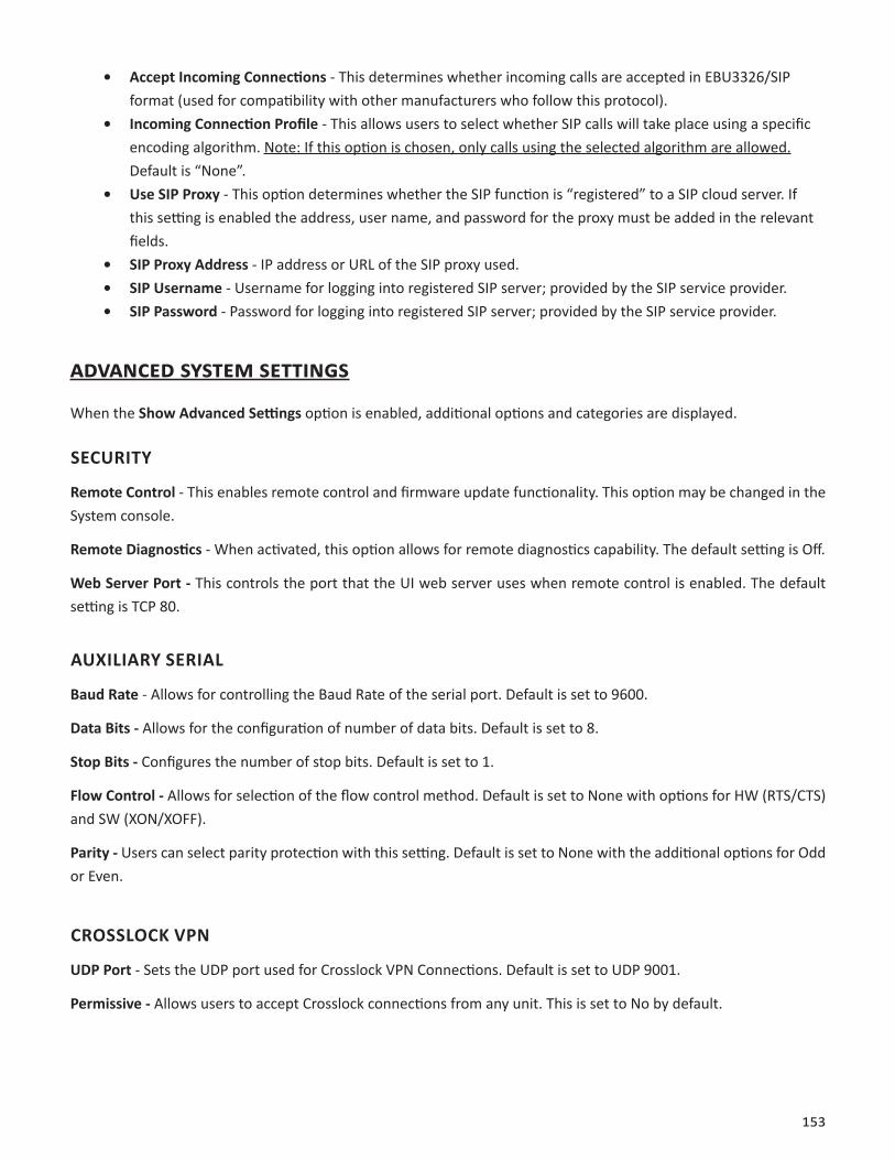
153
• Accept Incoming Connections - This determines whether incoming calls are accepted in EBU3326/SIP format (used for compatibility with other manufacturers who follow this protocol).
• Incoming Connection Profile - This allows users to select whether SIP calls will take place using a specific encoding algorithm. Note: If this option is chosen, only calls using the selected algorithm are allowed. Default is “None”.
• Use SIP Proxy - This option determines whether the SIP function is “registered” to a SIP cloud server. If this setting is enabled the address, user name, and password for the proxy must be added in the relevant fields.
• SIP Proxy Address - IP address or URL of the SIP proxy used.• SIP Username - Username for logging into registered SIP server; provided by the SIP service provider.• SIP Password - Password for logging into registered SIP server; provided by the SIP service provider.
aDvanceD system settings
When the Show Advanced Settings option is enabled, additional options and categories are displayed.
SECURITY
Remote Control - This enables remote control and firmware update functionality. This option may be changed in the System console.
Remote Diagnostics - When activated, this option allows for remote diagnostics capability. The default setting is Off.
Web Server Port - This controls the port that the UI web server uses when remote control is enabled. The default setting is TCP 80.
AUXILIARY SERIAL
Baud Rate - Allows for controlling the Baud Rate of the serial port. Default is set to 9600.
Data Bits - Allows for the configuration of number of data bits. Default is set to 8.
Stop Bits - Configures the number of stop bits. Default is set to 1.
Flow Control - Allows for selection of the flow control method. Default is set to None with options for HW (RTS/CTS) and SW (XON/XOFF).
Parity - Users can select parity protection with this setting. Default is set to None with the additional options for Odd or Even.
CROSSLOCK VPN
UDP Port - Sets the UDP port used for Crosslock VPN Connections. Default is set to UDP 9001.
Permissive - Allows users to accept Crosslock connections from any unit. This is set to No by default.

154
Authentication - Enables the authentication of connections. Default setting is No.
Protection - Enables AES encryption and payload integrity protection to prevent tampering with or interception of the transmitted content. This option has a SIGNIFICANT system overhead. Default setting is No.
Maximum Delay - Maximum allowed target delay, in milliseconds. Set to 5000 ms by default.
FEC - Enables data loss protection. This option controls protection on data transmitted to the remote end. Disabled by default.
FEC Delay - Amount of delay to allow for FEC. Lower packet rates will require higher delay to remain effective.
Rentransmit - Enables retransmission of lost data. This option controls protection on data transmitted to the remote end.
Header Compression - Enables the compression of headers to reduce overhead, especially at lower bitrates. Default is set to Yes.
Base FEC - Applies a constant base amount of FEC sufficient to recover the specified rate of packet loss. Default is set to 0%.
STUN Server - Displays IP address of the STUN Server. Default is stun. comrex.com.
Always Connect - Allows users to attempt to maintain a VPN connection to a selected peer whenever possible. Default is set to None.
BRIC NORMAL SETTINGS
IP Port - This option defines the incoming UDP port—the number to be used for incoming IP connections. The default is UDP 9000. Crosslock connection is defaulted to UDP 9001. Note that since most NX Rack codecs attempt a connection on this port number, changing it can mean the remote units in the field must dial specifically to the new port number in order to connect to the NX Rack. An outgoing call must be made to a specific port number in the form of IP-ADDRESS:PORT#. For example, dialing port UDP 5004 on the Comrex test line is formatted 70.22.155.131:5004.

155
HTTP
Accept Incoming Connections - Users can set NX Rack to listen for and automatically answer any HTTP incoming calls. This option is set to No by default.
IP Port - This option defines the incoming UDP port—the number to be used for incoming HTTP connections. The default is UDP 8000.
Encoder - This defines the encoder used for HTTP streaming. Default is HE-AAC V2 Stereo 48 kB.
User Agent Blacklist - List of HTTP user agents that will not be allowed to communicate. Entries are not case sensitive and will match if they are present in any part of the user agent string.
Genre - Users can define the Genre for HTTP streaming. Default value is set to Live.
Info URL - Informational URL associated with the stream. This setting is left blank by default.
Public - Allows users to define the HTTP stream as a Public Stream. Default setting is No.
MODEM
Ring Count - If Auto-Answer is enabled, users can determine the amount of rings before the line will be answered after. Default is set to 1.
Max Modem Rate - This allows users to set the maximum allowed modem connect rate. Default setting is 24000.
Min Modem Rate - This allows users to set the minimum allowed modem connect rate. Default setting is 9600.
Extra Modem Init - This allows users to enter an extra modem initialization string. The default is set to blank.
STANDARD RTP SETTINGS
These settings offer several modes that allow compatibility with specific IP coding devices.
Accept Incoming Connections - Listen for and automatically answer incoming calls.
Incoming Connection Profile - Use this profile for incoming connections.
IP Port - Allows users to designate an incoming network port.
RTP Compatibility Mode - Enables compatibility with select RTP audio streaming devices.
Return Channel Enable - Enables a return channel sent back to the transmitter for incoming calls.
Return Channel Encoder - For incoming calls, this specifies the codec to be used for the return channel.
Return Channel Frames per Packet - Determines how many audio frames are included in each packet. Values over 1 will reduce network bandwidth but will increase delay. This is set to 1 by default.

156
Incoming Timeout - For incoming calls, this specifies time connection timeout. Set to 60 seconds by default.
EBU3266/SIP SETTINGS
IP Port - The port used by the SIP negotiation channel when using EBU3326/SIP Mode. If this port is changed, it’s likely to break compatibility with other manufacturer’s codecs.
User Agent Whitelist - List of SIP user agents that are allowed to communicate. Only SIP agents on this list can communicate with the NX Rack. Note: This setting is not enabled when using a registered SIP proxy.
User Agent Blacklist - List of SIP user agents that are not allowed to communicate.
VIP QC Password - For legacy purposes with the VIP QC app, which has been deprecated.
RTP IP Port - The port used for audio transfer during EBU3326/SIP mode. Since this port info is transferred during the negotiation process, it can be changed without breaking compatibility. Note: RTSP data is always sent and received on the port one number higher than this.
Public IP Override - Enable this in an environment where ports have been forwarded through a router to the NX Rack. SIP protocol assumes no ports are forwarded and may have trouble connecting if this function is not enabled.
Use STUN Server - Determines whether or not to use the STUN derived address in the outgoing fields. NX Rack has alternate NAT Traversal ability so this is off by default.
SIP Proxy Keepalive - Defines how often the SIP proxy handshake happens when no call is present.
SIP Domain - When registering with some SIP services, a separate domain entry is required. If this is not populated, the domain of the SIP proxy entry is used.
SIP Auth Username - When registering for some SIP services, a separate Auth Username is required. Do not populate unless a specifc entry is required by the provider.
Send RTP To Source Port - A NAT Traversal function used with smartphone apps. Enabled by default.
SIP Routing - Specifically required by some SIP servers (e.g. OpenSIPS). Modifies the behavior of the route header.
tcp settings
NX Rack performs best when using UDP for connections, but there are some rare circumstances when the system may need to be switched over to TCP operation. This advanced option defines how incoming TCP calls are handled. Outgoing calls are defined as TCP when their profile is configured. NX Rack normally listens for incoming calls on both TCP and UDP ports, and chooses the first to arrive. If a TCP call is detected, NX Rack will attempt to use the same TCP link to transmit in the reverse direction.
157
Accept Incoming Connections - This allows turning TCP Auto Answer on and off. Disabling this function means only outgoing TCP calls can be established.
IP Port - Users have the option of setting the incoming TCP port number, which can be different than the UDP port number.
Note: Warnings given above about changing port numbers also apply here—calls with mismatched port numbers will fail.
MISCELLANEOUS
Meter Demo Mode - This setting will put the front panel LED meters into a demonstration mode. This setting is set to No by default.