
Technical Specification Portable Computer - Mercell
52
ÖPPEN/Unclassified Date 16 July 2012 Our reference Appendix 1 to 356594-AI812743 Version 1.0 Area of responsibility/Department AK Led Jesper Wide Classify ID Page 1 (52) All rights strictly reserved. Reproduction or issue to third parties in any form whatever is not permitted without the express written permission of FMV. PORTABLE COMPUTER Technical Specification Approved by: Date:
-
Upload
khangminh22 -
Category
Documents
-
view
2 -
download
0
Transcript of Technical Specification Portable Computer - Mercell
ÖPPEN/Unclassified Date
16 July 2012 Our reference Appendix 1 to 356594-AI812743
Version 1.0
Area of responsibility/Department AK Led Jesper Wide
Classify ID
Page 1 (52)
All rights strictly reserved. Reproduction or issue to third parties in any form whatever is not permitted without the express written permission of FMV.
PORTABLE COMPUTER Technical Specification
Approved by:
Date:

ÖPPEN/Unclassified Date
16 July 2012 Our reference Appendix 1 to 356594-AI812743
Version 1.0
Area of responsibility/Department AK Led Jesper Wide
Classify ID
Page 2 (52)
All rights strictly reserved. Reproduction or issue to third parties in any form whatever is not permitted without the express written permission of FMV.
Version history Version Author Comment Date
1.0 JEWID CCB 10 may 2012
ÖPPEN/Unclassified Date
16 July 2012 Our reference Appendix 1 to 356594-AI812743
Version 1.0
Area of responsibility/Department AK Led Jesper Wide
Classify ID
Page 3 (52)
All rights strictly reserved. Reproduction or issue to third parties in any form whatever is not permitted without the express written permission of FMV.
References The versions listed below or more recent versions will be accepted. Ref Title Identity Where to find 1 Environmental
Engineering Considerations and Laboratory Tests
MIL-STD-810G http://www.everyspec.com/ free
2 Requirements for the Control of Electromagnetic Interference Characteristics of Subsystems and Equipment
MIL-STD-461F http://www.everyspec.com/ free
3 Characteristics of 28 Volt DC Electrical Systems in Military Vehicles
MIL-STD-1275D
http://www.everyspec.com/ free
4 Environmental Conditions
AECTP 200 (Edition 3)
http://www.everyspec.com/ free
5 Degrees of Protection Provided by Enclosures
ANSI/IEC 60529
http://www.nema.org/stds/60529.cfm buy
6 Benchmark Application PCMARK05 http://www.futuremark.com buy
7 Electromagnetic Compatibility (EMC) Directive
EMC 2004/108/EC
http://ec.europa.eu/enterprise/sectors/electrical/documents/emc/index_en.htm free
8 Low Voltage Directive LVD 2006/95/EC
http://ec.europa.eu/enterprise/sectors/electrical/documents/lvd/index_en.htm free
9 Electromagnetic Compatibility (EMC), Electrostatic Discharge Immunity Test
EN-61000-4-2
ÖPPEN/Unclassified Date
16 July 2012 Our reference Appendix 1 to 356594-AI812743
Version 1.0
Area of responsibility/Department AK Led Jesper Wide
Classify ID
Page 4 (52)
All rights strictly reserved. Reproduction or issue to third parties in any form whatever is not permitted without the express written permission of FMV.
10 Electromagnetic Compatibility (EMC), Electrical Fast Transient/Burst Immunity Test
EN-61000-4-4
11 Electromagnetic Compatibility (EMC), Surge Immunity Test
EN-61000-4-5
12 Batteries and Accumulators
2006/66/EC http://ec.europa.eu/environment/waste/batteries/index.htm free
13 DC Power Vehicle Cable ANL-309657 Attached to procurement

ÖPPEN/Unclassified Date
16 July 2012 Our reference Appendix 1 to 356594-AI812743
Version 1.0
Area of responsibility/Department AK Led Jesper Wide
Classify ID
Page 5 (52)
All rights strictly reserved. Reproduction or issue to third parties in any form whatever is not permitted without the express written permission of FMV.
Table of ContentsVersion history ........................................................................................................ 2 References ............................................................................................................... 3 Table of Contents .................................................................................................... 5
1 INTRODUCTION .................................................................................................... 8
1.1 PURPOSE AND BACKGROUND ............................................................................... 8 1.2 READING DIRECTIONS ......................................................................................... 8 1.3 TERMS AND DEFINITIONS ..................................................................................... 9
2 SYSTEM OVERVIEW .......................................................................................... 12
2.1 USER APPLICATIONS .......................................................................................... 12 2.2 CONTRACTOR APPLICATIONS............................................................................. 12 2.3 HARDWARE ........................................................................................................ 12
3 GENERAL REQUIREMENTS ............................................................................. 13
3.1 OPERATIONAL MODES ....................................................................................... 13 3.2 COMPUTER REQUIREMENTS ........................................................................... 13
3.2.1 General ......................................................................................................... 13 3.2.2 Computer Design .......................................................................................... 13 3.2.3 Size ................................................................................................................ 14
3.2.3.1 Size LAPTOP-COMPUTER ................................................................ 14 3.2.3.1 Size TABLET-COMPUTER ................................................................ 14
3.2.4 Weight ........................................................................................................... 14 3.2.4.1 Weight LAPTOP-COMPUTER ........................................................... 14 3.2.4.2 Weight TABLET-COMPUTER ........................................................... 15
3.2.5 TPM .............................................................................................................. 15 3.2.6 CPU .............................................................................................................. 15
3.2.6.1 CPU LAPTOP-COMPUTER ............................................................... 15 3.2.6.2 CPU TABLET-COMPUTER ............................................................... 15
3.2.7 Memory (Internal RAM) ............................................................................... 15 3.2.7.1 RAM LAPTOP-COMPUTER .............................................................. 15 3.2.7.1 RAM TABLET-COMPUTER .............................................................. 15
3.2.8 Data Storage Device ..................................................................................... 16 3.2.9 Graphics ........................................................................................................ 16
3.2.9.1 Graphics LAPTOP-COMPUTER ......................................................... 17 3.2.9.2 Graphics TABLET-COMPUTER......................................................... 17
3.2.10 Built-in Monitor ........................................................................................ 17 3.2.10.1 Monitor LAPTOP-COMPUTER ...................................................... 18 3.2.10.2 Monitor TABLET-COMPUTER ...................................................... 18
3.2.11 Sound ........................................................................................................ 18 3.2.12 Touch-Screen Function ............................................................................. 19 3.2.13 Keyboard ................................................................................................... 19
3.2.13.1 Keyboard LAPTOP-COMPUTER ................................................... 19 3.2.13.2 Keyboard TABLET-COMPUTER ................................................... 19
3.2.14 Function Keys ........................................................................................... 20 3.2.15 Power supply ............................................................................................. 20
3.2.15.1 AC Power adapter ............................................................................. 20 3.2.15.2 DC Power cable/adapter ................................................................... 21
3.2.16 Battery ....................................................................................................... 21 3.2.16.1 Battery LAPTOP-COMPUTER ....................................................... 22 3.2.16.1 Battery TABLET-COMPUTER ....................................................... 22
3.2.17 Battery Charging ...................................................................................... 22 3.2.18 Firmware .................................................................................................. 22
3.2.18.1 COMPUTER BIOS/UEFI ................................................................. 22 3.2.18.2 COMPUTER Firmware .................................................................... 23 3.2.18.3 SYSTEM Firmware .......................................................................... 23
3.2.19 Operating System, Drivers and applications ............................................ 23 3.2.19.1 Operating system .............................................................................. 23 3.2.19.2 Drivers .............................................................................................. 24 3.2.19.3 Applications ...................................................................................... 24
3.2.20 Radio Emitters .......................................................................................... 25 3.2.21 External Interfaces Standalone ................................................................. 25 3.2.22 Accessories and Spare Parts..................................................................... 26
3.2.22.1 COMPUTER Transportation case (HARD) ..................................... 29 3.2.22.2 COMPUTER carry-accessory ........................................................... 30
3.2.23 Performance and reliability ...................................................................... 30
4 ENVIRONMENTAL REQUIREMENTS ............................................................ 31
4.1 GENERAL ........................................................................................................... 31 4.1.1 Specifications ................................................................................................ 31
4.2 CLIMATIC ENVIRONMENT .................................................................................. 34 4.2.1 International Protection Rating (IP) ............................................................ 36 4.2.2 Temperature .................................................................................................. 36
4.2.2.1 Temperature Definition ......................................................................... 36 4.2.2.2 Normal Operating Temperature, Procedure II ...................................... 37 4.2.2.3 Storage Temperature, Procedure I ........................................................ 37 4.2.2.4 Tactical Standby to Operational, Procedure III .................................... 38 4.2.2.5 Freeze / Thaw, Procedure III ................................................................ 38 4.2.2.6 Temperature Shock ............................................................................... 39
4.2.3 Altitude, MIL-STD-810G, Method 500.5 ...................................................... 39 4.2.4 Salt – Fog MIL-STD-810 G, Method 509.5, Procedure I ............................. 39 4.2.5 Humidity, MIL-STD-810G, Method 507.5 .................................................... 39
4.3 ELECTRICAL ENVIRONMENT ............................................................................... 41 4.3.1 General ......................................................................................................... 41 4.3.2 Conducted Emission ..................................................................................... 41 4.3.3 Radiated Emission ........................................................................................ 41 4.3.4 Conducted Susceptibility ............................................................................... 42
4.3.4.1 Power Leads .......................................................................................... 42 4.3.4.2 Bulk Cable Injection ............................................................................. 42 4.3.4.3 Sinusoidal Transients, Cables and Power Leads .................................. 42 4.3.4.4 Power- and Signal Line Transient/Burst Voltage Immunity ................ 42 4.3.4.5 Conducted Susceptibility, Surge ........................................................... 42 4.3.4.6 Radiated Susceptibility ......................................................................... 43 4.3.4.7 Vehicle Power Supply .......................................................................... 43 4.3.4.8 Over Voltage Protection ....................................................................... 43 4.3.4.9 Fluctuating Power Supply Voltage ....................................................... 43 4.3.4.10 Reversed Supply Voltage .................................................................. 44 4.3.4.11 ESD Immunity .................................................................................. 44 4.3.4.12 EC/EEA Declaration of Conformity ................................................. 44
4.4 MECHANICAL ..................................................................................................... 45 4.4.1 Shock, MIL-STD-810G, Method 516.6 ......................................................... 45
4.4.1.1 Functional Shock, Procedure I .............................................................. 45 4.4.1.2 Transit Drop, Procedure IV .................................................................. 45
4.4.2 Vibration, MIL-STD-810G, Method 514.6 ................................................... 46 4.4.2.1 General Vibration, Procedure I ............................................................. 48 4.4.2.2 Vibration loose cargo, Procedure II ...................................................... 48
4.5 CLEANING .......................................................................................................... 48 4.6 COLOUR ............................................................................................................. 48
5 COMPUTER DOCKING UNIT............................................................................ 49
5.1 OPERATIONAL MODES ....................................................................................... 50 5.2 HARDWARE REQUIREMENTS .............................................................................. 50
5.2.1 General ......................................................................................................... 50 5.2.2 Size ................................................................................................................ 50
5.2.2.1 Size TABLET-COMPUTER ................................................................ 50 5.2.2.2 Size LAPTOP-COMPUTER ................................................................ 51 5.2.2.3 Size Port Replicator .............................................................................. 51
5.2.3 Interfaces ...................................................................................................... 51
OPEN Date
25 July 2012 Our reference Appendix 1 to 356594-AI812743
Version 0.9
Area of responsibility/Department AK Led Jesper Wide
Classify ID
Page 8 (52)
All rights strictly reserved. Reproduction or issue to third parties in any form whatever is not permitted without the express written permission of FMV.
1 Introduction 1.1 Purpose and Background This document is a part of the Portable Vehicle COMPUTER RFQ issued by FMV. The purpose of this document is to specify and describe the requirements that must be fulfilled for all types of COMPUTERs. This specification stipulates the requirements for the Portable Vehicle COMPUTER that the TENDERER shall fulfil and, following award of the contract, will serve as the governing document regarding requirements for the Portable Vehicle COMPUTER.
1.2 Reading Directions
1. Terms and Definitions to be read to obtain a full and correct understanding of this specification. Terms and definitions are written in upper case letters throughout the specification.
2. In this document and in all other documents in this procurement, a requirement is marked in blue, underlined and has an ID to the left.
3. Text in black is to be regarded as background information.
4. The word “SHALL” is marked in red and the word “SHOULD” is marked in black in a requirement.
5. The “SHALL requirements” are the minimum requirements which must be met.
6. The “SHOULD requirements” are requirements for which the degree of fulfilment of these “SHOULD requirements” forms part of the evaluation on which award of the contract will be based.
7. “COMPUTER”-requirements are applicable to both LAPTOP-COMPUTER and TABLET-COMPUTER.
8. “LAPTOP-COMPUTER”-requirements are applicable to LAPTOP-COMPUTER only.
OPEN Date
25 July 2012 Our reference Appendix 1 to 356594-AI812743
Version 0.9
Area of responsibility/Department AK Led Jesper Wide
Classify ID
Page 9 (52)
All rights strictly reserved. Reproduction or issue to third parties in any form whatever is not permitted without the express written permission of FMV.
9. “TABLET-COMPUTER”-requirements are applicable to TABLET-COMPUTER only.
1.3 Terms and Definitions BIT Built-in Test system comprises functionality for failure detection and fault localisation. BITE Built-in Test Equipment COMPUTER In these specifications a COMPUTER is defined as a portable computer designed to be moved from one place to another and includes a display and keyboard. Portable computers are in these specifications defined as both LAPTOP-COMPUTER and TABLET-COMPUTER, ie the requirements for a portable computer are applicable for both LAPTOP-COMPUTERs AND TABLET-COMPUTERs. See definitions of Laptop and TABLET-COMPUTERs below. LAPTOP-COMPUTER A LAPTOP-COMPUTER, also called a notebook is a personal computer for mobile use. A laptop integrates most of the typical components of a desktop computer, including a display, a keyboard, a pointing device (a touchpad, also known as a trackpad, and/or a pointing stick) and speakers into a single unit. A LAPTOP-COMPUTER is powered by mains electricity via an AC adapter, and can be used away from an outlet using a rechargeable battery.
TABLET-COMPUTER A TABLET-COMPUTER, or a tablet, is a mobile computer, integrated into a flat touch screen and primarily operated by touching the screen rather than using a physical keyboard. It often uses an onscreen virtual keyboard. Convertible notebooks are in these specifications regarded as TABLET-COMPUTERs. Convertible notebook computers have an integrated keyboard that can be hidden by a swivel joint or slide joint, exposing only the screen for touch operation.
ECR Effective Contrast Ratio. ECR = 1 + (Emitted_Light / Reflected_Light).
OPEN Date
25 July 2012 Our reference Appendix 1 to 356594-AI812743
Version 0.9
Area of responsibility/Department AK Led Jesper Wide
Classify ID
Page 10 (52)
All rights strictly reserved. Reproduction or issue to third parties in any form whatever is not permitted without the express written permission of FMV.
FM The Swedish Armed Forces
FMV The Swedish Defence Materiel Administration
LAN Local Area Network
LRU Line Replaceable Unit
NITS The candela per square metre (cd/m2) is the SI unit of luminance; nit is a deprecated non-SI name also used for this unit (1 nit = 1 cd/m2).
NBD Network-based defence
NBG Nordic Battle Group, a rapidly deployable EU resource for international peacekeeping and peace enforcement.
Power Save Sleep, Hibernation or some other power saving mode.
Power-saving state that allows a computer to quickly resume full-power operation (typically within several seconds) when you want to start working again.
RFQ Request for Quotation
RFI Request for Information
OPEN Date
25 July 2012 Our reference Appendix 1 to 356594-AI812743
Version 0.9
Area of responsibility/Department AK Led Jesper Wide
Classify ID
Page 11 (52)
All rights strictly reserved. Reproduction or issue to third parties in any form whatever is not permitted without the express written permission of FMV.
SECRET/RESTRICTED This is the Swedish information security classification that defines the level of protection to be afforded in compliance with a set of rules defined by the Swedish Armed Forces. Approval is administered by the Swedish Military Intelligence & Security Directorate (MUST).
SLB C3I System of Swedish Armed Forces
SYSTEM The COMPUTER with accompanying accessories offered by the TENDERER. The Docking unit may or may not be in use/attached.
USB Universal Serial Bus
WAN Wide Area Network
WLAN Wireless Local Network
OPEN Date
25 July 2012 Our reference Appendix 1 to 356594-AI812743
Version 0.9
Area of responsibility/Department AK Led Jesper Wide
Classify ID
Page 12 (52)
All rights strictly reserved. Reproduction or issue to third parties in any form whatever is not permitted without the express written permission of FMV.
2 System Overview The SYSTEM includes the COMPUTER with BIOS, operating system, cables, docking station and any accompanying accessories. The docking station may or may not be attached.
2.1 User Applications This RFQ does not include any user application software, but the COMPUTER will be used in the field to execute user applications such as Microsoft Office 2003, 2007 or 2010.
2.2 Contractor Applications These comprise CONTRACTOR specific drivers and applications for hardware, accessories, fault control, user guides, help systems, educational software and maintenance.
2.3 Hardware The COMPUTERs will be deployed in the organization using hard-disk images (for example Norton Ghost or Acronis Snap Deploy). It is important to resolve compatibility issues to avoid the need for using several images due to variations in hardware and/or drivers.

OPEN Date
25 July 2012 Our reference Appendix 1 to 356594-AI812743
Version 0.9
Area of responsibility/Department AK Led Jesper Wide
Classify ID
Page 13 (52)
All rights strictly reserved. Reproduction or issue to third parties in any form whatever is not permitted without the express written permission of FMV.
3 General Requirements The COMPUTER is a ruggedised portable COMPUTER that is to be used by soldiers in vehicles, in shelters and in the field. For the majority of the time, the COMPUTER will be located inside a vehicle, mounted in a docking unit.
3.1 Operational Modes The COMPUTER will ensure the need for COMPUTER support is met for all communication and command-and-control services at a tactical level, for all levels of conflict, for all units engaged on foot or on skis.
3.2 COMPUTER Requirements 3.2.1 General
[PC1.] The COMPUTER hardware delivered in one unique batch as a result of one order SHALL be identical.
[PC2.] Any change of hardware between batches that may, in any manner, require a software upgrade or cause incompatibility with previously delivered software SHALL be communicated to FMV and approved by FMV prior to change.
[PC3.] For the purpose of technical and economic service life, the COMPUTER SHALL be compatible with specified operating system, operating system upgrades and service packs and applicable drivers for a minimum of 3 years, as per the date of CONTRACT.
[PC4.] For the purpose of technical and economic service life, the COMPUTER SHOULD be compatible with specified operating system, operating system upgrades and service packs and applicable drivers for a minimum of 5 years, as per the date of CONTRACT.
3.2.2 Computer Design [PC5.] The COMPUTER SHALL support video and audio communication.
[PC6.] The COMPUTER SHALL include built-in microphone, built-in speakers and built-in
video camera
[PC7.] The COMPUTER SHALL allow for use in a stand-alone mode with a built-in battery and touch screen.

OPEN Date
25 July 2012 Our reference Appendix 1 to 356594-AI812743
Version 0.9
Area of responsibility/Department AK Led Jesper Wide
Classify ID
Page 14 (52)
All rights strictly reserved. Reproduction or issue to third parties in any form whatever is not permitted without the express written permission of FMV.
[PC8.] The SYSTEM SHALL be manufactured in a manner that allows for all COMPUTER
components and accessories/peripherals to be recycled.
[PC9.] Any protective coverings SHALL have adequate means of fastening to prevent their displacement.
[PC10.] All screws, pins, etc. that may be unfastened in the field SHALL have some means of fastening to prevent their displacement.
[PC11.] The replacement of a COMPUTER component or a module SHALL be possible without the need of any additional mechanical or electronic adjustments and trimmings.
[PC12.] Any type of light emitter (for example, an LED) SHALL allow for switching off to avoid detection during night missions. Sometimes referred to as “stealth mode”.
3.2.3 Size 3.2.3.1 Size LAPTOP-COMPUTER The required size of the built in display will override the size of the LAPTOP-COMPUTER.
3.2.3.1 Size TABLET-COMPUTER [PC13.] The maximum size of the TABLET-COMPUTER SHALL be:
Width 300 mm Depth 300 mm Height 55 mm
3.2.4 Weight Weight requirements exclude cables and accessories but includes the internal main battery and internal Data Storage Device.
3.2.4.1 Weight LAPTOP-COMPUTER [PC14.] The total maximum weight of the LAPTOP-COMPUTER and the Docking Unit SHALL
not exceed 6 kg.
[PC15.] The total maximum weight of the LAPTOP-COMPUTER and the Docking Unit SHOULD not exceed 4.6kg.
OPEN Date
25 July 2012 Our reference Appendix 1 to 356594-AI812743
Version 0.9
Area of responsibility/Department AK Led Jesper Wide
Classify ID
Page 15 (52)
All rights strictly reserved. Reproduction or issue to third parties in any form whatever is not permitted without the express written permission of FMV.
3.2.4.2 Weight TABLET-COMPUTER [PC16.] The total maximum weight of the TABLET-COMPUTER and the Docking Unit SHALL
not exceed 4.6 kg.
3.2.5 TPM [PC17.] The COMPUTER SHALL be equipped with and support a Trusted Platform Module
(TPM) chip.
3.2.6 CPU The CPU performance is measured using Futuremark PCMARK05. (http://www.futuremark.com)
[PC18.] The CPU SHALL support Intel AES-NI instructions
[PC19.] The CPU SHALL support Windows 7 32 and 64 bit.
3.2.6.1 CPU LAPTOP-COMPUTER [PC20.] The LAPTOP-COMPUTER CPU SHALL comply to PCMARK05 CPU Index rating
4000 or above.
3.2.6.2 CPU TABLET-COMPUTER [PC21.] The TABLET-COMPUTER CPU SHALL comply to PCMARK05 CPU Index rating
2500 or above.
3.2.7 Memory (Internal RAM)
3.2.7.1 RAM LAPTOP-COMPUTER
[PC22.] The LAPTOP-COMPUTER SHALL have a minimum of 4 GB of internal memory included.
[PC23.] The LAPTOP-COMPUTER SHALL be upgradable to at least 8 GB.
3.2.7.1 RAM TABLET-COMPUTER [PC24.] The TABLET-COMPUTER SHALL have a minimum of 2 GB of internal memory
included.
OPEN Date
25 July 2012 Our reference Appendix 1 to 356594-AI812743
Version 0.9
Area of responsibility/Department AK Led Jesper Wide
Classify ID
Page 16 (52)
All rights strictly reserved. Reproduction or issue to third parties in any form whatever is not permitted without the express written permission of FMV.
[PC25.] The TABLET-COMPUTER SHALL be upgradable to at least 4 GB.
3.2.8 Data Storage Device [PC26.] The Data Storage Device SHALL be of the non-rotating type. This may be an SSD (Solid
State Drive), or flash disc.
[PC27.] The Data Storage Device SHALL allow for its removal and replacement without any proprietary tool.
[PC28.] It SHOULD be possible to use the COMPUTER without the built-in Data Storage Device.
[PC29.] It SHOULD be possible to boot the COMPUTER from an external USB source
[PC30.] It SHOULD be possible to boot the COMPUTER from an external Data Storage Device connected via eSATA.
[PC31.] It SHALL be possible to boot the COMPUTER using PXE over LAN.
[PC32.] The COMPUTER SHALL be equipped with a Data Storage Device with a minimum storage capacity of 120 GB.
[PC33.] The COMPUTER SHOULD be equipped with a Data Storage Device a minimum storage capacity of 240 GB.
3.2.9 Graphics [PC34.] The COMPUTER SHALL have hardware support for OpenGL 1.1 or newer.
[PC35.] The COMPUTER SHALL have support for DirectX 9.1 or newer..
[PC36.] The desired graphic performance SHALL be defined using a benchmark test from
Futuremark PCMARK05 (http://www.futuremark.com/ ) or running Quake 3.0 in demo mode. Either method may be used.
PCMARK05 requires a screen resolution of 1024x768. If the offered computer has some other screen resolution, the Quake 3.0 benchmark must be used.
OPEN Date
25 July 2012 Our reference Appendix 1 to 356594-AI812743
Version 0.9
Area of responsibility/Department AK Led Jesper Wide
Classify ID
Page 17 (52)
All rights strictly reserved. Reproduction or issue to third parties in any form whatever is not permitted without the express written permission of FMV.
How to execute Quake benchmark: - Start Quake 3.0 - Bring down the console window with the “½ §” key-button (or US “‘ ~” key-button) below ESC-button - Type s_initsound 0 (to switch off sound card) - Type timedemo 1 - Type demo four - Wait for test to complete - Press the “½ §” key-button again and read the “fps” (frames per second) value.
3.2.9.1 Graphics LAPTOP-COMPUTER [PC37.] The LAPTOP-COMPUTER SHALL be capable of displaying a minimum resolution of
1024x768 pixels.
[PC38.] The LAPTOP-COMPUTER SHALL support a minimum colour depth of 32 bits.
[PC39.] The benchmark for graphic performance for LAPTOP-COMPUTER SHALL be: - PCMARK05 Graphics 1300 or higher, or - Quake 3.0 150fps or higher.
3.2.9.2 Graphics TABLET-COMPUTER
[PC40.] The TABLET-COMPUTER SHALL be capable of displaying a minimum of 800x600 pixels
[PC41.] The TABLET-COMPUTER SHALL support a minimum colour depth of 24-bits.
[PC42.] The benchmark for graphic performance for TABLET-COMPUTER SHALL be: - PCMARK05 Graphics 700 or higher, or - Quake 3.0 30fps or higher.
3.2.10 Built-in Monitor [PC43.] The monitor SHALL have a touch-screen function.
OPEN Date
25 July 2012 Our reference Appendix 1 to 356594-AI812743
Version 0.9
Area of responsibility/Department AK Led Jesper Wide
Classify ID
Page 18 (52)
All rights strictly reserved. Reproduction or issue to third parties in any form whatever is not permitted without the express written permission of FMV.
[PC44.] The monitor SHALL be afforded some level of protection from physical damage.
[PC45.] The built in display of the COMPUTER SHALL have an Effective Contrast Ratio (ECR) value above 6.5 when ambient light is 10000 nits or higher.
[PC46.] The built in display of the COMPUTER SHOULD have an Effective Contrast Ratio (ECR) value above 10 when ambient light is 10000 nits or higher.
[PC47.] The monitor backlight SHALL allow for adjustment from full effect to zero.
[PC48.] The brightness SHOULD allow for adjustment from full effect down to less than 5 nits.
[PC49.] The brightness SHOULD allow for adjustment from full effect down to less than 1.5 nits for NVG (Night Vision Goggles) compatibility.
3.2.10.1 Monitor LAPTOP-COMPUTER
[PC50.] The size of the monitor for LAPTOP-COMPUTER SHALL be a minimum of 13".
[PC51.] The size of the monitor for LAPTOP-COMPUTER SHALL be a maximum of 15.4".
[PC52.] The monitor for LAPTOP-COMPUTER SHALL support a true hardware resolution of 1024x768 pixels or higher.
[PC53.] The monitor SHALL be adjustable with a hinge or hinges.
3.2.10.2 Monitor TABLET-COMPUTER [PC54.] The monitor for TABLET-COMPUTER SHALL be 8" or larger.
[PC55.] The monitor for TABLET-COMPUTER SHALL support a true hardware resolution of
800x600 pixels or higher.
3.2.11 Sound [PC56.] The COMPUTER SHALL contain a built-in sound card.
[PC57.] The COMPUTER SHALL be equipped with built-in microphone and speakers.
OPEN Date
25 July 2012 Our reference Appendix 1 to 356594-AI812743
Version 0.9
Area of responsibility/Department AK Led Jesper Wide
Classify ID
Page 19 (52)
All rights strictly reserved. Reproduction or issue to third parties in any form whatever is not permitted without the express written permission of FMV.
[PC58.] Any type of BIOS and/or Windows start-up beeps or any other sound emitters SHALL be possible to be permanently switched off.
[PC59.] The operator SHALL be able to turn on/off any audio alarm-signal functions.
3.2.12 Touch-Screen Function [PC60.] The touch screen SHALL be operable with gloves made of leather, synthetic material or
textiles with no special properties.
[PC61.] The touch screen SHALL allow use without any skin contact.
[PC62.] The touch screen SHALL allow use with a pointing device.
[PC63.] The touch screen pointing feature SHOULD be easy to switch on/off with, for example, a function key.
3.2.13 Keyboard [PC64.] Any keyboard (soft or hard keys) SHALL have a Swedish QWERTY-standard layout.
[PC65.] In a vehicle installation, the COMPUTER keyboard SHALL be of type hard-key
(mechanical).
3.2.13.1 Keyboard LAPTOP-COMPUTER
[PC66.] Mechanical keyboard for LAPTOP-COMPUTER SHALL be built in.
[PC67.] The built in keyboard SHOULD be backlit.
3.2.13.2 Keyboard TABLET-COMPUTER
[PC68.] Mechanical keyboard for TABLET-COMPUTER SHALL be provided as external accessory.
[PC69.] The external keyboard SHOULD be backlit.
OPEN Date
25 July 2012 Our reference Appendix 1 to 356594-AI812743
Version 0.9
Area of responsibility/Department AK Led Jesper Wide
Classify ID
Page 20 (52)
All rights strictly reserved. Reproduction or issue to third parties in any form whatever is not permitted without the express written permission of FMV.
3.2.14 Function Keys A function key is an extra mechanical key (in rubber or similar) to maintain specific functionalities, such as switching on/off the touch-screen feature, switching on/off the screen or its equivalent.
[PC70.] The COMPUTER SHALL have a minimum of 2 function keys: power on/off and backlighting (LCD) adjustment keys.
[PC71.] The COMPUTER SHOULD have a an additional configurable function key enabling the operator to turn off all light and sound emitting sources.
[PC72.] The functionality of the function keys SHOULD be configurable.
3.2.15 Power supply
3.2.15.1 AC Power adapter
[PC73.] The AC power adapter SHALL be compatible to and be able to connect the COMPUTER and Docking Unit.
[PC74.] The AC power adapter SHALL operate on 110-240 Volt AC, 50-60Hz.
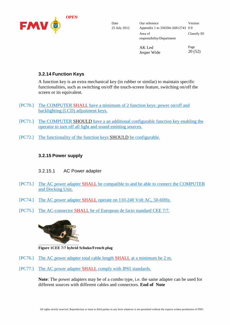
[PC75.] The AC-connector SHALL be of European de facto standard CEE 7/7.
Figure 1CEE 7/7 hybrid Schuko/French plug
[PC76.] The AC power adapter total cable length SHALL at a minimum be 2 m.
[PC77.] The AC power adapter SHALL comply with IP65 standards. Note: The power adapters may be of a combo type, i.e. the same adapter can be used for different sources with different cables and connectors. End of Note
OPEN Date
25 July 2012 Our reference Appendix 1 to 356594-AI812743
Version 0.9
Area of responsibility/Department AK Led Jesper Wide
Classify ID
Page 21 (52)
All rights strictly reserved. Reproduction or issue to third parties in any form whatever is not permitted without the express written permission of FMV.
3.2.15.2 DC Power cable/adapter
[PC78.] The DC power cable/adapter SHALL comply to MIL-STD-1275D.
[PC79.] The DC power cable/adapter SHALL operate on 10-30 Volt DC and have a male Cannon connector (CA3106E10SL-3P-B-F80) on the other end of the cable. (The vehicle has a female connector (CA3106E10SL-3S-B-F80)). See ANL-309657 document for pin out.
[PC80.] The DC power cable/adapter cable length SHALL be at minimum be 2 m, Note: The power adapters may be of a combo type, i.e. the same adapter can be used for different sources with different cables and connectors. End of Note
3.2.16 Battery
[PC81.] The COMPUTER battery SHALL be built in.
[PC82.] The built in battery SHALL be possible to replace.
[PC83.] The COMPUTER SHOULD, with batteries included in the required weight limitation, have an operating time of at least 8 hours at +-0°C, under following conditions: - COMPUTER and battery temperature at power-on: +-0°C. - Previously un-used standard built-in battery to be used. - Operating condition: Windows 7 Professional Desktop state available - Screen saver turned-off. - Windows 7 energy savings default settings - Display brightness 100%
[PC84.] The COMPUTER SHOULD, with a normal standard set of batteries, have a continuous operating time of at least 12 hours at +-0°C at a ratio of 1:2 between Operation and Power Save, i.e 4 hours of operation and 8 hours stand-by.
[PC85.] COMPUTER SHOULD be capable of indicating battery status and issuing alarm signals (audio and visual) when remaining battery energy levels are at 20%, 10% and 5%.
OPEN Date
25 July 2012 Our reference Appendix 1 to 356594-AI812743
Version 0.9
Area of responsibility/Department AK Led Jesper Wide
Classify ID
Page 22 (52)
All rights strictly reserved. Reproduction or issue to third parties in any form whatever is not permitted without the express written permission of FMV.
3.2.16.1 Battery LAPTOP-COMPUTER
[PC86.] The LAPTOP-COMPUTER SHALL have a built-in battery that provides the COMPUTER with the capacity to perform continuous work for a minimum of 2.5 hours at +-0°C.
3.2.16.1 Battery TABLET-COMPUTER
[PC87.] The TABLET-COMPUTER SHALL, with a normal standard set of batteries, have a continuous operating time of at least 2 hours at +-0°C.
3.2.17 Battery Charging [PC88.] The power consumption when charging batteries SHALL not exceed 100 Watts.
[PC89.] It SHALL be possible to recharge the battery and use the COMPUTER concurrently.
[PC90.] The re-charging time for uncharged COMPUTER batteries SHOULD not exceed 60
minutes.
3.2.18 Firmware [PC91.] Any change of firmware SHALL be communicated to FMV and approved by FMV prior
to change.
[PC92.] It SHOULD be possible to download firmware from the Internet.
3.2.18.1 COMPUTER BIOS/UEFI The BIOS/UEFI is the boot firmware, designed to be the first code run by a COMPUTER when powered on.
[PC93.] The COMPUTER SHALL support BIOS (Basic Input/Output System)
[PC94.] The BIOS/UEFI SHALL support a password feature to prevent unauthorized changing of settings.
[PC95.] The COMPUTER SHOULD support UEFI (Unified Extensible Firmware Interface)

OPEN Date
25 July 2012 Our reference Appendix 1 to 356594-AI812743
Version 0.9
Area of responsibility/Department AK Led Jesper Wide
Classify ID
Page 23 (52)
All rights strictly reserved. Reproduction or issue to third parties in any form whatever is not permitted without the express written permission of FMV.
[PC96.] The BIOS/UEFI SHALL allow for upgrading.
[PC97.] The BIOS/UEFI SHALL contain Built-In-Test, BIT, that execute during start-up and inform the user if any error is found.
[PC98.] The BIT features SHALL be documented.
3.2.18.2 COMPUTER Firmware Can include firmware in the graphic card, network card, etc.
[PC99.] The COMPUTER Firmware SHALL allow for upgrading.
3.2.18.3 SYSTEM Firmware Can include firmware in accessories.
[PC100.] The SYSTEM Firmware SHOULD be upgradable.
3.2.19 Operating System, Drivers and applications The Operating System (OS) is the software platform that enables the launch of a user application.
[PC101.] The operating system and drivers SHALL be available to order on CD or DVD.
[PC102.] Any changes to the recommended operating system upgrade level or the versions of software drivers SHALL be communicated to FMV and approved by FMV prior to change.
[PC103.] Any change of drivers or COMPUTER related applications SHALL be communicated to FMV and approved by FMV prior to change.
3.2.19.1 Operating system [PC104.] The COMPUTER SHALL be compatible with Microsoft Windows 7 Professional,
Enterprise and Ultimate (Swedish and English language versions) 32 and 64 bit.
[PC105.] The COMPUTER SHALL include fully installed and pre-configured in its standard configuration with Microsoft Windows 7 Professional 32 bit software (English or
OPEN Date
25 July 2012 Our reference Appendix 1 to 356594-AI812743
Version 0.9
Area of responsibility/Department AK Led Jesper Wide
Classify ID
Page 24 (52)
All rights strictly reserved. Reproduction or issue to third parties in any form whatever is not permitted without the express written permission of FMV.
Swedish language versions at FMV’s discretion).
[PC106.] It SHALL be possible to upgrade the COMPUTER to Windows 7 Enterprise/Ultimate 32/64.
[PC107.] The COMPUTER SHOULD support Microsoft Windows XP Professional 32-bit SP3. FMV will accept limitations to this due to restrictions or last-time-buy policy from Microsoft provided they are specified and brought to FMV’s attention.
3.2.19.2 Drivers [PC108.] All software drivers for any pre-installed built-in hardware and accessories SHALL be
included in delivery of the COMPUTER.
[PC109.] It SHALL be possible to download drivers from the Internet.
[PC110.] The COMPUTER and SYSTEM drivers SHALL be compatible with specified operating system, chapter 3.2.19.
3.2.19.3 Applications [PC111.] The COMPUTER SHALL be adequately prepared to enable the utilisation of installed
application’s fault tracing support, down to a rectification level.
[PC112.] The TENDERER SHALL provide a list of recommended SYSTEM applications and the versions required to fulfil the SYSTEM function. Note! This list will contain information about software for the SYSTEM, including any additional drivers needed and/or applications for accessories. End of Note
[PC113.] COMPUTER SHALL be compatible with any software applications compatible with specified operating system.
[PC114.] The COMPUTER SHALL be capable of logging all maintenance and operating data, including data from fault-tracing applications.
[PC115.] The COMPUTER SHALL be compatible with Microsoft Office 2007 and 2010.
[PC116.] The COMPUTER SHOULD be compatible with Microsoft Office 2003.
OPEN Date
25 July 2012 Our reference Appendix 1 to 356594-AI812743
Version 0.9
Area of responsibility/Department AK Led Jesper Wide
Classify ID
Page 25 (52)
All rights strictly reserved. Reproduction or issue to third parties in any form whatever is not permitted without the express written permission of FMV.
[PC117.] The COMPUTER SHALL allow for automatic update of applications to be switched off.
3.2.20 Radio Emitters Radio emitters may refer to WLAN, Bluetooth or other built-in radio transmitters.
[PC118.] It SHALL be possible to permanently disable any type of built-in radio emitters.
[PC119.] A normal Windows user without administrator rights SHALL not be allowed to switch on any radio emitters.
3.2.21 External Interfaces Standalone [PC120.] The COMPUTER SHALL also have an external connector for an external monitor.
[PC121.] The COMPUTER SHALL support a resolution of 1920x1200 or higher for the external
monitor. (1920x1200 is a common resolution for a 24" widescreen)
[PC122.] At a minimum, the COMPUTER SHALL have connectors pursuant to the following standards (C1-C7): C1: DC Power supply. C2: 2 x USB v2.0 connectors. C3: 1 x LAN TCP/IP supporting at least 100 Mbit. C4: 1 x Line out for headset speaker. C5: 1 x Line in for headset microphone. C6: 2 x Serial RS232, supporting at least 115200 bits/sec. C7: 1 x VGA or 1 x DVI or 1 x Displayport or 1 x HDMI.
[PC123.] The COMPUTER SHOULD have the following connectors (C8-C12): C8: Extra Serial RS232 ports C9: Extra USB v2.0 ports
OPEN Date
25 July 2012 Our reference Appendix 1 to 356594-AI812743
Version 0.9
Area of responsibility/Department AK Led Jesper Wide
Classify ID
Page 26 (52)
All rights strictly reserved. Reproduction or issue to third parties in any form whatever is not permitted without the express written permission of FMV.
C10: eSATA connector for external Data Storage Device C11: The type 2 PC-CARD with a total depth of 105mm instead of the standard depth of 85.6mm. Note that the IP- rating must be met even when the card is inserted C12: Extra USB v3.0 ports.
[PC124.] Any additional external interfaces other than those required under [PC122.] and [PC123.] included with the COMPUTER SHALL be brought to the attention of FMV.
[PC125.] It SHOULD be possible to use positioning system (e.g GPS) without external antenna.
[PC126.] It SHOULD be possible to use the positioning system using an externally connected an antenna.
[PC127.] The COMPUTER SHOULD have a minimum of one PC-card slot available
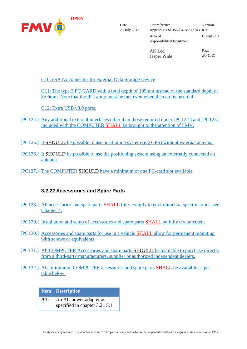
3.2.22 Accessories and Spare Parts
[PC128.] All accessories and spare parts SHALL fully comply to environmental specifications, see Chapter 4.
[PC129.] Installation and setup of accessories and spare parts SHALL be fully documented.
[PC130.] Accessories and spare parts for use in a vehicle SHALL allow for permanent mounting with screws or equivalents.
[PC131.] All COMPUTER Accessories and spare parts SHOULD be available to purchase directly from a third-party manufacturers, supplier or authorized independent dealers.
[PC132.] At a minimum, COMPUTER accessories and spare parts SHALL be available as per table below: Item Description
A1: An AC power adapter as specified in chapter 3.2.15.1
OPEN Date
25 July 2012 Our reference Appendix 1 to 356594-AI812743
Version 0.9
Area of responsibility/Department AK Led Jesper Wide
Classify ID
Page 27 (52)
All rights strictly reserved. Reproduction or issue to third parties in any form whatever is not permitted without the express written permission of FMV.
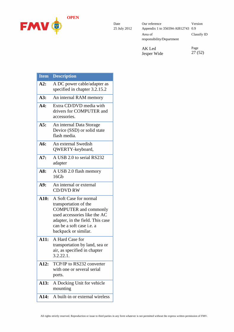
Item Description A2: A DC power cable/adapter as
specified in chapter 3.2.15.2
A3: An internal RAM memory
A4: Extra CD/DVD media with drivers for COMPUTER and accessories.
A5: An internal Data Storage Device (SSD) or solid state flash media.
A6: An external Swedish QWERTY-keyboard,
A7: A USB 2.0 to serial RS232 adapter
A8: A USB 2.0 flash memory 16Gb
A9: An internal or external CD/DVD RW
A10: A Soft Case for normal transportation of the COMPUTER and commonly used accessories like the AC adapter, in the field. This case can be a soft case i.e. a backpack or similar.
A11: A Hard Case for transportation by land, sea or air, as specified in chapter 3.2.22.1.
A12: TCP/IP to RS232 converter with one or several serial ports.
A13: A Docking Unit for vehicle mounting
A14: A built-in or external wireless
OPEN Date
25 July 2012 Our reference Appendix 1 to 356594-AI812743
Version 0.9
Area of responsibility/Department AK Led Jesper Wide
Classify ID
Page 28 (52)
All rights strictly reserved. Reproduction or issue to third parties in any form whatever is not permitted without the express written permission of FMV.
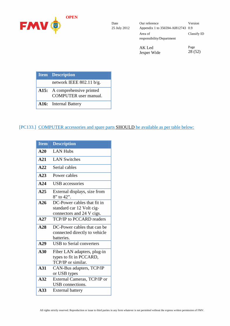
Item Description network IEEE 802.11 b/g.
A15: A comprehensive printed COMPUTER user manual.
A16: Internal Battery
[PC133.] COMPUTER accessories and spare parts SHOULD be available as per table below: Item Description A20 LAN Hubs
A21 LAN Switches
A22 Serial cables
A23 Power cables
A24 USB accessories
A25 External displays, size from 8” to 42”.
A26 DC-Power cables that fit in standard car 12 Volt cig-connectors and 24 V cigs.
A27 TCP/IP to PCCARD readers
A28 DC-Power cables that can be connected directly to vehicle batteries.
A29 USB to Serial converters
A30 Fiber LAN adapters, plug-in types to fit in PCCARD, TCP/IP or similar.
A31 CAN-Bus adapters, TCP/IP or USB types
A32 External Cameras, TCP/IP or USB connections.
A33 External battery
OPEN Date
25 July 2012 Our reference Appendix 1 to 356594-AI812743
Version 0.9
Area of responsibility/Department AK Led Jesper Wide
Classify ID
Page 29 (52)
All rights strictly reserved. Reproduction or issue to third parties in any form whatever is not permitted without the express written permission of FMV.
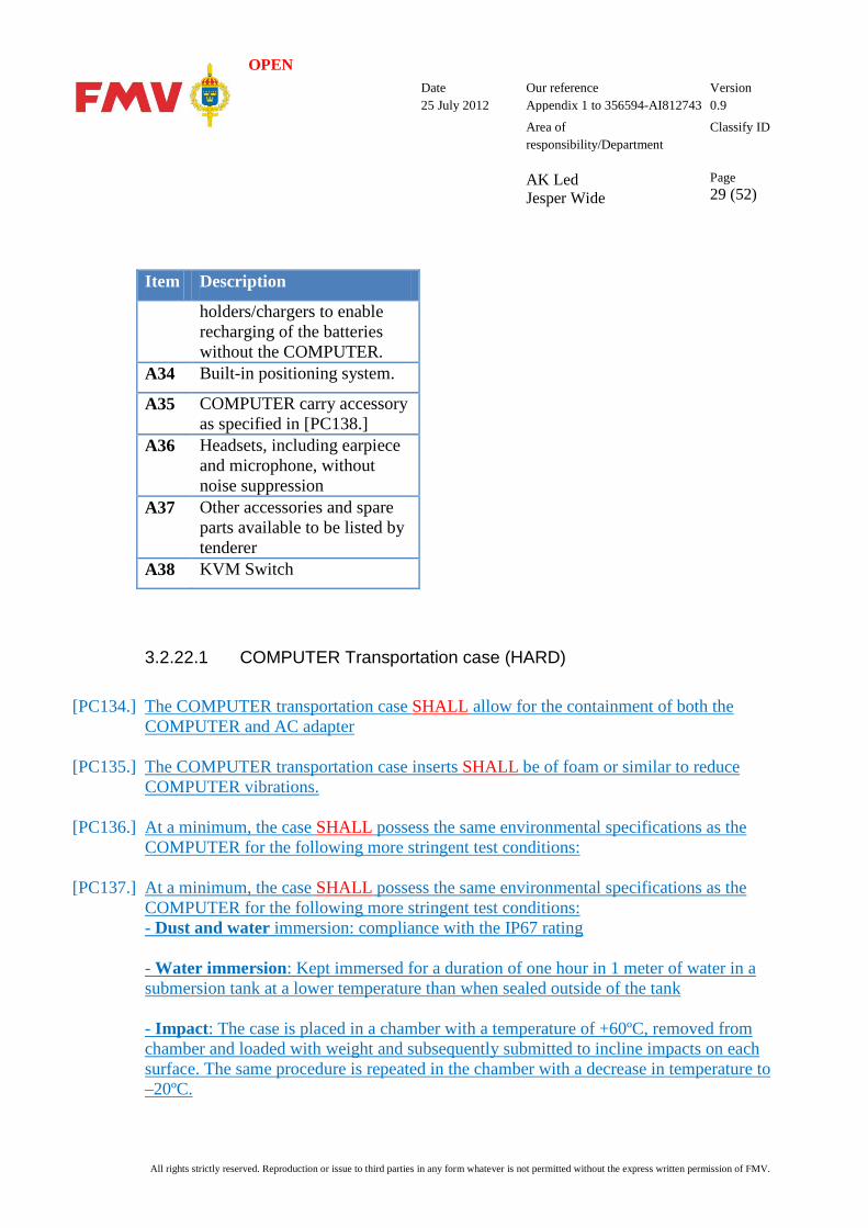
Item Description
holders/chargers to enable recharging of the batteries without the COMPUTER.
A34 Built-in positioning system.
A35 COMPUTER carry accessory as specified in [PC138.]
A36 Headsets, including earpiece and microphone, without noise suppression
A37 Other accessories and spare parts available to be listed by tenderer
A38 KVM Switch
3.2.22.1 COMPUTER Transportation case (HARD)
[PC134.] The COMPUTER transportation case SHALL allow for the containment of both the COMPUTER and AC adapter
[PC135.] The COMPUTER transportation case inserts SHALL be of foam or similar to reduce COMPUTER vibrations.
[PC136.] At a minimum, the case SHALL possess the same environmental specifications as the COMPUTER for the following more stringent test conditions:
[PC137.] At a minimum, the case SHALL possess the same environmental specifications as the COMPUTER for the following more stringent test conditions: - Dust and water immersion: compliance with the IP67 rating - Water immersion: Kept immersed for a duration of one hour in 1 meter of water in a submersion tank at a lower temperature than when sealed outside of the tank - Impact: The case is placed in a chamber with a temperature of +60ºC, removed from chamber and loaded with weight and subsequently submitted to incline impacts on each surface. The same procedure is repeated in the chamber with a decrease in temperature to –20ºC.
OPEN Date
25 July 2012 Our reference Appendix 1 to 356594-AI812743
Version 0.9
Area of responsibility/Department AK Led Jesper Wide
Classify ID
Page 30 (52)
All rights strictly reserved. Reproduction or issue to third parties in any form whatever is not permitted without the express written permission of FMV.
- Drop: The same procedure as Impact but the case is dropped with weights from various heights up to 0.76 meters and in different orientations. The drops ensure that the point of impact on the case is from all angles.
3.2.22.2 COMPUTER carry-accessory
[PC138.] The COMPUTER compatible carry-accessory SHALL ensure that the COMPUTER is portable by soldiers in action on foot (on skis or equivalent) in field environments, equipped with battle/protective gear and firearms (for example, AK5), without any significant impact on their mobility
3.2.23 Performance and reliability
[PC139.] COMPUTER SHOULD be operational (Windows 7 Desktop state) within 15 seconds from Power Save mode.
[PC140.] COMPUTER SHALL be operational (Windows 7 Desktop state) within 60 seconds from Power Save mode.
[PC141.] Once a communications connections has be established, the COMPUTER SHALL be able to maintain the connection for at least 4 hours by means of a normal set of batteries in Windows 7 Power Save mode.
[PC142.] Once a communications connections has be established, COMPUTER SHOULD be able to maintain the connection for at least 12 hours by means of a normal set of batteries in Windows 7 Power Save mode.
[PC143.] The COMPUTER SHALL be capable of maintaining full functionality for a minimum of 48 hours of continuous, non interrupted operations without requiring a reboot due to any hardware or hardware related drivers.
OPEN Date
25 July 2012 Our reference Appendix 1 to 356594-AI812743
Version 0.9
Area of responsibility/Department AK Led Jesper Wide
Classify ID
Page 31 (52)
All rights strictly reserved. Reproduction or issue to third parties in any form whatever is not permitted without the express written permission of FMV.
4 Environmental Requirements 4.1 General This section defines the environmental requirements that apply for the COMPUTER and/or SYSTEM. The baseline for the environmental requirements is set by the requirements governing terrain vehicles with rubber tires such as the Toyota Land Cruiser, Mercedes Geländewagen and equivalents. All vehicles are usually equipped with several sensitive communication radios.
The applicable standards for tests of the hardware have been named in conjunction with the environmental requirements. In case of deviations between limit values stated in this specification and the standard referred to, the requirements stated in this specification SHALL take precedence.
[PC144.] A test report SHALL delivered to verify all applicable requirements and test methods under Chapter 4.
[PC145.] The test reports SHALL be issued by an industry recognised third party independent test institute.
4.1.1 Specifications This chapter provides a brief overview for the reader of the recommended specifications. For a full specification, refer to the reference information. The following specifications are relevant to use:
• AECTP 200 (Edition 3) – ENVIRONMENTAL CONDITIONS is a NATO/PFP UNCLASSIFIED publication. The agreement of nations to use this publication is recorded in STANAG 4370.s AECTP 200 is one of five documents included in STANAG 4370. It provides characteristics and data on environmental conditions for operational events and scenarios that influence the design of defence materiel. Although it is not practicable to provide data to cover all circumstances, AECTP 200 is considered to include the most relevant environmental conditions. AECTP 200 is to be used in conjunction with the four other AECTPs included in STANAG 4370. These are: AECTP 100 Environmental Guidelines for Defence Materiel, AECTP 300 Climatic Environmental Tests, AECTP 400 Mechanical

OPEN Date
25 July 2012 Our reference Appendix 1 to 356594-AI812743
Version 0.9
Area of responsibility/Department AK Led Jesper Wide
Classify ID
Page 32 (52)
All rights strictly reserved. Reproduction or issue to third parties in any form whatever is not permitted without the express written permission of FMV.
Environmental Tests, and AECTP 500 Electrical Environmental Tests. An important application of AECTP 200 is for users to confirm that the key environmental conditions within project-specific environmental requirement documents have been addressed correctly. In particular, when used in conjunction with the other AECTPs, the environmental characteristics and data contained in AECTP 200 SHOULD facilitate the development of a comprehensive and cost-effective set of environmental tests and assessments. The data presented in AECTP 200 is intended for use during the specification process but is also to be considered when extended life is under focus. Refer to STANAG 4570 with AECTP 600 for guidance. When possible, the use of measured data is recommended to develop test severities. For many environmental conditions AECTP 200 provides advice on the derivation of test levels from measured data. AECTP 200 does not address abnormal environments arising from accidental or hostile conditions, or nuclear effects.
• MIL-STD-810G This standard is approved for use by all Departments and Agencies of the Department of Defense (DoD). Although prepared specifically for DoD applications, in addition, this standard may be tailored for commercial applications. While MIL-STD-810F incorporated a significant revision of MIL-STD-810E, MIL-STD-810G not only consolidates the basic -810F with its three change notices to result in one comprehensive document, but also includes a number of corrections, significant changes, and additions to the comprehensive -810F, to include five new test methods, one of which, (Method 526), was extracted from Method 516. The primary emphases remain the same – (with the exception of Method 528) tailoring a materiel item's environmental design and test limits to the conditions that the specific materiel will experience throughout its service life, and establishing laboratory test methods that replicate the effects of environments on materiel, rather than trying to reproduce the environments themselves. However, the "G" revision continues the up-front explanation of how to implement the environmental tailoring process throughout the materiel acquisition cycle.
• ANSI/IEC 60529 This standard describes a system for classifying the degrees of protection provided by enclosures of electrical equipment for two conditions: 1) the protection of persons against access to hazardous parts and the protection of equipment against the ingress of solid foreign objects 2) the ingress of water. The degree of protection against these two conditions is
OPEN Date
25 July 2012 Our reference Appendix 1 to 356594-AI812743
Version 0.9
Area of responsibility/Department AK Led Jesper Wide
Classify ID
Page 33 (52)
All rights strictly reserved. Reproduction or issue to third parties in any form whatever is not permitted without the express written permission of FMV.
designated by an IP Code.
• MIL-STD-461F This standard establishes interface and associated verification requirements for the control of the electromagnetic interference (EMI) emissions and susceptibility characteristics of electronic, electrical, and electromechanical equipment and subsystems designed or procured for use by activities and agencies of the Department of Defense (DoD). Such equipment and subsystems may be used independently or as an integral part of other subsystems or systems. This standard is best suited for items that have the following features: electronic enclosures that are no larger than an equipment rack, electrical interconnections that comprise discrete wiring harnesses between enclosures, and electrical power input derived from prime power sources. This standard SHOULD not be directly applied to items such as modules located inside electronic enclosures or entire platforms. The principles in this standard may be useful as a basis for developing suitable requirements for those applications. Data item requirements are also included.
OPEN Date
25 July 2012 Our reference Appendix 1 to 356594-AI812743
Version 0.9
Area of responsibility/Department AK Led Jesper Wide
Classify ID
Page 34 (52)
All rights strictly reserved. Reproduction or issue to third parties in any form whatever is not permitted without the express written permission of FMV.
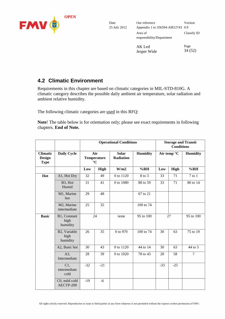
4.2 Climatic Environment Requirements in this chapter are based on climatic categories in MIL-STD-810G. A climatic category describes the possible daily ambient air temperature, solar radiation and ambient relative humidity.
The following climatic categories are used in this RFQ: Note! The table below is for orientation only; please see exact requirements in following chapters. End of Note.
Operational Conditions Storage and Transit Conditions
Climatic Design Type
Daily Cycle Air Temperature
°C
Solar Radiation
Humidity Air temp °C Humidity
Low High W/m2 %RH Low High %RH
Hot A1, Hot Dry 32 49 0 to 1120 8 to 3 33 71 7 to 1
B3, Hot Humid
31 41 0 to 1080 88 to 59 33 71 80 to 14
M1, Marine hot
29 48 67 to 21
M2, Marine intermediate
25 35 100 to 74
Basic
B1, Constant high
humidity
24 none 95 to 100 27 95 to 100
B2, Variable high
humidity
26 35 0 to 970 100 to 74 30 63 75 to 19
A2, Basic hot 30 43 0 to 1120 44 to 14 30 63 44 to 5
A3, Intermediate
28 39 0 to 1020 78 to 43 28 58 ?
C1, intermediate
cold
-32 -21 -33 -25
C0, mild cold AECTP-200
-19 -6
OPEN Date
25 July 2012 Our reference Appendix 1 to 356594-AI812743
Version 0.9
Area of responsibility/Department AK Led Jesper Wide
Classify ID
Page 35 (52)
All rights strictly reserved. Reproduction or issue to third parties in any form whatever is not permitted without the express written permission of FMV.
The following climatic categories are NOT addressed in this RFQ: (C1 partly), C2, C3, M3.
OPEN Date
25 July 2012 Our reference Appendix 1 to 356594-AI812743
Version 0.9
Area of responsibility/Department AK Led Jesper Wide
Classify ID
Page 36 (52)
All rights strictly reserved. Reproduction or issue to third parties in any form whatever is not permitted without the express written permission of FMV.
4.2.1 International Protection Rating (IP) This requirement classifies the degrees of protection provided against the intrusion of solid objects (including body parts like hands and fingers), dust, accidental contact, and water in the system. The requirement is based on IEC 60529.
[PC146.] The COMPUTER SHALL comply with IP54.
[PC147.] The COMPUTER SHOULD comply with IP65 or higher.
4.2.2 Temperature This requirement ensures that the SYSTEM can be used and stored at extreme temperatures as described below. These requirements are based on MIL-STD-810G:
- Method 501.5 High Temperature
- Method 502.5 Low Temperature
- Method 503.5 Temperature Shock
- Method 524 Freeze/Thaw
- Procedure I is Storage
- Procedure II is Operation
- Procedure III is Tactical Standby to Operational.
4.2.2.1 Temperature Definition The following definitions are used in the requirements below.
“Normal operating temperature range” –10°C to +40°C
“Extended operating temperature range” –20°C to +50°C
“Storage temperature range” –30°C to +70°C
[PC148.] The COMPUTER SHALL be operable in the “Normal operating temperature range” .
[PC149.] The COMPUTER SHOULD be operable in the “Extended operating temperature range”.
OPEN Date
25 July 2012 Our reference Appendix 1 to 356594-AI812743
Version 0.9
Area of responsibility/Department AK Led Jesper Wide
Classify ID
Page 37 (52)
All rights strictly reserved. Reproduction or issue to third parties in any form whatever is not permitted without the express written permission of FMV.
[PC150.] The COMPUTER SHALL be storable in the “Storage temperature range”.
4.2.2.2 Normal Operating Temperature, Procedure II This procedure investigates how high/low ambient temperatures may affect materiel performance while it is operating. There are two ways to perform Procedure II: (1) Expose the test item to cyclic chamber conditions with the test item operating either continuously or during the period of maximum response. (2) Expose the test item to a constant temperature and operate the test item when its temperature stabilizes.
[PC151.] The test method SHALL comply with MIL-STD-810G, method 501.5, 502.5 Procedure II.
[PC152.] It SHALL be possible to start up and use the SYSTEM with the specified performance in the “normal operating temperature range”.
[PC153.] The SYSTEM SHALL withstand temperature cycling 5 x 24h cycles from minimum temperature to maximum temperature in the “normal operating temperature range” and fulfil specified performance during and after the test.
[PC154.] The test method SHALL comply with MIL-STD-810G, method 501.5, 502.5 Procedure II.
[PC155.] It SHOULD require no extra time to heat up or cool down when starting the SYSTEM in the “normal operating temperature range”. Therefore, specify any extra start-up time required to achieve normal SYSTEM functionality and screen readability.
[PC156.] It SHOULD be possible to start up and use the SYSTEM in the “extended operating temperature range”. Therefore, specify any extra start-up time required to achieve normal SYSTEM functionality and screen readability.
4.2.2.3 Storage Temperature, Procedure I This procedure investigates how non-operational temperatures during storage affect the materiel (integrity of materials, and safety/performance of the materiel).
[PC157.] The test method SHALL comply with MIL-STD 810G, method 501.5, 502.5 Procedure I.
[PC158.] The SYSTEM SHALL withstand storage and maintain specified performance after storage in the “storage temperature range”.
OPEN Date
25 July 2012 Our reference Appendix 1 to 356594-AI812743
Version 0.9
Area of responsibility/Department AK Led Jesper Wide
Classify ID
Page 38 (52)
All rights strictly reserved. Reproduction or issue to third parties in any form whatever is not permitted without the express written permission of FMV.
[PC159.] The SYSTEM SHALL withstand temperature cycling 5 x 24h cycles from minimum temperature to maximum temperature in the “storage temperature range” and fulfil specified performance after the test.
4.2.2.4 Tactical Standby to Operational, Procedure III This procedure evaluates the SYSTEM’s performance at the operating temperatures after being exposed to non-operational temperature.
[PC160.] The test method SHALL comply with MIL-STD-810G, method 501.5, 502.5 Procedure III.
[PC161.] The SYSTEM SHALL be exposed to the maximum temperature in the “storage temperature range” for 2 hours following temperature stabilization. The temperature is then ramped (1°C/min) to the maximum temperature in the “normal temperature range” and an operational test is performed.
[PC162.] The SYSTEM SHALL be exposed to the minimum temperature in the “storage temperature range” for 2 hours following temperature stabilization. The temperature is then ramped (1°C/min) to the minimum temperature in the “normal temperature range” and an operational test is performed. Start-up time to be less than 20 minutes.
4.2.2.5 Freeze / Thaw, Procedure III The purpose of this test is to determine the ability of the SYSTEM to withstand: a. The effects of moisture phase changes between liquid and solid, in or on materiel, as the ambient temperature cycles through the freeze point; b. The effects of moisture induced by transfer from a cold-to-warm or warm-to-cold environment.
[PC163.] The test method SHALL comply with MIL-STD-810G, method 524 Procedure III.
[PC164.] The SYSTEM SHALL be stabilized at +25°C and a relative humidity of 97% for a minimum of 1 hour and then transferred rapidly to a freezing chamber at -10°C. The SYSTEM remains in the chamber for one hour following temperature stabilization and is then rapidly brought back to +25°C. The SYSTEM is not in operation during this cycle.
[PC165.] The SYSTEM SHALL power up and perform as normal at the end of the test in [PC164.]

OPEN Date
25 July 2012 Our reference Appendix 1 to 356594-AI812743
Version 0.9
Area of responsibility/Department AK Led Jesper Wide
Classify ID
Page 39 (52)
All rights strictly reserved. Reproduction or issue to third parties in any form whatever is not permitted without the express written permission of FMV.
4.2.2.6 Temperature Shock Use the temperature shock test to determine if materiel can withstand sudden change in the temperature of the surrounding atmosphere without sustaining physical damage or deterioration in performance. For the purpose of this document, “sudden change”" is defined as “an air temperature change greater than 10°C (18°F) within one minute.”
[PC166.] The test method SHALL comply with MIL-STD-810G, method 503.5, Procedure I.
[PC167.] The SYSTEM SHALL be stabilized at +25°C for a minimum duration of 1 hour and then withstand 3 shock cycles from +25°C to -30°C to +70°C and back to +25°C again.
[PC168.] The SYSTEM is not in operation during the cycle but SHALL be powered up and perform as normal between each cycle [PC167.]
4.2.3 Altitude, MIL-STD-810G, Method 500.5 Use low-pressure (altitude) tests to determine if materiel can withstand and/or operate in a low-pressure environment and/or withstand rapid pressure changes.
[PC169.] The test method SHALL comply with MIL-STD-810G, method 500.5, Procedure I.
[PC170.] The SYSTEM SHALL maintain performance in a chamber at an altitude of 4,572 meters (15,000 ft) for 1 hour, the SYSTEM is in operation.
[PC171.] The test method SHALL comply with MIL-STD-810G, method 500.5, Procedure II.
[PC172.] The SYSTEM SHALL maintain performance after transportation in a chamber at an altitude of 9,144 meters (30,000 ft) for 1 hour, the SYSTEM is not in operation during the test.
4.2.4 Salt – Fog MIL-STD-810 G, Method 509.5, Procedure I [PC173.] The test method SHALL comply with MIL-STD-810G, method 509.5, Procedure I.
[PC174.] The COMPUTER SHALL maintain performance after exposure to 5% saline exposure
for 2 cycles x 48hrs. 24hrs wet/24hrs dry. The unit is not in operation.
4.2.5 Humidity, MIL-STD-810G, Method 507.5 Use this method to evaluate materiel likely to be exposed to rain, water spray, or dripping water during storage, transit, or operation.
OPEN Date
25 July 2012 Our reference Appendix 1 to 356594-AI812743
Version 0.9
Area of responsibility/Department AK Led Jesper Wide
Classify ID
Page 40 (52)
All rights strictly reserved. Reproduction or issue to third parties in any form whatever is not permitted without the express written permission of FMV.
[PC175.] Test method SHALL comply with MIL-STD-810G, method 507.5, Procedure II.
[PC176.] The SYSTEM SHALL maintain the specified level of performance in an environment where humidity exceeds 95% with an upper temperature limit of +55°C for a period of one cycle/24h and for six cycles from +30°C to +55°C as the upper temperature limit.
[PC177.] The SYSTEM is not in operation during the test, but SHALL perform as normal following the test in [PC176.]
OPEN Date
25 July 2012 Our reference Appendix 1 to 356594-AI812743
Version 0.9
Area of responsibility/Department AK Led Jesper Wide
Classify ID
Page 41 (52)
All rights strictly reserved. Reproduction or issue to third parties in any form whatever is not permitted without the express written permission of FMV.
4.3 Electrical environment This requirement is based on MIL-STD-461F. MIL-STD-461F describes how to test the SYSTEM under different conditions.
4.3.1 General The electromagnetic requirements given below cover the essential requirements for the hardware. Measuring methods and levels are mainly in line with MIL-STD-461F.
[PC178.] Test procedures SHALL be submitted according to DI-EMCS-80201, as referred to in MIL-STD-461F.
[PC179.] Test reports SHALL be issued according to DI-EMCS-80200, as referred to in MIL-STD 461F.
4.3.2 Conducted Emission [PC180.] When measured with the specified test method, the SYSTEM SHALL not produce
conducted emissions on power leads and antenna terminals that exceed the limits given pursuant to MIL-STD-461F, CE102 10 kHz to 10 MHz, 28 V nominal voltage.
4.3.3 Radiated Emission [PC181.] The COMPUTER SHALL not produce radiated emissions that exceed the limits
stipulated in the following standard, using the specified test method: - MIL-STD-461F, RE102, figure RE 102-4, Navy Mobile & Army. Limits strengthened 10 dB in the frequency range from 2 to 512 MHz. Five fixed frequencies (between 2 to 512 MHz) with levels up to RE102 requirements are permitted.
[PC182.] The COMPUTER SHOULD not produce radiated emissions that exceed the limits stipulated in the following standard, using the specified test method: - MIL-STD-461F, RE102, figure RE 102-4, Navy Mobile & Army. Limits strengthened 20 dB in the frequency range from 2 to 512 MHz. Five fixed frequencies (between 2 to 512 MHz) with levels up to RE102 requirements are permitted.
OPEN Date
25 July 2012 Our reference Appendix 1 to 356594-AI812743
Version 0.9
Area of responsibility/Department AK Led Jesper Wide
Classify ID
Page 42 (52)
All rights strictly reserved. Reproduction or issue to third parties in any form whatever is not permitted without the express written permission of FMV.
4.3.4 Conducted Susceptibility 4.3.4.1 Power Leads
[PC183.] When measured with the specified test method, the SYSTEM SHALL maintain full performance during exposure to signal injection on the power leads in compliance with the following standard: - MIL-STD-461F, CS101 30 Hz to 150 kHz, figure CS 101-1 curve #2.
4.3.4.2 Bulk Cable Injection [PC184.] When measured with the specified test method, the SYSTEM SHALL maintain full
performance during exposure to signal injection on all interconnecting cables in compliance with the following standard: - MIL-STD-461F, CS114 10 kHz to 2 MHz, figure CS 114-1 curve 3. 2 MHz to 30 MHz, figure CS 114-1 curve 4. 30 MHz – 200 MHz, figure CS 114-1 curve 4.
4.3.4.3 Sinusoidal Transients, Cables and Power Leads [PC185.] When measured with the specified test method, the SYSTEM SHALL maintain full
performance during exposure to sinusoidal transients on the power and interconnecting cables in compliance with following the standard: - MIL-STD-461F, CS116 10 kHz to 100 MHz, figure CS 116-2, Imax = 10A.
4.3.4.4 Power- and Signal Line Transient/Burst Voltage Immunity [PC186.] When measured with the specified test method, the SYSTEM SHALL maintain full
performance during exposure to transient/burst voltages superimposed on transverse and longitudinal axes on the power and interconnecting cables in compliance with the following standard: - EN-61000-4-4, [12], test level 3.
4.3.4.5 Conducted Susceptibility, Surge [PC187.] When measured with the specified test method, the SYSTEM SHALL maintain full
performance during exposure to surge voltages in compliance with the following standard:
OPEN Date
25 July 2012 Our reference Appendix 1 to 356594-AI812743
Version 0.9
Area of responsibility/Department AK Led Jesper Wide
Classify ID
Page 43 (52)
All rights strictly reserved. Reproduction or issue to third parties in any form whatever is not permitted without the express written permission of FMV.
- EN-61000-4-5, [12], test level 3.
4.3.4.6 Radiated Susceptibility [PC188.] When measured with the specified test method, the SYSTEM SHALL maintain full
performance during exposure to electromagnetic fields in compliance with the following standard: - MIL-STD-461F, RS103 2 MHz to 18 GHz, Ground Army levels.
[PC189.] When measured with the specified test method, the SYSTEM SHALL maintain full performance during exposure to a transient electromagnetic field in compliance with the following standard: MIL-STD-461F, Figure RS105-1.
4.3.4.7 Vehicle Power Supply [PC190.] The SYSTEM SHALL comply with MIL-STD-1275D when the COMPUTER,
DOCKING UNIT and the DC-converter are connected to the power outlet in the car.
[PC191.] Full SYSTEM functionality SHALL be retained during the start/stop procedure for the vehicle engine. FMV will accept the SYSTEM utilising its own built-in battery for the short duration of the start/stop procedure for the vehicle engine.
4.3.4.8 Over Voltage Protection [PC192.] The SYSTEM SHALL maintain specified performance and show no physical
deterioration after being exposed to 80 VDC from a power source with internal impedance of less than 1 ohm for a duration of five (5) minutes.
4.3.4.9 Fluctuating Power Supply Voltage [PC193.] The SYSTEM SHALL maintain the specified level of performance and show no physical
deterioration after being exposed to a fluctuating power supply voltage in pursuant to the following test method: - Input voltage variation: 0 to 32 VDC. - Power source impedance: Less than 1 ohm.
OPEN Date
25 July 2012 Our reference Appendix 1 to 356594-AI812743
Version 0.9
Area of responsibility/Department AK Led Jesper Wide
Classify ID
Page 44 (52)
All rights strictly reserved. Reproduction or issue to third parties in any form whatever is not permitted without the express written permission of FMV.
4.3.4.10 Reversed Supply Voltage [PC194.] The SYSTEM SHALL maintain specified performance and show no physical
deterioration after being exposed to reversed supply voltage for a duration of five (5) minutes pursuant to the following test method: - Input voltage: 22 to 32 VDC. - Power source impedance: Less than 1 ohm.
4.3.4.11 ESD Immunity [PC195.] When measured with the specified test method, the SYSTEM SHALL not sustain
functional errors or performance impairment during and after exposure of the SYSTEM to ESD pursuant to the following standard: - EN-61000-4-2, [12]. - Contact discharge, level 2. - Air discharge, level 3. - The tests are to be applied on normally accessible points.
4.3.4.12 EC/EEA Declaration of Conformity [PC196.] The SYSTEM SHALL comply to directives:
- EMC 2004/108/EC - LVD 2006/95/EC
OPEN Date
25 July 2012 Our reference Appendix 1 to 356594-AI812743
Version 0.9
Area of responsibility/Department AK Led Jesper Wide
Classify ID
Page 45 (52)
All rights strictly reserved. Reproduction or issue to third parties in any form whatever is not permitted without the express written permission of FMV.
4.4 Mechanical 4.4.1 Shock, MIL-STD-810G, Method 516.6 Shock tests are performed to: a. provide a degree of confidence that materiel can physically and functionally withstand the relatively infrequent, non-repetitive shocks encountered in handling, transportation, and service environments. This may include an assessment of the overall materiel SYSTEM integrity for safety purposes in any one or all of the handling, transportation, and service environments; b. determine the materiel's fragility level, in order that packaging may be designed to protect the materiel's physical and functional integrity; and c. test the strength of devices that attach materiel to platforms that can crash. These requirements are based on: MIL-STD-810G Method 516.6 Procedure I is functional shock Procedure IV is transit drop.
4.4.1.1 Functional Shock, Procedure I Procedure I is intended to test materiel (including mechanical, electrical, hydraulic, and electronic) in its functional mode and to assess the physical integrity, continuity and functionality of the materiel to shock. In general, the materiel is required to function during the shock and to survive without damage to shocks representative of those that may be encountered during operational service.
[PC197.] The test method SHALL comply with MIL-STD-810G, Method 516.6, Procedure I.
[PC198.] The SYSTEM, in operational mode, configured with SSD, SHALL maintain the specified level of performance and sustain no physical deterioration during and after testing, shock 40G, 11ms, 3 shocks, +/- per axis, 3 axes.
[PC199.] The SYSTEM, in operational mode, configured with SSD, SHALL maintain the specified level of performance and sustain no physical deterioration during and after testing, being dropped 20 times from 0.5m to 50mm onto plywood over concrete. One drop to each face, edge and corner.
4.4.1.2 Transit Drop, Procedure IV Procedure IV is intended for materiel either outside of or within its transit or combination case, or as prepared for field use (carried to a combat situation by man, truck, rail, etc.).
OPEN Date
25 July 2012 Our reference Appendix 1 to 356594-AI812743
Version 0.9
Area of responsibility/Department AK Led Jesper Wide
Classify ID
Page 46 (52)
All rights strictly reserved. Reproduction or issue to third parties in any form whatever is not permitted without the express written permission of FMV.
This procedure is used to determine if the materiel is capable of withstanding the shocks normally induced by loading and unloading when it is (1) outside of its transit or combination case, e.g., during routine maintenance, when being removed from a rack, being placed in its transit case, etc., or (2) inside its transit or combination case. Such shocks are accidental, but may impair the function of the materiel.
[PC200.] The test method SHALL comply with MIL-STD-810G, Method 516.6, Procedure IV.
[PC201.] The SYSTEM SHALL be in non-operational mode within its transit case and maintain the specified level of performance and sustain no physical deterioration after being dropped 20 times from 1.8m to 50mm onto plywood over concrete. One drop to each face, edge and corner.
4.4.2 Vibration, MIL-STD-810G, Method 514.6 Vibration tests are performed to: a. Develop materiel to function in and withstand the vibration exposures of a life cycle including synergistic effects of other environmental factors, materiel duty cycle, and maintenance. This method is limited to consideration of one mechanical degree-of-freedom at a time. Refer to Method 527 for further guidance on multiple exciter testing. Combine the guidance of this method with the guidance of Part One and other methods herein to account for environmental synergism. b. Verify that materiel will function in and withstand the vibration exposures of a life cycle. These requirements are based on: MIL-STD-810G Method 514.6 Procedure I is general vibration Procedure II is loose cargo transportation Category 4 is secured cargo, transportation mode. Category 5 is loose cargo, transportation mode. Category 20 is ground vehicles, operational mode. Category 23 is personnel, operational mode.

OPEN Date
25 July 2012 Our reference Appendix 1 to 356594-AI812743
Version 0.9
Area of responsibility/Department AK Led Jesper Wide
Classify ID
Page 47 (52)
All rights strictly reserved. Reproduction or issue to third parties in any form whatever is not permitted without the express written permission of FMV.
OPEN Date
25 July 2012 Our reference Appendix 1 to 356594-AI812743
Version 0.9
Area of responsibility/Department AK Led Jesper Wide
Classify ID
Page 48 (52)
All rights strictly reserved. Reproduction or issue to third parties in any form whatever is not permitted without the express written permission of FMV.
4.4.2.1 General Vibration, Procedure I Use Procedure I for materiel to be transported as secured cargo or deployed for use on a vehicle. This procedure applies to ground vehicles as well as fixed and rotary wing aircraft. For this procedure, the test item is secured to a vibration exciter, and vibration is applied to the test item as an input at the fixture/test item interface. Steady state or transient vibration may be applied as appropriate.
[PC202.] The test method SHALL comply with MIL-STD-810G, Method 514.6, Procedure I, Category 20.
[PC203.] The SYSTEM SHALL be in operating mode, configured with SSD, and maintain the specified level of performance and sustain no physical deterioration during and after testing, 5-500Hz. 1.6 to 2.1G for 24h.
4.4.2.2 Vibration loose cargo, Procedure II Use procedure IV for materiel to be carried in/on trucks, trailers, or tracked vehicles and not secured to (tied down in) the carrying vehicle. The test severity is not tailorable, and represents loose cargo transport in military vehicles traversing rough terrain.
[PC204.] The test method SHALL comply with MIL-STD-810G, Method 514.6, Procedure II, Categories 4 and 5.
[PC205.] The SYSTEM SHALL be in non-operational mode, configured with SSD and maintain the specified level of performance and sustain no physical deterioration after being exposed to vibrations in the frequency range of 10-500Hz with an amplitude +/- 0.15mm or maximum 20G with a duration of 3 x 2h in three perpendicular directions.
4.5 Cleaning [PC206.] It SHALL be possible to clean and wipe the SYSTEM with alcohol (70% ethanol)
without the hardware sustaining any deterioration.
4.6 Colour [PC207.] The primary colour of the SYSTEM SHALL be dark with a matt finish. Examples of
acceptable colours are: black, grey, military green or similar.

OPEN Date
25 July 2012 Our reference Appendix 1 to 356594-AI812743
Version 0.9
Area of responsibility/Department AK Led Jesper Wide
Classify ID
Page 49 (52)
All rights strictly reserved. Reproduction or issue to third parties in any form whatever is not permitted without the express written permission of FMV.
5 COMPUTER Docking Unit The Docking Unit’s primary function is to provide all necessary interfaces. In addition, the Docking Unit comprises part of the safe mounting system in vehicles.
The COMPUTER itself will likely have an insufficient number of connectors, so a solution is required to provide additional external interfaces.
The vehicle/vessel SYSTEM comprises:
• The COMPUTER (Tablet-PC or Laptop)
• The Docking Unit to provide all external interface connectors
• Cables.
A Docking Unit may comprise two parts, for example, a Docking Station and a Port Replicator.
A Docking Unit solves two issues: 1. It provides a mechanically safe and easy way to mount a COMPUTER in a vehicle 2. It adds extra ports.
OPEN Date
25 July 2012 Our reference Appendix 1 to 356594-AI812743
Version 0.9
Area of responsibility/Department AK Led Jesper Wide
Classify ID
Page 50 (52)
All rights strictly reserved. Reproduction or issue to third parties in any form whatever is not permitted without the express written permission of FMV.
5.1 Operational Modes The “Docking Unit” is a COMPUTER peripheral for use in ground vehicles, vessels and office environments. The Docking Unit will, however, principally be deployed in ground vehicles.
5.2 Hardware Requirements
5.2.1 General
[PC208.] The Docking Unit SHALL be deployable in ground vehicles, maritime vessels and in office environments.
[PC209.] The COMPUTER SHALL be mountable on a Docking Unit as part of the vehicle mounting solution.
[PC210.] When the COMPUTER is used in a vehicle, vessel or office environment, it SHALL be possible to connect accessories to the COMPUTER, including but not limited to communication radios using RS232, TCP/IP devices, USB devices and PCCARD readers.
5.2.2 Size Size is defined with the COMPUTER attached to the Docking Unit, but with no cables connected.
5.2.2.1 Size TABLET-COMPUTER [PC211.] The maximum dimensions of the Docking Unit/Station with a TABLET-COMPUTER
mounted SHALL be: Width 300 mm Depth 300 mm Height 110 mm Note 1! The dimensions of any separate Port Replicator are not included in the above dimensions.
OPEN Date
25 July 2012 Our reference Appendix 1 to 356594-AI812743
Version 0.9
Area of responsibility/Department AK Led Jesper Wide
Classify ID
Page 51 (52)
All rights strictly reserved. Reproduction or issue to third parties in any form whatever is not permitted without the express written permission of FMV.
5.2.2.2 Size LAPTOP-COMPUTER [PC212.] The maximum dimensions of the Docking Unit/Station with a LAPTOP-COMPUTER
mounted SHALL be: Width: COMPUTER width + 50 mm Depth: COMPUTER depth + 100 mm Height: Not critical
5.2.2.3 Size Port Replicator [PC213.] If a separate Port Replicator is required to solve the function of the Docking Unit, the
maximum dimensions of the Port Replicator SHALL be: Width 150 mm Depth 150 mm Height 80 mm
5.2.3 Interfaces [PC214.] At a minimum, the Docking Unit SHALL have connectors for:
- C1: A DC Power supply. - C2: 2 x USB v2.0 connectors. - C3: 1 x LAN TCP/IP supporting a minimum speed of 100 Mbit. - C4: 1 x Serial RS232supporting a minimum speed of 115200 bits/sec
[PC215.] The Docking Unit SHOULD also have connectors for: - C6: 1 x Line out for headset speakers. - C7: 1 x Line in for headset microphones
[PC216.] The Tenderer SHALL list all external interfaces on the Docking Unit.
[PC217.] All cables attached to the Docking Unit SHOULD be located on the same side of the Docking Unit.
[PC218.] The maximum permitted width of the Docking Unit SHALL be complied with even when cables are connected to the Docking Unit.
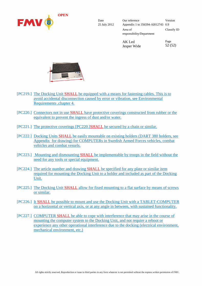
OPEN Date
25 July 2012 Our reference Appendix 1 to 356594-AI812743
Version 0.9
Area of responsibility/Department AK Led Jesper Wide
Classify ID
Page 52 (52)
All rights strictly reserved. Reproduction or issue to third parties in any form whatever is not permitted without the express written permission of FMV.
[PC219.] The Docking Unit SHALL be equipped with a means for fastening cables. This is to avoid accidental disconnection caused by error or vibration, see Environmental Requirements ,chapter 4.
[PC220.] Connectors not in use SHALL have protective coverings constructed from rubber or the equivalent to prevent the ingress of dust and/or water.
[PC221.] The protective coverings [PC220.]SHALL be secured by a chain or similar.
[PC222.] Docking Units SHALL be easily mountable on existing holders (DART 380 holders, see Appendix for drawing) for COMPUTERs in Swedish Armed Forces vehicles, combat vehicles and combat vessels.
[PC223.] Mounting and dismounting SHALL be implementable by troops in the field without the need for any tools or special equipment.
[PC224.] The article number and drawing SHALL be specified for any plate or similar item required for mounting the Docking Unit to a holder and included as part of the Docking Unit.
[PC225.] The Docking Unit SHALL allow for fixed mounting to a flat surface by means of screws or similar.
[PC226.] It SHALL be possible to mount and use the Docking Unit with a TABLET-COMPUTER on a horizontal or vertical axis, or at any angle in between, with sustained functionality.
[PC227.] COMPUTER SHALL be able to cope with interference that may arise in the course of mounting the computer system to the Docking Unit, and not require a reboot or experience any other operational interference due to the docking (electrical environment, mechanical environment, etc.)