
Cisco Nexus 9000 Series NX-OS Label Switching ...
290
Cisco Nexus 9000 Series NX-OS Label Switching Configuration Guide, Release 10.2(x) First Published: 2021-08-23 Last Modified: 2022-04-26 Americas Headquarters Cisco Systems, Inc. 170 West Tasman Drive San Jose, CA 95134-1706 USA http://www.cisco.com Tel: 408 526-4000 800 553-NETS (6387) Fax: 408 527-0883
-
Upload
khangminh22 -
Category
Documents
-
view
0 -
download
0
Transcript of Cisco Nexus 9000 Series NX-OS Label Switching ...
Cisco Nexus 9000 Series NX-OS Label Switching Configuration Guide,Release 10.2(x)First Published: 2021-08-23
Last Modified: 2022-04-26
Americas HeadquartersCisco Systems, Inc.170 West Tasman DriveSan Jose, CA 95134-1706USAhttp://www.cisco.comTel: 408 526-4000
800 553-NETS (6387)Fax: 408 527-0883

THE SPECIFICATIONS AND INFORMATION REGARDING THE PRODUCTS REFERENCED IN THIS DOCUMENTATION ARE SUBJECT TO CHANGE WITHOUT NOTICE.EXCEPT AS MAY OTHERWISE BE AGREED BY CISCO IN WRITING, ALL STATEMENTS, INFORMATION, AND RECOMMENDATIONS IN THIS DOCUMENTATION AREPRESENTED WITHOUT WARRANTY OF ANY KIND, EXPRESS OR IMPLIED.
The Cisco End User License Agreement and any supplemental license terms govern your use of any Cisco software, including this product documentation, and are located at:http://www.cisco.com/go/softwareterms.Cisco product warranty information is available at http://www.cisco.com/go/warranty. US Federal Communications Commission Notices are foundhere http://www.cisco.com/c/en/us/products/us-fcc-notice.html.
IN NO EVENT SHALL CISCO OR ITS SUPPLIERS BE LIABLE FOR ANY INDIRECT, SPECIAL, CONSEQUENTIAL, OR INCIDENTAL DAMAGES, INCLUDING, WITHOUTLIMITATION, LOST PROFITS OR LOSS OR DAMAGE TO DATA ARISING OUT OF THE USE OR INABILITY TO USE THIS MANUAL, EVEN IF CISCO OR ITS SUPPLIERSHAVE BEEN ADVISED OF THE POSSIBILITY OF SUCH DAMAGES.
Any products and features described herein as in development or available at a future date remain in varying stages of development and will be offered on a when-and if-available basis. Anysuch product or feature roadmaps are subject to change at the sole discretion of Cisco and Cisco will have no liability for delay in the delivery or failure to deliver any products or featureroadmap items that may be set forth in this document.
Any Internet Protocol (IP) addresses and phone numbers used in this document are not intended to be actual addresses and phone numbers. Any examples, command display output, networktopology diagrams, and other figures included in the document are shown for illustrative purposes only. Any use of actual IP addresses or phone numbers in illustrative content is unintentionaland coincidental.
The documentation set for this product strives to use bias-free language. For the purposes of this documentation set, bias-free is defined as language that does not imply discrimination basedon age, disability, gender, racial identity, ethnic identity, sexual orientation, socioeconomic status, and intersectionality. Exceptions may be present in the documentation due to languagethat is hardcoded in the user interfaces of the product software, language used based on RFP documentation, or language that is used by a referenced third-party product.
Cisco and the Cisco logo are trademarks or registered trademarks of Cisco and/or its affiliates in the U.S. and other countries. To view a list of Cisco trademarks, go to this URL: www.cisco.comgo trademarks. Third-party trademarks mentioned are the property of their respective owners. The use of the word partner does not imply a partnership relationship between Cisco and anyother company. (1721R)
© 2021–2022 Cisco Systems, Inc. All rights reserved.

C O N T E N T S
Trademarks ?
Preface xvP R E F A C E
Audience xv
Document Conventions xv
Related Documentation for Cisco Nexus 9000 Series Switches xvi
Documentation Feedback xvi
Communications, Services, and Additional Information xvi
New and Changed Information 1C H A P T E R 1
New and Changed Information 1
Configuring Static MPLS 5C H A P T E R 2
Licensing Requirements 5
About Static MPLS 5
Label Swap and Pop 6
Static MPLS Topology 6
Benefits of Static MPLS 7
High Availability for Static MPLS 7
Prerequisites for Static MPLS 8
Guidelines and Limitations for Static MPLS 8
Configuring Static MPLS 9
Enabling Static MPLS 9
Reserving Labels for Static Assignment 10
Configuring Static Label and Prefix Binding Using the Swap and Pop Operations 11
Configuring Segment Routing Adjacency Statistics 12
Cisco Nexus 9000 Series NX-OS Label Switching Configuration Guide, Release 10.2(x)iii

Verifying the Static MPLS Configuration 14
Displaying Static MPLS Statistics 16
Clearing Static MPLS Statistics 17
Configuration Examples for Static MPLS 18
Additional References 19
Related Documents 19
Configuring MPLS Label Imposition 21C H A P T E R 3
About MPLS Label Imposition 21
Guidelines and Limitations for MPLS Label Imposition 22
Configuring MPLS Label Imposition 22
Enabling MPLS Label Imposition 22
Reserving Labels for MPLS Label Imposition 23
Configuring MPLS Label Imposition 24
Verifying the MPLS Label Imposition Configuration 25
Displaying MPLS Label Imposition Statistics 28
Clearing MPLS Label Imposition Statistics 29
Configuration Examples for MPLS Label Imposition 29
Configuring MPLS Layer 3 VPNs 31C H A P T E R 4
Information About MPLS Layer 3 VPNs 31
MPLS Layer 3 VPN Definition 31
How an MPLS Layer 3 VPN Works 32
Components of MPLS Layer 3 VPNs 32
Hub-and-Spoke Topology 33
OSPF Sham-Link Support for MPLS VPN 34
Prerequisites for MPLS Layer 3 VPNs 35
Guidelines and Limitations for MPLS Layer 3 VPNs 35
Default Settings for MPLS Layer 3 VPNs 36
Configuring MPLS Layer 3 VPNs 37
About OSPF Domain IDs and Tags 37
Configuring OSPF at the PE and CE Boundary 37
Configuring the OSPF Domain Tag 37
Configuring the OSPF Domain ID 38
Cisco Nexus 9000 Series NX-OS Label Switching Configuration Guide, Release 10.2(x)iv
Contents

Configuring the Secondary Domain ID 39
Configuring the Core Network 40
Assessing the Needs of MPLS Layer 3 VPN Customers 40
Configuring MPLS in the Core 40
Configuring Multiprotocol BGP on the PE Routers and Route Reflectors 41
Connecting the MPLS VPN Customers 42
Defining VRFs on the PE Routers to Enable Customer Connectivity 42
Configuring VRF Interfaces on PE Routers for Each VPN Customer 45
Configuring Routing Protocols Between the PE and CE Routers 45
Configuring a Hub-and-Spoke Topology 54
Configuring MPLS using Hardware Profile Command 66
Configuring MPLS Layer 3 VPN Label Allocation 69C H A P T E R 5
About MPLS Layer 3 VPN Label Allocation 69
IPv6 Label Allocation 70
Per-VRF Label Allocation Mode 70
About Labeled and Unlabeled Unicast Paths 71
Prerequisites for MPLS Layer 3 VPN Label Allocation 71
Guidelines and Limitations for MPLS Layer 3 VPN Label Allocation 71
Default Settings for MPLS Layer 3 VPN Label Allocation 72
Configuring MPLS Layer 3 VPN Label Allocation 72
Configuring Per-VRF Layer 3 VPN Label Allocation Mode 72
Allocating Labels for IPv6 Prefixes in the Default VRF 73
Enabling Sending MPLS Labels in IPv6 over an IPv4 MPLS Core Network (6PE) for iBGPNeighbors 75
Advertisement and Withdraw Rules 76
Enabling Local Label Allocation 80
Verifying MPLS Layer 3 VPN Label Allocation Configuration 81
Configuration Examples for MPLS Layer 3 VPN Label Allocation 82
Configuring MPLS Layer 3 VPN Load Balancing 83C H A P T E R 6
Information About MPLS Layer 3 VPN Load Balancing 83
iBGP Load Balancing 83
eBGP Load Balancing 83
Cisco Nexus 9000 Series NX-OS Label Switching Configuration Guide, Release 10.2(x)v
Contents

Layer 3 VPN Load Balancing 84
Layer 3 VPN Load Balancing with Route Reflectors 85
Layer 2 Load Balancing Coexistence 85
BGP VPNv4 Multipath 86
BGP Cost Community 87
How the BGP Cost Community Influences the Best Path Selection Process 87
Cost Community and EIGRP PE-CE with Back-Door Links 88
Prerequisites for MPLS Layer 3 VPN Load Balancing 88
Guidelines and Limitations for MPLS Layer 3 VPN Load Balancing 88
Default Settings for MPLS Layer 3 VPN Load Balancing 89
Configuring MPLS Layer 3 VPN Load Balancing 89
Configuring BGP Load Balancing for eBGP and iBGP 89
Configuring BGPv4 Multipath 91
Configuring MPLS ECMP Load Sharing 92
Verifying MPLS ECMP Load Sharing 92
Configuration Examples for MPLS Layer 3 VPN Load Balancing 93
Example: MPLS Layer 3 VPN Load Balancing 93
Example: BGP VPNv4 Multipath 93
Example: MPLS Layer 3 VPN Cost Community 93
Configuring MPLS QoS 95C H A P T E R 7
About MPLS Quality of Service (QoS) 95
MPLS QoS Terminology 95
MPLS QoS Features 96
MPLS Experimental Field 96
Classification 96
Policing and Marking 96
Guidelines and Limitations for MPLS QoS 97
Configuring MPLS QoS 97
Configuring MPLS Ingress Label Switched Router 98
MPLS Ingress LSR Classification 98
Configuring MPLS Ingress Policing and Marking 98
Configuring MPLS Transit Label Switching Router 100
MPLS Transit LSR Classification 100
Cisco Nexus 9000 Series NX-OS Label Switching Configuration Guide, Release 10.2(x)vi
Contents

Configuring MPLS Transit Policing and Marking 100
Configuring MPLS Egress Label Switching Router 101
MPLS Egress LSR Classification 101
MPLS Egress LSR Classification - Default Policy Template 102
Custom MPLS-in-Policy Mapping 103
Configuring MPLS Egress LSR - Policing and Marking 104
About Traffic Queuing 105
Configuring QoS Traffic Queuing 105
Verifying MPLS QoS 106
Configuring Segment Routing 109C H A P T E R 8
About Segment Routing 109
Segment Routing Application Module 110
NetFlow for MPLS 110
sFlow Collector 110
Guidelines and Limitations for Segment Routing 111
Configuring Segment Routing 114
Configuring Segment Routing 114
Enabling MPLS on an Interface 116
Configuring the Segment Routing Global Block 117
Configuring the Label Index 118
Configuration Examples for Segment Routing 120
Configuring Segment Routing with IS-IS Protocol 125
About IS-IS 125
Configuring Segment Routing with IS-IS Protocol 125
Configuring Segment Routing with OSPFv2 Protocol 126
About OSPF 126
Adjacency SID Advertisement 126
Connected Prefix-SID 127
Prefix Propagation Between Areas 127
Segment Routing Global Range Changes 127
Conflict Handling of SID Entries 127
MPLS Forwarding on an Interface 128
Configuring Segment Routing with OSPFv2 128
Cisco Nexus 9000 Series NX-OS Label Switching Configuration Guide, Release 10.2(x)vii
Contents

Configuring Segment Routing on OSPF Network- Area Level 128
Configuring Prefix-SID for OSPF 129
Configuring Prefix Attribute N-flag-clear 131
Configuration Examples for Prefix SID for OSPF 131
Configuring Segment Routing for Traffic Engineering 131
About Segment Routing for Traffic Engineering 131
SR-TE Policies 132
SR-TE Policy Paths 132
Affinity and Disjoint Constraints 133
Segment Routing On Demand Next Hop 133
Guidelines and Limitations for SR-TE 134
Configuring SR-TE 135
Configuring Affinity Constraints 136
Configuring Disjoint Paths 138
Configuration Examples for SR-TE 140
Configuration Example for an SR-TE ODN - Use Case 141
Configuring SR-TE Manual Preference Selection 144
Guidelines and Limitations for SR-TE Manual Preference Selection 144
About SR-TE Manual Preference – Lockdown and Shutdown 144
Configuring SR-TE Manual Preference – Lockdown/Shutdown 145
Force a Specific Path Preference for an SRTE Policy 146
Force path re-optimization for an SRTE Policy or All SRTE Policies 147
Configuring SRTE Flow-based Traffic Steering 148
About SRTE Flow-based Traffic Steering 148
Guidelines and Limitations for Flow-based Traffic Steering for SRTE 149
Configuration Process: SRTE Flow-based Traffic Steering 150
Configuring Flow Selection Based on ToS/DSCP and Timer-based ACL 151
Configuring Route Map in Default and Non-default VRF for Flow-based Traffic Steering 152
Configuration Example for SRTE Flow-based Traffic Steering 161
Configuration Example for Flow Selection Based on ToS/DSCP and Timer-based ACL 161
Configuration Example for Route Map in Default VRF into a Policy Selected by Color andEndpoint 161
Configuration Example for Route Map in Default VRF into a Policy Selected by Name 162
Cisco Nexus 9000 Series NX-OS Label Switching Configuration Guide, Release 10.2(x)viii
Contents

Configuration Example for Route Map in Non-default VRF into a Policy Selected by Next hop,Color, and Endpoint 162
Configuration Example for Route Map in Non-default VRF into a Policy Selected by Next hopand Color 162
Configuration Example for Route Map in Non-default VRF into a Policy Selected by Next hopand Name 162
Configuration Example for Route Map in Non-default VRF into a Policy Selected by Color andEndpoint 162
Configuration Example for Route Map in Non-default VRF into a Policy Selected by Name 163
Verifying Configuration for Flow-based Traffic Steering for SRTE 163
Configuring MPLS OAMMonitoring for SRTE Policies 164
About MPLS OAMMonitoring for SRTE Policies 164
Paths Monitored 164
Index Limit 164
Guidelines and Limitations for MPLS OAMMonitoring for SRTE Policies 165
Configuring MPLS OAMMonitoring 165
Global Configuration 165
Policy-specific Configuration 168
Verifying Configuration for MPLS OAMMonitoring 171
Configuration Example for MPLS OAMMonitoring 172
Configuring Egress Peer Engineering with Segment Routing 174
BGP Prefix SID 174
Adjacency SID 174
High Availability for Segment Routing 174
Overview of BGP Egress Peer Engineering With Segment Routing 174
Guidelines and Limitations for BGP Egress Peer Engineering 176
Configuring Neighbor Egress Peer Engineering Using BGP 176
Configuration Example for Egress Peer Engineering 177
Configuring the BGP Link State Address Family 179
BGP Prefix SID Deployment Example 180
Configuring Layer2 EVPN over Segment Routing MPLS 181
About Layer 2 EVPN 181
Guidelines and Limitations for Layer 2 EVPN over Segment Routing MPLS 182
Configuring Layer 2 EVPN over Segment Routing MPLS 182
Configuring VLAN for EVI 186
Cisco Nexus 9000 Series NX-OS Label Switching Configuration Guide, Release 10.2(x)ix
Contents

Configuring the NVE Interface 186
Configuring EVI Under VRF 187
Configuring Anycast Gateway 187
Advertising Labelled Path for the Loopback Interface 187
About SRv6 Static Per-Prefix TE 188
Configuring a SRv6 Static Per-Prefix TE 188
About RD Auto 191
About Route-Target Auto 191
Configuring RD and Route Targets for BD 192
Configuring RD and Route Targets for VRF 193
Configuration Examples for Layer 2 EVPN over Segment Routing MPLS 193
Configuring Proportional Multipath for VNF for Segment Routing 194
About Proportional Multipath for VNF for Segment Routing 194
Enabling Proportional Multipath for VNF for Segment Routing 194
vPC Multihoming 196
About Multihoming 196
Per-BD label on vPC Peers 196
Per-VRF label on vPC Peers 197
Configuring Backup Link 197
Guidelines and Limitations for vPC Multihoming 197
Configuration Examples for vPC Multihoming 197
Configuring Layer 3 EVPN and Layer 3 VPN over Segment Routing MPLS 198
Configuring VRF and Route Targets for Import and Export Rules 198
Configuring BGP EVPN and Label Allocation Mode 199
Configuring BGP Layer 3 EVPN and Layer 3 VPN Stitching 202
Configuring the Features to Enable Layer3 EVPN and Layer3 VPN 204
Configuring BGP L3 VPN over Segment Routing 205
BGP Layer3 VPN Over SRTE 206
Guidelines and Limitations for Configuring Layer 3 VPN Over SRTE 206
Configuring Extended Community Color 207
Configuring Extended Community Color at the Ingress Node 207
Configuring Extended Community Color at the Egress Node 208
Configuring Extended Community Color for Network/Redistribute Command at the EgressNode 209
Cisco Nexus 9000 Series NX-OS Label Switching Configuration Guide, Release 10.2(x)x
Contents

Configuring Segment Routing MPLS and GRE Tunnels 210
GRE Tunnels 210
Segment Routing MPLS and GRE 211
Guidelines and Limitations for Segment Routing MPLS and GRE 211
Configuring Segment Routing MPLS and GRE 212
Verifying the Segment Routing MPLS and GRE Configuration 213
Verifying SR-TE for Layer 3 EVPN 213
Verifying the Segment Routing Configuration 214
Configuring SRTE Explicit-Path Endpoint Substitution 216
About SRTE Explicit-path Endpoint Substitution 216
Guidelines and Limitations for SRTE Explicit-path Endpoint Substitution 216
Configuring SRTE Explicit-path Endpoint Substitution 217
Configuration Example for SRTE Explicit-path Endpoint Substitution 218
Verifying Configuration for SRTE Explicit-path Endpoint Substitution 218
Configuring SRTE Over Default VRF 220
About SRTE Over Default VRF 220
Guidelines and Limitations for Configuring SRTE Over Default VRF 221
Configuration Process: SRTE Over Default VRF 222
Configuring Next-hop Unchanged 222
Configuring Extended Community Color 223
Configuring BGP for Ingress Peer (SRTE Headend) 230
Configuring BGP for Egress Peer (SRTE Endpoint) 231
Configuring SRTE for Ingress Peer (SRTE Headend) 233
Configuration Example for SRTE Over Default VRF 235
Configuration Example: Next-hop Unchanged 235
Configuration Examples: Extended Community Color 235
Configuration Example: BGP for Ingress Peer (SRTE Headend) 236
Configuration Example: BGP for Egress Peer (SRTE Endpoint) 236
Configuration Example: Ingress Peer for SRTE (SRTE Headend) 236
Verifying Configuration for SRTE Over Default VRF 236
Additional References 237
Related Documents 237
Configuring MVPNs 239C H A P T E R 9
Cisco Nexus 9000 Series NX-OS Label Switching Configuration Guide, Release 10.2(x)xi
Contents

About MVPNs 239
MVPN Routing and Forwarding and Multicast Domains 239
Multicast Distribution Trees 240
Multicast Tunnel Interface 241
Benefits of MVPNs 242
BGP Advertisement Method - MVPN Support 242
BGP MDT SAFI 242
Prerequisites for MVPNs 242
Guidelines and Limitations for MVPNs 243
Default Settings for MVPNs 244
Configuring MVPNs 244
Enabling MVPNs 244
Enabling PIM on Interfaces 245
Configuring a Default MDT for a VRF 246
Configuring MDT SAFI for a VRF 246
Configuring the MDT Address Family in BGP for MVPNs 247
Configuring a Data MDT 250
Verifying the MVPN Configuration 251
Configuration Examples for MVPN 251
Configuring MPLS Segment Routing OAM 253C H A P T E R 1 0
About MPLS Segment Routing OAM 253
Segment Routing Ping 254
Segment Routing Traceroute 254
Guidelines and Limitations for MPLS SR OAM 254
MPLS Ping and Traceroute for Nil FEC 255
MPLS Ping and Traceroute for BGP and IGP Prefix SID 256
Verifying Segment Routing OAM 256
Verifying Segment Routing OAM IS-IS 256
Examples for using Ping and Traceroute CLI commands 258
Examples for IGP or BGP SR Ping and Traceroute 258
Examples for Nil FEC Ping and Traceroute 259
Displaying Show Statistics 259
Cisco Nexus 9000 Series NX-OS Label Switching Configuration Guide, Release 10.2(x)xii
Contents

InterAS Option B 261C H A P T E R 1 1
Information About InterAS 261
InterAS and ASBR 261
Exchanging VPN Routing Information 262
InterAS Options 262
Guidelines and Limitations for Configuring InterAS Option B 263
Configuring BGP for InterAS Option B 263
Configuring BGP for InterAS Option B (with RFC 3107 implementation) 265
IETF RFCs Supported for Label Switching 269C H A P T E R 1 2
IETF RFCs Supported for Label Switching 269
Cisco Nexus 9000 Series NX-OS Label Switching Configuration Guide, Release 10.2(x)xiii
Contents

Cisco Nexus 9000 Series NX-OS Label Switching Configuration Guide, Release 10.2(x)xiv
Contents

Preface
This preface includes the following sections:
• Audience, on page xv• Document Conventions, on page xv• Related Documentation for Cisco Nexus 9000 Series Switches, on page xvi• Documentation Feedback, on page xvi• Communications, Services, and Additional Information, on page xvi
AudienceThis publication is for network administrators who install, configure, and maintain Cisco Nexus switches.
Document ConventionsCommand descriptions use the following conventions:
DescriptionConventionBold text indicates the commands and keywords that you enter literallyas shown.
bold
Italic text indicates arguments for which you supply the values.Italic
Square brackets enclose an optional element (keyword or argument).[x]
Square brackets enclosing keywords or arguments that are separated bya vertical bar indicate an optional choice.
[x | y]
Braces enclosing keywords or arguments that are separated by a verticalbar indicate a required choice.
{x | y}
Nested set of square brackets or braces indicate optional or requiredchoices within optional or required elements. Braces and a vertical barwithin square brackets indicate a required choice within an optionalelement.
[x {y | z}]
Cisco Nexus 9000 Series NX-OS Label Switching Configuration Guide, Release 10.2(x)xv

DescriptionConvention
Indicates a variable for which you supply values, in context where italicscannot be used.
variable
A nonquoted set of characters. Do not use quotation marks around thestring or the string includes the quotation marks.
string
Examples use the following conventions:
DescriptionConventionTerminal sessions and information the switch displays are in screen font.screen font
Information that you must enter is in boldface screen font.boldface screen font
Arguments for which you supply values are in italic screen font.italic screen font
Nonprinting characters, such as passwords, are in angle brackets.< >
Default responses to system prompts are in square brackets.[ ]
An exclamation point (!) or a pound sign (#) at the beginning of a lineof code indicates a comment line.
!, #
Related Documentation for Cisco Nexus 9000 Series SwitchesThe entire Cisco Nexus 9000 Series switch documentation set is available at the following URL:
http://www.cisco.com/en/US/products/ps13386/tsd_products_support_series_home.html
Documentation FeedbackTo provide technical feedback on this document, or to report an error or omission, please send your commentsto [email protected]. We appreciate your feedback.
Communications, Services, and Additional Information• To receive timely, relevant information from Cisco, sign up at Cisco Profile Manager.
• To get the business impact you’re looking for with the technologies that matter, visit Cisco Services.
• To submit a service request, visit Cisco Support.
• To discover and browse secure, validated enterprise-class apps, products, solutions and services, visitCisco Marketplace.
• To obtain general networking, training, and certification titles, visit Cisco Press.
• To find warranty information for a specific product or product family, access Cisco Warranty Finder.
Cisco Nexus 9000 Series NX-OS Label Switching Configuration Guide, Release 10.2(x)xvi
PrefaceRelated Documentation for Cisco Nexus 9000 Series Switches

Cisco Bug Search Tool
Cisco Bug Search Tool (BST) is a web-based tool that acts as a gateway to the Cisco bug tracking systemthat maintains a comprehensive list of defects and vulnerabilities in Cisco products and software. BST providesyou with detailed defect information about your products and software.
Cisco Nexus 9000 Series NX-OS Label Switching Configuration Guide, Release 10.2(x)xvii
PrefacePreface

Cisco Nexus 9000 Series NX-OS Label Switching Configuration Guide, Release 10.2(x)xviii
PrefacePreface

C H A P T E R 1New and Changed Information
This chapter provides release-specific information for each new and changed feature in the Cisco Nexus 9000Series NX-OS Label Switching Configuration Guide, Release 10.2(x).
• New and Changed Information, on page 1
New and Changed InformationTable 1: New and Changed Features
Where DocumentedChanged in ReleaseDescriptionFeature
Guidelines andLimitations forConfiguring SRTE OverDefault VRF, on page 221
Configuring ExtendedCommunity Color at theIngress Node, on page 225
Configuring ExtendedCommunity Color at theEgress Node, on page 223
Configuring ExtendedCommunity Color forNetwork/RedistributeCommand at the EgressNode, on page 227
Configuring ExtendedCommunity Color forDefault-Originate at theEgress Node, on page 228
10.2(3)FAdded new command forcolor-only (CO) bits inroute map.
SRTE BGP Color-Only
Cisco Nexus 9000 Series NX-OS Label Switching Configuration Guide, Release 10.2(x)1

Where DocumentedChanged in ReleaseDescriptionFeature
Guidelines andLimitations forFlow-based TrafficSteering for SRTE, onpage 149
10.2(2)FAdded support for CiscoN9K-C9332D-GX2Bplatform switches.
SRTE Flow-based TrafficSteering
Under the ConfiguringSegment Routing forTraffic Engineeringchapter:
SR-TE Policy Paths, onpage 132
Configuring SR-TEManual PreferenceSelection, on page 144
10.2(2)FAllows you to lockdownor shutdown an SR-TEpolicy or perform both;shutdown preference(s) ofan SR-TE policy or anon-demand colortemplate. Furthermore,allows you to force aspecific preference to beactive path option forSRTE policy and to forcepath re-optimization forall or a specific SRTEpolicy.
SRTE Manual PreferenceSelection
Under the ConfiguringSegment Routing forTraffic Engineeringchapter:
Guidelines andLimitations for SR-TE, onpage 134
Verifying Configurationfor Flow-based TrafficSteering for SRTE
Global Configuration, onpage 165
Policy-specificConfiguration, on page 168
Verifying Configurationfor MPLS OAMMonitoring, on page 171
Verifying the SegmentRouting Configuration, onpage 214
Verifying Configurationfor SRTE Explicit-pathEndpoint Substitution, onpage 218
10.2(2)FAdded new showcommands for SR-TEpolicy and introducedautocomplete for a fewexisting SR-TE policycommands to improveusability.
SRTE UsabilityEnhancements
Cisco Nexus 9000 Series NX-OS Label Switching Configuration Guide, Release 10.2(x)2
New and Changed InformationNew and Changed Information

Where DocumentedChanged in ReleaseDescriptionFeature
Guidelines andLimitations for SegmentRouting, on page 111
10.2(1q)FAdded support forSR-MPLS onN9K-C9332D-GX2Bplatform switches.
SR-MPLS
10.2(1)FNo Feature updates
Cisco Nexus 9000 Series NX-OS Label Switching Configuration Guide, Release 10.2(x)3
New and Changed InformationNew and Changed Information

Cisco Nexus 9000 Series NX-OS Label Switching Configuration Guide, Release 10.2(x)4
New and Changed InformationNew and Changed Information

C H A P T E R 2Configuring Static MPLS
This chapter contains information on how to configure static multiprotocol label switching (MPLS).
• Licensing Requirements, on page 5• About Static MPLS, on page 5• Prerequisites for Static MPLS, on page 8• Guidelines and Limitations for Static MPLS, on page 8• Configuring Static MPLS, on page 9• Verifying the Static MPLS Configuration, on page 14• Displaying Static MPLS Statistics, on page 16• Clearing Static MPLS Statistics, on page 17• Configuration Examples for Static MPLS, on page 18• Additional References, on page 19
Licensing RequirementsFor a complete explanation of Cisco NX-OS licensing recommendations and how to obtain and apply licenses,see the Cisco NX-OS Licensing Guide.
About Static MPLSGenerally, label switching routers (LSRs) use a label distribution protocol to dynamically learn the labels thatthey should use to label-switch packets. Examples of such protocols include:
• Label Distribution Protocol (LDP), the Internet Engineering Task Force (IETF) standard that is used tobind labels to network addresses
• Resource Reservation Protocol (RSVP), which is used to distribute labels for traffic engineering (TE)
• Border Gateway Protocol (BGP), which is used to distribute labels for MPLS virtual private networks(VPNs)
To use a learned label to label-switch packets, an LSR installs the label into its Label Forwarding InformationBase (LFIB).
The static MPLS feature enables you to statically configure the following:
Cisco Nexus 9000 Series NX-OS Label Switching Configuration Guide, Release 10.2(x)5

• The binding between a label and an IPv4 or IPv6 prefix
• The action corresponding to the binding between a label and an IPv4 or IPv6 prefix (label swap or pop)
• The contents of an LFIB cross-connect entry
Label Swap and PopAs a labeled packet traverses the MPLS domain, the outermost label of the label stack is examined at eachhop. Depending on the contents of the label, a swap or pop (dispose) operation is performed on the label stack.Forwarding decisions are made by performing anMPLS table lookup for the label carried in the packet header.The packet header does not need to be reevaluated during packet transit through the network. Because thelabel has a fixed length and is unstructured, theMPLS forwarding table lookup process is both straightforwardand fast.
In a swap operation, the label is swapped with a new label, and the packet is forwarded to the next hop thatis determined by the incoming label.
In a pop operation, the label is removed from the packet, which may reveal an inner label below. If the poppedlabel was the last label on the label stack, the packet exits the MPLS domain. Typically, this process occursat the egress LSR. A failure of the primary link in the aggregator reroutes the MPLS traffic to the backup linkand results in a swap operation.
Static MPLS TopologyThis diagram illustrates the staticMPLS source routing topology. The access nodes perform the swap operation,and the aggregation nodes perform the pop operation for the primary path and the swap operation for thebackup path.
Cisco Nexus 9000 Series NX-OS Label Switching Configuration Guide, Release 10.2(x)6
Configuring Static MPLSLabel Swap and Pop

Figure 1: Static MPLS Topology
Benefits of Static MPLS• Static bindings between labels and IPv4 or IPv6 prefixes can be configured to support MPLS hop-by-hopforwarding through neighbor routers that do not implement LDP label distribution.
• Static cross-connects can be configured to support MPLS label switched path (LSP) midpoints whenneighbor routers do not implement either LDP or RSVP label distribution but do implement an MPLSforwarding path.
High Availability for Static MPLSCisco Nexus 9500 Series switches support stateful switchovers (SSOs) for static MPLS. After an SSO, staticMPLS returns to the state it was in previously.
Static MPLS supports zero traffic loss during SSO. MPLS static restarts are not supported.
Cisco Nexus 9000 Series NX-OS Label Switching Configuration Guide, Release 10.2(x)7
Configuring Static MPLSBenefits of Static MPLS

The Cisco Nexus 9300 Series switches do not support SSO.Note
Prerequisites for Static MPLSStatic MPLS has the following prerequisites:
• For Cisco Nexus 9300 and 9500 Series switches and the Cisco Nexus 3164Q, 31128PQ, 3232C, and3264Q switches, you must configure the ACL TCAM region size for MPLS, save the configuration, andreload the switch. (For more information, see the "Using Templates to Configure ACL TCAM RegionSizes" and "Configuring ACL TCAM Region Sizes" sections in the Cisco Nexus 9000 Series NX-OSSecurity Configuration Guide.) The Cisco Nexus 9200 Series switches do not require TCAM carvingfor static MPLS.
By default the mpls region size is zero. You need to configure thisregion to 256 in order to support static MPLS.
Note
Guidelines and Limitations for Static MPLSStatic MPLS has the following guidelines and limitations:
• StaticMPLS is supported on Cisco Nexus 3100, 3200, 9200, 9300, 9300-EX, FX, FX2 and 9500 switcheswith the 9400, 9500, 9600, and 9700-EX line cards.
• Beginning with Cisco NX-OS Release 9.3(3), static MPLS is supported on Cisco Nexus 9364C-GX,Cisco Nexus 9316D-GX, and Cisco Nexus 93600CD-GX switches.
• Static MPLS, MPLS segment routing, and MPLS stripping cannot be enabled at the same time.
• Equal-cost multipath (ECMP) is not supported with Label pop.
• Label pop and swap operations are supported, but label push operations are not.
• MPLS packets are forwarded as long as the ingress label matches the configured label and the configuredFEC (prefix) is in the routing table.
• The device generally performs as a label switching router (LSR). If you install the explicit null label asthe out-label in the label FIB (LFIB) by an LSR before the packet is passed to an adjacent LER, thedevice performs as a label edge router (LER) for penultimate hop popping. Meaning that a label switchingrouter (LSR) functions with one or more labels.
If you intentionally use implicit-null CLI on LSR, the output packetgoing to the LER, it contains an explicit-null and the inner label.
Note
• Static MPLS supports up to 128 labels.
Cisco Nexus 9000 Series NX-OS Label Switching Configuration Guide, Release 10.2(x)8
Configuring Static MPLSPrerequisites for Static MPLS

• The backup path is supported only for a single adjacency and not for ECMP.
• Cisco Nexus 9300 Series switches support backup path Fast Reroute (FRR) subsecond convergencewhereas Cisco Nexus 9500 Series switches support a limited backup path FRR convergence.
• The output for most of the MPLS commands can be generated in XML or JSON. See Verifying the StaticMPLS Configuration, on page 14 for an example.
• VRFs, vPCs, FEX, and VXLAN are not supported with static MPLS.
• When sub-interfaces are used to connect to the remote vpnv4 neighbors, the parent interface needs toenable "mpls ip forwarding" command.
• Command "mpls ip forwarding" cannot be configured under a sub-interface.
• Subinterfaces are not supported for static MPLS.
• The Forwarding Equivalence Class (FEC) must match routes in the routing table.
• Static MPLS is enabled and cannot be disabled on the X9536PQ, X9564PX, and X9564TX line cardsand the M12PQ generic expansion module (GEM).
• When you configure Fast Reroute (backup), you can specify only the connected next hop (and not therecursive next hop) as the next-hop prefix in the backup configuration.
• When multiple FECs are sharing the backup (the same next-hop and interface), any change to the backupconfiguration requires a reconfiguration of all the other FECs that are sharing the backup configuration.
• When the backup path is active, the show mpls switching labels command will not show the out label/outinterface/next hop and related statistics. You can use the show forwarding mpls label label stats platformcommand to check the statistics.
• If traffic ingresses or egresses on a non-default unit (where the default unit is unit0), the correspondingULIB statistics will not be displayed in the output of the show mpls switching labels low-label-value[high-label-value] detail command. You can use the show forwarding mpls label label stats platformcommand to check the statistics.
• If the backup and primary paths are pointing to the same interface, the backup action swap takesprecedence.
• Physical (Ethernet) and port channels are supported only for backup.
• The following guidelines and limitations apply to Cisco Nexus 9200 Series switches:
• ECMP hashing is supported only on inner fields.
• MTU checks are not supported for packets with an MPLS header.
Configuring Static MPLS
Enabling Static MPLSYou must install and enable the MPLS feature set and then enable the MPLS static feature before you canconfigure MPLS static labels.
Cisco Nexus 9000 Series NX-OS Label Switching Configuration Guide, Release 10.2(x)9
Configuring Static MPLSConfiguring Static MPLS

Procedure
PurposeCommand or Action
Enters global configuration mode.configure terminal
Example:
Step 1
switch# configure terminalswitch(config)#
Installs the MPLS feature set. The no form ofthis command uninstalls the MPLS feature set.
[no] install feature-set mpls
Example:
Step 2
switch(config)# install feature-set mpls
Enables the MPLS feature set. The no form ofthis command disables the MPLS feature set.
[no] feature-set mpls
Example:
Step 3
switch(config)# feature-set mpls
Enables the static MPLS feature. The no formof this command disables the static MPLSfeature.
[no] feature mpls static
Example:switch(config)# feature mpls static
Step 4
Displays the status of the MPLS feature set.(Optional) show feature-set
Example:
Step 5
switch(config)# show feature-setFeature Set Name ID State
-------------------- -------- --------mpls 4 enabled
Displays the status of static MPLS.(Optional) show feature | inc mpls_static
Example:
Step 6
switch(config)# show feature | incmpls_staticmpls_static 1 enabled
Reserving Labels for Static AssignmentYou can reserve the labels that are to be statically assigned so that they are not dynamically assigned.
Before you begin
Ensure that the static MPLS feature is enabled.
Procedure
PurposeCommand or Action
Enters global configuration mode.configure terminal
Example:
Step 1
Cisco Nexus 9000 Series NX-OS Label Switching Configuration Guide, Release 10.2(x)10
Configuring Static MPLSReserving Labels for Static Assignment

PurposeCommand or Actionswitch# configure terminalswitch(config)#
Reserves a range of labels for static labelassignment.
[no] mpls label range min-value max-value[static min-static-value max-static-value]
Step 2
Example: The range for the minimum and maximumvalues is from 16 to 471804.switch(config)# mpls label range 17 99
static 100 10000
Displays the label range that is configured forstatic MPLS.
(Optional) show mpls label range
Example:
Step 3
switch(config)# show mpls label range
Copies the running configuration to the startupconfiguration.
(Optional) copy running-config startup-config
Example:
Step 4
switch(config)# copy running-configstartup-config
ConfiguringStaticLabelandPrefixBindingUsingtheSwapandPopOperationsIn a top-of-rack configuration, the outer label is swapped to the specified new label. The packet is forwardedto the next-hop address, which is auto-resolved by the new label.
In an aggregator configuration, the outer label is popped, and the packet with the remaining label is forwardedto the next-hop address. Pop operations are performed in the primary path, and swap operations are performedin the backup path.
Before you begin
Ensure that the static MPLS feature is enabled.
Procedure
PurposeCommand or Action
Enters global configuration mode.configure terminal
Example:
Step 1
switch# configure terminalswitch(config)#
Enters the interface configuration mode for thespecified interface.
interface type slot/port
Example:
Step 2
switch(config)# interface ethernet 2/2switch(config-if)#
Enables MPLS on the specified interface. Theno form of this command disables MPLS onthe specified interface.
[no] mpls ip forwarding
Example:switch(config-if)# mpls ip forwarding
Step 3
Cisco Nexus 9000 Series NX-OS Label Switching Configuration Guide, Release 10.2(x)11
Configuring Static MPLSConfiguring Static Label and Prefix Binding Using the Swap and Pop Operations

PurposeCommand or Action
EntersMPLS static global configuration mode.mpls static configuration
Example:
Step 4
switch(config-if)# mpls staticconfigurationswitch(config-mpls-static)#
Enters global address family configurationmode for the specified IPv4 or IPv6 addressfamily.
address-family {ipv4 | ipv6} unicast
Example:switch(config-mpls-static)#address-family ipv4 unicastswitch(config-mpls-static-af)#
Step 5
Specifies static binding of incoming labels toIPv4 or IPv6 prefixes. The local-label-value is
local-label local-label-value prefixdestination-prefix destination-prefix-mask
Step 6
the range of the static MPLS label defined inthe mpls label range command.Example:
switch(config-mpls-static-af)#local-label 2000 prefix 1.255.200.0255.255.255.25switch(config-mpls-static-af-lbl)#
Specifies the next hop. These options areavailable:
next-hop {auto-resolve |destination-ip-next-hop out-label implicit-null
Step 7
| backup local-egress-interface • next-hop auto-resolve—Use this optionfor label swap operations.destination-ip-next-hop out-label
output-label-value}
Example: • next-hop destination-ip-next-hopout-label implicit-null—Use this option
switch(config-mpls-static-af-lbl)#next-hop auto-resolve for the primary path in label pop
operations.
• next-hop backup local-egress-interfacedestination-ip-next-hop out-labeloutput-label-value—Use this option forthe backup path in label pop operations.
Copies the running configuration to the startupconfiguration.
(Optional) copy running-config startup-config
Example:
Step 8
switch(config-mpls-static-af-lbl)# copyrunning-config startup-config
Configuring Segment Routing Adjacency StatisticsBy default, the statistics collectionmode accumulates the number of packets that egress out of a given adjacency.Beginning Cisco NX-OS Release 9.3(1), you can configure the statistics collection mode to accumulate thenumber of bytes for an adjacency.
This mode is available when you enable the MPLS segment routing feature, however you must configure thecollection mode to accumulate bytes.
Cisco Nexus 9000 Series NX-OS Label Switching Configuration Guide, Release 10.2(x)12
Configuring Static MPLSConfiguring Segment Routing Adjacency Statistics

Procedure
PurposeCommand or Action
Enters global configuration mode.configure terminal
Example:
Step 1
switch# configure terminalswitch(config)#
Installs the MPLS feature set. The no form ofthis command uninstalls the MPLS feature set.
[no] install feature-set mpls
Example:
Step 2
switch(config)# install feature-set mpls
Enables the MPLS feature set. The no form ofthis command disables the MPLS feature set.
[no] feature-set mpls
Example:
Step 3
switch(config)# feature-set mpls
Enables theMPLS segment routing feature. Theno form of this command disables the MPLSsegment routing feature.
[no] feature mpls segment-routing
Example:switch(config)# feature mplssegment-routing
Step 4
Configures the statistics collectionmode for theoutput statistics to accumulate the count of bytes
[no] hardware profile mpls adjacency-statsbytes
Step 5
for a given adjacency. The no form of thisExample: command resets the collection mode to
accumulate the packet count.switch(config)# hardware profile mplsadjacency-stats bytes
Displays the knob configuration.(Optional) show running-config | grepadjacency stats
Step 6
Example:witch(config)# show running-config | grepadjacency-statshardware profile mpls adjacency-statsbytesswitch(config)#
Displays the status of the MPLS feature set.(Optional) show feature-set
Example:
Step 7
switch(config)# show feature-setFeature Set Name ID State
-------------------- -------- --------mpls 4 enabled
Displays the status of MPLS segment routing.(Optional) show feature | grepsegment-routing
Step 8
Example:switch(config)# show feature | grepsegment-routingsegment-routing 1 enabled
Cisco Nexus 9000 Series NX-OS Label Switching Configuration Guide, Release 10.2(x)13
Configuring Static MPLSConfiguring Segment Routing Adjacency Statistics

PurposeCommand or Action
Displays the adjacency statistics.show forwarding mpls [label label] stats
Example:
Step 9
switch(config)# show forwarding mplslabel 22 stats
slot 1=======
--------+-----------+-------------------+----------------+-------------+-------Local |Prefix |FEC |Next-Hop |Interface|OutLabel |Table Id |(Prefix/Tunnel id) | ||Label--------+-----------+-------------------+----------------+-------------+-------22 |0x1 |182.1.1.7/32 |30.1.8.1 |Po11 |0SWAP
Input Pkts : 488482 Input Bytes :250102784SWAP Output Pkts: 0 SWAP Output Bytes:84215808TUNNEL Output Pkts: 0 TUNNEL OutputBytes: 0switch(config)#
Verifying the Static MPLS ConfigurationTo display the static MPLS configuration, perform one of the following tasks:
PurposeCommand
Displays the status of static MPLS.show feature | inc mpls_static
Displays the status of the MPLS feature set.show feature-set
Displays routes from the unicast Routing InformationBase (RIB).
show ip route
Displays the label range that is configured for staticMPLS.
show mpls label range
Displays the configured static prefix or label bindings.show mpls static binding {all | ipv4 | ipv6}
Displays MPLS switching information.show mpls switching [detail]
Displays the MPLS switching label information.show mpls switching label [detail]
Displays the adjacency statistics based on the labelenabled.
show forwarding mpls [label label] stats
Displays the adjacency statisticsshow forwarding adjacency mpls stats
This example shows sample output for the show mpls static binding all command:
Cisco Nexus 9000 Series NX-OS Label Switching Configuration Guide, Release 10.2(x)14
Configuring Static MPLSVerifying the Static MPLS Configuration

1.255.200.0/32: (vrf: default) Incoming label: 2000Outgoing labels:
1.21.1.1 implicit-nullbackup 1.24.1.1 2001
2000:1:255:201::1/128: (vrf: default) Incoming label: 3000Outgoing labels:
2000:1111:2121:1111:1111:1111:1111:1 implicit-nullbackup 2000:1:24:1::1 3001
This example shows sample output for the show mpls switching detail command:VRF default
IPv4 FECIn-Label : 2000Out-Label stack : Pop LabelFEC : 1.255.200.0/32Out interface : Po21Next hop : 1.21.1.1Input traffic statistics : 0 packets, 0 bytesOutput statistics per label : 0 packets, 0 bytesIPv6 FECIn-Label : 3000Out-Label stack : Pop LabelFEC : 2000:1:255:201::1/128Out interface : port-channel21Next hop : 2000:1111:2121:1111:1111:1111:1111:1Input traffic statistics : 0 packets, 0 bytesOutput statistics per label : 0 packets, 0 bytes
This example shows normal, XML, and JSON sample output for the show mpls switching command whenthe switch is configured with a static IPv4 prefix:switch# show run mpls static | sec 'ipv4 unicast'address-family ipv4 unicastlocal-label 100 prefix 192.168.0.1 255.255.255.255 next-hop auto-resolve out-label 200
switch# show mpls switchingLegend:(P)=Protected, (F)=FRR active, (*)=more labels in stack.IPV4:In-Label Out-Label FEC name Out-Interface Next-Hop
VRF default100 200 192.168.0.1/32 Eth1/23 1.12.23.2
switch# show mpls switching | xml<?xml version="1.0" encoding="ISO-8859-1"?> <nf:rpc-replyxmlns:nf="urn:ietf:params:xml:ns:netconf:base:1.0"xmlns="http://www.cisco.com/nxos:1.0:ulib"><nf:data><show><mpls><switching><__XML__OPT_Cmd_ulib_show_switching_cmd_labels><__XML__OPT_Cmd_ulib_show_switching_cmd_detail><__XML__OPT_Cmd_ulib_show_switching_cmd_vrf><__XML__OPT_Cmd_ulib_show_switching_cmd___readonly__><__readonly__><TABLE_vrf>
Cisco Nexus 9000 Series NX-OS Label Switching Configuration Guide, Release 10.2(x)15
Configuring Static MPLSVerifying the Static MPLS Configuration

<ROW_vrf><vrf_name>default</vrf_name><TABLE_inlabel><ROW_inlabel><in_label>100</in_label><out_label_stack>200</out_label_stack><ipv4_prefix>192.168.0.1/32</ipv4_prefix><out_interface>Eth1/23</out_interface><ipv4_next_hop>1.12.23.2</ipv4_next_hop><nhlfe_p2p_flag> </nhlfe_p2p_flag></ROW_inlabel></TABLE_inlabel></ROW_vrf></TABLE_vrf></__readonly__></__XML__OPT_Cmd_ulib_show_switching_cmd___readonly__></__XML__OPT_Cmd_ulib_show_switching_cmd_vrf></__XML__OPT_Cmd_ulib_show_switching_cmd_detail></__XML__OPT_Cmd_ulib_show_switching_cmd_labels></switching></mpls></show></nf:data></nf:rpc-reply>]]>]]>
switch# show mpls switching | json{"TABLE_vrf": {"ROW_vrf": {"vrf_name": "default", "TABLE_inlabel":{"ROW_inlabel": {"in_label": "100", "out_label_stack": "200", "ipv4_prefix":"192.168.0.1/32", "out_interface": "Eth1/23", "ipv4_next_hop": "1.12.23.2","nhlfe_p2p_flag": null}}}}}
Displaying Static MPLS StatisticsTo monitor static MPLS statistics, perform one of the following tasks:
PurposeCommand
Displays MPLS IPv4 or IPv6 adjacency statistics.show forwarding [ipv6] adjacency mpls stats
Displays theMPLS forwarding packet drop statistics.show forwarding mpls drop-stats
Displays theMPLS forwarding statistics for equal-costmultipath (ECMP).
show forwarding mpls ecmp [module slot |platform]
Displays MPLS label forwarding statistics.show forwarding mpls label label stats [platform]
Displays MPLS forwarding statistics.show mpls forwarding statistics [interface typeslot/port]
Displays the MPLS label switching statistics. Therange for the label value is from 0 to 524286.
show mpls switching labels low-label-value[high-label-value] [detail]
This example shows sample output for the show forwarding adjacency mpls stats command:
Cisco Nexus 9000 Series NX-OS Label Switching Configuration Guide, Release 10.2(x)16
Configuring Static MPLSDisplaying Static MPLS Statistics

FEC next-hop interface tx packets tx bytes Label info--------------- ---------- ---------- ----------- --------- ----------1.255.200.0/32 1.21.1.1 Po21 87388 10836236 POP 31.255.200.0/32 1.24.1.1 Po24 0 0 SWAP 2001switch(config)#switch(config)# show forwarding mpls drop-stats
Dropped packets : 73454Dropped bytes : 9399304
This example shows sample output for the show forwarding ipv6 adjacency mpls stats command:
FEC next-hop interface tx packets tx bytes Label info---------------------- -------------- ---------- ----------- --------- -----------2000:1:255:201::1/128 2000:1.21.1.1 Po21 46604 5778896 POP 32000:1:255:201::1/128 2000:1:24:1::1 Po24 0 0 SWAP 3001
This example shows sample output for the show forwarding mpls label 2000 stats command:--------+-----------+-------------------+----------------+-------------+-------Local |Prefix |FEC |Next-Hop |Interface |OutLabel |Table Id |(Prefix/Tunnel id) | | |Label--------+-----------+-------------------+----------------+-------------+-------2000 |0x1 |1.255.200.0/32 |1.21.1.1 |Po21 |Pop LabelHH: 100008, Refcount: 1Input Pkts : 77129 Input Bytes : 9872512Output Pkts: 77223 Output Bytes: 9575652
This example shows sample output for the show mpls forwarding statistics command:MPLS software forwarding stats summary:
Packets/Bytes sent : 0/0Packets/Bytes received : 0/0Packets/Bytes forwarded : 0/0Packets/Bytes originated : 0/0Packets/Bytes consumed : 0/0Packets/Bytes input dropped : 0/0Packets/Bytes output dropped : 0/0
Clearing Static MPLS StatisticsTo clear the static MPLS statistics, perform these tasks:
PurposeCommand
Clears the MPLS IPv4 or IPv6 adjacency statistics.clear forwarding [ipv6] adjacency mpls stats
Clears the MPLS forwarding packet drop statistics.clear forwarding mpls drop-stats
Clears the ingress MPLS forwarding statistics.clear forwarding mpls stats
Clears the MPLS forwarding statistics.clear mpls forwarding statistics
Cisco Nexus 9000 Series NX-OS Label Switching Configuration Guide, Release 10.2(x)17
Configuring Static MPLSClearing Static MPLS Statistics

PurposeCommand
Clears the MPLS switching label statistics.clear mpls switching label statistics [interface typeslot/port]
Configuration Examples for Static MPLSThis example shows how to reserve labels for static assignment:switch# configure terminalEnter configuration commands, one per line. End with CNTL/Z.switch(config)# mpls label range 17 99 static 100 10000switch(config)# show mpls label rangeDownstream Generic label region: Min/Max label: 17/99Range for static labels: Min/Max Number: 100/10000
This example shows how to configureMPLS static label and IPv4 prefix binding in a top-of-rack configuration(swap configuration):switch# configure terminalEnter configuration commands, one per line. End with CNTL/Z.switch(config)# interface ethernet 1/1switch(config-if)# mpls ip forwardingswitch(config-if)# mpls static configurationswitch(config-mpls-static)# address-family ipv4 unicastswitch(config-mpls-static-af)# local-label 2000 prefix 1.255.200.0/32switch(config-mpls-static-af-lbl)# next-hop auto-resolve out-label 2000
This example shows how to configureMPLS static label and IPv6 prefix binding in a top-of-rack configuration(swap configuration):switch# configure terminalEnter configuration commands, one per line. End with CNTL/Z.switch(config)# interface ethernet 1/1switch(config-if)# mpls ip forwardingswitch(config-if)# mpls static configurationswitch(config-mpls-static)# address-family ipv6 unicastswitch(config-mpls-static-af)# local-label 3001 prefix 2000:1:255:201::1/128switch(config-mpls-static-af-lbl)# next-hop auto-resolve out-label 3001
This example shows how to configureMPLS static label and IPv4 prefix binding in an aggregator configuration(pop configuration):switch# configure terminalEnter configuration commands, one per line. End with CNTL/Z.switch(config)# interface ethernet 1/1switch(config-if)# mpls ip forwardingswitch(config-if)# mpls static configurationswitch(config-mpls-static)# address-family ipv4 unicastswitch(config-mpls-static-af)# local-label 2000 prefix 1.255.200.0/32switch(config-mpls-static-af-lbl)# next-hop 1.31.1.1 out-label implicit-nullswitch(config-mpls-static-af-lbl)# next-hop backup Po34 1.34.1.1 out-label 2000
This example shows how to configureMPLS static label and IPv6 prefix binding in an aggregator configuration(pop configuration):
Cisco Nexus 9000 Series NX-OS Label Switching Configuration Guide, Release 10.2(x)18
Configuring Static MPLSConfiguration Examples for Static MPLS

switch# configure terminalEnter configuration commands, one per line. End with CNTL/Z.switch(config)# interface ethernet 1/1switch(config-if)# mpls ip forwardingswitch(config-if)# mpls static configurationswitch(config-mpls-static)# address-family ipv6 unicastswitch(config-mpls-static-af)# local-label 3001 prefix 2000:1:255:201::1/128switch(config-mpls-static-af-lbl)# next-hop 2000:1:31:1::1 out-label implicit-nullswitch(config-mpls-static-af-lbl)# next-hop backup Po34 2000:1:34:1::1 out-label 3001
Additional References
Related DocumentsDocument TitleRelated Topic
See the Using Templates to Configure ACL TCAMRegion Sizes section in the Cisco Nexus 9000 SeriesNX-OS Security Configuration Guide.
MPLS TCAM regions
Cisco Nexus 9000 Series NX-OS Label Switching Configuration Guide, Release 10.2(x)19
Configuring Static MPLSAdditional References

Cisco Nexus 9000 Series NX-OS Label Switching Configuration Guide, Release 10.2(x)20
Configuring Static MPLSRelated Documents

C H A P T E R 3Configuring MPLS Label Imposition
This chapter contains information on how to configure multiprotocol label switching (MPLS) label imposition.
• About MPLS Label Imposition, on page 21• Guidelines and Limitations for MPLS Label Imposition, on page 22• Configuring MPLS Label Imposition, on page 22• Verifying the MPLS Label Imposition Configuration, on page 25• Displaying MPLS Label Imposition Statistics, on page 28• Clearing MPLS Label Imposition Statistics, on page 29• Configuration Examples for MPLS Label Imposition, on page 29
About MPLS Label ImpositionAn outgoing label stack having one or more labels can be statically provisioned using the MPLS Label StackImposition feature. The outgoing label stack is used in the following two types of statically configured MPLSbindings:
• Prefix and Label to Label Stack - Here an IP prefix or an incoming label is mapped to an outgoing stack,similar to static MPLS. An incoming prefix is mapped to out-label-stack for IP-only ingress traffic.
• Label to Label Stack - Here only an incoming label is mapped to an outgoing stack without any prefix.
The new MPLS binding types are implemented in the static MPLS component and are available only whenthe feature mpls segment-routing command is enabled.
If configured next-hops of MPLS label imposition are SR recursive next-hops (RNH), then they are resolvedto actual next-hops using RIB. The outer label of the out-label stack is imposed automatically from the SRallocated labels.
ECMP is also supported by adding a number of path configurations.
The static MPLS process is started when either the feature mpls segment-routing command or the featurempls static command is run. Certain standard staticMPLS commands will not be available when staticMPLSis run using the feature mpls segment-routing command, and the commands for MPLS bindings will not beavailable when the feature mpls static command is run.
Note
Cisco Nexus 9000 Series NX-OS Label Switching Configuration Guide, Release 10.2(x)21

Guidelines and Limitations for MPLS Label ImpositionMPLS label imposition has the following guidelines and limitations:
• MPLS label imposition is supported for the following:
• Cisco Nexus 9200, 9300, 9300-EX, 9300-FX and 9500 platform switches with the 9400, 9500,9600, 9700-EX, and 9700-FX line cards.
• Cisco Nexus 3164Q, 31128PQ, 3232C, and 3264Q switches.
• Beginning with Cisco NX-OS Release 9.2(1) release, it is supported on Cisco Nexus 9364C Switch.
• Beginningwith CiscoNX-OSRelease 9.3(3), it is supported on CiscoNexus 9364C-GX, 9316D-GX,and 93600CD-GX switches.
• MPLS label imposition supports only IPv4.
• Themaximum number of labels in an out-label stack is five for Cisco Nexus 9200, 9300-EX, and 9300-FXplatform switches and three for Cisco Nexus 9300 and 9500 platform switches and Cisco Nexus 3164Q,31128PQ, 3232C, and 3264Q switches. If you try to impose more labels, the trailing label is truncatedautomatically, and a syslog error message appears signaling to correct the configuration.
• Multicast is not supported for MPLS label imposition.
• In the multi-label stack configuration, changing an outgoing path is allowed only for Cisco Nexus 9200and 9300-EX Series switches.
• Subinterfaces and port channels are not supported for MPLS label imposition.
• Prefixes and associated subnet masks learned from routing protocols (including from static routes) cannotbe used as part of the label stack imposition policy.
• For label stack imposition verified scalability limits, see the Verified Scalability Guide for your device.
Configuring MPLS Label Imposition
Enabling MPLS Label ImpositionYou must install and enable the MPLS feature set and then enable the MPLS segment routing feature beforeyou can configure MPLS label imposition.
Procedure
PurposeCommand or Action
Enters global configuration mode.configure terminal
Example:
Step 1
switch# configure terminalswitch(config)#
Cisco Nexus 9000 Series NX-OS Label Switching Configuration Guide, Release 10.2(x)22
Configuring MPLS Label ImpositionGuidelines and Limitations for MPLS Label Imposition

PurposeCommand or Action
Installs the MPLS feature set. The no form ofthis command uninstalls the MPLS feature set.
[no] install feature-set mpls
Example:
Step 2
switch(config)# install feature-set mpls
Enables the MPLS feature set. The no form ofthis command disables the MPLS feature set.
[no] feature-set mpls
Example:
Step 3
switch(config)# feature-set mpls
Enables theMPLS segment routing feature. Theno form of this command disables the MPLSsegment routing feature.
[no] feature mpls segment-routing
Example:switch(config)# feature mplssegment-routing
Step 4
Displays the status of the MPLS feature set.(Optional) show feature-set
Example:
Step 5
switch(config)# show feature-setFeature Set Name ID State
-------------------- -------- --------mpls 4 enabled
Displays the status of MPLS segment routing.(Optional) show feature | grepsegment-routing
Step 6
Example:switch(config)# show feature | grepsegment-routingsegment-routing 1 enabled
Reserving Labels for MPLS Label ImpositionYou can reserve the labels that are to be statically assigned. Dynamic label allocation is not supported.
Before you begin
Ensure that the MPLS segment routing feature is enabled.
Procedure
PurposeCommand or Action
Enters global configuration mode.configure terminal
Example:
Step 1
switch# configure terminalswitch(config)#
Reserves a range of labels for static labelassignment.
[no] mpls label range min-value max-value[static min-static-value max-static-value]
Step 2
Cisco Nexus 9000 Series NX-OS Label Switching Configuration Guide, Release 10.2(x)23
Configuring MPLS Label ImpositionReserving Labels for MPLS Label Imposition

PurposeCommand or Action
Example: The range for the minimum and maximumvalues is from 16 to 471804.switch(config)# mpls label range 17 99
static 100 10000
Displays the label range that is configured forstatic MPLS.
(Optional) show mpls label range
Example:
Step 3
switch(config)# show mpls label range
Copies the running configuration to the startupconfiguration.
(Optional) copy running-config startup-config
Example:
Step 4
switch(config)# copy running-configstartup-config
Configuring MPLS Label ImpositionYou can configure MPLS label imposition on the device.
The feature mpls segment-routing command cannot be enabled when the following commands are in use:feature nv overlay, nv overlay evpn, feature vpc, and feature vn-segment-vlan-based.
Note
Before you begin
Ensure that the MPLS segment routing feature is enabled.
Set a static label range as follows: mpls label range 16 16 static 17 50000.
Procedure
PurposeCommand or Action
Enters global configuration mode.configure terminal
Example:
Step 1
switch# configure terminalswitch(config)#
Enters the interface configurationmode for thespecified interface.
interface type slot/port
Example:
Step 2
switch(config)# interface ethernet 2/2switch(config-if)#
Enables MPLS on the specified interface. Theno form of this command disables MPLS onthe specified interface.
[no] mpls ip forwarding
Example:switch(config-if)# mpls ip forwarding
Step 3
Cisco Nexus 9000 Series NX-OS Label Switching Configuration Guide, Release 10.2(x)24
Configuring MPLS Label ImpositionConfiguring MPLS Label Imposition

PurposeCommand or Action
EntersMPLS static global configurationmode.mpls static configuration
Example:
Step 4
switch(config-if)# mpls staticconfigurationswitch(config-mpls-static)#
Enters global address family configurationmode for the specified IPv4 address family.
address-family ipv4 unicast
Example:
Step 5
switch(config-mpls-static)#address-family ipv4 unicastswitch(config-mpls-static-af)#
Specifies a name for LSP.lsp name
Example:
Step 6
switch(config-mpls-static-af)# lsp lsp1switch(config-mpls-static-lsp)#
Configures an in-label value and a prefix value(optional).
in-label value allocate policy prefix
Example:
Step 7
switch(config-mpls-static-lsp)# in-label8100 allocate policy 15.15.1.0/24switch(config-mpls-static-lsp-inlabel)#
Enters the forward mode.forward
Example:
Step 8
switch(config-mpls-static-lsp-inlabel)#forwardswitch(config-mpls-static-lsp-inlabel-forw)#
Specifies the path. The maximum number ofsupported paths is 32.
path number next-hop ip-addressout-label-stack label-id label-id
Example:
Step 9
switch(config-mpls-static-lsp-inlabel-forw)#path 1 next-hop 13.13.13.13out-label-stack 16 3000
Copies the running configuration to the startupconfiguration.
(Optional) copy running-configstartup-config
Example:
Step 10
switch(config-mpls-static-lsp-inlabel-forw)#copy running-config startup-config
Verifying the MPLS Label Imposition ConfigurationTo display the MPLS label imposition configuration, perform one of the following tasks:
Cisco Nexus 9000 Series NX-OS Label Switching Configuration Guide, Release 10.2(x)25
Configuring MPLS Label ImpositionVerifying the MPLS Label Imposition Configuration

PurposeCommand
Displays the status of MPLS label imposition.show feature | grep segment-routing
Displays the status of the MPLS feature set.show feature-set
Displays MPLS label forwarding statistics for aparticular label.
show forwarding mpls label label
Displays the label range that is configured for MPLSlabel imposition.
show mpls label range
Displays the configured static prefix or label bindings.show mpls static binding {all | ipv4}
Displays MPLS label switching information.show mpls switching [detail]
Displays the running static MPLS configuration.show running-config mpls static
This example shows sample output for the show forwarding mpls label 8100 command:slot 1=======--------+-----------+-------------------+----------------+-------------+----------------------Local|Prefix|FEC |Next-Hop |Interface | Out Label |Table Id |(Prefix/Tunnelid)|Label--------+-----------+-------------------+----------------+------------+----------------------8100 |0x1 |25.25.0.0/16 |12.12.1.2 |Po121 |3131 SWAP | | |17" |0x1 |25.25.0.0/16 |12.12.2.2 |Eth1/51 |3131 SWAP | | |17" |0x1 |25.25.0.0/16 |12.12.3.2 |Vlan122 |3131 SWAP | | |17" |0x1 |25.25.0.0/16 |12.12.4.2 |Vlan123 |3131 SWAP | | |17
This example shows sample output for the show mpls static binding all command:LI_TEST1 25.25.0.0/16: (vrf: default) Incoming label: 8100LSP Type: POLICYOutgoing labels:
(path 1) 12.12.1.2 3131,17(path 2) 12.12.2.2 3131,17(path 3) 12.12.3.2 3131,17(path 4) 12.12.4.2 3131,17
LI_TEST2 (vrf: default) Incoming label: 8200LSP Type: XCOutgoing labels:
(path 1) 12.12.3.2 3132,16(path 2) 12.12.4.2 3132,16(path 3) 12.12.1.2 3132,16(path 4) 12.12.2.2 3132,16
This example shows sample output for the show mpls switching command:
Legend:(P)=Protected, (F)=FRR active, (*)=more labels in stack.
Local Out-Label FEC Out-InterfaceNext-Hop
Cisco Nexus 9000 Series NX-OS Label Switching Configuration Guide, Release 10.2(x)26
Configuring MPLS Label ImpositionVerifying the MPLS Label Imposition Configuration

8200 3132 Label 820012.12.3.2 *8200 3132 Label 820012.12.4.2 *8200 3132 Label 820012.12.1.2 *8200 3132 Label 820012.12.2.2 *
Local Out-Label FEC Out-InterfaceNext-Hop8100 3131 Pol 25.25.0.0/1612.12.1.2 *8100 3131 Pol 25.25.0.0/1612.12.2.2 *8100 3131 Pol 25.25.0.0/1612.12.3.2 *8100 3131 Pol 25.25.0.0/1612.12.4.2 *
This example shows sample output for the show running-config mpls static command:
mpls static configurationaddress-family ipv4 unicastlsp LI_TEST2in-label 8100 allocate policy 25.25.0.0 255.255.0.0forwardpath 1 next-hop 12.12.1.2 out-label-stack 3131 17path 2 next-hop 12.12.2.2 out-label-stack 3131 17path 3 next-hop 12.12.3.2 out-label-stack 3131 17path 4 next-hop 12.12.4.2 out-label-stack 3131 17
This example shows sample output for the show running-config mpls static all command.switch# show running-config mpls static all
!Command: show running-config mpls static all!Time: Mon Aug 21 14:59:46 2017
version 7.0(3)I7(1)logging level mpls static 5mpls static configurationaddress-family ipv4 unicastlsp 9_label_stack_LPMin-label 72000 allocate policy 71.200.11.0 255.255.255.0forwardpath 1 next-hop 27.1.32.4 out-label-stack 21901 29701 27401 24501 25801lsp 9_label_stack_LPM_01in-label 72001 allocate policy 72.201.1.1 255.255.255.255lsp DRV-01in-label 71011 allocate policy 71.111.21.0 255.255.255.0forwardpath 1 next-hop 27.1.31.4 out-label-stack implicit-nulllsp DRV-02in-label 71012 allocate policy 71.111.22.0 255.255.255.0forwardpath 1 next-hop 8.8.8.8 out-label-stack 28901lsp DRV-03switch# show forwarding mpls label 72000
slot 1=======
Cisco Nexus 9000 Series NX-OS Label Switching Configuration Guide, Release 10.2(x)27
Configuring MPLS Label ImpositionVerifying the MPLS Label Imposition Configuration

--------+-----------+-------------------+----------------+-------------+-------Local |Prefix |FEC |Next-Hop |Interface |OutLabel |Table Id |(Prefix/Tunnel id) | | |Label--------+-----------+-------------------+----------------+-------------+-------72000 |0x1 |71.200.11.0/24 |27.1.32.4 |Eth1/21 |21901 SWAP| | | | | 29701| | | | | 27401| | | | | 24501| | | | | 25801
Displaying MPLS Label Imposition StatisticsTo monitor MPLS label imposition statistics, perform one of the following tasks:
PurposeCommand
Displays MPLS IPv4 adjacency statistics (both,packets and bytes).
The CiscoNexus 9200 and 9300-EXSeriesswitches do not support this command.
Note
show forwarding [ipv4] adjacency mpls stats
Displays MPLS label forwarding statistics.show forwarding mpls label label stats [platform]
Displays MPLS forwarding statistics.show mpls forwarding statistics [interface typeslot/port]
Displays MPLS label switching statistics. The rangefor the label value is from 0 to 524286.
show mpls switching labels low-label-value[high-label-value] [detail]
This example shows sample output for the show forwarding adjacency mpls stats command:slot 1=======
FEC next-hop interface tx packets tx bytes Label info------ ----------- ---------- ------------ --------- --------------
12.12.3.2 Vlan122 0 0 SWAP 3131 1712.12.3.2 Vlan122 0 0 SWAP 3132 1612.12.4.2 Vlan123 0 0 SWAP 3131 1712.12.4.2 Vlan123 0 0 SWAP 3132 1612.12.1.2 Po121 0 0 SWAP 3131 1712.12.1.2 Po121 0 0 SWAP 3132 1612.12.2.2 Eth1/51 0 0 SWAP 3131 1712.12.2.2 Eth1/51 0 0 SWAP 3132 16
This example shows sample output for the show forwarding mpls label 8100 stats command:slot 1=======--------+-----------+-------------------+----------------+-------------+-------Local |Prefix |FEC |Next-Hop |Interface |OutLabel |Table Id |(Prefix/Tunnel id) | | |Label--------+-----------+-------------------+----------------+-------------+-------8100 |0x1 |25.25.0.0/16 |12.12.1.2 |Po121 |3131SWAP
| | | | | 17
Cisco Nexus 9000 Series NX-OS Label Switching Configuration Guide, Release 10.2(x)28
Configuring MPLS Label ImpositionDisplaying MPLS Label Imposition Statistics

" |0x1 |25.25.0.0/16 |12.12.2.2 |Eth1/51 |3131SWAP
| | | | | 17" |0x1 |25.25.0.0/16 |12.12.3.2 |Vlan122 |3131
SWAP| | | | | 17
" |0x1 |25.25.0.0/16 |12.12.4.2 |Vlan123 |3131SWAP
| | | | | 17
Input Pkts : 126906012 Input Bytes : 64975876096SWAP Output Pkts: 126959183 SWAP Output Bytes: 65764550340TUNNEL Output Pkts: 126959053 TUNNEL Output Bytes: 66272319384
This example shows sample output for the show mpls forwarding statistics command:MPLS software forwarding stats summary:
Packets/Bytes sent : 0/0Packets/Bytes received : 0/0Packets/Bytes forwarded : 0/0Packets/Bytes originated : 0/0Packets/Bytes consumed : 0/0Packets/Bytes input dropped : 0/0Packets/Bytes output dropped : 0/0
Clearing MPLS Label Imposition StatisticsTo clear the MPLS label imposition statistics, perform these tasks:
PurposeCommand
Clears the MPLS IPv4 adjacency statistics.clear forwarding [ipv4] adjacency mpls stats
Clears the ingress MPLS forwarding statistics.clear forwarding mpls stats
Clears the MPLS forwarding statistics.clear mpls forwarding statistics
Clears the MPLS switching label statistics.clear mpls switching label statistics [interface typeslot/port]
Configuration Examples for MPLS Label ImpositionThis example shows how to configure MPLS label imposition by allocating a prefix and an incoming-labelto out-label-stack binding:
switch(config-if)# mpls static configurationswitch(config-mpls-static)# address-family ipv4 unicastswitch(config-mpls-static-af)# lsp LI_TEST1switch(config-mpls-static-lsp)# in-label 8100 allocate policy 25.25.0.0/16switch(config-mpls-static-lsp-inlabel)# forwardswitch(config-mpls-static-lsp-inlabel-forw)# path 1 next-hop 12.12.1.2 out-label-stack 313117switch(config-mpls-static-lsp-inlabel-forw)# path 2 next-hop 12.12.2.2 out-label-stack 313117
Cisco Nexus 9000 Series NX-OS Label Switching Configuration Guide, Release 10.2(x)29
Configuring MPLS Label ImpositionClearing MPLS Label Imposition Statistics

switch(config-mpls-static-lsp-inlabel-forw)# path 3 next-hop 12.12.3.2 out-label-stack 313117switch(config-mpls-static-lsp-inlabel-forw)# path 4 next-hop 12.12.4.2 out-label-stack 313117
To remove a next-hop, you can useno path 1
To remove the named lsp, you can useno lsp LI_TEST1
This example shows how to configureMPLS label imposition by allocating an incoming-label to out-label-stackbinding (no prefix):
switch(config-if)# mpls static configurationswitch(config-mpls-static)# address-family ipv4 unicastswitch(config-mpls-static-af)# lsp LI_TEST1switch(config-mpls-static-lsp)# in-label 8200 allocateswitch(config-mpls-static-lsp-inlabel)# forwardswitch(config-mpls-static-lsp-inlabel-forw)# path 1 next-hop 12.12.3.2 out-label-stack 313216switch(config-mpls-static-lsp-inlabel-forw)# path 2 next-hop 12.12.4.2 out-label-stack 313216switch(config-mpls-static-lsp-inlabel-forw)# path 3 next-hop 12.12.1.2 out-label-stack 313216switch(config-mpls-static-lsp-inlabel-forw)# path 4 next-hop 12.12.2.2 out-label-stack 313216
Cisco Nexus 9000 Series NX-OS Label Switching Configuration Guide, Release 10.2(x)30
Configuring MPLS Label ImpositionConfiguration Examples for MPLS Label Imposition

C H A P T E R 4Configuring MPLS Layer 3 VPNs
This chapter describes how to configure Multiprotocol Label Switching (MPLS) Layer 3 Virtual PrivateNetworks (VPNs) on Cisco Nexus 9508 switches.
• Information About MPLS Layer 3 VPNs, on page 31• Prerequisites for MPLS Layer 3 VPNs, on page 35• Guidelines and Limitations for MPLS Layer 3 VPNs, on page 35• Default Settings for MPLS Layer 3 VPNs, on page 36• Configuring MPLS Layer 3 VPNs, on page 37
Information About MPLS Layer 3 VPNsAn MPLS Layer 3 VPN consists of a set of sites that are interconnected by an MPLS provider core network.At each customer site, one or more customer edge (CE) routers or Layer 2 switches attach to one or moreprovider edge (PE) routers. This section includes the following topics:
• MPLS Layer 3 VPN Definition
• How an MPLS Layer 3 VPN Works
• Components of MPLS Layer 3 VPNs
• Hub-and-Spoke Topology
• OSPF Sham-Link Support for MPLS VPN
MPLS Layer 3 VPN DefinitionMPLS-based Layer 3 VPNs are based on a peer model that enables the provider and the customer to exchangeLayer 3 routing information. The provider relays the data between the customer sites without direct customerinvolvement.
When you add a new site to an MPLS Layer 3 VPN, you must update the provider edge router that providesservices to the customer site.
MPLS Layer 3 VPNs include the following components:
• Provider (P) router—A router in the core of the provider network. P routers run MPLS switching and donot attach VPN labels (an MPLS label in each route assigned by the PE router) to routed packets.
Cisco Nexus 9000 Series NX-OS Label Switching Configuration Guide, Release 10.2(x)31

• Provider edge (PE) router—A router that attaches the VPN label to incoming packets that are based onthe interface or subinterface on which they are received. A PE router attaches directly to a CE router.
• Customer edge (CE) router—An edge router on the network of the provider that connects to the PE routeron the network. A CE router must interface with a PE router.
Figure 2: Basic MPLS Layer 3 VPN Terminology
How an MPLS Layer 3 VPN WorksMPLS Layer 3 VPN functionality is enabled at the edge of an MPLS network. The PE router performs thefollowing tasks:
• Exchanges routing updates with the CE router
• Translates the CE routing information into VPN routes
• Exchanges Layer 3 VPN routes with other PE routers through theMultiprotocol Border Gateway Protocol(MP-BGP)
Components of MPLS Layer 3 VPNsAn MPLS-based Layer 3 VPN network has three components:
1. VPN route target communities—AVPN route target community is a list of all members of a Layer 3 VPNcommunity. You must configure the VPN route targets for each Layer 3 VPN community member.
2. Multiprotocol BGP peering of VPN community PE routers—Multiprotocol BGP propagates VRFreachability information to all members of a VPN community. You must configure Multiprotocol BGPpeering in all PE routers within a VPN community.
3. MPLS forwarding—MPLS transports all traffic between all VPN community members across a VPNenterprise or service provider network.
Cisco Nexus 9000 Series NX-OS Label Switching Configuration Guide, Release 10.2(x)32
Configuring MPLS Layer 3 VPNsHow an MPLS Layer 3 VPN Works

A one-to-one relationship does not necessarily exist between customer sites and VPNs. A site can be a memberof multiple VPNs. However, a site can associate with only one VRF. A customer-site VRF contains all theroutes that are available to the site from the VPNs of which it is a member.
Hub-and-Spoke TopologyA hub-and-spoke topology prevents local connectivity between subscribers at the spoke provider edge (PE)routers and ensures that a hub site provides subscriber connectivity. Any sites that connect to the same PErouter must forward intersite traffic using the hub site. This topology ensures that the routing at the spokesites moves from the access-side interface to the network-side interface or from the network-side interface tothe access-side interface but never from the access-side interface to the access-side interface. A hub-and-spoketopology allows you to maintain access restrictions between sites.
A hub-and-spoke topology prevents situations where the PE router locally switches the spokes without passingthe traffic through the hub site. This topology prevents subscribers from directly connecting to each other. Ahub-and-spoke topology does not require one VRF for each spoke.
Figure 3: Hub-and-Spoke Topology
As shown in the figure, a hub-and-spoke topology is typically set up with a hub PE that is configured withtwo VRFs:
• VRF 2hub with a dedicated link connected to the hub customer edge (CE)
• VRF 2spokes with another dedicated link connected to the hub CE.
Interior Gateway Protocol (IGP) or external BGP (eBGP) sessions are usually set up through the hub PE-CElinks. The VRF 2hub imports all the exported route targets from all the spoke PEs. The hub CE learns allroutes from the spoke sites and readvertises them back to the VRF 2spoke of the hub PE. The VRF 2spokeexports all these routes to the spoke PEs.
If you use eBGP between the hub PE and hub CE, youmust allow duplicate autonomous system (AS) numbersin the path which is normally prohibited. You can configure the router to allow this duplicate AS number atthe neighbor of VRF 2spokes of the hub PE and also for VPN address family neighbors at all the spoke PEs.In addition, youmust disable the peer AS number check at the hub CEwhen distributing routes to the neighborat VRF 2spokes of the hub PE.
Cisco Nexus 9000 Series NX-OS Label Switching Configuration Guide, Release 10.2(x)33
Configuring MPLS Layer 3 VPNsHub-and-Spoke Topology

OSPF Sham-Link Support for MPLS VPNIn a Multiprotocol Label Switching (MPLS) VPN configuration, you can use the Open Shortest Path First(OSPF) protocol to connect customer edge (CE) devices to service provider edge (PE) devices in the VPNbackbone. Many customers run OSPF as their intrasite routing protocol, subscribe to a VPN service, and wantto exchange routing information between their sites using OSPF (during migration or on a permanent basis)over an MPLS VPN backbone.
The benefits of the OSPF sham-link support for MPLS VPN are as follows:
• Client site connection across the MPLS VPN Backbone—A sham link ensures that OSPF client sitesthat share a backdoor link can communicate over the MPLS VPN backbone and participate in VPNservices.
• Flexible routing in an MPLS VPN configuration—In an MPLS VPN configuration, the OSPF cost thatis configured with a sham link allows you to decide if OSPF client site traffic is routed over a backdoorlink or through the VPN backbone.
The figure below shows an example of how VPN client sites that run OSPF can connect over an MPLS VPNbackbone.
When you use OSPF to connect PE and CE devices, all routing information learned from a VPN site is placedin the VPN routing and forwarding (VRF) instance that is associated with the incoming interface. The PEdevices that attach to the VPN use the Border Gateway Protocol (BGP) to distribute VPN routes to each other.A CE device can learn the routes to other sites in the VPN by peering with its attached PE device. The MPLSVPN super backbone provides an additional level of routing hierarchy to interconnect the VPN sites that arerunning OSPF.
When OSPF routes are propagated over the MPLS VPN backbone, additional information about the prefixin the form of BGP extended communities (route type, domain ID extended communities) is appended to theBGP update. This community information is used by the receiving PE device to decide the type of link-stateadvertisement (LSA) to be generated when the BGP route is redistributed to the OSPF PE-CE process. In thisway, internal OSPF routes that belong to the same VPN and are advertised over the VPN backbone are seenas interarea routes on the remote sites.
Cisco Nexus 9000 Series NX-OS Label Switching Configuration Guide, Release 10.2(x)34
Configuring MPLS Layer 3 VPNsOSPF Sham-Link Support for MPLS VPN

Prerequisites for MPLS Layer 3 VPNsMPLS Layer 3 VPNs has the following prerequisites:
• Ensure that you have configured MPLS and Label Distribution Protocol (LDP) in your network. Allrouters in the core, including the PE routers, must be able to support MPLS forwarding.
• Ensure that you have installed the correct license for MPLS and any other features you will be usingwith MPLS.
Guidelines and Limitations for MPLS Layer 3 VPNsMPLS Layer 3 VPNs have the following configuration guidelines and limitations:
• You can configure MPLS Layer 3 VPN (LDP) on Cisco Nexus 3600-R and Cisco Nexus 9504 and 9508platform switcheswith theN9K-X9636C-RX,N9K-X9636C-R,N9K-X96136YC-R, andN9K-X9636Q-Rline cards.
• Ensure that MPLS IP forwarding is not enabled on the interface which terminates tunnel endpoint, as itis not supported.
• You must enable MPLS IP forwarding on interfaces where the forwarding decisions are made based onthe labels of incoming packets. If a VPN label is allocated by per prefix mode, MPLS IP forwardingmust be enabled on the link between PE and CE.
• Because of the hardware limitation on the trap resolution on Cisco Nexus 9508 platform switches withthe N9K-X9636C-R and N9K-X9636Q-R line cards, uRPF may not be applied on supervisor boundpackets via in-band.
• On Cisco Nexus 9500 platform switches with the -R series line cards, RACL is applied only to routedtraffic so that the bridge traffic does not hit RACL. This applies to all Multicast OSPF control traffic.
• On Cisco Nexus 9500 platform switches with the -R series line cards, Control Packets with Explicit-NULLlabel is not prioritized when sending to SUP. This may result in control protocols flapping whenexplicit-NULL is configured.
• Per-label statistics at a scale of 500K is not supported on Cisco Nexus 9500 platform switches with the-R series line cards because of the hardware limitation.
• ARP scaling on Cisco Nexus 9500 platform switches with the -R series line cards is limited to 64K if allthe 64K MACs are different. This limitation also applies if there are several Equal Cost Multiple Paths(ECMP) configured on the interface.
• Packets with MPLS Explicit-NULL may not be parsed correctly with default line card profile.
• MPLS Layer 3 VPNs support the following CE-PE routing protocols:
• BGP (IPv4 and IPv6)
• Enhanced Interior Gateway Protocol (EIGRP) (IPv4)
• Open Shortest Path First (OSPFv2)
• Routing Information Protocol (RIPv2)
Cisco Nexus 9000 Series NX-OS Label Switching Configuration Guide, Release 10.2(x)35
Configuring MPLS Layer 3 VPNsPrerequisites for MPLS Layer 3 VPNs

• Set statements in an import route map are ignored.
• The BGP minimum route advertisement interval (MRAI) value for all iBGP and eBGP sessions is zeroand is not configurable.
• In a high scale setup with many BGP routes getting redistributed into EIGRP, modify the EIGRP signaltimer to ensure that the EIGRP convergence time is higher than the BGP convergence time. This processallows all the BGP routes to be redistributed into EIGRP, before EIGRP signals convergence.
• MPLS Layer 3 VPNs are supported on M3 Series modules.
• When OSPF is used as a protocol between PE and CE devices, the OSPFmetric is preserved when routesare advertised over the VPN backbone. The metric is used on the remote PE devices to select the correctroute. Do not modify the metric value when OSPF is redistributed to BGP and when BGP is redistributedto OSPF. If you modify the metric value, routing loops might occur.
• MPLS Traffic Engineering (RSVP) is not supported on Cisco Nexus 9508 platform switches with theN9K-X9636C-R and N9K-X9636Q-R line cards, .
• Beginning Cisco NX-OS Release 9.3(1), the behavior of the BGP pre-best path point of insertion (POI)is changed. In this release, the NX-OS RPM, BGP, and HMM software use a single cost community ID(either 128 for internal routes or 129 for external routes) to identify a BGP VPNv4 route as an EIGRPoriginated route. Only the routes that have the pre-best path value set to cost community ID 128 or 129are installed in the URIB along with the cost extcommunity. Any non-EIGRP originated route carryingthe above described cost community ID would be installed in URIB along with pre-best path costcommunity. As a result, URIB would use this cost to identify the better route between the route learntvia the iBGP and backdoor-EIGRP instead of the admin distance.
Only the routes that have the pre-best path value set to cost community ID 128 or 129 are installed inthe URIB along with the cost extcommunity.
Default Settings for MPLS Layer 3 VPNsTable 2: Default MPLS Layer 3 VPN Parameters
DefaultParameters
DisabledL3VPN feature
DisabledL3VPN SNMP notifications
0allowas-in (for a hub-and-spoke topology)
Disableddisable-peer-as-check (for a hub-and-spoke topology)
Cisco Nexus 9000 Series NX-OS Label Switching Configuration Guide, Release 10.2(x)36
Configuring MPLS Layer 3 VPNsDefault Settings for MPLS Layer 3 VPNs

Configuring MPLS Layer 3 VPNs
About OSPF Domain IDs and TagsYou can set the domain_ID for an OSPF router instance within a VRF. In OSPF, Cisco NX-OS uses thedomain_ID and domain tag to control aspects of BGP route redistribution at the provider edge (PE) or customeredge (CE).
• You can configure a primary and secondary domain_ID for the redistributed OSPF routes.
• OSPF also uses a domain tag to identify the OSPF process ID.
The Cisco NX-OS implementation of domain IDs and domain tags complies with RFC 4577.
The OSPF primary and secondary domain_IDs and the domain tag are available only when MPLS L3VPNfeature is enabled.
Note
Configuring OSPF at the PE and CE BoundaryBy using, domain IDs and domain tags, you can configure NX-OS to redistribute OSPF routes into BGPnetworks, and receive BGP redistributed routes into OSPF at the PE and CE boundary. See the followingtopics:
• About OSPF Domain IDs and Tags, on page 37
• Configuring the OSPF Domain ID, on page 38
• Configuring the Secondary Domain ID, on page 39
• Configuring the OSPF Domain Tag, on page 37
Configuring the OSPF Domain TagThe domain tag specifies the OSPF process instance number that NX-OS redistributes into BGP at the PE orCE.
Before you begin
Make sure that MPLS and OSPFv2 are enabled.
Procedure
PurposeCommand or Action
Enters the configuration terminal.configure terminal
Example:
Step 1
Cisco Nexus 9000 Series NX-OS Label Switching Configuration Guide, Release 10.2(x)37
Configuring MPLS Layer 3 VPNsConfiguring MPLS Layer 3 VPNs
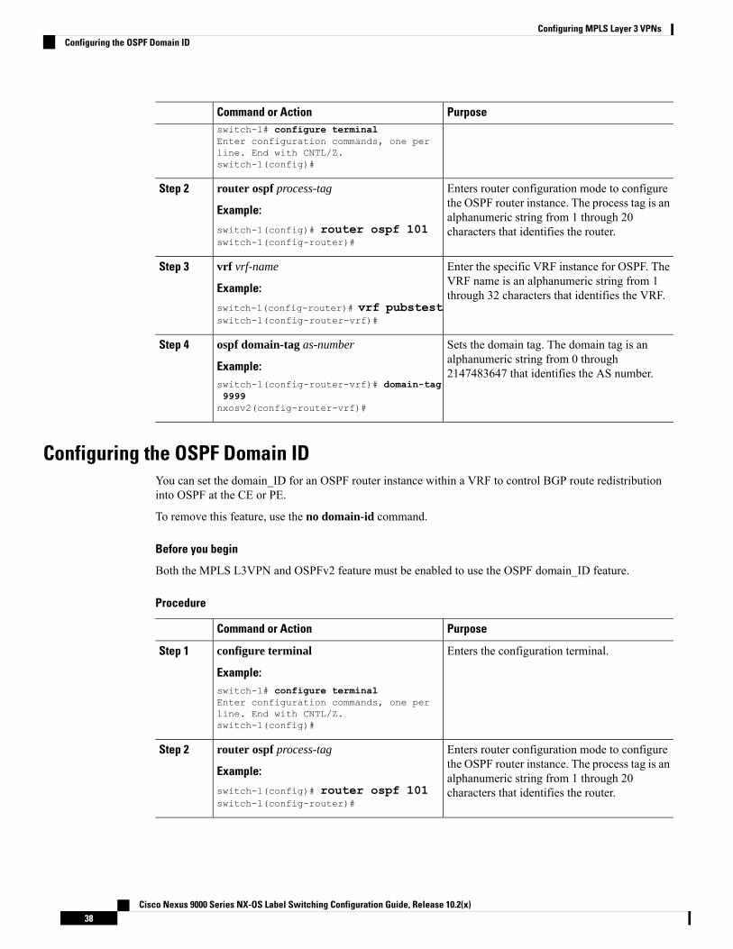
PurposeCommand or Actionswitch-1# configure terminalEnter configuration commands, one perline. End with CNTL/Z.switch-1(config)#
Enters router configuration mode to configurethe OSPF router instance. The process tag is an
router ospf process-tag
Example:
Step 2
alphanumeric string from 1 through 20characters that identifies the router.switch-1(config)# router ospf 101
switch-1(config-router)#
Enter the specific VRF instance for OSPF. TheVRF name is an alphanumeric string from 1through 32 characters that identifies the VRF.
vrf vrf-name
Example:
switch-1(config-router)# vrf pubstestswitch-1(config-router-vrf)#
Step 3
Sets the domain tag. The domain tag is analphanumeric string from 0 through2147483647 that identifies the AS number.
ospf domain-tag as-number
Example:switch-1(config-router-vrf)# domain-tag9999nxosv2(config-router-vrf)#
Step 4
Configuring the OSPF Domain IDYou can set the domain_ID for an OSPF router instance within a VRF to control BGP route redistributioninto OSPF at the CE or PE.
To remove this feature, use the no domain-id command.
Before you begin
Both the MPLS L3VPN and OSPFv2 feature must be enabled to use the OSPF domain_ID feature.
Procedure
PurposeCommand or Action
Enters the configuration terminal.configure terminal
Example:
Step 1
switch-1# configure terminalEnter configuration commands, one perline. End with CNTL/Z.switch-1(config)#
Enters router configuration mode to configurethe OSPF router instance. The process tag is an
router ospf process-tag
Example:
Step 2
alphanumeric string from 1 through 20characters that identifies the router.switch-1(config)# router ospf 101
switch-1(config-router)#
Cisco Nexus 9000 Series NX-OS Label Switching Configuration Guide, Release 10.2(x)38
Configuring MPLS Layer 3 VPNsConfiguring the OSPF Domain ID

PurposeCommand or Action
Enter the specific VRF instance for OSPF. TheVRF name is an alphanumeric string from 1through 32 characters that identifies the VRF.
vrf vrf-name
Example:
switch-1(config-router)# vrf pubstestswitch-1(config-router-vrf)#
Step 3
Sets the domain_ID and additional parameters:domain-id { id | type domain-type value value| Null }
Step 4
• id specifies the domain ID in dotteddecimal notation, for example, 1.2.3.4Example:
switch-1(config-router-vrf)# domain-id19.0.2.0 • type specifies the domain type in four-byte
notation, for example, 0005.
• value specifies the domain value in 6 bytesof hexadecimal notation, for example,0x0005.
You can use the Null argument to clear thedomain_ID.
Configuring the Secondary Domain IDYou can set a secondary domain_ID for an OSPF router instance within a VRF to control BGP routeredistribution into OSPF at the CE or PE.
Use the domain-id Null command to unconfigure the domain_ID.
Before you begin
Make sure that OSPFv2 and MPLS features are enabled.
Procedure
PurposeCommand or Action
Enters the configuration terminal.configure terminal
Example:
Step 1
switch-1# configure terminalEnter configuration commands, one perline. End with CNTL/Z.switch-1(config)#
Enters router configuration mode to configurethe OSPF router instance. The process tag is an
router ospf process-tag
Example:
Step 2
alphanumeric string from 1 through 20characters that identifies the router.switch-1(config)# router ospf 101
switch-1(config-router)#
Cisco Nexus 9000 Series NX-OS Label Switching Configuration Guide, Release 10.2(x)39
Configuring MPLS Layer 3 VPNsConfiguring the Secondary Domain ID

PurposeCommand or Action
Enters the specific VRF instance for OSPF. TheVRF name is an alphanumeric string from 1through 32 characters that identifies the VRF.
vrf vrf-name
Example:switch-1(config-router)# vrf pubstestswitch-1(config-router-vrf)#
Step 3
Sets the domain_ID for the autonomous system.domain-id { id | type domain-type value value| Null }
Step 4
Example:switch-1(config-router-vrf)# domain-id19.0.2.0
Configuring the Core Network
Assessing the Needs of MPLS Layer 3 VPN CustomersYou can identify the core network topology so that it can best serve MPLS Layer 3 VPN customers.
• Identify the size of the network:
• Identify the following to determine the number of routers and ports you need:
• How many customers do you need to support?
• How many VPNs are needed per customer?
• How many virtual routing and forwarding instances are there for each VPN?
• Determine which routing protocols you need in the core network.
• Determine if you need MPLS VPN high availability support.
MPLS VPN nonstop forwarding and graceful restart are supportedon select routers and Cisco NX-OS releases. You need to make surethat graceful restart for BGP and LDP is enabled.
Note
• Configure the routing protocols in the core network.
• Determine if you need BGP load sharing and redundant paths in the MPLS Layer 3 VPN core.
Configuring MPLS in the CoreTo enable MPLS on all routers in the core, you must configure a label distribution protocol. You can useeither of the following as a label distribution protocol:
• MPLS Label Distribution Protocol (LDP).
• MPLS Traffic Engineering Resource Reservation Protocol (RSVP).
Cisco Nexus 9000 Series NX-OS Label Switching Configuration Guide, Release 10.2(x)40
Configuring MPLS Layer 3 VPNsConfiguring the Core Network

Configuring Multiprotocol BGP on the PE Routers and Route ReflectorsYou can configure multiprotocol BGP connectivity on the PE routers and route reflectors.
Before you begin
• Ensure that graceful restart is enabled on all routers for BGP and LDP.
Procedure
PurposeCommand or Action
Enters global configuration mode.configure terminal
Example:
Step 1
switch# configure terminalswitch(config)#
Enables the BGP feature.feature bgp
Example:
Step 2
switch(config)# feature bgpswitch(config)#
Installs the MPLS feature-set.install feature-set mpls
Example:
Step 3
switch(config)# install feature-set mplsswitch(config)#
Enables the MPLS feature-set.feature-set mpls
Example:
Step 4
switch(config)# feature-set mplsswitch(config)#
Enables the MPLS Layer 3 VPN feature.feature mpls l3vpn
Example:
Step 5
switch(config)# feature mpls l3vpnswitch(config)#
Configures a BGP routing process and entersrouter configuration mode. The as-number
router bgp as - number
Example:
Step 6
argument indicates the number of answitch(config)# router bgp 1.1 autonomous system that identifies the router
to other BGP routers and tags the routinginformation. The AS number can be a 16-bitinteger or a 32-bit integer in the form of ahigher 16-bit decimal number and a lower16-bit decimal number in xx.xx format.
(Optional) Configures the BGP router ID. ThisIP address identifies this BGP speaker. This
router-id ip-address
Example:
Step 7
command triggers an automatic notification
Cisco Nexus 9000 Series NX-OS Label Switching Configuration Guide, Release 10.2(x)41
Configuring MPLS Layer 3 VPNsConfiguring Multiprotocol BGP on the PE Routers and Route Reflectors

PurposeCommand or Actionswitch(config-router)# router-id192.0.2.255
and session reset for the BGP neighborsessions.
Adds an entry to the iBGP neighbor table. Theip-address argument specifies the IP addressof the neighbor in dotted decimal notation.
neighbor ip-address remote-asas-number
Example:
Step 8
switch(config-router)# neighbor209.165.201.1 remote-as 1.1
switch(config-router-neighbor)#
Enters address family configuration mode forconfiguring routing sessions, such as BGP,
address-family { vpnv4 | vpnv6 } unicast
Example:
Step 9
that uses standard VPNv4 or VPNv6 addressprefixes.switch(config-router-neighbor)#
address-family vpnv4 unicast
switch(config-router-neighbor-af)#
Specifies that a communities attribute shouldbe sent to a BGP neighbor.
send-community extended
Example:
Step 10
switch(config-router-neighbor-af)#send-community extended
(Optional) Displays information about BGPneighbors.
show bgp { vpnv4 | vpnv6 } unicastneighbors
Example:
Step 11
switch(config-router-neighbor-af)# showbgp vpnv4 unicast neighbors
(Optional) Copies the running configurationto the startup configuration.
copy running-config startup-config
Example:
Step 12
switch(config-router-vrf)# copyrunning-config startup-config
Connecting the MPLS VPN Customers
Defining VRFs on the PE Routers to Enable Customer ConnectivityYou must create VRFs on the PE routers to enable customer connectivity. You configure route targets tocontrol which IP prefixes are imported into the customer VPN site and which IP prefixes are exported to theBGP network. You can optionally use an import or export route map to provide more fine-grained controlover the IP prefixes that are imported into the customer VPN site or exported out of the VPN site. You canuse a route map to filter routes that are eligible for import or export in a VRF, based on the route target extendedcommunity attributes of the route. The route map might, for example, deny access to selected routes from acommunity that is on the import route target list.
Cisco Nexus 9000 Series NX-OS Label Switching Configuration Guide, Release 10.2(x)42
Configuring MPLS Layer 3 VPNsConnecting the MPLS VPN Customers

Procedure
PurposeCommand or Action
Enters global configuration mode.configure terminal
Example:
Step 1
switch# configure terminalswitch(config)#
Installs the MPLS feature-set.install feature-set mpls
Example:
Step 2
switch(config)# install feature-set mplsswitch(config)#
Enables the MPLS feature-set.feature-set mpls
Example:
Step 3
switch(config)# feature-set mplsswitch(config)#
Enables the MPLS Layer 3 VPN feature.feature-set mpls l3vpn
Example:
Step 4
switch(config)# feature-set mpls l3vpnswitch(config)#
Defines the VPN routing instance by assigninga VRF name and enters VRF configuration
vrf context vrf-name
Example:
Step 5
mode. The vrf-name argument is anyswitch(config)# vrf context vpn1
switch(config-vrf)#
case-sensitive, alphanumeric string up to 32characters.
Configures the route distinguisher. Theroute-distinguisher argument adds an 8-byte
rd route-distinguisher
Example:
Step 6
value to an IPv4 prefix to create a VPN IPv4switch(config-vrf)# rd 1.2:1
switch(config-vrf)#
prefix. You can enter an RD in either of theseformats:
• 16-bit or 32-bit AS number: your 32-bitnumber, for example, 1.2:3
• 32-bit IP address: your 16-bit number, forexample, 192.0.2.1:1
Specifies the IPv4 address family type andenters address family configuration mode.
address-family { ipv4 | ipv6 } unicast
Example:
Step 7
switch(config-vrf)# address-family ipv4unicast
switch(config-vrf-af-ipv4)#
Specifies a route-target extended communityfor a VRF as follows:
route-target { import | export }route-target-ext-community }
Step 8
Cisco Nexus 9000 Series NX-OS Label Switching Configuration Guide, Release 10.2(x)43
Configuring MPLS Layer 3 VPNsDefining VRFs on the PE Routers to Enable Customer Connectivity

PurposeCommand or Action
Example: • The import keyword imports routinginformation from the target VPNextended community.
switch(config-vrf-af-ipv4)# route-targetimport 1.0:1
• The export keyword exports routinginformation to the target VPN extendedcommunity.
• The route-target-ext-community argumentadds the route-target extended communityattributes to the VRF's list of import orexport route-target extended communities.You can enter theroute-target-ext-community argument ineither of these formats:
• 16-bit or 32-bit AS number: your32-bit number, for example, 1.2:3
• 32-bit IP address: your 16-bitnumber, for example, 192.0.2.1:1
(Optional) Configures the maximum numberof routes that can be stored in the VRF route
maximum routes max-routes [ thresholdvalue ] [ reinstall ]
Step 9
table. The max-routes range is from 1 toExample: 4294967295. The threshold value range is from
1 to 100.switch(config-vrf-af-ipv4)# maximumroutes 10000
(Optional) Configures an import policy for aVRF to import prefixes from the default VRFas follows:
import [ vrf default max-prefix ] maproute-map
Example:
Step 10
• The max-prefix range is from 1 to2147483647. The default is 1000 prefixes.
switch(config-vrf-af-ipv4)# import vrfdefault map vpn1-route-map
• The route-map argument specifies theroute map to be used as an import routemap for the VRF and can be anycase-sensitive, alphanumeric string up to63 characters.
(Optional) Displays information about a VRF.The vrf-name argument is any case-sensitive,alphanumeric string up to 32 characters.
show vrf vrf-name
Example:switch(config-vrf-af-ipv4)# show vrfvpn1
Step 11
(Optional) Copies the running configurationto the startup configuration.
copy running-config startup-config
Example:
Step 12
switch(config-router-vrf)# copyrunning-config startup-config
Cisco Nexus 9000 Series NX-OS Label Switching Configuration Guide, Release 10.2(x)44
Configuring MPLS Layer 3 VPNsDefining VRFs on the PE Routers to Enable Customer Connectivity

Configuring VRF Interfaces on PE Routers for Each VPN CustomerYou can associate a virtual routing and forwarding instance (VRF) with an interface or subinterface on thePE routers.
Procedure
PurposeCommand or Action
Enters global configuration mode.configure terminal
Example:
Step 1
switch# configure terminalswitch(config)#
Specifies the interface to configure and entersinterface configuration mode as follows:
interface type number
Example:
Step 2
• The type argument specifies the type ofinterface to be configured.
switch(config)# interface Ethernet 5/0
switch(config-if)#• The number argument specifies the port,connector, or interface card number.
Associates a VRF with the specified interfaceor subinterface. The vrf-name argument is thename assigned to a VRF.
vrf member vrf-name
Example:switch(config-if)# vrf member vpn1
Step 3
(Optional) Displays information about interfacesassociated with a VRF. The vrf-name argument
show vrf vrf-name interface
Example:
Step 4
is any case-sensitive alphanumeric string up to32 characters.switch(config-if)# show vrf vpn1
interface
(Optional) Copies the running configuration tothe startup configuration.
copy running-config startup-config
Example:
Step 5
switch(config-router-vrf)# copyrunning-config startup-config
Configuring Routing Protocols Between the PE and CE Routers
Configuring Static or Directly Connected Routes Between the PE and CE Routers
You can configure the PE router for PE-to-CE routing sessions that use static routes.
Procedure
PurposeCommand or Action
Enters global configuration mode.configure terminal
Example:
Step 1
switch# configure terminalswitch(config)#
Cisco Nexus 9000 Series NX-OS Label Switching Configuration Guide, Release 10.2(x)45
Configuring MPLS Layer 3 VPNsConfiguring VRF Interfaces on PE Routers for Each VPN Customer

PurposeCommand or Action
Defines the VPN routing instance by assigninga VRF name and enters VRF configuration
vrf context vrf-name
Example:
Step 2
mode. The vrf-name argument is anyswitch(config)# vrf context vpn1
switch(config-vrf)#
case-sensitive, alphanumeric string up to 32characters.
Defines static route parameters for everyPE-to-CE session. The prefix and nexthop areas follows:
{ ip ipv6 } route prefix nexthop
Example:switch(config-vrf)# ip route192.0.2.1/28 ethernet 2/1
Step 3
• IPv4—in dotted decimal notation
• IPv6—in hex format.
Specifies the IPv4 address family type andenters address family configuration mode.
address-family { ipv4 | ipv6 } unicast
Example:
Step 4
switch(config-vrf)# address-family ipv4unicast
switch(config-vrf-af)#
Enables the BGP feature.feature bgp as - number
Example:
Step 5
switch(config-vrf-af)# feature bgp
switch(config)#
Configures a BGP routing process and entersrouter configuration mode. The as-number
router bgp as - number
Example:
Step 6
argument indicates the number of answitch(config)# router bgp 1.1 autonomous system that identifies the router
to other BGP routers and tags the routinginformation. The AS number can be a 16-bitinteger or a 32-bit integer in the form of ahigher 16-bit decimal number and a lower16-bit decimal number in xx.xx format.
Associates the BGP process with a VRF.vrf vrf-nameStep 7
Example: The vrf-name argument is any case-sensitive,alphanumeric string up to 32 characters.switch(config-router)# vrf vpn1
switch(config--router-vrf)#
Specifies the IPv4 address family type andenters address family configuration mode.
address-family { ipv4 | ipv6 } unicast
Example:
Step 8
switch(config-vrf)# address-family ipv4unicast
switch(config-vrf-af)#
Cisco Nexus 9000 Series NX-OS Label Switching Configuration Guide, Release 10.2(x)46
Configuring MPLS Layer 3 VPNsConfiguring Static or Directly Connected Routes Between the PE and CE Routers

PurposeCommand or Action
Redistributes static routes into BGP.redistribute static route-map map-nameStep 9
Example: The map-name can be any case-sensitive,alphanumeric string up to 63 characters.switch(config-router-vrf-af)#
redistribute static route-map StaticMap
Redistributes directly connected routes intoBGP.
redistribute direct route-map map-name
Example:
Step 10
The map-name can be any case-sensitive,alphanumeric string up to 63 characters.
switch(config-router-vrf-af)#redistribute direct route-map StaticMap
(Optional) Displays information about routes.show { ipv4 | ipv6 } route vrf vrf-nameStep 11
Example: The vrf-name argument is any case-sensitive,alphanumeric string up to 32 characters.switch(config-router-vrf-af)# show ip
ipv4 route vrf vpn1
(Optional) Copies the running configurationto the startup configuration.
copy running-config startup-config
Example:
Step 12
switch(config-router-vrf)# copyrunning-config startup-config
Configuring BGP as the Routing Protocol Between the PE and CE Routers
You can use eBGP to configure the PE router for PE-to-CE routing sessions.
Procedure
PurposeCommand or Action
Enters global configuration mode.configure terminal
Example:
Step 1
switch# configure terminalswitch(config)#
Enables the BGP feature.feature bgp
Example:
Step 2
switch(config)# feature bgp
switch(config)#
Configures a BGP routing process and entersrouter configuration mode.
router bgp as - number
Example:
Step 3
The as-number argument indicates the numberof an autonomous system that identifies the
switch(config)# router bgp 1.1
switch(config-router)# router to other BGP routers and tags the routinginformation passed along. The AS number canbe a 16-bit integer or a 32-bit integer in the formof a higher 16-bit decimal number and a lower16-bit decimal number in xx.xx format.
Cisco Nexus 9000 Series NX-OS Label Switching Configuration Guide, Release 10.2(x)47
Configuring MPLS Layer 3 VPNsConfiguring BGP as the Routing Protocol Between the PE and CE Routers

PurposeCommand or Action
Associates the BGP process with a VRF.vrf vrf-nameStep 4
Example: The vrf-name argument is any case-sensitive,alphanumeric string up to 32 characters.switch(config-router)# vrf vpn1
switch(config--router-vrf)#
Adds an entry to the iBGP neighbor table. Theip-address argument specifies the IP address of
neighbor ip-addressremote-as as-number
Example:
Step 5
the neighbor in dotted decimal notation. Theswitch(config-router)# neighbor209.165.201.1 remote-as 1.1
as-number argument specifies the autonomoussystem to which the neighbor belongs.
switch(config-router-neighbor)#
Enters address family configuration mode forconfiguring routing sessions, such as BGP, thatuse standard IPv4 or IPv6 address prefixes.
address-family { ipv4 | ipv6 } unicast
Example:switch(config-vrf)# address-family ipv4unicast
Step 6
switch(config-vrf-af)#
(Optional) Displays information about BGPneighbors. The vrf-name argument is any
show bgp { vpnv4 | vpnv6 } unicast neighborsvrf vrf-name
Step 7
case-sensitive alphanumeric string up to 32characters.Example:
switch(config-router-neighbor-af)# showbgp vpnv4 unicast neighbors
(Optional) Copies the running configuration tothe startup configuration.
copy running-config startup-config
Example:
Step 8
switch(config-router-vrf)# copyrunning-config startup-config
Configuring RIPv2 Between the PE and CE Routers
You can use RIP to configure the PE router for PE-to-CE routing sessions.
Procedure
PurposeCommand or Action
Enters global configuration mode.configure terminal
Example:
Step 1
switch# configure terminalswitch(config)#
Enables the RIP feature.feature rip
Example:
Step 2
switch(config)# feature rip
switch(config)#
Cisco Nexus 9000 Series NX-OS Label Switching Configuration Guide, Release 10.2(x)48
Configuring MPLS Layer 3 VPNsConfiguring RIPv2 Between the PE and CE Routers

PurposeCommand or Action
Enables RIP and enters router configurationmode.
router rip instance-tag
Example:
Step 3
The instance-tag can be any case-sensitive,alphanumeric string up to 20 characters.
switch(config)# router rip Test1
Associates the RIP process with a VRF.
The vrf-name argument is any case-sensitive,alphanumeric string up to 32 characters.
vrf vrf-name
Example:switch(config-router)# vrf vpn1
switch(config--router-vrf)#
Step 4
Specifies the address family type and entersaddress family configuration mode.
address-family ipv4 unicast
Example:
Step 5
switch(config-router-vrf)# address-familyipv4 unicast
switch(config-router-vrf-af)#
Redistributes routes from one routing domaininto another routing domain.
The as number can be a 16-bit integer or a32-bit integer in the form of a higher 16-bit
redistribute { bgp as | direct | { egrip | ospf |rip } instance-tag | static } route-mapmap-name vrf-name
Example:
Step 6
decimal number and a lower 16-bit decimalswitch(config-router-vrf-af)# show iprip vrf vpn1 number in xx.xx format. The instance-tag can
be any case-sensitive alphanumeric string up to20 characters.
(Optional) Displays information about RIP.
The vrf-name argument is any case-sensitive,alphanumeric string up to 32 characters.
show ip rip vrf vrf-name
Example:switch(config-router-vrf-af)# show iprip vrf vpn1
Step 7
(Optional) Copies the running configuration tothe startup configuration.
copy running-config startup-config
Example:
Step 8
switch(config-router-vrf)# copyrunning-config startup-config
Configuring OSPF Between the PE and CE Routers
You can use OSPFv2 to configure the PE router for PE-to-CE routing sessions. You can optionally create anOSPF sham link if you have OSPF back door links that are not part of the MPLS network.
Procedure
PurposeCommand or Action
Enters global configuration mode.configure terminal
Example:
Step 1
Cisco Nexus 9000 Series NX-OS Label Switching Configuration Guide, Release 10.2(x)49
Configuring MPLS Layer 3 VPNsConfiguring OSPF Between the PE and CE Routers

PurposeCommand or Actionswitch# configure terminalswitch(config)#
Enables the OSPF feature.feature ospf
Example:
Step 2
switch(config)# feature ospf
switch(config)#
Enables OSPF and enters router configurationmode.
router ospf instance-tag
Example:
Step 3
The instance-tag can be any case-sensitive,alphanumeric string up to 20 characters.
switch(config)# router ospf Test1
Enters router VRF configuration mode.vrf vrf-nameStep 4
Example: The vrf-name argument is any case-sensitive,alphanumeric string up to 32 characters.switch(config-router)# vrf vpn1
switch(config--router-vrf)#
(Optional) Configures the sham link on the PEinterface within a specified OSPF area and
area area-id sham-link source-addressdestination-address
Step 5
with the loopback interfaces specified by theIP addresses as endpoints.Example:
switch(config-router-vrf)# area 1sham-link 10.2.1.1 10.2.1.2 You must configure the sham link at both PE
endpoints.
Specifies the address family type and entersaddress family configuration mode.
address-family { ipv4 | ipv6 } unicast
Example:
Step 6
switch(config-router)# address-familyipv4 unicast
switch(config-router-vrf-af)#
Redistributes BGP into the EIGRP.redistribute { bgp as | direct | { egrip | ospf| rip } instance-tag | static } route-mapmap-name
Step 7
The autonomous system number of the BGPnetwork is configured in this step. BGP must
Example: be redistributed into EIGRP for the CE site toaccept the BGP routes that carry the EIGRPswitch(config-router-vrf-af)#
redistribute bgp 1.0 route-map BGPMap information. A metric must also be specifiedfor the BGP network.
The map-name can be any case-sensitive,alphanumeric string up to 63 characters.
(Optional) Specifies the autonomous systemnumber for this address family for the customersite.
autonomous-system as-number
Example:switch(config-router-vrf-af)#
autonomous-system 1.3
Step 8
The as-number argument indicates the numberof an autonomous system that identifies the
Cisco Nexus 9000 Series NX-OS Label Switching Configuration Guide, Release 10.2(x)50
Configuring MPLS Layer 3 VPNsConfiguring OSPF Between the PE and CE Routers

PurposeCommand or Action
router to other BGP routers and tags therouting information passed along. The ASnumber can be a 16-bit integer or a 32-bitinteger in the form of a higher 16-bit decimalnumber and a lower 16-bit decimal number inxx.xx format.
(Optional) Displays information about EIGRPin this VRF.
show ip egrip vrf vrf-name
Example:
Step 9
The vrf-name can be any case-sensitive,alphanumeric string up to 32 characters
switch(config-router-vrf-af)# show ipv4eigrp vrf vpn1
(Optional) Copies the running configurationto the startup configuration.
copy running-config startup-config
Example:
Step 10
switch(config-router-vrf)# copyrunning-config startup-config
Configuring EIGRP Between the PE and CE Routers
You can configure the PE router to use Enhanced Interior Gateway Routing Protocol (EIGRP) between thePE and CE routers to transparently connect EIGRP customer networks through an MPLS-enabled BGP corenetwork so that EIGRP routes are redistributed through the VPN across the BGP network as internal BGP(iBGP) routes.
Before you begin
You must configure BGP in the network core.
Procedure
PurposeCommand or Action
Enters global configuration mode.configure terminal
Example:
Step 1
switch# configure terminalswitch(config)#
Enables the EIGRP feature.feature eigrp
Example:
Step 2
switch(config)# feature eigrpswitch(config)#
Configures an EIGRP instance and enters routerconfiguration mode.
router eigrp instance-tag
Example:
Step 3
The instance-tag can be any case-sensitive,alphanumeric string up to 20 characters.
switch(config)# router eigrp Test1
Enters router VRF configuration mode.vrf vrf-nameStep 4
Example:
Cisco Nexus 9000 Series NX-OS Label Switching Configuration Guide, Release 10.2(x)51
Configuring MPLS Layer 3 VPNsConfiguring EIGRP Between the PE and CE Routers

PurposeCommand or Action
The vrf-name argument is any case-sensitive,alphanumeric string up to 32 characters.
switch(config-router)# vrf vpn1switch(config-router-vrf)#
(Optional) Enters address family configurationmode for configuring routing sessions that usestandard IPv4 address prefixes.
address-family ipv4 unicast
Example:switch(config-router-vrf)# address-familyipv4 unicastswitch(config-router-vrf-af)#
Step 5
Redistributes routes from one routing domaininto another routing domain.
redistribute bgp as-number route-mapmap-name
Step 6
Example: The as number can be a 16-bit integer or a32-bit integer in the form of a higher 16-bitswitch(config-router-vrf-af)#
redistribute bgp 235354 route-map mtest1 decimal number and a lower 16-bit decimalnumber in xx.xx format. The instance-tag canbe any case-sensitive alphanumeric string up to20 characters
(Optional) Displays information about OSPF.show ip ospf instance-tag vrf vrf-name
Example:
Step 7
switch(config-router-vrf-af)# show iprip vrf vpn1
(Optional) Copies the running configuration tothe startup configuration.
copy running-config startup-config
Example:
Step 8
switch(config-router-vrf)# copyrunning-config startup-config
Configuring PE-CE Redistribution in BGP for the MPLS VPN
You must configure BGP to distribute the PE-CE routing protocol on every PE router that provides MPLSLayer 3 VPN services if the PE-CE protocol is not BGP.
Procedure
PurposeCommand or Action
Enters global configuration mode.configure terminal
Example:
Step 1
switch# configure terminalswitch(config)#
Enables the BGP feature.feature bgp
Example:
Step 2
switch(config)# feature bgpswitch(config)#
Cisco Nexus 9000 Series NX-OS Label Switching Configuration Guide, Release 10.2(x)52
Configuring MPLS Layer 3 VPNsConfiguring PE-CE Redistribution in BGP for the MPLS VPN

PurposeCommand or Action
Configures a BGP routing process and entersrouter configuration mode. The as-number
router bgp instance-tag
Example:
Step 3
argument indicates the number of answitch(config)# router bgp 1.1switch(config-router)#
autonomous system that identifies the routerto other BGP routers and tags the routinginformation passed along. The AS number canbe a 16-bit integer or a 32-bit integer in theform of a higher 16-bit decimal number and alower 16-bit decimal number in xx.xx format.
(Optional) Configures the BGP router ID. ThisIP address identifies this BGP speaker. This
router id ip-address
Example:
Step 4
command triggers an automatic notificationswitch(config-router)# router-id192.0.2.255 1switch(config-router)#
and session reset for the BGP neighborsessions.
Adds an entry to the BGP or multiprotocolBGP neighbor table. The ip-address argument
router id ip-address remote-as as-number
Example:
Step 5
specifies the IP address of the neighbor inswitch(config-router)# neighbor209.165.201.1 remote-as 1.2switch(config-router-neighbor)#
dotted decimal notation. The as-numberargument specifies the autonomous system towhich the neighbor belongs.
Specifies the source address of the BGPsession.
update-source loopback [ 0 | 1 ]
Example:
Step 6
switch(config-router-neighbor)#update-source loopback 0#
Enters address family configuration mode forconfiguring routing sessions, such as BGP,
address-family { ipv4 | ipv6 } unicast
Example:
Step 7
that use standard VPNv4 or VPNv6 addressswitch(config-router-neighbor)#address-family vpnv4switch(config-router-neighbor-af)#
prefixes. The optional unicast keywordspecifies VPNv4 or VPNv6 unicast addressprefixes.
Specifies that a communities attribute shouldbe sent to a BGP neighbor.
send-community extended
Example:
Step 8
switch(config-router-neighbor-af)#send-community extended
Enters router VRF configuration mode.vrf vrf-nameStep 9
Example: The vrf-name argument is any case-sensitive,alphanumeric string up to 32 characters.switch(config-router-neighbor-af)# vrf
vpn1switch(config-router-vrf)#
Cisco Nexus 9000 Series NX-OS Label Switching Configuration Guide, Release 10.2(x)53
Configuring MPLS Layer 3 VPNsConfiguring PE-CE Redistribution in BGP for the MPLS VPN

PurposeCommand or Action
Enters address family configuration mode forconfiguring routing sessions that use standardIPv4 or IPv6 address prefixes.
address-family { ipv4 | ipv6 } unicast
Example:switch(config-router-vrf)#address-family ipv4 unicastswitch(config-router-vrf-af)#
Step 10
Redistributes routes from one routing domaininto another routing domain. The as number
redistribute { direct | { egrip | ospfv3 |ospfv3 |rip } instance-tag | static }route-map map-name
Step 11
can be a 16-bit integer or a 32-bit integer inthe form of a higher 16-bit decimal number
Example: and a lower 16-bit decimal number in xx.xxswitch(config-router-af-vrf)#redistribute eigrp Test2 route-mapEigrpMap
format. The instance-tag can be anycase-sensitive, alphanumeric string up to 20characters. The map-name can be anycase-sensitive alphanumeric string up to 63characters.
(Optional) Displays information about BGP.The vrf-name argument is any case-sensitive,alphanumeric string up to 32 characters.
show bgp { ipv4 | ipv6 } unicast vrf vrf-name
Example:switch(config-router--vrf-af)# show bgpipv4 unicast vrf vpn1vpn1
Step 12
(Optional) Copies the running configurationto the startup configuration.
copy running-config startup-config
Example:
Step 13
switch(config-router-vrf)# copyrunning-config startup-config
Configuring a Hub-and-Spoke Topology
Configuring VRFs on the Hub PE Router
You can configure hub and spoke VRFs on the hub PE router.
Procedure
PurposeCommand or Action
Enters global configuration mode.configure terminal
Example:
Step 1
switch# configure terminalswitch(config)#
Installs the MPLS feature-set.install feature-set mpls
Example:
Step 2
switch(config)# install feature-set mplsswitch(config)#
Cisco Nexus 9000 Series NX-OS Label Switching Configuration Guide, Release 10.2(x)54
Configuring MPLS Layer 3 VPNsConfiguring a Hub-and-Spoke Topology

PurposeCommand or Action
Enables the MPLS feature-set.feature-set mpls
Example:
Step 3
switch(config)# feature-set mplsswitch(config)#
Enables the MPLS Layer 3 VPN feature.feature-set mpls l3vpn
Example:
Step 4
switch(config)# feature-set mpls l3vpnswitch(config)#
Defines the VPN routing instance for the PEhub by assigning a VRF name and enters VRF
vrf context vrf-hub
Example:
Step 5
configuration mode. The vrf-hub argument isswitch(config)# vrf context 2hub
switch(config-vrf)#
any case-sensitive alphanumeric string up to32 characters.
Configures the route distinguisher. Theroute-distinguisher argument adds an 8-byte
rd route-distinguisher
Example:
Step 6
value to an IPv4 prefix to create a VPN IPv4switch(config-vrf)# rd 1.2:1
switch(config-vrf)#
prefix. You can enter an RD in either of theseformats:
• 16-bit or 32-bit AS number: your 32-bitnumber, for example, 1.2:3
• 32-bit IP address: your 16-bit number, forexample, 192.0.2.1:1
Specifies the IPv4 address family type andenters address family configuration mode.
address-family { ipv4 | ipv6 } unicast
Example:
Step 7
switch(config-vrf)# address-family ipv4unicast
switch(config-vrf-af-ipv4)#
Specifies a route-target extended communityfor a VRF as follows:
route-target { import | export }route-target-ext-community }
Step 8
Example: • The import keyword imports routinginformation from the target VPNextended community.
switch(config-vrf-af-ipv4)# route-targetimport 1.0:1
• The export keyword exports routinginformation to the target VPN extendedcommunity.
• The route-target-ext-community argumentadds the route-target extended communityattributes to the VRF's list of import orexport route-target extended communities.You can enter the
Cisco Nexus 9000 Series NX-OS Label Switching Configuration Guide, Release 10.2(x)55
Configuring MPLS Layer 3 VPNsConfiguring VRFs on the Hub PE Router

PurposeCommand or Action
route-target-ext-community argument ineither of these formats:
• 16-bit or 32-bit AS number: your32-bit number, for example, 1.2:3
• 32-bit IP address: your 16-bitnumber, for example, 192.0.2.1:1
Defines the VPN routing instance for the PEspoke by assigning a VRF name and enters
vrf context vrf-spoke
Example:
Step 9
VRF configuration mode. The vrf-spokeswitch(config-vrf-af-ipv4)# vrf context2spokes
argument is any case-sensitive, alphanumericstring up to 32 characters.
switch(config-vrf)#
Specifies the IPv4 address family type andenters address family configuration mode.
address-family { ipv4 | ipv6 } unicast
Example:
Step 10
switch(config-vrf)# address-family ipv4unicast
switch(config-vrf-af-ipv4)#
Specifies a route-target extended communityfor a VRF as follows:
route-target { import | export }route-target-ext-community }
Step 11
Example: • Creates a route-target extendedcommunity for a VRF. The importswitch(config-vrf-af-ipv4)# route-target
export 1:100 keyword imports routing informationfrom the target VPN extendedcommunity. The export keyword exportsrouting information to the target VPNextended community. Theroute-target-ext-community argumentadds the route-target extended communityattributes to the VRF's list of import orexport route-target extended communities.You can enter theroute-target-ext-community argument ineither of these formats:
• 16-bit or 32-bit AS number: your32-bit number, for example, 1.2:3
• 32-bit IP address: your 16-bitnumber, for example, 192.0.2.1:1
(Optional) Displays the running configurationfor the VRF.
show running-config vrf vrf-name
Example:
Step 12
Cisco Nexus 9000 Series NX-OS Label Switching Configuration Guide, Release 10.2(x)56
Configuring MPLS Layer 3 VPNsConfiguring VRFs on the Hub PE Router

PurposeCommand or Action
The vrf-name argument is any case-sensitive,alphanumeric string up to 32 characters.
switch(config-vrf-af-ipv4)# showrunning-config vrf 2spokes
.
(Optional) Copies the running configurationto the startup configuration.
copy running-config startup-config
Example:
Step 13
switch(config-router-vrf)# copyrunning-config startup-config
Configuring eBGP on the Hub PE Router
You can use eBGP to configure PE-to-CE hub routing sessions.
If all CE sites are using the same BGP AS number, you must perform the following tasks:
• Configure either the BGP as-override command at the PE (hub) or the allowas-in command at thereceiving CE router.
• To advertise BGP routes learned from one ASN back to the same ASN, configure thedisable-peer-as-check command at the PE router to prevent loopback.
Note
Procedure
PurposeCommand or Action
Enters global configuration mode.configure terminal
Example:
Step 1
switch# configure terminalswitch(config)#
Enables the MPLS feature-set.feature-set mpls
Example:
Step 2
switch(config)# feature-set mpls
Enables the MPLS Layer 3 VPN feature.feature mpls l3vpn
Example:
Step 3
switch(config)# feature mpls l3vpn
Enables the BGP feature.feature bgp
Example:
Step 4
switch(config)# feature bgpswitch(config)#
Configures a BGP routing process and entersrouter configuration mode.
router bgp as - number
Example:
Step 5
Cisco Nexus 9000 Series NX-OS Label Switching Configuration Guide, Release 10.2(x)57
Configuring MPLS Layer 3 VPNsConfiguring eBGP on the Hub PE Router

PurposeCommand or Action
The as-number argument indicates the numberof an autonomous system that identifies the
switch(config)# router bgp 1.1switch(config-router)#
router to other BGP routers and tags therouting information passed along. The ASnumber can be a 16-bit integer or a 32-bitinteger in the form of a higher 16-bit decimalnumber and a lower 16-bit decimal number inxx.xx format.
Adds an entry to the iBGP neighbor table.neighbor ip-address remote-asas-number
Step 6
• The ip-address argument specifies the IPaddress of the neighbor in dotted decimalnotation.
Example:switch(config-router)# neighbor209.165.201.1 remote-as 1.2switch(config-router-neighbor)# • The as-number argument specifies the
autonomous system towhich the neighborbelongs.
Specifies the IP address family type and entersaddress family configuration mode.
address-family { ipv4 | ipv6 } unicast
Example:
Step 7
switch(config-router-vrf-neighbor)#address-family ipv4 unicastswitch(config-router-neighbor-af)#
(Optional) Configures BGP to advertiseextended community lists.
send-community extended
Example:
Step 8
switch(config-router-neighbor-af)#send-community extended
Enters VRF configuration mode. The vrf-hubargument is any case-sensitive, alphanumericstring up to 32 characters.
vrf vrf-hub
Example:switch(config-router-neighbor-af)# vrf2hubswitch(config-router-vrf)#
Step 9
Adds an entry to the BGP or multiprotocolBGP neighbor table for this VRF.
neighbor ip-address remote-asas-number
Step 10
Example: • The ip-address argument specifies the IPaddress of the neighbor in dotted decimalnotation.
switch(config-router-vrf)# neighbor33.0.0.33 1 remote-as 150switch(config-router-vrf-neighbor)#
• The as-number argument specifies theautonomous system towhich the neighborbelongs.
Specifies the IP address family type and entersaddress family configuration mode.
address-family { ipv4 | ipv6 } unicast
Example:
Step 11
Cisco Nexus 9000 Series NX-OS Label Switching Configuration Guide, Release 10.2(x)58
Configuring MPLS Layer 3 VPNsConfiguring eBGP on the Hub PE Router

PurposeCommand or Actionswitch(config-router-vrf-neighbor)#address-family ipv4 unicastswitch(config-router--vrf-neighbor-af)#
(Optional) Overrides the AS-number whensending an update. If all BGP sites are using
as-override
Example:
Step 12
the same AS number, of the followingcommands:switch(config-router-vrf-neighbor-af)#
as-override
• Configure the BGP as-override commandat the PE (hub)
or
• Configure the allowas-in command at thereceiving CE router.
Enters VRF configurationmode. The vrf-spokeargument is any case-sensitive, alphanumericstring up to 32 characters.
vrf vrf-spoke
Example:switch(config-router-vrf-neighbor-af)#vrf 2spokesswitch(config-router-vrf)#
Step 13
Adds an entry to the BGP or multiprotocolBGP neighbor table for this VRF.
neighbor ip-address remote-as as-number
Example:
Step 14
• The ip-address argument specifies the IPaddress of the neighbor in dotted decimalnotation.
switch(config-router-vrf)# neighbor33.0.0.33 1 remote-as 150switch(config-router-vrf-neighbor)#
• The as-number argument specifies theautonomous system towhich the neighborbelongs.
Specifies the IP address family type and entersaddress family configuration mode.
address-family { ipv4 | ipv6 } unicast
Example:
Step 15
switch(config-router-vrf-neighbor)#address-family ipv4 unicastswitch(config-router--vrf-neighbor-af)#
(Optional) Allows duplicate AS numbers inthe AS path.
allowas-in [ number ]
Example:
Step 16
Configure this parameter in the VPN addressfamily configuration mode at the PE spokesand at the neighbor mode at the PE hub.
switch(config-router-vrf-neighbor-af)#allowas-in 3
(Optional) Displays the running configurationfor BGP.
show running-config bgp vrf-name
Example:
Step 17
switch(config-router-vrf-neighbor-af)#show running-config bgp
Cisco Nexus 9000 Series NX-OS Label Switching Configuration Guide, Release 10.2(x)59
Configuring MPLS Layer 3 VPNsConfiguring eBGP on the Hub PE Router

PurposeCommand or Action
(Optional) Copies the running configurationto the startup configuration.
copy running-config startup-config
Example:
Step 18
switch(config-router-vrf)# copyrunning-config startup-config
Configuring eBGP on the Hub CE Router
You can use eBGP to configure PE-to-CE hub routing sessions.
If all CE sites are using the same BGP AS number, you must perform the following tasks:Note
• Configure either the as-override command at the PE (hub) or the allowas-in command at the receivingCE router.
• Configure the disable-peer-as-check command at the CE router.
• To advertise BGP routes learned from oneASN back to the sameASN, configure the disable-peer-as-checkcommand at the PE router to prevent loopback.
Procedure
PurposeCommand or Action
Enters global configuration mode.configure terminal
Example:
Step 1
switch# configure terminalswitch(config)#
Enables the MPLS feature-set.feature-set mpls
Example:
Step 2
switch(config)# feature-set mpls
Enables the MPLS Layer 3 VPN feature.feature mpls l3vpn
Example:
Step 3
switch(config)# feature mpls l3vpn
Enables the BGP feature.feature bgp
Example:
Step 4
switch(config)# feature bgpswitch(config)#
Configures a BGP routing process and entersrouter configuration mode.
router bgp as - number
Example:
Step 5
The as-number argument indicates the numberof an autonomous system that identifies the
switch(config)# router bgp 1.1switch(config-router)#
router to other BGP routers and tags the
Cisco Nexus 9000 Series NX-OS Label Switching Configuration Guide, Release 10.2(x)60
Configuring MPLS Layer 3 VPNsConfiguring eBGP on the Hub CE Router

PurposeCommand or Action
routing information passed along. The ASnumber can be a 16-bit integer or a 32-bitinteger in the form of a higher 16-bit decimalnumber and a lower 16-bit decimal number inxx.xx format.
Adds an entry to the iBGP neighbor table.neighbor ip-addressremote-as as-numberStep 6
Example: • The ip-address argument specifies the IPaddress of the neighbor in dotted decimalnotation.
switch(config-router)# neighbor209.165.201.1 remote-as 1.2
switch(config-router-neighbor)# • The as-number argument specifies theautonomous system towhich the neighborbelongs.
Specifies the IP address family type and entersaddress family configuration mode.
address-family { ipv4 | ipv6 } unicast
Example:
Step 7
switch(config-router-vrf-neighbor)#address-family ipv4 unicastswitch(config-router-neighbor-af)#
(Optional) Configures BGP to advertiseextended community lists.
send-community extended
Example:
Step 8
switch(config-router-neighbor-af)#send-community extended
Enters VRF configuration mode. The vrf-hubargument is any case-sensitive, alphanumericstring up to 32 characters.
vrf vrf-hub
Example:switch(config-router-neighbor-af)# vrf2hubswitch(config-router-vrf)#
Step 9
Adds an entry to the BGP or multiprotocolBGP neighbor table for this VRF.
neighbor ip-addressremote-as as-number
Example:
Step 10
• The ip-address argument specifies the IPaddress of the neighbor in dotted decimalnotation.
switch(config-router-vrf)# neighbor33.0.0.33 1 remote-as 150switch(config-router-vrf-neighbor)#
• The as-number argument specifies theautonomous system towhich the neighborbelongs.
Specifies the IP address family type and entersaddress family configuration mode.
address-family { ipv4 | ipv6 } unicast
Example:
Step 11
switch(config-router-vrf-neighbor)#address-family ipv4 unicastswitch(config-router--vrf-neighbor-af)#
Cisco Nexus 9000 Series NX-OS Label Switching Configuration Guide, Release 10.2(x)61
Configuring MPLS Layer 3 VPNsConfiguring eBGP on the Hub CE Router
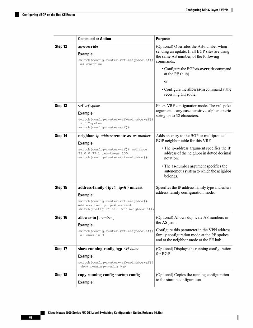
PurposeCommand or Action
(Optional) Overrides the AS-number whensending an update. If all BGP sites are using
as-override
Example:
Step 12
the same AS number, of the followingcommands:switch(config-router-vrf-neighbor-af)#
as-override
• Configure theBGP as-override commandat the PE (hub)
or
• Configure the allowas-in command at thereceiving CE router.
Enters VRF configurationmode. The vrf-spokeargument is any case-sensitive, alphanumericstring up to 32 characters.
vrf vrf-spoke
Example:switch(config-router-vrf-neighbor-af)#vrf 2spokesswitch(config-router-vrf)#
Step 13
Adds an entry to the BGP or multiprotocolBGP neighbor table for this VRF.
neighbor ip-addressremote-as as-number
Example:
Step 14
• The ip-address argument specifies the IPaddress of the neighbor in dotted decimalnotation.
switch(config-router-vrf)# neighbor33.0.0.33 1 remote-as 150switch(config-router-vrf-neighbor)#
• The as-number argument specifies theautonomous system towhich the neighborbelongs.
Specifies the IP address family type and entersaddress family configuration mode.
address-family { ipv4 | ipv6 } unicast
Example:
Step 15
switch(config-router-vrf-neighbor)#address-family ipv4 unicastswitch(config-router--vrf-neighbor-af)#
(Optional) Allows duplicate AS numbers inthe AS path.
allowas-in [ number ]
Example:
Step 16
Configure this parameter in the VPN addressfamily configuration mode at the PE spokesand at the neighbor mode at the PE hub.
switch(config-router-vrf-neighbor-af)#allowas-in 3
(Optional) Displays the running configurationfor BGP.
show running-config bgp vrf-name
Example:
Step 17
switch(config-router-vrf-neighbor-af)#show running-config bgp
(Optional) Copies the running configurationto the startup configuration.
copy running-config startup-config
Example:
Step 18
Cisco Nexus 9000 Series NX-OS Label Switching Configuration Guide, Release 10.2(x)62
Configuring MPLS Layer 3 VPNsConfiguring eBGP on the Hub CE Router

PurposeCommand or Actionswitch(config-router-vrf)# copyrunning-config startup-config
Configuring VRFs on the Spoke PE Router
You can configure hub and spoke VRFs on the spoke PE router.
Procedure
PurposeCommand or Action
Enters global configuration mode.configure terminal
Example:
Step 1
switch# configure terminalswitch(config)#
Installs the MPLS feature set.install feature-set mpls
Example:
Step 2
switch(config)# install feature-set mplsswitch(config)#
Enables the MPLS feature-set.feature-set mpls
Example:
Step 3
switch(config)# feature-set mplsswitch(config)#
Enables the MPLS Layer 3 VPN feature.feature-set mpls l3vpn
Example:
Step 4
switch(config)# feature-set mpls l3vpnswitch(config)#
Defines the VPN routing instance for the PEspoke by assigning a VRF name and enters
vrf context vrf-spoke
Example:
Step 5
VRF configuration mode. The vrf-spokeswitch(config)# vrf context spoke
switch(config-vrf)#
argument is any case-sensitive, alphanumericstring up to 32 characters.
Configures the route distinguisher. Theroute-distinguisher argument adds an 8-byte
rd route-distinguisher
Example:
Step 6
value to an IPv4 prefix to create a VPN IPv4switch(config-vrf)# rd 1.101
switch(config-vrf)#
prefix. You can enter an RD in either of theseformats:
• 16-bit or 32-bit AS number: your 32-bitnumber, for example, 1.2:3
• 32-bit IP address: your 16-bit number, forexample, 192.0.2.1:1
Cisco Nexus 9000 Series NX-OS Label Switching Configuration Guide, Release 10.2(x)63
Configuring MPLS Layer 3 VPNsConfiguring VRFs on the Spoke PE Router

PurposeCommand or Action
Specifies the IPv4 address family type andenters address family configuration mode.
address-family { ipv4 | ipv6 } unicast
Example:
Step 7
switch(config-vrf)# address-family ipv4unicast
switch(config-vrf-af-ipv4)#
Specifies a route-target extended communityfor a VRF as follows:
route-target { import | export }route-target-ext-community }
Step 8
Example: • The import keyword imports routinginformation from the target VPNextended community.
switch(config-vrf-af-ipv4)# route-targetimport 1.0:1
• The export keyword exports routinginformation to the target VPN extendedcommunity.
• The route-target-ext-community argumentadds the route-target extended communityattributes to the VRF's list of import orexport route-target extended communities.You can enter theroute-target-ext-community argument ineither of these formats:
• 16-bit or 32-bit AS number: your32-bit number, for example, 1.2:3
• 32-bit IP address: your 16-bitnumber, for example, 192.0.2.1:1
(Optional) Displays the running configurationfor the VRF.
show running-config vrf vrf-name
Example:
Step 9
The vrf-name argument is any case-sensitive,alphanumeric string up to 32 characters.
switch(config-vrf-af-ipv4)# showrunning-config vrf 2spokes
.
(Optional) Copies the running configurationto the startup configuration.
copy running-config startup-config
Example:
Step 10
switch(config-router-vrf)# copyrunning-config startup-config
Configuring eBGP on the Spoke PE Router
You can use eBGP to configure PE spoke routing sessions.
Cisco Nexus 9000 Series NX-OS Label Switching Configuration Guide, Release 10.2(x)64
Configuring MPLS Layer 3 VPNsConfiguring eBGP on the Spoke PE Router

If all CE sites are using the same BGP AS number, you must perform the following tasks:
• Configure the allowas-in command at the perceiving spoke router.
Note
Procedure
PurposeCommand or Action
Enters global configuration mode.configure terminal
Example:
Step 1
switch# configure terminalswitch(config)#
Enables the MPLS feature-set.feature-set mpls
Example:
Step 2
switch(config)# feature-set mpls
Enables the MPLS Layer 3 VPN feature.feature mpls l3vpn
Example:
Step 3
switch(config)# feature mpls l3vpn
Enables the BGP feature.feature bgp
Example:
Step 4
switch(config)# feature bgpswitch(config)#
Configures a BGP routing process and entersrouter configuration mode.
router bgp as - number
Example:
Step 5
The as-number argument indicates the numberof an autonomous system that identifies the
switch(config)# router bgp 100switch(config-router)#
router to other BGP routers and tags therouting information passed along. The ASnumber can be a 16-bit integer or a 32-bitinteger in the form of a higher 16-bit decimalnumber and a lower 16-bit decimal number inxx.xx format.
Adds an entry to the iBGP neighbor table.neighbor ip-addressremote-as as-numberStep 6
Example: • The ip-address argument specifies the IPaddress of the neighbor in dotted decimalnotation.
switch(config-router)# neighbor63.63.0.63 remote-as 100switch(config-router-neighbor)#
• The as-number argument specifies theautonomous system towhich the neighborbelongs.
Cisco Nexus 9000 Series NX-OS Label Switching Configuration Guide, Release 10.2(x)65
Configuring MPLS Layer 3 VPNsConfiguring eBGP on the Spoke PE Router

PurposeCommand or Action
Specifies the IPv4 or IPv6 address family typeand enters address family configuration mode.
address-family { ipv4 | ipv6 } unicast
Example:
Step 7
switch(config-router-vrf-neighbor)#address-family ipv4 unicastswitch(config-router-neighbor-af)#
(Optional) Allows an AS path with the PEASN for a specified number of times.
allowas-in number
Example:
Step 8
• The range is from 1 to 10.switch(config-router-vrf-neighbor-af)#allowas-in 3
• If all BGP sites are using the same ASnumber, configure the followingcommands:
Configure the BGP as-overridecommand at the PE (hub) orConfigure the allowas-in commandat the receiving CE router.
Note
The as-number argument indicates the numberof an autonomous system that identifies therouter to other BGP routers and tags therouting information passed along. The ASnumber can be a 16-bit integer or a 32-bitinteger in the form of a higher 16-bit decimalnumber and a lower 16-bit decimal number inxx.xx format.
(Optional) Configures BGP to advertiseextended community lists.
send-community extended
Example:
Step 9
switch(config-router-neighbor)#send-community extended
(Optional) Displays the running configurationfor BGP.
show running-config bgp
Example:
Step 10
switch(config-router-vrf-neighbor-af)#show running-config bgp
(Optional) Copies the running configurationto the startup configuration.
copy running-config startup-config
Example:
Step 11
switch(config-router-vrf)# copyrunning-config startup-config
Configuring MPLS using Hardware Profile CommandBeginning with release 7.0(3)F3(3), Cisco Nexus 9508 switches with N9K-X9636C-R, N9K-X9636C-RX,and N9K-X9636Q-R line cards supports multiple hardware profiles. You can configureMPLS and/or VXLAN
Cisco Nexus 9000 Series NX-OS Label Switching Configuration Guide, Release 10.2(x)66
Configuring MPLS Layer 3 VPNsConfiguring MPLS using Hardware Profile Command

using hardware profile configuration command in a switch. The hardware profile configuration commandinvokes appropriate configuration files that are available on the switch. VXLAN is enabled by default
Before you begin
Procedure
PurposeCommand or Action
Enters global configuration mode.configure terminal
Example:
Step 1
switch# configure terminalswitch(config)#
Enables the BGP feature.feature bgp
Example:
Step 2
switch(config)# feature bgpswitch(config)#
Enables MPLS on all the switch modules. .hardware profile [ vxlan | mpls] module all
Example:
Step 3
switch(config)# hardware profile mplsmodule all
Displays the hardware profile of all the modulesor specific module.
show hardware profile module [ all | number]
Example:
Step 4
switch(config)# show hardware profilemodule allswitch(config)#
Displays the switch software information.show module internal sw info | [ i | mpls]
Example:
Step 5
switch(config)# show module internal swinfo
Displays the running configuration.show running configuration | [ i | mpls]
Example:
Step 6
switch(config)# show module internal swinfo
Cisco Nexus 9000 Series NX-OS Label Switching Configuration Guide, Release 10.2(x)67
Configuring MPLS Layer 3 VPNsConfiguring MPLS using Hardware Profile Command

Cisco Nexus 9000 Series NX-OS Label Switching Configuration Guide, Release 10.2(x)68
Configuring MPLS Layer 3 VPNsConfiguring MPLS using Hardware Profile Command

C H A P T E R 5Configuring MPLS Layer 3 VPN Label Allocation
This chapter describes how to configure label allocation for Multiprotocol Label Switching (MPLS) Layer 3virtual private networks (L3VPNs) on Cisco Nexus 9508 switches.
• About MPLS Layer 3 VPN Label Allocation, on page 69• Prerequisites for MPLS Layer 3 VPN Label Allocation, on page 71• Guidelines and Limitations for MPLS Layer 3 VPN Label Allocation, on page 71• Default Settings for MPLS Layer 3 VPN Label Allocation, on page 72• Configuring MPLS Layer 3 VPN Label Allocation, on page 72• Advertisement and Withdraw Rules, on page 76• Enabling Local Label Allocation, on page 80• Verifying MPLS Layer 3 VPN Label Allocation Configuration, on page 81• Configuration Examples for MPLS Layer 3 VPN Label Allocation, on page 82
About MPLS Layer 3 VPN Label AllocationThe MPLS provider edge (PE) router stores both local and remote routes and includes a label entry for eachroute. By default, Cisco NX-OS uses per-prefix label allocation which means that each prefix is assigned alabel. For distributed platforms, the per-prefix labels consume memory. When there are many VPN routingand forwarding instances (VRFs) and routes, the amount of memory that the per-prefix labels consume canbecome an issue.
You can enable per-VRF label allocation to advertise a single VPN label for local routes throughout the entireVRF. The router uses a new VPN label for the VRF decoding and IP-based lookup to learn where to forwardpackets for the PE or customer edge (CE) interfaces.
You can enable different label allocation modes for Border Gateway Protocol (BGP) Layer 3 VPN routes tomeet different requirements and to achieve trade-offs between scalability and performance. All labels areallocated within the global label space. Cisco NX-OS supports the following label allocation modes:
• Per-prefix—A label is allocated for each VPN prefix. VPN packets received from remote PEs can bedirectly forwarded to the connected CE that advertised the prefix, based on the label forwarding table.However, this mode also uses many labels. This mode is the only mode available when VPN packetssent from PE to CE are label switched. This is the default label allocation mode.
• Per-VRF—A single label is assigned to all local VPN routes in a VRF. This mode requires an IPv4 orIPv6 lookup in the VRF forwarding table once the VPN label is removed at the egress PE. This mode isthe most efficient in terms of label space as well as BGP advertisements, and the lookup does not result
Cisco Nexus 9000 Series NX-OS Label Switching Configuration Guide, Release 10.2(x)69

in any performance degradation. Cisco NX-OS uses the same per-VRF label for both IPv4 and IPv6prefixes.
EIBGP load balancing is not supported for a VRF that uses per-VRFlabel mode
Note
• Aggregate Labels—BGP can allocate and advertise a local label for an aggregate prefix. Forwardingrequires an IPv4 or IPv6 lookup that is similar to the per-VRF scenario. A single per-VRF label is allocatedand used for all prefixes that need a lookup.
• VRF connected routes—When directly connected routes are redistributed and exported, an aggregatelabel is allocated for each route. The packets that come in from the core are decapsulated and a lookupis done in the VRF IPv4 or IPv6 table to determine whether the packet is for the local router or for anotherrouter or host that is directly connected. A single per-VRF label is allocated for all such routes.
• Label hold down—When a local label is no longer associated with a prefix, to allow time for updates tobe sent to other PEs, the local label is not released immediately. A ten minute hold down timer is startedper label. Within this hold down period, the label can be reclaimed for the prefix. When the timer expires,BGP releases the label.
IPv6 Label AllocationIPv6 prefixes are advertised with the allocated label to iBGP peers that have the labeled-unicast address-familyenabled. The received eBGP next hop is not propagated to such peers; instead, the local IPv4 session addressis sent as an IPv4-mapped IPv6 next hop. The remote peer resolves this next hop through one or more IPv4MPLS LSPs in the core network.
You can use a route reflector to advertise the labeled 6PE prefixes between PEs. You must enable thelabeled-unicast address-family between the route reflector and all such peers. The route reflector does notneed to be in the forwarding path and propagates the received next hop as is to iBGP peers and route reflectorclients.
6PE also supports both per-prefix and per-VRF label allocation modes, as in 6VPENote
Per-VRF Label Allocation ModeThe following conditions apply when you configure per-VRF label allocation:
• The VRF uses one label for all local routes.
• When you enable per-VRF label allocation, any existing per-VRF aggregate label is used. If no per-VRFaggregate label is present, the software creates a new per-VRF label.
The CE does not lose data when you disable per-VRF label allocation because the configuration revertsto the default per-prefix labeling configuration.
• A per-VRF label forwarding entry is deleted only if the VRF, BGP, or address family configuration isremoved.
Cisco Nexus 9000 Series NX-OS Label Switching Configuration Guide, Release 10.2(x)70
Configuring MPLS Layer 3 VPN Label AllocationIPv6 Label Allocation

About Labeled and Unlabeled Unicast PathsSubsequent Address Family Identifier (SAFI) is an indication of the BGP route. Example 1 is for an unlabeledroute and 4 for a labeled route.
• Unlabeled unicast (U) for IPv4 is SAFI 1.
• Labeled unicast (LU) for IPv4 is SAFI 4.
• Unlabeled unicast (U) for IPv6 is AFI 2 and SAFI 1.
• Labeled unicast (LU) for IPv6 is AFI 2 and SAFI 4.
Cisco NX-OS Release 9.2(2) supports both, IPv4 and IPv6 unlabeled and labeled unicast on one BGP session.This behavior is the same irrespective of whether one or both SAFI-1 and SAFI-4 are enabled on the samesession or not.
This behavior is applicable for all eBGP, iBGP, and redistributed paths and the eBGP and iBGP neighbors.
Prerequisites for MPLS Layer 3 VPN Label AllocationLayer 3 VPN label allocation has the following prerequisites:
• Ensure that you have configured MPLS, and LDP or RSVP TE in your network. All routers in the core,including the PE routers, must be able to support MPLS forwarding.
• Ensure that you have installed the correct license for MPLS and any other features you will be usingwith MPLS.
• Ensure that you disable the external/internal Border Gateway Protocol (BGP) multipath feature if it isenabled before you configure per-VRF label allocation mode.
• Before configuring a 6VPE per VRF label, ensure that the IPv6 address family is configured on thatVRF.
Guidelines and Limitations for MPLS Layer 3 VPN LabelAllocation
Layer 3 VPN label allocation has the following configuration guidelines and limitations:
• Enabling per-VRF label allocation causes BGP reconvergence, which can result in data loss for trafficcoming from the MPLS VPN core.
You can minimize network disruption by enabling per-VRF labelallocation during a scheduled MPLS maintenance window. Also, ifpossible, avoid enabling this feature on a live router.
Note
• Aggregate prefixes for per-prefix label allocation share the same label in a given VRF.
Cisco Nexus 9000 Series NX-OS Label Switching Configuration Guide, Release 10.2(x)71
Configuring MPLS Layer 3 VPN Label AllocationAbout Labeled and Unlabeled Unicast Paths

Default Settings for MPLS Layer 3 VPN Label AllocationTable 3: Default Layer 3 VPN Label Allocation Parameters
DefaultParameters
DisabledLayer 3 VPN feature
Per prefixLabel allocation mode
Configuring MPLS Layer 3 VPN Label Allocation
Configuring Per-VRF Layer 3 VPN Label Allocation ModeYou can configure per-VRF Layer 3 VPN label allocation mode for Layer 3 VPNs.
Procedure
PurposeCommand or Action
Enters global configuration mode.configure terminal
Example:
Step 1
switch# configure terminalswitch(config)#
Enables the BGP feature.feature bgp
Example:
Step 2
switch(config)# feature bgpswitch(config)#
Enables the MPLS feature-set.feature-set mpls
Example:
Step 3
switch(config)# feature-set mplsswitch(config)#
Enables the MPLS Layer 3 VPN feature.feature-set mpls l3vpn
Example:
Step 4
switch(config)# feature-set mpls l3vpnswitch(config)#
Configures a BGP routing process and entersrouter configuration mode. The as-number
router bgp as - number
Example:
Step 5
argument indicates the number of answitch(config)# router bgp 1.1 autonomous system that identifies the router
to other BGP routers and tags the routinginformation. The AS number can be a 16-bit
Cisco Nexus 9000 Series NX-OS Label Switching Configuration Guide, Release 10.2(x)72
Configuring MPLS Layer 3 VPN Label AllocationDefault Settings for MPLS Layer 3 VPN Label Allocation

PurposeCommand or Action
integer or a 32-bit integer in the form of ahigher 16-bit decimal number and a lower16-bit decimal number in xx.xx format.
Enters router VRF configuration mode. Thevrf-name can be any case-sensitive,alphanumeric string up to 32 characters.
vrf vrf-name
Example:switch(config-router)# vrf vpn1
Step 6
Specifies the IP address family type and entersaddress family configuration mode.
address-family { ipv4 | ipv6 } unicast |multicast }
Example:
Step 7
switch(config-router-vrf)#address-family ipv6 unicast
Allocates labels on a per-VRF basis.label-allocation-mode per-vrf
Example:
Step 8
switch(config-router-vrf-af)#label-allocation-mode per-vrf
(Optional) Displays information about Layer3 VPN configuration on BGP for this VRF.
show bgp l3vpn detail vrf vrf-name
Example:
Step 9
The vrf-name can be any case-sensitive,alphanumeric string up to 32 characters.switch(config-router-vrf-af)# show bgp
l3vpn detail vrf vpn1
(Optional) Copies the running configurationto the startup configuration.
copy running-config startup-config
Example:
Step 10
switch(config-router-vrf)# copyrunning-config startup-config
Allocating Labels for IPv6 Prefixes in the Default VRFIf you are running IPv6 over an IPv4 MPLS core network (6PE), you can allocate labels for the IPv6 prefixesin the default VRF.
By default, labels are not allocated for IPv6 prefixes in the default VRF.Note
Procedure
PurposeCommand or Action
Enters global configuration mode.configure terminal
Example:
Step 1
switch# configure terminalswitch(config)#
Cisco Nexus 9000 Series NX-OS Label Switching Configuration Guide, Release 10.2(x)73
Configuring MPLS Layer 3 VPN Label AllocationAllocating Labels for IPv6 Prefixes in the Default VRF

PurposeCommand or Action
Enables the BGP feature.feature bgp
Example:
Step 2
switch(config)# feature bgpswitch(config)#
Enables the MPLS feature-set.feature-set mpls
Example:
Step 3
switch(config)# feature-set mplsswitch(config)#
Enables the MPLS Layer 3 VPN feature.feature-set mpls l3vpn
Example:
Step 4
switch(config)# feature-set mpls l3vpnswitch(config)#
Configures a BGP routing process and entersrouter configuration mode. The as-number
router bgp as - number
Example:
Step 5
argument indicates the number of answitch(config)# router bgp 1.1 autonomous system that identifies the router to
other BGP routers and tags the routinginformation. The AS number can be a 16-bitinteger or a 32-bit integer in the form of a higher16-bit decimal number and a lower 16-bitdecimal number in xx.xx format.
Specifies the IP address family type and entersaddress family configuration mode.
address-family { ipv4 | ipv6 } unicast |multicast }
Example:
Step 6
switch(config-router-vrf)# address-familyipv6 unicast
Allocates labels for IPv6 prefixes in the defaultVRF.
allocate-label { all | route-map route-map }
Example:
Step 7
• The all keyword allocates labels for allIPv6 prefixes.
switch(config-router-af)# allocate-labelall
• The route-map keyword allocates labelsfor IPv6 prefixes matched in the specifiedroute map. The route-map can be anycase-sensitive alphanumeric string up to63 characters.
(Optional) Displays information about the BGPconfiguration.
show running-config bgp
Example:
Step 8
switch(config-router-af)# showrunning-config bgp
Cisco Nexus 9000 Series NX-OS Label Switching Configuration Guide, Release 10.2(x)74
Configuring MPLS Layer 3 VPN Label AllocationAllocating Labels for IPv6 Prefixes in the Default VRF

PurposeCommand or Action
(Optional) Copies the running configuration tothe startup configuration.
copy running-config startup-config
Example:
Step 9
switch(config-router-vrf)# copyrunning-config startup-config
Enabling Sending MPLS Labels in IPv6 over an IPv4 MPLS Core Network (6PE)for iBGP Neighbors
6PE advertises IPv6 prefixes in global VRF over IPv4 based MPLS network with the allocated label to iBGPpeers that have the labeled-unicast address-family enabled. PE requires LDP enabled on core facing interfacesto transport IPv6 traffic over IPv4 based MPLS network and “address-family ipv6 labeled-unicast” underBGP to exchange label for IPv6 prefixes between PEs.
The address-family ipv6 labeled-unicast command is supported only for iBGP neighbors. You cannot usethis command with the address-family ipv6 unicast command.
Note
Procedure
PurposeCommand or Action
Enters global configuration mode.configure terminal
Example:
Step 1
switch# configure terminalswitch(config)#
Enables the BGP feature.feature bgp
Example:
Step 2
switch(config)# feature bgpswitch(config)#
Enables the MPLS feature-set.feature-set mpls
Example:
Step 3
switch(config)# feature-set mplsswitch(config)#
Enables the MPLS Layer 3 VPN feature.feature-set mpls l3vpn
Example:
Step 4
switch(config)# feature-set mpls l3vpnswitch(config)#
Configures a BGP routing process and entersrouter configuration mode. The as-number
router bgp as - number
Example:
Step 5
argument indicates the number of answitch(config)# router bgp 1.1 autonomous system that identifies the router to
Cisco Nexus 9000 Series NX-OS Label Switching Configuration Guide, Release 10.2(x)75
Configuring MPLS Layer 3 VPN Label AllocationEnabling Sending MPLS Labels in IPv6 over an IPv4 MPLS Core Network (6PE) for iBGP Neighbors

PurposeCommand or Action
other BGP routers and tags the routinginformation. The AS number can be a 16-bitinteger or a 32-bit integer in the form of a higher16-bit decimal number and a lower 16-bitdecimal number in xx.xx format.
Adds an entry to the BGP or multiprotocol BGPneighbor table. The ip-address argument
neighbor ip-address
Example:
Step 6
specifies the IP address of the neighbor in dotteddecimal notation.switch(config-router)# neighbor
209.165.201.1
switch(config-router-neighbor)#
Specifies IPv6 labeled unicast address prefixes.This command is accepted only for iBGPneighbors.
address-family ipv6 labeled-unicast
Example:switch(config-router-neighbor)#address-family ipv6 labeled-unicast
Step 7
switch(config-router-neighbor-af)#
(Optional) Displays information about the BGPconfiguration.
show running-config bgp
Example:
Step 8
switch(config-router-af)# showrunning-config bgp
(Optional) Copies the running configuration tothe startup configuration.
copy running-config startup-config
Example:
Step 9
switch(config-router-vrf)# copyrunning-config startup-config
Advertisement and Withdraw RulesThe following table shows the advertisement and withdraw behavior for different scenarios.
Cisco Nexus 9000 Series NX-OS Label Switching Configuration Guide, Release 10.2(x)76
Configuring MPLS Layer 3 VPN Label AllocationAdvertisement and Withdraw Rules

Table 4: Advertisement and Withdraw Rules
CommentAdvertise orwithdraw?
Update-groupSAFI
NHS or NHULocal LabelPresent?
Bestpath/
Addpath Type
Case
Currentdefaultbehavior is toAdvertise.Ideal defaultbehaviorshould beWithdraw tomaintainbackwardcompatibility.If a neighborhas both SAFI1 and SAFI 4configured,the advertiselocal-labeled-routeCLI commandprovides adeterministicway toadvertise onlySAFI 4 pathto the peer.This featureprovides away toenforcepreference ofthe labeledpath.
Advertise bydefault.
SAFI-1NHSYesUnlabeledpath. Forexample, noRX label.
1
IPv4/IPv6redist routesand 6PE:implicit NHSalways.
AdvertiseSAFI-42
AdvertiseSAFI-1NHU3
Cisco Nexus 9000 Series NX-OS Label Switching Configuration Guide, Release 10.2(x)77
Configuring MPLS Layer 3 VPN Label AllocationAdvertisement and Withdraw Rules

CommentAdvertise orwithdraw?
Update-groupSAFI
NHS or NHULocal LabelPresent?
Bestpath/
Addpath Type
Case
IPv4/IPv6redist routesand 6PE:NHU ignored;implicit NHSalways.CurrentlyNXOSBGP isadvertisingwith implicitnull.
WithdrawSAFI-44
AdvertiseSAFI-1NHSNo5
WithdrawSAFI-46
AdvertiseSAFI-1NHU7
WithdrawSAFI-48
Currentdefaultbehavior is toAdvertise.Ideal defaultbehaviorshould beWithdraw tomaintainbackwardcompatibility.
Advertise bydefault.
WithdrawwithNbrKnob.
SAFI-1NHSYesLabeled path.For example,with an RXlabel.
9
AdvertiseSAFI-410
Cisco Nexus 9000 Series NX-OS Label Switching Configuration Guide, Release 10.2(x)78
Configuring MPLS Layer 3 VPN Label AllocationAdvertisement and Withdraw Rules

CommentAdvertise orwithdraw?
Update-groupSAFI
NHS or NHULocal LabelPresent?
Bestpath/
Addpath Type
Case
ForIBGP-IBGPreflectedroutes withthenext-hop-selfvalue, we arecurrentlywithdrawingas expected.ForIBGP-EBGProutes withthenext-hop-unchangedvalue, NXOSBGP iscurrentlyadvertisingwithout alabel.
WithdrawSAFI-1NHU11
AdvertiseSAFI-412
AdvertiseSAFI-1NHSNo13
WithdrawSAFI-414
ForIBGP-IBGPreflectedroutes, we arewithdrawing.ForIBGP-EBGProutes, we areadvertising.
WithdrawSAFI-1NHU15
ForIBGP-IBGPreflectedroutes, we arewithdrawing.ForIBGP-EBGProutes, we areadvertising.
AdvertiseSAFI-4
Cisco Nexus 9000 Series NX-OS Label Switching Configuration Guide, Release 10.2(x)79
Configuring MPLS Layer 3 VPN Label AllocationAdvertisement and Withdraw Rules

Enabling Local Label AllocationProcedure
PurposeCommand or Action
Enters global configuration mode.configure terminal
Example:
Step 1
switch# configure terminalswitch(config)#
Enables the BGP feature.feature bgp
Example:
Step 2
switch(config)# feature bgpswitch(config)#
Enables the MPLS feature-set.feature-set mpls
Example:
Step 3
switch(config)# feature-set mplsswitch(config)#
Configures a BGP routing process and entersrouter configuration mode. The as-number
router bgp as - number
Example:
Step 4
argument indicates the number of answitch(config)# router bgp 1.1 autonomous system that identifies the router
to other BGP routers and tags the routinginformation. The AS number can be a 16-bitinteger or a 32-bit integer in the form of ahigher 16-bit decimal number and a lower16-bit decimal number in xx.xx format.
Specifies the IP address family type and entersthe address family configuration mode.
address-family { ipv4 | ipv6 } unicast |multicast }
Example:
Step 5
switch(config-router-vrf)#address-family ipv4 unicast
Allocates labels for IPv6 prefixes in the defaultVRF.
allocate-label { all | route-map route-map }
Example:
Step 6
• The all keyword allocates labels for allIPv6 prefixes.
switch(config-router-af)# allocate-labelall
• The route-map keyword allocates labelsfor IPv6 prefixes matched in the specifiedroute map. The route-map can be anycase-sensitive alphanumeric string up to63 characters.
Cisco Nexus 9000 Series NX-OS Label Switching Configuration Guide, Release 10.2(x)80
Configuring MPLS Layer 3 VPN Label AllocationEnabling Local Label Allocation

PurposeCommand or Action
Adds an entry to the BGP or multiprotocolBGP neighbor table. The ip-address argument
neighbor ip-address
Example:
Step 7
specifies the IP address of the neighbor indotted decimal notation.switch(config-router)# neighbor
209.165.201.1
switch(config-router-neighbor)#
Indicates whether to advertise an IPv4 or IPv6route with a local label to the BGP neighbor
[no] advertise local-labeled-route
Example:
Step 8
via the IPv4 or IPv6 unicast SAFI (SAFI-1).switch(config-router-neighbor)#advertise local-labeled-route
The default is enabled so that it can beadvertised to the BGP neighbor.
Specifies the IP address family type and entersthe address family configuration mode.
address-family { ipv4 | ipv6 } unicast |multicast }
Example:
Step 9
switch(config-router-vrf)#address-family ipv6 unicast
Indicates whether to advertise an IPv4 or IPv6route with a local label to the BGP neighbor
[no] advertise local-labeled-route
Example:
Step 10
via the IPv4 or IPv6 unicast SAFI (SAFI-1).switch(config-router-neighbor)#advertise local-labeled-route
The default is enabled so that it can beadvertised to the BGP neighbor.
route-map label_routemap permit 10Step 11
Example:switch(config-router-vrf)# route-maplabel_routemap permit 10
(Optional) Displays information about the BGPconfiguration.
show running-config bgp
Example:
Step 12
switch(config-router-af)# showrunning-config bgp
(Optional) Copies the running configurationto the startup configuration.
copy running-config startup-config
Example:
Step 13
switch(config-router-vrf)# copyrunning-config startup-config
Verifying MPLS Layer 3 VPN Label Allocation ConfigurationTo display the Layer 3 VPN label allocation configuration, perform one of the following tasks:
Cisco Nexus 9000 Series NX-OS Label Switching Configuration Guide, Release 10.2(x)81
Configuring MPLS Layer 3 VPN Label AllocationVerifying MPLS Layer 3 VPN Label Allocation Configuration

Table 5: Verifying MPLS Layer 3 VPN Label Allocation Configuration
PurposeCommand
Displays Layer 3 VPN information for BGP in a VRF.show bgp l3vpn [ detail ] [vrf v rf-name ]
Displays label information for BGP.show bgp vpnv4 unicast labels [vrf v rf-name ]
Displays label information for routes.show ip route [vrf v rf-name ]
Configuration Examples for MPLS Layer 3 VPN Label AllocationThe following example shows how to configure per-VRF label allocation for an IPv4 MPLS network.PE1-----vrf context vpn1rd 100:1address-family ipv4 unicastroute-target export 200:1router bgp 100neighbor 10.1.1.2 remote-as 100address-family vpnv4 unicastsend-community extendedupdate-source loopback10vrf vpn1address-family ipv4 unicastlabel-allocation-mode per-vrfneighbor 36.0.0.2 remote-as 300address-family ipv4 unicast
Cisco Nexus 9000 Series NX-OS Label Switching Configuration Guide, Release 10.2(x)82
Configuring MPLS Layer 3 VPN Label AllocationConfiguration Examples for MPLS Layer 3 VPN Label Allocation

C H A P T E R 6Configuring MPLS Layer 3 VPN Load Balancing
This chapter describes how to configure load balancing for Multiprotocol Label Switching (MPLS) Layer 3virtual private networks (VPNs) on Cisco Nexus 9508 switches.
• Information About MPLS Layer 3 VPN Load Balancing, on page 83• Prerequisites for MPLS Layer 3 VPN Load Balancing, on page 88• Guidelines and Limitations for MPLS Layer 3 VPN Load Balancing, on page 88• Default Settings for MPLS Layer 3 VPN Load Balancing, on page 89• Configuring MPLS Layer 3 VPN Load Balancing, on page 89• Configuration Examples for MPLS Layer 3 VPN Load Balancing, on page 93
Information About MPLS Layer 3 VPN Load BalancingLoad balancing distributes traffic so that no individual router is overburdened. In an MPLS Layer 3 network,you can achieve load balancing by using the Border Gateway Protocol (BGP). When multiple iBGP paths areinstalled in a routing table, a route reflector advertises only one path (next hop). If a router is behind a routereflector, all routes that are connected to multihomed sites are not advertised unless a different routedistinguisher is configured for each virtual routing and forwarding instance (VRF). (A route reflector passeslearned routes to neighbors so that all iBGP peers do not need to be fully meshed.)
iBGP Load BalancingWhen a BGP-speaking router configured with no local policy receives multiple network layer reachabilityinformation (NLRI) from the internal BGP (iBGP) for the same destination, the router chooses one iBGP pathas the best path and installs the best path in its IP routing table. iBGP load balancing enables the BGP-speakingrouter to select multiple iBGP paths as the best paths to a destination and to install multiple best paths in itsIP routing table.
eBGP Load BalancingWhen a router learns two identical eBGP paths for a prefix from a neighboring autonomous system, it choosesthe path with the lower route ID as the best path. The router installs this best path in the IP routing table. Youcan enable eBGP load balancing to install multiple paths in the IP routing table when the eBGP paths arelearned from a neighboring autonomous system instead of picking one best path.
Cisco Nexus 9000 Series NX-OS Label Switching Configuration Guide, Release 10.2(x)83

During packet switching, depending on the switching mode, the router performs either per-packet orper-destination load balancing among the multiple paths.
Layer 3 VPN Load BalancingLayer 3 VPN load balancing for both eBGP and iBGP allows you to configure multihomed autonomoussystems and provider edge (PE) routers to distribute traffic across both external BGP (eBGP) and iBGPmultipaths.
Layer 3 VPN load balancing supports IPv4 and IPv6 for the PE routers and VPNs.
BGP installs up to the maximum number of multipaths allowed. BGP uses the best path algorithm to selectone path as the best path, inserts the best path into the routing information base (RIB) and advertises the bestpath to BGP peers. The router can insert other paths into the RIB but selects only one path as the best path.
Layer 3 VPNs load balance on a per-packet or per-source or destination pair basis. To enable load balancing,configure the router with Layer 3 VPNs that contain VPN routing and forwarding instances (VRFs) that importboth eBGP and iBGP paths. You can configure the number of paths separately for each VRF.
The following figure shows an MPLS provider network that uses BGP. In the figure, two remote networksare connected to PE1 and PE2, which are both configured for VPN unicast iBGP peering. Network 2 is amultihomed network that is connected to PE1 and PE2. Network 2 also has extranet VPN services configuredwith Network 1. Both Network 1 and Network 2 are configured for eBGP peering with the PE routers.
Figure 4: Provider MPLS Network Using BGP
You can configure PE1 so that it can select both iBGP and eBGP paths as multipaths and import these pathsinto the VPN routing and forwarding instance (VRF) of Network 1 to perform load balancing.
Traffic is distributed as follows:
• IP traffic that is sent from Network 2 to PE1 and PE2 is sent across the eBGP paths as IP traffic.
• IP traffic that is sent from PE1 to PE2 is sent across the iBGP path as MPLS traffic.
• Traffic that is sent across an eBGP path is sent as IP traffic.
Any prefix that is advertised from Network 2 will be received by PE1 through route distinguisher (RD) 21and RD22.
• The advertisement through RD21 is carried in IP packets.
Cisco Nexus 9000 Series NX-OS Label Switching Configuration Guide, Release 10.2(x)84
Configuring MPLS Layer 3 VPN Load BalancingLayer 3 VPN Load Balancing

• The advertisement through RD22 is carried in MPLS packets.
The router can select both paths as multipaths for VRF1 and insert these paths into the VRF1 RIB.
Layer 3 VPN Load Balancing with Route ReflectorsRoute reflectors reduce the number of sessions on PE routers and increase the scalability of Layer 3 VPNnetworks. Route reflectors hold on to all received VPN routes to peer with PE routers. Different PEs canrequire different route target-tagged VPNv4 and VPNv6 routes. The route reflector may also need to send arefresh for a specific route target to a PEwhen the VRF configuration has changed. Storing all routes increasesthe scalability requirements on a route reflector. You can configure a route reflector to only hold routes thathave a defined set of route target communities.
You can configure route reflectors to service a different set of VPNs and configure a PE to peer with all routereflectors that service the VRFs configured on the PE. When you configure a new VRF with a route targetthat the PE does not already hold routes for, the PE issues route refreshes to the route reflectors and retrievesthe relevant VPN routes.
The following figure shows a topology that contains three PE routers and a route reflector, all configured foriBGP peering. PE2 and PE3 each advertise an equal preference eBGP path to PE1. By default, the routereflector chooses only one path and advertises PE1.
The route reflectors do not need to be in the forwarding path, but you must configure unique route distinguisher(RDs) for VPN sites that are multihomed.
Note
Figure 5: Topology with a Route Reflector
For all equal preference paths to PE1 to be advertised through the route reflector, you must configure eachVRFwith a different RD. The prefixes received by the route reflector are recognized differently and advertisedto PE1.
Layer 2 Load Balancing CoexistenceThe load balance method that is required in the Layer 2 VPN is different from the methos that is used forLayer 3 VPN. Layer 3 VPN and Layer 2 VPN forwarding is performed independently using two different
Cisco Nexus 9000 Series NX-OS Label Switching Configuration Guide, Release 10.2(x)85
Configuring MPLS Layer 3 VPN Load BalancingLayer 3 VPN Load Balancing with Route Reflectors

types of adjacencies. The forwarding is not impacted by using a different method of load balancing for theLayer 2 VPN.
Load balancing is not supported at the ingress PE for Layer 2 VPNsNote
BGP VPNv4 MultipathBGP VPNv4 Multipath feature helps to achieve Equal Cost Multi-Path (ECMP) for traffic flowing from anAutonomous System Border Router (ASBR) towards the Provider Edge (PE) device in an Multi-ProtocolLabel Switching (MPLS) cloud network by using a lower number of prefixes and MPLS labels. This featureconfigures the maximum number of multipaths for both eBGP and iBGP paths. This feature can be configuredon PE devices and Route Reflectors in an MPLS topology.
Consider a scenario in which a dual homed Customer Edge (CE) device is connected to 2 PE devices and youhave to utilize both the PE devices for traffic flow from ASBR-2 to the CE device.
Currently, as shown in following figure, Virtual Routing and Forwarding (VRF) on each PE is configuredusing separate Route Distinguishers (RD). The CE device generates a BGP IPv4 prefix. The PE devices areconfigured with 2 separate RDs and generate two different VPN-IPv4 prefixes for the BGP IPv4 prefix sentby the CE device. ASBR-1 receives both the VPN-IPv4 prefixes and adds them to the routing table. ASBR-1allocates Inter-AS option-B labels, Inlabel L1 and Inlabel L2, to both the VPN routes and then advertises bothVPN routes to ASBR-2. To use both PE devices to maintain traffic flow, ASBR-1 has to utilize two Inter-ASoption-B labels and two prefixes which limits the scale that can be supported.
Figure 6: Virtual Routing and Forwarding (VRF) on each PE configured using separate Route Distinguishers
Using the BGP VPNMultipath feature, as shown in Figure 22-4, you can enable the VRF on both PE devicesto use the same RD. In such a scenario, ASBR-1 receives the same prefix from both the PE devices. ASBR-1allocates only one Inter-AS option-B label, Inlabel L1, to the received prefix and advertises the VPN route toASBR-2. In this case, the scale is enhanced as traffic flow using both PE devices is established with only oneprefix and label on ASBR-1.
Cisco Nexus 9000 Series NX-OS Label Switching Configuration Guide, Release 10.2(x)86
Configuring MPLS Layer 3 VPN Load BalancingBGP VPNv4 Multipath

Figure 7: Enabling the VRF on both PE devices to use the same RD
BGP Cost CommunityThe BGP cost community is a nontransitive extended community attribute that is passed to iBGP andconfederation peers but not to eBGP peers. (A confederation is a group of iBGP peers that use the sameautonomous system number to communicate to external networks.) The BGP cost community attributesincludes a cost community ID and a cost value. You can customize the BGP best path selection process fora local autonomous system or confederation by configuring the BGP cost community attribute. You configurethe cost community attribute in a route map with a community ID and cost value. BGP prefers the path withthe lowest community ID, or for identical community IDs, BGP prefers the path with the lowest cost valuein the BGP cost community attribute.
BGP uses the best path selection process to determine which path is the best where multiple paths to the samedestination are available. You can assign a preference to a specific path when multiple equal cost paths areavailable.
Since the administrative distance of iBGP is worse than the distance of most Interior Gateway Protocols(IGPs), the unicast Routing Information Base (RIB) may apply the same BGP cost community comparealgorithm before using the normal distance or metric comparisons of the protocol or route. VPN routes thatare learned through iBGP can be preferred over locally learned IGP routes.
The cost extended community attribute is propagated to iBGP peers when an extended community exchangeis enabled.
How the BGP Cost Community Influences the Best Path Selection ProcessThe cost community attribute influences the BGP best path selection process at the point of insertion (POI).The POI follows the IGP metric comparison. When BGP receives multiple paths to the same destination, ituses the best path selection process to determine which path is the best path. BGP automatically makes thedecision and installs the best path into the routing table. The POI allows you to assign a preference to a specificpath when multiple equal cost paths are available. If the POI is not valid for local best path selection, the costcommunity attribute is silently ignored.
You can configure multiple paths with the cost community attribute for the same POI. The path with thelowest cost community ID is considered first. All of the cost community paths for a specific POI are considered,starting with the one with the lowest cost community ID. Paths that do not contain the cost community (forthe POI and community ID being evaluated) are assigned with the default community cost value.
Cisco Nexus 9000 Series NX-OS Label Switching Configuration Guide, Release 10.2(x)87
Configuring MPLS Layer 3 VPN Load BalancingBGP Cost Community

Applying the cost community attribute at the POI allows you to assign a value to a path originated or learnedby a peer in any part of the local autonomous system or confederation. The router can use the cost communityas a tie breaker during the best path selection process. You can configure multiple instances of the costcommunity for separate equal cost paths within the same autonomous system or confederation. For example,you can apply a lower cost community value to a specific exit path in a network with multiple equal cost exitspoints, and the BGP best path selection process prefers that specific exit path.
Cost Community and EIGRP PE-CE with Back-Door LinksBGP prefers back-door links in an Enhanced Interior Gateway Protocol (EIGRP) Layer 3 VPN topology ifthe back-door link is learned first. A back-door link, or a route, is a connection that is configured outside ofthe Layer 3 VPN between a remote and main site.
The pre-best path point of insertion (POI) in the BGP cost community supports mixed EIGRP Layer 3 VPNnetwork topologies that contain VPN and back-door links. This POI is applied automatically to EIGRP routesthat are redistributed into BGP. The pre-best path POI carries the EIGRP route type and metric. This POIinfluences the best-path calculation process by influencing BGP to consider this POI before any othercomparison step.
Prerequisites for MPLS Layer 3 VPN Load BalancingMPLS Layer 3 VPN load balancing has the following prerequisites:
• You must enable the MPLS and L3VPN features.
• You must install the correct license for MPLS.
Guidelines and Limitations for MPLS Layer 3 VPN LoadBalancing
MPLS Layer 3 VPN load balancing has the following configuration guidelines and limitations:
• You can configure MPLS Layer 3 VPN load balancing for Cisco Nexus 9508 platform switches withthe N9K-X9636C-R, N9K-X9636C-RX, and N9K-X9636Q-R line cards.
• Beginning with Cisco NX-OS Release 9.3(3), you can configure MPLS Layer 3 VPN load balancing onCisco Nexus 9364C-GX, Cisco Nexus 9316D-GX, and Cisco Nexus 93600CD-GX switches.
• If you place a router behind a route reflector and it is connected to multihomed sites, the router will notbe advertised unless separate VRFs with different RDs are configured for each VRF.
• Each IP routing table entry for a BGP prefix that has multiple iBGP paths uses additional memory. Werecommend that you do not use this feature on a router with a low amount of available memory or whenit is carrying a full Internet routing table.
• You should not ignore the BGP cost community when a back-door link is present and EIGRP is thePE-CE routing protocol.
• A maximum of 16K VPN prefixes is supported on Cisco Nexus 9508 platform switches withN9K-X9636Q-R and N9K-X9636C-R line cards, and a maximum of 470K VPN prefixes is supportedon Cisco Nexus 9508 platform switches with N9K-X9636C-RX line cards.
Cisco Nexus 9000 Series NX-OS Label Switching Configuration Guide, Release 10.2(x)88
Configuring MPLS Layer 3 VPN Load BalancingCost Community and EIGRP PE-CE with Back-Door Links

• 4K VRFs are supported.
• Beginning with Cisco NX-OSRelease 10.1(1), on Cisco Nexus 9300-FX2, 9300-GX, 9300-GX2 platformswitches, addition or deletion of dot1q tag is not supported when packet is received on an interfaceenabled with mpls ip forwarding. For previous releases, addition or deletion of dot1q tag is not supportedwhen the CLI feature mpls segment-routing is enabled or mpls load-sharing [ label-only | [ label-ip]is configured.
• On Cisco Nexus 9300-EX, 9300-FX, 9300-EX-LC, 9300-FX-LC, and also N9K-C9364C,N9K-C9508-FM-E2, N9K-C9516-FM-E2, and N9K-C9332C platform switches, addition or deletion ofdot1q tag is not supported when the CLI feature mpls segment-routing is enabled ormpls load-sharing[ label-only | [ label-ip] is configured.
• On Cisco Nexus 9300-EX and 9300-EX-LC platform switches, port-channel and ecmp load-sharingbased on mpls label or SRC/DST-IP does not work even when the CLI mpls load-sharing label-ip isconfigured; however, label-only works.
• VXLAN BUM traffic should not traverse through a Pure L2 switch with mpls load-balancing enabled(mpls load-sharing [ label-only | [ label-ip]).
Default Settings for MPLS Layer 3 VPN Load BalancingThe following table lists the default settings for MPLS Layer 3 VPN load balancing parameters.
Table 6: Default MPLS Layer 3 VPN Load Balancing Parameters
DefaultParameters
DisabledLayer 3 VPN feature
128BGP cost community ID
2147483647BGP cost community cost
1maximum multipaths
DisabledBGP VPNv4 Multipath
Configuring MPLS Layer 3 VPN Load Balancing
Configuring BGP Load Balancing for eBGP and iBGPYou can configure a Layer 3 VPN load balancing for an eBGP or iBGP network.
Cisco Nexus 9000 Series NX-OS Label Switching Configuration Guide, Release 10.2(x)89
Configuring MPLS Layer 3 VPN Load BalancingDefault Settings for MPLS Layer 3 VPN Load Balancing
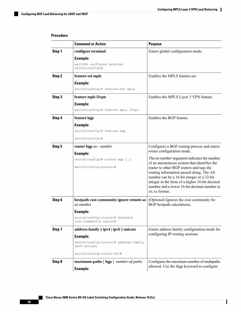
Procedure
PurposeCommand or Action
Enters global configuration mode.configure terminal
Example:
Step 1
switch# configure terminalswitch(config)#
Enables the MPLS feature-set.feature-set mpls
Example:
Step 2
switch(config)# feature-set mpls
Enables the MPLS Layer 3 VPN feature.feature mpls l3vpn
Example:
Step 3
switch(config)# feature mpls l3vpn
Enables the BGP feature.feature bgp
Example:
Step 4
switch(config)# feature bgp
switch(config)#
Configures a BGP routing process and entersrouter configuration mode.
router bgp as - number
Example:
Step 5
The as-number argument indicates the numberof an autonomous system that identifies the
switch(config)# router bgp 1.1
switch(config-router)# router to other BGP routers and tags therouting information passed along. The ASnumber can be a 16-bit integer or a 32-bitinteger in the form of a higher 16-bit decimalnumber and a lower 16-bit decimal number inxx.xx format.
(Optional) Ignores the cost community forBGP bestpath calculations.
bestpath cost-community ignore remote-asas-number
Example:
Step 6
switch(config-router)# bestpathcost-community ignore#
Enters address family configuration mode forconfiguring IP routing sessions.
address-family { ipv4 | ipv6 } unicast
Example:
Step 7
switch(config-router)# address-familyipv4 unicast
switch(config-router-af)#
Configures themaximumnumber ofmultipathsallowed. Use the ibgp keyword to configure
maximum-paths [ bgp ] number-of-paths
Example:
Step 8
Cisco Nexus 9000 Series NX-OS Label Switching Configuration Guide, Release 10.2(x)90
Configuring MPLS Layer 3 VPN Load BalancingConfiguring BGP Load Balancing for eBGP and iBGP

PurposeCommand or Action
iBGP load balancing. The range is from 1 to16.
switch(config-router-af)# maximum-paths4
(Optional) Displays the running configurationfor BGP.
show running-config bgp
Example:
Step 9
switch(config-router-vrf-neighbor-af)#show running-config bgp
(Optional) Copies the running configurationto the startup configuration.
copy running-config startup-config
Example:
Step 10
switch(config-router-vrf)# copyrunning-config startup-config
Configuring BGPv4 Multipath
Procedure
PurposeCommand or Action
Enters global configuration mode.configure terminal
Example:
Step 1
switch# configure terminalswitch(config)#
Enables the BGP feature.feature bgp
Example:
Step 2
switch(config)# feature bgp
Assigns an autonomous system (AS) numberto a router and enter the router BGPconfiguration mode.
router bgp as - number
Example:switch(config)# router bgp 2
switch(config-router)#
Step 3
Enters address family configuration mode forconfiguring routing sessions, such as BGP, thatuse standard VPNv4 address prefixes.
address-family vpnv4 unicast
Example:switch(config-router)# address-familyvpnv4 unicast
Step 4
switch(config-router-af)#
Specifies themaximumnumber of BGPVPNv4multipaths for both eBGP and iBGP paths. Therange is from 1 to 32.
maximum-paths eibgp parallel-paths
Example:switch(config-router-af)# maximum-pathseibgp 3
Step 5
Cisco Nexus 9000 Series NX-OS Label Switching Configuration Guide, Release 10.2(x)91
Configuring MPLS Layer 3 VPN Load BalancingConfiguring BGPv4 Multipath

Configuring MPLS ECMP Load SharingBeginning Cisco NX-OS Release 9.3(1), you can configure MPLS ECMP load sharing based on labels. Thisfeature is supported on Cisco Nexus 9200, Cisco Nexus 9300-EX, Cisco Nexus 9300-FX, and Cisco Nexus9500 platform switches with Cisco Nexus N9K-X9700-EX and N9K-X9700-FX line cards.
Beginning with Cisco NX-OS Release 9.3(3), this feature is supported on Cisco Nexus 9364C-GX, CiscoNexus 9316D-GX, and Cisco Nexus 93600CD-GX switches.
Procedure
PurposeCommand or Action
Enters global configuration mode.configure terminal
Example:
Step 1
switch# configure terminalswitch(config)#
Enables the MPLS feature-set.feature-set mpls
Example:
Step 2
switch(config)# feature-set mpls
Configures the load sharing based on the mplslabels. The label-only option configures the load
mpls load-sharing [ label-only | [ label-ip]
Example:
Step 3
sharing based on the labels, while the label-ipswitch(config)# mpls load-sharinglabel-only
option configures it based on the label and theIP address.switch(config)# mpls load-sharing
label-ip
(Optional) Copies the running configuration tothe startup configuration.
copy running-config startup-config
Example:
Step 4
switch(config)# copy running-configstartup-config
Verifying MPLS ECMP Load SharingTo display the mpls ECMP load sharing configuration, perform one of the following tasks:
Table 7: Verifying MPLS ECMP Load Sharing Configuration
PurposeCommand
Displays the number of labels that are used for thempls hashing and the IP fields that are used for thehashing.
show mpls load-sharing
Cisco Nexus 9000 Series NX-OS Label Switching Configuration Guide, Release 10.2(x)92
Configuring MPLS Layer 3 VPN Load BalancingConfiguring MPLS ECMP Load Sharing

Configuration Examples for MPLS Layer 3 VPN Load Balancing
Example: MPLS Layer 3 VPN Load BalancingThe following example shows how to configure iBGP load balancing:configure terminalfeature-set mplsfeature mpls l3vpnfeature bgprouter bgp 1.1bestpath cost-community ignoreaddress-family ipv6 unicastmaximum-paths ibgp 4
Example: BGP VPNv4 MultipathThe following example shows how to configure a maximum of 3 BGP VPNv4 multipaths:configure terminalrouter bgp 100address-family vpnv4 unicastmaximum-paths eibgp 3
Example: MPLS Layer 3 VPN Cost CommunityThe following example shows how to configure the BGP cost community:configure terminalfeature-set mplsfeature mpls l3vpnfeature bgproute-map CostMap permitset extcommunity cost 1 100router bgp 1.1router-id 192.0.2.255neighbor 192.0.2.1 remote-as 1.1address-family vpnv4 unicastsend-community extendedroute-map CostMap in
Cisco Nexus 9000 Series NX-OS Label Switching Configuration Guide, Release 10.2(x)93
Configuring MPLS Layer 3 VPN Load BalancingConfiguration Examples for MPLS Layer 3 VPN Load Balancing

Cisco Nexus 9000 Series NX-OS Label Switching Configuration Guide, Release 10.2(x)94
Configuring MPLS Layer 3 VPN Load BalancingExample: MPLS Layer 3 VPN Cost Community

C H A P T E R 7Configuring MPLS QoS
This chapter describes how to configure Quality of Service for Multiprotocol Label Switching (MPLS) Layer3 virtual private networks (VPNs).
• About MPLS Quality of Service (QoS), on page 95• Guidelines and Limitations for MPLS QoS, on page 97• Configuring MPLS QoS, on page 97• About Traffic Queuing, on page 105• Verifying MPLS QoS, on page 106
About MPLS Quality of Service (QoS)MPLS QoS enables you to provide differentiated types of service across an MPLS network. Differentiatedtypes of service satisfy a range of requirements by supplying the service specified for each packet. QoS allowsyou to classify the network traffic, police and prioritize the traffic flow, and provide congestion avoidance.
This section includes the following topics:
• MPLS QoS Terminology, on page 95
• MPLS QoS Features, on page 96
MPLS QoS TerminologyThis section defines some MPLS QoS terminology:
• Classification is the process that selects the traffic to be marked. Classification matches traffic with theselection criteria into multiple priority levels or classes of service. Traffic classification is the primarycomponent of class-based QoS provisioning. The switch makes classification decisions based on theEXP bits in the topmost label of the received MPLS packets (after a policy is installed).
• Differentiated Services Code Point (DSCP):
• Is the first six bits of the ToS byte in the IP header.
• Only present in an IP packet.
• Can be present in an IPv4 or an IPv6 packet.
• Is the first 6 bits of the 8-bit Traffic Class octet in the IPv6 header.
Cisco Nexus 9000 Series NX-OS Label Switching Configuration Guide, Release 10.2(x)95

• E-LSP is a label switched path (LSP) on which nodes infer the QoS treatment for MPLS packetsexclusively from the experimental (EXP) bits in theMPLS header. Because the QoS treatment is inferredfrom the EXP (both class and drop precedence), several classes of traffic can be multiplexed onto a singleLSP (use the same label). A single LSP can support up to eight classes of traffic because the EXP fieldis a 3-bit field.
• EXP bits define the QoS treatment (per-hop behavior) that a node should give to a packet. It is theequivalent of the DiffServ Code Point (DSCP) in the IP network. A DSCP defines a class and dropprecedence. The EXP bits are generally used to carry all the information encoded in the IP DSCP. Insome cases, however, the EXP bits are used exclusively to encode the dropping precedence.
• Marking is the process of setting a Layer 3 DSCP value in a packet. Marking is also the process ofchoosing different values for the MPLS EXP field to mark packets so that they have the priority that theyrequire during periods of congestion.
• MPLS Experimental Field: Setting the MPLS experimental (EXP) field value satisfies the requirementof operators who do not want the value of the IP precedence field modified within IP packets transportedthrough their networks. By choosing different values for the MPLS EXP field, you can mark packets sothat packets have the priority that they require during periods of congestion. By default, the three mostsignificant bits of the DSCP are copied into the MPLS EXP field during imposition. You can mark theMPLS EXP bits with an MPLS QoS policy.
MPLS QoS FeaturesQoS enables a network to provide improved service to selected network traffic. This section explains thefollowing MPLS QoS features, which are supported in an MPLS network:
MPLS Experimental FieldSetting the MPLS experimental (EXP) field value satisfies the requirement of service providers who do notwant the value of the IP precedence field modified within IP packets transported through their networks.
By choosing different values for the MPLS EXP field, you can mark packets so that packets have the prioritythat they require during periods of congestion.
By default, the IP precedence value is copied into the MPLS EXP field during imposition. You can mark theMPLS EXP bits with an MPLS QoS policy.
ClassificationClassification is the process that selects the traffic to be marked. Classification accomplishes this by partitioningtraffic into multiple priority levels, or classes of service. Traffic classification is the primary component ofclass-based QoS provisioning.
Policing and MarkingPolicing causes traffic that exceeds the configured rate to be discarded or marked down to a higher dropprecedence. Marking is a way to identify packet flows to differentiate them. Packet marking allows you topartition your network into multiple priority levels or classes of service.
The MPLS QoS policing and marking features that you can implement depend on the received traffic typeand the forwarding operation applied to the traffic.
Cisco Nexus 9000 Series NX-OS Label Switching Configuration Guide, Release 10.2(x)96
Configuring MPLS QoSMPLS QoS Features

Guidelines and Limitations for MPLS QoSMPLS Quality of Service (QoS) has the following configuration guidelines and limitations:
• When setting the QoS policy, the topmost keyword in the set mpls experimental imposition CLI is notsupported.
• MPLS QoS does not support marking based on policing.
• L3 EVPN egress node - policing is not supported on a system level mpls-in-policy.
• Egress QoS classification that is based on MPLS EXP is not supported.
• EXP labels are only set for newly pushed or swapped labels. The EXP in the inner labels remainsunchanged.
• When the traffic from the ingress line card takes the fabric module path to the line card, the line cardsacting as the MPLS Ingress LSR node do not support ECN marking. This occurs for the Cisco Nexus9500 platform switches with the N9K-X9700-EX and N9K-X9700-FX line cards.
• On the Label Edge Router (LER), policy match on EXP is not supported. Inner DSCP can be used tomatch the packets.
• Interface policy cannot be used to classify MPLS L3 EVPN packets on the Egress Label Edge Router(LER).System level MPLS-Default policy is used to classify the traffic.
• Explicit Congestion Notification (ECN) Marking is not supported on the label switching router transitnode.
• Only the default QoS Service template is supported for the MPLS handoff in Cisco NX-OS Release9.3(1). You cannot set the EXP labels on the MPLS.
• Beginning with Cisco NX-OSRelease 9.3(5), MPLSQoS is supported on Cisco Nexus 9364C-GX, CiscoNexus 9316D-GX, and Cisco Nexus 93600CD-GX switches.
• PFC is not supported for MPLS QoS and VXLAN MPLS DCI.
• Even after removing the queuing policy from an interface, previous micro-burst statistics remain. Usethe clear queuing burst-detect command to clear the remaining records.
• RACL on an ingress port of egress PE (sr decap) is not supported.
• In order to write an EXP value in the label, an explicit poicy is necessary on the PE. In absence of apolicy, the default EXP value is 7.
Configuring MPLS QoS
Be aware that the Cisco NX-OS commands for this feature may differ from those commands used in CiscoIOS.
Note
Cisco Nexus 9000 Series NX-OS Label Switching Configuration Guide, Release 10.2(x)97
Configuring MPLS QoSGuidelines and Limitations for MPLS QoS

Configuring MPLS Ingress Label Switched RouterTo configure MPLS Ingress label switched router, perform the following:
MPLS Ingress LSR ClassificationTo match the value of the Differentiated Services Code Point (DSCP) field, use the match dscp command inQoS policy-map class configuration mode. To disable the setting, use the no form of this command.
Default entries are programmed to match on DSCP and mark EXP when no ingress QoS policy is configured(Uniform mode behavior at encap).
Note
Before you begin
• You must enable MPLS configuration.
• Ensure that you are in the correct VDC (or use the switch to vdc command).
Procedure
PurposeCommand or Action
Enters global configuration mode.configure terminal
Example:
Step 1
switch# configure terminalswitch(config)#
Defines a class map, and enters class-mapconfiguration mode.
[no] class-map type qos class-map-name
Example:
Step 2
switch(config)# class-map type qos Class1switch(config-cmap-qos)#
List of DSCP values. Specifies that the packetsshould be matched (or not) on the DSCP labelin the MPLS header as follows:
[no] match [not] dscp dscp-list
Example:switch(config)# switch(config-cmap-qos)#match dscp 2-4
Step 3
• dscp-list—The list can contain values andranges. Values can range from 0 to 63.
Configuring MPLS Ingress Policing and MarkingTo configure a policy-map value and set the EXP value on all imposed label entries, use the set mplsexperimental imposition command in QoS policy-map class configuration mode. To disable the setting, usethe no form of this command.
Cisco Nexus 9000 Series NX-OS Label Switching Configuration Guide, Release 10.2(x)98
Configuring MPLS QoSConfiguring MPLS Ingress Label Switched Router

Procedure
PurposeCommand or Action
Enters global configuration mode.configure terminal
Example:
Step 1
switch# configure terminalswitch(config)#
Defines a policy map, and enters policy-mapconfiguration mode.
[no] policy-map type qos policy-map-name
Example:
Step 2
switch(config)# policy-map type qos pmap1switch(config-pmap-qos)#
Names the class-map.class class-name
Example:
Step 3
switch(config-pmap-qos)# class Class1
MPLS experimental (EXP) values. Value rangefrom 0 to 7.
set mpls experimental impositionexp_imposition_name
Example:
Step 4
switch(config)# switch(config-pmap-qos)#set mpls experimental imposition 2
Identifies the qos-group number.set qos-group group-number
Example:
Step 5
switch(config-cmap-qos)# set qos-group1
Defines a policer for classified traffic inpolicy-map class configuration mode.
police cir burst-in-msec bcconform-burst-in-msec conform-actionconform-action violate-action violate-action
Step 6
Example:switch(config-pmap-qos)# police cir 100mbps bc 200 ms conform transmit violatedrop
Enters the interface configuration mode for thespecified input interface, output interface,
interface type slot/port
Example:
Step 7
virtual circuit (VC), or a VC that will be usedas the service policy for the interface or VC.switch(config)# interface ethernet 2/2
switch(config-if)#
Attaches a policy map to an input interface, avirtual circuit (VC), an output interface, or a
service-policy type qos inputpolicy-map-name
Step 8
VC that will be used as the service policy forthe interface or VC.Example:
switch(config-if)# service-policy typeqos input pmap1switch(config-if)#
Cisco Nexus 9000 Series NX-OS Label Switching Configuration Guide, Release 10.2(x)99
Configuring MPLS QoSConfiguring MPLS Ingress Policing and Marking

Configuring MPLS Transit Label Switching RouterTo configure MPLS Transit Label Switching Routers, perform the following:
MPLS Transit LSR ClassificationTomap the value of theMPLS EXP field on all imposed label entries, use the set mpls experimental topmostcommand in QoS policy-map class configurationmode. To disable the setting, use the no form of this command.
Procedure
PurposeCommand or Action
Enters global configuration mode.configure terminal
Example:
Step 1
switch# configure terminalswitch(config)#
Defines a class map, and enters class-mapconfiguration mode.
[no] class-map type qos class-map-name
Example:
Step 2
switch(config)# class-map type qos Class1switch(config-cmap-qos)#
List of MPLS experimental (EXP) values.Specifies that the packets should be matched
[no] match [not] mpls experimentaltopmost exp-list
Step 3
(or not) on the 3-bit EXP field in the outermostExample: (topmost) MPLS label in the MPLS header as
follows:switch(config)# switch(config-cmap-qos)#match mpls experimental topmost 2, 4-7
• exp-list—The list can contain values andranges. Values can range from 0 to 7.
Configuring MPLS Transit Policing and MarkingTo configure a policy-map value and set the EXP value on all imposed label entries, use the service-policytype qos input pmap1 command in interface configuration mode. To disable the setting, use the no form ofthis command.
Procedure
PurposeCommand or Action
Enters global configuration mode.configure terminal
Example:
Step 1
switch# configure terminalswitch(config)#
Defines a policy map, and enters policy-mapconfiguration mode.
[no] policy-map type qos policy-map-name
Example:
Step 2
Cisco Nexus 9000 Series NX-OS Label Switching Configuration Guide, Release 10.2(x)100
Configuring MPLS QoSConfiguring MPLS Transit Label Switching Router
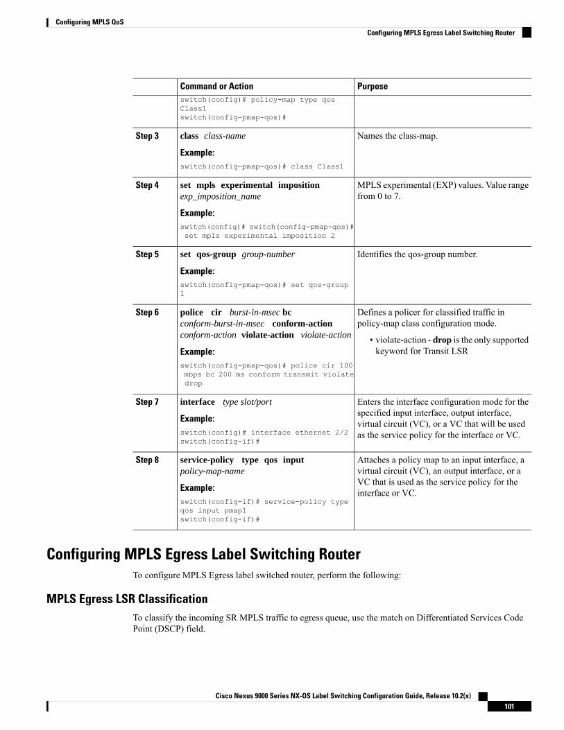
PurposeCommand or Actionswitch(config)# policy-map type qosClass1switch(config-pmap-qos)#
Names the class-map.class class-name
Example:
Step 3
switch(config-pmap-qos)# class Class1
MPLS experimental (EXP) values. Value rangefrom 0 to 7.
set mpls experimental impositionexp_imposition_name
Example:
Step 4
switch(config)# switch(config-pmap-qos)#set mpls experimental imposition 2
Identifies the qos-group number.set qos-group group-number
Example:
Step 5
switch(config-pmap-qos)# set qos-group1
Defines a policer for classified traffic inpolicy-map class configuration mode.
police cir burst-in-msec bcconform-burst-in-msec conform-actionconform-action violate-action violate-action
Step 6
• violate-action - drop is the only supportedkeyword for Transit LSRExample:
switch(config-pmap-qos)# police cir 100mbps bc 200 ms conform transmit violatedrop
Enters the interface configuration mode for thespecified input interface, output interface,
interface type slot/port
Example:
Step 7
virtual circuit (VC), or a VC that will be usedas the service policy for the interface or VC.switch(config)# interface ethernet 2/2
switch(config-if)#
Attaches a policy map to an input interface, avirtual circuit (VC), an output interface, or a
service-policy type qos inputpolicy-map-name
Step 8
VC that is used as the service policy for theinterface or VC.Example:
switch(config-if)# service-policy typeqos input pmap1switch(config-if)#
Configuring MPLS Egress Label Switching RouterTo configure MPLS Egress label switched router, perform the following:
MPLS Egress LSR ClassificationTo classify the incoming SR MPLS traffic to egress queue, use the match on Differentiated Services CodePoint (DSCP) field.
Cisco Nexus 9000 Series NX-OS Label Switching Configuration Guide, Release 10.2(x)101
Configuring MPLS QoSConfiguring MPLS Egress Label Switching Router

Procedure
PurposeCommand or Action
Enters global configuration mode.configure terminal
Example:
Step 1
switch# configure terminalswitch(config)#
Defines a class map, and enters class-mapconfiguration mode.
[no] class-map type qos class-map-name
Example:
Step 2
switch(config)# class-map type qos Class1switch(config-cmap-qos)#
List of DSCP values. Specifies that the packetsshould be matched (or not) on the DSCP labelin the MPLS header as follows:
[no] match [not] dscp dscp-list
Example:switch(config)# switch(config-cmap-qos)#match dscp 2-4
Step 3
• dscp-list—The list can contain values andranges. Values can range from 0 to 63.
MPLS Egress LSR Classification - Default Policy TemplateTo classify the incoming traffic to the egress queue of an EVPN tunnel, use the default default-mpls-in-policycommand at the system level. To disable the setting, use the no form of this command.
Procedure
PurposeCommand or Action
Enters global configuration mode.configure terminal
Example:
Step 1
switch# configure terminalswitch(config)#
Enters system QoS configuration mode.[no] system qos
Example:
Step 2
switch(config)# system qosswitch(config-sys-qos)#
Specifies the “default-mpls-in-policy” at thesystem level to match on the incoming SR L3EVPN MPLS traffic.
[no] service-policy type qos inputdefault-mpls-in-policy
Example:
Step 3
switch(config-sys-qos)# service-policytype qos input default-mpls-in-policy
The following is the default MPLS in policy template configured with the service-policy type qos inputdefault-mpls-in-policy command.policy-map type qos default-mpls-in-policy
class c-dflt-mpls-qosgrp1
Cisco Nexus 9000 Series NX-OS Label Switching Configuration Guide, Release 10.2(x)102
Configuring MPLS QoSMPLS Egress LSR Classification - Default Policy Template

set qos-group 1class c-dflt-mpls-qosgrp2set qos-group 2
class c-dflt-mpls-qosgrp3set qos-group 3
class c-dflt-mpls-qosgrp4set qos-group 4
class c-dflt-mpls-qosgrp5set qos-group 5
class c-dflt-mpls-qosgrp6set qos-group 6
class c-dflt-mpls-qosgrp7set qos-group 7
class class-defaultset qos-group 0
class-map type qos match-any c-dflt-mpls-qosgrp1Description: This is an ingress default qos class-map that classify traffic with prec 1match precedence 1
class-map type qos match-any c-dflt-mpls-qosgrp2Description: This is an ingress default qos class-map that classify traffic with prec 2match precedence 2
class-map type qos match-any c-dflt-mpls-qosgrp3Description: This is an ingress default qos class-map that classify traffic with prec 3match precedence 3
class-map type qos match-any c-dflt-mpls-qosgrp4Description: This is an ingress default qos class-map that classify traffic with prec 4match precedence 4
class-map type qos match-any c-dflt-mpls-qosgrp5Description: This is an ingress default qos class-map that classify traffic with prec 5match precedence 5
class-map type qos match-any c-dflt-mpls-qosgrp6Description: This is an ingress default qos class-map that classify traffic with prec 6match precedence 6
class-map type qos match-any c-dflt-mpls-qosgrp7Description: This is an ingress default qos class-map that classify traffic with prec 7match precedence 7
Custom MPLS-in-Policy MappingYou can override the queue mapping of incoming traffic by editing a local copy of the template provided.The system matching is always based on precedence, and requires the “mpls-in-policy” string to be part ofthe policy name. Marking with QoS is supported. Set can be qos-group, vlan-cos, or both.
class-map type qos match-all prec-1match precedence 1
class-map type qos match-all prec-2match precedence 2
policy-map type qos test-mpls-in-policyclass prec-1set qos-group 3
class prec-2set qos-group 4
system qosservice-policy type qos input test-mpls-in-policy
Cisco Nexus 9000 Series NX-OS Label Switching Configuration Guide, Release 10.2(x)103
Configuring MPLS QoSCustom MPLS-in-Policy Mapping

Classification based on Precedence is only supported and Marking is not supported on system levelmpls-in-policy.
Note
Configuring MPLS Egress LSR - Policing and MarkingTo configure and apply a policy-map with policer config, use the service-policy type qos input pmap1command in interface configuration mode. To disable the setting, use the no form of this command.
Policing is not supported for SR L3 EVPN MPLS trafficNote
Procedure
PurposeCommand or Action
Enters global configuration mode.configure terminal
Example:
Step 1
switch# configure terminalswitch(config)#
Defines a class map, and enters class-mapconfiguration mode.
[no] policy-map type qos class-map-name
Example:
Step 2
switch(config)# policy-map type qosClass1switch(config-pmap-qos)#
Names the class-map.policy policy-name
Example:
Step 3
switch(config-pmap-qos)# class Class1
Identifies the dscp value.set dscp dscp-value
Example:
Step 4
switch(config-pmap-qos)# set dscp 4
Identifies the qos-group number.set qos-group group-number
Example:
Step 5
switch(config-pmap-qos)# set qos-group1
Defines a policer for classified traffic inpolicy-map class configuration mode.
[no] police cir burst-in-msec bcconform-burst-in-msec conform-actionconform-action violate-action violate-action
Step 6
Example:switch(config-pmap-qos)# police cir 100mbps bc 200 ms conform transmit violatedrop
Cisco Nexus 9000 Series NX-OS Label Switching Configuration Guide, Release 10.2(x)104
Configuring MPLS QoSConfiguring MPLS Egress LSR - Policing and Marking

PurposeCommand or Action
Enters the interface configuration mode for thespecified interface.
interface type slot/port
Example:
Step 7
switch(config)# interface ethernet 2/2switch(config-if)#
Attaches a policy map to an input interface, avirtual circuit (VC), an output interface, or a
[no] service-policy type qos inputpolicy-map-name
Step 8
VC that will be used as the service policy forthe interface or VC.Example:
switch(config-if)# service-policy typeqos input pmap1switch(config-if)#
About Traffic QueuingTraffic queuing is the ordering of packets and applies to both input and output of data. Device modules cansupport multiple queues, which you can use to control the sequencing of packets in different traffic classes.You can also set weighted random early detection (WRED) and taildrop thresholds. The device drops packetsonly when the configured thresholds are exceeded.
Configuring QoS Traffic QueuingTo set the output queue, use the set qos-group command in policy map configuration mode. To disable thesetting, use the no form of this command.
Procedure
PurposeCommand or Action
Enters global configuration mode.configure terminal
Example:
Step 1
switch# configure terminalswitch(config)#
Defines a class map, and enters class-mapconfiguration mode.
[no] policy-map type qos class-map-name
Example:
Step 2
switch(config)# class-map type qos Class1switch(config-cmap-qos)#
Names the class-map.class class-name
Example:
Step 3
switch(config-cmap-qos)# class Class1
Applies queueing parameters for the namedQoS group in policy map. Value range from 0to 7.
set qos-group qos_group_number
Example:switch(config-pmap-c-qos)# set qos-group
Step 4
Cisco Nexus 9000 Series NX-OS Label Switching Configuration Guide, Release 10.2(x)105
Configuring MPLS QoSAbout Traffic Queuing

Verifying MPLS QoSTo display the MPLS QoS configuration, perform the following task:
DescriptionCommand
Displays information about the MAX label entriesand Used label entries.
show hardware internal forwarding table utilization
Displays the interface class mapping statistics.show class-map
Displays the cumulative statistics that show thepackets matched for every class for all the interfaces(only for the EVPN tunnel case). For moreinformation, see the sample output following thistable.
show policy-map system type qos input
Displays the statistics that show the packets matchedfor every class on that interface in the given direction.
show policy-map type qos interface interface
Displays the service policy maps configured on theinterfaces.
show policy-map type qos <pmap name>
Displays the queuing information of interfaces.show queuing interface
The following example displays the cumulative statistics that show the packets matched for every class forall the interfaces (only for the EVPN tunnel case).switch# show policy-map system type qos input
Service-policy (qos) input: default-mpls-in-policy
Class-map (qos): c-dflt-mpls-qosgrp1 (match-any)
Slot 32775483 packets
Aggregate forwarded :2775483 packets
Match: precedence 1set qos-group 1
Class-map (qos): c-dflt-mpls-qosgrp2 (match-any)
Slot 32775549 packets
Aggregate forwarded :2775549 packets
Match: precedence 2set qos-group 2
Class-map (qos): c-dflt-mpls-qosgrp3 (match-any)
Slot 22777189 packets
Aggregate forwarded :2777189 packets
Match: precedence 3
Cisco Nexus 9000 Series NX-OS Label Switching Configuration Guide, Release 10.2(x)106
Configuring MPLS QoSVerifying MPLS QoS

set qos-group 3
Class-map (qos): c-dflt-mpls-qosgrp4 (match-any)
Slot 32775688 packets
Aggregate forwarded :2775688 packets
Match: precedence 4set qos-group 4
Class-map (qos): c-dflt-mpls-qosgrp5 (match-any)
Slot 32775756 packets
Aggregate forwarded :2775756 packets
Match: precedence 5set qos-group 5
Class-map (qos): c-dflt-mpls-qosgrp6 (match-any)
Slot 32775824 packets
Aggregate forwarded :2775824 packets
Match: precedence 6set qos-group 6
Class-map (qos): c-dflt-mpls-qosgrp7 (match-any)
Slot 32775892 packets
Aggregate forwarded :2775892 packets
Match: precedence 7set qos-group 7
Class-map (qos): class-default (match-any)
Slot 32775962 packets
Aggregate forwarded :2775962 packets
set qos-group 0
Cisco Nexus 9000 Series NX-OS Label Switching Configuration Guide, Release 10.2(x)107
Configuring MPLS QoSVerifying MPLS QoS

Cisco Nexus 9000 Series NX-OS Label Switching Configuration Guide, Release 10.2(x)108
Configuring MPLS QoSVerifying MPLS QoS

C H A P T E R 8Configuring Segment Routing
This chapter contains information on how to configure segment routing.
• About Segment Routing, on page 109• Guidelines and Limitations for Segment Routing, on page 111• Configuring Segment Routing, on page 114• Configuring Segment Routing with IS-IS Protocol, on page 125• Configuring Segment Routing with OSPFv2 Protocol, on page 126• Configuring Segment Routing for Traffic Engineering, on page 131• Configuring SR-TE Manual Preference Selection, on page 144• Configuring SRTE Flow-based Traffic Steering, on page 148• Configuring MPLS OAMMonitoring for SRTE Policies, on page 164• Configuring Egress Peer Engineering with Segment Routing, on page 174• Configuring Layer2 EVPN over Segment Routing MPLS, on page 181• Configuring Proportional Multipath for VNF for Segment Routing, on page 194• vPC Multihoming, on page 196• Configuring Layer 3 EVPN and Layer 3 VPN over Segment Routing MPLS, on page 198• Configuring Segment Routing MPLS and GRE Tunnels, on page 210• Verifying SR-TE for Layer 3 EVPN, on page 213• Verifying the Segment Routing Configuration, on page 214• Configuring SRTE Explicit-Path Endpoint Substitution, on page 216• Configuring SRTE Over Default VRF, on page 220• Additional References, on page 237
About Segment RoutingSegment routing is a technique by which the path followed by a packet is encoded in the packet itself, similarto source routing. A node steers a packet through a controlled set of instructions, called segments, by prependingthe packet with a segment routing header. Each segment is identified by a segment ID (SID) consisting of aflat unsigned 32-bit integer.
Border Gateway Protocol (BGP) segments, a subclass of segments, identify a BGP forwarding instruction.There are two groups of BGP segments: prefix segments and adjacency segments. Prefix segments steerpackets along the shortest path to the destination, using all available equal-cost multi-path (ECMP) paths.
Adjacency segments steer packets onto a specific link to a neighbor.
Cisco Nexus 9000 Series NX-OS Label Switching Configuration Guide, Release 10.2(x)109

The segment routing architecture is applied directly to the MPLS data plane.
Segment Routing Application ModuleSegment Routing Application (SR-APP) module is used to configure the segment routing functionality.Segment Routing Application (SR-APP) is a separate internal process that handles all the CLIs related tosegment routing. It is responsible for reserving the SRGB range and for notifying the clients about it. It is alsoresponsible for maintaining the prefix to SID mappings. The SR-APP support is also available for the BGP,IS-IS, and OSPF protocols.
The SR-APP module maintains the following information:
• Segment routing operation state
• Segment routing global block label ranges
• Prefix SID mappings
For more information, see Configuring Segment Routing, on page 114.
NetFlow for MPLSNetFlow identifies packet flows for ingress IP packets and provides statistics that are based on these packetflows. NetFlow does not require any change to either the packets themselves or to any networking device.You can export the data that NetFlow gathers for your flow by using a flow exporter and export this data toa remote NetFlow Collector, such as Cisco Stealthwatch. Cisco NX-OS exports flow as part of a NetFlowexport User Datagram Protocol (UDP) datagram. You can export the data that NetFlow gathers for your flowby using a flow exporter and export this data to a remote NetFlow Collector, such as Cisco Stealthwatch.Cisco NX-OS exports a flow as part of a NetFlow export User Datagram Protocol (UDP) datagram.
Beginning with Cisco NX-OS Release 9.3(1), NetFlow Collector over segment routing is supported on CiscoNexus 9300-EX, 9300-FX, 9300-FX2, 9500-EX, and 9500-FX platform switches.
Beginning with Cisco NX-OS Release 9.3(5), NetFlow Collector over segment routing is supported on CiscoNexus 9300-FX3 platform switches.
NetFlow is not supported on Cisco Nexus 9300-GX platform switches..
NetFlow Collector supports both, single and double MPLS labels. Both, default and the non-default VRF inthe exporter destination configurations is supported. NetFlow does not support an MPLS data path.
Since segment routing does not support a single label, you must configure the address-family ipv4labeled-unicast command under BGP neighbor and the allocate-label command under the bgp configuration.
sFlow CollectorSampled flow (sFlow) allows you to monitor real-time traffic in data networks that contain switches androuters. It uses the sampling mechanism in the sFlow agent software on switches and routers to monitor trafficand to forward the sample data to the central data collector.
Beginning with Cisco NX-OS Release 9.3(1), sFlow collector over segment routing is supported on CiscoNexus 9300-EX, 9300-FX, 9300-FX2, 9500-EX, and 9500-FX platform switches.
Beginning Cisco NX-OS Release 9.3(5), sFlow collector over segment routing is supported on Cisco Nexus9300-FX3 platform switches.
Cisco Nexus 9000 Series NX-OS Label Switching Configuration Guide, Release 10.2(x)110
Configuring Segment RoutingSegment Routing Application Module

sFlow is not supported on Cisco Nexus 9364C-GX, Cisco Nexus 9316D-GX, and Cisco Nexus 93600CD-GXswitches.
For information on configuring sFlow, see the Configuring sFlow section in the Cisco Nexus 9000 SeriesNX-OS System Management Configuration Guide, Release 9.3(x).
Guidelines and Limitations for Segment RoutingSegment routing has the following guidelines and limitations:
• MPLS segment routing is not supported for FEX modules.
• Beginning with Cisco NX-OS Release 9.3(1), the segment-routing mpls command has changed tosegment-routing.
• When you enable MPLS segment routing on Cisco Nexus 9504 and 9508 platform switches with a -Rseries line card, there can be instances of the BFD sessions going down and coming back. BGP peerings,if configured with BFD, also go down and come back up. When a BGP session goes down, it withdrawsroutes from the hardware. This results in packet loss until the BGP session is re-established and routesare re-installed. However, once the BFD comes up, no additional flaps occurs.
• You can run segment routing under IGP(like OSPF) or by AF labeled unicast in BGP.
• Segment Routing is supported on Cisco Nexus 9300-FX platform switches and the Cisco NexusN9K-X9736C-FX line cards.
• Segment routing and SR-EVPN are supported on Cisco Nexus C31108PC-V, C31108TC-V, andC3132Q-V switches.
• Beginning with Cisco NX-OS Release 9.3(3), you can configure Layer 3 VPNs on Cisco Nexus 9300-GXplatform switches.
• Beginning with Cisco NX-OS Release 9.3(3), segment routing and SR-EVPN is supported on CiscoNexus 9364C-GX, Cisco Nexus 9316D-GX, and Cisco Nexus 93600CD-GX platform switches.
• Beginning with Cisco NX-OS Release 9.3(3), adjacency SIDs on OSPF are supported on Cisco Nexus9364C-GX, Cisco Nexus 9316D-GX, and Cisco Nexus 93600CD-GX platform switches.
• Beginning with Cisco NX-OS Release 9.3(3), segment routing with OSPF, IS-IS underlay, and BGPlabeled unicast is supported on Cisco Nexus 9364C-GX, Cisco Nexus 9316D-GX, and Cisco Nexus93600CD-GX platform switches.
• BGP allocates the SRGB label for iBGP route-reflector clients only when next-hop-self is in effect (forexample, the prefix is advertised with the next hop being one of the local IP/IPv6 addresses on RR).When you have configured next-hop-self on an RR, the next hop is changed for the routes that are beingaffected (subject to route-map filtering).
• A nondisruptive ISSU is not supported with MPLS features for Cisco Nexus 9300-EX and 9300-FXplatform switches.
• Static MPLS, MPLS segment routing, and MPLS stripping cannot be enabled at the same time.
• Beginning with Cisco NX-OS Release 9.3(5), MPLS stripping is supported on Cisco Nexus 9300-GXplatform switches and the following guidelines are applicable:
Cisco Nexus 9000 Series NX-OS Label Switching Configuration Guide, Release 10.2(x)111
Configuring Segment RoutingGuidelines and Limitations for Segment Routing

• For the MPLS strip feature to work, both the mpls strip and the hardware acl tap-agg commandsshould be configured after the switches are reloaded.
• When the MPLS strip is enabled on the Cisco Nexus 9300-GX platform switches, the ACL logprocess is not displayed.
• MPLS strip with dot1q VLAN is not supported.
• For all double VLAN tags, the second VLAN range should be between 2-510.
• MPLS strip with dot1q is not supported.
• For PACL redirect support, you must use the mode tap-aggregation command on the ingress TAPinterface.
• Because static MPLS, MPLS segment routing, and MPLS stripping are mutually exclusive, the onlysegment routing underlay for multi-hop BGP is single-hop BGP. iBGP multi-hop topologies with eBGPrunning as an overlay are not supported.
• MPLS pop followed by a forward to a specific interface is not supported. The penultimate hop pop (PHP)is avoided by installing the Explicit NULL label as the outlabel in the label FIB (LFIB) even when thecontrol plane installs an IPv4 Implicit NULL label.
• BGP labeled unicast and BGP segment routing are not supported for IPv6 prefixes.
• BGP labeled unicast and BGP segment routing are not supported over tunnel interfaces (including GREand VXLAN) or with vPC access interfaces.
• MTU path discovery (RFC 2923) is not supported over MPLS label switched paths (LSPs) or segmentrouted paths.
• For the Cisco Nexus 9200 Series switches, adjacency statistics are not maintained for Layer 3 or MPLSadjacencies.
• For the Cisco Nexus 9500 Series switches, MPLS LSPs and segment routed paths are not supported onsubinterfaces (either port channels or normal Layer 3 ports).
• For the Cisco Nexus 9500 platform switches, segment routing is supported only in the nonhierarchicalrouting mode.
• The BGP configuration commands neighbor-down fib-accelerate and suppress-fib-pending are notsupported for MPLS prefixes.
• The uniform model as defined in RFC 2973 and RFC 3270 is not supported. Therefore, the IP DSCPbits are not copied into the imposed MPLS header.
• Reconfiguration of the segment routing global block (SRGB) results in an automatic restart of the BGPprocess to update the existing URIB and ULIB entries. Traffic loss occurs for a few seconds, so youshould not reconfigure the SRGB in production.
• If the segment routing global block (SRGB) is set to a range but the route-map label-index delta valueis outside of the configured range, the allocated label is dynamically generated. For example, if the SRGBis set to range of 16000-23999 when a route-map label-index is set to 9000, the label is dynamicallyallocated.
• For network scalability, Cisco recommends using a hierarchical routing design with multi-hop BGP foradvertising the attached prefixes from a top-of-rack (ToR) or border leaf switch.
Cisco Nexus 9000 Series NX-OS Label Switching Configuration Guide, Release 10.2(x)112
Configuring Segment RoutingGuidelines and Limitations for Segment Routing

• BGP sessions are not supported over MPLS LSPs or segment routed paths.
• The Layer 3 forwarding consistency checker is not supported for MPLS routes.
• You can configure segment routing traffic engineering with on-demand next hop on Cisco Nexus 9000Series switches.
• Layer 3 VPN and Layer 3 EVPN stitching for segment routing is supported on Cisco Nexus 9000 Seriesswitches.
• Beginning with Cisco NX-OS Release 9.3(3), Layer 3 VPN and Layer 3 EVPN stitching for segmentrouting is supported on 9300-GX platform switches.
• You can configure OSPFv2 as an IGP control plane for segment routing on Cisco Nexus 9000 Seriesswitches.
• Layer 3 VPN and Layer 3 EVPN Stitching for segment routing is not supported on Cisco Nexus 9364C,9200, 9300-EX, and 9500 platform switches with the -EX line cards.
• The OSPF segment routing command and segment-routing traffic engineering with on-demand next hopis not supported on Cisco Nexus 9364C switches.
• Segment Routing is supported on Cisco Nexus 9300-FX2 and 9300-FX3 platform switches.
• Layer 3 VPN and Layer 3 EVPN Stitching for Segment Routing, the OSPF segment routing command,and the segment-routing traffic engineering with on-demand next hop is supported on Cisco Nexus 9364Cswitches.
• Layer 3 VPN over Segment Routing is supported on Cisco Nexus 3100, 3200, 9200, 9300,9300-EX/FX/FX2/FX3 platform switches and Cisco Nexus 9500 platform switches with -EX/FX and-R line cards.
• Deleting the segment routing configuration removes all the related segment routing configurationsincluding the MPLS and the traffic engineering configurations.
• If you downgrade the Cisco Nexus device from Cisco NX-OS Release 9.3(1) to the previous NX-OSreleases by setting the boot variables and reloading the switch, all earlier configurations of thesegment-routing MPLS are lost.
• Before performing an ISSD from Cisco NX-OS Release 9.3(1), you must disable the segment routingconfiguration. Failure to do so will result in the loss of the existing segment routing configurations.
• Segment routing MPLS adjacency statistics are collected based on the out label stack and the next hopon the intermediate nodes. However, in the PHPmode, the statistics are shown on all adjacencies becausethe same stack is shared on all the FECs.
• If segment routing is enabled on a switch, Q-in-Q tagging on a dot1Q tagged MPLS packet is notsupported, packets egress with only the outer tag.
For example: Consider an ingress port in access dot1q tunnel mode, with VLAN 100. Incoming MPLStraffic has a dot1Q tag of 200. Typically, the traffic should egress with an outer tag of 100, and inner tagof 200 (same as the tag of the incoming packet). However, the packet egresses with an outer tag andloses the inner tag.
• When an incoming MPLS packet is untagged and the ingress port is in access VLAN mode, packetsegress without any tag, if segment routing is enabled.
Cisco Nexus 9000 Series NX-OS Label Switching Configuration Guide, Release 10.2(x)113
Configuring Segment RoutingGuidelines and Limitations for Segment Routing

• We recommend that you do not configure segment routing using BGP, OSPF, and IS-IS underlaysimultaneously.
• Beginning with Cisco NX-OS Release 10.2(1q)F, SR-MPLS is supported on the N9K-C9332D-GX2Bplatform switches. However, SR PBR and MPLS strip dot1q features are not yet supported on GX2switches.
Configuring Segment Routing
Configuring Segment Routing
Before you begin
Confirm that the following conditions are met before configuring segment routing.
• The install feature-set mpls, feature-set mpls and feature mpls segment-routing commands shouldbe present before configuring the segment-routing command.
• If the global block is configured, the specified range is used. Otherwise, the default 16000 – 23999 rangeis used.
• BGP now uses both set label-index <value> configuration and the new connected-prefix-sid-mapCLI.In case of a conflict, the configuration in SR-APP is preferred.
Procedure
PurposeCommand or Action
Enters global configuration mode.configure terminal
Example:
Step 1
switch# configure terminalswitch(config)#
Enables the MPLS segment routingfunctionality. The no form of this commanddisables the MPLS segment routing feature.
segment-routing
Example:switch(config)# segment-routingswitch(config-sr)# mplsswitch(config-sr-mpls)#
Step 2
Configures the connected prefix segmentidentifier mappings.
connected-prefix-sid-map
Example:
Step 3
switch(config-sr-mpls)#connected-prefix-sid-mapswitch(config-sr-mpls)#
Specifies the global block range for the segmentrouting bindings.
global-block <min> <max>
Example:
Step 4
Cisco Nexus 9000 Series NX-OS Label Switching Configuration Guide, Release 10.2(x)114
Configuring Segment RoutingConfiguring Segment Routing

PurposeCommand or Actionswitch(config-sr-mpls)# global-block<min> <max>switch(config-sr-mpls)#
Configures the connected prefix segmentidentifier mappings.
connected-prefix-sid-map
Example:
Step 5
switch(config-sr-mpls)#connected-prefix-sid-mapswitch(config-sr-mpls-conn-pfsid)#
Configures the IPv4 address family.address-family ipv4
Example:
Step 6
switch(config-sr-mpls-conn-pfsid)#address-familyipv4
The optional keywords index or absoluteindicate whether the label value entered should
<prefix>/<masklen> [index|absolute ] <label>
Example:
Step 7
be interpreted as an index into the SRGB or asan absolute value.switch(config-sr-mpls)# 2.1.1.5/32
absolute 201101
Example
See the following configuration examples of the show commands:
switch# show segment-routing mplsSegment-Routing Global info
Service Name: segment-routing
State: Enabled
Process Id: 29123
Configured SRGB: 17000 – 24999
SRGB Allocation status: Alloc-Successful
Current SRGB: 17000 – 24999
Cleanup Interval: 60
Retry Interval: 180
The following CLI displays the clients that are registered with SR-APP. It lists the VRFs, for whichthe clients have registered interest.
switch# show segment-routing mpls clientsSegment-Routing Mpls Client Info
Client: isis-1PIB index: 1 UUID: 0x41000118 PID: 29463 MTS SAP: 412TIBs registered:
VRF: default Table: base
Cisco Nexus 9000 Series NX-OS Label Switching Configuration Guide, Release 10.2(x)115
Configuring Segment RoutingConfiguring Segment Routing

Client: bgp-1PIB index: 2 UUID: 0x11b PID: 18546 MTS SAP: 62252TIBs registered:
VRF: default Table: base
Total Clients: 2
In the show segment-routing mpls ipv4 connected-prefix-sid-mapCLI command example, SRGBindicates whether the prefix SID is within the configured SRGB. The Indx field indicates that theconfigured label is an index into the global block. The Abs field indicates that the configured labelis an absolute value.
If the SRGB field displays N, it means that the configured prefix SID is not within the SRGB rangeand it is not provided to the SR-APP clients. Only the prefix SIDs that fall into the SRGB range aregiven to the SR-APP clients.
switch# show segment-routing mpls ipv4 connected-prefix-sid-mapSegment-Routing Prefix-SID Mappings
Prefix-SID mappings for VRF default Table basePrefix SID Type Range SRGB13.11.2.0/24 713 Indx 1 Y30.7.7.7/32 730 Indx 1 Y59.3.24.0/30 759 Indx 1 Y150.101.1.0/24 801 Indx 1 Y150.101.1.1/32 802 Indx 1 Y150.101.2.0/24 803 Indx 1 Y1.1.1.1/32 16013 Abs 1 Y
The following CLI displays the show running-config segment-routing output.
switch# show running-config segment-routing ?
> Redirect it to a file>> Redirect it to a file in append modeall Show running config with defaults| Pipe command output to filter
switch# show running-config segment-routingswitch# show running-config segment-routing
!Command: show running-config segment-routing!Running configuration last done at: Thu Dec 12 19:39:52 2019!Time: Thu Dec 12 20:06:07 2019
version 9.3(3) Bios:version 05.39segment-routing
mplsconnected-prefix-sid-map
address-family ipv42.1.1.1/32 absolute 100100
switch#
Enabling MPLS on an InterfaceYou can enable MPLS on an interface for use with segment routing.
Cisco Nexus 9000 Series NX-OS Label Switching Configuration Guide, Release 10.2(x)116
Configuring Segment RoutingEnabling MPLS on an Interface

Before you begin
You must install and enable the MPLS feature set using the install feature-set mpls and feature-set mplscommands.
Procedure
PurposeCommand or Action
Enters global configuration mode.configure terminal
Example:
Step 1
switch# configure terminalswitch(config)#
Enters the interface configuration mode for thespecified interface.
interface type slot/port
Example:
Step 2
switch(config)# interface ethernet 2/2switch(config-if)#
Enables MPLS on the specified interface. Theno form of this command disables MPLS onthe specified interface.
[no] mpls ip forwarding
Example:switch(config-if)# mpls ip forwarding
Step 3
Copies the running configuration to the startupconfiguration.
(Optional) copy running-config startup-config
Example:
Step 4
switch(config-if)# copy running-configstartup-config
Configuring the Segment Routing Global BlockYou can configure the beginning and ending MPLS labels in the segment routing global block (SRGB).
Before you begin
You must install and enable the MPLS feature set using the install feature-set mpls and feature-set mplscommands.
You must enable the MPLS segment routing feature.
Procedure
PurposeCommand or Action
Enters global configuration mode.configure terminal
Example:
Step 1
switch# configure terminalswitch(config)#
Enters the segment routing configuration modeand enables the default SRGB of 16000 to
[no] segment-routing
Example:
Step 2
Cisco Nexus 9000 Series NX-OS Label Switching Configuration Guide, Release 10.2(x)117
Configuring Segment RoutingConfiguring the Segment Routing Global Block

PurposeCommand or Action
23999. The no form of this commandunallocates that block of labels.
switch(config)# segment-routingswitch(config-sr)# mpls
If the configured dynamic range cannot holdthe default SRGB, an error message appears,and the default SRGB will not be allocated. Ifdesired, you can configure a different SRGB inthe next step.
Specifies the MPLS label range for the SRGB.Use this command if you want to change the
[no] global-block beginning-label ending-label
Example:
Step 3
default SRGB label range that is configuredwith the segment-routing command.switch(config-sr-mpls)# global-block
16000 471804
The permissive values for the beginningMPLSlabel and the ending MPLS label are from16000 to 471804. The mpls label rangecommand permits 16 as the minimum label, butthe SRGB can start only from 16000.
The minimum value for theglobal-block command starts from16000. If you upgrading fromprevious releases, you shouldmodifythe SRGB so that it falls within thesupported range before triggering anupgrade.
Note
Displays the SRGB, only if the SRGB allocationis successful.
(Optional) show mpls label range
Example:
Step 4
switch(config-sr-mpls)# show mpls labelrange
Displays the configured SRGB.show segment-routingStep 5
Displays the configured SRGB.show segment-routing mpls
Example:
Step 6
switch(config-sr-mpls)# showsegment-routing mpls
Copies the running configuration to the startupconfiguration.
(Optional) copy running-config startup-config
Example:
Step 7
switch(config-sr-mpls)# copyrunning-config startup-config
Configuring the Label IndexYou can set the label index for routes that match the network command. Doing so causes the BGP prefixSID to be advertised for local prefixes that are configured with a route map that includes the set label-index
Cisco Nexus 9000 Series NX-OS Label Switching Configuration Guide, Release 10.2(x)118
Configuring Segment RoutingConfiguring the Label Index

command, provided the route map is specified in the network command that specifies the local prefix. (Formore information on the network command, see the "Configuring Basic BGP" chapter in the Cisco Nexus9000 Series NX-OS Unicast Routing Configuration Guide.)
Segment Routing Application (SR-APP) module is used to configure the segment routing functionality. BGPnow uses both set label-index <value> configuration under route-map and the new connected-prefix-sid-mapCLI for prefix SID configuration. In case of a conflict, the configuration in SR-APP is preferred.
Note
Route-map label indexes are ignored when the route map is specified in a context other than the networkcommand. Also, labels are allocated for prefixes with a route-map label index independent of whether theprefix has been configured by the allocate-label route-map route-map-name command.
Note
Procedure
PurposeCommand or Action
Enters global configuration mode.configure terminal
Example:
Step 1
switch# configure terminalswitch(config)#
Creates a route map or enters route-mapconfiguration mode for an existing route map.
route-map map-name
Example:
Step 2
switch(config)# route-map SRmapswitch(config-route-map)#
Sets the label index for routes that match thenetwork command. The range is from 0 to
[no] set label-index index
Example:
Step 3
471788. By default, a label index is not addedto the route.switch(config-route-map)# set label-index
10
Exits route-map configuration mode.exit
Example:
Step 4
switch(config-route-map)# exitswitch(config)#
Enables BGP and assigns the AS number to thelocal BGP speaker. The AS number can be a
router bgp autonomous-system-number
Example:
Step 5
16-bit integer or a 32-bit integer in the form ofswitch(config)# router bgp 64496switch(config-router)#
a higher 16-bit decimal number and a lower16-bit decimal number in xx.xx format.
Enters global address family configurationmode for the IPv4 address family.
Required: address-family ipv4 unicast
Example:
Step 6
Cisco Nexus 9000 Series NX-OS Label Switching Configuration Guide, Release 10.2(x)119
Configuring Segment RoutingConfiguring the Label Index

PurposeCommand or Actionswitch(config-router)# address-familyipv4 unicastswitch(config-router-af)#
Specifies a network as local to this autonomoussystem and adds it to the BGP routing table.
network ip-prefix [route-map map-name]
Example:
Step 7
switch(config-router-af)# network10.10.10.10/32 route-map SRmap
Displays information about route maps,including the label index.
(Optional) show route-map [map-name]
Example:
Step 8
switch(config-router-af)# show route-map
Copies the running configuration to the startupconfiguration.
(Optional) copy running-config startup-config
Example:
Step 9
switch(config-router-af)# copyrunning-config startup-config
Configuration Examples for Segment RoutingThe examples in this section show a common BGP prefix SID configuration between two routers.
This example shows how to advertise a BGP speaker configuration of 10.10.10.10/32 and 20.20.20.20/32with a label index of 10 and 20, respectively. It uses the default segment routing global block (SRGB) rangeof 16000 to 23999.hostname s1install feature-set mplsfeature-set mpls
feature telnetfeature bash-shellfeature scp-serverfeature bgpfeature mpls segment-routing
segment-routingmplsvlan 1
segment-routingmplsconnected-prefix-sid-mapaddress-family ipv42.1.1.1/32 absolute 100100
route-map label-index-10 permit 10set label-index 10
route-map label-index-20 permit 10set label-index 20
vrf context managementip route 0.0.0.0/0 10.30.108.1
interface Ethernet1/1no switchport
Cisco Nexus 9000 Series NX-OS Label Switching Configuration Guide, Release 10.2(x)120
Configuring Segment RoutingConfiguration Examples for Segment Routing

ip address 10.1.1.1/24no shutdown
interface mgmt0ip address dhcpvrf member management
interface loopback1ip address 10.10.10.10/32
interface loopback2ip address 20.20.20.20/32
line consoleline vty
router bgp 1address-family ipv4 unicastnetwork 10.10.10.10/32 route-map label-index-10network 20.20.20.20/32 route-map label-index-20allocate-label all
neighbor 10.1.1.2 remote-as 2address-family ipv4 labeled-unicast
This example shows how to receive the configuration from a BGP speaker.hostname s2install feature-set mplsfeature-set mpls
feature telnetfeature bash-shellfeature scp-serverfeature bgpfeature mpls segment-routing
segment-routing mplsvlan 1
vrf context managementip route 0.0.0.0/0 10.30.97.1ip route 0.0.0.0/0 10.30.108.1
interface Ethernet1/1no switchportip address 10.1.1.2/24ipv6 address 10:1:1::2/64no shutdown
interface mgmt0ip address dhcpvrf member management
interface loopback1ip address 2.2.2.2/32
line console
line vty
router bgp 2address-family ipv4 unicastallocate-label all
neighbor 10.1.1.1 remote-as 1
Cisco Nexus 9000 Series NX-OS Label Switching Configuration Guide, Release 10.2(x)121
Configuring Segment RoutingConfiguration Examples for Segment Routing
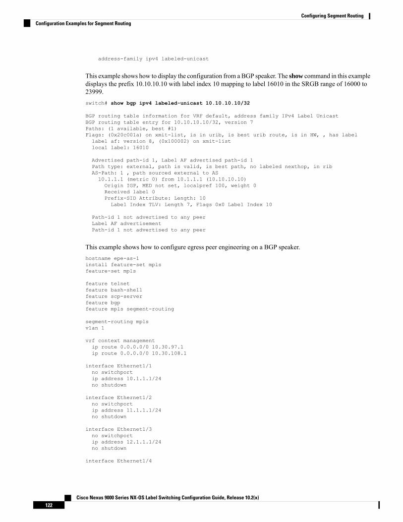
address-family ipv4 labeled-unicast
This example shows how to display the configuration from a BGP speaker. The show command in this exampledisplays the prefix 10.10.10.10 with label index 10 mapping to label 16010 in the SRGB range of 16000 to23999.switch# show bgp ipv4 labeled-unicast 10.10.10.10/32
BGP routing table information for VRF default, address family IPv4 Label UnicastBGP routing table entry for 10.10.10.10/32, version 7Paths: (1 available, best #1)Flags: (0x20c001a) on xmit-list, is in urib, is best urib route, is in HW, , has labellabel af: version 8, (0x100002) on xmit-listlocal label: 16010
Advertised path-id 1, Label AF advertised path-id 1Path type: external, path is valid, is best path, no labeled nexthop, in ribAS-Path: 1 , path sourced external to AS10.1.1.1 (metric 0) from 10.1.1.1 (10.10.10.10)Origin IGP, MED not set, localpref 100, weight 0Received label 0Prefix-SID Attribute: Length: 10Label Index TLV: Length 7, Flags 0x0 Label Index 10
Path-id 1 not advertised to any peerLabel AF advertisementPath-id 1 not advertised to any peer
This example shows how to configure egress peer engineering on a BGP speaker.hostname epe-as-1install feature-set mplsfeature-set mpls
feature telnetfeature bash-shellfeature scp-serverfeature bgpfeature mpls segment-routing
segment-routing mplsvlan 1
vrf context managementip route 0.0.0.0/0 10.30.97.1ip route 0.0.0.0/0 10.30.108.1
interface Ethernet1/1no switchportip address 10.1.1.1/24no shutdown
interface Ethernet1/2no switchportip address 11.1.1.1/24no shutdown
interface Ethernet1/3no switchportip address 12.1.1.1/24no shutdown
interface Ethernet1/4
Cisco Nexus 9000 Series NX-OS Label Switching Configuration Guide, Release 10.2(x)122
Configuring Segment RoutingConfiguration Examples for Segment Routing

no switchportip address 13.1.1.1/24no shutdown
interface Ethernet1/5no switchportip address 14.1.1.1/24no shutdown
The following is an example of show ip route vrf 2 command.show ip route vrf 2IP Route Table for VRF "2"'*' denotes best ucast next-hop'**' denotes best mcast next-hop'[x/y]' denotes [preference/metric]'%<string>' in via output denotes VRF <string>
41.11.2.0/24, ubest/mbest: 1/0*via 1.1.1.9%default, [20/0], 13:26:48, bgp-2, external, tag 11 (mpls-vpn)
42.11.2.0/24, ubest/mbest: 1/0, attached*via 42.11.2.1, Vlan2, [0/0], 13:40:52, direct
42.11.2.1/32, ubest/mbest: 1/0, attached*via 42.11.2.1, Vlan2, [0/0], 13:40:52, local
The following is an example of show forwarding route vrf 2 command.
slot 1=======
IPv4 routes for table 2/base
------------------+-----------------------------------------+----------------------+-----------------+-----------------Prefix | Next-hop | Interface | Labels
| Partial Install------------------+-----------------------------------------+----------------------+-----------------+-----------------0.0.0.0/32 Drop Null0127.0.0.0/8 Drop Null0255.255.255.255/32 Receive sup-eth1*41.11.2.0/24 27.1.31.4 Ethernet1/3 PUSH30002 492529
27.1.32.4 Ethernet1/21 PUSH30002 492529
27.1.33.4 port-channel23 PUSH30002 492529
27.11.31.4 Ethernet1/3.11 PUSH30002 492529
27.11.33.4 port-channel23.11 PUSH30002 492529
37.1.53.4 Ethernet1/53/1 PUSH29002 492529
37.1.54.4 Ethernet1/54/1 PUSH29002 492529
37.2.53.4 Ethernet1/53/2 PUSH29002 492529
37.2.54.4 Ethernet1/54/2 PUSH29002 492529
80.211.11.1 Vlan801 PUSH30002 492529
Cisco Nexus 9000 Series NX-OS Label Switching Configuration Guide, Release 10.2(x)123
Configuring Segment RoutingConfiguration Examples for Segment Routing

The following is an example of show bgp l2vpn evpn summary command.
show bgp l2vpn evpn summaryBGP summary information for VRF default, address family L2VPN EVPNBGP router identifier 2.2.2.3, local AS number 2BGP table version is 17370542, L2VPN EVPN config peers 4, capable peers 11428 network entries and 1428 paths using 268464 bytes of memoryBGP attribute entries [476/76160], BGP AS path entries [1/6]BGP community entries [0/0], BGP clusterlist entries [0/0]476 received paths for inbound soft reconfiguration476 identical, 0 modified, 0 filtered received paths using 0 bytes
Neighbor V AS MsgRcvd MsgSent TblVer InQ OutQ Up/Down State/PfxRcd1.1.1.1 4 11 0 0 0 0 0 23:01:53 Shut (Admin)1.1.1.9 4 11 4637 1836 17370542 0 0 23:01:40 4761.1.1.10 4 11 0 0 0 0 0 23:01:53 Shut (Admin)1.1.1.11 4 11 0 0 0 0 0 23:01:52 Shut (Admin)
The following is an example of show bgp l2vpn evpn command.show bgp l2vpn evpn 41.11.2.0BGP routing table information for VRF default, address family L2VPN EVPNRoute Distinguisher: 14.1.4.1:115BGP routing table entry for [5]:[0]:[0]:[24]:[41.11.2.0]:[0.0.0.0]/224, version 17369591Paths: (1 available, best #1)Flags: (0x000002) on xmit-list, is not in l2rib/evpn, is not in HW
Advertised path-id 1Path type: external, path is valid, received and used, is best path
Imported to 2 destination(s)AS-Path: 11 , path sourced external to AS1.1.1.9 (metric 0) from 1.1.1.9 (14.1.4.1)Origin incomplete, MED 0, localpref 100, weight 0Received label 492529Extcommunity: RT:2:20
Path-id 1 not advertised to any peer
Route Distinguisher: 2.2.2.3:113BGP routing table entry for [5]:[0]:[0]:[24]:[41.11.2.0]:[0.0.0.0]/224, version 17369595Paths: (1 available, best #1)Flags: (0x000002) on xmit-list, is not in l2rib/evpn, is not in HW
Advertised path-id 1Path type: external, path is valid, is best path
Imported from 14.1.4.1:115:[5]:[0]:[0]:[24]:[41.11.2.0]:[0.0.0.0]/224AS-Path: 11 , path sourced external to AS1.1.1.9 (metric 0) from 1.1.1.9 (14.1.4.1)
Cisco Nexus 9000 Series NX-OS Label Switching Configuration Guide, Release 10.2(x)124
Configuring Segment RoutingConfiguration Examples for Segment Routing

Configuring Segment Routing with IS-IS Protocol
About IS-ISIS-IS is an Interior Gateway Protocol (IGP) based on Standardization (ISO)/International EngineeringConsortium (IEC) 10589 and RFC 1995. Cisco NX-OS supports Internet Protocol version 4 (IPv4) and IPv6.IS-IS is a dynamic link-state routing protocol that can detect changes in the network topology and calculateloop-free routes to other nodes in the network. Each router maintains a link-state database that describes thestate of the network and sends packets on every configured link to discover neighbors. IS-IS floods thelink-state information across the network to each neighbor. The router also sends advertisements and updateson the link-state database through all the existing neighbors
Segment routing on the IS-IS protocol supports the following:
• IPv4
• Level 1, level 2, and multi-level routing
• Prefix SIDs
• Multiple IS-IS instances on the same loopback interface for domain border nodes
• Adjacency SIDs for adjacencies
Configuring Segment Routing with IS-IS ProtocolYou can configure segment routing with IS-IS protocol.
Before you begin
IS-IS segment routing is fully enabled when the following conditions are met:
• The mpls segment-routing feature is enabled.
• The IS-IS feature is enabled.
• Segment routing is enabled for at least one address family under IS-IS.
Procedure
PurposeCommand or Action
Enters global configuration mode.configure terminalStep 1
Creates a new IS-IS instance with theconfigured instance tag.
router isis instance-tagStep 2
Configures the NET for this IS-IS instance.net network-entity-titleStep 3
Enters address family configuration mode.address-family ipv4 unicastStep 4
Configures segment routingwith IS-IS protocol.segment-routing mplsStep 5
Cisco Nexus 9000 Series NX-OS Label Switching Configuration Guide, Release 10.2(x)125
Configuring Segment RoutingConfiguring Segment Routing with IS-IS Protocol

PurposeCommand or Action
• The IS-IS command issupported only on the IPv4address family. It is notsupported on the IPv6 addressfamily.
• Redistribution is not supportedfrom any other protocol to ISISfor the SR prefixes. You needto enable ip router isiscommand on all the prefix SIDinterfaces.
Note
Configuring Segment Routing with OSPFv2 Protocol
About OSPFOpen Shortest Path First (OSPF) is an Interior Gateway Protocol (IGP) developed by the OSPFworking groupof the Internet Engineering Task Force (IETF). Designed expressly for IP networks, OSPF supports IPsubnetting and tagging of externally derived routing information. OSPF also allows packet authentication anduses IP multicast when sending and receiving packets.
Segment routing configuration on the OSPF protocol can be applied at the process or the area level. If youconfigure segment routing at the process level, it is enabled for all the areas. However, you can enable oredisable it per area level.
Segment routing on the OSPF protocol supports the following:
• OSPFv2 control plane
• Multi-area
• IPv4 prefix SIDs for host prefixes on loopback interfaces
• Adjacency SIDs for adjacencies
Adjacency SID AdvertisementOSPF supports the advertisement of segment routing adjacency SID. An Adjacency Segment Identifier(Adj-SID) represents a router adjacency in Segment Routing.
A segment routing-capable router may allocate an Adj-SID for each of its adjacencies and an Adj-SID sub-TLVis defined to carry this SID in the Extended Opaque Link LSA.
OSPF allocates the adjacency SID for each OSPF neighbor if the OSPF adjacency which are in two way orin FULL state. OSPF allocates the adjacency SID only if the segment routing is enabled. The label for adjacencySID is dynamically allocated by the system. This eliminates the chances of misconfiguration, as this has gotonly the local significance.
Cisco Nexus 9000 Series NX-OS Label Switching Configuration Guide, Release 10.2(x)126
Configuring Segment RoutingConfiguring Segment Routing with OSPFv2 Protocol

Connected Prefix-SIDOSPFv2 supports the advertisement of prefix SID for address associated with the loopback interfaces. In orderto achieve this, OSPF uses Extended Prefix Sub TLV in its opaque Extended prefix LSA.When OSPF receivesthis LSA from its neighbor, SR label is added to the RIB corresponding to received prefix based upon theinformation present in extended prefix sub TLV.
For configuration, segment-routing has to be enabled under OSPF and corresponding to loopback interfacethat is configured with OSPF, prefix-sid mapping is required under the segment routing module.
SID will only be advertised for loopback addresses and only for intra-area and inter-area prefix types. No SIDvalue will be advertised for external or NSSA prefixes.
Note
Prefix Propagation Between AreasTo provide segment routing support across the area boundary, OSPF is required to propagate SID valuesbetween areas. When OSPF advertises the prefix reachability between areas, it checks if the SID has beenadvertised for the prefix. In a typical case, the SID value come from the router, which contributes to the bestpath to the prefix in the source area. In this case, OSPF uses such SID and advertises it between the areas. Ifthe SID value is not advertised by the router which contributes to the best path inside the area, OSPF will usethe SID value coming from any other router inside the source area.
Segment Routing Global Range ChangesOSPF advertises it's segment routing capability in terms of advertising the SID/Label Range TLV. In OSPFv2,SID/Label Range TLV is a carried in Router Information LSA.
The segment routing global range configuration will be under the “segment-routing mpls” configuration.When the OSPF process comes, it will get the global range values from segment-routing and subsequentchanges should be propagated to it.
When OSPF segment routing is configured, OSPFmust request an interaction with the segment routingmodulebefore OSPF segment routing operational state can be enabled. If the SRGB range is not created, OSPF willnot be enabled.When an SRGB change event occurs, OSPFmakes the corresponding changes in it's sub-blockentries.
Conflict Handling of SID EntriesIn an ideal situation, each prefix should have unique SID entries assigned.
When there is a conflict between the SID entries and the associated prefix entries use any of the followingmethods to resolve the conflict:
• Multiple SIDs for a single prefix - If the same prefix is advertised by multiple sources with differentSIDs, OSPF will install the unlabeled path for the prefix. The OSPF takes into consideration only thoseSIDs that are from reachable routers and ignores those from unreachable routers. When multiple SIDsare advertised for a prefix, which is considered as a conflict, no SIDwill be advertised to the attached-areasfor the prefix. Similar logic will be used when propagating the inter-area prefixes between the backboneand the non-backbone areas.
Cisco Nexus 9000 Series NX-OS Label Switching Configuration Guide, Release 10.2(x)127
Configuring Segment RoutingConnected Prefix-SID

• Out of Range SID - For SIDs that do not fit in our SID range, labels are not used while updating the RIB.
MPLS Forwarding on an InterfaceMPLS forwarding must be enabled before segment routing can use an interface. OSPF is responsible forenabling MPLS forwarding on an interface.
When segment routing is enabled for a OSPF topology, or OSPF segment routing operational state is enabled,it enables MPLS for any interface on which the OSPF topology is active. Similarly, when segment routing isdisabled for a OSPF topology, it disables the MPLS forwarding on all interfaces for that topology.
MPLS forwarding is not supported on an interface which terminates at the IPIP/GRE tunnel.
Configuring Segment Routing with OSPFv2Configure segment routing with OSPFv2 protocol.
Before you begin
Confirm that the following conditions are met before configuring segment routing with OSPFv2:
• The OSPFv2 feature is enabled.
• The segment-routing feature is enabled.
• Segment routing is enabled under OSPF.
Procedure
PurposeCommand or Action
Enters global configuration mode.configure terminal
Example:
Step 1
switch# configure terminalswitch(config)#
Enables the OSPF mode.[no]router ospf process
Example:
Step 2
switch(config)# router ospf test
Configures the segment routing functionalityunder OSPF.
segment-routing
Example:
Step 3
switch(config-router)# segment-routingmpls
Configuring Segment Routing on OSPF Network- Area Level
Before you begin
Before you configure segment routing on OSPF network, OSPF must be enabled on your network.
Cisco Nexus 9000 Series NX-OS Label Switching Configuration Guide, Release 10.2(x)128
Configuring Segment RoutingMPLS Forwarding on an Interface

Procedure
PurposeCommand or Action
Enables the OSPF mode.router ospf process
Example:
Step 1
switch(config)# router ospf test
Configures segment routing mpls mode in aspecific area.
area <area id> segment-routing [mpls |disable]
Example:
Step 2
switch(config-router)# area 1segment-routing mpls
Disables segment routing mpls mode for thespecified area.
[no]area <area id> segment-routing [mpls |disable]
Example:
Step 3
switch(config-router)#area 1segment-routing disable
Shows the output for configuring segmentrouting under OSPF.
show ip ospf process segment-routing
Example:
Step 4
switch(config-router)# show ip ospf testsegment-routing
Configuring Prefix-SID for OSPFThis task explains how to configure prefix segment identifier (SID) index under each interface.
Before you begin
Segment routing must be enabled on the corresponding address family.
Procedure
PurposeCommand or Action
Enters global configuration mode.configure terminal
Example:
Step 1
switch# configure terminal
Configures OSPF.[no]router ospf process
Example:
Step 2
switch(config)# router ospf test
Configures the segment routing functionalityunder OSPF.
segment-routing
Example:
Step 3
Cisco Nexus 9000 Series NX-OS Label Switching Configuration Guide, Release 10.2(x)129
Configuring Segment RoutingConfiguring Prefix-SID for OSPF

PurposeCommand or Actionswitch(config-router)# segment-routingswitch(config-sr)#mplsswitch(config-sr-mpls)#
Specifies the interface where OSPF is enabled.interface loopback interface_number
Example:
Step 4
switch(config-sr-mpls)# Interfaceloopback 0
Specifies the IP address configured on the ospfinterface.
ip address 1.1.1.1/32
Example:
Step 5
switch(config-sr-mpls)# ip address1.1.1.1/32
Specifies the OSPF enabled on the interfacein area.
ip router ospf 1 area 0
Example:
Step 6
switch(config-sr-mpls)# ip router ospf1 area 0
Configures prefix-sid mapping under SRmodule.
segment-routing
Example:
Step 7
switch(config-router)#segment-routing(config-sr)#mpls
Configures the prefix SID mapping under thesegment routing module.
connected-prefix-sid-map
Example:
Step 8
switch(config-sr-mpls)#connected-prefix-sid-mapswitch(config-sr-mpls-conn-pfxsid)#
Specifies the IPv4 address family configuredon the OSPF interface.
address-family ipv4
Example:
Step 9
switch(config-sr-mpls-conn-pfxsid)#address-family ipv4switch(config-sr-mpls-conn-pfxsid-af)#
Associates SID 10 with the address 1.1.1.1/32.1.1.1.1/32 index 10
Example:
Step 10
switch(config-sr-mpls-conn-af)#1.1.1.1/32 index 10
Exits segment routing mode and returns to theconfiguration terminal mode.
exit
Example:
Step 11
switch(config-sr-mpls-conn-af)# exit
Cisco Nexus 9000 Series NX-OS Label Switching Configuration Guide, Release 10.2(x)130
Configuring Segment RoutingConfiguring Prefix-SID for OSPF
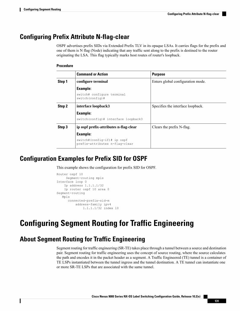
Configuring Prefix Attribute N-flag-clearOSPF advertises prefix SIDs via Extended Prefix TLV in its opaque LSAs. It carries flags for the prefix andone of them is N flag (Node) indicating that any traffic sent along to the prefix is destined to the routeroriginating the LSA. This flag typically marks host routes of router's loopback.
Procedure
PurposeCommand or Action
Enters global configuration mode.configure terminal
Example:
Step 1
switch# configure terminalswitch(config)#
Specifies the interface loopback.interface loopback3
Example:
Step 2
switch(config)# interface loopback3
Clears the prefix N-flag.ip ospf prefix-attributes n-flag-clear
Example:
Step 3
switch#(config-if)# ip ospfprefix-attributes n-flag-clear
Configuration Examples for Prefix SID for OSPFThis example shows the configuration for prefix SID for OSPF.Router ospf 10
Segment-routing mplsInterface loop 0
Ip address 1.1.1.1/32Ip router ospf 10 area 0
Segment-routingMpls
connected-prefix-sid-maddress-family ipv4
1.1.1.1/32 index 10
Configuring Segment Routing for Traffic Engineering
About Segment Routing for Traffic EngineeringSegment routing for traffic engineering (SR-TE) takes place through a tunnel between a source and destinationpair. Segment routing for traffic engineering uses the concept of source routing, where the source calculatesthe path and encodes it in the packet header as a segment. A Traffic Engineered (TE) tunnel is a container ofTE LSPs instantiated between the tunnel ingress and the tunnel destination. A TE tunnel can instantiate oneor more SR-TE LSPs that are associated with the same tunnel.
Cisco Nexus 9000 Series NX-OS Label Switching Configuration Guide, Release 10.2(x)131
Configuring Segment RoutingConfiguring Prefix Attribute N-flag-clear

With segment routing for traffic engineering (SR-TE), the network no longer needs to maintain a per-applicationand per-flow state. Instead, it simply obeys the forwarding instructions provided in the packet.
SR-TE utilizes network bandwidth more effectively than traditional MPLS-TE networks by using ECMP atevery segment level. It uses a single intelligent source and relieves remaining routers from the task of calculatingthe required path through the network.
SR-TE PoliciesSegment routing for traffic engineering (SR-TE) uses a “policy” to steer traffic through the network. A SR-TEpolicy is a container that includes sets of segments or labels. This list of segments can be provisioned by anoperator, a stateful PCE. The head-end imposes the corresponding MPLS label stack on a traffic flow to becarried over the SR-TE policy. Each transit node along the SR-TE policy path uses the incoming top label toselect the next-hop, pop or swap the label, and forward the packet to the next node with the remainder of thelabel stack, until the packet reaches the ultimate destination.
A SR-TE policy is uniquely identified by a tuple (color, end-point). A color is represented as a 32-bit numberand an end-point is an IPv4 . Every SR-TE policy has a color value. Every policy between the same nodepairs requires a unique color value. Multiple SR-TE policies can be created between the same two endpointsby choosing different colors for the policies.
Cisco Nexus 9000 Series switches support the following two types of SR-TE policies:
• Dynamic SR-TE Policy - When you configure dynamic path preference under the SR-TE policyconfiguration or an on-demand color configuration, the path computation engine (PCE) calculates thepath to the destination address. Dynamic path calculation at PCE results in a list of segments/labels thatgets applied to the head-end SR-TE policy, hence the traffic gets routed through the network by hittingthe segments that the SR-TE policy holds.
• Explicit SR-TE Policy - An explicit path is a list of labels, each representing a node or link in the explicitpath. This feature is enabled through the explicit-path command that allows you to create an explicitpath and enter a configuration submode for specifying the path.
SR-TE Policy PathsA SR-TE policy path is a list of segments that specifies the path, called a segment ID (SID) list. Every SR-TEpolicy consists of one or more candidate paths, which can be either a dynamic or an explicit path. The SR-TEpolicy instantiates a single path and the selected path is the preferred valid candidate path.
You can also add on-demand color with dynamic path option and explicit policy configuration with an explicitpath option for the same color and endpoint. In this case, a single policy is created on the head-end and thepath with the highest preference number configured is used for forwarding traffic.
The following two methods are used to compute the SR-TE policy path:.
• Dynamic Path -When you specify the dynamic PCEP option while configuring the path preference underan on-demand color configuration or a policy configuration, the path computation is delegated to a pathcomputation engine(PCE).
• Explicit Path - This path is an explicitly specified SID-list or a set of SID-lists.
Beginning with Cisco NX-OS Release 10.2(2)F, you can lockdown or shutdown an SR-TE policy or performboth; shutdown preference(s) of an SR-TE policy or an on-demand color template; force a specific preferenceto be active path option for SRTE policy; or force path re-optimization for all or a specific SRTE policy. This
Cisco Nexus 9000 Series NX-OS Label Switching Configuration Guide, Release 10.2(x)132
Configuring Segment RoutingSR-TE Policies

feature is supported on Cisco Nexus 9300-EX, 9300-FX, 9300-FX2, 9300-GX, and N9K-C9332D-GX2Bplatform switches. For more information, see Configuring SR-TEManual Preference Selection, on page 144.
For more information about the Cisco Nexus 9000 switches that support various features spanning from release7.0(3)I7(1) to the current release, refer to Nexus Switch Platform Support Matrix.
Affinity and Disjoint ConstraintsAffinity Constraints - You can assign attributes to a link which gets advertised to path computation engine(PCE). SRTE process hosts the affinity-map and interface level configurations. Routing protocol(IGP) willregister for interface updates and SRTEwill notify IGP with interface updates. IGP tlvs will be passed to BGPto advertise it to external peers. There are three types of affinity constraints:
• exclude-any: specifies that links that have any of the specified affinity colors must not be traversed bythe path.
• include-any: specifies that only links that have any of the specified affinity colors must be traversed bythe path. Thus, links that do not have any of the specified affinity colors must not be used.
• include-all: specifies that only links that have all of the specified affinity colors must be traversed by thepath. Thus, links that do not have all of the specified affinity colors must not be used.
Disjoint Constraints - You can assign disjoint constraints to the SR-TE policies which gets advertised to thePCE. The PCE then provides the disjoint path for the policies that share the same association group ID andthe disjoint disjointness type.
Cisco NX-OS Release 9.3(1) supports the following disjoint path levels :
• Link – The paths transit different links (but may transit same nodes).
• Node disjointness – The paths transit different links but may transit same node.
Segment Routing On Demand Next HopOn-DemandNext hop (ODN) leverages upon BGPDynamic SR-TE capabilities and adds the path computation(PCE) ability to find and download the end to end path based on the requirements. ODN triggers an SR-TEauto-tunnel based on the defined BGP policy. As shown in the following figure, an end-to-end path betweenToR1 and AC1 can be established from both ends based on IGPMetric. The work-flow for ODN is summarizedas follows:
Cisco Nexus 9000 Series NX-OS Label Switching Configuration Guide, Release 10.2(x)133
Configuring Segment RoutingAffinity and Disjoint Constraints

Figure 8: ODN Operation
Guidelines and Limitations for SR-TESR-TE has the following guidelines and limitations:
• SR-TE ODN for both, IPv4 and IPv6 overlay is supported.
• SR-TE ODN is supported only with IS-IS underlay.
• Forwarding does not support routes with recursive next hops, where the recursive next hop resolves toa route with a binding SID.
• Forwarding does not support mixing paths with binding labels and paths without binding labels for thesame route.
• The affinity and disjoint constraints are applicable only to those SR-TE policies that have a dynamicPCEP option.
• XTC supports only two policies with disjointness in the same group.
• When configuring the SR-TE affinity interfaces, the interface range is not supported.
• A preference cannot have both, the dynamic PCEP and the explicit segment lists configured together forthe same preference.
• Only one preference can have a dynamic PCEP option per policy.
• For explicit policy, when configuring ECMP paths under same preference, if the first hop (NHLFE) issame for both the ECMP paths, ULIB will only install one path in switching. This occurs because boththe ECMP paths create the same SRTE FEC as the NHLFE is same for both.
• In Cisco NX-OS Release 9.3(1), unprotected mode with affinity configuration is not supported by PCE(XTC).
Cisco Nexus 9000 Series NX-OS Label Switching Configuration Guide, Release 10.2(x)134
Configuring Segment RoutingGuidelines and Limitations for SR-TE

• Beginning with Cisco NX-OS Release 9.3(3), SR-TE ODN, policies, policy paths, and the affinity anddisjoint constraints are supported on Cisco Nexus 9364C-GX, Cisco Nexus 9316D-GX, and Cisco Nexus93600CD-GX switches.
• Beginningwith CiscoNX-OSRelease 10.2(2)F, few new show commands for SR-TE policy are introducedand the autocomplete feature is provided for some of the existing SR-TE policy commands to improveusability. This feature is supported on Cisco Nexus 9300-EX, 9300-FX, 9300-FX2, 9300-GX, andN9K-C9332D-GX2B platform switches.
For more information about the Cisco Nexus 9000 switches that support various features spanning release7.0(3)I7(1) to the current release, refer to Nexus Switch Platform Support Matrix.
Note
Configuring SR-TEYou can configure segment routing for traffic engineering.
Before you begin
You must ensure that the mpls segment routing feature is enabled.
Procedure
PurposeCommand or Action
Enters global configuration mode.configure terminalStep 1
Enters the segment-routing modesegment-routingStep 2
Enters the traffic engineering mode.traffic-engineeringStep 3
Configures the source address for the SR-TETunnel.
encapsulation mpls source ipv4tunnel_ip_address
Step 4
Enters the PCC mode.pccStep 5
Configure source address for the PCCsource-address ipv4 pcc_source_addressStep 6
Configure IP address of the PCE. The lowestnumbered PCE will take precedence, and theother(s) be used as a backup.
pce-address ipv4 pce_source_addressprecedence num
Step 7
Enters the on-demand mode to configure thecolor.
on-demand color color_numStep 8
Specifies the candidate paths of the policy.candidate-pathsStep 9
Specifies the preference of the candidate path.preference preference_numberStep 10
Specifies the path option.dynamicStep 11
Cisco Nexus 9000 Series NX-OS Label Switching Configuration Guide, Release 10.2(x)135
Configuring Segment RoutingConfiguring SR-TE

PurposeCommand or Action
Specifies the path computation that needs tobe done from the PCE.
pcepStep 12
Configuring Affinity ConstraintsYou can configure the affinity constraints to the SR-TE policy.
Before you begin
You must ensure that the mpls segment routing feature is enabled.
Procedure
PurposeCommand or Action
Enters global configuration mode.configure terminal
Example:
Step 1
switch# configure terminalswitch(config)#
Enables the MPLS segment routingfunctionality.
segment-routing
Example:
Step 2
switch(config)# segment-routingswitch(config-sr)#
Enters the traffic engineering mode.traffic-engineering
Example:
Step 3
switch(config-sr)# traffic-engineeringswitch(config-sr-te)#
Enters the PCC mode.pccStep 4
Configure source address for the PCCsource-address ipv4 pcc_source_addressStep 5
Configure IP address of the PCE.pce-address ipv4 pce_source_addressprecedence num
Step 6
The lowest numbered PCE takes precedenceand the other(s) are used as a backup.
Configures the affinity-map configurationmode.
affinity-map
Example:
Step 7
switch(config-sr-te)#affinity-mapswitch(config-sr-te-affmap)#
Configures a mapping of the user-definedname to a specific bit position in the affinitybit-map.
color name bit-position position
Example:switch(config-sr-te-affmap)# color redbit-position 2switch(config-sr-te-affmap)#
Step 8
Cisco Nexus 9000 Series NX-OS Label Switching Configuration Guide, Release 10.2(x)136
Configuring Segment RoutingConfiguring Affinity Constraints

PurposeCommand or Action
Specifies the name of the interface. This is theaffinity mapping name which refers to thespecific bit in the affinity bitmap.
interface interface-name
Example:Enter SRTE interface config modeswitch(config-sr-te-if)#interface eth1/1switch(config-sr-te-if)#
Step 9
Adds the affinity color to the interface.affinity
Example:
Step 10
switch(config-sr-te-if)# affinityswitch(config-sr-te-if-aff)#switch(config-sr-te-if-aff)# color redswitch(config-sr-te-if-aff)#
Configures the policy.policy name | on-demand color color_num
Example:
Step 11
switch(config-sr-te)# on-demand color211
orswitch(config-sr-te-color)# policytest_policy
Configures the color and the end point of thepolicy. This is required when you are
color color end-point address
Example:
Step 12
configuring the policy using the “policy name”config mode.switch(config-sr-te-pol)#color 200
endpoint 2.2.2.2
Specifies the candidate paths for the policy.candidate-path
Example:
Step 13
switch(config-sr-te-color)#candidate-pathsswitch(cfg-cndpath)#
Specifies the preference of the candidate path.preference preference_number
Example:
Step 14
switch(cfg-cndpath)# preference 100switch(cfg-pref)#
Specifies the path option.dynamic
Example:
Step 15
switch(cfg-pref)# dynamicswitch(cfg-dyn)#
Specifies that the headend uses PCEP torequest the PCE to compute a path from itselfto the segment routing's policy's end point.
pcep
Example:switch(cfg-dyn)# pcepswitch(cfg-dyn)#
Step 16
Cisco Nexus 9000 Series NX-OS Label Switching Configuration Guide, Release 10.2(x)137
Configuring Segment RoutingConfiguring Affinity Constraints

PurposeCommand or Action
Enters the candidate path preference constraintmode.
constraints
Example:
Step 17
switch(cfg-dyn)# constraintsswitch(cfg-constraints)#
Specifies the affinity constraints of the policy.affinity
Example:
Step 18
switch(cfg-constraints)# affinityswitch(cfg-const-aff)#
Specifies the affinity constraint type. Thefollowing affinity types are available:
exclude-any |include-all | include-any
Example:
Step 19
• exclude-any - specifies that links thathave any of the specified affinity colorsmust not be traversed by the path.
switch(cfg-const-aff)# include-anyswitch(cfg-aff-inclany)#
• include-any - specifies that only links thathave any of the specified affinity colorsmust be traversed by the path.
• include-all - specifies that only links thathave all of the specified affinity colorsmust be traversed by the path.
Specifies the affinity color definition.color color_name
Example:
Step 20
switch(cfg-aff-inclany)# color blueswitch(cfg-aff-inclany)#
Configuring Disjoint PathsYou can configure disjoint path constraints to the SR-TE policy.
Before you begin
You must ensure that the mpls segment routing feature is enabled.
Procedure
PurposeCommand or Action
Enters global configuration mode.configure terminal
Example:
Step 1
switch# configure terminalswitch(config)#
Cisco Nexus 9000 Series NX-OS Label Switching Configuration Guide, Release 10.2(x)138
Configuring Segment RoutingConfiguring Disjoint Paths

PurposeCommand or Action
Enables the MPLS segment routingfunctionality.
segment-routing
Example:
Step 2
switch(config)# segment-routingswitch(config-sr)#
Enters the traffic engineering mode.traffic-engineering
Example:
Step 3
switch(config-sr)# traffic-engineeringswitch(config-sr-te)#
Enters the PCC mode.pccStep 4
Configure source address for the PCCsource-address ipv4 pcc_source_addressStep 5
Configure IP address of the PCE.pce-address ipv4 pce_source_addressprecedence num
Step 6
The lowest numbered PCE takes precedenceand the other(s) are used as a backup.
Configures the policy.policy name | on-demand color color_num
Example:
Step 7
switch(config-sr-te)# on-demand color211
orswitch(config-sr-te-color)# policytest_policy
Configures the color and the end point of thepolicy. This is required when you are
color color end-point address
Example:
Step 8
configuring the policy using the “policy name”config mode.switch2(config-sr-te-pol)# color 200
endpoint 2.2.2.2
Specifies the candidate-paths for the policycandidate-path
Example:
Step 9
switch(config-sr-te-color)#candidate-pathsswitch(cfg-cndpath)#
Specifies the preference of the candidate path.preference preference_number
Example:
Step 10
switch(cfg-cndpath)# preference 100switch(cfg-pref)#
Specifies the path option.dynamic
Example:
Step 11
switch(cfg-pref)# dynamicswitch(cfg-dyn)#
Cisco Nexus 9000 Series NX-OS Label Switching Configuration Guide, Release 10.2(x)139
Configuring Segment RoutingConfiguring Disjoint Paths

PurposeCommand or Action
Specifies that the headend uses PCEP torequest the PCE to compute a path from itselfto the segment routing's policy's end point.
pcep
Example:switch(cfg-dyn)# pcepswitch(cfg-dyn)#
Step 12
Enters the candidate path preference constraintmode.
constraints
Example:
Step 13
switch(cfg-dyn)# constraintsswitch(cfg-constraints)#
Specifies the association group type.association-group
Example:
Step 14
switch(cfg-constraints)#association-groupswitch(cfg-assoc)#
Specifies the path that belongs to thedisjointness association group.
disjoint
Example:
Step 15
switch(cfg-assoc)# disjointswitch(cfg-disj)#
Specifies the disjointness group type.type | link | node
Example:
Step 16
switch(config-if)#type link
Specifies the identifier of theassociation-group.
id number
Example:
Step 17
switch(config-if)#id 1
Configuration Examples for SR-TEThe examples in this section show affinity and disjoint configurations.
This example shows the mappings of a user defined name to an administrative group.segment-routingtraffic-engaffinity-mapcolor green bit-position 0color blue bit-position 2color red bit-position 3
This example shows the affinity link colors red and green for the adjacency on eth1/1 and affinity link colorgreen for the adjacency on eth1/2.segment-routingtraffic-enginterface eth1/1affinitycolor redcolor green
Cisco Nexus 9000 Series NX-OS Label Switching Configuration Guide, Release 10.2(x)140
Configuring Segment RoutingConfiguration Examples for SR-TE

!interface eth1/2affinitycolor green
This examples shows the affinity constraints for the policy.segment-routingtraffic-engineeringaffinity-mapcolor blue bit-position 0color red bit-position 1
on-demand color 10candidate-pathspreference 100dynamicpcep
constraintsaffinity[include-any|include-all|exclude-any]color <col_name>color <col_name>
policy new_policycolor 201 endpoint 2.2.2.0candidate-pathspreference 200dynamicpcep
constraintsaffinityinclude-allcolor red
This examples shows the disjoint constraints for the policy.segment-routingtraffic-engon-demand color 99candidate-pathspreference 100dynamicpcep
constraintsassociation-groupdisjointtype linkid 1
Configuration Example for an SR-TE ODN - Use CasePerform the following steps to configure ODN for SR-TE. The following figure is used as a reference toexplain the configuration steps.
Cisco Nexus 9000 Series NX-OS Label Switching Configuration Guide, Release 10.2(x)141
Configuring Segment RoutingConfiguration Example for an SR-TE ODN - Use Case

Figure 9: Reference Topology
1. Configure all links with IS-IS point-to-point session from PE1 to PE2. Also, configure the domains asper the above topology.
2. Enable “distribute link-state” for IS-IS session on R1, R3, and R6.router isis 1net 31.0000.0000.0000.712a.00log-adjacency-changesdistribute link-stateaddress-family ipv4 unicastbfdsegment-routing mplsmaximum-paths 32advertise interface loopback0
3. Configure the router R1 (headend) and R6 (tailend) with a VRF interface.
VRF configuration on R1:
interface Ethernet1/49.101encapsulation dot1q 201vrf member srip address 101.10.1.1/24no shutdown
vrf context srrd autoaddress-family ipv4 unicastroute-target import 101:101route-target import 101:101 evpnroute-target export 101:101route-target export 101:101 evpn
router bgp 6500vrf srbestpath as-path multipath-relaxaddress-family ipv4 unicastadvertise l2vpn evpn
4. Tags VRF prefix with BGP community on R6 (tailend).
Cisco Nexus 9000 Series NX-OS Label Switching Configuration Guide, Release 10.2(x)142
Configuring Segment RoutingConfiguration Example for an SR-TE ODN - Use Case

route-map color1001 permit 10set extcommunity color 1001
5. Enable BGP on R6 (tailend) and R1 (headend) to advertise and receive VRF SR prefix and match oncommunity set on R6 (tailend).
R6 < EVPN > R3 < EVPN > R1
BGP Configuration R6:
router bgp 6500address-family ipv4 unicast
allocate-label allneighbor 53.3.3.3remote-as 6500log-neighbor-changesupdate-source loopback0address-family l2vpn evpnsend-community extendedroute-map Color1001 outencapsulation mpls
BGP Configuration R1:
router bgp 6500address-family ipv4 unicast
allocate-label allneighbor 53.3.3.3remote-as 6500log-neighbor-changesupdate-source loopback0address-family l2vpn evpnsend-community extendedencapsulation mpls
6. Enable BGP configuration on R3 and BGP LS with XTC on R1, R3.abd
BGP Configuration R3:
router bgp 6500router-id 2.20.1.2
address-family ipv4 unicastallocate-label alladdress-family l2vpn evpnretain route-target allneighbor 56.6.6.6remote-as 6500log-neighbor-changesupdate-source loopback0address-family l2vpn evpnsend-community extendedroute-reflector-clientroute-map NH_UNCHANGED outencapsulation mpls
neighbor 51.1.1.1remote-as 6500log-neighbor-changesupdate-source loopback0address-family l2vpn evpnsend-community extendedroute-reflector-clientroute-map NH_UNCHANGED outencapsulation mpls
neighbor 58.8.8.8remote-as 6500
Cisco Nexus 9000 Series NX-OS Label Switching Configuration Guide, Release 10.2(x)143
Configuring Segment RoutingConfiguration Example for an SR-TE ODN - Use Case

log-neighbor-changesupdate-source loopback0address-family link-state
route-map NH_UNCHANGED permit 10set ip next-hop unchanged
BGP Configuration R1:
router bgp 6500neighbor 58.8.8.8
remote-as 6500log-neighbor-changesupdate-source loopback0address-family link-state
BGP Configuration R6:
outer bgp 6500neighbor 58.8.8.8remote-as 6500
log-neighbor-changesupdate-source loopback0address-family link-state
7. Enable PCE and SR-TE tunnel configurations on R1.segment-routingtraffic-engineeringpccsource-address ipv4 51.1.1.1pce-address ipv4 58.8.8.8
on-demand color 1001metric-type igp
Configuring SR-TE Manual Preference SelectionThis section describes the configuration and execution commands introduced to support manual preferenceselection feature.
Guidelines and Limitations for SR-TE Manual Preference SelectionThe following guidelines and limitations apply to the SR-TE manual preference selection feature:
• Beginning with Cisco NX-OS Release 10.2(2)F, the SR-TE manual preference selection feature allowsyou to lockdown, shutdown, or perform both on an SRTE policy or an on-demand color template;shutdown preference(s) of an SR-TE policy or an on-demand color template. Furthermore, this featurealso allows you to force a specific preference to be active for the SR-TE policy and force pathre-optimization for all or a specific SR-TE policy.
This feature is supported on Cisco Nexus 9300-EX, 9300-FX, 9300-FX2, 9300-GX, andN9K-C9332D-GX2B platform switches.
About SR-TE Manual Preference – Lockdown and ShutdownBeginning with Cisco NX-OS Release 10.2(2)F, you can perform the following actions as appropriate:
Cisco Nexus 9000 Series NX-OS Label Switching Configuration Guide, Release 10.2(x)144
Configuring Segment RoutingConfiguring SR-TE Manual Preference Selection

• Lockdown an SRTE policy – You can enable lockdown under on-demand color templates or explicitpolicies. Lockdown disables auto re-optimization of path preferences for a policy. In case a new higherpreferred path comes up for a policy which is locked down, then it does not automatically switch to usethe new path and continues to use the current active path option until it is valid.
If an explicit policy configuration exists for the same color as theon-demand template, then the policy configuration takes precedenceover the template configuration for the lockdown.
Note
Example
Consider a scenario where there are multiple preferences on a policy. Assume that the higher preferencepath goes down due to some fault in the network. The fault could be an impending failure of a node inthe higher preference path. When investigating and rectifying the fault, the operations team may need toreload or disable the problematic node and prevent any disruptions while this occurs. Then, locking downthe lower preference path and preventing switching back to the higher preference path is a good optionto use.
• Shutdown an SRTE policy – You can enable shutdown under on-demand color templates or explicitpolicies. The policy state changes to admin down, and a policy down notification is sent to all the clientsinterested in the policy. Disabling shutdown under on-demand color configuration changes the policystate to up or down based on the path validity of the policy.
If an explicit policy configuration exists for the same color as theon-demand template, then the policy configuration takes precedenceover the template configuration for the shutdown.
Note
• Shutdown preference[s] of an SRTE policy – You can shut down a path preference under an on-demandcolor template configuration or under a path preference of explicit policy configuration. This disablesthat path preference and stops it from entering any future path re-optimization until the preference isunshut. The path preference is shown as admin down or up in the output of show srte policy based onwhether it is shut or unshut in the configuration.
Configuring SR-TE Manual Preference – Lockdown/ShutdownYou can configure lockdown, shutdown, or both on an SR-TE policy or an on-demand color template. Youcan also shutdown a preference under an SR-TE policy or an on-demand color template.
Before you begin
You must ensure that the mpls segment routing feature is enabled.
Procedure
PurposeCommand or Action
Enters global configuration mode.configure terminalStep 1
Cisco Nexus 9000 Series NX-OS Label Switching Configuration Guide, Release 10.2(x)145
Configuring Segment RoutingConfiguring SR-TE Manual Preference – Lockdown/Shutdown

PurposeCommand or Action
Enters the segment-routing mode.segment-routingStep 2
Enters the traffic engineering mode.traffic-engineeringStep 3
Enters the on-demand mode to configure thecolor
on-demand colorcolor_num or policy nameStep 4
or
configures the SR-TE policy respectively.
Enables lockdown under the on-demand colortemplate or explicit policy configuration.
(optional) [no] lockdownStep 5
When an explicit policyconfiguration exists for the samecolor as the on-demand template,then the policy configuration takesprecedence over the templateconfiguration, and the policy islocked down.
Note
Shuts down any policy created from theon-demand color template or the configuredSR-TE policy, as appropriate.
(optional) [no] shutdownStep 6
When an explicit policyconfiguration exists for the samecolor as the on- demand template,then the policy configuration takesprecedence over the templateconfiguration, and the policy is shutdown.
Note
Specifies the candidate paths of the policy.candidate-pathsStep 7
Specifies the preference of the candidate path.preference preference_numberStep 8
Shuts down a path preference under an SR-TEpolicy configuration or an on-demand colortemplate configuration.
(optional) [no] shutdownStep 9
Force a Specific Path Preference for an SRTE PolicyTo force a specific preference to be the active path option for an SRTE policy, use the segment-routingtraffic-engineering switch name <policy_name> pref <preference_number> execution command.This command uses the preference until it is valid.
A sample output is as follows:NX2# show srte policy Green_WhitePolicy: 8.8.8.0|801
Cisco Nexus 9000 Series NX-OS Label Switching Configuration Guide, Release 10.2(x)146
Configuring Segment RoutingForce a Specific Path Preference for an SRTE Policy

Name: Green_WhiteSource: 2.2.2.0End-point: 8.8.8.0State: UPColor: 801Authorized: YBinding-sid Label: 22Policy-Id: 3Path type = MPLS Active path optionPath-option Preference:180 ECMP path count: 11. PCE Weighted: NoDelegated PCE: 11.11.11.11Index: 1 Label: 16005Index: 2 Label: 16008NX2# segment-routing traffic-engineering switch name Green_White preference 170NX2(cfg-pref)# show srte policy Green_white detailPolicy: 8.8.8.0|801Name: Green_White…..Path type = MPLS Path options count: 4Path-option Preference:180 ECMP path count: 1 Admin: UP Forced: No1. PCE Weighted: NoDelegated PCE: 11.11.11.11Index: 1 Label: 16005Index: 2 Label: 16008Path-option Preference:170 ECMP path count: 1 Admin: UP Forced: Yes Active path option1. Explicit Weighted: NoName: YellowIndex: 1 Label: 16006Index: 2 Label: 16008
To undo this manually selected preference, you can perform any one of the following options:
• Use the segment-routing traffic-engineering reoptimize name <policy_name> command. Formore information, see the Force path re-optimization for an SRTE Policy or All SRTE Policies, on page147 section.
• Switch to another preference
• Shut this policy
• Shut the selected preference
Force path re-optimization for an SRTE Policy or All SRTE PoliciesWhen there are multiple preferences for an SRTE policy, you can re-optimize a policy, that is, pick the bestpreferred available path.
To force path re-optimization for a specific SRTE policy, use the segment-routing traffic-engineering
reoptimize name <policy_name> command. The <policy_name> can be the name or alias name of thepolicy. This command undoes the preference switch command explained in the previous section and overrideslockdown if configured.
A sample output is as follows:NX2# show srte policy Green_WhitePolicy: 8.8.8.0|801Name: Green_WhiteSource: 2.2.2.0End-point: 8.8.8.0State: UP
Cisco Nexus 9000 Series NX-OS Label Switching Configuration Guide, Release 10.2(x)147
Configuring Segment RoutingForce path re-optimization for an SRTE Policy or All SRTE Policies

Color: 801Authorized: YBinding-sid Label: 22Policy-Id: 3Path type = MPLS Active path optionPath-option Preference:170 ECMP path count: 11. Explicit Weighted: Yes Weight: 1Name: YellowIndex: 1 Label: 16006Index: 2 Label: 16008NX2# segment-routing traffic-engineering reoptimize name Green_WhiteNX2# show srte policy Green_WhitePolicy: 8.8.8.0|801Name: Green_WhiteSource: 2.2.2.0End-point: 8.8.8.0State: UPColor: 801Authorized: YBinding-sid Label: 22Policy-Id: 3Path type = MPLS Active path optionPath-option Preference:180 ECMP path count: 11. PCE Weighted: NoDelegated PCE: 11.11.11.11Index: 1 Label: 16005Index: 2 Label: 16008
To force path re-optimization for all SRTE policies, use the segment-routing traffic-engineering
reoptimize all command to force path re-optimization for all SRTE policies present on the system. Thiscommand undoes the preference switch command explained in the previous point and overrides lockdown ifconfigured.
Configuring SRTE Flow-based Traffic SteeringThis chapter describes how to configure SRTE flow-based traffic steering on Cisco Nexus 9000-FX, 9000-FX2,9000-FX3, 9000-GX, and 9300 platform switches.
About SRTE Flow-based Traffic SteeringThe Flow-based Traffic Steering feature for Cisco NX-OS release 10.1(2) provides an alternate method ofchoosing the traffic to be steered, which is direct and flexible. This method allows configuring the sourcerouting on the headend node directly, rather than on the egress node. Flow-based traffic steering allows theuser to select which packets will be steered into an SRTE policy by matching fields in the incoming packetsuch as destination address, UDP or TCP port, DSCP bits and other properties. The matching is done byprogramming an ACL to steer packets into the policy.
To match and steer traffic, the Policy-Based Routing (PBR) feature is enhanced to support SRTE policies.The current PBR feature involves the RPM, ACL Manager, and AclQoS components. Beginning from CiscoNX-OS release 10.1(2), to add SRTE support, the RPM component also communicates with the SRTE andULIB, and the communication with URIB is enhanced.
Thus, the flow-based traffic steering feature for SRTE includes the following:
• MPLS SR dataplane
Cisco Nexus 9000 Series NX-OS Label Switching Configuration Guide, Release 10.2(x)148
Configuring Segment RoutingConfiguring SRTE Flow-based Traffic Steering

• Steering IPv4 traffic is supported in default VRF, and steering IPv4 as well as IPv6 traffic is supportedin non-default VRF
• Matching traffic by ACL based on a combination of the 5 tuple fields (source addr, destination addr,protocol, tcp/udp source port, tcp/udp destination port)
• Steering matched traffic into an SRTE policy
• Matching on the DSCP/TOS bits in the packet for IPv4 packets
• Matching on the Traffic Class field of the packet for IPv6 packets
• Automatic enabling and disabling of ACLs based on time-period definitions
• When steering VRF cases, support steering into an SRTE policy without specifying a next hop
• Overlay ECMP using anycast endpoints
• Packets matched by ACL take precedence over regular routes
• Flow selection based on ToS/DSCP and timer-based ACL
• The next-hop-ip is used in steering traffic to SRTE policy from one endpoint to another
Guidelines and Limitations for Flow-based Traffic Steering for SRTEThe following guidelines and limitations apply to the Flow-based Traffic Steering for SRTE feature:
• Beginning with Cisco NX-OS release 10.1(2), the flow-based traffic steering features for SRTE aresupported on the Cisco Nexus 9000-FX, 9000-FX2, 9000-FX3, 9000-GX, and 9300 platform switches.
• When the SRTE policy is applied to a route-map assigned to an interface in a VRF (to steerL3VPN/L3EVPN traffic), if the next hop in the set statement resolves to a BGP prefix, and that BGPprefix is already using an SRTE policy to steer traffic, then the route-map does not steer traffic.
• Underlay ECMP is only supported if label stack is the same for each active SRTE path (ECMP member)in the policy. The 9000-GX platforms do not have this limitation.
• The route-map tracking feature is not supported.
• When steering into SRTE policies, having multiple set next-hop in a single route-map sequence entryis not supported.
• When the SRTE policy is applied to a route-map assigned to an interface in a VRF (to steerL3VPN/L3EVPN traffic), if the next hop in the set statement resolves to a BGP route (overlay route)that has multiple next hops in RIB, the traffic is only steered to the first next hop in the route and willnot ECMP over all next hops.
• When the SRTE policy name is used in the route-map set statement, rather than color and endpoint, itcan only be used for default VRF steering. If not, you must select an SRTE path that is defined explicitly.Specifically, this cannot be used to select SRTE policies defined to use a segment-list containing thepolicy-endpoint keyword in place of a label.
• The following keywords, which are applicable for the next hop-ip specified in the set ip next-hop <>,are not supported in the route-map when steering into SRTE policies:
• verify-availability
Cisco Nexus 9000 Series NX-OS Label Switching Configuration Guide, Release 10.2(x)149
Configuring Segment RoutingGuidelines and Limitations for Flow-based Traffic Steering for SRTE

• drop-on-fail
• force-order
• load-share
• Route-map with srte-policy can be applied on the interface even if the required features(segmenting-routing, l3 evpn or l3vpn) are not enabled on the device. But the set-actions with srte-policyare kept down, that is, default-routing will be done for those flows.
• A route-map can have set commands with srte-policy and without srte-policy.
• For set-commands without srte-policy information, steering is done only if the reachability to thenext-hop-ip does not require MPLS label.
• When a route-map is associated with an interface in a non-default VRF, and that route-map contains asequence that specifies a next hop IP address N and an SRTE policy, then all other sequences on thatroute-map and all other route-maps associated with the same VRF that also use the same next hop IPaddress must also have an SRTE policy. Associating another route-map or route-map sequence usingthe same next hop IP and a different SRTE policy to the same VRF is not allowed.
• Similarly, when a route-map is associated with an interface in a non-default VRF, and that route-mapdoes not specify an SRTE policy but specifies a next hop IP address N, then another sequence in thatroute-map or a separate route-map is not applied that uses the same next hop IP address N and specifiesan SRTE policy.
• The SRTE flow-based traffic steering cannot be used at the same time as VXLAN or EoMPLS PBR.
• The SR label stats are not supported for policy based routed traffic on the SRTE ingress node. However,ACL redirect stats are supported.
• The IPv6 traffic in the default VRF cannot be steered into an SRTE policy. The MPLS SR underlay isonly supported for IPv4. However, if an IPv6 SR underlay is required, use SRv6 instead.
• The 9000-FX, 9000-FX2, 9000-FX3, and 9300 platform hardware are unable to push unique underlaylabel stack per ECMP member, which impacts underlay ECMP on those platforms. In other words, ifthere are multiple active segment-lists on an SRTE policy (a single preference is configured with multiplesegment-lists) where the first hop of the segment lists is different, then such a configuration is notsupported. In such cases, as a workaround, configure anycast SID to make the label stack same acrossall ECMP members.
• Modular platforms are not supported in Cisco NX-OS release 10.1(2).
• Beginning with Cisco NX-OS release 10.2(2)F, the flow-based traffic steering features for SRTE aresupported on the Cisco N9K-C9332D-GX2B platform switches.
Configuration Process: SRTE Flow-based Traffic SteeringThe configuration process for the SRTE Flow-based Traffic Steering feature is as follows:
1. Configure the IP access lists, especially matching the criteria on the IP access list.
For more information, see the Configuring IP ACLs chapter in the Cisco Nexus Series NX-OS SecurityConfiguration Guide.
2. Define the SRTE policy.
Cisco Nexus 9000 Series NX-OS Label Switching Configuration Guide, Release 10.2(x)150
Configuring Segment RoutingConfiguration Process: SRTE Flow-based Traffic Steering

For more information about configuring SRTE, see the Configuring Segment Routing for TrafficEngineering chapter in the Cisco Nexus 9000 series NX-OS Label Switching Configuration Guide.
3. Configure the route map that binds the match (IP access list configured in step 1) and action. The matchrefers to the fields to match on the packet, and the action refers to what SRTE policy to steer into and theVPN label to use, if any.
Configuring Flow Selection Based on ToS/DSCP and Timer-based ACLIn the SRTE flow-based traffic steering feature, the flow selection is based on ToS/DSCP and Timer basedACL.
Perform the following configuration procedure for the route map configuration in default and non-defaultVRF into a policy selected by different criteria to work properly.
Before you begin
You must ensure that the MPLS segment routing traffic engineering and PBR features are enabled.
Procedure
PurposeCommand or Action
Enters global configuration mode.configure terminal
Example:
Step 1
switch# configure terminalswitch(config)#
Use a name to define an IP or IPv6 access listand enter the IP or IPv6 access-listconfiguration mode.
[ip | ipv6] access-list acl_name
Example:switch(config)# ip access-list L4_PORTswitch(config)#
Step 2
Shows the IP or IPv6 access lists configuredon the switch.
10 permit ip ip_address any
Example:
Step 3
switch(config)# 10 permit ip any5.5.0.0/16switch(config)#
Sets TCP permit conditions for an IP or IPv6access list.
20 permit tcp tcp_address [any]
Example:
Step 4
The any keyword is used for IPv6only.
Noteswitch(config)# 20 permit tcp any5.5.0.0/16switch(config)#
Use a name to define DSCP for an IP or IPv6access list and enter the IP or IPv6 access-listconfiguration mode.
[ip | ipv6] access-list dscp_name
Example:switch(config)# ip access-list dscpswitch(config)#
Step 5
Set the DSCP value for an IP or IPv6 accesslist.
10 permit tcp any tcp_address dscp <dscpvalue>
Step 6
Cisco Nexus 9000 Series NX-OS Label Switching Configuration Guide, Release 10.2(x)151
Configuring Segment RoutingConfiguring Flow Selection Based on ToS/DSCP and Timer-based ACL

PurposeCommand or Action
Example: The any keyword is used for IPv6only.
Note
switch(config)# 10 permit tcp any5.5.0.0/16 dscp af11switch(config)#
Use a name to define an IP or IPv6 access listand enter the IP or IPv6 access-listconfiguration mode.
[ip | ipv6] access-list acl_name
Example:switch(config)# ip access-list acllswitch(config)#
Step 7
Sets TCP permit conditions for an IP or IPv6access list.
10 permit tcp any tcp_address acl acl_name
Example:
Step 8
The any keyword is used for IPv6only.
Noteswitch(config)# 10 permit tcp any5.5.0.0/16 eq www dscp af11switch(config)#
Use a name to define an IP or IPv6 access listand enter the IP or IPv6 access-listconfiguration mode.
[ip | ipv6] access-list acl_name
Example:switch(config)# ip access-list acl1switch(config)#
Step 9
Sets time range value to define the time rangefor TCP for an IP or IPv6 access list.
10 permit tcp any any time - range tl
Example:
Step 10
The any keyword is used for IPv6only.
Noteswitch(config-acl)# 10 permit tcp any5.5.0.0/16 eq www dscp af11switch(config)#
Use a name to define the time range for an IPor IPv6 access list.
time-range name
Example:
Step 11
switch(config-acl)# time-range t1switch(config)#
Define a time range for the configuration.F2(config-time-range)#WOLF2(config-time-range)#
Step 12
Example:switch(config-time-range)# 10 absolutestart 20:06:56 8 february 2021end 20:10:56 8 february 2021
Configuring Route Map in Default and Non-default VRF for Flow-based Traffic SteeringThe following sections show how to configure the route map in default and non-default VRF for the SRTEflow-based traffic steering feature:
Configuring Route Map in Default VRF into a Policy Selected by Color and Endpoint
Perform the following steps to configure a route-map that steers traffic in the default VRF into a policy thatis selected by color and endpoint.
Cisco Nexus 9000 Series NX-OS Label Switching Configuration Guide, Release 10.2(x)152
Configuring Segment RoutingConfiguring Route Map in Default and Non-default VRF for Flow-based Traffic Steering

Before you begin
You must ensure that the MPLS segment routing traffic engineering and PBR features are enabled.
Procedure
PurposeCommand or Action
Names the route map FLOW1.route-map FLOW1 seq_num
Example:
Step 1
switch(config)# route-map FLOW1 seq 10switch(config-route-map)#
Specifies the fields the route-map should matchby attaching an ACL describing the fields.
match [ip | ipv6] address acl_name
Example:
Step 2
switch(config-route-map)# match ipaddress L4_PORTswitch(config-route-map)#
Configures the SRTE policy color and the endpoint of the policy.
set srte-policy color num endpoint ip address
Example:
Step 3
Only IPv4 address can be theendpoint.
Noteswitch(config-route-map)# set srte-policycolor 121 endpoint 10.0.0.1switch(config-route-map)#
Enters interface configuration mode.interface interface-type/slot/port
Example:
Step 4
switch(config-route-map)# interfaceethernet 1/1switch(config-route-map-if)#
Assigns a route map for IP or IPv6 policy-basedrouting to the interface. This applies the
[ip | ipv6] policy route-map FLOW1
Example:
Step 5
route-map for all the traffic ingressing into theinterface.switch(config-route-map-if)# ip policy
route-map FLOW1switch(config-route-map-if)#
Configuring Route Map in Default VRF into a Policy Selected by Name
Perform the following steps to configure a route-map that steers traffic in the default VRF into a policy thatis selected by name.
Before you begin
You must ensure that the MPLS segment routing traffic engineering and PBR features are enabled.
Procedure
PurposeCommand or Action
Names the route map FLOW1.route-map FLOW1 seq_num
Example:
Step 1
Cisco Nexus 9000 Series NX-OS Label Switching Configuration Guide, Release 10.2(x)153
Configuring Segment RoutingConfiguring Route Map in Default VRF into a Policy Selected by Name

PurposeCommand or Actionswitch(config)# route-map FLOW1 seq 10switch(config-route-map)#
Specifies the fields the route-map should matchby attaching an ACL describing the fields.
match [ip | ipv6] address acl_name
Example:
Step 2
switch(config-route-map)# match ipaddress L4_PORTswitch(config-route-map)#
Configures the SRTE policy name.set srte-policy name policy-name
Example:
Step 3
switch(config-route-map)# set srte-policyname policy1switch(config-route-map)#
Enters the interface configuration mode.interface interface-type/slot/port
Example:
Step 4
switch(config-route-map)# interfaceethernet 1/1switch(config-route-map-if)#
Assigns a route map for IP or IPv6 policy-basedrouting to the interface. This applies the
[ip | ipv6] policy route-map FLOW1
Example:
Step 5
route-map for all the traffic ingressing into theinterface.switch(config-route-map-if)# ip policy
route-map FLOW1switch(config-route-map-if)#
Configuring Route Map in Non-default VRF into a Policy Selected by Nexthop, Color, and Endpoint
Perform the following steps to configure a route-map that steers traffic in a non-default VRF into a policythat is selected by color and endpoint. In this procedure, a nexthop is specified so that the correct MPLS VPNlabel is imposed on the traffic.
Before you begin
You must ensure that the MPLS segment routing traffic engineering and PBR features are enabled.
Procedure
PurposeCommand or Action
Names the route map FLOW1.route-map FLOW1 seq_num
Example:
Step 1
switch(config)# route-map FLOW1 seq 10switch(config-route-map)#
Specifies the fields the route-map should matchby attaching an ACL describing the fields.
match [ip | ipv6] address acl_name
Example:
Step 2
Cisco Nexus 9000 Series NX-OS Label Switching Configuration Guide, Release 10.2(x)154
Configuring Segment RoutingConfiguring Route Map in Non-default VRF into a Policy Selected by Nexthop, Color, and Endpoint

PurposeCommand or Actionswitch(config-route-map)# match ipaddress L4_PORTswitch(config-route-map)#
Redirects packet to the configured next-hopthrough the srte-policy (color and endpoint).
set [ip | ipv6] next-hop destination-ip-next-hopsrte-policy color num endpoint ip address
Example:
Step 3
switch(config-route-map)# set ip next-hop5.5.5.5 srte-policy color 121 endpoint10.0.0.1switch(config-route-map)#
Exits the route-map configuration mode andreturns to the global configuration mode.
exit
Example:
Step 4
switch(config-route-map)# exitswitch(config)#
Enters the interface configuration mode.interface interface-type/slot/port
Example:
Step 5
switch(config)# interface ethernet 1/1switch(config-if)#
Adds this interface to a VRF.vrf member vrf-name
Example:
Step 6
switch(config-if)# vrf member vrf1switch(config-if)#
Assigns a route map for IP or IPv6 policy-basedrouting to the interface. This applies the
[ip | ipv6] policy route-map FLOW1
Example:
Step 7
route-map for all the traffic ingressing into theinterface.switch(config-if)# ip policy route-map
FLOW1switch(config-if)#
Disables the interface.[no] shutdown
Example:
Step 8
switch(config-if)# no shutdownswitch(config-if)#
Configuring Route Map in Non-default VRF into a Policy Selected by Nexthop and Color
Perform the following steps to configure a route-map that steers traffic in the default VRF into a policy thatis selected by color and endpoint, but the endpoint is not explicitly configured. The nexthop is specified sothat the correct MPLS VPN label is imposed on the traffic and so the correct SRTE endpoint is derived fromthe route matching the nexthop.
Before you begin
You must ensure that the MPLS segment routing traffic engineering and PBR features are enabled.
Cisco Nexus 9000 Series NX-OS Label Switching Configuration Guide, Release 10.2(x)155
Configuring Segment RoutingConfiguring Route Map in Non-default VRF into a Policy Selected by Nexthop and Color

Procedure
PurposeCommand or Action
Names the route map FLOW1.route-map FLOW1 seq_num
Example:
Step 1
switch(config)# route-map FLOW1 seq 10switch(config-route-map)#
Specifies the fields the route-map should matchby attaching an ACL describing the fields.
match [ip | ipv6] address acl_name
Example:
Step 2
switch(config-route-map)# match ipaddress L4_PORTswitch(config-route-map)#
Redirects packet to the configured next-hopthrough the srte-policy (color).
set [ip | ipv6] next-hop destination-ip-next-hopsrte-policy color num
Example:
Step 3
switch(config-route-map)# set ip next-hop5.5.5.5 srte-policy color 121switch(config-route-map)#
Exits the route-map configuration mode andreturns to the global configuration mode.
exit
Example:
Step 4
switch(config-route-map)# exitswitch(config)#
Enters the interface configuration mode.interface interface-type/slot/port
Example:
Step 5
switch(config)# interface ethernet 1/1switch(config-if)#
Adds this interface to a VRF.vrf member vrf-name
Example:
Step 6
switch(config-if)# vrf member vrf1switch(config-if)#
Assigns a route map for IP or IPv6 policy-basedrouting to the interface. This applies the
[ip | ipv6] policy route-map FLOW1
Example:
Step 7
route-map for all the traffic ingressing into theinterface.switch(config-if)# ip policy route-map
FLOW1switch(config-if-route-map)#
Disables the interface.[no] shutdown
Example:
Step 8
switch(config-if-route-map)# no shutdownswitch(config-if-route-map)#
Cisco Nexus 9000 Series NX-OS Label Switching Configuration Guide, Release 10.2(x)156
Configuring Segment RoutingConfiguring Route Map in Non-default VRF into a Policy Selected by Nexthop and Color

Configuring Route Map in Non-default VRF into a Policy Selected by Nexthop and Name
Perform the following steps to configure a route-map that steers traffic in a non-default VRF into a policythat is selected by name. The nexthop is specified so that the correct MPLS VPN label is imposed on thetraffic
Before you begin
You must ensure that the MPLS segment routing traffic engineering and PBR features are enabled.
Procedure
PurposeCommand or Action
Names the route map FLOW1.route-map FLOW1 seq_num
Example:
Step 1
switch(config)# route-map FLOW1 seq 10switch(config-route-map)#
Specifies the fields the route-map should matchby attaching an ACL describing the fields.
match [ip | ipv6] address acl_name
Example:
Step 2
switch(config-route-map)# match ipaddress L4_PORTswitch(config-route-map)#
Redirects packet to the configured next-hopthrough the srte-policy (name).
set [ip | ipv6] next-hop destination-ip-next-hopsrte-policy name
Example:
Step 3
switch(config-route-map)# set ip next-hop5.5.5.5 srte-policy policy1switch(config-route-map)#
Exits the route-map configuration mode andreturns to the global configuration mode.
exit
Example:
Step 4
switch(config-route-map)# exitswitch(config)#
Enters the interface configuration mode.interface interface-type/slot/port
Example:
Step 5
switch(config)# interface ethernet 1/1switch(config-if)#
Adds this interface to a VRF.vrf member vrf-name
Example:
Step 6
switch(config-if)# vrf member vrf1switch(config-if)#
Assigns a route map for IP or IPv6 policy-basedrouting to the interface. This applies the
[ip | ipv6] policy route-map FLOW1
Example:
Step 7
route-map for all the traffic ingressing into theinterface.
Cisco Nexus 9000 Series NX-OS Label Switching Configuration Guide, Release 10.2(x)157
Configuring Segment RoutingConfiguring Route Map in Non-default VRF into a Policy Selected by Nexthop and Name

PurposeCommand or Actionswitch(config-if)# ip policy route-mapFLOW1switch(config-if)#
Disables the interface.[no] shutdown
Example:
Step 8
switch(config-if)# no shutdownswitch(config-if)#
Configuring Route Map in Non-default VRF into a Policy Selected by Color and Endpoint
Perform the following steps to configure a route-map that steers traffic in a non-default VRF into a policythat is selected by color and endpoint. This procedure does not require a nexthop to be specified. The VPNlabel is derived by looking up the label assigned to the VRF on the local switch. This is only allowed to beconfigured when the same label is assigned to the VRF on all switches by using the BGP allocate-indexconfiguration for the VRF on all switches.
Before you begin
You must ensure that the MPLS segment routing traffic engineering and PBR features are enabled.
Procedure
PurposeCommand or Action
Names the route map FLOW1.route-map FLOW1 seq_num
Example:
Step 1
switch(config)# route-map FLOW1 seq 10switch(config-route-map)#
Specifies the fields the route-map shouldmatchby attaching an ACL describing the fields.
match [ip | ipv6] address acl_name
Example:
Step 2
switch(config-route-map)# match ipaddress L4_PORTswitch(config-route-map)#
Configures the SRTE policy color and the endpoint of the policy.
set srte-policy color num endpoint ip address
Example:
Step 3
Only IPv4 address can be theendpoint.
Noteswitch(config-route-map)# setsrte-policy color 121 endpoint 10.0.0.1switch(config-route-map)#
Enters the interface configuration mode.interface interface-type/slot/port
Example:
Step 4
switch(config-route-map)# interfaceethernet 1/1switch(config-route-map-if)#
Adds this interface to a VRF.vrf member vrf-name
Example:
Step 5
Cisco Nexus 9000 Series NX-OS Label Switching Configuration Guide, Release 10.2(x)158
Configuring Segment RoutingConfiguring Route Map in Non-default VRF into a Policy Selected by Color and Endpoint

PurposeCommand or Actionswitch(config-route-map-if)# vrf membervrf1switch(config-route-map-if)#
Assigns a route map for IP or IPv6policy-based routing to the interface. This
[ip | ipv6] policy route-map FLOW1
Example:
Step 6
applies the route-map for all the trafficingressing into the interface.switch(config-route-map-if)# ip policy
route-map FLOW1switch(config-route-map-if)#
Disables the interface.[no] shutdown
Example:
Step 7
switch(config-route-map-if)# no shutdownswitch(config-route-map-if)#
Exits the route-map configuration mode andreturns to the global configuration mode.
exit
Example:
Step 8
switch(config-route-map)# exitswitch(config)#
Enters the BGP feature.feature bgp
Example:
Step 9
switch(config)# feature bgpswitch(config)#
Configures a BGP routing process and entersrouter configuration mode.
router bgp as-number
Example:
Step 10
switch(config)# router bgp 1.1switch(config-router)#
Associates the BGP process with a VRF.vrf vrf-name
Example:
Step 11
switch(config-router)# vrf vrf1switch(config-router-vrf)#
Assigns an index to the VRF. This instructsBGP to allocate a staticMPLS local VPN label
allocate-index index
Example:
Step 12
for the VRF. The MPLS VPN label assignedswitch(config-router-vrf)#allocate-index 10
to the VRF is derived from the value specified- the index is used as an offset into a specialrange ofMPLS label values. For a given indexvalue the same local label is always allocated.
Configuring Route Map in Non-default VRF into a Policy Selected by Name
Perform the following steps to configure a route-map that steers traffic in a non-default VRF into a policythat is selected by name. This procedure does not require a nexthop to be specified. The VPN label is derivedby looking up the label assigned to the VRF on the local switch. This is only allowed to be configured when
Cisco Nexus 9000 Series NX-OS Label Switching Configuration Guide, Release 10.2(x)159
Configuring Segment RoutingConfiguring Route Map in Non-default VRF into a Policy Selected by Name

the same label is assigned to the VRF on all switches by using the BGP allocate-index configuration for theVRF on all switches.
Before you begin
You must ensure that the MPLS segment routing traffic engineering and PBR features are enabled.
Procedure
PurposeCommand or Action
Names the route map FLOW1.route-map FLOW1 seq_num
Example:
Step 1
switch(config)# route-map FLOW1 seq 10switch(config-route-map)#
Specifies the fields the route-map shouldmatchby attaching an ACL describing the fields.
match [ip | ipv6] address acl_name
Example:
Step 2
switch(config-route-map)# match ipaddress L4_PORTswitch(config-route-map)#
Configures the SRTE policy name.set srte-policy name
Example:
Step 3
switch(config-route-map)# setsrte-policy policy1switch(config-route-map)#
Enters interface configuration mode.interface interface-type/slot/port
Example:
Step 4
switch(config-route-map)# interfaceethernet 1/1switch(config-route-map-if)#
Adds this interface to a VRF.vrf member vrf-name
Example:
Step 5
switch(config-route-map-if)# vrf membervrf1switch(config-route-map-if)#
Assigns a route map for IP or IPv6policy-based routing to the interface. This
[ip | ipv6] policy route-map FLOW1
Example:
Step 6
applies the route-map for all the trafficingressing into the interface.switch(config-route-map-if)# ip policy
route-map FLOW1switch(config-route-map-if)#
Disables the interface.[no] shutdown
Example:
Step 7
switch(config-route-map-if)# no shutdownswitch(config-route-map-if)#
Cisco Nexus 9000 Series NX-OS Label Switching Configuration Guide, Release 10.2(x)160
Configuring Segment RoutingConfiguring Route Map in Non-default VRF into a Policy Selected by Name

PurposeCommand or Action
Exits the route-map configuration mode andreturns to the global configuration mode.
exit
Example:
Step 8
switch(config-route-map)# exitswitch(config)#
Enters the BGP feature.feature bgp
Example:
Step 9
switch(config)# feature bgpswitch(config)#
Configures a BGP routing process and entersrouter configuration mode.
router bgp as-number
Example:
Step 10
switch(config)# router bgp 1.1switch(config-router)#
Associates the BGP process with a VRF.vrf vrf-name
Example:
Step 11
switch(config-router)# vrf vrf1switch(config-router-vrf)#
Assigns an index to the VRF. This instructsBGP to allocate a staticMPLS local VPN label
allocate-index index
Example:
Step 12
for the VRF. The MPLS VPN label assignedswitch(config-router-vrf)#allocate-index 10
to the VRF is derived from the value specified- the index is used as an offset into a specialrange ofMPLS label values. For a given indexvalue the same local label is always allocated.
Configuration Example for SRTE Flow-based Traffic SteeringThis section includes the following examples for configuring flow-based traffic steering for SRTE:
Configuration Example for Flow Selection Based on ToS/DSCP and Timer-based ACLswitch# configure terminalswitch(config)# ip access-list L4_PORTswitch(config)# 10 permit ip any 5.5.0.0/16switch(config)# 20 permit tcp any 5.5.0.0/16switch(config)# ip access-list dscpswitch(config)# 10 permit tcp any 5.5.0.0/16 dscp af11switch(config)# ip access-list acllswitch(config)# 10 permit tcp any 5.5.0.0/16 eq www dscp af11switch(config)# ip access-list acl1switch(config-acl)# 10 permit tcp any 5.5.0.0/16 eq www dscp af11switch(config-acl)# time-range t1start 20:06:56 8 february 2021 end 20:10:56 8 february 2021
Configuration Example for Route Map in Default VRF into a Policy Selected by Color and Endpointswitch(config)# route-map FLOW1 seq 10switch(config-route-map)# match ip address L4_PORT
Cisco Nexus 9000 Series NX-OS Label Switching Configuration Guide, Release 10.2(x)161
Configuring Segment RoutingConfiguration Example for SRTE Flow-based Traffic Steering

switch(config-route-map)# set srte-policy color 121 endpoint 10.0.0.1switch(config-route-map)# interface ethernet 1/1switch(config-route-map-if)# ip policy route-map FLOW1
Configuration Example for Route Map in Default VRF into a Policy Selected by Nameswitch(config)# route-map FLOW1 seq 10switch(config-route-map)# match ip address L4_PORTswitch(config-route-map)# set srte-policy name policy1switch(config-route-map)# interface ethernet 1/1switch(config-route-map-if)# ip policy route-map FLOW1
Configuration Example for Route Map in Non-default VRF into a Policy Selected by Next hop, Color,and Endpoint
switch(config)# route-map FLOW1 seq 10switch(config-route-map)# match ip address L4_PORTswitch(config-route-map)# set ip next-hop 5.5.5.5 srte-policy color 121 endpoint 10.0.0.1switch(config-route-map)# interface ethernet 1/1switch(config-route-map)# vrf member vrf1switch(config-route-map-if)# ip policy route-map FLOW1
Configuration Example for Route Map in Non-default VRF into a Policy Selected by Next hop andColor
switch(config)# route-map FLOW1 seq 10switch(config-route-map)# match ip address L4_PORTswitch(config-route-map)# set ip next-hop 5.5.5.5 srte-policy color 121switch(config-route-map)# interface ethernet 1/1switch(config-route-map)# vrf member vrf1switch(config-route-map-if)# ip policy route-map FLOW1
Configuration Example for Route Map in Non-default VRF into a Policy Selected by Next hop andName
switch(config)# route-map FLOW1 seq 10switch(config-route-map)# match ip address L4_PORTswitch(config-route-map)# set ip next-hop 5.5.5.5 srte-policy policy1switch(config-route-map)# interface ethernet 1/1switch(config-route-map)# vrf member vrf1switch(config-route-map-if)# ip policy route-map FLOW1
Configuration Example for Route Map in Non-default VRF into a Policy Selected by Color andEndpoint
switch(config)# route-map FLOW1 seq 10switch(config-route-map)# match ip address L4_PORTswitch(config-route-map)# set srte-policy color 121 endpoint 10.0.0.1switch(config-route-map)# interface ethernet 1/1switch(config-route-map)# vrf member vrf1switch(config-route-map-if)# ip policy route-map FLOW1switch(config)# feature bgpswitch(config)# router bgp 1.1switch(config-router)# vrf vrf1switch(config-router-vrf)# allocate-index 10
Cisco Nexus 9000 Series NX-OS Label Switching Configuration Guide, Release 10.2(x)162
Configuring Segment RoutingConfiguration Example for Route Map in Default VRF into a Policy Selected by Name

Configuration Example for Route Map in Non-default VRF into a Policy Selected by Nameswitch(config)# route-map FLOW1 seq 10switch(config-route-map)# match ip address L4_PORTswitch(config-route-map)# set srte-policy policy1switch(config-route-map)# interface ethernet 1/1switch(config-route-map)# vrf member vrf1switch(config-route-map-if)# ip policy route-map FLOW1switch(config)# feature bgpswitch(config)# router bgp 1.1switch(config-router)# vrf vrf1switch(config-router-vrf)# allocate-index 10
Verifying Configuration for Flow-based Traffic Steering for SRTETo display the appropriate details about the flow-based steering for SRTE configuration, perform one of thefollowing tasks:
Table 8: Verifying Configuration for Flow-based Traffic Steering for SRTE
PurposeCommand
Displays only the authorized policies.show srte policy
Displays the list of all policies available in the SR-TE.show srte policy [all]
Displays the detailed view of all the requestedpolicies.
show srte policy [detail]
Filters the SR-TE policy with the name and displaysthe list of all policies available with that name in theSR-TE.
This command has the autocompletefeature for the policy-name. To use thisfeature, add a questionmark or press TAB.
Note
show srte policy <name>
Displays the SR-TE policy for the color and endpoint.
This command has the autocompletefeature for color and endpoint. To use thisfeature, add a questionmark or press TAB.
Note
show srte policy color <color> endpoint<endpoint>
Displays information about a route map.show route-map [name]
Displays SRTE information in ForwardingInformation Base - FIB module.
show forwarding mpls srte module
Cisco Nexus 9000 Series NX-OS Label Switching Configuration Guide, Release 10.2(x)163
Configuring Segment RoutingConfiguration Example for Route Map in Non-default VRF into a Policy Selected by Name

Configuring MPLS OAM Monitoring for SRTE Policies
About MPLS OAM Monitoring for SRTE PoliciesBeginning with Cisco NX-OS release 10.1(2), MPLS OAM monitoring allows the switch on which one ormore SRTE policies are configured to proactively detect if the active path or paths of an SRTE policy havefailed. If the paths in the currently active preference have all failed, SRTE will consider that preference downand so make the next highest preference on the policy active, if there is such a preference, or otherwise markthe policy as down.
Before this feature, the state of an SRTE preference and policy was only determined by the state of the firsthop (the first MPLS label) of the paths in the preference. If the label was programmed the path was consideredup, and if the label was missing or invalid the path was considered down.
The MPLS OAM monitoring augments this validation by sending MPLS LSPV Nil-FEC ping requestscontinuously along the SRTE path. Each ping request contains the same label stack as would be imposed ontraffic that follows the SRTE policy, making the pings take the same path. The pings are sent with a configurableinterval between each ping, and a response to the ping from the final node of the path is expected within theinterval. If a failure response is returned from the final node or no response is received within the interval, itis counted as a failed interval. After a configurable number of failed intervals occur in sequence, the path isconsidered down. If all paths in a preference are down, then the preference is considered down.
Paths MonitoredOnly when the CLIs are enabled to monitor a path using proactive monitoring will the path be monitoredusing OAM. Only the paths that are associated with a policy will be monitored. For example, if a segmentlist is created and is not associated with a policy it is not monitored. As well, if the same path is used in multiplepolicies only one monitoring session will be created for that path. This applies whether the path is a segment-listassociated to a preference in a policy or is calculated using path completion on the headend.
By default, when the image is upgraded from a version without OAM monitoring support to a version withmonitoring support, the monitoring method for policies will be the traditional first-hop method.
MPLSOAMmonitoringmay be enabled globally for all SRTE policies. If enabled globally, it can be selectivelydisabled per policy. If not enabled globally, it can be enabled selectively for individual policies.
Index LimitThe index-limit X CLI is used to ping only an initial subset of the path rather than the entire path. Only indexesin the segment list that are less than or equal to the specified index-limit are part of the path to monitor. Forexample, if the segment list is the following:index 100 mpls label 16001index 200 mpls label 16002index 300 mpls label 16003
Then if index-limit is not specified, the path to be pinged will be 16001, 16002, 16003. If index-limit is 250,then the path to be pinged will be 16001, 16002. If index-limit is 200, then the path to be pinged will also be16001, 16002.
Cisco Nexus 9000 Series NX-OS Label Switching Configuration Guide, Release 10.2(x)164
Configuring Segment RoutingConfiguring MPLS OAM Monitoring for SRTE Policies

Guidelines and Limitations for MPLS OAM Monitoring for SRTE PoliciesThe MPLS OAM monitoring for SRTE policies has the following guidelines and limitations:
• Beginning with Cisco NX-OS Release 10.1(2), MPLS OAMmonitoring (continuous and proactive path)is introduced and supported on Cisco Nexus 9300 EX, 9300-FX, 9300-FX2, and 9300-GX platformswitches.
• On the head-end node where the SRTE policies are configured, both SRTE and MPLS OAM must beseparately enabled as part of feature mpls segment-routing traffic-engineering and feature mpls oamrespectively. If not, the user cannot configure the monitoring of SRTE policies using OAM. In addition,the remaining nodes in the SR fabric must have MPLS OAM enabled using feature mpls oam to respondto the pings sent by MPLS OAM monitoring.
• SRTE limits the maximum number of monitoring sessions to 1000.
• The minimum interval between pings is 1000 milliseconds.
• When SRTE OAM monitoring policies are running on a device, feature mpls oam cannot be disabled.Only when all the SRTE OAMmonitoring policies are disabled, the feature mpls oam can be disabledfrom the device. Otherwise, the following error message is displayed:
"SRTE MPLS liveness detection is either enabled for all policies, is enabled for at least one policy, oris enabled for an on-demand color. Please ensure liveness detection is completely disabled before disablingMPLS OAM."
• In Cisco NX-OS Release 10.1(2) SRTE OAMmonitoring is supported for static policies and on-demandcolor having explicit path configured.
• The OAM sessions do not run for paths that are configured with dynamic option using PCEP.
Configuring MPLS OAM MonitoringThis section describes the CLIs required to enable proactive path monitoring for policies.
• Global Configuration
This configuration enables OAM path monitoring for all configured policies.
• Policy-specific Configuration
This configuration enables OAM path monitoring for a specific policy.
Global Configuration
Before you begin
You must ensure that the MPLS segment routing traffic engineering feature is enabled.
Cisco Nexus 9000 Series NX-OS Label Switching Configuration Guide, Release 10.2(x)165
Configuring Segment RoutingGuidelines and Limitations for MPLS OAM Monitoring for SRTE Policies

Procedure
PurposeCommand or Action
Enters global configuration mode.configure terminal
Example:
Step 1
switch# configure terminalswitch(config)#
Enters the segment routing configurationmode.
segment-routing
Example:
Step 2
switch(config)#segment-routingswitch(config-sr)#
Enters the traffic engineering mode.traffic-engineering
Example:
Step 3
switch(config-sr)# traffic-engineeringswitch(config-sr-te)#
Enters the liveness-detection configurationmode.
[liveness-detection]
Example:
Step 4
switch(config-sr-te)# liveness-detectionswitch(config-sr-te-livedet)#
The duration of the interval in milliseconds.The default is 3000 ms.
interval num
Example:
Step 5
switch(config-sr-te-livedet)# interval6000switch(config-sr-te-livedet)#
The multiplier sets the number of consecutiveintervals that must fail for a path that is up to
multiplier num
Example:
Step 6
be considered down, and the number ofswitch(config-sr-te-livedet)# multiplier5switch(config-sr-te-livedet)#
consecutive intervals for a path that is downto be considered up. The default is 3.
Enables segment routing over mpls.mpls
Example:
Step 7
switch(config-sr-te-livedet)# mplsswitch(config-sr-te-livedet-mpls)#
Enable MPLS OAMMonitoring globally forall SRTE policies.
[no]oam
Example:
Step 8
The no form of this command disables OAMmonitoring.
switch(config-sr-te-livedet-mpls)# oamswitch(config-sr-te-livedet-mpls)#
Creates the explicit SID list.segment-list name sidlist-nameStep 9
Example:
Cisco Nexus 9000 Series NX-OS Label Switching Configuration Guide, Release 10.2(x)166
Configuring Segment RoutingGlobal Configuration

PurposeCommand or Actionswitch(config-sr-te)# segment-list nameblue
This command has theautocomplete feature for thesidlist-name. To use this feature,add a question mark or press TAB.
Note
index 10 mpls label 16004index 10 mpls label 16005
Configures the policy.policy policy name
Example:
Step 10
switch(config-sr-te)# policy 1switch(config-sr-te-pol)
Configures the color and the endpoint of thepolicy.
color numberIP-end-point
Example:
Step 11
switch(config-sr-te-pol)# color 1endpoint 5.5.5.5switch(config-sr-te-pol)
Specifies the candidate paths for the policy.candidate-paths
Example:
Step 12
switch(config-sr-te-pol)#candidate-pathsswitch(config-expcndpaths)#
Specifies the preference of the candidate path.preference preference-number
Example:
Step 13
switch(config-expcndpaths)# preference100switch(cfg-pref)#
Specifies the explicit list.explicit segment-list sidlist-nameStep 14
Example: This command has theautocomplete feature for thesidlist-name. To use this feature,add a question mark or press TAB.
Note
switch(cfg-pref)# explicit segment-listredswitch(cfg-pref)#
Enters the on-demand color template mode toconfigure an on-demand color for the specifiedcolor.
on-demand color color_num
Example:switch(config-sr-te)# on-demand color211switch(config-sr-te-color)#
Step 15
Specifies the candidate paths for the policy.candidate-paths
Example:
Step 16
switch(config-sr-te-color)#candidate-pathsswitch(cfg-cndpath)#
Specifies the preference of the candidate path.preference preference-number
Example:
Step 17
Cisco Nexus 9000 Series NX-OS Label Switching Configuration Guide, Release 10.2(x)167
Configuring Segment RoutingGlobal Configuration

PurposeCommand or Actionswitch(cfg-cndpath)# preference 100switch(cfg-pref)#
Specifies the explicit list.explicit segment-list sidlist-nameStep 18
Example: This command has theautocomplete feature for thesidlist-name. To use this feature,add a question mark or press TAB.
Note
switch(cfg-pref)# explicit segment-listredswitch(cfg-pref)#
Policy-specific Configuration
Before you begin
You must ensure that the MPLS segment routing traffic engineering feature is enabled.
Procedure
PurposeCommand or Action
Enters global configuration mode.configure terminal
Example:
Step 1
switch# configure terminalswitch(config)#
Enters the segment routing configurationmode.
segment-routing
Example:
Step 2
switch(config)#segment-routingswitch(config-sr)#
Enters the traffic engineering mode.traffic-engineering
Example:
Step 3
switch(config-sr)# traffic-engineeringswitch(config-sr-te)#
Enters the liveness-detection configurationmode.
[liveness-detection]
Example:
Step 4
switch(config-sr-te)# liveness-detectionswitch(config-sr-te-livedet)#
The duration of the interval in milliseconds.The default is 3000 ms.
interval num
Example:
Step 5
switch(config-sr-te-livedet)# interval6000switch(config-sr-te-livedet)#
The multiplier sets the number of consecutiveintervals that must fail for a path that is up to
multiplier num
Example:
Step 6
be considered down, and the number of
Cisco Nexus 9000 Series NX-OS Label Switching Configuration Guide, Release 10.2(x)168
Configuring Segment RoutingPolicy-specific Configuration

PurposeCommand or Actionswitch(config-sr-te-livedet)# multiplier5switch(config-sr-te-livedet)#
consecutive intervals for a path that is downto be considered up. The default is 3.
Creates the explicit SID list.segment-list name sidlist-nameStep 7
Example: This command has theautocomplete feature for thesidlist-name. To use this feature,add a question mark or press TAB.
Note
switch(config-sr-te)# segment-list nameblue
index 10 mpls label 16004index 10 mpls label 16005
Configures the policy.policy policy name
Example:
Step 8
switch(config-sr-te)# policy 1switch(config-sr-te-pol)
Configures the color and the endpoint of thepolicy.
color numberIP-end-point
Example:
Step 9
switch(config-sr-te-pol)# color 1endpoint 5.5.5.5switch(config-sr-te-pol)
Specifies the candidate paths for the policy.candidate-paths
Example:
Step 10
switch(config-sr-te-pol)#candidate-pathsswitch(config-expcndpaths)#
Specifies the preference of the candidate path.preference preference-number
Example:
Step 11
switch(config-expcndpaths)# preference100switch(cfg-pref)#
Specifies the explicit list.explicit segment-list sidlist-nameStep 12
Example: This command has theautocomplete feature for thesidlist-name. To use this feature,add a question mark or press TAB.
Note
switch(cfg-pref)# explicit segment-listredswitch(cfg-pref)#
Enters the liveness-detection configurationmode.
[liveness-detection]
Example:
Step 13
switch(config-sr-te)# liveness-detectionswitch(config-sr-te-livedet)#
Monitors only SIDs that have an index of lessthan or equal to the user-specified number.
[no]index-limit num
Example:
Step 14
Cisco Nexus 9000 Series NX-OS Label Switching Configuration Guide, Release 10.2(x)169
Configuring Segment RoutingPolicy-specific Configuration

PurposeCommand or Actionswitch(config-sr-te-livedet)#index-limit 20switch(config-sr-te-livedet)#
Disables liveness detection. This is useful totemporarily disable liveness detection withoutentirely removing all related configuration.
[no]shutdown
Example:switch(config-sr-te-livedet)# shutdownswitch(config-sr-te-livedet)#
Step 15
The no form of this command disables OAMmonitoring.
Enables segment routing over mpls.mpls
Example:
Step 16
switch(config-sr-te-livedet)# mplsswitch(config-sr-te-livedet-mpls)#
Enable MPLS OAMMonitoring globally forall SRTE policies.
[no]oam
Example:
Step 17
The no form of this command disables OAMmonitoring.
switch(config-sr-te-livedet-mpls)# oamswitch(config-sr-te-livedet-mpls)#
Enters the on-demand color template mode toconfigure an on-demand color for the specifiedcolor.
on-demand color color_num
Example:switch(config-sr-te)# on-demand color211switch(config-sr-te-color)#
Step 18
Specifies the candidate paths for the policy.candidate-paths
Example:
Step 19
switch(config-sr-te-color)#candidate-pathsswitch(cfg-cndpath)#
Specifies the preference of the candidate path.preference preference-number
Example:
Step 20
switch(cfg-cndpath)# preference 100switch(cfg-pref)#
Specifies the explicit list.explicit segment-list sidlist-nameStep 21
Example: This command has theautocomplete feature for thesidlist-name. To use this feature,add a question mark or press TAB.
Note
switch(cfg-pref)# explicit segment-listredswitch(cfg-pref)#
Enters the liveness-detection configurationmode.
[liveness-detection]
Example:
Step 22
switch(config-sr-te-color)#liveness-detectionswitch(config-sr-te-color-livedet)#
Cisco Nexus 9000 Series NX-OS Label Switching Configuration Guide, Release 10.2(x)170
Configuring Segment RoutingPolicy-specific Configuration
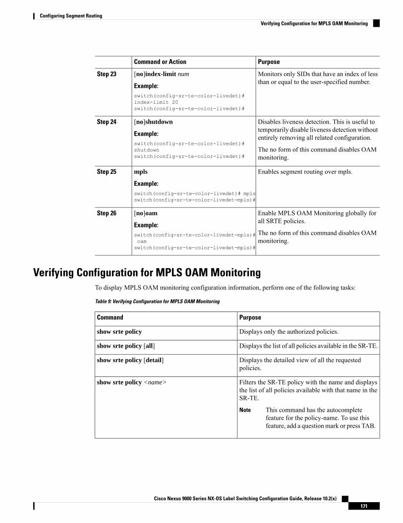
PurposeCommand or Action
Monitors only SIDs that have an index of lessthan or equal to the user-specified number.
[no]index-limit num
Example:
Step 23
switch(config-sr-te-color-livedet)#index-limit 20switch(config-sr-te-color-livedet)#
Disables liveness detection. This is useful totemporarily disable liveness detection withoutentirely removing all related configuration.
[no]shutdown
Example:switch(config-sr-te-color-livedet)#shutdownswitch(config-sr-te-color-livedet)#
Step 24
The no form of this command disables OAMmonitoring.
Enables segment routing over mpls.mpls
Example:
Step 25
switch(config-sr-te-color-livedet)# mplsswitch(config-sr-te-color-livedet-mpls)#
Enable MPLS OAMMonitoring globally forall SRTE policies.
[no]oam
Example:
Step 26
The no form of this command disables OAMmonitoring.
switch(config-sr-te-color-livedet-mpls)#oamswitch(config-sr-te-color-livedet-mpls)#
Verifying Configuration for MPLS OAM MonitoringTo display MPLS OAM monitoring configuration information, perform one of the following tasks:
Table 9: Verifying Configuration for MPLS OAM Monitoring
PurposeCommand
Displays only the authorized policies.show srte policy
Displays the list of all policies available in the SR-TE.show srte policy [all]
Displays the detailed view of all the requestedpolicies.
show srte policy [detail]
Filters the SR-TE policy with the name and displaysthe list of all policies available with that name in theSR-TE.
This command has the autocompletefeature for the policy-name. To use thisfeature, add a questionmark or press TAB.
Note
show srte policy <name>
Cisco Nexus 9000 Series NX-OS Label Switching Configuration Guide, Release 10.2(x)171
Configuring Segment RoutingVerifying Configuration for MPLS OAM Monitoring

PurposeCommand
Displays the SR-TE policy for the color and endpoint.
This command has the autocompletefeature for color and endpoint. To use thisfeature, add a questionmark or press TAB.
Note
show srte policy color <color> endpoint<endpoint>
Displays the list of all active proactive policymonitoring sessions that exist in the promon database.
You can use the question mark option atthe end of this command and provide oneof the following options or press ENTERto display all the sessions:
Note
• brief - shows brief information aboutthe sessions
• color - shows the promon sessionsrelated to the policy color
• name - shows the promon sessionsrelated to the policy name
• session-id - shows the promon sessionfor the session-id
show srte policy proactive-policy-monitoring
Displays only the list of session IDs and the states ofthe proactive policy monitoring sessions.
show srte policy proactive-policy-monitoring[brief]
Filters using session-id and displays information aboutthat session in detail.
This command has the autocompletefeature for the session-id. To use thisfeature, add a questionmark or press TAB.
Note
show srte policy proactive-policy-monitoring[session <session-id>]
Filters using color and endpoint and displays proactivepolicy monitoring sessions.
This command has the autocompletefeature for color and endpoint. To use thisfeature, add a questionmark or press TAB.
Note
show srte policy proactive-policy-monitoring color<color> endpoint<endpoint>
Configuration Example for MPLS OAM MonitoringThe following example shows how to configure MPLS OAM monitoring:
• Configuration example for global enablement with user specified multiplier and interval:segment-routingtraffic-engineeringliveness-detection
Cisco Nexus 9000 Series NX-OS Label Switching Configuration Guide, Release 10.2(x)172
Configuring Segment RoutingConfiguration Example for MPLS OAM Monitoring

interval 6000multiplier 5
mplsoam
segment-list name blueindex 10 mpls label 16004index 20 mpls label 16005
segment-list name greenindex 10 mpls label 16003index 20 mpls label 16006
segment-list name redindex 10 mpls label 16002index 20 mpls label 16004index 30 mpls label 16005
policy customer-1color 1 endpoint 5.5.5.5candidate-pathspreference 100explicit segment-list red
on-demand color 211candidate-pathspreference 100explicit segment-list green
• Configuration example for policy enablement with user specified multiplier, interval, index-limit andshutdown option:segment-routingtraffic-engineeringliveness-detection
interval 6000multiplier 5
segment-list name blueindex 10 mpls label 16004index 20 mpls label 16005
segment-list name greenindex 10 mpls label 16003index 20 mpls label 16006
segment-list name redindex 10 mpls label 16002index 20 mpls label 16004index 30 mpls label 16005
policy customer-1color 1 endpoint 5.5.5.5candidate-pathspreference 100explicit segment-list red
liveness-detectionindex-limit 20shutdownmplsoam
on-demand color 211candidate-pathspreference 100explicit segment-list green
liveness-detectionindex-limit 20shutdownmplsoam
Cisco Nexus 9000 Series NX-OS Label Switching Configuration Guide, Release 10.2(x)173
Configuring Segment RoutingConfiguration Example for MPLS OAM Monitoring

Configuring Egress Peer Engineering with Segment Routing
BGP Prefix SIDIn order to support segment routing, BGP requires the ability to advertise a segment identifier (SID) for aBGP prefix. A BGP prefix SID is always global within the segment routing BGP domain and identifies aninstruction to forward the packet over the ECMP-aware best path computed by BGP to the related prefix. TheBGP prefix SID identifies the BGP prefix segment.
Adjacency SIDThe adjacency segment Identifier (SID) is a local label that points to a specific interface and a next hop outof that interface. No specific configuration is required to enable adjacency SIDs. Once segment routing isenabled over BGP for an address family, for any interface that BGP runs over, the address family automaticallyallocates an adjacency SID toward every neighbor out of that interface.
High Availability for Segment RoutingIn-service software upgrades (ISSUs) are minimally supported with BGP graceful restart. All states (includingthe segment routing state) must be relearned from the BGP router's peers. During the graceful restart period,the previously learned route and label state are retained.
Overview of BGP Egress Peer Engineering With Segment RoutingCisco Nexus 9000 Series switches are often deployed in massive scale data centers (MSDCs). In suchenvironments, there is a requirement to support BGP Egress Peer Engineering (EPE) with Segment Routing(SR).
Segment Routing (SR) leverages source routing. A node steers a packet through a controlled set of instructions,known as segments, by prepending the packet with an SR header. A segment can represent any topologicalor service-based instruction. SR allows steering a flow through any topological path or any service chainwhile maintaining per-flow state only at the ingress node of the SR domain. For this feature, the SegmentRouting architecture is applied directly to the MPLS data plane.
In order to support Segment Routing, BGP requires the ability to advertise a Segment Identifier (SID) for aBGP prefix. A BGP prefix is always global within the SR or BGP domain and it identifies an instruction toforward the packet over the ECMP-aware best-path that is computed by BGP to the related prefix. The BGPprefix is the identifier of the BGP prefix segment.
The SR-based Egress Peer Engineering (EPE) solution allows a centralized (SDN) controller to program anyegress peer policy at ingress border routers or at hosts within the domain.
In the following example, all three routers run iBGP and they advertise NRLI to one another. The routers alsoadvertise their loopback as the next-hop and it is recursively resolved. This provides an ECMP between therouters as displayed in the illustration.
Cisco Nexus 9000 Series NX-OS Label Switching Configuration Guide, Release 10.2(x)174
Configuring Segment RoutingConfiguring Egress Peer Engineering with Segment Routing

Figure 10: Example of Egress Peer Engineering
The SDN controller receives the Segment IDs from the egress router 1.1.1.1 for each of its peers and adjacencies.It can then intelligently advertise the exit points to the other routers and the hosts within the controller’s routingdomain. As displayed in the illustration, the BGP Network Layer Reachability Information (NLRI) containsboth the Node-SID to Router 1.1.1.1 and the Peer-Adjacency-SID 24003 indicating that the traffic to 7.7.7.7should egress over the link 12.1.1.1->12.1.1.3.
Cisco Nexus 9000 Series NX-OS Label Switching Configuration Guide, Release 10.2(x)175
Configuring Segment RoutingOverview of BGP Egress Peer Engineering With Segment Routing
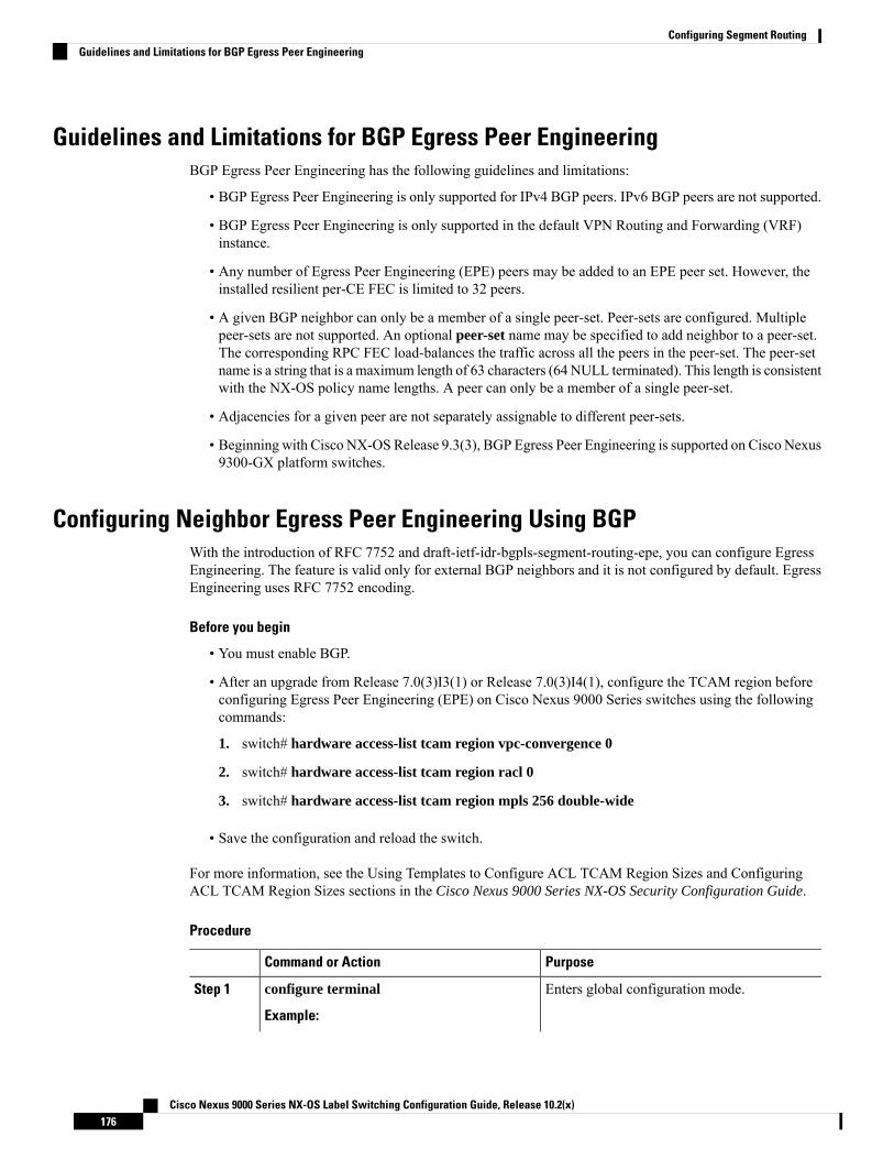
Guidelines and Limitations for BGP Egress Peer EngineeringBGP Egress Peer Engineering has the following guidelines and limitations:
• BGP Egress Peer Engineering is only supported for IPv4 BGP peers. IPv6 BGP peers are not supported.
• BGP Egress Peer Engineering is only supported in the default VPN Routing and Forwarding (VRF)instance.
• Any number of Egress Peer Engineering (EPE) peers may be added to an EPE peer set. However, theinstalled resilient per-CE FEC is limited to 32 peers.
• A given BGP neighbor can only be a member of a single peer-set. Peer-sets are configured. Multiplepeer-sets are not supported. An optional peer-set name may be specified to add neighbor to a peer-set.The corresponding RPC FEC load-balances the traffic across all the peers in the peer-set. The peer-setname is a string that is a maximum length of 63 characters (64 NULL terminated). This length is consistentwith the NX-OS policy name lengths. A peer can only be a member of a single peer-set.
• Adjacencies for a given peer are not separately assignable to different peer-sets.
• Beginning with Cisco NX-OS Release 9.3(3), BGP Egress Peer Engineering is supported on Cisco Nexus9300-GX platform switches.
Configuring Neighbor Egress Peer Engineering Using BGPWith the introduction of RFC 7752 and draft-ietf-idr-bgpls-segment-routing-epe, you can configure EgressEngineering. The feature is valid only for external BGP neighbors and it is not configured by default. EgressEngineering uses RFC 7752 encoding.
Before you begin
• You must enable BGP.
• After an upgrade from Release 7.0(3)I3(1) or Release 7.0(3)I4(1), configure the TCAM region beforeconfiguring Egress Peer Engineering (EPE) on Cisco Nexus 9000 Series switches using the followingcommands:
1. switch# hardware access-list tcam region vpc-convergence 0
2. switch# hardware access-list tcam region racl 0
3. switch# hardware access-list tcam region mpls 256 double-wide
• Save the configuration and reload the switch.
For more information, see the Using Templates to Configure ACL TCAM Region Sizes and ConfiguringACL TCAM Region Sizes sections in the Cisco Nexus 9000 Series NX-OS Security Configuration Guide.
Procedure
PurposeCommand or Action
Enters global configuration mode.configure terminal
Example:
Step 1
Cisco Nexus 9000 Series NX-OS Label Switching Configuration Guide, Release 10.2(x)176
Configuring Segment RoutingGuidelines and Limitations for BGP Egress Peer Engineering

PurposeCommand or Actionswitch# configure terminalswitch(config)#
Specifies the autonomous router BGP number.router bgp <bgp autonomous number>Step 2
Configures the IP address for the neighbor.neighbor <IP address>Step 3
Specifies whether a Peer-Node-SID is allocatedfor the neighbor and it is advertised in an
[no|default] egress-engineering [peer-setpeer-set-name]
Step 4
instance of a BGPLink-State (BGP-LS) addressExample: family Link NLRI. If the neighbor is aswitch(config)# router bgp 1switch(config-router)# neighbor 4.4.4.4
multi-hop neighbor, a BGP-LS Link NLRIinstance is also advertised for eachswitch(config-router)# egress-engineering
peer-set NewPeer Equal-Cost-MultiPath (ECMP) path to theneighbor and it includes a unique Peer-Adj-SID.
Optionally, you can add the neighbor to apeer-set. The Peer-Set-SID is also advertised inthe BGP-LS Link NLRI in the same instanceas the Peer-Node-SID. BGP Link-State NLRIis advertised to all neighbors with the link-stateaddress family configured.
See RFC 7752 anddraft-ietf-idr-bgpls-segment-routing-epe-05 formore information on EPE.
Configuration Example for Egress Peer EngineeringSee the Egress Peer Engineering sample configuration for the BGP speaker 1.1.1.1. Note that the neighbor20.20.20.20 is the SDN controller.hostname epe-as-1install feature-set mplsfeature-set mpls
feature telnetfeature bash-shellfeature scp-serverfeature bgpfeature mpls segment-routing
segment-routing mplsvlan 1
vrf context managementip route 0.0.0.0/0 10.30.97.1ip route 0.0.0.0/0 10.30.108.1
interface Ethernet1/1no switchportip address 10.1.1.1/24no shutdown
interface Ethernet1/2no switchport
Cisco Nexus 9000 Series NX-OS Label Switching Configuration Guide, Release 10.2(x)177
Configuring Segment RoutingConfiguration Example for Egress Peer Engineering
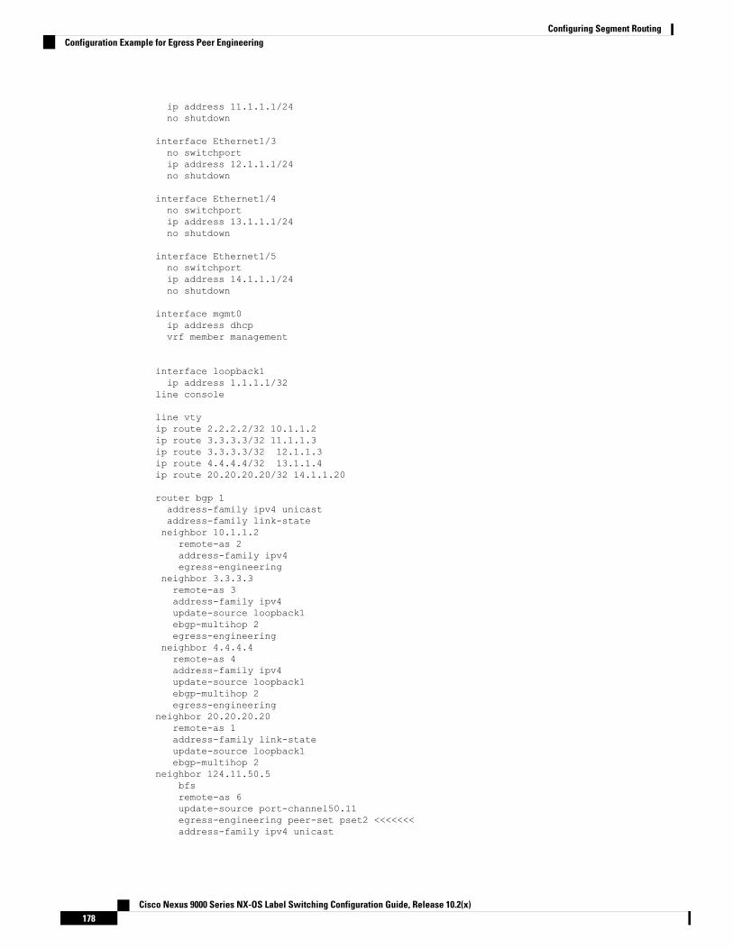
ip address 11.1.1.1/24no shutdown
interface Ethernet1/3no switchportip address 12.1.1.1/24no shutdown
interface Ethernet1/4no switchportip address 13.1.1.1/24no shutdown
interface Ethernet1/5no switchportip address 14.1.1.1/24no shutdown
interface mgmt0ip address dhcpvrf member management
interface loopback1ip address 1.1.1.1/32
line console
line vtyip route 2.2.2.2/32 10.1.1.2ip route 3.3.3.3/32 11.1.1.3ip route 3.3.3.3/32 12.1.1.3ip route 4.4.4.4/32 13.1.1.4ip route 20.20.20.20/32 14.1.1.20
router bgp 1address-family ipv4 unicastaddress-family link-stateneighbor 10.1.1.2
remote-as 2address-family ipv4egress-engineering
neighbor 3.3.3.3remote-as 3address-family ipv4update-source loopback1ebgp-multihop 2egress-engineering
neighbor 4.4.4.4remote-as 4address-family ipv4update-source loopback1ebgp-multihop 2egress-engineering
neighbor 20.20.20.20remote-as 1address-family link-stateupdate-source loopback1ebgp-multihop 2
neighbor 124.11.50.5bfsremote-as 6update-source port-channel50.11egress-engineering peer-set pset2 <<<<<<<address-family ipv4 unicast
Cisco Nexus 9000 Series NX-OS Label Switching Configuration Guide, Release 10.2(x)178
Configuring Segment RoutingConfiguration Example for Egress Peer Engineering

neighbor 124.11.101.2bfdremote-as 6update-source Vlan2401egress-engineeringaddress-family ipv4 unicast
This example shows sample output for the show bgp internal epe command.switch# show bgp internal epeBGP Egress Peer Engineering (EPE) Information:Link-State Server: InactiveLink-State Client: ActiveConfigured EPE Peers: 26Active EPE Peers: 3EPE SID State:RPC SID Peer or Set AssignedID Type Set Name ID Label Adj-Info, iod1 Node 124.1.50.5 1 16002 Set pset1 2 16013 Node 6.6.6.6 3 16024 Node 124.11.50.5 4 16035 Set pset2 5 16046 Adj 6.6.6.6 6 1605 124.11.50.4->124.11.50.5/0x1600b031, 807 Adj 6.6.6.6 7 1606 124.1.50.4->124.1.50.5/0x16000031, 78EPE Peer-Sets:IPv4 Peer-Set: pset1, RPC-Set 2, Count 7, SID 1601Peers: 124.11.116.2 124.11.111.2 124.11.106.2 124.11.101.2124.11.49.5 124.1.50.5 124.1.49.5IPv4 Peer-Set: pset2, RPC-Set 5, Count 5, SID 1604Peers: 124.11.117.2 124.11.112.2 124.11.107.2 124.11.102.2124.11.50.5IPv4 Peer-Set: pset3, RPC-Set 0, Count 4, SID unspecifiedPeers: 124.11.118.2 124.11.113.2 124.11.108.2 124.11.103.2IPv4 Peer-Set: pset4, RPC-Set 0, Count 4, SID unspecifiedPeers: 124.11.119.2 124.11.114.2 124.11.109.2 124.11.104.2IPv4 Peer-Set: pset5, RPC-Set 0, Count 4, SID unspecifiedPeers: 124.11.120.2 124.11.115.2 124.11.110.2 124.11.105.2switch#
Configuring the BGP Link State Address FamilyYou can configure the BGP link state address family for a neighbor session with a controller to advertise thecorresponding SIDs. You can configure this feature in global configuration mode and neighbor address familyconfiguration mode.
Before you begin
You must enable BGP.
Procedure
PurposeCommand or Action
Enters global configuration mode.configure terminal
Example:
Step 1
switch# configure terminalswitch(config)#
Cisco Nexus 9000 Series NX-OS Label Switching Configuration Guide, Release 10.2(x)179
Configuring Segment RoutingConfiguring the BGP Link State Address Family

PurposeCommand or Action
Specifies the autonomous router BGP number.router bgp <bgp autonomous number>Step 2
Enters address-family interface configurationmode.
[no] address-family link-state
Example:
Step 3
This command can also beconfigured in neighboraddress-family configuration mode.
Noteswitch(config)# router bgp 64497switch (config-router af)# address-familylink-state
Configures the IP address for the neighbor.neighbor <IP address>Step 4
Enters address-family interface configurationmode.
[no] address-family link-state
Example:
Step 5
This command can also beconfigured in neighboraddress-family configuration mode.
Noteswitch(config)#router bgp 1switch(config-router)#address-familylink-stateswitch(config-router)#neighbor20.20.20.20switch(config-router)#address-familylink-state
BGP Prefix SID Deployment ExampleIn the simple example below, all three routers are running iBGP and advertising Network Layer ReachabilityInformation (NRLI) to one another. The routers are also advertising their loopback interface as the next hop,which provides the ECMP between routers 2.2.2.2 and 3.3.3.3.
Cisco Nexus 9000 Series NX-OS Label Switching Configuration Guide, Release 10.2(x)180
Configuring Segment RoutingBGP Prefix SID Deployment Example

Figure 11: BGP Prefix SID Simple Example
Configuring Layer2 EVPN over Segment Routing MPLS
About Layer 2 EVPNEthernet VPN (EVPN) is a next generation solution that provides ethernet multipoint services over MPLSnetworks. EVPN operates in contrast to the existing Virtual Private LAN Service (VPLS) by enablingcontrol-plane based MAC learning in the core. In EVPN, PEs participating in the EVPN instances learncustomer MAC routes in control-plane using MP-BGP protocol. Control-plane MAC learning brings several
Cisco Nexus 9000 Series NX-OS Label Switching Configuration Guide, Release 10.2(x)181
Configuring Segment RoutingConfiguring Layer2 EVPN over Segment Routing MPLS

benefits that allow EVPN to address the VPLS shortcomings, including support for multihoming with per-flowload balancing.
In a data center network, the EVPN control plane provides:
• Flexible workload placement that is not restricted with the physical topology of the data center network.Therefore, you can place virtual machines (VM) anywhere within the data center fabric.
• Optimal East-West traffic between servers within and across data centers. East-West traffic betweenservers, or virtual machines, is achieved by most specific routing at the first hop router. First hop routingis done at the access layer. Host routes must be exchanged to ensure most specific routing to and fromservers or hosts. VM mobility is supported by detecting new endpoint attachment when a new MACaddress or the IP address is directly connected to the local switch. When the local switch sees the newMAC or the IP address, it signals the new location to rest of the network.
• Segmentation of Layer 2 and Layer 3 traffic, where traffic segmentation is achieved using MPLSencapsulation and the labels (per-BD label and per-VRF labels) act as the segment identifier.
Guidelines and Limitations for Layer 2 EVPN over Segment Routing MPLSLayer 2 EVPN over segment routing MPLS has the following guidelines and limitations:
• Segment routing Layer 2 EVPN flooding is based on the ingress replication mechanism. MPLS coredoes not support multicast.
• ARP suppression is not supported.
• Consistency checking on vPC is not supported.
• The same Layer 2 EVI and Layer 3 EVI cannot be configured together.
• Beginning with Cisco NX-OS Release 9.3(1), Layer 2 EVPN is supported on Cisco Nexus 9300-FX2platform switches.
• Beginning with Cisco NX-OS Release 9.3(5), Layer 2 EVPN over segment routing MPLS is supportedon Cisco Nexus 9300-GX and Cisco Nexus 9300-FX3 platform switches.
Configuring Layer 2 EVPN over Segment Routing MPLS
Before you begin
Do the following:
• You must install and enable the MPLS feature set using the install feature-set mpls and feature-setmpls commands.
• You must enable the MPLS segment routing feature.
• You must enable the nv overlay feature using the nv overlay command.
• You must enable EVPN control plane using the nv overlay evpn command.
Cisco Nexus 9000 Series NX-OS Label Switching Configuration Guide, Release 10.2(x)182
Configuring Segment RoutingGuidelines and Limitations for Layer 2 EVPN over Segment Routing MPLS

Procedure
PurposeCommand or Action
Enters global configuration mode.configure terminal
Example:
Step 1
switch# configure terminalswitch(config)#
Enables BGP feature and configurations.feature bgp
Example:
Step 2
switch(config)#feature bgp
Enables MPLS configuration commands.install feature-set mpls
Example:
Step 3
switch(config)#install feature-set mpls
Enables MPLS configuration commands.feature-set mpls
Example:
Step 4
switch(config)#install feature-set mpls
Enables segment routing configurationcommands.
feature mpls segment-routing
Example:
Step 5
switch(config)#feature mplssegment-routing
Enables EVPN over MPLS configurationcommands. This command is mutuallyexclusive with the feature-nv CLI command.
feature mpls evpn
Example:switch(config)#feature mpls evpn
Step 6
Enables the NVE feature that is used for thesegment routing Layer 2 EVPN.
feature nv overlay
Example:
Step 7
switch(config)#feature nv overlay
Enables EVPN.nv overlay evpn
Example:
Step 8
switch(config)#nv overlay evpn
Configures the loopback interface for NVE.interface loopback Interface_Number
Example:
Step 9
switch(config)#interface loopback 1
Configures the IP address.ip address address
Example:
Step 10
switch(config-if)#ip address192.168.15.1
Cisco Nexus 9000 Series NX-OS Label Switching Configuration Guide, Release 10.2(x)183
Configuring Segment RoutingConfiguring Layer 2 EVPN over Segment Routing MPLS

PurposeCommand or Action
Exits global address family configurationmode.
exit
Example:
Step 11
switch(config-if)#exit
Enters the EVPN configuration mode.evpn
Example:
Step 12
switch(config)#evpn
Configures Layer 2 EVI. If required, you canmanually configure the RT based on the EVIthat is generated automatically.
evi number
Example:switch(config-evpn)#evi 1000switch(config-evpn-sr)#
Step 13
Enables MPLS encapsulation andingress-replication.
encapsulation mpls
Example:
Step 14
switch(config-evpn)#encapsulation mpls
Specifies the NVE source interface.source-interface loopback Interface_Number
Example:
Step 15
switch(config-evpn-nve-encap)#source-interfaceloopback 1
Exits the configuration.exit
Example:
Step 16
switch(config-evpn-nve-encap)#exit
Configures the VRF.vrf context VRF_NAME
Example:
Step 17
switch(config)#vrf context Tenant-A
Configures L3 EVI.evi EVI_ID
Example:
Step 18
switch(config-vrf)#evi 30001
Exits the configuration.exit
Example:
Step 19
switch(config-vrf)#exit
Configures VLAN.VLAN VLAN_ID
Example:
Step 20
switch(config)#vlan 1001
Configures L2 EVI.evi auto
Example:
Step 21
Cisco Nexus 9000 Series NX-OS Label Switching Configuration Guide, Release 10.2(x)184
Configuring Segment RoutingConfiguring Layer 2 EVPN over Segment Routing MPLS

PurposeCommand or Actionswitch(config-vlan)#evi auto
exitStep 22
Example:switch(config-vlan)#exit
Enters the BGP configuration mode.router bgp autonomous-system-number
Example:
Step 23
switch(config)#router bgp 1
Enables EVPN address family globally.address-family l2vpn evpn
Example:
Step 24
switch(config-router)#address-familyl2vpn evpn
Configures BGP neighbor.neighbor address remote-asautonomous-system-number
Step 25
Example:switch(config-router)#neighbor192.169.13.1 remote as 2
Enables EVPN address family for neighbor.address-family l2vpn evpn
Example:
Step 26
switch(config-router-neighbor)#address-familyl2vpn evpn
Enables MPLS encapsulation.encapsulation mpls
Example:
Step 27
switch(config-router-neighbor)#encapsulationmpls
Configures BGP to advertise extendedcommunity lists.
send-community extended
Example:
Step 28
switch(config-router-neighbor)#send-communityextended
Configures BGP VRF.vrf VRF_NAME
Example:
Step 29
switch(config-router)#vrf Tenant-A
Exits the configuration.exit
Example:
Step 30
switch(config-router)#exit
Cisco Nexus 9000 Series NX-OS Label Switching Configuration Guide, Release 10.2(x)185
Configuring Segment RoutingConfiguring Layer 2 EVPN over Segment Routing MPLS

Configuring VLAN for EVI
Procedure
PurposeCommand or Action
Specifies the VLAN.vlan numberStep 1
Creates a BD label for the VLAN. This label isused as an identifier for the VLAN across thesegment routing Layer 2 EVPN.
evi autoStep 2
Configuring the NVE Interface
Procedure
PurposeCommand or Action
Enters global configuration mode.configure terminal
Example:
Step 1
switch# configure terminalswitch(config)#
Associates the IP address with this loopbackinterface and uses this IP address for thesegment routing configuration.
interface loopback loopback_number
Example:switch(config)# interface loopback 1
Step 2
Specifies the IPv4 address family and entersrouter address family configuration mode.
ip address
Example:
Step 3
switch(config-if)#ip address192.169.15.1/32
Enters EVPN configuration mode.evpn
Example:
Step 4
switch(config)#evpn
Enables MPLS encapsulation andingress-replication.
encapsulation mpls
Example:
Step 5
switch(config-evpn)# encapsulation mpls
Specifies the NVE source interface.source-interface loopback_number
Example:
Step 6
switch(config-evpn-nve-encap)#source-interfaceloopback 1
Exits segment routing mode and returns to theconfiguration terminal mode.
exit
Example:
Step 7
Cisco Nexus 9000 Series NX-OS Label Switching Configuration Guide, Release 10.2(x)186
Configuring Segment RoutingConfiguring VLAN for EVI

PurposeCommand or Actionswitch(config)# exit
Configuring EVI Under VRF
Procedure
PurposeCommand or Action
Create a VRF Tenant.vrf context tenantStep 1
Configure Layer 3 EVI under VRF.evi numberStep 2
Configuring Anycast GatewayThe fabric forwarding configuration is necessary only if the SVIs are configured in the anycast mode.
Procedure
PurposeCommand or Action
Configures the distributed gateway virtualMACaddress.
fabric forwarding anycast-gateway-mac0000.aabb.ccdd
Step 1
Associates SVIwith theAnycast Gateway underthe interface configuration mode.
fabric forwarding mode anycast-gatewayStep 2
Advertising Labelled Path for the Loopback InterfaceThe loopback interface, advertised as Layer 2 EVPN endpoint should be mapped to a label index. TherebyBGP advertises MPLS labelled path for the same.
Procedure
PurposeCommand or Action
Enters global configuration mode.configure terminal
Example:
Step 1
switch# configure terminalswitch(config)#
Enables the OSPF mode.[no]router ospf process
Example:
Step 2
switch(config)# router ospf test
Configures the segment routing functionalityunder OSPF.
segment-routing
Example:
Step 3
Cisco Nexus 9000 Series NX-OS Label Switching Configuration Guide, Release 10.2(x)187
Configuring Segment RoutingConfiguring EVI Under VRF

PurposeCommand or Actionswitch(config-router)# segment-routingmpls
Enters a sub-mode where you can configureaddress-family specific mappings for localprefixes and SIDs.
connected-prefix-sid-map
Example:switch(config-sr-mpls)#connected-prefix-sid-map
Step 4
Specifies IPv4 address prefixes.address-family ipv4
Example:
Step 5
switch(config-sr-mpls-conn)#address-family ipv4
Associates SID 100 with the address 1.1.1.1/32.1.1.1.1/32 index 100
Example:
Step 6
switch(config-sr-mpls-conn-af)#1.1.1.1/32 100
Exits the address family.exit-address-family
Example:
Step 7
switch(config-sr-mpls-conn-af)#exit-address-family
About SRv6 Static Per-Prefix TEThe SRv6 Static Per-Prefix TE feature allows you to map and advertise prefixes that at mapped to non-defaultVRFs. This feature allows you to advertise multiple prefixes in a single instance using the matching VRFroute target and prevents the manual entry of each prefix.
In Cisco NX-OS Release 9.3(5), only one VNF can service a VM.
Configuring a SRv6 Static Per-Prefix TE
Before you begin
Do the following:
• You must install and enable the MPLS feature set using the install feature-set mpls and feature-setmpls commands.
• You must enable the MPLS segment routing feature.
Procedure
PurposeCommand or Action
Enters global configuration mode.configure terminal
Example:
Step 1
Cisco Nexus 9000 Series NX-OS Label Switching Configuration Guide, Release 10.2(x)188
Configuring Segment RoutingAbout SRv6 Static Per-Prefix TE

PurposeCommand or Actionswitch# configure terminalswitch(config)#
Defines VRF and enters the VRF configurationmode.
vrf context VRF_Name
Example:
Step 2
switch(config)# vrf context vrf_2_7_8
Assign the RD to VRF.rd rd_format
Example:
Step 3
switch(config-vrf)# rd 2.2.2.0:2
Specifies either the IPv4 or the IPv6 addressfamily for the VRF instance and enters theaddress family configuration mode.
address-family {ipv4 | ipv6 }
Example:switch(config-vrf)# address-family ipv4unicast
Step 4
Configures the importing of routes to the VRF.route-target import route-target-id
Example:
Step 5
switch(config-vrf)# route-target import1:2
Configures importing of routes that have amatching route target value from the Layer 3EVPN to the VRF.
route-target import route-target-id evpn
Example:switch(config-vrf)# route-target import1:2 evpn
Step 6
Configures the exporting of routes from theVRF.
route-target export route-target-id
Example:
Step 7
switch(config-vrf)# route-target export1:2
Configures exporting of routes that have amatching route target value from the VRF tothe Layer 3 EVPN.
route-target export route-target-id evpn
Example:switch(config-vrf)# route-target export1:2 evpn
Step 8
Enables BGP and assigns the AS number tothe local BGP speaker.
router bgp autonomous-system-number
Example:
Step 9
switch(config)# router bgp 65000
Configures the router ID.router-id id
Example:
Step 10
switch(config-router)# router-id 2.2.2.0
Enters global address family configurationmode for the Layer 2 VPN EVPN.
address-family l2vpn evpn
Example:
Step 11
Cisco Nexus 9000 Series NX-OS Label Switching Configuration Guide, Release 10.2(x)189
Configuring Segment RoutingConfiguring a SRv6 Static Per-Prefix TE

PurposeCommand or Actionswitch(config-router-af)# address-familyl2vpn evpn
Configures the IPv4 address and AS numberfor a remote BGP peer.
neighbor ipv4-address remote-as
Example:
Step 12
switch(config-router)# neighbor 7.7.7.0remote-as 65000switch(config-router-neighbor)#
Specifies the loopback number.update-source loopback number
Example:
Step 13
switch(config-router-neighbor)#update-source loopback0
Enables EVPN address family for a neighbor.address-family l2vpn evpn
Example:
Step 14
switch(config-router-neighbor)#address-familyl2vpn evpn
Configures BGP to advertise extendedcommunity lists.
send-community extended
Example:
Step 15
switch(config-router-neighbor)#send-communityextended
Enables MPLS encapsulation.encapsulation mpls
Example:
Step 16
switch(config-router-neighbor)#encapsulationmpls
Exits the configuration.exit
Example:
Step 17
switch(config-router-neighbor)#exit
Example
The following example shows how to configure RPM configuration in order to define the VRF VT.rf context vrf_2_7_8
rd 2.2.2.0:2address-family ipv4 unicastroute-target import 0.0.1.1:2route-target import 0.0.1.1:2 evpnroute-target export 0.0.1.1:2route-target export 0.0.1.1:2 evpn
ip extcommunity-list standard vrf_2_7_8-test permit rt 0.0.1.1:2route-map Node-2 permit 4match extcommunity vrf_2_7_8-testset extcommunity color 204
Cisco Nexus 9000 Series NX-OS Label Switching Configuration Guide, Release 10.2(x)190
Configuring Segment RoutingConfiguring a SRv6 Static Per-Prefix TE
About RD AutoThe auto-derived Route Distinguisher (rd auto) is based on the Type 1 encoding format as described in IETFRFC 4364 section 4.2 https://tools.ietf.org/html/rfc4364#section-4.2. The Type 1 encoding allows a 4-byteadministrative field and a 2-byte numbering field. Within Cisco NX-OS, the auto derived RD is constructedwith the IP address of the BGP Router ID as the 4-byte administrative field (RID) and the internal VRFidentifier for the 2-byte numbering field (VRF ID).
The 2-byte numbering field is always derived from the VRF, but results in a different numbering schemedepending on its use for the IP-VRF or the MAC-VRF:
• The 2-byte numbering field for the IP-VRF uses the internal VRF ID starting at 1 and increments. VRFIDs 1 and 2 are reserved for the default VRF and the management VRF respectively. The first customdefined IP VRF uses VRF ID 3.
• The 2-byte numbering field for the MAC-VRF uses the VLAN ID + 32767, which results in 32768 forVLAN ID 1 and incrementing.
Example auto-derived Route Distinguisher (RD)
• IP-VRF with BGP Router ID 192.0.2.1 and VRF ID 6 - RD 192.0.2.1:6
• MAC-VRF with BGP Router ID 192.0.2.1 and VLAN 20 - RD 192.0.2.1:32787
About Route-Target AutoThe auto-derived Route-Target (route-target import/export/both auto) is based on the Type 0 encoding formatas described in IETF RFC 4364 section 4.2 (https://tools.ietf.org/html/rfc4364#section-4.2). IETF RFC 4364section 4.2 describes the Route Distinguisher format and IETF RFC 4364 section 4.3.1 refers that it is desirableto use a similar format for the Route-Targets. The Type 0 encoding allows a 2-byte administrative field anda 4-byte numbering field. Within Cisco NX-OS, the auto derived Route-Target is constructed with theAutonomous System Number (ASN) as the 2-byte administrative field and the Service Identifier (EVI) forthe 4-byte numbering field.
2-byte ASN
The Type 0 encoding allows a 2-byte administrative field and a 4-byte numbering field. Within Cisco NX-OS,the auto-derived Route-Target is constructed with the Autonomous System Number (ASN) as the 2-byteadministrative filed and the Service Identifier (EVI) for the 4-byte numbering field.
Examples of an auto derived Route-Target (RT):
• IP-VRF within ASN 65001 and L3EVI 50001 - Route-Target 65001:50001
• MAC-VRF within ASN 65001 and L2EVI 30001 - Route-Target 65001:30001
For Multi-AS environments, the Route-Targets must either be statically defined or rewritten to match theASN portion of the Route-Targets.
Auto derived Route-Targets for a 4-byte ASN are not supported.Note
4-byte ASN
Cisco Nexus 9000 Series NX-OS Label Switching Configuration Guide, Release 10.2(x)191
Configuring Segment RoutingAbout RD Auto

The Type 0 encoding allows a 2-byte administrative field and a 4-byte numbering field. Within Cisco NX-OS,the auto-derived Route-Target is constructed with the Autonomous System Number (ASN) as the 2-byteadministrative filed and the Service Identifier (EVI) for the 4-byte numbering field. With the ASN demandof 4-byte length and the EVI requiring 24-bit (3-bytes), the Sub-Field length within the Extended Communityis exhausted (2-byte Type and 6-byte Sub-Field). As a result of the length and format constraint and theimportance of the Service Identifiers (EVI) uniqueness, the 4-byte ASN is represented in a 2-byte ASN namedAS_TRANS, as described in IETF RFC 6793 section 9 (https://tools.ietf.org/html/rfc6793#section-9). The2-byte ASN 23456 is registered by the IANA (https://www.iana.org/assignments/iana-as-numbers-special-registry/iana-as-numbers-special-registry.xhtml) as AS_TRANS, a special purposeAS number that aliases 4-byte ASNs.
Example auto derived Route-Target (RT) with 4-byte ASN (AS_TRANS):
• IP-VRF within ASN 65656 and L3EVI 50001 - Route-Target 23456:50001
• MAC-VRF within ASN 65656 and L2EVI 30001 - Route-Target 23456:30001
Configuring RD and Route Targets for BDThe Bridge Domain (BD) RD and Route Targets are automatically generated when you configure evi autounder the VLAN. To configure the BD RD and Route Targets manually, perform these steps:
Procedure
PurposeCommand or Action
Enters global configuration mode.configure terminal
Example:
Step 1
switch# configure terminalswitch(config)#
Enters EVPN configuration mode.evpn
Example:
Step 2
switch(config)# evpn
Specifies L2 EVI to configure RD/Route Target.evi VLAN_ID
Example:
Step 3
switch(config-evpn)# evi 1001
Configures RD.rd rd_format
Example:
Step 4
switch(config-evpn-evi-sr)# rd192.1.1.1:33768
Configures Route Target.route-target both rt_format
Example:
Step 5
switch(config-evpn-evi-sr)# route-targetboth 1:20001
Cisco Nexus 9000 Series NX-OS Label Switching Configuration Guide, Release 10.2(x)192
Configuring Segment RoutingConfiguring RD and Route Targets for BD

Configuring RD and Route Targets for VRFThe VRF RD and Route Targets are automatically generated when you configure the evi evi_ID under theVRF. To configure the VRF RD and Route Targets manually, perform these steps:
Procedure
PurposeCommand or Action
Enters global configuration mode.configure terminal
Example:
Step 1
switch# configure terminalswitch(config)#
Configures the VRF.vrf context VRF_NAME
Example:
Step 2
switch(config)# vrf context A
Configures RD.rd auto or rd_format
Example:
Step 3
switch(config-vrf)# rd auto
Enables IPv4 address family.address-family ipv4 unicast
Example:
Step 4
switch(config-vrf)# address-family ipv4unicast
Configures Route Target.route-target both rt_format evpn
Example:
Step 5
switch(config-vrf-af-ipv4)# route-targetboth 1:30001 evpn
Configuration Examples for Layer 2 EVPN over Segment Routing MPLSThe following examples show the configuration for Layer 2 EVPN over Segment Routing MPLS:install feature-set mplsfeature-set mplsnv overlay evpnfeature bgpfeature mpls segment-routingfeature mpls evpnfeature interface-vlanfeature nv overlay
fabric forwarding anycast-gateway-mac 0000.1111.2222
vlan 1001evi auto
vrf context Tenant-Aevi 30001
Cisco Nexus 9000 Series NX-OS Label Switching Configuration Guide, Release 10.2(x)193
Configuring Segment RoutingConfiguring RD and Route Targets for VRF

interface loopback 1ip address 192.168.15.1/32
interface vlan 1001no shutdownvrf member Tenant-Aip address 111.1.0.1/16fabric forwarding mode anycast-gateway
router bgp 1address-family l2vpn evpnneighbor 192.169.13.1remote-as 2address-family l2vpn evpnsend-community extendedencapsulation mpls
vrf Tenant-A
evpnencapsulation mplssource-interface loopback 1
ConfiguringProportionalMultipath forVNFforSegmentRouting
About Proportional Multipath for VNF for Segment RoutingIn Network Function Virtualization Infrastructures (NFVi), service networks (Portable IPs) are routed byVirtual Network Functions (VNFs). The VNFs, also referred to as portable IP-Gateway (PIP-GW) routes thedata packets to and from the VMs in the VNF. The Proportional Multipath for VNF for Segment Routingfeature enables advertising the VNF of a service network (PIP) in the EVPN address-family. The IP addressof the VNF is encoded in the “Gateway-IP Address” field of the EVPN IP Prefix Route NLRI advertisementof a service network.
By advertising the IP address of the VNFs, ingress nodes in the EVPN fabric recursively resolve the VNF IPaddress to the leaf attached to the VNF, which could be the same node that advertises the service network(PIP).
Route-injectors are BGP protocols that inject routes in the IPv4 or IPv6 AF. In this case, the route-injectorinjects routes to the VMs whose next hop is set as VNFs.
Unlike a route-injector, VNFs can participate in a routing protocol to advertise the VM reachability. Thesupported protocols are eBGP, IS-IS, and OSPF.
Enabling Proportional Multipath for VNF for Segment RoutingYou can enable the Proportional Multipath for VNF for Segment Routing feature to redistribute routes forIGP or static routes by preserving the next-hop paths. You can then export and advertise the gateway-IP forthe reoriginated EVPN type-5 routes.
In Cisco NX-OS Release 9.3(5), only one VNF can service a VM.
Before you begin
Do the following:
Cisco Nexus 9000 Series NX-OS Label Switching Configuration Guide, Release 10.2(x)194
Configuring Segment RoutingConfiguring Proportional Multipath for VNF for Segment Routing

• Install and enable theMPLS feature set using the install feature-set mpls and feature-set mpls commands.
• Enable the MPLS segment routing feature.
Procedure
PurposeCommand or Action
Enter global configuration mode.configure terminal
Example:
Step 1
switch# configure terminalswitch(config)#
<<need description>>route-map export-l2evpn-rtmap permit 10
Example:
Step 2
switch(config)# route-mapexport-l2evpn-rtmap permit 10
Defines the prefixes that must be advertisedwith PIP-GW as the gateway.
match ip address prefix-list pip-pfx-list
Example:
Step 3
switch(config-route-map)# match ipprefix-list vm-pfx-list
Defines specific routes to advertise thegateway-ip.
set evpn gateway-ip use-nexthop
Example:
Step 4
switch(config-route-map)# set evpngateway-ip use-nexthop
Applies the route map to the vrf context.vrf context VRF_Name
Example:
Step 5
switch(config-route-map)# vrf contextvrfswitch(config-route-map)# address-familyipv4 unicastswitch(config-route-map)# export mapexport-l2evpn-rtmap
Applies the route map to the vrf context.address-family ipv4 unicast
Example:
Step 6
switch(config-route-map)# address-familyipv4 unicastswitch(config-route-map)# export mapexport-l2evpn-rtmap
Applies the route map to the vrf context.export map export-l2evpn-rtmap
Example:
Step 7
switch(config-route-map)# export mapexport-l2evpn-rtmap
Cisco Nexus 9000 Series NX-OS Label Switching Configuration Guide, Release 10.2(x)195
Configuring Segment RoutingEnabling Proportional Multipath for VNF for Segment Routing

PurposeCommand or Action
Configure BGP.router bgp number
Example:
Step 8
switch(config)# router bgp 100
Applies the route map to the vrf context.vrf VRF_Name
Example:
Step 9
switch(config-route-map)# vrf vrf3
Configure address family for IPv4.address-family ipv4 unicast
Example:
Step 10
switch(config-router)# address-familyipv4 unicast
Exports and advertises the gateway-ip toreconnect the EVPN type-5 routes.
export-gateway-ip
Example:
Step 11
The export gateway-ip and set theEVPN gateway configurations canbe performed simultaneously. Ifyou configure them simultaneously,all prefixes are exported with thegateway-ip.
Noteswitch(config-route-map)#export-gateway-ip
vPC Multihoming
About MultihomingCisco Nexus platform switches support vPC-based multihoming, where a pair of switches act as a singledevice for redundancy and both switches function in active mode. With Cisco Nexus platform switches in anEVPN environment, there are two solutions that support Layer 2 multihoming; these solutions are based onthe traditional vPC (emulated or virtual IP address), where the MCT link is required and the BGP EVPNtechniques.
While using the BGP EVPN control plane, each vPC pair uses a common virtual IP (VIP) to provideactive/active redundancy. BGP EVPN based multihoming further provides fast convergence during certainfailure scenarios, that otherwise cannot be achieved without a control protocol (data plane flood and learn).
Per-BD label on vPC PeersTo ensure that the vPC peers have the same per-BD label, you must specify the per-BD label to have thefollowing value:Label value = Label_base + VLAN_ID
The label base is configured on the same vPC peers. Currently, the VLAN configuration is identical on boththe vPC peers, which ensures that both vPC peers have the same label.
Cisco Nexus 9000 Series NX-OS Label Switching Configuration Guide, Release 10.2(x)196
Configuring Segment RoutingvPC Multihoming

In Cisco NX-OS Release 9.3(1), configuring the per-BD label is not supported. This release supports onlyevi auto.
Per-VRF label on vPC PeersTo ensure that the vPC peers have the same per-VRF label, you must specify the per-VRF label to have thefollowing value:Label value = Label_base + vrf_allocate_index
To configure the allocate-index for the vPC peers, do the following:Router bgp 1vrf Tenant_Aallocate-index 11
Configuring Backup LinkThe backup link needs to be configured between the vPC peers. This link can be any Layer 3 link which isparallel to MCT.
Example
interface vlan 100ip add 10.1.1.1/24
mpls ip forwarding
< enable underlay protocol >
Guidelines and Limitations for vPC MultihomingvPC multihoming has the following guidelines and limitations:
• ESI-based multihoming is not supported.
• The physical and virtual secondary IP addresses should be both advertised via the MPLS labeled path.
• vPC consistency checking is not supported for the per-BD label configuration.
Configuration Examples for vPC MultihomingThis example shows the configuration for vPC multihoming:
• vPC Primaryinterface loopback1ip address 192.169.15.1/32ip address 192.169.15.15/32 secondary
evpnencapsulation mplssource-interface loopback1
vlan 101evi auto
vrf context Aevi 301
Cisco Nexus 9000 Series NX-OS Label Switching Configuration Guide, Release 10.2(x)197
Configuring Segment RoutingPer-VRF label on vPC Peers

router bgp 1vrf Aallocate-index 1001
• vPC Secondaryinterface loopback1ip address 192.169.15.2/32ip address 192.169.15.15/32 secondary
evpnencapsulation mplssource-interface loopback1
vlan 101evi auto
vrf context Aevi 301
router bgp 1vrf Aallocate-index 1001
Configuring Layer 3 EVPN and Layer 3 VPN over SegmentRouting MPLS
This section describes tasks to configure the Layer 3 EVPN and stitching of L3 EVPN and L3VPN router.Perform the following tasks to complete the configuration:
Configuring VRF and Route Targets for Import and Export Rules
Procedure
PurposeCommand or Action
Enters global configuration mode.configure terminalStep 1
Defines a VPN routing and forwarding (VRF)instance and enters the VRF configurationmode.
vrf vrf-nameStep 2
Automatically assigns a unique routedistinguisher (RD) to VRF.
rd autoStep 3
Specifies either the IPv4 or IPv6 address familyfor the VRF instance and enters address familyconfiguration submode.
address-family { ipv4 | ipv6 } unicastStep 4
Configures importing of routes to the VRF fromthe L3VPNBGPNLRIs that have thematchingroute-target value.
route-target import route-target-idStep 5
Cisco Nexus 9000 Series NX-OS Label Switching Configuration Guide, Release 10.2(x)198
Configuring Segment RoutingConfiguring Layer 3 EVPN and Layer 3 VPN over Segment Routing MPLS

PurposeCommand or Action
Configures exporting of routes from the VRFto the L3VPN BGP NLRIs and assigns the
route-target export route-target-idStep 6
specified route-target identifiers to the L3VPNBGP NLRIs.
Configures importing of routes from the L3EVPN BGP NLRI that have the matchingroute-target value.
route-target import route-target-id evpnStep 7
Configures exporting of routes from the VRFto the L3 EVPN BGP NLRIs and assigns the
route-target export route-target-id evpnStep 8
specified route-target identifiers to the BGPEVPN NLRIs.
Configuring BGP EVPN and Label Allocation ModeYou can use MPLS tunnel encapsulation using the encapsulation mpls command. You can configure thelabel allocation mode for the EVPN address family. The default tunnel encapsulation in EVPN for IP Routetype in NX-OS is VXLAN.
Advertisement of (IP or Label) bindings from a Cisco Nexus 9000 Series switch via BGP EVPN enables aremote switch to send the routed traffic to that IP using the label for that IP to the switch that advertised theIP over MPLS.
The IP prefix route (Type-5) is:
• Type-5 route with MPLS encapsulation
RT-5 Route – IP Prefix
RD: L3 RDIP Length: prefix lengthIP address: IP (4 bytes)Label1: BGP MPLS LabelRoute TargetRT for IP-VRF
The default label allocation mode is per-VRF for Layer 3 EVPN over MPLS.
Complete the following steps to configure BGP EVPN and label allocation mode:
Before you begin
You must install and enable the MPLS feature set using the install feature-set mpls and feature-set mplscommands.
You must enable the MPLS segment routing feature.
Procedure
PurposeCommand or Action
Enters global configuration mode.configure terminalStep 1
Cisco Nexus 9000 Series NX-OS Label Switching Configuration Guide, Release 10.2(x)199
Configuring Segment RoutingConfiguring BGP EVPN and Label Allocation Mode

PurposeCommand or Action
Enables BGP and assigns the AS number tothe local BGP speaker. The AS number can be
[no] router bgp autonomous-system-number
Example:
Step 2
a 16-bit integer or a 32-bit integer in the formswitch(config)# router bgp 64496switch(config-router)#
of a higher 16-bit decimal number and a lower16-bit decimal number in xx.xx format.
Use the no option with this command toremove the BGP process and the associatedconfiguration.
Enters global address family configurationmode for the Layer 2 VPN EVPN.
Required: address-family l2vpn evpn
Example:
Step 3
switch(config-router)# address-familyl2vpn evpnswitch(config-router-af)#
Exits global address family configurationmode.
Required: exit
Example:
Step 4
switch(config-router-af)# exitswitch(config-router)#
Configures the IPv4 address and AS numberfor a remote BGP peer.
neighbor ipv4-address remote-asautonomous-system-number
Example:
Step 5
switch(config-router)# neighbor 10.1.1.1remote-as 64497switch(config-router-neighbor)#
Advertises the labeled Layer 2 VPN EVPN.address-family l2vpn evpn
Example:
Step 6
switch(config-router-neighbor)#address-family l2vpn evpnswitch(config-router-neighbor-af)#
Enables BGP EVPN address family and sendsEVPN type-5 route update to the neighbors.
encapsulation mpls
Example:
Step 7
The default tunnel encapsulation inEVPN for the IP route type inNX-OS is VXLAN. To overridethat, a new CLI is introduced toindicate MPLS tunnelencapsulation.
Noterouter bgp 100address-family l2vpn evpn
neighbor NVE2 remote-as 100address-family l2vpn evpnsend-community extendedencapsulation mpls
vrf fooaddress-family ipv4 unicastadvertise l2vpn evpn
BGP segment routing configuration:
router bgp 100address-family ipv4 unicast
Cisco Nexus 9000 Series NX-OS Label Switching Configuration Guide, Release 10.2(x)200
Configuring Segment RoutingConfiguring BGP EVPN and Label Allocation Mode
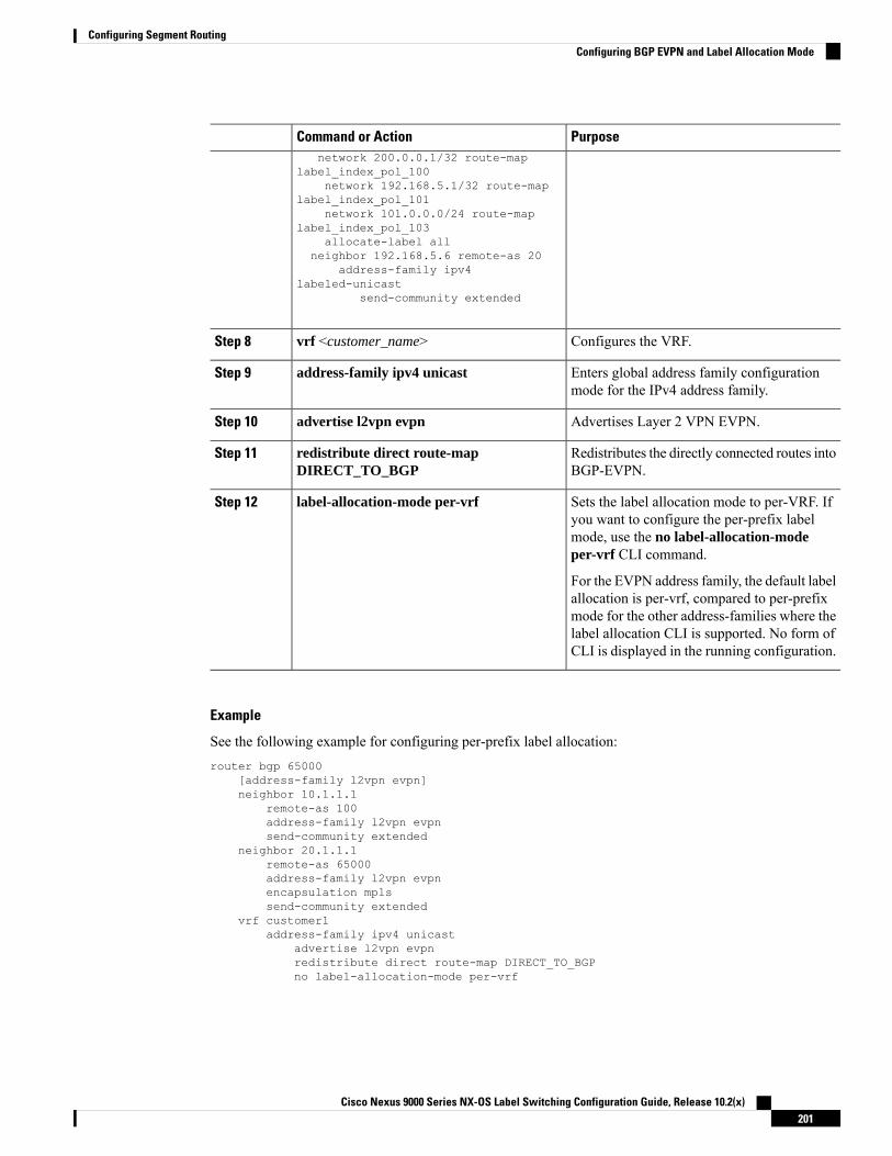
PurposeCommand or Actionnetwork 200.0.0.1/32 route-map
label_index_pol_100network 192.168.5.1/32 route-map
label_index_pol_101network 101.0.0.0/24 route-map
label_index_pol_103allocate-label all
neighbor 192.168.5.6 remote-as 20address-family ipv4
labeled-unicastsend-community extended
Configures the VRF.vrf <customer_name>Step 8
Enters global address family configurationmode for the IPv4 address family.
address-family ipv4 unicastStep 9
Advertises Layer 2 VPN EVPN.advertise l2vpn evpnStep 10
Redistributes the directly connected routes intoBGP-EVPN.
redistribute direct route-mapDIRECT_TO_BGP
Step 11
Sets the label allocation mode to per-VRF. Ifyou want to configure the per-prefix label
label-allocation-mode per-vrfStep 12
mode, use the no label-allocation-modeper-vrf CLI command.
For the EVPN address family, the default labelallocation is per-vrf, compared to per-prefixmode for the other address-families where thelabel allocation CLI is supported. No form ofCLI is displayed in the running configuration.
Example
See the following example for configuring per-prefix label allocation:router bgp 65000
[address-family l2vpn evpn]neighbor 10.1.1.1
remote-as 100address-family l2vpn evpnsend-community extended
neighbor 20.1.1.1remote-as 65000address-family l2vpn evpnencapsulation mplssend-community extended
vrf customer1address-family ipv4 unicast
advertise l2vpn evpnredistribute direct route-map DIRECT_TO_BGPno label-allocation-mode per-vrf
Cisco Nexus 9000 Series NX-OS Label Switching Configuration Guide, Release 10.2(x)201
Configuring Segment RoutingConfiguring BGP EVPN and Label Allocation Mode

Configuring BGP Layer 3 EVPN and Layer 3 VPN StitchingIn order to configure the stitching on the same router, configure the layer 3 VPN neighbor relationship androuter advertisement.
Procedure
PurposeCommand or Action
Enters global configuration mode.configure terminal
Example:
Step 1
switch# configure terminalswitch(config)#
Enables BGP and assigns the AS number tothe local BGP speaker. The AS number can be
[no] router bgp autonomous-system-number
Example:
Step 2
a 16-bit integer or a 32-bit integer in the formswitch# configure terminalswitch(config)# router bgp 64496switch(config-router)#
of a higher 16-bit decimal number and a lower16-bit decimal number in xx.xx format.
Use the no option with this command toremove the BGP process and the associatedconfiguration.
Enters global address family configurationmode for the Layer 3 VPNv4 or VPNv6.
address-family {vpnv4 | vpnv6} unicast
Example:
Step 3
switch(config-router)# address-familyvpnv4 unicastswitch(config-router-af)# address-familyvpnv6 unicastswitch(config-router-af)#
Exits global address family configurationmode.
exit
Example:
Step 4
switch(config-router-af)# exitswitch(config-router)#
Configures the IPv4 address and AS numberfor a remote BGP L3VPN peer.
neighbor ipv4-address remote-asautonomous-system-number
Example:
Step 5
switch(config-router)# neighbor 20.1.1.1remote-as 64498
Configure the neighbor address-family forVPNv4 or VPNv6.
address-family {vpnv4 | vpnv6} unicast
Example:
Step 6
switch(config-router)# address-familyvpnv4 unicastswitch(config-router-af)# address-familyvpnv6 unicastswitch(config-router-af)#
Enables BGP VPN address familysend-community extendedStep 7
Cisco Nexus 9000 Series NX-OS Label Switching Configuration Guide, Release 10.2(x)202
Configuring Segment RoutingConfiguring BGP Layer 3 EVPN and Layer 3 VPN Stitching

PurposeCommand or Action
Configures import of routing information fromthe Layer 3 VPN BGP NLRIs that has route
import l2vpn evpn reoriginateStep 8
target identifier matching the normal routetarget identifier and exports this routinginformation after re-origination that assigns itwith stitching route target identifier, to theBGP EVPN neighbor.
Configures the IPv4 address and AS numberfor a remote Layer 3 EVPN BGP peer.
neighbor ipv4-address remote-asautonomous-system-number
Example:
Step 9
switch(config-router)# neighbor 10.1.1.1remote-as 64497switch(config-router-neighbor)#
Configure the neighbor address-family forLayer 3 EVPN.
address-family {l2vpn | evpn
Example:
Step 10
switch(config-router-neighbor)#address-family l2vpn evpnswitch(config-router-neighbor-af)#
Enables import of routing information fromBGP EVPN NLRIs that has route target
import vpn unicast reoriginateStep 11
identifier matching the stitching route targetidentifier and exports this routing informationafter re-origination to the Layer 3 VPN BGPneighbor.
Configures the VRF.vrf <customer_name>Step 12
Enters global address family configurationmode for the IPv4 address family.
address-family ipv4 unicastStep 13
Advertises Layer 2 VPN EVPN.advertise l2vpn evpnStep 14
Example
vrf context Customer1rd autoaddress-family ipv4 unicast
route-target import 100:100route-target export 100:100route-target import 100:100 evpnroute-target export 100:100 evpn
segment-routingmplsglobal-block 11000 20000connected-prefix-sid
address-family ipv4 unicast200.0.0.1 index 101
!
Cisco Nexus 9000 Series NX-OS Label Switching Configuration Guide, Release 10.2(x)203
Configuring Segment RoutingConfiguring BGP Layer 3 EVPN and Layer 3 VPN Stitching

int lo1ip address 200.0.0.1/32
!interface e1/13description “MPLS interface towards Core”ip address 192.168.5.1/24mpls ip forwardingno shut
router bgp 100address-family ipv4 unicastallocate-label alladdress-family ipv6 unicastaddress-family l2vpn evpnaddress-family vpnv4 unicastaddress-family vpnv6 unicastneighbor 10.0.0.1 remote-as 200
update-source loopback1address-family vpnv4 unicastsend-community extendedimport l2vpn evpn reoriginate
address-family vpnv6 unicastimport l2vpn evpn reoriginatesend-community extended
neighbor 20.0.0.1 remote-as 300address-family l2vpn evpnsend-community extendedimport vpn unicast reoriginateencapsulation mpls
neighbor 192.168.5.6 remote-as 300address-family ipv4 labeled-unicast
vrf Customer1address-family ipv4 unicastadvertise l2vpn evpn
address-family ipv6 unicastadvertise l2vpn evpn
Configuring the Features to Enable Layer3 EVPN and Layer3 VPN
Before you begin
Install the VPN Fabric license.
Make sure that the feature interface-vlan command is enabled.
Procedure
PurposeCommand or Action
Enables BGP feature and configurations.feature bgpStep 1
Enables MPLS configuration commands.install feature-set mplsStep 2
Enables MPLS configuration commands.feature-set mplsStep 3
Enables segment routing configurationcommands.
feature mpls segment-routingStep 4
Cisco Nexus 9000 Series NX-OS Label Switching Configuration Guide, Release 10.2(x)204
Configuring Segment RoutingConfiguring the Features to Enable Layer3 EVPN and Layer3 VPN

PurposeCommand or Action
Enables EVPN over MPLS configurationcommands. This command is mutuallyexclusive with the feature-nv CLI command.
feature mpls evpnStep 5
Enables EVPN over MPLS configurationcommands. This command is mutuallyexclusive with the feature-nv CLI command.
feature mpls l3vpnStep 6
Configuring BGP L3 VPN over Segment Routing
Before you begin
You must install and enable the MPLS feature set using the install feature-set mpls and feature-set mplscommands.
You must enable the MPLS segment routing feature.
You must enable the MPLS L3 VPN feature using the feature mpls l3vpn command.
Procedure
PurposeCommand or Action
Enters global configuration mode.configure terminal
Example:
Step 1
switch# configure terminalswitch(config)#
Enables BGP and assigns the AS number tothe local BGP speaker. The AS number can be
[no] router bgp autonomous-system-number
Example:
Step 2
a 16-bit integer or a 32-bit integer in the formswitch(config)# router bgp 64496switch(config-router)#
of a higher 16-bit decimal number and a lower16-bit decimal number in xx.xx format.
Use the no option with this command toremove the BGP process and the associatedconfiguration.
Enters global address family configurationmode for the Layer 3 VPNv4 or VPNv6.
address-family {vpnv4 | vpnv6} unicast
Example:
Step 3
switch(config-router)# address-familyvpnv4 unicastswitch(config-router-af)# address-familyvpnv6 unicastswitch(config-router-af)#
Disables the inter-AS option-b[no] allocate-label option-bStep 4
Exits global address family configurationmode.
Required: exit
Example:
Step 5
Cisco Nexus 9000 Series NX-OS Label Switching Configuration Guide, Release 10.2(x)205
Configuring Segment RoutingConfiguring BGP L3 VPN over Segment Routing

PurposeCommand or Actionswitch(config-router-af)# exitswitch(config-router)#
Configures the IPv4 address and AS numberfor a remote BGP L3VPN peer.
neighbor ipv4-address remote-asautonomous-system-number
Example:
Step 6
switch(config-router)# neighbor 20.1.1.1remote-as 64498switch(config-router-neighbor)#
Configure the neighbor address-family forVPNv4 or VPNv6.
address-family {vpnv4 | vpnv6 } unicast
Example:
Step 7
switch(config-router-neighbor)#address-family vpnv4 unicastswitch(config-router-neighbor-af)#
Enables BGP VPN address family.send-community extendedStep 8
Configures the VRF.vrf <customer_name>Step 9
Configure the allocate-index.allocate-index xStep 10
Enters global address family configurationmode for the IPv4 address family.
address-family ipv4 unicastStep 11
Redistributes the directly connected routes intoBGP-L3VPN.
redistribute direct route-mapDIRECT_TO_BGP
Step 12
BGP Layer3 VPN Over SRTEThis feature enables the traffic engineering capabilities towards the Segment Routing core for Data-CenterInterconnect (DCI)/WAN Edge deployments. It enables DCI hand off (VxLAN to L3VPN based on SR andvice-versa) and can use SRTE capabilities in SR Core so that SLA’s can be achieved by different trafficclasses. SRTE capabilities can be applied on DCI or edge routers by applying SR-Policy for L3VPN prefixes.L3VPN prefixes can be advertised(by DCI or Edge nodes) after setting extended community color and BGPL3VPN neighbor can apply SR-policy based on that color to create SRTE. Listed below are the configurationsfor configuring extended community color on L3VPN prefixes.
Guidelines and Limitations for Configuring Layer 3 VPN Over SRTEBeginning with Cisco NX-OS Release 10.1(2), segment routing traffic engineering is supported over Layer3 VPN on Cisco Nexus 9300-FX3, N9K-C9316D-GX , N9K-C93180YC-FX, N9K-C93240YC-FX2, andN9K-C9364C platform switches.
The limitations for this feature are as follows:
• UnderLay IPv6 is not supported. SRv6 is the alternate.
• PCE using BGP underlay is not supported, due to PCE’s shortcoming on BGP only fabric.
• OSPF-SRTE with PCE is not supported, due NXOS’s inability to advertise LSA in BGP-LS.
Cisco Nexus 9000 Series NX-OS Label Switching Configuration Guide, Release 10.2(x)206
Configuring Segment RoutingBGP Layer3 VPN Over SRTE
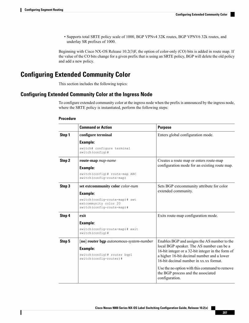
• Supports total SRTE policy scale of 1000, BGP VPNv4 32K routes, BGP VPNV6 32k routes, andunderlay SR prefixes of 1000.
Beginning with Cisco NX-OS Release 10.2(3)F, the option of color-only (CO) bits is added in route map. Ifthe value of the CO bits change for a given prefix that is using an SRTE policy, BGP will delete the old policyand add a new policy.
Configuring Extended Community ColorThis section includes the following topics:
Configuring Extended Community Color at the Ingress NodeTo configure extended community color at the ingress node when the prefix is announced by the ingress node,where the SRTE policy is instantiated, perform the following steps:
Procedure
PurposeCommand or Action
Enters global configuration mode.configure terminal
Example:
Step 1
switch# configure terminalswitch(config)#
Creates a route map or enters route-mapconfiguration mode for an existing route map.
route-map map-name
Example:
Step 2
switch(config)# route-map ABCswitch(config-route-map)
Sets BGP extcommunity attribute for colorextended community.
set extcommunity color color-num
Example:
Step 3
switch(config-route-map)# setextcommunity color 20switch(config-route-map)#
Exits route-map configuration mode.exit
Example:
Step 4
switch(config-route-map)# exitswitch(config)#
Enables BGP and assigns the AS number to thelocal BGP speaker. The AS number can be a
[no] router bgp autonomous-system-number
Example:
Step 5
16-bit integer or a 32-bit integer in the form ofswitch(config)# router bgp1switch(config-router)#
a higher 16-bit decimal number and a lower16-bit decimal number in xx.xx format.
Use the no option with this command to removethe BGP process and the associatedconfiguration.
Cisco Nexus 9000 Series NX-OS Label Switching Configuration Guide, Release 10.2(x)207
Configuring Segment RoutingConfiguring Extended Community Color

PurposeCommand or Action
Adds an entry to the BGP or multiprotocol BGPneighbor table. The ip-address argument
neighbor ip-address
Example:
Step 6
specifies the IP address of the neighbor in dotteddecimal notation.switch(config-router)# neighbor
209.165.201.1switch(config-router-neighbor)#
Enters router address-family configurationmodefor the vpnv4/vpnv6 address family type.
address-family vpnv4/vpnv6 unicast
Example:
Step 7
switch(config-router-neighbor)#address-family vpnv4/vpnv6 unicastswitch(config-router-neighbor-af)#
Applies the configured BGP policy to incomingroutes.
route-map map-name in
Example:
Step 8
The map-name can be any case-sensitive,alphanumeric string up to 63 characters.
switch(config-router-neighbor-af)#route-map ABC inswitch(config-router-neighbor-af)#
Configuring Extended Community Color at the Egress NodeTo configure extended community color at the egress node when the prefix is announced by the egress node,perform the following steps:
Procedure
PurposeCommand or Action
Enters global configuration mode.configure terminal
Example:
Step 1
switch# configure terminalswitch(config)#
Creates a route map or enters route-mapconfiguration mode for an existing route map.
route-map map-name
Example:
Step 2
switch(config)# route-map ABCswitch(config-route-map)
Sets BGP extcommunity attribute for colorextended community.
set extcommunity color color-num
Example:
Step 3
switch(config-route-map)# setextcommunity color 20switch(config-route-map)#
Exits route-map configuration mode.exit
Example:
Step 4
switch(config-route-map)# exitswitch(config)#
Cisco Nexus 9000 Series NX-OS Label Switching Configuration Guide, Release 10.2(x)208
Configuring Segment RoutingConfiguring Extended Community Color at the Egress Node

PurposeCommand or Action
Enables BGP and assigns the AS number to thelocal BGP speaker. The AS number can be a
[no] router bgp autonomous-system-number
Example:
Step 5
16-bit integer or a 32-bit integer in the form ofswitch(config)# router bgp1switch(config-router)#
a higher 16-bit decimal number and a lower16-bit decimal number in xx.xx format.
Use the no option with this command to removethe BGP process and the associatedconfiguration.
Adds an entry to the BGP or multiprotocol BGPneighbor table. The ip-address argument
neighbor ip-address
Example:
Step 6
specifies the IP address of the neighbor in dotteddecimal notation.switch(config-router)# neighbor
209.165.201.1switch(config-router-neighbor)#
Enters router address-family configurationmodefor the vpnv4/vpnv6 address family type.
address-family vpnv4/vpnv6 unicast
Example:
Step 7
switch(config-router-neighbor)#address-family vpnv4/vpnv6 unicastswitch(config-router-neighbor-af)#
Applies the configured BGP policy to outgoingroutes.
route-map map-name out
Example:
Step 8
The map-name can be any case-sensitive,alphanumeric string up to 63 characters.
switch(config-router-neighbor-af)#route-map ABC outswitch(config-router-neighbor-af)#
Configuring Extended Community Color for Network/Redistribute Command at the Egress NodeTo configure extended community color for the network/redistribute command at the egress node when theprefix is announced by the egress node, perform the following steps:
Procedure
PurposeCommand or Action
Enters global configuration mode.configure terminal
Example:
Step 1
switch# configure terminalswitch(config)#
Creates a route map or enters route-mapconfiguration mode for an existing route map.
route-map map-name
Example:
Step 2
switch(config)# route-map ABCswitch(config-route-map)
Sets BGP extcommunity attribute for colorextended community.
set extcommunity color color-num
Example:
Step 3
Cisco Nexus 9000 Series NX-OS Label Switching Configuration Guide, Release 10.2(x)209
Configuring Segment RoutingConfiguring Extended Community Color for Network/Redistribute Command at the Egress Node
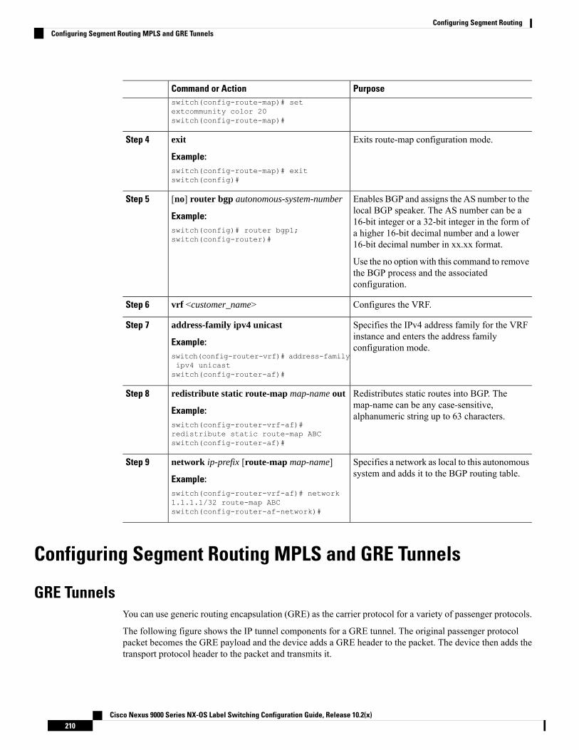
PurposeCommand or Actionswitch(config-route-map)# setextcommunity color 20switch(config-route-map)#
Exits route-map configuration mode.exit
Example:
Step 4
switch(config-route-map)# exitswitch(config)#
Enables BGP and assigns the AS number to thelocal BGP speaker. The AS number can be a
[no] router bgp autonomous-system-number
Example:
Step 5
16-bit integer or a 32-bit integer in the form ofswitch(config)# router bgp1;switch(config-router)#
a higher 16-bit decimal number and a lower16-bit decimal number in xx.xx format.
Use the no option with this command to removethe BGP process and the associatedconfiguration.
Configures the VRF.vrf <customer_name>Step 6
Specifies the IPv4 address family for the VRFinstance and enters the address familyconfiguration mode.
address-family ipv4 unicast
Example:switch(config-router-vrf)# address-familyipv4 unicastswitch(config-router-af)#
Step 7
Redistributes static routes into BGP. Themap-name can be any case-sensitive,alphanumeric string up to 63 characters.
redistribute static route-map map-name out
Example:switch(config-router-vrf-af)#redistribute static route-map ABCswitch(config-router-af)#
Step 8
Specifies a network as local to this autonomoussystem and adds it to the BGP routing table.
network ip-prefix [route-map map-name]
Example:
Step 9
switch(config-router-vrf-af)# network1.1.1.1/32 route-map ABCswitch(config-router-af-network)#
Configuring Segment Routing MPLS and GRE Tunnels
GRE TunnelsYou can use generic routing encapsulation (GRE) as the carrier protocol for a variety of passenger protocols.
The following figure shows the IP tunnel components for a GRE tunnel. The original passenger protocolpacket becomes the GRE payload and the device adds a GRE header to the packet. The device then adds thetransport protocol header to the packet and transmits it.
Cisco Nexus 9000 Series NX-OS Label Switching Configuration Guide, Release 10.2(x)210
Configuring Segment RoutingConfiguring Segment Routing MPLS and GRE Tunnels

Figure 12: GRE PDU
Segment Routing MPLS and GREBeginning Cisco NX-OS Release 9.3(1), you can configure both, segment routing MPLS and generic routingencapsulation (GRE) on a Cisco Nexus device. Both these technologies operate seamlessly. All MPLS trafficcan be forwarded to the GRE tunnel after the MPLS tunnel termination. Similarly, you can forward all trafficfrom the GRE tunnel to the MPLS cloud after the GRE termination.
All PE routers can initiate, forward, or terminate the GRE traffic from or to another GRE cloud. Similarly,all tunnel transit or tunnel end nodes can configure MPLS tunnel encapsulation.
When both, the tunnel and segment routing is enabled on the Cisco Nexus 9000 switches, the following is theTTL behavior is for the respective flows:
• Incoming IP traffic, egresses with GRE header, the TTL value in the GRE header is one less than theTTL value of the incoming IP packet.
• Incoming IP traffic, egresses with MPLS header, the TTL value in the MPLS header is one less than theTTL value of the incoming IP packet.
• Incoming GRE traffic, egresses with MPLS header, the TTL value in the MPLS header is default (255).
• Incoming MPLS traffic, egresses with GRE header, the TTL value in the GRE header is default (255).
Guidelines and Limitations for Segment Routing MPLS and GRESegment routing MPLS and GRE have the following guidelines and limitations:
• Ingress stats are not supported for tunnel packets.
• Only template-mpls-heavy template is supported.
• MPLS segment routing is not supported on the tunnel interfaces.
• Due to a hardware limitation on the modular switches, the tunnel Tx traffic is not supported if the egressinterface for the tunnel destination IP address is over the Cisco Nexus 9300-FX/FX2 platform switches.
• Maximum four GRE tunnels are supported.
• Beginning with Cisco NX-OS Release 9.3(3), you can configure both, segment routing MPLS and GREon Cisco Nexus 9300-GX platform switches.
• Tunnel Rx packet counters do not work when both segment routing MPLS and GRE coexist.
Cisco Nexus 9000 Series NX-OS Label Switching Configuration Guide, Release 10.2(x)211
Configuring Segment RoutingSegment Routing MPLS and GRE

Configuring Segment Routing MPLS and GREYou can enable MPLS segment routing as long as mutually-exclusive MPLS features such as static MPLSare not enabled.
Before you begin
You must install and enable the MPLS feature set using the install feature-set mpls and feature-set mplscommands.
You must enable the tunneling feature using the feature tunnel command.
Procedure
PurposeCommand or Action
Enters global configuration mode.configure terminal
Example:
Step 1
switch# configure terminalswitch(config)#
Enables the MPLS segment routing feature.The no form of this command disables theMPLS segment routing feature.
[no] feature segment-routing
Example:switch(config)# feature segment-routing
Step 2
Displays the status of the MPLS segmentrouting feature.
(Optional) show running-config | inc 'featuresegment-routing'
Example:
Step 3
switch(config)# show running-config |inc 'feature segment-routing'
Copies the running configuration to the startupconfiguration.
(Optional) copy running-configstartup-config
Example:
Step 4
switch(config)# copy running-configstartup-config
Enters global configuration mode.configure terminal
Example:
Step 5
switch# configure terminalswitch(config)#
Allows the creation of a new tunnel interface.feature tunnelStep 6
Example: To disable the tunnel interface feature, use theno form of this command.switch(config)# feature tunnel
switch(config-if)#
Enters a tunnel interface configuration mode.switch(config)# interface tunnel numberStep 7
Sets this tunnel mode to GRE.switch(config-if)# tunnel mode {gre ip }Step 8
Cisco Nexus 9000 Series NX-OS Label Switching Configuration Guide, Release 10.2(x)212
Configuring Segment RoutingConfiguring Segment Routing MPLS and GRE

PurposeCommand or Action
The gre and ip keywords specify that GREencapsulation over IP will be used.
Configures the source address for this IPtunnel. The source can be specified by IPaddress or logical interface name.
tunnel source {ip-address |interface-name}
Example:switch(config-if)# tunnel sourceethernet 1/2
Step 9
Configures the destination address for this IPtunnel. The destination can be specified by IPaddress or logical host name.
tunnel destination {ip-address |host-name}
Example:switch(config-if)# tunnel destination192.0.2.1
Step 10
tunnel use-vrf vrf-nameStep 11
Example:switch(config-if)# tunnel use-vrf blue
switch(config-if)# 10.1.1.1ipv6 address IPv6 addressStep 12
Configures the IPv6 address.
The tunnel source and thedestination addresses are still thesame (IPv4 address.)
Note
Displays the tunnel interface statistics.(Optional) switch(config-if)# show interfacetunnel number
Step 13
Sets the maximum transmission unit (MTU)of IP packets sent on an interface.
switch(config-if)# mtu valueStep 14
Saves the change persistently through rebootsand restarts by copying the runningconfiguration to the startup configuration.
(Optional) switch(config-if)# copyrunning-config startup-config
Step 15
Verifying the Segment Routing MPLS and GRE ConfigurationTo display the segment routing MPLS and GRE configuration, perform one of the following tasks:
PurposeCommand
Displays segment routing mpls informationshow segment-routing mpls
Verifying SR-TE for Layer 3 EVPNThe ODN verifications are based on L3VPN VRF prefixes.
1. Verify that the PCEP session between R1 (headend and PCE server) is established.
Cisco Nexus 9000 Series NX-OS Label Switching Configuration Guide, Release 10.2(x)213
Configuring Segment RoutingVerifying the Segment Routing MPLS and GRE Configuration

R1# show srte pce ipv4 peer
PCC's peer database:--------------------Remote PCEP conn IPv4 addr: 58.8.8.8Local PCEP conn IPv4 addr: 51.1.1.1Precedence: 0State: up
2. Verify BGP LS and BGP EVPN session on R1, R3, and R6 using the following commands:
• Show bgp l2vpn evpn summary
• Show bgp link-state summary
3. Verify that the R1 (headend) has no visibility to the R6 loopback address.R1# show ip route 56.6.6.6IP Route Table for VRF "default"'*' denotes best ucast next-hop'**' denotes best mcast next-hop'[x/y]' denotes [preference/metric]'%<string>' in via output denotes VRF <string>
56.6.6.6/32, ubest/mbest: 1/0*via Null0, [1/0], 1d02h, static
4. Verify that the VRF prefix is injected via MP-BGP in a R1 VRF SR routing table.R1# show ip route vrf sr106.107.4.1/32, ubest/mbest: 1/0
*via binding label 100534%default, [20/0], 1d01h, bgp-6503, external, tag 6500(mpls-vpn)
5. Verify the SR-TE Tunnel.R1# show srte policyPolicy name: 51.1.1.1|1001
Source: 51.1.1.1End-point: 56.6.6.6Created by: bgpState: UPColor: 1001Insert: FALSERe-opt timer: 0Binding-sid Label: 100534Policy-Id: 2Flags:Path type = MPLS Path options count: 1Path-option Preference:100 ECMP path count: 11. PCE Weighted: NoDelegated PCE: 58.8.8.8
Index: 1 Label: 101104Index: 2 Label: 201102Index: 3 Label: 201103
Verifying the Segment Routing ConfigurationTo display the segment routing configuration, perform one of the following tasks:
Cisco Nexus 9000 Series NX-OS Label Switching Configuration Guide, Release 10.2(x)214
Configuring Segment RoutingVerifying the Segment Routing Configuration

PurposeCommand
Displays the advertised label index and the selectedlocal label for the specified IPv4 prefix.
show bgp ipv4 labeled-unicast prefix
Displays the BGP path information, including theadvertised label index.
show bgp paths
Displays the configured SRGB range of labels.show mpls label range
Displays information about a route map, includingthe label index.
show route-map [map-name]
Displays information about Route Policy Manager(RPM).
show running-config rpm
Displays the status of the MPLS segment routingfeature.
show running-config | inc 'feature segment-routing'
Displays the list of OSPFv2 neighbors and theadjacency SID allocated, alongwith the correspondingflags.
show ip ospf neighbors detail
Displays the LSAs for the adjacency SID.show ip ospf database opaque-area
Displays all locally allocated adjacency SIDs.show ip ospf segment-routing adj-sid-database
Displays the status of the segment routing feature.show running-config segment-routing
Displays only the authorized policies.show srte policy
Displays the list of all policies available in the SR-TE.show srte policy [all]
Displays the detailed view of all the requestedpolicies.
show srte policy [detail]
Filters the SR-TE policy with the name and displaysthe list of all policies available with that name in theSR-TE.
This command has the autocompletefeature for the policy-name. To use thisfeature, add a questionmark or press TAB.
Note
show srte policy <name>
Displays the SR-TE policy for the color and endpoint.
This command has the autocompletefeature for color and endpoint. To use thisfeature, add a questionmark or press TAB.
Note
show srte policy color <color> endpoint<endpoint>
Displays the set of first hops.show srte policy fh
Displays the clients registered with the SR-APP.show segment-routing mpls clients
Displays detailed information.show segment-routing mpls details
Cisco Nexus 9000 Series NX-OS Label Switching Configuration Guide, Release 10.2(x)215
Configuring Segment RoutingVerifying the Segment Routing Configuration

PurposeCommand
Displays the information for the IPv4 address family.show segment-routing ipv4
Displays segment routing mpls informationshow segment-routing mpls
Displays the MPLS label range for the SRGB.
This command is only available in CiscoNX-OS Release 9.3(1) .
Note
show segment-routing ipv4 connected-prefix-sid
Displays the OSPF mode.show ip ospf process
Displays the segment routing database details.show ip ospf process segment-routing sid-database
Displays the segment routing global blockinformation.
show ip ospf process segment-routing global block
Displays the status of the EVIs.show nve evi
Displays the status of the segment routing peers.show nve peer mpls
Displays the status of the peer adjacencies.show nve adjacency mpls
Configuring SRTE Explicit-Path Endpoint SubstitutionThis chapter contains information on how to configure the SRTE Explicit-path Endpoint Substitution feature.
About SRTE Explicit-path Endpoint SubstitutionThe SRTE Explicit-path Endpoint Substitution feature allows the user to define an explicit path as a series ofMPLS labels, like a regular explicit path, but allows a placeholder to be added in the series that represents thepolicy endpoint label. The placeholder is represented by the policy-endpoint keyword. The position in thepath where the policy-endpoint placeholder appears is resolved by SRTE internally to the Segment Routinglabel representing the node SID of the endpoint IP address of the policy.
This is valuable when used in conjunction with on-demand color templates since it reduces the total numberof policies that must be defined. Rather than define a separate path for each color and endpoint combination,instead the user can define an on-demand color template that contains an explicit path with endpoint substitutionto define policies for all endpoints of that color.
Guidelines and Limitations for SRTE Explicit-path Endpoint SubstitutionSRTE Explicit-path Endpoint Substitution has the following guidelines and limitations:
• Beginning with Cisco NX-OS Release 10.1(1), SRTE Explicit-path Endpoint Substitution is supportedon Cisco Nexus 9300-FX, 9300-FX2, 9300-FX3, and 9300-GX platform switches.
• If the partial path ends in the same label as the resolved endpoint label, do not append the extra (duplicated)transport label.
Cisco Nexus 9000 Series NX-OS Label Switching Configuration Guide, Release 10.2(x)216
Configuring Segment RoutingConfiguring SRTE Explicit-Path Endpoint Substitution

• SRGB must be the same on all nodes; if not, the feature may not work depending on the segmentconfiguration of each intermediate node.
• A segment list can have only one policy-endpoint entry.
Configuring SRTE Explicit-path Endpoint SubstitutionTo create a policy that uses endpoint substitution, first define the path using the segment-list mode. Thenassociate the path with an on-demand color using its name.
Before you begin
You must ensure that the MPLS segment routing traffic engineering feature is enabled.
Procedure
PurposeCommand or Action
Enters global configuration mode.configure terminal
Example:
Step 1
switch# configure terminalswitch(config)#
Enters the segment routing configurationmode.
segment-routing
Example:
Step 2
switch(config)#segment-routingswitch(config-sr)#
Enters the traffic engineering mode.traffic-engineering
Example:
Step 3
switch(config-sr)# traffic-engineeringswitch(config-sr-te)#
Configures an explicit segment list.segment-list name path
Example:
Step 4
switch(config-sr-te)# segment-list namepathswitch(config-sr-te-exp-seg-list)#
Configures an MPLS label in the segment list.index 1 mpls label label-ID
Example:
Step 5
switch(config-sr-te-exp-seg-list)# index1 mpls label 16201switch(config-sr-te-exp-seg-list)#
Configures the policy endpoint resolution.index 2 policy-endpoint
Example:
Step 6
switch(config-sr-te-exp-seg-list)# index2 policy-endpointswitch(config-sr-te-exp-seg-list)#
Cisco Nexus 9000 Series NX-OS Label Switching Configuration Guide, Release 10.2(x)217
Configuring Segment RoutingConfiguring SRTE Explicit-path Endpoint Substitution

PurposeCommand or Action
Exits the segment list mode and returns to theSRTE mode.
exit
Example:
Step 7
switch(config-sr-te-exp-seg-list)# exitswitch(config-sr-te)#
Enters the on-demand color template mode toconfigure an on-demand color for the specifiedcolor.
on-demand color color_num
Example:switch(config-sr-te)# on-demand color201switch(config-sr-te-color)#
Step 8
Specifies the candidate paths for the SR-TEcolor policy.
candidate-paths
Example:
Step 9
switch(config-sr-te-color)#candidate-paths
Specifies the preference of the candidate path.preference preference-number
Example:
Step 10
switch(cfg-cndpath)# preference 100
Specifies the explicit segment list.explicit segment-list path
Example:
Step 11
switch(cfg-pref)# explicit segment-listpath
Configuration Example for SRTE Explicit-path Endpoint SubstitutionThis example shows the SRTE Explicit-path Endpoint Substitution configuration:switch(config)# segment-routingswitch(config-sr)# traffic-engineeringswitch(config-sr-te)# segment-list name pathswitch(config-sr-te-exp-seg-list)# index 1 mpls label 16201switch(config-sr-te-exp-seg-list)# index 2 policy-endpointswitch(config-sr-te-exp-seg-list)# exitswitch(config-sr-te)# on-demand color 201switch(config-sr-te-color)# candidate-pathsswitch(cfg-cndpath)# preference 100switch(cfg-pref)# explicit segment-list path
Verifying Configuration for SRTE Explicit-path Endpoint SubstitutionTo display the required details about the SRTE Explicit-path Endpoint Substitution configuration, performone of the following tasks:
Cisco Nexus 9000 Series NX-OS Label Switching Configuration Guide, Release 10.2(x)218
Configuring Segment RoutingConfiguration Example for SRTE Explicit-path Endpoint Substitution

Table 10: Verifying the SRTE Explicit-path Endpoint Substitution Configuration
PurposeCommand
Displays only the authorized policies.
If the endpoint label is resolved and thefirst hop is reachable, the state is displayedas UP. If the endpoint label is not resolvedor the first hop is not reachable, the stateis displayed as DOWN.
Note
show srte policy
Displays the list of all policies available in the SR-TE.
If the endpoint label is resolved and thefirst hop is reachable, the state is displayedas UP. If the endpoint label is not resolvedor the first hop is not reachable, the stateis displayed as DOWN.
Note
show srte policy [all]
Displays the detailed view of all the requestedpolicies.
If the endpoint label is resolved and thefirst hop is reachable, the state is displayedas UP. If the endpoint label is not resolvedor the first hop is not reachable, the stateis displayed as DOWN.
Note
show srte policy [detail]
Filters the SR-TE policy with the name and displaysthe list of all policies available with that name in theSR-TE.
This command has the autocompletefeature for the policy-name. To use thisfeature, add a questionmark or press TAB.
Note
show srte policy <name>
Displays the SR-TE policy for the color and endpoint.
This command has the autocompletefeature for color and endpoint. To use thisfeature, add a questionmark or press TAB.
Note
show srte policy color <color> endpoint<endpoint>
Displays the state of the existing first hop and policyendpoints.
show srte policy fh
Cisco Nexus 9000 Series NX-OS Label Switching Configuration Guide, Release 10.2(x)219
Configuring Segment RoutingVerifying Configuration for SRTE Explicit-path Endpoint Substitution

Configuring SRTE Over Default VRF
About SRTE Over Default VRFThe SRTEOver Default VRF feature allows you to incorporate segment routing traffic engineering to achievethe traffic steering benefits in your network. The SRTE provides increased scalability while using BGP forrouting in large-scale data centers (DC).
The SRTE Over Default VRF feature uses the route color that exists as an extended community attribute andis represented by a number as the base for traffic steering. Based on the color, plane separation is achieved,and an SR policy is created to carry the traffic. Furthermore, based on the color, the DC is divided into differentplanes. The applications are configured to use each plane to only route through a specific plane and steertraffic to appropriate destinations.
Plane separation has the following advantages:
• One flow does not affect the other flow.
• Large and small flows are separated into different planes.
• Fault isolation for better debuggability: Fault in one plane does not affect the other planes. For example,if a network fault occurs in one plane, only the applications in that plane are affected, but the applicationsin the rest of the planes are not impacted. Additionally, the fault can be isolated and troubleshooted inisolation.
The following example explains the SRTE Over Default VRF feature with an illustration.
Cisco Nexus 9000 Series NX-OS Label Switching Configuration Guide, Release 10.2(x)220
Configuring Segment RoutingConfiguring SRTE Over Default VRF

Figure 13: SRTE Over Default VRF Example
• For BGP, node A is the ingress router and node D is the egress router. D is also the next-hop.
• For SRTE, node A is the SRTE headend, node D is the endpoint for the policy.
• Route prefix 1 is configured to use the blue plane, and route 2 is configured to use the red plane.
The blue traffic is appended with instructions to steer the traffic through node B and node C, and the red trafficis appended with instruction to steer traffic through node E and node F. In summary, the traffic is handledbased on the color of the advertisement, that is, the prefix that was advertised earlier.
Guidelines and Limitations for Configuring SRTE Over Default VRF• Beginning with Cisco NX-OS Release 10.1(1), segment routing traffic engineering is supported overdefault VRF onCiscoNexus 9300-FX3,N9K-C9316D-GX ,N9K-C93180YC-FX,N9K-C93240YC-FX2,and N9K-C9364C platform switches. The limitations for this SR-TE feature are as follows:
• UnderLay IPv6 is not supported. SRv6 is the alternate.
Cisco Nexus 9000 Series NX-OS Label Switching Configuration Guide, Release 10.2(x)221
Configuring Segment RoutingGuidelines and Limitations for Configuring SRTE Over Default VRF

• PCE using BGP underlay is not supported, due to PCE’s shortcoming on BGP only fabric.
• OSPF-SRTE with PCE is not supported, due to NXOS’ inability to advertise LSA in BGP-LS.
• Supports total SRTE policy scale of 1000, BGP Default VRF(v4) of 130K v4, and underlay SRprefixes of 1000.
• Beginning with Cisco NX-OS Release 10.2(3)F, the option of color-only (CO) bits is added in routemap. If the value of the CO bits change for a given prefix that is using an SRTE policy, BGP will deletethe old policy and add a new policy. This feature is supported on Cisco Nexus 9300-EX, 9300-FX,9300-FX2, 9300-GX, and 9300-GX2 platform switches./
Configuration Process: SRTE Over Default VRFThe configuration process is as follows:
1. Set next-hop unchanged: The next-hop is used to calculate the SR policy at the ingress node. The next-hopin the SR domain on a prefix must be preserved as the prefix is advertised upstream. Hence, next-hopunchanged in needed on all upstream routers in the case for hop-by-hop ebgp.
2. Set extended community color at the egress node, ingress node, network/redistribute, or default-originate.
3. The ingress node, on receiving a color-extended community, matches it to an SR policy.
4. The endpoint for the SR policy is derived from the next-hop of the prefix and color in the color-extendedcommunity.
This section includes the following topics on configuring SRTE over default VRF:
Configuring Next-hop UnchangedTo configure next-hop unchanged on the intermediate (spine) nodes for default VRF overlay, to ensure thenext-hop is not changed, perform the following steps:
Procedure
PurposeCommand or Action
Enters global configuration mode.configure terminal
Example:
Step 1
switch# configure terminalswitch(config)#
Creates a route map or enters route-mapconfiguration mode for an existing route map.
route-map map-name
Example:
Step 2
switch(config)# route-map ABCswitch(config-route-map)
Sets next-hop unchanged.[no] set ip next-hop unchanged
Example:
Step 3
Cisco Nexus 9000 Series NX-OS Label Switching Configuration Guide, Release 10.2(x)222
Configuring Segment RoutingConfiguration Process: SRTE Over Default VRF

PurposeCommand or Actionswitch(config-route-map)# set ip next-hopunchangedswitch(config-route-map)#
Exits route-map configuration mode.exit
Example:
Step 4
switch(config-route-map)# exitswitch(config)#
Enables BGP and assigns the AS number to thelocal BGP speaker. The AS number can be a
[no] router bgp autonomous-system-number
Example:
Step 5
16-bit integer or a 32-bit integer in the form ofswitch(config)# router bgp1switch(config-router)#
a higher 16-bit decimal number and a lower16-bit decimal number in xx.xx format.
Use the no option with this command to removethe BGP process and the associatedconfiguration.
Adds an entry to the BGP or multiprotocol BGPneighbor table. The ip-address argument
neighbor ip-address
Example:
Step 6
specifies the IP address of the neighbor in dotteddecimal notation.switch(config-router)# neighbor
209.165.201.1switch(config-router-neighbor)#
Enters router address-family configurationmodefor the IPv4 address family type.
address-family ipv4 unicast
Example:
Step 7
switch(config-router-neighbor)#address-family ipv4 unicastswitch(config-router-neighbor-af)#
Applies the configured BGP policy to outgoingroutes.
route-map map-name out
Example:
Step 8
switch(config-router-neighbor-af)#route-map ABC outswitch(config-router-neighbor-af)#
Configuring Extended Community ColorThis section includes the following topics:
Configuring Extended Community Color at the Egress Node
To configure extended community color at the egress node when the prefix is announced by the egress node,perform the following steps:
Cisco Nexus 9000 Series NX-OS Label Switching Configuration Guide, Release 10.2(x)223
Configuring Segment RoutingConfiguring Extended Community Color
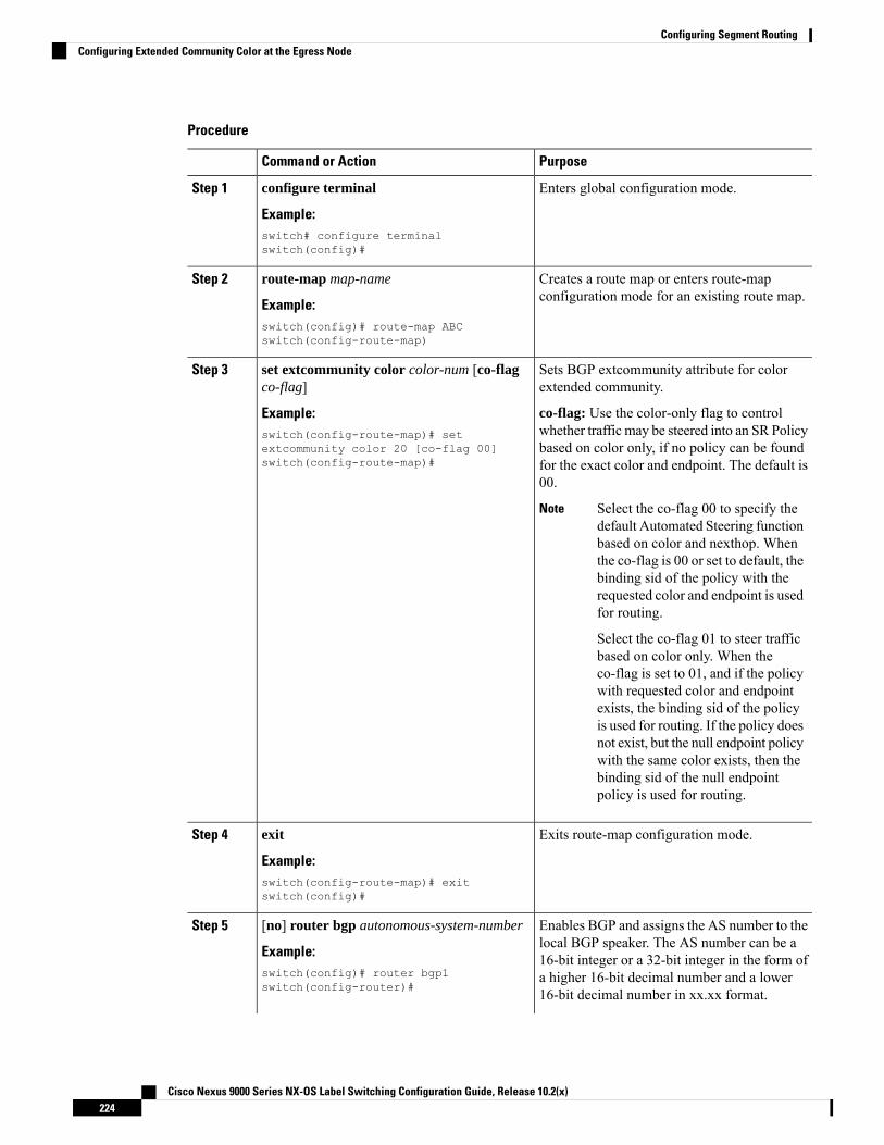
Procedure
PurposeCommand or Action
Enters global configuration mode.configure terminal
Example:
Step 1
switch# configure terminalswitch(config)#
Creates a route map or enters route-mapconfiguration mode for an existing route map.
route-map map-name
Example:
Step 2
switch(config)# route-map ABCswitch(config-route-map)
Sets BGP extcommunity attribute for colorextended community.
set extcommunity color color-num [co-flagco-flag]
Step 3
Example: co-flag: Use the color-only flag to controlwhether traffic may be steered into an SR Policyswitch(config-route-map)# set
extcommunity color 20 [co-flag 00]switch(config-route-map)#
based on color only, if no policy can be foundfor the exact color and endpoint. The default is00.
Select the co-flag 00 to specify thedefault Automated Steering functionbased on color and nexthop. Whenthe co-flag is 00 or set to default, thebinding sid of the policy with therequested color and endpoint is usedfor routing.
Select the co-flag 01 to steer trafficbased on color only. When theco-flag is set to 01, and if the policywith requested color and endpointexists, the binding sid of the policyis used for routing. If the policy doesnot exist, but the null endpoint policywith the same color exists, then thebinding sid of the null endpointpolicy is used for routing.
Note
Exits route-map configuration mode.exit
Example:
Step 4
switch(config-route-map)# exitswitch(config)#
Enables BGP and assigns the AS number to thelocal BGP speaker. The AS number can be a
[no] router bgp autonomous-system-number
Example:
Step 5
16-bit integer or a 32-bit integer in the form ofswitch(config)# router bgp1switch(config-router)#
a higher 16-bit decimal number and a lower16-bit decimal number in xx.xx format.
Cisco Nexus 9000 Series NX-OS Label Switching Configuration Guide, Release 10.2(x)224
Configuring Segment RoutingConfiguring Extended Community Color at the Egress Node

PurposeCommand or Action
Use the no option with this command to removethe BGP process and the associatedconfiguration.
Adds an entry to the BGP or multiprotocol BGPneighbor table. The ip-address argument
neighbor ip-address
Example:
Step 6
specifies the IP address of the neighbor in dotteddecimal notation.switch(config-router)# neighbor
209.165.201.1switch(config-router-neighbor)#
Enters router address-family configurationmodefor the IPv4 address family type.
address-family ipv4 unicast
Example:
Step 7
switch(config-router-neighbor)#address-family ipv4 unicastswitch(config-router-neighbor-af)#
Applies the configured BGP policy to outgoingroutes.
route-map map-name out
Example:
Step 8
The map-name can be any case-sensitive,alphanumeric string up to 63 characters.
switch(config-router-neighbor-af)#route-map ABC outswitch(config-router-neighbor-af)#
Configuring Extended Community Color at the Ingress Node
To configure extended community color at the ingress node when the prefix is announced by the ingress node,where the SRTE policy is instantiated, perform the following steps:
Procedure
PurposeCommand or Action
Enters global configuration mode.configure terminal
Example:
Step 1
switch# configure terminalswitch(config)#
Creates a route map or enters route-mapconfiguration mode for an existing route map.
route-map map-name
Example:
Step 2
switch(config)# route-map ABCswitch(config-route-map)
Sets BGP extcommunity attribute for colorextended community.
set extcommunity color color-num [co-flagco-flag]
Step 3
Example: co-flag: Use the color-only flag to controlwhether traffic may be steered into an SR Policyswitch(config-route-map)# set
extcommunity color 20 [co-flag 00]switch(config-route-map)#
based on color only, if no policy can be foundfor the exact color and endpoint. The default is00.
Cisco Nexus 9000 Series NX-OS Label Switching Configuration Guide, Release 10.2(x)225
Configuring Segment RoutingConfiguring Extended Community Color at the Ingress Node

PurposeCommand or Action
Select the co-flag 00 to specify thedefault Automated Steering functionbased on color and nexthop. Whenthe co-flag is 00 or set to default, thebinding sid of the policy with therequested color and endpoint is usedfor routing.
Select the co-flag 01 to steer trafficbased on color only. When theco-flag is set to 01, and if the policywith requested color and endpointexists, the binding sid of the policyis used for routing. If the policy doesnot exist, but the null endpoint policywith the same color exists, then thebinding sid of the null endpointpolicy is used for routing.
Note
Exits route-map configuration mode.exit
Example:
Step 4
switch(config-route-map)# exitswitch(config)#
Enables BGP and assigns the AS number to thelocal BGP speaker. The AS number can be a
[no] router bgp autonomous-system-number
Example:
Step 5
16-bit integer or a 32-bit integer in the form ofswitch(config)# router bgp1switch(config-router)#
a higher 16-bit decimal number and a lower16-bit decimal number in xx.xx format.
Use the no option with this command to removethe BGP process and the associatedconfiguration.
Adds an entry to the BGP or multiprotocol BGPneighbor table. The ip-address argument
neighbor ip-address
Example:
Step 6
specifies the IP address of the neighbor in dotteddecimal notation.switch(config-router)# neighbor
209.165.201.1switch(config-router-neighbor)#
Enters router address-family configurationmodefor the IPv4 address family type.
address-family ipv4 unicast
Example:
Step 7
switch(config-router-neighbor)#address-family ipv4 unicastswitch(config-router-neighbor-af)#
Applies the configured BGP policy to incomingroutes.
route-map map-name in
Example:
Step 8
The map-name can be any case-sensitive,alphanumeric string up to 63 characters.
Cisco Nexus 9000 Series NX-OS Label Switching Configuration Guide, Release 10.2(x)226
Configuring Segment RoutingConfiguring Extended Community Color at the Ingress Node

PurposeCommand or Actionswitch(config-router-neighbor-af)#route-map ABC inswitch(config-router-neighbor-af)#
Configuring Extended Community Color for Network/Redistribute Command at the Egress Node
To configure extended community color for the network/redistribute command at the egress node when theprefix is announced by the egress node, perform the following steps:
Procedure
PurposeCommand or Action
Enters global configuration mode.configure terminal
Example:
Step 1
switch# configure terminalswitch(config)#
Creates a route map or enters route-mapconfiguration mode for an existing route map.
route-map map-name
Example:
Step 2
switch(config)# route-map ABCswitch(config-route-map)
Sets BGP extcommunity attribute for colorextended community.
set extcommunity color color-num [co-flagco-flag]
Step 3
Example: co-flag: Use the color-only flag to controlwhether traffic may be steered into an SR Policyswitch(config-route-map)# set
extcommunity color 20 [co-flag 00]switch(config-route-map)#
based on color only, if no policy can be foundfor the exact color and endpoint. The default is00.
Select the co-flag 00 to specify thedefault Automated Steering functionbased on color and nexthop. Whenthe co-flag is 00 or set to default, thebinding sid of the policy with therequested color and endpoint is usedfor routing.
Select the co-flag 01 to steer trafficbased on color only. When theco-flag is set to 01, and if the policywith requested color and endpointexists, the binding sid of the policyis used for routing. If the policy doesnot exist, but the null endpoint policywith the same color exists, then thebinding sid of the null endpointpolicy is used for routing.
Note
Cisco Nexus 9000 Series NX-OS Label Switching Configuration Guide, Release 10.2(x)227
Configuring Segment RoutingConfiguring Extended Community Color for Network/Redistribute Command at the Egress Node

PurposeCommand or Action
Exits route-map configuration mode.exit
Example:
Step 4
switch(config-route-map)# exitswitch(config)#
Enables BGP and assigns the AS number to thelocal BGP speaker. The AS number can be a
[no] router bgp autonomous-system-number
Example:
Step 5
16-bit integer or a 32-bit integer in the form ofswitch(config)# router bgp1switch(config-router)#
a higher 16-bit decimal number and a lower16-bit decimal number in xx.xx format.
Use the no option with this command to removethe BGP process and the associatedconfiguration.
Specifies the IPv4 address family for the VRFinstance and enters the address familyconfiguration mode.
address-family ipv4 unicast
Example:switch(config-router)# address-familyipv4 unicastswitch(config-router-af)#
Step 6
Redistributes static routes into BGP. Themap-name can be any case-sensitive,alphanumeric string up to 63 characters.
redistribute static route-map map-name out
Example:switch(config-router-af)# redistributestatic route-map ABCswitch(config-router-af)#
Step 7
Specifies a network as local to this autonomoussystem and adds it to the BGP routing table.
network ip-prefix [route-map map-name]
Example:
Step 8
switch(config-router-af)# network1.1.1.1/32 route-map ABCswitch(config-router-af-network)#
Configuring Extended Community Color for Default-Originate at the Egress Node
To configure extended community color for default-originate at the egress node when the default prefix isannounced by the egress node, perform the following steps:
Procedure
PurposeCommand or Action
Enters global configuration mode.configure terminal
Example:
Step 1
switch# configure terminalswitch(config)#
Creates a route map or enters route-mapconfiguration mode for an existing route map.
route-map map-name
Example:
Step 2
Cisco Nexus 9000 Series NX-OS Label Switching Configuration Guide, Release 10.2(x)228
Configuring Segment RoutingConfiguring Extended Community Color for Default-Originate at the Egress Node

PurposeCommand or Action
The map-name can be any case-sensitive,alphanumeric string up to 63 characters.
switch(config)# route-map ABCswitch(config-route-map)
Sets BGP extcommunity attribute for colorextended community.
set extcommunity color color-num [co-flagco-flag]
Step 3
Example: co-flag: Use the color-only flag to controlwhether traffic may be steered into an SR Policyswitch(config-route-map)# set
extcommunity color 20 [co-flag 00] based on color only, if no policy can be foundfor the exact color and endpoint. The default is00.
Select the co-flag 00 to specify thedefault Automated Steering functionbased on color and nexthop. Whenthe co-flag is 00 or set to default, thebinding sid of the policy with therequested color and endpoint is usedfor routing.
Select the co-flag 01 to steer trafficbased on color only. When theco-flag is set to 01, and if the policywith requested color and endpointexists, the binding sid of the policyis used for routing. If the policy doesnot exist, but the null endpoint policywith the same color exists, then thebinding sid of the null endpointpolicy is used for routing.
Note
Exits route-map configuration mode.exit
Example:
Step 4
switch(config-route-map)# exitswitch(config)#
Enables BGP and assigns the AS number to thelocal BGP speaker. The AS number can be a
[no] router bgp autonomous-system-number
Example:
Step 5
16-bit integer or a 32-bit integer in the form ofswitch(config)# router bgp1switch(config-router)#
a higher 16-bit decimal number and a lower16-bit decimal number in xx.xx format.
Use the no option with this command to removethe BGP process and the associatedconfiguration.
Adds an entry to the BGP or multiprotocol BGPneighbor table. The ip-address argument
neighbor ip-address
Example:
Step 6
specifies the IP address of the neighbor in dotteddecimal notation.switch(config-router)# neighbor
209.165.201.1switch(config-router-neighbor)#
Cisco Nexus 9000 Series NX-OS Label Switching Configuration Guide, Release 10.2(x)229
Configuring Segment RoutingConfiguring Extended Community Color for Default-Originate at the Egress Node

PurposeCommand or Action
Enters router address-family configurationmodefor the IPv4 address family type.
address-family ipv4 unicast
Example:
Step 7
switch(config-router-neighbor)#address-family ipv4 unicastswitch(config-router-neighbor-af)#
Generates a default route to the BGP peer.default-originate [ route-map map-name ]Step 8
Example: The map-name can be any case-sensitive,alphanumeric string up to 63 characters.switch(config-router-neighbor-af)#
default-originate route-map ABCswitch(config-router-neighbor-af)#
Configuring BGP for Ingress Peer (SRTE Headend)To configure BGP for the ingress peer (SRTE headend), perform the following steps.
Procedure
PurposeCommand or Action
Enters global configuration mode.configure terminal
Example:
Step 1
switch# configure terminalswitch(config)#
Enables BGP.[no] feature bgpStep 2
Example: Use the no form of this command to disablethis feature.switch(config)# feature bgp
switch(config)
Enables BGP and assigns the AS number tothe local BGP speaker. The AS number can be
[no] router bgp autonomous-system-number
Example:
Step 3
a 16-bit integer or a 32-bit integer in the formswitch(config)# router bgp 64496switch(config-router)#
of a higher 16-bit decimal number and a lower16-bit decimal number in xx.xx format.
Use the no option with this command toremove the BGP process and the associatedconfiguration.
Enters global address family configurationmode for the IPv4 address family.
address-family ipv4 unicast
Example:
Step 4
switch(config-router)# address-familyipv4 unicastswitch(config-router-af)#
Configures the IPv4 address for a remote BGPpeer. The ip-address format is x.x.x.x.
neighbor ip-address
Example:
Step 5
Cisco Nexus 9000 Series NX-OS Label Switching Configuration Guide, Release 10.2(x)230
Configuring Segment RoutingConfiguring BGP for Ingress Peer (SRTE Headend)

PurposeCommand or Actionswitch(config-router-af)# neighbor209.165.201.1switch(config-router-af-neighbor)#
Configures the AS number for a remote BGPpeer.
remote-as as-number
Example:
Step 6
switch(config-router-af-neighbor)#remote-as 64497
Specifies and updates the source of the BGPsession.
update-source interface number
Example:
Step 7
switch(config-router-af-neighbor)#update-source loopback 300
Configures the eBGP TTL value for eBGPmultihop. The range is from 2 to 255. You
ebgp-multihop ttl-value
Example:
Step 8
must manually reset the BGP sessions afterusing this command.switch(config-router-af-neighbor)#
ebgp-multihop 5
Exits the neighbor configuration mode.exit
Example:
Step 9
switch(config-router-af-neighbor)# exit
Enters global address family configurationmode for the IPv4 address family.
address-family ipv4 unicast
Example:
Step 10
switch(config-router)# address-familyipv4 unicastswitch(config-router-af)#
Specifies the route map for the SRTE ingresspeer.
route-map map-name in
Example:
Step 11
The map-name can be any case-sensitive,alphanumeric string up to 63 characters.
switch(config-router-af)# route-mapcolor 401 in
Only one extended communitycolor can be applied to an NLRI, soany route-policy/route-map appliedoverrides the previous extendedcommunity color, if it exists.
Note
Configuring BGP for Egress Peer (SRTE Endpoint)To configure BGP for the egress peer (SRTE endpoint), perform the following steps.
Cisco Nexus 9000 Series NX-OS Label Switching Configuration Guide, Release 10.2(x)231
Configuring Segment RoutingConfiguring BGP for Egress Peer (SRTE Endpoint)

Procedure
PurposeCommand or Action
Enters global configuration mode.configure terminal
Example:
Step 1
switch# configure terminalswitch(config)#
Enables BGP.[no] feature bgpStep 2
Example: Use the no form of this command to disablethis feature.switch(config)# feature bgp
switch(config)
Enables BGP and assigns the AS number tothe local BGP speaker. The AS number can be
[no] router bgp autonomous-system-number
Example:
Step 3
a 16-bit integer or a 32-bit integer in the formswitch(config)# router bgp 64496switch(config-router)#
of a higher 16-bit decimal number and a lower16-bit decimal number in xx.xx format.
Use the no option with this command toremove the BGP process and the associatedconfiguration.
Configures the IPv4 address for a remote BGPpeer. The ip-address format is x.x.x.x.
neighbor ip-address
Example:
Step 4
switch(config-router)# neighbor209.165.201.1switch(config-router-neighbor)#
Configures the AS number for a remote BGPpeer.
remote-as as-number
Example:
Step 5
switch(config-router-neighbor)#remote-as 64497
Specifies and updates the source of the BGPsession.
update-source interface-number
Example:
Step 6
switch(config-router-neighbor)#update-source loopback 300
Configures the eBGP TTL value for eBGPmultihop. The range is from 2 to 255. You
ebgp-multihop ttl-value
Example:
Step 7
must manually reset the BGP sessions afterusing this command.switch(config-router-neighbor)#
ebgp-multihop 5
Exits the neighbor configuration mode.exit
Example:
Step 8
switch(config-router-af-neighbor)# exit
Cisco Nexus 9000 Series NX-OS Label Switching Configuration Guide, Release 10.2(x)232
Configuring Segment RoutingConfiguring BGP for Egress Peer (SRTE Endpoint)
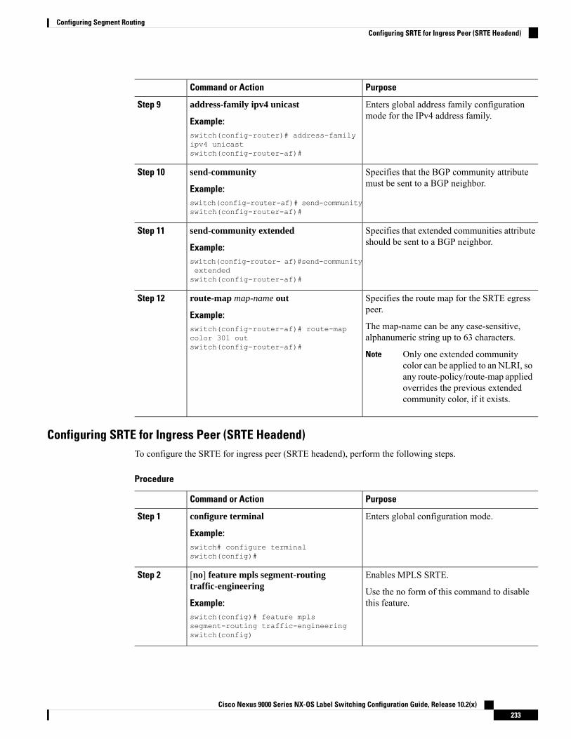
PurposeCommand or Action
Enters global address family configurationmode for the IPv4 address family.
address-family ipv4 unicast
Example:
Step 9
switch(config-router)# address-familyipv4 unicastswitch(config-router-af)#
Specifies that the BGP community attributemust be sent to a BGP neighbor.
send-community
Example:
Step 10
switch(config-router-af)# send-communityswitch(config-router-af)#
Specifies that extended communities attributeshould be sent to a BGP neighbor.
send-community extended
Example:
Step 11
switch(config-router- af)#send-communityextendedswitch(config-router-af)#
Specifies the route map for the SRTE egresspeer.
route-map map-name out
Example:
Step 12
The map-name can be any case-sensitive,alphanumeric string up to 63 characters.
switch(config-router-af)# route-mapcolor 301 outswitch(config-router-af)#
Only one extended communitycolor can be applied to an NLRI, soany route-policy/route-map appliedoverrides the previous extendedcommunity color, if it exists.
Note
Configuring SRTE for Ingress Peer (SRTE Headend)To configure the SRTE for ingress peer (SRTE headend), perform the following steps.
Procedure
PurposeCommand or Action
Enters global configuration mode.configure terminal
Example:
Step 1
switch# configure terminalswitch(config)#
Enables MPLS SRTE.[no] feature mpls segment-routingtraffic-engineering
Step 2
Use the no form of this command to disablethis feature.Example:
switch(config)# feature mplssegment-routing traffic-engineeringswitch(config)
Cisco Nexus 9000 Series NX-OS Label Switching Configuration Guide, Release 10.2(x)233
Configuring Segment RoutingConfiguring SRTE for Ingress Peer (SRTE Headend)

PurposeCommand or Action
Enters the segment routing configurationmode.
segment-routing
Example:
Step 3
switch(config)#segment-routingswitch(config-sr)#
Enters the traffic engineering mode.traffic-engineering
Example:
Step 4
switch(config-sr)# traffic-engineeringswitch(config-sr-te)#
Configures an explicit segment list.segment-list name path
Example:
Step 5
switch(config-sr-te)# segment-list namepathswitch(config-sr-te-exp-seg-list)#
Create an MPLS label in the segment list.index 1 mpls label label-ID
Example:
Step 6
switch(config-sr-te-exp-seg-list)# index1 mpls label 16601switch(config-sr-te-exp-seg-list)#
Creates MPLS label in the segment list.index 2 mpls label label-ID
Example:
Step 7
switch(config-sr-te-exp-seg-list)# index2 mpls label 16501switch(config-sr-te-exp-seg-list)#
Specifies the SRTE policy name.policy policy-name-bgp
Example:
Step 8
switch(config-sr-te-exp-seg-list)#policy dci1-edge1-bgpswitch(config-sr-te-exp-seg-list)#
Specifies the color and endpoint for the policy(SRTE Egress Node Loopback).
color color-num endpoint endpoint ID
Example:
Step 9
switch(config-sr-te)# color 13401endpoint 1.0.3.1
Specifies the candidate paths for the SRTEcolor policy.
candidate-paths
Example:
Step 10
switch(config-sr-te-color)#candidate-paths
Specifies the preference of the candidate path.preference preference-number
Example:
Step 11
switch(cfg-cndpath)# preference 100
Cisco Nexus 9000 Series NX-OS Label Switching Configuration Guide, Release 10.2(x)234
Configuring Segment RoutingConfiguring SRTE for Ingress Peer (SRTE Headend)

PurposeCommand or Action
Specifies the explicit segment list.explicit segment-list path
Example:
Step 12
switch(cfg-pref)# explicit segment-listpath
Configuration Example for SRTE Over Default VRFThe following examples show the SRTE over default VRF configuration:
Configuration Example: Next-hop Unchangedroute-map ABCset ip next-hop unchanged
router bgp 1neighbor 1.2.3.4address-family ipv4 unicast
route-map ABC out
Configuration Examples: Extended Community ColorThis section includes the following configuration examples for extended community color:
Configuration Example: At the Egress Node
ip prefix-list pfx1 seq 5 permit 7.7.7.7/32ip prefix-list pfx2 seq 5 permit 5.0.0.0/24route-map ABCmatch ip address prefix-list pfx1 pfx2set extcommunity color 20
router bgp 1neighbor 1.2.3.4address-family ipv4 unicast
route-map ABC out
Configuration Example: At the Ingress Node
ip prefix-list pfx1 seq 5 permit 7.7.7.7/32ip prefix-list pfx2 seq 5 permit 5.0.0.0/24route-map ABCmatch ip address prefix-list pfx1 pfx2set extcommunity color 20
router bgp 1neighbor 1.2.3.4address-family ipv4 unicast
route-map ABC in
Configuration Example: For Network/Redistribute Command at the Egress Node
route-map ABCset extcommunity color 20
router bgp 1address-family ipv4 unicast
Cisco Nexus 9000 Series NX-OS Label Switching Configuration Guide, Release 10.2(x)235
Configuring Segment RoutingConfiguration Example for SRTE Over Default VRF

redistribute static route-map ABCnetwork 1.1.1.1/32 route-map ABC
Configuration Example: For Default-Originate at the Egress Node
route-map ABCset extcommunity color 20
router bgp 1neighbor 1.2.3.4
address-family ipv4 unicastdefault-originate route-map ABC
Configuration Example: BGP for Ingress Peer (SRTE Headend)DCI-1(config)# show running-config bgpfeature bgprouter bgp 100address-family ipv4 unicastneighbor 1.0.3.1remote-as 101update-source loopback0ebgp-multihop 255address-family ipv4 unicast
route-map color-3401 in
Configuration Example: BGP for Egress Peer (SRTE Endpoint)This example shows the SRTE Explicit-Path Endpoint Substitution configuration:Edge-1(config)# show running-config bgpfeature bgprouter bgp 101neighbor 1.0.1.1
remote-as 100update-source loopback0ebgp-multihop 255address-family ipv4 unicastsend-communitysend-community extendedroute-map color-3401 out
Configuration Example: Ingress Peer for SRTE (SRTE Headend)DCI-1# show running-config srtefeature mpls segment-routing traffic-engineeringsegment-routingtraffic-engineeringsegment-list name dci1-edge1index 1 mpls label 16601index 2 mpls label 16501
policy dci1-edge1-bgpcolor 13401 endpoint 1.0.3.1candidate-pathspreference 30explicit segment-list dci1-edge1
Verifying Configuration for SRTE Over Default VRFTo display the appropriate details about the SRTE over default VRF configuration, perform one of the followingtasks:
Cisco Nexus 9000 Series NX-OS Label Switching Configuration Guide, Release 10.2(x)236
Configuring Segment RoutingConfiguration Example: For Default-Originate at the Egress Node

Table 11: Verifying SRTE Over Default VRF Configuration
PurposeCommand
Displays information about the ingress peer or theSRTE headend.
show running-config bgp
Displays information about the egress peer or theSRTE endpoint.
show running-config bgp
Displays information about the SRTE policy foringress peer.
show running-config srte
Additional References
Related DocumentsDocument TitleRelated Topic
Cisco Nexus 9000 Series Unicast RoutingConfiguration Guide
BGP
Cisco Nexus 9000 Series NX-OS Label Switching Configuration Guide, Release 10.2(x)237
Configuring Segment RoutingAdditional References

Cisco Nexus 9000 Series NX-OS Label Switching Configuration Guide, Release 10.2(x)238
Configuring Segment RoutingRelated Documents

C H A P T E R 9Configuring MVPNs
This chapter contains information on how to configure multicast virtual private networks (MVPNs)
• About MVPNs, on page 239• BGP Advertisement Method - MVPN Support, on page 242• Prerequisites for MVPNs, on page 242• Guidelines and Limitations for MVPNs, on page 243• Default Settings for MVPNs, on page 244• Configuring MVPNs, on page 244• Configuration Examples for MVPN, on page 251
About MVPNsThe multicast virtual private networks (MVPNs) feature allows you to support multicast connectivity overLayer 3 VPN. IP multicast is used to stream video, voice, and data to an VPN network core.
Historically, point-to-point tunnels were the only way to connect through an enterprise or service providernetwork. Although such tunneled networks had scalability issues, they were the only means of passing IPmulticast traffic through a virtual private network (VPN). Because Layer 3 VPNs support only unicast trafficconnectivity, deploying with a Layer 3 VPN allows operators to offer both unicast and multicast connectivityto Layer 3 VPN customers
MVPNs allows you to configure and support multicast traffic in an MVPN environment. MVPNs supportrouting and forwarding of multicast packets for each individual virtual routing and forwarding (VRF) instance,and it also provides a mechanism to transport VPN multicast packets across the enterprise or service providerbackbone. IP multicast is used to stream video, voice, and data to a VPN network core.
A VPN allows network connectivity across a shared infrastructure, such as an Internet Service Provider (ISP).Its function is to provide the same policies and performance as a private network at a reduced cost of ownership.
MVPNs allow an enterprise to transparently interconnect its private network across the network backbone.Using MVPNs to interconnect an enterprise network does not change the way that an enterprise network isadministered and it does not change general enterprise connectivity.
MVPN Routing and Forwarding and Multicast DomainsMVPNs introduce multicast routing information to the VPN routing and forwarding table. When a provideredge (PE) router receives multicast data or control packets from a customer edge (CE) router, the router
Cisco Nexus 9000 Series NX-OS Label Switching Configuration Guide, Release 10.2(x)239

forwards the data or control packets according to the information in the MVPN routing and forwarding(MVRF).
A set of MVRFs that can send multicast traffic to each other constitutes a multicast domain. For example, themulticast domain for a customer that wanted to send certain types of multicast traffic to all global employeeswould consist of all CE routers that are associated with that enterprise.
Multicast Distribution TreesMVPNs establish a static default multicast distribution tree (MDT) for each multicast domain. The defaultMDT defines the path used by PE routers to send multicast data and control messages to every other PE routerin the multicast domain.
MVPNs also support the dynamic creation ofMDTs for high-bandwidth transmission. DataMDTs are intendedfor high-bandwidth sources such as full-motion video inside the VPN to ensure optimal traffic forwarding inthe VPN core.
In the following example, a service provider has a multicast customer with offices in San Jose, New York,and Dallas. A one-way multicast presentation is occurring in San Jose. The service provider network supportsall three sites that are associated with this customer, in addition to the Houston site of a different enterprisecustomer. The default MDT for the enterprise customer consists of provider routers P1, P2, and P3 and theirassociated PE routers. PE4 is not part of the default MDT, because it is associated with a different customer.The following figure shows that no data flows along the default MDT, because no one outside of San Josehas joined the multicast.
Figure 14: Default Multicast Distribution Tree Overview
Cisco Nexus 9000 Series NX-OS Label Switching Configuration Guide, Release 10.2(x)240
Configuring MVPNsMulticast Distribution Trees

An employee in New York joins the multicast session. The PE router that is associated with the New Yorksite sends a join request that flows across the default MDT for the multicast domain of the customer. PE1,the PE router that is associated with the multicast session source, receives the request. The following figuredepicts that the PE router forwards the request to the CE router that is associated with the multicast source(CE1a).
Figure 15: Initializing the Data MDT
The CE router (CE1a) begins to send the multicast data to the associated PE router (PE1), which sends themulticast data along the default MDT. PE1 creates a dataMDT, sends a message to all routers using the defaultMDT that contains information about the data MDT, and, three seconds later, begins sending the multicastdata for that particular stream using the data MDT. Only PE2 has interested receivers for this source, so onlyPE2 joins the data MDT and receives traffic on it. (If the data MDT had not been configured and only thedefault MDT had been configured, all the customer sites would have received the traffic even though theywere not interested in it.) PE routers maintain a PIM relationship with other PE routers over the default MDTand a PIM relationship with its directly attached P routers.
Multicast Tunnel InterfaceAn MVPN routing and forwarding (MVRF), which is created per multicast domain, requires the router tocreate a tunnel interface from which all MVRF traffic is sourced. A multicast tunnel interface is an interfacethat the MVRF uses to access the multicast domain. The interface is a conduit that connects an MVRF andthe global MVRF. One tunnel interface is created per MVRF.
Cisco Nexus 9000 Series NX-OS Label Switching Configuration Guide, Release 10.2(x)241
Configuring MVPNsMulticast Tunnel Interface

Benefits of MVPNsThe benefits of MVPNs are as follows:
• Provides a scalable method to dynamically send information to multiple locations.
• Provides high-speed information delivery.
• Provides connectivity through a shared infrastructure.
BGP Advertisement Method - MVPN SupportWhen you configure the default MDT in a PIM Source Specific Multicast (PIM-SSM) environment ratherthan a PIM-SM environment, the receiver PE needs information about the source PE and the default MDT.This information is used to send (S, G) joins toward the source PE to build a distribution tree from the sourcePE without the need for a rendezvous point (RP). The source provider edge (PE) address and default MDTaddress are sent using the Border Gateway Protocol (BGP).
BGP MDT SAFIBGP MDT SAFI is the BGP advertisement method that is used for MVPNs. In the current release, only IPv4is supported. MDT SAFI has the following settings:
• AFI = 1
• SAFI = 66
In Cisco NX-OS, the source PE address and the MDT address are passed to PIM using BGP MDT SAFIupdates. The Route Descriptor (RD) type has changed to RD type 0 and BGP determines the best path for theMDT updates before passing the information to PIM.
You must configure the MDT SAFI address family for BGP neighbors by using the address-family ipv4 mdtcommand. You must still enable neighbors that do not support the MDT SAFI for the MDT SAFI in the localBGP configuration. Prior to the MDT SAFI, additional BGP configuration from the VPNv4 unicastconfiguration was not needed to support MVPNs.
Prerequisites for MVPNsMVPNs configuration has the following prerequisites:
• Ensure that you have configured MPLS and Label Distribution Protocol (LDP) in your network. Allrouters in the core, including the PE routers, must be able to support MPLS forwarding. VPNv4 routesare not installed by BGP if labeled paths do not exist for PE source addresses.
• Ensure that you have installed the correct license for MPLS and any other features you will be usingwith MPLS.
Cisco Nexus 9000 Series NX-OS Label Switching Configuration Guide, Release 10.2(x)242
Configuring MVPNsBenefits of MVPNs

Guidelines and Limitations for MVPNsConfiguring MVPNs has the following guidelines and limitations:
• MVPNs are supported beginning with Cisco NX-OS Release 9.3(3).
• MVPNs are supported only for Cisco Nexus 9500 platform switches with -R/-RX line cards (except theN9K-X96136YC-R line card).
• Bidirectional Forwarding Detection (BFD) is not supported on the Multicast Tunnel Interface (MTI).
• By default, the BGP update source is used as the source of the MVPN tunnel. However, you can use themdt source to override the BGP update source and provide a different source to the multicast tunnel.
• MVPN supports a maximum of 16 MDT source interfaces.
• You must configure the MDT SAFI on all routers that participate in the MVPN operations.
• Extended communities are needed for VPNv4 interior BGP (iBGP) sessions to carry the connectorattribute.
• MDT MTU configuration is not supported. The maximum customer multicast packet size that can besent over MVPN is limited by the MTU of the core interfaces. For example:
• MTU 1500 – Customer IP packet size = 1476
• MTU 9216 – Customer IP packet size = 9192
• Some of theMVPNmulticast control packets are classified into the copp-system-p-class-l2-default CoPPpolicy. We recommend modifying the CoPP policy to increase the policer rate under this class if theviolated count increases.
• MDT bidir-enable is not supported.
• vPCs are not supported for MVPN.
• Data MDT entries are not cached when the transit PE router does not have receivers and is connected toa CE which is a RP. The data MDT entries are cached only when a local receiver is attached to this PErouter. However, there is a delay in the switchover because the entries are not pre-downloaded.
• For Date MDT, only 'immediate-switch' mode is supported. Threshold based switching is not supported.
• Sub-interface and SVI support between PE and P /PE devices is not available.
• MVPN Consistency-checker is not supported in Cisco Nexus Release 9.3(3).
• Statistics for MTI interfaces are not supported in Cisco Nexus Release 9.3(3).
• Maximum 40G multicast traffic per ASIC is supported in Cisco Nexus Release 9.3(3).
• You are allowed to configure a non-default MTU on a VRF only after you remove the MDT MTUconfiguration from the VRF. This occurs when the MTI is down in a switch in which the VRF with thenon-default MDT MTU is available.
• Due to a hardware limitation, the MTI TX packet counts are not supported. However, all MTI RX packetand byte counts are supported.
Cisco Nexus 9000 Series NX-OS Label Switching Configuration Guide, Release 10.2(x)243
Configuring MVPNsGuidelines and Limitations for MVPNs

Default Settings for MVPNsTable 12: Default MVPN Parameters
DefaultParameters
No defaultmdt default address
Enabledmdt enforce-bgp-mdt-safi
No defaultmdt source
30000 msmdt ip pim hello-interval interval
60000 msmdt ip pim jp-interval interval
Disabledmdt default asm-use-shared-tree
Configuring MVPNsThis chapter describes how to configure multicast virtual private networks (MVPNs) on Cisco NX-OS devices.
For MVPN, a new TCAM region "ing-mvpn" is used (with default size of 10). This region is carvedautomatically hence you need not carve it. To verify if this TCAM region is carved or not, you can use thefollowing commands:switch# show hardware access-list tcam region | i ing-mvpnIngress mVPN [ing-mvpn] size = 10switch#
Note
If the region is not carved due to any reason (size shows is 0), you can use the following command to carvethe TCAM region to size 10 and reload the device. The TCAM is expected to be carved to size 10.switch (config)# hardware access-list tcam region ing-mvpn 10WARNING: On module 2,WARNING: On module 4,Warning: Please reload all linecards for the configuration to take effectswitch (config)#
Enabling MVPNsBeginning with Cisco NX-OS Release 9.3(3), you can configure MVPNs on Cisco Nexus 9500-R switches.
Before you begin
You must install and enable the MPLS feature set using the install feature-set mpls and feature-set mplscommands.
Cisco Nexus 9000 Series NX-OS Label Switching Configuration Guide, Release 10.2(x)244
Configuring MVPNsDefault Settings for MVPNs

Procedure
PurposeCommand or Action
Enters global configuration mode.configure terminal
Example:
Step 1
switch#configure terminalswitch(config)#
Enables BGP feature and configurations.feature bgp
Example:
Step 2
switch(config)#feature bgp
Enables the PIM feature.feature pim
Example:
Step 3
switch(config)#feature pim
Enables the MVPN feature.feature mvpn
Example:
Step 4
switch(config)#feature mvpn
Enables the MPLS Layer 3 VPN feature. Thisdetermines the unicast routes across sites.
feature mpls l3vpn
Example:
Step 5
switch(config)#feature mpls l3vpn
Enables the MPLS Label Distribution Protocol(LDP).
feature mpls ldp
Example:
Step 6
switch(config)#feature mpls ldp
Enabling PIM on InterfacesYou can configure Protocol Independent Multicast (PIM) on all interfaces that are used for IP multicast. Werecommend that you configure PIM sparse mode on all physical interfaces of provider edge (PE) routers thatconnect to the backbone. We also recommend that you configure PIM sparse mode on all loopback interfacesif they are used for BGP peering or if their IP address is used as an RP address for PIM.
Procedure
PurposeCommand or Action
Enters global configuration mode.configure terminal
Example:
Step 1
switch#configure terminalswitch(config)#
Enables PIM sparse mode on the interface.ip pim sparse-mode
Example:
Step 2
switch(config)#ip pim sparse-mode
Cisco Nexus 9000 Series NX-OS Label Switching Configuration Guide, Release 10.2(x)245
Configuring MVPNsEnabling PIM on Interfaces

Configuring a Default MDT for a VRFYou can configure a default MDT for a VRF.
Before you begin
The default MDT must be the same that is configured on all routers that belong to the same VPN. The sourceIP address is the address that you use to source the BGP sessions.
Procedure
PurposeCommand or Action
Enters global configuration mode.configure terminal
Example:
Step 1
switch#configure terminalswitch(config)#
Configures the VRF.vrf context VRF_NAME
Example:
Step 2
switch(config)#vrf context vrf1
Configures the multicast address range for dataMDTs for a VRF as follows:
mdt default address
Example:
Step 3
• A tunnel interface is created as a result ofthis command.
switch(config)#mdt default 232.0.0.1
• By default, the destination address of thetunnel header is the address argument.
Configuring MDT SAFI for a VRFBy default, MDT subsequent address family identifiers (SAFI) for a VRF are enforced. If desired, you canconfigure MDT to interoperate with peers that do not support MDT SAFI.
Procedure
PurposeCommand or Action
Enters global configuration mode.configure terminal
Example:
Step 1
switch#configure terminalswitch(config)#
Configures the VRF.vrf context VRF_NAME
Example:
Step 2
switch(config)#vrf context vrf1switch(config-vrf)#
Cisco Nexus 9000 Series NX-OS Label Switching Configuration Guide, Release 10.2(x)246
Configuring MVPNsConfiguring a Default MDT for a VRF

PurposeCommand or Action
EnablesMDT to interoperate with peers that donot support MDT SAFI. Initially only the (*,G)
no mdt enforce-bgp-mdt-safi
Example:
Step 3
entry for the default MDT group is populatedswitch(config-vrf)#no mdtenforce-bgp-mdt-safi
if it falls within the Any Source Multicast(ASM) range. Then later, based on traffic, the(S,G) entries are learned like regular ASMroutes.
Removing the no option from the commandenforces the use ofMDT SAFI for the specifiedVRF.
Configuring the MDT Address Family in BGP for MVPNsYou can configure an MDT address family session on PE routers to establish MDT peering sessions forMVPNs.
Use the address-family ipv4 mdt command under neighbor mode to configure an MDT address-familysession. MDT address-family sessions are used to pass the source PE address and MDT address to PIM usingBGP MDT Subaddress Family Identifier (SAFI) updates.
Before you begin
Before MVPN peering can be established through an MDT address family, you must configure MPLS in theBGP network and multiprotocol BGP on PE routers that provide VPN services to CE routers.
Procedure
PurposeCommand or Action
Enters global configuration mode.configure terminal
Example:
Step 1
switch#configure terminalswitch(config)#
Enters switch configuration mode and createsa BGP routing process.
feature bgp as-number
Example:
Step 2
switch(config)#feature bgp 65635
Defines a VPN routing instance identified byvrf-name and enters VRF configuration mode.
vrf context VRF_NAME
Example:
Step 3
The vrf-name argument is any case-sensitive,alphanumeric string up to 32 characters.switch(config)#vrf context vpn1
switch(config-vrf)#
Assigns a route distinguisher to the VRFvrf-name. The route-distinguisher argument
rd route-distinguisher
Example:
Step 4
adds an 8-byte value to an IPv4 prefix to createswitch(config-vrf)#rd 1.2.1 a VPN IPv4 prefix. You can enter an RD in
either of these formats:
Cisco Nexus 9000 Series NX-OS Label Switching Configuration Guide, Release 10.2(x)247
Configuring MVPNsConfiguring the MDT Address Family in BGP for MVPNs

PurposeCommand or Action
• 16-bit or 32-bit AS number: your 32-bitnumber, for example, 1.2:3
• 32-bit IP address: your 16-bit number, forexample, 192.0.2.1:1
Specifies the IPv4 address family type andenters address family configuration mode
address-family ipv4 unicast
Example:
Step 5
switch(config-vrf)#address-familyipv4unicastswitch(config-vrf-af)#
Specifies a route-target extended communityfor a VRF. The import keyword imports
route-target importroute-target-ext-community
Step 6
routing information from the target VPNextended community.Example:
switch(config-vrf-af)# route-targetimport 1.0.1 The route-target-ext-community argument adds
the route-target extended community attributesto the VRF list of import route-target extendedcommunities. You can enter theroute-target-ext-community argument in eitherof these formats:
• 16-bit or 32-bit AS number: your 32-bitnumber, for example, 1.2:3
• 32-bit IP address: your 16-bit number, forexample, for example, 192.0.2.1:1
Specifies a route-target extended communityfor a VRF. The export keyword imports
route-target exportroute-target-ext-community
Step 7
routing information from the target VPNextended community.Example:
switch(config-vrf-af)# route-targetexport 1.0.1 The route-target-ext-community argument adds
the route-target extended community attributesto the VRF list of import route-target extendedcommunities. You can enter theroute-target-ext-community argument in eitherof these formats:
• 16-bit or 32-bit AS number: your 32-bitnumber, for example, 1.2:3
• 32-bit IP address: your 16-bit number, forexample, for example, 192.0.2.1:1
Configures a BGP routing process and entersrouter configuration mode. The as-number
router bgp as-number
Example:
Step 8
argument indicates the number of an
Cisco Nexus 9000 Series NX-OS Label Switching Configuration Guide, Release 10.2(x)248
Configuring MVPNsConfiguring the MDT Address Family in BGP for MVPNs

PurposeCommand or Actionswitch(config)#router bgp 1.1switch(config-router)#
autonomous system that identifies the routerto other BGP routers and tags the routinginformation passed along. The AS number canbe a 16-bit integer or a 32-bit integer in theform of a higher 16-bit decimal number and alower 16-bit decimal number in xx.xx format.
Enters IPv4MDT address family configurationmode.
address-family ipv4 mdt
Example:
Step 9
switch(config-router)#address-familyipv4 mdt
Enters address family configuration mode forconfiguring routing sessions, such as BGP,
address-family {vpn4} [unicast]
Example:
Step 10
that use standard VPNv4 or VPNv6 addressswitch(config-router-af)# address-familyvpnv4switch(config-router-af)#
prefixes. The optional unicast keywordspecifies VPNv4 or VPNv6 unicast addressprefixes.
Enters address family configuration mode forconfiguring routing sessions that use standardIPv4 or IPv6 address prefixes.
address-family {ipv4} unicast
Example:switch(config-router-af)# address-familyipv4 unicastswitch(config-router-af)#
Step 11
Enters neighbor configuration mode.neighbor neighbor-address
Example:
Step 12
switch(config-switch-af)# neighbor192.168.1.1
Sets the update source as loopback1.update source interface
Example:
Step 13
switch(config-switch-neighbor)#update-source loopback 1
Enters address family configuration mode tocreate an IP MDT address family session.
address-family ipv4 mdt
Example:
Step 14
switch(config-router-neighbor)#address-family ipv4 mdt
Specifies that extended communities attributeshould be sent to a BGP neighbor.
send-community extended
Example:
Step 15
switch(config-router-neighbor-af)#send-communityextended
Displays information about BGP neighbors.The vrf-name argument is any case-sensitive,alphanumeric string up to 32 characters.
show bgp {ipv4} unicast neighborsvrfVRF_NAME
Example:
Step 16
Cisco Nexus 9000 Series NX-OS Label Switching Configuration Guide, Release 10.2(x)249
Configuring MVPNsConfiguring the MDT Address Family in BGP for MVPNs
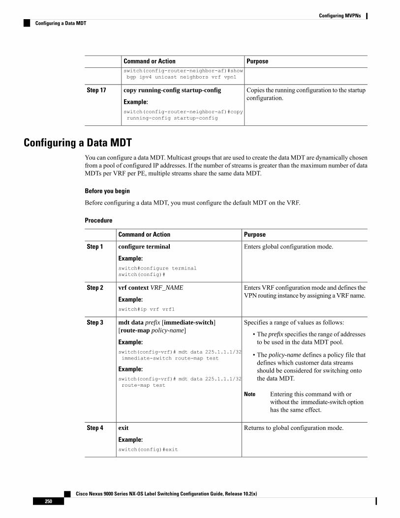
PurposeCommand or Actionswitch(config-router-neighbor-af)#showbgp ipv4 unicast neighbors vrf vpn1
Copies the running configuration to the startupconfiguration.
copy running-config startup-config
Example:
Step 17
switch(config-router-neighbor-af)#copyrunning-config startup-config
Configuring a Data MDTYou can configure a data MDT. Multicast groups that are used to create the data MDT are dynamically chosenfrom a pool of configured IP addresses. If the number of streams is greater than the maximum number of dataMDTs per VRF per PE, multiple streams share the same data MDT.
Before you begin
Before configuring a data MDT, you must configure the default MDT on the VRF.
Procedure
PurposeCommand or Action
Enters global configuration mode.configure terminal
Example:
Step 1
switch#configure terminalswitch(config)#
Enters VRF configurationmode and defines theVPN routing instance by assigning aVRF name.
vrf context VRF_NAME
Example:
Step 2
switch#ip vrf vrf1
Specifies a range of values as follows:mdt data prefix [immediate-switch][route-map policy-name]
Step 3
• The prefix specifies the range of addressesto be used in the data MDT pool.Example:
switch(config-vrf)# mdt data 225.1.1.1/32immediate-switch route-map test • The policy-name defines a policy file that
defines which customer data streamsExample: should be considered for switching onto
the data MDT.switch(config-vrf)# mdt data 225.1.1.1/32route-map test
Entering this command with orwithout the immediate-switch optionhas the same effect.
Note
Returns to global configuration mode.exit
Example:
Step 4
switch(config)#exit
Cisco Nexus 9000 Series NX-OS Label Switching Configuration Guide, Release 10.2(x)250
Configuring MVPNsConfiguring a Data MDT

Verifying the MVPN ConfigurationTo display the MVPN configuration, perform one of the following tasks:
Table 13: Verifying the MVPN Configuration
PurposeCommand
Displays details of an interface.show interface
Displays multicast routes.show ip mroute vrf
Displays the details of the MVPN event history logs.show ip pim event-history mvpn
Displays the details ofMTI tunnels created byMVPN.show ip pim mdt
Displays the mapping of the customer source, thecustomer group to data MDT source, and the dataMDT group on the receiving side.
show ip pim mdt receive vrf vrf-name
Displays the mapping of the customer source, thecustomer group to data MDT source, and the dataMDT group on the sending side.
show ip pim mdt send vrf vrf-name
Displays details of established PIM neighbors.show ip pim neighbor
Displays the details of the unicast routing tables.show ip route detail
Displays the BGP MDT SAFI database in MVPN.show mvpn bgp mdt-safi
Displays the encapsulation table inMVPN. This tableindicates howMVPN packets are encapsulated whensent out on the default vrf.
show mvpn mdt encap vrf vrf
Displays details of the default and MDT routes. Thisdata determines how customer data and control trafficis sent on the default VRF.
show mvpn mdt route
Displays the encapsulation table in the MRIB. Thistable indicates how MVPN packets are encapsulatedwhen sent out on the default vrf.
show routing [ip] multicast mdt encap
Configuration Examples for MVPNThe following example shows how to configure an MVPN with two contexts:
vrf context vpn1ip pim rp-address 10.10.1.2 -list 224.0.0.0/8ip pim ssm range 232.0.0.0/8rd automdt default 232.1.1.1mdt source loopback1mdt data 225.122.111.0/24 immediate-switch
Cisco Nexus 9000 Series NX-OS Label Switching Configuration Guide, Release 10.2(x)251
Configuring MVPNsVerifying the MVPN Configuration

vrf context vpn4ip pim rp-address 10.10.4.2 -list 224.0.0.0/8ip pim ssm range 232.0.0.0/8mdt default 235.1.1.1mdt asm-use-shared-tree
ip pim rp-address 10.11.0.2 -list 224.0.0.0/8ip pim rp-address 10.11.0.4 -list 235.0.0.0/8ip pim ssm range 232.0.0.0/8
The following example shows how to assign to the VPN routing instance a VRF named blue. TheMDT defaultfor a VPNVRF is 10.1.1.1, and the multicast address range for MDTs is 10.1.2.0 with wildcard bits of 0.0.0.3:
Vrf context bluemdt data 225.122.111.0/24 immediate-switch
Cisco Nexus 9000 Series NX-OS Label Switching Configuration Guide, Release 10.2(x)252
Configuring MVPNsConfiguration Examples for MVPN

C H A P T E R 10Configuring MPLS Segment Routing OAM
This chapter describes the Multiprotocol Label Switching (MPLS) segment routing OAM functionality.
• About MPLS Segment Routing OAM, on page 253• Guidelines and Limitations for MPLS SR OAM, on page 254• MPLS Ping and Traceroute for Nil FEC, on page 255• MPLS Ping and Traceroute for BGP and IGP Prefix SID, on page 256• Verifying Segment Routing OAM, on page 256• Examples for using Ping and Traceroute CLI commands, on page 258
About MPLS Segment Routing OAMMPLS segment routing (SR) has been deployed on the Cisco Nexus 9000 Series switches. As MPLS segmentrouting (SR) is deployed, a few diagnostic tools are required to help resolve the misconfigurations or failuresin the segment routing network. Segment Routing Operations, Administration, andMaintenance (OAM) helpsservice providers monitor label-switched paths (LSPs) and quickly isolate forwarding problems to assist withfault detection and troubleshooting in the network.
MPLS SR OAM provides two main functions for diagnostics purposes:
1. MPLS ping
2. MPLS traceroute
The segment routing OAM feature provides support for the following FEC types:
• Ping and traceroute to SR-IGP IS-IS IPv4 prefixes. This allows validation of prefix SIDs distributed inan IS-IS SR underlay.
• Ping and traceroute to BGP IPv4 prefixes. This allows validation of prefix SIDs distributed in a BGPSR underlay.
• Ping and traceroute to Generic IPv4 prefixes. This allows validation of prefix SIDs distributed in an SRunderlay agnostic to the protocol that performed the distribution. The validation is performed by checkingthe Unicast Routing Information Base (URIB) and Unicast Label Information Base (ULIB).
• Ping and traceroute to Nil FEC prefixes. This allows a less comprehensive data-plane-only validationfor any MPLS SR prefix, with finer-grained control over the path the ping or traceroute takes. The pathmay be specified using an SR-TE policy name or SR-TE policy color and endpoint.
Cisco Nexus 9000 Series NX-OS Label Switching Configuration Guide, Release 10.2(x)253

To enable MPLS OAM on Cisco Nexus 9000 Series switches, use the feature mpls oam CLI command. Usethe no feature mpls oam CLI command to disable MPLS OAM on Cisco Nexus 9000 Series switches.
Segment Routing PingSimilar to how an IP ping validates connectivity to an IP host, MPLS ping is used to validate unidirectionalcontinuity along an MPLS Label-Switched Path (LSP). By providing a FEC representing the LSP to bevalidated, MPLS ping performs the following:
• Confirms that the echo requests for the FEC reach an endpoint for the LSP. Except for the Nil FEC, forall other FEC types it confirms that the endpoint is the correct egress for that FEC.
• Measures coarse round trip time.
• Measures coarse round trip delay.
The MPLS LSP ping feature is used to check the connectivity between ingress Label Switch Routers (LSRs)and egress LSRs along an LSP. MPLS LSP ping uses MPLS echo request and reply messages, similar toInternet ControlMessage Protocol (ICMP) echo request and replymessages, to validate an LSP. The destinationIP address of the MPLS echo request packet is different from the address used to select the label stack. Thedestination IP address is defined as a 127.x.y.z/8 address and it prevents the IP packet from being IP switchedto its destination, if the LSP is broken.
Segment Routing TracerouteMPLS traceroute verifies forwarding and control plane at each hop of the LSP to isolate faults. Traceroutesends MPLS echo requests with monotonically increasing time-to-live (TTL), starting with TTL of 1. UponTTL expiry, transit node processes the request in software and verifies if it has an LSP to the target FEC andintended transit node. The transit node sends echo reply containing return code specifying the result of aboveverification and label stack to reach the next-hop, as well as ID of the next-hop towards destination, ifverification is successful. Originator processes echo reply to build the next echo request containing TTL+1.This process is repeated until the destination replies that it is the egress for the FEC.
The MPLS LSP traceroute feature is used to isolate the failure point of an LSP. It is used for hop-by-hop faultlocalization and path tracing. The MPLS LSP Traceroute feature relies on the expiration of the Time to Live(TTL) value of the packet that carries the echo request. When the MPLS echo request message hits a transitnode, it checks the TTL value and if it is expired, the packet is passed to the control plane, else the messageis forwarded. If the echo message is passed to the control plane, a reply message is generated based on thecontents of the request message
Guidelines and Limitations for MPLS SR OAMMPLS OAM Nil FEC has the following guidelines and limitations:
• MPLS OAM Nil FEC is supported on the Cisco Nexus 9300-FX platform switches.
• MPLS OAM Nil FEC is not supported on Cisco Nexus 9500 platform switches with -R line cards.
• For all new FEC types supported in Cisco NX-OS Release 9.3(1), only a one-label stack is supported.FEC-Stack change TLV support and the associated validations are not supported. This limitation is notapplicable to Nil FEC.
Cisco Nexus 9000 Series NX-OS Label Switching Configuration Guide, Release 10.2(x)254
Configuring MPLS Segment Routing OAMSegment Routing Ping
• In Cisco NX-OS Release 9.3(1), the SR-IGP "any" prefix type and the adjacency SIDs described in RFC8287 are not supported.
• OSPF ping and traceroute is not supported in Cisco NX-OS Release 9.3(1).
• Beginningwith CiscoNX-OSRelease 9.3(3),MPLSOAMNil FEC is supported on CiscoNexus 9300-GXplatform switches.
• A maximum of 4 labels can be specified in the ping mpls nil-fec and traceroute mpls nil-feccommands. This value is enforced by querying the platform and currently Cisco Nexus 9000 Seriesswitches limit the label stack to 5. It means that for a Nil FEC echo request, you can specify a maximumof 4 labels because internally an extra explicit-null is added.
• The nexthop specified in the ping and traceroute commandsmust be a connected nexthop on the originatorand it should not be a recursive nexthop.
• There is no support for treetrace.
• Nil FEC does not carry any information to identify the intended target. The packet may mis-forward atan incorrect node but the validation may return success if the packet ends up at a node after popping thenon-null labels.
• Nil FEC operates on forwarding the information alone. It cannot detect the inconsistencies between thecontrol plane and the forwarding plane by definition.
• Nil FEC ping and traceroute is not supported for deaggregator (per-VRF) labels. This includes the BGPEVPN-Layer 3 deaggregator labels.
• On Cisco Nexus 9000 Series switches that use Broadcom chipsets, there is no support to allow thesoftware to send a query to determine which ECMP a packet takes. It means that for MPLS traceroutesthat traverse one of these switches may display an error at the next hop if there is more than one ECMPas displayed in the following example:D 2 6.0.0.2 MRU 1496 [Labels: 2003/explicit-null Exp: 0/0] 4 ms
• When you use OAM to test a BGP EPE LSP (for example, the last label in the ping/traceroute label stackis an EPE label), OAM only returns success if the final router has OAM enabled and MPLS is enabledon the incoming interface.
For example, if you have a setup as A---B---C, A and B are in the SR network, and B acts like a PE andC acts like a CE, B is configured with C as a BGP EPE peer (using egress-engineering on B), then Cmust have OAM and MPLS forwarding enabled on the incoming interface.
MPLS Ping and Traceroute for Nil FECThe Nil FEC LSP ping and traceroute operations are extensions of regular MPLS ping and traceroute. TheNil FEC LSP ping and traceroute functionality supports segment routing and MPLS Static. It also acts as anadditional diagnostic tool for all other LSP types.
Unlike the other FEC types, Nil FEC does not provide control plane validation. Nil FEC ping or tracerouteprobes can reach any switch on which the MPLS OAM functionality is enabled.
This feature allows operators to provide the ability to freely test any label stack by allowing them to specifythe following:
• Label stack
Cisco Nexus 9000 Series NX-OS Label Switching Configuration Guide, Release 10.2(x)255
Configuring MPLS Segment Routing OAMMPLS Ping and Traceroute for Nil FEC

• Outgoing interface
• Nexthop address
In case of segment routing, each segment nodal label and adjacent label along the routing path is put into thelabel stack of an echo request message from the initiator Label Switch Router (LSR); MPLS data planeforwards this packet to the label stack target, and the label stack target sends the echo message back.
Use the [ping|traceroute] mpls nil-fec labels comma-separated-labels [output {interface tx-interface}[nexthop nexthop-ip-addr]] CLI command to execute a ping or a traceroute.
If you have configured an SR-TE policy name or the color and the endpoint, you can use the following CLIcommand to execute a ping or a traceroute to use the existing SR-TE policy information.:
[ping|traceroute] mpls nil-fec [policy name name] [endpoint nexthop-ip-addr] [on-demand color color-num] CLI command to execute a ping or a traceroute.
MPLS Ping and Traceroute for BGP and IGP Prefix SIDMPLS ping and traceroute operations for Prefix SID are supported for the following BGP and IGP scenarios:
• Within an IS-IS level
• Across IS-IS levels
• BGP SR underlay
These FEC types perform an additional control plane check to ensure that the packets are not mis-routed. Thisvalidation ensures that the pinged FEC type is connected to the switch and is distributed to the other nodes.Nil FEC does not provide this validation.
MPLS echo request packets carry Target FEC Stack sub-TLVs. The Target FEC sub-TLVs are used by theresponder for FEC validation. The IGP/BGP IPv4 prefix sub-TLV has been added to the Target FEC Stacksub-TLV. The IGP/BGP IPv4 prefix sub-TLV contains the prefix SID, the prefix length, and the protocol(IS-IS).
Use the ping|traceroute sr-mpls A.B.C.D/LEN fec-type [bgp | igp {isis} | generic] CLI command to executea traceroute.
Verifying Segment Routing OAMThis section provides information on the CLI commands that can be used to verify the segment routing OAMfeatures.
• Verifying Segment Routing OAM IS-IS, on page 256
Verifying Segment Routing OAM IS-ISThe following ping commands are used to display SR OAM when the underlying network is IS-IS:switch# ping sr-mpls 11.1.1.3/32 fec-type igp isis
Sending 5, 100-byte MPLS Echos to IGP Prefix SID(IS-IS) FEC 11.1.1.3/32,
Cisco Nexus 9000 Series NX-OS Label Switching Configuration Guide, Release 10.2(x)256
Configuring MPLS Segment Routing OAMMPLS Ping and Traceroute for BGP and IGP Prefix SID
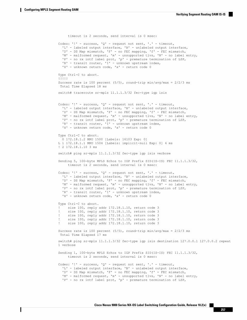
timeout is 2 seconds, send interval is 0 msec:
Codes: '!' - success, 'Q' - request not sent, '.' - timeout,'L' - labeled output interface, 'B' - unlabeled output interface,'D' - DS Map mismatch, 'F' - no FEC mapping, 'f' - FEC mismatch,'M' - malformed request, 'm' - unsupported tlvs, 'N' - no label entry,'P' - no rx intf label prot, 'p' - premature termination of LSP,'R' - transit router, 'I' - unknown upstream index,'X' - unknown return code, 'x' - return code 0
Type Ctrl-C to abort.!!!!!Success rate is 100 percent (5/5), round-trip min/avg/max = 2/2/3 msTotal Time Elapsed 18 ms
switch# traceroute sr-mpls 11.1.1.3/32 fec-type igp isis
Codes: '!' - success, 'Q' - request not sent, '.' - timeout,'L' - labeled output interface, 'B' - unlabeled output interface,'D' - DS Map mismatch, 'F' - no FEC mapping, 'f' - FEC mismatch,'M' - malformed request, 'm' - unsupported tlvs, 'N' - no label entry,'P' - no rx intf label prot, 'p' - premature termination of LSP,'R' - transit router, 'I' - unknown upstream index,'X' - unknown return code, 'x' - return code 0
Type Ctrl-C to abort.0 172.18.1.2 MRU 1500 [Labels: 16103 Exp: 0]
L 1 172.18.1.1 MRU 1504 [Labels: implicit-null Exp: 0] 4 ms! 2 172.18.1.10 3 ms
switch# ping sr-mpls 11.1.1.3/32 fec-type igp isis verbose
Sending 5, 100-byte MPLS Echos to IGP Prefix SID(IS-IS) FEC 11.1.1.3/32,timeout is 2 seconds, send interval is 0 msec:
Codes: '!' - success, 'Q' - request not sent, '.' - timeout,'L' - labeled output interface, 'B' - unlabeled output interface,'D' - DS Map mismatch, 'F' - no FEC mapping, 'f' - FEC mismatch,'M' - malformed request, 'm' - unsupported tlvs, 'N' - no label entry,'P' - no rx intf label prot, 'p' - premature termination of LSP,'R' - transit router, 'I' - unknown upstream index,'X' - unknown return code, 'x' - return code 0
Type Ctrl-C to abort.! size 100, reply addr 172.18.1.10, return code 3! size 100, reply addr 172.18.1.10, return code 3! size 100, reply addr 172.18.1.10, return code 3! size 100, reply addr 172.18.1.10, return code 3! size 100, reply addr 172.18.1.10, return code 3
Success rate is 100 percent (5/5), round-trip min/avg/max = 2/2/3 msTotal Time Elapsed 17 ms
switch# ping sr-mpls 11.1.1.3/32 fec-type igp isis destination 127.0.0.1 127.0.0.2 repeat1 verbose
Sending 1, 100-byte MPLS Echos to IGP Prefix SID(IS-IS) FEC 11.1.1.3/32,timeout is 2 seconds, send interval is 0 msec:
Codes: '!' - success, 'Q' - request not sent, '.' - timeout,'L' - labeled output interface, 'B' - unlabeled output interface,'D' - DS Map mismatch, 'F' - no FEC mapping, 'f' - FEC mismatch,'M' - malformed request, 'm' - unsupported tlvs, 'N' - no label entry,'P' - no rx intf label prot, 'p' - premature termination of LSP,
Cisco Nexus 9000 Series NX-OS Label Switching Configuration Guide, Release 10.2(x)257
Configuring MPLS Segment Routing OAMVerifying Segment Routing OAM IS-IS

'R' - transit router, 'I' - unknown upstream index,'X' - unknown return code, 'x' - return code 0
Type Ctrl-C to abort.Destination address 127.0.0.1! size 100, reply addr 172.18.1.10, return code 3
Destination address 127.0.0.2! size 100, reply addr 172.18.1.22, return code 3
Success rate is 100 percent (2/2), round-trip min/avg/max = 3/3/3 msTotal Time Elapsed 8 ms
Examples for using Ping and Traceroute CLI commands
Examples for IGP or BGP SR Ping and Traceroute
Using CLI to Execute a Ping with Explicit Outgoing Information
Use the ping sr-mpls fec fec-type igp isis CLI command to execute an IS-IS SR ping and the ping sr-mplsfec fec-type bgp CLI command to execute a BGP ping.switch# ping sr-mpls 11.1.1.3/32 fec-type igp isis
Sending 5, 100-byte MPLS Echos to IGP Prefix SID(IS-IS) FEC 11.1.1.3/32,timeout is 2 seconds, send interval is 0 msec:
Codes: '!' - success, 'Q' - request not sent, '.' - timeout,'L' - labeled output interface, 'B' - unlabeled output interface,'D' - DS Map mismatch, 'F' - no FEC mapping, 'f' - FEC mismatch,'M' - malformed request, 'm' - unsupported tlvs, 'N' - no label entry,'P' - no rx intf label prot, 'p' - premature termination of LSP,'R' - transit router, 'I' - unknown upstream index,'X' - unknown return code, 'x' - return code 0
Type Ctrl-C to abort.!!!!!Success rate is 100 percent (5/5), round-trip min/avg/max = 2/2/3 msTotal Time Elapsed 18 ms
switch# ping sr-mpls 11.1.1.3/32 fec-type igp isis verbose
Sending 5, 100-byte MPLS Echos to IGP Prefix SID(IS-IS) FEC 11.1.1.3/32,timeout is 2 seconds, send interval is 0 msec:
Codes: '!' - success, 'Q' - request not sent, '.' - timeout,'L' - labeled output interface, 'B' - unlabeled output interface,'D' - DS Map mismatch, 'F' - no FEC mapping, 'f' - FEC mismatch,'M' - malformed request, 'm' - unsupported tlvs, 'N' - no label entry,'P' - no rx intf label prot, 'p' - premature termination of LSP,'R' - transit router, 'I' - unknown upstream index,'X' - unknown return code, 'x' - return code 0
Type Ctrl-C to abort.! size 100, reply addr 172.18.1.10, return code 3! size 100, reply addr 172.18.1.10, return code 3! size 100, reply addr 172.18.1.10, return code 3! size 100, reply addr 172.18.1.10, return code 3! size 100, reply addr 172.18.1.10, return code 3
Cisco Nexus 9000 Series NX-OS Label Switching Configuration Guide, Release 10.2(x)258
Configuring MPLS Segment Routing OAMExamples for using Ping and Traceroute CLI commands
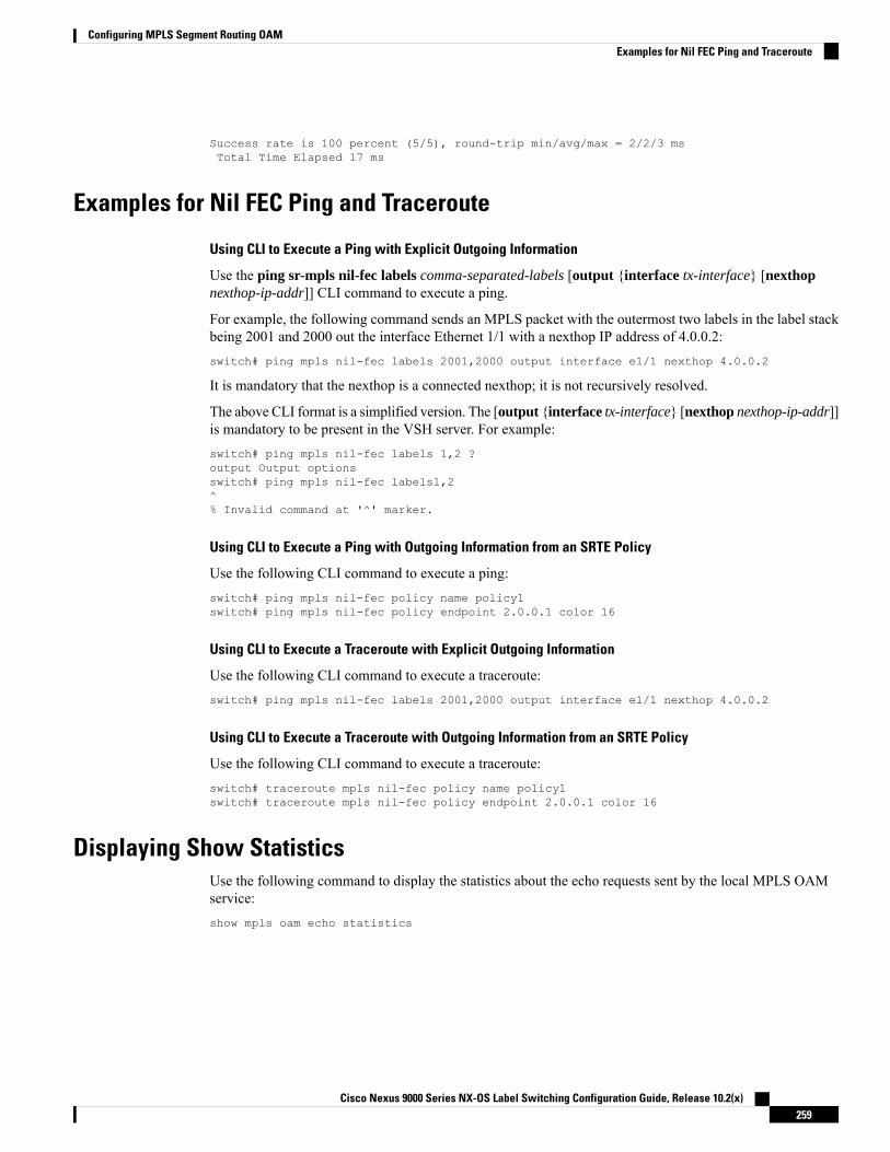
Success rate is 100 percent (5/5), round-trip min/avg/max = 2/2/3 msTotal Time Elapsed 17 ms
Examples for Nil FEC Ping and Traceroute
Using CLI to Execute a Ping with Explicit Outgoing Information
Use the ping sr-mpls nil-fec labels comma-separated-labels [output {interface tx-interface} [nexthopnexthop-ip-addr]] CLI command to execute a ping.
For example, the following command sends an MPLS packet with the outermost two labels in the label stackbeing 2001 and 2000 out the interface Ethernet 1/1 with a nexthop IP address of 4.0.0.2:switch# ping mpls nil-fec labels 2001,2000 output interface e1/1 nexthop 4.0.0.2
It is mandatory that the nexthop is a connected nexthop; it is not recursively resolved.
The above CLI format is a simplified version. The [output {interface tx-interface} [nexthop nexthop-ip-addr]]is mandatory to be present in the VSH server. For example:switch# ping mpls nil-fec labels 1,2 ?output Output optionsswitch# ping mpls nil-fec labels1,2^% Invalid command at '^' marker.
Using CLI to Execute a Ping with Outgoing Information from an SRTE Policy
Use the following CLI command to execute a ping:switch# ping mpls nil-fec policy name policy1switch# ping mpls nil-fec policy endpoint 2.0.0.1 color 16
Using CLI to Execute a Traceroute with Explicit Outgoing Information
Use the following CLI command to execute a traceroute:switch# ping mpls nil-fec labels 2001,2000 output interface e1/1 nexthop 4.0.0.2
Using CLI to Execute a Traceroute with Outgoing Information from an SRTE Policy
Use the following CLI command to execute a traceroute:switch# traceroute mpls nil-fec policy name policy1switch# traceroute mpls nil-fec policy endpoint 2.0.0.1 color 16
Displaying Show StatisticsUse the following command to display the statistics about the echo requests sent by the local MPLS OAMservice:show mpls oam echo statistics
Cisco Nexus 9000 Series NX-OS Label Switching Configuration Guide, Release 10.2(x)259
Configuring MPLS Segment Routing OAMExamples for Nil FEC Ping and Traceroute

Cisco Nexus 9000 Series NX-OS Label Switching Configuration Guide, Release 10.2(x)260
Configuring MPLS Segment Routing OAMDisplaying Show Statistics

C H A P T E R 11InterAS Option B
This chapter explains the different InterAS option B configuration options. The available options are InterASoption B, InterAS option B (with RFC 3107), and InterAS option B lite. The InterAS option B (with RFC3107) implementation ensures complete IGP isolation between the data centers and WAN. When BGPadvertises a particular route to ASBR, it also distributes the label which is mapped to that route.
• Information About InterAS, on page 261• InterAS Options, on page 262• Guidelines and Limitations for Configuring InterAS Option B, on page 263• Configuring BGP for InterAS Option B, on page 263• Configuring BGP for InterAS Option B (with RFC 3107 implementation), on page 265
Information About InterASAn autonomous system (AS) is a single network or group of networks that is controlled by a common systemadministration group and using a single, clearly defined protocol. In many cases, virtual private networks(VPNs) extend to different ASes in different geographical areas. Some VPNs must extend across multipleservice providers; these VPNs are called overlapping VPNs. The connection between ASes must be seamlessto the customer, regardless of the complexity or location of the VPNs.
InterAS and ASBRSeparate ASes from different service providers can communicate by exchanging information in the form ofVPN IP addresses. The ASBRs use EBGP to exchange that information. The IBGP distributes the networklayer information for IP prefixes throughout each VPN and each AS. The following protocols are used forsharing routing information:
• Within an AS, routing information is shared using IBGP.
• Between ASes, routing information is shared using EBGP. EBGP allows service providers to set up aninterdomain routing system that guarantees loop-free exchange of routing information between separateASes.
The primary function of EBGP is to exchange network reachability information between ASes, includinginformation about the list of AS routes. The ASes use EBGP border edge routers to distribute the routes, whichincludes label-switching information. Each border edge router rewrites the next-hop and MPLS labels.
Cisco Nexus 9000 Series NX-OS Label Switching Configuration Guide, Release 10.2(x)261

InterAS configuration supported in this MPLS VPN can include an interprovider VPN, which is MPLS VPNsthat include two or more ASes, connected by separate border edge routers. The ASes exchange routes useEBGP, and no IBGP or routing information is exchanged between the ASes.
Exchanging VPN Routing InformationASes exchange VPN routing information (routes and labels) to establish connections. To control connectionsbetween ASes, the PE routers and EBGP border edge routers maintain a label forwarding information base(LFIB). The LFIB manages the labels and routes that the PE routers and EBGP border edge routers receiveduring the exchange of VPN information.
The ASes use the following guidelines to exchange VPN routing information:
• Routing information includes:
• The destination network.
• The next-hop field associated with the distributing router.• A local MPLS label
• A route distinguisher (RD1) is part of a destination network address. It makes the VPN IP route globallyunique in the VPN service provider environment.
TheASBRs are configured to change the next-hopwhen sendingVPNNLRIs to the IBGP neighbors. Therefore,the ASBRs must allocate a new label when they forward the NLRI to the IBGP neighbors.
InterAS OptionsNexus 9508 series switches support the following InterAS options:
• InterAS option A - In an interAS option A network, autonomous system border router (ASBR) peersare connected by multiple subinterfaces with at least one interface VPN that spans the two ASes. TheseASBRs associate each subinterface with a VPN routing and forwarding (VRF) instance and a BGP sessionto signal unlabeled IP prefixes. As a result, traffic between the back-to-back VRFs is IP. In this scenario,the VPNs are isolated from each other and, because the traffic is IP Quality of Service (QoS) mechanismsthat operate on the IP traffic can be maintained. The downside of this configuration is that one BGPsession is required for each subinterface (and at least one subinterface is required for each VPN), whichcauses scalability concerns as the network grows.
• InterAS option B - In an interAS option B network, ASBR ports are connected by one or moresubinterfaces that are enabled to receiveMPLS traffic. AMultiprotocol Border GatewayRouter (MP-BGP)session distributes labeled VPN prefixes between the ASBRs. As a result, the traffic that flows betweenthe ASBRs is labeled. The downside of this configuration is that, because the traffic is MPLS, QoSmechanisms that are applied only to IP traffic cannot be carried and the VRFs cannot be isolated. InterASoption B provides better scalability than option A because it requires only one BGP session to exchangeall VPN prefixes between the ASBRs. Also, this feature provides nonstop forwarding (NSF) and GracefulRestart. The ASBRs must be directly connected in this option.
Some functions of option B are noted below:
• You can have an IBGP VPNv4/v6 session between Nexus 9508 series switches within an AS and youcan have an EBGP VPNv4/v6 session between data center edge routers and WAN routers.
Cisco Nexus 9000 Series NX-OS Label Switching Configuration Guide, Release 10.2(x)262
InterAS Option BExchanging VPN Routing Information

• There is no requirement for a per VRF IBGP session between data center edge routers, like in the liteversion.
• – LDP distributes IGP labels between ASBRs.
• InterAS option B (with BGP-3107 or RFC 3107 implementation)
• You can have an IBGP VPNv4/v6 implementation between Nexus 9508 switches within an AS and youcan have an EBGP VPNv4/v6 session between data center edge routers and WAN routers.
• BGP-3107 enables BGP packets to carry label information without using LDP between ASBRs.
• The label mapping information for a particular route is piggybacked in the same BGP update messagethat is used to distribute the route itself.
• When BGP is used to distribute a particular route, it also distributes an MPLS label which is mapped tothat route. Many ISPs prefer this method of configuration since it ensures complete IGP isolation betweenthe data centers.
• InterAS option B lite – Support for the InterAS option B feature is restricted in the Cisco NX-OS 6.2(2)release. Details are noted in the Configuring InterAS Option B (lite version) section.
Guidelines and Limitations for Configuring InterAS Option BInterAS Option B has the following guidelines and limitations:
• InterAS option B is not supported with BGP confederation AS.
• InterAS option B is supported on Cisco Nexus 9500 platform switches with -R line cards.
Configuring BGP for InterAS Option BConfigure DC Edge switches with IBGP & EBGP VPNv4/v6 with the following steps:
Before you begin
To configure BGP for InterAS option B, you need to enable this configuration on both the IBGP and EBGPsides. Refer to Figure 1 for reference.
Procedure
PurposeCommand or Action
Enters global configuration mode.configure terminal
Example:
Step 1
switch# configure terminalswitch(config)#
Cisco Nexus 9000 Series NX-OS Label Switching Configuration Guide, Release 10.2(x)263
InterAS Option BGuidelines and Limitations for Configuring InterAS Option B

PurposeCommand or Action
Enters the router BGP configuration mode andassigns an autonomous system (AS) numberto the local BGP speaker device.
router bgp as-number
Example:switch(config)# router bgp 100
Step 2
Adds an entry to the BGP or multiprotocolBGP neighbor table, and enters router BGPneighbor configuration mode.
neighbor ip-address
Example:switch(config-router)# neighbor10.0.0.2
Step 3
The as-number argument specifies theautonomous system to which the neighborbelongs.
remote-as as-number
Example:switch(config-router-neighbor)#remote-as 200
Step 4
Enters address family configuration mode forconfiguring IP VPN sessions.
address-family {vpnv4 | vpnv6} unicast
Example:
Step 5
switch(config-router-neighbor)#address-family vpnv4 unicast
Specifies that a communities attribute shouldbe sent to both BGP neighbors.
send-community {both | extended}
Example:
Step 6
switch(config-router-neighbor-af)#send-community both
(Optional). Retains VPNv4/v6 addressconfiguration on the ASBR without VRFconfiguration.
retain route-target all
Example:switch(config-router-neighbor-af)#retain route-target all
Step 7
If you have a VRF configuration onthe ASBR, this command is notrequired.
Note
Associates the BGP process with a VRF.vrf vrf-name
Example:
Step 8
switch(config-router-neighbor-af)# vrfVPN1
Specifies the IPv4 or IPv6 address family andenters address family configuration mode.
address-family {ipv4 | ipv6} unicast
Example:
Step 9
switch(config-router-vrf)#address-family ipv4 unicast
Exits IPv4 address family.exit
Example:
Step 10
switch(config-vrf-af)# exit
Cisco Nexus 9000 Series NX-OS Label Switching Configuration Guide, Release 10.2(x)264
InterAS Option BConfiguring BGP for InterAS Option B

PurposeCommand or Action
(Optional) Copies the running configurationto the startup configuration.
copy running-config startup-config
Example:
Step 11
switch(config-router-vrf)# copyrunning-config startup-config
Configuring BGP for InterAS Option B (with RFC 3107implementation)
Configure DC Edge switches with IBGP & EBGP VPNv4/v6 along with BGP labeled unicast family withfollowing steps:
Procedure
PurposeCommand or Action
Enters global configuration mode.configure terminal
Example:
Step 1
switch# configure terminalswitch(config)#
Enters the router BGP configuration mode andassigns an autonomous system (AS) numberto the local BGP speaker device.
router bgp as-number
Example:switch(config)# router bgp 100
Step 2
Enters address family configuration mode forconfiguring IP VPN sessions.
address-family {vpnv4 | vpnv6} unicast
Example:
Step 3
switch(config-router-neighbor)#address-family vpnv4 unicast
Redistributes directly connected routes usingthe Border Gateway Protocol.
redistribute direct route-map tag
Example:
Step 4
switch(config-router-af)# redistributedirect route-map loopback
Configures ASBRs with the BGP labeledunicast address family to advertise labels forthe connected interface.
allocate-label all
Example:switch(config-router-af)#allocate-label all
Step 5
Exits address family router configurationmodeand enters router BGP configuration mode.
exit
Example:
Step 6
switch(config-router-af)# exit
Cisco Nexus 9000 Series NX-OS Label Switching Configuration Guide, Release 10.2(x)265
InterAS Option BConfiguring BGP for InterAS Option B (with RFC 3107 implementation)

PurposeCommand or Action
Configures the BGP neighbor’s IP address,and enters router BGP neighbor configurationmode.
neighbor ip-address
Example:switch(config-router)# neighbor 10.1.1.1
Step 7
Specifies the BGP neighbor’s AS number.remote-as as-number
Example:
Step 8
switch(config-router-neighbor)#remote-as 100
Configures the ASBR with the BGP labeledunicast address family to advertise labels forthe connected interface.
address-family {ipv4|ipv6} labeled-unicast
Example:switch(config-router-neighbor)#address-family ipv4 labeled-unicast
Step 9
This is the command thatimplements RFC 3107.
Note
(Optional). Retains VPNv4/v6 addressconfiguration on the ASBR without VRFconfiguration.
retain route-target all
Example:switch(config-router-neighbor-af)#retain route-target all
Step 10
If you have a VRF configuration onthe ASBR, this command is notrequired.
Note
Exits router BGP neighbor address familyconfiguration mode and returns to router BGPconfiguration mode.
exit
Example:Switch(config-router-neighbor-af)# exit
Step 11
Configures a loopback IP address, and entersrouter BGP neighbor configuration mode.
neighbor ip-address
Example:
Step 12
switch(config-router)# neighbor 10.1.1.1
Specifies the BGP neighbor’s AS number.remote-as as-number
Example:
Step 13
switch(config-router-neighbor)#remote-as 100
Configures the ASBR with the BGP VPNv4unicast address family.
address-family {vpnv4|vpnv6} unicast
Example:
Step 14
switch(config-router-vrf)#address-family ipv4 unicast
Exits IPv4 address family.exit
Example:
Step 15
switch(config-vrf-af)# exit
Cisco Nexus 9000 Series NX-OS Label Switching Configuration Guide, Release 10.2(x)266
InterAS Option BConfiguring BGP for InterAS Option B (with RFC 3107 implementation)

PurposeCommand or Action
Configures the ASBR with the BGP VPNv4unicast address family.
address-family {vpnv4|vpnv6} unicast
Example:
Step 16
switch(config-router-vrf)#address-family ipv4 unicast
Configures ASBR2with option B (RFC 3107)settings and implements complete IGP
Repeat the process with ASBR2Step 17
isolation between the two data centers DC1and DC2.
(Optional) Copies the running configurationto the startup configuration.
copy running-config startup-config
Example:
Step 18
switch(config-router-vrf)# copyrunning-config startup-config
Cisco Nexus 9000 Series NX-OS Label Switching Configuration Guide, Release 10.2(x)267
InterAS Option BConfiguring BGP for InterAS Option B (with RFC 3107 implementation)

Cisco Nexus 9000 Series NX-OS Label Switching Configuration Guide, Release 10.2(x)268
InterAS Option BConfiguring BGP for InterAS Option B (with RFC 3107 implementation)

C H A P T E R 12IETF RFCs Supported for Label Switching
This appendix lists the IETF RFCs supported for label switching on the device.
• IETF RFCs Supported for Label Switching, on page 269
IETF RFCs Supported for Label SwitchingThis table lists the IETF RFCs supported for label switching on the device.
TitleRFCs
Carrying Label Information in BGP-4RFC 3107
North-Bound Distribution of Link-State and TrafficEngineering (TE) Information Using BGP
RFC 7752
Detecting Multiprotocol Label Switched (MPLS)Data-Plane failures.
RFC 8029
Label Switched Path (LSP) Ping/Traceroute forSegment Routing (SR) IGP-Prefix and IGP-AdjacencySegment Identifiers (SIDs) with MPLS Data Planes.
RFC 8287
Segment Routing BGP Egress Peer EngineeringBGP-LS Extensionsdraft-ietf-idr-bgpls-segment-routing-epe-05
Draft-ietf-idr-bgpls-segment-routing-epe-05
Cisco Nexus 9000 Series NX-OS Label Switching Configuration Guide, Release 10.2(x)269

Cisco Nexus 9000 Series NX-OS Label Switching Configuration Guide, Release 10.2(x)270
IETF RFCs Supported for Label SwitchingIETF RFCs Supported for Label Switching

I N D E X
A
address-family {ipv4 | ipv6} unicast 12address-family ipv4 unicast 25, 120
C
clear forwarding adjacency mpls stats 17, 29clear forwarding ipv4 adjacency mpls stats 29clear forwarding ipv6 adjacency mpls stats 17clear forwarding mpls drop-stats 17clear forwarding mpls stats 17, 29clear mpls forwarding statistics 17, 29clear mpls switching label statistics 18, 29
E
evi 186–187, 192evpn 192
F
feature mpls segment-routing 13, 23feature mpls static 10, 212feature tunnel 212feature-set mpls 10, 13, 23forward 25
G
global-block 118
I
in-label 25install feature-set mpls 10, 13, 23interface tunnel 212ipv6 address 213
L
local-label 12lsp 25
M
mpls ip forwarding 12, 24, 117mpls label range 11, 24mpls static configuration 12, 25mtu 213
N
neighbor 200network 120next-hop 12next-hop auto-resolve 12next-hop backup 12
R
route-map 119
S
segment-routing 118set label-index 119show bgp ipv4 labeled-unicast 215show bgp paths 215show feature | grep segment-routing 14, 23, 26show feature | inc mpls_static 10, 14show feature-set 10, 13–14, 23, 26show forwarding adjacency mpls stats 16, 28show forwarding ipv4 adjacency mpls stats 28show forwarding ipv6 adjacency mpls stats 16show forwarding mpls drop-stats 16show forwarding mpls ecmp 16show forwarding mpls ecmp module 16show forwarding mpls ecmp platform 16show forwarding mpls label 16, 26, 28show interface tunnel 213show ip route 14show mpls forwarding statistics 16, 28show mpls label range 11, 14, 24, 26, 118, 215show mpls static binding {all | ipv4 | ipv6} 14show mpls static binding {all | ipv4} 26show mpls switching 14, 26show mpls switching detail 14, 26
Cisco Nexus 9000 Series NX-OS Label Switching Configuration Guide, Release 10.2(x)IN-1

show mpls switching labels 16, 28show route policy manager 215show route-map 120, 215show running-config | inc 'feature segment-routing' 212
T
tunnel destination 213
tunnel mode 212tunnel source 213tunnel use-vrf 213
V
vlan 186vrf context 187
Cisco Nexus 9000 Series NX-OS Label Switching Configuration Guide, Release 10.2(x)IN-2
INDEX