Cisco Nexus 9000 Series NX-OS System Management ...
270
Cisco Nexus 9000 Series NX-OS System Management Configuration Guide, Release 6.x First Published: November 20, 2013 Last Modified: August 07, 2014 Americas Headquarters Cisco Systems, Inc. 170 West Tasman Drive San Jose, CA 95134-1706 USA http://www.cisco.com Tel: 408 526-4000 800 553-NETS (6387) Fax: 408 527-0883
-
Upload
khangminh22 -
Category
Documents
-
view
0 -
download
0
Transcript of Cisco Nexus 9000 Series NX-OS System Management ...
Cisco Nexus 9000 Series NX-OS System Management ConfigurationGuide, Release 6.xFirst Published: November 20, 2013
Last Modified: August 07, 2014
Americas HeadquartersCisco Systems, Inc.170 West Tasman DriveSan Jose, CA 95134-1706USAhttp://www.cisco.comTel: 408 526-4000 800 553-NETS (6387)Fax: 408 527-0883

THE SPECIFICATIONS AND INFORMATION REGARDING THE PRODUCTS IN THIS MANUAL ARE SUBJECT TO CHANGE WITHOUT NOTICE. ALL STATEMENTS,INFORMATION, AND RECOMMENDATIONS IN THIS MANUAL ARE BELIEVED TO BE ACCURATE BUT ARE PRESENTED WITHOUT WARRANTY OF ANY KIND,EXPRESS OR IMPLIED. USERS MUST TAKE FULL RESPONSIBILITY FOR THEIR APPLICATION OF ANY PRODUCTS.
THE SOFTWARE LICENSE AND LIMITEDWARRANTY FOR THE ACCOMPANYING PRODUCT ARE SET FORTH IN THE INFORMATION PACKET THAT SHIPPED WITHTHE PRODUCT AND ARE INCORPORATED HEREIN BY THIS REFERENCE. IF YOU ARE UNABLE TO LOCATE THE SOFTWARE LICENSE OR LIMITED WARRANTY,CONTACT YOUR CISCO REPRESENTATIVE FOR A COPY.
The Cisco implementation of TCP header compression is an adaptation of a program developed by the University of California, Berkeley (UCB) as part of UCB's public domain versionof the UNIX operating system. All rights reserved. Copyright © 1981, Regents of the University of California.
NOTWITHSTANDINGANYOTHERWARRANTYHEREIN, ALL DOCUMENT FILES AND SOFTWARE OF THESE SUPPLIERS ARE PROVIDED “AS IS"WITH ALL FAULTS.CISCO AND THE ABOVE-NAMED SUPPLIERS DISCLAIM ALL WARRANTIES, EXPRESSED OR IMPLIED, INCLUDING, WITHOUT LIMITATION, THOSE OFMERCHANTABILITY, FITNESS FORA PARTICULAR PURPOSEANDNONINFRINGEMENTORARISING FROMACOURSEOFDEALING, USAGE, OR TRADE PRACTICE.
IN NO EVENT SHALL CISCO OR ITS SUPPLIERS BE LIABLE FOR ANY INDIRECT, SPECIAL, CONSEQUENTIAL, OR INCIDENTAL DAMAGES, INCLUDING, WITHOUTLIMITATION, LOST PROFITS OR LOSS OR DAMAGE TO DATA ARISING OUT OF THE USE OR INABILITY TO USE THIS MANUAL, EVEN IF CISCO OR ITS SUPPLIERSHAVE BEEN ADVISED OF THE POSSIBILITY OF SUCH DAMAGES.
Any Internet Protocol (IP) addresses and phone numbers used in this document are not intended to be actual addresses and phone numbers. Any examples, command display output, networktopology diagrams, and other figures included in the document are shown for illustrative purposes only. Any use of actual IP addresses or phone numbers in illustrative content is unintentionaland coincidental.
This product includes cryptographic software written by Eric Young ([email protected]).
This product includes software developed by the OpenSSL Project for use in the OpenSSL Toolkit. (http://www.openssl.org/)This product includes software written by Tim Hudson ([email protected]).
Cisco and the Cisco logo are trademarks or registered trademarks of Cisco and/or its affiliates in the U.S. and other countries. To view a list of Cisco trademarks, go to this URL: http://www.cisco.com/go/trademarks. Third-party trademarks mentioned are the property of their respective owners. The use of the word partner does not imply a partnershiprelationship between Cisco and any other company. (1110R)
© 2013-2014 Cisco Systems, Inc. All rights reserved.
C O N T E N T S
P r e f a c e Preface xvii
Audience xvii
Document Conventions xvii
Related Documentation for Cisco Nexus 9000 Series NX-OS Software xix
Documentation Feedback xx
Obtaining Documentation and Submitting a Service Request xx
C H A P T E R 1 New and Changed Information 1
New and Changed Information 1
C H A P T E R 2 Overview 3
Software Image 4
Cisco NX-OS Device Configuration Methods 4
Configuring with CLI or XML Management Interface 5
Configuring with Cisco DCNM 5
Network Time Protocol 5
Cisco Discovery Protocol 5
System Messages 5
Smart Call Home 6
Rollback 6
Session Manager 6
Scheduler 6
SNMP 6
RMON 6
Online Diagnostics 7
Embedded Event Manager 7
Onboard Failure Logging 7
Cisco Nexus 9000 Series NX-OS System Management Configuration Guide, Release 6.x iii

SPAN 7
ERSPAN 7
LLDP 7
SMUs 8
Virtual Device Contexts 8
Troubleshooting Features 8
C H A P T E R 3 Configuring NTP 9
About NTP 9
NTP Associations 10
NTP as a Time Server 10
Clock Manager 10
High Availability 10
Virtualization Support 11
Licensing Requirements for NTP 11
Prerequisites for NTP 11
Guidelines and Limitations for NTP 11
Default Settings for NTP 12
Configuring NTP 12
Enabling or Disabling NTP 12
Configuring the Device as an Authoritative NTP Server 13
Configuring an NTP Server and Peer 13
Configuring NTP Authentication 15
Configuring NTP Access Restrictions 16
Configuring the NTP Source IP Address 17
Configuring the NTP Source Interface 18
Configuring NTP Logging 19
Verifying the NTP Configuration 19
Configuration Examples for NTP 20
Additional References 21
Related Documents 21
MIBs 21
C H A P T E R 4 Configuring CDP 23
About CDP 23
Cisco Nexus 9000 Series NX-OS System Management Configuration Guide, Release 6.xiv
Contents

VTP Feature Support 24
High Availability 24
Virtualization Support 25
Licensing Requirements for CDP 25
Guidelines and Limitations for CDP 25
Default Settings for CDP 25
Configuring CDP 25
Enabling or Disabling CDP Globally 26
Enabling or Disabling CDP on an Interface 26
Configuring Optional CDP Parameters 27
Verifying the CDP Configuration 28
Configuration Example for CDP 28
Additional References 29
MIBs 29
C H A P T E R 5 Configuring System Message Logging 31
About System Message Logging 31
Syslog Servers 32
Licensing Requirements for System Message Logging 32
Guidelines and Limitations for System Message Logging 33
Default Settings for System Message Logging 33
Configuring System Message Logging 33
Configuring System Message Logging to Terminal Sessions 33
Logging System Messages to a File 35
Configuring Module and Facility Messages Logging 37
Configuring Syslog Servers 39
Configuring Syslog Servers on a UNIX or Linux System 40
Displaying and Clearing Log Files 41
Verifying the System Message Logging Configuration 42
Configuration Example for System Message Logging 42
Additional References 43
Related Documents 43
C H A P T E R 6 Configuring Smart Call Home 45
About Smart Call Home 45
Cisco Nexus 9000 Series NX-OS System Management Configuration Guide, Release 6.x v
Contents

Destination Profiles 46
Smart Call Home Alert Groups 46
Smart Call Home Message Levels 49
Obtaining Smart Call Home 50
Database Merge Guidelines 51
High Availability 51
Virtualization Support 51
Licensing Requirements for Smart Call Home 51
Prerequisites for Smart Call Home 52
Guidelines and Limitations for Smart Call Home 52
Default Settings for Smart Call Home 52
Configuring Smart Call Home 53
Configuring Contact Information 53
Creating a Destination Profile 55
Modifying a Destination Profile 56
Associating an Alert Group with a Destination Profile 58
Adding Show Commands to an Alert Group 59
Configuring the Email Server 60
Configuring VRFs To Send Messages Using HTTP 62
Configuring an HTTP Proxy Server 63
Configuring Periodic Inventory Notifications 64
Disabling Duplicate Message Throttling 65
Enabling or Disabling Smart Call Home 66
Testing the Smart Call Home Configuration 67
Verifying the Smart Call Home Configuration 67
Configuration Examples for Smart Call Home 68
Additional References 69
Event Triggers 69
Message Formats 70
Short Text Message Format 71
Common Event Message Fields 71
Alert Group Message Fields 74
Fields for Reactive and Proactive Event Messages 74
Fields for Inventory Event Messages 74
Fields for User-Generated Test Messages 75
Cisco Nexus 9000 Series NX-OS System Management Configuration Guide, Release 6.xvi
Contents

Sample Syslog Alert Notification in Full-Text Format 75
Sample Syslog Alert Notification in XML Format 78
MIBs 81
C H A P T E R 7 Configuring Rollback 83
About Rollbacks 83
Automatically Generated System Checkpoints 84
High Availability 84
Virtualization Support 84
Licensing Requirements for Rollbacks 85
Prerequisites for Rollbacks 85
Guidelines and Limitations for Rollbacks 85
Default Settings for Rollbacks 86
Configuring Rollbacks 86
Creating a Checkpoint 86
Implementing a Rollback 87
Verifying the Rollback Configuration 87
Configuration Example for Rollback 88
Additional References 88
Related Documents 88
C H A P T E R 8 Configuring Session Manager 89
About Session Manager 89
High Availability 90
Licensing Requirements for Session Manager 90
Prerequisites for Session Manager 90
Guidelines and Limitations for Session Manager 90
Configuring Session Manager 90
Creating a Session 91
Configuring ACLs in a Session 91
Verifying a Session 92
Committing a Session 92
Saving a Session 92
Discarding a Session 93
Verifying the Session Manager Configuration 93
Cisco Nexus 9000 Series NX-OS System Management Configuration Guide, Release 6.x vii
Contents

Configuration Example for Session Manager 93
Additional References 94
Related Documents 94
C H A P T E R 9 Configuring the Scheduler 95
About the Scheduler 95
Remote User Authentication 96
Logs 96
High Availability 96
Licensing Requirements for the Scheduler 96
Prerequisites for the Scheduler 96
Guidelines and Limitations for the Scheduler 97
Default Settings for the Scheduler 97
Configuring the Scheduler 97
Enabling or Disabling the Scheduler 97
Defining the Scheduler Log File Size 98
Configuring Remote User Authentication 98
Defining a Job 99
Deleting a Job 100
Defining a Timetable 101
Clearing the Scheduler Log File 103
Verifying the Scheduler Configuration 103
Configuration Examples for the Scheduler 104
Creating a Scheduler Job 104
Scheduling a Scheduler Job 104
Displaying the Job Schedule 104
Displaying the Results of Running Scheduler Jobs 105
C H A P T E R 1 0 Configuring SNMP 107
About SNMP 107
SNMP Functional Overview 107
SNMP Notifications 108
SNMPv3 109
Security Models and Levels for SNMPv1, v2, v3 109
User-Based Security Model 111
Cisco Nexus 9000 Series NX-OS System Management Configuration Guide, Release 6.xviii
Contents

CLI and SNMP User Synchronization 111
Group-Based SNMP Access 112
SNMP and Embedded Event Manager 112
Multiple Instance Support 112
High Availability for SNMP 113
Virtualization Support for SNMP 113
Licensing Requirements for SNMP 113
Guidelines and Limitations for SNMP 113
Default Settings for SNMP 113
Configuring SNMP 114
Configuring SNMP Users 114
Enforcing SNMP Message Encryption 115
Assigning SNMPv3 Users to Multiple Roles 115
Creating SNMP Communities 116
Filtering SNMP Requests 117
Configuring SNMP Notification Receivers 117
Configuring a Source Interface for SNMP Notifications 118
Configuring the Notification Target User 119
Configuring SNMP Notification Receivers with VRFs 120
Configuring SNMP to Send Traps Using an Inband Port 121
Enabling SNMP Notifications 122
Disabling Link Notifications on an Interface 130
Displaying SNMP ifIndex for an Interface 131
Enabling a One-Time Authentication for SNMP over TCP 131
Assigning SNMP Device Contact and Location Information 132
Configuring the Context to Network Entity Mapping 133
Disabling SNMP 134
Modifying the AAA Synchronization Time 134
Verifying SNMP Configuration 135
Configuration Examples for SNMP 135
Additional References 137
Related Documents 137
RFCs 137
MIBs 137
Cisco Nexus 9000 Series NX-OS System Management Configuration Guide, Release 6.x ix
Contents

C H A P T E R 1 1 Configuring RMON 139
About RMON 139
RMON Alarms 140
RMON Events 140
High Availability for RMON 141
Virtualization Support for RMON 141
Licensing Requirements for RMON 141
Guidelines and Limitations for RMON 141
Default Settings for RMON 141
Configuring RMON 142
Configuring RMON Alarms 142
Configuring RMON Events 143
Verifying the RMON Configuration 144
Configuration Examples for RMON 144
Additional References 144
MIBs 144
C H A P T E R 1 2 Configuring Online Diagnostics 145
About Online Diagnostics 145
Bootup Diagnostics 146
Runtime or Health Monitoring Diagnostics 146
On-Demand Diagnostics 147
High Availability 148
Virtualization Support 148
Licensing Requirements for Online Diagnostics 148
Guidelines and Limitations for Online Diagnostics 148
Default Settings for Online Diagnostics 148
Configuring Online Diagnostics 149
Setting the Bootup Diagnostic Level 149
Activating a Diagnostic Test 150
Starting or Stopping an On-Demand Diagnostic Test 151
Simulating Diagnostic Results 152
Clearing Diagnostic Results 152
Verifying the Online Diagnostics Configuration 153
Cisco Nexus 9000 Series NX-OS System Management Configuration Guide, Release 6.xx
Contents

Configuration Examples for Online Diagnostics 153
C H A P T E R 1 3 Configuring the Embedded Event Manager 155
About EEM 155
Policies 156
Event Statements 157
Action Statements 158
VSH Script Policies 158
Environment Variables 158
EEM Event Correlation 159
High Availability 159
Virtualization Support 159
Licensing Requirements for EEM 159
Prerequisites for EEM 159
Guidelines and Limitations for EEM 159
Default Settings for EEM 160
Configuring EEM 160
Defining an Environment Variable 160
Defining a User Policy Using the CLI 161
Configuring Event Statements 162
Configuring Action Statements 167
Defining a Policy Using a VSH Script 169
Registering and Activating a VSH Script Policy 169
Overriding a Policy 170
Configuring Memory Thresholds 171
Configuring Syslog as EEM Publisher 173
Verifying the EEM Configuration 174
Configuration Examples for EEM 175
C H A P T E R 1 4 Configuring Onboard Failure Logging 177
About OBFL 177
Licensing Requirements for OBFL 178
Prerequisites for OBFL 178
Guidelines and Limitations for OBFL 178
Default Settings for OBFL 178
Cisco Nexus 9000 Series NX-OS System Management Configuration Guide, Release 6.x xi
Contents

Configuring OBFL 179
Verifying the OBFL Configuration 180
Configuration Example for OBFL 182
Additional References 182
Related Documents 182
C H A P T E R 1 5 Configuring SPAN 183
About SPAN 183
SPAN Sources 183
Characteristics of Source Ports 184
SPAN Destinations 184
Characteristics of Destination Ports 185
SPAN Sessions 185
High Availability 185
Licensing Requirements for SPAN 186
Prerequisites for SPAN 186
Guidelines and Limitations for SPAN 186
Default Settings for SPAN 187
Configuring SPAN 187
Configuring a SPAN Session 187
Shutting Down or Resuming a SPAN Session 190
Verifying the SPAN Configuration 191
Configuration Examples for SPAN 192
Configuration Example for a SPAN Session 192
Configuration Example for a Unidirectional SPAN Session 192
Configuration Example for a SPAN ACL 193
Additional References 194
Related Documents 194
C H A P T E R 1 6 Configuring ERSPAN 195
About ERSPAN 195
ERSPAN Types 195
ERSPAN Sources 196
ERSPAN Sessions 196
High Availability 196
Cisco Nexus 9000 Series NX-OS System Management Configuration Guide, Release 6.xxii
Contents

Licensing Requirements for ERSPAN 197
Prerequisites for ERSPAN 197
Guidelines and Limitations for ERSPAN 197
Default Settings 198
Configuring ERSPAN 198
Configuring an ERSPAN Source Session 198
Shutting Down or Activating an ERSPAN Session 201
Verifying the ERSPAN Configuration 203
Configuration Examples for ERSPAN 203
Configuration Example for a Unidirectional ERSPAN Session 203
Configuration Example for an ERSPAN ACL 204
Additional References 204
Related Documents 204
C H A P T E R 1 7 Configuring LLDP 205
About LLDP 205
About DCBXP 206
High Availability 206
Virtualization Support 207
Licensing Requirements for LLDP 207
Guidelines and Limitations for LLDP 207
Default Settings for LLDP 207
Configuring LLDP 208
Enabling or Disabling LLDP Globally 208
Enabling or Disabling LLDP on an Interface 209
Configuring Optional LLDP Parameters 210
Verifying the LLDP Configuration 211
Configuration Example for LLDP 211
C H A P T E R 1 8 Performing Software Maintenance Upgrades 213
About SMUs 213
Package Management 214
Impact of Package Activation and Deactivation 214
Prerequisites for SMUs 215
Guidelines and Limitations for SMUs 215
Cisco Nexus 9000 Series NX-OS System Management Configuration Guide, Release 6.x xiii
Contents

Performing a Software Maintenance Upgrade 215
Preparing for Package Installation 215
Downloading the SMU Package File from Cisco.com 216
Copying the Package File to a Local Storage Device or Network Server 217
Adding and Activating Packages 220
Committing the Active Package Set 222
Deactivating and Removing Packages 223
Displaying Installation Log Information 225
Additional References 227
Related Documents 227
A P P E N D I X A IETF RFCs supported by Cisco NX-OS System Management 229
IETF RFCs Supported by Cisco NX-OS System Management 229
A P P E N D I X B Embedded Event Manager System Events and Configuration Examples 231
EEM System Policies 231
EEM Events 233
Configuration Examples for EEM Policies 235
Configuration Examples for CLI Events 235
Monitoring Interface Shutdown 235
Monitoring Module Powerdown 235
Adding a Trigger to Initiate a Rollback 235
Configuration Examples to Override (Disable) Major Thresholds 236
Preventing a Shutdown When Reaching a Major Threshold 236
Disabling One Bad Sensor 236
Disabling Multiple Bad Sensors 236
Overriding (Disabling) an Entire Module 237
Overriding (Disabling) Multiple Modules and Sensors 237
Enabling One Sensor While Disabling All Remaining Sensors of All Modules 237
Enabling Multiple Sensors While Disabling All Remaining Sensors of All
Modules 238
Enabling All Sensors of One Module While Disabling All Sensors of the Remaining
Modules 238
Enabling a Combination of Sensors on Modules While Disabling All Sensors of the
Remaining Modules 238
Cisco Nexus 9000 Series NX-OS System Management Configuration Guide, Release 6.xxiv
Contents

Configuration Examples to Override (Disable) Shutdown for Fan Tray Removal 239
Overriding (Disabling) a Shutdown for Removal of One or More Fan Trays 239
Overriding (Disabling) a Shutdown for Removal of a Specified Fan Tray 239
Overriding (Disabling) a Shutdown for Removal of Multiple Specified Fan Trays 239
Overriding (Disabling) a Shutdown for Removal of All Fan Trays Except One 240
Overriding (Disabling) a Shutdown for Removal of Fan Trays Except for a Specified Set
of Fan Trays 240
Overriding (Disabling) a Shutdown for Removal of All Fan Trays Except One from a Set
of Fan Trays 240
Configuration Examples to Create a Supplemental Policy 240
Creating a Supplemental Policy for the Fan Tray Absent Event 240
Creating a Supplemental Policy for the Temperature Threshold Event 241
Configuration Examples for the Power Over-Budget Policy 241
Shutting Down Modules 241
Shutting Down a Specified List of Modules 241
Configuration Examples to Select Modules to Shut Down 242
Using the Policy Default to Select Nonoverridden Modules to Shut Down 242
Using Parameter Substitution to Select Nonoverridden Modules to Shut Down 242
Configuration Examples for the Online Insertion Removal Event 242
Configuration Example to Generate a User Syslog 243
Configuration Example to Monitor Syslog Messages 243
Configuration Examples for SNMP Notification 243
Polling an SNMP OID to Generate an EEM Event 243
Sending an SNMP Notification in Response to an Event in the Event Policy 244
Configuration Example for Port Tracking 244
Configuration Example to Register an EEM Policy with the EEM 245
A P P E N D I X C Configuration Limits for Cisco NX-OS System Management 249
Cisco Nexus 9000 Series NX-OS System Management Configuration Guide, Release 6.x xv
Contents

Cisco Nexus 9000 Series NX-OS System Management Configuration Guide, Release 6.xxvi
Contents

Preface
This preface includes the following sections:
• Audience, page xvii
• Document Conventions, page xvii
• Related Documentation for Cisco Nexus 9000 Series NX-OS Software, page xix
• Documentation Feedback, page xx
• Obtaining Documentation and Submitting a Service Request, page xx
AudienceThis publication is for network administrators who configure and maintain Cisco Nexus devices.
Document ConventionsCommand descriptions use the following conventions:
DescriptionConvention
Bold text indicates the commands and keywords that you enter literallyas shown.
bold
Italic text indicates arguments for which the user supplies the values.Italic
Square brackets enclose an optional element (keyword or argument).[x]
Square brackets enclosing keywords or arguments separated by a verticalbar indicate an optional choice.
[x | y]
Braces enclosing keywords or arguments separated by a vertical barindicate a required choice.
{x | y}
Cisco Nexus 9000 Series NX-OS System Management Configuration Guide, Release 6.x xvii

DescriptionConvention
Nested set of square brackets or braces indicate optional or requiredchoices within optional or required elements. Braces and a vertical barwithin square brackets indicate a required choice within an optionalelement.
[x {y | z}]
Indicates a variable for which you supply values, in context where italicscannot be used.
variable
A nonquoted set of characters. Do not use quotation marks around thestring or the string will include the quotation marks.
string
Examples use the following conventions:
DescriptionConvention
Terminal sessions and information the switch displays are in screen font.screen font
Information you must enter is in boldface screen font.boldface screen font
Arguments for which you supply values are in italic screen font.italic screen font
Nonprinting characters, such as passwords, are in angle brackets.< >
Default responses to system prompts are in square brackets.[ ]
An exclamation point (!) or a pound sign (#) at the beginning of a lineof code indicates a comment line.
!, #
This document uses the following conventions:
Means reader take note. Notes contain helpful suggestions or references to material not covered in themanual.
Note
Means reader be careful. In this situation, you might do something that could result in equipment damageor loss of data.
Caution
Cisco Nexus 9000 Series NX-OS System Management Configuration Guide, Release 6.xxviii
PrefaceDocument Conventions

IMPORTANT SAFETY INSTRUCTIONS
This warning symbol means danger. You are in a situation that could cause bodily injury. Before youwork on any equipment, be aware of the hazards involved with electrical circuitry and be familiar withstandard practices for preventing accidents. Use the statement number provided at the end of each warningto locate its translation in the translated safety warnings that accompanied this device.
SAVE THESE INSTRUCTIONS
Warning
Related Documentation for Cisco Nexus 9000 Series NX-OSSoftware
The entire Cisco NX-OS 9000 Series documentation set is available at the following URL:
http://www.cisco.com/en/US/products/ps13386/tsd_products_support_series_home.html
Release Notes
The release notes are available at the following URL:
http://www.cisco.com/en/US/products/ps13386/prod_release_notes_list.html
Configuration Guides
These guides are available at the following URL:
http://www.cisco.com/en/US/products/ps13386/products_installation_and_configuration_guides_list.html
The documents in this category include:
• Cisco Nexus 2000 Series NX-OS Fabric Extender Software Configuration Guide for Cisco Nexus 9000Series Switches
• Cisco Nexus 9000 Series NX-OS Fundamentals Configuration Guide
• Cisco Nexus 9000 Series NX-OS High Availability and Redundancy Guide
• Cisco Nexus 9000 Series NX-OS Interfaces Configuration Guide
• Cisco Nexus 9000 Series NX-OS Layer 2 Switching Configuration Guide
• Cisco Nexus 9000 Series NX-OS Multicast Routing Configuration Guide
• Cisco Nexus 9000 Series NX-OS Quality of Service Configuration Guide
• Cisco Nexus 9000 Series NX-OS Security Configuration Guide
• Cisco Nexus 9000 Series NX-OS System Management Configuration Guide
• Cisco Nexus 9000 Series NX-OS Unicast Routing Configuration Guide
• Cisco Nexus 9000 Series NX-OS Verified Scalability Guide
• Cisco Nexus 9000 Series NX-OS VXLAN Configuration Guide
Cisco Nexus 9000 Series NX-OS System Management Configuration Guide, Release 6.x xix
PrefaceRelated Documentation for Cisco Nexus 9000 Series NX-OS Software

Other Software Documents
• Cisco Nexus 7000 Series and 9000 Series NX-OS MIB Quick Reference
• Cisco Nexus 9000 Series NX-OS Programmability Guide
• Cisco Nexus 9000 Series NX-OS Software Upgrade and Downgrade Guide
• Cisco Nexus 9000 Series NX-OS System Messages Reference
• Cisco Nexus 9000 Series NX-OS Troubleshooting Guide
• Cisco NX-OS Licensing Guide
• Cisco NX-OS XML Interface User Guide
Documentation FeedbackTo provide technical feedback on this document, or to report an error or omission, please send your commentsto [email protected]. We appreciate your feedback.
Obtaining Documentation and Submitting a Service RequestFor information on obtaining documentation, using the Cisco Bug Search Tool (BST), submitting a servicerequest, and gathering additional information, seeWhat's New in Cisco Product Documentation at: http://www.cisco.com/c/en/us/td/docs/general/whatsnew/whatsnew.html
Subscribe toWhat’s New in Cisco Product Documentation, which lists all new and revised Cisco technicaldocumentation as an RSS feed and delivers content directly to your desktop using a reader application. TheRSS feeds are a free service.
Cisco Nexus 9000 Series NX-OS System Management Configuration Guide, Release 6.xxx
PrefaceDocumentation Feedback

C H A P T E R 1New and Changed Information
This chapter provides release-specific information for each new and changed feature in the Cisco Nexus9000 Series NX-OS System Management Configuration Guide, Release 6.x.
• New and Changed Information, page 1
New and Changed InformationThis table summarizes the new and changed features for the Cisco Nexus 9000 Series NX-OS SystemManagement Configuration Guide, Release 6.x and tells you where they are documented.
Table 1: New and Changed Features for Cisco NX-OS Release 6.x
Where DocumentedChanged inRelease
DescriptionFeature
Configuring ERSPAN, onpage 195
6.1(2)I2(3)Added support for FEX ports asan ERSPAN source.
ERSPAN
Configuring SPAN, onpage 183
6.1(2)I2(3)Added support for FEX ports asa SPAN source.
SPAN
Performing SoftwareMaintenance Upgrades, onpage 213
6.1(2)I2(2b)Removed the requirement toreload the standby supervisormodule when committing ordeactivating the SMU package.
Software maintenanceupgrades (SMUs)
Configuring SNMP, onpage 107
6.1(2)I2(2a)Added support for traffic stormcontrol.
SNMP
Configuring SPAN, onpage 183
6.1(2)I2(2)Added support for uplink ports asSPAN destinations on CiscoNexus 9300 Series switches.
SPAN
Cisco Nexus 9000 Series NX-OS System Management Configuration Guide, Release 6.x 1

Where DocumentedChanged inRelease
DescriptionFeature
Configuring CDP, on page23
6.1(2)I2(1)Added support for nativeVLANs,VTP, access ports, and trunkports.
CDP
Overview, on page 36.1(2)I2(1)Introduced this feature.DCNM
Configuring the EmbeddedEvent Manager, on page155
6.1(2)I2(1)Added support for traffic stormcontrol and object tracking.
EEM
Configuring ERSPAN, onpage 195
6.1(2)I2(1)Added support for sourceVLANs.
ERSPAN
Configuring LLDP, on page205
6.1(2)I2(1)Added support for port VLANs.LLDP
Configuring SNMP, onpage 107
6.1(2)I2(1)Added support for HSRP, STP,and VTP.
SNMP
Performing SoftwareMaintenance Upgrades, onpage 213
6.1(2)I2(1)Introduced this feature.Software maintenanceupgrades (SMUs)
Configuring SPAN, onpage 183
6.1(2)I2(1)Added support for sourceVLANsand support for SPAN destinationports in access or trunk mode.
SPAN
Cisco Nexus 9000 Series NX-OS System Management Configuration Guide, Release 6.x2
New and Changed InformationNew and Changed Information

C H A P T E R 2Overview
This chapter describes the systemmanagement features that you can use to monitor andmanage Cisco NX-OSdevices.
This chapter contains the following sections:
• Software Image, page 4
• Cisco NX-OS Device Configuration Methods, page 4
• Network Time Protocol, page 5
• Cisco Discovery Protocol, page 5
• System Messages, page 5
• Smart Call Home, page 6
• Rollback, page 6
• Session Manager, page 6
• Scheduler, page 6
• SNMP, page 6
• RMON, page 6
• Online Diagnostics, page 7
• Embedded Event Manager, page 7
• Onboard Failure Logging, page 7
• SPAN, page 7
• ERSPAN, page 7
• LLDP, page 7
• SMUs, page 8
• Virtual Device Contexts, page 8
• Troubleshooting Features, page 8
Cisco Nexus 9000 Series NX-OS System Management Configuration Guide, Release 6.x 3

Software ImageThe Cisco NX-OS software consists of one NXOS software image (for example, n9000-dk9.6.1.2.I1.1.bin).This image runs on all Cisco Nexus 9000 Series switches.
Cisco NX-OS Device Configuration MethodsYou can configure devices using direct network configuration methods or web services hosted on a CiscoData Center Network Management (DCNM) server.
This figure shows the device configuration methods available to a network user.
Figure 1: Cisco NX-OS Device Configuration Methods
This table lists the configuration method and the document where you can find more information.
Table 2: Configuration Methods Book Links
DocumentConfiguration Method
Cisco Nexus 9000 Series NX-OS FundamentalsConfiguration Guide
CLI from a Secure Shell (SSH) session, a Telnetsession, or the console port
CiscoNX-OSXMLManagement InterfaceUserGuideXML management interface
Cisco Nexus 9000 Series NX-OS System Management Configuration Guide, Release 6.x4
OverviewSoftware Image

DocumentConfiguration Method
Cisco DCNM Fundamentals GuideCisco DCNM client
Configuring with CLI or XML Management InterfaceYou can configure Cisco NX-OS devices using the command-line interface (CLI) or the XML managementinterface over Secure Shell (SSH) as follows:
• CLI from an SSH session, a Telnet session, or the console port—You can configure devices using theCLI from an SSH session, a Telnet session, or the console port. SSH provides a secure connection tothe device. For more information, see the Cisco Nexus 9000 Series NX-OS Fundamentals ConfigurationGuide.
• XMLmanagement interface over SSH—You can configure devices using theXMLmanagement interface,which is a programmatic method based on the NETCONF protocol that complements the CLIfunctionality. For more information, see the Cisco NX-OS XML Management Interface User Guide.
Configuring with Cisco DCNMYou can configure Cisco NX-OS devices using the Cisco DCNM client, which runs on your local PC anduses web services on the Cisco DCNM server. The Cisco DCNM server configures the device over the XMLmanagement interface. Formore information about the CiscoDCNMclient, see theCiscoDCNMFundamentalsGuide.
Network Time ProtocolThe Network Time Protocol (NTP) synchronizes the time of day among a set of distributed time servers andclients so that you can correlate time-specific information, such as system logs, received from the devices inyour network.
Cisco Discovery ProtocolYou can use the Cisco Discovery Protocol (CDP) to discover and view information about all Cisco equipmentthat is directly attached to your device. CDP runs on all Cisco-manufactured equipment including routers,bridges, access and communication servers, and switches. CDP is media and protocol independent, and gathersthe protocol addresses of neighboring devices, discovering the platform of those devices. CDP runs over thedata link layer only. Two systems that support different Layer 3 protocols can learn about each other.
System MessagesYou can use system message logging to control the destination and to filter the severity level of messages thatsystem processes generate. You can configure logging to a terminal session, a log file, and syslog servers onremote systems.
Cisco Nexus 9000 Series NX-OS System Management Configuration Guide, Release 6.x 5
OverviewConfiguring with CLI or XML Management Interface

System message logging is based on RFC 3164. For more information about the system message format andthe messages that the device generates, see the Cisco NX-OS System Messages Reference.
Smart Call HomeCall Home provides an e-mail-based notification of critical system policies. Cisco NX-OS provides a rangeof message formats for optimal compatibility with pager services, standard e-mail, or XML-based automatedparsing applications. You can use this feature to page a network support engineer, e-mail a Network OperationsCenter, or use Cisco Smart Call Home services to automatically generate a case with the Technical AssistanceCenter.
RollbackThe rollback feature allows you to take a snapshot, or checkpoint, of the device configuration and then reapplythat configuration at any point without having to reload. Rollback allows any authorized administrator toapply this checkpoint configuration without requiring expert knowledge of the features configured in thecheckpoint.
Session Manager allows you to create a configuration session and apply all commands within that sessionatomically.
Session ManagerSession Manager allows you to create a configuration and apply it in batch mode after the configuration isreviewed and verified for accuracy and completeness.
SchedulerThe scheduler allows you to create and manage jobs such as routinely backing up data or making quality ofservice (QoS) policy changes. The scheduler can start a job according to your needs—only once at a specifiedtime or at periodic intervals.
SNMPThe Simple Network Management Protocol (SNMP) is an application-layer protocol that provides a messageformat for communication between SNMP managers and agents. SNMP provides a standardized frameworkand a common language used for the monitoring and management of devices in a network.
RMONRemote monitoring (RMON) is an Internet Engineering Task Force (IETF) standard monitoring specificationthat allows various network agents and console systems to exchange network monitoring data. Cisco NX-OSsupports RMON alarms, events, and logs to monitor Cisco NX-OS devices.
Cisco Nexus 9000 Series NX-OS System Management Configuration Guide, Release 6.x6
OverviewSmart Call Home
Online DiagnosticsCisco Generic Online Diagnostics (GOLD) define a common framework for diagnostic operations acrossCisco platforms. The online diagnostic framework specifies the platform-independent fault-detection architecturefor centralized and distributed systems, including the common diagnostics CLI and the platform-independentfault-detection procedures for boot-up and run-time diagnostics. The platform-specific diagnostics providehardware-specific fault-detection tests and allow you to take appropriate corrective action in response todiagnostic test results.
Embedded Event ManagerThe Embedded Event Manager (EEM) allows you to detect and handle critical events in the system. EEMprovides event detection and recovery, including monitoring of events either as they occur or as thresholdsare crossed.
Onboard Failure LoggingYou can configure a device to log failure data to persistent storage, which you can retrieve and display foranalysis at a later time. This on-board failure logging (OBFL) feature stores failure and environmentalinformation in nonvolatile memory on the module. This information is useful for analysis of failed modules.
SPANYou can configure an Ethernet Switched Port Analyzer (SPAN) to monitor traffic in and out of your device.The SPAN features allow you to duplicate packets from source ports to destination ports.
ERSPANEncapsulated Remote Switched Port Analyzer (ERSPAN) is used to transport mirrored traffic in an IP network.ERSPAN supports source ports, source VLANs, and destinations on different switches, which provide remotemonitoring of multiple switches across your network.
To configure an ERSPAN source session, you associate a set of source ports or VLANs with a destination IPaddress, ERSPAN ID number, and virtual routing and forwarding (VRF) name.
LLDPLink Layer Discovery Protocol (LLDP) is a vendor-neutral, one-way device discovery protocol that allowsnetwork devices to advertise information about themselves to other devices on the network. This protocolruns over the data-link layer, which allows two systems running different network layer protocols to learnabout each other. You can enable LLDP globally or per interface.
Cisco Nexus 9000 Series NX-OS System Management Configuration Guide, Release 6.x 7
OverviewOnline Diagnostics

SMUsA software maintenance upgrade (SMU) is a package file that contains fixes for a specific defect. SMUs arecreated to respond to immediate issues and do not include new features. SMUs are not an alternative tomaintenance releases. They provide a quick resolution of immediate issues. All defects fixed by SMUs areintegrated into the maintenance releases.
Virtual Device ContextsCisco NX-OS can segment operating system and hardware resources into virtual device contexts (VDCs) thatemulate virtual devices. The Cisco Nexus 9000 Series switches currently do not support multiple VDCs. Allswitch resources are managed in the default VDC.
Troubleshooting FeaturesCisco NX-OS provides troubleshooting tools such as ping, traceroute, Ethanalyzer, and the Blue Beaconfeature.
When a service fails, the system generates information that can be used to determine the cause of the failure.The following sources of information are available:
• Every service restart generates a syslog message of level LOG_ERR.
• If the Smart Call Home service is enabled, every service restart generates a Smart Call Home event.
• If SNMP traps are enabled, the SNMP agent sends a trap when a service is restarted.
•When a service failure occurs on a local module, you can view a log of the event by entering the showprocesses log command in that module. The process logs are persistent across supervisor switchoversand resets.
•When a service fails, a system core image file is generated. You can view recent core images by enteringthe show cores command on the active supervisor. Core files are not persistent across supervisorswitchovers and resets, but you can configure the system to export core files to an external server usingthe file transfer utility Trivial File Transfer Protocol (TFTP) by entering the system cores command.
• CISCO-SYSTEM-MIB contains a table for cores (cseSwCoresTable).
Cisco Nexus 9000 Series NX-OS System Management Configuration Guide, Release 6.x8
OverviewSMUs

C H A P T E R 3Configuring NTP
This chapter describes how to configure the Network Time Protocol (NTP) on Cisco NX-OS devices.
This chapter includes the following sections:
• About NTP, page 9
• Licensing Requirements for NTP, page 11
• Prerequisites for NTP, page 11
• Guidelines and Limitations for NTP, page 11
• Default Settings for NTP, page 12
• Configuring NTP, page 12
• Verifying the NTP Configuration, page 19
• Configuration Examples for NTP, page 20
• Additional References, page 21
About NTPThe Network Time Protocol (NTP) synchronizes the time of day among a set of distributed time servers andclients so that you can correlate events when you receive system logs and other time-specific events frommultiple network devices. NTP uses the User Datagram Protocol (UDP) as its transport protocol. All NTPcommunications use Coordinated Universal Time (UTC).
An NTP server usually receives its time from an authoritative time source, such as a radio clock or an atomicclock attached to a time server, and then distributes this time across the network. NTP is extremely efficient;no more than one packet per minute is necessary to synchronize two machines to within a millisecond of eachother.
NTP uses a stratum to describe the distance between a network device and an authoritative time source:
• A stratum 1 time server is directly attached to an authoritative time source (such as a radio or atomicclock or a GPS time source).
• A stratum 2 NTP server receives its time through NTP from a stratum 1 time server.
Cisco Nexus 9000 Series NX-OS System Management Configuration Guide, Release 6.x 9

Before synchronizing, NTP compares the time reported by several network devices and does not synchronizewith one that is significantly different, even if it is a stratum 1. Because Cisco NX-OS cannot connect to aradio or atomic clock and act as a stratum 1 server, we recommend that you use the public NTP serversavailable on the Internet. If the network is isolated from the Internet, Cisco NX-OS allows you to configurethe time as though it were synchronized through NTP, even though it was not.
You can create NTP peer relationships to designate the time-serving hosts that you want your networkdevice to consider synchronizing with and to keep accurate time if a server failure occurs.
Note
The time kept on a device is a critical resource, so we strongly recommend that you use the security featuresof NTP to avoid the accidental or malicious setting of incorrect time. Twomechanisms are available: an accesslist-based restriction scheme and an encrypted authentication mechanism.
NTP AssociationsAn NTP association can be one of the following:
• A peer association—The device can either synchronize to another device or allow another device tosynchronize to it.
• A server association—The device synchronizes to a server.
You need to configure only one end of an association. The other device can automatically establish theassociation.
NTP as a Time ServerThe Cisco NX-OS device can use NTP to distribute time. Other devices can configure it as a time server. Youcan also configure the device to act as an authoritative NTP server, enabling it to distribute time even whenit is not synchronized to an outside time source.
Clock ManagerClocks are resources that need to be shared across different processes. Multiple time synchronization protocols,such as NTP, might be running in the system.
The clock manager allows you to specify the protocol to control the various clocks in the system. Once youspecify the protocol, the system clock starts updating. For information on configuring the clock manager, seethe Cisco Nexus 9000 Series NX-OS Fundamentals Configuration Guide.
High AvailabilityStateless restarts are supported for NTP. After a reboot or a supervisor switchover, the running configurationis applied. For more information on high availability, see theCisco Nexus 9000 Series NX-OSHigh Availabilityand Redundancy Guide.
You can configure NTP peers to provide redundancy in case an NTP server fails.
Cisco Nexus 9000 Series NX-OS System Management Configuration Guide, Release 6.x10
Configuring NTPNTP Associations

Virtualization SupportNTP recognizes virtual routing and forwarding (VRF) instances. NTP uses the default VRF if you do notconfigure a specific VRF for the NTP server and NTP peer. See the Cisco Nexus 9000 Series NX-OS UnicastRouting Configuration Guide for more information about VRFs.
Licensing Requirements for NTPLicense RequirementProduct
NTP requires no license. Any feature not included in a license package is bundled with thenx-os image and is provided at no extra charge to you. For a complete explanation of theCisco NX-OS licensing scheme, see the Cisco NX-OS Licensing Guide.
CiscoNX-OS
Prerequisites for NTPNTP has the following prerequisites:
• To configure NTP, you must have connectivity to at least one server that is running NTP.
Guidelines and Limitations for NTPNTP has the following configuration guidelines and limitations:
• NTP server functionality is supported.
• You should have a peer association with another device only when you are sure that your clock is reliable(which means that you are a client of a reliable NTP server).
• A peer configured alone takes on the role of a server and should be used as a backup. If you have twoservers, you can configure several devices to point to one server and the remaining devices to point tothe other server. You can then configure a peer association between these two servers to create a morereliable NTP configuration.
• If you have only one server, you should configure all the devices as clients to that server.
• You can configure up to 64 NTP entities (servers and peers).
• If you configure NTP in a VRF, ensure that the NTP server and peers can reach each other through theconfigured VRFs.
• You must manually distribute NTP authentication keys on the NTP server and Cisco NX-OS devicesacross the network.
Cisco Nexus 9000 Series NX-OS System Management Configuration Guide, Release 6.x 11
Configuring NTPVirtualization Support

Default Settings for NTPThe following table lists the default settings for NTP parameters.
DefaultParameters
EnabledNTP
DisabledNTP authentication
EnabledNTP access
DisabledNTP access group match all
DisabledNTP logging
Configuring NTP
Be aware that the Cisco NX-OS commands for this feature may differ from those commands used in CiscoIOS.
Note
Enabling or Disabling NTPYou can enable or disable NTP. NTP is enabled by default.
Procedure
PurposeCommand or Action
Enters global configuration mode.configure terminal
Example:switch# configure terminalswitch(config)#
Step 1
Enables or disables NTP.[no] feature ntp
Example:switch(config)# feature ntp
Step 2
(Optional)Displays the status of the NTPapplication.
show ntp status
Example:switch(config)# show ntp statusDistribution: EnabledLast operational state: Fabric Locked
Step 3
Cisco Nexus 9000 Series NX-OS System Management Configuration Guide, Release 6.x12
Configuring NTPDefault Settings for NTP

PurposeCommand or Action
(Optional)Copies the running configuration to thestartup configuration.
copy running-config startup-config
Example:switch(config)# copy running-configstartup-config
Step 4
Configuring the Device as an Authoritative NTP ServerYou can configure the device to act as an authoritative NTP server, enabling it to distribute time even whenit is not synchronized to an existing time server.
Procedure
PurposeCommand or Action
Enters global configuration mode.configure terminal
Example:switch# configure terminalswitch(config)#
Step 1
Configures the device as an authoritative NTPserver.
[no] ntp master [stratum]
Example:switch(config)# ntp master
Step 2
You can specify a different stratum level fromwhich NTP clients get their time synchronized.The range is from 1 to 15.
(Optional)Displays the NTP configuration.
show running-config ntp
Example:switch(config)# show running-configntp
Step 3
(Optional)Copies the running configuration to the startupconfiguration.
copy running-config startup-config
Example:switch(config)# copy running-configstartup-config
Step 4
Configuring an NTP Server and PeerYou can configure an NTP server and peer.
Before You Begin
Make sure you know the IP address or Domain Name System (DNS) names of your NTP server and its peers.
Cisco Nexus 9000 Series NX-OS System Management Configuration Guide, Release 6.x 13
Configuring NTPConfiguring the Device as an Authoritative NTP Server

Procedure
PurposeCommand or Action
Enters global configuration mode.configure terminal
Example:switch# configure terminalswitch(config)#
Step 1
Forms an association with a server.[no] ntp server {ip-address |ipv6-address | dns-name} [key
Step 2
Use the key keyword to configure a key to be used whilecommunicating with the NTP server. The range for the key-idargument is from 1 to 65535.
key-id] [maxpoll max-poll][minpoll min-poll] [prefer][use-vrf vrf-name]
Use themaxpoll andminpoll keywords to configure themaximum and minimum intervals in which to poll a server. TheExample:
switch(config)# ntp server192.0.2.10
range for the max-poll and min-poll arguments is from 4 to 16seconds, and the default values are 6 and 4, respectively.
Use the prefer keyword to make this server the preferred NTPserver for the device.
Use the use-vrf keyword to configure the NTP server tocommunicate over the specified VRF. The vrf-name argumentcan be default, management, or any case-sensitive,alphanumeric string up to 32 characters.
If you configure a key to be used while communicatingwith the NTP server, make sure that the key exists as atrusted key on the device.
Note
Forms an association with a peer. You can specify multiple peerassociations.
[no] ntp peer {ip-address |ipv6-address | dns-name} [key
Step 3
key-id] [maxpoll max-poll] Use the key keyword to configure a key to be used whilecommunicating with the NTP peer. The range for the key-idargument is from 1 to 65535.
[minpoll min-poll] [prefer][use-vrf vrf-name]
Example:switch(config)# ntp peer2001:0db8::4101
Use themaxpoll andminpoll keywords to configure themaximum and minimum intervals in which to poll a peer. Therange for the max-poll and min-poll arguments is from 4 to 17seconds, and the default values are 6 and 4, respectively.
Use the prefer keyword to make this peer the preferred NTPpeer for the device.
Use the use-vrf keyword to configure the NTP peer tocommunicate over the specified VRF. The vrf-name argumentcan be default, management, or any case-sensitive,alphanumeric string up to 32 characters.
(Optional)Displays the configured server and peers.
show ntp peers
Example:switch(config)# show ntp peers
Step 4
A domain name is resolved only when you have a DNSserver configured.
Note
Cisco Nexus 9000 Series NX-OS System Management Configuration Guide, Release 6.x14
Configuring NTPConfiguring an NTP Server and Peer

PurposeCommand or Action
(Optional)Copies the running configuration to the startup configuration.
copy running-configstartup-config
Example:switch(config)# copyrunning-config startup-config
Step 5
Configuring NTP AuthenticationYou can configure the device to authenticate the time sources to which the local clock is synchronized. Whenyou enable NTP authentication, the device synchronizes to a time source only if the source carries one of theauthentication keys specified by the ntp trusted-key command. The device drops any packets that fail theauthentication check and prevents them from updating the local clock. NTP authentication is disabled bydefault.
Before You Begin
Make sure that you configured the NTP server with the authentication keys that you plan to specify in thisprocedure.
Procedure
PurposeCommand or Action
Enters global configuration mode.configure terminal
Example:switch# configure terminalswitch(config)#
Step 1
Defines the authentication keys. The device does notsynchronize to a time source unless the source has one
[no] ntp authentication-key numbermd5md5-string
Step 2
of these authentication keys and the key number isspecified by the ntp trusted-key number command.Example:
switch(config)# ntpauthentication-key 42 md5 aNiceKey The range for authentication keys is from 1 to 65535.
For the MD5 string, you can enter up to eightalphanumeric characters.
(Optional)Displays the configured NTP authentication keys.
show ntp authentication-keys
Example:switch(config)# show ntpauthentication-keys
Step 3
Cisco Nexus 9000 Series NX-OS System Management Configuration Guide, Release 6.x 15
Configuring NTPConfiguring NTP Authentication

PurposeCommand or Action
Specifies one or more keys (defined in Step 2) that atime source must provide in its NTP packets in order
[no] ntp trusted-key number
Example:switch(config)# ntp trusted-key 42
Step 4
for the device to synchronize to it. The range fortrusted keys is from 1 to 65535.
This command provides protection against accidentallysynchronizing the device to a time source that is nottrusted.
(Optional)Displays the configured NTP trusted keys.
show ntp trusted-keys
Example:switch(config)# show ntptrusted-keys
Step 5
Enables or disables the NTP authentication feature.NTP authentication is disabled by default.
[no] ntp authenticate
Example:switch(config)# ntp authenticate
Step 6
(Optional)Displays the status of NTP authentication.
show ntp authentication-status
Example:switch(config)# show ntpauthentication-status
Step 7
(Optional)Copies the running configuration to the startupconfiguration.
copy running-config startup-config
Example:switch(config)# copy running-configstartup-config
Step 8
Configuring NTP Access RestrictionsYou can control access to NTP services by using access groups. Specifically, you can specify the types ofrequests that the device allows and the servers from which it accepts responses.
If you do not configure any access groups, NTP access is granted to all devices. If you configure any accessgroups, NTP access is granted only to the remote device whose source IP address passes the access list criteria.
Procedure
PurposeCommand or Action
Enters global configuration mode.configure terminal
Example:switch# configure terminalswitch(config)#
Step 1
Cisco Nexus 9000 Series NX-OS System Management Configuration Guide, Release 6.x16
Configuring NTPConfiguring NTP Access Restrictions

PurposeCommand or Action
Creates or removes an access group to control NTP accessand applies a basic IP access list.
[no] ntp access-group {peer | serve| serve-only | query-only}access-list-name
Step 2
ACL processing stops and does not continue to the nextaccess group option if NTP matches a deny ACL rule in aconfigured peer.Example:
switch(config)# ntpaccess-group peer accesslist1 • The peer keyword enables the device to receive time
requests and NTP control queries and to synchronizeitself to the servers specified in the access list.
• The serve keyword enables the device to receive timerequests and NTP control queries from the serversspecified in the access list but not to synchronize itselfto the specified servers.
• The serve-only keyword enables the device to receiveonly time requests from servers specified in the accesslist.
• The query-only keyword enables the device to receiveonly NTP control queries from the servers specified inthe access list.
(Optional)Displays the NTP access group configuration.
show ntp access-groups
Example:switch(config)# show ntpaccess-groups
Step 3
(Optional)Copies the running configuration to the startup configuration.
copy running-config startup-config
Example:switch(config)# copyrunning-config startup-config
Step 4
Configuring the NTP Source IP AddressNTP sets the source IP address for all NTP packets based on the address of the interface through which theNTP packets are sent. You can configure NTP to use a specific source IP address.
Cisco Nexus 9000 Series NX-OS System Management Configuration Guide, Release 6.x 17
Configuring NTPConfiguring the NTP Source IP Address

Procedure
PurposeCommand or Action
Enters global configuration mode.configure terminal
Example:switch# configure terminalswitch(config)#
Step 1
Configures the source IP address for all NTPpackets. The ip-address can be in IPv4 or IPv6format.
[no] ntp source ip-address
Example:switch(config)# ntp source 192.0.2.1
Step 2
(Optional)Copies the running configuration to the startupconfiguration.
copy running-config startup-config
Example:switch(config)# copy running-configstartup-config
Step 3
Configuring the NTP Source InterfaceYou can configure NTP to use a specific interface.
Procedure
PurposeCommand or Action
Enters global configuration mode.configure terminal
Example:switch# configure terminalswitch(config)#
Step 1
Configures the source interface for all NTPpackets. Use the ? keyword to display a listof supported interfaces.
[no] ntp source-interface interface
Example:switch(config)# ntp source-interfaceethernet 2/1
Step 2
(Optional)Copies the running configuration to the startupconfiguration.
copy running-config startup-config
Example:switch(config)# copy running-configstartup-config
Step 3
Cisco Nexus 9000 Series NX-OS System Management Configuration Guide, Release 6.x18
Configuring NTPConfiguring the NTP Source Interface

Configuring NTP LoggingYou can configure NTP logging in order to generate system logs with significant NTP events. NTP loggingis disabled by default.
Procedure
PurposeCommand or Action
Enters global configuration mode.configure terminal
Example:switch# configure terminalswitch(config)#
Step 1
Enables or disables system logs to be generatedwith significant NTP events. NTP logging isdisabled by default.
[no] ntp logging
Example:switch(config)# ntp logging
Step 2
(Optional)Displays the NTP logging configuration status.
show ntp logging-status
Example:switch(config)# show ntp logging-status
Step 3
(Optional)Copies the running configuration to the startupconfiguration.
copy running-config startup-config
Example:switch(config)# copy running-configstartup-config
Step 4
Verifying the NTP ConfigurationTo display the NTP configuration, perform one of the following tasks:
PurposeCommand
Displays the NTP access group configuration.show ntp access-groups
Displays the configured NTP authentication keys.show ntp authentication-keys
Displays the status of NTP authentication.show ntp authentication-status
Displays internal NTP information.show ntp internal
Displays the NTP logging status.show ntp logging-status
Displays the status for all NTP servers and peers.show ntp peer-status
Displays all the NTP peers.show ntp peers
Displays the RTS update status.show ntp rts-update
Cisco Nexus 9000 Series NX-OS System Management Configuration Guide, Release 6.x 19
Configuring NTPConfiguring NTP Logging

PurposeCommand
Displays the configured NTP source IP address.show ntp source
Displays the configured NTP source interface.show ntp source-interface
Displays the NTP statistics.show ntp statistics {io | local |memory | peer{ipaddr {ipv4-addr | ipv6-addr} | name peer-name}}
Displays the configured NTP trusted keys.show ntp trusted-keys
Displays NTP information.show running-config ntp
Use the clear ntp session command to clear the NTP sessions.
Use the clear ntp statistics command to clear the NTP statistics.
Configuration Examples for NTPThis example shows how to configure an NTP server and peer, enable NTP authentication, enable NTPlogging, and then save the configuration in startup so that it is saved across reboots and restarts:switch# configure terminalEnter configuration commands, one per line. End with CNTL/Z.switch(config)# ntp server 192.0.2.105 key 42switch(config)# ntp peer 2001:0db8::4101switch(config)# show ntp peers--------------------------------------------------Peer IP Address Serv/Peer--------------------------------------------------2001:db8::4101 Peer (configured)192.0.2.105 Server (configured)switch(config)# ntp authentication-key 42 md5 aNiceKeyswitch(config)# show ntp authentication-keys-----------------------------Auth key MD5 String-----------------------------42 aNicekeyswitch(config)# ntp trusted-key 42switch(config)# show ntp trusted-keysTrusted Keys:42switch(config)# ntp authenticateswitch(config)# show ntp authentication-statusAuthentication enabled.switch(config)# ntp loggingswitch(config)# show ntp loggingNTP logging enabled.switch(config)# copy running-config startup-config[########################################] 100%switch(config)#
This example shows an NTP access group configuration with the following restrictions:
• Peer restrictions are applied to IP addresses that pass the criteria of the access list named “peer-acl.”
• Serve restrictions are applied to IP addresses that pass the criteria of the access list named “serve-acl.”
• Serve-only restrictions are applied to IP addresses that pass the criteria of the access list named“serve-only-acl.”
Cisco Nexus 9000 Series NX-OS System Management Configuration Guide, Release 6.x20
Configuring NTPConfiguration Examples for NTP

• Query-only restrictions are applied to IP addresses that pass the criteria of the access list named“query-only-acl.”
switch# configure terminalswitch(config)# ntp peer 10.1.1.1switch(config)# ntp peer 10.2.2.2switch(config)# ntp peer 10.3.3.3switch(config)# ntp peer 10.4.4.4switch(config)# ntp peer 10.5.5.5switch(config)# ntp peer 10.6.6.6switch(config)# ntp peer 10.7.7.7switch(config)# ntp peer 10.8.8.8switch(config)# ntp access-group peer peer-aclswitch(config)# ntp access-group serve serve-aclswitch(config)# ntp access-group serve-only serve-only-aclswitch(config)# ntp access-group query-only query-only-aclswitch(config)# ip access-list peer-aclswitch(config-acl)# 10 permit ip host 10.1.1.1 anyswitch(config-acl)# 20 permit ip host 10.8.8.8 anyswitch(config)# ip access-list serve-aclswitch(config-acl)# 10 permit ip host 10.4.4.4 anyswitch(config-acl)# 20 permit ip host 10.5.5.5 anyswitch(config)# ip access-list serve-only-aclswitch(config-acl)# 10 permit ip host 10.6.6.6 anyswitch(config-acl)# 20 permit ip host 10.7.7.7 anyswitch(config)# ip access-list query-only-aclswitch(config-acl)# 10 permit ip host 10.2.2.2 anyswitch(config-acl)# 20 permit ip host 10.3.3.3 any
Additional References
Related DocumentsDocument TitleRelated Topic
Cisco Nexus 9000 Series NX-OS FundamentalsConfiguration Guide
Clock manager
MIBsMIBs LinkMIBs
To locate and download supported MIBs, go to thefollowing URL:
ftp://ftp.cisco.com/pub/mibs/supportlists/nexus9000/Nexus9000MIBSupportList.html
MIBs related to NTP
Cisco Nexus 9000 Series NX-OS System Management Configuration Guide, Release 6.x 21
Configuring NTPAdditional References

Cisco Nexus 9000 Series NX-OS System Management Configuration Guide, Release 6.x22
Configuring NTPMIBs

C H A P T E R 4Configuring CDP
This chapter describes how to configure the Cisco Discovery Protocol (CDP) on Cisco NX-OS devices.
This chapter includes the following sections:
• About CDP, page 23
• Licensing Requirements for CDP, page 25
• Guidelines and Limitations for CDP, page 25
• Default Settings for CDP, page 25
• Configuring CDP, page 25
• Verifying the CDP Configuration, page 28
• Configuration Example for CDP, page 28
• Additional References, page 29
About CDPThe Cisco Discovery Protocol (CDP) is a media-independent and protocol-independent protocol that runs onall Cisco-manufactured equipment including routers, bridges, access and communication servers, and switches.You can use CDP to discover and view information about all the Cisco devices that are directly attached tothe device.
CDP gathers protocol addresses of neighboring devices and discovers the platform of those devices. CDPruns over the data link layer only. Two systems that support different Layer 3 protocols can learn about eachother.
Each device that you configure for CDP sends periodic advertisements to a multicast address. Each deviceadvertises at least one address at which it can receive SNMP messages. The advertisements also containhold-time information, which indicates the length of time that a receiving device should hold CDP informationbefore removing it. You can configure the advertisement or refresh timer and the hold timer.
CDP Version-2 (CDPv2) allows you to track instances where the native VLAN ID or port duplex states donot match between connecting devices.
CDP advertises the following type-length-value fields (TLVs):
Cisco Nexus 9000 Series NX-OS System Management Configuration Guide, Release 6.x 23

• Device ID
• Address
• Port ID
• Capabilities
• Version
• Platform
• Native VLAN
• Full/Half Duplex
• MTU
• SysName
• SysObjectID
• Management Address
• Physical Location
• VTP
All CDP packets include a VLAN ID. If you configure CDP on a Layer 2 access port, the CDP packets sentfrom that access port include the access port VLAN ID. If you configure CDP on a Layer 2 trunk port, theCDP packets sent from that trunk port include the lowest configured VLAN ID allowed on that trunk port.The trunk port can receive CDP packets that include any VLAN ID in the allowed VLAN list for that trunkport. Formore information onVLANs, see theCisco Nexus 9000 Series NX-OS Layer 2 SwitchingConfigurationGuide.
VTP Feature SupportCDP sends the VLAN Trunking Protocol (VTP) type-length-value field (TLV) if the following conditionsare met:
• CDP Version 2 is enabled
• The VTP feature is enabled
• A VTP domain name is configured
You can view the VTP information with the show cdp neighbors detail command.
High AvailabilityCisco NX-OS supports both stateful and stateless restarts and switchover for CDP. For more information onhigh availability, see the Cisco Nexus 9000 Series NX-OS High Availability and Redundancy Guide.
Cisco Nexus 9000 Series NX-OS System Management Configuration Guide, Release 6.x24
Configuring CDPVTP Feature Support

Virtualization SupportCisco NX-OS supports one instance of CDP.
Licensing Requirements for CDPLicense RequirementProduct
CDP requires no license. Any feature not included in a license package is bundled with thenx-os image and is provided at no extra charge to you. For a complete explanation of theCisco NX-OS licensing scheme, see the Cisco NX-OS Licensing Guide.
CiscoNX-OS
Guidelines and Limitations for CDPCDP has the following configuration guidelines and limitations:
• CDP can discover up to 256 neighbors per port if the port is connected to a hub with 256 connections.
• CDP must be enabled on the device or you cannot enable it on any interfaces.
• You can configure CDP on physical interfaces and port channels only.
Default Settings for CDPThis table lists the default settings for CDP parameters.
DefaultParameters
Enabled globally and on all interfacesCDP
Version 2CDP version
Serial numberCDP device ID
60 secondsCDP timer
180 secondsCDP hold timer
Configuring CDP
Be aware that the Cisco NX-OS commands for this feature may differ from those commands used in CiscoIOS.
Note
Cisco Nexus 9000 Series NX-OS System Management Configuration Guide, Release 6.x 25
Configuring CDPVirtualization Support
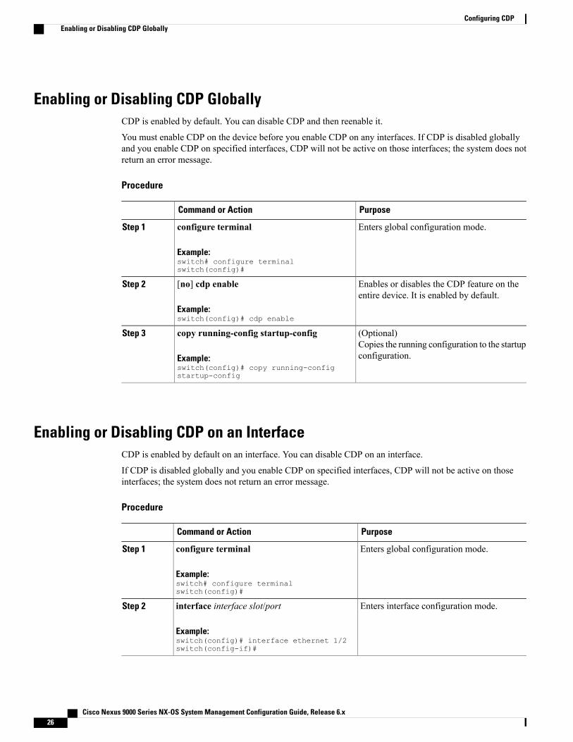
Enabling or Disabling CDP GloballyCDP is enabled by default. You can disable CDP and then reenable it.
You must enable CDP on the device before you enable CDP on any interfaces. If CDP is disabled globallyand you enable CDP on specified interfaces, CDP will not be active on those interfaces; the system does notreturn an error message.
Procedure
PurposeCommand or Action
Enters global configuration mode.configure terminal
Example:switch# configure terminalswitch(config)#
Step 1
Enables or disables the CDP feature on theentire device. It is enabled by default.
[no] cdp enable
Example:switch(config)# cdp enable
Step 2
(Optional)Copies the running configuration to the startupconfiguration.
copy running-config startup-config
Example:switch(config)# copy running-configstartup-config
Step 3
Enabling or Disabling CDP on an InterfaceCDP is enabled by default on an interface. You can disable CDP on an interface.
If CDP is disabled globally and you enable CDP on specified interfaces, CDP will not be active on thoseinterfaces; the system does not return an error message.
Procedure
PurposeCommand or Action
Enters global configuration mode.configure terminal
Example:switch# configure terminalswitch(config)#
Step 1
Enters interface configuration mode.interface interface slot/port
Example:switch(config)# interface ethernet 1/2switch(config-if)#
Step 2
Cisco Nexus 9000 Series NX-OS System Management Configuration Guide, Release 6.x26
Configuring CDPEnabling or Disabling CDP Globally

PurposeCommand or Action
Enables or disables CDP on this interface. Itis enabled by default.
[no] cdp enable
Example:switch(config-if)# cdp enable
Step 3
Make sure that CDP is enabledglobally on the device.
Note
(Optional)Displays CDP information for an interface.
show cdp interface interface slot/port
Example:switch(config-if)# show cdp interfaceethernet 1/2
Step 4
(Optional)Copies the running configuration to thestartup configuration.
copy running-config startup-config
Example:switch(config)# copy running-configstartup-config
Step 5
Configuring Optional CDP ParametersYou can use the optional commands in this procedure to modify CDP.
Procedure
PurposeCommand or Action
Enters global configuration mode.configure terminal
Example:switch# configure terminalswitch(config)#
Step 1
(Optional)Sets the CDP version supported by the device. Thedefault is v2.
cdp advertise {v1 | v2}
Example:switch(config)# cdp advertise v1
Step 2
(Optional)Sets the CDP device ID. The options are as follows:
cdp format device-id {mac-address |serial-number | system-name}
Example:switch(config)# cdp formatdevice-id mac-address
Step 3
• mac-address—TheMAC address of the chassis.
• serial-number—The chassis serialnumber/Organizationally Unique Identifier(OUI).
• system-name—The system name or fullyqualified domain name.
The default is system-name.
Cisco Nexus 9000 Series NX-OS System Management Configuration Guide, Release 6.x 27
Configuring CDPConfiguring Optional CDP Parameters

PurposeCommand or Action
(Optional)Sets the time that CDP holds onto neighbor informationbefore removing it. The range is from 10 to 255seconds. The default is 180 seconds.
cdp holdtime seconds
Example:switch(config)# cdp holdtime 150
Step 4
(Optional)Sets the refresh time when CDP sends advertisementsto neighbors. The range is from 5 to 254 seconds. Thedefault is 60 seconds.
cdp timer seconds
Example:switch(config)# cdp timer 50
Step 5
(Optional)Copies the running configuration to the startupconfiguration.
copy running-config startup-config
Example:switch(config)# copy running-configstartup-config
Step 6
Verifying the CDP ConfigurationTo display the CDP configuration, perform one of the following tasks:
PurposeCommand
Displays all interfaces that have CDP enabled.show cdp all
Displays the CDP database entries.show cdp entry {all | name entry-name}
Displays the CDP global parameters.show cdp global
Displays the CDP interface status.show cdp interface interface slot/port
Displays the CDP neighbor status.show cdp neighbors {device-id | interface interfaceslot/port} [detail]
Displays the CDP traffic statistics on an interface.show cdp interface interface slot/port
Use the clear cdp counters command to clear CDP statistics on an interface.
Use the clear cdp table command to clear the CDP cache for one or all interfaces.
Configuration Example for CDPThis example shows how to enable the CDP feature and configure the refresh and hold timers:configure terminalcdp enablecdp timer 50cdp holdtime 100
Cisco Nexus 9000 Series NX-OS System Management Configuration Guide, Release 6.x28
Configuring CDPVerifying the CDP Configuration

Additional References
MIBsMIBs LinkMIBs
To locate and download supported MIBs, go to thefollowing URL:
ftp://ftp.cisco.com/pub/mibs/supportlists/nexus9000/Nexus9000MIBSupportList.html
MIBs related to CDP
Cisco Nexus 9000 Series NX-OS System Management Configuration Guide, Release 6.x 29
Configuring CDPAdditional References

Cisco Nexus 9000 Series NX-OS System Management Configuration Guide, Release 6.x30
Configuring CDPMIBs

C H A P T E R 5Configuring System Message Logging
This chapter describes how to configure system message logging on Cisco NX-OS devices.
This chapter contains the following sections:
• About System Message Logging, page 31
• Licensing Requirements for System Message Logging, page 32
• Guidelines and Limitations for System Message Logging, page 33
• Default Settings for System Message Logging, page 33
• Configuring System Message Logging, page 33
• Verifying the System Message Logging Configuration, page 42
• Configuration Example for System Message Logging, page 42
• Additional References, page 43
About System Message LoggingYou can use system message logging to control the destination and to filter the severity level of messages thatsystem processes generate. You can configure logging to terminal sessions, a log file, and syslog servers onremote systems.
System message logging is based on RFC 3164. For more information about the system message format andthe messages that the device generates, see the Cisco NX-OS System Messages Reference.
By default, the device outputs messages to terminal sessions and logs system messages to a log file.
The following table describes the severity levels used in system messages. When you configure the severitylevel, the system outputs messages at that level and lower.
Table 3: System Message Severity Levels
DescriptionLevel
System unusable0 – emergency
Cisco Nexus 9000 Series NX-OS System Management Configuration Guide, Release 6.x 31

DescriptionLevel
Immediate action needed1 – alert
Critical condition2 – critical
Error condition3 – error
Warning condition4 – warning
Normal but significant condition5 – notification
Informational message only6 – informational
Appears during debugging only7 – debugging
The device logs the most recent 100 messages of severity 0, 1, or 2 to the NVRAM log. You cannot configurelogging to the NVRAM.
You can configure which system messages should be logged based on the facility that generated the messageand its severity level.
Syslog ServersThe syslog servers run on remote systems that log system messages based on the syslog protocol. You canconfigure up to eight IPv4 or IPv6 syslog servers.
To support the same configuration of syslog servers on all switches in a fabric, you can use Cisco FabricServices (CFS) to distribute the syslog server configuration.
When the device first initializes, messages are sent to syslog servers only after the network is initialized.Note
Licensing Requirements for System Message LoggingLicense RequirementProduct
System message logging requires no license. Anyfeature not included in a license package is bundledwith the nx-os image and is provided at no extracharge to you. For a complete explanation of theCisco NX-OS licensing scheme, see theCisco NX-OSLicensing Guide.
Cisco NX-OS
Cisco Nexus 9000 Series NX-OS System Management Configuration Guide, Release 6.x32
Configuring System Message LoggingSyslog Servers

Guidelines and Limitations for System Message LoggingSystem messages are logged to the console and the log file by default.
Default Settings for System Message LoggingThe following table lists the default settings for the system message logging parameters.
Table 4: Default System Message Logging Parameters
DefaultParameters
Enabled at severity level 2Console logging
Enabled at severity level 5Monitor logging
Enabled to log messages at severity level 5Log file logging
Enabled at severity level 5Module logging
EnabledFacility logging
SecondsTime-stamp units
DisabledSyslog server logging
DisabledSyslog server configuration distribution
Configuring System Message Logging
Be aware that the Cisco NX-OS commands for this feature might differ from those commands used inCisco IOS.
Note
Configuring System Message Logging to Terminal SessionsYou can configure the device to log messages by their severity level to console, Telnet, and SSH sessions.
By default, logging is enabled for terminal sessions.
Cisco Nexus 9000 Series NX-OS System Management Configuration Guide, Release 6.x 33
Configuring System Message LoggingGuidelines and Limitations for System Message Logging

The current critical (default) logging level is maintained if the console baud speed is 9600 baud (default).All attempts to change the console logging level will generate an error message. To increase the logginglevel (above critical), you must change the console baud speed to 38400 baud.
Note
Procedure
PurposeCommand or Action
Enables the device to log messages to the console.terminal monitor
Example:switch# terminal monitor
Step 1
Enters global configuration mode.configure terminal
Example:switch# configure terminalswitch(config)#
Step 2
Configures the device to logmessages to the console sessionbased on a specified severity level or higher. A lower
[no] logging console [severity-level]
Example:switch(config)# logging console3
Step 3
number indicates a higher severity level. Severity levelsrange from 0 to 7:
• 0 – emergency
• 1 – alert
• 2 – critical
• 3 – error
• 4 – warning
• 5 – notification
• 6 – informational
• 7 – debugging
If the severity level is not specified, the default of 2 is used.The no option disables the device’s ability to log messagesto the console.
(Optional)Displays the console logging configuration.
show logging console
Example:switch(config)# show loggingconsole
Step 4
Enables the device to log messages to the monitor based ona specified severity level or higher. A lower number
[no] loggingmonitor [severity-level]
Example:switch(config)# logging monitor3
Step 5
indicates a higher severity level. Severity levels range from0 to 7:
• 0 – emergency
Cisco Nexus 9000 Series NX-OS System Management Configuration Guide, Release 6.x34
Configuring System Message LoggingConfiguring System Message Logging to Terminal Sessions

PurposeCommand or Action
• 1 – alert
• 2 – critical
• 3 – error
• 4 – warning
• 5 – notification
• 6 – informational
• 7 – debugging
The configuration applies to Telnet and SSH sessions.
If the severity level is not specified, the default of 2 is used.The no option disables the device’s ability to log messagesto the Telnet and SSH sessions.
(Optional)Displays the monitor logging configuration.
show logging monitor
Example:switch(config)# show loggingmonitor
Step 6
Enables you to add the description for physical Ethernetinterfaces and subinterfaces in the systemmessage log. The
[no] loggingmessage interface typeethernet description
Step 7
description is the same description that was configured onthe interface.Example:
switch(config)# logging messageinterface type ethernetdescription
The no option disables the printing of the interfacedescription in the systemmessage log for physical Ethernetinterfaces.
(Optional)Copies the running configuration to the startupconfiguration.
copy running-config startup-config
Example:switch(config)# copyrunning-config startup-config
Step 8
Logging System Messages to a FileYou can configure the device to log system messages to a file. By default, system messages are logged to thefile log:messages.
Cisco Nexus 9000 Series NX-OS System Management Configuration Guide, Release 6.x 35
Configuring System Message LoggingLogging System Messages to a File
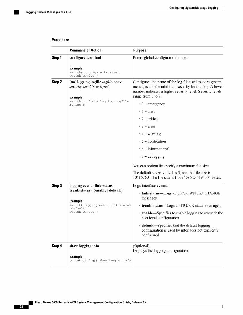
Procedure
PurposeCommand or Action
Enters global configuration mode.configure terminal
Example:switch# configure terminalswitch(config)#
Step 1
Configures the name of the log file used to store systemmessages and the minimum severity level to log. A lower
[no] logging logfile logfile-nameseverity-level [size bytes]
Step 2
number indicates a higher severity level. Severity levelsrange from 0 to 7:Example:
switch(config)# logging logfilemy_log 6 • 0 – emergency
• 1 – alert
• 2 – critical
• 3 – error
• 4 – warning
• 5 – notification
• 6 – informational
• 7 – debugging
You can optionally specify a maximum file size.
The default severity level is 5, and the file size is10485760. The file size is from 4096 to 4194304 bytes.
Logs interface events.logging event {link-status |trunk-status} {enable | default}
Step 3
• link-status—Logs all UP/DOWN and CHANGEmessages.
Example:switch# logging event link-statusdefaultswitch(config)#
• trunk-status—Logs all TRUNK status messages.
• enable—Specifies to enable logging to override theport level configuration.
• default—Specifies that the default loggingconfiguration is used by interfaces not explicitlyconfigured.
(Optional)Displays the logging configuration.
show logging info
Example:switch(config)# show logging info
Step 4
Cisco Nexus 9000 Series NX-OS System Management Configuration Guide, Release 6.x36
Configuring System Message LoggingLogging System Messages to a File

PurposeCommand or Action
(Optional)Copies the running configuration to the startupconfiguration.
copy running-config startup-config
Example:switch(config)# copyrunning-config startup-config
Step 5
Configuring Module and Facility Messages LoggingYou can configure the severity level and time-stamp units of messages logged by modules and facilities.
Procedure
PurposeCommand or Action
Enters global configuration mode.configure terminal
Example:switch# configure terminalswitch(config)#
Step 1
Enables module log messages that have the specifiedseverity level or higher. Severity levels range from 0 to 7:
[no] logging module [severity-level]
Example:switch(config)# logging module3
Step 2
• 0 – emergency
• 1 – alert
• 2 – critical
• 3 – error
• 4 – warning
• 5 – notification
• 6 – informational
• 7 – debugging
If the severity level is not specified, the default of 5 is used.The no option disables module log messages.
(Optional)Displays the module logging configuration.
show logging module
Example:switch(config)# show loggingmodule
Step 3
Cisco Nexus 9000 Series NX-OS System Management Configuration Guide, Release 6.x 37
Configuring System Message LoggingConfiguring Module and Facility Messages Logging
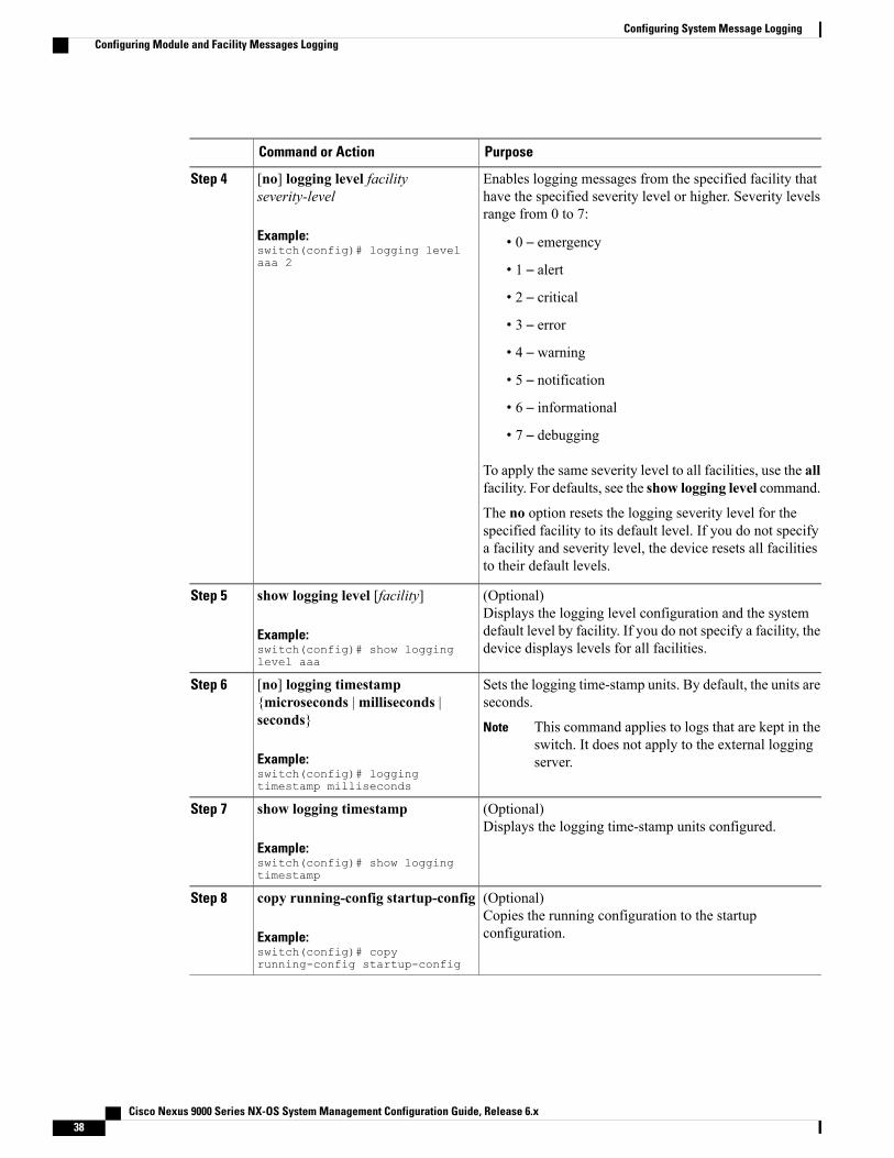
PurposeCommand or Action
Enables logging messages from the specified facility thathave the specified severity level or higher. Severity levelsrange from 0 to 7:
[no] logging level facilityseverity-level
Example:switch(config)# logging levelaaa 2
Step 4
• 0 – emergency
• 1 – alert
• 2 – critical
• 3 – error
• 4 – warning
• 5 – notification
• 6 – informational
• 7 – debugging
To apply the same severity level to all facilities, use the allfacility. For defaults, see the show logging level command.
The no option resets the logging severity level for thespecified facility to its default level. If you do not specifya facility and severity level, the device resets all facilitiesto their default levels.
(Optional)Displays the logging level configuration and the systemdefault level by facility. If you do not specify a facility, thedevice displays levels for all facilities.
show logging level [facility]
Example:switch(config)# show logginglevel aaa
Step 5
Sets the logging time-stamp units. By default, the units areseconds.
[no] logging timestamp{microseconds |milliseconds |seconds}
Step 6
This command applies to logs that are kept in theswitch. It does not apply to the external loggingserver.
Note
Example:switch(config)# loggingtimestamp milliseconds
(Optional)Displays the logging time-stamp units configured.
show logging timestamp
Example:switch(config)# show loggingtimestamp
Step 7
(Optional)Copies the running configuration to the startupconfiguration.
copy running-config startup-config
Example:switch(config)# copyrunning-config startup-config
Step 8
Cisco Nexus 9000 Series NX-OS System Management Configuration Guide, Release 6.x38
Configuring System Message LoggingConfiguring Module and Facility Messages Logging

Configuring Syslog ServersYou can configure up to eight syslog servers that reference remote systems where you want to log systemmessages.
Cisco recommends that you configure the syslog server to use the management virtual routing andforwarding (VRF) instance. For more information on VRFs, see the Cisco Nexus 9000 Series NX-OSUnicast Routing Configuration Guide.
Note
Procedure
PurposeCommand or Action
Enters global configuration mode.configure terminal
Example:switch# configure terminalswitch(config)#
Step 1
Configures a syslog server at the specified hostnameor IPv4 or IPv6 address. You can limit logging of
[no] logging server host [severity-level[use-vrf vrf-name]]
Step 2
messages to a particular VRF by using the use-vrfkeyword. Severity levels range from 0 to 7:Example:
switch(config)# logging server192.0.2.253 • 0 – emergency
Example:switch(config)# logging server2001::)db*::3 5 use-vrf red
• 1 – alert
• 2 – critical
• 3 – error
• 4 – warning
• 5 – notification
• 6 – informational
• 7 – debugging
The default outgoing facility is local7.
The no option removes the logging server for thespecified host.
The first example forwards all messages on facilitylocal 7. The second example forwards messages withseverity level 5 or lower for VRF red.
Cisco Nexus 9000 Series NX-OS System Management Configuration Guide, Release 6.x 39
Configuring System Message LoggingConfiguring Syslog Servers

PurposeCommand or Action
Enables a source interface for the remote syslog server.The range for the virtual-interface argument is from 0to 1023.
logging source-interface loopbackvirtual-interface
Example:switch(config)# loggingsource-interface loopback 5
Step 3
(Optional)Displays the syslog server configuration.
show logging server
Example:switch(config)# show logging server
Step 4
(Optional)Copies the running configuration to the startupconfiguration.
copy running-config startup-config
Example:switch(config)# copy running-configstartup-config
Step 5
Configuring Syslog Servers on a UNIX or Linux SystemYou can configure a syslog server on a UNIX or Linux system by adding the following line to the/etc/syslog.conf file:
facility.level <five tab characters> action
The following table describes the syslog fields that you can configure.
Table 5: Syslog fields in syslog.conf
DescriptionField
Creator of the message, which can be auth, authpriv,cron, daemon, kern, lpr, mail, mark, news, syslog,user, local0 through local7, or an asterisk (*) for all.These facility designators allow you to control thedestination of messages based on their origin.
Check your configuration before using alocal facility.
Note
Facility
Minimum severity level at which messages arelogged, which can be debug, info, notice, warning,err, crit, alert, emerg, or an asterisk (*) for all. Youcan use none to disable a facility.
Level
Destination for messages, which can be a filename,a hostname preceded by the at sign (@), acomma-separated list of users, or an asterisk (*) forall logged-in users.
Action
Cisco Nexus 9000 Series NX-OS System Management Configuration Guide, Release 6.x40
Configuring System Message LoggingConfiguring Syslog Servers on a UNIX or Linux System

Procedure
Step 1 Log debug messages with the local7 facility in the file /var/log/myfile.log by adding the following line to the/etc/syslog.conf file:
Example:debug.local7 var/log/myfile.log
Step 2 Create the log file by entering these commands at the shell prompt:
Example:$ touch /var/log/myfile.log$ chmod 666 /var/log/myfile.log
Step 3 Make sure the system message logging daemon reads the new changes by checking myfile.log after enteringthis command:
Example:$ kill -HUP ~cat /etc/syslog.pid~
Displaying and Clearing Log FilesYou can display or clear messages in the log file and the NVRAM.
Procedure
PurposeCommand or Action
Displays the last number of lines in the logging file.You can specify from 1 to 9999 for the last numberof lines.
show logging last number-lines
Example:switch# show logging last 40
Step 1
Displays the messages in the log file that have atimestampwithin the span entered. If you do not enter
show logging logfile [start-time yyyymmmdd hh:mm:ss] [end-time yyyy mmm ddhh:mm:ss]
Step 2
an end time, the current time is used. You enter threecharacters for the month time field and digits for theyear and day time fields.Example:
switch# show logging logfilestart-time 2013 oct 1 15:10:0
Displays the messages in the NVRAM. To limit thenumber of lines displayed, you can enter the last
show logging nvram [last number-lines]
Example:switch# show logging nvram last 10
Step 3
number of lines to display. You can specify from 1to 100 for the last number of lines.
Cisco Nexus 9000 Series NX-OS System Management Configuration Guide, Release 6.x 41
Configuring System Message LoggingDisplaying and Clearing Log Files

PurposeCommand or Action
Clears the contents of the log file.clear logging logfile
Example:switch# clear logging logfile
Step 4
Clears the logged messages in NVRAM.clear logging nvram
Example:switch# clear logging nvram
Step 5
Verifying the System Message Logging ConfigurationTo display system message logging configuration information, perform one of the following tasks:
PurposeCommand
Displays the console logging configuration.show logging console
Displays the logging configuration.show logging info
Displays the last number of lines of the log file.show logging last number-lines
Displays the facility logging severity levelconfiguration.
show logging level [facility]
Displays the messages in the log file.show logging logfile [start-time yyyy mmm ddhh:mm:ss] [end-time yyyy mmm dd hh:mm:ss]
Displays the module logging configuration.show logging module
Displays the monitor logging configuration.show logging monitor
Displays the messages in the NVRAM log.show logging nvram [last number-lines]
Displays the syslog server configuration.show logging server
Displays the logging time-stamp units configuration.show logging timestamp
Configuration Example for System Message LoggingThis example shows how to configure system message logging:configure terminallogging console 3logging monitor 3
Cisco Nexus 9000 Series NX-OS System Management Configuration Guide, Release 6.x42
Configuring System Message LoggingVerifying the System Message Logging Configuration

logging logfile my_log 6logging module 3logging level aaa 2logging timestamp millisecondslogging server 172.28.254.253logging server 172.28.254.254 5 facility local3copy running-config startup-config
Additional References
Related DocumentsDocument TitleRelated Topic
Cisco NX-OS System Messages ReferenceSystem messages
Cisco Nexus 9000 Series NX-OS System Management Configuration Guide, Release 6.x 43
Configuring System Message LoggingAdditional References

Cisco Nexus 9000 Series NX-OS System Management Configuration Guide, Release 6.x44
Configuring System Message LoggingRelated Documents

C H A P T E R 6Configuring Smart Call Home
This chapter describes how to configure the Smart Call Home feature of the Cisco NX-OS devices.
This chapter contains the following sections:
• About Smart Call Home, page 45
• Licensing Requirements for Smart Call Home, page 51
• Prerequisites for Smart Call Home, page 52
• Guidelines and Limitations for Smart Call Home, page 52
• Default Settings for Smart Call Home, page 52
• Configuring Smart Call Home, page 53
• Verifying the Smart Call Home Configuration, page 67
• Configuration Examples for Smart Call Home, page 68
• Additional References, page 69
About Smart Call HomeSmart Call Home provides an email-based notification for critical system policies. A range of message formatsare available for compatibility with pager services, standard email, or XML-based automated parsingapplications. You can use this feature to page a network support engineer, email a Network Operations Center,or use Cisco Smart Call Home services to automatically generate a case with the Technical Assistance Center.
Smart Call Home offers the following features:
• Automatic execution and attachment of relevant CLI command output.
• Multiple message format options such as the following:
◦Short Text—Suitable for pagers or printed reports.
◦Full Text—Fully formatted message information suitable for human reading.
◦XML—Machine-readable format that uses Extensible Markup Language (XML) and AdaptiveMessaging Language (AML) XML schema definition (XSD). The AML XSD is published on theCisco.comwebsite. The XML format enables communication with the Technical Assistance Center.
Cisco Nexus 9000 Series NX-OS System Management Configuration Guide, Release 6.x 45

• Multiple concurrent message destinations. You can configure up to 50 email destination addresses foreach destination profile.
Destination ProfilesA destination profile includes the following information:
• One or more alert groups—The group of alerts that trigger a specific Smart Call Home message if thealert occurs.
• One or more email destinations—The list of recipients for the Smart Call Home messages generated byalert groups assigned to this destination profile.
• Message format—The format for the Smart Call Home message (short text, full text, or XML).
• Message severity level—The Smart Call Home severity level that the alert must meet before CiscoNX-OS generates a Smart Call Home message to all email addresses in the destination profile. CiscoNX-OS does not generate an alert if the Smart Call Home severity level of the alert is lower than themessage severity level set for the destination profile.
You can also configure a destination profile to allow periodic inventory update messages by using the inventoryalert group that will send out periodic messages daily, weekly, or monthly.
Cisco NX-OS supports the following predefined destination profiles:
• CiscoTAC-1—Supports the Cisco-TAC alert group in XMLmessage format. This profile is preconfiguredwith the [email protected] email contact, maximummessage size, and message severity level 0. Youcannot change any of the default information for this profile.
• full-text-destination—Supports the full text message format.
• short-text-destination—Supports the short text message format.
Smart Call Home Alert GroupsAn alert group is a predefined subset of Smart Call Home alerts that are supported in all Cisco Nexus devices.Alert groups allow you to select the set of Smart Call Home alerts that you want to send to a predefined orcustom destination profile. The device sends Smart Call Home alerts to email destinations in a destinationprofile only if that Smart Call Home alert belongs to one of the alert groups associated with that destinationprofile and if the alert has a Smart Call Home message severity at or above the message severity set in thedestination profile.
The following table lists the supported alert groups and the default CLI command output included in SmartCall Home messages generated for the alert group.
Table 6: Alert Groups and Executed Commands
Executed CommandsDescriptionAlert Group
Execute commands based onthe alert group thatoriginates the alert.
All critical alerts from theother alert groups destinedfor Smart Call Home.
Cisco-TAC
Cisco Nexus 9000 Series NX-OS System Management Configuration Guide, Release 6.x46
Configuring Smart Call HomeDestination Profiles

Executed CommandsDescriptionAlert Group
show module
show version
Periodic events related toconfiguration.
Configuration
show diagnostic resultmodule all detail
show diagnostic resultmodule number detail
show hardware
show logging last 200
show module
show sprom all
show tech-support gold
show tech-support ha
show tech-supportplatform
show version
Events generated bydiagnostics.
Diagnostic
show diagnostic resultmodule all detail
show diagnostic resultmodule number detail
show module
show tech-support gold
show tech-support ha
show tech-supportplatform
Events generated by EEM.EEM
show environment
show logging last 200
show module
show version
Events related to power,fan, andenvironment-sensingelements such astemperature alarms.
Environmental
show inventory
show license usage
show module
show sprom all
show system uptime
show version
Inventory status that isprovided whenever a unitis cold booted or whenFRUs are inserted orremoved. This alert isconsidered a noncriticalevent, and the informationis used for status andentitlement.
Inventory
Cisco Nexus 9000 Series NX-OS System Management Configuration Guide, Release 6.x 47
Configuring Smart Call HomeSmart Call Home Alert Groups

Executed CommandsDescriptionAlert Group
show logging last 200Events related to licensingand license violations.
License
show diagnostic resultmodule all detail
show diagnostic resultmodule number detail
show hardware
show logging last 200
show module
show sprom all
show tech-support ethpm
show tech-support gold
show tech-support ha
show tech-supportplatform
show version
Events related to standardor intelligent switchingmodules.
Linecardhardware
show diagnostic resultmodule all detail
show hardware
show logging last 200
show module
show sprom all
show tech-support ethpm
show tech-support gold
show tech-support ha
show tech-supportplatform
show version
Events related tosupervisor modules.
Supervisorhardware
show license usage
show logging last 200
Events generated by thesyslog PORT facility.
Syslog portgroup
Cisco Nexus 9000 Series NX-OS System Management Configuration Guide, Release 6.x48
Configuring Smart Call HomeSmart Call Home Alert Groups

Executed CommandsDescriptionAlert Group
show diagnostic resultmodule all detail
show hardware
show logging last 200
show module
show sprom all
show tech-support ethpm
show tech-support gold
show tech-support ha
show tech-supportplatform
Events generated byfailure of a softwaresystem that is critical tounit operation.
System
show module
show version
User-generated testmessage.
Test
Smart Call Home maps the syslog severity level to the corresponding Smart Call Home severity level forsyslog port group messages.
You can customize predefined alert groups to execute additional CLI show commands when specific eventsoccur and send that show output with the Smart Call Home message.
You can add show commands only to full text and XML destination profiles. Short text destination profilesdo not support additional show commands because they only allow 128 bytes of text.
Smart Call Home Message LevelsSmart Call Home allows you to filter messages based on their level of urgency. You can associate eachpredefined or user-defined destination profile with a Smart Call Home threshold from 0 (least urgent) to 9(most urgent). The default is 0 (all messages are sent).
Syslog severity levels are mapped to the Smart Call Home message level.
Smart Call Home does not change the syslog message level in the message text.Note
The following table lists each Smart Call Home message level keyword and the corresponding syslog levelfor the syslog port alert group.
Table 7: Severity and Syslog Level Mapping
DescriptionSyslog LevelKeywordSmart Call Home Level
Network-widecatastrophic failure.
N/ACatastrophic9
Cisco Nexus 9000 Series NX-OS System Management Configuration Guide, Release 6.x 49
Configuring Smart Call HomeSmart Call Home Message Levels

DescriptionSyslog LevelKeywordSmart Call Home Level
Significant networkimpact.
N/ADisaster8
System is unusable.Emergency (0)Fatal7
Critical conditions thatindicate that immediateattention is needed.
Alert (1)Critical6
Major conditions.Critical (2)Major5
Minor conditions.Error (3)Minor4
Warning conditions.Warning (4)Warning3
Basic notification andinformational messages.Possibly independentlyinsignificant.
Notice (5)Notification2
Normal event signifyingreturn to normal state.
Information (6)Normal1
Debugging messages.Debug (7)Debugging0
Obtaining Smart Call HomeIf you have a service contract directly with Cisco, you can register for the Smart Call Home service. SmartCall Home analyzes Smart Call Homemessages and provides background information and recommendations.For known issues, particularly online diagnostics failures, Automatic Service Requests are generated with theCisco TAC.
Smart Call Home offers the following features:
• Continuous device health monitoring and real-time diagnostic alerts.
• Analysis of Smart Call Home messages and, if needed, Automatic Service Request generation, routedto the correct TAC team, including detailed diagnostic information to speed problem resolution.
• Secure message transport directly from your device, through an HTTP proxy server, or a downloadableTransport Gateway (TG). You can use a TG aggregation point to support multiple devices or in caseswhere security dictates that your devices may not be connected directly to the Internet.
•Web-based access to Smart Call Home messages and recommendations, inventory, and configurationinformation for all Smart Call Home devices. This feature rovides access to associated field notices,security advisories, and end-of-life information.
You need the following information to register:
Cisco Nexus 9000 Series NX-OS System Management Configuration Guide, Release 6.x50
Configuring Smart Call HomeObtaining Smart Call Home

• The SMARTnet contract number for your device
• Your email address
• Your Cisco.com ID
For more information about Smart Call Home, see the following Smart Call Home page: https://supportforums.cisco.com/community/netpro/solutions/smart_services/smartcallhome
Database Merge GuidelinesWhen you merge two Smart Call Home databases, the following guidelines apply:
• The merged database contains the following information:
◦A superset of all the destination profiles from the merging devices.
◦The destination profile email addresses and alert groups.
◦Other configuration information (for example, message throttling, or periodic inventory) presentin the managing device.
• Destination profile names cannot be duplicated within the merging devices—even though theconfigurations are different, the names cannot be duplicated. If a profile name is duplicated, one of theduplicate profiles must first be deleted or the merger fails.
High AvailabilityBoth stateful and stateless restarts are supported for Smart Call Home.
Virtualization SupportOne instance of Smart Call Home is supported. You can register your contact information at the Smart CallHome web site at the following URL: https://supportforums.cisco.com/community/netpro/solutions/smart_services/smartcallhome
You can test Smart Call Home using the callhome send and callhome test commands.
Smart Call Home is virtual routing and forwarding (VRF) aware. You can configure Smart Call Home to usea particular VRF to reach the Smart Call Home SMTP server.
Licensing Requirements for Smart Call HomeLicense RequirementProduct
Smart Call Home requires no license. Any feature not included in a license package is bundledwith the nx-os image and is provided at no extra charge to you. For a complete explanationof the Cisco NX-OS licensing scheme, see the Cisco NX-OS Licensing Guide.
CiscoNX-OS
Cisco Nexus 9000 Series NX-OS System Management Configuration Guide, Release 6.x 51
Configuring Smart Call HomeDatabase Merge Guidelines

Prerequisites for Smart Call HomeSmart Call Home has the following prerequisites:
• To send messages to an email address, you must first configure an email server. To send messages usingHTTP, you must have access to an HTTPS server and have a valid certificate installed on the CiscoNexus device.
• Your device must have IP connectivity to an email server or HTTPS server.
• Youmust first configure the contact name (SNMP server contact), phone, and street address information.This step is required to determine the origin of messages received.
• If you use Smart Call Home, you need an active service contract for the device that you are configuring.
Guidelines and Limitations for Smart Call HomeSmart Call Home has the following configuration guidelines and limitations:
• If there is no IP connectivity or if the interface in the virtual routing and forwarding (VRF) instance tothe profile destination is down, the device cannot send Smart Call Home messages.
• Smart Call Home operates with any SMTP server.
• You can configure up to five SMTP servers for Smart Call Home.
Default Settings for Smart Call HomeThis table lists the default settings for Smart Call Home parameters.
Table 8: Default Smart Call Home Parameters
DefaultParameters
2,500,000Destination message size for a message sent in fulltext format
2,500,000Destination message size for a message sent in XMLformat
4000Destination message size for a message sent in shorttext format
25SMTP server port number if no port is specified
50SMTP server priority if no priority is specified
Cisco Nexus 9000 Series NX-OS System Management Configuration Guide, Release 6.x52
Configuring Smart Call HomePrerequisites for Smart Call Home

DefaultParameters
All for full-text-destination and short-text-destinationprofiles. The cisco-tac alert group for the CiscoTAC-1destination profile.
Alert group association with profile
XMLFormat type
0 (zero)Smart Call Home message level
Disabled and no proxy server configuredHTTP proxy server use
Configuring Smart Call Home
Be aware that the Cisco NX-OS commands may differ from the Cisco IOS commands.Note
We recommend that you complete the Smart Call Home configuration procedures in the following sequence:
1 Configuring Contact Information, on page 532 Creating a Destination Profile, on page 553 Associating an Alert Group with a Destination Profile, on page 584 (Optional) Adding Show Commands to an Alert Group, on page 595 Enabling or Disabling Smart Call Home, on page 666 (Optional) Testing the Smart Call Home Configuration, on page 67
Configuring Contact InformationYoumust configure the email, phone, and street address information for Smart Call Home. You can optionallyconfigure the contract ID, customer ID, site ID, and switch priority information.
Procedure
PurposeCommand or Action
Enters global configuration mode.configure terminal
Example:switch# configure terminalswitch(config)#
Step 1
Configures the SNMP sysContact.snmp-server contact sys-contact
Example:switch(config)# snmp-server [email protected]
Step 2
Cisco Nexus 9000 Series NX-OS System Management Configuration Guide, Release 6.x 53
Configuring Smart Call HomeConfiguring Smart Call Home

PurposeCommand or Action
Enters Smart Call Home configuration mode.callhome
Example:switch(config)# callhomeswitch(config-callhome)#
Step 3
Configures the email address for the person primarilyresponsible for the device.
email-contact email-address
Example:switch(config-callhome)#email-contact [email protected]
Step 4
The email-address can be up to 255 alphanumericcharacters in email address format.
You can use any valid email address. Theaddress cannot contain spaces.
Note
Configures the phone number in international phonenumber format for the person primarily responsible
phone-contactinternational-phone-number
Step 5
for the device. The international-phone-number canExample:switch(config-callhome)#phone-contact +1-800-123-4567
be up to 17 alphanumeric characters and must be ininternational phone number format.
The phone number cannot contain spaces. Usethe plus (+) prefix before the number.
Note
Configures the street address as an alphanumeric stringwith white spaces for the person primarily responsiblefor the device.
streetaddress address
Example:switch(config-callhome)#streetaddress 123 Anystreet st.Anytown,AnyWhere
Step 6
The address can be up to 255 alphanumeric characters.Spaces are accepted.
(Optional)Configures the contract number for this device fromthe service agreement.
contract-id contract-number
Example:switch(config-callhome)#contract-id Contract5678
Step 7
The contract-number can be up to 255 alphanumericcharacters in free format.
(Optional)Configures the customer number for this device fromthe service agreement.
customer-id customer-number
Example:switch(config-callhome)#customer-id Customer123456
Step 8
The customer-number can be up to 255 alphanumericcharacters in free format.
(Optional)Configures the site number for this device.
site-id site-number
Example:switch(config-callhome)# site-idSite1
Step 9
The site-number can be up to 255 alphanumericcharacters in free format.
(Optional)Configures the switch priority for this device.
switch-priority number
Example:switch(config-callhome)#switch-priority 3
Step 10
The range is from 0 to 7, with 0 being the highestpriority and 7 the lowest. The default is 7.
Cisco Nexus 9000 Series NX-OS System Management Configuration Guide, Release 6.x54
Configuring Smart Call HomeConfiguring Contact Information
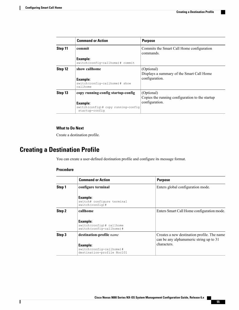
PurposeCommand or Action
Commits the Smart Call Home configurationcommands.
commit
Example:switch(config-callhome)# commit
Step 11
(Optional)Displays a summary of the Smart Call Homeconfiguration.
show callhome
Example:switch(config-callhome)# showcallhome
Step 12
(Optional)Copies the running configuration to the startupconfiguration.
copy running-config startup-config
Example:switch(config)# copy running-configstartup-config
Step 13
What to Do Next
Create a destination profile.
Creating a Destination ProfileYou can create a user-defined destination profile and configure its message format.
Procedure
PurposeCommand or Action
Enters global configuration mode.configure terminal
Example:switch# configure terminalswitch(config)#
Step 1
Enters Smart Call Home configurationmode.callhome
Example:switch(config)# callhomeswitch(config-callhome)#
Step 2
Creates a new destination profile. The namecan be any alphanumeric string up to 31characters.
destination-profile name
Example:switch(config-callhome)#destination-profile Noc101
Step 3
Cisco Nexus 9000 Series NX-OS System Management Configuration Guide, Release 6.x 55
Configuring Smart Call HomeCreating a Destination Profile

PurposeCommand or Action
Sets the message format for the profile. Thename can be any alphanumeric string up to31 characters.
destination-profile name format {XML | full-txt| short-txt}
Example:switch(config-callhome)#destination-profile Noc101 format full-txt
Step 4
Commits the Smart Call Home configurationcommands.
commit
Example:switch(config-callhome)# commit
Step 5
(Optional)Displays information about one or moredestination profiles.
show callhome destination-profile [profilename]
Example:switch(config-callhome)# show callhomedestination-profile profile Noc101
Step 6
(Optional)Copies the running configuration to thestartup configuration.
copy running-config startup-config
Example:switch(config)# copy running-configstartup-config
Step 7
What to Do Next
Associate one or more alert groups with a destination profile.
Modifying a Destination ProfileYou can modify the following attributes for a predefined or user-defined destination profile:
• Destination email address—The actual address, pertinent to the transport mechanism, to which the alertshould be sent.
• Destination URL—The HTTP or HTTPS URL that defines where alerts should be sent.
• Transport method—The email or HTTP transport that determines which type of destination addressesare used.
• Message formatting—The message format used for sending the alert (full text, short text, or XML).
• Message level—The Smart Call Home message severity level for this destination profile.
• Message size—The allowed length of a Smart Call Home message sent to the email addresses in thisdestination profile.
Cisco Nexus 9000 Series NX-OS System Management Configuration Guide, Release 6.x56
Configuring Smart Call HomeModifying a Destination Profile

Procedure
PurposeCommand or Action
Enters global configuration mode.configure terminal
Example:switch# configure terminalswitch(config)#
Step 1
Enters Smart Call Home configuration mode.callhome
Example:switch(config)# callhomeswitch(config-callhome)#
Step 2
Configures an email address for a user-definedor predefined destination profile. You can
destination-profile {name | CiscoTAC-1 |full-txt-destination | short-txt-destination}email-addr address
Step 3
configure up to 50 email addresses in adestination profile.
Example:switch(config-callhome)#destination-profile full-txt-destinationemail-addr [email protected]
Configures an HTTP or HTTPS URL for auser-defined or predefined destination profile.The URL can be up to 255 characters.
destination-profile {name | CiscoTAC-1 |full-txt-destination | short-txt-destination} httpaddress
Example:switch(config-callhome)#destination-profile CiscoTAC-1 httphttp://site.com/service/callhome
Step 4
Configures an email or HTTP transport methodfor a user-defined or predefined destination
destination-profile {name | CiscoTAC-1 |full-txt-destination | short-txt-destination}transport-method {email | http}
Step 5
profile. The type of transport method that youchoose determines the configured destinationaddresses of that type.Example:
switch(config-callhome)#destination-profile CiscoTAC-1transport-method http
Configures the Smart Call Home messageseverity level for this destination profile. Cisco
destination-profile {name | CiscoTAC-1 |full-txt-destination | short-txt-destination}message-level number
Step 6
NX-OS sends only alerts that have a matchingor higher Smart Call Home severity level to
Example:switch(config-callhome)#destination-profile full-txt-destinationmessage-level 5
destinations in this profile. The range is from0 to 9, where 9 is the highest severity level.
Cisco Nexus 9000 Series NX-OS System Management Configuration Guide, Release 6.x 57
Configuring Smart Call HomeModifying a Destination Profile

PurposeCommand or Action
Configures the maximummessage size for thisdestination profile. The range is from 0 to5000000. The default is 2500000.
destination-profile {name | CiscoTAC-1 |full-txt-destination | short-txt-destination}message-size number
Example:switch(config-callhome)#destination-profile full-txt-destinationmessage-size 100000
Step 7
Commits the Smart Call Home configurationcommands.
commit
Example:switch(config-callhome)# commit
Step 8
(Optional)Displays information about one or moredestination profiles.
show callhome destination-profile [profile name]
Example:switch(config-callhome)# show callhomedestination-profile profilefull-text-destination
Step 9
(Optional)Copies the running configuration to the startupconfiguration.
copy running-config startup-config
Example:switch(config)# copy running-configstartup-config
Step 10
What to Do Next
Associate one or more alert groups with a destination profile.
Associating an Alert Group with a Destination Profile
Procedure
PurposeCommand or Action
Enters global configuration mode.configure terminal
Example:switch# configure terminalswitch(config)#
Step 1
Enters Smart Call Home configurationmode.
callhome
Example:switch(config)# callhomeswitch(config-callhome)#
Step 2
Associates an alert group with thisdestination profile. Use the All keyword
destination-profile {name | CiscoTAC-1 |full-txt-destination | short-txt-destination}
Step 3
Cisco Nexus 9000 Series NX-OS System Management Configuration Guide, Release 6.x58
Configuring Smart Call HomeAssociating an Alert Group with a Destination Profile

PurposeCommand or Action
to associate all alert groups with thedestination profile.
alert-group {All | Cisco-TAC | Configuration |Diagnostic | EEM | Environmental | Inventory |License | Supervisor-Hardware | Syslog-group-port| System | Test}
Example:switch(config-callhome)# destination-profileNoc101 alert-group All
Commits the Smart Call Homeconfiguration commands.
commit
Example:switch(config-callhome)# commit
Step 4
(Optional)Displays information about one or moredestination profiles.
show callhome destination-profile [profile name]
Example:switch(config-callhome)# show callhomedestination-profile profile Noc101
Step 5
(Optional)Copies the running configuration to thestartup configuration.
copy running-config startup-config
Example:switch(config)# copy running-configstartup-config
Step 6
What to Do Next
Optionally add show commands to an alert group and then configure the SMTP email server.
Adding Show Commands to an Alert GroupYou can assign a maximum of five user-defined CLI show commands to an alert group.
You cannot add user-defined CLI show commands to the CiscoTAC-1 destination profile.Note
Procedure
PurposeCommand or Action
Enters global configuration mode.configure terminal
Example:switch# configure terminalswitch(config)#
Step 1
Cisco Nexus 9000 Series NX-OS System Management Configuration Guide, Release 6.x 59
Configuring Smart Call HomeAdding Show Commands to an Alert Group

PurposeCommand or Action
Enters Smart Call Home configurationmode.
callhome
Example:switch(config)# callhomeswitch(config-callhome)#
Step 2
Adds the show command output to anySmart Call Homemessages sent for this alert
alert-group {Configuration | Diagnostic | EEM| Environmental | Inventory | License |
Step 3
group. Only valid show commands areaccepted.
Supervisor-Hardware | Syslog-group-port |System | Test} user-def-cmd show-cmd
Example:switch(config-callhome)# alert-groupConfiguration user-def-cmd show ip route
Commits the Smart Call Home configurationcommands.
commit
Example:switch(config-callhome)# commit
Step 4
(Optional)Displays information about all user-definedshow commands added to alert groups.
show callhome user-def-cmds
Example:switch(config-callhome)# show callhomeuser-def-cmds
Step 5
(Optional)Copies the running configuration to thestartup configuration.
copy running-config startup-config
Example:switch(config)# copy running-configstartup-config
Step 6
What to Do Next
Configure Smart Call Home to connect to the SMTP email server.
Configuring the Email ServerYou must configure the SMTP server address for the Smart Call Home functionality to work. You can alsoconfigure the from and reply-to email addresses.
You can configure up to five SMTP servers for Smart Call Home. The servers are tried based on their priority.The highest priority server is tried first. If the message fails to be sent, the next server in the list is tried untilthe limit is exhausted. If two servers have equal priority, the one that was configured earlier is tried first.
Cisco Nexus 9000 Series NX-OS System Management Configuration Guide, Release 6.x60
Configuring Smart Call HomeConfiguring the Email Server

Procedure
PurposeCommand or Action
Enters global configuration mode.configure terminal
Example:switch# configure terminalswitch(config)#
Step 1
Enters Smart Call Home configuration mode.callhome
Example:switch(config)# callhomeswitch(config-callhome)#
Step 2
Configures the SMTP server as the domain nameserver (DNS) name, IPv4 address, or IPv6 address.
transport email mail-server ip-address[port number] [priority number] [use-vrfvrf-name]
Step 3
Optionally configures the port number. The portrange is from 1 to 65535. The default port numberis 25.Example:
switch(config-callhome)# transportemail mail-server 192.0.2.1 use-vrfRed
Also optionally configures the priority of the SMTPserver. The priority range is from 1 to 100, with 1being the highest priority and 100 the lowest. If youdo not specify a priority, the default value of 50 isused.
Also optionally configures the VRF to use whencommunicating with this SMTP server. The VRFspecified is not used to send messages using HTTP.
(Optional)Configures the email from field for Smart Call Homemessages.
transport email from email-address
Example:switch(config-callhome)# transportemail from [email protected]
Step 4
(Optional)Configures the email reply-to field for Smart CallHome messages.
transport email reply-to email-address
Example:switch(config-callhome)# transportemail reply-to [email protected]
Step 5
Commits the Smart Call Home configurationcommands.
commit
Example:switch(config-callhome)# commit
Step 6
(Optional)Displays the transport-related configuration forSmart Call Home.
show callhome transport
Example:switch(config-callhome)# showcallhome transport
Step 7
Cisco Nexus 9000 Series NX-OS System Management Configuration Guide, Release 6.x 61
Configuring Smart Call HomeConfiguring the Email Server

PurposeCommand or Action
(Optional)Copies the running configuration to the startupconfiguration.
copy running-config startup-config
Example:switch(config)# copy running-configstartup-config
Step 8
What to Do Next
Optionally use VRFs to send Smart Call Home messages over HTTP.
Configuring VRFs To Send Messages Using HTTPYou can use VRFs to send Smart Call Home messages over HTTP. If HTTP VRFs are not configured, thedefault VRF is used to transport messages over HTTP.
Procedure
PurposeCommand or Action
Enters global configuration mode.configure terminal
Example:switch# configure terminalswitch(config)#
Step 1
Enters Smart Call Home configurationmode.callhome
Example:switch(config)# callhomeswitch(config-callhome)#
Step 2
Configures the VRF used to send email andother Smart Call Homemessages over HTTP.
transport http use-vrf vrf-name
Example:switch(config-callhome)# transport httpuse-vrf Blue
Step 3
Commits the Smart Call Home configurationcommands.
commit
Example:switch(config-callhome)# commit
Step 4
(Optional)Displays information about Smart Call Home.
show callhome
Example:switch(config-callhome)# show callhome
Step 5
Cisco Nexus 9000 Series NX-OS System Management Configuration Guide, Release 6.x62
Configuring Smart Call HomeConfiguring VRFs To Send Messages Using HTTP

PurposeCommand or Action
(Optional)Copies the running configuration to thestartup configuration.
copy running-config startup-config
Example:switch(config)# copy running-configstartup-config
Step 6
What to Do Next
Optionally configure Smart Call Home to send HTTP messages through an HTTP proxy server.
Configuring an HTTP Proxy Server
Procedure
PurposeCommand or Action
Enters global configuration mode.configure terminal
Example:switch# configure terminalswitch(config)#
Step 1
Enters Smart Call Home configuration mode.callhome
Example:switch(config)# callhomeswitch(config-callhome)#
Step 2
Configures the HTTP proxy server domain nameserver (DNS) name, IPv4 address, or IPv6 address.
transport http proxy server ip-address[port number]
Step 3
Optionally configures the port number. The portExample:switch(config-callhome)# transporthttp proxy server 192.0.2.1
range is from 1 to 65535. The default port numberis 8080.
Enables Smart Call Home to send all HTTPmessagesthrough the HTTP proxy server.
transport http proxy enable
Example:switch(config-callhome)# transporthttp proxy enable
Step 4
You can execute this command only afterthe proxy server address has beenconfigured.
Note
The VRF used for transporting messagesthrough the proxy server is the same as thatconfigured using the transport http use-vrfcommand.
Note
Commits the Smart Call Home configurationcommands.
commit
Example:switch(config-callhome)# commit
Step 5
Cisco Nexus 9000 Series NX-OS System Management Configuration Guide, Release 6.x 63
Configuring Smart Call HomeConfiguring an HTTP Proxy Server

PurposeCommand or Action
(Optional)Displays the transport-related configuration for SmartCall Home.
show callhome transport
Example:switch(config-callhome)# showcallhome transport
Step 6
(Optional)Copies the running configuration to the startupconfiguration.
copy running-config startup-config
Example:switch(config)# copy running-configstartup-config
Step 7
What to Do Next
Optionally configure your device to periodically send inventory notifications.
Configuring Periodic Inventory NotificationsYou can configure the device to periodically send a message with an inventory of all software services currentlyenabled and running on the device along with hardware inventory information. The device generates twoSmart Call Home notifications: periodic configuration messages and periodic inventory messages.
Procedure
PurposeCommand or Action
Enters global configuration mode.configure terminal
Example:switch# configure terminalswitch(config)#
Step 1
Enters Smart Call Home configuration mode.callhome
Example:switch(config)# callhomeswitch(config-callhome)#
Step 2
Configures periodic inventory messages. Theinterval range is from 1 to 30 days, and the
periodic-inventory notification [intervaldays] [timeofday time]
Step 3
default is 7 days. The time argument is inExample:switch(config-callhome)#periodic-inventory notificationinterval 20
HH:MM format. It defines at what time of theday every X days an update is sent (where X isthe update interval).
Commits the Smart Call Home configurationcommands.
commit
Example:switch(config-callhome)# commit
Step 4
Cisco Nexus 9000 Series NX-OS System Management Configuration Guide, Release 6.x64
Configuring Smart Call HomeConfiguring Periodic Inventory Notifications

PurposeCommand or Action
(Optional)Displays information about Smart Call Home.
show callhome
Example:switch(config-callhome)# show callhome
Step 5
(Optional)Copies the running configuration to the startupconfiguration.
copy running-config startup-config
Example:switch(config)# copy running-configstartup-config
Step 6
What to Do Next
Optionally disable duplicate message throttling.
Disabling Duplicate Message ThrottlingYou can limit the number of duplicate messages received for the same event. By default, the device limits thenumber of duplicate messages received for the same event. If the number of duplicate messages sent exceeds30 messages within a 2-hour time frame, the device discards further messages for that alert type.
Procedure
PurposeCommand or Action
Enters global configuration mode.configure terminal
Example:switch# configure terminalswitch(config)#
Step 1
Enters Smart Call Home configuration mode.callhome
Example:switch(config)# callhomeswitch(config-callhome)#
Step 2
Disables duplicate message throttling forSmart Call Home.
no duplicate-message throttle
Example:switch(config-callhome)# noduplicate-message throttle
Step 3
Duplicate message throttling is enabled bydefault.
Commits the Smart Call Home configurationcommands.
commit
Example:switch(config-callhome)# commit
Step 4
Cisco Nexus 9000 Series NX-OS System Management Configuration Guide, Release 6.x 65
Configuring Smart Call HomeDisabling Duplicate Message Throttling

PurposeCommand or Action
(Optional)Copies the running configuration to the startupconfiguration.
copy running-config startup-config
Example:switch(config)# copy running-configstartup-config
Step 5
What to Do Next
Enable Smart Call Home.
Enabling or Disabling Smart Call HomeOnce you have configured the contact information, you can enable the Smart Call Home function.
Procedure
PurposeCommand or Action
Enters global configuration mode.configure terminal
Example:switch# configure terminalswitch(config)#
Step 1
Enters Smart Call Home configurationmode.callhome
Example:switch(config)# callhomeswitch(config-callhome)#
Step 2
Enables or disables Smart Call Home.[no] enableStep 3
Example:switch(config-callhome)# enable
Smart Call Home is disabled by default.
Commits the Smart Call Home configurationcommands.
commit
Example:switch(config-callhome)# commit
Step 4
(Optional)Copies the running configuration to the startupconfiguration.
copy running-config startup-config
Example:switch(config)# copy running-configstartup-config
Step 5
What to Do Next
Optionally generate a test message.
Cisco Nexus 9000 Series NX-OS System Management Configuration Guide, Release 6.x66
Configuring Smart Call HomeEnabling or Disabling Smart Call Home

Testing the Smart Call Home ConfigurationYou can generate a test message to test your Smart Call Home communications.
Procedure
PurposeCommand or Action
Enters global configuration mode.configure terminal
Example:switch# configure terminalswitch(config)#
Step 1
Enters Smart Call Home configurationmode.
callhome
Example:switch(config)# callhomeswitch(config-callhome)#
Step 2
Sends the specified Smart Call Home testmessage to all configured destinations.
callhome send [configuration | diagnostic]
Example:switch(config-callhome)# callhome senddiagnostic
Step 3
Sends a test message to all configureddestinations.
callhome test
Example:switch(config-callhome)# callhome test
Step 4
(Optional)Copies the running configuration to thestartup configuration.
copy running-config startup-config
Example:switch(config)# copy running-configstartup-config
Step 5
Verifying the Smart Call Home ConfigurationTo display Smart Call Home configuration information, perform one of the following tasks:
PurposeCommand
Displays the Smart Call Home configuration.show callhome
Displays one or more Smart Call Home destinationprofiles.
show callhome destination-profile name
Displays the transport-related configuration for SmartCall Home.
show callhome transport
Cisco Nexus 9000 Series NX-OS System Management Configuration Guide, Release 6.x 67
Configuring Smart Call HomeTesting the Smart Call Home Configuration

PurposeCommand
Displays CLI commands added to any alert groups.show callhome user-def-cmds
Displays the running configuration for Smart CallHome.
show running-config callhome [all]
Displays the startup configuration for Smart CallHome.
show startup-config callhome
Displays the technical support output for Smart CallHome.
show tech-support callhome
Configuration Examples for Smart Call HomeThis example shows how to create a destination profile called Noc101, associate the Configuration alert groupto that profile, configure contact and email information, and specify the VRF used to send Smart Call Homemessages over HTTP:configure terminalsnmp-server contact [email protected] [email protected] +1-800-123-4567streetaddress 123 Anystreet st. Anytown,AnyWheredestination-profile Noc101 format full-txtdestination-profile full-text-destination email-addr [email protected] full-text-destination message-level 5destination-profile Noc101 alert-group Configurationalert-group Configuration user-def-cmd show ip routetransport email mail-server 192.0.2.10 priority 1transport http use-vrf Blueenablecommit
This example shows how to configure multiple SMTP servers for Smart Call Home messages:configure terminalcallhometransport email mail-server 192.0.2.10 priority 4transport email mail-server 172.21.34.193transport email smtp-server 10.1.1.174transport email mail-server 64.72.101.213 priority 60transport email from [email protected] email reply-to [email protected]
Based on the configuration above, the SMTP servers would be tried in this order:
10.1.1.174 (priority 0)
192.0.2.10 (priority 4)
172.21.34.193 (priority 50, which is the default)
64.72.101.213 (priority 60)
Cisco Nexus 9000 Series NX-OS System Management Configuration Guide, Release 6.x68
Configuring Smart Call HomeConfiguration Examples for Smart Call Home

The transport email smtp-server command has a priority of 0, which is the highest. The server specifiedby this command is tried first followed by the servers specified by the transport email mail-servercommands in order of priority.
Note
This example shows how to configure Smart Call Home to send HTTP messages through an HTTP proxyserver:configure terminalcallhometransport http proxy server 10.10.10.1 port 4transport http proxy enablecommit
Additional References
Event TriggersThe following table lists the event triggers and their Smart Call Home message severity levels.
Smart CallHome SeverityLevel
DescriptionEvent NameAlert Group
2Periodic configuration updatemessage.
PERIODIC_CONFIGURATIONConfiguration
7GOLD generated a major alert.DIAGNOSTIC_MAJOR_ALERTDiagnostic
4GOLD generated a minor alert.DIAGNOSTIC_MINOR_ALERT
2Smart Call Home generated a normaldiagnostic alert.
DIAGNOSTIC_NORMAL_ALERT
5Cooling fan has failed.FAN_FAILUREEnvironmentaland CISCO_TAC
6Power supply warning has occurred.POWER_SUPPLY_ALERT
6Power supply has failed.POWER_SUPPLY_FAILURE
6Power supply has shut down.POWER_SUPPLY_SHUTDOWN
6Thermal sensor going bad.TEMPERATURE_ALARM
6Thermal sensor indicates temperaturehas reached operating majorthreshold.
TEMPERATURE_MAJOR_ALARM
4Thermal sensor indicates temperaturehas reached operating minorthreshold.
TEMPERATURE_MINOR_ALARM
Cisco Nexus 9000 Series NX-OS System Management Configuration Guide, Release 6.x 69
Configuring Smart Call HomeAdditional References

Smart CallHome SeverityLevel
DescriptionEvent NameAlert Group
2Switch is powered up and reset to acold boot sequence.
COLD_BOOTInventory andCISCO_TAC
2New piece of hardware has beeninserted into the chassis.
HARDWARE_INSERTION
2Hardware has been removed from thechassis.
HARDWARE_REMOVAL
2Periodic inventory message has beengenerated.
PERIODIC_INVENTORY
6Feature in use is not licensed and isturned off after grace periodexpiration.
LICENSE_VIOLATIONLicense
7Module operation has failed.LINEmodule_FAILURELine moduleHardware andCISCO_TAC
7Supervisor module operation hasfailed.
SUP_FAILURESupervisorHardware andCISCO_TAC
6syslog message that corresponds tothe port facility has been generated.
PORT_FAILURESyslog-group-port
5syslog alert message has beengenerated.
SYSLOG_ALERT
5Software process has failed with astateless restart, indicating aninterruption of a service. Messagesare sent for process crashes onsupervisor modules.
SW_CRASHSystem andCISCO_TAC
5Inconsistency has been detected insoftware or file system.
SW_SYSTEM_INCONSISTENT
2User generated test has occurred.TESTTest andCISCO_TAC
Message FormatsSmart Call Home supports the following message formats:
Cisco Nexus 9000 Series NX-OS System Management Configuration Guide, Release 6.x70
Configuring Smart Call HomeMessage Formats

Short Text Message FormatThe following table describes the short text formatting option for all message types.
DescriptionData Item
Configured device nameDevice identification
Time stamp of the triggering eventDate/time stamp
Plain English description of triggering eventError isolation message
Error level such as that applied to system messageAlarm urgency level
Common Event Message FieldsThe following table describes the first set of common event message fields for full text or XML messages.
XML Tag (XML Only)Description (Plain Text and XML)Data Item (Plain Text and XML)
/aml/header/timeDate and time stamp of event inISO time notation:
YYYY-MM-DD HH:MM:SSGMT+HH:MM.
Timestamp
/aml/header/nameName of message.Message name
/aml/header/typeName of message type, such asreactive or proactive.
Message type
/aml/header/groupName of alert group, such assyslog.
Message group
/aml/header/levelSeverity level of message.Severity level
/aml/header/sourceProduct type for routing, such asthe Cisco Nexus 9000 Seriesswitch.
Source ID
Cisco Nexus 9000 Series NX-OS System Management Configuration Guide, Release 6.x 71
Configuring Smart Call HomeMessage Formats

XML Tag (XML Only)Description (Plain Text and XML)Data Item (Plain Text and XML)
/aml/ header/deviceIdUnique device identifier (UDI) forthe end device that generated themessage. This field should beempty if themessage is nonspecificto a device. The format istype@Sid@serial.
• type is the product modelnumber from the backplaneIDPROM.
• @ is a separator character.
• Sid is C, identifying the serialID as a chassis serial number.
• serial is the numberidentified by the Sid field.
An example isN9K-C9508@C@12345678.
Device ID
/aml/ header/customerIDOptional user-configurable fieldused for contract information orother ID by any support service.
Customer ID
/aml/ header /contractIdOptional user-configurable fieldused for contract information orother ID by any support service.
Contract ID
/aml/ header/siteIdOptional user-configurable fieldused for Cisco-supplied site ID orother data meaningful to alternatesupport service.
Site ID
Cisco Nexus 9000 Series NX-OS System Management Configuration Guide, Release 6.x72
Configuring Smart Call HomeMessage Formats

XML Tag (XML Only)Description (Plain Text and XML)Data Item (Plain Text and XML)
/aml/header/serverIdIf the message is generated fromthe device, this ID is the uniquedevice identifier (UDI) of thedevice. The format istype@Sid@serial.
• type is the product modelnumber from the backplaneIDPROM.
• @ is a separator character.
• Sid is C, identifying the serialID as a chassis serial number.
• serial is the numberidentified by the Sid field.
An example isN9K-C9508@C@12345678.
Server ID
/aml/body/msgDescShort text that describes the error.Message description
/aml/body/sysNameNode that experienced the event(hostname of the device).
Device name
/aml/body/sysContactName of person to contact forissues associated with the node thatexperienced the event.
Contact name
/aml/body/sysContactEmailEmail address of person identifiedas the contact for this unit.
Contact email
/aml/body/sysContactPhoneNumber
Phone number of the personidentified as the contact for thisunit.
Contact phone number
/aml/body/sysStreetAddressOptional field that contains thestreet address for RMA partshipments associated with this unit.
Street address
/aml/body/chassis/nameModel name of the device (thespecific model as part of a productfamily name).
Model name
/aml/body/chassis/serialNoChassis serial number of the unit.Serial number
/aml/body/chassis/partNoTop assembly number of thechassis.
Chassis part number
Cisco Nexus 9000 Series NX-OS System Management Configuration Guide, Release 6.x 73
Configuring Smart Call HomeMessage Formats

Alert Group Message FieldsThe following table describes the fields specific to alert group messages for full text and XML. These fieldsmay be repeated if multiple CLI commands are executed for an alert group.
XML Tag (XML Only)Description (Plain Text and XML)Data Item (Plain Text and XML)
/aml/attachments/attachment/nameExact name of the issued CLIcommand.
Command output name
/aml/attachments/attachment/typeSpecific command output.Attachment type
/aml/attachments/attachment/mimeEither plain text or encoding type.MIME type
/aml/attachments/attachment/atdataOutput of command automaticallyexecuted.
Command output text
Fields for Reactive and Proactive Event MessagesThe following table describes the reactive and proactive event message format for full text or XMLmessages.
XML Tag (XML Only)Description (Plain Text and XML)Data Item (Plain Text and XML)
/aml/body/chassis/hwVersionHardware version of chassis.Chassis hardware version
/aml/body/chassis/swVersionTop-level software version.Supervisor module softwareversion
/aml/body/fru/nameName of the affected FRU that isgenerating the event message.
Affected FRU name
/aml/body/fru/serialNoSerial number of the affected FRU.Affected FRU serial number
/aml/body/fru/partNoPart number of the affected FRU.Affected FRU part number
/aml/body/fru/slotSlot number of the FRU that isgenerating the event message.
FRU slot
/aml/body/fru/hwVersionHardware version of the affectedFRU.
FRU hardware version
/aml/body/fru/swVersionSoftware version(s) that is runningon the affected FRU.
FRU software version
Fields for Inventory Event MessagesThe following table describes the inventory event message format for full text or XML messages.
Cisco Nexus 9000 Series NX-OS System Management Configuration Guide, Release 6.x74
Configuring Smart Call HomeMessage Formats

XML Tag (XML Only)Description (Plain Text and XML)Data Item (Plain Text and XML)
/aml/body/chassis/hwVersionHardware version of the chassis.Chassis hardware version
/aml/body/chassis/swVersionTop-level software version.Supervisor module softwareversion
/aml/body/fru/nameName of the affected FRU that isgenerating the event message.
FRU name
/aml/body/fru/serialNoSerial number of the FRU.FRU s/n
/aml/body/fru/partNoPart number of the FRU.FRU part number
/aml/body/fru/slotSlot number of the FRU.FRU slot
/aml/body/fru/hwVersionHardware version of the FRU.FRU hardware version
/aml/body/fru/swVersionSoftware version(s) that is runningon the FRU.
FRU software version
Fields for User-Generated Test MessagesThe following table describes the user-generated test message format for full text or XML.
XML Tag (XML Only)Description (Plain Text and XML)Data Item (Plain Text and XML)
/aml/body/process/idUnique process ID.Process ID
/aml/body/process/processStateState of process (for example,running or halted).
Process state
/aml/body/process/exceptionException or reason code.Process exception
Sample Syslog Alert Notification in Full-Text FormatThis sample shows the full-text format for a syslog port alert-group notification:Severity Level:5Series:Nexus9000Switch Priority:0Device Id:N9K-C9508@C@TXX12345678Server Id:N9K-C9508C@TXX12345678Time of Event:2013-05-17 16:31:33 GMT+0000 Message Name:Message Type:syslogSystem Name:dc3-testContact Name:Jay TesterContact Email:[email protected] Phone:+91-80-1234-5678Street Address:#1 Any StreetEvent Description:SYSLOG_ALERT 2013 May 17 16:31:33 dc3-test %ETHPORT-2-IF_SEQ_ERROR: Error(0x20) while communicating with component MTS_SAP_ELTM opcode:MTS_OPC_ETHPM_PORT_PHY_CLEANUP(for:RID_PORT: Ethernet3/1)
syslog_facility:ETHPORTstart chassis information:
Cisco Nexus 9000 Series NX-OS System Management Configuration Guide, Release 6.x 75
Configuring Smart Call HomeSample Syslog Alert Notification in Full-Text Format

Affected Chassis:N9K-C9508Affected Chassis Serial Number:TXX12345678 Affected Chassis Hardware Version:0.405 AffectedChassis Software Version:6.1(2) Affected Chassis Part No:11-11111-11 end chassis information:start attachment
name:show logging logfile | tail -n 200type:textdata:2013 May 17 10:57:51 dc3-test %SYSLOG-1-SYSTEM_MSG : Logging logfile (messages) cleared
by user2013 May 17 10:57:53 dc3-test %VSHD-5-VSHD_SYSLOG_CONFIG_I: Configuring console from
/dev/ttyS0 /dev/ttyS0_console2013 May 17 10:58:35 dc3-test %VSHD-5-VSHD_SYSLOG_CONFIG_I: Configuring console from
/dev/ttyS0 /dev/ttyS0_console2013 May 17 10:59:00 dc3-test %DAEMON-3-SYSTEM_MSG: error: setsockopt IP_TOS 16: Invalid
argument: - sshd[14484]2013 May 17 10:59:05 dc3-test %VSHD-5-VSHD_SYSLOG_CONFIG_I: Configuring console from
/dev/ttyS0 /dev/ttyS0_console2013 May 17 12:11:18 dc3-test %SYSMGR-STANDBY-5-SUBPROC_TERMINATED: "System Manager
(gsync controller)" (PID 12000) has finished with error codeSYSMGR_EXITCODE_GSYNCFAILED_NONFATAL (12).
2013 May 17 16:28:03 dc3-test %VSHD-5-VSHD_SYSLOG_CONFIG_I: Configuring console from/dev/ttyS0 /dev/ttyS0_console
2013 May 17 16:28:44 dc3-test %SYSMGR-3-BASIC_TRACE: core_copy: PID 2579 with messageCore not generated by system for eltm(0). WCOREDUMP(9) returned zero .
2013 May 17 16:28:44 dc3-test %SYSMGR-2-SERVICE_CRASHED: Service "eltm" (PID 3504) hasn'tcaught signal 9 (no core).2013 May 17 16:29:08 dc3-test %SYSMGR-3-BASIC_TRACE: core_copy: PID 2579 with message
Core not generated by system for eltm(0). WCOREDUMP(9) returned zero.2013 May 17 16:29:08 dc3-test %SYSMGR-2-SERVICE_CRASHED: Service "eltm" (PID 23210)
hasn't caught signal 9 (no core).2013 May 17 16:29:17 dc3-test %SYSMGR-3-BASIC_TRACE: core_copy: PID 2579 with message
Core not generated by system for eltm(0). WCOREDUMP(9) returned zero.2013 May 17 16:29:17 dc3-test %SYSMGR-2-SERVICE_CRASHED: Service "eltm" (PID 23294)
hasn't caught signal 9 (no core).2013 May 17 16:29:25 dc3-test %SYSMGR-2-HASWITCHOVER_PRE_START: This supervisor is
becoming active (pre-start phase).2013 May 17 16:29:25 dc3-test %SYSMGR-2-HASWITCHOVER_START: This supervisor is becoming
active.2013 May 17 16:29:26 dc3-test %USER-3-SYSTEM_MSG: crdcfg_get_srvinfo: mts_send failed -
device_test2013 May 17 16:29:27 dc3-test %NETSTACK-3-IP_UNK_MSG_MAJOR: netstack [4336] Unrecognized
message from MRIB. Major type 18072013 May 17 16:29:27 dc3-test %IM-5-IM_INTF_STATE: mgmt0 is DOWN2013 May 17 16:29:28 dc3-test %SYSMGR-2-SWITCHOVER_OVER: Switchover completed.2013 May 17 16:29:28 dc3-test %DAEMON-3-SYSTEM_MSG: ntp:socket family : 2 - ntpd[19045]2013 May 17 16:29:28 dc3-test %DAEMON-3-SYSTEM_MSG: ntp:socket family : 10 - ntpd[19045]
2013 May 17 16:29:28 dc3-test %DAEMON-3-SYSTEM_MSG: ntp:ipv6 only defined - ntpd[19045]2013 May 17 16:29:28 dc3-test %DAEMON-3-SYSTEM_MSG: ntp:bindv6 only defined - ntpd[19045]
2013 May 17 16:29:28 dc3-test %DAEMON-3-SYSTEM_MSG: ntp:socket family : 2 - ntpd[19045]2013 May 17 16:29:28 dc3-test %DAEMON-3-SYSTEM_MSG: ntp:socket family : 0 - ntpd[19045]2013 May 17 16:29:28 dc3-test %DAEMON-3-SYSTEM_MSG: ntp:socket family : 0 - ntpd[19045]2013 May 17 16:29:28 dc3-test %NETSTACK-3-CLIENT_GET: netstack [4336] HA client filter
recovery failed (0)2013 May 17 16:29:28 dc3-test %NETSTACK-3-CLIENT_GET: netstack [4336] HA client filter
recovery failed (0)2013 May 17 16:29:29 dc3-test %DAEMON-3-SYSTEM_MSG: ssh disabled, removing -
dcos-xinetd[19072]2013 May 17 16:29:29 dc3-test %DAEMON-3-SYSTEM_MSG: Telnet disabled, removing -
dcos-xinetd[19072]2013 May 17 16:29:31 dc3-test %DAEMON-3-SYSTEM_MSG: Telnet disabled, removing -
dcos-xinetd[19073]2013 May 17 16:29:32 dc3-test %DAEMON-3-SYSTEM_MSG: ssh disabled, removing -
dcos-xinetd[19079]2013 May 17 16:29:32 dc3-test %DAEMON-3-SYSTEM_MSG: Telnet disabled, removing -
dcos-xinetd[19079]2013 May 17 16:29:34 dc3-test %IM-5-IM_INTF_STATE: mgmt0 is UP2013 May 17 16:29:34 dc3-test %DAEMON-3-SYSTEM_MSG: ssh disabled, removing -
dcos-xinetd[19105]2013 May 17 16:29:34 dc3-test %DAEMON-3-SYSTEM_MSG: Telnet disabled, removing -
dcos-xinetd[19105]2013 May 17 16:29:35 dc3-test %PLATFORM-2-PS_AC_IN_MISSING: Power supply 2 present but
Cisco Nexus 9000 Series NX-OS System Management Configuration Guide, Release 6.x76
Configuring Smart Call HomeSample Syslog Alert Notification in Full-Text Format

all AC inputs are not connected, ac-redundancy might be affected2013 May 17 16:29:35 dc3-test %PLATFORM-2-PS_AC_IN_MISSING: Power supply 3 present but
all AC inputs are not connected, ac-redundancy might be affected2013 May 17 16:29:38 dc3-test %CALLHOME-2-EVENT: SUP_FAILURE2013 May 17 16:29:46 dc3-test vsh[19166]: CLIC-3-FAILED_EXEC: Can not exec command <more>
return code <14>2013 May 17 16:30:24 dc3-test vsh[23810]: CLIC-3-FAILED_EXEC: Can not exec command <more>
return code <14>2013 May 17 16:30:24 dc3-test vsh[23803]: CLIC-3-FAILED_EXEC: Can not exec command <more>
return code <14>2013 May 17 16:30:24 dc3-test vsh[23818]: CLIC-3-FAILED_EXEC: Can not exec command <more>
return code <14>2013 May 17 16:30:47 dc3-test %SYSMGR-3-BASIC_TRACE: core_copy: PID 2630 with message
Core not generated by system for eltm(0). WCOREDUMP(9) returned zero .2013 May 17 16:30:47 dc3-test %SYSMGR-2-SERVICE_CRASHED: Service "eltm" (PID 4820) hasn't
caught signal 9 (no core).2013 May 17 16:31:02 dc3-test %SYSMGR-3-BASIC_TRACE: core_copy: PID 2630 with message
Core not generated by system for eltm(0). WCOREDUMP(9) returned zero .2013 May 17 16:31:02 dc3-test %SYSMGR-2-SERVICE_CRASHED: Service "eltm" (PID 24239)
hasn't caught signal 9 (no core).2013 May 17 16:31:14 dc3-test %SYSMGR-3-BASIC_TRACE: core_copy: PID 2630 with message
Core not generated by system for eltm(0). WCOREDUMP(9) returned zero .2013 May 17 16:31:14 dc3-test %SYSMGR-2-SERVICE_CRASHED: Service "eltm" (PID 24401)
hasn't caught signal 9 (no core).2013 May 17 16:31:23 dc3-test %CALLHOME-2-EVENT: SW_CRASH alert for service: eltm2013 May 17 16:31:23 dc3-test %SYSMGR-3-BASIC_TRACE: core_copy: PID 2630 with message
Core not generated by system for eltm(0). WCOREDUMP(9) returned zero .2013 May 17 16:31:23 dc3-test %SYSMGR-2-SERVICE_CRASHED: Service "eltm" (PID 24407)
hasn't caught signal 9 (no core).2013 May 17 16:31:24 dc3-test vsh[24532]: CLIC-3-FAILED_EXEC: Can not exec command <more>
return code <14>2013 May 17 16:31:24 dc3-test vsh[24548]: CLIC-3-FAILED_EXEC: Can not exec command <more>
return code <14>2013 May 17 16:31:24 dc3-test vsh[24535]: CLIC-3-FAILED_EXEC: Can not exec command <more>
return code <14>2013 May 17 16:31:33 dc3-test %NETSTACK-3-INTERNAL_ERROR: netstack [4336] (null)2013 May 17 16:31:33 dc3-test %ETHPORT-2-IF_SEQ_ERROR: Error (0x20) while communicating
with component MTS_SAP_ELTM opcode:MTS_OPC_ETHPM_PORT_PHY_CLEANUP (for:RID_PORT: Ethernet3/1)end attachment start attachmenttype:textdata:
dc3-test interfaces:Ethernet3/1 Ethernet3/2 Ethernet3/3Ethernet3/4 Ethernet3/5 Ethernet3/6Ethernet3/7 Ethernet3/8 Ethernet3/9Ethernet3/10 Ethernet3/11 Ethernet3/12Ethernet3/13 Ethernet3/14 Ethernet3/15Ethernet3/16 Ethernet3/17 Ethernet3/18Ethernet3/19 Ethernet3/20 Ethernet3/21Ethernet3/22 Ethernet3/23 Ethernet3/24Ethernet3/25 Ethernet3/29 Ethernet3/30Ethernet3/31 Ethernet3/32 Ethernet3/33Ethernet3/34 Ethernet3/35 Ethernet3/36Ethernet3/37 Ethernet3/38 Ethernet3/39Ethernet3/40 Ethernet3/41 Ethernet3/42Ethernet3/43 Ethernet3/44 Ethernet3/45Ethernet3/46 Ethernet3/47 Ethernet3/48
end attachmentstart attachment
type:textdata:
end attachmentstart attachment
name:show license usagetype:textdata:Feature Ins Lic Status Expiry Date Comments
Count--------------------------------------------------------------------------------LAN_ENTERPRISE_SERVICES_PKG Yes - Unused Never ---------------------------------------------------------------------------------
Cisco Nexus 9000 Series NX-OS System Management Configuration Guide, Release 6.x 77
Configuring Smart Call HomeSample Syslog Alert Notification in Full-Text Format

end attachment
Sample Syslog Alert Notification in XML FormatThis sample shows the XML format for a syslog port alert-group notification:<?xml version="1.0" encoding="UTF-8" ?><soap-env:Envelope xmlns:soap-env="http://www.w3.org/2003/05/soap-envelope"><soap-env:Header><aml-session:Session xmlns:aml-session="http://www.cisco.com/2004/01/aml-session"soap-env:mustUnderstand="true"soap-env:role="http://www.w3.org/2003/05/soap-envelope/role/next"><aml-session:To>http://tools.cisco.com/neddce/services/DDCEService</aml-session:To><aml-session:Path><aml-session:Via>http://www.cisco.com/appliance/uri</aml-session:Via></aml-session:Path><aml-session:From>http://www.cisco.com/appliance/uri</aml-session:From><aml-session:MessageId>1004:TXX12345678:478F82E6</aml-session:MessageId></aml-session:Session></soap-env:Header><soap-env:Body><aml-block:Block xmlns:aml-block="http://www.cisco.com/2004/01/aml-block"><aml-block:Header><aml-block:Type>http://www.cisco.com/2005/05/callhome/syslog</aml-block:Type><aml-block:CreationDate>2013-05-17 16:31:33 GMT+0000</aml-block:CreationDate><aml-block:Builder> <aml-block:Name>DC3</aml-block:Name><aml-block:Version>4.1</aml-block:Version></aml-block:Builder><aml-block:BlockGroup><aml-block:GroupId>1005:TXX12345678:478F82E6</aml-block:GroupId><aml-block:Number>0</aml-block:Number><aml-block:IsLast>true</aml-block:IsLast><aml-block:IsPrimary>true</aml-block:IsPrimary><aml-block:WaitForPrimary>false</aml-block:WaitForPrimary></aml-block:BlockGroup><aml-block:Severity>5</aml-block:Severity></aml-block:Header><aml-block:Content><ch:CallHome xmlns:ch="http://www.cisco.com/2005/05/callhome" version="1.0"><ch:EventTime>2013-05-17 16:31:33 GMT+0000</ch:EventTime> <ch:MessageDescription>SYSLOG_ALERT2013 May 17 16:31:33 dc3-test %ETHPORT-2-IF_SEQ_ERROR: Error (0x20) while communicatingwith component MTS_SAP_ELTM opcode:MTS_OPC_ETHPM_PORT_PHY_CLEANUP (for:RID_PORT: Ethernet3/1)</ch:MessageDescription><ch:Event> <ch:Type>syslog</ch:Type> <ch:SubType></ch:SubType> <ch:Brand>Cisco</ch:Brand><ch:Series>Nexus9000</ch:Series> </ch:Event> <ch:CustomerData> <ch:UserData><ch:Email>[email protected]</ch:Email></ch:UserData><ch:ContractData><ch:DeviceId>N9K-C9508@C@TXX12345678</ch:DeviceId></ch:ContractData><ch:SystemInfo><ch:Name>dc3-test</ch:Name><ch:Contact>Jay Tester</ch:Contact> <ch:ContactEmail>[email protected]</ch:ContactEmail><ch:ContactPhoneNumber>+91-80-1234-5678</ch:ContactPhoneNumber><ch:StreetAddress>#1, Any Street</ch:StreetAddress> </ch:SystemInfo> </ch:CustomerData><ch:Device> <rme:Chassis xmlns:rme="http://www.cisco.com/rme/4.1"><rme:Model>N9K-C9508</rme:Model><rme:HardwareVersion>0.405</rme:HardwareVersion><rme:SerialNumber>TXX12345678</rme:SerialNumber></rme:Chassis></ch:Device></ch:CallHome></aml-block:Content><aml-block:Attachments><aml-block:Attachment type="inline"><aml-block:Name>show logging logfile | tail -n 200</aml-block:Name> <aml-block:Dataencoding="plain"><
2013 May 17 10:57:53 dc3-test %VSHD-5-VSHD_SYSLOG_CONFIG_I: Configuring console from/dev/ttyS0 /dev/ttyS0_console2013 May 17 10:58:35 dc3-test %VSHD-5-VSHD_SYSLOG_CONFIG_I: Configuring console from/dev/ttyS0 /dev/ttyS0_console2013 May 17 10:59:00 dc3-test %DAEMON-3-SYSTEM_MSG: error: setsockopt IP_TOS 16: Invalidargument: - sshd[14484]2013 May 17 10:59:05 dc3-test %VSHD-5-VSHD_SYSLOG_CONFIG_I: Configuring console from/dev/ttyS0 /dev/ttyS0_console2013 May 17 12:11:18 dc3-test %SYSMGR-STANDBY-5-SUBPROC_TERMINATED: \"System Manager (gsynccontroller)\" (PID 12000) has finished with error code SYSMGR_EXITCODE_GSYNCFAILED_NONFATAL(12).2013 May 17 16:28:03 dc3-test %VSHD-5-VSHD_SYSLOG_CONFIG_I: Configuring console from/dev/ttyS0 /dev/ttyS0_console2013 May 17 16:28:44 dc3-test %SYSMGR-3-BASIC_TRACE: core_copy: PID 2579 with message Corenot generated by system for eltm(0). WCOREDUMP(9) returned zero .2013 May 17 16:28:44 dc3-test %SYSMGR-2-SERVICE_CRASHED: Service \"eltm\" (PID 3504)hasn't caught signal 9 (no core).2013 May 17 16:29:08 dc3-test %SYSMGR-3-BASIC_TRACE: core_copy: PID 2579 with message Corenot generated by system for eltm(0). WCOREDUMP(9) returned zero .2013 May 17 16:29:08 dc3-test %SYSMGR-2-SERVICE_CRASHED: Service \"eltm\" (PID 23210)hasn't caught signal 9 (no core).2013 May 17 16:29:17 dc3-test %SYSMGR-3-BASIC_TRACE: core_copy: PID 2579 with message Corenot generated by system for eltm(0). WCOREDUMP(9) returned zero .2013 May 17 16:29:17 dc3-test %SYSMGR-2-SERVICE_CRASHED: Service \"eltm\" (PID 23294)hasn't caught signal 9 (no core).2013 May 17 16:29:25 dc3-test %SYSMGR-2-HASWITCHOVER_PRE_START: This supervisor is becomingactive (pre-start phase).2013 May 17 16:29:25 dc3-test %SYSMGR-2-HASWITCHOVER_START: This supervisor is becomingactive.2013 May 17 16:29:26 dc3-test %USER-3-SYSTEM_MSG: crdcfg_get_srvinfo: mts_send failed -device_test2013 May 17 16:29:27 dc3-test %NETSTACK-3-IP_UNK_MSG_MAJOR: netstack [4336] Unrecognizedmessage from MRIB. Major type 18072013 May 17 16:29:27 dc3-test %IM-5-IM_INTF_STATE: mgmt0 is DOWN2013 May 17 16:29:28 dc3-test %SYSMGR-2-SWITCHOVER_OVER: Switchover completed.2013 May 17 16:29:28 dc3-test %DAEMON-3-SYSTEM_MSG: ntp:socket family : 2 - ntpd[19045]2013 May 17 16:29:28 dc3-test %DAEMON-3-SYSTEM_MSG: ntp:socket family : 10 - ntpd[19045]2013 May 17 16:29:28 dc3-test %DAEMON-3-SYSTEM_MSG: ntp:ipv6 only defined - ntpd[19045]2013 May 17 16:29:28 dc3-test %DAEMON-3-SYSTEM_MSG: ntp:bindv6 only defined - ntpd[19045]2013 May 17 16:29:28 dc3-test %DAEMON-3-SYSTEM_MSG: ntp:socket family : 2 - ntpd[19045]2013 May 17 16:29:28 dc3-test %DAEMON-3-SYSTEM_MSG: ntp:socket family : 0 - ntpd[19045]2013 May 17 16:29:28 dc3-test %DAEMON-3-SYSTEM_MSG: ntp:socket family : 0 - ntpd[19045]2013 May 17 16:29:28 dc3-test %NETSTACK-3-CLIENT_GET: netstack [4336] HA client filterrecovery failed (0)2013 May 17 16:29:28 dc3-test %NETSTACK-3-CLIENT_GET: netstack [4336] HA client filterrecovery failed (0)2013 May 17 16:29:29 dc3-test %DAEMON-3-SYSTEM_MSG: ssh disabled, removing -dcos-xinetd[19072]2013 May 17 16:29:29 dc3-test %DAEMON-3-SYSTEM_MSG: Telnet disabled, removing -dcos-xinetd[19072]2013 May 17 16:29:31 dc3-test %DAEMON-3-SYSTEM_MSG: Telnet disabled, removing -dcos-xinetd[19073]2013 May 17 16:29:32 dc3-test %DAEMON-3-SYSTEM_MSG: ssh disabled, removing -dcos-xinetd[19079]2013 May 17 16:29:32 dc3-test %DAEMON-3-SYSTEM_MSG: Telnet disabled, removing -dcos-xinetd[19079]2013 May 17 16:29:34 dc3-test %IM-5-IM_INTF_STATE: mgmt0 is UP2013 May 17 16:29:34 dc3-test %DAEMON-3-SYSTEM_MSG: ssh disabled, removing -dcos-xinetd[19105]2013 May 17 16:29:34 dc3-test %DAEMON-3-SYSTEM_MSG: Telnet disabled, removing -dcos-xinetd[19105]2013 May 17 16:29:35 dc3-test %PLATFORM-2-PS_AC_IN_MISSING: Power supply 2 present but allAC inputs are not connected, ac-redundancy might be affected2013 May 17 16:29:35 dc3-test %PLATFORM-2-PS_AC_IN_MISSING: Power supply 3 present but allAC inputs are not connected, ac-redundancy might be affected2013 May 17 16:29:38 dc3-test %CALLHOME-2-EVENT: SUP_FAILURE2013 May 17 16:29:46 dc3-test vsh[19166]: CLIC-3-FAILED_EXEC: Can not exec command<more> return code <14>2013 May 17 16:30:24 dc3-test vsh[23810]: CLIC-3-FAILED_EXEC: Can not exec command<more> return code <14>2013 May 17 16:30:24 dc3-test vsh[23803]: CLIC-3-FAILED_EXEC: Can not exec command<more> return code <14>2013 May 17 16:30:24 dc3-test vsh[23818]: CLIC-3-FAILED_EXEC: Can not exec command
Cisco Nexus 9000 Series NX-OS System Management Configuration Guide, Release 6.x 79
Configuring Smart Call HomeSample Syslog Alert Notification in XML Format

<more> return code <14>2013 May 17 16:30:47 dc3-test %SYSMGR-3-BASIC_TRACE: core_copy: PID 2630 with message Corenot generated by system for eltm(0). WCOREDUMP(9) returned zero .2013 May 17 16:30:47 dc3-test %SYSMGR-2-SERVICE_CRASHED: Service \"eltm\" (PID 4820)hasn't caught signal 9 (no core).2013 May 17 16:31:02 dc3-test %SYSMGR-3-BASIC_TRACE: core_copy: PID 2630 with message Corenot generated by system for eltm(0). WCOREDUMP(9) returned zero .2013 May 17 16:31:02 dc3-test %SYSMGR-2-SERVICE_CRASHED: Service \"eltm\" (PID 24239)hasn't caught signal 9 (no core).2013 May 17 16:31:14 dc3-test %SYSMGR-3-BASIC_TRACE: core_copy: PID 2630 with message Corenot generated by system for eltm(0). WCOREDUMP(9) returned zero .2013 May 17 16:31:14 dc3-test %SYSMGR-2-SERVICE_CRASHED: Service \"eltm\" (PID 24401)hasn't caught signal 9 (no core).2013 May 17 16:31:23 dc3-test %CALLHOME-2-EVENT: SW_CRASH alert for service: eltm2013 May 17 16:31:23 dc3-test %SYSMGR-3-BASIC_TRACE: core_copy: PID 2630 with message Corenot generated by system for eltm(0). WCOREDUMP(9) returned zero .2013 May 17 16:31:23 dc3-test %SYSMGR-2-SERVICE_CRASHED: Service \"eltm\" (PID 24407)hasn't caught signal 9 (no core).2013 May 17 16:31:24 dc3-test vsh[24532]: CLIC-3-FAILED_EXEC: Can not exec command<more> return code <14>2013 May 17 16:31:24 dc3-test vsh[24548]: CLIC-3-FAILED_EXEC: Can not exec command<more> return code <14>2013 May 17 16:31:24 dc3-test vsh[24535]: CLIC-3-FAILED_EXEC: Can not exec command<more> return code <14>2013 May 17 16:31:33 dc3-test %NETSTACK-3-INTERNAL_ERROR: netstack [4336] (null)2013 May 17 16:31:33 dc3-test %ETHPORT-2-IF_SEQ_ERROR: Error (0x20) while communicatingwith component MTS_SAP_ELTM opcode:MTS_OPC_ETHPM_PORT_PHY_CLEANUP (for:RID_PORT: Ethernet3/1)]]> </aml-block:Data> </aml-block:Attachment> <aml-block:Attachment type="inline"><aml-block:Name> <aml-block:Data encoding="plain"> <![CDATA[dc3-test interfaces:
Ethernet3/1 Ethernet3/2 Ethernet3/3Ethernet3/4 Ethernet3/5 Ethernet3/6Ethernet3/7 Ethernet3/8 Ethernet3/9Ethernet3/10 Ethernet3/11 Ethernet3/12Ethernet3/13 Ethernet3/14 Ethernet3/15Ethernet3/16 Ethernet3/17 Ethernet3/18Ethernet3/19 Ethernet3/20 Ethernet3/21Ethernet3/22 Ethernet3/23 Ethernet3/24Ethernet3/25 Ethernet3/26 Ethernet3/27Ethernet3/28 Ethernet3/29 Ethernet3/30Ethernet3/31 Ethernet3/32 Ethernet3/33Ethernet3/34 Ethernet3/35 Ethernet3/36Ethernet3/37 Ethernet3/38 Ethernet3/39Ethernet3/40 Ethernet3/41 Ethernet3/42Ethernet3/43 Ethernet3/44 Ethernet3/45Ethernet3/46 Ethernet3/47 Ethernet3/48
]]></aml-block:Data></aml-block:Attachment><aml-block:Attachment type="inline"><aml-block:Name> <aml-block:Data encoding="plain"> <!> </aml-block:Data></aml-block:Attachment> <aml-block:Attachment type="inline"> <aml-block:Name>show licenseusage</aml-block:Name> <aml-block:Data encoding="plain"><![CDATA[Feature Ins Lic Status Expiry Date Comments
Count--------------------------------------------------------------------------------LAN_ENTERPRISE_SERVICES_PKG Yes - Unused Never ---------------------------------------------------------------------------------]]></aml-block:Data></aml-block:Attachment></aml-block:Attachments></aml-block:Block></soap-env:Body></soap-env:Envelope>
Cisco Nexus 9000 Series NX-OS System Management Configuration Guide, Release 6.x80
Configuring Smart Call HomeSample Syslog Alert Notification in XML Format

MIBsMIBs LinkMIBs
To locate and download supported MIBs, go to thefollowing URL:
ftp://ftp.cisco.com/pub/mibs/supportlists/nexus9000/Nexus9000MIBSupportList.html
MIBs related to Smart Call Home
Cisco Nexus 9000 Series NX-OS System Management Configuration Guide, Release 6.x 81
Configuring Smart Call HomeMIBs

Cisco Nexus 9000 Series NX-OS System Management Configuration Guide, Release 6.x82
Configuring Smart Call HomeMIBs

C H A P T E R 7Configuring Rollback
This chapter describes how to configure rollback on Cisco NX-OS devices.
This chapter contains the following sections:
• About Rollbacks, page 83
• Licensing Requirements for Rollbacks, page 85
• Prerequisites for Rollbacks, page 85
• Guidelines and Limitations for Rollbacks, page 85
• Default Settings for Rollbacks, page 86
• Configuring Rollbacks, page 86
• Verifying the Rollback Configuration, page 87
• Configuration Example for Rollback, page 88
• Additional References, page 88
About RollbacksA rollback allows you to take a snapshot, or user checkpoint, of the Cisco NX-OS configuration and thenreapply that configuration to your device at any point without having to reload the device. A rollback allowsany authorized administrator to apply this checkpoint configuration without requiring expert knowledge ofthe features configured in the checkpoint.
Cisco NX-OS automatically creates system checkpoints. You can use either a user or system checkpoint toperform a rollback.
You can create a checkpoint copy of the current running configuration at any time. Cisco NX-OS saves thischeckpoint as an ASCII file which you can use to roll back the running configuration to the checkpointconfiguration at a future time. You can create multiple checkpoints to save different versions of your runningconfiguration.
When you roll back the running configuration, you can trigger the following rollback types:
• atomic—Implement a rollback only if no errors occur.
Cisco Nexus 9000 Series NX-OS System Management Configuration Guide, Release 6.x 83
• best-effort—Implement a rollback and skip any errors.
• stop-at-first-failure—Implement a rollback that stops if an error occurs.
The default rollback type is atomic.
When you are ready to roll back to a checkpoint configuration, you can view the changes that will be appliedto your current running configuration before committing to the rollback operation. If an error occurs duringthe rollback operation, you can choose to cancel the operation, or ignore the error and proceed with the rollback.If you cancel the operation, Cisco NX-OS provides a list of changes already applied before the error occurred.You need to clean up these changes manually.
Automatically Generated System CheckpointsTheCiscoNX-OS software automatically generates system checkpoints to help you avoid a loss of configurationinformation. System checkpoints are generated by the following events:
• Disabling an enabled feature with the no feature command
• Removing an instance of a Layer 3 protocol, such as with the no router bgp command or the no ip pimsparse-mode command
• License expiration of a feature
If one of these events causes system configuration changes, the feature software creates a system checkpointthat you can use to roll back to the previous system configuration. The system generated checkpoint filenamesbegin with “system-” and include the feature name. For example, the first time that you disable the EIGRPfeature, the system creates the checkpoint named system-fm-__inst_1__eigrp.
High AvailabilityWhenever a checkpoint is created using the checkpoint or checkpoint checkpoint_name commands, thecheckpoint is synchronized to the standby unit.
A rollback remembers the states of the checkpoint operation, so if the checkpoint operation is interrupted andthe system is left in an inconsistent state, a rollback can complete the checkpoint operation (synchronize thecheckpoint with the standby unit) before proceeding with the rollback operation.
Your checkpoint files are still available after a process restart or supervisor switchover. Even if there is aninterruption during the process restart or supervisor switchover, the checkpoint will complete successfullybefore proceeding with the operation. In a supervisor switchover, the checkpoint is completed on the newactive unit.
If a process restart or supervisor switchover occurs during a rollback operation, after the restart or switchovercompletes, the rollback will resume from its previous state and complete successfully.
Virtualization SupportCisco NX-OS creates a checkpoint of the running configuration. You can create different checkpoint copies.
Cisco Nexus 9000 Series NX-OS System Management Configuration Guide, Release 6.x84
Configuring RollbackAutomatically Generated System Checkpoints
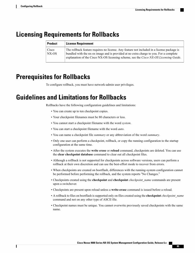
Licensing Requirements for RollbacksLicense RequirementProduct
The rollback feature requires no license. Any feature not included in a license package isbundled with the nx-os image and is provided at no extra charge to you. For a completeexplanation of the Cisco NX-OS licensing scheme, see the Cisco NX-OS Licensing Guide.
CiscoNX-OS
Prerequisites for RollbacksTo configure rollback, you must have network-admin user privileges.
Guidelines and Limitations for RollbacksRollbacks have the following configuration guidelines and limitations:
• You can create up to ten checkpoint copies.
• Your checkpoint filenames must be 80 characters or less.
• You cannot start a checkpoint filename with the word system.
• You can start a checkpoint filename with the word auto.
• You can name a checkpoint file summary or any abbreviation of the word summary.
• Only one user can perform a checkpoint, rollback, or copy the running configuration to the startupconfiguration at the same time.
• After the system executes the write erase or reload command, checkpoints are deleted. You can usethe clear checkpoint database command to clear out all checkpoint files.
• Although a rollback is not supported for checkpoints across software versions, users can perform arollback at their own discretion and can use the best-effort mode to recover from errors.
•When checkpoints are created on bootflash, differences with the running-system configuration cannotbe performed before performing the rollback, and the system reports “No Changes.”
• Checkpoints created using the checkpoint and checkpoint checkpoint_name commands are presentupon a switchover.
• Checkpoints are present upon reload unless a write-erase command is issued before a reload.
• A rollback to files on bootflash is supported only on files created using the checkpoint checkpoint_namecommand and not on any other type of ASCII file.
• Checkpoint names must be unique. You cannot overwrite previously saved checkpoints with the samename.
Cisco Nexus 9000 Series NX-OS System Management Configuration Guide, Release 6.x 85
Configuring RollbackLicensing Requirements for Rollbacks
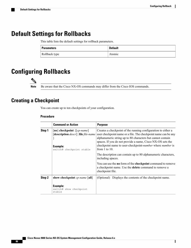
Default Settings for RollbacksThis table lists the default settings for rollback parameters.
DefaultParameters
AtomicRollback type
Configuring Rollbacks
Be aware that the Cisco NX-OS commands may differ from the Cisco IOS commands.Note
Creating a CheckpointYou can create up to ten checkpoints of your configuration.
Procedure
PurposeCommand or Action
Creates a checkpoint of the running configuration to either auser checkpoint name or a file. The checkpoint name can be any
[no] checkpoint {[cp-name][description descr] | file file-name}
Step 1
alphanumeric string up to 80 characters but cannot containspaces. If you do not provide a name, Cisco NX-OS sets the
Example:switch# checkpoint stable
checkpoint name to user-checkpoint-number where number isfrom 1 to 10.
The description can contain up to 80 alphanumeric characters,including spaces.
You can use the no form of the checkpoint command to removea checkpoint name. Use the delete command to remove acheckpoint file.
(Optional) Displays the contents of the checkpoint name.show checkpoint cp-name [all]
Example:switch# show checkpointstable
Step 2
Cisco Nexus 9000 Series NX-OS System Management Configuration Guide, Release 6.x86
Configuring RollbackDefault Settings for Rollbacks

Implementing a RollbackYou can implement a rollback to a checkpoint name or file. Before you implement a rollback, you can viewthe differences between source and destination checkpoints that reference current or saved configurations.
If you make a configuration change during an atomic rollback, the rollback will fail.Note
Procedure
PurposeCommand or Action
Displays the differences between the source anddestination checkpoint selections.
show diff rollback-patch {checkpointsrc-cp-name | running-config | startup-config| file source-file} {checkpoint dest-cp-name |running-config | startup-config | file dest-file}
Step 1
Example:switch# show diff rollback-patchcheckpoint stable running-config
Creates a rollback to the specified checkpoint nameor file. You can implement the following rollbacktypes:
rollback running-config {checkpoint cp-name| file cp-file} [atomic | best-effort |stop-at-first-failure]
Step 2
Example:switch# rollback running-configcheckpoint stable
• atomic—Implement a rollback only if noerrors occur.
• best-effort—Implement a rollback and skipany errors.
• stop-at-first-failure—Implement a rollbackthat stops if an error occurs.
The default is atomic.
This example shows how to implement a rollbackto a user checkpoint name.
Verifying the Rollback ConfigurationTo display the rollback configuration information, perform one of the following tasks:
PurposeCommand
Displays the contents of the checkpoint name.show checkpoint name [all]
Cisco Nexus 9000 Series NX-OS System Management Configuration Guide, Release 6.x 87
Configuring RollbackImplementing a Rollback

PurposeCommand
Displays the contents of all checkpoints. You can limitthe displayed checkpoints to user or system generatedcheckpoints.
show checkpoint all [user | system]
Displays a list of all checkpoints. You can limit thedisplayed checkpoints to user or system generatedcheckpoints.
show checkpoint summary [user | system]
Displays the differences between the source anddestination checkpoint selections.
show diff rollback-patch {checkpointsrc-cp-name | running-config | startup-config |file source-file} {checkpoint dest-cp-name |running-config | startup-config | file dest-file}
Displays the contents of the rollback log.show rollback log [exec | verify]
Use the clear checkpoint database command to delete all checkpoint files.
Configuration Example for RollbackThis example shows how to create a checkpoint file and then implements a best-effort rollback to a usercheckpoint name:checkpoint stablerollback running-config checkpoint stable best-effort
Additional References
Related DocumentsDocument TitleRelated Topic
Cisco Nexus 9000 Series NX-OS FundamentalsConfiguration Guide
Configuration files
Cisco Nexus 9000 Series NX-OS System Management Configuration Guide, Release 6.x88
Configuring RollbackConfiguration Example for Rollback

C H A P T E R 8Configuring Session Manager
This chapter describes how to configure Session Manager on Cisco NX-OS devices.
This chapter contains the following sections:
• About Session Manager, page 89
• Licensing Requirements for Session Manager, page 90
• Prerequisites for Session Manager, page 90
• Guidelines and Limitations for Session Manager, page 90
• Configuring Session Manager, page 90
• Verifying the Session Manager Configuration, page 93
• Configuration Example for Session Manager, page 93
• Additional References, page 94
About Session ManagerSessionManager allows you to implement your configuration changes in batchmode. SessionManager worksin the following phases:
• Configuration session—Creates a list of commands that you want to implement in Session Managermode.
• Validation—Provides a basic semantic check on your configuration. Cisco NX-OS returns an error ifthe semantic check fails on any part of the configuration.
• Verification—Verifies the configuration as a whole, based on the existing hardware and softwareconfiguration and resources. Cisco NX-OS returns an error if the configuration does not pass thisverification phase.
• Commit—Cisco NX-OS verifies the complete configuration and applies the changes to the device. If afailure occurs, Cisco NX-OS reverts to the original configuration.
• Abort—Discards the configuration changes before implementation.
Cisco Nexus 9000 Series NX-OS System Management Configuration Guide, Release 6.x 89

You can optionally end a configuration session without committing the changes. You can also save aconfiguration session.
High AvailabilitySession Manager sessions remain available after a supervisor switchover. Sessions are not persistent acrossa software reload.
Licensing Requirements for Session ManagerLicense RequirementProduct
SessionManager requires no license. Any feature not included in a license package is bundledwith the nx-os image and is provided at no extra charge to you. For a complete explanationof the Cisco NX-OS licensing scheme, see the Cisco NX-OS Licensing Guide.
CiscoNX-OS
Prerequisites for Session ManagerMake sure that you have the privilege level required to support the Session Manager commands that you planto use.
Guidelines and Limitations for Session ManagerSession Manager has the following configuration guidelines and limitations:
• Session Manager supports only access control list (ACL) and quality of service (QoS) features.
• You can create up to 32 configuration sessions.
• You can configure a maximum of 20,000 commands across all sessions.
• You cannot simultaneously execute configuration commands in more then one configuration session orconfiguration terminal mode. Parallel configurations (for example, one configuration session and oneconfiguration terminal) might cause validation or verification failures in the configuration session.
• If an interface reloads while you are configuring that interface in a configuration session, SessionManagermay accept the commands even though the interface is not present in the device at that time.
Configuring Session Manager
Be aware that the Cisco NX-OS commands might differ from Cisco IOS commands.Note
Cisco Nexus 9000 Series NX-OS System Management Configuration Guide, Release 6.x90
Configuring Session ManagerHigh Availability

Creating a SessionYou can create up to 32 configuration sessions.
Procedure
PurposeCommand or Action
Creates a configuration session and enters sessionconfiguration mode. The name can be anyalphanumeric string.
configure session name
Example:switch# configure session myACLsswitch(config-s)#
Step 1
Displays the contents of the session.
(Optional)Displays the contents of the session.
show configuration session [name]
Example:switch(config-s)# show configurationsession myACLs
Step 2
(Optional)Saves the session to a file. The location can be inbootflash:, slot0:, or volatile:.
save location
Example:switch(config-s)# savebootflash:sessions/myACLs
Step 3
Configuring ACLs in a SessionYou can configure ACLs within a configuration session.
Procedure
PurposeCommand or Action
Creates a configuration session and enterssession configuration mode. The name canbe any alphanumeric string.
configure session name
Example:switch# configure session myaclsswitch(config-s)#
Step 1
Creates an ACL and enters a configurationmode for that ACL.
ip access-list name
Example:switch(config-s)# ip access-list acl1switch(config-s-acl)#
Step 2
(Optional)Adds a permit statement to the ACL.
permit protocol source destination
Example:switch(config-s-acl)# permit tcp any any
Step 3
Cisco Nexus 9000 Series NX-OS System Management Configuration Guide, Release 6.x 91
Configuring Session ManagerCreating a Session
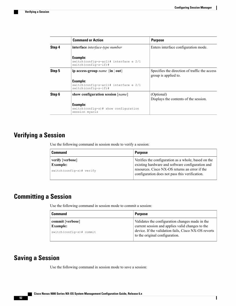
PurposeCommand or Action
Enters interface configuration mode.interface interface-type number
Example:switch(config-s-acl)# interface e 2/1switch(config-s-if)#
Step 4
Specifies the direction of traffic the accessgroup is applied to.
ip access-group name {in | out}
Example:switch(config-s-acl)# interface e 2/1switch(config-s-if)#
Step 5
(Optional)Displays the contents of the session.
show configuration session [name]
Example:switch(config-s)# show configurationsession myacls
Step 6
Verifying a SessionUse the following command in session mode to verify a session:
PurposeCommand
Verifies the configuration as a whole, based on theexisting hardware and software configuration andresources. Cisco NX-OS returns an error if theconfiguration does not pass this verification.
verify [verbose]Example:switch(config-s)# verify
Committing a SessionUse the following command in session mode to commit a session:
PurposeCommand
Validates the configuration changes made in thecurrent session and applies valid changes to thedevice. If the validation fails, Cisco NX-OS revertsto the original configuration.
commit [verbose]Example:switch(config-s)# commit
Saving a SessionUse the following command in session mode to save a session:
Cisco Nexus 9000 Series NX-OS System Management Configuration Guide, Release 6.x92
Configuring Session ManagerVerifying a Session

PurposeCommand
(Optional) Saves the session to a file. The locationcan be in bootflash:, slot0:, or volatile:.
save locationExample:switch(config-s)# savebootflash:sessions/myACLs
Discarding a SessionUse the following command in session mode to discard a session:
PurposeCommand
Discards the configuration session without applyingthe changes.
abortExample:switch(config-s)# abortswitch#
Verifying the Session Manager ConfigurationTo display the Session Manager configuration information, perform one of the following tasks:
PurposeCommand
Displays the contents of the configuration session.show configuration session [name]
Displays the status of the configuration session.show configuration session status [name]
Displays a summary of all the configuration sessions.show configuration session summary
Configuration Example for Session ManagerThis example shows how to create and commit an ACL configuration using Session Manager:switch# configure session ACL_tcp_inConfig Session started, Session ID is 1Enter configuration commands, one per line. End with CNTL/Z.switch(config-s)# ip access-list ACL1switch(config-s-acl)# permit tcp any anyswitch(config)# interface e 7/1switch(config-if)# ip access-group ACL1 inswitch(config-if)# exitswitch(config)# exitswitch# config session ACL_tcp_inConfig Session started, Session ID is 1Enter configuration commands, one per line. End with CNTL/Z.switch(config-s)# verifyVerification Successfulswitch(config-s)# commitCommit Successful
Cisco Nexus 9000 Series NX-OS System Management Configuration Guide, Release 6.x 93
Configuring Session ManagerDiscarding a Session

switch#
Additional References
Related DocumentsDocument TitleRelated Topic
Cisco Nexus 9000 Series NX-OS FundamentalsConfiguration Guide
Configuration files
Cisco Nexus 9000 Series NX-OS System Management Configuration Guide, Release 6.x94
Configuring Session ManagerAdditional References

C H A P T E R 9Configuring the Scheduler
This chapter describes how to configure the scheduler on Cisco NX-OS devices.
This chapter includes the following sections:
• About the Scheduler, page 95
• Licensing Requirements for the Scheduler, page 96
• Prerequisites for the Scheduler, page 96
• Guidelines and Limitations for the Scheduler, page 97
• Default Settings for the Scheduler, page 97
• Configuring the Scheduler, page 97
• Verifying the Scheduler Configuration, page 103
• Configuration Examples for the Scheduler, page 104
About the SchedulerThe scheduler allows you to define and set a timetable for maintenance activities such as the following:
• Quality of service (QoS) policy changes
• Data backup
• Saving a configuration
Jobs consist of a single command or multiple commands that define routine activities. Jobs can be scheduledone time or at periodic intervals.
The scheduler defines a job and its timetable as follows:
• Job—A routine task or tasks defined as a command list and completed according to a specified schedule.
• Schedule—The timetable for completing a job. You can assign multiple jobs to a schedule. A scheduleis defined as either periodic or one-time only:
◦Periodic mode—A recurring interval that continues until you delete the job. You can configurethe following types of intervals:
Cisco Nexus 9000 Series NX-OS System Management Configuration Guide, Release 6.x 95

Daily—A job is completed once a day.◦
◦Weekly—A job is completed once a week.
◦Monthly—A job is completed once a month.
◦Delta—A job begins at the specified start time and then at specified intervals(days:hours:minutes).
◦One-time mode—A job is completed only once at a specified time.
Remote User AuthenticationBefore starting a job, the scheduler authenticates the user who created the job. Since user credentials from aremote authentication are not retained long enough to support a scheduled job, you need to locally configurethe authentication passwords for users who create jobs. These passwords are part of the scheduler configurationand are not considered a locally configured user.
Before starting the job, the scheduler validates the local password against the password from the remoteauthentication server.
LogsThe scheduler maintains a log file containing the job output. If the size of the job output is greater than thesize of the log file, the output is truncated.
High AvailabilityScheduled jobs remain available after a supervisor switchover or a software reload.
Licensing Requirements for the SchedulerLicense RequirementProduct
The scheduler requires no license. Any feature not included in a license package is bundledwith the nx-os image and is provided at no extra charge to you. For a complete explanationof the Cisco NX-OS licensing scheme, see the Cisco NX-OS Licensing Guide.
CiscoNX-OS
Prerequisites for the SchedulerThe scheduler has the following prerequisites:
• You must enable any conditional features before you can configure those features in a job.
• You must have a valid license installed for any licensed features that you want to configure in the job.
Cisco Nexus 9000 Series NX-OS System Management Configuration Guide, Release 6.x96
Configuring the SchedulerRemote User Authentication

• You must have network-admin user privileges to configure a scheduled job.
Guidelines and Limitations for the SchedulerThe scheduler has the following configuration guidelines and limitations:
• The scheduler can fail if it encounters one of the following while performing a job:
• Verify that you have configured the time. The scheduler does not apply a default timetable. If you createa schedule and assign jobs and do not configure the time, the job is not started.
•While defining a job, verify that no interactive or disruptive commands (for example, copy bootflash:file ftp: URI, write erase, and other similar commands) are specified because the job is started andconducted noninteractively.
Default Settings for the SchedulerThis table lists the scheduler default settings.
DefaultParameters
DisabledScheduler state
16 KBLog file size
Configuring the Scheduler
Enabling or Disabling the SchedulerYou can enable the scheduler feature so that you can configure and schedule jobs, or you can disable thescheduler feature after it has been enabled.
Procedure
PurposeCommand or Action
Enters global configuration mode.configure terminal
Example:switch# configure terminalswitch(config)#
Step 1
Enables or disables the scheduler.[no] feature scheduler
Example:switch(config)# feature scheduler
Step 2
Cisco Nexus 9000 Series NX-OS System Management Configuration Guide, Release 6.x 97
Configuring the SchedulerGuidelines and Limitations for the Scheduler

PurposeCommand or Action
(Optional)Displays the scheduler configuration.
show scheduler config
Example:switch(config)# show scheduler configconfig terminal
Step 3
feature schedulerscheduler logfile size 16end
(Optional)Copies the running configuration to thestartup configuration.
copy running-config startup-config
Example:switch(config)# copy running-configstartup-config
Step 4
Defining the Scheduler Log File SizeYou can configure the log file size for capturing jobs, schedules, and job output.
Procedure
PurposeCommand or Action
Enters global configuration mode.configure terminal
Example:switch# configure terminalswitch(config)#
Step 1
Defines the scheduler log file size in kilobytes. Therange is from 16 to 1024. The default is 16.
scheduler logfile size value
Example:switch(config)# scheduler logfile size1024
Step 2
If the size of the job output is greater thanthe size of the log file, then the output istruncated.
Note
(Optional)Copies the running configuration to the startupconfiguration.
copy running-config startup-config
Example:switch(config)# copy running-configstartup-config
Step 3
Configuring Remote User AuthenticationYou can configure the scheduler to use remote authentication for users who want to configure and schedulejobs.
Cisco Nexus 9000 Series NX-OS System Management Configuration Guide, Release 6.x98
Configuring the SchedulerDefining the Scheduler Log File Size

Remote users must authenticate with their clear text password before creating and configuring jobs.Note
Remote user passwords are always shown in encrypted form in the output of the show running-configcommand. The encrypted option (7) in the command supports the ASCII device configuration.
Note
Procedure
PurposeCommand or Action
Enters global configuration mode.configure terminal
Example:switch# configure terminalswitch(config)#
Step 1
Configures a cleartext password for theuser who is currently logged in.
scheduler aaa-authentication password [0 | 7]password
Example:switch(config)# scheduler aaa-authenticationpassword X12y34Z56a
Step 2
Configures a cleartext password for aremote user.
scheduler aaa-authentication username namepassword [0 | 7] password
Example:switch(config)# scheduler aaa-authenticationusername newuser password Z98y76X54b
Step 3
(Optional)Displays the scheduler passwordinformation.
show running-config | include “scheduleraaa-authentication”
Example:switch(config)# show running-config | include“scheduler aaa-authentication”
Step 4
(Optional)Copies the running configuration to thestartup configuration.
copy running-config startup-config
Example:switch(config)# copy running-configstartup-config
Step 5
Defining a JobYou can define a job including the job name and the command sequence.
Cisco Nexus 9000 Series NX-OS System Management Configuration Guide, Release 6.x 99
Configuring the SchedulerDefining a Job
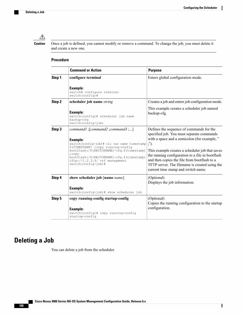
Once a job is defined, you cannot modify or remove a command. To change the job, you must delete itand create a new one.
Caution
Procedure
PurposeCommand or Action
Enters global configuration mode.configure terminal
Example:switch# configure terminalswitch(config)#
Step 1
Creates a job and enters job configurationmode.scheduler job name stringStep 2
Example:switch(config)# scheduler job namebackup-cfgswitch(config-job)
This example creates a scheduler job namedbackup-cfg.
Defines the sequence of commands for thespecified job. You must separate commands
command1 ;[command2 ;command3 ;...]
Example:switch(config-job)# cli var name timestamp$(TIMESTAMP) ;copy running-config
Step 3
with a space and a semicolon (for example, “;”).This example creates a scheduler job that savesthe running configuration to a file in bootflash
bootflash:/$(SWITCHNAME)-cfg.$(timestamp);copybootflash:/$(SWITCHNAME)-cfg.$(timestamp)
and then copies the file from bootflash to atftp://1.2.3.4/ vrf managementswitch(config-job)# TFTP server. The filename is created using the
current time stamp and switch name.
(Optional)Displays the job information.
show scheduler job [name name]
Example:switch(config-job)# show scheduler job
Step 4
(Optional)Copies the running configuration to the startupconfiguration.
copy running-config startup-config
Example:switch(config)# copy running-configstartup-config
Step 5
Deleting a JobYou can delete a job from the scheduler.
Cisco Nexus 9000 Series NX-OS System Management Configuration Guide, Release 6.x100
Configuring the SchedulerDeleting a Job

Procedure
PurposeCommand or Action
Enters global configuration mode.configure terminal
Example:switch# configure terminalswitch(config)#
Step 1
Deletes the specified job and allcommands defined within it.
no scheduler job name string
Example:switch(config)# no scheduler job nameconfigsaveswitch(config-job)
Step 2
(Optional)Displays the job information.
show scheduler job [name name]
Example:switch(config-job)# show scheduler job nameconfigsave
Step 3
(Optional)Copies the running configuration to thestartup configuration.
copy running-config startup-config
Example:switch(config)# copy running-configstartup-config
Step 4
Defining a TimetableYou can define a timetable in the scheduler to be used with one or more jobs.
If you do not specify the time for the time commands, the scheduler assumes the current time. For example,if the current time is March 24, 2013, 22:00 hours, jobs are started as follows:
• For the time start 23:00 repeat 4:00:00 command, the scheduler assumes a start time of March 24,2013, 23:00 hours.
• For the time daily 55 command, the scheduler assumes a start time every day at 22:55 hours.
• For the time weekly 23:00 command, the scheduler assumes a start time every Friday at 23:00 hours.
• For the time monthly 23:00 command, the scheduler assumes a start time on the 24th of every monthat 23:00 hours.
The scheduler will not begin the next occurrence of a job before the last one completes. For example, youhave scheduled a job to be completed at one-minute intervals beginning at 22:00; but the job requires twominutes to complete. The scheduler starts the first job at 22:00, completes it at 22:02, and then observesa one-minute interval before starting the next job at 22:03.
Note
Cisco Nexus 9000 Series NX-OS System Management Configuration Guide, Release 6.x 101
Configuring the SchedulerDefining a Timetable

Procedure
PurposeCommand or Action
Enters global configuration mode.configure terminal
Example:switch# configure terminalswitch(config)#
Step 1
Creates a new schedule and places you in scheduleconfiguration mode for that schedule.
scheduler schedule name string
Example:switch(config)# scheduler schedulename weekendbackupqosswitch(config-schedule)#
Step 2
Associates a job with this schedule. You can addmultiple jobs to a schedule.
job name string
Example:switch(config-schedule)# job nameoffpeakZoning
Step 3
Indicates the job starts every day at a designated timespecified as HH:MM.
time daily time
Example:switch(config-schedule)# time daily23:00
Step 4
Indicates that the job starts on a specified day of theweek.
time weekly [[dow:]HH:]MM
Example:switch(config-schedule)# time weeklySun:23:00
Step 5
Day of the week (dow) specified as one of thefollowing:
• An integer such as 1 = Sunday, 2 = Monday,and so on.
• An abbreviation such as Sun = Sunday.
The maximum length for the entire argument is 10.
Indicates the job starts on a specified day each month(dm). If you specify either 29, 30, or 31, the job isstarted on the last day of each month.
time monthly [[dm:]HH:]MM
Example:switch(config-schedule)# timemonthly 28:23:00
Step 6
Indicates the job starts periodically.time start {now repeat repeat-interval |delta-time [repeat repeat-interval]}
Step 7
The start-time format is[[[[yyyy:]mmm:]dd:]HH]:MM.
Example:switch(config-schedule)# time startnow repeat 48:00
• delta-time—Specifies the amount of time to waitafter the schedule is configured before startinga job.
• now—Specifies that the job starts now.
Cisco Nexus 9000 Series NX-OS System Management Configuration Guide, Release 6.x102
Configuring the SchedulerDefining a Timetable

PurposeCommand or Action
• repeat repeat-interval—Specifies the frequencyat which the job is repeated.
In this example, the job starts immediately and repeatsevery 48 hours.
(Optional)Displays the scheduler configuration.
show scheduler config
Example:switch(config)# show schedulerconfig
Step 8
(Optional)Copies the running configuration to the startupconfiguration.
copy running-config startup-config
Example:switch(config)# copy running-configstartup-config
Step 9
Clearing the Scheduler Log FileYou can clear the scheduler log file.
Procedure
PurposeCommand or Action
Enters global configuration mode.configure terminal
Example:switch# configure terminalswitch(config)#
Step 1
Clears the scheduler log file.clear scheduler logfile
Example:switch(config)# clear schedulerlogfile
Step 2
Verifying the Scheduler ConfigurationTo display the scheduler configuration information, perform one of the following tasks:
PurposeCommand
Displays the scheduler configuration.show scheduler config
Cisco Nexus 9000 Series NX-OS System Management Configuration Guide, Release 6.x 103
Configuring the SchedulerClearing the Scheduler Log File

PurposeCommand
Displays the jobs configured.show scheduler job [name string]
Displays the contents of the scheduler log file.show scheduler logfile
Displays the schedules configured.show scheduler schedule [name string]
Configuration Examples for the Scheduler
Creating a Scheduler JobThis example shows how to create a scheduler job that saves the running configuration to a file in bootflashand then copies the file from bootflash to a TFTP server (the filename is created using the current time stampand switch name):switch# configure terminalswitch(config)# scheduler job name backup-cfgswitch(config-job)# cli var name timestamp $(TIMESTAMP) ;copy running-configbootflash:/$(SWITCHNAME)-cfg.$(timestamp) ;copy bootflash:/$(SWITCHNAME)-cfg.$(timestamp)tftp://1.2.3.4/ vrf managementswitch(config-job)# endswitch(config)#
Scheduling a Scheduler JobThis example shows how to schedule a scheduler job called backup-cfg to run daily at 1 a.m.:switch# configure terminalswitch(config)# scheduler schedule name dailyswitch(config-if)# job name backup-cfgswitch(config-if)# time daily 1:00switch(config-if)# endswitch(config)#
Displaying the Job ScheduleThis example shows how to display the job schedule:switch# show scheduler scheduleSchedule Name : daily---------------------------User Name : adminSchedule Type : Run every day at 1 Hrs 00 MinsLast Execution Time : Fri Jan 2 1:00:00 2013Last Completion Time: Fri Jan 2 1:00:01 2013Execution count : 2-----------------------------------------------Job Name Last Execution Status-----------------------------------------------back-cfg Success (0)switch#
Cisco Nexus 9000 Series NX-OS System Management Configuration Guide, Release 6.x104
Configuring the SchedulerConfiguration Examples for the Scheduler

Displaying the Results of Running Scheduler JobsThis example shows how to display the results of scheduler jobs that have been executed by the scheduler:switch# show scheduler logfileJob Name : back-cfg Job Status: Failed (1)Schedule Name : daily User Name : adminCompletion time: Fri Jan 1 1:00:01 2013--------------------------------- Job Output ---------------------------------`cli var name timestamp 2013-01-01-01.00.00``copy running-config bootflash:/$(HOSTNAME)-cfg.$(timestamp)``copy bootflash:/switch-cfg.2013-01-01-01.00.00 tftp://1.2.3.4/ vrf management `copy: cannot access file '/bootflash/switch-cfg.2013-01-01-01.00.00'==============================================================================Job Name : back-cfg Job Status: Success (0)Schedule Name : daily User Name : adminCompletion time: Fri Jan 2 1:00:01 2013--------------------------------- Job Output ---------------------------------`cli var name timestamp 2013-01-02-01.00.00``copy running-config bootflash:/switch-cfg.2013-01-02-01.00.00``copy bootflash:/switch-cfg.2013--01-02-01.00.00 tftp://1.2.3.4/ vrf management `Connection to Server Established.[ ] 0.50KBTrying to connect to tftp server......[###### ] 24.50KBTFTP put operation was successful==============================================================================switch#
Cisco Nexus 9000 Series NX-OS System Management Configuration Guide, Release 6.x 105
Configuring the SchedulerDisplaying the Results of Running Scheduler Jobs

Cisco Nexus 9000 Series NX-OS System Management Configuration Guide, Release 6.x106
Configuring the SchedulerDisplaying the Results of Running Scheduler Jobs

C H A P T E R 10Configuring SNMP
This chapter describes how to configure the SNMP feature on Cisco NX-OS devices.
This chapter contains the following sections:
• About SNMP, page 107
• Licensing Requirements for SNMP, page 113
• Guidelines and Limitations for SNMP, page 113
• Default Settings for SNMP, page 113
• Configuring SNMP, page 114
• Verifying SNMP Configuration, page 135
• Configuration Examples for SNMP, page 135
• Additional References, page 137
About SNMPThe Simple Network Management Protocol (SNMP) is an application-layer protocol that provides a messageformat for communication between SNMP managers and agents. SNMP provides a standardized frameworkand a common language used for the monitoring and management of devices in a network.
SNMP Functional OverviewThe SNMP framework consists of three parts:
• An SNMP manager—The system used to control and monitor the activities of network devices usingSNMP.
• An SNMP agent—The software component within the managed device that maintains the data for thedevice and reports these data, as needed, to managing systems. The Cisco Nexus device supports theagent and MIB. To enable the SNMP agent, you must define the relationship between the manager andthe agent.
• A managed information base (MIB)—The collection of managed objects on the SNMP agent
Cisco Nexus 9000 Series NX-OS System Management Configuration Guide, Release 6.x 107

SNMP is defined in RFCs 3411 to 3418.
The device supports SNMPv1, SNMPv2c, and SNMPv3. Both SNMPv1 and SNMPv2c use a community-basedform of security.
Cisco NX-OS supports SNMP over IPv6.
SNMP NotificationsA key feature of SNMP is the ability to generate notifications from an SNMP agent. These notifications donot require that requests be sent from the SNMP manager. Notifications can indicate improper userauthentication, restarts, the closing of a connection, loss of connection to a neighbor router, or other significantevents.
Cisco NX-OS generates SNMP notifications as either traps or informs. A trap is an asynchronous,unacknowledged message sent from the agent to the SNMPmanagers listed in the host receiver table. Informsare asynchronous messages sent from the SNMP agent to the SNMP manager which the manager mustacknowledge receipt of.
Traps are less reliable than informs because the SNMP manager does not send any acknowledgment when itreceives a trap. The device cannot determine if the trap was received. An SNMP manager that receives aninform request acknowledges the message with an SNMP response protocol data unit (PDU). If the devicenever receives a response, it can send the inform request again.
You can configure Cisco NX-OS to send notifications to multiple host receivers.
The following table lists the SNMP traps that are enabled by default.
DescriptionTrap Type
: coldStartgeneric
: warmStartgeneric
: entity_mib_changeentity
: entity_module_status_changeentity
: entity_power_status_changeentity
: entity_module_insertedentity
: entity_module_removedentity
: entity_unrecognised_moduleentity
: entity_fan_status_changeentity
: entity_power_out_changeentity
: linkDownlink
: linkUplink
: extended-linkDownlink
: extended-linkUplink
: cieLinkDownlink
Cisco Nexus 9000 Series NX-OS System Management Configuration Guide, Release 6.x108
Configuring SNMPSNMP Notifications
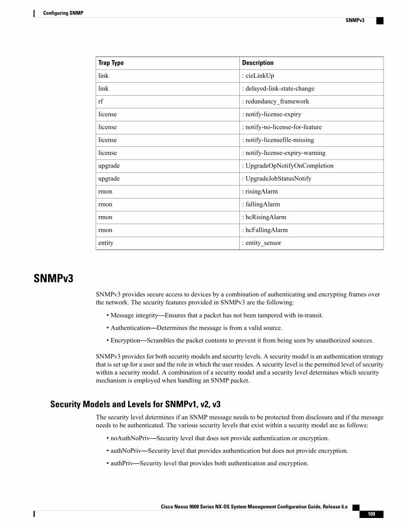
DescriptionTrap Type
: cieLinkUplink
: delayed-link-state-changelink
: redundancy_frameworkrf
: notify-license-expirylicense
: notify-no-license-for-featurelicense
: notify-licensefile-missinglicense
: notify-license-expiry-warninglicense
: UpgradeOpNotifyOnCompletionupgrade
: UpgradeJobStatusNotifyupgrade
: risingAlarmrmon
: fallingAlarmrmon
: hcRisingAlarmrmon
: hcFallingAlarmrmon
: entity_sensorentity
SNMPv3SNMPv3 provides secure access to devices by a combination of authenticating and encrypting frames overthe network. The security features provided in SNMPv3 are the following:
• Message integrity—Ensures that a packet has not been tampered with in-transit.
• Authentication—Determines the message is from a valid source.
• Encryption—Scrambles the packet contents to prevent it from being seen by unauthorized sources.
SNMPv3 provides for both security models and security levels. A security model is an authentication strategythat is set up for a user and the role in which the user resides. A security level is the permitted level of securitywithin a security model. A combination of a security model and a security level determines which securitymechanism is employed when handling an SNMP packet.
Security Models and Levels for SNMPv1, v2, v3The security level determines if an SNMP message needs to be protected from disclosure and if the messageneeds to be authenticated. The various security levels that exist within a security model are as follows:
• noAuthNoPriv—Security level that does not provide authentication or encryption.
• authNoPriv—Security level that provides authentication but does not provide encryption.
• authPriv—Security level that provides both authentication and encryption.
Cisco Nexus 9000 Series NX-OS System Management Configuration Guide, Release 6.x 109
Configuring SNMPSNMPv3

Three security models are available: SNMPv1, SNMPv2c, and SNMPv3. The security model combined withthe security level determine the security mechanism applied when the SNMP message is processed. Thefollowing table identifies what the combinations of security models and levels mean.
Table 9: SNMP Security Models and Levels
What HappensEncryptionAuthenticationLevelModel
Uses a communitystring match forauthentication.
NoCommunity stringnoAuthNoPrivv1
Uses a communitystring match forauthentication.
NoCommunity stringnoAuthNoPrivv2c
Uses a usernamematch forauthentication.
NoUsernamenoAuthNoPrivv3
Providesauthentication basedon the Hash-BasedMessageAuthenticationCode(HMAC) MessageDigest 5 (MD5)algorithm or theHMACSecureHashAlgorithm (SHA).
NoHMAC-MD5 orHMAC-SHA
authNoPrivv3
Providesauthentication basedon theHMAC-MD5or HMAC-SHAalgorithms. ProvidesData EncryptionStandard (DES)56-bit encryption inaddition toauthentication basedon the Cipher BlockChaining (CBC)DES (DES-56)standard.
DESHMAC-MD5 orHMAC-SHA
authPrivv3
Cisco Nexus 9000 Series NX-OS System Management Configuration Guide, Release 6.x110
Configuring SNMPSNMPv3

User-Based Security ModelThe SNMPv3 User-Based Security Model (USM) refers to SNMP message-level security and offers thefollowing services:
• Message integrity—Ensures that messages have not been altered or destroyed in an unauthorized mannerand that data sequences have not been altered to an extent greater than can occur nonmaliciously.
• Message origin authentication—Ensures that the claimed identity of the user on whose behalf receiveddata was originated is confirmed.
• Message confidentiality—Ensures that information is not made available or disclosed to unauthorizedindividuals, entities, or processes.
SNMPv3 authorizes management operations only by configured users and encrypts SNMP messages.
Cisco NX-OS uses two authentication protocols for SNMPv3:
• HMAC-MD5-96 authentication protocol
• HMAC-SHA-96 authentication protocol
Cisco NX-OS uses Advanced Encryption Standard (AES) as one of the privacy protocols for SNMPv3messageencryption and conforms with RFC 3826.
The priv option offers a choice of DES or 128-bit AES encryption for SNMP security encryption. The privoption and the aes-128 token indicate that this privacy password is for generating a 128-bit AES key. TheAES priv password can have a minimum of eight characters. If the passphrases are specified in clear text, youcan specify a maximum of 64 case-sensitive, alphanumeric characters. If you use the localized key, you canspecify a maximum of 130 characters.
For an SNMPv3 operation using the external AAA server, you must use AES for the privacy protocol inthe user configuration on the external AAA server.
Note
CLI and SNMP User SynchronizationSNMPv3 user management can be centralized at the Access Authentication and Accounting (AAA) serverlevel. This centralized user management allows the SNMP agent in Cisco NX-OS to leverage the userauthentication service of the AAA server. Once user authentication is verified, the SNMP PDUs are processedfurther. Additionally, the AAA server is also used to store user group names. SNMP uses the group names toapply the access/role policy that is locally available in the switch.
Any configuration changes made to the user group, role, or password results in database synchronization forboth SNMP and AAA.
Cisco NX-OS synchronizes the user configuration in the following ways:
• The authentication passphrase specified in the snmp-server user command becomes the password forthe CLI user.
• The password specified in the username command becomes the authentication and privacy passphrasesfor the SNMP user.
Cisco Nexus 9000 Series NX-OS System Management Configuration Guide, Release 6.x 111
Configuring SNMPSNMPv3

• If you create or delete a user using either SNMP or the CLI, the user is created or deleted for both SNMPand the CLI.
• User-role mapping changes are synchronized in SNMP and the CLI.
• Role changes (deletions or modifications) from the CLI are synchronized to SNMP.
When you configure a passphrase/password in localized key/encrypted format, Cisco NX-OS does notsynchronize the user information (passwords, roles, and so on).
Cisco NX-OS holds the synchronized user configuration for 60 minutes by default.
Note
Group-Based SNMP Access
Because group is a standard SNMP term used industry-wide, we refer to roles as groups in this SNMPsection.
Note
SNMP access rights are organized by groups. Each group in SNMP is similar to a role through the CLI. Eachgroup is defined with read access or read-write access.
You can begin communicating with the agent once your username is created, your roles are set up by youradministrator, and you are added to the roles.
SNMP and Embedded Event ManagerThe Embedded Event Manager (EEM) feature monitors events, including SNMP MIB objects, and triggersan action based on these events. One of the actions could be to send an SNMP notification. EEM sends thecEventMgrPolicyEvent of CISCO-EMBEDDED-EVENT-MGR-MIB as the SNMP notification.
Multiple Instance SupportA device can support multiple instances of a logical network entity, such as protocol instances or virtualrouting and forwarding (VRF) instances.Most existingMIBs cannot distinguish between these multiple logicalnetwork entities. For example, the original OSPF-MIB assumes a single protocol instance on a device, butyou can now configure multiple OSPF instances on a device.
SNMPv3 uses contexts to distinguish between these multiple instances. An SNMP context is a collection ofmanagement information that you can access through the SNMP agent. A device can support multiple contextsfor different logical network entities. An SNMP context allows the SNMP manager to access one of themultiple instances of a MIB module supported on the device for the different logical network entities.
Cisco NX-OS supports the CISCO-CONTEXT-MAPPING-MIB to map between SNMP contexts and logicalnetwork entities. You can associate an SNMP context to a VRF, protocol instance, or topology.
SNMPv3 supports contexts with the contextName field of the SNMPv3 PDU. You can map this contextNamefield to a particular protocol instance or VRF.
Cisco Nexus 9000 Series NX-OS System Management Configuration Guide, Release 6.x112
Configuring SNMPSNMP and Embedded Event Manager

For SNMPv2c, you can map the SNMP community to a context using the snmpCommunityContextNameMIB object in the SNMP-COMMUNITY-MIB (RFC 3584). You can then map thissnmpCommunityContextName to a particular protocol instance or VRF using theCISCO-CONTEXT-MAPPING-MIB or the CLI.
High Availability for SNMPCisco NX-OS supports stateless restarts for SNMP. After a reboot or supervisor switchover, Cisco NX-OSapplies the running configuration.
Virtualization Support for SNMPCisco NX-OS supports one instance of the SNMP. SNMP supports multiple MIB module instances and mapsthem to logical network entities.
SNMP is also VRF aware. You can configure SNMP to use a particular VRF to reach the SNMP notificationhost receiver. You can also configure SNMP to filter notifications to an SNMP host receiver based on theVRF where the notification occurred.
Licensing Requirements for SNMPLicense RequirementProduct
SNMP requires no license. Any feature not included in a license package is bundled with thenx-os image and is provided at no extra charge to you. For a complete explanation of theCisco NX-OS licensing scheme, see the Cisco NX-OS Licensing Guide.
CiscoNX-OS
Guidelines and Limitations for SNMPSNMP has the following configuration guidelines and limitations:
• Access control list (ACLs) can be applied only to local SNMPv3 users configured on the switch. ACLscannot be applied to remote SNMPv3 users stored on Authentication, Authorization, and Accounting(AAA) servers.
• Cisco NX-OS supports read-only access to some SNMP MIBs. See the Cisco NX-OS MIB support listat the following URL for more information: ftp://ftp.cisco.com/pub/mibs/supportlists/nexus9000/Nexus9000MIBSupportList.html
Default Settings for SNMPThe following table lists the default settings for SNMP parameters.
Cisco Nexus 9000 Series NX-OS System Management Configuration Guide, Release 6.x 113
Configuring SNMPHigh Availability for SNMP

DefaultParameters
EnabledLicense notifications
Configuring SNMP
Be aware that the Cisco NX-OS commands for this feature may differ from those commands used in CiscoIOS.
Note
Configuring SNMP UsersYou can configure a user for SNMP.
Procedure
PurposeCommand or Action
Enters global configuration mode.configure terminal
Example:switch# configure terminalswitch(config)#
Step 1
Configures an SNMP user with authentication andprivacy parameters. The passphrase can be any
snmp-server user name [auth {md5 | sha}passphrase [auto] [priv [aes-128]passphrase] [engineID id] [localizedkey]]
Step 2
case-sensitive, alphanumeric string up to 64characters. If you use the localizedkey keyword,
Example:switch(config)# snmp-server user Adminauth sha abcd1234 priv abcdefgh
the passphrase can be any case-sensitive,alphanumeric string up to 130 characters.
The engineID format is a 12-digit, colon-separateddecimal number.
(Optional)Displays information about one or more SNMPusers.
show snmp user
Example:switch(config) # show snmp user
Step 3
(Optional)Copies the running configuration to the startupconfiguration.
copy running-config startup-config
Example:switch(config)# copy running-configstartup-config
Step 4
Cisco Nexus 9000 Series NX-OS System Management Configuration Guide, Release 6.x114
Configuring SNMPConfiguring SNMP

Enforcing SNMP Message EncryptionYou can configure SNMP to require authentication or encryption for incoming requests. By default, the SNMPagent accepts SNMPv3 messages without authentication and encryption. When you enforce privacy, CiscoNX-OS responds with an authorization error for any SNMPv3 PDU request using a security level parameterof either noAuthNoPriv or authNoPriv.
Procedure
PurposeCommand or Action
Enters global configuration mode.configure terminal
Example:switch# configure terminalswitch(config)#
Step 1
Enforces SNMP message encryption forthis user.
snmp-server user name enforcePriv
Example:switch(config)# snmp-server user AdminenforcePriv
Step 2
Enforces SNMP message encryption forall users.
snmp-server globalEnforcePriv
Example:switch(config)# snmp-serverglobalEnforcePriv
Step 3
(Optional)Copies the running configuration to thestartup configuration.
copy running-config startup-config
Example:switch(config)# copy running-configstartup-config
Step 4
Assigning SNMPv3 Users to Multiple RolesAfter you configure an SNMP user, you can assign multiple roles for the user.
Only users belonging to a network-admin role can assign roles to other users.Note
Cisco Nexus 9000 Series NX-OS System Management Configuration Guide, Release 6.x 115
Configuring SNMPEnforcing SNMP Message Encryption

Procedure
PurposeCommand or Action
Enters global configuration mode.configure terminal
Example:switch# configure terminalswitch(config)#
Step 1
Associates this SNMP user with theconfigured user role.
snmp-server user name group
Example:switch(config)# snmp-server user Adminsuperuser
Step 2
(Optional)Copies the running configuration to thestartup configuration.
copy running-config startup-config
Example:switch(config)# copy running-configstartup-config
Step 3
Creating SNMP CommunitiesYou can create SNMP communities for SNMPv1 or SNMPv2c.
Procedure
PurposeCommand or Action
Enters global configuration mode.configure terminal
Example:switch# configure terminalswitch(config)#
Step 1
Creates an SNMP community string.snmp-server community name {group group | ro |rw}
Step 2
Example:switch(config)# snmp-server community publicro
(Optional)Copies the running configuration to thestartup configuration.
copy running-config startup-config
Example:switch(config)# copy running-configstartup-config
Step 3
Cisco Nexus 9000 Series NX-OS System Management Configuration Guide, Release 6.x116
Configuring SNMPCreating SNMP Communities

Filtering SNMP RequestsYou can assign an access control list (ACL) to an SNMPv3 user or SNMPv3 community to filter incomingSNMP requests. If the assigned ACL allows the incoming request packet, SNMP processes the request. If theACL denies the request, SNMP drops the request and sends a system message.
Create the ACL with the following parameters:
• Source IP address
• Destination IP address
• Source port
• Destination port
• Protocol (UDP or TCP)
Procedure
PurposeCommand or Action
Enters global configuration mode.configure terminal
Example:switch# configure terminalswitch(config)#
Step 1
Assigns an IPv4 or IPv6 ACL to anSNMPv3 user to filter SNMP requests.
snmp-server user name [use-ipv4acl ipv4acl-name][use-ipv6acl ipv6acl-name]
Step 2
Example:switch(config)# snmp-server community publicuse-ipv4acl myacl
The AAA server must support thecreation of SNMPv3 users.
Note
Assigns an IPv4 or IPv6 ACL to anSNMPv3 community to filter SNMPrequests.
snmp-server community name [use-ipv4aclipv4acl-name] [use-ipv6acl ipv6acl-name]
Example:switch(config)# snmp-server community publicuse-ipv4acl myacl
Step 3
(Optional)Copies the running configuration to thestartup configuration.
copy running-config startup-config
Example:switch(config)# copy running-configstartup-config
Step 4
Configuring SNMP Notification ReceiversYou can configure Cisco NX-OS to generate SNMP notifications to multiple host receivers.
Cisco Nexus 9000 Series NX-OS System Management Configuration Guide, Release 6.x 117
Configuring SNMPFiltering SNMP Requests

Procedure
PurposeCommand or Action
Enters global configuration mode.configure terminal
Example:switch# configure terminalswitch(config)#
Step 1
Configures a host receiver for SNMPv1 traps. Theip-address can be an IPv4 or IPv6 address. The
snmp-server host ip-address traps version1 community [udp_port number]
Step 2
community can be any alphanumeric string up to 255Example:switch(config)# snmp-server host192.0.2.1 traps version 1 public
characters. The UDP port number range is from 0 to65535.
Configures a host receiver for SNMPv2c traps orinforms. The ip-address can be an IPv4 or IPv6
snmp-server host ip-address {traps |informs} version 2c community [udp_portnumber]
Step 3
address. The community can be any alphanumericstring up to 255 characters. The UDP port numberrange is from 0 to 65535.Example:
switch(config)# snmp-server host192.0.2.1 informs version 2c public
Configures a host receiver for SNMPv3 traps orinforms. The ip-address can be an IPv4 or IPv6
snmp-server host ip-address {traps |informs} version 3 {auth | noauth | priv}username [udp_port number]
Step 4
address. The username can be any alphanumeric stringup to 255 characters. The UDP port number range isfrom 0 to 65535.
The SNMP manager must know the usercredentials (authKey/PrivKey) based on theSNMP engine ID of the Cisco NX-OS deviceto authenticate and decrypt the SNMPv3messages.
NoteExample:switch(config)# snmp-server host192.0.2.1 informs version 3 auth NMS
(Optional)Copies the running configuration to the startupconfiguration.
copy running-config startup-config
Example:switch(config)# copy running-configstartup-config
Step 5
Configuring a Source Interface for SNMP NotificationsYou can configure SNMP to use the IP address of an interface as the source IP address for notifications. Whena notification is generated, its source IP address is based on the IP address of this configured interface.
You can configure a source interface as follows:
• All notifications sent to all SNMP notification receivers.
• All notifications sent to a specific SNMP notification receiver. This configuration overrides the globalsource interface configuration.
Cisco Nexus 9000 Series NX-OS System Management Configuration Guide, Release 6.x118
Configuring SNMPConfiguring a Source Interface for SNMP Notifications

Configuring the source interface IP address for outgoing trap packets does not guarantee that the devicewill use the same interface to send the trap. The source interface IP address defines the source addressinside of the SNMP trap, and the connection is opened with the address of the egress interface as source.
Note
Procedure
PurposeCommand or Action
Enters global configuration mode.configure terminal
Example:switch# configure terminalswitch(config)#
Step 1
Configures a host receiver for SNMPv2c traps orinforms. The ip-address can be an IPv4 or IPv6
snmp-server host ip-address source-interfaceif-type if-number [udp_port number]
Step 2
address. Use ? to determine the supported interfaceExample:switch(config)# snmp-server host192.0.2.1 source-interface ethernet 2/1
types. The UDP port number range is from 0 to65535.
This configuration overrides the global sourceinterface configuration.
Configures a source interface for sending outSNMPv2c traps or informs. Use ? to determinethe supported interface types.
snmp-server source-interface {traps |informs} if-type if-number
Example:switch(config)# snmp-serversource-interface traps ethernet 2/1
Step 3
Displays information about configured sourceinterfaces.
show snmp source-interface
Example:switch(config)# show snmpsource-interface
Step 4
Configuring the Notification Target UserYou must configure a notification target user on the device to send SNMPv3 inform notifications to anotification host receiver.
Cisco NX-OS uses the credentials of the notification target user to encrypt the SNMPv3 inform notificationmessages to the configured notification host receiver.
For authenticating and decrypting the received inform PDU, the notification host receiver should havethe same user credentials as configured in Cisco NX-OS to authenticate and decrypt the informs.
Note
Cisco Nexus 9000 Series NX-OS System Management Configuration Guide, Release 6.x 119
Configuring SNMPConfiguring the Notification Target User

Procedure
PurposeCommand or Action
Enters global configuration mode.configure terminal
Example:switch# configure terminalswitch(config)#
Step 1
Configures the notification target user withthe specified engine ID for the notification
snmp-server user name [auth {md5 | sha}passphrase [auto] [priv [aes-128] passphrase][engineID id]
Step 2
host receiver. The engine ID format is a12-digit colon-separated decimal number.
Example:switch(config)# snmp-server user NMS authsha abcd1234 priv abcdefgh engineID00:00:00:63:00:01:00:10:20:15:10:03
(Optional)Copies the running configuration to thestartup configuration.
copy running-config startup-config
Example:switch(config)# copy running-configstartup-config
Step 3
Configuring SNMP Notification Receivers with VRFsSNMP adds entries into the cExtSnmpTargetVrfTable of the CISCO-SNMP-TARGET-EXT-MIB when youconfigure the VRF reachability and filtering options for an SNMP notification receiver.
You must configure the host before configuring the VRF reachability or filtering options.Note
You can configure Cisco NX-OS to use a configured VRF to reach the host receiver or to filter notificationsbased on the VRF in which the notification occurred.
Procedure
PurposeCommand or Action
Enters global configuration mode.configure terminal
Example:switch# configure terminalswitch(config)#
Step 1
Configures SNMP to use the selected VRF to communicatewith the host receiver. The ip-address can be an IPv4 or IPv6
[no] snmp-server host ip-addressuse-vrf vrf-name [udp_portnumber]
Step 2
address. The VRF name can be any alphanumeric string up to255 characters. The UDP port number range is from 0 to 65535.
Cisco Nexus 9000 Series NX-OS System Management Configuration Guide, Release 6.x120
Configuring SNMPConfiguring SNMP Notification Receivers with VRFs

PurposeCommand or Action
Example:switch(config)# snmp-serverhost 192.0.2.1 use-vrf Blue
This command adds an entry into the ExtSnmpTargetVrfTableof the CISCO-SNMP-TARGET-EXT-MB.
The no form of this command removes the VRF reachabilityinformation for the configured host and removes the entry fromthe ExtSnmpTargetVrfTable of theCISCO-SNMP-TARGET-EXT-MB.
This command does not remove the hostconfiguration.
Note
Filters notifications to the notification host receiver based onthe configured VRF. The ip-address can be an IPv4 or IPv6
[no] snmp-server host ip-addressfilter-vrf vrf-name [udp_portnumber]
Step 3
address. The VRF name can be any alphanumeric string up to255 characters. The UDP port number range is from 0 to 65535.
Example:switch(config)# snmp-serverhost 192.0.2.1 filter-vrf Red
This command adds an entry into the ExtSnmpTargetVrfTableof the CISCO-SNMP-TARGET-EXT-MB.
The no form of this command removes the VRF filterinformation for the configured host and removes the entry fromthe ExtSnmpTargetVrfTable of theCISCO-SNMP-TARGET-EXT-MB.
This command does not remove the hostconfiguration.
Note
(Optional)Copies the running configuration to the startup configuration.
copy running-configstartup-config
Example:switch(config)# copyrunning-config startup-config
Step 4
Configuring SNMP to Send Traps Using an Inband PortYou can configure SNMP to send traps using an inband port. To do so, you must configure the source interface(at the global or host level) and the VRF used to send the traps.
Procedure
PurposeCommand or Action
Enters global configuration mode.configure terminal
Example:switch# configure terminalswitch(config)#
Step 1
Cisco Nexus 9000 Series NX-OS System Management Configuration Guide, Release 6.x 121
Configuring SNMPConfiguring SNMP to Send Traps Using an Inband Port

PurposeCommand or Action
Globally configures a source interface for sending outSNMP traps. Use ? to determine the supported interfacetypes.
snmp-server source-interface trapsif-type if-number
Example:switch(config)# snmp-serversource-interface traps ethernet1/2
Step 2
You can configure the source interface at the global levelor at a host level. When the source interface is configuredglobally, any new host configuration uses the globalconfiguration to send the traps.
To configure a source interface at the host level,use the snmp-server host ip-addresssource-interface if-type if-number command.
Note
(Optional)Displays information about configured source interfaces.
show snmp source-interface
Example:switch(config)# show snmpsource-interface
Step 3
Configures SNMP to use the selected VRF to communicatewith the host receiver. The ip-address can be an IPv4 or
snmp-server host ip-address use-vrfvrf-name [udp_port number]
Step 4
IPv6 address. The VRF name can be any alphanumericExample:switch(config)# snmp-server host171.71.48.164 use-vrf default
string up to 255 characters. The UDP port number rangeis from 0 to 65535. This command adds an entry into theExtSnmpTargetVrfTable of theCISCO-SNMP-TARGET-EXT-MB.
By default, SNMP sends the traps using themanagement VRF. If you do not want to use themanagement VRF, you must use this commandto specify the desired VRF.
Note
(Optional)Displays information about configured SNMP hosts.
show snmp host
Example:switch(config)# show snmp host
Step 5
(Optional)Copies the running configuration to the startupconfiguration.
copy running-config startup-config
Example:switch(config)# copyrunning-config startup-config
Step 6
Enabling SNMP NotificationsYou can enable or disable notifications. If you do not specify a notification name, Cisco NX-OS enables allnotifications.
Cisco Nexus 9000 Series NX-OS System Management Configuration Guide, Release 6.x122
Configuring SNMPEnabling SNMP Notifications

The snmp-server enable traps command enables both traps and informs, depending on the configurednotification host receivers.
Note
The following table lists the commands that enable the notifications for Cisco NX-OS MIBs.
Table 10: Enabling SNMP Notifications
Related CommandsMIB
snmp-server enable trapsAll notifications
snmp-server enable traps aaa
snmp-server enable traps aaa server-state-change
CISCO-AAA-SERVER-MIB
snmp-server enable traps bgpCISCO-BGP4-MIB
snmp-server enable traps bridge
snmp-server enable traps bridge newroot
snmp-server enable traps bridge topologychange
CISCO-STP-BRIDGE-MIB
snmp-server enable traps callhome
snmp-server enable traps callhome event-notify
snmp-server enable traps callhome smtp-send-fail
CISCO-CALLHOME-MIB
snmp-server enable traps config
snmp-server enable traps configccmCLIRunningConfigChanged
CISCO-CONFIG-MAN-MIB
snmp-server enable traps eigrp [tag]CISCO-EIGRP-MIB
Cisco Nexus 9000 Series NX-OS System Management Configuration Guide, Release 6.x 123
Configuring SNMPEnabling SNMP Notifications

Related CommandsMIB
snmp-server enable traps entity
snmp-server enable traps entityentity_fan_status_change
snmp-server enable traps entity entity_mib_change
snmp-server enable traps entityentity_module_inserted
snmp-server enable traps entityentity_module_removed
snmp-server enable traps entityentity_module_status_change
snmp-server enable traps entityentity_power_out_change
snmp-server enable traps entityentity_power_status_change
snmp-server enable traps entityentity_unrecognised_module
ENTITY-MIB, CISCO-ENTITY-SENSOR-MIB
snmp-server enable traps feature-control
snmp-server enable traps feature-controlFeatureOpStatusChange
CISCO-FEATURE-CONTROL-MIB
snmp-server enable traps hsrp
snmp-server enable traps hsrp state-change
CISCO-HSRP-MIB
snmp-server enable traps license
snmp-server enable traps licensenotify-license-expiry
snmp-server enable traps licensenotify-license-expiry-warning
snmp-server enable traps licensenotify-licensefile-missing
snmp-server enable traps licensenotify-no-license-for-feature
CISCO-LICENSE-MGR-MIB
Cisco Nexus 9000 Series NX-OS System Management Configuration Guide, Release 6.x124
Configuring SNMPEnabling SNMP Notifications

Related CommandsMIB
snmp-server enable traps link
snmp-server enable traps linkIETF-extended-linkDown
snmp-server enable traps linkIETF-extended-linkUp
snmp-server enable traps linkcisco-extended-linkDown
snmp-server enable traps linkcisco-extended-linkUp
snmp-server enable traps link linkDown
snmp-server enable traps link Up
IF-MIB
snmp-server enable traps ospf [tag]
snmp-server enable traps ospf lsa
snmp-server enable traps ospf rate-limit rate
OSPF-MIB, OSPF-TRAP-MIB
snmp-server enable traps rf
snmp-server enable traps rfredundancy_framework
CISCO-RF-MIB
snmp-server enable traps rmon
snmp-server enable traps rmon fallingAlarm
snmp-server enable traps rmon hcFallingAlarm
snmp-server enable traps rmon hcRisingAlarm
snmp-server enable traps rmon risingAlarm
CISCO-RMON-MIB
snmp-server enable traps snmp
snmp-server enable traps snmp authentication
SNMPv2-MIB
snmp-server enable traps stpx
snmp-server enable traps stpx inconsistency
snmp-server enable traps stpx loop-inconsistency
snmp-server enable traps stpx root-inconsistency
CISCO-STPX-MIB
snmp-server enable traps sysmgr
snmp-server enable traps sysmgrcseFailSwCoreNotifyExtended
CISCO-SYSTEM-EXT-MIB
Cisco Nexus 9000 Series NX-OS System Management Configuration Guide, Release 6.x 125
Configuring SNMPEnabling SNMP Notifications

Related CommandsMIB
snmp-server enable traps upgrade
snmp-server enable traps upgradeUpgradeJobStatusNotify
snmp-server enable traps upgradeUpgradeOpNotifyOnCompletion
UPGRADE-MIB
snmp-server enable traps vtp
snmp-server enable traps vtp notifs
snmp-server enable traps vtp vlancreate
snmp-server enable traps vtp vlandelete
VTP-MIB
storm-control action trapCISCO-PORT-STORM-CONTROL-MIB
Use the following commands in the configuration mode shown to enable the specified notification:
PurposeCommand
Enables all SNMP notifications.snmp-server enable trapsExample:switch(config)# snmp-server enable traps
Enables the AAA SNMP notifications. Optionally,enables the following specific notifications:
• server-state-change—Enables AAA serverstate-change notifications.
snmp-server enable traps aaa [server-state-change]Example:switch(config)# snmp-server enable traps aaa
Enables Border Gateway Protocol (BGP) SNMPnotifications.
snmp-server enable traps bgpExample:switch(config)# snmp-server enable traps bgp
Enables STP bridge SNMP notifications. Optionally,enables the following specific notifications:
• newroot—Enables STP new root bridgenotifications.
• topologychange—Enables STP bridgetopology-change notifications.
snmp-server enable traps bridge [newroot][topologychange]Example:switch(config)# snmp-server enable trapsbridge
Cisco Nexus 9000 Series NX-OS System Management Configuration Guide, Release 6.x126
Configuring SNMPEnabling SNMP Notifications

PurposeCommand
Enables Call Home notifications. Optionally, enablesthe following specific notifications:
• event-notify—Enables Call Home externalevent notifications.
• smtp-send-fail—Enables SimpleMail TransferProtocol (SMTP) message send failnotifications.
snmp-server enable traps callhome [event-notify][smtp-send-fail]Example:switch(config)# snmp-server enable trapscallhome
Enables SNMP notifications for configurationchanges.
• ccmCLIRunningConfigChanged—EnablesSNMP notifications for configuration changesin the running or startup configuration.
snmp-server enable traps config[ccmCLIRunningConfigChanged]Example:switch(config)# snmp-server enable trapsconfig
Enables CISCO-EIGRP-MIB SNMP notifications.snmp-server enable traps eigrp [tag]Example:switch(config)# snmp-server enable trapseigrp
Enables ENTITY-MIB SNMP notifications.Optionally, enables the following specificnotifications:
• entity_fan_status_change—Enables entity fanstatus-change notifications.
• entity_mib_change—Enables entity MIBchange notifications.
• entity_module_inserted—Enables entitymodule inserted notifications.
• entity_module_removed—Enables entitymodule removed notifications.
• entity_module_status_change—Enables entitymodule status-change notifications.
• entity_power_out_change—Enables entitypower-out change notifications.
• entity_power_status_change—Enables entitypower status-change notifications.
• entity_unrecognised_module—Enables entityunrecognized module notifications.
snmp-server enable traps entity[entity_fan_status_change] [entity_mib_change][entity_module_inserted][entity_module_removed][entity_module_status_change][entity_power_out_change][entity_power_status_change][entity_unrecognised_module]Example:switch(config)# snmp-server enable trapsentity
Cisco Nexus 9000 Series NX-OS System Management Configuration Guide, Release 6.x 127
Configuring SNMPEnabling SNMP Notifications

PurposeCommand
Enables feature-control SNMP notifications.Optionally, enables the following specificnotifications:
• FeatureOpStatusChange—Enables featureoperation status-change notifications.
snmp-server enable traps feature-control[FeatureOpStatusChange]Example:switch(config)# snmp-server enable trapsfeature-control
Enables CISCO-HSRP-MIB SNMP notifications.Optionally, enables the following specificnotifications:
• state-change—Enables HSRP state-changenotifications.
snmp-server enable traps hsrp [state-change]Example:switch(config)# snmp-server enable traps hsrp
Enables ENTITY-MIB SNMP notifications.Optionally, enables the following specificnotifications:
• notify-license-expiry—Enables license expirynotifications.
• notify-license-expiry-warning—Enableslicense expiry warning notifications.
• notify-licensefile-missing—Enables licensefile-missing notifications.
• notify-no-license-for-feature—Enablesno-license-installed-for-feature notifications.
snmp-server enable traps license[notify-license-expiry][notify-license-expiry-warning][notify-licensefile-missing][notify-no-license-for-feature]Example:switch(config)# snmp-server enable trapslicense
Enables IF-MIB link notifications. Optionally, enablesthe following specific notifications:
• IETF-extended-linkDown—Enables InternetEngineering Task Force (IETF) extended linkstate down notifications.
• IETF-extended-linkUp—Enables InternetEngineering Task Force (IETF) extended linkstate up notifications.
• cisco-extended-linkDown—Enables Ciscoextended link state down notifications.
• cisco-extended-linkUp—Enables Ciscoextended link state up notifications.
• linkDown—Enables IETF link state downnotifications.
• linkUp—Enables IETF link state upnotifications.
snmp-server enable traps link[IETF-extended-linkDown][IETF-extended-linkUp][cisco-extended-linkDown] [cisco-extended-linkUp][linkDown] [linkUp]Example:switch(config)# snmp-server enable traps link
Cisco Nexus 9000 Series NX-OS System Management Configuration Guide, Release 6.x128
Configuring SNMPEnabling SNMP Notifications

PurposeCommand
Enables Open Shortest Path First (OSPF)notifications. Optionally, enables the followingspecific notifications:
• lsa—Enables OSPF link state advertisement(LSA) notifications.
snmp-server enable traps ospf [tag] [lsa]Example:switch(config)# snmp-server enable traps ospf
Enables redundancy framework (RF) SNMPnotifications. Optionally, enables the followingspecific notifications:
• redundancy-framework—Enables RFsupervisor switchover MIB notifications.
snmp-server enable traps rf[redundancy-framework]Example:switch(config)# snmp-server enable traps rf
Enables remote monitoring (RMON) SNMPnotifications. Optionally, enables the followingspecific notifications:
• fallingAlarm—Enables RMON falling alarmnotifications.
• hcFallingAlarm—Enables RMONhigh-capacity falling alarm notifications.
• hcRisingAlarm—Enables RMONhigh-capacity rising alarm notifications.
• risingAlarm—Enables RMON rising alarmnotifications.
snmp-server enable traps rmon [fallingAlarm][hcFallingAlarm] [hcRisingAlarm] [risingAlarm]Example:switch(config)# snmp-server enable traps rmon
Enables general SNMP notifications. Optionally,enables the following specific notifications:
• authentication—Enables SNMP authenticationnotifications.
snmp-server enable traps snmp [authentication]Example:switch(config)# snmp-server enable traps snmp
Enables remote monitoring (RMON) SNMPnotifications. Optionally, enables the followingspecific notifications:
• inconsistency—Enables SNMP STPX MIBinconsistency update notifications.
• loop-inconsistency—Enables SNMP STPXMIB loop-inconsistency update notifications.
• root-inconsistency—Enables SNMP STPXMIB root-inconsistency update notifications.
snmp-server enable traps stpx [inconsistency][loop-inconsistency] [root-inconsistency]Example:switch(config)# snmp-server enable traps stpx
Cisco Nexus 9000 Series NX-OS System Management Configuration Guide, Release 6.x 129
Configuring SNMPEnabling SNMP Notifications

PurposeCommand
Enables software change notifications. Optionally,enables the following specific notifications:
• cseFailSwCoreNotifyExtended—Enablessoftware core notifications.
snmp-server enable traps sysmgr[cseFailSwCoreNotifyExtended]Example:switch(config)# snmp-server enable trapssysmgr
Enables upgrade notifications. Optionally, enablesthe following specific notifications:
• UpgradeJobStatusNotify—Enables upgradejob status notifications.
• UpgradeOpNotifyOnCompletion—Enablesupgrade global status notifications.
snmp-server enable traps upgrade[UpgradeJobStatusNotify][UpgradeOpNotifyOnCompletion]Example:switch(config)# snmp-server enable trapsupgrade
Enables VTP notifications. Optionally, enables thefollowing specific notifications:
• notifs—Enables VTP notifications.
• vlancreate—Enables VLAN creationnotifications.
• vlandelete—Enables VLAN deletionnotifications.
snmp-server enable traps vtp [notifs] [vlancreate][vlandelete]Example:switch(config)# snmp-server enable traps vtp
Enables traffic storm control notifications when thetraffic storm control limit is reached.
storm-control action trapExample:switch(config-if)# storm-control action trap
Disabling Link Notifications on an InterfaceYou can disable linkUp and linkDown notifications on an individual interface. You can use this limitnotifications on flapping interface (an interface that transitions between up and down repeatedly).
Procedure
PurposeCommand or Action
Enters global configuration mode.configure terminal
Example:switch# configure terminalswitch(config)#
Step 1
Cisco Nexus 9000 Series NX-OS System Management Configuration Guide, Release 6.x130
Configuring SNMPDisabling Link Notifications on an Interface

PurposeCommand or Action
Disables SNMP link-state traps for theinterface. This command is enabled by default.
interface type slot/port
Example:switch(config)# interface ethernet 2/2
Step 2
Disables SNMP link-state traps for theinterface. This command is enabled by default.
no snmp trap link-status
Example:switch(config-if)# no snmp traplink-status
Step 3
(Optional)Copies the running configuration to the startupconfiguration.
copy running-config startup-config
Example:switch(config-if)# copy running-configstartup-config
Step 4
Displaying SNMP ifIndex for an InterfaceThe SNMP ifIndex is used across multiple SNMP MIBs to link related interface information.
Procedure
PurposeCommand or Action
Displays the persistent SNMP ifIndex value from theIF-MIB for all interfaces. Optionally, use the |
show interface snmp-ifindex
Example:switch# show interface snmp-ifindex| grep -i Eth12/1Eth12/1 441974784 (0x1a580000)
Step 1
keyword and the grep keyword to search for aparticular interface in the output.
Enabling a One-Time Authentication for SNMP over TCPYou can enable a one-time authentication for SNMP over a TCP session.
Procedure
PurposeCommand or Action
Enters global configuration mode.configure terminal
Example:switch# configure terminalswitch(config)#
Step 1
Cisco Nexus 9000 Series NX-OS System Management Configuration Guide, Release 6.x 131
Configuring SNMPDisplaying SNMP ifIndex for an Interface

PurposeCommand or Action
Enables a one-time authentication for SNMPover a TCP session. The default is disabled.
snmp-server tcp-session [auth]
Example:switch(config)# snmp-server tcp-session
Step 2
(Optional)Copies the running configuration to thestartup configuration.
copy running-config startup-config
Example:switch(config)# copy running-configstartup-config
Step 3
Assigning SNMP Device Contact and Location InformationYou can assign the device contact information, which is limited to 32 characters (without spaces) and thedevice location.
Procedure
PurposeCommand or Action
Enters global configuration mode.configure terminal
Example:switch# configure terminalswitch(config)#
Step 1
Configures sysContact, which is the SNMPcontact name.
snmp-server contact name
Example:switch(config)# snmp-server contact Admin
Step 2
Configures sysLocation, which is the SNMPlocation.
snmp-server location name
Example:switch(config)# snmp-server locationLab-7
Step 3
(Optional)Displays information about one or moredestination profiles.
show snmp
Example:switch(config)# show snmp
Step 4
(Optional)Copies the running configuration to thestartup configuration.
copy running-config startup-config
Example:switch(config)# copy running-configstartup-config
Step 5
Cisco Nexus 9000 Series NX-OS System Management Configuration Guide, Release 6.x132
Configuring SNMPAssigning SNMP Device Contact and Location Information

Configuring the Context to Network Entity MappingYou can configure an SNMP context to map to a logical network entity, such as a protocol instance or VRF.
Before You Begin
Determine the logical network entity instance. For more information on VRFs and protocol instances, see theCisco Nexus 9000 Series NX-OSUnicast Routing Configuration Guide or theCisco Nexus 9000 Series NX-OSMulticast Routing Configuration Guide.
Procedure
PurposeCommand or Action
Enters global configuration mode.configure terminal
Example:switch# configure terminalswitch(config)#
Step 1
Maps an SNMP context to a protocol instance, VRF,or topology. The names can be any alphanumericstring up to 32 characters.
[no] snmp-server context context-name[instance instance-name] [vrf vrf-name][topology topology-name]
Step 2
Example:switch(config)# snmp-server contextpublic1 vrf red
The no option deletes themapping between an SNMPcontext and a protocol instance, VRF, or topology.
Do not enter an instance, VRF, or topologyto delete a context mapping. If you use theinstance, VRF, or topology keywords, youconfigure a mapping between the contextand a zero-length string.
Note
(Optional)Maps an SNMPv2c community to an SNMP context.The names can be any alphanumeric string up to 32characters.
snmp-server mib community-mapcommunity-name context context-name
Example:switch(config)# snmp-server mibcommunity-map public context public1
Step 3
(Optional)Displays information about one or more SNMPcontexts.
show snmp context
Example:switch(config)# show snmp context
Step 4
(Optional)Copies the running configuration to the startupconfiguration.
copy running-config startup-config
Example:switch(config)# copy running-configstartup-config
Step 5
Cisco Nexus 9000 Series NX-OS System Management Configuration Guide, Release 6.x 133
Configuring SNMPConfiguring the Context to Network Entity Mapping

Disabling SNMPYou can disable SNMP on the device.
Procedure
PurposeCommand or Action
Enters global configuration mode.configure terminal
Example:switch# configure terminalswitch(config)#
Step 1
Disables SNMP. SNMP is enabled bydefault.
no snmp-server protocol enable
Example:switch(config)# no snmp-server protocolenable
Step 2
Modifying the AAA Synchronization TimeYou can modify how long Cisco NX-OS holds the synchronized user configuration.
Procedure
PurposeCommand or Action
Enters global configuration mode.configure terminal
Example:switch# configure terminalswitch(config)#
Step 1
Configures how long the AAA synchronizeduser configuration stays in the local cache. The
snmp-server aaa-user cache-timeout seconds
Example:switch(config)# snmp-server aaa-usercache-timeout 1200
Step 2
range is from 1 to 86400 seconds. The defaultis 3600.
(Optional)Copies the running configuration to the startupconfiguration.
copy running-config startup-config
Example:switch(config)# copy running-configstartup-config
Step 3
Cisco Nexus 9000 Series NX-OS System Management Configuration Guide, Release 6.x134
Configuring SNMPDisabling SNMP

Verifying SNMP ConfigurationTo display SNMP configuration information, perform one of the following tasks:
PurposeCommand
Displays the SNMP ifIndex valuefor all interfaces (from IF-MIB).
show interface snmp-ifindex
Displays the SNMP runningconfiguration.
show running-config snmp [all]
Displays the SNMP status.show snmp
Displays the SNMP communitystrings.
show snmp community
Displays the SNMP contextmapping.
show snmp context
Displays the SNMP engineID.show snmp engineID
Displays SNMP roles.show snmp group
Displays information aboutconfigured SNMP hosts.
show snmp host
Displays SNMP sessions.show snmp session
Displays information aboutconfigured source interfaces.
show snmp source-interface
Displays the SNMP notificationsenabled or disabled.
show snmp trap
Displays SNMPv3 users.show snmp user
Configuration Examples for SNMPThis example shows how to configure Cisco NX-OS to send the Cisco linkUp or Down notifications to onenotification host receiver using the Blue VRF and defines two SNMP users, Admin and NMS:configure terminalsnmp-server contact [email protected] user Admin auth sha abcd1234 priv abcdefghsnmp-server user NMS auth sha abcd1234 priv abcdefgh engineID00:00:00:63:00:01:00:22:32:15:10:03snmp-server host 192.0.2.1 informs version 3 auth NMSsnmp-server host 192.0.2.1 use-vrf Blue
Cisco Nexus 9000 Series NX-OS System Management Configuration Guide, Release 6.x 135
Configuring SNMPVerifying SNMP Configuration

snmp-server enable traps link cisco
This example shows how to configure SNMP to send traps using an inband port configured at the host level:switch# configure terminalEnter configuration commands, one per line. End with CNTL/Z.switch(config)# snmp-server host 171.71.48.164 version 2c publicswitch(config)# snmp-server host 171.71.48.164 source-interface ethernet 1/2switch(config)# show snmp host-------------------------------------------------------------------Host Port Version Level Type SecName-------------------------------------------------------------------171.71.48.164 162 v2c noauth trap publicSource interface: Ethernet 1/2-------------------------------------------------------------------switch(config)# snmp-server host 171.71.48.164 use-vrf defaultswitch(config)# show snmp host-------------------------------------------------------------------Host Port Version Level Type SecName-------------------------------------------------------------------171.71.48.164 162 v2c noauth trap publicUse VRF: defaultSource interface: Ethernet 1/2-------------------------------------------------------------------
This example shows how to configure SNMP to send traps using a globally configured inband port:switch# configure terminalEnter configuration commands, one per line. End with CNTL/Z.switch(config)# snmp-server source-interface traps ethernet 1/2switch(config)# show snmp source-interface-------------------------------------------------------------------Notification source-interface-------------------------------------------------------------------trap Ethernet1/2inform --------------------------------------------------------------------switch(config)# snmp-server host 171.71.48.164 use_vrf defaultswitch(config)# show snmp host-------------------------------------------------------------------Host Port Version Level Type SecName-------------------------------------------------------------------171.71.48.164 162 v2c noauth trap publicUse VRF: defaultSource interface: Ethernet 1/2-------------------------------------------------------------------
This example shows how to map VRF red to the SNMPv2c public community string:switch# configure terminalEnter configuration commands, one per line. End with CNTL/Z.switch(config)# vrf context redswitch(config-vrf)# exitswitch(config)# snmp-server context public1 vrf redswitch(config)# snmp-server mib community-map public context public1
This example shows how to map OSPF instance Enterprise to the same SNMPv2c public community string:switch# configure terminalEnter configuration commands, one per line. End with CNTL/Z.switch(config)# feature ospfswitch(config)# router ospf Enterpriseswitch(config-router)# exitswitch(config)# snmp-server context public1 instance Enterpriseswitch(config)# snmp-server mib community-map public context public1
Cisco Nexus 9000 Series NX-OS System Management Configuration Guide, Release 6.x136
Configuring SNMPConfiguration Examples for SNMP

Additional References
Related DocumentsDocument TitleRelated Topic
Cisco Nexus 9000 Series NX-OS SecurityConfiguration Guide
IP ACLs and AAA
Cisco Nexus 7000 Series and 9000 Series NX-OSMIBQuick Reference
MIBs
RFCsTitleRFC
User-based Security Model (USM) for Version 3 ofthe Simple NetworkManagement Protocol (SNMPv3)
RFC 3414
View-based Access Control Model (VACM) for theSimple Network Management Protocol (SNMP)
RFC 3415
MIBsMIBs LinkMIBs
To locate and download supported MIBs, go to thefollowing URL:
ftp://ftp.cisco.com/pub/mibs/supportlists/nexus9000/Nexus9000MIBSupportList.html
MIBs related to SNMP
Cisco Nexus 9000 Series NX-OS System Management Configuration Guide, Release 6.x 137
Configuring SNMPAdditional References

Cisco Nexus 9000 Series NX-OS System Management Configuration Guide, Release 6.x138
Configuring SNMPMIBs
C H A P T E R 11Configuring RMON
This chapter describes how to configure the remote monitoring (RMON) feature on Cisco NX-OS devices.
This chapter contains the following sections:
• About RMON, page 139
• Licensing Requirements for RMON, page 141
• Guidelines and Limitations for RMON, page 141
• Default Settings for RMON, page 141
• Configuring RMON, page 142
• Verifying the RMON Configuration, page 144
• Configuration Examples for RMON, page 144
• Additional References, page 144
About RMONRMON is a Simple NetworkManagement Protocol (SNMP) Internet Engineering Task Force (IETF) standardmonitoring specification that allows various network agents and console systems to exchange networkmonitoring data. Cisco NX-OS supports RMON alarms, events, and logs to monitor Cisco NX-OS devices.
An RMON alarm monitors a specific management information base (MIB) object for a specified interval,triggers an alarm at a specified threshold value (threshold), and resets the alarm at another threshold value.You can use alarms with RMON events to generate a log entry or an SNMP notification when the RMONalarm triggers.
RMON is enabled by default, but no alarms are configured in CiscoNX-OS. You can configure RMON alarmsby using the CLI or an SNMP-compatible network management station.
Cisco Nexus 9000 Series NX-OS System Management Configuration Guide, Release 6.x 139
RMON AlarmsYou can set an alarm on any MIB object that resolves into an SNMP INTEGER type. The specified objectmust be an existing SNMP MIB object in standard dot notation (for example, 1.3.6.1.2.1.2.2.1.14 representsifInOctets.14).
When you create an alarm, you specify the following parameters:
• MIB object to monitor.
• Sampling interval—The interval that the device uses to collect a sample value of the MIB object.
• Sample type—Absolute samples take the current snapshot of the MIB object value. Delta samples taketwo consecutive samples and calculate the difference between them.
• Rising threshold—The value at which the device triggers a rising alarm or resets a falling alarm.
• Falling threshold—The value at which the device triggers a falling alarm or resets a rising alarm.
• Events—The action that the device takes when an alarm (rising or falling) triggers.
Use the hcalarms option to set an alarm on a 64-bit integer MIB object.Note
For example, you can set a delta type rising alarm on an error counter MIB object. If the error counter deltaexceeds this value, you can trigger an event that sends an SNMP notification and logs the rising alarm event.This rising alarm will not occur again until the delta sample for the error counter drops below the fallingthreshold.
The falling threshold must be less than the rising threshold.Note
RMON EventsYou can associate a particular event to each RMON alarm. RMON supports the following event types:
• SNMP notification—Sends an SNMP risingAlarm or fallingAlarm notification when the associatedalarm triggers.
• Log—Adds an entry in the RMON log table when the associated alarm triggers.
• Both—Sends an SNMP notification and adds an entry in the RMON log table when the associated alarmtriggers.
You can specify a different even for a falling alarm and a rising alarm.
You may choose to use the default RMON events template configuration or you can delete these entriesand create new RMON events. Until you create RMON alarm configurations, no alarms will be triggeredby these configurations.
Note
Cisco Nexus 9000 Series NX-OS System Management Configuration Guide, Release 6.x140
Configuring RMONRMON Alarms

High Availability for RMONCisco NX-OS supports stateless restarts for RMON. After a reboot or supervisor switchover, Cisco NX-OSapplies the running configuration.
Virtualization Support for RMONCisco NX-OS supports one instance of RMON.
RMON is virtual routing and forwarding (VRF) aware. You can configure RMON to use a particular VRF toreach the RMON SMTP server.
Licensing Requirements for RMONLicense RequirementProduct
RMON requires no license. Any feature not included in a license package is bundled withthe nx-os image and is provided at no extra charge to you. For a complete explanation of theCisco NX-OS licensing scheme, see the Cisco NX-OS Licensing Guide.
CiscoNX-OS
Guidelines and Limitations for RMONRMON has the following configuration guidelines and limitations:
• You must configure an SNMP user and a notification receiver to use the SNMP notification event type.
• You can configure an RMON alarm only on a MIB object that resolves to an integer.
•When you configure an RMON alarm, the object identifier must be complete with its index so that itrefers to only one object. For example, 1.3.6.1.2.1.2.2.1.14 corresponds to cpmCPUTotal5minRev, and.1 corresponds to index cpmCPUTotalIndex, which creates object identifier 1.3.6.1.2.1.2.2.1.14.1.
Default Settings for RMONThe following table lists the default settings for RMON parameters.
DefaultParameters
EnabledRMON
None configuredAlarms
Cisco Nexus 9000 Series NX-OS System Management Configuration Guide, Release 6.x 141
Configuring RMONHigh Availability for RMON

Configuring RMON
Be aware that the Cisco NX-OS commands for this feature may differ from those commands used in CiscoIOS.
Note
Configuring RMON AlarmsYou can configure RMON alarms on any integer-based SNMP MIB object.
You can optionally specify the following parameters:
• The event number to trigger if the rising or falling threshold exceeds the specified limit.
• The owner of the alarm.
Ensure you have configured an SNMP user and enabled SNMP notifications.
Before You Begin
Make sure that you have configured an SNMP user and enabled SNMP notifications.
Procedure
PurposeCommand or Action
Enters global configuration mode.configure terminal
Example:switch# configure terminalswitch(config)#
Step 1
Creates an RMON alarm. The value rangeis from –2147483647 to 2147483647. The
rmon alarm index mib-object sample-interval{absolute | delta} rising-threshold value [event-index]falling-threshold value [event-index] [owner name]
Step 2
owner name can be any alphanumericstring.
Example:switch(config)# rmon alarm 201.3.6.1.2.1.2.2.1.14.1 2900 deltarising-threshold 1500 1 falling-threshold 0owner test
Creates an RMON high-capacity alarm.The value range is from –2147483647 to
rmon hcalarm index mib-object sample-interval{absolute | delta} rising-threshold-high valuerising-threshold-low value [event-index]
Step 3
2147483647. The owner name can be anyalphanumeric string.falling-threshold-high value falling-threshold-low
value [event-index] [owner name] [storagetype type] The storage type range is from 1 to 5.
Example:switch(config)# rmon alarm 201.3.6.1.2.1.2.2.1.14.16777216 2900 deltarising-threshold-high 15 rising-threshold-low
Cisco Nexus 9000 Series NX-OS System Management Configuration Guide, Release 6.x142
Configuring RMONConfiguring RMON

PurposeCommand or Action
151 falling-threshold-high 0falling-threshold-low 0 owner test
(Optional)Displays information about RMONalarmsor high-capacity alarms.
show rmon {alarms | hcalarms}
Example:switch(config)# show rmon alarms
Step 4
(Optional)Copies the running configuration to thestartup configuration.
copy running-config startup-config
Example:switch(config)# copy running-configstartup-config
Step 5
Configuring RMON EventsYou can configure RMON events to associate with RMON alarms. You can reuse the same event withmultipleRMON alarms.
Before You Begin
Make sure you have configured an SNMP user and enabled SNMP notifications.
Procedure
PurposeCommand or Action
Enters global configuration mode.configure terminal
Example:switch# configure terminalswitch(config)#
Step 1
Configures an RMON event. The descriptionstring, trap string, and owner name can beany alphanumeric string.
rmon event index [description string] [log] [trapstring] [owner name]
Example:switch(config)# rmon event 1 trap trap1
Step 2
(Optional)Displays information about RMON events.
show rmon events
Example:switch(config)# show rmon events
Step 3
(Optional)Copies the running configuration to thestartup configuration.
copy running-config startup-config
Example:switch(config)# copy running-configstartup-config
Step 4
Cisco Nexus 9000 Series NX-OS System Management Configuration Guide, Release 6.x 143
Configuring RMONConfiguring RMON Events

Verifying the RMON ConfigurationTo display RMON configuration information, perform one of the following tasks:
PurposeCommand
Displays information about RMON alarms.show rmon alarms
Displays information about RMON events.show rmon events
Displays information about RMON high-capacityalarms.
show rmon hcalarms
Displays information about RMON logs.show rmon logs
Configuration Examples for RMONThis example shows how to create a delta rising alarm on ifInOctets.14 and associates a notification eventwith this alarm:configure terminalrmon alarm 20 1.3.6.1.2.1.2.2.1.14.1 2900 delta rising-threshold 1500 1 falling-threshold0 owner testrmon event 1 trap trap1
Additional References
MIBsMIBs LinkMIBs
To locate and download supported MIBs, go to thefollowing URL:
ftp://ftp.cisco.com/pub/mibs/supportlists/nexus9000/Nexus9000MIBSupportList.html
MIBs related to RMON
Cisco Nexus 9000 Series NX-OS System Management Configuration Guide, Release 6.x144
Configuring RMONVerifying the RMON Configuration

C H A P T E R 12Configuring Online Diagnostics
This chapter describes how to configure the generic online diagnostics (GOLD) feature on Cisco NX-OSdevices.
This chapter contains the following sections:
• About Online Diagnostics, page 145
• Licensing Requirements for Online Diagnostics, page 148
• Guidelines and Limitations for Online Diagnostics, page 148
• Default Settings for Online Diagnostics, page 148
• Configuring Online Diagnostics, page 149
• Verifying the Online Diagnostics Configuration, page 153
• Configuration Examples for Online Diagnostics, page 153
About Online DiagnosticsWith online diagnostics, you can test and verify the hardware functionality of the device while the device isconnected to a live network.
The online diagnostics contain tests that check different hardware components and verify the data path andcontrol signals. Disruptive online diagnostic tests (such as the disruptive loopback test) and nondisruptiveonline diagnostic tests (such as the ASIC register check) run during bootup, line module online insertion andremoval (OIR), and system reset. The nondisruptive online diagnostic tests run as part of the backgroundhealth monitoring, and you can run these tests on demand.
Online diagnostics are categorized as bootup, runtime or health-monitoring diagnostics, and on-demanddiagnostics. Bootup diagnostics run during bootup, health-monitoring tests run in the background, andon-demand diagnostics run once or at user-designated intervals when the device is connected to a live network.
Cisco Nexus 9000 Series NX-OS System Management Configuration Guide, Release 6.x 145

Bootup DiagnosticsBootup diagnostics run during bootup and detect faulty hardware before Cisco NX-OS brings a module online.For example, if you insert a faulty module in the device, bootup diagnostics test the module and take it offlinebefore the device uses the module to forward traffic.
Bootup diagnostics also check the connectivity between the supervisor and module hardware and the data andcontrol paths for all the ASICs. The following table describes the bootup diagnostic tests for a module and asupervisor.
Table 11: Bootup Diagnostics
DescriptionDiagnostic
Module
Verifies the integrity of the onboard failure logging (OBFL) flash.OBFL
Supervisor
Nondisruptive test. Checks the USB controller initialization on amodule.USB
Disruptive test, not an on-demand test. Tests loopback on themanagement port of a module.
ManagementPortLoopback
Disruptive test, not an on-demand test. Ethernet out of band.EOBCPortLoopback
Verifies the integrity of the onboard failure logging (OBFL) flash.OBFL
Bootup diagnostics log failures to onboard failure logging (OBFL) and syslog and trigger a diagnostic LEDindication (on, off, pass, or fail).
You can configure the device to either bypass the bootup diagnostics or run the complete set of bootupdiagnostics.
Runtime or Health Monitoring DiagnosticsRuntime diagnostics are also called health monitoring (HM) diagnostics. These diagnostics provide informationabout the health of a live device. They detect runtime hardware errors, memory errors, the degradation ofhardware modules over time, software faults, and resource exhaustion.
Health monitoring diagnostics are nondisruptive and run in the background to ensure the health of a devicethat is processing live network traffic. You can enable or disable health monitoring tests or change theirruntime interval.
The following table describes the health monitoring diagnostics and test IDs for a module and a supervisor.
Cisco Nexus 9000 Series NX-OS System Management Configuration Guide, Release 6.x146
Configuring Online DiagnosticsBootup Diagnostics
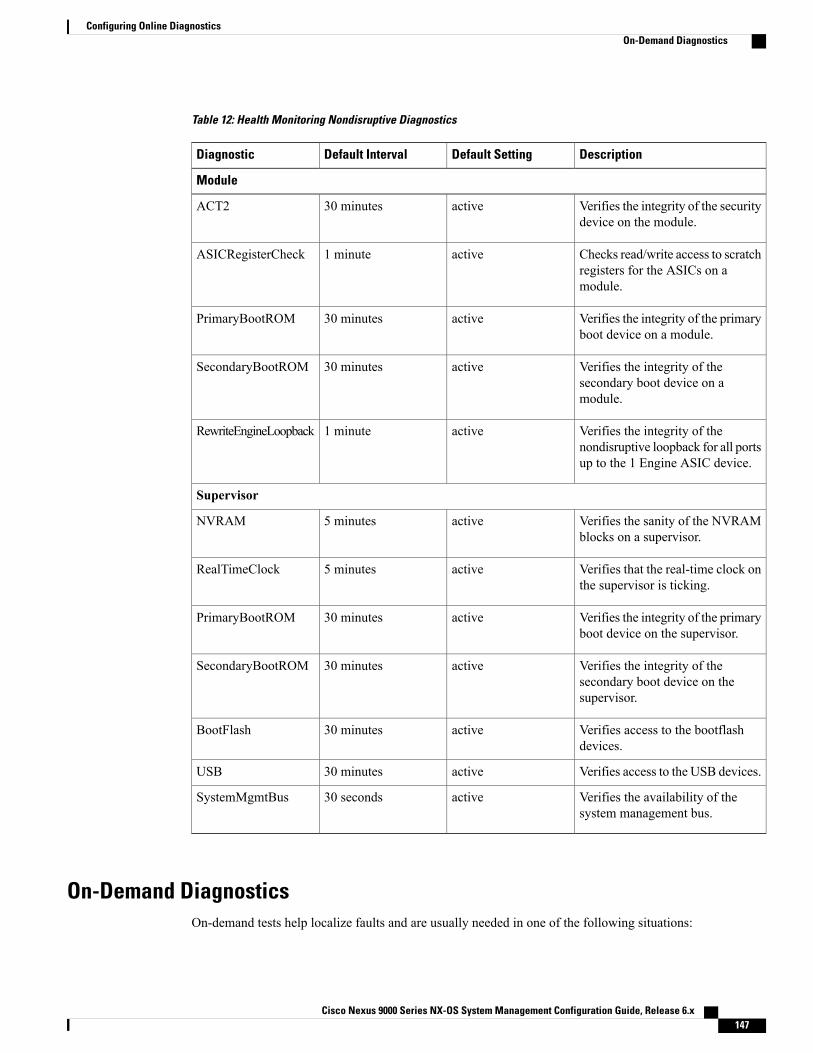
Table 12: Health Monitoring Nondisruptive Diagnostics
DescriptionDefault SettingDefault IntervalDiagnostic
Module
Verifies the integrity of the securitydevice on the module.
active30 minutesACT2
Checks read/write access to scratchregisters for the ASICs on amodule.
active1 minuteASICRegisterCheck
Verifies the integrity of the primaryboot device on a module.
active30 minutesPrimaryBootROM
Verifies the integrity of thesecondary boot device on amodule.
active30 minutesSecondaryBootROM
Verifies the integrity of thenondisruptive loopback for all portsup to the 1 Engine ASIC device.
active1 minuteRewriteEngineLoopback
Supervisor
Verifies the sanity of the NVRAMblocks on a supervisor.
active5 minutesNVRAM
Verifies that the real-time clock onthe supervisor is ticking.
active5 minutesRealTimeClock
Verifies the integrity of the primaryboot device on the supervisor.
active30 minutesPrimaryBootROM
Verifies the integrity of thesecondary boot device on thesupervisor.
active30 minutesSecondaryBootROM
Verifies access to the bootflashdevices.
active30 minutesBootFlash
Verifies access to the USB devices.active30 minutesUSB
Verifies the availability of thesystem management bus.
active30 secondsSystemMgmtBus
On-Demand DiagnosticsOn-demand tests help localize faults and are usually needed in one of the following situations:
Cisco Nexus 9000 Series NX-OS System Management Configuration Guide, Release 6.x 147
Configuring Online DiagnosticsOn-Demand Diagnostics

• To respond to an event that has occurred, such as isolating a fault.
• In anticipation of an event that may occur, such as a resource exceeding its utilization limit.
You can run all the health monitoring tests on demand. You can schedule on-demand diagnostics to runimmediately.
You can also modify the default interval for a health monitoring test.
High AvailabilityA key part of high availability is detecting hardware failures and taking corrective action while the deviceruns in a live network. Online diagnostics in high availability detect hardware failures and provide feedbackto high availability software components to make switchover decisions.
Cisco NX-OS supports stateless restarts for online diagnostics. After a reboot or supervisor switchover, CiscoNX-OS applies the running configuration.
Virtualization SupportOnline diagnostics are virtual routing and forwarding (VRF) aware. You can configure online diagnostics touse a particular VRF to reach the online diagnostics SMTP server.
Licensing Requirements for Online DiagnosticsLicense RequirementProduct
Online diagnostics require no license. Any feature not included in a license package is bundledwith the nx-os image and is provided at no extra charge to you. For a complete explanationof the Cisco NX-OS licensing scheme, see the Cisco NX-OS Licensing Guide.
CiscoNX-OS
Guidelines and Limitations for Online DiagnosticsOnline diagnostics has the following configuration guidelines and limitations:
• You cannot run disruptive online diagnostic tests on demand.
• PortLoopback and BootupPortLoopback tests are not supported.
Default Settings for Online DiagnosticsThe following table lists the default settings for online diagnostic parameters.
DefaultParameters
completeBootup diagnostics level
Cisco Nexus 9000 Series NX-OS System Management Configuration Guide, Release 6.x148
Configuring Online DiagnosticsHigh Availability
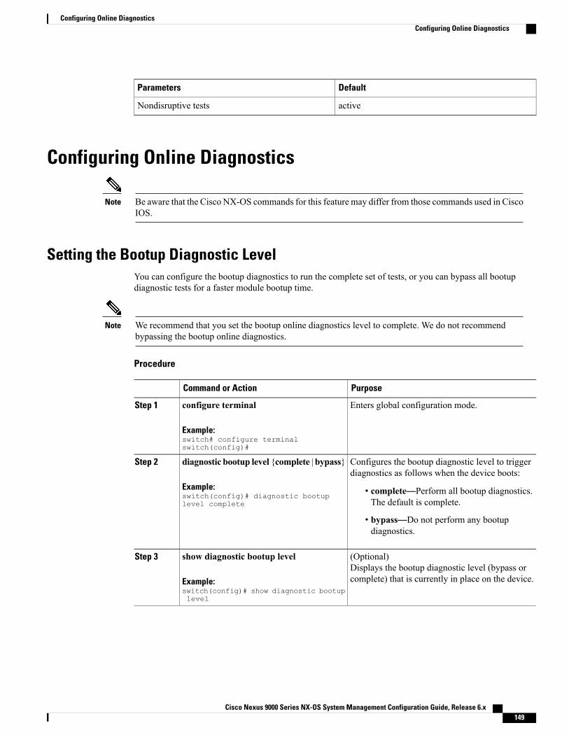
DefaultParameters
activeNondisruptive tests
Configuring Online Diagnostics
Be aware that the Cisco NX-OS commands for this feature may differ from those commands used in CiscoIOS.
Note
Setting the Bootup Diagnostic LevelYou can configure the bootup diagnostics to run the complete set of tests, or you can bypass all bootupdiagnostic tests for a faster module bootup time.
We recommend that you set the bootup online diagnostics level to complete. We do not recommendbypassing the bootup online diagnostics.
Note
Procedure
PurposeCommand or Action
Enters global configuration mode.configure terminal
Example:switch# configure terminalswitch(config)#
Step 1
Configures the bootup diagnostic level to triggerdiagnostics as follows when the device boots:
diagnostic bootup level {complete | bypass}
Example:switch(config)# diagnostic bootuplevel complete
Step 2
• complete—Perform all bootup diagnostics.The default is complete.
• bypass—Do not perform any bootupdiagnostics.
(Optional)Displays the bootup diagnostic level (bypass orcomplete) that is currently in place on the device.
show diagnostic bootup level
Example:switch(config)# show diagnostic bootuplevel
Step 3
Cisco Nexus 9000 Series NX-OS System Management Configuration Guide, Release 6.x 149
Configuring Online DiagnosticsConfiguring Online Diagnostics

PurposeCommand or Action
(Optional)Copies the running configuration to the startupconfiguration.
copy running-config startup-config
Example:switch(config)# copy running-configstartup-config
Step 4
Activating a Diagnostic TestYou can set a diagnostic test as active and optionally modify the interval (in hours, minutes, and seconds) atwhich the test runs.
Procedure
PurposeCommand or Action
Enters global configuration mode.configure terminal
Example:switch# configure terminalswitch(config)#
Step 1
Configures the interval at which the specified test is run.If no interval is set, the test runs at the interval setpreviously, or the default interval.
diagnosticmonitor intervalmodule slottest [test-id | name | all] hour hourminminute second second
Step 2
Example:switch(config)# diagnostic monitorinterval module 6 test 3 hour 1min 0 second 0
The argument ranges are as follows:
• slot—The range is from 1 to 10.
• test-id—The range is from 1 to 14.
• name—Can be any case-sensitive, alphanumericstring up to 32 characters.
• hour—The range is from 0 to 23 hours.
• minute—The range is from 0 to 59 minutes.
• second—The range is from 0 to 59 seconds.
Activates the specified test.[no] diagnostic monitor module slottest [test-id | name | all]
Step 3
The argument ranges are as follows:
Example:switch(config)# diagnostic monitorinterval module 6 test 3
• slot—The range is from 1 to 10.
• test-id—The range is from 1 to 14.
• name—Can be any case-sensitive, alphanumericstring up to 32 characters.
Cisco Nexus 9000 Series NX-OS System Management Configuration Guide, Release 6.x150
Configuring Online DiagnosticsActivating a Diagnostic Test

PurposeCommand or Action
The [no] form of this command inactivates the specifiedtest. Inactive tests keep their current configuration but donot run at the scheduled interval.
(Optional)Displays information about the diagnostics and theirattributes.
show diagnostic content module {slot| all}
Example:switch(config)# show diagnosticcontent module 6
Step 4
Starting or Stopping an On-Demand Diagnostic TestYou can start or stop an on-demand diagnostic test. You can optionally modify the number of iterations torepeat this test, and the action to take if the test fails.
We recommend that you only manually start a disruptive diagnostic test during a scheduled networkmaintenance time.
Procedure
PurposeCommand or Action
(Optional)Configures the number of times that the on-demandtest runs. The range is from 1 to 999. The default is1.
diagnostic ondemand iteration number
Example:switch# diagnostic ondemand iteration5
Step 1
(Optional)Configures the action to take if the on-demand testfails. The num-fails range is from 1 to 999. Thedefault is 1.
diagnostic ondemand action-on-failure{continue failure-count num-fails | stop}
Example:switch# diagnostic ondemandaction-on-failure stop
Step 2
Starts one or more diagnostic tests on a module. Themodule slot range is from 1 to 10. The test-id range
diagnostic start module slot test [test-id |name | all | non-disruptive] [portport-number | all]
Step 3
is from 1 to 14. The test name can be anycase-sensitive, alphanumeric string up to 32characters. The port range is from 1 to 48.Example:
switch# diagnostic start module 6 testall
Stops one or more diagnostic tests on a module. Themodule slot range is from 1 to 10. The test-id range
diagnostic stop module slot test [test-id |name | all]
Step 4
is from 1 to 14. The test name can be anyExample:switch# diagnostic stop module 6 testall
case-sensitive, alphanumeric string up to 32characters.
Cisco Nexus 9000 Series NX-OS System Management Configuration Guide, Release 6.x 151
Configuring Online DiagnosticsStarting or Stopping an On-Demand Diagnostic Test

PurposeCommand or Action
(Optional)Verifies that the diagnostic has been scheduled.
show diagnostic status module slot
Example:switch# show diagnostic status module6
Step 5
Simulating Diagnostic ResultsYou can simulate a diagnostic test result.
Procedure
PurposeCommand or Action
Simulates a test result. The test-id rangeis from 1 to 14. The port range is from 1to 48.
diagnostic test simulationmodule slot test test-id {fail| random-fail | success} [port number | all]
Example:switch# diagnostic test simulation module 2test 2 fail
Step 1
Clearing Diagnostic ResultsYou can clear diagnostic test results.
Procedure
PurposeCommand or Action
Clears the test result for the specified test.diagnostic clear result module [slot | all] test{test-id | all}
Step 1
The argument ranges are as follows:
Example:switch# diagnostic clear result module 2test all
• slot—The range is from 1 to 10.
• test-id—The range is from 1 to 14.
Clears the simulated test result. The test-idrange is from 1 to 14.
diagnostic test simulation module slot testtest-id clear
Example:switch# diagnostic test simulation module2 test 2 clear
Step 2
Cisco Nexus 9000 Series NX-OS System Management Configuration Guide, Release 6.x152
Configuring Online DiagnosticsSimulating Diagnostic Results

Verifying the Online Diagnostics ConfigurationTo display online diagnostics configuration information, perform one of the following tasks:
PurposeCommand
Displays information about bootup diagnostics.show diagnostic bootup level
Displays information about diagnostic test contentfor a module.
show diagnostic content module {slot | all}
Displays the diagnostic description.show diagnostic description module slot test[test-name | all]
Displays diagnostic events by error and informationevent type.
show diagnostic events [error | info]
Displays information about on-demand diagnostics.show diagnostic ondemand setting
Displays information about the results of a diagnostic.show diagnostic result module slot [test [test-name| all]] [detail]
Displays information about a simulated diagnostic.show diagnostic simulation module slot
Displays the test status for all tests on a module.show diagnostic status module slot
Displays information about the hardware capabilitiesand current hardware utilization by the system.
show hardware capacity [eobc | forwarding |interface |module | power]
Displays module information including the onlinediagnostic test status.
show module
Configuration Examples for Online DiagnosticsThis example shows how to start all on-demand tests on module 6:diagnostic start module 6 test all
This example shows how to activate test 2 and set the test interval on module 6:configure terminaldiagnostic monitor module 6 test 2diagnostic monitor interval module 6 test 2 hour 3 min 30 sec 0
Cisco Nexus 9000 Series NX-OS System Management Configuration Guide, Release 6.x 153
Configuring Online DiagnosticsVerifying the Online Diagnostics Configuration

Cisco Nexus 9000 Series NX-OS System Management Configuration Guide, Release 6.x154
Configuring Online DiagnosticsConfiguration Examples for Online Diagnostics

C H A P T E R 13Configuring the Embedded Event Manager
This chapter describes how to configure the Embedded Event Manager (EEM) to detect and handle criticalevents on Cisco NX-OS devices.
This chapter includes the following sections:
• About EEM, page 155
• Licensing Requirements for EEM, page 159
• Prerequisites for EEM, page 159
• Guidelines and Limitations for EEM, page 159
• Default Settings for EEM, page 160
• Configuring EEM, page 160
• Verifying the EEM Configuration, page 174
• Configuration Examples for EEM, page 175
About EEMEEMmonitors events that occur on your device and takes action to recover or troubleshoot these events, basedon your configuration.
EEM consists of three major components:
• Event statements—Events to monitor from another Cisco NX-OS component that may require someaction, workaround, or notification.
• Action statements—An action that EEM can take, such as sending an e-mail, or disabling an interface,to recover from an event.
• Policies—An event paired with one or more actions to troubleshoot or recover from the event.
Cisco Nexus 9000 Series NX-OS System Management Configuration Guide, Release 6.x 155

PoliciesAn EEM policy consists of an event statement and one or more action statements. The event statement definesthe event to look for as well as the filtering characteristics for the event. The action statement defines theaction EEM takes when the event occurs.
This figure shows the two basic statements in an EEM policy.
Figure 2: EEM Policy Statements
You can configure EEM policies using the command-line interface (CLI) or a VSH script.
EEM gives you a device-wide view of policy management. You configure EEM policies on the supervisor,and EEM pushes the policy to the correct module based on the event type. EEM takes any actions for atriggered event either locally on the module or on the supervisor (the default option).
EEM maintains event logs on the supervisor.
Cisco NX-OS has a number of preconfigured system policies. These system policies define many commonevents and actions for the device. System policy names begin with two underscore characters (__).
You can create user policies to suit your network. If you create a user policy, any actions in your policy occurafter EEM triggers any system policy actions related to the same event as your policy.
You can also override some system policies. The overrides that you configure take the place of the systempolicy. You can override the event or the actions.
Use the show eventmanager system-policy command to view the preconfigured system policies and determinewhich policies that you can override.
You should use the show running-config eem command to check the configuration of each policy. Anoverride policy that consists of an event statement and no action statement triggers no action and nonotification of failures.
Note
Your override policy should always include an event statement. An override policy without an eventstatement overrides all possible events in the system policy.
Note
Cisco Nexus 9000 Series NX-OS System Management Configuration Guide, Release 6.x156
Configuring the Embedded Event ManagerPolicies
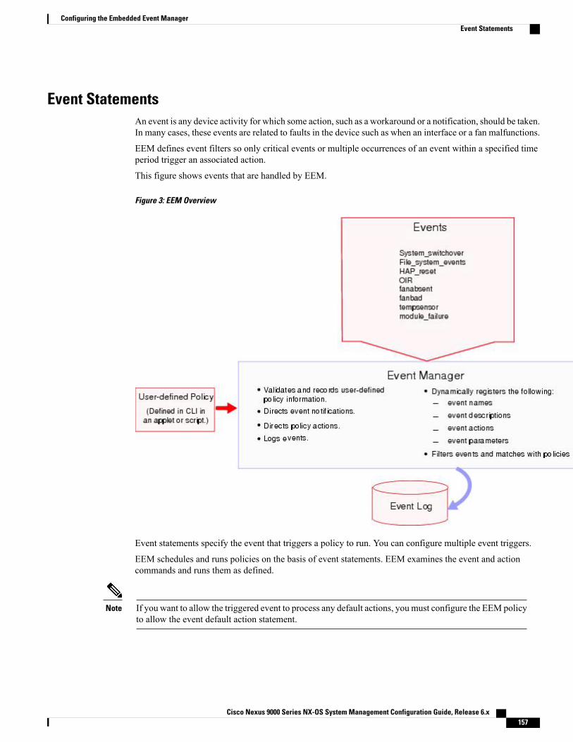
Event StatementsAn event is any device activity for which some action, such as a workaround or a notification, should be taken.In many cases, these events are related to faults in the device such as when an interface or a fan malfunctions.
EEM defines event filters so only critical events or multiple occurrences of an event within a specified timeperiod trigger an associated action.
This figure shows events that are handled by EEM.
Figure 3: EEM Overview
Event statements specify the event that triggers a policy to run. You can configure multiple event triggers.
EEM schedules and runs policies on the basis of event statements. EEM examines the event and actioncommands and runs them as defined.
If you want to allow the triggered event to process any default actions, you must configure the EEM policyto allow the event default action statement.
Note
Cisco Nexus 9000 Series NX-OS System Management Configuration Guide, Release 6.x 157
Configuring the Embedded Event ManagerEvent Statements

Action StatementsAction statements describe the action triggered by a policy. Each policy can have multiple action statements.If no action is associated with a policy, EEM still observes events but takes no actions.
EEM supports the following actions in action statements:
• Execute any CLI commands.
• Update a counter.
• Log an exception.
• Force the shutdown of any module.
• Reload the device.
• Shut down specified modules because the power is over budget.
• Generate a syslog message.
• Generate a Call Home event.
• Generate an SNMP notification.
• Use the default action for the system policy.
If you want to allow the triggered event to process any default actions, you must configure the EEM policyto allow the default action. For example, if you match a CLI command in a match statement, you mustadd the event-default action statement to the EEM policy or EEM will not allow the CLI command toexecute.
Note
Verify that your action statements within your user policy or overriding policy do not negate each otheror adversely affect the associated system policy.
Note
VSH Script PoliciesYou can also write policies in a VSH script, using a text editor. These policies have an event statement andaction statement(s) just as other policies, and these policies can either augment or override system policies.After you write your VSH script policy, copy it to the device and activate it.
Environment VariablesYou can define environment variables for EEM that are available for all policies. Environment variables areuseful for configuring common values that you can use in multiple policies. For example, you can create anenvironment variable for the IP address of an external e-mail server.
You can use an environment variable in action statements by using the parameter substitution format.
Cisco Nexus 9000 Series NX-OS System Management Configuration Guide, Release 6.x158
Configuring the Embedded Event ManagerAction Statements

This example shows a sample action statement to force a module 1 shutdown, with a reset reason of "EEMaction."switch (config-eem-policy)# action 1.0 forceshut module 1 reset-reson “EEM action.”
If you define an environment variable for the shutdown reason, called default-reason, you can replace thatreset reason with the environment variable, as shown in the following example.switch (config-eem-policy)# action 1.0 foreshut module 1 reset-reason $default-reason
You can reuse this environment variable in any policy.
EEM Event CorrelationYou can trigger an EEM policy based on a combination of events. First, you use the tag keyword to createand differentiate multiple events in the EEM policy. Then using a set of boolean operators (and, or, andnot),along with the count and time, you can define a combination of these events to trigger a custom action.
High AvailabilityCisco NX-OS supports stateless restarts for EEM. After a reboot or supervisor switchover, Cisco NX-OSapplies the running configuration.
Virtualization SupportNot all actions or events are visible. You must have network-admin privileges to configure policies.
Licensing Requirements for EEMLicense RequirementProduct
EEM requires no license. Any feature not included in a license package is bundled with thenx-os image and is provided at no extra charge to you. For a complete explanation of theCisco NX-OS licensing scheme, see the Cisco NX-OS Licensing Guide.
CiscoNX-OS
Prerequisites for EEMEEM has the following prerequisites:
• You must have network-admin user privileges to configure EEM.
Guidelines and Limitations for EEMEEM has the following configuration guidelines and limitations:
Cisco Nexus 9000 Series NX-OS System Management Configuration Guide, Release 6.x 159
Configuring the Embedded Event ManagerEEM Event Correlation

• The maximum number of configurable EEM policies is 500.
• Action statements within your user policy or overriding policy should not negate each other or adverselyaffect the associated system policy.
• If you want to allow a triggered event to process any default actions, you must configure the EEM policyto allow the default action. For example, if you match a CLI command in a match statement, you mustadd the event-default action statement to the EEM policy or EEM will not allow the CLI command toexecute.
• An override policy that consists of an event statement and no action statement triggers no action and nonotification of failures.
• An override policy without an event statement overrides all possible events in the system policy.
• The following rules apply to regular command expressions: all keywords must be expanded, and onlythe * symbol can be used for argument replacement.
• EEM event correlation is supported only on the supervisor module.
• EEM event correlation is not supported across different modules within a single policy.
• EEM event correlation supports up to four event statements in a single policy. The event types can bethe same or different, but only these event types are supported: cli, counter, module, module-failure, oir,snmp, and syslog.
•When more than one event statement is included in an EEM policy, each event statement must have atag keyword with a unique tag argument.
• EEM event correlation does not override the system default policies.
• Default action execution is not supported for policies that are configured with tagged events.
• You can invoke EEM from Python. For more information about Python, see theCisco Nexus 9000 SeriesNX-OS Programmability Guide.
Default Settings for EEMThis table lists the default settings for EEM parameters.
DefaultParameters
ActiveSystem policies
Configuring EEMYou can create policies that contain actions to take based on system policies. To display information aboutthe system policies, use the show event manager system-policy command.
Defining an Environment VariableYou can define a variable to serve as a parameter in an EEM policy.
Cisco Nexus 9000 Series NX-OS System Management Configuration Guide, Release 6.x160
Configuring the Embedded Event ManagerDefault Settings for EEM

Procedure
PurposeCommand or Action
Enters global configuration mode.configure terminal
Example:switch# configure terminalswitch(config)#
Step 1
Creates an environment variable for EEM. Thevariable-name can be any case-sensitive,
event manager environment variable-namevariable-value
Step 2
alphanumeric string up to 29 characters. TheExample:switch(config)# event manager environmentemailto “[email protected]”
variable-value can be any quoted alphanumericstring up to 39 characters.
(Optional)Displays information about the configuredenvironment variables.
show event manager environment{variable-name | all}
Example:switch(config)# show event managerenvironment all
Step 3
(Optional)Copies the running configuration to the startupconfiguration.
copy running-config startup-config
Example:switch(config)# copy running-configstartup-config
Step 4
Defining a User Policy Using the CLIYou can define a user policy using the CLI to the device.
Procedure
PurposeCommand or Action
Enters global configuration mode.configure terminal
Example:switch# configure terminalswitch(config)#
Step 1
Registers the applet with EEM and enters appletconfiguration mode. The applet-name can be any
event manager applet applet-name
Example:switch(config)# event manager appletmonitorShutdownswitch(config-applet)#
Step 2
case-sensitive, alphanumeric string up to 29characters.
Cisco Nexus 9000 Series NX-OS System Management Configuration Guide, Release 6.x 161
Configuring the Embedded Event ManagerDefining a User Policy Using the CLI

PurposeCommand or Action
(Optional)Configures a descriptive string for the policy. Thestring can be any alphanumeric string up to 80characters. Enclose the string in quotation marks.
description policy-description
Example:switch(config-applet)# description“Monitors interface shutdown.”
Step 3
Configures the event statement for the policy.Repeat this step for multiple event statements. SeeConfiguring Event Statements, on page 162.
event event-statement
Example:switch(config-applet)# event cli match“shutdown”
Step 4
(Optional)Correlates multiple events in the policy.
tag tag {and | andnot | or} tag [and | andnot| or {tag}] {happens occurs in seconds}
Step 5
Example:switch(config-applet)# tag one or twohappens 1 in 10000
The range for the occurs argument is from 1 to4294967295. The range for the seconds argumentis from 0 to 4294967295 seconds.
Configures an action statement for the policy.Repeat this step for multiple action statements. SeeConfiguring Action Statements, on page 167.
action number[.number2] action-statement
Example:switch(config-applet)# action 1.0 clishow interface e 3/1
Step 6
(Optional)Displays information about the status of theconfigured policy.
show event manager policy-state name[module module-id]
Example:switch(config-applet)# show eventmanager policy-state monitorShutdown
Step 7
(Optional)Copies the running configuration to the startupconfiguration.
copy running-config startup-config
Example:switch(config)# copy running-configstartup-config
Step 8
Configuring Event StatementsUse one of the following commands in EEM configuration mode to configure an event statement:
Cisco Nexus 9000 Series NX-OS System Management Configuration Guide, Release 6.x162
Configuring the Embedded Event ManagerDefining a User Policy Using the CLI

PurposeCommand
Triggers an event when an event specificationmatchesthe subsystem ID and application event type.
The range for the sub-system-id and for the event-typeis from 1 to 4294967295.
The tag tag keyword-argument pair identifies thisspecific event when multiple events are included inthe policy.
To use this command, you must first enablethe feature evmed command to enablegeneric event detectors.
Note
event application [tag tag] sub-system sub-system-idtype event-typeExample:switch(config-applet)# event applicationsub-system 798 type 1
Triggers an event if you enter a command thatmatches the regular expression.
The tag tag keyword-argument pair identifies thisspecific event when multiple events are included inthe policy.
The repeats range is from 1 to 65000. The time range,in seconds, is from 0 to 4294967295, where 0indicates no time limit.
event cli [tag tag] match expression [count repeats| time seconds]Example:switch(config-applet)# event cli match“shutdown”
Triggers an event if the counter crosses the entrythreshold based on the entry operation. The eventresets immediately. Optionally, you can configure theevent to reset after the counter passes the exitthreshold.
The tag tag keyword-argument pair identifies thisspecific event when multiple events are included inthe policy.
The counter name can be any case-sensitive,alphanumeric string up to 28 characters. The entryand exit value ranges are from 0 to 2147483647.
event counter [tag tag] name counter entry-val entryentry-op {eq | ge | gt | le | lt | ne} [exit-val exitexit-op {eq | ge | gt | le | lt | ne}]Example:switch(config-applet)# event counter namemycounter entry-val 20 gt
Triggers an event if a fan is removed from the devicefor more than the configured time, in seconds. Thenumber range is module dependent. The secondsrange is from 10 to 64000.
event fanabsent [fan number] time secondsExample:switch(config-applet)# event fanabsent time300
Triggers an event if a fan fails for more than theconfigured time, in seconds. The number range ismodule dependent. The seconds range is from 10 to64000.
event fanbad [fan number] time secondsExample:switch(config-applet)# event fanbad time3000
Cisco Nexus 9000 Series NX-OS System Management Configuration Guide, Release 6.x 163
Configuring the Embedded Event ManagerDefining a User Policy Using the CLI

PurposeCommand
Triggers an event for one of the following:
• adjacency extra—If there is an extra route inthe unicast FIB.
• resource tcam usage—Each time the TCAMutilization percentage becomes a multiple of 5,in either direction.
• route {extra | inconsistent |missing}—If aroute is added, changed, or deleted in the unicastFIB.
event fib {adjacency extra | resource tcam usage |route {extra | inconsistent |missing}}Example:switch(config-applet)# event fib adjacencyextra
Triggers an event if the named online diagnostic testexperiences the configured failure severity for theconfigured number of consecutive failures. The slotrange is from 1 to 10. The test-name is the name ofa configured online diagnostic test. The count rangeis from 1 to 1000.
event gold module {slot | all} test test-name[severity {major |minor |moderate}] testing-type{bootup |monitoring | ondemand | scheduled}consecutive-failure countExample:switch(config-applet)# event gold module 2test ASICRegisterCheck testing-typeondemand consecutive-failure 2
Triggers an event if the counter is exceeded for thespecified interface.
The tag tag keyword-argument pair identifies thisspecific event when multiple events are included inthe policy.
To use this command, you must first enablethe feature evmed command to enablegeneric event detectors.
Note
event interface [tag tag] {name interface slot/portparameter}Example:switch(config-applet)# event interfaceethernet 2/2 parameter
Triggers an event if a memory threshold is crossed.See also Configuring Memory Thresholds, on page171.
event memory {critical |minor | severe}Example:switch(config-applet)# event memorycritical
Triggers an event if the specified module enters theselected status.
The tag tag keyword-argument pair identifies thisspecific event when multiple events are included inthe policy.
eventmodule [tag tag] status {online | offline | any}module {all | module-num}Example:switch(config-applet)# event module statusoffline module all
Cisco Nexus 9000 Series NX-OS System Management Configuration Guide, Release 6.x164
Configuring the Embedded Event ManagerDefining a User Policy Using the CLI

PurposeCommand
Triggers an event if a module experiences the failuretype configured.
The tag tag keyword-argument pair identifies thisspecific event when multiple events are included inthe policy.
The repeats range is from 0 to 4294967295. Theseconds range is from 0 to 4294967295, where 0indicates no time limit.
event module-failure [tag tag] type failure-typemodule {slot | all} count repeats [time seconds]Example:switch(config-applet)# event module-failuretype lc-failed module 3 count 1
Manually runs the policy event without any eventsspecified.
To use this command, you must first enablethe feature evmed command to enablegeneric event detectors.
Note
event noneExample:switch(config-applet)# event none
Triggers an event if the configured device element(fan, module, or power supply) is inserted or removedfrom the device.
The tag tag keyword-argument pair identifies thisspecific event when multiple events are included inthe policy.
You can optionally configure a specific fan, module,or power supply number. The number range is asfollows:
• Fan number—Module dependent.
• Module number—Device dependent.
• Power supply number—The range is from 1to 3.
event oir [tag tag] {fan |module | powersupply}{anyoir | insert | remove} [number]Example:switch(config-applet)# event oir fan remove4
Uses the event configured in the system policy. Usethis option for overriding policies.
The repeats range is from 1 to 65000. The secondsrange is from 0 to 4294967295, where 0 indicates notime limit.
event policy-default count repeats [time seconds]Example:switch(config-applet)# event policy-defaultcount 3
Triggers an event if the power budget exceeds thecapacity of the configured power supplies.
event poweroverbudgetExample:switch(config-applet)# eventpoweroverbudget
Cisco Nexus 9000 Series NX-OS System Management Configuration Guide, Release 6.x 165
Configuring the Embedded Event ManagerDefining a User Policy Using the CLI

PurposeCommand
Triggers an event if the SNMP OID crosses the entrythreshold based on the entry operation. The eventresets immediately, or optionally you can configurethe event to reset after the counter passes the exitthreshold. The OID is in dotted decimal notation.
The tag tag keyword-argument pair identifies thisspecific event when multiple events are included inthe policy.
The entry and exit value ranges are from 0 to18446744073709551615. The time, in seconds, isfrom 0 to 2147483647. The interval, in seconds, isfrom 1 to 2147483647.
event snmp [tag tag] oid oid get-type {exact | next}entry-op {eq | ge | gt | le | lt | ne} entry-val entry[exit-comb {and | or}] exit-op {eq | ge | gt | le | lt |ne} exit-val exit exit-time time polling-intervalintervalExample:switch(config-applet)# event snmp oid1.3.6.1.2.1.31.1.1.1.6 get-type nextentry-op lt 300 entry-val 0 exit-op eq 400exit-time 30 polling-interval 300
Triggers an event if traffic on a port exceeds theconfigured storm control threshold.
event storm-controlExample:switch(config-applet)# event storm-control
Triggers an event if the specified syslog threshold isexceeded. The range for the count is from 1 to 65000,and the range for the time is from 1 to 4294967295.The priority range is from 0 to 7.
The tag tag keyword-argument pair identifies thisspecific event when multiple events are included inthe policy.
event syslog [occurs count] {pattern string | periodtime | priority level | tag tag}Example:switch(config-applet)# event syslog period500
Triggers an event if the specified system managermemory threshold is exceeded. The range for thepercentage is from 1 to 99.
event sysmgrmemory [modulemodule-num]majormajor-percentminor minor-percent clearclear-percentExample:switch(config-applet)# event sysmgr memoryminor 80
Triggers an event if the specified switchover count isexceeded within the time interval specified. Theswitchover count is from 1 to 65000. The time intervalis from 0 to 2147483647.
event sysmgr switchover count count time intervalExample:switch(config-applet)# event sysmgrswitchover count 10 time 1000
Triggers an event if the temperature sensor exceedsthe configured threshold. The sensor range is from 1to 18.
event temperature [module slot] [sensor-number]threshold {any |major |minor}Example:switch(config-applet)# event temperaturemodule 2 threshold any
Cisco Nexus 9000 Series NX-OS System Management Configuration Guide, Release 6.x166
Configuring the Embedded Event ManagerDefining a User Policy Using the CLI

PurposeCommand
Triggers an event if the specified time is reached. Therange for the time is from 1 to 4294967295.
• absolute time—Triggers an event when thespecified absolute time of day occurs.
• countdown time—Triggers an event whenwhen the specified time counts down to zero.The timer does not reset.
• cron cronentry—Triggers an event when theCRON string specification matches the currenttime.
• watchdog time—Triggers an event when thespecified time counts down to zero. The timerautomatically resets to the initial value andcontinues to count down.
The tag tag keyword-argument pair identifies thisspecific event when multiple events are included inthe policy.
To use this command, you must first enablethe feature evmed command to enablegeneric event detectors.
Note
event timer {absolute time time name name |countdown time time name name | cron cronentrystring | tag tag | watchdog time time name name}Example:switch(config-applet)# event timer absolutetime 100 name abtimer
Triggers an event if the tracked object is in theconfigured state.
The tag tag keyword-argument pair identifies thisspecific event when multiple events are included inthe policy.
The object-number range is from 1 to 500.
event track [tag tag] object-number state {any |down | up}Example:switch(config-applet)# event track 1 statedown
Configuring Action StatementsUse the following commands in EEM configuration mode to configure action statements:
PurposeCommand
Runs the configured CLI commands. You canoptionally run the commands on the module wherethe event occurred. The action label is in the formatnumber1.number2.
number can be any number up to 16 digits. The rangefor number2 is from 0 to 9.
action number[.number2] cli command1[command2...] [local]Example:switch(config-applet)# action 1.0 cli“show interface e 3/1“
Cisco Nexus 9000 Series NX-OS System Management Configuration Guide, Release 6.x 167
Configuring the Embedded Event ManagerDefining a User Policy Using the CLI

PurposeCommand
Modifies the counter by the configured value andoperation. The action label is in the formatnumber1.number2.
number can be any number up to 16 digits. The rangefor number2 is from 0 to 9.
The counter name can be any case-sensitive,alphanumeric string up to 28 characters. The val canbe an integer from 0 to 2147483647 or a substitutedparameter.
action number[.number2] counter name countervalue val op {dec | inc | nop | set}Example:switch(config-applet)# action 2.0 countername mycounter value 20 op inc
Executes the default action for the associated event.The action label is in the format number1.number2.
number can be any number up to 16 digits. The rangefor number2 is from 0 to 9.
action number[.number2] event-defaultExample:switch(config-applet)# action 1.0event-default
Forces a module, crossbar, or the entire system toshut down. The action label is in the formatnumber1.number2.
number can be any number up to 16 digits. The rangefor number2 is from 0 to 9.
The reset reason is a quoted alphanumeric string upto 80 characters.
action number[.number2] forceshut [module slot |xbar xbar-number] reset-reason secondsExample:switch(config-applet)# action 1.0 forceshut
module 2 reset-reason “flapping links”
Forces one or more modules or the entire system toshut down because of a power overbudget issue.
number can be any number up to 16 digits. The rangefor number2 is from 0 to 9.
action number[.number2] overbudgetshut [moduleslot[-slot]]Example:switch(config-applet)# action 1.0overbudgetshut module 3-5
Executes the default action for the policy that you areoverriding. The action label is in the formatnumber1.number2.
number can be any number up to 16 digits. The rangefor number2 is from 0 to 9.
action number[.number2] policy-defaultExample:switch(config-applet)# action 1.0policy-default
Forces the publication of an application-specificevent. The action label is in the formatnumber1.number2.
number can be any number up to 16 digits. The rangefor number2 is from 0 to 9.
action number[.number2] publish-eventExample:switch(config-applet)# action 1.0publish-event
Forces one or more modules or the entire system toreload.
number can be any number up to 16 digits. The rangefor number2 is from 0 to 9.
action number[.number2] reload [module slot[-slot]]Example:switch(config-applet)# action 1.0 reloadmodule 3-5
Cisco Nexus 9000 Series NX-OS System Management Configuration Guide, Release 6.x168
Configuring the Embedded Event ManagerDefining a User Policy Using the CLI

PurposeCommand
Sends an SNMP trapwith the configured data. numbercan be any number up to 16 digits. The range fornumber2 is from 0 to 9.
The data arguments can by any number up to 80digits. The string can be any alphanumeric string upto 80 characters.
action number[.number2] snmp-trap {[intdata1data [intdata2 data]] [strdata string]}Example:switch(config-applet)# action 1.0 snmp-trapstrdata “temperature problem”
Sends a customized syslogmessage at the configuredpriority. number can be any number up to 16 digits.The range for number2 is from 0 to 9.
The error-message can be any quoted alphanumericstring up to 80 characters.
action number[.number2] syslog [priority prio-val]msg error-messageExample:switch(config-applet)# action 1.0 syslogpriority notifications msg “cpu high”
If you want to allow the triggered event to process any default actions, you must configure the EEM policyto allow the default action. For example, if you match a CLI command in a match statement, you mustadd the event-default action statement to the EEM policy or EEM will not allow the CLI command toexecute. You can use the terminal event-manager bypass command to allow all EEM policies with CLImatches to execute the CLI command.
Note
Defining a Policy Using a VSH ScriptYou can define a policy using a VSH script.
Before You Begin
Ensure that you are logged in with administrator privileges.
Ensure that your script name is the same name as the script filename.
Procedure
Step 1 In a text editor, list the commands that define the policy.Step 2 Name the text file and save it.Step 3 Copy the file to the following system directory: bootflash://eem/user_script_policies.
Registering and Activating a VSH Script PolicyYou can register and activate a policy defined in a VSH script.
Cisco Nexus 9000 Series NX-OS System Management Configuration Guide, Release 6.x 169
Configuring the Embedded Event ManagerDefining a Policy Using a VSH Script

Procedure
PurposeCommand or Action
Enters global configuration mode.configure terminal
Example:switch# configure terminalswitch(config)#
Step 1
Registers and activates an EEM script policy.The policy-script can be any case-sensitivealphanumeric string up to 29 characters.
event manager policy policy-script
Example:switch(config)# event manager policymoduleScript
Step 2
(Optional)Displays information about the configuredpolicy.
show event manager policy internal name
Example:switch(config)# show event manager policyinternal moduleScript
Step 3
(Optional)Copies the running configuration to the startupconfiguration.
copy running-config startup-config
Example:switch(config)# copy running-configstartup-config
Step 4
Overriding a PolicyYou can override a system policy.
Procedure
PurposeCommand or Action
Enters global configuration mode.configure terminal
Example:switch# configure terminalswitch(config)#
Step 1
(Optional)Displays information about the system policy thatyou want to override, including thresholds. Use
show event manager policy-statesystem-policy
Example:switch(config-applet)# show eventmanager policy-state __ethpm_link_flap
Step 2
the show eventmanager system-policy commandto find the system policy names. For informationabout system policies, see Embedded EventManager System Events and ConfigurationExamples, on page 231.
Policy __ethpm_link_flapCfg count : 5Cfg time interval : 10.000000 (seconds)Hash default, Count 0
Cisco Nexus 9000 Series NX-OS System Management Configuration Guide, Release 6.x170
Configuring the Embedded Event ManagerOverriding a Policy

PurposeCommand or Action
Overrides a system policy and enters appletconfiguration mode. The applet-name can be any
event manager applet applet-name overridesystem-policy
Step 3
case-sensitive alphanumeric string up to 29Example:switch(config)# event manager appletethport override __ethpm_link_flapswitch(config-applet)#
characters. The system-policy must be one of theexisting system policies.
(Optional)Configures a descriptive string for the policy. Thestring can be any alphanumeric string up to 80characters. Enclose the string in quotation marks.
description policy-description
Example:description “Overrides link flappolicy.”
Step 4
Configures the event statement for the policy.event event-statement
Example:switch(config-applet)# eventpolicy-default count 2 time 1000
Step 5
Configures an action statement for the policy.action number action-statementStep 6
Example:switch(config-applet)# action 1.0 syslogpriority warnings msg “Link isflapping.”
Repeat this step for multiple action statements.
(Optional)Displays information about the configured policy.
show event manager policy-state name
Example:switch(config-applet)# show eventmanager policy-state ethport
Step 7
(Optional)Copies the running configuration to the startupconfiguration.
copy running-config startup-config
Example:switch(config)# copy running-configstartup-config
Step 8
Configuring Memory ThresholdsYou can set the memory thresholds used to trigger events and set whether the operating system should killprocesses if it cannot allocate memory.
Before You Begin
Ensure that you are logged in with administrator privileges.
Cisco Nexus 9000 Series NX-OS System Management Configuration Guide, Release 6.x 171
Configuring the Embedded Event ManagerConfiguring Memory Thresholds

Procedure
PurposeCommand or Action
Enters global configuration mode.configure terminal
Example:switch# configure terminalswitch(config)#
Step 1
Configures the systemmemory thresholds that generate EEMmemory events. The default values are as follows:
system memory-thresholds minorminor severe severe critical critical
Step 2
Example:switch(config)# systemmemory-thresholds minor 60severe 70 critical 80
• Minor-85
• Severe-90
• Critical-95
When these memory thresholds are exceeded, the systemgenerates the following syslogs:
• 2013 May 7 17:06:30 switch %$%PLATFORM-2-MEMORY_ALERT:Memory StatusAlert : MINOR
• 2013 May 7 17:06:30 switch %$%PLATFORM-2-MEMORY_ALERT:Memory StatusAlert : SEVERE
• 2013 May 7 17:06:30 switch %$%PLATFORM-2-MEMORY_ALERT:Memory StatusAlert : CRITICAL
• 2013 May 7 17:06:35 switch %$%PLATFORM-2-MEMORY_ALERT:Memory StatusAlert : MINOR ALERT RECOVERED
• 2013 May 7 17:06:35 switch %$%PLATFORM-2-MEMORY_ALERT:Memory StatusAlert : SEVERE ALERT RECOVERED
• 2013 May 7 17:06:35 switch %$%PLATFORM-2-MEMORY_ALERT:Memory StatusAlert : CRITICAL ALERT RECOVERED
(Optional)Configures the system to not kill processes when thememorycannot be allocated. The default value is to allow the system
systemmemory-thresholds thresholdcritical no-process-kill
Example:switch(config)# systemmemory-thresholds thresholdcritical no-process-kill
Step 3
to kill processes, starting with the one that consumes themost memory.
Cisco Nexus 9000 Series NX-OS System Management Configuration Guide, Release 6.x172
Configuring the Embedded Event ManagerConfiguring Memory Thresholds

PurposeCommand or Action
(Optional)Displays information about the system memoryconfiguration.
show running-config | include"system memory"
Example:switch(config-applet)# showrunning-config | include “systemmemory”
Step 4
(Optional)Copies the running configuration to the startup configuration.
copy running-config startup-config
Example:switch(config)# copyrunning-config startup-config
Step 5
Configuring Syslog as EEM PublisherYou can monitor syslog messages from the switch.
The maximum number of searchable strings to monitor syslog messages is 10.Note
Before You Begin
EEM should be available for registration by syslog.
The syslog daemon must be configured and executed.
Procedure
PurposeCommand or Action
Enters global configuration mode.configure terminal
Example:switch# configure terminalswitch(config)#
Step 1
Registers an applet with EEM and enters applet configurationmode.
event manager applet applet-name
Example:switch(config)# event managerapplet abcswitch(config-applet)#
Step 2
Monitors syslog messages and invokes the policy based onthe search string in the policy.
event syslog [tag tag] {occursnumber | period seconds | patternmsg-text | priority priority}
Step 3
• The tag tag keyword-argument pair identifies thisspecific event when multiple events are included in thepolicy.
Cisco Nexus 9000 Series NX-OS System Management Configuration Guide, Release 6.x 173
Configuring the Embedded Event ManagerConfiguring Syslog as EEM Publisher

PurposeCommand or Action
Example:switch(config-applet)# eventsyslog occurs 10
• The occurs number keyword-argument pair specifiesthe number of occurrences. The range is from 1 to65000.
• The period seconds keyword-argument pair specifiesthe interval during which the event occurs. The rangeis from 1 to 4294967295.
• The patternmsg-text keyword-argument pair specifiesthematching regular expression. The pattern can containcharacter text, an environment variable, or acombination of the two. If the string contains embeddedblanks, it is enclosed in quotation marks.
• The priority priority keyword-argument pair specifiesthe priority of the syslog messages. If this keyword isnot selected, all syslog messages are set at theinformational priority level.
(Optional)Copies the running configuration to the startup configuration.
copy running-config startup-config
Example:switch(config)# copyrunning-config startup-config
Step 4
Verifying the EEM ConfigurationTo display EEM configuration information, perform one of the following tasks:
PurposeCommand
Displays information about the event managerenvironment variables.
show event manager environment [variable-name| all]
Displays information about the event manager eventtypes.
show event manager event-types [event | all |module slot]
Displays the history of events for all policies.show event manager history events [detail][maximum num-events] [severity {catastrophic |minor |moderate | severe}]
Displays information about the configured policies.show event manager policy internal [policy-name][inactive]
Displays information about the policy state, includingthresholds.
show event manager policy-state policy-name
Cisco Nexus 9000 Series NX-OS System Management Configuration Guide, Release 6.x174
Configuring the Embedded Event ManagerVerifying the EEM Configuration

PurposeCommand
Displays information about the script policies.show event manager script system [policy-name |all]
Displays information about the predefined systempolicies.
show event manager system-policy [all]
Displays information about the running configurationfor EEM.
show running-config eem
Displays information about the startup configurationfor EEM.
show startup-config eem
Configuration Examples for EEMThis example shows how to override the __lcm_module_failure system policy by changing the threshold forjust module 3 hitless upgrade failures. This example also sends a syslog message. The settings in the systempolicy, __lcm_module_failure, apply in all other cases.event manager applet example2 override __lcm_module_failureevent module-failure type hitless-upgrade-failure module 3 count 2action 1 syslog priority errors msg module 3 “upgrade is not a hitless upgrade!”action 2 policy-default
This example shows how to override the __ethpm_link_flap system policy and shuts down the interface:event manager applet ethport override __ethpm_link_flapevent policy-default count 2 time 1000action 1 cli conf taction 2 cli int et1/1action 3 cli no shut
This example creates an EEMpolicy that allows the CLI command to execute but triggers an SNMP notificationwhen a user enters configuration mode on the device:event manager applet TESTevent cli match "conf t"action 1.0 snmp-trap strdata "Configuration change"action 2.0 event-default
You must add the event-default action statement to the EEM policy or EEM will not allow the CLIcommand to execute.
Note
This example shows how to correlate multiple events in an EEM policy and execute the policy based on acombination of the event triggers. In this example, the EEM policy is triggered if one of the specified syslogpatterns occurs within 120 seconds.event manager applet eem-correlateevent syslog tag one pattern "copy bootflash:.* running-config.*”event syslog tag two pattern “copy run start”event syslog tag three pattern “hello”tag one or two or three happens 1 in 120action 1.0 reload module 1
Cisco Nexus 9000 Series NX-OS System Management Configuration Guide, Release 6.x 175
Configuring the Embedded Event ManagerConfiguration Examples for EEM

For additional EEM configuration examples, see Embedded Event Manager System Events andConfiguration Examples, on page 231.
Note
Cisco Nexus 9000 Series NX-OS System Management Configuration Guide, Release 6.x176
Configuring the Embedded Event ManagerConfiguration Examples for EEM

C H A P T E R 14Configuring Onboard Failure Logging
This chapter describes how to configure the onboard failure logging (OBFL) features on Cisco NX-OSdevices.
This chapter includes the following sections:
• About OBFL, page 177
• Licensing Requirements for OBFL, page 178
• Prerequisites for OBFL, page 178
• Guidelines and Limitations for OBFL, page 178
• Default Settings for OBFL, page 178
• Configuring OBFL, page 179
• Verifying the OBFL Configuration, page 180
• Configuration Example for OBFL, page 182
• Additional References, page 182
About OBFLCisco NX-OS provides the ability to log failure data to persistent storage, which you can retrieve and displayfor analysis at a later time. This onboard failure logging (OBFL) feature stores failure and environmentalinformation in nonvolatile memory on the module. The information will help analyze failed modules.
OBFL stores the following types of data:
• Time of initial power-on
• Slot number of the module in the chassis
• Initial temperature of the module
• Firmware, BIOS, FPGA, and ASIC versions
• Serial number of the module
• Stack trace for crashes
Cisco Nexus 9000 Series NX-OS System Management Configuration Guide, Release 6.x 177

• CPU hog information
• Memory leak information
• Software error messages
• Hardware exception logs
• Environmental history
• OBFL-specific history information
• ASIC interrupt and error statistics history
• ASIC register dumps
Licensing Requirements for OBFLLicense RequirementProduct
OBFL requires no license. Any feature not included in a license package is bundled with thenx-os image and is provided at no extra charge to you. For a complete explanation of theCisco NX-OS licensing scheme, see the Cisco NX-OS Licensing Guide.
CiscoNX-OS
Prerequisites for OBFLYou must have network-admin user privileges.
Guidelines and Limitations for OBFLOBFL has the following guidelines and limitations:
• OBFL is enabled by default.
• OBFL flash supports a limited number of writes and erases. The more logging you enable, the fasteryou use up this number of writes and erases.
Be aware that the Cisco NX-OS commands for this feature may differ from those commands used in CiscoIOS.
Note
Default Settings for OBFLThe following table lists the default settings for OBFL parameters.
Cisco Nexus 9000 Series NX-OS System Management Configuration Guide, Release 6.x178
Configuring Onboard Failure LoggingLicensing Requirements for OBFL

DefaultParameters
All features enabledOBFL
Configuring OBFLYou can configure the OBFL features on Cisco NX-OS devices.
Before You Begin
Make sure that you are in global configuration mode.
Procedure
PurposeCommand or Action
Enters global configurationmode.
configure terminal
Example:switch# configure terminalswitch(config)#
Step 1
Enables all OBFL features.hw-module logging onboard
Example:switch(config)# hw-module logging onboardModule: 7 Enabling ... was successful.
Step 2
Module: 10 Enabling ... was successful.Module: 12 Enabling ... was successful.
Enables the OBFL counterstatistics.
hw-module logging onboard counter-stats
Example:switch(config)# hw-module logging onboardcounter-stats
Step 3
Module: 7 Enabling counter-stats ... was successful.Module: 10 Enabling counter-stats ... was successful.Module: 12 Enabling counter-stats ... was successful.
Enables the OBFL CPU hogevents.
hw-module logging onboard cpuhog
Example:switch(config)# hw-module logging onboard cpuhogModule: 7 Enabling cpu-hog ... was successful.
Step 4
Module: 10 Enabling cpu-hog ... was successful.Module: 12 Enabling cpu-hog ... was successful.
Enables the OBFLenvironmental history.
hw-module logging onboard environmental-history
Example:switch(config)# hw-module logging onboardenvironmental-history
Step 5
Module: 7 Enabling environmental-history ... wassuccessful.Module: 10 Enabling environmental-history ... wassuccessful.
Cisco Nexus 9000 Series NX-OS System Management Configuration Guide, Release 6.x 179
Configuring Onboard Failure LoggingConfiguring OBFL

PurposeCommand or Action
Module: 12 Enabling environmental-history ... wassuccessful.
Enables the OBFL errorstatistics.
hw-module logging onboard error-stats
Example:switch(config)# hw-module logging onboard error-statsModule: 7 Enabling error-stats ... was successful.
Step 6
Module: 10 Enabling error-stats ... was successful.Module: 12 Enabling error-stats ... was successful.
Enables the OBFL interruptstatistics.
hw-module logging onboard interrupt-stats
Example:switch(config)# hw-module logging onboardinterrupt-stats
Step 7
Module: 7 Enabling interrupt-stats ... was successful.Module: 10 Enabling interrupt-stats ... wassuccessful.Module: 12 Enabling interrupt-stats ... wassuccessful.
Enables the OBFL informationfor a module.
hw-module logging onboard module slot
Example:switch(config)# hw-module logging onboard module 7Module: 7 Enabling ... was successful.
Step 8
Enables the boot uptime, deviceversion, and OBFL history.
hw-module logging onboard obfl-logs
Example:switch(config)# hw-module logging onboard obfl-logsModule: 7 Enabling obfl-log ... was successful.
Step 9
Module: 10 Enabling obfl-log ... was successful.Module: 12 Enabling obfl-log ... was successful.
(Optional)Displays information aboutOBFL.
show logging onboard
Example:switch(config)# show logging onboard
Step 10
(Optional)Copies the runningconfiguration to the startupconfiguration.
copy running-config startup-config
Example:switch(config)# copy running-config startup-config
Step 11
Verifying the OBFL ConfigurationTo display OBFL information stored in flash on a module, perform one of the following tasks:
PurposeCommand
Displays the boot and uptime information.show logging onboard boot-uptime
Cisco Nexus 9000 Series NX-OS System Management Configuration Guide, Release 6.x180
Configuring Onboard Failure LoggingVerifying the OBFL Configuration

PurposeCommand
Displays statistics on all ASIC counters.show logging onboard counter-stats
Displays OBFL credit loss logs.show logging onboard credit-loss
Displays device version information.show logging onboard device-version
Displays OBFL logs to a specified end time.show logging onboard endtime
Displays environmental history.show logging onboard environmental-history
Displays error statistics.show logging onboard error-stats
Displays exception log information.show logging onboard exception-log
Displays interrupt statistics.show logging onboard interrupt-stats
Displays OBFL information for a specific module.show logging onboard module slot
Displays history information.show logging onboard obfl-history
Displays log information.show logging onboard obfl-logs
Displays kernel stack trace information.show logging onboard stack-trace
Displays OBFL logs from a specified start time.show logging onboard starttime
Displays OBFL status information.show logging onboard status
Use the show logging onboard status command to display the configuration status of OBFL.switch# show logging onboard status----------------------------OBFL Status----------------------------Switch OBFL Log: Enabled
Module: 4 OBFL Log: Enabledcpu-hog Enabledcredit-loss Enabledenvironmental-history Enablederror-stats Enabledexception-log Enabledinterrupt-stats Enabledmem-leak Enabledmiscellaneous-error Enabledobfl-log (boot-uptime/device-version/obfl-history) Enabledregister-log Enabledrequest-timeout Enabledstack-trace Enabledsystem-health Enabledtimeout-drops Enabledstack-trace Enabled
Module: 22 OBFL Log: Enabledcpu-hog Enabledcredit-loss Enabledenvironmental-history Enablederror-stats Enabledexception-log Enabledinterrupt-stats Enabledmem-leak Enabledmiscellaneous-error Enabledobfl-log (boot-uptime/device-version/obfl-history) Enabledregister-log Enabled
Cisco Nexus 9000 Series NX-OS System Management Configuration Guide, Release 6.x 181
Configuring Onboard Failure LoggingVerifying the OBFL Configuration

request-timeout Enabledstack-trace Enabledsystem-health Enabledtimeout-drops Enabledstack-trace Enabled
Use the clear logging onboard command to clear the OBFL information for each of the show commandoptions listed.
Configuration Example for OBFLThis example shows how to enable OBFL on module 2 for environmental information:switch# configure terminalswitch(config)# hw-module logging onboard module 2 environmental-history
Additional References
Related DocumentsDocument TitleRelated Topic
Cisco Nexus 9000 Series NX-OS FundamentalsConfiguration Guide
Configuration files
Cisco Nexus 9000 Series NX-OS System Management Configuration Guide, Release 6.x182
Configuring Onboard Failure LoggingConfiguration Example for OBFL

C H A P T E R 15Configuring SPAN
This chapter describes how to configure an Ethernet switched port analyzer (SPAN) to analyze traffic betweenports on Cisco NX-OS devices.
This chapter contains the following sections:
• About SPAN, page 183
• Licensing Requirements for SPAN, page 186
• Prerequisites for SPAN, page 186
• Guidelines and Limitations for SPAN, page 186
• Default Settings for SPAN, page 187
• Configuring SPAN, page 187
• Verifying the SPAN Configuration, page 191
• Configuration Examples for SPAN, page 192
• Additional References, page 194
About SPANSPAN analyzes all traffic between source ports by directing the SPAN session traffic to a destination portwith an external analyzer attached to it.
You can define the sources and destinations to monitor in a SPAN session on the local device.
SPAN SourcesThe interfaces from which traffic can be monitored are called SPAN sources. Sources designate the traffic tomonitor and whether to copy ingress, egress, or both directions of traffic. SPAN sources include the following:
• Ethernet ports (but not subinterfaces)
• Port channels
• The inband interface to the control plane CPU
Cisco Nexus 9000 Series NX-OS System Management Configuration Guide, Release 6.x 183

When you specify the supervisor inband interface as a SPAN source, the device monitorsall packets that arrive on the supervisor hardware in the ingress direction.
Note
• VLANs
When you specify a VLAN as a SPAN source, all supported interfaces in the VLANare SPAN sources.
Note
VLANs can be SPAN sources only in the ingress direction.Note
• Satellite ports and host interface port channels on the Cisco Nexus 2000 Series Fabric Extender (FEX)
These interfaces are supported in Layer 2 access mode and Layer 2 trunk mode. Theyare not supported in Layer 3 mode, and Layer 3 subinterfaces are not supported.
Note
FEX ports are supported as SPAN sources in the ingress direction for all traffic and inthe egress direction only for known Layer 2 unicast traffic.
Note
A single SPAN session can include mixed sources in any combination of the above.Note
Characteristics of Source PortsSPAN source ports have the following characteristics:
• A port configured as a source port cannot also be configured as a destination port.
• If you use the supervisor inband interface as a SPAN source, the following packets are monitored:
◦All packets that arrive on the supervisor hardware (ingress)
◦All packets generated by the supervisor hardware (egress)
SPAN DestinationsSPAN destinations refer to the interfaces that monitor source ports. Destination ports receive the copied trafficfrom SPAN sources. SPAN destinations include the following:
• Ethernet ports in either access or trunk mode
• Port channels in either access or trunk mode
Cisco Nexus 9000 Series NX-OS System Management Configuration Guide, Release 6.x184
Configuring SPANSPAN Destinations

• Uplink ports on Cisco Nexus 9300 Series switches
FEX ports are not supported as SPAN destination ports.Note
Characteristics of Destination PortsSPAN destination ports have the following characteristics:
• A port configured as a destination port cannot also be configured as a source port.
• A destination port can be configured in only one SPAN session at a time.
• Destination ports do not participate in any spanning tree instance. SPAN output includes bridge protocoldata unit (BPDU) Spanning Tree Protocol hello packets.
• All SPAN destinations configured for a given session receive all spanned traffic.
SPAN SessionsYou can create SPAN sessions to designate sources and destinations to monitor.
See theCisco Nexus 9000 Series NX-OS Verified Scalability Guide for information on the number of supportedSPAN sessions.
This figure shows a SPAN configuration. Packets on three Ethernet ports are copied to destination port Ethernet2/5. Only traffic in the direction specified is copied.
Figure 4: SPAN Configuration
High AvailabilityThe SPAN feature supports stateless and stateful restarts. After a reboot or supervisor switchover, the runningconfiguration is applied. For more information on high availability, see the Cisco Nexus 9000 Series NX-OSHigh Availability and Redundancy Guide.
Cisco Nexus 9000 Series NX-OS System Management Configuration Guide, Release 6.x 185
Configuring SPANSPAN Sessions
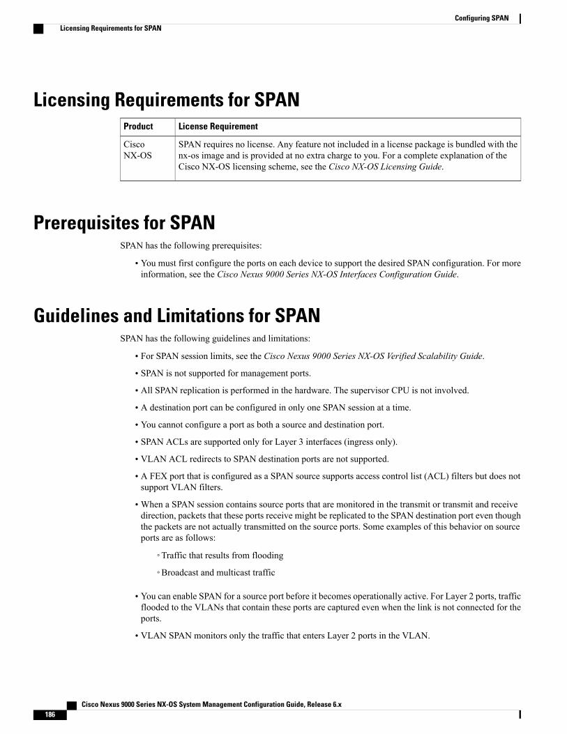
Licensing Requirements for SPANLicense RequirementProduct
SPAN requires no license. Any feature not included in a license package is bundled with thenx-os image and is provided at no extra charge to you. For a complete explanation of theCisco NX-OS licensing scheme, see the Cisco NX-OS Licensing Guide.
CiscoNX-OS
Prerequisites for SPANSPAN has the following prerequisites:
• You must first configure the ports on each device to support the desired SPAN configuration. For moreinformation, see the Cisco Nexus 9000 Series NX-OS Interfaces Configuration Guide.
Guidelines and Limitations for SPANSPAN has the following guidelines and limitations:
• For SPAN session limits, see the Cisco Nexus 9000 Series NX-OS Verified Scalability Guide.
• SPAN is not supported for management ports.
• All SPAN replication is performed in the hardware. The supervisor CPU is not involved.
• A destination port can be configured in only one SPAN session at a time.
• You cannot configure a port as both a source and destination port.
• SPAN ACLs are supported only for Layer 3 interfaces (ingress only).
• VLAN ACL redirects to SPAN destination ports are not supported.
• A FEX port that is configured as a SPAN source supports access control list (ACL) filters but does notsupport VLAN filters.
•When a SPAN session contains source ports that are monitored in the transmit or transmit and receivedirection, packets that these ports receive might be replicated to the SPAN destination port even thoughthe packets are not actually transmitted on the source ports. Some examples of this behavior on sourceports are as follows:
◦Traffic that results from flooding
◦Broadcast and multicast traffic
• You can enable SPAN for a source port before it becomes operationally active. For Layer 2 ports, trafficflooded to the VLANs that contain these ports are captured even when the link is not connected for theports.
• VLAN SPAN monitors only the traffic that enters Layer 2 ports in the VLAN.
Cisco Nexus 9000 Series NX-OS System Management Configuration Guide, Release 6.x186
Configuring SPANLicensing Requirements for SPAN

• VLANs are supported as SPAN sources only in the ingress direction.
• FEX ports are supported as SPAN sources in the ingress direction for all traffic and in the egress directiononly for known Layer 2 unicast traffic.
• You can configure a SPAN session on the local device only.
• SPAN supports only ingress source sessions.
• SPAN is supported on Layer 3 mode. Layer 3 subinterfaces are not supported.
• If you span a core interface when inter-VLAN routing is enabled across Layer 2 multipath (L2MP), itis not possible to capture the traffic egressing out of the core interface.
• Cisco NX-OS does not span Link Layer Discovery Protocol (LLDP) or Link Aggregation ControlProtocol (LACP) packets when the source interface is not a host interface port channel.
• SPAN sessions cannot capture packets with broadcast or multicast MAC addresses that reach thesupervisor, such as ARP requests and Open Shortest Path First (OSPF) protocol hello packets, if thesource of the session is the supervisor Ethernet in-band interface. To capture these packets, you mustuse the physical interface as the source in the SPAN sessions.
Default Settings for SPANThe following table lists the default settings for SPAN parameters.
DefaultParameters
Created in the shut stateSPAN sessions
Configuring SPAN
Cisco NX-OS commands for this feature may differ from those in Cisco IOS.Note
Configuring a SPAN SessionYou can configure a SPAN session on the local device only. By default, SPAN sessions are created in theshut state.
For bidirectional traditional sessions, you can configure the sessions without specifying the direction ofthe traffic.
Note
Before You Begin
You must configure the destination ports in access or trunk mode. For more information, see the Cisco Nexus9000 Series NX-OS Interfaces Configuration Guide.
Cisco Nexus 9000 Series NX-OS System Management Configuration Guide, Release 6.x 187
Configuring SPANDefault Settings for SPAN

Procedure
PurposeCommand or Action
Enters global configuration mode.configure terminal
Example:switch# configure terminalswitch(config)#
Step 1
Enters interface configuration mode on the selectedslot and port.
interface interface slot/port
Example:switch(config)# interface ethernet2/5switch(config-if)#
Step 2
Configures switchport parameters for the selected slotand port or range of ports.
switchport
Example:switch(config-if)# switchport
Step 3
Configures the switchport interface as a SPANdestination:
switchport monitor [ingress [learning]]
Example:switch(config-if)# switchportmonitor
Step 4
• ingress—Allows the SPAN destination port toinject packets that disrupt a certain TCP packetstream.
• ingress learning—Allows the SPANdestinationport to inject packets and allows the learning ofMAC addresses.
(Optional)—
Repeat Steps 2 through 4 to configuremonitoring on additional SPANdestinations.
Step 5
Clears the configuration of the specified SPANsession. The new session configuration is added tothe existing session configuration.
no monitor session session-number
Example:switch(config)# no monitor session3
Step 6
Enters the monitor configuration mode. The newsession configuration is added to the existing session
monitor session session-number [shut]
Example:switch(config)# monitor session 3rxswitch(config-monitor)#
Step 7
configuration. By default, the session is created in theshut state, and the session is a local SPAN session.The optional keyword shut specifies a shut state forthe selected session.
Example:switch(config)# monitor session 3txswitch(config-monitor)#
Cisco Nexus 9000 Series NX-OS System Management Configuration Guide, Release 6.x188
Configuring SPANConfiguring a SPAN Session

PurposeCommand or Action
Example:switch(config)# monitor session 3shutswitch(config-monitor)#
Configures a description for the session. By default,no description is defined. The description can be upto 32 alphanumeric characters.
description description
Example:switch(config-monitor)# descriptionmy_span_session_3
Step 8
Configures sources and the traffic direction in whichto copy packets. You can enter a range of Ethernet
source {interface type | vlan {number |range}} [rx | tx | both]
Step 9
ports, a port channel, an inband interface, a range ofExample:switch(config-monitor)# sourceinterface ethernet 2/1-3, ethernet3/1 rx
VLANs, or a satellite port or host interface portchannel on the Cisco Nexus 2000 Series FabricExtender (FEX).
Example:switch(config-monitor)# sourceinterface port-channel 2
You can configure one or more sources, as either aseries of comma-separated entries or a range ofnumbers. You can specify up to 128 interfaces.
You can specify the traffic direction to copy as ingress(rx), egress (tx), or both. By default, the direction isboth.
Example:switch(config-monitor)# sourceinterface sup-eth 0 both
Source VLANs are supported only in theingress direction. Source FEX ports aresupported in the ingress direction for alltraffic and in the egress direction only forknown Layer 2 unicast traffic.
Note
For a unidirectional session, the direction of the sourcemust match the direction specified in the session.
Example:switch(config-monitor)# source vlan3, 6-8 rx
Example:switch(config-monitor)# sourceinterface ethernet 101/1/1-3
(Optional)—
Repeat Step 9 to configure all SPANsources.
Step 10
(Optional)Configures which VLANs to select from theconfigured sources. You can configure one or more
filter vlan {number | range}
Example:switch(config-monitor)# filter vlan3-5, 7
Step 11
VLANs, as either a series of comma-separated entriesor a range of numbers.
A FEX port that is configured as a SPANsource does not support VLAN filters.
Note
(Optional)—
Repeat Step 11 to configure all sourceVLANs to filter.
Step 12
(Optional)Associates an ACL with the SPAN session.
filter access-group acl-filter
Example:switch(config-monitor)# filteraccess-group ACL1
Step 13
Cisco Nexus 9000 Series NX-OS System Management Configuration Guide, Release 6.x 189
Configuring SPANConfiguring a SPAN Session

PurposeCommand or Action
Configures destinations for copied source packets.You can configure one or more destinations as either
destination interface type {number |range}
Step 14
a series of comma-separated entries or a range ofnumbers. You can specify up to 128 interfaces.Example:
switch(config-monitor)# destinationinterface ethernet 2/5, ethernet3/7
SPAN destination ports must be either accessor trunk ports.
Note
You must enable monitor mode on alldestination ports.
Note
(Optional)—
Repeat Step 14 to configure all SPANdestination ports.
Step 15
Enables the SPAN session. By default, the session iscreated in the shut state.
no shut
Example:switch(config-monitor)# no shut
Step 16
(Optional)Displays the SPAN configuration.
show monitor session {all |session-number | range session-range}[brief]
Step 17
Example:switch(config-monitor)# show monitorsession 3
(Optional)Copies the running configuration to the startupconfiguration.
copy running-config startup-config
Example:switch(config)# copy running-configstartup-config
Step 18
Shutting Down or Resuming a SPAN SessionYou can shut down SPAN sessions to discontinue the copying of packets from sources to destinations. Youcan shut down one session in order to free hardware resources to enable another session. By default, SPANsessions are created in the shut state.
You can resume (enable) SPAN sessions to resume the copying of packets from sources to destinations. Inorder to enable a SPAN session that is already enabled but operationally down, you must first shut it downand then enable it.
You can configure the shut and enabled SPAN session states with either a global or monitor configurationmode command.
Cisco Nexus 9000 Series NX-OS System Management Configuration Guide, Release 6.x190
Configuring SPANShutting Down or Resuming a SPAN Session
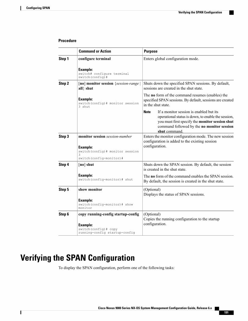
Procedure
PurposeCommand or Action
Enters global configuration mode.configure terminal
Example:switch# configure terminalswitch(config)#
Step 1
Shuts down the specified SPAN sessions. By default,sessions are created in the shut state.
[no] monitor session {session-range |all} shut
Step 2
Example:switch(config)# monitor session3 shut
The no form of the command resumes (enables) thespecified SPAN sessions. By default, sessions are createdin the shut state.
If a monitor session is enabled but itsoperational status is down, to enable the session,you must first specify themonitor session shutcommand followed by the no monitor sessionshut command.
Note
Enters the monitor configuration mode. The new sessionconfiguration is added to the existing sessionconfiguration.
monitor session session-number
Example:switch(config)# monitor session3switch(config-monitor)#
Step 3
Shuts down the SPAN session. By default, the sessionis created in the shut state.
[no] shut
Example:switch(config-monitor)# shut
Step 4
The no form of the command enables the SPAN session.By default, the session is created in the shut state.
(Optional)Displays the status of SPAN sessions.
show monitor
Example:switch(config-monitor)# showmonitor
Step 5
(Optional)Copies the running configuration to the startupconfiguration.
copy running-config startup-config
Example:switch(config)# copyrunning-config startup-config
Step 6
Verifying the SPAN ConfigurationTo display the SPAN configuration, perform one of the following tasks:
Cisco Nexus 9000 Series NX-OS System Management Configuration Guide, Release 6.x 191
Configuring SPANVerifying the SPAN Configuration

PurposeCommand
Displays the SPAN session configuration.show monitor session {all | session-number | rangesession-range} [brief]
Displays the resources that are available for thetraditional sessions.
show resource monitor-session
Configuration Examples for SPAN
Configuration Example for a SPAN SessionTo configure a SPAN session, follow these steps:
Procedure
Step 1 Configure destination ports in access mode and enable SPAN monitoring.
Example:switch# configure terminalswitch(config)# interface ethernet 2/5switch(config-if)# switchportswitch(config-if)# switchport monitorswitch(config-if)# no shutswitch(config-if)# exitswitch(config)#
Step 2 Configure a SPAN session.
Example:switch(config)# no monitor session 3switch(config)# monitor session 3switch(config-monitor)# source interface ethernet 2/1-3, ethernet 3/1 rxswitch(config-monitor)# source interface port-channel 2switch(config-monitor)# source interface sup-eth 0 bothswitch(config-monitor)# source vlan 3, 6-8 rxswitch(config-monitor)# source interface ethernet 101/1/1-3switch(config-monitor)# filter vlan 3-5, 7switch(config-monitor)# destination interface ethernet 2/5switch(config-monitor)# no shutswitch(config-monitor)# exitswitch(config)# show monitor session 3switch(config)# copy running-config startup-config
Configuration Example for a Unidirectional SPAN SessionTo configure a unidirectional SPAN session, follow these steps:
Cisco Nexus 9000 Series NX-OS System Management Configuration Guide, Release 6.x192
Configuring SPANConfiguration Examples for SPAN

Procedure
Step 1 Configure destination ports in access mode and enable SPAN monitoring.
Example:switch# configure terminalswitch(config)# interface ethernet 2/5switch(config-if)# switchportswitch(config-if)# switchport monitorswitch(config-if)# no shutswitch(config-if)# exitswitch(config)#
Step 2 Configure a SPAN session.
Example:switch(config)# no monitor session 3switch(config)# monitor session 3 rxswitch(config-monitor)# source interface ethernet 2/1-3, ethernet 3/1 rxswitch(config-monitor)# filter vlan 3-5, 7switch(config-monitor)# destination interface ethernet 2/5switch(config-monitor)# no shutswitch(config-monitor)# exitswitch(config)# show monitor session 3switch(config)# copy running-config startup-config
Configuration Example for a SPAN ACLThis example shows how to configure a SPAN ACL:switch# configure terminalswitch(config)# ip access-list match_11_pktsswitch(config-acl)# permit ip 11.0.0.0 0.255.255.255 anyswitch(config-acl)# exitswitch(config)# ip access-list match_12_pktsswitch(config-acl)# permit ip 12.0.0.0 0.255.255.255 anyswitch(config-acl)# exitswitch(config)# vlan access-map span_filter 5switch(config-access-map)# match ip address match_11_pktsswitch(config-access-map)# action forwardswitch(config-access-map)# exitswitch(config)# vlan access-map span_filter 10switch(config-access-map)# match ip address match_12_pktsswitch(config-access-map)# action forwardswitch(config-access-map)# exitswitch(config)# monitor session 1 type span-sourceswitch(config-erspan-src)# header-type 3switch(config-erspan-src)# filter access_group span_filter
Cisco Nexus 9000 Series NX-OS System Management Configuration Guide, Release 6.x 193
Configuring SPANConfiguration Example for a SPAN ACL

Additional References
Related DocumentsDocument TitleRelated Topic
Cisco Nexus 2000 Series NX-OS Fabric ExtenderSoftware Configuration Guide for Cisco Nexus 9000Series Switches
FEX
Cisco Nexus 9000 Series NX-OS System Management Configuration Guide, Release 6.x194
Configuring SPANAdditional References

C H A P T E R 16Configuring ERSPAN
This chapter describes how to configure an encapsulated remote switched port analyzer (ERSPAN) totransport mirrored traffic in an IP network on Cisco NX-OS devices.
This chapter contains the following sections:
• About ERSPAN, page 195
• Licensing Requirements for ERSPAN, page 197
• Prerequisites for ERSPAN, page 197
• Guidelines and Limitations for ERSPAN, page 197
• Default Settings, page 198
• Configuring ERSPAN, page 198
• Verifying the ERSPAN Configuration, page 203
• Configuration Examples for ERSPAN, page 203
• Additional References, page 204
About ERSPANERSPAN transports mirrored traffic over an IP network, which provides remote monitoring of multipleswitches across your network. The traffic is encapsulated at the source router and is transferred across thenetwork. The packet is decapsulated at the destination router and then sent to the destination interface.
ERSPAN TypesCisco Nexus 9000 Series switches support only ERSPAN Type II.
Cisco Nexus 9000 Series NX-OS System Management Configuration Guide, Release 6.x 195

ERSPAN SourcesThe interfaces from which traffic can be monitored are called ERSPAN sources. Sources designate the trafficto monitor and whether to copy ingress, egress, or both directions of traffic. ERSPAN sources include thefollowing:
• Ethernet ports (but not subinterfaces)
• Port channels
• The inband interface to the control plane CPU
• VLANs
When a VLAN is specified as an ERSPAN source, all supported interfaces in the VLANare ERSPAN sources.
Note
VLANs can be ERSPAN sources only in the ingress direction.Note
• Satellite ports and host interface port channels on the Cisco Nexus 2000 Series Fabric Extender (FEX)
These interfaces are supported in Layer 2 access mode and Layer 2 trunk mode. Theyare not supported in Layer 3 mode, and Layer 3 subinterfaces are not supported.
Note
FEX ports are supported as ERSPAN sources in the ingress direction for all traffic andin the egress direction only for known Layer 2 unicast traffic.
Note
A single ERSPAN session can include mixed sources in any combination of the above.Note
ERSPAN SessionsYou can create ERSPAN sessions that designate sources to monitor.
High AvailabilityThe ERSPAN feature supports stateless and stateful restarts. After a reboot or supervisor switchover, therunning configuration is applied.
For more information on high availability, see the Cisco Nexus 9000 Series NX-OS High Availability andRedundancy Guide.
Cisco Nexus 9000 Series NX-OS System Management Configuration Guide, Release 6.x196
Configuring ERSPANERSPAN Sources

Licensing Requirements for ERSPANThe following table shows the licensing requirements for this feature:
License RequirementProduct
ERSPAN requires no license. Any feature not included in a license package is bundled withthe nx-os image and is provided at no extra charge to you. For a complete explanation of theCisco NX-OS licensing scheme, see the Cisco NX-OS Licensing Guide.
CiscoNX-OS
Prerequisites for ERSPANERSPAN has the following prerequisites:
• You must first configure the ports on each device to support the desired ERSPAN configuration. Formore information, see the Cisco Nexus 9000 Series NX-OS Interfaces Configuration Guide.
Guidelines and Limitations for ERSPANERSPAN has the following configuration guidelines and limitations:
• For ERSPAN session limits, see the Cisco Nexus 9000 Series NX-OS Verified Scalability Guide.
• Only ERSPAN source sessions are supported. Destination sessions are not supported.
• All ERSPAN replication is performed in the hardware. The supervisor CPU is not involved.
• Control plane packets generated by the supervisor cannot be ERSPAN encapsulated or filtered by anERSPAN access control list (ACL).
• ERSPAN and ERSPAN ACL sessions are terminated identically at the destination router.
• ERSPAN ACLs are supported only for Layer 3 interfaces (ingress only).
• A FEX port that is configured as an ERSPAN source supports ACL filters but does not support VLANfilters.
• ERSPAN is not supported for management ports.
• ERSPAN supports only ingress source sessions.
• You can enable ERSPAN for a source port before it becomes operationally active. For Layer 2 ports,traffic flooded to the VLANs that contain these ports are captured even when the link is not connectedfor the ports.
• For VLAN ERSPAN sessions with both ingress and egress configured, two packets (one from ingressand one from egress) are forwarded from the destination port if the packets get switched on the sameVLAN.
• VLAN ERSPAN monitors only the traffic that leaves or enters Layer 2 ports in the VLAN.
• VLANs are supported as ERSPAN sources only in the ingress direction.
Cisco Nexus 9000 Series NX-OS System Management Configuration Guide, Release 6.x 197
Configuring ERSPANLicensing Requirements for ERSPAN

• FEX ports are supported as ERSPAN sources in the ingress direction for all traffic and in the egressdirection only for known Layer 2 unicast traffic.
• ERSPAN is supported on Layer 3 mode. Layer 3 subinterfaces are not supported.
• If you enable ERSPAN on a vPC and ERSPAN packets need to be routed to the destination through thevPC, packets that come through the vPC peer link cannot be captured.
Default SettingsThe following table lists the default settings for ERSPAN parameters.
Table 13: Default ERSPAN Parameters
DefaultParameters
Created in the shut stateERSPAN sessions
Configuring ERSPAN
Be aware that the Cisco NX-OS commands for this feature may differ from those commands used in CiscoIOS.
Note
Configuring an ERSPAN Source SessionYou can configure an ERSPAN session on the local device only. By default, ERSPAN sessions are createdin the shut state.
ERSPAN does not monitor any packets that are generated by the supervisor, regardless of their source.Note
Procedure
PurposeCommand or Action
Enters global configuration mode.configure terminal
Example:switch# configure terminalswitch(config)#
Step 1
Configures the ERSPAN global origin IP address.monitor erspan origin ip-addressip-address global
Step 2
Cisco Nexus 9000 Series NX-OS System Management Configuration Guide, Release 6.x198
Configuring ERSPANDefault Settings

PurposeCommand or Action
Example:switch(config)# monitor erspanorigin ip-address 10.0.0.1 global
Clears the configuration of the specified ERSPANsession. The new session configuration is added tothe existing session configuration.
nomonitor session {session-number | all}
Example:switch(config)# no monitor session3
Step 3
Configures an ERSPAN Type II source session. Bydefault the session is bidirectional. The optional
monitor session {session-number | all}type erspan-source [shut]
Step 4
keyword shut specifies a shut state for the selectedsession.Example:
switch(config)# monitor session 3type erspan-sourceswitch(config-erspan-src)#
Configures a description for the session. By default,no description is defined. The description can be upto 32 alphanumeric characters.
description description
Example:switch(config-erspan-src)#description erspan_src_session_3
Step 5
Configures the sources and traffic direction in whichto copy packets. You can enter a range of Ethernet
source {interface type | vlan {number |range}} [rx | tx | both]
Step 6
ports, a port channel, an inband interface, a range ofExample:switch(config-erspan-src)# sourceinterface ethernet 2/1-3, ethernet3/1 rx
VLANs, or a satellite port or host interface portchannel on the Cisco Nexus 2000 Series FabricExtender (FEX).
Example:switch(config-erspan-src)# sourceinterface port-channel 2
You can configure one or more sources, as either aseries of comma-separated entries or a range ofnumbers.
You can specify the traffic direction to copy as ingress,egress, or both. The default direction is both.Example:
switch(config-erspan-src)# sourceinterface sup-eth 0 both
Source VLANs are supported only in theingress direction. Source FEX ports aresupported in the ingress direction for alltraffic and in the egress direction only forknown Layer 2 unicast traffic.
Note
For a unidirectional session, the direction of the sourcemust match the direction specified in the session.
Example:switch(config-erspan-src)# sourcevlan 3, 6-8 rx
Example:switch(config-erspan-src)# sourceinterface ethernet 101/1/1-3
(Optional)—
Repeat Step 6 to configure all ERSPANsources.
Step 7
Cisco Nexus 9000 Series NX-OS System Management Configuration Guide, Release 6.x 199
Configuring ERSPANConfiguring an ERSPAN Source Session

PurposeCommand or Action
(Optional)Configures which VLANs to select from theconfigured sources. You can configure one or more
filter vlan {number | range}
Example:switch(config-erspan-src)# filtervlan 3-5, 7
Step 8
VLANs, as either a series of comma-separated entriesor a range of numbers. For information on the VLANrange, see the Cisco Nexus 9000 Series NX-OS Layer2 Switching Configuration Guide.
A FEX port that is configured as an ERSPANsource does not support VLAN filters.
Note
(Optional)—
Repeat Step 8 to configure all sourceVLANs to filter.
Step 9
(Optional)Associates an ACL with the ERSPAN session.
You can create an ACL using the standardACL configuration process. For moreinformation, see theCisco Nexus 9000 SeriesNX-OS Security Configuration Guide.
Note
filter access-group acl-filter
Example:switch(config-erspan-src)# filteraccess-group ACL1
Step 10
Configures the destination IP address in the ERSPANsession. Only one destination IP address is supportedper ERSPAN source session.
destination ip ip-address
Example:switch(config-erspan-src)#destination ip 10.1.1.1
Step 11
Configures the ERSPAN ID for the ERSPAN sourcesession. The ERSPAN range is from 1 to 1023.
erspan-id erspan-id
Example:switch(config-erspan-src)# erspan-id5
Step 12
Configures the virtual routing and forwarding (VRF)instance that the ERSPAN source session uses for
vrf vrf-name
Example:switch(config-erspan-src)# vrfdefault
Step 13
traffic forwarding. The VRF name can be anycase-sensitive, alphanumeric string up to 32 characters.
(Optional)Configures the IP time-to-live (TTL) value for theERSPAN traffic. The range is from 1 to 255.
ip ttl ttl-number
Example:switch(config-erspan-src)# ip ttl25
Step 14
(Optional)Configures the differentiated services code point(DSCP) value of the packets in the ERSPAN traffic.The range is from 0 to 63.
ip dscp dscp-number
Example:switch(config-erspan-src)# ip dscp42
Step 15
Enables the ERSPAN source session. By default, thesession is created in the shut state.
no shut
Example:switch(config-erspan-src)# no shut
Step 16
Cisco Nexus 9000 Series NX-OS System Management Configuration Guide, Release 6.x200
Configuring ERSPANConfiguring an ERSPAN Source Session

PurposeCommand or Action
Exits the monitor configuration mode.exit
Example:switch(config-erspan-src)# exitswitch(config)#
Step 17
(Optional)Displays the ERSPAN session configuration.
show monitor session {all |session-number | range session-range}[brief]
Step 18
Example:switch(config)# show monitor session3
(Optional)Displays the running ERSPAN configuration.
show running-config monitor
Example:switch(config)# show running-configmonitor
Step 19
(Optional)Displays the ERSPAN startup configuration.
show startup-config monitor
Example:switch(config)# show startup-configmonitor
Step 20
(Optional)Copies the running configuration to the startupconfiguration.
copy running-config startup-config
Example:switch(config)# copy running-configstartup-config
Step 21
Shutting Down or Activating an ERSPAN SessionYou can shut down ERSPAN sessions to discontinue the copying of packets from sources to destinations.You can shut down one session in order to free hardware resources to enable another session. By default,ERSPAN sessions are created in the shut state.
You can enable ERSPAN sessions to activate the copying of packets from sources to destinations. To enablean ERSPAN session that is already enabled but operationally down, you must first shut it down and thenenable it. You can shut down and enable the ERSPAN session states with either a global or monitorconfiguration mode command.
Cisco Nexus 9000 Series NX-OS System Management Configuration Guide, Release 6.x 201
Configuring ERSPANShutting Down or Activating an ERSPAN Session

Procedure
PurposeCommand or Action
Enters global configuration mode.configure terminal
Example:switch# configure terminalswitch(config)#
Step 1
Shuts down the specified ERSPAN sessions. Bydefault, sessions are created in the shut state.
monitor session {session-range | all} shut
Example:switch(config)# monitor session 3 shut
Step 2
Resumes (enables) the specified ERSPANsessions. By default, sessions are created in theshut state.
nomonitor session {session-range | all} shut
Example:switch(config)# no monitor session 3shut
Step 3
If a monitor session is enabled but its operationalstatus is down, then to enable the session, youmust first specify themonitor session shutcommand followed by the no monitor sessionshut command.
Enters the monitor configuration mode for theERSPAN source type. The new session
monitor session session-number typeerspan-source
Step 4
configuration is added to the existing sessionconfiguration.Example:
switch(config)# monitor session 3 typeerspan-sourceswitch(config-erspan-src)#
Enters the monitor configuration mode for theERSPAN destination type.
monitor session session-number typeerspan-destination
Example:switch(config-erspan-src)# monitorsession 3 type erspan-destination
Step 5
Shuts down the ERSPAN session. By default, thesession is created in the shut state.
shut
Example:switch(config-erspan-src)# shut
Step 6
Enables the ERSPAN session. By default, thesession is created in the shut state.
no shut
Example:switch(config-erspan-src)# no shut
Step 7
Exits the monitor configuration mode.exit
Example:switch(config-erspan-src)# exitswitch(config)#
Step 8
Cisco Nexus 9000 Series NX-OS System Management Configuration Guide, Release 6.x202
Configuring ERSPANShutting Down or Activating an ERSPAN Session

PurposeCommand or Action
(Optional)Displays the status of ERSPAN sessions.
show monitor session all
Example:switch(config)# show monitor sessionall
Step 9
(Optional)Displays the ERSPAN running configuration.
show running-config monitor
Example:switch(config)# show running-configmonitor
Step 10
(Optional)Displays the ERSPAN startup configuration.
show startup-config monitor
Example:switch(config)# show startup-configmonitor
Step 11
(Optional)Copies the running configuration to the startupconfiguration.
copy running-config startup-config
Example:switch(config)# copy running-configstartup-config
Step 12
Verifying the ERSPAN ConfigurationTo display the ERSPAN configuration, perform one of the following tasks:
PurposeCommand
Displays the ERSPAN session configuration.show monitor session {all | session-number | rangesession-range} [brief]
Displays the running ERSPAN configuration.show running-config monitor
Displays the ERSPAN startup configuration.show startup-config monitor
Configuration Examples for ERSPAN
Configuration Example for a Unidirectional ERSPAN SessionThis example shows how to configure a unidirectional ERSPAN session:switch# configure terminalswitch(config)# interface ethernet 14/30switch(config-if)# no shut
Cisco Nexus 9000 Series NX-OS System Management Configuration Guide, Release 6.x 203
Configuring ERSPANVerifying the ERSPAN Configuration

switch(config-if)# exitswitch(config)# no monitor session 3switch(config)# monitor session 3 rxswitch(config-erspan-src)# source interface ethernet 2/1-3 rxswitch(config-erspan-src)# erspan-id 1switch(config-erspan-src)# ip ttl 16switch(config-erspan-src)# ip dscp 5switch(config-erspan-src)# vrf defaultswitch(config-erspan-src)# destination ip 9.1.1.2switch(config-erspan-src)# no shutswitch(config-erspan-src)# exitswitch(config)# show monitor session 1
Configuration Example for an ERSPAN ACLThis example shows how to configure an ERSPAN ACL:switch# configure terminalswitch(config)# ip access-list match_11_pktsswitch(config-acl)# permit ip 11.0.0.0 0.255.255.255 anyswitch(config-acl)# exitswitch(config)# ip access-list match_12_pktsswitch(config-acl)# permit ip 12.0.0.0 0.255.255.255 anyswitch(config-acl)# exitswitch(config)# vlan access-map erspan_filter 5switch(config-access-map)# match ip address match_11_pktsswitch(config-access-map)# action forwardswitch(config-access-map)# exitswitch(config)# vlan access-map erspan_filter 10switch(config-access-map)# match ip address match_12_pktsswitch(config-access-map)# action forwardswitch(config-access-map)# exitswitch(config)# monitor session 1 type erspan-sourceswitch(config-erspan-src)# header-type 3switch(config-erspan-src)# filter access_group erspan_filter
Additional References
Related DocumentsDocument TitleRelated Topic
Cisco Nexus 2000 Series NX-OS Fabric ExtenderSoftware Configuration Guide for Cisco Nexus 9000Series Switches
FEX
Cisco Nexus 9000 Series NX-OS System Management Configuration Guide, Release 6.x204
Configuring ERSPANConfiguration Example for an ERSPAN ACL

C H A P T E R 17Configuring LLDP
This chapter describes how to configure the Link Layer Discovery Protocol (LLDP) in order to discoverother devices on the local network.
This chapter includes the following sections:
• About LLDP, page 205
• Licensing Requirements for LLDP, page 207
• Guidelines and Limitations for LLDP, page 207
• Default Settings for LLDP, page 207
• Configuring LLDP, page 208
• Verifying the LLDP Configuration, page 211
• Configuration Example for LLDP, page 211
About LLDPThe Cisco Discovery Protocol (CDP) is a device discovery protocol that allows network managementapplications to automatically discover and learn about other Cisco devices that are connected to the network.
To permit the discovery of non-Cisco devices, the switch also supports the Link Layer Discovery Protocol(LLDP), a vendor-neutral device discovery protocol that is defined in the IEEE 802.1ab standard. LLDPallows network devices to advertise information about themselves to other devices on the network. Thisprotocol runs over the data-link layer, which allows two systems running different network layer protocolsto learn about each other.
LLDP is a one-way protocol that transmits information about the capabilities and current status of a deviceand its interfaces. LLDP devices use the protocol to solicit information only from other LLDP devices.
LLDP supports a set of attributes that it uses to discover other devices. These attributes contain type, length,and value (TLV) descriptions. LLDP devices can use TLVs to send and receive information to other deviceson the network. Details such as configuration information, device capabilities, and device identity can beadvertised using this protocol.
LLDP advertises the following TLVs by default:
• DCBXP
Cisco Nexus 9000 Series NX-OS System Management Configuration Guide, Release 6.x 205

• Management address
• Port description
• Port VLAN
• System capabilities
• System description
• System name
About DCBXPThe Data Center Bridging Exchange Protocol (DCBXP) is an extension of LLDP. It is used to announce,exchange, and negotiate node parameters between peers. DCBXP parameters are packaged into a specificDCBXP TLV. This TLV is designed to provide an acknowledgement to the received LLDP packet. In thisway, DCBXP adds a lightweight acknowledgement mechanism on top of LLDP so that any application thatneeds a request-response semantic from a link-level protocol can make use of DCBXP.
Other applications that need to exchange and negotiate parameters with peer nodes using DCBXP are asfollows:
• Priority-based FlowControl (PFC)—PFC is an enhancement to the existing Pausemechanism in Ethernet.It enables Pause based on user priorities or classes of service. A physical link divided into eight virtuallinks with PFC provides the capability to use Pause on a single virtual link without affecting traffic onthe other virtual links. Enabling Pause on a per-user-priority basis allows administrators to create losslesslinks for traffic requiring no-drop service while retaining packet-drop congestion management for IPtraffic.
• Enhanced Transmission Selection (ETS)—ETS enables optimal bandwidth management of virtual links.ETS is also called priority grouping. It enables differentiated treatments within the same priority classesof PFC. ETS provides prioritized processing based on bandwidth allocation, low latency, or best effort,resulting in per-group traffic class allocation. For example, an Ethernet class of traffic may have ahigh-priority designation and a best effort within that same class. ETS allows differentiation betweentraffic of the same priority class, thus creating priority groups.
• Application Priority Configuration TLV—Carries information about which VLANs will be used byspecific protocols.
For information on the quality of service (QoS) features, see the Cisco Nexus 9000 Series NX-OS Qualityof Service Configuration Guide.
Note
DCBXP is enabled by default, provided LLDP is enabled. When LLDP is enabled, DCBXP can be enabledor disabled using the [no] lldp tlv-select dcbxp command. DCBXP is disabled on ports where LLDP transmitor receive is disabled.
High AvailabilityThe LLDP feature supports stateless and stateful restarts. After a reboot or supervisor switchover, the runningconfiguration is applied.
Cisco Nexus 9000 Series NX-OS System Management Configuration Guide, Release 6.x206
Configuring LLDPAbout DCBXP

For more information on high availability, see the Cisco Nexus 9000 Series NX-OS High Availability andRedundancy Guide.
Virtualization SupportOne instance of LLDP is supported.
Licensing Requirements for LLDPLicense RequirementProduct
LLDP requires no license. Any feature not included in a license package is bundled with thenx-os image and is provided at no extra charge to you. For a complete explanation of theCisco NX-OS licensing scheme, see the Cisco NX-OS Licensing Guide.
CiscoNX-OS
Guidelines and Limitations for LLDPLLDP has the following configuration guidelines and limitations:
• LLDP must be enabled on the device before you can enable or disable it on any interfaces.
• LLDP is supported only on physical interfaces.
• LLDP can discover up to one device per port.
• LLDP can discover Linux servers, provided they are not using a converged network adapter (CNA).LLDP cannot discover other types of servers.
• DCBXP incompatibility messages might appear when you change the network QoS policy if a physicalloopback connection is in the device. The incompatibility exists for only a short time and then clears.
Default Settings for LLDPThis table lists the LLDP default settings.
DefaultParameters
DisabledGlobal LLDP
Enabled, after LLDP is enabled globallyLLDP on interfaces
120 secondsLLDP hold time (before discarding)
2 secondsLLDP reinitialization delay
30 secondsLLDP timer (packet update frequency)
EnabledLLDP TLVs
Cisco Nexus 9000 Series NX-OS System Management Configuration Guide, Release 6.x 207
Configuring LLDPVirtualization Support

DefaultParameters
Enabled, after LLDP is enabled globallyLLDP receive
Enabled, after LLDP is enabled globallyLLDP transmit
Enabled, provided LLDP is enabledDCBXP
Configuring LLDP
Cisco NX-OS commands for this feature may differ from Cisco IOS commands for a similar feature.Note
Enabling or Disabling LLDP GloballyYou can enable or disable LLDP globally on a device. You must enable LLDP globally to allow a device tosend and receive LLDP packets.
Procedure
PurposeCommand or Action
Enters global configuration mode.configure terminal
Example:switch# configure terminalswitch(config)#
Step 1
Enables or disables LLDP on the device. LLDPis disabled by default.
[no] feature lldp
Example:switch(config)# feature lldp
Step 2
(Optional)Displays the global LLDP configuration. If LLDPis enabled, it shows "feature lldp." If LLDP isdisabled, it shows an "Invalid command" error.
show running-config lldp
Example:switch(config)# show running-configlldp
Step 3
(Optional)Copies the running configuration to the startupconfiguration.
copy running-config startup-config
Example:switch(config)# copy running-configstartup-config
Step 4
Cisco Nexus 9000 Series NX-OS System Management Configuration Guide, Release 6.x208
Configuring LLDPConfiguring LLDP
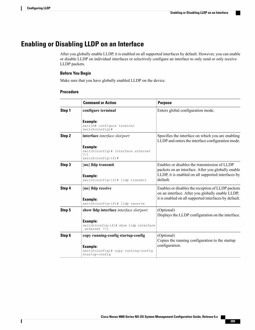
Enabling or Disabling LLDP on an InterfaceAfter you globally enable LLDP, it is enabled on all supported interfaces by default. However, you can enableor disable LLDP on individual interfaces or selectively configure an interface to only send or only receiveLLDP packets.
Before You Begin
Make sure that you have globally enabled LLDP on the device.
Procedure
PurposeCommand or Action
Enters global configuration mode.configure terminal
Example:switch# configure terminalswitch(config)#
Step 1
Specifies the interface on which you are enablingLLDP and enters the interface configurationmode.
interface interface slot/port
Example:switch(config)# interface ethernet7/1switch(config-if)#
Step 2
Enables or disables the transmission of LLDPpackets on an interface. After you globally enable
[no] lldp transmit
Example:switch(config-if)# lldp transmit
Step 3
LLDP, it is enabled on all supported interfaces bydefault.
Enables or disables the reception of LLDP packetson an interface. After you globally enable LLDP,it is enabled on all supported interfaces by default.
[no] lldp receive
Example:switch(config-if)# lldp receive
Step 4
(Optional)Displays the LLDP configuration on the interface.
show lldp interface interface slot/port
Example:switch(config-if)# show lldp interfaceethernet 7/1
Step 5
(Optional)Copies the running configuration to the startupconfiguration.
copy running-config startup-config
Example:switch(config)# copy running-configstartup-config
Step 6
Cisco Nexus 9000 Series NX-OS System Management Configuration Guide, Release 6.x 209
Configuring LLDPEnabling or Disabling LLDP on an Interface

Configuring Optional LLDP ParametersYou can configure the frequency of LLDP updates, the amount of time for a receiving device to hold theinformation before discarding it, and the initialization delay time. You can also select the TLVs to include inLLDP packets.
Procedure
PurposeCommand or Action
Enters global configuration mode.configure terminal
Example:switch# configure terminalswitch(config)#
Step 1
(Optional)Specifies the amount of time in seconds that a receivingdevice should hold the information sent by your devicebefore discarding it.
[no] lldp holdtime seconds
Example:switch(config)# lldp holdtime 200
Step 2
The range is 10 to 255 seconds; the default is 120seconds.
(Optional)Specifies the delay time in seconds for LLDP toinitialize on any interface.
[no] lldp reinit seconds
Example:switch(config)# lldp reinit 5
Step 3
The range is 1 to 10 seconds; the default is 2 seconds.
(Optional)Specifies the transmission frequency of LLDP updatesin seconds.
[no] lldp timer seconds
Example:switch(config)# lldp timer 50
Step 4
The range is 5 to 254 seconds; the default is 30 seconds.
(Optional)Displays the LLDP hold time, delay time, and updatefrequency configuration.
show lldp timers
Example:switch(config)# show lldp timers
Step 5
(Optional)Specifies the TLVs to send and receive in LLDPpackets. The available TLVs are dcbxp,
[no] lldp tlv-select tlv
Example:switch(config)# lldp tlv-selectsystem-name
Step 6
management-address, port-description, port-vlan,system-capabilities, system-description, andsystem-name. All available TLVs are enabled bydefault.
(Optional)Displays the LLDP TLV configuration.
show lldp tlv-select
Example:switch(config)# show lldptlv-select
Step 7
Cisco Nexus 9000 Series NX-OS System Management Configuration Guide, Release 6.x210
Configuring LLDPConfiguring Optional LLDP Parameters

PurposeCommand or Action
(Optional)Copies the running configuration to the startupconfiguration.
copy running-config startup-config
Example:switch(config)# copyrunning-config startup-config
Step 8
Verifying the LLDP ConfigurationTo display the LLDP configuration, perform one of the following tasks:
PurposeCommand
Displays the global LLDP configuration.show running-config lldp
Displays the LLDP interface configuration.show lldp interface interface slot/port
Displays the LLDP hold time, delay time, and updatefrequency configuration.
show lldp timers
Displays the LLDP TLV configuration.show lldp tlv-select
Displays the local DCBX control status.show lldp dcbx interface interface slot/port
Displays the LLDP neighbor device status.show lldp neighbors {detail | interface interfaceslot/port}
Displays the LLDP counters, including the numberof LLDP packets sent and received by the device, thenumber of discarded packets, and the number ofunrecognized TLVs.
show lldp traffic
Displays the number of LLDP packets sent andreceived on the interface.
show lldp traffic interface interface slot/port
Use the clear lldp counters command to clear the LLDP statistics.
Configuration Example for LLDPThis example shows how to enable LLDP on a device; disable LLDP on some interfaces; configure optionalparameters such as hold time, delay time, and update frequency; and disable several LLDP TLVs:switch# configure terminalEnter configuration commands, one per line. End with CNTL/Z.switch(config)# feature lldpswitch(config)# interface ethernet 7/9switch(config-if)# no lldp transmitswitch(config-if)# no lldp receiveswitch(config-if)# exitswitch(config)# interface ethernet 7/10
Cisco Nexus 9000 Series NX-OS System Management Configuration Guide, Release 6.x 211
Configuring LLDPVerifying the LLDP Configuration

switch(config-if)# no lldp transmitswitch(config-if)# no lldp receiveswitch(config-if)# exitswitch(config)# lldp holdtime 200switch(config)# lldp reinit 5switch(config)# lldp timer 50switch(config)# no lldp tlv-select port-vlanswitch(config)# no lldp tlv-select system-name
Cisco Nexus 9000 Series NX-OS System Management Configuration Guide, Release 6.x212
Configuring LLDPConfiguration Example for LLDP

C H A P T E R 18Performing Software Maintenance Upgrades
This chapter describes how to perform software maintenance upgrades (SMUs) on Cisco NX-OS devices.
This chapter includes the following sections:
• About SMUs, page 213
• Prerequisites for SMUs, page 215
• Guidelines and Limitations for SMUs, page 215
• Performing a Software Maintenance Upgrade, page 215
• Displaying Installation Log Information, page 225
• Additional References, page 227
About SMUsA software maintenance upgrade (SMU) is a package file that contains fixes for a specific defect. SMUs arecreated to respond to immediate issues and do not include new features. Typically, SMUs do not have a largeimpact on device operations. SMU versions are synchronized to the package major, minor, and maintenanceversions they upgrade.
The effect of an SMU depends on its type:
• Process restart SMU-Causes a process or group of processes to restart on activation.
• Reload SMU-Causes a parallel reload of supervisors and line cards.
SMUs are not an alternative to maintenance releases. They provide a quick resolution of immediate issues.All defects fixed by SMUs are integrated into the maintenance releases.
For information on upgrading your device to a new feature or maintenance release, see the Cisco Nexus 9000Series NX-OS Software Upgrade and Downgrade Guide.
Activating an SMU does not cause any earlier SMUs, or the package to which the SMU applies, to beautomatically deactivated.
Note
Cisco Nexus 9000 Series NX-OS System Management Configuration Guide, Release 6.x 213

Package ManagementThe general procedure for adding and activating SMU packages on the device is as follows:
1 Copy the package file or files to a local storage device or file server.2 Add the package or packages on the device using the install add command.3 Activate the package or packages on the device using the install activate command.4 Commit the current set of packages using the install commit command.5 (Optional) Deactivate and remove the package, when desired.
The following figure illustrates the key steps in the package management process.
Figure 5: Process to Add, Activate, and Commit SMU Packages
Impact of Package Activation and DeactivationThe activation or deactivation of an SMU package can have an immediate impact on the system. The systemcan be affected in the following ways:
• New processes might be started.
• Running processes might be stopped or restarted.
• All processes in the line cards might be restarted. Restarting processes in the line cards is equivalent toa soft reset.
• The line cards might reload.
• No processes in the line cards might be affected.
You must address any issues that result from the revised configuration and reapply the configuration, ifnecessary.
Note
Cisco Nexus 9000 Series NX-OS System Management Configuration Guide, Release 6.x214
Performing Software Maintenance UpgradesPackage Management
When you activate packages, use the test option to test the effects of a command without impacting therunning system. After the activation process completes, enter the show install log command to displaythe process results.
Tip
Prerequisites for SMUsThese prerequisites must be met for a package to be activated or deactivated:
• Youmust be in a user group associated with a task group that includes the proper task IDs. If you suspecta user group assignment is preventing you from using a command, contact your AAA administrator forassistance.
• Verify that all line cards are installed and operating properly. For example, do not activate or deactivatepackages while line cards are booting, while line cards are being upgraded or replaced, or when youanticipate an automatic switchover activity.
Guidelines and Limitations for SMUsSMUs have the following guidelines and limitations:
• Some packages require the activation or deactivation of other packages. If the SMUs have dependencieson each other, you cannot activate them without first activating the previous ones.
• The package being activated must be compatible with the current active software set.
• You cannot activate multiple SMUs in one command.
• Activation is performed only after the package compatibility checks have been passed. If a conflict isfound, an error message displays.
•While a software package is being activated, other requests are not allowed to run on any of the impactednodes. Package activation is completed when a message similar to this one appears:Install operation 1 completed successfully at Thu Jan 9 01:19:24 2014
• Each CLI install request is assigned a request ID, which can be used later to review the events.
• If you perform a software maintenance upgrade and later upgrade your device to a new Cisco NX-OSsoftware release, the new image will overwrite both the previous Cisco NX-OS release and the SMUpackage file.
Performing a Software Maintenance Upgrade
Preparing for Package InstallationYou should use several show commands to gather information in preparation for the SMU package installation.
Cisco Nexus 9000 Series NX-OS System Management Configuration Guide, Release 6.x 215
Performing Software Maintenance UpgradesPrerequisites for SMUs

Before You Begin
Determine if a software change is required.
Verify that the new package is supported on your system. Some software packages require that other packagesor package versions be activated, and some packages support only specific line cards.
Review the release notes for important information related to that release and to help determine the packagecompatibility with your device configuration.
Verify that the system is stable and prepared for the software changes.
Procedure
PurposeCommand or Action
Displays the active software on the device. Use thiscommand to determine what software should be added on
show install active
Example:switch# show install active
Step 1
the device and to compare to the active software reportafter installation operations are complete.
Confirms that all modules are in the stable state.show module
Example:switch# show module
Step 2
Verifies that the system clock is correct. Softwareoperations use certificates based on device clock times.
show clock
Example:switch# show clock
Step 3
This example shows how to display the active packages for the entire system. Use this information to determineif a software change is required.switch# show install activeActive Packages:Active Packages on Module #3:
Active Packages on Module #6:
Active Packages on Module #7:Active Packages on Module #22:
Active Packages on Module #30:
This example shows how to display the current system clock setting:switch# show clock02:14:51.474 PST Wed Jan 04 2014
Downloading the SMU Package File from Cisco.comFollow these steps to download the SMU package file:
Cisco Nexus 9000 Series NX-OS System Management Configuration Guide, Release 6.x216
Performing Software Maintenance UpgradesDownloading the SMU Package File from Cisco.com
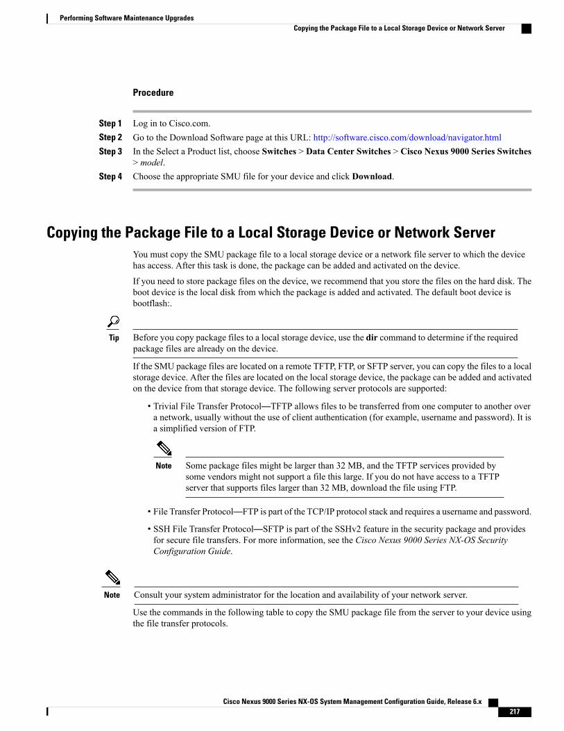
Procedure
Step 1 Log in to Cisco.com.Step 2 Go to the Download Software page at this URL: http://software.cisco.com/download/navigator.htmlStep 3 In the Select a Product list, choose Switches > Data Center Switches > Cisco Nexus 9000 Series Switches
> model.Step 4 Choose the appropriate SMU file for your device and click Download.
Copying the Package File to a Local Storage Device or Network ServerYou must copy the SMU package file to a local storage device or a network file server to which the devicehas access. After this task is done, the package can be added and activated on the device.
If you need to store package files on the device, we recommend that you store the files on the hard disk. Theboot device is the local disk from which the package is added and activated. The default boot device isbootflash:.
Before you copy package files to a local storage device, use the dir command to determine if the requiredpackage files are already on the device.
Tip
If the SMU package files are located on a remote TFTP, FTP, or SFTP server, you can copy the files to a localstorage device. After the files are located on the local storage device, the package can be added and activatedon the device from that storage device. The following server protocols are supported:
• Trivial File Transfer Protocol—TFTP allows files to be transferred from one computer to another overa network, usually without the use of client authentication (for example, username and password). It isa simplified version of FTP.
Some package files might be larger than 32 MB, and the TFTP services provided bysome vendors might not support a file this large. If you do not have access to a TFTPserver that supports files larger than 32 MB, download the file using FTP.
Note
• File Transfer Protocol—FTP is part of the TCP/IP protocol stack and requires a username and password.
• SSH File Transfer Protocol—SFTP is part of the SSHv2 feature in the security package and providesfor secure file transfers. For more information, see the Cisco Nexus 9000 Series NX-OS SecurityConfiguration Guide.
Consult your system administrator for the location and availability of your network server.Note
Use the commands in the following table to copy the SMU package file from the server to your device usingthe file transfer protocols.
Cisco Nexus 9000 Series NX-OS System Management Configuration Guide, Release 6.x 217
Performing Software Maintenance UpgradesCopying the Package File to a Local Storage Device or Network Server
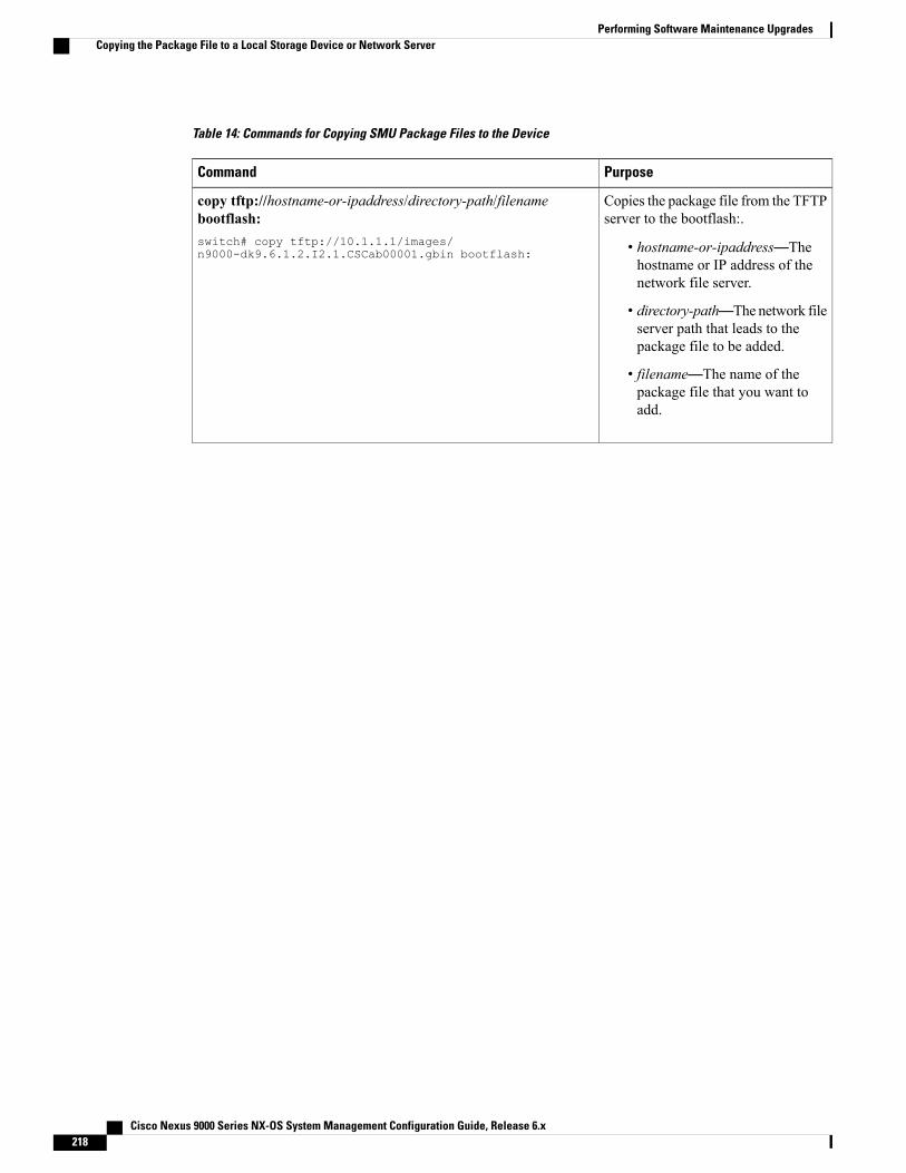
Table 14: Commands for Copying SMU Package Files to the Device
PurposeCommand
Copies the package file from the TFTPserver to the bootflash:.
• hostname-or-ipaddress—Thehostname or IP address of thenetwork file server.
• directory-path—The network fileserver path that leads to thepackage file to be added.
• filename—The name of thepackage file that you want toadd.
copy tftp://hostname-or-ipaddress/directory-path/filenamebootflash:switch# copy tftp://10.1.1.1/images/n9000-dk9.6.1.2.I2.1.CSCab00001.gbin bootflash:
Cisco Nexus 9000 Series NX-OS System Management Configuration Guide, Release 6.x218
Performing Software Maintenance UpgradesCopying the Package File to a Local Storage Device or Network Server

PurposeCommand
Copies the package file from the FTPserver to the bootflash:.
• username—The username of theuser who has access privilegesto the directory in which thepackage file is stored.
• password—The passwordassociated with the username ofthe user who has accessprivileges to the directory inwhich the package file is stored.If a password is not provided, thenetworking device acceptsanonymous FTP.
• hostname-or-ipaddress—Thehostname or IP address of thenetwork file server.
• directory-path—The network fileserver path that leads to thepackage file to be added. Thespecified directory should be adirectory under the homedirectory of the user. In thisexample, the file beingdownloaded is in a subdirectorycalled "images" in the homedirectory of the user "john."
For FTP services,directory-path is thedirectory relative to theusername homedirectory. If you want tospecify an absolute pathfor the directory, youmust add a “/” followingthe server address.
Note
• filename—The name of thepackage file that you want toadd.
copyftp://username:password@hostname-or-ipaddress/directory-path/filenamebootflash:switch# copy ftp://john:[email protected]/images/n9000-dk9.6.1.2.I2.1.CSCab00001.gbin bootflash:
Cisco Nexus 9000 Series NX-OS System Management Configuration Guide, Release 6.x 219
Performing Software Maintenance UpgradesCopying the Package File to a Local Storage Device or Network Server

PurposeCommand
Copies the package file from the SFTPserver to the bootflash:.
• hostname-or-ipaddress—Thehostname or IP address of thenetwork file server.
• directory-path—The network fileserver path that leads to thepackage file to be added.
• filename—The name of thepackage file that you want toadd.
copy sftp://hostname-or-ipaddress/directory-path/filenamebootflash:switch# copysftp://10.1.1.1/images/n9000-dk9.6.1.2.I2.1.CSCab00001.gbin bootflash:
After the SMU package file has been transferred to a network file server or the local storage device, you areready to add and activate the file.
Adding and Activating PackagesYou can add SMU package files that are stored on a local storage device or on a remote TFTP, FTP, or SFTPserver to your device.
The SMU package being activatedmust be compatible with the currently active software to operate.Whenan activation is attempted, the system runs an automatic compatibility check to ensure that the package iscompatible with the other active software on the device. If a conflict is found, an error message displays.The activation is performed only after all compatibility checks have been passed.
Note
Activating an SMU does not cause any earlier SMUs or the package to which the SMU applies to beautomatically deactivated.
Note
Before You Begin
Make sure that all packages to be added are present on a local storage device or a network file server.
Make sure that you meet all of the prerequisites for the activation of packages.
Complete the procedure described in Copying the Package File to a Local Storage Device or Network Server,on page 217.
Cisco Nexus 9000 Series NX-OS System Management Configuration Guide, Release 6.x220
Performing Software Maintenance UpgradesAdding and Activating Packages

Procedure
PurposeCommand or Action
Establishes a CLI management session to the consoleport.
Connect to the console port and log in.Step 1
(Optional)Displays the package files that are available to be added.
dir bootflash:Step 2
Only SMU package files can be added andactivated using this procedure.
Note
Unpacks the package software files from the localstorage device or network server and adds them to the
install add filename [activate]
Example:switch# install add bootflash:n9000-dk9.6.1.2.I2.1.CSCab00001.gbin
Step 3
bootflash: and all active and standby supervisors installedon the device.
The filename argument can take any of these formats:
• bootflash:filename
• tftp://hostname-or-ipaddress/directory-path/filename
• ftp://username:password@hostname-or-ipaddress/directory-path/filename
• sftp://hostname-or-ipaddress/directory-path/filename
• usb1:filename
• usb2:filename
Use the activate keyword to automatically activate thepackage after it is added successfully.
Multiple versions of an SMU package can beadded to the storage device without impactingthe running configuration, but only one versionof a package can be activated for a line card.
Note
(Optional)Displays the inactive packages on the device. Verify thatthe package added in the previous step appears in thedisplay.
show install inactive
Example:switch# show install inactive
Step 4
Activates a package that was added to the device. SMUpackages remain inactive until activated. (Skip this step
install activate filename [test]
Example:switch# install activaten9000-dk9.6.1.2.I2.1.CSCab00001.gbin
Step 5
if the package was activated earlier with the install addactivate command.)
Press ? after a partial package name to displayall possible matches available for activation. Ifthere is only one match, press the Tab key tofill in the rest of the package name.
Note
Cisco Nexus 9000 Series NX-OS System Management Configuration Guide, Release 6.x 221
Performing Software Maintenance UpgradesAdding and Activating Packages

PurposeCommand or Action
When you activate packages, use the testkeyword to test the effects of a commandwithoutimpacting the running system. After theactivation process finishes, enter the show installlog command to display the process results.
Tip
Example:switch# install activaten9000-dk9.6.1.2.I2.1.CSCab00001.gbintestWARNING! No changes will occur dueto 'test' optionWARNING! The following is thepredicted output forthis commadInstall operation 1 completedsuccessfully atThu Jan 9 01:27:56 2014
Example:switch# install activaten9000-dk9.6.1.2.I2.1.CSCab00001.gbinInstall operation 18 !!WARNING!!This patch will getactivated only after a reload of theswitch. atSun Mar 9 00:42:12 2014
Activates additional packages as required.Repeat Step 5 until all packages areactivated.
Step 6
(Optional)Displays all active packages. Use this command todetermine if the correct packages are active.
show install active
Example:switch# show install active
Step 7
Committing the Active Package SetWhen an SMU package is activated on the device, it becomes part of the current running configuration. Tomake the package activation persistent across system-wide reloads, you must commit the package on thedevice.
On startup, the device loads the committed package set. If the system is reloaded before the current activepackage is committed, the previously committed package set is used.
Note
Before You Begin
Before you commit a package set, verify that the device is operating correctly and is forwarding packets asexpected.
Complete the procedure described in Adding and Activating Packages, on page 220.
Cisco Nexus 9000 Series NX-OS System Management Configuration Guide, Release 6.x222
Performing Software Maintenance UpgradesCommitting the Active Package Set

Procedure
PurposeCommand or Action
Commits the current set of packages so that thesepackages are used if the device is restarted.
install commit filename
Example:switch# install commitn9000-dk9.6.1.2.I2.1.CSCab00001.gbin
Step 1
Reloads the standby supervisor module, if installed.reload module standby-sup-slotStep 2
Example:switch# reload module 2
If you are applying the SMU package in adual-supervisor system and your device isrunning Cisco NX-OS Release 6.1(2)I2(3)or a software release prior to Cisco NX-OS6.1(2)I2(2b), you must reload the standbysupervisor module.
Note
(Optional)Displays which packages are committed.
show install committed
Example:switch# show install committed
Step 3
This example shows how to commit active SMU packages on the device and then verify the committedpackages:switch# install commit n9000-dk9.6.1.2.I2.1.CSCab00001.gbinInstall operation 2 completed successfully at Thu Jan 9 01:20:46 2014
switch# show install committedCommitted Packages:n9000-dk9.6.1.2.I2.1.CSCab00001.gbin
Deactivating and Removing PackagesWhen a package is deactivated, it is no longer active on the device, but the package files remain on the bootdisk. The package files can be reactivated later, or they can be removed from the disk.
The Cisco NX-OS software also provides the flexibility to roll back the selected package set to a previouslysaved package set. If you find that you prefer a previous package set over the currently active package set,you can use the install deactivate and install commit commands to make a previously active package setactive again.
Before You Begin
You cannot deactivate a package if it is required by another active package. When you attempt to deactivatea package, the system runs an automatic check to ensure that the package is not required by other activepackages. The deactivation is performed only after all compatibility checks have been passed.
You cannot delete a package if it is part of the running or committed software of the device.
Cisco Nexus 9000 Series NX-OS System Management Configuration Guide, Release 6.x 223
Performing Software Maintenance UpgradesDeactivating and Removing Packages

Procedure
PurposeCommand or Action
Establishes a CLI management session to the consoleport.
Connect to the console port and log in.Step 1
Reloads the standby supervisor module, if installed.reload module standby-sup-slotStep 2
Example:switch# reload module 2
If you are deactivating the SMU package ina dual-supervisor system and your device isrunning Cisco NX-OS Release 6.1(2)I2(3) ora software release prior to Cisco NX-OS6.1(2)I2(2b), you must reload the standbysupervisor module.
Note
Deactivates a package that was added to the deviceand turns off the package features for the line card.
install deactivate filename
Example:switch# install deactivaten9000-dk9.6.1.2.I2.1.CSCab00001.gbin
Step 3
Press ? after a partial package name to displayall possiblematches available for deactivation.If there is only one match, press the Tab keyto fill in the rest of the package name.
Note
(Optional)Displays the inactive packages on the device.
show install inactive
Example:switch# show install inactive
Step 4
(Optional)Commits the current set of packages so that thesepackages are used if the device is restarted.
install commit
Example:switch# install commit
Step 5
Packages can be removed only if thedeactivation operation is committed.
Note
(Optional)Removes the inactive package.
install remove {filename | inactive}
Example:switch# install removen9000-dk9.6.1.2.I2.1.CSCab00001.gbin
Step 6
• Only inactive packages can be removed.
• Packages can be removed only if they aredeactivated from all line cards in the device.
Proceed with removingn9000-dk9.6.1.2.I2.1.CSCab00001.gbin?(y/n)? [n] y
• The package deactivation must be committed.Example:switch# install remove inactiveProceed with removing? (y/n)? [n] y
• To remove a specific inactive package from astorage device, use the install remove commandwith the filename argument.
• To remove all inactive packages from all nodesin the system, use the install remove commandwith the inactive keyword.
Cisco Nexus 9000 Series NX-OS System Management Configuration Guide, Release 6.x224
Performing Software Maintenance UpgradesDeactivating and Removing Packages

This example shows how to deactivate a package, commit the changes, and remove the inactive package fromthe device:switch# install deactivate n9000-dk9.6.1.2.I2.1.CSCab00001.gbinInstall operation 3 completed successfully at Thu Jan 9 01:20:36 2014
switch# show install inactiveInactive Packages:n9000-dk9.6.1.2.I2.1.CSCab00001.gbin
switch# install commitInstall operation 4 completed successfully at Thu Jan 9 01:20:46 2014
switch# install remove n9000-dk9.6.1.2.I2.1.CSCab00001.gbinProceed with removing n9000-dk9.6.1.2.I2.1.CSCab00001.gbin? (y/n)? [n] yInstall operation 5 completed successfully at Thu Jan 9 01:20:57 2014
Displaying Installation Log InformationThe installation log provides information on the history of the installation operations. Each time an installationoperation is run, a number is assigned to that operation.
• Use the show install log command to display information about both successful and failed installationoperations.
• Use the show install log command with no arguments to display a summary of all installation operations.Specify the request-id argument to display information specific to an operation. Use the detail keywordto display details for a specific operation, including file changes, nodes that could not be reloaded, andany impact to processes.
This example shows how to display information for all installation requests:switch# show install logThu Jan 9 01:26:09 2014Install operation 1 by user 'admin' at Thu Jan 9 01:19:19 2014Install add bootflash:n9000-dk9.6.1.2.I2.1.CSCab00001.gbinInstall operation 1 completed successfully at Thu Jan 9 01:19:24 2014----------------------------------------Install operation 2 by user 'admin' at Thu Jan 9 01:19:29 2014Install activate n9000-dk9.6.1.2.I2.1.CSCab00001.gbinInstall operation 2 completed successfully at Thu Jan 9 01:19:45 2014----------------------------------------Install operation 3 by user 'admin' at Thu Jan 9 01:20:05 2014Install commit n9000-dk9.6.1.2.I2.1.CSCab00001.gbinInstall operation 3 completed successfully at Thu Jan 9 01:20:08 2014----------------------------------------Install operation 4 by user 'admin' at Thu Jan 9 01:20:21 2014Install deactivate n9000-dk9.6.1.2.I2.1.CSCab00001.gbinInstall operation 4 completed successfully at Thu Jan 9 01:20:36 2014----------------------------------------Install operation 5 by user 'admin' at Thu Jan 9 01:20:43 2014Install commit n9000-dk9.6.1.2.I2.1.CSCab00001.gbinInstall operation 5 completed successfully at Thu Jan 9 01:20:46 2014----------------------------------------Install operation 6 by user 'admin' at Thu Jan 9 01:20:55 2014Install remove n9000-dk9.6.1.2.I2.1.CSCab00001.gbinInstall operation 6 completed successfully at Thu Jan 9 01:20:57 2014----------------------------------------Install operation 7 by user 'admin' at Thu Jan 9 01:21:07 2014Install removeInstall operation 7 completed successfully at Thu Jan 9 01:21:10 201
This example shows how to display additional information, including any impact to nodes and processes:switch# show install log detailThu Jan 9 01:24:03 2014
Cisco Nexus 9000 Series NX-OS System Management Configuration Guide, Release 6.x 225
Performing Software Maintenance UpgradesDisplaying Installation Log Information

Install operation 1 by user 'admin' at Thu Jan 9 01:19:19 2014Installer started downloading the package: /n9000-dk9.6.1.2.I2.1.CSCab00001.gbinvia bootflashInstall add bootflash:n9000-dk9.6.1.2.I2.1.CSCab00001.gbinCopying file at Thu Jan 9 01:19:20 2014Download success, 238545 bytes receivedVerifying packageChecking MD5 at Thu Jan 9 01:19:21 2014MD5 checksum OKChecking HW platform at Thu Jan 9 01:19:22 2014Checking SW platform at Thu Jan 9 01:19:23 2014Package verified successfullySending patch file to plugin manager at Thu Jan 9 01:19:23 2014The following package is now available to be activated: n9000-dk9.6.1.2.I2.1.CSCab00001.gbinInstall operation 1 completed successfully at Thu Jan 9 01:19:24 2014----------------------------------------Install operation 2 by user 'admin' at Thu Jan 9 01:19:29 2014Install activate n9000-dk9.6.1.2.I2.1.CSCab00001.gbinInstall activate action startedThe software will be activated with process restart2 processes affectedsysinfo (modified)vman (modified)Install operation 2 completed successfully at Thu Jan 9 01:19:45 2014----------------------------------------Install operation 3 by user 'admin' at Thu Jan 9 01:20:05 2014Install commit n9000-dk9.6.1.2.I2.1.CSCab00001.gbinMD5 checksum OK for patch: n9000-dk9.6.1.2.I2.1.CSCab00001.gbinInstall operation 3 completed successfully at Thu Jan 9 01:20:08 2014----------------------------------------Install operation 4 by user 'admin' at Thu Jan 9 01:20:21 2014Install deactivate n9000-dk9.6.1.2.I2.1.CSCab00001.gbinInstall deactivate action startedThe software will be deactivated with process restart2 processes affectedsysinfo (modified)vman (modified)Install operation 4 completed successfully at Thu Jan 9 01:20:36 2014----------------------------------------Install operation 5 by user 'admin' at Thu Jan 9 01:20:43 2014Install commit n9000-dk9.6.1.2.I2.1.CSCab00001.gbinMD5 checksum OK for patch: n9000-dk9.6.1.2.I2.1.CSCab00001.gbinInstall operation 5 completed successfully at Thu Jan 9 01:20:46 2014----------------------------------------Install operation 6 by user 'admin' at Thu Jan 9 01:20:55 2014Install remove n9000-dk9.6.1.2.I2.1.CSCab00001.gbinInstall operation 6 completed successfully at Thu Jan 9 01:20:57 2014----------------------------------------Install operation 7 by user 'admin' at Thu Jan 9 01:21:07 2014Install removeInstall operation 7 completed successfully at Thu Jan 9 01:21:10 2014
This example shows the output after an SMU package has been activated but before the switch has beenreloaded:switch# show install log detailInstall operation 18 by user 'admin' at Sun Mar 9 00:42:10 2014Install activate n9000-dk9.6.1.2.I2.1.CSCab00001.gbinInstall activate action startedThe software will be activated with system reloadInstall operation 18 !!WARNING!! This patch will get activated only aftera reload of the switch. at Sun Mar 9 00:42:12 2014
Cisco Nexus 9000 Series NX-OS System Management Configuration Guide, Release 6.x226
Performing Software Maintenance UpgradesDisplaying Installation Log Information

Additional References
Related DocumentsDocument TitleRelated Topic
Cisco Nexus 9000 Series NX-OS Software Upgradeand Downgrade Guide
Software upgrades
Cisco Nexus 9000 Series NX-OS System Management Configuration Guide, Release 6.x 227
Performing Software Maintenance UpgradesAdditional References

Cisco Nexus 9000 Series NX-OS System Management Configuration Guide, Release 6.x228
Performing Software Maintenance UpgradesRelated Documents

A P P E N D I X AIETF RFCs supported by Cisco NX-OS SystemManagement
This appendix lists the IETF RFCs for system management supported in Cisco NX-OS.
• IETF RFCs Supported by Cisco NX-OS System Management, page 229
IETF RFCs Supported by Cisco NX-OS System ManagementThis appendix lists the IETF RFCs for system management supported in Cisco NX-OS.
TitleRFCs
Remote Network Monitoring Management InformationBase
RFC 2819
The BSD syslog ProtocolRFC 3164
An Architecture for Describing Simple NetworkManagement Protocol (SNMP) Management Frameworks
RFC 3411 and RFC 3418
Cisco Nexus 9000 Series NX-OS System Management Configuration Guide, Release 6.x 229

Cisco Nexus 9000 Series NX-OS System Management Configuration Guide, Release 6.x230
IETF RFCs supported by Cisco NX-OS System ManagementIETF RFCs Supported by Cisco NX-OS System Management

A P P E N D I X BEmbedded Event Manager System Events andConfiguration Examples
This appendix describes the Embedded EventManager (EEM) system policies, events, and policy configurationexamples.
This appendix includes the following sections:
• EEM System Policies, page 231
• EEM Events, page 233
• Configuration Examples for EEM Policies, page 235
EEM System PoliciesThe following table lists the Embedded Event Manager (EEM) system policies.
DescriptionEvent
Do CallHome, log error in Syslog/OBFL/ExceptionLog, and disable further HM testing on affected portsafter 10 consecutive failures of GOLD"PortLoopback" test
__PortLoopback
Do CallHome, log error in Syslog/OBFL/ExceptionLog, and disable further HM testing on affected portsafter 10 consecutive failures of GOLD"RewriteEngine" test
__RewriteEngineLoopback
Do CallHome, log error, and disable further HMtesting for that ASIC device/instance after 20consecutive failures of GOLD "ASICRegisterCheck"test
__asic_register_check
Cisco Nexus 9000 Series NX-OS System Management Configuration Guide, Release 6.x 231

DescriptionEvent
Do CallHome, log error, and disable further HMtesting after 20 consecutive failures of GOLD"CompactFlash" test
__compact_flash
Do CallHome and log error when GOLD"CryptoDevice" test fails
__crypto_device
Do CallHome and log error when GOLD"EOBCPortLoopback" test fails
__eobc_port_loopback
Action: none__ethpm_debug_1
Action: none__ethpm_debug_2
Action: none__ethpm_debug_3
Action: none__ethpm_debug_4
More than 30 link flaps in a 420-second interval.Action: Error. Disable the port
__ethpm_link_flap
Do CallHome, log error, and disable further HMtesting after 20 consecutive failures of GOLD"ExternalCompactFlash" test
__external_compact_flash
Power cycle two times and then power down__lcm_module_failure
Do CallHome and log error when GOLD"ManagementPortLoopback" test fails
__management_port_loopback
Do CallHome, log error, and disable further HMtesting after 20 consecutive failures of GOLD"NVRAM" test
__nvram
Shuts down if both fan trays (f1 and f2) are absentfor 2 minutes
__pfm_fanabsent_all_systemfan
Syslog when fan goes bad__pfm_fanbad_all_systemfan
Syslog when fan goes bad__pfm_fanbad_any_singlefan
Syslog warning for insufficient power overbudget__pfm_power_over_budget
TempSensor Major Threshold. Action: Shutdown__pfm_tempev_major
TempSensor Minor Threshold. Action: Syslog__pfm_tempev_minor
Cisco Nexus 9000 Series NX-OS System Management Configuration Guide, Release 6.x232
Embedded Event Manager System Events and Configuration ExamplesEEM System Policies

DescriptionEvent
Do CallHome, log error, and disable further HMtesting after 20 consecutive failures of GOLD"PrimaryBootROM" test
__primary_bootrom
Do CallHome, log error, and disable further HMtesting for the module or spine-card after 20consecutive failures of GOLD "PwrMgmtBus" test
__pwr_mgmt_bus
Do CallHome, log error, and disable further HMtesting after 20 consecutive failures of GOLD"RealTimeClock" test
__real_time_clock
Do CallHome, log error, and disable further HMtesting after 20 consecutive failures of GOLD"SecondaryBootROM" test
__secondary_bootrom
Do CallHome, log error, and disable further HMtesting for that module or spine-card after 20consecutive failures of GOLD "SpineControlBus"test
__spine_control_bus
Do CallHome, log error, and disable further HMtesting after 10 consecutive failures
__standby_fabric_loopback
Do CallHome, log error, and disable further HMtesting after 5 consecutive failures of GOLD"StatusBus" test
__status_bus
Do Call Home, log error, and disable further HMtesting for that fan or power supply after 20consecutive failures of GOLD "SystemMgmtBus"test
__system_mgmt_bus
Do Call Home and log error when GOLD "USB" testfails
__usb
EEM EventsThe following table describes the EEM events you can use on the device.
DescriptionEEM Event
Publishes an application-specific event.application
CLI command is entered that matches a pattern witha wildcard.
cli
Cisco Nexus 9000 Series NX-OS System Management Configuration Guide, Release 6.x 233
Embedded Event Manager System Events and Configuration ExamplesEEM Events

DescriptionEEM Event
EEM counter reaches a specified value or range.counter
System fan tray is absent.fanabsent
System fan generates a fault.fanbad
Monitors routes or TCAM usage in the unicast FIB.fib
GOLD test failure condition is hit.gold
Interface counter exceeds a threshold.interface
Available system memory exceeds a threshold.memory
Specified module enters the selected status.module
Module failure is generated.module-failure
Runs the policy event without any events specified.none
Online insertion or removal occurs.oir
Default parameters and thresholds are used for theevents in the system policy you override.
policy-default
Platform software detects a power budget condition.poweroverbudget
SNMP object ID (OID) state changes.snmp
Platform software detects an Ethernet packet stormcondition.
storm-control
Monitors syslog messages and invokes the policybased on the search string in the policy.
syslog
System manager generates an event.sysmgr
Temperature level in the system exceeds a threshold.temperature
Specified time is reached.timer
Tracked object changes state.track
Cisco Nexus 9000 Series NX-OS System Management Configuration Guide, Release 6.x234
Embedded Event Manager System Events and Configuration ExamplesEEM Events

Configuration Examples for EEM Policies
Configuration Examples for CLI Events
Monitoring Interface ShutdownThis example shows how to monitor an interface shutdown:switch# configure terminalEnter configuration commands, one per line. End with CNTL/Z.switch(config)# event manager applet monitorShutdownswitch(config-applet)#switch(config-applet)# description “Monitors interface shutdown.”switch(config-applet)# event cli match “conf t; interface *; shutdown”switch(config-applet)# action 1.0 cli show interface e 3/1switch(config)# copy running-config startup-config
Outputs of show commands entered as part of EEM policy are archived in the logflash as text files withthe "eem_archive_" prefix. To view the archived output, use the show file logflash:eem_archive_ncommand.
Note
Monitoring Module PowerdownThis example shows how to monitor a module powerdown:switch# configure terminalEnter configuration commands, one per line. End with CNTL/Z.switch(config)# event manager applet monitorPoweroffswitch(config-applet)#switch(config-applet)# description “Monitors module power down.”switch(config-applet)# event cli match “conf t; poweroff *”switch(config-applet)# action 1.0 cli show moduleswitch(config)# copy running-config startup-config
Adding a Trigger to Initiate a RollbackThis example shows how to add a trigger to initiate a rollback:switch# configure terminalEnter configuration commands, one per line. End with CNTL/Z.switch(config)#switch(config)# event manager applet rollbackTriggerswitch(config-applet)#switch(config-applet)# description “Rollback trigger.”switch(config-applet)# event cli match “rollback *”switch(config-applet)# action 1.0 cli copy running-config bootflash:last_configswitch(config)# copy running-config startup-config
Cisco Nexus 9000 Series NX-OS System Management Configuration Guide, Release 6.x 235
Embedded Event Manager System Events and Configuration ExamplesConfiguration Examples for EEM Policies

Configuration Examples to Override (Disable) Major Thresholds
Preventing a Shutdown When Reaching a Major ThresholdThis example shows how to prevent a shutdown caused by reaching a major threshold:switch# configure terminalswitch(config)# event manager applet myappletname override __pfm_tempev_majorswitch(config)# end
This example shows how to revert to the default configuration:switch# configure terminalswitch(config)# no event manager applet myappletname override __pfm_tempev_majorswitch(config)# end
Disabling One Bad SensorThis example shows how to disable only sensor 3 on module 2 when sensor 3 is malfunctioning (all othersensors are unaffected):switch# configure terminalswitch(config)# event manager applet myappletname override __pfm_tempev_majorswitch(config-applet)# event temperature module 2 sensor 3 threshold majorswitch(config-applet)# end
This example shows how to revert to the default configuration:switch# configure terminalswitch(config)# no event manager applet myappletname override __pfm_tempev_majorswitch(config)# end
Disabling Multiple Bad SensorsThis example shows how to disable sensors 5, 6, and 7 on module 2 when these sensors are malfunctioning(all other sensors are unaffected):switch# configure terminalswitch(config)# event manager applet myappletname override __pfm_tempev_majorswitch(config-applet)# event temperature module 2 sensor 5 threshold majorswitch(config-applet)# endswitch# configure terminalswitch(config)# event manager applet myappletname override __pfm_tempev_majorswitch(config-applet)# event temperature module 2 sensor 6 threshold majorswitch(config-applet)# endswitch# configure terminalswitch(config)# event manager applet myappletname override __pfm_tempev_majorswitch(config-applet)# event temperature module 2 sensor 7 threshold majorswitch(config-applet)# end
This example shows how to revert to the default configuration:switch# configure terminalswitch(config)# no event manager applet myappletname override __pfm_tempev_majorswitch(config)# end
Cisco Nexus 9000 Series NX-OS System Management Configuration Guide, Release 6.x236
Embedded Event Manager System Events and Configuration ExamplesConfiguration Examples to Override (Disable) Major Thresholds

Overriding (Disabling) an Entire ModuleThis example shows how to disable module 2 when it is malfunctioning:switch# configure terminalswitch(config)# event manager applet myappletname override __pfm_tempev_majorswitch(config-applet)# event temperature module 2 threshold majorswitch(config-applet)# end
This example shows how to revert to the default configuration:switch# configure terminalswitch(config)# no event manager applet myappletname override __pfm_tempev_majorswitch(config)# end
Overriding (Disabling) Multiple Modules and SensorsThis example shows how to disable sensors 3, 4, and 7 on module 2 and all sensors on module 3 when theyare malfunctioning:switch# configure terminalswitch(config)# event manager applet myappletname override __pfm_tempev_majorswitch(config-applet)# event temperature module 2 sensor 3 threshold majorswitch(config-applet)# endswitch# configure terminalswitch(config)# event manager applet myappletname override __pfm_tempev_majorswitch(config-applet)# event temperature module 2 sensor 4 threshold majorswitch(config-applet)# endswitch# configure terminalswitch(config)# event manager applet myappletname override __pfm_tempev_majorswitch(config-applet)# event temperature module 2 sensor 7 threshold majorswitch(config-applet)# endswitch# configure terminalswitch(config)# event manager applet myappletname override __pfm_tempev_majorswitch(config-applet)# event temperature module 3 threshold majorswitch(config-applet)# end
This example shows how to revert to the default configuration:switch# configure terminalswitch(config)# no event manager applet myappletname override __pfm_tempev_majorswitch(config)# end
Enabling One Sensor While Disabling All Remaining Sensors of All ModulesThis example shows how to disable all sensors on all modules except sensor 4 on module 9:switch# configure terminalswitch(config)# event manager applet myapplet1 override __pfm_tempev_majorswitch(config-applet)# endswitch# configure terminalswitch(config)# event manager applet myapplet2 override __pfm_tempev_majorswitch(config-applet)# event temperature module 9 sensor 4 threshold majorswitch(config-applet)# action 2 policy-defaultswitch(config-applet)# end
Cisco Nexus 9000 Series NX-OS System Management Configuration Guide, Release 6.x 237
Embedded Event Manager System Events and Configuration ExamplesConfiguration Examples to Override (Disable) Major Thresholds

Enabling Multiple Sensors While Disabling All Remaining Sensors of All ModulesThis example shows how to disable all sensors on all modules except sensors 4, 6, and 7 on module 9:switch# configure terminalswitch(config)# event manager applet myapplet1 override __pfm_tempev_majorswitch(config-applet)# endswitch# configure terminalswitch(config)# event manager applet myapplet2 override __pfm_tempev_majorswitch(config-applet)# event temperature module 9 sensor 4 threshold majorswitch(config-applet)# action 2 policy-defaultswitch(config-applet)# endswitch# configure terminalswitch(config)# event manager applet myapplet3 override __pfm_tempev_majorswitch(config-applet)# event temperature module 9 sensor 6 threshold majorswitch(config-applet)# action 3 policy-defaultswitch(config-applet)# endswitch# configure terminalswitch(config)# event manager applet myapplet4 override __pfm_tempev_majorswitch(config-applet)# event temperature module 9 sensor 7 threshold majorswitch(config-applet)# action 4 policy-defaultswitch(config-applet)# end
Enabling All Sensors of One Module While Disabling All Sensors of the Remaining ModulesThis example shows how to disable all sensors on all modules except all sensors on module 9:switch# configure terminalswitch(config)# event manager applet myapplet1 override __pfm_tempev_majorswitch(config-applet)# endswitch# configure terminalswitch(config)# event manager applet myapplet2 override __pfm_tempev_majorswitch(config-applet)# event temperature module 9 threshold majorswitch(config-applet)# action 2 policy-defaultswitch(config-applet)# end
Enabling a Combination of Sensors on Modules While Disabling All Sensors of the RemainingModules
This example shows how to disable all sensors on all modules except sensors 3, 4, and 7 on module 2 and allsensors on module 3:switch# configure terminalswitch(config)# event manager applet myapplet1 override __pfm_tempev_majorswitch(config-applet)# endswitch# configure terminalswitch(config)# event manager applet myapplet2 override __pfm_tempev_majorswitch(config-applet)# event temperature module 2 sensor 3 threshold majorswitch(config-applet)# action 2 policy-defaultswitch(config-applet)# endswitch# configure terminalswitch(config)# event manager applet myapplet3 override __pfm_tempev_majorswitch(config-applet)# event temperature module 2 sensor 4 threshold majorswitch(config-applet)# action 3 policy-defaultswitch(config-applet)# endswitch# configure terminalswitch(config)# event manager applet myapplet4 override __pfm_tempev_majorswitch(config-applet)# event temperature module 2 sensor 7 threshold majorswitch(config-applet)# action 4 policy-defaultswitch(config-applet)# endswitch# configure terminalswitch(config)# event manager applet myapplet5 override __pfm_tempev_majorswitch(config-applet)# event temperature module 3 threshold major
Cisco Nexus 9000 Series NX-OS System Management Configuration Guide, Release 6.x238
Embedded Event Manager System Events and Configuration ExamplesConfiguration Examples to Override (Disable) Major Thresholds

switch(config-applet)# action 5 policy-defaultswitch(config-applet)# end
Configuration Examples to Override (Disable) Shutdown for Fan Tray Removal
Overriding (Disabling) a Shutdown for Removal of One or More Fan TraysThis example shows how to disable a shutdown so that you can remove one or more (or all) fan trays:switch# configure terminalswitch(config)# event manager applet myappletname override __pfm_fanabsent_any_singlefanswitch(config-applet)# end
This example shows how to revert to the default configuration:switch# configure terminalswitch(config)# no event manager applet myappletname override __pfm_fanabsent_any_singlefanswitch(config-applet)# end
Overriding (Disabling) a Shutdown for Removal of a Specified Fan TrayThis example shows how to disable a shutdown so that you can remove a specified fan tray (fan tray 3):switch# configure terminalswitch(config)# event manager applet myappletname override __pfm_fanabsent_any_singlefanswitch(config-applet)# event fanabsent fan 3 time 60switch(config-applet)# end
This example shows how to revert to the default configuration:switch# configure terminalswitch(config) no event manager applet myappletname override __pfm_fanabsent_any_singlefanswitch(config)# end
Overriding (Disabling) a Shutdown for Removal of Multiple Specified Fan TraysThis example shows how to disable a shutdown so that you can remove multiple specified fan trays (fan trays2, 3, and 4):switch# configure terminalswitch(config)# event manager applet myapplet1 override __pfm_fanabsent_any_singlefanswitch(config-applet)# event fanabsent fan 2 time 60switch(config-applet)# endswitch# configure terminalswitch(config)# event manager applet myapplet2 override __pfm_fanabsent_any_singlefanswitch(config-applet)# event fanabsent fan 3 time 60switch(config-applet)# endswitch# configure terminalswitch(config)# event manager applet myapplet3 override __pfm_fanabsent_any_singlefanswitch(config-applet)# event fanabsent fan 4 time 60switch(config-applet)# end
This example shows how to revert to the default configuration:switch# configure terminalswitch(config)# no event manager applet myappletname override __pfm_fanabsent_any_singlefanswitch(config)# end
Cisco Nexus 9000 Series NX-OS System Management Configuration Guide, Release 6.x 239
Embedded Event Manager System Events and Configuration ExamplesConfiguration Examples to Override (Disable) Shutdown for Fan Tray Removal

Overriding (Disabling) a Shutdown for Removal of All Fan Trays Except OneThis example shows how to disable a shutdown so that you can remove all fan trays except one (fan tray 2):switch# configure terminalswitch(config)# event manager applet myapplet1 override __pfm_fanabsent_any_singlefanswitch(config-applet)# endswitch# configure terminalswitch(config)# event manager applet myapplet2 override __pfm_fanabsent_any_singlefanswitch(config-applet)# event fanabsent fan 2 time 60switch(config-applet)# action 2 policy-defaultswitch(config-applet)# end
Overriding (Disabling) a Shutdown for Removal of Fan Trays Except for a Specified Set of FanTrays
This example shows how to disable a shutdown so that you can remove fans except for a specified set of fantrays (fan trays 2, 3, and 4):switch# configure terminalswitch(config)# event manager applet myapplet1 override __pfm_fanabsent_any_singlefanswitch(config-applet)# endswitch(config)# event manager applet myapplet2 override __pfm_fanabsent_any_singlefanswitch(config-applet)# event fanabsent fan 2,3,4 time 60switch(config-applet)# action 2 policy-defaultswitch(config-applet)# end
Overriding (Disabling) a Shutdown for Removal of All Fan Trays Except One from a Set of FanTrays
This example shows how to disable a shutdown so that you can remove all fan trays except one from a set offan trays (fan trays 2, 3, or 4):switch# configure terminalswitch(config)# event manager applet myapplet1 override __pfm_fanabsent_any_singlefanswitch(config-applet)# endswitch# configure terminalswitch(config)# event manager applet myapplet2 override __pfm_fanabsent_any_singlefanswitch(config-applet)# event fanabsent fan 2 time 60switch(config-applet)# action 2 policy-defaultswitch(config-applet)# endswitch# configure terminalswitch(config)# event manager applet myapplet3 override __pfm_fanabsent_any_singlefanswitch(config-applet)# event fanabsent fan 3 time 60switch(config-applet)# action 3 policy-defaultswitch(config-applet)# endswitch# configure terminalswitch(config)# event manager applet myapplet4 override __pfm_fanabsent_any_singlefanswitch(config-applet)# event fanabsent fan 4 time 60switch(config-applet)# action 4 policy-defaultswitch(config-applet)# end
Configuration Examples to Create a Supplemental Policy
Creating a Supplemental Policy for the Fan Tray Absent EventThis example shows how to create a supplemental policy using the event fanabsent command:
Cisco Nexus 9000 Series NX-OS System Management Configuration Guide, Release 6.x240
Embedded Event Manager System Events and Configuration ExamplesConfiguration Examples to Create a Supplemental Policy

[no] event fanabsent [fan fan-tray-number] time time-interval
In addition to the default policy, this example shows how to execute the policy myappletname and action 3if fan tray 1 is absent for 60 seconds:switch# configure terminalswitch(config)# event manager applet myappletnameswitch(config-applet)# event fanabsent fan 1 time 60switch(config-applet)# action 3 cli “show env fan”switch(config-applet)# end
Creating a Supplemental Policy for the Temperature Threshold EventThis example shows how to create a supplemental policy using the event temperature command:
[no] event temperature [mod module-number] [sensor sensor-number] threshold {major |minor | any}
In addition to the default policy, this example shows how to execute the policy myappletname and action 1if the temperature crosses the minor threshold on sensor 3 of module 2:switch# configure terminalswitch(config)# event manager applet myappletnameswitch(config-applet)# event temperature module 2 sensor 3 threshold minorswitch(config-applet)# action 1 cli “show environ temperature”switch(config-applet)# end
Configuration Examples for the Power Over-Budget PolicyThe power over-budget policy gets triggered when the available power capacity drops below zero and thedevice is no longer able to keep the previously powered-up modules in the powered-up state. The defaultaction is to print a syslog to notify the user of the occurrence of power over budget.
You can enable an additional action to power down modules until the available power recovers from the red(negative) zone.
Shutting Down ModulesIf you do not specify any modules, the power over-budget shutdown starts from slot 1 and shuts downmodulesuntil the power recovers from the red (negative) zone. Empty slots and slots that contain a supervisor, standbysupervisor, spine, or crossbar are skipped.
This example shows how to shut downmodules starting frommodule 1 when the available power drops belowzero:switch# configure terminalswitch(config)# event manager applet <myappletname4a> override __pfm_power_over_budgetswitch(config-applet)# event poweroverbudgetswitch(config-applet)# action 4 overbudgetshutswitch(config-applet)# end
Shutting Down a Specified List of ModulesYou can specify a list of modules that the power over-budget action uses to shut downmodules until the powerrecovers from the red (negative) zone. Empty slots and slots that contain a supervisor, standby supervisor,spine, or crossbar are skipped.
Cisco Nexus 9000 Series NX-OS System Management Configuration Guide, Release 6.x 241
Embedded Event Manager System Events and Configuration ExamplesConfiguration Examples for the Power Over-Budget Policy

This example shows how to shut downmodules from a specified list of modules (1, 2, 7, 8) when the availablepower drops below zero:switch# configure terminalswitch(config)# event manager applet <myappletname4b> override __pfm_power_over_budgetswitch(config-applet)# event poweroverbudgetswitch(config-applet)# action 5 overbudgetshut module 1,2,7,8switch(config-applet)# end
Configuration Examples to Select Modules to Shut Down
Using the Policy Default to Select Nonoverridden Modules to Shut DownThis example shows how to use the policy default to select the nonoverridden modules to shut down when amajor threshold is exceeded:switch# configure terminalswitch(config)# event manager applet my5a1 override __pfm_tempev_majorswitch(config-applet)# endswitch# configure terminalswitch(config)# event manager applet my5a2 override __pfm_tempev_majorswitch(config-applet)# event temperature module 1-3 sensor 4 threshold majorswitch(config-applet)# action 5 policy-defaultswitch(config-applet)# end
Using Parameter Substitution to Select Nonoverridden Modules to Shut DownThis example shows how to use parameter substitution to select the nonoverridden modules to shut downwhen a major threshold is exceeded:switch# configure terminalswitch(config)# event manager applet my5b1 override __pfm_tempev_majorswitch(config-applet)# endswitch# configure terminalswitch(config)# event manager applet my5b2 override __pfm_tempev_majorswitch(config-applet)# event temperature module 1-3 sensor 8 threshold majorswitch(config-applet)# action 6 forceshut module my_module_list reset “temperature-sensorpolicy trigger”switch(config-applet)# end
To create event manager parameters, use the event manager environment command. To display the valuesof event manager parameters, use the show event manager environment all command.
Configuration Examples for the Online Insertion Removal EventThe online insertion removal (OIR) event does not have a default policy.
This example shows how to configure the OIR event using the event oir command:
event oir device-type event-type [device-number]
The device-type can be fan, module, or powersupply.
The event-type can be insert, remove, or anyoir (insert or remove).
The optional device-number specifies a single device. If omitted, all devices are selected.
Cisco Nexus 9000 Series NX-OS System Management Configuration Guide, Release 6.x242
Embedded Event Manager System Events and Configuration ExamplesConfiguration Examples to Select Modules to Shut Down

This example shows how to configure the insert event:switch# configure terminalswitch(config)# event manager applet myoirswitch(config-applet)# event oir module insertswitch(config-applet)# action 1 syslog priority critical msg “OIR insert event: A Module isinserted”
This example shows how to configure the remove event:switch# configure terminalswitch(config)# event manager applet myoirswitch(config-applet)# event oir module removeswitch(config-applet)# action 1 syslog priority critical msg “OIR remove event: A Module isremoved”
Configuration Example to Generate a User SyslogThis example shows how to generate a user syslog using the action syslog command:switch# configure terminalswitch(config)# event manager applet myoirswitch(config-applet)# event oir module removeswitch(config-applet)# action 1 syslog priority critical msg “Module is removed”
When this event is triggered, the system generates a syslog as follows:switch(config)# 2013 May 20 00:08:27 p1b-57 %$ VDC-1 %$ %EEM_ACTION-2-CRIT: “Module isremoved”
Configuration Example to Monitor Syslog MessagesThis example shows how to monitor syslog messages from the switch:switch(config)# event manager applet a1switch(config-applet)# event syslog occurs 6 period 4294967 pattern "authentication failed"
When this event is triggered, the action defined in the policy is executed.
Configuration Examples for SNMP Notification
Polling an SNMP OID to Generate an EEM EventThe SNMP object ID (OID) CISCO-SYSTEM-EXT-MIB::cseSysCPUUtilization is used for querying theCPU utilization of the switch:cseSysCPUUtilization OBJECT-TYPESYNTAX Gauge32 (0..100 )UNITS "%"MAX-ACCESS read-onlySTATUS currentDESCRIPTION"The average utilization of CPU on the active supervisor."::= { ciscoSysInfoGroup 1 }
Cisco Nexus 9000 Series NX-OS System Management Configuration Guide, Release 6.x 243
Embedded Event Manager System Events and Configuration ExamplesConfiguration Example to Generate a User Syslog
This example shows the use of an SNMP OID that is polled at an interval of 10 seconds and has a thresholdvalue of 95 percent:switch# configure terminalswitch(config)# event manager applet test_policyswitch(config-applet)# event snmp oid 1.3.6.1.4.1.9.9.305.1.1.1.0 get-type exact entry-opgt entry-val 95 exit-op lt exit-val 90 poll-interval 10
Sending an SNMP Notification in Response to an Event in the Event PolicyYou can use this type of configuration to cause a critical event trigger to generate an SNMP notification.
This example shows how to send an SNMP notification for an event from the Event Manager appletconfiguration mode:switch(config-applet)# action 1.1 snmp-trap intdata1 100 intdata2 300 strdata "CPU Hoggingat switch1"switch(config-applet)# action 1.1 snmp-trap intdata1 100 intdata2 300 strdata "Port Failureeth9/1"
This configuration triggers an SNMP notification (trap) from the switch to SNMP hosts. The SNMP payloadcarries the values of user-defined fields intdata1, intdata2, and strdata.
Configuration Example for Port TrackingThis example shows how to configure the state of one port to match the state of another port (port tracking).
To configure the port tracking of Ethernet interface 3/23 by Ethernet interface 1/2, follow these steps:
Procedure
Step 1 Create an object to track the status of Ethernet interface 3/23.
Example:switch# configure terminalswitch(config)# track 1 interface ethernet 3/23switch(config-track)# end
Step 2 Configure an EEM event to shut Ethernet interface 1/2 when the tracking object shuts down.
Example:switch(config)# event manager applet track_3_23_downswitch(config-applet)# event track 1 state downswitch(config-applet)# action 1 syslog msg EEM applet track_3_23_down shutting down porteth1/2 due to eth3/23 being downswitch(config-applet)# action 2 cli conf termswitch(config-applet)# action 3 cli interface ethernet 1/2switch(config-applet)# action 4 cli shutswitch(config-applet)# end
Step 3 Configure an EEM event to bring up Ethernet interface 1/2 when Ethernet interface 3/23 comes up.
Example:switch# configure terminalswitch(config)# event manager applet track_3_23_upswitch(config-applet)# event track 1 state upswitch(config-applet)# action 1 syslog msg EEM applet track_3_23_down bringing up port
Cisco Nexus 9000 Series NX-OS System Management Configuration Guide, Release 6.x244
Embedded Event Manager System Events and Configuration ExamplesConfiguration Example for Port Tracking

eth1/2 due to eth3/23 being upswitch(config-applet)# action 2 cli conf termswitch(config-applet)# action 3 cli interface ethernet 1/2switch(config-applet)# action 4 cli no shutswitch(config-applet)# end
Configuration Example to Register an EEM Policy with the EEMThis example shows how to register an EEM policy with the EEM:
Basic switch configuration:event manager applet vpc_check_peer_at_startupevent track 101 state upaction 1.0 cli copy bootflash:eem/user_script_policies/load_schedules running-config
feature scheduler
!!## 2 x dummy loopbacks are required ##!!interface loopback 101interface loopback 102
track 1 list boolean orobject 13object 12object 102track 2 list boolean andobject 13object 12track 12 interface Ethernet 2/24 line-protocoltrack 13 interface port-channel 3000 line-protocoltrack 101 interface loopback 101 line-protocoltrack 102 interface loopback 102 line-protocol
In this example, port channel 3000 is the vPC peer link, and Ethernet 2/24 is the vPC keepalive link.Note
You need to copy the following files to the bootflash:
• A directory called: /eem/user_script_policies needs to be created on the supervisor bootflash.
• These five files need to be created and loaded into the above directory:
◦load_schedules
◦remove_vpc_if_peer_failed
◦clean_up
◦unload_schedules
◦restore_vpc
Configuration for the load_schedules file:feature scheduler
configure terminalscheduler job name vpc_checkconfigure terminal
Cisco Nexus 9000 Series NX-OS System Management Configuration Guide, Release 6.x 245
Embedded Event Manager System Events and Configuration ExamplesConfiguration Example to Register an EEM Policy with the EEM

event manager policy remove_vpc_if_peer_failedend
configure terminalscheduler job name clean_upconfigure terminalevent manager policy clean_upend
configure terminalscheduler job name triggerconfigure terminalinterface loopback 102shutdownno shutdownend
configure terminalscheduler schedule name load_vpc_checktime start +00:00:04job name vpc_check
scheduler schedule name trigger_vpc_checktime start +00:00:05job name trigger
scheduler schedule name load_clean_uptime start +00:00:08job name clean_up
scheduler schedule name trigger_clean_uptime start +00:00:10job name trigger
Configuration for the remove_vpc_if_peer_failed file:event manager applet remove_vpc_if_peer_failedevent track 1 state downaction 1.0 cli show run vpc > bootflash://sup-active/eem/user_script_policies/vpc_saved.cfgaction 2.0 cli show run vpc > bootflash://sup-standby/eem/user_script_policies/vpc_saved.cfgaction 3.0 cli configure terminalaction 4.0 cli no feature vpcaction 5.0 syslog msg severity alert "##### WARNING!!!! PEER SWITCH FAILED TO COME ONLINE.VPC CONFIG REMOVED #####"action 6.0 cli event manager policy restore_vpcaction 7.0 cli copy bootflash:eem/user_script_policies/unload_schedules running-configaction 8.0 cli no event manager applet remove_vpc_if_peer_failedaction 9.0 cli end
Configuration for the clean_up file:event manager applet clean_upevent track 102 state upaction 1.0 cli configure terminalaction 2.0 cli no event manager applet remove_vpc_if_peer_failedaction 3.0 cli copy bootflash:eem/user_script_policies/unload_schedules runningaction 4.0 cli no event manager applet clean_upaction 5.0 end
Configuration for the unload_schedules file:no scheduler schedule name load_vpc_checkno scheduler schedule name trigger_vpc_checkno scheduler schedule name load_clean_upno scheduler schedule name trigger_clean_upno scheduler job name vpc_checkno scheduler job name triggerno scheduler job name clean_up
Cisco Nexus 9000 Series NX-OS System Management Configuration Guide, Release 6.x246
Embedded Event Manager System Events and Configuration ExamplesConfiguration Example to Register an EEM Policy with the EEM

Configuration for the restore_vpc file:event manager applet restore_vpcevent track 2 state upaction 1.0 cli copy bootflash:eem/user_script_policies/vpc_saved.cfg running-configaction 2.0 syslog msg severity alert "##### VPC PEER DETECTED. VPC CONFIG RESTORED #####"action 3.0 cli configure terminalaction 4.0 cli copy bootflash:eem/user_script_policies/unload_schedules running-configaction 5.0 cli no event manager applet restore_vpcaction 6.0 cli end
Cisco Nexus 9000 Series NX-OS System Management Configuration Guide, Release 6.x 247
Embedded Event Manager System Events and Configuration ExamplesConfiguration Example to Register an EEM Policy with the EEM

Cisco Nexus 9000 Series NX-OS System Management Configuration Guide, Release 6.x248
Embedded Event Manager System Events and Configuration ExamplesConfiguration Example to Register an EEM Policy with the EEM

A P P E N D I X CConfiguration Limits for Cisco NX-OS SystemManagement
The configuration limits are documented in the Cisco Nexus 9000 Series NX-OS Verified Scalability Guide.
Cisco Nexus 9000 Series NX-OS System Management Configuration Guide, Release 6.x 249

Cisco Nexus 9000 Series NX-OS System Management Configuration Guide, Release 6.x250
Configuration Limits for Cisco NX-OS System Management