Deaerating Equipment - Nexus Valve
35
www.nexusvalve.com © 2014 Flamco group. All rights reserved. We reserve the right to change designs and technical specifications of our products. Rev 4.0 Mar-16 Page 1 / 35 Deaerating Equipment Nexus PSD Operation & Maintenance Manual Rev 3.0
-
Upload
khangminh22 -
Category
Documents
-
view
6 -
download
0
Transcript of Deaerating Equipment - Nexus Valve

www.nexusvalve.com
© 2014 Flamco group. All rights reserved. We reserve the right to change designs and technical specifications of our products. Rev 4.0 Mar-16 Page 1 / 35
Deaerating Equipment Nexus PSD
Operation & Maintenance Manual
Rev3.0

www.nexusvalve.com
© 2014 Flamco group. All rights reserved. We reserve the right to change designs and technical specifications of our products. Rev 4.0 Mar-16 Page 2 / 35
Customer Details
Please fill in information future reference:
Company: Contact:
Address: Tel No:
Fax No:
Post Code: E-mail:
Equipment Details
Details of model and serial number may be found on the label
Model: Serial No:
Purchase date: Purchased From:
Note:
Acompetentandqualifiedmechanicalcontractormustbeusedtoinstall,commissionandservicethisequipment.ThisOperation&Maintenancemanualmustbefollowed.
ForfurtheradviseoninstallationpleasecontactNexusValve[1-888-900-0947-www.nexusvalve.com]
Remembertofillininstallationandcommissioningdetailsforfuturereference.
www.nexusvalve.com
© 2014 Flamco group. All rights reserved. We reserve the right to change designs and technical specifications of our products. Rev 4.0 Mar-16 Page 3 / 35
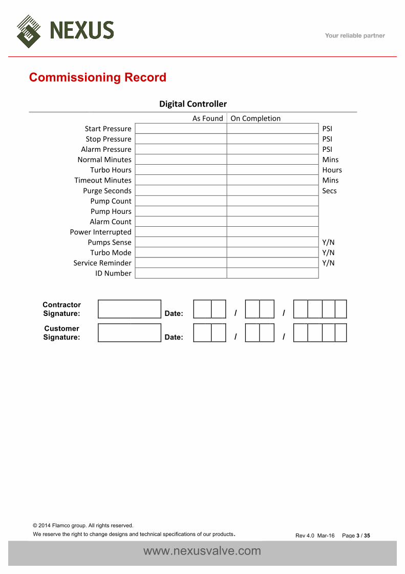
Commissioning Record
DigitalController AsFound OnCompletionStartPressure PSIStopPressure PSI
AlarmPressure PSINormalMinutes Mins
TurboHours HoursTimeoutMinutes Mins
PurgeSeconds SecsPumpCount PumpHours AlarmCount
PowerInterrupted PumpsSense Y/NTurboMode Y/N
ServiceReminder Y/NIDNumber
Contractor Signature: Date: / /
Customer Signature: Date: / /

www.nexusvalve.com
© 2014 Flamco group. All rights reserved. We reserve the right to change designs and technical specifications of our products. Rev 4.0 Mar-16 Page 4 / 35
Contents
CustomerDetails...............................................................................................................................................................................................2
EquipmentDetails.............................................................................................................................................................................................2
CommissioningRecord......................................................................................................................................................................................3
AboutthisManual.............................................................................................................................................................................................5
ConventionsusedinthisManual.................................................................................................................................................................5
Typography...................................................................................................................................................................................................5
WheretofindmoreInformation..................................................................................................................................................................6
EquipmentOverview.........................................................................................................................................................................................6
PrincipalofOperationVacuumDeaerator...................................................................................................................................................7
Installation/Capacity.........................................................................................................................................................................................8
PipeConnections..........................................................................................................................................................................................8
TypicalInstallationDiagramVacuumDeaerator..........................................................................................................................................9
FloorStandingClearanceandConnectionRequirements...............................................................................................................................10
ElectricalPowerSupply..............................................................................................................................................................................11
FaultContacts.............................................................................................................................................................................................12
Commissioning................................................................................................................................................................................................13
Pre-CommissioningChecklist.....................................................................................................................................................................13
ControllerOverview...................................................................................................................................................................................14
DeaeratorControllerProgramming...........................................................................................................................................................15
PurgeSecondsReferenceTimes............................................................................................................................................................16
HydraulicCommissioning...........................................................................................................................................................................17
Operation........................................................................................................................................................................................................19
Forpracticalguidanceondiagnosingandrectifyingfaults,pleaserefertotheTroubleshootingsectionofthismanual.........................19
DeaeratingFaultCodes..............................................................................................................................................................................19
Troubleshooting..............................................................................................................................................................................................21
Maintenance...................................................................................................................................................................................................22
Wiringlocationlist..........................................................................................................................................................................................25
Spares..............................................................................................................................................................................................................26
ElectricalItems...........................................................................................................................................................................................26
DeaeratorUnit................................................................................................................................................................................................27
ServiceLog......................................................................................................................................................................................................28
WarrantyStatement.......................................................................................................................................................................................30
WarrantyDetails.............................................................................................................................................................................................31
Notes...............................................................................................................................................................................................................32
Notes...............................................................................................................................................................................................................33
Notes...............................................................................................................................................................................................................34

www.nexusvalve.com
© 2014 Flamco group. All rights reserved. We reserve the right to change designs and technical specifications of our products. Rev 4.0 Mar-16 Page 5 / 35
About this Manual
ThisOperationandMaintenanceManualcontainsallthenecessaryinformationtoinstall,commission,operateandmaintainVacuumDeaerationequipment.
Itisrecommendedtoreadallpartsofthismanualbeforeundertakinganyworkontheequipment.
ConventionsusedinthisManualThismanualmakesuseofsymbolstoidentifykeypiecesofinformation.Pleasetakenoteofthefollowingsymbolsandtheirmeaning:
DANGER–Importantsafetyrelatedinformationintendedtopreventinjuryand/ordamagetotheequipment,systemorproperty.
CAUTION-Importantinformationintendedtopreventdamagetotheequipment,systemorproperty.
IMPORTANT-Importantinformationintendedtoensurethattheequipmentfunctionscorrectly.
USEFUL–Usefulinformationwhichmaybehelpful,butisnotnecessarilyrequiredfortheunittofunctioncorrectly.
TypographyThismanualmakesuseofdifferenttypographytoidentifydifferenttypesofinformation.
Italics Keywordsandphrases(RoundBrackets) Usedtoidentifyabuttononthedigitalcontroller[SquareBrackets] Aparameteronthedigitalcontroller<InequalitySymbols> Amessage/faultcodedisplayedonthedigitalcontroller

www.nexusvalve.com
© 2014 Flamco group. All rights reserved. We reserve the right to change designs and technical specifications of our products. Rev 4.0 Mar-16 Page 6 / 35
WheretofindmoreInformation
ForfurtherinformationpleasevisittheNexusValveWebsiteatthefollowingURL:
www.nexusvalve.com
Alternatively,pleasecontacttheNexusValveofficesusingthedetailsbelow:
Phone: 1-888-900-0947Email: [email protected]
Equipment Overview
Thefunctionofthisequipmentistoprovideameansofdissolvedairremovalfromthewaterusedinsealedheatingandcoolingsystems.
Thisequipmentisnotdesignedtocopewithsuddenlossesofsystempressure(e.g.manualdraining)ormajorwaterlosses(e.g.largeleaks).Theequipmentisalsonotintendedtobeusedforwaterboostingapplications.

www.nexusvalve.com
© 2014 Flamco group. All rights reserved. We reserve the right to change designs and technical specifications of our products. Rev 4.0 Mar-16 Page 7 / 35
PrincipalofOperationVacuumDeaeratorThefollowingschematicshowstheinternalarrangementofaVacuumDeaeratingunit:
WaterisallowedintotheVacuumcylinderthroughasafetysolenoid(13),apressurereducingvalve(14)andaspecialvariablebypassvalve(15).
Thepressurereducingvalve(14)isusedtolimitthewaterheldwithinthevacuumcylindertoapproximately18PSI.Thisisseenasthefirstpressurestep.
Whenthevacuumcylinderisfullandregisteringasuitablestartpressure(8b)thepumps(9a/9b)activate.Atthesametimethespecialvariablebypassvalve(15)opensfullytoallowthecylinderwatertobecompletelyflushedbackintothesystembythepumps(9a/9b).Thispurgecycleensuresthatthemaximumpossibleamountofaeratedwaterwillbeexposedtothevacuumprocess.
Afterthevacuumcylinderhasbeenrefreshed,thevariablebypassvalve(15)restrictstheflowintothevacuumcylinder.Thepumps(9a/9b)continuetodrawwateroutofthecylinderandcreateavacuumwithinthecylinder.Thepumps(9a/9b)thenstopaftera5seconddwellperiod.
Thevacuumcreatedwithinthecylinderiserodedbytheincomingwaterthroughthevariablebypassvalve(15) atalowflowrate,thisgentlyincreasesthepressurewithinthecylinderandforcesthereleasedairpocketoutthroughtheAutomaticAirVent(AAV)ontopofthecylinder.
Theequipmentisconnectedtothemainsystemvia2isolationvalves(7a/7b)andbackflowfromthesystemispreventbyanon-returnvalve(10a).

www.nexusvalve.com
© 2014 Flamco group. All rights reserved. We reserve the right to change designs and technical specifications of our products. Rev 4.0 Mar-16 Page 8 / 35
Installation
Thisunitisnotdesignedtobeinstalledinanoutdoorenvironment.Theunitmustbeinstalledinafrostfreeenvironment,awayfromprecipitationandwatersprays/jets.Ifthereisariskofflooding,theunitmustbeinstalledonaraisedheavysupportingbase.
Pleaserefertotheappropriatedatasheetforthemaximumworkingpressureandtemperatureofthepressurizationunit.Theconditionsatthepointofconnectiontothesystemmustnotexceedthesevalues.
UnitCapacityOneFPSD-250Dcanhandleasystemupto39,625gallonsofsystemvolume.Consultfactoryfor
Largervolumes.
PipeConnections
Whereapplicable,toavoiddamagingthefloatvalve,themainswatersupplypipemustbeflushedbeforeconnection.
Deaeratingconnections(2of)tothereturnheadermustbemadeinthehorizontalplanetopreventfloatingorheavydebrisenteringthepipeworktothisequipment.
ü üû ûAllpipeconnectionsmustbemadewithappropriatejointingcompound/PTFEtape.IfPTFEtapeisused,caremustbetakentoensurethatthetapedoesnotobstructtheorificeofthefitting.

www.nexusvalve.com
© 2014 Flamco group. All rights reserved. We reserve the right to change designs and technical specifications of our products. Rev 4.0 Mar-16 Page 9 / 35
TypicalInstallationDiagramVacuumDeaeratorInstallPSDunitonvibrationpador4rubberisolatorpads2“thick.

www.nexusvalve.com
© 2014 Flamco group. All rights reserved. We reserve the right to change designs and technical specifications of our products. Rev 4.0 Mar-16 Page 10 / 35
Floor Standing Clearance and Connection Requirements
Reference
Connection Size Notes
SystemConnections
2x½”NPT(ISO)
CONNECTIONKITINCLUDED
Thepointofconnectionshouldbeinthesystemreturn,onthesuctionsideofthecirculationpump.Non-returnvalves,pressurereducingvalvesandRPZvalvesmustnotbeused.
Minimum20”
Minimum6”
Minimum31.5”

www.nexusvalve.com
© 2014 Flamco group. All rights reserved. We reserve the right to change designs and technical specifications of our products. Rev 4.0 Mar-16 Page 11 / 35
ElectricalPowerSupplyThisequipmentmustbeelectricallyisolatedbeforeremovingthecovers.Cablesconnectedtothevoltfreecontactsmaybesuppliedfromanothersourceandmayremainliveaftertheunitisisolated.Thesemustbeisolatedelsewhere.Allelectricalconnectionsmustbecarriedoutbyasuitablyqualifiedandcompetentperson.
Themainspowersupplytothepressurizationunitmustbeconnectedintothefusedterminalblockasshownbelow:
ItisrecommendedtosupplypowertotheDeaerationunitviaalockabledisconnect.Thisshouldbeinstalledwithin78”oftheequipment.
Thisequipmentcanbedamagedbythehighvoltagesproducedbyelectricalinstallationtestingequipment.Whenperformingelectricalinstallationtests,theequipmentmustbeisolatedfromthesupply.

www.nexusvalve.com
© 2014 Flamco group. All rights reserved. We reserve the right to change designs and technical specifications of our products. Rev 4.0 Mar-16 Page 12 / 35
FaultContactsThereare3voltfreefaultcontactwhichcanbeusedforconnectiontoaBMSsystem,orasaninterlock.ThereistheCommonAlarmcontactonterminals1&2,theSensorHealthcontactonterminals3&4andthePumpHealthcontactonterminals7&8.
www.nexusvalve.com
© 2014 Flamco group. All rights reserved. We reserve the right to change designs and technical specifications of our products. Rev 4.0 Mar-16 Page 13 / 35
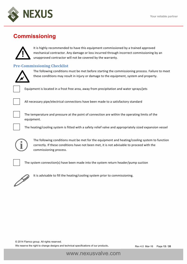
Commissioning
Itishighlyrecommendedtohavethisequipmentcommissionedbyatrainedapprovedmechanicalcontractor.Anydamageorlossincurredthroughincorrectcommissioningbyanunapprovedcontractorwillnotbecoveredbythewarranty.
Pre-CommissioningChecklistThefollowingconditionsmustbemetbeforestartingthecommissioningprocess.Failuretomeettheseconditionsmayresultininjuryordamagetotheequipment,systemandproperty.
Equipmentislocatedinafrostfreearea,awayfromprecipitationandwatersprays/jets
Allnecessarypipe/electricalconnectionshavebeenmadetoasatisfactorystandard
Thetemperatureandpressureatthepointofconnectionarewithintheoperatinglimitsoftheequipment.
Theheating/coolingsystemisfittedwithasafetyreliefvalveandappropriatelysizedexpansionvessel
Thefollowingconditionsmustbemetfortheequipmentandheating/coolingsystemtofunctioncorrectly.Iftheseconditionshavenotbeenmet,itisnotadvisabletoproceedwiththecommissioningprocess.
Thesystemconnection(s)havebeenmadeintothesystemreturnheader/pumpsuction
Itisadvisabletofilltheheating/coolingsystempriortocommissioning.

www.nexusvalve.com
© 2014 Flamco group. All rights reserved. We reserve the right to change designs and technical specifications of our products. Rev 4.0 Mar-16 Page 14 / 35
ControllerOverviewThefollowingimageshowsthefrontofthePSDunitdigitalcontroller.Fourbuttonsareprovidedforprogramming,andanLEDdisplaywhichshowsscrollingmessages.
Whenthecontrollerisfirstpoweredup,itwilldisplaythecontrollerversionnumber.Thismanualrelatestocontrollerversion6.3.Ifthecontrollerisofadifferentversion,theremaybedifferencesinthemenuitemsavailable.
Wheninnormaloperation,thecontrollerwilldisplaythecurrentinternalpressureoftheunit.Ifafaultoccurs,thecontrollerwilldisplayafaultcodeandproduceanaudiblealarm.
Innormaloperation,thefunctionsofthebuttonsareasfollows:
Button FunctionPress Hold
SET - ShowCurrentSystemPressureMUTE MuteAudibleAlarm ResetUnit
+ - EnterProgrammingMenu- - -

www.nexusvalve.com
© 2014 Flamco group. All rights reserved. We reserve the right to change designs and technical specifications of our products. Rev 4.0 Mar-16 Page 15 / 35
DeaeratorControllerProgrammingDonotalteranysettingswithoutfirstunderstandingtheimplicationsofdoingso.Incorrectsettingsmaycausedamagetotheequipment,systemorproperty.
Toentertheprogrammingmenu,holdthe(+)buttonuntil“entercode”appearsonthescreen,followedby“0000”withaflashingcursorafterthefirstdigit.
Togainaccesstotheprogrammingmenu,oneofthefollowingcodesmustbeentered:
CustomerCodeismostcommonlyusedforsetup.
CustomerCode Standardsetofoptions 2601EngineerCode Extendedsetofoptions 4706
Toenterthecode,changethefirstdigitwiththe(+)and(-)buttons,thenpress(SET)tomoveontothenextdigit.Repeatforalldigits,thenoncethecorrectcodeisshownonthedisplay,press(SET)toentertheprogrammingmenu.
Onceacorrectcodehasbeenentered,thefirstoption[STARTPRESSURE]willappearonthescreen.
Onceinthemenu,thevalueofthecurrentmenuitemcanbechangedusingthe(+)and(-)buttons.Oncethecurrentvaluehasbeenset,pressingthe(SET)buttonwillmoveontothenextoption.
Itisnotpossibletonavigatebackwardsthroughthemenu.Toreturntoaprevioussettinginthemenu,pressthe(SET)buttonrepeatedlytoscrollthroughtotheendofthemenu,andthenre-entertheappropriatecode.
Ifthecontrollerlosespowerwhileintheprogrammingmenu,allchangesmadewillbeerased.Toconfirmallchanges,theendofthemenumustbereached,andthe“SAVING...”messagemustbedisplayed.

www.nexusvalve.com
© 2014 Flamco group. All rights reserved. We reserve the right to change designs and technical specifications of our products. Rev 4.0 Mar-16 Page 16 / 35
Thetablebelowgivesdetailsofallmenuitems,intheorderthattheywillappear:
# MenuItem Function DefaultValue
1 StartPressure InternalSafePressureWithinTheVacuumCylinderForThePumpsToStartCirculatingWater 14PSI
2 StopPressure InternalStopPressureForThePumps,RequiredVacuumPressure
0PSI(LTHWSystems)
-7PSI(CHWSystems)
3 AlarmPressure InternalHighPressureAlarmSetting,ToActivateTheSlam-shutSolenoidValve 58PSI
4 NormalMinutes NormalIntervalBetweenPumpRuns(De-aeration) 60MINS5 TurboHours RunningTimeForTurboModeBeforeReturningToNormal 168HRS
6 TimeoutMinutes TimeLimitForVacuumGenerationOrRestorationOfInternalPressure(ErrorChecking) 10MINS
7 PurgeSeconds TimeSettingForWaterToBeRe-circulatedIntoTheMainSystem,TakingAFreshSample 20SEC
8 PumpCount PumpActivationCounter(Logging) -9 PumpHours PumpCumulativeHoursRunCounter(Logging) -10 AlarmCount CumulativeAlarmCounter(Logging) -
11 PowerInterrupted CumulativePowerOffCounter(Logging) -
12 PumpSense
Disablingthisoptionwillstopthecontrollerfrommonitoringthepumpsandgenerating<PUMPFAIL>faults.Itisnotrecommendedtodisablethisoption.PleaseconsultTechnicalSupportbeforedoingso.
y
13 TurboMode ActivationOptionForTurboMode(CommissioningSetup) Y14 Service 12MonthServiceReminder Y15 IDNumber ProtocolIDNumber 55
Ifusingthecustomercode,themenuitems12and15arenotdisplayed.
Theabovesettingsareallpre-programmedinthefactoryandshouldnotneedtobemodifiedonsitewiththeexceptionofthe‘PurgeSeconds’settingwhichissystemdependent.Ifthesesettingsappeartohavebeenreset,themostlikelycauseisapowerspike.Ifthisproblempersists,apowerfiltermayberequired.
PurgeSecondsReferenceTimes
MainSystemPressure PurgeTime14to42PSI 20seconds43to87PSI 30seconds87to145PSI 40seconds

www.nexusvalve.com
© 2014 Flamco group. All rights reserved. We reserve the right to change designs and technical specifications of our products. Rev 4.0 Mar-16 Page 17 / 35
HydraulicCommissioning
1-VentingtheVacuumCylinder
Checktheredcapontheairintakepreventerisfingertight.
Donotunscrewtheredcapcompletely.Insideisaglassbeadandspringthatpreventairbeingdrawnintotheequipmentatthispoint.Withoutthespringandthebeadsthisdevicewillnotfunctioncorrectlyandtheequipmentasawholewillbeunusable.
WiththeequipmentelectricallypowereddownremovethecoilfromthetwoInletsolenoids
Becarefulnottomixupthecoilswhendisconnected.Failuretopairthecorrectcoilwiththecorrectvalvewillstoptheunitfromworking.
WiththecoilsdisconnecteduseapairofDanfossoverridemagnets(018F0091Danfosspartnumber)tomanuallyopenbothofthesolenoidvalves.Thisallowstheexistingsystempressuretofillthevacuumcylinderforthefirstrun.
Removetheoverridemagnets,returnthecorrectcoiltothecorrectvalveandelectricallyswitchtheuniton.Ifthepressureshownonthede-aeratordisplayisbelowthestartpressureoftheequipmentitmaybenecessarytoadjustthepressurereducingvalveinbetweenthetwoinletsolenoids.Asettingonthepressurereducingvalve2to4PSIhigherthanthestartpressureisacceptable,anylowerthanthisandtheequipmentmaybecomeintermittentinoperation.

www.nexusvalve.com
© 2014 Flamco group. All rights reserved. We reserve the right to change designs and technical specifications of our products. Rev 4.0 Mar-16 Page 18 / 35
IftheDanfossmagnetsarenotavailablethenitispossibletoventthecylinderthroughtheinternal0.04”/1mmbypass,althoughthismaytakeaconsiderableamountoftime.Thealternativetothisistotemporarilyputlivepowerdirectlytothesolenoidcoilstoforcethevalvestoopen.
2-BleedingthePumps(ifrequired)
Locatethebleedscrewonthepump.Thefollowingdiagramsshowexamplesoftypicalbleedscrewlocationsformostpumps:
Donotuseexcessiveforcewhentighteningthebleedscrewasthismaydamagethepumpcasing.
Ifthepumphasaplasticbleedscrewliketheoneshownbelow,donotuseexcessiveforceorattempttouseanytoolstoturnitasthismayirreparablydamagethepumpcasing.

www.nexusvalve.com
© 2014 Flamco group. All rights reserved. We reserve the right to change designs and technical specifications of our products. Rev 4.0 Mar-16 Page 19 / 35
Operation
Oncecommissioned,theDeaeratingunitshouldoperatewithoutanyuserintervention.
Forpracticalguidanceondiagnosingandrectifyingfaults,pleaserefertotheTroubleshootingsectionofthismanual.
DeaeratingFaultCodes
FaultCode Description Auto/ManualReset
Error Incorrect password (Code) entered. AutoResetHigh Pressure High system pressure, audible alarm sounds. The Safety
Solenoid closes. This alarm will self-reset when the system pressure returns to normal, audible alarm can be silenced by pressing “mute”.
AutoReset
Insufficient Vacuum The low water switch has been activated, either a leak has occurred or the air non return valve has failed or is missing. ManualReset
Pump FAIL Pumps have failed, the pump failure relay closes. The boiler interlock opens, the audible alarm sounds. ManualReset
Timeout
Either the pumps have run for too long or the pressure has not reached the required start pressure for the pump within the time limit. Check the internal filter on the PRV and the solenoid valves for obstruction.
ManualReset
Service The unit has been in service for 12 months and a routine inspection is due (User option in menu). ManualReset
ShutdownProcedure
Thedeaerationunitmustbeshut-downduringanyofthefollowingscenarios:
• Workisbeingcarriedoutonthesystem.• WorkisbeingcarriedoutontheDeaeratingunit.• Theheating/coolingsystemisbeingflushed.
Toshutdowntheequipment,pleasefollowthestepsbelow:
1. Isolatetheelectricalpowersupplytotheunit.
2. Isolatetheunitfromthesystemusingtheisolationvalves.

www.nexusvalve.com
© 2014 Flamco group. All rights reserved. We reserve the right to change designs and technical specifications of our products. Rev 4.0 Mar-16 Page 20 / 35
Start-UpProcedure
Attention–Thisprocedureisforrestartingtheunitafterbeingshutdown(asdescribedabove).Forinitialstart-upandcommissioningprocedures,pleaserefertotheCommissioningsectionofthismanual.
Torestarttheunit,pleasefollowthestepsbelow:
1. Performavisualinspectionoftheunitandinstallationtocheckforsignsofdamage.
2. Opentheisolationvalves.
3. Turnonthemainspowersupplyandwaitforthecontrollertostart.
4. Dependingontheconditionsinthesystem,theunitmaydisplayoneormorefaultcodesatthispoint.Ifthishappens,pleaserefertotheTroubleshootingsectionofthismanualforguidance.

www.nexusvalve.com
© 2014 Flamco group. All rights reserved. We reserve the right to change designs and technical specifications of our products. Rev 4.0 Mar-16 Page 21 / 35
Troubleshooting IfforanyreasontheDeaeratingunitdoesnotseemtobefunctioningcorrectly,pleaserefertothetablebelowforalistofsolutionstoknownproblems.
Symptom Problem Solution
High Pressure
Theinternalpressurewithinthevacuumcylinderhasreachedthehighpressurealarmlimit,probablyduetothepressurereducingvalvebeingcontaminatedwithdebris.
Thesafetysolenoidvalvewillautomaticallycloseandthesystemwillattempttoself-resetduringthenextDeaeratingcycle.RepeatedHighpressurealarmswillrequirethepressurereducingvalvetobeinspectedandcleaned.
Insufficient Vacuum
TheVacuumcylinderisfullofairandthelowlevelswitchisstoppingfurtherpumpactivationtopreventthepump(s)runningdry.Thereisanairleakonthecylinder,thebypasssolenoidiscontaminatedwithdebrisortheairintakepreventeriscontaminatedwithdebris
Cleantheairintakepreventer,andtesttheunit.Ifthisfailsthencheckthebypasssolenoidandpipeworkforcontamination.Finallyreplacingtheautomaticairventassemblyisthebestcourseofaction.
Pump FAIL Thepumpisdrawingeithertoomuchcurrentornotenough,signifyingamechanical/electricalfailure.
Checkthecontrollersettingsfirsttoensurethatthecorrectpumpisbeingmonitored,alternativelyreplacethepump.
Timeout (1) Thevacuumcylinderhasnotbeenabletoreturntothestartpressureintheallottedtime
Checkthebypasssolenoidvalveisnotblocked(0.04”/1mmbypasshole),replaceifrequired.Checkthesettingonthepressurereducingvalveandtheinternalfilterofthepressurereducingvalve.
Timeout (2) Therequiredvacuumhasnotbeengeneratedintheallottedtime
Checkthepumpoperationandthatthesystempressureiswithintheoperationalpressuresoftheequipment.ReplacethePumpasrequired.
Checkthebypasssolenoidisfunctioningcorrectlyandclosingafterthepurgecycle.

www.nexusvalve.com
© 2014 Flamco group. All rights reserved. We reserve the right to change designs and technical specifications of our products. Rev 4.0 Mar-16 Page 22 / 35
Maintenance
Duetovariationsinoperatingconditions,andthevaryingloadsplacedonequipment,itisnotfeasibletoprovideaccuratepredictionsofcomponentlifespan.Themosteffectivemethodofmaintenanceistoinspectthepressurisationunitforearlysignsofcomponentfailureandtakeactionaccordingly.
Thefollowingmaintenanceproceduresshouldbeperformedatleastonceayear:
VisualInspection
Abasicvisualinspectionwillhighlightthemajorityofpotentialfaultsonthisequipment.Itisrecommendedtoperformavisualinspectionannually.However,duetothesimplicityofperformingthesechecks,frequentinspectionsareencouraged.
• Checkthedigitaldisplayforfaultcodes• Checkforsignsofleakage(e.g.water,mineraldeposits,corrodedcomponents/cabinet)• Checkflexiblehosesforsignsofdegradation(e.g.cracks)
IntegratedControl
Thedigitalcontrolkeepsalogofthenumberofpumpstartsandtotalhoursrunforeachpump,aswellasthenumberofalarmactivationsandpowerinterruptions.Itisadvisabletotakeanoteofthesefigureswhenservicingtheunit,astheymaybehelpfulindiagnosingpotentialissues.Fieldsareprovidedintheservicelogforthesefigures.
Itisadvisabletoscrollthroughallthesettings(includingengineerssetting)andcheckthemagainstthefiguresonthecommissioningreport.Ifthereareanydiscrepancies,checkfirstwithon-sitestafftoseeifthechangesaredeliberate.Ifnot,reconfigureappropriately.
Ifsettingsarepersistentlybecomingcorrupted,apowerfiltermayberequired.PleaserefertotheInstallationsectionofthismanualformoreinformation.

www.nexusvalve.com
© 2014 Flamco group. All rights reserved. We reserve the right to change designs and technical specifications of our products. Rev 4.0 Mar-16 Page 23 / 35
TestUnitOperation
CheckPRVStrainer
ThePressureReducingValve(PRV)isfittedwithameshstrainerbeneaththebrasshexagonbush.Thisshouldberemovedandinspected.Dependingonthecondition,thispartmayneedtobecleaned.
CheckSystemExpansionVesselPre-Charge
Manyoftheproblemsexperiencedwithsealedsystemequipmentcanbetracedbacktotheexpansionvessel.
Theexpansionvesselpre-chargepressuremustbecheckedafter2yearsandannuallythereafter.
Toperformthistest,theexpansionvesselmustfirstbedrainedofwater,thenagaugecanbeconnectedtotheSchradervalveonthevesseltomeasurethepre-chargepressure.Thepre-chargeshouldbeequaltothe[COLDFILL]pressuresetting.
Thepressurecanbeincreasedusingafootpump,aircompressororpressurisedair/nitrogencylinder.
Ifanyfaultsareidentifiedduringthesechecks,pleaserefertotheTroubleshootingsectionofthismanual.Ifreplacementpartsarerequired,pleaserefertotheSparessectionforpartcodes.

www.nexusvalve.com
© 2014 Flamco group. All rights reserved. We reserve the right to change designs and technical specifications of our products. Rev 4.0 Mar-16 Page 24 / 35
Wiringdiagram
PSD HAS A 10 AMP 250VAC BUSSMAN GLASS FUSE INSTALLED AT LINE CONNECTIONS.

www.nexusvalve.com
© 2014 Flamco group. All rights reserved. We reserve the right to change designs and technical specifications of our products. Rev 4.0 Mar-16 Page 25 / 35
Wiring location list

www.nexusvalve.com
© 2014 Flamco group. All rights reserved. We reserve the right to change designs and technical specifications of our products. Rev 4.0 Mar-16 Page 26 / 35
Spares
Thedrawingsonthefollowingpagesshowtheinternalcomponentsforarangeofequipment.Duetocontinuingdevelopmentandminordesignchanges,somecomponentsmaybechangedwithoutnotice.Therefore,thedrawingsmaynotaccuratelyreflectthecurrentproductiondesign.Ifinanydoubtaboutthecompatibilityofreplacementparts,pleasecontactTechnicalSupport.
ElectricalItems
*Imageforindicationonly
# Description1 DeaeratorController2 ElectricalPlate(FuseBlockand15VPSU)3 PowerSwitch4 5AmpFuse5 6.3AmpSlowBlowFuse(PQA90PumpsOnly)

www.nexusvalve.com
© 2014 Flamco group. All rights reserved. We reserve the right to change designs and technical specifications of our products. Rev 4.0 Mar-16 Page 27 / 35
Deaerator Unit
*Imageforindicationonly# Description1 Pump2 ½”Non-ReturnValve3 VacuumCylinderLowLevelSwitch4 VacuumTransducer5 CombinedIsolation&DrainValve6 AutomaticAirVent7 BypassSolenoidValve8 Slam-shutSolenoidValve9 AirVentNonReturnValve10 PressureReducingValve11 87PSI(6Bar)VacuumCylinderSafetyReliefValve

www.nexusvalve.com
© 2014 Flamco group. All rights reserved. We reserve the right to change designs and technical specifications of our products. Rev 4.0 Mar-16 Page 28 / 35
Service Log
Thisservicelogshouldbecompletedbytheserviceengineeraftereachannualservice.
Date P1COUNT EngineersName P1HOURS Company P2COUNT ContactNumber P2HOURS ALARMCOUNT Comments POWERINTERRUPTIONS
Date P1COUNT EngineersName P1HOURS Company P2COUNT ContactNumber P2HOURS ALARMCOUNT Comments POWERINTERRUPTIONS
Date P1COUNT EngineersName P1HOURS Company P2COUNT ContactNumber P2HOURS ALARMCOUNT Comments POWERINTERRUPTIONS

www.nexusvalve.com
© 2014 Flamco group. All rights reserved. We reserve the right to change designs and technical specifications of our products. Rev 4.0 Mar-16 Page 29 / 35
Date P1COUNT EngineersName P1HOURS Company P2COUNT ContactNumber P2HOURS ALARMCOUNT Comments POWERINTERRUPTIONS
Date P1COUNT EngineersName P1HOURS Company P2COUNT ContactNumber P2HOURS ALARMCOUNT Comments POWERINTERRUPTIONS
Date P1COUNT EngineersName P1HOURS Company P2COUNT ContactNumber P2HOURS ALARMCOUNT Comments POWERINTERRUPTIONS
www.nexusvalve.com
© 2014 Flamco group. All rights reserved. We reserve the right to change designs and technical specifications of our products. Rev 4.0 Mar-16 Page 30 / 35
Warranty Statement
This equipment is covered against manufacturing defects from date of purchase from Flamco Limited.
This warranty covers the replacement of parts or products, verified as having a manufacturing defect.
Flamco Limited reserves the right to inspect an installation to verify that the equipment has been installed in accordance with the written instructions.
Any modifications to the supplied equipment must be approved in writing by Nexus Valve, failure to do so will invalidate the warranty.
All goods are carefully tested and inspected before dispatch. Should any goods appear defective owing to faulty materials or manufacture, they must be returned to us for examination. If we (acting reasonably) agree they are defective, we shall replace them. This shall be our only obligation in relation to the defective goods, unless we have notified you in writing of any additional warranties we may provide and you have complied with all conditions attached to these warranties. Beyond this all conditions, warranties and representations expressed or implied by statute, common law or otherwise in relation to the Goods (save for the conditions implied by section 12 of the Sale of Goods Act 1979) are excluded from the Contract to the fullest extent permitted by law (if you are acting as a consumer please see paragraph below).
Nexus Valve can only respond to warranty queries from its direct customer. If in doubt, please contact your installer to establish the supply chain. We are not liable for any indirect, special or consequential liabilities, losses, charges, damages, costs and expenses you suffer howsoever caused and including, without limitation, pure economic loss, loss of anticipated profits, goodwill, revenue, reputation, anticipated savings, management time, business receipts or contracts or losses or expenses resulting from third party claims. Nothing in these Conditions excludes or limits our liability (a) for death or personal injury caused by our negligence, (b) for our fraud or fraudulent misrepresentation or (c) for any matter which it would be illegal for us to exclude or attempt to exclude our liability. If you are acting as a consumer you will have additional statutory rights which we cannot contract out of and we are not excluding or limiting these rights.

www.nexusvalve.com
© 2014 Flamco group. All rights reserved. We reserve the right to change designs and technical specifications of our products. Rev 4.0 Mar-16 Page 31 / 35
Warranty Details
Warranty - What Is Covered? The Nexus Valve warranty on equipment supplied to distribution and OEM covers manufacturing defects, under our standard terms and conditions of sale.
If the unit is identified with a manufacturing defect then no charge is made for correcting the defect.
The Nexus Valve equipment is manufactured to order and is clearly marked, where applicable, with a unique serial number, allowing traceability to both individual model configuration and the engineer or site responsible for the build and test.
Warranty - What Is Not Covered? If a defect or problem has arisen as a direct result of the connected system, misuse, incorrect handling, incorrect installation or incorrect commissioning then any service visit is chargeable.
If a defect is identified as a manufacturing defect it will be addressed as described above, additional remedial works as a result of misuse, incorrect handling, incorrect installation or incorrect commissioning then the additional work is chargeable.
Installation costs and/or consequential losses are not covered by this agreement. DOS - Date Of Supply DOC - Date Of Commissioning
Equipment Conditions Timescale
Flamco PSD
That there is an appropriate safety valve on the system protecting the equipment. That the equipment is undamaged at the time of installation. That the equipment is not exposed to adverse environmental conditions. That the equipment is stored and installed in a frost free area. That the operating and maintenance instructions are followed. That the equipment is used for the purpose for which it was designed.
18 months DOS 24 months DOC

www.nexusvalve.com
© 2014 Flamco group. All rights reserved. We reserve the right to change designs and technical specifications of our products. Rev 4.0 Mar-16 Page 32 / 35
Notes

www.nexusvalve.com
© 2014 Flamco group. All rights reserved. We reserve the right to change designs and technical specifications of our products. Rev 4.0 Mar-16 Page 33 / 35
Notes

www.nexusvalve.com
© 2014 Flamco group. All rights reserved. We reserve the right to change designs and technical specifications of our products. Rev 4.0 Mar-16 Page 34 / 35
Notes

www.nexusvalve.com
© 2014 Flamco group. All rights reserved. We reserve the right to change designs and technical specifications of our products. Rev 4.0 Mar-16 Page 35 / 35
Nexus
9982E.121stStreetFishers,IN46037
www.nexusvalve.com