Configuring DHCP - Cisco
22
Configuring DHCP This section provides information about configuring DHCP. • Prerequisites for Configuring DHCP, on page 1 • Restrictions for Configuring DHCP, on page 2 • Information About DHCP, on page 2 • How to Configure DHCP, on page 10 • Feature History for DHCP, on page 20 Prerequisites for Configuring DHCP The following prerequisites apply to DHCP Snooping and Option 82: • You must globally enable DHCP snooping on the switch. • Before globally enabling DHCP snooping on the switch, make sure that the devices acting as the DHCP server and the DHCP relay agent are configured and enabled. • If you want the switch to respond to DHCP requests, it must be configured as a DHCP server. • Before configuring the DHCP snooping information option on your switch, be sure to configure the device that is acting as the DHCP server. You must specify the IP addresses that the DHCP server can assign or exclude, or you must configure DHCP options for these devices. • For DHCP snooping to function properly, all DHCP servers must be connected to the switch through trusted interfaces. In a service-provider network, a trusted interface is connected to a port on a device in the same network. • You must configure the switch to use the Cisco IOS DHCP server binding database to use it for DHCP snooping. • To use the DHCP snooping option of accepting packets on untrusted inputs, the switch must be an aggregation switch that receives packets with option-82 information from an edge switch. • The following prerequisites apply to DHCP snooping binding database configuration: • You must configure a destination on the DHCP snooping binding database to use the switch for DHCP snooping. • Because both NVRAM and the flash memory have limited storage capacity, we recommend that you store the binding file on a TFTP server. Configuring DHCP 1
-
Upload
khangminh22 -
Category
Documents
-
view
1 -
download
0
Transcript of Configuring DHCP - Cisco

Configuring DHCP
This section provides information about configuring DHCP.
• Prerequisites for Configuring DHCP, on page 1• Restrictions for Configuring DHCP, on page 2• Information About DHCP, on page 2• How to Configure DHCP, on page 10• Feature History for DHCP, on page 20
Prerequisites for Configuring DHCPThe following prerequisites apply to DHCP Snooping and Option 82:
• You must globally enable DHCP snooping on the switch.
• Before globally enabling DHCP snooping on the switch, make sure that the devices acting as the DHCPserver and the DHCP relay agent are configured and enabled.
• If you want the switch to respond to DHCP requests, it must be configured as a DHCP server.
• Before configuring the DHCP snooping information option on your switch, be sure to configure thedevice that is acting as the DHCP server. You must specify the IP addresses that the DHCP server canassign or exclude, or you must configure DHCP options for these devices.
• For DHCP snooping to function properly, all DHCP servers must be connected to the switch throughtrusted interfaces. In a service-provider network, a trusted interface is connected to a port on a device inthe same network.
• You must configure the switch to use the Cisco IOS DHCP server binding database to use it for DHCPsnooping.
• To use the DHCP snooping option of accepting packets on untrusted inputs, the switch must be anaggregation switch that receives packets with option-82 information from an edge switch.
• The following prerequisites apply to DHCP snooping binding database configuration:
• You must configure a destination on the DHCP snooping binding database to use the switch forDHCP snooping.
• Because both NVRAM and the flash memory have limited storage capacity, we recommend thatyou store the binding file on a TFTP server.
Configuring DHCP1

• For network-based URLs (such as TFTP and FTP), you must create an empty file at the configuredURL before the switch can write bindings to the binding file at that URL. See the documentationfor your TFTP server to determine whether you must first create an empty file on the server; someTFTP servers cannot be configured this way.
• To ensure that the lease time in the database is accurate, we recommend that you enable and configureNetwork Time Protocol (NTP).
• If NTP is configured, the switch writes binding changes to the binding file only when the switchsystem clock is synchronized with NTP.
• Before configuring the DHCP relay agent on your switch, make sure to configure the device that is actingas the DHCP server. You must specify the IP addresses that the DHCP server can assign or exclude,configure DHCP options for devices, or set up the DHCP database agent.
• If you want the switch to relay DHCP packets, the IP address of the DHCP server must be configuredon the switch virtual interface (SVI) of the DHCP client.
• If a switch port is connected to a DHCP server, configure a port as trusted by entering the ip dhcpsnooping trust interface configuration command.
• If a switch port is connected to a DHCP client, configure a port as untrusted by entering the no ip dhcpsnooping trust interface configuration command.
Restrictions for Configuring DHCPWe recommend that you do not use transmit (Tx) Switched Port Analyzer (SPAN) or egress SPAN thatsupports DHCP Snooping, DHCP Relay Agent. If SPAN at Tx is required, avoid using VLAN ports that arein the forwarding path for DHCP packets.
Information About DHCP
DHCP ServerThe DHCP server assigns IP addresses from specified address pools on a switch or router to DHCP clientsand manages them. If the DHCP server cannot give the DHCP client the requested configuration parametersfrom its database, it forwards the request to one or more secondary DHCP servers defined by the networkadministrator. The switch can act as a DHCP server. If the DHCP server provides the client with the requestedconfiguration, it will not forward the message to the other server.
DHCP Relay AgentA DHCP relay agent is a Layer 3 device that forwards DHCP packets between clients and servers. Relayagents forward requests and replies between clients and servers when they are not on the same physical subnet.Relay agent forwarding is different from the normal Layer 2 forwarding, in which IP datagrams are switchedtransparently between networks. Relay agents receive DHCP messages and generate new DHCP messagesto send on output interfaces.
Configuring DHCP2
Configuring DHCPRestrictions for Configuring DHCP

DHCP SnoopingDHCP snooping is a DHCP security feature that provides network security by filtering untrusted DHCPmessages and by building and maintaining a DHCP snooping binding database, also referred to as a DHCPsnooping binding table.
DHCP snooping acts like a firewall between untrusted hosts and DHCP servers. You use DHCP snooping todifferentiate between untrusted interfaces connected to the end user and trusted interfaces connected to theDHCP server or another switch.
For DHCP snooping to function properly, all DHCP servers must be connected to the switch through trustedinterfaces.
Note
An untrusted DHCP message is a message that is received through an untrusted interface. By default, theswitch considers all interfaces untrusted. So, the switch must be configured to trust some interfaces to useDHCP Snooping. When you use DHCP snooping in a service-provider environment, an untrusted messageis sent from a device that is not in the service-provider network, such as a customer’s switch. Messages fromunknown devices are untrusted because they can be sources of traffic attacks.
The DHCP snooping binding database has the MAC address, the IP address, the lease time, the binding type,the VLAN number, and the interface information that corresponds to the local untrusted interfaces of a switch.It does not have information regarding hosts interconnected with a trusted interface.
In a service-provider network, an example of an interface you might configure as trusted is one connected toa port on a device in the same network. An example of an untrusted interface is one that is connected to anuntrusted interface in the network or to an interface on a device that is not in the network.
When a switch receives a packet on an untrusted interface and the interface belongs to a VLAN in whichDHCP snooping is enabled, the switch compares the source MAC address and the DHCP client hardwareaddress. If the addresses match (the default), the switch forwards the packet. If the addresses do not match,the switch drops the packet.
The switch drops a DHCP packet when one of these situations occurs:
• A packet from a DHCP server, such as a DHCPOFFER, DHCPACK, DHCPNAK, orDHCPLEASEQUERY packet, is received from outside the network or firewall.
• A packet is received on an untrusted interface, and the sourceMAC address and the DHCP client hardwareaddress do not match.
• The switch receives a DHCPRELEASE or DHCPDECLINE broadcast message that has a MAC addressin the DHCP snooping binding database, but the interface information in the binding database does notmatch the interface on which the message was received.
• A DHCP relay agent forwards a DHCP packet that includes a relay-agent IP address that is not 0.0.0.0,or the relay agent forwards a packet that includes option-82 information to an untrusted port.
• The maximum snooping queue size of 1000 is exceeded when DHCP snooping is enabled.
If the switch is an aggregation switch supporting DHCP snooping and is connected to an edge switch that isinserting DHCP option-82 information, the switch drops packets with option-82 information when packetsare received on an untrusted interface. If DHCP snooping is enabled and packets are received on a trustedport, the aggregation switch does not learn the DHCP snooping bindings for connected devices and cannotbuild a complete DHCP snooping binding database.
Configuring DHCP3
Configuring DHCPDHCP Snooping

When an aggregation switch can be connected to an edge switch through an untrusted interface and you enterthe ip dhcp snooping information option allow-untrusted global configuration command, the aggregationswitch accepts packets with option-82 information from the edge switch. The aggregation switch learns thebindings for hosts connected through an untrusted switch interface. The DHCP security features, such asdynamic ARP inspection or IP source guard, can still be enabled on the aggregation switch while the switchreceives packets with option-82 information on untrusted input interfaces to which hosts are connected. Theport on the edge switch that connects to the aggregation switch must be configured as a trusted interface.
Option-82 Data InsertionIn residential, metropolitan Ethernet-access environments, DHCP can centrally manage the IP addressassignments for a large number of subscribers. When the DHCP option-82 feature is enabled on the switch,a subscriber device is identified by the switch port through which it connects to the network (in addition toits MAC address). Multiple hosts on the subscriber LAN can be connected to the same port on the accessswitch and are uniquely identified.
The DHCP option-82 feature is supported only when DHCP snooping is globally enabled on the VLANs towhich subscriber devices using option-82 are assigned.
Note
The following illustration shows a metropolitan Ethernet network in which a centralized DHCP server assignsIP addresses to subscribers connected to the switch at the access layer. Because the DHCP clients and theirassociated DHCP server do not reside on the same IP network or subnet, a DHCP relay agent (the Catalystswitch) is configured with a helper address to enable broadcast forwarding and to transfer DHCP messagesbetween the clients and the server.
Figure 1: DHCP Relay Agent in a Metropolitan Ethernet Network
When you enable the DHCP snooping information option 82 on the switch, the following sequence ofevents occurs:
• The host (DHCP client) generates a DHCP request and broadcasts it on the network.
• When the switch receives the DHCP request, it adds the option-82 information in the packet. By default,the remote-ID suboption is the switch MAC address, and the circuit-ID suboption is the port identifier,vlan-mod-port, from which the packet is received. You can configure the remote ID and circuit ID.
• If the IP address of the relay agent is configured, the switch adds this IP address in the DHCP packet.
• The switch forwards the DHCP request that includes the option-82 field to the DHCP server.
Configuring DHCP4
Configuring DHCPOption-82 Data Insertion

• The DHCP server receives the packet. If the server is option-82-capable, it can use the remote ID, thecircuit ID, or both to assign IP addresses and implement policies, such as restricting the number of IPaddresses that can be assigned to a single remote ID or circuit ID. Then the DHCP server echoes theoption-82 field in the DHCP reply.
• The DHCP server unicasts the reply to the switch if the request was relayed to the server by the switch.The switch verifies that it originally inserted the option-82 data by inspecting the remote ID and possiblythe circuit ID fields. The switch removes the option-82 field and forwards the packet to the switch portthat connects to the DHCP client that sent the DHCP request.
In the default suboption configuration, when the described sequence of events occurs, the values in thesefields do not change (see the illustration,Suboption Packet Formats):
• Circuit-ID suboption fields
• Suboption type
• Length of the suboption type
• Circuit-ID type
• Length of the circuit-ID type
• Remote-ID suboption fields
• Suboption type
• Length of the suboption type
• Remote-ID type
• Length of the remote-ID type
In the port field of the circuit ID suboption, the port numbers start at 3. For example, on a switch with 2410/100/1000 ports and four small form-factor pluggable (SFP) module slots, port 3 is the Gigabit Ethernet1/0/1 port, port 4 is the Gigabit Ethernet 1/0/2 port, and so forth. Port 27 is the SFP module slot GigabitEthernet1/0/25, and so forth.
The illustration, Suboption Packet Formats. shows the packet formats for the remote-ID suboption and thecircuit-ID suboption when the default suboption configuration is used. For the circuit-ID suboption, the modulenumber corresponds to the switch number in the stack. The switch uses the packet formats when you globallyenable DHCP snooping and enter the ip dhcp snooping information option global configuration command.
Configuring DHCP5
Configuring DHCPOption-82 Data Insertion
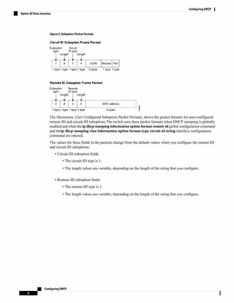
Figure 2: Suboption Packet Formats
The illustration, User-Configured Suboption Packet Formats, shows the packet formats for user-configuredremote-ID and circuit-ID suboptions The switch uses these packet formats when DHCP snooping is globallyenabled andwhen the ip dhcp snooping information option format remote-id global configuration commandand theip dhcp snooping vlan information option format-type circuit-id string interface configurationcommand are entered.
The values for these fields in the packets change from the default values when you configure the remote-IDand circuit-ID suboptions:
• Circuit-ID suboption fields
• The circuit-ID type is 1.
• The length values are variable, depending on the length of the string that you configure.
• Remote-ID suboption fields
• The remote-ID type is 1.
• The length values are variable, depending on the length of the string that you configure.
Configuring DHCP6
Configuring DHCPOption-82 Data Insertion
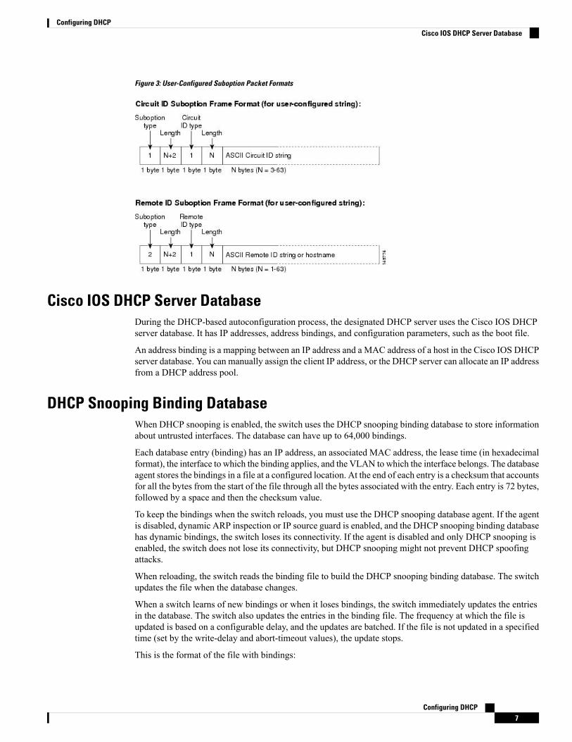
Figure 3: User-Configured Suboption Packet Formats
Cisco IOS DHCP Server DatabaseDuring the DHCP-based autoconfiguration process, the designated DHCP server uses the Cisco IOS DHCPserver database. It has IP addresses, address bindings, and configuration parameters, such as the boot file.
An address binding is a mapping between an IP address and a MAC address of a host in the Cisco IOS DHCPserver database. You can manually assign the client IP address, or the DHCP server can allocate an IP addressfrom a DHCP address pool.
DHCP Snooping Binding DatabaseWhen DHCP snooping is enabled, the switch uses the DHCP snooping binding database to store informationabout untrusted interfaces. The database can have up to 64,000 bindings.
Each database entry (binding) has an IP address, an associated MAC address, the lease time (in hexadecimalformat), the interface to which the binding applies, and the VLAN to which the interface belongs. The databaseagent stores the bindings in a file at a configured location. At the end of each entry is a checksum that accountsfor all the bytes from the start of the file through all the bytes associated with the entry. Each entry is 72 bytes,followed by a space and then the checksum value.
To keep the bindings when the switch reloads, you must use the DHCP snooping database agent. If the agentis disabled, dynamic ARP inspection or IP source guard is enabled, and the DHCP snooping binding databasehas dynamic bindings, the switch loses its connectivity. If the agent is disabled and only DHCP snooping isenabled, the switch does not lose its connectivity, but DHCP snooping might not prevent DHCP spoofingattacks.
When reloading, the switch reads the binding file to build the DHCP snooping binding database. The switchupdates the file when the database changes.
When a switch learns of new bindings or when it loses bindings, the switch immediately updates the entriesin the database. The switch also updates the entries in the binding file. The frequency at which the file isupdated is based on a configurable delay, and the updates are batched. If the file is not updated in a specifiedtime (set by the write-delay and abort-timeout values), the update stops.
This is the format of the file with bindings:
Configuring DHCP7
Configuring DHCPCisco IOS DHCP Server Database

<initial-checksum>TYPE DHCP-SNOOPINGVERSION 1BEGIN<entry-1> <checksum-1><entry-2> <checksum-1-2>......<entry-n> <checksum-1-2-..-n>END
Each entry in the file is tagged with a checksum value that the switch uses to verify the entries when it readsthe file. The initial-checksum entry on the first line distinguishes entries associated with the latest file updatefrom entries associated with a previous file update.
This is an example of a binding file:
2bb4c2a1TYPE DHCP-SNOOPINGVERSION 1BEGIN192.1.168.1 3 0003.47d8.c91f 2BB6488E Gi1/0/4 21ae5fbb192.1.168.3 3 0003.44d6.c52f 2BB648EB Gi1/0/4 1bdb223f192.1.168.2 3 0003.47d9.c8f1 2BB648AB Gi1/0/4 584a38f0END
When the switch starts and the calculated checksum value equals the stored checksum value, the switch readsentries from the binding file and adds the bindings to its DHCP snooping binding database. The switch ignoresan entry when one of these situations occurs:
• The switch reads the entry and the calculated checksum value does not equal the stored checksum value.The entry and the ones following it are ignored.
• An entry has an expired lease time (the switch might not remove a binding entry when the lease timeexpires).
• The interface in the entry no longer exists on the system.
• The interface is a routed interface or a DHCP snooping-trusted interface.
Default DHCP Snooping ConfigurationTable 1: Default DHCP Configuration
Default SettingFeature
Enabled in Cisco IOS software, requiresconfiguration1
DHCP server
Enabled2DHCP relay agent
None configuredDHCP packet forwarding address
Enabled (invalid messages are dropped)Checking the relay agent information
Configuring DHCP8
Configuring DHCPDefault DHCP Snooping Configuration

Default SettingFeature
Replace the existing relay agent informationDHCP relay agent forwarding policy
DisabledDHCP snooping enabled globally
EnabledDHCP snooping information option
DisabledDHCP snooping option to accept packets on untrustedinput interfaces3
None configuredDHCP snooping limit rate
UntrustedDHCP snooping trust
DisabledDHCP snooping VLAN
EnabledDHCP snooping MAC address verification
Enabled in Cisco IOS software, requires configuration.
The switch gets network addresses andconfiguration parameters only from adevice configured as a DHCP server.
Note
Cisco IOS DHCP server binding database
Enabled in Cisco IOS software, requires configuration.This feature is operational only when a destination isconfigured.
DHCP snooping binding database agent
1 The switch responds to DHCP requests only if it is configured as a DHCP server.2 The switch relays DHCP packets only if the IP address of the DHCP server is configured on the SVIof the DHCP client.
3 Use this feature when the switch is an aggregation switch that receives packets with option-82 informationfrom an edge switch.
DHCP Snooping Configuration Guidelines• If a switch port is connected to a DHCP server, configure a port as trusted by entering the ip dhcp
snooping trust interface configuration command.
• If a switch port is connected to a DHCP client, configure a port as untrusted by entering the no ip dhcpsnooping trust interface configuration command.
• You can display DHCP snooping statistics by entering the show ip dhcp snooping statistics user EXECcommand, and you can clear the snooping statistics counters by entering the clear ip dhcp snoopingstatistics privileged EXEC command.
DHCP Server Port-Based Address AllocationDHCP server port-based address allocation is a feature that enables DHCP to maintain the same IP addresson an Ethernet switch port regardless of the attached device client identifier or client hardware address.
Configuring DHCP9
Configuring DHCPDHCP Snooping Configuration Guidelines

When Ethernet switches are deployed in the network, they offer connectivity to the directly connected devices.In some environments, such as on a factory floor, if a device fails, the replacement device must be workingimmediately in the existing network.With the current DHCP implementation, there is no guarantee that DHCPwould offer the same IP address to the replacement device. Control, monitoring, and other software expect astable IP address associated with each device. If a device is replaced, the address assignment should remainstable even though the DHCP client has changed.
When configured, the DHCP server port-based address allocation feature ensures that the same IP address isalways offered to the same connected port even as the client identifier or client hardware address changes inthe DHCPmessages received on that port. The DHCP protocol recognizes DHCP clients by the client identifieroption in the DHCP packet. Clients that do not include the client identifier option are identified by the clienthardware address. When you configure this feature, the port name of the interface overrides the client identifieror hardware address and the actual point of connection, the switch port, becomes the client identifier.
In all cases, by connecting the Ethernet cable to the same port, the same IP address is allocated through DHCPto the attached device.
The DHCP server port-based address allocation feature is only supported on a Cisco IOS DHCP server andnot a third-party server.
Default Port-Based Address Allocation ConfigurationBy default, DHCP server port-based address allocation is disabled.
Port-Based Address Allocation Configuration Guidelines• By default, DHCP server port-based address allocation is disabled.
• To restrict assignments from the DHCP pool to preconfigured reservations (unreserved addresses arenot offered to the client and other clients are not served by the pool), you can enter the reserved-onlyDHCP pool configuration command.
How to Configure DHCP
Configuring the DHCP ServerThe switch can act as a DHCP server. If DHCP server for DHCP clients with management ports are used,both DHCP pool and the corresponding interface must be configured using the Management VRF.
Configuring the DHCP Relay AgentFollow these steps to enable the DHCP relay agent on the switch:
Procedure
PurposeCommand or Action
Enables privileged EXEC mode.enableStep 1
Example: • Enter your password if prompted.
Configuring DHCP10
Configuring DHCPDefault Port-Based Address Allocation Configuration

PurposeCommand or Action
Device> enable
Enters global configuration mode.configure terminal
Example:
Step 2
Device# configure terminal
Enables the DHCP server and relay agent onyour switch. By default, this feature is enabled.
service dhcp
Example:
Step 3
Device(config)# service dhcp
Exits global configuration mode and returns toprivileged EXEC mode.
end
Example:
Step 4
Device(config)# end
What to do next
• Checking (validating) the relay agent information
• Configuring the relay agent forwarding policy
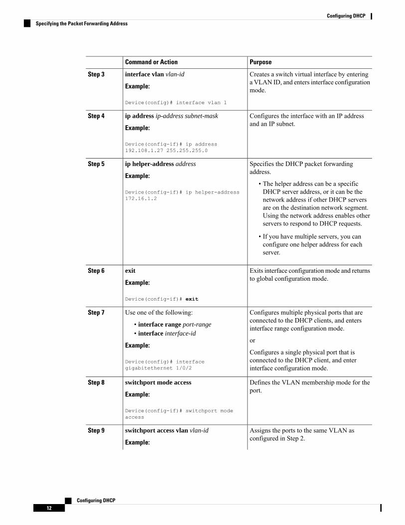
Specifying the Packet Forwarding AddressIf the DHCP server and the DHCP clients are on different networks or subnets, you must configure the switchwith the ip helper-address address interface configuration command. The general rule is to configure thecommand on the Layer 3 interface closest to the client. The address used in the ip helper-address commandcan be a specific DHCP server IP address, or it can be the network address if other DHCP servers are on thedestination network segment. Using the network address enables any DHCP server to respond to requests.
Perform these steps to specify the packet forwarding address:
Procedure
PurposeCommand or Action
Enables privileged EXEC mode.enableStep 1
Example: • Enter your password if prompted.
Device> enable
Enters global configuration mode.configure terminal
Example:
Step 2
Device# configure terminal
Configuring DHCP11
Configuring DHCPSpecifying the Packet Forwarding Address
PurposeCommand or Action
Creates a switch virtual interface by enteringa VLAN ID, and enters interface configurationmode.
interface vlan vlan-id
Example:
Device(config)# interface vlan 1
Step 3
Configures the interface with an IP addressand an IP subnet.
ip address ip-address subnet-mask
Example:
Step 4
Device(config-if)# ip address192.108.1.27 255.255.255.0
Specifies the DHCP packet forwardingaddress.
ip helper-address address
Example:
Step 5
• The helper address can be a specificDHCP server address, or it can be theDevice(config-if)# ip helper-address
172.16.1.2 network address if other DHCP serversare on the destination network segment.Using the network address enables otherservers to respond to DHCP requests.
• If you have multiple servers, you canconfigure one helper address for eachserver.
Exits interface configuration mode and returnsto global configuration mode.
exit
Example:
Step 6
Device(config-if)# exit
Configures multiple physical ports that areconnected to the DHCP clients, and entersinterface range configuration mode.
Use one of the following:Step 7
• interface range port-range• interface interface-id
orExample:
Configures a single physical port that isconnected to the DHCP client, and enterinterface configuration mode.
Device(config)# interfacegigabitethernet 1/0/2
Defines the VLAN membership mode for theport.
switchport mode access
Example:
Step 8
Device(config-if)# switchport modeaccess
Assigns the ports to the same VLAN asconfigured in Step 2.
switchport access vlan vlan-id
Example:
Step 9
Configuring DHCP12
Configuring DHCPSpecifying the Packet Forwarding Address

PurposeCommand or Action
Device(config-if)# switchport accessvlan 1
Exits interface configuration mode and returnsto privileged EXEC mode.
end
Example:
Step 10
Device(config-if)# end
Configuring DHCP for IPv6 Address Assignment
Default DHCPv6 Address Assignment ConfigurationBy default, no DHCPv6 features are configured on the switch.
DHCPv6 Address Assignment Configuration GuidelinesThe following prerequisites apply when configuring DHCPv6 address assignment:
• In the following procedures, the specified interface must be one of these Layer 3 interfaces:
• If the IPv6 address is not explicitly configured, enable IPv6 routing by using the ipv6 enablecommand.
• DHCPv6 routing must be enabled on a Layer 3 interface.
• SVI: A VLAN interface created by using the interface vlan vlan_id command.
• EtherChannel port channel in Layer 3 mode: a port-channel logical interface created by using theinterface port-channel port-channel-number command.
• The device can act as a DHCPv6 client, server, or relay agent. The DHCPv6 client, server, and relayfunction are mutually exclusive on an interface.
• Beginning from Cisco IOS XE Gibraltar 16.11.1, a DHCPv6 address will contain interface identifiersthat are not part of the reserved interface identifiers range specified in RFC5453.
Enabling DHCPv6 Server Function (CLI)Use the no form of the DHCP pool configuration mode commands to change the DHCPv6 pool characteristics.To disable the DHCPv6 server function on an interface, use the no ipv6 dhcp server interface configurationcommand.
To enable the DHCPv6 server function on an interface, perform this procedure:
Procedure
PurposeCommand or Action
Enables privileged EXEC mode.enableStep 1
Example: Enter your password if prompted.
Configuring DHCP13
Configuring DHCPConfiguring DHCP for IPv6 Address Assignment

PurposeCommand or Action
Device> enable
Enters global configuration mode.configure terminal
Example:
Step 2
Device# configure terminal
Enters DHCP pool configuration mode, anddefine the name for the IPv6 DHCP pool. The
ipv6 dhcp pool poolname
Example:
Step 3
pool name can be a symbolic string (such asEngineering) or an integer (such as 0).
Device(config)# ipv6 dhcp pool 7
(Optional) Specifies an address prefix foraddress assignment.
address prefix IPv6-prefix {lifetime} {t1 t1| infinite}
Step 4
Example: This address must be in hexadecimal, using16-bit values between colons.
Device(config-dhcpv6)# address prefixlifetime t1 t1—Specifies a time interval (inseconds) that an IPv6 address prefix remains
2001:1000::0/64 lifetime 3600
in the valid state. The range is 5 to 4294967295seconds. Specify infinite for no time interval.
(Optional) Specifies a link-address IPv6 prefix.link-address IPv6-prefixStep 5
Example: When an address on the incoming interface ora link-address in the packet matches the
Device(config-dhcpv6)# link-address specified IPv6 prefix, the server uses theconfiguration information pool.2001:1002::0/64
This address must be in hexadecimal, using16-bit values between colons.
(Optional) Enters vendor-specific configurationmode and specifies a vendor-specific
vendor-specific vendor-id
Example:
Step 6
identification number. This number is the
Device(config-dhcpv6)# vendor-specificvendor IANA Private Enterprise Number. Therange is 1 to 4294967295.9
(Optional) Enters a vendor-specific suboptionnumber. The range is 1 to 65535. Enter an IPv6
suboption number {address IPv6-address |ascii ASCII-string | hex hex-string}
Step 7
address, ASCII text, or a hex string as definedby the suboption parameters.Example:
Device(config-dhcpv6-vs)# suboption 1address 1000:235D::
Configuring DHCP14
Configuring DHCPEnabling DHCPv6 Server Function (CLI)

PurposeCommand or Action
Returns to DHCP pool configuration mode.exit
Example:
Step 8
Device(config-dhcpv6-vs)# exit
Returns to global configuration mode.exit
Example:
Step 9
Device(config-dhcpv6)# exit
Enters interface configuration mode, andspecifies the interface to configure.
interface interface-id
Example:
Step 10
Device(config)# interfacegigabitethernet 1/0/1
Enables DHCPv6 server function on aninterface.
ipv6 dhcp server [poolname | automatic][rapid-commit] [preference value][allow-hint]
Step 11
• poolname—(Optional)User-defined namefor the IPv6 DHCP pool. The pool nameExample:can be a symbolic string (such asEngineering) or an integer (such as 0).Device(config-if)# ipv6 dhcp server
automatic• automatic—(Optional) Enables thesystem to automatically determine whichpool to use when allocating addresses fora client.
• rapid-commit—(Optional) Allowstwo-message exchange method.
• preference value—(Optional) Configuresthe preference value carried in thepreference option in the advertisemessage sent by the server. The range isfrom 0 to 255. The preference valuedefault is 0.
• allow-hint—(Optional) Specifieswhetherthe server should consider clientsuggestions in the SOLICITmessage. Bydefault, the server ignores client hints.
Returns to privileged EXEC mode.end
Example:
Step 12
Configuring DHCP15
Configuring DHCPEnabling DHCPv6 Server Function (CLI)
PurposeCommand or Action
Device(config)# end
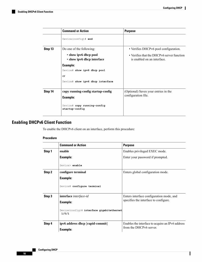
Do one of the following:Step 13 • Verifies DHCPv6 pool configuration.
• show ipv6 dhcp pool • Verifies that the DHCPv6 server functionis enabled on an interface.• show ipv6 dhcp interface
Example:Device# show ipv6 dhcp pool
orDevice# show ipv6 dhcp interface
(Optional) Saves your entries in theconfiguration file.
copy running-config startup-config
Example:
Step 14
Device# copy running-configstartup-config
Enabling DHCPv6 Client FunctionTo enable the DHCPv6 client on an interface, perform this procedure:
Procedure
PurposeCommand or Action
Enables privileged EXEC mode.enableStep 1
Example: Enter your password if prompted.
Device> enable
Enters global configuration mode.configure terminal
Example:
Step 2
Device# configure terminal
Enters interface configuration mode, andspecifies the interface to configure.
interface interface-id
Example:
Step 3
Device(config)# interface gigabitethernet1/0/1
Enables the interface to acquire an IPv6 addressfrom the DHCPv6 server.
ipv6 address dhcp [rapid-commit]
Example:
Step 4
Configuring DHCP16
Configuring DHCPEnabling DHCPv6 Client Function

PurposeCommand or Action
rapid-commit—(Optional)Allow two-messageexchange method for address assignment.Device(config-if)# ipv6 address dhcp
rapid-commit
(Optional) Enables the interface to request thevendor-specific option.
ipv6 dhcp client request [vendor-specific]
Example:
Step 5
Device(config-if)# ipv6 dhcp clientrequest vendor-specific
Returns to privileged EXEC mode.end
Example:
Step 6
Device(config)# end
Verifies that the DHCPv6 client is enabled onan interface.
show ipv6 dhcp interface
Example:
Step 7
Device# show ipv6 dhcp interface
Enabling the Cisco IOS DHCP Server DatabaseFor procedures to enable and configure the Cisco IOS DHCP server database, see the “DHCP ConfigurationTask List” section in the “Configuring DHCP” chapter of the Cisco IOS IP Configuration Guide.
Enabling the DHCP Snooping Binding Database AgentBeginning in privileged EXECmode, follow these steps to enable and configure the DHCP snooping bindingdatabase agent on the switch:
Procedure
PurposeCommand or Action
Enables privileged EXEC mode.enableStep 1
Example: • Enter your password if prompted.
Device> enable
Enters global configuration mode.configure terminal
Example:
Step 2
Device# configure terminal
Configuring DHCP17
Configuring DHCPEnabling the Cisco IOS DHCP Server Database

PurposeCommand or Action
Specifies the URL for the database agent or thebinding file by using one of these forms:
ip dhcp snooping database{flash[number]:/filename |
Step 3
ftp://user:password@host/filename | • flash[number]:/filenamehttp://[[username:password]@]{hostname |host-ip}[/directory] /image-name.tar |rcp://user@host/filename}| tftp://host/filename
• ftp://user:password@host/filename
• http://[[username:password]@]{hostname| host-ip}[/directory] /image-name.tarExample:
Device(config)# ip dhcp snooping databasetftp://10.90.90.90/snooping-rp2
• rcp://user@host/filename
• tftp://host/filename
Specifies (in seconds) how long to wait for thedatabase transfer process to finish beforestopping the process.
ip dhcp snooping database timeout seconds
Example:
Device(config)# ip dhcp snooping databasetimeout 300
Step 4
The default is 300 seconds. The range is 0 to86400. Use 0 to define an infinite duration,which means to continue trying the transferindefinitely.
Specifies the duration for which the transfershould be delayed after the binding database
ip dhcp snooping database write-delayseconds
Step 5
changes. The range is from 15 to 86400seconds. The default is 300 seconds (5minutes).Example:
Device(config)# ip dhcp snooping databasewrite-delay 15
Exits global configuration mode and returns toprivileged EXEC mode.
exit
Example:
Step 6
Device(config)# exit
(Optional) Adds binding entries to the DHCPsnooping binding database. The vlan-id range
ip dhcp snooping binding mac-address vlanvlan-id ip-address interface interface-id expiryseconds
Step 7
is from 1 to 4904. The seconds range is from 1to 4294967295.
Example:Enter this command for each entry that you add.
Device# ip dhcp snooping binding Use this command when you are testing ordebugging the switch.
0001.1234.1234 vlan 1 172.20.50.5interface gigabitethernet 1/1/0 expiry1000
Displays the status and statistics of the DHCPsnooping binding database agent.
show ip dhcp snooping database [detail]
Example:
Step 8
Device# show ip dhcp snooping databasedetail
Configuring DHCP18
Configuring DHCPEnabling the DHCP Snooping Binding Database Agent

Monitoring DHCP Snooping InformationTable 2: Commands for Displaying DHCP Information
Displays the DHCP snooping configuration for aswitch
show ip dhcp snooping
Displays only the dynamically configured bindingsin the DHCP snooping binding database, also referredto as a binding table.
show ip dhcp snooping binding
Displays the DHCP snooping binding database statusand statistics.
show ip dhcp snooping database
Displays the DHCP snooping statistics in summaryor detail form.
show ip dhcp snooping statistics
Display the dynamically and statically configuredbindings.
show ip source binding
If DHCP snooping is enabled and an interface changes to the down state, the switch does not delete thestatically configured bindings.
Note
Enabling DHCP Server Port-Based Address AllocationFollow these steps to globally enable port-based address allocation and to automatically generate a subscriberidentifier on an interface.
Procedure
PurposeCommand or Action
Enables privileged EXEC mode.enableStep 1
Example: • Enter your password if prompted.
Device> enable
Enters global configuration mode.configure terminal
Example:
Step 2
Device# configure terminal
Configures the DHCP server to globally use thesubscriber identifier as the client identifier onall incoming DHCP messages.
ip dhcp use subscriber-id client-id
Example:
Device(config)# ip dhcp use subscriber-idclient-id
Step 3
Configuring DHCP19
Configuring DHCPMonitoring DHCP Snooping Information

PurposeCommand or Action
Automatically generates a subscriber identifierbased on the short name of the interface.
ip dhcp subscriber-id interface-name
Example:
Step 4
A subscriber identifier configured on a specificinterface takes precedence over this command.Device(config)# ip dhcp subscriber-id
interface-name
Specifies the interface to be configured, andenters interface configuration mode.
interface interface-type interface-number
Example:
Step 5
Device(config)# interface gigabitethernet1/0/1
Configures the DHCP server to use thesubscriber identifier as the client identifier onall incoming DHCP messages on the interface.
ip dhcp server use subscriber-id client-id
Example:
Device(config-if)# ip dhcp server usesubscriber-id client-id
Step 6
Exits interface configuration mode and returnsto privileged EXEC mode.
end
Example:
Step 7
Device(config-if)# end
What to do next
After enabling DHCP port-based address allocation on the switch, use the ip dhcp pool global configurationcommand to preassign IP addresses and to associate them to clients.
Monitoring DHCP Server Port-Based Address AllocationTable 3: Commands for Displaying DHCP Port-Based Address Allocation Information
PurposeCommand
Displays the status and configuration of a specificinterface.
show interface interface id
Displays the DHCP address pools.show ip dhcp pool
Displays address bindings on the Cisco IOS DHCPserver.
show ip dhcp binding
Feature History for DHCPThis table provides release and related information for the features explained in this module.
Configuring DHCP20
Configuring DHCPMonitoring DHCP Server Port-Based Address Allocation

These features are available in all the releases subsequent to the one they were introduced in, unless notedotherwise.
Table 4: New Feature History
Feature InformationFeatureRelease
DHCP provides configuration parameters toInternet hosts. DHCP consists of two components:a protocol for delivering host-specific configurationparameters from a DHCP Server to a host and amechanism for allocating network addresses tohosts. DHCP is built on a client/server model,where designated DHCP Server hosts allocatenetwork addresses and deliver configurationparameters to dynamically configured hosts.
Support for this feature was introduced only on theC9500-12Q, C9500-16X, C9500-24Q, C9500-40Xmodels of the Cisco Catalyst 9500 Series Switches.
DHCPCisco IOSXEEverest 16.5.1a
Support for this feature was introduced only on theC9500-32C, C9500-32QC, C9500-48Y4C, andC9500-24Y4C models of the Cisco Catalyst 9500Series Switches.
DHCPCisco IOS XE Fuji 16.8.1a
The DHCP Client Option 12 feature specifies thehostname of the client. While acquiring an IPaddress for an interface from the Dynamic HostConfiguration Protocol (DHCP) server, if the clientdevice receives the DHCP Hostname option insidethe response, the hostname from that option is set.DHCP is used by DHCP clients to obtainconfiguration information for operation in an IPnetwork.
DHCP Client Option 12Cisco IOS XE Fuji 16.8.1a
Support for this feature was introduced on theC9500X-28C8Dmodel of the Cisco Catalyst 9500Series Switches.
DHCPCisco IOS XE Cupertino17.7.1
These features were implemented on supervisormodules C9400X-SUP-2 and C9400X-SUP-2XL,which were introduced in this release.
DHCP
DHCP Client Option 12
Cisco IOS XE Cupertino17.7.1
Use the Cisco Feature Navigator to find information about platform and software image support. To accessCisco Feature Navigator, go to http://www.cisco.com/go/cfn.
Configuring DHCP21
Configuring DHCPFeature History for DHCP

Configuring DHCP22
Configuring DHCPFeature History for DHCP