The Internet Protocol (IP) Part 1: IPv4 - School of Computer ...
Upload
khangminh22Category
view
1download
0
The University of AkronIdeaExchange@UAkron
Honors Research Projects The Dr. Gary B. and Pamela S. Williams HonorsCollege
Fall 2015
Implementing IS-IS Routing and DHCP Servicesin an IPv4 NetworkLaura ThompsonThe University Of Akron, [email protected]
Please take a moment to share how this work helps you through this survey. Your feedback will beimportant as we plan further development of our repository.Follow this and additional works at: http://ideaexchange.uakron.edu/honors_research_projects
Part of the Digital Communications and Networking Commons
This Honors Research Project is brought to you for free and open access by The Dr. Gary B. and Pamela S. WilliamsHonors College at IdeaExchange@UAkron, the institutional repository of The University of Akron in Akron, Ohio,USA. It has been accepted for inclusion in Honors Research Projects by an authorized administrator ofIdeaExchange@UAkron. For more information, please contact [email protected], [email protected].
Recommended CitationThompson, Laura, "Implementing IS-IS Routing and DHCP Services in an IPv4 Network" (2015). Honors ResearchProjects. 213.http://ideaexchange.uakron.edu/honors_research_projects/213

1
Implementing IS-IS Routing and DHCP Services in an IPv4 Network
Laura L. Thompson
Department of Business and Information Technology
Computer Information Systems
Honors Research Project
2
Table of Contents
Project Proposal ...............................................................................................................................3
Project Analysis ...............................................................................................................................6
Project Presentation .......................................................................................................................10
Project Description.........................................................................................................................19
1.1 IP Addressing Scheme .................................................................................................19
1.2 Router Code Upgrade ..................................................................................................22
1.3 Basic Device Configuration .........................................................................................25
1.4 Basic Switch Configuration .........................................................................................27
1.5 Basic Device Configuration .........................................................................................30
1.6 IS-IS Configuration ......................................................................................................31
1.7 OSPF Configuration.....................................................................................................43
1.8 Redistribution ...............................................................................................................45
1.9 Complete Device Configuration ..................................................................................51
2.1 Raspberry Pi Setup and dnsmasq Install ......................................................................76
2.2 DHCP and DNS Configuration ....................................................................................80
Project Testing Documentation......................................................................................................84
Project Weekly Journals ................................................................................................................87
Project References .........................................................................................................................95

3
Project Proposal
Project Name:
Implementing IS-IS Routing and DHCP Services in an IPv4 Network
Project Components:
Design and configure an IPv4 network running the IS-IS routing protocol, and use a Raspberry Pi
as a server to provide DHCP services to the network. OSPF will also be implemented in the
network, with redistribution between the 2 routing protocols.
Equipment:
Raspberry Pi B+
4 Cisco 2811 routers
1-2 Cisco 3750or 2960 Switches
Detailed Objective:
1. Research Topics
a. How the IS-IS Routing Protocol works
b. How a Raspberry Pi works
c. What software to use on the Raspberry Pi
d. How to configure the Raspberry Pi as a DHCP server
2. Design Tasks
a. Topology of the network
i. 4 routers in a hub and spoke topology
1. 2 of the spoke routers will run IS-IS only
2. 1 of the spoke routers will run OSPF only
3. The hub router will be the ASBR between the two domains
ii. 1-2 switches will be used for LAN connectivity
iii. Raspberry Pi will connect to one of the IS-IS spokes
b. IS-IS areas and routing functionality
c. OSPF to IS-IS redistribution plan
d. Addressing scheme for network devices
e. DHCP address pool
3. Implementation
a. Cable the devices according to topology designed in phase 2
b. Configure the routers with basic configurations and IP addresses
c. Configure the IS-IS routing protocol
i. IS-IS basic intra-area routing
ii. IS-IS areas and Level 2 (inter-area) routing
iii. Redistribution between IS-IS and OSPF
d. Set-up Raspberry Pi as the DHCP server
4
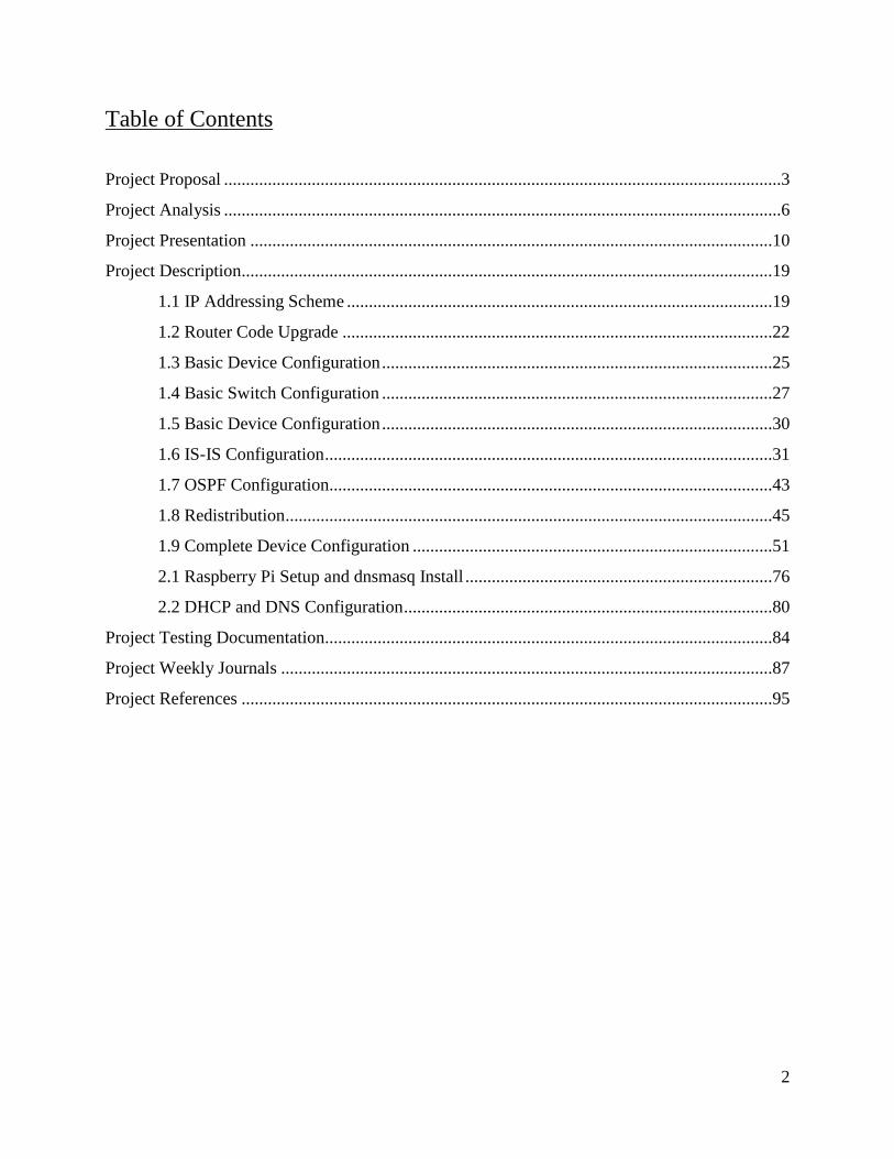
4. Testing
a. Confirm the configuration of IS-IS
i. View routing table
b. Use ping/traceroute/etc. to verify optimal routing
c. Confirm redistribution between OSPF and IS-IS
d. Confirm operation of the Server
i. Hosts receive IP addresses via DHCP
e. Issue appropriate show commands to verify all configurations
5. Documentation
a. Project Plan
b. Documentation of research and resources used
c. Issue appropriate show commands and capture screenshots to illustrate configuration
Estimated Time to Complete:
Research Design Implementation Testing Documentation Total
Estimate * 30 10 15 5 15 75
*Estimated in hours
Estimated Budget and Associated Costs:
Raspberry Pi $35.00
All other equipment $0.00 (Used FirstEnergy Lab equipment)
Location of the Work:
The majority of the work will be completed in the lab at FirstEnergy. In order to present this project, I
will utilize video recording. Access to the lab will be granted to the professor to view and verify my
completion of the project first hand.

5
Goals of the Project:
Gain an understanding of the basic functionality of the IS-IS routing protocol
Understand how to manipulate IS-IS routing, and support its integration with other protocols
Examine common problems with IS-IS, and learn how to troubleshoot effectively
Learn about the operation of the Raspberry Pi, and the Raspbian distribution of Linux
Determine the optimal method for configuration of DHCP services on the network
Final Presentation
The written portion of the project will consist of:
Weekly status reports
Show command output exhibiting the configuration of the network devices
Topology and network design diagrams
Screen shots and output of Raspberry Pi server configuration
Step-by-step configuration and troubleshooting guides
Works sited/reference page
The formal project presentation:
The formal project presentation will be given in front of my Computer Information Systems
Senior Projects class, and will meet the following criteria:
o PowerPoint presentation
o Video or live demonstration
o 15 minutes in length, with additional time granted for questions

6
Project Analysis
IS-IS Routing and Redistribution
In the early stages of research for this project, the idea of learning and configuring IS-IS
seemed like an overwhelming task. IS-IS has many elements that are not configured or used in
other IP routing protocols. Despite it’s intimidating nature, learning the basic operation of this
routing protocol was less difficult than expected. Although there are differences in commands,
and the underlying routing operations and metric calculation, IS-IS still accomplishes the same
tasks as EIGRP, OSPF, and other routing protocols.
Once routing within the IS-IS and OSPF domains was configured and working properly,
route redistribution between the two protocols was configured for full connectivity. Like all
routing protocols, redistribution into IS-IS is configured within the router IS-IS configuration
mode. The OSPF routes, including all subnets, were redistributed into the IS-IS routing domain.
This allowed the Intermediate Systems within the IS-IS domain to populate their routing tables
with routes to these remote OSPF networks, as IS-IS Level 2 routes. Likewise, route
redistribution was also configured into OSPF, allowing the OSPF routers to now have full
connectivity to the IS-IS domain via type O E1 redistributed routes.
Although two-way route redistribution can often cause problems such as routing loops
within networks, there were no such issues with this project. The main challenges that arose with
redistribution dealt with advertisement of specific networks.

7
Inspecting the intra-domain routes within the routing tables of each router was key to
understanding the protocol. However, the inter-domain routes proved to be even more essential
to formulating a clear picture of how IS-IS works. This was the central piece of this project, as it
not only was the focus of interest and learning, but also created a functioning backbone network
upon which the rest of the project plan was implemented.
The main challenges that arose with this aspect of the project dealt with advertisement of
specific routes, especially in regards to redistribution.
Raspberry Pi and DHCP/DNS
Implementing DHCP and DNS services into the network through the use of a Raspberry
Pi was an inexpensive way to incorporate both Linux, and server configuration into the project.
It was also a highly effective way to become all-around more familiar with Linux-based
operating systems and commands line.
With a basic knowledge of DHCP and DNS operation, the server implementation was
most challenging in terms of syntax. Although the initial project proposal did not include plans
for implementation of DNS services on the network, it was added in later to provide more
network functionality.
There are occasional intermittent issues with the DHCP service, causing a host to be
unsuccessful in acquiring an IP address for the server. This is only resolved by power cycling the
Raspberry Pi server, or waiting 2-3 minutes and attempting to release and renew the PC’s ip
configuration. There is no indication as to the cause of these issues anywhere in the daemon.log

8
file, which logs all DHCP related traffic entering and leaving the DHCP server. However, these
occurrences were very rare and intermittent.
In addition to the items listed on the project proposal, DNS services were also
implemented. The service that was used for DHCP is also capable of providing DNS services, so
the decision was made to implement some basic DNS functionality into the network as well.
In the initial project proposal, it was stated that the majority of the work would be
completed in the FirstEnergy lab. However, personal equipment has since been purchased for
this project. Due to the budget changes for the project, an updated cost analysis has been
included at the end of this section. Although the expected cost and proposed location of work
hasn’t been preserved, conformity to the original design has been maintained through the rest of
the project.
Overall, these elements combined to serve as an excellent project to meet the
requirements of the CIS Senior Projects Class, as well as facilitating interest and learning.
Budget and Associated Costs:
* The figures have been rounded to the nearest dollar amount, and include shipping fees.
Raspberry Pi $35.00
2 – Cisco 2950 Switches $95.00
4 – Cisco 2821 Routers $360.00
1 – HWIC-1FE Module $150.00
Cables, Rack, etc. Estimated $40.00
TOTAL $680.00

9
Time Analysis:
Research Design Implementation Testing Documentation Total
Estimate 30 10 15 5 15 75
Actual 20 6.5 16 9 19 70.5
Percent of
Estimated
Hours
Worked
66.7% 65% 100.1% 180% 126.7% 94%
* Time values are in hours

10
Project Presentation

11

12
13

14

15

16

17

18

19
Project Description
1.1 IP Addressing Scheme and Topology
The table above shows the overall IP Addressing scheme that was used for this project.
All point to point links were given a /30 address. The loopback addresses assigned to the routers
were /32 addresses, and all of the LANs stemming from the switch were given a /24 address
space. Individual static addresses were assigned according to the table above.
The Topology and cabling design varied slightly throughout the project. Initially, the
work was to be performed at FirstEnergy lab, however the purchase of personal equipment
allowed for the set-up of a home lab for this project. Because of this, the router and switch
models changed with this new development, and slight changes were made to the initial topology
design. None of these changes have had any effect on the functionality of the project, or the
overall structural design.
Subnet Device 1 Interface IP Device 2 Interface IP
Rtr Interconnects
10.1.1.0/30 CENTRAL-RTR-2821 Gig0/1 10.1.1.1 BRANCH-RTR-2821-1 Gig0/1 10.1.1.2
10.1.1.4/30 CENTRAL-RTR-2821 Gig0/0 10.1.1.5 BRANCH-RTR-2821-2 Gig0/0 10.1.1.6
172.16.0.0/30 CENTRAL-RTR-2821 Fa0/1/0 172.16.0.1 BRANCH-RTR-2821-3 Gig0/0 172.16.0.2
Branch1 to Server
10.1.100.0/30 BRANCH-RTR-2821-1 Gig0/0 10.1.100.2 RaspberryPi Eth0 10.1.100.1
Switch1 VLANS
192.168.50.0/24 BRANCH-RTR-2821-3 Gig0/1.50 192.168.50.1 BRANCH-SW-2950-1 Fa0/1 trunk
192.168.100.0/24 BRANCH-RTR-2821-3 Gig0/1.100 192.168.100.1 BRANCH-SW-2950-1 Fa0/1 trunk
192.168.200.0/24 BRANCH-RTR-2821-3 Gig0/1.200 192.168.200.1 BRANCH-SW-2950-1 Fa0/1 trunk
Switch2 VLANS
192.168.10.0/24 BRANCH-RTR-2821-2 Gig0/1.10 192.168.10.1 BRANCH-SW-2950-2 Fa0/1 trunk
192.168.150.0/24 BRANCH-RTR-2821-2 Gig0/1.150 192.168.150.1 BRANCH-SW-2950-2 Fa0/1 trunk
Loopbacks
192.168.1.1 BRANCH-RTR-2821-1 Lo0
192.168.2.1 BRANCH-RTR-2821-2 Lo0
192.168.3.1 BRANCH-RTR-2821-3 Lo0
192.168.4.1 CENTRAL-RTR-2821 Lo0
192.168.101.2 BRANCH-SW-2950-1 Native Vlan 101
192.168.201.2 BRANCH-SW-2950-2 Native Vlan 201

20
The final design and cabling structure of the network is as seen in the figure below.
CENTRAL-RTR-2821Lo0: 192.168.4.1
BRANCH-RTR-2821-3Lo0: 192.168.3.1
BRANCH-RTR-2821-2Lo0: 192.168.2.1
BRANCH-RTR-2821-1Lo0: 192.168.1.1
Gig0/0.5
Gig0/0.6
Gig0/1.2
Gig0/1.1
Gig0/0.2
Gig0/1
BRANCH-SW-2950Vlan 101: 192.168.101.2
Fa0/1
Raspberry Pi DHCP ServerDNS Server
VLAN Information
Vlan 50 – 192.168.50.0/24Vlan 100 – 192.168.100.0/24Vlan 200 – 192.168.200.0/24
Native Vlan 101 – 192.168.101.0/24
10.1.1.0/30
10.1.1.4/30
Fa0/1/0.1
172.16.0.0/30
Topology Diagram
DHCP Server dynamically assigns IP addresses to hosts in the Branch LANs based upon their VLAN assignment.
DNS Server provides DNS services for hosts on the network.
BRANCH-SW-2950Vlan 201: 192.168.201.2
Fa0/1Gig0/1
VLAN Information
Vlan 10 – 192.168.10.0/24Vlan 150 – 192.168.150.0/24
Native Vlan 201 – 192.168.201.0/24
The CENTRAL-RTR-2821 serves as the ASBR router, providing routing services for
both the OSPF and IS-IS domains. As seen in the figure, BRANCH-RTR-2821-1 and
BRANCH-RTR-2821-2 are both members of the IS-IS routing domain, and each is also a
member of additional IS-IS areas. This is known as multi-area IS-IS, and it was configured and
studied to understand the differences between Level 1 and Level 2 routes. This will be explained
further in later sections.
OSPF
IS-IS
IS-IS AREA1 IS-IS AREA2

21
Router BRANCH-RTR-2821-3 is not a member of the IS-IS domain, but rather the OSPF
routing domain. Both BRANCH-RTR-2821-2 and BRANCH-RTR-2821-3 have attached
switches which contain several user vlans. BRANCH-RTR-2821-3 connects to BRANCH-SW-
2950-1, which has 3 user vlans. They are vlan 50, vlan 100, and vlan 200. BRANCH-SW-2950-
1 also has a native vlan, vlan 101. BRANCH-SW-2950-2 is connected to the network via
BRANCH-RTR-2821-2, and it has 2 user vlans. These are vlans 10 and 150. The native vlan for
this switch is vlan 201.
By connecting to the ports of these switches, hosts are able to acquire an IP address on
the correct vlan from the Raspberry Pi DHCP server. In order to contact the server, hosts on
vlans 50, 100, and 200 must traverse both the OSPF and IS-IS routing domains. In order to
implement this, two-way redistribution was configured to allow full connectivity between these
two domains. Hosts on the vlans 10 and 150 must also traverse the IS-IS routing domain in
order to contact the server.
In addition to DHCP services, the Raspberry Pi was also configured for additional
functionality. It is also a fully functioning DNS server, which can perform lookups, and reverse
lookups for hosts on the network.

22
1.2 Router Code Upgrades
Code or IOS version upgrades were performed on all of the Cisco Routers. The IOS
version was chosen based upon the following factors:
1. Newest/Latest Supported IOS version
2. Memory/System requirements of the devices
For the Cisco 2821 Routers, 2 different IOS versions were chosen:
15.1.4M9 is the latest recommended IOS version, and was chosen for CENTRAL.
12.4.8 was chosen for the 3 remaining 2821 routers, as it is the latest IOS version suitable
for their memory.
The IOS versions were downloaded directly from Cisco’s website. In order to transfer
the IOS onto the routers, PSCP was used from the command prompt of a management PC.
PSCP (the puTTY Secure Copy Client) was used not only for the file transfer to the receiving
router, but also to pull the old IOS version from the routers. This was done to ensure that there
was a usable IOS version available for the routers in the event of upgrade issues.
The following were configured/enabled on the device prior to the initiation of transfer:
1) Hostname
2) Reachable IP address
3) Username and password
4) SSH and local authentication
5) SCP services (ip scp server enable)

23
6) Enable secret password
These configurations are necessary to allow the PSCP transfer. Once these requirements had
been satisfied, the necessary files were copied to/from a computer on the same network.
The following screenshots display:
1) the syntax for a PSCP transfer to a device
2) the syntax for pulling a file from a device using PSCP.

24
The IOS image file was then verified on each router, to ensure that the code was not
corrupted in the file transfer process. The following screenshots demonstrate the image
verification command syntax and output.
The value that is output after the verification is complete can be checked against Cisco’s
website to ensure that the IOS image is not corrupt. This was performed after each file transfer.
None of the transfers had any issues with corrupt code, however it is still a good practice to
verify the image. After successful verification, the code was upgraded on each router using the
following command syntax:
boot system flash:filename.bin
The routers were then reloaded to apply the changes. Neither BRANCH-SW-2950-1 or
BRANCH-SW-2950-2 was upgraded, as they were both already running the recommended code.

25
1.3 Basic Device Configuration
The configurations described in this section apply to all of the Cisco Routers and
Switches used in this project. For configurations specific to Switches see Section 1.4, and for
configurations specific to Routers, see section 1.5.
Basic Configuration
Basic configurations including hostname, usernames and passwords, console and vty line
configurations, and no ip domain-lookup were applied to each device. The following banner was
configured as well.
Notice! Unauthorized use of this system is strictly forbidden!
Laura Thompson - CIS Senior Project 2015
IP Host Configuration
In order to easily and quickly remote to each device, some basic ip host configurations
were applied to each terminal server. These configuration allow the user to establish remote
login sessions to the specified device by entering the ip host name for that device from privileged
exec mode. The ip host name configured for each device is different from that devices actual
hostname, for simplicity in typing. The configurations are shown below.
ip host branch3 192.168.3.1
ip host branch2 192.168.2.1
ip host central 192.168.4.1
ip host sw2 192.168.201.2
ip host sw1 192.168.101.2
ip host branch1 192.168.1.1

26
When entering the given ip host name for a device from privileged exec mode, the
configured banner is displayed, and the user is then prompted for that devices username and
password. Upon successful authentication, the user is now actively connected to the device as
shown below.
27
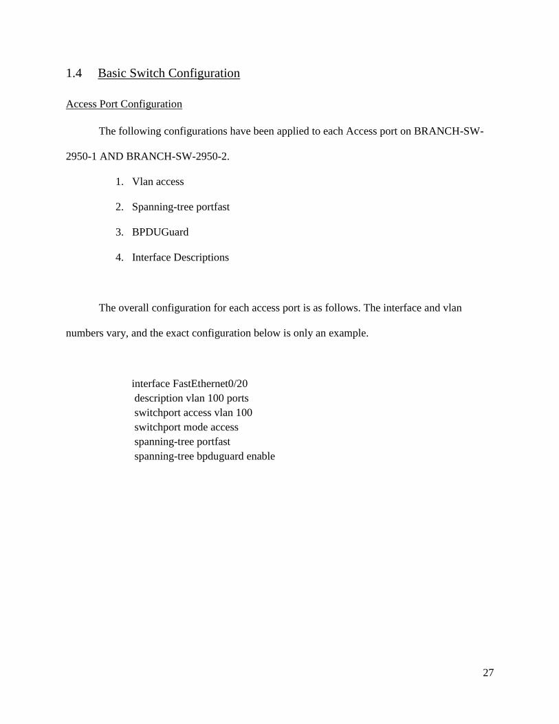
1.4 Basic Switch Configuration
Access Port Configuration
The following configurations have been applied to each Access port on BRANCH-SW-
2950-1 AND BRANCH-SW-2950-2.
1. Vlan access
2. Spanning-tree portfast
3. BPDUGuard
4. Interface Descriptions
The overall configuration for each access port is as follows. The interface and vlan
numbers vary, and the exact configuration below is only an example.
interface FastEthernet0/20
description vlan 100 ports
switchport access vlan 100
switchport mode access
spanning-tree portfast
spanning-tree bpduguard enable

28
The images below show the vlans and port assignments on each switch
BRANCH-SW-2950-1
BRANCH-SW-2950-2

29
Switch Trunk Port Configuration
The following configurations have been applied to the trunk links on BRANCH-SW
2950-1 AND BRANCH-SW-2950-2
1. Trunking for all vlans
2. Native vlan
3. Interface Descriptions
The configurations for each trunk port are as follows. The router subinterface
configurations used to establish router-on-a-stick connectivity can be viewed in the Basic Router
Configurations Section.
BRANCH-SW-2950-1
interface GigabitEthernet0/1
description uplink to branch-rtr-2821-3
switchport trunk native vlan 101
switchport mode trunk
BRANCH-SW-2950-2
interface FastEthernet0/1
description uplink to branch-rtr-2821-2
switchport trunk native vlan 201
switchport mode trunk

30
1.5 Basic Router Configuration
Router Interfaces
The Router interfaces were assigned IP addresses according to the IP addressing scheme
table that can be found in section 1.1. In addition, each router interface was given an interface
description matching the following format:
interface description to connected_device_name
Router Subinterfaces
The Router subinterfaces were assigned IP addresses in the same fashion as the physical
parent and loopback interfaces. They were also configured with the encapsulation dot1q
command to allow full router-on-a-stick connectivity.
BRANCH-SW-2950-1 and BRANCH-SW-2950-2 both have multiple vlans, on which
hosts need to acquire IP addresses from the Raspberry Pi DHCP server. In order to allow these
DHCP requests to be forwarded to the DHCP server with the correct vlan tag, the ip helper
address command was applied to each user vlan subinterface. The command syntax is as follows,
with 10.1.100.1 being the IP address of the server:
ip helper-address 10.1.100.1
Applying this command to all router subinterfaces allowed the hosts to reach and
communicate with the DHCP server on a different subnet.
31
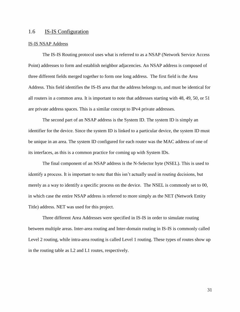
1.6 IS-IS Configuration
IS-IS NSAP Address
The IS-IS Routing protocol uses what is referred to as a NSAP (Network Service Access
Point) addresses to form and establish neighbor adjacencies. An NSAP address is composed of
three different fields merged together to form one long address. The first field is the Area
Address. This field identifies the IS-IS area that the address belongs to, and must be identical for
all routers in a common area. It is important to note that addresses starting with 48, 49, 50, or 51
are private address spaces. This is a similar concept to IPv4 private addresses.
The second part of an NSAP address is the System ID. The system ID is simply an
identifier for the device. Since the system ID is linked to a particular device, the system ID must
be unique in an area. The system ID configured for each router was the MAC address of one of
its interfaces, as this is a common practice for coming up with System IDs.
The final component of an NSAP address is the N-Selector byte (NSEL). This is used to
identify a process. It is important to note that this isn’t actually used in routing decisions, but
merely as a way to identify a specific process on the device. The NSEL is commonly set to 00,
in which case the entire NSAP address is referred to more simply as the NET (Network Entity
Title) address. NET was used for this project.
Three different Area Addresses were specified in IS-IS in order to simulate routing
between multiple areas. Inter-area routing and Inter-domain routing in IS-IS is commonly called
Level 2 routing, while intra-area routing is called Level 1 routing. These types of routes show up
in the routing table as L2 and L1 routes, respectively.

32
For the IS-IS backbone, 48 was used for the Area address. Therefore all three IS-IS
routers were configured with a routing process for the main IS-IS domain, and were given a NET
address beginning with 48.
For the IS-IS Area containing the Loopback0 of router BRANCH-RTR-2821-1, the Area
address 49 was used. This area was also given the name AREA1, which was specified in the
router isis command.
Finally, for the IS-IS Area containing the Loopback0 of router BRANCH-RTR-2821-2,
the Area address 50 was used. This area was given the name AREA2.
IS-IS Authentication
Similar to many other protocols, IS-IS supports authentication. There are two ways to
implement this authentication, and both were used in this project. First, a domain password can
be configured. The domain password is used for authentication between all neighbors in the
entire IS-IS routing domain. If one of the routers tries to join the domain, and does not have a
correct password configured, no adjacencies will be formed. Area specific passwords can also
be implemented. These password must match among all routers in the specified area, but do not
have to match routers in other areas within the domain. All passwords are case sensitive and
must be a single text string.

33
The examples below show the configurations of BRANCH-RTR-2821-1, BRANCH-
RTR-2821-2, and CENTRAL-RTR-2821, respectively. As noted above, the System ID portion
of the NET address was derived from the MAC address of one of the router’s interfaces.
Although these must be unique within an area, they may be duplicated within other areas.
Therefore, the same System ID was used in both areas for easier identification. Additionally,
router CENTRAL-RTR-2821 has redistribution commands, which will be explained in more
detail in section 1.8 Redistribution.
BRANCH-RTR-2821-1
router isis
net 48.0019.e869.6539.00
domain-password cisco
area-password CISCO
!
router isis AREA1
net 49.0019.e869.6539.00
is-type level-1
domain-password cisco
area-password CISCO1
BRANCH-RTR-2821-2
router isis
net 48.001c.f6b1.c5e1.00
domain-password cisco
area-password CISCO
!
router isis AREA2
net 50.001c.f6b1.c5e1.00
is-type level-1
domain-password cisco
area-password CISCO2

34
CENTRAL-RTR-2821
router isis
net 48.1c17.d3ec.96a1.00
domain-password cisco
area-password CISCO
redistribute ospf 1
passive-interface FastEthernet0/1/0
Advertising Networks
In addition to creating the IS-IS areas, the networks that need to be advertised must also
be specified. This is done in interface configuration mode, rather than router configuration mode.
Just as in other routing protocols, a network must be advertised in order for it to appear in the
routing tables of other routers within the domain.
The configuration of each interface follows, in order to depict which interfaces are being
advertised under which area.
BRANCH-RTR-2821-1
interface Loopback0
ip address 192.168.1.1 255.255.255.255
ip router isis AREA1
!
interface GigabitEthernet0/0
description to DHCP server
ip address 10.1.100.2 255.255.255.252
ip router isis
duplex auto
speed auto
!
interface GigabitEthernet0/1
description to central-rtr-2821
ip address 10.1.1.2 255.255.255.252
ip router isis
duplex auto
speed auto
35
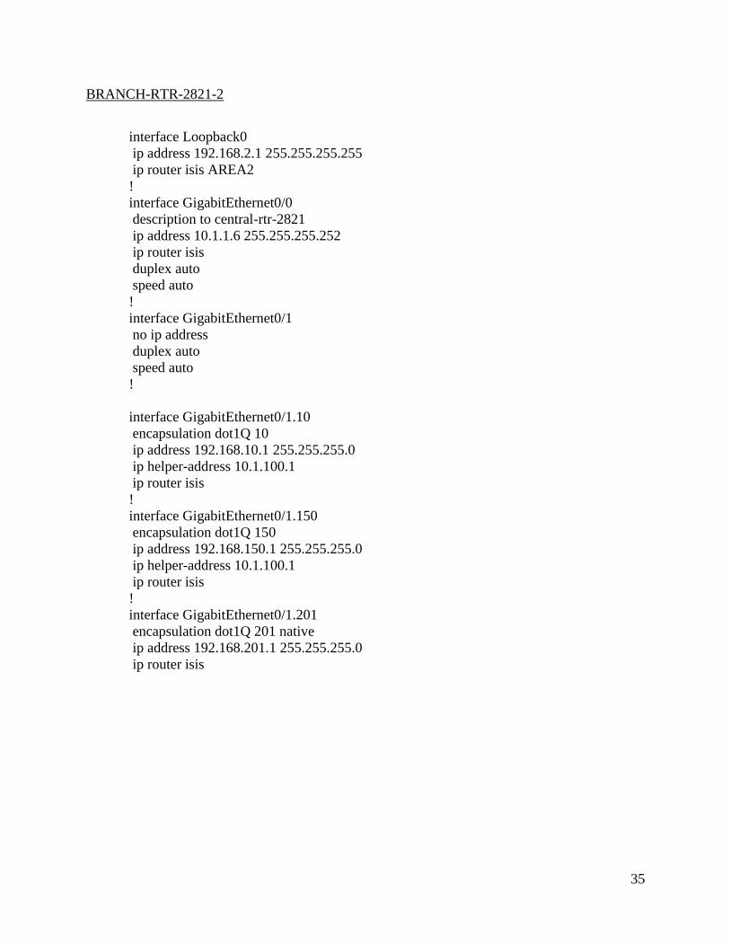
BRANCH-RTR-2821-2
interface Loopback0
ip address 192.168.2.1 255.255.255.255
ip router isis AREA2
!
interface GigabitEthernet0/0
description to central-rtr-2821
ip address 10.1.1.6 255.255.255.252
ip router isis
duplex auto
speed auto
!
interface GigabitEthernet0/1
no ip address
duplex auto
speed auto
!
interface GigabitEthernet0/1.10
encapsulation dot1Q 10
ip address 192.168.10.1 255.255.255.0
ip helper-address 10.1.100.1
ip router isis
!
interface GigabitEthernet0/1.150
encapsulation dot1Q 150
ip address 192.168.150.1 255.255.255.0
ip helper-address 10.1.100.1
ip router isis
!
interface GigabitEthernet0/1.201
encapsulation dot1Q 201 native
ip address 192.168.201.1 255.255.255.0
ip router isis

36
CENTRAL-RTR-2821
interface Loopback0
ip address 192.168.4.1 255.255.255.255
ip router isis
!
interface GigabitEthernet0/0
description to branch-rtr-2821-2
ip address 10.1.1.5 255.255.255.252
ip router isis
duplex auto
speed auto
isis priority 100
!
interface GigabitEthernet0/1
description to branch-rtr-2821-1
ip address 10.1.1.1 255.255.255.252
ip router isis
duplex auto
speed auto
isis priority 100
IS-IS Priority
IS-IS elects a router known as the DIS, or Designated Intermediate System. This router
is responsible for flooding Link State Packets, as well as creating the Pseudonode LSP. This type
of LSP is used to describe the overall LAN topology.
The DIS is elected based upon highest priority. If the priorities are the same, the highest
MAC address is used instead. As seen in the interface configuration above for router
CENTRAL-RTR-2821, an IS-IS interface priority was configured. Since the default priority is
64, giving each interface a priority of 100 ensures that router CENTRAL-RTR-2821 will be the
DIS. The screenshots below show the interface priority configurations for each router, as well as
other IS-IS information.

37
CENTRAL-RTR-2821

38
BRANCH-RTR-2821-1
BRANCH-RTR-2821-2

39
As seen in the screenshots above, the IS-IS interface priority was changed to 100 for both
interfaces on the router CENTRAL-RTR-2821. Just below the priority, the DR ID can be viewed
(although this router is generally referred to as the DIS or Designated Intermediate System in IS-
IS, the output of this command uses the terminology DR instead).
The DR ID that is shown in output of each of these show commands is central-rtr-28.01
or central-rtr-28.02. The .01 and .02 fields are indicative of the Circuit ID, which is automatically
assigned to each circuit in IS-IS.
Due to the interface priority configurations previously applied, the router CENTRAL-
RTR-2821 is now the designated intermediate system for the backbone IS-IS routing area.
For IS-IS AREA1 and AREA2, each respective router containing the area was used in the
name of the Circuit ID. As each of these areas was simulated using a loopback interface with no
physically connected routers, the DIS ID is set to 0000.0000.0000.00. This can be determined by
examining the same information from the screenshots that follow.

40
BRANCH-RTR-2821-1 Loopback 0 in AREA1
BRANCH-RTR-2821-2 Loopback 0 in AREA2

41
The IS-IS configurations explained in this section allowed both
BRANCH-RTR-2821-1 and BRANCH-RTR-2821-2 to form neighbor adjacencies with the
Designated Intermediate System, CENTRAL-RTR-2821. The IS-IS neighbor adjacency
information is displayed below.
CENTRAL-RTR-2821
BRANCH-RTR-2821-1
BRANCH-RTR-2821-2

42
The routers maintain separate adjacencies for Level 1 and Level 2 neighbor relationships,
even for the same physical neighbor. Each router also separates the adjacencies according to the
Area, listing the unnamed backbone area as Area null. Had this area been given a name, it would
appear here in place of null.

43
1.7 OSPF Configuration
OSPF Configuration
The OSPF configurations on both BRANCH-RTR-2821-3 and CENTRAL-RTR-2821
were kept relatively simple. Only Area 0 was implemented due to the small size of the network.
The link between the two routers was advertised in the OSPF process on each router. BRANCH-
RTR-2821-3 also advertised its loopback address, as well as the attached vlan networks. These
configurations combined with redistribution allow these remote networks to be accessible from
the IS-IS routing domain.
The OSPF process configuration on each router is shown below. The redistribution
configurations will be discussed in the next section, 1.8 Redistribution.
BRANCH-RTR-2821-3
router ospf 1
log-adjacency-changes
area 0 authentication message-digest
network 172.16.0.0 0.0.0.3 area 0
network 192.168.3.1 0.0.0.0 area 0
network 192.168.0.0 0.0.255.255 area 0
CENTRAL-RTR-2821
router ospf 1
area 0 authentication message-digest
redistribute connected subnets
redistribute isis level-1-2 subnets
passive-interface GigabitEthernet0/0
passive-interface GigabitEthernet0/1
network 172.16.0.0 0.0.0.3 area 0

44
MD5 Authentication for the OSPF routers was also configured by setting the key string
on the interfaces, and enabling MD5 authentication under the OSPF process. The interface
configurations are shown below.
CENTRAL-RTR-2821
interface FastEthernet0/1/0
description to branch-rtr-2821-3
ip address 172.16.0.1 255.255.255.252
ip ospf message-digest-key 1 md5 7 14141B180F0B
duplex auto
speed auto
BRANCH-RTR-2821-3
interface GigabitEthernet0/0
description to central-rtr-2821
ip address 172.16.0.2 255.255.255.252
ip ospf message-digest-key 1 md5 7 110A1016141D
duplex auto
speed auto
After configuring the OSPF process on CENTRAL-RTR-2821 and BRANCH-RTR-
2821-3, an OSPF adjacency was formed. In the output of the show ip ospf neighbors command
below, it can be viewed that CENTRAL-RTR-2821 is the Designated Router (DR), and
BRANCH-RTR-2821-3 is the Backup Designated Router (BDR).

45
1.8 Redistribution
IS-IS Redistribution
IS-IS Redistribution was configured within the OSPF routing process of the redistributing
router. In order to allow full connectivity within the network and between the routing domains,
several pieces of configuration were required.
First, redistribution of IS-IS level 1 and level 2 routes was configured using the following
command:
redistribute isis level-1-2 subnets
The level-1-2 keyword declares that both level 1 and level 2 routes should be
redistributed. Since the AREA1 and AREA2 subdomains appear as level 2 routes to
CENTRAL-RTR-2821, and the main IS-IS domain appears as level 1 routes, this keyword is
necessary for full redistribution. Without it, only level 1 routes would be redistributed and
devices in the OSPF domain would no longer have connectivity to AREA1 or AREA2. The
subnets keyword is necessary in order for all classless subnets to be redistributed into the OSPF
domain.
After applying this redistribution command, there were still a few remote networks that
were unreachable from the OSPF domain. After verifying that these networks were being
advertised in IS-IS, the routing table was used for further troubleshooting. It was discovered that
these networks were not being redistributed because they appeared in the routing table of the
ASBR as connected routes.

46
In order to solve this issue, an additional redistribution command was used to ensure that
full connectivity would be achieved. The following command allowed the remaining connected
routes to be redistributed into OSPF.
redistribute connected subnets
After applying this command, the connected routes could then be seen in the routing table
of router BRANCH-RTR-2821-3.
OSPF Redistribution
After having redistributed the IS-IS routes, two way redistribution was configured for full
connectivity both ways. Basic redistribution of OSPF routes into IS-IS was configured. The
The routing tables of each router are shown below with brief explanations of the types of routes
that are seen.

47
CENTRAL-RTR-2821
In router CENTRAL-RTR-2821’s routing table, all of the IS-IS routes appear with the
code “i”. The additional codes, L1 and L2 represent Level 1 and Level 2 routes respectively.
The routes to 192.168.1.1 and 192.168.1.1 both appear as L2 routes, because these networks are
part of IS-IS AREA1 and AREA2.

48
BRANCH-RTR-2821-1
In the routing table of BRANCH-RTR-2821-1, some IS-IS routes also appear as L2
routes. These are the routes that are being redistributed into IS-IS from OSPF. Since these
routes are not a part of the IS-IS domain, they will also appear as L2 routes in the routing table.

49
BRANCH-RTR-2821-2
The L2 routes to the OSPF networks appear in router BRANCH-RTR-2821’s routing
table as well. As pictured above, the administrative distance for all IS-IS routes is 115.

50
BRANCH-RTR-2821-3
In the routing table of BRANCH-RTR-2821-3, the redistributed IS-IS routes are coded as
O E2 routes. All of these routes were redistributed into OSPF from IS-IS.

51
1.9 Complete Device Configuration
This section includes the complete configuration of all devices. For explanations
regarding specific pieces of configuration, see the previous sections.
CENTRAL-RTR-2821
central-rtr-2821#show run
Building configuration...
Current configuration : 2065 bytes
!
version 15.1
service timestamps debug datetime msec
service timestamps log datetime msec
service password-encryption
!
hostname central-rtr-2821
!
boot-start-marker
boot-end-marker
!
!
!
no aaa new-model
!
!
dot11 syslog
ip source-route
!
!
ip cef
!
!
!
no ip domain lookup
ip domain name Thompson.test
ip host branch1 192.168.1.1
ip host branch2 192.168.2.1
ip host branch3 192.168.3.1
ip host sw2 192.168.201.2
ip host sw1 192.168.101.2
no ipv6 cef

52
!
multilink bundle-name authenticated
!
!
voice-card 0
!
crypto pki token default removal timeout 0
!
!
license udi pid CISCO2821 sn FTX1425A0YA
username Laura privilege 15 secret 5 $1$kEP8$5O2T9IYee0VLCWC12jE3u0
!
redundancy
!
!
!
interface Loopback0
ip address 192.168.4.1 255.255.255.255
ip router isis
!
interface GigabitEthernet0/0
description to branch-rtr-2821-2
ip address 10.1.1.5 255.255.255.252
ip router isis
duplex auto
speed auto
!
interface GigabitEthernet0/1
description to branch-rtr-2821-1
ip address 10.1.1.1 255.255.255.252
ip router isis
duplex auto
speed auto
!
interface FastEthernet0/1/0
description to branch-rtr-2821-3
ip address 172.16.0.1 255.255.255.252
ip ospf message-digest-key 1 md5 7 14141B180F0B
duplex auto
speed auto
!
router ospf 1
area 0 authentication message-digest
redistribute connected subnets
redistribute isis level-1-2 subnets
passive-interface GigabitEthernet0/0

53
passive-interface GigabitEthernet0/1
network 172.16.0.0 0.0.0.3 area 0
!
router isis
net 48.1c17.d3ec.96a1.00
domain-password cisco
area-password CISCO
redistribute ospf 1
passive-interface FastEthernet0/1/0
!
ip forward-protocol nd
no ip http server
no ip http secure-server
!
!
!
logging source-interface Loopback0
!
!
control-plane
!
!
mgcp profile default
!
!
banner motd ^C
Notice! Unauthorized use of this system is strictly forbidden!
Laura Thompson - CIS Senior Project 2015
^C
!
line con 0
line aux 0
line vty 0 4
exec-timeout 50 0
login local
transport input telnet ssh
!
scheduler allocate 20000 1000
end

54
BRANCH-RTR-2821-1
branch-rtr-2821-1#show run
Building configuration...
Current configuration : 1514 bytes
!
version 12.4
service timestamps debug datetime msec
service timestamps log datetime msec
service password-encryption
!
hostname branch-rtr-2821-1
!
boot-start-marker
boot-end-marker
!
no aaa new-model
ip subnet-zero
!
!
ip cef
!
!
no ip domain lookup
ip domain name Thompson.test
ip host branch1 192.168.1.1
ip host branch2 192.168.2.1
ip host branch3 192.168.3.1
ip host sw2 192.168.201.2
ip host sw1 192.168.101.2
ip host central 192.168.4.1
no ftp-server write-enable
!
!
username Laura privilege 15 secret 5 $1$QMKo$oS1jfuVLMeUPRQJZ84Vcd/
!
!
interface Loopback0
ip address 192.168.1.1 255.255.255.255
ip router isis AREA1
!
interface GigabitEthernet0/0
description to DHCP server
ip address 10.1.100.2 255.255.255.252

55
ip router isis
duplex auto
speed auto
!
interface GigabitEthernet0/1
description to central-rtr-2821
ip address 10.1.1.2 255.255.255.252
ip router isis
duplex auto
speed auto
!
router isis
net 48.0019.e869.6539.00
domain-password cisco
area-password CISCO
!
router isis AREA1
net 49.0019.e869.6539.00
is-type level-1
domain-password cisco
area-password CISCO1
!
ip classless
!
ip http server
no ip http secure-server
!
control-plane
!
banner motd ^C
Notice! Unauthorized use of this system is strictly forbidden!
Laura Thompson - CIS Senior Project 2015
^C
!
line con 0
logging synchronous
line aux 0
line vty 0 4
exec-timeout 50 0
login local
transport input telnet ssh
!
scheduler allocate 20000 1000
!
end

56
BRANCH-RTR-2821-2
branch-rtr-2821-2#show run
Building configuration...
Current configuration : 1816 bytes
!
version 12.4
service timestamps debug datetime msec
service timestamps log datetime msec
service password-encryption
!
hostname branch-rtr-2821-2
!
boot-start-marker
boot-end-marker
!
!
no aaa new-model
!
resource policy
!
!
!
ip cef
!
!
no ip domain lookup
ip domain name Thompson.test
ip host branch1 192.168.1.1
ip host branch3 192.168.3.1
ip host sw2 192.168.201.2
ip host sw1 192.168.101.2
ip host central 192.168.4.1
!
!
voice-card 0
no dspfarm
!
!
username Laura privilege 15 secret 5 $1$YieH$gEUsf5T4MgzttezkbheDB1
!
!
interface Loopback0
ip address 192.168.2.1 255.255.255.255
ip router isis AREA2

57
!
interface GigabitEthernet0/0
description to central-rtr-2821
ip address 10.1.1.6 255.255.255.252
ip router isis
duplex auto
speed auto
!
interface GigabitEthernet0/1
no ip address
duplex auto
speed auto
!
interface GigabitEthernet0/1.10
encapsulation dot1Q 10
ip address 192.168.10.1 255.255.255.0
ip helper-address 10.1.100.1
ip router isis
!
interface GigabitEthernet0/1.150
encapsulation dot1Q 150
ip address 192.168.150.1 255.255.255.0
ip helper-address 10.1.100.1
ip router isis
!
interface GigabitEthernet0/1.201
encapsulation dot1Q 201 native
ip address 192.168.201.1 255.255.255.0
ip router isis
!
router isis
net 48.001c.f6b1.c5e1.00
domain-password cisco
area-password CISCO
!
router isis AREA2
net 50.001c.f6b1.c5e1.00
is-type level-1
domain-password cisco
area-password CISCO2
!
!
!
ip http server
no ip http secure-server
!

58
!
!
control-plane
!
!
banner motd ^C
Notice! Unauthorized use of this system is strictly forbidden!
Laura Thompson - CIS Senior Project 2015
^C
!
line con 0
logging synchronous
line aux 0
line vty 0 4
exec-timeout 50 0
login local
transport input telnet ssh
!
scheduler allocate 20000 1000
!
end

59
BRANCH-RTR-2821-3
branch-rtr-2821-3#sho run
Building configuration...
Current configuration : 1982 bytes
!
version 12.4
service timestamps debug datetime msec
service timestamps log datetime msec
service password-encryption
!
hostname branch-rtr-2821-3
!
boot-start-marker
boot-end-marker
!
!
no aaa new-model
!
resource policy
!
!
ip cef
!
!
no ip domain lookup
ip domain name Thompson.test
ip host branch1 192.168.1.1
ip host sw2 192.168.201.2
ip host sw1 192.168.101.2
ip host central 192.168.4.1
ip host branch2 192.168.2.1
!
!
voice-card 0
no dspfarm
!
!
username Laura privilege 15 secret 5 $1$9VXY$OeOvKlOwgJi29kmgH19D.1
!
!
interface Loopback0
ip address 192.168.3.1 255.255.255.255
!

60
!
interface GigabitEthernet0/0
description to central-rtr-2821
ip address 172.16.0.2 255.255.255.252
ip ospf message-digest-key 1 md5 7 110A1016141D
duplex auto
speed auto
!
interface GigabitEthernet0/1
description to branch-sw-2950
no ip address
ip helper-address 10.1.100.1
duplex auto
speed auto
!
interface GigabitEthernet0/1.50
encapsulation dot1Q 50
ip address 192.168.50.1 255.255.255.0
ip helper-address 10.1.100.1
!
interface GigabitEthernet0/1.100
encapsulation dot1Q 100
ip address 192.168.100.1 255.255.255.0
ip helper-address 10.1.100.1
!
interface GigabitEthernet0/1.101
encapsulation dot1Q 101 native
ip address 192.168.101.1 255.255.255.0
!
interface GigabitEthernet0/1.200
encapsulation dot1Q 200
ip address 192.168.200.1 255.255.255.0
ip helper-address 10.1.100.1
!
router ospf 1
log-adjacency-changes
area 0 authentication message-digest
network 172.16.0.0 0.0.0.3 area 0
network 192.168.3.1 0.0.0.0 area 0
network 192.168.0.0 0.0.255.255 area 0
!
!
!
ip http server
no ip http secure-server
!

61
!
control-plane
!
!
!
banner motd ^C
Notice! Unauthorized use of this system is strictly forbidden!
Laura Thompson - CIS Senior Project 2015
^C
!
line con 0
logging synchronous
line aux 0
line vty 0 4
exec-timeout 50 0
login local
transport input telnet ssh
!
scheduler allocate 20000 1000
!
end

62
BRANCH-SW-2950-1
branch-sw-2950-1#show run
Building configuration...
Current configuration : 9068 bytes
!
version 12.1
no service pad
service timestamps debug uptime
service timestamps log uptime
service password-encryption
!
hostname branch-sw-2950-1
!
!
username Laura privilege 15 secret 5 $1$4OA4$2lgf/WP64FXXX2a/g6mz51
ip subnet-zero
ip dhcp relay information option
ip dhcp relay forward spanning-tree
!
ip host branch3 192.168.3.1
ip host branch2 192.168.2.1
ip host central 192.168.4.1
ip host sw2 192.168.201.2
ip host branch1 192.168.1.1
!
spanning-tree mode pvst
no spanning-tree optimize bpdu transmission
spanning-tree extend system-id
!
!
!
!
interface FastEthernet0/1
description vlan 50 ports
switchport access vlan 50
switchport mode access
spanning-tree portfast
spanning-tree bpduguard enable
!
interface FastEthernet0/2
description vlan 50 ports
switchport access vlan 50
switchport mode access

63
spanning-tree portfast
spanning-tree bpduguard enable
!
interface FastEthernet0/3
description vlan 50 ports
switchport access vlan 50
switchport mode access
spanning-tree portfast
spanning-tree bpduguard enable
!
interface FastEthernet0/4
description vlan 50 ports
switchport access vlan 50
switchport mode access
spanning-tree portfast
spanning-tree bpduguard enable
!
interface FastEthernet0/5
description vlan 50 ports
switchport access vlan 50
switchport mode access
spanning-tree portfast
spanning-tree bpduguard enable
!
interface FastEthernet0/6
description vlan 50 ports
switchport access vlan 50
switchport mode access
spanning-tree portfast
spanning-tree bpduguard enable
!
interface FastEthernet0/7
description vlan 50 ports
switchport access vlan 50
switchport mode access
spanning-tree portfast
spanning-tree bpduguard enable
!
interface FastEthernet0/8
description vlan 50 ports
switchport access vlan 50
switchport mode access
spanning-tree portfast
spanning-tree bpduguard enable
!
interface FastEthernet0/9

64
description vlan 50 ports
switchport access vlan 50
switchport mode access
spanning-tree portfast
spanning-tree bpduguard enable
!
interface FastEthernet0/10
description vlan 50 ports
switchport access vlan 50
switchport mode access
spanning-tree portfast
spanning-tree bpduguard enable
!
interface FastEthernet0/11
description vlan 50 ports
switchport access vlan 50
switchport mode access
spanning-tree portfast
spanning-tree bpduguard enable
!
interface FastEthernet0/12
description vlan 50 ports
switchport access vlan 50
switchport mode access
spanning-tree portfast
spanning-tree bpduguard enable
!
interface FastEthernet0/13
description vlan 50 ports
switchport access vlan 50
switchport mode access
spanning-tree portfast
spanning-tree bpduguard enable
!
interface FastEthernet0/14
description vlan 50 ports
switchport access vlan 50
switchport mode access
spanning-tree portfast
spanning-tree bpduguard enable
!
interface FastEthernet0/15
description vlan 50 ports
switchport access vlan 50
switchport mode access
spanning-tree portfast

65
spanning-tree bpduguard enable
!
interface FastEthernet0/16
description vlan 50 ports
switchport access vlan 50
switchport mode access
spanning-tree portfast
spanning-tree bpduguard enable
!
interface FastEthernet0/17
description vlan 100 ports
switchport access vlan 100
switchport mode access
spanning-tree portfast
spanning-tree bpduguard enable
!
interface FastEthernet0/18
description vlan 100 ports
switchport access vlan 100
switchport mode access
spanning-tree portfast
spanning-tree bpduguard enable
!
interface FastEthernet0/19
description vlan 100 ports
switchport access vlan 100
switchport mode access
spanning-tree portfast
spanning-tree bpduguard enable
!
interface FastEthernet0/20
description vlan 100 ports
switchport access vlan 100
switchport mode access
spanning-tree portfast
spanning-tree bpduguard enable
!
interface FastEthernet0/21
description vlan 100 ports
switchport access vlan 100
switchport mode access
spanning-tree portfast
spanning-tree bpduguard enable
!
interface FastEthernet0/22
description vlan 100 ports

66
switchport access vlan 100
switchport mode access
spanning-tree portfast
spanning-tree bpduguard enable
!
interface FastEthernet0/23
description vlan 100 ports
switchport access vlan 100
switchport mode access
spanning-tree portfast
spanning-tree bpduguard enable
!
interface FastEthernet0/24
description vlan 100 ports
switchport access vlan 100
switchport mode access
spanning-tree portfast
spanning-tree bpduguard enable
!
interface FastEthernet0/25
description vlan 100 ports
switchport access vlan 100
switchport mode access
spanning-tree portfast
spanning-tree bpduguard enable
!
interface FastEthernet0/26
description vlan 100 ports
switchport access vlan 100
switchport mode access
spanning-tree portfast
spanning-tree bpduguard enable
!
interface FastEthernet0/27
description vlan 100 ports
switchport access vlan 100
switchport mode access
spanning-tree portfast
spanning-tree bpduguard enable
!
interface FastEthernet0/28
description vlan 100 ports
switchport access vlan 100
switchport mode access
spanning-tree portfast
spanning-tree bpduguard enable

67
!
interface FastEthernet0/29
description vlan 100 ports
switchport access vlan 100
switchport mode access
spanning-tree portfast
spanning-tree bpduguard enable
!
interface FastEthernet0/30
description vlan 100 ports
switchport access vlan 100
switchport mode access
spanning-tree portfast
spanning-tree bpduguard enable
!
interface FastEthernet0/31
description vlan 100 ports
switchport access vlan 100
switchport mode access
spanning-tree portfast
spanning-tree bpduguard enable
!
interface FastEthernet0/32
description vlan 100 ports
switchport access vlan 100
switchport mode access
spanning-tree portfast
spanning-tree bpduguard enable
!
interface FastEthernet0/33
description vlan 200 ports
switchport access vlan 200
switchport mode access
spanning-tree portfast
spanning-tree bpduguard enable
!
interface FastEthernet0/34
description vlan 200 ports
switchport access vlan 200
switchport mode access
spanning-tree portfast
spanning-tree bpduguard enable
!
interface FastEthernet0/35
description vlan 200 ports
switchport access vlan 200

68
switchport mode access
spanning-tree portfast
spanning-tree bpduguard enable
!
interface FastEthernet0/36
description vlan 200 ports
switchport access vlan 200
switchport mode access
spanning-tree portfast
spanning-tree bpduguard enable
!
interface FastEthernet0/37
description vlan 200 ports
switchport access vlan 200
switchport mode access
spanning-tree portfast
spanning-tree bpduguard enable
!
interface FastEthernet0/38
description vlan 200 ports
switchport access vlan 200
switchport mode access
spanning-tree portfast
spanning-tree bpduguard enable
!
interface FastEthernet0/39
description vlan 200 ports
switchport access vlan 200
switchport mode access
spanning-tree portfast
spanning-tree bpduguard enable
!
interface FastEthernet0/40
description vlan 200 ports
switchport access vlan 200
switchport mode access
spanning-tree portfast
spanning-tree bpduguard enable
!
interface FastEthernet0/41
description vlan 200 ports
switchport access vlan 200
switchport mode access
spanning-tree portfast
spanning-tree bpduguard enable
!

69
interface FastEthernet0/42
description vlan 200 ports
switchport access vlan 200
switchport mode access
spanning-tree portfast
spanning-tree bpduguard enable
!
interface FastEthernet0/43
description vlan 200 ports
switchport access vlan 200
switchport mode access
spanning-tree portfast
spanning-tree bpduguard enable
!
interface FastEthernet0/44
description vlan 200 ports
switchport access vlan 200
switchport mode access
spanning-tree portfast
spanning-tree bpduguard enable
!
interface FastEthernet0/45
description vlan 200 ports
switchport access vlan 200
switchport mode access
spanning-tree portfast
spanning-tree bpduguard enable
!
interface FastEthernet0/46
description vlan 200 ports
switchport access vlan 200
switchport mode access
spanning-tree portfast
spanning-tree bpduguard enable
!
interface FastEthernet0/47
description vlan 200 ports
switchport access vlan 200
switchport mode access
spanning-tree portfast
spanning-tree bpduguard enable
!
interface FastEthernet0/48
description vlan 200 ports
switchport access vlan 200
switchport mode access

70
spanning-tree portfast
spanning-tree bpduguard enable
!
interface GigabitEthernet0/1
description uplink to branch-rtr-2821-3
switchport trunk native vlan 101
switchport mode trunk
!
interface GigabitEthernet0/2
description interface not in use
shutdown
!
interface Vlan1
no ip address
no ip route-cache
shutdown
!
interface Vlan101
ip address 192.168.101.2 255.255.255.0
no ip route-cache
!
ip default-gateway 192.168.101.1
no ip http server
banner motd ^C
Notice! Unauthorized use of this system is strictly forbidden!
Laura Thompson - CIS Senior Project 2015
^C
!
line con 0
logging synchronous
line vty 0 4
login local
transport input telnet
line vty 5 15
login
!
!
end

71
BRANCH-SW-2950-2
branch-sw-2950-2#show run
Building configuration...
Current configuration : 4809 bytes
!
version 12.1
no service pad
service timestamps debug uptime
service timestamps log uptime
service password-encryption
!
hostname branch-sw-2950-2
!
!
username Laura privilege 15 secret 5 $1$G58H$/GyEAZs366OTsrUheiI0Z0
ip subnet-zero
!
ip host branch1 192.168.1.1
ip host branch3 192.168.3.1
ip host branch2 192.168.2.1
ip host central 192.168.4.1
ip host sw1 192.168.101.2
ip domain-name Thompson.test
!
spanning-tree mode pvst
no spanning-tree optimize bpdu transmission
spanning-tree extend system-id
!
!
!
!
interface FastEthernet0/1
description uplink to branch-rtr-2821-2
switchport trunk native vlan 201
switchport mode trunk
!
interface FastEthernet0/2
description vlan 10 ports
switchport access vlan 10
switchport mode access
spanning-tree portfast
spanning-tree bpduguard enable
!

72
interface FastEthernet0/3
description vlan 10 ports
switchport access vlan 10
switchport mode access
spanning-tree portfast
spanning-tree bpduguard enable
!
interface FastEthernet0/4
description vlan 10 ports
switchport access vlan 10
switchport mode access
spanning-tree portfast
spanning-tree bpduguard enable
!
interface FastEthernet0/5
description vlan 10 ports
switchport access vlan 10
switchport mode access
spanning-tree portfast
spanning-tree bpduguard enable
!
interface FastEthernet0/6
description vlan 10 ports
switchport access vlan 10
switchport mode access
spanning-tree portfast
spanning-tree bpduguard enable
!
interface FastEthernet0/7
description vlan 10 ports
switchport access vlan 10
switchport mode access
spanning-tree portfast
spanning-tree bpduguard enable
!
interface FastEthernet0/8
description vlan 10 ports
switchport access vlan 10
switchport mode access
spanning-tree portfast
spanning-tree bpduguard enable
!
interface FastEthernet0/9
description vlan 10 ports
switchport access vlan 10
switchport mode access

73
spanning-tree portfast
spanning-tree bpduguard enable
!
interface FastEthernet0/10
description vlan 10 ports
switchport access vlan 10
switchport mode access
spanning-tree portfast
spanning-tree bpduguard enable
!
interface FastEthernet0/11
description vlan 10 ports
switchport access vlan 10
switchport mode access
spanning-tree portfast
spanning-tree bpduguard enable
!
interface FastEthernet0/12
description vlan 10 ports
switchport access vlan 10
switchport mode access
spanning-tree portfast
spanning-tree bpduguard enable
!
interface FastEthernet0/13
description vlan 150 ports
switchport access vlan 150
switchport mode access
spanning-tree portfast
spanning-tree bpduguard enable
!
interface FastEthernet0/14
description vlan 150 ports
switchport access vlan 150
switchport mode access
spanning-tree portfast
spanning-tree bpduguard enable
!
interface FastEthernet0/15
description vlan 150 ports
switchport access vlan 150
switchport mode access
spanning-tree portfast
spanning-tree bpduguard enable
!
interface FastEthernet0/16

74
description vlan 150 ports
switchport access vlan 150
switchport mode access
spanning-tree portfast
spanning-tree bpduguard enable
!
interface FastEthernet0/17
description vlan 150 ports
switchport access vlan 150
switchport mode access
spanning-tree portfast
spanning-tree bpduguard enable
!
interface FastEthernet0/18
description vlan 150 ports
switchport access vlan 150
switchport mode access
spanning-tree portfast
spanning-tree bpduguard enable
!
interface FastEthernet0/19
description vlan 150 ports
switchport access vlan 150
switchport mode access
spanning-tree portfast
spanning-tree bpduguard enable
!
interface FastEthernet0/20
description vlan 150 ports
switchport access vlan 150
switchport mode access
spanning-tree portfast
spanning-tree bpduguard enable
!
interface FastEthernet0/21
description vlan 150 ports
switchport access vlan 150
switchport mode access
spanning-tree portfast
spanning-tree bpduguard enable
!
interface FastEthernet0/22
description vlan 150 ports
switchport access vlan 150
switchport mode access
spanning-tree portfast

75
spanning-tree bpduguard enable
!
interface FastEthernet0/23
description vlan 150 ports
switchport access vlan 150
switchport mode access
spanning-tree portfast
spanning-tree bpduguard enable
!
interface FastEthernet0/24
description vlan 150 ports
switchport access vlan 150
switchport mode access
spanning-tree portfast
spanning-tree bpduguard enable
!
interface Vlan1
no ip address
no ip route-cache
shutdown
!
interface Vlan201
ip address 192.168.201.2 255.255.255.0
no ip route-cache
!
ip default-gateway 192.168.201.1
ip http server
banner motd ^C
Notice! Unauthorized use of this system is strictly forbidden!
Laura Thompson - CIS Senior Project 2015
^C
!
line con 0
line vty 0 4
login local
transport input telnet
line vty 5 15
login
!
!
end

76
2.1 Raspberry Pi Setup and dnsmasq Install
Operating System Install
The initial task involved with the Raspberry Pi was the Operating System install. After
researching different OS versions available for the Raspberry Pi, Raspbian was chosen. Raspbian
is a Debian distribution available for the Pi, and it was downloaded from the Raspberry Pi
website and installed.
System Updates
Once the Pi had been connected to the internet, it was necessary to check for and
download any available updates, using the following command syntax:
77
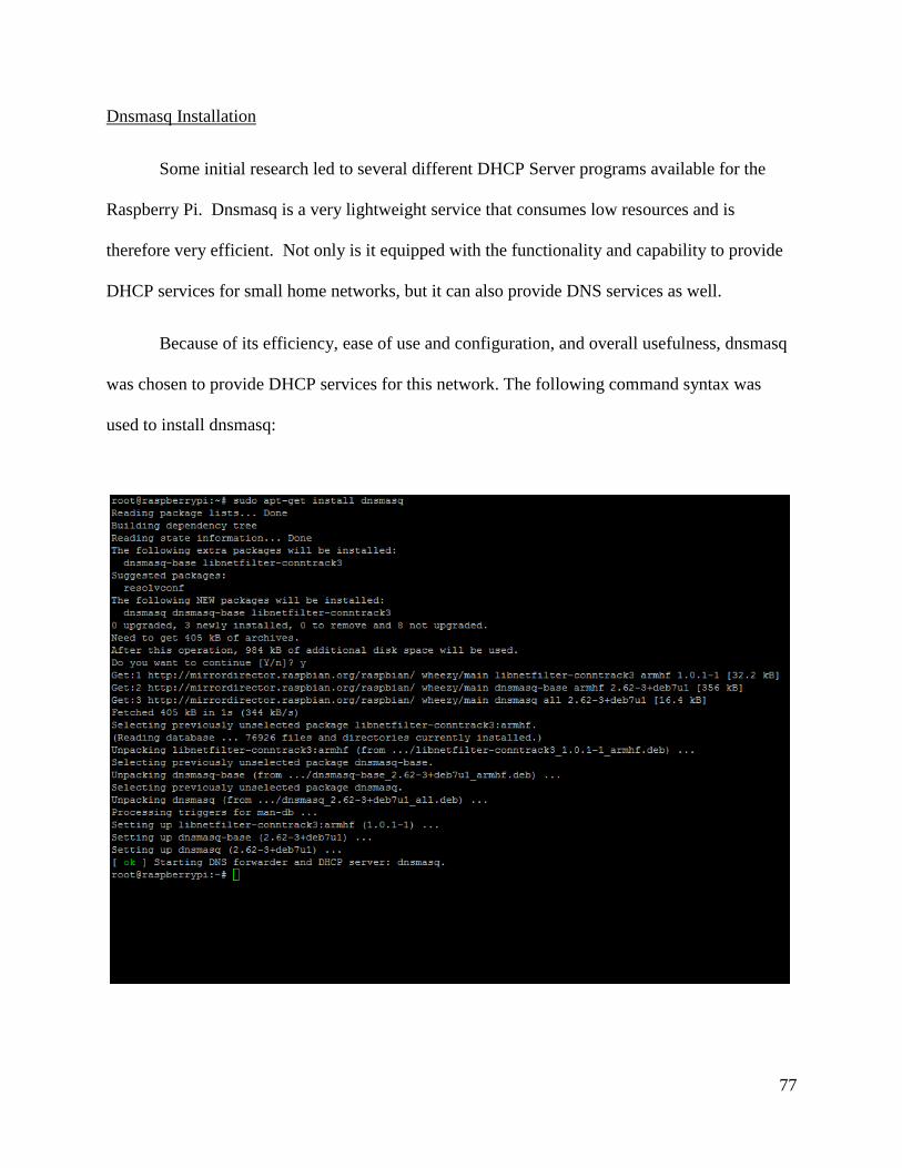
Dnsmasq Installation
Some initial research led to several different DHCP Server programs available for the
Raspberry Pi. Dnsmasq is a very lightweight service that consumes low resources and is
therefore very efficient. Not only is it equipped with the functionality and capability to provide
DHCP services for small home networks, but it can also provide DNS services as well.
Because of its efficiency, ease of use and configuration, and overall usefulness, dnsmasq
was chosen to provide DHCP services for this network. The following command syntax was
used to install dnsmasq:

78
Dnsmasq.conf File
The configuration of DHCP and DNS services is done within the dnsmasq.conf file. By
default, this file can be located in the etc directory of root.
For simplicity, the file was kept in this location for the duration of the project.
Network Configuration
After the necessary downloads had completed, the Raspberry Pi was disconnected form
the Internet and given a static IP address according to the topology and IP addressing scheme
previously designed.

79
A default route was also added to the Raspberry Pi to allow it to have full connectivity
and network reachability. The screenshots below display the syntax that was used as well as the
ip routing table.
The first entry seen in the routing table appears as a result of the route command
previously entered. As pictured, the route is specified as a default route, and the gateway is the
next hop address of 10.1.100.2.

80
2.2 DHCP and DNS Configuration
DHCP Configuration
Similar to many other DHCP services, dnsmasq works by first specifying a range or
ranges of addresses that may be dynamically assigned to hosts. Although some variations in the
syntax can still possibly produce working results, the most reliable and correct syntax is as
follows:
if=interface_name
dhcp-range=tag,starting_ip,ending_ip,subnet,_mask,lease_time
For this network, the DHCP server needed to be able to assign addresses for five different
subnets, therefore five different ranges needed to be specified. The ranges were created
according to the following rules:
1. Create a range for each vlan on the remote switches.
2. Exclude the first 10 addresses for network use.
The following displays the configuration for each of the DHCP ranges for this network:

81
Each of the ranges was also given a tag. The purpose of the tag was to allow the server to
append additional options in the DHCP packets. For this network, option 6 was used. Option 6 is
used to specify the Domain Name Server (DNS) for the subnet, using the following syntax:
dhcp-option=tag,option#,server_ip
As pictured above, the domain name to be communicated to the hosts needed to be
specified, as well as the domain that the server itself resides within. This is achieved through the
following lines:
domain=domain.name
local=/domain.name/
Based upon these configurations, a host requesting an IP address from this server is now
able to receive an IP within the correct subnet, domain information, and the IP address of the
DNS server. Daemon.log, a detailed log file containing all DHCP related messages can be found
on the Raspberry Pi in order to troubleshoot problems with the DHCP service. This will be
explored further in the “Testing Documentation” tab.
DNS Configuration
The dnsmasq service not only provides DHCP services to the network, but it can also
provide DNS services as well. Although including a DNS server was not an initial part of the
project plan, it was implemented as an additional feature within the network.

82
The domain information configured in the dnsmasq.conf file is used for DNS as well as
DHCP. In addition to this, the hostnames and IP addresses that will be resolved by the server
must also be specified.
The IP addresses were statically mapped to their corresponding hostname or DNS name
within the hosts file. This file can be found within the /etc directory.
The following screenshot shows the IP addresses and their corresponding DNS names
that were entered for this network.

83
Additional screenshots were taken to verify that hosts could acquire IP addresses on all
vlans. Nslookup and ping commands were used to verify that DNS hostnames and IP addresses
were resolving properly. Testing and verification for the DHCP and DNS services can be found
under the Testing Documentation tab.

84
Project Testing Documentation
The following screenshots demonstrate the ability of the Raspberry Pi DHCP server to
assign IP addresses for different subnets. A test PC was patched into a port on each vlan, and
received the IP addresses shown below. The PC also successfully received its domain suffix
information, subnet mask, and default gateway from the Raspberry Pi DHCP server as well.
Although it isn’t shown here, the DHCP server also communicated information about the DNS
server to the host.

85
After acquiring an IP address, hosts in each vlan were able to perform nslookups and
reverse lookups for any of the hostnames or IP addresses configured on the network. The
example below shows nslookup commands and pings performed on a test PC. When performing
an nslookup with a hostname, the request initially times out, however this issue resolves itself
within the same attempt.

86
Contents of the Raspberry Pi’s Daemon.log file are shown below. Additional
conversation occurred between the client and the server, however it was excluded in order to
emphasize the information that follows. Throughout the exchange below, a DHCP discover
message is received on interface Ethernet 0 of the Pi from a host on vlan 50, including its name
and current domain. The DHCP server then send out an offer message with information such as
an IP address, domain name, and DNS server. The host then responds with a DHCP request for
an IP on that subnet. When the server receives the request, it responds with a DHCP
Acknowledgement message.
All of the DHCP related traffic received on and sent from the Raspberry Pi is logged to
this file, so these types of messages are recorded for every DHCP address acquired by any host.
Feb 15 17:33:46 raspberrypi dnsmasq-dhcp[1983]: 3170466944 DHCPDISCOVER(eth0) 2c:41:38:04:77:d0
Feb 15 17:33:46 raspberrypi dnsmasq-dhcp[1983]: 3170466944 tags: vlan50, eth0
Feb 15 17:33:46 raspberrypi dnsmasq-dhcp[1983]: 3170466944 DHCPOFFER(eth0) 192.168.50.151
2c:41:38:04:77:d0
Feb 15 17:33:46 raspberrypi dnsmasq-dhcp[1983]: 3170466944 next server: 10.1.100.1
Feb 15 17:33:46 raspberrypi dnsmasq-dhcp[1983]: 3170466944 sent size: 4 option: 54 server-identifier 10.1.100.1
Feb 15 17:33:46 raspberrypi dnsmasq-dhcp[1983]: 3170466944 sent size: 4 option: 51 lease-time 86400
Feb 15 17:33:46 raspberrypi dnsmasq-dhcp[1983]: 3170466944 sent size: 4 option: 1 netmask 255.255.255.0
Feb 15 17:33:46 raspberrypi dnsmasq-dhcp[1983]: 3170466944 sent size: 4 option: 28 broadcast 192.168.50.255
Feb 15 17:33:46 raspberrypi dnsmasq-dhcp[1983]: 3170466944 sent size: 4 option: 3 router 192.168.50.1
Feb 15 17:33:46 raspberrypi dnsmasq-dhcp[1983]: 3170466944 sent size: 13 option: 15 domain-name
Thompson.test
Feb 15 17:33:46 raspberrypi dnsmasq-dhcp[1983]: 3170466944 sent size: 4 option: 6 dns-server 10.1.100.1
Feb 15 17:33:46 raspberrypi dnsmasq-dhcp[1983]: 3170466944 available DHCP range: 192.168.50.10 --
192.168.50.254
Feb 15 17:33:46 raspberrypi dnsmasq-dhcp[1983]: 3170466944 client provides name: TAG178809.fenetwork.com
Feb 15 17:33:46 raspberrypi dnsmasq-dhcp[1983]: 3170466944 DHCPREQUEST(eth0) 192.168.50.151
2c:41:38:04:77:d0
Feb 15 17:33:46 raspberrypi dnsmasq-dhcp[1983]: 3170466944 tags: vlan50, eth0
Feb 15 17:33:46 raspberrypi dnsmasq-dhcp[1983]: Ignoring domain fenetwork.com for DHCP host name
TAG178809
Feb 15 17:33:46 raspberrypi dnsmasq-dhcp[1983]: 3170466944 DHCPACK(eth0) 192.168.50.151
2c:41:38:04:77:d0 TAG178809

87
Project Weekly Journals
Summary – Week ending: February 1, 2015
Date Start
Time
End
Time
Description Total
Hours
1/26/2015 2:00 pm 3:00 pm Racked and cabled devices 1
1/28/2015 2:00 pm 4:00 pm Ordered server equipment, downloaded OS 2
1/29/2011 5:00 pm 8:30 pm Researched IS-IS 3.5
Total Hours This Week
Total Hours to Date
6.5
6.5
Journal Details
1/26/2015
Racked and cabled devices.
o Routers and switches were racked in the lab to match the topology design.
o Devices were cabled according to the topology.
1/28/2015
Ordered server equipment.
o Raspberry Pi B+ model will be used for DHCP server.
o Equipment will not arrive until next week.
Configuration will begin next week.
Downloaded Operating System.
o Researched Operating Systems for the Raspberry Pi.
o Raspbian, an Operating System designed specifically for the Raspberry Pi will be
used for this project.
1/29/2011
Researched IS-IS.
o Began researching basic functionality and configuration of IS-IS.
o Started creating an addressing scheme.
Router and switch IPs.
Server IP.
DHCP Pool.

88
Summary – Week ending: February 8, 2015
Date Start
Time
End
Time
Description Total
Hours
2/3/2015 3:00 pm 5:00 pm Installed the OS 2
2/5/2015 5:00 pm 8:00 pm Continued IS-IS research 3
2/6/2015 4:00 pm 5:00 pm Documentation 1
Total Hours This Week
Total Hours to Date
6
12.5
Journal Details
2/3/2015
Installed the OS.
o Installed the Raspbian Operating System on the Raspberry Pi.
o Researched DHCP services for the Raspberry Pi.
o Experimented to become more familiar with the Command Line and functionality
of the Pi.
2/5/2015
Continued to research IS-IS.
Began implementing basic configurations for each of the network devices.
2/6/2015
Documented Addressing.
o Began creating formal documentation for the network addressing scheme.
Documented Links.
o Began creating formal documentation for the links between network devices.

89
Summary – Week ending: February 15, 2015
Date Start
Time
End
Time
Description Total
Hours
2/11/2015
8:00 am 10:00
am
Configured DHCP Server 2
2/12/2015 6:00 pm 8:00 pm Re-cabled new devices 2
2/13/2015 4:00 pm 6:00 pm Performed code upgrade 2
Total Hours This Week
Total Hours to Date
6
18.5
Journal Details
2/11/2015
Configured DHCP Server
o Configured the Raspberry Pi as the DHCP Server for the network.
2/12/2015
Re-cabled the devices.
o Upon the acquisition of my own equipment, I transferred the configurations to
these devices and re-cabled the topology. The project devices will no longer be
FirstEnergy lab devices.
2/13/2015
Performed code upgrade.
o Upgrade the IOS version on the routers using PSCP (SCP for puTTY).

90
Summary – Week ending: February 22, 2015
Date Start
Time
End
Time
Description Total
Hours
2/16/2015
1:00 pm 4:30 pm Updated Documentation 3.5
2/17/2015
10:00
am
1:00 pm IS-IS Configuration 3
2/19/2015
6:00 pm 10:00
pm
IS-IS Research and Configuration 4
Total Hours This Week
Total Hours to Date
10.5
29
Journal Details
2/16/2015
Updated Documentation
2/17/2015
IS-IS Configuration
o Worked on and experimented with basic IS-IS configuration.
2/19/2015
IS-IS Research and Configuration
o Continued to research IS-IS.

91
Summary – Week ending: March 1, 2015
Date Start
Time
End
Time
Description Total
Hours
2/27/2015
9:00 am 1:00 pm IS-IS Configuration 4
2/28/2015
12:30
am
2:00 am Documentation 1.5
3/1/2015 2:30 pm 7:30 pm IS-IS Research and Configuration 5
Total Hours This Week
Total Hours to Date
10.5
39.5
Journal Details
2/27/2015
IS-IS Configuration
o Worked on IS-IS routing and areas.
2/28/2015
Documentation
o Worked on updating documentation.
3/1/2015
IS-IS Research and Configuration
o Researched IS-IS areas, and how to use show commands to verify operation. Also
worked on configuration.

92
Summary – Week ending: March 8, 2015
Date Start
Time
End
Time
Description Total
Hours
3/2/2015
4:00 pm 9:00 pm OSPF and Redistribution Configuration 5
3/3/2015
4:30
pm
6:30 pm Switch and Router-on-a-Stick Configuration 2
3/4/2015
8:00 pm 11:00
pm
DHCP Configuration per Subnet 3
3/5/2015
6:00 pm 9:00 pm Researched and Implemented DNS 3
Total Hours This Week
Total Hours to Date
13
52.5
Journal Details
3/2/2015
OSPF and Redistribution Configuration
o Configured OSPF area 0 and implemented redistribution between the two
domains for full connectivity.
3/3/2015
Switch and Router-on-a-Stick Configuration
o Configured vlans, sub-interfaces, router-on-a-stick, etc.
3/4/2015
DHCP Configuration per Subnet
o Worked with the Raspberry Pi DHCP server to implement DHCP services for
different subnets.
3/5/2015
Researched and Implemented DNS
o Used dnsmasq to implement DNS services for the network.

93
Summary – Week ending: March 15, 2015
Date Start
Time
End
Time
Description Total
Hours
3/9/2015 2:30 pm 6:00 pm Updated Documentation 3.5
3/11/2015
4:30
pm
6:30 pm Updated Documentation 2
Total Hours This Week
Total Hours to Date
5.5
58
Journal Details
3/9/2015
Updated Documentation
o Updated documentation on the Raspberry Pi and server configuration process.
3/11/2015
Updated Documentation
o Updated documentation of the overall device configuration.

94
Summary – Week ending: March 22, 2015
Date Start
Time
End
Time
Description Total
Hours
3/16/2015
2:00 pm 4:00 pm Completed Network Testing 2
3/16/2015
8:00 pm 11:00
pm
Updated Documentation 3
3/21/2015
4:00
pm
8:00 pm Documentation and Presentation 4
Total Hours This Week
Total Hours to Date
9
67
Journal Details
3/16/2015
Completed Network Testing
o Finished network testing and gathering screenshots for final report.
3/16/2015
Updated Documentation
o Updated documentation for the Project Description Section
3/21/2015
Documentation and Presentation
o Continued updated documentation and worked on Presentation
95
References
Configuring IS-IS for IP on Cisco Routers. (2005, August 10). Retrieved February 5, 2015, from
http://www.cisco.com/c/en/us/support/docs/ip/integrated-intermediate-system-to-
intermediate-system-is-is/13795-is-is-ip-config.html
Configuring ISO CLNS. (2008, January 18). Retrieved February 9, 2015, from
http://www.cisco.com/c/en/us/td/docs/ios/12_2/apollo/configuration/guide/fapolo_c/3c
fclns.html
Integrated IS-IS Commands. (2007, June 27). Retrieved February 5, 2015, from
http://www.cisco.com/c/en/us/td/docs/ios/12_2/iproute/command/reference/fiprrp_r/1r
fisis.html
IS-IS Multiarea Support. (n.d.). Retrieved February 19, 2015, from
http://www.cisco.com/en/US/products/ps6599/products_data_sheet09186a00800e9780
.html?referring_site=bodynav
Lab 4-1 Configuring Basic Integrated IS-IS. (2006). CCNP: Building Scalable Internetworks
V5.0, 1-17. Retrieved February 27, 2015, from
http://www.cs.rpi.edu/~kotfid/routing/PDF/CCNP1_lab_4_1_en.pdf
Marty, A. (2002). IS-IS Areas and Routing Heirarchies. In IS-IS Network Design Solutions
(Networking Technology). Cisco Press. Retrieved February 5, 2015, from
http://www.ciscopress.com/articles/article.asp?p=26850&seqNum=3
Raspberry Pi Foundation. (n.d.). Dynamic Host Configuration Protocol (DHCP). Retrieved
February 20, 2015, from http://www.raspberrypi.org/learning/networking-
lessons/lesson-3/README.md

96
Schroder, C. (2011, November 28). Dnsmasq for Easy LAN Name Services. Retrieved March 2,
2015, from https%3A%2F%2Fwww.linux.com%2Flearn%2Ftutorials%2F516220-
dnsmasq-for-easy-lan-name-services
Copyright © 2022 FDOKUMEN