Computer Networks Lecture -5- IPv4 Addresses
118
McGraw-Hill ©The McGraw-Hill Companies, Inc., 2000 Computer Networks Lecture -5- IPv4 Addresses Dr. Abbas Abdulazeez
-
Upload
khangminh22 -
Category
Documents
-
view
6 -
download
0
Transcript of Computer Networks Lecture -5- IPv4 Addresses
McGraw-Hill ©The McGraw-Hill Companies, Inc., 2000
Computer Networks
Lecture -5-
IPv4 Addresses
Dr. Abbas Abdulazeez

TCP/IP Protocol Suite 2
OBJECTIVES: To introduce the concept of an address space in general and the
address space of IPv4 in particular.
To discuss the classful architecture and the blocks of addresses
available in each class.
To discuss the idea of hierarchical addressing and how it has
been implemented in classful addressing.
To explain subnetting and supernetting for classful architecture.
To discuss classless addressing, that has been devised to solve the
problems in classful addressing.
To discuss some special blocks and some special addresses in
each block.
To discuss NAT technology and show how it can be used to
alleviate of address depletion.

TCP/IP Protocol Suite 3
Chapter
Outline
5.1 Introduction
5.2 Classful Addressing
5.3 Classless Addressing
5.4 Special Addresses 5.5 NAT

TCP/IP Protocol Suite 4
5-1 INTRODUCTION
The identifier used in the IP layer of the TCP/IP
protocol suite to identify each device connected to
the Internet is called the Internet address or IP
address. An IPv4 address is a 32-bit address that
uniquely and universally defines the connection of a
host or a router to the Internet; an IP address is the
address of the interface.

TCP/IP Protocol Suite 5
Topics Discussed in the Section
Notation
Range of Addresses
Operations

TCP/IP Protocol Suite 6
An IPv4 address is 32 bits long.
Note
The IPv4 addresses are unique
and universal.
Note

TCP/IP Protocol Suite 7
The address space of IPv4 is
232 or 4,294,967,296.
Note
Numbers in base 2, 16, and 256 are
discussed in Appendix B.
Note

TCP/IP Protocol Suite 8
Figure 5.1 Dotted-decimal notation

TCP/IP Protocol Suite 9
Change the following IPv4 addresses from binary notation to
dotted-decimal notation.
a. 10000001 00001011 00001011 11101111
b. 11000001 10000011 00011011 11111111
c. 11100111 11011011 10001011 01101111
d. 11111001 10011011 11111011 00001111
Solution We replace each group of 8 bits with its equivalent decimal
number (see Appendix B) and add dots for separation:
a. 129.11.11.239
b. 193.131.27.255
c. 231.219.139.111
d. 249.155.251.15
Example 5.1

TCP/IP Protocol Suite 10
Change the following IPv4 addresses from dotted-decimal
notation to binary notation.
a. 111.56.45.78
b. 221.34.7.82
c. 241.8.56.12 d. 75.45.34.78 Solution We replace each decimal number with its binary equivalent:
a. 01101111 00111000 00101101 01001110
b. 11011101 00100010 00000111 01010010
c. 11110001 00001000 00111000 00001100
d. 01001011 00101101 00100010 01001110
Example 5.2

TCP/IP Protocol Suite 11
Find the error, if any, in the following IPv4 addresses:
a. 111.56.045.78
b. 221.34.7.8.20
c. 75.45.301.14
d. 11100010.23.14.67
Solution a. There should be no leading zeroes (045).
b. We may not have more than 4 bytes in an IPv4 address.
c. Each byte should be less than or equal to 255.
d. A mixture of binary notation and dotted-decimal notation.
Example 5.3

TCP/IP Protocol Suite 12
Change the following IPv4 addresses from binary notation to
hexadecimal notation.
a. 10000001 00001011 00001011 11101111
b. 11000001 10000011 00011011 11111111
Solution
We replace each group of 4 bits with its hexadecimal
equivalent.
a. 810B0BEF16
b. C1831BFF16
Example 5.4

TCP/IP Protocol Suite 13
Find the number of addresses in a range if the first address is
146.102.29.0 and the last address is 146.102.32.255.
Solution
We can subtract the first address from the last address in base
256 (see Appendix B). The result is 0.0.3.255 in this base. To
find the number of addresses in the range (in decimal), we
convert this number to base 10 and add 1 to the result..
Range of Addresses
Example 5.5

TCP/IP Protocol Suite 14
The first address in a range of addresses is 14.11.45.96. If the
number of addresses in the range is 32, what is the last
address?
Solution
We convert the number of addresses minus 1 to base 256,
which is 0.0.0.31. We then add it to the first address to get the
last address. Addition is in base 256.
Example 5.6

TCP/IP Protocol Suite 15
Figure 5.2 Bitwise NOT operation

TCP/IP Protocol Suite 16
Example 5.7

TCP/IP Protocol Suite 17
Figure 5.3 Bitwise AND operation

TCP/IP Protocol Suite 18
Example 5.8

TCP/IP Protocol Suite 19
Figure 5.4 Bitwise OR operation

TCP/IP Protocol Suite 20
Example 5.9

TCP/IP Protocol Suite 21
5-2 CLASSFUL ADDRESSING
IP addresses, when started a few decades ago,
used the concept of classes. This architecture is
called classful addressing. In the mid-1990s, a new
architecture, called classless addressing, was
introduced that supersedes the original architecture.
In this section, we introduce classful addressing
because it paves the way for understanding
classless addressing and justifies the rationale for
moving to the new architecture. Classless
addressing is discussed in the next section.

TCP/IP Protocol Suite 22
Topics Discussed in the Section
Classes
Classes and Blocks
Two-Level Addressing
Three-Level Addressing: Subnetting
Supernetting

TCP/IP Protocol Suite 23
Figure 5.5 Occupation of address space

TCP/IP Protocol Suite 24
Figure 5.6 Finding the class of address

TCP/IP Protocol Suite 25
Figure 5.7 Finding the class of an address using continuous checking
1
Class: A
0
Start1
0
Class: B
1
0
Class: C
1
0
Class: D Class: E

TCP/IP Protocol Suite 26
Find the class of each address:
a. 00000001 00001011 00001011 11101111
b. 11000001 10000011 00011011 11111111
c. 10100111 11011011 10001011 01101111
d. 11110011 10011011 11111011 00001111
Solution See the procedure in Figure 5.7.
a. The first bit is 0. This is a class A address.
b. The first 2 bits are 1; the third bit is 0. This is a class C
address.
c. The first bit is 1; the second bit is 0. This is a class B
address.
d. The first 4 bits are 1s. This is a class E address.
Example 5.10

TCP/IP Protocol Suite 27
Find the class of each address:
a. 227.12.14.87
b. 193.14.56.22
c. 14.23.120.8
d. 252.5.15.111
Solution
a. The first byte is 227 (between 224 and 239); the class is D.
b. The first byte is 193 (between 192 and 223); the class is C.
c. The first byte is 14 (between 0 and 127); the class is A.
d. The first byte is 252 (between 240 and 255); the class is E.
Example 5.11

TCP/IP Protocol Suite 28
Figure 5.8 Netid and hostid

TCP/IP Protocol Suite 29
Figure 5.9 Blocks in Class A

TCP/IP Protocol Suite 30
Millions of class A addresses
are wasted.
Note

TCP/IP Protocol Suite 31
Figure 5.10 Blocks in Class B

TCP/IP Protocol Suite 32
Many class B addresses are wasted.
Note

TCP/IP Protocol Suite 33
Figure 5.11 Blocks in Class C

TCP/IP Protocol Suite 34
Not so many organizations are so small
to have a class C block.
Note

TCP/IP Protocol Suite 35
Figure 5.12 The single block in Class D
TCP/IP Protocol Suite 36
Class D addresses are made of one
block, used for multicasting.
Note

TCP/IP Protocol Suite 37
Figure 5.13 The single block in Class E

TCP/IP Protocol Suite 38
The only block of class E addresses was
reserved for future purposes.
Note

TCP/IP Protocol Suite 39
The range of addresses allocated to an
organization in classful addressing
was a block of addresses in
Class A, B, or C.
Note

TCP/IP Protocol Suite 40
Figure 5.14 Two-level addressing in classful addressing

TCP/IP Protocol Suite 41
Example 5.12

TCP/IP Protocol Suite 42
Figure 5.15 Information extraction in classful addressing
netid
First address
000 ... 0

TCP/IP Protocol Suite 43
An address in a block is given as 73.22.17.25. Find the number
of addresses in the block, the first address, and the last
address.
Solution Figure 5.16 shows a possible configuration of the network that
uses this block.
1. The number of addresses in this block is N = 232−n =
16,777,216.
2. To find the first address, we keep the leftmost 8 bits and set
the rightmost 24 bits all to 0s. The first address is
73.0.0.0/8, in which 8 is the value of n.
3. To find the last address, we keep the leftmost 8 bits and set
the rightmost 24 bits all to 1s. The last address is
73.255.255.255.
Example 5.13

TCP/IP Protocol Suite 44
Figure 5.16 Solution to Example 5.13

TCP/IP Protocol Suite 45
An address in a block is given as 180.8.17.9. Find the number
of addresses in the block, the first address, and the last
address.
Solution Figure 5.17 shows a possible configuration of the network that
uses this block.
1. The number of addresses in this block is N = 232−n =
65,536.
2. To find the first address, we keep the leftmost 16 bits and set
the rightmost 16 bits all to 0s. The first address is
18.8.0.0/16, in which 16 is the value of n.
3. To find the last address, we keep the leftmost 16 bits and set
the rightmost 16 bits all to 1s. The last address is
18.8.255.255.
Example 5.14

TCP/IP Protocol Suite 46
Figure 5.17 Solution to Example 5.14

TCP/IP Protocol Suite 47
An address in a block is given as 200.11.8.45. Find the number
of addresses in the block, the first address, and the last
address.
Solution Figure 5.17 shows a possible configuration of the network that
uses this block.
1. The number of addresses in this block is N = 232−n = 256.
2. To find the first address, we keep the leftmost 24 bits and set
the rightmost 8 bits all to 0s. The first address is
200.11.8.0/24, in which 24 is the value of n.
3. To find the last address, we keep the leftmost 24 bits and set
the rightmost 8 bits all to 1s. The last address is
200.11.8.255/24.
Example 5.15

TCP/IP Protocol Suite 48
Figure 5.18 Solution to Example 5.15

TCP/IP Protocol Suite 49
Figure 5.19 Sample Internet

TCP/IP Protocol Suite 50
The network address is the identifier of a
network.
Note

TCP/IP Protocol Suite 51
Figure 5.20 Network addresses

TCP/IP Protocol Suite 52
Figure 5.21 Network mask

TCP/IP Protocol Suite 53
Figure 5.22 Finding a network address using the default mask

TCP/IP Protocol Suite 54
A router receives a packet with the destination address
201.24.67.32. Show how the router finds the network address of
the packet.
Solution Since the class of the address is C, we assume that the router
applies the default mask for class C, 255.255. 255.0 to find the
network address.
Example 5.16

TCP/IP Protocol Suite 55
Three-level addressing can be found in the telephone system if
we think about the local part of a telephone number as an
exchange and a subscriber connection:
Example 5.17
in which 626 is the area code, 358 is the exchange, and 1301 is
the subscriber connection.
Subnetting

TCP/IP Protocol Suite 56
Figure 5.23 shows a network using class B addresses before
subnetting. We have just one network with almost 216 hosts.
The whole network is connected, through one single
connection, to one of the routers in the Internet. Note that we
have shown /16 to show the length of the netid (class B).
Example 5.18

TCP/IP Protocol Suite 57
Figure 5.23 Example 5.18

TCP/IP Protocol Suite 58
Figure 5.24 shows the same network in Figure 5.23 after
subnetting. The whole network is still connected to the Internet
through the same router. However, the network has used a
private router to divide the network into four subnetworks. The
rest of the Internet still sees only one network; internally the
network is made of four subnetworks. Each subnetwork can
now have almost 214 hosts. The network can belong to a
university campus with four different schools (buildings). After
subnetting, each school has its own subnetworks, but still the
whole campus is one network for the rest of the Internet. Note
that /16 and /18 show the length of the netid and subnetids.
Example 5.19

TCP/IP Protocol Suite 59
Figure 5.24 Example 5.19

TCP/IP Protocol Suite 60
Figure 5.25 Network mask and subnetwork mask
in which n is the length of netid, nsub is the length of each subnetid, and s is the number of subnets which must be a power of 2.
Subnetting

TCP/IP Protocol Suite 61
In Example 5.19, we divided a class B network into four
subnetworks. The value of n = 16 and the value of
n1 = n2 = n3 = n4 = 16 + log24 = 18.
This means that the subnet mask has eighteen 1s and fourteen
0s.
In other words, the subnet mask is 255.255.192.0 which is
different from the network mask for class B (255.255.0.0).
Example 5.20

TCP/IP Protocol Suite 62
In Example 5.19, we show that a network is divided into four
subnets. Since one of the addresses in subnet 2 is
141.14.120.77, we can find the subnet address as:
Example 5.21
The values of the first, second, and fourth bytes are calculated
using the first short cut for AND operation. The value of the third
byte is calculated using the second short cut for the AND
operation.

TCP/IP Protocol Suite 63
Supernetting
In supernetting, an organization can combine several
class C blocks to create a larger range of addresses. In
other words, several networks are combined to create a
supernetwork. By doing this, an organization can apply
for several class C blocks instead of just one. For
example, an organization that needs 1000 addresses
can be granted four class C blocks.
Supernetting
in which nsuper defines the length of the supernetid in
bits and c defines the number of class C blocks that
are combined.

TCP/IP Protocol Suite 64
Figure 5.26 Comparison of subnet, default, and supernet mask

TCP/IP Protocol Suite 65
5-3 CLASSLESS ADDRESSING
Subnetting and supernetting in classful addressing did
not really solve the address depletion problem. With
the growth of the Internet, it was clear that a larger
address space was needed as a long-term solution.
Although the long-range solution has already been
devised and is called IPv6, a short-term solution was
also devised to use the same address space but to
change the distribution of addresses to provide a fair
share to each organization. The short-term solution
still uses IPv4 addresses, but it is called classless addressing.

TCP/IP Protocol Suite 66
Topics Discussed in the Section
Variable –Length Blocks
Two-Level Addressing
Block Allocation
Subnetting

TCP/IP Protocol Suite 67
Figure 5.27 Variable-length blocks in classless addressing

TCP/IP Protocol Suite 68
In classless addressing, the prefix
defines the network and the suffix
defines the host.
Note

TCP/IP Protocol Suite 69
Figure 5.28 Prefix and suffix

TCP/IP Protocol Suite 70
The prefix length in classless
addressing can be 1 to 32.
Note

TCP/IP Protocol Suite 71
What is the prefix length and suffix length if the whole Internet is
considered as one single block with 4,294,967,296 addresses?
Solution In this case, the prefix length is 0 and the suffix length is 32. All
32 bits vary to define 232 = 4,294,967,296 hosts in this single
block.
Example 5.22

TCP/IP Protocol Suite 72
What is the prefix length and suffix length if the Internet is
divided into 4,294,967,296 blocks and each block has one
single address?
Solution In this case, the prefix length for each block is 32 and the suffix
length is 0. All 32 bits are needed to define 232 = 4,294,967,296
blocks. The only address in each block is defined by the block
itself.
Example 5.23

TCP/IP Protocol Suite 73
The number of addresses in a block is inversely related to the
value of the prefix length, n. A small n means a larger block; a
large n means a small block.
Example 5.24

TCP/IP Protocol Suite 74
Figure 5.29 Slash notation

TCP/IP Protocol Suite 75
In classless addressing, we need to
know one of the addresses in the block
and the prefix length to define the block.
Note

TCP/IP Protocol Suite 76
In classless addressing, an address cannot per se define the
block the address belongs to. For example, the address
230.8.24.56 can belong to many blocks some of them are
shown below with the value of the prefix associated with that
block:
Example 5.25

TCP/IP Protocol Suite 77
The following addresses are defined using slash notations.
a. In the address 12.23.24.78/8, the network mask is 255.0.0.0.
The mask has eight 1s and twenty-four 0s. The prefix length
is 8; the suffix length is 24.
b. In the address 130.11.232.156/16, the network mask is
255.255.0.0. The mask has sixteen 1s and sixteen 0s.The
prefix length is 16; the suffix length is 16.
c. In the address 167.199.170.82/27, the network mask is
255.255.255.224. The mask has twenty-seven 1s and five
0s. The prefix length is 27; the suffix length is 5.
Example 5.26

TCP/IP Protocol Suite 78
One of the addresses in a block is 167.199.170.82/27. Find the
number of addresses in the network, the first address, and the
last address.
Solution
The value of n is 27. The network mask has twenty-seven 1s
and five 0s. It is 255.255.255.224.
a. The number of addresses in the network is 232 − n = 32.
b. We use the AND operation to find the first address (network
address). The first address is 167.199.170.64/27.
Example 5.27

TCP/IP Protocol Suite 79
c. To find the last address, we first find the complement of the
network mask and then OR it with the given address: The last
address is 167.199.170.95/27.
Example 5.27 Continued

TCP/IP Protocol Suite 80
One of the addresses in a block is 17.63.110.114/24. Find the
number of addresses, the first address, and the last address in
the block.
Solution
The network mask is 255.255.255.0.
a. The number of addresses in the network is 232 − 24 = 256.
b. To find the first address, we use the short cut methods
discussed early in the chapter. The first address is
17.63.110.0/24.
Example 5.28

TCP/IP Protocol Suite 81
c. To find the last address, we use the complement of the
network mask and the first short cut method we
discussed before. The last address is 17.63.110.255/24.
Example 5.28 Continued

TCP/IP Protocol Suite 82
One of the addresses in a block is 110.23.120.14/20. Find the
number of addresses, the first address, and the last address in
the block.
Solution
The network mask is 255.255.240.0.
a. The number of addresses in the network is 232 − 20 = 4096.
b. To find the first address, we apply the first short cut to
bytes 1, 2, and 4 and the second short cut to byte 3. The
first address is 110.23.112.0/20.
Example 5.29

TCP/IP Protocol Suite 83
c. To find the last address, we apply the first short cut to
bytes 1, 2, and 4 and the second short cut to byte 3. The
OR operation is applied to the complement of the mask.
The last address is 110.23.127.255/20.
Example 5.29 Continued

TCP/IP Protocol Suite 84
An ISP has requested a block of 1000 addresses. The following
block is granted.
a. Since 1000 is not a power of 2, 1024 addresses are
granted (1024 = 210).
b. The prefix length for the block is calculated as n = 32 −
log21024 = 22.
c. The beginning address is chosen as 18.14.12.0 (which is
divisible by 1024).
The granted block is 18.14.12.0/22. The first address is
18.14.12.0/22 and the last address is 18.14.15.255/22.
Example 5.30

TCP/IP Protocol Suite 85

TCP/IP Protocol Suite 86
Assume an organization has given a class A block as 73.0.0.0
in the past. If the block is not revoked by the authority, the
classless architecture assumes that the organization has a
block 73.0.0.0/8 in classless addressing.
Example 5.31

TCP/IP Protocol Suite 87
The restrictions applied in allocating
addresses for a subnetwork are
parallel to the ones used to allocate
addresses for a network.
Note

TCP/IP Protocol Suite 88
An organization is granted the block 130.34.12.64/26. The
organization needs four subnetworks, each with an equal
number of hosts. Design the subnetworks and find the
information about each network.
Solution The number of addresses for the whole network can be found
as N = 232 − 26 = 64. The first address in the network is
130.34.12.64/26 and the last address is 130.34.12.127/26. We
now design the subnetworks:
1. We grant 16 addresses for each subnetwork to meet the
first requirement (64/16 is a power of 2).
2. The subnetwork mask for each subnetwork is:
Example 5.32

TCP/IP Protocol Suite 89
3. We grant 16 addresses to each subnet starting from the
first available address. Figure 5.30 shows the subblock for
each subnet. Note that the starting address in each
subnetwork is divisible by the number of addresses in
that subnetwork.
Example 5.32 Continued

TCP/IP Protocol Suite 90
Figure 5.30 Solution to Example 5.32

TCP/IP Protocol Suite 91
An organization is granted a block of addresses with the
beginning address 14.24.74.0/24. The organization needs to
have 3 subblocks of addresses to use in its three subnets as
shown below:
❑ One subblock of 120 addresses.
❑ One subblock of 60 addresses.
❑ One subblock of 10 addresses.
Solution There are 232 − 24 = 256 addresses in this block. The first
address is 14.24.74.0/24; the last address is 14.24.74.255/24.
a. The number of addresses in the first subblock is not a
power of 2. We allocate 128 addresses. The subnet
mask is 25. The first address is 14.24.74.0/25; the last
address is 14.24.74.127/25.
Example 5.33

TCP/IP Protocol Suite 92
b. The number of addresses in the second subblock is not a
power of 2 either. We allocate 64 addresses. The subnet
mask is 26. The first address in this block is
14.24.74.128/26; the last address is 14.24.74.191/26.
c. The number of addresses in the third subblock is not a
power of 2 either. We allocate 16 addresses. The subnet
mask is 28. The first address in this block is
14.24.74.192/28; the last address is 14.24.74.207/28.
d. If we add all addresses in the previous subblocks, the
result is 208 addresses, which means 48 addresses are left
in reserve. The first address in this range is 14.24.74.209.
The last address is 14.24.74.255.
e. Figure 5.31 shows the configuration of blocks. We have
shown the first address in each block.
Example 5.33 Continued

TCP/IP Protocol Suite 93
Figure 5.31 Solution to Example 5.33

TCP/IP Protocol Suite 94
Assume a company has three offices: Central, East, and West.
The Central office is connected to the East and West offices via
private, WAN lines. The company is granted a block of 64
addresses with the beginning address 70.12.100.128/26. The
management has decided to allocate 32 addresses for the
Central office and divides the rest of addresses between the two
other offices.
1. The number of addresses are assigned as follows:
Example 5.34
2. We can find the prefix length for each subnetwork:

TCP/IP Protocol Suite 95
3. Figure 5.32 shows the configuration designed by the
management. The Central office uses addresses
70.12.100.128/27 to 70.12.100.159/27. The company has used
three of these addresses for the routers and has reserved the
last address in the subblock. The East office
uses the addresses 70.12.100.160/28 to 70.12.100.175/28. One
of these addresses is used for the router and the company has
reserved the last address in the subblock. The West office uses
the addresses 70.12.100.160/28 to 70.12.100.175/28. One of
these addresses is used for the router and the company has
reserved the last address in the subblock. The company uses
no address for the point-to-point connections in WANs.
Example 5.34 Continued

TCP/IP Protocol Suite 96
Figure 5.32 Example 5.34

TCP/IP Protocol Suite 97
An ISP is granted a block of addresses starting with
190.100.0.0/16 (65,536 addresses). The ISP needs to distribute
these addresses to three groups of customers as follows:
❑ The first group has 64 customers; each needs approximately
256 addresses.
❑ The second group has 128 customers; each needs
approximately 128 addresses.
❑ The third group has 128 customers; each needs
approximately 64 addresses.
We design the subblocks and find out how many addresses are
still available after these allocations.
Example 5.35

TCP/IP Protocol Suite 98
Solution Let us solve the problem in two steps. In the first step, we
allocate a subblock of addresses to each group. The total
number of addresses allocated to each group and the prefix
length for each subblock can found as
Example 5.35 Continued
Figure 5.33 shows the design for the first hierarchical level.
Figure 5.34 shows the second level of the hierarchy. Note that
we have used the first address for each customer as the subnet
address and have reserved the last address as a special
address.

TCP/IP Protocol Suite 99
Figure 5.33 Solution to Example 5.35: first step

TCP/IP Protocol Suite 100
Figure 5.34 Solution to Example 5.35: second step

TCP/IP Protocol Suite 101
5-4 SPECIAL ADDRESSES
In classful addressing some addresses were
reserved for special purposes. The classless
addressing scheme inherits some of these special
addresses from classful addressing.

TCP/IP Protocol Suite 102
Topics Discussed in the Section
Special Blocks
Special Addresses in each Block

TCP/IP Protocol Suite 103
Figure 5.35 Example of using the all-zero address

TCP/IP Protocol Suite 104
221.45.71.20/24 221.45.71.178/24
221.45.71.64/24 221.45.71.126/24
Network
Figure 5.36 Example of limited broadcast address
TCP/IP Protocol Suite 105
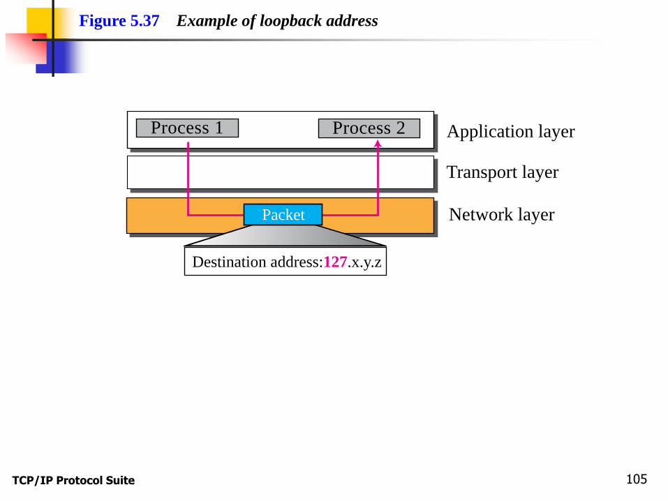
Transport layer
Application layer
Network layer
Process 1 Process 2
Figure 5.37 Example of loopback address
Destination address:127.x.y.z
Packet

TCP/IP Protocol Suite 106

TCP/IP Protocol Suite 107
221.45.71.0/24
221.45.71.20/24 221.45.71.178/24
221.45.71.64/24 221.45.71.126/24
Network:
Figure 5.38 Example of a directed broadcast address
Packet

TCP/IP Protocol Suite 108
5-5 NAT
The distribution of addresses through ISPs has
created a new problem. If the business grows or the
household needs a larger range, the ISP may not be
able to grant the demand because the addresses
before and after the range may have already been
allocated to other networks. In most situations,
however, only a portion of computers in a small
network need access to the Internet simultaneously.
A technology that can help in this cases is network address translation (NAT).
TCP/IP Protocol Suite 109
Topics Discussed in the Section
Address Translation
Translation Table

TCP/IP Protocol Suite 110
Figure 5.39 NAT

TCP/IP Protocol Suite 111
Figure 5.40 Address resolution
Internet
Site using private addresses
172.18.3.1
172.18.3.2
172.18.3.20
Source: 172.18.3.1 Source: 200.24.5.8
Destination: 200.24.5.8Destination: 172.18.3.1

TCP/IP Protocol Suite 112
Figure 5.41 Translation

TCP/IP Protocol Suite 113
NAT Table with only IP addresses (1)
P1 D1 G1 D1
P1
NAT Table for G1
D1 D1
D1 G1 D1 P1
1 private
1 global address
P1 D1 G1 D1
D1
D1 G1
2 privates
1 global address
P2 D2 G1 D2
D2 G1
P1
NAT Table for G1
D1
P2 D2
different external hosts
D2 D1 P1
D2 P2

TCP/IP Protocol Suite 114
NAT Table with only IP addresses (2)
P1 D1 G1 D1
D1
D1 G1 2 privates
P2 D1 G2 D1
D1 G2
P1
NAT Table for G1
D1
Same external host
P2
NAT Table for G2
D1
D1 P1
D1 P2
2 global addresses
P1 D1 G1 D1
D1 D1 G1
2 privates
1 global address
P2 D1 G1 D1
D1 G1
P1
NAT Table for G1
D1
P2 D1
???
???
Same external host

TCP/IP Protocol Suite 115
NAT Table with only IP addresses (3)
If using only one global address
Only one private-network host to access the same external host
If using a pool of global addresses (e.g. 4 addr)
No more than 4 connections can be made to the same destination
No private-network host can access two external server programs (e.g. HTTP and TELNET) at the same external host at the same time ???
Two private-network hosts cannot access the same external server program at the same time (by using the same global address)

TCP/IP Protocol Suite 116
NAT Table with IP address & Port # (1)
D1
3 privates
P1:#1
NAT Table for G1
G1:#1
Same external host
(Telnet)
1 global address
P1:#1D1:#23
P2:#1D1:#23
P1:#2D1:#23
P3:#1D1:#23
P1:#2 G1:#2
P2:#1 G1:#3
P3:#1 G1:#4
G1:#1D1:#23
G1:#3D1:#23
G1:#2D1:#23
G1:#4D1:#23
Must be unique
D1:#23G1:#1
D1:#23G1:#3
D1:#23G1:#2
D1:#23G1:#4
D1:#23P1:#1
D1:#23P2:#1
D1:#23P1:#2
D1:#23P3:#1

TCP/IP Protocol Suite 117
NAT Table with IP address & Port # (2)
Must be unique

TCP/IP Protocol Suite 118
NAT Table with IP address & Port # (3)