IPv4 to IPv6 Transition Complaint Mediastreaming Using ARM 11
16
IOSR Journal of Computer Engineering (IOSR-JCE) e-ISSN: 2278-0661,p-ISSN: 2278-8727, Volume 16, Issue 6, Ver. VI (Nov – Dec. 2014), PP 08-23 www.iosrjournals.org www.iosrjournals.org 8 | Page IPv4 to IPv6 Transition Complaint Mediastreaming Using ARM 11 Manju priya G Department of Communication Systems M.E. II year (Sree Sastha Institute of Engineering and Technology) Abstract: Internet Protocol version 6 (IPv6) is the next version of Internet Protocol (IP) which is currently in the transition phase from its predecessor, Internet Protocol version 4 (IPv4). With the number of IPv4 addresses almost completely depleted, the implementation of IPv6 has become a priority for many organizations. However, it is not all that feasible to just switch everything over to IPv6 without some type of transition. This project reconsiders the basic problems and key differences in IPv4-Ipv6 transition. IPv6 transition mechanisms are the technology that facilitates the transition of internet from its initial and current IPv4 infrastructure to the successor addressing and routing system of IPv6 (Internet Protocol Version 6). As IPv4 and IPv6 networks are not directly interoperable, these technologies are designed to permit hosts on either network to participate in networking with the other network. To meet its technical criteria, IPv6 must have a straight forward transition plan from the current IPv4. Internet Engineering Task Force (IETF) conducts working groups and discussions through the IETF Internet Drafts (ID) and Request for Comments (RFC) processes to develop these transition technologies towards that goal. This will overcomes the issues of scalability and an another challenge is that operates are facing situations in which IPv6 only access networks are deployed but the majority of internet services remain in IPv4. Also the application layer translation is the key issues in the previous translation methods that will be analyzed and found better solution by this.ARM 11 processor design a flexible, low cost IPv4/Ipv6 converter which support the Session Initiation Protocol (SIP), Real Time Streaming Protocol (RTSP) in the IPv4 network data can be achieved through IPv6 network. It also automatically configure the routers depending on the destination network instead of manual routing. Streaming technology will be analyzed and it will be done between two or more PC (Personal Computer) in which one PC will be in IPv4 network and the other is on Ipv6 network where the Raspberry Pi will acts as the server to do the transition mechanism. Key word: IPv4, IPv6, Raspberry pi, Streaming, SIP, Transition, Auto configuration I. Introduction As many are already aware, an increasingly likely candidate for the next-generation Internet Protocol is version 6 (IPv6), defined by Internet Engineering Task Force (IETF) .The proponents of IPv6 do not consider it a revolutionary protocol, designed to replace the existing IPv4, but more a long awaited improvement on the original IETF designs founded back in 1981. Much of its development has been influenced by lessons learned in the existing Internet. As a technology it promises a number of advances, including. A larger address space and flexible addressing scheme. More efficient packet forwarding support for secure communications. The ability to allow differentiated services. Better support for mobility. Ease of management Deployment of IPv6 is not going to happen overnight. Instead, the Internet will evolve toward IPv6, initially through isolated islands and then gradual global saturation. A. Motivation The transition between today’s IPv4 Internet and the future IPv6-based one will be a long process during which both protocol versions will coexist. Moving from IPv4 to IPv6 is not straightforward and guidelines to simplify transition between the two versions have to be standardized. Network transition has been discussed in detail; however applications should be reviewed to complete the porting process. Existing applications are written assuming IPv4. Only very recently IPv6 has been taken into account. Unless most of basic distributed applications are available now; there is too much work to do yet. The main motivation of this document is to provide general recommendations to be taken into account during the porting process of applications and services to IPv6. This will allow developers to move smoothly their applications into the new environment. The document is divided in three parts. The first analyzes in which conditions is possible the transition to IPv6 without changing applications. This chapter includes recommendations on how to proceed when source code is not available and explains which mechanisms can be used. The second is the main document part. It starts describing IPv6 transition scenarios from the application point of view. The document is focused on analyzing existing applications looking for characteristics, which usually should be reviewed during transition to IPv6. The document concludes providing general
-
Upload
independent -
Category
Documents
-
view
5 -
download
0
Transcript of IPv4 to IPv6 Transition Complaint Mediastreaming Using ARM 11
IOSR Journal of Computer Engineering (IOSR-JCE)
e-ISSN: 2278-0661,p-ISSN: 2278-8727, Volume 16, Issue 6, Ver. VI (Nov – Dec. 2014), PP 08-23 www.iosrjournals.org
www.iosrjournals.org 8 | Page
IPv4 to IPv6 Transition Complaint Mediastreaming Using
ARM 11
Manju priya G Department of Communication Systems M.E. II year
(Sree Sastha Institute of Engineering and Technology)
Abstract: Internet Protocol version 6 (IPv6) is the next version of Internet Protocol (IP) which is currently in
the transition phase from its predecessor, Internet Protocol version 4 (IPv4). With the number of IPv4 addresses
almost completely depleted, the implementation of IPv6 has become a priority for many organizations.
However, it is not all that feasible to just switch everything over to IPv6 without some type of transition. This
project reconsiders the basic problems and key differences in IPv4-Ipv6 transition. IPv6 transition mechanisms
are the technology that facilitates the transition of internet from its initial and current IPv4 infrastructure to the
successor addressing and routing system of IPv6 (Internet Protocol Version 6). As IPv4 and IPv6 networks are
not directly interoperable, these technologies are designed to permit hosts on either network to participate in
networking with the other network. To meet its technical criteria, IPv6 must have a straight forward transition
plan from the current IPv4. Internet Engineering Task Force (IETF) conducts working groups and discussions
through the IETF Internet Drafts (ID) and Request for Comments (RFC) processes to develop these transition technologies towards that goal. This will overcomes the issues of scalability and an another challenge is that
operates are facing situations in which IPv6 only access networks are deployed but the majority of internet
services remain in IPv4. Also the application layer translation is the key issues in the previous translation
methods that will be analyzed and found better solution by this.ARM 11 processor design a flexible, low cost
IPv4/Ipv6 converter which support the Session Initiation Protocol (SIP), Real Time Streaming Protocol (RTSP)
in the IPv4 network data can be achieved through IPv6 network. It also automatically configure the routers
depending on the destination network instead of manual routing. Streaming technology will be analyzed and it
will be done between two or more PC (Personal Computer) in which one PC will be in IPv4 network and the
other is on Ipv6 network where the Raspberry Pi will acts as the server to do the transition mechanism.
Key word: IPv4, IPv6, Raspberry pi, Streaming, SIP, Transition, Auto configuration
I. Introduction As many are already aware, an increasingly likely candidate for the next-generation Internet Protocol is
version 6 (IPv6), defined by Internet Engineering Task Force (IETF) .The proponents of IPv6 do not consider it
a revolutionary protocol, designed to replace the existing IPv4, but more a long awaited improvement on the
original IETF designs founded back in 1981. Much of its development has been influenced by lessons learned
in the existing Internet. As a technology it promises a number of advances, including. A larger address space
and flexible addressing scheme. More efficient packet forwarding support for secure communications. The
ability to allow differentiated services. Better support for mobility. Ease of management Deployment of IPv6 is
not going to happen overnight. Instead, the Internet will evolve toward IPv6, initially through isolated islands
and then gradual global saturation.
A. Motivation
The transition between today’s IPv4 Internet and the future IPv6-based one will be a long process
during which both protocol versions will coexist. Moving from IPv4 to IPv6 is not straightforward and
guidelines to simplify transition between the two versions have to be standardized. Network transition has been
discussed in detail; however applications should be reviewed to complete the porting process. Existing
applications are written assuming IPv4. Only very recently IPv6 has been taken into account. Unless most of
basic distributed applications are available now; there is too much work to do yet.
The main motivation of this document is to provide general recommendations to be taken into account
during the porting process of applications and services to IPv6. This will allow developers to move smoothly
their applications into the new environment. The document is divided in three parts. The first analyzes in which
conditions is possible the transition to IPv6 without changing applications. This chapter includes recommendations on how to proceed when source code is not available and explains which mechanisms can be
used. The second is the main document part. It starts describing IPv6 transition scenarios from the application
point of view. The document is focused on analyzing existing applications looking for characteristics, which
usually should be reviewed during transition to IPv6. The document concludes providing general

IPV4 to Ipv6 Transition Complaint Media streaming Using Arm 11
www.iosrjournals.org 9 | Page
recommendations for new IPv6 applications. In the future all IPv4 networks will be IPv6; however during a long
period mixed scenarios with both IPv4 and IPv6 will be the real environments. Therefore, new applications
should designed to work only in a pure IPv6 environment, but a design to allow mixed IPv4 and IPv6 environment is better now.
The PC 1 will be acting as the source and PC 2 as the destination and vice versa. The PC 1 will be
having the IP (Internet Protocol) address of version 4 i.e. IPv4 address whereas the PC 2 destination will be
working in IPv6 address. Both the source and the destination will be connected to a LAN (Local Area Network)
with the help of router.Generally the router can be configured to any of one network either IPv4 or IPV6 but
here the router can be configured to both IPv4 and IPv6 network simultaneously. This can be achieved by the Pi
which provides the auto configuration depending on the end user applications.
II. Objective And Research Issues Beside all the issues there is much more fundamental problem that has arisen since the very first day of
the IPv4-Ipv6 coexistence, network connectivity under the IPV4-IPv6 heterogeneous environment. Since IPv4
and IPv6 protocols are not compatible, they run their individual addressing and routing systems. Without
additional mechanisms, the two types of network cannot communicate. Therefore we have to enforce some
artificial inter-operability between IPv4 and Ipv6 to enable the network connectivity in heterogeneous networks.A
great series of efforts have been made on this problem,and the set of proposed solutions called IPv6 transition
techniques.the following of this project will focus on the application translation problem and the transition
techniques.
III. Basics of Transition from IPv4 to IPv6 In order for systems to locate each other in a distributed environment, nodes are given explicit
addresses that uniquely identify the particular network the system is on and uniquely identify the system to that
particular network. When these two identifiers are combined, the result is a globally-unique address. This
address, known as IP address as IP number or merely as IP is a code made up of numbers separated by three
dots that identifies a particular computer on the internet.
These addresses are actually 32 - bit binary numbers, consisting of the two sub addresses (identifiers)
mentioned above which, respectively, identify the network and the host to the network, with an imaginary
boundary separating the two. An IP address is, as such, generally shown as 4 octets of numbers from 0 - 255
represented in decimal form instead of binary form. For example, the address 168.212.226.204 represents the 32
- bit binary number 10101000.11010100.11100010.11001100. The binary number is important because that will determine which class of network the IP address
belongs. The class of the address determines which part belongs to the network address and which part belongs
to the node address. The location of the boundary between the network and host portions of an IP address is
determined through the use of a subnet mask. This is another 32 - bit binary number which acts like a filter
when it is applied to the 32 - bit IP address. By comparing a subnet mask with an IP address, systems can
determine which portion of the IP address relates to the network and which portion relates to the host. Anywhere
the subnet mask has a bit set to 1, the underlying bit in the IP address is part of the network address. Anywhere
the subnet mask is set to 0 the related bit in the IP address is part of the host address.
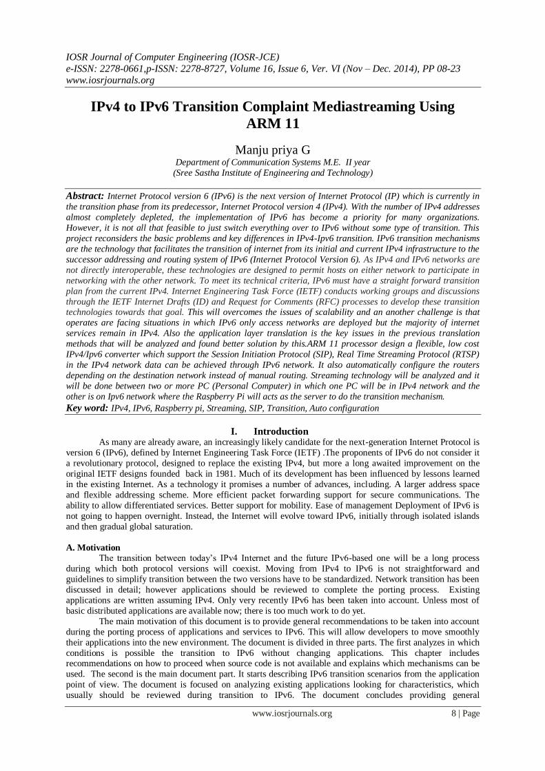
A. Internet protocol Classes
Class A addresses always have the first bit of their IP addresses set to 0. Since class A networks have
an 8-bit network mask, the use of a leading zero leaves only 7 bits for the network portion of the address,
allowing for a maximum of 128 possible network numbers used for internal testing on the local machine. Class B addresses always have the first bit set to 1 and their second bit set to 0. Since class B addresses
have a 16-bit network mask, the use of a leading 10 bit-pattern leaves 14 bits for the network portion of the
address, allowing for a maximum of 16,384 networks.
Class C addresses have their first two bits set to 1 and their third bit set to 0. Since class C addresses
have a 24-bit network mask, this leaves 21 bits for the network portion of the address, allowing for a maximum
of 2,097,152 network addresses.
Class D addresses are used for multicasting applications. Class D addresses have their first three bits
set to 1 and their fourth bit set to 0. Class D addresses are 32-bit network addresses, meaning that all the values
are used to uniquely identify multicast groups. There are no host addresses within the class D address space,
since all the hosts within a group share the groups IP address for receiver purposes.
Class E addresses are defined as experimental and are reserved for future testing purposes. They have never been documented or utilized in a standard way. The following fig.1 shows the types of classes of internet
protocol.
IPV4 to Ipv6 Transition Complaint Media streaming Using Arm 11
www.iosrjournals.org 10 | Page
Fig.1 Types of Internet Protocol Classes
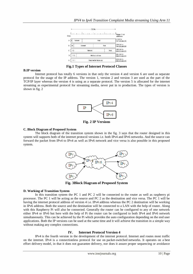
B.IP version
Internet protocol has totally 6 versions in that only the version 4 and version 6 are used as separate
protocol for the usage of the IP address. The version 1, version 2 and version 3 are used as the part of the
TCP/IP layer whereas the version 4 is using as a separate protocol. The version 5 is allocated for the internet
streaming as experimental protocol for streaming media, never put in to production. The types of version is
shown in fig. 2
Fig. 2 IP Versions
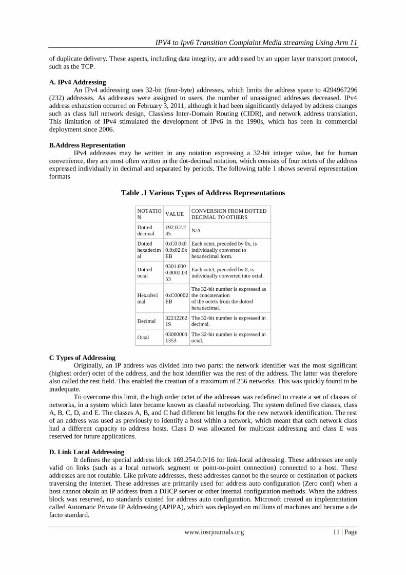
C. Block Diagram of Proposed System
The block diagram of the transition system shown in the fig. 3 says that the router designed in this
system will supports both of the internet protocol versions i.e. both IPv4 and IPv6 networks. And the source can
forward the packet from IPv4 to IPv4 as well as IPv6 network and vice versa is also possible in this proposed
system.
Fig. 3Block Diagram of Proposed System
D. Working of Transition System
In this transition system the PC 1 and PC 2 will be connected to the router as well as raspberry pi
processor. The PC 1 will be acting as the source and PC 2 as the destination and vice versa. The PC 1 will be
having the internet protocol address of version 4 i.e. IPv4 address whereas the PC 2 destination will be working
in IPv6 address. Both the source and the destination will be connected to a LAN with the help of router. Along
with this Raspberry Pi will also be connected. Generally the router can be configured to any of one network
either IPv4 or IPv6 but here with the help of Pi the router can be configured to both IPv4 and IPv6 network
simultaneously. This can be achieved by the Pi which provides the auto configuration depending on the end user
applications. Both the IP versions can be used at the same time and it will achieve the transition in a simple way
without making any complex connections.
IV. Internet Protocol Version 4 IPv4 is the fourth version in the development of the internet protocol. Internet and routes most traffic
on the internet. IPv4 is a connectionless protocol for use on packet-switched networks. It operates on a best
effort delivery model, in that it does not guarantee delivery, nor does it assure proper sequencing or avoidance
IPV4 to Ipv6 Transition Complaint Media streaming Using Arm 11
www.iosrjournals.org 11 | Page
of duplicate delivery. These aspects, including data integrity, are addressed by an upper layer transport protocol,
such as the TCP.
A. IPv4 Addressing
An IPv4 addressing uses 32-bit (four-byte) addresses, which limits the address space to 4294967296
(232) addresses. As addresses were assigned to users, the number of unassigned addresses decreased. IPv4
address exhaustion occurred on February 3, 2011, although it had been significantly delayed by address changes
such as class full network design, Classless Inter-Domain Routing (CIDR), and network address translation.
This limitation of IPv4 stimulated the development of IPv6 in the 1990s, which has been in commercial
deployment since 2006.
B.Address Representation
IPv4 addresses may be written in any notation expressing a 32-bit integer value, but for human
convenience, they are most often written in the dot-decimal notation, which consists of four octets of the address expressed individually in decimal and separated by periods. The following table 1 shows several representation
formats
Table .1 Various Types of Address Representations
NOTATIO
N VALUE
CONVERSION FROM DOTTED
DECIMAL TO OTHERS
Dotted
decimal
192.0.2.2
35 N/A
Dotted
hexadecim
al
0xC0.0x0
0.0x02.0x
EB
Each octet, preceded by 0x, is
individually converted to
hexadecimal form.
Dotted
octal
0301.000
0.0002.03
53
Each octet, preceded by 0, is
individually converted into octal.
Hexadeci
mal
0xC00002
EB
The 32-bit number is expressed as
the concatenation
of the octets from the dotted
hexadecimal.
Decimal
32212262
19
The 32-bit number is expressed in
decimal.
Octal
03000000
1353
The 32-bit number is expressed in
octal.
C Types of Addressing
Originally, an IP address was divided into two parts: the network identifier was the most significant
(highest order) octet of the address, and the host identifier was the rest of the address. The latter was therefore
also called the rest field. This enabled the creation of a maximum of 256 networks. This was quickly found to be
inadequate.
To overcome this limit, the high order octet of the addresses was redefined to create a set of classes of
networks, in a system which later became known as classful networking. The system defined five classes, class
A, B, C, D, and E. The classes A, B, and C had different bit lengths for the new network identification. The rest
of an address was used as previously to identify a host within a network, which meant that each network class
had a different capacity to address hosts. Class D was allocated for multicast addressing and class E was
reserved for future applications.
D. Link Local Addressing
It defines the special address block 169.254.0.0/16 for link-local addressing. These addresses are only
valid on links (such as a local network segment or point-to-point connection) connected to a host. These
addresses are not routable. Like private addresses, these addresses cannot be the source or destination of packets
traversing the internet. These addresses are primarily used for address auto configuration (Zero conf) when a
host cannot obtain an IP address from a DHCP server or other internal configuration methods. When the address
block was reserved, no standards existed for address auto configuration. Microsoft created an implementation
called Automatic Private IP Addressing (APIPA), which was deployed on millions of machines and became a de
facto standard.
IPV4 to Ipv6 Transition Complaint Media streaming Using Arm 11
www.iosrjournals.org 12 | Page
E. Loopback Addressing The class A network 127.0.0.0 (classless network 127.0.0.0/8) is reserved for loopback. IP packets whose source
addresses belong to this network should never appear outside a host. The mode of this network expands upon
that of a loopback interface.
IP packets whose source and destination addresses belong to the network (or sub network) of the same
loopback interface are returned to that interface.
IP packets whose source and destination addresses belong to networks (or sub networks) of different
interfaces of the same host, one of them being a loopback interface, are forwarded regularly.
F .Address Ending in 0 or 255
Networks with subnet masks of at least 24 bits, i.e. class C networks in classful networking, and
networks with CIDR suffixes 24 to 32 (255.255.255.0–255.255.255.255) may not have an address ending in 0 or 255.
Classful addressing prescribed only three possible subnet masks: class A, 255.0.0.0 or /8; class B,
255.255.0.0 or /16; and class C, 255.255.255.0 or /24. For example, in the subnet 192.168.5.0/255.255.255.0
(192.168.5.0/24) the identifier 192.168.5.0 commonly is used to refer to the entire subnet. To avoid ambiguity in
representation, the address ending in the octet 0 is reserved.
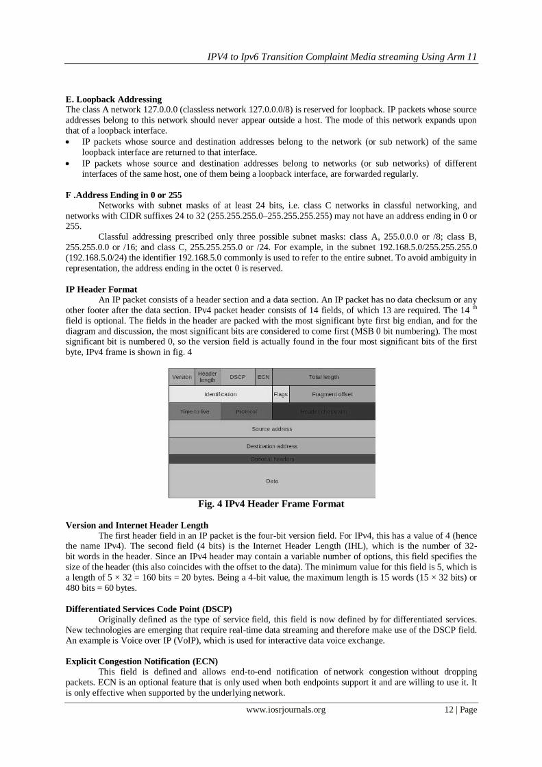
IP Header Format
An IP packet consists of a header section and a data section. An IP packet has no data checksum or any
other footer after the data section. IPv4 packet header consists of 14 fields, of which 13 are required. The 14 th
field is optional. The fields in the header are packed with the most significant byte first big endian, and for the
diagram and discussion, the most significant bits are considered to come first (MSB 0 bit numbering). The most significant bit is numbered 0, so the version field is actually found in the four most significant bits of the first
byte, IPv4 frame is shown in fig. 4
Fig. 4 IPv4 Header Frame Format
Version and Internet Header Length
The first header field in an IP packet is the four-bit version field. For IPv4, this has a value of 4 (hence the name IPv4). The second field (4 bits) is the Internet Header Length (IHL), which is the number of 32-
bit words in the header. Since an IPv4 header may contain a variable number of options, this field specifies the
size of the header (this also coincides with the offset to the data). The minimum value for this field is 5, which is
a length of 5 × 32 = 160 bits = 20 bytes. Being a 4-bit value, the maximum length is 15 words (15 × 32 bits) or
480 bits = 60 bytes.
Differentiated Services Code Point (DSCP)
Originally defined as the type of service field, this field is now defined by for differentiated services.
New technologies are emerging that require real-time data streaming and therefore make use of the DSCP field.
An example is Voice over IP (VoIP), which is used for interactive data voice exchange.
Explicit Congestion Notification (ECN)
This field is defined and allows end-to-end notification of network congestion without dropping
packets. ECN is an optional feature that is only used when both endpoints support it and are willing to use it. It
is only effective when supported by the underlying network.
IPV4 to Ipv6 Transition Complaint Media streaming Using Arm 11
www.iosrjournals.org 13 | Page
Total Length This 16-bit field defines the entire packet (fragment) size, including header and data, in bytes. The
minimum-length packet is 20 bytes (20 byte header + 0 bytes data), the maximum is 65,535 bytes and the
maximum value of a 16 bit word. All hosts are required to be able to reassemble datagrams of size up to 576
bytes, but most modern hosts handle much larger packets. Sometimes sub networks impose further restrictions
on the packet size, in which case datagrams must be fragmented. Fragmentation is handled in either the host or
router in IPv4. Here fragmentation will be done in an unconditional manner, where it will be done conditionally
by the source and destination alone in the internet protocol version 6.
Identification
This field is an identification field and is primarily used for uniquely identifying the group of fragments
of a single IP datagram. Some experimental work has suggested using the ID field for other purposes, such as for adding packet-tracing information to help trace datagrams with spoofed source addresses.
Flags
A three-bit field follows and is used to control or identify fragments. They are (in order, from high order to low
order)
Bit 0: Reserved must be zero.
Bit 1: Don't Fragment (DF)
Bit 2: More Fragments (MF)
If the DF flag is set, and fragmentation is required to route the packet, then the packet is dropped. This can be
used when sending packets to a host that does not have sufficient resources to handle fragmentation..
Fragment Offset The fragment offset field, measured in units of eight-byte blocks (64 bits), is 13 bits long and specifies
the offset of a particular fragment relative to the beginning of the original un-fragmented IP datagram. The first
fragment has an offset of zero. This allows a maximum offset of (213 – 1) × 8 = 65,528 bytes, which would
exceed the maximum IP packet length of 65,535 bytes with the header length included (65,528 + 20 = 65,548
bytes).
Time to Live (TTL)
An eight-bit time to live field helps prevent datagrams from persisting (e.g. going in circles) on an
internet. This field limits a datagram's lifetime. It is specified in seconds, but time intervals less than 1 second
are rounded up to 1. In practice, the field has become a hop count when the datagram arrives at a router, the
router decrements the TTL field by one. When the TTL field hits zero, the router discards the packet.
Protocol and Header Checksum
This protocol field defines the type of protocol used in the data portion of the IP datagram. The 16-
bit checksum field is used for error-checking of the header. When a packet arrives at a router, the router
calculates the checksum of the header and compares it to the checksum field. If the values do not match, the
router discards the packet. Errors in the data field must be handled by the encapsulated protocol. The number of
errors will be found and also the exact location of the error will be detected.
Source and Destination Address
This field is the IPv4 address of the sender of the packet. Note that this address may be changed in
transit by a network address translation device. This destination field is the IPv4 address of the receiver of the
packet. As with the source address, this may be changed in transit by a network address translation device.
Options
The options field is not often used. Note that the value in the IHL field must include enough extra 32 -
bit words to hold all the options. The list of options may be terminated with an End of Options List (EOL)
option this is only necessary if the end of the options would not otherwise coincide with the end of the header. If
the header length is greater than 5, i.e. it is from 6 to 15, it means that the options field is present and must be
considered.

IPV4 to Ipv6 Transition Complaint Media streaming Using Arm 11
www.iosrjournals.org 14 | Page
V. Transition to IPv6 The transition between today’s IPv4 internet and the future IPv6 - based one will be a long process
during which both protocol versions will coexist. Moving from IPv4 to IPv6 is not straightforward and
guidelines to simplify transition between the two versions have to be standardized.
Existing applications are written assuming IPv4. Only very recently IPv6 has been taken into account.
Unless most of basic distributed applications are available now; there is too much work to do yet. The aim of
this project is to provide general recommendations to be taken into account during the porting process of
applications and services to IPv6. This will allow developers to move smoothly their applications into the new
environment. In the future all IPv4 networks will be IPv6 however during a long period mixed scenarios with
both IPv4 and IPv6 will be the real environments. Therefore, new applications should designed to work only in
a pure IPv6 environment, but a design to allow mixed IPv4 and IPv6 environment is better now.
A. Internet Protocol Version 6 (IPv6)
It is the latest version of the internet protocol, the communications protocol that provides an
identification and location system for computers on networks and routes traffic across the internet. IPv6 was
developed by the IETF to deal with the long-anticipated problem of exhaustion. The two protocols are not
designed to be interoperable, complicating the transition to IPv6. However, several IPv6 transition
mechanisms have been devised to permit communication between IPv4 and IPv6 hosts.
IPv6 addresses are represented as eight groups of four hexadecimal digits separated by colons, for e.g.
The following are the features of the IPv6 protocol:
New header format
Large address space
Efficient and routing infrastructure
Stateless and stateful address configuration
Built-in security
Better support for prioritized delivery
Neighbouring node interaction
Extensibility
The following sections discuss each of these new features in detail:
New Header Format
The IPv6 header has a new format that is designed to keep header overhead to a minimum. This is
achieved by moving both non-essential fields and optional fields to extension headers that are placed after the
IPv6 header. The streamlined IPv6 header is more efficiently processed at intermediate routers. IPv4 headers and IPv6 headers are not interoperable. IPv6 is not a superset of functionality that is backward compatible with
IPv4.
Large Address Space
IPv6 has 128 bit (16 byte) source and destination IP addresses. Although 128 bits can express over 3.4
x 1038 possible address combinations, the large address space of IPv6 has been designed to allow for multiple
levels of sub netting and address allocation from the Internet backbone to the individual subnets within an
organization. Even though only a small number of the possible addresses are currently allocated for use by
hosts, there are plenty of addresses available for future use. With a much larger number of available addresses,
address-conservation techniques, such as the deployment of NATs, are no longer necessary.
Efficient and Hierarchical Addressing and Routing Infrastructure
IPv6 global addresses used on the IPv6 portion of the Internet are designed to create an efficient,
hierarchical and summarizable routing infrastructure that is based on the common occurrence of multiple levels
of internet service providers.
Stateless and Stateful Address Configuration
To simplify host configuration, IPv6 supports both stateful address configuration, such as address
configuration in the presence of a DHCP server and stateless address configuration (address configuration in the
absence of a DHCP server). With stateless address configuration, hosts on a link automatically configure
themselves with IPv6 addresses for the link (called link-local addresses) and with addresses derived from
prefixes advertised by local routers. Even in the absence of a router, hosts on the same link can automatically
configure themselves with link-local addresses and communicate without manual configuration.
IPV4 to Ipv6 Transition Complaint Media streaming Using Arm 11
www.iosrjournals.org 15 | Page
Built-in Security
Support for IPsec is an IPv6 protocol suite requirement. This requirement provides a standards- based
solution for network security needs and promotes interoperability between different IPv6 implementations.
Better Support for Prioritized Delivery
New fields in the IPv6 header define how traffic is handled and identified. Traffic identification using a
flow label field in the IPv6 header allows routers to identify and provide special handling for packets belonging
to a flow, a series of packets between a source and destination. Because the traffic is identified in the IPv6
header, support for prioritized delivery can be achieved even when the packet payload is encrypted with internet
protocol security.
New Protocol for Neighbouring Node Interaction
The neighbour discovery protocol for IPv6 is a series of internet control message protocol for IPv6 messages that manage the interaction of neighboring nodes (nodes on the same link). Neighbor discovery
replaces the broadcast-based Address Resolution Protocol (ARP), ICMPv4 router discovery, and ICMPv4
redirect messages with efficient multicast and unicast neighbor discovery messages.
Extensibility
IPv6 can easily be extended for new features by adding extension headers after the IPv6 header. Unlike
options in the IPv4 header, which can only support 40 bytes of options, the size of IPv6 extension headers is
only constrained by the size of the IPv6 packets.
Comparison with IPv4
The comparison of IPv4 and IPv6 says about the various advantages over internet protocol version 4 in
address space, multicasting, privacy, providing security at the network layer, mobility and the auto configuration. They are listed as follows:
Larger address space
The main advantage of IPv6 over IPv4 is its larger address space. The length of an IPv6 address is 128
bits, compared with 32 bits in IPv4. The address space therefore has 2128 or approximately 3.4 × 1038 addresses.
This would be about 100 addresses for every atom on the surface of the earth and almost four 64s per square
centimeter of the planet.
Multicasting
Multicasting, the transmission of a packet to multiple destinations in a single send operation, is part of
the base specification in IPv6. In IPv4 this is an optional although commonly implemented feature. IPv6 multicast addressing shares common features and protocols with IPv4 multicast, but also provides changes and
improvements by eliminating the need for certain protocols. IPv6 does not implement traditional IP broadcast,
i.e. the transmission of a packet to all hosts on the attached link using a special broadcast address, and therefore
does not define broadcast addresses. In IPv6, the same result can be achieved by sending a packet to the link-
local all nodes multicast group at address ff02::1 which is analogous to IPv4 multicast to address 224.0.0.1 IPv6
also provides for new multicast implementations, including embedding rendezvous point addresses in an IPv6
multicast group address, which simplifies the deployment of inter-domain solutions.
Stateless Address Auto Configuration
IPv6 hosts can configure themselves automatically when connected to an IPv6 network using
the neighbour discovery protocol via internet control message protocol version 6 router discovery messages.
When first connected to a network, a host sends a link-local router solicitation multicast request for its configuration parameters; routers respond to such a request with a router advertisement packet that contains
internet layer configuration parameters.
Routers present a special case of requirements for address configuration, as they often are sources of
auto configuration information, such as router and prefix advertisements. Stateless configuration of routers can
be achieved with a special router renumbering protocol.
Network Layer Security
Internet protocol security was originally developed for IPv6, but found widespread deployment first in
IPv4, for which it was reengineered. IPsec was a mandatory specification of the base IPv6 protocol suite but has
since been made optional.
IPV4 to Ipv6 Transition Complaint Media streaming Using Arm 11
www.iosrjournals.org 16 | Page
Simplified Processing by Routers
In IPv6, the packet header and the process of packet forwarding have been simplified. Although IPv6 packet headers are at least twice the size of IPv4 packet headers, packet processing by routers is generally more
efficient, thereby extending the end-to-end principle of internet design specifically.
Mobility
Unlike mobile IPv4, mobile IPv6 avoids triangular routing and is therefore as efficient as native IPv6.
IPv6 routers may also allow entire subnets to move to a new router connection point without renumbering.
Options extensibility
The IPv6 packet header has a fixed size (40 octets). Options are implemented as additional extension
headers after the IPv6 header, which limits their size only by the size of an entire packet.
Jumbo grams IPv4 limits packets to 65535 (216−1) octets of payload. An IPv6 node can optionally handle packets
over this limit, referred to as jumbo grams, which can be as large as 4294967295 (232−1) octets.
Privacy
Like IPv4, IPv6 supports globally unique IP addresses by which the network activity of each device
can potentially be tracked. The design of IPv6 intended to re-emphasize the end-to-end principle of network
design that was originally conceived during the establishment of the early internet. In this approach each device
on the network has a unique address globally reachable directly from any other location on the internet.
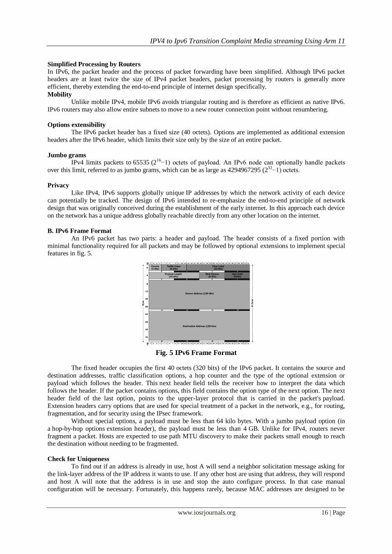
B. IPv6 Frame Format
An IPv6 packet has two parts: a header and payload. The header consists of a fixed portion with
minimal functionality required for all packets and may be followed by optional extensions to implement special features in fig. 5.
Fig. 5 IPv6 Frame Format
The fixed header occupies the first 40 octets (320 bits) of the IPv6 packet. It contains the source and
destination addresses, traffic classification options, a hop counter and the type of the optional extension or
payload which follows the header. This next header field tells the receiver how to interpret the data which
follows the header. If the packet contains options, this field contains the option type of the next option. The next
header field of the last option, points to the upper-layer protocol that is carried in the packet's payload.
Extension headers carry options that are used for special treatment of a packet in the network, e.g., for routing,
fragmentation, and for security using the IPsec framework.
Without special options, a payload must be less than 64 kilo bytes. With a jumbo payload option (in
a hop-by-hop options extension header), the payload must be less than 4 GB. Unlike for IPv4, routers never
fragment a packet. Hosts are expected to use path MTU discovery to make their packets small enough to reach the destination without needing to be fragmented.
Check for Uniqueness
To find out if an address is already in use, host A will send a neighbor solicitation message asking for
the link-layer address of the IP address it wants to use. If any other host are using that address, they will respond
and host A will note that the address is in use and stop the auto configure process. In that case manual
configuration will be necessary. Fortunately, this happens rarely, because MAC addresses are designed to be

IPV4 to Ipv6 Transition Complaint Media streaming Using Arm 11
www.iosrjournals.org 17 | Page
unique on each network card and so the only reason for an address to be in use is if the network is poorly set up
or if there has been an error in the conversion of the address.
Now that the address is unique on the link, the host can proceed to try to make the address global. It first determines if the network is connected to any routers at all, because if not then all nodes are reachable using
the link-local address that already is assigned to the host. The host will send out a router solicitation message to
the all-nodes multicast group with its link local address as source. If there is no answer after a predetermined
number of attempts, the host concludes that no routers are connected. If it does get a response from a router,
there will be network information inside that is needed to create a globally unique address. There are also two
flag bits that tell the host whether it should use DHCP to get further information and addresses:
The manage bit - Indicates whether or not the host should use DHCP to obtain additional addresses.
The other bit - If set, the host should obtain other information through DHCP.
C. Address Representation
The 128 bits of an IPv6 address are represented in 8 groups of 16 bits each. Each group is written as 4 hexadecimal digits and the groups are separated by colons (:). The address
2001:0db8:0000:0000:0000:ff00:0042:8329 is an example of this representation.
For convenience, an IPv6 address may be abbreviated to shorter notations by application of the following rules,
where possible.
One or more leading zeroes from any groups of hexadecimal digits are removed, this is usually done to
either all or none of the leading zeroes. For example, the group 0042 is converted to 42.
Consecutive sections of zeroes are replaced with a double colon (::). The double colon may only be used
once in an address, as multiple use would render the address indeterminate.
VI. Protocols Used A. Session Initiation Protocol
The session initiation protocol is a signaling communication protocol, widely used for controlling
multimedia communication sessions such as voice and video calls over internet protocol networks. It is widely
used for initiation and for connection establishment. SIP can be used for two-party (unicast) or multiparty
(multicast) sessions. Other SIP applications include video conferencing, streaming multimedia
distribution, instant messaging, presence information, file transfer, fax over IP and online games. It is
an application layer protocol designed to be independent of the underlying transport layer; it can run on
TCP, user datagram protocol or Stream Control Transmission Protocol (SCTP).
Protocol Operation SIP employs design elements similar to the http request / response transaction model. Each transaction
consists of a client request that invokes a particular method or function on the server and at least one response.
SIP reuses most of the header fields, encoding rules and status codes of http, providing a readable text-based
format. Each resource of a SIP network, such as a user agent or a voicemail box, is identified by a Uniform
Resource Identifier (URI), based on the general standard syntax also used in web services and e-mail. The URI
scheme used for SIP is the form: sip:username:password@host:port.
If secure transmission is required, the scheme is used and mandates that each hop over which the
request is forwarded up to the target domain must be secured with Transport Layer Security (TLS). The last hop
from the proxy of the target domain to the user agent has to be secured according to local policies. TLS protects
against attackers who try to listen on the signaling link but it does not provide real end-to-end security to prevent
espionage and law enforcement interception, as the encryption is only hop-by-hop and every single intermediate
proxy has to be trusted.
Working Scenario
SIP is primarily used in setting up and tearing down voice or video calls. It also allows modification of
existing calls. The modification can involve changing addresses or ports, inviting more participants, and adding
or deleting media streams is shown in fig. 6.1. SIP has also found applications in messaging applications, such
as instant messaging and event subscription and notification.
Goal of SIP
A motivating goal for SIP was to provide a signaling and call setup protocol for IP-based
communications that can support a superset of the call processing functions and features present in the Public
Switched Telephone Network (PSTN). SIP by itself does not define these features; rather, its focus is call-setup and signaling. The features that permit familiar telephone-like operations: dialing a number, causing a phone to

IPV4 to Ipv6 Transition Complaint Media streaming Using Arm 11
www.iosrjournals.org 18 | Page
ring, hearing ring back tones or a busy signal - are performed by proxy servers and user agents. Implementation
and terminology are different in the SIP world but to the end-user, the behavior is similar.
Session Messages
SIP is a text-based protocol with syntax similar to that of http. There are two different types of SIP
messages: requests and responses. The first line of a request has a method, defining the nature of the request,
and a Request-URI, indicating where the request should be sent. The first line of a response has a response
code.
SIP Request
REGISTER: Used by a UA to indicate its current IP address and the URLs for which it would like to
receive calls
INVITE: Used to establish a media session between user agents
ACK: Confirms reliable message exchanges
CANCEL: Terminates a pending request
BYE: Terminates a session between two users in a conference
Provisional Response Acknowledgement (PRACK): PRACK improves network reliability by adding an
acknowledgement system to the provisional responses (1xx). PRACK is sent in response to provisional
response (1xx)
SIP Response
Provisional (1xx): Request received and being processed
Success (2xx): The action was successfully received, understood, and accepted
Redirection (3xx): Further action needs to be taken (typically by sender) to complete the request
Client Error (4xx): The request contains bad syntax or cannot be fulfilled at the server
Server Error (5xx): The server failed to fulfill an apparently valid request
Applications
The market for consumer SIP devices continues to expand; there are many devices such as SIP terminal
adapters, SIP gateways, and SIP trunking services providing replacements for telephone lines.
B. Hyper Text Transfer Protocol
The Hyper Text Transfer Protocol (HTTP) is an application-level protocol for distributed and
collaborative hypermedia information systems. HTTP is a generic and stateless protocol which can be used for
other purposes as well using extension of its request methods, error codes and headers. Basically, HTTP is an
TCP/IP based communication protocol, which is used to deliver data (HTML files, image files, query results etc.) on the World Wide Web (WWW) is shown in fig. 6.2.
Basic Features
There are following three basic features which makes HTTP a simple but powerful protocol
Connectionless - The HTTP client i.e. browser initiates an HTTP request and after a request is made, the client
disconnects from the server and waits for a response. The server process the request and re-establish the
connection with the client to send response back.
Media Independent - This means, any type of data can be sent by HTTP as long as both the client and server
know how to handle the data content. This is required for client as well as server to specify the content type
using appropriate Multi-purpose Internet Mail Extension (MIME) type.
Stateless - As mentioned above, HTTP is a connectionless and this is a direct result that HTTP is a stateless protocol. The server and client are aware of each other only during a current request. Afterwards, both of them
forget about each other. HTTP 1.0 uses a new connection for each request / response exchange whereas HTTP
1.1 connection may be used for one or more request / response exchanges.
The HTTP protocol is a request / response protocol based on client / server based architecture where web
browser, robots and search engines, etc. act like HTTP clients and web server acts as server.
Client - The HTTP client sends a request to the server in the form of a request method, URI, and protocol
version, followed by a MIME-like message containing request modifiers, client information, and possible body
content over a TCP / IP connection.
Server - The HTTP server responds with a status line, including the message's protocol version and a success or
error code, followed by a MIME-like message containing server information, entity Meta information, and
possible entity-body content.

IPV4 to Ipv6 Transition Complaint Media streaming Using Arm 11
www.iosrjournals.org 19 | Page
HTTP Messages
HTTP is based on client-server architecture model and a stateless request / response protocol that operates by exchanging messages across a reliable TCP / IP connection. An HTTP client is a program (web
browser or any other client) that establishes a connection to a server for the purpose of sending one or more
HTTP request messages. An HTTP server is a program (generally a web server like Apache web server or
Internet Information Services (IIS)) that accepts connections in order to serve HTTP requests by sending HTTP
response messages.
HTTP-message = <Request> | <Response>
HTTP 1.1 messages HTTP request and HTTP response use a generic message format for transferring the
required data
Message Body
The message body part is optional for an HTTP message but if it is available then it is used to carry the entity-body associated with the request or response. If entity body is associated then usually content-type and
content-length headers lines specify the nature of the body associated. A message body is the one which carries
actual HTTP request data (including form data and uploaded etc.) and HTTP response data from the server
(including files, images etc.). Following is a simple content of a message body.
< Html >
< Body >
< h1 >Hello, World! < /h1 >
< /body >
< /html >
Message Request Line
The request line begins with a method token, followed by the request URI and the protocol version, and ending with CRLF. The elements are separated by space characters. Request-Line = Method SP Request-URI
SP HTTP-Version CRLF.
Request Method
The request Method indicates the method to be performed on the resource identified by the given request-URI.
The method is case-sensitive and should always be mentioned uppercase.
Request Header Fields
General-header and entity-header will helps us to learn HTTP header fields. For now check what
request header fields are. The request-header fields allow the client to pass additional information about the
request, and about the client itself, to the server. These fields act as request modifiers and there are following important request-header fields available which can be used based on requirement. After receiving and
interpreting a request message, a server responds with an HTTP response message:
A Status-line
Zero or more header (General |Response |Entity) fields followed by CRLF
An empty line (i.e., a line with nothing preceding the CRLF) indicating the end of the header
Optionally a message-body
HTTP Version
A server supporting HTTP version 1.1 will return following version information:
HTTP-Version = HTTP/1.1
Status Code
The Status-Code element is a 3-digit integer where first digit of the status-code defines the class of response and
the last two digits do not have any categorization role. There are 5 values for the first digit.
Response Header Fields
General-header and entity-header are the sub headers of HTTP header fields. The response-header fields allow
the server to pass additional information about the response which cannot be placed in the status line.
VII. Raspberry PI The Raspberry Pi is a credit-card sized processor that plugs into television and a keyboard. It’s a
capable little PC which can be used for many of the things that desktop PC does, like spreadsheets, word-

IPV4 to Ipv6 Transition Complaint Media streaming Using Arm 11
www.iosrjournals.org 20 | Page
processing and games. It also plays high-definition video. It is being used by kids all over the world to learn
programming. Combining both real-time and a time-sharing subsystem, hybrid operating systems can provide
both predictable real-time task execution and non-real-time services with well-known interfaces and lots of existing applications.
The Raspberry Pi has a broad com BCM2835 system on a chip, which includes an ARM1176JZF-
S 700 MHz processor video core IV GPU, and originally shipped with 256 megabytes of Random Access
Memory (RAM), later upgraded to 512 megabytes. It does not include a built-in hard disk or solid-state drive,
but uses a secure digital card for booting and long-term storage.
Hardware Features
The following are essential hardware of Raspberry Pi:
Raspberry Pi board
Prepared Operating System Secure Digital Card
Cables
Broad cam BCM 2835
USB 2.0 ports
Ethernet port
High Definition Multimedia Interface
Video port
Audio port
Micro USB for power
Software Tools
Kernel is heart of Linux Operating System (OS). It manages resource of Linux OS. Resources means
facilities available in Linux. For e.g. facility to store data, print data on printer, memory and file management etc. kernel decides who will use this resource, for how long and when. It runs the programs (or set up to execute
binary files). It's memory resident portion of Linux. It performs the following task.
Python Language
Python is a popular open source programming language used for both standalone programs and
scripting applications in a wide variety of domains. It is free, portable, powerful and remarkably easy and fun to
use shown in fig. 6
Fig. 6 Raspberry Pi Board
Advanced Reduced Instruction Set Computer Machine
ARM11 is an Advanced RISC Architecture 32-bit RISC microprocessor family which introduced the
ARMv6 architectural additions. These include Single Instruction Multiple Data (SIMD) media
instructions, multiprocessor support and a new cache architecture. It delivers extreme low power and a range of
performance from 350 MHz in small area designs up to 1 GHz in speed-optimized designs in 45 and 65 nm. The
implementation included significantly improved instruction processing pipeline, compared to
previous ARM9 or ARM10 families, and is used in smart phones from Apple, Nokia, and others. The various
features in ARM are as follows
Low risk and fast time to market
High performance in low-cost designs
Compelling end-user experience
The preceding ARM 9 has five pipeline facilities but in this ARM 11 it is provided with 5 to 8 pipeline that made the speed increased and inter blocking of pipeline is reduced

IPV4 to Ipv6 Transition Complaint Media streaming Using Arm 11
www.iosrjournals.org 21 | Page
Raspberry Pi Ports
There are various hardware ports available in raspberry pi they are secure digital cards, Ethernet LAN,
power supply module etc.
Secure Digital Card
Secure Digital or (SD) is a non-volatile memory card format for use in portable devices, such as
mobile phones, digital cameras and tablet computers. The Secure Digital standard is maintained by the SD card
association. SD technologies have been implemented in more than 400 brands across dozens of product
categories and more than 8,000 models some are shown in fig. 7
A newer card may offer greater capacity than the host device can handle
A newer card may use a file system the host device cannot navigate
Fig. 7 Secure Digital Cards
Broad cam
Broadcom Corporation is a fables semiconductor company in the wireless and broadband communication business. The company is head quartered in Irvine, California and USA. Broadcom was founded
by a professor-student pair Henry Samuel and Henry T. Nicholas III from University of California, Los
Angeles (UCLA) at Los Angeles, California in 1991. In 1995, the company moved from its Westwood,
California, office to Irvine, California. Broadcom first landed on the fortune 500 in 2009. The Broadcom logo is
inspired by the mathematical sink function. BCM2835 contains the following peripherals which may safely be
accessed by the ARM:
• Timers
• Interrupt controller
• General purpose input output
• USB
• Pulse code modulator / I2S
• Direct memory access controller • I2C master
• I2C / SPI slave
• SPI0, SPI1, SPI2
• Pulse width modulator
• Universal asynchronous receiver and transmitter
Ethernet Local Area Network
Ethernets a family of computer networking technologies for LAN. Ethernet was commercially
introduced in 1980 and standardized in 1985 as IEEE (Institute of Electrical and Electronics Engineers) 802.3.
Ethernet has largely replaced competing wired LAN technologies. The ethernet standards comprise several
wiring and signaling variants of the physical layer in use with ethernet. The original 10BASE5 ethernet used coaxial cable as a shared medium. Later the coaxial cables were replaced by twisted pair and fiber
optic links in conjunction with hubs or switches. Systems communicating over ethernet divide a stream of data
into shorter pieces called frames. Each frame contains source and destination addresses and error-checking data
so that damaged data can be detected and retransmitted shown in fig. 8
Fig. 8 Ethernet Local Area Network

IPV4 to Ipv6 Transition Complaint Media streaming Using Arm 11
www.iosrjournals.org 22 | Page
Power Supply Module
The unit is powered via the micro USB connector (only the power pins are connected, so it will not transfer data over this connection). A standard modern phone charger with a micro USB connector will do,
providing it can supply at least 700mA at +5V dc. The raspberry Pi is a credit card sized computer that runs the
freely available Linux Operating system. It recommend using the model version, since it is more powerful and
not much more expensive than the previous. It is powered by a typical mobile phone charger using a micro USB
connector, but be careful to choose a charger that can supply at least 700 mA. Raspberry Pi with connectors
shown in fig. 7.4 can be connected to a television using an HDMI cable although an analogue connection is also
available. With some early versions of linux for the Raspberry Pi, the HDMI connection failed to work properly.
Luckily these early problems seem to have gone away with later versions of the software.
Fig. 9 Raspberry Pi with Connector
Jitsi
Jitsi is a free and open source multiplatform voice (VoIP), videoconferencing applications
for windows, linux and MAC OS X. It supports several popular instant-messaging and telephony protocols,
including openrecognizedencryption protocols for chat and voice / video streaming and voice / video
conferencing (SIP/ RTP), as well as built-in IPv6.
VIII. Results In the configuration window for putty by typing the IP address in the host name block the IP will be
configured to raspberry pi then the command window will be opened. Here various commands are used in each
protocol to initiate the protocols. The Jitsi software window helps us to log in to the software. Then the window
for the SIP account registration with the secure user identity and password will appear. It shows the status
window of SIP protocol. It shows the online and offline status of the session communication by showing in the
respective tab.Finally the streaming will takes place between the client and the server shown in fig. 10 shows the
video streaming includes both the local live video and the remote live video.
Fig. 10streaming of video
IX. Conclusion And Future Work As mentioned in the introduction, the streaming of video from the internet protocol version 4 to the
IPv4 network have been shown. By extending this project the coding’s for IPv4 to IPv6 transition and vice versa
will be designed in the raspberry pi processor. Where the raspberry pi will acts as the gateway to convert the
transition if it is needed depending on the end user applications. By using the web rtc without using internet or
any application the transition will be done. It is an application independent transition of networks.
This project can also be extended to applications such as
IPV4 to Ipv6 Transition Complaint Media streaming Using Arm 11
www.iosrjournals.org 23 | Page
o Video conferencing in college
o Video conferencing in intra as well as internet
References [1]. Alain Durand (2011) ‘Deploying IPv6’, IEEE Internet computing Vol. 5, No. 2, pp. 79-81.
[2]. Baker F., Li X, and Bao C. (2011) ‘Frame work for IPV4 to IPV6 translation’, IETF RFC 6144.
[3]. Chen W.E., Taiwan I. and Ssushien (2012) ‘Client based IPv4 to IPv6 transition for session initiation protocol multimedia services
in next generation networks’, IEEE Internet Computing RFC 2529.
[4]. Clercq J. and Pervost. S. (2007) ‘Connecting IPv6 islands over MPLS using provider edge routers’, IETF RFC 4798.
[5]. Cynthia E. Martin SI International Reston, VA and Jeffrey (2007) ‘Internet Protocol Version 6 (IPV6) security assessment’, IEEE
Internet Computing RFC 2460.
[6]. Jianping Wu and X.Li, (2006) ‘Tunnel based Ipv6 transition’ IEEE Internet Computing RFC 6144.
[7]. Waddington and Fangzhe chang Bell Research laboratories (2011) ‘Realizing the transition to IPv6’, IEEE Communication
magazine RFC 4291.
[8]. Xin Cao , DaLing Jiang and Xiufen Wang (2011) ‘The design of Embedded IPv4 /IPv6 protocol converter based on ARM 9’, 2nd
International Conference on Digital Manufacturing &Automation vol 53 pp no 1256-1260.
[9]. Yongcui, Quisun, Ke Xu,Wiendong Wang, Ted Lemon (2007) ‘Configuring IPv4 over IPv6 networks transitioning with DHCP’,
IEEE Internet Computing Vol.18, No. 3, pp. 84-88.
[10]. YongCui, Pengwu, Jianping Wu and Chris Metz (2013) ‘Transition from IPv4 to IPv6 A state of the art survey’, IEEE
communication surveys and tutorials Vol. 15, No. 3, pp. 1407-1424.
[11]. Yungcui, Jiaunping Wu, Xing Li and Mingwei Xux (2006) ‘The transition to part II the soft wire mesh framework’, IEEE Internet
Computing Vol. 11, No.6, pp.76-80.