The Internet Protocol (IP) Part 1: IPv4 - School of Computer ...
76
1 The Internet Protocol (IP) Part 1: IPv4 Jean-Yves Le Boudec Fall 2009 ÉCOLE POLYTECHNIQUE FÉDÉRALE DE LAUSANNE
-
Upload
khangminh22 -
Category
Documents
-
view
8 -
download
0
Transcript of The Internet Protocol (IP) Part 1: IPv4 - School of Computer ...

1
The Internet Protocol (IP)Part 1: IPv4 Jean-Yves Le BoudecFall 2009
ÉCOLE POLYTECHNIQUE FÉDÉRALE DE LAUSANNE
2
Contents
1. Principles2. Addressing3. Packet Delivery and Forwarding4. IP header5. ICMP6. Fragmentation7. Terminology

3
1. Why a network layer?We would like to interconnect all devices in the world. We have seen that we can solve the interconnection problem with bridges and the MAC layer. However this is not sufficient as it does not scale to large networks.Q. Why ?Solution: connectionless network layer (eg. Internet Protocol, IP):
every host receives a network layer address (IP address)
intermediate systems forward packets based on destination address
solution
4
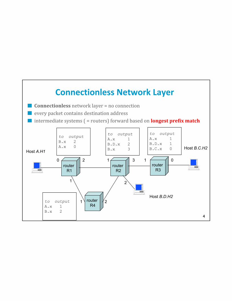
Connectionless Network LayerConnectionless network layer = no connectionevery packet contains destination addressintermediate systems ( = routers) forward based on longest prefix match
router R1
router R2
router R4
Host A.H1
Host B.D.H2
2 1
2
21
1
to outputB.x 2A.x 0
to outputA.x 1B.D.x 2B.x 3
to outputA.x 1B.x 2
router R3
to outputA.x 1B.D.x 1B.C.x 0
13
Host B.C.H2
0 0

5
Homogeneous addressingan IP address is unique across the whole network (= the world in general)IP address is the address of an interfacecommunication between IP hosts requires knowledge of IP addressesRouters between subnetworks only:a subnetwork = a collection of systems with a common prefixinside a subnetwork: hosts communicate directly without routersbetween subnetworks: one or several routers are usedHost either sends a packet to the destination using its LAN, or it passes it to the router for forwardingTerminology:
host = end system; router = intermediate systemsubnetwork = one collection of hosts that can communicate directly without routers
IP Principles

6
2. IP addresses
IP addressUnique addresses in the world, decentralized allocation
The current format is IPv4; next format will be IPv6; we will see IPv6 at the end of the lecture. By default, “IP address” = “IPv4 address”
An IP address is 32 bits, noted in dotted decimal notation: 192.78.32.2Host and Prefix PartAn IP address has a prefix and a host part:
prefix:hostPrefix identifies a subnetworkThe subnet prefix can be any length; frequent case is 24 bits but not alwaysIn order to know its prefix, a host needs to know how many bits constitute it
usually by means of a “subnet mask” (see later)

7
*Example 129.13266.46
129.132.100.12
lrcsuns128.178.156.24
08:00:20:71:0D:D4
lrcpc3128.178.156.7
00:00:C0:B8:C2:8D
in-inr128.178.156.1
00:00:0C:02:78:36128.178.79.1
00:00:0C:17:32:96
ed2-in182.1
in-inj128.178.182.3
182.5
128.178.100.3
LRC
15.221
Ring SIDI SUN
DI
ed0-swi15.13 128.178.100.12
128.178.84.1ed0-ext EPFL-Backbone
sic500cs128.178.84.130
Modem+ PPP
disun3128.178.79.9
08:00:20:20:46:2E
128.178.84.133
stisun115.7
128.178.47.5
128.178.47.3
Switch
ezci7-ethz-switch129.132.35.1
130.59.x.x
ed2-el
128.178.29.6408:00:07:01:a2:a5
LEMA
128.178.156.2308:00:07:01:a2:a5
ezci7-ethz-switch
KomsysETHZ-Backbone
129.132.100.27
lrcmac4
lrcmac4

8
Binary, Decimal and Hexadecimal
Given an integer B “the basis”: any integer can be represented in “base B” by means of an alphabet of B symbolsUsual cases aredecimal: 234
binary: b1110 1010
hexadecimal: xEAMapping binary <-> hexa is simple: one hexa digit is 4 binary digits xE = b1110 xA = b1010 xEA= b1110 1010Mapping binary <-> decimal is best done by a calculatorb1110 1010 = 128 + 64 + 32 + 8 + 2 = 234Special Cases to rememberxF = b1111 = 15
xFF = b1111 1111 = 255

9
Representation of IP Addresses
dotted decimal: group bits in bytes, write the decimal representation of the number example 1: 128.191.151.1
example 2: 129.192.152.2
hexadecimal: hexadecimal representation -- fixed size stringexample 1: x80 BF 97 01
example 2: x
binary: string of 32 bits (2 symbols: 0, 1)example 1: b0100 0000 1011 1111 1001 0111 0000 0001
example 2: b
solution

10
An IP address Prefix is written using one of two Notations: masks / prefixes
Using a mask: address + mask : example : 128.178.156.13 mask 255.255.255.0
the mask is the dotted decimal representation of the string made of : 1 in the prefix, 0 elsewhere
bit wise address & mask gives the prefix
here: prefix is 128.178.156.0
example 2: 129.132.119.77 mask 255.255.255.192Q1: what is the prefix ?
Q2: how many host ids can be allocated ?
Typically used in host configurationsolution

11
Prefix Notation
prefix – notation: 128.178.156.1/24the 24 first bits of the binary representation of the string, interpreted as dotted decimal
here: the prefix is 128.178.156.0
bits in excess are ignored128.178.156.1/24 is the same as 128.178.156.22/24 and 128.178.156/24
typically used in routing tables to identify routing prefixesexample 2:Q1: write 129.132.119.77 mask 255.255.255.192 in prefix notation
Q2: are these prefixes different ? 201.10.0.00/28, 201.10.0.16/28, 201.10.0.32/28, 201.10.0.48/28
how many IP addresses can be allocated to each of the distinct prefixes ?
solution

12
*IP Address HierarchiesThe prefix of an IP address can itself be structured into subprefix in order to support aggregationFor example: 128.178.x.y represents an EPFL host
128.178.156 / 24 represents the LRC subnet at EPFL128.178 / 16 represents EPFL
Used between routers by routing algorithmsThis way of doing is called classless and was first introduced in inter domain routing under the name of CIDR (classless interdomain routing)IP address classesIP addresses are sorted into classesThis is an obsolete classification – no longer used
At the origin, the prefix of an IP address was defined in a very rigid way. For class A addresses, the prefix was 8 bits. For class B, 16 bits. For class C, 24 bits. The interest of that scheme was that by simply analyzing the address you could find out what the prefix was.It was soon recognized that this form was too rigid. Then subnets were added. It was no longer possible to recognize from the address alone where the subnet prefix ends and where the host identifier starts. For example, the host part at EPFL is 8 bits; it is 6 bits at ETHZ. Therefore, an additional information, called the subnet mask, is necessary.Class C addresses were meant to be allocated one per network. Today, they are allocated in contiguous blocks.

13
*IP address classes
Examples: 128.178.x.x = EPFL host; 129.132.x.x = ETHZ host9.x.x.x = IBM host 18.x.x.x = MIT host
Class Range
ABCDE
0.0.0.0 to 127.255.255.255128.0.0.0 to 191.255.255.255192.0.0.0 to 223.255.255.255224.0.0.0 to 239.255.255.255240.0.0.0 to 247.255.255.255Class B addresses are close to exhausted; new addresses are taken from class C, allocated as continuous blocks
0 Net Id0 1 2 3… 8 16 24 31
10 Net Id
110 Net Id
1110 Multicast address
11110 Reserved
Subnet Id
Host Id
Host Id
class A
class B
class C
class D
class E
Host Id
Subnet Id

14
*Address allocationWorld CoverageEurope and the Middle East (RIPE NCC)
Africa (ARIN & RIPE NCC)
North America (ARIN)
Latin America including the Caribbean (ARIN)
Asia-Pacific (APNIC)Current allocations of Class C193-195/8, 212-213/8, 217/8 for RIPE
199-201/8, 204-209/8, 216/8 for ARIN
202-203/8, 210-211/8, 218/8 for APNICSimplifies routingshort prefix aggregates many subnetworks
routing decision is taken based on the short prefix

15
*Address delegationEurope62/8, 80/8, 193-195/8, …
ISP-162.125/16
customer 1: banana foods62.125.44.128/25
customer 2: sovkom62.125.44.50/24
ISP-2195.44/14
customer 1:195.46.216/21
customer 2: 195.46.224/21
Q. Assume sovkom moves from ISP-1 to ISP-2; comment on the impact.
solution

16
Special case IP addresses
1. 0.0.0.0 this host, on this network2. 0.hostId specified host on this net
(initialization phase)3. 255.255.255.255 limited broadcast
(not forwarded by routers)4. subnetId.all 1’s broadcast on this subnet5. subnetId.all 0’s BSD used it for broadcast
on this subnet (obsolate)
6. 127.x.x.x loopback
7. 10/8 reserved networks for172.16/12 internal use (Intranets)192.168/16
1,2: source IP@ only; 3,4,5: destination IP@ only

17
Test Your Understanding (1)
bridge? ?
?
? bridge host A
192.44.78.254
? 192.44.77.254 192.44.77.2__.__.__.1
__.__.__.__
187.44.__.__ __.__.__.__
__.__.__.253
Q: Can host A have this address? (masks are all 255.255.255)
solution

18
Test your Understanding (2)
Q1: An Ethernet segment became too crowded; we split it into 2 segments, interconnected by a router. Do we need to change some IP host addresses? Q2: same with a bridge.Q3: compare the twosolutions

19
3. IP packet forwarding
The IP packet forwarding algorithm is the core of the TCP/IP architecture. It defines what a system should do with a packet it has to send or forward. The rule is simple :
Rule for sending packets (hosts, routers)if the destination IP address has the same prefix as one of my interfaces, send directly to that interface
otherwise send to a router as given by the IP routing table
It uses the IP routing table; the table can be checked with a command such as “netstat” with Unix or “Route”with Windows.
In reality, there are exceptions to the rule. The complete algorithm is in the next slide; the cases should be tested in that order (it is a nested if then else statement).

20
IP packet forwarding algorithm
destAddr = destination address /* unicast! */if /*case 1*/: a host route exists for destAddr
for every entry in routing table if (destinationAddr = destAddr) then send to nextHop IPaddr; leave
else if /*case 2*/: destAddr is on a directly connected network (= on-link):for every physical interface IP address A and subnet mask SM
if(A & SM = destAddr & SM) then send directly to destAddr; leave
else if /*case 3 */ there is a matching entry in routing tablefind the longest prefix match for destAddrsend to nextHop IP addr given by matching entry; leave/* this includes as special case the default route, if it exists */
else /* error*/ send ICMP error message “destination unreachable” to source

21
*ExampleQ1: Fill in the table if an IP packet has to be sent from lrcsuns
Q2: Fill in the table if an IP packet has to be sent from ed2-insolutions
final destination next hop
128.178.79.9128.178.156.7
127.0.0.1128.178.84.133129.132.1.45
case number
7
Example 129.13266.46
129.132.100.12
lrcsuns128.178.156.24
08:00:20:71:0D:D4
lrcpc3128.178.156.7
00:00:C0:B8:C2:8D
in-inr128.178.156.1
00:00:0C:02:78:36128.178.79.1
00:00:0C:17:32:96
ed2-in182.1
in-inj128.178.182.3
182.5
128.178.100.3
LRC
15.221
Ring SIDI SUN
DI
ed0-swi15.13 128.178.100.12
128.178.84.1ed0-ext EPFL-Backbone
sic500cs128.178.84.130
Modem+ PPP
disun3128.178.79.9
08:00:20:20:46:2E
128.178.84.133
stisun1 15.7
128.178.47.5
128.178.47.3
Switch
ezci7-ethz-switch129.132.35.1
130.59.x.x
ed2-el
128.178.29.6408:00:07:01:a2:a5
LEMA
128.178.156.2308:00:07:01:a2:a5
ezci7-ethz-switch
KomsysETHZ-Backbone
129.132.100.27
lrcmac4
lrcmac4

22
Routing TablesHosts and routers have routing tables, but only routers have significant routingtablesRouting tables at routers are maintainedmanually or, more usually, by routingprotocolsDo not confuse
Packet forwarding:determine which outgoing interface to usereal time
Routingcompute the values in the routing tablebackground job

23
Test Your Understanding (3)Q1. What are the MAC and IP addresses at points 1 and 2 for packets sent by M1 to M3 ? At 2 for packets sent by M4 to M3 ?(Mx = mac address)
Router
EthernetConcentrator
EthernetConcentrator
M1p.h1
M2p.h2
M3q.h1
M8q.1
M4q.h3
M9p.1
subnet p subnet q
1
2
solution

24
Direct Packet Forwarding: ARPSending to host on the same subnet = direct packet forwardingdoes not use a routerRequires the knowledge of the MAC address on a LAN
(called “physical” address)
There are four types of solutions for that; all exist in some form or another.
1. write arp table manually: can always be implemented manually on Unix or Windows NT using the arp command
2. Derive MAC address algorithmically from IP address. This requires that the MAC address fits in the IP address; it is used with IPv6 but not with the current version of IP.
3. Write the mappings MAC <-> IP in a server (used in special cases like ATM or frame relay).
4. Use a discovery protocol by broadcast. This is done on all LANs (Ethernet, WiFi).
on LANs: uses the Address Resolution Protocol
32 bit IP address
48 bit MAC address
ARP

25
ARP Protocol
lrcsuns lrcpc1 lrcpc2 in-inr
128.178.156.2408:00:20:71:0D:D4
128.178.156.3100:00:C0:B3:D2:8D
128.178.156.100:00:0C:02:78:36
1128.178.156.0
1: lrcsuns has a packet to send to 128.178.156.31 (lrcpc1)
this address is on the same subnetlrcsuns sends an ARP request to all systems on the subnet (broadcast)
target IP address = 128.178.156.31ARP request is received by all IP hosts on the local network
is not forwarded by routers

26
ARP Protocol
lrcsuns lrcpc1 lrcpc2 in-inr
128.178.156.2408:00:20:71:0D:D4
128.178.156.3100:00:C0:B3:D2:8D
128.178.156.100:00:0C:02:78:36
1
2
128.178.156.0
2: lrcpc1 has recognized its IP addresssends an ARP reply packet to the requesting host
with its IP and MAC addresses

27
ARP Protocol
lrcsuns lrcpc1 lrcpc2 in-inr
128.178.156.2408:00:20:71:0D:D4
128.178.156.3100:00:C0:B3:D2:8D
128.178.156.100:00:0C:02:78:36
1
2
128.178.156.0
3
3: lrcsuns reads ARP reply, stores in a cache and sends IP packet to lrcpc1Systems learn from ARP-REQUESTs. At the end of flow 1, all systems have learnt the mapping IP <-> MAC addr for the source of the ARP REQUEST, namely, they have updated the following entry in their ARP table: IP addr: 128.178.156.24MAC addr: 08:00:20:71:0D:D4.As a result, lrcpc1 will not send an ARP-REQUEST to communicate back with lrcsuns. Gratuitous ARP consists in sending an ARP-REQUEST to self’s address. This is used at bootstrap to test the presence of a duplicate IP address. It is also used to force ARP cache entries to be changed after an address change (because systems learn from the ARP-REQUEST). As flow 2 shows, the ARP-REPLY is not broadcast, but sent directly to the system that issued the request. The “arp” command on Unix can be used to see or modify the ARP table.

28
Test Your Understanding (3, cont’d)Q2: What must the router do when it receives a packet from M2 to M3 for the first time?
Router
EthernetConcentrator
EthernetConcentrator
M1p.h1
M2p.h2
M3q.h1
M8q.1
M4q.h3
M9p.1
subnet p subnet q
1
2
solution

29
*Look inside an ARP packet
Ethernet IIDestination: ff:ff:ff:ff:ff:ff (ff:ff:ff:ff:ff:ff)Source: 00:03:93:a3:83:3a (Apple_a3:83:3a)Type: ARP (0x0806)Trailer: 00000000000000000000000000000000...
Address Resolution Protocol (request)Hardware type: Ethernet (0x0001)Protocol type: IP (0x0800)Hardware size: 6Protocol size: 4Opcode: request (0x0001)Sender MAC address: 00:03:93:a3:83:3a (Apple_a3:83:3a)Sender IP address: 129.88.38.135 (129.88.38.135)Target MAC address: 00:00:00:00:00:00 (00:00:00_00:00:00)Target IP address: 129.88.38.254 (129.88.38.254)

30
Proxy ARPProxy ARP = a host answers ARP requests on behalf of othersexample: sic500cs for PPP connected computers
Allows to cheat: connect to different physical networks that have same subnet prefix
Price to pay: ad-hoc configuration + single point of failureQ1: how must sics500cs routing table be configured ?Q2: explain what happens when ed2-in has a packet to send to 128.178.84.133 solution
ed2-in15.221
15.13
128.178.84.1ed0-ext EPFL-Backbone
sic500cs128.178.84.130
Modem+ PPP 128.178.84.133
stisun1 15.7

31
*4. IP header
Version H-size Type of service Size
Identification Offset
TTL Protocol Checksum
source address
destination address
options
F M
Transmitted "big-endian" - bit 31 firstVersion is always 4 (IPv6 uses a different packet format)
Header sizeoptions - variable size
in 32 bit words
031

32
*IP header
Type of servicePreviously used to encode priority;
now used by DiffServ (DifferentiatedServices)
1 byte codepoint determining QoS classExpedited Forwarding (EF) - minimizedelay and jitterAssured Forwarding (AF) - four classes and three drop-precedences (12 codepoints)
Used only in corporate networksPacket sizein bytes including header
≤ 64 Kbytes; limited in practice by link-level MTU (Maximum Transmission Unit)
every subnet should forward packets of 576 = 512 + 64 bytes
Id unique identifier for re-assemblingFlagsM : more ; set in fragments
F : prohibits fragmentationOffsetposition of a fragment in multiples of 8 bytesTTL (Time-to-live)in seconds
now: number of hops
router : --, if 0, drop (send ICMP packetto source)Protocol identifier of protocol (1 - ICMP, 6 - TCP, 17 - UDP) Checksumonly on the header

33
*IP Checksum
The IP checksum is a simple example of error detecting code. It works as follows. Consider a sequence of bytes and group them by 16-bit words. If the sequence has an odd number of bytes, add an extra 0 byte at the end. Obtain the 16 bits words W0 to Wj. Consider the number x = 216 j Wj + 216 (j-1) Wj-1 + … + 216 W1 + W0The checksum is y = (216 –1) – z withz = x mod (216 –1)The computation of y is algorithmically simple. Note that 216 = 1 mod (216 –1) and thusz = Wj + Wj-1 + … + W1 + W0 mod (216 –1)The algorithm is: compute z = Wj + Wj-1 + … + W1 + W0
group the result by blocks of 16 bits; obtain x’ = 216 j’ W’j’ + 216 (j’-1) W’j’-1 + … + 216 W’1 + W’0
start again with x’ instead of xuntil z is a 16 bit wordComments:
Addition modulo (216 –1) is called « one’s complement addition »The method is the same as the « proof by 9 » used by scholars before calculators existed, with 9 replaced by 216 –1;
ex: 2345678 mod 9 = 2+3+4+5+6+7+8 mod 9 = 35 mod 9 = 3+5 mod 9 = 8
See RFC 1624 for how to do the computations in practice with 32 bit arithmetic.

34
*Examples of IP Checksums
all numbers are written in hexadata: 0103 0012 W1=0103 W0= 0012z = checksum y = data: 0100 F203 F4F5 F6F7z = 0100 + F203 + F4F5 + F6F7 =
checksum y =
solution
source: http://www.netfor2.com/checksum.html

35
*Verifying a Checksum
Destination receives Wj … W0 yIf there is no error we should have: Wj + … +W0 + y = 0 mod (216 –1) Destination computes the one’s complement sum of the block including checksum and verifies if the result is 0 mod (216 –1)Examples:received block 0103 0012 FEEAverification: 0103 + 0012 + FEEA = FFFF √received block 0100 F203 F4F5 F6F7 210Everification: 0100 + F203 + F4F5 + F6F7 + 210E = 2 FFFD
2 + FFFD = FFFF √

36
*IP header OptionsOptionsstrict source routing
all routers
loose source routingsome routers
record route
timestamp route
router alertused by IGMP or RSVP for processing a packet

37
Look inside an IP packet
Ethernet IIDestination: 00:03:93:a3:83:3a (Apple_a3:83:3a)Source: 00:10:83:35:34:04 (HEWLETT-_35:34:04)Type: IP (0x0800)
Internet Protocol, Src Addr: 129.88.38.94 (129.88.38.94), Dst Addr: 129.88.38.241 (129.88.38.241)Version: 4Header length: 20 bytesDifferentiated Services Field: 0x00 (DSCP 0x00: Default; ECN: 0x00)Total Length: 1500Identification: 0x624dFlags: 0x04Fragment offset: 0Time to live: 64Protocol: TCP (0x06)Header checksum: 0x82cf (correct)Source: 129.88.38.94 (129.88.38.94)Destination: 129.88.38.241 (129.88.38.241)

38
5. ICMP: Internet Control Message Protocolused by router or host to send error or control messages to other hosts or routers
error or control messages relate to layer 3 only
carried in IP datagrams (protocol type = 1)ICMP message typesecho request ( reply) -> used by ping
destination unreachable
time exceeded (TTL = 0) -> used for traceroute responses
address mask request/reply
source quench
redirect - router discovery
timestamps
ICMP messages never sent in response toICMP error message - datagram sent or multicast or broadcast IP or layer 2 address - fragment other than first

39
Sent by router R1 to source host A when R1 receives a packet from A with destination = B, and R1 finds that the next hop is R2, A is on-link with R2 (thus A should not have sent to R1, but directly to R2)R1 sends ICMP redirect to A saying next hop for destination B is R2
A updates its routing table with a host route
General routing principle of the TCP/IP architecture:host have minimal routing information
learn host routes from ICMP redirects
routers have extensive knowledge of routes
*ICMP Redirect
/ /| IP datagram header (prot = ICMP) | +-+-+-+-+-+-+-+-+-+-+-+-+-+-+-+-+-+-+-+-+-+-+-+-+-+-+-+-+-+-+-+-+| Type=5 | code | checksum |+-+-+-+-+-+-+-+-+-+-+-+-+-+-+-+-+-+-+-+-+-+-+-+-+-+-+-+-+-+-+-+-+| Router IP address that should be preferred |+-+-+-+-+-+-+-+-+-+-+-+-+-+-+-+-+-+-+-+-+-+-+-+-+-+-+-+-+-+-+-+-+| IP header plus 8 bytes of original datagram data |/ /
/ /| IP datagram header (prot = ICMP) | +-+-+-+-+-+-+-+-+-+-+-+-+-+-+-+-+-+-+-+-+-+-+-+-+-+-+-+-+-+-+-+-+| Type=5 | code | checksum |+-+-+-+-+-+-+-+-+-+-+-+-+-+-+-+-+-+-+-+-+-+-+-+-+-+-+-+-+-+-+-+-+| Router IP address that should be preferred |+-+-+-+-+-+-+-+-+-+-+-+-+-+-+-+-+-+-+-+-+-+-+-+-+-+-+-+-+-+-+-+-+| IP header plus 8 bytes of original datagram data |/ /
ICMP Redirect Format

40
*ICMP Redirect Example
lrcsuns
in-inr156.1182.5
156.24 156.100
1
4
4
dest IP addr srce IP addr prot data part 1: 128.178.29.9 128.178.156.24 udp xxxxxxx2: 128.178.29.9 128.178.156.24 udp xxxxxxx3: 128.178.156.24 128.178.156.1 icmp type=redir code=host cksum
128.178.156.100xxxxxxx (28 bytes of 1)
4: 128.178.29.9 128.178.156.24 udp .........
3
2
2lemas3
29.1ed2-el
inr-el29.929.200
ed2-in

41
ICMP Redirect Example (cont’d)
lrcsuns:/export/home1/leboudec$ netstat -nrRouting Table: Destination Gateway Flags Ref Use Interface
-------------------- -------------------- ----- ----- ------ ---------127.0.0.1 127.0.0.1 UH 0 11239 lo0128.178.29.9 128.178.156.100 UGHD 0 19 128.178.156.0 128.178.156.24 U 3 38896 le0224.0.0.0 128.178.156.24 U 3 0 le0default 128.178.156.1 UG 0 85883
After 4
42
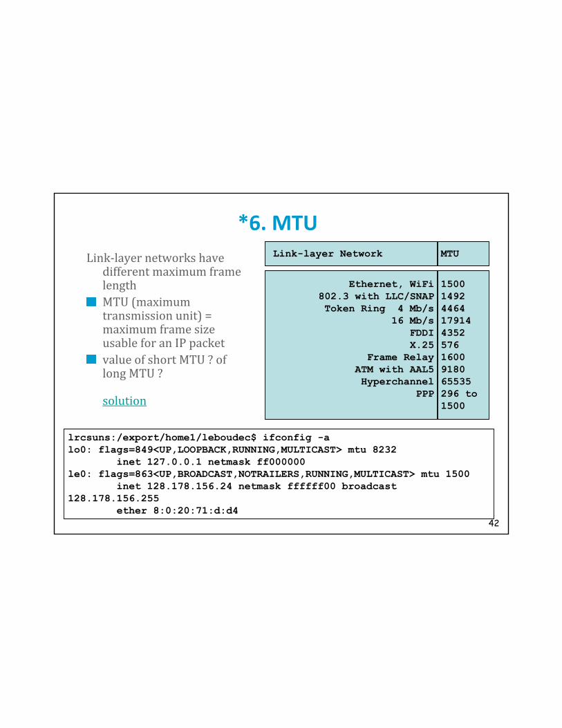
*6. MTULink-layer networks have different maximum framelengthMTU (maximum transmission unit) = maximum frame size usable for an IP packetvalue of short MTU ? of long MTU ?solution
Link-layer Network MTU
Ethernet, WiFi802.3 with LLC/SNAPToken Ring 4 Mb/s
16 Mb/sFDDIX.25
Frame RelayATM with AAL5Hyperchannel
PPP
1500149244641791443525761600918065535296 to1500
lrcsuns:/export/home1/leboudec$ ifconfig -alo0: flags=849<UP,LOOPBACK,RUNNING,MULTICAST> mtu 8232
inet 127.0.0.1 netmask ff000000le0: flags=863<UP,BROADCAST,NOTRAILERS,RUNNING,MULTICAST> mtu 1500
inet 128.178.156.24 netmask ffffff00 broadcast 128.178.156.255
ether 8:0:20:71:d:d4

43
IP FragmentationIP hosts or routers may have IP datagrams larger than MTUFragmentation is performed when IP datagram too largere-assembly is only at destination, never at intermediate pointsfragmentation is in principle avoided with TCP R2R1
MTU = 1500 MTU = 620 MTU =1500
IPHeader
1400 BytesIP
Header600 B
IPHeader
600 B
IPHeader
200 B
IPHeader
600 B
IPHeader
600 B
IPHeader
200 B
1 2a
2b
2c
3a
3b
3c
44
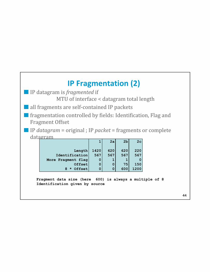
IP Fragmentation (2)IP datagram is fragmented if MTU of interface < datagram total lengthall fragments are self-contained IP packetsfragmentation controlled by fields: Identification, Flag and Fragment OffsetIP datagram = original ; IP packet = fragments or complete datagram
Fragment data size (here 600) is always a multiple of 8Identification given by source
LengthIdentification
More Fragment flagOffset
8 * Offset
1
1420567
000
2a
620567
100
2b
620567
175
600
2c
220567
01501200

45
*Fragmentation AlgorithmRepeated fragmentations may occurDon’t fragment flag prevents fragmentationFragmentation Algorithm:
procedure sendIPp(P0):
if P0.totalLength > MTU then data1Length = (MTU-P0.HLEN rounded to multiple of 8) data1= first data1Length bytes of P0 data partdata2= remainder of P0 data partheader1 = P0.header with
More bit settotalLength = P0.HLEN + data1Length
P1= new (IPPacket; header1; data1)send P1 on data link layerheader2 = P0.header with
totalLength = P0.totalLength - data1LengthfragmentOffset += data1Length/8
P2= new(IPPacket; header2; data2)sendIPp(P2)
elsesend P0 on data link layer

46
IP packet arrival (P0) /* and packet is not a complete datagram */ ->if (P0.(identification, source address)) is new then if (new(fragmentList, P0.(identification, source address), fl))
then insert P0 in flstart reassemblyTimer(fl)
elsefl = fragmentList(P0.(identification, source address))insert(fl,P0)if fl is complete
then deliver IP datagram else start reassemblyTimer(fl)
reassemblyTimer(fl) expires ->send ICMP error message to sourcedelete(fl)
IP packets are sorted in fragment listsone fragment list per (Identification, source IP @)sorted by increasing Fragment Offset
Fragments F1 and F2 are contiguous iffF1.moreBit = 1F1.fragmentOffset + F1.dataLength/8 = F2.fragmentOffset
Fragment List F0…Fn is complete iffF0.fragmentOffset = 0Fi and Fi+1 are contiguous for i=0…(n-1)Fn.moreBit = 0
Comments: new(fragment list) may fail if there is no buffer left; in that case the datagram is lostinsert may fail; if insert fails, then the fragment is discarded

47
*Issues with Fragmentation
Fragmentation requires re-assembly; issues aredeadlocks
identification wrapping problem
unit of loss is smaller than unit of re-transmission: can worsen congestion
Q. explain why
Solution = avoid fragmentationPath MTU = minimum MTU for all links of one path
Discovery of path MTUheuristics: local -> 1500; other : 576 (subnetsarelocal variable)
Path MTU discovery avoids fragmentation
solution

48
Path MTU DiscoveryMethod for Path MTU (PMTU) discovery1. host sets Don’t Fragment bit on all datagrams and estimate PMTU to local MTU
2. routers send an ICMP message: “destination unreachable/ fragmentation needed”
3. host reduces PMTU estimate to next smallest value
4. after timeout, host increases PMTU estimate
route changes may cause 2

49
TCP, UDP and FragmentationThe UDP service interface accepts a datagram up to 64 KBUDP datagram passed to the IP service interface as one SDU
is fragmented at the source if resulting IP datagram is too largeThe TCP service interface is stream orientedpacketization is done by TCP
several calls to the TCP service interface may be grouped into one TCP segment (many small pieces)
or: one call may cause several segments to be created (one large piece)
TCP always creates a segment that fits in one IP packet: no fragmentation at source
fragmentation may occur in a router, if IPv4 is used, and if PMTU discovery is not implemented
Q. If all sources use PMTU discovery, in which cases has a router to fragment a packet ?solution

50
7. TerminologyArchitecture IP router
a system that forwards packets based on IP addresses
performs packet forwarding + control method
Implementation: any UNIX machine can be configured as IP router
normally, dedicated box with specialized hardware called router

51
What is a “Multiprotocol Router” ?Multiprotocol routera system that forwards packets based on layer 3 addresses for various protocol architectures (ex: IP, Appletalk)
CISCO, IBM, etc…
most multiprotocol routers perform both bridging and routingarchitecture: bridge + router
implementation: one CISCO
IP router boxes also perform other functions: port filtering, DHCP relay, …
Q. In a pure IP world (if all machines run TCP/IP) do we need multiprotocol routers ?A. Yes if both IPv4 and IPv6 are used.
solution

52
* Example of Combined Functions in One ProductPut a bridge + Ethernet concentrator + router in the same boxThe resulting product is called “switching router”Avoids ARP broadcastsThe words switches and routers are normally used in many different ways. For us, a switch is an intermediate system for connection oriented network layers such as ATM or Frame Relay. For the commercial literature, it usually means a fast packet forwarder, usually implemented in hardware. In reality, routers can be implemented exactly in the same way and with the same performance as “switches”. The main difference is for multiprotocol routers that need to understand not just one network layer, but many. In such cases, only software implementations are available. In contrast, IP only routers are emerging with a performance similar to that of switches.
The “switching router” concept is an example of product, which is new as a product, but from an architecture viewpoint is nothing new. Since the router is in the same box as the Ethernet concentrator, it can know (by software) the MAC address of directly attached systems. Thus, the ARP broadcasts are avoided.
Router
SwitchingRouter
SwitchingRouter
M1p.h1
M2p.h2
M3q.h1
M8q.1
M4q.h3
M9p.1
1
2
H1 H2
53
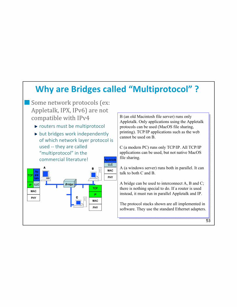
Why are Bridges called “Multiprotocol” ?Some network protocols (ex: Appletalk, IPX, IPv6) are not compatible with IPv4routers must be multiprotocol
but bridges work independently of which network layer protocol is used -- they are called “multiprotocol” in the commercial literature!
LLC
PHY
MAC
Appletalk
LLC
PHY
MAC
Appletalk
IP
TCP
PHY
MAC
IP
TCP
Bridge
A B
C
LLC
PHY
MAC
Appletalk
LLC
PHY
MAC
Appletalk
LLC
PHY
MAC
Appletalk
IP
TCP
LLC
PHY
MAC
Appletalk
IP
TCP
PHY
MAC
IP
TCP
PHY
MAC
IP
TCP
BridgeBridge
A B
C
B (an old Macintosh file server) runs only Appletalk. Only applications using the Appletalkprotocols can be used (MacOS file sharing, printing). TCP/IP applications such as the web cannot be used on B.
C (a modern PC) runs only TCP/IP. All TCP/IP applications can be used, but not native MacOSfile sharing.
A (a windows server) runs both in parallel. It can talk to both C and B.
A bridge can be used to interconnect A, B and C; there is nothing special to do. If a router is used instead, it must run in parallel Appletalk and IP.
The protocol stacks shown are all implemented in software. They use the standard Ethernet adapters.

54
What is a “Non Routable Protocol” ?NetBIOS was originally developed to work only in one bridged LANuses LLC-2, similar to TCP but located in layer 2 (also called NETBEUI)
in that form, it is not “routable”: can only be bridgedNetBIOS is an interface for distributed applications that is commonly used with IBM and Microsoft systems. Only MAC addresses are used. In addition, NetBIOS offers a naming service. This version of NetBIOS works only in a bridged environment.
NetBIOS today is offered as a TCP/IP applicationuses the NBT reserved port
Windows machines at EPFL use TCP/IP only
LLC2
PHY
MAC
NetBIOS
LLC2
PHY
MAC
NetBIOS
Layer 2
R1
MACMAC
PHY R2
Bridge
App App
LLC2
PHY
MAC
NetBIOS
LLC2
PHY
MAC
NetBIOS
Layer 2
R1R1
MACMAC
PHY R2R2
Bridge
App App

55
*Virtual LANs and Subnets
IP requires machines to be organized by subnets-- This is a problem when machines (and people) moveOne solution is provided by layer 2: virtual LANsWhat is does : define LANs independent from location
How: associate (by configuration rules) hosts with virtual LAN labels.
The picture shows two virtual LANs: (ACLNV) and (BDMPU). The concentrators perform bridging between the different collision domains of the same virtual LAN.
Between two virtual LANs, a router must be used. The figure shows one router that belongs to both VLANs
Between X1 and X2, the two virtual LANs use the same physical link. This is made possible by adding a label to the Ethernet packet header, that identifies the virtual LAN.
Q. How many spanning trees are there in this network ?solution
Q. Can you think of another solution to the same problem ?solution

56
VirtualLAN
Concen-trator
VirtualLAN
Concen-trator
VirtualLAN
Concen-trator
A
B
C
D
VU
L
M
N
P
X1 X2
X3
VirtualLAN
Concen-trator
VirtualLAN
Concen-trator
VirtualLAN
Concen-trator
A
B
C
D
VU
L
M
N
P
X1 X2
X3
Router

57
Facts to RememberIP is a connectionless network layerIPv4 addresses are 32 bit numbersOne IP address per interfaceRouters scale well because they can aggregate routesHosts on the Internet exchange packets with IP addresses

58
Solutions

59
1. Why a network layer?We would like to interconnect all devices in the world. We have seen that we can solve the interconnection problem with bridges and the MAC layer. However this is not sufficient as it does scale to large networks.Q. Why ?A.
1. Bridges use a tree. This is not efficient in a large network, as the tree concentrates all traffic. 2. Bridges use forwarding tables that are not structured. A bridge must lookup the entire table for every packet. The table size and lookup time would be prohibitive. Solution: connectionless network layer (eg. Internet Protocol, IP):every host receives a network layer address (IP address)
intermediate systems forward packets based on destination address back

60
Representation of IP Addresses
dotted decimal: group bits in bytes, write the decimal representation of the number example 1: 128.191.151.1
example 2: 129.192.152.2
hexadecimal: hexadecimal representation -- fixed size stringexample 1: x80 BF 97 01
example 2: x81 C0 98 02
binary: string of 32 bits (2 symbols: 0, 1)example 1: b0100 0000 1011 1111 1001 0111 0000 0001
example 2: b0100 0001 1100 0000 1001 1000 0000 0010back
61
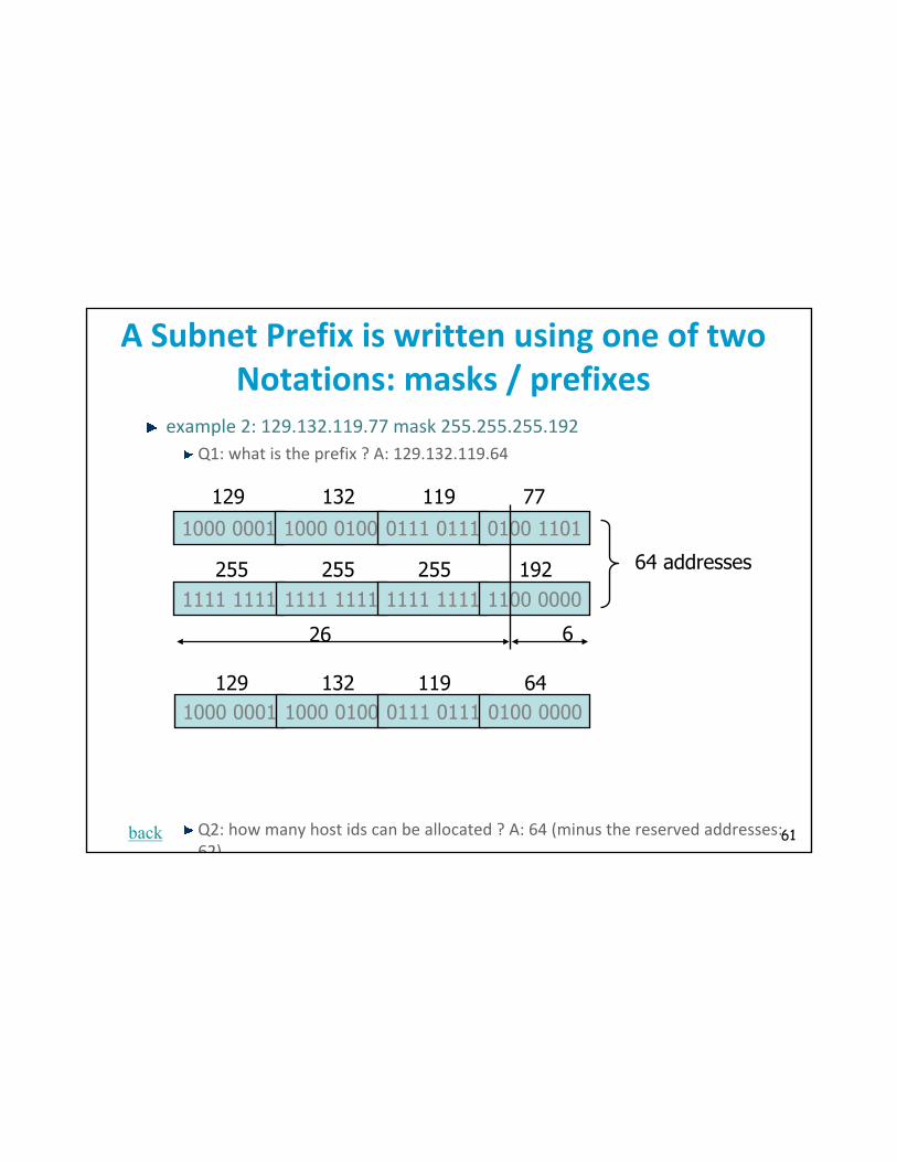
A Subnet Prefix is written using one of two Notations: masks / prefixes
example 2: 129.132.119.77 mask 255.255.255.192Q1: what is the prefix ? A: 129.132.119.64
Q2: how many host ids can be allocated ? A: 64 (minus the reserved addresses: 62)
1000 0001 1000 0100 0111 0111 0100 1101
1111 1111 1111 1111 1111 1111 1100 0000
129
255
132
255
119
255 192
77
64 addresses
26 6
1000 0001 1000 0100 0111 0111 0100 0000129 132 119 64
back
62
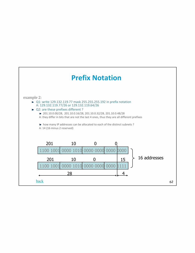
Prefix Notation
example 2:Q1: write 129.132.119.77 mask 255.255.255.192 in prefix notationA: 129.132.119.77/26 or 129.132.119.64/26 Q2: are these prefixes different ?
201.10.0.00/28, 201.10.0.16/28, 201.10.0.32/28, 201.10.0.48/28A: they differ in bits that are not the last 4 ones, thus they are all different prefixes
how many IP addresses can be allocated to each of the distinct subnets ?A: 14 (16 minus 2 reserved)
1100 1001 0000 1010 0000 0000 0000 0000
1100 1001 0000 1010 0000 0000 0000 1111
201
201
10
10
0
0 15
0
16 addresses
28 4
back

63
Address delegation
Europe62/8, 80/8, 193-195/8, …ISP-1
62.125/16customer 1: banana foods
62.125.44.128/25
customer 2: sovkom62.125.44.50/24
ISP-2195.44/14customer 1:
195.46.216/21
customer 2: 195.46.224/21
Q. Assume sovkom moves from ISP-1 to ISP-2; comment on the impact.A. If sovkom keeps the same IP addresses, the set of addresses of ISP-2 is no longer continguous. It cannot be represented by one single entry in routingtables. Routing tables in the internet need to represent ISP-2 by two entries: 195.44/14 and 62.125.44.50/24
back

64
Test Your Understanding (1)
bridgehost Y router
host X
router bridge host A
192.44.78.254
host Z192.44.77.254 192.44.78.2192.44.77.1
187.44.1.2
187.44.1.1 187.44.1.254
192.44.78.253
A: No, host A is on subnetwork 192.44.78
back

65
Test your Understanding (2)
Q1: An Ethernet segment became too crowded; we split it into 2 segments, interconnected by a router. Do we need to change some IP host addresses ? A: yes in general. Two different subnets cannot have the same prefixQ2: same with a bridgeA: no, bridging is transparent.Q3: compare the twoA: bridging is plug and play but the network performance is more difficult to guarantee (broadcasts + spanning tree)back

66
ExampleQ: Fill in the table if an IP packet has to be sent from lrcsuns
Q: Fill in the table if an IP packet has to be sent from ed2-in
final destination next hop
128.178.79.9128.178.156.7
127.0.0.1128.178.84.133129.132.1.45
128.178.156.1128.178.156.7
loopback128.178.156.1128.178.156.1
case number
32233
final destination next hop
128.178.79.9128.178.156.7
127.0.0.1128.178.84.133129.132.1.45
128.178.182.3128.178.182.5
loopback128.178.15.13128.178.100.12
case number
33233
back

67
Test Your Understanding (3)Q1: What are the MAC and IP addresses at points 1 and 2 for packets sent by M1 to M3 ? At 2 for packets sent by M4 to M3 ?(Mx = mac address)A: at 1: srce IP@=p.h1, dest IP@=q.h1, MACsrce=M1, MACdest=M9at 2: srce IP@=p.h1, dest IP@=q.h1, MACsrce=M8, MACdest=M3at 2: srce IP@=q.h3, dest IP@=q.h1, MACsrce=M4, MACdest=M3
Router
EthernetConcentrator
EthernetConcentrator
M1p.h1
M2p.h2
M3q.h1
M8q.1
M4q.h3
M9p.1
subnet p subnet q
1
2
back

68
Test Your Understanding (3)Q2: What must the router do when it receives a packet from M2 to M3 for the first time? A: send an ARP request broadcast on LAN q
Router
EthernetConcentrator
EthernetConcentrator
M1p.h1
M2p.h2
M3q.h1
M8q.1
M4q.h3
M9p.1
subnet p subnet q
1
2
back
69
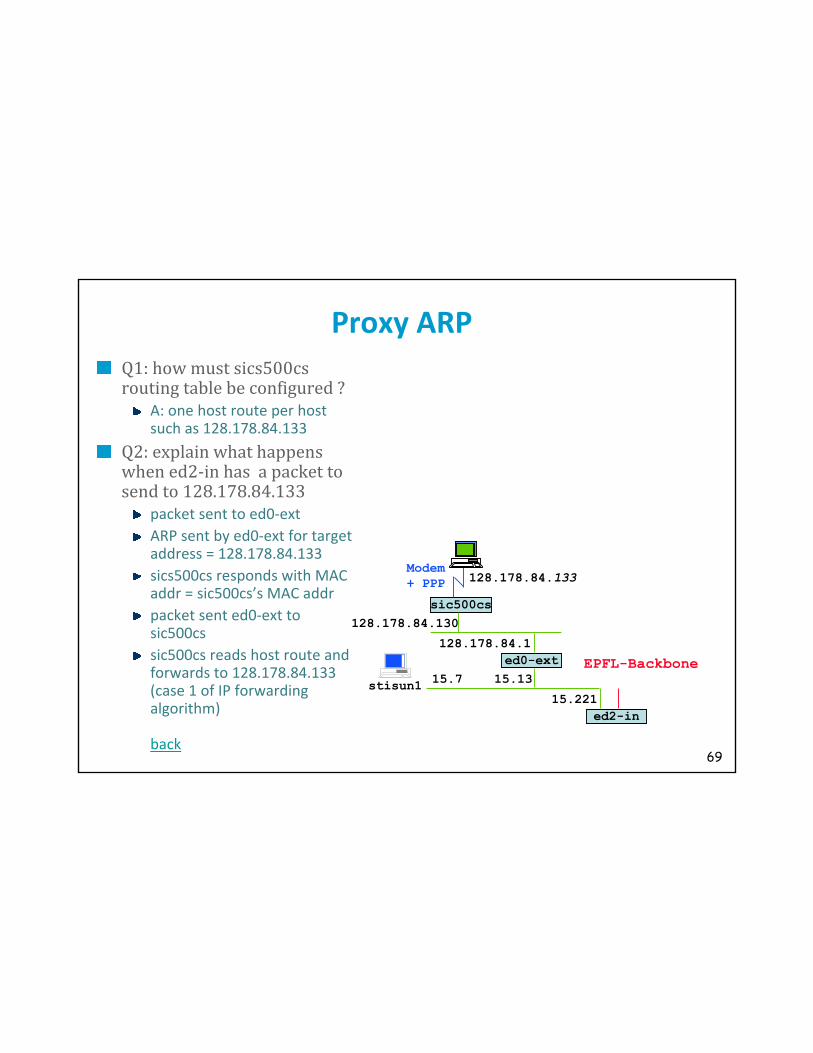
Proxy ARPQ1: how must sics500cs routing table be configured ?A: one host route per host such as 128.178.84.133Q2: explain what happens when ed2-in has a packet to send to 128.178.84.133 packet sent to ed0-extARP sent by ed0-ext for target address = 128.178.84.133sics500cs responds with MAC addr = sic500cs’s MAC addrpacket sent ed0-ext to sic500cs sic500cs reads host route and forwards to 128.178.84.133 (case 1 of IP forwarding algorithm)
back
ed2-in15.221
15.13
128.178.84.1ed0-ext EPFL-Backbone
sic500cs128.178.84.130
Modem+ PPP 128.178.84.133
stisun1 15.7

70
Examples of IP Checksums
all numbers are written in hexadata: 0103 0012 W1=0103 W0= 0012z = 0103 + 0012 = 01 15checksum y = FFFF – z = FEEAdata: 0100 F203 F4F5 F6F7z = 0100 + F203 + F4F5 + F6F7 = 0002 DEEFz = 0002 + DEEF = DEF1checksum y = FFFF - DEF1= 210E
back
source: http://www.netfor2.com/checksum.html

71
MTUvalue of short MTU ? reduces queue lengths and delays
on lossy links (radio) reduces proba of packet errorof long MTU ?reduces per packet processing
back

72
Issues with Fragmentation
Fragmentation requires re-assembly; issues aredeadlocksidentification wrapping problemunit of loss is smaller than unit of re-transmission: can worsen congestion
Q. explain why A. when a network is congested, packets get lost. Assume every datagram is fragmented in 10, and a single loss causes retransmission. The losses of a n packets (belonging to different datagrams) causes 10n retransmissions, which increases the offered traffic and makes congestion worse.Solution = avoid fragmentationPath MTU = minimum MTU for all links of one pathDiscovery of path MTU
heuristics: local -> 1500; other : 576 (subnetsarelocal variable)
Path MTU discovery avoids fragmentation
back

73
Fragmentation (sol)
The UDP service interface accepts a datagram up to 64 KBUDP datagram passed to the IP service interface as one SDU
is fragmented at the source if resulting IP datagram is too largeThe TCP service interface is stream orientedpacketization is done by TCP
several calls to the TCP service interface may be grouped into one TCP segment (many small pieces)
or: one call may cause several segments to be created (one large piece)
TCP always creates a segment that fits in one IP packet: no fragmentation at source
fragmentation may occur in a router, if IPv4 is used, and if PMTU discovery is not implemented
Q. If all sources use PMTU discovery, in which cases has a router to fragment a packet ?A. 1. UDP packets sent by sources that have a larger local MTU than the path MTU2. TCP packets where PMTU estimation failed (due to path changes)back

74
What is a “Multiprotocol Router” ?Multiprotocol routera system that forwards packets based on layer 3 addresses for various protocol architectures (ex: IP, Appletalk)
CISCO, IBM, etc…
most multiprotocol routers perform both bridging and routingarchitecture: bridge + router
implementation: one CISCO
IP router boxes also perform other functions: port filtering, DHCP relay, …
Q. In a pure IP world (if all machines run TCP/IP) do we need multiprotocol routers ?A. Yes if both IPv4 and IPv6 are used.
back

75
Virtual LANs and Subnets
IP requires machines to be organized by subnets-- This is a problem when machines (and people) moveOne solution is provided by layer 2: virtual LANsWhat is does : define LANs independent from location
How: associate (by configuration rules) hosts with virtual LAN labels.
The picture shows two virtual LANs: (ACLNV) and (BDMPU). The concentrators perform bridging between the different collision domains of the same virtual LAN.
Between two virtual LANs, a router must be used. The figure shows one router that belongs to both VLANs
Between X1 and X2, the two virtual LANs use the same physical link. This is made possible by adding a label to the Ethernet packet header, that identifies the virtual LAN.
Q. How many spanning trees are there in this network ?A. 2 (one per virtual LAN)
back

76
Virtual LANs and Subnets
Q. Can you think of another solution to the same problem ?A. DHCPback