PT IP Camera
63
Network Camera User ’ s Manual 1/63 User’s manual Version 0.2
-
Upload
khangminh22 -
Category
Documents
-
view
0 -
download
0
Transcript of PT IP Camera
Network Camera Userrsquos Manual
163
Userrsquos manual
Version 02
Network Camera Userrsquos Manual
263
Table of Contents
Overview 3 Package Contents 4 Connections 5
Hardware description 5 Hardware Installation 6
Install the IP Finder program 8 Bonjour program 14 C2mylevel1com(Free DDNS service) 15
Initial Access to the Network Camera 16 Playback 20 Client Setting 21
Definitions in Configuration 23 System 23 Security 25 Network 27 DDNS 29 Access list 31 Video 33 ROI(Region of Interest) 38 Defog 39 Video record 40 Stream 42 Camera control 44 Application 47 Servers 50 Storage 52 Syslog 53 Status and Parameters 54 Maintenance 55 Appendix 57
A Troubleshooting amp Frequently Asked Questions 57 B Technical specifications 62
Network Camera Userrsquos Manual
363
H264 PanTilt Night Vision IP Camera
Overview Law in your country may prohibit the use of surveillance devices The Network Camera is not only a high-performance web-ready camera but also can be part of a flexible surveillance system It is the userrsquos responsibility to ensure that the operation of such devices is legal before installing this unit for its intended use It is important to first verify that all contents received are complete according to the list in the Package Contents chapter Take notice of the warnings in ―Quick installation guide before the Network Camera is installed then carefully read and follow the instructions in the ―Installation chapter to avoid damages due to faulty assembly and installation This also ensures the product is used properly as intended The Network Camera is accessible via the LAN or Internet connection Connect your Network Camera directly to a computer network or DSL modem and with a standard Web browser you get instant on demand video streams Within minutes you can set up the Network Camera to capture a video sequence to a PC Live video image can be uploaded to a website for the world to see or made available only to select users on the network
The Network Camera is a network device and its use should be straightforward for those who have basic network knowledge The Network Camera is designed for various applications including video sharing general securitysurveillance etc The ―How to Use chapter suggests ways to best utilize the Network Camera and ensure proper operations
Minimum System Requirement
H264 PanTilt Night vision IP Camera Network Environment
LAN 10100M1000M Ethernet
Monitoring System Recommended for Internet Explorer
System Hardware Basic requirements middot CPU Intelreg Celeronreg Dual-Core 270GHz or above middot Memory Size 2 GB or above Recommended middot VGA card resolution 1024 x 768 or above
System Requirement for Viewer amp Recorder Application
Support OS XP Windows 7 Windows 8
System Hardware 1-4 cameras surveillance application middot CPU Intelreg Celeronreg Dual-Core 270GHz or above middot Memory Size 2 GB or above middot VGA card resolution 1024 x 768 or above
Network Camera Userrsquos Manual
463
Package Contents
If any of the above items are missing please contact your dealer immediately
Note Using a power supply with a different voltage than the one included with the Network Camera will cause damage and void the warranty for this product
Network Camera (Wired or PoE)
Software CD
Power adapter
Quick installation guide
WrenchScrewsWall Mount Bracket
RJ45 FemaleGeneral DI Block Moisture Absorber
Network Camera Userrsquos Manual
563
Connections
Hardware description
Plan view panel
Inner View
Network Camera Userrsquos Manual
663
Hardware Installation 1 Attach the Network Camera with the included stand
2 Place the Camera fix it onto ceiling or wall Use screws to fix the Network Camera onto the ceiling or wall
3 Power over Ethernet (PoE) Using a PoE-enabled switch The Network Camera is PoE-compliant allowing transmission of power and data via a single Ethernet cable Follow the below illustration to connect the Network Camera to a PoE-enabled switch via Ethernet cable
Network Camera Userrsquos Manual
763
Using a non-PoE switch Use a PoE power injector (optional) to connect between the Network Camera and a non-PoE switch
4General IO Terminal Block This Network Camera provides a general IO terminal block which is used to connect external input devices The pin definitions are described below
Network Camera Userrsquos Manual
863
Install the IP Finder program When you installed your Network camera on your LAN environment you may install ―IP Finder to discover Network camerarsquos IP address The Administrator must place the product software CD into the CD-ROM drive of the PC running in Microsoft Windows An auto-run program will pop up (If the program is not on auto-run go to the root directory of the software CD and click on ―autorunexe)
Click on ―Software Utility item after the window contents changed click on ―Install Cam Finder to run ―Cam Finder program
Network Camera Userrsquos Manual
963
ldquoCam Finderrdquo is used to search the IP address of Network Cameras or Video servers on a LAN After searching Video Servers or Network Cameras will be located by the Cam Finder
Network Camera Userrsquos Manual
1063
Search Camera
Click search Camera button The program will search for all family network devices on the same LAN After searching the main installer window will pop up Click on the MAC and model name which matches the product label on your device to connect to the Network Camera via Internet Explorer
Network Camera Userrsquos Manual
1163
Setup Camera Auto Install Wizard will be started and that it can auto guide through the installation process Press the ldquoNextrdquo button execute next process For more information please refer to the Network section on page 33
Network Camera Userrsquos Manual
1263
Network Camera Userrsquos Manual
1363
Network Camera Userrsquos Manual
1463
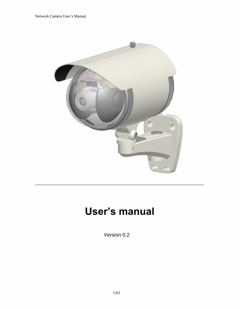
Bonjour program Safari browser supports Bonjour search program the will search for all family network devices on the same LAN
Network Camera Userrsquos Manual
1563
C2mylevel1com(Free DDNS service) 1 When you want to connect the network camera over Internet you can use the
service ―C2mylevel1com The ―ip-discoverycom is a free DDNS server for this camera Make sure that the router must start UPnP and DHCP server functions You can get the domain name which you wish very easily after registration In Network pagemdashDDNS settings of this camera you just input the host name you want and your e-mail address and click ―Register then you can have the hostname for this camera not longer than 20 seconds if the DDNS registration result is OK Then you can connect to this ip camera by httpXXXc2mylevel1com XXX the host name you type The HTTP port (get it automatically by c2mylevel1 server)
User password Default the password is last six number of the MAC To change ―root password at ―Security configuration can change the user password This ―User password is entered in the ip-discoverycom Password Note You must set the ports between your router and camera manually if the registration is failed
Network Camera Userrsquos Manual
1663
Initial Access to the Network Camera
(1) For the initial access to the Network Camera in Windows the web browser may prompt for permission to install a new plug-in for the Network Camera This plug-in has been registered for certificate and is used to display the video in the browser
Users may click on to proceed
1 Click ldquoInstallrdquo and ldquoRunrdquo ActiveX controls
Network Camera Userrsquos Manual
1763
Camera view On the top of image shows the connecting type of the Network Camera and the current datetime
View capabilities
1 Click this button to capture and save still images The captured images will be
displayed in pop-up window Right-click the image and choose Save Picture As to save it in JPEG format
2 The button selection lets you open a digital zoom and to control the window to
enlarge a specified area in the camera view
3 Click this button to switch to full screen mode Press the ―Esc key to switch back to normal mode
4 Click on this button freeze the video and playing when you click again
5 Click on this button stop video output
6 Use this functionyou can record video in your PC by browser directly The files
format will be in MP4 Note Due to the UAC (User Access Control) function in Windows Vista or Windows 7 the IE browser would need to be run under the ―Administrator privilege
7 Click on this button adjust the audio volume amp Latency
8 Click on this button switch Mute OnOff
Network Camera Userrsquos Manual
1863
9 Click on this button to adjust the Function ―2-way audio to be EnableDisable
Enable this function request insert an external speaker The server can play sound from the client and receive sound from the environment and send to client
10 Click on this button to adjust the Microphone volume
11 Click on this button switch Microphone Mute OnOff 12ldquoGo tordquo Once the Administrator has determined the preset positions the User can
aim the camera using this control
Network Camera Userrsquos Manual
1963
PanTilt amp connection control buttons
1 ldquoVideo Streamrdquo User can choose stream1 or stream2 amp picture 2 ldquoThe direction buttons arerdquo ―Left ―Right ―Up ―Down ―Cross Angles and ―Home Camera returns to center when click ―Home button
3 ldquoPan Anglerdquo User can choose the angles when the camera moves left and right each time
4 ldquoTilt Anglerdquo User can choose the angles when the camera moves up and down each time 5 ldquoFocusrdquo There are two different Focus modes Focus1 and Focus2 press two seconds on the Focus icon to switch the mode Focus1 is autofocus mode the camera will do focus after PanTilt moving Zoom inout any large video differencehellipand so on Focus2 mode the camera will do focus after Zoom inout
6ldquoSmart FocusrdquoSmart Focus function use
mouse and left key to pull a area and then the camera will focus to this area 7 ldquoIrisrdquo Adjust the iris size 8 ldquoPanrdquo The camera will move from right side to left side continuously when click the button 9 ldquoPatrolrdquo The button directs the camera to patrol among the preset positions in the patrol list which can be modified on the ldquoCamera control pagerdquo The cycle of patrol is from 1 to 50 10 ldquoVideo Trackingrdquo is able to track dynamic objects within screen video
11ldquo3D Auto locationrdquo Press the left key of the mouse and pull and choose a certain
area in the picture in diagonal direction can enlarge this area and put this area in the middle position of picture of controlling
Network Camera Userrsquos Manual
2063
Playback Playback function Support the image playback through SD CardNAS device capable
of further choice ―Trigger type―Stream―DateTime Use the playback function
through NAS device must set up the path of NAS device from ―Server page
1 Click this button to switch to full screen mode Press the ―Esc key to switch back to normal mode
2 Click on this button freeze the video and playing when you click again
3 Click on this button stop video output
4 Click the button to download the current video
Network Camera Userrsquos Manual
2163
Client Setting
1 ldquoProtocol settingrdquo Setting camera of protocol ldquoUDPrdquo Select use UDP protocol connect camera ldquoTCPrdquo Select use TCP protocol connect camera ldquoHTTPrdquo Select use HTTP protocol connect camera
2 ldquoRecording optionsrdquo Users can record live video as they are watching by
clicking start MP4 Recording on the main page Here you can specify the storage destination and file name
ldquoFolderrdquo Specify the storage destination for the recorded video files ldquoFile name prefixrdquo Enter the text that will be appended to the front of the video
file name ldquoAdd date and time suffix to file namerdquo Select this option to append the date
and time to the end of the file name
NOTEProtocol Options which allows choices on connection protocol between client and
server There are three protocols choices to optimize your usage ndash UDP TCP HTTP The UDP protocol allows for more real-time audio and video streams However some packets may be lost due to network burst traffic and images may be obscured The HTTP protocol allows for less packet loss and produces a more accurate video
Network Camera Userrsquos Manual
2263
display The downside with this protocol is that the real-time effect is worse than that with the UDP protocol The TCP guarantees the complete delivery of streaming data and thus provides better video quality However the real-time effect is not as good as that of the UDP protocol If no special need is required UDP protocol is recommended Generally speaking the
client choice will be in the order of UDP rarr HTTP After the Network Camera is connected successfully ―Protocol Option will indicate the selected protocol The selected protocol will be recorded in the users PC and will be used for the next connection If the network environment is changed or the user wants to let the web browser to detect again manually select the UDP and TCP protocol save and return HOME to re-connect
NOTEProtocol Options which allows choices on connection protocol between client and
server There are three protocols choices to optimize your usage ndash UDPTCPHTTP The UDP protocol allows for more real-time audio and video streams However some packets may be lost due to network burst traffic and images may be obscured The HTTP protocol allows for less packet loss and produces a more accurate video display The downside with this protocol is that the real-time effect is worse than that with the UDP protocol The TCP guarantees the complete delivery of streaming data and thus provides better video quality However the real-time effect is not as good as that of the UDP protocol If no special need is required UDP protocol is recommended Generally speaking the client choice will be in the order of UDP rarr HTTP After the Network Camera is connected successfully ―Protocol Option will indicate the selected protocol The selected protocol will be recorded in the users PC and will be used for the next connection If the network environment is changed or the user wants to let the web browser to detect again manually select the UDP and TCP protocol save and return HOME to re-connect
Network Camera Userrsquos Manual
2363
Definitions in Configuration
Please note that only the Administrator can access the system configuration Two types of user interfaces are available [Advanced Mode] for professional users and [Basic Mode] for entry-level users Those functions that are displayed only in Advanced Mode are marked with
Advanced Mode If you want to set up the advanced functions please click [Advanced
Mode] on the bottom of the configuration list to quickly switch over
System
Click to switch to Advanced mode
Network Camera Userrsquos Manual
2463
1 ldquoGeneral Settingrdquo (1) ldquoHost namerdquo The text displays the title on the top of the main page (2) ldquoLED indicatorrdquo If you do not want others to know that the network camera is operating you can select this option to turn off the LED indicators
2 ldquoTime Settingrdquo
(1) ldquoTime zonerdquo Choose a time zone from the down arrow
(2) ldquoDaylight savingrdquo For summertime It will be one hour ahead
(3) ldquoCurrent Timerdquo Network camera set the current time
(A) ldquoKeep current date and timerdquo Click on this to keep the current date and time of the Network Camera An internal real-time clock maintains the date and time even when the power of the system is turned off
(B) ldquoSync with computer timerdquo Synchronize the date and time in the Network Camera according to the local computer
(C) ldquoManualrdquo Adjust the date and time by the Administrator
(D) ldquoAdjust by NTP serverrdquo Synchronize the time according NTP server over the Internet whenever the Network Camera is switched on It fails if the assigned time-server cannot be found
(a) ldquoNTP serverrdquo Assign the IP address or domain name of the time-server Leaving the text box blank connects the Network Camera to the default time-servers
(b) ldquoUpdate intervalrdquo Select 0 ~ 23 hours update with the time on the NTP server
Network Camera Userrsquos Manual
2563
Security
Security setting The administrator account name is ―root which is permanent and can not be deleted If you want to add more accounts in the Manage User column please set a password for the ―root account first 1 ldquoChange root passwordrdquo Change the Administratorrsquos password by typing in the new password identically in both text boxes The typed entries will be displayed as asterisks for security purposes After pressing ldquofinishrdquo the web browser will ask the Administrator for the new password to access
2 ldquoManage privilegerdquo You can modify the manage privilege of operators or viewers Check or uncheck the item then click finish to enable the settings
3 ldquoManage userrdquo (1) ldquoAdd a new userrdquo Administrators can add up to 20 user accounts
(A) Input the new userrsquos name and password
Network Camera Userrsquos Manual
2663
(B) Select the privilege level for the new user account Click Finish to enable the setting
(2) ldquoDelete a userrdquo Select an existing user name Click Finish to enable the setting
(3) ldquoUpdate a existing userrdquo Select an existing user name Administrators can modify userrsquos password and privilege Click Finish to enable the setting
Access rights are sorted by user privilege (Administrator Operator and Viewer) Only administrators can access the Configuration page Operators cannot access the Configuration page but can use the URL Commands to get and set the value of parameters Viewers access only the main page for live viewing
Network Camera Userrsquos Manual
2763
Network
Any changes made on this page will restart the system in order to validate the changes Make sure every field is entered correctly before clicking on ldquofinishrdquo
Network Setting
Network Camera Userrsquos Manual
2863
ldquoLANrdquo amp ldquoPPPoErdquo The default type is LAN Select PPPoE if using ADSL
1 LAN
The default status is Get IP address automatically This could be tedious to perform software installation whenever the Network Camera starts Therefore once the network is set especially for the IP address should be entered correctly Select Use fixed IP address then the Network Camera will skip installation The Network Camera will automatically restart and operate normally after a power outage You can run IP installer to check the IP address assigned to the Network Camera if the IP address is forgotten or you can use the UPnP function provided by the Network Camera (MS Windows XP provides UPnP function at My Network Place)
(1) ldquoGet IP address automaticallyrdquo (2) ldquoUse fixed IP addressrdquo
- ldquoIP addressrdquo This is necessary for network identification - ldquoSubnet maskrdquo This is used to determine if the destination is in the same subnet The default value is ―2552552550 - ldquoDefault routerrdquo This is a gateway used to forward frames to destinations in a different subnet Invalid router setting will fail the transmission to destinations in different subnet - ldquoPrimary DNSrdquo The primary domain name server that translates hostnames into IP addresses - ldquoSecondary DNSrdquo Secondary domain name server backups the Primary DNS
2 PPPoE If using the PPPoE interface you should fill the following settings from ISP
(1) ldquoUser namerdquo The login name of PPPoE account (2) ldquoPasswordrdquo The password of PPPoE account (3) ldquoConfirm passwordrdquo Input password again for confirmation
Port parameters setting Advanced Mode - ldquoHttp Portrdquo This can be typed besides the default Port 80 Once the port is changed
the users must make sure the change for the connection is successful For instance when the Administrator changes the HTTP port of the Network Camera which IP address is 192168020 from 80 or 1025 to 65535 the users must type in the web browser ―http1921680208080 instead of ―http192168020
- ldquoHttps Portrdquo By default the HTTPS port is set to 443 It can also be assigned to another port number between 1025 and 65535
- ldquoRTSP Portrdquo RTSP port can be typed besides the default Port 554
- ldquoVideo RTP Portrdquo Video RTP port can be typed besides the default Port 6790
Network Camera Userrsquos Manual
2963
RTSP stream access names setting Advanced Mode
The RTSP streaming currently supports video only audio only and audiovideo To use the audiovideo stream type the URL as―rtsp613012543liveNsdp
DDNS
DDNS setting
ldquo3rd party DDNSrdquo This is enable 3rd
party DDNS ldquoProviderrdquo The provider list contains hosts that provide DDNS services Please connect to the service providerrsquos website to make sure the service charges
ldquoHost Namerdquo If the User wants to use DDNS service this field must be filled Please input the hostname that is registered in the DDNS server
ldquoUser namerdquo The Username or E-mail field is necessary for logging in the DDNS
Network Camera Userrsquos Manual
3063
server or notify the User of the new IP address
Note when this field is input as ―User name the following field must be input as ―Password
ldquoPasswordrdquo Please input the password or key to get the DDNS service
ldquoSaverdquo Click on this button to save modify settings for the DDNS service
Network Camera Userrsquos Manual
3163
Access list
General Settings ldquoFilter typerdquo Provided to Allow or Deny mode
ldquoAlways allow the IP address to access this devicerdquo You can check this item
and add the Administratorrsquos IP address in this field to make sure the Administrator can always connect to the device
Filter setting
ldquoAdd a rule to configure an AllowedDenied listrdquo Click ―Save to add a rule to
AllowedDenied list
There are three types of rules for user to set up ldquoSinglerdquo This rule allows the user to add an IP address to the AllowedDenied list For example
Network Camera Userrsquos Manual
3263
ldquoNetworkrdquo This rule allows the user to assign a network address and corresponding subnet mask to the AllowDeny List The IP address is written in the CIDR format For example
ldquoRangerdquo This rule allows the user to assign a range of IP addresses to the AllowDeny List This rule is only applied to IPv4 For example
Network Camera Userrsquos Manual
3363
Video
General Setting 1 ldquoColor moderdquo Select use color or monochrome video display
2 ldquoEnvironmentrdquo The orientation of video
(1) ldquoindoorrdquo This option is usually selected when the Network Camera is placed in indoor environments
(2) ldquooutdoorrdquo This option is usually selected when the Network Camera is placed in outdoor environments
3 ldquoFrequencerdquo Select 50 Hz or 60Hz power line frequency The fluorescent light will flash according to the power line frequency that depends on
Network Camera Userrsquos Manual
3463
local utility Change the frequency setting to eliminate uncomfortable flash image when the light source is only fluorescent light
4 ldquoVideo orientationrdquo The orientation of video
(1) ldquoFliprdquo Vertically rotate the video
(2) ldquoMirrorrdquo Horizontally rotates the video
5 ldquoLow lux moderdquo The video quality will be improved when the camera is in low lux environment
Video Setting Advanced Mode 1 Exposure setting Here it provides 3 mode Auto BLC and HSBLC Auto and HSBLC modes are 2 default settings for general purpose and backlight scene respectively
ldquoTarget Luminance and Offsetrdquo These two slide bar Target Luminance and Offset represent the expected target value of the luminance of the weighting result of AE windows in the image and its tolerance as offset For example target luminance is set to 100 and target offset is set to 20 that means the average luminance of the AE window should be in the range from 80 to 120 (100plusmn(10 When the actual luminance does not meet this range the AE function will adjust shutter and gain to meet it as possible In some extreme cases it cannot reach the target because the environment is too bright or dark When the environment is not consistent eg with big moving objects and the offset is too narrow the AE will act more frequently that will cause the background of view inconsistent The offset value is recommended to set 15~25 of target luminance
ldquoShutter Speedrdquo There are 2 fields minimal and maximal time for the range of Shutter Speed The precision of the parameter is 150000 sec but it is NOT actual precision of the shutter speed of the sensor The actual precision of the shutter speed depends on each sensorrsquos specification Here it will be rounded to approach sensorrsquos effective exposure time To avoid flickering or banding phenomenon under fluorescent light the actual shutter speed will be locked at 1120 160 130 if Power Line Frequency is 60Hz or 1100 150 125 if Power Line Frequency is 50Hz The setting of Power Line Frequency is on the sub-tab Video and Audio The exposure may not be stable if the maximum value and the minimum one are set to the same value without adjustable interval Besides the frame rate will drop down if the actual shutter speed is too slow to meet expected frame rate
Network Camera Userrsquos Manual
3563
2 White Balance
In the bottom of White Balance there are 5 modes for practice ATW AWC Indoor Outdoor and Manual modes Set the Red Gain and Blue Gain are active
3 Image Adjustment
Brightness The brightness can make the image brighter or darker The neutral value is 0
Saturation The saturation can change white content in the image The neutral value is 128
Contrast The contrast can adjust difference between dark and light The neutral value is 0
4 Noise Reduction
Check the box Enable to enable 3D de-noise There are 5 modes 2D 2D 1-ref 2D 2-ref 3D and Blend The modes 2D 2D 1-ref 2D 2-ref have a Normal Strength slide bar for adjustment The mode 3D has a Motion Adaptive option Current Weight and Reference Strength slide bars The mode Blend has all adjustable parameters The difference etween the modes 2D 1-ref and 2D 2-ref is one or two frames as temporal reference frames When the scene with motion objects the mode 3D and Blend may perform better without blur or ghost When the Current Weight is higher and the
Network Camera Userrsquos Manual
3663
Reference Strength is lower the motion blur of image is alleviated
5 Edge Enhancement
Check the box Enable to enable this function There are 4 slide bars for adjustment The Edge Sensitivity represents how textures are detected as edges The higher Noise Sensitivity value makes noises to be filtered out and avoid to amplify noises The Edge Strength is a capability to enhance edges with a limitation by Edge Strength Clip to avoid over artificial edges
6 Lens Correction Geometric and Photometric lens corrections are supported
Geometric lens correction is used to correct lens distortion The lens distortion includes barrel distortion and pincushion distortion if a lens is wide angle view or telescope respectively There are 2 barrel and 2 pincushion options can be used for either wide angle view lens or telescope lens Choose one of them and a reference image displayed below then save it and apply
Photometric lens correction can improve dark corners caused by lens even sensor limitation Options Photometric 1 and Photometric 2 in pull-down menu are predefined which can be applied directly User Defined 1 and User Defined 2 which can be re-defined by user are for specific cases according to lenses When User Defined 1 or User Defined 2 are selected an LSCRatio can be set The value of LSC-ratio is between 0 and 100 () 0
Network Camera Userrsquos Manual
3763
means no correction and 100 () means the lum of corners are equal to the lum of the center
7Wide Dynamic Range Enable Wide Dynamic Range auto in different level to improve the exposure when both bright and dark areas simultaneously in the field of view of the camera The default is off
Infrared Led Setting 1 ldquoInfrared LED Controlrdquo IR led for Day and Night (Option) User can turn onoff the built-in IR led This function is very useful under low illumination environment
(1) ldquoAutordquo Select IR sensitivity from 0 to 4
(2) ldquoManualrdquo Turn onoff the IR led manually
Video output setting ldquoTurn on video outputrdquo Can switch between NTSC and PAL
Network Camera Userrsquos Manual
3863
ROI(Region of Interest)
Note Stream Select the streaming source This option is only applied to H264 The function is that there are multiple regions (also called window) (up to 7 regions) on the encoding frame plane being selected for setting the quant value and frame-updating interval of the window
Network Camera Userrsquos Manual
3963
Defog
Defog setting Defog function allows visibility improvement through better image quality for foggy and smoggy circumstances
Network Camera Userrsquos Manual
4063
Video record
NOTE Before setting up this page please set up the Network Storage on the Servers setting(add Server) page first
Record setting Click Add to open the recording setting window
Record name Enter a server name Schedule mode
(1) ldquoAlwaysrdquo every day application
(2) ldquoWeek dayrdquo week day application
(3) ldquoSelected dayrdquo selected day application
Network Camera Userrsquos Manual
4163
Schedule information (1) Enter the ldquoStart timerdquo and ldquoStop timerdquo for day mode Note that the time format is [hhmm] and is expressed in 24-hour clock time
(2)ldquoSunrdquoldquoMonrdquoldquoTuerdquoldquoWedrdquoldquoThurdquoldquoFrirdquoldquoSatrdquo Select the days of the week to perform the application (3) ―Start day and ―Start time as the start timing the time ―End day and ―End time as the end timing the time
Record parameters (1)Source Select a stream for the recording source
(2)The recording interval Select the recording time interval
(3)Record prefix file name You can setting the file name and enable or disable to add the date and time on file name
(4)Destination You can select the SD card or network attached storage (NAS) for recording video files
Note Video record with the Application must be set to the same shared directory
path If you would like do detail recording settings or multi-channel recording please install bundled 64CH recording software in CD
Network Camera Userrsquos Manual
4263
Stream
Audio codec setting
(1) ldquoMuterdquo Select this option to disable audio transmission from the Network Camera to all clients
(2) ldquoAudio codec typerdquo There are two choices of audio codec types
available rdquoAMRrdquo ldquoAACrdquo and rdquoG711rdquo
(3) ldquoBit raterdquo -- ldquoAMRrdquo The bit rates are selectable at the following rates
47505150590067007400795010200 and 12200
-- ldquoAACrdquo The bit rates are selectable at the following rates 8Kbps16Kbps 24Kbps and 32Kbps
-- ldquoG711rdquo PCMU and PCMA
Network Camera Userrsquos Manual
4363
Video codec setting (1) ldquoSelect Streamrdquo The Network Camera supports ldquoStream 1rdquoand ldquoStream 2rdquo
(2) ldquoCodec typerdquo The Network Camera supports three kind of video compression mode ldquoH264rdquo or ldquoMPEG4 or ldquoMJPEGrdquo User can choose one of these compression modes based on requirement or application
(3) ldquoVideo sizerdquo Click the down arrow to choose the quality of image
(4) ldquoFrame raterdquo This limits the maximal refresh frame rate per second Set the frame rate higher for a smoother video quality
(5) ldquoIntra frame periodrdquo Determine how often to plant an ―I frame The shorter the duration the more likely you will get a better video quality but at the cost of higher network bandwidth consumption
(6) ldquoVideo Quality typerdquo Setting optimizes bandwidth utilization and video quality
-- ldquoConstant bit raterdquo User can adjust the video quality from 20 Kbps to 12 Mbps
-- ldquoFixed qualityrdquo user can select from highest quality to get best quality according The ―Quality are selectable at the following rates From 1 to 20
Snapshot and time display setting Adjust the photo size specifications and choose whether to mark time on the video and photo
Network Camera Userrsquos Manual
4463
Camera control
Network Camera Userrsquos Manual
4563
Camera control The pan and tilt functions can be controlled with these buttons The ldquoLeftrdquo button
controls the camera to the left the ldquoRightrdquo ldquoUprdquo and ldquoDownrdquo buttons control the camera accordingly
(1) ldquoULrdquo ldquoURrdquo ldquoLLrdquo and ldquoLRrdquo buttons control the camera to an oblique angle
And ldquoHomerdquo button controls the camera to the center
(2) ldquoZoom times displayrdquo The zoom indicator will be displayed on the screen when you zoom inout as shown in the illustration above (3)ldquoPan anglerdquo This sets the range of the horizontal movement of the camera The
larger value is setting the larger movement of ldquoLeftrdquo or ldquoRightrdquo is performing by the camera
(4) ldquoTilt anglerdquo This sets the range of the vertical movement of the camera The
larger value is setting the larger movement of ldquoUprdquo or ldquoDownrdquo is performing by the camera
(5) ldquoZoom steprdquo Set steps of zoom move (6) ldquoFocus steprdquo Set steps of focus move
(7) ldquoPatrol cyclerdquo It is the cycle of patrol function
(8) ldquoPatrol speedrdquo This defines the speed of auto patrol The larger value is setting the faster speed will run by the camera (9) ldquoAuto pan speedrdquo This defines the speed of auto panning The larger value is setting the faster speed will run by the camera
Preset and patrol setting ldquoPreset settingrdquo
(1)ldquoPreset point namerdquo Enter a name for the preset position Click Add to enable the settings The preset positions will be displayed under the Preset Location list on the left-hand side The camera allows for 20 preset locations (2)To remove a preset position select its checkbox from the drop-down list and click Remove
ldquoPatrol settingrdquo (1) Click to select one or multiple preset locations by checking their checkboxes (2) Click the gtgt (Move) button to move them to the Patrol list (3) Click to select a position and manually enter a Dwelling time for the camera to stay during an auto patrol The default value is 10 seconds (4) If you want to delete a selected location select it from the list and click Remove (5) Select a location and click Up or Down to rearrange the patrolling order (6) Click Save to enable the settings
Home position and auto pan range setting (1) ldquoHome positionrdquo
--ldquoSet default value as home positionrdquo Restore home position to original defaultrsquos home by clicking on this button
--ldquoSet the current position as home positionrdquo Click on the button will set the current aimed position as home of the Network Camera Each time the Network Camera reboots or finishes calibration it will automatically aim to the defined home position
(2) ldquoAuto pan rangerdquo
Network Camera Userrsquos Manual
4663
--ldquoSet default value as auto pan rangerdquo Restore auto pan range to original defaultrsquos auto pan range by clicking on this button
--ldquoSet the auto pan range manuallyrdquo Click on the button will set the auto pan range of the Network Camera
Network Camera Userrsquos Manual
4763
Application
NOTE Before setting up this page please set up the Network Storage on the Servers setting(add Server) page first
Network Camera Userrsquos Manual
4863
Application setting (1)Click Add to open the Application setting window
(2)Schedule name Enter a server name (3)Schedule mode
(a) ldquoAlwaysrdquo Every day application
(b) ldquoWeek dayrdquo Week day application
(c) ldquoSelected daterdquo Selected day application Schedule information
-- Enter the ldquoStart timerdquo and ldquoStop timerdquo for day mode Note that the time format is [hhmmss] and is expressed in 24-hour clock time By default the start and end time of day mode are set to 010000 and 235959
-- ldquoSunrdquoldquoMonrdquoldquoTuerdquoldquoWedrdquoldquoThurdquoldquoFrirdquoldquoSatrdquo Select the days of the week to perform the application -- ―Start day and ―Start time as the start timing the time ―End day and ―End time as the end timing the time
(4)Trigger mode
(a) ldquoVideo motion detectionrdquo EnableDisable video motion application (b) ldquoPeriodicallyrdquo This option allows the Network Camera to trigger
periodically for every other defined minute
(c) ldquoDigital inputrdquo This option allows the Network Camera to use an external digital input device or sensor as a trigger source Depending on your application there are many choices of digital input devices on the market which helps to detect changes in temperature vibration sound and light etc
(d) ldquoVideo Trackingrdquo is able to track dynamic objects within screen video
-- ldquoTracking levelrdquo 1 to 5 level the lowest the number the more sensitive
Parameters
--ldquoMotion parametersrdquo Higher sensitivity and small threshold will allow easier motion detection
--ldquoPeriod parametersrdquo This option allows the Network Camera to trigger periodically for every other defined seconds Up to 255 seconds are allowed
--ldquoDigital input parametersrdquo
Select the digital input type and set trigger time
(5)Action Selectable event Media and Server devices
Media setting (1)Click Add to open the Media setting window
(2)ldquoMedia namerdquo Enter a server name (3)There are four choices of media types available ldquoSystem logrdquo ldquoSnapshotrdquo ―Record(Motion Detection only)rdquo and ldquoMessagerdquo
Snapshot amp Record file setting
--You can setting the file name and enable or disable to add the date and time on file name
Network Camera Userrsquos Manual
4963
Motion windows setting The Object size and Sensitivity can be adjusted in Motion Setup window
Sensitivity determines if a pixel will be taken as ―moving according to its Y value difference between previous and current frame and Object size stands for the percentage of moving pixels over all pixels within the motion window If the value of object detected is higher than the value set IPCAM will detect ―Motion Please note that the lower the object size the higher the sensitivity and the easier this motion detection window would be triggered
Network Camera Userrsquos Manual
5063
Servers
Server setting Click the Add Server button on Event Settings page to open the Server Setting page On this page you can specify where the notification messages are sent when a trigger is activated A total of 5 server settings can be configured Server name Enter a name for the server setting
Server type There are four choices of server types available Email FTP HTTP and Network storage Select the item to display the detailed configuration options You can configure
Network Camera Userrsquos Manual
5163
either one or all of them
(1)ldquoEmailrdquo Select to send the media files via email when a trigger is activated -- ldquoEmail security moderdquo If your SMTP server requires a secure connection (SSL or TLS) check This server requires a secure connection (SSL or TLS)
--ldquoServer addressrdquo Enter the domain name or IP address of the email server
--ldquoServer portrdquo The default mail server port is set to 25 You can also manually set another port
--ldquoUser namerdquo Enter the user name of the email account if necessary
--ldquoPasswordrdquo Enter the password of the email account if necessary --ldquoSender email addressrdquo Enter the email address of the sender --ldquoRecipient email addressrdquo Enter the email address of the recipient
(2)rdquoFTPrdquo -- ldquoFTP Server addressrdquo Enter the domain name or IP address of the FTP server
-- ldquoFTP Server portrdquo By default the FTP server port is set to 21
-- ldquoUser accountrdquo Enter the login name of the FTP account
-- ldquoUser passwordrdquo Enter the password of the FTP account
-- ldquoFTP folder namerdquo Enter the folder where the media file will be placed If the folder name does not exist the Network Camera will create one on the FTP
(3)rdquoHTTP rdquo -- ldquoURLrdquo Enter the URL of the HTTP server
-- ldquoHttp server port rdquo The default http server port is set to 80
-- ldquoUser accountrdquo Enter the user name if necessary -- ldquoUser passwordrdquo Enter the password if necessary -- ldquoHTTP folder namerdquo Enter the folder where the media file will be placed
(4)rdquoNASrdquo --ldquoEnable cyclicrdquo The cyclic recording function is enabled during the transaction stage when a storage space is full and the incoming streaming data is about to overwrite the previously saved videos
--ldquoNAS server addressrdquo Enter IP address of the NAS server --ldquoNAS shared directoryrdquo Enter the NAS shared directory path --ldquoWorkgrouprdquo Enter the NAS workgroup parameter --ldquoUser accountrdquo Enter the login name of the NAS account --ldquoUser passwordrdquo Enter the password of the NAS account
Network Camera Userrsquos Manual
5263
Storage
NAS server setting Advanced Mode (1) ―NAS Host name Choose and input the NAS Host name of this camera
(2) ―Workgroup Input the name of Workgroup You can see the NAS Host name you input in the same workgroup with your PC Then you can connect to this device and download the files easily from SD card which is inserted to this camera SD Card Status Here show the storage device information This column shows the status and reserved space of your SD card Please remember to format the SD card when using for the first time
Network Camera Userrsquos Manual
5363
Syslog
You can configure the Network Camera to send the system log file to a remote server as a log backup Before utilizing this feature it is suggested that the user install a log-recording tool to receive system log messages from the Network Camera An example is Kiwi Syslog Daemon Visit httpwwwkiwisyslogcomkiwi-syslog-daemon-overview
Remote log setting Advanced Mode Follow the steps below to set up the remote log 1 In the IP address text box enter the IP address of the remote server 2 In the port text box enter the port number of the remote server 3 When completed select Enable remote log and click Save to enable the setting
Network Camera Userrsquos Manual
5463
Status and Parameters
User can find a lot of information about the system such as ldquoUpnp port forwardingrdquo
ldquoTraversing NATrdquo ldquoPublic IPrdquo and so on User also can get the number of current viewer of the Network Camera here
Network Camera Userrsquos Manual
5563
Maintenance
1 ldquoReboot systemrdquo The ldquoRebootrdquo button will reboot the Network Camera Itrsquos useful while the Network Camera got problem 2 ldquoRestore systemrdquo Click on ―Restore button on the configuration page to restore the factory default settings Restore all settings to factory default except settings in ―Network type and ―Root Password The system will restart and require the installer program to set up the network again 3 ldquoCalibrate Camerardquo -- ldquoHome positionrdquo Recalibrate the home position to the default center to recover the tolerance caused by some external forces Please note that there is no confirming message box after clicking on the ―Calibrate button the Network Camera will calibrate immediately -- ldquoFocus positionrdquoRecalibrate the autofocus position to the default range to recover the tolerance caused by some external forces Please note that there is no confirming message box after clicking on the ―Calibrate button the Network Camera will calibrate immediately
Firmware version
Network Camera Userrsquos Manual
5663
4 ldquoExportImport filerdquo Advanced Mode -- Export setting backup file Click to export all parameters for the device and user-defined scripts
-- Upload setting backup file Click Browsehellip to upload a setting backup file Please note that the model and firmware version of the device should be the same as the setting backup file If you have set up a fixed IP or other special settings for your device it is not suggested to upload a settings backup file
5 ldquoUpgrade firmwarerdquo (1)The file is in pck file format (2)Click Browsehellip and specify the firmware file (3)Click Upgrade The Network Camera starts to upgrade and will reboot automatically when the upgrade completes When upgrade firmware please wait for 210~360 seconds and then you can connect to Network Camera again The system will restart and require the installer program to set up the network again
Warning The upgrade firmware procedure cannot be interrupted If the power
andor network connection are broken during the procedure it might possibly cause serious damage to the Network Camera
Network Camera Userrsquos Manual
5763
Appendix
A Troubleshooting amp Frequently Asked Questions Q1 Status led does not light up
A1 First make sure that「ConfigurationgtSystemgtTurn off the LED indicator」is disabled
If it is check the item and the led should light up Second if red led does not light up please check that the power adapter in the package is plugged correctly And last if green led does not light up please check that category 5 UTP cable is plugged correctly If the problem is still not solved please contact your dealer for further help
Q2 What kind of Ethernet cable is used by network camera
A2 The network Camera uses Category 5 UTP cable allowing 10 andor 100 Base-T networking
Q3 The Network Camera will be installed and work if a firewall exists on
the network
A3 There are two way to set up the IP camera at Internet (1) By UPnP Port Forwarding 1 Select an IP router It must support UPnP port forwarding and enable this function
first
2 Connect camera RJ45 cable to IP router and the router is also connected to Internet
3 Plug power cord to camera
4 Go to camera Network page Enable UPnP port forwarding
Network Camera Userrsquos Manual
5863
5 Check camera status we can see the ports had been successfully opened
6Type IP address8081at browser Then you can see camera through Internet
(2) By Setting Port Forwarding Manually 1 Select a router Set the port forwarding as following
PS Port 80 is HTTP Port port 53 is stream port port 554 is RTSP port and port
Network Camera Userrsquos Manual
5963
443 is HTTPS port 2Go to camera Network page Disable UPnP port forwarding function
3 Type IP address at browser Then you can see camera through Internet Note The firewall software at PC may block the transfer of network camera Please remove or stop the kind software
Q4 How can I find the network camera in the local area network
A4 By using the IP Finder2 program or using UPnP to find it
Q5 IP Finder2 program cannot find Network Camera in the local area
network at first time
A5 Make sure the subnet of network camera is same as your PC If the local area network supports DHCP the camera is ―Get IP address automatically in the ―Network page default If the local area network does not support DHCP change your PC IP address to ―1921680xxx
Q6 How can I restore the network camera to default value
A6 Use a gem clip to press on the inside button Network camera begins to restore default value You can also press the button ldquoFactoryrdquo in ―Maintenance page to restore the default value
Network Camera Userrsquos Manual
6063
Q7 Infrared led does not light up
A7 Check「ConfigurationgtAudio and VideogtInfrared LED Control」 is ldquoAutordquo or
ldquoManual》Turn onrdquo
Q8 The network camera cannot focus accurately
A8 (1) The lens is dirty or dust is attached Clean the lens with lens cleaner And then adjust the camera focus manually (2) The image may be out of focus If the object is too near move the object away from Network Camera
Q9 The cover of network camera is warm Is it normal
A9 Network camera is a precision device The internal material has the operational temperature and it is normal when user touch the cover feels warm It is recommended to put the network camera at aired place and not put at any other device
Q10 The process of upgrade firmware abort
A10 Contact your dealer for further help
Q11 Cannot access the login page and other web pages of Network Camera
from Internet Explorer
A11 bull May be due to the network cable Try correcting your network cable and configuration Test the network interface by connecting a local computer to the Network Camera via a crossover cable bull Make sure the Internet connection and setting is ok bull Make sure enter the IP address of Internet Explorer is correct If Network Camera has
Network Camera Userrsquos Manual
6163
a dynamic address it may have changed since you last checked it bull Network congestion may prevent the web page appearing quickly Wait for a while The IP address and Subnet Mask of the PC and Network Camera must be in the same class of the private IP address on the LAN bull Make sure the http port used by the Network Camera default=80 is forward to the Network Camerarsquos private IP address bull The port number assigned in your Network Camera might not be available via Internet Check your ISP for available port bull The proxy server may prevent you from connecting directly to Network Camera set up not to use the proxy server bull Confirm that Default Gateway address is correct bull The router needs Port Forwarding feature Refer to your routers manual for details bull Packet Filtering of the router may prohibit access from an external network Refer to your routers manual for details bull Access Network Camera from the Internet with the global IP address of the router and port number of Network Camera bull Some routers reject the global IP address to access Network Camera on the same LAN Access with the private IP address and correct port number of Network Camera bull When you use DDNS you need to set Default Gateway and DNS server address bull If itrsquos not working after above procedure reset Network Camera to default setting and installed it again bull Maybe the IP Address of the Network Camera is already being used by another device or computer bull If the problem is not solved the Network Camera might be faulty Contact your dealer for further help
Network Camera Userrsquos Manual
6263
B Technical specifications
- System RAM 4G bit DDRⅢ
ROM 16MB Flash ROM
- Camera specification Type 128 Sony CMOS sensor IMX236 Resolution 1920x1080
- Infrared Led High power IR Leds 30~40 M visible AutoManual mode
- Lens 10X optical zoom lens auto iris auto focus f = 49~ 49mm F18~30 Fov(D) 666deg ~ 72deg
- Protocol TCPIP HTTPUDP SMTP FTP DDNS UPnP Telnet NTP PPPoE RTSP RTPRTCPDHCP and DNS
- Video Resolution Up to 30 frames at 19201080 1280x1024 1280x800 640x480 320x240 and 176x144
- Physical 10 baseT or 100 baseT Fast Ethernet auto negotiation
- Audio G711AMRAAC Support 2 way audio
- Algorithm supported H264MPEG4MJPEG dual codec for streaming video
JPEG for still image
- IO Interface RJ-45 DI Audio in Audio out Video out DC Power SD(inside camera)
- PanTilt angle Support multi - direction movement Pan 150deg(-75deg~75deg) Tilt 95deg(-75deg~20deg)
- Power Input 100-240VAC 5060Hz 07A Output 12VDC 15A Consumption Max 10W Support 8023af compliant Power over Ethernet
- EMI amp Safety CE FCC
- Dimension Length 210mm Diameter 115mm
- Operating Environment Temperature -20 - 50
Humidity 85 RH
- Weight NET 800g With bracket 1000g
Network Camera Userrsquos Manual
6363
Notification of Compliance Appendix C
Europe - EU Declaration of Conformity
For complete DoC please visit httpgloballevel1comdownloadsphpaction=init
GPL License Agreement GPL may be included in this product to view the GPL license agreement goes to httpdownloadlevel1comlevel1gplGPLpdf For GNU General Public License (GPL) related information please visit httpgloballevel1comdownloadsphpaction=init

Network Camera Userrsquos Manual
263
Table of Contents
Overview 3 Package Contents 4 Connections 5
Hardware description 5 Hardware Installation 6
Install the IP Finder program 8 Bonjour program 14 C2mylevel1com(Free DDNS service) 15
Initial Access to the Network Camera 16 Playback 20 Client Setting 21
Definitions in Configuration 23 System 23 Security 25 Network 27 DDNS 29 Access list 31 Video 33 ROI(Region of Interest) 38 Defog 39 Video record 40 Stream 42 Camera control 44 Application 47 Servers 50 Storage 52 Syslog 53 Status and Parameters 54 Maintenance 55 Appendix 57
A Troubleshooting amp Frequently Asked Questions 57 B Technical specifications 62
Network Camera Userrsquos Manual
363
H264 PanTilt Night Vision IP Camera
Overview Law in your country may prohibit the use of surveillance devices The Network Camera is not only a high-performance web-ready camera but also can be part of a flexible surveillance system It is the userrsquos responsibility to ensure that the operation of such devices is legal before installing this unit for its intended use It is important to first verify that all contents received are complete according to the list in the Package Contents chapter Take notice of the warnings in ―Quick installation guide before the Network Camera is installed then carefully read and follow the instructions in the ―Installation chapter to avoid damages due to faulty assembly and installation This also ensures the product is used properly as intended The Network Camera is accessible via the LAN or Internet connection Connect your Network Camera directly to a computer network or DSL modem and with a standard Web browser you get instant on demand video streams Within minutes you can set up the Network Camera to capture a video sequence to a PC Live video image can be uploaded to a website for the world to see or made available only to select users on the network
The Network Camera is a network device and its use should be straightforward for those who have basic network knowledge The Network Camera is designed for various applications including video sharing general securitysurveillance etc The ―How to Use chapter suggests ways to best utilize the Network Camera and ensure proper operations
Minimum System Requirement
H264 PanTilt Night vision IP Camera Network Environment
LAN 10100M1000M Ethernet
Monitoring System Recommended for Internet Explorer
System Hardware Basic requirements middot CPU Intelreg Celeronreg Dual-Core 270GHz or above middot Memory Size 2 GB or above Recommended middot VGA card resolution 1024 x 768 or above
System Requirement for Viewer amp Recorder Application
Support OS XP Windows 7 Windows 8
System Hardware 1-4 cameras surveillance application middot CPU Intelreg Celeronreg Dual-Core 270GHz or above middot Memory Size 2 GB or above middot VGA card resolution 1024 x 768 or above
Network Camera Userrsquos Manual
463
Package Contents
If any of the above items are missing please contact your dealer immediately
Note Using a power supply with a different voltage than the one included with the Network Camera will cause damage and void the warranty for this product
Network Camera (Wired or PoE)
Software CD
Power adapter
Quick installation guide
WrenchScrewsWall Mount Bracket
RJ45 FemaleGeneral DI Block Moisture Absorber
Network Camera Userrsquos Manual
563
Connections
Hardware description
Plan view panel
Inner View
Network Camera Userrsquos Manual
663
Hardware Installation 1 Attach the Network Camera with the included stand
2 Place the Camera fix it onto ceiling or wall Use screws to fix the Network Camera onto the ceiling or wall
3 Power over Ethernet (PoE) Using a PoE-enabled switch The Network Camera is PoE-compliant allowing transmission of power and data via a single Ethernet cable Follow the below illustration to connect the Network Camera to a PoE-enabled switch via Ethernet cable
Network Camera Userrsquos Manual
763
Using a non-PoE switch Use a PoE power injector (optional) to connect between the Network Camera and a non-PoE switch
4General IO Terminal Block This Network Camera provides a general IO terminal block which is used to connect external input devices The pin definitions are described below
Network Camera Userrsquos Manual
863
Install the IP Finder program When you installed your Network camera on your LAN environment you may install ―IP Finder to discover Network camerarsquos IP address The Administrator must place the product software CD into the CD-ROM drive of the PC running in Microsoft Windows An auto-run program will pop up (If the program is not on auto-run go to the root directory of the software CD and click on ―autorunexe)
Click on ―Software Utility item after the window contents changed click on ―Install Cam Finder to run ―Cam Finder program
Network Camera Userrsquos Manual
963
ldquoCam Finderrdquo is used to search the IP address of Network Cameras or Video servers on a LAN After searching Video Servers or Network Cameras will be located by the Cam Finder
Network Camera Userrsquos Manual
1063
Search Camera
Click search Camera button The program will search for all family network devices on the same LAN After searching the main installer window will pop up Click on the MAC and model name which matches the product label on your device to connect to the Network Camera via Internet Explorer
Network Camera Userrsquos Manual
1163
Setup Camera Auto Install Wizard will be started and that it can auto guide through the installation process Press the ldquoNextrdquo button execute next process For more information please refer to the Network section on page 33
Network Camera Userrsquos Manual
1263
Network Camera Userrsquos Manual
1363
Network Camera Userrsquos Manual
1463
Bonjour program Safari browser supports Bonjour search program the will search for all family network devices on the same LAN
Network Camera Userrsquos Manual
1563
C2mylevel1com(Free DDNS service) 1 When you want to connect the network camera over Internet you can use the
service ―C2mylevel1com The ―ip-discoverycom is a free DDNS server for this camera Make sure that the router must start UPnP and DHCP server functions You can get the domain name which you wish very easily after registration In Network pagemdashDDNS settings of this camera you just input the host name you want and your e-mail address and click ―Register then you can have the hostname for this camera not longer than 20 seconds if the DDNS registration result is OK Then you can connect to this ip camera by httpXXXc2mylevel1com XXX the host name you type The HTTP port (get it automatically by c2mylevel1 server)
User password Default the password is last six number of the MAC To change ―root password at ―Security configuration can change the user password This ―User password is entered in the ip-discoverycom Password Note You must set the ports between your router and camera manually if the registration is failed
Network Camera Userrsquos Manual
1663
Initial Access to the Network Camera
(1) For the initial access to the Network Camera in Windows the web browser may prompt for permission to install a new plug-in for the Network Camera This plug-in has been registered for certificate and is used to display the video in the browser
Users may click on to proceed
1 Click ldquoInstallrdquo and ldquoRunrdquo ActiveX controls
Network Camera Userrsquos Manual
1763
Camera view On the top of image shows the connecting type of the Network Camera and the current datetime
View capabilities
1 Click this button to capture and save still images The captured images will be
displayed in pop-up window Right-click the image and choose Save Picture As to save it in JPEG format
2 The button selection lets you open a digital zoom and to control the window to
enlarge a specified area in the camera view
3 Click this button to switch to full screen mode Press the ―Esc key to switch back to normal mode
4 Click on this button freeze the video and playing when you click again
5 Click on this button stop video output
6 Use this functionyou can record video in your PC by browser directly The files
format will be in MP4 Note Due to the UAC (User Access Control) function in Windows Vista or Windows 7 the IE browser would need to be run under the ―Administrator privilege
7 Click on this button adjust the audio volume amp Latency
8 Click on this button switch Mute OnOff
Network Camera Userrsquos Manual
1863
9 Click on this button to adjust the Function ―2-way audio to be EnableDisable
Enable this function request insert an external speaker The server can play sound from the client and receive sound from the environment and send to client
10 Click on this button to adjust the Microphone volume
11 Click on this button switch Microphone Mute OnOff 12ldquoGo tordquo Once the Administrator has determined the preset positions the User can
aim the camera using this control
Network Camera Userrsquos Manual
1963
PanTilt amp connection control buttons
1 ldquoVideo Streamrdquo User can choose stream1 or stream2 amp picture 2 ldquoThe direction buttons arerdquo ―Left ―Right ―Up ―Down ―Cross Angles and ―Home Camera returns to center when click ―Home button
3 ldquoPan Anglerdquo User can choose the angles when the camera moves left and right each time
4 ldquoTilt Anglerdquo User can choose the angles when the camera moves up and down each time 5 ldquoFocusrdquo There are two different Focus modes Focus1 and Focus2 press two seconds on the Focus icon to switch the mode Focus1 is autofocus mode the camera will do focus after PanTilt moving Zoom inout any large video differencehellipand so on Focus2 mode the camera will do focus after Zoom inout
6ldquoSmart FocusrdquoSmart Focus function use
mouse and left key to pull a area and then the camera will focus to this area 7 ldquoIrisrdquo Adjust the iris size 8 ldquoPanrdquo The camera will move from right side to left side continuously when click the button 9 ldquoPatrolrdquo The button directs the camera to patrol among the preset positions in the patrol list which can be modified on the ldquoCamera control pagerdquo The cycle of patrol is from 1 to 50 10 ldquoVideo Trackingrdquo is able to track dynamic objects within screen video
11ldquo3D Auto locationrdquo Press the left key of the mouse and pull and choose a certain
area in the picture in diagonal direction can enlarge this area and put this area in the middle position of picture of controlling
Network Camera Userrsquos Manual
2063
Playback Playback function Support the image playback through SD CardNAS device capable
of further choice ―Trigger type―Stream―DateTime Use the playback function
through NAS device must set up the path of NAS device from ―Server page
1 Click this button to switch to full screen mode Press the ―Esc key to switch back to normal mode
2 Click on this button freeze the video and playing when you click again
3 Click on this button stop video output
4 Click the button to download the current video
Network Camera Userrsquos Manual
2163
Client Setting
1 ldquoProtocol settingrdquo Setting camera of protocol ldquoUDPrdquo Select use UDP protocol connect camera ldquoTCPrdquo Select use TCP protocol connect camera ldquoHTTPrdquo Select use HTTP protocol connect camera
2 ldquoRecording optionsrdquo Users can record live video as they are watching by
clicking start MP4 Recording on the main page Here you can specify the storage destination and file name
ldquoFolderrdquo Specify the storage destination for the recorded video files ldquoFile name prefixrdquo Enter the text that will be appended to the front of the video
file name ldquoAdd date and time suffix to file namerdquo Select this option to append the date
and time to the end of the file name
NOTEProtocol Options which allows choices on connection protocol between client and
server There are three protocols choices to optimize your usage ndash UDP TCP HTTP The UDP protocol allows for more real-time audio and video streams However some packets may be lost due to network burst traffic and images may be obscured The HTTP protocol allows for less packet loss and produces a more accurate video
Network Camera Userrsquos Manual
2263
display The downside with this protocol is that the real-time effect is worse than that with the UDP protocol The TCP guarantees the complete delivery of streaming data and thus provides better video quality However the real-time effect is not as good as that of the UDP protocol If no special need is required UDP protocol is recommended Generally speaking the
client choice will be in the order of UDP rarr HTTP After the Network Camera is connected successfully ―Protocol Option will indicate the selected protocol The selected protocol will be recorded in the users PC and will be used for the next connection If the network environment is changed or the user wants to let the web browser to detect again manually select the UDP and TCP protocol save and return HOME to re-connect
NOTEProtocol Options which allows choices on connection protocol between client and
server There are three protocols choices to optimize your usage ndash UDPTCPHTTP The UDP protocol allows for more real-time audio and video streams However some packets may be lost due to network burst traffic and images may be obscured The HTTP protocol allows for less packet loss and produces a more accurate video display The downside with this protocol is that the real-time effect is worse than that with the UDP protocol The TCP guarantees the complete delivery of streaming data and thus provides better video quality However the real-time effect is not as good as that of the UDP protocol If no special need is required UDP protocol is recommended Generally speaking the client choice will be in the order of UDP rarr HTTP After the Network Camera is connected successfully ―Protocol Option will indicate the selected protocol The selected protocol will be recorded in the users PC and will be used for the next connection If the network environment is changed or the user wants to let the web browser to detect again manually select the UDP and TCP protocol save and return HOME to re-connect
Network Camera Userrsquos Manual
2363
Definitions in Configuration
Please note that only the Administrator can access the system configuration Two types of user interfaces are available [Advanced Mode] for professional users and [Basic Mode] for entry-level users Those functions that are displayed only in Advanced Mode are marked with
Advanced Mode If you want to set up the advanced functions please click [Advanced
Mode] on the bottom of the configuration list to quickly switch over
System
Click to switch to Advanced mode
Network Camera Userrsquos Manual
2463
1 ldquoGeneral Settingrdquo (1) ldquoHost namerdquo The text displays the title on the top of the main page (2) ldquoLED indicatorrdquo If you do not want others to know that the network camera is operating you can select this option to turn off the LED indicators
2 ldquoTime Settingrdquo
(1) ldquoTime zonerdquo Choose a time zone from the down arrow
(2) ldquoDaylight savingrdquo For summertime It will be one hour ahead
(3) ldquoCurrent Timerdquo Network camera set the current time
(A) ldquoKeep current date and timerdquo Click on this to keep the current date and time of the Network Camera An internal real-time clock maintains the date and time even when the power of the system is turned off
(B) ldquoSync with computer timerdquo Synchronize the date and time in the Network Camera according to the local computer
(C) ldquoManualrdquo Adjust the date and time by the Administrator
(D) ldquoAdjust by NTP serverrdquo Synchronize the time according NTP server over the Internet whenever the Network Camera is switched on It fails if the assigned time-server cannot be found
(a) ldquoNTP serverrdquo Assign the IP address or domain name of the time-server Leaving the text box blank connects the Network Camera to the default time-servers
(b) ldquoUpdate intervalrdquo Select 0 ~ 23 hours update with the time on the NTP server
Network Camera Userrsquos Manual
2563
Security
Security setting The administrator account name is ―root which is permanent and can not be deleted If you want to add more accounts in the Manage User column please set a password for the ―root account first 1 ldquoChange root passwordrdquo Change the Administratorrsquos password by typing in the new password identically in both text boxes The typed entries will be displayed as asterisks for security purposes After pressing ldquofinishrdquo the web browser will ask the Administrator for the new password to access
2 ldquoManage privilegerdquo You can modify the manage privilege of operators or viewers Check or uncheck the item then click finish to enable the settings
3 ldquoManage userrdquo (1) ldquoAdd a new userrdquo Administrators can add up to 20 user accounts
(A) Input the new userrsquos name and password
Network Camera Userrsquos Manual
2663
(B) Select the privilege level for the new user account Click Finish to enable the setting
(2) ldquoDelete a userrdquo Select an existing user name Click Finish to enable the setting
(3) ldquoUpdate a existing userrdquo Select an existing user name Administrators can modify userrsquos password and privilege Click Finish to enable the setting
Access rights are sorted by user privilege (Administrator Operator and Viewer) Only administrators can access the Configuration page Operators cannot access the Configuration page but can use the URL Commands to get and set the value of parameters Viewers access only the main page for live viewing
Network Camera Userrsquos Manual
2763
Network
Any changes made on this page will restart the system in order to validate the changes Make sure every field is entered correctly before clicking on ldquofinishrdquo
Network Setting
Network Camera Userrsquos Manual
2863
ldquoLANrdquo amp ldquoPPPoErdquo The default type is LAN Select PPPoE if using ADSL
1 LAN
The default status is Get IP address automatically This could be tedious to perform software installation whenever the Network Camera starts Therefore once the network is set especially for the IP address should be entered correctly Select Use fixed IP address then the Network Camera will skip installation The Network Camera will automatically restart and operate normally after a power outage You can run IP installer to check the IP address assigned to the Network Camera if the IP address is forgotten or you can use the UPnP function provided by the Network Camera (MS Windows XP provides UPnP function at My Network Place)
(1) ldquoGet IP address automaticallyrdquo (2) ldquoUse fixed IP addressrdquo
- ldquoIP addressrdquo This is necessary for network identification - ldquoSubnet maskrdquo This is used to determine if the destination is in the same subnet The default value is ―2552552550 - ldquoDefault routerrdquo This is a gateway used to forward frames to destinations in a different subnet Invalid router setting will fail the transmission to destinations in different subnet - ldquoPrimary DNSrdquo The primary domain name server that translates hostnames into IP addresses - ldquoSecondary DNSrdquo Secondary domain name server backups the Primary DNS
2 PPPoE If using the PPPoE interface you should fill the following settings from ISP
(1) ldquoUser namerdquo The login name of PPPoE account (2) ldquoPasswordrdquo The password of PPPoE account (3) ldquoConfirm passwordrdquo Input password again for confirmation
Port parameters setting Advanced Mode - ldquoHttp Portrdquo This can be typed besides the default Port 80 Once the port is changed
the users must make sure the change for the connection is successful For instance when the Administrator changes the HTTP port of the Network Camera which IP address is 192168020 from 80 or 1025 to 65535 the users must type in the web browser ―http1921680208080 instead of ―http192168020
- ldquoHttps Portrdquo By default the HTTPS port is set to 443 It can also be assigned to another port number between 1025 and 65535
- ldquoRTSP Portrdquo RTSP port can be typed besides the default Port 554
- ldquoVideo RTP Portrdquo Video RTP port can be typed besides the default Port 6790
Network Camera Userrsquos Manual
2963
RTSP stream access names setting Advanced Mode
The RTSP streaming currently supports video only audio only and audiovideo To use the audiovideo stream type the URL as―rtsp613012543liveNsdp
DDNS
DDNS setting
ldquo3rd party DDNSrdquo This is enable 3rd
party DDNS ldquoProviderrdquo The provider list contains hosts that provide DDNS services Please connect to the service providerrsquos website to make sure the service charges
ldquoHost Namerdquo If the User wants to use DDNS service this field must be filled Please input the hostname that is registered in the DDNS server
ldquoUser namerdquo The Username or E-mail field is necessary for logging in the DDNS
Network Camera Userrsquos Manual
3063
server or notify the User of the new IP address
Note when this field is input as ―User name the following field must be input as ―Password
ldquoPasswordrdquo Please input the password or key to get the DDNS service
ldquoSaverdquo Click on this button to save modify settings for the DDNS service
Network Camera Userrsquos Manual
3163
Access list
General Settings ldquoFilter typerdquo Provided to Allow or Deny mode
ldquoAlways allow the IP address to access this devicerdquo You can check this item
and add the Administratorrsquos IP address in this field to make sure the Administrator can always connect to the device
Filter setting
ldquoAdd a rule to configure an AllowedDenied listrdquo Click ―Save to add a rule to
AllowedDenied list
There are three types of rules for user to set up ldquoSinglerdquo This rule allows the user to add an IP address to the AllowedDenied list For example
Network Camera Userrsquos Manual
3263
ldquoNetworkrdquo This rule allows the user to assign a network address and corresponding subnet mask to the AllowDeny List The IP address is written in the CIDR format For example
ldquoRangerdquo This rule allows the user to assign a range of IP addresses to the AllowDeny List This rule is only applied to IPv4 For example
Network Camera Userrsquos Manual
3363
Video
General Setting 1 ldquoColor moderdquo Select use color or monochrome video display
2 ldquoEnvironmentrdquo The orientation of video
(1) ldquoindoorrdquo This option is usually selected when the Network Camera is placed in indoor environments
(2) ldquooutdoorrdquo This option is usually selected when the Network Camera is placed in outdoor environments
3 ldquoFrequencerdquo Select 50 Hz or 60Hz power line frequency The fluorescent light will flash according to the power line frequency that depends on
Network Camera Userrsquos Manual
3463
local utility Change the frequency setting to eliminate uncomfortable flash image when the light source is only fluorescent light
4 ldquoVideo orientationrdquo The orientation of video
(1) ldquoFliprdquo Vertically rotate the video
(2) ldquoMirrorrdquo Horizontally rotates the video
5 ldquoLow lux moderdquo The video quality will be improved when the camera is in low lux environment
Video Setting Advanced Mode 1 Exposure setting Here it provides 3 mode Auto BLC and HSBLC Auto and HSBLC modes are 2 default settings for general purpose and backlight scene respectively
ldquoTarget Luminance and Offsetrdquo These two slide bar Target Luminance and Offset represent the expected target value of the luminance of the weighting result of AE windows in the image and its tolerance as offset For example target luminance is set to 100 and target offset is set to 20 that means the average luminance of the AE window should be in the range from 80 to 120 (100plusmn(10 When the actual luminance does not meet this range the AE function will adjust shutter and gain to meet it as possible In some extreme cases it cannot reach the target because the environment is too bright or dark When the environment is not consistent eg with big moving objects and the offset is too narrow the AE will act more frequently that will cause the background of view inconsistent The offset value is recommended to set 15~25 of target luminance
ldquoShutter Speedrdquo There are 2 fields minimal and maximal time for the range of Shutter Speed The precision of the parameter is 150000 sec but it is NOT actual precision of the shutter speed of the sensor The actual precision of the shutter speed depends on each sensorrsquos specification Here it will be rounded to approach sensorrsquos effective exposure time To avoid flickering or banding phenomenon under fluorescent light the actual shutter speed will be locked at 1120 160 130 if Power Line Frequency is 60Hz or 1100 150 125 if Power Line Frequency is 50Hz The setting of Power Line Frequency is on the sub-tab Video and Audio The exposure may not be stable if the maximum value and the minimum one are set to the same value without adjustable interval Besides the frame rate will drop down if the actual shutter speed is too slow to meet expected frame rate
Network Camera Userrsquos Manual
3563
2 White Balance
In the bottom of White Balance there are 5 modes for practice ATW AWC Indoor Outdoor and Manual modes Set the Red Gain and Blue Gain are active
3 Image Adjustment
Brightness The brightness can make the image brighter or darker The neutral value is 0
Saturation The saturation can change white content in the image The neutral value is 128
Contrast The contrast can adjust difference between dark and light The neutral value is 0
4 Noise Reduction
Check the box Enable to enable 3D de-noise There are 5 modes 2D 2D 1-ref 2D 2-ref 3D and Blend The modes 2D 2D 1-ref 2D 2-ref have a Normal Strength slide bar for adjustment The mode 3D has a Motion Adaptive option Current Weight and Reference Strength slide bars The mode Blend has all adjustable parameters The difference etween the modes 2D 1-ref and 2D 2-ref is one or two frames as temporal reference frames When the scene with motion objects the mode 3D and Blend may perform better without blur or ghost When the Current Weight is higher and the
Network Camera Userrsquos Manual
3663
Reference Strength is lower the motion blur of image is alleviated
5 Edge Enhancement
Check the box Enable to enable this function There are 4 slide bars for adjustment The Edge Sensitivity represents how textures are detected as edges The higher Noise Sensitivity value makes noises to be filtered out and avoid to amplify noises The Edge Strength is a capability to enhance edges with a limitation by Edge Strength Clip to avoid over artificial edges
6 Lens Correction Geometric and Photometric lens corrections are supported
Geometric lens correction is used to correct lens distortion The lens distortion includes barrel distortion and pincushion distortion if a lens is wide angle view or telescope respectively There are 2 barrel and 2 pincushion options can be used for either wide angle view lens or telescope lens Choose one of them and a reference image displayed below then save it and apply
Photometric lens correction can improve dark corners caused by lens even sensor limitation Options Photometric 1 and Photometric 2 in pull-down menu are predefined which can be applied directly User Defined 1 and User Defined 2 which can be re-defined by user are for specific cases according to lenses When User Defined 1 or User Defined 2 are selected an LSCRatio can be set The value of LSC-ratio is between 0 and 100 () 0
Network Camera Userrsquos Manual
3763
means no correction and 100 () means the lum of corners are equal to the lum of the center
7Wide Dynamic Range Enable Wide Dynamic Range auto in different level to improve the exposure when both bright and dark areas simultaneously in the field of view of the camera The default is off
Infrared Led Setting 1 ldquoInfrared LED Controlrdquo IR led for Day and Night (Option) User can turn onoff the built-in IR led This function is very useful under low illumination environment
(1) ldquoAutordquo Select IR sensitivity from 0 to 4
(2) ldquoManualrdquo Turn onoff the IR led manually
Video output setting ldquoTurn on video outputrdquo Can switch between NTSC and PAL
Network Camera Userrsquos Manual
3863
ROI(Region of Interest)
Note Stream Select the streaming source This option is only applied to H264 The function is that there are multiple regions (also called window) (up to 7 regions) on the encoding frame plane being selected for setting the quant value and frame-updating interval of the window
Network Camera Userrsquos Manual
3963
Defog
Defog setting Defog function allows visibility improvement through better image quality for foggy and smoggy circumstances
Network Camera Userrsquos Manual
4063
Video record
NOTE Before setting up this page please set up the Network Storage on the Servers setting(add Server) page first
Record setting Click Add to open the recording setting window
Record name Enter a server name Schedule mode
(1) ldquoAlwaysrdquo every day application
(2) ldquoWeek dayrdquo week day application
(3) ldquoSelected dayrdquo selected day application
Network Camera Userrsquos Manual
4163
Schedule information (1) Enter the ldquoStart timerdquo and ldquoStop timerdquo for day mode Note that the time format is [hhmm] and is expressed in 24-hour clock time
(2)ldquoSunrdquoldquoMonrdquoldquoTuerdquoldquoWedrdquoldquoThurdquoldquoFrirdquoldquoSatrdquo Select the days of the week to perform the application (3) ―Start day and ―Start time as the start timing the time ―End day and ―End time as the end timing the time
Record parameters (1)Source Select a stream for the recording source
(2)The recording interval Select the recording time interval
(3)Record prefix file name You can setting the file name and enable or disable to add the date and time on file name
(4)Destination You can select the SD card or network attached storage (NAS) for recording video files
Note Video record with the Application must be set to the same shared directory
path If you would like do detail recording settings or multi-channel recording please install bundled 64CH recording software in CD
Network Camera Userrsquos Manual
4263
Stream
Audio codec setting
(1) ldquoMuterdquo Select this option to disable audio transmission from the Network Camera to all clients
(2) ldquoAudio codec typerdquo There are two choices of audio codec types
available rdquoAMRrdquo ldquoAACrdquo and rdquoG711rdquo
(3) ldquoBit raterdquo -- ldquoAMRrdquo The bit rates are selectable at the following rates
47505150590067007400795010200 and 12200
-- ldquoAACrdquo The bit rates are selectable at the following rates 8Kbps16Kbps 24Kbps and 32Kbps
-- ldquoG711rdquo PCMU and PCMA
Network Camera Userrsquos Manual
4363
Video codec setting (1) ldquoSelect Streamrdquo The Network Camera supports ldquoStream 1rdquoand ldquoStream 2rdquo
(2) ldquoCodec typerdquo The Network Camera supports three kind of video compression mode ldquoH264rdquo or ldquoMPEG4 or ldquoMJPEGrdquo User can choose one of these compression modes based on requirement or application
(3) ldquoVideo sizerdquo Click the down arrow to choose the quality of image
(4) ldquoFrame raterdquo This limits the maximal refresh frame rate per second Set the frame rate higher for a smoother video quality
(5) ldquoIntra frame periodrdquo Determine how often to plant an ―I frame The shorter the duration the more likely you will get a better video quality but at the cost of higher network bandwidth consumption
(6) ldquoVideo Quality typerdquo Setting optimizes bandwidth utilization and video quality
-- ldquoConstant bit raterdquo User can adjust the video quality from 20 Kbps to 12 Mbps
-- ldquoFixed qualityrdquo user can select from highest quality to get best quality according The ―Quality are selectable at the following rates From 1 to 20
Snapshot and time display setting Adjust the photo size specifications and choose whether to mark time on the video and photo
Network Camera Userrsquos Manual
4463
Camera control
Network Camera Userrsquos Manual
4563
Camera control The pan and tilt functions can be controlled with these buttons The ldquoLeftrdquo button
controls the camera to the left the ldquoRightrdquo ldquoUprdquo and ldquoDownrdquo buttons control the camera accordingly
(1) ldquoULrdquo ldquoURrdquo ldquoLLrdquo and ldquoLRrdquo buttons control the camera to an oblique angle
And ldquoHomerdquo button controls the camera to the center
(2) ldquoZoom times displayrdquo The zoom indicator will be displayed on the screen when you zoom inout as shown in the illustration above (3)ldquoPan anglerdquo This sets the range of the horizontal movement of the camera The
larger value is setting the larger movement of ldquoLeftrdquo or ldquoRightrdquo is performing by the camera
(4) ldquoTilt anglerdquo This sets the range of the vertical movement of the camera The
larger value is setting the larger movement of ldquoUprdquo or ldquoDownrdquo is performing by the camera
(5) ldquoZoom steprdquo Set steps of zoom move (6) ldquoFocus steprdquo Set steps of focus move
(7) ldquoPatrol cyclerdquo It is the cycle of patrol function
(8) ldquoPatrol speedrdquo This defines the speed of auto patrol The larger value is setting the faster speed will run by the camera (9) ldquoAuto pan speedrdquo This defines the speed of auto panning The larger value is setting the faster speed will run by the camera
Preset and patrol setting ldquoPreset settingrdquo
(1)ldquoPreset point namerdquo Enter a name for the preset position Click Add to enable the settings The preset positions will be displayed under the Preset Location list on the left-hand side The camera allows for 20 preset locations (2)To remove a preset position select its checkbox from the drop-down list and click Remove
ldquoPatrol settingrdquo (1) Click to select one or multiple preset locations by checking their checkboxes (2) Click the gtgt (Move) button to move them to the Patrol list (3) Click to select a position and manually enter a Dwelling time for the camera to stay during an auto patrol The default value is 10 seconds (4) If you want to delete a selected location select it from the list and click Remove (5) Select a location and click Up or Down to rearrange the patrolling order (6) Click Save to enable the settings
Home position and auto pan range setting (1) ldquoHome positionrdquo
--ldquoSet default value as home positionrdquo Restore home position to original defaultrsquos home by clicking on this button
--ldquoSet the current position as home positionrdquo Click on the button will set the current aimed position as home of the Network Camera Each time the Network Camera reboots or finishes calibration it will automatically aim to the defined home position
(2) ldquoAuto pan rangerdquo
Network Camera Userrsquos Manual
4663
--ldquoSet default value as auto pan rangerdquo Restore auto pan range to original defaultrsquos auto pan range by clicking on this button
--ldquoSet the auto pan range manuallyrdquo Click on the button will set the auto pan range of the Network Camera
Network Camera Userrsquos Manual
4763
Application
NOTE Before setting up this page please set up the Network Storage on the Servers setting(add Server) page first
Network Camera Userrsquos Manual
4863
Application setting (1)Click Add to open the Application setting window
(2)Schedule name Enter a server name (3)Schedule mode
(a) ldquoAlwaysrdquo Every day application
(b) ldquoWeek dayrdquo Week day application
(c) ldquoSelected daterdquo Selected day application Schedule information
-- Enter the ldquoStart timerdquo and ldquoStop timerdquo for day mode Note that the time format is [hhmmss] and is expressed in 24-hour clock time By default the start and end time of day mode are set to 010000 and 235959
-- ldquoSunrdquoldquoMonrdquoldquoTuerdquoldquoWedrdquoldquoThurdquoldquoFrirdquoldquoSatrdquo Select the days of the week to perform the application -- ―Start day and ―Start time as the start timing the time ―End day and ―End time as the end timing the time
(4)Trigger mode
(a) ldquoVideo motion detectionrdquo EnableDisable video motion application (b) ldquoPeriodicallyrdquo This option allows the Network Camera to trigger
periodically for every other defined minute
(c) ldquoDigital inputrdquo This option allows the Network Camera to use an external digital input device or sensor as a trigger source Depending on your application there are many choices of digital input devices on the market which helps to detect changes in temperature vibration sound and light etc
(d) ldquoVideo Trackingrdquo is able to track dynamic objects within screen video
-- ldquoTracking levelrdquo 1 to 5 level the lowest the number the more sensitive
Parameters
--ldquoMotion parametersrdquo Higher sensitivity and small threshold will allow easier motion detection
--ldquoPeriod parametersrdquo This option allows the Network Camera to trigger periodically for every other defined seconds Up to 255 seconds are allowed
--ldquoDigital input parametersrdquo
Select the digital input type and set trigger time
(5)Action Selectable event Media and Server devices
Media setting (1)Click Add to open the Media setting window
(2)ldquoMedia namerdquo Enter a server name (3)There are four choices of media types available ldquoSystem logrdquo ldquoSnapshotrdquo ―Record(Motion Detection only)rdquo and ldquoMessagerdquo
Snapshot amp Record file setting
--You can setting the file name and enable or disable to add the date and time on file name
Network Camera Userrsquos Manual
4963
Motion windows setting The Object size and Sensitivity can be adjusted in Motion Setup window
Sensitivity determines if a pixel will be taken as ―moving according to its Y value difference between previous and current frame and Object size stands for the percentage of moving pixels over all pixels within the motion window If the value of object detected is higher than the value set IPCAM will detect ―Motion Please note that the lower the object size the higher the sensitivity and the easier this motion detection window would be triggered
Network Camera Userrsquos Manual
5063
Servers
Server setting Click the Add Server button on Event Settings page to open the Server Setting page On this page you can specify where the notification messages are sent when a trigger is activated A total of 5 server settings can be configured Server name Enter a name for the server setting
Server type There are four choices of server types available Email FTP HTTP and Network storage Select the item to display the detailed configuration options You can configure
Network Camera Userrsquos Manual
5163
either one or all of them
(1)ldquoEmailrdquo Select to send the media files via email when a trigger is activated -- ldquoEmail security moderdquo If your SMTP server requires a secure connection (SSL or TLS) check This server requires a secure connection (SSL or TLS)
--ldquoServer addressrdquo Enter the domain name or IP address of the email server
--ldquoServer portrdquo The default mail server port is set to 25 You can also manually set another port
--ldquoUser namerdquo Enter the user name of the email account if necessary
--ldquoPasswordrdquo Enter the password of the email account if necessary --ldquoSender email addressrdquo Enter the email address of the sender --ldquoRecipient email addressrdquo Enter the email address of the recipient
(2)rdquoFTPrdquo -- ldquoFTP Server addressrdquo Enter the domain name or IP address of the FTP server
-- ldquoFTP Server portrdquo By default the FTP server port is set to 21
-- ldquoUser accountrdquo Enter the login name of the FTP account
-- ldquoUser passwordrdquo Enter the password of the FTP account
-- ldquoFTP folder namerdquo Enter the folder where the media file will be placed If the folder name does not exist the Network Camera will create one on the FTP
(3)rdquoHTTP rdquo -- ldquoURLrdquo Enter the URL of the HTTP server
-- ldquoHttp server port rdquo The default http server port is set to 80
-- ldquoUser accountrdquo Enter the user name if necessary -- ldquoUser passwordrdquo Enter the password if necessary -- ldquoHTTP folder namerdquo Enter the folder where the media file will be placed
(4)rdquoNASrdquo --ldquoEnable cyclicrdquo The cyclic recording function is enabled during the transaction stage when a storage space is full and the incoming streaming data is about to overwrite the previously saved videos
--ldquoNAS server addressrdquo Enter IP address of the NAS server --ldquoNAS shared directoryrdquo Enter the NAS shared directory path --ldquoWorkgrouprdquo Enter the NAS workgroup parameter --ldquoUser accountrdquo Enter the login name of the NAS account --ldquoUser passwordrdquo Enter the password of the NAS account
Network Camera Userrsquos Manual
5263
Storage
NAS server setting Advanced Mode (1) ―NAS Host name Choose and input the NAS Host name of this camera
(2) ―Workgroup Input the name of Workgroup You can see the NAS Host name you input in the same workgroup with your PC Then you can connect to this device and download the files easily from SD card which is inserted to this camera SD Card Status Here show the storage device information This column shows the status and reserved space of your SD card Please remember to format the SD card when using for the first time
Network Camera Userrsquos Manual
5363
Syslog
You can configure the Network Camera to send the system log file to a remote server as a log backup Before utilizing this feature it is suggested that the user install a log-recording tool to receive system log messages from the Network Camera An example is Kiwi Syslog Daemon Visit httpwwwkiwisyslogcomkiwi-syslog-daemon-overview
Remote log setting Advanced Mode Follow the steps below to set up the remote log 1 In the IP address text box enter the IP address of the remote server 2 In the port text box enter the port number of the remote server 3 When completed select Enable remote log and click Save to enable the setting
Network Camera Userrsquos Manual
5463
Status and Parameters
User can find a lot of information about the system such as ldquoUpnp port forwardingrdquo
ldquoTraversing NATrdquo ldquoPublic IPrdquo and so on User also can get the number of current viewer of the Network Camera here
Network Camera Userrsquos Manual
5563
Maintenance
1 ldquoReboot systemrdquo The ldquoRebootrdquo button will reboot the Network Camera Itrsquos useful while the Network Camera got problem 2 ldquoRestore systemrdquo Click on ―Restore button on the configuration page to restore the factory default settings Restore all settings to factory default except settings in ―Network type and ―Root Password The system will restart and require the installer program to set up the network again 3 ldquoCalibrate Camerardquo -- ldquoHome positionrdquo Recalibrate the home position to the default center to recover the tolerance caused by some external forces Please note that there is no confirming message box after clicking on the ―Calibrate button the Network Camera will calibrate immediately -- ldquoFocus positionrdquoRecalibrate the autofocus position to the default range to recover the tolerance caused by some external forces Please note that there is no confirming message box after clicking on the ―Calibrate button the Network Camera will calibrate immediately
Firmware version
Network Camera Userrsquos Manual
5663
4 ldquoExportImport filerdquo Advanced Mode -- Export setting backup file Click to export all parameters for the device and user-defined scripts
-- Upload setting backup file Click Browsehellip to upload a setting backup file Please note that the model and firmware version of the device should be the same as the setting backup file If you have set up a fixed IP or other special settings for your device it is not suggested to upload a settings backup file
5 ldquoUpgrade firmwarerdquo (1)The file is in pck file format (2)Click Browsehellip and specify the firmware file (3)Click Upgrade The Network Camera starts to upgrade and will reboot automatically when the upgrade completes When upgrade firmware please wait for 210~360 seconds and then you can connect to Network Camera again The system will restart and require the installer program to set up the network again
Warning The upgrade firmware procedure cannot be interrupted If the power
andor network connection are broken during the procedure it might possibly cause serious damage to the Network Camera
Network Camera Userrsquos Manual
5763
Appendix
A Troubleshooting amp Frequently Asked Questions Q1 Status led does not light up
A1 First make sure that「ConfigurationgtSystemgtTurn off the LED indicator」is disabled
If it is check the item and the led should light up Second if red led does not light up please check that the power adapter in the package is plugged correctly And last if green led does not light up please check that category 5 UTP cable is plugged correctly If the problem is still not solved please contact your dealer for further help
Q2 What kind of Ethernet cable is used by network camera
A2 The network Camera uses Category 5 UTP cable allowing 10 andor 100 Base-T networking
Q3 The Network Camera will be installed and work if a firewall exists on
the network
A3 There are two way to set up the IP camera at Internet (1) By UPnP Port Forwarding 1 Select an IP router It must support UPnP port forwarding and enable this function
first
2 Connect camera RJ45 cable to IP router and the router is also connected to Internet
3 Plug power cord to camera
4 Go to camera Network page Enable UPnP port forwarding
Network Camera Userrsquos Manual
5863
5 Check camera status we can see the ports had been successfully opened
6Type IP address8081at browser Then you can see camera through Internet
(2) By Setting Port Forwarding Manually 1 Select a router Set the port forwarding as following
PS Port 80 is HTTP Port port 53 is stream port port 554 is RTSP port and port
Network Camera Userrsquos Manual
5963
443 is HTTPS port 2Go to camera Network page Disable UPnP port forwarding function
3 Type IP address at browser Then you can see camera through Internet Note The firewall software at PC may block the transfer of network camera Please remove or stop the kind software
Q4 How can I find the network camera in the local area network
A4 By using the IP Finder2 program or using UPnP to find it
Q5 IP Finder2 program cannot find Network Camera in the local area
network at first time
A5 Make sure the subnet of network camera is same as your PC If the local area network supports DHCP the camera is ―Get IP address automatically in the ―Network page default If the local area network does not support DHCP change your PC IP address to ―1921680xxx
Q6 How can I restore the network camera to default value
A6 Use a gem clip to press on the inside button Network camera begins to restore default value You can also press the button ldquoFactoryrdquo in ―Maintenance page to restore the default value
Network Camera Userrsquos Manual
6063
Q7 Infrared led does not light up
A7 Check「ConfigurationgtAudio and VideogtInfrared LED Control」 is ldquoAutordquo or
ldquoManual》Turn onrdquo
Q8 The network camera cannot focus accurately
A8 (1) The lens is dirty or dust is attached Clean the lens with lens cleaner And then adjust the camera focus manually (2) The image may be out of focus If the object is too near move the object away from Network Camera
Q9 The cover of network camera is warm Is it normal
A9 Network camera is a precision device The internal material has the operational temperature and it is normal when user touch the cover feels warm It is recommended to put the network camera at aired place and not put at any other device
Q10 The process of upgrade firmware abort
A10 Contact your dealer for further help
Q11 Cannot access the login page and other web pages of Network Camera
from Internet Explorer
A11 bull May be due to the network cable Try correcting your network cable and configuration Test the network interface by connecting a local computer to the Network Camera via a crossover cable bull Make sure the Internet connection and setting is ok bull Make sure enter the IP address of Internet Explorer is correct If Network Camera has
Network Camera Userrsquos Manual
6163
a dynamic address it may have changed since you last checked it bull Network congestion may prevent the web page appearing quickly Wait for a while The IP address and Subnet Mask of the PC and Network Camera must be in the same class of the private IP address on the LAN bull Make sure the http port used by the Network Camera default=80 is forward to the Network Camerarsquos private IP address bull The port number assigned in your Network Camera might not be available via Internet Check your ISP for available port bull The proxy server may prevent you from connecting directly to Network Camera set up not to use the proxy server bull Confirm that Default Gateway address is correct bull The router needs Port Forwarding feature Refer to your routers manual for details bull Packet Filtering of the router may prohibit access from an external network Refer to your routers manual for details bull Access Network Camera from the Internet with the global IP address of the router and port number of Network Camera bull Some routers reject the global IP address to access Network Camera on the same LAN Access with the private IP address and correct port number of Network Camera bull When you use DDNS you need to set Default Gateway and DNS server address bull If itrsquos not working after above procedure reset Network Camera to default setting and installed it again bull Maybe the IP Address of the Network Camera is already being used by another device or computer bull If the problem is not solved the Network Camera might be faulty Contact your dealer for further help
Network Camera Userrsquos Manual
6263
B Technical specifications
- System RAM 4G bit DDRⅢ
ROM 16MB Flash ROM
- Camera specification Type 128 Sony CMOS sensor IMX236 Resolution 1920x1080
- Infrared Led High power IR Leds 30~40 M visible AutoManual mode
- Lens 10X optical zoom lens auto iris auto focus f = 49~ 49mm F18~30 Fov(D) 666deg ~ 72deg
- Protocol TCPIP HTTPUDP SMTP FTP DDNS UPnP Telnet NTP PPPoE RTSP RTPRTCPDHCP and DNS
- Video Resolution Up to 30 frames at 19201080 1280x1024 1280x800 640x480 320x240 and 176x144
- Physical 10 baseT or 100 baseT Fast Ethernet auto negotiation
- Audio G711AMRAAC Support 2 way audio
- Algorithm supported H264MPEG4MJPEG dual codec for streaming video
JPEG for still image
- IO Interface RJ-45 DI Audio in Audio out Video out DC Power SD(inside camera)
- PanTilt angle Support multi - direction movement Pan 150deg(-75deg~75deg) Tilt 95deg(-75deg~20deg)
- Power Input 100-240VAC 5060Hz 07A Output 12VDC 15A Consumption Max 10W Support 8023af compliant Power over Ethernet
- EMI amp Safety CE FCC
- Dimension Length 210mm Diameter 115mm
- Operating Environment Temperature -20 - 50
Humidity 85 RH
- Weight NET 800g With bracket 1000g
Network Camera Userrsquos Manual
6363
Notification of Compliance Appendix C
Europe - EU Declaration of Conformity
For complete DoC please visit httpgloballevel1comdownloadsphpaction=init
GPL License Agreement GPL may be included in this product to view the GPL license agreement goes to httpdownloadlevel1comlevel1gplGPLpdf For GNU General Public License (GPL) related information please visit httpgloballevel1comdownloadsphpaction=init

Network Camera Userrsquos Manual
1363
Network Camera Userrsquos Manual
1463
Bonjour program Safari browser supports Bonjour search program the will search for all family network devices on the same LAN
Network Camera Userrsquos Manual
1563
C2mylevel1com(Free DDNS service) 1 When you want to connect the network camera over Internet you can use the
service ―C2mylevel1com The ―ip-discoverycom is a free DDNS server for this camera Make sure that the router must start UPnP and DHCP server functions You can get the domain name which you wish very easily after registration In Network pagemdashDDNS settings of this camera you just input the host name you want and your e-mail address and click ―Register then you can have the hostname for this camera not longer than 20 seconds if the DDNS registration result is OK Then you can connect to this ip camera by httpXXXc2mylevel1com XXX the host name you type The HTTP port (get it automatically by c2mylevel1 server)
User password Default the password is last six number of the MAC To change ―root password at ―Security configuration can change the user password This ―User password is entered in the ip-discoverycom Password Note You must set the ports between your router and camera manually if the registration is failed
Network Camera Userrsquos Manual
1663
Initial Access to the Network Camera
(1) For the initial access to the Network Camera in Windows the web browser may prompt for permission to install a new plug-in for the Network Camera This plug-in has been registered for certificate and is used to display the video in the browser
Users may click on to proceed
1 Click ldquoInstallrdquo and ldquoRunrdquo ActiveX controls
Network Camera Userrsquos Manual
1763
Camera view On the top of image shows the connecting type of the Network Camera and the current datetime
View capabilities
1 Click this button to capture and save still images The captured images will be
displayed in pop-up window Right-click the image and choose Save Picture As to save it in JPEG format
2 The button selection lets you open a digital zoom and to control the window to
enlarge a specified area in the camera view
3 Click this button to switch to full screen mode Press the ―Esc key to switch back to normal mode
4 Click on this button freeze the video and playing when you click again
5 Click on this button stop video output
6 Use this functionyou can record video in your PC by browser directly The files
format will be in MP4 Note Due to the UAC (User Access Control) function in Windows Vista or Windows 7 the IE browser would need to be run under the ―Administrator privilege
7 Click on this button adjust the audio volume amp Latency
8 Click on this button switch Mute OnOff
Network Camera Userrsquos Manual
1863
9 Click on this button to adjust the Function ―2-way audio to be EnableDisable
Enable this function request insert an external speaker The server can play sound from the client and receive sound from the environment and send to client
10 Click on this button to adjust the Microphone volume
11 Click on this button switch Microphone Mute OnOff 12ldquoGo tordquo Once the Administrator has determined the preset positions the User can
aim the camera using this control
Network Camera Userrsquos Manual
1963
PanTilt amp connection control buttons
1 ldquoVideo Streamrdquo User can choose stream1 or stream2 amp picture 2 ldquoThe direction buttons arerdquo ―Left ―Right ―Up ―Down ―Cross Angles and ―Home Camera returns to center when click ―Home button
3 ldquoPan Anglerdquo User can choose the angles when the camera moves left and right each time
4 ldquoTilt Anglerdquo User can choose the angles when the camera moves up and down each time 5 ldquoFocusrdquo There are two different Focus modes Focus1 and Focus2 press two seconds on the Focus icon to switch the mode Focus1 is autofocus mode the camera will do focus after PanTilt moving Zoom inout any large video differencehellipand so on Focus2 mode the camera will do focus after Zoom inout
6ldquoSmart FocusrdquoSmart Focus function use
mouse and left key to pull a area and then the camera will focus to this area 7 ldquoIrisrdquo Adjust the iris size 8 ldquoPanrdquo The camera will move from right side to left side continuously when click the button 9 ldquoPatrolrdquo The button directs the camera to patrol among the preset positions in the patrol list which can be modified on the ldquoCamera control pagerdquo The cycle of patrol is from 1 to 50 10 ldquoVideo Trackingrdquo is able to track dynamic objects within screen video
11ldquo3D Auto locationrdquo Press the left key of the mouse and pull and choose a certain
area in the picture in diagonal direction can enlarge this area and put this area in the middle position of picture of controlling
Network Camera Userrsquos Manual
2063
Playback Playback function Support the image playback through SD CardNAS device capable
of further choice ―Trigger type―Stream―DateTime Use the playback function
through NAS device must set up the path of NAS device from ―Server page
1 Click this button to switch to full screen mode Press the ―Esc key to switch back to normal mode
2 Click on this button freeze the video and playing when you click again
3 Click on this button stop video output
4 Click the button to download the current video
Network Camera Userrsquos Manual
2163
Client Setting
1 ldquoProtocol settingrdquo Setting camera of protocol ldquoUDPrdquo Select use UDP protocol connect camera ldquoTCPrdquo Select use TCP protocol connect camera ldquoHTTPrdquo Select use HTTP protocol connect camera
2 ldquoRecording optionsrdquo Users can record live video as they are watching by
clicking start MP4 Recording on the main page Here you can specify the storage destination and file name
ldquoFolderrdquo Specify the storage destination for the recorded video files ldquoFile name prefixrdquo Enter the text that will be appended to the front of the video
file name ldquoAdd date and time suffix to file namerdquo Select this option to append the date
and time to the end of the file name
NOTEProtocol Options which allows choices on connection protocol between client and
server There are three protocols choices to optimize your usage ndash UDP TCP HTTP The UDP protocol allows for more real-time audio and video streams However some packets may be lost due to network burst traffic and images may be obscured The HTTP protocol allows for less packet loss and produces a more accurate video
Network Camera Userrsquos Manual
2263
display The downside with this protocol is that the real-time effect is worse than that with the UDP protocol The TCP guarantees the complete delivery of streaming data and thus provides better video quality However the real-time effect is not as good as that of the UDP protocol If no special need is required UDP protocol is recommended Generally speaking the
client choice will be in the order of UDP rarr HTTP After the Network Camera is connected successfully ―Protocol Option will indicate the selected protocol The selected protocol will be recorded in the users PC and will be used for the next connection If the network environment is changed or the user wants to let the web browser to detect again manually select the UDP and TCP protocol save and return HOME to re-connect
NOTEProtocol Options which allows choices on connection protocol between client and
server There are three protocols choices to optimize your usage ndash UDPTCPHTTP The UDP protocol allows for more real-time audio and video streams However some packets may be lost due to network burst traffic and images may be obscured The HTTP protocol allows for less packet loss and produces a more accurate video display The downside with this protocol is that the real-time effect is worse than that with the UDP protocol The TCP guarantees the complete delivery of streaming data and thus provides better video quality However the real-time effect is not as good as that of the UDP protocol If no special need is required UDP protocol is recommended Generally speaking the client choice will be in the order of UDP rarr HTTP After the Network Camera is connected successfully ―Protocol Option will indicate the selected protocol The selected protocol will be recorded in the users PC and will be used for the next connection If the network environment is changed or the user wants to let the web browser to detect again manually select the UDP and TCP protocol save and return HOME to re-connect
Network Camera Userrsquos Manual
2363
Definitions in Configuration
Please note that only the Administrator can access the system configuration Two types of user interfaces are available [Advanced Mode] for professional users and [Basic Mode] for entry-level users Those functions that are displayed only in Advanced Mode are marked with
Advanced Mode If you want to set up the advanced functions please click [Advanced
Mode] on the bottom of the configuration list to quickly switch over
System
Click to switch to Advanced mode
Network Camera Userrsquos Manual
2463
1 ldquoGeneral Settingrdquo (1) ldquoHost namerdquo The text displays the title on the top of the main page (2) ldquoLED indicatorrdquo If you do not want others to know that the network camera is operating you can select this option to turn off the LED indicators
2 ldquoTime Settingrdquo
(1) ldquoTime zonerdquo Choose a time zone from the down arrow
(2) ldquoDaylight savingrdquo For summertime It will be one hour ahead
(3) ldquoCurrent Timerdquo Network camera set the current time
(A) ldquoKeep current date and timerdquo Click on this to keep the current date and time of the Network Camera An internal real-time clock maintains the date and time even when the power of the system is turned off
(B) ldquoSync with computer timerdquo Synchronize the date and time in the Network Camera according to the local computer
(C) ldquoManualrdquo Adjust the date and time by the Administrator
(D) ldquoAdjust by NTP serverrdquo Synchronize the time according NTP server over the Internet whenever the Network Camera is switched on It fails if the assigned time-server cannot be found
(a) ldquoNTP serverrdquo Assign the IP address or domain name of the time-server Leaving the text box blank connects the Network Camera to the default time-servers
(b) ldquoUpdate intervalrdquo Select 0 ~ 23 hours update with the time on the NTP server
Network Camera Userrsquos Manual
2563
Security
Security setting The administrator account name is ―root which is permanent and can not be deleted If you want to add more accounts in the Manage User column please set a password for the ―root account first 1 ldquoChange root passwordrdquo Change the Administratorrsquos password by typing in the new password identically in both text boxes The typed entries will be displayed as asterisks for security purposes After pressing ldquofinishrdquo the web browser will ask the Administrator for the new password to access
2 ldquoManage privilegerdquo You can modify the manage privilege of operators or viewers Check or uncheck the item then click finish to enable the settings
3 ldquoManage userrdquo (1) ldquoAdd a new userrdquo Administrators can add up to 20 user accounts
(A) Input the new userrsquos name and password
Network Camera Userrsquos Manual
2663
(B) Select the privilege level for the new user account Click Finish to enable the setting
(2) ldquoDelete a userrdquo Select an existing user name Click Finish to enable the setting
(3) ldquoUpdate a existing userrdquo Select an existing user name Administrators can modify userrsquos password and privilege Click Finish to enable the setting
Access rights are sorted by user privilege (Administrator Operator and Viewer) Only administrators can access the Configuration page Operators cannot access the Configuration page but can use the URL Commands to get and set the value of parameters Viewers access only the main page for live viewing
Network Camera Userrsquos Manual
2763
Network
Any changes made on this page will restart the system in order to validate the changes Make sure every field is entered correctly before clicking on ldquofinishrdquo
Network Setting
Network Camera Userrsquos Manual
2863
ldquoLANrdquo amp ldquoPPPoErdquo The default type is LAN Select PPPoE if using ADSL
1 LAN
The default status is Get IP address automatically This could be tedious to perform software installation whenever the Network Camera starts Therefore once the network is set especially for the IP address should be entered correctly Select Use fixed IP address then the Network Camera will skip installation The Network Camera will automatically restart and operate normally after a power outage You can run IP installer to check the IP address assigned to the Network Camera if the IP address is forgotten or you can use the UPnP function provided by the Network Camera (MS Windows XP provides UPnP function at My Network Place)
(1) ldquoGet IP address automaticallyrdquo (2) ldquoUse fixed IP addressrdquo
- ldquoIP addressrdquo This is necessary for network identification - ldquoSubnet maskrdquo This is used to determine if the destination is in the same subnet The default value is ―2552552550 - ldquoDefault routerrdquo This is a gateway used to forward frames to destinations in a different subnet Invalid router setting will fail the transmission to destinations in different subnet - ldquoPrimary DNSrdquo The primary domain name server that translates hostnames into IP addresses - ldquoSecondary DNSrdquo Secondary domain name server backups the Primary DNS
2 PPPoE If using the PPPoE interface you should fill the following settings from ISP
(1) ldquoUser namerdquo The login name of PPPoE account (2) ldquoPasswordrdquo The password of PPPoE account (3) ldquoConfirm passwordrdquo Input password again for confirmation
Port parameters setting Advanced Mode - ldquoHttp Portrdquo This can be typed besides the default Port 80 Once the port is changed
the users must make sure the change for the connection is successful For instance when the Administrator changes the HTTP port of the Network Camera which IP address is 192168020 from 80 or 1025 to 65535 the users must type in the web browser ―http1921680208080 instead of ―http192168020
- ldquoHttps Portrdquo By default the HTTPS port is set to 443 It can also be assigned to another port number between 1025 and 65535
- ldquoRTSP Portrdquo RTSP port can be typed besides the default Port 554
- ldquoVideo RTP Portrdquo Video RTP port can be typed besides the default Port 6790
Network Camera Userrsquos Manual
2963
RTSP stream access names setting Advanced Mode
The RTSP streaming currently supports video only audio only and audiovideo To use the audiovideo stream type the URL as―rtsp613012543liveNsdp
DDNS
DDNS setting
ldquo3rd party DDNSrdquo This is enable 3rd
party DDNS ldquoProviderrdquo The provider list contains hosts that provide DDNS services Please connect to the service providerrsquos website to make sure the service charges
ldquoHost Namerdquo If the User wants to use DDNS service this field must be filled Please input the hostname that is registered in the DDNS server
ldquoUser namerdquo The Username or E-mail field is necessary for logging in the DDNS
Network Camera Userrsquos Manual
3063
server or notify the User of the new IP address
Note when this field is input as ―User name the following field must be input as ―Password
ldquoPasswordrdquo Please input the password or key to get the DDNS service
ldquoSaverdquo Click on this button to save modify settings for the DDNS service
Network Camera Userrsquos Manual
3163
Access list
General Settings ldquoFilter typerdquo Provided to Allow or Deny mode
ldquoAlways allow the IP address to access this devicerdquo You can check this item
and add the Administratorrsquos IP address in this field to make sure the Administrator can always connect to the device
Filter setting
ldquoAdd a rule to configure an AllowedDenied listrdquo Click ―Save to add a rule to
AllowedDenied list
There are three types of rules for user to set up ldquoSinglerdquo This rule allows the user to add an IP address to the AllowedDenied list For example
Network Camera Userrsquos Manual
3263
ldquoNetworkrdquo This rule allows the user to assign a network address and corresponding subnet mask to the AllowDeny List The IP address is written in the CIDR format For example
ldquoRangerdquo This rule allows the user to assign a range of IP addresses to the AllowDeny List This rule is only applied to IPv4 For example
Network Camera Userrsquos Manual
3363
Video
General Setting 1 ldquoColor moderdquo Select use color or monochrome video display
2 ldquoEnvironmentrdquo The orientation of video
(1) ldquoindoorrdquo This option is usually selected when the Network Camera is placed in indoor environments
(2) ldquooutdoorrdquo This option is usually selected when the Network Camera is placed in outdoor environments
3 ldquoFrequencerdquo Select 50 Hz or 60Hz power line frequency The fluorescent light will flash according to the power line frequency that depends on
Network Camera Userrsquos Manual
3463
local utility Change the frequency setting to eliminate uncomfortable flash image when the light source is only fluorescent light
4 ldquoVideo orientationrdquo The orientation of video
(1) ldquoFliprdquo Vertically rotate the video
(2) ldquoMirrorrdquo Horizontally rotates the video
5 ldquoLow lux moderdquo The video quality will be improved when the camera is in low lux environment
Video Setting Advanced Mode 1 Exposure setting Here it provides 3 mode Auto BLC and HSBLC Auto and HSBLC modes are 2 default settings for general purpose and backlight scene respectively
ldquoTarget Luminance and Offsetrdquo These two slide bar Target Luminance and Offset represent the expected target value of the luminance of the weighting result of AE windows in the image and its tolerance as offset For example target luminance is set to 100 and target offset is set to 20 that means the average luminance of the AE window should be in the range from 80 to 120 (100plusmn(10 When the actual luminance does not meet this range the AE function will adjust shutter and gain to meet it as possible In some extreme cases it cannot reach the target because the environment is too bright or dark When the environment is not consistent eg with big moving objects and the offset is too narrow the AE will act more frequently that will cause the background of view inconsistent The offset value is recommended to set 15~25 of target luminance
ldquoShutter Speedrdquo There are 2 fields minimal and maximal time for the range of Shutter Speed The precision of the parameter is 150000 sec but it is NOT actual precision of the shutter speed of the sensor The actual precision of the shutter speed depends on each sensorrsquos specification Here it will be rounded to approach sensorrsquos effective exposure time To avoid flickering or banding phenomenon under fluorescent light the actual shutter speed will be locked at 1120 160 130 if Power Line Frequency is 60Hz or 1100 150 125 if Power Line Frequency is 50Hz The setting of Power Line Frequency is on the sub-tab Video and Audio The exposure may not be stable if the maximum value and the minimum one are set to the same value without adjustable interval Besides the frame rate will drop down if the actual shutter speed is too slow to meet expected frame rate
Network Camera Userrsquos Manual
3563
2 White Balance
In the bottom of White Balance there are 5 modes for practice ATW AWC Indoor Outdoor and Manual modes Set the Red Gain and Blue Gain are active
3 Image Adjustment
Brightness The brightness can make the image brighter or darker The neutral value is 0
Saturation The saturation can change white content in the image The neutral value is 128
Contrast The contrast can adjust difference between dark and light The neutral value is 0
4 Noise Reduction
Check the box Enable to enable 3D de-noise There are 5 modes 2D 2D 1-ref 2D 2-ref 3D and Blend The modes 2D 2D 1-ref 2D 2-ref have a Normal Strength slide bar for adjustment The mode 3D has a Motion Adaptive option Current Weight and Reference Strength slide bars The mode Blend has all adjustable parameters The difference etween the modes 2D 1-ref and 2D 2-ref is one or two frames as temporal reference frames When the scene with motion objects the mode 3D and Blend may perform better without blur or ghost When the Current Weight is higher and the
Network Camera Userrsquos Manual
3663
Reference Strength is lower the motion blur of image is alleviated
5 Edge Enhancement
Check the box Enable to enable this function There are 4 slide bars for adjustment The Edge Sensitivity represents how textures are detected as edges The higher Noise Sensitivity value makes noises to be filtered out and avoid to amplify noises The Edge Strength is a capability to enhance edges with a limitation by Edge Strength Clip to avoid over artificial edges
6 Lens Correction Geometric and Photometric lens corrections are supported
Geometric lens correction is used to correct lens distortion The lens distortion includes barrel distortion and pincushion distortion if a lens is wide angle view or telescope respectively There are 2 barrel and 2 pincushion options can be used for either wide angle view lens or telescope lens Choose one of them and a reference image displayed below then save it and apply
Photometric lens correction can improve dark corners caused by lens even sensor limitation Options Photometric 1 and Photometric 2 in pull-down menu are predefined which can be applied directly User Defined 1 and User Defined 2 which can be re-defined by user are for specific cases according to lenses When User Defined 1 or User Defined 2 are selected an LSCRatio can be set The value of LSC-ratio is between 0 and 100 () 0
Network Camera Userrsquos Manual
3763
means no correction and 100 () means the lum of corners are equal to the lum of the center
7Wide Dynamic Range Enable Wide Dynamic Range auto in different level to improve the exposure when both bright and dark areas simultaneously in the field of view of the camera The default is off
Infrared Led Setting 1 ldquoInfrared LED Controlrdquo IR led for Day and Night (Option) User can turn onoff the built-in IR led This function is very useful under low illumination environment
(1) ldquoAutordquo Select IR sensitivity from 0 to 4
(2) ldquoManualrdquo Turn onoff the IR led manually
Video output setting ldquoTurn on video outputrdquo Can switch between NTSC and PAL
Network Camera Userrsquos Manual
3863
ROI(Region of Interest)
Note Stream Select the streaming source This option is only applied to H264 The function is that there are multiple regions (also called window) (up to 7 regions) on the encoding frame plane being selected for setting the quant value and frame-updating interval of the window
Network Camera Userrsquos Manual
3963
Defog
Defog setting Defog function allows visibility improvement through better image quality for foggy and smoggy circumstances
Network Camera Userrsquos Manual
4063
Video record
NOTE Before setting up this page please set up the Network Storage on the Servers setting(add Server) page first
Record setting Click Add to open the recording setting window
Record name Enter a server name Schedule mode
(1) ldquoAlwaysrdquo every day application
(2) ldquoWeek dayrdquo week day application
(3) ldquoSelected dayrdquo selected day application
Network Camera Userrsquos Manual
4163
Schedule information (1) Enter the ldquoStart timerdquo and ldquoStop timerdquo for day mode Note that the time format is [hhmm] and is expressed in 24-hour clock time
(2)ldquoSunrdquoldquoMonrdquoldquoTuerdquoldquoWedrdquoldquoThurdquoldquoFrirdquoldquoSatrdquo Select the days of the week to perform the application (3) ―Start day and ―Start time as the start timing the time ―End day and ―End time as the end timing the time
Record parameters (1)Source Select a stream for the recording source
(2)The recording interval Select the recording time interval
(3)Record prefix file name You can setting the file name and enable or disable to add the date and time on file name
(4)Destination You can select the SD card or network attached storage (NAS) for recording video files
Note Video record with the Application must be set to the same shared directory
path If you would like do detail recording settings or multi-channel recording please install bundled 64CH recording software in CD
Network Camera Userrsquos Manual
4263
Stream
Audio codec setting
(1) ldquoMuterdquo Select this option to disable audio transmission from the Network Camera to all clients
(2) ldquoAudio codec typerdquo There are two choices of audio codec types
available rdquoAMRrdquo ldquoAACrdquo and rdquoG711rdquo
(3) ldquoBit raterdquo -- ldquoAMRrdquo The bit rates are selectable at the following rates
47505150590067007400795010200 and 12200
-- ldquoAACrdquo The bit rates are selectable at the following rates 8Kbps16Kbps 24Kbps and 32Kbps
-- ldquoG711rdquo PCMU and PCMA
Network Camera Userrsquos Manual
4363
Video codec setting (1) ldquoSelect Streamrdquo The Network Camera supports ldquoStream 1rdquoand ldquoStream 2rdquo
(2) ldquoCodec typerdquo The Network Camera supports three kind of video compression mode ldquoH264rdquo or ldquoMPEG4 or ldquoMJPEGrdquo User can choose one of these compression modes based on requirement or application
(3) ldquoVideo sizerdquo Click the down arrow to choose the quality of image
(4) ldquoFrame raterdquo This limits the maximal refresh frame rate per second Set the frame rate higher for a smoother video quality
(5) ldquoIntra frame periodrdquo Determine how often to plant an ―I frame The shorter the duration the more likely you will get a better video quality but at the cost of higher network bandwidth consumption
(6) ldquoVideo Quality typerdquo Setting optimizes bandwidth utilization and video quality
-- ldquoConstant bit raterdquo User can adjust the video quality from 20 Kbps to 12 Mbps
-- ldquoFixed qualityrdquo user can select from highest quality to get best quality according The ―Quality are selectable at the following rates From 1 to 20
Snapshot and time display setting Adjust the photo size specifications and choose whether to mark time on the video and photo
Network Camera Userrsquos Manual
4463
Camera control
Network Camera Userrsquos Manual
4563
Camera control The pan and tilt functions can be controlled with these buttons The ldquoLeftrdquo button
controls the camera to the left the ldquoRightrdquo ldquoUprdquo and ldquoDownrdquo buttons control the camera accordingly
(1) ldquoULrdquo ldquoURrdquo ldquoLLrdquo and ldquoLRrdquo buttons control the camera to an oblique angle
And ldquoHomerdquo button controls the camera to the center
(2) ldquoZoom times displayrdquo The zoom indicator will be displayed on the screen when you zoom inout as shown in the illustration above (3)ldquoPan anglerdquo This sets the range of the horizontal movement of the camera The
larger value is setting the larger movement of ldquoLeftrdquo or ldquoRightrdquo is performing by the camera
(4) ldquoTilt anglerdquo This sets the range of the vertical movement of the camera The
larger value is setting the larger movement of ldquoUprdquo or ldquoDownrdquo is performing by the camera
(5) ldquoZoom steprdquo Set steps of zoom move (6) ldquoFocus steprdquo Set steps of focus move
(7) ldquoPatrol cyclerdquo It is the cycle of patrol function
(8) ldquoPatrol speedrdquo This defines the speed of auto patrol The larger value is setting the faster speed will run by the camera (9) ldquoAuto pan speedrdquo This defines the speed of auto panning The larger value is setting the faster speed will run by the camera
Preset and patrol setting ldquoPreset settingrdquo
(1)ldquoPreset point namerdquo Enter a name for the preset position Click Add to enable the settings The preset positions will be displayed under the Preset Location list on the left-hand side The camera allows for 20 preset locations (2)To remove a preset position select its checkbox from the drop-down list and click Remove
ldquoPatrol settingrdquo (1) Click to select one or multiple preset locations by checking their checkboxes (2) Click the gtgt (Move) button to move them to the Patrol list (3) Click to select a position and manually enter a Dwelling time for the camera to stay during an auto patrol The default value is 10 seconds (4) If you want to delete a selected location select it from the list and click Remove (5) Select a location and click Up or Down to rearrange the patrolling order (6) Click Save to enable the settings
Home position and auto pan range setting (1) ldquoHome positionrdquo
--ldquoSet default value as home positionrdquo Restore home position to original defaultrsquos home by clicking on this button
--ldquoSet the current position as home positionrdquo Click on the button will set the current aimed position as home of the Network Camera Each time the Network Camera reboots or finishes calibration it will automatically aim to the defined home position
(2) ldquoAuto pan rangerdquo
Network Camera Userrsquos Manual
4663
--ldquoSet default value as auto pan rangerdquo Restore auto pan range to original defaultrsquos auto pan range by clicking on this button
--ldquoSet the auto pan range manuallyrdquo Click on the button will set the auto pan range of the Network Camera
Network Camera Userrsquos Manual
4763
Application
NOTE Before setting up this page please set up the Network Storage on the Servers setting(add Server) page first
Network Camera Userrsquos Manual
4863
Application setting (1)Click Add to open the Application setting window
(2)Schedule name Enter a server name (3)Schedule mode
(a) ldquoAlwaysrdquo Every day application
(b) ldquoWeek dayrdquo Week day application
(c) ldquoSelected daterdquo Selected day application Schedule information
-- Enter the ldquoStart timerdquo and ldquoStop timerdquo for day mode Note that the time format is [hhmmss] and is expressed in 24-hour clock time By default the start and end time of day mode are set to 010000 and 235959
-- ldquoSunrdquoldquoMonrdquoldquoTuerdquoldquoWedrdquoldquoThurdquoldquoFrirdquoldquoSatrdquo Select the days of the week to perform the application -- ―Start day and ―Start time as the start timing the time ―End day and ―End time as the end timing the time
(4)Trigger mode
(a) ldquoVideo motion detectionrdquo EnableDisable video motion application (b) ldquoPeriodicallyrdquo This option allows the Network Camera to trigger
periodically for every other defined minute
(c) ldquoDigital inputrdquo This option allows the Network Camera to use an external digital input device or sensor as a trigger source Depending on your application there are many choices of digital input devices on the market which helps to detect changes in temperature vibration sound and light etc
(d) ldquoVideo Trackingrdquo is able to track dynamic objects within screen video
-- ldquoTracking levelrdquo 1 to 5 level the lowest the number the more sensitive
Parameters
--ldquoMotion parametersrdquo Higher sensitivity and small threshold will allow easier motion detection
--ldquoPeriod parametersrdquo This option allows the Network Camera to trigger periodically for every other defined seconds Up to 255 seconds are allowed
--ldquoDigital input parametersrdquo
Select the digital input type and set trigger time
(5)Action Selectable event Media and Server devices
Media setting (1)Click Add to open the Media setting window
(2)ldquoMedia namerdquo Enter a server name (3)There are four choices of media types available ldquoSystem logrdquo ldquoSnapshotrdquo ―Record(Motion Detection only)rdquo and ldquoMessagerdquo
Snapshot amp Record file setting
--You can setting the file name and enable or disable to add the date and time on file name
Network Camera Userrsquos Manual
4963
Motion windows setting The Object size and Sensitivity can be adjusted in Motion Setup window
Sensitivity determines if a pixel will be taken as ―moving according to its Y value difference between previous and current frame and Object size stands for the percentage of moving pixels over all pixels within the motion window If the value of object detected is higher than the value set IPCAM will detect ―Motion Please note that the lower the object size the higher the sensitivity and the easier this motion detection window would be triggered
Network Camera Userrsquos Manual
5063
Servers
Server setting Click the Add Server button on Event Settings page to open the Server Setting page On this page you can specify where the notification messages are sent when a trigger is activated A total of 5 server settings can be configured Server name Enter a name for the server setting
Server type There are four choices of server types available Email FTP HTTP and Network storage Select the item to display the detailed configuration options You can configure
Network Camera Userrsquos Manual
5163
either one or all of them
(1)ldquoEmailrdquo Select to send the media files via email when a trigger is activated -- ldquoEmail security moderdquo If your SMTP server requires a secure connection (SSL or TLS) check This server requires a secure connection (SSL or TLS)
--ldquoServer addressrdquo Enter the domain name or IP address of the email server
--ldquoServer portrdquo The default mail server port is set to 25 You can also manually set another port
--ldquoUser namerdquo Enter the user name of the email account if necessary
--ldquoPasswordrdquo Enter the password of the email account if necessary --ldquoSender email addressrdquo Enter the email address of the sender --ldquoRecipient email addressrdquo Enter the email address of the recipient
(2)rdquoFTPrdquo -- ldquoFTP Server addressrdquo Enter the domain name or IP address of the FTP server
-- ldquoFTP Server portrdquo By default the FTP server port is set to 21
-- ldquoUser accountrdquo Enter the login name of the FTP account
-- ldquoUser passwordrdquo Enter the password of the FTP account
-- ldquoFTP folder namerdquo Enter the folder where the media file will be placed If the folder name does not exist the Network Camera will create one on the FTP
(3)rdquoHTTP rdquo -- ldquoURLrdquo Enter the URL of the HTTP server
-- ldquoHttp server port rdquo The default http server port is set to 80
-- ldquoUser accountrdquo Enter the user name if necessary -- ldquoUser passwordrdquo Enter the password if necessary -- ldquoHTTP folder namerdquo Enter the folder where the media file will be placed
(4)rdquoNASrdquo --ldquoEnable cyclicrdquo The cyclic recording function is enabled during the transaction stage when a storage space is full and the incoming streaming data is about to overwrite the previously saved videos
--ldquoNAS server addressrdquo Enter IP address of the NAS server --ldquoNAS shared directoryrdquo Enter the NAS shared directory path --ldquoWorkgrouprdquo Enter the NAS workgroup parameter --ldquoUser accountrdquo Enter the login name of the NAS account --ldquoUser passwordrdquo Enter the password of the NAS account
Network Camera Userrsquos Manual
5263
Storage
NAS server setting Advanced Mode (1) ―NAS Host name Choose and input the NAS Host name of this camera
(2) ―Workgroup Input the name of Workgroup You can see the NAS Host name you input in the same workgroup with your PC Then you can connect to this device and download the files easily from SD card which is inserted to this camera SD Card Status Here show the storage device information This column shows the status and reserved space of your SD card Please remember to format the SD card when using for the first time
Network Camera Userrsquos Manual
5363
Syslog
You can configure the Network Camera to send the system log file to a remote server as a log backup Before utilizing this feature it is suggested that the user install a log-recording tool to receive system log messages from the Network Camera An example is Kiwi Syslog Daemon Visit httpwwwkiwisyslogcomkiwi-syslog-daemon-overview
Remote log setting Advanced Mode Follow the steps below to set up the remote log 1 In the IP address text box enter the IP address of the remote server 2 In the port text box enter the port number of the remote server 3 When completed select Enable remote log and click Save to enable the setting
Network Camera Userrsquos Manual
5463
Status and Parameters
User can find a lot of information about the system such as ldquoUpnp port forwardingrdquo
ldquoTraversing NATrdquo ldquoPublic IPrdquo and so on User also can get the number of current viewer of the Network Camera here
Network Camera Userrsquos Manual
5563
Maintenance
1 ldquoReboot systemrdquo The ldquoRebootrdquo button will reboot the Network Camera Itrsquos useful while the Network Camera got problem 2 ldquoRestore systemrdquo Click on ―Restore button on the configuration page to restore the factory default settings Restore all settings to factory default except settings in ―Network type and ―Root Password The system will restart and require the installer program to set up the network again 3 ldquoCalibrate Camerardquo -- ldquoHome positionrdquo Recalibrate the home position to the default center to recover the tolerance caused by some external forces Please note that there is no confirming message box after clicking on the ―Calibrate button the Network Camera will calibrate immediately -- ldquoFocus positionrdquoRecalibrate the autofocus position to the default range to recover the tolerance caused by some external forces Please note that there is no confirming message box after clicking on the ―Calibrate button the Network Camera will calibrate immediately
Firmware version
Network Camera Userrsquos Manual
5663
4 ldquoExportImport filerdquo Advanced Mode -- Export setting backup file Click to export all parameters for the device and user-defined scripts
-- Upload setting backup file Click Browsehellip to upload a setting backup file Please note that the model and firmware version of the device should be the same as the setting backup file If you have set up a fixed IP or other special settings for your device it is not suggested to upload a settings backup file
5 ldquoUpgrade firmwarerdquo (1)The file is in pck file format (2)Click Browsehellip and specify the firmware file (3)Click Upgrade The Network Camera starts to upgrade and will reboot automatically when the upgrade completes When upgrade firmware please wait for 210~360 seconds and then you can connect to Network Camera again The system will restart and require the installer program to set up the network again
Warning The upgrade firmware procedure cannot be interrupted If the power
andor network connection are broken during the procedure it might possibly cause serious damage to the Network Camera
Network Camera Userrsquos Manual
5763
Appendix
A Troubleshooting amp Frequently Asked Questions Q1 Status led does not light up
A1 First make sure that「ConfigurationgtSystemgtTurn off the LED indicator」is disabled
If it is check the item and the led should light up Second if red led does not light up please check that the power adapter in the package is plugged correctly And last if green led does not light up please check that category 5 UTP cable is plugged correctly If the problem is still not solved please contact your dealer for further help
Q2 What kind of Ethernet cable is used by network camera
A2 The network Camera uses Category 5 UTP cable allowing 10 andor 100 Base-T networking
Q3 The Network Camera will be installed and work if a firewall exists on
the network
A3 There are two way to set up the IP camera at Internet (1) By UPnP Port Forwarding 1 Select an IP router It must support UPnP port forwarding and enable this function
first
2 Connect camera RJ45 cable to IP router and the router is also connected to Internet
3 Plug power cord to camera
4 Go to camera Network page Enable UPnP port forwarding
Network Camera Userrsquos Manual
5863
5 Check camera status we can see the ports had been successfully opened
6Type IP address8081at browser Then you can see camera through Internet
(2) By Setting Port Forwarding Manually 1 Select a router Set the port forwarding as following
PS Port 80 is HTTP Port port 53 is stream port port 554 is RTSP port and port
Network Camera Userrsquos Manual
5963
443 is HTTPS port 2Go to camera Network page Disable UPnP port forwarding function
3 Type IP address at browser Then you can see camera through Internet Note The firewall software at PC may block the transfer of network camera Please remove or stop the kind software
Q4 How can I find the network camera in the local area network
A4 By using the IP Finder2 program or using UPnP to find it
Q5 IP Finder2 program cannot find Network Camera in the local area
network at first time
A5 Make sure the subnet of network camera is same as your PC If the local area network supports DHCP the camera is ―Get IP address automatically in the ―Network page default If the local area network does not support DHCP change your PC IP address to ―1921680xxx
Q6 How can I restore the network camera to default value
A6 Use a gem clip to press on the inside button Network camera begins to restore default value You can also press the button ldquoFactoryrdquo in ―Maintenance page to restore the default value
Network Camera Userrsquos Manual
6063
Q7 Infrared led does not light up
A7 Check「ConfigurationgtAudio and VideogtInfrared LED Control」 is ldquoAutordquo or
ldquoManual》Turn onrdquo
Q8 The network camera cannot focus accurately
A8 (1) The lens is dirty or dust is attached Clean the lens with lens cleaner And then adjust the camera focus manually (2) The image may be out of focus If the object is too near move the object away from Network Camera
Q9 The cover of network camera is warm Is it normal
A9 Network camera is a precision device The internal material has the operational temperature and it is normal when user touch the cover feels warm It is recommended to put the network camera at aired place and not put at any other device
Q10 The process of upgrade firmware abort
A10 Contact your dealer for further help
Q11 Cannot access the login page and other web pages of Network Camera
from Internet Explorer
A11 bull May be due to the network cable Try correcting your network cable and configuration Test the network interface by connecting a local computer to the Network Camera via a crossover cable bull Make sure the Internet connection and setting is ok bull Make sure enter the IP address of Internet Explorer is correct If Network Camera has
Network Camera Userrsquos Manual
6163
a dynamic address it may have changed since you last checked it bull Network congestion may prevent the web page appearing quickly Wait for a while The IP address and Subnet Mask of the PC and Network Camera must be in the same class of the private IP address on the LAN bull Make sure the http port used by the Network Camera default=80 is forward to the Network Camerarsquos private IP address bull The port number assigned in your Network Camera might not be available via Internet Check your ISP for available port bull The proxy server may prevent you from connecting directly to Network Camera set up not to use the proxy server bull Confirm that Default Gateway address is correct bull The router needs Port Forwarding feature Refer to your routers manual for details bull Packet Filtering of the router may prohibit access from an external network Refer to your routers manual for details bull Access Network Camera from the Internet with the global IP address of the router and port number of Network Camera bull Some routers reject the global IP address to access Network Camera on the same LAN Access with the private IP address and correct port number of Network Camera bull When you use DDNS you need to set Default Gateway and DNS server address bull If itrsquos not working after above procedure reset Network Camera to default setting and installed it again bull Maybe the IP Address of the Network Camera is already being used by another device or computer bull If the problem is not solved the Network Camera might be faulty Contact your dealer for further help
Network Camera Userrsquos Manual
6263
B Technical specifications
- System RAM 4G bit DDRⅢ
ROM 16MB Flash ROM
- Camera specification Type 128 Sony CMOS sensor IMX236 Resolution 1920x1080
- Infrared Led High power IR Leds 30~40 M visible AutoManual mode
- Lens 10X optical zoom lens auto iris auto focus f = 49~ 49mm F18~30 Fov(D) 666deg ~ 72deg
- Protocol TCPIP HTTPUDP SMTP FTP DDNS UPnP Telnet NTP PPPoE RTSP RTPRTCPDHCP and DNS
- Video Resolution Up to 30 frames at 19201080 1280x1024 1280x800 640x480 320x240 and 176x144
- Physical 10 baseT or 100 baseT Fast Ethernet auto negotiation
- Audio G711AMRAAC Support 2 way audio
- Algorithm supported H264MPEG4MJPEG dual codec for streaming video
JPEG for still image
- IO Interface RJ-45 DI Audio in Audio out Video out DC Power SD(inside camera)
- PanTilt angle Support multi - direction movement Pan 150deg(-75deg~75deg) Tilt 95deg(-75deg~20deg)
- Power Input 100-240VAC 5060Hz 07A Output 12VDC 15A Consumption Max 10W Support 8023af compliant Power over Ethernet
- EMI amp Safety CE FCC
- Dimension Length 210mm Diameter 115mm
- Operating Environment Temperature -20 - 50
Humidity 85 RH
- Weight NET 800g With bracket 1000g
Network Camera Userrsquos Manual
6363
Notification of Compliance Appendix C
Europe - EU Declaration of Conformity
For complete DoC please visit httpgloballevel1comdownloadsphpaction=init
GPL License Agreement GPL may be included in this product to view the GPL license agreement goes to httpdownloadlevel1comlevel1gplGPLpdf For GNU General Public License (GPL) related information please visit httpgloballevel1comdownloadsphpaction=init
Network Camera Userrsquos Manual
1463
Bonjour program Safari browser supports Bonjour search program the will search for all family network devices on the same LAN
Network Camera Userrsquos Manual
1563
C2mylevel1com(Free DDNS service) 1 When you want to connect the network camera over Internet you can use the
service ―C2mylevel1com The ―ip-discoverycom is a free DDNS server for this camera Make sure that the router must start UPnP and DHCP server functions You can get the domain name which you wish very easily after registration In Network pagemdashDDNS settings of this camera you just input the host name you want and your e-mail address and click ―Register then you can have the hostname for this camera not longer than 20 seconds if the DDNS registration result is OK Then you can connect to this ip camera by httpXXXc2mylevel1com XXX the host name you type The HTTP port (get it automatically by c2mylevel1 server)
User password Default the password is last six number of the MAC To change ―root password at ―Security configuration can change the user password This ―User password is entered in the ip-discoverycom Password Note You must set the ports between your router and camera manually if the registration is failed
Network Camera Userrsquos Manual
1663
Initial Access to the Network Camera
(1) For the initial access to the Network Camera in Windows the web browser may prompt for permission to install a new plug-in for the Network Camera This plug-in has been registered for certificate and is used to display the video in the browser
Users may click on to proceed
1 Click ldquoInstallrdquo and ldquoRunrdquo ActiveX controls
Network Camera Userrsquos Manual
1763
Camera view On the top of image shows the connecting type of the Network Camera and the current datetime
View capabilities
1 Click this button to capture and save still images The captured images will be
displayed in pop-up window Right-click the image and choose Save Picture As to save it in JPEG format
2 The button selection lets you open a digital zoom and to control the window to
enlarge a specified area in the camera view
3 Click this button to switch to full screen mode Press the ―Esc key to switch back to normal mode
4 Click on this button freeze the video and playing when you click again
5 Click on this button stop video output
6 Use this functionyou can record video in your PC by browser directly The files
format will be in MP4 Note Due to the UAC (User Access Control) function in Windows Vista or Windows 7 the IE browser would need to be run under the ―Administrator privilege
7 Click on this button adjust the audio volume amp Latency
8 Click on this button switch Mute OnOff
Network Camera Userrsquos Manual
1863
9 Click on this button to adjust the Function ―2-way audio to be EnableDisable
Enable this function request insert an external speaker The server can play sound from the client and receive sound from the environment and send to client
10 Click on this button to adjust the Microphone volume
11 Click on this button switch Microphone Mute OnOff 12ldquoGo tordquo Once the Administrator has determined the preset positions the User can
aim the camera using this control
Network Camera Userrsquos Manual
1963
PanTilt amp connection control buttons
1 ldquoVideo Streamrdquo User can choose stream1 or stream2 amp picture 2 ldquoThe direction buttons arerdquo ―Left ―Right ―Up ―Down ―Cross Angles and ―Home Camera returns to center when click ―Home button
3 ldquoPan Anglerdquo User can choose the angles when the camera moves left and right each time
4 ldquoTilt Anglerdquo User can choose the angles when the camera moves up and down each time 5 ldquoFocusrdquo There are two different Focus modes Focus1 and Focus2 press two seconds on the Focus icon to switch the mode Focus1 is autofocus mode the camera will do focus after PanTilt moving Zoom inout any large video differencehellipand so on Focus2 mode the camera will do focus after Zoom inout
6ldquoSmart FocusrdquoSmart Focus function use
mouse and left key to pull a area and then the camera will focus to this area 7 ldquoIrisrdquo Adjust the iris size 8 ldquoPanrdquo The camera will move from right side to left side continuously when click the button 9 ldquoPatrolrdquo The button directs the camera to patrol among the preset positions in the patrol list which can be modified on the ldquoCamera control pagerdquo The cycle of patrol is from 1 to 50 10 ldquoVideo Trackingrdquo is able to track dynamic objects within screen video
11ldquo3D Auto locationrdquo Press the left key of the mouse and pull and choose a certain
area in the picture in diagonal direction can enlarge this area and put this area in the middle position of picture of controlling
Network Camera Userrsquos Manual
2063
Playback Playback function Support the image playback through SD CardNAS device capable
of further choice ―Trigger type―Stream―DateTime Use the playback function
through NAS device must set up the path of NAS device from ―Server page
1 Click this button to switch to full screen mode Press the ―Esc key to switch back to normal mode
2 Click on this button freeze the video and playing when you click again
3 Click on this button stop video output
4 Click the button to download the current video
Network Camera Userrsquos Manual
2163
Client Setting
1 ldquoProtocol settingrdquo Setting camera of protocol ldquoUDPrdquo Select use UDP protocol connect camera ldquoTCPrdquo Select use TCP protocol connect camera ldquoHTTPrdquo Select use HTTP protocol connect camera
2 ldquoRecording optionsrdquo Users can record live video as they are watching by
clicking start MP4 Recording on the main page Here you can specify the storage destination and file name
ldquoFolderrdquo Specify the storage destination for the recorded video files ldquoFile name prefixrdquo Enter the text that will be appended to the front of the video
file name ldquoAdd date and time suffix to file namerdquo Select this option to append the date
and time to the end of the file name
NOTEProtocol Options which allows choices on connection protocol between client and
server There are three protocols choices to optimize your usage ndash UDP TCP HTTP The UDP protocol allows for more real-time audio and video streams However some packets may be lost due to network burst traffic and images may be obscured The HTTP protocol allows for less packet loss and produces a more accurate video
Network Camera Userrsquos Manual
2263
display The downside with this protocol is that the real-time effect is worse than that with the UDP protocol The TCP guarantees the complete delivery of streaming data and thus provides better video quality However the real-time effect is not as good as that of the UDP protocol If no special need is required UDP protocol is recommended Generally speaking the
client choice will be in the order of UDP rarr HTTP After the Network Camera is connected successfully ―Protocol Option will indicate the selected protocol The selected protocol will be recorded in the users PC and will be used for the next connection If the network environment is changed or the user wants to let the web browser to detect again manually select the UDP and TCP protocol save and return HOME to re-connect
NOTEProtocol Options which allows choices on connection protocol between client and
server There are three protocols choices to optimize your usage ndash UDPTCPHTTP The UDP protocol allows for more real-time audio and video streams However some packets may be lost due to network burst traffic and images may be obscured The HTTP protocol allows for less packet loss and produces a more accurate video display The downside with this protocol is that the real-time effect is worse than that with the UDP protocol The TCP guarantees the complete delivery of streaming data and thus provides better video quality However the real-time effect is not as good as that of the UDP protocol If no special need is required UDP protocol is recommended Generally speaking the client choice will be in the order of UDP rarr HTTP After the Network Camera is connected successfully ―Protocol Option will indicate the selected protocol The selected protocol will be recorded in the users PC and will be used for the next connection If the network environment is changed or the user wants to let the web browser to detect again manually select the UDP and TCP protocol save and return HOME to re-connect
Network Camera Userrsquos Manual
2363
Definitions in Configuration
Please note that only the Administrator can access the system configuration Two types of user interfaces are available [Advanced Mode] for professional users and [Basic Mode] for entry-level users Those functions that are displayed only in Advanced Mode are marked with
Advanced Mode If you want to set up the advanced functions please click [Advanced
Mode] on the bottom of the configuration list to quickly switch over
System
Click to switch to Advanced mode
Network Camera Userrsquos Manual
2463
1 ldquoGeneral Settingrdquo (1) ldquoHost namerdquo The text displays the title on the top of the main page (2) ldquoLED indicatorrdquo If you do not want others to know that the network camera is operating you can select this option to turn off the LED indicators
2 ldquoTime Settingrdquo
(1) ldquoTime zonerdquo Choose a time zone from the down arrow
(2) ldquoDaylight savingrdquo For summertime It will be one hour ahead
(3) ldquoCurrent Timerdquo Network camera set the current time
(A) ldquoKeep current date and timerdquo Click on this to keep the current date and time of the Network Camera An internal real-time clock maintains the date and time even when the power of the system is turned off
(B) ldquoSync with computer timerdquo Synchronize the date and time in the Network Camera according to the local computer
(C) ldquoManualrdquo Adjust the date and time by the Administrator
(D) ldquoAdjust by NTP serverrdquo Synchronize the time according NTP server over the Internet whenever the Network Camera is switched on It fails if the assigned time-server cannot be found
(a) ldquoNTP serverrdquo Assign the IP address or domain name of the time-server Leaving the text box blank connects the Network Camera to the default time-servers
(b) ldquoUpdate intervalrdquo Select 0 ~ 23 hours update with the time on the NTP server
Network Camera Userrsquos Manual
2563
Security
Security setting The administrator account name is ―root which is permanent and can not be deleted If you want to add more accounts in the Manage User column please set a password for the ―root account first 1 ldquoChange root passwordrdquo Change the Administratorrsquos password by typing in the new password identically in both text boxes The typed entries will be displayed as asterisks for security purposes After pressing ldquofinishrdquo the web browser will ask the Administrator for the new password to access
2 ldquoManage privilegerdquo You can modify the manage privilege of operators or viewers Check or uncheck the item then click finish to enable the settings
3 ldquoManage userrdquo (1) ldquoAdd a new userrdquo Administrators can add up to 20 user accounts
(A) Input the new userrsquos name and password
Network Camera Userrsquos Manual
2663
(B) Select the privilege level for the new user account Click Finish to enable the setting
(2) ldquoDelete a userrdquo Select an existing user name Click Finish to enable the setting
(3) ldquoUpdate a existing userrdquo Select an existing user name Administrators can modify userrsquos password and privilege Click Finish to enable the setting
Access rights are sorted by user privilege (Administrator Operator and Viewer) Only administrators can access the Configuration page Operators cannot access the Configuration page but can use the URL Commands to get and set the value of parameters Viewers access only the main page for live viewing
Network Camera Userrsquos Manual
2763
Network
Any changes made on this page will restart the system in order to validate the changes Make sure every field is entered correctly before clicking on ldquofinishrdquo
Network Setting
Network Camera Userrsquos Manual
2863
ldquoLANrdquo amp ldquoPPPoErdquo The default type is LAN Select PPPoE if using ADSL
1 LAN
The default status is Get IP address automatically This could be tedious to perform software installation whenever the Network Camera starts Therefore once the network is set especially for the IP address should be entered correctly Select Use fixed IP address then the Network Camera will skip installation The Network Camera will automatically restart and operate normally after a power outage You can run IP installer to check the IP address assigned to the Network Camera if the IP address is forgotten or you can use the UPnP function provided by the Network Camera (MS Windows XP provides UPnP function at My Network Place)
(1) ldquoGet IP address automaticallyrdquo (2) ldquoUse fixed IP addressrdquo
- ldquoIP addressrdquo This is necessary for network identification - ldquoSubnet maskrdquo This is used to determine if the destination is in the same subnet The default value is ―2552552550 - ldquoDefault routerrdquo This is a gateway used to forward frames to destinations in a different subnet Invalid router setting will fail the transmission to destinations in different subnet - ldquoPrimary DNSrdquo The primary domain name server that translates hostnames into IP addresses - ldquoSecondary DNSrdquo Secondary domain name server backups the Primary DNS
2 PPPoE If using the PPPoE interface you should fill the following settings from ISP
(1) ldquoUser namerdquo The login name of PPPoE account (2) ldquoPasswordrdquo The password of PPPoE account (3) ldquoConfirm passwordrdquo Input password again for confirmation
Port parameters setting Advanced Mode - ldquoHttp Portrdquo This can be typed besides the default Port 80 Once the port is changed
the users must make sure the change for the connection is successful For instance when the Administrator changes the HTTP port of the Network Camera which IP address is 192168020 from 80 or 1025 to 65535 the users must type in the web browser ―http1921680208080 instead of ―http192168020
- ldquoHttps Portrdquo By default the HTTPS port is set to 443 It can also be assigned to another port number between 1025 and 65535
- ldquoRTSP Portrdquo RTSP port can be typed besides the default Port 554
- ldquoVideo RTP Portrdquo Video RTP port can be typed besides the default Port 6790
Network Camera Userrsquos Manual
2963
RTSP stream access names setting Advanced Mode
The RTSP streaming currently supports video only audio only and audiovideo To use the audiovideo stream type the URL as―rtsp613012543liveNsdp
DDNS
DDNS setting
ldquo3rd party DDNSrdquo This is enable 3rd
party DDNS ldquoProviderrdquo The provider list contains hosts that provide DDNS services Please connect to the service providerrsquos website to make sure the service charges
ldquoHost Namerdquo If the User wants to use DDNS service this field must be filled Please input the hostname that is registered in the DDNS server
ldquoUser namerdquo The Username or E-mail field is necessary for logging in the DDNS
Network Camera Userrsquos Manual
3063
server or notify the User of the new IP address
Note when this field is input as ―User name the following field must be input as ―Password
ldquoPasswordrdquo Please input the password or key to get the DDNS service
ldquoSaverdquo Click on this button to save modify settings for the DDNS service
Network Camera Userrsquos Manual
3163
Access list
General Settings ldquoFilter typerdquo Provided to Allow or Deny mode
ldquoAlways allow the IP address to access this devicerdquo You can check this item
and add the Administratorrsquos IP address in this field to make sure the Administrator can always connect to the device
Filter setting
ldquoAdd a rule to configure an AllowedDenied listrdquo Click ―Save to add a rule to
AllowedDenied list
There are three types of rules for user to set up ldquoSinglerdquo This rule allows the user to add an IP address to the AllowedDenied list For example
Network Camera Userrsquos Manual
3263
ldquoNetworkrdquo This rule allows the user to assign a network address and corresponding subnet mask to the AllowDeny List The IP address is written in the CIDR format For example
ldquoRangerdquo This rule allows the user to assign a range of IP addresses to the AllowDeny List This rule is only applied to IPv4 For example
Network Camera Userrsquos Manual
3363
Video
General Setting 1 ldquoColor moderdquo Select use color or monochrome video display
2 ldquoEnvironmentrdquo The orientation of video
(1) ldquoindoorrdquo This option is usually selected when the Network Camera is placed in indoor environments
(2) ldquooutdoorrdquo This option is usually selected when the Network Camera is placed in outdoor environments
3 ldquoFrequencerdquo Select 50 Hz or 60Hz power line frequency The fluorescent light will flash according to the power line frequency that depends on
Network Camera Userrsquos Manual
3463
local utility Change the frequency setting to eliminate uncomfortable flash image when the light source is only fluorescent light
4 ldquoVideo orientationrdquo The orientation of video
(1) ldquoFliprdquo Vertically rotate the video
(2) ldquoMirrorrdquo Horizontally rotates the video
5 ldquoLow lux moderdquo The video quality will be improved when the camera is in low lux environment
Video Setting Advanced Mode 1 Exposure setting Here it provides 3 mode Auto BLC and HSBLC Auto and HSBLC modes are 2 default settings for general purpose and backlight scene respectively
ldquoTarget Luminance and Offsetrdquo These two slide bar Target Luminance and Offset represent the expected target value of the luminance of the weighting result of AE windows in the image and its tolerance as offset For example target luminance is set to 100 and target offset is set to 20 that means the average luminance of the AE window should be in the range from 80 to 120 (100plusmn(10 When the actual luminance does not meet this range the AE function will adjust shutter and gain to meet it as possible In some extreme cases it cannot reach the target because the environment is too bright or dark When the environment is not consistent eg with big moving objects and the offset is too narrow the AE will act more frequently that will cause the background of view inconsistent The offset value is recommended to set 15~25 of target luminance
ldquoShutter Speedrdquo There are 2 fields minimal and maximal time for the range of Shutter Speed The precision of the parameter is 150000 sec but it is NOT actual precision of the shutter speed of the sensor The actual precision of the shutter speed depends on each sensorrsquos specification Here it will be rounded to approach sensorrsquos effective exposure time To avoid flickering or banding phenomenon under fluorescent light the actual shutter speed will be locked at 1120 160 130 if Power Line Frequency is 60Hz or 1100 150 125 if Power Line Frequency is 50Hz The setting of Power Line Frequency is on the sub-tab Video and Audio The exposure may not be stable if the maximum value and the minimum one are set to the same value without adjustable interval Besides the frame rate will drop down if the actual shutter speed is too slow to meet expected frame rate
Network Camera Userrsquos Manual
3563
2 White Balance
In the bottom of White Balance there are 5 modes for practice ATW AWC Indoor Outdoor and Manual modes Set the Red Gain and Blue Gain are active
3 Image Adjustment
Brightness The brightness can make the image brighter or darker The neutral value is 0
Saturation The saturation can change white content in the image The neutral value is 128
Contrast The contrast can adjust difference between dark and light The neutral value is 0
4 Noise Reduction
Check the box Enable to enable 3D de-noise There are 5 modes 2D 2D 1-ref 2D 2-ref 3D and Blend The modes 2D 2D 1-ref 2D 2-ref have a Normal Strength slide bar for adjustment The mode 3D has a Motion Adaptive option Current Weight and Reference Strength slide bars The mode Blend has all adjustable parameters The difference etween the modes 2D 1-ref and 2D 2-ref is one or two frames as temporal reference frames When the scene with motion objects the mode 3D and Blend may perform better without blur or ghost When the Current Weight is higher and the
Network Camera Userrsquos Manual
3663
Reference Strength is lower the motion blur of image is alleviated
5 Edge Enhancement
Check the box Enable to enable this function There are 4 slide bars for adjustment The Edge Sensitivity represents how textures are detected as edges The higher Noise Sensitivity value makes noises to be filtered out and avoid to amplify noises The Edge Strength is a capability to enhance edges with a limitation by Edge Strength Clip to avoid over artificial edges
6 Lens Correction Geometric and Photometric lens corrections are supported
Geometric lens correction is used to correct lens distortion The lens distortion includes barrel distortion and pincushion distortion if a lens is wide angle view or telescope respectively There are 2 barrel and 2 pincushion options can be used for either wide angle view lens or telescope lens Choose one of them and a reference image displayed below then save it and apply
Photometric lens correction can improve dark corners caused by lens even sensor limitation Options Photometric 1 and Photometric 2 in pull-down menu are predefined which can be applied directly User Defined 1 and User Defined 2 which can be re-defined by user are for specific cases according to lenses When User Defined 1 or User Defined 2 are selected an LSCRatio can be set The value of LSC-ratio is between 0 and 100 () 0
Network Camera Userrsquos Manual
3763
means no correction and 100 () means the lum of corners are equal to the lum of the center
7Wide Dynamic Range Enable Wide Dynamic Range auto in different level to improve the exposure when both bright and dark areas simultaneously in the field of view of the camera The default is off
Infrared Led Setting 1 ldquoInfrared LED Controlrdquo IR led for Day and Night (Option) User can turn onoff the built-in IR led This function is very useful under low illumination environment
(1) ldquoAutordquo Select IR sensitivity from 0 to 4
(2) ldquoManualrdquo Turn onoff the IR led manually
Video output setting ldquoTurn on video outputrdquo Can switch between NTSC and PAL
Network Camera Userrsquos Manual
3863
ROI(Region of Interest)
Note Stream Select the streaming source This option is only applied to H264 The function is that there are multiple regions (also called window) (up to 7 regions) on the encoding frame plane being selected for setting the quant value and frame-updating interval of the window
Network Camera Userrsquos Manual
3963
Defog
Defog setting Defog function allows visibility improvement through better image quality for foggy and smoggy circumstances
Network Camera Userrsquos Manual
4063
Video record
NOTE Before setting up this page please set up the Network Storage on the Servers setting(add Server) page first
Record setting Click Add to open the recording setting window
Record name Enter a server name Schedule mode
(1) ldquoAlwaysrdquo every day application
(2) ldquoWeek dayrdquo week day application
(3) ldquoSelected dayrdquo selected day application
Network Camera Userrsquos Manual
4163
Schedule information (1) Enter the ldquoStart timerdquo and ldquoStop timerdquo for day mode Note that the time format is [hhmm] and is expressed in 24-hour clock time
(2)ldquoSunrdquoldquoMonrdquoldquoTuerdquoldquoWedrdquoldquoThurdquoldquoFrirdquoldquoSatrdquo Select the days of the week to perform the application (3) ―Start day and ―Start time as the start timing the time ―End day and ―End time as the end timing the time
Record parameters (1)Source Select a stream for the recording source
(2)The recording interval Select the recording time interval
(3)Record prefix file name You can setting the file name and enable or disable to add the date and time on file name
(4)Destination You can select the SD card or network attached storage (NAS) for recording video files
Note Video record with the Application must be set to the same shared directory
path If you would like do detail recording settings or multi-channel recording please install bundled 64CH recording software in CD
Network Camera Userrsquos Manual
4263
Stream
Audio codec setting
(1) ldquoMuterdquo Select this option to disable audio transmission from the Network Camera to all clients
(2) ldquoAudio codec typerdquo There are two choices of audio codec types
available rdquoAMRrdquo ldquoAACrdquo and rdquoG711rdquo
(3) ldquoBit raterdquo -- ldquoAMRrdquo The bit rates are selectable at the following rates
47505150590067007400795010200 and 12200
-- ldquoAACrdquo The bit rates are selectable at the following rates 8Kbps16Kbps 24Kbps and 32Kbps
-- ldquoG711rdquo PCMU and PCMA
Network Camera Userrsquos Manual
4363
Video codec setting (1) ldquoSelect Streamrdquo The Network Camera supports ldquoStream 1rdquoand ldquoStream 2rdquo
(2) ldquoCodec typerdquo The Network Camera supports three kind of video compression mode ldquoH264rdquo or ldquoMPEG4 or ldquoMJPEGrdquo User can choose one of these compression modes based on requirement or application
(3) ldquoVideo sizerdquo Click the down arrow to choose the quality of image
(4) ldquoFrame raterdquo This limits the maximal refresh frame rate per second Set the frame rate higher for a smoother video quality
(5) ldquoIntra frame periodrdquo Determine how often to plant an ―I frame The shorter the duration the more likely you will get a better video quality but at the cost of higher network bandwidth consumption
(6) ldquoVideo Quality typerdquo Setting optimizes bandwidth utilization and video quality
-- ldquoConstant bit raterdquo User can adjust the video quality from 20 Kbps to 12 Mbps
-- ldquoFixed qualityrdquo user can select from highest quality to get best quality according The ―Quality are selectable at the following rates From 1 to 20
Snapshot and time display setting Adjust the photo size specifications and choose whether to mark time on the video and photo
Network Camera Userrsquos Manual
4463
Camera control
Network Camera Userrsquos Manual
4563
Camera control The pan and tilt functions can be controlled with these buttons The ldquoLeftrdquo button
controls the camera to the left the ldquoRightrdquo ldquoUprdquo and ldquoDownrdquo buttons control the camera accordingly
(1) ldquoULrdquo ldquoURrdquo ldquoLLrdquo and ldquoLRrdquo buttons control the camera to an oblique angle
And ldquoHomerdquo button controls the camera to the center
(2) ldquoZoom times displayrdquo The zoom indicator will be displayed on the screen when you zoom inout as shown in the illustration above (3)ldquoPan anglerdquo This sets the range of the horizontal movement of the camera The
larger value is setting the larger movement of ldquoLeftrdquo or ldquoRightrdquo is performing by the camera
(4) ldquoTilt anglerdquo This sets the range of the vertical movement of the camera The
larger value is setting the larger movement of ldquoUprdquo or ldquoDownrdquo is performing by the camera
(5) ldquoZoom steprdquo Set steps of zoom move (6) ldquoFocus steprdquo Set steps of focus move
(7) ldquoPatrol cyclerdquo It is the cycle of patrol function
(8) ldquoPatrol speedrdquo This defines the speed of auto patrol The larger value is setting the faster speed will run by the camera (9) ldquoAuto pan speedrdquo This defines the speed of auto panning The larger value is setting the faster speed will run by the camera
Preset and patrol setting ldquoPreset settingrdquo
(1)ldquoPreset point namerdquo Enter a name for the preset position Click Add to enable the settings The preset positions will be displayed under the Preset Location list on the left-hand side The camera allows for 20 preset locations (2)To remove a preset position select its checkbox from the drop-down list and click Remove
ldquoPatrol settingrdquo (1) Click to select one or multiple preset locations by checking their checkboxes (2) Click the gtgt (Move) button to move them to the Patrol list (3) Click to select a position and manually enter a Dwelling time for the camera to stay during an auto patrol The default value is 10 seconds (4) If you want to delete a selected location select it from the list and click Remove (5) Select a location and click Up or Down to rearrange the patrolling order (6) Click Save to enable the settings
Home position and auto pan range setting (1) ldquoHome positionrdquo
--ldquoSet default value as home positionrdquo Restore home position to original defaultrsquos home by clicking on this button
--ldquoSet the current position as home positionrdquo Click on the button will set the current aimed position as home of the Network Camera Each time the Network Camera reboots or finishes calibration it will automatically aim to the defined home position
(2) ldquoAuto pan rangerdquo
Network Camera Userrsquos Manual
4663
--ldquoSet default value as auto pan rangerdquo Restore auto pan range to original defaultrsquos auto pan range by clicking on this button
--ldquoSet the auto pan range manuallyrdquo Click on the button will set the auto pan range of the Network Camera
Network Camera Userrsquos Manual
4763
Application
NOTE Before setting up this page please set up the Network Storage on the Servers setting(add Server) page first
Network Camera Userrsquos Manual
4863
Application setting (1)Click Add to open the Application setting window
(2)Schedule name Enter a server name (3)Schedule mode
(a) ldquoAlwaysrdquo Every day application
(b) ldquoWeek dayrdquo Week day application
(c) ldquoSelected daterdquo Selected day application Schedule information
-- Enter the ldquoStart timerdquo and ldquoStop timerdquo for day mode Note that the time format is [hhmmss] and is expressed in 24-hour clock time By default the start and end time of day mode are set to 010000 and 235959
-- ldquoSunrdquoldquoMonrdquoldquoTuerdquoldquoWedrdquoldquoThurdquoldquoFrirdquoldquoSatrdquo Select the days of the week to perform the application -- ―Start day and ―Start time as the start timing the time ―End day and ―End time as the end timing the time
(4)Trigger mode
(a) ldquoVideo motion detectionrdquo EnableDisable video motion application (b) ldquoPeriodicallyrdquo This option allows the Network Camera to trigger
periodically for every other defined minute
(c) ldquoDigital inputrdquo This option allows the Network Camera to use an external digital input device or sensor as a trigger source Depending on your application there are many choices of digital input devices on the market which helps to detect changes in temperature vibration sound and light etc
(d) ldquoVideo Trackingrdquo is able to track dynamic objects within screen video
-- ldquoTracking levelrdquo 1 to 5 level the lowest the number the more sensitive
Parameters
--ldquoMotion parametersrdquo Higher sensitivity and small threshold will allow easier motion detection
--ldquoPeriod parametersrdquo This option allows the Network Camera to trigger periodically for every other defined seconds Up to 255 seconds are allowed
--ldquoDigital input parametersrdquo
Select the digital input type and set trigger time
(5)Action Selectable event Media and Server devices
Media setting (1)Click Add to open the Media setting window
(2)ldquoMedia namerdquo Enter a server name (3)There are four choices of media types available ldquoSystem logrdquo ldquoSnapshotrdquo ―Record(Motion Detection only)rdquo and ldquoMessagerdquo
Snapshot amp Record file setting
--You can setting the file name and enable or disable to add the date and time on file name
Network Camera Userrsquos Manual
4963
Motion windows setting The Object size and Sensitivity can be adjusted in Motion Setup window
Sensitivity determines if a pixel will be taken as ―moving according to its Y value difference between previous and current frame and Object size stands for the percentage of moving pixels over all pixels within the motion window If the value of object detected is higher than the value set IPCAM will detect ―Motion Please note that the lower the object size the higher the sensitivity and the easier this motion detection window would be triggered
Network Camera Userrsquos Manual
5063
Servers
Server setting Click the Add Server button on Event Settings page to open the Server Setting page On this page you can specify where the notification messages are sent when a trigger is activated A total of 5 server settings can be configured Server name Enter a name for the server setting
Server type There are four choices of server types available Email FTP HTTP and Network storage Select the item to display the detailed configuration options You can configure
Network Camera Userrsquos Manual
5163
either one or all of them
(1)ldquoEmailrdquo Select to send the media files via email when a trigger is activated -- ldquoEmail security moderdquo If your SMTP server requires a secure connection (SSL or TLS) check This server requires a secure connection (SSL or TLS)
--ldquoServer addressrdquo Enter the domain name or IP address of the email server
--ldquoServer portrdquo The default mail server port is set to 25 You can also manually set another port
--ldquoUser namerdquo Enter the user name of the email account if necessary
--ldquoPasswordrdquo Enter the password of the email account if necessary --ldquoSender email addressrdquo Enter the email address of the sender --ldquoRecipient email addressrdquo Enter the email address of the recipient
(2)rdquoFTPrdquo -- ldquoFTP Server addressrdquo Enter the domain name or IP address of the FTP server
-- ldquoFTP Server portrdquo By default the FTP server port is set to 21
-- ldquoUser accountrdquo Enter the login name of the FTP account
-- ldquoUser passwordrdquo Enter the password of the FTP account
-- ldquoFTP folder namerdquo Enter the folder where the media file will be placed If the folder name does not exist the Network Camera will create one on the FTP
(3)rdquoHTTP rdquo -- ldquoURLrdquo Enter the URL of the HTTP server
-- ldquoHttp server port rdquo The default http server port is set to 80
-- ldquoUser accountrdquo Enter the user name if necessary -- ldquoUser passwordrdquo Enter the password if necessary -- ldquoHTTP folder namerdquo Enter the folder where the media file will be placed
(4)rdquoNASrdquo --ldquoEnable cyclicrdquo The cyclic recording function is enabled during the transaction stage when a storage space is full and the incoming streaming data is about to overwrite the previously saved videos
--ldquoNAS server addressrdquo Enter IP address of the NAS server --ldquoNAS shared directoryrdquo Enter the NAS shared directory path --ldquoWorkgrouprdquo Enter the NAS workgroup parameter --ldquoUser accountrdquo Enter the login name of the NAS account --ldquoUser passwordrdquo Enter the password of the NAS account
Network Camera Userrsquos Manual
5263
Storage
NAS server setting Advanced Mode (1) ―NAS Host name Choose and input the NAS Host name of this camera
(2) ―Workgroup Input the name of Workgroup You can see the NAS Host name you input in the same workgroup with your PC Then you can connect to this device and download the files easily from SD card which is inserted to this camera SD Card Status Here show the storage device information This column shows the status and reserved space of your SD card Please remember to format the SD card when using for the first time
Network Camera Userrsquos Manual
5363
Syslog
You can configure the Network Camera to send the system log file to a remote server as a log backup Before utilizing this feature it is suggested that the user install a log-recording tool to receive system log messages from the Network Camera An example is Kiwi Syslog Daemon Visit httpwwwkiwisyslogcomkiwi-syslog-daemon-overview
Remote log setting Advanced Mode Follow the steps below to set up the remote log 1 In the IP address text box enter the IP address of the remote server 2 In the port text box enter the port number of the remote server 3 When completed select Enable remote log and click Save to enable the setting
Network Camera Userrsquos Manual
5463
Status and Parameters
User can find a lot of information about the system such as ldquoUpnp port forwardingrdquo
ldquoTraversing NATrdquo ldquoPublic IPrdquo and so on User also can get the number of current viewer of the Network Camera here
Network Camera Userrsquos Manual
5563
Maintenance
1 ldquoReboot systemrdquo The ldquoRebootrdquo button will reboot the Network Camera Itrsquos useful while the Network Camera got problem 2 ldquoRestore systemrdquo Click on ―Restore button on the configuration page to restore the factory default settings Restore all settings to factory default except settings in ―Network type and ―Root Password The system will restart and require the installer program to set up the network again 3 ldquoCalibrate Camerardquo -- ldquoHome positionrdquo Recalibrate the home position to the default center to recover the tolerance caused by some external forces Please note that there is no confirming message box after clicking on the ―Calibrate button the Network Camera will calibrate immediately -- ldquoFocus positionrdquoRecalibrate the autofocus position to the default range to recover the tolerance caused by some external forces Please note that there is no confirming message box after clicking on the ―Calibrate button the Network Camera will calibrate immediately
Firmware version
Network Camera Userrsquos Manual
5663
4 ldquoExportImport filerdquo Advanced Mode -- Export setting backup file Click to export all parameters for the device and user-defined scripts
-- Upload setting backup file Click Browsehellip to upload a setting backup file Please note that the model and firmware version of the device should be the same as the setting backup file If you have set up a fixed IP or other special settings for your device it is not suggested to upload a settings backup file
5 ldquoUpgrade firmwarerdquo (1)The file is in pck file format (2)Click Browsehellip and specify the firmware file (3)Click Upgrade The Network Camera starts to upgrade and will reboot automatically when the upgrade completes When upgrade firmware please wait for 210~360 seconds and then you can connect to Network Camera again The system will restart and require the installer program to set up the network again
Warning The upgrade firmware procedure cannot be interrupted If the power
andor network connection are broken during the procedure it might possibly cause serious damage to the Network Camera
Network Camera Userrsquos Manual
5763
Appendix
A Troubleshooting amp Frequently Asked Questions Q1 Status led does not light up
A1 First make sure that「ConfigurationgtSystemgtTurn off the LED indicator」is disabled
If it is check the item and the led should light up Second if red led does not light up please check that the power adapter in the package is plugged correctly And last if green led does not light up please check that category 5 UTP cable is plugged correctly If the problem is still not solved please contact your dealer for further help
Q2 What kind of Ethernet cable is used by network camera
A2 The network Camera uses Category 5 UTP cable allowing 10 andor 100 Base-T networking
Q3 The Network Camera will be installed and work if a firewall exists on
the network
A3 There are two way to set up the IP camera at Internet (1) By UPnP Port Forwarding 1 Select an IP router It must support UPnP port forwarding and enable this function
first
2 Connect camera RJ45 cable to IP router and the router is also connected to Internet
3 Plug power cord to camera
4 Go to camera Network page Enable UPnP port forwarding
Network Camera Userrsquos Manual
5863
5 Check camera status we can see the ports had been successfully opened
6Type IP address8081at browser Then you can see camera through Internet
(2) By Setting Port Forwarding Manually 1 Select a router Set the port forwarding as following
PS Port 80 is HTTP Port port 53 is stream port port 554 is RTSP port and port
Network Camera Userrsquos Manual
5963
443 is HTTPS port 2Go to camera Network page Disable UPnP port forwarding function
3 Type IP address at browser Then you can see camera through Internet Note The firewall software at PC may block the transfer of network camera Please remove or stop the kind software
Q4 How can I find the network camera in the local area network
A4 By using the IP Finder2 program or using UPnP to find it
Q5 IP Finder2 program cannot find Network Camera in the local area
network at first time
A5 Make sure the subnet of network camera is same as your PC If the local area network supports DHCP the camera is ―Get IP address automatically in the ―Network page default If the local area network does not support DHCP change your PC IP address to ―1921680xxx
Q6 How can I restore the network camera to default value
A6 Use a gem clip to press on the inside button Network camera begins to restore default value You can also press the button ldquoFactoryrdquo in ―Maintenance page to restore the default value
Network Camera Userrsquos Manual
6063
Q7 Infrared led does not light up
A7 Check「ConfigurationgtAudio and VideogtInfrared LED Control」 is ldquoAutordquo or
ldquoManual》Turn onrdquo
Q8 The network camera cannot focus accurately
A8 (1) The lens is dirty or dust is attached Clean the lens with lens cleaner And then adjust the camera focus manually (2) The image may be out of focus If the object is too near move the object away from Network Camera
Q9 The cover of network camera is warm Is it normal
A9 Network camera is a precision device The internal material has the operational temperature and it is normal when user touch the cover feels warm It is recommended to put the network camera at aired place and not put at any other device
Q10 The process of upgrade firmware abort
A10 Contact your dealer for further help
Q11 Cannot access the login page and other web pages of Network Camera
from Internet Explorer
A11 bull May be due to the network cable Try correcting your network cable and configuration Test the network interface by connecting a local computer to the Network Camera via a crossover cable bull Make sure the Internet connection and setting is ok bull Make sure enter the IP address of Internet Explorer is correct If Network Camera has
Network Camera Userrsquos Manual
6163
a dynamic address it may have changed since you last checked it bull Network congestion may prevent the web page appearing quickly Wait for a while The IP address and Subnet Mask of the PC and Network Camera must be in the same class of the private IP address on the LAN bull Make sure the http port used by the Network Camera default=80 is forward to the Network Camerarsquos private IP address bull The port number assigned in your Network Camera might not be available via Internet Check your ISP for available port bull The proxy server may prevent you from connecting directly to Network Camera set up not to use the proxy server bull Confirm that Default Gateway address is correct bull The router needs Port Forwarding feature Refer to your routers manual for details bull Packet Filtering of the router may prohibit access from an external network Refer to your routers manual for details bull Access Network Camera from the Internet with the global IP address of the router and port number of Network Camera bull Some routers reject the global IP address to access Network Camera on the same LAN Access with the private IP address and correct port number of Network Camera bull When you use DDNS you need to set Default Gateway and DNS server address bull If itrsquos not working after above procedure reset Network Camera to default setting and installed it again bull Maybe the IP Address of the Network Camera is already being used by another device or computer bull If the problem is not solved the Network Camera might be faulty Contact your dealer for further help
Network Camera Userrsquos Manual
6263
B Technical specifications
- System RAM 4G bit DDRⅢ
ROM 16MB Flash ROM
- Camera specification Type 128 Sony CMOS sensor IMX236 Resolution 1920x1080
- Infrared Led High power IR Leds 30~40 M visible AutoManual mode
- Lens 10X optical zoom lens auto iris auto focus f = 49~ 49mm F18~30 Fov(D) 666deg ~ 72deg
- Protocol TCPIP HTTPUDP SMTP FTP DDNS UPnP Telnet NTP PPPoE RTSP RTPRTCPDHCP and DNS
- Video Resolution Up to 30 frames at 19201080 1280x1024 1280x800 640x480 320x240 and 176x144
- Physical 10 baseT or 100 baseT Fast Ethernet auto negotiation
- Audio G711AMRAAC Support 2 way audio
- Algorithm supported H264MPEG4MJPEG dual codec for streaming video
JPEG for still image
- IO Interface RJ-45 DI Audio in Audio out Video out DC Power SD(inside camera)
- PanTilt angle Support multi - direction movement Pan 150deg(-75deg~75deg) Tilt 95deg(-75deg~20deg)
- Power Input 100-240VAC 5060Hz 07A Output 12VDC 15A Consumption Max 10W Support 8023af compliant Power over Ethernet
- EMI amp Safety CE FCC
- Dimension Length 210mm Diameter 115mm
- Operating Environment Temperature -20 - 50
Humidity 85 RH
- Weight NET 800g With bracket 1000g
Network Camera Userrsquos Manual
6363
Notification of Compliance Appendix C
Europe - EU Declaration of Conformity
For complete DoC please visit httpgloballevel1comdownloadsphpaction=init
GPL License Agreement GPL may be included in this product to view the GPL license agreement goes to httpdownloadlevel1comlevel1gplGPLpdf For GNU General Public License (GPL) related information please visit httpgloballevel1comdownloadsphpaction=init

Network Camera Userrsquos Manual
5563
Maintenance
1 ldquoReboot systemrdquo The ldquoRebootrdquo button will reboot the Network Camera Itrsquos useful while the Network Camera got problem 2 ldquoRestore systemrdquo Click on ―Restore button on the configuration page to restore the factory default settings Restore all settings to factory default except settings in ―Network type and ―Root Password The system will restart and require the installer program to set up the network again 3 ldquoCalibrate Camerardquo -- ldquoHome positionrdquo Recalibrate the home position to the default center to recover the tolerance caused by some external forces Please note that there is no confirming message box after clicking on the ―Calibrate button the Network Camera will calibrate immediately -- ldquoFocus positionrdquoRecalibrate the autofocus position to the default range to recover the tolerance caused by some external forces Please note that there is no confirming message box after clicking on the ―Calibrate button the Network Camera will calibrate immediately
Firmware version
Network Camera Userrsquos Manual
5663
4 ldquoExportImport filerdquo Advanced Mode -- Export setting backup file Click to export all parameters for the device and user-defined scripts
-- Upload setting backup file Click Browsehellip to upload a setting backup file Please note that the model and firmware version of the device should be the same as the setting backup file If you have set up a fixed IP or other special settings for your device it is not suggested to upload a settings backup file
5 ldquoUpgrade firmwarerdquo (1)The file is in pck file format (2)Click Browsehellip and specify the firmware file (3)Click Upgrade The Network Camera starts to upgrade and will reboot automatically when the upgrade completes When upgrade firmware please wait for 210~360 seconds and then you can connect to Network Camera again The system will restart and require the installer program to set up the network again
Warning The upgrade firmware procedure cannot be interrupted If the power
andor network connection are broken during the procedure it might possibly cause serious damage to the Network Camera
Network Camera Userrsquos Manual
5763
Appendix
A Troubleshooting amp Frequently Asked Questions Q1 Status led does not light up
A1 First make sure that「ConfigurationgtSystemgtTurn off the LED indicator」is disabled
If it is check the item and the led should light up Second if red led does not light up please check that the power adapter in the package is plugged correctly And last if green led does not light up please check that category 5 UTP cable is plugged correctly If the problem is still not solved please contact your dealer for further help
Q2 What kind of Ethernet cable is used by network camera
A2 The network Camera uses Category 5 UTP cable allowing 10 andor 100 Base-T networking
Q3 The Network Camera will be installed and work if a firewall exists on
the network
A3 There are two way to set up the IP camera at Internet (1) By UPnP Port Forwarding 1 Select an IP router It must support UPnP port forwarding and enable this function
first
2 Connect camera RJ45 cable to IP router and the router is also connected to Internet
3 Plug power cord to camera
4 Go to camera Network page Enable UPnP port forwarding
Network Camera Userrsquos Manual
5863
5 Check camera status we can see the ports had been successfully opened
6Type IP address8081at browser Then you can see camera through Internet
(2) By Setting Port Forwarding Manually 1 Select a router Set the port forwarding as following
PS Port 80 is HTTP Port port 53 is stream port port 554 is RTSP port and port
Network Camera Userrsquos Manual
5963
443 is HTTPS port 2Go to camera Network page Disable UPnP port forwarding function
3 Type IP address at browser Then you can see camera through Internet Note The firewall software at PC may block the transfer of network camera Please remove or stop the kind software
Q4 How can I find the network camera in the local area network
A4 By using the IP Finder2 program or using UPnP to find it
Q5 IP Finder2 program cannot find Network Camera in the local area
network at first time
A5 Make sure the subnet of network camera is same as your PC If the local area network supports DHCP the camera is ―Get IP address automatically in the ―Network page default If the local area network does not support DHCP change your PC IP address to ―1921680xxx
Q6 How can I restore the network camera to default value
A6 Use a gem clip to press on the inside button Network camera begins to restore default value You can also press the button ldquoFactoryrdquo in ―Maintenance page to restore the default value
Network Camera Userrsquos Manual
6063
Q7 Infrared led does not light up
A7 Check「ConfigurationgtAudio and VideogtInfrared LED Control」 is ldquoAutordquo or
ldquoManual》Turn onrdquo
Q8 The network camera cannot focus accurately
A8 (1) The lens is dirty or dust is attached Clean the lens with lens cleaner And then adjust the camera focus manually (2) The image may be out of focus If the object is too near move the object away from Network Camera
Q9 The cover of network camera is warm Is it normal
A9 Network camera is a precision device The internal material has the operational temperature and it is normal when user touch the cover feels warm It is recommended to put the network camera at aired place and not put at any other device
Q10 The process of upgrade firmware abort
A10 Contact your dealer for further help
Q11 Cannot access the login page and other web pages of Network Camera
from Internet Explorer
A11 bull May be due to the network cable Try correcting your network cable and configuration Test the network interface by connecting a local computer to the Network Camera via a crossover cable bull Make sure the Internet connection and setting is ok bull Make sure enter the IP address of Internet Explorer is correct If Network Camera has
Network Camera Userrsquos Manual
6163
a dynamic address it may have changed since you last checked it bull Network congestion may prevent the web page appearing quickly Wait for a while The IP address and Subnet Mask of the PC and Network Camera must be in the same class of the private IP address on the LAN bull Make sure the http port used by the Network Camera default=80 is forward to the Network Camerarsquos private IP address bull The port number assigned in your Network Camera might not be available via Internet Check your ISP for available port bull The proxy server may prevent you from connecting directly to Network Camera set up not to use the proxy server bull Confirm that Default Gateway address is correct bull The router needs Port Forwarding feature Refer to your routers manual for details bull Packet Filtering of the router may prohibit access from an external network Refer to your routers manual for details bull Access Network Camera from the Internet with the global IP address of the router and port number of Network Camera bull Some routers reject the global IP address to access Network Camera on the same LAN Access with the private IP address and correct port number of Network Camera bull When you use DDNS you need to set Default Gateway and DNS server address bull If itrsquos not working after above procedure reset Network Camera to default setting and installed it again bull Maybe the IP Address of the Network Camera is already being used by another device or computer bull If the problem is not solved the Network Camera might be faulty Contact your dealer for further help
Network Camera Userrsquos Manual
6263
B Technical specifications
- System RAM 4G bit DDRⅢ
ROM 16MB Flash ROM
- Camera specification Type 128 Sony CMOS sensor IMX236 Resolution 1920x1080
- Infrared Led High power IR Leds 30~40 M visible AutoManual mode
- Lens 10X optical zoom lens auto iris auto focus f = 49~ 49mm F18~30 Fov(D) 666deg ~ 72deg
- Protocol TCPIP HTTPUDP SMTP FTP DDNS UPnP Telnet NTP PPPoE RTSP RTPRTCPDHCP and DNS
- Video Resolution Up to 30 frames at 19201080 1280x1024 1280x800 640x480 320x240 and 176x144
- Physical 10 baseT or 100 baseT Fast Ethernet auto negotiation
- Audio G711AMRAAC Support 2 way audio
- Algorithm supported H264MPEG4MJPEG dual codec for streaming video
JPEG for still image
- IO Interface RJ-45 DI Audio in Audio out Video out DC Power SD(inside camera)
- PanTilt angle Support multi - direction movement Pan 150deg(-75deg~75deg) Tilt 95deg(-75deg~20deg)
- Power Input 100-240VAC 5060Hz 07A Output 12VDC 15A Consumption Max 10W Support 8023af compliant Power over Ethernet
- EMI amp Safety CE FCC
- Dimension Length 210mm Diameter 115mm
- Operating Environment Temperature -20 - 50
Humidity 85 RH
- Weight NET 800g With bracket 1000g
Network Camera Userrsquos Manual
6363
Notification of Compliance Appendix C
Europe - EU Declaration of Conformity
For complete DoC please visit httpgloballevel1comdownloadsphpaction=init
GPL License Agreement GPL may be included in this product to view the GPL license agreement goes to httpdownloadlevel1comlevel1gplGPLpdf For GNU General Public License (GPL) related information please visit httpgloballevel1comdownloadsphpaction=init
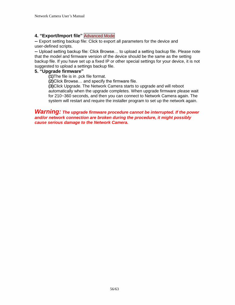
Network Camera Userrsquos Manual
5863
5 Check camera status we can see the ports had been successfully opened
6Type IP address8081at browser Then you can see camera through Internet
(2) By Setting Port Forwarding Manually 1 Select a router Set the port forwarding as following
PS Port 80 is HTTP Port port 53 is stream port port 554 is RTSP port and port
Network Camera Userrsquos Manual
5963
443 is HTTPS port 2Go to camera Network page Disable UPnP port forwarding function
3 Type IP address at browser Then you can see camera through Internet Note The firewall software at PC may block the transfer of network camera Please remove or stop the kind software
Q4 How can I find the network camera in the local area network
A4 By using the IP Finder2 program or using UPnP to find it
Q5 IP Finder2 program cannot find Network Camera in the local area
network at first time
A5 Make sure the subnet of network camera is same as your PC If the local area network supports DHCP the camera is ―Get IP address automatically in the ―Network page default If the local area network does not support DHCP change your PC IP address to ―1921680xxx
Q6 How can I restore the network camera to default value
A6 Use a gem clip to press on the inside button Network camera begins to restore default value You can also press the button ldquoFactoryrdquo in ―Maintenance page to restore the default value
Network Camera Userrsquos Manual
6063
Q7 Infrared led does not light up
A7 Check「ConfigurationgtAudio and VideogtInfrared LED Control」 is ldquoAutordquo or
ldquoManual》Turn onrdquo
Q8 The network camera cannot focus accurately
A8 (1) The lens is dirty or dust is attached Clean the lens with lens cleaner And then adjust the camera focus manually (2) The image may be out of focus If the object is too near move the object away from Network Camera
Q9 The cover of network camera is warm Is it normal
A9 Network camera is a precision device The internal material has the operational temperature and it is normal when user touch the cover feels warm It is recommended to put the network camera at aired place and not put at any other device
Q10 The process of upgrade firmware abort
A10 Contact your dealer for further help
Q11 Cannot access the login page and other web pages of Network Camera
from Internet Explorer
A11 bull May be due to the network cable Try correcting your network cable and configuration Test the network interface by connecting a local computer to the Network Camera via a crossover cable bull Make sure the Internet connection and setting is ok bull Make sure enter the IP address of Internet Explorer is correct If Network Camera has
Network Camera Userrsquos Manual
6163
a dynamic address it may have changed since you last checked it bull Network congestion may prevent the web page appearing quickly Wait for a while The IP address and Subnet Mask of the PC and Network Camera must be in the same class of the private IP address on the LAN bull Make sure the http port used by the Network Camera default=80 is forward to the Network Camerarsquos private IP address bull The port number assigned in your Network Camera might not be available via Internet Check your ISP for available port bull The proxy server may prevent you from connecting directly to Network Camera set up not to use the proxy server bull Confirm that Default Gateway address is correct bull The router needs Port Forwarding feature Refer to your routers manual for details bull Packet Filtering of the router may prohibit access from an external network Refer to your routers manual for details bull Access Network Camera from the Internet with the global IP address of the router and port number of Network Camera bull Some routers reject the global IP address to access Network Camera on the same LAN Access with the private IP address and correct port number of Network Camera bull When you use DDNS you need to set Default Gateway and DNS server address bull If itrsquos not working after above procedure reset Network Camera to default setting and installed it again bull Maybe the IP Address of the Network Camera is already being used by another device or computer bull If the problem is not solved the Network Camera might be faulty Contact your dealer for further help
Network Camera Userrsquos Manual
6263
B Technical specifications
- System RAM 4G bit DDRⅢ
ROM 16MB Flash ROM
- Camera specification Type 128 Sony CMOS sensor IMX236 Resolution 1920x1080
- Infrared Led High power IR Leds 30~40 M visible AutoManual mode
- Lens 10X optical zoom lens auto iris auto focus f = 49~ 49mm F18~30 Fov(D) 666deg ~ 72deg
- Protocol TCPIP HTTPUDP SMTP FTP DDNS UPnP Telnet NTP PPPoE RTSP RTPRTCPDHCP and DNS
- Video Resolution Up to 30 frames at 19201080 1280x1024 1280x800 640x480 320x240 and 176x144
- Physical 10 baseT or 100 baseT Fast Ethernet auto negotiation
- Audio G711AMRAAC Support 2 way audio
- Algorithm supported H264MPEG4MJPEG dual codec for streaming video
JPEG for still image
- IO Interface RJ-45 DI Audio in Audio out Video out DC Power SD(inside camera)
- PanTilt angle Support multi - direction movement Pan 150deg(-75deg~75deg) Tilt 95deg(-75deg~20deg)
- Power Input 100-240VAC 5060Hz 07A Output 12VDC 15A Consumption Max 10W Support 8023af compliant Power over Ethernet
- EMI amp Safety CE FCC
- Dimension Length 210mm Diameter 115mm
- Operating Environment Temperature -20 - 50
Humidity 85 RH
- Weight NET 800g With bracket 1000g
Network Camera Userrsquos Manual
6363
Notification of Compliance Appendix C
Europe - EU Declaration of Conformity
For complete DoC please visit httpgloballevel1comdownloadsphpaction=init
GPL License Agreement GPL may be included in this product to view the GPL license agreement goes to httpdownloadlevel1comlevel1gplGPLpdf For GNU General Public License (GPL) related information please visit httpgloballevel1comdownloadsphpaction=init
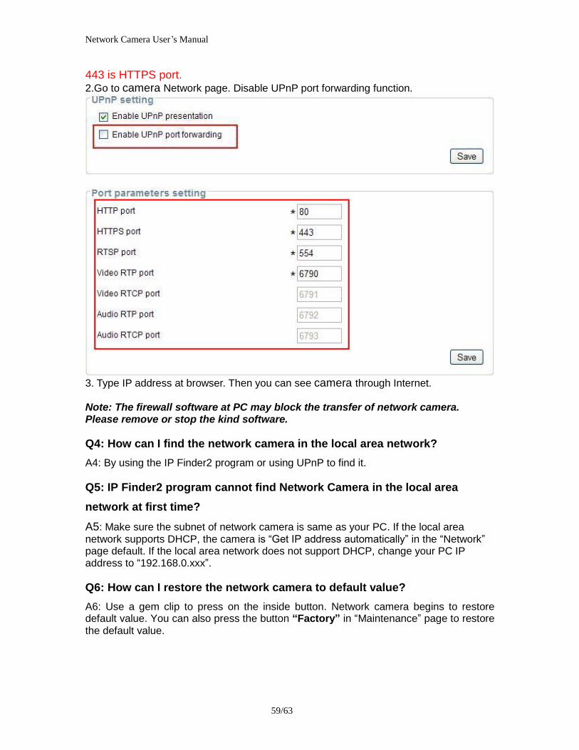
Network Camera Userrsquos Manual
6163
a dynamic address it may have changed since you last checked it bull Network congestion may prevent the web page appearing quickly Wait for a while The IP address and Subnet Mask of the PC and Network Camera must be in the same class of the private IP address on the LAN bull Make sure the http port used by the Network Camera default=80 is forward to the Network Camerarsquos private IP address bull The port number assigned in your Network Camera might not be available via Internet Check your ISP for available port bull The proxy server may prevent you from connecting directly to Network Camera set up not to use the proxy server bull Confirm that Default Gateway address is correct bull The router needs Port Forwarding feature Refer to your routers manual for details bull Packet Filtering of the router may prohibit access from an external network Refer to your routers manual for details bull Access Network Camera from the Internet with the global IP address of the router and port number of Network Camera bull Some routers reject the global IP address to access Network Camera on the same LAN Access with the private IP address and correct port number of Network Camera bull When you use DDNS you need to set Default Gateway and DNS server address bull If itrsquos not working after above procedure reset Network Camera to default setting and installed it again bull Maybe the IP Address of the Network Camera is already being used by another device or computer bull If the problem is not solved the Network Camera might be faulty Contact your dealer for further help
Network Camera Userrsquos Manual
6263
B Technical specifications
- System RAM 4G bit DDRⅢ
ROM 16MB Flash ROM
- Camera specification Type 128 Sony CMOS sensor IMX236 Resolution 1920x1080
- Infrared Led High power IR Leds 30~40 M visible AutoManual mode
- Lens 10X optical zoom lens auto iris auto focus f = 49~ 49mm F18~30 Fov(D) 666deg ~ 72deg
- Protocol TCPIP HTTPUDP SMTP FTP DDNS UPnP Telnet NTP PPPoE RTSP RTPRTCPDHCP and DNS
- Video Resolution Up to 30 frames at 19201080 1280x1024 1280x800 640x480 320x240 and 176x144
- Physical 10 baseT or 100 baseT Fast Ethernet auto negotiation
- Audio G711AMRAAC Support 2 way audio
- Algorithm supported H264MPEG4MJPEG dual codec for streaming video
JPEG for still image
- IO Interface RJ-45 DI Audio in Audio out Video out DC Power SD(inside camera)
- PanTilt angle Support multi - direction movement Pan 150deg(-75deg~75deg) Tilt 95deg(-75deg~20deg)
- Power Input 100-240VAC 5060Hz 07A Output 12VDC 15A Consumption Max 10W Support 8023af compliant Power over Ethernet
- EMI amp Safety CE FCC
- Dimension Length 210mm Diameter 115mm
- Operating Environment Temperature -20 - 50
Humidity 85 RH
- Weight NET 800g With bracket 1000g
Network Camera Userrsquos Manual
6363
Notification of Compliance Appendix C
Europe - EU Declaration of Conformity
For complete DoC please visit httpgloballevel1comdownloadsphpaction=init
GPL License Agreement GPL may be included in this product to view the GPL license agreement goes to httpdownloadlevel1comlevel1gplGPLpdf For GNU General Public License (GPL) related information please visit httpgloballevel1comdownloadsphpaction=init
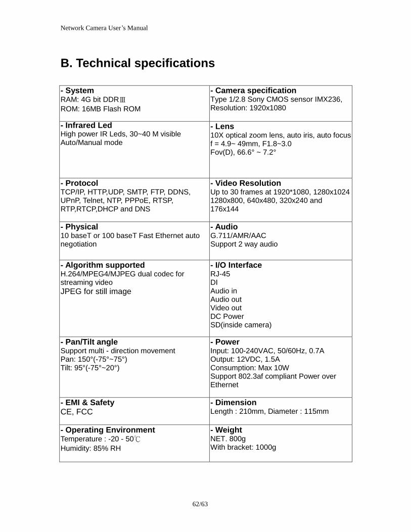
Network Camera Userrsquos Manual
6363
Notification of Compliance Appendix C
Europe - EU Declaration of Conformity
For complete DoC please visit httpgloballevel1comdownloadsphpaction=init
GPL License Agreement GPL may be included in this product to view the GPL license agreement goes to httpdownloadlevel1comlevel1gplGPLpdf For GNU General Public License (GPL) related information please visit httpgloballevel1comdownloadsphpaction=init


![3-087-918-32(1) © 2004 Sony Corporation Guía de operación de la cámara [ES] / Manual de instruções da câmera [PT] Video Camera Recorder/Digital Video Camera Recorder](https://static.fdokumen.com/doc/165x107/631c4157665120b3330bc43a/3-087-918-321-2004-sony-corporation-guia-de-operacion-de-la-camara-es.jpg)