Controlled microfluidic interfaces
8
INSIGHT REVIEW NATURE|Vol 437|29 September 2005|doi:10.1038/nature04163 648 1 Department of Biomedical Engineering, University of Wisconsin-Madison, 1550 Engineering Drive, Rm 2142 ECB, Madison, Wisconsin WI 53706, USA. Controlled microfluidic interfaces Javier Atencia 1 & David J. Beebe 1 The microfabrication technologies of the semiconductor industry have made it possible to integrate increasingly complex electronic and mechanical functions, providing us with ever smaller, cheaper and smarter sensors and devices. These technologies have also spawned microfluidics systems for containing and controlling fluid at the micrometre scale, where the increasing importance of viscosity and surface tension profoundly affects fluid behaviour. It is this confluence of available microscale engineering and scale- dependence of fluid behaviour that has revolutionized our ability to precisely control fluid/fluid interfaces for use in fields ranging from materials processing and analytical chemistry to biology and medicine. improved to the state where they are commercially available for bio- molecular separations (Caliper Life Sciences) and emerging as promis- ing tools for high-throughput discovery and screening studies in chemistry and materials science 12,13 . But beyond the manipulation of liquids as such, microfluidic systems also let us exploit the scale- dependence of interface properties to develop a wide range of other applications, as we aim to illustrate here. A striking demonstration of the potential for exquisite control of liq- uid interfaces at the micrometre scale appeared in 1992: a drop of water moves autonomously uphill when placed on a smooth surface that is treated so as to have a gradient in hydrophobicity 14 . Since then, many successful approaches have been developed for adjusting substrate sur- The effects of gravity and inertia dominate our experiences of the physical world. But as systems are reduced in size, phenomena such as diffusion, surface tension and viscosity become ever more important; at the micrometre scale they can dominate and result in a world that operates very differently from the macroscopic world we perceive and live in 1 . Purcell provided a fascinating peek into such a world popu- lated by microorganisms 2 , showing that Escherichia coli, with a size of about 2 Ȗm, moves more slowly than diffusing nutrients and waste. This means that rather than actively search for its food, E. coli can for- age just as efficiently by simply waiting for food to diffuse past. There are plenty of other processes where nature uses the micrometre scale to its advantage. For instance, gas exchange occurs with relatively slow rates within our lungs through diffusion, but nevertheless is efficient overall because it can take place over a large total surface area of about 80 m 2 provided by large numbers of very small air spaces (the alveoli). Similarly, muscle contraction is triggered by calcium ion diffusion, yet large muscles are often activated very rapidly. In this case, the muscle fibres are highly ordered and consist of micrometre-sized repeating structural units; this design keeps diffusion distances short so that the ions can rapidly reach their target destination. Unlike nature, we are only just beginning to harness microscale phenomena for practical use. This contrasts with our understanding of the behaviour of particles and fluids at the microscale, which has a long history that can be traced back to capillary experiments by Hagen and Poiseuille in the middle of the nineteenth century 3,4 . Navier and Stokes provided important contributions to fluid dynamic theory in the beginning of the nineteenth century 5,6 , and Taylor extended the field with his studies of diffusion under laminar flow in the 1950s 7 . But practical, creative use of this knowledge has had to await the availabil- ity of technologies for building microscale systems in a controlled and repeatable manner. That started to happen in the early 1980s, which saw the emergence of micro-electromechanical systems 8 (MEMS). MEMS aimed to integrate electronics and mechanical elements such as sensors and actuators on a common substrate, by adapting the advanced fabrication capabilities of the microelectronics industry. The same fabrication technologies were subsequently also used to create devices for containing and controlling fluid at the micrometre scale 9,10 , giving rise to the field of microfluidics. Much of the original motiva- tion for microfluidics arose out of developments in biology that call for the ability to manipulate fluids on the cellular length scale, and by the desire to provide cheap and efficient diagnostic tools that require only small sample volumes 11 . Microfluidic systems have now been Box 1 | The importance of scale Reynolds number The Reynolds number relates the ratio of inertial to viscous forces. Viscosity, the internal friction of a fluid, produces a resistance to shear and a tendency for the fluid to move in parallel layers known as laminar flow; and inertia, the tendency of a body in motion to retain its initial motion, counters laminar flow and can ultimately result in turbulent flow. Quantitatively, the Reynolds number is calculated as Reǃav/ȗ, where v is the velocity scale of the fluid, a is a characteristic distance of the system (in the case of flow through a pipe, a would be the pipe diameter), and ȗ is the kinematic viscosity of the fluid. Peclet number The Peclet number, Pe, provides an indication of the relative importance of diffusion and convection, diffusion being the random thermal motion of molecules within their surrounding environment and convection the transport as a result of bulk motion of a fluid 23 . The Peclet number is defined as PeǃU a H/D, where U a is the average velocity of the flow, H is a characteristic length of the system perpendicular to the direction of the flow and D is the diffusion coefficient of the particle or molecule of interest. Capillary number The ratio between viscous and capillary forces is given by the capillary number. Capillarity is the rise or depression of a liquid in a small passage, such as a thin tube. Water inside a glass capillary tube will have a concave meniscus that is in equilibrium because of a pressure difference across the interface. Such a pressure difference exists whenever a liquid surface is curved (as in the case of liquid drops or soap bubbles 27 ), with the higher pressure found on the inner side of the curve. The capillary number is given by CaǃUȖ/ȍ, where U is the velocity of the flow, Ȗ is the viscosity of the fluid, and ȍ is the surface tension. Nature Publishing Group ©2005
-
Upload
independent -
Category
Documents
-
view
1 -
download
0
Transcript of Controlled microfluidic interfaces

© 2005 Nature Publishing Group
INSIGHT REVIEW NATURE|Vol 437|29 September 2005|doi:10.1038/nature04163
648
1Department of Biomedical Engineering, University of Wisconsin-Madison, 1550 Engineering Drive, Rm 2142 ECB, Madison, Wisconsin WI 53706, USA.
Controlled microfluidic interfacesJavier Atencia1 & David J. Beebe1
The microfabrication technologies of the semiconductor industry have made it possible to integrateincreasingly complex electronic and mechanical functions, providing us with ever smaller, cheaper andsmarter sensors and devices. These technologies have also spawned microfluidics systems for containing andcontrolling fluid at the micrometre scale, where the increasing importance of viscosity and surface tensionprofoundly affects fluid behaviour. It is this confluence of available microscale engineering and scale-dependence of fluid behaviour that has revolutionized our ability to precisely control fluid/fluid interfaces foruse in fields ranging from materials processing and analytical chemistry to biology and medicine.
improved to the state where they are commercially available for bio-molecular separations (Caliper Life Sciences) and emerging as promis-ing tools for high-throughput discovery and screening studies inchemistry and materials science12,13. But beyond the manipulation ofliquids as such, microfluidic systems also let us exploit the scale-dependence of interface properties to develop a wide range of otherapplications, as we aim to illustrate here.
A striking demonstration of the potential for exquisite control of liq-uid interfaces at the micrometre scale appeared in 1992: a drop of watermoves autonomously uphill when placed on a smooth surface that istreated so as to have a gradient in hydrophobicity14. Since then, manysuccessful approaches have been developed for adjusting substrate sur-
The effects of gravity and inertia dominate our experiences of thephysical world. But as systems are reduced in size, phenomena such asdiffusion, surface tension and viscosity become ever more important;at the micrometre scale they can dominate and result in a world thatoperates very differently from the macroscopic world we perceive andlive in1. Purcell provided a fascinating peek into such a world popu-lated by microorganisms2, showing that Escherichia coli, with a size ofabout 2 �m, moves more slowly than diffusing nutrients and waste.This means that rather than actively search for its food, E. coli can for-age just as efficiently by simply waiting for food to diffuse past. Thereare plenty of other processes where nature uses the micrometre scaleto its advantage. For instance, gas exchange occurs with relatively slowrates within our lungs through diffusion, but nevertheless is efficientoverall because it can take place over a large total surface area of about80 m2 provided by large numbers of very small air spaces (the alveoli).Similarly, muscle contraction is triggered by calcium ion diffusion, yetlarge muscles are often activated very rapidly. In this case, the musclefibres are highly ordered and consist of micrometre-sized repeatingstructural units; this design keeps diffusion distances short so that theions can rapidly reach their target destination.
Unlike nature, we are only just beginning to harness microscalephenomena for practical use. This contrasts with our understandingof the behaviour of particles and fluids at the microscale, which has along history that can be traced back to capillary experiments by Hagenand Poiseuille in the middle of the nineteenth century3,4. Navier andStokes provided important contributions to fluid dynamic theory inthe beginning of the nineteenth century5,6, and Taylor extended thefield with his studies of diffusion under laminar flow in the 1950s7. Butpractical, creative use of this knowledge has had to await the availabil-ity of technologies for building microscale systems in a controlled andrepeatable manner. That started to happen in the early 1980s, whichsaw the emergence of micro-electromechanical systems8 (MEMS).MEMS aimed to integrate electronics and mechanical elements suchas sensors and actuators on a common substrate, by adapting theadvanced fabrication capabilities of the microelectronics industry. Thesame fabrication technologies were subsequently also used to createdevices for containing and controlling fluid at the micrometre scale9,10,giving rise to the field of microfluidics. Much of the original motiva-tion for microfluidics arose out of developments in biology that call forthe ability to manipulate fluids on the cellular length scale, and by thedesire to provide cheap and efficient diagnostic tools that require onlysmall sample volumes11. Microfluidic systems have now been
Box 1 | The importance of scale
Reynolds numberThe Reynolds number relates the ratio of inertial to viscous forces. Viscosity,the internal friction of a fluid, produces a resistance to shear and a tendencyfor the fluid to move in parallel layers known as laminar flow; and inertia, thetendency of a body in motion to retain its initial motion, counters laminarflow and can ultimately result in turbulent flow. Quantitatively, the Reynoldsnumber is calculated as Re�av/�, where v is the velocity scale of the fluid, ais a characteristic distance of the system (in the case of flow through a pipe,a would be the pipe diameter), and � is the kinematic viscosity of the fluid.
Peclet numberThe Peclet number, Pe, provides an indication of the relative importance ofdiffusion and convection, diffusion being the random thermal motion ofmolecules within their surrounding environment and convection thetransport as a result of bulk motion of a fluid23. The Peclet number is definedas Pe�UaH/D, where Ua is the average velocity of the flow, H is acharacteristic length of the system perpendicular to the direction of the flowand D is the diffusion coefficient of the particle or molecule of interest.
Capillary numberThe ratio between viscous and capillary forces is given by the capillarynumber. Capillarity is the rise or depression of a liquid in a small passage,such as a thin tube. Water inside a glass capillary tube will have a concavemeniscus that is in equilibrium because of a pressure difference across theinterface. Such a pressure difference exists whenever a liquid surface iscurved (as in the case of liquid drops or soap bubbles27), with the higherpressure found on the inner side of the curve. The capillary number is givenby Ca�U�/�, where U is the velocity of the flow, � is the viscosity of thefluid, and � is the surface tension.
29.9 Beebe 19/9/05 3:28 PM Page 10
Nature Publishing Group© 2005
© 2005 Nature Publishing Group
NATURE|Vol 437|29 September 2005 INSIGHT REVIEW
649
of magnitude. For a fluid, the effect allows for more efficient mass andheat transfer in microsystems: relatively more interface is available fortransfer to occur, and less total mass or energy needs to be transferredto reach the final state. Therefore both the creation and the homo-genization of solute or temperature gradients are faster as system sizeis reduced.
Fluid behaviour in reduced dimensions will also be increasinglyinfluenced by viscosity rather than inertia. In the case of microfluidicsystems with simple geometries, this results in laminar flow. (Suchbehaviour occurs if the Reynolds number Re, which gives the ratio ofviscous to inertial forces, is small; see Box 1). In laminar flow, diffusioncan be effective for moving and mixing solutes on micrometre lengthscales. The relative importance of diffusion and convective bulk flowfor transporting solute and solvent molecules is given by the Pecletnumber Pe (see Box 1), and can be readily adjusted through the choiceof flow velocity and the dimensions of the system used.
The large ratio of surface area to volume typical for microfluidicsystems ensures that surface tension can profoundly influence fluidbehaviour. If surface tension varies along a surface or interface as aresult of thermal or concentration gradients, for example, so-calledMarangoni flows23,24 can arise and effectively homogenize the thermalor concentration gradients; the convective flows may even be used to
face properties as a means of manipulating liquid drops, and sophisti-cated methods capable of controlling surface properties both temporallyand spatially are now at our disposal15–18. One such method — known aselectrowetting — uses electrical control of contact angle to manipulateliquid droplets in real time19. This control capability can be used in dig-ital microfluidics, the processing of discrete fluid packets that is of inter-est for the development of clinical diagnostic assays20,21. But it is theability of microfluidics to harness interfaces that is continuing to opennew avenues of inquiry and application, and is the focus of this review.
In our discussions, we will go beyond the classical view of an ‘inter-face’ as the thin boundary layer that separates two distinct phases ofmatter (each of which may be a solid, a liquid or a gas) and that hasproperties distinct from those of the bulk material on either side. Inaddition to such classical interfaces, we also consider de facto interfacessuch as the diffusive layers that appear if miscible fluids are broughtinto contact or a solute source is placed in a fluid22. A common themeis the precise control that microfluidics offers over the interface, per-mitting many applications that were not previously possible.
Fluid at the microscale An obvious effect of shrinking a system to the micrometre scale is thehuge increase in surface area relative to volume, often by several orders
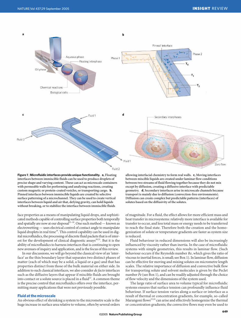
Figure 1 | Microfluidic interfaces provide unique functionality. a, Floatinginterfaces between immiscible fluids can be used to produce droplets ofprecise shape and varying content. These can act as microscale containerswith permeable walls for performing and analysing reactions, creatingcustom magnetic or protein-coated vesicles, or transporting cargo. b,Pinned interfaces between immiscible liquids are created by selectivesurface patterning of a microchannel. They can be used to create verticalinterfaces between liquid and air that, defying gravity, can hold liquidswithout breaking, or to stabilize the interface between immiscible fluids
allowing interfacial chemistry to form real walls. c, Moving interfacesbetween miscible liquids are created under laminar flow conditionsbetween two streams of fluid flowing together because they do not mixexcept by diffusion, creating a diffusive interface with predictablegeometry. d, Secondary interfaces arise in microscale channels becausetransport is mainly due to diffusion (convection-free environments).Diffusion can create complex but predictable patterns (interfaces) ofsolutes based on the diffusivity of the solutes.
29.9 Beebe 19/9/05 3:28 PM Page 11
Nature Publishing Group© 2005
© 2005 Nature Publishing Group
INSIGHT REVIEW NATURE|Vol 437|29 September 2005
650
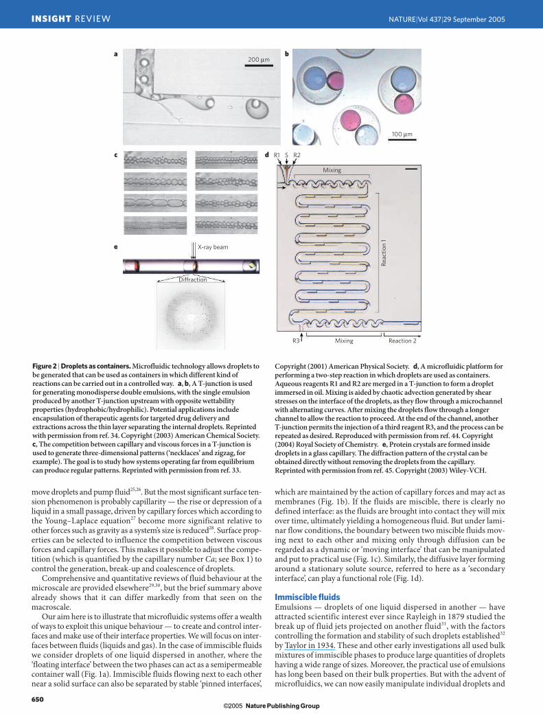
Figure 2 | Droplets as containers. Microfluidic technology allows droplets tobe generated that can be used as containers in which different kind ofreactions can be carried out in a controlled way. a, b, A T-junction is usedfor generating monodisperse double emulsions, with the single emulsionproduced by another T-junction upstream with opposite wettabilityproperties (hydrophobic/hydrophilic). Potential applications includeencapsulation of therapeutic agents for targeted drug delivery andextractions across the thin layer separating the internal droplets. Reprintedwith permission from ref. 34. Copyright (2003) American Chemical Society.c, The competition between capillary and viscous forces in a T-junction isused to generate three-dimensional patterns (‘necklaces’ and zigzag, forexample). The goal is to study how systems operating far from equilibriumcan produce regular patterns. Reprinted with permission from ref. 33.
Copyright (2001) American Physical Society. d, A microfluidic platform forperforming a two-step reaction in which droplets are used as containers.Aqueous reagents R1 and R2 are merged in a T-junction to form a dropletimmersed in oil. Mixing is aided by chaotic advection generated by shearstresses on the interface of the droplets, as they flow through a microchannelwith alternating curves. After mixing the droplets flow through a longerchannel to allow the reaction to proceed. At the end of the channel, anotherT-junction permits the injection of a third reagent R3, and the process can berepeated as desired. Reproduced with permission from ref. 44. Copyright(2004) Royal Society of Chemistry. e, Protein crystals are formed insidedroplets in a glass capillary. The diffraction pattern of the crystal can beobtained directly without removing the droplets from the capillary.Reprinted with permission from ref. 45. Copyright (2003) Wiley-VCH.
200 µmba
c
e
d
100 µm
R1
R3
X-ray beam
Diffraction
S
Mixing
Mixing Reaction 2
Reac
tion
1
R2
move droplets and pump fluid25,26. But the most significant surface ten-sion phenomenon is probably capillarity — the rise or depression of aliquid in a small passage, driven by capillary forces which according tothe Young–Laplace equation27 become more significant relative toother forces such as gravity as a system’s size is reduced28. Surface prop-erties can be selected to influence the competition between viscousforces and capillary forces. This makes it possible to adjust the compe-tition (which is quantified by the capillary number Ca; see Box 1) tocontrol the generation, break-up and coalescence of droplets.
Comprehensive and quantitative reviews of fluid behaviour at themicroscale are provided elsewhere29,30, but the brief summary abovealready shows that it can differ markedly from that seen on themacroscale.
Our aim here is to illustrate that microfluidic systems offer a wealthof ways to exploit this unique behaviour — to create and control inter-faces and make use of their interface properties. We will focus on inter-faces between fluids (liquids and gas). In the case of immiscible fluidswe consider droplets of one liquid dispersed in another, where the‘floating interface’ between the two phases can act as a semipermeablecontainer wall (Fig. 1a). Immiscible fluids flowing next to each othernear a solid surface can also be separated by stable ‘pinned interfaces’,
which are maintained by the action of capillary forces and may act asmembranes (Fig. 1b). If the fluids are miscible, there is clearly nodefined interface: as the fluids are brought into contact they will mixover time, ultimately yielding a homogeneous fluid. But under lami-nar flow conditions, the boundary between two miscible fluids mov-ing next to each other and mixing only through diffusion can beregarded as a dynamic or ‘moving interface’ that can be manipulatedand put to practical use (Fig. 1c). Similarly, the diffusive layer formingaround a stationary solute source, referred to here as a ‘secondaryinterface’, can play a functional role (Fig. 1d).
Immiscible fluidsEmulsions — droplets of one liquid dispersed in another — haveattracted scientific interest ever since Rayleigh in 1879 studied thebreak up of fluid jets projected on another fluid31, with the factorscontrolling the formation and stability of such droplets established32
by Taylor in 1934. These and other early investigations all used bulkmixtures of immiscible phases to produce large quantities of dropletshaving a wide range of sizes. Moreover, the practical use of emulsionshas long been based on their bulk properties. But with the advent ofmicrofluidics, we can now easily manipulate individual droplets and
29.9 Beebe 19/9/05 3:28 PM Page 12
Nature Publishing Group© 2005
© 2005 Nature Publishing Group
NATURE|Vol 437|29 September 2005 INSIGHT REVIEW
651
precisely control their properties. It has, quite simply, transformedthe field.
Dispersion and floating interfacesA simple microfluidic device for producing and manipulating dropletsis the ‘T-junction’ (Fig. 2a): the T-shaped channel geometry forces twoflows of immiscible liquids to merge in such a way that one liquidforms droplets dispersed in the other33. The droplet-forming phase canbe selected by adjusting the hydrophobicity of the device walls at thejunction and the relative flow rates of the liquids34. The use of T-junc-tions in series with alternating surface wettabilities produces monodis-perse double emulsions that are useful for encapsulation applicationsor extractions across the thin layer separating the internal droplets andthe continuous phase34,35 (Fig. 2b). When reversing the flow direction,T-junctions with differently sized exit channels will passively sortdroplets according to size36 or break large droplets into smaller oneswith controlled sizes37. Despite its simple design, the T-junction pro-vides precise control over droplet formation (Fig. 2c), making it ideally suited for commercial uses that require parallel, high-through-put predictable droplet creation.
Dispersed droplets may also be created using a microfluidic exten-sion of Rayleigh’s approach, with two streams of one liquid flanking astream of a second immiscible liquid and the combined two-phaseflow then forced through a small orifice. The pressure and viscousforces exerted by the outer fluid ultimately force the inner fluid tobreak into droplets, either in or just downstream of the orifice. Thefabrication of a planar microchannel system uses simple soft lithogra-phy, making it straightforward to adjust not only flow rates but also thegeometry of the microchannel design to ensure selective generation ofdroplets over a range of different sizes and at different rates38,39. Themethod is easily adjusted to produce droplets of various compositions(see also Fig. 1a), as demonstrated by the successful synthesis ofmonodisperse microparticles40 and nanoparticles41 from solutions thatallow the droplets to be solidified in situ after their formation (by, forexample, photopolymerization).
In addition to allowing controlled production of droplets, microflu-idic devices also provide an opportunity for precisely manipulatinggenerated droplets. Owing to this combination of capabilities, indi-vidual dispersed droplets may serve as floating containers or reactionvessels that can be loaded with different reagents for kinetic measure-ments42: once a reaction medium has been added and mixed in, thespatial position of the droplet moving continuously along a knownpath within a microchannel will correlate with reaction time. That is,a given position in the channel will correspond to the same kineticstate, so signals can be collected from several successive droplets andintegrated to improve the signal-to-noise ratio, making it possible tomonitor even relatively fast reactions with millisecond time resolutionor better43. The system is readily extended to studying controlledmulti-step reactions by adding new reagents at selected downstreamlocations44 (Fig. 2d). A variation of the method allows efficient screen-ing for optimum protein crystallization conditions by using aqueousdroplets in a linear array. Droplets containing different protein solu-tions alternate with droplets containing salt solutions of different con-centrations (see Fig. 2e). Once the array is formed, the difference inosmotic pressure between the alternating static droplets drives the dif-fusion of water through the oil and thus creates a wide range of differ-ent crystallization conditions45 while requiring only small quantitiesof often precious protein material.
Dispersed droplets offer the potential to manipulate or analysesmall fluid volumes and thus allow experiments that require only smallquantities of reagents (which may be very costly). But the droplet sizeis so small that solutes will quickly diffuse from the centre to the inter-face. Depending on composition and affinity, this might result insolutes selectively diffusing out of the droplet or adhering to the inter-face. If adhesion occurs, the large surface area relative to volume canprove problematic, particularly if the droplet size is decreased so muchthat adhesion greatly depletes the solute in the droplet interior. In the
case of proteins, adhesion to the droplet interface is often associatedwith a conformational change, which may become permanent46. Thistendency to stick to the interface can be prevented by using appropri-ate surfactants47. The effect has also been used to advantage for the fab-rication of mechanically stable hollow protein spheres48 that mightserve as biocompatible ‘smart’ containers for drug delivery.
At the time of writing, new manipulation methods continue toemerge. For example, microdroplets may be levitated in gas or vacuumusing magnetic or acoustic forces49, and asymmetric laser heating ofthe liquid/liquid interface between an aqueous droplet and its sur-rounding immiscible fluid can induce Marangoni flows to move thedroplet50. In yet another approach, dispersed droplets are exposed toamphiphilic magnetic nanoparticles that accumulate and align at thedroplet interface; the resultant nanoparticle ‘coat’ then chaperones theliquid droplet in response to an applied external magnetic field51.
Patterned surfaces and pinned interfacesA mixture of water and oil in a macroscopic vessel will separate intotwo phases, with gravitation and the density difference between thefluids ensuring that a horizontal interface separates the oil at the topfrom the water at the bottom. In micrometre-sized systems, capillaryforces can overcome gravitation and be used to create precisely con-trolled vertical interfaces, or ‘virtual walls’, between water and air52.This requires sufficiently strong capillary forces to ‘pin’ the water/airinterface in position and counteract the action of gravity, which driveswater to ‘fall’ and spread out horizontally. To achieve this, the internalsurface of a microchannel is patterned to create hydrophilic andhydrophobic paths. Water molecules will adhere to the hydrophilicchannel surface, with surface tension preventing the liquid frominvading hydrophobic regions. Aqueous solutions introduced into thepatterned microchannel will thus be confined to the hydrophilicregions (see also Fig. 1b), provided the pressure difference across thewater/air interface does not exceed a critical value determined by theYoung–Laplace equation. The virtual wall between the streams pro-vides a large gas/liquid interface for efficient removal of dissolved gasspecies such as oxygen from the water stream under continuous oper-ation53. The large surface area provided by virtual walls, and the rela-tively small volume of the streams to be treated, ensure efficienttransport between liquid and gas phases. In this respect, microfluidicdevices mimic the alveoli in our lungs, whose large surface area to vol-ume ratio similarly allows rapid exchange of O2 and CO2 between airand blood. These systems are not limited to removing dissolved gasfrom liquid; they could also be used to passively adjust the pH of abuffer solution by exposing it to CO2 across a virtual wall. Or imaginetriggering a chemical reaction within a microfluidic device by intro-ducing a gas-phase species through a virtual wall, or using chemicalreactions to generate a gas to be used elsewhere. If airborne analytesare captured into the liquid phase, the system might be used for con-tinuous sensing applications.
It is straightforward to extend the basic idea underlying virtualwalls to immiscible liquids flowing side by side (or even on top of eachother) in a microchannel. Because the interface between such liquidstends to be unstable owing to differences in liquid properties, pattern-ing the interior microchannel surface to create regions with differentwettabilities allows capillary forces to stabilize both vertical54 and hor-izontal55 liquid/liquid interfaces. Such ‘pinned interfaces’ allow forrapid and precise control over the contact time between the twophases, which are typically an organic liquid and an aqueous solution.Moreover, pinned interfaces are produced within seconds, whereas itcan take tens of minutes56 to establish a stable liquid/liquid interface ina macroscopic system through the action of gravity. These featuresmake microfluidic pinned interfaces attractive for applications such asthe study of drug partitioning behaviour56 and enzymatic reactions57,solvent extraction of metal ions58,59, and the execution of multiphasereactions13 and phase-transfer reactions60.
Pinned interfaces can also be harnessed more directly. For instance,a stable pinned interface between appropriately chosen aqueous and
29.9 Beebe 19/9/05 3:28 PM Page 13
Nature Publishing Group© 2005
© 2005 Nature Publishing Group
INSIGHT REVIEW NATURE|Vol 437|29 September 2005
652
organic liquids can serve as the site for aninterfacial reaction; if an interfacial poly-merization is conducted, the pinned inter-face is transformed into a real membrane54
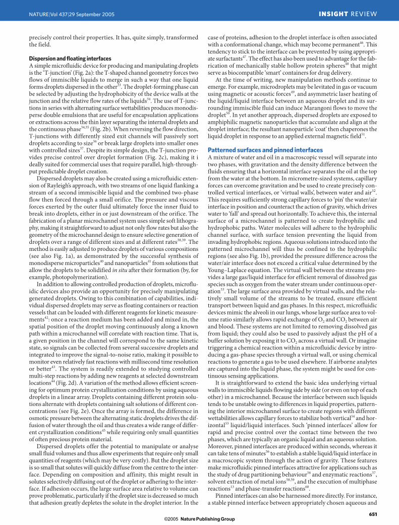
(Fig. 1b) that is readily functionalized (forinstance by immobilizing an enzyme on oneof its sides61). This approach has allowed theformation of a membrane incorporating apeptide crosslinker (N. O. L. Viernes and J. S.Moore, personal communication), so thatexposure to a peptide-cleaving enzyme solu-tion leads to a breakdown of the membrane-forming polymer; the resultant fluid leakagethen serves as a visual indicator for the pres-ence of the enzyme (Fig. 3). Instead of serv-ing as indicators or sensors, interfacialreactions can also be used to create materi-als. Particularly when using photopolymer-ization and suitable surfactant molecules, awide range of interfaces (including themenisci formed at the solid/liquid/air inter-face) can be transformed into stablemicrostructures with unusual shapes, suchas microneedles with smooth curved side-walls62.
Miscible fluidsThe interface between immiscible fluids is easily recognized as thecommon boundary separating the phases. But if fluids are completelymixed, there is clearly no interface. Still, two miscible fluids, usuallyliquids, brought into contact will have a boundary between them thatdisappears as the fluids start mixing. This boundary region can act asa de facto dynamic interface that changes with time22 (Fig. 1c) andsome of its properties may resemble those of the interface betweenimmiscible fluids63,64. Moreover, if two or more miscible liquids movenext to each other under laminar flow conditions, then their diffusiveinterface can be controlled and used65.
Laminar flow and moving interfacesLaminar flow ensures that mixing between streams in contact witheach other occurs only through diffusion. If conditions exist such thatthe Peclet number is high, mixing will be negligible (see Fig. 1c). At theinterface between streams of miscible liquids the contact time is soshort that the interface is kinetically stable and remains sharplydefined. At lower flow velocity, the liquids are in contact for longer andmix through diffusion: a diffusive interface forms between the fluids,flows and broadens downstream, as the contact time increases.
Laminar flow and diffusion were first put to practical use by Gid-dings, who used the interface between aqueous streams flowingthrough microchannels as a ‘virtual membrane’ for protein fractiona-tion66–68. The success of this approach demonstrated that membrane-like performance can be obtained without the potential foulingproblems associated with real membranes, and that the effective mem-brane thickness — the width of the diffusive layer — can be adjustedby simple changes in flow rate. This work, which largely pre-dates whatwe now regard as microfluidics, used readily available components tocreate channels of micrometre dimensions in height and millimetredimensions in width and length. Such simple microchannels sufficefor maintaining laminar flow because it is the smallest dimension thatlargely determines the ratio of inertial to viscous forces (the Reynoldsnumber is a function of channel geometry via hydraulic diameter).That is, in three-dimensional space the scaling of one dimension to themicrometre scale is often sufficient to harness the forces that are dom-inant at that scale.
Still, the ease with which laminar flow can be realized in modernmicrofluidic devices allows for particularly effective and precise con-trol over multiple streams of miscible liquids and exploitation of the
a b c d
membrane
interfaces between them. In 1997, microfluidics as we know it todaywas used to tap into the potential of diffusion and laminar flow69,70, inthe shape of the ‘H-filter’. This device merges two separate fluidstreams in a central channel and then separates them again into indi-vidual channels; the flow regime throughout is laminar. One of the flu-ids carries particles or solutes of different sizes (the sample stream),while the other is particle-free (the extraction stream). The momentthe fluids are in contact, particles start diffusing from the sample to theextraction stream. Diffusivity depends inversely on solute size accord-ing to the Stokes–Einstein equation23, and provided the contact timebetween the streams is adjusted appropriately, only the smallersolute(s) will enter the extraction stream. Downstream of the centralchannel, the fluid is split and the extracted solute collected. To achievefluid splitting without any gross mixing69, the two streams need tomove with equal velocity and steady flow — conditions that can bechallenging to realize experimentally. Moreover, the H-filter requirescontinually flowing liquids so that the performance of the diffusiveinterface can be controlled; solutes are therefore extracted at theexpense of being diluted.
Like the H filter, the ‘T-sensor’71 merges two fluid streams into acommon channel to create a controlled diffusive interface. One streamtypically contains an analyte, the other a tracer compound such as afluorescent dye or dye-labelled antibody that can interact with the ana-lyte and provide a signal for optical detection. By monitoring thebroadening of the interface during the early stages of diffusive mixing,it is then possible to determine diffusion coefficients (from which ana-lyte size can be extracted), analyte concentrations, reaction kineticsand binding affinities72. An attractive and useful feature of the T-sen-sor is that the reagents start to interdiffuse and react the moment thetwo fluid streams are in contact, so the time available for diffusion andreaction correlates with the distance the fluid travels subsequently. Anoutside observer will therefore ‘see’ the course of the reaction or diffu-sion as a still image, and reaction kinetics and diffusion distances canbe measured as a function of distance rather than time. This allows theoptical signal to be integrated over time to improve sensitivity, makingthe T-sensor a robust device that is straightforward to implement (incontrast to the H-filter, where the need for stream splitting constitutesa serious complication). At the time of writing, this basic system hasbeen developed for use in molecular mass sensors73, chemical assays74,membraneless microfluidic fuel cells75,76, and immunoassays72.
Figure 3 | Pinned interfaces. The use of ‘pinned’ aqueous/organic liquids creates a stable interface wherechemistry can occur, for example to create polymer walls. Making use of enzymatic cleavage of peptides,one can create a biosensing or bio-dissolving wall. Here the wall is created through the interfacialreaction of adipoyl chloride and a lysine-terminated peptide creating a thin wall with a known peptidesequence as a crosslink. When exposed to a solution containing appropriate enzymes the peptides arecleaved, the wall becomes more porous and the dyed enzyme-containing solution leaks through themembrane. (Eventually there may be complete dissolution of the wall; not shown.) a–d, Sequentialimages of membrane breakdown. a, b, A dyed buffer solution containing chymotrypsin is flowed bycapillary action into the top half of the channel. c, The solution permeating through the membraneindicates that enzyme cleavage has caused a change in the membrane porosity. d, The readout channel iscompletely filled. Such walls should find use as biosensors with simple visual readouts (as shown) or asintelligent valves that can make process decisions based on changes in the local environment, therebygating flow to appropriate paths. Courtesy of J. S. Moore, University of Illinois at Urbana-Champaign.
29.9 Beebe 19/9/05 3:28 PM Page 14
Nature Publishing Group© 2005
© 2005 Nature Publishing Group
NATURE|Vol 437|29 September 2005 INSIGHT REVIEW
653
a 300 µm
Reductant
Agx
Ag wire
b c
UV
Monomer
Sheath
Polymer string
Non-diffusive region
Diffusive region500 µm
10 µm
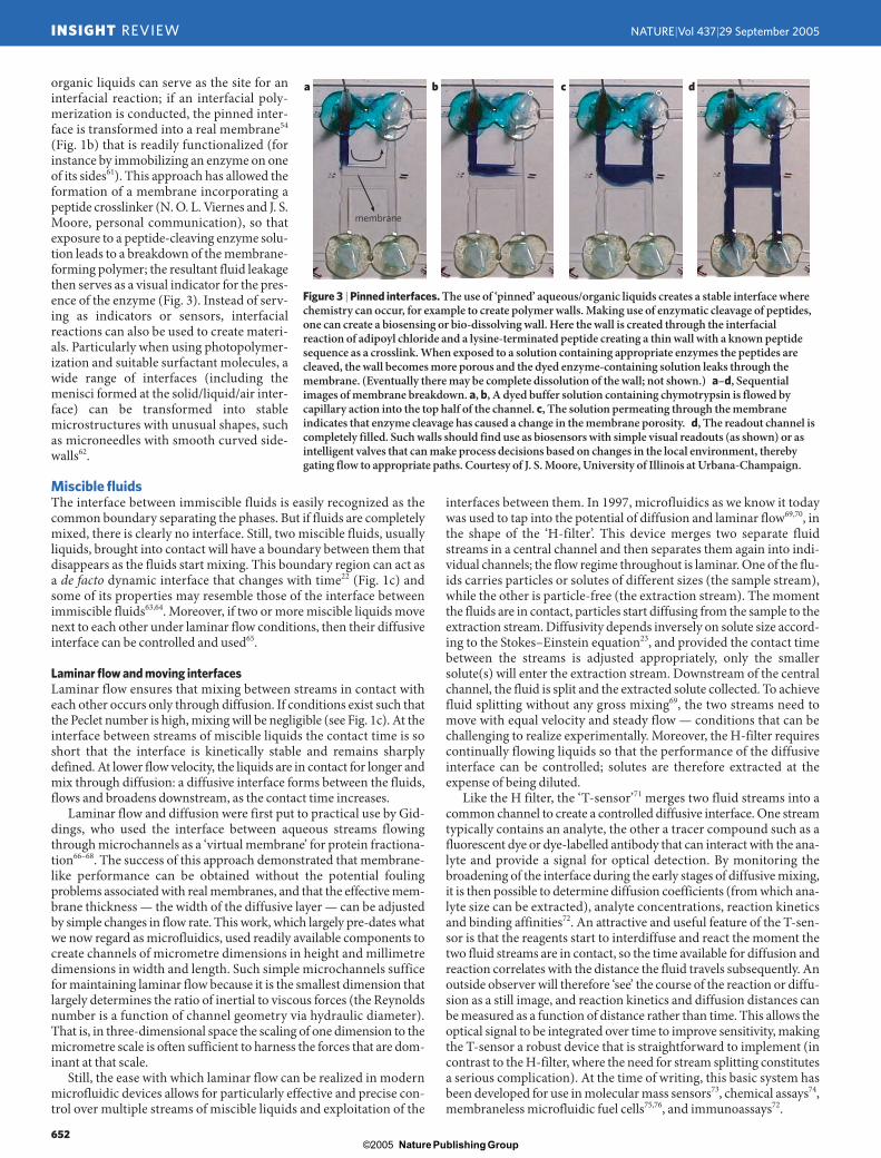
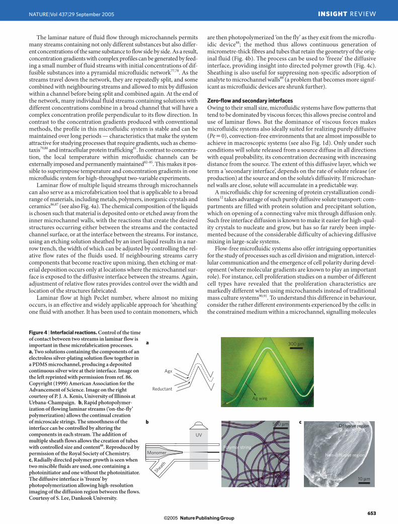
Figure 4 | Interfacial reactions. Control of the timeof contact between two streams in laminar flow isimportant in these microfabrication processes.a, Two solutions containing the components of anelectroless silver-plating solution flow together ina PDMS microchannel, producing a depositedcontinuous silver wire at their interface. Image onthe left reprinted with permission from ref. 86.Copyright (1999) American Association for theAdvancement of Science. Image on the rightcourtesy of P. J. A. Kenis, University of Illinois atUrbana-Champaign. b, Rapid photopolymer-ization of flowing laminar streams (‘on-the-fly’polymerization) allows the continual creation of microscale strings. The smoothness of theinterface can be controlled by altering thecomponents in each stream. The addition ofmultiple sheath flows allows the creation of tubeswith controlled size and content88. Reproduced bypermission of the Royal Society of Chemistry.c, Radially directed polymer growth is seen whentwo miscible fluids are used, one containing aphotoinitiator and one without the photoinitiator.The diffusive interface is ‘frozen’ byphotopolymerization allowing high-resolutionimaging of the diffusion region between the flows.Courtesy of S. Lee, Dankook University.
are then photopolymerized ‘on the fly’ as they exit from the microflu-idic device88; the method thus allows continuous generation ofmicrometre-thick fibres and tubes that retain the geometry of the orig-inal fluid (Fig. 4b). The process can be used to ‘freeze’ the diffusiveinterface, providing insight into directed polymer growth (Fig. 4c).Sheathing is also useful for suppressing non-specific adsorption ofanalyte to microchannel walls89 (a problem that becomes more signif-icant as microfluidic devices are shrunk further).
Zero-flow and secondary interfacesOwing to their small size, microfluidic systems have flow patterns thattend to be dominated by viscous forces; this allows precise control anduse of laminar flows. But the dominance of viscous forces makesmicrofluidic systems also ideally suited for realizing purely diffusive(Pe�0), convection-free environments that are almost impossible toachieve in macroscopic systems (see also Fig. 1d). Only under suchconditions will solute released from a source diffuse in all directionswith equal probability, its concentration decreasing with increasingdistance from the source. The extent of this diffusive layer, which weterm a ‘secondary interface’, depends on the rate of solute release (orproduction) at the source and on the solute’s diffusivity. If microchan-nel walls are close, solute will accumulate in a predictable way.
A microfluidic chip for screening of protein crystallization condi-tions12 takes advantage of such purely diffusive solute transport: com-partments are filled with protein solution and precipitant solution,which on opening of a connecting valve mix through diffusion only.Such free interface diffusion is known to make it easier for high-qual-ity crystals to nucleate and grow, but has so far rarely been imple-mented because of the considerable difficulty of achieving diffusivemixing in large-scale systems.
Flow-free microfluidic systems also offer intriguing opportunitiesfor the study of processes such as cell division and migration, intercel-lular communication and the emergence of cell polarity during devel-opment (where molecular gradients are known to play an importantrole). For instance, cell proliferation studies on a number of differentcell types have revealed that the proliferation characteristics aremarkedly different when using microchannels instead of traditionalmass culture systems90,91. To understand this difference in behaviour,consider the rather different environments experienced by the cells: inthe constrained medium within a microchannel, signalling molecules
The laminar nature of fluid flow through microchannels permitsmany streams containing not only different substances but also differ-ent concentrations of the same substance to flow side by side. As a result,concentration gradients with complex profiles can be generated by feed-ing a small number of fluid streams with initial concentrations of dif-fusible substances into a pyramidal microfluidic network77,78. As thestreams travel down the network, they are repeatedly split, and somecombined with neighbouring streams and allowed to mix by diffusionwithin a channel before being split and combined again. At the end ofthe network, many individual fluid streams containing solutions withdifferent concentrations combine in a broad channel that will have acomplex concentration profile perpendicular to its flow direction. Incontrast to the concentration gradients produced with conventionalmethods, the profile in this microfluidic system is stable and can bemaintained over long periods — characteristics that make the systemattractive for studying processes that require gradients, such as chemo-taxis79,80 and intracellular protein trafficking81. In contrast to concentra-tion, the local temperature within microfluidic channels can beexternally imposed and permanently maintained82–85. This makes it pos-sible to superimpose temperature and concentration gradients in onemicrofluidic system for high-throughput two-variable experiments.
Laminar flow of multiple liquid streams through microchannelscan also serve as a microfabrication tool that is applicable to a broadrange of materials, including metals, polymers, inorganic crystals andceramics86,87 (see also Fig. 4a). The chemical composition of the liquidsis chosen such that material is deposited onto or etched away from theinner microchannel walls, with the reactions that create the desiredstructures occurring either between the streams and the contactedchannel surface, or at the interface between the streams. For instance,using an etching solution sheathed by an inert liquid results in a nar-row trench, the width of which can be adjusted by controlling the rel-ative flow rates of the fluids used. If neighbouring streams carrycomponents that become reactive upon mixing, then etching or mat-erial deposition occurs only at locations where the microchannel sur-face is exposed to the diffusive interface between the streams. Again,adjustment of relative flow rates provides control over the width andlocation of the structures fabricated.
Laminar flow at high Peclet number, where almost no mixingoccurs, is an effective and widely applicable approach for ‘sheathing’one fluid with another. It has been used to contain monomers, which
29.9 Beebe 19/9/05 3:28 PM Page 15
Nature Publishing Group© 2005

© 2005 Nature Publishing Group
INSIGHT REVIEW NATURE|Vol 437|29 September 2005
654
produced by a given cell (autocrine signals) or surrounding cells(paracrine signals) can accumulate, whereas such signalling moleculeswill be diluted or even removed by the convective flows that inevitablyarise in mass culture systems or flowing microfluidic systems (see alsoFig. 1d). Culturing in microchannels in the absence of flow, wheretransport is purely by diffusion and the size of the system preventsextensive dilution, appears to increase the sensitivity of proliferatingcells to the effects of soluble factors91. Similar effects may explain whythe efficiency of embryo development improves in microchannelsunder no-flow conditions92. So microfluidics should open new oppor-tunities for studying cell signalling, where convection-free culture con-ditions allow signalling molecules secreted by a cell to form diffusivelayers and influence the secreting and surrounding cells. Of course,cells in ‘real’ living systems are unlikely to experience environments ofeither laminar flow or no flow at all; still, the ease of creating a range ofmicroenvironmental conditions should allow complementary inves-tigations to characterize and understand cellular processes more fully.
Broadening the rangeAs we have seen, microfluidics provides us with a powerful way ofexploring and exploiting fluid behaviour at a scale where diffusion, vis-cous drag and surface tension can dominate. Of the applications thatare now emerging, we are particularly excited about the unique oppor-tunities for exploring cellular processes. But as the breadth of materialand methods presented in this review illustrates, microfluidics caninfluence a vast range of fields and topics. In fact, whenever we need touse or analyse a fluid, microfluidics could add a new dimension to thetask. Cellular autocrine/paracrine signalling mechanisms in develop-ment and pathological conditions can now be explored in new ways.Questions of interfacial instabilities and their role in complex systemsmay become more tractable33. Basic polymerization dynamics andinterfacial reactions can be more carefully examined and turned tobetter advantage87. Basic cellular transport mechanisms might be stud-ied using engineered controlled interfaces to validate proposed mod-els, such as the selective phase model for transport through nuclearpore complexes by hydrophobic exclusion93. It is likely that the futurewill see a maturing in the way microfluidics are applied: movingbeyond the demonstration stage, microfluidics will become an integraltool for formulating and answering these and many other fundamen-tal cross-disciplinary questions. ■
1. Vogel, S. Life in Moving Fluids (Princeton Univ. Press, Princeton, New Jersey, 1996).2. Purcell, E. M. Life at low Reynolds number. Am. J. Phys. 45, 3–11 (1977).3. Hagen, G. Ueber die Bewegung des Wassers in engen cylindrischen Rohren. Ann. Phys.
Chem. 46, 423–442 (1839).4. Poiseuille, J. L. M. Recherches expérimentales sur le mouvement des liquides dans les tubes
de très-petits diamètres. Comptes Rendus 11, 961–967 (1841).5. Navier, L. M. H. Mémoire sur les lois du mouvement des fluides. Mem. Acad. R. Sci. 6,
389–440 (1827).6. Stokes, G. G. On the theories of the internal friction of fluids in motion. Trans. Camb. Phil. Soc.
8, 287–319 (1845).7. Taylor, G. I. Dispersion of soluble matter in solvent flowing slowly through a tube. Proc. R.
Soc. Lond. A 219, 186–203 (1953).8. Petersen, K. E. Silicon as a mechanical material. Proc. IEEE 70, 420–457 (1982).9. Harrison, D. J. et al. Micromachining a miniaturized capillary electrophoresis-based
chemical-analysis system on a chip. Science 261, 895–897 (1993).10. Jacobson, S. C., Hergenroder, R., Koutny, L. B. & Ramsey, J. M. High-speed separations on a
microchip. Anal. Chem. 66, 1114–1118 (1994).11. Manz, A., Graber, N. & Widmer, H. M. Miniaturized total chemical-analysis systems: a novel
concept for chemical sensing. Sensors Actuators B 1, 244–248 (1990).12. Hansen, C. L., Skordalakes, E., Berger, J. M. & Quake, S. R. A robust and scalable microfluidic
metering method that allows protein crystal growth by free interface diffusion. Proc. NatlAcad. Sci. USA 99, 16531–16536 (2002).
13. Kobayashi, J. et al. A microfluidic device for conducting gas-liquid-solid hydrogenationreactions. Science 304, 1305–1308 (2004).
14. Chaudhury, M. K. & Whitesides, G. M. How to make water run uphill. Science 256,1539–1541 (1992).
15. Zhang, T., Chakrabarty, K. & Fair, R. B. Microelectrofluidic Systems: Modeling and Simulation(CRC, Boca Raton, 2002).
16. Lee, J. & Kim, C. J. Surface-tension-driven microactuation based on continuouselectrowetting. J. Microelectromech. Sys. 9, 171–180 (2000).
17. Moorthy, J., Khoury, C., Moore, J. S. & Beebe, D. J. Active control of electroosmotic flow inmicrochannels using light. Sensors Actuators B 75, 223–229 (2001).
18. Gascoyne, P. R. C. et al. Dielectrophoresis-based programmable fluidic processors. Lab Chip4, 299–309 (2004).
19. Pollack, M. G., Fair, R. B. & Shenderov, A. D. Electrowetting-based actuation of liquid dropletsfor microfluidic applications. Appl. Phys. Lett. 77, 1725–1726 (2000).
20. Wheeler, A. R., Moon, H., Kim, C. J., Loo, J. A. & Garrell, R. L. Electrowetting-basedmicrofluidics for analysis of peptides and proteins by matrix-assisted laserdesorption/ionization mass spectrometry. Anal. Chem. 76, 4833–4838 (2004).
21. Srinivasan, V., Pamula, V. K. & Fair, R. B. An integrated digital microfluidic lab-on-a-chip forclinical diagnostics on human physiological fluids. Lab Chip 4, 310–315 (2004).
22. Joseph, D. D. & Renardy, Y. in Fundamentals of Two-Fluid Dynamics (eds Antman, S., Marsden,J. E., Sirovich, L. & Wiggins, S.) (Springer, New York, 1993).
23. Bird, R. B., Stewart, W. E. & Lightfoot, E. N. Transport Phenomena (Wiley, New York, 2001).24. Koschmieder, E. L. in Bénard Cells and Taylor Vortices (eds Ablowitz, M. J. et al.) (Cambridge
Univ. Press, Cambridge, 1993).25. Gallardo, B. S. et al. Electrochemical principles for active control of liquids on submillimeter
scales. Science 283, 57–60 (1999).26. Prins, M. W. J., Welters, W. J. J. & Weekamp, J. W. Fluid control in multichannel structures
by electrocapillary pressure. Science 291, 277–280 (2001).27. Adamson, A. W. & Gast, A. P. Physical Chemistry of Surfaces (Wiley, New York, 1997).28. Trimmer, W. S. N. Microrobots and micromechanical systems. Sensors Actuators 19,
267–287 (1989).29. Stone, H. A., Stroock, A. D. & Ajdari, A. Engineering flows in small devices: Microfluidics
toward a lab-on-a-chip. Annu. Rev. Fluid Mech. 36, 381–411 (2004).30. Squires, T. M. & Quake, S. R. Microfluidics: fluid physics on the nanoliter scale. Rev. Mod.
Phys. (in the press). 31. Rayleigh, L. On the capillary phenomena of jets. Proc. R. Soc. Lond. 29, 71–97 (1879).32. Taylor, G. I. The formation of emulsions in definable fields of flow. Proc. R. Soc. Lond. A 146,
501–523 (1934).33. Thorsen, T., Roberts, R. W., Arnold, F. H. & Quake, S. R. Dynamic pattern formation in a
vesicle-generating microfluidic device. Phys. Rev. Lett. 86, 4163–4166 (2001).34. Okushima, S., Nisisako, T., Torii, T. & Higuchi, T. Controlled production of monodisperse
double emulsions by two-step droplet breakup in microfluidic devices. Langmuir 20,9905–9908 (2004).
35. Utada, A. S. et al. Monodisperse double emulsions generated from a microcapillary device.Science 308, 537–541 (2005).
36. Tan, Y. C., Fisher, J. S., Lee, A. I., Cristini, V. & Lee, A. P. Design of microfluidic channelgeometries for the control of droplet volume, chemical concentration, and sorting. Lab Chip4, 292–298 (2004).
37. Link, D. R., Anna, S. L., Weitz, D. A. & Stone, H. A. Geometrically mediated breakup of dropsin microfluidic devices. Phys. Rev. Lett. 92, 054503 (2004).
38. Anna, S. L., Bontoux, N. & Stone, H. A. Formation of dispersions using ‘flow focusing’ inmicrochannels. Appl. Phys. Lett. 82, 364–366 (2003).
39. Xu, Q. & Nakajima, M. The generation of highly monodisperse droplets through the breakupof hydrodynamically focused microthread in a microfluidic device. Appl. Phys. Lett. 85,3726–3728 (2004).
40.Jeong, W. J. et al. Continuous fabrication of biocatalyst immobilized microparticles usingphotopolymerization and immiscible liquids in microfluidic systems. Langmuir 21,3738–3741 (2005).
41. Xu, S. et al. Generation of monodisperse particles by using microfluidics:control over size,shape, and composition. Angew. Chem. Intl Edn Engl. 43, 2–5 (2004).
42. Bringer, M. R., Gerdts, C. J., Song, H., Tice, J. D. & Ismagilov, R. F. Microfluidic systems forchemical kinetics that rely on chaotic mixing in droplets. Phil. Trans. R. Soc. Lond. A 362,1087–1104 (2004).
43. Song, H. & Ismagilov, R. F. Millisecond kinetics on a microfluidic chip using nanoliters ofreagents. J. Am. Chem. Soc. 125, 14613–14619 (2003).
44.Shestopalov, I., Tice, J. D. & Ismagilov, R. F. Multi-step synthesis of nanoparticles performedon millisecond time scale in a microfluidic droplet-based system. Lab Chip 4, 316–321(2004).
45. Zheng, B., Tice, J. D., Roach, L. S. & Ismagilov, R. F. A droplet-based, composite PDMS/glasscapillary microfluidic system for evaluating protein crystallization conditions by microbatchand vapor-diffusion methods with on-chip X-ray diffraction. Angew. Chem. Intl Edn Engl. 43,2508–2511 (2004).
46. Dickinson, E. & Matsumura, Y. Proteins at liquid interfaces: role of the molten globule state.Colloids Surf. B 3, 1–17 (1994).
47. Roach, L. S., Song, H. & Ismagilov, R. F. Controlling nonspecific protein adsorption in a plug-based microfluidic system by controlling interfacial chemistry using fluorous-phasesurfactants. Anal. Chem. 77, 785–796 (2005).
48. Lu, G., An, Z. H., Tao, C. & Li, J. B. Microcapsule assembly of human serum albumin at theliquid/liquid interface by the pendent drop technique. Langmuir 20, 8401–8403 (2004).
49. Lyuksyutov, I. F., Naugle, D. G. & Rathnayaka, K. D. D. On-chip manipulation of levitatedfemtodroplets. Appl. Phys. Lett. 85, 1817–1819 (2004).
50. Kotz, K. T., Noble, K. A. & Faris, G. W. Optical microfluidics. Appl. Phys. Lett. 85, 2658–2660(2004).
51. Dorvee, J. R., Derfus, A. M., Bhatia, S. N. & Sailor, M. J. Manipulation of liquid droplets usingamphiphilic, magnetic one-dimensional photonic crystal chaperones. Nature Mater. 3,896–899 (2004).
52. Zhao, B., Moore, J. S. & Beebe, D. J. Surface-directed liquid flow inside microchannels.Science 291, 1023–1026 (2001).
53. Hibara, A. et al. Surface modification method of microchannels for gas-liquid two-phaseflow in microchips. Anal. Chem. 77, 943–947 (2005).
54. Zhao, B., Viernes, N. O. L., Moore, J. S. & Beebe, D. J. Control and applications of immiscibleliquids in microchannels. J. Am. Chem. Soc. 124, 5284–5285 (2002).
55. Hibara, A. et al. Stabilization of liquid interface and control of two-phase confluence andseparation in glass microchips by utilizing octadecylsilane modification of microchannels.Anal. Chem. 74, 1724–1728 (2002).
56. Surmeian, M. et al. Three-layer flow membrane system on a microchip for investigation ofmolecular transport. Anal. Chem. 74, 2014–2020 (2002).
57. Maruyama, T. et al. Enzymatic degradation of p-chlorophenol in a two-phase flowmicrochannel system. Lab Chip 4, 159–159 (2004).
29.9 Beebe 19/9/05 3:28 PM Page 16
Nature Publishing Group© 2005
© 2005 Nature Publishing Group
NATURE|Vol 437|29 September 2005 INSIGHT REVIEW
655
78. Dertinger, S. K. W., Chiu, D. T., Jeon, N. L. & Whitesides, G. M. Generation of gradientshaving complex shapes using microfluidic networks. Anal. Chem. 73, 1240–1246 (2001).
79. Jeon, N. L. et al. Neutrophil chemotaxis in linear and complex gradients of interleukin-8formed in a microfabricated device. Nature Biotechnol. 20, 826–830 (2002).
80. Mao, H. B., Cremer, P. S. & Manson, M. D. A sensitive, versatile microfluidic assay forbacterial chemotaxis. Proc. Natl Acad. Sci. USA 100, 5449–5454 (2003).
81. Sawano, A., Takayama, S., Matsuda, M. & Miyawaki, A. Lateral propagation of EGF signalingafter local stimulation is dependent on receptor density. Dev. Cell 3, 245–257 (2002).
82. Mao, H. B., Holden, M. A., You, M. & Cremer, P. S. Reusable platforms for high-throughputon-chip temperature gradient assays. Anal. Chem. 74, 5071–5075 (2002).
83. Ross, D. & Locascio, L. E. Microfluidic temperature gradient focusing. Anal. Chem. 74,2556–2564 (2002).
84. Pearce, T. M., Wilson, J. A., Oakes, S. G., Chiu, S. Y. & Williams, J. C. Integratedmicroelectrode array and microfluidics for temperature clamp of sensory neurons in culture.Lab Chip 5, 97–101 (2005).
85. Lucchetta, E. M., Lee, J. H., Fu, L. A., Patel, N. H. & Ismagilov, R. F. Dynamics of Drosophilaembryonic patterning network perturbed in space and time using microfluidics. Nature 434,1134–1138 (2005).
86. Kenis, P. J. A., Ismagilov, R. F. & Whitesides, G. M. Microfabrication inside capillaries usingmultiphase laminar flow patterning. Science 285, 83–85 (1999).
87. Kenis, P. J. A. et al. Fabrication inside microchannels using fluid flow. Acc. Chem. Res. 33,841–847 (2000).
88. Jeong, W. et al. Hydrodynamic microfabrication via 'on the fly' photopolymerization ofmicroscale fibers and tubes. Lab Chip 4, 576–580 (2004).
89. Munson, M. S., Hasenbank, M. S., Fu, E. & Yager, P. Suppression of non-specific adsorptionusing sheath flow. Lab Chip 4, 438–445 (2004).
90. Beebe, D., Wheeler, M., Zeringue, H., Walters, E. & Raty, S. Microfluidic technology forassisted reproduction. Theriogenology 57, 125–135 (2002).
91. Yu, H., Meyvantsson, I., Shkel, I. A. & Beebe, D. Dimension dependent cell behavior inmicroenvironments. Lab Chip (2005).
92. Raty, S. et al. Embryonic development in the mouse is enhanced via microchannel culture.Lab Chip 4, 186–190 (2004).
93. Ribbeck, K. & Gorlich, D. The permeability barrier of nuclear pore complexes appears tooperate via hydrophobic exclusion. EMBO J. 21, 2664–2671 (2002).
Acknowledgments We thank J. Moorthy and D. Kim for help in preparing themanuscript.
Author Information Reprints and permissions information is available atnpg.nature.com/reprintsandpermissions. The authors declare that they have nocompeting financial interests. Correspondence and requests for materials shouldbe addressed to D.J.B. ([email protected]).
58. Maruyama, T. et al. Intermittent partition walls promote solvent extraction of metal ions in amicrofluidic device. Analyst 129, 1008–1013 (2004).
59. Maruyama, T. et al. Liquid membrane operations in a microfluidic device for selectiveseparation of metal ions. Anal. Chem. 76, 4495–4500 (2004).
60. Viernes, N. O. L. & Moore, J. S. in Proc. 7th Int. Conf. Micro Total Analysis Systems (edsNothrup, M. A., Jensen, K. F. & Harrison, D. J.) 1041–1044 (Transducers ResearchFoundation, San Diego/Squaw Valley, 2003).
61. Hisamoto, H. et al. Chemicofunctional membrane for integrated chemical processes on amicrochip. Anal. Chem. 75, 350–354 (2003).
62. Bauer, J. A., Saif, T. A. & Beebe, D. J. Surface tension driven formation of microstructures. J.Microelectromech. Syst. 13, 553–558 (2004).
63. Garik, P., Hetrick, J., Orr, B., Barkey, D. & Benjacob, E. Interfacial cellular mixing and aconjecture on global deposit morphology. Phys. Rev. Lett. 66, 1606–1609 (1991).
64. Anderson, D. M., McFadden, G. B. & Wheeler, A. A. Diffuse-interface methods in fluidmechanics. Annu. Rev. Fluid Mech. 30, 139–165 (1998).
65. Ismagilov, R. F., Stroock, A. D., Kenis, P. J. A., Whitesides, G. & Stone, H. A. Experimental andtheoretical scaling laws for transverse diffusive broadening in two-phase laminar flows inmicrochannels. Appl. Phys. Lett. 76, 2376–2378 (2000).
66. Giddings, J. C., Yang, F. J. F. & Myers, M. N. Flow field-flow fractionation: versatile newseparation method. Science 193, 1244–1245 (1976).
67. Williams, P. S., Levin, S., Lenczycki, T. & Giddings, J. C. Continuous split fractionation basedon a diffusion mechanism. Ind. Eng. Chem. Res. 31, 2172–2181 (1992).
68. Giddings, J. C. Field-flow fractionation: analysis of macromolecular, colloidal, andparticulate materials. Science 260, 1456–1465 (1993).
69. Brody, J. P. & Yager, P. Diffusion-based extraction in a microfabricated device. SensorsActuators A 58, 13–18 (1997).
70. Brody, J. P., Yager, P., Goldstein, R. E. & Austin, R. H. Biotechnology at low Reynolds numbers.Biophys. J. 71, 3430–3441 (1996).
71. Weigl, B. H. & Yager, P. Silicon-microfabricated diffusion-based optical chemical sensor.Sensors Actuators B 39, 452–457 (1997); Microfluidics: microfluidic diffusion-basedseparation and detection. Science 283, 346–347 (1999).
72. Hatch, A. et al. A rapid diffusion immunoassay in a T-sensor. Nature Biotechnol. 19, 461–465(2001).
73. Costin, C. D., McBrady, A. D., McDonnell, M. E. & Synovec, R. E. Theoretical modeling andexperimental evaluation of a microscale molecular mass sensor. Anal. Chem. 76, 2725–2733(2004).
74. Kamholz, A. E., Weigl, B. H., Finlayson, B. A. & Yager, P. Quantitative analysis of molecularinteraction in a microfluidic channel: the T-sensor. Anal. Chem. 71, 5340–5347 (1999).
75. Ferrigno, R., Stroock, A. D., Clark, T. D., Mayer, M. & Whitesides, G. M. Membranelessvanadium redox fuel cell using laminar flow. J. Am. Chem. Soc. 124, 12930–12931 (2002).
76. Choban, E. R., Markoski, L. J., Wieckowski, A. & Kenis, P. J. A. Microfluidic fuel cell based onlaminar flow. J. Power Sources 128, 54–60 (2004).
77. Jeon, N. L. et al. Generation of solution and surface gradients using microfluidic systems.Langmuir 16, 8311–8316 (2000).
29.9 Beebe 19/9/05 3:28 PM Page 17
Nature Publishing Group© 2005