Requirements-document-based prototyping of CARA software
21
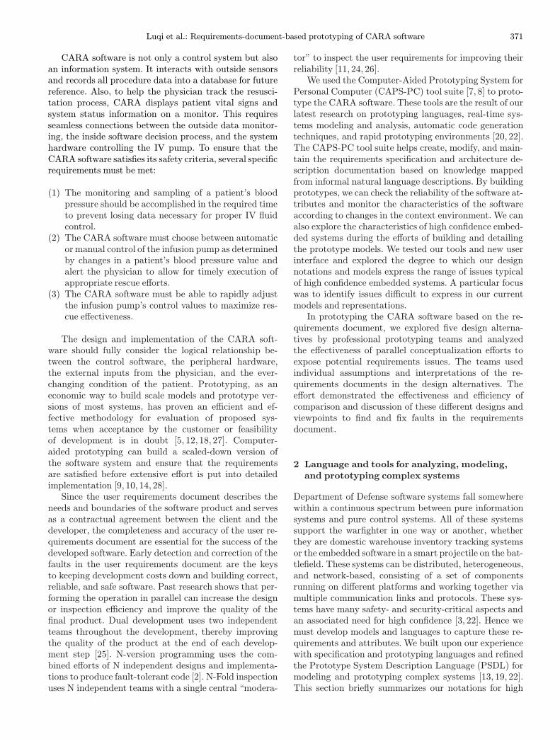
Int J Softw Tools Technol Transfer (2004) 5: 370–390 / Digital Object Identifier (DOI) 10.1007/s10009-003-0116-7 Requirements-document-based prototyping of CARA 1 software Luqi 1 , Z. Guan 1 , V. Berzins 1 , L. Zhang 1 , D. Floodeen 1 , V. Coskun 2 , J. Puett 1 , M. Brown 1 1 Software Engineering Automation Center, Naval Postgraduate School, 833 Dyer Road, Monterey, CA 93943, USA e-mail: {luqi,zguan,berzins,lzhang,dlfloode,jfpuett,mlbrown}@nps.navy.mil 2 Turkish Naval Academy, Istanbul, Turkey e-mail: [email protected] Published online: 19 December 2003 – Springer-Verlag 2003 Abstract. Computer-aided prototyping evaluates and refines software requirements by defining requirements specifications, designing underlying compositional archi- tecture, doing restricted real-time scheduling, and con- structing a prototype by using reusable executable soft- ware components. This paper presents a case study of the Computer Assisted Resuscitation Algorithm (CARA) software for a casualty intravenous fluid infusion pump and explores the effectiveness of performing rapid pro- totyping with parallel conceptualization to expose re- quirements issues. Using a suite of prototyping tools, five different design model alternatives are generated based on the analysis of customer requirements docu- ments. Further comparison is conducted with specific focus on a sample of comparative criteria: simplicity of design, safety aspects, requirements coverage, and en- abling architecture. The case study demonstrates the usefulness of comparative rapid prototyping for reveal- ing the omissions and discrepancies in the requirements document. The study also illustrates the efficiency of creating/modifying parallel models and reason for their complexity by using the tool suite. Additional enhance- ments for the prototyping suite are highlighted. Keywords: Rapid prototyping – Specification – Soft- ware tools – Requirements analysis – Parallel design 1 Introduction This paper demonstrates how computer-aided prototyp- ing from multiple viewpoints can clarify requirements for safety-critical embedded systems. The case study pre- sented in this paper compares five different designs for the control software of a sophisticated medical device. All five 1 Computer Assisted Resuscitation Algorithm designs were constructed from the same set of customer- supplied requirements documentation. We found that parallel redundancy in the prototyping and requirements analysis processes improved the quality of the results: different teams found different requirements defects and later cross comparisons identified defects that were not found by the individual teams. The requirements for the Life Support for Trauma and Transport (LSTAT) system were given by a requirements definition document written using natural language ex- pression [29–31]. This is a real system, and the require- ments documents were written by domain experts who were independent of the prototyping teams. The purpose of the LSTAT stretcher is to sustain trauma patients in transit to a medical facility until they can receive emer- gency medical treatment. The LSTAT includes multiple blood pressure sensors and an intravenous (IV) infusion pump. The embedded Computer Assisted Resuscitation Algorithm (CARA) software automates the delivery of IV fluids to the trauma patient as needed by controlling the infusion pump based on the patient’s blood pressure read- ings [1]. The algorithm calculates the drive voltage for the infusion pump. This determines the volume and rate of IV fluid administered. Proper operation of the CARA software should enable safe transport of critically injured patients without the need for continuous monitoring by medical professionals. The situation and context of using CARA is complex and varied in terms of the level of the patient’s blood pressure and the patient’s different body effects after re- ceiving IV fluid. The drive voltage used to control the IV fluid pump needs to be calculated dynamically. The re- quirements document gives detailed descriptions of the real-time constraints for the application process of the rescue strategies, which are crucial for satisfying CARA’s inherent safety requirements. A delay in delivery or an improper amount of IV fluid to the patient can result in serious injury or loss of life.
-
Upload
independent -
Category
Documents
-
view
1 -
download
0
Transcript of Requirements-document-based prototyping of CARA software
Int J Softw Tools Technol Transfer (2004) 5: 370–390 / Digital Object Identifier (DOI) 10.1007/s10009-003-0116-7
Requirements-document-basedprototypingof CARA1
software
Luqi1, Z. Guan1, V. Berzins1, L. Zhang1, D. Floodeen1, V. Coskun2, J. Puett1, M. Brown1
1Software Engineering Automation Center, Naval Postgraduate School, 833 Dyer Road, Monterey, CA 93943, USAe-mail: {luqi,zguan,berzins,lzhang,dlfloode,jfpuett,mlbrown}@nps.navy.mil2Turkish Naval Academy, Istanbul, Turkeye-mail: [email protected]
Published online: 19 December 2003 – Springer-Verlag 2003
Abstract. Computer-aided prototyping evaluates andrefines software requirements by defining requirementsspecifications, designing underlying compositional archi-tecture, doing restricted real-time scheduling, and con-structing a prototype by using reusable executable soft-ware components. This paper presents a case study ofthe Computer Assisted Resuscitation Algorithm (CARA)software for a casualty intravenous fluid infusion pumpand explores the effectiveness of performing rapid pro-totyping with parallel conceptualization to expose re-quirements issues. Using a suite of prototyping tools,five different design model alternatives are generatedbased on the analysis of customer requirements docu-ments. Further comparison is conducted with specificfocus on a sample of comparative criteria: simplicity ofdesign, safety aspects, requirements coverage, and en-abling architecture. The case study demonstrates theusefulness of comparative rapid prototyping for reveal-ing the omissions and discrepancies in the requirementsdocument. The study also illustrates the efficiency ofcreating/modifying parallel models and reason for theircomplexity by using the tool suite. Additional enhance-ments for the prototyping suite are highlighted.
Keywords: Rapid prototyping – Specification – Soft-ware tools – Requirements analysis – Parallel design
1 Introduction
This paper demonstrates how computer-aided prototyp-ing from multiple viewpoints can clarify requirements forsafety-critical embedded systems. The case study pre-sented in this paper compares five different designs for thecontrol software of a sophisticated medical device. All five
1 Computer Assisted Resuscitation Algorithm
designs were constructed from the same set of customer-supplied requirements documentation. We found thatparallel redundancy in the prototyping and requirementsanalysis processes improved the quality of the results:different teams found different requirements defects andlater cross comparisons identified defects that were notfound by the individual teams.The requirements for the Life Support for Trauma and
Transport (LSTAT) system were given by a requirementsdefinition document written using natural language ex-pression [29–31]. This is a real system, and the require-ments documents were written by domain experts whowere independent of the prototyping teams. The purposeof the LSTAT stretcher is to sustain trauma patients intransit to a medical facility until they can receive emer-gency medical treatment. The LSTAT includes multipleblood pressure sensors and an intravenous (IV) infusionpump. The embedded Computer Assisted ResuscitationAlgorithm (CARA) software automates the delivery of IVfluids to the trauma patient as needed by controlling theinfusion pump based on the patient’s blood pressure read-ings [1]. The algorithm calculates the drive voltage forthe infusion pump. This determines the volume and rateof IV fluid administered. Proper operation of the CARAsoftware should enable safe transport of critically injuredpatients without the need for continuous monitoring bymedical professionals.The situation and context of using CARA is complex
and varied in terms of the level of the patient’s bloodpressure and the patient’s different body effects after re-ceiving IV fluid. The drive voltage used to control the IVfluid pump needs to be calculated dynamically. The re-quirements document gives detailed descriptions of thereal-time constraints for the application process of therescue strategies, which are crucial for satisfying CARA’sinherent safety requirements. A delay in delivery or animproper amount of IV fluid to the patient can result inserious injury or loss of life.
Luqi et al.: Requirements-document-based prototyping of CARA software 371
CARA software is not only a control system but alsoan information system. It interacts with outside sensorsand records all procedure data into a database for futurereference. Also, to help the physician track the resusci-tation process, CARA displays patient vital signs andsystem status information on a monitor. This requiresseamless connections between the outside data monitor-ing, the inside software decision process, and the systemhardware controlling the IV pump. To ensure that theCARA software satisfies its safety criteria, several specificrequirements must be met:
(1) The monitoring and sampling of a patient’s bloodpressure should be accomplished in the required timeto prevent losing data necessary for proper IV fluidcontrol.
(2) The CARA software must choose between automaticor manual control of the infusion pump as determinedby changes in a patient’s blood pressure value andalert the physician to allow for timely execution ofappropriate rescue efforts.
(3) The CARA software must be able to rapidly adjustthe infusion pump’s control values to maximize res-cue effectiveness.
The design and implementation of the CARA soft-ware should fully consider the logical relationship be-tween the control software, the peripheral hardware,the external inputs from the physician, and the ever-changing condition of the patient. Prototyping, as aneconomic way to build scale models and prototype ver-sions of most systems, has proven an efficient and ef-fective methodology for evaluation of proposed sys-tems when acceptance by the customer or feasibilityof development is in doubt [5, 12, 18, 27]. Computer-aided prototyping can build a scaled-down version ofthe software system and ensure that the requirementsare satisfied before extensive effort is put into detailedimplementation [9, 10, 14, 28].Since the user requirements document describes the
needs and boundaries of the software product and servesas a contractual agreement between the client and thedeveloper, the completeness and accuracy of the user re-quirements document are essential for the success of thedeveloped software. Early detection and correction of thefaults in the user requirements document are the keysto keeping development costs down and building correct,reliable, and safe software. Past research shows that per-forming the operation in parallel can increase the designor inspection efficiency and improve the quality of thefinal product. Dual development uses two independentteams throughout the development, thereby improvingthe quality of the product at the end of each develop-ment step [25]. N-version programming uses the com-bined efforts of N independent designs and implementa-tions to produce fault-tolerant code [2]. N-Fold inspectionuses N independent teams with a single central “modera-
tor” to inspect the user requirements for improving theirreliability [11, 24, 26].We used the Computer-Aided Prototyping System for
Personal Computer (CAPS-PC) tool suite [7, 8] to proto-type the CARA software. These tools are the result of ourlatest research on prototyping languages, real-time sys-tems modeling and analysis, automatic code generationtechniques, and rapid prototyping environments [20, 22].The CAPS-PC tool suite helps create, modify, and main-tain the requirements specification and architecture de-scription documentation based on knowledge mappedfrom informal natural language descriptions. By buildingprototypes, we can check the reliability of the software at-tributes and monitor the characteristics of the softwareaccording to changes in the context environment. We canalso explore the characteristics of high confidence embed-ded systems during the efforts of building and detailingthe prototype models. We tested our tools and new userinterface and explored the degree to which our designnotations and models express the range of issues typicalof high confidence embedded systems. A particular focuswas to identify issues difficult to express in our currentmodels and representations.In prototyping the CARA software based on the re-
quirements document, we explored five design alterna-tives by professional prototyping teams and analyzedthe effectiveness of parallel conceptualization efforts toexpose potential requirements issues. The teams usedindividual assumptions and interpretations of the re-quirements documents in the design alternatives. Theeffort demonstrated the effectiveness and efficiency ofcomparison and discussion of these different designs andviewpoints to find and fix faults in the requirementsdocument.
2 Language and tools for analyzing, modeling,and prototyping complex systems
Department of Defense software systems fall somewherewithin a continuous spectrum between pure informationsystems and pure control systems. All of these systemssupport the warfighter in one way or another, whetherthey are domestic warehouse inventory tracking systemsor the embedded software in a smart projectile on the bat-tlefield. These systems can be distributed, heterogeneous,and network-based, consisting of a set of componentsrunning on different platforms and working together viamultiple communication links and protocols. These sys-tems have many safety- and security-critical aspects andan associated need for high confidence [3, 22]. Hence wemust develop models and languages to capture these re-quirements and attributes. We built upon our experiencewith specification and prototyping languages and refinedthe Prototype System Description Language (PSDL) formodeling and prototyping complex systems [13, 19, 22].This section briefly summarizes our notations for high
372 Luqi et al.: Requirements-document-based prototyping of CARA software
confidence embedded systems, which we used for theCARA prototyping effort.Formally, the external view computational model ζ′
can be represented as follows:
ζ′ = (G,H),
where G is a functional emergent property vector thatrepresents the functional requirements of an embed-ded system and H denotes a nonfunctional emergentproperty vector that reveals the nonfunctional require-ments related to the high confidence of an embeddedsystem [22]. By mapping nonfunctional and functionalemergent properties presented in an external view ofa model into local constraints, the internal view compu-tational model can be derived. It is formally described asa 6-tuple:
ζ = (S,E,C,D, F1, F2)
where:
S = {si|i ∈ [1, n]}, si is the component system, andn is the number of component systems;E = {ejk|j, k ∈ [1, n]}, ejk is the set of interactionsfrom component system sj to component system sk;C = {ci|i ∈ [1, n]}, c
pi is the p-th constraint for si;
D = {djk|j, k ∈ [1, n]}, dqjk is the q-th constraint for
ejk;C = F1(G,H); D = F2(G,H), F1 and F2 are twomaps that map emergent properties into local con-straint sets on component systems and local con-straint sets on interactions between component sys-tems, respectively.
The main differences between the current and previ-ous versions of PSDL are that constraints can be asso-ciated with interactions as well as with subsystems andthat the open syntax for expressing an unbounded setof properties of the structural elements of the model hasbeen given additional standard interpretations for ex-pressing additional kinds of constraints.
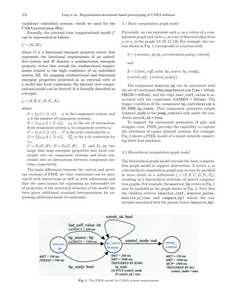
Fig. 1. The PSDL model for CARA system requirements
2.1 Basic computation graph model
Pictorially, we can represent each si as a vertex of a com-putation graph and each eij as a set of directed edges fromsi to sj in the graph [13, 16, 17, 19]. For example, the sys-tem shown in Fig. 1 corresponds to a system with
S = {monitor_bp,bp_corroboration,pump_control}
and
E = {{last_cuff_value, bp_source, bp_ready},
{corrob_ok}, {control_mode}}.
The component monitor_bp can be associated withthe set of constraints {Maximum Execution Time = 100 ms,PERIOD = 500 ms}, and the edge last_cuff_value is as-sociated with the constraints {LATENCY = 500 ms}. Thetrigger condition of the component bp_corrobration isBY SOME bp_ready. That component generates outputcontrol_mode to the pump_control only under the con-dition corrob_ok = true.To support the automated generation of glue and
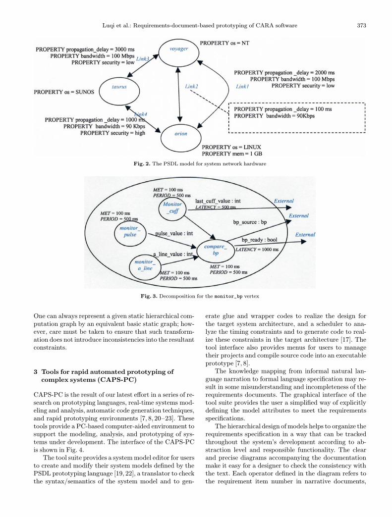
wrapper code, PSDL provides the capability to capturethe attributes of target network systems. For example,Fig. 2 shows a PSDL model of a target network connect-ing three host machines.
2.2 Hierarchical computation graph model
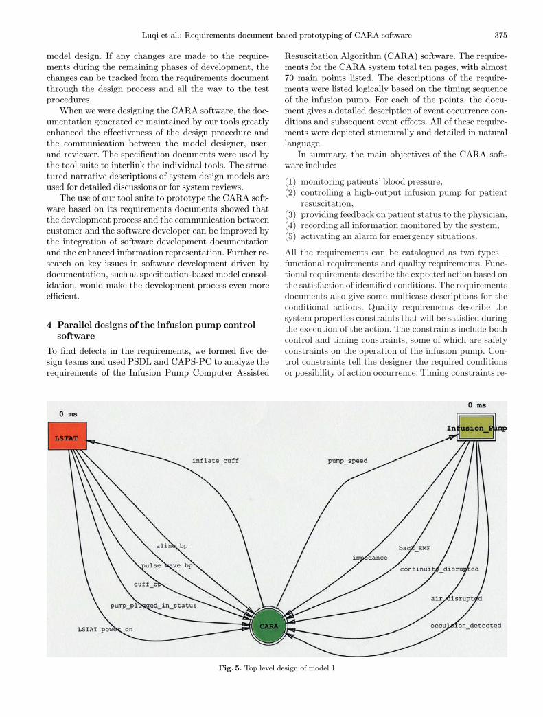
The hierarchical graph model extends the basic computa-tion graph model to support abstraction. A vertex si ina hierarchical computation graphmay in turn be modeledin more detail as a subsystem ζ = (S,E,C,D, F1, F2),resulting in a hierarchical structure of nested computa-tion graphs. For example, the monitor_bp vertex in Fig. 1may be modeled as the graph shown in Fig. 3. Note thatthe children vertices (monitor_cuff, monitor_pulse,monitor_a_line, and compare_bp) inherit the con-straints associated with the parent vertex (monitor_bp).
Luqi et al.: Requirements-document-based prototyping of CARA software 373
Fig. 2. The PSDL model for system network hardware
Fig. 3. Decomposition for the monitor_bp vertex
One can always represent a given static hierarchical com-putation graph by an equivalent basic static graph; how-ever, care must be taken to ensure that such transform-ation does not introduce inconsistencies into the resultantconstraints.
3 Tools for rapid automated prototyping ofcomplex systems (CAPS-PC)
CAPS-PC is the result of our latest effort in a series of re-search on prototyping languages, real-time systems mod-eling and analysis, automatic code generation techniques,and rapid prototyping environments [7, 8, 20–23]. Thesetools provide a PC-based computer-aided environment tosupport the modeling, analysis, and prototyping of sys-tems under development. The interface of the CAPS-PCis shown in Fig. 4.The tool suite provides a systemmodel editor for users
to create and modify their system models defined by thePSDL prototyping language [19, 22], a translator to checkthe syntax/semantics of the system model and to gen-
erate glue and wrapper codes to realize the design forthe target system architecture, and a scheduler to ana-lyze the timing constraints and to generate code to real-ize these constraints in the target architecture [17]. Thetool interface also provides menus for users to managetheir projects and compile source code into an executableprototype [7, 8].The knowledge mapping from informal natural lan-
guage narration to formal language specification may re-sult in some misunderstanding and incompleteness of therequirements documents. The graphical interface of thetool suite provides the user a simplified way of explicitlydefining the model attributes to meet the requirementsspecifications.The hierarchical design of models helps to organize the
requirements specification in a way that can be trackedthroughout the system’s development according to ab-straction level and responsible functionality. The clearand precise diagrams accompanying the documentationmake it easy for a designer to check the consistency withthe text. Each operator defined in the diagram refers tothe requirement item number in narrative documents,

374 Luqi et al.: Requirements-document-based prototyping of CARA software
Fig. 4. Interface of the CAPS-PC environment
which makes it easy to find cross references in the wholedesign model.Several supporting documents can be built by the de-
signers or generated automatically by using CAPS-PC.As the central chain of development documentation,these documents drive the specification, design, imple-mentation, and even testing of the system development.The consistency maintained by the tool suite betweenthese documents provides a solid baseline throughout thedevelopment effort. The documentation generation func-tion of the tool suite makes it easy for the customer, user,and sponsor to understand, handle, and review the sys-tem during development.First, the specification of requirements can be gen-
erated with completeness and consistency checking, ac-cording to the system functionalities and constraints. Thegraphical design process maintains the syntax of the re-quirements specification, and a further translation pro-cess ensures the semantic consistency of the specificationdocument.Second, the narrative description of a designed model
in natural language can be generated based on the defin-ition of model functionalities and constraints, whichtell the customers and users what the system will and
will not do. For example, for CARA’s periodic bloodpressure corroboration, the model can generate the fol-lowing narration: “if VALID_BP is CUFF_BP, and ifMEAN_BP > 90, the CUFF_BP will get data fromCUFF_MONITOR every 10 minutes”.Third, by using technical terminology to describe the
system’s structure, data and function can be generatedbased on the model specification. Information about in-put, such as where data come from and how they are for-matted; output, such as where data are sent and how theyare formatted; general functional characteristics, such asperiodic execution or sporadic execution; performanceconstraints, such as minimum execution time; and spe-cific fault-handling approaches can be generated and de-scribed in the design documentation.Fourth, during the generation of prototype code, the
tool suite can generate partial implementation documen-tation based on the specification structure. The name,type, and purpose of major data structures and variables,simple description of logic flow, expected input, and pos-sible output can be derived from the information definedin the model.Furthermore, CAPS-PC canmaintain the version con-
trol documentation for requirements specifications and
Luqi et al.: Requirements-document-based prototyping of CARA software 375
model design. If any changes are made to the require-ments during the remaining phases of development, thechanges can be tracked from the requirements documentthrough the design process and all the way to the testprocedures.When we were designing the CARA software, the doc-
umentation generated or maintained by our tools greatlyenhanced the effectiveness of the design procedure andthe communication between the model designer, user,and reviewer. The specification documents were used bythe tool suite to interlink the individual tools. The struc-tured narrative descriptions of system design models areused for detailed discussions or for system reviews.The use of our tool suite to prototype the CARA soft-
ware based on its requirements documents showed thatthe development process and the communication betweencustomer and the software developer can be improved bythe integration of software development documentationand the enhanced information representation. Further re-search on key issues in software development driven bydocumentation, such as specification-basedmodel consol-idation, would make the development process even moreefficient.
4 Parallel designs of the infusion pump controlsoftware
To find defects in the requirements, we formed five de-sign teams and used PSDL and CAPS-PC to analyze therequirements of the Infusion Pump Computer Assisted
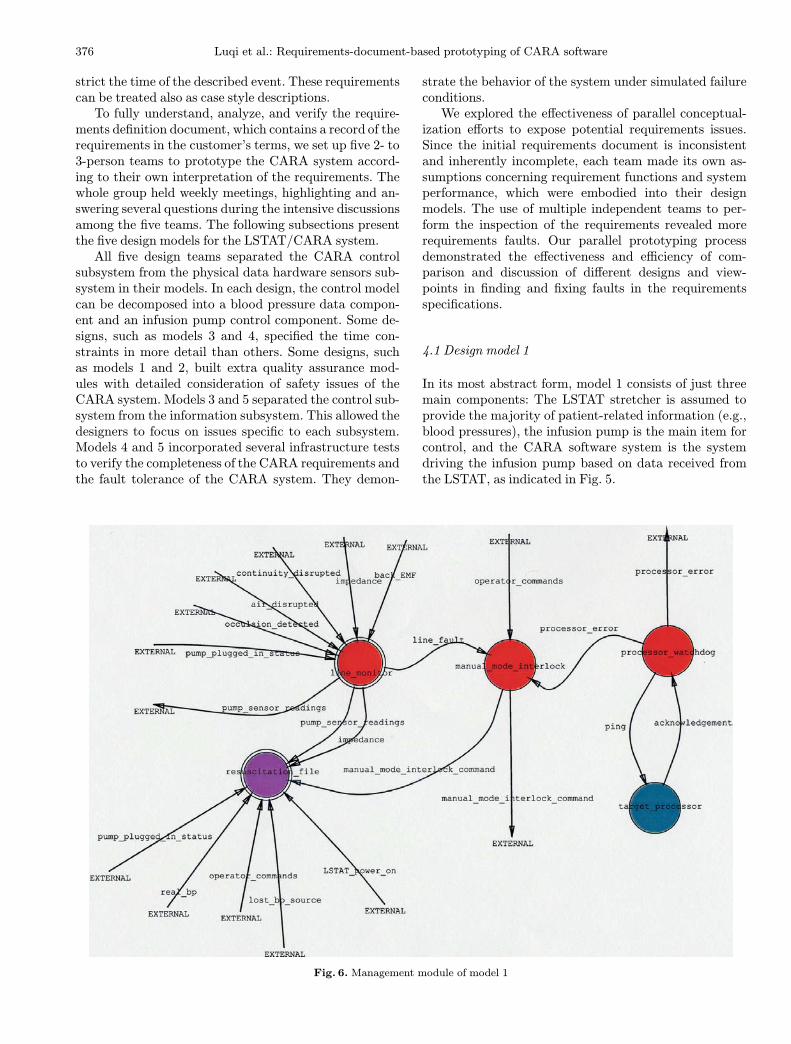
Fig. 5. Top level design of model 1
Resuscitation Algorithm (CARA) software. The require-ments for the CARA system total ten pages, with almost70 main points listed. The descriptions of the require-ments were listed logically based on the timing sequenceof the infusion pump. For each of the points, the docu-ment gives a detailed description of event occurrence con-ditions and subsequent event effects. All of these require-ments were depicted structurally and detailed in naturallanguage.In summary, the main objectives of the CARA soft-
ware include:
(1) monitoring patients’ blood pressure,(2) controlling a high-output infusion pump for patientresuscitation,
(3) providing feedback on patient status to the physician,(4) recording all information monitored by the system,(5) activating an alarm for emergency situations.
All the requirements can be catalogued as two types –functional requirements and quality requirements. Func-tional requirements describe the expected action based onthe satisfaction of identified conditions. The requirementsdocuments also give some multicase descriptions for theconditional actions. Quality requirements describe thesystem properties constraints that will be satisfied duringthe execution of the action. The constraints include bothcontrol and timing constraints, some of which are safetyconstraints on the operation of the infusion pump. Con-trol constraints tell the designer the required conditionsor possibility of action occurrence. Timing constraints re-
376 Luqi et al.: Requirements-document-based prototyping of CARA software
strict the time of the described event. These requirementscan be treated also as case style descriptions.To fully understand, analyze, and verify the require-
ments definition document, which contains a record of therequirements in the customer’s terms, we set up five 2- to3-person teams to prototype the CARA system accord-ing to their own interpretation of the requirements. Thewhole group held weekly meetings, highlighting and an-swering several questions during the intensive discussionsamong the five teams. The following subsections presentthe five design models for the LSTAT/CARA system.All five design teams separated the CARA control
subsystem from the physical data hardware sensors sub-system in their models. In each design, the control modelcan be decomposed into a blood pressure data compon-ent and an infusion pump control component. Some de-signs, such as models 3 and 4, specified the time con-straints in more detail than others. Some designs, suchas models 1 and 2, built extra quality assurance mod-ules with detailed consideration of safety issues of theCARA system. Models 3 and 5 separated the control sub-system from the information subsystem. This allowed thedesigners to focus on issues specific to each subsystem.Models 4 and 5 incorporated several infrastructure teststo verify the completeness of the CARA requirements andthe fault tolerance of the CARA system. They demon-
Fig. 6. Management module of model 1
strate the behavior of the system under simulated failureconditions.We explored the effectiveness of parallel conceptual-
ization efforts to expose potential requirements issues.Since the initial requirements document is inconsistentand inherently incomplete, each team made its own as-sumptions concerning requirement functions and systemperformance, which were embodied into their designmodels. The use of multiple independent teams to per-form the inspection of the requirements revealed morerequirements faults. Our parallel prototyping processdemonstrated the effectiveness and efficiency of com-parison and discussion of different designs and view-points in finding and fixing faults in the requirementsspecifications.
4.1 Design model 1
In its most abstract form, model 1 consists of just threemain components: The LSTAT stretcher is assumed toprovide the majority of patient-related information (e.g.,blood pressures), the infusion pump is the main item forcontrol, and the CARA software system is the systemdriving the infusion pump based on data received fromthe LSTAT, as indicated in Fig. 5.
Luqi et al.: Requirements-document-based prototyping of CARA software 377
This design model presents the most comprehensiveconsideration of the safety issues and deals directly withthe potential confusion in control modes between man-ual control and autocontrol and the potential confusion inacquiring blood pressure sensor data.The manual_mode_interlock operator in the decom-
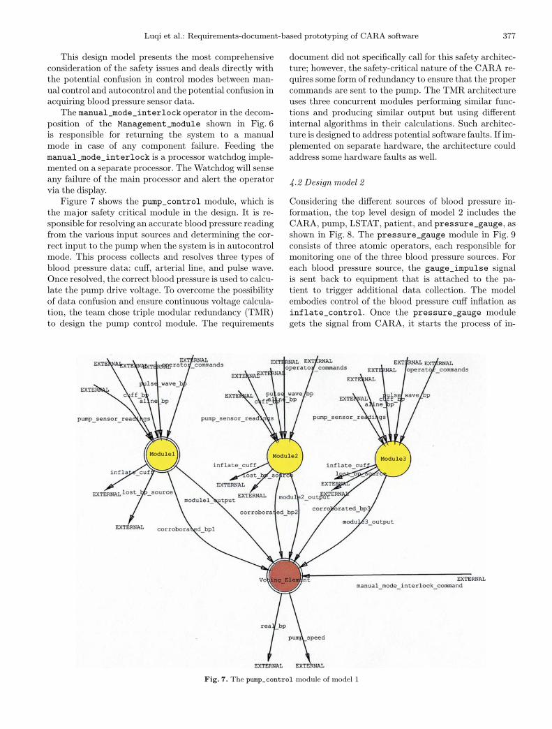
position of the Management_module shown in Fig. 6is responsible for returning the system to a manualmode in case of any component failure. Feeding themanual_mode_interlock is a processor watchdog imple-mented on a separate processor. The Watchdog will senseany failure of the main processor and alert the operatorvia the display.Figure 7 shows the pump_control module, which is
the major safety critical module in the design. It is re-sponsible for resolving an accurate blood pressure readingfrom the various input sources and determining the cor-rect input to the pump when the system is in autocontrolmode. This process collects and resolves three types ofblood pressure data: cuff, arterial line, and pulse wave.Once resolved, the correct blood pressure is used to calcu-late the pump drive voltage. To overcome the possibilityof data confusion and ensure continuous voltage calcula-tion, the team chose triple modular redundancy (TMR)to design the pump control module. The requirements
Fig. 7. The pump_control module of model 1
document did not specifically call for this safety architec-ture; however, the safety-critical nature of the CARA re-quires some form of redundancy to ensure that the propercommands are sent to the pump. The TMR architectureuses three concurrent modules performing similar func-tions and producing similar output but using differentinternal algorithms in their calculations. Such architec-ture is designed to address potential software faults. If im-plemented on separate hardware, the architecture couldaddress some hardware faults as well.
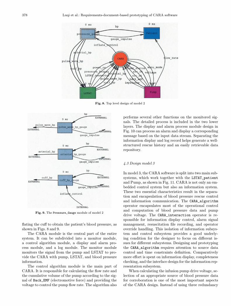
4.2 Design model 2
Considering the different sources of blood pressure in-formation, the top level design of model 2 includes theCARA, pump, LSTAT, patient, and pressure_gauge, asshown in Fig. 8. The pressure_gauge module in Fig. 9consists of three atomic operators, each responsible formonitoring one of the three blood pressure sources. Foreach blood pressure source, the gauge_impulse signalis sent back to equipment that is attached to the pa-tient to trigger additional data collection. The modelembodies control of the blood pressure cuff inflation asinflate_control. Once the pressure_gauge modulegets the signal from CARA, it starts the process of in-
378 Luqi et al.: Requirements-document-based prototyping of CARA software
Fig. 8. Top level design of model 2
Fig. 9. The Pressure_Gauge module of model 2
flating the cuff to obtain the patient’s blood pressure, asshown in Figs. 8 and 9.The CARA module is the central part of the entire
system. It can be subdivided into a monitor module,a control algorithm module, a display and alarm pro-cess module, and a log module. The monitor modulemonitors the signal from the pump and LSTAT to pro-vide the CARA with pump, LSTAT, and blood pressureinformation.The control algorithm module is the main part of
CARA. It is responsible for calculating the flow rate andthe cumulative volume of the pump according to the sig-nal of Back_EMF (electromotive force) and providing thevoltage to control the pump flow rate. The algorithm also
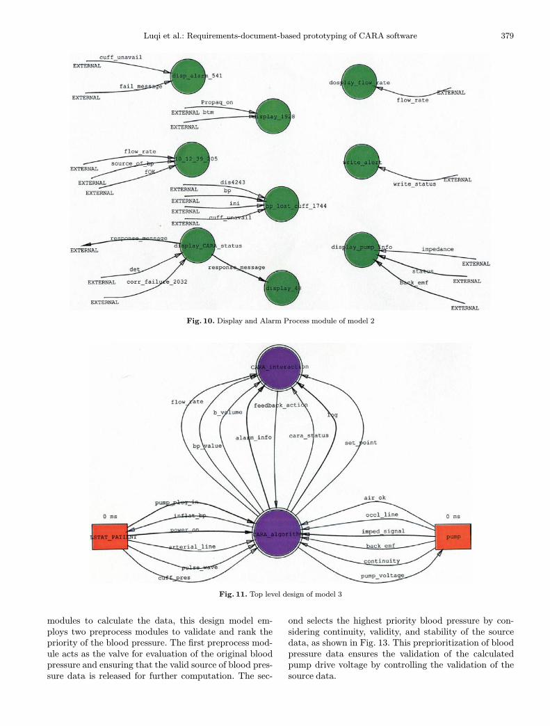
performs several other functions on the monitored sig-nals. The detailed process is included in the two lowerlayers. The display and alarm process module design inFig. 10 can process an alarm and display a correspondingmessage based on the input data stream. Separating theinformation display and log record helps generate a well-structured rescue history and an easily retrievable datarepository.
4.3 Design model 3
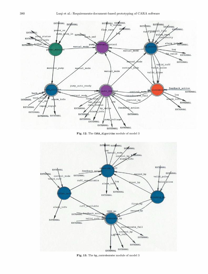
In model 3, the CARA software is split into two main sub-systems, which work together with the LSTAT_patientand Pump, as shown in Fig. 11. CARA is not only an em-bedded control system but also an information system.These two essential characteristics result in the separa-tion and encapsulation of blood pressure rescue controland information communication. The CARA_algorithmoperator encapsulates most of the operational controland computation of blood pressure data and pumpdrive voltage. The CARA_interaction operator is re-sponsible for information display control, alarm signalmanagement, resuscitation file recording, and operatoroverride handling. This isolation of information subsys-tem and control subsystem provides a good underly-ing condition for the designer to focus on different is-sues for different subsystems. Designing and prototypingthe CARA_algorithm requires attention to source datacontrol and time constraints definition. Comparativelymore effort is spent on information display, completenesschecking, and the interface design for the information rep-resentation subsystem.When calculating the infusion pump drive voltage, se-
lection of an appropriate source of blood pressure datafor corroboration is one of the most important aspectsof the CARA design. Instead of using three redundancy
Luqi et al.: Requirements-document-based prototyping of CARA software 379
Fig. 10. Display and Alarm Process module of model 2
Fig. 11. Top level design of model 3
modules to calculate the data, this design model em-ploys two preprocess modules to validate and rank thepriority of the blood pressure. The first preprocess mod-ule acts as the valve for evaluation of the original bloodpressure and ensuring that the valid source of blood pres-sure data is released for further computation. The sec-
ond selects the highest priority blood pressure by con-sidering continuity, validity, and stability of the sourcedata, as shown in Fig. 13. This preprioritization of bloodpressure data ensures the validation of the calculatedpump drive voltage by controlling the validation of thesource data.
380 Luqi et al.: Requirements-document-based prototyping of CARA software
Fig. 12. The CARA_Algorithm module of model 3
Fig. 13. The bp_corroborate module of model 3
Luqi et al.: Requirements-document-based prototyping of CARA software 381
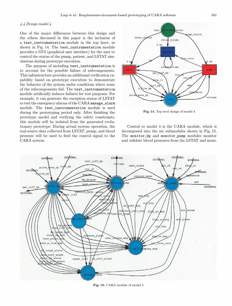
4.4 Design model 4
One of the major differences between this design andthe others discussed in this paper is the inclusion ofa test_instrumentation module in the top layer, asshown in Fig. 14. The test_instrumentation moduleprovides a GUI (graphical user interface) for the user tocontrol the status of the pump, patient, and LSTAT sim-ulations during prototype execution.The purpose of including test_instrumentation is
to account for the possible failure of subcomponents.This infrastructure provides an additional verification ca-pability based on prototype execution to demonstratethe behavior of the system under conditions where someof the subcomponents fail. The test_instrumentationmodule artificially induces failures for test purposes. Forexample, it can generate the exception status of LSTATto test the emergency alarms of the CARA manage_alarmmodule. The test_instrumentation module is usedduring the prototyping period only. After finishing theprototype model and verifying the safety constraints,this module will be isolated from the generated evolu-tionary prototype. During actual system operation, thereal source data collected from LSTAT, pump, and bloodpressure will be used to feed the control signal to theCARA system.
Fig. 15. CARA module of model 4
Fig. 14. Top level design of model 4
Central to model 4 is the CARA module, which isdecomposed into the six submodules shown in Fig. 15.The monitor_bp and monitor_pump modules monitorand validate blood pressures from the LSTAT and moni-
382 Luqi et al.: Requirements-document-based prototyping of CARA software
Fig. 16. The Monitor_bp module of model 4
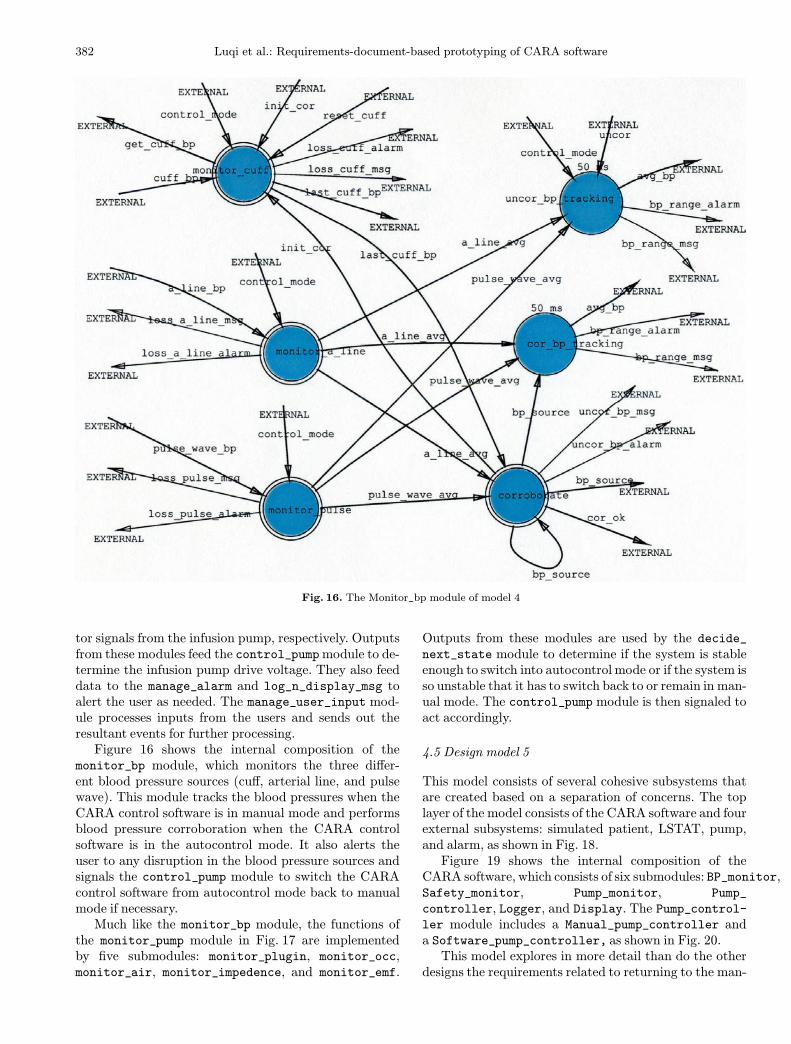
tor signals from the infusion pump, respectively. Outputsfrom these modules feed the control_pumpmodule to de-termine the infusion pump drive voltage. They also feeddata to the manage_alarm and log_n_display_msg toalert the user as needed. The manage_user_input mod-ule processes inputs from the users and sends out theresultant events for further processing.Figure 16 shows the internal composition of the
monitor_bp module, which monitors the three differ-ent blood pressure sources (cuff, arterial line, and pulsewave). This module tracks the blood pressures when theCARA control software is in manual mode and performsblood pressure corroboration when the CARA controlsoftware is in the autocontrol mode. It also alerts theuser to any disruption in the blood pressure sources andsignals the control_pump module to switch the CARAcontrol software from autocontrol mode back to manualmode if necessary.Much like the monitor_bp module, the functions of
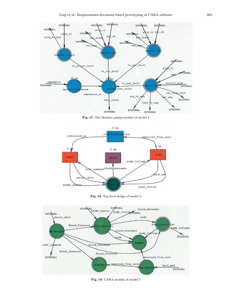
the monitor_pump module in Fig. 17 are implementedby five submodules: monitor_plugin, monitor_occ,monitor_air, monitor_impedence, and monitor_emf.
Outputs from these modules are used by the decide_next_state module to determine if the system is stableenough to switch into autocontrol mode or if the system isso unstable that it has to switch back to or remain in man-ual mode. The control_pump module is then signaled toact accordingly.
4.5 Design model 5
This model consists of several cohesive subsystems thatare created based on a separation of concerns. The toplayer of the model consists of the CARA software and fourexternal subsystems: simulated patient, LSTAT, pump,and alarm, as shown in Fig. 18.Figure 19 shows the internal composition of the
CARA software, which consists of six submodules: BP_monitor,Safety_monitor, Pump_monitor, Pump_
controller, Logger, and Display. The Pump_control-ler module includes a Manual_pump_controller anda Software_pump_controller, as shown in Fig. 20.This model explores in more detail than do the other
designs the requirements related to returning to the man-
Luqi et al.: Requirements-document-based prototyping of CARA software 383
Fig. 17. The Monitor_pump module of model 4
Fig. 18. Top level design of model 5
Fig. 19. CARA module of model 5

384 Luqi et al.: Requirements-document-based prototyping of CARA software
Fig. 20. The Pump_controller module of model 5
ual control mode when the safety of the automatic controlis compromised. This design identifies the need for addi-tional external interaction when unsafe conditions arise.When the patient’s well-being is in jeopardy, alarms willalert human operators. The simulated patient tests theeffectiveness of proposed pump control policies. Combin-ing this design with the test instrumentation structureof model 4 would more effectively check the transitionsbetween automatic control and manual control and backagain, particularly with respect to safety issues and pos-sible missing requirements.
5 Features of the designmodels
Using a suite of prototyping tools, five teams generatedalternative design models based on the analysis of cus-tomer requirements documents. Because the experimentswere conducted by five different teams independently,the five models had different features. The different fea-tures can be divided into four main categories: require-ments coverage, simplicity of design, enabling architec-ture, and safety aspects. Analyzing features of the fivemodels helped us uncover the defects of the requirementsfrom different perspectives.
5.1 Requirements coverage
All of the models cover most of the stated requirementsin the broad sense, but they vary in detail when it comesto capturing the logic of the procedures stated in the re-quirements. All of the models identify the major functionsof the CARA software and group them into different mod-ules. With the exception of model 5, each model covers∼ 90% of the high-level requirements and at least half ofthe detailed ones.
5.2 Simplicity of design
Model 1 maintains its elegance and simplicity as we followthe decomposition to the lower levels of granularity. Thewhole architecture is easily followed and understood. Thesegregation of the identified safety-critical functions fromnon-safety-critical functions greatly enhances the safetyof the design. Models 2, 3, and 4 suffer from varying de-grees of complexity at the lower levels of granularity.Models 3 and 5 also attempt to segregate the safety-
critical functions from the non-safety-critical ones in theirdesign, but both need more work to complete the design.Model 2 attempts to divide the detailed activities of thecontrol algorithms into six concurrent processes but failsto capture the event/response relationship among theseprocesses. Model 4 gives the most detailed design. It at-tempts to reduce the complexity of the graph throughthe use of triggering conditions and timer operators.For example, the pump_control module models a statemachine consisting of three states {auto_off_state,auto_ready_state, and auto_on_state}. Dependingon the value of the control_mode state stream, oneof the three processes in the pump_control modulewill be active at all times. Human input will triggerthe get_initial_cuff_bp operator to request that themonitor_bpmodule corroborate the different blood pres-sure sources. The other four operators will remain idlewhil waiting for the results from the monitor_bp mod-ule. When triggered by the arrival of the results, thesefour operators will decide whether it is safe to switchinto auto_control_state and change the value of thecontrol_mode state stream accordingly.Simplicity of design, in general, can be accomplished
with sparse diagrams. Again, model 1 gives the simplestdesign. While all designs limit the number of operatorsin all levels to at most seven operators, they all sufferfrom varying degrees of data stream overcrowding. One
Luqi et al.: Requirements-document-based prototyping of CARA software 385
way to solve this problem is to move the functions andform weaker coupling modules. For example, model 4can greatly simplify the top layer of the CARA softwareshown in Fig. 15 if it follows model 1’s design and placesthe monitor_bp module inside the control_pump mod-ule. Another way to reduce the number of data streams isthrough the use of composite streams. For example, com-bining all alarm signals into a common stream and let-ting the alarm manager differentiate the different signalsources and priorities and then process them accordinglysignificantly simplifies the alarm data stream design.
5.3 Understandability of the model architecture
Understandability of the model architecture was a com-mon goal of all the designs. The design teams attemptedto accomplish this goal via decomposition based on sepa-ration of concerns. This approach resulted in very similar,but nevertheless different, top level designs. The top leveldesigns reflect two different assumptions of the intendedprototype. Models 1 and 3, as indicated by Figs. 5 and 11,model the prototypes as open systems, where the pumpand the LSTAT modules represent interfaces to the ac-tual hardware. Models 2, 4, and 5, as displayed by Figs. 8,14, and 18, model the prototypes as closed systems. Thesedesigns include a simulated patient to model the effect ofthe IV infusion on the patient’s blood pressure. In add-ition, model 4 includes a test_instrumentationmoduleto facilitate runtime testing.In an effort to decompose the CARA system, each
design team identified the following functions of theCARA software – monitoring pump, monitoring bloodpressure, controlling pump, logging and displaying mes-sages, and managing user input. However, the five designteams varied in how they presented these functions inthe hierarchical decompositions. Model 1 provides thesimplest design. It groups these major functions intothree modules – pump_control_module (for monitor-ing blood pressure and controlling pump), io_module(for displaying messages and managing user input), andmanagement_module (for monitoring pump and loggingmessages). Model 2 groups all monitoring functions, suchas monitoring pump and monitoring blood pressure, intoa single monitor module and buries the user input man-agement in the control_algmodule. On the other hand,model 3, as shown in Fig. 12, separates the message dis-play and user input management from the CARA controlsoftware and places them in a CARA_interactionmodulein the top level of the prototype. Models 4 and 5, as shownin Figs. 15 and 19 respectively, have very similar designs.They both lay out all six functions explicitly in the toplayer of the CARA software.
5.4 Safety aspects of the design
CARA is a software system that provides closed-loopcontrol to a high-output infusion pump [6, 15]. It is im-
portant to quantitatively define the safety issues in itsrequirements documents. However, the design require-ments, even with the additional questions and answersdocument [30] provided, are very incomplete, especiallyin the system safety aspect. The requirements documentsdo not provide any performance requirements – they pro-vide primarily design requirements. In particular, the re-quirements documents do not identify or prioritize thefunctions, especially from a safety perspective. As a re-sult, some models, such as models 2 and 4, do not dif-ferentiate between safety-critical and non-safety-criticalfunctions.The segregation of the identified safety-critical func-
tions from non-safety-critical functions greatly enhancesthe design of models 1 and 5. In addition to thosespecified in the requirements documents, model 1 in-cludes two additional safety features in the design.First, it implements triple modular redundancy (TMR)within the principal safety-critical module, the pump_control module in Fig. 7. This TMR architecture relieson three different algorithms for calculating the infu-sion rate when in autocontrol mode and a single votingmechanism to determine which rate to pass to the pump.Second, it implements a processor watchdog function ona separate processor to alert the operator in cases of mainprocessor failure, as shown in Fig. 5. The redundant archi-tecture on the blood pressure corroboration promises tosubstantially reduce the potential for a faulty monitor todrive the infusion pump.Model 2 provides for ready identification of safety-
related functions and data; however, the design doesnot segregate either from the non-safety-related functionsand data. Therefore, the safety assessment and verifica-tion of this design is more difficult than the assessment ofmodel 1 or 5.The complexity of model 3 makes it the hardest to
assess from a safety perspective. Most of the objects inthe design have safety-related functions or information.Therefore, the design will require analysis and testing ofa majority of the software. The preprocess modules ofmodel 3 are safety critical in that they provide all of thesafety-critical information used to control CARA.The test_instrumentationmodule incorporated in
model 4 provides a valuable tool for verifying safety-related functions in the design. In the current implemen-tation, the design incorporates limited testing of safety-critical signals and functions; however, the design couldexpand to address additional safety-critical aspects. Likemodel 2, the complexity of the software and the lack ofsegregation of safety-related processing from non-safety-related processing make safety assessment and verifica-tion difficult.The safety_monitor module in model 5 uses a differ-
ent system architecture to achieve the necessary level ofrisk mitigation in the design. The use of this architecturecan reduce the overall effort required to perform safetyassessment; however, it requires that the safety_monitor
386 Luqi et al.: Requirements-document-based prototyping of CARA software
module be robust and highly reliable from a safety per-spective and that it be capable of terminating other func-tions in the design when it detects unsafe conditions. Itsdesign will require identification of all safety-related func-tions and data and potential failure modes that couldpose a risk to the patient.
6 Elicitation and evaluationof the requirements document
6.1 Requirements inspection and evaluation
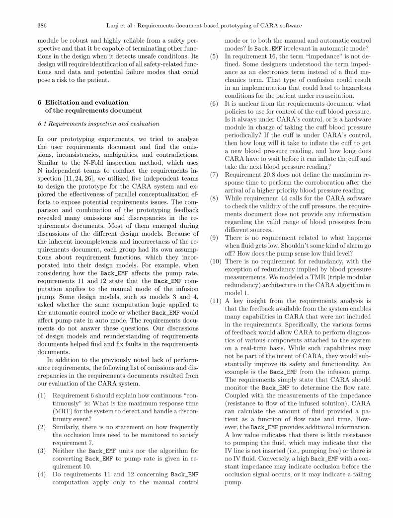
In our prototyping experiments, we tried to analyzethe user requirements document and find the omis-sions, inconsistencies, ambiguities, and contradictions.Similar to the N-Fold inspection method, which usesN independent teams to conduct the requirements in-spection [11, 24, 26], we utilized five independent teamsto design the prototype for the CARA system and ex-plored the effectiveness of parallel conceptualization ef-forts to expose potential requirements issues. The com-parison and combination of the prototyping feedbackrevealed many omissions and discrepancies in the re-quirements documents. Most of them emerged duringdiscussions of the different design models. Because ofthe inherent incompleteness and incorrectness of the re-quirements document, each group had its own assump-tions about requirement functions, which they incor-porated into their design models. For example, whenconsidering how the Back_EMF affects the pump rate,requirements 11 and 12 state that the Back_EMF com-putation applies to the manual mode of the infusionpump. Some design models, such as models 3 and 4,asked whether the same computation logic applied tothe automatic control mode or whether Back_EMF wouldaffect pump rate in auto mode. The requirements docu-ments do not answer these questions. Our discussionsof design models and reunderstanding of requirementsdocuments helped find and fix faults in the requirementsdocuments.In addition to the previously noted lack of perform-
ance requirements, the following list of omissions and dis-crepancies in the requirements documents resulted fromour evaluation of the CARA system.
(1) Requirement 6 should explain how continuous “con-tinuously” is: What is the maximum response time(MRT) for the system to detect and handle a discon-tinuity event?
(2) Similarly, there is no statement on how frequentlythe occlusion lines need to be monitored to satisfyrequirement 7.
(3) Neither the Back_EMF units nor the algorithm forconverting Back_EMF to pump rate is given in re-quirement 10.
(4) Do requirements 11 and 12 concerning Back_EMFcomputation apply only to the manual control
mode or to both the manual and automatic controlmodes? Is Back_EMF irrelevant in automatic mode?
(5) In requirement 16, the term “impedance” is not de-fined. Some designers understood the term imped-ance as an electronics term instead of a fluid me-chanics term. That type of confusion could resultin an implementation that could lead to hazardousconditions for the patient under resuscitation.
(6) It is unclear from the requirements document whatpolicies to use for control of the cuff blood pressure.Is it always under CARA’s control, or is a hardwaremodule in charge of taking the cuff blood pressureperiodically? If the cuff is under CARA’s control,then how long will it take to inflate the cuff to geta new blood pressure reading, and how long doesCARA have to wait before it can inflate the cuff andtake the next blood pressure reading?
(7) Requirement 20.8 does not define the maximum re-sponse time to perform the corroboration after thearrival of a higher priority blood pressure reading.
(8) While requirement 44 calls for the CARA softwareto check the validity of the cuff pressure, the require-ments document does not provide any informationregarding the valid range of blood pressures fromdifferent sources.
(9) There is no requirement related to what happenswhen fluid gets low. Shouldn’t some kind of alarm gooff? How does the pump sense low fluid level?
(10) There is no requirement for redundancy, with theexception of redundancy implied by blood pressuremeasurements. We modeled a TMR (triple modularredundancy) architecture in the CARA algorithm inmodel 1.
(11) A key insight from the requirements analysis isthat the feedback available from the system enablesmany capabilities in CARA that were not includedin the requirements. Specifically, the various formsof feedback would allow CARA to perform diagnos-tics of various components attached to the systemon a real-time basis. While such capabilities maynot be part of the intent of CARA, they would sub-stantially improve its safety and functionality. Anexample is the Back_EMF from the infusion pump.The requirements simply state that CARA shouldmonitor the Back_EMF to determine the flow rate.Coupled with the measurements of the impedance(resistance to flow of the infused solution), CARAcan calculate the amount of fluid provided a pa-tient as a function of flow rate and time. How-ever, the Back_EMF provides additional information.A low value indicates that there is little resistanceto pumping the fluid, which may indicate that theIV line is not inserted (i.e., pumping free) or there isno IV fluid. Conversely, a high Back_EMFwith a con-stant impedance may indicate occlusion before theocclusion signal occurs, or it may indicate a failingpump.

Luqi et al.: Requirements-document-based prototyping of CARA software 387
6.2 Integration of the five design alternatives
Not only did the five parallel prototyping efforts revealthe defects of the requirements document, but the in-tegration of the five design alternatives helped to findemergent supplements for the requirements and providea more complete design model. The five design teamsidentified different requirements discrepancies. For ex-ample, one of the most important discrepancies was thelack of reference to safety constraints. The requirementsdocuments also do not discuss exception handling mech-anisms, which required the designers to make assump-tions to complete the system design. Models 1, 4, and 5characterize these assumptions.The difference in design focus among the five teams
results in a better coverage of the functionalities of therequirements document. The final postdesign discussionwith the whole group unanimously concluded that a com-paratively more complete, effective, and efficient designmodel of the CARA system would result if we:
(1) fully considered the separation of the CARA controlmodule and the physical data source modules,
(2) explicitly specified the time constraints (as done inmodels 3 and 4),
Fig. 21. Model for a cuff blood pressure monitor policy
(3) built an extra quality assurancemodule with detailedconsideration of the safety issues associated with theCARA system (as done in models 1 and 2),
(4) built in prototype testing infrastructure to verify thecompleteness and consistency of the CARA require-ments documents (as done in models 4 and 5).
Also, the group suggested that, following a prototypingeffort such as ours, the requirements documentation berefined to include explicit system constraints identifiedand defined by this type of effort.
7 Evaluation of PSDL and CAPS-PC
This experiment shows that PSDL can effectively modelcomplex embedded software. PSDL’s triggering guardsand execution guards provide a convenient means forusers to specify state machines explicitly without beingconcerned with target code. The timer feature is usefulin modeling complicated timing policies. For example,Fig. 21 shows a simple model with two operators and fourtimers for the policy that“When the cuff pressure is being used for control:
if the mean blood pressure is 60 or below, cuff pres-sures will be taken once per minute;
388 Luqi et al.: Requirements-document-based prototyping of CARA software
if the mean blood pressure is (60–70], cuff pressureswill be taken once every 2min;if the mean blood pressure is (70–90], cuff pressureswill be taken once every 5min;if the mean blood pressure is above 90, cuff pressureswill be taken once every 10min.”
The sporadic operator established_cuff_bp is trig-gered each time it receives a new cuff blood pressurereading and starts the appropriate timer for the nextcuff reading event. The get_next_cuff operator, on theother hand, polls the timers once every 30 s and issuesthe init_cor command to the monitor_bp module inmodel 4 if any of the active timers reaches its preset trig-ger conditions.Since the above design implements the policy via
PSDL directly, users can accommodate policy changeseasily without the need to modify any source code. More-over, since a cuff reading event may also be generatedby other conditions like the loss of a beat-to-beat bloodpressure source detected by the monitor_bp module inmodel 4, the above design avoids any conflict with suchevents since it will reset its timers automatically when-ever it receives a new cuff blood pressure reading.CAPS-PC provides the essential facilities for users
to create and modify the models. It is easy to reasonabout complexity using CAPS-PC. When a level is de-termined to be too complex, it is easy to decompose.
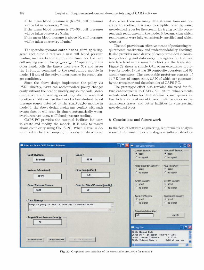
Fig. 22. Graphical user interface of the executable prototype for model 4
Also, when there are many data streams from one op-erator to another, it is easy to simplify, often by usinguser-defined types for the stream. By trying to fully repre-sent each requirement in the model, it became clear whichrequirements were fully/consistently specified and whichwere not.The tool provides an effective means of performing re-
quirements consistency and understandability checking.It also provides some degree of computer-aided inconsis-tency checking and data entry propagation at the userinterface level and a semantic check via the translator.Figure 22 shows a simple GUI of an executable proto-type for model 4 that has 20 composite operators and 89atomic operators. The executable prototype consists of14.7K lines of source code, 8.5 K of which are generatedby the translator and the scheduler of CAPS-PC.The prototype effort also revealed the need for fu-
ture enhancements to CAPS-PC. Future enhancementsinclude abstraction for data streams, visual queues forthe declaration and use of timers, multiple views for re-quirements traces, and better facilities for constructinguser-defined types.
8 Conclusions and future work
In the field of software engineering, requirements analysisis one of the most important stages in software develop-
Luqi et al.: Requirements-document-based prototyping of CARA software 389
ment. It plays an essential role in achieving a reliable,robust, safe, and cost-effective software product. A defectfound during requirements engineering costs two ordersof magnitude less to fix than the same defect found afterdelivery [4]. Catching faults at the beginning of the de-velopment process can prevent high development cost,delays in product delivery, and loss of reputation. TheCARA, as a safety-critical software system, especially re-quires a complete and correct requirements document forsubsequent system development.
8.1 Parallel prototyping
Our parallel prototyping experiments based on the ini-tial requirements document of the CARA system demon-strated that conceptual prototyping conducted by multi-ple teams can significantly help in revealing omissions andambiguities in the requirements document. Each teamdesigned its model independently with its individual eval-uation focus, which made its design expose requirementsproblems not exposed by the other models. The undu-plicated requirements problems exposed by each designmodel resulted in the high quality of the integrated proto-type model. We also found that dividing concerns amongteammembers and developing simple overlappingmodelsindependently by focusing on different issues was help-ful in keeping us from getting lost in a complex prob-lem. We believe this was largely due to the fact thatfocusing on a coherent but proper subset of the require-ments using an informal slicing technique reduced theamount of relevant detail to a level that a single per-son could understand. This made it much easier for peo-ple to identify missing issues and to find the associatedimplications. We conjecture that the diversity of back-grounds and interests of the different teams helped toform natural focus areas and made the process evenmore effective.In addition, the information exchanged between teams
through meetings held at each stage led to the crossexamination and evaluation of the reasonability of thefindings and the feasibility of the design. Later cross com-parisons helped expose issues that one person missed andanother found in a different context. By explicitly ask-ing whether an issue raised in one context was relevantto the others, we found errors of omission, such as theneed for a test instrumentation interface to fully explorethe issues of concern in model 5, as discussed in Sect. 4.5.Parallel independent efforts helped to expose ambiguitiesin natural language requirements and tacit assumptionsof the domain experts that wrote the requirements. Forexample, some teams interpreted “impedance” in thedocument as “electrical impedance” and others as “fluidimpedance”. Both concepts are relevant to the applica-tion domain and both interpretations were plausible tosoftware developers who were not experts on the LSTATsystem. Cross comparison identified the ambiguity.
We also found that the process of developing a high-level architecture triggered many requirements questionsand that parallel work by a team of analysts was effect-ive in identifying them. A high-level prototyping languageand tool support was needed to avoid getting boggeddown in low-level details of the code and to enable theanalysts to focus on requirements issues. A constructivemodel helped us find missing parts of the requirementsand unanswered questions that had to be resolved beforea system could be built. As the complexity of the embed-ded systems we develop increases, this process and theapplication of this and similar tools will prove extremelyvaluable in developing reliable, safe, and robust software.
8.2 Future work
In the future, we will further explore the efficiency andcoverage of requirements inspection by using multiplespecifications and joint inspection methods to conductthe prototype design. As mentioned earlier in this article,our 5 teams were able to uncover more than 12 differ-ent discrepancies in the requirements documentation, ei-ther as ambiguous requirements or as requirements omit-ted altogether. Some discrepancies were found by severalteams, but others were found by only one. This raises thequestion of how many teams would be optimal for sucha development effort. Obviously too many teams wouldbe cumbersome to manage and the return on investmentof the additional teams would be questionable. But in ourcase study, had we used fewer teams, some discrepanciesmay have been missed. The question of what the most ef-fective mix of teams is for a given project deserves furtherattention. It could be useful to explore the use of multiplespecifications to conduct the design and assess the impactof that approach on the refinement of requirements docu-mentation.We plan to refine our languages, models, and tools
to respond to specific deficiencies identified in the ini-tial CARA prototyping effort and to use the improvedtools to establish a measurable basis for high confidenceembedded systems. Future work on CARA will includecompletion of the prototype to the point where measure-ments can be made and exploration of ways in which suchmeasurements can be related to the degree of confidenceusers can put on systems. We also plan to fix deficien-cies in the models and tools that were exposed by thisexercise. For example, we found that we needed to de-compose data streams into finer generic data streams tokeep complex architecture understandable.We also foundthat safety concerns required expressing new kinds of con-straints. For instance, particular logical processes shouldbe hosted on independent hardware to remove commoncauses for coincident failures (common mode failures).
Acknowledgements.We would like to thank the FDA for providingthe case study and the requirements description and the ARO fortheir support. We would also like to thank the teams at Univer-sity of Pennsylvania, SUNY at Stony Brook, Stanford University,
390 Luqi et al.: Requirements-document-based prototyping of CARA software
Software Engineering Automation Center at Naval PostgraduateSchool, and the rest of our research team. Special thanks to D. His-lop, P. Jones, S. Smolka, R. Cleaveland, I. Lee, H. Sipma, P. Iyer,M. Shing, W. Ray, L. Qiao, X. Liang, and N. Chaki.
References
1. Alur R, Arney D, Gunter E, Lee I, Nam W, Zhou J (2002)Formal specifications and analysis of the computer assisted re-suscitation algorithm (CARA) infusion pump control system.In: Proceedings of Integrated Design and Process Technology(IDPT), Pasadena, CA, 23–28 June 2002
2. Avizienis A (1985) The N-version approach to fault-tolerantsoftware. IEEE Trans Softw Eng 11(12):1491–1501
3. Bastani FB, I-Yen L, Linn J, Rao K, Winter VL (2001)Design for independent composition and evaluation of high-confidence embedded software systems. In: Proceedings of theMonterey workshop on engineering automation for softwareintensive system, Monterey, CA, 18–20 June 2001, pp 198–207
4. Boehm B (1987) Industrial software metrics top 10 list. IEEESoftw 4(5):84–85
5. Bernstein L (1996) Forward: importance of software prototyp-ing. J Sys Integ (Special Issue on Computer Aided Prototyp-ing) 6(1):9–14
6. Eugene SW (2002) CARA infusion pump project. SUNY atStony Brook. Available at:http://bsd7.starkhome.cs.sunysb.edu/ ∼cara/
7. Guan Z, Luqi (2003) A software prototyping framework andmethods for supporting human’s software development activ-ities. In: Proceedings of the workshop on bridging the gapsbetween software engineering and human computer interac-tion. International conference on software engineering, Port-land, OR, May 2003, pp 114–121
8. Guan Z, Luqi et al (2002) Computer aided prototyping fordependable interactive system development In: Proceedingsof the 5th Asia-Pacific conference on computer human in-teraction, Beijing, China, 1–4 November 2002. Science Press,China, pp 480–490
9. Guler M, Kejriwal N, Wills L, Clements S, Heck B, Vachtse-vanos G (2002) Rapid prototyping of transition managementcode for reconfigurable control systems. In: Proceedings of the13th IEEE international workshop on rapid system prototyp-ing, Darmstadt, Germany, July 2002, pp 76–83
10. Janka RS, Wills LM (2000) Combining virtual benchmarkingwith rapid system prototyping for real-time embedded multi-processor signal processing system codesign. In: Proceedingsof the 11th international workshop on rapid system proto-typing – shortening the path from specification to prototype,Paris, 21–23 June 2000, pp 20–25
11. Kantorowitz E, Guttman A, Arzi L (1997) The performanceof the N-Fold requirement inspection method. Require Eng J2(3):152–164
12. Kordon F, Luqi (2002) An introduction to rapid system proto-typing. IEEE Trans Softw Eng 28(9):817–821
13. Kraemer B, Luqi, Berzins V (1993) Compositional semanticsof a real-time prototyping language. IEEE Trans Softw Eng19(5):453–477
14. Kuhl M, Spitzer B, Muller-Glaser KD, Dambacher U (2001)Universal object-oriented modeling for rapid prototyping ofembedded electronic systems. In: Proceedings of the 12th in-ternational workshop on rapid system prototyping, Monterey,CA, 25–27 June 2001, pp 149–154
15. Lee, I (2003) Advanced tool integration for embedded systemassurance (HASTEN). University of Pennsyl-vania. Available at: http://www-2.cs.cmu.edu/∼weigand/aro/presentations/upenn_lee_1.pdf
16. Luqi (1989) Handling timing constraints in rapid prototyping.In: Proceedings of the 22nd annual Hawaii international con-ference on system sciences. Kailua-Kona, HI, January 1989,pp 417–424
17. Luqi (1993) Real-time constraints in a rapid prototyping lan-guage. Comput Lang 18:77–103
18. Luqi (1996) System engineering and computer-aided prototyp-ing. J Sys Integ (Special Issuse on Computer Aided Prototyp-ing) 6(1):15–17
19. Luqi, Berzins V, Yeh R (1988) A prototyping language for realtime software. IEEE Trans Softw Eng 14(10):1409–1423
20. Luqi, Chang C, Zhu H (1998) Specifications in software proto-typing. J Sys Softw 42(2):150–177
21. Luqi, Berzins V, Shing M, Puett J, Guan Z, et al (2002) In-fusion pump. Technical Report No. NPS-SW-02-004, NavalPostgraduate School, Monterey, CA, September 2002
22. Luqi, Qiao Y, Zhang L (2002) Computational model for high-confidence embedded system development. In: Proceedings ofthe Monterey workshop on radical innovations of software andsystems engineering in the future, Venice, Italy, October 2002,pp 7–11
23. Luqi, Shing M, Berzins V, Puett J, Guan Z, et al (2003) Com-parative rapid prototyping: a case study. In: Proceedings ofthe 13th international workshop on rapid system prototyping,San Diego, 9–11 June 2003, pp 210–217
24. Martin J, Tsai WT (1990) N-Fold inspection: a requirementsanalysis technique. Commun ACM 33(2):225–232
25. Ramamoorthy CV et al (1981) Application of a methodologyfor the development and validation of reliable process controlsoftware. IEEE Trans Softw Eng 7(6):537–555
26. Schneider GM, Martin J, Tsai WT (1992) An experimentalstudy of fault detection in user requirements documents. ACMTrans Softw Eng Methodol 1(2):188–204
27. Siewiorek DP, Smailagic A, Salber D (2001) Rapid prototyp-ing of computer systems: experiences and lessons. In: Pro-ceedings of the 12th international workshop on rapid systemprototyping, Monterey, CA, 25–27 June 2001, pp 2–8
28. Spitzer B, Kuhl M, Muller-Glaser K (2001) A methodology forarchitecture-oriented rapid prototyping. In: Proceedings of the12th IEEE international workshop on rapid system prototyp-ing, Monterey, CA, 25–27 June 2001, pp 200–205
29. WRAIR Department of Resuscitative Medicine (2001) Nar-rative description of the CARA software. Proprietary Docu-ment, WRAIR, Silver Spring, MD, January 2001
30. WRAIR Department of Resuscitative Medicine (2001) CARApump control software questions, version 6.1. ProprietaryDocument, WRAIR, Silver Spring, MD, January 2001
31. WRAIR Department of Resuscitative Medicine (2001 CARAtagged requirements, increment 3, version 1.2. ProprietaryDocument, WRAIR, Silver Spring, MD, March 2001