Print Preview - D:\temp\.aptcache\aea01324/tfa01324 - Used Lighting
Upload
khangminh22Category
view
2download
0
GENERAL
ENGINE BLOCKENGINE BLOCKENGINE MOUNTSFRONT CASE
MAIN MOVING SYSTEMCRANK SHAFTPISTON
COOLING SYSTEMENGINE COOLANT PUMPRADIATORRADIATOR PAN MOTOR
LUBRICATION SYSTEM
OIL FILTEROIL PUMP
INTAKE AND EXHAUST SYSTEMEXHAUST MANIFOLDMUFFLERTURBO CHARGER (TC)INTERCOOLERAIR CLEANER (ACL)
CYLINDER HEAD ASSEMBLYCYLINDER HEADROCKER ARM
TIMING SYSTEMTIMING BELT

EM -2 ENGINE MECHANICAL SYSTEM [2.5 TCI]
GENERALGENERAL ELCB0010
[2.5 TCI]
Boost compensator
Oil level gauge
Oil pan
Auto idle up actuator
Fly wheel
Waste gahe valve
EGR valve
Injection pump
Turbo charger
Oil filter
Generator
ECLA001B

GENERAL EM -3
SPECIFICATIONS ELCB0020
Standard LimitEngine modelTypeNo. of cylindersValve mechanismTotal displacementBor x strokeCompression ratio
D4BH (2.5 TCI)Diesel engine4 in - lineOHC2,467 cc91.1 × 95 mm21
Valve timingIntake valveOpens (BTDC)Closes (ABDC)
Exhaust valveOpens (BBDC)
Closes (ATDC)
2048
5422
Firing order 1 - 3 - 4 - 2
Cylinder headFlatness of gasket surfaceFlatness of maunting mounting surfaceOverall heightOversize rework dimensions of valve guidehole (both intake and exhaust)
0.050.250.50
Oversize rework dimensions of intakevalve seat ring hole
0.300.60
Oversize rework dimensions of intakevalve seat ring hole
0.300.60
0.05 mm (0.002 in.)0.15 mm (0.006 in.)94.0 - 94.1 mm (3.701 - 3.705in.)
13.050 - 13.068 mm (0.5138 - 0.5145)13.250 - 13.268 mm (0.5127 - 0.5224)13.500 - 13.518 mm (0.5315 - 0.5322)
43.300 - 43.325 mm (1.7047 - 1.7057 in.)43.600 - 43.625 mm (1.7165 - 1.7175 in.)
37.300 - 37.325 mm (1.4685 - 1.4695 in.)37.600 - 37.625 mm (1.4803 - 1.4813 in.)
0.2 mm (0.0079 in.)0.3 mm (0.0118 in.)
CamshaftCam height
Intake and ExhaustJournal diameterOil clearanceEnd play
37.05 mm (1.4587 in.)29.94 - 29.95 mm (1.1787 - 1.1791in.)0.05 - 0.08 mm (0.002 - 0.0031in.)0.1 - 0.2 mm (0.0039 - 0.0079 in.)
36.55 mm (1.4389)
0.13 mm (0.005 in.)0.4 mm (0.0157 in.)
Rocker armI.D.Rocker arm - to - shaft clearance
18.910 - 18.928 mm (0.7445 - 0.7452 in.)0.012 - 0.050 mm (0.0005 - 0.0020 in.)
0.08 mm (0.0031 in.)
Rocker shaftO.D. 18.878 - 18.898 mm (0.7432 - 0.7440 in.)

EM -4 ENGINE MECHANICAL SYSTEM [2.5 TCI]
Standard LimitValveOverall length
Intake and ExhaustStem diameter
IntakeExhaust
Face angleThickness of valve head (margin)
Intake and ExhaustStem-to - guide clearance
IntakeExhaust
136.5 mm (5.3740 in.)
7.96 - 7.975 mm (0.3133 - 0.3140 in.)7.93 - 7.950 mm (0.3122 - 0.3130 in.)45 - 45 30’
2.0 mm (0.0787 in.)
0.03 - 0.06 mm (0.0012 - 0.0024 in.)0.05 - 0.09 mm (0.0020 - 0.0035 in.)
1.0 mm (0.0394 in.)
0.10 mm (0.0039 in.)0.15 mm (0.0059 in.)
Valve springFree heightLode / Installed heightOut - of squareness
49.1 mm (1.9331 in.)276 N (27.6 kg) / 40.4Max 2
48.1 mm (1.8937 in.)
4
Valve guideOverall lenght
IntakeExhaust
I.D.O.D.
71 mm (2.7953 in.)74 mm (2.9134 in.)8.0 - 8.02 mm (0.3150 - 0.3157 in.)13.06 - 13.07 mm (0.5142 - 0.5146 in.)
Valve statSeat angleValve contack widthSinkage
450.9 - 1.3 mm (0.0354 - 0.0512 in.)
0.2 mm (0.0079 in.)
Silent shaftJournal diameter
Right(front)(rear)
Left(front)(rear)
Oil clearanceFrontRear
18.300 - 18.467 mm (0.7205 - 0.7270 in.)42.975 - 42.991 mm (1.6920 - 1.6926 in.)
18.959 - 18.980 mm (0.7464 - 0.7472 in.)42.975 - 42.991 mm (1.6919 - 1.6926 in.)
0.02 - 0.06 mm (0.0008 - 0.0024 in.)0.05 - 0.09 mm (0.0020 - 0.0035 in.)
PistonO.D.Piston - to cylinder clearance
79.0 - 79.2 mm (3.1102 - 3.1181 in.)0.04 - 0.08 mm (0.0016 - 0.0031 in.)
Ring groove widthNo. 1 ringNo. 2 ringOil ringService size
2.601 - 2.603 mm (0.1024 - 0.1025 in.)2.100 - 2.102 mm (0.0827 - 0.0828 in.)4.010 - 4.035 mm (0.1579 - 0.1589 in.)0.25, 0.50, 0.75, 1.00 oversize

GENERAL EM -5
Standard LimitPiston ringEnd gap
No. 1 ringNo. 2 ringOil ring
Ring - to - ring froove clearanceNo. 1 ringNo. 2 ringOil ring
Service size
0.35 - 0.50 mm (0.0138 - 0.0197 in.)0.25 - 0.40 mm (0.0098 - 0.0157 in.)0.25 - 0.45 mm (0.0098 - 0.0177 in.)
0.056 - 0.076 mm (0.0022 - 0.0030 in.)0.046 - 0.066 mm (0.0018 - 0.0026 in.)0.02 - 0.065 mm (0.0008 - 0.0026 in.)0.25, 0.05, 0.75, 1.00
0.8 mm (0.0315 in.)0.8 mm (0.0315 in.)0.8 mm (0.0315 in.)
0.15 mm (0.0059)0.15 mm (0.0059)0.1 mm (0.0039)
Piston pinO.D. 28.994 - 29.0 mm (1.1415 - 1.1417 in.)
Coonecting rodBig end center - to - small end center lenghtBendTwistBig end side clearance
157.95 - 158.05 mm (6.2185 - 6.2224 in.)Max. 0.05 (0.0020)Max. 0.1 (0.0039)0.10 - 0.25 mm (0.0039 - 0.0098 in.)
CrankshaftEnd playJournal O.D.Pin O.D.Out - of roundness and taper of journal and pinOil clearance of journalOil clearance of pinJournal
0.25 U.S.0.50 U.S.0.75 U.S.
Pin0.25 U.S.0.50 U.S.0.75 U.S.
0.05 - 0.18 mm (0.0020 - 0.0071 in.)66 mm (2.5984 in.)53 mm (2.0866 in.)0.05 mm (0.0020 in.)0.02 - 0.05 mm (0.0008 - 0.0020 in.)0.02 - 0.05 mm (0.0008 - 0.0020 in.)
65.735 - 65.750 mm (2.5879 - 2.5886 in.)65.485 - 65.500 mm (2.5781 - 2.5787 in.)65.235 - 65.250 mm (2.5683 - 2.5689 in.)
52.735 - 52.750 mm (2.0716 - 2.0768 in.)52.485 - 52.500 mm (2.0663 - 2.0669 in.)52.235 - 52.250 mm (2.0565 - 2.0571 in.)
0.25 mm (0.0098 in.)
0.1 mm (0.0039 in.)0.1 mm (0.0039 in.)
Cylinder blockI.D.Flatness of gasket surfaceOverall height
91.10 - 91.13 mm (3.5866 - 3.5878 in.)0.05 mm (0.0020 in.)318.45 - 318.55 mm (12.537 - 12.541 in.)
0.1 mm (0.0039 in.)
FlywheelFlatness 0.13 mm (0.0051 in.) 0.13 mm (0.0051 in.)
Oil pumpTip clearance
Inner gearOuter gear
Side clearanceInner gear, Outer gear
Body clearanceOuter gearInner gear,
Oil pressure at engine idle speed
0.22 - 0.35 mm (0.0087 - 0.0138in.)0.12 - 0.22 mm (0.0047 - 0.0087 in.)
0.04 - 0.10 mm (0.0016 - 0.0039 in.)
0.12 - 0.22 mm (0.0047 - 0.0087 in.)0.03 - 0.09 mm (0.0012 - 0.0035 in.)80 Kpa (0.8 kg/cm²) or more
0.5 mm (0.0197 in.)0.4 mm (0.0157 in.)
0.15 mm (0.0059 in.)
Cooling systemDrive beltWater pump typeFan clutch type
Water - cooled forced circulation systemV - typeCentrifugal impellerThermo type with plate type bimetal

EM -6 ENGINE MECHANICAL SYSTEM [2.5 TCI]
Standard LimitThermostat typeType Wax type with by - pass valve
Coolant temperature gauge unitType Thermister type (2 elements)
ThermostatValve opening temperature ( C)Fully opening temperature ( C)
8295
Coolant temperature gauge unitResistance
Coolant temperature gauge element (Ω / C)Glow control element (Ω / C)
90.5 - 117.5 / 70, 21.3 - 26.3 / 11522.3 - 27.3 / -20, 2.92 - 3.58 / 20
Air cleaner Paper filter type
Muffler Expansion resonance type
NOTE• O.D. : Outer Diameter• I.D. : Inner Diameter• U.S. : Undersize Diameter• O.S. : Oversize Diameter

GENERAL EM -7
TORQUE SPECIFICATIONSSS ELCB0030
Nm kg.cm lb.ftCrankshaft pulley bolt 170 - 190 1700 - 1900 125 - 140
Camshaft sprocket bolt 65 - 75 650 - 750 48 - 55
Timing belt tensioner bolt 22 - 30 220 - 300 16 - 22
Injection pump sprocket nut 80 - 90 800 - 900 59 - 66
Silent shaft sprocket nut 34 - 40 340 - 400 25 - 30
Timing belt tensuioner “ B” nut 22 - 30 220 - 300 16 - 22
Rocker cover bolt 5 - 7 50- 70 4 - 5
Rocker arm shaft bolt 35 - 40 350 - 400 25 - 29
Camshaft bearing cap bolt 19 - 21 190 - 210 13 - 15
Cylinder head bolt
Cold engine 105 - 115 1050 - 1150 77 - 85
Hot engine 115 - 125 1150 - 1250 85 - 92
Oil pan bolt 6 - 8 60 - 80 4 - 6
Oil pan drain plug 35 - 45 350 - 450 26 - 33
Front case bolt (upper, lower) 12 - 15 120 - 150 9 - 11
Silent shaft driven gear bolt 34 - 40 340 - 400 25 - 30
Silent shaft plug cap 30 - 45 300 - 450 22 - 33
Silent shaft gear cover bolt 15 - 18 150 - 180 11 - 13
Connecting rod cap nut 45 - 48 450 - 480 33 - 35
Flywheel bolt 130 - 140 1300 - 1400 96 - 103
Crankshaft bearing cap bolt 75 - 85 750 - 850 55 - 63
Oil relief valve plug 30 - 45 300 - 450 22 - 33
Oil pump cover screw 9 - 14 90 - 140 7 - 10
Oil pressure switch 8 - 12 80 - 120 6 - 9
Oil filter bracket 12 - 15 120 - 150 9 - 11
Oil jet check valve 30 - 35 300 - 350 22 - 26
Ouil cooller by - pass valve 50 - 60 500 - 600 37 - 44
Cooling fan attaching bolt 10 - 12 100 - 120 7 - 8
Fan clutch attaching bolt 10 - 12 100 - 120 7 - 8
Water outlet fitting attaching bolt 10 - 13 100 - 130 7 - 9
Water pump attaching bolt 12 - 15 120 - 150 8 - 11
Coolant temperature gauge unit 30 - 40 300 - 400 22 - 30
Intake and exhaust manifold nuts and bolts 15 - 20 150 - 200 11 - 15
Heat protector to exhaust manifold 12 - 15 120 - 150 9 - 11
Exhaust pipe to exhaust manifold stud nuts 30 - 40 300 - 400 22 - 30
Exhaust pipe to muffler 30 - 40 300 - 400 22 - 30

EM -8 ENGINE MECHANICAL SYSTEM [2.5 TCI]
SPECIAL TOOLS ELCB0040
Tool (Number and name) Illustration Use
Silent shaft bearing puller(09212 - 43100)
ECLA002L
Removal of silent shaft rear bearing
Silent shaft bearing installer(09212 - 43200)
ECLA002M
Installation of silent shaft rear bearing
Bearing installer stopper(09212 - 43300)
ECLA002N
Removal of Right silent shaft rear bearing
Crank shaft front oil seal installer(09214 - 32000)
ECLA002O
Installation of crankshaft front oil seal
Crankshaft front oil seal guide(09214 - 32100)
ECLA002P
Guide for installation of crank shaft front oil seal
Connecting - rod small - endbusing replacement tool(09214 - 43000)
ECLA002J
Replacement of connecting - rod small- end bushing
Camshaft oil seal installer(09221 - 21000)
ECLA002I
Installation of the camshaft oil seal

GENERAL EM -9
Tool (Number and name) Illustration Use
Cylinder head bolt wrench(09221 - 32000)
ECLA002A
Loosening and tightening of cylinder head bolt.
Valve seat cutter pilot(09221 - 43200)
ECLA002B
Correction of valve seat
Valve seat cutter 45(09221 - 43300)
ECLA002C
Correction of valve seat
Valve seat cutter 65(09221 - 43400)
ECLA002D
Correction of valve seat
Valve seat cutter 30(09221 - 43500)
ECLA002E
Correction of valve seat
Valve spring compressor(09222 - 21000)
ECLA002G
Compression of valve spring
Valve stem seal installer(09222 - 32100)
ECLA002H
Installation of valve stem seal
Valve guide installer(09222 - 32200)
ECLA002F
Removal and Installation of valve guide

EM -10 ENGINE MECHANICAL SYSTEM [2.5 TCI]
Tool (Number and name) Illustration Use
Silent shaft drive gear oilseal guide(09222 - 43200)
ECLA002K
Installation of silent shaft drive oil seal
Crankshaft rear oil seal installer(09231 - 32000)
ECLA002Q
Installation of crankshaft rear oil seal
Oil pressure switch wrench(09260 - 32000)
ECLA002S
Removal and Installation of oil pressure switch
Injection pump sprocket puller(09314 - 43000)
ECLA002R
Removal of injection pump sprocket

GENERAL EM -11
TROUBLESHOOTING ELCB0050
Symptom Probable cause Remedy
Low compression Blown cylinder head gasket Install new head gasket
Worn or broken piston rings Hone cylinder bores andinstall new rings
Warped or pitted valves Install new valve
Excessive run - out of valve seats on valve faces Reconditioning valveseats and valves
Incorrect valve clearance Adjust to specifications
Noisy valves Worn valve guides Install new valves land/ or new valve guideswith O.S.
Excessive run - out of valve seats on valve faces Reconditioning valveseats and valve
Excessive camshaft end play Correct end play
Connecting rod noise Insufficient oil supply Check engine oil level
Low oil pressure Check engine oil level,Inspect oil relief valveand spring
Thin or diluted oil Change oil to correctviscosity
Excessive bearing clearance Measure bearings forcorrect clearance
Connecting rod journals out - of - roundness Replace crankshaft orregrind journals
Misaligned connecting rods Replace bent connectingrods
Crankshaft bearing noise Insufficient oil supply Check engine oil level
Lower oil pressure Check engine oil level.Inspect oil relief valveand spring
Thin or diluted oil Change oil to correctviscos8ity
Excessive bearing clearance Measure bearings forcorrect clearances
Excessive end play Check No. 3 mainbearing for wear onflangesReplace crankshaft orregrind journals
Crankshaft journal out - of - roundness worn Tighten to correct torque
Loose flywheel Correct cylinder wear
Symptom Probable cause Remedy
Piston noise Execssive clearance due to cylinder wear Replace piston

EM -12 ENGINE MECHANICAL SYSTEM [2.5 TCI]
Symptom Probable cause Remedy
Piston or piston pin worn Install new piston
Burnt piston Install new rings
Piston ring damaged
Oil leak Oil pan drain plug loose Tighten to torque
Oil pan mounting bolt loose Tighten to correct torque
Oil pan gasket broken Install new gasket
Crankshaft front oil seal defective Install new oil seal
Crankshaft rear oil seal dective Install new oil seal
Rocker cover gasket broken Install new gasket
Oil filter loose Tighten to correct torque
Oil filter gasket broken Install new gasket
Oil consumption Worn, scuffed, or broken rings Hone cylinder bores andinstall new rings
Carbon in oil ring slot Install new rings
Rings fitted too tight in grooves Remove the rings. Checkgrooves. If grooveis not proper width,replace pistion
Worn valve guides Install new valve and/ or new valve guideswith O.S.
Faulty valve stem seals Install new valve stemseals
Oil pressure drop Low oil level Check engine oil level
Slow idle speed Set idle speed tospecification
Faulty oil pressure switch Install new switch
Colgged oil filter Install new oil filter
Worn parts in oil pump Replace worn partsor pump
Thin or diluted oil Change oil to correctviscosity
Excessive bearing clearance Measure bearings forcorrect clearance
Oil relief valve stuck Remove valve andinspect, clean andreinstall
Oil pump cover bent or cracked Install new oil pump
Oil screen loose or clogged Clean or replace screen
Symptom Probable cause Remedy
Oil pressure drop Hole in oil pickup tube Replace or repair tube

GENERAL EM -13
Symptom Probable cause Remedy
Cracked, porous or plugged gallery Repair or replacecylinder block
Gallery plugs missing or misinstalled Install plugs or repair
Overheat Insufficient coolant Replenish
Antifreeze concentration too great Correct
Loose or broken drive belt Correct or replace
Inoperative fan clutch Replace
Damaged or blocked (insufficiently venti-lated) radiator fins
Correct
Water leaks
Damaged radiator core joint Replace
Corroded or cracked hoses(Radiator hose, heater hose, etc)
Replace
Loose bolt or defective gasket in water outletfitting (thermostat)
Correct or replace
Faulty radiator cap valve or setting of spring Replace
Loose cylinder head bolt Correct
Damaged cylinder head gasket Replace parts
Cracked cylinder block Replace
Cracked cylinder head Replace
Faulty thermostat operation Replace
Faulty water pump operation Replace
Water passage clogged with slime or rustdeposit or foreign substance
Clean
No rise in temperature Faulty thermostat Repair
Loss of power Intake system
a. Clogged air cleaner a. Clean or replaceelement
b. Air leaks from intake system connection b. Repair
Exhaust system
a. Deformed muffler and exhaust pipe ordeposited carbon
a. Repair or replace
b. Gas leak from system b. Retighten jointsRepair or replace brokenpipe or muffler

EM -14 ENGINE MECHANICAL SYSTEM [2.5 TCI]
Symptom Probable cause Remedy
Unusual noise and vibration Intake system
a. Loose clamping bolts and nuts of the intake system a. Tighten
Exhaust system
a. Loose clamping bolts and nuts oef the exhaust system a. Tighten
b. Damaged muffler and exhaust pipe b. Replace
c. Broken rubber hangers c. Replace
d. Interference of pipe or muffler with vehicle body d. Correct

GENERAL EM -15
CHECKING ENGINE OIL ECJA0500
1. Position a vehicle on a level surface.
2. Turn off the engine.
NOTEIf a vehicle that has not been used for a prolongedperiod, run the engine for several minutes.Turn off the engine and wait for 5 minutes at least, andthen check the oil level.
3. Check that the engine oil level is within the level rangeindicated on the oil dipstick. If the oil level is found tohave fallen to the lower limit (the “ L” mark), refill tothe "F" mark.
NOTEWhen refilling, use the proper grade of engine oil.
4. Check that the oil is not dirty or mixed with coolant orgasoline and it has the proper viscosity.
Good
EDA9000A

EM -16 ENGINE MECHANICAL SYSTEM [2.5 TCI]
SELECTION OF ENGINE OIL ELCB0070
Recommended API classification: ABOVE CD
Recommended SAE viscosity grades:
5W
-20
5W
-30
5W
-40
*1
*2
*1*1
Recommended SAE viscosity number
Temperature rangeanticipated beforenext oil change
*1 Restricted by driving condition and environment.*2 Not recommended for sustained high speed vehicle operation
EDA9990B
NOTEFor best performance and maximum protection of alltypes of operation, select only those lubricants which:
1. Satisfy the requirements of the API classification.2. Have the proper SAE grade number for expected
ambient temperature range.
Lubricants which do not have both an SAE gradenumber and an API service classification on the con-tainer should not be used.

GENERAL EM -17
CHANGING ENGINE OIL ECMB0100
1. Run the engine until it reaches normal operating tem-perature.
2. Turn off the engine.
3. Remove the oil filler cap and the drain plug. Drain theengine oil.
4. Tighten the drain plug to the specified torque.
Tightening torqueOil pan drain plug :
35 - 45 Nm (350 - 450 kg.cm, 25 - 33 lb.ft)
NOTEWhenever tightening the oil drain plug, use a newdrain plug gasket.
5. Fill new engine oil through the oil filler cap opening.
Capacity :Drain and refill : 6.5 lit (6.87 U.S.qts., 5.72 lmp.qts.)
NOTEDo not overfill. This will cause oil aeration and loss ofoil pressure.
6. Install the oil filler cap.
7. Start and run the engine.
8. Turn off the engine and then check the oil level. Addoil if necessary.
REPLACING THE OIL FILTER ECJA0800
All Hyundai Motor Company engines are equipped witha high quality, disposable oil filter. This filter is recom-mended as a replacement filter for all vehicles. The qualityof aftermarket replacement filters is considerably diverse.
High quality replacement filters should be used to assurethe most efficient service. Make sure that the rubber gas-ket from the old oil filter is completely removed from thecontact surface on the engine block before installing a newfilter.
Part number
ECA9970A
PROCEDURE FOR REPLACING THE OIL FILTER
1. Use a filter wrench to remove the oil filter.
2. Before installing a new oil filter on the engine, applyclean engine oil to the surface of the rubber gasket.
3. Tighten the oil filter to the specified torque.
Oil filter : 12-16 Nm (120-160 kg.cm, 9-12 lb.ft)
4. Start and run the engine and check for engine oil leak.
5. After turning off the engine, check the oil level and addoil as necessary.
Apply engine oil
ECA9970B

EM -18 ENGINE MECHANICAL SYSTEM [2.5 TCI]
CHECKING COOLANT LEAK ECMB0110
1. Loosen the radiator cap.
2. Confirm that the coolant level is up to the filler neck.
3. Install a radiator cap tester to the radiator filler neckand apply 150 KPa (21psi, 1.53 kg/cm²) pressure.Hold it for two minutes in that condition while checkingfor leakage from the radiator, hoses or connections.
NOTE1. Radiator coolant may be extremely hot. Do not
open the system because hot, or scalding watercould gush out causing personal injury. Allow thevehicle to cool before servicing this system.
2. When the tester is removed, be careful not to spillany coolant from it.
3. Be sure to clean away completely any coolantfrom the area.
4. Be careful when installing and removing thetester and when testing, not to deform the fillerneck of the radiator.
4. If there is leakage, repair or replace with the appropri-ate part.
KDMB002A
RADIATOR CAP PRESSURE TEST ELCB0110
1. Use an adapter to attach the cap to the tester.
2. Increase the pressure until the gauge stops moving.
Main valve opening pressure :
107.9kPa±14.7kPa (1.1±0.15 kg/cm², 15.64±2.13)
Main valve closing pressure :
83.4 kPa (0.85 kg/cm², 12.1 psi)
3. Check that the pressure level is maintained at orabove the limit.
4. Replace the radiator cap if the reading does not re-main at or above the limit.
NOTEBe sure that the cap is clean before testing, since rustor other foreign material on the cap seal will cause anincorrect reading.
Adapter
ECA9090A

GENERAL EM -19
SPECIFIC GRAVITY TEST ECMB0120
1. Measure the specific gravity of the coolant with a hy-drometer.
2. Measure the coolant temperature and calculate theconcentration from the relation between the specificgravity and temperature, using the following table forreference.
KDMB002B
RELATION BETWEEN COOLANT CONCENTRATION AND SPECIFIC GRAVITY
Coolant temperature C ( F) and specific gravity
10 (50) 20 (68) 30 (86 40 (104) 50 (122)
Freezingtemperature
C ( F)
Safeoperating
temperatureC ( F)
Coolantconcentration
(Specificvolume)
1.054 1.050 1.046 1.042 1.036 -16 (3.2) -11 (12.2) 30%
1.063 1.058 1.054 1.049 1.044 -20 (-4) -15 (5) 35%
1.071 1.067 1.062 1.057 1.052 -25 (-13) -20 (-4) 40%
1.079 1.074 1.069 1.064 1.058 -30 (-22) -25 (-13) 45%
1.087 1.082 1.076 1.070 1.064 -36 (-32.8) -31 (-23.8) 50%
1.095 1.090 1.084 1.077 1.070 -42 (-44) -37 (-35) 55%
1.103 1.098 1.092 1.084 1.076 -50 (-58) -45 (-49) 60%
Example
The safe operating temperature is -15 C (5 F) when themeasured specific gravity is 1.058 at coolant temperatureof 20 C (68 F)
CAUTION• If the concentration of the coolant is below
30%, its anti-corrosion properties will be ad-versely affected.
• if the concentration is above 60%, both theanti-freeze and engine cooling property willdecrease, affecting the engine adversely. Forthese reasons, be sure to maintain the con-centration level within the specified range.
• Do not mix types of anti-freeze.
RECOMMENDED COOLANT
Antifreeze Mixture ratio of anti freeze in coolant
ETHYLENE GLYCOL BASE FOR ALUMINUM 50% [Except tropical areas]40% [Tropical areas]

EM -20 ENGINE MECHANICAL SYSTEM [2.5 TCI]
CHECKING ENGINE COMPRESSIONPRESSURE ELCB0130
1. Be sure that the engine oil, starting motor and batteryare in the normal condition.
2. Start the engine and allow it to warm up until the tem-perature of the coolant reaches 80 C to 90 C (176 Fto 194 F)
3. Loosen the nuts at the nozzle side of the infecdtionpipes, and disconnect the pipes from the nozzle hold-ers.
CAUTIONCaps must be used to prevent entry of foreign ma-terials into the nozzles.
4. Remove the glow plug plate and all 4 glow plugs.
5. Set an engine tachometer in place.
6. Place a compression gauge adaptor and compres-sion gauge in the glow plug hole.
Compression gauge
ECLA005A
7. Crank the engine with the throttle valve fully open,and measure the compression at the place where thecompression gauge indicator shows a stabilized read-ing.
Standard value (at engine speed of 250 rpm) :
1920 kPa (19.2 kg/cm², 278 psi)
Difference between each cylinder :
300 kPa (3.0 kg/cm², 43 psi) or less
8. If, after the measurement, the compression is belowthe limit, put a small amount of engine oil throughthe glow plug hole into the cylinder, then measure thecompression once again and determine the cause ofthe malfunction
9. If, after oil is added, the compression rises, the causeof the malfunction is a worn or damaged pistion ringand / or cylinder inner surface. If however, the com-pression does not rise, the cause is a bad valve or abad gasket.
CHECKING AND ADJUSTMENT OF VALVECLEARANCE ELCB0140
1. Start the engine and allow it to warm up until the tem-perature of the coolant reaches 80 C to 90 C (176 Fto 194 F)
2. Check the infection timing and the idling speed, andadjust if necessary.
3. Remove the upper timing belt cover.
4. Remove the rocker cover.
5. Turn the crankshaft clockwise and align the timingmark on the camshaft sprocket with the timing markon the top of the front upper case.
Timing mark(on front upper case)
Timing mark(on camshaft sprocker)
ECLA019H
6. Check that valve clearance indicated in the diagram(A) is at the standard value.
No. 1Exh. Int.
No. 1Exh. Int.
No. 1Exh. Int.
No. 1Exh. Int.
[ A ]
ECLA019I
Standard value : Hot engineIntake : 0.25 mm (0.0098 in.)Exhaust : 0.25 mm (0.0098 in.)
Cold engineIntake : 0.15 mm (0.0059 in.)Exhaust : 0.15 mm (0.0059 in.)

GENERAL EM -21
7. If not within the standard value, loosen the adjust-ing screw locking nut and, while turning the adjust-ing screw, use a thickness gauge to adjust the valveclearance to the standard value.
Thickness gauge
ECLA003E
8. Block the adjusting screw with a screwdriver, so thatit cannot move and tighten the locknut to the specifiedtorque.
Tightening torque :12 - 18 Nm (120 - 180 kg.cm, 9 - 13 lb,.ft)
9. Rotate clockwise the crankshaft one complete turn(360 degree).
10. Check that valve clearance indicated in the diagram(B) is at the standard value.
No. 1Exh. Int.
No. 2Exh. Int.
No. 3Exh. Int.
No. 4Exh. Int.
[ B ]
ECLA019K
Standard value : Hot engineIntake : 0.25 mm (0.0098 in.)Exhaust : 0.25 mm (0.0098 in.)
Cold engineIntake : 0.15 mm (0.0059 in.)Exhaust : 0.15 mm (0.0059 in.)
11. If not within the standard value, repeat steps 7 to 8 toadjust the valve clearance of remaining valves.
12. When installing the rocker cover assembly to the cylin-der head, apply a coating of the specified sealant tothe semicircular packing and cylinder head top sur-faces, and then tighten at the specified torque
Specified sealant :3M ART Part No. 8660 or equivalent
Tightening torque :5 - 7 Nm (50 - 70 kg.cm, 4- 5 lb.ft)
CAUTIONIf they are overtorqued, a deformed rocker coveror oil leakage could result.
Apply sealant
Cylinder block
Semi - circular
ECLA003F
ADJUSTMENT OF THE TIMING BELTTENSION ELCB0150
1. Remove the timing beklt upper cover and bring thepistion in No. 1 cylinder to top dead center on com-pression strocke. Check that the timing marks ofsprockets are aligned.
Timing marks
Piston in No. 1 cylinder at top dead center
ECLA005B
2. Loosen the timing belt tensioner mounting bolts.
CAUTIONDo not loosen the belts more than necessary.They could drop in the lower cover.

EM -22 ENGINE MECHANICAL SYSTEM [2.5 TCI]
Direction of tensioning
Back off 1 to 2 turns
Back off 1 turn
ECLA005C
3. Turn the crankshaft in normal direction (clockwise)through two camshaft sprocket teeth and hold it.
4. Tighten the tensioner mounting bolts.
NOTETighten the upper bolts first and then the lower ones.
Camshaft sprocket2 teeth
ECLA005D
5. Reverse the crankshaft to aligh the timing marks, andpush down belt at a point halfway with forefinger tocheck that tension of belt is up to standard value.
Standard value : 4 - 5 mm (0.16 - 0.20 in.)
ECLA005E
6. Mount the timing belt upper cover.
ADJUSTMENT OF THE TIMING BELT “ B”TENSION
1. Remove the timing belt upper cover and bring the pis-tion in No. 1 cylinder to top dead center on compres-sion stroke. Check that the timing marks of sprocketsare aligned.
Timing marks
Piston in No. 1 cylinder at top dead center
ECLA005B
2. Remove the access cover.
Access cover
ECLA005F
3. Loosen the timing belt “ B” tensioner mounting nutand bolt.
NOTEDo not loosen the bolts (upper) more than necessary.Tyey could drop in the lower cover.
4. Tighten the tensioner mounting nut and bolt.
NOTETighten the nut (lower) first and then the bolt (upper).
1 turn
1 - 2 turns
ECLA005G

GENERAL EM -23
5. Mount the access cover.
6. Mount the timing belt upper cover.
INSPECTION AND ADJUSTMENT OF THEBELT FLEX ECMB0140
1. Check the belt for damage or wear. Confirm that thebelt is set correctly in pulley groove.
NOTEIf the belt “ squeals” or slips, check belt for friction,damage or breaks and check pully contact surface fordamage.
2. Press at 100N (10 kg,22lbs.) center of belt betweenpulleys as indicated in the diagram. Measure belt flex.
Standard valueAir - conditioner compressor :
7 - 10 mm (0.28 - 0.39 in.)
Alternator : 10 - 13 mm (0.39 - 0.51 in.)
Power steering : 8 - 11 mm (0.31 - 0.43 in.)
CAUTIONMeasure the blet flex between specified pulleys(→).
Crankshaft pulley
Air conditioner compressor pulley
Alternatorpulley
Power steering
Water pump puller
Air conditioner pulley
Air conditioner compressor belt
GeneratorV - belt
ECLA003A

EM -24 ENGINE MECHANICAL SYSTEM [2.5 TCI]
ENGINE BLOCK
ENGINE BLOCK
COMPONENTS ELCB0200
40 - 50 (400 - 500, 30 - 37)
Cylinder sleeve
Cover
Packing
50 - 60 (500 - 600, 37 - 44 )
5 - 7 (50 - 70, 4 - 5)
Cylinder block
TORQUE : Nm (kg.cm, lb.ft)
ECLA007A

ENGINE BLOCK EM -25
INSPECTION ELCB0210
NOTE1. Before inspection and repair, clean parts to re-
move dirt, oil, carbon, deposits, and scale.2. Before cleaning the cylinder block, be sure to
check for evidences of water leaks and damage.3. Romove contaminants from oil holes with com-
pressed air and, at the same time, make sure thatthey are not blocked.
CYLINDER BLOCK
1. Check for scratches, rust, and corrosion. Use alsoa flaw - detecting agent for the check. If defects areevident, correct or replace.
2. Using a straightedge and thickness gauge, checkthe cylinder block top surface for flatness. Lay thestraightedge longways and crossways as indicatedby A, B,... in illustration. If flatness is not within thelimit, replace the cylinder block. At measurement,ensure that the cylinder block top surface is free fromany traces of gasket material.
C
GB
FED
A
ECLA007B
Standard value : 0.05 mm (0.002 in.)Limit : 0.1 mm (0.004 in.)
3. Check cylinder wall for scratches and seizure.If defects are evident, correct (to oversize) or replace.
4. Using cylinder gauge, measure the cylinder bore.If it wears out excessively, bore the cylinder to over-size and replace the piston and piston rings.Measurement points are as shown.
ECLA007C
Standard value : 91.1 mm (3.5866 in.)
BORING OF CYLINDER
1. Using the maximum cylinder bore as a basis, deter-mine the oversize piston to be used.
2. There are four oversize pistons available :0.25 mm (0.010 in.), 0.50 mm (0.020 in.), 0.75 mm(0.030 in.), and 1.00 mm (0.039 in.). bore the cylin-der to obtain the specified clearance according to thepiston O.D.
3. Based on the piston O.D. measured, calculate the bor-ing dimension.
Boring dimension = Piston O.D. + 0.04 to 0.08 mm(0.0016 to 0.0031 in.) (piston to cylinder clearance)- 0.02 mm (0.0008 in.) (haning margin).
4. Bore cylinders to obtain the calculated boring dimen-sion.
Piston O.D. Thrust direction
ECLA007D

EM -26 ENGINE MECHANICAL SYSTEM [2.5 TCI]
NOTE1. To prevent thermal distortion due to temperature
rise during boring operation, bore cylinders in thesequence of No. 2, 4, 1 and 3.
2. The cylinders must be honed to finish dimension.3. Check clearance between piston and cylinder.
Piston to cylinder clearance :
0.04 - 0.08 mm (0.0016 - 0.0031 in.)
NOTE1. When boring cylinders, finish all of four cylinders
to the same oversize.2. Don’t bore only one cylinder to oversize.

ENGINE BLOCK EM -27
ENGINE MOUNTS
ENGINE MOUNTING ECMB0150
COMPONENTS
30 - 40 (300 - 400, 22 - 30)
Engine mounting
Engine support front insulator
12 - 20 (120 - 200, 9 - 15)
TORQUE : Nm (kg.cm, lb/.ft)
FRONT ENGINE MOUNTING
30 - 40 (300 - 400, 22 - 30)
ECMB015A

EM -28 ENGINE MECHANICAL SYSTEM [2.5 TCI]
T/M MOUNTING ECMB0160
30 - 42 (300 - 420, 22 - 31)
Transaxle mounting insulator
TORQUE : Nm(kg·cm, lb.ft)
30 - 42 (300 - 420, 22 - 31)
ECMB004A
INSPECTION ELCB0240
1. Check the insulator for damage, crack and deforma-tion.
2. Check the insulator stopper plate for damage, crackand deformation.
NOTEBe careful not to apply oil to the insulator.

ENGINE BLOCK EM -29
FRONT CASE
COMPONENTS ELCB0250
BearingSilent shaft (Right)
Driven gear
Gear cover
15 - 18 (150 - 180, 11 - 13)
34 - 40 (340 - 400, 25 - 30)
20 - 27 (200 - 270, 15 - 20)
Drive gear
Front oil seal
12 - 15 (120 - 150, 9 - 11)
12 - 15 (120 - 150, 9 - 11)
Oil screen
Gasket
Front upper case
Plug
Drain plug gasket
35 - 45 (350 - 450, 25 - 33)
Oil pan 6 - 8 (60 - 80, 4 - 6)
Front lower case
Silent shaft (left)
TORQUE : Nm (kg.cm, lb.ft)
ECLA007G

EM -30 ENGINE MECHANICAL SYSTEM [2.5 TCI]
REMOVAL ELCB0260
SILENT SHAFT
1. Remove the oil pan.
2. Remove the oil screen.
3. Remove the spacer from the forward end of the leftsilent shaft.
4. Remove the front upper case.
5. Remove the left silent shaft.
6. Remove the plug cap from the top of the right silentshaft drive gear.
Plug
Cylinder block (Right)
ECLA007I
7. Slightly loosen the flange bolt at the forward end of theright silent shaft. When loosening the bolt, remove theplug on the right side of the cylinder block and inserta screwdriver to prevent rotation.
Driver
Silent shaft(Right)
ECLA007J
8. Remove the front lower case and the silent shaft asan assembly.
9. Remove the left silent shaft from the front lower case.
OIL PUMP
1. Remove the oil pump cover from the front lower case.
2. Remove the oil pump outer gear. Put matching markon the outer gear to insure correct reassembly.
3. Remove the silent shaft drive gear cover and thenremove the drive gear and driven gear.
CAMSHAFT
1. Turn the crankshaft to bring the piston in No. 1 cylin-der to the top dead center on the compression stroke.(The piston in cylinder is at the top dead center on thecompression stroke when the dowel pin is at the top-most.)
2. Remove the timing belt upper cover. With the timingbelt as installed, remove the camshaft sprocket, andplace on the timing belt lower cover.
3. Remove the rocker shaft assembly.
4. Remove the camshaft bearing cap and take out thecamshaft.
INSPECTION ELCB0270
SILENT SHAFT
1. The oil holes must be free from clogging.
2. Check journal for seizure, damage, and contact withthe bearing. If defects are evident, replace the silentshaft, bearing, or front case assembly.
3. Check the silent shaft for oil clearance. If wear is ex-cessive, replace the silent shaft bearing, silent shaft,or front case assembly.
Oil clearance standard valueFront : 0.02 - 0.06 mm (0.0008 - 0.0024 in.)Rear : 0.05 - 0.09 mm (0.0020 - 0.0035 in.)
ECLA007K

ENGINE BLOCK EM -31
CAMSHAFT
1. Check the camshaft journal surfaces and, if damageor seizure is evident, replace the camshaft. If thecamshaft journals are seized, check the cylinder headfor damage. Check also the cylinder head oil holes forclogging.
Journal
ECLA019B
2. Check cam surfaces for abnormal wear and damage.If defects are evident, replace the camshaft, measurethe lobe height and, if the limit is exceeded, replacethe camshaft.
EDA9260A
Standard value :Intake and exhaust : 37.05 mm (1.4587 in.)
Limit :Intake and exhaust : 36.55 mm (1.4389 in.)
REPLACEMENT ELCB0280
SILENT SHAFT
NOTEUse Bearing Installer Stopper (special tool) only forremoval and reinstallation of the right bearing.
09212-43300
ECLA008A
1. Using Bearing Installer Stopper and Silent Shaft Bear-ing Puller (09212 - 43300, 09212 - 43100), removetwo rear bearings from the cylinder block.
09212 - 43100
09212 - 43300Apply oil
Bearing
ECLA008B
2. Using Bearing Installer Stopper and Silent Shaft Bear-ing Installer (09212 - 43300, 09212 - 43200), press-fitbearing into cylinder block.
09212 - 43300
09212 - 43200 Bearing
Apply oil
ECLA008C

EM -32 ENGINE MECHANICAL SYSTEM [2.5 TCI]
INSTALLATION ELCB0290
TORQUE : Nm (kg.cm, lb.ft)
Oil pump inner rotor
Oil pump outer rotor
Oil pump cover
Relief spring
GasketPlug30 - 45 (300 - 450, 22 - 33)
Driven gear15 - 18 (150 - 180, 11 - 13)
9 - 14 (90 - 140, 7 - 10)
Gear cover
Relief plunger
Back of silent shaft gear
Mating marks
Drive gear
* Replace the gasket with new ones after removal.
H7EM062A
OIL SEAL
When mounting the oil seal from the rear, too, fit the OilSeal Guide to the drive gear shaft first to prevent the oil
seal lips from being caught in steps in shaft during instal-lation.

ENGINE BLOCK EM -33
NOTEApply oil to outer surfaces of Oil Seal Guide.
SocketOil seal
ECLA008E
SILENT SHAFT DRIVE GEAR
When mounting the drive gear from the rear because ofthe drive gear oil seal press-fitted in front lower case, firstfit Oil Seal Guide (09222 - 43200) to the drive gear shaftbefore insertion.
NOTEApply oil to outer surfaces of Oil Seal Guide.
Oil pump case
Oil seal
09222 - 43200
ECLA008G
FRONT LOWER CASE
Tighten seven flange bolts to specification.
Front lower case
L = 25
L = 65L = 55
L = 65
L = 75
L = 55
L = 25
L = Bolt thread length
ECLA008H
FLANGE BOLT
When tightening the bolts, be sure to secure the silentshaft in position.
Driver
Silent shaft(Right)
ECLA007J
Plug
Cylinder block (Right)
ECLA007I
EM -34 ENGINE MECHANICAL SYSTEM [2.5 TCI]
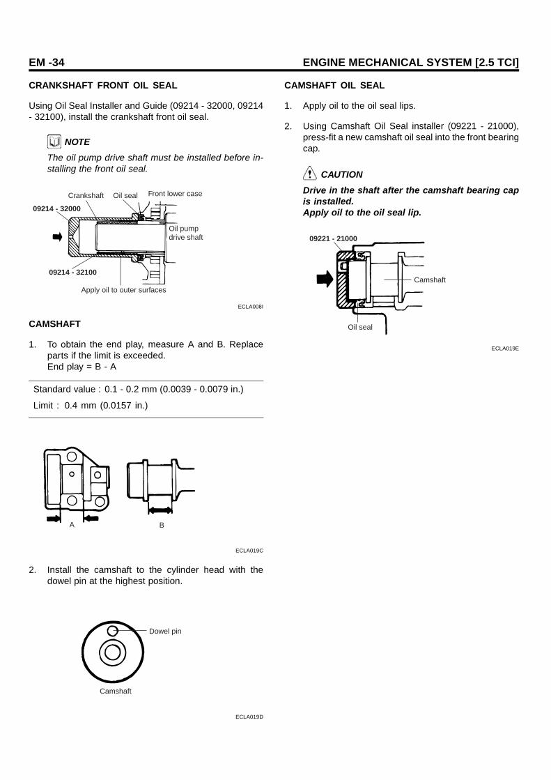
CRANKSHAFT FRONT OIL SEAL
Using Oil Seal Installer and Guide (09214 - 32000, 09214- 32100), install the crankshaft front oil seal.
NOTEThe oil pump drive shaft must be installed before in-stalling the front oil seal.
09214 - 32000
Crankshaft Oil seal Front lower case
Oil pump drive shaft
Apply oil to outer surfaces
09214 - 32100
ECLA008I
CAMSHAFT
1. To obtain the end play, measure A and B. Replaceparts if the limit is exceeded.End play = B - A
Standard value : 0.1 - 0.2 mm (0.0039 - 0.0079 in.)
Limit : 0.4 mm (0.0157 in.)
A B
ECLA019C
2. Install the camshaft to the cylinder head with thedowel pin at the highest position.
Dowel pin
Camshaft
ECLA019D
CAMSHAFT OIL SEAL
1. Apply oil to the oil seal lips.
2. Using Camshaft Oil Seal installer (09221 - 21000),press-fit a new camshaft oil seal into the front bearingcap.
CAUTIONDrive in the shaft after the camshaft bearing capis installed.Apply oil to the oil seal lip.
09221 - 21000
Camshaft
Oil seal
ECLA019E

MAIN MOVING SYSTEM EM -35
MAIN MOVING SYSTEM
CRANK SHAFT
ELCB0300
TORQUE : Nm (kg.cm, lb.ft)
75 - 85 (750 - 850, 55 - 63)
Crankshaft bearing cap
Lower bearing
Crankshaft
Upper bearing
Drive adapter
Crankshaft adapter
Adapter plate
130 - 140 (1300 - 1400, 96 - 103)
Gasket
Rear oil seal case
Oil separator
Rear oil seal Fly wheel
[ A/T ]
[ M/T ]
ECLA009A

EM -36 ENGINE MECHANICAL SYSTEM [2.5 TCI]
INSPECTION ELCB0310
CRANKSHAFT
1. Measure the journal and pin dimensions in directionsA and B at front and rear (1 and 2) positions.
2. If worn excessively, grind to an undersize. If the ser-vice limit is exceeded, replace the crankshaft.
ECLA009B
Standard valueJournal O.D. : 66 mm (2.598 in.)Pin O.D. : 53 mm (2.087 in.)
CRANKSHAFT OIL CLEARANCE
1. Determine the clearance from the diference betweenthe O.D. of journal as well as pin O.D. and the I.D. ofeach bearing as assembled to the crankshaft. Mea-sure the bearing I.D. in directions A and B at front andrear (1 and 2) positions.
Standard valueOil clearance of journal :
0.02 - 0.05 mm (0.0008 - 0.002 in.)
Oil clearance of pin :
0.02 - 0.05 mm (0.0008 - 0.002 in.)
Limit : 0.1 mm (0.0039 in.)
1 2A
B
75 - 85 Nm (750 - 850 kg.cm, 54 -62 lb.ft)
ECLA009C
2. If the use of a new bearing still results in an oil clear-ance larger than the standard value, grind the crank-shaft to the undersize and use a bearing of corre-sponding undersize.
3. When grinding the crankshaft to undersize, ensurecorrect fillet radius dimensions in journals and pins.
2.5 mm R (0.0098 in.)
2.5 mm R (0.0098 in.)
2.5 mm R (0.0098 in.)
ECLA009D
CRANKSHAFT OIL CLEARANCE (PLASTIGAGEMETHOD)
A Plastigage can be used to simplify the measurement ofoil clearance. use the following procedure to check the oilclearance with a Plastigage (for journals).
1. Wipe crankshaft O.D. and bearing I.D. clean of oil.
2. Install the crankshaft.
3. Put a strip of Plastigage lengthwise in the center ofthe journal.
Plastigage
ECLA009E
4. Replace the main bearing cap carefully and tightenbolts to specification.
5. Remove bolts and carefully remove the main bearingcap.
6. Using the scale printed on the bag of plastigage, mea-sure the amount the Plastigage has been flattened(the widest point).

MAIN MOVING SYSTEM EM -37
ECLA009F
CRANKSHAFT FRONT AND REAR OIL SEALS
1. Wear and damage in oil seal lips.
2. Deteriorated or hardened rubber.
3. Cracks or damage on oil seal case.
RING GEAR (MANUAL TRANSAXEL)
1. If the ring gear teeth are worn, damaged, or broken,replace the ring gear. If the teeth are damaged or bro-ken, check the starting motor pinion. To remove thering gear for replacement, tap its outer rim one placeafter another. Heating the gear makes it impossibleto remove. To install the ring gear onto the flywheel,heat it up to 260-280 C (500-536 C) : it is a shrink fitin the flywheel.
2. Check the ball bearing for rotating condition and un-usual noise. Ensure also that the packed grease isnot leaking.
Ring gearFlywhyeel
ECLA009G
FLYWHEEL
1. Check the flywheel clutch disc surface visually.
2. If ridge wear, streak, or seizure is evident, replace.
3. If the clutch disc surface runs out exceeding the limit,replace.
Limit : 0.13 mm (0.0051 in.)
INSTALLATION ELCB0320
CRANKSHAFT BEARING
The upper main bearing is provided with an oil hole,whereas the lower bearing has no oil hole, There is nodifference in center bearing (with flange) between upperand lower.
Without oil hole
Without oil hole
With oil hole
Lower bearing(No. 1.2.4.5)
(Center)Upper and lower bearings
Upper bearing(No. 1.2.4.5)
ECLA009H
BEARING CAP
1. Install the main bearing to the cylinder block. Ensurethe correct cap number and arrow mark direction.
Main bearing cap direction
Arrow mark(Shows front of engine)Front of engine
Cap No.
ECLA009I
2. Check to ensure that the crankshaft turns smoothlyand there is an adequate end play.
ECLA009J
Standard value :
0.05 - 0.18 mm (0.0020 - 0.0071 in.)
Limit : 0.25 mm (0.010 in.)

EM -38 ENGINE MECHANICAL SYSTEM [2.5 TCI]
OIL SEAL CASE
Using special tool, press-fit a new crankshaft rear oil sealinto the oil seal case.
09231 - 32000
ECLA009K
OIL SEPARATOR
1. Push oil separator into the oil seal case.
2. Make sure that the oil hole in the separator comes atthe bottom (indicated by an arrow in illustration.)
Oil hole
ECLA009L

MAIN MOVING SYSTEM EM -39
PISTON
COMPONENTS ELCB0330
TORQUE : Nm (kg.cm, lb.ft)
Piston ring No. 1
Piston ring No. 2
Oil ring
PistonPiston pin
Snap ring
Bushing
Connecting rod
Piston and connecting rod assembly
Upper bearing
Cylinder bolck
Lower bearing
Connecting rod cap
45 - 48 (450 - 480, 33 - 35)
ECLA010A

EM -40 ENGINE MECHANICAL SYSTEM [2.5 TCI]
INSPECTION ELCB0340
PISTON
1. Check each piston for scuffing, scoring, wear andother defects. Replace any piston that is defective.
2. Check that the piston pin fits in the piston pin hole.Replace any piston and pin assembly that is defective.The piston pin must be smoothly pressed by hand intothe pin hole (at room temperature)
PISTON RING
1. Check each piston ring for breakage, damage andabnormal wear.Replace the defective rings.
2. When the piston requires replacement, its ring shouldalso be replaced.
3. Measure the clearance between piston ring and ringhome.
ECLA010B
Standard Value : Ring - to - ring groove clearanceNo. 1 : 0.056 - 0.076 mm (0.0022 - 0.0030 in.)No. 2: 0.046 - 0.066 mm (0.0018 - 0.0026 in.)Oil ring : 0.02 - 0.065 mm (0.0008 - 0.0026 in.)
[Limit]No. 1 : 0.15 mm (0.0059 in.)No. 1 : 0.15 mm (0.0059 in.)Oil ring : 0.1 mm (0.0039 in.)
4. Place a piston ring in the cylinder bore and set itsquare by pushing it down with piston.
5. Measure the end clearance using a thickness gauge.
Piston ring End gap
ECLA010D
Standard Value : End gapNo. 1 : 0.35 - 0.50 mm (0.0138 - 0.0197 in.)No. 2 : 0.25 - 0.40 mm (0.0098 - 0.0157 in.)Oil ring : 0.25 - 0.45 mm (0.0098 - 0.0177 in.)
Limit : 0.8 mm (0.0315 in.)
CONNECTING ROD BEARING
1. Check the bearing surfaces for uneven contact pat-tern, streaks, scratches, and seizure. If defects areevident, replace. If the surfaces are seriously nickedand seized, check also the crankshaft. If the crank-shaft is also damaged, replace the crankshaft or grindto undersize for reuse.
ECLA010E
2. Measure the connecting rod bearing I.D. and crank-shaft pin O.D. If the clearance (oil clearance) exceedsthe limit, replace the bearing and, if necessary, thecrankshaft. Or, grind the crankshaft to an undersizeand, at the same time, replace the bearing with an un-dersize.
ECLA010F

MAIN MOVING SYSTEM EM -41
Standard value : 0.02 - 0.05 mm (0.0008 - 0.0020 in.)Limit : 0.10 mm (0.0039 in.)
INSTALLATION ELCB0350
CONNECTING ROD, PISTION PIN AND PISTON
1. Match the piston with the connecting rod.
2. Line up the front marks and insert the piston pin. Thepiston pin must be smoothly pressed by hand into po-sition. Replace the piston pin if there is excessive play.
Front mnark
Front mark (ID mark)
ECLA010J
PISTON RING
1. Install the oil ring expander and oil ring to the piston.
No. 1
No. 2
Oil
ECLA010L
2. 2. Then, install No.2 piston ring and No.1 piston ring,in that order. Make sure that the ring side, on whichmanufacturer and size marks are stamped, faces tothe piston crown.
3. Position ends of piston and oil (side rail, spacer) ringsas illustrated.
Upper side rail
Pistion pin
No. 2
No. 1
Lower side rail
ECLA010M
4. Insert the piston and connecting rod assembly fromabove the top of cylinder. Ensure that the front markon piston crown and that (ID mark) on the connectingrod face toward the front of engine (to the crank pulleyside).
5. Clamp firm the piston rings with the ring band and in-stall the piston assembly into cylinder. Do not strikeit hard into the piston, as broken piston ring or dam-aged crank pin could result.
ECLA010N
6. Make sure the clearance of connecting rod big endside.
Standard Value : 0.10 - 0.25 mm (0.0039 - 0.0098 in.)Limit : 0.4 mm (0.0157 in.)
ECLA010O

EM -42 ENGINE MECHANICAL SYSTEM [2.5 TCI]
COOLING SYSTEM
ENGINE COOLANT PUMP
COMPONENTS ELCB0400
TORQUE : Nm (kg.cm, lb.ft)
Water pump
Gasket
12 - 15 (120 - 150, 9 - 11)
12 - 15 (120 - 150, 9 - 11)
12 - 15 (120 - 150, 9 - 11)
Water inlet fitting
Thermostat
Thermostat housing
Radiator lower hoseGasket
O - ring
12 - 15 (120 - 150, 9 - 11)
Power steering pump
Power steering pump bracket
* Replace the gasket and O - ring with new ones after removal
ECLA011F

COOLING SYSTEM EM -43
INSPECTION ELCB0410
THERMOSTAT
1. Check that valve closes tightly at room temperature.
2. Check for defects or damage.
3. Check for rust on valve. Remove if any.
4. Immerse thermostat in container of water. Stir to raisewater temperature and check that thermostat openingvalve temperature and the temperature with valve fullyopen [valve liftover 8.5 mm (0.33 in.)] are at the stan-dard value.
ECLA011C
Standard value :Opening valve temperature 82 C (180 F)Full - open temperature 95 C (203 F)
NOTEMeasure valve heifht when fully close. Calculate liftby measuring the height when fully open.
BELT
1. Check the surface for damage, peeling or cracks.
2. Check the surface for presence of oil or grease.
3. Check the rubber for wear or hardening.
WATER PUMP
1. Check each part for cracks, damage or wear, and re-place the water pump assembly if necessary.
2. Check the bearing for damage, abnormal noise andsluggish rotation, and replace the water pump assem-bly if necessary.
3. Check the seal unit for leaks, and replace the waterpump assembly if necessary.
4. Check for water leakage. If water leaks from hole“ A” seal unit is defective. Replace as an assembly.
A
ECLA011B
INSTALLATION ELCB0420
WATER PIPE O - RING
Fit water pipe O-ring in the groove provided at water pipeend, wet the periphery of water pipe O-ring and insert wa-ter pipe.
O - ring
ECLA011E
CAUTION1. Do not apply oil and grease to water pipe
O-ring.2. Keep the water pipe connections free of sand,
dust, etc.3. Insert water pipe until its end bottoms.

EM -44 ENGINE MECHANICAL SYSTEM [2.5 TCI]
WATER PUMP
Water pump installation bolt size are different and cautionmust be paid to ensure that they are properly installed.
NoHardnesscategory
(Head mark)
d × Imm (in.)
Torque Nm(kg.cm, lb.ft)
1 4T 8 × 25 (0.31× 0.98)
2 4T 8 × 40 (0.31× 1.57)
12 - 15 (120 -150, 9 - 11)
3 7T 8 × 70 (0.31× 2.76)
20 - 27 (200 -270, 15 - 20)
22
1
32
Indication forhardness category
ECLA011D

COOLING SYSTEM EM -45
RADIATOR
ELCB0430
Reserve tank
Radiator upper hose
Radiator cap
Radiator lower hose
Shroud
ECLA012A

EM -46 ENGINE MECHANICAL SYSTEM [2.5 TCI]
REMOVAL ELCB0440
RADIATOR
1. Loosen the radiator drain plug to drain the coolant.
2. Disconnect the radiator hoses from the followingparts.Upper hose ... from the radiatorLower hose ... from the engine.
3. Disconnect the overflow tube from the radiator.
H7EM913A
4. Remove the radiator shroud bolts from the radiator.
NOTEShroud should be hung on the cooling fan, because itcannot be removed unless the radiator is taken out.
H7EM913B
5. Remove the radiator mounting bolts.
H7EM914A
6. Tilt radiator and take out obliquely upward.
H7EM003A
NOTEWhen the radiator is removed, make sure that the ra-diator core is not bent or crushed by other parts.
7. Remove the radiator shroud.
CORRECTION OF RADIATOR FIN
A bent or crushed portion shoude be corrected as shown.
H7EM003B

COOLING SYSTEM EM -47
RADIATOR PAN MOTOR
COMPONENTS ELCB0450
TORQUE : Nm (kg.cm,lb.ft)
Drive belt
Cooling fan clutch
Shroud
Cooling fan
3 - 7 (30 - 70, 2 - 5)
10 - 12 (100 - 120, 7 - 9)
10 - 12 (100 - 120, 7 - 9)
ECLA012B

EM -48 ENGINE MECHANICAL SYSTEM [2.5 TCI]
INSPECTION ELCB0460
COOLING FAN
1. Check the blades for damage and cracks.
2. Check for cracks and damage around bolt holes infan hub.
3. If any portion of fan is damaged or cracked, replacecooling fan.
FAN CLUTCH
1. Check to ensure that fluid in fan clutch is not leakingat case joint and seals. If fluid quantity decreasesdue to leakage, fan speed will decrease and engineoverheating might result.
2. When fan attached to engine is turned by hand, itshould give a sense of some resistance. If fan turnslightly, it is defective.
3. In case of thermostatic control type, check for a bro-ken bimetal.
Bimetal
ECLA012C
BELT
A belt which has following defects should be replaced.
1. Damaged, peeled or cracked surface.
2. Oil or greasy surface.
3. A belt worn to such an extent that it is in contact withbottom of V groove in pulley.
4. Worn or hardened rubber.

COOLING SYSTEM EM -49
WATER TEMPERATURE GAUGE UNIT,THERMO SWITCH ELCB0470
TORQUE : Nm (kg.cm,lb.ft)
Thermo switch 10 -12 (100 - 120, 7 - 9)
Whter temperature gauge unit10 -14 (100 - 140, 7 - 10)
ECLA012D

EM -50 ENGINE MECHANICAL SYSTEM [2.5 TCI]
INSPECTION ELCB0480
WATER TEMPERATURE GAUGE UNIT
1. Put the sensor in water and increase the water tem-perature to measure the nesistance.
ECLA012E
2. If the measurement radically deviates from specifica-tion, replace.
3. Measure the resistance across terminal (A) and bodyfor water temperature gauge element and across ter-minal (B) and body for glow control element.
0.4 Ω / 70 CTerminal (A)
23.8 Ω / 115 C
24.8 Ω / - 20 CTerminal (B)
3.25 Ω / 20 C
Terminal(A)Terminal(B)
ECLA012F

LUBRICATION SYSTEM EM -51
LUBRICATION SYSTEM
OIL FILTER
ELCB0500
TORQUE : Nm (kg.cm,lb.ft)
12 - 15 (120 - 150, 9 - 11)
50 - 60 (500 - 600, 37 - 44)Oil cooler by - pass valve
8 - 12 (80 - 120, 6 - 9)Oil pressure switch
Oil filter bracket
30 - 45 (300 - 450, 22 - 33)Joint
Oil filter
Oil jet
Check valve30 - 50 (300 - 350, 22 - 26)
Gasket
* Replace the gasket with new ones after removal.
ECLA013A

EM -52 ENGINE MECHANICAL SYSTEM [2.5 TCI]
REMOVAL ELCB0510
OIL PRESSURE SWITCH
To remove the oil pressure switch, use Oil Pressure SwitchWrench (09260 - 32000).
NOTEDuring removal, use care to prevent damage to thesealant applied to threads.
09260 - 32000
ECLA013B
INSPECTION ELCB0520
OIL FILTER BRACKET
1. The oil filter mounting surface must be free from dam-age.
2. Check for cracks and oil leaks.
3. Make sure that the relief plunger slides smoothly andthe relief spring is not damaged.
OIL PRESSURE SWITCH
1. Connect a tester (ohm range) between the terminaland the body of the switch to check for continuity. Theswitch is normal if there is continuity. If there is nocontinuity, replace the switch.
ECLA013C
2. Insert a thin rod in the oil hole of the switch and pushit in lightly. The switch is normal if no continuity isdetected (infinite resistance on the tester). If there iscontinuity, replace the switch.
Thin rod
ECLA013D
3. Apply a 0.5 kg/cm² pressure to the oil hole.The switch is normal if there is no continuity.Also check for air leaks. If any air leaks are detected,the cause may be a broken diaphragm. Replace theswitch if it leaks.
OIL JET, CHECK VALVE
1. Check the oil jet and check valve for clogging.
2. Check the oil jet for damage and deformation.
Engine oil
Oil jet
Check valve assembly
ECLA013E
OIL COOLER BYPASS VALVE
1. Make sure that the valve moves smoothly.
2. Ensure that the dimension L measures the standardvalue under normal temperature and humidity.
Dimension L : 34.5 mm (1.36 in.)

LUBRICATION SYSTEM EM -53
3. The dimension must be the standard value whenmeasured after the valve has been dipped in 100 C(212 F) oil.
Dimension L : 40 mm (1.57 in.) or more
Valve
L
ECLA013F
INSTALLATION ELCB0530
OIL JET
There are two types of oil jets installed: one for No. 1 and3, and the other for No. 2 and 4. Make sure that the correctone is installed with correct direction as shown.
No.1.3Cylinder
No.2.4Cylinder
Oil jet(for No. 1.3)
Oil jet(for No. 2.4)
Cylinderbolck
Knock pin
Oil jet
ECLA013G
OIL PRESSURE SWITCH
Before installation, apply sealant to the switch threads.
NOTEThe sealant must not get into the thread top surface.Use care not to torque excessively.
OIL FILTER
Wipe clean the mounting surface on the filter bracket.Then, apply a thin coat of engine oil to filter O-ring andtighten oil filter hand-tight.
CAUTIONNever use a wrench to tighten the oil filter.
Apply engine oil
ECA9970B

EM -54 ENGINE MECHANICAL SYSTEM [2.5 TCI]
OIL PUMP
COMPONENTS ELCB0540
Relief plunger
Relief spring
Gasket
Plug30 - 45 (300 - 450, 22 - 33)
9 - 14 (90 - 140, 7 - 10)
Oil pump case
Oil pump inner gear
Oil pump outer gear
Oil pump cover
TORQUE : Nm (kg.cm,lb.ft)
* Replace the gasket with new ones after removal.
ECLA014A

LUBRICATION SYSTEM EM -55
DISASSEMBLY ELCB0550
OIL PUMP
Before removing the oil pump outer and inner gears, markthe outer gear to make sure that it goes back to the positionwith correct direction.
Outer gear
Inner gear
Marking
ECLA014B
INSPECTION ELCB0560
OIL PUMP
1. Install the outer and inner gear into the front case andmake sure that they turn smoothly with no excessiveplay between them.
2. Check the side clearance (the front case and oil pumpcover surface)
EDA9340B
Standard : 0.04 - 0.10 mm (0.0016 - 0.0039 in.)Limit : 0.15 mm (0.0059 in.)
3. Check the body clearance.
[Standard]Drive gear : 0.03 - 0.09 mm (0.0012 - 0.0035 in.)Driven gear : 0.12 - 0.22 mm (0.0047 - 0.0087 in.)
[Limit]Drive gear : 0.5 mm (0.0197 in.)Driven gear : 0.4 mm (0.0157 in.)
INSTALLATION ELCB0570
OIL PUMP
Install the outer gear, ensuring it is in position with correctdirection according to the alignment mark made during dis-assembly.
NOTEWhen installing the gears, be sure to apply engine oilto the entire surfaces of the gears.
Outer gear
Inner gear
Marking
ECLA014B

EM -56 ENGINE MECHANICAL SYSTEM [2.5 TCI]
INTAKE AND EXHAUSTSYSTEM
EXHAUST MANIFOLD
COMPONENTS ELCB0600
TORQUE : Nm (kg.cm, lb.ft)
30 - 40 (300 - 400, 22 - 30)18 (180, 13)
9 (90 , 7)
19 (190 , 14)
9 (90 , 7)
EGR
Intake manifole
18 (180 , 13)
Waste gate actuator
Heat protector
Exhaust manifoldand turbo charger
Heat protector
Gasket
Front exhaust pipe
*Replace the gasket with new ones after removal.
ECLA015A

INTAKE AND EXHAUST SYSTEM EM -57
COMPONENTS ELCB0610
TORQUE : Nm (kg.cm,lb.ft)
Gasket
Turbo charger assembly
Exhaust manifold
Exhaust fitting
Gasket60 (600, 44)
60 (600, 44)
60 (600, 44)
[ TCI ]
* Replace the gasket with new ones after removal.
ECLA015B

EM -58 ENGINE MECHANICAL SYSTEM [2.5 TCI]
INSPECTION ELCB0620
Check the following and replace if faulty.
INTAKE AND EXHAUST MANIFOLDS
1. Check the parts for cracks and damage.
2. Check the vacuum port, water passages and gas pas-sages for clogging.
3. Using a straightedge and a thickness gauge, checkdistortion of the cylinder head mounting surface.
Standard value : 0.15 mm max.
Limit : 0.3 mm
EXHAUST MANIFOLD GASKET
The gasket may be reused if they are free from peeled ordamaged surface.

INTAKE AND EXHAUST SYSTEM EM -59
MUFFLER
COMPONENTS ECMB0250
30 - 40 ( 300 - 400, 22 - 30)
TORQUE : Nm (kg.cm, lb.ft)
30 - 40 ( 300 - 400, 22 - 30)
30 - 40 ( 300 - 400, 22 - 30)
Front exhaust pipe Center exhaust pipe
Gasket
Gasket
Main muffler
Gasket
30 - 40 ( 300 - 400, 22 - 30)
Rear muffler
ECMB001A

EM -60 ENGINE MECHANICAL SYSTEM [2.5 TCI]
INSPECTION ELCB0640
1. Check the mufflers and pipes for corrosion and dam-age.
2. Check the rubber hangers for deterioration andcracks.

INTAKE AND EXHAUST SYSTEM EM -61
TURBO CHARGER (TC)
COMPONENTS ELCB0650
TORQUE : Nm (kg.cm,lb.ft)
INTAKE AIR OUTLET PISTON RING
EXHAUSTGAS OUTLET
EXHAUST GAS INLET
OIL OUTLETPISTON RING
INTAKEAIR INLET
BEARING
OIL INLET
ECLB002A

EM -62 ENGINE MECHANICAL SYSTEM [2.5 TCI]
COMPONENTS ELCB0660
TORQUE : Nm (kg.cm,lb.ft)
Coupling
Turbine housing
Snap ring
Compressor cover
O - ring
Cartridge assembly
* Replace the gasket with new ones after removal.
ECLA016A

INTAKE AND EXHAUST SYSTEM EM -63
DISASSEMBLY ELCB0670
1. Before removal, make the matching mark on com-pressor cover bearing housing and turbine housing.
CAUTIONBe sure not to damage the compressor and tur-bine wheel blade.
Matchingmark
ECLA016B
2. Loosen the assembly and tap the housing by plastichammer when removing the housing.
Coupling Assembly
Turbine housing
H7ET008B
3. Remove the snap ring using snap ring filler.
Snap ring
ECLA016C
4. Remove by tapping the compressor cover of cartridgeassembly with plastic hammer.
Cartridge assembly
ECLA016D
CLEANING
1. Use a heavy duty carbon solvent to loosen the carbonfrom the parts.
CAUTIONDo not use caustic solutions, wire brushes, orwire wheels to remove carbon deposits from anyturbo charger part.
2. A small, closed, agitated cleaning tank and solventwill give the best results.
H7ET009A
3. After the carbon is loosened, use a hard, bristle typebrush and remove all dirt particles.
H7ET009B

EM -64 ENGINE MECHANICAL SYSTEM [2.5 TCI]
4. Clean all drilled passages with air under pressure andput oil on cleaned parts to prevent corrosion.
H7ET009C
INSPECTION ELCB0680
1. Check the inner housing contacting turbine wheel forcrack, pitching and other damages caused by over-heat.
2. Make sure that the waste gate valve lever operatesfreely by hands.
3. Make sure there are no damages on the inner housingsurface contacting compressor wheel.
Contacting surface
ECLA016E
4. Turbine wheel and shaft assemblies with cracks in theblades or broken blades can not be used again. Ifthe blades are slightly bent, it can be used again butseverely bent blades can not be reused.
Compressorwheel
Oil passage Turbine wheel
ECLA016F
5. Check if there are foreign materials disturbing the oilflow in the oil passage of cartridge assembly.
WASTE GATE INSPECTION
1. Check the waste gate rod operation under the pres-sure below.
Nominal Value : 77.5 kPa (0.79 kgf / cm²)
ECLA016J
REASSEMBLY ELCB0690
1. Apply engine oil to new O-ring and insert the O-ringto the groove of cartridge assembly.
O - ring
ECLA016G
2. Assemble cartridge assembly and compressor covermatching the mark.
ECLA016H

INTAKE AND EXHAUST SYSTEM EM -65
3. Install the snap ring as shown in the figure.
Snap Ring
Cartridge
Compressor cover
ECLA016I
4. Before reassembly, make sure that the turbine hous-ing matching mark is matched with compressor coverand cartridge assembly.
H7ET010D

EM -66 ENGINE MECHANICAL SYSTEM [2.5 TCI]
INTERCOOLER
COMPONENTS ELCB0700
Air hose
Intercooler
Fan motor assembly
Intercooler cover
ECMB700A

INTAKE AND EXHAUST SYSTEM EM -67
REMOVAL ELCB0710
1. Remove the intercooler cover.
2. Disconnect the fan motor and air temperature switchconnector.
3. Remove the air hoses.
4. Remove the intercooler assembly.
5. Remove the fan motor assembly.
6. Remove the intercooler bracket.
INSPECTION ELCB0720
AIR TEMPERATURE SWITCH
1. Place the sensing part of sensor into the water.
2. Check the continnity according as the temperature in-crease.
ECLA017B
Temperature Normal Condition50 C or less No - Continuity
60 C or more Continuity
INTERCOOLER FAN MOTER
Check the working of fan when the vehicle speed is 60km/h or less and intake air temperature is 50 C or more.(Revolution : 3500 rpm)

EM -68 ENGINE MECHANICAL SYSTEM [2.5 TCI]
AIR CLEANER (ACL)
COMPONENTS ECMB0400
Air cleaner cover Clamp Air intakek hose
Air cleaner filter
Air cleaner body
ECMB005A

INTAKE AND EXHAUST SYSTEM EM -69
INSPECTION ECMB0410
1. Check the air cleaner body, cover, or filter for distor-tion, corrosion or damage.
2. Check the air duct for damage.
ECKA060B
3. Check the air cleaner filter for restriction, contami-nation or damage. If the filter is slightly restricted,remove the dust and other contaminants by blowingcompressed air from the upper side through the filter.
EDDA080B
4. Check the air cleaner housing for restrictions, contam-ination or damage.

EM -70 ENGINE MECHANICAL SYSTEM [2.5 TCI]
CYLINDER HEADASSEMBLY
CYLINDER HEAD
COMPONENTS ELCB0800
TORQUE : Nm (kg.cm, lb.ft)
Retainer lock
Retainer
Spring
Valve spring seat
Valve stem seal
Exhaust valve guideIntake valve guide
Cylinder head bolt
Cold engine : 105 - 115 (1050 - 1150, 77 - 85)Hot engine : 115 - 125 (1150 - 1250, 85 - 92 )
Cylinder head
GasketExhaust valve seat ring
Intake valve seat ring
Intake valve Exhaust valve
* Replace the gasket with new ones after removal
ECLA018A

CYLINDER HEAD ASSEMBLY EM -71
DISASSEMBLY ELCB0810
CYLINDER HEAD
1. Remove the injection pipe assembly. When looseningthe injection pipe nut, hold the nozzle holder and thedelivery valve holder with a spanner to prevent themfrom turning with the nut.
NOTEAfter the injection pipe is removed, put a cap on thenozzle holder and the delivery valve holder to preventingress of dust and foreign matter.
2. Remove the timing belt upper cover.
3. Loosen the camshaft sprocket bolt to such an extentthat it can be further loosened with fingers.
4. Bring the piston in No.1 cylinder to the top dead centeron the compression stroke. Align the timing mark onthe camshaft sprocket with that made on the uppercase.
5. Manually remove the camshaft sprocket bolt.
6. With the timing belt engaged, remove the sprocketfrom the camshaft and place the assembly on the tim-ing belt lower cover.
CAUTIONDo not turn the crankshaft once the sprocket isremoved. Keep the timing belt tense.
7. Remove the rocker cover, rocker arm shaft assemblyand camshaft.
8. Using the special tool, Cylinder Head bolt Wrench(09221-32000), loosen 18 Cylinder head bolts and re-move them. Loosen the bolts in the sequence shownand in two to three steps.
09221 - 32000
ECLA018B
2
610
14
1816
128
4
3
1
5 13 159 11
717
ECLA018C
9. Remove the cylinder head.
10. Remove the cylinder head gasket. Clean the cylinderhead and cylinder block gasket surfaces.
VALVE AND VALVE SPRING
1. Remove the cylinder head assembly.
2. Remove the parts as illustrated below and store themseparately for each cylinder.Using Valve Spring Compressor (09222-21000), re-move the valve spring retainer lock.Keep the disassembled parts arranged according tothe cylinder number and intake and exhaust.
09222 - 21000
ECLA018D

EM -72 ENGINE MECHANICAL SYSTEM [2.5 TCI]
INSPECTION ELCB0820
INTAKE VALVE, EXHAUST VALVE
1. If the valve stem develops wear (taper wear) or dam-aged, replace. If there is a dent in the stem endface (the surface in contact with the rocker arm ad-just screw), replace.
45˚ Margin
A
B
ECA9281B
2. Check the valve face for contact. If the contact isnot proper, correct with a valve refacer. The contactpattern with the valve seat must be even at the centerof valve face.
3. Replace if the margin (valve head thickness) exceedsthe limit.
Standard valueIntake and exhaust : 2.0 mm (0.0394 in.)
LimitIntake and exhaust : 1.0 mm (0.0394 in.)
Contact area(It must be at thecenter of the face
Margin
EDA9300D
VALVE SPRING
1. Measure the free height of spring and replace if thelimit is exceeded.
Standard value : 49.1 mm (91.933 in.)Limit : 48.1 mm (1.894 in.)
2. Measure the squareness of the spring and, if the limitis exceeded, replace.
2˚
Free heighty
B0Y041D
Standard value : 2 or lessLimit : 4
VALVE GUIDE
Measure the valve guide to stem clearance and, if themeasurement exceeds the limit, replace the valve guideor valve, or both.
Standard valueIntake : 0.03-0.06 mm (0.0012-0.0024 in.)Exhaust : 0.05-0.09 mm (0.0012-0.0024 in.)
LimitIntake : 0.10 mm (0.0394 in.)Exhaust : 0.15 mm (0.0394 in.)
Stem O.D.Guide I.D.
B0Y105D
CYLINDER HEAD
1. Before cleaning the cylinder head, check for water andoil leaks, damage, or cracks.
2. Remove oil, scale, sealant, and carbon depositscompletely. After cleaning the oil passages, applycompressed air to ensure that the passages are notclogged.
3. If there is gas leak from the cylinder head gasket sur-face, measure the surface flatness. If distortion ex-ceeds the limit, replace the cylinder head.
Standard value : 0.05 mm (0.002 in.)Limit : 0.2 mm (0.008 in.)

CYLINDER HEAD ASSEMBLY EM -73
4. Visually check the camshaft bearing internal surfacesfor damage or seizure. If defects are evident, replacethe bearing.
RECONDITIONING VALVE SEAT
Check the valve seat for overheating and improper con-tact with the valve face. Recondition or replace the seat ifnecessary. Bofore reconditioning the seat, check the valveguide for wear. If the valve guide is worn, replace if andthen recondition the seat. Recondition the valve seat witha valve seat grinder or cutter. The valve seat contact widtyshould be within specificatons and centered on the valveface. After reconditioning, the valve and valve seat shouldbe lapped lightly with a lapping compound.
Cutter
Pilot
IntakeExhaust45˚ 45˚
ECHA920B
Angle No.45 09221-43300
65 09221-43400
30 09221-43500
VALVE SEAT REPLACEMENT PROCEDURE
1. Cut the valve seat to be replaced from the inside tothin the wall thickness. Then, replace the valve seat.
0.5 - 1 mm (0.0197 - 0.0394 in.)
0.5 - 1 mm (0.0197 - 0.0394 in.)
Cut away
B0YR3940
2. Rebore the valve seat hole in cylinder head to theoversize valve seat diameter.
Intake valve seat ring hole diameter0.30 O.S. : 43.300 - 43.325 mm (1.7047 - 1.7057 in.)0.60 O.S. : 43.600 - 43.625 mm (1.7165 - 1.7175 in.)Exhaust valve seat ring hole diameter0.30 O.S. : 37.300 - 37.325 mm (1.4685 - 1.4695 in.)0.60 O.S. : 37.600 - 37.625 mm (1.4803 - 1.4813 in.)
3. Before fitting the valve seat, either heat the cylinderhead up to approximately 250 C (482 F) or cool thevalve seat in liquid nitrogen to prevent the cylinderhead bore from abrasion.
4. After installation, recondition the valve seat.
Over size I.D.
Height of valve seat
B0YR167A

EM -74 ENGINE MECHANICAL SYSTEM [2.5 TCI]
VALVE GUIDE REPLACEMENT PROCEDURE
1. Using the push rod of Valve Guide installer (09222 -32200) and apress, remove the valve guide forwardcylinder block.
Push rod09222 - 32200
Cylinder headValve guide
ECLA018F
2. Rebore valve guide hole to the new oversize valveguide outside diameter.
3. Using Valve Guide Installer (09222 - 32200), press-fitthe valve guide, working from the the cylinder headtop surface.
09222 - 32200
Valve guideCylinder head
ECLA018G
NOTEWhen valve guides have been replaced, check forvalve contact and correct valve seats as necessary.
4. After installing valve guides, insert new valves in themto check for sliding condition.
Valve guide hole diameter0.05 O.S.: 13.050-13.068 mm (0.0012-0.0024 in.)0.25 O.S.: 13.250-13.268 mm (0.5216-0.5223 in.)0.50 O.S.: 13.500-13.518 mm (0.5315-0.5322 in.)
INSTALLATION ELCB0830
VALVE STEM SEAL
1. Using Valve Stem Seal Installer (09222 - 32100), in-stall the valve stem seal into the valve guide.
NOTE1. The valve stem seal must be not reused.2. The special tool must be used for the installa-
tion of the valve stem seal. Improper installa-tion could result in oil consumption through valveguide.
09222 - 32100
Valve spring seat
ECLA018I
VALVE SPRING
Direct the valve spring end with identification color to therocker arm.
IdentificationcolorIdentificationcolor
Spring retainer
Stem seal
Spring seat
B0Y044B

CYLINDER HEAD ASSEMBLY EM -75
VALVE SPRING RETAINER LOCK
Using a valve spring compressor (09222 - 21000), com-press the spring and fit the retainer lock in position.
NOTEThe valve spring, if compressed excessively, causesthe bottom end of retainer to be in contact with, anddamages, the stem seal.
09222 - 21000
ECLA018D
CYLINDER HEAD
1. Scrape off gasket adhered to cylinder head assembly.
CAUTIONBe careful that foreign material does not fall intocoolant and oil passage ways.
2. Tighten in the numerical order indicated in the dia-gram in two or three groups with special tool.
Forward of engine
17
139
5
1
3
7
1115
1612
84
26
1014
18
ECLA018J
Specified torqueCold engine :
105 - 115 Nm (1050 - 1150 kg.cm, 77 - 85 lb.ft)
Hot engine :
115 - 125 Nm (1150 - 1250 kg.cm, 85 - 92 lb.ft)

EM -76 ENGINE MECHANICAL SYSTEM [2.5 TCI]
ROCKER ARM
COMPONENTS ELCB0840
TORQUE : Nm (kg.cm, lb.ft)
Breather hose
Rocker cover
Rocker cover gasket
Rocker shaft
Rocker arm (Intake)
Camshaft bearing cap
Camshaft
Packing
Rocker arm(Exhaust)
Rocker shaft spring
Camshaft oil seal
*Replace the gasket with new ones after removal.
5 - 7 (50 - 70, 4 - 5)
35 - 40 (350 - 400, 25 - 29)
19 - 21 (190 - 210, 13 - 15)
Oil filler cap
ECLA019A

CYLINDER HEAD ASSEMBLY EM -77
INSPECTION ELCB0845
ROCKER SHAFT
1. Check oil holes for clogging and clean as necessary.
2. Replace the shaft if damage or seizure is evident onthe surfaces, to which rocker arms are installed.
2 Oil holes 1Oil hole
Engine front
ECLA019F
ROCKER ARM
1. Check the slipper surface (the surface in contact withthe cams). Replace if damage or seizure is evident.
2. Check bore for damage and seizure. Replace if de-fects are evident.
3. Check the oil clearance
Standard : 0.01 - 0.04 mm (0.0004 -0.0016 in.)Limit : 0.08 mm (0.0031 in.)
CHECKING AND ADJUSTMENT OF VALVECLEARANCE
Refer to general part.
INSTALLATION ELCB0850
ROCKER ARM AND ROCKER SHAFT
Turn the crackshaft to bring the pistion in No 1. cylinderto the top dead center on the compression stroke. Thisreduces the cam lift to minimum and facilitates installation.
ROCKER SHAFT
1. Keep the oil hole side down.
2. Install the rocker shaft with its side having one oil holefacing to the front.
2 Oil holes 1Oil hole
Engine front
ECLA019F
ROCKER ARM (EXHAUST AND INTAKE)
Install in correct position, confirming the identificationmarks.
SEMI - CRICULAR PACKING
Apply sealant to the portion indicated in illustration.
Specified sealant : 3M part No 8660 or equivalent
Apply sealant
ECLA019G

EM -78 ENGINE MECHANICAL SYSTEM [2.5 TCI]
TIMING SYSTEM
TIMING BELT
COMPONENTS ELCB0900
TORQUE : Nm (kg.cm, lb.ft)
Timing belt upper cover Camshaft sprocket
Timing belt lower cover
Crankshaft pulley
Crankshaft sprocket
Timing belt
Flange
Injection pump sprocket
80 - 90 (800 - 900, 59 - 66)
65 - 75 (650 - 750, 48 - 55)
2.2 - 3.0 kgm
170 - 190 (1700 - 1900, 125 - 140)
ECLA020A

TIMING SYSTEM EM -79
REMOVAL ELCB0910
TIMING BELT
1. Remove the cooling fan, water pump, crankshaft pul-ley and timing belt cover.
2. Turn the crankshaft to bring the piston in No. 1 cylin-der to the top dead center on the compression stroke.
3. Mark an arrow on the back of the timing belt and timingbelt B with a chalk to indicate the direction of rotation.This ensures that the belt is installed in the same di-rection for reuse.
ECLA020B
4. The piston in No. 1 cylinder is at the top dead centeron the compression stroke when all timing marks atthe three places are aligned as shown.
Timing marks
Piston in No. 1 cylinder at top dead center
ECLA005B
5. Slightly loosen the two bolts securing the tensioner.Then, slide the tensioner toward the water pump andtighten the bolts temporarily to secure the tensionerin place.
6. Remove the timing belt.
Slide toward water pump
ECLA020C
CAMSHAFT SPROCKET
1. Loosen the bolt securing the camshaft sprocket andremove the camshaft sprocket.
2. Remove the sprocket nut.
NOTEUse care not to give shock to the fuel injection pumpshaft, as it could result in defective fuel injection pump.Using Injection Pump Sprocket Puller (09314 - 43000)or suitable tool, remove the sprocket from injectionpump.
3. Remove the tensioner and tensioner spring.
09314 - 43000
ECLA020D

EM -80 ENGINE MECHANICAL SYSTEM [2.5 TCI]
INSPECTION ELCB0920
TIMING BELT
1. Check the belt for oil or dust deposits. Replace ifnecessary. Small deposits should be wipe away witha dry cloth or paper. Do not clean with solvent.
2. When the engine is overhauled or belt tension ad-justed, check the belt in detail. If the following flawsare evident, replace the belt with a one.
OIL WATER
ECA9200A
Description Flaw conditions1. Hardened back surface of rubber Back surface is glossy, Non-elastic and so hard that, when
your fingernail is pressed into it, no mark is produced.
ECA9200B
2. Cracked back surface of rubber
ECA9200Y
3. Cracked or separating canvasCrack
ECA9200I
Crack
Separation
ECA9200J
Separation
ECA9200K
4. Badly worn out teeth (initial stage) Canvas on load side tooth flank worn (Fluffy canvasfibers, rubber gone and color changed to white,and unclear canvas texture)

TIMING SYSTEM EM -81
Description Flaw conditions
Flank worn(On load side)
ECA9200C
5. Badly worn out teeth (last stage) Canvas on load side tooth flank worn down and rubberexposed (tooth width reduced)
Rubber exposed
ECA9200D
6. Cracked tooth bottom
Crack
ECA9200E
7. Missing tooth Tooth missing andcanvas fiber exposed
ECA9200F
8. Side of belt bady worn Rounded belt side
Abnormal wear (Fluffy canvas fiber)
ECA9200G
NOTENormal belt should have precisely cut side as if producedby a sharp knife.
9. Side of belt cracked
ECA9200H

EM -82 ENGINE MECHANICAL SYSTEM [2.5 TCI]
INSTALLATION ELCB0930
CRANKSHAFT SPROCKET
1. Mount the crankshaft sprocket to the crankshaft not-ing the direction of the sprocket as well as the flange.
2. Mount the camshaft sprocket and tighten the flangebolts to specified torque.
Front
Crankshaft
Oil pump geardrive shaft
SprocketFlange
Sprocket "B"
ECLA020E
TIMING BELT TENSIONER
Install the tensioner, tensioner spring and tensioner spacerand with the tensioner moved all the way to the waterpump, temporarily tighten bolt A. Tighten bolt B not fullybut finger - tight.
Slide toward water pump
ECLA020C
TIMING BELT
1. Correctly line up timing marks on three sprockets.
2. While ensuring that the tension side of timing belt isnot slack, install belt onto the crankshaft sprocket,injection pump sprocket, tensioner and camshaftsprocket, in that order.
NOTEWhen installing the belt onto the injection pumpsprocket, keep the sprocket in position, as it tends toturn by itself at the timing mark alignment position.If the belt is to be reused, make sure that the arrowmark made during disassembly faces to the correctdirection at reassembly.
Timing marks
Piston in No. 1 cylinder at top dead center
ECLA005B
3. Check if all timing marks are aligned correctly.
4. Back off tensioner bolt A, that have previously beensecured to the water pump side, one to two turns togive tension to the belt using tensioner spring tension.
Bolt A
Bolt B
ECLA020F
5. Confirm that the timing belt is correctly engaged withthree sprockets.
6. Turn crankshaft clockwise by the two teeth of thecamshaft sprocket and keep the position.
CAUTIONNever turn the crankshaft counterclockwise.
Camshaft sprocket
Two teeth
ECLA020G

TIMING SYSTEM EM -83
7. Tighten the bolt A.
8. Tighten the bolt B.If the bolt B is tightened first, the tensioner shouldbe turned together, causing an undue tension to beapplied to the timing belt.
Bolt A
Bolt B
ECLA020F
9. Turn the crankshaft in the direction of backward rota-tion to line up timing marks. In this condition, ensurethat the deflection when the center of belt is pushedby the index finger.
Standard : 4 - 5 mm (0.1575 - 0.1969 in.)
Deflection
ECLA020H
FLANGE
Note that bolt holes in the flange and those in the injectionpump sprocket are offset positioned at one place. Whenassembling, position the jlange and sprocket as shown.
Sprocket
Flange
Offset
Notch for timing adjustment
ECLA020I

EM -84 ENGINE MECHANICAL SYSTEM [2.5 TCI]
TIMING BELT ELCB0940
COMPONENT
TORQUE : Nm (kg.cm, lb.ft)
Gasket
Tensioner spacier
Tensioner spring
Timing belt tensioner B
22 - 30 (220 - 300, 16 - 22)
Timing blet B
Crankshaft spricket B
Silentshaft sprocket - Left
Silent shaft sprocket - Right
34 - 40 (340 - 400, 25 - 30)
Flange
Spacier
34 - 40 (340 - 400, 25 - 30)
ECLA021A

TIMING SYSTEM EM -85
REMOVAL ELCB0950
TIMING BELT “ B”
1. Remove the timing belt.
2. Using chalk or the like, put an arrow on the back ofthe timing belt “ B” to indicate the direction of drive.
ECLA021B
3. Slightly loosen the bolts and nuts securing the ten-sioner.Then, slide the tensioner toward the water pump andtighten the nuts to secure the tensioner in place tem-porarily.
4. Remove the timing belt “ B”
5. Remove the crankshaft sprocket “ B”
6. Remove the two silent shaft sprockets.
7. When loosening the nut and bolt for two silent shaftsprockets, be sure to lock the silent shaft as shown.
NOTE1. Water, oil, or grease on the belt shortens its life
drastically. Use special care to ensure that theremoved timing belt, sprockets, and tensioner arefree from oil and grease.
2. Note also that these parts should not be cleaned.Replace them if seriously contaminated.
3. If there is oil on parks, check for oil leaks from oilseals in from case and camshaft.
CAUTIONKeep the removed parts free from oil and grease.Do not use detergent to clean the timing belt“ B” , sprocket and tensioner. Wipe clean withrag if found dirty.Replace if excessively contaminated with dirt,grease or oil.
Remove cover and insert barLeft side
Remove this plug and insert a screwdriver
Screw driver [shaft dia. 8 mm (0.31 in.)
Wrench extension bar or similar size rod
Silent shaft, right
Right side
Silent shaft, left
ECLA021C

EM -86 ENGINE MECHANICAL SYSTEM [2.5 TCI]
INSTALLATION ELCB0960
CRANKSHAFT SPROCKET “ B”
1. Mount the crankshaft sprocket “ B” to the crank-shaft, noting the direction of the sprocket “ B” .
Front
Crankshaft
Oil pump geardrive shaft
SprocketFlange
Sprocket "B"
ECLA020E
2. The spacer must be installed with its chamfered endfacing toward the silent shaft. If the spacer is installedin the wrong direction, damage to oil seal will result.
Silent shaftSpacier
Tapper
ECLA021D
TIMING BELT “ B” TENSIONER
Install the tensioner spring and spacer, with the tensionermoved all the way to the water pump, and tighten the nut.Tighten the bolt not fully put finger - tight.
SpringTensioner
Front lower case
Spacer
Gasket
Nut
Bolt
Tensioner "B"
Water pump
ECLA021E
TIMING BELT “ B”
1. Line up timing marks on the crankshaft sprocket B,and right and left silent shaft sprockets.
2. With the timing belt B installed, ensure that its tensionside is not slack.
NOTEIf the belt is to be reused, make sure that the arrowmark made during disassembly faces to the correctdirection at reinstallation.
Timing mark
Tensioner
Timing mark
Timing belt B
sprocket b
ECLA021F

TIMING SYSTEM EM -87
3. With the tension side of timing belt B kept tight bypushing the slack side (indicated by A in illustration)with a finger, make sure that the timing marks areproperly aligned with each other.
Timing mark
Tensioner
Timing markTension size
Timing belt B
ECLA021G
4. Back off tensioner B nut, that have previously beensecured to the water pump side, one to two turns togive tension to the belt using tensioner spring tension.
5. Tighten the tensioner B attaching nut.
6. Tighten the tensioner B attaching bolt.
NOTEIf the bolt is tightened first, the tension B should beturned together, resulting in reduced timing belt B ten-sion.
Bolt
Nut
Tensioner spring "B"
ECLA021H
7. Ensure that the deflection is 4 to 5 mm (0.0394 to0.1969 in.) when the belt is pushed by the index fingerat the position indicated by and arrow.
Belt deflection : 4 - 5 mm (0.157 - 0.197 in.)
Belt deflection
Crankshaft sprocket
Silent shaft sprocket
ECLA021I
Copyright © 2022 FDOKUMEN