Pile Wall-Temp Works-Method Statement Rev. 00
30
www.deep-foundations.co.uk Job No: DFS170805 Design Engineer: AA Date: 01 September2017 Job Name: 93 BARNSBURY STREET LONDON Calc Title: Designs for Pile Retaining Wall, Trench Sheet Retaining Walls, Associated Temporary Works & Construction Method Statement Page: 1 of 30 CALCULATIONS D F S DESIGN STATUS & ISSUE RECORD Revision Status Description Design Check Engineer Date Engineer Date / Planning Preliminary designs for pile wall, trench sheet walls, temporary works & method statement AR 01/09/17 AA 01/09/17 Piling Contractor: Geotechnical Designers: Deep Foundations Specialists Limited Foundation Specialist Consulting Engineers 21 Brambling Way Maidenhead SL6 8PQ Berkshire Tel: Fax: Tel: 01628 664449 W: www.deep-foundations.co.uk Project Engineers: Main Contractor: CONISBEE Consulting Civil & Structural Engineers 1-5 Offord Street London N1 1DH Ecore Construction Limited Bizspace Business Centre Unit A4 Wandsworth Road Greenford UB6 7JJ Tel – 0207 700 6666 Fax – 0207 700 6686 Tel: 020 8998 1769 W: www.ecoreconstruction.co.uk 93 BARNSBURY STREET LONDON N1 1EJ Designs for ∅350 Pile Retaining Wall / MABEY M17 Temporary Trench Sheet Retaining Walls, Associated Temporary Works & Construction Method Statement
-
Upload
khangminh22 -
Category
Documents
-
view
3 -
download
0
Transcript of Pile Wall-Temp Works-Method Statement Rev. 00

www.deep-foundations.co.uk
JobNo: DFS170805 DesignEngineer: AA Date: 01September2017
JobName: 93BARNSBURYSTREETLONDON
CalcTitle: DesignsforPileRetainingWall,TrenchSheetRetainingWalls,AssociatedTemporaryWorks&ConstructionMethodStatement
Page: 1of30
CALCULATIONSDFS
DESIGNSTATUS&ISSUERECORD
Revision Status Description Design Check Engineer Date Engineer Date
/ PlanningPreliminarydesignsforpilewall,trenchsheetwalls,temporaryworks&methodstatement
AR 01/09/17 AA 01/09/17
Piling Contractor: Geotechnical Designers: Deep Foundations Specialists Limited
Foundation Specialist Consulting Engineers 21 Brambling Way Maidenhead SL6 8PQ Berkshire
Tel:
Fax:
Tel: 01628 664449 W: www.deep-foundations.co.uk
Project Engineers: Main Contractor: CONISBEE Consulting Civil & Structural Engineers 1-5 Offord Street London N1 1DH
Ecore Construction Limited Bizspace Business Centre Unit A4 Wandsworth Road Greenford UB6 7JJ
Tel – 0207 700 6666
Fax – 0207 700 6686
Tel: 020 8998 1769
W: www.ecoreconstruction.co.uk
93BARNSBURYSTREETLONDON
N11EJ
Designsfor∅350PileRetainingWall/MABEYM17TemporaryTrenchSheetRetainingWalls,AssociatedTemporaryWorks&ConstructionMethodStatement

www.deep-foundations.co.uk
JobNo: DFS170805 DesignEngineer: AA Date: 01September2017
JobName: 93BARNSBURYSTREETLONDON
CalcTitle: DesignsforPileRetainingWall,TrenchSheetRetainingWalls,AssociatedTemporaryWorks&ConstructionMethodStatement
Page: 2of30
CALCULATIONSDFS
93BARNSBURYSTREETLONDONN11EJ
DESIGNSFOR∅350PILEWALL,TEMPORARYTRENCHSHEETRETAININGWALLS,ASSOCIATEDTEMPORARYPROPPINGSCHEME&CONSTRUCTIONMETHODSTATEMENT
1.0 INTRODUCTION
ECOREConstructionLimitedarecurrentlyproposingtoconstructanewrearextensiontotheexisting4storey-
GradeIIlistedmidterraceearlyVictorianhouseontheabovesite.Theprojectwouldinvolvethedemolitionof
theexisting2storey-extensionattherearofthepropertyandconstructionofanewlarger2storey-extension
with a basement, whichwould accommodate a basement room, undergroundwine cellar, desk space and
TV/Playroom.
Thesubterraneanconstructionschemeforthenewbasementwouldincludereinforcedconcreteunderpinning
oftheadjoiningboundary/partywallsonbothsidesofthebasement,constructionofanewpileretainingwall
at the rear of the proposedbasement, installation of temporary trench sheet retainingwalls to enable the
deeper excavations for the spiral wine cellar and the stair case/desk space area, as well as associated
temporaryworks.
Thedesignanddetailingoftheproposedunderpinningwallsisbeingcarriedoutbyothers.However,theyare
proposedtocompriseof250mm-400mmthickL-shapedsegmentalreinforcedconcreteunits,whichwouldbe
installedinbaysof1mmaximumwidth.Theunderpinningunitsareproposedtoprovidebothtemporaryand
permanent earth and groundwater retention, as well as permanent vertical support to the adjoining
boundary/partywalls.
This report chiefly focuses on the designs for the proposed pile retaining wall, temporary trench sheet
retainingwalls,temporaryproppingschemeandrecommendationsonsuitableconstructionsequenceforthe
proposed basement scheme. The pile retaining wall shall comprise of∅350 piles spaced at 500mm c/c
intervals,while the temporary trench sheet retainingwalls shall compriseofMABEYM17S350 interlocking
trenchsheets.

www.deep-foundations.co.uk
JobNo: DFS170805 DesignEngineer: AA Date: 01September2017
JobName: 93BARNSBURYSTREETLONDON
CalcTitle: DesignsforPileRetainingWall,TrenchSheetRetainingWalls,AssociatedTemporaryWorks&ConstructionMethodStatement
Page: 3of30
CALCULATIONSDFS
Thereportispresentedunderthefollowingheadings:
• INPUTDATA
• OUTLINEOFDESIGN&CONSTRUCTIONMETHODSTATEMENT
• GROUNDCONDITIONS
• PILEWALL&TRENCHSHEETRETAININGWALLANALYSIS&DESIGN
- GeotechnicalDesign
- StructuralDesign
• TEMPORARYPROPDESIGN
• REFERENCES
• APPENDICES
- ProposedPileWall&TrenchSheetWallLayout,TemporaryProppingSchemeLayout,Sections&
Detailing
- PileWallSchedule
- TrenchSheetWallSchedule
- CADSPWS5.6ComputerOutputFiles–ULSAnalysisforPileRetainingWall
- CADSPWS5.6ComputerOutputFiles–SLSAnalysisforPileRetainingWall
- CADSPWS5.6ComputerOutputFiles–ULSAnalysisforTrenchSheetRetainingWalls
- CADSPWS5.6ComputerOutputFiles–SLSAnalysisforTrenchSheetRetainingWalls
- TemporaryPropDesignCalculationSheets
- MABEYTrenchSheetTechnicalDataSheets
- RelevantHistoricalBoreholeLogs.
www.deep-foundations.co.uk
JobNo: DFS170805 DesignEngineer: AA Date: 01September2017
JobName: 93BARNSBURYSTREETLONDON
CalcTitle: DesignsforPileRetainingWall,TrenchSheetRetainingWalls,AssociatedTemporaryWorks&ConstructionMethodStatement
Page: 4of30
CALCULATIONSDFS
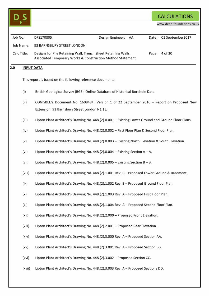
2.0 INPUTDATA
Thisreportisbasedonthefollowingreferencedocuments:
(i) BritishGeologicalSurvey(BGS)’OnlineDatabaseofHistoricalBoreholeData.
(ii) CONISBEE’s Document No. 160848/T Version 1 of 22 September 2016 – Report on Proposed New
Extension.93BarnsburyStreetLondonN11EJ.
(iii) LiptonPlantArchitect’sDrawingNo.448.(2).0.001–ExistingLowerGroundandGroundFloorPlans.
(iv) LiptonPlantArchitect’sDrawingNo.448.(2).0.002–FirstFloorPlan&SecondFloorPlan.
(v) LiptonPlantArchitect’sDrawingNo.448.(2).0.003–ExistingNorthElevation&SouthElevation.
(vi) LiptonPlantArchitect’sDrawingNo.448.(2).0.004–ExistingSectionA–A.
(vii) LiptonPlantArchitect’sDrawingNo.448.(2).0.005–ExistingSectionB–B.
(viii) LiptonPlantArchitect’sDrawingNo.448.(2).1.001Rev.B–ProposedLowerGround&Basement.
(ix) LiptonPlantArchitect’sDrawingNo.448.(2).1.002Rev.B–ProposedGroundFloorPlan.
(x) LiptonPlantArchitect’sDrawingNo.448.(2).1.003Rev.A–ProposedFirstFloorPlan.
(xi) LiptonPlantArchitect’sDrawingNo.448.(2).1.004Rev.A–ProposedSecondFloorPlan.
(xii) LiptonPlantArchitect’sDrawingNo.448.(2).2.000–ProposedFrontElevation.
(xiii) LiptonPlantArchitect’sDrawingNo.448.(2).2.001–ProposedRearElevation.
(xiv) LiptonPlantArchitect’sDrawingNo.448.(2).3.000Rev.A–ProposedSectionAA.
(xv) LiptonPlantArchitect’sDrawingNo.448.(2).3.001Rev.A–ProposedSectionBB.
(xvi) LiptonPlantArchitect’sDrawingNo.448.(2).3.002–ProposedSectionCC.
(xvii) LiptonPlantArchitect’sDrawingNo.448.(2).3.003Rev.A–ProposedSectionsDD.

www.deep-foundations.co.uk
JobNo: DFS170805 DesignEngineer: AA Date: 01September2017
JobName: 93BARNSBURYSTREETLONDON
CalcTitle: DesignsforPileRetainingWall,TrenchSheetRetainingWalls,AssociatedTemporaryWorks&ConstructionMethodStatement
Page: 5of30
CALCULATIONSDFS
(xviii) LiptonPlantArchitect’sDrawingNo.448.(2).3.004Rev.A–ProposedSectionsEE.
(xix) LiptonPlantArchitect’sDrawingNo.448.(2).3.005Rev.B–ProposedSectionFF.
(xx) LiptonPlantArchitect’sDrawingNo.448.(2).3.006Rev.A–ProposedSectionII.
(xxi) LiptonPlantArchitect’sDrawingNo.448.(2).3.007Rev.A–ProposedSectionJJ.
(xxii) LiptonPlantArchitect’sDrawingNo.448.(2).5.005Rev.B–ProposedBasement.

www.deep-foundations.co.uk
JobNo: DFS170805 DesignEngineer: AA Date: 01September2017
JobName: 93BARNSBURYSTREETLONDON
CalcTitle: DesignsforPileRetainingWall,TrenchSheetRetainingWalls,AssociatedTemporaryWorks&ConstructionMethodStatement
Page: 6of30
CALCULATIONSDFS
3.0 OUTLINEOFDESIGN&CONSTRUCTIONMETHODSTATEMENT
• Wall/propanalysisanddesigncalculationshavebeencarriedoutinaccordancewiththerecommendationsof
theBS8002(2015),CIRIAReportNo.C760(2017)andBS5950-1(2000).
• Earthretentionsystemfortheproposedbasementshallcompriseofacombinationofpileretainingwall,L-
shapedreinforcedconcretesegmentalunderpinningwallsandtemporarytrenchsheetretainingwalls.
• Excavation for the new basement is approx. 4.2m deep (measured from existing garden level), while
excavationforthenewwinecellarisapprox.7.6mdeep(measuredfromexistinggardenlevel).
• Pilingplatformlevelistakentobetheexistinggardenlevelonthesite(approx.+9.500).
• Basementformationlevelisgenerally+5.300,whileformationlevelforthewinecellarisapprox.+1.900.
• The additional deeper excavation for the wine cellar would need to be temporarily trench-sheeted and
temporarily braced in thedirectionof theunderpinnedneighbouringpartywall (please see recommended
sequence of construction in the later part of this section, aswell as preliminary drawings attached to the
appendicesofthisreport).Maximumlocalisedexcavationforthewinecellarisapprox.3.4m(measuredfrom
generalbasementformationlevel).
• Theadditionaldeeperexcavationforthestaircase/deskspaceareawouldalsoneedtobetemporarilytrench-
sheeted.However,thetrenchsheetretainingwallinthisareawouldsafelyactasafreestandingcantilever,
withnotemporaryprops.
• The pile retaining wall is designed for both temporary and permanent conditions, while the trench sheet
retainingwallsareonlydesignedfortemporaryuse.
• The design for the pile retaining wall in the temporary condition is based on a conservative maximum
retainedheightof7.6minthetemporarycondition,toallowforadegreeofredundancyinservice,especially
the pilewall section adjacent to the area of proposedwine cellar (excavation forwhichwould be trench-
sheeted). However, design for the pile wall in the permanent condition is based on amaximum retained
heightof4.2m.
• While the pile retaining wall cannot provide groundwater cut-off or support hydrostatic pressure in the
temporarycondition,ithasbeendesignedtosupportlongtermhydrostaticpressureassociatedwithawater

www.deep-foundations.co.uk
JobNo: DFS170805 DesignEngineer: AA Date: 01September2017
JobName: 93BARNSBURYSTREETLONDON
CalcTitle: DesignsforPileRetainingWall,TrenchSheetRetainingWalls,AssociatedTemporaryWorks&ConstructionMethodStatement
Page: 7of30
CALCULATIONSDFS
head equivalent to 2/3 of wall retained height (or 1m bgl static water level), in accordance with the
recommendationsoftheBS8102(2009),iffacedwithapermanentwater-prooflinerwall.
• ReinforcedconcretedesignsfortheL-shapedsegmentalunderpinningwallsandreinforcedconcreteshellfor
basementstructuretobecarriedoutbyothers.
• Structural surcharge loading from theadjoiningbasementwall andgardenwall (whichareproposed tobe
underpinned) have not been provided by the Project Structural Engineers at this stage. However, for
preliminary design purpose, surcharge loading from the adjoin basement wall has been conservatively
estimatedtobe120KN/m,whilethestructuralsurchargefromtheadjoingardenwallhasbeenestimatedto
be50KN/m.ProjectStructuralEngineers(CONISBEE)mustconfirmactualstructuralsurchargeloadsfromthe
adjoiningstructurespriortodetaileddesignsforthetrenchsheetretainingwalls.
• Inadditiontostructuralsurcharge loads fromadjoiningstructures,analysis forwall sectionsaccount for10
kPanominaltraffic/services/slabsurchargeatcrestlevel.
• Atthisstage,asnospecificverticalloadingonpilewallhasbeenprovidedbytheProjectStructuralEngineers,
the pile retaining wall has not been designed to support any form of vertical loading. Project Structural
Engineers must confirm vertical loading on pile wall (if any) prior to the commencement of construction
worksonthesite.
• Priortothecommencementofbulkexcavationforthebasement,thenewRCunderpinningwallsandthepile
retainingwallmustbetemporarilyproppedwithdiagonalbraces@+8.250;thesecanberemovedoncethe
basementslabachievessufficientstructuralstrength(pleaseseerecommendedsequenceofconstructionin
thelaterpartofthissection,aswellaspreliminarytemporaryworksdrawingsattachedtotheappendicesof
thisreport).
• Theclaylayersaremodelledasundrainedmaterials,withtotalstressparametersinthetemporarycondition.
Inthepermanentcondition,theyareassumedtoexhibitdrainedbehaviourandthusmodelledwitheffective
stress parameters accordingly. All other soil layers are modelled with effective stress parameters in both
temporaryandpermanentconditions.

www.deep-foundations.co.uk
JobNo: DFS170805 DesignEngineer: AA Date: 01September2017
JobName: 93BARNSBURYSTREETLONDON
CalcTitle: DesignsforPileRetainingWall,TrenchSheetRetainingWalls,AssociatedTemporaryWorks&ConstructionMethodStatement
Page: 8of30
CALCULATIONSDFS
• Historicalboreholelogsshowthatstaticgroundwaterlevelwithinthevicinityofthesiteislowerthan10mbgl,
whichliesbelowproposedexcavationdepthsonthesite.Nonetheless,asgroundwaterregimemaybesubject
to seasonal fluctuation, site operatives must make contingency allowance for the control of potential
groundwateringressintoexcavationareaduringbulkexcavation.
• GradeC28/35concreteforpiles.
• 50mmcovertopilereinforcement.
Typicalwallsectionsconsideredindesignaredescribedbelow:
TYPICALCONTIGUOUSPILEWALLSECTION(PROPPED):PilingPlatformLevel=+9.500.CappingBeamLevel=
+8.500. Excavation Level in Front of Wall = (+5.300) – (+1.900). Design Maximum Retained Height in the
Temporary Condition = 7.6m. DesignMaximum Retained Height in the Permanent Condition = 4.2m.Wall
SectionisDesignedtobeTemporarilyPropped@+8.250intheTemporaryCondition,duringBulkExcavation.
In the Permanent Condition, Wall will be Propped by the Basement Slab. 10 kPa nominal garden
traffic/servicessurchargeisconsideredindesign.
TRENCHSHEETWALLSECTION1–1 (PROPPED,WINECELLARAREA):WallCrestLevel=+5.300.Excavation
Level in Front ofWall = +1.900. DesignMaximum Retained Height = 3.4m.Wall Section is Designed to be
Temporarily Propped aroundCrest Level in theDirectionof theAdjoiningUnderpinnedBuilding. 120KN/m
Estimated Structural Surcharge from the Underpinned Neighbouring Building and 10 kPa nominal slab/
traffic/servicessurchargeisconsideredindesign.
TRENCHSHEETWALLSECTION2–2(FREESTANDINGCANTILEVER,STAIRCASE/DESKSPACEAREA):WallCrest
Level = +5.300. Excavation Level in Front ofWall = +2.700.DesignMaximumRetainedHeight = 2.6m.Wall
section isDesigned toAct as a Free StandingCantilever. 50 KN/mEstimated Structural Surcharge from the
UnderpinnedNeighbouringGardenWalland10kPanominalslab/traffic/servicessurcharge isconsidered in
design.
RecommendedSequenceofConstruction
1. Installpileretainingwallfrompilingplatformlevel(+9.500).

www.deep-foundations.co.uk
JobNo: DFS170805 DesignEngineer: AA Date: 01September2017
JobName: 93BARNSBURYSTREETLONDON
CalcTitle: DesignsforPileRetainingWall,TrenchSheetRetainingWalls,AssociatedTemporaryWorks&ConstructionMethodStatement
Page: 9of30
CALCULATIONSDFS
2. InstallL-shapedreinforcedconcretesegmentalunderpinningretainingwallsbeneaththeexistingparty
wallsonbothsidesofproposedbasementstructureinhitandmisssequence.Segmentalunderpinsshall
beinstalledinindividualbaysof1mmaximumwidth.Adjacentsegmentalunderpinswillbeconnectedby
dowelsatmultiplelevels.Eachindividualbaymustbeback-filledbeforeexcavationcommencesinthe
nextbayonthesequencelist.Noimmediatelyadjacentbaysshallbeexcavatedconcurrentlyor
consecutively.
3. Carryoutinitialbulkexcavationto+8.000,whiletrimmingpilesdownto75mmaboveproposedsoffitlevel
ofRCcappingbeam(approx.+8.075);highleveltemporaryshoringmustbeprovidedbehindpilesduring
thetrimming-downprocess.
4. ConstructRCcappingbeamonpileretainingwall.
5. Installtemporarysteelwalingbeamsalongsegmentalunderpinningwalls@+8.250.
6. InstalldiagonalbracesagainsttheRCcappingbeam&steelwalingbeams@+8.250,asillustratedin
temporaryworksdrawingsattachedtotheappendicesofthisreport.
7. Continuebulkexcavationtogeneralbasementformationlevel(approx.+5.300).
8. Constructbasementslab,whileleavingoutthelocationsoftheproposedspiralwinecellarandthe
staircase/TV/playroomarea,wheredeeperexcavationsarerequired.
9. InstallMABEYM17temporarytrenchsheetsatlocationsofproposedwinecellarandthestaircase/desk
spacearea,asillustratedinthelayoutdrawingsandtypicalsectionsattachedtotheappendicesofthis
report.
10. Installatemporaryproparoundthecrestlevelofthetrenchsheetwallforthewinecellar,inthedirection
oftheadjoiningunderpinnedbasementwall.
11. Carryoutadditionaldeeperlocalisedexcavationsforthewinecellarandthestaircase/deskspacearea
(+1.900lowestexcavationlevel).
12. Constructreinforcedconcreteshellsforthespiralwinecellarandthestaircase/deskspaceareaand
removetemporarytrenchsheets.
13. ConstructRClinerwallforthebasement.
14. Removetemporarydiagonalbracesandwalingbeams@+8.250.
15. Constructbasementroofslab.
16. Constructsuperstructure.

www.deep-foundations.co.uk
JobNo: DFS170805 DesignEngineer: AA Date: 01September2017
JobName: 93BARNSBURYSTREETLONDON
CalcTitle: DesignsforPileRetainingWall,TrenchSheetRetainingWalls,AssociatedTemporaryWorks&ConstructionMethodStatement
Page: 10of30
CALCULATIONSDFS
4.0 GROUNDCONDITIONS
Based on DFS’ review of historical borehole data of the area provided by the Project Structural Engineers
(CONISBEE),anticipatedsitestratigraphyat93BarnsburyStreetLondonmaybegeneralisedasshownintable
1below:
DEPTH(mbgl) DESCRIPTION Representative

www.deep-foundations.co.uk
JobNo: DFS170805 DesignEngineer: AA Date: 01September2017
JobName: 93BARNSBURYSTREETLONDON
CalcTitle: DesignsforPileRetainingWall,TrenchSheetRetainingWalls,AssociatedTemporaryWorks&ConstructionMethodStatement
Page: 11of30
CALCULATIONSDFS
NsptValue
0.0–1.5 MadeGround -
1.5–6.0 DenseSand&Gravel 44-R
Below6mbgl FirmtoStifftoVeryStiff
LondonClay
21
• Historicalboreholelogsshowstaticwaterleveltoliebelow10mbgl.
Table1–GeneralisedSiteStratigraphy
SoilparametersusedinFEmodellingarepresentedintable2overleaf.Intable2;
φʹvaluesforthecohesionlesslayers/madegroundhavebeendeducedfromNsptvalues(afterPeck,Hanson&Thorburn(1974)).φʹvaluesforthecohesivelayersarededucedfromplasticityindices(afterCIRIAReportNo.104,1984&CIRIAReportNo.C580,2003).E’valuesforcohesionlessmaterials/madegroundareestimatedwiththecorrelation:E’=2000–3000*NsptinkPa(afterCIRIAReportNo.143,1995&CIRIAReportNo.C580,2003).E’valuesforcohesivelayersarededucedfromtheexpressionE’=0.8*Eu,whereEu=800*Cu.
SOILLAYER Nspt γ (kN/m3)
φʹ (°) C’(kPa) Cu(kPa) Eu E’(kPa)
MadeGround - 18.0 30.0 0.0 - - 30000
DenseSand&Gravel 44-R 20.0 39.0 0.0 - - 120000

www.deep-foundations.co.uk
JobNo: DFS170805 DesignEngineer: AA Date: 01September2017
JobName: 93BARNSBURYSTREETLONDON
CalcTitle: DesignsforPileRetainingWall,TrenchSheetRetainingWalls,AssociatedTemporaryWorks&ConstructionMethodStatement
Page: 12of30
CALCULATIONSDFS
Table2–Inputsoilparameters
5.0 PILEWALL&TRENCHSHEETRETAININGWALLANALYSIS&DESIGN
(i) GeotechnicalDesign
Thegeotechnicaldesigninvolvedtwostages,whicharesummarisedbelow.Forthepileretainingwall,
separatesetsofanalysisarecarriedoutforthetemporaryandpermanentconditions.Forthetrench
sheetretainingwalls,analysisiscarriedoutforthetemporaryconditiononly.
FirmtoStifftoVery
StiffLondonClay
21 19.0 25.0 5.0 100.0 80000 65000

www.deep-foundations.co.uk
JobNo: DFS170805 DesignEngineer: AA Date: 01September2017
JobName: 93BARNSBURYSTREETLONDON
CalcTitle: DesignsforPileRetainingWall,TrenchSheetRetainingWalls,AssociatedTemporaryWorks&ConstructionMethodStatement
Page: 13of30
CALCULATIONSDFS
(i) UltimateLimitState(ULS)Analysis–Thisinvolvestheuseoffactoredsoilparameterstoestimatethe
requiredembedmentofthewall,foroverallstabilitytobemaintained.Thisanalysishasbeencarried
out with the ‘CADS PWS 5.6‘ geostructural modelling programme for embedded retaining walls.
Analysis also provides information on ultimate bending moments, shear forces and if applicable,
ultimateloadsonthestruts.
(ii) Serviceability Limit State (SLS) Analysis – This involves the use of unfactored soil parameters to
estimatethelateraldisplacementofthewall,aswellasservicebendingmoments,shearforcesandif
applicable, service loads on the struts. The analysis has been carried out with the ‘CADS PWS 5.6‘
geostructuralmodellingprogrammeforembeddedretainingwalls.
Theresultsofthewallanalysisanddesignarepresentedintable3overleaf.
WALLSECTION MaximumRetainedHeight(m)
RequiredPileLengthfor WallStability(m)
MaximumPileDeflection(mm)
Service Prop / SlabLoads(KN/mrun)
Required SteelReinforcement

www.deep-foundations.co.uk
JobNo: DFS170805 DesignEngineer: AA Date: 01September2017
JobName: 93BARNSBURYSTREETLONDON
CalcTitle: DesignsforPileRetainingWall,TrenchSheetRetainingWalls,AssociatedTemporaryWorks&ConstructionMethodStatement
Page: 14of30
CALCULATIONSDFS
- ‘CADSPWS5.6’computeroutputfilesforwalllateralstabilityanalysisarealsoattachedtotheappendices.
Table3–SummaryofResults
(ii) StructuralDesign
TYPICALPILEWALLSECTION(∅350):
The ‘CADS PWS 5.6’ geostructural modelling programme has also been used to design thereinforcementbarsinthepilesforthepileretainingwall.Seeattachedcomputeroutputfiles.
TYPICAL PILE WALLSECTION
(∅350,Propped)
7.6(Temp)
4.2(Perm)
10.0 10.0 60.0 (Temporary Prop@ Capping BeamLevel)
120.0(BasementFloorSlab)
50.0(RoofSlab)
4 – B25s with B8 links @150mmc/c
TRENCHSHEETWALLSECTION1–1(WineCellarArea)
(MABEY M17,Propped)
3.4 6.0 10.0 60.0 (Temporary Prop@WallCrestLevel)
N/A
TRENCHSHEETWALLSECTION 2 – 2(Staircase/DeskSpaceArea)
(MABEY M17, FreeStandingCantilever)
2.6 5.0 10.0 N/A N/A

www.deep-foundations.co.uk
JobNo: DFS170805 DesignEngineer: AA Date: 01September2017
JobName: 93BARNSBURYSTREETLONDON
CalcTitle: DesignsforPileRetainingWall,TrenchSheetRetainingWalls,AssociatedTemporaryWorks&ConstructionMethodStatement
Page: 15of30
CALCULATIONSDFS
BendingReinforcement
TheSLSanalysisproducestheworstcasebendingmomentforthissection;
ServicebendingmomentMs=120kNm/m(see‘CADSPWS5.6’computeroutputfiles)
Adoptingafactorofsafetyof1.35(afterCIRIAReportNo.C760,2017)andconsidering500mmc/cpilespacing,ultimatebendingmomentperpileMu=120*1.35*0.5=81kNm/pile
‘CADSPWS5.6’ structuraldesignoutput– foraØ350gradeC28/35concrete sectionwith4 – B25sand50mmcovertopilereinforcement,ultimatemomentcapacityMc=81kNm(o.k.).
ShearReinforcement
TheSLSanalysisproducestheworstcaseshearforceforthissection;
ServiceshearforceFs=103KN/m(see‘CADSPWS5.6’computeroutputfiles)
Adoptingafactorofsafetyof1.35(afterCIRIAReportNo.C760,2017)andconsidering500mmc/cpilespacing,ultimateshearforceperpileFu=103*0.5*1.35=70KN/pile
‘CADSPWS5.6’structuraldesignoutput–provideB8linksorhelicals@150mmc/c
TRENCHSHEETRETAININGWALLSECTION1–1(WineCellarArea):
BendingCapacity
TheULSanalysisproducestheworsecasebendingmomentforthissection;
UltimatebendingmomentMu=58kNm/m(see‘CADSPWS5.6’computeroutputfile)
UltimateMomentCapacityMcofasectionisgivenby;
Mc=fy*Z ----------------------------(1)
WhereZiselasticmodulusandfyisyieldstrength.

www.deep-foundations.co.uk
JobNo: DFS170805 DesignEngineer: AA Date: 01September2017
JobName: 93BARNSBURYSTREETLONDON
CalcTitle: DesignsforPileRetainingWall,TrenchSheetRetainingWalls,AssociatedTemporaryWorks&ConstructionMethodStatement
Page: 16of30
CALCULATIONSDFS
ForaMABEYM17S350trenchsheetwall,Z=424cm3/m≡4.24x10-4m3/m,whilefy=350N/mm2
(use275N/mm2);seemanufacturer’stechnicaldatasheetsattachedtotheappendicesofthisreport.
∴Mc=275x103*4.24x10-4=117kNm/m
Adoptingafactorofsafetyof1.15onmaterialstrength,ultimatebendingcapacitybecomes;
Mc=[117/1.15]kNm=102kNm>58kNm(O.K.).
∴ProvideMABEYM17S350TrenchSheets
TRENCHSHEETRETAININGWALLSECTION2–2(Staircase/DeskSpaceArea):
BendingCapacity
TheSLSanalysisproducestheworsecasebendingmomentforthissection;
ServicebendingmomentMs=43kNm/m(see‘CADSPWS5.6’computeroutputfile)
Adoptingafactorofsafetyof1.35(afterCIRIAReportNo.C760,2017),ultimatebendingmomentMu
isgivenby;
Mu=43*1.35=59kNm/m
Adoptingequation1 above, theUltimateMomentCapacityMcof aMABEYM17S350 trench sheet
wallmaybeestimatedas;
∴Mc=275x103*4.24x10-4=117kNm/m
Adoptingafactorofsafetyof1.15onmaterialstrength,ultimatebendingcapacitybecomes;
Mc=[117/1.15]kNm=102kNm>59kNm(O.K.).
∴ProvideMABEYM17S350TrenchSheets

www.deep-foundations.co.uk
JobNo: DFS170805 DesignEngineer: AA Date: 01September2017
JobName: 93BARNSBURYSTREETLONDON
CalcTitle: DesignsforPileRetainingWall,TrenchSheetRetainingWalls,AssociatedTemporaryWorks&ConstructionMethodStatement
Page: 17of30
CALCULATIONSDFS
6.0 TEMPORARYPROPDESIGN
(i) StructuralDesignforTemporaryProps
Structuraldesignsforthediagonalbracesandsteelwalingbeamshavebeencarriedoutinaccordance
with the recommendations of the BS5950-1: 2000. Please see appendices for structural design
calculationsheets.

www.deep-foundations.co.uk
JobNo: DFS170805 DesignEngineer: AA Date: 01September2017
JobName: 93BARNSBURYSTREETLONDON
CalcTitle: DesignsforPileRetainingWall,TrenchSheetRetainingWalls,AssociatedTemporaryWorks&ConstructionMethodStatement
Page: 18of30
CALCULATIONSDFS
7.0 REFERENCES
Adekunte, Hilton & Greentree (2016), “An Alternative Approach for Estimating the Vertical Capacity of L-Shaped Segmental Underpinning Systems in Urban Basement Construction”. Proceedings of the DeepFoundationsInstitute’sInternationalConferenceonDeepFoundations,SeepageControlandRemediation,NewYork,USA,October12-15,2016.

www.deep-foundations.co.uk
JobNo: DFS170805 DesignEngineer: AA Date: 01September2017
JobName: 93BARNSBURYSTREETLONDON
CalcTitle: DesignsforPileRetainingWall,TrenchSheetRetainingWalls,AssociatedTemporaryWorks&ConstructionMethodStatement
Page: 19of30
CALCULATIONSDFS
Adekunte (2015), “Collaborative Development of Sustainable & Economical Solutions for UndergroundStructures”.Proceedings of the Deep Foundations Institute’s 40th Annual International Conference onDeepFoundations,OaklandCalifornia,USA,October12-15,2015.Adekunte(2014),“DealingwithComplexitiesAssociatedwiththeApplicationofBoredPileRetainingWallsinUrban Developments”. Proceedings of the Deep Foundations Institute’s 39th Annual Conference on DeepFoundations,AtlantaGeorgia,USA,October21-24,2014.
BritishStandardsInstitution(1986),“BS8004-CodeofPracticeforFoundations”.
BritishStandardsInstitution(1994),“BS8002-CodeofPracticeforEarthRetainingStructures”.
BritishStandardsInstitution(1997),“BS8110-CodeofPracticefortheStructuralUseofConcrete”.
BritishStandards Institution (2000), “BS5950–Structuraluseof Steelwork inBuilding.CodeofPractice forDesign.Rolled&WeldedSections”.
CIRIA(2003),“ReportNo.C580;EmbeddedRetainingWalls;GuidanceforEconomicDesign”.
CIRIA(1984),“ReportNo.104–DesignofEmbeddedRetainingWallsinStiffClay”.
CIRIA(1995),“ReportNo.143–TheStandardPenetrationTest(SPT):MethodsandUse”.
InstitutionofCivilEngineers(2007),“ICESpecificationforPilingandEmbeddedRetainingWalls”.2ndEd.
Peck,Hanson&Thorburn(1974),“FoundationEngineering”.2ndEd.

www.deep-foundations.co.uk
JobNo: DFS170805 DesignEngineer: AA Date: 01September2017
JobName: 93BARNSBURYSTREETLONDON
CalcTitle: DesignsforPileRetainingWall,TrenchSheetRetainingWalls,AssociatedTemporaryWorks&ConstructionMethodStatement
Page: 20of30
CALCULATIONSDFS
APPENDICES

www.deep-foundations.co.uk
JobNo: DFS170805 DesignEngineer: AA Date: 01September2017
JobName: 93BARNSBURYSTREETLONDON
CalcTitle: DesignsforPileRetainingWall,TrenchSheetRetainingWalls,AssociatedTemporaryWorks&ConstructionMethodStatement
Page: 21of30
CALCULATIONSDFS
ProposedPileWall&TrenchSheetWallLayout,Temporary
ProppingSchemeLayout,Sections&Detailing

www.deep-foundations.co.uk
JobNo: DFS170805 DesignEngineer: AA Date: 01September2017
JobName: 93BARNSBURYSTREETLONDON
CalcTitle: DesignsforPileRetainingWall,TrenchSheetRetainingWalls,AssociatedTemporaryWorks&ConstructionMethodStatement
Page: 22of30
CALCULATIONSDFS
PileWallSchedule

www.deep-foundations.co.uk
JobNo: DFS170805 DesignEngineer: AA Date: 01September2017
JobName: 93BARNSBURYSTREETLONDON
CalcTitle: DesignsforPileRetainingWall,TrenchSheetRetainingWalls,AssociatedTemporaryWorks&ConstructionMethodStatement
Page: 23of30
CALCULATIONSDFS
TrenchSheetWallSchedule

www.deep-foundations.co.uk
JobNo: DFS170805 DesignEngineer: AA Date: 01September2017
JobName: 93BARNSBURYSTREETLONDON
CalcTitle: DesignsforPileRetainingWall,TrenchSheetRetainingWalls,AssociatedTemporaryWorks&ConstructionMethodStatement
Page: 24of30
CALCULATIONSDFS
ULSAnalysisforPileRetainingWall:
CADSPWS5.6ComputerOutputFiles

www.deep-foundations.co.uk
JobNo: DFS170805 DesignEngineer: AA Date: 01September2017
JobName: 93BARNSBURYSTREETLONDON
CalcTitle: DesignsforPileRetainingWall,TrenchSheetRetainingWalls,AssociatedTemporaryWorks&ConstructionMethodStatement
Page: 25of30
CALCULATIONSDFS
SLSAnalysisforPileRetainingWall:
CADSPWS5.6ComputerOutputFiles

www.deep-foundations.co.uk
JobNo: DFS170805 DesignEngineer: AA Date: 01September2017
JobName: 93BARNSBURYSTREETLONDON
CalcTitle: DesignsforPileRetainingWall,TrenchSheetRetainingWalls,AssociatedTemporaryWorks&ConstructionMethodStatement
Page: 26of30
CALCULATIONSDFS
ULSAnalysisforTrenchSheetRetainingWalls:
CADSPWS5.6ComputerOutputFiles

www.deep-foundations.co.uk
JobNo: DFS170805 DesignEngineer: AA Date: 01September2017
JobName: 93BARNSBURYSTREETLONDON
CalcTitle: DesignsforPileRetainingWall,TrenchSheetRetainingWalls,AssociatedTemporaryWorks&ConstructionMethodStatement
Page: 27of30
CALCULATIONSDFS
SLSAnalysisforTrenchSheetRetainingWalls:
CADSPWS5.6ComputerOutputFiles

www.deep-foundations.co.uk
JobNo: DFS170805 DesignEngineer: AA Date: 01September2017
JobName: 93BARNSBURYSTREETLONDON
CalcTitle: DesignsforPileRetainingWall,TrenchSheetRetainingWalls,AssociatedTemporaryWorks&ConstructionMethodStatement
Page: 28of30
CALCULATIONSDFS
TemporaryPropDesignCalculationSheets:
www.deep-foundations.co.uk
JobNo: DFS170805 DesignEngineer: AA Date: 01September2017
JobName: 93BARNSBURYSTREETLONDON
CalcTitle: DesignsforPileRetainingWall,TrenchSheetRetainingWalls,AssociatedTemporaryWorks&ConstructionMethodStatement
Page: 29of30
CALCULATIONSDFS
MABEYTrenchSheetTechnicalDataSheets:

www.deep-foundations.co.uk
JobNo: DFS170805 DesignEngineer: AA Date: 01September2017
JobName: 93BARNSBURYSTREETLONDON
CalcTitle: DesignsforPileRetainingWall,TrenchSheetRetainingWalls,AssociatedTemporaryWorks&ConstructionMethodStatement
Page: 30of30
CALCULATIONSDFS
RelevantHistoricalBoreholeLogs
Source:BritishGeologicalSurvey(BGS)