Pile foundation design using Microsoft Excel
12
Pile Foundation Design Using Microsoft Excel HANIFI CANAKCI Department of Civil Engineering, University of Gaziantep, 27310 Gaziantep, Turkey Received 14 September 2006; accepted 20 May 2007 ABSTRACT: This article presents a program called Pile-D developed for the teaching of pile foundation design to undergraduate level geotechnical engineering students. The program performs drained and undrained analysis for frictional resistance of the pile in clay, and uses critical depth approach for the analysis of the pile in sand. ß 2007 Wiley Periodicals, Inc. Comput Appl Eng Educ 15: 355366, 2007; Published online in Wiley InterScience (www.interscience.wiley.com); DOI 10.1002/cae.20206 Keywords: pile foundation; geotechnical engineering; spreadsheet application; clay; sand INTRODUCTION Pile foundation design is considered as one of the state-of-the-art areas of the geotechnical engineering. There are different theoretical and empirical methods used in pile foundation design. The design procedure requires use of different soil and pile material properties. Teaching this course in a classroom environment with limited time and practicing few examples makes it difficult for students to understand the concepts of pile foundation design. Pile foundation design in some cases is lengthy, which is always a limiting factor in an educational environment and there is not much we can do to change this. However, we may increase the student experience by exposing the students to many more cases and variations with the help of user-friendly computer programs. Computer programs with visual interface are easy to use even for students with little experience with personal computer. It allows effective presentation of fundamental principles underlying the design and operation of different engineering appli- cations. These type of programs not only give students the opportunity to learn fast, but also enable them to tackle a broad range of applications by employing various types of problem in very short time period. Thus, problem solving is no longer time-consuming and boring for the students. Many different programs were developed as courseware and teaching tools for geotechnical engi- neering students. The software Geocal [1] developed as a joint project of several universities from UK covers many areas of soil mechanics and geotechnical engineering. Budhu’s [2] soil mechanics courseware contains multimedia material for a typical university undergraduate level soil mechanics course. Sharma and Hardcastle [3] developed a geotechnical labo- ratory software module. It covers common soil mechanics tests, which are presented in a multimedia format. Masala and Biggar [4] also developed a virtual geotechnical laboratory for simulation of permeability test. Most of these programs are prepared using visual interface for ease of use. Correspondence to H. Canakci ([email protected]). ß 2007 Wiley Periodicals Inc. 355
Transcript of Pile foundation design using Microsoft Excel

Pile Foundation DesignUsing Microsoft Excel
HANIFI CANAKCI
Department of Civil Engineering, University of Gaziantep, 27310 Gaziantep, Turkey
Received 14 September 2006; accepted 20 May 2007
ABSTRACT: This article presents a program called Pile-D developed for the teaching of
pile foundation design to undergraduate level geotechnical engineering students. The program
performs drained and undrained analysis for frictional resistance of the pile in clay, and uses
critical depth approach for the analysis of the pile in sand. � 2007 Wiley Periodicals, Inc. Comput
Appl Eng Educ 15: 355�366, 2007; Published online in Wiley InterScience (www.interscience.wiley.com); DOI
10.1002/cae.20206
Keywords: pile foundation; geotechnical engineering; spreadsheet application; clay; sand
INTRODUCTION
Pile foundation design is considered as one of the
state-of-the-art areas of the geotechnical engineering.
There are different theoretical and empirical methods
used in pile foundation design. The design procedure
requires use of different soil and pile material
properties. Teaching this course in a classroom
environment with limited time and practicing few
examples makes it difficult for students to understand
the concepts of pile foundation design.
Pile foundation design in some cases is lengthy,
which is always a limiting factor in an educational
environment and there is not much we can do to
change this. However, we may increase the student
experience by exposing the students to many more
cases and variations with the help of user-friendly
computer programs. Computer programs with visual
interface are easy to use even for students with little
experience with personal computer. It allows effective
presentation of fundamental principles underlying the
design and operation of different engineering appli-
cations. These type of programs not only give students
the opportunity to learn fast, but also enable them to
tackle a broad range of applications by employing
various types of problem in very short time period.
Thus, problem solving is no longer time-consuming
and boring for the students.
Many different programs were developed as
courseware and teaching tools for geotechnical engi-
neering students. The software Geocal [1] developed
as a joint project of several universities from UK
covers many areas of soil mechanics and geotechnical
engineering. Budhu’s [2] soil mechanics courseware
contains multimedia material for a typical university
undergraduate level soil mechanics course. Sharma
and Hardcastle [3] developed a geotechnical labo-
ratory software module. It covers common soil
mechanics tests, which are presented in a multimedia
format. Masala and Biggar [4] also developed a virtual
geotechnical laboratory for simulation of permeability
test. Most of these programs are prepared using visual
interface for ease of use.Correspondence to H. Canakci ([email protected]).
� 2007 Wiley Periodicals Inc.
355

Pile-D is developed using Microsoft Excel
for more effective teaching of pile foundation design
and it makes use of all the advantageous of visual
programs. There are various programs in the market
performing advanced calculations on the topic.
However, they are not much use for the teaching of
pile foundation design. The program presented here is
a simple tool for more effective teaching of pile
foundation design, which is what a student needs
during an undergraduate level program.
The program is developed for undergraduate level
civil engineering students who already have back-
ground knowledge in pile design analysis. It allows
the user to practice the solution procedures of pile
design typically used in manual calculations. The
Pile-D is designed to play an active role in dealing
with user-defined problems. The main advantage of
this is that it facilitates active and experiential
learning. Below, we present the theory of the design
procedure for clay and sand as used by the program
and explain the modules of the program.
PILE FOUNDATION
In most of the Civil Engineering projects, loads
coming from the super structure are transferred to soil
through foundation that can be either spread or pile.
Although spread footings are more commonly used,
engineers often encounter circumstances where pile
foundation is more appropriate. Following conditions
can be given as examples:
* The upper soils are so weak and/or the structural
loads are so high that spread footing would be too
large.* The upper soil is subjected to score or under-
mining.* The foundation must penetrate through water.* Large uplift capacity is required.* There will be future excavation adjacent to the
foundation, and this excavation would under-
mine shallow foundation.
Pile foundations typically extent to depths in the
order of 15 m below ground surface but in some cases
they can be as deep as 45 m. Even greater lengths have
been used in some offshore structures such as oil
drilling platforms [5].
Engineers and contractors have developed many
kinds of pile foundations each of which is best suited
to certain loading and soil conditions. Construction
and design of these pile types are different. Although
numerous theoretical and experimental investigations
have been conducted in the past to predict the
behavior and load carrying capacity of piles in
granular and cohesive soils, the mechanism are not
entirely understood. Pile foundation is considered as
an art because of the uncertainties involved in working
with some soil conditions [6].
ESTIMATION OF PILE LOADCARRYING CAPACITY
The load is transmitted to the soil surrounding the pile
by friction or adhesion between the soil and the sides
of the pile or/and the load is transmitted directly to the
soil just below the pile tips. This can be expressed by
Qult ¼ Qs þ Qp ð1Þ
where Qult is the ultimate bearing capacity of a single
pile, Qs is the bearing capacity gained by friction or
adhesion, and Qp is the bearing capacity furnished
by the soil just below the pile tip. The term Qs in
Equation (1) can be evaluated by multiplying the unit
skin friction or adhesion between the soil and the sides
of the pile f by the pile surface area As. The term Qp
can be evaluated by multiplying the ultimate bearing
capacity of the soil at the tip of the pile q by Ab.
Hence, Equation (1) can be expressed as follows:
Qult ¼ f � As þ q � Ab ð2Þ
The calculation of Qs and Qp values has been the
subject of numerous published studies. Equation (1) is
a general relation and applicable to all soils.
PILES IN CLAY
The bearing capacity at the tip of the pile can be
calculated from:
Qp ¼ cu � Nc � Ab ð3Þ
where cu is undrained cohesion of the clay below the
pile tip, Nc is the bearing capacity factor and has a
value of about 9, and Ab is the base area of the pile [7].
There are several methods available for the calcu-
lation of the unit frictional resistance of pile in clay.
Some of the accepted procedures are discussed briefly
below.
�� Method
This method is based on drained shear strength. When
piles are driven into saturated clay, pore water
pressure in the soil around the pile increases.
However, within a month or so, this pressure gradually
356 CANAKCI

dissipates. Hence, the unit frictional resistance for
the pile can be determined on the basis of the effective
stress parameters of the clay in a remolded state
(c¼ 0). Thus, at any given depth unit, frictional
resistance can be expressed by
f ¼ � � �0v ð4Þ
where �0v is the vertical effective stress at any depth,
’R is the drained friction angle of remolded clay, K is
the earth pressure coefficient, and
� ¼ Kðtan’RÞ ð5Þ
The value of K can be conservatively taken as the
earth pressure coefficient at rest, or
Ks ¼ 1� sin�R ðfor normally consolidated claysÞð6Þ
Ks ¼ ð1� sin�RÞffiffiffiffiffiffiffiffiffiffi
OCRp
ðfor overconsolidated claysÞð7Þ
where OCR is overconsolidation ratio.
Combining Equations (4)�(7), the unit frictional
resistance for normally consolidated clay may be
given as
f ¼ ð1� sin�RÞtan�R � �0v ð8Þ
For overconsolidated clays
f ¼ ð1� sin�RÞtan�R
ffiffiffiffiffiffiffiffiffiffi
OCRp
� �0v ð9Þ
Once the value of f is determined, the total
frictional resistance may be evaluated from
Qs ¼ Sf � p � DL ð10Þ
where p is the perimeter of the pile section, DL is the
incremental pile length over which p and f are taken
constant.
�� Method
Although a drained strength analysis is theoretically
more accurate, it is also possible to analyze frictional
resistance based on empirical correlation with the
undrained strength, cu. This method is extensively used
because of the large base of experience and because
the test required obtaining cu is simple and inex-
pensive. In this method, the unit frictional resistance is
determined from
f ¼ a � cu ð11Þ
where � is the empirical adhesion factor. The
approximate variation of the value of � is shown in
Figure 1. For normally consolidated clays with cu less
than or equal to about 50 kPa, the value of � is equal to
one. Thus
Qs ¼ S� � cupDL ð12Þ
�� Method
This method combines drained and undrained analy-
sis. It computes average unit frictional resistance from
favg ¼ lð��0v þ 2cuÞ ð13Þ
where �0v is the mean effective stress for entire
embedded length and l is the coefficient which
depends on entire embedded depth of the pile (Fig. 2).
Care should be exercised in obtaining the value of �0v
and cu in layered soil. This can be explained with the
help of Figure 3. Using Figure 3, the mean value of cumay be determined from
cuðavgÞ ¼ ðcuð1ÞL1 þ cuð2ÞL2 þ cuð3ÞL3 þ . . .Þ=L ð14Þ
Figure 3 shows the plot of the variation of
effective stress with depth. The mean effective stress
should be determined from
��0v ¼
A1 þ A2 þ A3 þ . . .
Lð15Þ
where A1, A2, A3, . . . are the areas in the vertical
effective stress diagram.
PILES IN SAND
The bearing capacity at the tip of the pile can be
calculated by
Qp ¼ cu � Nc � Ab ð16Þ
Figure 1 Variation of alpha factor with undrained cohe-
sion.
PILE-D 357

In the case of piles driven in sand, the unit frictional
resistance at a given depth for a pile can be expressed
as
Qs ¼ K � �0v � tan � ð17Þ
where K is the earth pressure coefficient, �0v is the
effective vertical stress at the depth under consid-
eration, and � is the friction angle developed at soil-
pile interface. The value of K changes with depth. It is
approximately equal to the Rankine passive pressure
coefficient at the top of the pile. It may be less than the
at rest earth pressure coefficient at the pile tip. Based
on presently available results, the coefficient of lateral
earth pressure is assumed to vary between 0.60 and
1.25, with lower values used for silty sand, and higher
values for other deposits.
Effective stress normally increases as the depth
increases. In the case of pile driven in sand, it has been
determined that effective pressure of soil adjacent to a
pile does not increase without limit as depth increases.
Instead, effective vertical stress increases as depth
increases until a certain depth of penetration is
reached. Below this depth, which is called critical
depth and denoted Dc, effective vertical stress more or
less remains constant (Fig. 4). The critical depth is
dependent on the field condition of the sand and
pile size. Tests indicate that critical depth ranges
from about 10 piles diameter for loose sand to about
20 piles diameter for dense compacted sand.
The coefficient of friction between sand and the
pile surface may be obtained from Table 1.
The load bearing capacity at the pile tip can be
calculated from
Qp ¼ �0v � Nq � Ab ð18Þ
where �0v is the mean effective stress for entire
embedded length, Nq is the bearing capacity factor,
and Ab is the base area of the pile. Although many
more different approaches are proposed for the design
of pile foundation in sand and clay, the program uses
only the methods explained above.
THE PROGRAM Pile-D
Two essential characteristics are considered while
developing the program. These are the capability
of promoting interactivity with the user and easily
producing interfaces with a pleasant layout [8]. The
layout can strongly influence the improvement of
user’s motivation. Concerning these characteristics,
Microsoft Excel is chosen as programming platform.
Readiness of a wide group of functions for different
tasks such as graphic capacities, two-dimensional
array with the capacity to link rows and columns,
handling of data, accessibility, and manageability are
considered as advantages of Microsoft Excel [9].
Figure 2 Variation of � with embedded length of the pile.
Figure 3 Application of l method in layered clayey soil.
358 CANAKCI

These advantageous of Microsoft Excel are mostly
used in Pile-D.
The program interfaces are developed in such a
way that it is not only easy to use but also provides an
environment where students feel motivated to explore.
The visual graphics used in the pages ensure a
motivating environment. In the developed program
Pile-D, a consistent screen layout is designed to
provide effective instruction, appropriate navigational
tools, and visual aesthetics. The screen is organized
into functional areas. These areas appear in the same
locations throughout the program for consistency.
Pile-D has two sections. These are pile in clay
and pile in sand. Pile in clay section has six sub-
sections, namely geotechnical data input, pile pro-
perties input, alpha and lambda values selection,
presentation of results, and calculation check. Pile in
sand has four subsections namely, geotechnical and
pile properties input, bearing capacity factor selec-
tion, presentation of results, and calculation check.
Pile in clay section is designed to solve vertical
downward axial load carrying capacity of a single pile
embedded in layered clay. Frictional resistance of the
pile in clay is analyzed using three different theories
known as Alpha, Beta, and Lambda. The user can
obtain the solution using all these three methods. End
bearing capacity of the pile in sand is calculated using
user selected bearing capacity factor. To allow para-
metric studies, four different bearing capacity factors
proposed by different researchers are included in the
program. The user can easily move between the
subsections and change soil and pile properties and
observe changes in the result immediately. The
program can be used for back calculation for existing
pile if soil and pile properties are known. Also, the
length of a pile can be calculated for a specific load by
trying different pile shapes and materials.
DEMONSTRATING EXAMPLES
In this section, two examples are given to demonstrate
the computational and graphical utilities of Pile-D.
The first example is for pile design in clay and
the second one is for pile design in sand. Cells and
combo boxes used in the program are explained while
going through examples.
Example Calculation for Pile in Clay
Example 9-4 of Reference [6] is selected for
demonstrating example calculation. The problem
requires the calculation of ultimate point resistance
and frictional resistance of a 30 m long circular pipe
pile embedded into two different clay layers. The
frictional resistance of the pile is to be determined
using alpha, beta, and lambda methods. We notice that
the water table remains within the embedded length of
the pile.
To start the solution of the problem, ‘‘pile design
in clay’’ section is called from the main page (Fig. 5).
Given soil data and ground water level are entered as
an input data into provided cells as shown in Figure 6.
The user is allowed to choose pile shape from the
combo box (Fig. 7). Three most widely used pile
shapes are placed into the combo box. These are cir-
cular, square, and octagonal. After selecting the shape
of the pile, the user can input size of the pile into the
provided cell. If the user wants to choose alpha and
lambda factor he/she simply clicks on ‘‘Chose �factor’’ or ‘‘Chose l factor’’ buttons and calls alpha
and lambda graphs. From these graphs, he/she reads
corresponding alpha and lambda values depending on
the undrained cohesion and total embedded length of
the pile, and enters these values into the provided cell
(Fig. 8). This option of the program encourages the
Table 1 Coefficient of Friction Between Sand and Pile
Materials
Coefficient of friction between
sand and pile material tan �
Concrete 0.45
Wood 0.40
Steel (smooth) 0.20
Steel (rough, rusted) 0.4
Steel (corrugated) Use tan� of sand
Figure 4 Variation of vertical effective stress adjacent to
pile with depth.
PILE-D 359

user to contribute to the solution. To obtain the
solution, the user simply clicks on ‘‘Calculate’’ button
and the page with results comes on to the screen
(Fig. 9).
The results page contains point resistance; fric-
tional resistances calculated using three methods,
ultimate capacity, and allowable capacity values. The
user may change the factor of safety value and
Figure 5 Main page of the program Pile-D.
Figure 6 Pile design in clay section soil data entrance page.
360 CANAKCI

recalculate allowable capacity. The screen also
contains frictional resistance values calculated using
the coefficients read by the user. This allows the user
compare these resistances by those calculated by the
program. In the computer solution, the coefficients are
determined using best fit curve functions of the alpha
and lambda graphs. The program allows the user to go
back to previous data entrance screens and change soil
or pile properties using the buttons located at the
bottom part of the screen, and obtain the new results.
When the user clicks on the ‘‘check your
calculation’’ button, the screen shown in Figure 10
comes on. This page contains selected parameters
and certain intermediate results obtained during the
calculations. This page allows the student to compare
his hand calculation with that of the program. This
way the student has opportunity to identify his/her
mistakes and correct them.
Example Calculation for Pile in Sand
Example 10-2 of Reference [7] is used to illustrate the
use of program for pile in sand problems. The problem
statement is as follows: A concrete pile is to be driven
into a medium dens to dens sand. The diameter of the
pile is 305 mm, and its embedded length is 7.62 m.
Unit weight of the sand is 20.1 kN/m3 and, its internal
angle of friction is 388. K is assumed as 0.95. Ground
water table is 3 m below ground surface. Calculate
pile’s axial load carrying capacity assuming factor of
safety is 2.
The problem requires the calculation of frictional
resistance, tip resistance, ultimate load, and allowable
load carrying capacity of circular concrete pile driven
into medium to dense sand.
First, ‘‘pile in sand’’ section is called from main
page of the program. Geotechnical properties and
depth of the water table are entered to appropriate
cells provided in the data entrance page (Fig. 11). The
user is allowed to choose bearing capacity factor from
the graph that comes on by clicking ‘‘For bearing
capacity factor click’’ button. Four different bearing
capacity factors are presented in the graph (Fig. 12)
proposed by different researchers and the user can
select any of them. Two options including loose and
medium to dense for the in situ state of sand are
provided in the same page. This selection affects the
value of critical depth. The combo box provided at
the top right corner of the window allows the user to
choose a pile material. The options are concrete,
wood, corrugated steel, smooth steel, and rusted steel.
The program assigns a specified friction coefficient
between pile-soil interfaces depending on the selected
pile material. The user can select the shape of the pile
Figure 7 Selection of pile shape and dimension.
PILE-D 361

from the same page. The options provided are square,
circular, and hexagonal cross-sections. Once the user
enters the pile diameter into the provided cell he/she
can click ‘‘Calculate’’ button to call results page
(Fig. 13). The page contains point resistance, fric-
tional resistance, ultimate capacity, and allowable
capacity values. The user may change the factor of
safety value and recalculate allowable capacity.
As in ‘‘pile in clay’’ section, the user can move
between the pages and change soil or pile properties,
and obtain new results. Also, ‘‘check your calcula-
tion’’ button allows the student to compare his/her
hand calculation with that of the program (Fig. 14).
INSTRUCTOR’S EXPERIENCE ANDSTUDENT EVALUATIONS
Pile-D program is used in CE 466 Foundation
Engineering II course, which is offered every
Figure 8 Selection of design parameters (a) alpha parameter and (b) lambda parameter.
362 CANAKCI
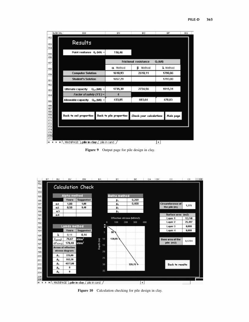
Figure 9 Output page for pile design in clay.
Figure 10 Calculation checking for pile design in clay.
PILE-D 363

academic year. This is an elective course and an
average of 20 students in their senior year takes the
course. After teaching the theory of load carrying
capacity of a single pile in sandy and clayey soil, some
examples considering various cases are solved.
Next, new example is given to students to solve it
in the classroom in a 30-min period. When the
given time is over, same sample problem is solved
Figure 11 Data entrance for pile design in sand.
Figure 12 Selection of bearing capacity factor.
364 CANAKCI

while demonstrating the use of Pile-D program in the
classroom. This takes only about 20 min, and thus the
use of this program does not affect the content that
needs to be covered during the classroom time.
The students taking the course obtain the program
from the instructor and they are allowed to install it
in their personal computer. They are assigned some
homework problems and they are asked to solve the
Figure 13 Output page for pile design in sand.
Figure 14 Calculation checking for pile design in sand.
PILE-D 365

problems by hand and check their solutions using
Pile-D program. They are supposed to submit both
hand and Pile-D solutions. As part of the homework
assignments, the students are also asked to perform
some analytical studies by varying some soil and pile
material parameters and observe their effects on the
results.
Verbal feedback from students is usually sought
after they complete their assignments on the use of
Pile-D. Almost all of the students find the program
user-friendly. The navigation through the program is
found easy. They say they have no problems with
understanding the meaning of buttons and icons
within the program. The automatic generation of a
plot showing the effective stress with depth consid-
ering critical depth in sandy soil and a plot showing
the change in effective stress with depth in layered
clayey soil are favored features. The students also
pointed out that the use of this program helped them to
understand the load carrying capacity of single pile in
sandy and clayey soil much better.
CONCLUSIONS
Microsoft Excel is a useful programming platform
due to its easy accessibility and execution on any type
of computers. It is well-suited to perform Geo-
technical Engineering calculations. Pile-D is a Micro-
soft Excel based educational computer program
module. It is developed as a courseware for more
effective teaching of pile foundation design in clayey
and sandy soil in undergraduate level geotechnical
engineering courses. The program allows the user to
change various parameters used in the calculations
and observe their effects on load carrying capacity of
pile in sand and clay. Using the program, the user can
configure and conduct his/her own examples inter-
actively instead of following a limited number of
examples selected by the instructor.
REFERENCES
[1] GeotechniCAL, Educational technology for ground
engineering. http://www.uwe.ac.uk/geocal/geocal.htm
2002.
[2] M. Budhu, Soil mechanics and foundations, Wiley,
New York, 2000.
[3] S. Sharma and J. H. Hardcastle, Computer based
instruction for consolidation testing, Proceedings of
the 36th Annual Symposium on Engineering Geology
and Geotechnical Engineering, Las Vegas, Nevada,
March 2001, 28�30.
[4] S. Masala and K. Biggar, Geotechnical virtual
laboratory. I. Permeability, Comp Appl Eng Educ
11 (2003), 132�143.
[5] D. P. Coduto, Foundaton design principles and
practices, Prentice Hall, Englewood Cliffs, NJ, 1994.
[6] B. M. Das, Principles of foundation engineering,
4th ed., PWS-KENT, Boston, 1999.
[7] C. Liu and J. B. Evett, Soils, foundations, 5th ed.,
Prentice Hall, Englewood Cliffs, NJ, 2001.
[8] S. A. Brretto, R. Piazzalunga, and V. G. Ribeiro, A
web-based 2D structural analysis educational software,
Comp Appl Eng Educ 11 (2003), 83�92.
[9] K. Y. Kabalan and A. El-Hajj, Digital filter design
using spreadsheets, Comp Appl Eng Educ 7 (1999),
9�15.
BIOGRAPHY
Hanifi Canakci received his BSc degree in
civil engineering fromMiddle East Technical
University, Turkey, in 1989, and his MSc
and PhD in geotechnical engineering from
University of Strathclyde, Glasgow, United
Kingdom, in 1992 and 1996, respectively.
He is currently an assistant professor in
the Department of Civil Engineering at The
University of Gaziantep in Turkey. His
current research interests are computer-aided learning and ground
improvement.
366 CANAKCI