ADEPT*Preview - C:\TEMP\.aptcache\EM000\EM
104
GENERAL ENGINE AND TRANSAXLE ASSEMBLY TIMING SYSTEM CYLINDER HEAD ASSEMBLY ENGINE BLOCK COOLING SYSTEM LUBRICATION SYSTEM INTAKE AND EXHAUST SYSTEM www.cargeek.ir www.cargeek.ir
-
Upload
khangminh22 -
Category
Documents
-
view
3 -
download
0
Transcript of ADEPT*Preview - C:\TEMP\.aptcache\EM000\EM

GENERAL
ENGINE AND TRANSAXLE ASSEMBLY
TIMING SYSTEM
CYLINDER HEAD ASSEMBLY
ENGINE BLOCK
COOLING SYSTEM
LUBRICATION SYSTEM
INTAKE AND EXHAUST SYSTEM
www.cargeek.ir
www.cargeek.ir

EM -2 ENGINE (G6DB/G6DA - GSL 3.3/3.8)
GENERALSPECIFICATION E4EB72CB
Description Specifications Limit
GeneralType V-type, DOHC
Number of cylinders 6
Bore 92mm (3.6220in)(3.3L)96mm(3.7795in)(3.8L)
Stroke 83.8mm (3.2992in)(3.3L)87.0mm(3.4252in)(3.8L)
Total displacement 3,342cc (203.94cu.in.)(3.3L)3.778cc(230.55cu.in.)(3.8L)
Compression ratio 10.4
Firing order 1-2-3-4-5-6
Valve timing
Opens(ATDC) 14˚ (3.3L) / 10 (3.8L)Intake
Closes(ABDC) 62˚ (3.3L / 3.8L)
Opens(BBDC) 42˚ (3.3L / 3.8L)Exhaust
Closes(ATDC) 6˚ (3.3L / 3.8L)
Cylinder headFlatness of gasket surface Less than 0.05mm (0.0019in.)
[Less than 0.02mm (0.0008in.) / 150x150]
Intake Less than 0.1mm(0.0039in.)[Less than 0.03mm(0.001in)/110x110]
Flatness of manifoldmounting
Exhaust Less than 0.1mm(0.0039in.)[Less than 0.03mm(0.001in)/110x110]
Camshaft
Intake 46.3mm (1.8228in.)(3.3L)46.8mm(1.8425in.)(3.8L)
LHCamshaft
Exhaust 45.8mm (1.8031in.)(3.3L / 3.8L)
Intake 46.3mm (1.8228in.)(3.3L)46.8mm(1.8425in.)(3.8L)
Cam height
RHCamshaft
Exhaust 45.8mm (1.8031in.)(3.3L / 3.8L)
Intake No.1: 27.964 ~ 27.980mm (1.1009 ~ 1.1016in.)No.2,3,4: 23.954 ~ 23.970mm (0.9430~ 0.9437in.)
Journal outerdiameter
LH ,RHcamshaft
Exhaust No.1: 27.964 ~ 27.980mm (1.1009 ~ 1.1016in.)No.2,3,4: 23.954 ~ 23.970mm (0.9430~ 0.9437in.)
www.cargeek.ir
www.cargeek.ir

GENERAL EM -3
Description Specifications Limit
Intake No.1: 0.020 ~ 0.057mm (0.0008 ~ 0.0022in.)No.2,3,4: 0.030 ~ 0.067mm (0.0012 ~ 0.0026in.)
Bearing oilclearance
LH ,RHcamshaft
Exhaust No.1: 0.020 ~ 0.057mm (0.0008 ~ 0.0022in.)No.2,3,4: 0.030 ~ 0.067mm (0.0012 ~ 0.0026in.)
End play 0.02 ~ 0.18mm (0.0008 ~ 0.0071in.)
ValveIntake 105.27mm(4.1445in.)Valve length
Exhaust 105.50mm (4.1535in.)
Intake 5.465 ~ 5.480mm (0.2151 ~ 0.2157in.)Stem outer diameter
Exhaust 5.458 ~ 5.470mm (0.2149 ~ 0.2153in.)
Face angle 45.25 ~ 45.75
Intake 1.56 ~ 1.86mm(0.06142 ~ 0.07323in.)Thickness ofvalvehead(margin) Exhaust 1.73 ~ 2.03mm(0.06811 ~ 0.07992in.)
Intake 0.020 ~ 0.047mm (0.00078 ~ 0.00185in.) 0.07mm (0.00275in.)Valve stem to valveguide clearance Exhaust 0.030 ~ 0.054mm (0.00118 ~ 0.00212in.) 0.09mm (0.00354in.)
Valve guideIntake 5.500 ~ 5.512mm (0.2165 ~ 0.2170in.)Inner diameter
Exhaust 5.500 ~ 5.512mm (0.2165 ~ 0.2170in.)
Intake 41.8 ~ 42.2mm (1.6457 ~ 1.6614in.)Length
Exhaust 41.8 ~ 42.2mm (1.6457 ~ 1.6614in.)
Valve seatIntake 1.15 ~ 1.45mm(0.05118 ~ 0.05709in.)Width of seat
contact Exhaust 1.35 ~ 1.65mm(0.05315 ~ 0.06496in.)
Intake 44.75 ~ 45.20Seat angle
Exhaust 44.75 ~ 45.20
Valve springFree length 43.86mm (1.7267in.)
19.3±0.8kg/34.0mm (42.7±1.8 lb/1.3386in.)Load
42.3±1.3kg/24.2mm (93.3±2.9 lb/0.9527in.)
Out of squareness Less than 1.5
MLAIntake 34.964 ~ 34.980mm (1.3765 ~ 1.3772in.)MLA outer diameter
Exhaust 34.964 ~ 34.980mm (1.3765 ~ 1.3772in.)
Intake 35.000 ~ 35.025mm (1.3779 ~ 1.3789in.)Cylinder headtappet bore innerdiameter Exhaust 35.000 ~ 35.025mm (1.3779 ~ 1.3789in.)
Intake 0.020 ~ 0.061mm (0.0008 ~ 0.0024in.) 0.07mm(0.0027in.)MLA to tappet boreclearance Exhaust 0.020 ~ 0.061mm (0.0008 ~ 0.0024in.) 0.07mm(0.0027in.)
Valve clearance
www.cargeek.ir
www.cargeek.ir

EM -4 ENGINE (G6DB/G6DA - GSL 3.3/3.8)
Description Specifications Limit
Intake 0.17 ~ 0.23mm (0.0067 ~ 0.0090in.) 0.10 ~ 0.30mm(0.0039 ~ 0.0118in.)
Exhaust 0.27 ~ 0.33mm (0.0106 ~ 0.0129in.) 0.20 ~ 0.40mm(0.0078 ~ 0.0157in.)
Cylinder block
Cylinder bore 92.00 ~ 92.03mm (3.6220 ~ 3.6232in.)(3.3L)96.00 ~ 96.03mm (3.7795 ~ 3.7807in.)(3.8L)
Flatness of gasket surface Less than 0.05mm (0.0019in.)[Less than 0.02mm (0.0008in.) / 150x150]
Piston
Piston outer diameter 91.96 ~ 91.99mm(3.6205 ~ 3.6216in.)(3.3L)95.96 ~ 95.99mm(3.7779 ~ 3.7791in.)(3.8L)
Piston to cylinder clearance 0.03 ~ 0.05mm(0.0012 ~ 0.0020in.)
No. 1 ring groove 1.22 ~ 1.24mm (0.0480 ~ 0.0488in.) 1.26mm (0.0496in.)
No. 2 ring groove 1.22 ~ 1.24mm (0.0480 ~ 0.0488in.) 1.26mm (0.0496in.)
Ring groove width
Oil ring groove 2.01 ~ 2.03mm (0.0791 ~ 0.0799in.) 2.05mm (0.0807in.)
Piston ringNo. 1 ring 0.03 ~ 0.07mm (0.0012 ~ 0.0027in.) 0.1mm (0.004in.)
No. 2 ring 0.03 ~ 0.07mm (0.0012 ~ 0.0027in.) 0.1mm (0.004in.)
Side clearance
Oil ring 0.06 ~ 0.15mm (0.0024 ~ 0.0059in.) 0.2mm (0.008in.)
No. 1 ring 0.17 ~ 0.32mm (0.0067 ~ 0.0126in.) 0.6mm (0.0236in.)
No. 2 ring 0.32 ~ 0.47mm (0.0126 ~ 0.0185in.) 0.7mm (0.0275in.)
End gap
Oil ring 0.20 ~ 0.70mm (0.0078 ~ 0.0275in.) 0.8mm (0.0315in.)
Piston pinPiston pin outer diameter 23.001 ~ 23.006mm (0.9055 ~ 0.9057in.)
Piston pin hole inner diameter 23.016 ~ 23.021mm (0.9061 ~ 0.9063in.)
Piston pin hole clearance 0.01 ~ 0.02mm (0.0039 ~ 0.0078in.)
Connecting rod small end inner diameter 22.974 ~ 22.985mm (0.9045 ~ 0.9049in.)
Connecting rod small end hole clearance -0.032 ~ -0.016mm (-0.0012 ~ 0.0006in.)
Connecting rodConnecting rod big end innerdiameter 58.000 ~ 58.018mm(2.2834 ~2.2842in.)
Connecting rod bearing oil clearance 0.030 ~ 0.048mm (0.0012 ~ 0.0019in.)
Side clearance 0.1 ~ 0.25mm (0.0039 ~ 0.0098in.)
CrankshaftMain journal outer diameter 68.942 ~ 68.960mm (2.7142 ~ 2.7149in.)
Pin journal outer diameter 54.954 ~ 54.972mm (2.1635 ~ 2.1642in.)
Main bearing oil clearance 0.022 ~ 0.040mm (0.0008 ~ 0.0016in.)
End play 0.10 ~ 0.28mm (0.0039 ~ 0.0110in.)
Oil pump
Relief valve opening pressure 450 ~ 550kPa(4.59 ~ 5.61kgf/cm²,65.28 ~ 79.79psi)
www.cargeek.ir
www.cargeek.ir

GENERAL EM -5
Description Specifications Limit
Engine oilOil quantity (Total) 6.4L(6.76U.S.qts,5.63lmp.qts)
Oil quantity (Oil pan) 5.5L(5.81U.S.qts,4.84lmp.qts)
Oil quantity (Oil filter) 0.4L(0.42U.S.qts,0.35lmp.qts)
Oil quantity (Drain and refill) 5.2L(5.49U.S.qts,4.58lmp.qts)
Oil quality Above SJ or SL
Oil pressure 130kPa(1.32kgf/cm²,18.77psi)[at 1000rpm,110 C(230 F)]
Cooling systemCooling method Forced circulation with electrical fan
Coolant quantity 8.6L(9.09U.S.qts,7.57lmp.qts)
Type Wax pellet type
Opening temperature 82±2 C (179.6±35.6 F)
Fully openedtem-perature 95 C (203 F)
Thermostat
Full lift 10mm (0.3937in.)
Main valve openingpressure
93.16 ~ 122.58kpa(0.95 ~ 1.25kg/cm², 13.51 ~ 17.78psi)
Radiator cap
Vacuum valveopening pressure
0.98 ~ 4.90 kpa(0.01 ~ 0.05kg/cm², 0.14 ~ 0.71 psi)
Water temperature sensorType Thermister type
20 C (68 F) 2.31 ~ 2.59KΩResistance
80 C(176 F) 0.3222 KΩ
www.cargeek.ir
www.cargeek.ir

EM -6 ENGINE (G6DB/G6DA - GSL 3.3/3.8)
TIGHTENING TORQUE
Item Quan-tity Nm kgf.m lb-ft
Crankshaft pulley bolt 1 284.2 ~ 303.8 29.0 ~ 31.0 209.76 ~ 224.22
Timing chain cover bolt B 17 18.62 ~ 21.56 1.9 ~ 2.2 13.74 ~ 15.91
Timing chain cover bolt C 4 9.80 ~ 11.76 1.0 ~ 1.2 7.23 ~ 8.68
Timing chain cover bolt D 1 58.80 ~ 68.80 6.0 ~ 7.0 43.40 ~ 50.63
Timing chain cover bolt E 1 58.80 ~ 68.80 6.0 ~ 7.0 43.40 ~ 50.63
Timing chain cover bolt F 2 24.50 ~ 26.46 2.5 ~ 2.7 18.08 ~ 19.53
Timing chain cover bolt G 4 21.56 ~ 23.52 2.2 ~ 2.4 15.91 ~ 17.36
Timing chain cover bolt H 1 9.80 ~ 11.76 1.0 ~ 1.2 7.23 ~ 8.68
Timing chain cover bolt I 1 9.80 ~ 11.76 1.0 ~ 1.2 7.23 ~ 8.68
Timing chain cover bolt J 1 9.80 ~ 11.76 1.0 ~ 1.2 7.23 ~ 8.68
Cam to cam guide bolt 4 9.80 ~ 11.76 1.0 ~ 1.2 7.23 ~ 8.68
Timing chain auto tensioner bolt 2 9.80 ~ 11.76 1.0 ~ 1.2 7.23 ~ 8.68
Timing chain auto tensioner nut 2 9.80 ~ 11.76 1.0 ~ 1.2 7.23 ~ 8.68
Timing chain guide bolt 4 19.60 ~ 24.50 2.0 ~ 2.5 14.17 ~ 18.08
Oil pump chain cover bolt 3 9.80 ~ 11.76 1.0 ~ 1.2 7.23 ~ 8.68
Oil pump chain tensioner bolt 1 9.80 ~ 11.76 1.0 ~ 1.2 7.23 ~ 8.68
Oil pump chain guide bolt 2 9.80 ~ 11.76 1.0 ~ 1.2 7.23 ~ 8.68
Oil pump chain sprocket bolt 1 18.62 ~ 21.56 1.9 ~ 2.2 13.74 ~ 15.91
Lower oil pan bolt 13 9.80 ~ 11.76 1.0 ~ 1.2 7.23 ~ 8.68
Drive belt auto tensioner bolt(M12) 1 96.04 ~ 99.96 9.8 ~ 10.2 70.88 ~ 73.78
Drive belt auto tensioner bolt(M8) 1 17.64 ~ 21.56 1.8 ~ 2.2 13.02 ~ 15.91
Drive belt idler bolt 1 53.90 ~ 57.82 5.5 ~ 5.9 39.78 ~ 42.67
OCV(oil control valve) bolt 2 9.80 ~ 11.76 1.0 ~ 1.2 7.23 ~ 8.68
Cylinder head bolt 16 39.2 + 120˚ + 90˚ 4.0 + 120˚ + 90˚ 28.93+ 120˚ + 90˚
Cylinder head bolt 1 18.62 ~ 23.52 1.9 ~ 2.4 13.74 ~ 17.36
CVVT & exhaust cam sprocket bolt 4 64.68 ~ 76.44 6.6 ~ 7.8 47.74 ~ 56.42
Camshaft bearing cap bolt 32 9.80 ~ 11.76 1.0 ~ 1.2 7.23 ~ 8.68
Cylinder head cover bolt 38 9.80 ~ 11.76 1.0 ~ 1.2 7.23 ~ 8.68
Connecting rod bearing bolt 12 19.60 + 90˚ 2.0 + 90˚ 14.46 + 90˚
Main bearing cap inner bolt(M11) 8 49.00 + 90˚ 5.0 + 90˚ 36.16 + 90˚
Main bearing cap outer bolt(M8) 8 19.60 + 120˚ 2.0 + 120˚ 14.46 + 120˚
Main bearing cap side bolt(M8) 6 29.40 ~ 31.36 3.0 ~ 3.2 21.70 ~ 23.14
Oil drain cover bolt 6 9.80 ~ 11.76 1.0 ~ 1.2 7.23 ~ 8.68
Rear oil seal case bolt 6 9.80 ~ 11.76 1.0 ~ 1.2 7.23 ~ 8.68
Baffle plate bolt 12 9.80 ~ 11.76 1.0 ~ 1.2 7.23 ~ 8.68
Upper oil pan bolt 16 9.80 ~ 11.76 1.0 ~ 1.2 7.23 ~ 8.68
www.cargeek.ir
www.cargeek.ir

GENERAL EM -7
Item Quan-tity Nm kgf.m lb-ft
Knock sensor bolt 2 15.68 ~ 23.52 1.6 ~ 2.4 11.57 ~ 17.36
Drive plate bolt 8 71.54 ~ 75.46 7.3 ~ 7.7 52.80 ~ 55.69
Oil filter cap 24.50 2.5 18.08
Oil drain bolt 1 34.30 ~ 44.10 3.5 ~ 4.5 25.31 ~ 32.55
Oil pump bolt 3 20.6 ~ 22.6 2.1 ~ 2.3 15.2 ~ 16.6
Oil filter body bolt 10 9.80 ~ 11.76 1.0 ~ 1.2 7.23 ~ 8.68
Oil filter body cover bolt 11 9.80 ~ 11.76 1.0 ~ 1.2 7.23 ~ 8.68
Water vent hose bolt 2 9.80 ~ 11.76 1.0 ~ 1.2 7.23 ~ 8.68
Water pump bolt(Timing chain cover bolt L) 1 21.56 ~ 26.46 2.2 ~ 2.7 15.91 ~ 19.53
Water pump bolt(Timing chain cover bolt K) 4 9.80 ~ 11.76 1.0 ~ 1.2 7.23 ~ 8.68
Water pump pulley bolt 4 7.84 ~ 9.80 0.8 ~ 1.0 5.78 ~ 7.23
Water temp. control nut 4 18.62 ~ 23.52 1.9 ~ 2.4 13.74 ~ 17.36
Water temp. control bolt 2 18.62 ~ 23.52 1.9 ~ 2.4 13.74 ~ 17.36
Water inlet pipe bolt 3 16.66 ~ 19.60 1.7 ~ 2.0 12.30 ~ 14.47
Air vent pipe bolt 2 9.80 ~ 11.76 1.0 ~ 1.2 7.23 ~ 8.68
Intake manifold bolt 6 18.62 ~ 23.52 1.9 ~ 2.4 13.74 ~ 17.36
Intake manifold nut 2 18.62 ~ 23.52 1.9 ~ 2.4 13.74 ~ 17.36
Surge tank bolt(3.3L) 5 9.80 ~ 11.76 1.0 ~ 1.2 7.23 ~ 8.68
Surge tank nut(3.3L) 2 9.80 ~ 11.76 1.0 ~ 1.2 7.23 ~ 8.68
Surge tank bolt (3.8L : M8 × 25) 3 18.62 ~ 23.52 1.9 ~ 2.4 13.74 ~ 17.36
Surge tank bolt (3.8L : M6 × 106) 2 9.80 ~ 11.76 1.0 ~ 1.2 7.23 ~ 8.68
Surge tank nut (3.8L) 1 18.62 ~ 23.52 1.9 ~ 2.4 13.74 ~ 17.36
Breather pipe bolt 2 9.80 ~ 11.76 1.0 ~ 1.2 7.23 ~ 8.68
Surge tank bracket bolt(3.3L) 2 27.44 ~ 31.36 2.8 ~ 3.2 20.25 ~ 23.14
Surge tank bracket bolt rear(3.8L : M10 × 18 ) 2 27.44 ~ 31.36 2.8 ~ 3.2 20.25 ~ 23.14
Surge tank bracket bolt front(3.8L : M8 × 16) 2 18.62 ~ 23.52 1.9 ~ 2.4 13.74 ~ 17.36
ETC bracket bolt 2 15.68 ~ 25.48 1.6 ~ 2.6 11.57 ~ 18.80
Exhaust manifold nut 16 39.20 ~ 44.10 4.0 ~ 4.5 28.93 ~ 32.55
Heat protector bolt 8 16.66 ~ 21.56 1.7 ~ 2.2 12.30 ~ 15.91
Front muffler 2 39.20 ~ 58.80 4.0 ~ 6.0 28.93 ~ 43.40
www.cargeek.ir
www.cargeek.ir

EM -8 ENGINE (G6DB/G6DA - GSL 3.3/3.8)
COMPRESSION
NOTEIf the there is lack of power, excessive oil consump-tion or poor fuel economy, measure the compressionpressure.
1. Warm up and stop engine.Allow the engine to warm up to normal operating tem-perature.
2. Remove the surge tank. (Refer to EM - 100)
3. Remove the ignition coil connectors(A) and ignitioncoils(B).
A
B
KDRF158B
4. Remove the spark plugs.Using a 16mm plug wrench, remove the 6 spark plugs.
5. Check cylinder compression pressure.
1) Insert a compression gauge into the spark plughole.
2) Fully open the throttle.
3) After 7 times of cranking the engine, measure thecompression pressure.
NOTEAlways use a fully charged battery to obtain enginespeed of 250 rpm or more.
4) Repeat steps (a) through (c) for each cylinder.
NOTEThis measurement must be done in as short a time aspossible.
Compression pressure :1,225kPa (12.5kgf/cm², 177psi) - 200 ~ 250rpmMinimum pressure :1,078kPa (11.0kgf/cm², 156psi)
5) If the cylinder compression in 1 or more cylindersis low, pour a small amount of engine oil into thecylinder through the spark plug hole and repeatsteps (1) through (3) for cylinders with low com-pression.
• If adding oil helps the compression, it is likelythat the piston rings and/or cylinder bore areworn or damaged.
• If pressure stays low, a valve may be stick-ing or seating is improper, or there may beleakage past the gasket.
6. Reinstall the spark plugs.
7. Install the ignition coil and ignition coil connectors.
8. Install the surge tank. (Refer to EM - 104)
www.cargeek.ir
www.cargeek.ir
GENERAL EM -9
VALVE CLEARANCE INSPECTION ANDADJUSTMENT
NOTEInspect and adjust the valve clearance when the en-gine is cold (Engine coolant temperature : 20 C) andcylinder head is installed on the cylinder block.
1. Remove the engine cover.
2. Remove air cleaner assembly.(Refer to EM - 17)
3. Remove the surge tank.(Refer to EM - 100)
4. Remove the cylinder head cover.
1) Disconnect the ignition coil connector and re-move the ignition coil.
2) Disconnect the breather pipe assembly(A) fromthe cylinder head cover.
A
ECBF031A
3) Loosen the cylinder head cover bolts and thenremove the cover(A) and gasket.
A
KDRF112A
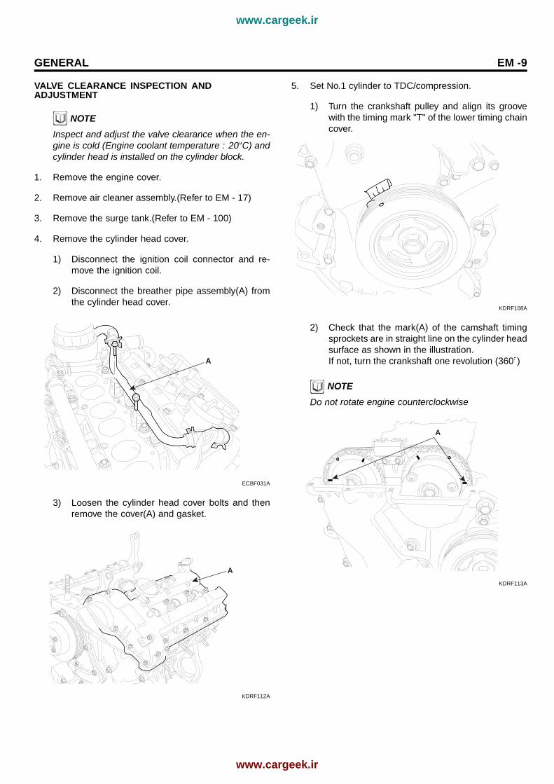
5. Set No.1 cylinder to TDC/compression.
1) Turn the crankshaft pulley and align its groovewith the timing mark "T" of the lower timing chaincover.
KDRF108A
2) Check that the mark(A) of the camshaft timingsprockets are in straight line on the cylinder headsurface as shown in the illustration.If not, turn the crankshaft one revolution (360 )
NOTEDo not rotate engine counterclockwise
A
KDRF113A
www.cargeek.ir
www.cargeek.ir

EM -10 ENGINE (G6DB/G6DA - GSL 3.3/3.8)
6. Inspect the valve clearance.
1) Check only the valve indicated as shown. [No. 1cylinder : TDC/Compression] measure the valveclearance.
RH EXHAUST
LH EXHAUST
INTAKE
Timing mark
EDRF021A
Measurement method.• · Using a thickness gauge, measure the
clearance between the tappet and the basecircle of camshaft.· Record the out-of-specification valve clear-ance measurements. They will be used laterto determine the required replacement ad-justing tappet.
Valve clearanceSpecificationEngine coolant temperature : 20 C [68 F]LimitIntake : 0.10 ~ 0.30mm (0.0039 ~ 0.0118in.)Exhaust : 0.20 ~ 0.40mm (0.0079 ~ 0.0157in.)
2) Turn the crankshaft pulley one revolution (360 )and align the groove with timing mark "T" of thelower timing chain cover.
NOTEDo not rotate engine counterclockwise
3) Check only valves indicated as shown. [NO. 4cylinder : TDC/compression]. Measure the valveclearance. (Refer to procedure step1))
RH EXHAUST
LH EXHAUST
INTAKE
Timing mark
Timing mark
EDRF022A
7. Adjust the intake and exhaust valve clearance.
1) Set the No.1 cylinder to the TDC/compression.(Refer to EM - 9)
2) Remove the timing chain.(Refer to EM - 26)
3) Remove the camshaft bearing caps(A).
A
KDRF196A
4) Remove the camshaft assembly(A).
A
KDRF197A
www.cargeek.ir
www.cargeek.ir

GENERAL EM -11
5) Remove MLAs.
6) Measure the thickness of the removed tappet us-ing a micrometer.
EDKE889D
7) Calculate the thickness of a new tappet so thatthe valve clearance comes within the specifiedvalue.
Valve clearance(Engine coolant tempera-ture: 20 C[68 F])T : Thickness of removed tappetA : Measured valve clearanceN : Thickness of new tappetIntake : N = T + [A - 0.20mm(0.0079in.)]Exhaust : N = T + [A - 0.30mm (0.0118in.)]
8) Select a new tappet with a thickness as close aspossible to the calculated value.
NOTEShims are available in 41size increments of 0.015mm(0.0006in.) from 3.00mm (0.118in.) to 3.600mm(0.1417in.)
9) Place a new tappet on the cylinder head.
NOTEAppling engine oil at the selected tappet on the pe-riphery and top surface.
10) Install the intake and exhaust camshaft. (Referto EM - 55)
11) Install the bearing caps. (Refer to EM - 56)
12) Install the timing chain. (Refer to EM - 32)
13) Turn the crankshaft two turns in the operat-ing direction(clockwise) and realign crankshaftsprocket and camshaft sprocket timing marks(A).
A
KDRF113A
14) Recheck the valve clearance.
Valve clearance (Engine coolant tempera-ture: 20 C[68 F])[Specification]Intake : 0.17 ~ 0.23mm (0.0067 ~ 0.0090in.)Exhaust : 0.27 ~ 0.33mm (0.0106 ~ 0.0129in.)
www.cargeek.ir
www.cargeek.ir

EM -12 ENGINE (G6DB/G6DA - GSL 3.3/3.8)
TROUBLESHOOTING EB9DDED8
Symptom Suspect area Remedy
Worn crankshaft bearings.Loose or improperly engine drive plate.
Replace the crankshaft and bearingsas required.Repair or replace the drive plateas required.
Worn piston rings.(Oil consumption may or may not causethe engine to misfire.)
Inspect the cylinder for a loss ofcompression.Repair or replace as required.
Engine misfire with abnormalinternal lower engine noises.
Worn crankshaft thrust bearings Replace the crankshaft and bearingsas required.
Stuck valves.(Carbon buildup on the valve stem)
Repair or replace as required.
Excessive worn or mis-alignedtiming chain.
Replace the timing chain andsprocket as required.
Engine misfire with abnormalvalve train noise.
Worn camshaft lobes. Replace the camshaft and valve lifters.
Engine misfire with coolantconsumption.
• Faulty cylinder head gasket and/orcranking or other damage to thecylinder head and engine blockcooling system.
• Coolant consumption may or may notcause the engine to overheat.
• Inspect the cylinder head andengine block for damage tothe coolant passages and/or afaulty head gasket.
• Repair or replace as required.
Worn valves, guides and/or valvestem oil seals.
Repair or replace as required.Engine misfire with excessiveoil consumption.
Worn piston rings.(Oil consumption may or may not causethe engine to misfire)
• Inspect the cylinder for a lossof compression.
• Repair or replace as required.
Incorrect oil viscosity. • Drain the oil.• Install the correct viscosity oil.
Engine noise on start-up, butonly lasting a few seconds.
Worn crankshaft thrust bearing. • Inspect the thrust bearing andcrankshaft.
• Repair or replace as required.
www.cargeek.ir
www.cargeek.ir

GENERAL EM -13
Symptom Suspect area Remedy
Low oil pressure. Repair or replace as required.
Broken valve spring. Replace the valve spring.
Worn or dirty valve lifters. Replace the valve lifters.
Stretched or broken timing chain and/ordamaged sprocket teeth.
Replace the timing chain and sprockets.
Worn timing chain tensioner, if applicable. Replace the timing chain tensioneras required.
Worn camshaft lobes. • Inspect the camshaft lobes.• Replace the timing camshaft and
valve lifters as required.
Worn valve guides or valve stems. Inspect the valves and valve guides,thenrepair as required.
Stuck valves. (Carbon on the valvestem or valve seat may cause thevalve to stay open.
Inspect the valves and valve guides,then repair as required.
Upper engine noise,regard-less of engine speed.
Worn drive belt, idler, tensionerand bearing.
Replace as required.
Low oil pressure. Repair or required.
Loose or damaged drive plate. Repair or replace the drive plate.
Damaged oil pan, contacting theoil pump screen.
• Inspect the oil pan.• Inspect the oil pump screen.• Repair or replace as required.
Oil pump screen loose, damagedor restricted.
• Inspect the oil pump screen.• Repair or replace as required.
Excessive piston-to-cylinder boreclearance.
• Inspect the piston, piston pinand cylinder bore.
• Repair as required.
Excessive piston pin-to-piston clearance. • Inspect the piston, piston pin andthe connecting rod.
• Repair or replace as required.
Excessive connecting rod bearingclearance
Inspect the following componentsand repair as required.
• The connecting rod bearings.• The connecting rods.• The crankshaft pin journals.
Excessive crankshaft bearing clearance. Inspect the following components,and repair as required.
• The crankshaft bearings.• The crankshaft main journals.• The cylinder block.
Lower engine noise,regard-less of engine speed.
Incorrect piston, piston pin andconnecting rod installation
• Verify the piston pins and connectingrods are installed correctly.
• Repair as required.
www.cargeek.ir
www.cargeek.ir

EM -14 ENGINE (G6DB/G6DA - GSL 3.3/3.8)
Symptom Suspect area Remedy
Low oil pressure Repair or replace as required.
Excessive connecting rod bearingclearance .
Inspect the following componentsandrepair as required :
• The connecting rod bearings.• The connecting rods.• The crankshaft.
Engine noise under load.
Excessive crankshaft bearing clearance. Inspect the following components,andrepair as required.
• The crankshaft bearings.• The crankshaft main journals.• The cylinder block.
Hydraulically locked cylinder.• Coolant/antifreeze in cylinder.• Oil in cylinder.• Fuel in cylinder.
1. Remove spark plugs and checkfor fluid.
2. Inspect for broken head gasket.3. Inspect for cracked engine block
or cylinder head.4. Inspect for a sticking fuel injector
and/or leaking fuel regulator.
Broken timing chain and/or timing chainand/or timing chain gears.
1. Inspect timing chain and gears.2. Repair as required.
Material in cylinder.• Broken valve• Piston material• Foreign material
1. Inspect cylinder for damagedcomponents and/or foreign materials.
2. Repair or replace as required.
Seized crankshaft or connectingrod bearings.
1. Inspect crankshaft and connectingrod bearing.
2. Repair as required.
Bent or broken connecting rod. 1. Inspect connecting rods.2. Repair as required.
Engine will notcrank-crankshaft willnot rotate.
Broken crankshaft. 1. Inspect crankshaft.2. Repair as required.
www.cargeek.ir
www.cargeek.ir

GENERAL EM -15
SPECIAL TOOLS E787872C
Tool (Number and name) Illustration UseCrankshaft front oil seal installer(09231-3C100)
KDRF233A
Installation of the front oil seal
Flywheel stopper(09231-3C300)
KCRF030D
Removal and installation of the flywheeland crankshaft pulley.
Torque angle adapter(09221-4A000)
LCAC030A
Installation of bolts & nuts needingan angular method
Valve stem seal remover(09222-29000)
KDRF232A
Remover of the valve stem seal
Valve stem seal remover(09222-3C100)
LCAC030D
Installation of the valve stem seal
www.cargeek.ir
www.cargeek.ir

EM -16 ENGINE (G6DB/G6DA - GSL 3.3/3.8)
Tool (Number and name) Illustration UseValve spring compressor& holder(09222-3K000)(09222-3C300)
A
A
B
ECRF003A
Removal and installation of the intakeor exhaust valveA : 09222-3K000B : 09222-3C300 (holder)
Crankshaft rear oil seal installer(09231-3C200)(09231-H1100)
A
B
ACRF003A
Installation of the crankshaft rear oil sealA : 09231-3C200B : 09231-H1100
Oil pan remover(09215-3C000)
KDRF219A
Removal of oil pan
Oil filter wrench(09263-3C100)
B6327000
Removal and installation of the oil filter
www.cargeek.ir
www.cargeek.ir

ENGINE AND TRANSAXLE ASSEMBLY EM -17
ENGINE AND TRANSAXLEASSEMBLYREMOVAL E31DBAFC
CAUTION• Use fender covers to avoid damaging paint-
edsurfaces.• To avoid damage, unplug the wiring connec-
tors carefully while holding the connectorportion.
NOTE• Mark all wiring and hoses to avoid misconnec-
tion.
1. Remove the engine cover.
2. Remove the air duct(A).
A
KCBF143A
3. Disconnect the neagative terminal from the battery.
4. Recovering refrigerant and remove the high & lowpressure pipe. (Refer to HA group - air conditionercompressor)
5. Remove the intake air hose and air cleaner assembly.
1) Disconnect the AFS connector(A).
2) Disconnect the breather hose(B) from air clean-erhose.
3) Disconnect the ECM connector. (Refer to FLgroup)
4) Remove the intake air hose(C) and air cleanerupper cover(D).
D
A
B
C
KDRF173A
5) Remove the air cleaner lower cover(A).
A
ECBF016A
6. Remove front wheels.
7. Remove under cover(A).
A
KCBF101A
8. Drain the engine coolant.Remove the radiator cap to speed draining.
www.cargeek.ir
www.cargeek.ir

EM -18 ENGINE (G6DB/G6DA - GSL 3.3/3.8)
9. Remove the upper radiator hose and lower radiatorhose(A).
A
KDRF148A
10. Remove transaxle oil cooler hose.
11. Remove fuel hose(A) and PCSV(B) hose.
A
B
KDRF149A
12. Remove engine wiring.
1) Disconnect RH oxygen sensor connector(A).
A
[3.3L]
ECBF020A
2) Disconnect RH oxygen sensor connector(A) andsolenoid valve connector(B).
A
B
[3.8L]
ECBF021A
3) Disconnect power steering oil pressure sensorconnector(A).
A
KDRF152A
4) Disconnect RH injector connector(A) and ignitioncoil connector(B).
A
B
[3.3L]
ECBF022A
www.cargeek.ir
www.cargeek.ir

ENGINE AND TRANSAXLE ASSEMBLY EM -19
B
A
[3.8L]
ECBF023A
5) Disconnect OCV connector(A) and knock sensorconnector(B).
A
B
KDRF155A
6) Disconnect LH front oxygen sensor connec-tor(A).
A
KDRF156A
7) Disconnect alternator connector(A).
A
KDRF157A
8) Disconnect LH ignition coil connector(A), injec-tor connector(B), condenser connector(C) andground(D), and remove wiring harness protec-tor(E).
E
D
B
A
C
KDRF158A
9) Disconnect LH CMPS(A) and oil pressure switchconnector(B).
A
B
KDRF159A
www.cargeek.ir
www.cargeek.ir

EM -20 ENGINE (G6DB/G6DA - GSL 3.3/3.8)
10) Disconnect PCSV connector(A) and MAP sensorconnector(B).
A
B
[3.3L]
ECBF024A
A
B
[3.8L]
ECBF025A
11) Disconnect RH CMPS(A) and OTS connector(B).
A
B
KDRF161A
12) Disconnect ETC connector(A) and knock sensorconnector(B).
A
B
KDRF162A
13) Disconnect WTS connector(A).
A
KDRF163A
14) Disconnect LH rear oxygen sensor connector(A)and CPS connector(B).
B
A
KDRF164A
www.cargeek.ir
www.cargeek.ir

ENGINE AND TRANSAXLE ASSEMBLY EM -21
13. Disconnect the transaxle wire harness connectorand remove the transaxle control cable.(Refer to TRgroup)
14. Disconnect EPS connector.
A
KCBF103A
15. Remove heater hose(A).
A
KDRF165A
16. Remove brake vacuum hose(A).
A
KDBF101A
17. Remove power steering pump hose(A).
A
KDRF175A
18. Remove A/C compressor hose.
19. Drain transaxle oil.
20. Remove lower arm ball joint. (Refer to DS group)
21. Remove tie rod end ball joint. (Refer to DS group)
22. Remove stabilizer link. (Refer to SS group)
23. After removing a split pin and nut from the steeringbar tie rod, disconnect it. (Refer to ST group)
24. Remove power steering return hose(A) and drainpower steering oil.
A
ECBF007A
25. Remove front roll stopper mounting bolt.
26. Remove rear roll stopper mounting bolt.
27. Remove steering u-joint mounting bolt. (Refer to STgroup)
www.cargeek.ir
www.cargeek.ir

EM -22 ENGINE (G6DB/G6DA - GSL 3.3/3.8)
28. Remove front exhaust pipe(A).
A
KCBF102A
29. Supporting the cross member(A) with a jack, removethe stay with the mounting bolts.
Tightening torque :137.3~156.9Nm (14.0~16.0kgf.m, 101.3~115.7lb-ft)
A
KMRE009R
30. Remove drive shaft from transaxle.(Refer to DSgroup)
31. Install jack for supporting engine and transaxle as-sembly.
32. Disconnet the ground cable(A) from the enginemounting bracket.
A
KDBF102A
33. Remove the engine mounting bracket(A).
A
KDRF172A
34. Remove the transaxle mounting bracket(A).
A
B
KMRE009T
www.cargeek.ir
www.cargeek.ir

ENGINE AND TRANSAXLE ASSEMBLY EM -23
35. Remove the engine and transaxle assembly by liftingvehicle.
NOTEWhen remove the engine and transaxle assembly, becareful not to damage any surrounding parts or bodycomponents.
INSTALLATION EAD5D6B1
Installation is in the reverse order of removal.Perform the following :
• Adjust the shift cable.• Refill the engine with engine oil.• Refill the transaxle with fluid.• Refill the radiator with engine coolant.• Bleed air from the cooling system with the heater
valve open.• Clean the battery posts and cable terminals with
sandpaper assemble them, then apply grease toprevent corrosion.
• Inspect for fuel leakage.After assembling the fuel line, turn on the ignitionswitch (do not operate the starter) so that the fuelpump runs for approximately two seconds and fuelline pressurizes.Repeat this operation two or three times, then checkfor fuel leakage at any point in the fuel line.
www.cargeek.ir
www.cargeek.ir

EM -24 ENGINE (G6DB/G6DA - GSL 3.3/3.8)
TIMING SYSTEMCOMPONENT EFFAFA9E
17.64 ~ 21.56(1.8 ~ 2.2, 13.02 ~ 15.91)
7.84 ~ 9.80(0.8 ~ 1.0, 5.78 ~ 7.23)
9.8 ~ 11.76(1.0 ~ 1.2, 7.23 ~ 8.68)
52.92 ~ 57.82(5.4 ~ 5.9, 39.06 ~ 42.67)
96.04 ~ 99.96(9.8 ~ 10.2, 70.85 ~ 73.74)
284.2 ~ 303.8(29.0 ~ 31.0, 209.76 ~ 224.22)
9.8 ~ 11.76(1.0 ~ 1.2, 7.23 ~ 8.68)
1. Drive belt2. Drive belt tensioner3. Idler4. Damper pulley
5. Water pump pulley6. Oil pan7. Cylinder head cover
TORQUE : N.m (kgf.m, lb-ft)
ECBF008A
www.cargeek.ir
www.cargeek.ir

TIMING SYSTEM EM -25
1. Timing chain cover2. Oil pump chain cover3. Oil pump sprocket4. Oil pump chain5. Crankshaft sprocket6. Timing chain auto tensioner7. Timing chain tensioner arm
8. Timing chain 9. Cam to cam guide10. Timing chain guide11. Timing chain auto tensioner12. Timing chain tensioner arm13. Crankshaft sprocket14. Timing chain
15. Timing chain guide16. Cam to cam guide17. Tensioner adapter18. Gasket19. Oil pump chain guide20. Oil pump temsioner assembly
TORQUE : N.m (kgf.m, lb-ft)
9.80 ~ 11.76(1.0 ~ 1.2, 7.23 ~ 8.68)
9.80 ~ 11.76(1.0 ~ 1.2, 7.23 ~ 8.68)
19.60 ~ 24.50(2.0 ~ 2.5, 14.17 ~ 18.08)
9.80 ~ 11.76(1.0 ~ 1.2, 7.23 ~ 8.68)
9.80 ~ 11.76(1.0 ~ 1.2, 7.23 ~ 8.68)
18.62 ~ 21.56(1.9 ~ 2.2, 13.74 ~ 15.91)
19.60 ~ 24.50(2.0 ~ 2.5, 14.17 ~ 18.08)
18.62 ~ 21.56(1.9 ~ 2.2, 13.74 ~ 15.91)
ECBF009A
www.cargeek.ir
www.cargeek.ir

EM -26 ENGINE (G6DB/G6DA - GSL 3.3/3.8)
REMOVAL EE688815
Engine removal is required for this procedure.
1. Remove the drive belt(A).
A
KDRF101A
2. Remove the power steering pump(A).
A
KDRF102A
3. Remove the air compressor(A).
A
KDRF103A
4. Remove the alternator(A).
A
KDRF104A
5. Remove drive belt idler(A).
A
KDRF105A
6. Remove drive belt auto tensioner(A).
A
KDRF106A
www.cargeek.ir
www.cargeek.ir

TIMING SYSTEM EM -27
7. Remove water pump pulley(A).
A
KDRF107A
8. Remove intake manifold.(Refer to EM - 100)
DISASSEMBLY ECE9DBD5
1. Remove cylinder head cover.a. Remove connector bracket(A) from LH cylinder
head cover.
A
KDRF110A
b. Disconnect RH ignition coil connector(A),condenser connector(B) and remove wiringbracket(C)
C
A
B
KDRF111A
c. Remove LH,RH ignition coil.
www.cargeek.ir
www.cargeek.ir

EM -28 ENGINE (G6DB/G6DA - GSL 3.3/3.8)
d. Remove LH,RH cylinder head cover(A).
A
KDRF112A
2. Set No.1 cylinder to TDC/compression.
1) Turn the crankshaft pulley and align its groovewith the timing mark "T" of the lower timing chaincover.
NOTEDo not rotate engine counterclockwise.
KDRF108A
2) Check that the mark(A) of the camshaft timingsprockets are in straight line on the cylinder headsurface as shown in the illustration.If not, turn the crankshaft one revolution (360 ).
A
KDRF113A
NOTEDo not rotate engine counterclockwise.
3. Remove the lower oil pan(A).Insert the blade of SST(09215-3C000) between theupper oil pan and lower oil pan, and cut off appliedsealer and removed lower oil pan.
09215-3C000
ECRF060A
NOTEBe careful not to damage the contact surfaces of Up-per oil pan and lower oil pan.
www.cargeek.ir
www.cargeek.ir

TIMING SYSTEM EM -29
4. Remove the crankshaft damper pulley(A).
A
KDRF109A
5. Remove the timing chain cover(A).
A
KDRF115A
NOTEBe careful not to damage the contact surfaces of cylin-der block, cylinder head and timing chain cover.
6. Install a set pin after compressing the timing chaintensioner.
KCRF105A
7. Remove RH cam-to-cam guide(A).
A
KDRF116A
8. Remove RH timing chain auto tensioner(A) and RHtiming chain tensioner arm(B).
B
A
KDRF117A
9. Remove RH timing chain.
10. Remove RH timing chain guide(A).
A
KDRF118A
www.cargeek.ir
www.cargeek.ir

EM -30 ENGINE (G6DB/G6DA - GSL 3.3/3.8)
11. Remove oil pump chain cover(A).
A
KDRF185A
12. Remove oil pump chain tensioner assembly(A).
A
KDRF119A
13. Remove oil pump chain guide(A).
A
KDRF120A
14. Remove oil pump chain sprocket(A) and oil pumpchain(B).
A
B
KDRF121A
15. Remove crankshaft sprocket(A)(Oil pump & RHcamshaft drive).
A
KDRF122A
16. Remove LH cam-to-cam guide(A).
A
KDRF123A
www.cargeek.ir
www.cargeek.ir

TIMING SYSTEM EM -31
17. Remove LH timing chain auto tensioner(A) and LHtiming chain tensioner arm(B).
A
B
KDRF124A
18. Remove LH timing chain.
19. Remove LH timing chain guide(A).
A
KDRF125A
20. Remove crankshaft sprocket(A)(LH camshaft drive).
A
KDRF126A
21. Remove tensioner adapter assembly(A).
A
KDRF127A
www.cargeek.ir
www.cargeek.ir

EM -32 ENGINE (G6DB/G6DA - GSL 3.3/3.8)
INSPECTION E33C7CDB
SPROCKETS, CHAIN TENSIONER, CHAINGUIDE, CHAIN TENSIONER ARM
1. Check the camshaft sprocket and crankshaft sprocketfor abnormal wear, cracks, or damage. Replace asnecessary.
2. Inspect the tensioner arm and chain guide for abnor-mal wear, cracks, or damage. Replace as necessary.
3. Check that the tensioner piston moves smoothly whenthe ratchet pawl is released with thin rod.
BELT, IDLER, BELT TENSIONER, PULLEY
1. Check the belt for oil or dust deposits.Replace, if necessary.Small deposits should be wiped away with a dry clothor paper. Do not clean with solvent.
2. When the engine is overhauled or belt tension ad-justed, check the belt carefully. If any of the followingflaws are evident, replace the belt.
NOTE• Do not bend, twist or turn the timing belt inside
out.• Do not allow the timing belt to come into contact
with oil, water and steam.
3. Inspect the idler for easy and smooth rotation andcheck for play or noise.
REASSEMBLY E0BF1C9F
1. The key(A) of crankshaft should be aligned with thetiming mark(B) of timing chain cover. As a result ofthis, the piston of No.1 cylinder is placed at the topdead center on compression stroke.
B
A
KDRF128A
2. Install tensioner adapter assembly(A).
A
KDRF127A
3. Install crankshaft sprocket(A)(LH camshaft drive).
A
KDRF126A
www.cargeek.ir
www.cargeek.ir

TIMING SYSTEM EM -33
4. Install LH timing chain guide(A).
Tightening torque19.60 ~ 24.50Nm(2.0 ~ 2.5kgf.m, 14.17 ~ 18.08lb-ft)
A
KDRF125A
5. Install LH timing chain.To install the timing chain with no slack between eachshaft (cam, crank), follow the below procedure.Crankshaft sprocket(A) → Timing chain guide(B) →Exhaust camshaft sprocket(C) → Intake camshaftsprocket(D).The timing mark of each sprockets should be matchedwith timing mark (color link) of timing chain at installingtiming chain.
KDRF123B
6. Install LH timing chain tensioner arm(B).
Tightening torque18.62 ~ 21.56Nm(1.9 ~ 2.2kgf.m, 13.74 ~ 15.91lb-ft)
7. Install LH chain tensioner(A).
Tightening torque9.80 ~ 11.76Nm(1.0 ~ 1.2kgf.m, 7.23 ~ 8.68lb-ft)
A
B
KDRF124A
8. Install LH cam-to-cam guide(A).
Tightening torque9.80 ~ 11.76Nm(1.0 ~ 1.2kgf.m, 7.23 ~ 8.68lb-ft)
A
KDRF123A
www.cargeek.ir
www.cargeek.ir

EM -34 ENGINE (G6DB/G6DA - GSL 3.3/3.8)
9. Install crankshaft sprocket(A)(Oil pump & RHcamshaft drive).
A
KDRF122A
10. Install oil pump chain(B) and oil pump sprocket(A).
Tightening torque18.62 ~ 21.56Nm(1.9 ~ 2.2kgf.m, 13.74 ~ 15.91lb-ft)
A
B
KDRF121A
11. Install RH timing chain guide(A).
Tightening torque19.60 ~ 24.50Nm(2.0 ~ 2.5kgf.m, 14.17 ~ 18.08lb-ft)
A
KDRF118A
12. Install RH timing chain.To install the timing chain with no slack between eachshaft (cam, crank), follow the below procedure.Crankshaft sprocket(A) → Intake camshaftsprocket(B)→ Exhaust camshaft sprocket(C).The timing mark of each sprockets should be matchedwith timing mark (color link) of timing chain at installingtiming chain.
KDRF129A
KDRF116B
www.cargeek.ir
www.cargeek.ir

TIMING SYSTEM EM -35
13. Install RH timing chain tensioner arm(B).
Tightening torque18.62 ~ 21.56Nm(1.9 ~ 2.2kgf.m, 13.74 ~ 15.91lb-ft)
14. Install RH timing chain auto tensioner(A).
Tightening torque9.80 ~ 11.76Nm(1.0 ~ 1.2kgf.m, 7.23 ~ 8.68lb-ft)
B
A
KDRF117A
15. Install RH cam-to-cam guide(A).
Tightening torque9.80 ~ 11.76Nm(1.0 ~ 1.2kgf.m, 7.23 ~ 8.68lb-ft)
A
KDRF116A
16. Install oil pump chain guide(A).
Tightening torque9.80 ~ 11.76Nm(1.0 ~ 1.2kgf.m, 7.23 ~ 8.68lb-ft)
A
KDRF120A
17. Install oil pump chain tensioner assembly(A).
Tightening torque9.80 ~ 11.76Nm(1.0 ~ 1.2kgf.m, 7.23 ~ 8.68lb-ft)
A
KDRF119A
18. Pull out the pins of hydraulic tensioners(LH & RH).
www.cargeek.ir
www.cargeek.ir

EM -36 ENGINE (G6DB/G6DA - GSL 3.3/3.8)
19. Install oil pump chain cover(A).
Tightening torque9.80 ~ 11.76Nm(1.0 ~ 1.2kgf.m, 7.23 ~ 8.68lb-ft)
A
KDRF185A
20. After rotating crankshaft 2 revolutions in regular direc-tion(clockwise viewed from front), confirm the timingmark.
NOTEAlways turn the crankshaft clockwise.
21. Install timing chain cover.a. The sealant locations on chain cover and on
counter parts (cylinder head, cylinder block, andlower oil pan) must be free of engine oil andETC.
b. Before assembling the timing chain cover, the liq-uid sealant TB1217H should be applied on thegap between cylinder head and cylinder blockThe part must be assembled within 5 minutesafter sealant was applied.
Bead width : 2.5mm(0.1in.)
KDRF134A
c. After applying liquid sealant TB1217H on timingchain cover.The part must be assembled within 5 minutesafter sealant was applied.Sealant should be applied without discontinuity.
Bead width : 2.5mm(0.1in.)
1 0.5mm
1 0.5mm
*
* *
*Sealant **
*
*
*
*
**
*
*
*
*
ECBF032A
d. Install the new gasket(A) to the timing chaincover.
A
KDRF220A
www.cargeek.ir
www.cargeek.ir

TIMING SYSTEM EM -37
e. The dowel pins on the cylinder block and holeson the timing chain cover should be used as areference in order to assemble the timing chaincover to be in exact position.
Tightening torqueB(17): 18.62 ~ 21.56Nm(1.9 ~ 2.2kgf.m,13.74 ~ 15.91lb-ft)C(4): 9.80 ~ 11.76Nm(1.0 ~ 1.2kgf.m, 7.23 ~ 8.68lb-ft)D(1): 58.80 ~ 68.80Nm(6.0 ~ 7.0kgf.m,43.40 ~ 50.63lb-ft)E(1): 58.80 ~ 68.80Nm(6.0 ~ 7.0kgf.m,43.40 ~ 50.63lb-ft)F(2): 24.50 ~ 26.46Nm(2.5 ~ 2.7kgf.m,18.08 ~ 19.53lb-ft)G(4): 21.56 ~ 23.52Nm(2.2 ~ 2.4kgf.m,15.91 ~ 17.36lb-ft)H(1): 9.80 ~ 11.76Nm(1.0 ~ 1.2kgf.m, 7.23 ~ 8.68lb-ft)I(1): 9.80 ~ 11.76Nm(1.0 ~ 1.2kgf.m, 7.23 ~ 8.68lb-ft)J(1): 9.80 ~ 11.76Nm(1.0 ~ 1.2kgf.m, 7.23 ~ 8.68lb-ft)K(4): 9.80 ~ 11.76Nm(1.0 ~ 1.2kgf.m, 7.23 ~ 8.68lb-ft)L(1): 21.56 ~ 26.46Nm(2.2 ~ 2.7kgf.m, 15.91~ 19.53lb-ft) - New bolt
D E
F GGB
B
F I
C
CC
J GG
L
K KK
K
HB
B
B
B
B
B
B
B
BCB
B
B
B
B
B
A
ECBF033A
f. The firing and/or blow out test should not be per-formed within 30 minutes after the timing chaincover was assembled.
22. Using SST(09231-3C100), install timing chain coveroil seal.
09231-3C100
ECRF050A
23. Install lower oil pan.a. Using a gasket scraper, remove all the old pack-
ing material from the gasket surfaces.b. Before assebling the oil pan, the liquid sealant
TB1217H should be applied on oil pan.The part must be assembled within 5 minutesafter the sealant was applied.
Bead width : 2.5mm(0.1in.). But markedarea(*) to be 5.0mm(0.2in.)
KDRF136A
CAUTION• Make clean the sealing face before assem-
bling two parts.• Remove harmful foreign matters on the seal-
ing face before applying sealant.• When applying sealant gasket, sealant must
not be protruded into the inside of oil pan.• To prevent leakage of oil, apply sealant gas-
ket ot the inner threads of the bolt holes.• After assembly, wait at least 30 minutes be-
fore filling the engine with oil.
www.cargeek.ir
www.cargeek.ir

EM -38 ENGINE (G6DB/G6DA - GSL 3.3/3.8)
f. Install oil pan(A).Uniformly tighten the bolts in several passes.
Tightening torque9.80 ~ 11.76Nm(1.0 ~ 1.2kgf.m, 7.23 ~ 8.68lb-ft)
A
KDRF114A
24. Using SST(09231-3C300) install crankshaft damperpulley(A).
Tightening torque284.2 ~ 303.8Nm(29.0 ~ 31.0kgf.m, 209.76~ 224.22lb-ft)
A
KDRF109A
09231-3C300
ECRF061A
25. Install cylinder head cover.a. The hardening sealant located on the upper area
between timing chain cover and cylinder headshould be removed before assembling cylinderhead cover.
b. After applying sealant(TB1217H), it shouldbe assembled within 5 minutes.Bead width :2.5mm(0.1in.)
KDRF231A
c. The firing and/or blow out test should not be per-formed within 30 minutes after the cylinder headcover was assembled.
www.cargeek.ir
www.cargeek.ir

TIMING SYSTEM EM -39
d. Install the cylinder head cover bolts as followingmethod.
Tightening torque9.80 ~ 11.76Nm(1.0 ~ 1.2kgf.m, 7.23 ~ 8.68lb-ft)
13
17
19
3 7
3 7
9 1
6
6
16
18
12
9 1 12
11
1110 2
10 2
485
485
15
17
19
15
13
14
16
18
14
KDRF139A
CAUTIONDo not reuse cylinder head cover gasket.
e. Install ignition coilf. Connect RH ignition coil connector(A),
condenser connector(B) and install wiringbracket(C).
C
A
B
KDRF111A
g. Install connector bracket(A) from LH cylinderhead cover.
A
KDRF110A
www.cargeek.ir
www.cargeek.ir

EM -40 ENGINE (G6DB/G6DA - GSL 3.3/3.8)
INSTALLATION E0ED79CB
1. Install intake manifold.(Refer to EM - 104)
2. Install water pump pulley(A).
Tightening torque7.84 ~ 9.80Nm(0.8 ~ 1.0kgf.m, 5.78 ~ 7.23lb-ft)
A
KDRF107A
3. Install drive belt auto tensioner(A).
Tightening torque96.04 ~ 99.96Nm(9.8 ~ 10.2kgf.m, 70.85 ~ 73.74lb-ft)17.64 ~ 21.56Nm(1.8 ~ 2.2kgf.m, 13.02 ~ 15.91lb-ft)
A
KDRF106A
4. Install drive belt idler(A).
Tightening torque52.92 ~ 57.82Nm(5.4 ~ 5.9kgf.m, 39.06 ~ 42.67lb-ft)
A
KDRF105A
5. Install alternator(A).
A
KDRF104A
6. Install air conditioner compressor(A).
A
KDRF103A
www.cargeek.ir
www.cargeek.ir

TIMING SYSTEM EM -41
7. Install power steering pump(A).
A
KDRF102A
8. Install drive belt(A).Crankshaft pulley→ A/C pulley→ idler pulley→ alter-nator pulley→ water pump pulley→ P/S pump pulley→ tensioner pulley.Rotate auto tensioner arm in the counter - clockwisemoving auto tensioner pulley bolt with wrench.After putting belt on auto tensioner pulley, release theauto tensioner pulley slowly.
A
KDRF101A
www.cargeek.ir
www.cargeek.ir

EM -42 ENGINE (G6DB/G6DA - GSL 3.3/3.8)
CYLINDER HEADASSEMBLYCOMPONENTS EEECCDC0
39.2 (4.0, 28.93) + 120 + 90 18.62 ~ 23.52(1.9 ~ 2.4, 13.74 ~ 17.36)
1. RH cylinder head2. RH cylinder head gasket3. LH cylinder head
4. LH cylinder head gasket5. Cylinder block
TORQUE : N.m (kgf.m, lb-ft)
ECBF010A
www.cargeek.ir
www.cargeek.ir

CYLINDER HEAD ASSEMBLY EM -43
9.80 ~ 11.76(1.0 ~ 1.2, 7.23 ~ 8.68)
64.68 ~ 76.44(6.6 ~ 7.8, 47.74 ~ 56.4)
9.80 ~ 11.76 (1.0 ~ 1.2, 7.23 ~ 8.68)
1. Camshaft bearing cap2. Exhaust camshaft3. Intake camshaft4. Exhaust camshaft sprocket5. CVVT assembly
6. MLA 7. Retainer lock 8. Retainer 9. Valve spring10. Valve stem seal
11. Valve12. OCV13. Cylinder head
TORQUE : N.m (kgf.m, lb-ft)
ECBF011A
www.cargeek.ir
www.cargeek.ir

EM -44 ENGINE (G6DB/G6DA - GSL 3.3/3.8)
REMOVAL EC0F8ABA
CAUTION• Use fender covers to avoid damaging painted
surfaces.• To avoid damaging the cylinder head, wait un-
til the engine coolant temperature drops be-low normal temperature before removing it.
• When handling a metal gasket, take care notto fold the gasket or damage the contact sur-face of the gasket.
• To avoid damage, unplug the wiring connec-tors carefully while holding the connectorportion.
NOTE• Mark all wiring and hoses to avoid misconnec-
tion.• Turn the crankshaft pulley so that the No. 1 piston
is at top dead center. (Refer to EM - 9)
Engine removal is required for this procedure.
1. Remove exhaust manifold.(Refer to EM - 102)
2. Remove intake manifold.(Refer to EM - 100)
3. Remove timing chain.(Refer to EM - 26)
4. Remove water temperature control assembly. (Referto EM - 81)
5. Remove camshaft bearing cap(A).
A
KDRF196A
6. Remove camshaft assembly(A).
A
KDRF197A
7. Remove cylinder head bolts, then remove cylinderhead.
1) Uniformly loosen and remove the 16 cylinderhead bolts, in several passes, in the sequenceshown. Remove the 16 cylinder head bolts andplate washers.
4
3762
1 5 8
2673
1584
KDRF199A
CAUTIONHead warpage or cracking could result from re-moving bolts in an incorrect order.
2) Lift the cylinder head from the dowels on thecylinder block and place the cylinder head onwooden blocks on a bench.
CAUTIONBe careful not to damage the contact surfaces ofthe cylinder head and cylinder block.
www.cargeek.ir
www.cargeek.ir

CYLINDER HEAD ASSEMBLY EM -45
DISASSEMBLY EC0C0D1E
NOTEIdentify MLA, valves and valve springs as they areremoved so that each item can be reinstalled in itsoriginal position.
1. Remove MLAs(A).
A
KDRF200A
2. Remove valves.
1) Using SST(09222-3K000, 09222-3C300), com-press the valve spring and remove retainer lock.
09222-3C300
09222-3K000
KDRF201A
2) Remove the spring retainer.
3) Remove the valve spring.
4) Remove the valve.
5) Using SST(09222-29000), remove the valvestem seal.
09222-29000
KDRF234A
NOTEDo not reuse old valve stem seals.
3. Remove OCV(A).
A
KDRF202A
www.cargeek.ir
www.cargeek.ir

EM -46 ENGINE (G6DB/G6DA - GSL 3.3/3.8)
INSPECTION EA4BD93A
CYLINDER HEAD
1. Inspect for flatness.Using a precision straight edge and feeler gauge,measure the surface the contacting the cylinder blockand the manifolds for warpage.
Flatness of cylinder head gasket surfaceStandard : Less than 0.05mm(0.002in.)[Lessthan 0.02mm(0.0008in.)/150x150]Flatness of manifold gasket surfaceStandard : Less than 0.03mm(0.001in)/110x110
EDQF160A
2. Inspect for cracks.Check the combustion chamber, intake ports, exhaustports and cylinder block surface for cracks. If cracked,replace the cylinder head.
VALVE AND VALVE SPRING
1. Inspect valve stems and valve guides.
1) Using a caliper gauge, measure the inside diam-eter of the valve guide.
Valve guide I.D.Intake / Exhaust : 5.500 ~ 5.512mm (0.216 ~ 0.217in.)
ECBF034A
2) Using a micrometer, measure the diameter of thevalve stem.
Valve stem O.D.Intake : 5.465 ~ 5.480mm (0.2151 ~ 0.2157in.)Exhaust : 5.458 ~ 5.470mm (0.2149 ~ 0.2153in.)
KCRF227A
www.cargeek.ir
www.cargeek.ir

CYLINDER HEAD ASSEMBLY EM -47
3) Subtract the valve stem diameter measurementfrom the valve guide inside diameter measure-ment.
Valve stem-to-guide clearance[Standard]Intake : 0.020 ~ 0.047mm (0.0008 ~ 0.0018in.)Exhaust : 0.030 ~ 0.054mm (0.0012 ~ 0.0021in.)[Limit]Intake : 0.07mm (0.0027in.)Exhaust : 0.09mm (0.0035in.)
2. Inspect valves.
1) Check the valve is ground to the correct valveface angle.
2) Check that the surface of the valve for wear.If the valve face is worn, replace the valve.
3) Check the valve head margin thickness.If the margin thickness is less than minimum, re-place the valve.
Margin[Standard]Intake : 1.56 ~ 1.86mm(0.06142 ~ 0.07323in.)Exhaust : 1.73 ~ 2.03mm(0.06811 ~ 0.07992in.)
Margin
ECKD221A
4) Check the valve length.
LengthIntake : 105.27mm (4.1445in)Exhaust : 105.50mm (4.1535in)
5) Check the surface of the valve stem tip for wear.If the valve stem tip is worn, replace the valve.
3. Inspect valve seatsCheck the valve seat for evidence of overheating andimproper contact with the valve face.If the valve seat is worn, replace cylinder head.Before reconditioning the seat, check the valve guidefor wear. If the valve guide is worn, replace cylin-der head. Recondition the valve seat with a valveseat grinder or cutter. The valve seat contact widthshould be within specifications and centered on thevalve face.
4. Inspect valve springs.
1) Using a steel square, measure the out-of-squareof the valve spring.
2) Using a vernier calipers, measure the free lengthof the valve spring.
Valve spring[Standard]Free height : 43.86mm (1.7267in.)Out-of-square : 1.5˚
KCRF205A
www.cargeek.ir
www.cargeek.ir

EM -48 ENGINE (G6DB/G6DA - GSL 3.3/3.8)
MLA
1. Inspect MLA.Using a micrometer, measure the MLA outside diam-eter.
MLA O.D.Intake/Exhaust : 34.964 ~ 34.980mm(1.3765~ 1.3771in.)
2. Using a caliper gauge, measure MLA tappet bore in-ner diameter of cylinder head.
Tappet bore I.D.Intake/Exhaust : 35.000 ~ 35.025mm(1.3779~ 1.3789in.)
3. Subtract MLA outside diameter measurement fromtappet bore inside diameter measurement.
MLA to tappet bore clearance[Standard]Intake/Exhaust : 0.020 ~ 0.061mm(0.0008 ~ 0.0024in.)[Limit]Intake/Exhaust : 0.07mm(0.0027in.)
CAMSHAFT
1. Inspect cam lobes.Using a micrometer, measure the cam lobe height.
Cam height[Standard value]Intake : 46.3mm (1.8228in.)(3.3L)Intake : 46.8mm (1.8425in.)(3.8L)Exhaust : 45.8mm (1.8031in.)(3.3L / 3.8L)
KCRF206A
If the cam lobe height is less than standard, replacethe camshaft.
2. Inspect camshaft journal clearance.
1) Clean the bearing caps and camshaft journals.
2) Place the camshafts on the cylinder head.
3) Lay a strip of plastigage across each of thecamshaft journal.
KCRF207A
www.cargeek.ir
www.cargeek.ir

CYLINDER HEAD ASSEMBLY EM -49
4) Install the bearing caps. (Refer to EM - 56)
CAUTIONDo not turn the camshaft.
5) Remove the bearing caps.
6) Measure the plastigage at its widest point.
Bearing oil clearance[Standard value]IntakeNo.1 journal : 0.020 ~ 0.057mm (0.0008 ~ 0.0022in.)No.2,3,4 journal : 0.030 ~ 0.067mm (0.0012~ 0.0026in.)ExhaustNo.1 journal : 0.020 ~ 0.057mm (0.0008 ~ 0.0022in.)No.2,3,4 journal : 0.030 ~ 0.067mm (0.0012~ 0.0026in.)
KCRF208A
If the oil clearance is greater than maximum, re-place the camshaft. If necessary, replace cylin-der head.
7) Completely remove the plastigage.
8) Remove the camshafts.
3. Inspect camshaft end play.
1) Install the camshafts. (Refer to EM - 55)
2) Using a dial indicator, measure the end play whilemoving the camshaft back and forth.
Camshaft end play[Standard value] : 0.02 ~ 0.18mm(0.0008 ~ 0.0071in.)
KDRF196B
If the end play is greater than maximum, replacethe camshaft. If necessary, replace cylinderhead.
3) Remove the camshafts.
www.cargeek.ir
www.cargeek.ir

EM -50 ENGINE (G6DB/G6DA - GSL 3.3/3.8)
CVVT ASSEMBLY
1. Inspect CVVT assembly.
1) Check that the CVVT assembly will not turn.
2) Apply vinyl tape to the retard hole except the oneindicated by the arrow in the illustration.
ARetard
ECRF015A
3) Wind tape around the tip of the air gun and applyair of approx. 150kpa(1.5kgf/cm², 21psi) to theport of the camshaft.(Perform this order to release the lock pin for themaximum delay angle locking.)
NOTEWhen the oil splashes, wipe it off with a shop rag.
4) Under the condition of (3), turn the CVVT assem-bly to the advance angle side (the arrow markeddirection in the illustration) with your hand.Depending on the air pressure, the CVVT assem-bly will turn to the advance side without applyingforce by hand. Also, under the condition that thepressure can be hardly applied because of the airleakage from the port, there may be the casethatthe lock pin could be hardly released.
Retard
Advance
ECRF016A
5) Except the position where the lock pin meets atthe maximum delay angle, let the CVVT assem-bly turn back and forth and check the movablerange and that there is no disturbance.
Standard: Movable smoothly in the range about 22.5
6) Turn the CVVT assembly with your hand and lockit at the maximum delay angle position (counterclockwise).
www.cargeek.ir
www.cargeek.ir

CYLINDER HEAD ASSEMBLY EM -51
REASSEMBLY ED39E8BC
NOTEThoroughly clean all parts to be assembled.Before installing the parts, apply fresh engine oil to allsliding and rotating surfaces.Replace oil seals with new ones.
1. Install valves.
1) Using SST(09222-3C100), push in a new oil seal.
NOTEDo not reuse old valve stem seals.Incorrect installation of the seal could result in oil leak-age past the valve guides.
09222-3C100
KCRF120B
2) Install the valve, valve spring and spring retainer.
NOTEPlace valve springs so that the side coated withenamel faces toward the valve spring retainer andthen installs the retainer.
3) Using the SST(09222 - 3K000, 09222-3C300),compress the spring and install the retainer locks.After installing the valves, ensure that the retainerlocks are correctly in place before releasing thevalve spring compressor.
09222-3C300
09222-3K000
KDRF201A
4) Lightly tap the end of each valve stem two orthree times with the wooden handle of a hammerto ensure proper seating of the valve and retainerlock.
2. Install MLAs.Check that the MLA rotates smoothly by hand.
A
KDRF200A
NOTEMLA can be reinstalled in its original position.
www.cargeek.ir
www.cargeek.ir

EM -52 ENGINE (G6DB/G6DA - GSL 3.3/3.8)
3. Install OCV(A).
Tightening torque9.80 ~ 11.76Nm(1.0 ~ 1.2kgf.m, 7.23 ~ 8.68lb-ft)
A
KDRF202A
NOTE• To install OCV with gray colored connector into
RH bank.• To install OCV with black colored connector into
LH bank.
CAUTION• Do not reuse the OCV when dropped.• Keep clean the OCV.• Do not hold the OCV sleeve during servicing.• When the OCV is installed on the engine, do
not move the engine with holding the OCVyoke.
INSTALLATION E63A6A04
NOTE• Thoroughly clean all parts to be assembled.• Always use a new head and manifold gasket.• The cylinder head gasket is a metal gasket. Take
care not to bend it.• Rotate the crankshaft, set theNo.1 piston at TDC.
(Refer to EM - 9)
1. Install the cylinder head.a. The sealant locations on cylinder head and cylin-
der block must be free of engine oil and ETC.b. Apply sealant on cylinder block top face before
assembling cylinder head gaskets.The part must be assembled within 5 minutesafter sealant was applied.
15mm15mmB
D
C
A
A
B
D
CRH BANK
LH BANK
CYLNIDERBLOCKTOP FACE (LH BANK)
CYLNIDERBLOCKTOP FACE (RH BANK)
Engine Front Face
ECBF017A
www.cargeek.ir
www.cargeek.ir

CYLINDER HEAD ASSEMBLY EM -53
NOTERefer to below illustration to apply the sealant.
Bead width : 2.0~3.0 mmSealant locations : 1.0~1.5mm from block surfaceRecommended sealant :Liquid sealant TB1217H
2.0 ~ 3.0mm
1.0 ~ 1.5mm
CYLINDER HEAD GASKET
CYLINDER BLOCKFRONT FACE
SEALANT(TB1217H)
ECBF018A
c. Apply sealant on cylinder head gaskets after as-sembling cylinder head gaskets on cylinder block.The part must be assembled within 5 minutesafter sealant was applied.
15mmB
D
A
A
B
D
C
LH CYINDER HEAD GASKET
RH CYINDER HEAD GASKET
15mm
C
RH BANK
LH BANK
Engine Front Face
ECBF019A
NOTEBe careful of the installation direction.
3R
R : RHL : LH
3 : 3.3L8 : 3.8L
KDRF203A
d. Install the cylinder head.
NOTERemove the extruded sealant after assembling cylin-der heads.
KDRF198A
www.cargeek.ir
www.cargeek.ir

EM -54 ENGINE (G6DB/G6DA - GSL 3.3/3.8)
2. Place the cylinder head carefully in order not to dam-age the gasket with the bottom part of the end.
3. Install cylinder head bolts.
1) Do not apply engine oil on the threads and underthe heads of the cylinder head bolts.
2) Using SST(09221-4A000), install and tighten thecylinder head bolts and plate washers, in severalpasses, in the sequence shown.
Tightening torque39.2Nm (4.0kgf.m, 28.93lb-ft)+ 120˚ + 90˚18.62 ~ 23.52Nm(1.9 ~ 2.4kgf.m, 13.74 ~ 17.36lb-ft)(A)
NOTEAlways use new cylinder head bolt.
5
6237
8 4 1
7326
8415
KDRF199B
A
ECBF035A
09221 - 4A000
KDRF223A
4. Install the CVVT and camshaft sprocket.
Tightening torque64.68 ~ 76.44Nm(6.6 ~ 7.8 kgf.m, 47.74 ~ 56.4lb-ft)
KCRF122A
NOTE• Install camshaft-inlet to dowel pin of CVVT as-
sembly .At this time, attend not to be installed to oil holeof camshaft-inlet.
• Hold the hexagonal head wrench portion of thecamshaft with a vise, and install the bolt andCVVT assembly.
• Do not rotate CVVT assembly when camshaft isinstalled to dowel pin of CVVT assembly.
www.cargeek.ir
www.cargeek.ir

CYLINDER HEAD ASSEMBLY EM -55
5. Install camshafts(A).
NOTE• Apply a light coat of engine oil on camshaft jour-
nals.• Assemble the key groove of camshaft rear side
to the same level of head top surface.• Be careful the right, left bank, intake, exhaust
side before assembling.
A
KDRF197A
INTAKE CAMSHAFT
A
B
KDRF226A
LH RH
3.3L A: 27mm(1.0630in.)B: 27mm(1.0630in.)
A: 30mm(1.1811in.)B: 30mm(1.1811in.)
3.8L A: 30mm(1.1811in.)B: 27mm(1.0630in.)
A: 27mm(1.0630in.)B: 30mm(1.1811in.)
EXHAUST CAMSHAFT
A
KDRF227A
LH RH
3.3L / 3.8L A: 27mm(1.0630in.) A: 30mm(1.1811in.)
www.cargeek.ir
www.cargeek.ir

EM -56 ENGINE (G6DB/G6DA - GSL 3.3/3.8)
6. Install camshaft bearing caps.
Tightening torque9.80 ~ 11.76Nm(1.0 ~ 1.2kgf.m, 7.23 ~ 8.68lb-ft)
A
KDRF196A
NOTEBe careful the right, left bank, intake, exhaust side,front mark before assembling.
A
B
C
D
ECBF036A
A : L(LH),R(RH)B : I(Intake),None(Exhaust)C : Journal numberD : Front mark
CAUTIONRotate the crankshaft not to contact the valvesto the pistons by making the pistons below10mm(0.3937in.) from the top of cylinder block.
7. Install water temperature control assembly.(Refer toEM - 81)
8. Install timing chain(Refer to EM - 32)
9. Check and adjust valve clearance. (Refer to EM - 9)
10. Install the exhaust manifold. (Refer to EM - 104)
11. Install the intake manifold. (Refer to EM - 104)
www.cargeek.ir
www.cargeek.ir

ENGINE BLOCK EM -57
ENGINE BLOCKCOMPONENTS EA1BE037
19.6 (2.0, 14.46) + 90
9.80 ~ 11.76(1.0 ~ 1.2, 7.23 ~ 8.68)
9.80 ~ 11.76 (1.0 ~ 1.2, 7.23 ~ 8.68)
1. Piston ring2. Piston3. Connecting rod4. Connecting rod upper bearing5. Piston pin
6. Connecting rod lower bearing 7. Connecting rod bearing cap 8. Baffle plate 9. Upper oil pan10. Cylinder block
TORQUE : N.m (kgf.m, lb-ft)
ECBF012A
www.cargeek.ir
www.cargeek.ir

EM -58 ENGINE (G6DB/G6DA - GSL 3.3/3.8)
19.60 (2.0, 14.46) +120
49.00 (5.0, 36.16) +90
1. Oil drain cover2. Crankshaft upper bearing3. Thrust bearing4. Plate adapter5. Drive plate
6. Rear oil seal case 7. Crankshaft 8. Crankshaft lower bearing 9. Main bearing cap10. Oil drain cover gasket11. Rear oil seal
8.8 ~ 10.8(0.9 ~ 1.1, 6.5 ~ 8.0)
71.54 ~ 75.46(7.3 ~ 7.7, 52.80 ~ 55.69)
29.40 ~ 31.36 (3.0 ~ 3.2, 21.70 ~ 23.14)
9.80 ~ 11.76 (1.0 ~ 1.2, 7.23 ~ 8.68)
TORQUE : N.m (kgf.m, lb-ft)
ECBF001A
www.cargeek.ir
www.cargeek.ir

ENGINE BLOCK EM -59
REMOVAL E4DADBA3
CAUTION• Use fender covers to avoid damaging painted
surfaces.• To avoid damage, unplug the wiring connec-
tors carefully while holding the connectorportion.
NOTE• Mark all wiring and hoses to avoid misconnec-
tion.• Inspection the timing belt before removing the
cylinder head.• Turn the crankshaft pulley so that the No.1 piston
is at top dead center. (Refer to EM - 9)• Engine removal is required for this procedure.
1. Remove exhaust manifold.(Refer to EM - 102)
2. Remove intake manifold.(Refer to EM - 100)
3. Remove timing chain.(Refer to EM - 26)
4. Remove water temperature control assembly.(Referto EM - 81)
5. Remove cylinder head.(Refer to EM - 44)
6. Remove oil pump.(Refer to EM - 92)
7. Remove oil filter assembly.(Refer to EM - 93)
8. Remove A/C compressor(A) from engine.
A
KDRF103A
9. Remove alternator(A) from engine.
A
KDRF104A
10. Remove power steering pump(A) from engine.
A
KDRF102A
www.cargeek.ir
www.cargeek.ir

EM -60 ENGINE (G6DB/G6DA - GSL 3.3/3.8)
DISASSEMBLY EBCBF7FE
1. Remove drive plate.
2. Remove knock sensor(A).
A
KDRF205A
3. Remove upper oil pan(A).
A
KDRF206A
4. Remove baffle plate(A).
A
KDRF207A
5. Remove rear oil seal case(A).
A
KDRF208A
6. Remove oil drain cover(A).
A
KDRF209A
7. Check the connecting rod end play.(Refer to EM - 61)
8. Check the connecting rod cap oil clearance.(Refer toEM - 62)
9. Remove piston and connecting rod assemblies.
1) Using a ridge reamer, remove all the carbon fromthe top of the cylinder.
2) Push the piston, connecting rod assembly andupper bearing through the top of the cylinderblock.
NOTE• Keep the bearings, connecting rod and cap to-
gether.• Arrange the piston and connecting rod assem-
blies in the correct order.
www.cargeek.ir
www.cargeek.ir

ENGINE BLOCK EM -61
10. Remove crankshaft main bearing cap and check oilclearance.(Refer to EM - 64)
11. Check the crankshaft end play.(Refer to EM - 65)
12. Lift the crankshaft(A) out of engine, being careful notto damage journals.
A
KDRF210A
NOTEArrange the main bearings and thrust bearings in thecorrect order.
13. Check fit between piston and piston pin.Try to move the piston back and forth on the pistonpin. If any movement is felt, replace piston and pistonpin as a set.
14. Remove piston rings.
1) Using a piston ring expender, remove the 2 com-pression rings.
2) Remove 2 side rails and the spacer by hand.
NOTEArrange the piston rings in the correct order only.
15. Disconnect connecting rod from piston.Using a press, remove the piston pin from piston.(Press-in load : 800 ~ 1400kg (1764 ~ 3086lb)
INSPECTION EAA56C18
CONNECTING ROD AND CRANKSHAFT
1. Check the connecting rod end play.Using a feeler gauge, measure the end play whilemoving the connecting rod back and forth.
Standard end play : 0.1~ 0.25mm(0.004 ~ 0.010in.)
KDRF211A
• If out-of-tolerance, install a new connecting rod.• If still out-of-tolerance, replace the crankshaft.
2. Check the connecting rod bearing oil clearance.
1) Check the matchmarks on the connecting rodand cap are aligned to ensure correct reassem-bly.
2) Remove 2 connecting rod cap bolts.
3) Remove the connecting rod cap and bearing half.
4) Clean the crank pin and bearing.
5) Place plastigage across the crank pin.
6) Reinstall the bearing half and cap, and torque thebolts.
Tightening torque19.6Nm (2.0kgf.m, 14.46lb-ft) + 90
NOTEDo not turn the crankshaft.
www.cargeek.ir
www.cargeek.ir

EM -62 ENGINE (G6DB/G6DA - GSL 3.3/3.8)
7) Remove 2 bolts, connecting rod cap and bearing-half.
8) Measure the plastigage at its widest point.
Standard oil clearance0.030 ~ 0.048mm(0.0012 ~ 0.0019in.)
KDRF212A
9) If the plastigage measures too wide or too nar-row, remove the upper half of the bearing, in-stall a new, complete bearing with the same colormark (select the color as shown in the next col-umn), and recheck the clearance.
CAUTIONDo not file, shim, or scrape the bearings or thecaps to adjust clearance.
10) If the plastigage shows the clearance is still in-correct, try the next larger or smaller bearing (thecolor listed above or below that one), and checkclearance again.
NOTEIf the proper clearance cannot be obtained by usingthe appropriate larger or smaller bearings, replace thecrankshaft and start over.
CAUTIONIf the marks are indecipherable because of an ac-cumulation of dirt and dust, do not scrub themwith a wire brush or scraper. Clean them only withsolvent or detergent.
CONNECTING ROD MARK LOCATION
EDQF196A
DISCRIMINATION OF CONNECTING ROD
CLASS MARK INSIDE DIAMETER
0 a 58.000 ~ 58.006mm(2.2834 ~ 2.2837in.)
1 b 58.006 ~ 58.012mm(2.2837 ~ 2.2839in.)
2 c 58.012 ~ 58.018mm(2.2839 ~ 2.2842in.)
CRANKSHAFT PIN MARK LOCATION
DISCRIMINATION OF CRANKSHAFT
P1P2P3
P4P5P6
ECBF037A
www.cargeek.ir
www.cargeek.ir

ENGINE BLOCK EM -63
DISCRIMINATION OF CRANKSHAFT
CLASS MARK OUTSIDE DIAMETEROF PIN
I A 54.966 ~ 54.972mm(2.1640 ~ 2.1642in.)
II B 54.960 ~ 54.966mm(2.1638 ~ 2.1640in.)
III C 54.954 ~ 54.960mm(2.1635 ~ 2.1638in.)
PLACE OF IDENTIFICATION MARK (CONNECTINGROD BEARING)
Color
ECRF021A
DISCRIMINATION OF CONNECTING ROD BEARING
CLASS MARK THICKNESS OFBEARING
E BLUE 1.514 ~ 1.517mm(0.0596 ~ 0.0597in.)
D BLACK 1.511 ~ 1.514mm(0.0595 ~ 0.0596in.)
C BROWN 1.508 ~ 1.511mm(0.0594 ~ 0.0595in.)
B GREEN 1.505 ~ 1.508mm(0.0593 ~ 0.0594in.)
A YELLOW 1.502 ~ 1.505mm(0.0591 ~ 0.0593in)
11) Selection
CONNECTING RODIDENTIFICATION MARK
0(a) 1(b) 2(c)
Ⅰ(A)A
(YEL-LOW)
B(GREEN)
C(BROWN)
Ⅱ(B)B
(GREEN)C
(BROWN)D
(BLACK)
CRANK-SHAFTINDEN-TIFICA-
TIONMARK
Ⅲ(C)C
(BROWN)D
(BLACK)E
(BLUE)
3. Check the crankshaft bearing oil clearance.
1) To check main bearing-to-journal oil clearance,remove the main bearing caps and bearinghalves.
2) Clean each main journal and bearing half with aclean shop tower.
3) Place one strip of plastigage across each mainjournal.
4) Reinstall the bearings and caps, then torque thebolts.
Tightening torque49.00Nm(5.0 kgf.m, 36.16lb-ft) + 9019.60 Nm(2.0 kgf.m, 14.46lb-ft)+ 12029.40 ~ 31.36Nm(3.0 ~ 3.2 kgf.m, 21.70 ~ 23.14lb-ft)
NOTEDo not turn the crankshaft.
www.cargeek.ir
www.cargeek.ir

EM -64 ENGINE (G6DB/G6DA - GSL 3.3/3.8)
5) Remove the cap and bearing again, and measurethe widest part of the plastigage.
Standard oil clearance0.022 ~ 0.040mm (0.0009 ~ 0.0016in.)
KCRF170A
6) If the plastigage measures too wide or too nar-row, remove the upper half of the bearing, in-stall a new, complete bearing with the same colormark (select the color as shown in the next col-umn), and recheck the clearance.
CAUTIONDo not file, shim, or scrape the bearings or thecaps to adjust clearance.
7) If the plastigage shows the clearance is still in-correct, try the next larger or smaller bearing (thecolor listed above or below that one), and checkclearance again.
NOTEIf the proper clearance cannot be obtained by usingthe appropriate larger or smaller bearings, replace thecrankshaft and start over.
CAUTIONIf the marks are indecipherable because of an ac-cumulation of dirt and dust, do not scrub themwith a wire brush or scraper. Clean them only withsolvent or detergent.
Crankshaft bore mark locationLetters have been stamped on the block as amark for the size of each of the 5 main journalbores.Use them, and the numbers or bar stamped onthe crank (marks for main journal size), to choosethe correct bearings.
B B BB B BB BBC
12
43
ECBF038A
DISCRIMINATION OF CYLINDER BLOCK
CLASS MARK INSIDE DIAMETER
a A 73.500 ~ 73.506mm(2.8937 ~ 2.8939in.)
b B 73.506 ~ 73.512mm(2.8939 ~ 2.8942in.)
c C 73.512 ~ 73.518mm(2.8942 ~ 2.8944in.)
CRANKSHAFT JOURNAL MARK LOCATION
DISCRIMINATION OF CRANKSHAFT
J1J3
J4J2
ECBF039A
DISCRIMINATION OF CRANKSHAFT
CLASS MARK OUTSIDE DIAMETEROF JOURNAL
I A 68.954 ~ 68.960mm(2.7147 ~ 2.7150in.)
II B 68.948 ~ 68.954mm(2.7145 ~ 2.7147in.)
III C 68.942 ~ 68.948mm(2.7142 ~ 2.7145in.)
www.cargeek.ir
www.cargeek.ir

ENGINE BLOCK EM -65
PLACE OF IDENTIFICATION MARK (CRANKSHAFTBEARING)
Color
ECRF022A
DISCRIMINATION OF CRANKSHAFT BEARING
CLASS MARK THICKNESS OFBEARING
E BLUE 2.277 ~ 2.280mm(0.0896 ~ 0.0897in.)
D BLACK 2.274 ~ 2.277mm(0.0895 ~ 0.0896in.)
C BROWN 2.271 ~ 2.274mm(0.0894 ~ 0.0895in.)
B GREEN 2.268 ~ 2.271mm(0.0893 ~ 0.0894in.)
A YELLOW 2.265 ~ 2.268mm(0.0892 ~ 0.0893in.)
SELECTION
CRANKSHAFT BOREIDENTIFICATION MARK
a(A) b(B) c(C)
Ⅰ(A)A
(YEL-LOW)
B(GREEN)
C(BROWN)
Ⅱ(B)B
(GREEN)C
(BROWN)D
(BLACK)
CRANK-SHAFTIDEN-
TIFICA-TION
MARKⅢ(C)
C(BROWN)
D(BLACK)
E(BLUE)
4. Check crankshaft end play.Using a dial indicator, measure the thrust clearancewhile prying the crankshaft back and forth with ascrewdriver.
Standard end play0.10 ~ 0.28mm (0.0039 ~ 0.0110in.)
ECKD001B
If the end play is greater than maximum, replace thethrust bearings as a set.
Thrust bearing thickness2.41 ~ 2.45mm(0.0949 ~ 0.0964in.)
5. Inspect main journals and crank pinsUsing a micrometer, measure the diameter of eachmain journal and crank pin.
Main journal diameter : 68.942 ~ 68.960mm(2.7142 ~ 2.7149in.)Crank pin diameter : 54.954 ~ 54.972mm(2.1635 ~ 2.1642in.)
ECKD001E
www.cargeek.ir
www.cargeek.ir

EM -66 ENGINE (G6DB/G6DA - GSL 3.3/3.8)
CONNECTING RODS
1. When reinstalling, make sure that cylinder numbersput on the connecting rod and cap at disassemblymatch. When a new connecting rod is installed, makesure that the notches for holding the bearing in placeare on the same side.
2. Replace the connecting rod if it is damaged on thethrust faces at either end. Also if step wear or aseverely rough surface of the inside diameter of thesmall end is apparent, the rod must be replaced aswell.
3. Using a connecting rod aligning tool, check the rod forbend and twist. If the measured value is close to therepair limit, correct the rod by a press. Any connectingrod that has been severely bent or distorted should bereplaced.
Allowable bend of connecting rod :0.05mm / 100mm (0.0020 in./3.94 in.) or lessAllowable twist of connecting rod :0.1mm / 100mm (0.0039 in./3.94 in.) or less
CYLINDER BLOCK
1. Remove gasket material.Using a gasket scraper, remove all the gasketmaterialfrom the top surface of the cylinder block.
2. Clean cylinder blockUsing a soft brush and solvent, thoroughly clean thecylinder block.
3. Inspect top surface of cylinder block for flatness.Using a precision straight edge and feeler gauge,measure the surface contacting the cylinder headgasket for warpage.
Flatness of cylinder block gasket surfaceStandard : Less than 0.05mm(0.0020 in.),Lessthan 0.02mm(0.0008in.) / 150 x 150
EDQF154A
4. Inspect cylinder bore diameterVisually check the cylinder for vertical scratchs.If deep scratches are present, replace the cylinderblock.
www.cargeek.ir
www.cargeek.ir

ENGINE BLOCK EM -67
5. Inspect cylinder bore diameterUsing a cylinder bore gauge, measure the cylinderbore diameter at position in the thrust and axial di-rections.
Standard diameter92.00 ~ 92.03mm (3.6220 ~ 3.6232in.)(3.3L)96.00 ~ 96.03mm (3.7795 ~ 3.7807in.)(3.8L)
A
B
C
EDQF153A
6. Check the cylinder bore size code on the cylinderblock.
B B BB B BB BBC
RHBank
LHBank
1
24
6
35
ECBF002A
[3.3L]
Class Size code Cylinder bore innerdiameter
A A 92.00~92.01mm(3.6220 ~ 3.6224in.)
B B 92.01~92.02mm(3.6224 ~ 3.6228in.)
C C 92.02~92.03mm(3.6228 ~ 3.6232in.)
[3.8L]
Class Size code Cylinder bore innerdiameter
A A 96.00~96.01mm(3.7795 ~ 3.7799in.)
B B 96.01~96.02mm(3.7799 ~ 3.7803in.)
C C 96.02~96.03mm(3.7803 ~ 3.7807in.)
www.cargeek.ir
www.cargeek.ir

EM -68 ENGINE (G6DB/G6DA - GSL 3.3/3.8)
7. Check the piston size code on the piston top face.
A
KDRF215A
[3.3L]
Class Size code Piston outer diameter
A A 91.96~91.97mm(3.6205 ~ 3.6209in.)
B B 91.97~91.98mm(3.6209 ~ 3.6213in.)
C C 91.98~91.99mm(3.6213 ~ 3.6219in.)
[3.8L]
Class Size code Piston outer diameter
A A 95.96~95.97mm(3.7779 ~ 3.7783in.)
B B 95.97~95.98mm(3.7783 ~ 3.7787in.)
C C 95.98~95.99mmm(3.7787 ~ 3.7791in.)
8. Select the piston related to cylinder bore class.
Clearance :0.03 ~ 0.05mm(0.0012 ~ 0.0020in.)(3.3L / 3.8L)
PISTON AND RINGS
1. Clean piston
1) Using a gasket scraper, remove the carbon fromthe piston top.
2) Using a groove cleaning tool or broken ring, cleanthe piston ring grooves.
3) Using solvent and a brush, thoroughly clean thepiston.
NOTEDo not use a wire brush.
2. The standard measurement of the piston outside di-ameter is taken 14 mm (0.5512 in.) from the bottomof the piston.
Standard diameter91.96 ~ 91.99mm (3.6205~ 3.6216in.)(3.3L)95.96 ~ 95.99mm (3.7779~ 3.7791in.)(3.8L)
ECKD001D
3. Calculate the difference between the cylinder bore di-ameter and the piston diameter.
Piston-to-cylinder clearance0.03 ~ 0.05mm(0.0012 ~ 0.0020in.)(3.3L / 3.8L)
www.cargeek.ir
www.cargeek.ir

ENGINE BLOCK EM -69
4. Inspect the piston ring side clearance.Using a feeler gauge, measure the clearance betweennew piston ring and the wall of the ring groove.
Piston ring side clearance(3.3L / 3.8L)StandardNo.1 : 0.03 ~ 0.07mm (0.0012 ~ 0.0027in.)No.2 : 0.03 ~ 0.07mm (0.0012 ~ 0.0027in.)Oil ring : 0.06 ~ 0.15mm (0.0024 ~ 0.0059in.)LimitNo.1 : 0.1mm (0.004in.)No.2 : 0.1mm (0.004in.)Oil ring : 0.2mm (0.008in.)
ECKD001G
If the clearance is greater than maximum, replace thepiston.
5. Inspect piston ring end gap.To measure the piston ring end gap, insert a pistonring into the cylinder bore. Position the ring at rightangles to the cylinder wall by gently pressing it downwith a piston. Measure the gap with a feeler gauge. Ifthe gap exceeds the service limit, replace the pistonring. If the gap is too large, recheck the cylinder borediameter against the wear limits on page EM - 67 Ifthe bore is over the service limit, the cylinder blockmust be replaced. (Refer to EM - 67)
Piston ring end gap(3.3L / 3.8L)StandardNo.1 : 0.17 ~ 0.32mm (0.0067 ~ 0.0126in.)No.2 : 0.32 ~ 0.47m (0.0126 ~ 0.0185in.)Oil ring : 0.20 ~ 0.70mm (0.0079 ~ 0.0275in.)LimitNo.1 : 0.6mm (0.0236in.)No.2 : 0.7mm (0.0275in.)Oil ring : 0.8mm (0.0315in.)
ECKD001K
www.cargeek.ir
www.cargeek.ir

EM -70 ENGINE (G6DB/G6DA - GSL 3.3/3.8)
PISTON PINS
1. Measure the diameter of the piston pin.
Piston pin diameter23.002 ~ 23.006mm (0.9056 ~ 0.9057in.)
ECKD001Z
2. Measure the piston pin-to-piston clearance.
Piston pin-to-piston clearance0.01 ~ 0.02mm (0.0004 ~ 0.0008in.)
3. Check the difference between the piston pin diameterand the connecting rod small end diameter.
Piston pin-to-connecting rod interference-0.032 ~ -0.016mm (-0.00126 ~ -0.00063in.)
www.cargeek.ir
www.cargeek.ir

ENGINE BLOCK EM -71
REASSEMBLY E2B1FCB7
NOTE• Thoroughly clean all parts to assembled.• Before installing the parts, apply fresh engine oil
to all sliding and rotating surfaces.• Replace all gaskets, O-rings and oil seals with
new parts.
1. Assemble piston and connecting rod.
1) Use a hydraulic press for installation.
2) The piston front mark and the connecting rodfront mark must face the timing belt side of theengine.
A
KCRF168A
2. Install piston rings.
1) Install the oil ring spacer and 2 side rails by hand.
2) Using a piston ring expander, install the 2 com-pression rings with the code mark facing upward.
3) Position the piston rings so that the ring ends areas shown.
ECKD321A
3. Install connecting rod bearings.
1) Align the bearing claw with the groove of the con-necting rod or connecting rod cap.
2) Install the bearings(A) in the connecting rod andconnecting rod cap(B).
A
B
KCRF118B
4. Install main bearings.
NOTEUpper bearings have an oil groove of oil holes; Lowerbearings do not.
1) Align the bearing claw with the claw groove of thecylinder block, push in the 4 upper bearings(A).
A
KDRF216A
2) Align the bearing claw with the claw groove of themain bearing cap, and push in the 4 lowerbear-ings.
www.cargeek.ir
www.cargeek.ir

EM -72 ENGINE (G6DB/G6DA - GSL 3.3/3.8)
5. Install thrust bearings.Install the 2 thrust bearings(A) under the No.3 journalposition of the cylinder block with the oil grooves fac-ing outward.
A
ECKD324A
6. Place crankshaft on the cylinder block.
A
KDRF210A
7. Place main bearing caps on cylinder block.
8. Install main bearing cap bolts.
1) Install and uniformly tighten the bearing capbolts, in several passes, in the sequence shown.
Tightening torqueMain bearing cap bolt49.00Nm(5.0 kgf.m, 36.16lb-ft) + 90 (1 ~ 8)19.60 Nm(2.0 kgf.m, 14.46lb-ft)+ 120 (9 ~ 16)29.40 ~ 31.36Nm(3.0 ~ 3.2 kgf.m, 21.70 ~23.14lb-ft) (17 ~ 22)
NOTE• Always use new main bearing cap bolt.• If any of the bearing cap bolts in broken or de-
formed, replace it.
91
210
135
614
124
311
16
18 17 19
222021
8
715
KDRF140A
Use SST( 09221-4A000 ), install main bearingcap bolts.
09221 - 4A000
KDRF224A
2) Check that the crankshaft turns smoothly.
9. Check crankshaft end play. (Refer to EM - 65)
10. Install piston and connecting rod assemblies.
NOTEBefore installing the pistons, apply a coat of engine oilto the ring grooves and cylinder bores.
1) Install the ring compressor, check that the bear-ing is securely in place, then position the piston inthe cylinder, and tap it in using the wooden han-dle of a hammer.
www.cargeek.ir
www.cargeek.ir

ENGINE BLOCK EM -73
2) Stop after the ring compressor pops free, andcheck the connecting rod-to-check journal align-ment before pushing the piston into place.
3) Apply engine oil to the bolt threads. Install therod caps with bearings, and torque the bolts.
Tightening torque19.6Nm (2.0kgf.m, 14.46lb-ft) + 90
Use SST(09221-4A000), install connecting rodbearing cap bolts.
09221 - 4A000
KDRF225A
NOTE• Always use new connecting rod bearing cap bolt.• Maintain downward force on the ring compressor
to prevent the rings from expanding before enter-ing the cylinder bore.
ECKD001F
11. Check the connecting rod end play.(Refer to EM - 61)
12. Install oil drain cover.
Tightening torque8.8 ~ 10.8Nm (0.9 ~ 1.1kgf.m, 6.5 ~ 8.0lb-ft)
A
KDRF209A
NOTE• Make clean the sealing face before assembling
two parts.• Remove harmful foreign matters on the sealing
face before applying sealant• Be assembling oil drain cover, the liquid sealant
TB1217H should be applied oil drain cover.• The part must be assembled within 5 minutes
after sealant was applied.• Apply sealant to the inner threads of the bolt
holes.
ECBF003A
www.cargeek.ir
www.cargeek.ir

EM -74 ENGINE (G6DB/G6DA - GSL 3.3/3.8)
13. Install rear oil seal case.
Tightening torque9.80 ~ 11.76Nm (1.0 ~ 1.2kgf.m, 7.23 ~ 8.67lb-ft)
A
KDRF208A
NOTE• Make clean the sealing face before assembling
two parts.• Remove harmful foreign matters on the sealing
face before applying sealant• Be assembling rear oil seal case, the liquid
sealant TB1217H should be applied rear oil sealcase.
• The part must be assembled within 5 minutesafter sealant was applied.
• Apply sealant to the inner threads of the boltholes.
KDRF218A
14. Using SST(09231-3C200, 09231-H1100), install rearoil seal.
09231-3C200
09231-H1100
KDRF237A
15. Install baffle plate.Install and uniformly tighten the baffle plate bolts, inseveral passes, in the sequence shown.
Tightening torque9.80 ~ 11.76Nm (1.0 ~ 1.2kgf.m, 7.23 ~ 8.68lb-ft)
1
4 5 12 9 8 3
6 11 10 7 2
KDRF135A
16. Install upper oil pan.a. Using a gasket scraper, remove all the old pack-
ing material from the gasket surfaces.b. Before assebling the oil pan, the liquid sealant
TB1217H should be applied on upper oil pan.The part must be assembled within 5 minutesafter the sealant was applied.
Bead width : 2.5mm(0.1in.)
KDRF130A
www.cargeek.ir
www.cargeek.ir

ENGINE BLOCK EM -75
NOTE• Make clean the sealing face before assembling
two parts.• Remove harmful foreign matters on the sealing
face before applying sealant• When applying sealant gasket, sealant must not
be protruded into the inside of oil pan.• To prevent leakage of oil, apply sealant gasket ot
the inner threads of the bolt holes.
e. Install upper oil pan.Uniformly tighten the bolts in several passes.
Tightening torque9.80 ~ 11.76Nm (1.0 ~ 1.2kgf.m, 7.23 ~ 8.68lb-ft)
3
4 57
9 8
6 11 15
12 16 13
14 10 12
KDRF131A
17. Install knock sensor.
Tightening torque15.68 ~ 23.52Nm (1.6 ~ 2.4kgf.m, 11.57 ~ 17.36lb-ft)
A
KDRF205A
18. Install drive plate.
Tightening torque71.54 ~ 75.46Nm (7.3 ~ 7.7kgf.m, 52.80 ~ 55.69lb-ft)
INSTALLATION EC9DBCE3
1. Install power steering pump.
2. Install alternator.
3. Install air conditioner compressor
4. Install oil filter assembly.(Refer to EM - 95)
5. Install oil pump.(Refer to EM - 94)
6. Install cylinder head.(Refer to EM - 52)
7. Install water temperature control assembly.(Refer toEM - 81)
8. Install timing chain.(Refer to EM - 32)
9. Install intake manifold.(Refer to EM - 104)
10. Install exhaust manifold.(Refer to EM - 104)
www.cargeek.ir
www.cargeek.ir

EM -76 ENGINE (G6DB/G6DA - GSL 3.3/3.8)
COOLING SYSTEMCOMPONENT E6DF76AB
1. Water pump pulley2. Water pump3. Water pump gasket4. Thermostat
5. Water inlet pipe6. Gasket7. O - ring8. Air vent pipe9. Hose
18.62 ~ 23.52 (1.9 ~ 2.4, 13.74 ~ 17.36)
21.56 ~ 23.52 (2.2 ~ 2.4, 15.91 ~ 17.36)
9.80 ~ 11.76 (1.0 ~ 1.2, 7.23 ~ 8.68)
16.66 ~ 19.60(1.7 ~ 2.0, 12.30 ~ 14.47)
9.8 ~ 11.76 (1.0 ~ 1.2, 7.23 ~ 8.68)
7.84 ~ 9.80(0.8 ~ 1.0, 5.78 ~ 7.23)
TORQUE : N.m (kgf.m, lb-ft)
ECBF013A
www.cargeek.ir
www.cargeek.ir

COOLING SYSTEM EM -77
4.9 ~ 7.8(0.5 ~ 0.8, 3.6 ~ 5.8)
2
1
TORQUE : N.m (kgf.m, lb-ft)
1. Radiator2. Radiator fan
ECBF004A
www.cargeek.ir
www.cargeek.ir

EM -78 ENGINE (G6DB/G6DA - GSL 3.3/3.8)
ENGINE COOLANT REFILLING ANDBLEEDING ED42148D
WARNINGNever remove the radiator cap when the engine ishot. Serious scalding could be caused by hot fluidunder high pressure escaping from the radiator.
CAUTIONWhen pouring engine coolant, be sure to shut therelay box lid and not to let coolant spill on theelectrical parts or the paint. If any coolant spills,rinse it off immediately.
1. Make sure the engine and radiator are cool to thetouch.
2. Remove radiator cap.
3. Loosen the drain plug, and drain the coolant.
4. Tighten the radiator drain plug securely.
5. Remove, drain and reinstall the reservoir. Fill the tankhalfway to the MAX mark with water, then up to theMAX mark with antifreeze.
6. Fill fluid mixture with coolant and water(4 : 6) slowlythrough the radiator cap. Push the upper/lower hosesof the radiator so as bleed air easily.
NOTE• Use only genuine antifreeze/coolant.• For best corrosion protection, the coolant con-
centration must be maintained year-round at 50%minimum.Coolant concentrations less than 50% may notprovide sufficient protection against corrosion orfreezing.
• Coolant concentrations greater then 60% will im-pair cooling efficiency and are not recommended.
CAUTION• Do not mix different brands of an-
tifreeze/coolants.• Do not use additional rust inhibitors or an-
tirust products; they may not be compatiblewith the coolant.
7. Start the engine and run coolant circulates.When the cooling fan operates and coolant circulates,refill coolant through the radiator cap.
8. Repeat 7 until the cooling fan 3 ~ 5times and bleed airsufficiently out of the cooling system.
9. Install the radiator cap and fill the reservoir tank to the"MAX" line with coolant.
10. Run the vehicle under idle until the cooling fan oper-ates 2 ~ 3 times.
11. Stop the engine and wait coolant gets cool.
12. Repeat 6 to 11 until the coolant level doesn’t fall anymore, bleed air out of the cooling system.
NOTEAs it is to bleed air out to the cooling system and refillcoolant when coolant gets cool completely, recheckthe coolant level in the reservoir tank for 2 ~ 3 daysafter replacing coolant.
www.cargeek.ir
www.cargeek.ir

COOLING SYSTEM EM -79
CAP TESTING
1. Remove the radiator cap, wet its seal with enginecoolant, then install it no pressure tester.
ECKD501X
2. Apply a pressure of 93 ~ 123kPa (0.95 ~ 1.25kgf/cm²,14 ~ 19psi)
3. Check for a drop in pressure.
4. If the pressure drops, replace the cap.
TESTING
1. Wait until engine is cool, then carefully remove theradiator cap and fill the radiator with engine coolant,then install it on the pressure tester.
KCRF184A
2. Apply a pressure tester to the radiator and applya pressure of 93 ~ 123kPa (0.95 ~ 1.25kgf/cm² 14~18psi).
3. Inspect for engine coolant leaks and a drop in pres-sure.
4. Remove the tester and reinstall the radiator cap.
NOTECheck for engine oil in the coolant and/or coolant inthe engine oil.
www.cargeek.ir
www.cargeek.ir

EM -80 ENGINE (G6DB/G6DA - GSL 3.3/3.8)
REMOVAL EECA3D1E
WATER PUMP
1. Drain the engine coolant.
WARNINGSystem is under high pressure when the engine ishot. To avoid danger of releasing scalding enginecoolant, remove the cap only when the engine iscool.
2. Remove drive belt(A).
A
KDRF101A
3. Remove the 4 bolts and pump pulley(A).
A
KDRF107A
4. Remove the water pump(A) and gasket.
A
KDRF221A
www.cargeek.ir
www.cargeek.ir

COOLING SYSTEM EM -81
WATER TEMPERATURE CONTROL ASSEMBLY
1. Drain the engine coolant.
2. Remove air cleaner assembly.(Refer to EM - 17)
3. Disconnect radiator upper and lower hose(A).
A
KDRF148A
4. Disconnect WTS connector.(Refer to EM - 20)
5. Disconnect heater hose, water vent hose and waterhose from water temperature control assembly.
6. Remove wiring protector.
7. Remove water temperature control assembly(A).
A
KDRF194A
THERMOSTAT
NOTERemoval of the thermostat would have an adverseeffect, causing a lowering of cooling efficiency. Donot remove the thermostat, even if the engine tendsto overheat.
1. Drain engine coolant so its level is below thermostat.
2. Remove water inlet(A) and thermostat(B).
B
A
KDRF195A
www.cargeek.ir
www.cargeek.ir

EM -82 ENGINE (G6DB/G6DA - GSL 3.3/3.8)
RADIATOR
1. Drain the engine coolant.
2. Remove the air duct(A).
A
KCBF143A
3. Disconnect radiator upper and lower hoses(A).
A
KDRF148A
4. Disconnect transaxle oil cooler hoses.(Refer to TRgroup)
5. Disconnect the radiator fan connector(A).
A
KCBF159A
6. Remove the radiator bracket(A).
A
KCBF142A
7. Remove the radiator(A).
A
KCBF142B
8. Remove the radiator fan(A).
A
KCBF142C
www.cargeek.ir
www.cargeek.ir

COOLING SYSTEM EM -83
INSPECTION EEE5DC80
WATER PUMP
1. Check each part for cracks, damage or wear, and re-place the coolant pump assembly if necessary.
2. Check the bearing for damage, abnormal noise andsluggish rotation, and replace the coolant pump as-sembly if necessary.
3. Check for coolant leakage. If coolant leaks from hole,the seal is defective. Replace the coolant pump as-sembly.
NOTEA small amount of "weeping" from the bleed hole isnormal.
THERMOSTAT
1. Immerse the thermostat in water and graduallyheatthe water.
ECKD503B
2. Check the valve opening temperature.Valve opening temperature : 82 C (177 F)Full opening temperature : 95 C (205 F)If the valve opening temperature is not as specified,replace the thermostat.
3. Check the valve lift.Valve lift : Min. 10mm (0.4in.) at 95 C (205 F)If the valve lift is not as specified, replace the thermo-stat.
www.cargeek.ir
www.cargeek.ir

EM -84 ENGINE (G6DB/G6DA - GSL 3.3/3.8)
INSTALLATION EFD4FFC4
WATER PUMP
1. Install the water pump(A) and a new gasket(B) with12 bolts.
Tightening torque21.56 ~ 23.52Nm (2.2 ~ 2.4kgf.m, 15.91 ~ 17.36lb-ft)9.80 ~ 11.76Nm (1.0 ~ 1.2kgf.m, 7.23 ~ 8.68lb-ft)
A
B
KDRF221B
NOTEMake clean the contact face before assembly.
2. Install the 4 bolts and pump pulley(A).
Tightening torque7.84 ~ 9.80Nm (0.8 ~ 1.0kgf.m, 5.78 ~ 7.23lb-ft)
A
KDRF107A
3. Install drive belt(A).
A
KDRF101A
4. Fill with engine coolant.
5. Start engine and check for leaks.
6. Recheck engine coolant level.
www.cargeek.ir
www.cargeek.ir

COOLING SYSTEM EM -85
WATER TEMPERATURE CONTROL ASSEMBLY
NOTEMake clean the contact face before assembly.
1. Install water temperature control assembly(B) andnew gasket(A).
Tightening torque18.62 ~ 23.52Nm (1.9 ~ 2.4kgf.m, 13.74 ~ 17.36lb-ft)
B
C
A
KDRF194B
NOTEUse new O-rings(C) when reassembling.
2. Connect water hoses to the water temperature controlassembly.
3. Install wiring protector.
4. Connect WTS connector.
5. Connect radiator upper and lower hose(A).
A
KDRF148A
6. Install air cleaner assembly.
7. Fill with engine coolant.
8. Start engine and check for leaks.
9. Recheck engine coolant level.
www.cargeek.ir
www.cargeek.ir

EM -86 ENGINE (G6DB/G6DA - GSL 3.3/3.8)
THERMOSTAT
1. Place thermostat in thermostat housing.
1) Install the thermostat with the jiggle valve up-ward.
2) Install a new thermostat(B).
B
A
KDRF195A
2. Install water inlet(A).
Tightening torque16.66 ~ 19.60Nm (1.7 ~ 2.0kgf.m, 12.30 ~ 14.47lb-ft)
3. Fill with engine coolant.
4. Start engine and check for leaks.
RADIATOR
1. Install the radiator fan(A) to the radiator.
A
KCBF142C
2. Install the radiator(A).
A
KCBF142B
3. Install the radiator bracket(A).
A
KCBF142A
www.cargeek.ir
www.cargeek.ir

COOLING SYSTEM EM -87
4. Reconnect the radiator fan connector(A).
A
KCBF159A
5. Connect transaxle oil cooler hoses.(Refer to TRgroup)
6. Connect radiator upper and lower hoses(A).
A
KDRF148A
7. Install the air duct(A).
A
KCBF143A
8. Fill with engine coolant.
9. Start engine and check for leaks.
10. Recheck engine coolant level.
www.cargeek.ir
www.cargeek.ir

EM -88 ENGINE (G6DB/G6DA - GSL 3.3/3.8)
LUBRICATION SYSTEMCOMPONENT E35BD1AA
9.80 ~ 11.76(1.0 ~ 1.2, 7.23 ~ 8.68)
20.6 ~ 22.6 (2.1 ~ 2.3, 15.2 ~ 16.6)
1. Oil filter cap2. O - ring3. Oil filter element4. Oil filter body5. Oil filter body cover
6. Gasket 7. O - ring 8. Gasket 9. Oil pump10. Gasket
11. Oil pump sprocket12. Oil pump chain cover13. Lower oil paon
9.8 ~11.76 (1.0 ~ 1.2, 7.23 ~ 8.68)
18.62 ~21.56(1.9 ~ 2.2, 13.74 ~ 15.91)
9.8~11.76 (1.0 ~ 1.2, 7.23 ~ 8.68)
TORQUE : N.m (kgf.m, lb-ft)
ECBF005A
www.cargeek.ir
www.cargeek.ir

LUBRICATION SYSTEM EM -89
OIL AND FILTER EEB0D5C9
CAUTION• Prolonged and repeated contact with mineral
oil will result in the removal of natural fatsfrom the skin, leading to dryness, irritationand dermatitis. In addition, used engine oilcontains potentially harmful contaminantswhich may cause skin cancer.
• Exercise caution in order to minimize thelength and frequency of contact of your skinto used oil. Wear protective clothing andgloves. Wash your skin thoroughly with soapand water, or use water-less hand cleaner,to remove any used engine oil. Do not usegasoline, thinners, or solvents.
• In order to preserve the environment, used oiland used oil filter must be disposed of only atdesignated disposal sites.
1. Park the car on level ground.Start the engine and let it warm up.
2. Turn the engine off and open the hood.Remove the engine cover.
3. Wait for 5minutes after loosening the oil filter cap byturning it counterclockwise with SST(09263-3C100)to drain well the oil in the oil filter.
09263-3C100
ECRF051A
4. Drain the engine oil.a. Remove the oil filler cap.b. After lifting the car, remove the oil drain plug and
drain the oil into a container.
5. Replace oil filter.a. Disconnect the oil filter cap from oil filter body.b. Remove the oil filter element.c. Check and clean the oil filter installation surface.d. Check the part number of the new oil filter is as
same as old one.
e. Install new oil filter element(A) and two newO-rings(B).
B
A
KDRF188A
f. Apply clean engine oil to the new O-rings.Lightly screw the oil filter cap into place, andtighten it until the O-ring contacts the seat.
g. Finally tighten it again by specified tighteningtorque.
Tightening torque24.50Nm (2.5kgf.m, 18.08lb-ft)
6. Refill with engine oil.a. Install the oil drain plug with a new gasket.
Tightening torque34.3 ~ 44.1Nm (3.5 ~ 4.5kgf.m, 25.3 ~ 32.5lb-ft)
b. Fill with fresh engine oil, after remove the engineoil level gauge.
CapacityTotal : 6.4L(6.76U.S.qts,5.63lmp.qts)Oil pan : 5.5L(5.81U.S.qts,4.84lmp.qts)Oil filter : 0.4L(0.42U.S.qts,0.35lmp.qts)Drain and refill : 5.2L(5.49U.S.qts,4.58lmp.qts)
c. Install the oil filler cap and oil level gauge.
7. Start the engine and check to be sure no oil is leakingfrom the drain plug or oil filter.
8. Recheck engine oil level.
www.cargeek.ir
www.cargeek.ir

EM -90 ENGINE (G6DB/G6DA - GSL 3.3/3.8)
INSPECTION
1. Check engine oil quality.Check the oil for deterioration, entry of water, discol-oring or thinning.If the quality is visibly poor, replace the oil.
2. Check engine oil level.After warming up the engine and then 5 minutes afterthe engine stop, oil level should be between the "L"and "F" marks on the dipstick.If low, check for leakage and add oil up to the "F" mark.
NOTEDo not fill with engine oil above the "F" mark.
www.cargeek.ir
www.cargeek.ir

LUBRICATION SYSTEM EM -91
SELECTION OF ENGINE OIL
Recommended API classification : Above SJ or SLRecommended SAE viscosity grades : 5W-20
If 5W-20 engine oil is not available, 5W-30 or secondaryrecommanded engine oil for carrespanding temperaturerange can be used.
Recommended SAE viscosity number
Temperature rangeanticipated beforenext oil change
5W
10W
- 30
- 20
- 30
EDRF020A
NOTEFor best performance and maximum protection of alltypes of operation, select only those lubricants which:
• Satisfy the requirement of the API classification.• Have proper SAE grade number for expected am-
bient temperature range.
Lubricants that do not have both an SAE grade num-ber and API service classification on the containershould not be used.
www.cargeek.ir
www.cargeek.ir

EM -92 ENGINE (G6DB/G6DA - GSL 3.3/3.8)
REMOVAL EEB453AF
OIL PUMP
1. Drain engine oil.
2. Using SST(09215-3C000) remove lower oil pan(A).
09215-3C000
ECRF060A
CAUTIONBe careful not to damage the contact surfaces ofupper oil pan and lower oil pan.
3. Remove oil pump chain cover(A).
A
KDRF185A
4. Remove oil pump chain sprocket(A).
A
KDRF189A
5. Remove oil pump(A).
A
KDRF190A
www.cargeek.ir
www.cargeek.ir

LUBRICATION SYSTEM EM -93
OIL FILTER ASSEMBLY
1. Loosen the oil filter cap by turning it counterclockwiseto drain well the oil in the oil filter.
2. Remove surge tank and intake manifold.(Refer to EM- 100)
3. Disconnect oil pressure switch connector.(Refer toEM - 19)
4. Drain the engine coolant.
5. Disconnect water hoses from ETC.
6. Remove water temperature control assembly.(Referto EM - 81)
7. Disconnect water vent hose(A).
8. Remove oil filter body cover(B).
A
B
KDRF191A
9. Remove oil filter body.(A).
A
KDRF192A
NOTEBe careful of the knock sensor connector.
INSPECTION E9C606A4
OIL PRESSURE SWITCH
1. Check the continuity between the terminal and thebody with an ohmmeter.If there is no continuity, replace the oil pressureswitch.
ECKD001W
2. Check the continuity between the terminal and thebody when the fine wire is pushed. If there is con-tinuity even when the fine wire is pushed, replace theswitch.
3. If there is no continuity when a 50kpa (7psi) vacuumis applied throgh the oil hole, the switch is operaingproperly.Check for air leakage. If air leaks, the diaphragm isbroken. Replace it.
ECKD001Y
www.cargeek.ir
www.cargeek.ir

EM -94 ENGINE (G6DB/G6DA - GSL 3.3/3.8)
INSTALLATION EF2EDF0E
OIL PUMP
1. Install oil pump(A).
Tightening torque20.6 ~ 22.6Nm (2.1 ~ 2.3kgf.m, 15.2 ~ 16.6lb-ft)
NOTEAlways use a new O-ring(B).
B
A
KDRF222A
2. Install oil pump sprocket(A)and oil pump chain on theoil pump.
Tightening torque18.62 ~ 21.56Nm (1.9 ~ 2.2kgf.m, 13.74 ~ 15.91lb-ft)
A
KDRF189A
3. Install oil pump chain cover(A).
Tightening torque9.80 ~ 11.76Nm (1.0 ~ 1.2kgf.m, 7.23 ~ 8.68lb-ft)
A
KDRF185A
4. Install lower oil pan.a. Using a gasket scraper, remove all the old pack-
ing material from the gasket surfaces.b. Before assembling the oil pan, the liquid sealant
TB1217H should be applied on upper oil pan.The part must be assembled within 5 minutesafter the sealant was applied.
Bead width : 2.5mm(0.1in.)But marked area(*) to be 5.0mm(0.2in.)
KDRF136A
CAUTION• Make clean the sealing face before assem-
bling two parts.• Remove harmful foreign matters on the seal-
ing face before applying sealant• When applying sealant gasket, sealant must
not be protruded into the inside of oil pan.• To prevent leakage of oil, apply sealant gas-
ket ot the inner threads of the bolt holes.
www.cargeek.ir
www.cargeek.ir

LUBRICATION SYSTEM EM -95
e. Install lower oil pan.Uniformly tighten the bolts in several passes.
Tightening torque9.80 ~ 11.76Nm (1.0 ~ 1.2kgf.m, 7.23 ~ 8.68lb-ft)
A
KDRF114A
f. After assembly, wait at least 30 minutes beforefilling the engine with oil.
OIL FILTER ASSEMBLY
1. Install oil filter body(A) and new O-rings.
Tightening torque9.80 ~ 11.76Nm (1.0 ~ 1.2kgf.m, 7.23 ~ 8.68lb-ft)
A
KDRF192A
NOTE• All rubber gasket must be no damaged by assem-
bling parts.• Be careful of the knock sensor connector.• Always use a new O-ring
2. Install oil filter body cover(B) and new gasket on theoil filter body.
Tightening torque9.80 ~ 11.76Nm (1.0 ~ 1.2kgf.m, 7.23 ~ 8.68lb-ft)
A
B
KDRF191A
www.cargeek.ir
www.cargeek.ir

EM -96 ENGINE (G6DB/G6DA - GSL 3.3/3.8)
3. Connect water vent hose(A)
Tightening torque9.80 ~ 11.76Nm (1.0 ~ 1.2kgf.m, 7.23 ~ 8.68lb-ft)
4. Install water temperature control assembly.(Refer toEM - 81)
5. Connect water hoses on the ETC.
6. Connect oil pressure switch connector.(Refer to EM -19)
7. Install intake manifold and surge tank.(Refer to EM -104)
8. Fill with engine coolant.
9. Start engine and check for leaks.
10. Recheck engine coolant level.
www.cargeek.ir
www.cargeek.ir

INTAKE AND EXHAUST SYSTEM EM -97
INTAKE AND EXHAUSTSYSTEMCOMPONENT ECD3DA39
[3.3L] [3.8L]
18.62 ~ 23.52(1.9 ~ 2.4, 13.74 ~ 17.36)
9.80 ~ 11.76(1.0 ~ 1.2, 7.23 ~ 8.68)
18.62 ~ 23.52(1.9 ~ 2.4,
13.74 ~ 17.36)
9.80 ~ 11.76(1.0 ~ 1.2, 7.23 ~ 8.68)
1. Surge tank2. Surge tank gasket3. Delivery pipe
4. Intake manifold5. Intake manifold gasket
TORQUE : N.m (kgf.m, lb-ft)
ECBF026A
www.cargeek.ir
www.cargeek.ir

EM -98 ENGINE (G6DB/G6DA - GSL 3.3/3.8)
39.2 ~ 44.1(4.0 ~ 4.5, 28.92 ~ 32.53)
16.66 ~ 21.56(1.7 ~ 2.2, 12.29 ~ 15.91)
1. Gasket2. Exhaust manifold
3. Heat protector
TORQUE : N.m (kgf.m, lb-ft)
ECBF014A
www.cargeek.ir
www.cargeek.ir

INTAKE AND EXHAUST SYSTEM EM -99
1. Catalytic converter2. Center muffler3. Main muffler
39.2 ~ 58.8 (4.0 ~ 6.0, 28.92 ~ 43.37)
39.2 ~ 58.8 (4.0 ~ 6.0, 28.92 ~ 43.37)
TORQUE : N.m (kgf.m, lb-ft)
4. LH muffler5. Gasket6. Rubber hanger
ECBF015A
www.cargeek.ir
www.cargeek.ir

EM -100 ENGINE (G6DB/G6DA - GSL 3.3/3.8)
REMOVAL E689CFFB
INTAKE MANIFOLD
1. Disconnect AFS(A) and breather hose(B).
2. Remove air cleaner upper cover(D) and intakehose(C).
D
A
B
C
KDRF173A
3. Disconnect RH oxygen sensor connector(A).
A
KDRF151A
4. Disconnect RH injector connector(A) and ignition coilconnector(B).
A
B
KDRF153A
5. Disconnect PCSV connector(A), MAP sensor connec-tor(B) and PCSV hose.
A
B
KDRF160A
6. Disconnect ETC connector(A) and knock sensor con-nector(B).
A
B
KDRF162A
www.cargeek.ir
www.cargeek.ir

INTAKE AND EXHAUST SYSTEM EM -101
7. Remove ETC bracket(A).
8. Disconnect water hoses(B) from ETC.
9. Disconnect PCV(C) hose.
C
A
B
KDRF176A
10. Disconnect brake vacuum hose.
11. Remove surge tank stay(A).
A
[3.3L]
ECBF027A
A
[3.8L]
ECBF028A
12. Remove connector bracket(A) from surge tank.
A
KDRF178A
13. Remove surge tank(A).
A
[3.3L]
ECBF029A
A
B
[3.8L]
ECBF030A
www.cargeek.ir
www.cargeek.ir

EM -102 ENGINE (G6DB/G6DA - GSL 3.3/3.8)
14. Disconnect breather pipe assembly(A).
A
ECBF031A
15. Disconnect LH injector connector.
16. Remove delivery pipe(A).
A
KDRF181A
17. Remove intake manifold(A) and gasket.
A
KDRF182A
EXHAUST MANIFOLD
1. Remove under cover(A).
A
KCBF101A
2. Disconnect LH,RH rear oxygen sensor connectorfrom bracket.
3. Remove front muffler(A).
A
KCBF102A
www.cargeek.ir
www.cargeek.ir

INTAKE AND EXHAUST SYSTEM EM -103
4. Remove oil level gauge(A).
5. Disconnect LH front oxygen sensor connector(B) frombracket.
A
B
KDRF183A
6. Remove LH heat protector(A).
A
KDRF184A
7. Remove LH exhaust manifold.
8. Disconnect RH front oxygen sensor connector frombracket.
A
KDRF177B
9. Remove RH heat protector.
10. Remove RH exhaust manifold.
A
KDRF187A
www.cargeek.ir
www.cargeek.ir

EM -104 ENGINE (G6DB/G6DA - GSL 3.3/3.8)
INSTALLATION E5F3CD1A
INTAKE MANIFOLD
1. Install intake manifold and new gasket on the cylin-der head. Pre-tighten all bolts by 3.9 ~ 5.9Nm (0.4 ~0.6kgf.m, 2.9 ~ 4.3lb-ft) and then tighten by the spec-ified torque.
Tightening torque18.62 ~ 23.52Nm (1.9 ~ 2.4kgf.m, 13.74 ~ 17.36lb-ft)
NOTEBe careful of the installation direction.
7 3 2 5
8416
EDQF164A
2. Install delivery pipe.(Refer to FL group)
3. Connect LH injector connector.
4. Connect breather pipe assembly.
Tightening torque9.80 ~ 11.76Nm (1.0 ~ 1.2kgf.m, 7.23 ~ 8.68lb-ft)
5. Install surge tank.
Tightening torque9.80 ~ 11.76Nm (1.0 ~ 1.2kgf.m, 7.23 ~ 8.68lb-ft)
6. Install connector bracket on the surge tank.
Tightening torque6.86 ~ 10.78Nm (0.7 ~ 1.1kgf.m, 5.06 ~ 7.96lb-ft)
7. Install surge tank stay.
Tightening torque27.44 ~ 31.36Nm (2.8 ~ 3.2kgf.m, 20.25 ~ 23.14lb-ft)
8. Connect brake vacuum hose.
9. Connect PCV hose.
10. Connect water hoses to ETC.
11. Install ETC bracket.
Tightening torque15.68 ~ 25.48Nm (1.6 ~ 2.6kgf.m, 11.57 ~ 18.80lb-ft)
12. Connect ETC connector and knock sensor connector.
13. Connect PCSV connector, MAP sensor connectorand PCSV hose.
14. Connect RH injector connector and ignition coil con-nector.
15. Connect RH oxygen sensor connector.
16. Install air cleaner upper cover and intake hose.
17. Connect AFS(A) and breather hose.
EXHAUST MANIFOLD
1. Install new gasket and exhaust manifold.
Tightening torque39.2 ~ 44.1Nm(4.0 ~ 4.5kgf.m, 28.92 ~ 32.53lb-ft)
2. Install heat protector.
Tightening torque16.66 ~ 21.56Nm(1.7 ~ 2.2kgf.m, 12.30 ~ 15.91lb-ft)
3. Install front muffler.
Tightening torque39.2 ~ 58.8N.m(4.0 ~ 6.0kgf.m, 28.92 ~ 43.37lb-ft)
4. Connect oxygen sensor connector.
5. Install under cover.
www.cargeek.ir
www.cargeek.ir