Observation of Vehicle Axles Through Pass-by Noise: A Strategy of Microphone Array Design
Upload
khangminh22Category
view
6download
0
Document code
Date
TBM_2070-01
Maart 2013
VALX Trailer axles� Trailer builder manual

For additional information contact VALX B.V.:
P.O. Box 2, 5550 AA ValkenswaardJohn F. Kennedylaan 51, 5555 XC ValkenswaardThe Netherlands
Tel: +31 (0)40-20 88 444 (general)Tel: +31 (0)40-20 88 777 (technical support)Tel: +31 (0)800VALXVALX +31 (0)800 8259 8259 (free breakdown number)Fax: +31 (0)40-20 79 757
E-mail: [email protected] (general)E-mail: s�[email protected] (technical support)
www.valx.eu
Document code: TBM 2070-01
Copyright © 2012
Revis�ion s�ummaryDate Revis�ion number CommentJuli 2012 01 Initial version


4 TBM_2070-01
Table of contents� Pictograms� in this� manual 9 Symbols� for quick reference 10 1 General s�afety ins�tructions� and regulations� 18 1.1 General 18 1.2 This� manual 18 1.3 Decals� and ins�tructions� on the product 18 1.4 Warranty and original VALX parts� 18 1.5 Remove or ins�tall tas�ks� 18 1.6 A contribution to the protection of our environment 19 1.7 Explanation of the axle type code 20
2 Technical specifications / design information 22 2.1 Axle weights� 22 2.2 Center of gravity 2.3 Sus�pens�ion s�troke limitation. 23
3 As�s�embly 24 3.1 Mounting height specifications - disk brake axles with PAN 22-1/19-1... 24 3.2 Mounting height specifications - drum brake axles 420 x 180 25 3.3 General 26 3.4 Air suspension / Air spring 26 3.5 Hanger bracket 34 3.6 Bump s�top 38
4 Finis�hing 40
5 Alignment 42 5.1 Pre mount the pivot bolt 42 5.2 Alignment us�ing a meas�uring tape 43 5.3 Alignment us�ing a las�er 44 5.4 Adjus�ting the alignment 45
6 Remove and ins�tall tas�ks� 46 6.1 Exploded view of the air s�us�pens�ion s�ys�tem 46 6.2 Tightening torques� of the air s�us�pens�ion s�ys�tem 47 6.3 (Dis�)as�s�embly of the air s�us�pens�ion s�ys�tem 47 6.4 Prepare the s�hock abs�orber 48 6.5 Fas�ten the axle clamp (front) 48 6.6 Fas�tening of the axle clamp (rear) 49 6.7 Replace the s�hock abs�orber 50 6.8 Replace the air s�pring 52 6.9 (Re)Place the bump s�top 53 6.10 Mounting the brake cilinder 54
7 Axle lift 56 7.1 Overview of the axle lift 56 7.2 Ground clearance of the axle lift 56 7.3 Assembling the axle lift 57 7.4 Tightening torques of the axle lift 57
8 Splitter system 58 8.1 Conventional splitter 58 8.2 Modular splitter 60
9 Hubcap 62 9.1 Removing the hubcap 62 9.2 Mounting the hubcap 62 9.3 Removing the hubcap with hubodometer 64 9.4 Mounting a hubcap with hubodometer 64
10 Packaging 66 10.1 Trans�portation rack (VALX partnumber 90 900 001) 66 10.2 Pallet (VALX partnumber 90 900 020) 66 10.3 Pallet (VALX partnumber 90 900 022) 67

8 TBM_2070-01
Preface
Us�e of this� manualThis Trailer Builder Manual is intended for trained and for qualified persons to enable them to perform design, installation and repair tasks on VALX products in an efficient, safe and environmentally sound way.
TAKE THE TIME TO READ THIS MANUAL THOROUGHLY BEFORE STARTING WORK ON THE TRAILER, TRAILER AXLE AND/OR ON OTHER VALX COMPONENTS.
KEEP THIS MANUAL IN A SAFE PLACE, BUT READY TO USE WHEN NEEDED.
THIS MANUAL REPLACES ALL PREVIOUS VERSIONS, IF ANY.
This document and all information herein is and remains at all times the exclusive property of VALX B.V. and shall not - in whole nor in part - without the prior written permission of VALX B.V. be disclosed to any other person, published in any form of publicity or news story, copied, photographed, reproduced or stored in any retrieval system of any nature.
The information in this document has been prepared solely for the purpose of providing information about assembly, disassembly, repair and maintenance on the trailer axle and the suspension system (hereafter: trailer axle). It has been compiled in good faith by VALX B.V. and is provided without any express or implied warranty as to its completeness or accuracy. We reserve the right to make amendments to this document to reflect further developments.
The original English text in this document will be legally binding and shall prevail in case of any variance between the English text and a translation. As any translation may be imprecise and inaccurate in whole or in part, VALX B.V. does not accept any risk, liability and responsibility for any translation.
Any quotations, offers and agreements relating to goods to be delivered and/or services to be provided by VALX B.V. shall always be subjected to VALX B.V.’s Terms of Sale and Delivery. All other terms and conditions are expressly rejected.
© 2012 VALX B.V. All rights� res�erved.

TBM_2070-01 9
Conventions�
In this manual:- The steps required to perform a certain task are always numbered. The procedures must imperatively be carried out
in the order given.- Enumerations (without a prescribed order) are always preceded by a dash (-).- “VALX” is used as a substitute for “VALX B.V.”- The words ‘left’, ‘right’, ‘back’ and ‘front’ are used to indicate a certain part or assembly based on the direction of
travel (D.O.T.) of the trailer. See figure below.
LEFT
D.O.T.
BACK
RIGHT
FRONT
D.O.T.
- VALX axles, Equipped with the VALX MBS air suspension can be delivered with a specific air spring offset. Position corrections are indicated with a ‘+’ (towards the outside) and a ‘-’ (towards the inside). See figure below.
++ --
0 25 50 65909065 50 25
10 TBM_2070-01
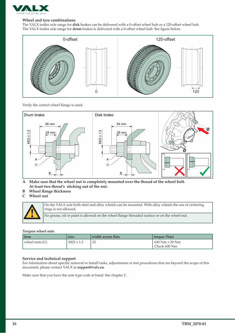
Wheel and tyre combinations�The VALX trailer axle range for dis�k brakes can be delivered with a 0-offset wheel hub or a 120-offset wheel hub.The VALX trailer axle range for drum brakes is delivered with a 0-offset wheel hub. See figure below.
0-offset 120-offset
1200
Verify the correct wheel flange is used.
Drum brake Disk brake
C
A
M22
x 1
,5 28 mm
56 mm
B
C
A
M22
x 1
,5 28 mm
54 mm
B
A Make s�ure that the wheel nut is� completely mounted over the thread of the wheel bolt. At leas�t two threat’s� s�ticking out of the nut.
B Wheel flange thicknessC Wheel nut
On the VALX axle both steel and alloy wheels can be mounted. With alloy wheels the use of centering rings is not allowed.
No grease, oil or paint is allowed on the wheel flange threaded surface or on the wheel nut.
Torques� wheel nuts�item s�ize width across flats torque (Nm) wheel nuts (C) M22 x 1.5 32 630 Nm ± 30 Nm
Check 600 Nm
Service and technical s�upportFor information about specific removal or install tasks, adjustments or test procedures that are beyond the scope of this document, please contact VALX at s�[email protected].
Make sure that you have the axle type code at hand. See chapter 2.

TBM_2070-01 11
Dimens�ion codes� in this� documentThe left figure shows a drum brake axle. The right figure shows a disk brake axle.
TW
TR
SL
STR
CB
PC
D
SD
TW
TR
STR
PC
D
SD
Drum brake Disk brake
TW Total axle widthSTR Spring trackCB Cylinder bracket dis�tanceTR Track width
SL S-cam dimens�ionPCD Pitch circle diameterSD Spigot diameter
Document codeThe document code of this manual can be found in the footer of each page. The document code consists of three fields:- Document type (WSM = Workshop Manual, TBM = Trailer Builder Manual, DM = Driver Manual)- Document number (2070)- Revision number (-01)
Related documents�The following related documents are available:- Workshop Manuals (WSM_20XX)- Driver Manual (DM_20XX)
Convers�ion SI-units� – imperial units�SI-units� -> non-metric units� non-metric units� -> SI-units�1 kg ≈ 2.2046 lb 1 lb ≈ 0.453592 kg1 mm = 0.03937 in 1 in = 25.4 mm1 m = 3.28 ft 1 ft = 0.3048 m1 km = 0.62 mile 1 mile = 1.609 km1 Nm ≈ 0.7376 ft-lb 1 ft-lb ≈ 1.3558 Nm1 mPa (10 Bar) = 145 psi 1 psi = 0.0068966 mPa (0.0689 bar)

12 TBM_2070-01
Pictograms� in this� manual
Pictograms� for general alertsIn this manual the following pictograms and symbols may be used for general alerts:
NOTE Important instruction, recommendation or tip that you must always observe.
If the safety instruction is not observed, a potential hazardous situation can occur, causing personal injury or damage to the product, the workshop or the environment.
Pictograms for specific alertsIn this manual the following pictograms and symbols are used for specific alerts:
CAUTION Risk of injury due to hazardous dusts.
CAUTION Risk of injury due to heavy weight.
CAUTION Risk of injury: crushing of fingers.
>25 kg
CAUTION Weight exceeds 25 kg.

TBM_2070-01 13
Symbols�Sometimes, a picture or a pictogram tells more than text can. For that reason, the maintenance, assembly and disassembly procedures in the chapters 5 through 10 mainly consist of graphical instructions.In these graphical instructions the following pictograms may be used:
SymboleManchmal sagt ein Bild oder Symbol mehr aus als Text. Daher bestehen die Wartungs-, Montage- und Demontageverfahren in Kapitel 5 bis 10 größtenteils aus grafischen Anweisungen.In diesen grafischen Anwendungen können folgende Symbole verwendet werden:
Symboles�Parfois, une image ou un pictogramme en disent plus qu’un long discours. Pour cette raison, les procédures de maintenance, de montage et de démontage des chapitres 5 à 10 comportent des instructions graphiques.Dans ces instructions graphiques, les pictogrammes suivants peuvent être employés:
SymbolenSoms is een afbeelding of een pictogram veelzeggender dan tekst. Daarom bestaan de onderhouds-, montage- en demontageprocedures in hoofdstukken 5 t/m 10 hoofdzakelijk uit grafische instructies.In deze grafische instructies kunnen de volgende pictogrammen worden gebruikt:
Tools / Werkzeuge / Outils / Gereedschappen
32
Us�e a s�pannerThe value in the left-hand corner is the width across flats.Maulschlüssel verwendenDer Wert in der linken Ecke ist die Schlüsselweite.Utilis�ez une cléLa valeur de l’angle gauche indique la largeur entre les bords.Gebruik een steeksleutelDe waarde linksonder is de sleutelwijdte.
8
Us�e a ring s�pannerThe value in the left-hand corner is the width across flats.Ringschlüssel verwendenDer Wert in der linken Ecke ist die Schlüsselweite.Utilis�ez une clé polygonaleLa valeur de l’angle gauche indique la largeur entre les bords.Gebruik een ringsleutelDe waarde linksonder is de sleutelwijdte.
290 Nm
Us�e an appropriate torque wrench Tighten the fastener to the torque (in Nm) given in the left-hand corner.Geeigneten Drehmomentschlüssel verwenden Ziehen Sie die Befestigung mit dem Drehmoment an (in Nm), das in der linken Ecke angegeben ist.Utilis�ez une clé dynamométrique adaptée Serrez la fixation au couple (en Nm) indiqué dans l’angle gauche.Gebruik een geschikte momentsleutelDraai de sleutel aan tot het linksonder aangegeven draaimoment (in Nm).
1 mm
Us�e a feeler gaugeThe value in the left-hand corner is the thickness of the feeler gauge.Fühlerlehre verwendenDer Wert in der linken Ecke ist die Dicke der Fühlerlehre.Utilis�ez un calibre d’épais�s�eurLa valeur de l’angle gauche est l’épaisseur du calibre.Gebruik een voelermaatDe waarde linksonder is de dikte van de voelermaat.
14
Us�e a hex keyThe value in the left-hand corner is the hex key size.Innensechskantschlüssel verwendenDer Wert in der linken Ecke ist die Größe des Innensechskantschlüssels.Utilis�ez une clé AllenLa valeur de l’angle gauche indique la taille de la clé Allen.Gebruik een inbussleutelDe waarde linksonder is de maat van de inbussleutel.

14 TBM_2070-01
Us�e a pair of circlip pliers� Sicherungsringzange verwendenUtilis�ez des� pinces� à circlipGebruik een klemtang
Us�e a hammerHammer verwendenUtilis�ez un marteauGebruik een hamer
Us�e an appropriate wire brus�hGeeignete Drahtbürste verwendenUtilis�ez une bros�s�e métallique adaptéeGebruik een geschikte staalborstel
Us�e a chis�el Meißel verwenden Utilis�ez un burinGebruik een beitel
Us�e a s�crewdriver
Us�e a crowbar
Us�e an ins�ide calliper
Us�e a s�as�h angle
Us�e a measuring probe
Us�e a jack
Us�e a s�liding caliper
32
Us�e a s�ocket wrench The value in the left-hand corner is the socket wrench size.

TBM_2070-01 15
Special tools / Sonderwerkzeuge / Outils spéciaux / Speciale gereedschappen
Us�e the axle nut locking toolWerkzeug zum Sichern der Achsmutter verwendenUtilis�ez l’outil de blocage d’écrou d’es�s�ieuGebruik het borggereedschap voor de asmoer
75
Use the socket wrench (width across flats 75)Steckschlüssel verwenden (Schlüsselweite 75)Utilis�ez la clé à douille (largeur entre les� bords� 75)Gebruik de dopsleutel (sleutelwijdte 75)
Us�e the s�pecial torque tool Spezial-Drehmomentwerkzeug verwendenUtilis�ez l’outil dynamométrique s�pécialGebruik de speciale momentsleutel
Lubricants / Schmiermittel / Lubrifiants / Smeermiddelen
Optimol White Paste
Lubricate with Optimol White Pas�te Schmieren mit Optimol White PasteLubrifiez avec de la pâte Optimol WhiteSmeer met Optimol Witte pasta
Mobilith SHC 220
Lubricate with Mobilith SHC 220 Schmieren mit Mobilith SHC 220Lubrifiez avec de la Mobilith SHC 220Smeer met Mobilith SHC 220
Renolit HLT1
1 Lubricate with Renolit HLT1 Schmieren mit Renolit HLT1Lubrifiez avec de la Renolit HLT1Smeer met Renolit HLT1
WABCO ABSsensor grease
1 Lubricate with ABS s�ens�or greas�e Schmieren mit ABS Sensorschmierfett Lubrifiez avec de la graisse pour capteur ABSSmeer met ABS sensorvet
Clean with an appropriate degreas�ing agent Reinigen mit geeignetem EntfettungsmittelNettoyez avec un dégraissant adaptéReinig met een geschikt ontvettingsmiddel
1 Contained in the original VALX Repair Kits.

16 TBM_2070-01
Miscellaneous / Verschiedenes / Divers / Diversen
Releas�e the brakeRelease the brake prior to this step.Bremse lösenBremse vor diesem Schritt lösen.Relâchez le freinRelâchez le frein avant cette étape.De rem loszettenVoorafgaand aan deze stap de rem loszetten.
Vis�ual checkCheck for damage, wear, corrosion, correct fastening.SichtprüfungPrüfung auf Schaden, Verschleiß, Korrosion, korrekte Befestigung.Contrôle vis�uelContrôlez l’état, l’usure, la corrosion et la fixation correcte.Visuele controleControleer op beschadigingen, slijtage, corrosie en juiste bevestiging.
This step requires two trained and qualified service techniciansDieser Schritt erfordert zwei ausgebildete und qualifizierte ServicetechnikerCette étape requiert deux techniciens d’entretien formés et qualifiésDeze stap vereist twee geschoolde en gekwalificeerde onderhoudsmonteurs
Clean with a lint free clothMit fusselfreiem Tuch reinigenNettoyez avec un chiffon non pelucheuxReinigen met een pluisvrije doek
Meas�ureMessenMes�ureMeten

TBM_2070-01 17

18 TBM_2070-01
1 General s�afety ins�tructions� and regulations�
1.1 General- VALX accepts no liability for any damage or physical injury caused by non-compliance with the safety
instructions and regulations in this manual, or by carelessness during any remove or install task.- Depending on the trailer type, the specific remove or install task(s) that need to be carried out, the
workshop conditions, the environmental circumstances and the cargo that may be loaded, additional safety instructions may be applicable. As VALX has no direct control over these specific working conditions or trailer configurations, it is the trailer builders sole responsibility to ensure that the national accident prevention guidelines and the local Health and Safety regulations are adhered to. Please inform VALX immediately if you have dealt with unsafe situations that have not been described.
1.2 This� manual- Read this manual thoroughly before starting work on the trailer or on the trailer axle.- Keep this manual for future reference. Retain the manual in a safe place but ready to use when needed.- Carry out the procedures in the order given. Do not change the order of the steps.
1.3 Decals� and ins�tructions� on the product- Decals or instructions fitted on the product are part of the safety features provided. They must not be
covered or removed, but must be present and legible throughout the entire life of the product. Damaged or illegible decals and instructions must be replaced or repaired immediately.
1.4 Warranty and original VALX parts�- All products of VALX are covered by warranty as stipulated in the “VALX Warranty Commitment” supplied
with the product. The “VALX Warranty Commitment” can also be downloaded from our website www.valx.eu.- Modification and / or conversion of the product without the written consent of VALX is not allowed at the
risk of forfeiting all warranty rights. - When replacing parts, ONLY use original VALX spare parts. Parts approved by VALX for use in the product
periodically undergo severe tests. As a result, VALX is able to warrant the quality of these parts.- VALX can not assess for every single third-party product whether it can be used for the VALX product
without any safety risk. This applies even if such products have already been tested by an accredited test authority. Therefore, the VALX warranty becomes null and void if spare parts other than original VALX parts are used.
1.5 Remove or ins�tall tas�ks�- Removal or installation of (parts of) the VALX trailer axle is strictly reserved to trained and qualified service
technicians. 1.5.1 Before starting work
- Make sure that the trailer is properly secured.- Make sure that unauthorised persons have no access to the working area.- Make sure that the working area is sufficiently lit and ventilated.- Dress properly. Do not wear torn or loose fitting clothes, but wear protective clothing. Remove jewelery,
watches, etc. to prevent them from being caught in moving parts.- Wear protective shoes and keep long hair out of the way.

TBM_2070-01 19
1.5.2 During work- Stay alert and watch what you are doing. Use common sense. Do not work on the product when you are
tired or have been taking alcohol, medicine or drugs. Do not smoke.- Use a hoist when lifting heavy parts. Only use suitable and technically perfect lifting devices with adequate
lifting capacity built in compliance with all safety measures. Fastening of loads and instructions to the operator of the lifting device are restricted to experienced personnel who are within sight or sound of the operator of the lifting device.
- Only use tools, parts, materials, lubricants and installation techniques that were approved by VALX. Do not use contaminated or used lubricants. Used lubricants, cleansing agents and expended parts must be disposed of in an environmentally safe way.
- Avoid bodily contact with lubricants.- Never use worn tools and do not leave tools behind on the trailer axle or on the trailer.- Never weld on any part of the trailer axle or suspension without the prior written permission of VALX.- Never re-use self-locking fixing materials. Always replace them.
1.5.3 When the trailer is ready- Inspect the product. Check for damage, leakage or defects. Any part removed for repair purposes must be
refitted and checked immediately upon completion of the work.- Do not clear a product for operation unless it was established that it is absolutely safe and in perfect working
order.
1.6 A contribution to the protection of our environment Please obtain information about recycling or environmentally friendly processing of parts and materials that
have been used during removel or installation of (parts of) the VALX trailer axle. Almost all used lubricants are considered to be chemical waste. For the disposal of these a specialized company
must be contacted.

20 TBM_2070-01
1.7 Explanation of the axle type code
1.7.1 Location of the identification plate
Type: Axle nr.:
Prod. nr.:
Brake appr.:
Perm. axlecap. stat.:
V Max.:km/h
A B H D
C F E G
1.7.2 Information on the identification plateThe identification plate consists of the following fields:
A Axle type codeThe axle type code is built up as shown in the table below.
brake type brake diameter
wheel axle type load capacity (in kg)
wheel bolts
drum brake Ddisk brake (rotor) Rsmall diameter (17.5” rim size) Smedium diameter (19.5” rim size) Mlarge diameter (22.5” rim size) Lsingle mounting / offset = 0 Sdouble mounting Dsingle mounting / offset = 120 Origid axle XE2! energy axle Eforced steering Fself steering Sload capacity 9.000 kg 0 9load capacity 10.000 kg 1 0load capacity 11.000 kg 1 1load capacity 12.000 kg 1 2load capacity 13.000 kg 1 3hub with 6 wheel bolts 0 6hub with 8 wheel bolts 0 8hub with 10 wheel bolts 1 0
B Brake approval (with tes�t report number)C Permis�s�ible axle capacity s�tatic (in kg)D Axle number (barcode type 128)E Production number (barcode type 128)F Maximum allowable speed (in km/h)G Production number H Axle number

TBM_2070-01 21
H Axle numberThe axle number is built up as shown in the table below.
Axl
e ty
pe
Axl
e sp
ecs
ID n
umbe
r
1 2 3 4 5 6 7 8
disk brake axle (17,5” rim size) incl. ABS 1/9 4disk brake axle (17,5” rim size) 1/9 5disk brake axle (19,5” rim size) incl. ABS 1/9 6disk brake axle (19,5” rim size) 1/9 7disk brake axle (22,5” rim size) incl. ABS 1/9 8disk brake axle (22,5” rim size) 1/9 9
drum brake axle (17,5” rim size) incl. ABS 2 4drum brake axle (17,5” rim size) 2 5drum brake axle (19,5” rim size) incl. ABS 2 6drum brake axle (19,5” rim size) 2 7drum brake axle (22,5” rim size) incl. ABS 2 8drum brake axle (22,5” rim size) 2 9
single mounting / offset = 0 0double mounting 1single mounting / offset = 120 2no steering 0forced steering 1self steering 2load capacity 9.000 kg 9load capacity 10.000 kg 0load capacity 11.000 kg 1load capacity 12.000 kg 2load capacity 13.000 kg 3hub with 6 wheel bolts 6hub with 8 wheel bolts 8hub with 10 wheel bolts 0
Unique ID number axles 0 19 9
1.7.3 Ordering of parts�See the parts ordering procedure on www.valx.eu or contact VALX at tel: +31 (0)40-20 88 444.

22 TBM_2070-01
2 Technical specifications / design information
2.1 Axle weights�2.1.1 Drum brake axle
axle type track width [TR] (in mm) axle weight (in kg)DLSX 0910 2140 297DLSX 0910 2090 295DLSX 0910 2040 294
DLSX 0910 2010 293
The stated weight is with the automatic slack adjusters, but without wheel nuts and brake cylinders.
2.1.2 Disk brake axle
axle type track width [TR] (in mm) axle weight (in kg)RLOX 0910 2140 305RLOX 0910 2090 303RLOX 0910 2040 302RLOX 0910 2010 301
The stated weight is with PAN 22-1 callipers, but without wheel nuts and brake cylinders.
2.1.3 Air suspension weight per axle - MBS-100 air suspension (including Ø 300 air spring, bumpstop 30): 128 kg- MBS-200 air suspension (including Ø 300 air spring, bumpstop 130): 132 kg 2.1.4 Weight difference per axle - Ø 335 Air spring compared to Ø 300 air spring: + 2 kg- Bolted hanger bracket compared to standard welded hanger brack: + 9 kg- ABS set (ABS ring, sensor, sensor bush): + 1 kg- 0-Offset hub compared to 120-offset hub: - 10 kg- PAN 19-1 calliper and rotor compared to PAN 22-1 calliper and rotor : - 24 kg
Weight deviations are within the permitted DIN tolerances for the respective manufacturing process.

TBM_2070-01 23
2.2 Center of gravity the below values are for drum brake axles type “DLSX 0910” and disk brake axles type “RLOX 0910”
track width [TR] (in mm) s�pring track [STR] (in mm) Maximum center of gravity (in mm) s�us�pens�ion type2140 1400 2.870 MBS
1300 2.845 MBS1200 2.795 MBS1100 2.607 MBS
2090 1350 2.793 MBS1250 2.767 MBS
2040 1300 2.715 MBS1200 2.688 MBS1100 2.597 MBS
2010 1300 2.676 MBS1200 2.650 MBS
Above values are calculated with 385/65 R22.5 tyres, a lateral acceleration of 0.34 g m/s2, combined with a roll angle of 4.06°.
2.3 Sus�pens�ion s�troke limitation.
External fixed bump stops, mounted to the chassis beam above the axle are used to limit the upward suspension stroke.When a suspension failure occurs, these bump stops enable the user to proceed to a safe parking area at low speed without causing further damage.This type of stroke limitation is also very suitable for vehicles that are used in intermodal traffic, where the full load will rest on the bump stop during the sea- or train voyage.
Outward suspension stroke limitation is achieved by the special designed shock absorbers.Catch straps are therefore not required for the Valx MBS air suspension.
Always use the original Valx shock absorbers that must be mounted in the correct holes in the hanger bracket.always observe the correct suspension / air spring / bump stop combination.If in doubt contact [email protected] or your local Valx sales representative.
24 TBM_2070-01
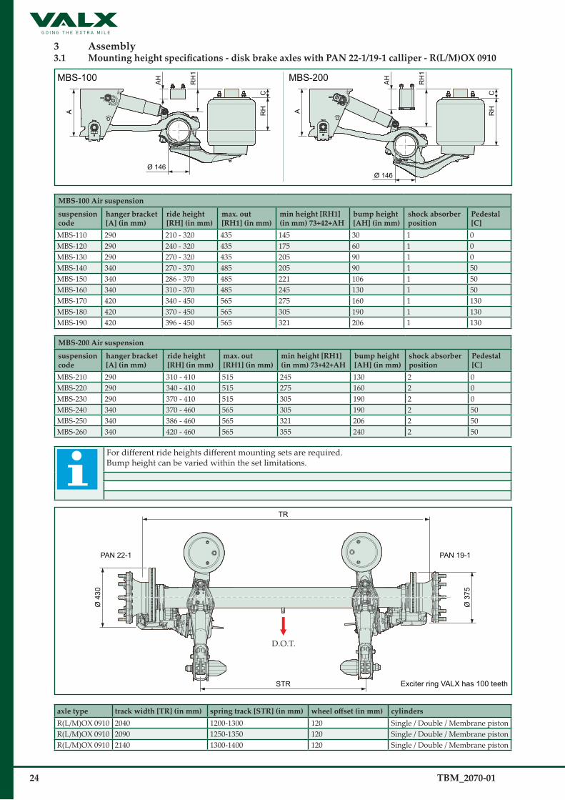
3 As�s�embly 3.1 Mounting height specifications - disk brake axles with PAN 22-1/19-1 calliper - R(L/M)OX 0910
MBS-100 MBS-200AH
RH
1
RH
C C
A A
Ø 146
AH
RH
1
RH
Ø 146
MBS-100 Air s�us�pens�ion
s�us�pens�ion code
hanger bracket [A] (in mm)
ride height [RH] (in mm)
max. out [RH1] (in mm)
min height [RH1] (in mm) 73+42+AH
bump height [AH] (in mm)
s�hock abs�orber pos�ition
Pedes�tal [C]
MBS-110 290 210 - 320 435 145 30 1 0MBS-120 290 240 - 320 435 175 60 1 0MBS-130 290 270 - 320 435 205 90 1 0MBS-140 340 270 - 370 485 205 90 1 50MBS-150 340 286 - 370 485 221 106 1 50MBS-160 340 310 - 370 485 245 130 1 50MBS-170 420 340 - 450 565 275 160 1 130MBS-180 420 370 - 450 565 305 190 1 130MBS-190 420 396 - 450 565 321 206 1 130
MBS-200 Air s�us�pens�ion
s�us�pens�ion code
hanger bracket [A] (in mm)
ride height [RH] (in mm)
max. out [RH1] (in mm)
min height [RH1] (in mm) 73+42+AH
bump height [AH] (in mm)
s�hock abs�orber pos�ition
Pedes�tal [C]
MBS-210 290 310 - 410 515 245 130 2 0MBS-220 290 340 - 410 515 275 160 2 0MBS-230 290 370 - 410 515 305 190 2 0MBS-240 340 370 - 460 565 305 190 2 50MBS-250 340 386 - 460 565 321 206 2 50MBS-260 340 420 - 460 565 355 240 2 50
For different ride heights different mounting sets are required.Bump height can be varied within the set limitations.
TR
PAN 22-1 PAN 19-1
STR
D.O.T.
Ø 4
30
Ø 3
75
Exciter ring VALX has 100 teeth
axle type track width [TR] (in mm) s�pring track [STR] (in mm) wheel offset (in mm) cylinders�R(L/M)OX 0910 2040 1200-1300 120 Single / Double / Membrane pistonR(L/M)OX 0910 2090 1250-1350 120 Single / Double / Membrane pistonR(L/M)OX 0910 2140 1300-1400 120 Single / Double / Membrane piston

TBM_2070-01 25
3.2 Mounting height specifications - drum brake axles 420 x 180 - DLSX 0910
MBS-100 MBS-200AH
RH
1
RH
C C
A A
Ø 146
AH
RH
1
RH
Ø 146
MBS-100 Air s�us�pens�ion
s�us�pens�ion code
hanger bracket [A] (in mm)
ride height [RH] (in mm)
max. out [RH1] (in mm)
min height [RH1] (in mm) 73+42+AH
bump height [AH] (in mm)
s�hock abs�orber pos�ition
Pedes�tal [C]
MBS-110 290 210 - 320 435 145 30 1 0MBS-120 290 240 - 320 435 175 60 1 0MBS-130 290 270 - 320 435 205 90 1 0MBS-140 340 270 - 370 485 205 90 1 50MBS-150 340 286 - 370 485 221 106 1 50MBS-160 340 310 - 370 485 245 130 1 50MBS-170 420 340 - 450 565 275 160 1 130MBS-180 420 370 - 450 565 305 190 1 130MBS-190 420 396 - 450 565 321 206 1 130
MBS-200 Air s�us�pens�ion
s�us�pens�ion code
hanger bracket [A] (in mm)
ride height [RH] (in mm)
max. out [RH1] (in mm)
min height [RH1] (in mm) 73+42+AH
bump height [AH] (in mm)
s�hock abs�orber pos�ition
Pedes�tal [C]
MBS-210 290 310 - 410 515 245 130 2 0MBS-220 290 340 - 410 515 275 160 2 0MBS-230 290 370 - 410 515 305 190 2 0MBS-240 340 370 - 460 565 305 190 2 50MBS-250 340 386 - 460 565 321 206 2 50MBS-260 340 420 - 460 565 355 240 2 50
For different ride heights different mounting sets are required.Bump height can be varied within the set limitations.
TR
CB
STR
180
Exciter ring VALX has 100 teeth
D.O.T.
Ø 4
20
axle type track width [TR] (in mm)
s�pring track [STR] (in mm)
wheel offset (in mm)
cylinders� Cilinder bracket dis�tance [CB] (in mm)
DLSX 0910 2040 1200-1300 0 Single / Double 556DLSX 0910 2090 1250-1350 0 Single / Double 606DLSX 0910 2140 1300-1400 0 Single / Double 656

26 TBM_2070-01
3.3 General
Within the scope of this document it is not possible to describe every single trailer chassis configuration. We therefore provide some general but binding guidelines on the mounting of the trailer axle: defining the hole pattern, bracing and finishing of the chassis. Construction of the trailer chassis and mounting of the trailer axle remains the sole responsibility of the trailer builder. Always observe the general safety instructions and regulations (see chapter 1).
3.4 Air suspension / Air spring
3.4.1 Overview air suspension parts MBS-100.
BOLTED HANGER BRACKET WELDED HANGER BRACKET
D.O.T.
Air spring Ø300 Air spring Ø335
L1L2
235
55
241
55
(279)
8
(90)
73
48
R 175
R 195 M22 x 1,5
M12 x 1,75
M22 x 1,5
M12 x 1,75
65
150
MBS-100
845 (825 for 90 offset)
265514+5
- 0
Max
. out
85
27,5 mm (side flange to center chassis bolts)
20
11045 45
(10)
(Exa
mpl
e fla
nge
thic
knes
s)

TBM_2070-01 27
3.4.2 Overview air suspension parts MBS-200
845 (825 for 90 offset)
265514+5
- 0
L1
L2
Max
. out
235
55
241
55
(279)
85
8
BOLTED HANGER BRACKET WELDED HANGER BRACKET
D.O.T.
Air spring Ø300 Air spring Ø335
(90)
73
48
R 175
R 195 M22 x 1,5
M12 x 1,75
M22 x 1,5
M12 x 1,75
65
150
MBS-200
27,5 mm (side flange to center chassis bolts)
2011045 45
(10)
(Exa
mpl
e fla
nge
thic
knes
s)

28 TBM_2070-01
3.4.3 Overview sizes air suspension.
-+A
B F ± 10 mm (max)
L1
L2
C D E
Air spring Ø300 Air spring Ø335
65
40MBS 100tail end offset (in mm)
L1 (in mm)
L2 (in mm)
(A)(in mm)
(B)(in mm)
(C)(in mm)
(D)(in mm)
(E)(in mm)
(F)(in mm)
-90 520 325 825 +3 / -3 514 +5 / -0 65 x 40 115 90 0 +/- 10-65 520 325 845 +3 / -3 514 +5 / -0 65 x 40 90 65 0 +/- 10-50 520 325 845 +3 / -3 514 +5 / -0 65 x 40 75 50 0 +/- 10-25 520 325 845 +3 / -3 514 +5 / -0 65 x 40 50 25 0 +/- 100 520 325 845 +3 / -3 514 +5 / -0 65 x 40 25 0 0 +/- 1025 520 325 845 +3 / -3 514 +5 / -0 65 x 40 50 25 0 +/- 10
MBS 200tail end offset (in mm)
L1 (in mm)
L2 (in mm)
(A)(in mm)
(B)(in mm)
(C)(in mm)
(D)(in mm)
(E)(in mm)
(F)(in mm)
-90 520 323 825 +3/-3 514 +5/-0 65 x 40 115 90 0 +/- 10-65 520 323 845 +3/-3 514 +5/-0 65 x 40 90 65 0 +/- 10-50 520 323 845 +3/-3 514 +5/-0 65 x 40 75 50 0 +/- 10-25 520 323 845 +3/-3 514 +5/-0 65 x 40 50 25 0 +/- 100 520 323 845 +3/-3 514 +5/-0 65 x 40 25 0 0 +/- 1025 520 323 845 +3/-3 514 +5/-0 65 x 40 50 25 0 +/- 10
A Center pivot bolt to center air s�pringB Center pivot bolt to center bump s�topC Hole pattern bump stop D Air spring Ø 300 mounting holes (offset -in mm- from trailing arm center)E Air spring Ø 335 mounting holes (offset -in mm- from trailing arm center)F Max. offset from upper and lower air spring mounting (in mm)

TBM_2070-01 29
3.4.4 Defining the hole pattern of the chassis member.
25
150
150
Tailend offset 0 Tailend offset -25 Tailend offset -50
Tailend offset -90 Tailend offset -65
Tailend offset 25 CL
825
845
Chassis member left
For air spring Ø300 For air spring Ø335
150
150
Tailend offset 0 Tailend offset -25 Tailend offset -50
Tailend offset -90 Tailend offset -65
Tailend offset 25
825
845
Chassis member left
CL 23
3.4.5 Defining the hole pattern of the air spring.
Air spring Ø300 Air spring Ø335
25
48
150 150
48
The hole pattern for air spring Ø300 and air spring Ø335 is not the same!Changing the air spring Ø300 for an airspring Ø335 requires an off set change of 25mm from the tail end!
3.4.6 Position of the air springs on the chassis
air spring Ø300 air spring Ø335
tail end offset 0minimal thickness 6 mm
110
mm
25 m
m
tail end offset 25minimal thickness 6 mm
110
mm
25 m
m
*If chassis is less than 110 mm a support plate min. 110 mm has to be added!
For hole pattern see section 3.4.4

30 TBM_2070-01
3.4.6 Spring offset possibilities - disk brake axles with MBS 100 - 200 Configuration: disk brake, 385/65 R22.5 tyres and type 300 air springs (maximum Ø: 350 mm)
wheel offset (in mm)
axle type track width [TR] (in mm)
s�pring track [STR] (in mm)
brake cylinders�(in inch)
tail end offset+ 25 mm 0 mm - 25 mm - 50 mm - 65 mm - 90 mm
120 RL/RM OX 0910 2140 1400 20/24
120 RL/RM OX 0910 2140 1300 20/24
120 RL/RM OX 0910 2090 1350 20/24
120 RL/RM OX 0910 2090 1250 20/24
120 RL/RM OX 0910 2040 1300 20/24
120 RL/RM OX 0910 2040 1200 20/24
120 RL/RM OX 0910 2010 1300 20/24
120 RL/RM OX 0910 2010 1200 20/24
= possible, = not possible.
Configuration: disk brake, 385/65 R22.5 tyres and type 335 air springs (maximum Ø: 390 mm)
wheel offset (in mm)
axle type track width [TR] (in mm)
s�pring track [STR] (in mm)
brake cylinders�(in inch)
tail end offset+ 25 mm 0 mm - 25 mm - 50 mm - 65 mm - 90 mm
120 RL/RM OX 0910 2140 1400 20/24
120 RL/RM OX 0910 2140 1300 20/24
120 RL/RM OX 0910 2090 1350 20/24
120 RL/RM OX 0910 2090 1250 20/24
120 RL/RM OX 0910 2040 1300 20/24
120 RL/RM OX 0910 2040 1200 20/24
120 RL/RM OX 0910 2010 1300 20/24
120 RL/RM OX 0910 2010 1200 20/24
= possible, = not possible.

TBM_2070-01 31
3.4.7 Spring offset possibilities - drum brake axles MBS 100 - 200Configuration: 420 x 180 mm drum brake, 385/65 R22.5 tyres and type 300 air springs (maximum Ø: 350 mm)
wheel offset (in mm)
axle type track width [TR] (in mm)
s�pring track [STR] (in mm)
brake cylinders�(in inch)
tail end offset0 mm - 25 mm - 50 mm - 65 mm - 90 mm
0 DLSX 0910 2140 1.400 24/30
0 DLSX 0910 2140 1.400 24
0 DLSX 0910 2140 1.300 24/30
0 DLSX 0910 2140 1.300 24
0 DLSX 0910 2090 1.350 24/30
0 DLSX 0910 2090 1.350 24
0 DLSX 0910 2090 1.250 24/30
0 DLSX 0910 2090 1.250 24
0 DLSX 0910 2040 1.300 24/30
0 DLSX 0910 2040 1.300 24
0 DLSX 0910 2040 1.200 24/30
0 DLSX 0910 2040 1.200 24
0 DLSX 0910 2010 1.300 24/30
0 DLSX 0910 2010 1.300 24
0 DLSX 0910 2010 1.200 24/30
0 DLSX 0910 2010 1.200 24
= possible, = not possible.
Configuration: 420 x 180 mm drum brake, 385/65 R22.5 tyres and type 335 air springs (maximum Ø: 390 mm)
wheel offset (in mm)
axle type track width [TR] (in mm)
s�pring track [STR] (in mm)
brake cylinders�(in inch)
tail end offset0 mm - 25 mm - 50 mm - 65 mm - 90 mm
0 DLSX 0910 2140 1.400 24/30
0 DLSX 0910 2140 1.400 24
0 DLSX 0910 2140 1.300 24/30
0 DLSX 0910 2140 1.300 24
0 DLSX 0910 2090 1.350 24/30
0 DLSX 0910 2090 1.350 24
0 DLSX 0910 2090 1.250 24/30
0 DLSX 0910 2090 1.250 24
0 DLSX 0910 2040 1.300 24/30
0 DLSX 0910 2040 1.300 24
0 DLSX 0910 2040 1.200 24/30
0 DLSX 0910 2040 1.200 24
0 DLSX 0910 2010 1.300 24/30
0 DLSX 0910 2010 1.300 24
0 DLSX 0910 2010 1.200 24/30
0 DLSX 0910 2010 1.200 24
= possible, = not possible.

32 TBM_2070-01
3.4.8 Determination of the relation between the air s�pring pres�s�ure and the axle load.
Air s�us�pens�ion s�ys�tem: MBS 100 - 200 Ø 300Air s�pring type: MBS Ø 300Drawing number: US04300FAs�s�umed value uns�prung mas�s� : 750kgMaximum axle load: 9 t
7000
8000
9000
10000
11000
12000
13000
Bellow pressure p [bar]
Axl
e lo
ad
F [k
g]
0 1 2 3 4 5 6 7 8
1000
2000
3000
4000
5000
6000
7000
8000
9000
10000
11000
12000
13000This diagram is theore�cal.No rights can be claimed.
Always check VALX websitefor latest version.
L1L2
Ltot
P =
Ltot = 845 mmL1 = 520 ± 10 mmL2 = 325 ± 10 mm
=
Air spring pressure p [bar]
axle load - unsprung mass geometry and airspring factor
F - 750 1335

TBM_2070-01 33
3.4.9 Determination of the relation between the air s�pring pres�s�ure and the axle load.
Air s�us�pens�ion s�ys�tem: MBS 100 - 200 Ø 335Air s�pring type: MBS Ø 335Drawing number: US04335FAs�s�umed value uns�prung mas�s� : 750kgMaximum axle load: 9 t
7000
8000
9000
10000
11000
12000
13000
Bellow pressure p [bar]
Axl
e lo
ad
F [k
g]
0 1 2 3 4 5 6 7 8
1000
2000
3000
4000
5000
6000
7000
8000
9000
10000
11000
12000
13000This diagram is theore�cal.No rights can be claimed.
Always check VALX websitefor latest version.
L1L2
Ltot
P =
Ltot = 845 mmL1 = 520 ± 10 mmL2 = 325 ± 10 mm
=
Air spring pressure p [bar]
axle load - unsprung mass geometry and airspring factor
F - 750 1656

34 TBM_2070-01
3.5 Hanger bracket
3.5.1 Overview hanger bracket
D.O.T.D.O.T.
Welded hanger bracket Bolted hanger bracket
Chassis railChassis rail
3.5.2 Alignment of the hanger brackets
Spring track
Spring track -95*
King pin orturn table
2 A
A
3 A
1 A
* Dimension check before welding braces.

TBM_2070-01 35
3.5.3 Overview hanger bracket
95 +1.5- 0.3
Chassis rail
0.4
1
1 A
Before welding 84.4After welding 82.2
90 + 1- 1265
D.O.T.
3.5.4 Hanger bracket welding
20 mm
max
. 1.5
mm
max
. 2.7
5 m
m
30 mm
20 mm
1
50 mm
30 mm
min. 30 mm
min. 30 mm
3A
3B
Welding cross-section
A
max. 2
.2 mm
a = 5
mm
2 ≈ 7 mm
Weld the ins�ide of the hanger bracket as� well. For brackets� higher than 290 welding ins�ide not neces�s�ery.
Welding order 1 - 2 - 3A - 3B or mirrored image.

36 TBM_2070-01
3.5.4 Hanger bracket welding continued
Brace
No welding betweenbrace and hanger bracket
Hanger bracket
a4 a4
( 118
)
+2 0
Tack weld
Position of the tack weld
90° ±3°90° ±8°
90° ±18°
for Platform Trailersfor Central axis Trailersfor Turntable Trailers
For 9t application 7.5 min thickness advised
3.5.5 Welding techniques and specifications
item specificationswelding wire in accordance with DIN 8559-SG2 / EN 440-G3 Si1. Material-Nr 1.5125, Ø 1.2 mmsupply 1-wire techniquegas mixture 92-8 Argon / O2 or Argon /CO2 / O2 or Argon / CO2 , in accordance with DIN and ISO 14175welding parameters current: 240 - 340 A pulse voltage: 26 - 40 V
Protect the trailing arm against welding spatters. Never mount the ground cable on the trailing arm, the hub unit, the wheel or the wheel flange to prevent damage.

TBM_2070-01 37
3.5.6 Hanger bracket welding / bracing
45-60 mm
8 mm
Min. required bracing area
B B
a5
D.O.T.
SECTION B-B50
45-60 mm
8 mm
30 ±5
85 85
30 ±5
Min. required bracing area
C C
a5
D.O.T.
SECTION C-C
30 ±5 30 ±5
50
a5 .....x50 (±30)(all 4 bracings)
a5 .....x50 (±30)(all 2 bracings)
514+50 514
+50
Min
. 200
mm
Min. 45 mm
Max. 60 mm
Min
. 200
mm
Min. 45 mm
Max. 60 mm
Welded hanger bracket Bolted hanger bracket
Weld bracing for welded hanger bracketRight - Left ( as drawn )
Weld bracing for bolted hanger bracketRight - Left ( as drawn )
For welded hanger brackets the weld bracing is already mounted on the hanger bracket.For bolted hanger brackets the weld bracing needs to be mounted on the hanger bracket.

38 TBM_2070-01
3.5.7 Bolted hanger bracket(2
41)
A
V
V -95
L
45
27,5
22,5 22,5
45 32,5
(8)
110D.O.T.
A
A
SECTION A-A
D
22,5
27,5
Drill diameter Ø18
A (in mm) V (in mm) L (in mm) D (in mm)1200 1218 1263 81300 1318 1363 8
* Check before bolting braces to chassis.

TBM_2070-01 39
3.6 Bump s�top
3.6.1 Overview of the bump stop
MBS-100 MBS-200
V2
W
Z2
Z1
V2
W
Z2
Z1
3.6.2 Bump stop – mounting
MBS100
MBS200
MBS200MBS100
The long side of the bump stop must be positioned parallel to the trailer flat.

40 TBM_2070-01
3.6.3 Bump stop – welded bracing
45-60 mm A
a5 .....x50 (±30)(both bracings)
Min
. 200
mm
Min. 45 mm
Max. 60 mm 65 mm 40 m
m
8 mm
50
32.5 mm
Min. required bracing area
A
a5
D.O.T.
SECTION A-A
51485+50

TBM_2070-01 41
4 Finis�hing
No paint is allowed in the red marked areas. The red marked areas are only allowed to be primered, KTL coated (max. 30µm), or zinc dipped (50 - 100µm).
Hanger bracket for welding Bolt-on hanger bracket Wear plates
MBS trailing arm MBS shock absorber
≥ Ø67 (4 sides)
2x ≥Ø35 (4 sides)
≥ Ø67 (4 sides)
2x ≥ Ø35(4 sides)
between plates≥ Ø 67 ( 2 sides)
≥ 57 ( 2 sides)
( 2x 2 sides )( 2 sides)
≥ Ø 57 ≥ Ø 67
42 TBM_2070-01
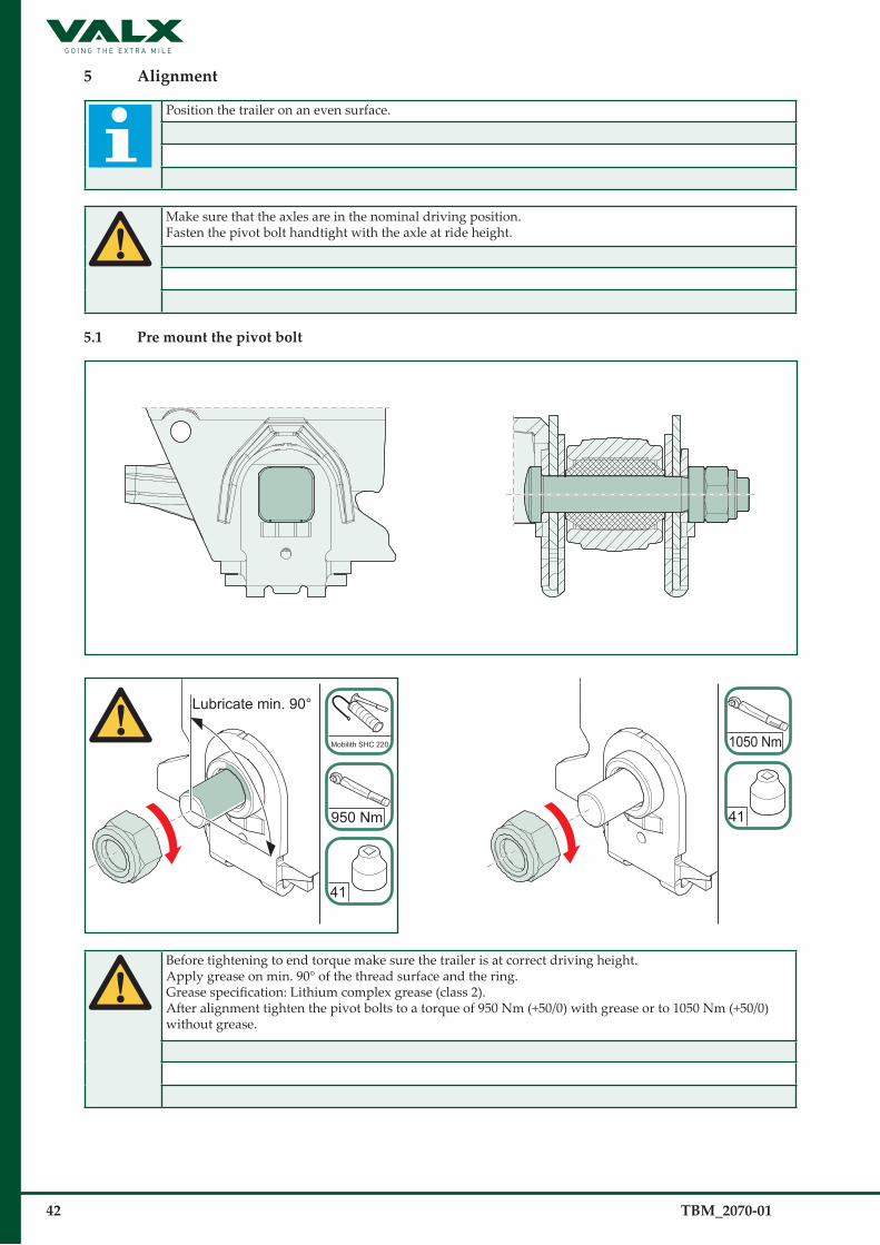
5 Alignment
Position the trailer on an even surface.
Make sure that the axles are in the nominal driving position.Fasten the pivot bolt handtight with the axle at ride height.
5.1 Pre mount the pivot bolt
Lubricate min. 90°
Mobilith SHC 220
41
950 Nm 41
1050 Nm
Before tightening to end torque make sure the trailer is at correct driving height.Apply grease on min. 90° of the thread surface and the ring. Grease specification: Lithium complex grease (class 2).After alignment tighten the pivot bolts to a torque of 950 Nm (+50/0) with grease or to 1050 Nm (+50/0)without grease.

TBM_2070-01 43
5.2 Alignment us�ing a meas�uring tapeAlign the axles within the tolerances given, taking the second axle as a reference.
X ±2 mm Y ±1 mm Z ±1 mm
X ±2 mm Y ±1 mm Z ±1 mm
A EC
D FB
King pin position
The figure shows the drum brake axle. For the disk brake axle the same tolerances apply.A through F are the axle centres.

44 TBM_2070-01
5.3 Alignment us�ing a las�erAlign the axles within the tolerances given in section 5.1.
A
Measuring ruler
Measuring A1
Laser supportLaser
Measuring B1
0 0
The figure shows the drum brake axle. Positioning the tool for the disk brake is the same.The tolerances as given in section 5.2 remains the same.
TBM_2070-01 45
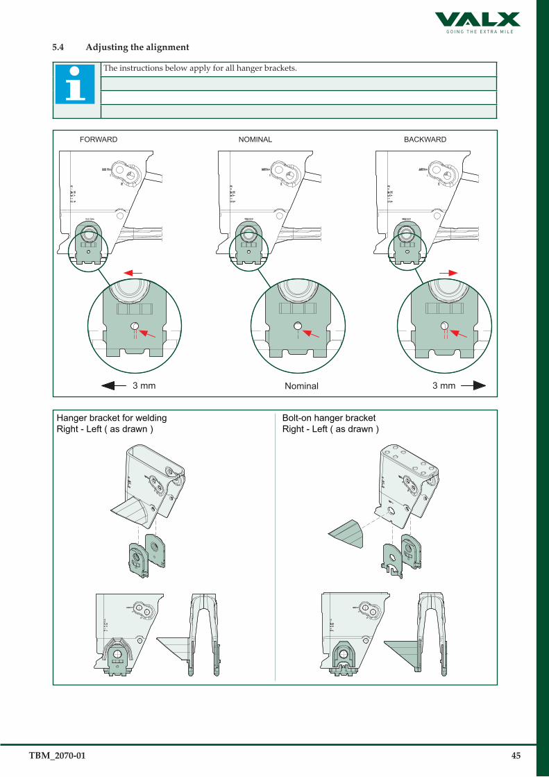
5.4 Adjus�ting the alignment
The instructions below apply for all hanger brackets.
3 mm Nominal 3 mm
FORWARD NOMINAL BACKWARD
Hanger bracket for weldingRight - Left ( as drawn )
Bolt-on hanger bracketRight - Left ( as drawn )
46 TBM_2070-01
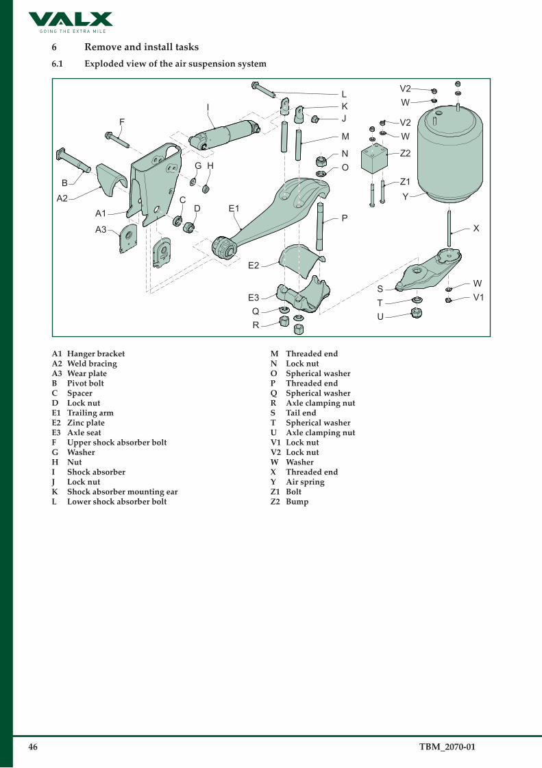
6 Remove and ins�tall tas�ks� 6.1 Exploded view of the air s�us�pens�ion s�ys�tem
HG
E1
B
E3
E2
QR
A2
A3
A1
LKJ
N
M
OZ1
Z2
WV2
V2W
Y
P
I
D
F
C
TS
U
W
X
V1
A1 Hanger bracketA2 Weld bracingA3 Wear plateB Pivot boltC SpacerD Lock nutE1 Trailing armE2 Zinc plateE3 Axle s�eatF Upper s�hock abs�orber boltG Was�herH NutI Shock abs�orberJ Lock nutK Shock abs�orber mounting ear L Lower s�hock abs�orber bolt
M Threaded end N Lock nutO Spherical was�herP Threaded end Q Spherical was�herR Axle clamping nutS Tail endT Spherical was�herU Axle clamping nutV1 Lock nutV2 Lock nutW Was�herX Threaded endY Air springZ1 BoltZ2 Bump

TBM_2070-01 47
6.2 Tightening torques� of the air s�us�pens�ion s�ys�tem
Always tighten or check the fasteners with a calibrated torque wrench.
min. 90°*Mobilith SHC 220
1
5 3 2 64
899 7
Torques�item s�ize width across flats ins�pection when replacing
1 shockabsorber (bottom ) M16 24 300 Nm 170 Nm + 270°
2 axle clamp (rear) M27 41 750 Nm 950 Nm (+50 / -0) + apply grease min 90° of the thread surface + ring*
3 shock absorber (top) M20 24 & 30 450 Nm 550 Nm (+50 / -0)
4 axle clamp (front) M24 36 650 Nm 800 Nm (+50 / -0)
5 pivot bolt M27 41 750 Nm 950 Nm (+50 / -0) + apply grease min 90° of the thread surface + ring*Or 1050 Nm (+50 / -0) without grease
6 air spring (bottom) M12 19 40 Nm 66 Nm (+0 / -16)
7 air spring (top) M12 19 30 Nm 30 Nm (+10 / -0)
8 bump fastening M12 19 30 Nm 30 Nm (+10 / -0)
9 bolted bracket M16 24 300 Nm 170 Nm + 270°
* Grease specification: Litium complex grease (class 2)
6.3 (Dis�)as�s�embly of the air s�us�pens�ion s�ys�temWhen loosening the fasteners of the axle clamping, do not re-use these fasteners. Always use new fasteners.
Carry out the following steps in the order given:1. Loosen the rear axle clamp.2. Loosen the front axle clamp.3. Loosen the upper shock absorber bolt.4. Loosen the lower shock absorber bolt.5. Loosen the pivot bolt.6. Loosen the lock nut at the bottom of the air spring.7. Loosen the lock nuts at the top of the air spring.

48 TBM_2070-01
6.4 Prepare the s�hock abs�orber
1
K
M
2
RightLeft
JKI
K
L
LKI
KJ
To facilitate replacement of the shock absorber, always fit the lower shock absorber bolt from the inside. So per axle, left and right differ!
6.5 Fas�ten the axle clamp (front)
3
E2
E1
E3
>25 kg
36
4
QR
800 Nm
For the tightening torque of the axle clamp (front), see section 6.1.Always tighten nuts (R) before tightening nuts (U)!
Torques�item s�ize width across flats ins�pection when replacingaxle clamp (front) M24 37 650 Nm 800 Nm (+50/0) steps 200 Nm L+R

TBM_2070-01 49
6.6 Fas�tening of the axle clamp (rear)
Min
. 1 th
read
1
P
N
2
O
3S 4UT
P
950 Nm
Leave one thread free.
Check the correct air spring offset.
Make sure that the spherical washer is positioned correctly in the trailing arm.Make sure to apply the correct tail end offset. See section “conventions”.For the tightening torque of the axle clamp (rear) and the grease specifications, see section 6.1.
Torques�item s�ize width across flats ins�pection when replacingaxle clamp (rear) M27 41 750 Nm 950 Nm (+50/-0) + apply grease min 90°
of the thread surface + ring*
* Grease specification: Litium complex grease (class 2)
1
3
4
50 TBM_2070-01
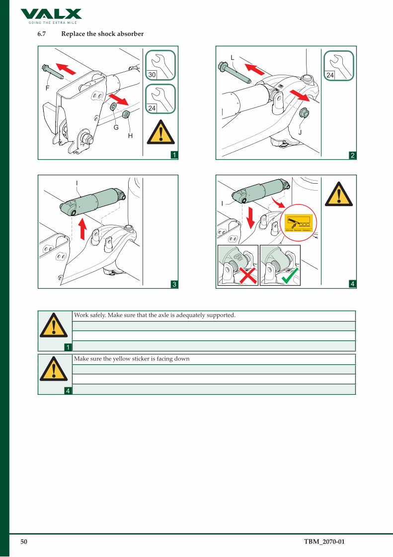
6.7 Replace the s�hock abs�orber
1
F
HG
24
30
2
L
24
J
3
I
4
I
Work safely. Make sure that the axle is adequately supported.
Make sure the yellow sticker is facing down
1
4

TBM_2070-01 51
6.7 Replace the s�hock abs�orber (continued)
5
24
170 Nm+270°
L
J
6
24
30
F
HG
550 Nm
MBS-200
MBS-100
Bolt shock absorber from inside to outside.
Check for correct torque, and use the correct hole for MBS-100 or MBS-200.
Torques� item s�ize width across flats torque (Nm) upper shock absorber bolt (F) M20 30 550 Nm (+ 50 Nm - 0 Nm)
Check 450 Nmlower shock absorber bolt (L) M16 24 170 Nm + 270°
Check 300 Nm
5
6

52 TBM_2070-01
6.8 Replace the air s�pring
Before replacement disconnect the air line.
1
19V2
W
2
19
V1
W
3
Y
4
YX
±35
Work safely. Make sure that the axle is adequately supported.
Make sure the treaded end is completely inserted into the air spring bottom piece.
1
4
TBM_2070-01 53
5
Y
6
66 Nm
V1
W
7
V2
W
30 Nm
After replacement reconnect the air line.
Torques� item s�ize width across flats torque (Nm)
lock nut (V1) M12 19 66 Nm (+ 0 Nm - 16 Nm) Check 40 Nmlock nut (V2) M12 19 30 Nm (+ 10 Nm - 0 Nm) Check 30 Nm
6.9 (Re)Place the bump s�top
1
Z2
Z1
V2
W 30 Nm
Torques� item s�ize width across flats torque (Nm)
lock nut (V2) M12 19 30 Nm (+ 10 Nm - 0 Nm) Check 30 Nm

54 TBM_2070-01
6.10 Mounting the brake cilinder
21
D
C2
65 Nm
24
22
23
E
24
210 Nm
C1
24
Check that the brake cylinder seat is perfectly flat. If not, repair. Mount the new brake cylinder using the same hole positions as before.
Prüfen, ob der Sitz des Bremszylinders absolut eben ist. Falls nicht, muss er repariert werden. Den neuen Bremszylinder über die gleichen Bohrungen einbauen, die vorher verwendet wurden.
Assurez-vous que le siège du cylindre de frein est parfaitement plat. Sinon, réparez. Montez le nouveau cylindre de frein dans les mêmes orifices que précédemment.
Controleer of de zitting van de remcilinder perfect vlak is. Zo niet, verhelp dit. Monteer de nieuwe remcilinder met gebruikmaking van de eerder gebruikte gaten.
Torques / Drehmomente / Couples de serrage / Aanhaalmomentenitem / Elementélément / onderdeel
size / Größetaille / maat
width across flats / Schlüsselweitelargeur entre les bords / sleutelwijdte
ins�pection when replacing
Set nut (C2)Einstellmutter (C2) Contre-écrou (C2) Stelmoer (C2)
M16 24 60 Nm 65 Nm (±4)
Nut (C1) Mutter (C1) Écrou (C1) Nut (C1)
M16 24 175 Nm 210 Nm (-30)

TBM_2070-01 55
25
≈90°
E
G
26
190 mm
147 mm 75 mm
27
Mobilith SHC 220
21
BA
3
When the brake is actuated, the angle must be approximately 90°.
Der Winkel muss 90° betragen, wenn die Bremse betätigt wird.
Lorsque le frein est actionné, l’angle doit être de 90°.
Bij bediening van de rem moet de hoek 90° zijn.
Forkhead assy Forkhead slot assy
Use external return springs only in combination with slotted forkhead.
56 TBM_2070-01
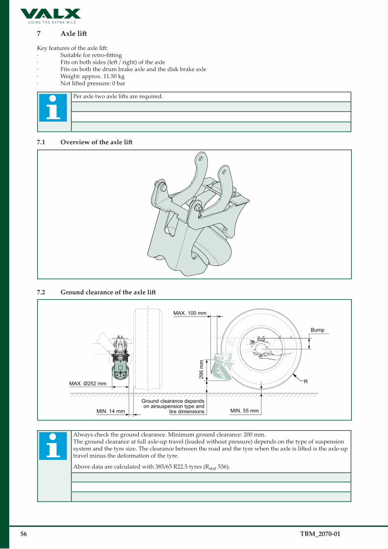
7 Axle lift
Key features of the axle lift:· Suitable for retro-fitting· Fits on both sides (left / right) of the axle· Fits on both the drum brake axle and the disk brake axle· Weight: approx. 11.50 kg· Not lifted pressure: 0 bar
Per axle two axle lifts are required.
7.1 Overview of the axle lift
7.2 Ground clearance of the axle lift
MAX. Ø252 mm
MIN. 14 mm
MAX. 100 mm
295
mm
MIN. 55 mm
Ground clearance dependson airsuspension type and
tire dimensions
Bump
R
Always check the ground clearance. Minimum ground clearance: 200 mm.The ground clearance at full axle-up travel (loaded without pressure) depends on the type of suspension system and the tyre size. The clearance between the road and the tyre when the axle is lifted is the axle-up travel minus the deformation of the tyre.
Above data are calculated with 385/65 R22.5 tyres (Rstat 536).

TBM_2070-01 57
7.3 Assembling the axle lift
Left Right
To facilitate replacement of the axle lift, always fit the mounting bolt on the inside.
7.4 Tightening torques of the axle lift
MBS 100
MBS 200
2
1
4
43
5
4
Torques�item s�ize width across flats torque (Nm)
1 mounting nut M16 24 200 Nm (+ 20 Nm - 20 Nm)2 pivot point nut M14 22 150 Nm (+ 10 Nm - 10 Nm)3 mounting rubber support M10 17 50 Nm (+ 10 Nm - 10 Nm)4 air spring mounting M10 17 30 Nm (+ 10 Nm - 10 Nm)5 air line connection ¼” - 20 Nm (+ 10 Nm - 10 Nm)

58 TBM_2070-01
8 Splitter system
There are two types of splitters available.· Conventional splitter· Lightweight splitter
8.1 Conventional splitter
With the conventional splitter ,offset 0mm and offset 25mm are possible.
8.1.1 Tightening torques of the conventional splitter.
3
1
2
Torques�item s�ize width across flats torque (Nm)
1 Bolt M16 24 200 Nm (+ 20 Nm - 20 Nm)2 Bolt M8 13 25 Nm (+ 3 Nm - 3 Nm)3 lock nut (V1) M12 19 66 Nm (+ 0 Nm - 16 Nm)

TBM_2070-01 59
RightLeft
To facilitate replacement of the splitter, always fit the mounting bolt on the inside.
Spr
ing
track
Pos
ition
spl
itter
tube
at s
prin
g tra
ck
45 m
m
Max
. out
Offsett 0mm or 25mmare possible
0 mm25 mm
Position splitter tube 855 mm
514 mm
Wel
ded
hang
er b
rack
et 2
35 m
mB
olte
d ha
nger
bra
cket
241
mm
Min. 160 mm (MBS-200)Min. 60 mm (MBS-100)
Drawn at ride heightMin. height: 275 mm (MBS-200)Min. height: 175 mm (MBS-100)
Splitted condition
a4

60 TBM_2070-01
8.2 Modular splitter
8.1.1 Tightening torques of the lightweight splitter.
1
2
23
3
1
To facilitate replacement of the splitter, always fit the mounting bolt on the inside.
Torques�item s�ize width across flats torque (Nm)
1 Bolt M16 24 200 Nm (+ 20 Nm - 20 Nm)2 Bolt M8 13 25 Nm (+ 3 Nm - 3 Nm)3 Bolt M12 19 70 Nm (+ 10 Nm - 10 Nm)

TBM_2070-01 61
A ±1
B ±
1
C ±
1
D ±
1
738
155.
5
614
s�pring track (in mm)
chas�s�is� width center to center (in mm)
chas�s�is� rail width (in mm)
air spring offset(in mm)
A(in mm)
B(in mm)
C(in mm)
D(in mm)
1200 1200 150 90 1087 1016 1045 7201300 1300 150 90 1187 1116 1145 820

62 TBM_2070-01
9 Hubcap
9.1 Removing the hubcap
hub offset-120hub offset-0
9.2 Mounting the hubcap
1
Mobilith SHC 220
AB
2
A
Always replace the O-ring (B) whenever the hubcap (A) has been removed.Always check whether the O-ring (B) is properly seated and not damaged.
Make sure the hub cap (A) can rotate freely to ensure the O-ring is seated properly before step 3.
1
2

TBM_2070-01 63
3
Make sure there is no gap between the edge of the hub cap and the hub flange, and check that the hub cap cannot be rotated by hand when fitted.

64 TBM_2070-01
9.3 Removing the hubcap with hubodometer
hub offset-120hub offset-0
9.4 Mounting a hubcap with hubodometer
1
Mobilith SHC 220
AB
2
A
Always replace the O-ring (B) whenever the hubcap (A) has been removed.Always check whether the O-ring (B) is properly seated and not damaged.
Make sure the hub cap (A) can rotate freely to ensure the O-ring is seated properly before step 3.
1
2

TBM_2070-01 65
3
Make sure there is no gap between the edge of the hub cap and the hub flange, and check that the hub cap cannot be rotated by hand when fitted.

66 TBM_2070-01
10 Packaging
10.1 Trans�portation rack (VALX partnumber 90 900 001)
2300
820
750
The weight of the transportation rack is approximatily 170Kg.
10.2 Pallet (VALX partnumber 90 900 020)
1700
1040
140
If you have any questions about the transportation rack, pallet.Please contact VALX at tel: +31 (0)40-20 88 444.

TBM_2070-01 67§
10.3 Pallet (VALX partnumber 90 900 022)
1700
1040
140
If you have any questions about the transportation rack, pallet.Please contact VALX at tel: +31 (0)40-20 88 444.

68 TBM_2070-01§
Copyright © 2022 FDOKUMEN