TELEVISION - World Radio History
52
Practical TELEVISION AUGUST 1964 OPTICAL SYSTEMS FOR AMATEUR CLOSED CIRCUIT TV
-
Upload
khangminh22 -
Category
Documents
-
view
0 -
download
0
Transcript of TELEVISION - World Radio History
PracticalTELEVISIONAUGUST 1964
OPTICAL SYSTEMSFOR AMATEURCLOSED CIRCUIT TV

PRACTICAL TELEVISION August, 1964
Modern styling in light
MPROIMgrey with legible blackengraving.
Constructed to with-
stand adverse climaticconditions.
Ever ready case, includ-ing leads, prods andclips.
Improved internalassemblies.
Re -styled scale plate foreasy rapid reading.
2 basic scales, each2.5 inches in length.
New standards of accur-acy, using an individualcalibrated scale plated.c. ranges 2.25% f.s.d.a.c. ranges 2.75% f.s.d.
Available accessoriesinclude a 2500V d.c.multiplier and 5, 10and 25A shunts ford.c. current measure-ment.
STANDARDS OF ACCURACY
RELIABILITYThe Mk. 4 MULTIMINOR is anentirely new version of this famousAvo instrument and supersedes allprevious models. It is styled on mod-ern lines, with new high standards ofaccuracy, improved internal assem-blies. and incorporating panclimaticproperties.
The instrument is supplied in an attractiveblack carrying case, which also houses a pairof leads with interchangeable prods and clips,and an instruction booklet. It is packed in anattractive display carton. Robust real leathercases are available, if required, in two sizes,one to take the instrument with leads, clipsand prods. and the other to house these andalso a high voltage multiplier and a d.c. shunt.
MULTIMINORD.C. Current: 100µA f.s.d. -A f.s.d. in 5 rangesA.C. Voltage: I OV f.s.d. -1,000 f.s.d. in 5 rangesD.C. Voltage: 2.5V f.s.d. -1.000 f.s.d. in 6 rangesD.C. Millivolt range: 0 -100mV f.s d.
Resistance: 0-2 MU in 2 ranges using I.5V cellSensitivity: 10,00052 V on d.c. Voltage ranges.
1,0000 V on a.c. Voltage ranges
For full details of this great new pocket-size instrument, write for descriptive leaflet.
14,0LTD AVOCET HOUSE - 92-96 VAUXHALL BRIDGE ROAD - LONDON, S.W.I - VICtoria 3404 (12 lines)
MM17
141DCOLPN SOLDERING
EQUIPMENT( Regd.T-ade Mark)
DESIGNED
FOR
ALL RADIO
ENGINEERS
APPLY CATALOGUES: --
ADCOLA PRODUCTS LTD.ADCOLA HOUSE,GAUDEN ROAD,LONDON, S.W.4.TELEPHONE: MACAULAY 4272 & 3101TELEGRAMS: SOLJOINT, LONDON, S.W.4.
Moor
"SABRINA"STILL WELL IN
FRONT
STOP FIDDLING WITH KNOBS . .. ABSO-LUTELY UNNECESSARY . . . Our AutomaticRegulator ensures constant voltages on TV, even withMains of 180'265 v. YES, we Know it's wonderful."Have a heart for your Valves and Tube."S.A.E. details. Conditional Free Trial.
COMPLETELY REBUILT C.R. TUBESALL TYPES12" now ... f5. 0.0 For14" to 17" now ... f5.10.0 Single21" now ... f8. 0.0 Tubes
ALL C.W.O.-TRADE SUPPLIEDSpecial Bonus Scheme for Service
Engineers-Reducing to:12"-8716; 14", 17"-97f6; 21"-147f6FREE. Pass. transit & Ins. anywhere in BritishIsles or N. Ireland (12 months' guarantee).
ALSO FULL RANGE OF VALVES(Guaranteed 12 months)
SABRINA C.R. TUBE CO.Electron Works, North Bar
BANBURY, OXONTelephone 2390
August, 1964 PRACTICAL TELEVISION 48I
2511I ANNIVERSARY OF THE SECOND WORLD WAR
OUR FINEST
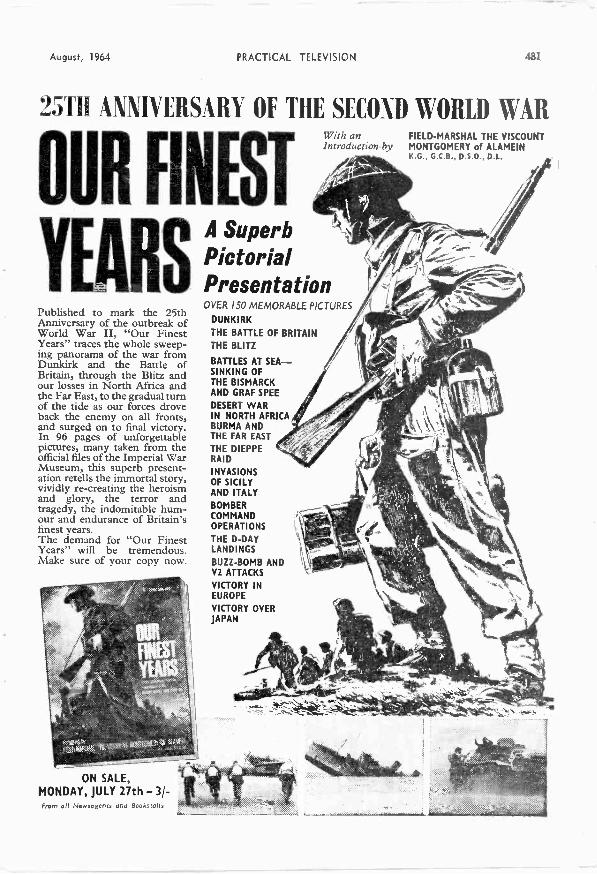
YEARSPublished to mark the 25thAnniversary of the outbreak ofWorld War II, "Our FinestYears" traces the whole sweep-ing panorama of the war fromDunkirk and the Battle ofBritain, through the Blitz andour losses in North Africa andthe Far East, to the gradual turnof the tide as our forces droveback the enemy on all fronts,and surged on to final victory.In 96 pages of unforgettablepictures, many taken from theofficial files of the Imperial WarMuseum, this superb present-ation retells the immortal story,vividly re-creating the heroismand glory, the terror andtragedy, the indomitable hum-our and endurance of Britain'sfinest years.The demand for "Our FinestYears" will be tremendous.Make sure of your copy now.
ON SALE,MONDAY, JULY 27th - 3/ -From all Newsagents and Bookstalls
With an FIELD-MARSHAL THE VISCOUNTIntroduction by MONTGOMERY of ALAMEIN
A SuperbPictorialPresentationOVER ISO MEMORABLE PICTURES
DUNKIRK
THE BATTLE OF BRITAINTHE BLITZ
BATTLES AT SEA-SINKING OFTHE BISMARCKAND GRAF SPEE
DESERT WARIN NORTH AFRICABURMA ANDTHE FAR EAST
THE DIEPPERAID
INVASIONSOF SICILYAND ITALYBOMBERCOMMANDOPERATIONS
THE D-DAYLANDINGS
BUZZ -BOMB ANDV2 ATTACKS
VICTORY INEUROPE
VICTORY OVERJAPAN
482 PRACTICAL TELEVISION
rAugust 1964
G
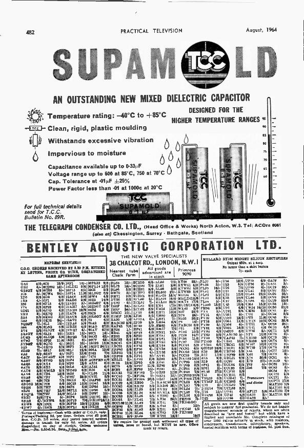
AN OUTSTANDING NEW MIXED DIELECTRIC CAPACITOR
DESIGNED FOR THETemperature rating: -40°C to +85°C
-4,c, I- Clean, rigid, plastic moulding
UI Withstands excessive vibration
Impervious to moisture
Capacitance available up to 0.33.1FVoltage range up to 600 at 85°C, 750 at 70°C 0Cap. Tolerance at .014F +25%Power Factor less than .01 at 1000c at 20°C
For full technical detailssend for T.C.C.Bulletin No. 89R.
HIGHER TEMPERATURE RANGES "60
65
NU
75
70
65
60
THE TELEGRAPH CONDENSER CO. LTD., (Head Office & Works) North Acton, W.3. Tel: ACOrn 0061
(also at) Chessington. Surrey Bathgate, Scotland
BENTLEY ACOUSTIC CORPORATION LTD.EXPRESS SERVICEIH
C.O.D. ORDERS RECEIVED BY 3.80 P.M. EITHERNY LETTER. PHONE OR WIRE, DIMPATCHED
BABE AFTERNOON
THE NEW VALVE SPECIALISTS
38 CHALCOT RD., LONDON, N.W. IA0 goods Primrose
Chalk FarmNearest tube advertised are
in stock9090
0A2 416 809 10/90132 6/- 710D6G 18/.07.4GT 4/8 80116 5/-106 5/- 6CW4 241.IDS 9/6 6D3 9/61E5 4/- 811 9/6186 2/6 6113 4/91T4 2/8 6923 61821011 5/6 6370 4/6212 11/- 8170 1/83A4 8/6 61080 8/33.46 6/9 6E25 24/-NWT 7/- CU 10/-384 4/11 SLOG 6/6394 11/11 SWOT 4/66114GY 8/6 6118 10/-61140 ate oLDeo 6/69140 7/6 eras 11/6.493415 an 6Q7G ft -
:go71- 613713 e/27/- 08L7 5/8
64.8 5/9 6887 4/-6A07 2/- 61140T 8/66.607 6h 6V8G 8/964Q6 6/9 614 319CATS 1/9 616 4/611A06 8/2 6/30173 8/36A96 511 7136 18/66/31.6 4/6 7B7 7/.613166 4/9 706 7/368060 1106 706 6/9emu 6/2 7117 6/967378 6/6 717 12/668Q7A 7/6'787 14/6SBR7 102 7Y4 6/-6288 81- 9BWIS 8/66BW6 616 1001 8/96BW7 1002 1103
1011 10/-101.1)11 9/610113 8/810P14 11/611.606 8/612A.D6 9/612.6106 8/-125117 5/-12AR8 10/912AT6 41612AU6 6/912AV6 6/819J3A6 6/9128E6 4/9121307 6/-161E6 101-19AQ6 7/319111 61-2001 10/.20P2 11/620L1 12/62091 12/62013 12/-2014 12/62015 /82516 04/921584G S112326 10-21817 211/330012 9/-30018 10/63016 6/930FL1 9/330115 9/830P4 12/230112 7/630/19 12/23011,1 8/6
2011.13 9/6301144 12/83606 6/836L6G/ 6/936W4 4193523 14/635840T 4/63616GT 6/930114 6/63008 6/660160T 8/872 6/685A2 6/6904.0 87/690AV 67/S9001 110-90011 42/-9001 42/-15082 16/61.86BT 84/11sect 12/65763 7/67475 2/9ACIPIIN 4/9AZ31 6/6AZ41 6/6B38 4/9CL33 11/6CY31 5/9DAF96 6/9I3D41 10/6DF66 15/-0196 5/9DF97 10/-DH101 26/-08107111/11017.93 6/9DE96 6/6
Terms of business:-Cath with order or C.O.D. only.Postage/Packing 6d. per Item. Orders over 13 postgrew C.O.D. 3,6 extra. Any parcel insured againstelasnage in transit for only 61. extra. All ordersdespatched on day of receipt. Winne welcome36ers.-1/w- 0.346.30. 8ais,0.341.A3kus,
DL68 15/- 101136 613 E1.86 7/8 KT88 28/-DL72 110- 10142 716 EL01 818 KTW61 4/9DL96 6/9DM70 61-
1101181 6/9E01183 6/6
EELLa6960 275/16. KIETwTW6632 61466
D1171 9/9 ECH84 9/6 EL820 16/4 6111D4 8/.DY88 6/9 ECL80 6/. EL822 16/6 MSI1,0618/6DY87 8/ - EC1,82 7/- ELL 20/5 MKT4 17/6ROOF 14/- EC1.83 9/6 10204 17/9 MU12/144/61839 14/- ECL86 8/9 81434 11/6 M140 819E880C 10/- EF22 6/6 1871 18/6 N37 28/8E180F 19/6 1136 6/8 10.6180 615 N78 16/-EA50 1 /6 E137A 6/- 83181 71- 8108 65/2&ABCS° 5/6 B139 8/9 EM84 6/8 P2 10/-EAF42 7/61-
EB34 1E140 8/9EF41 619
Bu86 8/910687 7/6
PABC80 6/9151 2/6
E1141 4/1 1142 4/9 EN31 10/- PC86 10/81891 2/2 B150 2/6 EY151 6/6 1088 14/711.11333 8/6 10F80 819 £Y81 7/3 PC95 11/8EBC41 6/6 E183 9/9 EY89 6/3 P097 7/9EBC81 519 E186 4/6 EY84 9/6 1(X:84 6/6113180 5/6 B186 61- EY/16 5/6 20082 619EBF8S 7/8 E989 4/- By88 BM PCC88 10/6EBF89 6/8 E/91 31 10Y91 8/- POC89 7/9121211 6/ - EF92 8/6 E£40 6/3 PC0189 10/6Eon 12/6 E193 4/9 10241 6/. PCF80 6/6F.C70 4/9 £197 11/8 6280 819 PC162 613MC92 6/8 E198 10/- 1E81 4/- PC184 11/6
80031 7/8 EF183 7/. 0233 17/6 PCF86 7/9WINO 7/- 81184 7/- (1234 10/. 10/x60610/6B0081 8/6 3/1804 20/6 0237 14/6 PC1806 17/62000192 4/6 11190 7/- 1168080 9/3 10122 6/610083 416 11132 5/9 26/- PCL88 7_79
10084 6/6E(X86 5/9
21.33 6/9EL84 8/6
H VR2 818R2A 8/9
101.84 7/.PCL85 7/6
ECC88 8/6 ELM 8/5 I.T630 4/. 101.86 91910091 8/. EL41 7/8 hT38 29/1 P1146 7/-80018911/6 EL42 7/6 ETT4441 7/6511 11774600107/80 6- £1.81 8/8 12/.10182 6/8 £1.83 6/9 KT61 619 PEN46 4/8£0188 11/6 107.84 4/6 KT63 8/9 PEN 383BC1121 9/9 1186 7/6 KT68 16/8 10/3
We require for prompt cash settlement all typo ofyahoo. loose or boxed. but MUST he new. 06.3
made by return
BULLARD BY100 MIDGET SILICON RECTIFIERSOutput 230n. at I amp.
No larger than a shirt button71- each
1133 91-2136 81-PL38 16/-11,81 6/9PL82 6/311.83 5/811.34 31.PLOW 15/916(84 9/3PX4 9/-Pi(31 6/-PY32 8/6PY33 8/9PY80PY81 4/9PY82 4/9PY83 5/9PY88 7/9PY800 6/-19801 6/3Q87620 10/6R10 26/6R17 17/6R18 9/61019 8/68141 2/-8161 8/-61726 27/2T41 9/-TH233 6/9TY86F 11/81/10 9/-1316
16/.12114
7/6111718/20 6/61122 6/9
U24 12/6025 8/6036 7/61331 6/9033 18/61135 15/0U37 29/-049 16/61176 4/60191 9/80251 9/-13182 12/80301 11/30404 6/-0801 16104020 6/6UABC80 5/-UA142 71.UB41 10/6UBC41 61$110081 6 $170180 6/9UBF89 6 9021.21 9/9U092 6/6001784 8/9UC(339 6/600180 8/9001121 8/3UCH42 7/-UCH81 6/8U01.82 7/9UCL93 8/6UF41 6/9UF42 4/6UF80 8/8
0/85 6/90186 10-11289 6/-01.81 6/91. 1,44 23/8
146 8/6i:L84 6/-02.44 16/901434 16/1005180 8/80176 8/-17538 11/6UY1N 10/8UY21 8/-UY41 4/6UY85 8/-VP4 14/6VE106 6/69E150 4/9W107 10/6W729 17/6141 16/-166 7/2
171: "16271-Y83 61-Z116 7/5
Transistorsand diode.
AF117 5/60.670 St -0A73 8/-
0A79 3/-0681 81-C1C19 26/-0022 22/-0028 26/-01728 24/60C29 26/60035 18/-0(736 21/004:41 8/-0C44 8/20C45 8/-0065 22/60066 26/-0070 6/60071 3/80072 8/-0073 16/-0074 8/-0075 8/-0076 8/60077 12/-0078 8/-0001 41-OCA1D 4/-0082 101-0083 6/-0084 8/-00170 8/600171 9/-017171 17/6MAT100 7/9IUT101 8/8MAT120 7/9MAT121 8/6
All goods are new Brit quality brands only andsubject to maker.' full guarantee. We do not handlemanufacturers' eeconds or rejects, which are oftendescribed as "new and tested" but which have alimited and unreliable lite. Complete catalogue ofover 1000 valve, actually In stock, with resistors,condensers, transformers, microphone,. speakers,metal rectifiers with tem. of bissIness. 641- Foot Los.
== Practical Television- EAND TELEVISION TIMES=
_=
VOL 14, No. 167, AUGUST, 1964 .1.±
E.: Field of Visionr21111111111111111111111111111111111111111111111111111111111111E
E == HE old time wireless enthusiast, if suddenly transportedEditorial and Advertisement E from 1924 (or even 1934) to 1964, would be astonished,
offices == to put it mildly, at the strides his pet subject had taken.= PRACTICAL TELEVISION g. He would be amazed at the change in appearance of receivers,E =
George Newnes Ltd.. Tower House a at the change in components and at the overall performance,=E Southampton Street, w.c.2. = versatility and efficiency of equipment. He would also find it= E difficult to assimilate many of the newer types of componentsE @ George Newnes Ltd., 1964 =
E.. and the various new techniques of circuitry and construction.F.- Phone: Temple Bar 4363. F.- But perhaps the greatest feeling of helplessness would beE =E Telegrams: Newnes, Rand, London. = engendered by the very scope of radio devices. Transmitters,=a = receivers and the more orthodox types of test equipment,SUBSCRIPTION RATE=
.1-4 although radically different, would be a common ground ofE including postage for one yearF.7. understanding, but many pieces of auxiliary equipment nowE To any part of the World CI.9.0.
== g. in common use would cause some furrowing of the brows.= = Even the enthusiast of today, weaned on transistors and== E electronic music, is sometimes hard put to it to keep in touch= - Contents E with all the latest developments.= =a-4, N' witot = For the television amateur, however, progress has not been_ -: so dramatic. Discounting mechanical systems, the main dif-EE Page = ferences since the adoption of electronic scanning, have".-1- Editorial ... ... ... ... 483 If- been in improved circuitry. Since the days when t.r.f. circuitsE Teletopics ... ... ... ... 484 5 and thyratron oscillators vanished and flyback e.h.t. 'E. Optical Systems for Amateur a introduced, the enthusiast has easily taken in his stride such= Closed Circuit TV ......486 E-E ... ... ... 491 ..q
things as mean level a.g.c., cascode r.f. stages and other circuit= Stock Faults5-.--
refinements which have become standard practice. He has hadE Transistorised TV Camera ... 496 g. to acquaint himself with turret tuners and the problems of77: Underneath the Dipole ... 502 E.: Band III and now, of course, with the 625 -line system.= Microvolt Multiplication ... 504 a These are all, however, evolutionary trends in the basicE Changing Cathode Ray Tubes 508E receiving equipment and apart from larger tubes and smaller Servicing TV Receivers .. 512 E cabinets the typical TV receiver still looks much the same..== Pay -TV ............515 == TV has not erupted in such a disconcerting way as has radioPractical Servicing Aids ... 516 a
Your Problems Solved ... 520 a and eleCtronics; at least not for the amateur enthusiast.524 =Test Case ... Most amateurs are able to find but a handful of more... ... ...
= E.... exotic paths to follow. The first is DX -TV, which not onlyEE.- requires a knowledge of propagation in its various forms but'
The Editor will be pleased to consider E has the merit of posing constructional or modification= articles of a practical nature suitable F-E for publication in "Practical Television". = problems to be resolved and gives a good deal of opportunity= Such rticles should be written on one =E side of the paper only. and should con- = to experiment with aerial systems. This is still in its infancy.= tain the name and address of the sender. =-E Whilst the Editor does not hold himself = There is also amateur TV transmitting whose small tut= responsible for the manuscripts, every == effort will be made to return them if a = enthusiastic band of adherents may well increase.= stamped and addressed envelope is en- = Thirdly there is a field which, perhaps, offers the greatest= closed. All correspondence intended for == the Editor should be addressed to The = possibilities for the average enthusiast-CCTV. This is a .field= Editor, "Practical Television", George == Newnes Ltd., Tower House, Southampton = wherein lies all manner of possible avenues to explore. 3n= Street, London, W.C.2. _'E Owing to the rapid progress in the E.-- this issue we are not only running the second cart of the.T-- design of radio and television apparatus == and to our efforts to keep our readers = second CCTV camera to be described in this magazine but= in touch with the latest developments. = also an article on optical systems which will clearly indicate= we give no warranty that apparatus == described in our columns is not the sub- E. all manner of potential lines for the keen amateur to pursue.E feet of letters patent. _= Copyright in all drawings. photo- -.L As time goes on, more and more scope will be available toE. graphs and articles published in == "Practical Television" is specifically = the average constructor and experimenter and it will become= reserved throughout the countries == signatory to the Berne Convention and = increasingly obvious that, to those with initiative, TV is some.E the U.S.A. Reproductions or imitations = thi more than switchin on to watch "Coronation Street"!= of any of these are therefore expressly = ng g
forbidden.= IIIIIIIIIIiiiiIIIIIIIIIIIIIIIIIIIIIIIIIIIIIIIIIIIIIIIIIIIIIIIIIIIIIIIIIIIIIIMIIIIIIIIHMIIMIHMIMIUMMOU
Falfillfilliallillifilill1W111111111111111111111111111111111g Our next issue dated September will be published on August 21st

4/14 TELEVISION TIMES Auquct 1964
T E LETOPJCSBirmingham to Receive BBC -2
Ahead of ScheduleAt Sutton Coldfield, where the 750ft. mast carrying existing BBC -1
aerials is being modified to accommodate additional aerials forBBC -2, temporary equipment is to be installed which will advancethe advent of the second BBC programme in the Birmingham area,about nine months ahead on the previous schedule which marksAutumn 1965 as the completion date for the permanent BBC -2 trans-mitter.
The temporary installation will provide two million people in Bir-mingham and its environs with BBC -2 programmes by the end of thisyear. Its coverage will, of course, be limited and some shadow areaswill occur where the permanent transmitter will give continuouscoverage. However, this new move, which has come after consulta-tion between the Corporation and the radio industry, is expected toboost sales of 625 -line receivers and u.h.f. aerials in the Birminghamarea which is the second area to receive the new programme.
The aerial for the temporary transmitter will be mounted 150ft. up,considerably lower than the final one, but Or station will operate onthe same channel to be used eventually br the permanent station,i.e. channel 40 (vision 623.25Mc/s, sound 629.25Mc/s) withhorizontal polarisation.
Amateurs Run TV Station in JapanCENTRAL television receiving station for the broadcast channels1, 3, 5, 9, and 11, has recently been set up, as a private under-
taking, in the Japanese town of Gujohachiman.Gujohachiman has a population of approximat-ly 22,000 and
individual houses in the area are fed with signals, via cable, fromthis' new receiving station which relays the radiated television signalsfrom the broadcast transmitters in the service area of Nagoya.
e initiator of this installation, Mr Ichiro Kanno has, in addition,&Ivied the remaining channel 7 (which was free of broadcast trans-missions) with small-scale dosed circuit television transmissions forfeeding into his cable network, having obtained a special licence forthe purpose. A small c.c.TV transmitter, two vidicon cameras, a16mm telecine unit and a simple control room (all entirely self -built)have been accommodated in a former stable, together with aminiature studio.
Programmes are produced by amateurs on a voluntary basis. Twohours of programmes are broadcast daily, chiefly concerning localevents in the town and surrounding district. The callsign of thisamateur " television station " is JHK-TV and, suprisingly for theBritish amateur, the special licensing of this station permits limitedcommercial advertising; 60 seconds of " hot commercials " on thisstation cost 300 yen-about 7s. 6d.!
TELEVISIONCAMERA TUBES
UNDER ASSEMBLYAT NEW PLANT
A stage in the manufacture of a tele-vision camera tube. Shown hereduring its assembly is the electron gunand electron multiplier of a 41in.image orthicon camera tube.
In operation, the gun provides thefine analysing beam of electrons whichpicks off stored electrical informationfrom a thin glass target. The multi-plier amplifies the return signal beforeit is linked to conventional amplifiersystems, giving electrical signals,which are broadcast and subsequentlyreconstituted into the image on domes-tic TV screens. A signal pre -amplifi-cation of about 1000 to I is given bythe multiplier.
This picture was taken at a newtube plant at the Hayes factory ofEMI Electronics Limited.
August, 1964
C.C. TV COVERSROYAL VISIT
AV HEN Her Majesty, Queen' Elizabeth, the Queen
Mother performed the officialopening of a new extension toSunderland's art gallery, closedcircuit television cameras carriedpictures of her to receivers placedat strategic points about thebuilding.
Fiv" --"eras in all covered thevisit, two being mounted outsidefor the Queen Mother's arrivaland her inspection of a guard ofhonour.
The relayed pictures from allfive cameras were received oneight Murphy 19in. monitors setup in two galleries. Three hun-dred and fifty guests seated inthese galleries were thus assuredof good views of the proceedings.
Rank Telecommunications ofWelwyn Garden City, Hertford-shire, supplied both cameras animonitors for the occasion.
New Baird ScholarTHE John Logie Baird Travel-
ling Scholarship, inauguratedlast year, was presented recentlyat a meeting of the TelevisionSociety, to its second recipient,Mr. James D. Last.
The Scholarship, which is pre-sented annually by the Societyand financed by Baird TelevisionLimited, is awarded to a post-graduate in the U.K. selected forhis work in television engineeringor an allied technology.
Mr. Last was presented withthe award by Mr. P. Perring-Thoms, chairman of Baird Tele-vision.
TELEVISION TIMES 485
Airborne Television Relayfor Olympics
T° provide efficient television coverage of the Olympic Gamestaking place this year in Tokyo, airborne as well as mobile ground I
units will be used to televise events from many parts of the Gamesarea. To increase the distance over which these ground units canoperate, the helicopter, which will be used to provide aerial televisionshots, will also be equipped to act as a relay point for picture stnalsbetween them and the base station.
The new equipment necessary to provide this facility, was speciallydeveloped by the Japan Broadcasting Corporation (Nippon HosoKyokai) and has increased the standard range for existing units fromabout four kilometres to some 50 kilometres or more. This has beenmade possible by increasing transmitter output, improved antennagain and through the development of an automatic direction controlunit for the antenna mounted onthe helicopter.
This last item of equipmentoperates in conjunction with aspecial companion unit installedat the base station which em-ploys the ground magnetismas the common bearing stan-dard for the ground station andthe helicopter. In use, thereceiving antenna at the basestation is kept pointing towardsthe helicopter and, by obtaininga bearing between the antennadirected at its helicopter " tar-get " and the ground magnetism,signals of a frequency correspon-ding to this bearing are trans-mitted to the helicopter as direc-tion information. The helicopterequipment, acting on these sig-nals, automatically controls thedirection of its transmittingantenna keeping it always turnedtowards the ground station, sothat it and the receiving antennaat the ground base station alwaysface each other.
Signals from the mobile groundunits are thus relayed via the heli-copter back to the base stationwith extreme directional accuracy,increasing by more than ten ti -r -sthe range of the normal ground-to -ground link.
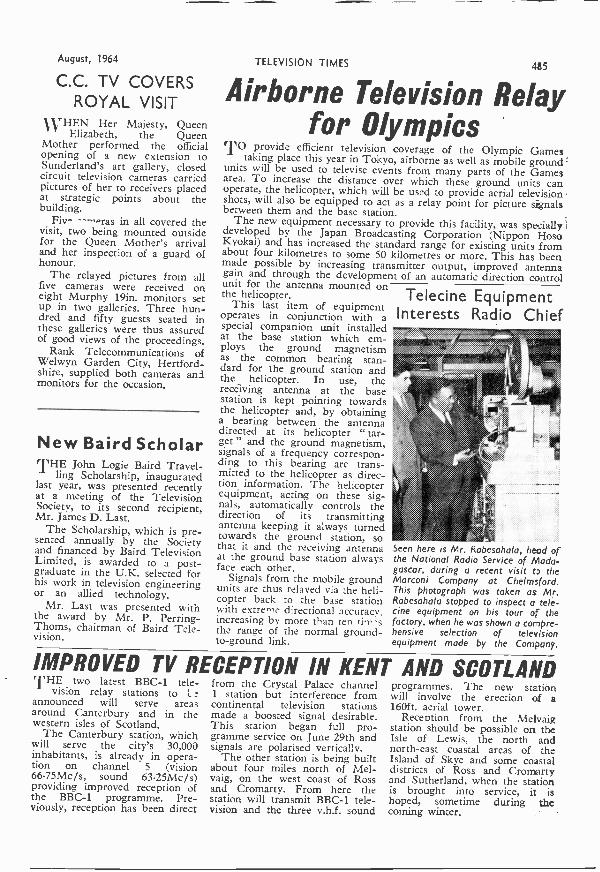
Telecine EquipmentInterests Radio Chief
.7.774
Seen here is Mr. Rabesahala, head ofthe National Radio Service of Mada-gascar, during a recent visit to theMarconi Company at Chelmsford.This photograph was taken as Mr.Rabesahala stopped to inspect a tele-eine equipment on his tour of thefactory, when he was shown a compre-hensive selection of televisionequipment made by the Company.
IMPROVED TV RECEPTION IN KENT AND SCOTLANDTHE two latest BBC -1 tele-vision relay stations to L
announced will serve areasaround Canterbury and in thewestern isles of Scotland.
The Canterbury station, whichwill serve the city's 30,000inhabitants, is already in opera-tion on channel 5 (vision66.75Mc/s, sound 63.25Mc/s)providing improved reception ofthe BBC -1 programme. Pre-viously, reception has been direct
from the Crystal Palace channel1 station but interference fromcontinental television stationsmade a boosted signal desirable.This station began full pro-gramme service on June 29th andsignals are polarised vertically.
The other station is being builtabout four miles north of Mel-vaig, on the west coast of Rossand Cromarty. From here thestation will transmit BBC -1 tele-vision and the three v.h.f. sound
programmes. The new stationwill involve the erection of a160ft. aerial tower.
Reception from the Melvaigstation should be possible on theIsle of Lewis, the north andnorth-east coastal areas of theIsland of Skye and some coastaldistricts of Ross and Cromartyand Sutherland, when the stationis brought into service, it ishoped, sometime during thecoming winter.

486 PRACTICAL TELEVISION August, 1964
Optical Systems
for Amateur Closed Circuit TV
ADAPTING AMATEUR EQUIPMENT FOR CCTV
MICROSCOPY8Y M. L. 1VIIC AMIAIS
UNTIL recently the amateur televisionenthusiast has been confined almost entirelyto conventional TV receivers which employ
neither optical systems as such nor anything morethan very rudimentary mechanical devices. Theonly receivers which have employed an opticalsystem are those designed for projection TV.
To obtain the necessary brilliance on the screenof a small receiver c.r.t. without overloading thescreen due to excessive beam current one has toresort to very high e.h.t. voltages-up to 50kV or
furthermore, give rise to considerable generationof X-rays in the projection c.r.t., particularly ifthis is incorrectly operated. In common with allforms of atomic radiation such X-rays are a hazardto health and represent the second reason whylittle has been heard about amateur constructedprojection -TV receivers.
Thus the conception of amateur optical designshas attained the necessary pertinence only with therecent advent of widespread amateur CCTVactivities. We are now forced to reorientate ourthoughts and to remember a basic fact, namely,that, by its very nature, television is a marriagebetween electronics and optics.
EquipmentEven the experienced electronics experimenter
can find himself helpless in the face of the opticalproblems posed by his CCTV constructions. Goodlenses are expensive and can cost more than halfas much again as the entire electronics side of abasic CCTV design.
Even with the relatively low prices of kits nowcffentd for building CCTV cameras the outlay isnevertheless considerable. If one has invested insuch a kit it would be a great pity to forfeit manyof its potentialities due to the purchase of aninadequate optical system or due to lack of know-ledge concerning all possible uses of an existing setof optical components.
The reader may be a keen amateur photographer,es in the case of the author, and may possess anumber of excellent lenses for his photographicbobby which could probably be used for CCTVLance it is understood what is required.'lie optical systems for CCTV equipment to be
discussed centre entirely around normal amateurphotographic lenses of conventional design. Thedetailed CCTV camera references are to the designpublished in the October, 1963, to February, 1964,issues of this magazine.
Note that these specific references are illustrativeonly and not in any way fundamentally exclusive.The important point in every case is the principleinvolved, which can be logically applied to anyother CCTV camera design be it home-made, akit or of commercial origin.
The Alms of this DiscussionWe do not intend to go into long discussions of
normal televising of ordinary indoor and outdoorscenes. This subject has been covered in detail byMr. H. Peters in the November and December,1962, issues. The present aim is to discuss appli-cations of CCTV which, in the opinion of theauthor, will bring the first real long-term justifica-tion for the purchase of a CCTV camera.
Particular reference will be made to CCTVmicroscopy, ,including full constructional details fora micro -objective system. CCTV microscopyprobably ranks at the top of the list of more refineduses to which the average reader interested inpractical CCTV would like to put his cameraequipment and is a field most amenable to amateurmethods and facilities from a practical point ofview. Other fields, such as CCTV astronomy,require rather complex and specialised equipment ifreally satisfactory standards of performance are tobe achieved.
CCTV MicroscopyAmateur CCTV microscopy suffers from no
fundamental drawbacks. It is indeed not evennecessary to possess or purchase any form ofconventional microscope. Provided one hasobtained the specified lens for the original CCTVcamera (Schneider Cine-Xenon RX 1:1.4/f=25mm)-or a direct equivalent-which is thenormal lens for televising ordinary indoor andoutdoor scenes, one needs nothing else than thissame lens for operating with the micro-objectiveunit.
48m
m in
side
dia
.56
mm
out
side
dia
10m
m W
ide
100m
m
50m
m
3mm
A...
.firs
t con
dens
er le
nsB
seco
nd c
onde
nser
lens
O
0 0
Knu
rled
colla
r -r
est
2rnm thic
k
4442
mm
mm
Bra
ze
Leng
th o
f bra
sstu
be to
sat
isfy
this
con
ditio
nac
cord
ing
to ty
peof
bul
b us
ed
3 mm
tT
ight
t pus
h
Ver
y lo
ose
clea
ranc
e
Knu
rled
Ifirim
"117
Trr
,,
4mm
1mm
-th
ick
0 0
O. t
hick
06 @
26
:* 2
0mm
'
15m
m
Rac
k an
d pi
nion
focu
s as
sem
bly
50m
m lo
ng
Sam
e th
read
as
cam
era
trip
od
35m
m d
ia
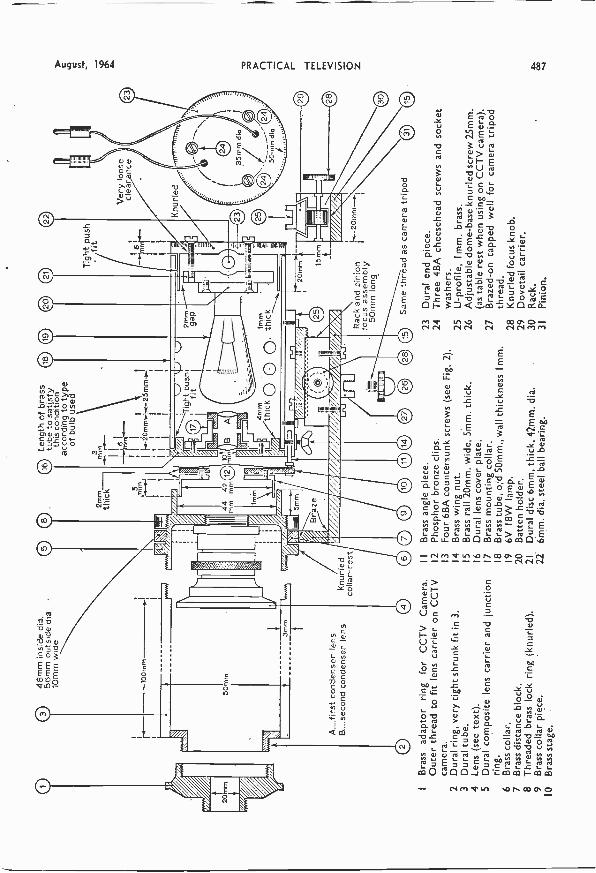
IB
rass
ada
ptor
rin
gfo
r C
CT
V C
amer
a.B
rass
ang
le p
iece
.23
Dur
al e
nd p
iece
.O
uter
thre
ad to
fit l
ens
carr
ier
on C
CT
V2
Pho
spho
r br
onze
clip
s.24
Thr
ee 4
BA
che
eseh
ead
scre
ws
and
sock
etca
mer
a.3
Fou
r 6B
A c
ount
ersu
nk s
crew
s (s
ee F
ig. 2
).w
ashe
rs.
2D
ural
rin
g, v
ery
tight
shr
unk
fit in
3.
4B
rass
win
g nu
t.25
U -
prof
ile,
I mm
. bra
ss.
3D
ural
tube
.5
Bra
ss r
ail 2
0mm
. wid
e, 5
mm
. thi
ck.
26A
djus
tabl
e do
me
-bas
e kn
urle
d sc
rew
25m
m.
4Le
ns (
see
text
).6
Dur
al le
ns c
over
pla
te.
(as
tabl
e re
st w
hen
usin
g on
CC
TV
cam
era)
.5
Dur
al c
ompo
site
lens
car
rier
and
junc
tion
7B
rass
mou
ntin
g co
llar.
27B
raze
d -o
n ta
pped
wel
l for
cam
era
trip
odrin
g.8
Bra
ss tu
be, o
d 5
0mm
.,th
ickn
ess
I mm
.th
read
.6
Bra
ss c
olla
r.9
6V I
8W la
mp.
28K
nurle
d fo
cus
knob
.7
Bra
ss d
ista
nce
bloc
k.20
Bat
ten
hold
er.
29D
ovet
ail c
arrie
r.8
Thr
eade
d br
ass
lock
rin
g (k
nurle
d).
21D
ural
dis
c 6m
m, t
hick
, 42m
m. d
ia.
30R
ack.
9B
rass
col
lar
piec
e.22
. 6m
m. d
ia. s
teel
bal
l bea
ring.
31P
inio
n.10
Bra
ss s
tage
.
488 PRACTICAL
Apart from using this same high -quality lens themicro -objective is built from odd pieces of brassand aluminium. Only a few simple items, such asa 6V car bulb and a pair of watchmaker's eyepieces,are required in addition. The actual additional costof the micro -objective therefore will be negligible.
However, the time required for lathe work isappreciable; but since the amateur reader, incontrast to commercial projects, is looking forinteresting ways of employing his time at low costin materials, this is certainly no disadvantage. Itmay also prove an attractve programme for schoolsand radio clubs where the necessary workshopfacilities will probably be available.
PerformanceFig. 1 shows the full constructional details. With
the arrangement shown, the front end adapter ring" 1 " being screwed into the lens carrier of theCCTV camera in place of the normal lens, whichis itself removed to the lens carrier junction ring,the televised picture represents a magnification of300 diameters on the receiver screen.
With a picture width of some 50cm on theauthor's receiver and an electronic resolution ofsome 300 lines across_ the width of the picture twolines on the display which are one -sixth of a
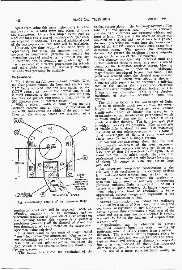
Stage-to-
condenseradjustment
according tospecimenthickness
Tapped to,take wingnut U Slide into V -profile
Fig. 2-Assembly details of the specimen stage.
centimetre apart can still be resolved. With aneffective magnification of 300 diameters and anelectronic resolution of one -sixth of a centimetre onthe receiving screen this represents a potentialresolution (rounding off the figures) of about onetwo -thousandth of a centimetre on the microscopicspecimen being televised.
It is more usual to use units of length called"mu" for microscopic dimensions. One mu is theten -thousandth part of a centimetre. The overallresolution of our micro -objective, including the.CCTV link in this setting, is therefore about S muon the specimen.
. The author has tested the resolution of the
TELEVISION August, 1964
optical system alone in the following manner: Thetube " 3 " and adapter ring " 1 " were removedand the CCTV camera was operated without anyform of lens. The rest of the micro -objective wasmounted on a tripod and moved back to a greaterdistance. projecting an image into the lens -carrierhole of the CCTV camera across open space in adarkened room. The greater the projectiondistance the greater the resulting physical magnifi-cation on the screen of the TV receiver.
The distance was gradually increased until anyfurther increase failed to reveal any more resolveddetail on the television receiver screen, blurringmerely increasing in proportion to additionalmagnification introduced beyond this limit. Thispoint was reached when the physical magnificationon the receiver screen was about a thousanddiameters with respect to the specimen, signifyingthat at this setting the optical and electronicresolutions were roughly equal and both about 1 to2 mu on the specimen. This is the absolute,maximum of resolution obtainable from thissystem.
The limiting factor is the wavelength of light.just as an obstacle much smaller than the wave-length of a particular wireless wave cannotsignificantly reflect or hinder that wave in itspropagation so can no object or part thereof whichis much smaller than the light directed at it berendered visible thereby. The light just goes pastit without noticing its presence. The wavelengthof visible light is about 0.5 mu. The maximumresolution of our micro -objective is thus some 2to 4 wavelengths of light, a quite remarkableperformance for such a simple system.
Theoretical considerations show that the bestoil -immersion objectives of the most expensiveprofessional microscopes can only get down to aresolution of abut 0.4 wavelengths of light, i.e. toabout 0.2 mu. In other words, the very bestprofessional microscopes are only better by a factorof about 10 compared with the design herepublished.
An important component contributing to therelatively high resolution is the carefully devisedlamp and condenser arrangement. At low magnifi-cations in any micro system the method ofspecimen illumination is relatively unimportantprovided sufficient light is injected to obtain a
picture of adequate intensity. At higher magnifica-tions, where the limit of resolution is beingapproached, correct design and alignment of thesystem of illumination is vital.
Skewed illumination can reduce the realisableresolution by a factor of 5 or more. The lamp andcondenser arrangement in any high -power micro -optical system thus constitutes a vital part of thewhole and the arrangement here adopted is beyondreproach as far as the fundamental requirementsare concerned.
Magnification can be obtained in almostunlimited amount from this system merely byprojecting into the CCTV camera from a sufficientdistance. The practical limit is imposed solely bythe available light and was reached for the proto-type at about 3yd projection distance, correspond-ing to a magnification of about five thousanddiameters on the television receiver screen.
The use of a more powerful lamp would, in
August, 1964 PRACTICAL
principle, enable the projection distance andcorresponding magnification to be increased furtherstill. But such additional magnification is of littleuse since no further resolution of detail is obtainablebeyond a magnification of about one thousanddiameters.
The very smallest single bacteria, the cocci, areabout 1 mu in diameter. Most bacteria areconsiderabl), larger. Thus even in the normal" 300 diameter magnification " closed system withthe tube " 3 " and ring " 1 " in position and witha resolution of about 5 mu many types of bacteria
TELEVISION 489
unwieldy for the majority of microscopic speci-mens such as plant and seed sections, small pond -water organisms, fragments of insect organs, etc.The resolution in the maximum setting is also inpractice greater than required for such purposes.The specimens would come out at several timesthe size of the television receiver screen so thatonly a small portion thereof would be visible at anyone time, giving an inadequate general conception.
After careful and extensive work with the proto-type, using a great number of varied slidespecimens, the author has found a lower magnifi-
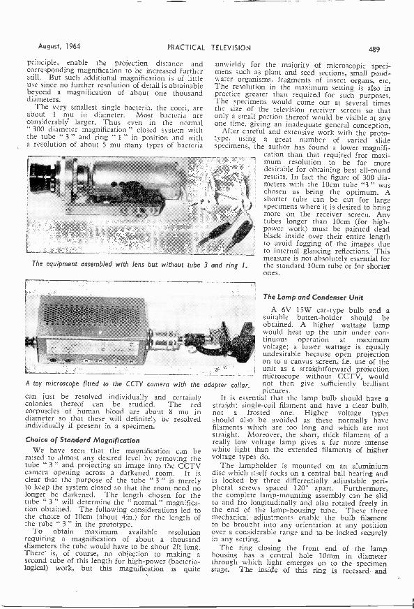
cation than that required fror maxi-mum resolution to be far moredesirable for obtaining best all-roundresults. In fact the figure of 300 dia-meters with the 10cm tube "3 " waschosen as being the optimum. Ashorter tube can be cut for largespecimens where it is desired to bringmore on the receiver screen. Anytubes longer than 10cm (for high -power work) must be painted deadblack inside over their entire lengthto avoid fogging of the images dueto internal glancing reflections. Thismeasure is not absolutely essential forthe standard 10cm tube or for shorterones.
The equipment assembled with lens but without tube 3 and ring I.
A toy microscope fitted to the CCTV camera with the adapter collar.
can just be resolved individually and certainlycolonies thereof can be studied. The redcorpuscles of human blood are abo-tt 8 mu indiameter so that these will definitely be resolvedindividually if present in a specimen.
Choice of Standard MagnificationWe have seen that the magnification can be
raised to almost any desired level by removing thetube " 3 " and projecting an image into the CCTVcamera opening across a darkened room. It isclear that the purpose of the tube " 3 " is merelyto keep the system closed so that the room need nolonger be darkened. The length chosen for thetube " 3 " will determine the " normal " magnifica-tion obtained. The following considerations led tothe choice of 10cm (about 4in.) for the length ofthe tube " 3 " in the prototype.
To obtain maximum available resolutionrequiring a magnification of about a thousanddiameters the tube would have to be about 2ft long.There' is, of course, no objection to making asecond tube of this length for high -power (bacterio-logical) work, but this magnification is quite
The Lamp and Condenser Unit
A 6V 15W car -type bulb and asuitable batten -holder should beobtained. A higher wattage lampwould heat up the unit under con-tinuous operation at maximumvoltage; a lower wattage is equallyundesirable because open projectionon to a canvas screen, i.e. use of theunit as a straightforward projectionmicroscope without CCTV, wouldnot then give sufficiently brilliantpictures.
It is essential that the lamp bulb should have astraight single -coil filament and have a clear bulb,not a frosted one. Higher voltage typesshould also be avoided as these normally havefilaments which are too long and which are notstraight. Moreover, the short, thick filament of areally low voltage lamp gives a far more intensewhite light than the extended filaments of highervoltage types do.
The lampholder is mounted on an aluminiumdisc which itself rocks on a central ball bearing andis locked by three differentially adjustable peri-pheral screws spaced 120° apart. Furthermore,the complete lamp -mounting assembly can be slidto and fro longitudinally and also rotated freely inthe end of the lamp -housing tube. These threemechanical adjustments enable the bulb filamentto be broueht into any orientation at any positionover a considerable range and to be locked securelyin any setting.
The ring closing the front end of the lamphousing has a central hole 10mm in diameterthrough which light emerges on to the specimenstage. The inside of this ring is recessed and

490 PRACTICAL
carries a suitable mounting collar for a pair ofwatchmaker's eyepieces, A and B, serving as aprecision double condenser.
The principle of a condenser in general is toform an image of the lamp filament on to theprincipal plane (the iris stop) of the main lens usedfor forming the optical image of the specimen. Ifthis condition is accurately satisfied, and if thelamp filament is a true point of zero size, all thelight will pass through the main lens regardless ofthe aperture which may be set, which then has noeffect upon the brilliance of the ultimate image ofthe specimen in such an arrangement (in contrastto the conditions of diffuse illumination in normalphotography where each aperture step halves or
TELEVISION August, 1964
of view, even if very uneven.Now scratch a small mark on the focus carriage
and then rack it backwards by an amount exactlyequal to the focal length of the main lens. Theimage of the lamp filament should now have takenthe place of the specimen image on the projectionscreen. First of all slide the rear lamp mountinglongitudinally in the lamp -housing tube to bringthe lamp filament sharply into focus on the screenwithout moving anything else. Then rotate thelamp mounting to bring the lamp filament exactlyhorizontal on the screen. Finally adjust the threerocker screws to bring the focused horizontalfilament image into the exact centre of the field ofview.
Both these photographs were taken from a standard television screen. The subject on the left was a human hair, tornout from the root.
doubles the image intensity).Now our lamp filament is not a true point but
has a definite size. However, as long as its imageremains smaller than the aperture set on the mainlens that aperture will still have no effect upon thebrilliance; thereafter, for a straight filament largerthan the lens aperture, the reduction of brillianceis linear, not'square law as in normal photography.
In short the advantage of such a small -size sourceof illumination is that efficient light transmissionpersists relatively regardless of the aperture set onthe main lens, which can then be chosen accordingto the requirements for optimum resolution. Stopnumbers between full aperture and about f/8should be tried in any given set-up, comparing theimage quality at each setting.
AIlitunentA point source operates effectively in the above-
' Mentioned respects only if it is correctly aligned,and such adjustments are rather critical. Thefollowing alignment procedure should be adopted:
Place a specimen on to the stage and, with tube." 3" and ring " 1" both removed, project a-focused magnified image of the specimen on to acanvas screen some 2yd distant. Adjust thefocusing rack and pinion to bring the projectedspecimen image sharply into focus on the screen,if necessary empirically adjusting the lamp positionto get some sort of illumination over the field
Repeat this sequence of adjustments in the samemanner as when adjusting the various cores duringalignment of an i.f. amplifier chain until mutuallyoptimum settings are reached. The lamp andcondenser system is then accurately aligned and,upon racking forwards again to bring the specimenimage into focus on the screen, the whole field willbe seen to be illuminated uniformly and at greatbrilliance.
Regarding the condenser lenses themselves,ordinary watchmaker's eyepieces with a lensdiameter of about half an inch (obtainable at anyoptician's for a few shillings) and with a X10magnification are suitable. Two are required andthese must be identical in every way.
The eyepieces will already be fixed in a mountwith collar which conveniently slides in the mainouter collar, holding both condenser lenses a
definite distance apart, AB. This distance ABshould be adjusted if necessary for removing anychromatic aberration during alignment of the lamp.In other words, if the outer zones of the lampfilament on the projection screen appear colouredduring alignment first adjust the separation of thecondenser lenses AB to minimise or remove thiseffect.
This adjustment is not critical and the separationof 20m shown in Fig. 1 will probably be satisfac-tory right from the start.
TO BE CONTINUED

August, 1964 PRACTICAL TELEVISION 491
oc
coSTOCK FAULTSPREVALENT TROUBLES IN COMMERCIAL RECEIVERS
CONTINUED FROM PAGE455 OF THE JULY ISSUE
DETECTOR, video output and interferencelimiter circuits are lumped together for thepurpose of this article. The reason-as any
experienced service man will know-is that they areinterdependent in practice. Faults that originate inany one section have their effect upon the others.Indeed, it is often difficult to extricate the rootcause from some very misleading symptoms, as weshall see.
Variations in design make it almost impossible tobe dogmatic about specific com-ponents that fail, but we cangeneralise to a certain extent, andto aid discussion, Fig. 18 hasbeen drawn, showing the mostimportant features of a " conven-tional " vision output circuit.
From the final i.f. transformerTl, the signal is taken off bycrystal diode DI, connected so asto produce a positive -going pulseacross the load resistor Rl.
LI, in conjunction with CI,C2, provides an i.f. filter. Thevalues of these two capacitors maybe quite small, 10pF or less beingquite usual, and the load resistormay be similarly low (comparedwith the audio circuits discussed min our last article). ci
High Resistance joints
The first real speciality comesin the R2, L2, C3 circuit, whichis employed to " boost " thehi"her frequencies of the videowaveform, say from 2.5 to 3Mc/s.These peaking coils tend tosharpen the outline of the picture, and the principalfault found with them is the development of highresistance joints, due to their physical construction.
Fig. 19(a) shows the way they are wound on thedamping resistor (R2 of Fig. 18), with the fine wirejoined to the resistor lead -out wires. As the wholecomponent is often mounted on a printed -circuitboard and, all too often, in the path of a current of
Fig.
0111,11=111
PART 4VISION OUTPUT CIRCUITS
hot air, deterioration of the joints will cause partialbad joints or open circuits which give rise tosymptoms of a " smeary " picture or a plasticappearance in certain cases and a weak modulationin others.
In general, an open -circuit of R2 would result inovershoot, and severe ringing, as L2 would then notbe damped and a short-circuit would cause lackof detail as the high frequencies in the video waveform would not be accentuated.
R2\ MA-
ii.)....0730.\_e_rzybm.\_2
R
V1
R6
c>L3
R3
R1C2-f R5
c.;
R6
"-:R7C5
D2
TC1
H.T.
R10
VR1
C7
6
18-Composite circuit of detector, vision output and interferencelimiter stages.
The Video DetectorWe have mentioned loss of detail, but have
skipped the prime cause of this fault, the videodetector. This is quite often a crystal diode, asshown, although in many sets a double -diode valve,such as the EB91, 6AL5 or D77 was used, with thesecond half of the valve taking the place of 132, the
492 PRACTICAL
interference limiter diode.Where a crystal is used, breakdown causes it to
develop a high forward resistance, and the effect isa weak and watery picture, sometimes mistaken fora low gain fault. As this can also be caused by alow emission video amplifier, some experience ofthe particular circuit is needed to spot the exactcause quickly.
The difficulty lies in testing this diode, which isoften mounted in the final i.f. transformer screenedcan, and which has to be disconnected to bemetered.
In Fig. 19(b) the most usual types of crystal areshown, with the circuit symbol included-the
Resistor Coil
(a) (a)
Fig. I9(a)-Peaking or correction coil wound with finewire on a damping resistor. Look for poor connectionsat the joints and loose mounting of the resistor inprinted circuit panels. Check that the whole com-ponent is mounted with the coil well clear of thechassis: (b) ---crystal diode symbol and two examplesof physical shape. Note that red or white dot, andwhite, red or black band, denote cathode connection.
important point being that thiscomponent must be connected incircuit the right way round.
Damage to this component canbe caused by two quite separatefaults. In Part 2 of this series, i.f.instability was mentioned. Thiscan result in a heavy d.c. beingpassed through the crystal, withcertain circuits using a low valueload resistor.
In its initial stages, this faultcan be isolated by a test with ahigh ohms/volt meter at thedetector load resistor. With nosignal coming in, there should notbe a standing voltage; instabilitywill result in a rectified voltageand this becomes apparent on test.
The snag about other types oftest is that application of themeter modifies the circuit andvery often causes a temporarycure to the fault one is trying totrace.
The second cause is an internalshort-circuit between electrodesof the video amplifier. This
TELEVISION August, 1964
valve, often an EF80 or the pentode section of adual valve such as PCF80 or PCL84, is used as acurrent amplifier and works quite hard.
The incidence of failure is fairly high. When thistype of interelectrode short-circuit occurs, heavyd.c. is drawn through the crystal diode, which verysoon breaks down under the strain.
Unfortunately, this fault is an accumulative one.For example, instability in the i.f. stages-oftencaused, as noted in Part 2, by an open circuitedscreen grid decoupling capacitor, or a short-cir-cuited a.g.c. line-causes an upset in the quitestringent bias conditions of the video amplifier, anover -heating and possible change in value of thecathode resistors, the valve glowing red-hot, inter -electrode shorts and breakdown of the diode.
It is not sufficient to replace the diode: a checkshould always be made of the video amplifier andits circuit.
Reference to Fig. 18 shows that the screen gridof this valve is fed via a tapping on an h.t.potentiometer, the lower leg of which is also acathode resistor. This type of circuitry is common.Its purpose is to give a standing bias to the cathode,operating the valve as a current amplifier.
The decoupling across the cathode bias resistormay consist of a single capacitor, or a combinationof capacitors, and may be tuned, as in Fig. 18. Thepurpose of TC1 is to provide the set user withsome variation of feedback, and thus a control overthe video response. For this reason, such a controlis often termed a " Quality " control.
If the cathode bias decoupling fails, the resultis sometimes a heavily contrasted but poorlydetailed picture. This can happen when theproximity of a silver mica capacitor to a burningcarbon resistor causes damage. Typical of this is theFerguson 506 circuit, where the cathode bypassis a 0.0012µF capacitor.
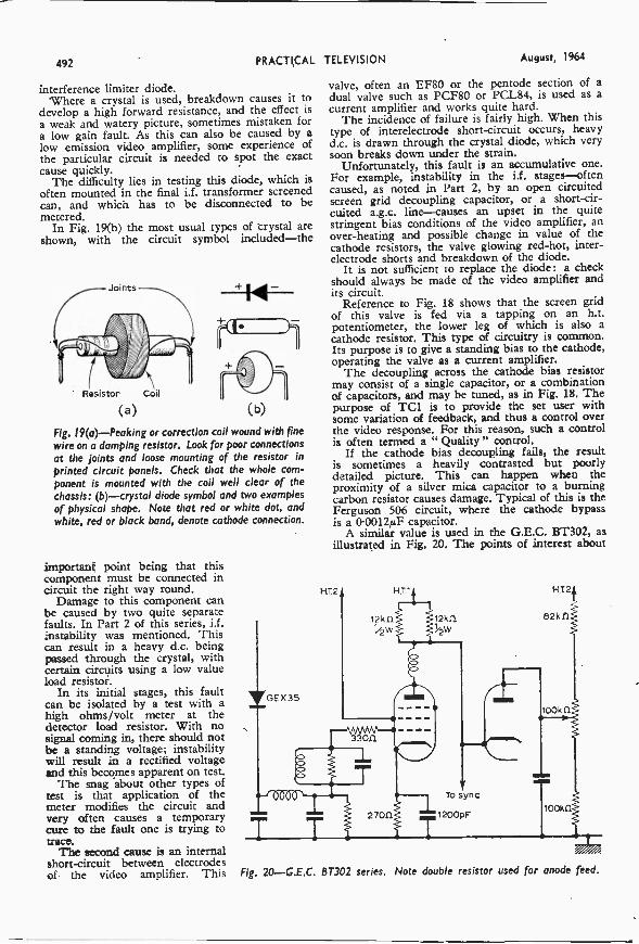
A similar value is used in the G.E.C. BT302, asillustrated in Fig. 20. The points of interest about
Fig. 20-G.E.C. BT302 series. Note double resistor used for anode feed.
August, 1964 PRACTICAL
this circuit are the return of screen grid to h.t. andthus no tapped cathode resistor, and the split loadin the anode feed, consisting of a pair of 12kf2resistors.
Intermittent Overload
The fault of intermittent overload should bechecked early on this range of receivers, as theresult will be a periodic over -running of the videooutput valve, which then develops a control toscreen grid short-circuit, and burns out both theGEX 35 diode and the 270(1 cathode resistor.
The decoupling of the i.f. stages should bechecked, especially the screen grid capacitors. Amisleading symptom on the BT302, giving a similarindication of severe overload, can be caused by quitea different fault. This is cancellation of the a.g.c. bya tracking of h.t. across the plug and socket connec-tion that carries the power and a.g.c. circuit.
Cleaning of a plug that has suffered this trackingeffect is seldom successful. The best cure is to dis-connect the h.t. line from the plug and socket anduse a direct connection, or, if dismantling is stillrequired, a portion of strip connector for the highvoltage lines.
The vision interference limiter control on thesereceivers is a conventional peak limiter, flatteningthe white level according to the voltage applied tothe anode of the diode by the tapping on the poten-tial divider, tht 100k0 being preset. Open -circuit-ing of this preset at its lower end will cause thediode to conduct and a grey, lifeless picture results.
A somewhat similar arrangement exists with thelater BT318 and 320 series, except that the valuesof the upper and lower resistors in the potentio-meter chain are 47ki2 and 82k(1 respectively. Butthere are other differences earlier in the circuitthat may be worth noting.
The cathode on these models is biased from theh.t. line via a compensating coil which is tappedfrom the junction of a 3.31:12 1W resistor and the2700 cathode resistor. On certain models, such asthe 319, 321 and 329, an extra if. stage was fitted,and precautions against instability which cause thebum -out of these last mentioned components werenecessary.
This consisted of the inclusion of a dampingresistor across the second i.f. primary and a 1.7pFcapacitor from the anode of the second i.f. stage tochassis.
The 303/305 models also used an extra i.f. stageand in these sets the screen decoupling capacitor ofthe second i.f. stage was doubled by the additionof an 0.001µF, while the primary of the anode trans-former was damped with a 33k11 resistor.
The adjustment of this coil is quite important inthese sets, to reduce the plastic effect due to poorvideo response, which is actually caused by a restric-tion of bandwidth.
The opposite fault, a severe ringing, can becaused by lack of screen grid decoupling, as whenthe 10,uF electrolytic on the Philips 1758U goesopen -circuit, or by a damaged bias resistor, as thecathode resistor, 330(1, of the Ekco TC388 andassociated models, where this component is tuned,as in our composite Fig. 18 circuit.
TELEVISION 493
The symptoms, in an advanced stage, are quiteobvious, but it is not always so apparent that poorvideo response can cause line pulling, and generalweakness of the sync circuits.
Sync Faults
On some models, such as the Alba 644, 744, 363and 655 receivers, the frame is affected quite soon,and a similar effect may be noted on the Emerson704 and 708 and the Philco 1000 and 1100U.Replacement of the video amplifier valve can oftencure a deeply obscure sync fault. More about thislater, when we discuss sync circuits more fully.
A peculiar fault of this kind crops up with theFerguson 406 and associated models, where theanode of the video amplifier receives an h.t. feedfrom two separate sources.
First is the direct source, from the load resistors(two 31c12 resistors in series) and the loading coil.Second is from a tapping of a 150k1.1 and 330k(2across the hi. line.
If the anode loading coil develops a high resis-tance, usually varying in persistence and serious-ness as the set heats up, the result is a drop in videoanode volts, intermittent overload due to lack ofa.g.c., and some peculiar sync faults.
Another coil which can give similar symptoms isthe grid coupling. It is wise to check these sets withthe back in place, or some other form of heat con-centration applied, as it has often been found thatfaults crop up only under extreme temperatureconditions.
Sometimes, the complication of the circuit givesrise to these faults, when something goes wrong. Atypical example is the Stella 5721, where poor linehold may be noted because the 220kf1 resistor from
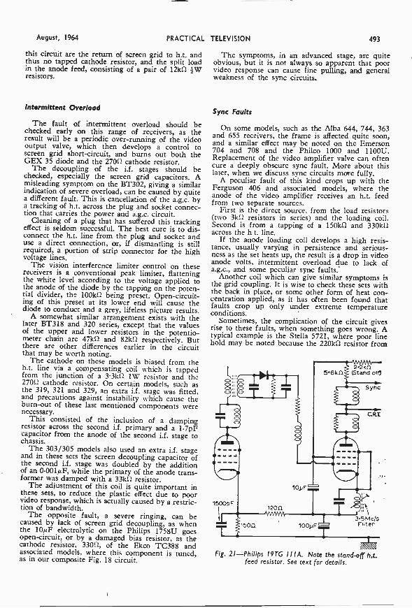
Fig. 21-Philips I9TG I I IA. Note the stand-off h.t.feed resistor. See text for details.

494 PRACTICAL TELEVISION August, 1964
ti
3.3kfl
11=1 15k11
!RT.
Fig. 22-Video output stage of the HMV 1842, withbalanced contrast control and tuned grid loading.
the bias line to the video grid goes high.In this arrangement, the limiter applies a
negative bias to the suppressor grid and a compen-sating bias to the control grid is derived from theline oscillator. Perfect balance is the secret of thiscircuit.
Less complicated, but quite as individual, is thePhilips 19TG111A as illustrated in Fig. 4. Hereit may be noted that a common cathode return forboth video amplifier and final vision i.f. valve isused. The importance of the two electrolytics,100,uF cathode and 10µF screen decoupling, needpot be stressed. The catch, with these receivers, isthe mounting of the 2.21a1 resistor taking anodecurrent.
This component, in common with the sound out-put anode feed, the turret and frame h.t. feeds, ismounted on stand-off tags with low -temperaturesolder, so that overheating due to excessive currentcauses melting of the solder and the falling awayof the resistor to afford a measure of protection.Very handy-when you know about it; very con-fusing, when you don't!
Reconnection should be made by fitting theresistor on the underside of the solder tags withoutwrapping the ends, and using 60/40 solder, if youwant to retain the protection which is much prefer-able to the burn -out that can otherwise result.
Qn an earlier model, the Stella 1007U, a confu-sihg fault was commonly found, with its origin alsoin' the video circuit, though apparently elsewhere.The video cathode decoupling capacitor, 100uFelectrolytic, is in a can with a shared common nega-tiVe.
The other section is the sound output cathodedecoupler. The symptoms are sound -on -vision,which appears to originate in the tuner unit sub -panel, on which speaker and volume control aremounted. Much fruitless searching can be obviatedby checking first the earthing of this dual capacitor,then, if the fault persists, fitting a separate videobypass.
Similar faults occur on the Pye CW17, where theunit is a triple electrolytic, bypassing sound outputscreen grid, one h.t. line and the video cathode.
Lack of Band III Response
Another baffling fault is lack of Band IIIresponse, although Band I is apparently in order.This happens on the HMV 1842. Before getting tooinvolved in the "front-end" circuits, check whetheran alteration of contrast also makes greater changesthan would be expected in general brightness level.See that the video amplifier (PL83) bias is no morethan 4.8V. If it is, check the 15162 resistor from theupper end of the contrast control, which reduces invalue. Fit a wirewound replacement.
Fig. 5 shows the rather unusual circuit. If the3.31d2 goes high, a negative picture, with no visioninterference control, can result.
Earlier a mention was made of sync beingaffected by a video fault. This is very noticeable onthe Ultra 1774, and similar models, when the550pF cathode decoupler develops a fault-usuallywhen the set heats up. This high value is quiteimportant, and it is not advisable to use any handyelectrolytic in its place.
Fromdetector
5501.1F
To sync. and C.RT.
HT.+
6D2
control
Fig. 23-Large value cathode bypass electrolytic isused on the Ultra 1774 and associated models.
Fig. 23 shows the circuit. Note in this circuit alsothe h.t. feed to the anode of the limiter diode iscommon to the pentode anode, with the triodesection employed as cathode follower output.
The ultimate fault-no raster-can have itsorigins in practically any of the previously discussedfaults, when they develop, but could also be a verysmall trouble-our old favourite, the dry joint.
-This is evident in such circuits as the Sobel! andMcMichael TPS180, MP18, etc., where the feedto the c.r.t. cathode is via a peaking coil. Check thesoldering at both sides of the printed circuit onthese models.
TO BE CONTINUED

August, 1964 PRACTICAL TELEVISION 495
11=01.11111.MINIM
A MONTHLY FEATUREFOR DX ENTHUSIASTS
by Charles Rafarel
WE hope DX-ers have now found that theprediction, in last month's column, thatthere would be a DX Sporadic E opening
in June, was in fact correct.The opening started on May 18, and at the
time of writing is still in full swing (Mid -June)and is, without doubt, one of the best ever, inspite of many dismal pessimists who forecast thatthis season would be below average for receptionconditions.
Most of the old favourites have already beencoming in well, as well as a number of new ones,and there has been plenty of interest to sec. Ithas not required too much patience, either, andthe openings have been almost continuous from08.00 until 22.00 or even later, signals viaSporadic E being received on all channels inBand I.
Th. only disappointment has been the tropo-spherics in Band III still suffering from theunsettled weather conditions, and extremelyvariable, although at times good reception of DXwas possible in this area. I can only hope thatit has been better in other parts of the country,and we would be most interested to hear fromreaders regarding this.
U.H.F., strangely enough, has at times beencoming in rather better than Band III, and thenew Lille-Bouvigny transmitter on channel 27 isputting a good signal into many parts of Southernand South Eastern England. The exact power isnot yet known, but it is understood to be oneof the most powerful u.h.f. transmitters inEurope, and seems to be completely " blottingout " its co -channel partner N.T.S. Lopik forreception in many localities over here.
Station identificationWe are anticipating a number of enquiries
(particularly from beginners) regarding stationidentification. Some have already arrived, andthere are certain requests that I would like tomake, so that we can help as far as possible.For identification the following information isrequired:-
(1) Date and Time of reception.(2) Standard, i.e.: 625 Pos. or Neg. Image or
819 lines.(3) Channel. If you do not know on which
E.R. of F channel you received the signalgive the nearest English B channel and sayif your reception was h.f. or 1.f. of this.
(4) Please give rough sketch or photo of any
Test Card or Opening Caption.(5) Any Programme details together with times
of reception.A number of readers have given good Test
Card sketches, but have omitted channel details.This causes difficulty over similar Test Cardssuch as for example Grunten (West Germany)and Jauerling (Austria) on Channels E2 and E2a.So please give fullest details.
DX NOTESJugo-Slavia has been positively logged from
Kapaonik on Channel E3, CCIR, a poor signalhere in Poole. More identification details will begiven as soon as it gives a longer durationpicture, but it carries a Test Card similar to N.T.S.Lopik, seen from 18.00 to 18.15. At 18.15 therewas an opening caption carrying the words" Studio!? Zagreb," followed by a newsreel carry-ing a weather map of Jugo-Slavia at 18.22 andat the end of the news at 18.30 a photo captionof a bridge over the Danube was shown. Thishas been seen by a number of viewers.Mystery Signals
At least 2 new electronic patterns are comingin, details as follows:
(1) Channel E3, CCIR, on 2-6-64 at 17.50 fora few minutes, a very strong small mesh patternwith two graded horizontal bands across centrefaded out before Test Card or Opening Caption.
(2) Channel E4, CCIR, on 9-6-64 from 19.03to 19.35 black and white checkboard patternexactly as N.T.S. Lopik, but via Sporadic Enot Lopik which is too near in this area).
If any reader knows the answer regarding the'locations of these we shall be delighted to hear.DX Logging
A number of interesting points have been notedduring the opening, and I will mention three ofthem to show that what is often commonpractice in " logging " by DX-ers is not alwayscorrect.
I refer to the assumption that it is the neareststation that is received in a country, when one,has seen a Test Card. This is not always the,case, it depends on prevailing conditions.
For example: A Swedish Test Card normallyassumed to emanate from the Horby station wasseen to carry the word " Vannas " on it; Vannesis in North Sweden and Horby is in the South.
R.A.I. Italy on channel la, is usually logged asMonte Nerone, but on most occasions recentlyon a good Test Card the number in the ton righthand corner is not 31 (for Mte Nerone) but 23which indicates that the station is in fact Monte'Cammarata (Sicily) much further away!
Similarly the entry USSR?, Minsk?, oftenappears in logs for the RI signal, but this some-
-continued on page 501

496 PRACTICAL TELEVISION August, 1964
TRANSISTORISED
iv cameraB. W. SMITH G3LGJ/T
CONTINUED FROM PAGE 460 OF THE JULY ISSUE
THE diagram of Fig. 6 shows the constructionlayout chosen for the camera and is a verypractical one, making good use of available
space.
The ChassisThe mains transformer and power supply com-
ponents, including vidicon tube coupling capacitorsand resistors are fitted into a four-sided chassis4in. x 10in. x 2fin. deep. This willgive rigidity to the whole structureand accommodate most of the bulkycomponents.
The transformer should be fittedat the rear end of the chassis wellaway from the coil assembly andalso preferably enclosed in a steelbox. Stray magnetic fields such assurround a mains transformer canaffect the camera tube scanning andproduce unwanted 50c/s shift onthe vidicon, which will appear asbent verticals in the picture.
The coil assembly is supportedby its middle and rear discs ontop of the power supply chassis
Lens
to sit flush with the front edge of the chassis.See Fig. 6.
The video amplifier is constructed on AM.paxolin board, and turret lugs or panel pins areused to hold the components on to the board.
When planning the component layout do notwaste space, place Trl as near to the camera headoutput as possible and lay Tr2 and Tr3 etc.in order, along the board away from Tr3. Thiswill minimise the possibility of capacitive feedback
Vidicon tube Timebase componentboard
Beamand
..--Targetpots.
N. Videooutput
socket
. .. Fig 6-The style of construction adopted by the author for...
the prototype camera.
. from output to input which could well causespurious oscillations.
Avoid a layout which involves long couplingleads and multi criss-crossing of wires; arrangeif possible for the output to be taken off theopposite end of the board to the input. Rememberthat the amplifier handles 3 Mc/s or more andhas a very high gain.
A home-made printed circuit board can be con-structed quite easily for the vision amplifier andtimebases.
The three control potentiometers, beam current,electrical focus, and target sensitivity are fittedtogether with the output socket onto a bracketmounted on the rear of the power chassis. Thisbracket has its two upright sides bent at right -angles, for use as mounts for the two scan com-ponent boards.
The two boards, which will be about 4in. x 44in.,are constructed in a similar way to the videoboard, although in this case component layout is

August, 1964 PRACTICAL TELEVISION 497
not so critical. One board will hold all the frametimebase components, and the other, all the linetimebase parts. The boards are held on each sideof the rear bracket by two self -tapping screws andare also supported by a small bracket mounted onthe main chassis.
A simple case can easily be fabricated fromeither wood or aluminium sheet. The, finishedcase, being finished off using a contemporarycolour scheme with the operator's call sign writtenacross the side.
Printed CircuitThe more ambitious experimenter would find
it worth while to design a printed circuit layoutfor the three vision and timebase boards. Theprocess is quite simple and should be tackled inthe following way.
First prepare twice full size, a layout of thecomponents as they lie in the circuit, putting eachfairly close together with the positive rail at oneside, and negative rail at the other. Very littlere -arrangement should be necessary to draw theprint circuit connections between the various com-ponents. A little perseverance will be required,but once the technique has been mastered every-thing will fall into place. Remember that jumperwires can be used in the awkward places.
Having obtained a layout, cut a piece of single -sided copper laminate board to size and mark outand drill all the component holes, drill No. 50,and don't forget the fixing holes. Paint the con-nections on the copper side, using black cellulosepaint, with a small paint brush. Do not makesharp right-angle corners, keep lines separated byat least 0.05in. and put extra paint round corn -
Beam currentpot. VR2
100V AC.on T1
ponent holes where possible. Mistakes can bescraped off when dry, using a razor blade. Whenthe painting is finished allow to dry, and checkthat everything is correct.
Ferric chloride can be bought in crystal formand should be dissolved in very warm water. Donot mix in metal pans, but use a glass dish.About -I pint of water only will be needed andit will dissolve a large quantity of ferric chloride.The solution will turn a very deep brown.
The painted board can then be dropped in.The reaction will be increased by keeping thewater hot and constant agitation; time requiredwill vary from 5 minutes to hour. The boardshould be checked now and then until all un-painted copper has dissolved, when it should thenbe removed and washed. The paint is dissolvedusing an acetone -soaked rag. The board can thenbe lightly rubbed with steel wool and is readyfor assembling.
After all components have been assembled andsoldered, a coat of clear varnish can be used tomaintain the copper shine.
Photographs will tell you that the pictures youcan obtain will be only as good as your cameraoptics. While this may not be strictly the onlylimitation in television cameras, a good lens is wellworth the money spent on it.
The range of lenses available is prodigious andchoice depends on several factors. Lenses that arereadily available are 8mm, 16mm, 35mm. The lin.vidicon scanning format (picture area) will beadequately covered by a 16mm lens.
The lens required will need to be a focusingtype preferably with an adjustable iris so as tocontrol the light on to the vidicon mosaic. The
230V A.C. Earthon T1 (chassis)
-6.2V videoamp.
VR3VR
Targe4 tiVidicon Vidicon
target anodeVidicon VR4mesh Target
Beamfocus Timebases and
head pin 5via R13
etc.
pin 6 pot.(slider)
pot.(slider)
focus coil LI,and -25V
Fig. 7-The wiring and layout diagram of the camera's power supply section. Note: the rectifier MR2, as shown inFig. 1 on page 458 last month, was drawn incorrectly and should be reversed to agree with the above diagram.
498 PRACTICAL TELEVISION August, 1964
camera tube can be made more or less sensitiveby varying its target voltage but due to the circuitdesign and other considerations it is preferable toset this to a fixed potential and use the irisadjustment.
The focal length depends entirely on what isrequired of the camera. The normal angle shot willrequire a lens of about 1-2in. focal length. Thelong distance shot will require a 6in. or more focallength. Of course a zoom lens will give all of thesevariations with the one lens. A good choice foroperation in a confined space or a small room is alin. lens.
Cost of lens depends on its stop number. Thesmaller the stop number, the more expensive, butthe more light it passes, hence the less lightingrequired for camera operation. The stop or fnumber is the lens apperture divided by the focallength. The iris adjustment goes in steps, i.e. 2.8,4, 5.6, 8, 11, 16, 22 etc., each step higher innumber reduces the light by half.
Thus a lens with the smallest stop number(widest opening) of f 5.6 will only transmit quarteras much light as a lens with f 2.8 as its smallestnumber.
A good choice of lens would be a 16mm of lin.focal length with focusing, and adjustment fromf1.9 to f16. However, if this proves too expensive,it is hoped that these comments on lenses will helpin choosing.
TestingAn oscilloscope will be needed to check whether
the correct waveforms are present at the appropriatepoints of the circuit. A vidicon tube should not beinserted in the camera during critical tests since itwill be liable to damage during the setting upprocedure. Voltage measurements should be madeon the power supply to ascertain that the correctd.c. voltages are present. Indication that power isconnected to the camera is given by the neon targetvoltage stabiliser which should light.
IThe oscilloscope X -sweep should be set to run at
about 5kc/s and the input connected to the end ofthe line scan coil. Negative -going line frequency(i.e. 10kc/s) pulses will be present, speed adjustedby VR8. Turn the oscilloscope sweep to about 25c/sand couple the Y input to the C27 end of the framescan coil. A positive going from sawtooth waveformshould be present providing frame scan. This wave-form should be locked to the mains 50c/s by VR5.
IWith the oscilloscope sweep still at the low speed
connect the Y input to the base of Tr4 where nega-tive frame sync pulses should be present.
I Look at the camera video output with the oscillo-scope. Composite sync should be present, tryadjusting VR1. This control clips the waveformmixed syncs. to the correct level which will beapproximately 0.2V or about half the maximumamplitude that can be obtained. Take care whensetting up VR1 otherwise picture white clippingcan occur.
Connect the camera output to a video monitor(do not forget that the output is at video not r.f.)and observe the raster. A raster locked both onframe and line should be obtained, of even bright-ness. By bringing one's hand near to the input ofTrl, stray video pick up in the form of hatchingshould be observed. The vision monitor should
remain locked.If the monitor does not lock, check that the line
oscillator is near the correct frequency, the frameoscillator is locked to the mains, and the syncmixing controlled by VR1 is correct.
The final stage of testing the camera has nowarrived, when the camera tube can be inserted. Dis-connect the 250V mains and insert the vidicon intothe front of the assembly, base pins first (see Fig. 4for final assembled arrangement). When clampingthe tube in, make sure that the target spring con-necting clip is making contact with the targetmosaic pick -off ring. Plug on the tube socket basebefore clamping the tube in the assembly.
Turn VR2 so that maximum negative volts areapplied to the vidicon grid thus biasing its beamoff. Turn VR4 to set target voltage potentio-meter to its mid -position.
Connect mains to the camera and allow the tubeheater to warm up. The lens can be screwed on,although it is not absolutely necessary at this stageof checking the camera.
The front of the camera should be pointed at awhite sheet of paper lit by 100W light bulb. Do notunder any circumstances point the tube at a brightlight or the sun, especially if the lens is fitted.
Turn the beam current potentiometer slowly andwatch the video monitor raster. At a certain settingof the potentiometer, light should spread over thescreen rather like milk running over it. If this effectis not obtained after one or two attempts at turningthe potentiometer, immediately bias the beamcurrent off the tube. The tube could well bedamaged if left in this condition, with the beam
Repeat the testing and try and locate the faultbefore attempting to obtain pictures from thecamera as this will probably damage the cameratube.
Assuming that the effect described is obtained,the camera is now working and will producepictures if a lens is fitted. It is best set up first ona test card or test picture. This picture should beabout 12in. x 9in. set at 3ft. from the camera, andon the same level, preferably evenly lit with artifi-cial light, say two 100W bulbs set on each side afew feet away from the card.
Turn up the beam potentiometer until the effectalready described occurs, then adjust the electricalfocus VR3 and lens focus until a sharp picture isobtained. Note that the electrical focus may havemore than one focal position, only one is correct.
Now adjust the beam current control and set itjust far enough up so that the picture whites arenot clipped, but no further. Any further increaseis detrimental to focus and to tube life. Sensitivitycan be controlled by the iris adjustment on the lensand, or, by the target voltage on the tube.
At this point check that scans are correct (i.e.picture is not upside down or a mirror image); ifnot, reverse the appropriate scan coil leads. Notethat reversing the polarity of the focus coil will alsocause a scan reversal of both vertical and horizon-tal scans.
A hatching pattern may be observed when thetube is spot on focus electrically, this is due to aneffect caused by interaction of the scan on theanode mesh. This patterning can be eliminated byrotating the vidicon slightly in the coil assembly

August, 1964 PRACTICAL TELEVISION 499
REBUILT AND RESCREENED
CATHODE RAY TUBESComplete with all new components excepting glass
FOR QUALITY, RELIABILITY AND SERVICE BUY FROM BRITAIN'SLARGEST GROUP OF INDEPENDENT MANUFACTURERS OF REBUILT
CATHODE RAY TUBES
SUFFOLK TUBES LIMITED1/3 UPPER RICHMOND ROADPUTNEY, S.W.15.Tel: Vandyke 4304/5267
MIDLAND TUBES LIMITED477/483 OLDHAM ROADMANCHESTER, 10.Tel: Collyhurst 4412
VIDIO REPLACEMENTS LTD.25 ADDINGTON SQUARECAMBERWELL, S.E.5Tel: Rodney 7550/7559
ALL TYPES KEEN PRICES PROMPT DELIVERY12 MONTHS' GUARANTEE
Cuttriss Ltd.Westminster HouseFrederick StreetBirminghamTelephone: Central 3221/2/3
Lawsons Ltd.36 CornhillBury St. Edmunds, SuffolkTel: Bury St. Edmunds 3304
J. H. Sunderland11 Clements StreetRochdale, Lancs.Tel: Rochdale 48484
Wizard Productions16 Withy GroveManchesterTel: Dea 2772
Radiovison (New Forest) Ltd.The CroftBurley, Hants.Tel: Burley 2128
M. & G. Trade Services23 Boscombe Grove RoadBournemouth, Hants.Tel: Bournemouth 37184
Chester Radio11 City RoadChesterTel: Chester 24727
Taylors162 Eastney RoadMilton, PortsmouthTel: Portsmouth 35000
Millards Southern Rentals3 High StreetAldershot, Hants.Tel: Aldershot 20408
Lucketts of Banbury57a/58a High StreetBanbury, OxonTel: Banbury 2813
Electrical Marketing Co. Ltd.12a College Square NorthBelfast ITel: Belfast 33340
R.E.D. Ltd.Waltham StreetCreweTel: Crewe 4364
WRITE FOR BROCHURE
Fylde Television Services460 Talbot RoadBlackpoolTel: Blackpool 31159
R. WatsonLeathern BottelWavenden, Woburn Sands, BucksTel: Woburn Sands 2027
J. Wildbore Ltd.6/12 Peter StreetOldhamTel: Mai 4475
T. Barratt & Co. Ltd.Mill StreetSutton ColdfieldTel: Sutton Coldfield 1192/3
G. M. Carlow Ltd.3 Hurst Green RoadBentley Heath, SolihullTel: Knowle 2742
Cotton T.V. Service Ltd.63/65 Oundle RoadPeterboroughTel: Peterborough 2169

500 PRACTICAL TELEVISION August, 1964
ARE YOU TRAINED FOR1965 ? 1966 Y 1967 ?
Will automation or new techniques in Electronics replace you one day?DON'T TAKE CHANCES WITH YOUR FUTURE-DECIDE THAT
YOU ARE GOING TO BE THE MAN IN DEMANDINever before in history has it been so easy and no inexpensive to train for a
rewarding career in Electronics, Radio and Television!SISITECH NOW OFFER THREE EXCLUSIVE HOME TRAINING
COURSES.Anyone can afford theme amazing courses-anyone can understand this practicaltraining-No complicated mathematics to hold you back-No old fashioned,obscure explanations to frustrate you,.The lessons are CRYSTAL CLEAR, PRACTICAL. EASY TO MASTER ANDUSE-Early lemons make fundamentals clear even to the beginner, while otherlessons will give you the practical ''know-how" of an expert!Compares favourably with some courses costing very much morel By creatinga mass market through large volume sales and eliminating individual letterwriting we are able to pass on these savings directly to youlEach coarse is printed on extra large quarto size sheets and bound into onemanual to simplify handling and distribution.Please select the course most suitable for your requirements from the following:No. 1. RADIO COURSE. Fundamental tarts-Electrons--Conductors andinsulators-Radio Batteries--Ciremits--Magnetism-Ohru's Law-ResistorColour Code-f 'hart- What resistor to use-Eleetro-Magnetism-Electro-magnetic Induction-Bed Induction-Radio Frequency Inductances-CapacItyCoupling-I.F. Transformers-Radio Coils-Radio Capacitors-The Farad-Dielectric-Capacitor Colour Code-Alternating Current Theory & Filters-Reactance and Resistance-Charts to calculate Capacity Frequency andInductance-Handy Radio Formulae-Practical Aspects of Radio Servicing-Radio Valves-Transistor Theory-N Type Germanium-P Type Germanium-Diode Action-Transistor Action-D.C. Stabilization-Transistor Bias Adjust-ment-R.F. Amplification-Superheterodyne Principles-A.V.C.-Power Sup-plies-Meters-Multitesters and Valve Testers-Point to Point Servicing-Signal Generators and Signal Tracers-Using an Oscilloscope for Servicing-Alignment-Amplifiers and P.A. Equipment-High Fidelity-Advantages ofInverse Feedback-Speakers-Frequency Modulation-How to Obtain RadioJobs. Price for the complete course. ONLY 36/-. Plus postage 1/6.No, 2. ELECTRONICS COURSE. Includes most of the above lessons plus L.C.and R. Combined Circuits-Resonance Phenomenon-Behaviour at Resonance-How Meters Work-Making a Voltmeter-Ohm meter Connectione-Valves-Electron Behaviour--Triode-Characteristic Curves-Power Supplies-AudioAmplifiers-Microphones-Resistance Coupling-Obtaining Grid Bias-Push Pull and Parallel-Phase Inverter Circuit-Radio Frequency VoltageAmplifiers-LE. and Multiband Coils-Detection-Receiver Circuits-Resultsof Frequency Mixing-A.V.C.-Electronic Omillatore-Quartz Crystals-Radio Transmitter Circuits-Modulation and Tuning-Lines. Antennas andBadiation-Test Equipment Using Meters-Electronic Test Equipmont--Thyratrons-Photo-Cell Equipment-Radio Compaes-H.F. Heating-Electronic Shaping Circuits-Electron Microscope-Electric Strain Gauges-Inter-Communicators- Radio Servicing Techniques-Servicing Printed Circuits.Prim for the complete coarse. Only 89/8. Pius postage 1/8.Graduates of the Electronics Course eau qualify for a certificate-details seatwith rash order.No. 8. TELEVISION COURSE. Effect of Mis.adjutated controls-Pictures ofwarione faults-Service adjustments-Circuit Faults Indicated by a PoorPattern-Finding Bad Valves by observing Picture Faults-Separate ChannelI.F. System-Intercanier I.F. System-Negative Picture--Interference-Antenna Principles and Practices-U.H.F. Transmission Lines-Facts Aboutthe T.V. Signal to Help you in Service Work-Synchronizing Separators-T.V.Interference Aids-All about Cathode Ray Tubes --Explanation of T.V. Circuits-Video Detector-Video Ampliner-D.C. Restorer Circuit-Automatic GainControl Circuits--Oscillators-Deflection Coils-Automatic Frequency ControlCircuits--Analysie of Stagger Tuned I.F. Receiver-Analysis of Three Inter -Carrier Type Receivers-The Vertical Deflection Circuit --The HorizontaiDeflection Circuit-Waveforms--Schematics of various sections of a T.V.-17.11.F. Converters and Tuners-T.V. Test Equipment and Alignment-Analysisof Various Problems.Price for the complete course. Only 38/, Plus postage I/8.UNCONDITIONALLY GUARANTEED TO GIVE COMPLETE SATISFACTIONYou must be convinced that this is the best value you have ever seen in Elec-tronic, Radio or T.V. Training, otherwise you can return the course (or havepolar money refunded if sent with order) after you have examined it in yourown home for a full seven days.IF YOU SEND CASH WITH ORDER WE WILL INCLUDE A FREE 70 -PAGEBOOK. Tick on the coupon one hook for each course ordered with full cash.RADIO SERVICING FAULT FINDING BOOR. TELEVISION FAULTBOOK. OSCILLOSCOPE BOOR.These free books are authoritative, and loaded with information. Wouldcost at least 5/- each if bought separately-by sending cash you reduce book-keeping and other costs, which eavings we pass back to youl
FREE TRIAL OFFER!Map orgy 15/. per week if you wish. Clip coupon right now for this special offer,I
To: Sts -Tech Book Company, Dept, CT% Gator'. Mill, West End, Southampton.Banta
Please send the following courses for a full seven days' trial.O No. L RADIO COURSE. 0 No. R. ELECTRONICS COURSE.
87/8, incl. postage, 4I/-. incl. postage.O No. 8. TELEVISION COURSE.
37/8, incl. postage,(Pres trial customers tick only one please.)
1 not delighted. I may return the comae postpaid without further obligationmy part. Otherwise I will pay cash price OR 5i weekly until purchase
hoe plus 2/6 service charge has been paid.O Tick here if enclosing full purchase price.
I Please send rue Ei FREE. RADIO FAULT FINDING BOOK,El FREE. T.V. FAULT FINDING BOOK. 0 FREE. OSCILLOSCOPE BOOE
Amount enclosed S . ..._
7 understand that you will refund this money in full if I am not 100% eatiefledOverseas customers please send full amount (including Ireland).
SAME
ADDREBB
rt7T
,05)
BUILDa complete
TRANSISTORISED
C.C.TVCAMERA!Buy it and build it in easy stages with the famous BEUKITS-Kit No. 1 iI8.17.6. Spec., principles of vidicon tube, scanningassembly and optical system diagram. Kit No. 2 L16.10.0. Printedcircuit board and assoc. components, circuit, diagram, layoutinstructions and Manual. Kit No. 3 L8.0.0. All transistors and semi-conductors. Kit No. 4 L6.0.0. All metal work. Plus 7,6 P. & P.for each kit. (Kits cannot be split. Inst. Manual cannot be suppliedseparately.)
Get more out of itwith a genuine
BEUKIT !
SAVE MONEYand buy the CombinationKit comprising Kits 1-4
for
ONLY
E48P &p
.-or factory assembled and tested with lens and vidicon79 Gns. Lens with fixed iris LII. EMI Experimental type vidicontube I0667M 1E12. S.A.E. for free literature.
BEULAH ELECTRONICS LTD., Dept. PTV126 Hamilton Road, West Norwood, London, S E 27
Telephone: GIP 6166 (PBX)
FREE TUBE EQUIVALENTS CHART
will be sent on receipt of S.A.E.BRAND NEW THROUGHOUT
excepting glass
I2in.... ... L4.10.0 I4in. ... L5. 5.0
15-17in. L5.15.0 19-2Iin. ... L7.15.0
23in. ... L12.10.0
New Silver Screen and Aluminising. All makesMullard, Mazda, Emiscope, Cossor, Brimar,Emitron, etc.
REBUILT MULLARD AND MAZDATUBES
I2in.... L3. 0.0 I4in. ... L4. 0.0
15-17in. L4.10.0 2lin. ... L6.10.0
All Tubes Fully GUARANTEED 12 MONTHS.Dispatch same day. Cash with Order. Carriageand Insurance 10/-.Wholesalers of Tungsram and R.F.T. Valves.
S.T.S. Ltd.35 POUND STREET, CARSHALTON,
SURREYTelephone: WALLINGTON 9665
County
August, 1964 PRACTICAL TELEVISION 501
with respect to the deflection coils.Slight rotation of the picture will occur when the
electrical focus is altered, this is due to the ortho-gonal type scanning.
Adjust VR6 and VR7 to set the frame height andlinearity to give the correct aspect ratio, which canbe seen most easily on a picture of circles. Note,however, that the linearity and aspect of the TVmonitor must be correct before setting up thecamera.
Every time the target voltage is adjusted, thebeam current will also need re -adjusting. It is usual,except under very high lighting such as bright sun-light, to run the target as high as possible. Thereis an optimum position for maximum target gainand it is found as follows.
Cap the lens and biai- the camera tube off, thevideo monitor's raster should now be even greyoverall, with little shading. Bias the tube on, usingthe minimum bias necessary. If there is severeshading present, reduce the target voltage in smallsteps, readjusting the tube bias each time until theshading has been reduced to a minimum.
On the other hand if the raster is without severeshading, increase the target voltage in small stepswith corresponding adjustments in beam currentuntil shading occurs.
The tube light sensitivity becomes greater -as thetarget voltage is increased, but after a certainvoltage is reached, depending on the tube, the straytarget signals increase and become apparent on thepicture as shading. The target voltage should beset as high as possible before this effect takes place,and will give the maximum output for that particu-lar tube.
Camera OperationThis is a subject on its own and only a few
pointers can be given here. One of the first acces-sories that will be required is a tripod for mountingthe camera, providing controlled pan and tilt. Thisshould be as heavy a tripod as possible, lightweighttripods do not have the rigidity or strengthrequired.
The most important part of good camera opera-tion is the use of correct lighting. When usedindoors artificial lighting will be needed. Picturescan be obtained with ordinary room lighting, butextra illumination will be required for best results.
150W focus spot lights with ordinary bayonetlight sockets have a long life and are very suitablefor the purpose. Two of these correctly positionedshould provide good lighting for set position shots.Avoid over contrasty scenes by the TV system.
After the operator has the camera working, andtried the effect of lighting it will become apparentthat lighting cannot be taken for granted.
Caption BoardA useful accessory is a caption board with built-
in lighting. Two lights screened from the camera.one at each side of the board, about 60W shouldsuffice. Position these for even illumination of thecaption position. Flat two-dimentional syrfaces canbe lit easily but care should be taken to avoid sur-face reflection.
Home made captions can be very effective andcan be drawn on art paper with Indian ink.Contrast range is difficult to obtain and the best
methods are to use standard ink line drawingtechniques or pencil for grey. A definition chart,not necessarily test card C, should be included inthe captions, to provide a check on performance.
There will come a time when outdoor operationis attempted. The lighting is already set, and cannotbe altered, and again the main " don't" is toavoid over contrasty scenes. For example, try notto have much skyline, if any at all, in your shot(the sky is very bright). Generally best pictureswill be obtained when the sun is obscured byclouds.
A lin. lens will be rather wide angle and a moresuitable one will be a 3in. or 4in. focal length. It ison outdoor scenes that the zoom lens (variable focallength) is most useful, but the lenses are ratherexpensive. The target voltage should be reducedfrom the maximum sensitivity position, since thisproduces more pleasing pictures.
When the sun is shining on the lens watch outfor lens flare.
A monitor is necessary for the camera operator,and when outdoors even the brightened monitorwill be very dull, and a wooden screen or hoodshould be constructed to prevent most externallight falling on the screen. There is nothing worsethan trying to focus the camera using a monitorthat can hardly be seen.
Finally remember that the pictures in the end,can only be as good as the camera operator. Theiris and lens focus must be constantly attendedwhen taking different shots. The beam focus shouldalso be checked frequently for drift. and the targetand beam controls may also be used.
DX -TV-continued from page 495
times is Kiev. So you may be doing better thanyou think.Readers' Reports
L. Alsopp (Cardiff) has had good pictures fromT.V.E. Zaragossa/Alicante (Spain) on Ch E3. Hegave full programme details, which made identifi-cation easy from my own log for that day.
C. Vernall (Leominster) also had Zaragossa/Alicante E3 and what must be Carcassonne R.T.F.France on F4 via Sporadic "E". This is a "rare"one for most of us!
A. Connolly (1Cilkeel, Northern Ireland) hasreceived Switzerland, Poland, West Germany, andAustria.
1. Rose (Blackburn) had T.V.E. Zaragossa/Alicante.
It has been most noticeable that reception ofT.V.E. on Ch E3 has been exceptionally strong andregular recently, and has caused much chagrinto domestic viewers of BBC Rowridge in thisarea, when their BBC picture has been " blastedoff " their screens by it.
I suffer too! I have an uncomfortable feelingthat when this happens many near neighboursthink that it is due to my activities, in particularwhen they see the aerial arrays rotating!
Now that the season has opened up, we shallbe delighted to hear of your results, and to assistin the identification of the unknown signals .thatwe hope you will receive.

502 PRACTICAL TELEVISION August, 1964
A MONTHLY COMMENTARY
Underneath the Dipole
BY ICON OS
TF the latest TAM ratings haveany significance (which I am
sure they have) then the BBC -TV programme department hasbeen dropping quite a fewdangers during the last year orso. Opinions differ on the meritsof many BBC features but theoff-putting effect of ill-manneredinterviewers, kitchen sink plays,displays of violence and badlanguage, all play their part inmaking viewers change over toITV or to " off ". Clangerscontinue to ring out but at lasta penny has dropped instead witha " clink ": when Stuart Hood,Controller of TV programmes,resigned from the BBC andjoined Rediffusion in a similartop executive capacity.
Gloomy Plays
Some time ago, before leavingthe BBC, Mr. Hood said at ameeting of script writers thatmany TV plays are pessimisticand gloomy, and sometimescontain situations which aresordid and questionable. It isthe current outlook of the writersand the results do not favourablyimpress viewers, according toMr. Hood, who is now Controllerof Pr9grammes at Rediffusion.I must say that I agree with him.Script writers seem to bedevoted to the so-called realisticstyle of play writing which ispresented in the plays of certain
live theatres in London, such asthe Royal Court or the ArtsTheatre Club, which appeal tospecialised audiences and receivegood notices from some of thenewspaper critics. It must beadmitted, however, that ITVprogramme companies provide afair quota of gloom, but this istempered with a cheerful injec-tion of many of the commercials.Stories of a trivial characteralways seem to be even moretrivial when they have a pessi-mistic finish without a real endand the viewer is left guessing.Let us hope that the writers takethe hint from Mr. Hood andavoid writing stories which are" messages " instead of enter-tainment. Mr. Sam Goldwynonce said: " My films are notmessages-I send messages bytelegraph ". Mr. Hood's recentspeech and Press statements giveus hope that he will carry outthe same policies in entertain-ment at Rediffusion TV whichachieved such success and pres-tige for Mr. Goldwyn in the filmindustry.
Pirate Radio-and TV?
The operations of the" pirate " commercial radio shipsoff the coast of East Anglia hasslowly warmed up during the lastmonth or so and may, in anindirect way, lead to similarenterprises in television in thedistant future. The Atlanta,moored 31 miles south-east ofFrinton-on-Sea, Essex, startedtesting on 197m, a wavelengthwhich seemed to me to be mightyclose to that of Radio Carolineon 199m. The Atlanta is a 470 -ton ship, " Mi Amigo ". ownedby the Rosebud Shipping Co.,of Panama, but the operatingcompany, Atlanta, is registered inSwitzerland with offices in
Vaduz, Lichtenstein. The activi-ties of yet another pirate radioenterprise, Radio Sutch, startedout in a 60ft fishing trawler," Cornucopia ", originally hiredand moored a few miles fromShoeburyness, whose transmitterwas subsequently moved on toone of the old gun towers 4.1
miles off land. This transmitterhas mainly achieved great atten-tion by the Press to the activitiesof Screaming Lord Sutch andhis associates-good, free pub-licity. I think. But the amountof interference that it will causeto legitimate radio transmissionson licensed wavelengths remainsto be seen-or, rather, heard.Most of these stations intend tobroadcast a continuous pro-gramme of music all day long,interspersed with advertisingannouncements, in the same timeratio as on Independent Tele-vision. As a matter of fact someof the ITV companies haveshown interest in the possibilitiesof using this advertising mediumduring the daytime for makingannouncements about their ownevening programmes. The signalsare heard over a fairly wide area,from King's Lynn to Portsmouth,from Harwich to Oxfordshire,and they will provide a " music -while -you -work " type of con-tinuous programme. It iscertainly not a bad idea to use" pirate " advertising slots as a
reminder to potential viewers tosee certain TV programmes thesame evening, but whether thesewould be subject to legal orpolitical complications is anothermatter. The use of u.h.f. channelsfor local commercial sound radiostations in this country is nowbeing lobbied for (and against) inParliamentary circles. Whetherthese stations are controlled bythe BBC or commercial interests-or both-there seems to be no
August, 1914 PRACTICAL TELEVISION 503
doubt that the continuous flow of" pop " music will drone onthrough the day, plus localannouncements. This does notappeal to me personally but thereis no doubt at all that itspopularity is general. Com-petition between the BBC andindependent interests will bringabout improvements in theformat of such programmes. Theareas are much more restricted,of course, than on the mediumwaves, and if tried out on anexperimental basis with successmay have practical value as astarting point for the establish-ment of ITV -2 stations.
Pay -TV
Yet another source of televisionprogrammes will soon be avail-able in various areas in differentparts of the country. particularlythose which already have as abasis the supply to viewers, viaPost Office lines, the programmesof the BBC and ITA, plus soundradio. Good quality redistributionof these programmes by relayingthem from well -sited andsuperbly equipped receivingstations is particularly importantin many cities and towns wherereception on local home aerials issubject to interference or reflec-tions. There are technicaldifferences in the methods usedfor providing satisfactory signalsto the subscribers, some of whichuse perfectly normal TVreceivers at the usual h.f. fre-quency and others which transferthe signal to a lower frequencyfor reception on speciallydesigned sets. It depends largelyupon the size of the area to becovered, h.f. relays being mainlyused in small, isolated areas. Allof these piped TV stations lookforward to providing a Pay -TVchannel as an extra programmesource. Just what programmesthe Pay -TV companies willtransmit in return for the viewerputting money in a slot or beingcharged a weekly accountremains to be seen. TolvisionLtd., whose managing director isEdward Roth (formerly withATV), seems to favour a propor-tion of the programmes beingproduced by live TV or on videotape and is considering thepurchase of the Wood GreenEmpire. This ex -music hall wasexcellently converted in 1956 into
a television studio suitable forstraight plays, audience participa-tion programmes or (with itstelecine equipment) featureswhich included film excerpts ofexteriors. British Telemeter,with piped television alreadyestablished in the Merton,Morden and Wimbledon dis-tricts, favour the use ofprogrammes on film, and alreadyhave an elaborate telecine suite inthe course of installation in partof the Merton Park Film Studios,where facilities for straight-forward film production workcan also be used when required.Payvision and Choiceview, twoother companies which have beensuccessful in obtaining Pay -TVlicences, are also considering thepart occupation of space atexisting film studios. Just howgood the Pay -TV programmeswill have to be to obtain therevenues needed from viewerswhen they are in competitionwith the existing BBC and ITVprogrammes remains to be seen.The general use of film wouldenable companies to exchangetheir film product programmesaround the Pay -TV's own net-work at different times ratherthan make use of expensivecoaxial lines all over the countrybetween their stations. Filmproduction for television israther a slow process, however,with a daily output of less thanten minutes of edited filmsequences compared with 30minutes per day, per stage, whenusing electronic processes onvideo *tape, an output which isquite normal at British televisionstudios. In West Germanymotion -picture cameras are usedwith streamlined television tech-niques, with a daily output ofabout 17 minutes per stage, withthe advantage that the endproduct is suitable for use in TVstations all over the world andcan easily be cut and dubbed intodifferent languages or photo-graphed in colour.
Ivor Novello
The BBC biographical seriesbased on the life of Ivor Novellopromised a musical treat forviewers which did not quite comeoff. The Ivor Novello musicalplays of the '30s and '40sfilled many a London theatre
with enthusiastic audiences, and" House Full" boards were dis-played night after night.Novello's talent as a writer andcomposer and his great personalcharm were remembered bymany show business personalitieswho were interviewed in thisvariation of a "This Is YourLife " theme. This part of theBBC series was well done but themusical excerpts were disappoint-ing. When Ivor Novelloproposed to produce GlamorousNight at Drury Lane he stipu-lated that he wanted a cast of120, an orchestra of at least 40players, together with elaboratescenery. Sugary though thestory -line was compared withmost of today's musical stageshow offerings, all of the Novellomusicals were beautifully pro-duced and colourful both inscenic effects and gorgeousdresses. The artistes sang andmoved without placing a footwrong in Glamorous Night andother spectacular Novello musi-cals such as Careless Rapture,Crest of the Wave, Perchance toDream and King's Rhapsody atTheatre Royal, Drury Lane,Palace Theatre and on tour at"No. 1 " provincial theatres.The television biography repro-duced musical excerpts frommany of these shows, as was tobe expected, but these did notconvey their original spectacularcharacter. One setting appearedto be used as a background to allthe shows from the earliestmusical he played in (and com-posed the music for), TheGolden Moth, onwards. TheBBC set was crowded with stair-cases, spindly pillars and flashycandelabra. Some of thesefixtures and " props " seemed togrow out of the heads of thevocalists and dancers as theymoved around, pursued by arestless TV camera on a crane.Of course the musical productionnumbers were handicapped bythe lack of colour, and it is to behoped that in due course Novellomusicals will appear on colourtelevision-but reproduced withthe large and impressive groupsof singers and dancers. Withcolour added there would be agood future for TV theatricalmusical shows of the theatre ina theatre-that is, when there aresufficient viewers who are able toboast that they own colour tele-vision receivers.

ATELEVISION picture (and sound for thatmatter) can only be as good as the signalpicked up by the aerial allows, assuming, of
course, that the set itself is in good order andcorrectly adjusted.
There is a certain level of aerial signal which,when exceeded will fail to improve the picture.This can be called the "optimum threshold " signallevel, for want of a better term. Above thisoptimum level, then, an increase of signal strengthwill (or should be) accommodated by the automaticgain control (a.g.c.) circuits of the set, until a pointis reached where the ag.c. just cannot cope anymore.
The set then tends to overload and the pictureand sound exhibit the effects of sound -on -visionand vision -on -sound, due to the overload conditionscausing cross modulation. The symptoms are adancing of the picture in sympathy with the soundaccompaniment and a " buzz " on the sound of anintensity which changes with the picture content.
These are typical 405 -line overload conditions.On 625 lines, the buzz (now called " intercarrierbuzz ") still occurs, though the picture symptommay not be present, since frequency modulation isused on the sound channel instead of the amplitudemodulation of the 405 -line standard.
NOISE SIGNALSo much, then for excessive signal strength, but
what happens if the level of the aerial signal isbelow the optimum threshold? If the signalstrength is substantially below this threshold, thepicture quality deteriorates as the result of " gain "arising from a " noise signal " produced by thefirst stages in the set. On the sound, the noisesignal is responsible for the " hiss " which mayaccompany the audio when the set is worked on aweak aerial signal.
The noise signal is produced mainly in the v.h.f.or u.h.f. tuner and, generally speaking, the higherthe frequency of the channel, the greater the levelof noise signal produced. For example, there maybe as much as three or four times more " noise "produced on Channel 33 (the new BBC -2 channel)than on Channel 1 (the old BBC -1 channel).
The noise signal rises slowly from the lownumbered channels in Band 1, through Band III
MUL I41M11111M.MP
and Band IV and then a little more sharply towardsthe high numbered channels in Band V (these arenot yet used, but will be soon as BBC -2 spreadsacross the country).
The noise signal is produced not because of thefrequency and characteristics of the signal, butbecause a valve or transistor amplifier itselfgenerates more " noise " as the frequency of thesignal it is called upon to amplify is raised.
Noise signal is produced by any material which iscapable of conducting electricity and it arisesbecause of the random movement of the free elec-trons in that material. In a thermionic valve, the
Fig. 1-This diagram shows the nature of noise signalwhen displayed on the tube of an oscilloscope. It issometimes referred to by engineers as "grass".
noise signal is added to, in some measure, by theemisson of electrons from the cathode, through thegrid or grids to the anode. This noise signal contri-bution is sometimes called " thermal noise ".
Even a resistor produces a noise signal acrossitself and this can be heard in a loudspeaker (as ahiss) or seen on the screen of an oscilloscope as aspiky waveform (see Fig. 1) after passing it throughan amplifier of high gain (note here that the ampli-fier itself then adds to the noise signal, as explainedabove, so the total noise heard or seen is partlyfrom the resistor at the input of the amplifier andpartly from the amplifier itself).
Awl
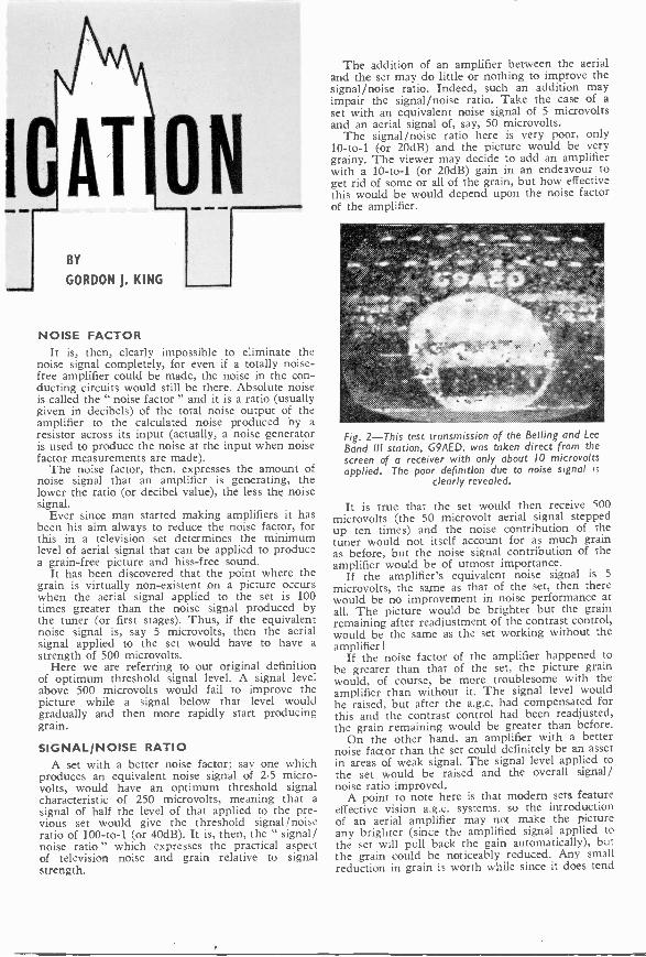
I AT ON11.11. OMB
=MO
BY
GORDON J. KING
NOISE FACTORIt is, then, clearly impossible to eliminate the
noise signal completely, for even if a totally noise -free amplifier could be made, the noise in the con-ducting circuits would still be there. Absolute noiseis called the " noise factor " and it is a ratio (usuallygiven in decibels) of the total noise output of theamplifier to the calculated noise produced by aresistor across its input (actually, a noise generatoris used to produce the noise at the input when noisefactor measurements are made).
The noise factor, then, expresses the amount ofnoise signal that an amplifier is generating, thelower the ratio (or decibel value), the less the noisesignal.
Ever since man started making amplifiers it hasbeen his aim always to reduce the noise factor, forthis in a television set determines the minimumlevel of aerial signal that can be applied to producea grain -free picture and hiss -free sound.
It has been discovered that the point where thegrain is virtually non-existent on a picture occurswhen the aerial signal applied to the set is 100times greater than the noise signal produced bythe tuner (or first stages). Thus, if the equivalentnoise signal is, say 5 microvolts, then the aerialsignal applied to the set would have to have astrength of 500 microvolts.
Here we are referring to our original definitionof optimum threshold signal level. A signal levelabove 500 microvolts would fail to improve thepicture while a signal below that level wouldgradually and then more rapidly start producinggrain.
SIGNAL/NOISE RATIOA set with a better noise factor; say one which
produces an equivalent noise signal of 2.5 micro-volts, would have an optimum threshold signalcharacteristic of 250 microvolts, meaning that asignal of half the level of that applied to the pre-vious set would give the threshold signal/noiseratio of 100 -to -1 (or 40dB). It is, then, the " signal/noise ratio" which expresses the practical aspectof television noise and grain relative to signalstrength.
The addition of an amplifier between the aerialand the set may do little or nothing to improve thesignal/noise ratio. Indeed, such an addition mayimpair the signal/noise ratio. Take the case of aset with an equivalent noise signal of 5 microvoltsand an aerial signal of, say, 50 microvolts.
The signal/noise ratio here is very poor, only10 -to -1 (or 20dB) and the picture would be verygrainy. The viewer may decide to add an amplifierwith a 10 -to -1 (or 20dB) gain in an endeavour toget rid of some or all of the grain, but how effectivethis would be would depend upon the noise factorof the amplifier.
ts41,01frar
-1161fitte'*ilte
Fig. 2-This test transmission of the Belling and LeeBand 111 station, G9AED, was taken direct from thescreen of a receiver with only about 10 microvoltsapplied. The poor definition due to noise signal is
clearly revealed.
It is true that the set would then receive 500microvolts (the 50 microvolt aerial signal steppedup ten times) and the noise contribution of thetuner would not itself account for as much grainas before, but the noise signal contribution of theamplifier would be of utmost importance.
If the amplifier's equivalent noise signal is 5
microvolts, the same as that of the set, then therewould be no improvement in noise performance atall. The picture would be brighter but the grainremaining after readjustment of the contrast control,would be the same as the set working without theamplifier!
If the noise factor of the amplifier happened tobe greater than that of the set, the picture grainwould, of course, be more troublesome with theamplifier than without it. The signal level wouldbe raised, but after the a.g.c. had compensated forthis and the contrast control had been readjusted,the grain remaining would be greater than before.
On the other hand, an amplifier with a betternoise factor than the set could definitely be an assetin areas of weak signal. The signal level applied tothe set would be raised and the overall signal/noise ratio improved.
A point to note here is that modern sets featureeffective vision a.g.c. systems. so the introductionof an aerial amplifier may not make the pictureany brighter (since the amplified signal applied tothe set will pull back the gain automatically), butthe grain could be noticeably reduced. Any smallreduction in grain is worth while since it does tend

506 PRACTICAL TELEVISION August, 1964
to impair the definition of a picture.Fig. 2 shows a very noisy (grainy) picture of an
early Band III (by Belling and Lee Limited) testtransmission. The signal at the set was little morethan 10 microvolts and a low -noise amplifier wasused to produce even this poorly defined picture.
TELSTARFig. 3 shows a slightly less noisy picture on a
more modern set, while Fig. 4 shows a relativelynoise -free picture direct from America, via Telstar.It is interesting to note that the picture here was
Fig. 3-This picture shows a television picture with asignal/noise ratio of about 30 to I.
produced from a signal of a lower level than thatapplied to the receiver which produced the picturein Fig. 2.
It may be recalled that Telstar radiates approxi-mately 2 watts of signal at a frequency of 4Gc/s.For " grain -free" reception, therefore, the groundreceiver must amplify and detect the extremelysmall signals with the minimum of inherent noise,and this is possible only by the use of elaboratedish aerials and special very low -noise aerial ampli-fiers. The " dish" at Goonhilly Down satellitecommunication ground station at Cornwall, forinstance, is some eighty-five feet in diameter andweighs more than 800 tons.
The aerial amplifiers used for such applicationsare based on the parametric or maser (short for
microwave and amplification by stimulatedemission of radiation ") principle. These are some-what specialised in operation and cannot, of course,be described in an article of this nature.
Suffice it to say that such amplifiers have extreme-ly low noise factors, so that the combination of theelaborate aerial and the amplifier gives the bestpossible signal/noise ratio known at this stage ofthe article, this being proved by the noise -freepictures relayed by Telstar and transmitted overthe ordinary television networks.
TRANSISTOR AMPLIFIERSParametric and maser amplifiers cost many
thousands of pounds and fall well outside (for thepresent) the economics of ordinary domestic recei-vers. However, from the domestic angle, the
development in recent months of low -noise tran-sistor v.h f. and u.h.f. amplifiers has tended to makegrain -free pictures possible at lower levels of aerialsignal.
Well -made transistor amplifiers of this type havea noise figure often fifty per cent (or greater) betterthan the noise figure of an average valve tuner, thenoise improvement being more noticeable at thehigher channel numbers. A worth -while improve7
Fig. 4 -.Although the signal from the Telstar relaygiving this picture was extremely small, the noiseresulting is also very small because of the ultralow -noise characteristics of the maser aerial amplifierand the elaborate aerial system together giving a
reasonable signal/noise ratio.
ment in noise performance in weak signal areas isusually possible simply by connecting the amplifierbetween the aerial downlead and the set at the setend of the downlead, and set -top single- and dual -band amplifiers complete with battery and on/offswitch are now available commercially. A u.h.f.version of this type of amplifier is shown in Fig. 5.
Fig. 5-A commercial version of a u.h.f. set -toptransistor amplifier with self-contained battery and
on 'off switch.
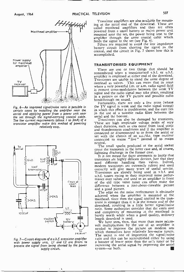
August, 1964 PRACTICAL TELEVISION 507
Masthead amplifier
Power supplyfor masthead
amplifier
TVreceiver
Fig. 6-An improved signal/noise ratio is possible incertain cases by installing the amplifier near theaerial and applying power from a power unit nearthe set through the signal -carrying coaxial cable.The low current requirements (about I to 3mA) of atransistor amplifier make this method of powering
relatively easy.
aerialTo
-12kfl
1000pF
UHFcoil
UHFtransistor
Ll
Coaxialdownlead
L2
On/Oft 12Vswitch battery
Toreceiver
Fig. 7-Circuit diagram of a u.h.f. transistor amplifierwith power supply unit. LI and L2 are filters toprevent the signal from being shorted by the power
supply circuit.
Transistor amplifiers are also available for mount-ing at the aerial end of the downlead. These arecalled masthead amplifiers and they are oftenpowered from a small battery or mains power unitmounted near the set, the power being sent to theamplifier through the same coaxial cable whichfeeds the signal to the set (see Fig. 6).
Filters are required to avoid the low impedancebattery circuit from shorting the signal in thecoaxial, and the circuit in Fig. 7 shows how this isaccomplished.
TRANSISTORISED EQUIPMENTThere are one or two things that should be
remembered when a transistorised v.h.f. or u.h.f.amplifier is employed at either end of the downlead.Transistors are unable to stand the same degree ofoverload as valves. This can mean that in areaswhere a very powerful f.m. or a.m. radio signal fieldis present cross -modulation between the weak TVsignal and the radio signal may take place, resultingin a pattern on the TV picture and possible radiobreakthrough on sound.
Fortunately, there are only a few areas (wherethe TV signal is weak and the radio signal strong)in which this effect is troublesome, and the cure liesin the use of a suitable radio filter between theaerial and the booster.
Transistors can also be damaged by transients.These are high amplitude voltage peaks of veryshort duration, such as can occur from local staticand thunderstorm conditions and if the amplifier isconnected or disconnected to or from the aerial orset with the chassis of an a.c./d.c. type receiverconnected to mains " live " instead of to mainsneutral.
The small sparks produced at the aerial socketcause the transients in the latter case and, of course,lightning discharge in the former case.
It is not meant for these comments to imply thattransistors are highly delicate devices, just that theyneed different handling than valves. Indeed,modem transistors are extremely robust and usedcorrectly will give many years of useful service.Transistors are already being used in v.h.f. andu.h.f. tuners owing to their improved noise perfor-mance over valves and used as an amplifier in frontof the old type valve tuner can often make thedifference between a just -about -viewable pictureand a good picture.
The edge on the noise oerformance is obviouslyachieved when the amplifier is mounted at themasthead. since then the signal applied to the tran-sistor is stronger than it is at the remote end of thedownlead, resulting in a little better signal/noiseratio. Some authorities consider that the extra costand complexity of mounting at the masthead isbarely worth while when a good quality, ordinarylength downlead is used.
We have seen, then, that more than mere micro-volt multiplication by the use of an amplifier isneeded to improve the picture on modern setswhich themselves have relatively low -noise tuners.The secret is one of improving the signal/noiseratio and this can be accomplished either by usinga booster of lower noise than the set's tuner or byincreasing the aerial signal by improving the aerialsystem-or both.
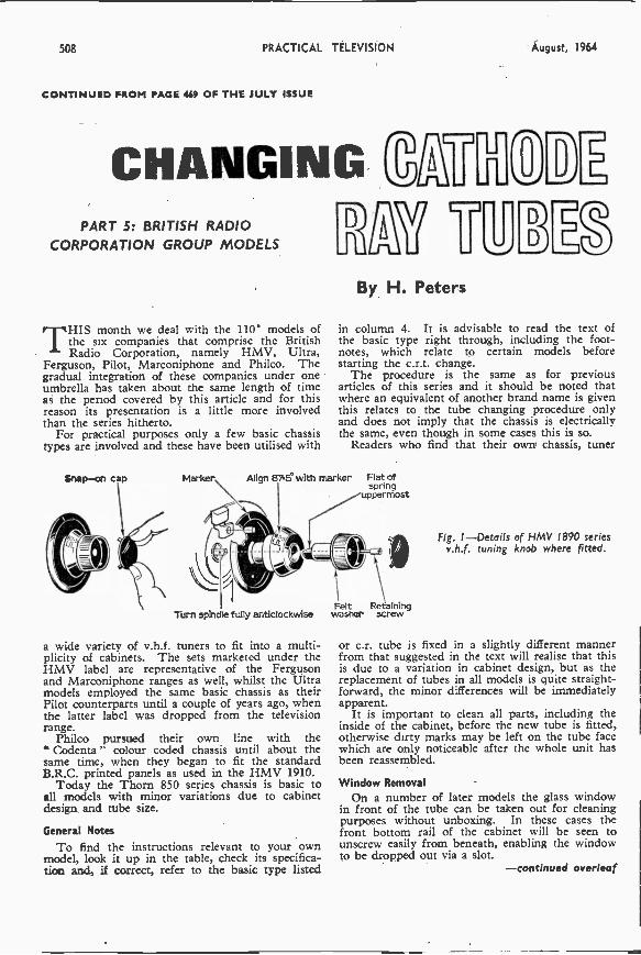
508 PRACTICAL TELEVISION August, 1964
CONTINUED FROM PAGE 40 OF THE JULY ISSUE
CHANGING ErPART 5: BRITISH RADIO
CORPORATION GROUP MODELS
THIS month we deal with the 110' models ofthe six companies that comprise the BritishRadio Corporation, namely HMV, Ultra,
Ferguson, Pilot, Marconiphone and Philco. Thegradual integration of these companies under oneumbrella has taken about the same length of timeas the period covered by this article and for thisreason its presentation is a little more involvedthan the series hitherto.
For practical purposes only a few basic chassistypes are involved and these have been utilised with
By H. Peters
:El
in column 4. It is advisable to read the text ofthe basic type right through, including the foot-notes, which relate to certain models beforestarting the c.r.t. change.
The procedure is the same as for previousarticles of this series and it should be noted thatwhere an equivalent of another brand name is giventhis relates to the tube changing procedure onlyand does not imply that the chassis is electricallythe same, even though in some cases this is so.
Readers who find that their own chassis, tuner
Marker Align 87.5° with marker Flat ofspring
uppermost
wastetTurn spindle fully anticlockwiseR screwnin g
a wide variety of v.h.f. tuners to fit into a multi-plicity of cabinets. The sets marketed under theHMV label are representative of the Fergusonand Marconiphone ranges as well, whilst the Ultramodels employed the same basic chassis as theirPilot counterparts until a couple of years ago, whenthe latter label was dropped from the televisionrange.
Philco pursued their own line with the" Codenta " colour coded chassis until about thesame time, when they began to fit the standardB.R.C. printed panels as used in the HMV 1910.
Today the Thorn 850 series chassis is basic toall models with minor variations due to cabinetdesign and tube size.
General Notes
To find the instructions relevant to your ownmodel, look it up in the table, check its specifica-tion and, if correct, refer to the basic type listed
Fig. I-Details of HMV 1890 seriesv.h.f. tuning knob where fitted.
or c.r. tube is fixed in a slightly different mannerfrom that suggested in the text will realise that thisis due to a variation in cabinet design, but as thereplacement of tubes in all models is quite straight-forward, the minor differences will be immediatelyapparent.
It is important to clean all parts, including theinside of the cabinet, before the new tube is fitted,otherwise dirty marks may be left on the tube facewhich are only noticeable after the whole unit hasbeen reassembled.
Window RemovalOn a number of later models the glass window
in front of the tube can be taken out for cleaningpurposes without unboxing. In these cases thefront bottom rail of the cabinet will be seen tounscrew easily from beneath, enabling the windowto be dropped out via a slot.
-continued overleaf
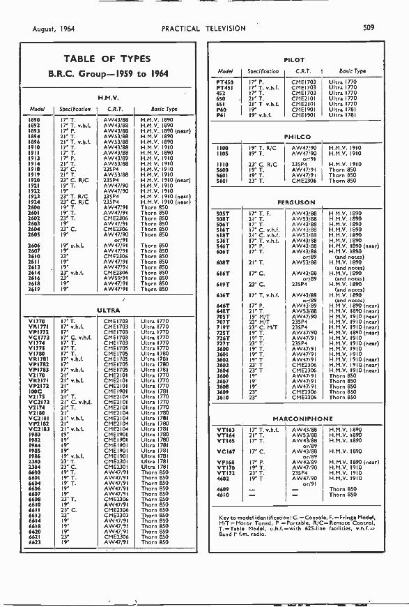
August, 1964 PRACTICAL TELEVISION 509
TABLE OF TYPES
B.R.C. Group -1959 to 1964
H.M.V.
Model Specification I C.R.T. Basic Type
1890 IT T. AW43/88 H.M.V. 18901892 17' T. v.h.f. AW43'88 H.M.V. 18901893 17' P. AW43/88 H.M.V. 1890 (near)1894 21' T. AW53,88 H.M.V 18901896 21" T. v.h.f. AW53/88 H.M.V. 18901910 IT T. AW43!88 H.M.V.19101911 IT T. AW43188 H.M.V. 18901913 17' P. AW43,139 H.M.V. 19101914 21" T. AW53,88 H.M.V. 19101918 2T C. 23SP4 H.M.V. 19101919 21' T. AW53/88 H.M.V. 19101920 23' C. R/C 23SP4 H M.V. 1910 (near)1921 19' T. AW47/90 H.M.V. 19101922 19" AW47/90 H.M.V. 19101923 23" T. R/C 23SP4 H.M.V. 1910 (near)1924 23" C. R/C 23SP4 H.M.V. 1910 (near)2600 19" T. AW47/91 Thorn 8502601 19" T. AW47/91 Thorn 8502602 23' T. CME2306 Thorn 8502603 19" AW47/91 Thorn 8502604 23" C. CME2306 Thorn 8502605 19" AW47/90
or/91Thorn 850
2606 19' u.h.f. AW47/91 Thorn 8502607 19' AW47/91 Thorn 8502610 23' CME2306 Thorn 8502611 19" AW47/91 Thorn 8502613 19' AW47/91 Thorn 8502614 23' v.h.f. CME2306 Thorn 8502616 23' AW59/9I Thorn 8502618 19" AW47/91 Thorn 8502619 19' AW47191 Thorn 850
ULTRA
VI770 ITT. CME1703 Ultra 1770VRI771 (7' v.h.f. CMEI703 Ultra 1770VP1772 17' CMEI703 Ultra 1770VC1773 17' C. v.h.f. CMEI703 Ultra 1770VI774 I' T. CMEI703 Ultra 1770VI775 17' T. CMEI705 Ultra 1770V1780 17' T. CME1705 Ultra 1780VR1781 17' v.h.f. CMEI705 Ultra 1781VP1782 17' CME1705 Ultra 1780VP1783 17' v.h.f. CME1705 Ultra 1781V2170 21' CME2I01 Ultra 1770VR2I71 21' v.h.f. CME2I01 Ultra 1770VP2172 21' CME2101 Ultra 1770100C 19' CMEI901 Ultra 1781V2175 21' T. CME2I04 Ultra 1770VC2173 21' C. v.h.f. CME2I01 Ultra 1770V2174 21' T. CME2I01 Ultra 1770V2180 21' CME2104 Ultra 1780VC2181 21' v.h.f. CME2I04 Ultra 1781VP2182 21' CME2104 Ultra 1780VC2183 21' v.h.f. CME2I04 Ultra 17811980 19' CME190 Ultra 17801982 19' CME190 Ultra 17801984 19' CMEI90 Ultra 17811985 19' CME190 Ultra 17811986 19" v.h.f. CMEI90 Ultra 17812380 23' T. CME230 Ultra 17812384 23" C. CME230 Ultra 17816600 19' T. AW47,9 Thorn 8506601 19" T. AW47,9 Thorn 8506604 19" T. AW4719 Thorn 8506606 19" AW47,9 Thorn 8506607 19" AW47,9 Thorn 8506608 23"T. CME2306 Thorn 8506610 19' AW47/9 Thorn 8506611 23" C. CME2306 Thorn 8506613 23' CME2303 Thorn 8506614 19" AW47 91 Thorn 8506618 19" AW47 91 Thorn 8506620 19" AW47 91 Thorn 8506621 23" CME2306 Thorn 8506623 19' AW47/91 Thorn 850
Model I Specification
PILOT
C.R.T. 1 Basic Type
PT450PT451452650651P60P6I
17' P.17' T. v.h.f.17' T.21' T.21' T v.h.f.19'19" v.h.f.
CMEI703CMEI703CMEI703CME2I01CME2I01CME1901CME1901
Ultra 1770Ultra 1770Ultra 1770Ultra 1770Ultra 1770Ultra 1781Ultra 1781
PHILCO
11001105
1110560056015601
19' T. R/C19' T.
23- C. R;C19" T.19' T.23' T.
AW47/90AW47'90
or,9123SP4AW47/91AW47/91CME2306
H.M.V. 1910H.M.V. 1910
H.M.V. 1910Thorn 850Thorn 850Thorn 850
FERGUSON
505T508T506T516T5187536T546T606T
6087
6I6T
619T
636T
646T648T705T707T719T72ST726T727T3600360136023603360436063607360836093610
17" T. F.21" T.17' T17" C. v.h.f.21" C. v.h.f.17' T. v.h.f.17' P.17' T.
21' T.
17' C.
23' C.
17' T. v.h.f.
17' P.21' T.19" M/T23" MIT23" C. M/T19' T.In T.23" T.19" T.19" T.19' T23" T23" T19"19'19"23"23'
AW43/88AW53/88AW43 88AW43/88AW53/88AW43/88AW43/88AW43/88
or/89AW53/88
AW43/88or/89
23SP4
AW43188or/89
AW43/89AW53/88AW4719023SP423SP4AW47/90AW47/9123SP4AW47/91AW47191AW47/91CME2306CME2306AW47,91AW47'9IAW47191CME2306CME2306
H M.V. 1890H.M.V. 1890H.M.V. 1890H.M.V. 1890
1
H.M.V. 1890H.M.V. 1890H.M.V. 1890 (near)H.M.V. 1890
(and notes)H.M.V. 1890
(and notes)H.M.V. 1890
(and notes)H.M.V. 1890
(and notes)H.M.V. 1890
notes)H.M.V. 1890 (near)H.M.V. 1890 (near)H.M.V. 1910 (near)H.M.V. 1910 (near)H.M.V. 1910 (near)H.M.V. 1890 (near)H.M.V. 1910H.M.V. 1910 (near)H.M.V. 1910H.M.V. 1910H.M.V. 1910 (near)H.M.V. 1910. (near)H.M.V. 1910 (near)Thorn 850Thorn 850Thorn 850Thorn 850Thorn 850
MARCONIPHONE
VT163VTI64VTI65
VCI67
VPI68VT170VTI724602
46094610
17' T. v.h.f.21' T.IT T.
17' C.
17' P.19' T.23" T.19' T
--
AW43188AW53/88AW43188
or/89AW43/88
or/89AW43/89AW47 9023SP4AW47/90
or/91--
H.M.V. 1890H.M.V. 1890H.M.V. 1890
H.M.V. 1890
H.M.V. 1890 (near)H.M.V. 1910H.M.V. 1910H.M.V. 1910
Thorn 850Thorn 850
Key to model identification: C. =Console, F.= Fringe Model.M,T= Motor Tuned, P =Portable, R/C= Remote Control,T.=Table Model, u.h.f.=with 625 -line facilities, v.h.f.=Band II f.m. radio.
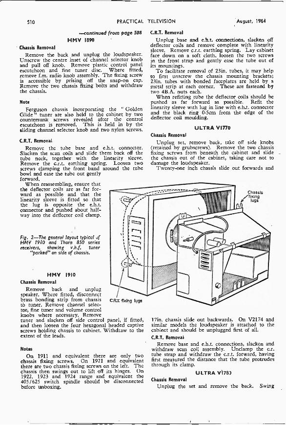
510 PRACTICAL TELEVISION August, 1964
-continued from page 508HMV 1890
Chassis Removal
Remove the back and unplug the loudspeaker.Unscrew the centre inset of channel selector knoband pull off knob. Remove plastic control panelescutcheon and fine tuner disc. Where fitted,remove f.m. radio knob assembly. The fixing screwis accessible by prising off the snap -on cap.Remove the two chassis fixing bolts and withdrawthe chassis.
Note
Ferguson chassis incorporating the GoldenGlide " tuner are also held to the cabinet by twocountersunk screws revealed after the controlescutcheon is removed. This is held in by thesliding channel selector knob and two nylon screws.
C.R.T. Removal
Remove the tube base and e.h.t. connector.Slacken the scan coils and slide them back off thetube neck, together with the linearity sleeve.Remove the c.r.t. earthing spring. Loosen twoscrews clamping the front band around the tubebowl and ease the tube out gentlyforward.
When reassembling, ensure thatthe deflector coils are as far for-ward as possible and that thelinearity sleeve is fitted so thatthe lug is opposite the e.h.t.connector and pushed about half-way into the deflector coil clamp.
Fig. 2-The general layout typical ofHMV 1910 and Thorn 850 seriesreceivers, showing v.h.f. tuner
"parked" on side of chassis.
HMV 1910Chassis Removal
Remove back and unplugspeaker. Where fitted, disconnectbrass bonding strip from chassisto tuner. Remove channel selec-tor, fine tuner and volume controlknobs where necessary. Removetuner and slacken off side control panel, if fitted,and then loosen the four hexagonal headed captivescrews holding chassis to cabinet. Withdraw to theextent of the leads.
C.R.T. fixing lugs
NotesOn 1911 and equivalent there are only two
chassis fixing screws. On 1921 and equivalentthere are two chassis fixing screws on the left. Thechassis then swings out to lift off its hinges. On1922, 1923 and 1924 range and equivalent the405/625 switch spindle should be disconnectedbefore unboxing.
C.R.T. Removal
Unplug base and e.h.t. connections, slacken offdeflector coils and remove complete with linearitysleeve. Remove c.r.t. earthing spring. Lay cabinetface down on a soft cloth, loosen the two screwsin the front strap and gently ease the tube out ofits mountings.
To facilitate removal of 23in. tubes, it may helpto first unscrew the chassis mounting brackets;23in. tubes with bonded faceplates are held by ametal strip at each corner. These are fastened bytwo 4B.A. nuts each.
When refitting tube the deflector coils should bepushed as far forward as possible. Refit thelinearity sleeve with lug in line with e.h.t. connectorand the black ring 0.5cm from the edge of thedeflector coil moulding.
ULTRA VinoChassis Removal
Unplug set, remove back, take off side knobs(retained by grubscrews). Remove the two chassisfixing screws from beneath the cabinet and slidethe chassis out of the cabinet, taking care not todamage the loudspeaker.
Twenty-one inch chassis slide out forwards and
Chassisfixing
IG lugs
17in. chassis slide out backwards. On V2174 andsimilar models the loudspeaker is attached to thecabinet and should be unplugged first of all.C.R.T. Removal
Remove base and e.h.t. connections, slacken andwithdraw scan coil assembly. Unclamp the c.r.tube strap and withdraw the c.r.t. forward, havingfirst measured the distance that the tube protrudesthrough its clamp.
ULTRA V178)Chassis Removal
Unplug the set and remove the back. Swing
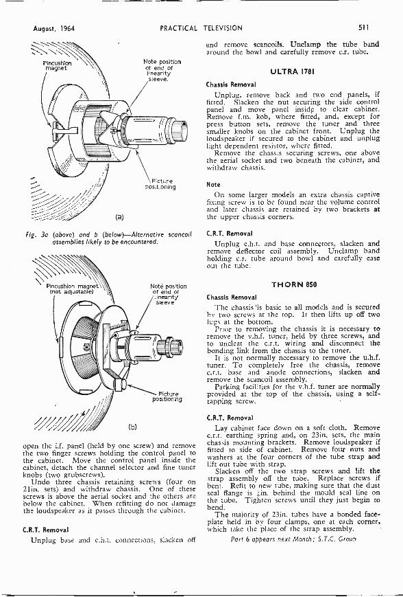
August, 1964 PRACTICAL TELEVISION 511
Pincushionmagnet
(a)
Note positionof end oflinearitysleeve.
Picturepositioning
Fig. 3a (above) and b (below)-Alternative scancoilassemblies likely to be encountered.
Pincushion magnet(not adjustable)
(b)
Note positionof end oflinearitysleeve
Picturepositioning
open the i.f. panel (held by one screw) and removethe two finger screws holding the control panel tothe cabinet. Move the control panel inside thecabinet, detach the channel selector and fine tunerknobs (two grubscrews).
Undo three chassis retaining screws (four on21in. sets) and withdraw chassis. One of thesescrews is above the aerial socket and the others arebelow the cabinet. When refitting do not damagethe loudspeaker as it passes through the cabinet.
C.R.T. Removal
Unplug base and e.h.t. connections, slacken off
and remove scancoils. Unclamp the tube bandaround the bowl and carefully remove c.r. tube.
ULTRA 1781
Chassis Removal
Unplug, remove back and two end panels, iffitted. Slacken the nut securing the side controlpanel and move panel insidp to clear cabinet.Remove f.m. kob, where fitted, and, except forpress button sets, remove the tuner and threesmaller knobs on the cabinet front. Unplug theloudspeaker if secured to the cabinet and unpluglight dependent resistor, where fitted.
Remove the chassis securing screws, one abovethe aerial socket and two beneath the cabinet, andwithdraw chassis.
Note
On some larger models an extra chassis captivefixing screw is to be found near the volume controland later chassis are retained by two brackets atthe upper chassis corners.
C.R.T. Removal
Unplug e.h.t. and base connectors, slacken andremove deflector coil assembly. Unclamp bandholding c.r. tube around bowl and carefully easeout the tube.
THORN 850
Chassis Removal
The chassis 'is basic to all models and is securedby two screws at the top. It then lifts up off twolugs at the bottom.
Prior to removing the chassis it is necessary toremove the v.h.f. tuner, held by three screws, andto uncleat the c.r.t. wiring and disconnect thebonding link from the chassis to the tuner.
It is not normally necessary to remove the u.h.f.tuner. To completely free the chassis, removec.r.t. base and anode connections, slacken andremove the scancoil assembly.
Parking facilities for the v.h.f. tuner are normallyprovided at the top of the chassis, using a self -tapping screw.
C.R.T. Removai
Lay cabinet face down on a soft cloth. Removec.r.t. earthing spring and, on 23in. sets, the mainchassis mounting brackets. Remove loudspeaker iffitted to side of cabinet. Remove four nuts andwashers at the four corners of the tube strap andlift out tube with strap.
Slacken off the two strap screws and lift thestrap assembly off the tube. Replace screws ifbent. Refit to new tube, making sure that the dustseal flange is kin. behind the mould seal line onthe tube. Tighten screws until they just begin tobend.
The majority of 23in. tubes have a bonded face-plate held in by four clamps, one at each corner,which take the place of the strap assembly.
Part 6 appears next Month; S.T.C. Grout'
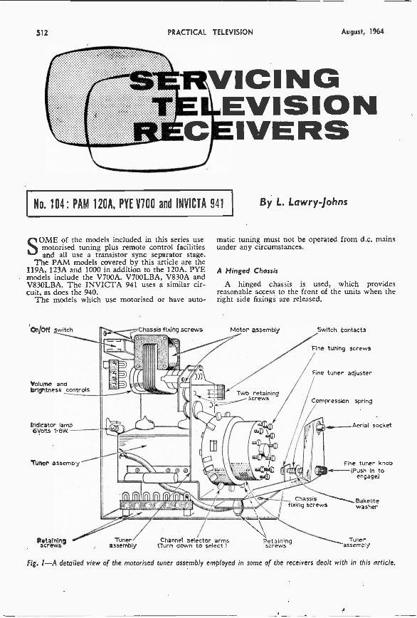
512 PRACTICAL TELEVISION August, 1964
VICINGEVISIONIVERS
No. 104: PAM 120A, PYE V100 and INVICTA 941
SOME of the models included in this series usemotorised tuning plus remote control facilitiesand all use a transistor sync separator stage.
The PAM models covered by this article are the119A, 123A and 1000 in addition to the 120A. PYEmodels include the V700A. V700LBA, V830A andV830LBA. The INVICTA 941 uses a similar cir-cuit, as does the 940.
The models which use motorised or have auto-
cnjoff Switch
Volume andbrightness controls
Indicator lamp6Volts 1.8W.
Tuner assembly
Retainingscrews
-----Chassis fixing screws
Tunerassembly (Turn down to select.)
By L. Lawry Johns
matic tuning must not be operated from d.c. mainsunder any circumstances.
A Hinged Chassis
A hinged chassis is used, which providesreasonable access to the front of the units when theright side fixings are released.
Motor assembly Switch Contacts
Fine tuning screws
Fine tuner adjuster
Compression spring
Aerial socket
Chassisfixing screws
Fine tuner knob--(Push In to
engage)
Bakelitewasher
Channel selector arms Retaining Tunerscrews assembly
Fig. I-A detailed view of the motorised tuner assembly employed in some of the receivers dealt with in this article.
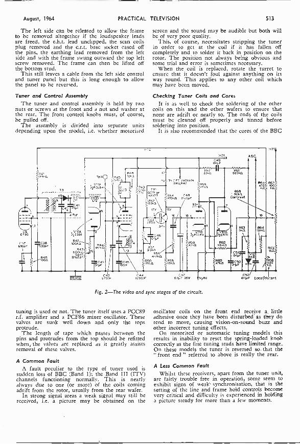
August, 1964 PRACTICAL TELEVISION 513
The left side can be released to allow the frameto be removed altogether if the loudspeaker leadsare freed, the e.h.t. lead unclipped, the scan coilsplug removed and the c.r.t. base socket eased offthe pins, the earthing lead removed from the leftside and with the frame swung outward the top leftscrew removed. The frame can then be lifted offthe bottom stud.
This still leaves a cable from the left side controland tuner panel but this is long enough to allowthe panel to be reversed.
Tuner and Control AssemblyThe tuner and control assembly is held by two
nuts or screws at the front and a nut and washer atthe rear. The front control knobs must, of course,be pulled off.
The assembly is divided into separate unitsdepending upon the model, i.e. whether motorised
screen and the sound may be audible but both willbe of very poor quality.
This, of course, necessitates stripping the tunerin order to get at the coil if it has fallen offcompletely and to solder it back in position on therotor. The position not always being obvious andsome trial and error is sometimes necessary.
When the coil is replaced, rotate the turret toensure that it doesn't foul against anything on itsway round. This applies to any other coil whichmay have been moved.
Checking Tuner Coils and CoresIt is as well to check the soldering of the other
coils on this and the other wafers to ensure thatnone are adrift or nearly so. The ends of the coilsmust be cleaned off properly and tinned beforesoldering into position.
It is also recommended that the cores of the BBC
3.10941k
73
V8E F80
C377pR 75 C3g1T6 P
1\--. R40
T:
V
C414573oF
.5 E691
042loOks1
R43500k0sppot
to Iter
Tp3
VILAi.%
a
R4447k.0.
12
C42TlyF
C43270pF
HT2
045
_.04913 TR1
oc71 orV20417
8
3
T800FC45
4
14
C44
17V 15v
5220211111Ug
3.10
C460.11JF
0513.360
R564.7111
0503300.
1000 F
6 1
1041
930
hpvc11,4
tiir80
C490.1pF
11111.11
42%
062tsma
061560kfl
-^,1Co.'
R65Z R67
4;,3}.
19
C4750,,F 25V SyriC
Fig. 2-The video and sync stages of the circuit.
tuning is used or not. The tuner itself uses a PCC89r.f. amplifier and a PCF86 mixer oscillator. Thesevalves are sunk well down and only the topsprotrude.
The length of tape which passes between thepins and protrudes from the top should be refittedwhen, the valves are replaced as it greatly assistsremoval of these valves.
A Common FaultA fault peculiar to the type of tuner used is
sudden loss of BBC (Band 1); the Band III (ITV)channels functioning normally. This is nearlyalways due to one (or more) of the coils comingadrift from the rotor, usually from the rear wafer.
In strong signal areas a weak signal may still bereceived, i.e. a picture may be obtained on the
R63Pan
gT:r=C50
olpF
06410140
160
66
sC52
0.1.9F LOcalidistant
oscillator coils on the front end receive a littleadhesive once they have been disturbed as they dotend to move, causing vision -on -sound buzz andother incorrect tuning effects.
On motorised or automatic tuning models thisresults in inability to reset the spring -loaded knobcorrectly as the fine tuning studs have limited range.On these models the tuner is reversed so. that the" front end " referred to above is really the rear.
A Less Common FaultWhilst these receivers, apart from the tuner unit,
are fairly trouble free in operation, some seem toexhibit signs of weak synchronisation, that is thesetting of the line and frame hold controls becomevery critical and difficulty is experienced in holdinga picture steady for more than a few moments.
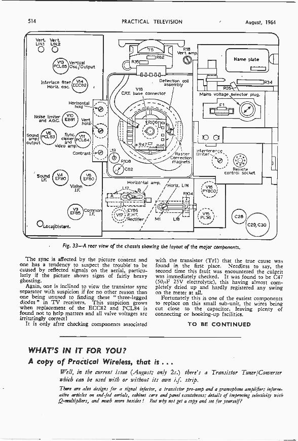
514 PRACTICAL TELEVISION August, 1964
Vert VertLIN.1 LIN2
VerticalOsc./ Output
Interlace filterHoriz. osc.
Noise limiterand A.G.C.
ampoutput
Sound
V14ECC82
Horizontalhold
V10El391
Syncclipper
andvideo amp.
Vert.hold:
Contrast
Vision
OLocaVDistant.
O R82'C35==1
R18Vert. amp
-41641041-0--
Deflection coilassembly
V18CRT base connector
R106n\pDo
o F3471=' ..R46L19
/Rasterorrectonmagnets
Horizontal amp. /Horiz, LIN
R104
A
EY86 L_1,E.H.T.
M1
JAZ B
r -
Remotecontrol socket
VI3EFBO
CommonI.F.
Name plate
Mains voltage selector plug.
171-
I
interferencelimiter
V16\PY800,!
V15PL36 '
Fig. 33-A rear v ew of the chassis showing the layout of the major components.
The sync is affected by the picture content andone has a tendency to suspect the trouble to becaused by reflected signals on the aerial, particu-larly if the picture shows signs of fairly heavyghosting.
Again, one is inclined to view the transistor syncseparator with suspicion if for no other reason thanone being unused to finding these " three-leggeddiodes" in TV receivers. This suspicion growswhen replacement of the ECC82 and PCL84 isfound not to help matters and all valve voltages areirritatingly correct!
It is only after checking components associated
R34
C29, C30
with the transistor (Tr1) that the true cause wasfound in the first place. Needless to say, thesecond time this fault was encountered the culpritwas immediately checked. It was found to be C47(50/LF 25V electrolytic), this having almost com-pletely dried up and hardly registered any swingon the meter at all.
Fortunately this is one of the easiest componentsto replace on this small sub -unit, the wires beingcut close to the capacitor, leaving plenty ofconnecting or hooking -up facilities.
TO BE CONTINUED
WHAT'S IN IT FOR YOU?A copy of Practical Wireless, that is ...
!Fell, in the current issue (August; only 2s.) there's a Transistor Tuner/Converterwhich can be used with or without its own i.f. strip.There are also designs for a signal injector, a transistor pre -amp and a gramophone amplifier; inform-ative articles on end fed aerials, cabinet care and panel escutcheons; details of improving selectivity with,Q -multipliers, and much more besides ! But why not get a copy and see for yourself?

August, 1964 PRACTICAL TELEVISION 515
PAY -TV using coaxial relayA NEW SYSTEM BY TELEFUSION
rr ELEFUSION, through its manufacturingI subsidiary Teleng Ltd., has demonstrated a
new relay system of multiple transmission bycoaxial cable. This is incorporated in the Pay -TVpilot scheme being conducted by the company aspart of the experimental period of Pay -TV which isbeing undertaken by various companies in differentparts of the country.
The Teleng system is to be used in the SouthLondon scheme (Wimbledon, Merton, Morden andMitcham areas) and is the outcome of four years'investigations into various methods of distributingmore and more TV programmes, including Pay -TVand colour TV, over a single cable.
This system is already in use in Belgium (at
channellBBC1London cony.
to ch 13
pay TVch A
III lchrrAel 9
I Londontge'criri v4,
channel 33BBC 2 toocnhm G
channel 10I TA Dover
cony.to ch 2
Wrotham pre-ampFM Radio
operating signals required for Pay -TV.BBC -1 was received on channel 1, distributed
and received on channel 13; BBC -2 on channel 33converted to channel " G "; ITA (London) onchannel 9 converted to channel 4; ITA (Dover) onchannel 10 converted to channel 2. The three f.m.programmes from Wrotham were received, dis-tributed and received in Band II.
Apart from the four off -air (" free ") TV pro-grammes (which required no coins to be insertedin the coin box) there were three Pay -TV pro-grammes which were distributed on three specialsub -channels and all converted by the coin box forreception on channel 5. Although these wereshown as "stills", in actual commercial operation
pay TVchB
pay TV programmech C information
Tpay TVmixer
mixer
Distribution systemequivalent to7 miles of line
Standard 405/625TV Receiver
Telemetersubscriber
unit
0 0 0payTV-
filter
Fig. I-A representation of the Telefusion system of Pay -TVas set up during a recent demonstration.
Liege, Verviers and Namur) to distribute five TVprogrammes of four different standards and up to30 f.m. radio programmes-using Teleng equip-ment-on one coaxial cable. A town in Switzer-land is now being wired for the system andnegotiations are taking place with other Europeancountries.
At a recent demonstration to the technical Press,equipment was set up to simulate a multipleprogramme system operating over seven miles ofcoaxial cable, and although this distance is repre-sentative of a large practical system it is not alimitation and the company considers that a 20 -milecable run would be feasible.
In the demonstration seven TV and three f.m.radio channels were being distributed on the singlecable, plus special information and coin -box
these could be any form of presentation suitedto Pay -TV such as films. sporting events, etc.
Finally provision was made for a special Pay -TVchannel, the information being passed to thereceiver on channel 5, the coin box accepting thesetting pulses as transmitted. In the demonstrationit was shown how, by selection of this channel atthe telemeter subscriber unit, the user receivesinformation on the programmes to be offered onthe Pay -TV channels with details of their contentand the price and time of the programmes.
The user at all times has the option of viewingthe special programmes (which must be paid for)or simply tuning to any of the " free " servicesprovided, including the normal BBC and ITAtelevision programmes and f.m. radio programmes.
-continued on page 519
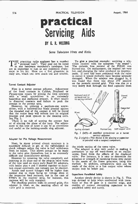
516 PRACTICAL TELEVISION August, 1964
practicalServicing AidsBY G. R. WILDING
Some Television Hints and Kinks
THE practising radio engineer has a numberof " personal tools". They may not be listedin any hardware merchant's catalogue, but
are as important to him as any expensive imple-ment in his kit. Here are a few gimmicks indaily use, which can save much toil and trouble.
Turret Contact Adjuster
First is a turret contact adjuster. Adjustmentof the fixed contacts in Cyldon, Brayhead orPlessey -type tuners by prising the loop upwardswith a small screwdriver is an extremelyhazardous and inefficient process. It often resultsin distorted contacts and failure to peak thecontact in the correct spot.
However, by utilising a medium -size screw-driver, with a hollowed -out blade pressed againstthe rounded end of the contact it will be foundthat the entire loop will reform into its originalposition and peak spot-on to the rotating coils.See Fig. 1.
There is no risk of scoring the contact faceor of altering the plane of the loop. For adjust-ment to this type of tuner it can be as convenientand useful as the knitting -needle slug adjuster.
Adaptor for Pin Voltage Measurement
Next, in many printed circuit receivers it isextremely difficult to get at the valveholders tocheck voltages unless the valve is half withdrawnfrom its socket. This allows contact to be madeto the valve pins themselves, but is an extremelydifficult and unsatisfactory method.
However by removing the valve completely andinserting in its place one of the plug-in valve basesof the type used on many early Band III adaptors,with heater pins 4 and 5 shorted together to main-tain circuit continuity, pin voltages can be checked.
Anode and screen voltages will be higher thannormal due to there being no voltage drop inthe respective feed resistors, but in the case ofEF80's in the receiver strip, for instance, thisincrease will be only marginal.
For checking positive leaks to control grids, thisadaptor is ideal, as the masking effect of thevalve grid is removed.
To give a practical example: servicing a tele-vision receiver with the symptom "no sound".The cathode bias resistor of the PCL82 wasburned -out. On replacement, the resistor ran veryhot, and changing the valve produced no improve-ment. If tests had been continued with the valvein circuit it would probably have become seriouslydamaged. When the adaptor was plugged in, itwas found that there was about 25V positiveon the pentode control grid. This was due to avery heavy leak through the feed capacitor from
Hollowed end ofscrewdriver tofit spring contact
Rivet
Spring contact
rt.
/iPointed tag Stiff copper wire
Dowelod
Capacitor
Fig. I (left)-A modified screwdriver as a turretcontact adjuster.
Fig. 2 (right)-This device is for placing a capacitorin parallel with a suspect component.
the triode section of the same valve.The adaptor is also very useful in making it
convenient to tap off wave -forms to an oscillo-scope, freed from the effects of the displacedvalve. For instance, it is easy to determine thepresence or strength of incoming frame sync pulsesto the anode of the frame generator, using thismethod. In addition, comparative tests can bemade of the drive to a line output valve whoseoutput may be below par.
Capacitors Paralleled Safely
Another simple device is shown in Fig. 2. Thiswas devised to help when confronted with insta-bility or loss of gain in a receiver stage, andenables all suspect decoupling capacitors to beparalleled safely and surely.
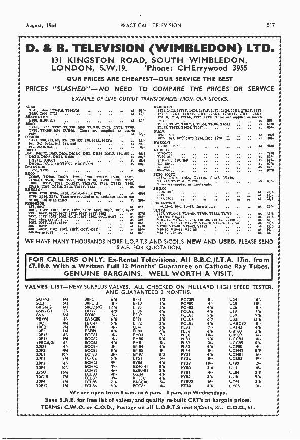
August, 1964 PRACTICAL TELEVISION 517
D. & B. TELEVISION (WIMBLEDON) LTD.131 KINGSTON ROAD, SOUTH WIMBLEDON,LONDON, S.W.I9. 'Phone: CHErrywood 3955
OUR PRICES ARE CHEAPEST -OUR SERVICE THE BEST
PRICES "SLASHED"- NO NEED TO COMPARE THE PRICES OR SERVICEEXAMPLE OF LINE OUTPUT TRANSFORMERS FROM OUR STOCKS.
ALBA FERRANTIT641, 1644 T724117d, T744FM at 62/- 1412, 14T3, 14136', 1414, 1414F, 1415, 14T6, 1783,1783F, 17T3,T655, T909, T717 at 50/- 171'36', 17K4. 17840', 1785, 17884, 17884F, 1780. 17885,
BEETHOVEN 178E6, 17T4, 17T4F, 1715, 17T6. These are supplied as InsertsB106, B109, 208 at 60/ - 30/-
BUSH 1'1001, T1002, T1002/1, T1004, T1005, T1011 at 48/6TVA TV56, TV57 1I.1058, M59, TU059, TV62, TV63, TV68, T1012, T1023, T1024, T1027 at 86/TV67. TU088, M69, TU069. These are supplied as Insert. R.M.V.nnly at 311/- 1865, 1869 at 48/6COMIOR 1870, 1871, 1872. 1873, 1874, 1875, 1878 at 20/ -1117A, 990, 951,953, 934 935, 937, 938. 930A, 939FA . 0940. 942, 942A, 943, 944, 946 at
52/-52/6 MARCONI60/- VT155, VT156 .. at 48/6
DECCAD511, DM2/C, DM8, D114, D114/C, D515, DM14 DM17, 444, 555 at 68/6
MURPHY17240-250 at 78/6
DM35, DM45, DhL55, DM56 .. .. 91 58/5 V270-280 -
at 82/-D51210, 1)51021 _ at 72/6 V310-320, 930, 350 : at 82/-
DR19, 8110TV777. . at 80/- 410-410 at 97/8DYNATRON 170-5411 at 82/-
48/6 650-759. at 97/6"CO PETO SCOTTTons, T11109, T109/1, T221, T231, 1231F, T249, T0267. 14RA, TRIO, 178A, TV1418, T1418, T1419,1'0467/1. T283, T184, 1293, T811, T310, TOE316, '1'326. 1'327. TV17IO, 1111719,1171710 at 30/ -T930, T530F, T331. 1E0337. 11M11171, T344, T344F. 1'348. These are supplied as Inserts only.12480', T356, TC312, T313, T313F, 11335 at
EMERSON8700, 16701, E704, E708, Port -0 -Rama E707 at8709. 8710, 8711. These are supplied as an exchange wait or canbe supplied es an Insert
48/6
48/6
30/-
PRILCO1000, 101010191021, 1053
atatat
72/676/-72/6
FERGUSON REGENTONE46T, 4541 _ at 66/- T14, 10-6, 10-4, 10-17. Inserts only .. at 80/ -103T, 106T 11.3T, 155T, 1491, 143T, 148T, 11901, 991T, 992T ULTRA993T, 994T, 995T, 990T, 997T, 998T, 988T, 989T _ at 27/6 1453, VP14-53, 1115-60, V1750, V1753, V1760 at 42/6203T, 204T, 2051, 2061, 214T, 2351, 236T, 2441, 2461, _ at 64/- VR1751, V 81761 at 42/6Used when available at305T, 507T, 315T, 317T _ _ at
301-65/-
WR1762, V1763, V1764, V21-50, 1121452, V21601117-70, V17-71, 1117-72, 5'17-73, V17-74, 1117-75
atat
60/ -62/6
3061, 9081' at 48/8 171780, V17-81, 1717-82, V1783 at 42/64061, 408T, 416T, 456.T, 43811, 405T, 407T _ _ at 50/- V19-80, 1719-84, V19-85 at 801 -WO aeries 604T 661- V23 -30-V23-84 at 66/ -
WE HAVE MANY THOUSANDS MORE L.O.P.T.S AND S/COILS NEW AND USED. PLEASE SENDS.A.E. FOR QUOTATION.
FOR CALLERS ONLY. Ex -Rental Televisions. All B.B.C./I.T.A. I7in. from87.10.0. With a Written Full 12 Months' Guarantee on Cathode Ray Tubes.
GENUINE BARGAINS. WELL WORTH A VISIT.
VALVES LIST -NEW SURPLUS VALVES. ALL CHECKED ON MULLARD HIGH SPEED TESTER,AND GUARANTEED 3 MONTHS.
5U4/G 5/6 30PL I 6/6 EF4 I 613 PCC89 51- U24 101-5Z3 5/3 30PL I 3 61- EF80 1/6 PCF80 4,- 1125 101-6BG6/G 613 50CD6/G 12/6 EF85 316 PCF82 416 U26 81-65147GT 31- DH77 4/9 EF86 616 PCL82 4/6 UI91 7166V6 516 DY86 5,- EF89 7/6 PCL83 5/6 U301 9169BW6 61. EABC80 616 EF9 I 216 PCL84 6/9 U801 1216
OC I 416 EBC4 I 5/6 EF92 316 PCL85 616 UABC80 5 1-,0C2 716 EBF80 V- EL41 616 PL33 7r- UAF42 4/6OF I 1/6 EBF89 4/6 EL84 616 PL36 6/6 UBF80 5/60P13 61- ECC8 1 41- EM34 71- PL38 101- UBF89 61-01,14 916 ECC82 41- EM80 516 PL8 I 5/6 UCC84 41-98G6/G 6,- ECC83 4/6 EMS! 51- PL82 31- UCC8S 516
20D1 41- ECC84 51- EM84 416 PL83 4/6 UCF80 41-20F2 416 ECC8S 5/6 EM85 51- PL84 5/- UCH42 51920L1 101- ECF80 51- EM87 513 PY31 416 UCH8 1 61-20P1 716 ECF82 516 EY5 1 51- PY32 81- UCL83 91-20P3 6/- ECH2I 91- EY86 416 PY33 10/. UF80 21-20P4 10/- ECH42 7r- EZ40-41 5/6 PY80 316 UL4I 41-27SU30C15
15/6716
ECH811601. 801601,82
61-4,-V-
EZ80-81G Z34KT33C
516614/6
PYBIPY82
41-3/6
UL84UU8
3/9916
30P4 7/6 ECL83 7/6 PABC80 5r. PY800 61- UY4 I 31630P I 2 5/6 ECL86 8/6 PCC84 41- PZ30 416 UY85 31 -
We are open from 9 a.m. to 6 p.m. -1 p.m. on Wednesdays.Send S.A.E. for free list of valves, and quality re -built CRT's at bargain prices.
TERMS: C.W.O. or C.O.D., Postage on all L.O.P.T.S and S/Coils, V-. C.O.D., 51-.
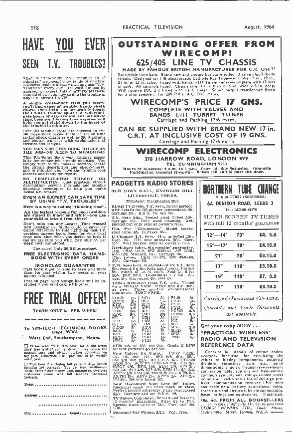
518 PRACTICAL TELEVISION August, 1964
HAVE YOU EVER
SEEN T.V. TROUBLES?
That is "Pin -Point T.V. Troubles in 10minutes" we mean! Thousands of PracticalTelevision readers already own and use "T.V.Troubles" every day. Designed for use byamateur or expert, this amazingly practicalmanual shows you how to find the trouble inany T.V. circuit FAST!A simple cross-index tells you whereyou'll and cause of trouble, handy checkcharts then help you accurately locatethe EXACT trouble spot! You will elimi-nate hours of aggravation, cut out wastetime, because this new Coyne system willhelp you get right down to the heart ofthe trouble in minutes.Over 700 trouble spots are covered In the340 cross-index pages. Included are 50 timesaving check charts as well as 290 diagramsand photos together with explanations ofcircuits and designs.YOU CAN USE THIS BOOK RIGHT ONTHE JOB -NO NEED TO MEMORISE!This Pin -Point Book was designed espec-ially for on-the-job trouble shooting. Yousimply turn to the indexed section, locatethe circuit description and check -charts,and in minutes you have the trouble spotlocated and ready for repair.NO COMPLICATED THEORY ORMATHEMATICS. Just practical circuitdescription, service methods and troubleshooting techniques to help you makefaster t.v. repairs.EVEN AN EXPERT CAN SAVE TIME
BY USING "T.V. TROUBLES"Here is a way to reduce "thinking time".All the logical reasons for each problemare stated In black and white -you useyour skill to take it from there!Don't miss out any longer. Time wastednow locating t.v. faults could be saved byquick reference to this lightning fast t.v.problem answer book. Send for your trialcopy now, then' when you decide to keep it(as we are sure you will), pay only 5/- perweek until completed.
The price? Only 38/6 plus postage.FREE ELECTRONIC DATA HAND-
BOOK WITH EVERY ORDER
IRONCLAD GUARANTEEThis book must be able to earn you morethan its cost within two weeks or yourmoney refunded!Free 88 page oscilloscope book will be in-cluded if you send cash with order.
FREE TRIAL OFFER!TERMS ONLY 5/- PER WEEK!
To SIM-TECH TECHNICAL BOOKSDept. WX6.
West End, Southampton, Hants.
ID Deane send "T.V. Troubles" for a full sevendays' free trial. If not delighted I may return themanual, post paid without further obligation onmy part. Otherwise I will pay cash of 6/- weeklyuntil paid.
Tick here if enclosing full price of 41/- (whichIncludes 1/6 postage). You get free OscilloscopeBook. Same 7 -day money back guarantee. Overseascustomers please sent full amount (includingIreland).
Name
Adam=
City County
OUTSTANDING OFFER FROMWIRECOMP!
625/405 LINE TV CHASSISMADE BY FAMOUS BRITISH MANUFACTURER FOR U.K. USE)'
Switchable time base. Brand new and unused but store soiled 13 valve plus 2 diodecircuit. Designed for 110 electrostatic Cathode Ray Tube -will take 17 in., 19 in.,21 in. or 23 in. tube. Fitted with bands 1/III Turret tuner -complete with 12 setsof coils. All controls fitted. Chassis size: 18 in. high x IS in. wide x 5 in. deep.Will receive BBC 2 if fitted with u.h.f. Tuner. Sound output transformer fittedfor 3 ohm speaker. For 200 250 v. A.C. D.C. mains.
WIRECOMP'S PRICE 17 GNS.COMPLETE WITH VALVES ANDBANDS I/III TURRET TUNER
Carriage and Packing 12/6 extra.
CAN BE SUPPLIED WITH BRAND NEW 17 in.C.R.T. AT INCLUSIVE COST OF 19 GNS.
Carriage and Packing 17/6 extra
WIRECOMP ELECTRONICS378 HARROW ROAD, LONDON W9
TEL CUNNINGHAM 9530Hours of business: 9 a.m. to 6 p.m. Open all day Saturday. Opposite
Paddington General Hospital. B uses 1811 and 86 pass the door.
PADGETTS RADIO STORESOLD TOWN HALL, KNOWLER HILL
LIVERSEDGE, YORKS.Telephone: Cleckheaton 2866
BUSH TV53 14in. T.V. Sets, tested perfect:with details for 625 picture conversions, £8,carriage 10/-. B.R.S. By' rail 15/-.T.V. Sets ten. Tested good Tubes 50/-,carriage 10/-. Only want cleaning. Wellpacked but only sent at owner's risk.17in. Pye "Continental" Model tested,good tube, £5. Carriage 10/-.13 Channel T.V. Sets. 141n. untested 30/-.Carr. 10/-. 171n. sets untested, 50/-. Carr.10/-. Well packed, sent at owner's risk.Reclaimed tubes, Six months' guarantee.141n. CRM 141-2, MW 36/24-44. AW 36/21:also 12in. Mullard, 171-. Carriage 7/6.17in. tubes. CRM 171-172, MW 43-64-69,30/-. Carriage 7/6.P.M. Speakers, Guaranteed ex T.V. setsbin. round, 6 x 4in. Rola and Plessey, Philips5in. round. all at 3/- each. Post 2/-, 6 for20/-, post paid. Goodman. 7 x 4in.. 5/-.post 2/-. 81n. round. 6/-, post 2/-.Valves Removed from T.V. sets. Testedon a Mullard Valve Tester and are 100%as new. Three months' unconditionalguarantee. POST FREE.ECL80 2/- 20D1 3/- PL38 8/-ECC82 3/- 20L1 /- PY80 5/-EY51 2/6 20P3 5/- PY81 4/-EBF80 4/6 20P4 8/6 PY82 5/-EB91 9d. 20P1 5/- PCF80 4/6EF91 9t1. U801 816 PCC84 4166F1 1/- U281 5/- B36 41-eF14 5/- 0232 5/- N37 5/-6E15 5/- U329 5/- 6U4 51-6LD20 5/- KT3G 5/- 6P25 3/610C2 5,- PL81 51- 6IT25 5/-1031 PL82 5/- 6P23 3/-10P13 5/- PL83 5/- P280 5/ -10P14 5/- PL33 4/-EF80 1/6, or 10/- per doz. Grade II En°for test purposes 4/- per doz.New Valves Ex Units. POST FREE,6K7 1/8, doz. 12/-. 6K8 2/8. doz. 22/-.6V6 2/13. doz. 22/-. 807 U.S.A. 6/-. PP3/250(PX4) 5/-. AC2PEN (PENA4) 9/6. 5U4 3/-.6V6GT 4/8. EF91 1/9. EL91 1/9. 6F6 2/ .5Z4 5/8. 5Y3 4/6. 6X5 4/6. EF50 1/-. 61- doz.ARP12 1/8. 6 for 5/8, box of 50 19/-. KT66ARTP2 2/-. ART9 21-. APP37 2/-. AR8 2/-.IT4 2/-. 954 new boxed 1/3.New Resunned Slim Line 90'' Tubes.(Seconds) small pin head mark on glass.Perfect picture otherwise. Fully guaranteed39/-. Carriage and ins. B.R.S. 7/6.TV Tubes. Completely Rebuilt and Refaced.12 months' guarantee. Sizes up to 17in.Special trade price of 75/-. Carr. and ins.17/6.Personal Ear Phone, 2/11. Post Free.
NORTHERN TUBE CHANGEB & Ni TUBES (NORTHERN)
6A DENISON ROAD, LEEDS 3Tel.: LEEDS 24576
SUPER SCREEN TV TUBESwith full 12 months' guarantee
12°-14' 70° £4. 5.0
15°-17' 70° 24.15.0
21' 70° £6.15.0
17" 110° 96.10.0
19" 110° U. 0.0
21" 110° 28.10.0
Carriage & Insurance 10/- extra.
Quantity and Trade Discountsare available.
Get your copy NOW ..."PRACTICAL WIRELESS"RADIO AND TELEVISIONREFERENCE DATA
Contains full details of colour codes;everyday formulae, for calculating thevalues of biasing components, potentialdividers, resonance, gain, etc.; aerialdimensions; a quick frequency -wavelengthconversion table; stations and frequencies;common symbols and abbreviations; noteson amateur radio and a list of call -sign pre-fixes; communication receiver I.F.s; wireand cable data: battery equivalents; valve,transistors and picture tube pin connections,bases, ratings and equivalents. Illustrated.10s. 6d. FROM ALL BOOKSELLERS... or, in case of difficulty I Is. 6d. by pos: fromGEORGE NEWNES LTD., Tower House,Southampton Stree', London, W.C.2.
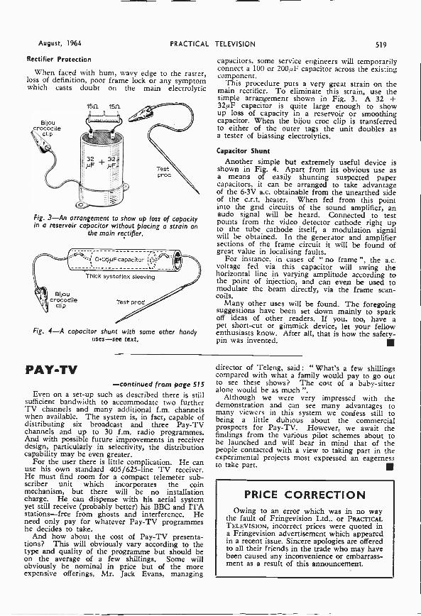
August, 1964
Rectifier Protection
PRACTICAL
When faced with hum, wavy edge to the raster,loss of definition, poor frame lock or any symptomwhich casts doubt on the main electrolytic
1511 1511
Bijoucrocodile
clip
Testprod
Fig. 3-An arrangement to show up loss of capacityin a reservoir capacitor without placing a strain on
the main rectifier.
Bijoucrocodile
clip
0.0}.iF capacitor I:1;P
Thick systoflex sleeving
Test prod
Fig. 4-A capacitor shunt with some other handyuses-see text.
PAY -TV
TELEVISION 519
capacitors, some service engineers will temporarilyconnect a 100 or 200/AF capacitor across the existingcomponent.
This procedure puts a very great strain on themain rectifier. To eliminate this strain, use thesimple arrangement shown in Fig. 3. A 32 +32/AF capacitor is quite large enough to showup loss of capacity in a reservoir or smoothingcapacitor. When the bijou croc clip is transferredto either of the outer tags the unit doubles asa tester of biassing electrolytics.
Capacitor Shunt
Another simple but extremely useful device isshown in Fig. 4. Apart from its obvious use asa means of easily shunting suspected papercapacitors, it can be arranged to take advantageof the 6.3V a.c. obtainable from the unearthed sideof the c.r.t. heater. When fed from this pointinto the grid circuits of the sound amplifier, anaudo signal will be heard. Connected to testpoints from the video detector cathode right upto the tube cathode itself, a modulation signalwill be obtained. In the generator and amplifiersections of the frame circuit it will be found ofgreat value in localising faults.
For instance. in cases of " no frame ", the a.c.voltage fed via this capacitor will swing thehorizontal line in varying amplitude according tothe point of injection, and can even be used tomodulate the beam directly, via the frame scan -coils.
Many other uses will be found. The foregoingsuggestions have been set down mainly to sparkoff ideas of other readers. If you, too, have apet short-cut or gimmick device, let your fellowenthusiasts know. After all, that is how the safety-pin was invented.
-continued from page 515Even on a set-up such as described there is still
sufficient bandwidth to accommodate two furtherTV channels and many additional f.m. channelswhen available. The system is, in fact, capable ofdistributing six broadcast and three Pay -TVchannels and up to 30 f.m. radio programmes.And with possible future improvements in receiverdesign, particularly in selectivity, the distributioncapability may be even greater.
For the user there is little complication. He canuse his own standard 405/625 -line TV receiver.He must find room for a compact telemeter sub-scriber unit which incorporates the coinmechanism, but there will be no installationcharge. He can dispense with his aerial systemyet still receive (probably better) his BBC and ITAstations-free from ghosts and interference. Heneed only pay for whatever Pay -TV programmeshe decides to take.
And how about the cost of Pay -TV presenta-tions? This will obviously vary according to thetype and quality of the programme but should beon the average of a few shillings. Some willobviously be nominal in price but of the moreexpensive offerings, Mr. Jack Evans, managing
director of Teleng, said : " What's a few shillingscompared with what a family would pay to go outto see these shows? The cost of a baby-sitteralone would be as much ".
Although we were very impressed with thedemonstration and can see many advantages tomany viewers in this system we confess still tobeing a little dubious about the commercialprospects for Pay -TV. ,However, we await thefindings from the various pilot schemes about tobe launched and will bear in mind that of thepeople contacted with a view to taking part in theexperimental projects most expressed an eagernessto take part.
PRICE CORRECTIONOwing to an error which was in no way
the fault of Fringevision Ltd.. or PRACTICALTELEVISION, incorrect prices were quoted ina Fringevision advertisement which appearedin a recent issue. Sincere apologies are offeredto all their friends in the trade who may havebeen caused any inconvenience or embarrassment as a result of this announcement.
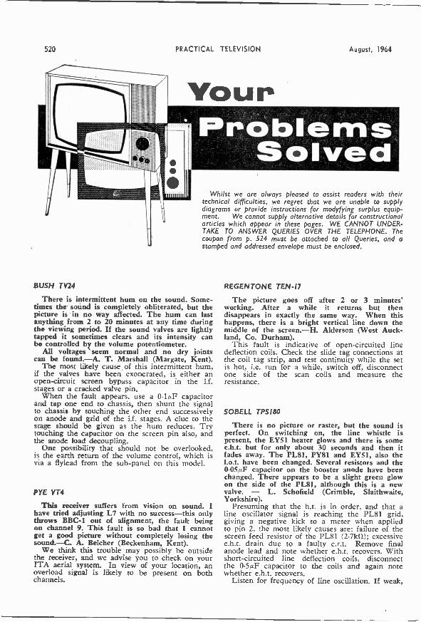
520
BUSH TV24
PRACTICAL TELEVISION August, 1964
Whilst we are always pleased to assist readers with theirtechnical difficulties, we regret that we are unable to supplydiagrams or provide instructions for modyfying surplus equip-ment. We cannot supply alternative details for constructionalarticles which appear in these pages. WE CANNOT UNDER-TAKE TO ANSWER QUERIES OVER THE TELEPHONE. Thecoupon from p. 524 must be attached to all Queries, and astamped and addressed envelope must be enclosed.
There is intermittent hum on the sound. Some-times the sound is completely obliterated, but thepicture is in no way affected. The hum can lastanything from 2 to 20 minutes at any time duringthe viewing period. If the sound valves are lightlytapped it sometimes clears and its intensity canbe controlled by the volume potentiometer.
All voltages seem normal and no dry jointscan be found.-A. T. Marshall (Margate, Kent).
The most likely cause of this intermittent hum,if the valves have been exonerated, is either anopen -circuit screen bypass capacitor in the i.f.stages or a cracked valve pin.
When the fault appears, use a 0.1,,F capacitorand tap one end to chassis, then shunt the signalto chassis by touching the other end successivelyon anode and grid of the i.f. stages. A clue to thestage should be given as the hum reduces. Trytouching the capacitor on the screen pin also, andthe anode load decoupling.
One possibility that should not be overlooked,is the earth return of the volume control, which isvia a flylead from the sub -panel on this model.
PYE VT4
This receiver suffers from vision on sound. Ihave tried adjusting L7 with no success-this onlythrows BBC -1 out of alignment, the fault beingon channel 9. This fault is so bad that I cannotget a good picture without completely losing thesound.-C. A. Belcher (Beckenham, Kent).
We think this trouble may possibly be outsidethe receiver, and we advise you to check on yourITA aerial system. In view of your location, anoverload signal is likely to be present on bothchannels.
REGENTONE TEN -17
The picture goes off after 2 or 3 minutes'working. After a while it returns but thendisappears in exactly the same way. When thishappens, there is a bright vertical line down themiddle of the screen.-H. Alderson (West Auck-land, Co. Durham).
This fault is indicative of open -circuited linedeflection coils. Check the slide tag connections atthe coil tag strip, and test continuity while the setis hot, i.e. run for a while, switch off, disconnectone side of the scan coils and measure theresistance.
SOBELL TPS180
There is no picture or raster, but the sound isperfect. On switching on, the line whistle ispresent, the EY51 heater glows and there is somee.h.t. but for only about 30 seconds and then itfades away. The PL8I, PY81 and EY51, also thel.o.t. have been changed. Several resistors and the0.05pF capacitor on the booster anode have beenchanged. There appears to be a slight green glowon the side of the PL81, although this is a newvalve. - L. Schofield (Crimble, Slaithwaite,Yorkshire).
Presuming that the h.t. is in order, and that aline oscillator signal is reaching the PL81 grid,giving a negative kick to a meter when appliedto pin 2, the most likely causes are: failure of thescreen feed resistor of the PL81 (2.7kfl); excessivee.h.t. drain due to a faulty c.r.t. Remove finalanode lead and note whether e.h.t. recovers. Withshort-circuited line deflection coils, disconnectthe 0.5,uF capacitor to the coils and again notewhether e.h.t. recovers.
Listen for frequency of line oscillation. If weak,
August, 1964 PRACTICAL TELEVISION
VALVES SAME DAY SERVICENEW ! TESTED ! GUARANTEED !
SETS 1115, 185, 114, :134, 314. DA191, DF91, DK91, DL92, DL94, Setof 4 for 15/-. DAF96, 111,96, DR96. DL96: 4 for 114/6.
I A7DT 7/6 ON 3/9 DC(190 6/9 ECL80 6/8 PCF82 6/917281 8/611/5 616 6V6UT 6/8 D933 8/- ECL82 7/- PCF84 5/- U282 11/91H5GT 8/5 6X4 819 11991 2/6 ECL86 9/- PCF86 8/. U291 9/-1N5GT 5/- 6X6GT 5/8 1)996 61- 59311 819 P091306 14/- U801 15/91113 41111 7117 8/- 11/176 8/6 5941 8/6 PCL82 6/6 U4030 6/9183 8/9 701 7/9 DH77 8/8 EF42 4/4 PCL83 9/. UABC80 5/9114 2/8 706 7/6 DK32 8/- EF80 4/8 PCL84 7/6 111.942 8/-105 6/- 7117 5/9 1)5191 4/9 119815 5/- 100L83 8/6 UBC41 8/33A) 6/9 747 14/8 DK92 8/8 EF86 6/8 PEN4DD UBC81 7/331/4 4/10 7Y4 5/- DK96 6/6 EF89 4/8 19/8 UBF80 8/-334 4/9 1002 12/8 DL33 7/3 E1091 2/9 PENA4 6/6 6/93V4 5/6 12ATO 4/8 DL35 8/9 EF92 8/6 9E584 17/6 UC92 6/65040 4/6 12AT7 8/9 01.82 9/- EL38 12/6 9E5383 9/6 UCC84
-6 Y3GT 12AU7 4/9 D1.92 4/9 51.41 7/5 9126 8/9 00082 1/ 96Z40 71- 12A17 4/9 DL94 6/6 EL84 4/9 PLR 7/- UCF80 9/661.13 11/. 12K7GT 4/8 DL96 6/- 2E34 7/11 PL82 9/6 UCH42 7/6tugs 6/. 12K8GT 8/9 &ABCS° 5/8 E/A80 6/9 91.83 5/- UCH81 8/66AT6 8/8 12Q70T 4 8 EA942 8/- EM81 7/9 PL84 5/9 UCL82 71e6BA8 II/. 1913060 6/9 EB41 4/- 58184 7/6 PX4 9/- 1701.88 8/3613E6 5/8 3094 12/6 EBB/. 2/- 11587 8/- PX25 7/9 17941 7/36/906/3 12/6 2096 14/9 EBC38 5/- EY51 61- PY32 9/. 11942 4/96806 6/- 26L6GT 4 9 EB041 7/8 EY84 7/- PY33 9/. 6/3OBJ6 5/6 26154GT10 6 EBC81 5/9 EYS6 6/6 PY80 5/8 01,41 7l -6E1 5/6 30L16 a 6 EBF80 6/- EZ40 5/8 PY81 6/9 UL44 1.6/-6513 4/. 30PL1 111. EBF83 7/9 2341 7/6 PY82 4/9 01.46 8/66914 9/- 30PL13 9/. EBF89 6/- EZ80 4/- PY83 6/9111184 6/86E15 6/6 3091114 11 3 ECC40 7/6 EZ61 4/6 PY88 7/9 111.17 8/661170 1/6 35A3 14 - ECC81 8/9 KT32 5/. 1117 15/-11118 10/66K7GT 4/- 3116GT 6/8 ECM 4/9 KT66 12/8 101)4 719 UY21 7/961180 4/8 3324014/11 ECC83 7/- KTW61 4/9 111210 9/6 UY41 4/96K80T 7/9 13KU 8 6 E0084 6/3 51014 5/- TH233 5/9 UY86 6/-6L60 6/9 AZ31- 6 6 ECM 8/8 3X40 8/6 U22 4/9 V941 4/96L18 7/6113R 46 ECF80 613 N18 4/105722 8/6 W76 3/66P38 9/6 001136 19/3 20F83 6/6 PC95 9/- 1120 10/- W77 2/66Q70 4/9 CL33 9 8 ECF86 10/9 PC97 7/6 U47 8/6 W729 16/66Q7GT 7/9 CYO 12/6 EPH36 6/- P0084 6/61150 6/- X8114 19/6611701 9/6 DAC32 8 8 11C1142 8/8 PC086 6/91152 4/6 X109 17/6691.701 DAF91 8/9 ECH81 6/- PCC89 8/- U78 8/9 Y63 4/968570T 8/9 DA996 6/- P0980 5/9 U191 8/6 366 7/.
READERS RADIO24 COLBERG PLACE, STAMFORD HILL LONDON N.I6
STA.Post ad. per valve extra. Any Parcel Insured against Damage In Transit 6d. extra
Any 0.0.D. Parcel 4/3 extra.
YOUR CAREER in
TELEVISION?Big opportunities and big money await the qualifiedmain in every held of Electronics today -both in theU.K. and throughout the world. We offer the finesthome study training for all subjects in radio, television,etc., especially for the CITY & GUILDS EXAMS. (Tech-nicians' Certificates); the Grad. Brit. I.R.E. Exam.; theRADIO AMATEURS' LICENCE, P.M.G. Certificates; theR.T.E.B. Servicing Certificates; etc. Also courses inTelevision; Transistors; Radar; Computers; Servo-mechanisms; Mathematics and Practical TransistorRadio course with equipment. We have OVER 20 YEARS'experience in teaching radio subjects and an unbrokenrecord of exam. successes. We are the only privatelyrun British home study college specialising in electronicsubtects only. Fullest details will be gladly sent withoutany obligation.
To: BRITISH NATIONAL RADIO SCHOOL, Dept. 2RADIO HOUSE, READING, Berks.
Please send FREE BROCHURE to:
NAME Block
ADDRESS Caps.
Please8.64
BRITISH NATIONAL RADIO SCHOOL
INN
521'
Wirt/ Ltd
ELCOT LANEMARLBOROUGH WILTS
TELEPHONE: 657 and 658
WIDE BANDUHF AERIALS
for BBC2 nowand ITV 2
FIVE STAR QUALITY AERIALS* Anodised elements for protection. * Modernplastic moulding techniques used for convectedreflector and parasitic elements giving longer,life. * Staggered spaced elements for maximumperformance with all channel band width.* Multi -element reflector giving high back tofront ratio. * Maximum efficiency of matchingby using laboratory developed collector plate -without any other matching device.
Model
OF/H3
OF/H5
OF/H7
OF/H10
UF/HI2
UF/HI4
UF/HI8
OF/H22
Description
3 -ELEMENT, HEAD ONLYwith CLAMP
5 -ELEMENT, HEAD ONLYwith CLAMP
7 -ELEMENT, HEAD ONLYwith CLAMP
10 -ELEMENT, HEAD ONLYwith CLAMP
I2 -ELEMENT, HEAD ONLYwith CLAMP
I4 -ELEMENT, HEAD ONLYwith CLAMP
I8 -ELEMENT, HEAD ONLYwith CLAMP
22 -ELEMENT, HEAD ONLYwith CLAMP
GainDB
7.0
8.25
10-5
12.5
13.5
15.0
16.25
17.0
11/FRatio
DB
18-0
19.5
24-5
260
28-0
294
30'0
314
RetailPrice
31/6
36/6
41/.
471-
51/-
55/-
70/-
85/ -
PLEASE _ STATE LARGE OR SMALL CLAMP REQUIRED,
522 PRACTICAL TELEVISION August, 1964
LAWSONBRITAIN'S CATHODE RAYTUBE SPECIALISTS
LAWSON TUBE WITH NEW SILVERACTIVATED SCREEN AND
100- "PlICRO FINE' ALUMINISED
75
LIGHTOUTPUT
SO
25SIMILAR TUBE REBUILT
OR RECUNNED BUT NOTRESCREENED
BRILLIANCE CONTROL
C.O.D. or C.W.O.12" .. £4.10.014" .. £5.10.015"-17" £5.19.019"-21" £7.15.0
Carr, and Ins. 7'6.10/Refundable- if old tubereturned.
12 MONTHS' FULL RE-PLACEMENT GUAR-ANTEE AND FITTINGINSTRUCTIONS WITHEVERY TUBE.
OUR PRODUCTSLAW SON TUBES are the Productsof the Commonwealth's largest cathoderay tube manufacturers. All tubesare designed to give very muchimproved performance in all TVs(especially older sets). Their new highresolution electron guns by Mullard, Mazda, GEC, Cossor, etc.(suitable for 625 or 405), give crisp needle sharp definition andfocus. Brilliant new silver activated screens ensure much improvedbrightness and contrast. Exclusive "Micro Fine" controlledthickness aluminising gives 50% more light output. Siliconvacuum pumping plus depth formed cathodes ensure very long life.
Each tube is 100% BRAND NEW (glass excepted), andguaranteed an exact replacement for the original.
OUR SERVICETHE LAWSON CRT organisation is specially designed togive a world wide CRT service, from the largest stocks of alltypes of CRTs in Britain. We can supply the EXACT tube yourequire by return, it matters not if you live at No. 10, the OuterHebrides or far away New Zealand, or if you want 1 tube or1,000 our long experience, vast stocks and special CRT containersensure rapid and safe delivery anywhere.
LAWSON TUBES, 2 PEACHFIELD CLOSE, MALVERN, WORCS. Malvern 2100
FREE_ THE LATEST EDITION OF ENGINEERING OPPORTUNITIESOUS1719/NEERS
Have you sent for your copy?ENGINEERING OPPORTUNITIESis a highly informative 156 -page guide tothe best paid engineering posts. It tellsyou how you can quickly prepare at homefor a recognised engineering qualificationand outlines a wonderful range of modernHome Study Courses in all branches ofEngineering. This unique book also givesfull details of the Practical Radio & Elec-tronics Courses, administered by ourSpecialist Electronics Training Division-the B.I.E.T. School of Electronics, explainsthe benefits of our Employment Dept. andshows you how to qualify for five yearspromotion in one year.
We definitely Guarantee"NO PASS - NO FEE"Whatever your age or experience, you cannot affordto miss reading this famous book. If you areearning less than £25 a week, send for yourcopy of "ENGINEERING OPPORTUNITIES"today-FREE.
WHICH IS YOURPET SUBJECT ?
Mechanical Eng..Electrical Eng.,
Civil Engineering,Radio Engineering,
Automobile Eng.,Aeronautical Eng.,Production Eng.,
Building, Plastics,Oraughtsmanshis.
Television. etc.
GET SOMELETTERS AFTERYOUR NAME!
A.M.I.C.E.A.M.I.Prod.E.
A.M.I.M.I.A.I.O.B.
B.Sc.A.M.Brit.I.R.E.City & Guilds
Gen. Cert. of EducationEtc., etc.
paikeTicht. INCLUDING
Eta TOOLS!EQUIPM The specialist
Ironic, Division of,Baits
Coursesco.!, rr saecst ircoarl baengdi rien-
Radio, XV., Electronics, Etc.. real laboratoyou a
ry train-A.M.Brit.I.R.E. City Guilds
Radio Amateur? Exam. ipmv:Lh.R.T.E.B. Certificate Ask for details,P.M.G. CertificatePractical Radio
Radio A Television Servicing B.I.E.T.Practical Electronics
Electronics Engineering SCHOOL OFAutomation
ELECTRONICS
POST COUPON NOW
ADDRESS
BRITISH INSTITUTE OF ENGINEERINGTECHNOLOGY
'(Dept. SE/20), 29 Wright's Lane, London, W.8
Please send me your FREE 156.pageENGINEERING OPPORTUNITIES"
(Write if you prefer not to cut page)
NAME
SUBJECT OR EXAMTHAT INTERESTS ME
111
THE B.I.E.T. IS THE LEADING ORGANISATION OF ITS KIND IN THE WORLD
August, 1964 PRACTICAL
check the 10pF pulse capacitor, part of the feed-back circuit from the line output transformer tothe ECC82 grid. Do not overlook the possibilityof the ECC82 itself being weak. The PL81 mustbe driven in this circuit, and the green glowdescribed could be a charge at the G3/G2 spacedue to under -driving.
ULTRA V2I -50A
Once the set has warmed up the picture shrinks,leaving gaps of between fin. and 2in. all round.-S. G. Vickery (Tidworth, Hampshire).
The most probable cause of this fault is failureof the metal rectifier.
You will find it advantageous (and probablycheaper) to replace this component with one of thelater silicon diode rectifiers, such as the MullardBY100, or the Rec 51, or a pair of matchedSTC14's.
Remember when fitting these components that,because of their improved efficiency it is necessaryto include a wirewound resistor (5W); a com-ponent of between 21 and 331-1 being suitable forthis receiver.
EKCO TC208
The picture died away and I suspected loss ofe.h.t. Putting a screwdriver to the e.h.t. terminalon the tube produced no spark at all. Uponswitching on a few hours later, the sound wasperfect but Vii (U25) was glowing blue and asmall spark appeared on the anode accompaniedby a rumbling on the sound.-T. H. Gardiner(Glenfield, Nr. Leicester).
This fault could be caused by a defective U.25e.h.t. rectifier, but if the line output transformerappears burnt, we advise you to replace this aswell, and also check for a shorting line linearitychoke.
FURGUSON 406TThe screen lights up but there is no picture,
and the sound is very faint.-C. Truckle (Ames-bury, Wiltshire).
This symptom is usually caused by a failure ofthe PCC84 valve. This r.f. amplifier is in theFireball tuner unit, the right-hand one, viewedfrom the spindle side.
Note that some later models of this set used aFireball unit with a PCC89 instead of a PCC84.These are not interchangeable.
GEC BT320
After 4 or 5 minutes of viewing, the picturefades, starts to roll, and the sound almost fades.away. There is no sign of any burning or over-heating, and after the set has been left to cooldown and then once again switched on, the pic-ture is perfect, but for a short period only.-L.Harris (Ealing, London, W.5).
The fault seems to originate in the signal -handling circuits, the rolling and fading beingincidental faults caused by lack of signal.
Check the B349 valve if the fading does not alsoinclude fading of the raster when the brightness isturned up, or decrease in picture size.
TELEVISION 523
MURPHY V510
Sound and picture are both normal when firstswitched on, but once the set has warmed up thesound becomes somewhat distorted. The screendecoupler on the first sound i.f. amplifier (C68,0-001µF) was replaced with no apparent improve-ment.-M. M. Richards (Beauly, Inverness-shire).
The symptoms described suggest a faulty 30P12sound output valve or a leaky 0.01µF couplerfrom the driver anode (30FL1). In our circuit,this capacitor is designated C94.
BUSH TV.%
When first switched on, the sound and the pic-ture are perfect, but after a few minutes pictureshrinkage takes place, leaving a Ifin. margin allround. This condition persists for the remainder ofthe time that the set is on.
The picture width control is adjusted to maxi-mum, and changing the PY82's makes nodifference. The line hold adjustment will shiftthe picture bodily in a horizontal plane.-I. Law(Cape!, Surrey).
Shrinkage all round usually indicates that theh.t. has dropped, but this is a progressive fault,not one that would recur in exactly the same wayevery time.
It seems however, that there is a fault in theline output stage, causing lack of width and lackof boost voltage-the frame oscillator being fedfrom the boost line, this resulting in the marginat top and bottom. Check first the PY81, then thePL81, and the screen feed resistor (3.3k.0) of thelatter.
If there is edge distortion of the reduced raster,check the electrolytic capacitors.
Incidentally, there are two width controls, theswitch, and a tapped tag on the transformer, theupper tag being maximum.
EKCOVISION T380
Either the height begins by being extended withthe picture becoming normal after five minutes orso, or the picture starts normal and then shrinkssuddenly after warming up.-J. G. Proundler(Middlesbrough, Yorkshire).
This fault is due either to the 30PL13 valve onthe frame timebase panel on top of the chassis, orto failure of the 500,4F + 2,4F electrolytic capa-citor.
PYE RTL
When this receiver is switched on the picturefails to fill the screen at the bottom by about 2in.After about two minutes' running this gap disap-pears. The linearity control that adjusts the bottomframe makes the picture shudder at the bottom.The PCL82 has been replaced.
The horizontal lock is also critical, and I havereplaced the EY86, PY81, PL81 and have alsocleaned and adjusted the horizontal control butwith no change.-J. D. Corish (Liverpool, 21). .
The usual cause of your frame trouble, apartfrom a faulty PCL82, is a faulty 250/iF bias

524 PRACTICAL
decoupling capacitor in its pentode cathodecircuit. Critical line hold suggests a faulty PCF80sync separator valve, just to the left of the PCL82.
EKCO T33IThis set has a lack of bandwidth, and up
through the middle there is an a:flaunt of foldoverwhen the line is locked. However when the lineis not locked the lack of width is not apparent.Both the width and line linearity coils have beenchanged but this has- made no difference. I havealso changed the line oscillator valve (30FL1) andthe line output valve (30P4).-P. Perkins (Bath,Somerset).
We suspect a faulty boost capacitor. This is a0.5µF connected between h.t. positive and thejunction of the line linearity choke and the lineoutput transformer. It is located below the chassisnear the line output transformer.
BUSH TV24CI am unable to get the picture in the centre of
the screen on this old 12in. model. The picturestays constantly to the left of the tube so thatabout lin. of the left side of the picture is lost
TELEVISIDN August, 1964
" round the corner " leaving about lin. of blankscreen on the right-hand side of the tube.-R. M.Wood (Hatfield, Hertfordshire).
The shift control consists of a copper ringaround ,the neck of the tube, and within the magnetassembly bracket. This is brought out to an angledarm, which may be moved up and down for lateralmovement of the raster. The "fixed" end of thisring assembly is secured with a 4BA nut. Makesure that this is in place, and that the scancoilsare pushed fully forward on the neck of the tube.
As a final cure, you could turn the tube through180 degrees-it is not unknown for an eccentricgun to cause this kind of baffling fault.
GEC BT8149
The picture is reduced to half size and isroughly triangular in shape; the apex to the top.Definition is sharp to the centre but out -of -focusat the edges. The sound is normal except for aslight hum.-F. Stone (Timperley, Cheshire).
We would advise you to check the main 100µF400µF electrolytic capacitor. The 100µF
section is likely to be o.c. if the voltage is low.Check the deflection coils if necessary.
TEST CASEEach month we provide an interesting case of television servicing
to exercise your ingenuity. These are not trick questions, but are basedon actual practical faults.
A modern receiver featuring printed circuitpanels, exhibited extreme cramping at the topof the picture and elongation at the bottom.
All the chief components in the frame timebasecircuit, including valves, transformers, resistors andcapacitors were tested by substitution and found tobe in order.
During the course of testing, it was discoveredthat even with the frame output valve removed com-pletely (with the heater chain continuity maintainedby a resistor) a partial frame scan of an inch or soremained.
What was the most likely cause of this unusualfault and what steps should be taken to remedy thesymptom?
See next month's PRACTICAL TELEVISION for thesolution to this Test Case and for another problem.
SOLUTION TO TEST CASE 20(Page 476, last month)
Excessive frame amplitude can only be caused byan increase in frame drive to the frame amplifiervalve. Such drive increase could probably be caused
=21by a rise in h.t. voltage to the frame oscillator dueto a decrease in value of the anode feed resistor.Most modern frame oscillators are fed from theboosted h.t. line in the line amplifier circuits.
However, this could not be the case as it wasstated that the voltages checked normally againstthe manual. The valves were also in order. Theonly factor left, therefore, was an increase in framedrive signal from the oscillator to the amplifier,resulting from change in value of a component inthis signal feed circuit.
Subsequent testing of the components in this net-work revealed an increase in value of a capacitorforming a section of a capacitive potential -divider.This upset the ratio of the divider and caused a risein signal to the control grid of the amplifier valvewith a small degree of non -linearity at the top ofthe picture.
Ir
QUERIES COUPONThis coupon is available until August 21st, 1964, and mustaccompany all Queries sent in accordance with the noticeon page 520.
PRACTICAL TELEVISION, AUGUST 1964
Published on the 22nd of each month by GEORGE NEWNES. LIMITED Tower House, Southampton Street. London. W.C.Z and printedIn England by WATMOUGHS LIMITED, Idle. Bradford; and London. sole Agents for Australia and New Zealand: GORDON & GOTCH(Aisle). Ltd. South Africa and Rhodesia: CENTRAL NEWS AGENCY, LTD. East Africa: STATIONERY & OFFICE SUPPLIES LTD.
Subscription rate including postage for one year: To any part of the World tLe.O.

August, 1964 Practical Television Classified Advertisements 525
SALVAGED VALVES TESTED ONA MULLARD HIGH SPEED VALVE
TESTER
ACIF 2/61330 2/8B329 4/-DI 28068 2/18D77 416DAF91 4/-DD4 2/8131141 vsinnA etcDF91 4/-01177 4/-DK91 4/-ZA50 118BB34 1/8EB41 1/3BBC.93 2/6NBC41 4/-ECC88 2/6ECC34 2/6EC3261. 4/ -ECM 41-ECL80 4/-EPP) 1/8EF:s0 2/8Ent 11810T330 1/8KT61 2/6KTZ41 2/6L63 2/88308 4/-8329 4/-8339 41-N369 4/-8379 4/-P4t 2/6161 2/610084 6/-P0180 Id-PUL62 a/ -POLO 5/ -PESO 2/6PEN46 2/8PL83 4/-PL21 5/-PLE12 4/ -Puts 4/-P1,84 4/ -Pin 4/-PY81 4/-P230 2/86P41 1/3SP42 2/6SP81 1/8031 4/-U261 4/-0329 4/-0F42 218VP4 41-W77 2/6263 2/6266 2/8277 1/8290 1/82719 2/84TPB 2/6BALE 2/6SAW 1/8615W7 4/-6E3E6 2/6
EXAMPLESFULL CATALOGUE 9d.
VALVE HOLDERS
American Octal 5/- dos.Nova) , , 94. each
RESISTORSCard of OW Resistors, 72 valves
covering complete 10% range.24/- per card.
Full range of eeparate ReMitors,Condensers, etc.
VARIABLE CONDENSERS3.50pf conesntric trimmers dos.
SEC airs (SALVAGED)SPECIAL OFFER
121a, G.E.C. 7102 10/- ea.?enamel Callers Only.
83 Mc/e, 16 Mc/s, 10 MO INCRE-MENTAL OR TURRET TUNERSLESS VALVES. EX-RECE1VERS
12/6.We can often supply for theactual set you want the tuner toSt. But cannot guarantee whatchannels are fitted.
TRANSFORMERSCRT Boost Transformers,IV, 4V, 8V, 10V, 13V.State which required .. 12/8 ea.Heavy Duty Output Trans.formers. 8 ratios from 13 :1to 43 : 1 25/. ea.Miniature Output Trans... 3/9 ea.standanl Output Trans-former,, Multi -match 10/- ea.Transistor Driver: 1-1 CT 10/- ea.
3.6-1 CT 12/6 ea.Transistor Output: 8,5.1 CT 10/- ea.
9.2.1 CT 10/- ea.Microphone Transformers.ratio 66 :1.. .. 28/ -
LP. TRANSFORMERSStandard 4435 kola 12/6 per pairMidget 433 kchi 16/- Per pair
AUTO TRANSFORMERS67/6 s.
100WWOW
e27/8 ea.
TRANSISTORISED FAULTFINDER
606 4/. Enables faults to be located6136 4/- quickly. Consists of a two -aria 1/3 transistor, multi -vibrator in a box.
6238E13
2/61/3 Complete with battery. 12/0
6J7 2/661'23 2/661'28 2/6803 1/3906 2/810F1 4/-10P13 4/-10P14 2/812E117 4/-SOF2 4/- TRANSISTORS20P1 2/8 0016W 48/- 0072 SP20P9 4/- 0019 481- 0073 5i -20P5 41- 0028 26/- 01.:713 SPsaLs 2/8 0044 11/- 0078 9/-3001 5/- 0C46 10/- 0081 51-30015 6/- 0070 6/6 0062SOLI 5/- 0071 8/6 00170 311/6-301L1 4/.SOPL13 4/-32 2/6 TEEMS: or C.O.D.4423 8f8 .., Orders under 41. P. A P. 1/3.
2/8807 4/- '9' ()pep 110 11 p.m. most days.
3d. stamp for list or 9d. for full catalogueDept. PTA
CRYSTALSGENUINE MULLARD. Boxed
0A3 6/- 0A81 5/-0A70 OARS SP0A79 2/- 0A91 8/8
Arion TelevisionPleated Road, S.E.15 NEW X 7152
It ATES: 4/- per line or partthereof, average live words to line,minimum 2 lines. Box No. 1/- extra.Advertisement roust .be prepaidand addressed to AdvertisementManager, "Practical Television",Tower House, Southampton Street.London, W.C.X.
SETS & COMPONENTSUHF /025/ BBC -2. All your require-ments. Complete Conversion Kitscomprising tuner, 625 1.f. panel, t.b.panel, fittings, circuit, etc. Or tunersand panels separately. Send for freelist. Also latest Pye (Labgear) Tran-sistorised Booster Units. Sensationalincrease in reception. U.H.F. E5 / 5/.,BBC/ITA A3/151.., p/p 2/6. MANORSUPPLIES, 64 Golders Manor Drive.London, NW11. Callers, 589b HighRoad (near Granville Road), NorthFlnchley, N12. HD. 9118 (SPE 4032evg I.
EKCO-FERRANTI L.O.T.sU25 Type
PERSPEX HOUSINGS to suit above
161- each. Post Free.
Quantity Prices: 6 at L4; 12 at a 5s.BOYLAN ELECTRONICS
Church St., Warrenpoint, N. Ireland
" HEATHKITS " can now be seen inLondon and purchased on H.P. FreeBrochure. DIRECT TV REPLACE-MENTS LTD., 120 Hamilton Road,West Norwood, SE27. GIPsy Hill 6168.
TUBES-FAMOUS MAKES!MW43/69, AW43/80, MW36/24, AW43/88,etc. Fully screened, aluminised, 100% new(except glass). Mostly E4.15s. (1216 cge.).LISTS. One Year's Guarantee Card.We do NOT sell regunned only tubes.
NEW VALVES, 12 months guarantee!BYI00, EY5I, EY86, PY8I, PY800-IPLO!, PCF80, PCL82, 30CI, PC86-8 ...PY800, BYI00, ECH8I 57/. doz. mixed.
FREE lists of valves, tubes, transformers.Return of post service.
P. BEARMAN, 43 Leicester Road,New Barnet, Herts. Tel.: BAR 1934
THE FINEST and cheapest mail-orderservice in Britain now supplies every-th.ng E.ectronlcalectrical. S.A.E.brings details of genuine bargainoffers. HANMEY. 112 Bagel= St..Hereford.
SPECIAL VALVEOFFER
BOXED B.V.A.
2-PCC89 1 60/-2-PCF862-30C 15 .) The Lot, P. & P. paid
Send for lists to:
DIAMOND (MAIL ORDER)PRODUCTS
(Dept. PT) MBC/OIALondon, W.C.2.
TELEVISION TUBE SHOPWe have the following
Unused, Guaranteed Tubesin Stock now
AW36-20, 21AW36-80AW43-80, 88AW43-89AW47-90, 91AW53-80AW53-88CI4BM, FMCI7BM, FM, HMCI7LM, PM, SMC2I HM, SM, TMCME1402CMEI702, 1703CME1705CME2I01CRM93CRM 124CRMI41,2,3,4CRMI52, 153CRMI71, 2,3CRM21 1, 212MW6-2MW22-I6MW31-I6, 74MW36-24, 44MW4I-IMW43-64, 69MW43-80MW53-20MW53-80T901AI4KP4A, 14IK171K, 172K, 173K6901A720IA, 7203A7204A740IA7405A
LS. 2.6LS. 7.6L6. 7.6L6.12.60.10.0L7.12.6L7.17.6LS. 5.0L6. 7.6(6.12.6L7.17.6L5. 7.6L6.12.6O. 7.0L8. 7.6L4. 2.6(4.12.6L5. 7.6L5.17.6L6. 7.6L7.17.6L6.17.6L4. 2.6L4. 2.6L5. 2.6L6.12.6L6. 7.6£6. 7.617.12.6(7.12.6L6.12.6L5. 2.6L6. 7.6L6.12.6L5. 2.6L5. 5.0L6. 7.6L6.I6.2
All tubes tested before despatchand guaranteed for 12 months.
CARRIAGE 716, via B.R.S. or12'6 via passenger train.
TERMS £2 down (plus carriage)balance 41 per month.Midland Stockists:-
Amateur Electronics Co.240 Lichfield Road, Aston,Birmingham.
Shop Soiled Tubes (unused)(Subject to Availability)
I 4in. CRM141, 2 6716. Others 5716I 7in. CRM171, MW43-69, 43-64
751.. Plus Carriage. Guaranteedfor 12 months.
TORISION TUBE SHOP48 BATTERSEA BRIDGE ROADLONDON S.W.! I. BAT 6859South of the Bridge. Open Sats.
until 4 p.m.
526 Practical Television Classified Advertisements August, 1964
SETS & COMPONENTS(continued)
" BUILD your own Slimline TV. Well-known manufacturer's surplus stock.19tn. chassis with v.h.f. radio,£41151-. 28 Rushmere Road. Bos-combe, Bournemouth, Hants."GUARANTEED REPLACEMENT LineOutput Transformers. Emerson, allmodels 50/, Ekco 50/, Ferguson 80/-,Pye 52/8, p. and p. 3/6, over £5 postfree. Trade supplied. Three-day re-wind service. S.A.E. for enquiries. AllL.O.P.T.s in stock. All types of wavewinding carried out. WHITWORTHTV SERVICE, 32a All Saints Road,London. W11. Tel.: PARK 9972.
TUBES. AERIALS. VALVESU.H.F. aerials. Bands I. II & III aerials.U.H.F. transistorised boosters. I.T.V.boosters, Regunned T.V. tubes, Valves, etc.New and second-hand T.V. sets. TransistorRadios and all types of Electrical Appli-ances. Quotations without obligation.Co -axial cable, fluorescent light fittings,all at special prices to the trade and HomeEngineers. S.A.E. for list.
G. A. STRANGEBROADFIELD, NORTH WRAXHALL,sir. Ch1ppenbam, Wilts. Tel. Marshfield 236
DIRECT TV REPLACEMENTS LTD.,largest stockists of TV components inthe U.K. Line Output Transformers.Frame Output Transformers DeflectorCoils for most makes. Official solesuppliers for many set makers. SameDay Despatch Service. Terms: C.O.D.or C.W.O. Send S.A.E. for quotes.Day and Night Telephone: GIPsy Hill6166. 126 Hamilton Road, West Nor-wood, 5E27.
R. & R. RADIO & TV SERVICE44 MARKET STREET
BACUP, LANCS.Telephone 465
Turret Tuners ex T.V.,' as removed, 8/-,post 2L. As available, query first. Completeset in working order, less tube and valves,suitable for conversion to continentalreception. E2 carriage free.
SALVAGE VALVESTested before dispatch
EF80 1/6 PCF80 4/- 20L1 5/-ECL80 31- PCC84 41- 6F19 6/6ECC82 31- PL8I 51- 20P5 6/6EY86 41- PY8I 3/6 PL36 61-EF91 2/6 30P4 71. 10P13 5/630F5 7/6 20P4 6/6 10P14 5I -U191 6/- PY32 PL83 3'6
I4in. 13 Channel T.V., untested, 30/-,carriage I0/-.17in. 13 Channel T.V., untested, 501-,carriage 101-.
Well packed, sent at owner's risk.
I7in. 13 Channel T.V.s. Fully recondi-tioned, OLIO. Personal collection advised.
100 assorted valves, ex T.V. MS. Post free.Lino and Frame transformers, Scan coils, etc.
S.A.E. please with all queries.Assorted printed circuit panels with com-ponents as available. 5/6 post free.
FOR ONE MONTH ONLY - FREE6 x 4 speaker, with every order,
Please include 2,!- extra for post & packing.
SETS & COMPONENTS(continued)
TV SPARESFully Guaranteed Makers Parts.Telephone orders sent same day.
Line Output Transformersa-Maker's Correct Parts;
6-Cheaper Replacement PartEkco T221 -T331, T327, TC267; FerrantiT1001-1027, 6-52/6; a-6216. MurphyU240/250, 72/6; V270/280, 79/6. PyeV4/7, UT4/UT7, 5216. H.M.V. 18-40-9,62/6. Bush TV53, 6-69/6; a-79/6. TV80,b-8916; a-9916. Any other make ormodel supplied.C.O.D. or Price Quoted if required.Scan Coils: Ekco, Ferranti, Pye, etc.,from 50/-. Used Parts Available.Please state clearly whether Maker's correctpart (a) or cheaper replacement part (b)required. Ekco-Ferranti plastic housingavailable, 15/- each.Free Insurance and Quantity discountsCallers Welcome. Open all day SaturdaysTerms: C.W.O. or C.O.D. Post & Pack 4/ -
TELEVISION CONSUMERSERVICES LIMITED
Callers:8 CRAY PARADE, MAIN ROAD
ST. PAUL'S CRAY, KENTTel. Orpington 30566
Post Orders to:112 CAMBERWELL ROAD, S.E.5After business hours. Phone: RODney 7917
(Autophone)
MISCELLANEOUSCONVERT ANY TV SET into anOscilloscope. Instructions and dia-grams 12/8. REDMOND, 63 Bruns-wick Road, Hove 2, Sussex.
ALUMINIUMSheet for Chassis building and generaluse. Cut to size. Also Brass. Copper,Steel. etc., in Sheets, Tubes, Rods,Foils, Sections, etc. Write for FREEILLUSTRATED PRICE LIST. Callerswelcome.
SENMOR METALS, Dept. R/735 St. John's Road, Isleaorth, Middx.
ISL: 6017
FOR SALEVALVE CARTONS at keen prices.Send 1/- for sample and list. J. & A.BOXMAKERS, 75a Godwin Street.Bradford 1.
AMAZING OFFER! Buy now andsave-save ££Es. New replacementL.O.P.T.s for 1/3rd of normal price.Ekco U25, 38/8 exchange; Emerson.38/8 exchange; Cossor, 38/8 exchange.Money refunded in 7 days if not satis-fied. Compare our prices. Virtuallyany make supplied. Send us yourold L.O.P.T. We will send you areplacement one for 38/6. Pleasenote slight additional charge ifpanels damaged. No gimmicks.Genuine offer. S.A.E. for furtherdetails. Postage on all LOPTsC.O.D. 5/- extra. WITWORTH TVSERVICE. 32a All Saints' Road, W11.Tel.: PAR -9972. Open all day Mon. -Sat. inc.
FOR SALE(continued)
1,000 TELEVISIONS, all makes, from£3 working. 10!- not. Callers only,9 till 6, including Sats. 39 White-horse. Lane, Stepney, London.
EKCO/FERRANTI L.O.T., Shrouds.sample 14/, 3 for 30/-, C.W.O. Sendfor full lists to DIAMOND (MailOrder) PRODUCTS, Dept. P.T., BMC/DIA. London, WC1.
METAL RECTIFIERSRECTIFIERS-CONTACT COOLED14RA1282 (FC101) type 250 v., 200 mA, 13/8:125A1083 (FC31) type 250 v., 300 m.A, 1718;350 we. 1918; EC1 131-: gene 716.
RECTIFIERS-FIN TYPESRooms. for 111144 18/8; 51,15 17/8; 14A989 1818;14A86 18/8; 14A97 19/-; 14A100 22/6; 14A94920/-; LW7 17/6; LW15 20/-; EE8 20/,T.V. Silicon 7/6; with haste°. reel. cond. 9/-.MULTIMETERS from 19/8.Stamped envelope for full latest selection andbargain offers in cheap meters.Under 21 P. C P. fid., over 81 Post Free.
NO C.O.D.
DURHAM SUPPLIES175 Durham Road, Bradford 8, Yorkshire
WANTED
NEW VALVES WANTED . . . EY51,EY86, PL81, PCC84, PCPS°, POL82.PGLS3, PY81, R19, 30P19 1726, etc.Best cash prices by return. DURHAMSUPPLIERS. 175 Durham Road, Brad-ford 8, Yorks.
SERVICE SHEETS purchased.HAMILTON RADIO, Western Road.St. Leonards, Sussex.A PROMPT CASH OFFER for yoursurplus brand new Valves and Tran-sistors. R.H.S., Beverley House,Mannville Terrace, Bradford 7.
CONTINENTAL Standard TelevisionWanted, new or second hand. BOXNo. 38.
BOOKS & PUBLICATIONSFIND TV SET TROUBLES INMINUTES from the great book, ' ThePrinciples of TV Receiver Servicing:10/8 all book houses and radio whole-salers. If not in stock, from Dept. CSecretary, 32 Kidmore Road, Caver-sham, Reading, Berks.
EDUCATIONALTHE INCORPORATED PRACTI-TIONERS in Radio and Electronics(I.P.R.E.) Ltd. Membership condi-tions booklet 1/.. Sample copy ofI.P.R.E. official Journal 2/- post free.Dept. C Secretary, 32 Kidmore Road,Caversham, Reading. Berks.
BUSINESS OPPORTUNITIESIF YOU ARE A Self employed TVService Engineer wishing to increaseyour profits by at least 25% andreceive free technical informationsend s.a.e. for details to BOX No. 36.
SITUATIONS VACANTRADIO AND TV Exams. and Coursesby Britain's finest home study School.Coaching for Brit. I.R.E., City andGuilds Amateur's Licence, R.T.E.B.,P.M.G. Cert.. etc. FREE BROCHUREfrom British National Radio School,Russell Street,Reading.
August, 1964 Practical Television Classified Advertisements 527
PACEMAKERSINAVIATIONPROGRESS
BECOME ANELECTRONICDEVELOPMENT ENGINEERThe Corporation proposes to train young men who areengaged in either laboratories; testing or servicing ofradio, television, communication, radar, computer orother electrical equipment. Technical ex -Service men arealso particularly suitable.
A specially designed course will be arranged and on-the-job training will lead quickly to electronic developmentwork covering a wide range of application. Normalsalaries will be paid during this time.
To succeed applicants need an active interest in theperformance of electronic circuits and be willing andable to undertake a 10 -week full-time theoretical andpractical course of
TRAINING IN TRANSISTOR TECHNIQUES
Staff will be encouraged to obtain qualifications andpart-time day release will be given to appropriateapplicants.
Some housing is available locally and assistancewith the cost of relocation can be given.
Please apply immediately to
Senior Personnel OfficerBritish Aircraft CorporationSix Hills Way, StevenageHerts.
BRITISH AIRCRAFT CORPORATION

528 Practical Television Classified Advertisements
SERVICE SHEETS
SERVICE SHEETS, Radio, TV. 5,000models. List 1/-. S.A.E. inquiries:TELRAY, 11 Maudland Bk., Preston.
S.E.S. SERVICE SHEETS for all TV,Radio and Tape Recorders, etc. List1'8 plus S.A.E. SUN ELECTRICALSERVICES, 38 St. Georges Road.Hastings, Sussex.
SERVICE SHEETSFor all makes of Radio and Television -1925 -1964. Prices fromFree fault-finding guide with all ServiceSheets. Please send S.A.E. with enquiries.Catalogue of 6,000 models, I /6.All types of modern and obsolete valves.Radio and TV books. S.A.E. lists enquiries.
HAMILTON RADIOWestern Road, St. Leonards, Sussex
SERVICE SHEETS: Radio and TV,4/- each. 1964 list now available. 1/6.All orders dispatched on day received.Also Manuals for sale and hire. List1/-. S.A.E. please. SULTAN RADIO,29 Church Road, Tunbridge Wells.Kent.
SEND 6/- and description of faultfor a Service Sheet and free diagno-ala. S.A.E. to HANDLEY, BastionMews, Hereford.
SERVICE SHEETS41- each, plus postage
We have the largest display of Ser-vice Sheets for all makes and typesof Radios, Televisions, Tape Recor-ders, etc. in the country, and cansupply by return of post.To obtain the Service Sheet yourequire, please complete the at-tached coupon:From:
Name:
Address:
To: S.P. DISTRIBUTORS44 Old Bond St., London, W.IPlease supply Service Sheets for thefollowing:Make.
Model No.: Radio/TVMake.
Model No.: Radio/TV-Make:
Model NoI also require list of Service Sheetsat 116.I also require list of Manuals at (r -
(please delete items not applicable)
I enclose remittance of_________MAIL ORDERS ONLY
SERVICE SHEETS(continued)
SERVICE SHEETS (30,000), 2/8 eachwith S.A.E. DARWIN. 19 George St.,St. Helens, Lancashire.
SERVICE SHEETS, also Current andObsolete Valves for sale. JOHNGILBERT TELEVISION, lb Shep-herd's Bush Road. London W6. Tel:SHE 8441. Nr. Goldhawk Rd. Station.
WANTED: Service Sheets andManuals. No quantity too large.Highest prices paid. SULTANRADIO. 29 Church Road, TunbridgeWells. Kent.
ALUMINIUM, LIGHT ALLOYSBRASS, COPPER, BRONZE
STAINLESS STEEL
IN ROD, BAR, SHEET, TUBE, STRIPWIRE, ANGLE, CHANNEL, TEE
3,000 STANDARD STOCK SIZES
H. ROLLET 8c CO. LTD.HOWIE STREET, S.W.1 I
BATtersea 7872
Branches at Liverpool, Manchester,Birmingham, Leeds, Glasgow.
No Quantity too small
NEW VALVES!Guaranteed Set Tested
24 -HOUR SERVICEIRS. 1S5, 1T4. 354, 3V4. DAF91, DF91, DK91,DL92, DL94. SET OF 4, 14/,DAF96, DF96, DK96, DL96, SET OF 4. 22/-.0A2 3/9 DL351D5 4/9 DL921R5 3/9 DL941S5 3/3 DL.961T4 2/3 EB913S4 4/3 EBC413V4 EBF805Y3GT 5/- ECC405Z4G 6/9 ECC816K70 1/3 ECC826K8G 3/- ECC836Q7G 4/3 ECC846070 6/6 ECC856V6G 3/6 ECF806X5GT 5/- ECF8212K7GT 3/3 ECH4212K8GT 8/6 ECH8112Q7GT 3/3 ECL8025L6G 4/9 ECL8230PL1 7/9 EF4135L6GT 6/- EF8035Z4GT 4/6 EF8685A2 6/6 EF89CL33 8/8 EF91DAC32 7/9 EL41DAF91 3/3 EL84DAF96 5/6 EY51DF33 7/6 EY86DF91 2/3 EZ40DF96 5/6 EZ80131177 3/6 EZ81DK32 7/6 MU14DK91 3/9 PCC84DK92 6/9 PCC89DK98 6/- PCF80DL83 6/9 PCF82
4/35/-
5/61/116/36/-6/93,3
4/64/6
5/8
6/9-55/9
5/37/3
5/96/38/83/9
4/35/9
2/97/-4/65/6
5/-3/93,3
5/3319
7/65/96/-
PCL82 6/3PCL83 7/9PCL84 7/-PL36 7/9PL81 6/6PL82 5/-PL83 5/-PL84 5/3PY32 8/6PY33 8/6PY80 4/9PY81 5/-PY82 4/9PY83 5/6
UU258191
8/30801
15/.UABC80 5/-UAF42 6/9UBC41 6/-UBF8480
7/1165/
UCC
UCF80 8/3UCH42 6/9UCH81 5/9UCL82 7/3UCL83 7/9UF41 8/3UF89 5/0UL41 6/6CUM 5/9URIC 5/-UY21 7/3
UY85UY41 3/191
4/
Postage 6d. per valve extra. Any ParcelInsured against Damage In Transit 6d. extra.
Any C.O.D. Parcel 4/3 extra.Office address, no callers.
GERALD BERNARD83 OSBALDESTON ROAD,
STOKE NEWINGTON,LONDON, N.I6
August, 1964
BBC2 (625 LINE) TV AERIALS
EXTERNAL MASTMOUNTING ARRAYS
9 element 45/-: 11 element 55/-:14 element 62/6
WALL MOUNTING with CRANKEDARM. 9 element 60/-: 11 element 67/6:14 element 75/-. CHIMNEY ARRAYSwith LASHINGS, 9 element 721-: 11element 80/-; 14 element 87/8. LOFT'ARRAYS, 7 element 32/6:11 element 62/614 element 70/-. Co -ax. Plugs, 1/3. LowLoss Co -axial Cable. 1/6 yd.
BBC ITV F.M. AERIALSB.B.C. (BAND I). Tele-scopic loft 21/, ExternalB/D 30/,I.T.V. (BAND 3). 3 Ele-ment loft array 25/-. 5Element 35/-. Wall mount-ing. 3 Element 35/-. 5Element 45/-.COMBINED B.B.C./I.T.V.Loft 1+3. 41/8; 1+5. 48/9.Wall mounting 1+3. 56/3:1+5. 63/9. Chimney 1+3.63/9:1+5, 71/3.
P.M. (BAND 2). Loft S/D. 12/6. "Ir.30/- 3 Element, 52/6. External unitsavailable. Co -ax. cable Sd. yd. Co -ax.Plugs. 1/3. Outlet boxes. 4/6. DiplexerCrossover Boxes 12/6. C.W.O. or C.O.D.P.Y. 3/-. Send Sd. stamps for illustratedlists.K.V.A. ELECTRONICS (Dept. P.T.)
Godstone Road, Kenley, Surrey.CRO. 2527
FIRST-CLASS RADIOAND T/V COURSES...
GET A CERTIFICATE !
After brief, intensely interesting stuci,-undertaken at home in your sparetime -YOU can secure a recognisedqualification or extend your knowledgeof Radio and T.V. Let us show you how.
FREE GUIDEThe New Free Guide contains 120pages of information of the greatestimportance to both the amateur andthe man employed in' the radioindustry. Chambers College pro-vides first rate postal courses forRadio Amateur? Exam., R.T.E.B.Servicing Cert., C & C. Telecoms..Grad. Brit. Guide also givesdetails of range of diploma coursesin Radio/T.V. Servicing, Electronicsand other branches of engineering,together with particulars of our
remarkable Guarantee ofSUCCESS OR NO FEEWrite now for your copy of thisinvaluable publication. It may wellprove to be the turning point in your
career.FOUNDED 1885 -OVER
150,000 SUCCESSES
CHAMBERS COLLEGE(Incorp. National Inst. of Engineering)
(Dept 462), 148 HOLBORNLONDON. E.C.I
August, 1964 PRACTICAL TELEVISION iii
REBUILT TUBES!You're safe when you buy from
RE -VIEW !
Each tube is rebuilt with a completelynew gun assembly and the correct voltageheater.
Each tube comes to you with a guaranteecard covering it for a year against all butbreakage.
Each tube is delivered free anywherein the U.K. and insured on the journey.
Each tube is rebuilt with experience andknow-how. We were amongst the veryfirst to pioneer the technique of rebuildingtelevision tubes.
RE -VIEW ELECTRONIC TUBES385 LONDON ROAD, WEST CROYDON,SURREY. Tel. THOrnton Heath 7735
HERE IS WHAT YOUPAY:
I2in.I4in.I5in.
I7in.I9in.2Iin.
£4.10.0
£4.15.0
E5. 0.0£5. 0.0E5.10.0
£7. 0.0
Cash or cheque withorder, or cash on delivery
-Discount for Trade -
BBC 2, TELEVISION, TAPE RECORDER& RADIO COMPONENTS SUPPLIEDJHF;62S,BBC2 complete modification kits, tuner, IF and T.B.panels, fittings and circuits, Or tuners and IF panels separately,also aerials, send for free lists.BOOSTER UNITS. Sensational gain. Latest Pye transistorised.UHF masthead, £5.5.0. ITA BBC! (plugs into back of set),0.15.0, P.P. 2 6.LINE OUTPUT TRANSFORMERS. All popular typesavailable brand new, exact replacements fully guaranteed. Aselection which can be supplied:
PHILIPS 1768 to 17TGI00, etc., STELLA8617 to 1007, etc. ...
EKCO 221 to 331 (1.125 types) .. 55'-FERRANTI 1001 to 1011 (U25 types) 55'-EKCO FERRANTI (U26 types) ... ... 62'6FERGUSON 406 to 606 etc., 67,6 3-06, 308 551-PHILCO 1000, 1010, etc. 6716 MARCONI G.E.C. R.G.D.
yr157 etc. .. ... 67'6 K.B. Regentn.HMV 1840 to .1854 601- 1865 to 1869 .. Inyicta Sobel/
1870, 1890, 1910 types etc. 67'6 Puns UltraPYE all types available V4 to V700 etc. from 5416 Murphy Etc.
Postage and Packing for above L.O.T.s 3'6. C.O.D. 2'6 extra.* Also available for all sets *
SCAN COILS. Frame o'p, frame osc. transf., width linearitycoils, sound o p transf., mains droppers, control knobs, dual vol.controls, line osc. transf., resistors, condensers, etc.TUNER UNITS. Fireball, Pye Miniature, incremental, turrets,channel coils, technical replacement service available.C.R.T.s. Mallard, Marcia rebuilt with new guns by long est. Nat. Co.Guaranteed 12 months, 14, I7in. [4.5.0, 2Iin. £6,10.0. Carr. 10'-.'APE REC CHANGER. Drive Belts, Heads, Pinch Wheels, Idlers,Motors for most British (incl. WALTER) and some foreign makes.SALVAGED COMPONENTS. Large selection for popularmodels, clean serviceable condition, turrets, transformers, etc.* ELECTRICAL appliances and components, transistor radios, etc.ENQUIRIES invited, prices by return. C.O.D. available.
ALSO 1..0.T,Available f,,r
Alba Peto
Comm ScottDacca Pilot
MANOR SUPPLIES64 GOLDERS MANOR DRIVE, LONDON, N.W.11(CALLERS: 589b, HIGH ROAD, Near Granville Road,N. Fl NCH LEY, N.I2). Open Sat. HIL 9118 (Day) SPE 4032 (Evg )
EX -MAINTENANCE TESTED TUBESI7in. - 351-. I4in. -- IV-.
Carriage .5f- Satisfaction Guaranteed.REGUNNED TUBES
Guaranteed ,,,,........_One Year. 'Carr. 10f6. Add ,
101- refundableon OLD TUBE(110- Tubes instock.)
21 in. 99/617 in. 79/615,14,12 in.
59/6
EX -RENTAL T.V. SETSCOLOUREDFREE LIST
Demonstrationsdaily from ourlarge selection.
12 months writtenguarantee.I7in.,Channels for all
areas.
I7in.El 1.10.0
I4in.E7.10.0
. 20,:Carr' I4n30'
Personal Col-lectionAdvised
AERIALS. Blic ITA cianliinial Loll anda
rivanaerials From 25/-. 141421.11E wl raliieraerials- -From 37/8. SENT, FOR FREE LIST.VALVES 9d. each. ',nob', mailable. Send tarList.CONDENSERS. loo 10/-. New. .4esortedeieetrilytii, arid pl.'s. P. s P...b6.V/PONTROLS. 2ii 10/, A selection of new:a, P. , P...11-1.tyt,s a ilzSPEAKERS. 7/9. iiiiv, ',in.. 7 x 4in. and'. x Sin.E. Illf,i. 5.11,1,41 P. a P..2NEONS. .27 biix, 2/.. IS.B.c.P.P. littliviiistain, li,ter and iisiail re/timbers. P. 4 P. I ..
TELEPHONEHANDSET
15/6 pair.G.P.O. patternHouse toWorkshop,garage, inter -office, etc.
, Works off any. small battery.
P. & P. 4/6.
Phone DUKE&CO.(LONDON)LTD.1 StampILFord I 621 3 Romford Road, Manor Park, E.12 For Free6001 2'3 Liverpool St. -Manor Pk. -I0 mins. List
PRACTICAL TELEVISION August, 1964
NOWBetter, Clearer TV pictures with the
LabgearDUAL BAND
SUPER
BOOSTS- for poor reception areas
The Labgear VHF Super Booster improves TV sound and vision inlocalities where low signal strength mars reception. Older setsparticularly, show a spectacular improvement in picture claritywith a marked reduction in noise when fitted with a Super Booster.
Wide-band-covers both BBC and ITV 405 -linechannels.
No mains needed-internal battery operated (P.P.4) Increases signal power over 25 times. Can be used with indoor or outdoor aerials. Hooks on to back of set-no installation costs. Price £3.15.0.An alternative model at the same price is also available incorporating anexternal battery lead for connecting to a larger battery (e.g. PP9) where longerbattery life is required.
.CIPER 8040471X RR est: 2 .13.6.0Available from your local Radio and TV dealeror in case of difficulty from:
LABGEAR LIMITEDCROMWELL ROAD CAMBRIDGE TEL: CAMBRIDGE 47301