TELtiblell - World Radio History
68
THE RADIO EXPERIMENTER'S MACAZ:NE 1111011111 WAIVE TELtiblell SH "C ORT DWAV RULATIos WORLD's LARGEST HUGO GERNSBACK Editor -."7- ..5,91111140-1* ! r 't . *: New ELECTRON GUN Projects Large Television Images See Page 214 a. IN U.S. ANO ANADA ..... emm - ....... see. ........ m ..... ow m VIV0 m m. se. flS Sees . VOW W0 'P.. OF * I... a. -- 4, V Ws wee SS. . VmNo .. 0 , 0 www.americanradiohistory.com
-
Upload
khangminh22 -
Category
Documents
-
view
1 -
download
0
Transcript of TELtiblell - World Radio History
THE RADIO EXPERIMENTER'S MACAZ:NE
1111011111
WAIVE TELtiblell
SH "C ORT DWAV RULATIos
WORLD's LARGEST
HUGO GERNSBACK Editor
-."7- ..5,91111140-1*
! r
't .
*:
New ELECTRON GUN Projects Large
Television Images See Page 214
a.
IN U.S. ANO ANADA
..... emm - ....... see. ........ m ..... ow m VIV0 m m. se. flS Sees . VOW W0 'P..
OF * I... a.
-- 4,
V Ws wee
SS. . VmNo .. 0 , 0 www.americanradiohistory.com

RCA ALL THE WAY
Re3 Jctug RCA Manufacturing Company, Inc. Camden, New Jersey
A Service of the Radio Corporation of America
EVERYTHING IN
RADIO - MICROPHONE
TO LOUDSPEAKER
To the consumer. RCA means high quality performance at low cost...To the radio man. RCA means easier selling, higher profits
TUNING 50 TIMES EASIER New RCA Victor Overseas Dial
Is Short Wave Sensation Electric Tuning Also Scores. Push a Button -There's Your Station! Fall Radiotron Check -Up
Remote Tuning Achieved by Fool - Proof Armchair Control Device
Short wave fans are buzzing about the new 1938 RCA Victor Overseas Dial, a radical departure which makes short wave tuning easier than domestic.
The individual band scales representing the popular international entertainment bands are each 91 inches long. This com-
pares with the / -inch segments on the usual short wave dials. By actual measure - mentthecrowded short wave sta- tions are spread fifty times wider.
Each wave band lights up only when in use. Foreign stations appear by name on the dial scales.
The Overseas Dial is the leader of four improved dials in the 1938 RCA Victors. All are larger, easier to read.
Another major RCAVictor improvement is Electric Tuning- the first that's truly automatic. Push a button- there's your station. It's as simple as that. Gets any eight stations, foreign or domestic.
Electric Tuning may be extended to your easy chair with Armchair Control which may also be placed anywhere, in any room, that is convenient.
A fourth big new RCA Victor feature is the Sonic -Arc Magic Voice, which ap- plies the principle of a band shell to bring finer tone, free from boomy reverberation.
RCA Victor Dealers are now demon- strating the 39 new 1938 models, ranging in price from $20 up. All models incorpo- rate a generous number of RCA Victor's 55 great extra -value features.
RCA Victor Model 811E featuring new Straight - Line Dial and Electric Tuning, 11 tubes, new Sonic - Are Magie Voice, Magic Brain, Magie Eye, RCA Metal Tubes, covers standard broadcast band and49, 31, 25, and 19, 1fand 13 meter bands of inter- national entertainment. Armchair Tuning avail- able at slight extra cost. 3150. (f.o.b./ Camden, N. J., subject to change without notice.
Gets Under Way
Gives Old Sets New Life ... RCA Offers Outstanding Selling Helps
To alert service men and dealers, Septem- ber means the RCA Radiotron Check -Up Plan. Experience proves this plan gives radio dealers and service men a fine opportunity to make money.
The RCA Radiotron Check -Up puts new life in radios that are wob- bling on their last legs. It's good for them. Makes them perform like they did when new. And it's a service most radio owners are glad to pay for -because the job is so satisfactory and the cost is so small.
To dealers and service men the Check - Up means more service jobs - at a mini- mum of $1.50 a job. It means not only a chance to sell tubes, but by providing entry into the various homes in the community, an opportunity for the sale of many other electrical products.
The RCA Radiotron Check -Up is easy to sell : first, because it's an excellent service; second, because RCA backs it up with sell- ing helps and advertising that does a job.
The Saturday Evening Post and Collier's will carry timely ads on Check -Up every other week. Real selling commercials will be plugged on a full hour radio program every Sunday. Besides these, there are scores of store helps available to you, plus tested direct mail pieces, such as letters and postcards, the Listening Ear, auto door hangers, auto radio check -up letters -every one of which packs a real selling punch. See your distributor.
Get behind the RCA Radiotron Fall Check -Up campaign -and your cash regis- ter will bang out a merry tune. Full de- tails from your jobber.
v
Window Display scheduled for deliv- ery in September. See yourdistributor about yours.
Ask your RCA Parts Distributor for new RCA Parts Catalog and data about Magic Wave Antenna System.
New Antenna Cuts Noise
RCA Magic Wave Antenna System Operates up to 16 Outlets
on One Antenna
illpVM,, ut VS :
;s,
No improvement in radio reception is more universally desired than the elimination or the reduction of noise. RCA now offers a product that does the job! The new Magic Wave Antenna System provides noise re- duction on both standard and international short wave bands from 530 to 23,000 kcs. This is due to use of a new magnetite core transformer and the transmission line.
Operates 16 Outlets at One Time The Magic Wave Antenna will operate up to 16 outlets on one antenna. This is possi- ble through the use of additional special distribution and set coupling transformers.
The length of the antenna proper may be varied between 20 and 120 feet, making for ease of installation -yet retaining ex- cellent efficiency. The transmission line is also variable to any desired length, again with a minimum of losses. No doublets or critical lengths required. Adaptable to existing installations.
Can Be Used for Vertical Installations By using several lengths of ordinary iron pipe and reduction couplings, a high effi- ciency vertical antenna may be used in conjunction with the RCA Magic Wave System. By using stock number 12429, Submarine Cable, the transmissionline may be buried and all unsightly wiring elimi- nated. Such an installation can be conve- niently located remote from interference.
The new RCA Magic Wave Antenna Sys- tem consists of one antenna coupling transformer and one receiver coupling transformer. Each coupling unit has two transformers in which magnetite cores are used. One of the transformers responds with greater efficiency on the standard broadcast band. The other on the interna- tional short wave band.
The Magic Wave Antenna System, stock 9812, lists at $6.95, assembled in one com- plete unit ready for installation.
www.americanradiohistory.com
SHORT WAVE & TELEVISION for SEPTEMBER, 1937 LIP/
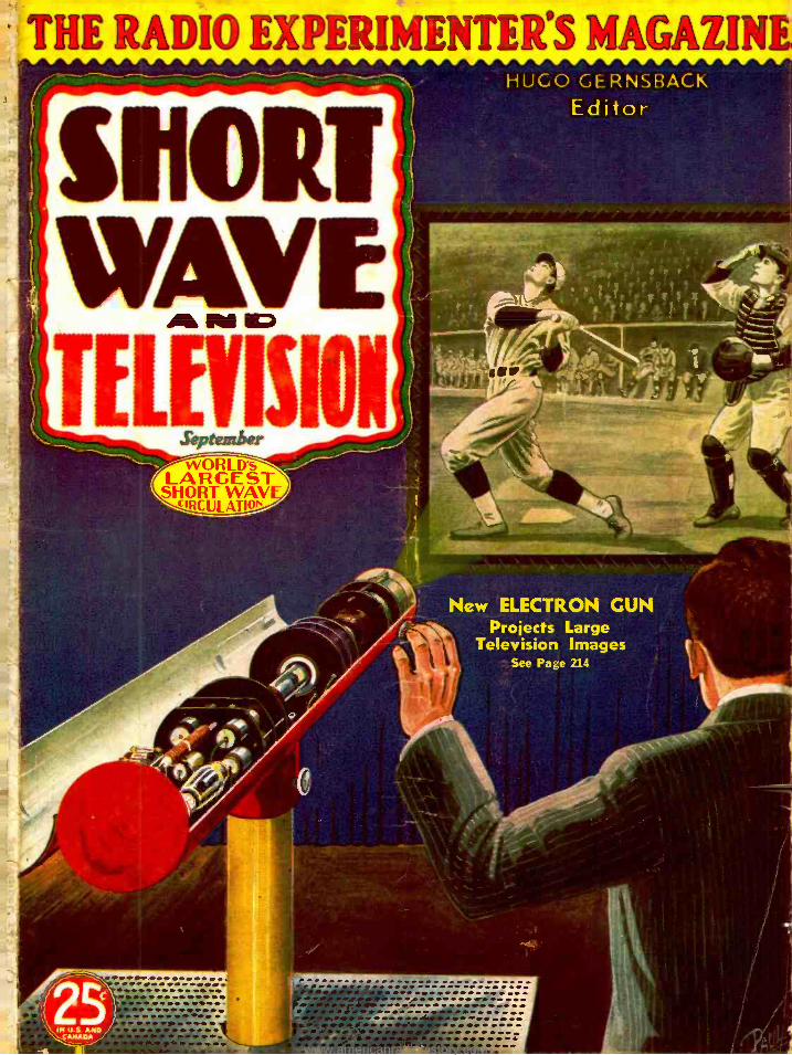
Read wf'zat ñappiized ,
YES I'll take your training. That's what S. J. Ebert said. Ile is making good money and has found suc- c::ss in Radio.
I'm not interested. That's what this fellow said. To. day be wotdd be ashamed if I gave ynu his real name and salary.
mlun bniA:
I will Train You at Home in Spare Time
for a GOOD JOB IN RADIO These two fellows had the same chance. Each sent me a coupon. like the one in this al. They got my book on Radio's opportunities.
S. J. Ebert, 104 -B Quadrangle, University of Iowa, Iowa City, Iowa, saw Radio offered him a real chance- Ile enrolled. The other
fellow, whom we will call John Doe, wrott- he wasn't interested. He was just one of those fellows who wants a better job, better pay, but never does anything about it. One of the many who spend their lives in a loss -
pay, no future job, because they haven't titt-
ambition, the determination, the action it take-. to succeed.
But read what S. J. Ebert wrote me and re- member John Doe had the same chance: "Up- on graduation I accepted a job as service- man. Within three weeks I was made Service Manager. This job paid me $40 to $50 a week compared with $13 i earned in a shoe factory before. Eight months later I went with sta- tion KWCR as operator. From there I went to KTNT. Now i am Radio Engineer with WSUI. I certair.ly recommend the X. R. I. to all interested in the greatest field of all, Radio."
Get Ready for Jobs Like These. Many Radio Experts Make
530, $50, $7S a Week
Do you want to make more money? Broad- casting stations employ engineers, operators, station managers and pay up to $5.000 a year. Spare time Raditt set servicing Napa a: nnwl,
Get My Lesson on Radio Servicing Tips FREE
I'll prove my Training ri' I i act irai. money-nub l ng in- formation; is easy to untie n coal ta just n hat you need to master Radio. My sample irssan text "Radio itetviver Troubles-their
troils- and Remedy" covers a long list of
Radio reee . \. t'., U.O., battery. universal. auto, T.lt. F.. sup, i - ' r oynt, all -wave, and other typa
of sets and a cross refer- enee System gires you the probable rouse and a Quick nay to Locate and remedy hisse Set troubles. Aspe- rial Sectioll it dotard to receiver rllta.k -up align- ment. balancing. neutral- izing and testing. Get this lesson Free. No obliga- tion. Just mail coupon.
"I WANT TO IIf.LP YOU. If you are earn- ing less than $30 a
week I believe I can raise your pay. How- ever, I will let you de- cide that. Let nie show you what I have clone for others, what I am prepared to do for you. Get my book, read it over, anti decide one way or another."
J. E. Smith.
as $200 to $500 a year -full time Radio serv- icing jolts pay as much as $30. $50, $75 a week. Many Radio Experts operate their own full tinte or part tinte Radio businesses. Radio manufacturers and jobbers employ testers, in- spectors, foremen, engineers. servicemen, pay- ing up to $6,000 a year. Radio operators ou ships get good pay and see the world besides. Automobile, police, aviation, commercial Radie and loud speaker systems offer good oppor- tunities now and for the future. Television promises many goal jobs soon. Men who havt- taken N. R. 1. Training are building good job. in all Ow, bralleb -: of Radio.
, 1
Many Make 55, 510, 515 a Week Extra in Spare Time While Learning
Almost every neighborhood needs a good spare time serviceman. The day you enroll I start sending you Extra Money Job Sheets. They show you how to do Radio repair jobs, how to cash in quickly. Throughout your training I send you plans and ideas that made good spare time money for hundreds of fellows. I send you special Radio equipment, show you how to conduct experiments, build cir- cuits illustrating important Radio principles. My training gives you valuable, practical ex- perience while learning.
Get My Free 64 -Page Book Now Mail the coupon now for "Rich Rewards in Radio." It's free to anyone over 16 years old. it points out Radio's spare time and full time opportunities and those coming in Television ;
tells about my Training for Radio and Tele- vision ; shows you letters from men I trained, telling what they are doing anti earning; tells about my Money Back Agreement. MAIL THE COUPON in an envelope, or paste it on a penny postcard -NOW !
J. E. SMITH, President National Radio Institute, Dept. 7J83
Washington, D. C.
FOR FREE BOOK OF FACTS_ ABOUT RADIO -t,
r 7 J. E. SMITH, President, National Radio Institute Dept. 7J83, Washington, D. C.
wl,, heut ub1 i :satin é Tn u res -Their c ol. nn
i Itcnnr d
Aÿ Your
n 1 frcce la.kn cl
mt ' i. tes." "
tli ie ind full lime Rad sae
particularly ant tire' 1 n train (tir them + brow In Y
spare lime. 1 m particularly in leerstetlin tritt brunch of ita,ilu checked
Radio Service Business of My Own Spare Tinte Radio Servire work Retail Sales of Radio Sets and Equipment Broadcasting station operator Aviation Radio Operator Ship Radio Operator Auto Radio Installation and Service
of you have not decided which liranrh y
NAME
Ali -around Servicing Expert Loud Speaker aysI'isis, Installation and Servi.. TeieViSiOn Station Operator Designing and Construction Testing Equipmi,,I
Co,-vire Exiler with Radio Factory mmercial Radio Station Operator
ou prefer -mail coupon now. for information to help you deride.,
ACV
LADDRESS
1
I 1.... I
a Please mention SHORT WAVE & TELEVISION when writing advertisers
===== - -J
www.americanradiohistory.com
a.
E
IN THIS ISSUE:
Peck Spitz
PROMINENT SHORT -WAVE AND TELEVISION AUTHORS
McNish Coronado Shuart r-..: --...."....
i
s HORT WAVE w Pal o
TELEIIISIOM'
HUGO GERNSBACK
Editor
Combined Willi Official SHORT WAVE
Contents for September, 1937 Editorial- Mechanical Scanning for Television by
William Hoyt Peck 213 New "Electron Gun" Projects Large Television Images 214 "Ghost Echo" Detector To Reduce Plane Crashes 214 Short Wave Pictorial 215 Spitz Flight Recorder, by Mae Noble Rineman 216 "Spot News" Transmitted by Television, by Robert
Oakhill 217 Short -Wave Transmission and The Ionosphere, by A
G. McNish 218 How To Photograph Television Images 219 Weather Forecasting by Short Waves, by J. Merino
y Coronado 220 World -Wide Short -Wave Review, by C. W. Palmer 221 A.B.C. Beginner's Short -Wave Set, by H. G. Cisin,
M. E 222 A Twin- Pentode Receiver, by G. W. Shuart, W2AMN 223 An Effective S -W Pre- Selector, by Raymond P. Adams _224 806 "All- Band" Xmitter, by G. W. Shuart, W2AMN 226 5 -Meter Beam Antenna, by Arthur H. Lynch, W2DKJ- 228 Short -Wave Scouts -Forty -first Trophy Award 229 Piping R.F. with Concentric Lines, by P. H. Smith,
Bell Telephone Labs 230 What's New In Short -Wave Apparatus 232 Let's "Listen In" with Joe Miller 234 World S -W Station List, by M. Harvey Gernsback 235 How To Identify Short Wave Stations 238 Short Waves and Long Raves 240 New S -W Apparatus of Interest to "Hams" 242 $5.00 For Best Kink 244 Short Wave League -"When To Listen In," by M
Harvey Gernsback 245 Short -Wave Question Box 246
Features in the October Issue A Dandy 4 -tube receiver for "Ham" and "Fan"
bands, by Ernest Kahlert, W2BHZ. A 5 -meter 100 -watt transmitter, with adjustable
frequency to avoid QRM, by G. W. Shuart, W2AMN. Don't miss it!
The 5 -40 -400 transmitter, Part 2, by Arthur H. Lynch, W2DKJ.
Short wave antennas for "Fans" and "Hams ", the best types and how to build them, by W2A1IN.
A Real Pocket -Size Receiver. 7 -tube Battery Superhet, by Mander Barnett.
Adams Lynch
H. WINFIELD SECOR
Managing Editor
GEORGE W. SHUART, W2AMN
Associate Editor
LISTENER Certified Circuits
SHORT WAVE & TELEVISION goes to a large expense in verify-
ing new circuits. When you see this seal it is your guarantee that such sets have been tested in our labora- tories, as well as privately, in differ-
ent parts of the country. Only "Constructional - Experimental" circuits are certified by us.
When you see our certified seal on any set de- scribed, you need not hesitate to spend money for parts, because you are assured in advance that the set and circuit are bona fide and that this magazine stands behind them.
SHORT WAVE & TELEVISION is the only magazine that certifies circuits and sets.
OUR COVER The cover illustration shows how large television images
will be projected on a screen by the new "electron gun," devised by television experts of the RCA. The construc- tion of the new television projection gun is described and illustrated with photos and diagrams on page 214.
COPYRIGHT, 1937, BY II. GERNSBACK
Published by POPULAR BOOK CORPORATION 404 N. Wesley Avenue. Mount Morris, III.
Editorial and Executive Offices - - - - 99 -101 Hudson St., New York. N. Y. HUGO GERNSBACK, President - - - - H. W. SECOR, Vice- President EMIL GROSSMAN Director of Advertising European Agent: Gorringe's American News Agency, 9A Green St..
Leicester Square, London W. C. 2
Australian Agents: McGILL'S AGENCY, 179 Elizabeth St., Melbourne
SHORT WAVE & TELEVISION -Monthly, Entered as second -class mat- ter May 7, 1930. at the post office at Mount Morris. Illinois, under the act of March 3. 1079. Trademarks and copyrights by permission of H. Gernsback, 99 -101 Hudson St.. N. Y. C. Text and illustration. of this magazine are copyrighted and must not be reproduced without per- mission. SHORT WAVE & TELEVISION is published on the 1st of every month. Twelve numbers per year. Subscription price is $2.50 a year in the United States and possessions and Canada. Foreign countries. $3.00 a year. Single copies 25c. Address all contributions for publication to Editor SHORT WAVE & TELEVISION. 99 -101 Hud- son St., New York. N. Y. Publishers are not responsible for lost man- uscripts. Contributions cannot be returned unless authors remit full postage. SHORT WAVE & TELEVISION is for sale at all principal newsstands in the United State. and Canada. European agents: Bren- tano' s, London and Paris. Printed in U. S. A. Make all subscription checks payable to Popular Book Corporation.
210
www.americanradiohistory.com
SHORT WAVE & TELEVISION for SEPTEMBER, 1937 211
EVERYTHING IN RADIO at.id.wee
FOR DEALERS
SERVICE MEN AMATEURS
RADIO BUILDERS SOUND MEN
-Mou -tko 000 PARTS
e.
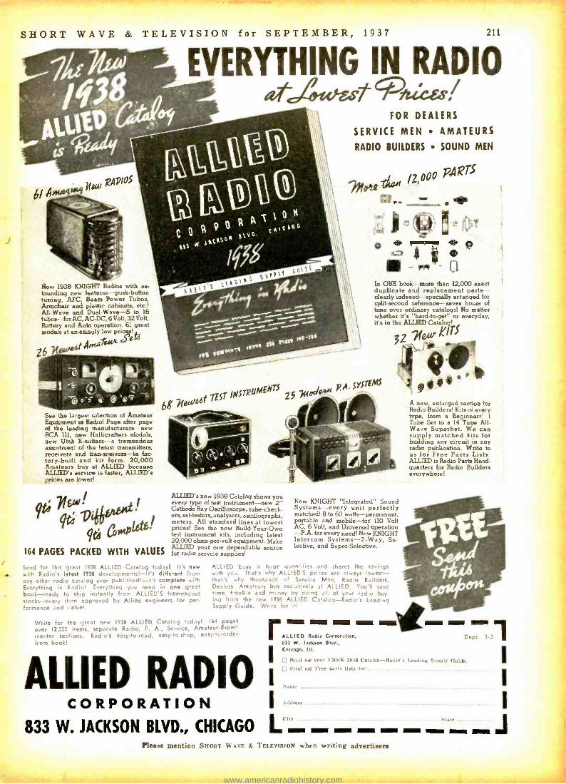
New 1938 KNIGHT Radios with as- tounding new features push -button tuning, AFC, Beam Power Tubes, Armchair and plastic cabinets, etc.! All -Wave and Dual -Wave -5 to 16 tubes- for AC, AC-DC, 6 Volt, 32 Volt, Battery and Auto operation. 61 great modela at amazingly low pricgp!
ff44
Z6
0 rummIe Q ® ® -* C1
In ONE book-- more than 12,000 exact duplicate and replacement parts - clearly indexed -- specially arranged for split- second reference-- saves hours of time over ordinary catalogs! No matter whether it's "hard -to -get" or everyday, it's in the ALLIED Catalog!
3?\ nil
.4.* See the largest selection of Amateur Equipment in Radio! Page after page of the leading manufacturers new RCA ill, new Hallicrahers models, new Utah X-mitters ---a tremendous assortment of the latest transmitters, receivers and tian-sceivers -lu fac- tory-builr and kit form. 20,000 Amateurs buy at ALLIED because ALLIED's service is taster, ALLIED's prices are lower!
164 PAGES PACKED WITH VALUES
ALLIED's new 1938 Catalog shows you every type of test instrument -new 2" Cathode Ray Oscilloscope, tube- check- ers, set- testers, analyzers, oscillographs, meters. All standard lines at lowest prices! See the new Build -Your -Own test instrument kits, including latest 20,000 ohms -per -volt equipment. Make ALLIED your one dependable source for radio service supp:ies!
Send for this great 1938 ALLIED Catalog today! It's new with Radio's latest 1938 developments! -It's different from any other radio catalog ever published! -it's complete with Everything in Fadio! Everything you need in one great book -ready to ship instantly from ALLIED'S tremendous stocks -every it -)m approved by Allied engineers for per- formance and salue!
New KNIGHT "Integrated" Sound Systems- -every unit perfectly matched! 8 to 60 watts-permanent, portable and mobile -for 110 Volt AC, 6 Volt, and Universal operation -P.A. for every need! New KNIGHT Intercom Systems -2 -Way, Se- lective,_and Super -Selective.
ALLIED buys in huge quantities and shares the savings with yo,. That's why ALLIED'S prices are always lowest - that's why thousands cf Service Men, Radio Builders, Dealers Amateurs b.:y excüsive!y at ALLIED. You'll save time 1-cable and money by doing all of your radio buy- ing from the new 1938 ALLIED Catalog- Radio's Lend' ^g Supp'y Guide. Wr7rr. - ' -
Write for the great new 1938 ALLIED Catalog today! 164 pages,
over 12,000 items, separate Radio, P. A., Service, Amateur- Experi-
menter secic -s. Radio's easy -to -read, easy -to -shop, easy-to- order-
from book!
A new, enlarged sechoa for Radio Builders! Kits of every type, from a Beginners' 1
Tube Set to a 14 Tube All - Wave Superhet. We can supply matched kits for building any circuit in any radio publication. Write to us for Free Parts Lists. ALLIED is Radio Parts Head- quarters for Radio Builders everywhere!
ALLIED Radio Coreoration, 833 W. Jackson Blvd.. I Chicago, III.
D pend næ raur I'It Ht: 1n38 l'atalox- Radln'a IaaJlnx .<
ALL `sud ntc }ne .arts Ihty
Same
CORPORATION i .t.lrlrr us
833 W. JACKSON BLVD., CHICAGO `.t`- - - MEEK
Please mention SHORT WAVE & TELEVISION when writing advertisers
www.americanradiohistory.com

212 SHORT WAVE & TELEVISION for SEPTEMBER, 1937
AT LAST!
First 1938 Edition
ßG O1;14`"&VNorad4z U^,,,p6pIIGqgr GOW'Jc. s...
A new book that will appeal to tens of thousands - An essential book for all beginners - The foundation of a radio education.
An outline of some of the chapters in this Alternating Current Resistance, Inductance and Capacity How the Vacuum Tube Works Vacuum Tubes as Regenerators and Oscillators Class A, B and C Amplifiers The M.O.P.A. Transmitter The Fundamentals of Amplitude Modulation The Selection of Tubes in the Low Power Exciter Stages Power Supplies for all Amateur Needs Antenna and Feeder Systems
Bandspread, Regeneration and Methods of Coupling in Receivers A Discussion of Superheterodyne Circuits Ultra High Frequency Receivers -Simple and Advanced Types Ultra High Frequency Transmitters -All Types Th3 Construction of Transmitters and Receivers Remote Control Circuits for Transmitting Stations Learning the Code
Extracts from the Communications Act as pertaining to Amateur Radio
BIG book
In the past few years we received thou- sands of requests from our readers in this and foreign countries urging us to issue a popular priced book that will describe in SIMPLE LANGUAGE the FUNDA- MENTAL PRINCIPLES of short wave receivers and transmitters.
George W. Shuart, W2AMN, the author of this book, is well known to the short wave fraternity through the hundreds of outstanding constructional articles that ap- peared in SHORT WAVE CRAFT and SHORT WAVE & TELEVISION during the past five years. His articles have been frequently reproduced by many foreign magazines.
Through the "Question Box," edited monthly by Mr. Shuart in SHORT WAVE & TELEVISION, thousands of problems are solved for our readers. He knows what information is needed in order that they may have a thorough working knowl- edge of the art of Short Waves and thereby obtain the greatest enjoyment from their hobby.
No other book heretofore published contains so much valuable data, diagrams and illustrations.
This book covers EVERYTHING - from the theory of alternating current electricity to the complete short wave transmitting and receiving apparatus.
The book is now being printed and will be completed September 1st and shipped to thousands of chain, radio supply and book stores in time to make certain that when you call for your copy on September 15th, it will be handed to you.
If your dealer does not have the "Radio Amateur Course" in stock by September 15th, please send us his name and address or you may order from us direct and ship- ment will be made immediately.
THIS BOOK DESERVES A PLACE IN YOUR LIBRARY
SHORT WAVE & TELEVISION, 99 HUDSON STREET, NEW YORK, N. Y. Please mention SHORT WAVE & TELEVISION when writing advertisers
www.americanradiohistory.com

orY
t
HUGO GERNSBACK, EDITOR H. WINFIELD SECOR, MANAGING EDITOR
Ito° 11\1il
Mechanical Scanning for Television
By William Hoyt Peck, President, Peck Television Corporation
FIVE years ago the public was told that television was "just- around- the -corner." Today, they are told approxi-
mately the same story -and it is beginning to wear a little thin. As a matter of fact, television is actually here and has been here for some time. As this is written, I confi-
dently expect that one form of television at least will be
before the public within sixty days. This is a Television news service which displays news bulletins and similar material in type or other characters moving across a screen.
However, the idea which most people have of television is moving images similar to talking mo- tion pictures. These, indeed, exist in the laboratory and have existed there for several years. The chief problem in making such forms of entertainment public is to finance stations and pro- grams. There is a vicious circle; the public cannot be expected to buy televi- sion receivers in any quantity, unless they are assured of excellent programs of reasonable diversity and certain to continue for a number of years. Nor can broadcasters be expected to invest tens of thousands of dollars in transmission equipment, unless they can be assured of an adequate revenue from program spon- sors. Such sponsors, in turn are likely to be reluctant to make any large ex- penditures such as are necessitated by first -class programs, unless they can be assured of a large listening and looking audience, which brings us back where we started. These problems will doubt- less be solved and I feel confident in saying that the solution will come with- in approximately 18 months.
There are two major systems of tele- vision between which the public will pos- sibly have to choose. For that reason I should like to express my opinion of the systems which will doubtless compete.
In the cathode ray system, light source, modulating means. scanning means, and screen, are contained in a single tube, whereas, in the mechanical system these must be separate elements. At first glance it would seem the cathode ray system, due to its greater simplicity, was su- perior for manufacturing operations. Further examination, however, shows this not to be the case, for in order to control the cathode ray tube sweep circuits are necessary, and such sweep circuits require the use of numerous addi- tional resistors, condensers, chokes and tubes. It is a fact that the more successful cathode ray receivers of today em- ploy upwards of 30 tubes. Compare this with the mechanical
systems, which need no more than 9 regular radio tubes. Further, excessively high voltages comparable with those
used in the electric chair at Sing Sing, are necessary to operate a cathode ray tube in order to secure a sufficiently large and brilliant image. Not only is such a voltage dan- gerous to human life, but it is also expensive, in that it requires more heavily insulated apparatus throughout the power pack.
Mechanical systems, like those in which I am interested, for example, derive light from an automobile headlight
bulb working on but 71/2 volts. No volt- ages in the receiver need be greater than those commonly employed in standard broadcast receiving sets.
The factor of size of image is another point which must be considered. A cathode ray tube producing a 5" x 7" picture must be approximately 9" in di- ameter and 17" in length. While 8" x 10" pictures and even larger ones have been broadcast, I consider it doubtful that tubes could produce images of home - movie size, or that images 2 x 3 ft. can ever be broadcast commercially, unless a small projection tube working at tre- mendous voltage is used. This obstacle is not met with in the mechanical sys- tem, for it is unnecessary to use any dif- ferent equipment or higher voltages to produce an image 2' x 3' or larger.
As to detail, the size of the scanning spot remains constant in the mechanical system, while it doubles its size when in the cathode ray. For this reason, a 220 line mechanical system affords detail which is the equivalent of 441 line cathode ray pictures. The mechanical system is also more flexible; if a cathode ray receiver is factory -adjusted to re-
ceive a 441 line, 60 frame image, and if the user desires to receive images composed of any other number of lines per frame, or frames per second, it is a lengthy job for a tech- nician to re -align the sweep circuits in order that this may be done.
In the mechanical scanning system as developed in our laboratories, a self- synchronizing multi -speed motor is used. A component of the signal received is fed into an amplifier which incorporates a grid -glow relay. Thus the speed of the motor is regulated to scan the incoming signal per- fectly, irrespective of number of lines or number of frames. There is no reasonable limit to the number of lines or frames which the mechanical system is capable of handling. We will have no difficulty in (Continued on page 271))
William Hoyt Pee Peck Television C exponent of mecha inventor of a telev
k, President of the orporation, leading nical scanning and ision news service.
Ninth of a Series of "Guest" Editorials
SHORT WAVE & TELEVISION IS PUBLISHED ON THE 1st OF EVERY MONTH
This is the September, 1937 Issue. -Vol. VIII, No. 5. The Next Issue Comes Out September 1
SHORT WAVE & TELEVISION, Published monthly at Mount Morris, Ill.
EDITORIAL and EXECUTIVE Offices, 99 Hudson St., New York City
213
www.americanradiohistory.com

214 SHORT WAVE & TELEVISION for SEPTEMBER, 1937
New "Electron Gun" Projects
Large Television Images
Dr. Law of the RCA Laboratories views a Television image pro- jected by his new "Kinescope."
NEW television projection tubes capable of reproducing televised scenes brightly on a relatively large screen
were described before the Institute of Radio Engineers in New York City recently by V. K. Zworykin, W. H. Painter and R. R. Law of the Radio Corporation of America's laboratories. Dr. Zworykin and Mr. Painter disclosed that present achievements with such tubes result from research directed to this end and which has been carried on for years. A demonstration by Dr. Law came as a highlight in a sym- posium of technical reports on the status of television by RCA scientists, whose laboratory work along with the ex- perimental field tests now in progress in the New York City area are vital parts of RCA'S television program.
The tube, which is about eighteen inches in length, pro- duces an image about 11/2 x 21/2 inches on its fluorescent
screen. This is so brilliant that a simple optical system will project it onto a large screen. A projected picture 18 x 24 inches compares favorably in brightness with home motion pictures. In the demonstration, a picture 3 x 4 feet in size was shown, which was bright enough to be seen by the audience of several hundred engineers.
The principal feature of the demonstrated device is a new type of "electron gun," developed by Dr. Law and a grou of associates in the RCA laboratories at Harrison, N.J. The gun is the structure in a television receiving tube which focusses flying electrons into an extremely slender beam. In projection, it is necessary to start (Continued on page 252)
I)r. R. R. Law points to a newly developed "Electron Gun" in the new "Kinescope" for projecting Television images.
"Ghost Echo" Detector To Reduce Plane Crashes
MUCH has been said and even more has been written about the constant danger to air -traffic caused by mys-
terious radio "ghost echoes." No one has been able to find where they come from and where they go to; and the number of airplanes which have crashed to pieces has by no means decreased. Not only has America been alarmed by the in- creasing number of air -crashes, especially during the time of sunset and sunrise, but European aviation has also ex- perienced similar accidents in increasing number.
Science, which does not believe in supernatural things, started to search for the real nature of these "ghost echoes" and the results of the research work here and abroad has
Left -Cathode ra\ indicator and beloe the "ghost echo" receiver shoe
it. the tuning dial for n at the right.
disclosed some very inter- esting facts, which not on- ly concern radio- communi- cation between airliners and ground stations, but also short -wave transmis- sion in general.
According to the experi- ments and the ensuing conclusions, this disastrous radio phenomena (often referred to as g h o s t echoes) is by no means of supernatural origin, al- though it has not been proven, nevertheless it may be stated with a fair degree of accuracy, that solar flocculi eruptions (whether visible or not) are the initial cause of the widespread impairment of any type of radio trans- mission. In addition to this generally observed ef- fect radio transmissions especially on the higher frequencies are influenced to a considerable degree by the exposure of the so- called Heaviside Layer to light rays from the sun, and dur- ing the daily periods of sunrise and sunset these two fac- tors cause especially strong disturbances in the straight or reflected path of transmission. The much commented upon "ghost echoes," although they caused ghostly accidents, are of a clear physical origin, and (Continued on page 256)
AUXILIARY AERIAL
LOOP AERIAL
CATHODE RAY
TUBE
DIAL TUNES RECEIVER, COM'S
R RECEIVER
"(:host Echo" detector set -up This apparatus distinguishes he- tween the desired signals and the "ghost echo" by means of a
cathode ray tube.
www.americanradiohistory.com
SHORT WAVE & TELEVISION for SEPTEMBER, 1937
SHORT -WAVE PICTORIAL
The latest television and short -wave events in various parts of the world have been caught in the camera's eye by our roving
reporter.
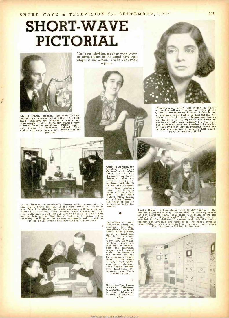
Edward Startz, probably the most famous short -wave announcer in the world. Ile speaks seven languages and frequently makes an- nouncements in all of them. Mr. Starti s voice is heard from th.' well-known PHOHI short- wave station at Eindhoven. Holland. This station will soon have a new transmitter in
operation
215
Elizabeth -Ann Tucker. who is now in charge of the Short -Wave Program Activities of the Columbia Broadcasting System. Although not an engineer. Miss Tucker is none -the -less fa- miliar with engineering technique and has, as she describes it. "a layman's knowledge of short -wave radio broadcasting." She has trav- eled extensively and has first -hand knowledge of what people in foreign countries would like to hear via short -wave from the CBS short-
wave transmitter, W2XE.
Lowell Thomas. internationally known radio commentator, is here shown being televised at the NBC television studios in New York City. Shortly, our radio audiences will have the sat- isfaction of "seeing" their favorite news commentator and other entertainers, and will not have to be satis2.ed with simply hearing their voices. "Spot News" Bashed by television will be extremely thrilling as the listener frequently will be able to
see the actual scene Laing described at the moment.
Conchita Ascanio, the beautiful "Radio Caracas" artist often heard by North American short -wave listeners. Miss As- canio is a born co- medienne and she is as well the possessor of a lovely soprano voice. Her interpre- tation of "Dona Car- men" in the radio feature "Don Lisan- dro y Dona Carmen" has endeared her to Venezuelan radio lis- teners.
Left -Here we see a Hollywood group in- specting the iatest invention of the well - known radio pioneer. Leroy J. Leishman. The device is a spe- cial tuning dial which Mr. Leishman is here shown ex- pl; ining; it enables both the television image a n d sound dials to be moved to the correct settings by pressing a single lever. In the photo we see Lloyd Corri- gan. movie director: Jean Rogers, actress. Mr. Leishman. the inventor, and Boris
Karloff, actor.
R i g h t -The Farns- w or t h Television transmitter installed in their laboratory located at Philadel-
phia.
Amelia Earhart is here shown with E. Jay Quinby of the Western Electric Company who supplied the radio equipment for her powerful plane. This photo was taken before the start of her "round -;he- world" Bight. The radio sets are installed in "out -of -the -way" corners and only the tuning controls and switches are mounted in the pilot's cockpit; these controls being centralized in the small unit which
Miss Earhart is holding in her hand.
www.americanradiohistory.com
216 SHORT
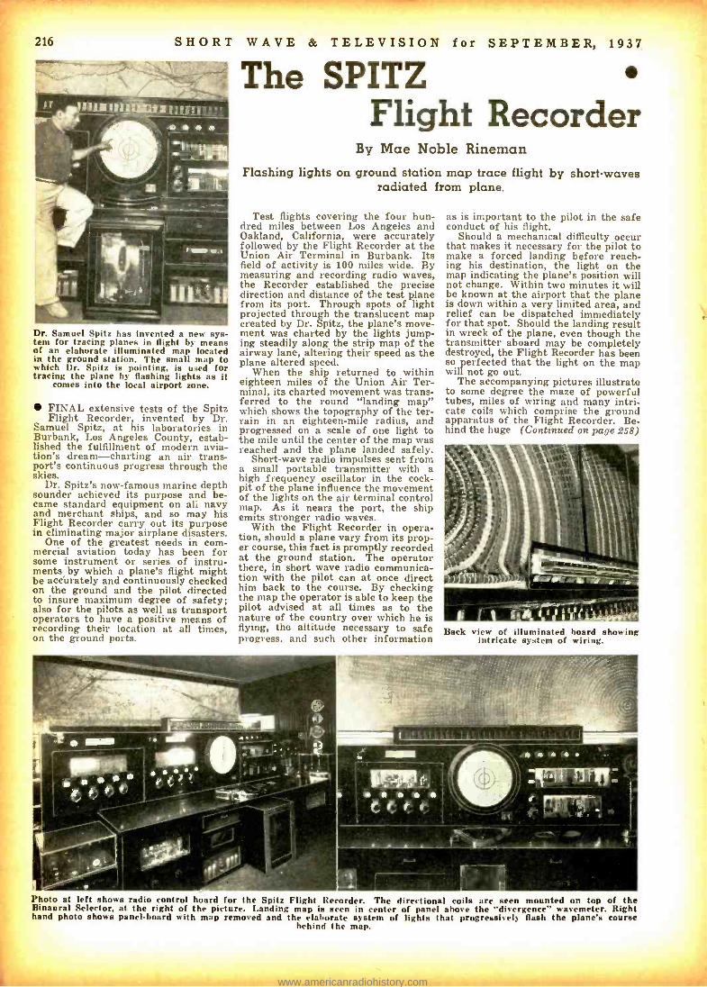
Dr. Samuel Spitz has invented a new sys- tem for tracing planes in flight by means of an elaborate illuminated map located in the ground station. The small map to which Dr. Spitz is pointing, is used for tracing the plane by flashing lights as it
comes into the local airport zone.
FINAL extensive tests of the Spitz Flight Recorder, invented by Dr.
Samuel Spitz, at his laboratories in Burbank, Los Angeles County, estab- lished the fulfillment of modern avia- tion's dream -charting an air trans- port's continuous progress through the skies.
Dr. Spitz's now -famous marine depth sounder achieved its purpose and be- came standard equipment on al: navy and merchant ships, and so may his Flight Recorder carry out its purpose in eliminating major airplane disasters.
One of the greatest needs in com- mercial aviation today has been for some instrument or series of instru- ments by which a plane's flight might be accurately and continuously checked on the ground and the pilot directed to insure maximum degree of safety; also for the pilots as well as transport operators to have a positive means of recording their location at all times, on the ground ports.
WAVE & TELEVISION for SEPTEMBER, 1937
The SPITZ Flight Recorder
By Mae Noble Rineman Flashing lights on ground station map trace flight by short -waves
radiated from plane.
Test flights covering the four hun- dred miles between Los Angeles and Oakland, California, were accurately followed by the Flight Recorder at the Union Air Terminal in Burbank. Its field of activity is 100 miles wide. By measuring and recording radio waves, the Recorder established the precise direction and distance of the test plane from its port. Through spots of light projected through the translucent map created by Dr. Spitz, the plane's move- ment was charted by the lights jump- ing steadily along the strip map of the airway lane, altering their speed as the plane altered speed.
When the ship returned to within eighteen miles of the Union Air Ter- minal its charted movement was trans- ferred to the round "landing map" which shows the topography of the ter- rain in an eighteen -mile radius, and progressed on a scale of one light to the mile until the center of the map was reached and the plane landed safely.
Short -wave radio impulses sent from a small portable transmitter with a high frequency oscillator in the cock- pit of the plane influence the movement of the lights on the air terminal control map. As it nears the port, the ship emits stronger radio waves.
With the Flight Recorder in opera- tion, should a plane vary from its prop- er course, this fact is promptly recorded at the ground station. The operator there, in short wave radio communica- tion with the pilot can at once direct him back to the course. By checking the map the operator is able to keep the pilot advised at all times as to the nature of the country over which he is flying, the altitude necessary to safe progress, and such other information
as is important to the pilot in the safe conduct of his flight.
Should a mechanical difficulty occur that makes it necessary for the pilot to make a forced landing before reach- ing his destination, the light on the map indicating the plane's position will not change. Within two minutes it will be known at the airport that the plane is down within a very limited area, and relief can be dispatched immediately for that spot. Should the landing result in wreck of the plane, even though the transmitter aboard may be completely destroyed, the Flight Recorder has been so perfected that the light on the map will not go out.
The accompanying pictures illustrate to some degree the maze of powerful tubes, miles of wiring and many intri- cate coils which comprise the ground apparatus of the Flight Recorder. Be. hind the huge (Continued on page 258)
Back view of illuminated hoard showing intricate system of wiring.
Photo at left shows radio control hoard for the Spitz Flight Recorder. The directional coils are seen mounted on top of the Binaural Selector, at the right of the picture. Landing map is seen in center of panel above the "divergence" wavemeter. Right hand photo shows panel -board with map removed and the elaborate system of lights that progressively flash the plane's course
behind the map.
www.americanradiohistory.com

SHORT WAVE & TELEVISION for SEPTEMBER, 1937 217
OPERATOR TYPES OUT
"NEWS" HERE
TRANSPARENT CELLULOID
STRIP ;\ TAPE . _,T.I
MEIN -
PHOTO- ELECTRIC
CELL
LAMP TRANSMITTER S.W. RECEIVER POLARIZER LAMP
A
0 0 0 0 O O p
RADIO TRANSMITTER
(OR
TELEP
TO
HO L =
NE = COMPENSATED
MOTOR ORINEN CIRCUIT)
MIRROR (SCANNING)DRUM
MIRROR DRUM
SPECIAL TYPEWRITER
TAPE CONTAINING
"NEWS"
TAPE CONTAINING 'ADV.' COPY
MIRROR GROUND GLASS SCREEN
-" LIGHT
MODULATOR L
TUBE
\ / ,/ ANALYZER
SCREEN
SYNCH. MOTOR
`ARMY 6- NAV
OPAQUE LETTERS "TYPED ON CELLULOID
TAPE
SAVE MONEY LIGHT MAY BE FLASH- ED THROUGH "ADV." TAPE WHENEVER
DESIRED REVOLVING MIRROR DRUM
DETAIL OF "B"
( OBSERVER
MIRROR SCANNING DRUM
The general plan for distributing "spot news" by television or wire is shown above. The news is dispatched to the one or more receiving points by means of a special typewriter, which prints the characters on a cellophane tape. The words are scanned as
the tape passes before a mirror -drum and photo- electric cell, the scanning process being repeated at the receiver.
"Spot News" Transmitted by TELEVISION
ODDLY enough, the first commercial ap-
pearance of television will apparently not be the pro- grams of entertainment which fiction writers have imagined, but instead will consist of news flashes, headlines and bulletins, sent out either by radio or over stand- ard "land lines" similar to those used in broadcasting networks.
The apparatus to make transmission and reception of such material possible has been perfected in the laboratories of the Peck Television Corporation in New York City, and an independent company has contracted to take over the gathering and dissemination of news, and the rental of receiving equip- ment to key locations.
By Robert Oakhill Here is the very latest method of flashing "spot news" to public -via television! Advertising items can
also be woven into the "news" report. the
J. Francia Dusek is shown examining one of the Peck "light- modulator" cells; the multi- mirrored scanner appears below in the cabinet, and the S -W receiver at the
right.
William Hoyt peck, inventor of the latest "spot news" distributing system, watching a "televised" news item as it travels
across the "screen."
Images consisting of moving letters in a strip six inches tall by three feet wide are produced on a screen that may be as much as seventy miles away from the typewriter where the messages orig- inate.
This typewriter looks much like a standard machine, save that its char- acters are % -inch tall, and are written on a continuously moving strip of cello- phane, instead of the conventional paper. An electric motor, automatical- ly stopped and started, is built as an integral part of the typewriter, causing the transparent tape to move one space each time a letter is struck, without need for carriage return.
From the typewriter, the tape is fed into a transmitter cabinet, which is about the size of a four -drawer file. At the back of the cabinet, there is an automobile headlight bulb, the light of which is concentrated and focussed onto a scanning disc, where reflecting lenses, patented by William Hoyt Peck, pres- ident and chief engineer of the cor- poration, cause the beam to scan the moving tape. The light passes through
the transparent portions, but is blocked by the opaque ink of the typed letters as it passes to the photo -electric cell at the upper part of the cabinet.
The output of this cell is connected to a pre -amplifier, which may be used di- rectly into wire lines, or to actuate a radio transmitter.
The signal, sent in either of these ways, is picked up by one, or any num- ber of, receivers. There the signal is detected and amplified, then fed into a special light- modulator cell, which modulates the beam coming from a second automobile headlight bulb and passing through the cell on its way to the scanning disc, which also is pro- vided with re- (Continued on page 250)
An engineer is shown in the act of check- ing the 6 -volt exciter lamp on the trans- mitter. The short -wave transmitting panel
is shown at the right of the photo.
www.americanradiohistory.com

218 SHORT WAVE & TELEVISION for SEPTEMBER, 1937
Short -Wave Transmission and
The IONOSPHERE By A. G. McNish Department of Terrestrial Magnetism, Carnegie Institution of Washington
THE remarkable advances in radio science accomplished in recent years
would probably have been very much retarded, except for one remarkable provision of nature -a region of the atmosphere capable of reflecting radio waves back to the earth. Although ex- istence of such a region was suggested
PATH OF
HIGH FREQ- UENCY
I MOST PEN-
ETRATING
a00
600
500
w 400.71
z_
300,-
w
200
PATHS OF
INTER- MEDIATE FRoj-
UENCIES
PATH OF
LOW FREQ- UENCY (LEAST PENETRAT-"\
TRANSMITTER RECEIVER ING)
00
Figure 4 -Paths of radio waves of differ- ent frequencies in the ionosphere.
over 50 years ago by the British meteorologist, Balfour Stewart, to ex- plain certain facts of terrestrial mag- netism, definite proof of its existence was not supplied until 1925 when Breit
ton and Tuve in this country and Appleton England performed their experi-
ments on radio wave reflection. Since that time the earth's upper atmosphere, called the ionosphere, has been a fertile field for scientific research.
Cause of Ionization All scientific evidence clearly shows
that radiations from the sun are the on- ly important causes of the ionization which gives this region its peculiar electrical properties. At first thought of as a single region of ionization, it is now known that the ionosphere is high- ly stratified. A lower layer exists ca- pable of reflecting only long waves, while higher are the F- and F_- layers, capable of reflecting shorter and still shorter waves. The reflecting power of these layers is determined by the number of electrified particles present, either free electrons or electrically - charged air molecules called ions. If the number of free electrons per cubic centimeter in a layer is high, then very
Figure 1- Magnetic, radio, and earth -cur- rent disturbances associated with brilliant
solar eruption, April 8, 1936.
The editors asked Mr. McNish to prepare this article especially for our readers, in view of the fact that the author has carried on a great number of experimental researches covering the phenomena of short -wave transmission; particularly the effects of sun spots.
magnetic storms, etc.
short waves may be reflected by it. For reflecting efficiency a single elec- tron is equivalent to about 10,000 ions because of the much greater weight of ions. If the number of electrons per cubic centimeter in a layer is 1,000,000 then a wave of roughly 33 meters will be reflected back to earth at vertical incidence -that is, going straight up and straight down -while still shorter waves will pass on through and escape into space. However, such a layer is able to reflect waves three times as short, if the waves strike the layer at the oblique angles commonly involved in long- distance transmission.
These statements apply only for the highest parts of the atmosphere where electrons can move appreciable dis- tances without colliding with molecules of air. Lower in the atmosphere where air molecules are more numerous, elec-
trolls, set into vibration by the radio waves, strike against air molecules so frequently that they waste all the en- ergy given them by the radio waves, and do not reflect it back to the earth. If the electrons are sufficiently numer- ous in such a region they waste all of the radio -wave energy and constitute an absorbing layer.
The "E" and "F," Layers It is now known that the E- and F.-
layers of the ionosphere are due to ultra -violet radiation from the sun. Solar ultra- violet light striking the air - molecules sets electrons free in much the same manner as electrons are set free in a photo- electric cell.
A recent discovery, announced by Dr. J. H. Dellinger of the National Bureau of Standards, has opened the way for a considerable (Continued on page 253)
4D0
f ,1200
S ' 0! I 40
ION -DISTRIBUTION IN OUTER ATMOSPHERE (HUANCAYO MAGNETIC OBSERVATORY) 118 900
OI.IE N TESTS DuINNO THIS SNOWED NO ECHOES ANY HON
4.F.....
18 "20^
50 60 7 0 8 D 9 0 4.0 5.0 6.0 7.0 8.0 9.0 4.0 50 6.0 7.0 8.0 9.0 FREQUENCY IN MC/SEC.
SPECTROHELIOGRAMS (MOUNT WILSON OBSERVATORY)
MAGNETIC CHANGES (HUANCAYO MAGNETIC OBSERVATORY)
2D N MMITAAVI ISOr
o DECLINATION
loos H00.1 ONTAL INTENSITY
loor sot
NLTPMENNIrIMr ttlt 0 "00"' 4 "00" 8 "00- 1200"' 16 00" 20n 00'
INCREASING WEST D
EARTH-CURRENTS (HUANCAYO MAGNETIC OBSERVATORY
° 11. lCR AST
5 1111111 NCRASING NORTH
.
12"°°"' 16"b1M 0 ̂ 0"00^ 4"óóm
1 M
20"00^
is
y to
www.americanradiohistory.com
.-,..«....aV .,._ wi... rY.::....,oa«.+i
SHORT WAVE & TELEVISION for SEPTEMBER, 1937 219
T E S1' ¡ !`Z,M`S-tA
by the
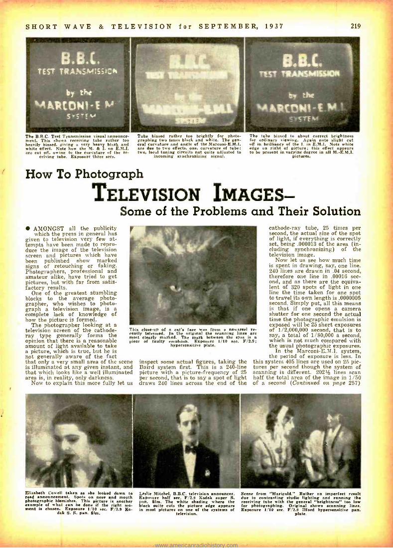
A ARCflN1- E ' The B.B.C. Test Transmission visual announce- ment. This shows receiving tube rather too heavily biased, giving a very heavy black and white effect. Note how the M. & I. on E.M.I. are cut off, owing to the curvature of the re-
ceiving tube. Exposure three secs.
Tube biased rather too brightly for photo- graphing two tones black and white. The gen- eral curvature and angle of the Marconi- E.M.I. are due to two effects, one, curvature of tube; two, local tuning circuits not quite adjusted to
incoming synchronizing signal.
The tube biased to about correct brightness for ordinary viewing. Again note slight cut off in brilliancy of the I. in E.M.I. Note white edge on right of picture; this effect appears to be present in varying degree in all M.-E.M.I.
pictures.
How To Photograph
TELEVISION IMAGES - Some of the Problems and Their Solution
AMONGST all the publicity which the press in general has
given to television very few at- tempts have been made to repro- duce the image of the television screen and pictures which have been published show marked signs of retouching or faking. Photographers, professional and amateur alike, have tried to get pictures, but with far from satis- factory results.
One of the greatest stumbling blocks to the average photo- grapher, who wishes to photo- graph a television image, is a complete lack of knowledge of how the picture is formed.
The photographer looking at a television screen of the cathode - ray type generally forms the opinion that there is a reasonable amount of light available to take a picture, which is true, but he is not generally aware of the fact that only a very small area of the scene is illuminated at any given instant, and that which looks like a well illuminated area is, in reality, only darkness.
Now to explain this more fully let us
This close -up of a cat's face was from newsreel cently televised. In the original the scanning lines most clearly marked. The mark between the eyes i piece of faulty emulsion. Exposure 1 /10 sec. F/2
hypersensitive plate.
re- are
.9;
inspect some actual figures, taking the Baird system first. This is a 240 -line picture with a picture- frequency of 25 per second, that is to say a spot of light draws 240 lines across the end of the
cathode -ray tube, 25 times per second, the actual size of the spot of light, if everything is correctly set, being .000013 of the area (in- cluding synchronizing) of the television image.
Now let us see how much time is spent in drawing, say, one line. 240 lines are drawn in .04 second, therefore one line in .00016 sec- ond, and as there are the equiva- lent of 320 spots of light in one line the time taken for one spot to travel its own length is .0000006 second. Simply put, all this means is that if one opens a camera shutter for one second the actual time the photographic emulsion is exposed will be 25 short exposures of 1/2,000,000 second, that is to say, a total of 1/80,000 a second, which is not much compared with the usual photographic exposures.
In the Marconi- E.M.I. system, the period of exposure is less. In
this system 405 lines are used on 25 pic- tures per second though the system of scanning is different. 202% lines scan half the total area of the image in 1/50 of a second (Continued on page 257)
Elizabeth Cowell taken as she looked down to read announcement. Spots on nose and mouth photographic blemishes. This picture is another example of what can be done if the right mo- ment is chosen. Exposure 1 10 sec. F 2.9 Ko-
dak S. S. pan. film.
Leslie Mitchel. B.B.C. television announcer. Exposure half sec. F 2.9 Kodak super S. pan. film. The white shading where the black suite cuts the picture edge appears in most pictures on one of the systems of
television.
Scene from "Marigold." Rather an imperfect result due to contrasting studio lighting and running the receiving tube with the general "brightness" too low for photographing. Original shows scanning lines. Exposure 1 10 sec. F 2.9 Ilford hypersensitise pan.
plate.
www.americanradiohistory.com

220 SHORT WAVE & TELEVISION for SEPTEMBER, 1937
E REGION,
EL REGION -R THE WAVES
EXPERIENCE SUCCESSIVE
REFRACTION HERE
REA4 t
HEIGHT
CSENDER RECEIVER
THE SHORT WAVES EXPERIENCE A TOTAL REFLECTION WHEN TRAVELING ACROSS THE DIFFERENT IONIZED LAYERS. WHAT HAPPENS
WITH A GLASS OF WATER WILL HELP YOU TO UNDERSTAND THIS
VIRTUAL HE ONT -R
LESS DENSE
MEDIUM
MORE /DENSE
MEDIUM
-p
IN A GLASS OF WATER, IF YOU LOOK FROM'B- YOU SEE THE LUMINOUS POINT "P; AS IF LOCATED
AT "A-.
IONIZATION DUE TO SUN ACTION
, ,,NAVE NO SUN ACTION
WHY IT IS BEST TO USE SNORTER WAVES DURING THE DAY, DUE ® TO SUNS IONIZING ACTION
MOT AIR GOES UP SUN SUNS HEATING ACTION
FROM A
WEAK WINOS j l\ M / SIDES EQUATORIAL. CALM ZONE
CLOUDS AND, E
RAIN 11;,--,:-.."----- - (7-7-2
U
WEAK/ ... CENTRALS WIND _.y PLATEAU - WIND
PACIFIC OCEAN ATLANTIC OCEAN
RAINY SEASON IN COSTA RICA HOT AIR GOES UP,ORIGINATING A LOW PRESSURE AREA. SO WEAK WINDS COME FROM ALL SIDES, ® MI BRINGING HUOITY,WN ICH CONDENSES ON THE
HIGHER PARTS OF THE COUNTRY. GIVING RAIN.
..WEAK
Diagrams above show region in which short waves are relected; why short waves are best during day, and weather conditions during rainy season in Costa Rica.
Weather Forecasting By J. Merino y Coronado, (TI2JM) by Short Waves Ex -Ass's Professor of Physics, Liceo, San Jose, Costa Rica.
WHAT I have to say here with re- gard to weather forecasting by short
waves is the result of actual experi- ments, and I am addressing my report in this case to the average "Ham" and also the "Fan," who listens to the short- wave stations, and who is interested in the great problems still to be solved by the meteorologists. I have purposely omitted therefore all involved mathe- matical analysis, but have presented the more practical aspects of the subject, so that those interested may have a chance to try and apply this latest de- velopment in short waves. The experi- ments and studies which I have made may be considered as a particular appli- cation in this part of the world, that is, Costa Rica, where tropical storms form rapidly and where it is important to know of their probable route as quickly as possible. At the same time, it is also to be pointed out that the general rules given have been followed successfully in other countries.
While I do not advocate this system as a substitute for known weather fore- casting systems, I do believe that it will prove valuable as an additional aid in weather forecasting. This system should also prove extremely valuable in coun- tries like Costa Rica, where the farmers do not have the benefit of a well- organ- ized meteorological service.
How Weather Affects Short Waves To begin with, it is interesting to re-
member that, in general short waves
Describing the interesting experi- ments carried on in Costa Rica, Central America, by the author. An extension of this radio method of weather forecasting should prove very useful to weather ex- perts in all parts of the world.
travel upward to the ionized layers of the upper atmosphere and there experi- ence a reflection; really this phenomenon is one of successive refractions as shown in Fig. 1. The reflected waves come back to earth and impinge on the aerial of the receiving apparatus if one is set up for the purpose. It is also well to re- member that great atmospheric pres- sure changes produce correspondently large meteorological changes. As Lad- ner and Stoner, in their short -wave treatise Short Wave Wireless Communi- cation point out -"The importance of atmospheric pressure, in regard to radio transmission, lies in the fact that pres- sure determines conductivity and dielec- tric constant, for although air at atmos- pheric pressure is almost a perfect insulator, at low pressures it becomes ionized by the sun's action. The effect of ionization is to reduce the dielectric constant and to increase the conductiv- ity of the gas in different ways to differ- ent frequencies."
rizi HIGH NIGH CARIBBEAN BAROMETRIC PRESSURE HURRICANE
SW PZONERE /ZONE NE
l/ .1
/DIRECTION LOW y' / -: Oc WIND PRIS Y F" CENTRAL CARIBBEAN PI AtGU° -
SEA - COSTA RICA --_ PACIFIC OCEAN
BABOMETRE PRESSURE DISTRIBUTION IN COSTA RICA AND CARIBBEAN SEA WNENA CARIBBEAN SEA HURRICANE TAKES PLACE.
®CLOUDS (CUMULOS) OVER THE NIGH
SW MOUNTAINS
HUMID OR011NA
CLEAR, FAIR WEATHER CLOUDS GOING ON THE ATLANTIC EASTWARD
SIDE NE ` }}T '-'- DIRWINDN
"'MCAIE OF `` FEMME
AREA
CARIBBEAN / SEA
SAN JOS / 71J J
^ PUNTARENAS PORT LIMON
WHAT HAPPENS MOVE
NS IN RICA WHEN PA IFIC
OCEAN AIR BEGINS THE
Thus we see that the propagation of radio waves suffer considerable changes under the action of all meteorological and cosmic phenomena capable of pro- ducing alterations in the atmospheric pressure, dielectric constant, conductiv- ity and ionization. Just as we choose different wavelengths to suit different operating and weather conditions for everyday transmission between two points, we must also be able to listen to a considerable number of different wavelengths if we wish to make efficient weather observations. Some are best for daytime while others are better suited for night observation, due to the sun's action on the ionized layers of the upper atmosphere. See Fig. 2.
Climate in Costa Rica Let us consider for a moment the cli-
mate in this part of the world, Costa Rica, where the short -wave method of weather forecasting has been tried out with considerable success. The climate in Costa Rica, which is an isthmus, is essentially tropical and oceanic. We have a dry season from November to April, a rainy season from April to November, but this rainy season is di- vided into two parts by a short dry season when the sun is on its yearly travel; i.e., arriving at the tenth paral- lel (the latitude of Costa Rica).
While these climatic changes seem easy to understand, yet they suffer from powerful outside factors such as the cold northern (Continued on page 259)
SW HEAVY RAINS OVER THE CENTRAL PLATEAU AND PACIFIC COAST, LOW TOP AND BAD VISIBILITY FOR
ÇAIRPLANES,WITH WEST. SOFT WINOS: CLOUDS ARE NIMBUS. LOW
)
PRESSURE
- =- '' ̂v'°_.'>1.-)2,, --Il VY..
RAIN ON TH ATLANTIC
SATURATED AIR/
IMS
CENTRAL PLATEAU
COSTA RICA
1 -"'" CLOUDS
(CUMULUS)GOING CARIBBEAN EASTWARD SEA
)43 FLORIDA
MEKICO
`R AJECTORY OF CYCLONE AND
LOW PRESS AREA.
i NIU
SRLVAEÓR COSTA - HIGH MOUNTAINS
WHY ACARIBBEANSEA Oy CYCLONE HAS GREAT 54%4, EFFECTS UPON THE WEATHER So, IN CENTRAL AMERICA.
THIS HAPPENS IF THE PHENOMENON IS TOO STRONG. ® w PANALM,THE PHENOMENON NO
15 HIGH
O T 50 SPANA A.
THE ETHERE ARE NIMOUw.<'.NS
vANAMA
Above -Storm conditions in Costa Rica -What happens if heavily saturated air is blown north -eastward- finally, path of cyclone and low- pressure area with resultant effect on Costa Rica weather.
www.americanradiohistory.com
SHORT WAVE & TELEVISION for SEPTEMBER, 1937 221
WORLD -WIDE SHORT -WAVE REVIEW
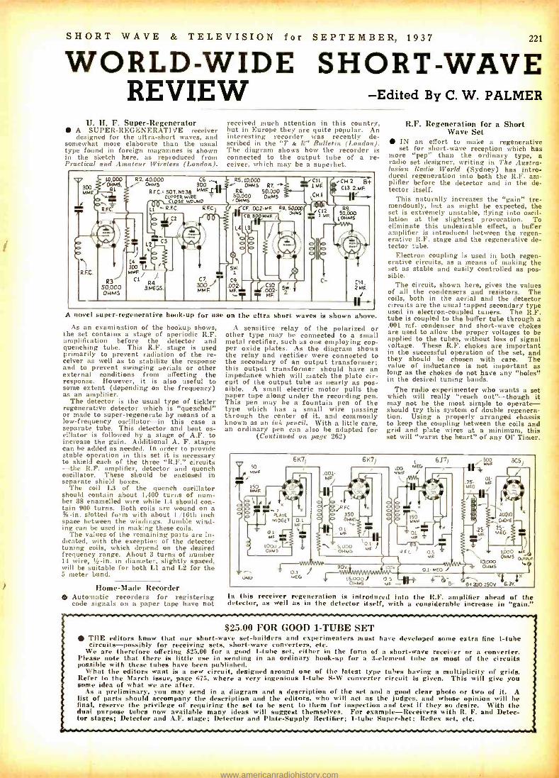
U. H. F. Super- Regenerator A SUPER -REGENERATIVE receiver designed for the ultra -short waves, and
somewhat more elaborate than the usual type found in foreign magazines is shown in the sketch here, as reproduced from Practical and Amateur Wireless (London).
R2. OHM90 300 Ai
R.F.C. 507. H 38 MMF COPPER WIRE T
CLOSE WOUND
-Edited By C. W. PALMER
received much attention in this country, but in Europe they are quite popular. An interesting recorder was recently de- scribed in the "T & R" Bulletin (London). The diagram shows how the recorder is connected to the output tube of a re- ceiver, which may be a superhet.
R5,10.000 OHMS R7,
RG, 50,000
5Ó,M05 OHMS
CF, .002 -MF Re, 50.000 OHMS
A novel super -regenerative hook -up for use on the ultra short waves is
As an examination of the hookup shows, the set contains a stage of aperiodic R.F. amplification before the detector and quenching tube. This R.F. stage is used primarily to prevent radiation of the re- ceiver as well as to stabilize the response and to prevent swinging aerials or other external conditions from affecting the response. However, it is also useful to some extent (depending on the frequency) as an amplifier.
The detector is the usual type of tickler regenerative detector which is "quenched" or made to super- regenerate by means of a low -frequency oscillator -in this case a separate tube. This detector and beat os- cillator is followed by a stage of A.F. to increase the gain. Additional A. F. stages can be added as needed. In order to provide stable operation in this set it is necessary to shield each of the three "R.F." circuits -the R.F. amplifier, detector and quench oscillator. These should be enclosed in separate shield boxes.
The coil L3 of the quench oscillator should contain about 1,400 turns of num- ber 38 enamelled wire while L4 should con- tain 900 turns. Both coils are wound on a % -in. slotted form with about 1 /16th inch space between the windings. Jumble wind- ing can be used in making these coils.
The values of the remaining parts are in- dicated, with the exception of the detector tuning coils, which depend on the desired frequency range. About 3 turns of number 14 wire, 12 -in. in diameter, slightly spaced, will be suitable for both L1 and L2 for the 5 meter band.
Home -Made Recorder Automatic recorders for registering code signals on a paper tape have not
shown above.
A sensitive relay of the polarized or other type may be connected to a small metal rectifier, such as one employing cop- per oxide plates. As the diagram shows the relay and rectifier were connected to the secondary of an output transformer; this output transformer should have an impedance which will match the plate cir- cuit of the output tube as nearly as pos- sible. A small electric motor pulls the paper tape along under the recording pen. This pen may be a fountain pen of the type which has a small wire passing through the center of it, and commonly known as an ink pencil. With a little care, an ordinary pen can also be adapted for
(Continued on. page 262)
R.F. Regeneration for a Short Wave Set
IN an effort to make a regenerative set for short -wave reception which has
more "pep" than the ordinary type, a radio set designer, writing in The Austra- lasian Radio World (Sydney) has intro- duced regeneration into both the R.F. am- plifier before the detector and in the de- tector itself.
This naturally increases the "gain" tre- mendously, but as might be expected, the set is extremely unstable, flying into oscil- lation at the slightest provocation. To eliminate this undesirable effect, a buffer amplifier is introduced between the regen- erative R.F. stage and the regenerative de- tector tube.
Electron coupling is used in both regen- erative circuits, as a means of making the set as stable and easily controlled as pos- sible.
The circuit, shown here, gives the values of all the condensers and resistors. The coils, both in the aerial and the detector circuits are the usual tapped secondary type used in electron -coupled tuners. The R.F. tube is coupled to the buffer tube through a .001 mf. condenser and short-wave chokes are used to allow the proper voltages to be applied to the tubes, without loss of signal voltage. These R.F. chokes are important in the successful operation of the set, and they should be chosen with care. The value of inductance is not important as long as the chokes do not have any "holes" in the desired tuning bands.
The radio experimenter who wants a set which will really "reach out " -though it may not be the most simple to operate - should try this system of double regenera- tion. Using a properly arranged chassis to keep the coupling between the coils and grid and plate wires at a minimum, this set will "warm the heart" of any 01' Timer,
11. 50
LOAF
LATE.
Y TE PLATE M DGE7
6K71 6K71
001 M%
/fi y 1,
RFC
350 OHM!
ti
/
MF ,
_5.000 1 OHMS
LIF
,iNU 0.1 MEG
6J7,
i üCSf
ó Ç
90v.
150
01- MF
ecc
15.0001 O OHMS MF -v
1000 MF EHM a q T
to.000 01035
64 2 )0 250v 6 3v.
x
In this receiver regeneration is introduced into the R.F. amplifier ahead of the detector, as well as in the detector itself, with a considerable increase in "gain."
$25.00 FOR GOOD 1 -TUBE SET THE editors know that our short -wave set -builders and experimenters must have developed some extra fine 1 -tube circuits -possibly for receiving sets, short -wave converters, etc.
We are therefore offering $25.00 for a good l -tube set, either in the form of a short -wave receiver or a converter. Please note that there is little use in sending in an ordinary hook -up for a 3- element tube as most of the circuits possible with these tubes have been published.
What the editors want is a new circuit, designed around one of the latest type tubes having a multiplicity of grids. Refer to the March issue, page 675, where a very ingenious 1 -tube S -W converter circuit is given. This will give you some idea of what we are after.
As a preliminary, you may send in a diagram and a description of the set and a good clear photo or two of it. A list of parts should accompany the description and the editors, who will act as the judges, and whose opinion will he final, reserve the privilege of requiring the set to he sent to them for inspection and test if they so desire. With the dual purpose tubes now available many ideas will suggest themselves. For example- Receivers with R. F. and Detec- tor stages; Detector and A.F. stage; Detector and Plate- Supply Rectifier; 1 -tube Super -het; Reflex set, etc.
www.americanradiohistory.com

f
222 SHORT WAVE & TELEVISION for SEPTEMBER, 1937
A.B.0 BEGINNER'S Short-Wave Set By H. G. Cisin, M.E.
As the author points out, the beginner should start with a 1 -tube set -the simpler the better. This receiver has regeneration and a simple coil arrangement, provided with taps, so that different bands can be switched in quickly and easily. It works on batteries and its low cost should commend it to every S -W "Fan."
HERE'S a beginner's set which should help to create thousands of
new short -wave "fans." Although it has an extremely attractive appearance, a glance at the top and the bottom views confirms the statement that it has been designed especially for the man without previous experience in set -building.
A bottom view of the Beginner's set -the wiring can be done in an hour, easily.
Only 1 Tube Used The following features, in the writer's
opinion, are essential in every beginner's
set. First of all, the set should em- ploy only o n e tube and that, a very simple one - a tube having only the follow - i n g elements - plate, grid and filament. For this reason, battery opera- tion is preferable for the novice. Second- ly, the receiver should have only a mini- mum number of parts -i.e., only truly essential components, leaving out the tricks, gadgets, automatic "doo- dads," mystic brains and eyes and all other luxuries tending to complicate the wir- ing or to add to the expense.
Thirdly, the beginner's set should be built on a wood or bristol -board chassis instead of on a metal one. Wood is easy to drill and provides insurance against short -circuits. On the other hand, metal requires special tools and if a bare wire happens to touch the chassis in the wrong place, this may be the cause of extra expense for burned out tubes or run -down batteries:
With the above three points in mind, the writer set about to provide a short -wave receiver for the em- bryo set -builder which would actually be "as simple as A.B.C." Hence, we offer you the "A.B.C." Beginner's Short - Wave Set.
All parts of this novel set are assem- bled on an 8 %" by 11" wood or bristol- board panel, which in turn is mounted on two inclined plane wood side -sup- ports which start from a maximum height of three inches. The popular 30 type tube is employed because of its
The 1 -tube Begin- ner's receiver here described is very easy to tune and can be switched from one band to another in a
simple structure and low battery drain. It is of the two volt type, and needs only two 1% volt dry cell "A" batteries and one 22% volt "B" battery. This tube uses so little current, that the batteries will last for months under normal con- ditions. For added volume, more "B" batteries can be added, up to a maximum of 135 volts.
This circuit is of the "regenerative" type, which means that additional am- plification is given to the output cur- rent, through the simple expedient of connecting an extra coil of wire, called a "tickler," in series with the plate and the earphones and placing this close to the tuned coil in the antenna circuit. This actually magnifies the strength of the incoming signals, and the experi- menter can verify this for himself, by placing the set in operation and then shorting out the tickler coil with a piece of wire. The great drop in volume will be noticed at once.
The "A.B.C." Beginner's Set uses a coil of the solenoid type, wound on an air core. The secondary has a diame- ter of 2 %" and a primary (not used) of the same size. The tickler, which is also air- wound, has a diameter of 1%". This latter coil is provided with a rotary shaft and when this shaft is turned by (Continued on page 261)
i NT TICKLERT35 ANT POTABLE TICKLER 35 TURNS 50
0'Th
CLIPS
/ /
T. 1 Cl C2. C3.
30 450 ANT
TRIMME0.
a
140 MMF MMF
MMF.
CL tLO1L C3
TPALER (Li (rim' 30 J_/4F
Rl,
MEG
ti;p
l' +
Jl FLEX /N °S
20 T. --r - LEAD
EAR PHONE CoPs
Nat 0
.1N °_2
FLEXIBLE LEAD
/ 20
TURNS
20 TURNS
/ f6RVS
140 MMF /
1 T
^ vi
aa
.MF'
r C5
OG - ®42 20T -' _" _ P I I O
TOTAL - IOOTURNS _ STA T ö F' F
N' 28 ENAM WIRE -
2%2` DIA FORM. ARM .02- Ass,
% C5
R2. (1ßry
B +, EXTERNAL B_RR 300HMS
CLIP -GROUND CLIP
.. 1Á4V. 105 ' /8 - ANT
CL
R2
J BAIT
Je
COIL TAPS ® 'j ' FJ - a TICK
_ -. Vl hueE I ` C2 EARPHONE FLEXIBLE LEAD Cu PS
+1
221/4V B GATT.
- BATTERY CONNECTIONS-
_L r I l
3/4" THICK CUT ON PLVw°OD DOTTED
LINE
-HOw TO MAKE SIDE SUPPORTS
RSA lA +t 1MEG //// t^[[[[^^-
GND CLIP T
EXTERNAL s GROUND
L R2. 00HM5
Al B }CIIP
8+ CLIP
Schematic, as well as picture wiring diagrams for the Beginner's 1 -tube receiver are given above, also battery connections.
www.americanradiohistory.com
SHORT WAVE & TELEVISION for SEPTEMBER, 1937 223
_SIED._ _ att_
For the BEGINNER
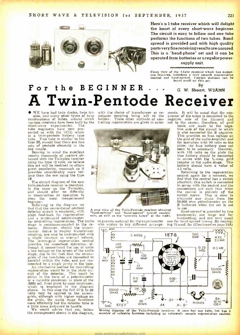
Here's a 1 -tube receiver which will delight the heart of every short -wave beginner. The circuit is easy to follow and one tube performs the functions of two tubes. Band - spread is provided and with high quality parts very fine receiving results are assured. This is a "head- phone" set and it can be operated from batteries or a regular power-
supply unit.
Front view of the 1 -tuhe receiver which has numer- ous features, including a very smooth regeneration control and band -spread. Foreign stations can he
heard swell on this set.
By G. W. Shuart. W2AMN
A Twin -Pentode Receiver WE have had twin diodes, twin tri- odes, and many other types of twin
combinations of tubes, around which various receivers have been built by the short -wave experimenter. The tube engineers have now pre- sented us with the 1E7G which is a twin -pentode battery type tube. This tube is similar to the type 33, except that there are two sets of pentode elements in the one couple.
Bearing in mind the excellent results thousands of readers ob- tained with the Twinplex receiver using the type 19 tube, we believe this set will be destined to attain great popularity, inasmuch as it provides considerably more vol- ume than the one using the type 19.
The circuit diagram of the new twin -pentode receiver is essential- ly the same as the Twinplex, and should offer no difficulty in construction or operation to even the most inexperienced beginner.
Referring to the diagram we find that the conventional pentode detector circuit is employed, with plate feed -back for regeneration and a screen -grid potentiometer for controlling regeneration. The audio stage is resistance- coupled to the de- tector. However, should the experi- menter desire to employ transformer coupling, one may be incorporated with a slight increase in over -all volume. The screen -grid regeneration control provides the smoothest operation, al- though it necessitated the use of quite a low voltage on the screen of the audio stage, due to the fact that the screen - grids of the two -tubes are connected in parallel within the tube, and are rep- resented by a single prong in the base.
An alternative method for controlling regeneration would be in the plate cir- cuit of the detector. This could be either in the form of a potentiometer or a variable condenser in place of the .0005 mf. fixed plate by -pass condenser, which is employed in the diagram shown. In this case the full 67% to 90 volts may be applied to the screen - grids, although with higher voltage on the grids, the audio stage functions more efficiently but the detector tube is a little more awkward to handle.
We would advise that you follow the arrangement shown in the diagram,
with the choice of transformer or re- sistance coupling being left to the builder. These other methods of con- trolling regeneration are given in order
ments. It will be noted that the sup- pressor of the tubes is connected to the negative side of the filament and not to the center, therefore, all grid
leads are made to the nega- tive side of the circuit to which is also connected the B negative. This provides no bias voltage on the grid of the audio amplifier and for operation with 90 volts on the plate, the bias battery does not seem to be necessary. However, with 135 volts on the plate the bias battery should be connected in series with the '4 -meg. grid resistor in the audio stage. This battery should have a value of 4.5 volts.
Returning to the regeneration control again for a moment, we find that the control has a switch attached; this switch is connected in series with the control and the connections are such that when the control is entirely off the switch opens. This is done to eliminate any drain from the 50,000 ohm potentiometer on the B batteries when the set is not in use.
Band-spread is provided by two condensers; one large one for bandsetting, and one very small
one for band- spread tuning. By employ- ing 15 mmf. for (Continued on page 248)
A rear view of the Twin -Pentode receiver showing "band- setting" and "hand- spread" tuning conden- sers. as well as the "antenna tuner" at the right.
to provide material for the experimenter who wishes to try different arrange-
ANT. i
140 MMF
35 j MME
2.
..M.EG /S. --'yVy\/r
It- 100 MMF
N
15 MME
0.5 MF
50,000 OHMS
¿Hp 67.5
1E7 -G MMOF1
0.25- MEG.
006- MF. -
20 1--2V OHMS Al- A -,8-
50.000 OHMS
e+.1135V
Wiring diagram of the Twin -Pentode receiver. It uses but one tube. hut has a number of valuable features including an extremely smooth regeneration control.
www.americanradiohistory.com
224 SHORT WAVE & TELEVISION for SEPTEMBER, 1937
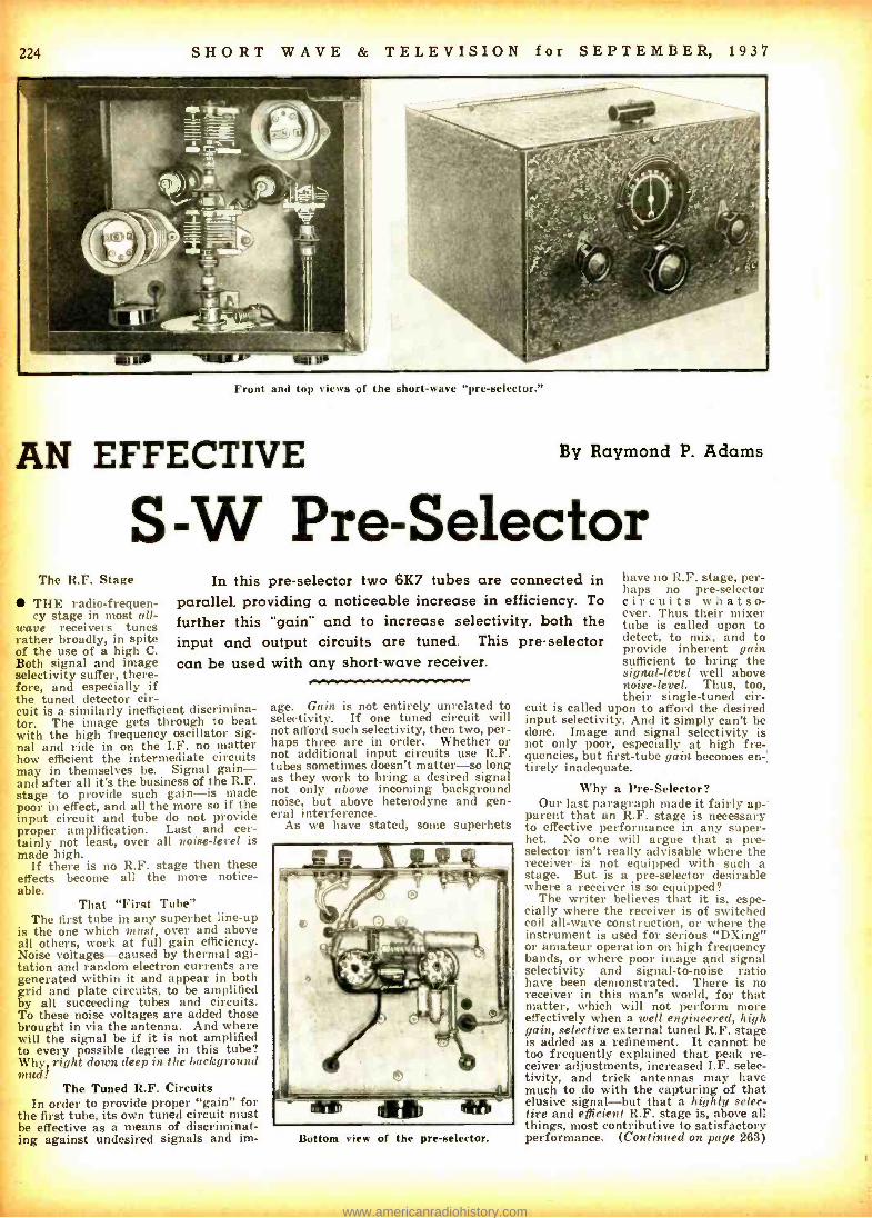
Front and top its of the short -wave "pre- selector."
AN EFFECTIVE By Raymond P. Adams
S -W Pre - Selector The R.F. Stage
THE radio- frequen- cy stage in most all-
wave receivers tunes rather broadly, in spite of the use of a high C. Both signal and image selectivity suffer, there- fore, and especially if the tuned detector cir- cuit is a similarly inefficient discrimina- tor. The image gets through to beat with the high frequency oscillator sig- nal and ride in on the I.F. no matter how efficient the intermediate circuits may in themselves be. Signal gain - and after all it's the business of the R.F. stage to provide such gain -is made poor in effect, and all the more so if the input circuit and tube do not provide proper amplification. Last and cer- tainly not least, over all noise -level is made high.
If there is no R.F. stage then these effects become all the more notice- able.
In this pre -selector two 6K7 tubes are connected in parallel, providing a noticeable increase in efficiency. To
further this "gain" and to increase selectivity, both the input and output circuits are tuned. This pre - selector can be used with any short -wave receiver.
That "First Tube" The first tube in any superhet line -up
is the one which must, over and above all others, work at full gain efficiency. Noise voltages- caused by thermal agi- tation and random electron currents are generated within it and appear in both grid and plate circuits, to be amplified by all succeeding tubes and circuits. To these noise voltages are added those brought in via the antenna. And where will the signal be if it is not amplified to every possible degree in this tube? Why, right down deep in the background mud!
The Tuned R.F. Circuits In order to provide proper "gain" for
the first tube, its own tuned circuit must be effective as a means of discriminat- ing against undesired signals and im-
age. Gain is not entirely unrelated to selectivity. If one tuned circuit will not afford such selectivity, then two, per- haps three are in order. Whether or not additional input circuits use R.F. tubes sometimes doesn't matter -so long as they work to bring a desired signal not only above incoming background noise, but above heterodyne and gen- eral interference.
As we have stated, some superhets
Bottom view of the pre- selector.
have no R.F. stage, per- haps no pre- selector circuits whatso- ever. Thus their mixer tube is called upon to detect, to mix, and to provide inherent gain sufficient to bring the signal -level well above noise- level. Thus, too, their single -tuned cir-
cuit is called upon to afford the desired input selectivity. And it simply can't be done. Image and signal selectivity is not only poor, especially at high fre- quencies, but first -tube gain becomes en tirely inadequate.
Why a Pre -Selector? Our last paragraph made it fairly ap-'
parent that an R.F. stage is necessary to effective performance in any super - het. No one will argue that a pre - selector isn't really advisable where the receiver is not equipped with such a stage. But is a pre -selector desirable where a receiver is so equipped?
The writer believes that it is, espe- cially where the receiver is of switched coil all -wave construction, or where the instrument is used for serious "DXing" or amateur operation on high frequency bands, or where poor image and signal selectivity and signal -to -noise ratio have been demonstrated. There is no receiver in this man's world, for that matter, which will not perform more effectively when a well engineered, high gain, selective external tuned R.F. stage is added as a refinement. It cannot be too frequently explained that peak re- ceiver adjustments, increased I.F. selec- tivity, and trick antennas may have much to do with the capturing of that elusive signal -but that a highly selec- tire and efficient R.F. stage is, above all things, most contributive to satisfactory performance. (Continued on page 263)
www.americanradiohistory.com
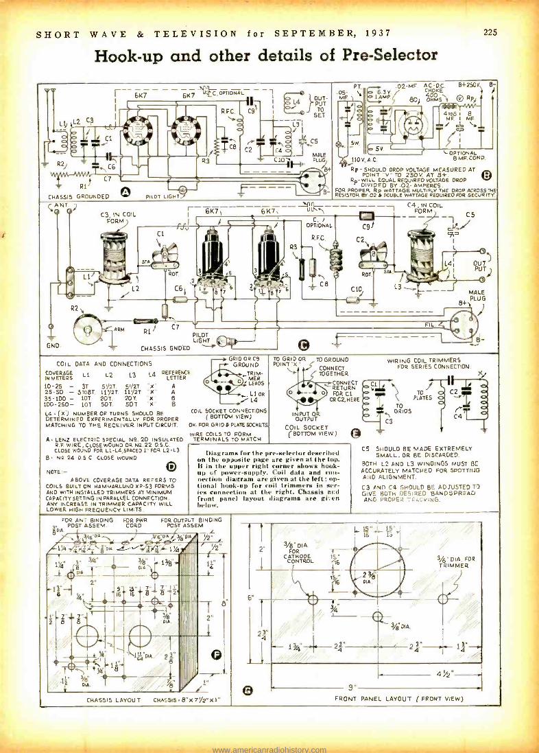
SHORT WAVE & TELEVISION for SEPTEMBER, 1937
Hook -up and other details of Pre -Selector
6K7
I
L1 L2 C3 C / - 11- .Ç1
A--- ó T 4 -. ' R2/ , C6
C7
'7' R1
CHASSIS GROUNDED
6K7 111. CC. OPTIONAL 1
PILOT LIGHT
R3
C C4
4 ?PUT JJ TO
SET
L3 /I 0 C5
_J -MALE CIO, . . PLUG/
8+
PT .05- 1, MF
225
02 -MF A.0 -D C. B +250V B-
0 6.3 V / CHOKE LAMP 7/ 80 4OH OHMS `i
4ro8 1 8 MF. I MF / cl= s"A
(« L OPTIONAL
8 MF. COND.
SW
110V A.C.
Rp- SHOULD DROP VOLTAGE MEASURED AT
O POINT -V" TO 250V AT 8 +. R.- WILL EQUAL REQUIRED VOLTAGE DROP
DIVIDED BY .02- AMPERES. FOR PROPER Rp WATTAGE MULTIPLY THE DROP ACROSS THE RESISTOR BY.02 to DOUBLE WATTAGE REQUIRED FOR SECURITY.
`ANT 2 O O
TIL-------- C4 IN COIL 6K71 ----6K7N - OU`1 FORM
CS
/ } - C.)
OPTIONAL
RFC.
-1
C8
Si= C2`
r
L4¡
ROT STA
L3
OUT) PUT)
MALE PLUG
GNO
PILOT LIGHT
CHASSIS GNDED
COIL DATA AND CONNECTIONS
COVERAGE LI. IN METERS
L2 1.3
10 -25 - 31 5'/27. 5./2T 25 -50 - 5To8T 11%21 11'/2T 35-100 - 10T. 207. 20T 100-250- 10T 50T. 507
L4 REFERENCE LETTER
A A B
x
L4 (X ) NUMBER OF TURNS SHOULD BE DETERMINED EXPERIMENTALLY FOR PROPER MATCHING TO THE RECEIVER INPUT CIRCUIT.
ALENZ ELECTRIC SPECIAL N2. 20 INSULATED R F WIRE, CLOSE WOUND OR N2 22 D S C. CLOSE WOUND FOP. L1-L4,SPACEO 1" FOR L2-L3
B. NQ 24 D 5 C CLOSE WOUND
NOTE - O ABOVE COVERAGE DATA REFERS TO
COILS BUILT ON HAMMARLUND XP -53 FORMS AND WITH INSTALLED TRIMMERS AT MINIMUM CAPACITY SETTING IN PARALLEL CONNECTION. ANY INCREASE IN TRIMMER CAPACITY WILL LOWER HIGH FREQUENCY LIMITS.
GRID OR C9 GROUND
TRIM- MER LEADS
,_.LIoR t.4
COIL SOCKET CONNECTIONS ( BOTTOM VIEW)
OK FOR GRID & PLATE SOCKETS
WIRE COILS TO FORM TERMINALS TO MATCH
TO GRID OR TO GROUND POINT "X"
CONNECT TOGETHER
CONNECT RETURN FOR Cl
OR C2, HERE
INPUT OR OUTPUT
COIL SOCKET (BOTTOM VIEW )
Diagrams for the pre- selector described on the opposite page are given at the top. IS in the upper right corner shows hook- up of power- supply. (oil data and con- nection diagram are given at the left ; op- tional hook -up for coil trimmers in ser- ies connection at the right. Chassis acd front panel layout diagrams are gi; en below.
WIRING COIL TRIMMERS FOR SERIES CONNECTION
.. Xl
fC..
C3
TO GRIDS
TO PLATES
C4
C5 SHOULD BE MADE EXTREMELY SMALL, OR BE DISCARDED.
BOTH L2 AND L3 WINDINGS MUST 13E
ACCURATELY MATCHED FOR SPOTTING AND ALIGNMENT.
C3 AND C4 ;FICULD BE ADJUSTED T) GIVE BOTH DE'.RLD LAND5PIREAD AND PRCPE2 IJ x NG.
FOR AN BINDING POST ASSEM
8 DIA
FOR PWR CORD
FOR OUTPUT BINDING POST ASSEM
V16DA9/eDA AIII 14r 83DIA - 16f6 14,IIiAIIIII
II YI
I
Y2"
%2 T
I"
CHASSIS LAYOUT CHASSIS. 8 X7%2X1"
3/8 DIA FOR
CATHODE CONTROL
15"..4_ i q is
16
24
4
1334, 24,E
3/83 DIA
9"
3/6"DIA FOR TRIMMER
24
4%2"
FRONT PANEL LAYOUT ( FRONT VIEW)
www.americanradiohistory.com

226 SHORT WAVE & TELEVISION for SEPTEMBER, 1937
Front view of the complete transmitter. The "exciter" and "driver" stages are built on the lower panel and sub -base; the
806 "final- amplifier" and control panel being the top one.
THE main purpose in the design of this transmitter was flexibility and simplicity. It is an easy matter to make
an all -band transmitter employing a large number of stages. On the other hand, if proper tubes and circuit arrangements are employed, the problem is not quite so complicated as it
, may seem. In transmitters having fairly high -power amplifier stages,
that is somewhere around 4z kw., (500 watts) the driver stage should receive greatest care in the choice of compo- nents. The tube used as the driver determines whether or not the transmitter would be complicated. If the tube used in this position requires only a few watts excitation, then we can reduce the number of stages to three, providing we do not desire all -band operation with a single crystal. With this transmitter we have chosen the 804, which works excep- tionally well down to 10 meters. The excitation require- ments of this tube are extremely modest, less than 1 watt being sufficient for maximum output.
806 "ALL- This very interesting transmitter employs an 806 as a final amplifier. Details of the exciter and driver stages are given; the exciter unit can be used as a 90 -watt transmitter if desired, This transmitter has been tested "on the air" and has proven to be one of the "smoothest"
operating rigs ever built,
"Pen -tet" Exciter Employed In order to obtain the utmost in flexibility, we resorted to
the "Pen -tet" exciter which was described in the March 1937 issue of this magazine. This unit consists of nothing more than 6F6 pentode crystal- oscillator, followed by a 6L6 mul- tiplier. This arrangement makes it possible to quadruple the crystal frequency with excellent efficiency. With 400 volts on the plates of the oscillator and multiplier, the output of the fourth harmonic and 80 meter crystal is more than sufficient to drive the 804 driver and it is necessary to adjust the coupling in order not to over -drive the large pentode. The 804 pentode seems to be the ideal driver for the 806 final amplifier used in this transmitter, as its output ranges from 50 to 80 watts, depending upon the circuit connections and the voltages applied to the tube.
Excitation Requirement Is Small In our case we used the Tetrode connection and applied
1,000 volts to the plate of the tube. The output with this arrangement was approximately 50 watts with an excita- tion requirement of only .65 watt. This output, of course, is slightly greater than the 25 to 30 watts required for the 806, when operated as a plate- modulated class C amplifier. However, the driver stage, especially in a phone transmitter should have good regulation and a fair surplus of power; proper excitation being obtained by varying the coupling between the driver and the final stage.
Since link coupling is used, a variation of the excitation is simply a matter of the proper placement of the link coil. The amount of grid current present in the final amplifier stage is the best guide to proper excitation adjustment. For class C telegraphy, the final amplifier grid current should be in the neighborhood of 25 to 40 mills. (M.A.) This can be obtained with a 15,000 ohm grid -leak.
Smaller values of grid -leaks may be used with lower voltages.
CRYSTAL 6F6
MF.
x x
6.3V C'0-100 MA
50.000 100 OHMS `MF
¡¡ J R.F.C. b O/ JJb
1 O
T O T', dx
71 .001-
L MF 001
MFfT s.000/
JACK OHMS
1J MF
250 6L6 MMF
)
2.000 OHMS i
X .001- MF
SW
8+ 400V.-5001(
( SEE TEXT) B-
R.F.0 too 2.1 MH MMF
100 15,000 MMF OHMS
0 200 O MMF o
r Q .001-
MF.
804J
SUP
w w
ó1
(EACH) 4 5V
R.FC 2.1 MO
O
too MMF
100 MMF.
fi3_
.001- MF
JACK
100 OHMS
30.000 0.200 1 Sw.OR OHMS
1 00 MA
, KEY
MF.. 1.Ó00V. . \\\®
Y
SW T H. IN
2.
20.000 NOTE - OHMS (ALL TUBE SOCKETS,
BOTTOM VIEW B+ 1000V (EXCEPT 804.WHICH IS TOPVIEw)
.001 ( 7. 5 v I 1.Ó00v
Complete Exciter Unit 50 -to -90 watts; for operation of the exciter alone, the switch in the suppressor -grid circuit should hi in the position which puts .15 volts on the suppressor.
www.americanradiohistory.com
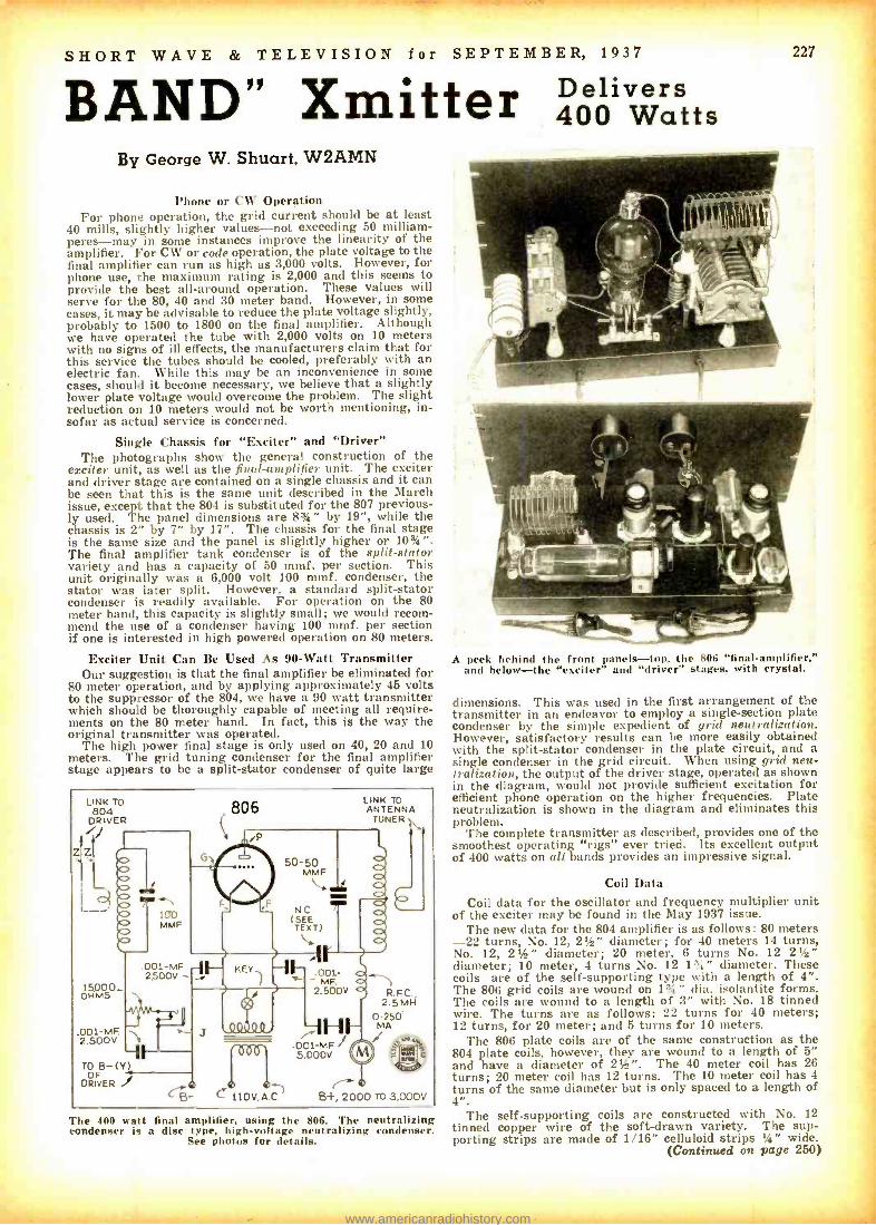
SHORT WAVE & TELEVISION for SEPTEMBER, 1937
BAND" Xmitter Delivers 400 Watts
By George W. Shuart, W2AMN
Phone or CW Operation For phone operation, the grid current should be at least
40 mills, slightly higher values -not exceeding 50 milliam- peres -may in some instances improve the linearity of the amplifier. For CW or code operation, the plate voltage to the final amplifier can run as high as 3,000 volts. However, for phone use, the maximum rating is 2,000 and this seems to provide the best all- around operation. These values will serve for the 80, 40 and 30 meter band. However, in some cases, it may be advisable to reduce the plate voltage slightly, probably to 1500 to 1800 on the final amplifier. Although we have operated the tube with 2,000 volts on 10 meters with no signs of ill effects, the manufacturers claim that for this service the tubes should be cooled, preferably with an electric fan. While this may be an inconvenience in some cases, should it become necessary, we believe that a slightly lower plate voltage would overcome the problem. The slight reduction on 10 meters would not be worth mentioning, in- sofar as actual service is concerned.
Single Chassis for "Exciter" and "Driver" The photographs show the general construction of the
exciter unit, as well as the final -amplifier unit. The exciter and driver stage are contained on a single chassis and it can be seen that this is the same unit described in the March issue, except that the 804 is substituted for the 807 previous- ly used. The panel dimensions are 83/4" by 19 ", while the chassis is 2" by 7" by 17 ". The chassis for the final stage is the same size and the panel is slightly higher or 103/4 ". The final amplifier tank condenser is of the split -stator variety and has a capacity of 50 mmf. per section. This unit originally was a 6,000 volt 100 mmf. condenser, the stator was later split. However, a standard split -stator condenser is readily available. For operation on the 80 meter band, this capacity is slightly small; we would recom- mend the use of a condenser having 100 mmf. per section if one is interested in high powered operation on 80 meters.
Exciter Unit Can Be Used As 90 -Watt Transmitter Our suggestion is that the final amplifier be eliminated for
80 meter operation, and by applying approximately 45 volts to the suppressor of the 804, we have a 90 watt transmitter which should be thoroughly capable of meeting all require- ments on the 80 meter band. In fact, this is the way the original transmitter was operated.
The high power final stage is only used on 40, 20 and 10 meters. The grid tuning condenser for the final amplifier stage appears to be a split -stator condenser of quite large
LINK TO 804
ORIVER 806
G
LINK TO ANTENNA
TUNER
15p00_ OHMS
.001-MF. 2.500V
TO B -(Y) DRIVER J
50 -50 MMF
NC (SEE
.001. MF.
2.500V g
R.F.C., 2.5 MH
0-250- MA HI-
.001-MF 5,000V
/-'0 - C 110V, A.0 B+, 2000 TO 3,000V
The 400 watt final amplifier, using the 806. The neutralizing condenser k a disc type, high -voltage neutralizing condenser.
See photos for details.
227
A peek behind the front panels -top, the 806 "final- amplifier," and below -the "exciter" and "driver" stages, with crystal.
dimensions. This was used in the first arrangement of the transmitter in an endeavor to employ a single- section plate condenser by the simple expedient of grid neutralization. However, satisfactory results can be more easily obtained with the split- stator condenser in the plate circuit, and a single condenser in the grid circuit. When using grid neu- tralization, the output of the driver stage, operated as shown in the diagram, would not provide sufficient excitation for efficient phone operation on the higher frequencies. Plate neutralization is shown in the diagram and eliminates this problem.
The complete transmitter as described, provides one of the smoothest operating "rigs" ever tried. Its excellent output of 400 watts on all bands provides an impressive signal.
Coil Data Coil data for the oscillator and frequency multiplier unit
of the exciter may be found in the May 1937 issue. The new data for the 804 amplifier is as follows: 80 meters
-22 turns, No. 12, 21/2" diameter; for 40 meters 14 turns, No. 12, 2%" diameter; 20 meter, 6 turns No. 12 21/2" diameter; 10 meter, 4 turns No. 12 13á" diameter. These coils are of the self -supporting type with a length of 4 ". The 806 grid coils are wound on 13/4" dia. isolantite forms. The coils are wound to a length of 3" with No. 18 tinned wire. The turns are as follows: 22 turns for 40 meters; 12 turns, for 20 meter; and 5 turns for 10 meters.
The 806 plate coils are of the same construction as the 804 plate coils, however, they are wound to a length of 5" and have a diameter of 21/2". The 40 meter coil has 26 turns; 20 meter coil has 12 turns. The 10 meter coil has 4 turns of the same diameter but is only spaced to a length of 4 ".
The self- supporting coils are constructed with No. 12 tinned copper wire of the soft -drawn variety. The sup- porting strips are made of 1/16" celluloid strips 1 /4" wide.
(Continued on page 250)
www.americanradiohistory.com
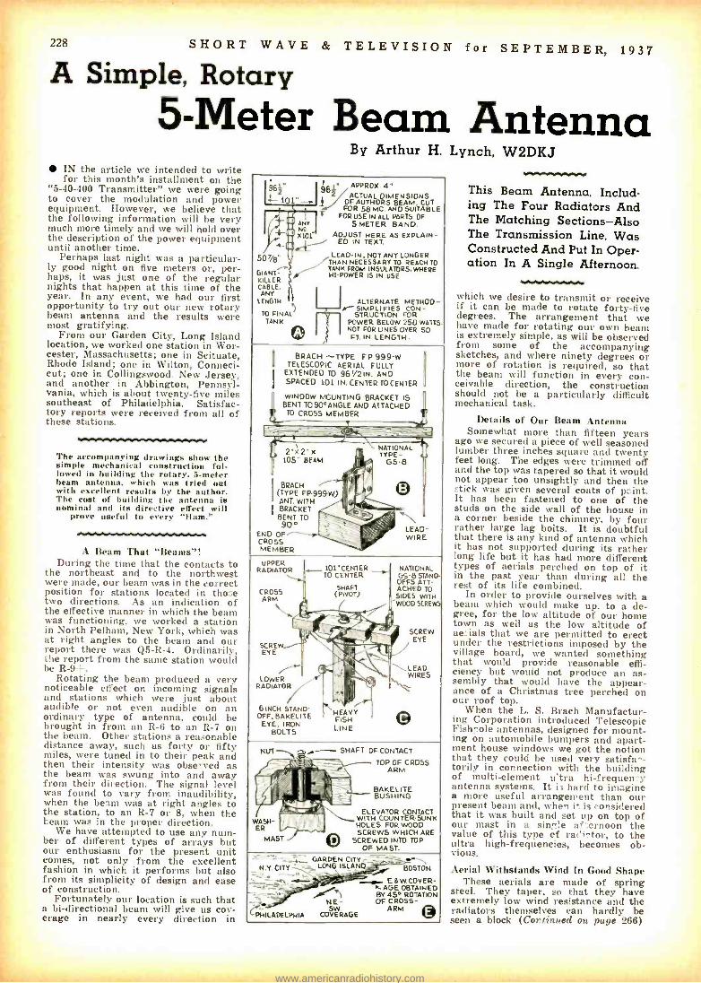
228 SHORT WAVE & TELEVISION for SEPTEMBER, 1937
A Simple, Rotary 5 -Meter Beam Antenna
IN the article we intended to write for this month's installment on the
"5 -40 -400 Transmitter" we were going to cover the modulation and power equipment. However, we believe that the following information will be very much more timely and we will hold over the description of the power equipment until another time.
Perhaps last night was a particular- ly good night on five meters or, per- haps, it was just one of the regular nights that happen at this time of the year. In any event, we had our first opportunity to try out our new rotary beam antenna and the results were most gratifying.
From our Garden City, Long Island location, we worked one station in Wor- cester, Massachusetts; one in Scituate, Rhode Island; one in Wilton, Conneci- cut; one in Collingswood. New Jersey, and another in Abbington, Pennsyl- vania, which is about twenty -five miles southeast of Philadelphia. Satisfac- tory reports were received from all of these stations.
The accompanying drawings show the simple mechanical construction fol- lowed in building the rotary, 5 -meter beam antenna, which was tried out with excellent results by the author. The cost of building the antenna is nominal and its directive effect will
prove useful to every "flam."
A Beam 'l'hat "Beams ": During the time that the contacts to
the northeast and to the northwest were made, our beam was in the correct position for stations located in tho. e two directions. As an indication of the effective manner in which the beam was functioning, we worked a station in North Pelham, New York, which was at right angles to the beam and our report there was Q5 -R -4. Ordinarily, the report from the same station would be R -9 -L.
Rotating the beam produced a very noticeable effect on incoming signals and stations which were just about audible or not even audible on an ordinary type of antenna, could be brought in from an R -6 to an R -7 on the beam. Other stations a reasonable distance away, such as forty or fifty miles, were tuned in to their peak and then their intensity was obsewed as the beam was swung into and away from their direction. The signal level was found to vary from inaudibility, when the beam was at right angles to the station, to an R -7 or 8, when the beam was in the proper direction.
We have attempted to use any num- ber of different types of arrays but our enthusiasm for the present unit comes, not only from the excellent fashion in which it performs but also from its simplicity of design and ease of construction.
Fortunately our location is such that a bi- directional beam will give us cov- erage in nearly every direction in
By Arthur H. Lynch, W2DKJ
62,.
.- I 1" - r 5
APPROX 4"
1 OFAUTHOD25 BEAM CUT FOR 58 MC. AND SUITABLE
50
GIANT- KILLER CABLE,
ANY LENGTH
l0
4-
)/8
.-
r I
ANY R : X101 I-
1 GL
r
T
ADJUST
LEAD THAN TANK HI -POWER
FOR USE IN ALL PARTS OF 5METER BAND.
NERE AS EXPLAIN - EO IN TEXT.
-IN, NOT ANY LONGER NECESSARY TO REACH TO
FROM INSULATORS,WHERE IS IN USE
ALTERNATE METHOD - FOR
POWER BELOW 250 WATTS NOT FOR UNES OVER 50 FT. IN LENGTH.
TO FINAL) TANK
J
BRACH --TYPE FP 999-W TELESCOPIC AERIAL FULLY
EXTENDED TO 96 21N. AND SPACED 101 IN. CENTER TO CENTER
WINDOW MOUNTING BRACKET IS I BENT T090 °ANGLE AND ATTACHED
ID CROSS MEMBER
EN')
MEMBER
2 "X2 "X 105" BEAM
BRACH
H IANT. WIT BRACKET
BENT TO 90 °
OF
!
93W) II \ \..
- -
NATIONAL I TYPE- i. GS -6
, O
LEAD- :/' WIRE WIRE
UPPER RADIATOR 101
TO
CROSS ARM
F
4I -`r EYE I
,,,...--I C LOWER
RADIATOR
6 INCH STAND- OFF. BAKELITE EYE, IRON
BOLTS
"CENTER CENTER
SHAFT (PIVOT)
_la -)')PLI
- HEAVY FISH LINE
NATIONAL OS-8 STAND- OFFS ATT- ACHED TO SIDES WITH
-WOOD SCREWS
SCREW EYE
PLEAD WIRES
NUT ...----'- SHAFT OF CONTACT
ñ N .----. TOP OF CROSS ARM
% -, BAKELITE F, I
WAS_ ER
MAST
1-z! '_.L
BUSHING
ELEVATOR CONTACT WITH R HOLES FO WOOD SCREWS WHICH ARE e SCREWED INTO TOP
OF MAST. - °- ' GARDEN CITY. : _ 1 _ .
N.Y. CITY - LONG ISLAND BOSTON
... `w_i . E &W.COVER- `= 3`` --' '' -AGE OBTAINED r -u- / .1 By 45° ROTATION ek - -0.. NE- OF CROSS -
CPHILADELPHIA COV RAGE ARM
This Beam Antenna. Includ- ing The Four Radiators And The Matching Sections -Also The Transmission Line. Was Constructed And Put In Oper- ation In A Single Afternoon.
which we desire to transmit or receive if it can be made to rotate forty -five degrees. The arrangement that we have made for rotating our own beam is extremely simple, as will be observed from some of the accompanying sketches, and where ninety degrees or more of rotation is required, so that the beam will function in every con- ceivable direction, the construction should not be a particularly difficult mechanical task.
Details of Our Beam Antenna Somewhat more than fifteen years
ago we secured a piece of well seasoned lumber three inches square and twenty feet long. The edges were trimmed off and the top was tapered so that it would not appear too unsightly and then the :tick was given several coats of paint. It has been fastened to one of the studs on the side wall of the house in a corner beside the chimney, by four rather large lag bolts. It is doubtful that there is any kind of antenna which it has not supported during its rather long life but it has had more different types of aerials perched on top of it in the past year than during all the rest of its life combined.
In order to provide ourselves with a beam which would make up, to a de- gree, for the low altitude of our home town as well as the low altitude of aerials that we are permitted to erect under the restrictions imposed by the village board, we wanted something that would provide reasonable effi- ciency but would not produce an as- sembly that would have the appear- ance of a Christmas tree perched on our roof top.
When the L. S. Brach Manufactur- ing Corporation introduced Telescopic Fishnole antennas, designed for mount- ing on automobile bumpers and apart- ment house windows we got the notion that they could be used very satisfa -'- torily in connection with the building of multi -element u'tra hi- frequen -y antenna systems. It h hard to imagine a more useful arrangement than our present beam and, when it is considered that it was built and set up on top of our mast in a sinn'.e ai ".ernoon the value of this type cf ra'i ̂ tor, to the ultra high -frequencies, becomes ob- vious.
Aerial Withstands Wind In Good Shape These aerials are made of spring
steel. They taper, so that they have extremely low wind resistance and the radiators themselves can hardly be seen a block (Cortinued on page 266)
www.americanradiohistory.com

SHORT WAVE & TELEVISION for SEPTEMBER, 1937 229
Short Wave Scouts FORTY -FIRST TROPHY
Presented to SHORT WAVE SCOUT
ALFRED K. KULECK 57 E. Parker St.
Scranton, Pa. 103 Stations -91 Foreign
For his contribution toward the advancement of the art of Radio
by
sNOr WAVE MN II Magazins
WoIsboresedaweisOPPSWWWWWWWW
THE forty -first Short Wave Scout Trophy goes to Alfred K. Kuleck of
Scranton, Pa., for his excellent total of 103 verification cards, 91 of which were foreign. These stations were received on a 1936 Philco model 66OX receiver employing 10 tubes with a 50 ft. single wire some 30 ft. high. Mr. Kuleek's list represents a very interesting period of DXing and he is to be congratulated for his untiring efforts.
His list was neatly prepared, and the cards were in the same chronological order as the list, which greatly aids checking by the judges -other contest- ants please note!
The complete list of the stations and verifications submitted follows:
Stations
Call -Frequency W1XA L- 15.120
Mass. W IXAL- 11.790
Mass. W1XA L -6.040
Mass. W2XAD- 15.330
Heard by Mr. Kuleck United States
Location mc.- University Club. Boston,
mc.- University Club. Boston.
mc.- University Club. 13oston,
mc.- General Electric Co.. Schenectady. N.Y.
W2XAF -9.530 mc.- General Electric Co., Sche- nectady, N.Y.
WSXAL- 17.780 mc. -Bound Brook. N.J. W3XAL -6.100 mc. -Bound Brook. N.J. W3XAU -9.590 mc.- Philadelphia, Pa. W3XAU -6.060 mc.- Philadelphia. Pa. W9XAA- 11.830 mc.- Chicago. Ill. W9XAA -6.080 mc.- Chicago. III. W9XF -6.100 mc. Chicago III.
Canada CFCX -6.005 mc.- Canadian Marconi Co., Mont-
real. Canada. CJRO -6.150 mc.- Winnipeg. Manitoba. Canada CJRX- 11.720 mc.- Winnipeg, Manitoba, Can-
ada. Cuba
COCD -6.130 mc.- Havana. Cuba LOCH -9.428 me.- General Broadcasting Co.,
2 B St., Vedado, Havana COCO -6.010 mc. -P.O. Box 98, Havana, Cuba.
Daily COCQ -9.750 mc. -De la "RCA Victor" Calle
25 No. 44 5. entre 6y 8 Vedado. Havana COCX -11.435 mc. -La Vox del Radio "Philco,"
Apartado 32, Havana, Cuba Mexico
XEFT -9.510 mc. -Av. Indepdencia 28 Vera Cruz. Mex.
XEXA -6.132 mc.- Departamento Autonomo De Publicidad y Propaganda, Mexico City, Mexico.
XEUZ -6.120 mc. -Nat'l Broadcasting Network - Cadena Radio Nacioal, 5 de Mayo 19 y 21. Mexico, D.F.
West Indies HIN -6.243 mc. -La Vox del Partido Domini-
cano. Ciudad Trujillo, Dom. Rep. HIT -6.630 me.-"La Voz de La RCA Victor"
Apartado 1105 Ciudad Trujillo. Dominican Republic.
ON this page is illustrated the handsome trophy which was designed by one of New York's leading silversmiths.
It is made of metal throughout. except the base, which is
made of handsome black Bakelite. The metal itself Is
quadruple silver -plated, in the usual manner of all trophies today.
It is a most imposing piece of work. and stands from tip to base 22''x'- The diameter of the base is 7?.,. The dia- meter of the globe Is 5Sí ". The work throughout is first - class, and no money has been spared in Its execution. It will enhance any home, and will be admired by everyone who sees it.
The trophy will be awarded every month. and the winner will be announced in the following issue of SHORT WAVE a TELEVISION. The winner's name will be hand en- g raved on the trophy.
The purpose of this contest is to advance the art of radio by "logging" as many shortwave phone stations. amateurs excluded. in a period not exceeding 30 days. as
possible by any one contestant. The trophy will be awarded to that SHORT WAVE SCOUT who has logged the greatest number of short -wave stations during any 30 -day period.
HONORABLE MENTION W. A. Dennis E. Berlin, Conn.
J. Dolzanski Winnipeg, Man. Canada
Dr. G. D. DiMarco Chicago, Ill.
William Elliott New York City, N.Y.
Theodore Bottema Bethlehem, Pa.
HIX -6.340 mc.- Secretaria De E de Comuni- caciones y Obras Publica,., Ciudad Tru- jillo, Dom. Rep.
HI1J -5.865 mc. -Box 204. San Pedro de Ma- coria, Dom. Rep.
HI3C -6.730 mc.-"La Voz de La Feria' -La Romana, Dom. Rep.
HI3U -6.015 mc. -"La Vox del Comercio" - Santiago. Dom. Rep.
11I8A -6.479 mc. -"La Fa -Doc en el Aire"- - Apartado 1912, Ciudad Trujillo, Dom. Ren.
HH2S -5.915 mc. -P.O. Box A103, Port au Prince. Haiti.
"Radio- Fort -De- France" -9.450 mc. - Edouard Boullanger Fils. Fort de France, Martinique. French West Indies.
Central America TI4NRH -9.670 mc. -"La Vox de Costa Rica."
Amando Cespedes Marin. Apartado 40, Heredia. Costa Rica.
TGW .9.450 mc.- Radiodifusora Nacional. Min- istre de Fomento, Guatemala City, Guate- mala
HRD 6.235 mc. - -"La Voz de Atlantida," La Ceiba, Honduras
HP5B -6.030 mc. -Mira Mar, Apartado 910, Panama City, Panama
HP5J -9.590 mc. -La Voz de Panama, Aparta- do 867, Panama City. Rep. of Panama
South America LRX -9.660 mc.- -Radio El Mundo. Buenos
Aires LRU- 15.280 mc. -Radio El Mundo, Buenos
Aires PRFS- 9.501 mc. -Comp. Radia Internacional
Do Brazil, Y.O. Box 709, Rio de Janeiro, Brazil
VP3MR -6.010 mc.-'The Br. Guiana Broadcast- ing Co. Ltd., The Voice of Guiana, George- town, British Guiana
CB615- 12.300 mc. -Radio Service, Bandera 176, Casilla 761, Santiago, Chile
HJ1ABE -9.500 mc. -"La Voz de Los Labora- torios Fuentes"
HJIABG -6.042 mc.- Emisora Atlantico, liar - ranquila. Colombia
HJ1ABP -9.600 mc. -Radio Cartagena. Apar- tado 37. Cartagena. Colombia.
HJ3ABD- 6.050 mc.- Emisora Nueva Granada. Colombia Broadcasting S.A.. Apartado 509, Bogota. Colombia.
HJ3ABX- 6.122 me. -"La Voz de Colombia, Apartado No. 26 -65, Bogota, Colombia.
HJ4ABE- 6.097 mc. -"Lo Voz de Antioquia". Medellin, Colombia.
HJ4A BP -6.030 mc.- Emisora Philco, Medellin, Colombia
HSJB -4.107 me. -La Voz de Los Andes. Quito, Rcuador.
HC2JSB- 7.854 mc.- "Ecuador Radio." Guaya- quil, Ecuador
IIC2RL -6.635 mc. -P.O. Box 759, Guayaquil, Ecuador.
PRADO- 6.625 mc.- Fabrica de Tejodos de "El Prado", Apartado 98, Riobamba, Ecuador.
OAXIA -6.125 mc.-- Companio de Radios "Del - car", Casilla No. 9. Chiclayo. Peru.
YVIRB -5.800 mc. -Ecos Del Zulia. Apartado Correos No. 37, Maracaibo, Venezuela.
YV3RC -6.158 mc. -Now YVSRD. Radiodifu- sora Venezuela, Caracas. Venezuela.
YV5RC -5.800 me.-"Le Habla a la Nacion "Radio Caracas, Caracas, Venezuela.
YV5RP -6.270 mc. -"La Voz de La Philco", Apartado 508. Caracas.
YV6RV -6.520 mc. -Now YV4RB. Radiodifu- sora "La Voz de Carabobo", Valencia, Ven- ezuela.
YV9RC -6.400 mc. -Now YV5RH. Emisora Ondas Populares, Apartado 1931. Caracas, Venezuela.
Europe OER2- 11.801 mc.- Osterr. Radioverkehrs A.G.,
Wien. 1.. Johannesgasse 4 b. Vienna. Aus. tria.
(Continued on pope 271)
www.americanradiohistory.com
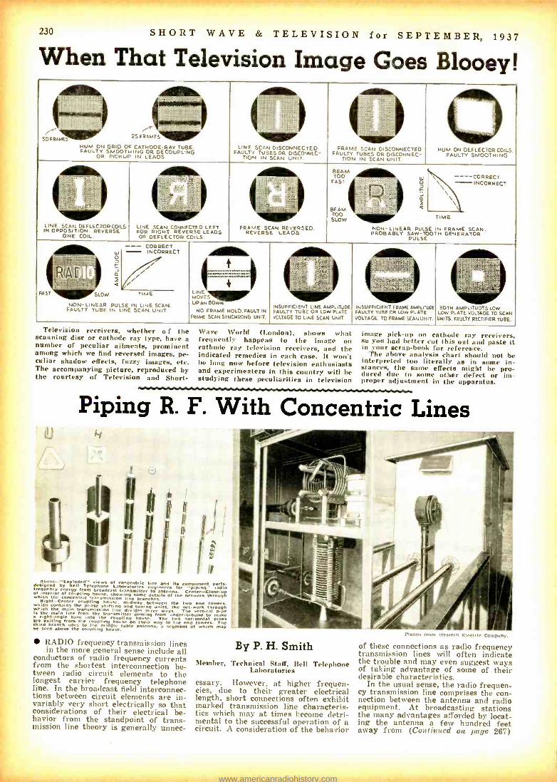
230 SHORT WAVE & TELEVISION for SEPTEMBER, 1937
When That Television Image Goes Blooey!
SO FRAMES 25 FRAMES
HUM ON GRID OF CATHODE -RAY TUBE. FAULTY SMOOTHING OR DECOUPLING
OR PICKUP IN LEADS
LINE SCAN DISCONNECTED. FAULTY TUBES OR DISCONNEC-
TION IN SCAN UNIT.
FRAME SCAN FAULTY TUBES
TION IN
Di OR
SCAN
SCONNECTED. DISCONNEC- UNIT
0 HUM ON DEFLECTOR COILS.
FAULTY SMOOTHING
LINE SCAN IN OPPOSITION.
ONE
BEAM
DEFLECTOR
COIL.
COILS REVERSE
Ï
LINE SCAN FOR RIGHT
OF DEFLECTOR
¡' l
`
i` ...!Lid
CONNECTED LEFT REVERSE LEADS
COILS.
Illi
!if II
i
II
FRAME SCAN REVERSE
l 1 t I
siil ,
t I. .MI ?
REVERSED. LEADS
FASOT itffI t C I, Ç
fa
:I
BEAM isI (.l I...._.. a TOO SLOW
NON- LINEAR PULSE PROBABLY SAW -TOOTH
PULSE
\ --_- CORRECT \ - INCORRECT
\\ TIME
N FRAME SCAN. GENERATOR
FAST
A
NON FAULTY
-
bl o
I SLOW
LINEAR PULSE TUBE. IN LINE
-- CORRECT
LINE MOVE- UP AN COW N
NO FRAME HOLD. FRAME SCAN SYNCHRONE,
FAULT IN UNIT.
a._
INSUFFICIENT LINE AMPLITUDE FAULTY TUBE OR LOW PLATE VOLTAGE TO LINE SCAN UNIT
P .hi `ii3l-
INSUFFICIENT FRAME AMPLEUDE FAULTY TUBE OR LOW PLATE VOLTAGE TO FRAME SCAN UNIT.
:
BOTH AMPLITUDES LOW LOW PLATE VOLTAGE TO SCAN UNITS. FAULTY RECTIFIER TUBE
INCORRECT
/ TIME
IN LINE SCAN. SCAN UNIT
Television receivers, whether o f the scanning disc or cathode ray type, have a number of peculiar ailments, prominent among which we find reversed images, pe- culiar shadow effects, fuzzy images, etc. The accompanying picture, reproduced by the courtesy of Television and Short-
Wave World (L radon), shows what frequently happens to the image on cathode ray television receivers, and the indicated remedies in each case. It won't be long now before television enthusiasts and experimenters in this country will be studying these peculiarities in television
image pick -up on cathode ray receivers, so you had better cut this out and paste it in your scrap -book for reference.
The above analysis chart should not be interpreted too literally as in some in- stances, the same effects might be pro- duced due to some other defect or im- proper adjustment in the apparatus.
Piping R. F. With Concentric Lines
1
.
¡fi . designed by
views of concentric line and its component Part, bit Sell Telephone Laboratories engineers for piping" frequency energy from broadcast transmitter to antenna. Center -Close dun of interior o coupling house, showing a details of the network through which the concentric transmission line é anches. Right -Center coupling house, midway between the two end towers. which contains the phase shifting and tuning :nits. the net work through I.
Bich the main transmission line divides three ways. The vertical p the main line from the transmitter coming from inder- ground to mak a right -angle turn into the coupling house. The two horizontal pipes are from om the coupling house on their way to the end towers. The third branch goes to the middle cable antenna, segment of which may be teen above the coupling house.
RADIO frequency transmission lines in the more general sense include all
conductors of radio frequency currents from the shortest interconnection be- tween radio circuit elements to the longest carrier frequency telephone line. In the broadcast field interconnec- tions between circuit elements are in- variably very short electrically so that considerations of their electrical be- havior from the standpoint of trans- mission line theory is generally unnec-
By P. H. Smith Member, Technical Staff, Bell Telephone
Laboratories
essary. However, at higher frequen- cies, due to their greater electrical length, short connections often exhibit marked transmission line characteris- tics which may at times become detri- mental to the successful operation of a circuit. A consideration of the behavior
,.-.-.,,cil.
Photos from N iiii 11. ,i . l'o.Pany.
of these connections as radio frequency transmission lines will often indicate the trouble and may even suggest ways of taking advantage of some of their desirable characteristics.
In the usual sense, the radio frequen- cy transmission line comprises the con- nection between the antenna and radio equipment. At broadcasting stations the many advantages afforded by locat- ing the antenna a few hundred feet away from (Continued on page 267)
- :,I.R61rrWrr,.e-Me :.-tiI rnsrIìi www.americanradiohistory.com
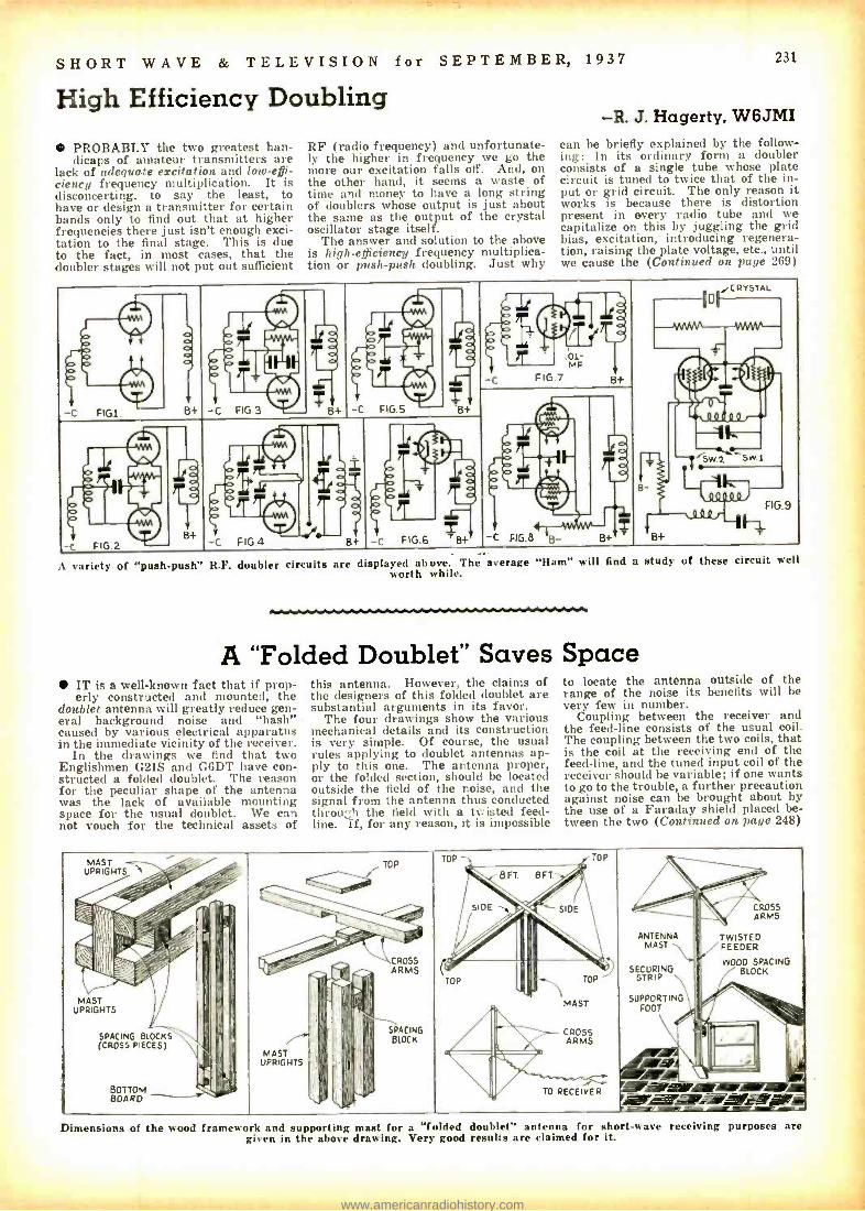
SHORT WAVE & TELEVISION for SEPTEMBER, 1937 231
High Efficiency Doubling
PROBABLY the two greatest han- dicaps of amateur transmitters are
lack of adequate excitation and low-effi- ciency frequency multiplication. It is disconcerting, to say the least, to have or design a transmitter for certain bands only to find out that at higher frequencies there just isn't enough exci- tation to the final stage. This is due to the fact, in most cases, that the doubler stages will not put out sufficient
RF (radio frequency) and unfortunate- ly the higher in frequency we go the more our excitation falls off. And, on the other hand, it seems a waste of time and money to have a long string of doublers whose output is just about the same as the output of the crystal oscillator stage itself.
The answer and solution to the above is high -efficiency frequency multiplica- tion or push -push doubling. Just why
-R. J. Hagerty, W6JMI can be briefly explained by the follow- ing: In its ordinary form a doubler consists of a single tube whose plate circuit is tuned to twice that of the in- put or grid circuit. The only reason it works is because there is distortion present in every radio tube and we capitalize on this by juggling the grid bias, excitation, introducing regenera- tion, raising the plate voltage, etc., until we cause the (Continued on page 269)
,C YSTAL
0 61/
116%
MF V C FIG 7.°1- B+
I T # t ,
- C FIGI, -C FIG 3 + -C FIG 5 8+ h
- -
1164
"Sw.2 Sw1
-
8+
B
-C
FIG 9
FIG.B B- B+ B+ -c FIG 2
B+ -C FIG4
_ -C FIG.6 rB+
variety of "push push" R.F. doubler circuits are displayed above. The average "Ham" will find a study of these circuit well worth while.
A "Folded Doublet" Saves Space IT is a well -known fact that if prop- erly constructed and mounted, the
doublet antenna will greatly reduce gen- eral background noise and "hash" caused by various electrical apparatus in the immediate vicinity of the receiver.
In the drawings we find that two Englishmen G2IS and G6DT have con- structed a folded doublet. The reason for the peculiar shape of the antenna was the lack of available mounting space for the usual doublet. We can not vouch for the technical assets of
this antenna. However, the claims of the designers of this folded doublet are substantial arguments in its favor.
The four drawings show the various mechanical details and its construction is very simple. Of course, the usual rules applying to doublet antennas ap- ply to this one. The antenna proper, or the folded section, should be located outside the field of the noise, and the signal from the antenna thus conducted throu; 'I the field with a twisted feed - line. i f, for any reason, it is impossible
to locate the antenna outside of the range of the noise its benefits will be very few in number.
Coupling between the receiver and the feed -line consists of the usual coil. The coupling between the two coils, that is the coil at the receiving end of the feed -line, and the tuned input coil of the receiver should be variable; if one wants to go to the trouble, a further precaution against noise can be brought about by the use of a Faraday shield placed be- tween the two (Continued on page 248)
MAST UPRIGHTS
: ,í , %
MAST UPRIGHTS
I
SPACING (CROSS
/ ,\\C"O y 'Ve'. , i .F'
BLOCKS PIECES)
BOTTOM BOD
.,` .
' `-`'
-i I /
i
I
I
1 I
8°
T'
II'II +
I
p lü
17 ,; MAST
UPRIGHTS
III¡^ I1
I'.
I
.
i
I I''I I,
I I
. TOP ` i _
- i* CROSS ARMS
''I SDACING II I BLOCK
I
I
TOP Th TOP
ANTENNA
SECURING STRIP
SUPPORTING FOOT
,y
FEEDER
WOOD BLOCK
'
CROSS ARMS
SPACING
8 FT. 8FT.
s10E SIDE
1 . /j AI II , ¡', - \' I _, TOP .h TOP
MAST
Ala:, - CROSS ARMS
" .
O RECE -s+ :SWAM ,
Dimensions of the wood framework and supporting mast for a 'folded doublet" antenna for short -wave receiving purposes are given in the above drawing. Very good results are claimed for it.
www.americanradiohistory.com
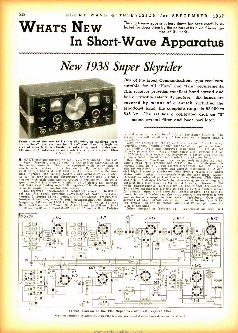
É
232 SHORT WAVE
WHAT'S NEW & TELEVISION for SEPTEMBER, 1937
The short -wave apparatus here shown has been carefully se- lected for description by the editors after a rigid investiga-
tion of its merits.
In Short -Wave Apparatus
New 1938 Super Skyrider
Front view of the new 1938 Super Skyrider, an excellent "com- munications' type receiver for "Ham" and "Fan." A high de- gree of selectivity is afforded, thanks to a carefully designed I.F. amplifier featuring variable selectivity, plus a crystal filter
circuit. No. 641.
MANY new and interesting features are combined in the 1938 Super Skyrider, one of them is the unique construction of
the tuning controls. These are equipped with heavy balance wheels which makes tuning far easier. By merely giving a twist to the knobs it will continue to rotate for quite some time. Further -the tuning controls are accurately calibrated. As can be seen from the photograph, the main dial is clearly marked with each band and calibrated in frequency. The band - spread control has a special combination of electro and mechan- ical features providing over 1,000 degrees of band -spread, which is quite ample for comfortable tuning.
This receiver incorporates a frequency range of 62,000 to 545 kc. Six bands covering everything of "air" interest -5 meters, 7 meters (2 -way police), all "broadcast" frequencies, foreign short -wave, aircraft, relay broadcasting, etc. Band 1- frequency 545 kc. to 1,550 kc.; Band 2 -1,550 kc. to 4.3 mc.; Band 3 -4.2 mc. to 10.2 mc.; Band 4 -9.8 mc. to 20.5 mc.; Band 5 -19 mc. to 36 me.; Band 6 -35 mc. to 62 mc. A Band Pointer
One of the latest Communications type receivers. suitable for all "Ham" and "Fan" requirements. This receiver provides excellent band- spread and has a variable selectivity feature. Six bands are covered by means of a switch. including the broadcast band; the complete range is 62.000 to 545 kc. The set has a calibrated dial. an "S"
meter. crystal filter and beat oscillator.
is used as a tuning aid, found only on the Super Skyrider. The average over -all sensitivity of the receiver is better than 1 microvolt.
Now for selectivity. There is a wide range of variable se- lectivity, from "single- signal" razor -edge sharpness to broad high- fidelity. New and improved iron core I.F. transformer circuits permit this "Wide Range Selectivity" control (7.5 kc. to 25.5 kc.). With crystal in, selectivity is better than one kc., giving a total ratio of variable selectivity of over 30 to 1.
Band Spread: The Super Skyrider not only satisfies the usual band -spread requirements but betters them. Band -spread is accomplished in a unique electro- mechanical manner, highly efficient electrically; simple and smooth mechanically. A spe- cial high frequency condenser with double rotors and single stator units, makes a tuning -unit with the band -spread section forming an integral part of the main condenser. This simple and sensible design feature, by eliminating extra wiring and parallel insulator losses in the tuned circuits, achieves worth- while improvements, particularly at the higher frequencies. The added mechanical rigidity gained by such a system makes for steadier signals and smoother tuning ability. The new dy- namic balanced tuning and the large controls represents a new and exclusive concept in band -spread technique. Over 1,000 degrees of band -spread calibration provide better than 5 kc. per division on the 20 meter band, and 25 kc. per complete turn of the knob.
Other outstanding features -11 (Continued on page 268)
bo
el9 RS` !R2 ti
6K7
MSC
CII CI] nnl
IB
R3 R4
6L7 SW 1
6K7 6 K7 6 R7
C23
Cu °y CI5 °i C16
C°.L 1
czrT.T1 C25
RC
9
26
Z
R to
R16
417
=
C36 522 ' C4
R27 C ¡ C42 77 S
6K7 C31 sasf pasla C R14 ,
/C21 i-C2o p7) .C22 5wz j
;::
F33 R6 }k 6]5 _ ° 6]7 "ti!.
atre LOT Sw
5w 3
i 6V6
CB C3 5e44
SqOV, Il
C
SW S
` 6V6
Circuit diagram of the 1938 Super Skyrider, with crystal filter. Names and addresses of manufacturers of apparatus furnished upon receipt of postcard request; mention No. of article.
www.americanradiohistory.com
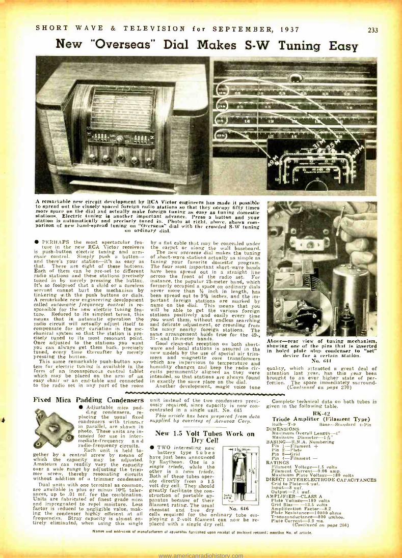
y
SHORT WAVE & TELEVISION for SEPTEMBER, 1937
New "Overseas" Dial Makes S -W Tuning Easy 233
RaiMMISMNres
- - - s ---_ --^. ï larlis111ß_`41.
MIMS
A remarkable new circuit development by RCA Victor engineers has made it possible to spread out the closely spaced foreign radio stations so that they occupy fifty times more space on the dial and actually make foreign tuning as easy as tuning domestic stations. Electric tuning is another important advance. Press a button and your station is automatically and precisely tuned in. Photo at right, above, shows com- parison of new band- spread tuning on "Overseas" dial with the crowded S -W tuning
on ordinary dial.
PERHAPS the most spectacular fea- ture in the new RCA Victor receivers
is push- button electric tuning and arm- chair control. Simply push a button - and there's your station -it's as easy as that. There are eight of these buttons. Each of them can be pre -set to different radio stations and these stations precisely tuned in by merely pressing the button. It's so foolproof that a child or a careless servant cannot hurt the mechanism by tinkering with the push buttons or dials. A remarkable new engineering development called automatic frequency control is re- sponsible for the new electric tuning fea- ture. Reduced to its simplest terms, this means that in automatic operation the radio circuit will actually adjust itself to compensate for any variation in the me- chanical system so that the station is pre- cisely tuned to its most resonant point. Once adjusted to the stations you want you can always get them back, precisely tuned, every time thereafter by merely pressing the button.
This same remarkable push- button sys- tem for electric tuning is available in the form of an inconspicuous control tablet which may be placed on the arm of an easy chair or an end -table and connected to the radio set in any part of the room
Fixed Mica Padding Condensers Adjustable mica pad- ding condensers, re-
placing the usual fixed condensers with trintm, r in parallel, are shown in photo. These units are in- tended for use in inter- mediate- frequency a n d radio -frequency circuits.
Each unit is held to- gether by a central screw by means of which the capacity may be adjusted. Amateurs can readily vary the capacity over a wide range by adjusting the trim- mer screw, thereby resonating circuits without addition of a trimmer condenser.
Dual units with one terminal as common, are available in plus or minus 10% toler- ances, up to .01 mf. for the combination. Units are fabricated of finest grade mica and impregnated to repel moisture. Loss factor is reduced to negligible value, mak- ing the condenser highly efficient at all frequencies. Stray capacity is almost en- tirely eliminated, when using this single
by a flat cable that may be concealed under the carpet or along the wall baseboard.
The new overseas dial makes the tuning of short-wave stations actually as simple as tuning your favorite domestic program. The four most important short -wave bands have been spread out in a straight line across the front of the radio set. For instance, the popular 25 -meter band, which formerly occupied a space on ordinary dials never more than % inch in length, has been spread out to 9% inches, and the im- portant foreign stations are marked by name on the dial. This means that you will be able to get the various foreign stations positively and easily every time you want them, without endless searching and delicate adjustment, or crowding from the many nearby foreign stations. The same arrangement holds true for the 49 -, 31- and 19 -meter bands.
Good clean -cut reception on both short- wave and local stations is assured in the new models by the use of special air trim- mers and magnetite core transformers which are impervious to temperature and humidity changes and keep the radio cir- cuits permanently aligned as they were intended, so that stations are always found in exactly the same place on the dial.
Another development, magic voice tone
unit instead of the two condensers previ- ously required, since capacity is now con- centrated in a single unit. No. 645
This article has been prepared from data supplied by courtesy of Aerovox Corp.
New 1.5 Volt Tubes Work on Dry Cell
TWO interesting new battery type tubes
have just been announced by Raytheon. One is a single triode, while the other is a twin triode. Both of these tubes oper- ate directly from a 1.5 volt dry cell. They should greatly facilitate the con- struction of portable ap- paratus because of their filament rating. The usual rheostat and two dry cells required for the ordinary tube em- ploying a 2 -volt filament can now be re- placed with a single dry cell.
No. 646
Above -rear view of tuning mechanism, showing one of the pins that is inserted in holed plate atop condenser to "set"
device for a certain station. No. 644
quality, which attracted a great deal of attention last year, has this year been brought to an ever higher state of per- fection. The space immediately surround -
(Continued on page 270)
Complete technical data on both tubes is given in the following table.
RK -42 Triode Amplifier (Filament Type) Bulb -T -9 Base- Standard 4 -Pin
DIMENSIONS Maximum Overall Length -4' Maximum Diameter -1 A,-
BASING- R.M.A. Numbering Pin 1- Filament + Pin 2 -Plate Pin 8 -Grid Pin 4- Filament -
RATINGS Filament Voltage -1.5 volts Filament Current -0.06 amp. Maximum Plate Voltage -180 volts
DIRECT INTERELECTRO DE CAPACITANCES Grid to Plate -6 uuf. Input -3 tuf. Output -2.1 uuf.
AMPLIFIER -CLASS A Plate Voltage -180 volts Grid Bias- -13.5 volts Amplification Factor -8.2 Plate Resistance -10300 ohms Transconductance -800 umhos. Plate Current -3.9 ma.
(Continued on page 256) Names and addresses of manufacturers of apparatus furnished upon receipt of postcard request; mention No. of article.
www.americanradiohistory.com

t
234 SHORT WAVE
Let's "Listen In" With
alzlévv
Our Short Wave "DX" Editor
Winner of 30th "S -W Scout" Trophy
All Times E. S. T.
DX for the past month (June) has been quite active and numbers of new catches
have been heard by those DXers who haven't packed away the old DX rig in mothballs for the summer.
We have spent much time (and cur- rency) in rigging up a new matched- imped- ance doublet antenna here and the results certainly atoned for the bruises, blisters, mosquito bumps, etc., suffered in erecting the antenna in this neck of the woods.
Stations in Europe and Asia, to which antenna is partial, being d!rectional East and West, came in with "roaring" s'gnals, and we await the quiet DX season this fall and winter with eagerness, con- fident in the belief this sky -wire will "drag 'em in" as never before, especially from the Orient.
Details on the doublet will be sent to all DXers who will send a stamped self - addressed envelope. And so to DX:
SIAM HSE2, 19.016 mc., at Bangkok, has been
heard late in June, twice in one morning, at 6:30 a.m., and again at 9:10 a.m., both times in communication with DFB. Nauen, Germany, on 17.52 mc. HSE2 had a stronger signal at the earlier time but was well heard at both times.
As our friend Sangiem Powtongsook, Asst. Engineer at HSRPJ has told us, Sia- mese radiophone stations are now equipped with apparatus for inverted speech modu- lation, and we noted that in our reception of HSE2. DFB was clearly heard to call "Hello, Bangkok," several times and to address Mr. Powtongsook in person, before both switched to inverted speech.
In an unusually long letter, Mr. Pow - tongsook, a young man of 27, operator of 3 Siamese amateur stations, and who has amassed all his radio knowledge from the study of books purchased from the U.S. A. and England, gives us some valuable data concerning the operation of the famous Siamese Xmtrs.
Here's the dope: HSE2, 19.016 mc., (ones JVE, Tokio, 15.66 mc. anytime between 11 p.m. and 6 a.m., and IISE2 also fones DFB anytime between 3 -5 a.m. and 8 -9 p.m., when there is a commercial call.
HSP, on 17.74098 mc., or, in fact, 17.741 mc. (this differs from frequency given in HSP veri), will be used only where HSE2 is unavailable. Ordinarily, HSP will be heard on CW only.
During the period from August- Novent- ber, 1936, HSG2, 15.53 mc., was used for radiophony. However, upon Mr. Powtong- sook's suggestion, HSE2 was used and re- sults using same power as HSG2 were much improved, so HSG2 was thereafter silent.
Regarding the recent rumor that Siam would no longer verify reports, it is clearly stated that all reports are welcomed, and will be answered as soon as possible, but owing to the lack of staff and time, some delay must be expected.
Thank you, Mr. Powtongsook, for a most informative and interesting letter, and
& TELEVISION for SEPTEMBER, 1937
C:`
THIENS-CREECE
gVii ;i 800'*3 ..... < oo ,4,7T
Ar:,.TvLi-WG+rí Ire rI NW(SE
ax ,.6,c`,.41
SVIKE -the Greek station sends a handsome QSL; light blue red letters.
please w r i t e again, often, OM!
FRENCH SOMALILAND FZE8, 17.28 mc., located at DJIBOUTI,
has confirmed our recent reception of their station while heard in contact with France; a letter -Teri with the gorgeous stamps on cover for which the French Colonies are famous. Quite informally, the Chief Engi- neer comments on a photo sent with our report, adding that a pipe, shown in photo, must have helped overcome our discomfort in posing for the picture, hi!
The Chief also adds that FZE8 is gen- erally to be heard in radio -phone com- munication with France on the first days of each month from 7:35 -8:15 a.m. The veri took just 5 weeks to arrive, to and from DJIBOUTI! Unusually prompt!
FZE8 was again heard phoning France, this time at 9:05 a.m. Signal was an R7 -8 here! QRA (address) in previous issue.
INDIA VCS, 12.87 mc., Mingaladon, Burma,
which is considered a separate country from India proper, was logged on several occasions during the past month, at 5:50 a.m. and again at 6 a.m. using inverted speech. A typical Asiatic "bumpy" signal here, with good strength. VVS generally phones VVN, 13.26 mc., at Fort Madras, India.
In a letter from Mr. Ashley at VWY, Poona, the QRA of VVS is given as: Sta- tion Engineer, Wireless Station VVS, Mingaladon, Burma, India, VVS, is located just to the HF side of CNR, so should not be too difficult to "log."
Jim Langon of Vancouver, B. C., relates
hearing the Rangoon Gov't. station during April and May, and that the station shifted often, being on 6.08, 6.06, and lastly 6.005 mc. Tnx for the "bouquet," Jim, and glad to hear from you.
MADAGASCAR Radio Tananarive, 6.01 mc., at Tanana-
rive, has at last replied to our report of last November, and, to our joy, verifies most specifically our report of November 29, when we heard them with such an unusual signal that we were somewhat doubtful that we were actually hearing Madagascar! Reception that morning was exceptionally good, especially from the di- rection of South Africa, as ZEB in South- ern Rhodesia was also heard, though not well enough to get an acceptable report.
Radio Tananarive is lately reported to be using frequencies in the 25 and 31 meter bands, near 9.50 and 11.81 mc., be- sides their 6.01 mc. wave. Times reported are 12 -12:30 a.m. and 9:45 -10:30 a.m. We have not been informed as to which fre- quencies may be heard at these times, and doubt that all broadcast simultaneously.
QRA is: Le Directeur des P. T. Admin- istration des P. T. T., Tananarive, Mada- gascar.
MOZAMBIQUE CR7BH, 11.718 mc., Laurenco Marques
has verified reports of Ashley Walcott, John DeMyer, Charles Miller and Irving Cohen. Card is green and black, in same design as CR7AA's QSL. The best time for reception here is between 9:30 -11 a.m. Full schedule is: Weekdays 11:45 p.m. -12:30 a.m.; 9:30 -11 a.m.: 12:45 -3:45 p.m. On Sundays 5:30 -7 a.m.; 10 a.m.-12:30 p.m.; 1:30 -3:30 p.m. (Continued on page 2361
G. W. WESTCOTT.
Radio `rwL
Xmtr: 75 watts Pair 210's final
Ream Antenna
O\1 TM1X ' y 7,
M. D. BELGIAN CONGO
OQ.5 A A/1c Glad to /i I 93 'J-at ay-loc. M.T.
. ` í .
ir !l _ t ' = If j a , r. 1i 1
4'I ,,. 1/ I
, t - s` . 1Ì ' ,{
V r 1
n
' ' . - r
-
tati ` ;
,i @ic
TONDO., IREBU
on.-
.
Rcvr: RME-69
i M/ ANt., 1"'
ote Stet ;.1;
.
°
o c/i /1
OQ5AA -From the Congo conies this tine card, all in black.
www.americanradiohistory.com
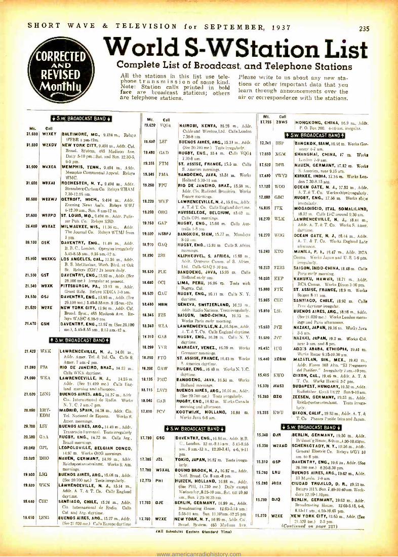
SHORT WAVE & TELEVISION for SEPTEMBER, 1937 235
World S- WStation List Complete List of Broadcast. and Telephone Stations
All the stations in this list use tele- phone transmission of some kind. Note: Station calls printed in bold face are broadcast stations; others are telephone stations.
Please write to us about any new sta- tions or other important data that you learn through announcements over the air or correspondence with the stations.
S BROADCAST BAND +
Mc. Call 31.600 WBXEY
81.600
31.600
51.600
31.000
81.100
*100
21.100
26.960
21.560
21.540
21.530
21.520
BALTIMORE, MD., 9.494 m., Relays 1VFBR 4 pm -12m.
W2XDV NEW YORK CITY, 9.494 m., Addr. Col. Broad. System, 485 Madison Ave. Daily 5-10 pm.; Sat. and Sun. 12.30.5, 6-9 pm.
W4XCA MEMPHIS, TENN., 9.494 m., Addr. Memphis Commercial Appeal. Relaye WMC.
WIXAI ROCHESTER, N. Y., 9.494 m., Addr. Stromberg Carlson Co. Relays WHAM 7.30 -12.05 am.
W$XWJ DETROIT, MICH., 9.494 m., Addr. Evening News Ass'n. Relays WWJ 6 -12.30 am., Sun. 8 am -12 m.
W9XPD ST. LOUIS, MO., 9.494 m., Addr. Pulit- zer Pub. Co. Relaye KSD.
WIXAZ MILWAUKEE, WIS., 11.36 m., A,hlr. The Journal Co. Itclays WTMJ from 1 pm.
01K DAVENTRY, ENO., 11.49 m., Addr. B. B. C., London. Operates irregularly 5.45 -8.55 am., 9.55 am.-12 n.
WSXKG LOS ANGELES, CAL, 11.56 m., Addr. B. S. McGlashun, Wash. Blvd. at Oak St. Relays KGFJ 24 boors daily.
GST DAVENTRY, ENO., 13.92 m., Addr. (See 211.100 me.) Irregular at present.
W8XK PITTSBURGH, PA., 13.93 m., Addr. Grant Bldg. Relays KDKA 7 -9 am.
GSJ DAVENTRY, ENG., 13.93 m., .Addr. (See 26.100 me.) 5.45-8.55 am. .9.I5am: 12n.
W2XE NEW YORK CITY, 13.94 m., Addr. Col. Broad. Syst., 485 Madison Ave. Re- lays WABC 6.30.9 am.
DAVENTRY, ENG., 13.97 m. (See 26.100 me.), 5.458.55 ant.. 9.1 5 a m.-12 n.
21.470 GSH
21.420
21.080
21.060
21.020
20.860
20.700
20.380
20.040
20.020
19.900
19.820
19.680
? 5.W. BROADCAST BAND?
WICK
PSA
WKA
LSN6
ERY- EDM
LSY
GAA
OPL
DHO
LSG
WKN
CEC
19 650 LSN5
LAWRENCEVILLE, N. J., 14.01 m., Addr. Amer. Tel. & Tel. Co. Calls S. Amer. 7 am.-7 pm.
RIO DE JANEIRO, BRAT., 14.23 m.. Calls WKK daytime.
LAWRENCEVILLE, N. J., 14.25 m. Addr. (See 21.420 me.) Calls Eng- land morning and afternoon.
BUENOS AIRES, ARO., 14.27 m., Addr Cia. Internacional dc Radio. Works N. Y. C. 7 am. -7 pm.
MADRID, SPAIN, 14.38 m., Addr. Cia. Tel. Nacional de Espana. Works S. Amer. mornings.
BUENOS AIRES, ARG., 14.49 m., Addr. Transrmlio Internal!. Tests irregularly
RUGBY, ENG., 14.72 m. Calls Arg., Brazil mornings.
LEOPOLDVILLE, BELGIAN CONGO, 14.97 m. Works ORG mornings.
NAUEN, GERMANY, 14.99 m., Addr. Reichspostzenstralamt. Works S. Am. mornings.
BUENOS AIRES, ARO., 15.08 in., Addr. (See 20.700 mc.) Testa irregularly.
LAWRENCEVILLE, N. J.. 15.19 m., Addr. A. T. & T. Co. Calls England daytime.
SANTIAGO, CHILE, 15.24 m., Addr. Cia. Internacional de Radio. Calla Col. and Arg. daytime.
BUENOS AIRES, ARG., 15.27 m., Addr. (See 21.020 me.) Calls Europe daytime
Mc. 19.620
19.600
19.480
19.355
19.345
19.260
19.220
19.200
19.160
19.020
18.9 -0
18.890
18.830
18.680
18.620
18.480
18.345
18.340
18.310
18.299
18.250
18.200
18.135
18.115
18.040
17.810
17.790
17.706
17.790
17.770
17.760
17.760
Call VQG4
LSF
GAD
FTM
PMA
PPU
WKF
ORG
GAP
HS$PJ
GAQ
ZSS
PLE
0CI
GAU
H8H
FZS
WL.A
GAS
YVR
FTO
GAIV
PMC
LSY3
GAB
PCV
?NAIROBI, KENYA, 15.28 m., Addr. Cable and Wireteas,Ltd. Calls London 7.30 -8 am.
BUENOS AIRES, ARG., 15.31 m., Addr. (Skr 20.70) nie.) Tests irregularly.
RUGBY, ENO., 15.4 in. Calls VQG4 7.3(1 -8 am.
ST. ASSISE, FRANCE, 15.5 m. Calls S. America mornings.
BANDOENG, JAVA, 15.51 m. Works Holland 5.30 -11 am.
210 DE JANEIRO, BRAL, 1.5.58 m., Addr. Cia. R:uliotel. Brasilcira. Works France mornings.
LAWRENCEVILLE, N. J., 15.6 m., Addr. A. T. k T. Co. Calls England daytime.
RUYSSELEDE, BELGIUM, 15.62 m. Calls OPI, mornings.
RUGBY, ENO., 15.66 m. Culls Aus- tralia 1.8 am.
BANGKOK, SIAM, 15.77 m. Mondays 8-10 am.
RUGBY, ENG., 15.81 m. Calls S. Africa I mornings. I KLIPHEUVEL, S. AFRICA, 15.88 m.,
Addr. Overseas ('noun. of S. Africa, Ltd. Calls GAQ 9.10 am.
BANDOENG, JAVA, 15.93 m. Calls Holland early am.
LIMA, PERU, 16.06 m. Tests with Bogota, Col.
RUGBY, ENG., 16.11 m. Calls N. Y. daytime.
GENEVA, SWITZERLAND, 16.23 m., Addr. ?tad io N -.iI. <. T.-Is irregularly.
SAIGON, INDO- CHINA, 16.35 m. Works Pari. ' ,tit ruing.
LAWRENCEVILLE, N.4,16.36 Addr. A. T. k T. Co. Calls England daytime.
RUGBY, ENG., 16.38 m. Calls N. Y. daytime.
MARACAY, VENEZ., 16.39 m. Works Germany mornings.
ST. ASSISE, FRANCE, 16.43 m. Works S. America daytime.
RUGBY, ENO., 16.48 m. Works N. Y.C. daytime.
BANDOENG, JAVA, 16.54 m. Works Holland mornings.
BUENOS AIRES, ARG., 16.56 m., Addr. (Sec 20.700 mc.) Tests irregularly.
RUGBY, ENG., 16.83 m. Works Canada morning and afternoon.
KOOTWIJK, HOLLAND, 16.84 m. Works .lava 6 -8 am.
Mc. 17.755
17.741
17.650
17.520
17.410
17.110
17.010
11.1136
1{270
16.270
11.240
16.233
11.030
16.110
15.105
15.810
15.060
15.020
16.150
15.440
16.116
16.370
15.310
16.366
15.340
16.330
16.110
16.210
15210
15.200
16.270
Call
I ZBWS HONGKONG, CHINA, '.III m., Addr. I,. O. Ii c ?rnL 4.I. rregnlar.
? S.W. BROADCAST BAND?
11,1'
XGM
DFB
VWY2
WOO
GBC
ITK
WLK
WOG
KTO
FZR3
KKP
FTK
CEC
ISL
JVE
J1'F
ll'G
XEBM
KWO
HASS
DZG
KWU
BANGKOK, SIAM, 11 ,91 Ia. Works Ger- many 4 -7 am.
SHANGHAI, CHINA, 17 na. Works Inndon 7 -9 am.
NAUEN, GERMANY, 17.12 m. Works S. America, near 9.15 am.
KIRKEE, INDIA, 17.16 na. Works Lon- don 7.30 -8.15 am.
OCEAN GATE, N. J., 17.52 m., Addr. A. T. k T. ('o. Works shipeirregularly,
RUGBY, ENO., 17.56 m. Works ships irregularly.
MOGADISCIO, ?TAL SOMALILAND, 18.32 m. Calls IA(' around 9.30 am.
LAWRENCEVILLE, N. J., 18.44 m., Addr. A. T. A T. Co. Works S. Amer. daytime.
OCEAN GATE, N. J., 18.44 m., Addr. A. T. k T. Co. Works England Late afternoon,
MANILA, P. I., 18.47 m., Addr. RCA Comm. Works Japan and U. S. 5-9 pm.
irregularly. SAIGON, INDO-CHINA, 18.48 m. Calls
Paris early morning. KAHUKU, HAWAII, 18.71 m., Addr.
RCA Comm. Works Dixon 3-10 pm. ST. ASSISE, FRANCE, 18.9 m. Works
Saigon 8-11 am.
SANTIAGO, CHILE, 18.91 m. Calls Peru daytime irregular,
BUENOS AIRES, ARG., 18.98 m., Addr. (See 21.020 mc.) Works London morn- ings and Paris afternoons.
NAZAKI, JAPAN, 19.16 m. Works Java 35 am.
NAZAKI, JAPAN, 19.2 m. Works Cal. near 55 am. and 8 pm.
ADDIS ABABA, ETHIOPIA, 19.41 m. Works Rome 9.15 -10.30 am.
MAZATLAN, SIN., MEL, 19.43 m., Addr. Flores 103 Alto. "El Pregonero del Pacifico." Irregularly 7 am.-I0 pm.
DIXON, CAL, 19.46 m., Addr. A. T. & T. Co. Works Hawaii 2 -7 pm.
BUDAPEST, HUNGARY, 19.52 m.,Addr. Radiolabor. Gyali Ut 22. Sun 9-10 am.
ZEESEN, GERMANY, 19.53 m., Addr. Reichspostze,stmlamt. Teats irregu- larly.
DI XON, CALIF., 19..53 m., Addr. A. T. A T. Co. Phasen Pacific Isles and Japan.
4. 5 W. BROADCAST BAND + + S
OJR
W2XAD
GSP
LRU
HISX
DJQ
W2XE NEW
(Continued
W. BROADCAST BAND +
BERLIN, GERMANY, 19.56 m., Addr. Br ilnust'g lIousr, 8- 9am.,4.50- 10.45pm.
SCHENECTADY, N. Y., 19.56 m., Addr. (haunt! Electric Co. Relays WGY 10 am. to 8 pm.
DAVENTRY, ENO., 19.6 m., Addr. (See 26.100 nlr.) 6.20-8.30 pm.
BUENOS AIRES, ARO., 19.62 m., Addr. El Mundo. 7-9 am.
CIUDAD TRUJILLO, D. R., 19.63 in. Relays MX Sun. 7.40- 10.40am. Week- days 1 2.10- 1.10pm.
BERLIN, GERMANY, 19.63 m., Addr, Broadcasting House, 12.05 -5.15, 6-8, 8.15-11 am., 4.50-10.45 pm.
YORK CITY, 19.65 m., Addr. (See 21.520 mc.) 2 -5 pm.
on pape 237)
GSO
JZL
WHAM.
PHI
DJE
W2XE
DAVENTRY, ENG., LV. 6,, in. . Addr. B.B. C.. London. 12 m.-2. I 5 am_ 5.4.5-8.55 am., 9 am.-12 n., 12.20-3.45, 4-6, 9.11
pm. OK10, JAPAN, 16.87 in. Tests irregu- larly.
BOUND BROOK, N. J., 16.87 m., Addr. .Natl. Broad. Co. 8 am.-8 pm.
HUIZEN, HOLLAND, 16.88 m., Addr. ISar PHI, 11.730 mc.) Doily except We,Inesdap,8.25-10 am., Sat. till 10.90 am., Sun. 7.25-10.35 am.
BERLIN, GERMANY, 16.89 m., Addr. Broadcasting House. 12.055.15 am.; 5.55 -II am. Sun. 11.10!am:12.25 pm.
NEW YORK, N. Y., 16.89 m., Addr. Cnl. II Broad. System, 485 Madison Ave.
(All Sehadulse Euters Standard TRW
www.americanradiohistory.com

236 SHORT WAVE & TELEVISION for SEPTEMBER, 1937
M. PLkr-up ' r A.F. am w J
,
rt. v.. _ a ' J THE EXVERIM An A D : , " . . . . ..
Ar SALADENG, BANl,htrh. aLA1.4 .
Na r.v",h. we leg, to .ett. o.ea ye., ., nt o,
.. reception ,late.. __ . .r. Further re,wrs will always be appreciated.
CR7AA and CR7BH have same QRA: Box 594, Lourenco Marques, Mozambique.
CEYLON VPB, Colombo, has confirmed reception
report of Ashley Walcott with a fine veri- fication from the Chief Telecommunication Engineer, Broadcasting Office, Torrington Square, Colombo. Along with a letter veri was a copy of the Ceylon Radio Times, and also a few Ceylon postage stamps! We in- tend to write the engineer as soon as we hear VPB, hi!
Data on VPB: 6.16 mc. Schedule: 6:30- 11:30 a.m., which must be daily.
CHINA The Chinese commercials are quite active,
as almost every morning we can "log" at least 2 X's near 6 a.m.
The following were heard the past month: XTB, 11.415 mc., Shanghai; XTV, 9.49 mc., Canton; XGW, 10.42 mc., Shang- hai; XTS, 11.47 mc., Swatow; XTK, 9.08 ntc., Hankow; XTR, 9.36 mc., Swatow, all near 6 a.m., before or after, and also XOJ, often heard evenings with JVE, JVF, or KWU, and near 5 a.m., with JVE.
All reports should be sent, with a reply coupon to: Mr. T. C. Loo, Chinese Gov't. Radio Administration, Sassoon House, Jinkee Road, Shanghai.
SWEDEN SBG, operating on both 11.705 mc. and
6.095 ntc. at Motala, and formerly SM5SX, has the following schedule: Weekdays - 11.705 mc., 7 -9 a.m., 11 a.m:1:30 p.m. Sundays -3 a.m.-1:30 p.m. On 6.095 mc., weekdays and Sundays, 1:30 -5 p.m.
This data received from SM5SV, OM John Lagercrantz, former builder and op- erator of SM5SX, the man responsible for the inauguration of international broad- casting in Sweden. John informs us that the Government has taken over SM5SX, and we can safely say that it was entirely due to John's efforts that Sweden today is heard throughout the world. The power of SBG is stated us 700 watts and due to be increased.
INDO -CHINA From Mr. Paul C. Brown, Radio Engi-
neer at Philco Radio, Saigon, comes a let- ter giving the latest schedule in effect. It is: Daily 11 p.m.-1 a.m.; 5:30 -9:30 a.m. Frequency is 11.71 and 6.03 mc., operating simultaneously and each is powered at 250 watts. Power to be increased soon.
Mr. Brown adds that the station is now called "Boy- Landry, Saigon," in announce- ments. Ashley Walcott adds that of late the lower frequency has been changed from 5.985 mc., to 5.91 inc., and that frequency stability of both frequencies is poor. This station, with a power increase, should be well heard this Fall and Winter.
ASIATIC REVIEW "Erlanger and Gallinger, Inc., Manila,
Philippines," heard testing a Xmtr on 11.84 mc., 9 p.m.-9 a.m., E.S.T., first heard on June 10 by Ashley Walcott, San Francisco. Ashley adds that station becomes audible
Athos.*
HS8PJ -This dis- tinctive Siamese QSL verifiies both
frequencies.
in California at 1:30 a.m., and that station relays KZEG, Manila, until 5:30 or 6 a.m., and KZRM from then until "shutdown," No call letters as yet issued.
TDE, 10.065 mc., Shinkyo, Manchukuo, heard "QSOing" JVO, 10.37 mc., Nazaki, Japan, at 3:35 a.m. These two may be heard daily anywhere between 3 -6 a.m., generally.
JIB, 10.53 mc., Taiwan, Formosa, heard using inverted speech at 5:50 a.m. JIB is verified through the regular Tokio address. JVK, 12.02 mc., Nazaki, heard phoning at 6 a.m.
PK6CI, was heard from 6:30 -7:30 a.m., while on 20 meter band, in an unusual contact with PNI, 8.775 mc., at Makassar, Celebes Island, Java. Th:s was arranged as an emergency telephone circuit; this front our friend Ashley Walcott.
DX REVIEW VK6ME, 9.59 mc., Perth, Western Aus-
tralia, has verified to Jim Lanyon and Ash - ley Walcott, giving power as 5 kw., and schedule daily except Sunday from 6 -8 a.m.
VK8SC, 6.96 mc., Port Hedland Western Australia, was heard from 8:30 -8:40 a.m. calling listeners in Melbourne and asking that they get in touch with the Postmaster. Sounds like an emergency. This is by courtesy of Ashley Walcott.
ZGB, 13.643 mc., Kuala Lumpur, Feder- ated Malay States, heard irreg. from 7:45- 8:15 a.m. phoning PLQ, 10.68 mc., Ban - doeng, using inverted speech.
PJCI, 5.93 mc., Willemstad, Curacao, Netherland West Indies, has QSL'd reports of our friends Ed Goss and John DeMeyer, stating schedule to be Monday to Saturday inclusive, 7 -9 p.m.
QRA or PJCI is: "Carom," KORTE GOLF ZENDER, PJCI, Willemstad, Cur- acao. N. W. I.
To
Re VAC standings this month, we have not heard from all members as to revisions of their standings, so will give full list next month. New members standings are: Clarence Hartzell, 5 VAC, 58 countries; Roger Legge, Jr.; an OT, rates 16 VAC, 78 countries; Albert Emerson, 10 VAC, 64 countries; W. S. Wade, 5 VAC; Ashley Walcott, 11 VAC.
HAM STARDUST "SU1SG, on approximately 14000 kc.,
Alexandria, Egypt." as announced during our Special Broadcast was heard here with a terrific signal, far above expectations, and we feel sure all IDA and SW &T read- ers throughout the U.S.A. had an easy time of it in "logging" this FB catch. All DXers who write Mr. Pettitt should thank him for his kindness and trouble. We were cer- tainly lucky in just making the "deadline" with this flash scoop, and were doubly glad that SW &T readers would know in time about this fine Special. We surely hope all of you heard it, as SU1SG sends one of the best ham QSL's ever received here!
OQ5AA, Tondo, Belgian Congo, has con- firmed reception here, with an interesting QSL, and it seems that all of our friends have also heard from "Doc," as the mis- sionary, Dr. George W. Westcott, M.D., terms himself. The card is shown in this month's article. OQ5AA is often heard near 14050 in the afternoons, with an unusually strong signal between 3:30 and 5:30 p.m., and, as we suspected, "Doc" uses a beam antennae.
EA9AH, 14004, Tetuan, Spanish Morocco, seems to be on daily, and may be heard anywhere between 3 p.m. and midnight, "pouring in" a powerful signal; usually QSOing Central and South American ama- teurs.
EA8AE, 14060, Canary Islands, also heard FB, QSOing in Spanish, usually an- nouncing as "Aqui ocho ah ay, Canarias" same times as EA9AH.
CN8AM, "America, Morocco," 14100, at Casablanca, French Morocco, with a FB signal at 5:30 p.m.
CN8AJ, "America Japan," 14120, same QRA as above, also FB, weekends, near 4:30 -5:30 p.m.
SU1CH, 14320, at Cairo, heard lately at 5:25 p.m. an R9 signal.
ZS5AB, 14060, South Africa, "logged" by Irving Goodeve, QSOing a W1 at 7:10 a.m. This is an unusual time for such DX. Congrats, Irv.! !
Other Africans reported are FT4AA, 14380, R8 at 1 a.m., by Charles Miller and Clarence Hartzell, FT4AN, same "ham" as above, heard at 12:30 a.m. by Murray Buitekant, our Brighton Beach DX Eagle.
Also reported are FA8GT, 14340; CN8MU, 14130; these in afternoons.
ZE1JF, 14070, Southern Rhodesia, heard at 9:30 a.m.; ZU6N, 14265, lately using
(Continued on page 262)
QR.A. ALEXANDRIA
lì. \UIt1. S,ï 'Phis ronlie rr receipt of your card
ay\d report on my. 1 Me r.QHPSiga
I41:1 l !.R
Il:unm:uli,nd A. I.. Pro
Xtal Filtì r& Pre Selector
(1146 28, 1 ipd;ai 3 3 Me. o. T+ .+ -^eW.- `: diÏi.`
'l'li. \NSMl'f'I'l:li
FI).
'':,rl \V'ts. C. W.
jllU tY1v-416as eB.,Fula Tt. Zepp. -
a,:W..y.... - -
y"nr ra ,p' h is zoos( 3 _ I 4 I ' t c i the air io }n )
.
.
1 r.( 9`
Empire !Atilt Station- . ¡ ( q , 7c141011 , - - 7 7 W % z.,.. )Sl. Bureau Sl . SI' 71. '"--In- . _ ,:i.4.... rS! . '///7 "P7411 1i
R.b:.H('. 2epresntat vc SI Sr./(. , t. 11 S.6.14. 1c-A.RI1L
SU1SG -Red
.
.
letters, green background make a handsome QSL.
www.americanradiohistory.com
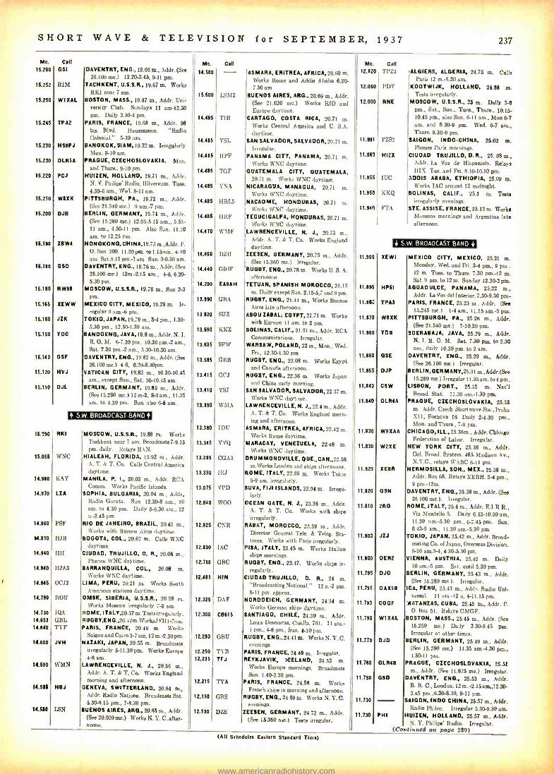
SHORT WAVE & TELEVISION for SEPTEMBER, 1937 237
Mc. Call
16.280 OS1
16.252 RIM
16.250 W1XAL
16.245 TPA2
15.230 HSSPJ
15.230 OLR5A
15.220 PCI
15.210 W8XK
15.200 DJB
16.190 ZBWI
16.180 OSO
15.180 RW96
15.165 XEWW
15.160 JZK
15.150 YDC
16.140 GSF
15.120 HVJ
15.110 DJL
15.790 RKI
15.055 WNC
14.980 KAY
14.970 LZA
14.960 PSF
14.950 HJB
14.940 HII
14.940 HJA3
14.845 0CJ2
14.790 ROU
14.730 IQA 14.653 GBL 14.640 TYF
14.600 JVH
14.590 WMN
14.536 HBJ
14.530 L8N
DAVENTRY, ENO., 19.66 m., Addr. (See
26.100 mc.) 12.20 -3.45, 9.11 pm. TACHKENT, U.S.S.R., 19.67 m. Works
RKI near 7 am.
B OSTON, MASS., 19.67 m., Addr. Uni- versity Club. Sundays 11 am -12.30 pm. Daily 3.30-4 pm.
PARIS, FRANCE, 19.68 m., Addr. 98
bis. Blvd. Haussmann. "Radio Colonial." 5-10 am.
B ANGKOK, SIAM, 19.32 m. Irregularly Mon. 8-10 am.
PRAGUE, CZECHOSLOVAKIA. Mon. and Thurs., 9 -10 pm.
HUIZEN, HOLLAND, 19.71 m., Addr. N. V. Philips' Radio, Hilversum. Tues. 4.30 -6 am., Wed. 8 -11 am.
PITTSBURGH, PA., 19.72 m., Addr. (See 21.540 mc.) 9 am.-7 pm.
BERLIN, GERMANY, 19.74 m., Addr. (See 15.280 mc.) 12.05 -5.15 am., 5.55- 11 am., 4.50.11 pm. Also Sun. 11.10 am. to 12.25 pm.
HONGKONG, CHINA, 19.75 m.,Addr. P. O. Box 200. 11.30 pm. to 1.15 am.. 440 am. Sat.9.15 pm. -1 am. Sun. 3 -9.30 am.
DAVENTRY, ENG., 19.76 m.. Addr. (See
26.100 mc.) 12m.-2.15 am., 4-6, 6.20- 8.30 pm.
MOSCOW, U.S.S.R., 19.76 m., Sun 2-3 pm.
MEXICO CITY, MEXICO, 19.78 m. Ir- regular 9 am.-6 pm.
TOKIO, JAPAN, 19.79 m., 3-4 pm., 1.30- 5.30 pm., 12.30 -1.30 am.
BANDOENG, JAVA, 19.8 m., Addr. N. I. R. O. M. 6 -7.30 pm. 10.30 pm.-2 am., Sat. 7.30 pm. -2 am.. 5.30-10.30 am.
DAVENTRY, ENG., 19.82 m., Addr. (See
26.100 mc.) 4 -6, 8.20.8.30pm. VATICAN CITY, 19.83 m., 10.30.10.45
am., except Sun., Sat. 10.10.45 am. BERLIN, GERMANY, 19.85 m., Addr.
(See 15.280 mc.) 12 m -2. 8.9 am., 11.35 am. to 4.30 pm. Sun. also 6-8 am.
S W. BPOADCA.aT BAND
MOSCOW, U.S.S.R., 19.88 m. Works Tashkent near 7 am. Broadcasts7 -9.15 pm. daily. Relays RAN.
HIALEAH, FLORIDA, 19.92 m., Addr. A. T. k T. Co. Calls Central America daytime.
MANILA, P. I., 20.03 m., Addr. RCA Comm. Works Pacific Islands.
SOPHIA, BULGARIA, 20.04 m., Addr, Radio Garata. Sun. 12.30-8 am., IO
am. to 4.30 pm. Daily 5-6.30 am., 12
n.-2.45 pm. RIO DE JANEIRO, BRAZIL, 20.43 m..
Works with Buenos Aires daytime. B OGOTA, COL, 20.07 m. Calls WNC
daytime. CIUDAD, TRUJILLO, D. R., 20.08 m.,
Phones WNC daytime. B ARRANQUILLA, COL, 20.08 m.
Works WNC daytime. LIMA, PERU, 20.21 m. Works South
American stations daytime. OMSK, SIBERIA, U.S.S.R., 20.28 m.
Works Moscow irregularly 7 -9 am. ROME, ITALY,20.37m. Testsirregularly. R U O B Y, E N G., 20.4 7 m. Wo rkaJ VH I -7a m. PARIS, FRANCE, 20.49 m. Works
Saigon and Cairo 3-7 am,12 m. -2.30 pm. N AZAKI, JAPAN, 20.55 m. Broadcasts
irregularly 5-11.30 pm. Works Europe 4-8 am.
LAWRENCEVILLE, N. J., 20.56 m., Addr. A. T. k T. Co. Works England morning and afternoon.
GENEVA, SWITZERLAND, 20.64 m., Addr. Radio Nations. Broadcasts Sat. 5.30-6.15 pm., 7á.30 pm.
B UENOS AIRES, ARG., 20.65 m., Addr. (See 20.020 me.) Works N. Y. C. after- noons.
Me. Call
14.600 - 16.600
14.486
14.415
14.486
14.486
14.485
14.40
14.415
14.470
14.410
14.440
14.200
13.990
13.820
13.00
13.036
13.615
13.416
13.410
13.30
13.310
19.345
19.285
13.330
19.075
12.840
12.125
12.000
12.710
12.455
12.325
12.300
12.290
12.250
12.235
12.215
12.160
12.130
ASMARA, ERITREA, AFRICA, 20.69 m. Works Rome and Addis Ababa 6.30- 7.30 am
LSM2 BUENOS AIRES, ARG., 20.69 m., Addr. (See 21.020 mc.) Works RIO and Europe daytime.
TIR CARTAGO, COSTA RICA, 20.71 m. Works Central America and U. S.A. daytime.
YSL SAN SALVADOR, SALVADOR, 20.71 m. Irregular.
HPF PANAMA CITY, PANAMA, 20.71 m. Works WNC daytime.
TGF GUATEMALA CITY, GUATEMALA, 20.71 m. Works WNC daytime.
YNA NICARAGUA, MANAGUA, 20.71 m. Works \V NC daytime.
HRLS NACAOME, HONDURAS, 20.71 m. Works 1VNC daytime.
IMF TEGUCIGALPA, HONDURAS, 20.71 m. Works WNC daytime.
WMF LAWRENCEVILLE, N. J., 20.73 m., Addr. A. T. k T. Co. Works England daytime.
DLH ZEESEN, GERMANY, 20.75 m., Addr. (See 15.3611 me.) Irregular.
GBW RUGBY, ENO., 20.78 m. Works U. S. A. afternoons.
EASAH TETUAN, SPANISH MOROCCO, 21.13 m. Daily except Sun. 2.15 -5,7 and 9 pm.
GBA RUGBY, ENG., 21.44 m., Works Buenos Aires late afternoon.
SUZ ABOU ZABAL, EGYPT, 21.71 m. Works with Europe I I am. to 2 pm.
KKZ BOLINAS, CALIF., 21.91 m., Addr. RCA Communications. Irregular.
SPW WARSAW, POLAND, 22 m., Mon., Wed. Fri., 12.30-1.30 pm.
GBB RUGBY, ENG., 22.08 m. Works Egypt and Canada afternoon.
GCJ RUGBY, ENG., 22.38 m. Works Japan and China early morning.
YS.I AN SALVADOR, SALVADOR, 22.37 m. Works WNC daytime.
WMA LAWRENCEVILLE, N. 422.4 m., Addr. A. T. k T. Co. Works England morn- ing and afternoon.
IDU ASMARA, ERITREA, AFRICA, 22.42 m. Works Rome daytime.
YVQ MARACAY, VENEZUELA, 22.48 m. Works WNC daytime.
CGA3 DRUMMONDVILLE, QUE., CAN.,22.58 m.Works London and ships afternoons.
IRJ ROME, ITALY, 22.69 m. Works Tokio 5-9 am. irregal cly.
VPD SUVA, FIJI ISLANDS, 22.94 m. Irregu- larly.
WOO OCEAN GATE, N. J., 23.36 m., Addr. A. T. k T. Co. Works with ships irregularly.
CNR , MOROCCO, 23.39 m., Addr. Director General Tele. k Teleg. Sta- tions. Works with Paris irregularly.
IAC PISA, ITALY, 23.45 m. Works Italian ships mornings.
GBC RUGBY, ENO., 23.47. Works ships ir- regularly.
HIN CIUDAD TRUJILLO, D. R., 24 m. "Broadcasting National." 12 n. -2 pm. 611 pm. approx.
DAF NORDDEICH, GERMANY, 24.34 in. Works German ships daytime.
CB816 SANTIAGO, CHILE, 24.39 m., Addr. Louis Desmaras, Casilla, 761. 11 am: 1 pm., 4 -8 pm.. Sun. 4-10 pm.
RUGBY,ENG.,24.4Im. Works N. Y. C. evenings.
PARIS, FRANCE, 24.49 m. Irregular. REYKJAVIK, ICELAND, 24.52 m.
Works Europe mornings. Broadcasts Sun. 1.40-2.30 pm.
PARIS, FRANCE, 24.56 m. Works French ships in morning and afternoon.
RUGBY, ENO., 24.69 m. Works N. Y. C. evenings.
ZEESEN, GERMANY, 24.73 m., Addr. (See 15.360 mc.) Tests irregular.
GBU
TYB TFJ
TYA
GBS
DZE
(All Schedules Eastern Standard Time)
Me. Call 12.120 TPZ2
12.010
12.000
11.01
11.08
11.566
11.560
11.540
PDV
RNE
FZS2
HI2X
I UC
KKQ
FTA
ALGIERS, ALGERIA, 24.75 m. Calls Paris 12 m.-6.30 am.
KOOTWIJK, HOLLAND, 24.88 m. Tests irregularly.
MOSCOW, U.S.S.R., 25 m. Daily 3-0 pm., Sat., Sun., Tues., Thurs., 10.15- 10.45 pm., also Sun. 6-11 am., Mon 6-7 am. and 8.30 -9 pm. Wad. 6-7 am, Thurs. 8.30 -9 pm.
SAIGON, INDO- CHINA, 25.02 m. Phones Paris mornings.
CIUDAD TRUJILLO, D. R., 25. 08 m., Addr. La Voa de Hispaniola. Relaya HIX Tue. and Fri. 8.10 -10.10 pm.
ADDIS ABABA, ETHIOPIA, 25.09 m. Works IAC around 12 midnight.
BOLINAS, CALIF., 25.1 in. Testa irregularly evenings.
STE. ASSISE, FRANCE, 25.13 m. Works Morocco mornings and Argentina late afternoon.
4 S W. BROADCAST BAND +
11.900 XEWI MEXICO CITY, MEXICO, 25.21 m. Monday, Wed. and Fri. 3-4 pm., 9 pm.. G m. Tues. to Thurs. 7.30 pm.-I2 m. Sat. 9 pm. to 12 m. Sunday 12.30.2 pm.
11.895 HP51 AGUADULCE, PANAMA, 25.22 m., . \ddr. La Vos del Interior. 7.30-9.30 pm-
11.88: TPA3 PARIS, FRANCE, 25.23 m., Addr. (See 15.245 mc.) 1-4 am., 11.15 am.-5 pm.
11.570 We X PITTSBURGH, PA., 25.26 m., Addr. (See 21.540 mc.) 7 -10.30 pm.
11.860 YOB SOERABAJA, JAVA, 25.29 m., Addr, N. I. R. O. M. Sat. 7.30 pm. to 2.30 am., daily 10.30 pm. to 2 am.
11.860 GSE DAVENTRY, ENO., 25.29 m., Addr. (See 26.100 mc.) Irregular.
11.855 OJP BERLIN ,GERMANY,25.31m.,Addr.(See 15.280 mc.) Irregular 11.35 am. to 4 pm.
11.840 CSW LISBON, PORT., 25.35 m. Nat'l Broad. Stat. 11.30 am. -1.30 pm.
11.840 OLR4A PRAGUE, CZECHOSLOVAKIA, 25.35 m. Addr. Czech Shortwave Sta., Praha X11, Fochova I6. Daily 2-4.30 pm., Mon. and Thure.. 7 -9 pm.
11.830 WSXAA CHICAGO, ILL, 25.36m.. Addr. Chicago Federation of Laient. Irregular.
11.830 W2XE NEW YORK CITY, 25.38 m., Addr. Col. Broad. System, 485 Madison Av., N.Y.C., relaye WABC 6-11 pm.
11.920 XEBR HERMOSILLA, SON., MEX., 25.38 m., Addr. Box 68. Relaye XEBH. 2-4 pm., 9 pm. -12m.
11.120 GIN DAVENTRY, ENG., 25.38 m., Addr. (See 26.100 mc.). Irregular.
11.510 2R0 ROME, ITALY, 25.4 m., Addr. E.I.R.R., Via Montello 5. Daily 6.43.10.30 am, 11.30 am. -5.30 pm.. 6-7.45 pm. Sun. 6.43-9 am., 11.30 am.-5.30 pm.
11.503 JZJ TOKIO, JAPAN, 25.42 m., Addr. Broad- casting Co. of Japan, Overseas Division. 9.10 am,3 -4, 4.30 -5.30 pm.
11.800 OER2 VIENNA, AUSTRIA, 25.42 m. Daily 10 am.-5 pm. Sat. until 5.30 pm.
11.795 OJO BERLIN, GERMANY, 25.43 m., Addr. (See 15.280 mc.). Irregular.
11.795 OAXSB ICA, PERU, 25.43 m., Addr. Radio Uni- versal. 11 am.-12 n, 4-11.15 pm.
11.790 COGF .AATANZAS, CUBA, 25.45 m., Addr. P. 0. Box 51. Relays CMGF.
11.790 W1 XAL BOSTON, MASS., 25.45 m., Addr. (See 15.250 mc.) Daily 3.30-5.45 pm. Irregular at other times.
11.770 DJD BERLIN, GERMANY, 25.49 m., Addr. (See 15.280 mc.) 11.35 am. -4.30 pm., 4.50-11 pm.
11.710 OLR4B PRAGUE, CZECHOSLOVAKIA, 25.51 m., Addr. (See 11.875 mc.) Irregular.
11.760 050 DAVENTRY, ENO., 25.53 m., Addr. B. B. C., London. 12 m. -2.15 am.,12.20- 3.45 pm.,6.20 -8.30. 941 pm.
11.730 SAIGON, IN DO CHINA, 25.57 m., Addr. Radio Philco. Irregular 5.30-9.30 am.
11.710 PHI HUIZEN, HOLLAND, 25.57 m., Addr. N. Y. Philips' Radio. Irregular.
(Continued on pape 239)
www.americanradiohistory.com
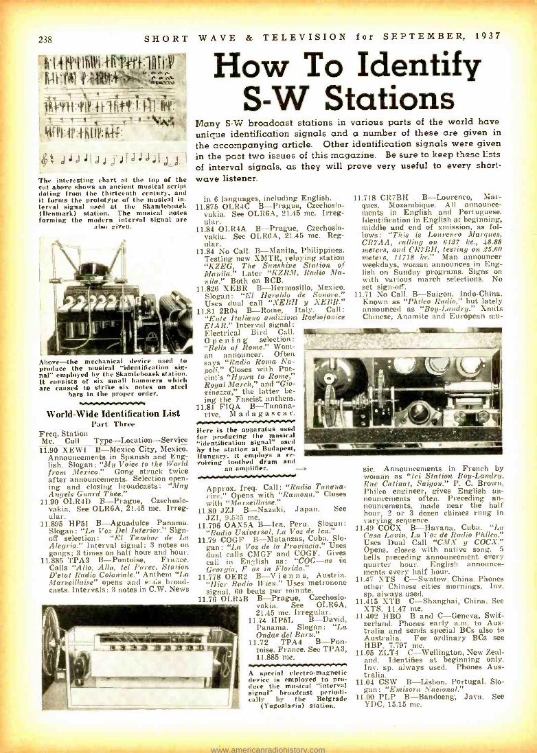
238 SHORT WAVE & TELEVISION for SEPTEMBER, 1937
h.I 1 ILK I IR1'}:111r:w ,, ,..,1 ...-.. ;+m.,.., a,, ,- .
i#i+.Yi#F:tñ4:l: N , 41fPl:l':ffifl:i4kf._
...
dJaJ;J`i JIJJJJj j I
The interesting chart at the top of the cut above shows an ancient musical script dating from the thirteenth century, and it forms the prototype of the musical in- terval signal used at the Skamlehoaek (Denmark) station. The musical notes forming the modern interval signal are
also given.
How To Identify S -W Stations
Many S -W broadcast stations in various parts of the world have unique identification signals and a number of these are given in the accompanying article. Other identification signals were given in the past two issues of this magazine. Be sure to keep these Lsts of interval signals. as they will prove very useful to every short- wave listener.
Above -the mechanical device used to produce the musical "identification sig- nal" employed by the Skamlehoaek station. It consists of six small hammers which are caused to strike six notes on steel
bars in the proper order.
World -Wide Identification List Part Three
Freq. Station Mc. Call Type- Location -Service 11.90 XEWI B- Mexico City, Mexico.
Announcements in Spanish and Eng- lish. Slogan: "My Voice to the World from Mexico." Gong struck twice after announcements. Selection open- ing and closing broadcasts: "May Angels Guard Thee."
11.90 OLR4D B- Prague, Czechoslo- vakia. See OLR6A, 21.45 mc. Irreg- ular.
11.895 HP5I B- Aguadulce Panama. Slogan: "La Voz Del Interior." Sign - off selection: "El Tambor de La Alegría." Interval signal: 3 notes on gongs; 3 times on half hour and hour.
11.885 TPA3 B- Pontoise, France. Calls "Allo, Allo, Ici Paree, Station D'etat Radio Coloniale." Anthem "La Marseillaise" opens and e:.ds b..oad- casts. Intervals: 3 notes in C.W. News
in 6 languages, including English. 11.875 OLR4C B- Prague, Czechoslo-
vakia. See OLR6A, 21.45 mc. Irreg- ular.
11.84 OLR4A B- Prague, Czechoslo- vakia. See OLR6A, 21.45 mc. Reg- ular.
11.84 No Call. B- Manila, Philippines. Testing new XMTR, relaying station "KZEG, The Sunshine Station of Manila." Later "KZRM, Radio Ma- nila." Both on BCB.
11.826 XEBR B- Hermosillo, Mexico. Slogan: "El Heraldo de Sonora." Uses dual call "XEBH y XEBR."
11.81 2R04 B -Rome, Italy. Call: "Ente Italiano audizioni Radiofonice EIAR." Interval signal: Electrical Bird Call. _.. O p e n i n g selection :
"Bells of Rome." Wom- an announcer. Often says "Radio Roma Na- poli." Closes with Puc- cini's "Hymn to Rome," Royal March," and "Gio- vinezza," the latter be- ing the Fascist anthem.
11.81 FIQA B- Tanana- rive, Madagascar.
Here is the apparatus used for producing the musical "identification signal" used by the station at Budapest, Hungary. It employs a re- volving toothed drum and
an amplifier.
11.718 CR7BH B- Lourenco, Mar- ques, Mozambique. All announce- ments in English and Portuguese. Identification in English at beginning, middle and end of xmission, as fol- lows: "This is Lourenco Marques, CR7AA, calling on 6137 kc., 48.88 meters, and CR7BH, testing on 25.60 meters, 11718 kc." Man announcer weekdays, woman announces in Eng- lish on Sunday programs. Signs on with various march selections. No set sign -off.
11.71 No Call. B- Saigon, Indo- China. Known as "Philco Radio," but lately announced as "Boy -Landry." Xmits Chinese, Anamite and European mu-
Approx. freq. Call: "Radio Tanana- rive." Opens with "Ramona." Closes with "Marseillaise."
11.80 JZJ B- Nazaki, Japan. See JZI, 9.535 mc.
11.796 OAX5A B -Ica, Peru. Slogan: "Radio Universal, La Voz de Ica."
11.79 COGF B- Matanzas, Cuba. Slo- gan: "La Voz de la Provincia." Uses dual calls CMGF and COGF. Gives call in English as: "COG -as in Georgia, F as in Florida."
11.778 OER2 B -V i e n n a, Austria. "Hier Radio Wien." Uses metronone signal, 60 beats per minute.
11.76 OLR4B B- Prague, Czechoslo- vakia. See OLR6A, 21.45 mc. Irregular.
11.74 HP5L B- David, Panama. Slogan: "La Ondas del Baru."
11.72 TPA4 B-Pon- toise, France. See TPA3, 11.885 mc.
A special electro- magnetic device is employed to pro- duce the musical "interval signal" broadcast periodi- cally by the Belgrade
(Yugoslavia) station.
sic. Announcements in French by woman as "Ici Station Boy-Landry, Rue Catinat, Saigon." P. C. Brown, Philco engineer, gives English an- nouncements often. Preceding an- nouncements, made near the half hour, 2 or 3 dozen chimes rung in varying sequence.
11.49 COCX B- Havana, Cuba. "La Casa Lavin, La Voz de Radio Philco." Uses Dual Call "CMX y COCX." Opens, closes with native song. 5 bells preceding announcement every quarter hour. English announce- ments every half hour.
11.47 XTS C- Swatow, China. Phones other Chinese cities mornings. Inv. sp. always used.
11.415 XTB C- Shanghai, China. See XTS, 11.47 mc.
11.402 HBO B and C- Geneva, Swit- zerland. Phones early a.m. to Aus- tralia and sends special BCs also to Australia. For ordinary BCs see HBP, 7.797 mc.
11.05 ZLT4 C- Wellington, New Zeal- and. Identifies at beginning only. Inv. sp. always used. Phones Aus- tralia.
11.04 CSW B- Lisbon, Portugal. Slo- gan: "Emisora Nacional."
11.00 PLP B- Bandoeng, Java. See YDC, 15.15 mc.
www.americanradiohistory.com

SHORT WAVE & TELEVISION for SEPTEMBER, 1937 239
Mc. Call Mc. Call Me. Call 11.720 CJRX WINNIPEG, CANADA, 2.5.6 m., Addr.
rames Richardson & Sons, Ltd. 4 -10pm. 10.290 DZC ZEESEN, GERMANY, 29.16 m., Addr.
(See 15.360 mc.) Irregular.
6.630 HJ2ABD BUCARAMANGA, COL, 31.14 m. 11.30 am.-12.30 pm., 5.30-6.30, 7.30-
11.710 CR7RH LAURENCO MARQUES, PORTU- 10.260 PMN BANDOENG, JAVA, 29.24 m., Relaya 10.30 pm. GESE, E. AFRICA, 25.6 m. Daily YDB 5.30 -10.30 or 11 am., Sat. to 6.020 HJIABP CARTAGANA, COL, 31.19 m., Addr. 4.30 -0.30, 9.30 -11 am., 12.30.3.30 p.m. 11.30 am. P. 0. Box 37. 11 am.-1 pm., 5.11 pm. ,Sun. 64 am., 10 am: 12.30 pm., 1.30- 10.250 LSK3 BUENOS AIRES, ARG., 29.27 m., Addr. Sun. 10 am. -1 pm., 3-6 pm. 3.20 pm. lip :1, ks Europe and 6.616 HP6J PANAMA CITY, PANAMA, 31.22 m.
11.715 TPA{ PARIS, FRANCE, 25.61 m., (See 15.245 Addr. Apartado 867. 12 0. to 1.30 Ile.) 5.15 -7.15 pm., 9 pm.-12 m. 10.230 CED ANTOFAGASTAN, CHILE, 29.33 m. 6.10.30 r.,.
11.710 SOO MOTALA, SWEDEN, 225.63 m., 9 am.- Tests 7 -9.30 pm. Opm. 10.220 PSH RIO DE JANIERO, BRAZIL, 29.35 m.
Irregular. e S.W. BROADCAST BAND +
? S.W. BROADCAST BAND } 11.680.
11.600
ICIU
COCK
KAHUKU, HAWAII, 25.oí in., Addr. RCA Communications. Irregularly,
HAVANA, CUBA, 25.86 m. 8 am.-1 am. Relaye C AIX.
10.170
10.140
RIO
OPM
BAKOU, U.S.S.R., 29.15 m. Works Moscow IO pm.-5 am.
LEOPOLDVILLE, BELGIAN CONGO, 29.59 m. Works Belgium around
9.600
9.600
RAN
CB960
MOSCOW, U.S.S.R., 31.25 m. Daily 7 -9.15 pm.
SANTIAGO, CHILE, 31.25 m. Heard
11.605 VItR4 STONY HILL, JAMAICA, B. W. I., 25.87 m. Works WNC daytime. 10.080 RIO
3 am. and fron 1-4 pm. TIFLIS, U.S.S.R., 29.76 m. Works 9.595 HBL
after 9.30 pm. GENEVA, SWITZERLAND, 31.27 m.,
11.600 VIZ3 FISKVILLE, AUSTRALIA, 25.95 m., Addr. Amalgamated Wireless of Australasia Ltd. Testa irregularly.
10.070 EDM- EHY
Moscow early morning. MADRID, SPAIN, 29.79 m. Works
S. A. evenings.
8.590 PCJ ..Addr. Radio Nations. Irregular.
HUIZEN, HOLLAND, 31.28 m., Addr. (See 15.220 mc.) Sun. 2-3, 7-8 pm.
11.680 XAM MERIDA, YUCATAN, 26.09 m. Irregular 1 -7.30 pm.
10.065 JZB- TDB
SHINKYO, MANCHUKUO, 29.81 m. Works Tokio 6.30-7 am. 9.590 VK6ME
Tues. 1.30 -3 pm. Wed. 7 -10 pm. PERTH, W. AUSTRALIA, 31.38 m.,
11.680 PMK BANDOENG, JAVA, 26.09 m. Tests irregularly.
10.055 ZFB HAMILTON, BERMUDA, 29.84 m. Works N. Y. C. irregular.
Addr. Amalgamated Wireless of Australasia, Ltd. 6-8 am. exc. Sun.
11.413
11.406
11.280
CJA4
HBO
HIN
DRUMMONDVILLE, QUE., CAN., 26.28 m. Testa irregularly.
GENEVA, SWITZERLAND, 26.30 m., Addr. Radio Nations. Sat. 5.30.6.15, 7-8.30 pm.
CIUDAD TRUJILLO, D. R., 26 m.,Addr.
10.055
10.042
9.990
SC'V
029
KAZ
ASOU ZABAL, EGYPT, 29.84 m. Works Europe I -6 pm.
ZEESEN, GERMANY, 29.87 m., Addr. Reichapn+tzenstralamt. Irregular.
MANILA, P. I., 311.03 m., Addr. RCA Communications. '{Corks Java early
9.590
9.590
VK2ME
W3XAU
SYDNEY, AUSTRALIA, 31.38 m., Addr. Amalgamate) Wireless of Australasia, Ltd., 47 York St. Sun. 1 -3, 4.304.30 am., 10.30 am. -12.30 pm.
PHILADELPHIA, PA., 31.28 m. Relay. W'CAU 11 am. to 7 pm.
La Voz del I'; rtido Dominicano. morning. 9.580 GSC DAVENTRY, ENGLAND, 31.32 m.,
Irregular. 9.950 CCU RUGBY, ENGLAND, 30.15 In. Works Addr. B. B. C., London.
11.080 7.I.T4 WELLINGTON, NEW ZEALAND, 27.15 N. Y. C. night time. 9.580 VK3LR MELBOURNE, AUSTRALIA, 31.32 m.,
11.640 COW
m. Works Australia and England early morning.
LISBON, PORTUGAL, 27.17 m., Adule.
9.930
9.930
if KB
CSW
BOGOTA, COL, 30.21 m. Works Rio evenings.
LISBON, PORTUGAL, 30.31 m., Addr.
.Addr. 61 Little Collins St. Daily 3.30.8.30 am. Sun. 3.30-7.30 am. Suu., Fri. 9.30 pm.-2.30 am.
Nat. Broadcasting Sta. 1.30.5 pm. Nat. Broad. Station. 5-7 pm. 9.575 HJ2ABC CUCUTA, COL, 31.34 m. 8 pm. to 12 m.
11.000 PLP BANDOENG, JAVA, 27.27 m. Relays VDB. 5.30.10.30 or 11 am. Sat. until 11.30 am.
9.890 LSN BUENOS AIRES, ARG., 30.33 m., Addr. (See 10.300 mc.) Workr N. Y. C.
evenings
9.570 W1XK SPRINGFIELD, MASS., 31.35 m., .1.11r. Westinghouse Electric k Mfg. Co. Relays WBZ 6 am. to 12 m.
10.070 OCI LIMA, PERU, 27.35 m. Works Bogota, 9.870 WON LAWRENCEVILLE, N. J.,30.4 m., Addr. . ,. 7 .m. to 12 m.
('nl. evenings. A. T. A T. Co. Works England nights. 9.560 DJA BERLIN, GERMANY, 31.38 m., Addr.
10.040
10.770
KWV
GBP
DIXON, CALIF., 27.68 m., Addr. A. T. &
T. Co. Works with Hawaii evenings. RUGBY, ENGLAND, 27.85 m. Works
9.680 EAQ MADRID, SPAIN, 30.43 m., Addr. Poet Office Box 951. Daily 5.15-7.30 pm., Sat. also 12 n.-2 pm. 9.555 HJI ABB
I', mg House. 12.05.5.15 am., -I 0.45 pm.
BARR ANQUILLA, COL, 31.39 m.,
Australia early morning. 1.810 IRM ROME, ITALY, 30.52 m. Works Egypt Aldr. P. 0. Box 715. 11.30 am. to
10.740 JVM NAZAKI, JAPAN, 27.93 m. Works afternoons. I pm., 4.30-6 pm.
U.S.A. 2 -7 am. Broadcasts daily 9-IO am., 2.30-3.30 pen.
1.100 LSI BUENOS AIRES, ARO., 30.61 m., A.1.1r.
(See 10.350 me.) Testa irregularly.
9.550 OLR3A PRAGUE, CZECHOSLOVAKIA, 31.41 m. tir 11.840 mc.
10.676 WNB LAWRENCEVILLE, N. J.,28.1 m, Addr. 1.710 GCW RUGBY, ENGLAND, :30.61 m. Works 9.540 DJN BERLIN, GERMANY, 31.45 m., Addr.
A. T. k 3'. Co. Works with Bermuda irregularly. /.710 VLJ-
N. Y. C. evenings. SYDNEY, AUSTRALIA, 30.74 m., Addr.
(Se 9.560 me.) 12.05-5.15 am., 4.50-10.45 pm.
10.670 CEC SANTIAGO, CHILE, 28.12 m. Daily VLZ2 Amalgamated Wireless of Australasia 9.540 VPD2 SUVA, FIJI ISLANDS, 31.45 m., Addr.
10.660 JVN 7 -7.15 pin.
NAZAKI, JAPAN, 28.14 m. Broadcasts
Ltd. Works Java and New Zealand early morning.
Amalgamated Wireless of Australasia, I I I. 5.30-7 am.
10.680 WOK
daily 2-8 am. Works Europe irregu- larly at other tins.
LAWRENCEVILLE, N. J., 28.44 m.,
1.760 WOF LAWRENCEVILLE, N. J., 30.77 m., Addr. A. T. & T. Co. Works London, night time.
9.535
9.530
JZI
W2XAF
TOK10, JAPAN, 31.46 m., Addr. (See 11.b00, JZI) 9-10 am.
SCHENECTADY, N. Y., 31.48 m., Addr.
Addr. A. T. & T. Co. Works S. A. 9.740 COCQ HAVANA, CUBA, 30.78 m. 6.50 am. I huneral Electric Co. 4 pm.-12 m.
nights. 1 am. 9.525 ZBW3 HONGKONG, CHINA, 31.49 m., Addr.
10.616 JIB TAIWAN, FORMOSA, 28.48 m. Works Japan around 6.25 am.
9.710 GCA RUGBY, ENGLAND, 30.89 m. Works S. A. evenings.
l'. O. Box 21)0. Irregular 11.30 pm. to 1.15 am., 4 -IO am.
10.620 VLK SYDNEY, AUSTRALIA, 28.51 m., Addr. 9.675 DZA ZEESEN, GERMANY, 31.01 m., Addr. 9.525 LKJ1 JELOY, NORWAY, 31.29 m. 54 am.
Amalgamate) Wireless of Australasia (.See 10.042 mc.) Irregular. 9.520 HJ4ABH ARMENIA, COLOMBIA, 31.51 m. 8-
Ltd. Works England 1.6 am. 0.670 TI4NRH HEREDIA, COSTA RICA, 31.02 m., I am., 6-10 pm.
10.430 YBG MEDAN, SUMATRA, 28.76 m. 5.30- 6.30 am., 7.30-8.30 pm.
Addr. Am:mdo C. Marin, Apartado 40. 8.30-10 pm., 11.30 pm.-12 m.
9.510 VK3ME MELBOURNE, AUSTRALIA, 31.55 m., .r. \ malgamatel Wireless of Aus-
10.120 XGW SHANGHAI, CHINA, 28.79 m. Works 11.8110 LRX BUENOS AIRES, ARG., 31.06 m., Addr. ,. I7 Quern St. Daily except
Japan 12 m.3 am. EI Mundo. 9.30 ato :11.30 pm.
10.410 PDK KOOTWIJK, HOLLAND, 28.8 m. Works Java 7.30-9.40 am.
8.060 CT1AA LISBON, PORTUGAL, 31.09 m., Addr. Radio Colonial. Tues., Thurs. and
9.510 GSB DAVENTRY, ENGLAND, 31.55 m., Addr. (Sce9.580,mc. -CSC) 12 m.-2.15
10.110 KES BOLINAS, CALIF., 28.8 m., Addr. RCA Sat. 3.30 -6 pm. 12.20.6 pm., 9-11 pm.
Communications. Irregular. 8010 YOB SOERABAJA, JAVA, 31.09 m., Addr. 9.505 HJ1ABE CARTAGENA, COLOMBIA, 31.57 m.
10.370 JVO NAZAKI, JAPAN, 28.93 m. Broadcasts N. I. It. O. M. Daily except Sat. Addr. P. 0. Box 31. 5.10.30 pm.
around 5 am. 6.7.30 pm., 5.30 to 10.30 or 11 pm. 9.500 XEWW MEXICO CITY, MEX., 31..58 m. Adult.
10.370 EHZ TENERIFFE, CANARY ISLANDS, 28.93 Sat. 5.30 -11.30 am. Apart. 2516. Relays XEW.
m. Relays EAJ43 2.153.15, 6.15 -9. 9.650 DGU NAUEN, GERMANY, 31.09 m., Addr. 9.500 HJU BUENAVENTURA, COLOMBIA, 31.58
10.350 LOX BUENOS AIRES, ARG., 28.98 m., Addr. Transradio International. Broadcasts
(See 20.020 me.) Works Egypt after- noons.
m., Addr. National Railways. Mon., Wed. and Fri. 8 -11 pm.
5-6 pm. Mon. and Fri. Tests irregu- larly at other times.
9.615 HH3W PORT -AU- PRINCE, HAITI, 31.1 m., Addr. P. 0. Box AI17. 1 -2, 7-8 pm.
9.500 PRF5 RIO DE JANIERO, ORAL, 31.58 m. Irregularly 4.45 to 5.45 pm.
10.330 ORK RUYSSELEDE, BELGIUM, 29.04 m. 9.645 YNLF MANAGUA, NICARAGUA, 31.1 m. 9.500 EAR- MADRID, SPAIN, 31.58 m., Addr. (See
1.30.3 pm. 8-9 am., 12.30-2.30, 6.30-10 pm. EAQ2 9.860 mc.) Exc. Mon. 2.30-3, 6.30.7,
10.100 LSL2 BUENOS AIRES, ARO., 29.13 m., Addr. 9.635 !RO ROME, ITALY, 31.13 m., Addr. (See 7.30-9.30 pm., Mon. 7.30-9.30 pm.
Cia. Internacional de Radio. Works 11.810 mc.) Mon., SVed. and Fri. 6.7.30 Europe evenings. pm. Tue,., Thurs. and Sat. 6.7.45 ? 5 W. BROADCAST BAND }
pm. (('murinurd m, pao n411 (All Schedules Eastern Standard Tima)
www.americanradiohistory.com
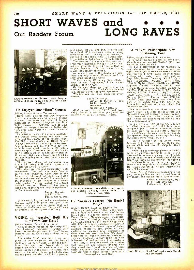
i
240 SHORT WAVE & TELEVISION for SEPTEMBER, 1937
SHORT WAVES and Our Readers Forum LONG RAVES
Layton Bennett of Forest Grove, Oregon, owns and operates this fine looking "Ham"
station.
He Enjoyed Our "Ham" Course Editor, SHORT WAVE & TELEVISION:
Have been picking UR FB magazine from the newsstands ever since I spotted it about two years ago, when I became interested in Radio! I enjoyed the Ham Radio Course by W2AMN and it sure helped me progress towards a better sta- tion, ever since I got my "ticket" about a year ago.
I started out with a 6L6 crystal oscillator and worked forty meters for some time with just the exciter of the present "rig." The 6L6 is now driving an RK2O "final" to about 100 watts. Am using an 80 meter Zepp antenna and the rig puts out and pulls in very good reports on 20 meters when using a 20 meter crystal; she "socks out" a little more on 40 and better still on 80 meters. 160 meters hasn't been tried as yet, but is going to be taken in as soon as possible.
The receiver whose end just shows is a T -R -F job, using a 58 radio frequency, a 58 detector and a 56 audio.
The whole receiver and transmitter is all home -made. The rack was made from a pair of bed longerons, which were in the form of a right -angle of which the knobs on the end were hacked off. The panels are the standard 19 inch, bought at a sheet - metal works. They will probably be crackle finished later on. There are two panels left blank at the top for "future expansion" or for a modulator.
Layton Bennett 325 Fifth St., Forest Grove, Ore.
(Good work, Layton, and a neat- looking line -up. Let's hear more from you. Our readers will be glad to know that the "Ham" or Radio Amateur Course will soon be available in book form.- Editor.)
VK4FE, an "Aussie," Built His Rig From Our Data!
Editor, SHORT WAVE & TELEVISION: As a constant reader of your very F.B.
(fine business) magazine, I watch with keen interest the pictures of "Ham" trans- mitters, and herewith submit photo of my "rig."
The entire "rig" was built from data given in your magazine. On the bottom shelf are the power supplies for the oscil- lator, bias and P.A. Second shelf, the speech amplifier, the modulator and the power -supply for the same. The third shelf contains the 46 oscillator and 46 doubler; the top panel contains two 210's in parallel
and aerial set -up. The P.A. is modulated by a single 2A5, used as a triode in series modulation and it is surprising the way I can pick up the sticks with it! I work most- ly on 7,205 kc. but often QSY to 14,120 kc.
The receiver I use is one that was built from your magazine, and is a 4 -tube T.R.F. using a 58 in the R.F., a 57 as an electron coupled detector; a 56 first audio, driving a 2A5 for speaker operation.
As you are aware, the Australian ama- teurs are only allowed 25- watts, so I am only using about 24.5 watts.
While I do no DXing on Pone, which I keep for local "rag- chews," I am always anxious for it on C.W.
On the shelf above the receiver I have a stack of "S.W. & T.'s," which are indexed in a separate book for quick reference.
Wishing you and your magazine every success,
Yours faithfully, Arthur R. Burton, VK4FE 33 Leichhardt St., Brisbane, Queensland, Australia.
Glad to hear from a "VK "-and espe- cially pleased to hear that you found our construction data of serriee.- Editor.
A dandy amateur transmitting and receiv- ing slation- VK4FE, "down under" in
Brisbane, Australia.
He Answers Letters; No Reply! Why?
Editor, SHORT WAVE & TELEVISION: Since you printed my letter in the maga-
zine, I have had about a score of letters from people in different states in America. From Texas, Massachusetts, Wisconsin, New York, Mississippi, Ohio and many more, all asking me if I could oblige them with different things, including information such as prices of different types of tubes, catalogs, photos of sets, prices of corn- modities for making sets, blueprints of short wave sets used over here (England), blueprints of long and medium wave sets, views of Sheffield (so they could see what it looked like) and pictures of its products.
Well sir, I have answered every letter that was sent and besides sending what they asked for, I sent each one of them three magazines (the one we use here), together with a little present, such as a
(Contiued on page 250)
A "Live" Philadelphia S -W Listening Post
Editor, SHORT WAVE & TELEVISION: I herewith submit a photo of my Short
Wave Listening Post W3- "SWL." (My own call -letter combination.)
Here is a description of my "shack "; A two tube converter in connection with an eight -tube Majestic broadcast receiver. With this receiver I have logged many foreign stations with veris from: HVJ, Vatican City, DJA, Zessen, Germany, YV2RC, Car- acas, Venezuela. Amateur veris from, EA4AO, Madrid, Spain, G5ML and G5VN, England, ON4DX, Belgium, K6CRU and K6JUY, Hawaiian Islands, OZ2M, Denmark, KA1XA, Philippine Islands, HB9AQ, Swit- zerland, SP1DE, Poland, GI5QX, Ireland, K5AC, Canal Zone, HP1A, Panama, X1AY, Mexico, K4DDH, Puerto Rico, CM2RA, CM6RC, Cuba. Also veris from Naval Sta- tions NPM, NAA, NSS, NPG and NPO. Also police and ship veris, and about 125 broadcast stations.
The four -tube long and short wave re- ceiver, which is between the converter and Majestic broadcast receiver, is used for reg- ular broadcast and police reception and also is used for phonographic pick -up and "home broadcasting."
To the extreme right of the photo is my so called, "transmitter," which is a rack - and -panel job. It houses a code oscillator for code practice; an old battery receiver for amplifying the code oscillator signals for speaker reception, wave -traps for long and short wave reception, etc.
I am a member of the Short Ware .League, R -9 Listeners League, Radio Ex- plorers Club and the I'hiladelphia Short Wave Club.
I would like to exchange photos and SWL cards with anyone caring to do so. I will also send to anyone a souvenir of Philadel- phia in honor of the "Constitution Celebra- tion, " the 150th Anniversary of the signing of the Constitution, providing they will en- close a 3c stamp along with their SWL or QSL cards and photo. All mail received by me will be answered.
Short Ware & Television magazine is the only radio publication that is used here at my shack, and believe me it sure is swell.
Frank J. Schrameyer, Opr. 1510 North 26th St., Philadelphia, Penna.
Boyi What a "flock" of veri cards Frank has collected.
www.americanradiohistory.com
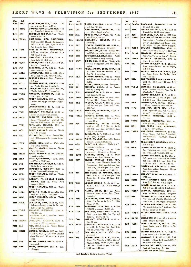
SHORT WAVE & TELEVISION
Me.
9.400
9.470
9.460
9.450
9.440
1./40
9.429
9.415
9.363
9.350
9.330
9.330
9.300
9.280
9.170
9.150
1.126
9.060
9.020
9.010
8.957
8.960
8.950
8.795
8.776
1.766
8.160
/.760
1.730
8.720
1.680
1.666
1.110
5.6M
3.409
8.380
8.190
8.115
LOU
Call
XEFT
XEDQ
ICK
TOWA
FZFO
HC2RA
COCH
PLV
COBB
HSOPJ
CGA4
OAX4J
THOU
GCB
WNA
YVR
HATO
TFK
GCS
KEJ
VWY
TPZ
HCJB
HKV
PNI
DAF
GCQ
FZEB
GC!
VPDB
GBC
COJK
TNLO
WOO
II02C W
IAC
XEME
PSK
CNN
VERA CRUZ, MEXICO, 31.61 m. 11.30 am. to 4 pm., 7 pm. to 12 m.
GUADALAJARO, GAL, MEXICO, 31.68
m. Irregular 7.30 pm. to 12.30 am.
TRIPOLI, N. AFRICA, 31.71 m. Works Rome, 5.30-7 am.
GUATEMALA CITY, GUATEMALA, 31.75 m., Addr. Ministre de Fomento. Daily 12 n. to 2 pm., 8 pm. to 12 m.
Sat. 9 pm. to 5 am. (Sun.)
FORT de FRANCE, MARTINIQUE, 31.78 m. 11.30 am., 12.30 pm., 6.15- 7.15 pm., 8-9 pm.
GUAYAQUIL, ECUADOR, 31.78 m.
Irregularly till 10.40 pm. HAVANA, CUBA, 31.8 m., Addr. 2 B St.,
Vedado. 7 am-1 am. BANDOENG, JAVA, 31.87 m. Work,
Holland around 9.45 am.
HAVANA, CUBA, 32.03 m. Addr. Maxi- mo Gome, No. 139. Relays CMBC.
BANGKOK, SIAM, 32.09 m. Thursday, 8-10 am.
DRUMMONDVILLE, CANADA, 32.15
m. Works England irregularly. LIMA, PERU, 32.15 m., Addr. Box 1166,
"Radio Universal." 7 pm.-12 m.
MANAGUA, NICARAGUA, 32.26 m.
12 n. -2 pm., 6-7 pm.
RUGBY, ENGLAND, 32.33 m. Works Canada and Egypt evenings and after- noons.
LAWRENCEVILLE, N. J 32.72 m. Works England evenings.
MARACAY, VENEZUELA, 32.79 m.
Works with Europe afternoon,. BUDAPEST, HUNGARY, 32.88 m.,
Addr. " Radiolabor," Gyali -ut, 22.
Sun. and Wed. 7-8 pm., Sat. 6-7 pm.
REYKJAVIK, ICELAND, 33.11 m. Workv London afternoons.
RUGBY, ENGLAND, 33.26 m. Works N. Y. C. evenings.
BOLINAS, CAL, 33.3 m. Relaye NBC and ('BS programs In evening irregu- larly.
KIRKEE, INDIA, 33.43 m. Works with England in morning.
ALGIERS, ALGERIA, 33.48 m. Works Paria afternoons.
QUITO, ECUADOR, 33.5 m. 7 -10 pm. except Monday.
BOGOTA, COLOMBIA, 34.09 m. Moti. and Thurs. 7 -7.30 pm.
MAKASSER, CELEBES, N. I., 34.19 m.
Works Java around 4 am.
NORDDEICH, GERMANY, 34.23 m.
Works German ,hip, irregularly. RUGBY, ENGLAND, 34.25 m. Works
Africa afternoons. DJIBOUTI, FR. SOMALILAND,
AFRICA, 34.29 m. Works Paris around 2.30 am.
RUGBY, ENGLAND, 34.36 m. Works India 8 am.
SUVA, FIJI ISLES, 34 m., Addr. (See
9.540 mc., \'PO2). 5.30-7 am. RUGBY, ENGLAND, 34.56 m. Works
chip, irregularly.
CAMAGUEY, CUBA, 34.62 m., Addr. 4 General Gomez. 5.30. 6.30, 8-11 pm., daily except Sat. and Sun.
MANAGUA, HICAlAOUA, 34.92 m.
7.30-9.30 pm.
OCEAN 014k, P. J., 35.05 m. Works ship, irregularly.
GUAYAQUIL, l CUAOO, 35.71 m. 11.30 am.-12.30 pm., 8 -11 pm.
PISA, ITALY, 35.8 m. Work, Italian ships irregularly.
MERIDA, YUCATAN, 36.63 m., Addr. Calle 59, No. 517, "La Vo, de Yucatan deede Merida." 10 am.-12 n., 6 pro: 12 m.
RIO DE JANEIRO, BRAZIL, 36.65 m. Irregularly.
RABAT, MOROCCO, 37.33 m. Sun.
Mc.
7.975
T.901
7.560
7.064
7.799
7.716
7.826
7.810
7.660
7.620
7.610
7.500
7.390
7.3/0
7.220
7.200
7.100
6.896
6.877
1.976
5.306
6.560
1.550
1.500
1.770
11.776
5.75*
5.730
1.720
1.710
6.672
1.670
LOM
1.111
Call
HC2TC
LSL
SUX
HC2JSB
RBP
KEE
RIM
KWX
VOWS
KKR
JVP RKI
ZLT2
XECR
HKE
YNAM
FOBAA
P7H
XBA
HCETC
GDS
EEL
xeOX
HI7P
MIN
WOA
JVT
HI3C
PMH
TIEP
TVQ
HC2RL
IAC
HIT
2.30-5 pm.
for SEPTEMBER,
QUITO, ECUADOR, 37.62 m. Thum. and Sun. at 8 pm.
HURLINOHAM, ARGENTINA, 37.97
m. Works Brazil at night. ABOU ZABAL, EGYPT, 38.17 m. Works
with Europe, 4-6 pm.
GUAYAQUIL, ECUADOR, 38.2 m.
Evenings.
GENEVA, SWITZERLAND, 38.47 m., Addr. Radio-Nations. Irregular.
BOLINAS, CAL, 38.89 m. Relaye NBC andCBSprograms ineveningirregularly.
TACHKENT, U.S.S.R., 39.34 m. Works with Moscow in early morning.
DIXON, CAL, 39.42 m. Works with Hawaii, Philippines, Java and Japan, nights.
PUNTA ARENAS, COSTA RICA, 39.74
m., Addr. "Ecce Del Pacificti ", P. 0. Box 75. 6 pm.-I2 m.
KAHUKU, HAWAII, 39.89 m. Works with Dixon and broadcasts Irregularly nights.
NAZAKI, JAPAN, 39.95 m. Irregular. MOSCOW, U.S.S.R., 40 m. Works
with RIM early am.
WELLINGTON, N. Z., 40.6 en. Works with Sydney, 3-7 am.
MEXICO CITY, MEX., 40.65 m., Addr. Foreign Office. Sunday 6-7 pm.
BOGOTA, COL, S. A., 41.55 m. Tues.
and Sat. 8-9 pm. Mon. and Thurs.
6.30-7 pm.
MANAGUA, NICARAGUA, 41.67 m.
Daily at 9 pm. PAPEETE, TAHITI, 42.25 m., Addr.
Radio Club Papeete. Tues. and Fri. 11 pm.-12 m.
PARAMIRABO, DUTCH GUIANA, 42.88 m., Addr. P. 0. Box 18. Daily 6.06 -8.36 am., Sun. 9.36 -11.36 am.,
Daily 5.36 -8.36 pm.
TACUBAYA, D. F., MEX., 43 m. 9.30
am.-1 pm., 7-8.30 pm.
QUITO, ECUADOR, 43m., Addr. Teatro Bolivar. Thum. till 9.30 pm.
RUGBY, ENG., 43.45 m. Works N.Y.C. evenings irregularly.
B OLINAS, CALIF., 43.70 m. Teets
irregularly. 11 am. -12 n., 6-9 pm. NANKING, CHINA, 43.8 m. Daily
6.40-8.40 am., Sun. 4.40-6.05 am.
CIUDAD TRUJILLO, DOM. REP., 44.12 m., Addr. Emisoria Diaria de
Commercio. Daily exc. Sat. and Sun.
12.40.1.40, 6.40-8.40 pm. Sat. 12.40-
1.40 pm. Suas. 10.40 am.-11.40 am.
SAN PEDRO DE MACORIS, DOM. REP., 44.26 m. 12.10.1.40 pm., 7.30-
9 pm. Sun. 3.4 am., 4.15-6 pm., 4.40.
7.40 pm. LAWRENCEVILLE, N. J., 44.41 m.,
Addr. A. T. A T. Co. Works England evenings.
NAZAKI, JAPAN, 44.44 m., Addr. Koku,ai -Denwa Kaieha, Ltd., Tokio. Irregular.
LA ROMANA, DOM. REP., 44.58 m.,
Addr. "La Voz de la Feria." 12.30.
2 pm., 5-6 pm. B ANDOENG, JAVA, 44.64 m. Relaye
NIROM programs. 5.30-9 am.
SAN JOSE, COSTA RICA, 44.71 m., Addr. Apartado 257, La Vox del
Tropico. Daily 7 -10 pm.
MARACAY, VENEZUELA, 44.95 m.
Sat. 8.9 pm.
GUAYAQUIL, ECUADOR, S. A., 44.95
m., Addr. P. 0. Box 759. Sun. 5.45-
7.45 pm., Tues. 9.15 -11.15 pm.
PISA, ITALY, 45.11 m. Works chipe
irregularly. CIUDAD TRUJILLO, D. R., 45.25 m.,
Addr. "La Vox de la RCA Victor," Apartado 1105. Daily exc. Sun. 12.10.
1.40 pm., 5.40-8.40 pm.; also Sat.
10.40 pm.-12.40 am.
Me.
5.526
6,666
6.660
6.660
0.646
11.1341
0.620
11.600
1.SN
LI77
5.170
8.410
5.120
1.410
6.400
6.380
6.360
1.360
5.9M
S.940
L31S
5.316í
L3N
L U u se
5.275
1.243
5.236
5.230
1.230
1.210
5.1841
LIN
5.171
1937 241
Call
PRADO RIOBAMBA, ECUADOR, 45.28 m. Thum. 9 -11.45 pm.
H1/0 CIUDAD TRUJILLO, D. R., 45.74 m. Except Sun. 11.55 am. -1.40 pm.
XBC VERA CRUZ, MEL, 45.8 m. 8.15-9 am. TIRCC SAN JOSE, COSTA RICA,45.8 m.,Addr.
Radioemisora Catolica Coetarricense. Sun. 11 am. -2 pm., 6-7, 8-9 pm. Daily 12 n.-2 pm., 6-7 pm., Thurs. 6-1l pm.
YVBRB BOLIVAR, VENEZUELA, 45.84 m., Addr. "Ecos de Orinoco." 6-10.30 pm.
YN100 MANAGUA, NICARAGUA, 45.94 m., Addr. "La Voz de los lagos." 8-9 pm.
TVIM VALENCIA, VENEZUELA, 46.01 m. 11 am.-2 pm., 5-10 pm.
HIL CIUDAD TRUJILLO, D. IL, 46.15 m., Addr. Apartado 623. 12.10 -1.40 pm 5.40 -7.40 pm.
TIOW PUERTO LIMON, COSTA RICA, 46.15 m., Addr. Ondas del Caribe. Daily 12 m-1.30 pm.
H60V SAN FRANCISCO de MACORIS, D. R., 46.32 m. 11.40 am.-1.40 pm., 5.10. 9.40 pm.
TNLAT GRANADA, NICARAGUA, 46.38 m., Addr. Leonidas Tenoria, "La Vos del Mombacho." Irregular.
HIBA CIUDAD TRUJILLO, D. R., 46.51 m. 8.40-1040 am., 2.40-4.10 pm. Sat. 9.40.10.40 pm. Sun. 2.40 -4.40 pm.
H118 SANTIAGO, D. R., 46.73 m. 11.40 am. -1.40 pm., 5.40-7.40, 9.40-11.40 pm.
TIPO SAN JOSE, COSTA RICA, 46.8 m., Addr. Apartado 225, "L3 Voz de la Victor." 12 n.-2 pm., 6 -11.30 pm.
TURN CARACAS, VENEZUELA, 46.88 m. 7 -11 pm.
YV5RF CARACAS, VENEZUELA, 47.02 m., Addr. Box 983. 6 -10.30 pm.
HRP1 SAN PEDRO SULA, HONDURAS, 47.19 m. 7.30-9.30 pm.
TV1RH MARACAIBO, VENEZUELA, 47.19 m.. Addr. "Ondas Del Lago," Apartado de Correa, 261. 6-7..30 am., 11 am.-2 pm., 5-11 pm.
MT TEGUCIGALPA, HONDURAS, 47.24 m. 6.30.8.30 pm.
H11X CIUDAD TRUJILLO, D. R., 49.32 m. Sun. 7.40-10.40 am., daily 12.10-1.10 pm., Tues. and Fri. 8.10-10.10 pm.
HIZ CIUDAD TRUJILLO, D. R., 47.5 m. Daily except Sat. and Sun. 11.10 am.- 2.25 pm., 5.10.8.40 pm. Sat. 5.10- 11.10 pm. Sun. 11.40 am.-1.40 pm.
T02 GUATEMALA CITY, GOAT 47.55 m., Addr. Secretaria de Fomento. Relays TGI 11 pm. -1 am.
TVIRO MARACAY, VENEZUELA, 47.62 m. 8- 10.30 pm.
CONS SANCTI SPIRITUS, CUBA, 47.78 m.. Addr. P. 0. Box 85. 4-6, 9.11 pm.
HI0 CIUDAD TRUJILLO, D. R., 47.77 m. 7.10 -6.49 am., 12.40-2.10, 8.10-9.40 pm.
TV6RP CARACAS, VENEZUELA, 47.79 m.. Addr. "La Voz de laPhilco." Irregular.
ION CIUDAD TRUJILLO, D. R., 48 m.,Addr. "La Voz del Partido Dominicano." 12 m. -2 pm., 7.30-9.30 pm., irregularly.
H R D LA CEIBA, HONDURAS, 48.12 m.,Addr. "La Vox de Atlantida." 8-Il pm.; Sat. 8 pm. -1 am.; Sun. 4-6 pm.
YV1RG VALERA, VENEZUELA, 48.15 m. 6 -9.30 pm.
OAXIG LIMA, PERU, 48.15 m., Addr. Apartado 1242. Daily 7 -10.30 pm.
YV6RI CORO, VENEZUELA, 48.31 m., Addr. Roger Leyba, care A. Urbina y Cia. Irregular.
HIBQ CIUDAD TRUJILLO, D. R., 48.47 m.
11.45 am.-1 pm., 4.45 -6.45 pm.
HI1A SANTIAGO, D. R., 48.5 m., Addr. P. 0. Box423. 11.40am. -1. 40 pm.; 7.40-9.40 pm.; Wed. 6-10.30 pm.
XEXA MEXICO CITY, MEX., 48.61 m., Addr. Dept. of Education. 7 -11 pm.
(Continued on PODe 243)
(All SehMules Eastern Standard TI.e)
www.americanradiohistory.com

242 SHORT WAVE & TELEVISION for SEPTEMBER, 1937
New S -W Apparatus of Interest to HAMS NEW CRYSTAL MIKE
In the photograph we see a repro-
duction of one of the latest crystal microphones. This is a sound -cell prop- osition known as B -1. It is very sim- ilar to the former Brush BR2S in elec- trical characteris- tics However, as can be seen in the photograph, it has a much different ap- pearance. The di- mensions are 3's inches long, 174 in- ches wide, by ?i inch thick, and the net weight is 11 ounces. It is fur- nished complete with a locking type plug and socket -con- nector for conven- ience of installation. No. 636
This article has been prepared from data supplied by courtesy of the Brush Develop - ment Company.
Dual Trim -Air Condensers THESE new standard double -section Trim -Air condensers are constructed
with stur- dy, o v e r- size double bearings and are selling for less than the cost of two indi- vidual units. They can be fur- nished ei- ther with a circular
shield as illustrated in this ER -25 -AD mod- el, or with a square shield that is remov- able from the nickeled brass tie -rods. A t -inch shaft extends at the rear for addi- tional "ganging." This midget is so con- structed as to allow for any of four con- venient methods of mounting. Isolantite insulation is employed and the condensers are available in ten standard sizes.
This article has been prepared from data supplied by courtesy of Allen D. Cardwell Mfg. Corp.
New Transmitting Condensers THE accompanying picture shows two types of transmitting condensers re-
cently made available for amateur and commercial use. The rotor and stator plates are stamped from a special grade of aluminum .051 inch thick and all edges are perfectly rounded to eliminate corona discharge.
New Double- Section Con- denser (No. 637)
The flat surfaces are also highly pol- ished, the general construction of the frame results in an extremely rigid and neat appearing unit. The single type are available in capacities ranging from 40 mmf. to 340 ,nmf. with working voltages ranging from 4,000 to 11,000.
The split- stator condensers have capaci- ty ranges from 50 to 250 nimf. with vari- ous spacings and in voltage ranges from 2,000 to 9,000 per section. In all cases the insulating material used is Micalex, which provides extremely low losses at the high and ultra high frequencies.
This article has been prepared from data supplied by courtesy of Bud Radio, Inc.
The New T -20 (20 Watts Plate Dissipation)
A general -purpose triode, offering out- standing value to the amateurs, the T -20 will soon establish itself as an extremely fine amplifier on all frequencies up to and including 56 mc. It is efficient as a doubler or buffer and gives real power output in Class B audio work.
GENERAL CHARACTERISTICS Filament Voltage, volts 7.50 Filament Current, amps 1.75 Plate Resistance, ohms .. 8000 Mutual Conductance, uMhos 2500 Amplification Factor 20
Left -New half -wave mercury vapor rec- tifier, type rififi Jr. Right -Recently developed general- purpose triode for fre-
quencies as high as 56 mc. No. 639.
PHYSICAL CHARACTERISTICS Max. Length, inches fc Max. Diameter. inches "_ UX Ceramic Base
INTER -ELECTRODE CAPACITIES Plate to Grid. mmf. .. 4
CLASS "C" OSC AND POWER AMP. Max. Plate Volts 750 Modulated D.C. Volts 750 Max. D.C. Plate Current, mills. 75 Max. D.C. Grid Current, mills. 25
'4, Otite _ Max. Plate Dissipation, watts 20 j 's% 'P , t, Max. R.F. Grid Current, amps. 2.6 +,, '1. ̂ w. s,y - R.F. Output, watts 42
Percentage of Efficiency 75% NORMAL OPERATION
Ep = 750 EG = -100
CLASS "B" A.F. MODULATOR Push -Pull Operation
TYPICAL OPERATING COND. Filament, volts 7.5 7.5 D.C. Plate Voltage 800 600 Grid Voltage Approx. -40 -30 Load Resistance P -P 12,000 8100 Average D. C. Plate Current
per tube ... 68 Static Plate Current 10
of the latest amateur type trans- Power Output, Watts (2 tubes) 70 mitting condensers. No. 638. (Continued ou page 2651
Two
Ef =7.5
Aerodynamic Microphone An Aerody-
namic micro- phone which combines a x- treme compact- ness, excellent fidelity a n d novel stream- lined appear- ance at low cost has been intro- duced by t h e R C A Commer- cial Sound Sec- tion.
Of the in- creasingly pop- ular pressure - operated type, the RCA Aero- dynamic micro- phone was de- signed to fit a at :-
wide variety of public address and "close talking" applications. It has a frequency range of from 100 to 6000 cycles. Impervious to temperature, humidity and barometric pressure changes, of a rugged construction which makes it insensitive to mechanical vibration, the new microphone is particu- larly suitable for outdoor use too. Amateur radio operators will also find it exception- ally adaptable to their needs.
The aerodynamic microphone is actually small enough to fit into the hand and weighs only a pound and a half. It mea- sures 2%" wide, 3" high and 3%" deep. Its graceful shaped casing of polished chrome metal fits easily to desk or floor type of stands. External excitation or power are unnecessary. It operates at an impedance of 250 ohms and is completely shielded against r -f or a -c fields.
This article has been prepared from data supplied by courtesy of RCA Mfg. Co.
High -Voltage Neutralizing Condensers
THE neutralizing condensers shown in the photo are designed to be used with
the new high efficiency triodes operating at high voltages and frequencies. One is for neutralizing the smaller tubes such as the 35 -T, T -55, RK -37, 808 and other simi- lar tubes. This condenser has two adjust- able plates mounted 1% inches high with a diameter of 1 -27 32 inches and a thick- ness of ¡;; inch. The larger condensers have a 3 -inch mounting with t;i inch thick plates and a diameter of 2; inches; these are for neutralizing the high -power tubes such as the 150 -T, HK -354, HF-300, RK -37, 806 and other tubes having similar capacities and voltage ratings.
This article has been prepared front data supplied by courtesy of Bud Radio, Inc.
70 New neutralizing condensers for use at 10 hight voltages and frequencies. The plates 50 are very substantial and will hold their
adjustment. No 640. Names and addresses of manufacturen of apparatus furnished upon receipt of postcard request; mention No. of article.
www.americanradiohistory.com

SHORT WAVE & TELEVISION for SEPTEMBER, 1937 243
Mc. Call Me. Call S W. BROADCAST BAND i
6.095 JZH TOKIO, JAPAN, 49.22 m., Addr. (See 6.012 HJ3ABH BOGOTA, COL, 49.91 m., Addr. Apar- Mc. Call 11.800 mc., JZJ.) Irregular. tado 565. 12 n. -2 pm., 6-11 pm.; Sun.
6.160 YV6RD CARACAS, VENEZUELA, 48.7 m. 11 6.092 OAXIZ LIMA, PERU 49.25 in. Radio National 12m-2 pm., 4-11 pm.
am.-2 pm., 4 -10.40 pm. 7 -11 pm. 6.010 VP3MR GEORGETOWN, SRI. GUTANA,49.9 m.
6.160 VUZ COLOMBO, CEYLON, 48.7 m. Daily 6.090 HJ4ABC IBAGUE, COL, 49.26 m. 7 pm. -12 m. Sun. 7.45 -10.15 am. ; Dai:y4.45 -8.45 pm.
exc. Thurs. and Fri.,7 lm.- 12.30 pm.; 6.090 CRCX TORONTO, CAN., 49.26 m., Addr. Can. 6.010 COCO HAVANA, CUBA, 49.92 m., Addr. P. 0.
6.150 CSL
Sun. 7.11.30 am.
LISBON, PORTUGAL, 48.78 m Irregu- Broadcasting Corp. Daily 5.30-11.30
pm.; Sun. 5.11.30 pm. Box 98. Daily 9.30 am. -1 pm., 4-7 pm.,
8-10 pm.; Sat. aleo 11.30 pm.-2 am. lar. 7-8.30 am., 2 -7 pm 6.090 28W2 HONGKONG, CHINA, 49.26 m., Addr. 6.005 HPSK COLON, PAN., 49.96 m., Addr. Box 33.
6.150 CJNO WINNIPEG, MAN., CANADA,48.78 m., P. O. Box 200. Irregular. .30-9 am., 12m:1 pm., 6-9 pm. Addr. (See 11.720 mc.) 4-10 pm. 6.085 HJSABD CALI, COLOMBIA, 49.3 m., Addr. La 6.005 CFCX MONTREAL, CAN., 49.96 m., Can.
6.147 ZEB BULAWAYO, RHODESIA, I. AFRICA, 48.8 m. Sun. 3.305 am.; Tues., Fri.,
Von de Valle. 12m.-1.30 pm., 5.10-9.40
pm. Marconi Co. Relays CFCF 6 am.- 11.15 pm.; Sun. 9 am.-I1.15 pm.
1.153.15 pm.; Mon. and Tburs.11 am.-
12 m.
6.083 VQ7L0 NAIROBI, KENYA, AFRICA, 49.31 m.,
Addr. Cable and Wireless, Ltd. Mon. - 6.005 VE9DN DRUMMONDVILLE, QUE., CAN.,
49.96 m., Addr. Canadian Marconi 6.1/7 COKO SANTIAGO, CUBA, 48.8 m., Addr. Box Fri. 5.45-6.15 am., 11.30 am.-2.30 pm., Co. Sat. 11.30 pm.-2 am.
137. 9.10 am., 11.30 am.-1.30 pm., 3-
4.30 pm., 10.11 pm., 12 m. -2 am.
alsoTuee. and Thurs. 8.30 -9.30 am. ;Sat.
11.30 am. 3.30 pm.; Sun. 11 am. -2 pm. 6.000 ZEA SALISBURY, RHODESIA, S. AFRICA,
50 m. (See 6.147 mc., ZEB )
6.145 HJ/ABU PEREIRA, COL, 48.8 m. 9.30 am.-I2 6.060 ZMJ PENANG, FED. MALAY STATES, 49.34 6.000 RVS9 MOSCOW, U.S.S.R., 50 m. Irregular. m., 6.30.10 pm. In. 6.40-8.40 am., except Sun., also 6.990 XEBT MEXICO CITY, MEL, 50.08 m., Addr.
6.1/0 WBXK PITTSBURGH, PA., 48.86 m., Addr. Sat. 11 pm.-1 am. P. O. Box 79-44. 8 am. -1 am.
Westinghouse Electric & Mfg. Co. SAO CPI LAPAI, BOLIVA, 49.34 m. 7 -10.30
Relaye KDKA 9 pm.-12 m. 11.000 H6F pm.
COLON, PAN., 49.34 m., Addr. Carlton f S.W. BROADCAST BAND
HJ4ABD MEDELLIN, COL, Su 2,, m., Addr. La 6.137 CR7AA LAURENCO MARQUES, PORT. E. Hotel. 11.45am: 1.15 pm., 7.45.10 pm. 6.970 48.87 m. 4-9, 10.30-11 am., 12 m.4.30 LOU WIXAA CHICAGO,ILL, 49.34 m.. Addr. Chicago Voz Catia. 8 -11.30 pm. pm., 11.15 pm: 1 am. Fed. of Labor. Relaye WCFL irregular 6.960 HVJ VATICAN CITY, 50.27 ca. 2 -2.15 pm.
6.135 HJ1ABB BARRANQUILLA, COL, 48.9 m., Addr. 6.079 DJM BERLIN, GERMANY, 49.34 in., Addr. daily ; Sun. 5 -5.30 am. P. 0. Box 715. 11.30 am.-1 pm., 4.30- Broadcasting House. Irregular. 5.950 HJN BOGOTA, COL,Radiodifueoea Nacional, 10pm. 6.070 HJ3ABF BOGOTA, COL, 49.42 m. 7 -11.15 pm. 50.42 m. 6-11 pm.
6.135 HIM SANTIAGO, D. R., 48.9 m. 6.40.9.10 pm 6.070 CFRX TORONTO, CAN., 49.42 m. Relaye 6.640 TM GUATEMALA CITY, GUAT., 50.5 m 5.130 TOXA GUATEMALA CITY, GUAT., 48.94 m., CFRB 8.30 am -11 pm. Sun. 9.30 am.- 4 -6, 9 -11 pm.; Sun. 25 am.
Addr. Giornal Liberal Progressiste. 11 p. m. 6.630 YVIRL MARACAIBO, VEN., 50.59 m., Addr. Irregularly. 6.070 YV1RE MARACAIBO, VEN., 49.42 m. 6.11pm. Radio Popular, Jose A. Higuera M,
6.130 COCD HAVANA, CUBA, 48.94 m., Addr. Calle
G y 25, Vedado. Relays CMCD 11
6.070 VEBCS VANCOUVER, B. C., CAN., 49.42 m.
Sun. 1.45 -9 pm., 10.30 pm.-lam.; Tues. P. 0. Box 247. Daily 11.43 am.-1.43 pm., 5.13 -10.13 pm.; Sun. 9.13 am:
am.-12 m., 7 -IO pm.: Sun. 12m. -4 pm. 6.7.30 pm., 11.30 pm.-1.30 am. Daily 3.13 pm. 6.130 VE9HX HALIFAX, N. S., CAN., 48.04 m., Addr. 6-7.30 pm. 6.625 HHZS PORT -AU- PRINCE, HAYTI, 50.63 m.,
P. 0. Box 908. Mon :Fri. 9 am.-1 pm.,
5.11 pm. Fri.; 13 pm., Sat.; Sun. 9 am: 6.065 HJ4ABL MANIZALES, COL., 49.46 m. Daily
11 am.-12 m., 5.30 -7.30 pm.; Sat. 6317 TV/RP Addr. P. 0. Box A103. 7 -9.45 pm.
VALENCIA, VEN., 50.71 m. Irregular. 1 pm., 2.11 pm. Relays CHNS. 5.30 -10.30 pm. 5300 TINS PUNTARENAS, COSTA RICA, 50.85 m.
8.130 ZOE KUALA LUMPUR, FED. MALAY ST., 6.065 SBG MOTALA, SWEDEN, 49.46 m. Relays 6-10 pm. 48.94 m. Sun., Tue. and Fri. 6.40- Stockholm 1.30.6 pm. 5.666 YVURA BARQUISIMETO, VEN., 50.80 m.,Addr. 8.40 am. 6.060 WBXAL CINCINNATI, OHIO, 49.6 m., Addr. La Voz de Lara, 12 m -1 pm., 6-10 pm.
8.1M LKL JELOY, NORWAY, 48.94 m. 11 am. Croeley Radio Corp. Relaye WLW LINO .TIC TAIHO KU, FORMOSA, 50.93 m. Works 6 pm. 5.30 am.-7 pm., 10 pm. -1 am. Tokio 6-9 am.
6.125 CXAI MONTEVIDEO, URUGUAY, 48.98 m., I 6.060 W3XAU PHILADELPHIA, PA., 49.5 m. Relaye 6.p6 HCK QUITO, ECUADOR, 50.98 m. 8-11 pm. Addr. Radio Electrico de Montevideo.. WCAU 7 -10 pm. 6.875 HRN TEGUCIGALPA, HONDURAS, 51.06 m.
6.125 OAX1A
Mercedes 823. 10 am.-12 n., 2 -8 pm. 6.060
CHICLAYO, PERU, 48.98 m., Addr. OXY SKAMLEBOAEK, DENMARK, 49.5 m.
1 -6.30 pm. 1.15-2.16, 8.30 -10 pm.; Sun 3.30 -5.30,
8.30 -9.30 pm.
6.122 OAX4P
Vuz de Chivlayo, Casilla No. 9. 8.11 6.050
pm.
HUANCAYO, PERU, 49 ea. La Voz del
HJ3ABD BOGOTA, COL, 49.59 m., Addr. La Nueva Granada, Box 509. 12m.-2 pm., 7.11 pm.; Sun. 5-9 pm.
6.666 HIIJ SAN PEDRO DE MACORIS, D. R., 51.25 m., Addr. Box 204. 12 m -2 pm., 6.30 -9 pm.
Centro del Peru. 8 pm. on. 6.045 HI9B SANTIAGO, D. R., 49.63 m. Irregular 5.653 WOB LAWRENCEVILLE, N. i, 51.26 m., 6.122 HP5A PANAMA CITY, PAN.,49.m. Addr. Box I -11 ; Addr. A. T. k T. Co. Works Bermuda
58. 12 n -1 pm.. 8-10 pm. 6.042 HJ1A6G BARRANQUILLA,COL,49.65m., Addr. nights. 5.122 HJ3ABX BOGOTA, COL, 49 m., Addr. La Voz de l:misora Atlantico. 11 am. -il pm.; 6.660 YVIRS MARACAIBO, VEN., 51.28 m.. Addr.
('ol., Apartado 2665. 12 n:2 pm.,5.30- Sun. 11 am.4 pm. Apartado 214. 8.45 -9.45 am., 11.15 11 pm.; Sun. 6-11 pm. 6.040 W/XB MIAMI BEACH, FLA., 49.65 m. Relaye am.-12.15 pm., 4.45.9.45 pm.; Sun.
6.120 W2XE NEW YORK CITY, 49.02 m., Addr. Col. WIOD 12m. -2 pm., 5.30-6 pm., 10 11.45 am :12.45 pm. Irreg. System, 485 Madison Ave. pm.-12 m. 6.830 TDD SHINKYO, MANCHUKUO, 51.46 m. Irregular. 6.040 W1XAL BOSTON, MASK, 49.65 m., Addr. Uni- Works Tokio 6-9 am.
6.120 XEUZ MEXICO CITY, MEL, 49.02 m., Addr. versity Club. Generally from 6-10 pm. 6.930 TIOPH SAN JOSE, COSTA RICA, 51.5 m.,
1.115 OLR2C 5 de Mayo 21. Relaye XEFO 1-3 am.
PRAGUE, CZECHOSLOVAKIA, 49.05
6.040 YDA TANDJONGPRIOK, JAVA, 49.65 m., Addr. N.I.R.O.M., Batavia. 10.30
Addr.Alma Tica, Apartado 800.11 am.- 1 pm., 6-IO pm. Relays TIX 9 -10 pm.
m. (See 11.875 mc.) pro.-2 am.; Sat. 7.30 pm., -2 am. 6.900 YVIRC CARACAS, VEN., 51.72 m., Addr. Radio 6.110 XEPW MEXICO CITY, HEX., 49.1 m., Addr. 6.030 HJ4ABP MEDELLIN, COL, 49.75 m. 8.11 pm. Caracas. Sun. 8.30am -10.30 pm. Daily
La Von de Aguila Azteca deede Men., Apartado 8403. Relaye XEJW 11 pm:
6.030 HP6B PANAMA CITY, PAN., 49.75 m., Addr. P.O. Box 910. 12m: 1 pm., 7 -10.30 pm. 5.790 JVU
7 -Sam.,10.45 am :1.30 pm.,4 -9.30 pm. NAZAKI, JAPAN, 51.81 m. Irregular.
1 am. 6.030 YESCA CALGARY, ALTA., CAN., 49.75 m. 5.790 OAXID LIMA, PERU, 51.9 m., Addr. P. 0. Box 6.110 VUC CALCUTTA, INDIA, 49.1 m. Daily 3- Thur. 9 am.-2 am.; Sun 12 m. -12 m. 853. Mon., Wed. and Sat. 9.11.30 pm.
5.30 am., 9.30 am .-12 m.; Sun 7.30 am: 6.030 122 m.
OLR2B PRAGUE, CZECHOSLOVAKIA, 49.75 m. (See 11.875 me.)
5.759 TROP MANAGUA, NICARAGUA, 52.11 m. 8-9.30 pm.
1.105 HJ4ABB MANIZALES, COL, 49.14 m., Addr. 6.025 HJIABJ SANTA MARTA, COL, 49.79 m. 5.30- 5.740 TOS GUATEMALA CITY, QUAY., 52.26 m.
1'. O. Box 175. Mon: Fri 12.15.1 pm.; 10.30 pm. except Wed. Wed., Thur. and Sun. 6-9 pm.
6.100 W3XAL
Tue. and Fri. 7.30 -10 pm.; Sun 2.30-
5 pm.
BOUND BROOK, N. J., 49.18 m., Addr. Natl. Broad. Co. 7 -10 pm.
6.020
6.020
DJC
XEUW
BERLIN, GERMANY, 49.83 m., Addr. (See 6.079 mc.) 11.35 am. -4.30 pm.
VERA CRUZ, MEL, 49.83 m., Addr. Av.
5.730
6.720
HCIPM
YV2R11
QUITO, ECUADOR, 52.36 m. Irregular IO pm.-12 m.
SAN CRISTOBAL, VEN., 52.45 m.,Addr. La Voz de Tachira. 6-11.30 pm.
6.100 W9 XT CHICAGO, ILL, 49.18 m., Addr. N.B.C. 6.018 ZHI
Independencia 98. 8 pm. -12.30 am.
SINGAPORE, MALAYA,49.18 Addr. 6.600 TIIHH SAN RAMON, COSTA RICA, 54.55 m.
10.30 pm. -1 am. m., Irregular 3.304, 8-11.30 pm. 6.100 HJ4ABE MEDELLIN, COL, 49.18 m. 11 am.-12
n., 6 -10.30 pm.
Radio Service Co., 20 Orchard Rd. Mon., Wed. and Thur. 5.40-8.0 am.;
6.145 PRY ANDOENG, JAVA, 58.31 m 5.30 -11 am.
6.097 ZTJ JOHANNESBURG, S. AFRICA, 49.2 m., Sat. 10.40 pm. -1.10 am 5.077 WCN LAWRENCEVILLE, N. J., 59.08 m. Addr. African Broad. Co. Sun: Fri. 11.45 pm.-12.30 am.; Mon. -Sat. 3.30 -7
6.015 HI3U SANTIAGO DE LOS CABALLEROS, D. N., 49.88. m. 7.30-9 am., 12m. -2
Addr. A. T. & T. Co. Works England late at night irregularly.
am., 9 am.4 pm.; Sun. 8 -10.15 am., pm.. 5-7 pm., 8 -9.30 pm.; Sun. 12.30- 8.625 ZFA HAMILTON, BERMUDA, 69.7 m. 12.30-3 pm. 2, 5.6 pm. Works N. T. C. irregularly at night.
(Continued on paye 252) IÁ11 Schedules Eastern Standard Tim)
www.americanradiohistory.com

244 SHORT WAVE & TELEVISION for SEPTEMBER, 1937 $5.00 PRIZE
5 -METER ANTENNA CONNECTOR
Obtain two brass couplings of the tree Used for connecting variable condenser rotors together. rut both in two with a hack -saw, take the belt out of each coupling part. put a solder lug on two of them and then lock them with a bolt. Cet a stand -off insula- tor and screw it into the ether ha1F coupling. The topper tubing can be mounted by slip- ping the st :ndnlT with the half coupling onto the tubing right In the exact renter; tighten It by turning the stand -off insulator. The lead -in wires can be soldered to Re other two coupling kilt solder lugs after the coupling is slipped on the copper tubing
here they should be. The lead -in roup- ling can be easily adjusted by merely un-
yd"DR 3 /a" BRASS
SHAFT COUPLINGS
ENLARGED VIEW OF
COUPLING
A "OR 3/8"
TUBING
SPACER
R NUT TRANSMITTER
LUG
RECÉIVER 1 OR loosening the bolts. % Inch tubing an 1
couplings work better as they are mur Curdy. Consult the drawing for details.-
Gordon Mastallo.
SIMPLE HALF -WAVE RECTIFIER
I am submitting a simple half -wave recti- fier which I find quite useful for experi- mental work. The following description will explain it. Connect a 10 -watt light in series with the cathode and filament of a 76 tube. connect the grid and plate to- gether as shown in sketch. Shunt a 6 mf. condenser across the 1).1'. output and the rectifier will deliver about 70 volts and not exceed 20 milliamperes; try shunting con- densers of different values for different
$5.00 FOR BEST SHORT -WAVE KINK
The Editor will award a five dollar prize each month for the best short -wave kink submitted by our read- ers. All other kinks accepted and published will be awarded eight months' subscription to SHORT WAVE & TELEVISION. Look over these "kinks "; they will give you some idea of what the editors are looking for. Send a typewritten or ink description, with sketch, of your favorite short -wave kink to the "Kink" Editor, SHORT WAVE & TELEVISION.
village and current aov. -2.t. F. Fu,tsch man.
IRON HEAT CONTROLLED BY HOLDER
Itere is a simple soldering iron rest that not only holds the iron safely. but auto- matically cuts in the resistance of a lamp when the iron is laid on it. Thus the iron is kept let enough for instant use, yet overheating is avoided and power is saved. The size of the lamp to use is determined by the wattage of your particular Iron. The wiring of the holder is shown and can easily be followed. The upper contact is a spring leaf taken from an old radio jack and the lower contact Is a
r screw through a
strip of bakelito 1 /16 -Inch in thickness anti r4 -inch side; the length is determined by the weight of the Iron. The stiffness of the bakelite holds the contacts of the
RESISTANCE (LAMP)
BAKELITE IDLE IRON STRIP PLACEO IN
JACK ASBESTOS SPRING BLOCK
TO SOLDE;PG IRON
witch closed until the iron is placed on he rest. -W. T. D. \tunas.
RELAY FROM GENERATOR CUT -OUT To make a relay from a generator "cut-
out." remove the original x'indi nga and re- wind with about No 22 magnet mire. The original terminate can be used but it Is necessary to ground the one opposite the contacts to the coil frame. These relays may be used for turning circuits "on" and "off." and for keying the transmitter. etc. - Fay Field.
New U.H.F. Tube ESPECIALLY designed for use
in ultra high fre- quency or short wave service, a new oscillator and am- plifier tube has been announced by a leading radio tube manufacturer. Some of the main fields of application in which this tube will be used, due to its unique char- acteristics, are for therapy, radio, and other high fre- quency purposes. In therapy work, in particular, it will permit higher power output to be
obtained at the shorter wave lengths than has heretofore been conveniently possible. It can be used equally well in ultra high frequency radio transmitters, wherever a three element radio frequency amplifying tube of its characteristics is required.
The usual types of tube construction have been modified in this distinctly modern power tube by supporting the grid, filament and plate electrodes directly from short heavy rods. These support rods in turn
SPRING
CONTACT TERM
CONTACTS
CONTACT TERM.
GROUND TO FRAME,...ilfjJ
F(-KEY
LEADS FROM NEW WINDING TO KEY
T "jTO PLATE OF TRANS-
MITTER OR OTHER a
DEVICES SINGLE URYCELL
A GREAT IDEA FOR SOLDER
1 e )
e that the following idea mill be found useful by amateurs. experimenters and s r-I 1 . T o p d by obtaining a i: -Inch rod or lead pencil and winding the sire solder to whatever length you want the handle; than pull the solder off the rod. l'u.h on end of the toiler Inside the coll. With pair of pliers clap the other end around
m the straight pleee of saltier and it
is tluishcil. Urane the solder out as you use 11.- Elbert Cline.
PENCIL
;)))ȟ,
4
SPOOL OF SOLDER
PINCH END TOGETHER,
BUT NOT TIGHTLY
PULL OUT SOLDER AS NEEDED
VbAri ORDINARY PLIERS
PIECE OF CLOCK SPRING
TAPE ENOS OF SPRÑAGNÓ PLIER
ES
AUTOMATIC PLIER OPENER
mere Is my pet time and temper saver. The automatic plier opener is simply an old piece of clock- sicrlllg taped In place as nhuu'n. when pliers are bring used stead- ily, this will lie found to be very convent -
ent.- Gordon Sadler.
INSULATING PAINT I have not seen this Kink in print be-
fore so I pass It on to the Ilan," fra- ternity. Obtain a Mark for brown. If brown paint Is desired) phonograph record and remove all the paper. 'then crush It until it Is In the smallest pieces possible and cover with alcohol. Let it stand over mail then stir and thin 'Ith more alcohol and it is ready to use. It makes a nice, com- urerciatlike finish. -Itopp Triplett.
HELP! Come on boys. step on it, we need good Kinks and let us have
original ones. No duplicates or "lifts' from other magari new! This department is made sip of material furnished by our readers and unless good material is received the depart- ment won't last. Rush your Kinks and win the $5.00 erize or 8 months subscription. -Kink Editor.
Water -Cooled Tube terminate in short sturdy thimbles which may be used to connect directly with the external circuits. This tube is one of the first on which such basing has been used, although it has been used for many years on high wattage airport flood lamps where the high current carrying ability has been conclusively demonstrated.
Other decided advantages are the low inter -electrode capacity of the tube which results from the new mounting and the high conductivity of the large and short support rods. Tantalum is utilized for the anode material in this tube which from previous experience has proven superior for tubes designed for high frequency op- eration. This tube has a plate dissipation of 160 watts and is capable of delivering 400 watts of useful power up to 50 mega- cycles (6 meters).
The simplification of the internal sup- porting structure has also made it possible to reduce the size of the tube to the point where only a minimum amount of space need be reserved for it. Designated as the WL -461, this tube has the following rat- ings:- maximum d.c. plate voltage -2000 volts; maximum a.c. plate voltage -2500 volts; and maximum plate current -250 ma. The filament voltage is 5 volts and the fila- ment current is 11% amperes. The maxi- mum overall length is 7% inches. No. 642.
Our information bureau will gladly sup- ply manufacturer's names and addresses of
any items 'mentioned in Short Wane & Television. Please enclose a stamped re- turn envelope.
TWO new RCA Water- Cooled Trans- mitting Triodes have been designed to
give high power output at ultra -high fre- quencies, the RCA -887 and RCA -888.
Alike in fundamental design, the 887 and 888 feature no internal insulating material, low inter- electrode capacitances, low lead inductance, attached w a t e r- jacket, and high out -put capability. The 887 has a low mu, whereas the 888 has a high mu.
When used as oscillators, t h e s e new tubes can be operated with the maximum power input of 1200 watts at frequencies as high as 240 mega- cycles (wavelengths down to 1.25 me- ters). In r -f am- plifier service with its inherently high- er efficiency at the
(Continued on page 27111
Names and addresses of manufacturers of apparatus furnished upon receipt of pollard request: mention No of art'ele.
www.americanradiohistory.com
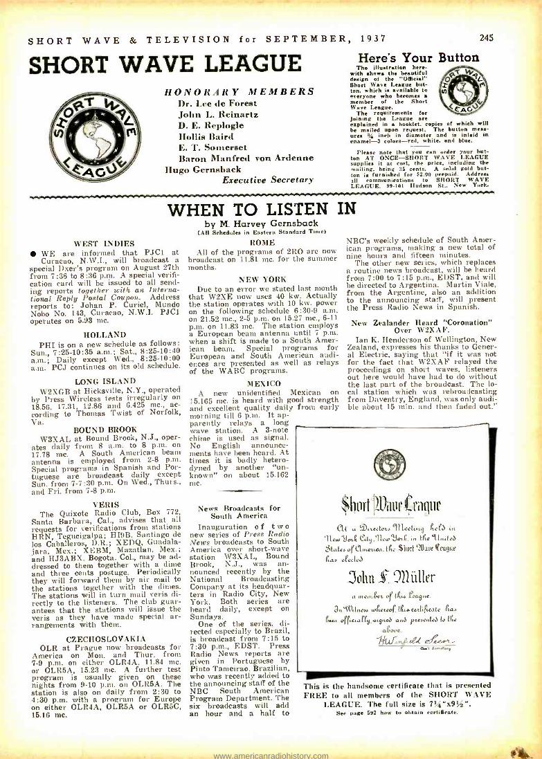
SHORT WAVE & TELEVISION for SEPTEMBER, 1937
SHORT WAVE LEAGUE HONORARY MEMBERS
Dr. Lee de Forest John L. Reinartz D. E. Replogle Hollis Baird E. T. Somerset Baron Manfred von Ardenne
Hugo Gernsback Executive Secretary
Here's Your Button The illustration here-
with show the beautiful design of the "Official" Short Wave League but- ton. which is available to everyone who becomes e member of the Short Wave League.
The requirements for joining the League are explained in booklet. copies of which will be mailed upon request. The button mess- ores % inch in diameter and is inlaid in enamel -3 colors -red. white, and blue.
Please note that you can order your but- ton AT ONCE -SHORT WAVE LEAGUE supplies it at cost. the price, including the mailing. being 35 cents. A solid gold but. ton is furnished for 52.00 prepaid. Address all communications to SHORT WAVE LEAGUE. 99.101 Hudson St.. New York.
245
WHEN TO LISTEN IN
WEST INDIES WE are informed that PJC1 at Curacao, N. \V.I., will broadcast a
special Dxer's program on August 27th from 7:36 to 8:36 p.m. A special verifi- cation card will be issued to all send- ing reports together with an Interna- tional Reply Postal Coupon. Address reports to: Johan P. Curiel, Mundo Nobo No. 143, Curacao, N.W.I. PJC1 operates on 5.93 mc.
HOLLAND PHI is on a new schedule as follows:
Sun., 7:25 -10:35 a.m.; Sat., 8:25 -10:40 a.m.; Daily except Wed., 8:25 -10:00 a.m. PCJ continues on its old schedule.
LONG ISLAND W2XGB at Hicksville, N.Y., operated
by Press Wireless tests irregularly on 18.56, 17.31, 12.86 and 6.425 mc., ac- cording to Thomas Twist of Norfolk, Va.
BOUND BROOK W3XAL at Bound Brook, N.J., oper-
ates daily from 8 a.m. to 8 p.m. on 17.78 mc. A South American beam antenna is employed from 2 -8 p.m. Special programs in Spanish and Por- tuguese are broadcast daily except Sun. from 7 -7:30 p.m. On Wed., Thurs., and Fri. from 7 -8 p.m.
VERIS The Quixote Radio Club, Box 772,
Santa Barbara, Cal., advises that all requests for verifications from stations HRN, Tegucigalpa; HI9B, Santiago de los Caballeros, D.R.; XEDQ, Guadala- jara, Mex.; XEBM, Mazatlan, Mex.; and HJ3ABX. Bogota, Col., may be ad- dressed to them together with a dime and three cents postage. Periodically they will forward them by air mail to the stations together with the dimes. The stations will in turn mail veris di- rectly to the listeners. The club guar- antees that the stations will issue the veris as they have made special ar- rangements with them.
CZECHOSLOVAKIA OLR at Prague now broadcasts for
America on Mon. and Thur. from 7 -9 p.m. on either OLR4A, 11.84 inc. or OLR5A, 15.23 mc. A further test program is usually given on these nights from 9 -10 p.m. on OLR5A. The station is also on daily from 2:30 to 4:30 p.m. with a program for Europe on either OLR4A, OLR5A or OLR5C, 15.16 mc.
by M. Harvey Gernsback (All Schedules in Eastern Standard Time)
ROME All of the programs of 2R0 are now
broadcast on 11.81 mc. for the summer months.
NEW YORK Due to an error we stated last month
that W2XE now uses 40 kw. Actually the station operates with 10 kw. power on the following schedule 6:30 -9 a.m. on 21.52 mc., 2 -5 p.m. on 15.27 mc., 6 -11 p.m. on 11.83 mc. The station employs a European beam antenna until 7 p.m. when a shift is made to a South Amer- ican beam. Special programs for European and South American audi- ences are presented as well as relays of the WABC programs.
MEXICO A new unidentified Mexican on
15.165 mc. is heard with good strength and excellent quality daily from early morning till 6 p.m. It ap- parently relays a long wave station. A 3 -note chime is used as signal. No English announce- ments have been heard. At times it is badly hetero- dyned by another "un- known" on about 15.162 mc.
News Broadcasts for South America
Inauguration of two new series of Press Radio News broadcasts to South America over short -wave station W3XAL, Bound Brook, N.J., was an- nounced recently by the National Broadcasting Company at its headquar- ters in Radio City, New York. Both series are heard daily, except on Sundays.
One of the series, di- rected especially to Brazil, is broadcast from 7:15 to 7:30 p.m., EDST. Press Radio News reports are given in Portuguese by Pinto Tameirao, Brazilian, who was recently added to the announcing staff of the NBC South American Program Department. The six broadcasts will add an hour and a half to
NBC's weekly schedule of South Amer- ican programs, making a new total of nine hours and fifteen minutes.
The other new series, which replaces a routine news broadcast, will be heard from 7:00 to 7:15 p.m., EDST, and will be directed to Argentina. Martin Viale, from the Argentine, also an addition to the announcing staff, will present the Press Radio News in Spanish.
New Zealander Heard "Coronation" Over W2XAF.
Ian K. Henderson of Wellington, New Zealand, expresses his thanks to Gener- al Electric, saying that "if it was not for the fact that W2XAF relayed the proceedings on short waves, listeners out here would have had to do without the last part of the broadcast. The lo- cal station which was rebroadcasting from Daventry, England, was only audi- ble about 15 min. and then faded out."
$I1nFt1auI!u c
C'tA a:tlttactoL» Incet..t9 ñelb in 91..To4 ed9.91e...°JA...t tYe 1...teJ
Latee orlleuts t. (he Short `2Uauf feague
4a, m%ctea
an lüller a loam gat of lPto láa9ua.
3n iViL.e» a.ita2aor. tP.r catt.Ptcate ltn van or.ctaPly, >.gneJ anJ pteaenleJ lo irte
aiooe.
This is the handsome certificate that is presented FREE to all members of the SHORT WAVE
LEAGUE. The full size is 71A "x91iz ". See page 592 how to obtain certificate.
www.americanradiohistory.com

246 SHORT WAVE & TELEVISION for SEPTEMBER, 1937
SHORT WAVE QUESTION EDITED BY BOX G.W. SHUART, W2AMN
Because the amount of work involved in the drawing of diagrams and the compilation of
data, we are forced to charge 25e each for let- ters that are answered directly through the mail. This fee includes only hand -drawn schematic drawings. We cannot furnish "picture -layouts"
or 'full- sized" working drawings. Letters not ac- companied by 25c will be answered in turn on this page. The 25c remittance may be made in the form of stamps, coin or money order.
Special problems involving considerable re- search will be quoted upon request. We cannot
offer opinions as to the relative merits of com- mercial instruments.
Correspondents are requested to write or print their names and addresses clearly. Hundreds of letters remain unanswered because of incomplete
or illegible addresses.
High Voltage Bridge Rectifier -1082 BRIDGE RECTIFIER
Alvin Nichols, Pawtucket, R. I. (Q.) I have a power -supply
which, at the present time delivers 500 volts. The transformer used is a center -tap affair and has 500 volts each side of the center -tap. I would like to use a bridge rectifier ar- rangement whereby I could obtain 1,000 volts from the same trans- former. Will you please print the necessary diagram in the Question Box?
(A.) We have shown the dia- gram of a power- supply employing three type 83 rectifiers. The filament transformer must have three sepa- rate 2.5 volt windings. If your transformer is rated at 500 volts at 250 ma. with a full -wave rectifier system, the output of the new sys- tem will then be rated at 1,000 volts at approximately 125 ma.
°PUSH- PULL" BEAM - TUBE TRANSMITTER
Roger Parsons, Massillon, Ohio. (Q.) I would like to build a sim-
ple crystal control transmitter using two beam tubes. Would you be kind enough to show the diagram of such a transmitter.
(A.) If only one -band operation is desired with a single crystal, the most efficient arrangement would be one employing two tubes in push -pull. It should be compara- tively easy to obtain 40 or 60 watts from such a transmitter. In some cases there may be a tendency to- ward high -frequency parasitic os- cillation and therefore we recom- mend a 6 or S turn coil be placed in series with one of the plate leads. While this coil will not affect the circuit appreciably. it will in a majority of cases eliminate all ten- dencies toward ultra high frequency oscillation.
Simple Transmitter -I083
PORTABLE 5-METER RECEIVER
Kenneth Richfield, Olympia, Wash. (Q.) I would like to build a
portable 5 -meter receiver using 2 tubes, something that will give fairly good results and still not be too complicated. I would like to use a 1A6 and a 1F4. Kindly print the diagram showing the values of parts.
(A.) We have shown the dia- gram of the simple super -regener-
TUNING TRANSMITTER R. Johnson, New York City, N. Y.
(Q) Would you kindly explain the procedure for tuning a crystal -con- trolled MOPA transmitter, includ- ing neutralization; some simple method which can be easily followed and is sure to work out properly.
(A.) Assuming a transmitter to have a 47 pentode crystal- controlled oscillator and a 210 amplifier. the proper procedure would be (with the filaments already heated) to ap- ply plate voltage to the oscillator only. Rotate the oscillator tuning dial until a dip occurs in the plate current. The condenser should be set slightly toward the low capacity side of this dip, we assume here also that grid -leak bias is employed in the 47 circuit. The next pro- cedure is to measure the grid cur- rent in the final amplifier, without the plate voltage applied, but with the keying circuits closed. If ca- pacity coupling is employed between the output of the oscillator and the grid of the amplifier, the grid cur- rent would be already indicated by the meter, however. if link coupling is employed then the amplifier grid condenser should be adjusted for maximum grid current. If at this point the oscillator plate current rises too high or the oscillator
(1 A6 50.000 OHMS 0.1-MF 1 F4 OUTPUT
6 T.
Y2-aA SW -
50.00 0HM5
8+,67.6V
tM ̀ MEP. o t tammr
C+ ^, A4.
LoOSC 4.5V .,/C- (13+ 1.35V
Ultra Short -Wave Receiver -1084 ator, employing an 1A6 combination high frequency oscillator. The out- put of this arrangement should be sufficient to operate a small speaker, if one is desired. For earphone op- eration a volume control must be employed. This has been shown in the diagram. Some juggling of the grid coil may be necessary in order to place the tuning range of the receiver in the 5 -meter band; this can be accomplished by merely com- pressing or spreading the turns.
SMALL SPACE ANTENNA Paul Edson, Los Angeles, Calif.
Q. I would like to build an ef- ficient transmitting antenna, how- ever, on the 80 -40 -20 meter bands I find that I do not have space for a good antenna. I have tried many varieties but do not seem to get out well on 80 with them. Will you kindly help us with this problem.
(A.) The solution of your prob- lem is a simple one, providing you have at least 65 to 70 ft. of space available for an antenna. If you will refer to the August 1936 issue. page 211, you will find described an antenna system which works out very well. It is a 40 meter halt - wave doublet with "spaced" tuned feeders. Experience had proven that it works exceptionally well on 80 meters and, of course, on 40 it is a conventional half -wave doublet and on 20 meters it operates as two
half waves in phase.
stops functioning. coupling should be reduced by spacing the link coil farther away from either the grid or plate coil. In the case of ca- pacity coupling the connection from the oscillator to the amplifier should be at a point t/a the total number of turns from the B+ or cold end of the oscillator plate coil. For neutralizing merely rotate the am- plifier tank condenser until a change in grid current is noted. Then adjust the neutralizing con- denser, starting at minimum ca- pacity, until the amplifier condenser can be tuned to resonance without
(Continued on page 260)
Monitor -1085
MONITOR FREQUENCY METER
Richard Atkins, Capetown, So. Africa. (Q.) I am completing new equip-
ment for the transmitting station and would like to have a diagram of the most efficient yet simple com- bination frequency meter and mon- itor.
(A.) We find the diagram a 67 electron -coupled oscillator. The size of the coils will depend upon the particular band on which it is to operate. This instrument should be built in an entirely shielded cab- inet or box and the power -supply leads should also be shielded in order to prevent too much pick -up. If external pick -up is needed a short piece of wire is used and one end should be placed reasonably close to the grid lead on the coil and the other end extending outside the shielded box for a distance of sev- eral inches.
3 -TUBE RECEIVER Ramon Fernandez, Havana, Cuba
(Q.) I have several older type tubes around which I would like to build a short -wave receiver. These consist of types 24 and 27. Would you kindly show a diagram of suitable receiver employing 3 of these tubes.
(A.) The diagram you requested is shown. The circuit is entirely conventional and has been published a great many times. It consists merely of a regenerative detector with two stages of audio amplifica- tion. Resistance coupling is used between the detector and the first audio amplifier, while transformer coupling is used between the 2 audio stages. Resistance coupling may be employed here also. The grid cir- cuit would be the same as the first stage, while the plate circuit of the first stage should have a 25,000 to 50,000 ohm resistor.
2 100 MEos MMF
135 MMF
RFC,25MH. /0.1MF 27 _.- 500 MMF.
27t ouTpuT
/ 0M0F6
1r 2.5V 50 000 ~-- MEG OHMS C.1
2.000 OHMS
3 -Tube Receiver Using Old -Style Tubes -1080
www.americanradiohistory.com
SHORT WAVE & TELEVISION for SEPTEMBER,
PERFECTED ELECTRIC TUNING-
JUST TOUCH BUTTONS
1937 247
AUTOMATIC
NO MORE DIAL TWIDDLING-
ELECTRICALLY AUTOMATIC
9 TOUCH BUTTONS BRING IN
9 STATIONS - IN A FLASH !
JUST TOUCH 8 LATEST Z0'
MIDWEST TUNES I1SEL
syF1ECTR1G MOTOR.
N'
ONLY MIDWESTS DIRECT -FROM -FACTORY POLICYMAKES THIS AND OTHER SENSATIONAL FEATURES POSSIBLE ATAMAZIN6LY LOW PRICES!
301;411
FREE TRIAL
HERE'S today's radio sensation! No more dial twiddling -no more squinting -no more stooping when you tune a radio!
J ust touch an electric button (on top of radio) and its corresponding station zips in ... and the dial STOPS ITSELF automatically on the station. All this happens in F3 second with Midwest Perfected ELECTRIC Tuning: (1) You touch button -electric motor speeds dial towards corresponding station; (2) Colorful Bull's Eye dart.,.
acro,rs dial and locates itself behind station; (3) As dial flashes to station, it "hunts" back and forth for an instant -and stops itself and winks at exact center of resonance. Zip ...Zip ... Zip ... you bring in 9 perfectly tuned stations in 3 seconds! o
FACTORY- TO-YOU NEW LOW BASE -PR-ICE- CHASSIS
AMAZING NEW FEATURES GIVE HUMAN PERFORMANCE The "Magic Mystic Brain" is just one of 101 advanced features, many of them exclusive! It interprets your touch button signals and
controls the electric motor. Nine contact fingers can be easily set to any stations you desire. Even a child can do it 1
MAGIC MOVIE DIAL Now. you can delight in the world's finest six - continent overseas reception with a rance of 12,000 and more miles (1225 to 20,000 KC.) Note that chassis dial shows only broadcast band. Then flip 6- save ba nil switch, ch, and instantly, fiv additional Lands are projected n the dial.
MAGIC MYSTIC BRAIN
20TUBES FOR PRICE OF 10 Why i.e content seal, an ordinary H), 12 or 14 -tube set, when you can buy a 20 -tube Super DeLuxe ELECTRIC TUNING Midwest for the same money! It will surprise and delight you with its brilliant world -wide reception on b bands. You ,,,vc 50%-and get 30 clays fire trial in your own home -when syou buy direct from the factory at
holesale prices. You are triply protected is jilt Foreign Reception Guarantee, One -Year Warranty and Money - Back Guarantees.
TERMS As LOW AS //eOOA WEEK You have a whole year to pay for your Midwest on the easiest and most convenient credit terms. Never before have you been offered so much radio for so little money -and on such easy terms!
Send for FREE 40 -page Catalog! See for yourself that Midwest offers today's greatest radio values! Write for new 1238 Factory -To-You Catalog showing 40 pages of radios, chassis and features-in their natural colors. Select the one you like on 30 days FREE TRIAL in your own home.
[Join nation -wide SERVICE MENS
11idwert renice organization. Wrilej rfreedetoi4
PASTE COUPON ON I Ç POSTCARD-OR OR WRITE TODA .
WORLD -WIDE RADIOS MIDWEST RADIO CORPORATION
MIDWEST RADIO CORPORATIO N
Dept. BB -14, Cincinnati B.
Send me your r n I' R r. E catalog atalog and
,mplete details of Address your liberal 30 - day FREE trial offer. (Special offer and Town State prices graved my
User-A ants Make Ea Extra Mone Check Here for decals hen dealing drect 9 Easy Money. Check
E Bl1-14 cm Il C I D Il on, I, OHIO, U.S.II 1 with factory by mail.) O Check Here for 24 -page BATTERY catalog
Please mention SHORT WAVE & TELEVISION when writint advertisers
Name
www.americanradiohistory.com
248 SHORT WAVE & TELEVISION for SEPTEMBER, 1937
Twin -Pentode Receiver
THE NEW 1938 SUPER SKY RIDER
5 to 550 Meters
5 to 550 Meter Coverage
6 Bands
V I I Tubes
VWide Range Variable Selec- tivity
$ 00 Less Speaker 99- Less Crystal
1,000 Electrical Band Spread
"5" Meters
Air -trimmed RQ Circuit
Improved Crystal Filter Con- trol
Here's a receiver that has everything! Complete coverage from 5 to 550 meters, with a 5 meter band that's "hot." A new Band Spread of over 1,000 degrees that really permits you to "spread them out." Wide range variable selectivity (razor -sharpness to true high fidelity) and an overall sensitivity of better than 1 microvolt. All this in one precision -built receiver at an excep- tionally favorable price. Available on Hallicrafters Liberal Time Payments. See this outstanding new receiver today!
Stop in to see it or write for complete information.
HARRISON RADIO CO. 12 West Broadway NEW YORK CITY
CORNELL -DUBILIER TYPES 4 and 9
MICA CAPACITORS föl': ' II. able, X'mtg. on 5 Meters
Designed with the utmost preci- sion. these capacitors have won first ranking honors for maximum efficiency and dependability. Di'ers and "llama" have found these condensers Ideal for port- able work because of their com- pact and sturdy construction. negligible leakage. accurate and
constant capacity and sim- ple mounting. For com- plete information and list- ing see Catalog No. 137Á.
CORNELL- DUBILIER CORP. SOUTH PLAINFIELD, NEW JERSEY
Please men
A ''Folded Doublet" Saves Space
(Continued from page 231)
coils. The material used for the construc- tion of the mast which supports the an- tenna are reasonably low- priced and easily obtainable. The mast is made up of 15 ft. lengths of 1 -inch square straight grain pine. A length of this material is used to form each of the 4 corners of the mast cross -pieces of this same material are placed every 2 ft. as bracing in order to strengthen the mast and even the spacing, as shown in Television and Short Wave World (London).
The physical dimensions of the antenna allow most efficient operation on 20 meters, however, its dimensions may be changed so that efficient operation may be obtained on any particular frequency.
tion SHORT WAVE & TELEVISION when writing advertisers
(Continued front page 223) band -spread, it is possible to use a straight dial which has no vernier attach- ment. When wiring up this condenser the rotors should be grounded independent of the chassis; do not depend upon the chas- sis for connections in the R.F. circuit. All connections in the diagram which go to the B negative or A negative side of the circuit should be connected to one point, preferably to a lug on one of the screws holding the tube socket. This will eliminate all signs of body- capacity and will improve the stability of the receiver.
Standard Hammarlund plug -in coils are employed, and for the benefit of those who wish to construct their own coils, we refer them to the February 1937 issue of the Question Box.
The antenna employed with this receiver should be one preferably 75 ft. long, that is the over -all length from the receiver to the far end. However, if a long lead -in is used, it should be as much in the clear as possible, for remember this also counts as part of the antenna. For those inter- ested in extreme DXing in a certain direc- tion, we might offer the suggestion that they employ a long antenna, one 150 to 200 ft. long or even longer providing space is available; point this antenna right at the section of the globe from which reception is desired. This is the simplest form of directional antenna that one can erect and it has proved to be sur- prisingly effective.
Parts List HAMMARLUND 1 -35 mmf. condenser. HF style 1 -140 mmf. condenser, HF style 1 -15 mmf. condenser. HF style 1 -2.1 mh. R.F. choke 1 -octal socket, isolantite 1 -4 -prong socket, isolantite 1 -set of plug -in coils CORNELL -DUBILIER 1 -.0001 mf. mica condenser 1 -.0005 mf. mica condenser 1 -.5 mf. by -pass condenser 100 or 200 V. rating 1 -.1 mmf. by -pass condenser 100 or 200 V. rat-
ing 1 -.006 mf. mica condenser I.R.C. 1 -2 meg. 1/2 -watt resistor 1- 50,000 ohm potentiometer with switch 1 -1/4 meg. t.. -watt resistor 1- 50,000 ohm %-watt resistor. RAYTHEON 1 -IE7G Twin -Pentode tube MISCELLANEOUS
The set was constructed on a 5 "x8"x2" chas- sis, with a 6 "x6" panel. There are two dials, plain non -vernier type and one twin- binding post assembly for earphones. 1 -20 ohm rheostat.
Under -side of the Twin- Pentode 1 -tube receiver. The parts are few, but should be of high quality if maximum DX results
are to be obtained.
In the Next Issue!
New 5 Meter Xmitter, by George W. Shuart, W2AMN.
Don't Miss It!!
www.americanradiohistory.com
SHORT WAVE & TELEVISION for SEPTEMBER, 1937 249
SHORT WAVE APPARATUS PROMPT SHIPMENT ON ALL ITEMS
EILEN RX19 7 -Tube Bandspread Receiver 81/2 to 3000 Meters
Our largest, finest, and most sensitive new 1937 ece- unequaled in appearance Per- formance and value. Use. special, highly efficient and selective circuit producing r a It. which the
is ousEILENh NOISE SUdiscriminating OR he
s f cart wdevelopment of our laboratories [R19 's, equipped with tW fa^ out EILEN
which r skyrocketing itself into immense popularity. This makable development, exclusive with EILEN, enables you to enjoy reception from those far-ooff stations with excellent clarity and volume. two ßK7 tewoo(3,15G,fionet(ICSOriale and
2. to
,,ne 5 V:, high hgaii,. tubes as engineering
RFiIAMPLIFIER. TUNED A ELEC- TRON COUPLED SCR1E[NORID REGENERATIVE DETECTOR, powerful 3 stage audio ire.hientyd amplifier r with TYlir speaker.
IG-aa VARIABLE
ial electron tube circuit
enabling rectifier
operator to reduce Or the
eliminate certain types of noises *m- ewing in 11 short wave receivers-automatic headphone jack- smootk and noiseless ce trola-high1 efficient in- terchangeable inductors -doublet or aerial-ground connections-POWERFUL hofidel,ty audio system -avge, illumi- nated plane type vernier dial -sensitivity, volume, and selectivity that will
features to be found - ER -19. amER- 191inaBEAUTY, well as performance. Is in class by Itself -heavy
steel cabinet with hinged lid finished In durable black shrivel- colored dial lights behind black and white scale- chrome plated escutcheon -calibrated dial plates -plated te ba chassis
I b and shielding -Operates entirely from your 105 to 130 volts
AC house under fair condition. will bang In dozens of foreign as well es do-
mestic short wave stations with enormous volume- Order one and see for yourself.
ER -19, Fee thew wise wi.n te build their
$142 romplstil BEADY TO VOL IIBor with 7 Cers, 9C e
l2 low -Ins silver plated coils for 8$ to 3000 meter, wired, in , í7(t11 KIT of ait pares, roú. rose s+,9 -3 cabinet, and Instructions _ .. tea unwired (less tubes a wòtnet/
Cafiatc extra f3.35 of metal tubes are preferred over the glass type, add $1 to T matched Sylvania tubes, extra 305
above price., Wired and tested, extra 2 00
AMATEURS: Model ER -19 -B has wme specifications as ER -19, except that It I. equipped
iw with plate voltage
cut.off handspread coils for
special 40-
B0-160 le bands spreading these banda 130c-e of dial Escale. Add 111 to Price of H -19. (1O meter band coils if desired extra 41.5.)
BS -5 6 -Tube Band switch Receiver
10 to 600 Meters
oriverfvl, sensitive- and selective SW r
nó tie entire wave-length pan f to to 5 steps. NO PLUGIN COILS ',ply to n the waveband selector itch and recent on any wavelength within this ra
uses two aÚO, 70, 43. one K42A, and 2525 tubes as RF amplifier, electron coupled
l regenerative detector, powerful lio 'el- nl ie n ls act stage, +e1
. and ioetbuil- power IIU\I- FREE- 111- fidelity dynamic loudspeaker-
.
fee editorial article Page ii nalr -I. airplane type vernier dial -hand 432, Dec. i eue S.W.C. Mimi lining control-automatic headphone Jack- extremely smooth acting Controls_p8eraMe froms your AC u use ent- beauutifuu heavy. black shrivel finish chassis and cabinet.
I ILS GREAT LOUDSPEAKER VOLUME ON THE GREAT MAJORITY OF SHORT WAVE FOREIGN STA. :DER FAIR CONDITIONS. P . > .. ,srlete
with 0 tubes, cabinet, wired, and instructions, to
BEAM POWER TUBES TO BE HAD
BS -5 KIT, of necessary parts, including detailed$1095 instructions; less tubes, cabinet, unwired 1
SPELT LL: Complete kit. cabinet, tubes and $14.95 Ilia seul, ,..d L. .il i, I-, ebd b, gL,.= fili'. add Ill
$1695
AMATEURS : Model 89 -5 -AB has same specifications as nS -5 except that it has special hand - spread circuit for 20 -40 -40 -160 M bands end is equipped with plate voltage cut- off e,,itch. Add $1.00 to above pri,
A I I nt le I
which is guaranteed to give results. 1l Operates en- tirely from the AC a DC
l
house tureen t. Simple to timid and easy to orate. Beautifu ,black shrivel t I t i I limns furnished. Wave- length range 12 -008 - ters. An ideal set for the beginner ho wishes to learn the thrill of short wave reception.
3 Tube Short Wave Radio
only $3.25 (leu tubes, peones, unwired)
A REAL, powerful 3 tube abort a e set tharead- ily brings In amateurs.
ons police calls. broadcast
atad foreign statiorsath i fair
THE WORLD AT YOUR DOOR!
THREE TUBE BAT- TERY SET. less tubes,
nones. ur wired $2.95 TWO TUBE BATTERY SET.
flew tubes,
Phones, ired 52.00
KITS wired. extra Tyr, Tu c.
11bes,
ach 5 Broad ast band coils 121. extra
onlv,ll doubt eadphnnen $1.:15.
7C 5 -Tube Short Wave Receiver
61/4 to 625 meters
Bigger and More
Powerful Than Ever A Giant In Perform-
ance ' ktS/4 The Last Word in SHORT WAVE RECEIVERS
Model RX 20 NMI The HF-25 B.Inrserrs Transmitter An ncxie calve transmitter capable of delivering a gond 20 watts crystal power to the antenna on the 111O. 140, 411 meter lands and 13 watts on 20 meter band. Using the new ßLRC, In a TriTeta ircuit allowing operation two lands with one crystal. cHighest grade mounted on metal chassis housed In a beautiful crackle finished cabinet. lenna timing unit built in. Eilen silvered transmitters antenna
Triplett meter. including set thole and plate lank ils for any ne band. Specially priced at 511.5, In kit form, Including all parte necessary to put in operation ez seta ries listed below. Exta: OLEO 41.25. Quarts. crystal $1.95 for 80, 100 meter band, ad- ditional 01
reeá r4 $2.50. Crystal holder $1.00. Coils for per set.
eu' latest CATALOG
al shortwave receivers. transmitters. d. 5 me- ter apparatus. Send stamp to cover mail- ing costs on YOUR copy.
JUST Off THE PRESS
An 8 Tube 6L6 Beam Power Audio Electrical Band - spread Receiver. 21/2 to 3101 Meters
Our latest development. An 8 -tube receiver for the ASIA - TEUN and Short have fan, using a tuned R.F. Stage :, tuned Electron pled regenerative detector. Covers all wavelengths now in including the ultra high frenoeo rien and experimental bands. A gain control for the enta,' receiver is included. 5 WATTS OF AUDIO POWER R AVAI- ABLE FOR THE BUILT HI- FIDELITY DYNAMIC SPEAKER For the HAM we offer type AB. Special Band Spread coil covering
in each the halo
il Lands
included in inl this individual padding Also l,, stand
Jack by witch for ee during transmission periods.. Tip,
imo e lc cai hancluded which automatically cuts out apes..
-r supply. READY TO 11SF.. FACTORY WIRED ANT TESTED INCI.UD- II\ND.illhI'S 2uí1'
1n111 SPREAD COILS FO1t THE HAM To 3000 511:TERS GENERAL COVERAGE COILS.
-s the followtn, tubes: 0KTG tuned R.F. amplifier. OK7G id eleetr,.n ,. ,,lel detector, one (MSG ultra high ire.
qq nay oscillator) tul.e. l'we 6Ci,G audio amplifier. , Ilt51' s the noie' suppressor and 61.liG BEAM POWER A l!T IDE OUTPUT TITRE and a 5Y3G rectifier.
the Short Wace Fan: RX-20ít complete as above with coil:, from ,. ,i. i,U m s $28.95. For the Amateur: I:r OAR' complete as above with special $20r hunn.pread coils and 200 to 3000 metercoils
615.
RX -20AB Amateur Kit: Includes all parte factory assembled ready to wire no hole. to drill or parts to mount and ache. matic PARTS.
and 19.05. Tubes. $4.50 EXTRA. Special band spread cous $1.00 per band for any one ham band. RX -20R S.W.L.
KIT: Same as amateur kit but with m,. lar coverage 3000 meters. KIT OF l'ART.S,$11.T5. S 2
Tubes, $4.50. EXTRA.
EILEN RADIO LABORATORIES Please mention SHORT
FULL 6 TORE PERFORMANCE ri lus THE NEW R92Á SERIES TUBE nukes this an outstanding value .
t:qu111Md with powerful 3 stage audio frequency sea 0000F7 (twin 2 In I tutel- 76- K92A 12\' twin tube/ tubes as R.F. amplifier. electron Coupled
screen grid regenerative detector, powerful 3 stage audio amplifier with er sage. ìe- and competebuilt n pow supply. ppeer s. entire- ly from 105 to 130 volt AC or DC ight socket. RAND SPREAD TUNLSG- smooth regeneration con. col- built In high quality loudspeaker -automatic headphone Jack -larger illuminated airplane tri"
Ì11 dial -large 10W.1011 Heavy. black Olvel tlnlah tai hassis d cabinet. Must be keen to be appreciated. Satisfied inpert , high as d loudspeaker with modl. foreign countries
same under 00dÌ ORDER YOURS TODAY! YOU WILL NOT i.liET IT!
EILEN TC RECEIVER, Wired, In cabin- et, ompslete. READY TO USE. with S, 295 sneaker 5 RCA tubes- 4 coils for Mi t 200 meters, and simple Instructions... 2 Broadcast Ilan Coils, extra 51.25 TC KIT. unwired. of necessary part.. tolls for la fá to 200 meters. d inatae- a lions less cabinet. speaker, tubas Beautiful al binet, extra 51.25 5 matched ItCA tubes 3.15 Special loudspeaker 1.45 121 Broadcast band coils. 200.625 meters 1.25 labor for wiring A testing. extra-- ......... 1.50 SPECIAL: COMPLETE KIT, unwired, can- Met. 5 Lutes, pe ker, 4 coils for 844 a $11.45 200 meters, and simple Instructions 2 bradas( Coils, extra 51.25
AMATEURS: Model 7C-AB, e reclfications se TC xcept that has special tuning cirruit d coils fo r ding out the 20 -40- 80.140 M bands over 8e. 0 of dial. Also equipped ito plate voltage t-ott witch. Same price 7C. Model SS er 62-AS tat.
É i yi o de, of 7C Operates from inexpensive dry Lter price.
Prompt service, 20% depnit on C. 0. D, orders
Dept SC I,1U6 Liberty Street, NEW YORK, N. Y.
WAVE & TELEVISION when writing advertisers
www.americanradiohistory.com
250 SHORT WAVE & TELEVISION for SEPTEMBER, 1937
A "WORLD- BEATER"
The ONLY Receiver incorporating `t ALL of these DESIRABLE FEATURES!
TWO TUNED STAGES 211/2 to 3000 METERS A positive o. rs DoAll is
ll baodeet I.
LATEST TUBES SET -Tined R.F. Amplifier. IIK7 -Tuned electron coupled regenerative de. lector. Tli- U.Ii.F, 212 to Ill meter super regenerative detector. TO- 'C50.OLII High Fidelity three stage audi°
Amplifier. R°YJG -Full wave, high voltage
t HEAD PHONE JACK HIGH FIDELITY SPEAKER FULL BANDSPREAD Automatic. 4speaker au4 "R- Fc
ñaÌVeiu aleh ilsoramnziv úrn 1 +s'cr
NOISE SUPPRESSOR and 4oahty. AND-
Velvet. remarkable development pioneered by Are Velvet smooth. calibrated enntrols- Dnublet A remarkab. Positive su'ipi, Crol I
Ingle antenna Input -Self contained. HUMLESS! presses intc,teri ile u,lOi,, bruui m nut
sup- Po Supply -Metal tubes ,inaL lower Sens °nÿnnd forae.n st.iti,ms 0all Irr,uan,la,. t'Itans,. level-Dual er
lectivity. alu!dity surpassed byto Sensitivity.
See buck issues of Short Wave and Television-send m for liter fora --or better yet order your D,'AII right ,w -net thrill
and keener kind of radio reception. now-and
know Ynull ensued:
The NEW ACE
DO -ALL DE LUXE
SEVEN TUBE HIGH PERFORMANCE
OMMUNICATIONS RECEIVER BEAM POWER
,'`ear, crisp audio volume ...;,kcr
DUAL REGENERATION
l eck re option, Manual rsettluetcu`ïnj alit for
stations:
e, FOR COMPLETE DETAILS
DO -ALL DELUXE STANDARD MODEL (9 to 3000 Meters)
eknedrtu bee cane
,.a,.i t.a otl,Illg $1975 else to buy! iNnt wired. Lsborelory wtre1 and tested. r n,iy socket.
alnd thrill to lens :adl strange
programme.! Price new and 52175
tubes, cainet, and 200 to 300o meter S iredbat
wavelength rspresent
ouannay are
t from 5500
DO -ALL DELUXE ULTRA MODEL (2t,.i to 3000 Meters) Seven nom Receiver. mm,plela w 1F $2375 ialrhad lutina and cabinet. Itpa,!yiW
ra wired.
Laboratory wired and tested. ready [ p a.2rJ to ;perme. The entire world of S26 Radio at your command! Complete
If tubes, cabinet, ana 200 to 3000 meter wavelength range are not de.
5 ` sired abovpresent s..
you may deduct from
SPECIAL: An ight ape 1nteuction booklet i ncluded FREE with every DO -ALL: loci di á c mplete, easy, wiar Sad operating instruction., as well a use et and essential short wave formation; chock full t iltustral,ons, anagram
9 etc., Booklet available for 25e. postpaid.
BATTERY OPERATION AC -DC FOR VACATION, CAMP, MOBILE FOR HOME. HOTEL, PORTABLE .UNIVERSAL -SIX" FOUR WITH
RECEIVER IMAGINE! A compact. self contain., 1. Sensitive I, ,üli real SIX
TUBE performance that will operate °n any eAC or DC house line. Simply plug tEl a cable and- l'MEual`OI -a completely
lIattert 1pt rat,',!
v that
)'ou can use in your ear, loud speaker Volume -the saute thrilling foreign reception-the same ease of operation! No changes in l airing. itealiy TWO teretrers for less than you stook' espert to pay for only on
Look at this perful tube Il ur'up, Screen grid pentode Ici' stage- high gain regwtrlaIlve delertor- 71IItE1: STAGE high quality a udio a
pliliratlan with lamer pentode output-healer type recli lier and hornless power supply. FULL SIX TUBE POWER from too dual -Twin" 6F7 tubes and heavy duty 3$ and 1 -V tubes!
And these features: Full hendsprtad 91.4 to 625 meters -self contained. good quality loud speaker -New Transmitter type tuning dial si ith dual speed friction drive-Provision for headphones -Indirect panel illumin- atlon- Velvet smooth control of regeneration-oper- ates entirely from any AC or DC house socket OR ON BATTERIES. Low current drain means long, economical life of tubes and batteries.
This receiver Is easy to build -easy to operate - and It certainly pulls 'eta in!I Order your Uni- versal SI: nowt You will be amazed at the full loud speaker tontine of distant stations! Every set Is fully
THE TUBE
sell. Buy with ea fett'!
QUALITY AC RADIO LABORATORIES VALUE 227 GREENWICH ST., Dept. C -9, NEW YORK CITY
receiver tulles, abinet, all $ ' 75 roils. and built -in speaker. COM- PLETE, nothing else to buy. Not wired. Laboratory wired and tested. r,ii,Iet -.514 50 ready to plug In. i
ELGIN .\lIt 1111-%Ml:lt "3"
3 -Tube Receiver Airplane Dial 91/2 -2000 Meters Vernier Regener- Earphone Jack ation Control
completely outelimses any reeelver of sim- ilar design. I igielis out Mid palls In Sig- n:115 from ail Warts or the world. Plug in calla, the Most efficient system for short -
wave tuning. lire rulployml. The molls fur nlabaal with the nrei ver filth. front 15 t. 550 tinder. Additional mills may be pnr chased to Prom ntf, to 15 mud 55(1 t. 2(510 meters h'uir tills. performative I-. obtained from the three us.,!. 1.6F7 com- bination deteetur and 1st :uulin nods into n 43. A 253:5 Is used for realifleuti °u. A
° le In e salker eapnhly ba n, I b,
the full output. ('bassis n Ìy with 3 tubes S11.70
Matched grey ti 9G wrinkled cabinet 0 LT7
I TRY-MO RADIO CO., INC.,
85 Cortlandt St., New York City, N. Y.
Please mention SHORT
806 All -Band Xmitter Delivers 400 Watts
(Continued front page 227)
Parts List for 806 Transmitter For a complete list of parts used in the 6F6-
f,1.6 portion, refer to the article on the exciter unit on pare 704. March 1934 issue. The parts list for the New Driver portion are as follows: IIAMMAR LUND I -100 mf. variable condenser, MTC -1008 1 -5-prong isolantite socket 1 -2.1 rah. R.F. socket ('ORNELL- DUBILIER 2-.111 mf. mica condensers 600 V. 1 - -.001 mf. mica condenser 2500 V. I -100 mmf. mica condenser 5000 V.
-.001 mf. mica condensers 1000 V. I .R.C. I 30,000 ohm. 20 watt resistor I -100 ohm center -tap resister I 15,000 ohm 20 -watt resistor
Parts List for Final Amplifier II AMMARLUND
1 -50 mint. per section split-stator condenser TCD -50A.
1 -100 mmf. condenser MTC- 10011. I ('H -500 It.I,. choke 2.5 mh. IIIJD 1 -small disc -type neutralizing condenser I -4 -prong push -type luntbu socket
S -Ws and Long Raves (Continued front page 240)
set of beads, a pocket- knife, picture views of my honte town and little souvenirs of the coronation, etc. Would you believe it, sir, not one has been good enough to answer my letter!
I do not think that this is at all fair, as I think that I should have received a little note saying that the souvenir was received in good order. I don't think that this is the right way to establish friend- ship and brotherhood between fellowmen, but I suppose they mean well.
I received a letter from a writer in Scot- land and also a copy of Short Ware & Television with my original letter printed in it. Since I mentioned the event, all book- sellers seem to be getting a good supply of bark n ranbers now and find a ready sale, three for one shilling.
Wishing your magazine every success, which it fully deserves.
Thomas Mooney 49 Aylward Road Abourthorne Estate Sheffield, Yorkshire, England.
"Spot News Transmitted by Television
(Continued froto page 217)
fleeting lenses covered by patents. The beam is reflected from this disc to
a transparent screen, suspended about four feet above it. The screen forms the bot- tom of a shadow box, which has a mirror set in its upper rear portion, and the au- dience sees the images projected onto the screen as they appear on the mirror.
The television news bulletins are seen about six feet from the floor; they are bright enough to be clearly visible in a room with ordinary artificial light, or in diffused daylight, and large enough to be easily read at distances up to 150 feet. They have been successfully demonstrated in leading Canadian hotels, and will be shown in America, probably upon a com- mercial basis, within a few weeks after this magazine goes to press.
Next Issue! Special ANTENNA article will appear. Complete data of interest to FANS and HAMS who want to get DX:
WAVE & TELEVISION when writing advertisers
www.americanradiohistory.com

SHORT WAVE & TELEVISION for SEPTEMBER, 1937 251
JJ. 9'kw 1938 Ultra Stratosphere "10" 22 to 4000 Meters Trans - Receiver *Ten tubes, 1-6K7 Regenerative Tuned
R.F. Amplifier. 1-6J7 Regenerative Detec-
tor. 1 --6J5G Super Regenera-
tive Detector & Transmit- ting Osc.
2-6C5 P.P. 1st Audio stage. 2 -25L6 P.P. Beam power
output stage & modula- tors.
2 -25Z6 Parallel Rectifiers. 1-6G5 Electronic tuning in-
dicator & R meter. *Receives from 21/2 to 4000
meters. *Transmits on 21/2 & 5 meters *8" Dynamic Speaker. *Calibrated R.F. Gain Control. *A.F. Gain Control. *Size -1712" x 191/2"-16 gauge metal. *Tone control. *R.F. Resonator control. *Separate electrical bandspread. *Vernier planetary drives on tuning
Cond. *Large illuminated 8" tuning dials. *May be used for I.C.W. and phone
transmission and as a code practice oscillator. Only a key required.
*Standby switch. *Automatic Phone jack. *Built -in A.C. & D.C. Power supply.
{' . 1 i i of parts including a 895 Speaker, unwired, 'a n old accessories
I Kit of 10 matched Sylvania tubes $6.95 Set of 4 coils -21/2 to 15 meters .30 Set of 8 coils -15 to 550 meters 2.20 Set of 4 coils -550 to 4000 meters 2.00 American S. B. Handmike 2.95 Wired and tested extra 4.50
SENSATIONAL ULTRA "AIR ROVER" 2 -TUBE TRANS -RECEIVERS
A.C.,D.C. MODEL Numerous let-
ters of apprecia- tion received from the many purchasers of the Ultra Air Rover since its release a few months ago pronounces it as the sensation of the year. Never before was a unit of this type avail- able at any price. This compact and self -contained unit will receive from 2% to 4000 meters with a high degree of excellence. Will receive for - foreign stations, amateurs, police calls, broadcast, press, airplane and weather reports, time signals, and all ultra high frequency stations. Asa 2 'fs to 6 meter transmitter surprising results will be obtained when calling friends from afar.
FEATURES * Transmits from 21/2 to 5 meters * Receives from 2 to 4000 meters
(12 bands) * Separate electrical and mechan-
ical bandspread * Loud speaker volume * Automatic super- regeneration
from 2% to 15 meters * House to house communciation * Plate modulation
BATTERY MODEL In compliance
with countless re- quests we have designed a bat- tery model of the now famous A.C: D.C. Air Rover. This remarkable unit uses 2 twin tubes, 19 & 1E7G which insure con- sistent loud- speaker volume and powerful
transmission. Receives from 2% to 4000 meter s, trans- mits on 2% and 5 meters. Cabinet is provided with handle (not shown) for portable use. May also be mounted in a car. The same features which char- acterize the electric model are incorporated in this unit.
Either kit unwired, lees tubes and ac -S715 cessories ._..__.....____._........._
Set of 2 Sylvania tubes for electric model 6156 and 1!A7 ............._ ...._..__.._....__. _...$1.05
Set of 2 Sylvania tubes for battery model 19 and 1E7G $1.95
Set of 4 calls 2% to 15 metes...__.__. ..50e Set of 4 roils 15 to 200 meters 95e Set of 5 coils 200 to 4000 meter...._..._..._..._$1.75 American S.B. Handmlke ...._. ......... _.._...... .$2.95 Cabinet less battery compartment 95e Cabinet with battery and speaker compart-
ment f2 25
5 -inch magnetic speaker._.._ $1.25 Wired and tested__.._ 42.00
Ultra High Frequency Products Co., 123 Liberty St., New York Please mention SHORT WAVE & TELEVISION when writing, advertisers
www.americanradiohistory.com

252 SHORT WAVE & TELEVISION for SEPTEMBER, 1937
20 Instruments in One , Price is $ 1 04,0
Only
The All:net, is the Season's Biggest Sensation!
The Allmeter, a 1,000- ohms -per -volt d'Ar- sonval instrument, instead of being just a volt- ohm -ammeter, is such an instru- ment plus a.c. readings for voltages and currents, also accurately measuring very low resistance, from below one ohm, also high resistance, capacity, henries and de- cibels, comprising twenty instruments in one. For a.c.-d.c. use. 0.15- 150 -750 -volts and milliamperes, a.c. and d.c. -12 to 4. 30 decibels .03 -500 ohms 500 -500,000 ohms 5 -1,000 henries .01 -50 mfd. Continuity Tester
Incomparable Signal Generator Our new generator has the following features:
1. Direct reading in frequencies. 100 kc -22 mc, in five bands, all funda- mentals, by front -panel switching. Ultra band by harmonics to 105 mc, also direct- reading.
2. Direct reading in frequencies, 25- 10,000 cycles, in three bands, all fun- damentals, by front -panel switching.
3. R.F. and A.F. outputs independently obtainable alone. or with A.F. (any frequency) modulating R.F.
4. Output meter. 5. R.F. attenuation. 6. Condenser and other leakages to 100
megohms. 7. Main dial protracted on 7s_. "( Ay40 diameter, precision pointer 4
-2 - to-1 vernier planetary drive. 8. All services on 90 -130 volts
a.c. or d.c. PRICE
Send for our Free Catalogue Pl' in colors'
_ , SUPERIOR INSTRUMENTS COMPANY
LIBERTY STREET Dept. SW- 9, New York, N.Y.
WORN - OUT
DOWN - LEADS WITH
TOUCH LIVE RUSSES
OUTER JACKIE
HEAVY STRANDIO TINNED COPPER
CONDUCTOR
LYNCH GIANT KILLER CABLE
I. Efficient in all weather 2. Insures greatest signal strength 3. Outlasts ordinary down -leads by
many years
World's Largest Makers of Antenna Systems
L. S. BRACH Mfg. Corp. Newark, N. J. .:j; Est. 1906
CHASSIS -CABINETS PANELS & CANS
STANDARD SIZES ON HAND SPECIAL SIZES MADE TO ORDER KORROL RADIO PRODUCTS CO.
Dopt. 5 232 Greenwich SL, New York City
New "Electron Gun" Projects Large Tele-
vision Images (Continued front page 214)
with a much smaller and brighter picture than in the case of a "Kinescope," which is viewed directly. Since the brightness is dependent on the current in the beam, the smaller picture requires a much larger beam current in a smaller "spot."
The television images shown were on the 441 line standard, which RCA adopted some months ago for its practical field tests. Despite the enlargement, it was difficult if not impossible for the eye to detect lice scanning or other details by which the illusion of direct vision was ac- complished.
The detailed construction of the newly devised electron gun which makes this ad- vance possible calls for specifications so rigid that the idea was nearly discarded as impracticable, when first proposed. A flood of electrons must be regimented into the solid column of a narrow beam, to "paint" the received picture more vividly on the fluorescent screen of the "Kine- scope." The electrons are "conditioned" for the job by being passed through three metal discs, each having an aperture in its center about the diameter of a pencil lead. '!'hen, they pass through a fourth and last disc, similar to the others, but with an opening too small to pass a human hair. Electrons are made to pour through this tiny opening to the fluorescent screen at the tube's end. The bombardment is so intense that the light produced on the screen of the projection "Kinescope" may be spread over an area 100 to 400 times greater in a projected picture.
Although it is regarded in scientific cir- cles as a distinct technical advance in RCA's television developments, engineer- ing opinion is that Dr. Law's contribu- tion could not at this stage be incorpo- rated in home television receives.
FINAL FOCUSING MAGNETIC LENS OF SPECIAL DESIGN TO GIVE LOw SPHERICAL ABERRATION.
1120 AMPERE TURNS REQUIRED FOR A 10.000-VOLT BEAM
MAGNETIC DEFLECTIC1N
YOKE
SECOND ANODE TERMINAL
FIRST CROSS-OVER-FORMWG SYSTEM
INNER WALL OF BULB COATED WITH AQUADAG rD FORM SECOND
ANODE
MAGNETIC SHIELD / BETWEEN DEFLECT- F UORESCENT ING AND FOCUSING SCREEN
FIELDS
TWO LENSES
NO CATHODE RAYS RROJECT BEYOND
HERE TWO LENSES
IMAGE FORMED ON FLUORESCENT SCREEN ON INSIDE
OF TUBE
LIGHT RAYS (NOT CATHODE
RAYS)
CLOTH SCREEN
ENLARGED IMAGE (REALLY A SHADOW- GRAPH) PROJECTED
ONTO SCREEN
INDIRECTLY HEATED CATHODE
ELEC- TROOE
N?.
APER- TURE SIZE
ELEC- TRODE
VOLTAGE
o 0.152 0 0.086 100
2 0.067 .200
3 0.052 2.000
4 0.004 10.000
TUNGSTEN WIRE CONTACT TO AQUADAG ON BULB'WALL -
0 123 4
COATED AREA ELECTRODE NO
0.05" DIAMETER
5.000
4,075
4.SL0
4.7111
4.702
World S -W Station List (Con i,, ti cul front page 243)
TFL REYKJAVIK, ICELAND, 60 m. Works Europe nightime irregularly.
GBC RUGBY, ENO., 60.3 m. Works ships
irregularly. GDW RUGBY, ENG., 62.24 m. Works N.Y.C.
nightime irregularly.
YEOBK VANCOUVER, B. C., CAN., 62.63 m.,
Addr. Radio Sales Service, Ltd.,780
Beatty St. Except Sun. 11.30.11.45
am., 33.15, 8 -8.15 pm.
WOO OCEAN GATE, N. J., 63.1 m., Addr. A. T.& T. Co. Works ships irregularly.
4.503 HC2ET GUAYAQUIL, ECUADOR, 65.22 m., Addr. Apartado 249. Wed. and Sat. 9.15.11 pos.
OCEAN GATE, N. J., 70.22 m., Addr. .A. T. t T. Co. Works shills irregularly.
KHABAROVSK SIBERIA, U. S. S. R., 70.42 nl. l -III am.
QUITO, ECUADOR, 73 m. Daily 7.30- 8.45 aull. Daily except Mon. 11.30
am.-2.30 pm., 5-7 pm., 7 -10 pm.
4.010 WND ,HIALEAH, FLORIDA, 73.21 m., Addr- A. T. & T. Co. Works Bahamas Ir- regular.
4.272
4.750 RV15
4.107 HCJB
!'lease mention SHORT WAVE Sc TELEVISION when writing advertisers
www.americanradiohistory.com
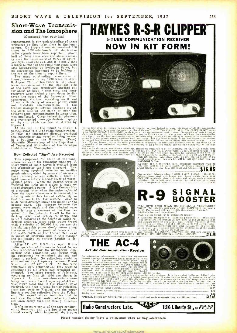
SHORT WAVE & TELEVISION for SEPTEMBER, 1937 253
Short -Wave Transmis- sion and The Ionosphere
(Continued from page 218)
improvement in our understanding of these processes as they take place in the iono- sphere. On frequent occasions -about 100 times in 1936 -fade -outs of short -wave radio signals have been reported. About half of these cases occurred simultaneous- ly with the appeorance of flares of hydro- gen light upon the stun, and it is likely that a large number of the remaining cases were also accompanied by hydrogen flares, but no astronomer happened to be looking at the sun at the time to report them.
The most outstanding occurrences of these fade -outs during 1936 were on April 8, August 25, and November 6. All short- wave transmission on the daylight side of the earth was completely knocked out for about an hour in each case, and many receivers were probably torn down to dis- cover the cause of the fade -outs. Even commercial stations, operating on 8 and 13 mc. with plenty of reserve power, could not maintain communication. If the transmission -path between stations lay on the dark side of the earth or near the twilight zone, communication between them was unaffected. Other terrestrial phenom- ena accompanied these pyrotechnic displays on the sun which are best illustrated by Figure 1.
At the top of the figure is shown a photographic record of radio signals reflect- ed from the ionosphere directly overhead the transmitter and receiver being located in a building at the Huancayo (Peru) Magnetic Observatory of the Department of Terrestrial Magnetism of the Carnegie Institution of Washington.
How Reflected "Sigs" Are Recorded This equipment for study of the iono-
sphere works in the following manner: A short pulse of radio waves is emitted from the transmitter ten times a second. This pulse when received actuates an oscillo- graph mirror, which by means of an auxil- liary rotating mirror reflects a beam of light upon a slowly moving sheet of photo- graphic paper. When the ground wave is received the light -beam makes a mark on the photographic paper. A few thousandths of a second later when the pulse reflected from the upper atmosphere is received, the rotating mirror has turned sufficiently so that the mark for the reflected wave is made some distance above the mark for the ground wave. The distance between the ground wave mark and the reflected wave mark is thus a measure of the time re- quired for the pulse to travel to the re- flecting layer and return to earth, and hence a measure of the height at which re- flection occurred, since radio waves travel with a velocity of 300,000 km. per sec. As the photographic paper slowly moves along the series of dots so produced forms a line. the wave -length of the transmitted wave is varied at intervals and in this manner the ion- density at various heights is de- termined.
After 11b 46m E.S.T. on April 8 the radio operator at Huancayo ceased to re- ceive reflections from the ionosphere. Sus- pecting that something was wrong with his equipment he examined the set and found it perfect. No reflections could be obtained on any frequency between 2 and 9 mc. until 12" 40'" E.S.T. At this time reflections were returned and they revealed conditions of all layers had remained un- changed. Two other records of fade -outs, occurring on May 28, 1936 are shown in Figure 2. In this case observations were being made on a fixed frequency of 4.8 mc. The lower solid line is the ground wave received, the next a weak border reflection from the lower or E- layer, and the upper line is a regular reflection from the F, -lay- er. The record shown indicates that in each case the weak border reflection fades out more easily than the strong Ft- reflec- tion.
While measurements of the sort conduct- ed at Huancayo and at a few other places reveal exactly what happened, short -wave
HAYNES R -S -R CLIPPER- 5 -TUBE COMMUNICATION RECEIVER
NOW IN KIT FORM!
I or the Iir.A time. in response to hundreds of requests. we have decided to make this finest of all the regenerative
toenters available to the man who prefers to °build his owvri'. RUT TIL\T'S NOT ALL! The CLIPPER KIT romea
you COMPLETELY ASSEMIRLED, ready to wire. All the mechanical work Is done. No question of parts fitting or where they belong. We have consistently refused to sell the CLIPPER in kit form to date. WE knew. from comparative testa, that it was the finest regenerative receiver available today and we a not willing to jeopardize Its reputation by selling It in any manner except rotnplelely built and tested. The CIA I'I'Kit's record as the best regenerative receiver for unusual long dLtance reception is now 8111,111 established that we feel me no longer need hesitate to offer it in kit form. We are. hoveter, taking the a livel preraut ion of completing the mech:ndrel assembly work so that there can be no question of its mechanical ruggedness, so necessary to its precision tuning and extreme bandspread on the high frequencies. Every slight change and modification which Mtr. Haynes has suggested to us for improving the CI.IPPER circuit. since It was first developed, has )wan im orporated In this new kit. 61.6 Ream Power output; 6 Inch dynamic speaker; 3 to 550 meter tuning range In seven separate bands and all its other well known features. too numerous to list here. are included In this de -luxe kit at a pike which will make It possible for hundreds of new owners to Join the ranks of CLIP-
PER DX bunters. And please rte: To give you the benefit of the lowest possible price, this new kit will be sold only direct from our laboratori.. to you. HAYNES 11-5 -1t CLIPPER KIT. completely assembled ready to wire with built -In Ac lancer supply. 6' dynande speaker. 5- cali- brated tuning dial, etc. Less only tubes and cabinet $16.85 Five matched Sylvania tubes: 2 6J5(:. 1 6K7. 1 6LeO. 1 50- $3.90. Cabinet heavy steel with hinged top. Black crackle finish 33.10 CLIPPER completely wired with tubes and cabinet ready to operate (additional 600 to 1600 meter hand may be had if desired at same price in complete set ouly) . ____...._.._ ................_.. _...._..__...._.........$28.85
R -9 SIGNAL WI LL GIVE YOUR WEAK IS >I.:N LS A TREMENDOUS BOOST. T r y this new unit ahead of , , , O r CLIPPER If you want a thrill! Can he used with any reeirer that operates front A.C. Selectivity Increased tremendously! Weak stations brought up to loudspeaker volume! A bandswl nò preamplifier U bands -no plug -in coils). Tunes from 14 to 560 meters with overlaps on each band. If you are Interested In long distance reception you need a signal booster regardless of what receiver you are using. 'ore R -9 not only gives you extreme selec- tivity. preventing Interference from other stations. but it gives you. at the same time. maximum regenerative amplification of the station you want before it even reaches your receiver.
In ordering. specify shat output tube Is used in your receiver. It -9 SIGNAL 1tO0STER with 6K7 tube complete In cabinet ready to operate. List price $18.75. f,iPECIAL EXI'EItIMIEN'rFit'S INTRODUCTORY
$11.25 PRICE ..... ._...._.._...._......__ .... ___. '/
THE AC -4 4 -Tube Communication Receiver
An r n. t.inding achievement. A truly fire r ngenerativo receiver covering the tremendous tuning range of 2!Ç to 5 meters . A. C. operation ..lilt built -in power supply. lsulant ile Insuleted bandspread and high'frequmete tuning condenser. Super-regeneration on the .. and l0 encrer bond. Separate volume and regeneration control. Antenna coupling control on front of panel. Stcuts o-Ilne -tker. ry tank condenser. Jack for earpbuthes, cuti nut speaker. Standby- sty Itch. eta Ibis three of the new 6J:d; super- triodes with 80 rectifier. The AC-4 stands Ina class by itself among long nee low price receiver,. it Is the greatest "miles per dollar" slue In ratio; a rear u unira) ton etti err with perfeet Uandspread -the 20 ureter armateur hand, for Instance. ne of the suret fascinating DX nhands
expertly Is only 400 kl lnrynlea wide. rosera 100 degrees un the big 3!t- German silver land -
cpread dual Itir NO hand rapaci ly enact. Our foreign reception you sill be atoaud at the way the AC-4 separates the crowded foreign etaliess on wire abort -weave bands. Price, . \C -1; complete kit of parts, drilled chassis. speaker, etc. Leas only cabinet and tube., unwired $10.7$ Crystalline finished metal cabinet _......_.....___...$135 Kitof four picked Sylvania tubes._ ................_........_......_......_...._........_......_.... ...._........_._.._...._......_ .._.._._.._........_....... 2.05 Wiringand testing... _......._......_.........._.._...._._.._.._.._.._... ._......._.._..__._...__.._ __ 2.50 SPECIAL PRICE ON COMIPLFTO AC -1; wired. tested and ready to operate from any 110 -volt Ilse..._... $15.35
IRadio Constructors Labs. ''AW. 136 Liberty St., N.r eC ,,N.
Please mention Sawa WAVE & TELEVISION when writing advertisers
www.americanradiohistory.com
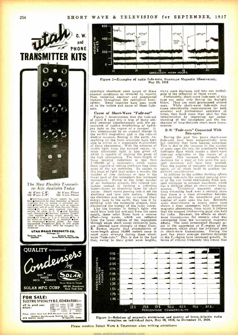
i
254 SHORT WAVE & TELEVISION for SEPTEMBER, 1937
C. W.
z and
PHONE
TRANSMITTER KITS
p A J .1 #
P AC Att r xfff a e
111111111MIli
The Most Flexible Transmit- ter Kits Available Today
80 Watts C.W. 80 Watts Phone 500 Watts C.W. 500 Watts Phone
Self- Contained Power Supply for each UnitDesigned for Hark Mounting. or Speech Amplifier may he located at perating eta -
tion.Exelter Unit may be used as separate emergency unit or as 80 Watt Portable Trans- mitterNo extra parts required when con- necting for phone nr C. W.Link Coupling used throughout Universal Antenna Coupler "link coupled "Every circuit properly me- teredAll bands on 2 or 3 crystals.No. Y
kit makes an excellent P. A. amplifier .Eas- ily constructed. Lowest prices. See the outstanding Transmitter Hits at your dealer today or write Dept. SW9 for complete in- formation.
UTAH RADIO PRODUCTS CO. Chicago. In.
Toronto. Ont. tassa Radio Producis CO.
QUALITYrecommend:
PAPER ... DRY
R
MICA . TRIMMER Pl.ew. Wri" lev Delay
SOLAR MFG. CORP. 59sregdway Nr-6si Ysork w Ciry
FOR SALE: ELECTRIC SPECIALTY D.C. GENERATORS - all in good eon- dootla volte, a /3o amps.
400 /]b volts, 1/90 amps. dition: 500 volts, amp.
1500 0 /11 volts. l7 /2d amps. 1500 volte, . amps.
Price, while they last 515.00 each f.o.b. Bridgeport. Electric wintenance Sarnia Co.. Inc.
S75 Warren street Sridgepert, Conn.
600 -
400
Iw Ur J
"1 200-
FAOE- Our
1111111111111111111 111111111111111111 11111111110111 ....M.Isr ..wim onsw+
17 58
FADE- OUT
o-
12 14 16 IB 20
Figure 2- Examples of radio fade -outs, Huancayo Magnetic Observatory, May 28, 1936
operators elsewhere were aware of these unusual conditions as revealed by reports from numerous amateur and commercial stations throughout the aunlighted hemi- sphere. Many inquiries have been made as to the nature and cause of these fade- outs.
Cause of Short -Wave "Fade -out" Figure 1 demonstrates that the fade -out
of April 8 (and this is true of many oth- ers) occurred simultaneously with the ap- pearance of sudden brightening of hydro- gen light in the region of a sunspot. It was accompanied by an unusual change in the earth's magnetism and in the natural electric currents flowing in the earth. As- sembling all the facts scientists have been able to arrive at a reasonable explanation of these phenomena. With the emission of visible light from the sunspot region, in- tense ultraviolet light is also given off which is capable of ionizing the gases of the high atmosphere. The wave -length of these ionizing radiations is less than 1 /100,000 of a centimeter, which makes then capable of setting electrons free from some of the air molecules. So sudden is this blast of light that within a minute, the number of free electrons or ions in the lower part of the ionosphere has increased enormously. Owing to the large number of air molecules present, this intense ion- ization instead of forming a reflecting layer -forms an absorbing layer for short waves. Short waves passing into it set the electrons and ions into motion. Before the electrons and ions can re- radiate their energy back to the earth, they lose it by colliding with the molecules present, thus dissipating the energy of the radio waves.
Like the traveler in Aesop's fable who could blow both hot and cold from the same mouth, these solar flares have a reverse effect -long waves, which are reflected from the lower regions of the ionosphere through which short waves ordinarily pass, are reflected more strongly at these times. R. Bureau reports that atmospherics of wave -length about 10,000 meters come in much more strongly during these short- wave "fade -outs." This is due to the fact that, owing to their great wave lengths,
many more electrons and ions can partici- pate in the reflection of these waves.
Fortunately, short -wave fade -outs of this type can occur only during the daylight hours. They are most pronounced around noon. While short-wave fade -outs may cause considerable inconvenience for both amateur and professional operators at times, they have more than paid for this inconvenience by improving our under- standing of the ionosphere and the me- chanism of long- distance short -wave trans- mission.
S -W "Fade- outs" Connected With Sun -spots
During the past few years short -wave fade -outs have been comparatively rare, but recently they have become numerous. This is due to the increase in the number of spots upon the sun, for practically every hydrogen flare which causes a short -wave fade -out originates in the region of a sunspot. This increase in sunspots will continue for a year or two until the sun- spot maximum will have been reached. Then the number of sunspots will decrease again, all of which leads to another im- portant consideration.
In addition to the sudden ionizing effects causing fade -outs the normal ionizing pow- er of the sun varies enormously from sun- spot minimum to sunspot maximum, which has a striking effect on short -wave trans- mission. Terrestrial magnetic observa- tions extending back over a century show that there is a close connection between the condition of the ionosphere and the number of spots upon the sun. Scientific radio observations in recent years have shown a close agreement with terrestrial magnetic phenomena, from which it follows that the sunspot relationship must also hold for radio. However, the effects on short- wave transmission far exceeds what was anticipated from the terrestrial magnetic effects. The most pronounced changes oc- cur in the uppermost or F, -region of the ionosphere, which plays the principal part in short -wave transmission. During the past few years average electron- densities in the Fe.-region have increased greatly. In terms of critical frequency this means that
0.15 I 0.35 w 2
w Zt./ < ,
11
ww
.11.1.11111111.11. 0.55 _.1.0.M 0.75
M EMM 0.95
°355 1.35 = 1.55 _I 17955 1.95
12.5 25.0 37 5 50.0 62.5 75.0 PERCENTAGE COMMERCIALITY
87.5
Figure 3- Relation of magnetic stormness and quality of trans -Atlantic radio reception on individual days, May 28, 1928, to December 31, 1930.
Please mention SHORT WAVE & TELEVISION when writing advertisers
www.americanradiohistory.com

SHORT WAVE & TELEVISION for SEPTEMBER, wave -lengths are reflected by this layer now which previously penetrated it and passed off into space.
An illustration of this change has been supplied by an amusing consequence of in- complete understanding of the ionosphere and factors affecting radio transmission. A few years ago certain stations were as- signed frequencies for short -distance trans- mission so high that the signals would penetrate the ionosphere and pass off into space, instead of being propagated for great distances. To the amazement of lis- teners the increased ion- density during re- cent years caused these frequencies to be heard across the Atlantic -a thoroughly unanticipated result.
Ultra Short -Wave Range to Increase During the period of sunspot minimum
which occurred around 1922, trans -Atlantic communication on 15 mc. was not reliable. On the other hand 45 mc. has been heard across the Atlantic during recent months following the increase in sunspot- numbers. Perhaps during the next few months the sunspot maximum which seems to be ap- proaching may exceed the preceding one and permit long- distance communication on short waves of exceedingly short wave- length. It is unbecoming that a scientist should indulge in speculations of this na- ture, but there is evidence suggesting that the sunspot maximum which is approach- ing will be the greatest that has occurred since the vogue of amateur radio. Those interested in the advancement of scientific knowledge will perform a real service if they experiment in long- distance com- munication with extremely short wave- lengths. It may be possible during the next few months or years to achieve long distance communication on 50 or 60 mc.
5 meter (56n1r.) signals have already been heard across the Atlantic. -Editor. (5 meter region). It should be pointed out that the experiments suggested should be carefully conducted. Long -distance communication on these frequencies can- not be accomplished regularly. Perhaps on one or two clays success may be attained. The writer of this article would be glad to receive information concerning any authenticated cases of long- distance com- munication on ultra -short waves.
"Sunspots" Serve As Index of Solar Activity
While these variations in the ionosphere are frequently attributed to sunspots, it is necessary to recognize that the sunspots are probably not the cause of the effects but rather an index of a more fundamental phenomenon -variations in the activity of the sun. Our sun is a variable star the radiations from which vary in intensity over an approximately 11 -year period. The changes which take place in the radiations capable of ionizing our atmosphere are most pronounced although their results can be perceived only indirectly. These are the radiations which play a leading role in short -wave phenomena.
It is believed that at times of sunspot maxima the sun intermittently sends out clouds of corpuscles traveling through space at a speed of about 1,000 km. per sec. (600 miles per sec.) These corpnsclar clouds are assumed in order to account for the aurorae and sudden changes in the earth's magnetism called "magnetic storms ?' Math- ematical analysis has revealed that these magnetic storms result from processes tak- ing place in the upper atmosphere, caused, it is presumed by some solar action. Dur- ing magnetic storms aurorae flash in the arctic and antarctic skies, particularly brilliant aurorae accompanying the more intense storms. The consequent changes in radio conditions are striking and signifi- cant.
These effects are best illustrated by reci- tation of the events occurring during a recent magnetic' storm. This storm be- gan around noon E.S.T. on April 24, 1937, and continued through April 28, on which day it attained its maximum intensity. (This stormy interval probably involved three distinct storms, one directly after another.) During this period, short -wave
1937 255
Operators Out For DX Records Are Using This Receiver
Regenerative Input
About the "LC Ratio"
Sargent Model21
Before you buy your next super -het. look "under th, Idol." Cheek up on the "L t'' ratio at the dial
oings used for amateur hand reception. High Ir /C l m is extremely iullx,rtant for weak signal reception. .
or DX. For greatest DX range tuning condenser don't! be almost entirely out of mesh. Model 21 has
it designed so as to give tills favorable tuning oin- idion to the 10. 20 40, 75 and 80 meter amateur .ads. tinder these favorable conditions, weak signais
heard that are frequently lost when tuned with a desrapacity selling. This Is just one of the malin
ign features that make Model 21 the DX man's receiver.
Red Hot on 10 Meters nigh I. rot., and n eratice )gran dig tho.r seat l6 ureter signals "out of the nmd. Model 21 really steps out MI this hand. Ten meter signals travel special circuits from antenna to 1st detector. This is really a 10 meter reeei ver within an ail -wave set. You don't know what really good 10 meter reception Is until you have tried this one.
A ivi r riii better than its input circuits. Signals lost here can never be retrieved later in the circuit by any amount of amplification. One of the most important func- tions of a good receiver is to provide low impedance path, to conduct the extremely weak signal currents from the an- tenna to the first tube. The efficiency with which this is done is a direct measure of the DX range of the receiver. This is the reason REGENER- ATIVE INPUT, the most sen- sitive known circuit arrange- ment. is used on Model 21.
COMMERCIAL MODEL COnlintlnrls tuning'. 9.3 r. n n,.I t, l i,Ja x ]fodel 21 °ullaldr ton i Ld i Lm.il ion;. Panel is ark Operation is stablr.l ignite.. y Is high throughout. This receiver is excellent on 600 meters. the beacon and tiare signal hands. in addition to its regular shirt stay, and bmzdrart ruy0.1_
A. C. OR 6 V. BATTERY Furnished for either tuning range at $3.00 higher than the A.C. price. Etcellent for portable or direction find- ing work.
NET PRICES (Effective May 15011
Model 2I -AA. 9.5 -550 meters 0139.01 Model 214L1. 9.5 -3750 eters 155.1111 These prices Include RI'.d. tulles. power supply. Sen-
E. M. SARGEN T C Cable Address a'EMSCO"
212 Ninth Street Oakland, Calif.
operators were greatly perturbed. Persons listening to ordinary broadcast programs heard the familiar announcement many times: "Due to atmospheric conditions be- yond our control we are unable to bring you the program scheduled for this hour." Auroral displays of unusual brilliance were seen in many places. Short -wave com- munication was particularly poor during much of this time.
Effect of "Magnetic Storms" on S -W North Atlantic Circuits
Figure 3 shows a plot in which short- wave transmission conditions. measured in percentage of time North Atlantic (short- wave) circuits were available for commer- cial service, is coordinated with the Ameri- can magnetic chara .ter- figure, a measure of the amount of magnetic storminess. A small black area is put in one block for each day indicating the degree of stormi- ness and the percentage of time during which commercial traffic could be carried. On days when the magnetic storminess was a minimum, character -figure 0.15 or less, the circuits could be used commer- cially nearly all day or all day, while the magnetic storminess was a maximum, the circuits were available less than 12.5 per cent of the time. These results apply when the radio transmission is over a path pass- ing within about 20° from the geomag- netic pole, located in longitude 69° east, latitude 78.5° north. Transmission over paths traversing equatorial regions is not severely affected. Use was made of this important fact by commercial companies during the recent magnetic storm in April. Communication with European stations was maintained by routing the traffic through Buenos Aires.
An attempt to explain these idiosyn- crasies of short -wave transmission at the present time would be hazardous, as suffi- cient data are not yet available as a basis for definite conclusions. Observations show that during times of magnetic disturbance the ion -densities in the F- region, upon
Please mention SHORT WAVE & TELEVISION when writing
SEE YOUR JOBBER y.- .,., `.,
PLUG and SOCKET CONNECTOR
ÿ *- ti-1 I SPItI N G
CAB L E PROTECTOR
f.4% 4111-- MODEL D -104
FaVoriio. uY 1110 .tulai eau' A quality crystal microphone espe-
cially adaptable for voice transmission. output level -54 DB (conservatively rated), New redesigned case. List Price
22.50. Licensed under Brush Development
Co. Patents.
ASIATIC Microphone Laboratories, Inc. Dept. SW YOUNGSTOWN, OHIO
advertisers
so-. Money on Radio! R ere your copy NOW of Pm ne- 19)1 Coralag Ne. 69.4.17. More than
SO models of LAFAYETTE radie fen. Iran 9.95. Complete Farm Radios lot 19.95. Over 10.000 Ear. gain, in rober. porn. lin, teals. ale. Everything at lo- rr Wholerele pelo,,. Write at
Ce- s FREE.
WHOLESALE RADIO SERVICE CO., 1a. 104151ITH AVENUE NEW YORK N. Y.
www.americanradiohistory.com
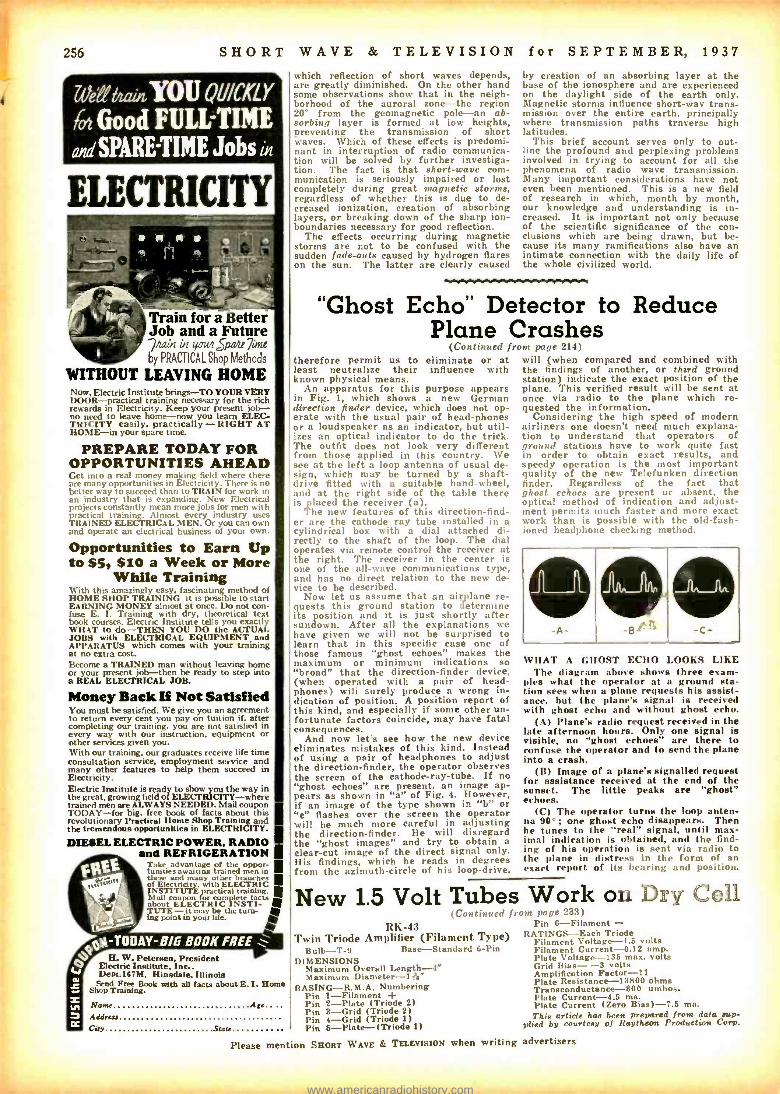
256 SHORT WAVE & TELEVISION for SEPTEMBER, 1937
Neff brain, YOU QUICKLY
10 Good FULL -TIME 0dSPARE TIME Jobs UI
ELECTRICITY
Train for a Better Job and a Future 74ain zpu4 Sp 7iint by PRACTICAL Shop Methods
WITHOUT LEAVING HOME Now. Electric Institute brings -TO YOUR VERY DOOR -practical training necessary for the rich rewards in Electricity. Keep your present job - no need to leave borne -now you learn ELEC- TRICITY easily, practically -RIGHT AT HOME -in your spare time.
PREPARE TODAY FOR OPPORTUNITIES AHEAD Get into a real money making field where there are many opportunit ies in Electricity. There is no better way to succeed than to TRAIN for work in an industry that is expanding. New Electrical projects constantly mean more jobs for men with practical training. Almost every industry uses TRAINED ELECTRICAL MEN. Or you can own and operate an electrical business of your own.
Opportunities to Earn Up to $5, $10 a Week or More
While Training With this amazingly easy, fascinating method of HOME SHOP TRAINING it is possible to start EARNING MONEY almost at once. Do not con- fuse E. I. Training with dry, theoretical text book courses. Electric Institute tells you exactly WHAT to do -THEN YOU DO the ACTUAL JOBS with ELECTRICAL EQUIPMENT and APPARATUS which comes with your training at no extra cost. Become a TRAINED man without leaving home or your present job -then be ready to step into a REAL ELECTRICAL JOB.
Money Back If Not Satisfied You must be satisfied. We give you an agreement to return every cent you pay on tuition if, after completing our training, you are not satisfied in every way with our instruction, equipment or other services given you. With our training, our graduates receive life time consultation service, employment service and many other features to help them succeed in Electricity. Electric Institute is ready to show you the way in the great, growing field of ELECTRICITY -where trained men are ALWAYS NEEDED. Mail coupon TODAY -for big, free book of facts about this revolutionary Practical Home Shop Training and the tremendous opportunities in ELECTRICITY.
DIESEL ELECTRIC POWER, RADIO and REFRIGERATION
1 ake advantage of the oppor- tunities awaiting trained men in these and many other branches of Electricity. with ELECTRIC INSTITUTE practical training. Mail coupon complete about ELECTRIC INSTI-
fo
TUTS- it may be the turn- about
point in your life. ('
H. W. Petersen, President Electric Institute, Inc.. Dept.167M, Hinsdale, Illinois Send Free Book with all facts about E. I. Home
Shop Training.
Name Ate.... Addrr.0 Cuy Star
Please
which reflection of short waves depends, are greatly diminished. On the other hand some observations show that in the neigh- borhood of the auroral zone -the region 20° from the geomagnetic pole -an ab- sorbing layer is formed at low heights, preventing the transmission of short waves. Which of these effects is predomi- nant in interruption of radio communica- tion will be solved by further investiga- tion. The fact is that short -wave com- munication is seriously impaired or lost completely during great magnetic storms, regardless of whether this is due to de- creased ionization, creation of absorbing layers, or breaking down of the sharp ion - boundaries necessary for good reflection.
The effects occurring during magnetic storms are not to be confused with the sudden fade -outs caused by hydrogen flares on the sun. The latter are clearly caused
by creation of an absorbing layer at the base of the ionosphere and are experienced on the daylight side of the earth only. Magnetic storms influence short-way trans- mission over the entire earth, principally where transmission paths traverse high latitudes.
This brief account serves only to out- line the profound and perplexing problems involved in trying to account for all the phenomena of radio wave transmission. Many important considerations have not even been mentioned. This is a new field of research in which, month by month, our knowledge and understanding is in- creased. It is important not only because of the scientific significance of the con- clusions which are being drawn, but be- cause its many ramifications also have an intimate connection with the daily life of the whole civilized world.
"Ghost Echo" Detector to Reduce Plane Crashes
(Continued from page 214) therefore permit us to eliminate or at least neutralize their influence with known physical means.
An apparatus for this purpose appears in Fig. 1, which shows a new German direction finder device, which does not op- erate with the usual pair of head -phones or a loudspeaker as an indicator, but util- izes an optical indicator to do the trick. The outfit does not look very different from those applied in this country. We see at the left a loop antenna of usual de- sign, which may be turned by a shaft - drive fitted with a suitable hand -wheel, and at the right side of the table there is placed the receiver (a).
The new features of this direction -find- er are the cathode ray tube installed in a cylindrical box with a dial attached di- rectly to the shaft of the loop. The dial operates via remote control the receiver at the right. The receiver in the center is one of the all -wave communications type, and has no direct relation to the new de- vice to be described.
Now let us assume that an airplane re- quests this ground station to determine its position and it is just shortly after sundown. After all the explanations we have given we will not be surprised to learn that in this specific case one of those famous "ghost echoes" makes the maximum or minimum indications so "broad" that the direction -finder device, (when operated with a pair of head- phones) will surely produce a wrong in- dication of position. A position report of this kind, and especially if some other un- fortunate factors coincide, may have fatal consequences.
And now let's see how the new device eliminates mistakes of this kind. Instead of using a pair of headphones to adjust the direction- finder, the operator observes the screen of the cathode -ray -tube. If no "ghost echoes" are present, an image ap- pears as shown in "a" of Fig. 4. However, if an image of the type shown in "b" or "c" flashes over the screen the operator will be much more careful in adjusting the direction -finder. He will disregard the "ghost images" and try to obtain a clear -cut image of the direct signal only. His findings, which he reads in degrees from the azimuth -circle of his loop -drive,
will (when compared and combined with the findings of another, or third ground station) indicate the exact position of the plane. This verified result will be sent at once via radio to the plane which re- quested the information.
Considering the high speed of modern airliners one doesn't need much explana- tion to understand that operators of ground stations have to work quite fast in order to obtain exact results, and speedy operation is the most important quality of the new Telefunken direction finder. Regardless of the fact that ghost echoes are present or absent, the optical method of indication and adjust- ment permits much faster and more exact work than is possible with the old -fash- ioned headphone checking method.
-B1 ' -C-
WHAT A GHOST ECHO LOOKS LIKE The diagram above shows three exam-
ples what the operator at a ground sta- tion sees when a plane requests his assist- ance, but the plane's signal is received with ghost echo and without ghost echo.
(A) Plane's radio request received in the late afternoon hours. Only one signal is visible, no "ghost echoes" are there to confuse the operator and to send the plane into a crash.
(B) Image of a plane's signalled request for assistance received at the end of the sunset. The little peaks are "ghost" echoes.
(C) The operator turns the loop anten- na 90° ; one ghost echo disappears. Then he tunes to the "real" signal, until max- imal indication is obtained, and the find- ing of his operation is sent via radio to the plane in distress in the form of an exact report of its bearing and position.
New 1.5 Volt Tubes Work on Dry Coll (Continued front page 233)
RK -43 Pin 6- Filament - Twin Triode Amplifier (Filament Type) RATINGS -Each Triode
Filament Voltage -l.5 volts Bulb -T -9 Base- Standard 6 -Pin Filament Current -0.12 amp.
Plate Voltage -136 max. volts Grid Bias- -3 volts Amplification Factor -11 Plate Resistance -18800 ohms Transconductance -800 umhos. Plate Current -4.6 ma. Plate Current (Zero Bias) -7.6 ma.
This article has been prepared from data sup- plied by courtesy of Raytheon Production Corp.
DIMENSIONS Maximum Overall Length -4" Maximum Diameter -1r's"
BASING- R.M.A. Numbering Pin 1- Filament + Pin 2 -Plate (Triode 2) Pin 3 -Grid (Triode 2) Pin 4-Grid (Triode 1) Pin 6- Plate- (Triode 1)
mention SHORT WAVE & TELEVISION when writing advertisers
www.americanradiohistory.com
SHORT WAVE & TELEVISION for SEPTEMBER, 1937 257
How to Photograph Television Images
(Continued from page 219)
while the second half is scanned in an- other 1/50 second, the two halves being interlaced.
In this system the time taken for one spot of light to travel its own length is .00000017, so a one -second shutter ex- posure gives the emulsion an exposure
One of the lady announcers. This is an example of watching one's chance. It was noticed that the announcer kept looking down at her script and an ef- fort was made to photograph directly she looked down. Unfortunately the exposure was just too long and traces of movement have spoilt what might have been a very good result, the eyes being recorded mostly cast down, al- though the shutter was not quite closed when the eyes were looking at the camera. Exposure 2 secs. F/2.9 S.S.
pan. Kodak film.
This picture must be one of the best known scenes to television experimenters, having been used for testing purposes by the (British) Baird Company for nearly two years. The picture is from a loop of film and the artist slowly turns her head, faces the looker -in and then with great rapidity turns her face left. The subject gives photographers a chance to know what is coming, and though the subject is never quite still, a one second exposure with a F/2.9 lens S.S. pan. Kodak film re- corded the picture. In the original the scanning lines can be seen. The four faint horizontal lines are produced by the scan- ning disc at the transmitter, which ro-
tates four times per picture.
equal to 1/250,000 second. On the surface these figures seem to make the photo- graphy of a television image impossible. Luckily the light of a cathode -ray tube is very intense and it is quite possible to get a printable negative with a shutter speed of one second using a suitable camera and
emulsion. Shutter speeds of 1 /10 second have produced very thin negatives, while exposures of 1.5 to 2 seconds give ample exposure.
The lens must be fast, the writer uses a Dallmeyer F/2.9 Pentac lens and Kodak super sensitive panchromatic film, devel- oped in a normal metol -hydroquinous de- veloper.
Unfortunately, though ample exposure is easily obtained, most of the television screens contain fairly rapid movement, which produces a blurred result when ade- quately exposed. Few scenes televised could in the ordinary way be photo- graphed much more slowly than 1 /10 of a second without blurr, so one is rather limited to subject from an ordinary trans- mission and much patience is required to get a satisfactory picture. Often announc- ers are comparatively still at the begin- ning or end of a transmission. The same applies, though to a lesser extent, with ar- tists. Sometimes test transmissions are made when somebody sits in a chair read- ing for some minutes on end. There is definitely much luck in choosing the right time to expose.
Another big factor in successful tele- vision photography is the brightness at which the cathode -ray tube is operated. Obviously the brighter the tube the shorter the exposure. If the brightness of a tube is increased, the picture appears, to the eye, to become flat. The shadows are lightened but the high lights do not get proportionately brighter so the gam- ma is reduced. This is desirable from a photographer's point of view, as the aver- age television picture is generally tonally distorted (if in no other way).
The three prints of a B.B.C. caption card transmitted prior to the opening of the station clearly illustrate the effect of adjusting the picture brightness. The third would produce the best setting for photographing average scenes, although for a caption a strong contrast is best.
There is also another problem in photo- graphing a television image which must be mentioned, namely, synchronization. Modern high -definition television is syn- chronized to a high degree of perfection, when the eye is the judge, but over pe- riods of, say, two seconds quite a lot of unsteadiness is sometimes noticeable in a receiver as seen by a camera. So that when the artist is still, with ample ex- posure and sharp focusing, and the result is blurred, unsteady synchronism was probably the cause. A good photograph of a television image should show the scan- ning lines on close inspection.
Earlier it was mentioned that in the Marconi -E.M.I. system the scanning is in- terlaced. Sometimes receivers do not in- terlace properly, with the result that the, scanning lines are very clearly marked, definition is reduced, but generally speak- ing photographically the intensity is dou- bled. In such a case the picture appears apparently more exposed than others for a given exposure.
Those who use electronic exposure met- ers will find that the more sensitive type will give a reading of the average cathode - ray tube of such an order as to indicate an exposure of about one second at F/3 with an H. & D. speed of 1,000. The colour of the light, of course, plays an important part, the greenish tubes are more actinic than the black and white or sepia tubes. This apparent increase in actinic value may, of course, be due to "afterglow" of the fluorescent screen, which will natur- ally increase the exposure in some cases quite a considerable amount, and in every case increases the apparent exposure to some extent.
We hope photographers will attack the problem with renewed vigor, as good pho- tos of television images are scarce. - R. C. Hanner in Television and Short -Wave World (London).
Tite Best "BUYS"
Are hade For
Cash!*
IrM MY OWN BOO-.
I BUY NAY, - N
*By "CASH" we mean your jobber's regu- lar terms.
THERE is satisfaction as well as profit in doing business in a hard- headed way- buying on regular terms rather than getting into "tanglefoot" deals. RAY - THEONS were never sold by de- pression methods -that is one of the reasons why RAYTHEON sales are increasing every month. Another important reason is the uncontested high quality of RAY- THEON tubes.
kÀYillhui
ASK YOUR
RAYTHEON
JOBBER
RADIO TUBES 445 Lake Shore Drive, Chicago, Illinois 555 Howard Street, San Francisco, CaL 420 Lexington Avenue, New York, N. Y. 55 Chapel Street, Newton, Massachusetts 415 Peachtree Street, N. E., Atlanta, Ca.
Please mention SHORT WAVE & TELEVISION when writing advertisers
www.americanradiohistory.com
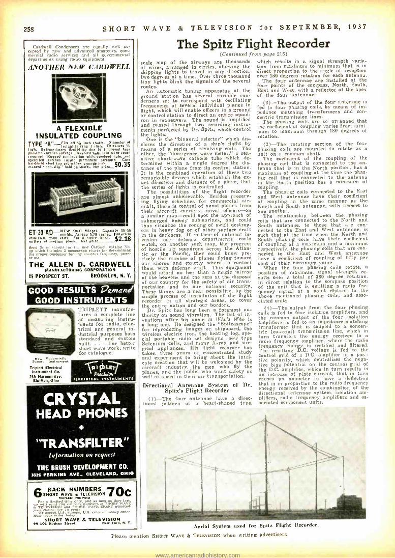
258 SHORT WAVE & TELEVISION for SEPTEMBER, 1937
The Spitz Flight Recorder Cardwell Condensers are equally well ac- cepted by new and advanced amateurs. com- mercial radio services and all governmental departments using radio equipment.
ANOTHER NEW CARDWELL
A FLEXIBLE INSULATED COUPLING
TYPE "A" -`its all ', inch shafts. Diameter of holantite ring I inch. Thickness Ya
inch. Extraordinary flexibility due to improved type Phosphor-bronze springs. Reversed hubs minimize spare required. Rugged construction with swedged hubs and eycletted springs insure permanent strength. Case hardened steel cup set screws provide per- $o. 35
canent 'non- slip" hold on shafts. Net price....
ET -30 -AD -NEW Dual Midget. Capacity 30-30 mmfds. Airgap 0.70 inches. Isolantite
insulated, 2500 volts. For 5 meter trans - 12.16` ns mitte of medium power. Net price..._...._.....i
Send 3e In stamps for the new Cardwell catalog No. 40 ohich Includes 3 nomograph rl,.,i is I d,l,- rndning the proper condenser for ans .i power or use.
THE ALLEN D. CARDWELL MANUFACTURING CORPORATION
89 PROSPECT ST. BROOKLYN, N. Y.
GOOD RESULTS !%amand GOOD INSTRUMENTS
New Modernists Square ln.tra,.,,'nt
Triplett Electrical Instrument Co.
289 Harmon Ave. Bluffton, Ohio
TRIPLETT manufac- tures a complete line of measuring instru- ments for radio, elec- trical and general in- dustrial purposes both standard and custom built. . For better short wave work, write for catalogue.
{i1 LEr Precision
ELECTRICAL INSTRUMENTS
CRYSTAL HEAD PHONES
"TRANSFILTER" Information on request
THE BRUSH DEVELOPMENT CO.
3326 PERKINS AVE.. D, OHIO
aBACK NUMBERS 7O SHORT WAVE i TELEVISION MAILED PREPAID
y For ill send ix l,-',ly. and, as lof SHORT they
s eTELEVISION and .SHORT uWAVE CRAFT assorted. ) -o', 0 choice, for 7 een
We weep( U.S. stamps, U.J. coin, or money , ney order. Itush your order t.,,l:t).
SHORT WAVE & TELEVISION 99.101 Hudson Street New York, N.Y.
C
(Continued from page 2161
scale map of the airways are thousands of wires, arranged in circles, allowing the skipping lights to travel in any direction, two degrees at a time. Over three thousand tiny lights blink the signals of the several routes.
An automatic tuning apparatus at the ground station has several variable con- densers set to correspond with oscillating frequencies of several individual planes in flight, which will enable officers in a ground or control station to direct an entire squad- ron in maneuvers. The sound is amplified and passed through two recording instru- ments perfected by Dr. Spitz, which control the lights.
One is the "binaural selector" which dis- closes the direction of a ship's flight by means of a series of revolving coils. The other, the "divergence wave meter," a sen- sitive short -wave cathode tube which de- termines within a single degree the dis- tance of the plane from its control station. It is the combined operation of these two remarkable devices which establish the ex- act direction and distance of a plane, that the series of lights is controlled.
The possibilities of the flight recorder are almost unbelievable. Besides preserv- ing flying schedules for commercial air- craft, there is control of naval planes from their aircraft carriers; naval officers -on a similar map -could spot the approach of submerged enemy submarines, and could thus visualize the coming of swift destroy- ers in heavy fog or of other surface craft in the darkness. If in time of national in- vasion our defense departments could watch, on another such snap, the progress of hostile air squadrons across the Atlan- tic or the Pacific, they could know pre- cisely the number of planes flying toward our shores and exactly where to contact them with defense craft. This equipment would afford no less than a magic mirror of the heavens and the seas at the disposal of our country for the safety of air trans- portation and to our national security. These things are a near possibility, by the simple process of installation of the flight recorder in all strategic areas, to cover the entire nation and our borders.
Dr. Spitz has long been a foremost au- thority on sound vibration. The list of in- ventions after his naine in Who's Who is a long one. He designed the "Spitzascope" for reproducing images on shipboard, the wireless electric iron, the heating log, spe- cial portable radio set designs, new type Selenium cells, and many X-ray and sur- gical appliances. His flight recorder has taken three years of concentrated study and experiment to bring about the intri- cate creation that will be welcomed by the aircraft industry, the men who fly the planes, and the public who want safety as well as speed in their air transportation.
Directional Antennae System of Dr. Spitz's Flight Recorder
(1) -The four antennae have a direc- tional pattern of a heart- shaped type,
which results in a signal strength varia- tion from maximum to minimum that is in direct proportion to the angle of reception over 180 degrees rotation for each antenna.
The four antennae are installed at the four points of the compass, North, South, East and West, with a reflector at the apex of the four antennae.
(2) -The output of the four antennae is fed to four phasing coils, by means of im- pedance matching transformers and con- centric transmission lines.
The phasing coils are so arranged that the coefficient of coupling varies from mini- mum to maximum through 180 degrees of rotation.
(31 -The rotating section of the four phasing coils are mounted to rotate as a unit on a common shaft.
The coefficient of the coupling of the phasing coil that is connected to the an- tenna that is in the North position, has a maximum of coupling at the time the phas- ing coil that is connected to the antenna in the South position has a minimum of coupling.
The phasing coils connected to the East and West antennae have their coefficient of coupling in the same manner as the North and South antennae, with respect to one another.
The relationship between the phasing coils that are connected to the North and South antennae, to those that are con- nected to the East and West antennae, is such that at the time when the North and South phasing coils have their coefficient of coupling at a maximum and a minimum respectively, the phasing coils that are con- nected to the East and West antennae have a coefficient of coupling of fifty per cent of their maximum value.
When the four phasing coils rotate, a position of maximum signal strength re- sults over a total of 360 degree rotation, in direct relation to the compass position of the unit that is emitting a radio fre- quency signal at a point distant to the above mentioned phasing coils, and asso- ciated units.
(4) -The output from the four phasing coils is fed to four isolation amplifiers, and the common output of the four isolation amplifiers is fed to an impedance -matching transformer that is coupled to a concen- tric (co- axial) transmission line, which in turn transfers the energy received to a radio frequency amplifier, where the radio frequency energy is rectified and filtered. The resulting D.C. voltage is fed to the control grid of a D.C. amplifier in a pos'- tive polarity, which neutralizes the nega- tive bias potential on the control grid of the D.C. amplifier, which in turn results in an increase of plate current, that in turn causes an ammeter to have a deflection that is in proportion to the radio frequency energy received by the combination of the directional antennae system, isolation am- plifiers, radio frequency amplifiers and as- sociated component units.
Aerial System used for Spitz Flight Recorder.
Please mention SHORT WAVE & TELEVISION when writing advertisers
www.americanradiohistory.com

SHORT WAVE & TELEVISION for SEPTEMBER, 1937 259
Weather Forecasting by Short Waves (Continued from page 220)
SUN WARMS ACCELERATES
OF DRY WINOS
HERE THE OAT WINDS ABSORB ALL NUMIOIT T.GIVIHG CLEAR FAIR WEATHER
PACIFIC DCEAN
WHEN THE PHENOMENON IS FIG 8 ACT ONENDED TRADE WOOS BLOW
AGAIN THEN WtIAVE0000, COT ,, \ WEATHER ON THE PACIFIC SIDE Y \ DRY RAINY WEATHER ON THE
1 WINO _ATLANTIC SIOE .. HUMIDITY CONDENSES MERE, BIG RA INS ON
CAV C. WEATHER OTE4 - ATLANTIC SIDE
ENTRAL PLATEAU Y- _ TRADE WINDS (HUMID) PACIFIC COAST SEA
FIG 9 DEPRESSION))ITHEH
5C(ARIBBEAN HEN/ LAYER MAYA TAPE THE
FIGURE THEN,A SHORT WAVE PROGRAM MAY BE "LADED: OR IMPOSSIBLE TO NEAR
IONIZED ABNORMAL VARIATION IM HEAVISIDE LAYER
FORM OCT.% CONSIDERABLY
NOWAY. REFLECTING LAYERS
WAVES
REFLECTED 7C
RAY -... RAY MISSING SHORT WAVE s. STATION
KMRTER í ..sREC .,, 1 M1T. C\ \ "` R(L.
w STATIONS AND LISTEN
GABAROMETTRILC FIG 10
BAROMETRIC PRESSURE MINIMUM IS MINIMUM
5 W. RAY / \ NORMALLY \
ABSORBED SWMY PA RTLY'
A OR RE- IONO:ED/ ) ELECTED BYIONR\E D AIR
WAVE L4GN f i .), LONG WAVE WITH FADING h STATIC \ \\
FIG II 9 C GODOS.W. RECEPTION. BAO LONG WAVE
1 2 ROC. IODANI SA) >i ^I TAB BAD SWEL.W. ,p , RECEPTION
-NOW TO // - GOOD. DETERMINE j , RECPTION ALL WAVES THE PATH OF CYCLONE ARRIVES AT 2 A CLONE By / RECEPTION FRONT' BECOMES BAD RaZ)pVES_
GOOD ^ RECEPTION
CYCLONE
waves coming from the U.S.A. (North American Continent); the Caribbean's terrific hurricanes which come over from the sea, and which frequently prove so disastrous to Columbia and Florida. Let us first study the actions of the hurri- canes which originate in the Caribbean Sea, and follow them via radio.
When the equator's calm zone moves northward and reaches Costa Rica, we have the pressure distributed over the country as shown in fig. 3; and we find rain areas on both sides of the isthmus, with almost no wind -the drawing is self - explanatory. Then we have the rainy sea- son, but if--for reasons known to stu- dents of meteorology -a cyclone takes place in the Caribbean Sea and a hurri- cane begins, then the pressure distribution will be more or less like that shown in Fig. 4.
If the barometric disturbance is of suffi- cient strength, the air currents from the Pacific side will go to the Atlantic side, carrying humidity with them that will con- dense and produce rain on the central pla- teau (Fig. 5). However, unless the disturb- ance is exceptionally strong, the air cur- rents will arrive in a dry condition on the Atlantic coast. Thus, while the Pacific side of the isthmus will have heavy rains, for example, the Atlantic side will have clear dry weather. If the phenomenon is suffi- ciently strong, the Pacific air currents will arrive at the Atlantic coast with sufficient
PITTSBURG
-.G000 RECEPTION CINCINNATI' -*BAD RECEPTION
Bar MOVING HUMID AIR * BRINGING RAINTO COUNTRY
PATH OF CARIBBEAN SEA CYCLONE
-ACTUAL APPLICATION OF FIG tl-
TO MEE ICO
CITY. GOOD RECEPTION
NEW YORK CITY
DAY
TO CERTAIN EUROPEAN STATIONS
r
THIS WAS THE CASE OF AN ACTUAL CYC.ONE- AW.201933. BY OBSERVING THIS FIG &FIG II.YOU CAN UNDERSTAND THE PRINCIPLES OF WEATHER FORECASTING.
(Al DRAWN BY SUCTION)
-nl ..
:
FIG.IZ
VENEZUELA *COLOASIA.
GOOD RECEP- TION AT ALL
TIMES.
humidity to produce slight rains and a cloudy sky, and we'll have rain over all of the country, as shown in Fig. 6.
S -W Weather Forecasts With Small Error
Consider a typical cyclone's trajectory to be as in Fig. 7, and the influence over the weather in Central America will be seen to be extensive. When the hurricane is ended the trade winds will blow again and the bad weather also come to an end on the Pacific side, but begins on the Atlantic side, (see Fig. 8). Knowing all this, it is only necessary to know when, where and how a cyclone is occurring in order to be able to forecast the weather within an error of 10%, more or less, and this forecasting becomes possible simply by listening on a short -wave radio set and making a brief study of a map, as we shall see.
We know that great changes in baro- metric pressure affect the height and den - sity, (electron density) of the ionized layers. Therefore, pressure changes influ- ence short -wave communication more or less, (see Fig. 9); thus we are able to tell when there is a cyclone occurring between a certain radio transmitter and the listener, (see Fig. 10). Let us assume that long radio waves travel over the surface of the earth, and suffer a series of successive diffrac- tions; at least this effect is sufficiently cor- rect for our purposes. We will assume also that the short -waves are reflected as shown in the figures, but in truth they are re- fracted many times and experience several changes in their velocity.
We can point out or map the cyclone's trajectory simply by listening to different short- and long -wave stations, (see Fig. 11). When the cyclone is between transmitter "C" and the listener, it would be difficult to pick up the program transmitted from "C," due to high ionization in the lower parts of the atmosphere, but stations located be- tween the cyclone and the listener will be heard all during this time with good volume, and without any unusual disturbances. Very distant stations will not suffer at all, be- cause their waves will be reflected at a point far removed from the barometric dis- turbance. Thus, by suitably interpreting radio reception it becomes possible to pre- vent damage to cities, towns, and farming communities by giving due advance warn- ing.
Eight Year's Observations This theory would seem to hold true for
the reason that careful radio observations made over a period of nearly eight years prove the points mentioned. It should also be possible for short -wave listeners to ob- serve the occurrence and trajectory of Caribbean Sea cyclones from the United States in a similar way. Here in Costa Rica, when we have no Caribbean hurri- canes, we have no big rains, which are called "temporales." (In 1930, no Carib- bean cyclones, no big rains. In 1934, the same conditions. On the other hand, 1933 was noted for tremendous rains; and a long series of hurricanes took place over the Caribbean Sea.)
As an illustration of the way in which these radio observations are made, let us take the big barometric disturbance of August 1933 which caused many deaths and great destruction over a vast area with losses amounting to several million dollars. (Refer to Fig. 12.)
On August 28th, the fading was notice- ably severe for English stations operating on short waves. It was impossible to pick up the long -wave (800 to 2,000 meters) sta- tions located in England and France. The ionization of the lower layers of the atmos- phere was sufficiently great to "cut out" all of these communications. The big baromet- ric minimum was located between Port Limon and Jamaica. On the morning of August 29th, TILCR, a broadcast station operated by the author in the college where he was a professor, announced that a big cyclone bad originated in the Caribbean
Please mention SHORT WAVE & TELEVISION when writing advertisers
SENSATIONAL
A%IERIUY
AND FOREIGN
RECEPTION
FOpaNL,s2295
IN THE NEW 1938
"CROSLEY FIVER
CROSLEY INTRODUCES 2 ADVANCED FIVER MODELS
UPRIGHT TABLE MODEL The famous Croaky Fiver ...completely re- designed, with Foreign Reception, beautiful new Crosley Mirro-Dial, and modern cabinet styling. Moro than ever "The World's Greatest Radio Value I" Dimensions: 12' -_" high, 103" wide, 61? i6 ' deep.
COMPACT TABLE MODEL The some Fiver in the popular com- pact type cabinet. Embodies all the outstanding features and same chassis as the regular Fiver. Is identical in per- formance, receiving both foreign and American broad- casts. Dimensions: 834" high, 1374" wide, 61 e r' deep. 5 -tube Superheterodyne; 2 bands, 540 -1725 Kc. and S800- 15,400 Kr.: 5" full floating, moving coil Electro- dynamic speaker; full vision, illuminated, 3-dimen- sional Mino -Dial; automatic volume control; power supply noise filter.
THE CROSLEY RADIO CORPORATION POWEL CROSLEY, Jr., President
Home of "the Nation' Station" - WLW- 500,000 wtt. -70 on your dial.
YOU'RE THERE WITH A
www.americanradiohistory.com

260 SHORT
RADIO ,INSTRUCTION
Get in Line for Big Money A.0. met. ,li t lt L'r...rnl
servire . i i, I I .a . ..... .. . . . . . n . . i,., I, I,.m . v1,11 right at home . . . dolma!) it. 'l'. .t. methods acid Maul earnIng tonne, ' amost from the start of your course. In
Be the ONE Man in 1,000
Al tin um: < there Is to ten quirk "sure-Iii. al: I .....,. receivers. You ran be the o
who ran take the sery ire .
!non unl the old -ti co ... "'i nker."
No Experience Needed Even though you know about 14ulio naw, you can qualify the a. 'r. A.
` right into a well -paying r start your nvn l.'
business. l'se your tspare rr-
INCLUDED WITH OUR TRAINING
LEARN AT HOME This efficient time Most n.'cA. members start , mkinu inO troubleónd
,ey right fi' Uu. say
Circuit Analyser Tie special and Resistance Tester Slidell IS supplied
i
ithl.,in l ,'sli J
helps you to make cost makes this nside. u,nri money wnnont solar. wait -get started now. write try for interesting Radio Ihs.k Our Free Book tells
FREE. our
you how.
Don't Put It Off-Send Coupon Now RADIO TRAINING ASSOCIATION OF AMERICA 4525 Ravenswood Ave., Dept- SWT49, Chicago, III.
IRADIO TRAINING ASSN. of AMERICA Dept. SWT79, 4525 Ravenswood Ave.. Chicago. 111.
crnurmeti: Send the nevus or roar F:nrall,nwd I real, ml minrailinn hew m team to nose real money In railla mock.
Name
Address
I City ?tate . 'WM I= GM
I 1
I
I
LEARN CODE RIGHT Tapes for yo yTypical Messages by yINSTRUCTOGRAPH. It's easy and trrurat to learn or im r re your Radio or blouse Cinte, any snood. Senior model
'ici, Id lapes and It,.,k of Insb'urtians lai o.: :i unoi
',st Junior .ut .- Eanes
land (took of In.h'm'- inn._- S12.uu Nat
.d.. t rator t
less battery. ibattery. a t tie -
i.:::.` today to-1 It,IRUCTOGRAPH CO.. Oapt. SW -9
912 Lakeside Piace Chicago.
Canadian Represent- ative: Radio College of Canada. 563 Bay
St.. Toronto WE ALSO HANDLE: HALLICNAFTEI1 and R.M.E. SHORT -WAVE RECEIVERS- MICROPHONES -VI- BROPLEXES -TAYLOR TUBES. CASH OR TERMS.
.ir
ep
RADIO COURSES RADIO OPERATING: Prepare for Gov't Licen-ie Exam. RADIO SERVICING: Including Short Wave AMATEUR CODES ELECTRONICSOTELE V (SION : Day and F.ventng Classes. Booklet l'Ion Request.
New York YMCA Schools. e W. 84th Street. New York City
WAVE & TELEVISION Sea. The author explained to the public via radio the danger of great rains over all of the country, and many of the farmers that listened to the broadcast warning took precautions and managed to save their products from being damaged by the great Temporale, The cyclone moved toward Cuba, as indi-
cated by the static heard on the long waves, which gave the effect as if it were receding in strength or going away to a distant point. Also it now became possible to re- ceive the English stations fairly well, while the fading of these stations became less and less noticeable. On August 30th, it became impossible to pick up Cuba, which was very near the cyclone; stations located in San Antonio, Texas, and Mexico were clearly audible.
Poor reception on tong waves of stations in New York and Pittsburgh became notice- able, due to electrical disturbances in the lower atmospheric layers, and on short waves, (caused by reflection of the short- waves at a point near the disturbance) this effect indicated that the cyclone was now over Cuba. Actually, the great hurricane passed over Havana on August 31st. At this time reception of Pittsburgh and Cin- cinnati stations on long waves was almost impossible. On short waves it was impos- sible to pick up these stations due to the great fading. Some were able to listen to Cuba again, but now we found that new stations suffered from fading as the cyclone moved along north -westward. But all dur- ing this time we heard perfectly stations located in Mexico, California, Colombia, Venezuela, and even Argentina -all of them located well out of the hurricane's path, or not forming a straight line with the cyclone and the listener's location.
The effects of that disturbance were dis- astrous to Costa Rica and Central Amer- ica, because of the great rains. But the "weather forecasting" via short -waves was a success and distinctly aided in saving life and property. Here are suggestions for listeners in the United States; Observe the conditions under which you obtain stations in Cuba, Colombia, Venezuela, Costa Rica, and in general, South America. As people in the states have a good meteorological service, study the path of barometric pres- sure minimums in the same way as the author observed the Caribbean cyclones. After a little practice you will be surprised how you can follow all major barometric disturbances and by knowing the effect they produce on your local weather conditions you will be able to make some surprising weather forecasts.
Some of the experiments conducted by the author have shown that a barometric high pressure area can be followed in a similar manner to that already explained, and in a further article I hope to have the pleasure of explaining this phenomenon. This method of forecasting the weather by variations in short- and long -wave reception presents a new field of experimentation and one which is certain to be of great future importance. Anyone interested in further details may write to the author enclosing a stamped self- addressed envelope and he will be glad to advise them. Address, Lic. J. Merino y Coronado, 150 S. de La Tranquil - idad, San José, Costa Rica.
Editor's Note: While the foregoing article may present
a rather new and unfamiliar aspect to the average student of short waves, a very in- teresting new discovery described in The New York Times" of April 30th gives valu- able support to Professor Coronado's theory and observations on radio weather fore-
'm casting.
In the issue of the Tintes referred , he
discovery of a new radio reflecting layer in the troposphere known as the C -Layer was reported by Doctors R. C. Colwell and A. W. Friend of West Virginia University. Some radio students may wonder just how atmospheric changes, variations in the barometric pressure for example, may affect short -wave transmission and recep- tion so as to enable listeners to detect
ENGINEERING, aviation and police radio, eeryicIng. ma-
rub,. telegraphy and telephony. Morse telegraphy nd rain, ay accounting taught thoroughly. Engineer-
ing course of nine months' duration equivalent to three years
e of college lige radio
established 1874. All ernenne, low. Cata-
log free Institute, Turner St., Valparaiso, Ind.
..,
for SEPTEMBER, 1937
variations caused by "storm centers," such as pointed out in the foregoing article.
The whole theory is now complete for the Doctors Colwell and Friend have found that the new (reflecting) C -Layer varies its height with changes in the barometric pressure and other weather conditions. When the barometer is high for example, the altitude of the C -Layer above the earth is low, and vice versa. The variations in the height of the C -Layer is also very marked, passing through a variation of from 1 to 15 kilometers. (From 0.6 to 9 miles).
As these scientists point out in their report, this discovery promises to provide a valuable new means of forecasting the weather at least 24 hours ahead.
Students of the subject will see from this report, that if the C- Layer, for instance, changes its elevation from time to time as the barometer and other weather condi- tions change, the strength of signal from a certain short -wave station will change in strength also, the skip distance changing between the transmitter and the listener. In the extreme case -with the C -Layer high above the earth -the reflected short wave may be reflected back so as to entirely miss a listener who had been receiving the sig- nals or program on that wave possibly an hour or so before, when the C -Layer was at
C-LAYER
SIGNAL O K STRONG
iR
TRANSMITTER - -
SKIP DISTANCE
,C-LAVER
(WEAKOR NOT HEARD AT
ALL
TRANSMITTER SKIP DISTANCE ALOiTUDE
How variation in altitude of reflecting layer causes signal reception to vary also.
a lower altitude. Likewise, if the C -Layer should lower its altitude markedly, the re- flected signal will now exhibit a shorter skip distance, and the signal may again miss a given listening post which had been receiving the signal clearly a few hours before, because of the higher altitude of the C- Layer.
Of course, in making a complete study of the various atmospheric reflecting layers, now cataloged and labelled by our radio experts, it becomes necessary to remember that we will have reflected signals coming down to earth from other layers than the C- Layer. But, regardless of this fact and the various reflections from different lay- ers, the main basic principle of the new theory of weather forecasting via short waves has been set forth, and it is also un- doubtedly true that more or less variation in altitude occurs for the other reflecting layers as well as the C- Layer.
Therefore, variations in the reflected sig- nals or waves will occur with the other layers as well, and the whole action will be seen to "tie in" with the new analysis pro- pounded by Drs. Colwell and Friend.
Tuning Transmitter (Continued front page 246)
a change in grid current. The final am- plifier dial should now rest at the point where this change occurred. We are now ready to apply the plate voltage of the final amplifier and adjust the plate con- denser to minimum plate current. The an- tenna is then coupled to the final amplifier to the extent that will cause the plate cur- rent to rise to normal operating specifica- tions and the final touch will be to set the amplifier plate condenser for lowest plate current. This, of course, is the procedure with conventional tuned antenna; not with the Collins impedance matching device.
Please mention SHORT WAVE & TELEVISION when writing advertisers
www.americanradiohistory.com
SHORT WAVE & TELEVISION for SEPTEMBER,
A.B.C. Beginner's Short - Wave Set
(Cooti,,.icd j, "111 Halle 222)
means of a knob, the tickler coil can be turned through an angle of over 180 de- grees, so that the direction of its windings can be completely reversed with respect to that of the secondary windings. The sec- ondary, consists of 100 turns of No. 28 d.c.c. (double cotton covered) wire. The same size wire is used on all the windings. The secondary is tapped at two points, as in- dicated on the schematic diagram. It is tuned by a .00014 mf. variable condenser. Connections are made from the taps to four clips, shown at the lower part of the panel in a semi -circle. A flexible wire connection from the grid terminal of the variable con- denser, permits the use of the condenser to tune any selected portion of the coil, instead of the entire secondary. For ex- ample, if the entire coil is tuned without connecting the flexible wire to any of the two clips, the receiver will bring in sta- tions on the broadcast band. By connect- ing the flexible lead to clip No. 1 and cut- ting out 20 turns, stations on the upper police (180 meters) band will be received. By connecting the flexible lead to Clip No. 2 and cutting out a total of 40 turns, the set will bring in amateur and lower wave- length 1 120 meter) police calls.
This set is intended mainly for experi- mental purposes, since the efficiency of a tapped secondary such as the one used, drops considerably on wavelengths below 100 meters.
An antenna -trimmer is provided in the antenna circuit as shown at "Cl." This may be adjusted by means of a screw- driver, or a shaft may be soldered to the adjusting screw, permitting the use of a knob. The antenna trimmer is of consider- able help in tuning in short -wave stations. The filament rheostat is provided to keep the filament voltage constant as the "A" batteries become weaker. The .0001 mf. condenser C3 is known as the grid con- denser. RI is the grid -leak.
Regeneration is controlled by rotating the tickler. As this is turned very slowly, station whistles will be heard. After proper adjustment, the stations will come in clearly, as the tuning condenser is turned.
In assembling the "A.B.C." receiver, fasten the panel to the side supports by means of wire brads. Then, mount the coi!, antenna trimmer and variable con- denser beneath the panel. The socket may be mounted above or below the panel as de- sired. The ten clips are fastened above the panel. Next proceed with the wiring, in the following order, -first complete all "A" plus and ground connections; next "A" minus, then grid and plate circuits and finally, wire in the condensers C4 and C5. Check over the wiring carefully, then con- nect the "A" battery and see whether tube lights up. Remove tube, connect "A" and "B" batteries, earphones, antenna and ground, insert tube and the set is ready for test.
This receiver gives surprisingly good ear- phone volume. By increasing the "B" vol- tage, it will even operate a small magnetic spetiker, on the stronger stations. The en- tire receiver can be built in an hour, even by an inexperienced person and its low cost matches its simplicity.
List of Parts for the "A.B.C." Beginners' Short Wave Set
HAMMARLIIND Cl- Equalizer Antenna Trimmer, type MICS
(10 to 10 mf.) C2- Midget Condenser, 140 mmf., type MC -140-
M
CORNELL -DUBILIER C3 -.00I mf. mica condenser, type 3L C4- .00045 mf. mica condenser. type 1W C5 -.02 mf. either mica or "CUB" type tubular
condenser ELECTRAD R2- Eiectrad Filament control rheostat, 35
ohms, type 270 -W T.R.C. Resistor RI -1 meg. t,!. watt metallized resistor RAYTHEON Tub-- R:yt4con. 1 -30 type
1937 261
RADIO INSTRUCTION
-all you need is
CANDLER TRAINING Right now you have the capacity of sending and receiving code as easily as you talk and listen. \Valter Candler knows how to develop your sound consciousness so that your sending and receiving senses will work automatically. You will be amazed at your progress with CANDLER instruction! CANDLER methods are so easy. so interesting -that code skill will just come to you naturally. Almost before you realize it you will be "pounding brass' with the best of them, and taking it as fast as they can send it! Look what the World's Champion Radio Oper- ator, T. R. McElroy, says about learning Code
CANDLER SYSTEM CO.
Department SW, Asheville, North CafolinP, U.S. A.
RIGHT, and . yuiring skill "Practice :dune, with ale tint of practice set, will not develop n skilled operator. It takes a thorough knowl- edge of the Fundamentals and Mind Training taught exclusively by the Candler System."
The only difference between you and a skilled radio operator is the coupon below. Mail it today. Walter Candler, maker of champions, will do the rest! Save time and money by learning code and acquiring skill the Candler Tray!
Candler System Co. Dept SW9. Asheville. North Carolina. U. S. A. Send at once the FREE 1lOOl Or' F.tC'i.5. This does not obli- gate me.
Name
Address
city
$100 for a RADIO KEY!!? WORTH IT-but I only charge $.D This s nli autnmatle key makes it easy to send: Dot atahll leer equipped. Selected main- spring. Marbleite finish base stays put. Chromium metal pmts. Pnrper height for tireless. rhythmic ding. New 1038 Mac Key only 50.50. Order today Also New Mac Straight Key -hest ve ' - my $2.511. Write fnr complete dope on other Mac items of tremendous help to radio ops.
T. R. McELROY- 175 Congress St.. Boston. Mass. WORLD'S CHAMPION TELEGRAPHER
LEARN RADIOTELEVISION MIDLAND'S
Color.Coded Extension Training fits you for better radio Ohs ny
51101I.wott for
baste network oacasting tation. KMRC. Graduates Orr llaed to take Government operator's Ilcenae ri ms. Lifetime employment service. All lteces- ant for home lahomlo nlshrryy ed:
qu Oil illustrated lesions. 10 lahoralory manuals. After
Intensive' training hus
laboratories. Kansas
et facts- write for free catalog.
MIDLAND (SION, Inc., Power & Light Idg., 112 W. 14th St., Kansas City, Mo.
RADIO ENGINEERING RGt Institutes otter on intensive course of hiih standard embracing all phases of Radio. Israeti- tal training with modern equipment at New York and Chicago schools. Also specialized courses and Ruine Study Courses under "No obligation" plan. Catalog Dept. SW -37.
RCA INSTITUTES, Inc. :t Rodio Corporation. of A toe rira Serrire
75 Varlek St., New York. 1154 Merchandise Mart, Chinon
RE O AL J OB 5 flA' REAL PAY
Earn While Learning et Hans! TELEVISION. PHOTO
ELECTRIC CELLS PUBLIC S
yLnr R -T -1 Trained Man m.ki ue w a. :, -e.k and m ,o. radi,. 1 í5d1mu-5 it Toe sinne. Mao
Le>arn et home by
cononed lv 6o hiss AT.
urns. wrio for hie
RADIO ANO TELEVISION INSTITUTE. Ins. 2130LawreneeAve.. Dept. 216. CHICAGO. ILL.
PHILCO CROSLEY ZENITH G RU NOW and 46 other mfrs. endorse R -T -1
MISCELLANEOUS Socket. 1 -four prong socket 1- Find -All Air -Core Antenna Coupler with
rotatable tickler 10 Fahnestock connection clips Two dials 1- 1,t(.xI1" panel, wood or bristol board 2- Sloping wood side- supports, 3" high x 105,',"
long Hook -up wire, knobs. etc. BATTER -ES 2-1. _. tolt "A" dry cell batteries, either flash-
light type or No. 6 type 1. --22t volt "13" battery CANNON -BALL Earphones- sensitive type
READ and a SEND Learn Easily At Home This Quicker Way
No experience needed. Beginners read code quickly, copy accurately. If already an op., speed up your wpm with this approved amazing all Electric Master Teleplex Code Teacher. Only in- strument ever produced which records your sending in visible dots and dashes on specially prepared paper tape then sends back your own
key work at any speed you wish. Fas- cinating. fool- proof, gets results be- cause " -u learn by HEARING as well as seeing. That is why thousands agree
this method is surest and quickest. We furnish Com- plete Course, lend you the New All Electric Master
Teleplex, amt personal instruction with a MON- EY-BACK fil'.\IL \N- TEE. low cast. easy terms. Write today for tuldrr C -.1, Im iiL ilal i. ni.
TELEPLEX COMPANY
72-76 Cortlandt St.. NEW YORK. N.Y.
Complete Radio Engineering Course in 90 weeks. Bachelor of Seience Degree. Radin (television. talk- ing pictures and the vg st e etrnn one field) offers unusual opportunities for trained radio engineers. Courses clan In Civil. Elect rieal. .terha tical. Chem- ical. Aeronautical Engineering: Business Adminis- tra and Aetaunting. Low titi üun. low living to t5. World famous f.er technical two -year courses. Those who lack high school may make up work. Students from all Parts of the world. Enter Sep - tenilwr. January. March. June. Write for catalog. 1:;97 C'ollr ye . 1re., Angola, Ind.
oeáhrt SOUND RECORDING
TALKING PICTURE PROJECTION TELEVISION -RADIO
Master tratning courses qualify you for good Job.. Prae- tiral. easy to learn. Nosiest equipment. Fst,l,llshed 1005. Earn r.. and ,., e ,',ie a V '-'Ht It. R. fare ilbr.ved to ai.. A. r lWI fie ,,,r FREE HOOK. Address
'NATIONAL SCHOOLS -.GSA 'elm' Please mention SHORT WAVE & TELEVISION when writing advertisers
www.americanradiohistory.com

262 SHORT WAVE & TELEVISION foi SEPTEMBER, 1937
H. G. CISIN S All -Ware Air South. Radios 20 THREE-TUBE $ WITH ALL ELECTRIC PONE
E
ALL WAVE SET Urnwired MODEL 3A -E
-A powerful sensitive ll -wave Set. Holds wonderful for oreign reception. Also brings in aillee
ls, amateurs, ole. Tran.sAtlantie plane and broad- cast entertainment. Excellent volume. Works from any A.C. or U.C. house current. Easiest se` to build. Employ newest metal ballast tube. Speaker
Mamounts attractive panel. nge RN to 010 meters or to
201.10 meters with special long 'ludesGOl
coil. brooaaden=
'
Proil, 70 to 200 meter coil. anel (two styles available,
.V,1d 0.1.R pointed rectangular tom. Pa. Ns. '.Sb'a'.' - -c Chassis.
or Ire Grade Variable
Condenser, Potentiometer, An- tenna Trimmer, DialSockets, Knobs. Wire, Resistors, Condensers, and all other required parts including in- structions ndndiagram. With Phoe (L sa ONLY tubes, unwired) Following Auxiliary Parts are available: Ell's to 20 meter coil 25e; 15 to 45 meter roll foreign) 2.5e: 40 to KÚ meter coil Iforeig 25e: long wave oil and l.w. ail nl
b, 2000 meters, $I: Hand .plead Attachment 75e: 5" Find -All Loud Speaker $1: Double Earphones $1.30; Set of 3 matchedl tidies $1.35; wired Extra 75c.
t ,
NOTE:nI s S'oly already Base
earphones. two extra fur-
BEGINNERS ABC KIT 1 -Tub
SPECIAL: Complete Kit of BEGINNERS AMC Ile. ,'cirer, including tube, earphone, antenna wire, s
il and all other parts, hook-up special j1 1, "A" nd 'ea" `batteries - NothinSS else d, buy A2Ù Coil sold separately for $1.25.
H. G. CISIN, Chief Eng., ALLIED ENG. INSTITUTE 98 Park Place Dept. 839 New York. N.Y.
MAILING LISTS GET OUR FREE
REFERENCE BOOK acrd MAILING
LIST CATALOG
Gives counts and prices on accurate guaranteed mailing lists of all classes of business enter - prises in the U. S. Wholesalers- Retailers- Manufacturers by classification and state. Also hundreds of selections of individuals such as professional men, auto owners, income lists, etc.
Write today for your copy
R. L. POLK &CO. Polk Bldg.- Detroit, Mich.
Branches in Principal Cities World's Largest City Directory Publishers Mailing List Compilers. Business Statis- tics. Producers of Direct Mail Advertising.
ELECTRIC PENCIL AN electric tool
that embosses on leather, wood, silk. paper or other ma- terial. Writes like a pencil. The writing can be embossed in any of the five following colors: Gold, Silver, Red, Green, Blue. A roll of colored foil of each of these colors is furnished with the outfit. Cord and plug is included in the box. Also 4 -page instruction booklet. Plugs into any electric outlet, A.C. or D.C. 110 volts. Amount of current used is negli- gible. Very useful to anyone wanting to emboss books, wooden objects, leatherware, fabrics, Radio panels, hat bands, stationery goods, gifts, tools. instruments, etc. Size of writing tool 6 ". Size of box con- ing outfit 10 "x8l /4" STOCK NUMBER: 8204 ELEC- TRIC
ttwA .s-r EMBOSSING SET. YOUR i /"
PRICE...__.._ .............. _....._...._...._... Sent postpaid anywhere in U. '. 1.
Money back guarantee
WELLWORTH TRADING CO. Dept. SWT -937
560 W. WASHINGTON BLVD., Chicago, Ill.
WOO
Home -Made Recorder (Cretin hrd Jr'oat page 221)
the purpose. The magnet operating the pen may be of quite low resistance, such as that obtained from a bell or other de- vice and is operated from a 4% volt bat- tery. The local circuit through the pen magnet is opened and closed by silver or other contacts actuated by a high resist- ance relay. In the article referred to, this relay was made from the field -magnet of an old dynamic speaker. The moving coil, for relay purposes, was especially made by winding 1,500 turns of No. 42 enameled wire on a form made of thin fibre or paper, shellacked to hold it in shape. The magnet winding on the speaker field frame is excited from any convenient source of D.C. The original author used it as the filter choke in his receiver power -pack.
A very soft lead pencil may be used for recording; if an ordinary fountain pen is to be used this should be arranged to strike the paper at a very slight angle.
OUTPUT TRANS. MUST MATCH MAX. LOAD OF TUBE TO LOGO OHMS
ON COIL
41/2 V
/r l
MAGNET AND PEN.
RELAY MAGNET
Let's "Listen In" With Joe Miller
',(Blued from page 236) 14090; ZS5AB, 14060; ZU6P, 14110; ZS6AJ, 14330; ZS2X, 14030; all in South Africa, lately reported by Ashley Walcott, between 8:15 -10 a.m.
ASIA XU8JR, "Japan Radio," 14130, China;
J1CR, "Canada, Russia," 14265; J7CJ, in Hokkaido, 14350, also in Japan reported by Ashley Walcott between 8 -9:30 a.m. on West Coast.
Also reported heard are VS7AK, 14005, Ceylon; VU2DP, 14005, India; MX2B, 14310, Manchukuo; J2KJ, 14280, and J2MI, 14145, with J4MI, 14310, all in Japan. Also VS6AG, 14084, in Hongkong.
Ashley Walcott reports VS6AB, 14040, and VS6AG. Also VS1AD, "America Den- mark," 19350, Singapore; VS2AK, 14265, Malay States. Very FB, Ashley! Best times for Asiatics in East is near 6 a.m.
YI2BA, 14100 approximately, Iraq, was heard by Ralph Gozen at 9 -9:30 p.m. with an R6 signal. QRA is given below, received by Ed Murphy, W1IFK, our Stamford Nite Owl, when Ed was in CW QSO with YI2BA. QRA: YI2BA, % Port Directorate, Basra ya Mirgil ya, Irak.
HAM DX REVIEW GW5KJ, 14125, giving no location, heard
lately at 6:45 p.m. As the British Isles are being divided into different call -prefix areas, as Scotland, GM; Ireland, GI; Irish Free State, EI, it is quite likely that this is the new prefix for Welsh amateur stations. Those hearing other GW hams may write to the QRA of English amateurs whose call corresponds to the one heard, when the letter W is omitted from call, and we feel certain a veri will be forthcoming.
Till next month, our best wishes for DX and a mailbox chockfull o' Veries! Vy 73 from Ye ED.
Joe Miller.
n
,°$ ñ ff ñ g
iá x3
ó
E
o
'A 'N 'HBOA M3N '1S NOSOf1H 101.66
NOISIA3131 ONV 3AVM 180HS
:O á 0= -svGCS
aW2F '
O E`Wé#6E1)
S OOLL Is 7m
Wh Y
o32Ó ®® oV°o
m
Y
1 S ÌI
g
e
Please mention SHORT WAVE & TELEVISION when writing advertisers
www.americanradiohistory.com
SHORT WAVE & TELEVISION for SEPTEMBER, 1937
An Effective S -W Pre -Selector (Continued from page 224)
Pre -Selector Requirements An effective pre -selector should, as it
will be largely used at the high frequencies, tune with a comparatively low C, use plug - in coils of high efficiency or a switch -band system having no -loss characteristics, em- ploy steatite or isolantite insulating parts, and be in general designed in keeping with the demonstrated dictates of ultra high frequency constructional practice. It may or may not be self- powered, but in any circumstance it should be small, quite in- expensive, and so engineered that no loss in power will be effected in transfering the signal which it selects and amplifies to the input of the receiver.
This design of ours is really quite ele- mentary and simplified -but it non -the- less meets requirements to a "T." It is extremely efficient, provides enormous R.F. signal gain, tunes sharply and cleanly, corrects image and signal selectivity mal- adjustments in the worst of receivers, and -which is highly important- features a thoroughly sound method of matching its output to the receiver. Powering voltages are obtained from the receiver or a sepa- rate "A" and "B" supply, and the coils are of the plug -in type.
The Circuit The circuit is adapted from the familiar
tuned grid -tuned plate hook -up and re- quires two sets of coils for each band to be covered. Both coils -that is, both grid and plate windings -are simultaneously tuned by a "two -gang" .0001 mf. (per sec- tion) variable condenser, and peak align- ment is facilitated by the adjustment of Hammarlund APC air trimmers installed within the coil forms, and wired so that they be used in parallel or in series with the tuning capacities. (The series arrange- ment is desirable for full dial scale spread- ing of limited amateur and short -wave broadcast bands).
The plate winding does not, it might be noted, carry DC, B plus to the tube plates being fed through a pie -wound short -wave choke.
This sort of scheme works out excep- tionally well for pre- selector purposes and is well worth the additional cost of plate coils and the inconvenience of having to remove and replace two forms with each band -change. The tuned plate circuit places a positive load on the tubes, permits really effective amplification, and further facil- itates the business of properly matching the instrument into the receiver and with- out signal loss. With regard to this last, it should be noted that output windings on the plate coil forms may be so adjusted, in number of turns, etc., that an exact match to receiver input coils may be ef- fected. The windings may be made differ- ent on different coils and to match differ- ent inputs as determined by matters of individual receiver construction.
Some regeneration is, of course, desir- able, and we have so arranged the place- ment of parts that the right amount of feedback coupling between plate coil and grid circuit is had without any necessity for a coupling device. Note that the grid cap of one R.F. tube is quite close to the plate winding.
The manually adjustable rheostat in the cathode to ground lead determines both regeneration and general gain. Two tubes, note, are employed in parallel connection, and it is suggested that the pair be used by the builder of a duplicate pre- selector. No difficulties in the way of "peak -loading" are experienced, no especial broadness of tuning is effected, and no noticeable tend- ency toward instability results when the two tubes are thus employed. As a matter of fact the gain is almost doubled over that for a single tube -as can be at least fairly well shown with the pre -selector in opera- tion, by lifting one grid cap connector from
tube contact and noticing the drop in sig- nal level.
As maximum gain and selectivity are more or less dependent upon the exact alignment of grid and plate tuned circuits at a selected frequency, some means for manually peaking these circuits is made desirable. The air- trimmers in the coil - forms do, of course, effect alignment at the high frequency limits, but precise "tracking" calls for an additional trimmer mounted on the panel and bridged across either the grid or plate tuning condensers, exact placement depending upon matters of load as they affect the tuning curves for the two circuits. Some antennas may be such that they load up the grid coil; and here the trimmer might be required across the output circuit in order to compensate for the effect of such a load. Some con- nections may disturb the output tuning curve, requiring use of the trimmer in the grid circuit. Proper placement will be really a matter of trial and error experi- ment in individual instances.
Construction Any small lift -cover cabinet will work
out satisfactorily for this design, that used for the laboratory model being a made -up job 9" long by 6" high by 8" deep and pro- vided with a rather shallow (1 inch high) chassis, spot -welded to the removable front panel. As constructional layout data must be referred to some particular chassis and cabinet, however, that used for the lab. model is suggested for exact reproduction by the reader.
The specified dial is small, very efficient, and certainly neat and professional look- ing, and is mounted on the chassis (for proper line -up with the front panel cutout) by means of its support, one -half inch of which is bent back and bolted down. The two tuning condensers are ganged together with a flexible coupler, and then mounted on stand -off insulators -with five- and ten - cent store fibre washers placed between frames and insulators until with the stand- offs fastened to the chassis the common condenser shaft lines up properly with the dial hub. Another flexible coupling is used to connect shaft and hub together, to facil- itate alignment and to isolate the tuned circuit as much as possible from the grounded dial mechanism, whose bearings and wiping parts might cause tuning noises.
The two socket holes are stamped out so that the 6K7 tube grid caps will be really close to the stator terminals on the grid tuning condenser. Sockets as used in the laboratory model are suggested, not only because of their high dielectric effi- ciency (low power and loss factors) at ultra high frequencies, but because they take up little space and further may be positioned for shortest possible leads to associated components. (These sockets are retainer -ring mounted and will require no riveting or bolting to the chassis.)
Similar sockets mounted in the adapter plates with which they are regularly sup- plied are used for coil plug -in, and are ele- vated above the chassis by means of spac- ers and long machine screws until prong terminals are in the clear. (The resilient concentric retainer rings take on the full strain of repeated coil form insertion and removal and the plates the full strain of chassis mounting. This assures us against any possibility of socket breakage.)
The gain or regeneration control and the manually adjustable tracking- trimmer are mounted on the front panel, to the right and left of the dial, and a 3- terminal moulded antenna assembly and two termi- nal output assembly are mounted on the rear wall of the chassis.
Wiring Little information need be given regard-
ing proper wiring procedure. Simply keep leads as short as conveniently possible-
Please mention SHORT WAVE & TELEVISION when writing
263
Send Today for Detai;s of
"Pay -After -Graduation" Plan Don't spend your life never sure of a jcb. Let us pre- pare you for your start in a good paying field. Let us teach you how to Prepare for positions that lead to good salaries in Electricity -NOT by correspondence, but by an amazing way we teach rigkt here in the great Coyne Shops. You get a practical training in 90
days. Mail the coupon below. If you are short of money I'll send you all details of my "pay- after -graduation plan" where many get my training first and start paying for it 5 months after they start school and then have 18 months to complete their payments.
LEARN BY DOING -IN 90 DAYS
BY ACTUAL WORK IN THE GREAT COYNE SHOPS I don't care if you don't know an armature from an air brake -I don't expect you tot Coyne training is practical "learn -by- doing" training. Don't let lack of money hold you back from getting all details of my amazing plan.
MANY EARN WHILE LEARNING If you need part time work to help pay your expenses. we may be able to help you as we have hundreds of others. When you graduate well give you lifetime employ- ment service. And. in 12 brief weeks, in the great shops of Coyne, we train you as you never dreamed you could be trained ... on one of the greatest outlays of electrical apparatus ever assembled ... real dynamos, engines. power plants. autos. switchboards, housewiring armature wind- ing and many other branches of Electricity.
Electric Refrigeration Air Conditioning
Right now we are including additional instruction in Elec- tric Refrigeration and Air Conditioning without extra cost so that your training will be complete and you can get into this marvelous, rapidly expanding field.
GET THE FACTS Coyne is your great chance to get into Elec-
tricity. This school is 38 years old -Coyne training is tested. You can find out everything absolutely free. Simply mail the coupon and let us send you the big, free Coyne book with photographs ... facts ... opportunities. Tells you how many earn expenses while training and how we assist our graduates in the field. No obligation to you. So act at once. Just mail coupon.
BIG FREE BOOK Send for my big book containing photo- graphs and telling the complete story-abso- lutely FREE. 4Y. C. 1(1
COYNE ELECTRICAL SCHOOL SOO S. PAULINA ST., Dept. 67 -83. CHICAGO, ILL.
H. C. Lewis, Pres., COYNE ELECTRICAL SCHOOL SOO S. Paulin Street, Dept. 67.8a, chiesgo, Ill. Dear Mr. Lewis: Without obligation send me your big. free catalog with facts about Coyne Training and details of your "Pay- Tultfou- After -Graduation" Plan.
Name
Address
City advertisers
Stele
Age
www.americanradiohistory.com

L
264 SHORT WAVE & TELEVISION for SEPTEMBER, 1937
FOR RLL C
I
DATA
ROD CIRO
OF RE ROD TRRnSIRITTERS
Price 25 tents
N E'i S.Vo s 'IONS
SHORT WAVE COIL DATA BOOK
inr ial l.i 1.
:eudnhe
There.. whirl, e1
r l tiu Á
on bow cud V' e41'1Dile.
m wre
.
sires o end to m Every experimenter eed.
hihook--it Ì a p yetr ata un h11
types o t,coda. eedvr
wih 1 ' u tahlcr t
iins ñ eseile. Äleu c plete
:e, ñ;::iPtiá it i+nen ;giti. with n
rv"i t áDam
' a circuit. such :ra per: e r 1, , le rerrm.
I:nn I en Is lirieIh Outlined . T. R. F. Receivern
lo stn Metm Ik,rde a -tuL. ".pis r 1 Griper'' Electrified i Tube 4 ntesI Corer. e (',il, on Ribbed F..rm
T
fo"; Surperhet . m
por
e S Converter
n Ultra
C91 I
Ultra
cG
ur i&le
x C
INls Seltch nC for
ioheu, e Employing
o e ne. (kern s Co n co
All Sand Band Antenna for Transmitting Plug-in for Ea- sur. Frequency-Wavelength Conversion Chart.
'
PRICE 25c PREPAID For a cope of this bandy book, send 25c in U.S. Coin or stamps to
o RADIO PUBLICATIONS FOR ¡Ep ANSMITTERS 97 HUDSON STREET NEW YORK, N. Y.
,....mee
DATAPRINT SERVICE ,1,...11//.
New low price- - -
-
Any 3 Prints $1.00
TESLA COIL DATA: Dataprint- drawings and data for building 36 Inch spark Tesla SOc Exciter -1 K.W. 26.000 Vt. Trans!.
6 Ik. Tesla Coil. Works on Ford Coil t" Spk. Ondin Coll. Works on 110
20A TrIcks with Teslas ß Ondins
" Spk. Tesla Coll SOc Exciter -1/4 14.W. 13.006 W. Trans! SOC
Ñ e tae de fl type C w o Operate Ouin from V. T. O O
S -W DIATHERMY (Artificial Fever)
I rataprint Constructional data for Small, Nrdiuul and Large size. App 50e
RECORD PROGRAMS on Steel Wire!
'l'elegraphone Data, for Voice or Code 50c
Induc ion PIPE & ORE LOCATOR
Construcllotr Data SOc
20 ELECTRIC LODGE & PARTY TRICKS. Fun
Galore! "How to Do 'Em" Data 50c
RADIO CONTROL for MODEL BOATS, etc.
Circuit data 50e
More DATAPRINTS You Need!
sec eaeh Prepaid 3 for $1.00 Rewtn.hng'
s man M.,
Armatures Induction Balance Telautograph Einthoven String Oalean-
Ele Cric Furnace Draft Ping 4 bells on one cit.. Electric Pipe cult Sim,ltr Thawer 211 Simple Bell Book -Ups VheatstoneetBridge Electric Chime Ringer Ate Induction Colls-1 te 12
any clock Inch Sp'k. data Welding Tri. 2 K.W. 110 V. Prim. IS V. See SOe
Water Turbines Water Wheels Motor Circuits 120) Telephone llook -ups (20) 100 Mechanical Movements Polarized Relay, Ultra.
The DATAPILINT Co. Lock Box 322 RAMSEY, N.1.
COaNISH Wlet CO., 30 CHUCCH STO (IL NEW YOaa CITY
Please
R.F. leads ill particular -and uoe tie -points where necessary to keep small parts from moving about and making chassis or other contact when they shouldn't. Use physi- cally small by -pass condensers and make every effort to bring all returns to one Conlnlol ground point.
Coil sockets should be wired as the ac- companying diagram indicates. Leads from the antenna input posts to the grid coil socket should be brought across the chassis depth through low- capacity shield -tubing and leads from the plate coil socket to the output posts should be short and direct.
If the cabinet and chassis which we have recommended are used there will be no space on the rear chassis wall for either a power -supply connection plug, or for an alternative four post A and B tie assembly. For that reason it is suggested that four leads (two for filament, one for ground, and one for B plus connection) be brought out the rear and through a low- capacity shield tubing (as shown) for soldering to a male plug. Such a plug should be con- nected in after the chassis has been in- stalled in the cabinet, by the way, unless an opening is provided in the back of this cabinet large enough to permit the passing through of the plug.
Coils Coil winding data is given in an accom-
panying diagram. Both grid and plate coils for a given band may be exactly alike in adjustment and number of primary and secondary turns, in which case they will be interchangeable. However, though the grid and plate windings in themselves must be alike to insure proper tracking and spotting, primary windings may have un- like characteristics if dissimilarity is found advisable because of antenna and output load matters.
The trimmers are installed in the coil forms, their two leads brought to separate prongs for parallel or series connection with the tuning condensers and as indi- vidual service suggests. If they are used in series, they will, of course, cut down the total tuning capacity appreciably and thus spread ordinarily narrow bands over a wider than normal amount of dial scale. The coils must be the more accurately wound to permit precise spotting and track- ing, of course, and it will be imperative to bring the return lead for the variable con- denser to one socket terminal for the series trimmer, to break the regular tuning con- denser return to ground, and to connect the free trimmer socket terminal to chas- sis to complete the LC circuit,
The formula for capacities in series will be of value here in determining the maxi- mum C and thus the minimum to maximum capacity variation.
CS C, X C.
C, plus C,
Where CI has a maximum capacity of -0001 mf. and C2 (the trimmer) is adjusted to say .000025 mf. maximum effective C or CS will equal
.0001 X .000025 .0001 plus .000025 or 20 mmf.
Where Ct has a minimum capacity of .000006 mf. and C, retains its adjustment at .000025 mf. an effective minimum ca- pacity of 4.8 mmf. will be obtained.
The change in capacity from minimum to maximum will be approximately 5 mmf. -sufficient for wide scale bandspreading of 28 me amateur phone stations and more than full scale spreading for the complete 19 mc. band. The actual variable C in the circuit will not be sufficient for complete coverage on lower frequency bands, how- ever, and series trimmers for coils used on such bands must be adjusted for a much wider range.
Adjustments and Operation With the pre- selector and at least one
set of coils built, the constructor should go over his wiring carefully and check on opens and shorts in the few components. He should then work out some means of obtaining a proper B supply from his re- ceiver.
The two tubes will draw from 15 to 20 milliamperes of B and 6 amperes of 6.3 volt "A" current, and if the receiver has insufficient reserve power to permit this additional drain on its transformer a sep- arate supply may be necessary. Such a supply may be inexpensively built and will require simply a midget transformer, a miniature AC -DC choke and a power re- sistor which will (in series connection) drop rectified "B" output down to 250 or so volts, an 80 tube and socket, and a dual or 8 -8 mf. electrolytic. Sometimes a re- ceiver will supply the necessary "B" volt- age but will not stand an additional .6 ampere of "A" current drain, and here we may simply get the high voltage from the receiver, relying on an auxiliary 6.3 volt filament transformer installed in the pre - selector cabinet to provide the 6K7 heater current.
B plus measurement at the R.F. tube plates should be approximately 250 volts, screen measurement 100 volts through 50,- 000 ohms dropping resistor, cathode volt- age with the gain control wide open for full tube conductance -3 volts.
Now connect the antenna to one input post- shorting the other post to ground. I For doublet connection use both antenna posts and do not ground either one.) Then connect the output posts to the receiver input posts using as short as possible lengths of wire and running them through low- capacity shield tubing grounded at both pre -selector and receiver. Plug in the two coils, connect the power supply, open the ganged tuning condensers, set the manual trimmer for approximately middle capacity and the gain control for moderate amplification, and then adjust the trimmers within the coil forms for maximum noise level. Tune in various signals throughout the operating range, noting required read- justment for the manual trimmer, and change the connections on this trimmer from grid to plate circuits or vice versa if such seems necessary.
With a signal tuned in, advance the gain control for maximum level. The signal should come in strongly and sharply, with background noise falling off greatly.
Oscillation should definitely not be ex- perienced with the gain control advanced. If it is present, then the capacity between plate coil and the grid cap and lead of the nearby 6K7 is too large and the feed -back too great. A shield partition should be placed between this coil and the tubes and, as effective shielding will entirely eliminate any feed -back and regeneration, some ex- ternal means for coupling coil to grid cir- cuit should be employed (such as an in- sulated wire, one end connected to the plate terminal at the coil socket, one end wrapped around but insulated from one grid lead) to secure a desirable maximum gain.
mention SHORT WAVE & TELEVISION when writing advertisers
www.americanradiohistory.com

SHORT WAVE & TELEVISION for SEPTEMBER, 1937 265
FREE! THE handiest, most
7314V771' ' ̀ 't helpful Condenser fir '. Catalog yet pro- duced! Includes a complete listing of famous Sprague
Condensers for every radio serv- ice and amateur need. Hundreds of
exact duplicate replacements -new small size dry electrolytics -new Trimmers. Mica Condensers. Rectangular Transmitting Units, etc.. etc. Don't miss it !
SPRAGUE PRODUCTS CO,
North Adams. Mass. THE YEAR'S OUTSTANDING
SERVICE BOOK!
Over 1,000 Pages
Over 1,000 Illustrations
OCADIO SERVICE
FFI HIAL ARDIBROOK
PUm.ISIIED only n few months ago. the OFFICIAL RADIO SERVICE NANDIIt(1DA by IternsleY. i. the 11105I modern.
up-to-the-minute 1,000 PAGESI tiled ithdiviitallyvi important
L sreice on
data -over 1,000 ILLUSTRATIONS. sea -vice
OVER 250 PAGES OF OPERATING NOTES
ioúie ,;otns nfli -cn sñ ¡Iá fr,m ,r) i Notes oon' valuable informa-
tion Men for over 1 thousand 1m1í 1nrtunsI ' 's.
Other highlights 4 the OFFICIAL RADIO SERVICE MANDIBOOK: CIRCUIT THEORY AND ANALYSIS-Cir- cuit F'unt :snot ls. 'tuning Circuits Volume Control, Tone control. A.V.C.. Resonance Indicator Circuits. A. F. A(npl lier Systems and l'ow'er Supplies, er
SERVICING s EQUIPMENT-Fundamentals e r f at
Te Receiv-
ers: struments. Co'n
TIri: Equipment. Cathode-Ray Oscilli,.
graph, 001101,ges Instruments. Localising Trouble. Short Cuts, onl.ual ' ry in F.xperlont-e: S AND SPECIALIZED RECEIVER AND INSTALLATION DATA -All -Wave Receivers. Ant.. Radios. Noise Interference; MODERNIZATION AND CONVERSION DATA -Receiver Con. version Work: SOCIAL AND ECONOMIC PROBLEMS OF THE SERVICE MAN -Improving Knowledge and Technique Uplifting the Profession: ING NOTES FOR STAND- ARD RECEIVERS.
Order snur HANDIB00K todnv -ar, the coupon Mno RADCRAFT PUBLICATIONS, Inc. 99 Hudson St., New York, N. Y. - - - - - -
RADCRAFT PUBLICATIONS. I SWTr93r B9 Hudson Street. New York. N. Y.
IGentlemen: Enclosed please find my remittance yr' $4.00 for which 'end MO Immediately, POSTPAID. One copy of the OFFICIAI. RADIO SERVICE MANDI- 500R Dy Demsley -just published.
D Please send RANDIBOOK to me C. O. D. 1
'Name Address
Ineater d ecmldete litenif"on NANDIUOuK' 6l(Send remittance by check or moo v .,r4, r. n,-vtsterr l
etter f you send sh or currency .
Please mention SHORT WAVE & TELEVISION when writing
I
List of Parts and Materials COIL DATA Ll- Antenna winding on grid form. L2 -Grid winding. LS -Plate winding -similar to L2. L4- Output winding on plate form.
(See text for data on above windings.) HAMMARLUND Cl and C2 -Type MC100 -M variable condens-
ers. C3 and C4 -APC air trimmers, two for each
set of coil forms, maximum capacity as required.
C5 -HF -15 midget variable. C-Optional-HF-15 midget variable. RFC -CH -X midget choke. 2 -FC couplings or two ICA 2101 couplings. AEROVOX C6, C7. C8 -Type 284 .05 mfd. tubular con-
densers. C9 -Type 1467 -.001 mfd. CIO-Type 484 -.1 mfd. R1 -1 watt resistor -200 ohms. ELECTRAD R2- Volume control type. R3 -1,¢ watt 60,000 ohms. P -6.3 volt dial and socket (socket to be
soldered to panel). Male plug- Connector. OTHER ITEMS REQUIRED: 2 -Round 8 -pin steatite sockets. 2 -Round 6 -pin steatite sockets, with adapter
plates. 1 -Three -post antenna assembly (Two posts
insulated). 1- Two -post output assembly (Both posts in- sulated). 2- Nameplate knobs. 1- Nameplate dial.
1 -Cabinet and chassis, to layout specifica- tions.
RAYTHEON 2 -6K7 tubes, with isolantite insulation be-
tween shells and grid -cap terminals. 50 feet -No. 20 hook -up wire.
2 feet -Low- capacity shield tubing. 2 Stand-off insulators-1 t," between mount- ing hole centers.
1 -dial. airplane type.
New S -W Apparatus for HAMS
(Continued ed J ro in page 2, 2)
The New 866 Jr. (Half -Wave Mercury Vapor Rectifier) The 866 Jrs. fill a real need for inter-
mediate power requirements. They are intended to be used as rectifiers in power supplies of from 600 to 1000 volts D.C. where the receiving type full -wave recti- fiers will not stand up and where the power capabilities of the Heavy Duty 866's are not necessary. The smaller size of the 866 Jrs. is another feature that will prove to be of great advantage in the lay- out of compact power supplies.
The 866 Jr. uses the multi -strand fila- ment. The multi- strand filament con- struction used in these rectifiers has twice the emitting surface of the nickel -alloy ribbon -type filaments used in ordinary 866's. The longer life secured with heavy duty 866's has proven that the use of the multi -strand filament results in better
GENERAL CHARACTERISTICS rectifiers. STOPPANI
'25 V COMPASS
2.5 A Aader,çisiolél,, Instrument
LEARN the truth about :to- talled "bargain" condensers -get the facts about power factor. leakage. etc. This new 1937 Catalog also includes the famous Sprague Tel -U -How Condenser Guide: com- plete data on Radio Interference Elimina-
tion, duplicate replace- ments, etc.. etc.
Get your copy today'
USE SPRAGUES.
SPRAGUE -
PRODUCTS CO. North Adams. Mass.
TR-6A6 TRANSMITTER -RECEIVER
FOR 5 -METER BAND DUPLEX OPERATION A Station. including a Re- rely r for DUPLEX Tiroak.In opera limn I:.. ill I:11s housed t a sturdy buck crystallipe eahinet, oil!) separate
in dials and
speaker. AMATEUR PRICE $39.75 NET LESS TUBES
Also A Crystal Controlled !dadrl
Write for new 1937 catalog
CAMERAvIO 963 LIBERTY AVE. 30 TWELFTH ST. PITTSBURGH, PA. WHEELING,W.VA.
Established 1919
Fil. Volts Fil. Current ..
Max. RMS A.C. Volts _...1250 cbssed by w1. 1
Max. D.C. Current per pair á30.ó0 each I
(Choke input) 2.10 M.A. Radio Esp...
PHYSICAL CHARACTERISTICS L:MUK drnx .!I. " ;iir: ,, ammeter for detecting Max. Length, Inches 6 t electric trente m
Max. Diameter. Inches UX Ceramic Base Connect plate terminal to usual position stand- a
u
sardwu l n
c ne
and on all 11X bases. d surveyors.
21/4 circuits. Ruht'. jeweled, solid hrllnu. 4 mrhra square. fitted
The Editors Want articles describing in detail television re- ceivers on which short -wave experimenters may pick up the television images being broadcast by the RCA Station, in New York City. on about 5 meters, and also those being broadcast in Los Angeles and Philadelphia. All articles accepted and published will be paid for at regular space rates. Send outline of article and what diagrams available to: The Editor. Short Wave and Television, 99 Hudson St., New York. N.Y.
Our price ,repaid $4.50 ch
GOLDSHIELD PRODUCTS 99 Ru
New YoorklCity Fluer
BLILEY CRYSTALS 20 -40 -80 -160 Meter Bands
$3.95 up. Bliley Electric Co., Erie, Pa.
advertisers
www.americanradiohistory.com

266 SHORT WAVE & TELEVISION for SEPTEMBER, 1937
ON TELEVISION AND SHORT WAVES . . a
Hundreds of readers of SHORT WAVE AND TELEVISION with long term subscriptions complained to us because we offered the two books, ABC OF TELEVISION and SHORT WAVE GUIDE, only with subscriptions. THEY WERE NEVER SOLD. In view of the importance of these books to short wave and television fans we have decided to make them available to our readers, at the nominal cost of fifty cents each, only for a very short time. YOU NOW HAVE THE OPPORTUNITY TO BUY THESE BOOKS . . WE SUGGEST YOU ACT PROMPTLY BECAUSE WE CANNOT GUARANTEE THE OFFER TO BE REPEATED NEXT MONTH. Use the coupon below to order.
ABC OF TELEVISION This book contains only the latest material and Its relation to television: the photn.elee. available on Television. It is written by a Ole cell; neon lamps: brief description of se
v well -known radio authority. eral modern mechanical systems -Need for st a PARTIAL CONTENTS OF ABC broaad channel f l widthc In transmission of high-
fidelit teYllevision 'goals -The se of the
e television receivers: neces-
sary associated e quipmenusd n ay
systems-How a television tation looks and
transmission ne in uthe RCA system-The 1eFaarns- nrth system of televisio transmission -The
Farns- worth
of television.
64 PAGES -100 ILLUSTRATIONS. STIFF, FLEXIBLE COVERS, Si aaBta INCHES
The simplest television iv. of scow
the eye sees-Theory scanning: the Nipkow disc
i'i .~J
50c Postpaid SHORT WAVE GUIDE I i o an a
a cellent 1 a, ek- rerooun d ened by
short- wave enthusiasts everywhere. PARTIAL CONTENTS OF SHORT WAVE
CUIDE SHORT -WAVE QUESTIONS AND AN- SWERS - SHORT -WAVE KINKS. Illus-
trated -HOW TO BUILD SIMPLE SHORT -WAVE RECEIVERS - WHICH
IS THE. BEST TYPE OF AERIAL TO USE?-A SIMPLE 'HAM' TRANSMIT - TER -All the details. Including list of
wiring diagrams aiñiti nai eltl iuilding me "ham" transmitter will he found In this took -PRACTICAL HINTS ON SHORT -WAVE TUNING. 64 PAGES - 196 ILLUSTRATIONS STIFF. FLEXIBLE COVERS. St .585,
INCHES. 50c Postpaid ADD THESE BOOKS TO YOUR
TECHNICAL LIBRARY! Here are e two One hooks which the Editors SHUIt l' WAVE AND TELE- VISION have written for you. Each volume brings you new well as mportant developments in each field.
Read these hooks. not just once, on I, bin ea and . . . you'll And
them a help.
SHORT WAVE & TELEVISION N -e Hudson *NM, Now YEA, N. Y.
MAIL COUPON TODAY!
SNORT STREEET,t NEW YORK, N. T.
Gentlemen: Enclosed you ill and my remittance of 6 to for which please mail me POSTPAID, the book Or book
dicated below;
. .e
E-37
Name
Address .
O ABC OF TELEVISION ®
50e O SHORT WAVE GUIDE 50e
snl-
goiné r,n,laeie I N.A,< e,ua d DÁ e H Secn Fernes..ten
.
eea,'Tdal Reete 1410. I
ed p,.
<n,Á.
V AItLtI1LE speed in-
duction type self- starting. il_ `w. n_. _' 110 volt, 25 to 60 !Pelee i'rl AC. with Decd cord.
Speed Plug and ` 1 i
cord. range from 5 to 200 RPM. $hiVDi rap Weight-12 lbs. BhIppEO express collect.
WESTINGHOUSE UNIVERSAL MOTOR S IF1CATIO \N: 1/30 11P. operates on either AC
lIC. 110 volts. 5000 ItP31. Rheostat can he used to fury speed. Height 3Ya -. Length 3?. ". width 154.". Shaft t' one Inch long.
110 Volts MOTOR $295 AC and DC only J` tl
l
MOTOR with Arbor and 395 W Chuck
Shipping Weight 3 lbs.
Add 25c for *ea.! parking and mailing anywhere ill U.S.A.
WELLWORTH TRADING CO. 560 W. Washington Blvd.. Dept. SWT -937, Chicago, III.
DEAL DIRECT...FACTORY PR ICE Chimes modals to se- lect f rom: AC -UC; All -Wave: Farm acts that operate like city radios! Year name and address on poateard brine. ' y uo
NEW Bargain Catalog in ,et detail. of 30 -DAY TRIA I. plan and
D V De t. CS E EARBO Dept. CS DEARBORN. MICHIGAN
SET BUILDERS, SERVICEMEN, RADIO EXPERIMENTERS
DON'T BUY RADIO PARTS UN- TIL YOU HAVE SENT FOR OUR
SUMMER BULLETIN. UNITED RADIO CO, Dept. S -9, Newark, N. J.
Please
A Simple, Rotary 5 -Meter Beam Antenna
(Continued from page 228)
away. While our own beam was actually in the air for nearly a month before we had an opportunity to use it, we had plenty of time to observe the manner in which it would withstand the wind and two weeks ago, we had one of the most severe wind storms that Long Island has seen in sev- eral years. No difficulty was experienced.
The Brach type FP -999 -W broadcast antenna poles are provided with a mount- ing bracket which is bent to an angle of forty -five degrees. We bent this bracket to an angle of ninety degrees and it formed an ideal support for the antenna itself.
It happens that our crystal has been cut to oscillate on a frequency of 7,245 kilo- cycles and by suitable doubling, as ex- plained in our article last month, we came to an ultimate frequency in the final stage of 57,960 kilocycles. Extending the tele- scopic fishpoles to their limit produces rods which are 96%" long and that is just about correct for the frequency on which we are transmitting. Such poles can be used satis- factorily from the middle to the high fre- quency end of the five meter band but they are not satisfactory for frequencies below 58 megacycles.
The crossarm that we use is made of a piece of well seasoned pine two inches square and one -hundred and five inches long. Two radiators are mounted on the upper side of this cross -member and two are mounted on the lower side. A piece of heavy, insulated wire is provided with this type of fishpole and by joining these lead wires from the two upper radiators at the center and following the same procedure with the two lower radiators we have an "H" beam which might very well be fed by a low impedance transmission line.
In our case, however, we preferred to use an open line for a part of the run to the shack and a junction to the open line is made, without introducing any serious difficulties by sliding the ends of the low
impedance twisted pair up and down the last foot or so of the open line until the best point is found, in the usual way. A satisfactory point for starting to locate the optimum junction between the open line and the low impedance twisted pair is to make the open line any number of half wavelengths long.
A Simple Spaced Pair A few years ago we designed a special
type of transposition block, for use in con- nection with the making of noise -reducing antenna. These blocks provide one of the simplest methods of making an open trans- mission line because they keep the wires separated the correct distance, they can be inserted in the line without any tie -wires and any time that it is found desirable to insert additional spreaders these trans- position blocks can be used very satisfac- torily. When a transmission line of this type is made it should be borne in mind that the wires are NOT transposed. The wire we used is approximately the equival- ent of No. 14 solid and, as it becomes auto- matically spaced with the use of these transposition blocks, we provide ourselves with a line having an impedance of ap- proximately 450 ohms. The losses in a line of this kind are negligible, even at five meters. This is not true of any twisted pair nor is it true of any type of coaxial conductor. So, wherever an open spaced pair can be used, particularly on the ultra hi- frequencies, it should be used and the use of nothing but the best twisted pair should be used in conjunction with it.
Making the Beam Rotate The simplest method for mounting the
2 x 2 inch cross- member on the top of our 3 x 3 mast would be to drill a reasonably small hole through the 2 x 2 and run a fairly long lag screw into the top of the mast, placing a metal washer between the head of the lag screw and the top of the cross member and another one between the bottom of the cross -member and the top of the mast. Such an arrangement is all right for a temporary affair but it is cer- tainly not workmanlike and we believe that the arrangement that we have used will be welcomed by those amateurs who contem- plate making their rotary beams more sub- stantial. The arrangement that we have used is a very simple but very effective one.
We secured a copper contact, of the type which is used on large elevator controls from the Chas. E. Chapin Company which happens to have its headquarters in our own building in New York City. The con- tact that we use is known as No. 109 and it has an outside diameter of 21/4". The base is %" thick, the pin is 2%" long and the diameter of the pin is 1/2". We drilled the holes through the base and then counter -sunk the holes so that the contact itself could be fastened to the top of the mast with three wood screws. Insulating bushings for these copper contacts are stock items and they are made of molded bakelite. They have a bottom surface which is equivalent to the surface of the base of the copper contact. We drilled a hole through the cross -member and sunk the bakelite bushing into the hole and that gave us a very satisfactory bearing and prevented any side swaying of the cross - member. Plenty of vaseline was applied to the upper surface of the copper contact and the lower surface of the bakelite bush- ing. The complete antenna can be rotated so easily that it turns as though it was mounted on ball -bearings.
The manner in which the rotation is effected may be seen from the accompany- ing sketch.
In designing the ultra high frequency antenna it should be borne in mind that we are very likely to run into a situation where more than ordinarily good insulation will be required. This is especially so if the ultra hi- frequency transmitter is being operated on reasonably high power, as is the case in connection with our own trans- mitter. It will be seen from one of the sketches that National Steatite stand -off insulators have been attached to the center of the cross- member so as to provide suit- able insulation at the central portion of the matching section of the antenna itself.
e Address furnished upon request.
mention SHORT WAVE & TELEVISION when writing advertisers
www.americanradiohistory.com

SHORT WAVE & TELEVISION for SEPTEMBER,
Piping R.F. With Concentric Lines (Continued froto page 230)
the transmitter have encouraged this practice generally. These advantages include among others greater freedom from spurious coupling effects in the transmitter which are produced by the strong electric fields immediately beneath the antenna structure, and a greater de- gree of flexibility in the overall design. Under these conditions, however, the ra- dio frequency connection to an antenna required is generally of sufficient electri- cal length to warrant careful considera- tion of its electrical properties from the standpoint of transmission line theory if an efficient, troub:e -free connection is to be provided.
Within the past few years the concen- tric type of transmission line has been gaining in favor over the open -wire type. In addition to providing far more constant electrical characteristics, this type of line offers many other attractive advantages. Concentric transmission lines may be buried in the ground since all of the ra- dio energy is tota.ly enclosed by the outer conductor. Thus the hazard of unsightly exposed wires carrying high voltages is eliminated and the possibility of spurious couplings between the antenna and line are prevented. Furthermore, the concen- tric line will not be a source of harmonic radiation and is not affected by weather conditions.
The outward appearance of these lines is simply that of a metal tube or pipe. A cross sectional view, however, reveals an inner coaxial ccnductor which for the sake of economy is frequently made hol- low. This inner conductor is generally supported by toroidal shaped, ceramic in- sulators spaced so that by far the greater part of the medium between the inner and outer conductors is air or gas. Calcula- tions and experimental verifications have shown that a most desirable ratio of di- ameters' of the;e conductors exists and that this ratio ;s ordinarily between 2.7 and 3.6 to 1. While the ratio is not very critical, there is considerable justification for employing lines having a ratio of di- ameters within this range. The ratio 2.7 to 1 represents the optimum ratio from the standpoint of corona formation and voltage flashove-', while the 3.6 to 1 ratio corresponds to the minimum radio fre- quency loss conditions, both for a given size outer conductor. Also, these ratios present no particular mechanical prob- lems.
Typical concentric radio frequency transmission lines cut away to show the insulators and inner conductors are shown in one of the photos. These lines are manufactured in sizes ranging from a fraction of an inch to several inches in diameter. The fourth line from the right is used to transmit radio frequency pow- ers up to 15 kilowatts and the second line from the right will handle up to 100 kilo- watts.
In contrast to the complex nature of the electro- magnetic field about open -wire transmission lines, concentric lines pre- sent well defined field patterns. The di- agram depicts such a pattern. The elec- tromagnetic field, as in any conductor of electric currents, radiates outward from the conductor in a series of concentric rings; whereas the electrostatic field ex- tends radially outward from the inner conductor cutting the magnetic field at right angles similar to the spokes of a wheel. The fields, as may be seen from the diagram, are entirely confined to the medium between the internal surface of the outer conductor and the external sur- face of the inner conductor. It is for this reason that no radiation takes place from the line, permitting it to be buried in the ground if desired.
The flow of electric current becomes more confined to the surface of the con-
The ratio of liner diameter of the outer conductor to the outer diameter of the Inner conductor.
ductors as the frequency is increased, thereby increasing the current density for a given current and in turn increasing the conductor losses. At broadcasting fre- quencies, the current may be considered as confined to very thin conducting sur- faces. It is interesting to note in this connection that at ultra high frequencies a tarnished wire exhibits a measurably higher resistance than a polished one. Neglecting dielectric losses, which can be made small in well constructed concentric transmission lines, the losses are propor- tional to the square root of the frequency.
The conductor losses are also inversely proportional to the diameters (with fixed diameter ratio) and proportional to the square root of the resistivity of the con- ductors. At broadcasting frequencies, the losses in copper transmission lines with air or gas dielectric are for most practical purposes negligible and, in general, less than the losses in the associated circuits.
One of the most fundamental param- eters of a transmission line is its charac- teristic impedance. This is a function of its several distributed electrical constants but may be easily computed, however, from its physical dimensions. It is desir- able, for several reasons, to terminate a transmission line in a pure resistance load equivalent in value to the characteristic impedance. By so doing, standing waves are avoided which if present may cause corona discharges or flashover within the line at nodal points. Also, the input im- pedance is then equal to the load impe- dance irrespective of the length of the transmission line, so that the transmitter output circuit can be designed to work into a predetermined transmission line impedance.
The design of lines suitable for trans- mitting a specified amount of radio fre- quency power safely must also involve a consideration of the voltages which are to be imposed on the line. This voltage in the case of a line terminated in its characteristic impedance (Z ) remains constant throughout its length and is simply:
E = V P Z where P is the radio frequency power at
the carrier in watts. E is the radio frequency r.m.s. voltage at
the carrier. This must be multiplied by 1.914 to obtain the radio frequency peak voltage at the carrier and again by 2 to obtain the radio frequency peak voltage at 100% modula- tion.
In a concentric transmission line the maximum voltage gradient occurs at the surface of the inner conductor. A smooth line free from insulators and perfectly concentric flashes over at radio frequen- cies when this gradient exceeds about 20 kv'cm. The presence of insulators. slight irregularities in the surface of the con- ductors, etc., often produces this gradient at localized points on the inner conductor long before the same gradient on a smooth part of the surface is reached; consequently the breakdown voltage is not readily calculated from standard formu- las with any great degree of accuracy.
Theoretically for two lines of similar construction but of different cross -sec- tional dimensions, the ratio of their breakdown voltages is proportional to the ratio of their characteristic impedances times the ratio of their inner conductor diameters. However, experiments have shown that due to the large number of other variable factors involved, it is ad- visable to measure the actual breakdown voltage in each case to obtain definite in- formation.
A notable example of the use of concen- tric transmission lines is at the new 5o kilowatt station WOR in Carteret, N. J., in connection with a three -element, di- rective antenna system designed by Bell
Please mention SHORT WAVE & TELEVISION when writing advertisers
1937 267
a . For Better Radio For better radio, use the new HF' micro condensers with their many advanced fen. tures guaranteeing highest efficiency in tun- ing or trimming critical high frequency e
cuits. Cadmium plated soldered brass plates and i.olantite insulation insure rigidity. stability and lowest losses. Noise- less operation. Single and dual types -10 sizes -15 to 1I0 mint.
Write Dept. SWT -9 for `HF' Bulletin
HAMMARLUND MFG. CO., INC. 424 -438 West 33rd St., N. Y. City
G Please send me `11F' bulletin.
Please send me "37 catalog.
Name
Address
City State SWT'I
PAR -METAL RACKS -PANELS- CABINETS -a size and style
for every requirement PAR-METAL offers you a uniform line of standardised metal products that enables yon to quickly build up ,I Job that Is professional both In construction and appear - enee.
THE RACKS. cabinets. linnets, etc., are the result of many years experience In making similar eq., 1pment for the sound Industry. All of these products have been designed and made by a
eemodern plant that has fahrl-
atd about everything from small shield can to the
uetnl work on a broadcast - t a Lion.
in of the parts are avull- uhfe, in various standard
fees -e complete line that gill meet almost every re- yuir,.,nent.
WRITE FOR COPY OF OUR CATALOG NUMBER 37
PAR -METAL PRODUCTS CORPN. 35 -27 41st ST., LONG ISLAND CITY, N. Y.
BRUNO I í'/otroll SPECIAL PURPOSE MICROPHONE
Type SP
Write for FREE 51358 data. Only list. BRUNO LABORATORIES, INC.
30 West 15th Street. New York
Extremely com- pact, this low cost microphone is the ideal job for ama- teur and experi- menter use. Available at all progressive dis tributors.
www.americanradiohistory.com

268 SHORT WAVE & TELEVISION for SEPTEMBER, 1937
AMERICA'S MOST POPULAR RADIO BOOKS We herewith present a selected collection of recent important radio books. We have selected these volumes because they represent the fore-
st radio books of their kind in print today. We publish no catalog. Order direct from this page. Prompt shipments will be made to you. Remit by money order or certified cheek. Register all letters containing cash.
SHORT WAVES, $ .69 784 pages, 258 illus 7 PRACTICAL TELEVISION.
23 pages. _$3.69 _27 Illus. ........._...._..._.
ELEMENTS OF RADIO 98 MUNICATION 286 pages, 8
241 illus. RADIO PHYSICS COURSE. 992 pages, $4.00 510 illus. ..._.........._. _ THE R A D I O AMATEUR'S HANDBOOK. 448 pages.$1.97 126 illus. RADIO THEORY AND OPERAT- ING. 1,000 pages: over 800$4.38 illus. MODERN RADIO ESSENTIALS. over 200 pages. and over 100$1.95
FOUNDATIONS OF RADIO, 246 pages. 145 IIIus. $2.47 PHOTOCELLS AND THEIR AP- PLICATION. 332 pages, 180$2.88 illus. ELECTRONICS. 134 pages,$1.95 45 illus. _.
SHORT WAVE RADIO HAND BOOK. 128 pages. 150$1.00 illus.
PRINCIPLES OF RADIO, 478 pages, 306 illus.._. _.. ___._...._ $3.46 EXPERIMENTAL RADIO. 256 pages. $2e69 168 illus. Prepaid MODERN RADIO SERVICING 1300 pages. over 700 $4.00 illus DRAKE'S CYCLOPEDIA OF RADIO AND ELECTRONICS. 1050 pones, 1178 $4.88 Illua.
FUNDAMENTALS OF RADIO 426 Illustrated. Prepaid 83.46 ELECTRICITY AT HIGH PRES- SURES AND FREQUENCIES. 248 pages, 141 $1.89 illus. Prepaid....
RADIO CONSTRUCTION AND REPAIRING. 444 pages, $2.50 illustrated '1 THEORY OF VACUUM TUBE CIRCUITS, 226 pages, 226$3.00 1 nus. ...___.. .. _..
PRINCIPLES OF RADIO COM- MUNICATION. 988 $7.35 pages. profusely illus._
98 pages. 418 IIN ̀ E R1NG $5.00
EXPERIMENTAL RADIO EN- GINEERING, 346 pages, $3.40` 250 Illus. ..._ ................... RADIO OPERATING QUES- TIONS AND ANSWERS 50 427 pages. 106 illus..... .... _.
OFFICIAL RADIO SERVICE HANDIBOOK. over 1.000 pages. over 1.000 illus. $3.92 Prepaid OFFICIAL SHORT -WAVE RADIO MANUAL. 210 pages, many illustra- tions. Vol. I (1934) $2.00 Prepaid....... _...... Vol. 2 (1935) $2.50 Prepaid OFFICIAL RADIO SERVICE MANUAL. Volume 4. 2.000 illus.,
Prep id °' ° "' $3.43 OFFICIAL RADIO SERVICE MANUAL. Volume 5. ever 3.000 Il- 1en. over 1.000 pages. $6.86 Prepeld OFFICIAL RADIO SERVICE MANUAL. Volume 8, over 1.200 pages. ever 2,500 illus. $6.86
15 HANDY - POCKET -SIZE RADIO BOOKS
Here and air conditioning.1 I, Modern
In every a ALL 1100E5 UNI- FORM-they
sense. In 114 nages; ',n to
Izu illustrations. All hooks written by well -known authors. Order by 2i mher.
5. MODERN VACUUM TUBES 3. THE SUPERHETERODYNE
BOOK 5. HOW TO BECOME A SERV-
ICE MAN G. BRINGING ELECTRIC SETS
UP TO DATE 8. RADIO QUESTIONS AND ANS
SWERS 9. AUTOMOBILE RADIO A N D
SERVICING 10. HOME RECORDING AND ALL
ABOUT IT 1i. PUBLIC ADDRESS INSTAL-
LATION AND SERVICE 13. ABC OF AIR CONDITIONING 14. POCKET RADIO GUIDE 15. ABC OF REFRIGERATION 10. PRACTICAL RADIO CIRCUITS 17. SERVICING WITH SET AN-
ALYZERS 18. POINT -TO -POINT RESIS-
TANCE ANALYSIS 19. PRACTICAL RADIO KINKS
AND SHORT CUTS
PRICE PREPAID EACH 1100K ........... _49c
HOW TO ORDER et, a shown. Some of
prices he books
thaI prepaid (in U.S. only). Those t not thus listed
shipped collect if sufficient post- age
postage. n to sent. 'Add 7óó of price
RADIO PUBLICATIONS, 97 HUDSON ST., NEW YORK, N. Y.
More and More Radio Men Are Reading RADIO -CRAFT ! RAlltO.r'R:1rT Is devoted to all phases of radio. to Item-king, and to the advanced sr - ' Brings you shortcuts that show you the way out of difficult prnblems.. Latest II .1
Dest is i lluetrated and described. Then there's the International Radio Revlee.
ata Sheets, New Tubes, Radio Month In Review, set Construction, Television. .
Notes, and other Interesting departments. Edited by Hugo Gernsback. Over 175 III, in each Issue.
Months $
for
RADIO- CRAFT, 99 C Hudson Street, New York, N. Y.
MILA The Woman Magazine Sensation
;IILADY mbined sill, w'uVAN'.V1,I. ;L:T ,ne pp. dura,iis, 'flur rnn,U ..,1. rl`ildyprl,- i. : nd ,n:'i
u t:11i,a
id. ,.If `: 'there . :;r,° , 1(i,. `G. Ii: :i;i'. `sii- i°ui L. J,,i., ...`,
;;;t, r.
. ., .nr. Send ̀ st.0"o`ió
M ÌUDUYe. r.
(Or the
9la-s WhHvUe d nspostd.y
,
is5ues. N ewYerkN.Y.
Telephone Laboratories. In this installa- tion a 2%" O.D. copper line is employed. The line is filled with nitrogen gas under pressure which serves to exclude the pos- sible entrance of moisture and to provide an additional factor of safety by more than doubling the normal breakdown volt- age. Two of the photos show close -up views of details of this line. Gas valves and connections are partially visible in one of the photos.
Concentric lines have been found to ex- hibit certain electrical properties which render them useful in performing special duties as circuit elements. Sections of line which are either short- circuited or open- circuited at the far end are equiva- lent at the near end to substantially pure inductances and capacitances varying cyc- lically between zero and infinity as the length of the section is varied.
In the significant case of a quarter - wave line which is short- circuited at the far end, the input impedance approaches infinity at the operating frequency, while at even harmonics of this frequency the input impedance is but a fraction of an
ohm. This property makes the quarter - wave line valuable as a shunt for suppres- sion of the even harmonic frequencies flowing in the plain transmission line con- necting the transmitter to the antenna. A similar shunt for the third harmonic and its multiplier is obtained in a line which is short -circuited at a distance equal to one -sixth of the operating wave- length
The one -sixth wave line exhibits a posi- tive input reactance at the operating fre- quency. While this property makes it im- possible to bridge it across the main line as in the case of the quarter -wave line without proper coupling means, the posi- tive reactance can be anti -resonated with a line, in parallel at the coupling point, which is equal to one -twelfth of the oper- ating wavelength and open- circuited at the far end. The latter line will offer further attenuation to the odd harmonics.
The attenuation offered to the harmon- ics by these shunts depends upon the ra- tio of the harmonic impedance of the main line to that of the shunt, since the output of the transmitter may be con- sidered as a source of constant harmonic current. Expressed in decibels, this at- tenuation is:
db = 20 lo gm Z, where Zt is the harmonic impedance of
main line. Z. is the harmonic impedance of shunt
line. When the shunt is connected across the sending end of the main transmission line
of a given length, it. is necessary to con- sider the impedance of the load at the harmonic frequency. The most desirable load impedance at the harmonic frequen- cy will depend entirely upon the particu- lar length of transmission line which is used. Thus, for example, a line which is approximately a quarter wavelength long at the harmonic frequency should be terminated in a low harmonic impedance in order to produce a desirable high im- pedance at the sending end.
On the other hand, a line which is ap- proximately a half wavelength long should be terminated in a relatively high har- monic impedance. Under favorable condi- tions, harmonics delivered to the antenna may be suppressed 50 db or more by the application of such a shunt. The new 50 kilowatt station WJR at Detroit makes use of a quarter wavelength concentric transmission line harmonic shunt to sup- press the second harmonic radiation which, in this case, is the exact operating frequency of another Detroit station.
Static and Magnetic Fields
With the advent of tall radiating struc- tures, the problem of suitable tower light- ing circuits has become of some import- ance. In many cases large electric signs displaying the station's call letters, etc., have imposed unusually heavy require- ments upon these circuits, which must be designed to prevent the flow of radio fre- quency energy from the antenna struc- ture to ground and at the same time al- low the free passage of low frequency power to the lights.
At station WWJ in Detroit a quarter - wave concentric transmission line serves in the above capacity. The inner conduc- tor of the line is the conduit which car- ries the lighting wires from the source to the lights. The outer conductor extends from the antenna base back towards the transmitter for a quarter wavelength and is then short -circuited to the inner con- ductor. This quarter wavelength section of concentric line, as well as the remain- ing length of conduit, is buried except for a short vertical section at the antenna where the connections emerge from the ground. Large amounts of low frequency power can in this way be economically and efficiently fed to the lights. In ad- dition, this tower lighting connection serves to suppress even order harmonic radiations and provides a static drain for the antenna. -Courtesy of "Pick Ups " -
1938 Super Skyrider I L'un tin uod from pape 2321
tubes -4 metal, 7 glass, and they function as follows: 6K7 R.F., 6L7 first detector, 6J5G oscillator, 6K7's in the two I.F. stages, 6R7G second detector, AVC and first audio, 2V6G beans tube power- ampli- fiers, 6J7G signal indicator amplifier and a GZ3 full -wave rectifier. The band- saread dial and the signal meter dial are illumi- nated; air trimmers are used. The undis- torted power output is 13 watts with a maximum of 18 watts. The set measures 11" deep, by 9%" high, by 21" long. The various controls on the panel are: tone control, AVC, "on- and -off" switch, BFO injector, "send- receive" switch, A.F. gain, Band- Switch, R.F. Gain, Selectivity (broad and sharp), Pitch Control for beat oscil- lator, and crystal (in -and -out) and phas- ing control.
This article has been prepared from da- ta supplied by courtesy of The Hallicraftera, Inc.
Please mention SHORT WAVE. & TELEVISION when writing advertisers
www.americanradiohistory.com

SHORT WAVE & TELEVISION for SEPTEMBER,
High Efficiency Doubling (Continued fro ut page 231)
generation of new frequencies which are multiples of the exciting frequency. But with all of this an efficiency of 30% can be considered good, with considerable less efficiency on the ultra-high frequencies. And we haven't mentioned the "trickiness" usually associated with such doublers.
Push -Push Doubling -Its Features But in push -push doubling the picture
is entirely reversed because in reality the tube or tubes are acting as a straight amplifier with its attendant high effi- ciency. Figure 1 shows the fundamental circuit. Here we see that the grids are connected in push -pull and the plates in parallel. This circuit doubles the frequency, not because of distortion, but because each RF impulse applied to the grid circuit re- sults in two impulses in the plate circuit. Thus there are twice as many impulses in the plate circuit as there are in the grid circuit, or in other words, the frequency of the plate tank is twice that of the grid tank. The ultimate result is that the out- put is all second -harmonic output and effi- ciencies of 60 to 70% are the rule and not the exception. This means, "believe it or not," that in the push -push doubler stage the output on the second harmonic will be greater than the output of a single tube used in the same stage as a straight ampli- fier. And this is a very welcome condi- tion as every amateur will readily testify.
The single tuning condenser in the grid circuit and the by -pass condenser from the center of the coil to ground, allows half of the grid coil to act as an untuned grid coil of a TNT oscillator with consequent spuri- ous oscillations. i'ig..4 will cure all this and has never failed to work-. Here the split - stator tuning condenser across the grid coil, with the rotors connected to the center of the filament circuit and grounded, de- livers an equal amount of RF to each grid and provides a capacitance reactance to the second harmonic, which in turn prevents spurious oscillations in the doubler circuit.
Figure 4 illustrates how the push -push doubler can be converted to a push -pull amplifier with a minimum amount of trouble. This cir..uit is first set up as a push -pull amplifier and the stage neu- tralized in the usual manner. Then to use as a push -push doubler, no changes are necessary -other than to use a plate coil of twice the frequency and connect the plates in parallel. This can be effected by a switch as shown.
An Interesting Circuit Using a "Dead" Tube
Figure 5 is very interesting, especially when applied to neutralization. To use as a push -push doubler, the circuit is exactly the same as Fig. 3. But to use this circuit as a straight amplifier a plate tank of the same frequency as the grid tank is used and one side of one filament is opened. This "dead" tube, due to its internal ca- pacities, effectively and completely neu- tralizes the other tube. For the amateur who has one good tube and another burned - out tube of the same kind, this is a God- send as he can change frequencies at will and forget about neutralization. No diffi- culties with this circuit should be en- countered but if the stage is not com- pletely neutralized reverse the filament leads to the dead tube and this will usually effect a cure.
In the foregoing we have spoken solely of doubler "stages," but there is no reason why the same can not be said for using this circuit as a final amplifier. In fact I per- sonally prefer this circuit as a final, due to its efficiency and simplicity.
Fig. 4 illustrates how to get about the same output on two consecutive bands with the changing of only one coil and the throwing of a switch. For the amateur who has a number of crystals and likes to work in different parts of the bands,
or for the phone amateur, where complete neutralization is a necessity and sometimes a problem, the circuit of Fig. 5 is ideal.
As to the proper tubes to use -any of the ordinary tubes used as class C ampli- fiers will work OK. The common 45's, 10's, and 211's are fine, down to and including 20 meters. The same can be said for 46's with their grids tied together. On the higher frequencies, 10 meters and up, 92's, 53's, 50T's work better than the higher C tubes. Some of the newer tubes with their very low inter -electrode capacities should make ideal push -push doublers at all frequencies. Remember that the out- put capacity of the tubes are in parallel and consequently some experimenting may be necessary to get a low C plate tank. In order to get the highest efficiency both grid and plates should be as low C or high inductance as possible, and the grid circuit should be kept symmetrical.
The 53, 6A6, RK34 are known as twin triodes and therefore make ideal low -power push -push doublers. See Figure 6. A 53 with 350 volts on the plates will put out 10 watts of RF down to and including 10 meters. They will work on 5 meters but at a somewhat lower efficiency. More output can be secured by raising the plate voltage and then it would be advisable to insert a 400 ohm, 10 watt resistor in series with the cathode to provide some automatic bias.
Figure '7 shows a novel development of the circuit as applied to a twin triode and shown in the new transmitter kit of the Phelps -Dodge Corp. Here a .01 mf. mica condenser and a switch are connected across the plates. With the switch closed the circuit acts as a normal push -push doubler. With the switch open the DC is cut off from one plate, yet leaves the circuit capacities practically unchanged. Thus the "dead" section neutralizes the other sec- tion and the circuit acts as a straight amplifier.
The problem of doubling from 10 meters to 5 meters is probably the toughest one of all. Yet Fig. 8 shows how it can be done and is the only one I have seen where any appreciable power gain was realized. The tubes used are 42's or 2A5's. While the screen voltage can be obtained from a dropping resistor, it is advisable to use a tapped bleeder arrangement as shown. With too high voltage the screens run hot, and with too low voltage the output drops off so the variable screen voltage arrange- ment is preferable. With 400 volts on the plates 10 to 15 watts of RF on 5 meters can be obtained without any difficulty.
A high -output crystal oscillator with low crystal current is something we usually strive for. Figure 9 illustrates such an oscillator with equal output on two conse- cutive bands. The circuits shows type 59 tubes used with their screens and sup- pressors tied together, although 802's or RK25's would give more than twice the output of 59's. Two coils are used -one tuning to the crystal frequency and an- other tuning to twice that of the crystal. For fundamental operation SW1 is closed, the fundamental coil inserted in the plate circuit and SW2 thrown so as to connect this coil to the other plate. The circuit now becomes a push -pull oscillator for fundamental operation. For push -push operation at twice the crystal frequency the fundamental coil is put in the screen - suppressor circuit and SW1 opened. The coil tuning to twice the crystal frequency is inserted in the plate circuit and SW2 thrown so as to connect the two plates together. We now have all second harmonic output. In an experimental set -up using a single 59 as a straight pentode crystal oscillator and a 400 volt power supply, the output was 8 watts on 80 meters. Changing over to the well known "tritet" circuit the output was 5 watts on 40 meters. Using the same crystal and power supply in the circuit of Fig. 9 gave an output of 16 watts on 80 meters and 15 watts on 40 meters.
1937
colt TRANSFORMERS
FOR THIS
100 WATT MODULATOR
J. HIS inexpensive but efficient modu- ffi lator delivers 100 clean watts of audio
with 800 volts on the plates of the modu- lator tubes. Built on standard Relay Rack and PaneL TUBES: 6C6 Pre -amplifier. 76 voltage amplifier: Push -Pull 76's: 6A3 Driven: TZ -20 Class li Modulators. STANCOR TRANSFORMERS: Push -Pull Input, XA4206: Push -Pull Intentase, XA4208: Push -Pull Driver, XA4212: Output, XA2908. FREE BLUEPRINT AND LAYOUT TEMPLATE
STANDARD TRANSFORMER CORPORATION 850 BLACKHAWK 5T., CHICAGO
269
AND NOW
HUGO GESn.AC. Ed.,w
IN THIS ISSUE
"1 MADE A SUCCESS
WITH GADGETS"
1 S 0
..
Ta. MONTr, SAr»Tr.u«TS
HEWETT
G .IC. Ow TO HAIII TOME 01;N MMIITS
fiNtwtall » Na S.N ST.nT HEW Tb... M T.
25 Cents S3 nu
Tb world's only magazine on this subject. Contain. 150 1 lustrations of the latest and best gadgets. novelties. and yetiaities. A veritable gold mine of Information which you can not get in any other way.
Ecc y month. GADGETS ransacks not only America but the et tire world for the newest. most useful articles of this type. Including the latest gadget and novelty patents.
Itoff ran to read the monthly articles how Inventors of S1'.I1 known gadgets hava made fortunes front their ideas.
Ir t r' l,.,aer cannot Enpply GADGETS MAGA- 7.I I
Ir p, -5 Io
GADGETS Magazine 99 -S Hudson Street, New York City
Please mention SHORT WAVE & TELEVISION when writing advertisers
www.americanradiohistory.com
270 SHORT
All about the
SHORT WAVE LEAGUE
A FEW WORDS AS TO THE PURPOSE OF THE LEAGUE
The SHORT WAVE LEAGUE was founded in 1930. Honorary Directors are as follows:
Dr. Lee de Forest, John L. Reinert., D. E. Replogle, Hollis Baird. E. T. Somerset. Baron Manfred von Ardenne, Hugo Gerns- back. Executive Secretary.
The SHORT WAVE LEAGUE is a scien- tific membership organization for the pro- motion of the short wave art. There are no dues, no fees, no initiations, in connec- tion with the LEAGUE. No one makes any money from it; no one derives any salary. The only income which the LEAGUE has is from its short wave essentials. A pamphlet setting forth the LEAGUE'S numerous as- pirations and purposes will be sent to any- one on receipt of a 3e stamp to cover postage.
FREE MEMBERSHIP CERTIFICATE
As soon as you are enrolled as a member. a beautiful certificate with the LEAGUE'S seal will be sent to you, providing 10e in stamps or coin Is sent for mailing charges.
Members are entitled to preferential dis- counts when buying radio merchandise from numerous Orals who have agreed to allow lower prices to all SHORT WAVE LEAGUE. mem- ber
t0
Short )l)dur.Cragor
a. . ......, n..,.., Lw R1..4.d,:,,9L. J..t tk.u...fd.,...e. it. Si rd 'sr.o.fu. t.. .ta.a
3olln S'?lliiller
.t... lrof- .P<. -''
If you wish your name engraved on the Free member - ahlp certificate, a illustrated above, please send 25e to rover cost. SHORT WAVE ESSENTIALS LISTED HERE SOLD
ONLY TO SHORT WAVE LEAGUE MEMBERS They cannot be bought by anyone unless
he has already enrolled as one of the mem- bers of the Sllt)lt'r WAVE LEAGUE or signs the blank on this page (which automatically enrolls him as a member, always provided that he is a short wave experimenter, a short wave fan, radio engineer, radio student, etc.).
Inasmuch as the LEAGUE is international, It makes no difference whether you are a citizen of the United States or any other country. The LEAGUE: Is open to all.
Application for Membership SHORT WAVE LEAGUE
SHORT WAVE LEAGUE 9.37 99.101 Hod... Street, New York. N. Y.
1, the undersigned. herewith desire to apply for mem- bership In the SHORT WAVE LEAGUE. In joining the LEAGUE I understand that I am not encased for mem- bership and that there are no dues and no tees or any kind. I pledge myself to abide by all the rules and reg- ulations of the SHORT WAVE LEAGUE, which rule. YOU are to send to me on receipt of this application.
I consider myself belonging to the following ciao (put an X in correct space): Short Wave Experimenter O Short Wave Tan Recite lagi000r O Student O
I own the following radio equipment:
Call L.ti.n
Reseirj s
Address
City and Stau
Country
lenclose 1100e tOr postage and handling for my Member-
WAVE & TELEVISION
Water -Cooled Tube t Continued from page 244)
higher frequencies, either type can be used with maximum input at frequencies as high as 300 megacycles. No. 643.
RCA -887 As R -F Power Amplifier -Class C Telephony. Carrier conditions per tube for use with a
max. modulation factor of I.O. D -C PLATE VOLTAGE ....2000 max. Volts D -C GRID VOLTAGE -500 max. Volts D -C PLATE CURRENT 200 max. Milliamperes D -C GRID CURRENT 75 max. Milliamperes PLATE INPUT 400 max. Watts PLATE DISSIPATION 400 max. Watts TYPICAL OPERATION: D -C Plate Voltage 1500 2000 Volts D -C Grid Voltage -450 -500 Volts Peak R-F' Grid Voltage 800 850 Volts D -C Plate Current 200 200 Milliamperes D -C Grid Current
(Approx.) 50 50 Milliamperes Driving Power
(Approx.) 35 90 Watts Power Output
(Approx.) 200 300 Watts This article has been prepared from data
supplied by courtesy of RCA Radiotron Division.
New "Overseas" Dial Makes S -W Tuning
Easy (CIStinut'd jrom. page 2331
ing the loudspeaker unit has been scien- tifically sealed in a chamber shaped like an arc. The back waves from the speaker are thus controlled, directed and released through a number of measured openings to blend with the sound coming out of the front of the set and create a truly natural tone quality. This new Sonic -Arc Magic Voice eliminates the boominess and over- emphasis of the kw tones found in many other receivers.
Added to all of these new developments are innumerable other features, such as the Magic Brain and Magic Eye, which with almost human intelligence direct and con- trol the functions of the radio set.
(This article has been prepared from data supplied by courtesy of RCA Manu- facturing Co.)
Mechanical Scanning for Television
(Continued from page 213) scanning as much as 1,000 line pictures, either at the transmitter or the receiver. It will, doubtless, be some time until such television is ready for the market.
The first television which the public is likely to see will, I am confident, be a television news service developed in our laboratories. In this, letters 6 inches high will be seen moving across a screen 3 feet wide, spelling out the latest news of the day as to world affairs, politics, sports, stock exchange prices, weather, etc. Inter- spersed among such bulletins there may be advertising notices of business houses. While news has been transmitted by me- chanical typewriters over wire lines, hitherto, such apparatus was neither noiseless nor inexpensive and particularly in these days, expense is a matter which concerns most everyone. By using tele- vision news equipment, these disadvan- tages are eliminated for only a simple receiver and scanning disc, modulator tube and light source are needed.
Transmission is equally simple, being accomplished by typing messages on transparent tape, which is then scanned mechanically. The electrical impulses thus broadcast being transmitted either over land lines or by radio. Such apparatus has been operating successful at our lab- oratories for more than a year and we feel it will bring the public its first glimpse of practical commercial tele- vision.
for SEPTEMBER, 1937
Accessories for Members of the
SHORT WAVE LEAGUE Every member of the SHORT WAVE LEAGUE wants to dentiify himself way. For your convenience the League directors
in prepared suitable letterheads. taeel buttons stickers, etc. In addition there are many short.
such h a p., globes. etc.. which the League offers only to maps,
at !uncial prices. Take your choice from this advertisement. HESE ESSENTIALS ARE SOLD ONLY TO LEAGUE MEMBERS.
12-111DIEW
A -50c per 100
I
LEAGUE LETTERHEADS
inbee(rnd I f letterhead n esige for members. correspondence. e` letterhead
invaluable it necessary to deal until the radio
uf rn ass "ay ao ffactures, and
oer men here of the LEAGUE preferential discount. The letterhead Is also absolutely essential when
(radiwriting ,,. either here or abroad. It automatically gives you professional standing.
A- SHORT WAVE LEAGUE letterheads. 5Oc per 100._
WORLD GLOBE This for every den
essential study. It la s globe. a in. in diameter,
printed In fifteen colors, can In
Thisaglobe helps you to Intelligently log stations. The base is or solid mut, 1
the semimeridian of a nickel - like tal. Entire device sub. etantially made. and will give an ttractive appearance to every distance work of Ore operator. D -Globe of the World 89e Prepaid
D-89e each
SHORT WAVE MAP OF THE WORLD This o ,eautiful map, m a uring 15x20 in. and printed m la lors is indispensable when hung in sight or placed "under glass"
containsn` table
01info rma the short
distances to a parts of the world. political nature f the country in which a broadcast station n is located. isle.. n manner
Innaldifferent `parttss of thecae time
at a glance. ' world WAVE Map 95c
of the World, ..... Prepaid s74
C -25e each
LEAGUE SEALS
WORLD RADIO MAP AND STATION FINDER
The finest device of its kind pub- lished. The world's map on heavy board is divided into 23 sections, while the rotary disc show. you Im- mediately the exact time in any foreign country. Invaluable in log- ging foreign stations. Also gives call letters assigned to all nations. Size 11'x22". G- -Radio Map of the World and Station Finder. 2u -.._.._ Prepaid
G -15c or
25 These seals rinl'three colore and measure I V. in. in diameter, and a gummed on one e side.
bers are o
ealitt1wa bagtation-
a tle the Tike, The`a al signifies that you . WAVI,member
of the SHtiRT E LEAGUE. Sold In
25y lots or multiples Q- WAVE LEAGUE seals, per 25.
Prepaid 15e
LEAGUE LAPEL BUTTON
E -35c each
This beautiful button le mad. i white.
enamel and gold. It measure*
three quarters of an inch In ha-
othe rmenihers wearing button,
and H will give you a prof s-
Riled. not ted.lnMu t be seen be appreciated `
E -SHORT WAVE LEAGUE lapel button
Prepaid 35c EE -SHORT WAVE LEAGUE lapel button, Ilke the one de- scribed above but in solid gold. (rE 1L/k
Prepaid $2 00 SHORT WAVE LEAGUE
99.101 Hudson St., New York. N.Y.
SHORT WAVE LEAGUE, 0.37 55-101
Hn dson Street, New York, N. Y.
o Pi aa. send meeapplication eforamembeerrsh p. LEAGUE
SHORT WAVE LEAGUE
Please send mflwing short rt wave essentials a. Hated nadvertisement:
for which I enclose S herewith. Name Address
Country State
Stampi In any denomination. cash cash
or stamp )
IL
Please mention SHORT WAVE & TELEVISION when writing advertisers
www.americanradiohistory.com

SHORT WAVE & TELEVISION for SEPTEMBER, 1937 271
Short Wave Scouts (Continued from page 2x9)
OLR3A -9.550 mc.- Czechoslovak Shortwave Sta- tion, Praha, Praha XII., Fochava 16, Czecho- slovakia.
ORK- 10.330 me. -Radio Ruysselede, West Flans del,. Belgium.
Radio -Coloniale- 15.245 me.-- "Radio- Coloniale". Paris, France.
Radio -Coloniale -11.880 mc.-"Radio-Coloniale", Paris, France.
Radio-Coloniale 11.715 me.- "Radio -Coloniale ", Paris, France.
DJA -9.560 mc.- Deutschen Kurzwellensenders, Berlin, Germany.
DJB- 15.200 mc. -(Same as above) DJD- 11.770 mc. -(Same as above) DJE- 17.760 mc. -(same as above) DJL- 15.110 me. -(Same as above) DJN- 9.540 mc. -(Same as above) DJO- 11.795 mc. -(Same as above) DJP- 11.855 mc. -(Same as above) DJQ- 15.280 mc. -(Same as above) DJR- 15.340 mc. -.Same as above) DZB -- 10.042 mc. -.Same as above) DZC- 10.290 mc.- Same as above) DZH- 14.460 mc.- (Same as above) PHI- 17.775 mc.- Philips Radio. Huizen, Hol-
land. HAT4 -9.125 me. -"Radiolabor" Gyali -ut 22.
Budapest. Hungary. HAS3 -1 5.30 mc. -' Radiolabor", Gyali-ut 22,
Budapest. Hungary. 2R0 -3 -9.635 me.-- E.I.A.R., Rome. Italy. 2R0-4--11.810 me. -E.I.A.R., Rome, Italy. HVJ- 15.120 mc.- Vatican City. Shortwave Radio Station -6.100 mc.- Belgrade-
Poste Emetteur A Ondes Courtes. Belgrade, Jugoslavia.
CT1AA -9.650 mc. -Radio Colonial. Av. Antonio Augusto d'Ag'3iar, 144. Lisbon, Portugal.
RAN -9.600 mc.- -Radio Centre Moscow, U.S. S.A.
RNE- 12.000 mc. -Radio centre Moscow, U.S. S.R.
EAQ -9.860 mc. -P.O. Box 951, Madrid. HBJ- 14.535 mc.- -Radio Nations. Geneva. Swit-
zerland. HBL -9.595 mc.- -Radio Nations. Geneva, Swit-
zerland. HBP -7.799 mc. -Radio Nations, Geneva, Swit-
zerland. Asia
JVN- 10.660 mc.- Kokusai -Denwa Kaisha Ltd.. Osaka Bldg., Kojimachiku, Tokyo. Japan.
JZJ- 11.800 mc.- Kokaai -Denwa Kaisha Ltd., Osaka Bldg.. Kojimachiku. Tokyo, Japan.
XGOX -6.850 me. -The Central Broadcasting Administration, Nanking. China.
Australia VK2ME -9.590 mc.- "The Voice of Australia ".
Amalgamated Wireless. Ltd.. 47 York St.. Sydney. Australia.
VK3ME -9.510 mc.- Amalgamated Wireless Ltd.. Melbourne. Australia.
VK3LR -9.580 mc.- National Short -wave Trans- mitter, Lyn ihurst, Victoria. Australia
Sweden SM5SX- 11.705 Mc. -Royal Technical University.
Stockholm, Sweden. Iceland
TFJ- 12.235 Mr.- Icelandic State Broadcasting Service, Reykjavik, Iceland.
Canary Islands EAJ43- 10.370 Mc.- Apartado de Correos. 225.
Santa Crus de Tenerife. Canary Islands.
Africa EA9AH -- 14.200 Mc. -- Tetuan. Spanish Morocco.
Trophy Contest Rules THE first of the new contests will be for the greatest number of verified stations heard in
Asia. You may "listen in" from now until Aug. 25th.
A notarized affidavit must be sent with the veri cards and, of course, all of the versa will have to he for the contest assigned for each particular contest. The Aaia 'listening in" contest will ( lose Aug. 25th, and the trophy award will be announced in the November number.
A -By midnight August 25th all entries for the Asia contest must therefore be in the hands of the Editors, together with the vetis and the notarized oath that the contestant personally listened to all of the stations listed.
B -For the next issue, the October number. trophies will be awarded on the basis of the old rules, which require that 50% of the stations heard and verified must be foreign, and also that the listening time may be any 30-day per- iod. In either contest, and in the event of a tie between two or more contestants, each listing the same number of stations, the judges will award a similar trophy to each contestant so tying.
BRINGS YOU ANY ONE OF THESE 4 FAMOUS RADIO BOOKS RADIO FANS! Help yourselves to radio education for the price of 10e per book. These books glee you good foundation towards the study of radio. You'll be amazed at the wealth of Information contained In them. They are especially written for beginners but are useful review and reference books for all.
Each book contains 32 pages, profusely illustrated with clear, self -explanatory diagrams. They contain over 15,000 words of clear legible type. They are an education in themselves and lay the groundwork for a complete study of radio and electricity.
HOW TO BUILD FOUR DOERLE SHORT -WAVE
SETS Due to a special arrange-
ant with the publishers of SHORT WAVE CRAFT. we present In this hook complete details for build- ing the Doerle sets, also an excellent power pack if you electrify to lectrify any of the sets. Contains EVERYTHING that has ever been printed on these famous receivers. These are the famous sets that appeared in SHORT WAVE CRAFT: "A 2 -Tube Receiver that Reaches the 12.500 Mlle Mark. by Walter C. Doerle. 'A ;`- Tine 'Signal Gripper,' " by Ore /merle
Walter Doerle,
HOW TO MAKE THE MOST POPULAR ALL -WAVE 1- AND
2 -TUBE RECEIVERS This
excellent i' and 2 -tole sets` some of which nave appeared In past issues of RADIO,
sets CRAFT. These a o, t h ave been carefully
engineered. They are no e l-
perimenls. To mention not
few f the sets the following Ill give you ilea. The will
1 -Tube Pentode Loudspeaker Set, by Hug" nernshyynrk- Electrifying T h e
Tube dLou Loudspeaker et.
by W.
P. Chesney-How for Slake a simple 1,T,le All -Wave Elec. trie Set. b, F. W. Harris- How ll Wa a Electric
by ,nu ti Ì y J.
T. Bernsley. and others. Each de- scribed a is In simple lan- guage build with limited
and with prac- tically o exMrience a
w th- w9,ile ali.wave
radio set. Has 30 illustrations.
10c postpaid
ALTERNATING CURRENT FOR BEGINNERS
This look gives the beginner a foothold in electricity and radio. lectric circuits are explained
this includes Ohm's Law. alternating current, sine waves.
its. amperes, watts. condensers. transformers, otors and gener- ators. A.C. instruments, house- wiring systems. electrical appli-
es and electric lamas.
Her are x ram
ñ , f the practical
fxperimul wlr ln you ler-
orm. Simple Testa D.C. - Dating flight A.C. and D.C.: now to light a lamp ey induc- tion: making a simple electric horn: demagnetizing a watch; testing moor armatures: charg-
f on, storage
test- ing condensers with
iiectronugneta: fry-
ng eggs on a cake ,f Ice: making simple otherss.o Haas 42 illus- trations.
10c postpaid
ALL ABOUT AERIALS so simple.
miple. un,lirsltas in,k
a e explains the theory un- derlying the rims types
il "I.." the the
Dur,,. l ear tit` Double Doublet. e
se.freel reception can Ì,e1 obtained. show low- Impedance transmission lines urk; why trans - posed lead -ins are used. It gives in detail the suiconstruction
f aerials table for
of
broadcast receive.. for
2.Tul,er Adapted to A. C. Oleratiun," The Doerle 3 -Tube Signal Gripper' f :lertrlaed, and 'The Doerle G o a B a n d- Spread.' fias 30 illus.
100 postpaid `cati °na'
r 'a
Remember that each hook has 32 pages and contains over 15,000 words. Each hook has from 30 to 66 fine illustrations. POSITIVELY THE GREATEST 10c VALUE IN RADIO BOOKS EVER OF- FERED TO THE PUBLIC.
If you do not think that these books are worth the money asked for them, return them within 24 hours and your money will be instantly refunded.
Send for our FREE circular listing 48 new 10c Publications
RADIO PUBLICATIONS 101 Hudson St., New York, N. Y.
short-wave ceivers, and for all -wave n s . The book is written
imple style. Various types of aerials for the a in atour. transmitting
you can er understand them. Has SS illustra- tions.
10c postpaid
RADIO PUBLICATIONS 101 Hudson Street, New York, N. Y.
Please send immediately POSTPAID the books checked:
D No. t -How to Build 4 Doerle Short Wave Sets 10c
O No. 2 ot -Tuake be ihernlost
Popular All -Wave lOc
D No. 3-Alternating Alternating Current for Beginners 10e
D No. 4 -All About Aerials 10e
I am enclosing c the price of each book Is 10c
D Send
nme FREE circular listing 48 new 10e publica-
S WT-937
Name
Addeesa
City State (U. S. Coin or U. S. Stamps acceptable.) Books are gent postpaid.
CLASSIFIED Advertisements are inserted at 5c per word to strictly amateurs. or 10e a word to manufacturers or dealers. Each word in a name and address is counted. Cash should accompany all orders. Copy
for the October issue should reach us not later than August 5.
AGENTS WANTED MISCELLANEOUS (GILD LETTERS FOR STORE
W i nduu s. 500'; Profit. Free Sa, -
pies. Metallic Co., 433 -11. N. Clark. Chicago.
"HAM" OFFERS AND WANTS 11-9 LISTENERS LEAGUE. WOULD
you Ilke rang.
a pIHS11. carde photos.
stamps or shave pen pals? Write to 7117-nth Ave.. tRedhaven. N.Y.
\CANTED USED TIL4NSSIITTEIL Give Iklalls. K. Hume, ltoothbay Har- bor. Maine.
SELL: SKY -BUDDY. AI (MIND. $25.00. Adeline Belford, flay l'enter. Nebraska.
WE ORIGINALLY HAD FIVE thousand Stoppani Compasses for which the I'. S. Government paid over $30.00 ea h. We sold all but very few. We cannot obtain more to sell at three times nor present price. Send In your order before they are all sold at $4.50 each, postage paid. Gold Shield Products, (hem 14. Eleventh floor, 99 Hudson St., New York ('Ity.
INSTRUCTION COMPLETE TRAINING FOR AI.I.
Amateur and Professional Radio Li- censes New York Wireless Seised. 113 Broadway New York.
l'OIL INDI'(TANCE l'ILtIt.TS- completo set for any size colt: accu- rate, $2.15 prepaid. Slide Rules -4 inch circular type $ 2.00; S' dia., 20' scale, 55.00 prepaid. Dalaprinl Co Biz 3 .i' Ramsey, N.J.
PATENT ATTORNEYS
INVENTORS. ALL PATENT AND trademark cases submitted given per-
Please mention SHORT WAVE & TELEVISION when writing advertisers
F' mal attention by members of the firm.
n "Evidence of Conception" and Instructions free. Lancaster, Aliwine & Ihnnmel. 430 Bowen Building. Wash- ington. D. C.
QSL- CARDS -SWL 100 NEAT NLYL CARDS PRINTED
with your name and address sent post- paid for $1. Bunch of samples and BST chart for five rent stamp. W'IItEF- 1f Stockbridge. Lowell, Mass.
OSI.. Sll'1, CARI)S. NEAT. AT- tractive, reasonably priced, samples free. Stiller, Printer. Ambler, Pa.
SHORT WAVE RECEIVERS
BEGINNERS, MAKE CRYSTAI., Pocket. and Short Wave Sets. South - Western Laboratories. Santa Ana. Calif.
5 METER SETS. KITS $1.59. MUN- SON Radio, 151 Quincy Street. Brook- lyn.
www.americanradiohistory.com
272 SHORT WAVE & TELEVISION for SEPTEMBER, 1937
ñ
Latest version of popular tape molded mica capacitor. Screw terminals. Ta- pered sides.
Capacity and test voltage values stamped on each unit. Color coded on reverse side.
A superior high -voltage high -frequency capacitor. 1000 to 10,000 D.C. test volt- age ratings. .00005 to .05 mfd.
.1' r ('IT AI L O 1:... Big. Startling. 32 -page book. Just issued. Ask local supplier or write us for copy, TODAY.
C-Bear in mind that the veri cards should be absolute verifications, and not simply an ac- knowledgement that you notified a station that you heard them. Several stations do not verify, but simply send an acknowledgement card. Note that in either contest that only experimental phone or broadcast stations should be entered in your list. No amateur transmitters or Corr,- merciai code stations can be entered. For the October contest, which follows our regular rules, the entries must be in the Editor's hands by midnight of the 25th day of the month for the next succeeding issue. The contest for the Octo- ber issue will close in New York City, July 24th, etc.
The judges in each contest will be the Editors of Short Wave & Telivision and the opinion of the judges will be final.
Send veri cards with your letter and oath cer- tificate all in one package. Use a single line for each station and list them in a regular order, such as: frequency, schedule. (All time should be reduced to E.S.T., which is five hours behind Greenwich Meridian Time.) Name of station, city, country: musical identification signal if any.
Notice To Trophy Contestants The closing date for tho Asia Contest announced In the May issue, has been advanced from lune 25th to August
25th, In order to provide sufficient time for the veris to reach the contestants from Asiatic stations. Note: We are also including in he Asia group, short -wave stations in the Philippines and the East Indies.
The group for which entries must be In the Editor's hands by September 25th are Australia. Africa and Oceania.
The group in which entries must be In our hands by October 25th includes the veris from European short -wave stations, including Iceland.
For entries to be in the Editor's hands by November 25th. North America (including Central America, West In- dies, Canada and Mexico) veris are to be in by that time.
For entries to be in our hands by December 24th. South American stations are the objective.
CORPORATION 70 Washington S! Brooklyn. N. Y.
KENYON
EFFICIENT
RELIABLE
MODERN
LOW PRICED
KEN -O -TAP The RELIABLE Solution To The
Modulation Problem
KEN -O -DRIVE The MODERN Answer To Critical
Driver Operation
KEN -O -DYNE The Precision Method of Matching
Output Tubes to Speakers
KEN -O -LINE The EFFICIENT Coupling Device
From UNIVERSAL LINE Ask Your Dealer For Our 16 Page "T" Line Catalog Which Contains One Of The Most Complete Lines of Audio And Power Com- ponents Ever Presented. Also Contains A Large Selection Of Modern Audio Circuits.
Kenyon Transformer Co., Inc. 840 Barry St. New York, N. Y. Export Dept. 25 Warren St.
New York, N. Y.
A new model of the well -known Velotron microphone has recently been introduced. It is a rather small unit, %" thick, by 2',4" high, by 23" wide. It is designed with a flat mounting surface, permitting it to be fastened directly to the pre -amplifier unit, or it can be operated as a lapel microphone.
The output is -55 DB and it is designed to work directly into the grid of the first amplifier. The frequency response is ad- justable from 30 to 14,000 cycles per sec- ond. This response is adjusted by varying the polarizing voltage from between 150 volts to 350 volts. It is furnished in two finishes, one model in gun metal and the other in chromium. This article has been prepared from data
supplied by courtesy of Bruno Lab. Inc.
CQ A local "B. C. L." failed to catch the
joke when he asked W4VK to see what was wrong with the set. 4VK found the H. C. L. had thrown away all tube shields as the instructions had said remove all tube cartons before using! -Barnett Mit- chell.
B. C. L. to S. W. L.-"What do you have to do to become a "Ham," get smoked? - J. C. Balloch.
a,-ffill1
Index to Advertisers
A Ace Radio Laboratories ..._ 250 Aerovox Corporation 272 Allied Engineering Institute 262 Allied Radio Corp 211 Astatic Microphone Laboratory, Inc 266
B Bliley Electric Co 265 Brach, L. S., Mfg. Corp 252 Bruno Laboratories 26? Brush Development Co., The 258
C Cameradio Co 265 Candler System Co 261 Cardwell, Allen D., Mfg. Corp., The 268 Classified Advertisements 271 Cornell -Dubilier Corp 248 Cornish Wire Co 264 Coyne Electrical School 263 Crosley Radio Corporation, The 259
D Dataprint Company 264 Dodge's Institute 260
E Eilen Radio Laboratories 249 Electric Institute, Inc 256 Electric Maintenance Service Co., Inc 254
G Gadgets Magazine 269 Gold Shield Products Co 265 Goldentone Radio Co 266
H Hallicrafters, Inc Back Cover Hammarlund Manufacturing Co., Inc 267 Harrison Radio Company 248
I Instructograph Company 260
K Kenyon Transformer Co., Inc 272 Korrol Radio Products Co 252
M McElroy, T. R 261 Midland Television, Inc 261 Midwest Radio Corporation 247 Milady 268
N National Company, Inc Inside Back Cover National Radio Institute 209 National Schools 261 New York Y.M.C.A. Schools 260
P Par -Metal Products Corporation 267 Polk, R. L., & Co
R Radcraft Publications Radio Amateur Course Radio & Television Institute Radio Constructors Laboratories Radio Craft Radio Publications Radio Training Asan. of America Raytheon Production Corporation RCA Institutes, Inc RCA Manufacturing Company. Inc
968,
262
265 212 261 253 268 271 260 257 261
Inside Front Cover
S Sargent. E. M., Co 255 Short Wave Coil Book 264 Short Wave League 270 Solar Mfg. Corp 254 Sprague Products Co 266 Standard Transformer Corporation 269 Superior Instruments Company 252
T Teleplex Co 261 Triplett Electrical Instrument Co 268 Tri -State College 261 Try -Mo Radio Co., Inc 250
U Ultra High Frequency Products Co 251 United Radio Company 266 Utah Radio Products Co 264
W Wellworth Trading Company 262, 266 Wholesale Radio Service Co., Inc....... .......... 255
(While every precaution is taken to insure accuracy, we cannot guarantee against the pos- sibility of an occasional change or omission in the preparation of this index.)
Please mention SHORT WAVE & TELEVISION when writing advertisers
www.americanradiohistory.com

], V the
adds distinction
to
Dial ad racy insures
a National its accu
finish °f ruent, been preferred Insures
The fine of your equip have
appearance National Dials T e fo
been
vernier, For years vernier, is a
precision. quality apparatus.
flush
scale and The plain
on the best of li
nickel-s'lVer sca needed solid of appearance with its
smooth accuracy
Dial, without favorite wherever
Dial permits thrift
LS For years a favorite,
¡s not required. with a concealed
vernier tuning adjustable
ratio ¡deal led
wheiT fS
illuminator.
all HR0 Dial an
regeneration. adj s
the Type combines small volume or
1 ¡s {ed
¡icator {or.controls such as They are built-in every
purpose. will bring a
riot indicator for a1 Dial for on below+
There is a Nation The coup
¡n the National Catalogue.
copy.
ears of specialized been the result ° ye ring has out denser
a1 detail
{erial to P W Con
National detail fro^` `" d ¡al has
to Every performance. Theater
design. to
achieve
worm drive
and micrometer ,dial h, The
studied d worm d electrical a that ¡s typical
with Preloade
precision a^ Midget
for p transmitting competitor little units. The
¡s a husky of rigid,
low
o{ a whole series
ND¡lvv- ants
4 y + such refinements
ding main bearing
nt e
Condenser is outstanding
Con and
insulating that fits easily In
Receiving a
little unit of low-
loss,
pigtail versatile of a series
as non- largest Na-
tional
¡s an extremely There is a
NC 500 is the din the
laces. densost are Isere awkward P neutralizing
cO copy,
loss, hiCond every purpps
below will bring a
a1
Condenser for The coupon t¡on Catalogue.
National
basa actual
¡s other on anent Coll Forms
of National
receivers and 13 trans-
mitter
design constructing
Xfz -{2A and far supe-
rior
X
The XR-10A, and are lied experience
ce Th supe
are of low-loss ceramic
sheet, e They forms are forms. A the proper
m¡tter coil ordinary
porcelain to determ ¡ne
to it easy
r1O` form, with each
V - loss I y band.
The low-loss
conveni-
ent
for any amateur
factor Th drilled
They can be
readily Handy number of turns }O of excellent
threaded.
Isl
ver circuits. convenient, popular
Co lied }aloe The eut size N
are supplied Catalogue.
or threaded atonal luescr the National
versatile plug-in
described in
They are a copy' 5izes wit b coupon below AIDEN, SASS
` ERMAN STREET o Yp °` general
NA1. COMPANY:
h$C
Please
a free copy
pT10 Gentle catalogue'
Name Address
www.americanradiohistory.com
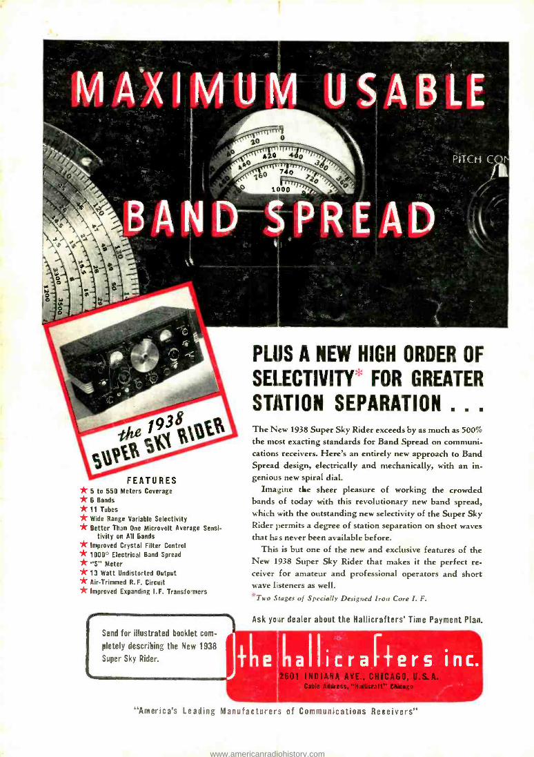
N USABLE
FEATURES * 5 to 550 Meters Coverage * 6 Bands
*11 Tubes * Wide Range Variable Selectivity * Better Than One Microvolt Average Sensi- tivity on All Bands * Improved Crystal Filter Control * 1000° Electrical Band Spread * "S" Meter
*13 Watt Undistorted Output * Air -Trimmed R. F. Circuit * Improved Expanding I.F. Transfo -mers
I Send for illustrated booklet com-
pletely describing the New 1938
Super Sky Rider.
PLIJS A NEW HIGH ORDER OF
SELECTIVITY FOR GREATER
STATION SEPARATION . . .
The New 1938 Super Sky Rider exceeds by as much as 500%
the mast exacting standards for Band Spread on communi- cations receivers. Here's an entirely new approach to Band Spread design, electrically and mechanically, with an in- genious new spiral dial.
Imagine the sheer pleasure of working the crowded bands of today with this revolutionary new band spread, which with the outstanding new selectivity of the Super Sky Rider permits a degree of station separation on short waves that he s never been available before.
This is but one of the new and exclusive features of the New 1938 Super Sky Rider that makes it the perfect re- ceiver for amateur and professional operators and short wave listeners as well.
*Tn -o Stages of Specially Designed Iron Core I. F.
Ask yoar dealer about the Hallicrafters' Time Payment Plan.
2601 INDIANA AYE., CHICA60, U.S. Cable Address, "Halticraft" CAic.go
"America's Leading Manufacturers of Communications Receivers"
www.americanradiohistory.com


![ESOPS] - World Radio History](https://static.fdokumen.com/doc/165x107/631e25131aedb9cd850f9e54/esops-world-radio-history.jpg)