-electronics« 7 - World Radio History
158
-
Upload
khangminh22 -
Category
Documents
-
view
0 -
download
0
Transcript of -electronics« 7 - World Radio History

-electronics« 7 DEUTERIUM TIIYRATRON New pulse modulator handles 150 Kw, p 94 (photo below)
A McGraw-Hill Weekly
SEISMIC-WAVE COMMUNICATIONS Latest medium: the earth itself, p 51
75 Cents April 12, 1963
ARMY AIR FORCE REBORN Non-nuclear forces plan inventory, p 32
956 XOt: .IssflGKIMOU

N STANDARD Sweep-Frequency Generator
. • . In One Instrument ... Everything you need
e MOW«,
• ----11111111111; .01:lee&
PAU*
POWER
08 I,
-ere.
Ranges: 4-8 Mc 40-80 Mc 0.7-1.4 Mc 7-14 Mc 65-140 Mc 1.3-2.6 Mc 13-26 Mc 100-230 Mc 2.4-4.8 Mc 24-48 Mc
Bandspread Ranges: 400 to 500 kc and 10.4 to II Mc Other ranges available on special order.
Sweep Width: Entire selected range is swept. However, visual presentation of swept range can be expanded to permit full oscilloscope display of portions of range as small as 10% with EXPAND DISPLAY and DISPLAY START controls.
Selected range is swept from low end to high end in 22.2 msec twenty times a second. Output is blanked off during return sweep. A saw-tooth sweep voltage is provided which is synchronized with frequency, and adjustable in starting point and amplitude (DISPLAY START and EXPAND DISPLAY controls. respectively).
Stability: Drift less than .0.1% for frequency for 5 hours after one-hour warm-up. Frequency dial accuracy is within .0.5%.
Marker: Continuously adjustable from 3mv to lu. multiplier effectively extends range to 100v. Accuracy of indication is typically better than .10%. Shape and width of marker permit resolu-tion to better than .0.1% of indicated frequency.
RF Output: Adjustable from 0.3m0 to lo behind 50 ohms (-123 to 7 dbm power into 50 ohms.) Output is flat to within .1% up to 100 Mc and within .3% up to 230 Mc. RF amplitude indicated to a typical accuracy of better than .10%.
0111•LAV 11.111
1011.Ortrf POtellVe.
.11.41,V1
Sweep Generator
OW Generator
Marker Generator
Attenuator
and Output Meter
Type 1025-A Standard
Sweep-Frequency Generator
Price: $3250 in U.S.A.
for Quantitative Frequency Response Measurements
* Covers 0.7 to 230 Mc in ten overlapping octave ranges plus two bandspread ranges (400 to 500 kc and 10.4 to I I Mc).
* Has the "perfect marker" ... continuously adjustable both in frequency and ampli-tude ... accurately calibrated in frequency and amplitude . . . lets you take data directly from display ... does not interfere with response display...a single unambig-(lOtIS marker, mIt a confusing string of pips.
Fr« * Marker permits frequency measure-ments to 0.5% di-rectly from display.
* Irma lily con‘erts from sweep to cw operation for accurate point-by-point measurements without changing adjust-ments or connections. Separate output
drives frequency counters directly for ac-curate measurements of low-level devices.
* Meter measures both rf input and detected output of device being tested.
* Accessory high-impedance detector probe supplied with instrument simplifies re-sponse measurements — minimizes circuit loading.
"What signal generators are to oscillators this instrument is to sweep generators"
* Accurate frequency calibration *0.5% of reading.
* Stable ... no annoying drift of displayed response. Low residual fm permits investigations of steep response slopes.
* Motor-driven capacitor produces a high-level swept signal free from harmonic distortion and spurious outputs.
* No awkward interactions between controls.
* Low leakage permits measurements to 0.3 mv.
* Accurate, 120-db attenuator has low 1.01 VSWR.
GENERAL RADIO COMPANY WEST CONCORD, MASSACHUSETTS
Is EUROPE General Radio
Overseas Zurich, Switzerland
NEW YORK, N. Y., 964-2/2/ CHICAGO Ridgefield N I.. 943-3140 (Oak Park) 848-9400
PHILADELPHIA, 124-7419 WASHINGTON. D.C. SYRACUSE DALLAS Moneton. 887-8486 (Rockville. Md.) 946-1600 454-9323 FL 7-4031
SAN FRANCISCO LOS ANGLES ORLANDO, FLA. (Los Altos) 9484233 469-6201 425-4671
CIRCLE 900 ON READER SERVICE CARD
IN CANADA (Toronto) 247-2171

April 12, 1963
electronics A McGraw-Hill Weekly 75 Cents
W. W. MacDONALD, Editor
J. M. CARROLL, Managing Editor
SENIOR EDITORS
Samuel Weber, George W. Sideris
SENIOR ASSOCIATE EDITORS
Michael F. Wolff, John F. Mason
ASSOCIATE EDITORS
Michael F. Tomaino, Sylvester P. Carter, William P. O'Brien, Sy Vogel, Leslie Solomon, George J. Flynn, Laurence D. Shergolis, George V. Novotny, Leon H. Dulberger
ASSISTANT EDITORS
Nilo Lindgren, Stanley Froud, Ste-phen B. Gray, Roy J. Bruun, Barry A. Briskman
REGIONAL EDITORS
Harold C. Hood (Pacific Coast, Los Angeles), Thomas Maguire (New England, Boston), Cletus M. Wiley (Midwest, Chicago)
ART DIRECTOR
Howard R. Berry
ASSISTANT ART DIRECTOR
John C. Wright, Jr
EDITORIAL ASSISTANTS
Lorraine Rossi, Virginia T. Bastian, Lynn Emery, Ann Mello, Lorraine Werner, Alice M. O'Brien, Sharon Parks, Patricia Mitchell, Claire Benell
FOREIGN NEWS BUREAU
DIRECTOR, John Wilhelm; Alyne Elias, Charles Obertance
LONDON—John Shinn, Derek Barlow, Nicholas Landon
BONN—Bruce Bendow, Richard Mikton, SiIke McQueen
BRUSSELS—Peter Forbath
PARIS—Robert Farrell, Arthur Erikson
MILAN—Marc A. Messina
MEXICO CITY—Wesley Perry, Jr
RIO DE JANEIRO—Leslie Warren
MOSCOW—Stewart Ramsey
TOKYO—Richard Halloran, Charles Cohen, John Yamaguchi
CIRCULATION MANAGER
Hugh J. Quinn
HEAVY-HYDROGEN THYRATRONS will be used in high-power radar and accelerators where their ability to modulate such high power is becoming increasingly important (General Elec-tric, Ltd.). Others will fulfill space communications needs. See p 94 COVER
LASER MEETINGS Double Up. Here's a preview of two im-portant conferences next week. At New York, one report is on ultrasonic control. In Pittsburgh, the emphasis will be on ch elates 22
ORBITING OBSERVATORY Nears Flight Tests. Stabilization and control system for the Orbiting Astronomical Observatory "flies" in vacuum chamber. Unusual facility tests star trackers 28
ARMY OF THE AIR Creates New Market. Army is buying 1,600 planes and a host of subsystems. Air-mobility and non-nuclear capability calls for new gear
RESISTANCE PATHS Associate Terms. Experimental retrieval system associates stored information as voltage levels. It's one example of bionics research
BROADCAST ENGINEERS Report New Systems. A-m/f-m mul-tiplex is among new gear reported at NAB conference. An-other is four-vidicon cameras for sharper color tv
32
39
42
COMMUNICATING BY SEISMIC WAVES: New Transducers and Design Details. Man has learned to communicate through air, water and space. Given the proper transducer, the earth itself can be a communications medium. Such a seismic system could also watch for earthquakes or nuclear blasts and study geological structures. By K. Ikrath and W. Schneider, U.S. Army Electronic R&D Lab. 51
UNUSUAL WAVEFORM ANALYZER Aids Automatic Testing. This programmer-computer enables unskilled operators to make complex electrical measurements. It uses tunnel diodes to sense peak amplitudes, rise and fall times and pulse widths. These are converted to voltage analog outputs for meter display or record-ing. By R. W. Jones, General Electric 56
CRYSTAL-CONTROLLED MULTIVIBRATOR Has Better Sta-bility. Conventional astable multivibrators may be useless for generating pulses and square waves with good stability and rise and fall times because of basic instability. Piezoelectric crystals in the cross coupling circuit can overcome this problem
By H. R. Newhoff, Litton Systems 60
RELIABILITY IN SEMICONDUCTOR CIRCUITS: Eight Ways to Get It. Here are a few basic principles and their application to logic gates, buffers, power switches, flip flops, monostable multivibrators and pulse stretchers. Among other schemes, diode quadding and use of redundant transistors are important.
By K. L. Hall, Radiation Inc. 62
W. W. GAREY, Publisher Contents continued

CONTENTS continued electronics April 12, 1963 Volume 36 No. 15
Published weekly, with Electronics
Buyers Guide as part of the subscrip-
tion, by McGraw-Hill Publishing Corn.
pony, Inc. Founder: James H. McGraw
11860-1948).
Title ® registered U.S. Patent Office,
0 copyright 1963 by McGraw-Hill
Publishing Co., Inc. All rights re-
served, including the right to repro-
duce the contents of this publication, in whole or in part.
Executive, editorial, circulation and
advertising offices: McGraw-Hill Build-
ing, 330 West 42nd Street, New York
36, N. Y. Telephone Longacre 4-3000.
Teletype TWX N.Y. 212-640-4646. Cable
McGrawhill, N. Y. PRINTED IN AL-
BANY, N. Y.; second class postage
paid at Albany, N. Y.
OFFICERS OF THE PUBLICATIONS
DIVISION: Shelton Fisher, President;
Vice Presidents: Joseph H. Allen, Op-
erations; John R. CaIlaham, Editorial;
Ervin E. DeGraff, Circulation; Donald
C. McGraw, Jr., Advertising Sales; Angelo R. Venezian, Marketing.
OFFICERS OF THE CORPORATION:
Donald C. McGraw, President; Hugh J.
Kelly, Harry L. Waddell, Executive
Vice Presidents; L. Keith Goodrich,
Executive Vice President and Treas-
urer; John J. Cooke, Vice President and Secretary.
Subscriptions are solicited only from
those actively engaged in the field of
the publication. Position and com-
pany connection must be indicated on
orders. Subscription rates: United
States and Possessions, $6.00 one
year, $9.00 two years, $12.00 three years. Canada: $10.00 one year. All
other countries $20.00 one year. Single copies, United States and Possessions
and Canada 75. Single copies all
other countries 51.50.
THE PUBLISHER, UPON WRITTEN RE-
QUEST FROM ANY SUBSCRIBER TO
OUR NEW YORK OFFICE AGREES TO REFUND THAT PART OF THE SUB-
SCRIPTION PRICE APPLYING TO COPIES NOT YET MAILED.
Subscribers- Please address change of address notices, subscription orders or
complaints to Fulfillment Manager,
Electronics, at above address. Change
of address notices should provide old
as well as new address, including
Postal zone number if any. If pos-
sible, attach address label from re-
cent issue. Allow one month for change to become effective.
Postmaster. Please send Form 3579 to Fulfillment Manager, Electronics, 330 West 42nd Street, New York 36,
New York,
Audited Paid Circulation
FIELD-EFFECT TRANSISTORS: Now Used in Low-Noise Pre-amplifier. These components are creating high interest but tried and tested applications are still few and far between. In this one, off-the-shelf units make up a circuit that combines low noise and high input impedance with gain stability with temperature changes.
By E. G. Fleenor, Lockheed 67
SHRINKING PHOTOFLASH CONTROL: Solid-State Compo-nents Do It. As part of an experiment with a particle accelerator, the control signal is a light pulse from a photoflash tube. It is directed through a telescope at a receiver that is 3-million volts above ground.
By E. L. Harris, Jr., Lawrence Radiation Lab 70
REFERENCE SHEET: Thin-Film-Resistor Short Cut. Interde-pendence of length, width, resistance and power-handling ability can require tedious calculations in thin-film resistor design. This graphical method can be a real time saver.
By H. L. Cook, Martin Company 72
DEPARTMENTS
Crosstalk. The New Army
Comment. Servo Amplifiers. CGE, not CS?
Electronics Newsletter. Radiation Decay Nil in Van Allen Belt
Washington This Week. Pentagon Ponders De-preciation Allowance
Meetings Ahead. Design and Use of Microwave Valves (Tubes) Symposium
Research and Development. Vacuum Deposited Circuits Use Field Effect
Components and Materials. New Thyratron Peaks at 200 Mw
3
4
7
12
44
80
94
Production Techniques. Spot-Testing Aids Manu-facture of High-Reliability Relays 106
New Products. Data Converter has 60-Db Dynamic Range
Literature of the Week
New Books. Nonlinear Automatic Control
People and Plants. Melabs Moves Manufacturing Activities 138
118
132
134
Index to Advertisers 150
2 April 12, 1963 • electronics

CROSSTALK
The New Army THE ILLUSTRATION reproduced here isn't from science fiction. It's taken from the Army Information Digest and it represents a guessti-mate of what the Army will look like in the not-too-distant future. The missiles are already on hand, the jet-propelled soldiers, weapons de-livery systems and transport will come. The groundwork for this Army of the future
is being laid right now, through the plans and programs outlined this week on p 32 through 36. The Army is concentrating on modernizing its forces, making its firepower more versatile, acquiring mobility, tightening its command and control functions.
Foot-slogging won't disappear, but a signifi-cant portion of the Army will return to the air to give the Army greater ability to perform any kind of land mission—in any climate, over any terrain, from small local actions through general nuclear war and its aftermath. Aviation is an important part of this overriding aim because, the Army says, it permits substantial improve-ment in tactical mobility on the battlefield.
Before strategic warfare concepts shifted to missiles, massive force represented by armies was the clincher in a war. Now the Army must be prepared to unleash swift action while keep-ing brute force carefully in reserve.
"Tactical nuclear war and large-scale non-nuclear war will be subject to increasing re-straints on both sides because of the danger of escalation into a general nuclear exchange," says Gen. Barksdale Hamlett, Army vice chief of staff. Unless the USSR achieves a technical breakthrough—like an effective ICBM defense— to upset the present condition of nuclear deter-rence, Hamlett expects the cold-war pattern of small, local conflicts to continue. The Army stresses that it must be able to fight both the big wars and the small wars, but it sees the latter as more likely.
Soviet ground forces, the Army figures, is thinking along the same lines. Army expects the USSR to emphasize mobility, increasing nu-clear and non-nuclear firepower, better communi-cations, missile and rocket artillery and battle-field surveillance—in short, everything the U.S. Army believes is essential. By 1970, the Army expects to be able to field
more air-mobile and combat support units, to have new types of aircraft to move and supply troops and for reconnaissance and surveillance. Airborne target-sighting systems will feed data to ground computers that direct artillery fire.
Antitank weapons will be operated by automatic fire control and command guidance systems. Troops will be well-supplied with Pershing, Sergeant, Lance, Redeye, Mauler and other mis-siles. For short range communications, sys-tems like Rada (ELEcTRoxi(s. p 18, April 5) will be used, and for long range communications, satellite systems. Portable reactors will power command and communications centers, radar, depots, weapons systems and other field units— the prototypes are already in operation. Behind the scenes, inventory control systems, communi-cations nets between depots and contractors and many other electronic logistical aids will be in operation. The list of modern equipment that the Army
will have in 1970 is far longer than that and will undoubtedly include systems not yet con-ceived. Any electronics engineer or company that feels
he can make a contribution to Army equipment will find a willing ear. But, says Gen. Earle G. Wheeler, Army chief of staff, Army is not look-ing for minor improvements in what it already has. It wants large-scale technical improvements that will make material contributions to the toughness and flexibility of land forces. "Gadgets and frills," says Wheeler, won't be bought.
electronics • April 12, 1963 3

Analab e/i7cie
the industry's finest dual-trace oscilroscope
the only oscilloscope
on which you can make
PRECISE QUANTITATIVE
MEASUREMENTS!
USE AS PRECISION
AC & DC VOLTMETER,
PHASE METER,
TIME-INTERVAL METER.
• Superior triggering and over-all stability
• Highest sensitivity (100µv/cm) • Both single-ended and
differential amplifier inputs, AC or DC-coupled • No interpolation needed with
direct-reading Null-Balance dials • "Instantaneous" beam finder • Delayed trigger output from 1 psec to 50,000,000 psec
• Bandwidth from DC to 150 kc Call or write for specifications on the 1120/700 and on the full line of Analab scopes, scope camera systems, and accessories.
Analab Instrument Corporation Cedar Grove, New Jersey
Analab r.z• A subsidiary of THE JERROLD CORPORATION
COMMENT
Servo Amplifiers
I was very interested in the article, Designing Servo Amplifiers For High Efficiency (p 62, Feb. 8), by J. A. Walston and J. E. Setliff of Texas Instruments, since it fol-lowed closely after my article, Ver-satile Servo Amplifier for 50, 60 or 400-Cycle Operation (p 44, Jan. 18). I think, however, that a section
on the advantages and disadvan-tages of unfiltered d-c should have been added. Using a full-wave rectified, unfiltered, a-c sinewave for power to a push-pull servo am-plifier can also generate quite a few problems. As advantages I would list: (1)
theoretically high efficiency ap-proaching 100 percent at full out-put; (2) low power-supply imped-ance; (3) low distortion in the out-put sinewave especially at full out-put; and (4) quadrature rejection due to the fact that the power sup-ply voltage is zero at the point of maximum quadrature signal. As disadvantages: (1) Poor stability of power-sup-
ply voltage because of line fluctua-tion requires higher-voltage tran-sistors.
(2) Line spikes and transient pulses will be directly passed to the output transistors and can be ex-tremely dangerous.
(3) Input phase must be locked to power-supply voltage or line phase. An a-c servomotor's torque is reduced by only the cosine of the phase angle as it varies with re-spect to the motor's reference volt-age. This means that phase in a standard amplifier is not too criti-cal. Phase shift of the input volt-age, however, with unfiltered d-c will reduce gain and affect full torque directly.
(4) The maximum torque from the motor will be less than a com-parable standard amplifier because the standard amplifier can supply a square wave at full output. This square wave increases motor torque due to its higher fundamental, as-suming constant d-c supply voltage. The square wave also increases motor heating, but also increases the amplifier's efficiency.
(5) Often, 90-deg phase shift is
desired through the amplifier. This, of course, is not possible with the supply voltage locked to the line without shifting the line voltage.
MICHAEL BODNAR Diehl Manufacturing Company Somerville, New Jersey
Author Walston replies:
Two comments should be added to Mr. Bodnar's remarks. First, destructive voltage transients may appear across an inductive load when the driving current is non-sinusoidal. This condition may sometimes occur, when a standard amplifier is overdriven to produce square waves or a high-efficiency amplifier receives a large quadra-ture signal. Parallel tuning of the load will reduce the transient, but it also increases amplifier dissipa-tion. Series tuning may not help at all. Avalanche diodes are a way out, if one allows for their a-c im-pedance after avalanche, but there goes more expense! You can't win.
Second, even though a 90-deg phase shift is difficult within a high-efficiency amplifier the refer-ence phase of the servo can often be shifted instead.
JOSEPH A. WALSTON Texas Instruments Inc. Dallas, Texas
CGE, not CSF
We greatly appreciate the pub-lication (p 15, March 1) of a photo-graph of our booth at the Quantum Electronics Exhibition in Paris, February 8-15, where our Research Center displayed among other lasers, a ruby laser telemeter with instant digital display of the dis-tance to be measured. We only regret that, due to some
kind of misunderstanding, this new product was attributed to our com-petitor, C.S.F.
It is C.G.E. which was chosen by the French Centre National d'Etudes des Télécommunications as industrial designer for the con-struction of the Space Communica-tion Center of Pleumeur Bodou in Brittany, which received and trans-mitted the first Telstar messages across the Atlantic a year ago.
C. LACARRIERE Compagnie Générale d'Electricité Paris, France
4 CIRCLE 4 ON READER SERVICE CARD April 12, 1963 • electronics

Lambda announces 3 new LE models
Environment-Engineered at competitive prices
LE 106 0-18VDC 15 AMP • LE 107 0-18VDC 22 AMP • LE 110 0-9VDC 20 AMP
Note these quality design features
CONVECTION
COOLED No' blowers or filters; maintenance free.
WIDE
INPUT RANGE Wide input voltage
and frequency range —105-135 VAC, 45-66 CPS and
320-480 CPS in two bands selected by switch.
COMPLETELY PROTECTED against—short circuit and
electrical overload; input line voltage transients; excessive
ambient temperatures. No
voltage spikes due to-turn•on, turn-oft " or power failure.
LE SERIE
CONDENSED
S
DATA
DC OUTPUT Model
LE101
LE102
LE103
LE104 LE105
LE106 LE107 LE109 LE110
(VOLTAGE REGULATED FOR LINE AND
Voltage Range Current Range
0-36 VDC 0- 5 Amp 0-36 VDC 0-10 Amp
0-36 VDC 0-15 Amp 0-36 VDC 0-25 Amp 0-18 VDC 0- 8 Amp 0-18 VDC 0-15 Amp
0-18 VDC 0-22 Amp
0- 9 VDC 0-10 Amp 0- 9 VDC 0-20 Amp
LOAD) ti)
Price(2)
$420
525 595 775 425 590 695
430 675
(1)Current rating applies over entire voltage range. (2)Prices are for nonmetered models. For models with ruggedized MIL
meters add suffix "M" to model number and add $40 to the non-metered price. For metered models and front panel control add suffix "FM" and add $50 to the nonmetered price.
models available
CONSTANT VOLTAGE CONSTANT CURRENT
by automatic switchover.
REMOTELY PROGRAMMABLE
AND CONTINUOUSLY VARIABLE Voltage con,inuously variable over entire range. Programmable over voltage and current range.
5 Year
Guarantee
OTHER FEATURES
• All solid state.
• Adjustable automatic current limiting.
• 0°C to + 50'C ambient.
• Grey ripple finish.
• Ruggedized voltmeters and ammeters
per MIL-M-1030413 on metered models.
REGULATED VOLTAGE:
Regulation
(line and load) Less than .05 per cent or 8 millivolts' (whichever is greater). For input variations from 105-135 VAC and for load variations from 0 to full load.
Remote Programming ... .50 ohms/volt constant over entire voltage range.
Less than 0.5 millivolt rms.
. Less than 0.015%/°C
Ripple and Noise
Temperature Coefficient . •
AC INPUT: 105-135 VAC; 45-66 CPS and 320-4801 CPS in two bands selected by switch.
PHYSICAL DATA:
Mounting Standard 19" rack mounting.
Size LE 101, LE 105, LE 109 31/2 " H x 19" W x 16" D
LE 102, LE 106, LE 110 51/4" H x 19" W x 16" D
LE 103,LE 107.. .... 7" H x 19" W x 16 1/2 " D
LE 104 10 1/2 " H x 19" W x 16 1/2 "D
SEND FOR LAMBDA CATALOG.
LAMBDA. ELECTRON I CS CORP.
.515 BROAD HOLLOW ROAD • MELVILLE, L. I., NEW YORK • 516 MYRTLE 4-4200
„SALES OFFICES AND REPRESENTATIVES CONVENIENTLY LOCATED IN MAJOR CITIES
CIRCLE 5 Otg READER SERVICE CARD

PUSH TEST I 1% BUTTON SIGNALS! ACCURACY!
10 cpil tm'c, 1.1
Push-button convenience and repeat-ability for selecting frequencies from 10 cps to 999 KC makes the new 241A Oscillator ideal for supplying stable test signals for lab or production work. Just push one of five decade multipliers and three frequency push buttons to select any of 4,500 discrete frequencies. You get accuracy of 1% and repeatability typically better than 0.005%.
Three-digit frequency resolution is pro-vided by the solid-state 241A. Infinite resolution is provided by a vernier con-trol, which extends the upper frequency to 1 MC.
Frequency response is flat within -±-2% over the entire range, and a front panel control provides output levels from 10 to —30 dbm, presenting a constant out-put impedance of 600 ohms. Hum and noise are reduced below 0.05% of the output.
High repeatability, positive push-button operation and compact, rugged solid-state design make the p 241A especial-ly suitable for production line or other repetitive testing. Write today for complete data, or call your nearest representative for a demonstration.
HEWLETT-PACKARD COMPANY 1501 Page Mill Road, Palo Alto, California
Area Code 415, DA 6-7000 Sales and service representatives in all principal areas Europe, Hewlett-Packard S.A., 54-54bis Route des Acacias, Geneva; Canada, Hewlett-Packard (Canada) Ltd., 8270 Mayrand Street, Montreal
111- 10100
- - -00110
111-8100-0
le 241A
Osci llator
SPECIFICATIONS
Frequency: 10 cps to 1 MC, 5 ranges, each with 900 frequency increments with vernier overlap
Calibration Accuracy: ± 1%
Frequency Response: ±2% into rated load
Output Impedance: 600 ohms
Distortion: 1% maximum
Hum and Noise: 0.05% maximum of output
Output: +10 to —30 dbm into 600 ohms (2.5 volts max.)
Dimensions: 61/2 " high x 73/4 " wide x 8" deep. 13 lbs.
Price: $425.00 Data subject to change without notice. Prices f.o.b. factory.
7927
6 CIRCLE 6 ON READER SERVICE CARD April 12, 1963 • electronics

electronics NEWSLETTER
Radiation Decay Nil in Van Allen Belt BEDFORD, MASS.—Since late October there has been little de-
crease in intensity of trapped ra-
diation injected into Van Allen
Belt by July 9, 1962 U. S. high-altitude nuclear detonation in
Pacific, it was reported last week at AF Cambridge Research Lab-oratories. Ludwig Katz said data from Beta
Kappa 1962 AF Satellite launched Oct. 26 shows an apparent state of equilibrium has been reached in the magnetic shell in which the detona-tion took place. Present level within this shell is considerably higher than prior to shot, Katz said.
Results of measurements contra-dict James A. Van Allen's predic-tion (p 7, Nov. 23, 1962 and p 220, Dec. 14) that the artificial belt will have vanished by July, 1963. Van Allen recently revised his estimate to 5 to 10 years.
Katz disclosed that the satellite also acquired data on Oct. 27 and 28 on Russian detonations. Bulk of par-ticles injected from Soviet tests lasted only a few days, rapid decay probably resulting because detona-tions took place in polar region. AFCRL also disclosed: • Geophysicists will next month
fire ruby laser beam 30 miles to test laser-beam bounce off geodetic sat-ellites for more accurate determina-tion of earth distances. Late this summer, AFCRL will fire a laser beam at S-66 geodetic satellite.
• AFCRL scientists stepping up plasma sheath studies point out that proposed solutions for blunt body vehicles like Mercury (p 7, Feb. 22) may not work for boost-glide reentry vehicles like Dyna-Soar or for superorbital vehicles like Apollo. While a few minutes of communications blackout could be tolerated in Mercury, the estimated 20 to 30 minutes could be critical in other missions. AFCRL will study reentry effects next March with Trailblazer vehicle equipped with transmitters at 200 Mc, 400 Mc and 3 Ge, and a telemetry transmitter at 9 Ge. RCA's transmitter for Dyna-Soar is also at 9 Ge.
• In a Project Firefly experi-ment, AFCRL scientists bounced tv signal from Shreveport, La., to Florida by an artificially created electron cloud. Concept could be used for over-horizon reception of vhf, h-f, and m-f significant to mili-tary. Firefly experiments have also aided studies of detection of mis-siles by their gas exhaust trails.
Titanium Oxide Shows Microelement Potential
FARmiNGDALE—New class of micro-circuit elements may result from studies underway at Republic Avia-tion. Franz Huber reports that thin-film p-n junctions in semicon-ducting titanium oxide on a flexible plastic substrate show piezoresistive and piezoelectric effects. The diodes are formed by anodic
oxidation of a titanium film. Oxide film is about 300 A thick, counter electrodes are palladium and junc-tion area is 1 sq mm. As junctions are deformed by bending the sub-strate, junction resistance de-creases. Voltage polarity depends upon whether compression or ten-sion is applied. Up to 100 mv has been obtained by deformation with 1 cm radius of curvature.
Although the phenomenon is not yet completely understood or con-trollable, it conceivably could lead to strain gages and microphones where the junctions are deposited directly on the membrane. Since ti-tanium oxides can also be insulators and conductors, it points to a com-patible thin-film microelectronic technology ( effect is anticipated for tantalum oxides also.)
Switching matrices have been made with 10-Kc diode switching times. Huber feels field-effect tran-sistors should be possible and is try-ing to lick problems of contact fab-rication and oxide preparation. He also has observed light emission from titanium films in an electro-lyte, but not yet in a diode.
Laser Welds Shut Holes in Retina
TECHNIQUE has been developed at Stanford University to correct reti-nal detachment by welding shut the puncture or hole in the retina. Laser beams can also be used to scar and essentially destroy certain blood vessel tumors in the eye and to make a new pupil in a blocked or out-of-position iris. Laser, built by
Texas Science Gets a Boost from NASA
DALLAs—Southwest electronic and aerospace industry leaders are beginning to see part of the "scientific awakening" they had hoped NASA's Manned Spacecraft Center in Houston would bring their area (p 28, Nov. 17, 1961).
An ambitious Science Research Center (SRC) in Dallas is showing signs of getting off the ground. Area universities are beginning to create departments and curricula geared to support-ing space research and training. In Houston, funds are being raised for a $250,000 technical information center to serve the area's scientists and engineers. SRC is a new name for the Graduate Research Center of the
Southwest. Its backers have had difficulty getting the center going but now, NASA is providing a much-needed boost with a $1.5-million contract for space experiments. SRC presently has a 50-man staff in temporary facilities at
Southern Methodist University. Permanent facilities are being constructed on a 1,400-acre campus north of Dallas
electronics • April 12, 1963 7

Optics Technology Inc., is used in conjunction with a Zeiss photo-coagulator, which utilizes light from a xenon gas tube. Prof. Ar-thur L. Schawlow, co-discoverer of laser principle, took part in the project, along with two Stanford ophthalmologists.
Navy Plans to Buy 2 Sidewinder Types
WASHINGTON—Navy's shopping list for the year starting July 1 includes funds to buy Sidewinder 1-C air-to-air missiles with alternate guid-ance heads. One version will have Sarah heads (Semi-Active Radar Homing) produced by Motorola. The other version will be equipped with less-expensive Irah heads (In-frared Homing) produced by Philco. All-weather fighter - interceptor planes will be equipped with both versions of the missile.
Conveyor Speeds Film Through Vacuum Chamber
ENDLESS CONVEYOR line that moves straight through a high-level vac-uum chamber and back into the air has been developed by Western Electric. Process makes tantalum thin films economically feasible, firm says. Production speed is 50 square inches of tantalum film per minute. Machine is designed for computer control and is compatible with other in-line operations. West-ern Electric says metal evaporation, electron-beam welding and glass sealing are also well-suited for such machines.
Britain Rewrites Rules On Exports to Reds
LONDON—Britain has revised its rules on strategic goods subject to embargo in trade with the Soviet bloc and Communist China.
Controls have been reduced on synchronous motors; electronic measuring, testing and calibrating instruments; modular insulating panels; measuring, calibrating, counting and time-interval measur-ing apparatus; radio-relay com-munications equipment; radio spec-
trum analysers, recording and re-producing equipment; certain semi-conductor diodes, telegraph appa-ratus; and low-frequency and switching-type transistors. New controls are being imposed
on semiconductor hall-field probes, certain electrochemical semicon-ductor and radioactive devices, cer-tain gravity meters, electron-beam welding and machining equipment and electric-arc devices.
Spaceships Leave Trail in Ionosphere
RADAR TRANSMITTERS may not be needed to track spaceships in flight, says Prof. Floyd V. Schultz of Pur-due University. Schultz, who has analyzed the behavior of the iono-sphere in mathematical terms, says it sends out electromagnetic waves when it is disturbed by a moving object. These could be picked up on earth with only an antenna and re-ceiver, according to Schultz. His theoretical results are now being checked experimentally.
Pyrometer Will Use Thermistor for Moon Scan
CAMBRIDGE — Radiation pyrometer built at Harvard College Observa-tory uses thermistor for ir scanning of moon's surface from the earth. Filters allow only narrow band of ir, between 8 and 14 microns, to fall on thermistor. To get thermal pro-file of moon, 35-mm camera is at-tached to pyrometer.
Explorer 17 Carrying Electrometer Amplifier
SUCCESSFUL LAUNCH of Explorer 17 marks the first orbiting of a highly sensitive electrometer amplifier and a new 40-channel pcm telemetry system providing 500-mw output power.
High-impedance linear amplifier is used to detect tiny ion currents from two mass spectrometers and can pick up signals as small as 10' amp. Built by Consolidated Systems Corp., device measures amounts of helium, oxygen and nitrogen atoms, water vapor, and nitrogen and oxygen molecules.
In Brief . . .
RUSSIANS INSIST that Lunik IV, which they say passed within 8,500 kilometers of moon on April 6, is fulfilling its scientific mis-sion. They do not specify what the mission is.
AF IS CONFIDENT it will get approval for construction of multiplate an-tenna facility at Bedford, Mass. (p 39, Sept. 7, 1962).
SALES by microwave components manufacturers hit $75 million last year, EIA says.
PHILCO signed a $33,797,565 con-tract to provide flight informa-tion and control display equip-ment for the Integrated Mission Control at NASA's Manned Spacecraft Center (p 20, Feb. 8).
CHRISTIAN HERTER, President Ken-nedy's special trade envoy, will negotiate with the Japanese for lower tariff rates, including those on electronic equipment.
FAIL-SAFE electronic altimeter and improved failure-warning devices would be a big help to aircraft safety, David S. Little, of Air Line Pilots Association, said last week.
ARMY SIGNAL CORPS has ordered $18,667,000 worth of vehicular command communications sys-tems from Magnavox.
ELLIOTT-AUTOMATION, a British firm, will build 25 NCR 315 computers for National Cash Register. Order totals $30 million.
STOCK OFFER is in the works that would cover start-up costs of pro-posed pay-tv system in Santa Monica, Calif.
GERMAN GOVERNMENT has placed $18-million order for military communications equipment with Standard Telephones and Cables of London, an ITT subsidiary.
STUDY of superheterodyne-receiver techniques for above 100 Ge will be made for NASA by Electronic Communications, Inc.
FAA GAVE Telecomputing Corp. $4.3 million contract for delivery of 52 air traffic control radars.
8 April 12, 1963 • electronics

MM.
40 0 .1.1111:11.11
I e nninaelli
30Lill
Ge
min
2. mum V „ s
leed'w 1.0E6.
SPRAGUE LOGIC TRANSISTORS GIVE SUPERIOR LATCH-UP PROTECTION
Mes° 2142795*
12 15
VcE (volts)
300 S-2 Load Line
Mesa Latch-Up
*ratings for most prime germanium mesa types. *based on guaranteed ratings!
For Guaranteed High Voltage Operation at High Speeds, Investigate Sprague ECDC® and MADT Transistors
Type
No.
'PT
(typical)
BVCES
(minimum)
BVCEO
(minimum)
2N2795 450 mc 25 volts 15 volts
2N2796 450 mc 20 volts 12 volts 2N984 350 mc 15 volts 10 volts
r 2N979 150 mc 20 volts 15 volts
TO-18 2N980 150 mc 20 volts 12 vo lts
CASE 2N2048t 250 me 20 volts 15 volts
TO-9 Case)
SPRAGUE COMPONENTS
• For additional information on Sprague High Voltage Logic Transistors, write to the Technical Literature Service, Sprague Electric Company, 35 Marshall Street, North Adams, Massachusetts.
Trademark, Philco Corp.
TRANSISTORS CAPACITORS
MAGNETIC COMPONENTS RESISTORS
MICROCIRCUITS
INTERFERENCE FILTERS
PULSE TRANSFORMERS
PIEZOELECTRIC CERAMICS
PULSE-FORMING NETWORKS
TOROIDAL INDUCTORS
HIGH TEMPERATURE MAGNET WIRE
CERAMIC-BASE PRINTED NETWORKS
PACKAGED COMPONENT ASSEMBLIES
FUNCTIONAL DIGITAL CIRCUITS
ELECTRIO WAVE FILTERS
SPRAGUE® THE MARK OF RELIABILITY
417 , 00-43
electronics • April 12, 1963
'Sprague and'(:)' are registered trademarks of the Sprague Electric Co.
CIRCLE 9 ON READER SERVICE CARD 9

TIPS (Technical Information and Product Service)
4 MORE VALUE-ACCENTED
1
TUBE PLATE CURRENT IN MA
_orsà >a
, o
3 ó
›r.;
71
ó ó
Ci
CERAMIC TUBE DYNAMIC TEST
TYPE 6442
TYPE 7588
TYPE 7462
TYPE 7077
10 IINVT 10"NVT 10 1 NVT 10"NVT 10 'NVT E .3 Mev.
10 7ERGS 10'ERGS 109ERGS 10"ERGS 10"ERGS GM(C)
TOTAL INTEGRATED NEUTRON AND GAMMA FLUX
New tests confirm G-E ceramic tubes survive high nuclear radiation levels
Recent tests confirm that G-E ceramic tubes show no measurable
changes in operation or characteristics during and after receiving
total integrated flux of 5.6 x 10 16 NfVT > 0.3Mev) and 7 x 10'°
ergs/gm (c).
This exposure is in excess of all estimated requirements for presently
conceived weapons systems. Tests were conducted by the radiation
effects group of a leading airframe manufacturer and proved: G-E
ceramic tubes will meet all currently anticipated requirements for steady-
state radiation tolerance in weapons systems, communications and other
military electronic equipment.
Three types of G-E tubes (five samples of each) —6442, 7077 and 7588—
were irradiated under D-C operating conditions. Also, 18 samples of type 7462 were irradiated while operating in three 6-stage, 60-megacycle
IF amplifiers. No significant changes were noted in tube currents, gain.
bandwidth, or noise. Final complete and detailed information on these
most recent tests will be available after June 1963.
New flexible-lead photoconductive cell for street-lighting
applications The B-1035 is G.E.'s newest photoconductive cell, and the
first of its type to offer these im-portant value-analyzed features: 1. Flexible Leads—The B-1035 allows fast, easy, direct-soldering installa-tion. No sockets or clamp-on clips are required, resulting in definite sav-ings of time and materials. 2. Low Moisture Level—Like all G-E photoconductive cells, the new B-1035 is hermetically sealed after reducing the moisture level within the envelope to an extremely low level. This assures longer life and in-creases over-all performance. As an added benefit in designing, the B-1035 has a lower seated height than G-E type B-935 which it replaces.
MAXIMUM RATINGS AND CHARACTER-ISTICS— Photoconductive material: Cadmium sulfide. Spectral response: S-15. Voltage between terminals, DC or peak AC: 350 volts. Power dis-sipation: 0.35 watts. Photo current.: 50 ma. Ambient temperature range: -75 to +60°C. Diameter: 1.26 in.
CHARACTERISTICS AT 25°C.— Voltage between terminals, 50 VAC. Ilium. sens., 2000 ua/fc. Max. dark current, 40 ua.
10 CIRCLE 10 ON READER SERVICE CARD CIRCLE 200 ON READER SERVICE CARD

ELECTRONICS
DEVELOPMENTS FROM G-E RESEARCH
-J
CC LLJ L. IA.
O
1962
INITIAL COSTS SAVINGS OF G-E COMPACTRONS VS CONVENTIONAL
TUBES
CONVENTIONAL TUBE TYPES I
G-E COMPACTRONS I
1963 1964
5% SAVINGS NOW
20^:, FUTURE SAVINGS
1965
More G-E compactrons in tomorrow's radio,
TV, hi-fi and industrial equipment
A, Two major reasons account for the mushrooming growth of G-E compactrons in new, critical cir-cuit design: (1) performance; (2) lower costs. Compactrons overcome the limitations of tubes and transis-tors and deliver more watts per cubic inch than any other component. They have a lower initial cost per function and offer savings in labor and materials. By combining several functions into one low-profile envelope requiring fewer pins, stems, sockets, welds and handling, compactrons provide increased reliability and more com-pact circuitry, when compared to present-day components.
SPECIFIC VALUE-ANALYZED BENEFITS OF G-E COMPACTRONS • They use up to 35% less power
to perform the same function. • Cost less than tubes or transistors
to perform any given function. Lower initial costs, plus fewer compactrons needed in a given cir-cuit, reduce hardware, wiring and soldering connections, and assem-bly time.
• Wide range of 52 production types to meet all requirements.
• Dissipate heat up to 35% better than conventional tubes, increas-ing life and reliability.
• Provide more compact circuits, allowing use of a smaller chassis and cabinet with resultant savings in materials.
SIGNAL
GENERATION
8102
TRIPLER
8106 TRIPLER
MOD.
AUDIO
8102
1. 40-WATT OUTPUT Add 8106 and 7984 to basic signal generation.
2. 20-WATT OUTPUT Substitute 8156 for 7984 in " diagram #1.
3. 80-WATT OUTPUT Add 8156 tripler and two 7984's to basic signal gen-eration to provide 80-watt output.
DOUBLE & DRIVE
DOUBLE &l DRIVE _1
TRIPLE & DRIVE
POWER AMP
7984
POWER I AMP 8156
POWER AMP
POWER AMP
7984
7984
20-80 watt power output range possible from four new communication tubes
A 20, 40 or 80-watt transmitter, working from the same basic signal-generation unit, can be built with the use of these two new
compactrons and two new 9-pin miniaturas. Specifically designed for use in mobile communications equipment, they help reduce circuit design and assembly costs without any loss in quality or transmitter performance. The above diagram shows the three different transmitter outputs which are possible using only these four basic new tubes: 7984 high-power transmitting tube. Power output: 46 watts at 175 MC. Single-ended construction, low seated height, multiple cathode and screen connections, low output capacitance and low driving-power re-quirements. Compactron T-12 tube. 8156 medium-power transmitting tube. Power output: 21 watts at 175 MC. Low output capacitance: 4.8 pf. Compactron T-12 tube. 1% inches seated height.
8106 175-MC, driver and multiplier. Miniature beam pentode. Low cathode-and-screen inductance, multiple leads, T-6; 2 bulb. 1% inches seated height.
8102 FM modulator and frequency tripler. Miniature triode-pentode.
73-ogress /s Our Most Impar/ant Product
GENERAL ELECTRIC For more information: Write G-E Receiving Tube Dept., Technical Information and Product Service (TIPS), Room 7003, Owensboro, Ky. Please specify product(s).
CIRCLE 201 ON READER SERVICE CARD CIRCLE 11 ON READER SERVICE CARD 11

WASHINGTON THIS WEEK
PENTAGON
PONDERS
DEPRECIATION
ALLOWANCE
SHIFT TO
COMPETITIVE
PROCUREMENT
ACCELERATED
SENATE CUTS
DEFENSE BILL,
ADDS TO RS-70
NASA DEFENDS
R&D CENTER
IN BOSTON
PENTAGON OFFICIALS have a tough decision to make on the amount of depreciation allowance they will permit defense contractors whose productive equipment is eligible for the 7 percent investment credit. DOD's decision is apt to be followed by other departments who face the same problem. The question, simplified, is: for determining costs under defense
contracts should contractors' costs be based on 100 percent of the cost of the equipment involved? Or should cost formulas be adjusted down to 93 percent of the purchase price of the equipment, as the so-called Long Amendment to last year's tax credit legislation requires companies to do in figuring their depreciation allowances for tax purposes?
DEFENSE SECRETARY McNAMARA has set a $2.7-billion cost reduction target for the upcoming year. Costs were cut $1.9 bil-lion this year. About one-quarter of the anticipated savings next year will come from trimming procurement of spare parts and the like. He's also pushing for increased use of excess inventory in place of new con-tracting.
Cost reductions amounting to $402 million are forecast by shifting from noncompetitive procurement from sole sources to price com-petition; an even greater saving is expected by accelerating the shift from cost-plus fixed-fee contracting to fixed or incentive-price procure-ment. Last year, $760 million of contracting was shifted from non-competitive procurement to price competition with an average saving of 25 percent. In another two years, officials figure that about $2 billion more in procurement will be handled through price competition than in fiscal 1961. The drive for price competition will be toughest in pro-curement of parts.
DEFENSE BUDGET has advanced another step in the congres-sional appropriation machinery with the approval of a $14.9-billion air-craft-missiles-ships authorization bill by the Senate Armed Services Committee. The sum is $900 million less than the amount authorized by the House and $407.3 million under the administration's request. The Senate Committee went along with expanding the RS-70 program
by $363.7-million. But it voted a 3-percent cut in R&D, spare parts procurement and weapons modifications. It also stretched out plans for procurement of some weapons already in production, and rejected the House's $134-million addition for two extra nuclear attack sub-
marines.
CONGRESSIONAL criticism of NASA's proposed $50-million elec-tronics center in Boston (BLEcTsoN tus, p 7, Jan. 25) is not expected to affect the program. NASA officials deny it will be a "gigantic operation" —they are sticking to predictions the maximum staff will be 2,000, at least until 1970. They also deny the site selection was political, stating the site was selected before last fall's elections and that they wanted the center close to New England's industrial and scientific complex, where important electronics research is being done, to fill a technological
gap in NASA's in-house capability.
12 April 12, 1963 • electronics

IF YOU ARE RECORDING IN THE LAB.
IN A 25-POUND RECORDER/REPRODUCER
ihelleasumm..mumfflamommIllImmmild
CAN SIMULTANEOUSLY RECORD/REPRODUCE
4 TRACKS.
OR IN THE FIELD. YOU CAN NOW...
THAT IS COMPLETELY SELF-POWERED.
(I. DIRECT SYSTEM ' Tape Speed Frequency Response -4- 3db
17/e 50-5.000
33/4 50-10,000
71/2 50-20,000
FM SYSTEM
Tape Speed Frequency Response ± V2 db
L 33/4
0-1,000
71/2 0-2,000
•opiional speeds available
-.0111
GET PRECISION PERFORMANCE...
CAN BE HAND-CARRIED ANYWHERE.
06 05
04
:3 2
L11
1-7/8
3-3/4 WS
7-1/2 1P5
20 50 00 200 500 1000 2000 MAXIMUM CUMULATIVE RUTTER
FM OR DIRECT. WITH EXTREMELY LOW FLUTTER.
THE NEW LOCKHEED 411 INSTRUMENTATION RECORDER
MAIL COUPON TODAY FOR FULL INFORMATION
LOCKHEED ELECTRONICS COMPANY/TAPE PRODUCTS DEPT., INDUSTRIAL TECHNOLOGY GROUP, Metuchen, New Jersey
Mr. Bernard Mayer: Send me free product specification folders
on the Lockheed 411 instrumentation recorder/reproducer.
NAME
TITLE
COMPANY
ADDRESS
CITY STATE
LOCKHEED ELECTRONICS COMPANY A Division of Lockheed Aircraft Corporation, Metuchen, N. J.
(.4
electronics • April 12, 1963 CIRCLE 13 ON READER SERVICE CARD 13

PHILIPS GM 5603 broad-band oscilloscope
points of special interest to users
complete set of accessories delivered with oscilloscope includes: 2 cathode follower probes 2 attenuator probes (10 : 1) 1 viewing hood
unvarying performance stable calibration; amplification factors remain constant;time-base speeds will not vary
differential input real voltage and current differences may be measured anywhere in a circuit measurements can be made free of earth;hum and other disturb-ances are automatically rejected ; rejection factor approx. 300
simple and reliable trigger setting no stability adjustment needed,only trigger level control to set
brightness setting does not influence focus or astigmatism
high brightness 10 kV E.H.T. cathode follower probes provide high sensitivity with low capacity at measuring point with full DC to 14 Mc/s bandwidth probes require no external power supply
convenient screen photography graticule brightness uniform over entire screen at all illumina-tion levels instant mounting of cameras and other optical accessories
optional accessories recording camera equipment attenuator probes 1 : 20
1 : 50 DC-coupled cathode follower probes
PHILIPS electronic measuring Sold and serviced by Philips Organizations all over the world
Further information will gladly be supplied by:
N.V. Philips' Gloeilampenfabrieken, EMA-Department, Eindhoven, the Netherlands
For Canada: Philips Electronic Equipment Ltd.. 116 Vanderhoof Ave., Toronto 17. Ont.
14 CIRCLE 14 ON READER SERVICE CARD April 12, 1963 • electronics

instruments:
main specification
5" C.R.T. with 10 kV accelerating voltage; DC coupled differential amplifier up to 14 Mc/s sensitivity 50 mV/cm sweep speeds between 40 mysec/cm and 2.5 sec cm; 3 °/o accuracy for vertical deflection and sweep speeds
mains voltage: instantly adjustable to 110, 125, 145, 200, 220 and 245 V, 40-60 c/s
Quality Cools for industry and research
electronics • April 12, 1963 CIRCLE 15 ON READER SERVICE CARD 15

WHERE THE LIVING'S AS FINE AS THE FOOD
Hard crabs. Soft living. Some of the world's greatest
medical and educational institutions. If you want
to hire and hold people who appreciate such things,
pick a plant site in the pleasant Baltimore area.. You
get better workers . . . better work . . . when your
fringe benefits include everything from Chesapeake
Bay boating to the big-league Orioles and Colts, from
PUT YOUR PLANT IN
pre-Broadway plays to a symphony that plays to standing-room-only.
All the cultural and historical attractions of Washing-ton, too, are less than an hour away. The climate is usually agreeable. The competitive advantages are enormous ... when you include Baltimore's location (near half the nation's markets), transportation (land, sea, and air), diversification (stability, suppli-ers, labor skills). When you want to think big, think BALTIMORE.
For confidential information, write Robert J. George, BALTIMORE GAS AND ELECTRIC COMPANY, Balti-more 3, Maryland. Or call him at 301-539-8000.
April 12, 1963 • electronics 16 CIRCLE 16 ON READER SERVICE CARD

You can
open new markets
in any part
of the country
Because Air Express delivers overnight.., anywhere in the USA
There's an easy way to probe potential markets for your prod-
uct in new areas. And it's inexpensive, too. Overnight Air Ex-
press deliveries let your salesmen compete effectively...without
the need to set up local inventories first.
Air Express distribution works as simply as this: Salesmen
phone in their orders. You call Air Express. We pick up your
shipments... put them on the first flight out.. and our trucks
deliver them to your new customers the next day... anywhere
in the USA.
Cost? Less than you think. For example, 20 lbs. travels 649
miles for only $5.56. Or you can send 10 lbs. nearly 2,000 miles
for ¡ust $7.94.
Air Express alone can offer this service, because only Air
Express has scheduled service between 2,500 airport cities...
plus scheduled surface express connections with another 21,000
off-airline cities. And Air Express shipments have official priority
with all 38 scheduled airlines—first cargo aboard after air mail.
To open new markets at minimum cost, support your salesmen
with overnight Air Express deliveries. Call your R E A Express
office for Air Express service.
AIR EXPRESS SION
CIRCLE 17 ON READER SERVICE CARD CIRCLE 18 ON READER SERVICE CARD ›-

I
A wide selection of legend display and color coding.
110 vac or 220 vac
display units <' available.
Heavy Duty or Electronic Duty contact blocks. May be tandem
mounted.
Coordinated MIMI MIMI MM MIMMI MIR MIMI MIMI MM MINIM
The Coordinated Manual Control system of manual con-trol and lighted display is an innovation in the control field. Included are three operator-indicator units and one indi-cator unit...each, oil-tight. The wide variety of operators and contact blocks, together with an exclusive legend and color system, make Coordinated Manual Controls the most versatile, efficient and functional units in the field. They are adaptable to an enormous range of applications—stretching from machine tools to missile ground support equipment.
All are designed for different and varied functional re-quirements... all feature distinctive and compatible panel appearance with legends an integral part of the display field to save space on the panel; a wide variety of easily labeled and color-coded display; unlimited industrial pilot and electronic control capabilities.
CHOICE OF UNITS There are four units... one indicator for legend display
and three operator-indicator units (a Pushbutton, a Selector and a Selector-Push) for control and display. The colored, lighted legend display furnishes system or control status feedback, or conventional industrial control signals.

inur! Controls
CHOICE OF CONTACT BLOCKS Two basic types of double-break contact blocks are
available...Heavy Duty with butting contacts, and Elec-tronic Duty with either silver or gold sliding contacts. Each Heavy Duty plunger operates a single-pole double-throw double-break switch. Each plunger of an Electronic Duty contact block operates two single-pole double-throw double-break switches...twice the circuitry previously available in the same size contact block. Both the Heavy Duty and the Electronic Duty contact blocks are available with one or two plungers. They can be combined in any order on the same operator. Tandem mounting permits control of many and different types of circuits from one operator.
CHOICE OF COLORS AND LEGENDS All units offer a choice of five colors of inserts. The
legend plate is transparent and can contain as many as four different color inserts. The new square styling provides for up to seven lines of
legend. Legend plates are supplied either blank, with standard legends, with a combination of standard and
custom legends, or with all-custom legends. The complete color and display arrangement includes
the four selected color inserts which snap into the legend plate. This sub-assembly then snaps into the cover plate to complete the assembly. As a unit they provide a brilliant colored legend display area almost equal to the total space utilized on the panel.
Write for Catalog No. 69
...colorful, fully illustrated catalog, complete with circuitry, dimensions, legend and color information.
H HONEYWELL
MICRO SWITCH FREEPORT, ILLINOIS
A DIVISION OF HONEYWELL IN CANADA: HONEYWELL CONTROLS LIMITED, TORONTO 17, ONTARIO
HONEYWELL IONA.. SALES AND SERVICE OFFICES IN ALL PRINCIPAL CITIES OF THE WORLD. MANUFACTURING IN UNITED STATES, UNITED KINGDOM, CANADA, NETHERLANDS, GERMANY, FRANCE, JAPAN

MORE lo THAN KLEIN PLIERS SPECIALLY DESIGNED FOR THE
©j o in o 1L Special skills are important in the wiring of today's sophisticated assemblies for electronic and telem-etry systems. Klein has developed special pliers to assist in solving difficult assembly problems.
• For instance, there is a plier with a blade as hard as a file for cutting nickel ribbon wire (No. D230-4C).
• For instance, there is an oblique cutter, spe-cially designed for printed circuits . . . it cuts and crimps the end to hold wire in place for soldering. (D 052-C).
• For instance, there is a needle nose plier with the tip bent to facilitate reaching into con-fined spaces. D 338-5 C.
In all, there are over 100 different styles and sizes of pliers available from stock. Klein will be glad to discuss with you the development of a special tool to solve a particular problem you may be facing.
ASK YOUR SUPPLIER
The Klein Plier Catalog illustrating and describing the complete Klein line of pliers is available on request.
rT\ D 328-5
116,
Mathias KLEIN Established 18S)
D 318-5V,
D 211-8C
D 310-6
D 338-5MC
81 Sons Chicago,111,U SA
IN
7200 McCORMICK ROAD, CHICAGO 45, ILL.
1011111°111° !I.:n...11, m a 01111011
E 19 ON READER SERVICE CARD CIRCLE 20 ON READER SERVICE CARD

WHAT MAKES "INSTRUMENTATION CABLE" DIFFERENT?
It is no more like power or control cable than a Ferrari is like the old family sedan. Not knowing this can cause you a lot of grief: project delays, costly re-placements, malfunctions.
THE THIN BLACK LINE On your schemat-ics, instrumentation cable is a black line from launching pad to blockhouse or from one part of a computor to another. In the broadest sense, it connects data or signal sources with display or record-ing or control devices. Its function is to carry those signals unfailingly and with the required reliability. In this day and age, it's no easy job.
WHAT CAN GO WRONG The improperly de-signed cable can simply fail. This has happened and at important sites. An untried saturant, lacquer or compound ingredient used in the cable may destroy the electrical integrity of this primary insulation. This sort of deterioration need not be sudden; only experts know which impregnants will migrate in a week or a month or more.
Or a relative lack of art in manufac-ture may create problems for the future. Under certain circumstances in use, variations in insulation thickness, con-ductor placement, or conductor unbal-ance in the cable lay-up may cause spurious or ambiguous signals to arrive at the display, recording or control panel. Your sharp, precise pulses be-come displaced in time, are a little too fuzzy, or are joined by other unwanted signals from another line.
DESIGN IS HALF THE STORY Configuration of conductors within the cable is im-portant, for physical as well as for electrical reasons. For example, posi-tioning of coaxial components within the cable is critical in order to assure maintenance of minimum standards of concentricity between the inner and outer conductors when the cables may be subjected to bending operations dur-ing installation work.
Selection of insulating, filler and
jacketing materials requires expert knowledge and judgment. Some mate-rials, as mentioned above, tend to migrate. Others harden or soften with cold or heat. Some change their elec-trical characteristics in time. These are not fundamentally new problems in cable design, but in instrumentation cable the standards are far more severe ¡hart ever before.
MANUFACTURE IS THE OTHER HALF Even a properly designed cable may well be-come unacceptable sooner or later if it is not manufactured to new standards of precision. This requires stranding ma-chines that reduce circular eccentricity to remarkably low figures and help as-sure insulation uniformity, insulating machines of considerable precision, and highly precise cabling equipment. It also requires, as is so often the case in precision manufacture, an indefinable skill on the part of machine operators.
ASK THE EXPERTS To protect the func-tioning of your system, there's only one way to make sure the thin black lines on your schematics become cables with the requisite dependability: have them designed by experts, in consultation with you, and constructed by experts.
Rome-Alcoa is, frankly, one of the very few companies that qualify. We've been designing and constructing these cables since their first conception. If you're going to need instrumentation cable soon, call us, the sooner the better. We now have a 24-page booklet titled
"Instrumentation Cables, Cable Assem-blies and Hook-up Wires." In it, we de-scribe instrumentation cable construc-tions, production, military specifications and our qualifications. For your copy, write Rome Cable Division of Alcoa, Dept. 27-43, Rome, N. Y.
ALCOA ROME CABLE
DIVISION
electronics • April 12, 1963 CIRCLE 21 ON READER SERVICE CARD 21

Laser Meetings Double Up
Next week there'll be two—one in New York, another in Pittsburgh
NEW YORK—First U. S. meeting designed to give a broad picture of both the physics and technology of lasers opens here at the Waldorf-Astoria for three days beginning next Tuesday. New phenomena, new directions in lasers and advances in such techniques as modulation and detection will be reported. The symposium was organized
by Polytechnic Institute of Brook-lyn, in cooperation with IEEE, Optical Society of America, and the Air Force, Navy and Army research offices.
OUT'
REFLECTOR
(A)
OUT
POWER SUPPLY
The first session will be primarily invited review papers. In one, Benjamin Lax, of MIT Lincoln Lab, is expected to discuss possi-bilities for three new classes of semiconductor masers: • Cyclotron-resonance. This ap-
proach, under study for a few years, may produce a laser that is magnetically tunable, by a field of 100 kilogauss, over 10 to 20 percent of its center frequency. Emission is stimulated by electrical pumping and then by cyclotron resonance transitions between neighboring levels within the valence band. • Magneto-optical masers. These
would use population inversion in forward-biased tunnel diodes, would require 100-kilogauss pulsed fields and might be made of indium antimonide.
/ficV111-)-RUBY
TRIGGER TRIGGER
VAR DELAY
-(1
POWER SUPPLY
TRANSDUCER
PULSER
___-1 LASER MEDIUM
REFLECTOR
(B)
TRIGGER
AMPL
ULTRASONIC CELL
TO BE DEVIATED FROM PARALLEL WHEN SWITCH IS ON "I"
EXPERIMENTAL arrangement of ultrasonic refraction shutter (A) and diffraction shutter (B). These setups are used at United Aircraft to control laser action
• Indirect-transition masers. Now being investigated at the Ecole Normal Superieure in Paris, they would utilize electrical pumping in a germanium pin junction.
MODULATION—Ultrasonic con-trol of laser beams will be de-scribed by A. J. DeMaria, R. Gagosz and G. Barnard, of United Aircraft Research Labs. The refractive in-dex of the medium in the Fabry-Perot cavity (see diagram) is varied by propagating ultrasonic energy in the medium. Resulting interaction can accentuate either refraction or diffraction effects. The refraction effect can be used
as a shutter for generating single pulses of short duration and large amplitude, as in setup (A) when the switch is on position 1 and the reflectors are not parallel. Pulses 70 times stronger than normal have been obtained with rise times around 25 nsec and total duration of 70 nsec.
Refraction has also synchronized the usually random output pulses of a ruby laser with ultrasonic fre-quencies from 50 to 200 Kc. The switch is placed in position 2 to establish a standing-wave operating mode.
Amplitude has been modulated at 8 Mc by using the diffraction effect in the standing-wave mode as in (B). The ultrasonic cell was driven by an x-cut quartz crystal reso-nating at 4 Mc with 150 y r-f peak (Switch is on "1".) Since a ruby system is relatively insensitive to variations in its positive feedback, this technique can also modulate other laser systems.
Millimetric photo-mixing using surface waves will be proposed by A. L. Cullen, of the University of Sheffield, England. In one approach laser beams cause photoelectrons to be emitted from a corrugated pho-toemissive surface that is capable of supporting a surface wave at the millimeter or sub-millimeter output frequency. The electrons are then collected by an anode that does not play a part in the inter-action. In a second approach the
22 April 12, 1963 • electronics

IN PITTSBURGH—CHELATES AND GAS
Electrochemical Society meeting in Pittsburgh next week will put the emphasis on chelate lasers during the laser symposium Monday and Tuesday. Laser emission from europium chelate solutions will be discussed by Alexander Lempicki and Harold Samelson, of General Telephone & Electronics Labs. N. E. Wolff and R. J. Pressley, of RCA Labs, will describe laser action in an organic matrix containing trivalent europium.
Basic advantage of the chelate laser (ELECTRONICS, p 7 and p 14, March 1, and p 7, March 7) is that large organic molecules are efficient absorbers of energy. This energy can be then trans-ferred to a metal ion (europium) imbedded within the organic molecule. The metal ion emits energy in short-line fluorescence, and is thus a suitable material for laser action.
Another significant development, a new pulsed helium-neon gas laser that uses transient phenomenon in the gas, will be reported by E. Byerly, J. Goldsmith and W. McMahan, of Martin Co. A rapid inversion technique is claimed to yield between 2 to 3 orders of magnitude power increase. One watt can be obtained from a gas laser that normally produces between 1 and 10 mw
anode is corrugated and can sup-port a surface wave.
Latest experimental data on their internal laser modulation will be reported by K. Gurs and R. Muller, of Siemens and Halske, Munich (ELECTRONICS, p 15 and 16, March 1). An electrical bire-fringent material inserted in the laser feedback path provides full modulation of the emitted light by only a small rotation of the plane of polarization within the modu-lating material.
NEW EFFECTS — Considerable medical interest is expected from a paper by V. T. Tomberg, of Kollsman Instrument. He will dis-cuss the possibility of using laser beams to build up strong electrical fields to induce biological effects. The field of more than 10' volts
per meter that a laser can produce reportedly can produce chemical effects in tissue. Electrolytical changes have been obtained in blood and plasma irradiated with a pulsed ruby laser. Possible appli-cations may include brain surgery. An unusual phenomenon for gen-
erating coherent light will be dis-cussed by Martin Hertzberg, of Republic Aviation. He says it is theoretically possible to produce co-herent light in a luminescent exo-thermic chemical reaction.
Paper on optical coherence theory by E. Wolf, of the University of Rochester, will touch on one of the
most controversial subjects in laser theory today—how adequately does purely classical coherence theory describe the coherence properties of laser beams. Laser beam fluctua-tions are nongaussian and there is considerable argument about how much quantum mechanics may be needed to generalize the theory de-veloped so far. This has practical implications because, for example, an estimate of the ultimately limit-ing noise properties of a laser com-munications system would depend upon an adequate theory of co-herence.
Radar Guards Nike Base
BISTATIC doppler radar installed by Sylvania at Nike Hercules missile base detects person stepping inside electromagnetic field
NEW PRINTER DIVISION
Broad acceptance of our product line coupled with the fact that so many Potter "specials" are now industry standards has resulted in such dramatic growth that we have increased our plant and production capacity by more than 65%. This new production capability can directly benefit you through faster delivery.
For example, we can deliver our standard transports in 4 weeks, and standard printers in 12 weeks from receipt of order.
If you require fast delivery —with no sacrifice in performance or reliability, write us today.
TN.
POTTER INSTRUMENT 00.. INO.
TAPE TRANSPORT DIVISION
151 Sunnyside Boulevard • Plainview, New York PRINTER DIVISION
East Bethpage Road • Plainview, New York
electronics • April 12, 1963 CIRCLE 23 ON READER SERVICE CARD 23

BUSIEST BIRIIIDAY WE'VE HAD
$O FAR (et. 25 t11,THAT
It sneaked up on us, as anniversa-ries do. Made us stop short to ask ourselves a few inevitable ques-tions: Where are we? Where are we going? What are we doing for you —a designer, a plant engineer, a manufacturer? We are, for one thing, busy in
places we never dreamed of a quar-ter of a century ago, when the first Du Pont TEFLON fluorocarbon res-in was born. In satellites braving the hard vacuum and radiation of outer space, in arctic radar instal-lations, in the nerve systems of giant computers. There we're help-
ing you meet standards of rel iability that a while ago would have seemed fantastic or just plain impossible. We're busy, too, in more familiar places—in candy factories and processing plants, helping you dis-pose of problems as old as too-sticky taffy pullers and leaky steam valves.
You're putting us to work in hookup wire and hoses, pack ings and piston rings, coil forms and coaxial cables, lined pipe and sand-chute liners, relays and ribbon cables, seals and stand-off insula-tors. You're using us to save weight
April 12, 1963 • electronics 24

when every pound counts, to save space when every cubic inch is precious, to cut maintenance when every hour of downtime is more costly than ever. You're using us when it gets too hot or too cold or too corrosive for ordinary mate-rials—or when you simply get tired of replacing a gasket once every three or four days.
You're taking advantage of one thing we've spent 25 years in prov-ing: the utmost reliability in use. Where are we going? We like to
think of ourselves as growing along with your needs. We've already
grown to a full line of twelve different fluorocarbon resins. The newest members of our family, the FEP resins, are meeting your re-quirements for long extruded in-sulation and jacketing, for complex molded shapes, for foamed wire in-sulation. Our fabricators are offer-ing us an increasing variety of con-structions for your electrical, me-chanical and chemical uses. Our next 25 years, like the last,
depend entirely on what we can do for you. We'd like you to tell us about any problems we might help with. And we'd like to tell you
more about ourselves, including our full technical credentials. Write to: E. I. du Pont de Nemours & Co. (Inc.), Dept. E-412 63TX, Rm. 2526, Nemours Building, Wilmington 98, Delaware.
In Canada: Du Pont of Canada Ltd., P.O. Box 660, Montreal, Que.
TEFLON' FLUOROCARBON RESINS
*PONT TEFLON u DI/ Pour.: read. Wed trademark far it• Amite
e.erzleivezrifrge.:. VP-'°;:`,,1".‘tr:d ZAtreVre propylene) riais..
BETTER THINGS FOR BETTER LIVING..THROUGH CHEMISTRY
electronics • April 12, 1963 CIRCLE 25 ON READER SERVICE CARD 25

Predetection Recording by DCS gives you these 7 features:
• Best s/n performance • Best transient characteristics
• Up to 800,000 bit/second response • Tape speed compensation
• Off-the-shelf modular flexibility • 100% solid state • Usable with most receivers and recorders
Considering predetection recording? Only DCS can give you all these advantages:
First, the phase lock loop design of the GFD-4 Discriminator permits playback at the recorded frequency without incurring the noise and transient degradation typical of up-con-version systems. And in addition, response
from DC to beyond that required for 800 Kilo-bit NRZ PCM is provided, for full IRIG requirements.
What's more, DCS has the only system pro-viding tape speed compensation of reproduced data. Components are all solid state.. . modu-lar (just plug 'em in!) ... and available off the shelf. Whether you need a complete predetection
recording system, or want to build one using your present receiver and recorder (DCS com-ponents are compatible with most), DCS can
help you.
Write us for complete information. Address: Dept. E-7-2.
DATA-CONTROL SYSTEMS, INC. 1«detusgeeteackue Art Zulu:n(4
Los Angeles • Santa Clara • Wash.. D. C.• Cape C oil Hernia Offices E. Liberty St.. Danbury. Conn. • Pioneer 3-9241
26 CIRCLE 26 ON READER SERVICE CARD April 12, 1963 • electronics

The only circuit
thal outperforms a
CINCH-GRAPHIK
Printed Board
The human brain still has the edge on a CINCH-GRAPFIIK etched circuit, but they both have some-thing in common.
Each does the best job in its field.
CINCH- GRAPHIK is known throughout the industry for its leadership: Versatile handling of multilayer circuitry as well as subminiature, thin-film and
other high density circuit problems. The company's
combination of experienced craftsmen plus the finest in automatic equipment has made us one of the largest manufacturers in the etched circuit field.
Everything at CINCH-GRAPHIK is done under one roof. This keeps prices down and makes delivery dates firm. Call us.
CINCH-GRAPHIK DIVISION OF UNITED-CARR FASTENER CORPORATION
200 South Turnbull Canyon Road, City of Industry (Los Angeles), California • Phone (Area Code 213) 333-1201 Offices in 22 Principal Cities throughout United States, Canada, England and Australia listed under Cinch Mfg. Co.
or United-Carr Fastener Corporation • Cinch • Ucinite • Monadnock Mills • Howard B. Jones • Palnut
electronics • April 12, 1963 CIRCLE 27 ON READER SERVICE CARD 27

ORBITING
OBSERVATORY
Nears Flight
Stabilization system
"flies" for first
time in test chamber
BETHPAGE, L. I.—Stabilization and control system of the Orbiting Astronomical Observatory (0A0) has made its first flight—under simulated space conditions — at
Grumman Aircraft Engineering Corp. here.
Qualitative tests, demonstrating that the system will work in space, were being completed this week. Quantitative tests of system per-formance will begin about June 15. The flyable satellite system will be tested this fall. Launching of a series of OAO's is to begin in 1964-65. OAO's mission will be to study
cosmic phenomena—including X-ray, ultraviolet and infrared— that are normally obscured by the earth's atmosphere (ELECTRONICS, p 58, July 29, 1960; p 36, Oct. 28, 1960; p 99 and 102, Nov. 17, 1961, and p 22, Feb. 23, 1962). Grumman says that OAO will be
one of the most precisely stabilized satellites ever orbited. It is de-signed to track a star within 0.1 second of arc, using a combination of on-board sun and star sensors and computer controls.
In actual flight once OM) is in orbit photocell sensors acquire the sun line. Tumbling is reduced by gyros. Then six star trackers, po-sitioned 90 degrees apart in all axes, acquire stars to orient the satellite. Coarse jets then turn the satellite until the spacecraft locks onto a particular star. The lock-on command comes from a ground con-troller, who views star pictures
OUTER SPACE conditions are simulated at test facility. System is on air-bearing table that provides frictionless movement
transmitted from a low-light tv camera mounted on a telescope, and selects the star. All command sig-nals are processed by a digital com-puter and sent by a narrow-band transmitter to the satellite.
TEST FACILITY—To test out the stabilization system, Grumman puts it onto a table that floats on a cushion of air. This air-bearing table provides frictionless motion of the system. The table is in an aluminum vacuum chamber. Vac-uum pumps, serving the chamber and air-bearing independently, evacuate the chamber to 0.001 at-mosphere, equal to the pressure at 250,000 feet.
Chamber's solar simulator con-sists of 18 6-Kw xenon arc lamps placed atop the table to test for sun-line acquisition. The unit emits 14 Kw of light in the 0.6 to 1.2 micron band. To simulate the star search, five
star collimators provide —1 to +6 magnitude "stars," the magnitude sensed by the star trackers. For the tests, only three star trackers are used.
FIELD SIMULATOR — Earth's magnetic field is simulated with Helmholtz coils. Fixed field wind-ings null out the earth's magnetic field within the test facility. Vari-able field windings simulate the magnetic field in space that varies with the orbital path. Data on aerodynamics, earth's
gravity and solar pressure are pro-vided with a magnetic torquer, con-sisting of three sets of coils, acting like an induction motor. Five 3-inch cubical mirrors are positioned over an auto-collimator to sense the motion in the three axes during
GROUND STATION console pro-vides digital gimbal angle and 366 analog status readouts to Walter Muench, °AO test director, shown giving instructions to spacecraft controllers during a test
BUTTONED-UP CHAMBER. Men at top adjust solar simulator, while those at left control simulated space phenomena
lock-on simulation. One odd-shaped mirror with 2-degree facets per-mits tests of slew maneuvers (re-orientations with subsequent lock-ons) from 2 degrees in 30 seconds to 30 degrees in 3 minutes. A seismic block supported by 12
large spring coils eliminates earth tremors from outside the test facility. Outer space conditions are duplicated as far as possible.
28 CIRCLE 29 ON READER SERVICE CARD-4-

•.>
e
truly lniversal Microwav is exclusive combination of features is not merely desirable — is essential, if you are to make full use of the enormous range measurement capabilities inherent in spectrum analyzer tech-lues. As a minimum, for truly quantitative measurements, you ist have:
ACCURATE CRYSTAL MARKERS . . . -70.01% in the SA-84WA!
ACCURATE IF ATTENUATION . . . +0.05 db/db accuracy in the SA-84 WA!
WIDE FREQUENCY RANGE . 10-63,680 mc in the SA-84WA!
SA-84WA 10-63,680 mc
This instrument was the microwave "hit" last August at WESCON. They were standing three deep to see it in October, at N.E.C. At NEREM, in November, we were demonstrating it continuously. At IEEE, eight months after its introduction, it was a standout attraction!
Why? Because it stands alone. No other manufacturer offers, in a single standard instrument, the complete complement of performance characteristics placed at your command by this fully-equipped, truly quantitative spectrum analyzer.
uantilathe Spectrum Analyzer HIGH MAXIMUM SENSITIVITY ... to —115 dbm in the SA-84WA! (defined in the only meaningful way: S ± N = 2 x N)
CALIBRATED WIDE-RANGE DISPERSION . . . over 80 mc in the SA-84 WA!
WIDE-RANGE VARIABLE RESOLUTION ... 1-80 KC in the SA-84WA!
LOG/LINEAR AMPLITUDE SCALES . . . to 36 db log display in the SA-84WA!
WIDE-RANGE VARIABLE-FREQUENCY MARKERS . . . ±40 mc in the SA-84WA!
We can only touch the high spots here — but our brand-new 40-page Spectrum Analyzer Bulletin A63 gives the complete
specifications. Use this card—we'll send your copy by return mail!
Incidentally, we make seven classes of spectrum analyzers, in
35 standard versions, hundreds of standard variations. Turn
the page for a brief summary.
0.0 Crystal M.,ker 10MC & 1MC;.0. b db co i.to cc(
Polarad Electronic Instruments • A Division of Polarad Electronics Corporation
34-02 Queens Blvd. • Long Island City 1, New York
E Please send me your new 40-page ti] I may have an immediate require-Engineering Bulletin A63 on Micro- ment—have my local Polarad field wave Spectrum Analyzers. engineer get in touch with me.
(My telephone extension is
My application is
Name
Title Dept
Company
Address
City Zone State

Choose from the industry's largest, most complete line of microwave spectrum analyzers
Choose the exact price/performance combination to meet your needs, without compromise
without excessive cost. Remember, only Polarad makes them all — because Polarad originate(
and pioneered the microwave spectrum analyzer . . . and Polarad has consistently led tht
way in extending the range, the versatility, and the scope of applications of spectrum analy
sis. Experience really counts, too, when you must have reliable, accurate, "bug-free" meas
uring capability . . . and there are more Polarad microwave
spectrum analyzers in service than all other types combined!
MODEL PRICE
TSA $3,990.*
TSA-W $4,335.*
TSA-S $4,635.*
SA-84 $5,000.
SA-847 $5,650.
SA-84W $6,290.
SA-84WA $6,490.
• With One Head
Config-uration
Multiple PLUG-IN HEADS
Multiple PLUG-IN HEADS
Multiple PLUG-IN HEADS
Universal MULTI-BAND
Universal MULTI-BAND
Universal MULTI-BAND
Universal MULTI-BAND
Freq. Range
10 mc to 40 gc
10 mc to 44 gc
10 mc to 44 gc
10 mc to 40.88 gc
10 mc to 40.88 gc
10 mc to 40.88 gc
10 mc to 63.68 gc
Resolution
1 kc to 80 kc
1 kc to 80 kc
Spect.f 5 kc Anal. 50 kc Syn-J500 kc chro.\ 5 mc
25 kc
20 kc
1 kc to 80 kc
1 kc to 80 kc
Postage Will be Paid
by Addressee
MU—
Dispersion
100 kc to 25 mc
25 kc to 80 mc (25 mc on STU-1 band)
400 kc to 25 mc
500 kc to 25 mc
500 kc to 25 mc
25 kc to 80 mc (25 kc to 100 mc on special order $100 adc1.1)
25 kc to 80 mc (25 kc to 100 mc on special order — $100. ode)
Display
LIN-LOG
LIN-LOG
LIN
LIN
LIN
LIN-LOG
LIN-LOG
118MINFIllt d aignighigialland CItY 1 Y.
POLARAD ELECTRONIC INSTRUMENTS
A Division of Polarad Electronics Corporation
34-02 Queens Blvd.
Long Island City 1, N. Y.
If Mailed in the united statu
Additional Features
Max. & Min. Sensitivity (S±N=2)<N)
Video Filter
Sweep and Video Outputs. Video Filter
Sweep and Video Outputs. Trigger Output
Military Standard UPM-84
41 DB Calibrated IF Attenuator
20 DB Calibrated IF Attenuators IF & RF Crystal Markers, Video Filter
20 DB Calibrated IF Attenuator IF & RF Crystal Markers. Video Filter
—115 dbm to
—50 dbm
—115 dbm to
—50 dbm
—105 dbm to
— 50 dbm
—90 dbm to
—40 dbm
—105 dbm to
—55 dbm
—105 dbm to
—55 dbm
—115 dbm to
—45 dbm
REMARKS
Lowest cost analyzer for specific frequency application.
Lowest cost analyzer for specific frequency application requiring wide dispersion.
Combined spectrum analyzer & synchroscope for frequency & time domain displays.
Lowest cost analyzer for wide frequency coverage
Transistorized, portable, battery or line operated. wide frequency coverage.
Wide frequency coverage with wide dispersion.
Widest frequency coverage with wide dispersion.
Single u
nit co
vers
all bands
STANDARD OPTIONS
OPTIONS
I. 100 mc Dispersion 2. Phase Lock Capability 3. AM Marker Modulation Input 4. XY Recorder Output & Slow Scan Rate 5. 50 DB on Screen Log Display 6. 63 DB Calibrated IF Attenuator 7. Choice of CRT Phosphor
Microwave Spectrum Analyzers
1
UNIT
1. TSA-W, SA-84W, SA-84WA 2. All Units 3. All Units 4. TSA, TSA-W, SA-84W. SA-84V 5. TSA. TSA-W, SA-84W. SA-84V 6. SA-84T 7. All Units
This 40-page engineering bulletin contains an excellent "State of the
Art" summary and a review of many new and unusual applications, as
well as complete specifications on the industry's largest line. Use the
card—get your copy by return mail!

SECOND BEST? That's the Corning CYFM capacitor. It's topped only by the Corning CYFR —the first one that completed the Autonetics/Minuteman high reliability program. We learned how to make the CYFM
while working to improve reliability. It's electrically and environmentally interchangeable with the CYFR. The major difference is price, and that's because we use refined processes on the CYFR for applications requir-ing guaranteed failure rates and re-liability.
All in all, the CYFM is a positively
sealed capacitor for complete en-vironment-proof performance (it goes far beyond MIL-C-11272B), and it sells for less.
Developmental testing of the CYFM went 6,000,000 test hours, and in-cluded load life, boiling salt, salt spray, fluxes, and solvents. You can get its reliable capacitive
element of foil and ribbon glass, frozen inside glass with hermetic seals at the leads, in four types. The CYFM10 gives pf values from 0.5 to 300; CYFM15, 220 to 1200; CYFM20, 560 to 5100; CYFM30, 3600 to 10000.
But, when you must have the ulti-mate in guaranteed reliability to your specifications, specify the CYFR. It's available in the same sizes and capacitance range. The CYFR is sec-ond to none.
For complete information, write for data sheets.
CORNING ELECTRONICS A DIVISION OF CORNING GLASS WORKS
3901 ELECTRONICS DR., RALEIGH, N. C.
-4—CIRCLE 30 ON READER SERVICE CARD CIRCLE 31 ON READER SERVICE CARD 31

ARMY OF THE AIR CREATES
NEW MARKET
Air-mobility and non-
nuclear capability
call for new gear
By JOHN F. MASON Senior Associate Editor
THE NEW ARMY is creating a new market that will phase out some old Army contracts and open the door for others. Army needs a new kind of equipment to bring its new fighting concept into being.
Mobility ( by air instead of ground whenever possible) and non-nuclear capability are the main characteristics of the revamped Army posture. It must be able to move quickly to any spot in the world, it will be more self-con-tained, and it will be bigger. Army
COMBAT surveillance drone, SD-2, carries side-looking radar, ir, and Photograph je cameras. Raw and photo-graphed data are telemetered back to headqu a rters
will grow to a 22-division force by the end of fiscal 1964, requiring "a high annual level of funding for several years," Army's Chief of Staff, Gen. E. G. Wheeler, said.
NEW ARMY AIR FORCE—Army will buy 1,600 planes to test the effectiveness of two new types of completely air-mobile combat units: air-assault divisions and air-cavalry combat brigades. Special-purpose air units will appear, and both air transport and corps aviation bri-gades. Army helicopters and light fixed-
wing aircraft will replace or aug-ment trucks, ground fire support
THE KEY IS "NON-NUCLEAR"
Although nuclear weapons on order will be bought, the impor-tance of the non-nuclear aspect cannot be over emphasized in understanding this new, big market.
The non-nuclear requirement is based on the administration's nuclear stalemate theory, articulated by Defense Secretary Robert S. McNamara, and Harold Brown, director of defense research and engineering. "An analogy can be drawn to a mathematical equation in
which the first order terms (nuclear weapons) cancel out, and so the second order terms (conventional weapons), though smaller than the first order, nevertheless become determining,"
Brown has said. McNamara says this was proven in the Cuban crisis last Octo-
ber: ". . . the forces that were the cuffing edge of the action were the non-nuclear ones," he told the NATO ministers. "Nu-clear force was not irrelevant but it was in the background. Non-nuclear forces were our sword, our nuclear forces were our
shield"
and armored combat vehicles, Army Secretary C. R. Vance said.
Secretary of Defense Robert S. McNamara and Army generals are enthusiastic over the plan—recom-mended by the (Lt. Gen. H. H.) Howze board—and see no big ob-stacle to its success. Once checked out, the plan will call for many more aircraft and associated gear for years to come.
Besides the $522.1 million for air-craft procurement in 1964, $68.8 million, from "Communications and Electronic Equipment" (table, p 36), will buy navigation, communi-cation and surveillance gear.
For improved and future planes,
IROQUOIS helicopter carries six SS11 wire-guided missiles to tanks and other targets. Other missiles being considered for helicopters are ENTAC, Shillelagh, and Tow
32 April 12, 1963 • electronics

Army will initiate R&D work on the Mohawk surveillance ( both elec-tronic and photographic) plane, Iroquois helicopter, Chinook me-dium transport helicopter, Caribou II tactical transport plane, light ob-servation helicopter, a new surveil-lance plane, operational evaluation of V/STOL concepts, a research helicopter, heavy lift helicopter, a weapons helicopter, and exploratory development of air mobility. Added to the $82.1 million for
aircraft RDT&E is $40.6 million, from "Other Equipment," to buy development of tactical communica-tions ($4 million), combat surveil-lance ($24 million) and navigation ($12 million). These amounts are bound to escalate rapidly when Army learns more about specific needs for their new airborne oper-ations.
AIR TRAFFIC CONTROL (ATC) —Where central ground control of airborne operations will be needed, and to what extent, still haven't been determined. Army now feels that light planes in the forward area will not need a command and
control system. Air transport and cargo planes will require some ATC system, as will air cavalry brigades when crossing air cargo routes. Some kind of command and control will be required when Army's air missions coincide with Air Force and Navy operations. IFF will be an important device, in such a menage, especially when an enemy
these are theI
main
reasons why you will
choose WESTON-ROCHAR COUNTERS • All solid state • High crystal stability a High input sensitivity • Maximum count capacity • Low consumption • AC or DC power supply • Cabinet or standard rack mounting • Direct reading on the counter evenwhenconnectedto
H F. converters opera-• Direct recording from the counter wig at any frequency.
• Wide temperature range
• Shock and vibration tests • A great number of additional accessories (plug-in,
transducers, ...) extending the range
of applications of the instruments.
For complete specifications, asic:
manufactured by litirdifir
fi/i6/Hilque
Distributed in U.S.A. and Canada by : vvEs-riorq- Newark (N.J.) for complete information on our line of products and address of our agency in your country please apply to ROCHAR-ELECTRONIQUE, 51, rue Racine MONTROUGE (Seine) FRANCE.
electronics • April 12, 1963 CIRCLE 33 ON READER SERVICE CARD 33

///
small size
BIG performance!
se,
NEW 1/4" round single turn
MECHATRINI trimmer potentiometer
FEATURES:
• infinite resolution
• 200°C temperature performance
• • .015%/° C temp. coefficient
• 100 megacycle frequency range
• mil spec moisture resistance • non-wire wound reliability
• limit stops
PHONE OR WRITE FOR DETAILS
Sh17-1>
sEnvoroecti,4rvisa4s/trvc.
MECHATROL DIVISION
NEW YORK - Home Office 1200 Prospect Avenue Westbury, New York Area Code 516 — EDgewood 3-6000
CALIF. - (Branch Office) Mechatrol of California
200 North Aviation Boulevard
El Segundo, California Arec, Code 213 - ORegon 8-7841
air force is attacking Army's low-flying planes. Army's present ATC system re-
lies on pilot reports for position in-formation, recorded manually at the ground center. Detailed system con-cept for an automated system is now being drafted by Army's Com-bat Development Command at Fort Belvoir, Va. Requirements should be firmed up during early 1964. De-velopment and hardware contracts will follow.
AIRBORNE COMMUNICATIONS —Unless someone comes up with a real breakthrough, Army communi-cations—complex though they might be due to the low altitudes at which the planes fly—do not offer R&D contract possibilities at this time. Although no development work is planned for h-f gear, used between Army planes and the ground, Army is studying Navy's h-f ssb equipment. Army has just bought new f-m and vhf systems. F-m is used to talk with Army's ground net, vhf on civil air routes in Europe and the U. S., and vhf and uhf to communicate with USAF and Navy planes.
NAVIGATION—A real need ex-ists in the field of navigation. Sys-tem must be cheap enough for wide-spread use, and frequencies low enough to provide over-the-horizon coverage. Bendix-Pacific has deliv-ered a low-frequency ground-based, grid system for testing at Fort Huachuca, Ariz. Called the Posi-tion Fixing Navigation System, AN/GRN-14, the system can be set up and grid maps produced in hours.
Although neither type is under development, Army is testing off-the-shelf doppler and inertial equip-ment. Cost militates against either for the time being.
SURVEILLANCE — Biggest area of interest is surveillance. Side-looking airborne radar (slar) will be used in USD-2 drone, now under development. It is used in the op-erational Mohawk, and will be used in the advanced Mohawk (ELEC-TRONICS, p 22, March 22). Army-sponsored work continues on slar at the University of Michigan and at Goodyear Aircraft. Present equipment now has a resolution of 50 feet. Goodyear is working on a
REDHEAD/ROADRUNNER su-personic target missile was de-signed to train air-defense missile crews
program definition for slar equip-ment with resolution from 2 to 6 meters. Transmission of slar data —both raw and filmed—is no prob-lem, Army says. A far greater headache is image
interpretation. The quantity of film that comes back can not pos-sibly be examined quickly enough by men. Equipment is needed to identify target patterns automati-cally. Army has researched this problem on a modest scale, but would like some technological solu-tions before starting development work.
Although infrared gear has im-proved greatly over the past year and a half, more work is needed. Texas Instruments has a study con-tract for a high resolution ir set with a new type scanning device. The present rotating mirror is un-desirable, Army says. Rotation speeds are high, and the device is heavy. Army says the ideal surveillance
system would be a sensitive, light-weight, passive device. Sperry Gyroscope is working on two infra-red surveillance devices, both pas-sive: ground-based ranging equip-ment for the Army, and airborne detection gear for the Navy. Navy's $98,000 contract is about a year old, and calls for development and de-livery of one flight test model. Tests will begin soon. Sperry Microwave Electronics is developing an air-borne microwave radiometer for passive detection, designated AN/ AAR-26, for the Army. Problems are sensitivity and weight.
MISSILES—A big part of the $558.4 million for missiles will go
34 CIRCLE 34 ON READER SERVICE CARD April 12, 1963 • electronics

We guarantee it You can't go wrong when you choose from the 15,219 standard electronic com-
ponents in the CAMBION® line, which includes terminals, terminal boards,
insulated terminals, coil forms, coils, capacitors, connectors, chokes, computer components and hardware.Why? Because they're manufactured under the con-
stant supervision of CAMBION's independent Quality Control Department and
In conformance to applicable military specifications. Many of them actually
exceed MIL specs. What's more, they are immediately available from stock.
Cambridge Thermionic Corporation, 437 Concord Avenue, Cambridge 38,
Massachusetts. Phone: 617 876-2800. Write today for your copy of our lat-
est complete-line CAMBION catalog. :3D31*P STANDARDIZE ON CAMBION...THE GUARANTEED ELECTRONIC COMPONENTS
electronics • April 12, 1963 CIRCLE 35 ON READER SERVICE CARD 35

ARMY OF THE AIR • • • (continued)
for the electronic portion of the missiles and for tactical ground support gear. This includes acquisi-tion and tracking radars, test sets, training kits, simulators, and nu-clear warhead adaption kits. The $22.3 million for missile spare parts pertains mainly to ground support items, such as electron tubes and electronic assemblies.
Production will continue for Hawk and Hercules missiles for an-other year. The initial procurement of Mauler air defense missiles is planned for 1964 with larger buys in later years. The proposed pro-curement of Little John and Ser-geant missiles should be final buys for both. More Pershings will also be bought. About $45 million is in-cluded for Entac and SS-11 anti-tank, wire-guided missiles. Army will buy two target missile
systems. The mach 2 Redhead is capable of 60,000-ft altitude, uses command guidance and is recovered by parachute. Another version, Roadrunner reaches speeds of mach 0.9 to 1.2, and flies at 300 ft and up. Investment through 1964 will be $31 million; through 1968, $68.5 million. North American is prime contractor.
RDT&E FOR MISSILES-Apart from the $576.6 million RDT&E for missiles, $51.9 million from other budget categories will be spent for work on items such as electronic fuses, radar trainers, and antitank weapon systems. The latter includes developmental efforts on Shillelagh and Tow, antitank systems using a missile as well as conventional or rocket capability.
Lance (formerly Missile B) will be a going concern for a long time.
R&D alone on this surface-to-surface missile will last until 1969. Ling-Temco-Vought is the devel-oper. Hawk will be equipped to knock
down short range tactical ballistic missiles under a $10-million pro-gram. Development of Mauler will cost $83.3 million in 1964, $8.8 mil-lion of which will be spent for Multi-purpose Missile Test Equip-ment (MTE).
Nike Zeus will get $89 million, and Nike X, $246 million (ELEC-TRONICS, p 24, March 8).
GROUND COMMUNICATIONS-Largest item, $59 million, is for Starcom, Army's strategic commu-nications system. About $20 mil-lion is requested for a large num-ber of AN/PRC-25 portable radios, and $22 million for 5,000 AN/ VRC-12 vehicular radios.
Biggest Army communications expenditure depends on the outcome of three one-year study contracts on Rada (Random Access Discrete Ad-dress ) communications system signed two weeks ago with RCA, Motorola and Martin-Marietta (ELECTRONICS, p 8, March 29, p 18,
SIDELOOKING radar antenna protrudes from below Mohawk OV-1 surveillance plane. Better systems are needed
PROCUREMENT EQUIPMENT AND MISSILES. ARMY (PEMA)
(in mill of dollars) 1963 1964
‘11, 1..,ft $207.5 $188.3 rcrat t Spare Parts 19.4 33.8
Alissilea 512.1 558 4 Missile Spare Parts 17.8 22.3 M ea 1 /OM & Conduit Vehicles 535.0 488.6 Tactical & Ssipport Vehicles 3(6 3 313 1 1 7onimunien I ions A Electronic Equipment 315 6 105 9 Other Support Equipment 216.2 213.1 A llllllll nition 359.0 589.3 Production-Rase Support 114.8 1(3.2
Total $2.643.7 $3.316.0
MAULER missile system will de-fend troops against aircraft and short-range missiles. First buy is this year
April 5). If successful, the broad-band, dial system could revolution-ize tactical communications.
DATA PROCESSING-Army needs a new data processing system for the field. For equipment beyond the obsolescent Mobidic, software studies are being carried out at Ft. H u a c h u ca by Thompson-Ramo-Wooldridge. The project, called the Command and Control Information System 1970 (CCIS-70), is broken down into five parts: tactical oper-ational center (contracted sepa-rately to Ford Motor's Aeronu-tronics), fire support, intelligence, administration and personnel, and logistics. TRW's work on this five-part package will lead to tactical use of computers in the field army. Using Mobidic as a test bed,
TRW is working out the procedure and computer programs. By 1964, Army will be ready to specify actual hardware for the new central proc-essor. If the program continues as planned, it will create a substan-tial market.
1F1ESEARCIL DEVELOPMENT, TEST & EVALUATION (RDT&E)
(In millions of dollars) 1963 1964
Military Scienoni $199.4 $220 5 Aircraft 80.7 82.2 Al imams 453.1 576.6 Astronautics 51.0 20.2 Ships & Small Craft 1.2 1.2 Ordnance, Combat Vehicles 166 9 175.4 Other Equipment 263.0 317 5 Management & Support 71.2 76.3
Total $1,286.5 $1,469.9•
• Industry will get 64% ($940.74 million) of thew 1964 RDT&E funds
36 April 12, 1963 • electronics

ARMY'S AN/GRG-106 mobile ssb radio (p 7, Feb. 1) will have a range of at least 50 miles, can use any one of 28,000 1-Kc channels. Contractor is General Dynamics
U. S. Trade Center Opening in Tokyo
TOKYO—Nearly 60 U.S. manufac-turers will display their products at an exhibit of industrial instru-ments and laboratory equipment this month in the new U.S. Trade Center here. About 500 products will be
shown. Some 20,000 representatives of Japanese users, manufacturers and trading firms have been invited to view them. The trade center, the fourth to
be set up overseas, is run by the U.S. Depts. of Commerce and Agri-culture. This will be its first show.
Japan Tv Firm Deaf To Competitor's Pleas
TOKYO—Competing manufacturers of tv receivers have tried without success to persuade Sanyo to cancel its plans to sell a 19-inch portable set for $180, the price of a deluxe 16-inch set. Sanyo says fears that the market will be disrupted are unfounded. The attempt to alter Sanyo's course was made at a meet-ing of the tv committee of the Elec-tronic Industry Association of Japan.
Sanyo's move is expected to force competitors to bring out similarly priced sets. These should be on the market in several months. By the end of the year, monthly produc-tion of 19-inch sets may go as high as 100,000. This is also expected to increase tv exports.
UHF
ML-677I PLANAR TRIODE
The only electron tubes aboard
the MARINER II in rf circuits
are the Machlett ML-6771 pla-
nar triodes, adapted specifically
for this application
Space communications from
the Mariner II Venus experiment
were successfully maintained
by the two 3-watt transmitters
and 1/4 watt driver, each powered by a Machlett special ML-6771
planar triode.
High reliability* is the reason
that Jet Propulsion Laboratory,
designer of the rf cavities, has
chosen Machlett planar triodes.
*High reliability means, here, excellent
cathode emission stability; and uni-
form long-life, performance achieved
through the highest Quality Control
standards.
Send for
UHF Planar Triode Brochure
An Affiliate of Raytheon Company
THE MACHLETT LABORATORIES, INC.
SPRINGDALE, CONNECTICUT
electronics • April 12, 1963 CIRCLE 37 ON READER SERVICE CARD 37

Clearly a major event in oscillography Now you con use your CEC oscillograph as an event recorder.
You can get direct time correlation between evert and analog information! Simultaneously. On thé same recording. Thanks to CEC's new Event-Marking Gal-vanometers . .. Types 7-371, 7-372, and 7-373.
Here's how they work: When a signal is applied, a galvanometer
suspension act votes a shutter which ex-poses a mirror. This mirror, attached to the front terminal post, can be adjusted
for spot positipn on the record. Under
CIRCLE 38 ON READER SERVICE CARD
"signal" conditions, a straight-line trace, similar to a static reference, is recorded. When the "no signal" condition exists, the shutter is in place in front of the mir-ror, and no trace is recorded.
Just the way you see it in the, illustra-tion above.
Thus, in addition to giving you a response time capability much greater than that of the pen type, CEC's new Event-Marking Galvanometers permit you to use more channels of any CEC oscillograph with greater effectiveness.
For complete information and specifica-
tions, call your nearest CEC office. Or, write for Bulletin CEC 7371-X3.
CEC Transducer Division
CONSOLIDATED ELECTRODYNAMICS A Subsidiary ol Bell & Howell • Pasadena, California

39 reasons to measure with CEC
39 different CEC galvanometers designed to give your oscillo-graph an unequalled range of capabilities. High frequency and highly sensitive types as well as computing, integrating and event-marking models help you achieve the records you need. For more information, check with your CE C office or write for Galvanometer Users Handbook CEC 7300-X3.
CEC Transducer [Jbe,On
CONSOLIDATED ELECTRODYNAMICS A Subsidiary of Bell 8. Howell • Pasadena, Calif.
CIRCLE 39 ON READER SERVICE CARD electronics • April 12, 1963
Computer Runs Steel Plant TOKYO—Nippon Kokan Kaisha, a steelmaker, and Hokushin Elec-tric Work have developed a sys-tem to control the basic oxygen process for production of steel and steel alloys. It is now controlling two furnaces at a plant near Tokyo. Computer operation is based on
stored mathematical models for process variables, including nine equations for composition, tem-perature and weight. Measured values and data on the types of steel to be produced are also stored in advance in the 8,192-word memory. Calculated control variables are used to automatically adjust oxygen flow and raw ma-terials feeds. The system is linked to the com-
puter of a spectrometer that an-
alyzes iron and steel composition. Presently, the system has 144 in-puts and 74 outputs. NKK plans to investigate applications in blast furnace, sintering, rolling and energy supply processes.
Stellar-Interial System Tested on Surface Ship STELLAR - INERTIAL autonavigator system built by North American is being giving shakedown tests aboard U.S.N.S. Range Tracker, used to track and recover missiles along the Pacific Missile Range. System is the same as that used on Polaris submarines, with the ad-dition of an automatic star-track-ing telescope.
Researches Real-World Associations
ACORN 4 is latest in series of experimental associative information retrieval devices under development at A. D. Little, Inc. (see p 7, March 29). When voltage is put across term to be associated, the associated terms are read out in order of decreasing output voltage. Output levels are determined by resistive paths representing stored information. Graph shows response of Acorn 3 to input term tv cameras. Tv cameras (25) are used in Ranger (37) and Tiros (23) satellites. Tiros, built by RCA (68) also contains infrared sensors (47) and is used for solar research (67). Ranger is fired by an Atlas-Agena rocket (38) and placed into parking orbit (69). Tiros is launched by a Thor-delta rocket (24). Both contain other camerae (95) and are launched from Cape Canaveral (3)
39

UZ®clffi% reports on: the brew for masks ... a big one with a low threshold ... the awful
consequences of the soldering ladies' retirement
We can hardly believe it ourselves
tase., friend!
The business of photographically converting a drawing into the thing drawn has attained some volume. Look at how we are now putting up the liquids that are hardened by light into etchant resists in making masks. KODAK Photo Resist (KPR) can be ordered from graphic arts dealers in 425-1b. drums, KODAK Metal-Etch Resist (KMER) in 400-lb. drums, and KODAK Ortho Resist (KOR) in 450-1b. drums. Also available on a less ambitious scale. As to which does what, consult Graphic Arts Division, Eastman Kodak Company, Rochester 4, N. Y.
We can make laser rods big because we make them out of glass. A big piece of homogeneous glass is far more likely than a big homogeneous crystal. Homogeneity and long experience in precision prism-polishing help keep beam divergence small. The problem with glass has been threshold. Fortunately, with non-silicate glass it's no problem. Low, low, low. Inquiries about KODAK Neodymium Glass Laser Rods welcomed by Eastman Kodak Company, Apparatus and Optical Division, Rochester 4, N. Y. (Phone 716-562-6000, Ext. 5166).
Microphotography for microelectronics The optics of microscopy, the fabrication of electronic cir-cuitry, and the techniques of the graphic arts are now all en-twined. Girls who once lived by the soldering gun now devote themselves to baking bread and planning P.-T.A. carnivals. To manufacture a thin-film circuit or a micromodule, one carefully draws it all up (perhaps 200 times actual size) and then converts the drawing into the thing drawn. Incredible to the incredulous. Very difficult. Requires an understanding of the following:
II A
10
.1 L4 Le 0.7 0.5 1/32 22 16 11 8 5.6 4.0 26 7.0
LENS OPENING
This tells how wide a lens opening is required at the very least when photographically.reducing a white_line on a black
background down to the width represented on the ordinate. Each diagonal plot represents a quality level.* "1.0" indicates quality so good that for practical purposes you'd never need it any better; "0.1" is ten times as good and "10" is ten times as bad. This scale is arbitrary and is for the benefit of those who have to know stuff like this but who are too tired in the evening to study the literature on modulation transfer con-cepts in photography and therefore send for a how-to-do-it booklet entitled "Techniques of Microphotography" to East-man Kodak Company, Special Sensitized Products Division, Rochester 4, N. Y. It covers much more than what lens aper-tures to use.
*Perhaps this will help show what the oblique lines connect:
r7.6
18.8
î
8
î 2.2
I "...... I ....„„.
....I., I
•11•1111111m.......1
I . .........
*4...... I 4........
........,
I 11 1/3.6
LENS OPENING 1/2.11
This is another advertisement where Eastman Kodak Company probes at random for mutual
Interests and occasionally a little revenue from those whose work has something to do with science
40 April 12, 1963 • electronics

NEW s-BAND ATTENuAToRi Direct reading attenuation, 0 to 60 db; ±1% accuracy, 2.6 to 3.95 gc!
011ES HEWLETT PACKARD COMPANY 1501 Page Mill Road, Palo Alto, California, (415) 326-7000
Sales and service representatives in all principal areas
Europe, Hewlett-Packard S.A., 54 Route des Acacias,
Geneva, Switzerland; Canada, Hewlett-Packard (Canada)
Ltd., 8270 Mayrand Street, Montreal, Quebec. i33 5')
RESETTABILITY
ACCURACY Here's a new S-band rotary attenuator that offers highest accuracy, resettability and reso-lution in an instrument only 254" long. The new hp S382B and S382C Attenuators feature dielectric loading that achieves the long electrical length necessary for high accuracy, yet keeps the physical length small. •These direct-reading instruments are calibrated in both db and "degrees of rotation". Resettability is enhanced by the fact that the ball-bear-
ing-mounted rotating barrel is driven by a backlashless spring-loaded drive train. RESO LuTI ON I.T1hedegwroe ea tti he dnrueamtoerhsts. differThei nst3h8e2i rccasl di bariaet ioisn ,dwaiiitbhrat hteedS311820B0s1cadleegdreivei di ehdd rein
ments and incorporates a scale with an effective length of 53 feet. Thus, the S382C, for example, of.fers 0.01 db resolution at 30 db on the dial. • Each attenuator is capable of handling 10 watts of continuous power, and they are unaffected by changes in humidity or temperature. Contact your Hewlett-Packard representative today for a demonstration on your bench.
SPECIFICATIONS
Frequency Range: 2.6 to 3.95 gc Calibrated Attenuation Range: 0 to 60 db
Accuracy: ±1% of reading in db or 0.1 db from 0 to 50 db, whichever is greater; ±2% of reading above 50 db
Insertion Loss: Less than 1 db
SWR: Less than 1.15 Phase Shift Variation: Less than 3 from 0 to 60 db
Power: 10 watts continuous duty Degree Dial: 0 to 90 S382C calibrated in 0.01 0;
S382B calibrated in 0.1. increments
Size: 25%' long, 6' high,8' deep; may be rack mounted
Price: 5382 B, $600; S382C, $650
Data subject to change without notice. Prices fob, factory
CIRCLE 41
ON READER SERVICE
CARD

BUILT TO BACKUP YOUR EQUIPMENT RELIABILITY
TIUNG-SOL
SUBMINIATURE
READ-OUT
AND
INDICATOR
LAMPS Designers have a wide range of
selection in Tung-Sol subminiature
lamps. Configurations, filament con-
struction and light output fully meet
all current instrument design require-
ments up to 28 volts. Life ratings
range up to indeterminate. Sup-
plied in clear glass bulbs or in colors.
Special design requests are eval-
uated with all the experience Tung-
Sol has amassed during nearly sixty
years of making low voltage lamps.
If anyone can meet your subminia-
ture lamp requirements, Tung-Sol
can. Write for data folder A-14.
Tung-Sol Electric Inc., Newark 4,
N. J. TWX: 201-621-7977.
CENTER LINE
QUALITY
42
/\ TUNG-SOL
CIRCLE 42 ON READER SERVICE CARD
1,000 KC 90° TOWER
CHANNEL A
REF
DELAY LINE
1,000 KC REF TOWER
o CHANNEL e
CL PPE RS MIXER
L1 KC AT re .90'
TRIGGER
,001 KC n
TAL
üSC
1,001 KC
0. CLIPPERS -1> MIXER
fiL
VIBRATOR
MULTI - F e. GATE
à
TRIGGER
\-1 KC REF
090.000
— à-
360- KC XTAL OSC
COUNTER
DIGITAL phase meter is part of phase monitoring system described by J. K. Birch, of Vitro Electronics, as meeting FCC requirements. Phase angle can be read with long-term re-peatibility to within 0.15 degree
F-M Plus A-M Yields Another broadcast advance
is four-vidicon cameras
for sharper color tv
CHICAGO — "Three-dimensional" audio broadcasting, four-vidicon color tv cameras and a regulation-anticipating triplex monitor were featured at the NAB Broadcast Engineering Conference last week.
Three-channel stereo — simul-casting a-m with f-m multiplex— delivers a "significant" increase in fidelity, reported Kenneth Hamann,
INPUT
VRMS 1
WIDEBAND RCVR
of station WDOK, Cleveland. An experimental setup developed
during a nine-year study found an overhead center-stage cluster of three directional cardioid micro-phones adequate for all but the monophonic audience.
Listeners place their a-m re-ceiver either in line—between stereo speakers—or behind them.
COLOR TV—Adding a "lumin-ance" tube sharpens up tv trans-missions of both color and black and white pictures, reported J. C. Abrahams, of General Electric.
Additional tube—mounted above
WIDEOAND AUDIO OUTPUT
V
1 r- -L
I FREQUENCY I METER r--
1 ADAPTER I
L -
r - SCA 1
1 ADAPTER I
TOTAL
19 KC FILTER
PILOT
59-75KC FILTER
SCA
I 5KC LP F I LTER
MAIN
23-53 KC
FILTER
STEREO
SUB
10E-EMPHASIS MONO NETWORK
L 2 Kc
1
SCA
TRAP
STEREO DEMODULATOR
LEFT
RIGHT '
TRUE PEAK READING
VOLT METER
AUDIO VOLTMETER
MULTIPLEX MONITOR, reported by C. E. Dixon, of Collins Radio, anticipates future FCC stereo requirements. Self-checking, it continuously reads total modulation percentage and carrier frequency and will pert ovin other proof-of-performance measurements
April 12, 1963 • electronics

0'
%.*‘:‘%\‘‘‘'‘‘
4$eleee..e.
•,...2.4.1,1>ik .4"
ZIG-ZAG PANELS like this one are assembled by GE into uhf-tv radiating arrays are computer designed
3-D Stereo three conventional vidicons ex-clusively picks up detail bright-ness which determine quality of the compatible signal, Abrahams said.
In coloring-book terms, the broadband luminance vidicon sketches the black and white im-age, which is filled in with appro-priate color by three other vidi-cons. Image registration of the three color channels becomes much less critical, since they contribute only to chromaticity of the picture. RCA demonstrated its four-tube
color-tv camera. The black-and-white vidicon is a 14-incher, while the color tubes are 1 inch. The larger vidicon, for a separate monochrome or luminance chan-nel, enriches the color hues and picture quality, RCA said.
REMOTE UNIT FILTER—Inter-ference reducing filter, described by J. L. Hathaway, of National Broadcasting Company, improves mobile unit broadcasts from the vicinity of a powerful a-m trans-mitter. The interfering signal is tuned
in by a highly selective circuit, whose next stage amplifies it to precisely the required degrees for reinsertion—in phase opposition— to cancel the interference. Ampex introduced an automatic
editing and animation system for tv tape. It permits scene-by-scene program assembly, recording in any convenient sequence. Scenes may be inserted into existing tapes or lengthened or shortened. Splice time-base errors are said to be re-duced to less than 1 µsec.
TI has what you need
in pulse programming!
Versatility — Custom combination of modules for any desired performance characteristics. Portability —Compact, light-weight, easy to carry. High Rep Rate—Repetition rates of 100 cycles to 100 megacycles.
Texas Instruments Series 6000 Pulse Generators are the smallest instruments available with the advantages of modular construction plus a wide range of operating features which include variable width and delay, variable rise and fall times, plus and minus out-
puts, pulse mixing, programmed and random word generation.
Ti Pulse Generators combine dependable performance degree of versatility and convenience. Circuitry is all solid state with com-pact controls. Write for complete information.
INDUSTRIAL PRODUCTS GROUP
with a high
TEXAS INSTRUMENTS INCORPORATED
P 0 BOX 66027 HOUSTON 6. TEXAS
15IEPISINO • PECORDINO TPIPTINO • CI I ITIZINO INSTRUMENTS
THE INSTRUMENT* OF TEXAS INSTRUMENTS 572
CIRCLE 43 ON READER SERVICE CARD
Your electronics BUYERS'
GUIDE should be kept in
your office at all times—as
accessible as your tele-
phone book.
electronics • April 12, 1963 43

HOW TO LACE FOR Why Gudebrod's Common Sense Approach to Lacing Problems Pays Dividends for Customers!
Recently a customer involved in the missile program came to us with a
problem. He wanted a lacing tape that would be easy to use but must with-
stand extremely high temperatures... well above 1000°F1
We had to admit that we had no such tape. Our high temperature tapes
such as GUDEGLASSn have a maximum temperature range of 800°F.
To solve this customer's problem, we developed GUDE-Q®, a revolutionary
new lacing tape that is essentially stable to temperatures in excess of I500°F.
GUDE-Q is a flat braid made from continuous length silica fibers that
have been especially impregnated with a silicon finish to produce excellent
handling and tying qualities. GU DE-Q lacing tape allows harnesses to be easily
tied ... knots don't slip, yet it withstands temperatures in excess of 1500°F.
Creating a new tape to meet high temperature requirements is but one of
many ways in which we serve customers' needs. Whatever your lacing tape
needs—civilian, military, fungus proofing, high temperature, color coding
—Gudebrod's common sense approach to the problem will pay dividends
for you because:
1. Gudebrod lacing tape increases production!
2. Gudebrod lacing tape reduces labor costs!
3. Gudebrod lacing tape means minimal maintenance after installation!
4. Gudebrod is quality—our standards for lacing tape are more exacting than those required for compliance with MIL-T!
Write today for our Technical Products Data Book which explains in
detail the many advantages of Gudebrod lacing tape for both civilian and
military use.
Address your inquiry and your lacing tape problems to:
FUDEBROD BROS. SILK CO., INC. FOUNDED IN 1870
12 SOUTH 12th STREET, PHILADELPHIA 7, PENNA.
MEETINGS AHEAD
OPTICAL MASER SYMPOSIUM, Electro-ehemical Society; Penn Sheraton Hotel, Pittsburgh, Pa., April 15-16.
THIN FILM ELECTRONIC APPLICATIONS SYMPOSIUM, Electrochemical Society; Penn Sheraton Hotel, Pittsburgh, Pa., April 15-18.
OHIO VALLEY INSTRUMENT-AUTOMA-T'ON SYMPOSIUM, ISA, et al; Cin-cinnati Gardens, Cincinnati, Ohio, April 16-17.
CLEVELAND ELECTRONICS CONFERENCE, IE7E, Case lneitute, Western Re-serve University, isa; Hotel Shera-ton, Cleveland, 0., April 16-18.
OPTICAL MASERS SYMPOSIUM, IEEE, American Optical Society, Armed Sorvices, et al; Waldorf-Astoria Ho-tel. New York City, April 16-18.
INTERNATIONAL NONLINEAR MAGNETICS CONFERENCE, IEEE; Shoreham Hotel, Washington, D. C., April 17-19.
SOUTHWESTERN IEEE CONFERENCE á ELECTRONICS SHOW, IEEE (Region 5) ; Dallas Memorial Auditorium, Dal-las, Texas, April 17-19.
PLASTICS FOR ELECTRONICS SYMPOSIUM, Society of Plastics Engineers; Syra-cuse University, Syracuse, N. Y., April 18.
BIO-MEDICAL ENGINEERING SYMPOSIUM, IFFE, et al; Del Webb's Ocean House, San Diego, Calif., April 22-24.
NATIONAL ELECTROMAGNETIC RELAY CONFEICNCE; Oklahoma State Uni-versity: OSU, Stillwater, Okla., April 23-25.
POWER INDUSTRY COMPUTER CONFER-ENCE, IEEE; Westward-Ho Hotel, Phoenix, Ariz., April 24-26.
IMPACT OF MICROELECTRONICS CONFER-ENCE, Armour Research Foundation and ELECTRONICS Magazine; Illinois Institute of Technology, Chicago, Ill., June 26-27.
WESTERN ELECTRONIC SHOW AND CON-FERENCE, WEMA, IEEE; COW Palace, San Francisco, Calif., Aug. 20-23.
ADVANCE REPORT
DESIGN AND USE OF M ICROWAVE VALVES
Ti• RES ), INSTITUTION OF ELECTRICAL
ENGINEERS IRK. Savoy Mace, London W.( '.2 (o sent Garden 1871, England, riming Sept. April 30 is deadline for sub-miitin y papers in triplicate to: t) rganiz-ing committee. The Institution of Elec-trical Engineers. Na soy Place. London W.c.2 Covent Garden, 1871, London, E nob, nd. Fundamental drsign, perform-ance and use of tubes in systems are aspects to be coi,ered in following areas: radio astronomy. plasma physics. HI tern-ware lisiks. c-w and f-m radar, pulse radar.
44 CIRCLE 44 ON READER SERVICE CARD April 12, 1963 • electronics

NUMBER ONE IN ELECTRICAL CONNECTORS...
he oil 1STANDING CANNOK PLUG SERIES
AlEk 'mu REQUIREMENTS OF MIL -C-26482C
KPT SOLDER POT SMOOTHER ENGAGEMENT AND SEPARATION FORCES, INHERENTLY PERFORMING IN A NARROWER RANGE, PROVIDED BY A REVOLUTIONARY BOWSPRING* SOCKET CONTACT DESIGN.
HIGHLY CONDUCTIVE LEADED-COPPER, PROBE-PROOF, CLOSED-ENTRY SOCKET CONTACT HAS LOWER MILLIVOLT DROP.
LOWER COUPLJNG FORCES REQUIRED ON THE CANNON QUICK CONNECT-DISCONNECT BAYONET LOCK.
SUPERIOR INSULATORS COMPLETELY MANUFACTURED AND QUALITY-CONTROLLED BY CANNON.
AVAILABLE IN 7 SERVICE TYPES-7 SHELL STYLES.
SIZES 8 THRU 24; 2 TO 61 CONTACTS.
ACCOMMODATES AWG SIZE 26 THRU 16 WIRE.
5-KEY POLARIZATION PREVENTS CROSS PLUGGING.
HIGH STRENGTH IMPACT EXTRUDED HOUSINGS.
AVAILABLE FOR QUICK DELIVERY THRU CANNON AUTHORIZED DISTRIBUTORS.
KPTM CRIMP TYPE IMPROVED RELIABILITY BECAUSE OF SIMPLE ONE-PIECE MOLDED INSULATOR/GROMMET CONSTRUCTION —DUAL SHORE* OF SPECIALLY COMPOUNDED POLYCHLOROPRENE RUBBER.
HIGHLY CONDUCTIVE LEADED-COPPER, PROBE-PROOF, CLOSED-ENTRY CONTACT HAS LOWER MILLIVOLT DROP PLUS MEETS REQUIREMENTS OF MIL-C-23216.
INTEGRALLY- MOLDED POSITIVE STOP PREVENTS CONTACT OVER-INSERTION.
DUAL SHORE INTEGRALLY-MOLDED INSULATOR/GROMMET FOR DEPENDABLE SEALING OF CONTACTS.
RAISED BARRIERS AROUND EACH PIN, MATING WITH LEAD-IN CHAMFER AROUND SOCKET, PROVIDE INDIVIDUAL INTERFACIAL CONTACT SEALING.
REAR HARDWARE FOR KPT/KPTM COMPLETELY INTERCHANGEABLE.
SEALED IN TRANSPARENT, ENVIRONMENTAL PROOF BAG, WITH COMPLETE ASSEMBLY INSTRUCTION; CONTACTS, WITH SPARES, AND SEALING PLUGS PROTECTED IN SEPARATE VIAL.
WHETHER YOUR REQUIREMENTS ARE FOR MIL-C-26482C (NAVY) SOLDER POT OR CRIMP TYPE, SPECIFY CANNON, THE WORLD'S LARGEST AND MOST EXPERIENCED MANUFACTURER OF ELECTRICAL CONNECTORS. FOR COMPLETE INFORMATION, WRITE TO:
0"CANNON'• IS A TRADEMARK REGISTERED IN U.S. PAT. OPP. ANO IN OTHER COUNTR1CS BY CANNON ELECTRIC COMPANY
RSAADEMA« OP CANNON ELECTRIC COMP..,
CANNON ELECTRIC COMPANY 3208 Humboldt Street, Los Angeles 31, California
ADDITIONAL PLANTS IN, SANTA ANA & ANAHEIM, CALIF. • PHOENIX, ARIZ. • SALEM.
MASS, • TORONTO • LONDON • PARIS • BORNEM, BELGIUM • TOKYO • MELBOURNE
19S3 CANNON ELECTRIC COMPANY Sales offices and representatives in principal cities of the world
CAN1101 PHIRI
electronics • April 12, 1963 CIRCLE 45 ON READER SERVICE CARD 45

open this
door to a warehouse of several million O/-IMITE
components
*Ohmite Stock Catalog 30
46 CIRCLE 46 ON READER SERVICE CARD
0 .00 _t elo e•ileu -a woo • - o _ »deg tr-etneigs I leiit'aatme 2 II le
hi:n be ',tea Imm (j ji« )
I À ita,-7 %h.
4Z,
tea,.
ei4
et>lim o., el%
k411 0%0
40 0 44% et **
April 12, 1963 • electronics

Fast shipment off the shelf Eight different Ohmite component lilies Thousands of values Quantities for production "short-runs"
RESISTORS, WIRE-WOUND, POWER (1 TO 1500 WATTS)
Axial-Lead • Lug Type • Fixed • Variable • Brown Devil' • Corrib ° • Powr-Rie • Dividohm ,' • Vitreous Enamel Covered
• Silicone Ceramic Coating (Series 88) • Molded • Non-Inductive • Precis.on •
Thin Type • MIL-R-26C • MIL-R-19365C
RHEOSTATS, WIRE-WOUND, POWER (121/2 TO 1,000 WATTS)
All Ceramic and Metal • Unenclosed • Enclosed • Heat Control • MIL-R-22A
• Tandem Kits • MIL-R-6749
• •
ROTARY TAP SWITCHES (3 TO 100 AMP)
All Ceramic • Enclosed • Open • Non-Shorting • Shorting • Single Pole • Up to 12 Taps • Tandem Units • U.L. Listed
RELAYS (5 TO 25-AMP CONTACTS)
General Purpose • Sensitive • Tele-phone Type • Latching • Plug Type • Hermetically Sealed • Dust-tight • Indi-
cator Type • Above Chassis Mounted • Below Chassis Mounted • U.L. Listed
SEMICONDUCTOR DIODES
Germanium, Gold Bonded • Hermeti-
cally Sealed Glass Envelope • MIL-E-1D • MIL-S-19500C
R. F. CHOKES (0.2 TO 84 uh)
Solenoid Type • Single Layer Wound • 3 to 520 Mc • Axial Leads • Lug Term-inals • Power Line Type
VARIABLE TRANSFORMERS, V.T.® (1.4 TO 25 AMPS)
Unenclosed • Enclosed • Grounded In-put and Output • 110 and 240 V Input Low Voltage Input • Motor Drive
Modules • Portable • Single Units • Two-in-Tandem • Three-in-Tandem •
U.L. Listed
TANTALUM CAPACITORS, TAN-O-MITE (0.1 TO 560 MFD)
85°C and 125°C • Wet Electrolyte Type • Foil, Etched and Plain • Non-Polar • Polar • Slug • Wire • Insulated • Uninsu-lated • M I L-C-3965B
Call your electronic distributor or write the factory for a copy of Ohmite Stock Catalog 30. It's your entree to "components by the millions," ready for immediate delivery. Ohmite's factory stock alone inventories several million components. Ohmite distributors across the country carry millions more. Stock Catalog 30 puts all these at your fingertips. It's revised twice a year with new items and current prices. Your procurement file isn't up-to-date if it doesn't contain the latest Ohmite Stock Catalog 30.
OHIVIITE
iHMITE. MANUFACTURING COMPANY 3610 Howard St., Skokie, III. • Phone: (312) ORchard 5-2600
electronics • April 12, 1963 CIRCLE 47 ON READER SERVICE CARD 47

no margin for error Moving with incredible swift-ness and flawless timing, the mongoose evades the strike of the deadly cobra. No
less dramatic is the split second accuracy of Tempo solid state timing. Do you have
a time problem which allows no margin for error? Whether in the areas of time delay
relays, programmers, timing devices and controls, or magnetostrictive application,
let Tempo know-how offer a fast, efficient and economical solution.
TeMPO INSTRUMeNT INCORPORRTe0 East Bethpage Road • Plainview, L.I., N.Y., 516 MYrtle 4-4400
50 CIRCLE 50 ON READER SERVICE CARD April 12, 1963 • electronics

Fast shipment off the shelf Eight different Ohmite component lees Thousands of values Quantities for production "short-runs"
RESISTORS, WIRE-WOUND, POWER (1 TO 1500 WATTS)
Axial-Lead • Lug Type • Fixed • Variable • Brown Devil° • Corrib° • Powr-Rib '' •
Dividohml' . • Vitreous Enamel Covered
• Silicone Ceramic Coating (Series 88) • Molded • Non-Inductive • Precision •
Thin Type • MIL-R-26C • MIL-R-19365C
RHEOSTATS, WIRE-WOUND, POWER (12 1/2 TO 1,000 WATTS)
All Ceramic and Metal • Unenclosed • Enclosed - Heat Control • MIL-R-22A • Tandem Kits • MIL-R-6749
• se
ROTARY TAP SWITCHES (3 TO 100 AMP)
All Ceramic • Enclosed • Open • Non-Shorting • Shorting • Single Pole • Up
to 12 Taps • Tandem Units • U.L. Listed
RELAYS (5 TO 25-AMP CONTACTS)
General Purpose • Sensitive • Tele-phone Type • Latching • Plug Type •
Hermetically Sealed • Dust-tight • Indi-cator Type • Above Chassis Mounted
• Below Chassis Mounted • U.L. Listed
SEMICONDUCTOR DIODES
Germanium, Gold Bonded • Hermeti-cally Sealed Glass Envelope • M I L-E-1 D • MIL-S-19500C
R. F. CHOKES (0.2 TO 84 uh)
Solenoid Type • Single Layer Wound •
3 to 520 Mc • Axial Leads • Lug Term-
inals • Power Line Type
VARIABLE TRANSFORMERS, V.T. (1.4 TO 25 AMPS)
Unenclosed • Enclosed • Grounded In-put and Output • 110 and 240 V Input 4 Low Voltage Input • Motor Drive Modules • Portable • Single Units • Two-in-Tandem • Three-in-Tandem • U.L. Listed
TANTALUM CAPACITORS, TAN-0-MITE0 (0.1 TO 560 MFD)
85°C and 125°C • Wet Electrolyte Type • Foil, Etched and Plain • Non-Polar • Polar • Slug • Wire • Insulated • Uninsu-lated • MIL-C-3965B
Call your electronic distributor or write the factory for a copy of Ohmite Stock Catalog 30. It's your entree to "components by the millions," ready for immediate delivery. Ohmite's factory stock alone inventories several million components. Ohmite distributors across the country carry millions more. Stock Catalog 30 puts all these at your fingertips. It's revised twice a year with new items and current prices. Your procurement file isn't up-to-date if it doesn't contain the latest Ohmite Stock Catalog 30.
OHMiTE MANUFACTURING COMPANY 3610 Howard St., Skokie, III. • Phone: (312) ORchard 5-2600
electronics • April 12, 1963 CIRCLE 47 ON READER SERVICE CARD 47

How fine can you get? (with nickel alloy wire, 4 the thickness of a human hair)
The two thick bars in this magnified photograph are actually human hairs!
They're tied together with nickel alloy wire 0.0009-inch in diameter. Wire so fine that the men who make it work by touch rather than sight as they draw it through their diamond dies. Wire so fine that a pound of it would stretch more than 80 miles.
That's just one size. You can get the unique properties of Huntington high-nickel alloys in practically any wire size you need...and as thick as the giant forgings used for the gate stems of Boulder Dam, if that's what you want.
You can get these remarkable prop-erties in strip, tubing, and in the var-
HUNTINGTON ALLOYS
ious other shapes and sizes needed for electronic applications.
More information? The important facts you want about each of these high-nickel alloys are summarized in the free booklet, "Huntington Alloys for Electronic Uses." A copy is yours for the asking.
" HUNTINGTON ALLOY PRODUCTS DIVISION INCO The International Nickel Company, Inc.
--.-:-.. Huntington 17 West Virginia
48 CIRCLE 48 ON READER SERVICE CARD April 12, 1963 • electronics

tie .eeeler ice in the Arctic? ,-
-
Only a submarine can reach the North Pole by sea — with continuous Sonar operation to determine
distances from sea bottom, ice ceiling and other hazards. In critical applications like this, where ex-treme accuracy in sending and receiving signals is required, Gamewell Precision Rotary Switches have proved completely dependable. Characteristics include: tolerance of ± 0.5° for any segment
width over 1°; phasing to ±0.25%;torque less than 1 oz. in.with sleeve bearings at room temperature; high resistance to shock, vibration, temperature and acceleration. For special switches to meet your
circuit sampling, sequencing, programming or similar
applications, take advantage of Gamewell's YES service —
* your engineered Specials service. Send us details. GAMEWELL ELECTRONICS DIVISION
electronics • April 12, 1963
THE GAMEWELL COMPANY, 1603 CHESTNUT ST , NEWTON 64, MASS. A SUBSIDIARY OR E. W BLISS COMPANY
CIRCLE 49 ON READER SERVICE CARD 49

no margin for error Moving with incredible swift-ness and flawless timing, the mongoose evades the strike of the deadly cobra. No
less dramatic is the split second accuracy of Tempo solid state timing. Do you have
a time problem which allows no margin for error? Whether in the areas of time delay
relays, programmers, timing devices and controls, or magnetostrictive application,
let Tempo know-how offer a fast, efficient and economical solution.
TEMPO INSTRUMENT INCORPORRTEO • East Bethpage Road • Plainview, L.I., N.Y., 516 MYrtle 4-4400
50 CIRCLE 50 ON READER SERVICE CARD April 12, 1963 • electronics

SEISMIC TRANSDUCERS being tested on the ice of Lake Warainaug, Connecticut this winter
ANCIENT ART, NEW SCIENCE
The study of seismic wave propagation is an old art and science . . . earthquakes at some dim moment in prehistoric times must have aroused curiosity as well as fear. But it has been only in recent years that man has given serious attention to the possible use of much more moderate seismic waves as a medium for communication. The seismic transducers and ex-periments of this story are described by the authors as a "modest beginning" in the development of earth transmitters and receivers
By K. IKRATH and W. SCHNEIDER Institute for Exploratory Research. U.S. Army Electronic R & D Lab, Ft. Monmouth, N. J.
NEW TRANSDUCERS FOR
Communicating By Seismic Waves This experimental seismic transducer—essentially an elastic
analog of a tuned radio transmitter—serves as either a transmitter
or receiver of seismic waves. Full design details are given
SEISMIC WAVE PROPAGATION could conceiv-ably be used for seismic communication, for seismic surveillance and for geological research provided there were available seismic transducers that could act effectively as transmitter and receiver. An ap-proach to the development of such a transducer has been made with an elastic analog to tuned radio transmitters. A tuned radio transmitter uses a quarter-wave dipole antenna as a resonant matching transformer between the drive system and radio-propagation medium. Similarly, the seismic trans-mitter described here uses an artificial elastic trans-mission-line section as a resonant matching transformer between the electromechanical drive system and the hard seismic propagation medium. The experimental seismic transmitter-transducer that was developed works equally well as a tuned receiver-transducer. A transducer with some of its design characteris-
tics is shown in Fig. 1. The first and second resonant vibration-modes are about 80 and 260 cps, correspond-ing roughly to the one-quarter and three-quarter wave resonances. The exact operating frequency de-pends on the ground medium. The detuning by different ground media, that is, the load impedances for the transducer, is usually less than 3 cps. The 3-db bandwidth, which also depends on the mechani-cal impedance of the ground medium, is about 1 cps. The transducer can be operated continuously with 10 watts, and intermittently with up to 20-watts drive power. The electrical input impedance of the trans-ducer depends on the ground medium and is between 3 and 6 ohms. The drive system is electrodynamic, employing a permanent magnet. The static load de-flection characteristic of the slotted steel tube is also shown in Fig. 1. The slots correspond to shunt ca-pacitance in the analogous electric transmission line, while the masses of the slot sections correspond to
51

2
0 5 10 15 2C
STATIC-COMPRESSION LOAD IN KG
DESIGN SPECIFICATIONS Slotted Steel Tube (the artificial elastic transmiss-
ion line sections) Seamless carbon steel tube Outer diameter Inner diameter .1.75" Slot width .0.031" Slot length .1.9625" Number of $lot elements on the circumference .3 Number of slot sections along the tube length .50 Static stiffness .105 Newtons per meter
Drive System Permanent magnet Measured maximum flux density in magnet gap
. 2,400 Gauss
Mosses of Components Moss of slotted steel tube (active portion) mo
0.64 Kg Moss of drive coil and drive coil mount m2
0.16 Kg Moss of ground piston Mo 18.925 Kg Piston diameter 12" Consisting of actual mass of piston 16.225 Kg Center rod 1.02 Kg Permanent magnet 1.69 Kg
TRANSDUCER DESIGN, the static load deflection of the slotted tube, and some of the design specs are shown here with photo of the completed model—Fig. 1
the serial inductances in this electrical transmission line. As for any elastic element, the dynamic stiffness
of the slotted steel tube is only a fraction of its static stiffness. The static stiffness can be accurately calcu-lated by considering the slotted steel tube as a serial and parallel arrangement of stiffly coupled cantilever beams. The static stiffness of the slotted steel tube of Fig. 1 is S„ = 10 K,/mm = 10' Newtons/meter. The discrepancy between static and dynamic stiff-
ness stems from the elastic relaxation in the ma-terial. Elastic relaxation denotes the time lag be-tween the stress and the strain under dynamic load conditions. Lacking knowledge of the elastic relaxa-tion parameters for the slotted steel tube material, we defined dynamic stiffness in terms of an equivalent homogeneous elastic line. We then determined the dynamic stiffness, indirectly by experiment, with approximately 40 percent of the static stiffness. The formula for the resonance frequencies of the trans-ducer determines the dynamic stiffness S,'
where
(-w-) M. ri 4.10 " tan (—w
coo + MI ( Ifs Mo
= NiSoymo (2)
The sum of the masses of the ground piston M. and M, is Mi. Mass M, corresponds to the inertial re-action of the ground medium to the driving force, that is, the reactive component of the mechanical ground impedance at the transducer piston to ground inter-face. This mechanical ground impedance has also a resistive component Ri that damps the transducer
vibration. For a properly designed transducer that does not violate the elastic range limitations of the ground medium, this resistive component is equiva-lent to the mechanical radiation resistance R, of the ground, if friction resistance R, is neglected. The angular frequency w„ is a design parameter of the artificial elastic transmission line, that is, the slotted steel tube, or more precisely, a physical parameter of an equivalent homogeneous elastic transmission line. If the latter has an elasticity modulus E' and a mass density p, the longitudinal wave propagation velocity is
= •./E7p (3) Expand this formula by introducing the material cross section area q and the length of the line l to the identity
..\1(E'q/1)11 \IS0' (4) c = — 1 — pql In
The term (E'q/1) is dynamic stiffness, that is, the ratio of force to displacement where the force E'q would double the length 1 of the elastic line; pq/ = ma is the mass of the line. Substitution of Eq. (4) into Eq. (2) reveals the physical significance of
we = c / = 1/ro (5)
as the inverse of the elastic-wave propagation time T. for the length 1. Since the number of slot sections per wavelength is large, we can describe the perform-ance of the slotted steel tube with an equivalent homogeneous elastic line of equal length 1, mass m., and a dynamic stiffness S'.,.
Figure 2A shows the graphical solutions of Eq. (1) for the resonant frequencies w, and w,. This spot shows the relative insensitivity of the operating fre-quency from the type of ground medium. Equation
32 April 12, 1963 • electronics

2
O
•2
—3
FOR ri-m 277 .0.25
(A)
GRAPHICAL SOLUTION for to/w„ shown in against distance r from surface-based driving
IC
0.1 1 JO
VERTICAL DISPLACEMENT OF SURFACE
DISPLACEMENT OF SURFACE BY DRIVER AT r
EFFECTIVE DRIVER AREA
TRANSVERSAL WAVELENGTH (b. 2,) AT
LONGITUDINAL (,1C XL
v POISSON RATIO -
XT
(B)
100 1000
(A); vertical component of ground surface displacement 18.1 plottedj source (B) is normalized for different ground media—Fig. 2
(1) also reveals that by extreme reduction of the drive-coil mass w2, a lower resonance frequency will be obtained. The resultant frequency corresponds more closely to the quarter-wave resonance; but this reduction of the mass en, towards zero would increase the dependency of oh on the ratio M,/m,,, and cause a larger detuning of the transducer by different media. The ratio M,/in,, = 28.5 _ M,,/m„ used in Fig. 2A,
corresponds to the situation where the transducer is fully decoupled from the ground medium, such as by lifting it off the ground by hand or by placing a com-pliant foam rubber cushion between piston and ground surface. The ratio Mdm. = 28.5 = M,,/m, used in Fig. 2A,
to 22 Kg of reactive mass contributed by the ground impedance. In this case codoh = 2 and co, = 2e (80)
cps = 500 sec-' so that w„ = 500/2 = 250 = VS',./0.64. This yields the dynamic stiffness S'„ = 0.64 x 6.25 x 10' = 0.4 x 10' Newton/meter. This is 40 percent of the static stiffness (which is reasonable).
POWER—If transducer internal losses are neg-glected and the damping of the vibration is attributed only to radiation, the radiated power at the resonance frequencies w„ is given by:
(co. r + ino 2 ( ma Y RI„ (g.)2 P„ = ( (6)
where g. = — sin co.,/ce, + (con/w.) (cos 61,1
The radiated power P„ is in watts if the driving force F„ is in Newtons and the mechanical resistance R, „ = R„ „ is in kilograms per second. In this case = —1.12 and therefore radiated power at co, is
(F'1)' [ me 1.12 P, X X (7) 1.26 2.1
If an electrodynamic system is used,
= LI,B (8)
where F, is in Newtons, L is the total length of the drive coil wire in the magnetic field given in meters, I, is the drive current in amperes, and B is the mag-netic flux density in voltseconds per square meter ( Weber/ nr2). The electromotional resistance of the transducer is then defined by setting the power equal to
12, = (6) 2 so that by substitutions of Eq. (9) and Eq. (8) into Eq. I 7), the transducer electromotional input resist-ance in ohms is obtained
(R,h„.1.1 = 3.5 [1 — (0.55) Pi"- (W) [1.112
The mass ratio (m./M,) is the transformation ratio of the mechanical ground impedance to a small me-chanical impedance ( R„ at the drive end of the elastic transmission line. This small mechanical impedance is transformed by its reciprocal value into the electric circuit as an electromotional impedance.
Figure 1 shows that the improvised magnetic cir-cuit is not an ideal one for which Eq. (8) would be directly applicable. Only about one-third of the coil is within the magnetic gap proper, and the magnetic field distribution is inhomogeneous. Nevertheless, a practical rule of thumb is that the mean flux density is about one-third of the peak flux density measured close to the pole shoe edges. Taking into account
electronics • April 12, 1963 53

that the effective coil wire length is only one-third of the total length, and that the mean flux density is only one-third the measured flux density, the effective L B product is about
L B = 0.43 volt sec/m (11) Substituting Eq. (11) into (10), where we can also neglect the second term involving 0.55 m,/Mi for m,/M, << 1.
0.65 2
(PPI 0
(12)
Let us introduce numerical values for M, and R, which are representative for the mechanical ground impedances of various ground media. A first order approximation for the radiation resistance R, was derived with
R, = 2P—.1 X DPIT X (.)- DrY (13) 8 4
For the mass M, associated with the inertial react-ance,
3fe P(DV 13) (14) where p is the mass density of the ground medium, c, is the longitudinal wave velocity in ground me-dium, 2.2 is the angular frequency, and D, is the piston diameter.
GROUND IMPEDANCE—The table indicates the order of magnitude of the mechanical ground imped-ances of various seismic media at 20 cps for circular transducer-to-ground interface of one-meter di-ameter. For this transducer, which has a piston di-ameter of 12 in. = 0.3 meters and which operates at 80 cps, the resistance values must be multiplied by a factor (80/20)' (0.3)' = 0.13 and the reactive mass values by a factor (0.3)* = 0.027 because the re-sistance is proportional to the square of the frequency and to the fourth power of the piston diameter; and the reactive mass is proportional to the third power of the piston diameter. Theoretical ground imped-ances at the transducer-to-ground interface for ground media referred to a piston diameter of 1 meter and a frequency of 20 cps are shown in the table. Sandstone comes closest to the sand-gravel medium in which we conducted initial tests. Thus, R, = 0.13 x 2,960 = 385 Kg/sec and M, = 0.027 x 860 = 23 Kg. Thus M, = M, M, = 42 Kg. From Eq. 12, the electromotional resistance is 7.3 ohms.
These results were checked against the test data. Shear wave velocity in the sandy soil test medium was approximately 640 meters/sec. The correspond-ing compression wave velocity was roughly 1 Km/ sec; the mass density was roughly 2.3 metric tons per cubic meter. These yield with Eq. 13 that R, = 390 Kg/sec and with Eq. 14 that M, = 20.6 Kg. The corresponding theoretical electromotional imped-ance is
/th„. = 6.3 ohms (15) Even though this resistance figure, used as output
impedance for the drive amplifier, gave about the maximum seismic signal amplitude observed with a geophone a few meters away from the transducer, this electromotional resistance need not be a direct measure of the actual radiated power. In addition to radiation damping, damping by friction enters
also into the electromotional resistance, that is, R, = R, R, will produce an electromotional impedance that may be either smaller or the same as in Eq. 15. Tests have not yet been conducted in which the two mechanical resistance terms could be distin-guished. Thus, the exact radiation efficiency of the transducer is not yet known.
EFFICIENCY—Using 2 volt-amperes of drive power, we measured the rms acceleration of the pis-ton with 3 g's (roughly 3 meters per square second). The velocity is then, at 80 cps, equal to (3m/s') 500 sec' = 6 mm/sec. The piston mass has 19 Kg which gives a force of 19 Kg x 3 sec' = 57 Newtons. The force velocity product is then 342 mw. Thus, the efficiency is at least better than 10 percent. The power density which might be expected in the
ground is limited to the elastic range of the seismic medium. Almost all hard ground media could stand 6 w/cm' and some media up to 16 w/cm'. Only a fraction of this permissible power density
can be exploited for radiation because of the strong curvature of the wavefront in the limited region of transducer excitation. Transducer arrays could achieve a wider region of ground excitation and a more planar wavefront.
Intimately associated with elastic range limitations in the medium, and hence in the efficiency of the transducer, is the requirement that the static weight of the transducer must not shift the elastic operating point into or close to the nonlinear region of the force displacement characteristic of the medium. The weight alone may give a good ground crusher but a bad seismic radiator. Local overstressing of the ground at the piston edges must be avoided.
Figure 2B is the theoretical plot of the relative vertical ground surface displacement vs distance from the surface-based transducer. Distance is counted in multiples of 1/222 times the shear wave-length. In the immediate vicinity of the radiating transducer, the attenuation follows an inverse square of the distance law for soft ground media (that is, media which have a Poisson ratio 8, = 0.2), and an inverse third power of the distance law for very hard ground media (that is, media with a Poisson ratio V = 0.3). The dips in the curves (e.g., at 27c/X = 15 for y = 0.2) are associated with the transition from the higher order of the propagation modes which are dominant in the near zone, to the Rayleigh surface wave mode which is dominant in the far zone. The transition dip is closer to the transmitter for more rigid media. For y = 0.2, the dip occurs at 2.5 shear wavelengths; for 2, = 0.25, 1.6 shear wavelengths; and for y = 0.3, 0.6 shear wavelengths away from the transmitter. Because of the extreme domi-
TABLE—THEORETICAL GROUND IMPEDANCES
Mechanical resistance Reactive mass Ground medium in kilograms per second (R.) in kilograms (M.)
Granite Sandstone Basalt Lime Stone
960 2,960
830 1,100
850 860 940 940
54 April 12, 1963 • electronics

ance of the shear modes in the immediate vicinity of the transducer, the measurement of the shear wave velocity of a ground medium can be made with high accuracy in the near zone. For this purpose, meas-ure only the relative phase of the transmitted to the received signal as a function of distance. For ex-ample, a 90 deg phase difference corresponds to a separation of two points of signal reception equal to a quarter shear wavelength. Similarly, the surface wave velocity can be measured in the far zone. In the transition zone, compression and shear displacements have about equal magnitudes. In fact, the undula-tions (relative minima and maxima) in the displace-ment amplitude curves are essentially produced by interference between compression and shear mode before the surface wave mode becomes dominant. Thus, shape and location of the dips are related to the reciprocal value of the difference of the inverse of the shear and compression wave velocity. The in-terference between these modes is described by a beat term cos b-a/2 r. The distance separation of maximum and minimum of the wiggle yields the compression wavelength in connection with the shear wavelength determined in the near zone.
For example, for y = 0.2 with b = 2704 and a =
a 1 a — 1 — —h fb(ri 1'2)1= 2 8
2 2
Thus, 1 — a/b = r/8 = 0.39 and n = b/a = = 1/(1-0.39) = 1.64, which is correct within the graphical accuracy of the plot. In practice, the wig-gles may not always be so sharp in detail if the in-trinsic losses of the medium are large.
CONCLUSION—Several preliminary experiments with these seismic transducers confirm the validity of the design principle and the theoretical analysis. These experiments fall into three categories: those that demonstrate the practicability of seismic trans-ducers as geological research tools; those that show the feasibility of seismic communication by modula-tion of the transmitted seismic signal; and those that show the possibilities for seismic surveillance.
Measurements of received signal strength as a function of distance from the transmitter transducer gave qualitative evidence of the sharp transition from the near to the far zone, even on sandy soil. The determination of the shear wavelength in
terms of distance between two points where the sig-nals were received with a phase difference of 180 deg was carried out with the seismic electric loop circuit shown in Fig. 3. For the sandy soil medium, the wavelength was about 8 meters. This amounts to a shear wave velocity of 640 m/second at 80 cps. The feasibility of a diversity-type communication
with a seismic signal and an electric phase reference channel, or conversely, was demonstrated with the same loop circuit. Information can be encoded into phase. Because of the coherent detection by a phase discriminator and integrator, communication at high ambient noise is practical. The same circuit was em-ployed for the detection of obstacles along the seis-mic propagation path on the ground surface.
These experiments represent only a modest begin-
SIGNAL SOURCE PHASE METER
AMPLIFIER
SEISMIC ELECTRIC FEEDBACK circuit used for de-termining shear wavelength—Fig. 3
/ SEISMIC PATH
DISCRIMINATOR
RECEIVER
RESONANT TRANSDUCER (12 cps) with power cap-acity of 1 Kw— Fig. 4
fling for the exploitation of resonant seismic trans-ducer-transmitters and receivers for steady-state seismic wave regeneration and reception. The dis-tances over which seismic communications will be practical with transducers of this type are still un-known. We expect, however, from several theoreti-cal considerations, that communication over a few miles should be possible with relatively little power and simple instrumentation on hard ground and ice. A large 12-cps resonant transducer has been built
with a nominal power capacity of 1 Kw (Fig. 4). The work on seismic communications is a coopera-
tive in-house effort of the Laboratory of Electronics Command. Of many who contributed, we especially thank E. Nolan of Mechanical Engineering Branch, H. Wichello and G. Wilson of our shops, for their technical advice, support, and craftsmanship in the manufacture of the experimental models. We ap-preciate the interest of our Deputy Director, B. S. Levin, and gratefully acknowledge the editorial as-sistance of Mrs. L. Sacher, Institute for Exploratory Research, U. S. Army Electronic Research and De-velopment Laboratory.
•lectronics • April 12, 1963 55

Unusual Waveform Analyzer Automatic programmer-comparators can simplify measurements of a-c and d-c
problem in achieving fully automatic testing. Here is a device that converts
CONVENTIONAL methods of waveform analysis involve complex oscilloscope and period counters that are difficult to use and of questionable accuracy in the hands of an unskilled operator. Direct automation of these tech-niques is impractical, since the end product must meet the severe environmental requirements of military test equipment. One solution is a unique but
simple device that uses conven-tional, solid-state, analog-com-puter circuits. It can convert wave-form parameters into an analog d-c voltage that may be evaluated automatically by limit-comparison techniques, or manually, by dis-playing the information on a d-c voltmeter. The accuracy, range and repeat-
ability of the equipment allows a relatively unskilled technician to make rapid waveform measure-ments with precision previously obtainable only under laboratory conditions, using skilled personnel and complex test equipment; these accuracies are shown in the table.
DESCIPTION—The unique fea-tures of the waveform analyzer evolve from its ability to accurately transform the peak amplitude of a train of video pulses into a pro-portional d-c voltage level. This is accomplished by several level sen-sors. Each is a high-gain, closed-loop, electronic servo using a tun-nel diode as an error-sensing device. The remainder of the wave-form analyzer circuit converts the waveform parameters into a train of video pulses whose peak-to-peak amplitude is proportional to the parameter under investigation.
LEVEL SENSOR—The heart of any servo mechanism is the error-
sensing device. Here it is a one-milliampere tunnel diode exhibiting characteristics as shown in Fig. 1B. It is stable when reverse-biased, (point A) and retains stability when forward-biased, until the cur-rent equals one milliampere (point B). Then, the diode breaks down, and any further increase in for-ward-bias current causes the volt-age-drop across the diode to rapidly switch from about 65 to 500 milli-volts (point C).
Figure 2 is block diagram of the level sensor. The tunnel diode is current-driven by an amplitude de-tectable input pulse train. The tun-nel diode is initially forward-biased at its firing point (point B), caus-ing the forward current to exceed one milliampere. Then, the tunnel diode switches on and produces an output pulse. This pulse is ampli-fied and triggers a one-shot multi-vibrator, the output of which charges an R-C network through an isolation diode. The charge on the network drives an emitter-follower supplying negative output voltage that is resistively coupled to the tunnel-diode input. This reverse-bias source nulls out the forward-bias current produced by the in-put pulse. The loop continues to function, building up the charge in the R-C network, until the re-verse-bias current precisely equals the input pulse current. Thus, under null conditions, the emitter-follower output voltage is directly propor-tional to the peak-to-peak ampli-tude of the input pulse.
In this circuit only the error-sensing tunnel diode with directly connected input and feedback re-sistors is critical; wide operating parameters are tolerable in the re-mainder of the circuit due to servo-loop action. A simplified diagram of the wave-
form analyzer is shown in Fig. 3. The tunnel-diode comparator in Fig. 2 is shown in detail in Fig. 4.
INPUT MODULE AND SENSOR —The input module contains the input amplifiers, attenuators and other circuits necessary to present a high impedance (100,000 dm) to the circuit under test, as well as to supply input signals scaled to the requirements of the conversion cir-cuits. Two level sensors operating back-
to-back convert the input signal to d-c voltage levels. One level sensor converts the positive portion of the pulse train to a proportional nega-tive d-c voltage level, while the other provides a similar positive d-c voltage level. The outputs of the dual level sensors supply a floating d-c voltage proportional to the peak-to-peak ampltude of the input sig-nal and independent of the duty cycle.
PROPORTIONAL CONTROLLER —The proportional controller de-tects the 10, 50 or 90-percent levels of either the rising or falling edge of an input pulse, and supplies a narrow positive or negative output pulse aligned in time with the level detected.
Either of two tunnel diodes are used in the level-detection device, depending upon the polarity sense of the input pulse. In addition to the tunnel diodes, a precision pulse input resistor, one of three pre-cision pairs of biasing resistors to determine the percent level, a stable current-source to statically bias the tunnel diode at its peak current value, and a reset circuit to allow operation of the low-current tunnel diodes with low-amplitude input pulses are also used. For a given input pulse polarity
Si April 12, 1963 • electronics

Aids Automatic Testing voltages, resistances and voltage ratios. However, waveform analysis has still been a
waveform parameters into a form suitable for an automatic programmer-comparator
By R. W. JONES, Light Military Electronics. General Electric Co.. Johnson City, N. Y.
TABLE----PERFORMANCE ACHIEVABLE WITH ANALYZER
Parameter Ronge PRF Accuracy
Amplitude Ito 10V 50cps to 5Mc ± I% of Reading or ±50 mv
10 to 100V 50cps to 5Mc ± 3% of Reading
Time Interval 0.05 to 100µsec 50cps to I Mc ± 3% of Reading or 0.005µsec
These accuracies ore realized over on operating ronge of 0 to 55 C ; somewhot better accuracy may be obtained when operated in a controlled environment
LEVEL SENSOR uses tunnel diode for error sensing—Fig. 2
VIDEO INPUT
ImA
(A) RISE TIME FALL TIME
1 0. 65 mV 500mV
(B)
ANALYZER will convert these parameters for program-mer-comparator use (A). Characteristic curve of the 1 milliampere tunnel diode used in the level sensor (6) Fig. I
TUNNEL
DIODE
COMPARATOR
-e
NEGATIVE FEEDBACK
AMPLIFIER
AND IN
41>
ONE-SHOT
MULTI-
VIBRATOR
AUTHOR operates the waveform analyzer to check out an airborne digital computer
R-C NETWORK
EMITTER
FOLLOWER DC VOLTAGE OUTPUT

SPEED AND SIMPLICITY
Automatic programmer-comparators can simplify and increase the speed of measurements. This waveform analyzer uses tunnel diodes to sense peak amplitudes, rise and fall time and pulse widths and converts these parameters into voltage analog outputs
and a desired level of either the leading or trailing edge, the for-ward or reverse-connected tunnel diode and a pair of biasing resistors are selected. The tunnel diode is statically biased at its peak current point of one milliampere. The use of the amplitude analog output from the dual level sensor across the pair of bias resistors, develops either a forward or reverse bias current through the diode. The input pulse is applied across the diode through the input resistor and currents from the three sources pass through the tunnel diode si-multaneously. When the sum of the currents equals one milliampere in the forward direction, the diode breaks down, switches from low to high voltage state, and detection is accomplished.
After detection, combinations of current from the reset circuit, the input pulse and the reverse analog bias, prepare the tunnel diode for detection, by switching it from high to low-voltage state on the edge of the pulse opposite that de-tected. The switching action of the tun-
nel diode is modified for operation as a trigger for the square-pulse generator, by a programmable-bi-polar amplifier and passive differ-entiator. The bipolar amplifier has diode gates in its collector and emitter circuits, with a common output to an output emitter-follower and differentiator. By selecting either of the two gates, the correct polarity triggering spike for square-pulse-generator operation is present at the output and is aligned in time with the level detected.
SQUARE-PULSE GENERATOR— The square-pulse generator is a tun-nel-diode gate circuit acting as a high-speed flip-flop. This circuit is actuated by the negative spike from channel one and disabled by the positive spike from channel two.
The high-speed switching action of the tunnel diodes produces a pulse with a fast rise and fall time. The width of this pulse is proportional to the time interval between the negative and positive spikes, and is therefore, proportional to the time interval parameter under measure-ment.
LINEAR INTEGRATOR — The linear integrator converts the width of the square-pulse-generator out-put to a linear ramp with a peak value directly proportional to the pulse width. This is accomplished with a transistor switch, an R-C integrator network, buffer-ampli-fier, and bootstrap circuit. The square-pulse-generator out-
put disables the transistor switch, allowing the R-C integrator net-work to charge and generate a ramp voltage dependent on the R-C inte-gration constant specified by the automatic programmer and the width of the square-pulse-generator output. In the absence of an input, the transistor switch conducts, shorting the R-C integrator. The buffer amplifier provides isolation and drives a boostrap circuit that supplies a feedback voltage to in-sure ramp linearity. The ramp output is applied to
the time interval level sensor where its peak value is converted to a d-c analog proportional to the time in-terval parameter.
PEAK AMPLITUDE MEASURE-MENT—In measuring the peak-to-peak amplitude of an input pulse or symmetrical waveshape, only the channel one dual level sensor is used. Depending on the range se-lected, the input pulse is routed through either of the two identical input modules for scaling and is then applied to the channel one dual level sensor tunnel diode com-parators. Positive and negative level sensors convert the peak-to-
peak amplitude to proportional d-c voltage signals, and supply a float-ing d-c voltage analog of the input peak-to-peak amplitude. On command, charge dissipating
circuits (a diode and resistor to ground, physically located on the input module) remove the stored charge in the level-sensor R-C net-works after the conversion is com-pleted. This prepares the level sensors for the next measurement.
PULSE WIDTH — To measure pulse width, the input pulse is routed through either of the two input modules for scaling, and is then switched into both dual-level sensors. The resultant analog volt-ages are supplied as proportional bias to the controllers. The channel one proportional controller gives a negative triggering spike that cor-responds to the point of 50-percent amplitude of the leading pulse edge. The proportional controller in chan-nel two provides a positive trigger-ing spike corresponding to the point of 50-percent amplitude on the trail-ing edge of the pulse. These spikes trigger the square-pulse generator and produce a pulse that triggers the linear integrator to supply a ramp voltage with peak amplitude proportional to the width of the input signal. The time-interval level sensor then measures peak amplitude and provides a d-c voltage analog of the input signal width.
RISE AND FALL TIME — The same technique used to measure pulse width is used to measure rise and fall time. However, for meas-uring rise time the proportional controller in channel one provides a negative triggering spike corre-sponding to one-tenth the amplitude of the leading edge of the input sig-nal, and the proportional controller in channel two provides a positive triggering spike equal to 90-percent amplitude of the leading edge of the input signal. To measure fall time, channel
one triggers at 90 percent of the amplitude of the trailing edge of the input pulse, while channel two triggers at 10 percent amplitude of the trailing edge.
DELAY MEASUREMENT — To measure delay, the reference pulse is applied to channel one, and the proportional controller is pro-
5$ April 12, 1963 • electronics

grammed to give a negative trigger-ing spike corresponding to 50-per-cent amplitude of the leading edge of the reference pulse. The signal pulse is applied to channel two and the proportional controller provides a positive triggering spike at the 50-percent amplitude point of the leading edge of the signal pulse.
Delay measurements may be made between the 10, 50 or 90-per-cent amplitude points of the leading or trailing edges of a reference pulse and the 10, 50 or 90-percent amplitude points of the leading or trailing edges of a second pulse. The pulses need not be of the same polarity; hence, measurements of turn-on time, propagation delay or storage time of amplifiers and in-verters may be performed or the input and output of delay lines may
be compared.
APPLICATIONS — A program-mable switch capable of selecting any one of fifty-five different video signals is the interface between the waveform analyzer and the prime radar. An automatic programmer-comparator selects the signal to be monitored, sets up the scaling and mode selection relays in the wave-form analyzer, sets high and low limits within the comparator. and measures all of parameters of in-terest on a go/no-go basis.
The unit is suited for in-flight performance monitoring in either the automatic or manual mode. By using an x-y recorder as a measur-ing device, a permanent record of in-flight performance data can be retained. Ground-based checkout equipment that performs low-con-fidence level static tests can be re-placed by airborne checkout equip-ment to test and record the dynamic performance characteristics of ra-dar systems, digital or pulse-time computers, encoders, pulsed control systems and other equipment. When used with a recorder, the
waveform analyzer operates as fac-tory test equipment to perform life tests. This technique provides a continuous minotor throughout the complete test and a permanent rec-ord of all parameters interrogated. This eliminates the need for stand-by personnel to perform periodic manual tests.
Still another monitoring function of this equipment is to automati-cally analyze navigation or guid-
ance equipment during the last stages of countdown at the missile launch pad. The analyzer can be at the launch pad to convert pulse information to d-c signals that are easily transmitted to the block-house. Without equipment of this type, last-minute, dynamic pulse measurements would be impracti-cal or even impossible due to the normal attenuation of pulse signals over long transmission lines.
Although the waveform analysis technique is suited for automation, it also provides advantages in a manual configuration to assist the checkout and failure isolation of prime equipment on the flight line. The d-c analog outputs of the
measurement channels can be scaled or normalized, displayed on a d-c voltmeter, and directly monitored.
GAIN CONTROL—The wavefohn analyzer is suitable for many ap-plications in automatic gain con-
CHANNEL
'NPUT
INPUT MODULE
INPUT MODULE
CHANNEL
INPUT
AMPLITUDE ANALOG OUTPUT
-110.
DUAL LEVEL SENSOR
trol. For example, in telemetry, it is used for monitoring steady-state signal conditions to identify change and provide feedback in-formation. The level-sensor circuit can be
adapted to become the error-sensing element to precisely control the level of pulsed r-f signals. This tech-nique was used to control the level of programmable, 30-Mc pulsed r-f simulation circuit for the automatic radar bench test system mentioned earlier.
It is also feasible to control the rise time and width of pulsed sig-nals with similar techniques utiliz-ing rise time and width sensing circuits as programmable error de-tectors.
Since the output of the wave-form analyzer appears as d-c volt-age levels, it provides feedback in-formation that is easier to control and might be impossible to extract ii raw form.
PROPORTIONAL CONTROLLER
LEVEL I B AI Pm011,_LA
DEI It-
I-I cr uJ»_csJ
121W-I W 0« 0. 1-> crz e dd
DUAL LEVEL SENSOR
_ PROPORTIONAL CONTROLLER
LEVEL 'BIPOLAR DEI AMPL
[11111- 1-
L _ _ _ _ _J
SQUARE PULSE GEN
TIME INTERVAL ANALOG OUTPUT
LINEAR LEVEL INTEGRATOR SENSOR
14-1-
RANGE I IELECTION.J
COMPLETE waveform analyzer has two channels feeding a square pulse generator, linear integrator and final level sensor—Fig. 3
ADJUSTING the ¡HT ITIC to the peak current of the tunnel diode es-tablishes zero point switch re-qu irem e n t s . Steady-state pulse current conditions V r/ m must equal the feedback cur-rent, I fb to estab-lish the relation-ship V„=Vp(R,b/R,)— Fig. 4
+ V
I STATIC
;R fb
lib
Rfb V. -Vp(----)
RI
AMPLIFIER STRETCHER
electronics • April 12, 1963 59

Frequency of a conventional multivibrator is determined by feed-
back-loop time constants. Although versatile, standard multis suffer
from inherent instability, this circuit uses crystal control
to achieve higher stability and improved rise and fall time
Crystal-Controlled Multivibrator By HARRY R. NEWHOFF
Litton Systems. Inc., Woodland Hills, Calif.
THE FREQUENCY of a conven-tional multivibrator is controlled by the R-C time constant of its feedback loops. This type of cir-cuit has fairly good rise and fall time and will operate at repetition rates as high as 10 to 15 Mc. The main disadvantage of the standard free-running multivibrator is poor frequency stability. Also, the fre-quency will be affected by tem-perature, voltage variations, and variation (within tolerance ranges) between the capacitors and re-sistors used in the feedback loops. the latter affecting not only fre-quency but waveform symmetry. With the circuit shown in Fig.
1, all of the previous disadvantages can be eliminated, while the advan-
tages of a conventional multivi-brator such as frequency range and simplicity, will not be lost. More-over, the same total number of components are required, as the crystal or crystals replace the capacitor in one or both feed-back loops.
OPERATION—The circuit of Fig. 1 operates by using the piezo elec-tric resonance of the crystal to control frequency. The rate of storage and release of energy de-pends upon the natural frequency of the crystal, and therefore de-termines the frequency of oscilla-tion. The resistor value in the feedback loop is not critical when a crystal is used, because it no longer controls the time constant. It's value is still an important consideration, however, as it con-trols the base drive to the tran-
sistor and should, as with the col-lector load, be selected to drive the transistors at their best operating points.
In a single crystal unit, the R-C time constant of the noncrystal-controlled side can be designed using the same rules as for a free-running multivibrator. The circuit of Fig. 1 was op-
erated at frequencies as low as 750-Kc with minor resistor changes; however, crystal activity was down to about one tenth of its 7 Mc value. Operation below 750-Kc will probably not be pos-sible without using a higher activity crystal.
EXPERIMENT—To prove that the crystal was controlling the fre-quency, the feedback resistor was first varied to change the fre-quency by 2:1 in a conventional free-running multivibrator. This had practically no effect on fre-quency with the crystal controlled multivibrator; it did, however, de-grade the output waveform be-cause the transistor became un-saturated. The capacitance of both crystals (7 Mc and 3.5 Mc) were measured on a Tektronix Model 130 L-C meter as 13 pf and 12 pf, respectively. These capacitance values are not in the range that create an R-C time constant that permits the circuit to work at these frequencies; therefore, there is no doubt that the frequency was being controlled by the crystal. The effect of R-C loading on both
a crystal controlled and a non-
AUTHOR checking the circuit in the laboratory
60 April 12, 1963 • electronics

HIGH STABILITY MULTIVIBRATOR
There is often a need for a circuit that will generate either square waves or pulses with good stability and rise and fall time. Some con-ventional multivibrators may be useless for this application because they are basically unstable.
Here is a circuit that retains the advantages of conventional arrange-ments and does away with the disadvantages normally encountered. Moreover, it boasts simplicity and economy as bonuses.
Has Better Stability crystal-controlled multivibrator was determined. Both circuits were op-erating at approximately 3.5 Mc and the load was a 33 pf capacitor in parallel with a 1,200-ohm re-sistor from collector to ground, on the side of the multivibrator con-nected to a scope. The crystal-con-trolled unit used one 3.5-megacycle crystal in the loaded side and showed absolutely no frequency ex-cursion. The noncrystal controlled unit changed its frequency by ap-proximately 16 percent and this shift was due to a change in the time constant on the loaded side; the unloaded side was not affected. Therefore, it is safe to assume that if both sides of the multivibrator were loaded, the frequency change would be twice as large, or about 32 percent.
If the resistor or capacitor are slightly off value in the standard free-running multivibrator, the cir-cuit will either operate at a dif-ferent frequency, or if the values in only one feedback loop are incor-rect, symmetry will be lost. With the crystal, however, the circuit can operate only at its rated frequency or multiple, or not at all. Fre-quency tolerances, in the order of 0.001 to 0.0001 percent can be ob-tained with this circuit. The frequency change of the cir-
cuit in Fig. 1 was with a 20 per-cent supply voltage variation. How-ever, the identical circuit with a second 7-Mc crystal in the alter-nate feedback loop held the fre-qunecy to 0.0001 percent (1.4 ppm) with a 20 percent supply-voltage variation. If voltage variations of this magnitude are not required, frequency tolerances can be even better. Normally, system voltage
regulation is specified at 10 percent or better.
Resistor values shown satisfy the parameters of the 2N2475 that was used for these tests. If other tran-sistors are selected, the values shown must be changed to com-pensate for differences in their beta and switching times. The 2N2475 is an extremely fast
switch; if another transistor is chosen, it does not have to be as fast, but should have a switching time that will permit operation at the desired frequency. The circuit shown in Fig. 1 was
modified to control symmetry by employing different frequency crystals in the two feedback loops. To accommodate this change, R. and R. were changed to 10,000 ohms, while Y, was selected for 3.5 Mc. The 7-Mc crystal remained in the second feedback loop. All other values are the same as shown in Fig. 1. This modification produced a symmetry change of 2:1 but
TEST circuit uses a pair of 2N2475 transistors and a 7 Mc crystal with a low activity CT cut. Crystals with an AT cut are also suitable—Fig. 1
11111111111111111111111111111111111111 11111111,11111R111111111111111 1111111111111111111101011
«WilliMINOR 11110011111111111111111111111111 1011111111101110111111111111
SCOPE trace of the circuit in Fig. 1 (A), and trace showing a sym-metrical operation with a 3.5 and a 7-Mc crystal (B). Scale settings in both cases are 2 v/cm vertical and 0.1 eisec/cm horizontal swept from left to right—Fig. 2
maintained a frequency stability of 0.007 percent with a 20 percent sup-ply voltage variation.
This modification has other ad-vantages. For example, it can be used to produce an extremely stable asymmetrical square wave for use as a timing signal in a computer. Furthermore, this function can be generated in one, simple, two-tran-sistor device. If additional current drive is needed, it can be followed by a simple pulse amplifier. Crystals selected for this type of operation must have a harmonic relationship in order to operate satisfactorily. Moreover, large changes in sym-metry (greater than approximately 3:1) are not possible because the lower frequency crystal will look in at the higher frequency due to its higher activity level. The circuit configurations are
also applicable to instrumentation sensors. The 7-Mc crystal was re-moved from the modified circuit and replaced with a variable ca-pacitor that covered the range of 7 to 47 pf. This permitted the pulse width of the noncrystal controlled side of the multivibrator to be varied from about a 50 percent duty cycle to a 3:1 duty cycle, with good frequency tolerance. This cir-cuit can also be used for pressure sensing by using a capacitance probe in place of the variable ca-pacitor. Here, small changes in ca-pacitance will produce large changes in symmetry.
•lectronics • April 12, 1963 61

CHECKING a diode quad in a typical redundant circuit
EIGHT RULES FOR BETTER RELIABILITY
(P Study requirements and funds available to accomplish the task. Use a tradeoff analysis to determine what can be sacri-ficed to gain reliability.
(2 , Use the most reliable components possible. Get life history data from the manufacturers for mean time between failures (MTBF and possible modes of failure.
(3 Determine modes of failure of all components to be used. Most components fail by both opening and shorting, except fixed composition resistors. These fail only by opening. (4 , Use actual environmental extremes with reasonable safety factors.
(5 Reduce power supply voltage tolerances through better regu-lation.
(6 , Design logic to eliminate such hazards os long strings of diode gates with no gain stages. Successive worst-case failures in such strings can couse the output to fall outside predetermined states.
(7 , Design all circuits so that normal operation will continue
after any failure and under all worst cose extremes applied simultaneously.
(8 Derate the stress applied (power consumed, voltage applied, etc , to each component as much as possible. A stress of about 30 percent of rated value is desirable. This increases reliability of individual components and prevents overloading after o fail-ure occurs
(A)SERIE-r-'RALLEL QUAD
(B) PARALLEL-SERIES
+V
IN1
IN2
11,3
OUT
(C) AN(' GATE OR GATE
DIODE QUADS in two configurations (A) and (B), and logic gates (C) using the series-parallel quad—Fig. 1
BASIC
RULES
FOR
Designing .111•••••••
By K. L. HALL Radiation Incorporated, Melbourne, Florida
REDUNDANCY in circuit design implies duplicate components or cir-cuits. These duplicate parts may be active at all times, carrying a por-tion (if in parallel) or all (if in series) of signal flow. Duplicate parts may be on a standby basis to be utilized when a switching device has sensed a failure. In either case, duplicate parts are not superfluous, but are an integral part of the sys-tem and are necessary to obtain the required mean - time - before - failure (MTBF ) of the complete system. There are two approaches to re-
dundancy: (1) redundancy of com-ponents, and (2) redundancy of circuits (or systems). In the first case, each component in a given circuit is replaced by a redundant configuration that will protect against all modes of expected fail-ure of that type of component. In the second case, circuits (or sys-tems) are in parallel so that failure of one will not effect the output.
DESIGN PRINCIPLES—Good de-sign starts with a set of rules and assumptions and incorporates all known worst-case conditions. For example, if component redundancy is used, a design rule or require-ment must be that the circuit will continue to operate normally after one component has failed. Normal operation could continue after two or more failures have occurred, but this is not a requirement.
Most components fail both by
opening and shorting. Protection must be provided against all modes of expected failure of each com-
62 April 12, 1963 • electronics

How to apply redundancy techniques to semiconductor switching circuits
to increase reliability. These principles can solve many design problems
Reliability into Semiconductor Circuits
ponent. For most components this means either a series-parallel or parallel-series quad. However, only parallel redundancy is used for composition resistors since failure by shorting does not occur.
In low-power equipment, the probability of failure of all com-ponents in a redundant configura-tion is equal, and after one com-ponent failure, the stress in the remaining components usually does not change enough to increase the probability of their failure.
COMPONENT REDUNDANCY— Diodes may fail either by shorting or opening. For component redun-dancy in a logic circuit, the diode may be placed in a quad configura-tion. If the diodes used are ex-pected to fail more often by short-ing than by opening, the series-parallel configuration, Fig. IA, should be used. The parallel-series quad configuration, Fig. IB, should
r—
GRO
R19
be used if more diodes are expected to fail by opening. The probability of diodes short-
ing to the probability of diodes opening is about equal, and the probability of success of both con-figurations is equal. Therefore, the midpoint tie line in a parallel-series configuration is unnecessary. If used, it would only be an extra wire and might degrade reliability. For this reason, the series-parallel diode quad configuration is preferred.
Logic gates using diode quads are shown in Fig. IC. Resistors are used in parallel groups of three to reduce the overdesign necessary to provide enough drive current to the following stage should one resistor open.
Voltage tolerance on the two out-put levels must be wider than usual to accommodate the slight change that will be encountered if one diode shorts and changes output voltage by the amount of the for-
.1-VI
R20
ward biased diode voltage. Any one component may fail in
any of its expected modes of failure, and several more failures may occur without hampering nor-mal operation. But after one fail-ure has occurred, there is the possibility that an additional com-ponent failure will disable the cir-cuit.
INVERTERS — Two redundant transistor inverters forming a re-dundant buffer, are shown in Fig. 2. The design concepts involved are similar to the diode quad. Since the transistor is a three terminal device, it must be handled slightly different than the diode quad. The bases of the transistors cannot be hooked directly together. Some isolation must be provided.
This is done by resistors, R„ R., Ri,„ R.,. If the input is driven from a low impedance source, this cir-cuit will perform for all single
I R9 03 03
C5 C6 R21 +-1(-11—e—NAA,—•
+V2
D4 R10 I
C8
_J
REDUNDANT BUFFER consists of two inverters. Capacitors in the circuit at the right speed-up re-sponse finie—Fig. 2
electronics • April 12, 1963

OUT +V
_J ONO IN
QUAD BUFFER is similar to Fig. 2 but does the same thing with fewer components—Fig. 3
failures including a collector-to-base short in an upper transistor. However, if the base-current source is a high impedance, such as a back-biased diode, a collector-to-base short in an upper transistor of the quad could still supply some base current to the remaining tran-sistors. The amount of current would depend on the relative values of the collector circuit resistors and the base circuit resistors. For this reason, diodes are used in the upper base circuits.
Diodes are also placed in the lower legs to more evenly divide available base current and to pre-vent starving the other transistors
POWER SUPPLY COMMON OUTPUT
POWER SWITCH application for a noninverting driver —Fig. 4
out of saturation in the event of a base-to-emitter short in a lower transistor.
Each transistor used in the quad will have an /,„0 leakage current that increases with temperature. A resistor must be placed between the base and emitter of each tran-sistor to carry the maximum ex-pected /,„„ and develop a voltage less than the threshold voltage of a silicon transistor (about 0.5 volt). Since the I,,,,, approximately doubles for every 10 C increase above room temperature (25 C), and assuming that the maximum expected tem-perature is around 75 C, a multi-plication factor of 32 must be used
OUT I
- - - - -
POWER SUPPLY COMMON
0.3 V Rua: '=
I CB0 X 32
where 0.3 volt is used as it is well below threshold voltage of a tran-sistor at elevated temperatures. A resistor in the immediate base
circuit (I?, or R„) could open with the result that the leg would be disabled. The quad continues to op-erate normally, and one failure does not hamper normal operation. The collector load resistors are a
common element and must be handled in a different manner. If only two resistors, R, and R, were used and should R, open, R, would still provide drive current to the
OUT _2
RESET
FLIP-FLOP designed with cross coupling to minimize the possibility of a complete failurc—Fig.5
64 April 12, 1963 • electronics

following stage. Assume R, and R, equal, the drive current to the following stage would be reduced by less than one-half. The tran-sistor quad in Fig. 2 (Q„ Q, Q,, Q,,) would have to be designed to carry the collector current fur-nished from the source through R, and R, in parallel. With R, open, this current would be cut in half. This means the quad would carry twice as much collector current as necessary, and since the base drive source is similar to the collector cir-cuit and subject to current reduc-tion by resistor failure, the quad must be able to handle excessive collector current with reduced base current. Furthermore, if R, and R, are still functioning normally, but reduced base drive is available, one transistor in the quad (Q, for in-stance) could still be allowed to fail by opening or shorting. This means that one side of the quad must now carry the entire (exces-sive) collector current at reduced base drive current. To summarize, any one transistor
must be able to carry the maximum expected collector current with the minimum expected base current. Power supply variations must
also be considered. Maximum col-lector current will be encountered at the upper voltage tolerance. Minimum base current will occur at the lower voltage tolerance. If three, or even four, parallel re-
sistors are used in the collector cir-cuit, as shown in Fig. 2, the prob-lem is not as difficult.
Figure 3 is an integrated quad buffer. Each leg of the quad has been expanded to include two transistors. This circuit performs the same function as the circuit of Fig. 2, but with fewer components, and has less propagation delay. The MTBF is slightly less, but it is still more reliable than a conventional cir-cuit. A shorted or open speed-up ca-
pacitor would only disable one leg and not the quad. Therefore, this capacitor need not be made re-dundant. The integrated quad buffer has two tandem-connected transistor circuits in each leg. Dis-abling one leg in any manner would not disable the quad.
Another possible combination is the npn-pnp transistor quad shown in Fig. 4. This circuit can be used as a power switch, thereby offering a significant cut in power consump-tion. It can also be used as a non-inverting driver (buffer) with high current capabilities in the up state.
These inverters and buffers are the main building blocks for all other types of circuits. The exten-sion of these principles is all that is necessary to convert most digital circuits to a redundant design.
FLIP-FLOPS—A redundant flip-flop, Fig. 5, is nothing more than
two inverters with appropriate cross coupling that can withstand failures. Capacitors C. and C. with R„ form the differentiating input network. Diode D, is part of in-put. C, and C. are speed up ca-pacitors across Ri. Both sides of the flip-flop are identical and similar components in other legs of the quad perform the same function. From this beginning, counter
stages and shift register stages can be developed. Also, a flip-flop could be developed similar to the inte-grated quad buffer with two tran-sistors per leg. This could be used if only one side of the flip-flop were desired for an output.
MONOSTABLE MULTIVIBRA-TORS—The MSMV is similar to the flip-flop circuit in that it can be built from two inverter circuits with appropriate cross coupling. The RC network that forms the time constant of the circuit is the first problem. If a capacitor quad were used with resistors in parallel for the timing network, any one component failure would change the time constant. This cannot usually be tolerated. By placing two ca-pacitors in series and using only one resistor, the timing network has been moved into the base cir-cuits of the transistors in the sec-ond quad, Fig. 6. Capacitors C, and C., resistor R. and diode D, form the differentiating input. Resistor Ri is
MULTIVIBRATOR is built from two inverter circuits with appropriate croas coupling—Fig. 6
electronics • April 12, 1963 63

a feedback resistor. Diode D, pre-vents reverse breakdown of base-emitter junction of Q. Capacitors
C. and R, form the time constant of MSMV. The second quad (right side) is
normally on, but is turned off by coupling action of C„ and C. (and similar capacitors in other legs) when the first quad is turned on. Re-sistor R, (and similar resistors in other legs) are the feedback re-sistors and hold the first quad on until the second quad again turns on. When the capacitors recharge sufficiently, the second quad again turns on and the operation is com-plete. Any failure now will render only
IN
one transistor inoperative or make its operation erratic. In this event, the rest of the quad will still govern and normal operation will be con-tinued. Another possibility for a redun-
dant MSMV, Fig. 7, offers advan-tages of fewer components and less power consumption than other re-dundant configurations. A pulse stretcher (or monostable
multivibrator with output pulse wider than the input pulse) is il-lustrated in Fig. 8. This circuit was designed for a specific application and has the added feature that if the input pulses occur closer than the time constant of the circuit, the output will become positive. Most
POWER SUPPLY COMMON
REDUNDANT MSMV uses fewer components than other redundant con-figurations and uses less power—Fig. 7
C3I I TT
PULSE STRETCHER may be operation—Fig. 8
retriggered at any
*POWER I I SUPPLY T T COMMON
time during period of
MSMV circuits cannot be retrig-gered during the period of opera-tion. This circuit can be retrig-gered at any time.
CIRCUIT REDUNDANCY — Dig-ital circuits are nonlinear, and have two discrete states. By moving these two states slightly farther apart, and widening the tolerances on each state, the techniques of component redundancy can be in-corporated into digital circuits. On the contrary, analog circuits
usually do not have two discrete output levels. They may be linear or nonlinear, and will travel through a continuous range of states from one extreme to the other. Since any failure that would cause offset or error in the output is not permis-sible, analog circuits are not easily adapted to component redundancy.
Only portions of the analog cir-cuit such as bypass capacitors and other noncritical components, can be made redundant. Complete com-ponent redundancy is impossible and the improvement obtained in reliability for digital circuits can-not be obtained for analog circuits.
Circuit redundancy is the only approach to these problems. Two circuits may be used in parallel with a failure-sensing device to dis-able an inoperative circuit and select the operative circuit. If this device is automatic, it is usually complex and must be included in reliability calculations. Sometimes the failure sensing can be by hu-man observation. This places an un-certain factor, the human element, into reliability calculations. Another method is to place three
circuits in parallel and let the ma-jority rule. This is similar to ma-gray logic. Since individual components are
more reliable than the system in which they are used, the use of redundant components provides a system that has a probability of successful operation greater than ordinary systems in a system or circuit redundant configuration.
Design time for systems using circuit redundancy is about the same as that for conventional, non-redundant circuits. The component redundant technique requires more design time because of the many loop equations encountered.
66 April 12, 1963 • electronics

FILLING TRANSISTOR PERFORMANCE GAPS
Despite the profound influence of transistors on cir-cuit design, practical use of these devices has not been without problems. For example, the difficulty of designing transistor amplifiers with high input impedance still makes the vacuum tube the logical choice in many applications. The commercial avail-ability of the field-effect transistor is changing this situation. Here's how its characteristic high input impedance can be used to design a practical low-noise preamplifier suitable for many applications
LOW-NOISE PREAMPLIFIER Uses Field-Effect
Transistors AUTHOR FLEENOR checks performance of low-noise field-effect transistor preamplifier
Few parts are needed in multiple-purpose preamplifier design using
off-the-shelf field-effect transistors. High input impedance and
low noise are combined with gain stability despite temperature change
By E. G. FLEENOR, Senior Electronics Research Engineer Lockheed Missiles & Space Company, Sunnyvale, California
FIELD-EFFECT transistors have input impedances and optimum source impedances that are typically two orders of magnitude higher than those of ordi-nary bipolar transistors. These characteristics have been used to design a general-purpose preamplifier that is suitable for use with any low-level, high-impedance source. A commercially available field-effect transistor is used in the circuit, which has an input resistance greater than 100 megohms. Noise figure can be less than 1 db. The preamplifier oper-ates from 12 volts and draws 1.4 ma.
CHARACTERISTICS—The electrical characteris-tics of the field-effect transistor are similar to those of a vacuum tube, and the same equivalent circuit can be used. The field-effect transistor terminal des-ignations and the analogous tube electrodes are gate for grid, source for cathode and drain for plate. The equivalent circuit is shown in Fig. 1A. Typical values for the 2N2497 field-effect transistor at drain-source
voltage VD8 of —7 volts and drain current I. of 0.5 ma are transconductance g„, of 800 micromhos, drain resistance rd of 100,000 ohms, gate-drain capacitance C„d of 4 pf, drain-source capacitance Cd, of 4 pf and gate-source capacitance C„ of 16 pf.
The TI 2N2497 is a silicon p-channel field-effect transistor, so polarity of the biasing voltages are opposite to those of an n-channel field-effect tran-sistor or a tube. The characteristics, shown in Fig. 1B, are similar to those of a pentode tube.
In the field-effect transistor in Fig. 1C, the bar of p-type silicon has had n-type impurities introduced into opposite sides creating p-n junctions. Ohmic connections for the source and drain are made at opposite ends of the bar, and an ohmic connection for the gate is made to the two n regions. If the gate-source and gate-drain junctions are reverse biased, depletion layers are formed between the two n regions, which effectively reduces the size of the p channel through which majority carriers flow. Thus, source-drain conductance can be modulated by vary-ing gate-source or gate-drain voltage. The operating range in which the depletion layers
electronics • April 12, 1963 67

are not touching is called the ohmic reg on and is
shown on the curves in Fig. 1B. If gate-drain voltage is increased sufficiently, the two depletion layers touch and pinch off the channel. The constant-current operating range that results is called the pinch-off region. The field-effect transistor is operated in the pinch-off region in linear amplifiers where high trans-conductance and drain resistance must be main-tained.
PREAMPLIFIER—The low-noise field-effect tran-sistor amplifier in Fig. 2A has a voltage gain of 10.5 and an input resistance of 100 megohms. It can be used as a preamplifier for piezoelectric transducers (microphones, hydrophones, accelerometers, pressure cells), capacitor microphones and radiation detectors (thermistor-bolometers, photodiodes, phototubes, and lead-sulfide, cadmium-sulfide and gallium-arsenide de-tectors). The input field-effect transistor stage is d-c cou-
pled to a common-emitter transistor stage, and 26 db of feedback is used. The circuit can provide a 3-volt peak-to-peak output into a 5,000-ohm load. Perform-ance can be calculated from the equivalent circuit in Fig. 2B. Gain can be calculated from the approximation
( R, /R„ which yields a value of 11, compared to the measured gain of 10.5. Precision resistors with low temperature coefficients are used for R, and R, to stabilize gain. The circuit was tested over a temperature range of —40 to +100 deg C, and gain changed less than 1 percent. This highly stable gain can be partly attributed to the large amount of feed-back. In addition, there is a partial cancellation of the negative temperature coefficient of transconduct-ance of the field-effect transistor (-0.6 percent per deg C) by the positive temperature coefficient of beta of the output transistor (+0.5 percent per deg C).
INPUT IMPEDANCE—The equivalent input cir-cuit of the preamplifier is a 100-megohm resistor, R,, shunted by an 8.3-picofarad capacitor, C,. The high input resistance is obtained by bootstrapping Q, so that the source voltage is fed back through C, to the bottom of R3. Feedback voltage across R, also reduces the effect of gate-source capacitance C„ and conse-quently of C,. The value of C, is determined by gate-drain ca-
pacitance C,,,, which is increased by the Miller effect, and by gate-source capacitance C„, which is reduced by the feedback, as shown in Fig. 2B. Thus
C, = (I — E,
The value of R, is determined by R, and the amount of feedback. Gate-source and gate-drain leakage re-sistances are assumed to be negligible. Thus
R. = R3/(1 — E./ E,) = R3(1 ±
The value of R, was selected to be low enough so that gate leakage current (0.1 /Lamp at 100 deg C) would not disturb bias at high temperature. The 3-db frequency response of the preamplifier
extends from 0.5 cps to 700 Kc using a 600-ohm source. The lower 3-db frequency is determined by R,C, and the amount of feedback. Thus, the lower
3-db frequency is f •-••• 1/27rR,C.R,g,,. If a resistive source such as a radiation detector is used, the upper 3-db frequency is limited by the R-C circuit formed by external source resistance R. and C, of the pre-amplifier (8.3 pf). For a 1-megohm source, the upper 3-db frequency is 20 Kc. If gain at high frequencies is not needed, it can be reduced to minimize pickup problems by shunting R. with capacitor C„. Thus the upper 3-db frequency is f Measured output impedance is 250 ohms. The
equation is
R . ( I -I- R2/ RI) (, Rd?: ) • + R2 (/..
Output impedance can be reduced by a factor of 3 by replacing the 2N910 with the higher beta 2N930.
NOISE FIGURE—The noise figure of the preampli-fer is detemined primarily by the noise performance of the field-effect transistor because it has a large power gain and furnishes approximately optimum source impedance to the second stage. Noise figure of a field-effect transistor is limited fundamentally by thermal noise of the conducting channel,' but shot noise of the gate current and 1/f noise of the gate and channel currents contribute to the noise.
GATE
(A)
-2.4
Cgd
DRAIN
OHMIC REGION
a - 2
cc
‘-)
«71 cr -0.4 C3
Vgs .-0.2 PINCH-OFF REGION OV
0.2V
0.4V
0.6V
0.8V
IV I 2V 4V
SOURCE
-5 -10 -15 DRAIN-SOuRCE VOLTAGE VDs IN VOLTS
DRAIN
-20
(C) GATE DEPLETION REGIONS
EQUIVALENT circuit (A) and characteristics (B) are shown for field-effect transistor (C)—Fig. 1
Its April 12, 1963 • •lectronics

At frequencies below 1 Kc and with a high-imped-ance source, 1/f noise of the gate current tends to predominate. The noise figure varies with frequency and source impedance. A test setup for measuring noise figure is shown in Fig. 2B. The following equation can be derived from the definition of noise figure
NF =
10 log 2. ” ( FA; ) (2fR,C, (R1 R.
R,
where A is voltage gain of preamplifier-amplifier combination, f is center frequency, is bandwidth of wave analyzer, k is Boltzman's constant, t is tem-perature in deg K and V. is rms noise voltage out. Another method of determining noise figure involves measuring the equivalent short-circuit noise voltage and the open-circuit noise current.'
Noise figure is plotted as a function of source im-pedance and frequency in Fig. 3. In this preampli-fier, optimum source impedance is about 0.5 megohm at 1,000 cps, but the preamplifier is useful over an impedance range of 20,000 ohms to 20 megohm. The noise figure is typically less than 3 db referred to 1 megohm at frequencies between 100 cps and 10 Kc.
(B)
2N9I0
hfe -'.A* 100 hie ')--• 4K hfe
R4th ie
A 10.5
10 2— HP 302A WAVE
ANALYZER
(C) PREAMPL UNDER TEST LOW-NOISE AMPL ArAIA2
LOW-NOISE preamplifier (A) is shown with equivalent circuit (B) and noise measurement setup (C)—Fig. 2
For ultralow noise applications, the 2N2500 field-effect transistor, which has a guaranteed noise figure of 1 db at 1 Kc, can be used by determining the value of R. experimentally for the proper bias level.
BIASING—Transistor Q, is biased by returning gate resistor R. to a fixed bias level determined by the resistance divider formed by R. and R.. Stability of the bias was analyzed, and the results indicate that the temperature coefficient of drain current is re-duced from —0.6 percent per deg C to —0.15 percent per deg C by the d-c feedback.
Bias is stable enough so that any 2N2497 having the 3 to 1 range of drain current values can be used without changing the bias resistors (specified drain current of the 2N2497 is between 1 and 3 ma when gate-source voltage is zero and drain-source voltage is —10 volts). The ratio of drain currents for field-effect transistors at the limits is 77.5 percent.
REFERENCES (1) W. Shockley, A Unipolar Field-Effect Transistor. Pros
IRE, 40, p 1365, November 1952. (2) A. van der Ziel, Thermal Noise in Field-Effect Transis-
tors, Proc IRE, 50, p 1808, August 1962. (3) A. E. Sanderson and R. G. Fulks, A Simplified Noise
Theory and Its Application to the Design of Low-Noise Ampli-fiers, IRE Trans on Audio, p 106. July-August 1961.
NOISE FIGURE IN DB
NOISE FIGURE IN
DB 5
4
3
2
o
100K i MEG SOURCE IMPEDANCE RS IN OHMS
10 MEG
10 KC 10 100 I KC (B) FREQUENCY IN CPS
NOISE FIGURE is plotted as a function of frequency (A) and source impedance (B)—Fig. 3
electronics • April 12, 1963 69

Áté
AUTHOR Harris compai es photo-flash unit with conventional thyra-tron
SIMPLIFIED PHOTOFLASH
Developed as part of an experiment with a particle accelerator at the Lawrence Radiation Laboratory, the photoflash control unit described in this article is mounted on a telescope and aimed at a receiver that is 1/2 -million volts above ground
50 -100V INPUT PULSE
IN 3255
2NI597
I N750A 5V
SA309 PHOTO FLASH
TUBE
_0.5 R2 --- I KV 5.1
OIL
SOLID-STATE unit is triggered from external pulse generator
Solid-State Components
Shrink Photoflash Control Physical size of a photoflash unit can be reduced
by using an scr and other semiconductors
By EVERETT L. HARRIS Jr. Lawrence Radiation Laboratory. Berkeley, California
RECENT developments in semi-conductor components permit a radical reduction in the physical size of electronic photoflash con-trols. In addition, filament supplies are not needed and heat generation is greatly reduced when the vacuum tubes are replaced by semiconduc-tor devices. The scr-controlled photoflash unit
uses an scr to replace the conven-tional thyratron and a 1-Kv piv
diode to replace the rectifier tube. A smaller power transformer can be used since the gas-discharge tube requires no filament supply.
OPERATION — Capacitor C, charges to approximately 100 v. An external pulser supplies the scr gate with a trigger signal that fires the scr to connect capacitor C, across the primary of pulse transformer Ti. The peak voltage at the sec-
ondary of T, is about 5 Kv, enough to trigger the photoflash tube. Max. imum repetition rate is about twenty pulses per second.
Diode D, keeps capacitor C, from discharging through R,. Since the external pulser produces a variable voltage, zener diode D, is used as a 5-v clamp to protect the ser gate. Resistor R_ discharges high-voltage oil capacitor C, after the unit is turned off.
70 April 12, 1963 • electronics

Chosen 100% by Lowery Organ for terminal board use, Thiokol Panelyte Laminates provide insulation and mechanical support for working elements
Photos of Lowery tonal effect selector show Panelyt .
sheet functioning as insulator and support
for moving and fixed contacts of
multi-pull electrical switches..
wery Electric Organ assures concert hall performance hrough strict quality control and rigid testing
e all materials and components.
Through care in manufacture and materials selection, Lowery Organs have gained recognition as superb performers. For three years, Panelyte laminated plastics have met Lowery's high standards without a single rejection, have been used exclusively in terminal board application.
Panelyte's laminates for particular electrical applications feature good dimensional stability and low water absorption Superior punching and fabricating characteristics combined with excellent insulation resistance and low dielectric losses make Panelyte laminated stock preferred.
Panelyte's electrical grades, including copper-clad for printed circuitry, meet NEMA and government specifications. For full information write to Panelyte. Or see the Product Design Section of Sweet's Catalog. For rapid delivery, call the Panelyte office or distributor nearest you.
MAKE BEAUTIFUL MUSIC TOGETHER
111 MIMI II& ma.
exiokoe PANELYTE INDUSTRIAL
THIOKOL CHEMICAL CORPORATION Panelyte Industrial Division, N. Enterprise Ave.,Trenton 4, N. J.
LAMINATED SHEETS, INCLUDING COPPER-CLAD, ROD,
TUBE, HIGH PRESSURE MOLDINGS AND FABRICATED PARTS
•lectronics • April 12, 1963 CIRCLE 71 ON READER SERVICE CAP» 71

electronics REFERENCE SHEET
172211.71=1 Single copy of this cuticle available free by simply checking the READER SERVICE CARD
NEW CHARTS
Speed Thin-Film Resistor Design
Graphical method eliminates tedious calculations in finding thin-
resistor dimensions for desired resistance and power rating
By HENRY L. COOK Supervisor, Thin Film Laboratory
Martin Company, Orlando, Florida
GRAPHS and a chart have been developed that eliminate many tedious calculations from thin-film resistor design. This method, now in use at Martin-Orlando, has also improved over-all reliability in thin-film opera-tions. The resistance of a thin-film
resistor is determined by the di-mensions of a resistive material deposited on a substrate. Many hours may be required to calcu-late the sizes required to obtain a large number of resistance values. Also, the calculated size is sometimes too small to manu-facture, requiring additional cal-culations to obtain practical di-mensions.
Thickness of a thin-film re-sistor, which is about 200 ang-stroms, is predetermined. A resistive constant is used in thin-film resistor design, which is the measured resistance of a geo-metric square (length equals width regardless of their actual dimensions) of a resistive ma-terial deposited at constant thickness. The resistive constant is commonly expressed in ohms per square. Since thickness is constant, a desired resistance is obtained by calculating the re-quired length and width.
The ability of a thin-film re-sistor to dissipate power is gov-erned by the substrate area oc-cupied by the resistor. Power dissipation per unit area is an experimentally determined con-stant. At the present state of the art, redundant calculations are often required to obtain a
TABLE-RESISTOR LENGTIIS FOR GIVEN CONSTANTS
CONSTANTS LENCTH IN INCHES
OHMS MW PER l'ES
SQUARE SQU ARE INCH
A D E CI IC
125 32,000 0.01 0.02 0.04 0.08 0.16 0.32 0.64 1.28 ........
250 16,000 0.005 0.01 0.02 0.04 0.08 0.16 0.32 0.64 1.28 ....
SOO 8,000 0.0025 0.005 0.01 0.02 0.04 0.08 0.16 0.32 0.64 1.28
1.000 4,000 0.00125 0.0025 0.005 0.01 0.02 0.04 0.08 0.16 0.32 0.64
2,000 2.000 0.00125 0.0025 0.005 0.01 0.02 0.04 0.08 0.16 0.32
4,000 1,000 0.00125 0.0025 0.005 0.01 0.02 0.04 0.08 0.16
desired resistance and power dissipation capability. The length of a thin-film re-
sistor required to obtain a de-sired resistance is determined from
L = (RP/K,. /C,)i (1)
where L is length in inches, R is required resistance in ohms, P is required power dissipation in milliwatts, K, is resistive con-stant in ohms per square and K, is power constant in milli-watts per square inch. Length is determined by Eq. 1 so that the resistor will be capable of the required heat dissipation.
Because of the direct relation-ship between length and width in establishing the resistance of a thin-film resistor, width can be found from
W = LK,/R, (2) where W is width in inches. When either calculated length
or width is too small, additional calculations are required assum-ing a new length or width. The table and graphs were
constructed from the two equa-tions. Length can be determined for numerous sets of constants from the graph at the top of the figure and from the table, and width can be found from the graph at the bottom of the fig-ure. These graphs and the table are based on resistive constants from 125 to 4,000 ohms per square and power constants
72 April 12, 1963 • electronics

OC-10 KC
SANBORN® DC DATA AMPLIFIERS
e
•wwwwwwien.
• •
•
DC-100 cps
DC-50 KC
For precise control of low level signals from thermocouples, strain gages and resistance bridges, other millivolt-output transducers
Low noise and drift, high linearity and freedom from ground loop problems are a few of many distinct advantages these stable, all-solid-state Sanborn amplifiers offer your low-level DC signal instrumentation. Typical inputs include millivolt signals from thermocouples and strain gages. Amplifier out-puts can be connected to scopes, meters, magnetic tape, oscil-
Bandwidth Linearity .0.1% of 10 V f.s. at DC
Gain 1000, 500, 200,100, 50. Smooth gain control covers intermediate ranges
"FIFO" 860-4000 WIDEBAND 860-4200
DC — 10 KC within 3 db DC — 50 KC within 3 db
lographs, computers, and for high current output models, high frequency optical galvanometers. This choice from Sanborn lets you select the performance characteristics you need in your data acquisition system — you pay for only what you need. And the specs hold true in practice as well as on paper.
• Consult Sanborn on your instrumentation requirements — your local Sanborn Sales-Engineering Representative will be glad to work out the details with you . . . and a phone call will get immediate action. Offices throughout the U.S.,, Canada and foreign countries.
NARROW BAND 860-4300
DC — 100 cps within 3 db
.0.01% of 10 V f.s. at DC
1000, 500, 200, 100, 50, 20, 10. Does not phase invert
.0.03.7n of 5 V f.s. at DC
1000, 500, 200, 100. 50, 2C, 10. (Gain of 10 to 20,000 in 12 fixed steps available on special order)
Overload Recovery For 20 V, 1 ms to 1% of f.s. output For *10 v, 200 ms to within 25 mv of original output
Drift .2 us ref to input. .0.01% of fo. .0.02% of Ls at constant ambient .2 us ref. to input. *0.1 mv. ref. to at output at constant ambient for for 40 hours output for constant ambient for 40 hours 40 hours
Noise 5 sir rms, DC-10 KC (rel. to input at gain of 1000)
7 lie rms. DC-50 KC (ref to input) 1 se p-p, DC-20 cps (ref. to input. at gain of 1000)
Input Isolated from gnd and output. Im-pedance 100 rung. min. at DC in parallel with 0.001 mfd.
Impedance 100 meg. at DC in parallel with 0.001 mfd.
Isolated from gnd and output. Im• pedance 500K
Output Isolated from input and ground. .10 V at 10 ma ( 4000P has grounded output, .10 V at 100 ma.)
.111 V at *100 nia. Sustained short across output will not caLse damage to amplifier.
Isolated from input and ground .5V at .2.5 ma. Part or all of internal 2K in parallel with 25 mfd. may be re-moved, connected externally.
Common Mode Characteristics
120 db rejection at 60 cps, 160 db re-jection at DC (1000 ohms in either input lead). Tolerance .300 V DC or peak AC.
Amplifier floats with respect chassis. Isolation impedance greater than 3000 megohms parallel with 5 pfd.
to 130 db rejection at 60 cps, 160 db re-is jection at DC (1000 ohms in either in input lead). Tolerance .300 V DC
or peak AC
Price (F.O.B. Waltham, Mass.)
$825 (860-4000P $900)
$650 (including internal power supply)
$425
INDUSTRIAL DIVISIDN
SANBORN COMPANY WALTHAM 54, MASS
A Subsidiary of Hewlett Packard Co.
CIRCLE 73 ON READER SERVICE CARD

electronics REFERENCE SHEET
from 1,000 to 32,000 milliwatts per square inch.
EXAMPLE — Determine the length and width of a 1,000-ohm thin-film resistor that can dissi-pate 5 milliwatts when the given resistive constant is 500 ohms per square and the given power constant is 8,000 milliwatts per square inch.
POWER I
N MILLIWATTS
WIDTH I
N INCHES
100
10
0.1 10K 100K
RESISTANCE IN OHMS
I MEG 100
0.1
0.01
0.001 10K 100K
RESISTANCE IN OHMS
I MEG 100
IK
IK
Using the graph at the top of the figure, locate the junction of 1,000 ohms and 5 milli watts. If this point does not fall on a line length, continue upwards to the next line length (0.04 inch), which indicates the required length.
In the table, find the two con-stants 500 ohms per square and 8,000 milliwatts per square inch.
Horizontally along this line, find the line length (0.04). At the top of the column containing the line length, find the correspond-ing letter (E).
Using the graph at the bottom of the figure, find the intersec-tion of line length E and 1,000 ohms. Moving horizontally from this point, the required width is indicated on the width axis.
10 MEG
10 MEG
RESISTANCE ia shown as a function of power in upper graph and as a function of resistor width in lower graph

Long term, drift-free performance Unlimited shelf life Minimum
derating requirements Highest immunity to mechanical wear
Negligible change under widely varying atmospheric conditions
Widest resistance range-10On to 100 megohms Wobble-free shaft
operation Velvet touch and zero backlash, optional
complete line, including switches LOW COST
Aedu
Selection from
sroutemceetaie
Many variable resistors have some of these features, but no other
has all these features. Reason: Stackpole STABILITE Controls use
a unique new resistance element—the first inherently stable
carbon composition element ever developed for commercial
grade controls.
Want top quality and economy too? Then write or
call today!
CARBON COMPANY, Electro -Mechanical Products Division
Johnsonburg, Pennsylvania
electronics • April 12, 1963 CIRCLE 75 ON READER SERVICE CARD 75

63 8MS
Send for Application Report MS1118
Standard Telephones and Cables Limited VALVE DIVISION: BRIXHAM ROAD • PAIGNTON • DEVON • ENGLAND USA enquiries for price and delivery to ITT COMPONENTS DIVISION • P.O. BOX 412. CLIFTON N.J. ITT
World's fastest cold cathode trigger tube
STC type 01/311K The special gas mixture and structure, incorporating a biased shield electrode and priming discharge gap, enables this tube to achieve ionization times of less than 5 :).sec and recovery times as low as 10 ;fsec: figures several orders smaller than those obtained with most tubes in this category.
These remarkably short times permit the use of circuitry with small time con stants, resulting in squarer wave-forms and allowing high operating speeds.
The tube may be used for a variety of purposes including square, exponential and saw-tooth pulse generators, count rate meters and in gate, flip flop and counter circuits: indeed this tube can be used in a special ring counter at input frequencies up to 100 kc/s.
The G1 371K is being used in a variety of equipments, including the STC CADE (Commutated Aerial Direction Finder) which, instead of having a mechanically rotated aerial, has aerials electronically selected in high speed rotation. Using two or more CADE units spaced apart, a fix on an aircraft position can be displayed on a cathode ray tube im-mediately the aircraft transmitter is operated.
Abridged Data
Anode supply voltage 270 to 360 V Anode maintaining voltage 180 V Cathode current, average 2 to 10 mA
Trigger bias 0 to 165 V Trigger voltage (a) for ionization within 25 psec 185 V (b) for ionization within 5 p.sec 195 V Priming gap current 0.2 to 0.5 mA
76 CIRCLE 76 ON READER SERVICE CARD CIRCLE 77 ON READER SERVICE CARD-*

Economy Size Tiger
You're looking down the 84-foot cargo hold of a Flying Tiger Swingtail-44. That huge capacity (33 tons) means economical "Deferred Freight" gets a big break. It moves out fast—first available space after first class airfreight. And with the Swing-tail-44's, there's plenty of available space. CAB regulations fix minimum delivery
time for deferred cargo at about 3 days.
But look at what you can save. For example, 100 lbs. Los Angeles to Chicago: first class airfreight, $14.45; deferred, $9.60. So when time is important but not essen-
tial, ship via Tigers' "Deferred Freight" serv-ice and save yourself some money. Call Flying Tigers for the whole story on the "Economy Size Tiger".
law I g lirnffl l'w11 I I g first in airfreight with airfreight first 11.7 I IV (.71 (.7 I= fir 1.1 IV 1."'
'"" , k r , 4,0.77 -`e , ex.,

WHAT'S 1/turn? Daystrom's new ten-turn precision 349 series pots...that's what.
Here's a new computer-grade Multipot® produced to
provide all the precision and reliability you need...and
priced at reasonable levels.
The series 349 Multipot® gives you ten quick turns
with resistances to 1 full Megohm and with torques
which never exceed 2.5 oz.-inches. Look at these specs...
MECHANICAL
Mechanical Rotation Refer to Schematic
Starting Torque (Max.) 2.5 oz.-in.
Running Torque (Max.) 2.5 oz.-in.
ELECTRICAL
Linearity +.25% 1K and above
Total Resistance 1K to 1 Meg.
Resistance Tolerance ±- -5%
Power Dissipation 2.5 W
Electrical Angle 3600 °
Insulation Resistance (500 VDC) 50 Meg. Minimum Dielectric Strength (1 Minute) 1000 VAC
Contact your local Daystrom representative for technical
ACTUAL SIZE At
Equivalent Noise Resistance (Max.) 1% or 100 2
Max. Continuous Working Voltage 500 VDC
ENVIRONMENTAL
Vibration 10-2000 CPS (MIL-STD-202 Method 204
Condition "B")
Shock 50 G's (MIL-STD-202 Method 205)
Operating Temperature —55'C to "-105°C
MECHANICAL ROTATION
ELECTRICAL CONTINUITY
ACTIVE
ELECTRICAL
ANGLE
i\AMMAi +10 °
3600*:: O. 4-
assistance, volume prices, and deliveries. Or write:
DAYSTROM POTENTIOMETERS ARE ANOTHER PRODUCT OF
WESTON Instruments & Electronics
'on of Daystrom. Incorporated
614 FRELINGHUYSEN AVENUE, NEWARK 14, NEW JERSEY

AR.
zeta girmer4 ...4.--,
.41e-
• •and
What won't you think of next?
-ur
Brew a perfect pot of coffee ... even in the middle of a lake? Impossible? Of course
not, but a portable coffee pot (battery-powered) may be somewhat impractical.
Our point is this—your present design problem may seem impractical, just as the drill,
shaver, mixer and other cordless products did a few years ago. But Gould-National
research engineers developed a package of concentrated power using NICADD
Hermetically Sealed Rechargeable Cells that helped to make these products a reality.
Have a design problem that could be solved with Nicad portable power? Write us, We may
be able to help you solve your problem.
GOULD NATIONAL
NICAD BATTERY DIVISION no
GOULD-NATIONAL BATTERIES. INC. /St. Paul 1, Minnesota
electronics • April 12, 1963 CIRCLE 79 ON READER SERVICE CARD 79

RESEARCH AND DEVELOPMENT
COMPLETELY DEPOSITED multivibrators using thin-film, in-sulated gate, field effect devices formed on amorphous glass sub-strates. At least three semiconduc-tors have been found suitable: cad-mium selenide, cadmium sulfide and cadmium telluride
I I
Vacuum Deposited Circuits Use Field Effect By CHARLES FELDMAN, HERBERT L. WILSON and WILLIAM A. GUTIERREZ
Melpar Research Laboratories. Falla Church, Va.
Active microcircuits studied at Melpar have thin-film construction
COMPLETELY DEPOSITED thin-film microcircuits containing both active and passive components are being formed and studied in the research laboratories of Melpar, Inc. The circuits make use of in-sulated-gate field-effect phenomena for the active elements, as described by Feldman', Weimer', and pre-viously by Lilienfield8, Heir and Shockley' and others. The micro-circuits are formed on amorphous substrates by a sequence of evapora-tions in vacuum, and require no intermediate or post-deposition
8+
(A)
treatment. Oscillators, multivibra-tors and various digital circuits are currently being studied. Pas-sive circuit components consisting of rhenium film resistors (ELEC-TRONICS, May 11, 1962, p 69) and silicon dioxide dielectrics are com-bined with active thin-film devices. Two types of field-effect modula-
tion are under study. In one type, typefied by germanium films, con-ductivity modulation is controlled by surface states on the semicon-ductor (ELECTRONICS, Oct. 12, 1962, p 24). Such units show appreciable current and power gain. The second type of modulation involves volt-age dependence of the semicon-ductor space charge region or ma-jority carrier injection, or both. De-vices formed with cadmium sele-
METAL «GATE« ELECTRODE
SEMICONDUCTOR LAYER
METAL «SOURCE" ELECTRODE
,SUBSTRATE
(B)
DIELECTRIC INSULATING LAYER
METAL "DRAIN"
ELECTRODE
SCHEMATIC of the experimental microcircuit, (A); cross-sectional view of a field-effect active device, (B)—Fig. 1
nide, cadmium sulfide and cadmium telluride use this type of modula-tion. Appreciable voltage gains are achieved, as well as current and power gains.
MULTIVIBRATORS—The photo-graph shows three experimental multivibrators that were completely vacuum deposited. Each substrate contains five deposited cadmium selenide devices, four of which are used in the circuit. Evaporated gold films form the interconnections according to the schematic of Fig. 1. A cross-section of one of the active devices is shown in Fig. 1B. Devices are formed by subsequent evaporation of metals, source-drain electrodes, a semiconductor layer, a dielectric layer, and a metal gate electrode. Typical film thicknesses are 100 to 500 A for the metallic electrodes, 200 to 500 A for the semiconductor layer, and 300 to 1,200 A for the dielectric layer.
Investigations at Melpar have shown that cadmium selenide and cadmium telluride, in addition to previously reported cadmium sul-fide, are suitable for use in these devices. Cadmium selenide appears to be the most suitable material for completely deposited active devices. Thus far, the CdSe units have shown better reproducibility, sta-bility, higher electron mobility, while
so April 12, 1963 • electronics

ITT SURPRENANT SURCODUR superior new abrasion-resistant Teflon insulated wire—the most nearly perfect hook-up wire for critical conditions of miniaturization, weight and high temperature.
World's most nearly perfect hook-up wire: new SURCODUR
in heavy duty abrasion-resistant Teflon
ITT
SURCODUR hook-up wire preserves all the exceptiopal electrical and ther-mal properties of Teflon TFE and FEP insulation: lowest dielectric constant, lighter weight, higher heat resistance, greater mechanical strength, non-flammability, no shrinkback or insula-tion damage from soldering, chemical inertness, and flexibility even at low temperatures.
But now ITT Surprenant Laboratories have overcome the previous weakness of TFE resins—low abrasion resistance due to poor cold flow properties. The secret: extrusion of a remarkable triple
insulation of ultra abrasion-resistant material sandwiched between two lay-ers of pure Teflon.
Specify Surprenant Mil Spec MS 17411, MS 17412, MS 18000 and MS 18001 (WEP). Available in all types and sizes, with silver-plated or nickel-plated conductors.
See your ITT Surprenant representa-tive for full details or write for techni-cal information.
Surprenant Mfg. Co., a Subsidiary of International Telephone and Telegraph Corporation, Clinton, Massachusetts.
*Reg. du Pont Trademark **Surprenant Mfg. Co. Trademark
CIRCLE 81 ON READER SERVICE CARD

for maximum reliability
SPECIFY BIRTCHER HEAT RADIATORS
LOW-COST HEAT RADIATOR FITS 75% OF SEMICONDUCTORS Birtcher's new compact, low-cost 3AL-771 heat radiator has a univer-sal hole pattern for mounting 75% of most popular semiconductors in-cluding TO-3, TO-36 and all 3/4 -in, stud mounted cases. You don't have to stock a variety of heat radiators for different case sizes now—one de-sign, from stock does the job of keeping junction temperatures well within safe limits at highest wat-tage dissipation even in free-air mounting. No protruding fins or fingers to get in the way. A total of 15 sq. in. of effective radiating surface in a clean design. Material is .063 aluminum alloy 1100-H14 per QQ-A-561c and black anodize finish per MIL-A-8625A Type II.
Available from authorized distributors
Write today for certified comparison test reports
THE BIRTCHER CORPORATION
INDUSTRIAL DIVISION
745 S. Monterey Pass Road, Monterey Park, Calif. ANgelus 8-8584
TUBE/TRANSISTOR/COMPONENT
COOLING AND RETENTION DEVICES
DEVICE CHARACTERISTIC of a unit, (A); arrangement of 81 isolated units on a one-inch-square substrate, (B)—Fig. 2
their sensitivity, transconductance and voltage amplification factors are comparable to CdS devices. Characteristics of a CdSe thin-film transistor are shown in Fig. 2A. SiO., is used as the insulating layer.
ARRAYS OF DEVICES—The cir-cuits illustrated represent, of course, only a beginning in the de-velopment of sophisticated thin-film circuits. The ability to make large numbers, or arrays, of active devices simply and cheaply is a matter of masking techniques. The arrangement in Fig. 2B, under study at Melpar, contains 81 isolated units on a one-inch substrate; inter-connections and passive components may be added for computer and other applications. Further size re-ductions are possible. The work is supported by the
Bureau of Naval Weapons as part of a general program for develop-ment of temperature and radiation resistant circuits.
REFERENCES (1) C. Feldman, Conference on Navy
Lab. Microelectronics Program. Applied Physics Laboratory, The John Hopkins University, June 12-13, 1961, sponsored by Office of Naval Research (OTS No. PB-181314) P 53.
(2) P. K. Weimer. Proc IRE 60, p 1462 (1962).
(3) J. Lillenfield, U.S. Pat. 1,745,175 Jan 28, 1930 and U.S. Pat. 1,900,018 Mar 7, 1933.
(4) 0. Hell, U.K. Pat. 439,457 Mar 4, 1935.
(5) W. Shockley and G. L. Pearson. Phya Rey 74.p 232 (1948).
Cold-Cathode X-Ray Tube For High-Speed Movies MCMINNVILLE, ORE.—A short step away from stereo x-ray motion pictures, a cine-radiographic sys-tem recently developed by Field Emission Corp. takes 16 sequential photos with exposure times as low as 30 nanoseconds and at frame
rates up to one million per second. X-ray source is moved electronically to permit stationary photographic film. Present machine mounts tubes in twin banks at angle determined by degree of stereo effect desired, and presents data on film.
Heart of the system is a new cold-cathode x-ray tube which features small size and an impedance of only 70 ohms. Remotely located tubes may be joined to associated elec-tronics by coaxial cable. Applica-tions include studies of ballistic fragmentation, terminal ballistics, hyper-velocity impact, and monitor-ing and analysis of explosive form-ing operations. Tubes may be ef-fectively used in radiation effect studies because of their high dose rates of up to 10' rads per sec.
Apollo System Checkout For Space Environment HOUSTON—Garrett-AiResearch Los Angeles has started system develop-ment testing of Apollo spacecraft's environmental control system, re-ports NASA's Manned Spacecraft Center.
Test profile will include simulat-ing prelaunch, ascent, orbital and reentry pressure conditions on an operating system.
Tests will be conducted in new laboratory built specially for the Apollo program. Laboratory is com-posed of programmed altitude chamber with auxiliary test sup-port instrumentation. Its data ac-quisition system is described as the most comprehensive ever devised for ECS development.
Over 200 data points of tempera-ture and pressure will be auto-matically recorded, magnetic tape will then be analyzed by an IBM
82 CIRCLE 82 ON READER SERVICE CARD April 12, 1963 • electronics

Fluke-manufactured, precision wirewound resistors, aged and matched both for resistance and temperature coefficient, guarantee the long term DC accuracy of the voltmeter to be better than 0.01%. Resistors used in critical portions of the Kelvin-Varley divider have temperature coefficients of less than one part per million per degree Centigrade.
Accuracy of 0.01% DC, 0.1% AC a uniquely useful measuring instrument
The new Fluke Model 823A differential voltmeter provides the highest accuracy obtainable in a portable instrument. In addition, it provides infinite DC input resistance at null (0-500V), divider terminal linearity of 2-20 ppm, DC polarity switch, recorder output, and no zero controls. Model 823A is designed to perform under severe environmental condi-
tions. It is guaranteed to withstand the shock and vibration requirements of Mil-T-945A. It is guaranteed to perform within specifications from 0-80% humidity and from 55° to 95°F. It's quite a package.
Ask your Fluke representative for a demonstration, or request complete data from John Fluke Mfg. Company, Inc., P.O. Box 7428, Seattle 33, Wash. Tel. PR 6-1171; TWX 206-879-1864, TLX 852.
IFLU KEI
Brief Specifications:
MODEL 823A DC ACCURACY
±0.01% trois 05V to 500V + (0.01%-1-10 uy) below 0.5V
AC ACCURACY + 0.1% from 30 cps to 5 KC ±015% from 20 cps to 10 KC overall frequency range 5 cps • 100 KC
CALIBRATION 500V internal reference supply calibrated to better than 20 ppm against built-in standard cell
INPUT POWER 115/230V AC + 10%, 50-400 cps, 80 watts
CABINET
SIZE: 13 high n9% . wide x 16' deep
WT.: 28 pounds
PRICE: 51300.00
RACK 7' high o 19' wide x 151/2 ' deep
26 pounds
51811.110
MODEL 803D New Model 8030, available in either reck or cabinet configuration, offers many of the features of Model 823A. Accuracy—AC. 0.1%; DC. 0.02%. Price— cabinet, 81100.00; rack, $1120.00.
CIRCLE 83 ON READER SERVICE CARD

MORE LIGHT ON VIVID IMAGE SCREEN
New Bausch & Lomb 10" Bench Projector spots rejects faster
Here's amazing new ease, speed and certainty in measuring production parts or checking them against screen templates. New 2-level illumination shows vividly magnified screen im-ages, with extra brilliance for complex parts. The wide-angle screen itself is of a new diffusing glass that won't fog or stain, wipes clean in a wink. And the distortion-free optical system keeps readings true from center to edge. Interchangeable objec-tives with telecentric stops give you 5 accurate magnifications . . . from 10 x to 50 X. 5" focusing range permits free use of tools and fixtures. Optional measuring stage reads directly to 0.0001", without verniers. Surprisingly low price, too.
BAUSCH 8c LOMB
BAUSCH & LOMB
INCORPORATED
61440 Bausch Street, Rochester 2, N. Y.
D I'd like a demonstration of the new B&L 10" Bench Projector.
I:1 Please send me Catalog D-2029.
Name
Company
Address
City Zone State
7070 computer. This rapid analysis will permit engineers to correct problem areas on a continuing basis, since a complete test run will be analyzed in less than a day.
Visual monitoring and recording of fluid temperatures, pressures and flows will take place during each run.
Prelaunch condition for the ECS is evaluated by integrating the actual test equipment checkout con-sole into the test loop. A metabolic simulator will inject carbon dioxide, heat and water vapor in measured amounts to simulate one, two or three men in the spacecraft.
Soviet Scientists Probe Ice Thickness
TWO Moscow physicists, V. V. Bog-orodskiy and V. N. Rudakov, de-scribe an electromagnetic method for measuring the thickness of floating ice, especially thin ice (up to 3 m thick), from an aircraft. First, the dielectric permeability and the tangent of the angle of elec-tric losses of ice close to sea water were determined. After studying the plane monochromatic and in-verse waves, the authors estab-lished that the reflection coefficient r of ice is a periodic function of the ratio of ice thickness to wavelength.
It was found that the absolute er-ror in determination of ice thick-ness varies inversely with the value of the period, and the relative error
Titan Crew Trainer
SIMULATOR installed by ACP Electronics at Vandenberg AFB, Calif., is used to train Titan II launch control center crews
84 CIRCLE 84 ON READER SERVICE CARD April 12, 1 963 • electronics

Another Original Sealectro "PRESS-FIT" TEFLON TERMINAL
GUI MT JACK offers
GREATER CHASSIS PULL OUT STRENGTH
HIGHER TORQUE RESISTANCE
UNIFORM CONTACT RETENTION
"Years ahead" engineering are embodied in this new Sealectro "Press-Fit" SKT-0804 test point jack...and each new
feature has been designed to overcome the shortcomings of more conventional construction test jacks. The "formed"
beryllium-copper contact provides greater support of the Teflon bushing and at the same time increases substantially the pull-out and torque resistance of the jack from the chassis. Providing guided-entry for an .080" diameter probe, the
SKI-0804 maintains uniform retention throughout the contact area. Using a standard S-38 insertion tool, installation
into a prepared chassis hole is achieved with simple "Press-Fe technique. Write today for details and samples to
•Patent Pending
"Press-Fit" Teflon Terminals • "Conhex" Subminiature RF Connectors • "Sealectoboard" Program Boards • "Deltime" Magnetostrictive Delay Lines • "Actan" Pro-gramming Switches
CORPORATION
139 HOYT STREET, MAMARONECK, NEW YORK
electronics • April 12, 1963 CIRCLE 85 ON READER SERVICE CARD 85

In the shadow of Roger Conant's Pioneer Village, Salem's first settlement in 1626, Metcom, Salem's Pioneer Aerospace Company, produces the latest in Microwave tubes and devices — this 2 cavity Doppler Klystron, now in production at Metcom, is gaining special acceptance in military heli-copters. Metcom power Doppler Klystrons allow helicopters extreme mobility in brush fire wars. The Doppler Klystron gives the helicopter measurement of heading speed, drift speed, vertical speed, and other data. The helicopter operates over land or sea, in all weather without the aid of ground radio stations or any other instrumentation.
for better
11/1 ETCOM INC. SALEM. MASSACHUSETTS
microwave tubes and devices
varies inversely with the number of periods. Reflection coefficient r was also found to be a function of flight altitude, though this does not hinder the use of the fixed-fre-quency method of determination. A distorting influence of the snow cover was also discovered.
Ion Beam Generator Gun Has Monoenergetic Beam
MONOENERGETIC ion gun, developed by CBS laboratories, uses surface ionization to emit steady metal-ion beams up to 10 microamperes. Ma-terial is inserted in oven well (lower right) and heated, then ionized by hot tungsten ribbon, ac-celerated through slot in an electro-static lens, deflected through an electrostatic radical analyzer to separate ions from remaining neu-tral atoms. Monoenergetic ion beam emerges from slot, top right, can be used for ion bombardment.
Ion materials are light metals in-cluding lithium, sodium, potassium, rubidium and cesium. Ionization efficiencies approach 100 percent for some materials.
Encoder Provides 3-D Display of Heart Beats
THREE-DIMENSIONAL display of the electrical vectors associated with heart activity is simulated on a two-dimensional crt screen by a vector-cardiograph encoder developed by ITT Federal Laboratories for Lan-kenau Hospital, Philadelphia. Volt-ages in the three body axes are rep-resented by loops formed in the crt trace. The third dimension is placed in perspective by size and bright-
86 CIRCLE 86 ON READER SERVICE CARD April 12, 1963 • electronics
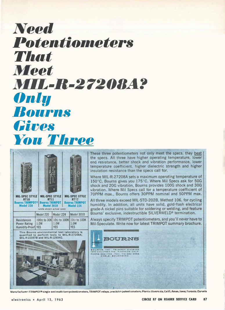
Need Potentiometers That Meet MIL-R-2720111? Only Bourns Gives You Three
MIL-SPEC STYLE RTIO
Bourns TRIMPOT'l, Model 220
MIL-SPEC STYLE MIL-SPEC STYLE RT11 RP2
Bourns TRIMPOT Bourns TRIMPOT Model 3010 Model 224
(unds shown actual sne)
Model 220 Model 224 Model 3010
Resistances Power Rating Humidity-Proof
100U to 30K 1.0W YES
10t.! to 100K 1.0W YES
10'.! to 100K 1.0W YES
This Bourns environmental test laboratory is qualified to perform tests to MIL-R-27208A, MIL-R-22097B and MIL-R-12934C.
These three potentiometers not only meet the specs, they beat the specs. All three have higher operating temperature, lower end resistance, better shock and vibration performance, lower temperature coefficient, higher dielectric strength and higher insulation resistance than the specs call for.
Where MIL-R-27208A sets a maximum operating temperature of 150cC, Bourns gives you 175' C. Where Mil Specs ask for 50G shock and 20G vibration, Bourns provides 100G shock and 30G vibration. Where Mil Specs call for a temperature coefficient of 7OPPM max., Bourns offers 3OPPM nominal and 5OPPM max.
All three models exceed MIL-STD-202B, Method 106, for cycling humidity. In addition, all units have solid, gold-flash electrical grade-A nickel pins suitable for soldering or welding, and feature Bourns' exclusive, indestructible SILVERVVELD'-' termination.
Always specify TRIMPOT potentiometers, and you'll never have to Mil-Speculate. Write now for latest TRIMPOT summary brochure.
"1"--pOT_TR,I\TS
11118111111111111111MINIIIIINIIIIIIIMNI BOURNE, INC.. TRIIHROV DIVISION 1200 COLuMBIA AVE RIVERSIDE CAL,.
PHONE ese-17oo • TVV, 714.01112 95/12 CABLE, BOURNSING.
Manufacturer:TRIMPOT»single-and multi-turn potentiometers, TRIMPOT relays, precision potentiometers. Plants: Riverside, Calif.:Ames, Iowa; Toronto.Canada
electronics • April 12, 1963 CIRCLE 87 ON READER SERVICE CARD 87

all sizes for all jobs
Waii4 FREQUENCY TO DC
CONVERTERS
One Frequency-to-DC Converter (handling input frequencies from 5 to 10 Kc) is a printed circuit card measuring three by four inches. Our solid state FR-500 series features modular construction for multi-channel operation in your instrument con-trol room. In addition, a variety of Frequency-to-DC Converters are available that have been shaped, sized and engineered for virtually every type of application or environment—airborne, shipboard, field, plant or laboratory.
Typical applications include Frequency-to-DC conversion of symmetrical pulse trains from turbine flowmeters, tachometer generators, electro-magnetic coils, photocells and nuclear detec-tion devices. Wherever incoming AC signals must be converted to a triggering or recording DC output with exceptional linearity, sensitivity and reliability, specify FOXBORO.
PDXBORO REGISTIRED 1tAramAne,
WAUGH ENGINEERING DIVISION 7740 LEMONA AVENUE. VAN NUYS. CALIFORNIA • STATE 2-1710
Call or write regarding your current projects
ness coding. ITT says the display is much easier to interpret than two-dimensional projections on con-ventional vectorcardiographs (ELECTRONICS, p 49, Jan. 20, 1961).
EL Diode Characteristics
-1 > O ‹ O
0.5V /DIV —*
TYPICAL current-voltage curve for new electroluminescent gallium arsenide diode (ELECTRONICS, p 7, March 16) is shown in photo, above. Curves, below, of the spec-tral distribution of light before and after breakdown illustrate the large change in intensity of the 0.84-micron zinc line. Work was described by K. Weiser, R. S. Levitt and W. P. Dumke, of IBM Watson Research Center, at the American Physical Society meeting in St. Louis March 25-28
LIGHT INTENSITY (ARBITRARY UNITS)
0.8
JUST AFTER BREAKDOWN
(CURRENT 70ma) INTENSITY APPR. 300 FIG. 7A
0.9
MICRONS
08
JUST BEFORE BREAKDOWN
(CURRENT Sma)
0.89
0.89
38 CIRCLE 88 ON READER SERVICE CARD CIRCLE 89 ON READER SERVICE CARD —)-

I NEED 50KW CW POWER AT X-BAND BUT I ALSO NEED TUBE STABILITY!
ANY IDEAS ??
AN MBK! ITS GENERAL ELECTRICS MULTIPLE BEAM KLYSTRON,
TYPE ZM-660 I • THIS NEW TUBES' conservatively designed individual beams, multiplied in a phase-locked multiple-beam structure, provide high RF power output at low thermal densities. And G.E. is now offering 60 day delivery!
Electrical and thermal stability of the ZM-6601 is typical of tubes operating at one-tenth the power level. The MBK requires only 12.8 KV beam voltage, eliminating extra size and weight encountered in paralleling conventional "high power" klystron tubes. Its unique among factory-built klystrons.
Here are some of its vital statistics . Frequency . 8.3-8.5 Oc Tuning Range 80 mc Power Output 50 KW CW Typical Voltage 12.8 KV Nominal Gain 45 db Efficiency 35%
Tubes sold in pairs are priced substantially below $1000 per kilowatt. And design is flexible, so ask about other frequency and power capability or pulse service design. Call any G-E Power Tube district sales office for full information.
GET THE PICTURE?
o E'LECIRCINICS INCLUDING IGNITRONS. HYDROGEN
THYRATRONS. VOLTAGE-TUNABLE GENERAL ELECTRIC PROGRESS IN MICROWAVE TECHNOtOGY MAGNETRONS. METAL-CERAMIC
TRANSMITTING TUBES, MICROWAVE POWER FILTERS. HIGH SUPERPOWER KLY-STRONS. FOR INFORMATION ON THESE PRODUCTS, WRITE SECTION 265-25, POWER POWER TUBE DEPARTMENT 265-25
TUBE DEPT., GENERAL ELECTRIC CO., SCHENECTADY 5, N. Y. OR TELEPHONE
TODAY: SCHENECTADY, N. Y. FRanklin 4-2211 (Ext. 5-3433) • WASHINGTON, o. c EXentive 3-3600 • )qyT0N, mud BAIdYrin 3-7151 • LOS ANGELES. CALIF BRadshaw 2-8566
SYRACUSE, N. Y. 652-5102 • CHICAGO, ILL. SPring 7-1800 • CLIFTON. N. I. GRegorY 2-8100 • NEW YORK, N. Y. Wisconsin 7-4065 • ORLANDO. FLA. GArden 4-6280

COMPONENTS AND MATERIALS
New Thyratron Peaks at 200 Mw
Can handle power for interplanetary radar bounce, and nucleonics
By L. E. ALGAR
J. E. MARSHALL General Electric. Hirst Research
Center. Wembley. England
C. R. RUSSELL M-0 Valve Co..
Brook Green Works. London
TWO HUNDRED megawatts peak and one hundred and fifty kilo-watts mean power levels are now commercially available in a deu-terium-filled thyratron. Deuterium is a hydrogen isotope having mass number 2. It is one form of heavy hydrogen. Pulsed from a single trigger cir-
cuit, the tetrode requires a pulse of only 10 amps at 1 Kv to switch 10,000 amps at 40 Kv. Ability to switch such large
powers becomes increasingly im-portant for outer space tracking,
CERAMIC
CATHODE
CATHODE CAN
POWER requirements of thyratron led to metal envelope tube. Reser-voir system replenishes gas for long tube life—Fig. 1
CATHODE temperature of deuterium thyratron is measured during ex-haust stage. Pulse modulator was developed by General Electric Ltd., England on behalf of M-0 Valve Company
signal bounces off planets, and resolution of closely-spaced tar-gets. In physics, the charting of new particles require higher en-ergies from new accelerators. At the present time, large thyra-
trons are being used in connec-tion with nuclear physics experi-ments. One such machine is the 50 Mev proton linear accelerator in operation at the Rutherford High Energy Laboratory in Har-well, England. Maximum parameters at which
the thyatron is operated at Har-well are: 30 Kv hold-off voltage, 330 amp peak current, 400 micro-second pulse length, 50 pulses per second and 6.6 amps mean current. Proton linear accelerator is used
24 hours per day for 10 days of every 14. Reliability of the tube is especially important where the energy level of the accelerator must be well defined.
HEAVY HYDROGEN —In this tube, E2986, the hydrogen is re-placed by deuterium.' All the ad-
vantages of hydrogen are retajned. In addition, the tube has less energy loss as a consequence of the reduced mobility of the ions. Further, the ability to use higher anode voltages at a given gas pres-sure arises from the greater dielec-tric strength of deuterium.'
Consideration of the fundamental requirements in high power thyra-trons led to the metal envelope con-cept, see Fig. 1.
Important differences between ceramic and metal lies in the tem-perature of the electrodes and of the deuterium gas. The metal en-velope configuration makes it pos-sible to take water cooling into the heart of the tube, near the actual grid slots, for maximum effect. In-sulator between grid and anode is cooler, enhancing dielectric strength and giving freedom from stray emission effects. Also, the in-sulator is less likely to become covered with sputtered material. A hold-off voltage level of 40
Kv was chosen as a compromise. Too low a voltage leads to high cur-
94 April 12, 1953 • electronics

o
I NEED 50KW CW POWER AT X- BAND BUT I ALSO NEED TUBE STABILITY!
ANY IDEAS ??
/VHAT ?
ELECTRONICS
AN MBK! IT'S GENERAL ELECTRIC'S MULTIPLE BEAM KLYSTRON,
TYPE ZM- 6601 • THIS NEW TUBES' conservatively designed individual beams, multiplied in a phase-locked multiple-beam structure, provide high RF power output at low thermal densities. And G.E. is now offering 60 day delivery!
Electrical and thermal stability of the ZM-6601 is typical of tubes operating at one-tenth the power level. The MBK requires only 12.8 KV beam voltage, eliminating extra size and weight encountered in paralleling conventional "high power" klystron tubes. It's unique among factory-built klystrons.
Here are some of its vital statistics . Frequency 8.3-8.5 Gc Tuning Range 80 mc Power Output 50 KW CW
Nominal Gain 4152.8db" Typical Voltage
Efficiency 35%
Tubes sold in pairs are priced substantially below $1000 per kilowatt. And design is flexible, so ask about other frequency and power capability or pulse service design. Call any G-E Power Tube district sales office for full information.
GET THE PICTURE?
INCLUDING IGNITRONS, HYDROGEN
THYRATRONS. VOLTAGE-TUNABLE
PROGRESS IN MICROWAVE TECHNOLOGY MAGN E IRONS. METAL-CERAMIC
TRANSMITTING TUBES, MICROWAVE POWER FILTERS. HIGH SUPERPOWER KLY-
STRONS FOR INFORMATION ON THESE PRODUCTS, WRITE SECTION 265-25, POWER
TUBE DEPT, GENERAL ELECTRIC CO., SCHENECTADY 5, N. Y. OR TELEPHONE
TODAY: SCHENECTADY, N. Y. FRanklin 4-2211 (Ext. 5-3433) • WASHINGTON, 0. C . EXectitive 3-3600 • DAYTON. OHIO BAldwin 3-7151 • Los ANGELES, CALIF BRacisha• 2.8566
SYRACUSE, N. Y. 652-5102 • CHICAGO. •LL SPring 7-1600 • CLIFTON, N. 1. GRegory 2-8100 • NEW YORK, N. Y. Wisconsin 7-4065 • ORLANDO, FLA. GArden 4-6280
GENERAL ELECTRIC POWER TUBE DEPARTMENT 265-25

Mullard Tubes for Television
LOW IMPEDANCE OUTPUT PENTODE
For audio, video amplifier and field
output stages there is no better tube than the Mullard EL86.
This 12 Watt output pentode
gives advantages of high slop-
low impedance and high efficient A single EL86 will give
audio output of 5.3 Watt
170
-12 5
70
%herd ' Is the trade mark of Mallard Limited CIRCLE 90 ON READER SERVICE CARD
Full details on the Mullard range of tubes for television, stereo and high-fidelity available from: INTERNATIONAL ELECTRONICS CORPORATION, 81 SPRING STREET, NEW YORK 12, N Y Worth 6-0790
Mullard ELECTRONIC TUBES
NULLARD OVERSEAS LTD., LONDON, ENGLAND.

1/108/SEC-1/106/WEEK
1 LITIf 1-12.4 GC
Introducing a compact electronic instrument to
control microwave oscillator frequency
You name the application. The Dymec DY-2650A Oscillator Synchronizer will make it easier! Absolute
control of frequency is yours when the DY-2650A phase locks your klystron oscillator to a crystal ref-
erence, to achieve short-term stability of 1 part in 108 per second, 1 part in 106 per week. Temperature
stability is 1 part in 106, 0-50 C. The DY-2650A re-quires only a small sample of klystron power—less than —10 dbm.
The DY-2650A will synchronize most reflex klystrons,
1 to 12.4 GC, with complete elimination of klystron drift and minimization of all incidental fm caused by klystron noise, power supply ripple and mechan-
ical shock. You can use it for oscillator stabilization, frequency modulation and control, frequency sta-bility monitoring and fm monitoring.
Frequency modulation and control: Use the DY-2650A to apply fm to a klystron oscillator with deviations up to 500 KC at rates to 50 KC.
Manual frequency control: Over 2 MC range of klystron frequency.
Frequency monitoring: Use an electronic counter or fre-quency meter to monitor the microwave signal for fre-quency stability.
FM monitoring: Demodulate fm on the test signal, provid-ing an output for monitoring with a VTVM, oscilloscope or other monitoring devices.
doppler systems
spectrum analyzers
radio astronomy
parametric amplifier pumps microwave frequency standards
microwave spectroscopy
AD*
SAMPLE STABILIZED RI OUTPUT
DY 26SOA
OSCILLATOR
SYNCHRONIZER
DIRECTIONAL
COUPLER
CORRECTED REFLECTOR VOLTAGE IF\
REFLECTOR
VOLTAG
MAIER SUPINT
1#116A,
KLYSTRON
The DY-2650A is essentially a crystal-controlled superheterodyne receiver terminating in a phase comparator. An oscillator sample is mixed with harmonics of the rf reference to produce an intermediate frequency of 30 MC, which is compared in phase with the 30 MC reference. For stabilizing
a klystron, the resultant phase error voltage is added in series with the klystron reflector power supply voltage.
SPECIFICATIONS Frequency range: 1 to 12.4 GC Stability: 1/108 per second, 1/106 per week (over -± 5°C), 1/106 over range 0 to 50°C. Output circuitry: Suitable for connection to klystron reflector; floating and insulated up to 2000 y dc. A phase lag network provides optimum characteristics for matching klystron sensitivities from 0.05 to 4 MC/volt nominal. Input power: Less than — 10 dbm. Price: $1,450.00, f.o.b. factory. Data subject to change without notice.
Describe your requirement today to your Dymec/Hewlett-Packard representative, write
Dymec for further information or call Dymec direct. Extension 223 or 224.
E A Division of Hewlett-Packard Company 'cee
Dept. E-426, 395 Page Mill Road, Palo Alto, Calif. Tel. (415) 326-1755 • TWX, 415-492-9363
electronics • April 12, 1963 CIRCLE 91 ON READER SERVICE CARD 91

NEW FROM NORTHEASTERN!
Compact 25 MC Solid State Counter
Features Time
Interval Measurement
Northeastern's Model 40-81 meets the demand for a low 51/4 " panel height, 8 digit in-line presentation, fully solid state 25MC counter which features Time Interval Measurement in the basic unit as well as fre-quency, period and ratio. Re-mote operation and program-mability are included features.
Specifications: Frequency Measurement Range
0 to 25 MCs Standard Gates Times
1/2 sec to 10 sec in decade steps
Period Measurement Range (single) 0 to 1MC
(multiple) 0 to 300 KC Time Interval Range
1µ sec to 109 sec (digit capacity)
Stability ±7 parts in 109/day (averaged over 7 days)
Temperature....-20°C to +65°C Power
115 VAC ±10%, 50-60 Cps Dimensions
Basic Unit 12' W x 15 1/2 D x 51/4 H
w/rack mount 14" W x 15 1/2 D x 51/4 H
w/plug in 17"W x 15 1/2 D x 51/4 H w/plug in & rack mount 19" W x 15 1/2 D x 51/4 H
Weight 28 pounds w/plug-in hardware. 33 pounds
NORTH EASTERN ENGINEERING INCORPORATED A SUBSIDIARY Of Alt ANTIC RESEARCH CORPORATION DEPARTMENT 5A, MANCHESTER. NEW HAMPSHIRE
Employment OPportundles Open At All ToYels
E-Z CODE wire markers
assure POSITIVE, LASTING IDENTIFICATION
Ancient hieroglyphs gave lasting identification to temples and tombs. Modern, easy to use E-Z CODE* wire, cable and harness markers provide similar positive identification.
Thousands of stock items, in a variety of mate-rials, for electrical, electronic and industrial use are available for "off-the-shelf" delivery.
Write for FREE SAMPLES. complete catalog, stock list
and name of your LOCAL DISTRIBUTOR with exclusive, adhesive.protecting tabs
F, eWESTLINE E.t.ODE DIVISION .., e
Western Lithograph Company
630 E. 2nd St., Los Angeles 54, Calif
CIRCLE 204 ON READER SERVICE CARD
General RF Fittings , Inc.
the finest precision coaxial connectors*
ji‘ .1.T.
702 BEACON STREET. BOSTON 15. MASSACHUSETTS Tiklep ,,o,, e 617 267.5120
92 CIRCLE 92 ON READER SERVICE CARD
CIRCLE 205 ON READER SERVICE CARD
April 12, 1963 • electronics

Actual size
Mighty Micropot® for close quarters Tighten up your parameters all you
want because some good things still come in small packages.
7A^ DIAMETER, +2 MILLION REVOLUTIONS
Like the new, miniaturized (ye diam-eter) 2150 Micropot. Here is a tiny, 10-turn precision potentiometer that de-livers over 2 million revolutions with high accuracy and good resolution. Independent linearity holds to -±0.25%.
In fact, the only modest thing about this Micropot is its price (under $10— and much less in production quantities).
GANG IT, HEAT IT TO 105°C
Looking for component versatility?
The 2150 ignores heat up to 105°C. You can gang it (2 units). Tap it. Even add rear-shaft extensions, if you want to. Torque and noise are extremely low. Compare specs and prices. We believe
you won't match our 2150 Micropot anywhere for either commercial or mili-tary applications.
NEED SPECIALS?
Take advantage of the Borg Quick Reac-tion Facility. Get fast delivery of proto-types built exactly to your specifications.
Call your nearby Borg representative or distributor. Or a letter to R. K. Johnson will put the 2150 story on your desk in short order,
2150-2160 SERIES TEN-TURN MICROPOTe
Mechanical rotation 3600° +10° — 0° Electrical rotation 3600° +10° —0° Resistance range, ohms 100 to 100 K Resistance tolerance ±
Standard linearity +0.25% Power rating 3 watts at 40°C Noise 100!.2 equiv. noise resist. max. Temperature range —55°C to +105°C Resolution from .054% at 1009
to .0088% at 100K Torque Start 0.5 oz/in; Run 0.4 oz/in Shaft dia IA° (2150) and lie (2160) Weight 1 oz
Life 2 000,000 revolutions
BORG EQUIPMENT A Division of Amphenol-Borg Electronics Corporatioei
Jonesville, Wisconsin
CIRCLE 93 ON READER SERVICE CARD

Can handle power for interplanetary radar bounce, and nucleonics
By L. E. ALGAR
J. E. MARSHALL General Electric, Hirst Research Center, Wembley. England
C. R. RUSSELL M-0 Valve Co.. Brook Green Works, London
TWO HUNDRED megawatts peak and one hundred and fifty kilo-watts mean power levels are now commercially available in a deu-terium-filled thyratron. Deuterium is a hydrogen isotope having mass number 2. It is one form of heavy hydrogen.
Pulsed from a single trigger cir-cuit, the tetrode requires a pulse of only 10 amps at 1 Kv to switch 10,000 amps at 40 Kv.
Ability to switch such large powers becomes increasingly im-portant for outer space tracking,
CERAMIC
CATHODE
CATHODE temperature of deuterium thyratron is measured during ex-haust stage. Pulse modulator was developed by General Electric Ltd., England on behalf of M-0 Valve Company
signal bounces off planets, and resolution of closely-spaced tar-gets. In physics, the charting of new particles require higher en-ergies from new accelerators. At the present time, large thyra-
trons are being used in connec-tion with nuclear physics experi-ments. One such machine is the 50 Mev proton linear accelerator in operation at the Rutherford High Energy Laboratory in Har-well, England. Maximum parameters at which
the thyatron is operated at Har-well are: 30 Kv hold-off voltage, 330 amp peak current, 400 micro-second pulse length, 50 pulses per second and 6.6 amps mean current. Proton linear accelerator is used
vantages of hydrogen are retained. In addition, the tube has less energy loss as a consequence of the reduced mobility of the ions. Further, the ability to use higher anode voltages at a given gas pres-sure arises from the greater dielec-tric strength of deuterium.'
Consideration of the fundamental requirements in high power thyra-trons led to the metal envelope con-cept, see Fig. 1.
Important differences between ceramic and metal lies in the tem-perature of the electrodes and of the deuterium gas. The metal en-velope configuration makes it pos-sible to take water cooling into the heart of the tube, near the actual grid slots, for maximum effect. In-

BOTH THESE MAGNETIC TAPES HAVE A POLYESTER BASE
...BUT ONLY ONE IS MYLAR (8 YEARS PROVEN)
Eight years ago instrumentation tape of Du Pont MYLAR >' polyester film appeared on the scene and set new standards of reliability. Naturally enough, people whose needs called for a magnetic tape of highest performance couldn't risk a tape other than MYLAR. • Now, other polyester films are be-ginning to appear.They are not all the same: MYLAR is a polyester film, but other polyester films are
*Du Pont's registered trademark for its polyester film.
BETTER THINGS FOR BETTER LIVING ... THROUGH CHEMISTRY
not MYLAR. In the past you could safely assume you were getting MYLAR when you specified "poly-ester base". Today you cannot. u There's only one way to be sure you're getting the MYLAR you've used and trusted for magnetic tapes of proven reliability: specify MYLAR by name. E. I. du Pont de Nemours & Co. (Inc.), 10452 Nemours Bldg., Wilmington 98, Delaware.
only DU PONT makes
MYLAR® POLYESTER FILM
electronics • April 12, 1963 CIRCLE 95 ON READER SERVICE CARD 95

RELIABLE MODULES ARE POTTED IN
TIMONIUM
E 1111111111311111201M11111111 I. IM 0 D MIMI» g pp ocaA o g o
1949 GREENSPRING DRIVE • TIMONIUM. MO.
CLearbrool. 2-2900
DIGITAL LOGIC MODULES • DIGITAL EQUIPMENT AND CUSTOM PACKAGING
1— 1 I POSITIVE — I DRIVE I I PULSE I
I BIAS "L--- '` 1-1- 00 F l L —r- T1 _I
TRIGGER PULSE GENERATOR
1.000V 0.04F
vv% ANODE 100
GRID BAFFLE
500 500 HEATER
CATHODE
CAPACITOR-resistor network connects generator to grid and baffle—Fig. 2
rents and to low delay line im-pedance. This could lead to trouble from stray inductance. Too high a hold-off voltage leads to too low a gas pressure and failure to sup-port adequate discharge. Advantage of deuterium stems
from gas pressure in the tube.' Higher pressure enables the gas to support a higher power discharge. Gas pressure required to support the peak current rating of the tube can be obtained by the use of deuterium. With hydrogen at the same pressure, the operating volt-age would be limited to about 25 Kv.
INSULATOR—Voltage breakdown hazard is prevented by inserting an insulator between anode and grid surface. A combination of two concentric cylinders of insulating material, glass, with a gas-filled gap between them was used. The glass cylinders extend to become integral with the envelope.' High mean power of 150 Kw is
achieved by preventing grid emission and maintaining a high gas density by cooling. Cooling is taken right to the edge of the grid slots without increasing the im-pedance of the grid to the dis-charge.'
Efficient grid cooling has led to the tube rating of 40,000 Mw cycles for the product of :1 x peak anode voltage x peak anode cur-rent x pulse repetition frequency, that is, a Pb factor of 80 x 10°. A metal baffle, interposed between grid and cathode, prevents emis-sion from the cathode.
REFERENCES
(1) U. S. Patent No. 2953705, The M-0 Valve Co. Ltd. and K. G. Conk.
(2) K. G. Cook, G. G. Isaacs and R. J. Armstrong, N. S. Nicholls. Deuterium Filled Thyratrons, British Journal App Phys. p 497-499. 9. Dec., 1958.
(3) Patent No. 798.627, M-0 Valve Co Ltd and G. G. Isaacs.
(4) Patent No. 855.998, The M-0 Valve Co Ltd and L. E. Alger. K. G. Cook.
The cathode is maintained at a temperature of 1,050 C by a heater system.° Six tungsten coils are ar-ranged in parallel. The total area of primary emitting surface is about 250 sq cm. Heat shield is molybdenum cylinder provided with radial fins. Area acting in an emissive capacity is 750 sq cm. By these two processes, an emitting area of 1,000 sq cm needed for peak currents of 10,000 amps is ob-tained. Pulse lengths are 5 its or less. Much longer pulse lengths can be obtained with appropriate reduction in peak current. The two triggering electrodes, baf-
fle and grid, supplies trigger pulse of minimum amplitude of 1 Kv and leading edge rising at the rate of 2 to 4 Kv per microsecond, see Fig. 2. This ensures that the grid-cathode arc is struck during the rising part of the grid pulse. Vari-ations in the timing of successive pulses are kept to a minimum.
LONG LIFE—A reservoir replen-ishes lost gas for long tube life.' Metallic hydrides of titanium, zirconium or hafnium evolve deuterium gas. Trigger pulse of 2 to 3 micro-
seconds long is superimposed on a negative d-c bias of 60 to 80 volts. The generator has a maxi-mum pulse source impedance of 100 ohms. A 100 microfarad ca-pacitor, connected across the bias supply, keeps the pulse source im-pedance within specified value. The generator is connected to
the grid and baffle with a capaci-tor-resistor network.' Grid bias en-
(5) Patent Application The M-0 Valve Co Ltd an E. A. Taylor.
(6) Patent Application The M-0 Valve Co and B. Wheldon.
(7) Patent No. 729,962, Co Ltd and A. J. Booth, K.
(fi) Patent No. 747,484, Co Ltd and K. G. Cook.
No. 34220/40, d L. E. Algar,
No. 14527/42, O. Baker. R. J.
The M-0 Valve G. Cook.
The M-0 Valve
96 CIRCLE 96 ON READER SERVICE CARD April 12, 1963 • •lectronics

now there are
WITH MIRROR SCALE Series 4M
$50.95
2 new 26a VOMs
WITH STANDARD 260
SCALE Series 4... Still Only
$48.95
with 6 new features Now the world-famous 260® volt-ohm-milliammeter is a better buy than ever before. Call your distrib-utor now for immediate delivery on either of these two new 260's, or on any of the other 50 Simpson testers —the world's largest selection.
• New Self-Shielded Movement
• New Higher Accuracy: 2% DC, 3% AC
• New Ruggedness From Spring-Backed Jewels
" Greater Repeatability
• Increased Linearity and Stability
• *Mirror Scale (260, Series 4M)
SIMPSON INSTRUMENTS STAY ACCURATE
Both new 260's can be used with Simpson's
popular "Add-A-Tester" adapters.
Write for Revised Stock Catalog 2064A.
SIMPSON ELECTRIC COMPANY 5203 West Kinzre Street, Chicago 44, III.
Representatives in Principal Cities ...See Telephone Yellow Pages
hone: (312) EStebrook 9-1121 In Canada: Bach-Simpson Ltd., London, Ontario
electronics • April 12, 1963 CIRCLE 97 ON READER SERVICE CARD 97

Forget Wire!
Photo Courtesy International Resistance Company
S séfiFfel-Clad* Replace expensive hand wiring with low-cost continuous processing of Schjel-Clad
This unique combination of flexibility and dimensional stability in Schjeldahl's metal-to-plastic electrical laminate, Schjel-Clad, can really cut costs. It permits reliable, continuous in-line processing to produce flexi-ble wiring harnesses, computer memories and other flexible printed wiring.
Schjel-Clad is available in a variety of materials: Copper, Aluminum or Nickel bonded to Polypropylene, Mylart or Teflont. Each laminate is available in a wide variety of thicknesses and widths. Write or call for data sheets and samples in the sizes you need. Phone: Area Code 507, NI 5-5635.
°G. T. Schleklahl Co., T.A.I. Rep. U.S. Pat. Off. tduPont trademarks for Its polyester film; fluorocarbon resin
Putting Materials Together Through Chemistry and Mechanical Design PRODUCTS
10
SERVICES
G.T. Schjeldahl Co.
SAY "SHELL-DOLL" • NORTHFIELD, MINNESOTA
sures a short recovery time. In the accelerator, used at Har-
well pulsed r-f power at a fre-qency of 202.5 Mc. Peak power of the order of 1 Mw is fed into each of three high Q resonators which are responsible for acceleration successively to 10, 30 and 50 Mev.
Variable Transformers Feature Wider Ratings
MAJOR redesign of a variable trans-formers was announced last week by General Electric. New line con-sists of 19 basic single core ratings. There are 11 single phase units rated 120 volts, 2 to 65 amperes, and 8 units rated 240 volts, 3 to 40 amperes.
Automatic Volt-Pac units are de-signed to provide automatic control of line voltage where incoming line fluctuation cannot be tolerated; or automatic control of variable out-puts.
Design features include an ex-clusive heat sink ring, new current collector, new solid-carbon brush and motor drive. New solid state ser control is utilized to minimize moving parts and provide mainte-nance-free operation.
Functional Block Trends Pushed by Air Force
THE MAJORITY of functional elec-tronic blocks, commercially avail-able, are for digital applications. However, there appears to be con-siderable effort underway to de-velop solid-state blocks for analog applications, according to United A ircraft.
Presently FEB's are packaged in either hermetic cans, such as the TO-5 and TO-18, or in flat open con-tainers, such as the Texas Instru-ments package. Trend strongly encouraged by
the Air Force, according to United Aircraft, is latter type packaged with standardized dimensions and geometries.
Prototype modular interconnec-tion packaging system has been built at United Aircraft for a government contract. This is a grooved monolithic ceramic wafer within which functional blocks are to be attached to optimize dissipa-
98 CIRCLE 98 ON READER SERVICE CARD April 12, 1963 • electronics

In FIXED COMPOSITION RESISTOR if it's news, expect it first from IRC
Only IRC Fixed Composition Resistors offer
5 WAYS TO SAVE ON WELDING HERE'S WHY ... IRC realizes that no single lead ma-terial satisfies all the welding techniques in use today. There is also a wide price differential among different materials. IRC offers 5 types of weldable leads . . . lets you choose the material and price that meets your particular need.
Compare the add-on prices of weldable leads. You will find IRC's to be significantly lower.
IRC's standard leads are alloy-plated copper. Many users weld these leads successfully and save the cost of premium materials.
Write for complete weldable lead pricing and derating infor-mation. International Resistance Co., Philadelphia 8, Pa. *Typical add-on prices are for RC20 size.
PERFORMANCE ADVANTAGES
IRC Type GBT's also provide
• Superior high frequency characteristics
• Lower operating temperature
• Outstanding load life
• Greater moisture protection
• Ranges to 100,000 megohms
• Stronger terminations
• Better resistance-temperature characteristics
ei.ctronics • April 12, 1963 CIRCLE 99 ON READER SERVICE CARD 99

RESOLVERS, SYNCHROS PHASE SHIFTERS
STANDARD RESOLVERS
A full line of compensated and uncompensated resolvers in standard BuOrd size 23, 15 and 11 cases. Size 23 series has functional accuracy of 0.05%; resolvers in other two series have accuracy of 0.1%.
HIGH PRECISION SIZE 23 RESOLVERS
New series of extremely accurate resolvers, includes a 0.01% func-tional accuracy computing re-solver with 100% compensation and a data transmission resolver with 20-second accuracy. The ultimate in precision for resolvers of this case size.
For data transmission; coordinate transformation and conversion; computer chain; and sweep applications. Write for data file 104.
••••• •••• ••••. ••••• •••• .........0.•••••••
•••• '.- ••• •
::::. ••• “••.
•••• ••••,.
...—.._ , ••••
30-SECOND SIZE 23 SYNCHROS
These three wire synchros are the most accurate units available in a standard BuOrd size 23 case. Both transmitters and con-trol transformers can be supplied, for either 400-cycle or 60-cycle input.
PRECISION PANCAKE RESOLVERS
0.005% functional accuracy computer resolvers with 100% compensation. 10-second accu-racy data transmission resolvers. Intregral bearing design permits direct mounting to gimbal struc-ture. Beryllium housings provide stable operation under extreme temperature variation.
BOOSTER AMPLIFIERS
Complete line of vacuum tube and transistorized booster am-plifiers, for use in conjunction with compensated resolvers. Transistorized units contain two fully encapsulated amplifiers in a single case.
REEVES INSTRUMENT CORPORATIONI
A Subsidiary of Dynamics Corporation of America, Roosevelt Field, Garden City, N.Y.
tion of thermal energy.
Communication between blocks
and outside will be provided by a
horizontal and vertical intercon-
nection matrix. Hermetic system
is directed toward use of uncased functional blocks. However pro-visions are made for presently
available hermetic packaged solid
blocks.
Light Dependent Resistor Dissipates 25 Watts
POWER PHOTOCELL with current han-
dling capacity of :1 ampere and
power dissipation of 25 watts has
been developed by Delco.
Company's LDR-25 is constructed
of a thin layer of sintered cadmium
sulphide applied to an aluminum
oxide substrate. Unit is sealed by
film adhesives and a glass cap.
Unit permits variable speed con-
trol for fractional horse power mo-
tors. The power photocell is in-
tended primarily for medium or
high-power switching and control
applications where turn-on and
turn-off times in the order of tens
of milliseconds can be tolerated. De-
vice can operate from 110-v a-c and
is conservatively rated at 200 y d-e
or peak a-c.
Rating and slow switching speed
make photocell particularly suited
for control of inductive loads where
voltage surges encountered with
breaker points or junction devices
can be a problem.
When used with standard minia-
Bright Cathode Ray
TUBE features electrostatic focus-ing and an aluminized screen. Initial use will be for high-speed military aircraft. Face of tube is 3 inches in diameter. Sylvania tube uses special blend of phosphor in screen
100 CIRCLE 100 ON READER SERVICE CARD April 12, 1963 • electronics

I 1 lit al ill I 41111111 II Mal 11 ••11 la • Ili AY iMaMMIML
.1% FAILURE RATE .01% FAILURE RATE .001% FAILURE RATE in 10,000 operations with in 10,000 operations with in 10,000 operations with 90% confidence factor 90% confidence factor 90% confidence factor
DESIGN FEATURES OF BABCOCK RELIABILITY-RATED RELAYS
Vycor activated getter. Ex-clusive to Babcock, this porous glass getter prevents contact contamination by adsorbing all outgassed or-ganic substances, following production degassing at 200 C under less than 5 microns vacuum.
Self-wiping, gold-plated con-tacts. Contacts of AgMgNi alloy with specially-designed configuration assure miss-free performance under load and minimize low level contact resistance.
Welded-header construction. Automatic sealing process gives stronger header-case bond and prevents solder flux contamination. Leakage rate is less than 10-8 c.c. per sec. by mass spec-trometer.
Not all relay applications demand "millions of miss-free operation." Yet
for every level of reliability, one requirement is mandatory—consistent
performance within predictable limits of accuracy.
Babcock's pioneering work on relay reliability has evolved a statistical
test procedure which verifies reliability by combining Darnell Report methods with proprietary testing techniques. Result: the design engineer
can obtain any desired level of relay reliability with assurance of uniform predictable operation at a cost no greater than the need justifies.
In classifying relay reliability by failure rate level, Babcock provides the user with a universal yardstick for specifying and evaluating requirements.
High reliability units are presently testing to failure rates under .01% in 10,000 operations with a 90 0/o confidence factor.
Babcock reliability verification procedures offer other benefits, too. With
testing carried on continuously, ratings are based on cumulative data,
preventing any possibility of quality deterioration. In addition, the use
of uniform reliability test standards enables the user to eliminate costly
evaluation testing . .. each rated relay is shipped with a certificate docu-
menting reliability test results.
General catalog BR-6200, describing the complete line of Babcock Relays,
is available upon request. For reliability information pertaining to specific
applications, please write directly, outlining requirements.
BABCOCK RELAYS A Division of Babcock Electronics Corporation
3501 Harbor Boulevard, Costa Mesa, California
CIRCLE 101 ON READER SERVICE CARD

MICRO-MINIATURE ROTARY RELAYS*
40 MW I 100 MW I 250 MW
ONE SIZE — 3 DIFFERENT SENSITIVITI ES
Catalog Number
Coil Resistance
*10% @ 25°C
Maximum Pull-In Current
Minimum Drop-Out Current
Nominal Operating Value
Coll Sensitivity
Ohms MA. MA. Volts Milliwatts
2R25A420-8 625 19 1.9 26.5 250
2R10A440-13 1500 8.2 .82 26.5 100
2R04A460-13 4000 3.2 .32 26.5 40
Weight: 18 ± Gram Ambient Temperature: —65°C to +125°C Contacts: 2PDT (2 Form C) 2A 30 VDC
•CVE type
Vibration: 30 G to 2,000 CPS Shock: 100 G Dielectric Strength: 1,000 VAC
ORDNANCE, INC. A Subsidiary of S. H. Couch Company, Inc.
_ in the load circuit, with control in-put of one watt or less. Using mini-ature neon lamps, it is possible to switch up to 40 watts with less than 500 mw input. At IEEE show, Mar 25-29, Delco
showed how photocell unit can be used in household food mixer. Con-tinuously variable speed control of motor dissipated more than 15 watts in control of 100 w motor.
Electroluminescent Powders in Colors
AVAILABILITY of electroluminescent powders of the zinc sulphide series, in ten colors, has been announced by Cole Commercial Company, Seattle, Washington. Company compounds powders to
specifications, assures average par-ticle size of 10 microns. Minimum half life for most colors is 7,000 hours.
Integrated Wafers PRACTICAL methods will be devised at Melpar for integrated planar and electrical connections between thin-film circuits, discrete parts, and solid circuits on microwafers. Discrete parts of interest are the dot or chip forms which are suit-able for recessing flush with the surface of the wafer. Vacuum and other deposition
techniques will be developed for simultaneously forming intercon-nection to the hybrid wafers.
Thin-Film Inductors With Bulk Ferrite
FLAT SPIRAL coils, used in combina-tion with two or more bulk ferrite wafers, have obtained maximum in-ductance values of 153 ith with a Q value of 20 as measured at 1 Mc.
Final Motorola report on minia-ture inductors (ELECTRONICS, May 11, 1962, p 72) to Navy indicates limitations of obtaining larger values for both inductance and Q. Substantial increase in inductance would result if ferrite with larger initial permeability could be found.
n.r ••••a,be,,n net •.n A r. -en r.4-114n.

ELECTRONIC PRODUCTS NEWS BY CARBORUNDUM
Varistor helps cut picture interference
on latest Zenith TV—automatically A development of the patented "Fringe Lock" circuit incorpor-ated in Zenith TV receivers now automatically cuts annoying pic-ture disturbances, whether made by nearby electrical machines or external influences such as pass-ing automobiles.
Function of the circuit is to cut off the twin pentode 6HS8 (see below) when external noise is introduced. Plates of the pentode are connected respectively to the AGC and Sync circuits. Two of the grids are fed by composite video signals. Automatic bias set-ting, varying with signal level
N EWS
fluctuations and always safely above the Sync tips, is provided by the voltage-sensitive resist-ance characteristics of the type BNR-331 Carborundum varistor. The varistor replaces a potenti-
ometer that required adjustment for maximum noise protection, particularly in fringe areas. The varistor not only provides auto-matic control and positive, instan-taneous cut out, but also costs one-third less than the potentiom-eter previously used.
New Technical data on varistors points way to wider applications and production savings
Carborundum offers a new bulle-tin and technical literature to aid
AGC Output
To Video Amplifier Plate Circuit
To Video Detector
Clipped Sync Output
To Video Amplifier Plate Circuit
Video Amplifier Screen
in the selection and application of silicon carbide non-linear, volt-age-sensitive resistors. A variety of body types and
sizes is available, with electrical characteristics suitable for appli-cations requiring microamperes at one volt up to kiloamperes at kilo-volts. Typical applications are lightning arrestors; contact arc suppression for relay coils and solenoids; protection for silicon rectifiers, capacitors and other electronic components against high peak inverse voltage; and voltage regulation and control. The bulletin lists standard stock
varistors with pertinent design information. Individual technical sheets provide E/I characteristic curves and specifications on over 100 stock varistors.
For your copies, write Dept. EL-4, Electronics Division, Carborundum Company, Niagara Falls, New York. Inquiries regard-ing application to specific prob-lems are invited.
CARBORUNDUM°
electronics • April 12, 1963 CIRCLE 103 ON READER SERVICE CARD 103

FOR SCIENTISTS & ENGINEERS
EQUIPMENT DEVELOPMENT BSEE — Elec. Eng. — 3-5 yrs. exp. HF or VHF (CR)
BSEE — FJec. Eng. — 6 yrs. exp. Power Servo Design (CR)
BSEE — Dec. Eng. — 3-5 yrs. exp. UHF (CR)
BSEE — Dec. Eng. — 3 yrs. exp. Command Control
Systems (CR)
BSEE — Elec. Eng. — 3 yrs. exp. Radar Beacon Work (CR)
BSEE or BSME — 3-5 yrs. exp. Ground Support (CR)
BSEE — Dec. Eng. — 2-5 yrs. exp. Digital and Logic
Design (CR)
BSEE — Eke. Eng. — 1-5 yrs. Exp. Circuit Design (CR)
BSEE — Elec. Eng. — 2-5 yrs. exp. Pulse Techniques
(CR or D)
BSEE — Dec. Eng. — 3-5 yrs. rap Caine Telephone Circuit Design (CR)
BSEE — Elec. Eng. —3-7 yrs. exp. Antenna Development (D)
BSME — Mech. Eng. — 3-7 yrs. exp. Packaging; Shock, Vibration, Heat Transfer, etc. (D at CR)
GENERAL BSME or BS Physics — Maintainability, Analysis fot
Accessibility Layout Logic, Mean Repair Time, etc. — 2-5 yrs. exp. (D)
BSEE or higher — Resident Eng. 3-5 yrs. exp. — Data
Storage, Radar Beacon (CR) BSEE — Reliability — Design Review — 2-5 yrs. exp. (D)
BSEE — Manufacturing Test Control and Pre-production Testing — 1-5 yrs. exp. (D)
BSEE — Technical Writing-2-4 yrs. exp. (D or NB)
BSEE — Test Eng. — 3-5 yrs. exp. — Communication
Design Testing (CR) ESEE desirable — Logistics Eng. — 2-5 yrs. cap.
Space Program Logistics (CR)
BSEE or higher — Comp. Designer — Exp. in
Network Theory (NB)
B51E — Production Methods, MTM, Quality Control — 1-4 yrs. cxp. (D. CR or NB)
B51E or BA Ind. Mgrist. — Production Foreman — 2 yrs. electronic mfg. exp. (D)
ME or IE — Staff Eng. — 2 yrs. exp. in MT?A (CR or NB)
MS or PhD — Solid State Physics — 3 yrs. exp. — Thin Film Development (CR)
BA — Production Control Mgr. — 5 yrs. production
control exp. (D)
wieb. DATA
SYSTEMS BSEE & BSME — 3-5 yrs. exp. — Trcpcopktric Saner
Systems (D)
BSEE — 1-5 yrs. exp. Microwave Systems, Applications and Field Installations (D)
BSEE — 2-7 yrs. exp. Space Tracking and Communications Systems (D)
BSEE — 2-8 yrs. exp. General Communications Systems (D)
BSEE — 2-5 yrs. exp. CHI Systems (CR)
BSME or equiv. — 3-5 yrs. exp. Environmental Tcst and Procedures (CR)
NISME — 3-5 yrs. exp. — Thermal Design and Evaluation (CR)
BSME or equiv. — Supervisor — 8-10 yrs. rap. —
Management and Administration (CR) BS or equiv. in EE — Field Eng. — 3-5 yrs. exp. —
Communications (CR)
BS — Field Supervisor — 5-10 yrs. exp. — Airborne Electronics and Communications (CR)
MS or equiv. in Physics or Mechanics — System Analyst — 3 yrs. exp. — Classical or Celestial (CR)
MSEE — System Analyst — 5 yrs. exp. Communications (CR)
MSEE — System Analyst — 5 yrs. exp. Tracking and Ranging (CR
MSEE — System Analyst — 5 yrs. exp. Modulation Technique (CR )
BSEE or higher — Senior Staff Asst. — 8-10 yrs. exp. Digital (NB or CR)
MS or PhD — Applied Math — 10 yrs. exp. Business
Computing (NB or CR)
BSEE — Eke. Eng. — 5-8 yes exp. Digital Data
Design (NB, D or CR)
MS — Applied Math — Business Programming — ext. exp. (NB or CR)
MS — Applied Math — Logic Program Designer —
8.10 yrs. exp. (NB or CR)
BSEE or higher — Peripheral Equip. Designer (CR)
BS — MS — PhD — Applied Math — Software
Systems Programming (D)
BSEE — Data Communications — Systems —
Computer Applications — 5-10 yrs. exp.
PLEASE NOTE Dept. EL When writing to one of the following:
On listings marked (CR). send resume ro L R. NUSS.
COLLINS RADIO COMPANY, CEDAR RAPIDS, IOWA
On listings marked (D). send resume to C P. NELSON
COLLINS RADIO COMPANY, DALLAS, TEXAS
On listings marked (NB), send resume to E D. MONTANO. COLLINS RADIO COMPANY, NEWPORT BEACH, CALIFORNIA
an equal opportunity employer
_ 47,

ELECTRONICS
NEW... Low-COST MEDIUM CURRENT RECTIFIERS
A40 A44
Specifically designed and priced for industrial, consumer and commercial applications
TYPICAL PRICES (in 100-999 quantities)
Stud Mounted 3 A4OF (50V) $0.79 A408 (200V) $1.19
1 A44F (50V) $0.49 Press nt
A448 (200V) $0.80
RATINGS AND CHARACTERISTICS (Single Phase Resistive Load)
Fw'd. Pol. A4OF A40A A40B A40C A4OD A40E A4OM Rev. Pol. A41F A41A A41B A41C A41D A41E A41M
Fw'd. Pol. A44F A44A A44B A44C A44D A44E A44M Rev. Pol. A45F A45A A45B A45C A45D A45E A45M
Max. Peak Reverse Voltage 50 100 200 300 400 500 600 volts Max. Avg. D-C Forward
Current at 110°C Stud 20 amps
at 150°C Stud 15 amps
Peak One-Cycle Forward Surge Current (60 cps, 25° CT) 300 amps
Operating Junction Temperature Range Storage Temperature Range
Stud Mounted A40
Press Fit A44
4-- —65°C to +175°C —> 411E--- 65°C to -I- 175°C
NOTE: 1N3208-1N3214 or 1N3208R-1N3214R are available when desired and are identical to A4OF-A4OM or A41F-A41N1 respectively, except that hex size will be 11,¡0" across the flats on the 1N3208 series.
• Excellent for hand tools, home light dimmers, tem-perature controls, power sup-plies, battery chargers, and many other applications
• One piece terminal (positive solder case-to-hex mounting in A40)
• Stud mounted and press fit housings
• 500 and 600 volt ratings (as well as 50 to 400 volts)
• Forward and reverse polarities
• Up to 300 amperes surge current
• %a" and W111" hex available on A40 series
• For complete specifications and immediate availability, see your G-E Semiconductor District Sales Manager, or write Section 16D107, Rec-tifier Components Dept., General Electric Company, Auburn, New York.
Available Through Your G-E Semiconductor Distributor
GENERAL ELECTRIC electronics • April 12, 1963 CIRCLE 105 ON READER SERVICE CARD 105

PRODUCTION TECHNIQUES
Quick detection of contact contaminants permits timely process adjustments
WHITE - ROOM relay assembly procedures have not eliminated re-lay contact contamination problems. Despite out-gassing processes, her-metic sealing and precious-metal contacts, failures continue to occur. Obscure and sometimes invisible contaminants of manufacturing ori-gin impede contact conduction. Only through immediate and exacting identification of contaminants can timely adjustments be made in man-ufacturing processes. Spot tests have been developed that can be per-formed quickly and easily as against
INEXPENSIVE spot tests are rapid, usually nondestructive and sensi-tive in pointing-out needed manufacturing technique changes. In one instance, a 50-cent spot test correctly identified a contaminant material within 1 minute while a confirmatory 28-dollar test taking 1 week made an incorrect identification
Spot-Testing
Aids Manufacture of
High-Reliability Relays
By EARL F. LISH, Fi'tors, Inc., East Northport. N. Y.
elaborate, time-consuming proce-dures. A case-in-point: A white-room
relay, supposedly free of particulate contamination, failed. Under 200X magnification it was found that a fiber between contacts was the cause. It appeared to be metallic. But measurement of its melting point, first without, and then with a crystal of p-nitrophenol identi-fied the material as Nylon 6-6 (Zy-tel 101). This was probably a bit of a flash that fell off Nylon coil bobbin after sealing, indicating that improvement in molding tech-nique was required.
Another white-room relay had high contact resistance after a one-ampere load-life test. Examination under polarized light showed nu-
WISE EXPENSE
Establishment of a chemistry lab at Filtors for in-process control of precision-relay manufacturing at first appeared extravagant. Its value in ensuing years has been such that it was expanded to permit even better process control. Use is made of exotic techniques mentioned here as well as more common-place ones such as gravimetric and volumeric analysis, pH and conductivity measurements
NYLON coil bobbin flash on relay contact (dark areas) was quickly identified as such, not a metallic fiber as it appeared, thus pinpoint-ing needed improvement in molding process
merous non-metallic inclusions in and around the gold-plated contact area appearing as pin-points of light. These inclusions were traced to a tumblepolish of contacts by vendor.
SPOT TESTS — Qualitative spot checks are most useful. Such tests are inexpensive, rapid, usually non-destructive and extremely sensitive. A 50-cent spot test identified a con-taminant material as nickel-flashed high purity iron within a minute or
106 CIRCLE 107 ON READER SERVICE CARD+

How tube skills made these new Sylvania Ni-Cd batteries more efficient than any others
Especially for designers of transistorized
equipment who are thinking small, here
are rechargeable nickel-cadmium batteries
which occupy up to 50% less space per unit
output than any others—ideal for field ra-
dios, beacons and other low-rate-discharge
equipment.
Key to this remarkable high efficiency is
the Sylvania film forming process, by which
nickel is cast and sintered to form a por-
ous, self-supporting film. Then this nickel
"sponge" is loaded with chemicals to form cell plates. Because there's no need for a
plate backing, and because each cell is an
easily stacked rectangular shape, the result
is very high output per unit volume and
weight.
What's the connection with tubes? In addition to benefiting by our experience in
heliarc welding and hermetic sealing, these
batteries are the second big payoff from
pioneer work in film forming. First was the
Sarong cathode, which has a wraparound
emission coating that greatly improves
tube performance.
The broad, integrated capabilities that
produced these developments are working in many ways to advance electronics.
Electronic Tube Division, Sylvania Electric
Products Inc., Box 87, Buffalo, N. Y.
SYLVAN IA GENERAL TELEPHONE g ELECTRON/OS
•ENERA)I
gel SYSTEM
NEW CAPABILITIES IN: ELECTRONIC TUBES • SEMICONDUCTORS • MICROWAVE DEVICES • SPECIAL COMPONENTS • DISPLAY DEVICES

7 Seconds to
CAP IT! once and for all...
with
NEW S
ALPHLEr
SHRINKABLE FIT-Caps
FIT'
TUBING TUBING C.11•111.1.
New, easy-to-use Alphlex FIT-Caps are short lengths of semi-rigid shrink-able polyolefin tubing sealed on one end and specifically designed to per-manently seal and insulate wire, cable and splices. FIT-Caps form a skin-tight, moisture-proof encapsula-tion that clings firmly to the ends of one or more wires, even when subject to extreme stress, vibration or abra-sion. Simply slip on the cap, apply heat (275°F) with the Alpha Heat Gun or other heat source, and within 7 seconds the FIT-Cap shrinks down to 1/2 its original diameter . . . and stops.
Supplied in expanded form to slip on easily, Alphlex FIT-Caps are available in 4 sizes. See them at your local electronics distributor.
Write for FREE catalog describing the industry's most complete tubing line.
ALPHA WIRE CORPORATION Subsidiary of LORAL Electronics Corporation
200 Varick Street, New York 14, N.Y.
PACIFIC DIVISION: 11844 Mississippi Ave., Los Angeles 25, Calif.
so. Confirmatory spectrograpnic analysis costing 28 dollars and tak-ing one week failed to detect nickel as being a surface constituent, erroneously reporting it as being a bulk constituent of less than 0.1 percent. One important use of spot tests is
an immediate check of flux deposits to make sure that not too much is used. With hydrazine flux, almost invisible particles have a greenish glow under ultraviolet light. More exact identification is made with a solution of chloromine-T + fluores-cein, which causes the particles to develop a visible red stain. Presence of a certain amount of these parti-cles indicates that something is wrong with hydrazine flux deposit
control. Presence of rosin flux on contacts
is also identifiable by a spot test. Quantities too slight (40 micro-grams) to fluoresce under ultra-violet light are turned visibly red-dish-purple when a drop of acetic anhydride (90-percent) and sul-furic acid (10-percent) mixture is
added.
SUBTLE CONTAMINATION — Spot tests are quite useful in detect-ing and indicating necessary proc-ess control of an extremely subtle form of contamination—that due to invisible traces of base metals. Tests at Filtors, Bell Telephone Laboratories, Stanford Research Laboratories and elsewhere have proved that metals such as iron, copper, lead and nickel are trans-ferred to relay contacts during roll-ing, riveting, plating, welding, gag-ing, and handling. Some manufacturers inadvert-
ently leave iron and nickel trace residues on contacts during header assembly welding. Invisible iron particles can be turned visibly blue by fuming contact areas with hy-drochloric acid vapors and then adding a drop of potassium fern-cyanide. Nickel particles are turned red by neutralizing acid with am-monia fumes before adding a drop of 1-percent dimethylgloxime solu-tion.
Rolled tape contacts may appear clean, but iron and nickel tests often prove these metals are present, showing that more stringent con-trol is required during rolling op-
eration. Welding can blow lead from
POSITIVE reaction to spot test disproved vendor's claims of water stains on gold-plated iron headers and indicated nickel contaminant (light areas) due to faulty plating
CORNCOB tumble polish produced insulated areas on contacts that contrasted with metallic areas which remained dark under test
IRON OXIDE insulating film on glass reed switch contacts remained light while metallic areas darkened under ferric ferricyanide test

Differentiated Waveform
DISPLAY OF INTEGRATED WAVEFORM—transformer second-ary voltage integrated and plotted against the transformer primary current—for enabling study of B-H loops of transformer cores.
INTEGRATOR
Current
VOLTAGE
DISPLAY OF DIFFERENTIATED WAVEFORM—tunnel diode in liq-uid helium—for enabling detection of quantum phenomena at low temperature.
DIFFERENTIATOR
100V
10V
IV
0.1V
(0)
1111 1111
Iusecicin
DISPLAY OF LOGARITHMIC RE-SPONSE—two pulses of widely varying amplitudes—for enabling observation of 100-volt pulse and 0.1-volt pulse in the same viewing area (simplified schematic shown below).
NON-LINEAR AMPLIFIER
Operational Amplifier Plug-In Unit Permits
Oscilloscope Measurements Under Dynamic Conditions
TYPE O OPERATIONAL AMPLu/IFIER PLUG-IN UNIT 81.0 LL
worm.« >mar VOOS,Cht
OC
e LoAI
•
TYPE 0 UNIT
gl,
A ETZ
ere-40 ê 1
1.1121•1.
• *-:ë ap.ca tie 7,
ttttt 0,11[.
e I
ut
U. S. Sales Price, f.o.b. Beaverton, Oregon
For a demonstration— please call your Tektronix Field Engineer.
$525
TYPE 0 UNIT—for Tektronix Oscilloscopes that accept letter-series plug-in units. e
Using this new Operational Amplifier Unit in your Tektronix Oscil-loscope, you can perform precise operations of integration, differ-entiation, function generation, linear and non-linear amplification.
You can accomplish many of these operations by simply manipu-lating the front-panel controls—for the Type 0 Unit features con-venient selection of precision input and feedback components.
You can use the Type 0 Unit as a gated integrator . . . as a high-input-impedance amplifier . . . as a bandpass amplifier . . . as a constant-current-drive amplifier . . . as a peak-memory amplifier . . as a function generator . . . as a capacitance-measuring device
... as a low-current measuring device . .. and for many and varied other specialized operations—some performed with external cir-cuitry and some without.
CHARACTERISTICS The Type 0 Unit contains two complete operational amplifiers and one complete vertical preamplifier.
Each operational amplifier features 15 mc open-loop gain-bandwidth product, open-loop dc-gain of 2500, selectable input and feedback impedances, drift rejection for ac integration. The output of one operational amplifier can be applied to the input of the other for combined operations.
The vertical preamplifier can be used independently or to monitor the output of either operational amplifier. In a Tektronix Type 540-Series Oscilloscope, the passband is dc-to-25 mc, the risetime is 14 nsec, and the maximum calibrated sensitivity is 50 mv/cm.
Te P. 0. BOX 500 • BEAVERTON, OREGON / Mitchell 4-0161 • TWX-503-291-6805 • Cable TEKTRONIX. ktronix, Inc./OVERSEAS DISTRIBUTORS IN 27 COUNTRIES AND HONOLULU, HAWAII. Tektronix Field Offices are located in principal cities throughout the United States. Please consult your Telephone Directory,
Tektronix Canada Ltd: Montreal, Quebec • Toronto (Willowdale) Ontario • Tektronix International A. G., Terrassenweg 1A, Zug, Switzerland.
electronics • April 12, 1963 CIRCLE 109 ON READER SERVICE CARD 109

LLJS
Emeour holds - the answer to all your enclosure needs with Depth of Line! Ingersoll Products provides a single source to meet all your enclosure needs with EMCOR Depth of Line. Standard EMCOR Modular Enclosure System provides enclosure selection from hundreds of widths, depths and heights in a variety of configurations. EMCOR II Modular Enclosures assures a custom look for each customer. The Heavy Duty Line meets rugged construction demands. SLIM-SLIDE Solid Bearing Chassis Slides answer slide requirements. All EMCOR Enclosures feature flexibility, high load carrying capacities, rugged construction, compatibility, imaginative design and choice of color. Take advantage of meeting all your enclosure requirements with catalog-ordering simplicity. Reduce costly custom enclosure design time. Get full details today!
EMCOR MODULAR MODULAR ENCLOSURE SYSTE
41..Illige-am iR
EMCO
IR ------ le . '.
OSURE SYSTEM
1011
HEAVY-DX ENCLOSURE LINE
ale•
liCaelmr
SLIM-SLIDE SOLID BEARING CHASSI`;
SLIDES
INGERSOLL
PRODUCTS
BORG-WARNER
EMCOR -The Original Modular Enclosure System By
INGERSOLL PRODUCTS Division of Borg-Warner Corporation
1000 W. 120th ST., DEPT 1242 • CHICAGO 43, ILL.
PLEASE SEND ME INFORMATION ON PRODUCTS CHECKED
EMCOR MODULAR ENCLOSURE SYSTEM D HEAVY-DUTY ENCLOSURE LINE D EMCOR II MODULAR ENCLOSURE SYSTEM E SLIM-SLIDE SOLID BEARING CHASSIS SLIDES
NAME
TITLE
FIRM
ADDRESS
CITY ZONE STATE
Ingersoll Products Sales Engineers also represent McLean Blowers for enclosures
PLASTIC FILM from finger cot insulated contact and remained light while metallic areas darkened under test
solder-coated header pins onto con-tacts. A spot test using rhodizonic acid will turn lead particles into a visible red stain.
ORGANIC CONTAMINATION — While organic contamination is bet-ter known than that due to base metals, common practice of vacuum baking to remove volatile compo-nents is ineffectual for bulk re-moval of rosin—less than 1 percent is removed at 150-degrees C. and 10-microns pressure over a period of 48 hours.
First-rate detection techniques can combat another misconception —that unsintered polytetrafluoro-ethylene film commonly used as a coil-wrap is oil-free. There is a trace of oil which does not com-pletely vacuum-bake out, as indi-cated by an iodine fume test; the yellow stain is a positive indication of oil. An exceptionally useful test for
organic contaminants uses a fresh mixture of ferric chloride and po-tassium ferricyanide solutions; the red ferric ferricyanide that results will leave a blue film on any metallic surface, even platinum. Non-metal-lies, such as oxides and organic films, will show up on the blue sur-face as colorless spots since they produce no color change whatso-ever.
VENDOR PROCESSES — Relay manufacturers have to contend with insulating films resulting from vendor processes. In one instance, a relay manufacturer's gold-plated
110 CIRCLE 110 ON READER SERVICE CARD CIRCLE 111 ON READER SERVICE CARD—)-

store of reliability...
LEACH SUBMINIATURE CRYSTAL CAN RELAYS are ready to do hundreds of critical jobs. Every one meets or beats mil specs for the critical extremes of vibration, shock, high and low temperatures. They per-form like grown-up relays but their subminiature sizes are just what missile control, computer, and printed cir-cuits need.
Best of all, they're on the shelf and ready to go.
ie-el,e --m-er1-1-.4 *!
A magnetic latch version of the standard 0.2-inch grid space design, it takes shock to 50 G's ... vibration, 20 G's to 2000 cps. It switches and carries 2 amp. resistive loads without continuous coil power.
LEACHm RELAY 2 AMP, 2
E ACM COIL
26.5 VDC6301 M23001-112 î ENt/ICafe
m230 The toughest
Half-size at only .4-inches high and weighing a mere .25 ounces, it still meets all standard crystal can specs in low level to 2 amp. switching.
LCIel MICALIS CM Mt !IMO
COIL 26 VOC 700 (1 PART NO.M250C2-112
Smallest • of the family
It requires a mere 40 milli-watts of power but still stands up against shock and vibration. This is the relay to use where power is limited as in transistorized devices.
LEACH RELAY, 2POT, 2A COIL OP 14240 ra 11111
m240 Most sensitive
It allows increased contact _rating for normal life re-quireménts or, if you like, extra long life at 2 amp. rating. It has standard 0.20-inch terminal spacIng.
LEACH RELAY 2PDT 21 COIL 26 5VDC
i4200 E 2 112
à LOS ANGELES Cal
m200 most versatile
One of the smallest 10 amp. relays available (.885 inches high), it provides greater resistance to shock (to 50 G's) and vibration (20 G's to 2000 cps) than most conventional size 10 amp. relays.
LEACH "Dur="" Pli C200A1-112 COIL 26.5 VDC 390 I-1 DPDT,10A,26.5VDC
a
mentueaffl C200 Most powerful
NOT ACTUAL SIZE—So you wouldn't miss them, these Leach relays • are pictured almost twice their actual size. For complete specs write Leach Corporatioñ or see your nearest Leach representative.
.4. timid.
LEACH CORPORATION 405 Huntington Drive San Marino, California Export: Leach International S. A.

INCORPORATED
MULTILAYER CIRCUITRY WITHOUT PLATED THRU HOLES
C.:, CD' C.:,
4:, 4:, C:, C:30
t:, e.:11
C:70 CD>
f:, cDP
f:› e:, t:, (:)
C:'
C:f
C:,
CI>
C)
-1
" - CZ,
C:.
11:10.
IC:, IC) e..11
IC) C.) CZ) (7>,
t:» £:› tl,
C.) 4.1›
(7> 40›
_ - • • • e NOW ASSURED RELIABILITY
Intellux multilayer circuit boards are electro-formed in three dimensions. This exclusive process
enables the construction of solid copper feed-thru busses and land areas. Reliability is assured by
proven performance and they make economic sense.
ADVANTAGES ARE MANY:
Higher circuit density
Blind subsurface layer/layer interconnections
Freedom in ground plane design
Board may be flexed without circuit damage
Pads can be wave, dip or iron soldered and series welded
Design changes can be readily made at minimum expense
Write for complete Intellux multilayer
data and specilicationr.
P.O. Box 929, Santa Barbara, Calif.
HYDRAZINE FLUX particles (ai-rows) normally invisible to eye have green glow under ultraviolet light. When tested with certain solution they turn red under light to give positive identification
silver rivets appeared to be insu-lated by a film impervious to sol-vents and acids. When given the ferric ferricyanide test, only a few small areas turned blue, proving that most of the contact surfaces truly were insulated. An additional test with red chromic acid conclu-sively proved the film to be organic as the acid changed from red to green and bubbled.
Origin of this film was traced to a vendor who had tumblepolished the plated springs in corncob dust prior to riveting. This tumbling coated the springs with a film of zein, a natural plastic found in corn germ. Rivets then became coated when they rubbed against the springs during subsequent han-dling. Tumblepolish was eliminated, and so was insulation problem. Another vendor problem occurred
when rhodium plating was used over a nickel undercoat. As all rhodium plating is more or less stressed, and also porous, nickel ox-ides sometimes rise to the surface, forming an insulating film. A red color with the hydrochloric acid-ammon ia-d i methylgloxime test read-ily proved the presence of nickel oxide. The manufacturing process was modified by slightly etching the nickel surface and by using low pH, Watts-type nickel together with dull, low-stress rhodium.
Defective plating by vendors can be detected by spot tests. A ven-dor's claim that brown stains con-taining iron and appearing on some gold-plated iron headers were only water stains, was disproved by a test for nickel. A positive reaction pointed to nickel as culprit, indi-
112 CIRCLE 112 ON READER SERVICE CARD April 12, 1963 • electronics

The Honeywell Visicorder oscillograph
GUNPOWDER records forces in circuit breaker bushings Wham! Forces imposed by the operation of oil-
filled circuit breakers—especially during short-cir-cuit interruption—are destructive enough to damage bushings. Engineers at the Ohio Brass Company have devised an ingenious method of simulating this ex-plosive force in order to analyze bushing loads. On a typical bushing, they mounted a dummy in-
terrupter, in which they exploded gunpowder to pro-. pel from the interrupter fist-sized metal projectiles.
Strain gages, installed on the bushing ground sleeve, were connected to a Honeywell 119 Amplifier. A Honeywell 906 Visicorder oscillograph was
chosen to record the test data because of the extremely high speed and transient nature of the signals to be measured. A typical record of this test, shown at right, was
made at a record speed of 50"/second. These Ohio Brass tests have opened the way to the
development of standards for the mechanical per-formance of bushings (AIEE papers 62-153, 60-107). This application is only one of thousands where
the Visicorder is called upon daily as a basic research, test, and development tool. One of the six different Visicorder models should be a basic instrument in the management of your data acquisition.
Schematic at left diagrams method for duplicating bushing loads during short-circuit interruptions. Projectile (A) produces lateral forces at right angles to bushing axis; projectile (B) produces axial load on bushing terminal. At right, squibs have just detonated charges propelling projectiles from dummy interrupter. Below, Honeywell Model 906 Visicorder Oscillograph records circuit breaker bushing test for Ohio Brass.
For full details on all Visicorder Oscillographe, tape systems, and signal conditioning equip-ment, write to Honeywell, Denver Division, Denver 10, Colorado, or phone 303-794-4311.
DATA HANDLING SYSTEMS
Honeywell
electronics • April 12, 1963
The Honeywell Model 906 Visicorder Oscillograph—with a Honeywell Model 119 Amplifier—record circuit bushing tests for Ohio Brass.
CIRCLE 113 ON READER SERVICE CARD 113

In Seconds.. Now measure voltages with a wide range of wave-forms and frequency to 1/1% ACCURACY
with Ballantine's Model 350 Precision True-RMS Voltmeter
Price: $720.
Measurement of a non-sinusoidal voltage, accu-rate to V4%, can now be made in a few seconds using the Ballantine Model 350 True RMS Voltmeter. Prior to the availability of this instru-ment, such a voltage could be measured to this accu-racy only by an involved series of steps in which the heating power of the ac was equated to that of dc by means of a thermo-couple as intermediary, and then by measuring the dc voltage, with ulti-mate reference to a dc standard cell. The method was accurate, but required much certificated equip-ment and a carefully trained technician. Ballantine Laboratories developed the Model 350 to simplify both the method and the required training.
SPECIFICATIONS
Voltage Range 0.1 V to 1199.9 V Frequency Range 50 cps to 20 kc (Harmonics to 50 kc are attenuated negligibly)
Max Crest Factor 2 Input Impedance 2 ma shunted by 15 pF
to 45 pF Available in portable or relay rack versions
Accuracy V4%, 100 cps to 10 kc, 0.1 V to 300 V;
1/2 %, 50-100 cps and 10 kc-20 kc,
0.1 V to 1199.9 V A specified correction for volt-ages above 300 V is applied to keep within V2%.
Write for brochure giving many more details
¡i)e iiE elnce I2 . BA L LA N T I LABORAT ORIES INC. Boonton, New Jersey
CHECK WITH BALLANTINE FIRST FOR LABORATORY AC VACUUM TUBE VOLTMETERS. REGARDLESS OF YOUR REQUIREMENTS FOR AMPLITUDE, FREQUENCY, OR WAVEFORM. WE HAVE A LARGE LINE, WITH ADDITIONS EACH YEAR. ALSO AC DC AND DC/AC INVERTERS, CALIBRATORS, CALIBRATED WIDE BAND AF AMPLIFIER, DIRECT-READING CAPACITANCE METER, OTHER ACCESSORIES.
eating defective plating since only possible nickel source was between iron header and gold.
Solder Seminar Airs Problems
PRINTED CIRCUIT soldering seminar sponsored by Alpha Metals during IEEE convention highlighted a variety of problems in quality mass-production soldering. Speakers and panel members from various major electronic firms were quite cognizant of legitimate problems of soldering but at same time gave definite ap-proaches to securing reliability.
H. Manko, of Alpha, was first of three speakers who preceded a panel answering questions from audience. He emphasized proper control of process parameters, centering his discussion around optimum use of available fluxes. Water soluble fluxes, he said, are receiving atten-tion where adequate cleaning is feasible and high reliability is de-sired. RCA was represented at seminar
by L. Pessel. He described tests de-veloped at RCA for determining solderability and stressed roles of solder surface tension and inter-facial tension between solder and base metal surfaces.
R. Corish, of IBM, said that it is not enough to inspect solder joints. One key to good quality con-trol, says Corish, is training in-spectors in soldering techniques. The below-listed factors were
established by a panel composed of three speakers and following com-pany representatives: W. G. Bader, Bell Labs; G. Cavanaugh (modera-tor), General Electric; F. C. Disque, Alpha Metals; R. J. Gruendle, IBM; F. A. Hallock, Sperry Gyroscope: • Alloying of solder and base
metal is not required for sound metallurgical bonding. Good elec-trical joints are formed due to the action of Van der Waal forces (molecular and atomic attractions) • Contamination of solder pot is
generally catastrophic—occurs sud-denly due to some basic error in housekeeping • Dry runs of production solder-
ing should always be done for each different setup • Soldering of gold-plated ma-
terials is universally difficult
114 CIRCLE 114 ON READER SERVICE CARD April 12, 1963 • electronics

ELECTRONICS IRO.," 114 SIMICONOJC ,ORS
NOW...SILICON PLANAR EPITAXIAL SIGNAL DIODES FOR AS LITTLE AS 35C*
The G-E line of Planar Epitaxial Passi-vated (PEP) Silicon Signal Diodes now features new high temperature, high-reliability anode and cathode contacts for greater electrical and mechanical sta-bility ... and they are further stabilized by 100% baking for one week (168 hrs.1 at 300°C before test.
N MAX MIN
GOLD PLATED LEADS—,
CATHODE END ---'1
1N4009
020+ 001 DiA—t
.105DIA MAX
670 miN - :g€5.? 44.
-
NEGATIVE LEAD
1N4009, 1N4043 RATINGS AND CHARACTERISTICS
Power 1N4009 Dissipation P, 250 mw 1N4043 Dissipation P, 150 mw
Breakdown Voltage DR = 5 pa)
Forward Voltage (1,-30 ma)
Reverse Current (\fa= 25 V) (V=25 V, 150°C)
Reverse Recovery Time (VR=6 V, R,=100 ohms, 11=10 mal
(1,=1,=10 ma, Recovery to 1.0 ma)
Capacitance (VR=0 V, Note 1)
25 C Ambient
Sym Min. Max. Units
13, 35 volts
VF 1.0 volts
0.100 ¡Amps 1R 100 pamps
t„ 2 nsec.
t„ 4 nsec.
Co 4 pf
NOTE 1: Capacitance as measured on Boonton model 75A capacitance bridge at a signal level of 50 mv and a frequency of 1 mc.
1N3873, 1N3873/HR RATINGS AND CHARACTERISTICS
Power Dissipation (25`C) 250 mw 25' C Ambient Power Dissipation (125' C) 100 mw Sym Min. Max. Reverse Current, VE= —50 volts I 0.1 Forward Voltage
I, =0.01 ma VF 0.32 0.50 I,=20 ma V. 0.70 0.85 I. =150 ma (Note 1) V. 0.95 1.10 I,=200 ma (Note 1) V., 0.99 1.14
Large Signal Incremental Forward Voltage A VF 0.040 0.090 (V,2-V,)
Reverse Recovery Time, (I, =10 ma, 1,-10 ma, recovery to 1 ma)
Capacitance, (VR=0 V, f =1 mc, Signal level 50 mv)
t.,
Co 4 pf
Units
vamps
volts volts volts volts volts
4 nsec
Note 1 Forward Current, 1,, is peak value of 30 µsec square pulse, 3% duty cycle. Forward voltage, V., is measured at 25 3 psec.
Note 2 Reverse Current at 150°C, V.= —50 volts, is 40 ¡lamps maximum.
oso - 4-1 .1
033 MAX
I ; 004 TyP
670 MIN
—.II re— 035 TYP
1N4043
I 0030 ± .0003 + I
POSITIVE LEAD
For the high reliability inherent in the Planar Epitaxial Passivated technology . . . at prices as low as 35C in 100-999" quantities . . . specify General Electric Silicon Signal Diodes. The new 1N4009 series, for example, fea-tures ultra-high speed switching for general purpose use in military and industrial applications . . . with lower leakage, higher conductance, and switching speeds to 2 nanoseconds. And also at low prices we have the 1N4043 series in a microminiature hermetically sealed package. For high reliability applications, try the G-E 1N3873, a very high speed switching diode with electrical specifications identical to or tighter than the Polaris G-321 high reliability diode. The forward Voltage of 1N3873 is closely controlled from 10 microamps to 200 ma at both 25 C and 100 C. Diodes processed to the full G-321 specification including 100% burn-in (for 168 hrs.) plus group A, B, C, and D lot acceptance testing are also available on special order. Just check the listing for typi-cal parameters of the low-cost and high reliability types.
For complete details, write Section 16D150, Semicon-ductor Products Department, General Electric Company, Electronics Park, Syracuse, New York. In Canada: Cana-dian General Electric, 189 Dufferin Street, Toronto, Ont. Export: International General Electric, 159 Madison Ave., New York 16, New York. ' Manufacturer's suggested resale price
Diode Selection Chart now available This new diode characteristic calcula-tor is designed to be a handy, easy-to-use selection chart for all G-E diodes. You simply select the parameters you require, the slide rule tells you the proper diode. See your G-E semicon-ductor distributor.
CIT7
Available through your G-E semiconductor distributor
GENERAL* ELECTRIC
electronics • April 12, 1963 CIRCLE 115 ON READER SERVICE CARD '115

The Electronics and Control Engineers' Book Club
helps you keep ahead in your field
start your membership with any of these selections:
• Modern Transistor Circuits
Electronic Switching, Tim-ing, and Pulse Circuits 1,, J. M. l'ettit. l'rovides à practical understanding of operation of complex cir-cuits.
Publisher's Price, $8.50 Club Price, $7.25
Information Transmission, Modulation, and Noise by M. Schwartz. A unified ap-proach to communication systems.
Publisher's Price, $11.75 Club Price. $9.95
Mathematics for Electronics with Applications by H. M. Nodelman and F. W. Smith, Jr. Methods for solving practical problems.
Publisher's Price. $7.00 Club Price, $5.95
Digital Computer and Con-trol Engineering by R. S Ledley. Full coverage from basic electronic design to advanced programming tech-niques.
Publisher's Price, $14.30 Club Price, $12.35
Modern Transistor Circuits by J. Carroll. Presents al-most 200 modern transistor circuits in 101 separate articles.
Publisher's Price. $0.00 Club Price. $7.65
Magnetic Recording Tech-niques by W. E. Stewart. Full description of magnetic recording methods and de-vices.
Publisher's Price, $9.00 Club Price, $7.65
Wave Generation and Shap-ing by L. Strauss. Essential features and techniques of practical wave-generating and -shaping circuits.
Publisher's Price, $12.50 Club Price, $10.65
Your engineering career owes a great deal to books. Why not take advantage of this convenient, economical way to have the best professional books available when you need them? THE ELECTRONICS AND CONTROL ENCINFiRS' BOOK CLUB brings you the es-sential technical literature in your field. It also helps you overcome today's high cost of building a professional library by saving you an average of 15% from publisher's prices.
How the Club Operates. You regularly receive free of charge The Electronics and Control Engineers' Book Bulletin. This gives complete advance notice of the next selection-of-the-month, as well as mans alternate selections. If you want the main selection you do nothing: the hook will he mailed to you. If you want an alternate se-lection—or no book at all—you can notifs the Club by returning the convenient card enclosed with each Bulletin.
Saves You Time and Money. You agree only to the purchase of three books in a year. Certainly out of the large number of books in your field offered in any twelve months there are at least three you would huy anyway. By joining the Club you save both money and the trouble of searching
Send No Money Now. Just check the book you want as your fit-st selection on the coupon below. With it you will be sent Transistor Circuit Design for onls one dollar. 'lake advantage of this offei and receive two books for less than the regular price of one. (If coupon is de-tached, write to The Electronics and Control Engineers' Book Club. Dept. L-4-12,330 W. 42nd St., New York 36,N. Y.)
• • • at a savings
ACCEPT THIS
BRAND NEW
$15.00 BOOK
FOR $F0 ONLY
with membership In
The Electronics and Control Engineers'
Book Club
TRANSISTOR CIRCUIT DESIGN
Prepared by the Engineering Staff of Texas Instruments Incorporated
Here's a piactical ril.ciencr timt can ease your transistor circuit design work. It brings you a wealth of data and facts prepared by the engineering staff of Texas Instruments, Inc. Reflecting the combined knowledge and experience of 32 expert circuit design engi-neers, this book makes conveniently available the actual design procedures and circuits most often requested from Texas Intruments.
Transistor Circuit Design is typical of the selections of THE ELECTRONICS AND CON-TROL ENGINEERS' BOOK CLUB. All books are chosen by qualified editors and consultants. Their thoroughgoing understanding of the standards and values of the literature in your field guarantees the authoritativeness of the selections.
{NOTE: If you already own this volume, you may substitute any other book on this page as your DOLLAR book. Check two books below and you will receive the higher priced selection for only a1.00.
CLIP AND MAIL THIS COUPON TODAY The Electronics and Control Engineers' Book Club, Dept. 1.-4-12 330 West 42nd Street, New York 36, N. Y. Plea, enroll it,,. as a member il Tin. Electronics and Control Engi-neers' Book ('lub. You will bill me for my first selection indicated at right at the special club price and $1 for Transistor Circuit Design or alternate 'bolee), plus few cents delivery costs. (The club assumes this charge on prepaid orders.) Forthcoming selections ,iii deseribed in advance and t may decline any book. I need lake only 3 selections or attenuates In 12 months of membership. (This offer good in U. 8. only.)
PLEASE PRINT Name
Address
City Zeus State
Company
NO RISK GUARANTEE:
Send as my first selection: (If more than one book is checked we will send the higher priced selection as your $1.00 book.)
Electronic Switching. Timing. and Pulse Circuits, $7.25 Information Transmission. Modula-tion. and Noise, $9.95
C Mathematics for Electronics with Applications. $5.95
G Digital Computer and Control Engi-neering. 512.35
Modern Transistor Circuits. $7.65
D Magnetic Recording Techniques, $7.65
C Wave Generation and Shaping. $10.65 If not completely satisfied, you may return your first shipment within 10 days and )1i. membership nil! be canceled. 1.-112
'116 April 12, 1963 • electronics

_ MIDWEC INSTRUMENT GRADE MYLAR• DIELECTRIC
Ca-PaCitOrs Best Shipping Interval In The Industry-3 Weeks Standard
High Reliability and Quality
Competitively Priced
Specialists In Low Tolerance Units Approved for use in Talos, Minute Man, Titan, Typhon,
Telephone Companies • 100% Test for dielectric strength
capacitance, insulation resistance and dissipation factor
MIDWEC OSHKOSH, NEBRASKA
write for data sheets and prices
SALES OFFICE: 601 So. Jason St Denver 23. Colo. TWX. 292-389I—Telephone SH 4-3481—DOD 303
• DuPont TM for Polyester Film.
g-CIRCLE 206 ON READER SERVICE CARD
Planning to change your address?
Use the form below to indicate a change of address. Be-cause our issues are addressed in advance, please try to allow at least 5 weeks for change of address to become effective. Attach the address label from your most recent issue in the space provided below.
(Please print the following information for proper service)
Title or position
Name
Chief Job Responsibility
Distributor 7 Manufacturerp
Company and Div.
Product or Approx. No. Service of Employees
Address State or
City Zone Prov.
Mail to home address below:
Address
City Zone
Moil to: Fulfillment Manager, electronics 330 West 42nd Street, New York City 36, N. Y.
State or Prov.
• Paste present mailing label or address
from wrapper or envelope here.
JUST SAY WHEN You want insulating tubings for reg-
ular production when you want them—not weeks later! That's why we stock miles and miles of the dependable FLEXITE Extruded Tubings at our factory and at other points across the country—for immediate delivery!
Quality Approved
FUME HT-105C EXTRUDED VINYL TUBING
This strong, flexible vinyl tubing has excellent dielectric strength, heat stabil-ity, and oil and fungus resistance. It is U/L-approved up to 105°C and qualified to MIL-I-631C, Grade C. specifications.
FLEXITE E EXTRUDED VINYL TUBING
Highly flexible tubing for use at tem-peratures down to —55°C, as in aero-nautical applications. Performs to MIL-I-22076 and MIL-I-7444B specs. Both of the above tubings are available in sizes from #24 to 11/2", in clear and in standard colors—on spools or in coils.
RUDED PLASTIC TUBINGS L FRANK & SONS
Norristown, Pennsylvania
Send for samples, data and prices of
these FLEXITE Vinyl Tubings
A letterhead re-quest will bring the complete Markel Sample file of in-sulating tubings & sleerings.
rr SOURCE for EXCELLENCE
electronics • April 12, 1963 CIRCLE 117 ON READER SERVICE CARD 117

NEW PRODUCTS
Data Converter Has 60-Db Dynamic Range
A-c to d-c unit also has
variable time averaging
for statistical studies
OPERATING with input fre-quencies from 0 to 25 Kc and with a 60-db dynamic range, the model TP-660 a-c to d-c converter, de-signed to convert a-c data signals to d-e, is manufactured by Tech-nical Products Company, 6670 Lexington Avenue, Los Angeles 38, California. Operational abilities of this solid-state device are extended by inclusion of a time-averaging circuit. The output then is a time function whose period can be selected from 0.1 to 100 seconds. The absolute value circuit is shown in the sketch. Amplifier gain is
eiN
very high and controlled by polarity of instantaneous input signal. Posi-tive-going signals produce different gains than negative-going ones. For example, if signal is negative, D, is cut off and D, conducts. Under this condition, effective gain is estab-lished by ratio of RJR,. Voltage at junction of R, and D. causes cur-rent flow through R. and R,,. At same time, et,, will also cause cur-rent flow through R. and R.. Since direction of both currents through R. is opposing, difference of the two currents will appear across R..
The ratio of RJR, is adjusted so that when signal is negative, cur-rent flowing through R„ and R. is twice that flowing through R. and R,. When input becames positive, D, conducts while D, is cutoff. Ef-fective gain is zero and the only current flowing through R, is that derived from e,„ through R,. Cur-rent through R„ is in same direction regardless of polarity of e,„, and current is directly proportional to absolute value of e,..
CIRCLE 301, READER SERVICE CARD
Automatic Gain Control For 40-Db Signal Variation
ANNOUNCED by Winston Re-search Corp., 11162 LaGrange Avenue, Los Angeles 25, California, the model C automatic gain con-trol unit provides a relatively con-stant output from tv, facsimile, sinusoidal or pulse-type signals whose input level might vary over a 40 db range. A switch allows selection of either of two inputs; 0.01 to 1.0 y rms and 0.1 to 10 rms for approximately 1 y peak-to-peak output. Dynamic range com-pression is 40 db at input to 6 db at output and 26 db at input to 1.5 db at output, attack time is 1 izsec and bandwidth is 10 cps to 10 Mc. System will follow fade rates to 20 cps with 40 db input variation. The device can be used as a com-pressor when recording receiver video output or receiver i-f before limiting, as might be done in some predetection applications, and it
IN
PHASE AMPL
AMPL
AGC
DIFF AMPL
AMPL
can be used to increase dynamic range capability of magnetic re-
R-F Switcher Operates Between D-C and 900 Mc
NEW from Blonder-Tongue Labs., Inc., 9 Alling St., Newark 2, New Jersey, the model 4102 is an elec-tronically - actuated, high - speed switch that provides simultaneous display of input and output of a de-
AMPL
AMPL
OUT
DET
corders for a-m information. Device operation is shown above. (302)
vice under test. Usable input fre-quéney response is d-c to 900 Mc, switching rate is 30 cps, impedance is 75 ohms, vswr from 0 to 216 Mc is 1.08 maximum and from 216 to 900 Mc, vswr is 1.15 maximum. Iso-lation (closed to open contact) from 0 to 216 Mc is 40 db minimum and from 216 to 900 Mc is 27 db mini-
118 April 12, 1963 • electronics

ENGINEERS EXPECT MORE FROM NO QUARTZ TRIMMERS AND THEY GET IT:
1. High (11 and low inductance coaxial construction for high frequency operation. (Custom-made
units are even used as tuning cavities.)
2. High Stability across a wide range of temperature extremes because of approximately zero
temperature coefficient. (+ 25 PPM/"C manufacturing tolerances.)
3. High altitude performance—in the Sealcap series. (Closed dielectric end and sealed adjust-
ment end) eliminates corona, arcing or voltage discharge. Outgoing inspection under 40 pounds
PSI in water-filled tank assures water-tight construction. Sealcaps will more than withstand
humidity and salt-spray cycling as per Mil-C-14409A.
4. High temperature operation. no derating up to -I- 150 degrees, or low temperature operation
(cyrogenics anyone?) down to —55"C. (Specials with no derating from —65 to -I- 200' C upon
request.)
5. High resistance to shock and vibration. All JFD units will exceed low frequency (60 cycles)
and high frequency (2000 cycles) cycling requirements of Mil-C-14409A (as well as other perform-
ance requirements of said spec. QS171, for example, was selected for 3000 G crash-landing
on the moon in the Ranger Satellite.)
Select from over 174 different standard panel and printed circuit JFD Quartz Trimmers in
ranges varying from 0.6 - 1.8 pf. to 0.8 - 16. pf. Our engineers will be glad to discuss the appli-
cation of these extra-ordinary capacitors to your extra-ordinary projects. (We make ordinary
capacitors, too. Call us and see.)
Special models with virtually limitless modifications can be designed to meet your particular
needs by our local field engineers. For more information, write for Catalog C-63.
U. S. Pat. No. 2,922,093 Canadian Pat. No. 604,810
JFD ELECTRONICS CORPORATION
a;:R 011A0I1
QUARTZ MEANS Q IN JFD PRECISION QUARTZ TRIMMER CAPACITORS
1 qinate
VC99 0810 0 pf
High Voltage (2500 VDC Working Vi Unit
VC813GWA 0.6 to 5 pf.
coromical Reversed Spilt-Bushing.
Printed Circuit Type.
135171 0 to 1 pf
Quartz Sealcap
M0101 0.6 to 1.8 pl.
Miniature Quartz
VC81A 0.55 to 2.8 plate to bushing
0.75 to 1.3 plate to plate
Quartz Split Stator
,001•111111
VC.1337 1.2 to 10 pf.
High Voltage 2500 (VDC Working V) Model
Components Division 15th Avenue at 62nd Street. Brooklyn 19. N Y. • Phone 212 DE 1.1000 • TWX212.833.2001 Cable-JEFDEE N. Y JFD WESTERN • 9 Morlan Place • Arcadia, Calif • Phone, FillIcrest 6 0312 JFD MIDWESTERN • 6330 Hermione St • Chicago 46 III • Phone 775-5424 JFD MIDWESTERN.OHIO • P. 0. Bon 36090 • Cincinnati 36. Ohio • Phone: 421-1166 JFD NORTHEASTERN • Ruth Drive. P 0 Box 228 • Marlboro. Mass • Phone HUntley 5.7311 JFD CANADA • 51 McCormack Street • Toronto. Ontario. Canada • Phone ROger 2 7571 JFD ELECTRONICS (ISRAEL) LTD • Industrial area B Building 23 • Azur. Israel • Cable Address: JFD AZUR, ISRAEL LCC STEAFIX • 128 Rue de Pans • Montreuil. Seine, France STANDARD TELEPHONE 8. CABLES LTD • Footscray. Sicicup. Kent. U K. DUCON CONDENSER PTV LTD • Vollawood. N S W Australia
Variable Trimmer Piston Capacitors • Metalized Inductors to LC Tuners • Filters • Diplesers • Fixed and Variable Distributed and lumped Constant Delay Lines • Pulse Forming Networks
electronics • April 1 2 , 1 9 6 3 CIRCLE 119 ON READER SERVICE CARD 119

Your Only Source
Worthy Of The Name In
PRECIOUS
METAL
PLATING
of CRITICAL ELECTRONIC COMPONENTS
. DEMANDING:
• Purity of deposit • Completeness of coverage • Close tolerances • Tight quality controls • Rigid inspections
Our experienced staff specializes in high reliability, heat resistant plating with Gold, Silver, Rhodium and other pre-cious metals. Prices on specific appli-cations submitted promptly. Deliveries of completed assignments are on time, too. Write, wire or phone:
PRECIOUS METAL PLATING DIVISION OF CHEMICAL PLATING COMPANY 120 Bruce Avenue, Stratford, Connecticut Phone: EDison 7-3376 TWX: 203-337-9713
mum. Full 360-degree phase adjust-ment is provided. Actual switching is accomplished by a pair of single-pole, double-throw hermetically-sealed reed relays. As shown in the sketch, current flow through Q. closes both switches simultaneously in the A position. When Q3 conducts,
direction of current flow through driver coils is reversed and both switches close in the B position. Multivibrator frequency is con-trolled by Q, which in turn is driven by a sine wave generated in the power supply. Nominal frequency is 30 cps, but slight variations can be made by bias variation of Q. and Q..
CIRCLE 303, READER SERVICE CARD
Fast-Switch SCR For Pulse Application ON THE MARKET from Motorola Semiconductor Products Inc., 5005 East McDowell Rd, Phoenix 8, Arizona, are a series of fast-switch-ing, high-voltage, silicon controlled rectifiers especially designed for radar, proximity fuse, beacon and similar pulse applications. The new devices, types MCR-729-5 through MCR-729-10 are capable of operat-ing with prf's of more than 10,000 pps, at voltages up to 800 y and repetitive pulse currents to 100 amperes. Continuous forward cur-rent is 2 amperes, repetitive pulse current with a 10 ¿sec width is 100 amperes, peak forward volt-age is 1 Kv, peak reverse voltage is 50 v, peak gate power is 20 w, and
average gate power is 1 w. Peak gate current is 5 amperes and peak gate voltage forward and reverse is 10 v. (304)
Solid-State Amplifier Uses Magnetic Techniques MANUFACTURED by Acromag Inc., 15360 Telegraph Road, Detroit 39, Michigan, the model 190 solid-state magnetic thermocouple amplifier is designed for general purpose, low-level d-c amplification from low-re-sistance sources. The device does not use choppers, tubes or tran-
sistors. Typical d-c voltage gain with a 5,000-ohm load is 2,750 and with a 25,000-ohm load is 4,000. Linear output (d-c) into a 5,000-ohm load is ±-2 y and d-c null sta-bility referred to input is -±-5 µV. The device will directly drive panel meters and recorders. The sketch shows operation as a recorder pre-amplifier. Feedback of 10:1 in-creases input resistance to approxi-mately 1,000 ohms and stabilizes gain to about 1 percent. (305)
Vibrating Capacitor Has Very Low Drift VIDRATING CAPACITOR is a modulator of the vibrating reed type which varies its capacitance in a sinusoidal manner for the purpose of modulat-ing a d-c signal. When long time stability is required, it becomes the key component in circuits used for measuring currents as low as 10-" amp. It is well suited for high impedance instrumentation such as electrometers and beta-gaging equipment. Drift at constant tem-perature is 0.1 my max per 24 hr,
120 CIRCLE 120 ON READER SERVICE CARD April 12, 1963 • electronics

BRUSHLESS D.C. MOTORS Can you use them? Should you? You may have wondered what to expect from a brushless d.c. motor. In its simplest form a brushless d.c. motor is an a.c. motor with a transistor inverter that changes d.c. to square wave or sine wave a.c., and thus avoids the brushes and commutator. The main advantage of the idea is that the motor will have an extremely long and reliable life because there won't be any brushes to replace or brush dust to reduce bearing life. Side benefits include superior high altitude performance and improved dielectric strength; no brushes mean no arcing, and hence less radio noise. A good brushless d.c. motor may operate continuously for more than 10,000 hours; a conventional d.c. motor under the same conditions will operate for considerably less time before the brushes need changing.
low vs. high price Brushless d.c. should not be thought of as an automatic solution to all problems. You need more hardware to do the same job when you use the brushless concept and so the price includes performance loss as well as money.
From our experience we find that the increased price ranges from $10 to $100 per unit, with $15 a good average. For a given frame size, the brushless d.c. motor is capable of less torque than a permanent magnet motor of the same size, particularly for motors up to 1/10 HP. is Another point should be made in all fairness. The semiconductor circuits range from extremely simple, refined and dependable units to complex filtered circuits that are protected against incoming high voltage transients, and outgoing radio noise. The power transistors in the miniature inverter do generate radio noise when they switch, although this noise is easy to filter. However, the more sophisticated the circuit, the higher the price.
motor heat vs. transistor junctions At Globe we use two basic mounting configurations for the inverter. When used with a motor alone we put the inverter in its own package (31/2 cubic inches) separate from the motor to keep temperatures within reason. On axial blowers the best place for the inverter is integral with the motor, a location that permits cooling in the blower's airstream. Motors make a notoriously poor heat sink when they are operating, so you do need caution before you specify an integral inverter.
speed variations A small potentiometer wired into the winding can be used to change the frequency, and thus to change
the speed of the motor. This vernier-type of adjustment may be useful where you need to set the speed to match other components. The potentiometer won't make an infinitely variable drive out of the motor, but a reasonable range may be useful. By using a toroid in the winding, refinements may be made in this technique.
exclusive speed control Here is another development, different in function, but related in hardware: at Globe we have a unique solid state circuit that not only gives brushless d.c. performance, but holds an exact speed within 0.5% at any variation in the range from 22 to 32 v.d.c. and from —55 C to 75'C. Virtually synchronous performance from d.c. is now possible under variable environments.
A 3" blower may operate more than 10,000 hours on d.c. using an inverter that adds 15/e" to motor length.
Globe is headquarters Thus, we have separate inverters, integral inverters, and a black box speed control that works beautifully. All three of these are potted for maximum vibration resistance and environment protection. • Globe is the largest builder of precision miniature motors, and we have spent years refining the brushless d.c. motor from a laboratory development to a practical product. If you are interested in the benefits of brushless d.c. motors, we invite you to talk with us. We have positive, constructive suggestions to give you the quality product you need. Our background can help you to stay in perspective on brushless d.c. motors. Request Bulletin BDC.
Globe Industries, Inc., 1784 Stanley Avenue, Dayton 4, Ohio
GLOBE
electronics • April 12, 1963 CIRCLE 121 ON READER SERVICE CARD 121

FREDDY by k e-eg:
CWELL, WHAT GOOD IS A CRYSTAL OVEN IF IT CAN'T EVEN BAKE A CAKE!?! C5EAH ) A CHOCUT CAKE I
A.A;,:;)
\i
REEVES-HOFFMAN OVENS provide precise temperature control for precision
crystals and components, Smarty; that's what they're good for! They're available
in types that are Proportionally Controlled for precise frequency standards,
Thermostatically Controlled for high reliability requirements, and Snap-Action
Controlled for rugged military uses. Write for bulletin QCV. Sorry, Charlene, but
Reeves-Hoffman dosent make the common or garden-variety kitchen-type oven.
REEVES-."I " F—I OFF 1\/1 N CARLISLE, PENNSYLVANIA
EZZSSZZ2
PRODUCERS OF PRECISION FREQUENCY CONTROL DEVICES ..
crystals • crystal-controlled frequency sources, standards, filters • component ovens.
DIVISION OF DYNAMICS CORPORATION or AMERICA
CIRCLE 207 ON READER SERVICE CARD
#5 of a Series—what's behind the superior reliability of Atohm Trimmer Potentiometers
"'MULTI-WELD" TERMINATION
INSULATED METAL MANDREL
SPECIAL HEAT-TRANSFER EPDXY
HIGH TEMP CASE
Atohm Multi-Weld* technique assures minimum end resistance
The Multi-Weld termination technique welds a strong, wide band
to multiple turns of resistance wire. The connection is a true weld
(not silver solder) but does not effect the crystalline structure of
the materials. By joining the band to multiple turns of wire, end
resistance is held to a minimum and the termination withstands tem-
perature shock, vibration, and load life conditions far better than
conventional single-wire terminations. Write for catalog.n A
P,éA/Vol-11M d'OHM ELECTRONICS
'Patent applied for
ATOHM ELECTRONICS 7648 San Fernando Road, Sun Valley, California
noncumulative. Capability is 0.05
mv. Temperature coefficient of drift
is 0.03 mv per deg C. Stevens-
Arnold Inc., 7 Elkins St., South
Boston 27, Mass.
CIRCLE 306, READER SERVICE CARD
Reflex Klystrons For Ku Band EITEL-MCCULLOUGH, INC., 301 In-
dustrial Way, San Carlos, Calif.
Four new Ku reflex klystrons, the
X1115A and B, and X1116A and B,
are designed to provide stable, ef-
ficient operation in severe environ-
ments. The A series provide 100
mw, and the B series 30 mw, power
outputs. -The X1115 tubes operate at
12.2 to 12.7 Ge and the X1116's at
11.7 to 12.2 Ge. All four are grid-
less gun, low noise types and are
intended for microwave relay point-
to-point communications, radar and
parametric amplifier pump appli-
cations. (307)
Printed-Circuit Flux Is Fast-Acting ALLOYS UNLIMITED SOLDER, 21-01
43rd Ave., Long Island City 1,
N. Y., announces a fast-acting
printed circuit flux that is easy to
apply and leaves substantially re-
duced deposits after the solvent is
volatilized. Called 183-35, it is com-
pletely homogeneous, noncorrosive
and nonconductive. It meets all
military specifications. The flux is
available in 1 quart, 1 and 5 gallon
glass or plastic containers and 54
gallon drums. (308)
Compact Oscillator Covers 1 to 400 Mc DIAGNOSTIC INSTRUMENTATION INC.,
49 Hampshire St., Cambridge,
Mass., offers a high powered oscilla-
tor series covering the range of 1-

ANCIENT HISTORY
MUNI* b/ énaropp)ptov revraedesoi XiMot
ETI CTJION OWZDILM
WESCON e61.;
MINCOM CM-100 1.5 MC RECORDER / REPRODUCER
Only the Mincom CM-100 has a field-proven record of predetection performance. Mincom's leader-ship in this highly complex telemetry technique stems from the CM-100's long-standing and reliable 1.5-mc response. CM-100's versatility and extreme wideband capability have made it the industry's instrumentation standard: 1, 1.2 or 1.5 mc at 120 ips in analog recording/reproducing, or simul-
taneous post- and pre-detection recording in FM/FM mod, PCM, PCM/FM. PAM/FM, PACM/FM and other FM-type carrier systems. Superior fixed heads and phase-compensating electronics pro- , duce better rise time, correcting for phase shift and overshoot. Write today for specifications.
Mincorn Division 3 tin C11111PANY 2049 South Barrington Avenue, Los Angeles 25
425 13th Street NW., Washington 4, D.C.
electronics • April 12, 1963 CIRCLE 123 ON READER SERVICE CARD 123

6 reasons why:
WESTON c, VAMISTORS
PRECISION METAL FILM RESISTORS
have lowest noise... highest reliability
Weston Vamistors, the most reliable precision metal film resistors available, have the lowest average noise level. Using NBS resistor measurement tech-niques, Vamistors average below -33db (0.023 pv/v), and are guaranteed to have a level no greater than -20db (1 pv/v in a decade of frequency). The Vamistor's lowest noise and,
therefore, outstanding reliability is a re-sult of superior Weston design and spe-cialized production techniques. Six major factors contribute to its remark-ably low noise level:
1 Silver terminations are treated to prevent migration;
2 Tough glaze seals out moisture; 3 Resistance alloy is thermally
bonded into glaze with patented Weston process;
4 Resistance spiral is precision-cut and controlled;
5 Capping method assures virtually perfect contact;
6 Incoming materials inspection, in-process control, testing and quality assurance programs guarantee Specifications!
Weston Vamistors are available with the highest resistances and voltage rat-ings in sizes from 1/1 to 2 watts. Toler-ance: to 0.05%. Temperature coefficient: 0 ±25 or 50 ppmrC. Stability: exceeds all MIL R-10509D specs. Write for de-tails. We'll include Weston Spec 9800 covering High Reliability Vamistors.
WE STO NI (›,, Instruments & Electronics Division of Daystrom, Incorporated, Newark 14, N. J.
400 Mc for use where precise, crys-tal controlled, fixed frequency sinus-oid generation is required. Series is based on the plug-in module con-cept with a corresponding highly regulated basic power supply. Each of the type 1000 series unit oscil-lators will generate a conservatively rated 30 w into a 50 ohm load. Sinus-oid is free from harmonic content and has extremely low distortion. Development models are available to a range of 1,000 Mc.
CIRCLE 309, READER SERVICE CARD
Thermistors for Dense Packaging NOW AVAILABLE are Sensistor posi-tive - temperature - coefficient ther-mistors in a microminiature glass package. Devices measure 0.060 in. long, 0.040 in. in diameter. The MicroSensistor silicon resistor has a large positive temperature coeffi-cient of resistance of 0.7 C, plus a constant rate of change. Guaran-teed cyclical repeatability with no hysteresis effect and fast 0.5-to-1.5-sec response time are added advan-tages. The device is available in re-sistance values of 10 ohms to 1,000 ohms with a 10 percent tolerance. It is designed for operation in en-vironmental temperatures from —50 C to 200 C. Texas Instruments Inc., 13500 N. Central Expressway, Dallas, Texas. (310)
Television Camera Is Fully Transistorized TELEVISION camera model V-500 is a fully transistorized unit which in-corporates a vidicon tube and offers 500 lines video resolution. It meas-ures 9 in. by 6 in. by 3 in. and weighs 5.7 lb. An automatic light sensor and compensator is built into the circuitry and functions with a variety of standard, tele-photo, wide angle, zoom and closeup
IRERNAI AMERICAN MEP II tel 4 CM" 11,1). 40 .Jeri go.
Pure Fused Quartz
VITREOSIL® PURE FUSED
QUARTZ LABORATORY WARE INDUSTRIAL WARE TUBING AND ROD SPECIAL APPARATUS IF YOU DON'T HAVE THIS NEW 30 PAGER, WHICH INCLUDES THE UNUSUAL PHYSICAL PROPERTIES OF VITREOSIL, WRITE TODAY, IT'S FREE.
14
124 CIRCLE 124 ON READER SERVICE CARD CIRCLE 208 ON READER SERVICE CARD

lenses. Camera is designed for use with any of several matching moni-tors in the VMW-100 series. Video Systems of America, Inc., 445 Park Ave., New York, N. Y. (311)
Isolated Power Supply Has Dual Output ELCOR, INC., 1225 W. Broad St., Falls Church, Va. Model 124-EI Isoply offers an extremely low shunt capacitance of 25 pf and a very high leakage resistance of more than 100,000 megohms at the output. These characteristics are ideally suited for powering an am-plifier to be used as a buffer or in the potentiometric mode. Outputs are a positive and negative 18 y d-c plus an unregulated center tapped 6.3 y a-c. This modular unit main-tains 0.2 percent line and load regu-lation. (312)
Voltage Comparator Is Modular Unit BINARY ELECTRONICS, INC., 30-48 Linden Place, Flushing 54, N.Y. Parametric-amplifier input cir-cuitry and solid state logic have been combined to create an ultra high performance and versatile d-c voltage comparator which may be operated in both manual and trig-gered modes. Unit compares an unknown d-e voltage to one or two
Buttonhole •
your
CTS engineer
ask him about the new 11/32" dia.
CERMET TRIMMER POTENTIOMETER The new %-inch diameter TO-5 transistor size Cermet Trimmer Potentiom-eter, Series 385, has an exceptionally wide resistance range of 100 ohms to 500K ohms, high stability and reliability under extreme temperatures and severe environmental conditions. Its ceramic substrate offers superior heat
sink capabilities, permitting even heat dissipation and preventing hot spot temperatures. Rating is Y. watt at 125°C derated to zero load at 175°C with a maximum of 200 VDC across resistance element. Exceeds performance
specifications of MIL-R-9413. Ask your CTS engineer for more information.
CTS OF BERNE, INC. BERNE, INDIANA
SUBSIDIARY OF P“rc %.• e CORPORATION • ELKHART, INDIANA
electronics • April 12, 1963 CIRCLE 125 ON READER SERVICE CARD 125

MICROCIRCUIT JIG
AND
MASK CHANGER
The micro-circuit jig is complete with a six-position vapor source, enabling six 2" square substrates to be coated with six different materials using six different masks. The jig is also provided with two substrate heaters, one to preheat the substrate to 150° C. and the second to raise the temperature of the sub-strate in the evaporation position to 300° C. Resistance monitor pick-up points are pro-vided and separate resistance monitor and automatic source shutter can be provided. Standard EDWARDS patented glow discharge cleaning rings are supplied with the jig, along with the rotating six-position vapor source. The accuracy of registration of each successive mask in contact with a given sub-strate is within zt-0.001".
MULTIPLE VAPOR SOURCE VACUUM COATING UNITS
EDWARDS HIGH VACUUM has pioneered the design and development of evaporation systems and accessory equipment from small versatile laboratory units to high capacity production plants. All "Speedivac" evapora-tors are supplied ready for production, and, of course, fast reliable pump downs are standard on all EDWARDS equipment .
EDWARDS HIGH VACUUM, INC. 3279 GRAND ISLAND BLVD., GRAND ISLAND, N. Y.
CIRCLE 209 ON READER SERVICE CARD
KELVIN CUSTOM DESIGNED
RESISTANCE NETWORKS
Our experienced engineers will answer your applica-tion inquiries accurately and promptly. Send speci-fications or requirements to:
PRESENT APPLICATIONS:
VOLTAGE DIVIDERS
COMPUTER APPLICATIONS
SUMMING NETWORKS
REFERENCE OR RATIO STANDARDS
LADDER TYPE CONVERTERS
MISSILE CHECKOUT SYSTEMS
DIGITAL TO ANALOG CONVERSION
Kelvin has specialized for years in the cos-tom design and production of resistance net-works to suit individual customer require-ments. Recognized, high quality Kelvin precision wire-wound resistors are used to obtain the ultimate in high accuracy and stability. Units Perform in airborne and missile environ-ments involving altitude, shock, vibration. humidity and wide temperature ranges. Net-works are packaged in hermetically sealed cases or encapsulated in epoxy resin to meet exact mechanical specifications.
Electrical Characteristics Available:
• Nominal resistance tolerances to -l-. .005%.
• Resistance ratio tolerances as close as .002%.
• Long term resistance stability of .002% per year.
• Low reactances to provide rise times as low as 50 nanoseconds.
• Temperature coefficients of resistors track as close as 1PPM,, C from —55'C to -1-125`C.
Representatives in principal cities tui KE LV I N ELECTRIC COMPANY
5907 Noble Ave , Van Nuys, Calif., TRiangle 3-3430 New York: Yonkers, 916 McLean Ave., BEverly 7-2500
externally provided references and forms drift-free decisions of "go", "high" or "low" at a max rate of 10 tests per sec. Circuitry provides a 10,000 megohm differential input resistance virtually eliminating loading errors and a 1-mv operat-ing differential which is unaffected by source impedance effects.
CIRCLE 313, READER SERVICE CARD
Bobbin Resistor Produced in 7 Sizes DALE ELECTRONICS, INC., P. 0. Box 488, Columbus, Neb. The CWR line of unencapsulated ceramic bobbin resistors are produced in seven sizes ranging from 0.15 w to 1 w. Resistance range is from 1 ohm to 150,000 ohms for the 0.15 w CWR-1 to 1 ohm to 12 megohms for the 1w CWR-7. Tolerances are 0.5 percent and 1 percent. Radial leads of tinned copperweld are standard. Models CWR-1 to CWR-3 are in-ductively wound; models CWR-4 to CWR-7 have noninductive wind-ings. Operating temperature range is from —55 C to 145 C. (314)
Sequence Timers For Space Use TWO MINIATURE sequence timers perform switching functions to tim-ing accuracies of up to 1 percent for space and airborne applications. The five- and 10-cam types both are operated by internally con-tained rfi-filtered and regulated 28
d-c motors, drawing approxi-mately 70 ma, working through pre-
126 CIRCLE 126 ON READER SERVICE CARD April 12, 1963 • electronics

cision worm drives. Units feature a precision method of phasing the switch cams, which are located on a common axis, each operating a spdt microswitch having 7-ampere contacts. Acton Laboratories, Inc.,
533 Main St., Acton, Mass. (315)
Diffusion Furnace MODEL DF4-57 furnace units offer-ing ±-0.50 C scr temperature control over a 16-in, flat zone at 1200 C for the diffusion of silicon-integrated circuitry and other semiconductor devices are available. Theco Manu-facturing, 242 Commercial St., Sun-nyvale 2, Calif. (316)
Voice Coil Winder Is Semiautomatic GEO. STEVENS MFG. CO., INC., Pulaski Road at Peterson, Chicago 46, III., offers a compact semiautomatic time-saving voice coil winder with which a single inexperienced oper-ator can produce over 800 perfectly sized and finished coils every hour. Model 62-PM winds most 2 and 4 layer voice coils covering over 80 percent of all voice coil winding re-quirements. Operator never touches wire after original set-up. Auto-matic operations include applying solvent to wire entering machine, winding to exact turns count, dry-ing coil on sized mandrel, cutting leads to desired length, and eject-ing finished coil completely wound, fused, sized and with desired lead lengths to the exact specification re-quired. Price is $6,800. (317)
Transistor Amplifier Tested at 100 Mc FUNCTIONALLY tested silicon planar-epitaxial transistor amplifier for
Now you can test me quicker, easier, cheaper
Now you can buy a 35 pound, precise, solid state magnetics tester for only $4,500. It will do everything the big, expensive testers can do. And then some. In fact, when it comes to test-ing magnetic cores and circuits it's a compact, high performance work-horse. We know. Our 100-Series testers have been used, abused, revised and endorsed by some of the most persnickety, finicky, hypercritical
Most flexible tester configuration is shown above. Top modules: 4 univibrators and power supply. Bottom modules: 2 positive drivers. 2 negative drivers, current calibrator and switch activated program generator. Weight: 40 lbs. Price: $6,000. Designation: Model 150.
Who says it takes
a heavy, expensive
tester to check
magnetic cores
and circuits?
specialists in the business: our own core, and memory production men.
Electronic Memories' 100-Series testers are completely modular; each tester consists of a series of economic, compact high performance pulse gen-erators together with a current cali• brator module and a power supply package. Module interchangeability
plus an optional program generator module allows complete test program flexibility. And, to reduce costs, you buy only the modules you need for your specific application.
If you're interested in compact, flex-
ible, sensibly priced instruments for testing and evaluating any magnetic core or circuit, you'll want to see our bulletin on the 100-Series Testers. May we send you a copy?
FERRITE CORES • ARRAYS • TRANSFLUXERS • MEMORY SYSTEMS
electronic memories inc. 9430 Bellanca Ave., Los Angeles 45, California
electronics • April 12, 1963 CIRCLE 127 ON READER SERVICE CARD 127

CHRISTIE SINCE 192 9
XENON il & XENON MERCURY ARC LAMP
D-C POWER SUPPLIES
150 - 5000 watt MIL & RFI Specs
Silicon
From Stock:
Various Ratings
and Styles
Igniters
Also
Available
Also 200 other Models of Power Supplies & Battery Chargers • Write for Catalog
CHRISTIE ELECTRIC CORP. 3400 West 67th Street, Los Angeles 43, Calif.
CIRCLE 210 ON READER SERVICE CARD
any size panels engraved in your own plant
Engrave 1-inch nameplates or 6-foot panels by unskilled labor.
Spindle covers 18'.i" x 6" in one set-up — more than any other machine of its kind.
Bench type model I-R-8685. Send for complete catalog ZR-4 Write direct on your letterhead.
new herines ENGRAVING MACHINE CORP. 154 WEST 14th STREET, NEW YORK 11, N.Y. IN CANADA: 359 St. James Street West. Montreal. P
high frequency military and indus-trial communications circuits is announced. The T-2857 exhibits an 18 db power gain and a 4.5 noise figure typically at 100 Mc. Every transistor is functionally tested to assure users that the units will per-form in an amplifier circuit pre-cisely as specified. Philco Corp., Lansdale, Pa.
CIRCLE 318, READER SERVICE CARD
Coax-Stub Antenna For Severe Weather COAX-STUB ANTENNA, operating in the frequency range from 100 to 174 Mc, is ruggedly designed for use in areas where severe weather conditions exist. Type F-11 is a vertically polarized coaxial stub with 21 in. diameter tubular ele-ments. Impedance is 52 ohms, with a vswr under 2.0:1. Diameter across the ground plane rods is 43 in. and the height is 40 in. Connec-tion is with a type N connector. Technical Appliance Corp., Sher-burne, N. Y. (319)
F-M Multiplexer in Compact Package PACIFIC COMMUNICATIONS & ELEC-
TRONICS, INC., 3102 Rolison Road, Redwood City, Calif. Model 501 Datamux provides up to 10 f-m data channels in a 100 Kc frequency band for transmission or recording
128 April 12, 1963 • •lectronics

measure dc
100mv to 500v
'OD ine
•up•B•o•B
• .41 -4 4
e e Iv
within 0.02%
New Differential Voltmeter
Keithley 660 measures dc voltages
with the accuracy and stability of
a laboratory standard and the ease
and low cost of an ordinary VTVM.
Features include:
• 0.02% limit of error • reference supply stable to 0.005%
indefinitely, without periodic re-standardization
• 100µv f.s. null range • 2,uy resolution • infinite resistance at null, to 500v • 0.005% repeatability • 10mv recorder output • fully guarded input • positive, negative or floating
Model 660 Differential Voltmeter . $575
Model 6601 10:1 Divider Probe . . $175
Send for four page Engineering
Note on the Model 660
latest catalog available upon request
la Li I 1.1- u M E I m s 12415 Euclid Avenue • Cleveland 6, Ohio
of analog data. Constant band-width channels with precise time correlation between channels per-mits accurate reproduction of data from multiple sources. Transmit and receive units are plug-in mounting 8 units in 3 in. of rack space with associated power supply. Features include: high input im-pedance, balanced or unbalanced, 0-5 percent center frequency stabil-ity, 1.0 percent linearity and less than 1.5 percent distortion. Inter-channel crosstalk is more than 65 db down. (320)
Photo Transistor Has High Sensitivity FAIRCHILD SEMICONDUCTOR, 545 Whisman Road, Mountain View, Calif. Type 2N2452 has a sensitiv-ity radiation system range of 50-200 p.a/mw/cne. Its sensitivity illu-mination system range is 2.6-10.3 ¿a/ft-can. It is priced at $27 in 1-99 lots, $18.10 in 100-999. (321)
Duplexers in the 50 to 1,000 Mc Range SERIES 9300 solid state duplexers are passive devices for isolating a re-ceiver from a transmitter when a common antenna is employed. On "transmit", insertion loss between transmitter and antenna is typically
More Relay
25 Amps!
'
3.__ ..-.•
''. e,r- : ...I. COIL 115VAC LOAD 25A. 240 V. AD. RES. tie. Le2H.P. 240Y. &C. SO/UM
le"-«+"le
THE HART MFG. CO. HARTFORD, CONN.
RELAY CAT. NO. W115A4-183
I —
--
NEW! HOLDING CONTACT With Series "W" Plug-in Relay
You get more relay with the new Model WH. It features a new hold-ing coil and contact for momentary contact switching which lets you build "inching" or "jogging" capa-bility into machinery.
Like other Series W relays, this new version is: COMPACT: Measures only 11/2 " x 11/2 " x l"". Weighs only 10 oz. More compact than most 10 amp relays. You can fit up to fourteen 25-amp circuits into a group of Series W relays occupying a space of only 11 1/2 " x 11/2 " x
VERSATILE: a-c or d-c units available. RELIABLE: Mechanical life in excess of 10,000,000- cycles. RATED HIGH IN AMPERAGE: Up to 25 amps, 240V, a-c, or 28V, d-c. EASY To INSTALL: Spade terminals for socket or quick disconnect installations. Solder or pigtail terminals available.
Write today for Bulletin WU-09 giv-ing specifications and applications of Series W Relays. Additional data on the new WH model with holding contact is available on request.
HART MANUFACTURING CO. 202 BARTHOLOMEW AVENUE HARTFORD 1, CONNECTICUT Telephone Area Code 203 525-3491
A SUBSIDIARY OF OAK MANUFACTURING CO.
CIRCLE 211 ON READER SERVICE CARO
electronics • April 12, 1963 CIRCLE 129 ON READER SERVICE CARD 129

Higher-speed operation from built-in gauging
New cam-lever linkage of the Di-Acro Model 36 shear pro-vides a greater mechanical advantage than lever ac-tions. This makes it easier to control both machine and material so that operation is easier, faster and safer.
Quick-Set micrometer gauges set to hair-line ac-curacy in seconds. The new Model 36 shear is fast to set-up, fast to operate. To main-tain tolerances to thou-sandths of an inch, an auto-matic hold down bar grips materials during shearing. Notching and slitting can be done easily by setting the adjustable ram stops to limit stroke length. Capacity of the machine is 16 gauge steel.
Steel, rubber, mesh and all shearable sheet materials (even some plastics) can be cut to die-accuracy with the new Model 36.
Similar performance is also delivered by a range of other models down to 6 inches in width. For com-plete, detailed information, call your Di-Acro distributor who is listed in the yellow pages of your phone book under Machinery—Machine Tools, or write us.
DI-ACRO POWER SHEARS Di-Acro Shears in power models are available in 24", 86". and 50" widths. The standard model provides continuous and single stroke operation. Vari-O-Speed model shears automatically at a range of speed from 30 to 200 R.P.M. or single stroke.
DI-ACRO CORPORATION 434 8th Ave., Lake City,
Minn. eawisicipit
less than 1 db and isolation between transmitter and receiver is typi-cally greater than 30 db. On "re-
ceive", insertion loss between an-tenna and receiver is typically less than 1 db. Bandwidth is typically 5 percent of center frequency. Power handling capacity is 1.5 Kw (peak), 100 w average. RMS Engineering, Inc., 486 Fourteenth St. NW, At-lanta 13, Ga.
CIRCLE 322, READER SERVICE CARD
Power Supplies Are Solid-State Units DESIGNED for use in major missile, radar, beacon, telemetry and other equipments and systems, the series 600 subminiature solid-state power supplies vary in volume from 1.5 to 3 cu in., match their weight in ounces to volume. All are for 24 to 30 y d-c input, with outputs from 30 to 180 y d-c and current ratings from 175 ma to 10 ma. Regulation is 0.1 percent for all but the 120 ma and 175 ma types which feature 1.0 percent regulation. Ripple is down to 0.03 percent for most units. Ad-vanced Electronics Corp., 2 Com-mercial St., Hicksville, N.Y. (323)
Keyboard, for Input Devices DONALD P. MOSSMAN, INC., P. 0. Box 265, Brewster, N. Y. Series 7100 keyboard is designed to provide a compact assembly for interrogation and input devices in conjunction with data processing equipment.
Acoustical Components of Superior Quality
JAPAN PIEZO supplies 80% of
Japan's crystal product require-
ments.
STEREO CARTRIDGE Crystal — "PIEZO" Y-130
X'TAL STEREO CARTRIDGE
At 20 °C, response: 50 to 10,000 c/s with a separation of 16.5 db. 0.6 V output at 50 mm/sec. Tracking force: 6 ± 1 gm. Compliance: 1.5 x 10⁻⁶ cm/dyne. Termination: 1 Ma +150 pF.
Write for detailed catalog on our complete line of acoustical products including pickups, microphones, record players, phonograph motors and many associated products.
JAPAN PIEZO ELECTRIC CO., LTD. Kami-renjaku, Mitaka, Tokyo, Japan
130 CIRCLE 130 ON READER SERVICE CARD CIRCLE 212 ON READER SERVICE CARD
April 12, 1963 • electronics

Buttons are momentary in opera-tion, actuating reliable leaf spring contacts for long life. Standard button spacing is I in., however special configurations are available to provide matrices to fit the appli-cation. (324)
H-V Power Rectifiers Feature Small Size ELECTRONIC DEVICES, INC., 50 Web-ster Ave., New Rochelle, N. Y. Kilo-watt selenium cartridges have rat-ings up to 25,000 I/ peak inverse and 40 ma forward current in air, 60 ma in oil. Dimensions are 10 in. by 11 in. square. Three series are avail-able: SA for 20 ma, SB for 30 ma,
SC for 40 ma. (325)
Gold-Palladium Based Alloy AGE HARDENABLE gold-palladium based alloy No. 239 possesses ex-tremely good wear characteristics, electrical stability and spring prop-erties, suiting it for the manufac-ture of potentiometer sliding con-tacts featuring high reliability and long, low noise level. Presently available are laminations to beryl-lium copper, grade C phosphor bronze, 18 percent nickel silver and others of lesser importance in the electrical field. Leach & Garner Co., Attleboro, Mass. (326)
Microminiature Switch Has Durability TELEX, INC., 3054 Excelsior Blvd., Minneapolis 16, Minn., assures over one-half million positive, trouble-
free switching operations for its se-ries TH microminiature switch. Available in both spst and spdt con-figurations, the switch measures in. by I in. by in. Contact rating is 1 amp 30 y d-c, 1 amp 115 y a-c resistive. Contact resistance is 0.120 ohm at terminals. Dielectric strength is 500 y rms at sea level between terminals. Capacitance between contacts is 1 µed. (327)
Meg expanded scale meters
achieve 0.1% accuracy with no added depth
'meanie ruzca..
When you want the range of interest on a meter expanded to occupy
the full scale for higher resolution and improved readability, do you
have to accept enlarged dimensions? No. The advanced Expando
technique expands the scale without back-case extensions. Expando
achieves accuracies as fine as 0.1% in completely self-contained
meters built into any manufacturer's models. Now you can match me-
ters for a uniform instrument panel. What's more, because Expando's
low consumption eliminates costly external circuitry, you get a com-
pact meter with more reliable performance at a lower price. Write
for specifications on expanded range AC and DC voltmeters, amme-
ters, milliammeters, true RMS, frequency meters, and meter relays.
EXPANDO METERS • A & M INSTRUMENT, INCORPORATED 48-01 31ST AVENUE, LONG ISLAND CITY, NEW YORK
electronics • April 12, 1963 CIRCLE 131 ON READER SERVICE CARD 131

WILL ANY OF THESE Literature of the Week
STANDARD STOCK
IES POWER SUPPL Meet Your Needs?
Why pay the extra cost of custom built power supplies if your needs can be accommodated by
one of these Acme Electric stock model designs? These units have all the most wanted - features of circuitry and per-formance; continuous duty, negligible thermal drift, constant output voltage, fast recovery on line voltage variations and load changes, current limiting and ever so many other advantages. Check the specs and write for catalog 174.
Input: 100-130 volts, 60 cycles
Output: Regulated -±- 1 % for
line voltage variation
Ripple: Less than 1 % RMS
Catalog Number
Etfi- Approx. ciency Ship.
D.C. Approx. Weight Wafts Amps Volts % Lbs.
PS-41422 SO 2.08 24 72 14 PS-41423 150 6.25 24 76 23 PS-41424 200 4.15 PS-41425 250 2.0 PS-41426 300 2.0 PS-41427 200 1.0
PS-41428 250 1.0 250 85 26
48 125 150 200
81 86 86 80
25 26 30
25
Dependable Construction Features
Continuous duty, constant voltage transformer;
computer grade electrolytic filter capacitors; silicon rectifiers; input and output connections on terminal board; heavy gauge, structurally braced relay rack panel.
SIGNAL DEVELOPER eel POWER ' SUPPLY
A reliable, solid state rectifier, sup-
plying 5 ma, 0-25 volts direct current for manual control of a magnetic amplifier or other application requiring low current values.
Manual regulator gives stepless control of dc output from 0 to 25 volts. Compact, light-weight. Our stock model P5-39787, full de-tails in catalog 174. Write for your copy.
ACME ELECTRIC CORPORATION 314 WATER ST 500 3645/ CUBA, N.Y.
In Canada Acme Electric Corp. LtL. 50 Malibu Rd., Toronto. Oat.
IR DETECTOR MEASUREMENT Instrumen-tation Division of Infrared Indus-tries, Inc., Box 989, Santa Barbara, Calif. A 26-page manual spells out circuitry specs and applications of the 33 components that make up the infrared detector measurement console. CIRCLE 328, READER SERVICE CARD
POWER SUPPLIES Advanced Electronics Corp., 2 Commercial St., Hicksville, L. I., N. Y. Catalog bulletin 209PS covers a series of low power output subminiature solid state d-c to d-c power converters. (329)
DIGITAL VOLTMETER Princeton Applied Research Corp., Box 565, Princeton, N. J., offers bulletin 107 on a small transistorized reed-relay type digi-tal voltmeter. (330)
INSTRUMENTS Kay Electric Co., Maple Ave., Pine Brook, N. J. A 100-page catalog contains data on the various lines of oscillators, audio spectrum analyzers, noise generators, attenu-ators, etc. (331)
ULTRASONICS MaCrOSOniCS Corp., 1001 Roosevelt Ave., Carteret, N. J., has published a brochure describing its capabilities and facilities in the ul-trasonic research and development field. (332)
PINHOLE DETECTOR General Electric Co., Waynesboro, Va. Bulletin GEA-7596 describes a transistorized pin-hole detector for inspection of fast-moving metal strip. (333)
D-C POWER SUPPLY Kearfott Division, General Precision Aerospace, Little Falls, N. J. Catalog sheet describes the C70 3933001 transistorized reg-ulated d-c power supply. (334)
LOW-NOISE AMPLIFIERS Industrial In-struments Inc., 89 Commerce Road, Cedar Grove, N. J. Catalog sheet No. 26314D describes four low-noise amplifiers. (335)
COORDINATED MANUAL CONTROLS Micro Switch, Freeport, Ill. Catalog 69 describes the new system of manual control and lighted legend display for modern panels. (336)
WELDING TORCH Laramy Products Co., Inc., 220 Beechwood St., Cohasset, Mass. A 6-page catalog describes the Located Heat thermoplastics welding torch and related equip-ment. (337)
POTENTIOMETERS Computer Instru-ments Corp., 92 Madison Ave., Hempstead, N. Y. A 20-page cata-log covers a complete line of rotary precision film potentiometers. (338)
POWER PACKS Electronic Research As-sociates, Inc., 67 Factory Place, Cedar Grove, N. J., announces a technical bulletin on a line of low cost 28 y d-c high current power packs. (339)
COOLING EQUIPMENT McLean Engineer-ing Laboratories, P. 0. Box 228, Princeton, N. J., has published a 42-page catalog presenting its 1963 line of blowers for cooling electronic enclosures. (340)
METALLIZED MYLAR CAPACITORS Elec-tron Products, division of Marshall Industries, 1960 Walker Ave., Mon-rovia, Calif. One-page data sheet covers complete specifications for new thin film metallized Mylar capacitors. (341)
GLASS REED RELAYS Wheelock Signals, Inc., 273 Branchport Ave., Long Branch, N. J. Bulletin describes a glass reed relay design which, re-portedly, eliminates problems caused by epoxy encapsulation. (342)
MICROWAVE DEVICES International Mic-rowave Corp., 105 River Road, Cos Cob, Conn., has released a file folder and technical bulletins on its solid-state microwave devices. (343)
ELECTROMAGNETIC DELAY LINES ESC Electronics Corp., 534 Bergen Blvd., Palisades Park, N. J., has issued a 4-page catalog describing electro-magnetic delay lines, networks and filters. (344)
MULTIPLE TAPE LISTER SYSTEM Anelex Corp., 150 Causeway St., Boston 14, Mass., offers a 4-page brochure on a high speed multiple tape lister system. (345)
SEMICONDUCTOR METALS & ALLOYS Sig-mund Cohn Corp., 121 S. Columbus Ave., Mt. Vernon, N. Y., has issued a new, up-dated eight-page brochure on metals and alloys for use in the semiconductor field. (346)
DECADE AMPLIFIER Gulton Industries, Inc., 212 Durham Ave., Metuchen, N. J., has issued bulletin AF2a de-scribing a multi-mode a-c decade amplifier. (347)
SOLID STATE POWER MODULES Techni-power, Inc., 18 Marshall St., South Norwalk, Conn., has available its 34-page catalog, No. 634, which reflects its greatly expanded line of solid state power supplies. (348)
MULTIREED RELAY Thermosen Inc., 375 Fairfield Ave., Stamford, Conn. Technical data TR-1 covers the Multireed relay which combines the advantages of the glass-sealed reed switch with several major advances made by the company. (349)
COAXIAL CABLE Phelps Dodge Elec-tronic Products Corp., 60 Dodge Ave., North Haven, Conn. A 20-page bulletin offers full details on Spirafil coaxial cable. (350)
UHF RECEIVER Communication Elec-tronics, Inc., 4900 Hampden Lane, Bethesda, Md. Bulletin describes type 701 and 702 receivers designed to meet the highest performance requirements for uhf receivers in critical reconnaissance work. (351)
132 CIRCLE 132 ON READER SERVICE CARD April 12, 1963 • electronics

p SELF BALANCING IV/14f! POTENTIOMETRIC
DC VOLTMETER
_
0.2% ACCURACY OVER 1000 MEGOHMS Multi-Range: 11 Selections INPUT IMPEDANCE 0-3 MV to 0-300 Volts 14" scale
Zener Reference
Universal Case Design providing a quick change from
Case to Bench to Rack Enclosures
$625 to $655
Literature Available Upon Request
• houst.on instrument
corporation
Box 22234G Houston 27, Texas MO 7-7403
CIRCLE 213 ON READER SERVICE CARD
At left: No. 105- BSTI single position Button Stem and Wafer making machine—Fully automatic. Designed for small pro-duction runs on special tube parts or for labora-tory use. Produces button stems up to 11 4" diameter. Machine can be supplied with up to 24 positions.
Illustrated below: An Eisler precision Vertical Spot Weld-er designed exclusively for welding of electronic compo-nents. Available in sizes from 1/2 to 71/2 KVA.
Write us today for full
particulars!
EISLER ENGINEERING CO., INC. Charles Eisler Jr., Prsident
751 So. 13th St., Newark 3, N.J.
CIRCLE 214 ON READER SERVICE CARD
electronics April 12 . 1 9 6 3
For Average or Critical insulation, you need QUALITY-CONTROLLED Synthane laminates It costs you little or nothing more to have Synthane quality laminated plastics for any application, the same quality you would demand for critical circuits. Synthane quality is built into every Synthane grade— every Synthane sheet, rod, tube or fabricated part— from the time the resins and fillers are received through manufacture and machining of the laminates. Every step is tightly controlled to insure uniform and high quality. You can easily afford Synthane for your normal requirements; use it by all means on your most exacting applications.
CSYVICÍFIAN CORPORATION OAKS, PENNA.
GLendale 2-2211 (Area Code 215) TWX 215-666-0589
Synthane-Paclfic. SIB W. Garfield Ave , Glendale 4, Cant TWO 213-'240-2104U
Synthane Corporation, 36 River Rd., Oaks, Pa,
Gentlemen
Please send me complete catalog of Synthane laminated plastics.
Name
Address
City Zone State
CIRCLE 133 ON READER SERVICE CARD 133

DUMMY LOADS and RHOMBIC ANTENNA
TERMINATORS — DL-2K and DL-6K
RADIO COMMUNICATION
COMPONENTS for
TRANSMITTING AND RECEIVING
MODEL DL-500
R.F. Dummy Loads and Rhombic Antenna Termi-nators. Frequency Range: up to 30 MC. Models available for power dissipation from 100 watts to 6 kilowatts.
Receiving Couplers — Match Rhombic or Folded Dipole Antennas to coaxial lines. Models avail-able for a variety of impedances.
0318ADDT
DUMMY LOADS
ANTENNA
COUPLER
MODEL
RDL-797
BARKER & WILLIAMSON, Inc. -"Pork Communication É'quipnéPol 5nrr 022
BRISTOL. PENNSYLVANIA • STillwall 11-668/
PUTS THE BEST IN CREATIVE ELECTRONICS
INTO YOUR HANDS
Catalog
28 pages of professional elec-tronic equipment in kit and wired form— for Lab . . . Line . . . Home
EICO. 3300 N. Blvd., t.I.C. 1. N Y. E-4A G Send free 32.page catalog d dealer's name. G Send new 36.page dui te 01141 for
which f enclose 25e for postage & handling.
Name
Address City Zone State
L; 3300 N. Blvd., L.I.C. 1, N. Y.
Export Dept., Roburn Agencies 431 Greenwich St.. N. Y. 13, N.Y.
MODEL RDL•100
Send for
Technical
Bulletins
CIRCLE 215 ON READER SERVICE CARD
The Choice of the Discriminating Communication Engineer . . . the Man who Never Settles for Anything Less than THE-VERY-BEST!
lei ze/x "BEAMED-POWER" ANTENNAS and ANTENNA SYSTEMS
Provide optimum performance and reliability per element, per dollar. Antennas from 500 Kc to 1500 Mc. Free PL88 condensed data and pricing catalog, describes military and com-mercial antennas, systems, accessories, Towers, Masts, Rotators, "Baluns''
and transmission line data.
Communication / and TV Antennas
LABORATORIES
NEW BOOKS
2
mx + t ( imogel
m.+1 region
Optimum switching curve
I Trajectory l'for m -1
m.-1 limage)
3 r,
OPTIMUM SWITCHING boun-dary for second-order system with. Complex roots
Nonlinear Automatic Control By JOHN E. GIBSON
McGraw-Hill Book Company, Inc., New York, 1963, 585 p, $16.50
ADMITTING that a general method of synthesis for nonlinear control
problems is impossible, the author presents a series of analytic meth-
ods that apply to restricted classes of nonlinear problems, and extend the usefulness of known techniques to a wider range of systems. With this approach, the book
starts off as a postgraduate text with a review of linear control theory, and progresses to areas
such as adaptive control systems
in which there is active research today. In between, the book con-tains a wealth of material includ-ing numerical and statistical meth-ods, time-varying systems, per-
turbation methods, phase-plane methods, the second method of Li-apunov and others. In several in-stances, Russian techniques and applied-mathematics subjects (sub-harmonic analysis) are brought to-
gether for the first time in English with the control engineer in mind.
In brief, this volume brings to Asbury Park 41, New Jersey, U.S.A
CIRCLE 216 ON READER SERVICE CARD 134 CIRCLE 134 ON READER SERVICE CARD April 12, 1963 • electronics

Scientists and Engineers, too, Look to Lockheed for Leadership
New York to Los Angeles... in less time than thé sun!
TIME SQUEEZE
Time: NOON
Place: NEW YORK INTERNATIONAL AIRPORT
A big needle-nosed transport stands poised for take-off in the mid-day sun. Suddenly its jets roar into full-throated life. The plane arrows down the runway and into the air in a sweeping climb-out that takes it to 70,000 feet in less than 20 minutes heading westward toward the distant Pacific.
Time: If AM (Same Day)
Place: LOS ANGELES INTERNATIONAL AIRPORT
Out of the eastern sky the plane descends in a long glide, its engines muted, its wings still hot from the Mach 3 speed which outpaced the sun for 2,469 miles. Result? Time is squeezed until it runs backward and the plane arrives before it departs—less than two hours out of New York.
FANTASTIC? Not at Lockheed California where studies involving flight characteristics and airline operation of the SST have been in process for some time. Projects like these are one reason why the Company appeals to the man who enjoys work-ing in a creative climate that welcomes new ideas and concepts
SCIENTISTS AND ENGINEERS who are qualified byexperience and talent are invited to investigate these immediate openings: Electronic Systems; Flight Test; Aerodynamics; Thermo-dynamics; Dynamics; Guidance and Control; Operations Research; Astrodynamics; Aerophysics; Theoretical Physics; Astrophysics; Expanding Structures; Spacecraft Radiation Shielding.
Write: Mr. E. W. Des Lauriers, Manager, Professional Place-ment Staff, Dept. 1504, 2404 N. Hollywood Way, Burbank, California. An equal opportunity employer.
LOCKHEED CALIFORNIA COMPANY
Spacecraft • Advanced Aircraft • ASW
A DIVISION OF LOCKHEED AIRCRAFT CORPORATION

POWER SUPPLIES AND
LIGHT PUMPS FOR
LASERS Standard model Power Supplies, Light Pumps and Special Devices are available for prompt delivery. They are designed and built to be readily adaptable to the require-ments of almost every type of solid state laser material. New equipments with enlarged capabilities and new features (including the CW solid state laser) are under development. The models listed below merely indicate the variety of units now in production.
POWER SUPPLIES All models with con-tinuously variable voltages from 0 to maximum rating. Fast recycling.
Console Models 325 — 5,000 volt with output to 20,000 joules. 330 — 10,000 volt with output to 20,000 joules.
Modular Units Model 265 — 5,000 volt with output to
20,000 joules.
Model 320 — 10,000 volt with output to 20,000 joules.
•
PORTABLE LASER
POWER SUPPLY with self-contained energy storage.
Model 322—Complete, self-contained Power Supply
and Energy Storage. Voltage continuously variable 0 to 3,000. Output to 800 joules.
SOLID STATE LASER MOUNTS 6 models available.
Choice of air or liquid (nitro-gen) cooling for helix or
straight arc flash tubes. Maximum powers, 2,000 to 20,000 joules.
ENERGY STORAGE BANKS... available in units of 1,000 joules for use with the Power Supplies listed above.
SPECIAL DEVICES... Model 3C-4000 Rotary Arc Quench for fast quenching.
Model 3C-4039 External Reflector Model 3C-4040 Rotary Disc and Mirror Assembly for "Q" spoiling or"Q"dumping.
Write for further information
ELECTRO POWERPACS, INC. A subsidiary of Hydra-Power Corp.
16 Hadley Street
Cambridge 40, Mass.
the reader a thorough exposition of up-to-date control theory.
An Introduction to Electronic Analogue Computers By M. G. HARTLEY
John Wiley & Sons, Inc., New York, 1963, 152 p, $4.50.
A volume of the Methuen's Mono-graphs on Physical Subjects, this little book is a thorough introduc-tion to analog computing for re-search workers and development engineers who may have occasional need for use of such computers. Digital and analog machines are compared in the second chapter; then a detailed discussion follows of the operational amplifier and its applications, and the idealized ana-log machine.
The second half of the book deals with practical d-c amplifiers, tran-sistor computing amplifiers and auxiliary equipment. Practical ex-amples and circuits are given throughout.
Elements of Network Synthesis By DOV HAZONY
Reinhold Publishing Corporation,
New York, 1963, 352 p, $11.50.
THIS text for senior and graduate students represents an attempt to unify as far as possible the variety of techniques used in network syn-thesis. For instance, the Bott-Duffin, Brune, and cascade syn-thesis techniques are developed by applying Darlington-type synthesis to extensions of Richard's theorem. The book makes wide use of non-
reciprocal networks (gyrators), in order to achieve further simplifica-tion, though reciprocal representa-tions are also covered in all cases.
Basic synthesis functions and mathematical tools are presented first, later, one to n-port networks are covered, and the proof of the existence theorem for an n-port network presented.
Coils Î.E' kt--/ for Contact
\ Capsules
f
1 to 5 Reeds .095 — .215 dia.
6 to 48 V.D.C. Lead or Pin Term.
Also Available with Reeds.
Write for Bulletin and Prices
ELECTRICAL COIL WINDINGS
Wire sizes es to #56, Classes A, B, F and H. Complete engineering service available.
Coto Coils COTO-COIL COMPANY INC.
Pavilion Avenue, Providence 5, R. I.
CIRCLE 217 ON READER SERVICE CARD
• SCAN CONVERSION • FLICKERLESS
DISPLAY STORE • VIDEO STORAGE RECORDING STORAGE TUBE SYSTEMS Single-gun, dual-gun, multi-tube systems to convert scan for radar, sonar, television, and to perform analog processing, data analysis, contract or expand time scale, auto correlation.
o SLOWED TELEVISION TRANSMISSION by telephone line or other narrow band systems.
O IMAGE ENGINEERING OPTICAL CHART READERS, FLY. ING SPOT SCANNERS, LOW-LIGHT-LEVEL CAMERAS, and IMAGE RECTIFICATION. Automatic inspec-tion and recognition of size, shape, color, and texture.
• Write or call for complete information:
o INSTRUMENTS. Inc.
2300 Washington Street Newton 62, Massachusetts 617 WOodward 9.8440
CIRCLE 218 ON READER SERVICE CARD 136 CIRCLE 136 ON READER SERVICE CARD April 12, 1963 • electronics

AEROCOM PRESENTS VHF AM TRANSMITTERS
and RECEIVERS AEROCOM communications equipment is designed with
both performance and reliability in mind, and is produced
by experienced personnel using high-quality materials. The
following features are found in all three transmitters: Single
crystal controlled frequency (plus an additional frequency
1/2% away from main frequency): stability -± .003% or ±-
.001% over temperature range of 0° C to + 55° C, any humid-
ity up to 95%; audio system incorporates high level plate
modulation, with compression; forced ventilation with air
filter is employed. Welded steel cabinets.
Model 10V1-A-1000 Watts output—Successfully being
used in Troposcat service for communications with aircraft
beyond the optical horizon. Frequency range 118-153 mc.
Can be completely remote controlled by using AEROCOM's
remote control equipment. All tuning from front panel by
means of dials. Power requirements 210-250 V 50/60 cycles,
single phase.
Model VH-200-200 Watts output in range 118-132 mc.
Excellent for both point-to-point and ground-to-air communi-
cations. Press-to-talk and audio input may be remoted using
single pair of telephone lines. Power requirements 105-120V
50/60 cycles. Also available for use above 132 mc; output
drops gradually to 150 watts at 165 mc.
Model VH-50-50 Watts output. Frequency range 118-153 mc. Outstanding low power transmitter for ground-to-air
service. With remote control provisions; main power control
with front panel switch. Convection cooling for press-to-talk
service—otherwise forced air cooling. Power requirements 115/230 V 50/60 cycles.
Model 85 VHF Receiver. A high performance, low noise, single channel crystal controlled, single conversion VHF re-
ceiver. Stability normally -± .001% (with oven
crystal .± .0005%) over temperature range 0° C
to + 55° C. Sensitivity 1/2 microvolt or better
for 1 watt output with 6 db signal to noise ratio.
Standard selectivity bandwidth 30 kc; other
widths available. Spurious response down 90 db.
Frequency range 118-154 mc. Power require-
ments either 115 V or 230 V 50/60 cycles. Made
for standard rack panel mounting.
As in all AEROCOM products, the quality and workmanship of this VHF equipment is of the highest.
All components are conservatively rated. Replacements parts are always available for all AEROCOM equipment.
- ,.«,«IMMIMIMINI•11.111011,9.41114.11WWIMM1100.15.10,11.01
Complete
technical data available AER CON on request
3090 S. W. 37th Avenue—Miami 33, Florida
FCC Type Accepted for Aviation Service
111.1111M11.nibi. euon,nws
electronics • April 12, 1963
Mg«.
CIRCLE 137 ON READER SERVICE CARD 137

PEOPLE AND PLANTS
Melabs Moves Manufacturing Activities
MELABS, Palo Alto electronics firm, has moved its manufacturing activities into a new $800,000 sup-plement to the company's engineer-ing facility. The new building in Stanford Industrial Park more than doubles Melabs' working space. The two-story building adds 48,-
600 square feet to the 33,000 square feet in a facility first occupied early in 1960. Built on a 4.4-acre site, it can be expanded to essentially double its size for future growth. The new structure houses as-
sembly and manufacturing testing, metal and machine shops, quality-assurance, printed circuit, plastics, plating and painting facilities, ship-ping, receiving and stockroom. The older building, containing business and executive offices and engineer-ing laboratories, is connected to the new structure by a covered breezeway. The plant presents a sharp con-
trast to the company's quarters when it was founded in 1956—a wine cellar on the property of its president, Lloyd A. Addleman. Op-erations began with two contracts totaling $15,000, one for an S-band radiometer (for Stanford Univer-sity) and the other for development of a microwave ferrite switch and driver. Sales in the six-month
period ending last January ex-ceeded $3 million, and the firm's staff numbered almost 300.
Since 1956 Melabs has diversified into development and manufacture of microwave systems, equipment and components including receivers, low-noise and parametric ampli-fiers, filters, mixers, ferrite devices, and diode switches. While substan-tial commercial sales are made, the firm's major market is federal agencies.
Other corporate officers are Perry H. Vartanian, executive vice presi-dent; Wesley P. Ayres, vice presi-dent of engineering; and Robert E. Wolfe, vice president of manu-facturing.
Hughes Announces Two Appointments
HUGHES AIRCRAFT CO., Culver City,
Calif., has appointed two assistant division managers in its space sys-tems division.
Joseph M. Pasternack was named assistant division manager—ad-vanced programs. He also will con-tinue to serve in his current posi-tion of manager of the advanced projects laboratories.
Adolph Burstein was named as-sistant division manager—engi-neering laboratories. He also will continue as manager of the engi-neering laboratories.
Loral Subsidiary Elects President
HOWARD B. SALTZMAN has been elected president of Alpha Wire Corp., a subsidiary of Loral Elec-tronics Corp., Bronx, N.Y.
Saltzman, who was executive vice president, succeeds Peter Bercoe, who will remain as a member of the board of directors and a con-sultant to Alpha.
Alpha, a manufacturer of wire, cable and tubing for the electronics industry, has plants in New York City, Holbrook, L.I., N.Y., and Los Angeles.
Organize New Company In Los Angeles
LP ASSOCIATES, INC., Los Angeles, Calif., has been organized to offer specialized equipment and engineer-ing services in the field of parame-tric amplifiers, solid state frequency multipliers, ferrite microwave de-vices, microwave antennas, pulse
138 April 12, 1963 • •lectronics

V,4 • • 40
: • ley • es
•• •
• • • s
there will never be a better time than now
NASA MANNED MANNED SPACECRAFT CENTER
Get next to
NASA Houston
Next to NASA's Manned Spacecraft Center near Hous-ton are Clear Lake City's superb Research and Industrial Parks. These Parks will be second to none for strategic location and stimulating atmosphere. Investigate.
Your facilities will be in good company. In the Research Park, only "think" industries will be permitted. Most will be space-related. The Industrial Park will serve only clean, light manufacturing and service industries. Strict controls will assure architectural harmony. Extensive landscaping. All utilities underground.
Supporting these technical-industrial areas will be a com-plete community. Homes, shopping center, apartments, community recreation center, country club and motor
CLEAR LIAIKE CIITY
hotel are already under construction in the first develop-ment phase. Soon to follow is the start of a $150 million "downtown" area with high-rise office buildings, major stores, restaurants, and civic center.
Clear Lake City's 15,000 acres reflect long-range plan-ning but short-range fulfillment. Projected population in fifteen years is 180,000.
Isn't it time you looked into an office or plant location next to NASA/Houston? Selections will never be better.
Write: W. Lawrence Prehn, Jr., Resident Manager, Commercial and Industrial Development, Del E. Webb Corporation, 900 Texas National Bank Building, Houston 2, Texas. Your inquiry will be kept in the strictest confidence, of course. n. Wits
COPPORATICN
...Next to NASA /Houston A project of Del E. Webb Corporation for Friendawood Development Company, owned by Humble Oil & Refining Company and Del E. Webb Corporation
CIRCLE 139 ON READER SERVICE CARD

ULTRA-PRECISE TEMPERATURE TESTING ONLY THE NEW STATHAM SD-6 TEST CHAMBER OFFERS ALL THESE FEATURES — a Three turn, 24 lineal inch set-point scale, with a deviation meter calibrated in 1° increments
• All solid-state heater power produces true proportional control • Liquid CO2 cooling system • Ranges from —100°F to +525°F • Control accuracy < -±14 °F. 700 cubic inch capacity • Available from stock
WRITE FOR SPECIFICATIONS
Statham Instruments, Inc.
12401 West Olympic Blvd. Los Angeles 64, Calif.
25 20 15 10 5 0 5 e 15 20 25 - DEVI* ION DEGREES F
SET POINT DEGREES F
COOL MEAT
POWER -
WHEATSTONE BRIDGE
0.1% ACCURACY
Model WC
Range: .ocni2 to 11.11 Me ---"1 Rheostat Arm: 1 ex10 +10i2x10+10012
x10+1000ux10 (4 dials) Ratio Arm: x0.001, x0.01. x0.1, xl
x10, x100, x1000 Overall Accuracy: 100e to 100ke ±-0.1%
1011 to 1Me ±0.3% lu to 10Mu -±0.6%
Accurate resistance measurement achieved with a single unit. No accessories, no power source re-quired. Operates on three type D, 1.5V dry cells, YEW's new, rugged galvanometer, Model G-2(B) incorporated. All 5 dials make no-rubbing cont-act and are dust- proofed, housed in individual plastic case. The L-3C has elastic mold unbreak-able housing. Size: 7¼" x 9" x 5" Weight:5 lbs. shipping weight, 10 lbs. Available for immediate delivery. Cat No. 52402 $156.00
CONFIDENCE BEGINS WITH YEW YOKOGAWA ELECTRIC WORKS,INC. 40 WORTH STREET NEW YORK 13, N Y. Area Code 212 Telephone: BEekman 3-6720
CIRCLE 219 ON READER SERVICE CARD
NIMS
NATIONWIDE IMPROVED
MAIL SERVICE PROGRAM
For Better Service
Your Post Office
Suggests
That You Mail Early
In The Day!
modulators and linear accelerator components.
President of the new company is
Leonard Pincus (picture on p 138), formerly vice president and direc-tor of Quantatron, Inc.
TI Elect Hansen Vice President
HOWARD INDUSTRIES, INC., an-nounces the election of David F. Hansen as vice president. Hansen will continue in his capac-
ity as general manager of sales, with headquarters in the Racine, Wisc., office of the company.
Martin-Orlando Appoints Pierson
APPOINTMENT of C. D. Pierson, Jr. as technical director, reliability and maintainability, for Martin Com-pany's Orlando division has been announced. Martin Company is a division of Martin Marietta Corp. A veteran of 12 years service
with Martin, Pierson was previously engineering support manager for the Orlando division.
Birchard Assumes Sony Post
SONY CORPORATION of America, New York, has appointed Bruce Birch-
140 CIRCLE 140 ON READER SERVICE CARD April 12, 1963 • electronics

Are you a
COMPLETELY INFORMED
electronics engineer?
Today you may be working in microwaves. But on what project will you be working tomorrow? You could have read electronics this past year and kept abreast of, say, microwave technology. There were 96 individual micro-wave articles between July, 1961 and June, 1962!
But suppose tomorrow you work in some area of stand-ard electronic components, in semiconductors, in systems? Would you be up-to-date in these technologies? Did you read the more than 3,000 edi-torial pages that electronics' 28-man editorial staff pre-pared last year?
electronics is edited to keep you current wherever you work in the industry, what-ever your job function (s) . If you do not have your own copy of electronics, subscribe today via the Reader Service Card in this issue. Only 71/2 cents a copy at the 3 year rate.
electronics
ACTON LABORATORIES, INC.
PRECISION DIGITAL PHASE METER SERIES 330
e Provide direct, four-digit phase angle readings, 0-360° resolution.
e Frequency range, 30 cps to 40 kc.
e Absolute accuracy, -_±0.5°.
e Available options include DC or AC/DC voltage measurement, printer output.
e Completely transistorized, except for high impedance input,
Precisíon Phase/Voltage
Measurement
PRECISION PHASE/VOLTMETER 360-A
e Measures total, fundamental, quadrature and in-phase voltage components.
• Meter scale provides direct phase angle reading, accurate to ±-1° absolute.
e High common mode and harmonic re-jection.
o Completely transistorized, except for high impedance input.
SEND FOR COMPLETE DATA
ACTON 533 Main Street Acton, Massachusetts
A Subsidiary of Bowmar Instrument Corporation tale
Laporatories, Inc. 0 1963 AC ,ON LABoRATORIES, INC.
electronics • April 12, 1963 CIRCLE 141 ON READER SERVICE CARD 141

LABORATORY STANDARD
R. F. VOLTMETERS
• Flat response to 100 megacycles/sec
• Ideal for checking V T V M's
• Calibrate on D.C. or 60 cycles/sec.
• Con be certified by Bureau of Standards
• Separate thermocouple units available in ranges 1 volt, 3 volts and 10 volts
• Also units for 30 volts and 100 volts with less frequency range
Write for Bulletin 800.
Zawdoeit ELECTRICAL INSTRUMENT CO.
fine instruments since 1918
Ill Potter Street • Cambridge, Mass.
CIRCLE 220 ON READER SERVICE CARD
Accuracy ±0.05°
crov'ave
H N1 AE ST EE
S 15 MC TO
18,000 MC
• •
FEATURES Suitable for C• or pulsed sine wares with no limit on duty cycle. Usable for signal level below 1 Inv with external receiver as deector. Based on com-parison principle, no error due to meter movement and tolerance of circuit elements. Infinite resolu-tion, 0.005 uus.
SPECIFICATIONS
FREQUENCY RANGE: Type 205E11-15 rnc to 000 rnc, Type 205132-83 - 15 rnc toi 500 inc. Type 206A -300 ',lc to 4000 inc, Type 20613-3.95krnc to18 krnc.
CHARACTERISTIC
IMPEDANCE: 15 ohms nominal input and output.
PHASE RANGE: From a fraction of 1° up to 360°.
ACCURACY: vi %or ±0.050.
AD-YU ELECTRONICS INC.
249 TERHUNE AVE. PASSAIC, N.1. GRegory 2 5622
ard as vice president in charge of its newly created Industrial Prod-ucts division. He will be responsible for the general sales and marketing of all Sony industrial equipment in the United States.
Prior to joining the subsidiary of the Sony Corp., Tokyo, Birchard was manager of the Industrial Products division of Hoffman Elec-tronics Corp., Los Angeles, Calif.
Golub Heads Up New EOS Facility
ELECTRO-OPTICAL SYSTEMS, INC.,
Pasadena, Calif., has established an electronics fabrication and assem-bly facility for production line de-velopment of soldered, welded, pel-letized and integrated circuitry. Sy Golub has been named to the
position of facility manager. He was formerly with United Aero-Space, a division of United Electro-Dynamics, Inc.
DeMornay-Bonardi Promotes Purdy
WILLIAM E. PURDY has advanced to the position of vice president and general manager of DeMornay-Bonardi Corp., Pasadena, Calif. Be-fore joining the organization in 1961, he was associated with Gian-
nini Controls Corporation. DeMornay-Bonardi designs and
manufactures microwave devices and test equipment.
Fisher Advances at Hammarlund
ROBERT W. FISHER has been pointed engineering activities ordinator for Hammarlund Manu-facturing Co., a Giannini Scientific Company, with plants in New York City and Mars Hill, N.C.
Fisher joined Hammarlund in 1961 after serving for six years at Allen B. Du Mont Laboratories in Clifton, N.J.
ap-co-
Radiometrics Names Vice President
APPOINTMENT of Jordan H. Prince to the post of vice president, Radio-metrics division, Polarad Electron-ics Corp., Long Island City, N.Y.,
is announced. The Radiometrics division performs research, develop-ment, and production of advanced electronic systems for government and industry.
Prince was formerly director of advanced design for Fairchild Stratos-Electronic Systems division, and prior to that director of engi-neering for Huyck Systems Co.
Automatic Electric Promotes Three
AUTOMATIC ELECTRIC LABORATORIES,
Northlake, Ill., recently announced three promotions to the posts of staff supervisors:
Richard P. Sanders, system de-
142 CIRCLE 142 ON READER SERVICE CARD April 12, 1 963 • electronics

sign; Ronald E. Schauer, electronic techniques and computer design; and Martin R. Winandy, applica-tions engineering. These are newly created positions in the industrial systems laboratory.
PEOPLE IN BRIEF
Michael W. Newell, v-p, named g-m of the Lansdale div. of Philco Corp. Richard C. Koch leaves Martin Marietta Co. to return to Regency Electronics, Inc., as v-p, engineer-ing. R. A. Lambrecht, formerly with Centralab, appointed chief engineer of Wilrite Products Inc. David Richardson, previously with Melabs, named mgr. of research at Mitek Corp. Philip E. Sellers moves up from v-p in charge of sales to president of James G. Biddle Co. Mois Gerson advances to mgr. of the United AeroSpace div. of United ElectroDynamics, Inc. Ned J. Marino promoted to asst. director of mfg. in Lockheed Missile & Space Co.'s Missile Sys-tems div. Edmund V. Marshall, ex-Chance Vought Corp., named a v-p at United Aircraft's Hamilton Standard div. Joseph F. Dolland elevated to group v-p, sales, for North Electric Co. Anton Seda, formerly with Coleman Instru-ment Co., now chief engineer, equipment design, at Stancor Elec-tronics, Inc. Bruce L. Mims leaves Barden Corp. to found Axion Corp. for the development and manufac-ture of electromechanical com-ponents. Robert J. Lynch, Col. USAF Ret., has joined General Precision, Inc., as director of com-mand-and-control systems. George Compton moves up to head of prod-uct engineering, special products, at Fairchild Semiconductor's diode mfg. plant. Seymour Cohen, re-cently with Raytheon, appointed mgr. of quality assurance and ap-plications engineering for the Semiconductor div. of Micro State Electronics Corp. E. J. Bradley, previously with Hoffman Electron-ics, now v-p and g-m of Collins Electronics, Inc. Robert W. Beck-with, from General Electric to Gulton Industries, Inc., as mgr., in-formation systems.
base price
287" portable model 200" shown
• CHOICE OF 0.1% or 0.2% FULL SCALE ACCURACY
• DIGITAL READINGS FROM 0.1 MV to 1000 V-DC.
• "4 RANGE" MODELS: o to 1.000, 10.00, 100.0 & 1000 volts 0 to 2.000, 20.00, 200.0 & 1000 volts 0 to 4.000, 40.00. 400.0 & 1000 volts
• "SINGLE RANGE" MODEL —0 to 100.0 MV
Write or wire for demonstration
UNITED SYSTEMS CORPORATION Dayton 3, Ohio
Stocking Representatives Throughout the United States and Canada
• Floating or Grounded Input • Bi-Directional Tracking Without Flicker
• Reliable Transistorized Circuit • 1-Year Guarantee • Individually Calibrated & Certified • Adaptors for Current Measurement from 0.1 µA to 2 AMP.
• Specific Variations to Your OEM Requirements
CIRCLE 221 ON READER SERVICE CARD
DYNAMIC S INSTRUMENTATION AMPLIFIERS —fully isolated from
the power line.
through use of double
shielding techniques
and integral
power supplies
DYNAMIça
°to
,11
t.
MODEL 6109—dc amplifier. Unit meets low-noise and low-drift requirements for driving galvanometers—meets other per-tinent requirements, including: Voltage gain: 0.1 through 100 in 7 steps, continu-ously variable between steps. Noise: less than 20 microvolts rms, referred to Input. Frequency response: DC to 30 kc. Output capability: 4-10 v, ± 100ma (simultaneously). OC drift: less than 0.1% of full scale output. Small size: 2,/e" W x 51/4" H x 13I/2" D.
Instrument is compatible with many other Dynamics amplifiers and signal conditioners for use in standard 6-channel, rack mounting module. Write for literature on Model 6109, or on the entire line.
DYNAMICS INSTRUMENTATION COMPANY 583 Monterey Pass Road, Monterey Park, Calif. Phone: CUmberland 3-7773
electronics • April 12, 1963 CIRCLE 143 ON READER SERVICE CARD 143

EMPLOYMENT OPPORTUNITIES
electronics WEEKLY QUALIFICATION FORM FOR POSITIONS AVAILABLE
ATTENTION: ENGINEERS, SCIENTISTS, PHYSICISTS
This Qualification Form is designed to help you advance in the elec-
tronics industry. It is unique and compact. Designed with the assistance
of professional personnel management, it isolates specific experience
in electronics and deals only in essential background information.
The advertisers listed here are seeking professional experience. Fill in
the Qualification Form below.
STRICTLY CONFIDENTIAL
Your Qualification form will be handled as "Strictly Confidential" by
ELECTRONICS. Our processing system is such that your form will be
forwarded within 24 hours to the proper executives in the companies
you select. You will be contacted at your home by the interested
companies.
WHAT TO DO
1. Review the positions in the advertisem•nts.
2. Select those for which you qualify.
3. Notice the key numbers.
4. Circle the corresponding key number below the Qualification Form.
5. Fill out the form completely. Please print clearly.
6. Mail to: Classified Advertising Div., ELECTRONICS, Box 12, New
York 36, N. Y. (No charge, of course).
(cut hero)
COMPANY
APPLIED PHYSiCS LABORATORY The Johns Hopkins University Silver Spring, Maryland
ATOMIC PERSONNEL INC. Philadelphia, Penna.
COLLINS RADIO CORP. Cedar Rapids, Iowa
GENERAL DYNAMICS ELECTRIC BOAT Groton Conn.
GENERAL DYNAMICS ELECTRONICS A Div. of General Dynamics Corp. Rochester, New York
HONEYWELL St Petersburg, Fla.
LOCKHEED CALIFORNIA CO. A Div. of Lockheed Aircraft Corp. Burbank, California
LOCKHEED MISSILES 8 SPACE COMPANY Div of Lockheed Aircraft Corp. Sunnyvale, California
P 1823
SEE PAGE KEY =
78' 1
78' 2
104 3
146 4
145 5
68* 6
135 7
73' 8
78* 9
• These advertisements appeared in the April 5th issue.
BM all MI BIM MI MI MI NZ
electronics WEEKLY QUALIFICATION FORM FOR POSITIONS AVAILABLE (Please type or print clearly. Necessary for reproduction.)
Personal Background Education
NAME
HOME ADDRESS
CITY ZONE STATE
HOME TELEPHONE
(cut here)
PROFESSIONAL DEGREE(S)
MAJOR(S)
UNIVERSITY
DATE(S)
FIELDS OF EXPERIENCE (Please Check) 41263
D Aerospace El Fire Control EI Radar
E Antennas D Human Factors E Radio—TV E ASW D Infrared ESImulators
D Circuits D Instrumentation E Solid State
D communicati... III Medicine El Telemetry
E Components [I] Microwave E Transformers E Computers El Navigation Ill Other
El ECM E Operations Research
E Electron Tubes ID Optics El Engineering Writing E Packaging
CATEGORY OF SPECIALIZATION Please indicate number of months
experience on proper lines.
Technical Supervisory bloodies, Iiiirliaci (Months) (Ninths)
RESEARCH (pure, fundamental, basic)
RESEARCH (Applied)
SYSTEMS (New Concepts)
DEVELOPMENT (Model)
DESIGN (Product)
MANUFACTURINO (Product)
FIELD (Service)
SALES (Proposals & Products)
CIRCLE KEY NUMBERS OF ABOVE COMPANIES' POSITIONS THAT INTEREST YOU
1 2 3 4 5 6 7 8 9 10 11 12 13 14 15 16 17 18 19 20 21 22 23 24 25
144 April 12, 1963 • electronics

IMMEDIATE OPENINGS WITH
GENERAL DYNAMICS/ELECTRONICS
The large number of diversified development contracts now in the house at General Dynamics/Electronics provide immediate assignments for additional professional personnel in the following disciplines:
SYSTEMS ENGINEERING SENIOR DESIGN ENGINEER. To assist in evaluation of com-plex electronic reconnaissance systems. Requires experience in 2 or more of the following: digital, RF, pulse, audio, CRT, photorecorders, magnetic recorders, pulse multiplex and frequency multiplex.
SENIOR ENGINEER. With broad knowledge of Aerospace Ground Electronic design. Will analyze aerospace electronic subsystems for test requirements and determine test equip. ment needs. Experience in Air Force shop or Naval carrier installations desirable, with emphasis on equipment layout, intercabling, work flow analysis, and operational and calibra-tion procedures.
PROJECT ENGINEERS. To supervise design and integration of test equipments and test stations. Should be familiar with all types of testing equipment and techniques in one or more of the following areas: flight control systems, radar. HF-UHF navigation and communication equipment, microwave equip. ment, antenna systems and electronic countermeasures.
DIGITAL EQUIPMENT DESIGN SENIOR ENGINEERS. To supervise and do design work on MODEMS, logic and input/out-put devices for data commu-
nication equipment used in industrial and military systems. Work includes transistor circuit design, logic design, modu-lation techniques for radio and wire line data transmission. mechanical design of in-put/out-put devices, packaging de-sign and integration of complete communications systems.
CIRCUIT DESIGN ENGINEERS. With experience in the design of transistorized logic circuits, pulse generators and other digitally controlled circuits such as numerical indicators.
MAINTAINABILITY Long Range Programs in Development/Test/Evaluation/Pro-duction of Aerospace Electronic Equipment for:
PRINCIPAL ENGINEER. To establish and operate elite group — experience with all phases of MIL-M-26512; maintenance engineering analysis; principal practices and techniques in the design, maintenance and use of Aerospace Electronic equipment.—Supervisory Position.
SENIOR ENGINEERS. To implement maintai-ability tasks — experience with design principles, practices r:rid techniques on Aerospace Electronic hardware; analysis, control and dem-onstration means; familiar with aerospace ground equipment specifications and Government maintenance procedures.
ENGINEERS. To maximize maintainability on Aerospace Elec-tronic Equipment; perform analysis, monitor, audit and review designs; coordinate demonstration testing, simula-tions; reporting and documentation responsibilities.
RF EQUIPMENT DESIGN MICROWAVE ENGINEERS. Experienced in the design of sig-nal generators and receivers in the following frequency bands: L. S. C, T. Ku, Ka. Should also know techniques for remote control of frequency and signal amplitude.
ENGINEERS. Experienced in the design of RF and microwave receivers, digital display circuits, data handling and CRT displays including storage tube circuits.
ENGINEERS. Experienced in the design and development of solid state receivers for reconnaissance telemetry. Doppler and communications equipment. Knowledge of tracking fil-ters, phase lock, and synthesizer circuits desirable.
LOW FREQUENCY DESIGNERS. Experienced in the design of audio and sweep signal generators and servo systems test equipment. Senior engineers are also required with experi-ence in the design of LF receivers and transmitters.
HF-UHF ENGINEERS. With experience in design of signal generators, using both transistorized and vacuum tube cir-cuitry. Knowledge of techniques for digital selection of fre-quency such as frequency synthesis and remote control of signal amplitude is required.
SENIOR ENGINEERS. Experienced in the design and develop. ment of single side band receivers and transmitters.
RELIABILITY Long Range Programs in Aerospace Electronic Equipment. Positions available in staff functional areas and state-of-the-art systems programs for:
PRINCIPAL ENGINEERS. To provide reliability technical group support and program project task support—experience in reliability activities of the following: Analysis, Design Review. Surveillance, Audit, Sub-Contractor Liaison, Appor-tionment, Allocation and Assessment. Responsible for the application of techniques on Aerospace Electronic programs and generation of methods and procedures. Staff and pro-gram positions available.—Supervision.
SENIOR ENGINEERS. To implement reliability engineering and reliability services group tasks. Experience required in Aerospace Electronic equipment reliability activities. Posi-tions available in all reliability areas including: Analysis,
Aur lS'•erveillance. Monitoring, Sub-Contractor Liaison. St7:tis -cal Demonstration Testing Studies. etc. Staff and program positions avati.:Dle.
ENGINEERS. To perform reliability tasks of all kinds on Aerospace Electronic equipment.
Please send your resume to Mr. R. W. Holmes, Dept. 22. G1111111111) GENERAL OleNAIVIICS ELECTRONICS
1400 N. GOODMAN ST., ROCHESTER 1, NEW YORK An Equal Opportunity Employer
electronics • April 12, 1963 145

Look what EE's are doing
at ELECTRIC BOAT • Design of Special Instrumentation for Measurement of Acoustic &
Vibration Data
• Design & Installation of Interior Communication Systems, Naviga. tion Systems, Ship Control Systems. Depth Control Systems, Steering & Diving Devices
• Application and Systems Engineering of Radio, Radar, Sonar & Countermeasures Systems & Components
• Design and Installation of Electric Power Plants & Distribution Systems
• Quality/Reliability Control & Assurance
• Nuclear Power Plant Systems Schematics Review
• Advanced Circuit Design
• Electronic Systems Engineering
• Missile Fire Control, Guidance and Checkout Systems & Equipment
• Installation and Test of Reactor Plant Auxiliary Power Supplies
• Integration of Control and Instrumentation Systems
• Navigation Systems and Equipment
• Procurement
• Vendor Product Application Design
• Electrical Power & Control Systems & Component Design
• Test Development & Instrumentation Design
• Vendor Performance Analysis
• Process Control Engineering & Instrumentation
• Sound, Shock & Vibration Analysis
• Signal Systems Analysis
As a world of technology in miniature—incorporating missile launching systems,
a nuclear propulsion plant, and life support systems—the nuclear submarine is
an engineering challenge of the highest order. The Electrical and Electronic
Engineer working at Electric Boot has a unique opportunity for professional
development, not only in his own specialty but through broad knowledge
gained in the unity of all technologies.
Your resumes are invited. Please address Mr. Fred Whitehouse.
GIIIIIIIID GENERAL 'DYNAMICS
ELECTRIC BOAT Groton, Connecticut
AN EQUAL OPPORTUNITY EMPLOYER
SEARCHLIGHT
SECTION (Classified Advertising)
BUSINESS OPPORTUNITIES
EQUIPMENT - USED or RESALE
SAVE UP TO 66 2/3%!!! SOLA REGULATED DC POWER SUPPLIES
Constant voltage within 1%
RMS ripple 1% or less.
Contain Sola Constant Voltage Transformer, semi-conductor rectifier and Hi-Cap filters for mounting on relay racks.
All Primaries, 115, 208, 230 volts, 60 cyc, 1 ph.
No. Output
28266 28270 28271 28267 28237
20 volts 4 amps. 10 volts 4 amps. 5 volts 4 amps. 10 volts 20 amps.
400 volts 2 amps.
$49.50 39.50 29.50 59.50 59.50
removed from eqpt. Like new. Guaranteed
MERCURY RELAYS Plunger type
EBERT ELECTRONICS CO. Type EM-7 Coil 230 y AC, 3 Pole, NC $17.50
ADLAKE Type 1101 440 512 230 v. 50-60 cyc NO $12.50
Type 1140-50-22 230 v. 50-60 cyc NC $ 9.50
1963 CATALOG FREE All material F.O.B. our warehouse Wood de,
New York
ALVARADIO INDUSTRIES est. 1947
3103 Pico Blvd Santa Monica, Calif.
Area code 213 870-1323, 451-3216
Cable, ALVARADIO
CIRCLE 950 ON READER SERVICE CARE
FREE... TCBJEsii'ZIECT, BARRY ELECTRONICS
512 BROADWAY 212-WAlker 5-7000 NEW YORK 12, N.Y. TWX-571-0484
CIRCLE 951 ON READER SERVICE CARD
h iSi e5 80111 11 COASTS
Over 62 years of de-pendable ON-TIME Freight Forwarding
Service. We welcome your
inquiry. PROMPT DAILY PKKUP
end DELIVERY
LIFSCHULTZ FAST FREIGHT
146
CIRCLE 952 ON READER SERVICE CARD
April 12, 1963 • electronics

SEARCHLIGHT SECTION
E L. ECT RON IC WAR TERMINATION INVENTORIES
WRITE OR WIRE FOR INFORMATION ON OUR
COMPLETE LINE OF SURPLUS ELECTRONIC
COMPONENTS. ALL PRICES NET F.O.B.
PASADENA, CALIFORNIA
C&II SALES CO. 2176.E East Colorado St. Posodeno 8, California
MUnrcry 1-7393
SIMPLE DIFFERENTIAL WITH BALL-BEARING
SUN GEARS The 1:1 reverse ratio spur gears ore 48-tooth, 32 pitch brass with 3/16" ovoiloble face. On one side, the shaft is 23.64" dio. for
11/16" and has a pin hole, then increases in dio. to .377" for the remaining 3/16" of length On the other, side, the shaft is .377 dio. y," lg. 2.13./16" dio is required to clear the body. Stock no A6.115 each $15.00
RCA 6032 IMAGE-CONVERTER TUBE Combined with suitable optical systems, this 3-electrode tube permits viewing of scene with infrared radiation. Scene to be viewed is imaged by optical ob-jective upon semi-transparent photo-cathode. Spectral resp., S-1; good response up to about 1 200A. Max. ratings, absolute, grid =2, 20,000VDC or peak AC, grid =1,2700.
$9.95 ppd.
MINOR SWITCH 10-position, 3-pole, with stopper 8. reset coil 6-12 V. D.C. off-nor-mal non-bridging wiper. wt.: 1 lb. 59.95
POTTER & BRUMFIELD RELAY #SM5LS. SPDT 8,000 ohm 11/16" dia. x 1 - 11 / 16" long. Approx. weight 1 oz. Hermet-ically sealed. Standard 7-pin miniature base. $2.00
SIGMA EXTRA-SENSITIVE PRECISION RELAY-SERIES 5F
Extremely precise, rugged DC general-purpose sensitive re-lay. Balanced armature, single-pole, double-throw. Suitable for wide ronge of adjustments. Dimensions: 1 3/4" x 1-5/16" x 1-1 1 16" high. Weight: 41/4 oz. 5F-10,000-S: 10,000 coil ohms. Oper-ates 1.0 ma DC $4.95
5F-16,000-S: 16,000 coil ohms. Operates 0.5 ma DC 55.95
8-DAY ELAPSED-TIME SURPLUS AIRCRAFT CLOCK
Here's an accurate lime-control center that II help you win your nest rallye. It not only tells _you the date and time of doy right to the second, it's a stop watch that gives you elapsed time in seconds, minutes, and
hours , The 24-hour clock simplifies adding and subtracting elapsed time for your navigator. Manu-factured by Elgin Watch Co. to exacting military specifications, it will remain accurate in spite of rood bumps and vibrotioris. Uses no electrical con-nections. Does the job of high-cost equipment. Jeweled/Sweep Second Hand/luminous Hands and Numerals/25-Hour Dial/Black Face and Plastic Case/3 1/s" Mounting. Cost the Government $185.00
Only $39.95 Postpaid
SPERRY VERTICAL GYRO
Part #673073. Moto, 115 volts, 3 phase, 400 cycle, 8 watts, 20,000 RPM. 3-minute runup, synchro pickoffs, roll 360, pitch 15. Synchro excitation 26 volts, 400 cycle, 150 rn.a. Vertical accuracy "±-y," Weight lbs. Approx. dim. 5V." L., 41/2 " W., 1,/," H. Priers $35.00
VARIABLE SPEED BALL DISC INTEGRATORS (All Shafts
Ball Bearing Supported) Na. 145 Forward E. Reverse 2V."•0-2 1/.. Input shaft spline gear 12 teeth 9/32" dia. V." long. Outppt shaft 15/64" die. x 15/32" long. Control shaft 11/32" a V." long. Cast aluminum con-struction. Approx. site 3" a 3" o 2V," $17.50
No. 146 Forward d Reverse 4-0.4. Input shaft 5/16" dio. o long: Output shaft 15/64" dio x 9/16" long. Control shof 11/64" dia. o 11/16" long. Cast aluminum construction. Approx.
$18.50 size 4i4" 41/4 " o 4". ea.
SMALL DC MOTORS
(approx. size over 3V." o 11/." die., 5067043 Delco 12 VDC PM 1• a 1" o 2",
10,000 rpm. $7.50 5067126 Delco PM, 27 VDC, 125 RPM,
Governor Controlled 15.00 ea. 506.600 Delco PM 27.5 VDC 250 rpm 12.50 #5069625 120 rpm, mfr. Delco, 27 VDC gao ornar controlled $1 5.00 5069230 Delco PM 27.5 VDC 145 rpm 15.00 5068750 Delco 27. 5 VDC 160 rpm w. brake 6.50 5068571 Delco PM 27.5 VDC 10,000 rpm
(10,a") 5.00 5069790 Delco PM, 27 VDC, 100 RPM,
Gov•rnor Controlled 15 00 ea #5069800 575 rpm, mfr. Delco, 27 VDC, PM reu•rsible governor controlled, equipped with 17 VDC clutch 617.50 5071735 Delco 27 VDC 200 rpm governor con
trolled 15.00 513A10A118 GE 24 VDC 110 rpm 1 0.00 513A10A137 GE 27 VDC 250 rpm reversible 10 00 58A10A152 27 VDC 145 rpm reversible 1'2 50 58.410,4150. G.E., 12 VDC. 140 rpm 15.00 56A10F140111, G.E. 21 VDC, 215 rpm,
10 or. in.. 7 erne, contains broke 15.00 58.410E1421, G.E. 26 VDC, 4 rpm, reversible. 4 ny in.. .65 cam 1500
400 CYCLE PM GENERATOR
115/200 volts A.C. 1.
or 3-phase, 200 watts.
4,000 r.p.m. Approx.
dimensions: 4,/," die.;
3" long; r,,.. shaft,
AN connector. $75.00
9KVA
400-CYCLE
GENERATOR --A1611 =
120'208 volts, 3-phase power factor 1.0 CCW
rotation. Approx. 131/2 lg. x 8" dia. 4000
rpm, mfg. Bendix Aviation P/N 1633-1A.
$150 00
MINNEAPOLIS-HONEYWELL RATE GYRO (Control Flight)
Part no 1G7005A, 115 volts A.C., 400 cycle. single phase potentiorn eter take off resistance 530 ohms. Speed 21.000 r.p.m. Angular momen-tum 21/, million, CM'/ sec. Weight 2 lbs. Di' mensions 4-7/32 a 3-29/32 x 3-31/64.
Price $22.50
SELSYNS-
SYNCH ROS
ICI cont. Trans 90/55V 60 cy IDO Diff. Gen. 90/90V 60 cy IF Syn. Mtr. 115/90V 60 cg 1G Gen. 115V 60 cy 1 DG 1HCT ISF Syn. Mtr. 115/90V 400 cy 23114 torque receiver 23TR6 torque receiver 23CT6 control transformer 23CX6 control transmitter 231/(6 torque transmitter 7DG differential generator 211F1 Gen. 115/57.5V 400 cy 211E3 Gen. 115/57.5V 400 cy. 211FAI Gen, 115/57.5V 400 cy 211GI 57.5/57.5V 400 cy. 2.11H1 Dill. Gen. 57.5V 400 cy 215D1 Cont. Trans. 105/55V 60 cy 215F1 Cont. Trans. 105/55V 60 cy 2.15H1 Gen. 115/105V 60 cg 2.115M1 Gen, 115/57.5V 400 5C7 Cont. Trans. 90/55V 60 5D Diff, Mtr. 90/90V 60 cg 5DG Dill. Gen. 90/90V 60 ca. 5F Syn. Mtr, 115/90 VAC 60 cY 5G Syn. Gen, 115/90VAC 60 cy 5HCT Cont. Trans. 90/55V 60 cY 5SDG Dill. Gen, 90/90V 400 cy 6DG Diff. Gen. 90/90V 60 cy. 6G Syn. Gen. 115/90VAC 60 cy 7G Syn. Gen. 115/90VAC 60 cy C5670I Type 11.4 Rep. 115V 60 cY C69405.2 Type 1-1 Transm, 115V 60 cg.... 20 00
C69406 Syn. Tromso,. 115V 60 cy 20 00 C69406.1 Type 11-2 Rep, 115V 60 cy 20.00
C78248 Syn. 'Neilsen I I5V 60 cg 12.50 C78410 Repeater 115V 60 cy. 20.00 FPE 49.7 Diehl servo motor, 115 volts, 60 cycle, 10 watts 30.00
$27.50 34.50
34.50 34.50
37.50 37.50
12.50 34.50 37.50 37.50 37.50 37.50 37.50 7.50
10 00 7.50 5.00 7.50 17.50 17.50, 17.50-17.50 34.50 34.50 34.50 34.50 34.50 37.50 12.50 25.00 34.50 42.50
20.00
cy cy
400 CYCLE, 3 PHASE GENERATOR BY MASTER ELECTRIC Type AG, home 364Y,
7.5 kw, 3428 rpm, pf .15 Star connected 120/208 3 phase, 22 amps. Delta connected 120 volt single phase 6 amps. Self excited. Complete with control box, voltage regulator, AC voltmeter and fre-qu•ncy meter. Shaft 1" dirt., 2" long; overall dim. of unit. 216x111a 20". Pre $395 00 each
SENSITIVE INTEGRATING GYROS This is the tumour HIG Gyro which is being used in missile guidance systems, rodor stabi-lization and line control sys-tems. Government cost op. proximately S1500. PRICE $50.00
OIL CAPACITORS 1 MFD. 25,000 V. DC Westinghouse inter-
teen type FP style 1313854. $39.95 each
10 or more, $35.00 each.
HONEYWELL VERTICAL GYRO MODEL JG 7044A 17
115 volts, 400 cycles, single phase, 35 watts. Pitch and roll potentiometer pickoffs 890 ohms, 40 volts moo. AC or DC. Speed 20,000 rpm, ang. mo-
mentum 12,500,000 gm•cm 7/sec. Erec-tion system 27 VAC,
400 cycles, time 5 min. to 1/2 '; caging mecha-nism operates ors 24 VDC.
$49.50
24 VOLT DC POWER SUPPLY input: 115/4.10 ,ults A C. GO Cycle ;single phase Output: 24 sons D C at 25 amps tapped primary and secondary to vary voltage unit contains 0-30 volt 1) C meter and 0-30 emir meter.eir-cult breaker, filtered, selenium typo rectifier approx. dim: 16" wide. 18" long 81/2 " high approx. wt.: 70 11)9 PRICE $49.50 each
me" Pig
electronics • April 12, 1963
CIRCLE 953 ON READER SERVICE CARD
147

SEARCHLIGHT SECTION Clu:n:hcd Ad,crt, ti
BUSINESS OPPORTUNITIES EQUIPMENT - USED or RESALE
DISPLAYED --RATES--- UNDISPLAYED The advertising is $27.25 per inch for all $2.70 a line, minimum 3 lines. To figure ad-advertising other than on a contract basis. vance payment count 5 average words as o line. AN ADVERTISING INCH is measured 7/8" vert.
BOX NUMBERS count as one line additional. on a column, 3 cols.-30 inches-to a page. EQUIPMENT WANTED or FOR SALE ADVERTISE- DISCOUNT of 10% if full payment is made in MENTS acceptable only in Displayed Style. advance for four consecutive insertions.
Send NEW ADS or Inquiries to Classified Adv. Div. of Electronics, P. 0. Box 12, N. Y. 36, N. Y. The publisher cannot accept advertising in the Searchlight Section. which lists the names of the manufacturers of resistors, capacitors, rheostats. and potentiometers or other narines designed to describe such products.
eeie, Full azimuth and e'evat,on sweeps 360 degrees in azimuth. 210 degrees in elevation. Accurate to 1 mil, or better over system. Complete for full tracking response. Angle acce'eration rate: AZ, 9 degrees per second squared EL, 4 degrees per second squared. Angle viewing rate, AZ 20 degrees per sec. EL. 10 degrees per sec. Can mount up to a 20 ft. dish. Angle tracking rate: 10 degrees per sec. Includes pedestal drives, selsyns, potentiometers, drive motors, control amplidynes. New condition. Quan-tity in stock for immediate shipment. Ideal for missile & satellite tracking, antenna pattern ranges, radar system, radio astronomy, any project requiring accurate response in elevation and azimuth. Complete description in McGraw-Hill Radiation Laboratory Series, Volume 1, page 284 and page 209, and Volume 26, page 233.
PEDESTAL
MP 618
MIT MODEL 9 PULSER
MEGAWATT-HARD TUBE Output 25kv 411 amp. Duty cycle. .002. luise lengths. 25 to 2 mierosee. Also .5 to 5 microsec. and .1 to .5 toner. 1• ,es 6C21 Input 115v 60 cycle AC Mfr. GE. Complete with arisen and high voltage power supply. Ref: MIT Rad. Lab. series Vol. 5 pos. 1
SOOKW THYRATRON PULSER output 22kv cl 2s mop. Rep. rates: 2.25 micro-sec. 300 tips, 1.75 more 550 Piss. .4 rase(' 25 00 ups. Uses 5C22 hydrogen thyratron. Complete with driver and high voltage power supply. In-Put 115v 60 cy AC.
2 MEGAWATT PULSER Output 30 kv at 70 arm, Duty .ycle 001. Rep rates: t mirror:en lino pp s I ru 2 roser 300 tips. Uses 5C22 hydrogen thyratron. Complete I20/20s VAC 60 cycle Alfr (1E Complete witIr high voltage pow, supPR
15KW PULSER-DRIVER Biased onu ti is Rumor type pulse generator using 3E29. Output 3kv at 5 amp. Pulse lgths .5 to 5 mierosee, rosily adj to .1 to .5 men Input 115v 60 cy AC 6175. Ref: MIT Rail Loh Series Vol 5 PP 157-160.
TEST EQUIPMENT
1. Measurement, Signal Generator Model 80 1. Measurement, Pulse Generator Model 79-8 2. 8allanfine A.C. V.T.V.M. Model 300 1. Kay Electric Megasweep 1. Key Electric Marker 3. General Fle,tric Signal Generators Model YG-S-3 3. Heathkit I.M. Analyzers Model I Mg 4. lleathkit T V. Generators Model TS-4
14. Hickok Generators Model 2881( 2. RCA TV Sweep Generators Model WR-59-A 1. Kay Elertronirs Mega Node Model 240-A 2. General Radio output power meters Model 783.0 1. Boonton Univerter Tyne R-203-11 1. Measurements IF Converter Model M-275 1 RCA Television Calibrator Model WR 395
WRITE. CALL OR WIRE
ALL PRICES NET F.O.B.. LONG ISLAND CITY. NEW YORK
Fisher Radio Corporation 21-21 44th Drive,
Long Island City 1, N. Y.
Phone EX-2-8900 Ext. 11
SCR 584 RADAR AUTO-TRACK
3 CM & lit I'M out :,040 in au-in condition. ready to go, and in stock tor immediate delivers'. Used on Atlantic Missile Range, Pacific Missilo Range, NASA William Island, ARMA, Write us. Fully Desc. MIT Red, Lab. Series. Vol I. PPs. '207-2111, 228. 284-286.
300 TO 2400MC RF PKG. :mo to 2400111c I'W, Tuneable. Transmitter 10 to 30 Watts. Output. As new $475.
AN/TPS-1D RADAR 500 kw. I 220- 1359 roes. I 60 nautical mile search range P.P.1. and A. Scopes, MTI. thyra-tron mod. 5.126 magnetron. Conurlete system.
AN/TPS 10D HEIGHT FINDER 250 KW X Hand 10 & 120 mile ranges to 611,000 feet. I
AN/APS-15B 3 CM RADAR Airborne radar. .101(w output using 725A man netron. Model 3 nulaer. 30 in. parabola sr:: hilized antenna. PPI scope Complete systep 51200 each. New.
100 KW 3 CM. X BAND RADAR Complete AN/APS-27 radar system using 4352 magnetron. PP1. ants-mm 360 degree rotation azimuth. 60 degree elevation arm Complete in-stallation Including gyro & AMTI 12000.
L BAND RF PKG. 211KW peak 990 to 1040mc Pulse width .7 to I '2 micro sec. Rep rate 180 to 420 pps. Input II' vile. Inri Ihreelter $1200.
CARCINOTRONS TYPe ("SF C117011,5 Freq. 301M to 4000 mes. Tyr, CSF CM710A. F'rert. 2400 to 3100 nits. CW. Output 200 Watts minimum Ness'. Full wry.
AN/CPS-9 WEATHER RADAR 250 kw rot, 31:0 deg. ax, 00 deg. elev. gran PPI, lUIt S
RADIO RESEARCH Fa INSTRUMENT CO. 550 FIFTH AVE.. NEW YORK
JUDSON 6-4691
CIRCLE 954 ON READER SERVICE CARD
SMALL AD but BIG STOCK of choice test equipment
and surplus electronics
Higher Quality-Lower Costs Get our advice on your problem
ENGINEERING ASSOCIATES 434 Patterson Road - Dayton 19, Ohio
CIRCLE 956 ON READER SERVICE CARD
POTTING APPLICATORS MANUAL AND DISPOSABLE
6cc 12cc 30cc FOR POTTING, ENCAPSULATING, AND SEALING OF MINIATURE COMPONENTS
PHILIP FISHMAN CO. 7 CAMERON ST.. WELLESLEY 81, MASS.
CIRCLE 957 ON READER SERVICE CARD
TO SEARCHLIGHT ADVERTISERS Your Inquiries Mean OPPORTUNITY!
. . . not only for the advertiser. or the publisher, hut FOR YOU! When you mention this publica-tion in Inquiries to advertisers, you enable them to value the evidence of your readership .. This advertisers 'satisfaction' means we have an easier Urne seeming more SEARCHLIGHT advertise-nionts - meaning MORE Information NIORE choice let products. MORE ,alue- FOR YOU!
RELAYS? WHAT ARE YOU WORRIED ABOUT
Specification ? Price ?
Procurement ?
UNIVERSAL CAN SOLVE YOUR PROBLEMS OVER 2,000,000 in STOCK Types ? All Makes ? Most
Quantities ? Production Lots
DON'T BE A WORRY WART Write for Catalogue EK
niversa RELAY CORP.
42A White St., New York 13, N. Y., WA 5-6900
CIRCLE 960 ON READER SERVICE CARD
SEARCHLIGHT Equipment Locating Service
NO COST OR OBLIGATION
Thin service is aimed at helping you, the reader of "SEARCHLIGHT". to locate Surplus new and used electronic equipment and components not currently advertised. (This service is for USER.BUYERS only).
Hew to use: Check the dealer ads to see If what you want in not currently advertised. If not, send un the specifi-cations of the equipment wanted on the coupon below, or on your own company letterhead to:
Searchlight Equipment Locating Service
c/o ELECTRONICS P. 0. Box 12, N. Y. 36, N. Y.
Your requirements will be brought promptly to the attention of the equip-ment dealera advertising in this section. You will receive replies directly from them.
Searchlight Equipment Locating Service
do ELECTRONICS
P. 0. Box 12, N. Y. 36, N. Y.
Please help us locate the following equipment cow. ponents.
NAME
TITLE
COMPANY
STREET
CITY 4/12/83
CIRCLE 955 ON READER SERVICE CARD
148 April 12, 1963 • electronics

SEARCHLIGHT SECTION
Are you a COMPLETELY INFORMED electronics engineer?
Today you may be working in microwaves. But on what project will you be working tomorrow? You could have read electronics this past year and kept abreast of, say, microwave technology. There were 96 individual micro-wave articles between July, 1961 and June, 1962!
But suppose tomorrow you work in some area of stand-ard electronic components, in semiconductors, in systems? Would you be up-to-date in these technologies? Did you read the more than 3,000 edi-torial pages that electronics' 28-man editorial staff pre-pared last year?
electronics is edited to keep you current wherever you work in the industry, what-ever your job function (s) . If you do not have your own copy of electronics, subscribe today via the Reader Service Card in this issue. Only 71/2 cents a copy at the 3 year rate.
electronics
SPECIAL PURPOSE TUBES 0A2 0A2WA 0A3 .115 0A5 5.75 082 JO 0 B2WA 1.50 083 .75 0C3 003 CIA 1AD4 1B24 1624A 1635A 1E159 /811306 1663A 1C 3822 1021 SN4. CI K 1 P21 1P22 1P25 1P28 1 Z2 2-01C 2AP1A 2623 28P1 2C36 2C39 2C39A 2C3913 2C40 2 C42 2 C43 2C50 2C53 2021 2021W 2E22 2E24 2E26 2.142 2.151 2.155 2.166 2K22 2K25 2K26 2K28 2K29 21( 30 2K 33A 2K34 2K 35 2K39 2K41 2K42 2K43 2K44 2K45 2K47 2K48 2K50 2K54 2K55 2K56 2 X2A
.80 4-125A 1.50 4-250A
4-400A 4-1000A 4APIO 4631
.50 6.50 1.75 7.50
17.50 3.50
10.00 10.00 4.00 6.00 8.50 30.00 8.00
10.00 15.00 2.50 12.50 8.50
20.00 10.00 22.50 5.50
11.00 16.50 7.50 3.00
10.00 4.00 7.50 .65 I
1.25 3.00 3.50 3.00
611.85 50.00 100.00 200.00 25.00 10,00 35.00 20.00 25.00 50.00
175.00 100.00 200.00 125.00 35.00
150.00 175.00 125.00 20.00 150.00 60.00 100.00 15.00 15.00 50.00 1.25
3A5 1.00 3APIA 12.50 384 2.50 3B24W 3.00 3824 WA 5.00 3625 2.50 3826 3.50 3628 3.00 3629 5.00 3BP1A 7.50 3C/4824 4.00 3C22 25.00 10KP7 3C23 ...... 5.00 12AT7WA 3C24 /240 5.00 12AU7WA 3C45 5.00 12A X7W 3CX 100AS 16.50 12A Y7 3021A 5.00 12GP7 3E29 7.50 X-I 3 3GPIA 12.50 C16J ...... C 3J 7.50 H K -24 3.121 35.00 25T 3J31 100.00 26 Z5W. 3K21 125.00 FG-32 3K22 125.00 351' 3K23 200.00 35TG . 3K27 150.00 I FP -54 3K 30 100.00 FG-57 3K PI 9.75 RK -60 /1641 3R P1 7.50 HY-69 3WPI 12.50 7571. 3X2500A3.. 150.00 KU -99 4-65A 12.00 HF-100
TELEX or TWX: 916.681.3061 Telephone: 916-685-9582
20.00 100TH 12.00 35.00 FG-105 25.00 35.00 FG-172 25.00 95.00 HF-200. 15.00 10.00 212E 50.00 15.00 242C 15.00
4C35 15.00 244A 3.50 4C X25011. 30.00 2498 10.00 4C X300A 40.00 249C 6.50 4CX1000A 135.00 25011 12.50 4032 15.00 250TH 25.00 4E27 10.00 251A 4.132 100.00 259A 4.134 100.00 V-262 4.150 100.00 2628 4.152 35.00 2676 4.162 150.00 271A 4.163 150.00 274A 4.164 150.00 279A 4PR60A 60.00 283A 4 X150A 12.50 287A 4X1500 12.50 0K-288 4X1SOF 20.00 HF - 300 4X1SOG 25.00 3008. 4X2508 25.00 304TH 4 X250F 30.00 30421 4 X 500A . 105.00 310A 5A BP1 20.00 31IA 5A HP7A 25.00 31 3C 5BP1A 9.50 323A 5C22 15.00 328A 5CP1A 9.50 329A 5.126 75.00 336A 5LP1A 20.00 337A 5R 4GY 1.25 348A 5R 4WGA 4.00 349A 5R 4WGB 6,00 350A 5R4WGY 2.00 3508 5RP1A 35.00 352A 5UP 1 12.50 354A 5Y3WGT 1.25 355A 6AC7W 1.00 1 393A 6AG5WA 1.50 j 394A 6AG7Y 1.00 4038 6AK 5W 1.25 404A 6AL 5W .60 407A 6AN5 1.75 408A 6AN5WA 3.50 CA-414 6A 05W 1.00 4168 6.457G 2.50 417A 6A1.16WA 1.10 4111A 6B4G 3.85 420A 6BA6W .75 42IA 6BF7W 2.00 422A 6816 . 25.00 423A 6BM6 25.00 427A 6BM6A 30.00 429A 6C4W 2.50 4326 6C21 30.00 GL -434A 6C24 35.00 450TH 6F4 5.00 45011. C6J 10.00 0K-531 6J4 1.75 OK-532 6J4WA 2.50 OK-549 6J6WA 1.00 575A 614 3.00 578 6L6GAY 1.25 NI-615 6L6WGA 1.50 NI-623 6L6WGB 2.00 631-P1 605G 2.50 673 6S.17WGT 1.25 677 6SK 7W 1,00 BL-696 651.7WGT 1.25 7071 65N7W .75 NL-710 6S1s17WGT 1.25 715C 6V6GTY 1. 00 719A 6 X4W 75 7218 6 X SWOT 1.00 ' 723A/8 7MP7
75.00 866A 5.00 872A
125.00 884 4.00 885 5.00 889RA
10.00 8918 3.50 8928
200.00 913 3.50 927 3.50 931A
200.00 1000T 35.00 NL 1052AP 5.00 VC-1258
35.00 K-1303 40.00 15001 3.50 1603 3.50 1614 1.50 1620 6.00 1624 4.50 1629 4.50 1645A 2.50 1846 3.50 2000T 4.50 2050 3.30 Z8-3200 3.50 5514 2.50 5516 8.50 5528 /C6L 12.50 5531 12.50 5345 5.00 5550 3.00 5551 J0271 3.00 5552 /F0235 7,50 5553 'FG258 3.75 5556 'P.18 2.75 5557 'FG 17
80.00 5558 'FG 32 20.00 5559 'FG 57 7.50 5560 JG95 7.50 5561 'FG104 5.00 5586 7.50 5590 7.50 5591 4.00 5603 4.00 5608A 6.50 56 36 5.00 5641
10,00 5642 50,00 5643 40 00 5647 35.00 5651 35.00 5654 45.00 5656 15.00 5665 5.00 5667 7.50 5670 10.00 5672 1.35 6.00 5675 9.50 15.00 5678 1.50 50.00 5684 35.00 5685 2.50 5686 10.00 I 5687 15.00 5691 12 50 5692 500 5693 3.50 5696
15.00 5718 5.00 5721 5.00 5725
10.00 5726 112.50 5722 25.00 5728 'FG67. 75.00 57 34 7.50 5749 5.00
15.00 7.50 1.50 2.50 4.75 18.85
22.50 725A
772266AC
151..0500 11..2355 772560TBL
1.00 NI-760 BL-800
12505.00 0 802 25.00 803
75.00 8 0 8004 .5 3
1.50 807 10.00 807W 7.50 809
1503..7005 881101 3.00 10.00 811A 4.73
3.00 813 4.75 1.50 812A
15.00 15.00 814 4.50 12.50 815 3.50 10.00 816 2.00
15.00 6385 2.25 6 390 1.50 6 394 5.00 6442 3.50 I 6468 3.50 6476
1.00 1 6478 1.00 6484
90.00 6485 • 6AS6W. 1.50 6528
.7 5 6550 1.25 6655
20.00 68 07 15.00 6816 1.00 6877
5750 '66E6W . 2. 00 6883 5751 WA...... 1.50 68 96 5755 5.00 6922 5763 1.75 69 39 5777 150.00 72 36 5778 150.00 7 391 5783 2.25 7521 5784 WA 3.35 7580 5787 2.50 8000 58 00 7.50 8008 5803 5.00 5814A 1.35 5819 40.00 5829 1.00
826 5.00 58 36 828 17.50 I 58 37 8298 10.00 5840 832A 7.00 5842 8833A 37.50 5845 36 2.50 5847
837 1.50 5852 842 5.00 5876 845 12.50 5879 849 75.00 5881 851 75.00 5886
2.00 5893 5.00 5894 1.25 5915 1.00 5933
150.00 5948 300.00 5949 300.00 5963 12.50 5964 2.50 5965 5.00 5976
100.00 ' 5993 .75.00 6005 15.00 6012 35.00 ' 6021A
200.00 6028 3.50 6032 2.00 6045 4.00 6072 1.00 6073 .50 6074
4.00 6080 50.00 6080WA
285.00 6080W6 1.35 6081
150.00 6082 7.50 6087 7.50 , 6101 5.00 I 6115A
425.00 6130 25.00 6136 35.00 6146 50. 00 16161 6000 1 6163 125.00 6164 20.00 6167 - 5.00 1 6186
10.00 6189 rr 10.00 6197 20.00 6199. 40.00 6201. r
100" 00 6202 - I 1.00 6211 -
3.00 6213 3.00 6216 5.00 I 6236 2.25 1 6263 2.00 6279 2.25 6280 2.50 6291 3.50 6292 1.00 6293
1.50 1 6299 5.00 I 6 303 40.00 1 6316 150.00 ' 6328 1.00 6336A
SO, 00 50.00
2. 50 7.50
6.00 7.50 5.00 9.50 1.00 2.50 3.50
10.00 19.85 1.00 3.50
150.00 100.00
1.00 .8 5 .85
50.00 5.00 1.50 5.00 2.00 2.75 50.00 1.15 1.25 1.00 1.50 3.35 4.35 15.00 25.00 3.35 2.50 1.50
65.00 6.50 1.25 3.25
50.00 15.00 45.00 25.00 1.60 1.60 1.75
35.00 1.50 1.50 .75
2.50 3.00
125.00 9.00 22.50 30.00 35.00 40.00 4.50 40.00 65.00 100.00
7.50 12.75
6 350 1.25 6360 4.00 6 363 90.00 6364 130.00
10.00 125,00 12.75 25.00
175.00 . . 10.00
5.00 4.00 1.50
12.75 3, 50
40.00 25.00 40.00 12.50 3.50
250.00 2.75 7.50 7.00
47 .50 100.00 35.00 18.85 6.00
8013A 5.00 8020 6.00 9003 - 2.00 9005 3.50
ALL TUBES ARE NEW, INDIVIDUALLY CARTONED, FULLY GUARANTEED
western engineers ELK GROVE, CALIFORNIA SUPPLIERS OF ELECTRON TUBES SINCE 1932
Prices F015
Min order $10
CIRCLE 962 ON READER SERVICE CARD
electronics • April 12, 1963 149

INDEX TO ADVERTISERS • Ad-Yu Electronics 142 A & M Instrument, Inc. 131
• Acme Electric Corp 132 • Acton Laboratories Inc 141 Aerocom 137 Air Express 17 Alpha Wire Corp. 108 Analab
Sub, of the Jerrold Corp 4 Atohm Electronic Inc. 132
Babcock Relays, Inc 101 Baltimore Gas & Electric Co 18
• Ballantine Laboratories. Inc 114 Barker & Willamson. Inc 134 Bausch & Lomb, Inc 84 Birtcher Corporation, The 81
• Borg Equipment Division Amphenol-Borg Electronics COrP• • • • 91
Bourns Inc. 87 • Brush Instruments
Div. of Clevite Corp 3rd Cover
CTS of Berne. Inc 128 Cambridge Thermionie Corp. 18
• Cannon Electric Co 45 Carborundum Company. The 103
• Christie Electric Corp 128 Cinch Graphik 27 Collins Radio Co 104 Consolidated ElectrodynamicsCorp..38 39
• Corning Electronics Div. of Corning Glass Works 11
• Coto-Coll Co.. Inc 138 • Couch Ordnance Inc 193
Data-Control Systems. Inc 24 Di Acro Corp 119 duPont de Nemours & Co.. Inc.,
E. I. 24, 25. 98 Dyinec A Division of Hewlett Packard Co... 91
Dynamics Instrumentation Co 143
• Eastman Kodak Co. 40 Edwards High Vacuum, Inc 136
• Eisler Engineering Co.. Inc 133 Electro Powerpaca. Inc 136
• Electronic Instrument Co.. Inc. (EICO) 134 Electronic Memories Inc 127 Electronic Modules Corp 94
Fluke Mfg. Co.. Inc., John 83 Flying Tiger Line 77
Gamewell Co., The 49 General Electric
Receiving Tube Dept 10, 11 Semiconductor Products Dept. 116 Rectifier Components Dept. 105 Power Tube Dept. 89
General Radio Co 2nd cover • General RF Fittings. Inc 11 Globe Industries. Inc 121
• Gould National Batteries. Inc 79 Gudebrod Bros. Silk Co.. Inc 44
• Hart Manufacturing Co 119 • Hewlett-Packard Company 41
Honeywell Denver Division
Houston Instrument Corti Huntington Alloys
Div. of International Nickel Co., Inc.
ITT Surprenant • Image Instruments, Inc • Ingersoll Products
Division of Borg-Warner Corp 110 Intellux Inc. 112 International Resistance Co 99
• J F D Electronics Corp 119 • Japan Pies() Electric Co., Ltd 130
• Keithley Instruments, Inc 129 Kelvin Electric Co 126
• Klein & Sons, Mathias 20
• Lambda Electronics Corp 5 Leach Corporation 111 Lockheed Electronics Co. 13 Lockheed Calif. Co 135
Machlett Laboratories, Inc., The 37 Markel & Sons. L. Frank 117 McGraw-Hill Hook Co. 116 Metcom Inc. 86 Microswitch Division of Honeywell 18, 19
Midwec 117 Minneapolis-Honeywell Denver Division 113
Minnestoa Mining & Mfg. Co. Mincom Division 123
?dullard Ltd. 90
• New Hermes Engraving Machine Corp. 128 • Northeastern Engineering. Inc 92
• Ohmite Mtg. Co 41, 47
Philips Gloellampenfabrieken, N.V 14, 15 • Potared Electronic Instruments
Div. of Polarad Electronics Corpora-tion 39, 30
• Potter Instrument Co.. Inc 2$ Precious Metal Plating
Div. of Chemical Plating Co 120
• Radio Corporation of America. .4th cover Rawson Electrical Instrument Co 141
• Reeves-Hoffman Div. of Dynamics Corp. of America 123
Reeves Instrument Corp. Sub. of Dynamics Corp. of America 100
• Rochar Electronique 33 Rome Cable
Div. of Alcoa 21
• Sanborn Company 73 • SchJeldahl Co.. 0. T 98 • Sealertro Corp. 85
Servomechanisms Inc. 111 Mechatrol Div. 31 131 Simpson Electric Company 97
Sprague Electric Co. 9 41 Stackpole Carbon Co 7;
Standard Telephone & Cables, Ltd 76 Statham Instruments. Inc 140
11 Sylvania Electric Products, Inc. 136 Electronic Tube Div 107
Synthane Corp. 133
Tektronix, Inc. 109 Telrex Laboratories 114
• Tempo Instrument. Inc 50 Texas Instruments Incorporated Industrial Products Group 43 Thermal American Fused Quartz Co
Inc. 124 Thiokol Chemical Corp 71
• Tung-Sol Electric. Inc 42
United Systems Corp 143
Waugh Engineering Div 88 Webb Corp.. Del E 139 Waistline E-Z Code 92 Weston Instruments & Electronics A Division of Daystrom Inc . 78, 124
Tokegawa Electric Works, Inc. 140
CLASSIFIED ADVERTISING F. J. Eberle, Business Mgr.
EMPLOYMENT OPPORTUNITIES 145, 146 SPECIAL SERVICES 146 EQUIPMENT (Used or Surplus New) For Sale 146, 149
INDEX TO CLASSIFIED ADVERTISERS Alvaradio Industr.es 146
• Barry Electronics 146 • C & H Sales Co 147 • Engineering Associates 148
Fisher Radio Corporation 148 Fishman Co., Philip 148 General Dynamics/Electric Boat 146 General Dynamics/Electronic. 145 Lifachuitz Fast Freight 146
• Radio Research Instrument Co., Inc 148 • Universal Relay Corp 148 • Western Engineers 149
• See advertisement in the July 25, 1962 issue
of Electronics Buyers' Guide for complete line of
products or services.
This Index and our Reader Service Numbers are pub-lished as a service. Every precaution is taken to make them accurate, but electronics assumes no responsi-
bilities for errors or omissions
electronics
Audit Bureau of Circulation
Mancini. d Business Pohl cations
Audited Paid Circulation
JAMES T. HAUPTLI
Advertising Sales Manager
BEN ANEU.0 Market Services Manager
DAVID CUNNIFF Promotion Manager
Electronics Buyers' Guide
R. S. QUINT General Manager
RICHARD J. TOMLINSON Business Manager
ADVERTISING REPRESENTATIVES
ATLANTA (9): Michael H. Miller, Robert C. Johnson 1375 Peachtree St. N.E., Trinity 5-0523
(area code 404)
BOSTON (16): William S. Hodgkinson, Donald R. Furth McGraw-Hill Building, Copley Square, Congress 2-1160 (area code 617)
CHICAGO (11): Harvey W. Wernecke, Robert M. Denmead 645 North Michigan Avenue, Mohawk 4-5800
(area code 312)
CLEVELAND (13): Paul T. Fegley 55 Public Square, Superior 1-7000
(area code 216)
DALLAS (1): Frank Le Beau The Vaughn Bldg., 1712 Commerce St. Riverside 7-9721 (area code 214)
DENVER (2): John W. Patten Tower Bldg., 1700 Broadway, Alpine 5-2981 (area code 303)
HOUSTON (25): Joseph C. Page, Jr. Prudential Bldg., Holcombe Blvd., Riverside 8-1280 (area code 713)
LOS ANGELES (17): Ashley P. Hartman, John G. Zisch, William C. Gries 1125 W. 6th St., Huntley 2-5450
(area code 213) NEW YORK (36):
Donald H. Miller, Henry M. Shaw, George F. Werner 500 Fifth Avenue, 10-4-3000
(area code 212) PHILADELPHIA (3): Warren H. Gardner, William J. Boyle 6 Penn Center Plaza, LOcust 8-4330
(area code 215) SAN FRANCISCO (11):
Richard C. Alcorn 255 California Street, Douglas 2-4600
(area code 415)
LONDON W1 : Edwin S. Murphy Jr. 34 Dover St.
FRANKFURT/Main: Matthée Herfurth 85 Westendstrasse
GENEVA: Michael R. Zeynel 2 Place du Port
TOKYO: George Olcott, 1, Kotohiracho, Shiba, Minato-ku
150 April 12, 1963 • electronics

this is the Brush Mark II... anyone can plug it in
put it in writing anywhere
—.‘rush RECORDER MA..< II
•RUM I« INUTRIIM Eyre co•twout•Nowo
c
There is no direct writing recorder on the market that approaches the compact Mark II in sheer usefulness. It is a completely integrated engineering tool that can be operated by anyone . . . in the shop or in the field . . . for countless research or design requirements. Every function necessary for uniform, crisp, easily reproduced readouts is "built-in". The Mark II gives you two analog channels plus two event markers; 4 chart speeds; DC to 100 cps response with 40 mm amplitude; 10 mv/mm sensitivity; high input impedance. Ink or electric writing models. Immediate shipment from stock.
Vensottroty
• volts/chart hew
I 2
2 -
hrush IN S Trium E NTS DIVISION OF
37TH AND PERKINS cLEvrrE C001•01••••0•4
CLEVELAND 14, OHIO CIRCLE 901 ON READER SERVICE CARD

THE PICTURE IS CLEAR! CURB "SNI VETS" HERE
RCA 6JB6 NOVAR RCA 22_106 NOVAR RCA 6JE6 NOVAR for B & W TV for low-B t 13.8,W TV for color TV
WITH RCA NOVAR TUBER New RCA NOVAR Beam Power Tubes Minimize the Picture-Spoiling Effects of TV "Snivets"
New FCC Regulations require that television sets, manu-factured after April 30, 1964, and shipped in interstate commerce, shall be capable of adequately receiving all channels allocated by the FCC to the television broadcast service, including UHF channels.
Since "snivets" are most likely to occur in UHF TV re-ceivers, the set designer must, more than ever, be pre-pared for this problem.
There is a simple solution. The 9-pin construction of RCA NOVAR tubes provides a separate base-pin connec-tion for grid-No. 3. This basing arrangement permits ap-plication of positive voltage to grid No. 3 to minimize "snivet"-type interference originating in the horizontal-de-flection-amplifier circuit.
Three new families of RCA NOVAR beam power tubes are specifically designed to curb "snivets" in both UHF and VHF TV receivers, color and black-and-white:
RCA-6JB6, -12JB6 and -17JB6 NOVAR tubes for black-and-white TV
RCA-22JG6 NOVAR tubes for low-B+ black-and-white TV receivers RCA-6JE6 NOVAR tubes for color TV
These new beam power tubes provide the established NOVAR benefits of:
Large pin circle, long pins, rugged cage structure, inte-gral-based all-glass envelope to assure firm socket seat-ing and very effective heat dissipation. Wide pin spacing (0.172") to guard against high-voltage breakdown and interelectrode leakage. Low initial cost. Plus RCA's highly-efficient "Dark Heater" for cooler heater operation, longer tube life and more stable per-formance.
Specify applicable RCA NOVAR tubes for your horizontal-deflection-amplifier stages. And for added dependability, there are NOVAR types for TV damper service, audio-output
stages and low voltage rectifier use. Ask your RCA Field Representative about them, or write: Commercial Engi-neering, Section D-19-DE-2, RCA Electron Tube Division, Harrison, N. J.
The Most Trusted Name in Electronics
Field Offices — EAST: 32-36 Green Street, Newark 2, N. J, (2011 485-3900 • MIDWEST: Suite 1154, Merchandise Mart Plaza, Chicago 54, III., (312) 527-2900 • WEST: 6801 E. Washington Blvd., Los Angeles 22, Calif., 12131 RAymond 3-8361 • 1838 El Camino Recl, Burlingame, Calif., (415) 697-1620.