Popular Electronics - World Radio History
128
BUILD A DC - ADAPTER FOR YOUR CAR Popular Electronics HIGH-TECH AUTOMOTIVE ELECTRONICS A look at how electronics has made the automobile easier, safer, and more fun to drive BUILD A TRACKING UNE 1992 Keep track of your child, car, or even your dog with our easy -to -build device -MOTO Learn how to use stepper motors and control the world! -ROTOR CONTROL Aim your antenna with pin -point accuracy GERNSBACK r #B,,BC,CC:HTTt:Yr 17-DIGIT E050E 1 #E0506DHfi1997:_AE06# rEB93 65 ROBERT CHHh RESP 997 12L )E 079 tYE *H: 0 71896 i 784 OE $3.50 U.S. $3.95 CANADA 3 NEW FactCares IN THIS ISSUE 8 www.americanradiohistory.com AmericanRadioHistory.Com
-
Upload
khangminh22 -
Category
Documents
-
view
1 -
download
0
Transcript of Popular Electronics - World Radio History

BUILD A DC - ADAPTER FOR YOUR CAR
Popular Electronics HIGH-TECH AUTOMOTIVE ELECTRONICS A look at how electronics has made the automobile easier, safer, and more fun to drive
BUILD A TRACKING
UNE 1992
Keep track of your child, car, or even your dog with our easy -to -build device
-MOTO
Learn how to use stepper motors and control the world!
-ROTOR CONTROL Aim your antenna with pin -point accuracy
GERNSBACK r #B,,BC,CC:HTTt:Yr 17-DIGIT E050E 1
#E0506DHfi1997:_AE06# rEB93 65
ROBERT CHHh RESP
997 12L )E 079
tYE *H:
0 71896 i
784
OE
$3.50 U.S.
$3.95 CANADA
3 NEW FactCares IN THIS ISSUE
8
www.americanradiohistory.comAmericanRadioHistory.Com

r
Electronics Paperback Books BP 248 -TEST
EQUIPMENT CON- STRUCTION $5.95. Details con- struction of simple, in- expensive, but ex- tremely useful test equipment. AF Gen, Test Bench Ampi, Au- dio Millivoltmeter, Tran- sistor Tester and six more
GREAT PAPERBACKS AT SPECIAL PRICES
TeetEQUlpment Ccnetruotlon
CMOS1 -CMOS POCKET GUIDE 1
$18.95. Works like the TTL Guides but covers all commonly used CMOS standard devices. Six major sections. The first shows the device schematic. Next is a brief description of the component and is followed by full operating details. The fourth section lists major applica- tions, while the 5th and 6th sections present essential data for that device and a list of the relevent manufacturers. The final two sections are a valuable cross -reference.
olofrelAudb I BP245- DIGITAL AUDIO PROJECTS
$5.95. Practical cir- cuits to build and ex- periment with. In- cludes A D converter, input amplifier, digital delay line, compander, echo effect and more.
BP303- UNDERSTANDING PC SOFTWARE $6.95. This book will help you understand the basics of various types of business software in common use. Types of software covered include word pro- cessors, spelling checkers, graph- ics programs, desktop publishing. databases. spreadsheets and util- ities.
Normur Oe Jleeeoor eneOMrTM ewwm.m
BP267 -HOW TO USE OSCILLO- SCOPES AND OTHER TEST EQUIP- MENT $6.95. Mas- tering the oscilloscope is not really too difficult. This book explains all the standard controls and functions. Other equipment is also de- scribed.
BP 247 -MORE ADVANCED MIDI PROJECTS $5.95. Circuits included are a MIDI indicator, THRU box, merge unit, code generator, pedal, pro- grammer, channelizer, and analyzer.
BP265 -MORE ADVANCED USES OF THE MULTI - METER $5.95. Use these techniques to test and analyze the performance of a vari- ety of components. Also see how to build ad -ons to extend multi-
1
meter capabilities.
BP299- PRACTICAL ELECTRONIC FILTERS
$6.95. Presents a doz- en filter -based practical projects with applications in and around the home or in the constructor's workshop. Complete construction de- tails are included.
f 1 BP257 -INTRO TO AMATEUR RADIO ..... $6.95. Amateur is a unique and fascinating hobby. This book gives the newcomer a com- prehensive and easy to understand guide to the subject.
BP251- COMPUT- ER HOBBYISTS HANDBOOK $8.95. A wrapup of ev- erything the computer hobbyist needs to know in one easy to use volume. Provides a range of useful refer- ence material in a sin- gle source.
ae esseaseöée iawpelire end ermrs tlense
BP 249 -MORE ADVANCED TEST EQUIPMENT CON- STRUCTION $6.95. Eleven more test equipment con- struction projects. They include a digital voltmeter, capacitance meter, current tracer and more.
Preamplifier and
Filter Circuits
BP256 -INTRO TO LOUDSPEAKERS AND ENCLOSURE DESIGN $5.95. We explore the variety of enclosure and speaker designs in use today so the reader can under- stand the principles in- volved.
C7 BP309- PREAMPLI- FIER AND FILTER CIR- CUITS $6.95. Provides circuits and background info for a range of pre- amplifiers, plus tone con- trols, filters, mixers and more. All are high- perfor- mance circuits that can be built at a reasonable cost.
i I PCP115- ELECTRONIC PROJECTS FOR HOME SECUR- ITY $10.00. 25 projects ranging from a single -door protection cir- cuit that can be completed in an hour or two, to a sophisticated multi -channel security system. Each project is described in detail with circuit diagrams, explanations of how it works, instructions for building and testing, and how to adapt circuits to meet special re- quirements.
ELECTRONIC
ROIIIEM=11 ..we
BP195- INTRODUCTION TO SATELLITE TV $9.95. A definitive introduction to the subject written for the professional engineer electronics enthusiast. Or others who want to know more before they buy. 8 10 in
BP190- ADVANCED ELECTRONIC SECURITY PROJECTS $5.95. Includes a passive infra -red detector, a fiber -optic loop alarm, computer -based alarms and an unusual form of ultrasonic intruder detector
Cl BP235 -POWER SELECTOR GUIDE $10.00. Complete guide to semiconduc- tor power devices. More than 1000 power handling devices are included. They are tabulated in alpha -numeric sequency, by technical specs. Includes power diodes, Thyristors, Triacs, Power Transistors and FET's.
- BP234- TRANSISTOR SELECTOR GUIDE $10.00. Companion volume to BP235. Book covers more than 1400 JEDEC, JIS, and brand- specific devices. Also contains listing by case type, and electronic parameters. Includes Darlington transistors, high -voltage devices, high- current devices, high power devices.
BP99 -MINI- MATRIX BOARD PROJECTS $5.50. Here are 20 useful circuits that can be built on a mini- matrix board that is just 24 holes by ten copper -foil strips.
BP117- PRACTICAL ELECTRONIC BUILDING BLOCKS -Book 1 $5.75. Oscillators, Timers. Noise Generators, Rectifiers, Comparators, Triggers and more
BP184 -INTRO TO 68000 ASSEMBLY LANGUAGE $6.95. The 68000 is a great new breed of microprocessor. Programming in assembly language increases the running speed of your programs. Here's what you need to know.
BP179- ELECTRONIC CIRCUITS FOR THE COMPUTER CONTROL OF ROBOTS $7.50. Data and circuits tor interfacing the computer to the robot's motors and sensors
i
Fl BP239-GETTING THE MOST FROM YOUR MULTIMETER $5.95. Covers basics of analog and digital meters. Methods of component testing includes transistors, thyristors, resistors, capacitors and other active and passive devices.
BP97 -IC PROJECTS FOR BEGINNERS $5.50. Power supplies, radio and audio circuits, oscillators, timers, switches, and more. If you can use a soldering iron you can build these devices.
BP37 -50 PROJECTS USING RELAYS, SCR'S 8 TRIACS $5.50. Build pri- ority indicators, light modulators. warning devices, light dimmers and more.
'.: RADIO -100 RADIO HOOKUPS $3.00. Reprint of 1924 booklet presents radio circuits of the era including regenerative, neutrodyne, reflex 8 more.
¡l BP42- SIMPLE LED CIRCUITS..... $5.50. A large selection of simple applications for this simple electronic component.
H BP127 -HOW TO DESIGN ELECTRONIC PROJECTS.....$5.75. Helps the reader to put projects together from standard circuit blocks with a minimum of trial and error.
El BP122 -AUDIO AMPLIFIER CONSTRUCTION $5.75. Construction details for preamps and power amplifiers up through a 100 -watt DC- coupled FED amplifier.
I 1 BP92 -CRYSTAL SET CONSTRUCTION $5.50. Everything you need to know about building crystal radio receivers.
r BP45- PROJECTS IN OPTOELECTRONICS $5.50. Includes infra -red detec- tors, transmitters, modulated light transmission and photographic applications.
CHECK OFF THE BOOKS YOU WANT
ELECTRONIC TECHNOLOGY TODAY INC. PO Box 240, Massapequa Paric, NY 11762 -0240
Name
Address
City State Zip
PE692
SHIPPING CHARGES IN
USA AND CANADA
$0.01 to $5.00 $1.50 $5.01 to $10.00 $2.50 $10.01 to 20.00 $3.50 $20.01 to 30.00 . . . $4.50 $30.01 to 40.00 $5.50 $40.01 to 50.00 $6.50 $50.01 and above $8.00
SORRY No orders accepted outside of USA & Canada
Total price of merchandise S
Shipping (see chart) S
Subtotal $
Sales Tax (NYS only) S
Total Enclosed $
All payments must be in U.S. funds
i
BP255- INTERNATIONAL RADIO STATIONS GUIDE $7.95. Provides the casual listened, amateur radio DXer and the professional radio monitor with an essential reference work designed to guide him or her around than ever more complex radio bands.
Number of books ordered I
J www.americanradiohistory.comAmericanRadioHistory.Com

JUNE 1992, VOLUME 9, NO. 6
ropular Ele C ° THE MAGAZINE FOR THE ELECTRONICS ACTIVIST!
CONSTRUCTION ARTICLES BUILD A MINIATURE TRACKING TRANSMITTER Vincent Vollono 29
This circuit can help you find your car in a packed parking lot, locate a lost child, or reunite you with your cherished pet
BUILD A PRECISION ANTENNA -ROTOR CONTROL SYSTEM Guy E. Hocking 34 Augment your antenna -rotor system with a circuit that allows you to aim your antenna with pin -point accuracy
A SIMPLE REMOTE -CONTROL ANALYZER John Yacono and Marc Spiwak 38 Uncover the language of remote controls and display their signals on your oscilloscope
A PC -BASED STEPPER -MOTOR CONTROLLER Larry R. Antonuk 41
Learn about the single most- important component in robotic systems
BUILD THE TINY TUNER Phil Salas 45 This take -along tuner may be just what you need to optimize your ORP rig for the frequency of interest
BUILD A VOLTAGE ADAPTER FOR YOUR CAR John Yacono 47 Power any other device that requires 3, 6, or 9 volts from your car's cigarette lighter
FEATURE ARTICLES SOLID -STATE LIGHT SOURCES Joseph J. Carr 31
Learn how to use LED's properly, and how they can add a little pizzazz to your next project
A ONE -CHIP RECEIVER FRONT-END Joseph J. Carr 53 One little chip can greatly simplify your next receiver circuit
RESISTOR CALCULATIONS MADE EASIER Jan Axelson 58 Use a simple program to find the real -world resistor values that give the resistance ratios you need
LCD TECHNOLOGY Daniel Katznelson 61
Explore how LCD's work and why they've become so popular
PRODUCT REVIEWS GIZMO 5
Including: Blaupunkt Travelpilot Vehicle Navigation System, RACE Remote Key /Car Control System, Alpine CD Changer System, and much more
HANDS -ON REPORT 22 Color Burst SV1000 Video Digitizer
PRODUCT TEST REPORT Len Feldman 26 Daewoo Video Cassette Player
COLUMNS ANTIQUE RADIO Marc Ellis 63
COMPUTER BITS Jeff Holtzman 65
CIRCUIT CIRCUS Charles D. Rakes 67
THINK TANK John J. Yacono 70
DX LISTENING Don Jensen 72
HAM RADIO Joseph J. Carr 74
SCANNER SCENE Marc Saxon 76
DEPARTMENTS EDITORIAL Chris F O'Brian 2
LETTERS 3
FACTCARDS 49
FREE INFORMATION CARD 51
ELECTRONICS LIBRARY 80
NEW PRODUCTS 81
ELECTRONICS MARKET PLACE 95
ADVERTISER'S INDEX 98 Popular Electronics (ISSN 1042-170X) Published monthly by Gernsback Publications. Inc., 500 -B Bi- County Boulevard, Farmingdale, NY 11735. Second -Class postage paid at Farmingdale, NY and at additional mailing offices. One -year, twelve issues, subscription rate U.S. and possessions $21.95. Canada $28.84 (includes
G.S.T. Canadian Goods and Services Tax Registration No. R125166280), all other countries $29.45. Subscription orders payable in U.S. funds only, International Postal
Money Order, or check drawn on a U.S. bank. U.S. single copy price $2.95. 5 1992 by Gemsback Publications, Inc. All rights reserved. Hands -on Electronics and
Gizmo trademarks are registered in U.S. and Canada by Gernsback Publications, Inc. Popular Electronics trademark is registered in U.S. and Canada by Electronics Technology Today, Inc. and is licensed to Gemsback Publications, Inc. Printed in U.S.A.
Postmaster: Please send address changes to Popular Electronics, Subscription Dept., P.O. Box 338, Mount Morris, IL 61054 -9932.
A stamped self-addressed envelope must accompany all submitted manuscripts and/or artwork or photographs if their return is desired should they be rejected. We
disclaim any responsibility for the loss or damage of manuscripts and/or artwork or photographs while in our possession or otherwise.
As a service to readers, Popular Electronics publishes available plans or information relating to newsworthy products, techniques, and scientific and technological
developments. Because of possible variances in the quality and condition of matenats and workmanship used by readers, Popular Electronics disclaims any
responsibility for the safe and proper functioning of reader -built projects based upon or from plans or information published in this magazine. 1
www.americanradiohistory.comAmericanRadioHistory.Com

jpu1ar E1ectroiiics EDITORIAL Larry Steckler
EHF. ('ET Editor -In -Chief and Publisher
EDITORIAL DEPARTMENT
Carl Laron Editor
Robert A. Young Asvociate Edilnr
John J. Yacono Aseruiate Edirne
Byron G. Wels, K2AVB Associate Erlimr
Teri Scaduto A.ssìstant Editor
Kathy Terenzi Editorial Assistant
Marc Spiwak Editorial Associate
Joseph J. Carr, K4IPV Marc Ellis
Len Feldman Jeffrey K. Holtzman
Don Jensen Charles D. Rakes
Marc Saxon ('ontribtaine Edimrs
PRODUCTION DEPARTMENT
Ruby M. Yee Production Dire,ro,r
Karen S. Brown l'raducrton Manager.
Marcella Amoroso Production Aesio runt
Lisa Rachowitz Editorial rrad,n Lion
ART DEPARTMENT
Andre Duzant Art Director
Injae Lee Illustrator
Russell C. Truelson Illustrator
Jacqueline R. Cheeseboro Circulation Director
Michele Torrillo l' -E Brokstnre
BUSINESS AND EDITORIAL OFFICES
Gernsback Publications, Inc. 500 -B Bi- County Blvd. Farmingdale, NY 11735
1 -516- 293 -3000 Fax: 1-516-293-3115
President: Larry Steckler
Customer Service /Order Entry
1- 800 -435 -0715 7:30 AM - 8:30 PM EST
Advertising Sales offices listed on page 96
Cover photography by Ami Katz /Unicorn Stock Photos and Diversified Photo Services
Composition by Mates Graphics
The Bue Bureau
of Circulation
The publisher has no knowledge of any proprietary rights which will be violated by the making or using of any items
2 disclosed in this issue.
ELECTRONICS AND THE AUTOMOBILE It's getting more and more difficult to think of the car as a mechanical device. Six years ago, the car contained about $500 worth of electronics. Today cars -which have computers faster and more powerful than those in the Apollo rockets that went to the moon -contain about $1000 worth of electronics. At the turn of the century, that figure should double to $2000.
Despite the dramatic improvements that electronics has brought to our cars -from anti -lock brakes to increases in fuel economy- there's lots more to come. Electronics doesn't have to be limited to the automobile itself; it can dramatically improve our roads, too. That's the idea behind IVHS or Intelligent Vehicle Highway Systems.
IVHS promises several benefits. Imagine always knowing where you are even on unfamiliar roads. Imagine never having to worry about collisions with other vehicles because of IVHS collision avoidance systems. Imagine travelling at speeds higher than today's speed limits- during rush hour.
Building IVHS will take a great deal of engineering know -how. But engineers can't build IVHS by themselves. In fact, much of the technology that could make our roads and vehicles far safer and far more efficient -and more intelligent -already exists. But unless the government is willing to invest in an IVHS infrastructure, simply having the technology won't help.
In 1990, a mere $4 million was invested in IVHS. Although that jumped to $20 million last year, it's simply not enough. Even with the current recession and our huge budget deficit, we should spend more. Why? Because the return on the investment will be so great.
Intelligent highways will save time. Saving time will, of course, save money. (It's estimated that delays caused by highway congestion costs each of the 12 largest metropolitan areas more than $1 billion each year.) But IVHS doesn't stop at saving time and increasing productivity. Efficient highways also save energy and reduce pollution. And those, in turn, save money, too.
It seems to us that spending money on IVHS is a smart investment. Not only will we get an efficient transportation system out of the deal, we'll also have a way to put to work all of the talented engineers who are now out of a job because of reduced defense spending. If there was ever a true win -win situation for the U.S., IVHS is it.
Chris F. O'Brian Gizmo Editor
www.americanradiohistory.comAmericanRadioHistory.Com

PA- SYSTEM PRIMER CORRECTION
Sam Allen's article, 'A PA -Sys- tem Primer" (Popular Electronics, February 1992)
brought back memories of years past. I have worked on many systems such as the Miami Beach Convention Hall (on the original construction), the Edenroc Hotel, several schools, hospitals, power plants, and even an insane asylum.
There was a big error in the
article, which said that con- necting a load between the 4-
ohm tap and the 16 -ohm tap would find an impedance of 1.4
ohms. Wrong! The 4 -ohm tap of
the transformer is the center point of the 16 -ohm winding, so
the impedance between those two taps is 4 ohms. Connecting a 2 -ohm load there would result in a great loss of power, distor- tion, and, on a solid -state amplifier, possible overload and damage to the output tran- sistors. An older, tube -type amplifier would distort, but would probably not be damaged. D.E. Hendersonville, NC
Thank you for taking the time to share your thoughts about my article. And thank you for spotting the error that slipped past my proofreading. The con- nection should be made between the 8 -ohm and the 16-
ohm tap. The connection was
shown correctly on an illustra- tion that I submitted with the original article, but that illustra- tion unfortunately was left out of the printed version due to lack of space. -Sam Allen
WHAT MAKES AN ENGINEER?
Although I missed the Sep- tember 1991 issue of Popular Electronics in which Harry Treitley's article "What Do Elec- trical Engineers Do ?" appeared, I'm compelled to write after reading the commentary about it in the February 1992 Letters column.
Frankly, I couldn't believe JDS of Seaford, NY. Either he's
unhappy with his career or with
some aspect of his work. As well- tenured as he says he is, it
LETTERS would seem he regrets his past 14 years, and for that I am truly sorry.
It's my experience that there is something inherent in what's needed to master any profes- sion, including engineering. For example, one doesn't invest many years to earn an MFA and then say he's an "artist." He may know what art is and its value, but to say that knowledge results in "artisanship" stretches the truth. Many of us have the training, but how many the talent? How many tinkered with junked TV sets (and repaired them) before puberty? Clearly, there are psychological factors at work.
Unfortunately, some "institu- tions" capitalize on this, and the result is that we have "gradu- ates" with little talent calling themselves engineers simply because they have a diploma. Recent educational statistics show that about 60% of gradu- ates have poor reading and math skills. The numbers are discouraging to the engineering sciences and those seeking a
career there. I agree with Mr. Treitley on
several points. If anything could be added, I'd say that engineers must have not only solid educa- tions but also elements about them that were fostered and supported long before college. The letter from that 14- year -old in Canada is one such example. But it is both sad and frighten- ing that JDS is supporting that interest in his own children.
While we are faced with a
recession and other fiscal woes, most engineers and managers are aware that salaries have fallen short of inflation. At the same time, good engineering talent has always been hard to
find and keep. There is, in fact, a shortagc despite the fact that engineering positions have become over -specialized.
My point is, if you've gained some notoriety for the finely - honed skills you possess, the matter of salary ceases to be an issue. Of course it will take hard
work and maybe years of expe- rience, but talent always bypasses the leveling -out of sal- aries. But that also requires use of your imagination, intuition, sense of creativity, and prob- lem- solving abilities, which are
stretched to their limits. Those qualities are what many employ- ers pay top dollar for.
So if you want to enter this field, keep those things in mind. Be careful about the schools you choose. Above all, learn all
that you possibly can about the world around you. P.J. S -E San Diego, CA
SPEAKER -PROTECTOR CORRECTION
In the article "Build a Speaker Protector" (Popular Elec- tronics, March 1992) there is a
mistake in Fig. 1. In the sche- matic, relay Kl, right -channel contact set the connections to the common (wiper) and nor- mally closed (upper) contact are shown reversed. As drawn, as soon as K1 pulls in you have a
dead short across the right out- put. R.D.A. Hialeah, FL
OHM, MIGOSH!
I recently broke a small variable resistor accidentally, and I
noticed that the resistance ele- ment greatly resembled the ohm symbol (S2). I thought that was an interesting, and useless fact. Thanks for a great magazine! D.C. Temple, TX
WHERE'S THE BEEF?
I have a beef I would like to share: I'm finding more and more projects in the popular press that require the purchase of a special part from a par- ticular company in order to be completed. The fact that most readers can accomplish the
project only after an outlay of cold cash to "Z Company" de- tracts significantly, in my view, from the value of the article.
Also, the current plethora of
static -electricity machines in
several electronics magazines gives me the feeling that au-
thors are trying to reinvent the wheel.
To end on a positive note, I
find many interesting and useful articles in Popular Electronics. I guess I'm just old enough to
find some of the current materi- al to be old hat.
W.T.R.
Seattle, WA
We strive to present projects that use only readily available parts. However, some projects require the use of special pur- pose IC's to either function properly or to keep construction costs down. Unfortunately, while such parts are readily available through industrial channels, they can be nearly impossible to find through those few com- panies that are still willing to sell one IC at a time to a hobbyist. Rather than scrap an otherwise worthwhile circuit, in those in-
stances arrangements are made to secure a reliable source of those parts at a rea- sonable cost.
In a few much rarer in- stances, we have published projects that use either a pro- prietary component or proprietary software. That's done when the project does something at a far lower cost, or in a far better way, than other similar projects or products. It is
not something we are comfort- able with, but we feel it is better than not publishing the project at all.- Editor
WE WANT LETTERS
We want your opinions about what appears in these pages and what you would like to
see. Please write to us at: Pop- ular Electronics, 500 -B Bi-
County Blvd., Farmingdale, NY
11727. 3
www.americanradiohistory.comAmericanRadioHistory.Com

vat , ft,rer,tiade. ,, o.,cope
¡hc AMlateur
Welcome to. .
ur
t` t. for 10"9 moot co,11
wail Yo Pd
a piasinla
eerr s
Science PROBE! - the only magazine devoted entirely to Amateur Scientists! If you are fascinated by sci- ence in all its many forms ... if you can't stay away from a microscope, tele- scope, calipers, or test tube -we in- vite you to share the wonders in every issue of Science PROBE! You will joir a community of Amateur and Student Scientists who enthusiastically seek scientific knowledge or follow scientific pursuits for their own sakes and not merely as a profession.
Obtain your next issue of Science PROBE! by visiting a quality News- stand, Convenience Store, or Super- market or by reserving your personal copy through the mail by completing the coupon below.
From your very first issue of Science PROBE! you will be involved in a world of scientific facts, experiments, and studies pursued by amateur scientists who are university students, investors, academicians, engineers, or office workers, salesmen, farmers -whose quest is to probe into the mysteries of science and reveal them to all.
Ran to become a Science PROBE! reader!
SCIENCE
?OBE! The Amateur Scientist's Journal
Embark on an irresistible new journey into the realm of mystery, challenge, and exploration! The perfect magazine for the budding scientist, the serious amateur, the professional who would like to relax, and those who simply want to gaze at the stars.
Articles to appear in upcoming issues of Science PROBE! are:
How an Amateur Mapped the Milky Way Make your own Seismometer
Operate a Solar- powered Weather Station Grow Crystals Automatically
Experiment with a Saltwater Aquarium How to Keep a Science Notebook
If you're fascinated by science in all its many forms, if you are compelled to experiment and explore, then Science PROBE! is your kind of magazine!
r Science PROBE! 500 -B Bi- County Boulevard Farmingdale, NY 11735
Please forward my copy of Science PROBE! as soon as it comes off the press. I am enclosing $3.50- U.S.A. ($4.23- Canada -includes G.S.T.) plus $1.00 for shipping and handling. Better still, please enroll me as a subscriber and send the next four (4) quarterly issues of Science Probe. I am enclosing $9.95 - U.S.A. (Canada: $16.00 -includes G.S.T.)
Next Issue Only Next Four Issues (1 Year) Offers valid in the U.S.A. and Canada only. No foreign orders. Name
Address
City State ZIP All Orders payable in U.S.A. Funds only.
7PF28
ON SALE AT QUALITY NEWSSTANDS, CONVENIENCE STORES AND SUPERMARKETS
GET YOUR COPY TODAY -$3.50- U.S.A. --$3.95- Canada
www.americanradiohistory.comAmericanRadioHistory.Com

AIJIL( A CHRONICLE OF CONSUMER ELECTPONICS
(1 mg 7
II JUNE 1992
VOLUME 5,
NUMBER 6
The Road to Tomorrow A look at where electronics in the auto- mobile will take us.
A couple of summers ago, while on a West Coast vacation, we happened upon the Oregon Country Fair. Not your typical cattle judging and bake -sale type of fair, the annual event is a free- flowing collec- tion of arts and crafts booths; demonstra- tions of solar devices, geodesic dome living, and various ecologically friendly technologies; chemical -free foods; and plenty of long hair, bell bottoms, incense, and, of course, music. The fair is orga- nized by an extended family of hippies, living in a commune. For anyone who lived through the 1960's, and particularly those of the "Woodstock" generation, it was a trip down memory lane. On the long walk back to our car, we even spotted one of those old school buses, painted in "psy- chedelic" flowers and peace signs and ob- viously serving as someone's home as well as transportation. After a moment, we noticed a satellite dish mounted on the back! That dish jerked us abruptly back to reality. We were entering the 1990's, and we were reminded how much had changed since the 60's.
While you might not see many vehicles sporting satellite dishes, there have been significant automotive advancements in the past few decades. There are cars and vans on the road today that boast all the electronic comforts of home -televisions, VCR's, phones, and incredible audio sys- tems -and others with all the electronic necessities of the office -PC's and fax ma- chines. Soon to come to these shores (translate: already available in Japan) are voice -controlled audio and navigation sys- tems, and sunroofs that are actually trans- parent solar cells that provide power to top off your battery charge or to drive a vent to keep the car cool when it's parked in the sun.
Car stereo has taken on a life of its own. Although AM /FM /tape decks are virtually standard equipment on new cars, the after-
market autosound industry is going strong even in a recession. You can equip your car, truck, or van with CD changers, re- ceivers with built -in karaoke, digital sig- nal processors, DAT players, power ampli- fiers, subwoofers, and extra speakers. In fact, enough people have boosted the deci- bel levels of their auto sound systems that several states have enacted noise -control legislation. (In New York, repeat offenders face increasingly steep fines and possible license suspension or revocation.)
Car manufacturers, noting the strength of the automotive aftermarket are now of-
fering very competitive systems. Ford has teamed up with JBL, General Motors (Delco) has teamed up with Bose, Chrysler with Infinity. The same holds true for foreign manufacturers.
Even cars that boast no add -on elec- tronic gadgets carry an average of almost $1000 worth of electronic gear, an amount that's expected to double by 2001. In to- day's car, even analog dials depend on in- formation obtained electronically, as do digital displays, air bags, automatic cli- mate con_rols, antilock brake systems, and cruise control systems. Seats, windows,
TURN PAGE FOR CONTENTS 5
www.americanradiohistory.comAmericanRadioHistory.Com
This month
in
GIZMO, The Road To Tomorrow pg. 5
Blaupunkt Travelpilot Vehicle Navigation System pg. 7
RACE Remote Key /Car -Control System pg. 10
Alpine 5951 CD Changer System pg. 12
Philips DC777 AM /FM /Shortwave Cassette Deck pg. 14
Cobra Trapshooter Solar Steal Radar Detector pg. 18
Gizmo is published by Gernsback Publications, Inc., 500 -B Bi- County Blvd., Farmingdale, NY 11735. Senior Writers: Chris F O'Brian and Teri Scaduto. Contributors to this issue: Thomas A. Sunkin, Mike Barnes, John Reinert. Copyright 1992 by Gernsback Publications, Inc. Gizmo is a registered trademark. All rights reserved.
door and trunk locks are all electronically controlled in luxury cars, and as option packages in most other cars.
The electronics in tomorrow's cars will go beyond comfort, convenience, and safety controls. The "smart" cars of the not - too -distant future are expected to be able to sense, and warn drivers about, dan- gerous obstructions and annoying traffic jams on the road ahead, to be able to adjust their suspension according to road condi- tions, and even to help drivers parallel park. In a sense, the evolution of elec- tronics in the car may mimic the changes that the airplane went through as it changed from a mechanical device with some electrical parts to more of a solid - state device whose mechanical parts are useless without electronics.
This month, GIZMO takes a look at 6 what's new, and what's upcoming, in car
electronics. We'll describe some of the latest advances and preview things to come- traffic warning systems, anti -col- lision radar, voice control, and electric cars. Then we'll take a look at several gadgets that you might want to have in- stalled in your car today.
While airbags, which rely on sensors to trigger the bag's inflation, and anti -lock brakes, which sense when a wheel is about to stop too abruptly, are becoming stan- dard in an increasing number of cars, new safety features are being introduced. One is traction control, which works in the opposite way as anti -lock brakes, activat- ing when the tire is about to spin too fast. It's intended to prevent your car from skid- ding out, or "fishtailing" on slippery sur- faces, and to provide smooth acceleration even on icy roads. Designed particularly for rear -drive vehicles, a traction -control system senses when a rear wheel is turning faster than the front wheels and automat- ically applies enough braking force to bring it back under control. If it senses that both rear wheels are spinning, it actually reduces engine power by throttling it back or by changing its spark timing. Although limited -slip differentials, which have been around for some time, tried to do the same thing, electronic control promises to do it much better. Several luxury cars currently offer traction control, but it's still priced too high for the mass market.
A different type of sensor is used in BMW's electronic "curb feelers." Object sensors mounted in the bumpers recognize when you come too close to a curb, a pole, or another car, and sound an alarm. Avail- able only in Germany, the system costs about $650.
A horrible traffic accident that occurred in California last autumn -when a sudden dust storm totally obscured drivers' vision on a major highway and resulted in a huge car and truck pileup and several fa- talities -might have been avoided if colli- sion- warning systems were available.
Why not put that sunroof to work? Here Sanyo demonstrates their see- through solar -panel sunroof that helps to keep your car cool by powering vents while you're parked.
Several such warning systems are under development. One, expected to be mar- keted later this year by VORAD Safety Systems Inc. of San Diego for about $1500, is a radar system that operates on the same band as police radar guns. A small, domed antenna, mounted in the car's grille, scouts road conditions ahead and a compact computer evaluates the data to determine if a collision seems immi- nent. Both an alarm and a dashboard light warn the driver of the danger. The idea is that in many cases even a one- second warning can prevent an accident. The VO- RAD systems also acts as like an air- plane's "black box" to provide an event recorder that can be used by police to reconstruct an accident.
GM is working on a "near proximity warning system" that mounts on the rear bumper and detects the presence of mov- ing objects. It not only helps when back- ing out of the garage, but should also monitor the driver's "blind spot."
Another warning system depends on "smart streets:" Intelligent Vehicle /High- way Systems, or 1VHS's are traffic -man- agement systems that keep track of cars on the road, perhaps showing drivers the least- congested routes.
One vision is an automatic- guided high- way system that would send signals to the car's computer via a metal track embedded in the highway. The car would be under complete computer control. Inter -vehicle spacing would be maintained for both safe and efficient travel, and expected speeds would be high. Planners theorize that be- cause the computer -controlled highway would be so efficient, a single lane in each direction would be all that is necessary.
Other visionaries see an approach where the car, instead of the highway, is intelligent. "Vision steered radar" would process images from a camera to find lane boundaries and curvature.
Don't expect to see any of those sce- narios soon. A better idea of what our cars and highways will be like at the turn of the century might be gleaned by looking at
some of today's IVHS test projects. In Germany, Sieman's Ali -Scout sys-
tem handles traffic management and navi- gation. The systems relies on infrared transceivers in the car and mounted along the highway. The "beacons" along the road pick up information from a car as it passes -its speed, direction, destination, etc.
Here in the U.S. several IVHS projects are being tested. One is California's Smart Corridor Demonstration project, which integrates traffic sensors, computers, and communications links to coordinate traffic and give drivers information for the Santa Monica Freeway and five major arterials between downtown Los Angeles and the San Diego Freeway.
www.americanradiohistory.comAmericanRadioHistory.Com

Keeping up with the aftermarket. Ford offers DSP technology -the latest craze in car audio -in the epitome of the Amer- ican familiy car, the Taurus.
The most ambitious project in the U.S., also in California, is the Program on Ad- vanced Technology for the Highway or PATH. It's envisioned that, eventually, conductors embedded in the roadway would inductively couple energy to the vehicle either to drive it directly or to re- charge its batteries.
The largest obstacle to IVHS isn't the technology -much of the technology al- ready exists. Rather it's the immense costs of building the necessary infrastructure. It's not that such spending wouldn't buy any tangible benefits. It's estimated that delays caused by highway congestion costs each of the 12 largest metropolitan areas more than $1 billion each year. The reduced pollution would also have eco- nomic benefits, as would the reduction in consumed fuel. Even so, U.S. government funding for IVHS was a mere $4 million in 1990 and $20 million in 1991. Now that the Cold War has ended and the world has changed so dramatically, perhaps a public - works project of this scale would be the perfect place to put to work all of those highly qualified engineers and technicians who have lost their defense -industry jobs.
Digital mapping technology -essential to IVHS -is used on a much smaller scale in car -tracking systems. The Lo -Jack sys- tem, available for about $600 in select areas of the country, places a small radio beacon in a car. If the car is reported stolen, the police can use special tracking equipment to trace the vehicle. Of course, the widespread use of this type of system depends on police departments' ability to buy the necessary gear. Another such sys- tem, marketed by International Teletrac Systems (Inglewood, CA) also features ra- dio transmitters hidden in cars, but uses its own network of receiving antennas to au- tomatically track any car that is started without its normal ignition key. Hot -wir- ing or other tampering with the ignition causes the transmitter to alert the Teletrac center, which uses a computerized grid system of maps to track the car's location, and passes that information on to the local police on a minute -to- minute basis. Tele- trac, which carries an initial cost between $600 and $700 and a monthly fee of about $15, also provides a "roadside assistance"
(Continued on page 89)
Let Blaupunkt be Your Copilot TRAVELPILOT VEHICLE NAVIGATION SYSTEM. Manufactured by Blaupunkt Bosch Telecom, Robert Bosch Corpora- tion, Mobile Communications Division, 2800 South 25th Avenue, Broadview, IL 60153; Price: $2495.
Your last service call took twice as long as expected, and now you're running late for the next one -a new customer, to make matters worse. The directions you were given are convoluted at best, and it's in an unfamiliar part of town. Now you're driv- ing around in circles, teeth clenched, way behind schedule, worried about bad first impressions, and trying to simultaneously read the directions, a crumpled road map, and street signs simultaneously.
Your cousin is getting married in a can- dlelight ceremony in his bride's parent's home, 300 miles away. Despite delays from road construction, you've made it to the town with a couple of minutes to spare. Now you're headed down the main thor- oughfare (speed limit 50 mph), from which the directions instruct you to "make a left turn onto Williams Stmt after about a half a mile." Unfortunately, the only street signs are unlit, too small to read from more than 10 feet away, and located directly at the intersections. The odometer says you've already traveled 6 /10's of a mile -have you missed your turnoff? (And the wedding ceremony ?)
Anyone who drives, for a living or just to get from place to place, has experienced moments like those. Whether you're lost on the way to a doctor's appointment, .a job interview, or a social engagement, it's a
stressful situation -and the traditional "helps" often cause still more frustration. Well- marked streets are a rarity, fold -out maps are unwieldy to use while driving, and books of maps require frequent page - turning to follow your course. And strain- ing to read the small print on a street sign -o- trying to determine both where you are and where you're headed on a
printed map -while driving is a dan- gerous proposition.
Blaurunkt offers a safe, convenient. self -contained solution to all of those prob- lems. Their Travelpilot navigation system not only places detailed local street maps or long-distance road maps on an LCD screen, but also displays the location and direction of your vehicle. the location of your selected destination, and the distance between the two. The moving -map display changes continuously as you drive -the entire map actually rotates in response to any turns you make. That means you can clearly see precisely where you are at any given moment -an arrow -shaped cursor represents your car -and hour much fur- ther you must travel. The display can be mounter in the dash or on a goose -neck swivel base so that it can easily be viewed by the driver or the passenger.
The Travelpilot uses a "dead-reckon- ing.' system, in combination with CD- ROM- stored maps and map -matching softwatt, to keep itself, and you, on the
7
www.americanradiohistory.comAmericanRadioHistory.Com

8
right course. A small computer equipped with a CD -ROM player is stashed in the trunk or under a seat. Digital data is sup- plied by Etak, Inc. of Menlo Park, CA. Each of their CD -ROM disks contains de- tailed maps of the specific metropolitan area as well as a complete map of all U.S. interstate highways. An electronic flux - gate compass mounted in the rear window and sensors mounted in the vehicle's wheels (one on each side of the car) are used to plot the vehicle's movement in relation to those digital maps. As the car makes a turn, sensors detect that one wheel has traveled farther than the other; from that information. both the distance and the direction are obtained. The direc- tion and distance data from the compass and sensors are compared with digital data on the map discs, and the results are shown on the 4.5 -inch, monochrome, moving - map display.
The Travelpilot is self -contained; it is not dependent on satellite signals, LORAN equipment, or radio transmitters and does not entail any user fees. It is also quite sophisticated. You can opt between maps of different scales. The screen can zoom into a %s -mile close -up or out to a 30- mile wide view. Other map scales are 1/4,
, 1, 2. 4, 8, and 15 miles. The Travelpilot allows you to input the general vicinity or exact address of your destination, which is then indicated on the map by a star. Can't make out the words on a street sign? The Travelpilot displays street names on com- mand.
But before you run out to buy a Trav- elpilot, keep in mind the system's two ma- jor requirements -you must live near one of the major metropolitan areas for which maps are currently available and you must have deep pockets to afford almost-$ 3000 (including installation) price tag for the system. The locale requirement is getting easier to meet all the time: Etak recently introduced four new CD -ROM maps covering East Coast cities (New York, Boston, Philadelphia, Providence, Bal- timore, Washington DC), Southwestern cities (Albuquerque, Houston, Dallas /Ft. Worth, New Orleans), Southeastern cities (Atlanta, Memphis, Jacksonville, Tampa/ St. Petersburg, Orlando, Miami /Ft. Lauderdale), and Midwestern cities (Chi- cago, Milwaukee, Springfield, Detroit, Lansing, Minneapolis /St. Paul, Cleve- land, Cincinnati, Columbus, Lexington, and Louisville). Their original West Coast cities disc covers San Francisco, Oakland, Los Angeles. San Diego, Las Vegas, and Honolulu. Each $100 disc also covers the surrounding suburbs and rural areas (al- though there is not always full coverage of some outlying areas) and includes a com- plete map of all U.S. interstate high - ways-a truly impressive amount of data. In terms of cost, Blaupunkt is quick to
Distance to Destination
Main Menu i';!
Map Top North
Destination Info
Other St. Names
Shift Cursor Left or Right
Current Location and Direction
of Travel
ELAUPUNKT Travelpilot Vehicle Navigation System
Direction to Destination
Compass North
Destination Located Between Two Stars J,
M,-: :'';;: :,.... .,..<:..,.:,_ <. _;;"
5.; MEN 0.9 mi
Map Scale 1/8 - 30 mi.
1 mile shown
Current Destination
. .............._.....W. B -ig htness
* No access when vehicle is moving. Control
The Blaupunkt Travelpilot looks deceptively complex. It's actually surprisingly easy to use.
point out that the first cellular phones had higher price tags than the Travelpilot. At this point, as far as consumers are con- cerned, the Travelpilot is still a rich man's toy. However, for such businesses as truck- ing companies and limo services, or for any individual who depends on a car for his living, it could pay for itself in no time. And the Travelpilot is being used in several cities by fire departments, electric compa- nies, and ambulance services. Of course, prices are expected to drop as sales in- crease.
Here at GIZMO, we had no problem with the first requirement: Long Island, our home base, is covered by the East Coast cities disc. Price is another matter. Fortunately, we were able to borrow a Trav- elpilot- equipped Jaguar from Tom Sunkin, owner of Audio Mobile, as authorized Travelpilot installer located in Deer Park, NY.
Limited to four hours, our test drive route took us from the middle of Long Island out to the end of the North Fork, about 130 miles round trip. That short jaunt included travel in towns, or highways, in rural areas, and even on din roads.
The system is quite easy to use. In fact, we had a harder time getting used to the climate and radio controls in that un- familiar car than we had using the high - tech Travelpilot. We didn't have a manual on hand during our test drive. A short demo before leaving Audio Mobile got us started. When we got into trouble built -in on -screen help got us back on track.
For safety's sake, the he screens and
several other functions reached via the main menu can be accessed only when the car is stopped. To enter a location (which is one of those things you can't do while driving). you can select either region /city, single street. intersection, or street ad- dress, depending upon how much you know about where you're going. By typ- ing in the first four or five letters of the street -for example, "W- A- S -H " -a list of possibilities is generated: Washburn Ave., Washington Ave., Washington Street, etc. After the correct one is se- lected, the numerical address can also be entered. The destination (as long as it is within 30 miles) appears on the map as a
star symbol, and the distance And direction is displayed at the top of the screen. At least 32 destinations can be stored in mem- ory; previously stored destinations can be recalled at the touch of a button. (The first time you use the Travelpilot, you might also want to select the type size in which street names will be displayed, the lan- guage to be used. and whether distance should be displayed in miles or kilo- meters.)
The Travelpilot conies on automatically when the ignition is turned on, and the map shows the location of the vehicle when it was last turned off. Six buttons running down each side of the screen are used to control arl functions; on- screen icons serve to remind us of their functions. We weren't quite sure about the " ?" icon, but soon discovered that it stood for "infor- mation": When it's we pressed, the pres- ent position and the destination are
www.americanradiohistory.comAmericanRadioHistory.Com

automatically shown on a map selected for optimum scale for the distance, and the name of the destination is displayed for a
few seconds at the bottom of the screen. By the time we'd gotten nominally ac-
quiinted with the controls, we were raring to go. We struck out on the Long Island Expressway, and were amazed to see every exit appear in real life just as the on- screen cursor reached it on the map. Actually, for accuracy's sake, we should say "when the on- screen intersection reached our cur- sor" because it's the map, not the cursor, that moves. At each bend in the road, the map shifts so that the top of the map is
always the direction in which we're head- ed. There aren't many twists or turns on the LIE, however. We'd heard that the sys- tem, which relies on information about turns to keep on track, sometimes gets hung up a bit on long, straight stretches of highway, but we didn't experience any dif- ficulty at that point.
Since it's difficult to get lost on the LIE, we decided to exit at a road we'd never driven before, even though it meant going away from our intended destination -and even though that sort of maneuver inevita- bly gets us hopelessly lost. That wasn't the case with the Travelpilot. Not only could we see exactly where we were in terms of both the LIE and our ultimate destination, but we could track our progress as each street we passed was clearly marked on our display. (To avoid crowding the screen, not every street on the map is labeled at once; pressing the str button calls up different sets of street names.) We immediately re- alized what that could mean at rush hour on the LIE, a road that's been nicknamed "the longest parking lot in the world." We'd be able to take side roads without worrying about getting lost, and then find our way back to the main road at some (according to radio traffic reports) less - crowded point.
We opted instead to turn off on a dif- ferent road heading northeast (back on the trail to our North Fork destination). As the surroundings became increasingly rural, we were quite impressed to see that even dirt roads were displayed (with dotted lines and without street names) on the Trav- elpilot map when it was in one of its local (small- scale) modes. When we switched to the 30 -mile map, the result was discon- certing. At that scale, only highways and their exits are shown. Out on the eastern end of Long Island, that meant that the area between the LIE and I -95 in Connect- icut was blank, except for the arrow repre- senting our car! There was no indication of the Long Island or Connecticut shoreline or the Long Island Sound.
Switching back to a smaller scale, we
realized that the system had gotten slightly off track and needed to be repositioned. That problem is known to occur when the
vehicle is transported by tow truck or ferry or is driven for long periods in areas not covered by the map database, on ( "invisi- ble") side roads when the map is in its 30- mile mode, on long stretches of straight roadway, and in large parking lots. What- ever caused our mistracking, setting it
right was easy enough, particularly con -. sidering that we didn't know previously how to do it. We simply drove to an inter- section, stopped the car, used the help menu, and then moved the cursor to that position on the 1/2-mile map, using the ar-
row keys on the "reposition" help screen. Smaller corrections can be made while driving and are sometimes necessary to keep the system on track.
We have heard reports of 15- year -old housing developments that were missing from the map database, but we didn't en- counter anything like that during our ad- mittedly short test drive -except that the six -year -old street on which the main Pop- ular Electronics offices are located wasn't included. Otherwise, even develop- ments that appeared new were shown.
Etak plans to make upgrades available as needed, and has much more in store for Travelpilot users. Starting this year. Etak- Maps will include business -listing infor- mation for hotels, restaurants, service stations, and points of interest. By the end of 1993, the company plans to introduce enhanced map databases that will cover the road network of 40 major metropolitan regions (an area whose combined popula- tion is more than 100 million) and will include such tourist and traffic informa- tion, such as one -way streets and no -left- turn intersections. They're also expecting to include Yellow Pages listings, so you could locate a restaurant on the map and on your way there use your cellular phone to make a reservation. We wouldn't be sur- prised if the potential advertising reduced the cost of the disc to essentially free. In
addition, the Travelpilot's built -in RS -232 interface -which now allows the system to be connected to radio -dispatch sys- tems -will in the future allow it to be integrated to navigation and traffic- avoid- ance systems based on Global Positioning Satellites (GPS) or intelligent vehicle! highway systems (IVHS) technologies. That should eliminate the need to ever manually reposition the vehicle -and the fear of spending a lot of money on a tech- nology that will soon become obsolete.
Even without all those future promises, the Travelpilot is a worthwhile device sim- ply for stress reduction and peace of mind. For anyone whose livelihood depends on traveling from place to place, it could be invaluable. Having extremely poor senses of direction, we would love to have one in
our car. Maybe, one day, we will -when the price comes more in line with our bank accounts, that is.
Earn Your B.S. Degree in
ELECTRONICS or
COMPUTERS
By Studying at Home Grantham College of Engineering,
now in our 42nd year, is highly ex- perienced in "distance education" - teaching by correspondence- through printed materials, computer materials, fax, and phone.
No commuting to class. Study at your own pace, while continuing on your present job. Learn from easy -to- understand but complete and thorough lesson materials, with additional help from our instructors.
Our Computer B.S. Degree Pro- gram includes courses in BASIC, PASCAL and C languages - as well as Assembly Language, MS DOS, CADD, Robotics, and much more.
Our Electronics B.S. Degree Pro- gram includes courses in Solid -State Circuit Analysis and Design, Control Systems, Analog/ Digital Communica- tions, Microwave Engr, and much more.
An important part of being pre- pared to move up is holding the right college degree, and the absolutely neces- sary part is knowing your field. Grantham can help you both ways - to learn moré and to earn your degree in the process.
Write or phone for our free m
catalog. Toll free, 1- 800 -955 -2527, or see mailing address below.
C c Accredited by
the Accrediting Commission of the m National Home Study Council o cp
ó cn o' GRANTHAM
College of Engineering Grantham College Road g
Slidell, LA 70460
www.americanradiohistory.comAmericanRadioHistory.Com

10
Electronic Car Keys REMOTE KEY CAR -CONTROL SYSTEM. Manufactured by: RACE, Inc., 5310 Finch Avenue East, Unit 8, Scarborough, Ontario, M1S 5E8, Canada. Price: $800 plus installation.
Even though the cover date on this issue makes us think of the beach, flowers, and even mosquitoes, we're writing this in the middle of winter. We don't complain too much about the cold weather. But that's because, as a rule, we don't have to be out in it if we don't want to be. There are only two times when cold weather really gets to us. One is when our home heating -oil bills arrive. The other is when we have to get into our car on a cold morning and head off to work.
On the worst of those cold mornings, we'd run out of the house a little ahead of schedule to start the car and turn on the defroster to make it a little easier to scrape off the windows when we were ready to go. Doing that had a couple of drawbacks. First, we'd get pretty cold just running out to the car to start it. Second, we needed a
second key for the car so that we could keep the doors locked, to avoid having it stolen out of our driveway while the engine ran.
Imagine, though, if you could start your car on a cold winter morning as you have a
last cup of coffee and finish reading the paper at your breakfast table. Imagine that you could turn on the heat and rear-win- dow defroster so that by the time you were ready to go, the car would be, too. Imag- ine that a would -be thief would not only set off your alarm system and "page" you to alert you to a potential problem. but also would cause the engine to shut off.
We don't have to imagine any longer. We just had the Remote Key installed in our 1988 Mazda 626. The Remote Key is man- ufactured by a company called RACE, Inc., a clever acronym for Remote Auto- mation and Control Electronics. By adding a convenience that neither Detroit or Tokyo has yet addressed, we instantly updated our car to something that is the envy even of people driving their new '92 models. It almost feels like we're driving a
new car. The Remote Key can be installed in al-
most any car with automatic transmission. (But putting it in a car without a healthy amount of power accessories doesn't make much sense.) Installing the Remote Key is not a simple matter, however. RACE says that it should take about four to six hours to install it in our Mazda. But since no RACE dealer was located in our area, we had to find an alarm shop that was willing to do it.
Our installer, Mike Barnes of Speaker Street Sound and Security (Commack, NY), estimated that the installation would take more than twice that long -at least the first time around.
We certainly weren't going to attempt to install the Remote Key ourselves. Even though we've had some experience install- ing car stereo systems, we didn't feel corn - petent enough to handle the Remote Key installation. After watching the system being installed, we know we made the right choice. Finding a g3aalitied installer is essential. The base unit-that is, the part of the Remote Key that mounts inside the car -needs to be connected to up to 38 points in the car. Virtually every electrical device in the car is affected. That includes the horn, power trunk la :ch, power win- dows, headlights, ignition switch, air con- ditioner, brake switch, dcor locks, and more. It's easy to do a lot of damage if you don't have full knowledge of your car's electrical system.
Our installer, a car security and audio
professional who has a great deal of expe- rience with Mazdas, mounted the base unit under the front driver seat, which was es- sentially the only place it would fit. Lon- ger wire harnesses, which are available as
an opticn, would have allowed us to mount the base unit in the trunk. The installations went relatively smoothly, if slowly. But it was not free of problems.
The manual was reasonably well writ- ten. But it was not as thorough as it should have been, and didn't take into account all possible configurations. We'll give a cou- ple of examples.
The locks on all tour doors are con- trolled by the driver -side door. When the key is turned, or the lock is manually oper- ated, all four doors are locked or un- locked. In either case, the system depends on the actual movement of the driver -side lock. Remote Key, however, puts out a mo- mentary signal to lock or unlock the door, which e compatible with the many cars that use a momentary switch for door con- trol. We had to add an actuator to control
www.americanradiohistory.comAmericanRadioHistory.Com

the lock. The installation manual made no mention of that possibility.
For similar reasons, we also had to add a window -control module and three relays to complete the installation. Again, those possibilities aren't mentioned in the man- ual. For qualified installers, such customizing doesn't present much of a problem. But a less experienced installer would undoubtedly run into trouble, even though RACE offers help by telephone.
Although the system installation is dif- ficult, using the Remote Key is rather straightforward. The controller is about the size of a pocket calculator, but with its spring -loaded pop -up lid, it looks some- thing like the communicator used on the old Star Trek TV series. Under the lid is a
twelve- button keypad and eight LED in- dicator lights.
To start things off, you first press the ON
button, then enter a 7 -digit security code and press the enter key. If you're within range of your car, the green ON LED will flash. If not, the red RANGE LED will blink. Turning the car on is as easy as pushing the ENG and ON keys in sequence. A push of the STAT key will give you the status of the engine, air conditioning, de- froster, locks, and alarm.
It's likely that you'll leave the door lock- ed when you start your car so that no one will simply get in and drive away. Even if you don't, however, you don't have to wor- ry too much. First, without the key in the ignition switch, your steering column will remain locked. If someone still tries to drive away without putting the key in the ignition, they will be stopped the first time they step on the brake, for instance, when they try to put the car in gear. If you leave the alarm on, they won't even get that far -the engine will shut off as soon as they open the door.
The alarm has several operating modes. Fully armed, it will blow the horn. flash the headlights, and page the transmitter. If you like -since no one pays attention to blaring alarms anyway -you can turn off either the light or the horn function, and just keep the paging feature operational.
Regardless of how you set the alarm, you can control the horn and headlights from the keypad. You can blow the horn to help you find your car or to frighten away potential thieves. You can flash the lights to help you find your car, or hold the LHT-
button down to keep the headlights burn- ing to light your way.
The range of the remote key is claimed to be 1000 feet, extending to 2000 feet under ideal conditions. We apparently never sound ideal conditions -our max- imum rangé in an unobstructed area was less than 750 feet, a little more than 1 /10 mile. That was certainly more than ade- quate between our kitchen and our driv- eway. It also allowed us to start the car
before leaving a local restaurant -as long as we were sitting at a table in the front and were lucky enough to have I )und a good parking spot, that is
The toughest real -life test we put it
through was when we went to a mid- winter jockey game. We figured that the remote key would help us at the end of the gaine hv1etting us get out of the parking lot not only faster, but in a warmer car. Things ulidin't work as we expected. !aowerer.
w4c parked the car in the Irrge, quickly llirg parking lot, got t out- and started
walking toward the Nassau Coliseum, in
`tending to lock the doors and set the alarm sn the way. But by the time we had entered our security code and locked the doors- we
'were out of range. We had to walk back coward the car to finish arming the alarm.
Installing the Remote Key is not a job for amateurs. Here our installer routes wires through the firewall. Note that the dashboard is partially disassembled and that the door panel Eras been re- -mired to work on the power door locks and power windows.
We LIso had to alter the alarm functions because we knew that the paging feature evasn't going to do us much good from inside the building if it couldn't make it
halfway across the parking lot! Appar- ently- the other cars and vans in the lot teduced the range dramatically. On the way out of the game. we started to head in
the general direction of our _ar. We pur- pose didn't pay too much attention to whcte we parked on the way m because we wanted to see if the Remote Key really could help us find our car.
That. too, didn't work out well. As we
wa'Iced, entering our code, the red RANGE
light would flash telling us we were not in
range. So we'd enter the code again. And again. (Nine key presses each time.) By
the time we were both close enough, and had entered our code, we hat walked past out car. In effect, the range was roughly equivalent to the other. one -way remote starters on the market, nowhere near the f000 feet we were expecting.
The requirement ofenterin^- seven digits s a 'hig drawback in conveni:nce RACE
diet i- to increase security. t Wt uld -he thiev- es u.lien use 3 -digit scanners to quickly
IGITAL VIDEO STABILIZER ELIMINATES ALL VIDEO COPYGUARDS
While watching rent- al movies, you will notice annoying pe- riodic color darken- ing, color shift, unwanted lines flashing or jagged edges. This is caused by the copy protection jamming signals embedded in the video tape, such as Macrovision copy protection. THE DIGITAL. VIDEO STABI- LIZER: ma' COMPLETELY ELIMINATES ALL COPY PROTECTIONS AND JAM- MING SIGNALS AND BRINGS YOU CRYSTAL CLEAR PICTURES.
WARNING THE DIGITAL VIDEO STA- BILIZER IS INTENDED FOR PRIVATE HOME USE ONLY. IT IS NOT IN- TENDED TO COPY RENT- AL MOVIES OR COPYRIGHTED VIDEO TAPES THAT MAY CON- STITUTE COPYRIGHT IN- FRINGEMENT.
FEATURES
Easy to use and a snap to install State -of- the -art Microchip technol- ogy 100% automatic Compatible to all types of VCRs and TVs The best and most exciting Video Sta- bilizer In the market Light weight (8 ounces) and corn- pact (1x3.5x5') Uses a standard 9 Volt battery ( last 1- 2 years Fast UPS delivery Air shipping avail- able UNCONDITIONAL 30 day money back guarantee 1 year warranty
(Dealers Welcome) FREE 20P Catalog
To Order: $59.95 ea +$5for p & h Visa, M /C, COD Mon -Fri: 9 -6 EST
1- 800 -445 -9285 ZENTEK CORP. DEPT. 6316 3670 -12 WEST OCEANSIDE RD. OCEANSIDE. NY 11572
CIRCLE 5 ON FREE INFORMATION CARD
CABLE TV DESCRAMBLERS
How You Can Save Money on Cable Rental Fees
Bullet Proof
ill 1 Unit 5+
BEEF Super Tri-Bi Auto/ Var. Gain Adjustment $119.95..$85 Jerrold Super Tri-Bi S109.95..579 Scientific Atlanta $109 $79 Pioneer $109 $79 Panasonic TZPC145.... $99.95 $79 Stargate Converter $95 $69 Digital Video Stabilizer. $59.95 $29 Wireless Video Sender..$59.95 $49.95
30 Day Money Back Guarantee FREE 20 page Catalog
Visa, WC, COD or send money order to:
U.S. Cable TV Inc. Dept. 5316 4100 N. Powerline Rd., Bldg. F-4
Pompano Beach, FL 33073
US Cable'1I Beat Anyone's Price Advertised in this Magazine!
1- 800 -772 -6244 For Our Record
I, the undersigned, do hereby declare under penalty of perjury that all products purchased, now and in the future, will only be used on Cable TV systems with proper authorization from local officials or cable company officials in accordance with all applicable federal and state laws. FEDERAL AND VARIOUS STATE LAWS PROVIDE FOR SUBSTANTIAL CRIMINAL AND CIVIL PENALTIES FOR UNAUTHORIZED USE.
Date:
Signed:
No Florida Sales! CIRCLE 6 ON FREE INFORMATION CARD
11
www.americanradiohistory.comAmericanRadioHistory.Com

find the codes of less -secure systems.) And seven digits aren't necessarily diffi- cult to remember -phone numbers are also seven digits. Yet we would prefer to have the ability to set internal switches to automatically send out a personalized se- curity code, perhaps along with three ad- ditional key presses. Such a set up would keep the system just as secure, while mak- ing it much faster and also more conve- nient to use.
We'd also like to see a smaller control- ler. RACE says that their market research showed that people don't want a small controller because they're easier to lose. Well, our car keys aren't too big, and we don't lose them very often. And if the Remote Key were smaller, we'd be able to attach it to our keychain.
One other potential weak link in the system is that the security features can be overridden by the ignition switch. That's good in some respects If you walk to your car without the handheld controller, you can still use your car key to operate the car as normal. The disadvantage is that a thief can bypass the Remote Key's security fea- tures by replacing the ignition switch. But then again, no security system that we've ever seen is going keep a determined thief from getting what he wants. And a security system that isn't convenient to use is the worst kind you can have because you're less likely to use it.
Despite our complaints, Remote Key is, indeed, an innovative product. That's why it won a Design and Engineering Award at the 1991 Summer Consumer Electronics Show. It has a host of features that we haven't yet mentioned. For example, it in- cludes circuitry to protect the starter motor from accidentally re- engaging when you insert your ignition key. If the motor idles too high (3000 rpm) the engine will be automatically shut off. It will also shut off after a maximum idling time of 15 min- utes -and page you to let you know. It has a safety function that doesn't allow you to start the engine if the hood is opened, and will automatically shut off the engine if it's opened.
But whether you'll be happy with it de- pends on what you need it for. To start your car from your breakfast table in a suburban area, it will probably do fine. In urban areas or in large, crowded parking lots, its range decreases. RACE offers an optional trunk -mounted external antenna that might eliminate our major complaint with the system. We hope to have the oppor- tunity to try the antenna out for ourselves and report on its performance in a future issue of GIZMO.
In the meantime, we're looking forward to summer, when we can use the Remote Key to control our air conditioner instead of our defroster. At this time of year, it's a
12 nice thought.
Alpine CD'ing ALPINE 5951 CAR CD REMOTE CHANGER SYSTEM. From Alrine Elec- tronics of America, Inc., 19145 Gramer- cy Place, Torrance, CA 90501. Price: $620.
Although the compact disc has been around for a full decade and is by all ac- counts a dramatic success, it's been slow to penetrate the automotive world. That's not to say that it hasn't made a dent. Even Detroit offers in -dash CD players. (Ford was the first, in 1985, -with a limited quan- tity in luxury cars.)
As we see it, in -dash CD has its prob- lems. We like our cassette player in the dash -and we don't have room to mount both a cassette unit and CD player. Cas- settes are a sensible format for the car. They're easy to handle, they're not af- fected by vibration, and, in the car, we don't find their limited dynamic range or tape hiss to be a serious problem -re- gardless of what some purists say.
CD's, on the other hand, are difficult to handle -it's virtually impossible to open a jewel box using only one hand -and vibration can lead to problems. Even so, we do love CD's. We buy virtually all of our pre -recorded music on disc, and we love the fast access time of the discs. But can the cassette. the CD, and the car co- habit sensibly and conveniently? After having the opportunity to put Alpine's 5951 CD Shuttle remote changer system through its paces, we know that the answer is a resounding "yes!"
The 5951 gives everyone who currently has an AM /FM stereo in his car the ability to upgrade to CD- changer capability with a relatively simple installation. The 5951 can be added to virtually any car -audio
system because it modulates the audio from your favorite CD's onto an FM fre- quency of either 88.3 or 88.7 MHz-it becomes, in effect, another radiostatiion. That means that it doesn't require a line- level input, a feature missing on many older car receivers. The changer is intend- ed to mount in the trunk or other remote location; you pre-load it with up to six discs before you set off or your drive.
The "unfortunate" result of translating CD audio to FM is that the result is only as good as your current FM audio system. And the quality of FM at its best is a distant second to CD. But we do most of our automotive listening when we're driv- ing -not at a sound -off competition, or while parked outside the 7 -11 on the strip trying to show off for oar buddies. We don't want to imply that there's no truth to the claims of car -audio enthusiasts and high -end advertisers, but if there's any place we can put up with a compromise in frequency response, it's in our car.
The factory -installed audio system in our Mazda 626 is a fairly mediocre one. Its tuner -and -cassette portion is as good or better than most OEM units, although its amplifier portion could use improvement. Although stock sound systems are unques- tionably getting better each year, many of you probably have a similar sound system in your car, but don't want to spend the big bucks required to upgrade to top -notch sound. But we saw a couple of advantages to adding the 5951 to our system. First, the upgrade gave us CD compatibility-the feature we wanted most. Second, it let us upgrade our system piece by piece, which let us keep the apparent cost down.- We can, at a later date, add a new compatible head unit that will not only control the CD Shuttle, bin will also let us connect the changer directly to the amplifier, instead of through the FM tuner.
www.americanradiohistory.comAmericanRadioHistory.Com

The 5951 consists of two main units. The first is the 5952V CD Shuttle, AI- pine's entry-level 6-disc chanter. The 5952V uses t x oversampling. TheDAC's used in the changer are hybrid 13 -bit/1 -bit converters. The combination of rrulti -bit and 1 -bit tecnnologies is said to take ad- vantage of the best qualities in each, while overcomirg the disadvantages of each. The results are CD changer specifications that include a dynamic range of 95 dB, a
total harmonic distortion figure of 0.01% 11 -kHz test signal), a frequency response of 5 Hz to 20 kHz ( ± I dB). signal -to- noise ratio 'of 98 dBA, and channel separa- tion of 85 dB (1 -'kHz test signal).
The second component of the 5951 sys- tern is Alpine's 5955 CD controller with FM stereo modulator. The modulator takes the audio output of the changer and feeds it directly into the existing system's FM an- tenna input. The FM antenna in turn, plugs into the modulator unit, and is fed to the radio when the CD changer is switched off. A small control panel is used to power the system up and to control the functions of the changer. Because of the limitations inherent it FM radio, you are not able to take advantage of the changer's excellent specifications
We chose to mount the changer in our trunk, under the rear deck, because it used our trunk splice most efficiently. We don't want to give the impression, however, that the changer :s large. It's actually une of the smallest on the rrrarket, measuring about 3
x I I x 7 inches. The location we chose certainly wasn't our only option. Al- though it would certainly have fit with ease under a seat. axe preferred not to mount it in the car's iptenor. In the trunk, we could
have mounted the changer vertically, rather than horizontally. But in our car, the trunk floor isn't as rigid as we'd need to do so. Although we had a horizontal surface to which we could attach the changer, we could have tilted the unit as far as 30 de- grees off the horizontal axis. The same goes for vertical mounting. Now that's mounting flexibility!
The changer connects to the modulator snit through a single, fairly bulky, cable with DIN connectors on either end. Our installer routed the cable under the rear seat, and under the door channels up to the modulator unit, which he tucked invisibly behind the glove box, securing it with wire ties. Since the modulator measures only 43/4 x 11/4 x 23/s inches and weighs just 7
ounces, that wasn't a difficult feat. The modulator must be connected to the
power and ground, and between the car's antenna and the receiver's antenna input. Other than that, setting two switches com- pletes the installation. The first switch se- lects the output frequency of either 88.3 or 88.7 MHz. The other is a three - position (L, M, H) level switch, which is used to adjust the output level of the modulator. The idea is to set the level to sound like a good FM station, without distorting. The final step is to set the selected output fre- quency in our radio's station memory.
The "control panel," or controller, for the CD Shuttle plugs into the modulator with another DIN cable. We mounted it to our center console, using a supplied strip of Velcro. The controller measures about 23/8 x 31/4 inches and is about '/a -inch thick. Unfortunately, our dash didn't offer any convenient, flat surface on which to mount the controller. The center console
Alpine's 5952V changer not oily makes installation easy- requiring only a single cable between the changer and modulator. It also can be mounted vertically or horizontally, or at angles as much as 30 degrees from perpendicular.
was a compromise that didn't provide the easiest access.
With the CD changer's power off, the radio operates as normal. We didn't notice any signal degradation with the modulator in -line. When you hit the POWER button on the controller, the modulator disconnects the external antenna and inserts its own signal. The controller's back -lit LCD is
easy to read in all lighting conditions. The buttons. which light up when the power is
turned on, were also easy to see. Besides the power button, there are
three other rocker buttons that perform two functions each. One selects which disc you want to hear and also serves as a pause/ play control. A second rocker is used to
search for the next or previous track, and also serves as an audible fast forward or reverse control. The third button lets you repeat either a single track or an entire disc, as well as play tracks in a random order. After all the tracks on a disc have been played once, the changer will play the tracks on the next disc in a random se- quence. You cannot play tracks randomly across all discs, however.
When you turn the changer's power off, the radio returns to normal operation. If you're lucky, there will be a local station on the frequency that you've chosen for the modulator. If you're really lucky, the sta- tion is one that you enjoy. We were lucky on both counts. If there is no station in
your area on either 88.7 or 88.3, you'll have to remember to lower the volume on
the radio before you power down the CD changer. or you'll be rudely met with inter - station noise. When you turn the power back on, the changer picks up right where it left off -even in the middle of a song.
The changer mechanism uses air sus- pension, spring suspension, and rubber damping to protect the player mechanism from road vibrations. To say that it works would be an understatement. We could not make the changer skip, even with deliber- ate, repeated drives over railroad tracks.
Track -to -track access time was very rapid; disc -to -disc access was about 10
seconds, equivalent to many home car- tridge -style changers. Even though we'd like to see all manufacturers adopt a single cartridge style as standard, Alpine's pro- prietary cartridge has some features that we liked quite a bit. First, there are no fold- out disc leaves to damage; discs are inser- ted simply by slipping them into slots in
the cartridge. Second, discs are inserted label side up-now that makes sense!
We were interested in CD for our car primarily for its convenience. We were impressed, however, by how much it im- proved the sound of our factory- installed, stock sound system. And now that we've gotten a taste for car CD, we're beginning to wonder how good a non -modulated sys- tem would sound. 13
www.americanradiohistory.comAmericanRadioHistory.Com

The World in your Car PHILIPS DC777 AM /FM /SHORTWAVE STEREO CASSETTE RECEIVER. Man- ufactured by Philips Car Stereo Interna- tional, 9600 54th Avenue North, Minneapolis, MN 55442; Tel: 1- 800 -328 -0795. Price: $499.
The trend in car audio today is high - powered, multi -source head units that combine AM /FM reception with cassette decks and CD changers. Options abound in terms of add -on speakers, amplifiers. subwoofers, and digital signal processors. But one thing that isn't readily available is shortwave car receivers.
That's a direct result of the drive for hi -fi car audio. Back in the 1930's and '40's, shortwave wasn't all that uncommon in a car. As we became more interested in- and accustomed to -good audio, short- wave took a back seat to fidelity. With the problems inherent in shortwave recep- tion- fading, interchannel interference, manmade noise, and unpredictable propa- gation conditions -there were better choices available.
At home, we're reasonably frequent lis- teners to the shortwave bands. Over the last couple of years, we've been joined by a lot of other people. Last year, shortwave radios saw record sales of more than 1.4 million units. A lot of that was a direct result of events in Eastern Europe, the Per- sian Gulf War, and the disintegration of the Soviet Union. Soon after the war ended, sales took a decided turn for the worse. Even so, growth appears to be slow but stable, thanks to new consumer awareness. Unfortunately, recent comers to the medium won't appreciate how strange it sounds to hear Radio Moscow talk about how many Russian citizens are in serious economic trouble. Seasoned lis- teners (like us) are still used to them telling us how the Soviet government guaranteed everyone not only ajob, but a place to live. An unemployment rate of 0% was pretty tough to beat!
Having shortwave radio in our car is an idea that never really seemed practical to us. That is, until we got the opportunity to try the Philips DC777 cassette receiver. The DC777 is no throwback to the 1940's. Besides being a shortwave receiver, it's also an AM /FM cassette receiver. It pro- vides such features as an auto -reverse tape transport, automatic station- storing, and a 50 -watt (total power into 4 ohms) ampli- fier. (Line -level outputs are also provided.) The unit, with its red backlit LCD and fold -out keypad, looks modern too, and has the features to prove it.
14 Besides receiving the FM and AM (to
1700 kHz) bands, the DC777 receives shortwave frequencies from 3170 -21,910 kHz. That broad range is broken down into eleven shortwave bands from 90 meters to j3 meters. To enter the shortwave mode, you press the front panel sw button. Each successive press of the button moves you up in frequency to the next band.
Because of the nature of radio -wave propagation, different bands are viable at different times of day. In the afternoon, for example, the 19 -meter band (15,100- 15,600 kHz) will generally provide good listening conditions. At night, however, you'll have better luck on the lower fre- quencies, for example, the 31 -, 41 -, or 49- meter bands. When you're in a given band, you can automatically search for stations in either direction.
Although the search function is cer- tainly convenient, it's a good example of where the DC777 is not as user -friendly as it should be. Because of the nature of shortwave broadcasting, many of the sta- tions that the tuner stopped at were either strong interference sources or foreign -lan- guage broadcasts. We found ourselves constantly leaning over to push the search buttons to find a station that we wanted to hear. If there ever was a radio that could really benefit from scan tuning, where the tuner stops for a few seconds on successive new stations, it's this one.
You may find yourself doing a limited amount of search tuning on the shortwave bands, however, because the DC777 offers 20 memory presets for shortwave. On the AM and FM bands, five memory buttons are used to store preset frequencies. On shortwave, however, four of the five mem- ory buttons can store 5 frequencies each. The fifth button is used to switch between the different locations on each button.
Unfortunately, storing a shortwave fre- quency in memory was not as easy to do as it should have been. When you're driving and find a new station, you can't neces- sarily store it in memory without over- writing another location - unless you planned ahead of time.
If you're interested in tuning to frequen- cies between the major shortwave bands, you can enter a frequency directly. A fold- out keypad gives you two rows of buttons to do just that. The two -row keypad is not convenient to use, and we wouldn't rec- ommend using it while driving. The keys are somewhat mushy, and if you mis -enter a key, you can't clear it or backspace over your error.
The AM and FM bands also offer a mix of user -friendly and user -unfriendly fea- tures. The front panel of the radio sports a single rotary control. Normally it's a vol- ume control. But subsequent pushes of an AUDIO button allows it to control balance, front -to -rear fading, treble, and bass. Al- though it keeps the front -panel clutter down, that sort of control isn't the sort that's easy to use when you're driving. Fortunately, it's not likely that you'll have to use it often. The bass and treble settings for FM, AM and shortwave, and the cas- sette are stored independently, a great fea- ture.
The DC777 also features an auto -store feature in which the five strongest stations on either the FM or AM bands are stored in memory-a convenience when travelling. When you use auto -store, you do not de- lete your other presets!
When we're driving through different areas, we have to admit that we don't nor- mally use auto -store. We'd rather find a good but weak station than a strong lousy one. Philips has an interesting way of let-
www.americanradiohistory.comAmericanRadioHistory.Com
Start amoney- malting career in video /audio servicing!
Only NRI gets you started fast with real -world training designed around state -of- the -art equipment you keep!
NRI's newly expanded training cov- ers all the latest advances in home entertainment electronics, then takes you inside today's high -tech equip- ment as you learn to troubleshoot, diagnose, and service the complete home entertainment system included in your course: 13" color TV, pro- grammable VCR, and integrated audio rack system. Only NRI makes it so easy to start a new career, earn part -time income, even start a video /audio servicing business of your own!
Billions of dollars of video /audio equipment means big opportunity for you There's never been a better time to get involved in home entertainment electron- ics. Experts predict that consumers of video /audio equipment will spend over °26 billion by 1995 as product manufacturers race to fill the demand for increasingly sophisticated technology.
This explosive acceleration of new product innovation means new opportu- nities for you in video /audio servicing. And NRI prepares you to take advantage of those opportunities by giving you the skills to troubleshoot and service a full range of TV, video, and audio equip- ment.
The most advanced, most complete video /audio training ever offered! You start with lessons that give you a strong foundation in electronics funda- mentals, mastering the basic circuits and components at the heart of today's video /audio equipment.
Then you build on that foundation as you explore the high technology of digi- tal controls, CDs and digital audio tape players, advanced TV systems, cable TV, VCRs and camcorders, even microprocessors.
Best of all, you're pre- pared for the technology of today and tomorrow with hands -on train- ing designed to give you invalu- able practical experience.
Hands -on training with this incredi- ble array of home entertainment equipment gives you the skills you need for success.
State -of- the -art equipment included in your training makes theory come to life Only NRI gives you so much real -world equipment ,.. all yours to train with and keep! Get hands -on experience as you work with a complete, high -tech home entertainment system: a 13" color TV with remote, a programmable VCR, and an integrated remote- controlled audio system including AM/FM tuner, 100 watt amplifier, CD player, dual cassette play- er, turntable, speakers, and audio rack cabinet.
Theory comes to life as you learn to perform component -level diagnosis and service on advanced technology audio equipment ... conduct in -set demonstra- tions of TV circuits and components ... and discover first -hand how to maintain and service today's commercial VCRs.
Plus, NRI custom -produced videos
show you in close -up detail how to test, troubleshoot, and service TVs and VCRs like a pro.
No experience necessary ... NRI builds it in You need no previous experience in elec- tronics to succeed with NRI. Step by step, you accumulate the knowledge and practi- cal experience that will make you unique- ly qualified for today's opportunities in home entertainment electronics.
You learn at your own pace and on your own time. And all throughout your training, you have the full support of your personal NRI instructor and the entire NRI technical staff.
FREE catalog tells more If the coupon is missing, write to
NRI Schools, McGraw -Hill Continuing Education Center, 4401 Connecticut Avenue, NW, Washington, DC 20008.
SEND TODAY FOR FREE NR1 CATALOG
MMW Schools McGraw -Hill Continuing Education Center 4401 Connecticut Avenue, NW, Washington, DC 20008
likheck one FREE catalog only
TV/Video /Audio Servicing Microcomputer Servicing Computer Programming Telecommunications PC Applications Specialist Programming in C ++ with Windows
For Career Opportunities approved under GI Bill
cheek for details 7-J'!/01 !Atm.
Desktop Publishing & Design Electronic Music Technology Home Inspection Automotive Servicing Basic Electronics Bookkeeping & Accounting
Name
Address
City
(Please print) Age
State Zip 18 -062
It Ito 1-0 1.,0
k;
Im
lô 1g
117 J
www.americanradiohistory.comAmericanRadioHistory.Com

18
ting us find weaker stations, but one that we don't like. On AM and FM, search tuning starts off with a low sensitivity level. That is, it stops at only strong sta- tions. Once you've scanned the entire band, the next pass will be at a higher sensitivity level. The third pass will be at the highest sensitivity level, meaning it will stop at weak stations. Even though it would mean an extra front -panel button, we would prefer to see a front panel w /Dx switch or something similar.
Using manual tuning to find stations isn't too convenient, either. First you have to hold down both search buttons until you hear a beep -about 2 seconds. Then each push of the button moves you either up or down in frequency. But, because the radio is built for European markets as well as for North America, each push of the tuning button steps the frequency only .05 MHz on FM or I kHz on AM. Because FM stations in the U.S. are spaced 0.2 MHz apart, you have to press the button 4 times to move to the next possible station. That increases to ten button pushes on the AM band.
The cassette portion of the DC777 is a fairly bare -bones auto -reverse transport. No noise -reduction circuitry is offered. One feature that we do like very much is that the radio becomes operational during fast - forward and rewind operation.
The DC777 does offer one feature that we've never seen before in a car radio: three timer memories. You can set the ra- dio (assuming that it is turned on) to tune in up to three different stations every day at different times. The timer will switch sta- tions or interrupt cassette playback at its appointed time.
This is a radio for people who truly appreciate that medium, and enjoy the va- riety of programming that is found only on the shortwave bands. Although we have a number of complaints about its ease of use, we don't want to give a negative over- all impression of the receiver. Before we listened to the DC777, we had no idea that shortwave could sound so good. And using the shortwave portion of the DC777 was straightforward, even while driving. Any- one who enjoys shortwave should se- riously consider putting it in his car. And anyone who finds himself driving any- where there's a dearth of AM and FM stations will be able to feel in touch with the world with the DC777.
The DC777 is not a DX -er's radio, but that's just as well for its intended use. A car's ignition system will present trouble to any weaker station. And the effort and concentration that's required for DX -ing doesn't mix very well with driving. But its ease of use and exceptional shortwave sound might serve" to introduce a new group of listeners to the pleasures of short- wave listening.
Stealthy Road Warrior TRAPSHOOTER SOLAR STEALTH RADAR DETECTOR (RD- 6000). Man- ufactured by Cobra Electronics Group, Dynascan Corp., 6500 West Cortland Street, Chicago, IL 60635. Price $319.95.
The battle lines are drawn when it comes to radar detectors. On the one side you have a natural alliance of law- enforce- ment and highway -safety agencies and in- surance companies, who would like to see all radar detectors banned outright. They argue that the devices are bought and used solely to break the law, and that their use causes dangerous driving maneuvers (abrupt decreases in speed), and an in- crease in traffic accidents. Insurance com- panies have even tried- unsuccessfully- to deny coverage to people who own radar detectors!
On the other side is a more eclectic group consisting of champions of personal freedom to monitor the airwaves, drivers who have been unfairly ticketed by police using inaccurate radar guns -and, of course, people who speed, and the radar - detector manufacturers (who are the founding members of the Radio Associa- tion Defending Airwave Rights, or RADAR). The radar- detector advocates adamantly support the use of radar detec- tors, defending their right to monitor all the radio bands. They argue that actual travel speeds are rarely within legal speed limits, that traffic fines are simply another form of state taxation, and that the radar guns used by police are unreliable.
It's that last argument that carries the most weight. One of the most dramatic demonstrations of traffic radar's draw - hacks was a- television program that showed Florida viewers footage of a radar gun "catching" a banyan tree moving down the road at an impressive -and il- legal -85 miles per hour, and a house moving along at a more sedate 28 mph (and it wasn't even hurricane season!). It's been estimated that as many as 30% of the speeding tickets issued by radar- equipped police are wrong. In fact, the first radar detector, the "Fuzzbuster," was created by Dale Smith after he was erroneously tick- eted at a radar -equipped speed trap in 1968. Radar -gun standards, which ad -=
dressed the problem of inaccuracy, were proposed in 1981 by the National Highway Traffic Safety Administration but have yet to be adopted,
When most of us think of radar, what comes to mind is the sort of sophisticated military radar system that uses a rotating dish to sweep an area and then clearly displays the speed, distance, and shape of objects on a screen. In comparison, the radar guns used by police are quite sim- plistic. Instead of a sweep, they use a con- stant (straight -line) beam that can't distinguish between more than one mov- ing object. Instead of a screen. traffic radar has a digital readout that simply displays a number. The Doppler principle is used to measure the speed at which a car is mov- ing: That is, the difference between the transmitted frequency and the frequency= reflected by the car is used to determine the speed. -
That all sounds pretty straightforward, but there are plenty of problems with the approach. First, the constant -beam traffic radar, with its rather wide beam, has a
www.americanradiohistory.comAmericanRadioHistory.Com

difficult time indicating precisely which car on a crowded highway is the one that's speeding. Second. radar guns are suscep- tible to interference from several sources -among those are moving vehi- cles, other radio and microwaves, reflec- tions from buildings or road signs, and even the rear -view mirror inside the patrol car! Finally, the reader's accuracy is af-
fected by weather conditions, terrain, and operator proficiency.
Radar detectors "listen" for micro- waves transmitted by traffic radar, at
10.525 GHz for X -band radar and 24.150 for K -band, and beep when such frequen- cies are encountered. With a much greater range than the guns, the detectors can alert the driver in plenty of time to slow to the legal limit.
The radar -detector battle is being fought not only in the legislative and judicial sys- tems- Connecticut, Virginia, and Wash- ington DC have banned the use of radar detectors and several other states are con- sidering adopting similar laws -but also in electronics labs. The law- enforcement camp countered X- and K -band radar de- tectors with systems operating on the 34.36 -GHz Ka -band, including "Photo Cop," which photographs speeders and sends them, via the U.S. Mail, a print that's stamped with their speed and, of course, a speeding ticket.
In response, radar- detector manufac- turers offered "tri- band" models, with the added capability to also pick up Ka -band radar. What the tri -bands can't detect, however, is the new "Stalker" gun, which is said to be much more accurate and less prone to false readings. You guessed it- wideband radar detectors are now begin- ning to hit the market in response to these units. If laser guns are ever adopted in
large enough numbers by police depart- ments, we're sure we'll see a whole new
breed of detectors. Meanwhile, police in those states that
have banned the devices have started to use radar -detector detectors (RDD's); now they can ticket you for owning and using the detector as well as for speeding. Natu- rally enough, manufacturers have re- sponded with anti -radar -detector -detector radar detectors. (Whew!)
Cobra is one of the main advocates of "undectable" radar detectors. While not entirely transparent to RDD's, Cobra's Stealth line of radar detectors use a "di- electric resonant oscillator" (DRO) circuit that eliminates microwave leakage, reduc- ing the chance of external detection. Be-
sides the DRO circuitry, the Trapshooter Solar Stealth has a pulsed power -supply system that uses 98% less power than tra- ditional 12 -volt radar detectors by sending power to the unit only once every '/so of a
second. That reduces the unit's exterior signal leakage to "negligible levels,"
making it the company's least detectable model.
As you've probably guessed from its name, the Trapshooter Solar Stealth's anti -detection capability is not its main claim to fame -that would have to be its status as the first solar- powered. cordless radar detector to hit the market. The unit features a photovoltaic panel that is more sensitive to low -light levels and offers more output per lumen than conventional solar arrays. Molded to the top of the com- pact Solar Stealth which is about the site and shape of a computer mouse -is a
nine -segment photovoltaic cell that con- tinuously charges a ni -cad battery system while the unit is in daylight. The batteries. which are in an airtight pack designed to
withstand the wide range of temperature and humidity conditions found in cars, can maintain a full charge from the solar - power system. The radar detector can the- oretically operate on internal battery power for up to 30 hours without the bene- fit of daylight.
To extend battery life, the Solar Stealth has a motion -detection system that shuts the unit Wafter three minutes of no move- ment. The detector automatically turns it-
self on as soon as it detects movement again, for instance, when a car door is
opened. Again theoretically, you should - once the unit is charged either from sun exposure or using the supplied 12 -volt power /recharging cigarette -lighter cord - never have to turn the power switch oft. The motion detector is so sensitive, how- ever, that you may occasionally hear and see a low battery indicator that reminds you to recharge it. How sensitive is it? Well, when we set the detector on our kitchen table, we couldn't walk into the room without causing it to power up. In a car parked outdoors on a windy day. the Solar Stealth would surely keep switching itself on. Fortunately, there is a rather sim- ple solution to that problem: Shut off the unit's power switch.
The radar detector can be mounted ei- ther on the dashboard, using the supplied Velcro strip, or on the windshield, using a
mounting bracket with suction cups. Of course, it must he located in a spot that lets the sun hit it. It must also be horizontal and be placed so it can have an unobstructed "view" of the road.
The manual accompanying the Solar Stealth provides, in plain English, full de- tails on how to use it and how to interpret its visible and audible warnings. Five LED's arrayed across the front of the unit act as a signal strength meter, lighting in a
flashing pattern from left to right to indi- cate the strength of the received radar sig- nal (weak signals on the left and strong signals on the right side). A red lamp on the left front corner and an amber lamp on the right front corner flash when K -hand
and X -hand radar, respectively, are de- tected by the unit. (The Solar Stealth is not
a tri -hand radar detector. It detects only the X- and K -hand signals. Those two are still
by far the most commonly used radar bands, however, and probably will remain firmly entrenched in speed traps for the
next several years at the very least.) The Solar Stealth used different audio
cues to alert you to the type of radar being used: It "beeps" to indicate X -band radar, and "braps" when it sniffs out K -hand radar signals. It also "chirps" to indicate a
low battery condition. There is a volume control on the side of the unit, and both a
mute button and a dim switch on its top, so you can opt for either audible or visual warnings, or both.
Also located on the top of the unit is the
city /highway mode switch. In highway mode, any radar signal will set off the
alarms. In towns or cities, where there are many sources of false tout -of -band) radar signals (microwave relay towers for tele- phone and TV signalling, surveillance and
alarm systems, and anti -shoplifting sys-
tems, for instance), the city mode is pre- ferable. Instead of reducing the Solar Stealth's operating range and sensitivity, switching to city mode mutes the audible alarm until the signal is analyzed and ver-
died as most likely to he caused by police radar. The unit has lock -out circuitry that wards against false alarms caused by in-
terference from such out -of -band signals. In addition. "no false" circuitry reduces the chance of false alarms triggered by
spurious signals from. of all things, poorly designed radar detectors.
In our driving tests, we were alerted to
several speed traps. Otherwise, we hardly noticed the Solar Stealth was there - which is precisely how a radar detector should behave. at least as far as we're con- cerned!
It's difficult to argue with a driver's right to use a radar detector as protection against possible false arrest due to inaccurate radar -gun technology. Of course, those false readings can work in one's favor on
occasion. We were recently pulled over
and told we'd been clocked doing 72 mph in a 55 -mph zone. Because it was our first
day driving a brand new car, and with no
previous moving violations on our driving record, we were "let off" with a $50 ticket for a moving violation that wouldn't go on
our license or be reported to our insurance carrier. Had the radar gun clocked our actual speed -over 80 mph (it really is
quite easy to lose track of speed when you
are driving a new car!) there's not much of a chance we'd have met such leniency. Of course, if we'd had our Solar Stealth hack then. we'd have been reminded to
cheek our speed: we would have slowed to
the legal limit and probably wouldn't have
been stopped at all. 19
www.americanradiohistory.comAmericanRadioHistory.Com

ELECTRONICS WISH LIST
Citizen Personal Color LCD TV /Stereo
Sansui Portfolio Style Personal CD Ster- eo System
CD /Mate 10 -Disc Carrier
For more information on any product in this section, circle the appropriate number on the Free Information Card.
Portable LCD TV Providing portable audio as well as video, Citizen's (CBM America Corpora-
tion, 2020 Santa Monica Blvd., Suite 410, Santa Monica, CA 90404) T530 2.9- inch LCD TV has a built -in AM /FM stereo receiver. It can be used as a TV with stereo sound or as a separate TV and stereo. Weighing just over one pound, the sleek unit features a pop-up screen with the controls and tuning system located inside and around the base. The color TV is compatible with both NTSC and PAL, and has automatic on -screen tuning. The radio is manually tuned. The T530, which runs for about three hours on five "AA" batteries, has A /V, earphone, DC, and external antenna jacks and a three -way power supply. A carrying case is included. Price: $299.99.
CIRCLE 60 ON FREE INFORMATION CARD
Portfolio -Style Personal Stereo System Sansui USA Inc. (1290 Wall Street West, Lyndhurst, NJ 07071) has packed a lot
of audio into a notebook -sized package. Its portfolio -styled Audio A -4 includes a CD player, an auto - reverse cassette deck, a digital AM /FM stereo tuner, and fold- out speakers in a compact 121 x 8 ;/8 x 31/4-inch package that weighs less than five pounds. A top -mounted control panel allows operation even when the unit is closed. The tuner has 20 FM and 10 AM presets and features manual and automatic tuning, a digital clock, a 24 -hour timer, and a sleep timer. The CD player has 20 -track random -access programming automatic dubbing to the built -in cassette deck, which features a "karaoke" mode that allows users to replace the vocals on recordings with their own voices. Microphone inputs are provided, along with a separate volume control. The speakers are mounted in fold -out doors that are vented to allow operation whether they are open or closed. Other features include a telescoping antenna, AC or battery power, and extension -speaker jacks. Best of all, you can carry it around and everyone will think you're a hard -working executive with a notebook computer, not someone looking for a party about to happen. Price: $499.95.
CIRCLE 61 ON FREE INFORMATION CARD
Thrilla's Surfari Video Game Everybody's surfing with Town & Country II: Thrilla's Surfari, the Nintendo
video -game sequal to the popular Town & Country from LIN Ltd. (1 Spring Street, Oyster Bay, NY 11771). Players enter the world of a gorilla called Thrilla- "the ultimate surfer dude " -as he skateboards through jungles, boogie- boards down rivers, windsurfs across the desert, and hangs ten on an active volcano. All that, not to mention battling two- headed "lavabeasts" and sharks, in an attempt to rescue Barbie Bikini, Thrilla's sweetheart. Price: $47.95.
CIRCLE 62 ON FREE INFORMATION CARD
CD Carrying Case It's easy to take your portable or car CD player and ten of your favorite discs on
the road with the CD /Mate 10 -disc carrier from Sunstone Enterprises, Inc. (19215 Parthenia St., Suite C, Northridge, CA 91324). The ten discs are stored in soft, semi -rigid, anti -static- nylon, fleece -lined, half-height pockets that allow the discs to be easily accessed, but prevent them from rubbing against each other when the case is closed. In fact, the CD /Mate is guaranteed not to damage CD's. A "hook - and- loop" closure keeps the discs securely enclosed, while a zippered compart- ment holds a portable CD player. The case is made of a durable, leather -like material over resilient, impact -resistant foam padding. Other versions of the case (disc -only, for example) are also available. Price: $18.95.
CIRCLE 63 ON FREE INFORMATION CARD
www.americanradiohistory.comAmericanRadioHistory.Com

Discover the Latest Advances in Electronics. .. FREE for 15 Days
N1(1111 varlcs
MASTER
!14CROWAVE
M'M1lLATCNAL FNeT1r1Nl.A(Y uMIGRATED
bra TITS
31111& YOUR OWN TESI EQUIPMENT
1F:?
/ e
EXAM BOOK
`Mr
MAINTAINING AND REPAIRING VCR'S -2ND ED.
by Robert L. Goodman
"... gives all the necessary background... for learning
the art of troubleshooting popular brands." -Electronics for You
Use this revised guide for professional tips and in-
depth coverage of every mechanical system and elec-
tronic circuit used in VCRs and much more.
352 pp., 370 illus. /3103H $21.95
MASTERING TECHNICAL MATHEMATICS
by Norman H. Crowhurst. Get the computational
answers you need in any technical or scientific field
with this comprehensive, one -stop source. Step -by -step,
illustrated instructions and alternative techniques help
you solve math problems.
586 pp., 420 illus. #3438H $39.95
THE MASTER IC COOKBOOK -2ND ED.
by Clayton L. Hallmark and Delton T. Horn. Use the
vital data in this book to complete any project you
undertake. Pinouts, block diagrams, temperature
ranges, truth tables, schematics, and voltage and
current ratings help you put the information you need
to use right away. 576 pp., 386 illus. /3550H $34.95
MICROWAVE OVEN REPAIR -2ND ED.
by Homer L. Davidson. Save yourself hundreds of
dollars in repair bills with this fix -it manual by your
side. Step -by -step instructions and detailed working
illustrations and photographs help you easily accom-
plish repairs for more than 200 common microwave
oven malfunctions. 368 pp., 383 illus. /3457H $29.95
INTERNATIONAL ENCYCLOPEDIA OF INTEGRATED
CIRCUITS -2ND ED. by Stan Gibilisco. Find the circuits
you need without having to turn to stacks of manufac-
turers' data books. You'll find a complete descrip-
tion of circuit functions and uses, pinout diagrams,
and much more. 1,088 pp., 4,000 illus. /3802H $84.95
BUILD YOUR OWN TEST EQUIPMENT
by Homer L. Davidson. Build 32 different testers,
including perforated and etched boards for circuit testing and a laser infrared CD diode checker. Hun-
dreds of illustrations guide you through each process.
300 pp., 336 illus. #3475H $27.95
VCR R E V A I R
It,r. GSTRATfiU -__..
THE CET STUDY GUIDE -2ND ED.
by Sam Wilson
THE CET EXAM BOOK -2ND ED.
by Ron Crow and Dick Glass
'Whether you're just starting out in the electronics
service field or you're an experienced techni-
cian... this is the ideal sourcebook to prepare
you." -Hands -On Electronics
Pass the Associate or Journeyman exams. You'll
find the technical information you need to help
you become a certified electronics technician soon.
Buy both books and save 10%
(regularly $30.90) #5447C $26.90
THE RADIO AMATEUR'S DIGITAL COMMUNICATIONS
HANDBOOK by Jonathan L. Mayo
"...ideal for beginners in packet radio, regardless
of license class." -Ham Radio Magazine
Discover everything you need to know on the digital
modes now available. Mayo shows you everything from
packet protocols and procedures to setting up a real
digital communications station.
224 pp., 80 illus. 13362H $22.95
rr+
1 411 411 411 411 411
i11
411_,.411 4
.i ELECTRONIC 4
CIRCUITS V Ak
Imw Remote ,,ointii,n Ihka
HOME VCR REPAIR ILLUSTRATED
by Richard C. Wilkins and Cheryl A Hubbard. Correct
all of the most common VCR malfunctions with the
help of this guide -no expensive tools or test equip-
ment necessary! You get in -depth details on main-
tenance procedures and trade secrets for repairing
dozens of specific VCR problems.
400 pp., 459 illus. /3711H $29.95
THE ENCYCLOPEDIA OF ELECTRONIC CIRCUITS
-VOL 4 by Rudolf F. Graf and William Sheets.
Find the circuits you need -FAST! You get more
than 1,000 all -new circuits -everything from field
strength meters and filter circuits to infrared,
intercom, and interface circuits. You also get
schematics and descriptions for the very latest
circuitry in computers, controls, instrumentation,
and more. 768 pp., 1,000 illus. /3752H
Special introductory otter -only $39.95! (regularly $80.00)
ENCYCLOPEDIA OF ELECTRONIC CIRCUITS
-VOL 3 by Rudolf F. Graf. Find the answers to
your specific electronics problems or dream up
new project ideas with this comprehensive guide.
Covers power supplies...filters and oscillators
...and much more.
832 pp., 1000 illus. /334811 $39.95
(regularly $60.00)
THE ENCYCLOPEDIA OF ELECTRONIC CIRCUITS
-VOL 1 768 pp., 1,762 illus,
THE ENCYCLOPEDIA OF ELECTRONIC CIRCUITS
-VOL 2 744 pp., 728 illus.
These) references would be a valuable asset
to any circuit designer or hobbyist. -Art Kleiman, Editor, Radio Electronics
#5316C $49.95 (regularly $59.90)
Buy volumes 1 and 2 (#585185 -5) for oily $15.90 (regularly $120)
Volumes 1, 2, and 3 ( #585786 -3) for $109.90 (regularly $180)
Superdeal! Get volumes 14 ( #586148 -8) for the
low price of $139.90 (regularly $240)
HOME REMOTE -CONTROL A AUTOMATION PROJECTS
-2ND ED. by Delton T. Horn. Use this one -of -a -kind
guide for complete instructions, wiring diagrams, and
illustrations for building a sound -activated intru-
sion detector a remote telephone ringer an over
voltage protector and much more.
280 pp., 240 illus. #3165H $29.95
F R E E E X A M
TO ORDER CALL TOLL FREE 1- 800 -822 -8158 Please call between 8:30 a m and 5 00 p m. EST
FAX Orders: 111 -194 -2080
or mail coupon to: TAB Books, Blue Ridge Summit, PA 17294-0840
- Please Cut Along Dotted Une
Send me the book(s) below for FREE 15 -day examination,
No. Price No Price No Price
Please add applicable state and local sales tax.
(Outside the U.S. add $5.00 shipping & handling) TOTAL
Check or money order enclosed made payable to TAB Books.
Charge my VISA MasterCard Am. Exp.
Acct. No. Exp
Signature
Name
Address
City/State/Zip
Satisfaction Guaranteed -If you are not satisfied, return the book(s) within 15 days
for a complete refund. PE62
Please Print
www.americanradiohistory.comAmericanRadioHistory.Com

22
COLORBURST SV1000 VIDEO DIGITIZER
CIRCLE 119 ON FREE INFORMATION CARD
Grab frames of video with your computer and an inexpensive interface.
Would you like to be able to take a static picture with a video camera or cam-
corder, digitize it, then display it on your VGA monitor? Especially if you could then "grab" it for use with your desktop- publishing program, or dis- play it as an illustration within a
database. Well, you can do all that with the $90 SV1000 Video Digitizer from Colorburst (PO Box 3091, Nashua, NH 03061; Tel. 603 -891 -1588;.
To illustrate the usefulness of the gadget, suppose you were a real -es- tate agent that kept all the local list- ings on a computer. You could scroll
This is a digitized high -resolution picture as seen on a VGA monitor. Note the excellent clarity of the image.
up data regarding a home, and also show a picture of it on the screen! Or, if you're in manufacturing or sales, you could use the SV1000 to capture a "picture" of a product. Then you could import it into your sales literature using a desktop- publishing program. There are countless applications for dig- itized pictures.
Hardware Requirements. The SV1000 unit is a compact 2.4 -inch by 3.8 -inch board with a DB -25 male connector and an RCA jack. To use the SV1000 you'll need a computer, a source of composite video, and a 9- volt transistor -radio battery for power.
The computer should be an IBM PC/ XT /AT or compatible, with minimum re- quirements of an 8 -MHz motherboard with 512K of RAM, a VGA card, mono- chrome VGA monitor, 360K floppy drive (a hard drive is also recom- mended), a parallel -printer port, a BASIC interpreter (such as BASICA or GWBASIC), and DOS 2.0 or higher.
The SV100 does not need a slot in your computer, since it simply plugs into your computer's parallel -printer port via the DB -25 connector. That permits it to be used with lap -top and notebook computers as well as full - size PC's. If, like some models of the Tandy 1000, your printer port does not
(Continued on page 87)
www.americanradiohistory.comAmericanRadioHistory.Com
Why take chances in today's job market?
Graduate as a fully trained electronics professional. To get ahead and stay ahead in today's economy, you need the electronics training CIE has been providing its
150,000 -plus successful graduates with for nearly 60 years.
Meet the Electronics Specialists. When you pick an electronics school, you're getting ready to invest time and
money. And your whole future depends on the education you receive in return. That's why it makes so much sense
to go with number one... with the
specialists... with CIE!
There's no such thing as a bargain education. If you talk to some of our graduates, and we recom- mend you do, chances are you'd find a lot of them shopped around for their training. Not for the lowest priced, but for the best training available. They pretty much knew what was available when they picked CIE as
number one.
Because we're specialists we have to
stay ahead. At CIE we have a position of leadership to maintain. Here are just a few of the ways we hang onto it...
Programmed Learning. That's exactly what happens with CIE's
Auto -Programmed Lessons®. Each
lesson uses famous "programmed learning" methods to teach you import- ant electronics principles. You explore
them, master them completely, before you start to apply them. You thoroughly understand each step before you go on
to the next. You learn at your own pace.
And, beyond theory, some courses
come fully equipped with electronics
equipment to actually let you perform hundreds of hands -on experiments.
Experienced specialists work closely with you. Even though you study at home, CIEs faculty and staff stand ready to assist via
CIE's toll free number. And, each time
you return a completed exam you can
be sure it will be reviewed, graded and
returned with the appropriate instruc- tional help, you get it fast and in writing from the faculty technical specialist best
qualified to answer your question in
terms you can understand.
Pick the pace that's right for you. CIE understands people need to learn at
their own pace. There's no pressure to keep up...no slow learners hold you back.
If you're a beginner, you start with the
basics. If you already know some electro-
nics, you move ahead to your own level.
"Same Day" grading cycle. When we receive your lesson, we
grade it and mail it back the
same day. You find out quickly how well you're doing!
needed to work with state -of- the -art equipment of today and tomorrow.
New Courses! CIE now offers two new career courses:
Automotive Electronics and Computer Operation and Programming.
CIE offers you an Associate Degree.
One of the best credentials you can have
in electronics - or any other career field - is a college degree. That's why CIE
offers an Associate in Applied Science
in Electronics Engineering Technology. And all CIE career courses earn credit toward your degrees.
Which CIE training fits you? Beginner? Intermediate? Advanced?
CIE home study courses are designed for ambitious people at all entry levels.
People who have: No previous electronics knowledge, but do have
an interest in it; Some basic knowledge
or experience in electronics; In -depth
working experience or prior training in
electronics. State -of- the -art At CIE you start where you fit and
laboratory feel comfortable where you start, then go
equipment. on from there to your Diploma, Associate Some courses Degree and career! feature the CIE
Microprocessor Training Laboratory. An integral part of
computers, microprocessor technology is used in many phases of business, including service and manufacturing industries. The MTL gives you the
opportunity to program it and interface it with LED displays, memory devices and
switches. You'll gain all the experience
Today is the day. Send now. Fill in and return the postage -paid card
attached. If some ambitious person has
already removed it, cut out and mail the
coupon below. You'll get a FREE CIE
school catalog, plus complete informa- tion on independent home study. Mail
in the coupon below or, if you prefer,
call toll -free 1- 800 -321 -2155 (in Ohio.
1- 800 -523 -9109).
r YES! I want to get started. Send me my CIE school catalog including details
about the Associate Degree program. (For your convenience, CIE will have a
representative contact you - there is no obligation.) AH29
Print Name
Address
City
Apt.
State Zip
Age Area Code /Phone No ( )
Check box for G.I. Bulletin on Educational Benefits 1 Veteran O Active Duty
CLEVELAND INSTITUTE OF ELECTRONICS, INC.
L1776
East 17th Street Cleveland, Ohio 44114 (216) 761 -9400
kN A school of thousands. Ë A class of one.
Since 1934. J 25
www.americanradiohistory.comAmericanRadioHistory.Com

26
By Len Feldman
Daewoo Model
DVP -1060N Video
Cassette Player
PRODUCT TEST REPORTS
Electronics industry statis- tics reveal that a
substantial percentage of people that own VCR's rarely, if ever, record any- thing for themselves. In the past, "time shifting" (record- ing a broadcast for later viewing) was the primary use to which people put video recorders. In recent years, however, the avail- ability of thousands of motion pictures and other material on pre- recorded videotapes for purchase or rental has altered the pri- mary use of VCR's. It made
CIRCLE 120 ON FREE INFORMATION CARD
This Daewoo Model DVP -1060N Video -Cassette Player has a few creature -comfort features even though it is, for the most part, a basic play -on/v unit.
sense, therefore, for some companies to produce play -only video -cassette machines -units that play tapes but have no record- ing capability. Clearly, such a machine can be man- ufactured at considerably less expense than a video recorder /player.
Daewoo is a company based in Korea that has come up with just such a machine. With their Ameri- can division based in Carlstadt, New Jersey,
Daewoo offers a six -month warranty on both parts and labor for their Model DVP- 1060N. The unit is quite small compared with full - blown VCR's, measuring only 11 inches in width by 31/2 inches high by 131/a
inches deep. It weighs just over 10 pounds. The player operates on either 117 volts AC or 12 volts DC. The unit can be powered from a car's cigarette lighter socket with a supplied cable. Other accessories supplied with this player include an RF cable and a remote control complete with a pair of M size batteries for power.
Operating features in- clude a motorized front - loading cassette system, auto rewind and auto re- peat, shuttle search in both directions for quick location of particular segments at 21 times normal playing speed in the SLP mode, con- nectors for separate audio and video outputs, and an "encore" feature that re- winds a tape at high speed for 8 seconds, and then plays.
When a cassette is inser- ted into the slot on the front panel of this player, power is automatically turned on and playback begins auto- matically. When it reaches the end of a tape, the unit automatically rewinds it to the beginning, ejects the tape, and turns off. In addi- tion to the usual RF- output (for watching playback via TV channels 3 or 4), there are audio- and video -out- put jacks to accommodate TV sets having external au-
dio and video inputs. That type of connection usually results in better picture quality.
CONTROLS Since only playback func-
tions are available with this unit, the number of front panel controls needed is
relatively small. Soft-touch buttons along the lower right section of the panel, below the cassette slot, in- clude a power switch, an auto -repeat switch, rewind, play and fast -forward switches, a pause /still -frame button, a stop /eject button, and a button labeled "N /C" that is used to reduce or eliminate noise bars that often appear when trying to view a single frame. Fur- ther to the right are Iwo small circular buttons that can be used to adjust tracking.
The rear panel of the DVP -1060N is equipped with RF type -F input and output connectors, a channel 3/4 selector switch, standard phono -type video- and au- dio- output jacks, and a DC terminal for use when powering the player from a 12 -volt DC source.
One minor criticism of the rear -panel layout is in order: The power cord is
permanently attached to the machine, so if you want to operate the player from a DC source, you will need to tie up the power cord with one of those familiar plastic -bag ties if you don't want it dangling all over the place.
The remote control sup- plied with the player
www.americanradiohistory.comAmericanRadioHistory.Com

SRAT. A ca=a.sx Ian _ Q 11.6s
A1
Video frequency response at 2 MH: was off by some 8.94 dB, which is poorer than what's obtained with most VHS video recorders we have tested in recent years.
TEST RESULTS- DAIEWOO DVP -1060N
Specification PE Measured Video frequency response
At 2.0MHz At 3,0 MHz
Video signal -to -noise ratios Chroma AM Chroma PM Luminance, 100 -IRE reference Luminance, 50 -IRE reference Luminance, 10 -IRE reference
0 -dB audio reference level THD at 0 dB reference level
THD at -10 dB reference level Audio frequency response ( -3 dB) Per requirements (watts, AC /DC) Weight Fast forward time (T -120 tape) Fast rewind time (T -120 tape) Dimensions (H x W x D, inches) Price:
-8.94 dB -19.4 dB
46.2 dB 39.4 dB 47.7 dB 47.6 dB
46.4 dB 0.58 Volts 3.0% 0.57% 96 Hz to 12 kHz 14.5/8.8 10.8 lbs. 3 min. 59 sec. 3 min. 58 sec. 31hx11 x131/ Unavailable_
Color accuracy and levels of color saturation were good on the play -only deck.
duplicates the major con- trols found on the front panel and adds a few of its
own. For example, the pre- viously described encore feature is accessible only from the remote control, and two buttons are pro- vided on the remote for the stop and eject functions in- stead of one as found on the player's front panel.
TEST RESULTS As usual, lab tests were
performed on this product by Advanced Product Eval- uation Labs (APEL), under the direction of Frank Barr.
The results of those tests,
along with the sample ac- tually tested were then sent to our lab where further subjective testing and hands -on evaluations were done. In the case of this player, APEL had to use a pre- recorded test tape that they prepared, using an in- dustrial- quality VCR whose specifications exceed those of VCR's typically found in
peoples homes. All mea- surements were made at the SP speed, although it should be noted that the player will play tapes at any of the popular VHS format speeds (SF? LP and SLP).
While tests were made with the player operating from AC line current, APEL indi- cated to us that the player operates correctly with DC voltages as low as 9.2 volts.
Video frequency re- sponse at 2 MHz was off by some 8.94 dB, which is
poorer than what's ob- tained with most VHS video recorders we have tested in
recent years. This measure- ment was made using a multiburst test signal, and results are shown in a photo accompanying this article. The amplitude- modulation (AM) red -field chroma sig- nal -to -noise ratio measured an excellent 46.2 dB, while phase modulation (PM)
chroma S/N was about
average with a reading of 39.4 dB. Luminance (bright- ness) signal -to -noise ratio was excellent, ranging from 46.4 dB to 47.7 dB depend- ing upon the reference luminance level used when making the measurement. Color accuracy and levels of color saturation were good.
As for audio perfor- mance, the output level for a 0 -dB reference recorded signal was 0.58 volts at a total-harmonic-distortion level of 3.0 %. Signal -to- noise ratio for the mono- phonic linear edge track was 47.1 dB, which is about normal for this type of au- dio reproduction system. Frequency response during the playback of audio sig- nals extended from 96 Hz to 12 kHz between the Iwo -3 dB cutoff points. Harmonic distortion for a 1 -kHz test signal recorded at -10 dB with respect to the refer- ence level was an acceptably low 0.57 %. All
of the video- and audio - performance measure- ments made by APEL are summarized in the table accompanying this report.
HANDS -ON TESTS We played several of the
video tapes we own -both those made by us on other VCR's and a few commer- cially available pre- recorded tapes from our video library. While tracking adjustment was necessary for many of these randomly selected tapes, there was sufficient range of the tracking controls to bring each tape into proper syn- chronization. As suggested by the rather poor video frequency response, the picture detail was not par- ticularly outstanding. In fact, Daewoo, in their rather complete operating man- ual, only claim a horizontal resolution of 230 lines,
(Continued on page 88) 27
www.americanradiohistory.comAmericanRadioHistory.Com

28
Enter A World Of Excitement with a Subscription to
Popular Electronics Get the latest electronic technology
and information monthly! Now you can subscribe to the magazine that plugs you into the exciting world of electronics. With every issue of Popular Electronics you'll find a wide variety of electronics projects you can build and enjoy.
Popular Electronics brings you informative new product and literature listings, feature articles on test equipment and tools -all designed to keep you tuned in to the latest devel- opments in electronics. So if you love to build fascinating electronics, just fill out the subscription form below to sub- scribe to Popular Electronics...It's a power -house of fun for the electronics enthusiast.
EXCITING MONTHLY FEATURES LIKE: CONSTRUCTION -Building projects from crystal sets to electronic roulette FEATURES -Educational training on digital electronics, Ohm's Law, Antennas, Communications, Antique Radio, Simplified Theory HANDS -ON- REPORTS -User test comments on new and unusual consumer products SPECIAL COLUMNS -Think Tank, Circuit Circus, Com- puter Bits, DX Listening, Antique Radio, Amateur, Scanner Scene
HOW RADIO GOT ITS VOICE
Ponular Electrorn
0
A Buyer's Guide to DMM's Explore the digital -multimeter marketplace at a glance in our handy round up
Does Your Meter Lie To You? Even the best meter can lead you astray if you don't fully understand what you are measuring
Build a Precision Dual - Output Power Supply An inexpensive, adjustable, dual -output supply that's packed with features
The Light -Beam Communicator Talk on a beam of light with this just- for -fun project
Product Reviews Gnon L7 Camcorder, Yamaha AM/FM Stereo Tuner, Heath
Analyzer, NeoGeo Yld t_ - astern, and more
PLUS: ALL OUR GREAT DEPARTMENTS! You'll get 12 exciting and informative issues of Popular Elec- tronics for only $18.95. That's a savings of $16.45 off the regular single copy price. Subscribe to Popular Electronics today! Just fill out the subscription order form below.
r
$2 .° s. I row
$3 )S C ° roclCord, 15 surs ISSUE
Also Think Tank Ham Radio Antique Radio Scanner Scene
FOR FASTER SERVICE CALL TODAY
1- 800 -827 -0383 (7:30AM- 8:30PM) EASTERN STANDARD TIME
Popular Electronics SUBSCRIPTION ORDER FORM P.O. Box 338, Mt. Morris IL. 61054
YES! I want to subscribe to Popular Electronics for PLEASE PRINT BELOW: 1 Full year (12 Issues) for only $18.95. That's a savings of $16.45off the newstand price.
Payment Enclosed Bill me later Please charge my: Visa Mastercard
Acct #I I I I III III 11 I I
L Signature
NAME
APEF2
ADDRESS
CITY STATE ZIP
Allow 6 to 8 weeks for delivery of first issue. U.S. Funds only. Exp. Date In Canada add $fi.ti$ Postage (Includes C.S.TI. All other Fura,gn add $7.5o Ibstagv
-11
www.americanradiohistory.comAmericanRadioHistory.Com

hen we need to lo- cate an ob-
ject, the first sense that we use is sight. Well, with the Tracking Transmitter de- scribed in this article, you can also use your hearing. The Tracking Transmitter outputs a series of short, tone -modu- lated pulses that can be picked up on almost any FM re- ceiver, as a recognizable beep. Using an FM receiver (either mobile or portable), one can scout areas where you might expect the object to be located.
When the transmitted signal is
detected, simply varying the posi- tion of the receiver will cause the re-
ceived signal strength to increase or decrease, enabling you to determine the general direction of the signal. By
continuing to scan the area, you should soon be able to pinpoint the location of the object.
Build a Miniature Tracking
Transmitter
the multivibrator output, Q3 and Q4 turn off, which also turns off
the transmitter. Corn - ponents Q6, R10, R11,
R12, L1, L2, and C5 through C9 comprise the
circuit's transmitter section, which operates from below 88 MHz to above 108 MHz.
Capacitor C7 is used to coarse tune the transmitter, while
C6 (which is optional and can be left out of the circuit) is used to fine
tune it. The antenna for this project is
nothing more than a 6- to 12 -inch length of stranded insulated wire at- tached to the appropriate point in
the circuit. The Tracking Transmitter is de- signed to operate from a 9-
volt battery; however, it will also operate from voltages ranging from 5 to 18 volts.
The higher voltages would produce the most powerful output
signals.
Circuit Description. The Tracking Transmitter (see the block diagram in
Fig. 1) is a fairly simple circuit consisting of four distinct sub -assemblies; a free - running multivibrator, a transmit switch, an audio -tone generator, and an FM transmitter. The multivibrator is
used to control the transmit switch, which turns both the audio generator and the transmitter on and off at a given rate. That helps to reduce power consumption to a bare mini- mum. The output of the audio gener- ator is fed to the FM transmitter, which puis out a periodic beep in the 88- to 108 -MHz range that can be detected using an ordinary FM receiver.
A schematic diagram of the Track-
ing Transmitter is shown in Fig. 2. The
multivibrator is comprised of compo- nents Q1, Q2, Cl, C2, and R1 through R4. The values of R2 and R3 have been chosen to produce a pulse width of 300 milliseconds with a pulse separation of 1500 milliseconds. The
output of the multivibrator, which is
taken from the collector of Q2, is cou- pled through R5 to the base of Q3. The
output of Q3, taken at its emitter, is
used to drive Q4. Together those two
This little circuit can help
you to find your car in a packed parking lot; locate
a child who has disappeared in a crowd; or reunite you with a dog that
has escaped the confines
and safety of your yard.
BY VINCENT VOLLONO
transistors (Q3 and Q4) form the trans- mit switch.
When the output of the multi - vibrator swings positive, Q3 turns on, which then turns Q4 on. With Q4 on, the emitter of Q6 is pulled to ground, causing it to conduct. With Q6 con- ducting, any signal applied to its base is transferred to the antenna, which is
connected to the junction formed by C8 and C9. Components Q5, R6, R7,
R8, and C3 make up the audio -tone generator, whose output is coupled to the base of Q6 through C4 and R8.
During the negative alternation of
Circuit Construction. The layout for the Tracking Transmitter is fairly com- pact. The circuit board measures only 21/2-inches long by 13/16- inches wide (see Fig. 3). When building the Track-
ing Transmitter, it is important that all leads be kept as short as possible to avoid any unwanted capacitances. You must also avoid any looping of the component leads to limit unwanted inductances.
All of the components, with the ex-
ception of the battery supply, are mounted on the printed- circuit board. Install all of the board - mounted components using Fig. 4 as a guide. Be sure to double -check all transistor pinouts before mounting those units.
Note that all of the axial -lead com- ponents (R1 through R12 and L1) are vertically mounted. The electrolytic capacitors should be miniature radi- al -lead units. If axial -lead electrolytics are used, they must also be mounted vertically and be miniature types.
Note that inductor L2 is a hand - wound, air -core coil, consisting of seven turns of #22 solid magnet wire. 29
www.americanradiohistory.comAmericanRadioHistory.Com

MULTIVIBRATOR
Q1 Q2 j TRANSMIT SWITCH
03 04
ANTENNA
AUDIO TONE GENERATOR
05
88 TO 108 MHz FM TRANSMITTER
06
Fig. I. The Tracking Transmitter consists of four distinct subassemblies; a free- running multivibrator, a transmit switch, an audio -tone generator, and an FM transmitter.
B1 1+9V
R6 100K
05
C3 2N2648
.01^
R7t R10
1K o 3312
R8
1K '444
C4 101%
L1 C6 í C7 2.2NH 1.5-3pF 10-50pF
C5 T 7.01
R2 180K
Q
PN2222
R1
6.8K
Cl 10
C2
10 T
R3 t 39K
R4
6.8K 03
R5 PN2222 10K
R9 1K
'AA
02 Í7 rcr PN2222 04 PN2222
R11
10K ANTI
L2 SEE TEXT,
06 PN2222
R12 4.7K
C8
27pF ̂
C9 27pF
Fig. 2. The multivibrator (which produces a pulsewidth of 300 milliseconds with a pulse separation of 1500 milliseconds) is built around QI and Q2. The multivibrator output is coupled through RS to the base of Q3, whose emitter feeds Q4, which controls the circuit's transmitter section.
ri 2I/2 INCHES
Fig. 3. The Tracking Transmitter was assembled on a small printed- circuit board, measuring only 21/2- inches long by 13/16-inches wide. Because of its size, the axial -lead components (all resistors and LI) must be mounted vertically.
B1
=
T R2
C2
R5
Cl
R\ R3( 1R4
ANTI
C3 R8\ -L1- C5- -R12-
-C8- -C9- 1 R10
L2 R6 R1j R9 3
R7 C6
C7
Fig. 4. All of the components, with the exception of the battery supply are mounted on 30 the board. Install all of the board -mounted components using this diagram as a guide.
PARTS LIST FOR THE TRACKING TRANSMITTER
SEMICONDUCTORS Ql --Q4, Q6- PN2222 general -
purpose NPN silicon transistor Q5- 2N2646 N- channel unijunction
transistor
RESISTORS (All resistors are V4-watt, 5% units.) RI, R4 6800 -ohm R2- 180,000 -ohm R3- 39,000 -ohm R5, R11- 10,000 -ohm R6- 100,000 -ohm R7 R9 -1000 -ohm R10-33 -ohm R 12 -4700 -ohm
CAPACITORS Cl, C2, C4- 10 -.LF, 16 -WVDC,
miniature radial -lead Electrolytic C3, C5- .01 -u,F, ceramic -disc C6 -1.5- to 3 -pF miniature variable C7 -10- to 50 -pF miniature variable C8, C9- 27 -pF, ceramic -disc
ADDITIONAL PARTS AND MATERIALS
L1- 2.2 -µ,H coil L2 -See text ANTI -See text Printed -circuit board materials, #22
magnet wire, 5/32 -inch drill bit (see text), 9 -volt transistor -radio battery, battery connector, enclosure (optional), on/off switch (optional) wire, solder, hardware, etc.
Note: The following items are available from Xandi Electronics, P.O. 25647, Tempe, AR 85285 -5647; Tel 602- 829 -8152 (catalogs and general information) or 800- 336 -7389 (orders only). A complete parts kit ( #XTRIOOKB) for $28.90 + $3.00 S /H, containing an etched and drilled printed -circuit board, all resistors, capacitors, inductors, transistors, and battery snap. COD orders, add $6.00. Arizona residents add 6.7% sales tax.
That coil is made by carefully wrap- ping 7 turns of the specified wire on a 5/32 -inch drill bit. Once wound, scrape the insulation off of each end of the coil and insert the ends into the ap- propriate holes in the printed- circuit board, and solder it into place; make sure that you have a good electrical connection. Once the coil is formed and installed on the circuit board, you must be careful not to move the coil, or the windings may accidentally
(Continued on page 94)
www.americanradiohistory.comAmericanRadioHistory.Com

Most people (whether tech- nical or non -technical) like projects that liW-up more
than ones that just sit there. Apart from just our simple fascination w light,
blinking indicators give us a f ing that "something" is going on.
On a more serious level, illuminate indicators can provide the user with important information about a cir- cuit's operation, or even its lack of op- eration. The most popular indica on hobbyist- built- electronic devices today is probably the LED or light- emitting diode. So it
behooves the hobbyist to know abo how to use them wisely and advantage, and that is why this article was written: To share sgPr1e basic de- sign techniques for LED -driver circuits, and provide a few useful LED applica- tions.
SOLID-STATE LI
A Variable- Brightness Circuit. Figure 1A shows a graph of LED output for various levels of diode current. The
two curves in Fig. 1A were created from data taken from the test set -ups shown in Figs. 1B and 1C. When build- ing those circuits each silicon solar cell was mounted in a light -tight box that had its interior painted with flat black antireflection paint. A common red LED was mounted in each box such that its light fell directly on a solar cell less than 1 cm away.
A solar cell becomes somewhat more linear when it is heavily loaded. So to linearize the cell and provide an indication of output current, it was shunted with a milliammeter resulting in the circuit in Fig. 1B. The resulting output current gives us a relative measure of LED light output.
The scheme shown in Fig. 1C also uses a milliammeter as the output in-
dicator. However, the solar cell is load- ed by a 47 -ohm resistor, so the meter reads the relative voltage across the resistor. This can also be used as a relative measure of the LED's intensity.
Since the resulting curves are nearly linear for most of their range, the light intensity can obviously be controlled by varying the current flow through the LED. In other words, we can make a variable- brightness control by con- trolling the current through the LED.
Figure 2 shows the use of a variable resistor, R2, for that purpose. The LED
current (I) in amps is equal to:
I =('J +)- VLED )/(R1 + R2)
lIT SOURCES LED's can really dress up a project
as well as provide a user with necessary proration, so learning to use them
properly is important to the
look and use of your circuits.
BY JOSEPH J. CARR
The voltage drop across an LED is typ- ically around 1.8 volts, so you can use
that value for VLED in your calculations. The value of fixed resistor R1 should
be selected so that current I does not exceed its maximum allowable value when V+ is at its maximum value or when the resistance of R2 is zero. For
example, assume that the maximum value of V+ is 11.8 volts DC, and I, is
20 mA. The value of R1 is found by setting R2 to zero and solving the pre- vious equation for R1:
R1= ( (V +) - VLED ) /IMM R1= (11.8 - 1.8)/.02 = 500 ohms
As a practical matter, 500 ohms is not a standard value for composition or metal -film resistors, so use a 510- or 560 -ohm resistor instead.
The minimum power rating of re-
sistor R1 can be found by calculating as follows:
P = l 2R1
P = (.02)2(500) P = 0.2 watts
Because only 0.20 watts are dissi-
pated by the resistor, a' /4 -watt resistor
can be used, and it will provide a 20%
safety margin. If you prefer an even wider safety margin opt for a' /2 -watt rating for R1.
The value of R2 is found by solving the first equation for R2 when R1 is set
to the selected value (e.g., 510 ohms in our example), and I is at the mini- mum value that corresponds to the minimum desired brightness (IMIN).
That manipulation yields:
R2 = ((V +) -VLED ) /IMIN R1
Assume, for the sake of our example, that the minimum current value is 1
mA (i.e., .001 amperes): And, solving for R2:
R2 = (11.8 - 1.8)/0.001 - 510 R2 = 9490 ohms
The calculated value for R2 is close enough to 10,000 ohms to make a 10k
potentiometer a good choice. Note in Fig. 2 that R2 uses only Iwo
terminals. Use either the middle termi- nal and either end terminal, or short the middle terminal and one end ter- minal together and use this joined ter- minal and the remaining terminal as
the variable resistor.
Driving LED's From Digital Cir- cuits. Light- emitting diodes are often used as indicators in digital circuits. There are four common digital- driver circuits: two are transistor- transistor- logic (TTL) drivers, and the other Iwo are Complementary Metal -Oxide Semiconductor (CMOS) drivers.
The circuit in Fig. 3 shows one form of TTL driver. Such TTL drivers are called open -collector devices because the output terminal is the collector of an internal transistor (shown in the inset). 31
www.americanradiohistory.comAmericanRadioHistory.Com

The inverters output state is always opposite its input state. So, if the input is low, then the output is high; if the input is high, then the output is low. Under the output high condition there is no path to ground for the LED, so no current flows and the LED is off. But when the inverter output is low, the internal transistor is turned on hard, so its collector terminal is grounded. The cathode end of the LED is grounded through the inverter's output transistor, so it turns on.
Although the power terminal on the inverter chip must be +5 volts ±0.15 volts (the standard for all TTL devices), the open- collector output of some TTL
units can operate at considerably higher potentials. For example, in some devices (e.g., 7405) no output can come in contact with a voltage greater than +5 volts, while the volt- age presented to 7406 and 7407 de- vices can be as high as + 30 volts DC. In such devices, output currents up to 30 mA are permitted.
The collector -to- emitter voltage of the inverter's output transistor is typ- ically very low (< few hundred milli- volts), so it is usually ignored in calculating the value of the series cur- rent limiting resistor, Rl. The value of R1
should be:
R1 =V+ /ICED
where ILED is the current allowed to flow through the LED.
Other TTL outputs (see inset to Fig. 4) may be series 'totem pole" circuits, but they also act as current sinks. When transistor Q2 is turned off, no current can flow between ground and the output. But if Q2 is turned on hard, a current path is completed be- tween ground and the output termi- nal.
The typical amount of current needed by one regular TTL input, (called "fan in ") is 1.8 mA. The number of standard TTL inputs that one output can drive is called the "fan-out."A
z standard TTL output has a fan -out of ten, so it can drive ten standard 1.8 mA TTL inputs. Thus, a TTL output can also handle a current load of 10 x 1.8 mA, or 18 mA (which is sufficient for most common LED's).
có
á The normal LED driver is naturally a á current source, so one can be con-
nected directly to a TTL output as shown. If resistor R1 is selected to limit
32 the LED current to 18 mA or less, then it
V (mV)
21
20
15
10
OPEN- CIRCUIT VOLTAGE OUTPUT
lo
(mA)
SHORT- CIRCUIT CURRENT OUTPUT
10 15 20 25 30
LED CURRENT (mA)
A
VARIABLE DC POWER
SUPPLY
R1
M1
MILLIAMMETER
R2
VARIABLE DC POWER
SUPPLY M1
MILLIAMMETER
LEDI
R
LED2
35 40 45
lo M2 MILLIAMMETER
PC1 PHOTOVOLTAIC
CELL (SOLAR CELL)
F- --1 CM -1 C
Fig. 1. In A we show two LED output curves derived by experiment. The circuit in B was used to get the data for the short -circuit current plot, while the circuit in C yielded the data for the open- circuit voltage plot.
R2
47f2
M3 VOLTMETER
:tc;I LED1
R1 v 1 51012 VLeo
Fig. 2. Since LED intensity is linearly related to the input current this circuit can be used to vary the LED's brightness via R2.
+5VDC
Fig. 3. You can drive an LED with an open -collector TTL inverter. The inverter shown must ground the LED to turn it on.
0-- o
74XX
LED1 +5V/DC
AAA I
R1
33012
Fig. 4. A totem -pole TTL output can drive an LED by grounding the LED's cathode, much like the open -collector driver.
will function well with the TTL device. Using 15 mA to allow for a margin of safety against both resistor tolerance and voltage variations, the value of R1
should be:
50
10
9
8
6
5
4
3
2
www.americanradiohistory.comAmericanRadioHistory.Com

Fig. 5. Unlike TTL devices, integrated circuits made with CMOS technology can source enough current to power an LED as shown here.
LED1 V+
R1 f..
Fig. 6. A CMOS -based gate can sink currer.! much like a TTL gate ih order to activate an LED.
+5VDC
R3
2.7K (USED FOR TTL);:
GENERIC DRIVER R2
V+
*NOMINAL VALUE
Fig. 7. This driver circuit will work for either CMOS or TTL gates, but you don't need R3 in a CMOS- driven circuit.
B
Fig. 8. This simple polarity checker is
easy to build and can be of help if you
don't know much about a circuit's wiring or grounding convention.
VI
V2
+12VDC
Fig. 9. This is a bipolar output indicator that lets you know if one voltage is
greater than, less than, or equal to another.
R1= 5/0.015 = 333 ohms
That value is very close to the stan-
dard value of 330 ohms, so one would ordinarily select 330 ohms as the cor- rect value.
The other major class of digital de-
vices is the CMOS family, which often carry 4xxx and 45xx part numbers. The
output of a CMOS device is a current source when high and a current sink
when low. A CMOS output can drive an LED in either condition. Figure 5
shows a CMOS LED driver that turns
the LED on when high. Under this con- dition, the CMOS output is connected to the V + power supply through inter- nal circuitry. In that way electrons flow through the LED, the current -limiting resistor, and the CMOS device output terminal to V +.
Figure 6 shows the opposite con- dition -the LED turns on when the CMOS output is low, Undèr this con- dition, the CMOS output is connected to ground through internal circuitry. Electrons flow from ground, through the CMOS output to the LED, R1, to V + .
A generic LED driver circuit is shown in Fig. 7. That configuration can be used with almost any digital or other fòrm of DC signal source. The LED is
turned on and off by switching tran- sistor Ql. When the gate is high, Q1 is
biased hard on and the collector - emitter path is a near -short circuit. In
this way, the LED's cathode is
grounded and the LED turns on. If the gate source is a CMOS device, then the circuit will work without R3, how- ever, if the gate is a TTL device, then that pull -up resistor is needed to pro- vide enough current to activate Ql.
The transistor selected for Q1 should have sufficient collector current and collector power dissipation ratings to sustain the full LED current indefinitely. It should also have sufficient beta gain (Hfe), to turn on hard when the base is
at a potential of 1 volt less than V +. The value of R1 can be adjusted to ensure Q1 turn -ony without exceeding the base -current rating of the device.
Checking Polarity and Voltage. There are many cases where you need to know the polarity of a DC
voltage source. When installing or ser- vicing automobile electronics, for ex-
ample, it is necessary to know whether the car's ground is positive or negative.
The circuit of Fig. 8 is a simple polar- ity tester consisting of a pair of back - to -back LED's in series with a current - limiting resistor. If point "A" is positive with respect to point "B," then LEDI will turn on. On the other hand, if point "B"
is positive with respect to point A,"
D1
LED1 VLED 7.--1.8VDC
Fig. 10. This is a simpler voltage -level sensor than that shown back in Fig. 9.
To use it you have to know the polarity of the voltage it is to, monitor.
R1
BLACK SILICONE SEAL
BLACK HEATSHRINK TUBING
Fig. Il. You can "roll your own" optocoupler by using some heat -shrink tubing, an LED, an optical transistor,
and silicon sealant as shown here.
LOGIC SIGNAL INPUT R1
+5VDC
R2
330Q LED 1
20K
02 2N2222
Fig. 12. This high sensitivity Darlington LED driver circuit can be used as a
simple logic probe. You may have to
vary the value of RI to suit the circuit under test.
then LED2 turns on. In other words, the polarity of the voltage across the two points determines which LED lights. An
AC source causes both LED's to turn on.
This technique can be used to build some more interesting circuits. For ex-
ample, Fig. 9 shows an op -amp volt- age- comparator circuit that uses the polarity tester circuit as the output - state indicator. The output of op -amp Al (point "A') will be close to 12 volts
when V1 < V2, close to 12 volts when V1 > V2, and zero when V1 = V2. By connecting the LED's back -to- back as shown, we obtain an indica- tor of which state exists.
One application for the voltage - comparator circuit of Fig. 9 is as a voltage level indicator. If the non -in-
verting input ( +), or V2, is set to a (Continued on page 93) 33
www.americanradiohistory.comAmericanRadioHistory.Com

Build a Precision Antenna -Rotor
Control System
B GU E HOCK NG
Augment your antenna -rotor system with a circuit that allows. you to aim your antenna with pin -point accuracy.
When cable television came to our town, our home was connected on a "special in-
troductory" basis. After paying the tab for several months, the expense ap- peared greater than the benefits. I felt the money would be better spent on a new antenna system, so I canceled my cable service and purchased the necessary hardware. In fact, over time I purchased a few antennas, ampli- fiers, and the like.
One antenna (a stacked -Yagi UHF antenna I use to receive San Diego's "Movie Channel" 120 miles away) was very directional, so a strong VHF signal in the area often swamped the UHF amplifier (even in spite of a filter placed in the line). Repositioning the antenna by hand worked, but soon became an irritating task: The wind would sometimes move the antenna, and certain weather conditions seemed to shift the location of the strongest signal.
I eventually purchased an anten- na -rotor system with the expectation that it would accurately aim the an- tenna and indicate its direction. How- ever, wind became an even larger
34 problem due, at least in part, to the
play in the rotor bearings. The extreme directionality of the antenna required numerous small corrections to aim it for the best reception. To make mat- ters worse, the direction indicator on the control box and the antenna quickly went out of sync. All this lead me to design and build my own rotor - control system which is described here.
Circuit Operation. The system con- sists of a store -bought antenna rotor and a home -made rotor -control unit. If you already own a rotor -control unit, you can salvage some of its parts to use in the home -made control circuit, or you could augment itwith the addi- tional parts used in the home -made unit.
The system has a home -made di- rection sensor that 'tells" the control circuit the position of the antenna and the control circuit then compares that with the desired direction. The control circuit will activate the rotor to reposition the antenna as necessary.
The direction sensor is shown keep- ing tabs on an antenna mast in Fig. 1. It
consists of a potentiometer (R7) in a sealed enclosure and capped with a
control knob fitted in a roll of tape. As the mast rotates, a drive cord wrapped around it and the tape spool causes the potentiometer to ro- tate as well. (Note the position of the terminal marked "CW" for clockwise as you will need to know which termi- nal that is.)
To see how the potentiometer works in the system, take a look at the control circuit in Fig. 2. The control cir- cuit contains a three- voltage power supply comprised of T1, D3-D6, and U2. The negative voltage ( -V) is held to -10 volts or less by the voltage divider action of R15 and R17, and is
filtered by C1. The positive 18 -volt source ( +V) from D3 and D4 is filtered by C2 and C3. The maximum dif- ference between + V and -V is lim- ited to about 28 volts. The positive voltage is regulated to 5 volts by U2 for use in the signal -processing portion of the circuit. Resistor R16 limits the cur- rent of the 5 -volt supply to 5 mA in the event of a short.
The remainder of the circuit is re- sponsible for comparing the antenna
www.americanradiohistory.comAmericanRadioHistory.Com

ROLL OF TAPE
LARGE (30MM) CONTROL KNOB
ROOF OF HOUSE
PLASTIC
SWITCH BOX
CW TERMINAL
HOLE WITH GROMMET
DRIVE CORD AND
SPRING
ANTENNA MAST-
ANTENNA ROTOR
EAVE OF ROOF
Fig. I. An enclosed potentiometer keeps tabs on the antenna direction via a drive cord and spring made from a radio -dial cord. As the antenna rotates the potentiometer rotates as well.
position to the user -requested posi- tion and operating the rotor accord- ingly. As mentioned, the circuit senses the antenna position via the antenna - direction potentiometer (R7). The de- sired position is set by the user through the direction -control potentiometer, R12.
Both of those potentiometers are in
series with R13. That resistor ensures that the signals from the potentiome-
ters will always be above ground. However, potentiometer R12 is also wired in series with R14. That limits its
voltage range to about 4% less than R7. The reduced voltage range helps to ensure that the voltage from the antenna -direction potentiometer will
be able to equal the buffered direc- tion- adjust voltage, thus allowing the control- circuit to enter its quiescent state, as you'll see.
Potentiometers R7 and R12 are con- nected through isolation resistors R5
and R10 to pins 12 and 10 of U1, re-
spectively. Those pins are the non -in-
verting inputs of Iwo amplifiers wired as voltage followers. The followers prevent the remainder of the circuit from loading the potentiometers. That
is important since even a few micro - amps of current would develop a sig-
nificant voltage across the 5k units.
The buffered antenna -direction voltage is sent to a meter circuit. In the meter circuit a current proportional to that voltage flows through R9, M1, R11,
and R13 to ground. In that fashion, the circuit displays the antenna position via M1. North is represented by both the full -scale and zero positions of the meter's needle. Trimmer R11 is ad- justed to limit the maximum meter current to 50µA (the full -scale deflec- tion value for M1).
The antenna -direction voltage -fol- lower output is also sent to the invert- ing input of U1 -d, an op -amp con- figured as a comparator that controls clockwise rotation of the rotor. Some of that voltage is tapped off trimmer R8 to provide U1 -b a comparator that controls counterclockwise rotor operation -with hysterisis. The trim- mer is adjusted to a value slightly clockwise of the point where the cir- cuit stops "hunting." At that setting the circuit will give the greatest direc- tional sensitivity with a minimum of motor reversals. In a manner similar to the antenna -direction voltage, the buffered direction -adjust signal is sent to U1 -b and U1 -d.
The action of those two com- parators is as follows: If the direction - adjust voltage at pin 5 is higher than the antenna -direction voltage at pin 6, the output at pin 7 goes high (to the positive rail). That causes current to flow through LEDI (which lights up),
D7, R4, and the base of Q2. Current also flows through R3 and the base of Q1, so Q1 and Q2 are both turned on.
Those transistors activate relays K1
and K2. Relay K2 applies line current to T2, the transformer used to power the rotor. Relay K1 causes the rotor to spin clockwise by connecting the ap- propriate rotor terminal to T2. Capaci- tor C7 takes the applied AC, shifts it by 90 °, and applies that phase -shifted voltage to the remaining terminal of MOTI. In that way, C7 provides the ro-
tor with a voltage that compliments 35
www.americanradiohistory.comAmericanRadioHistory.Com

U2 LM7805
C3 I+ C2
4701 G 1000 'j`
R10 10K
CW
R12 9
5K DIRECTION
ADJUST
---. R13 1K
+
U1-a
1/4 LM324
Cl v R17 4707 1K
R14 22052 - R8
1K
HYSTERISIS ADJUST
CW
C5 R11
220 20K FULL -SCALE
R7 ADJUST 5K 12
ANTENNA DIRECTION
OK
C6 10 ;
R15 D5 18052 1N4004
D4
1N4004
I D6
1N4004
LA
M1
50µA
R9 33K
14
1/4 LM324
1/4 LM324 O REp2 +V
D8 R4 1 N4004 t 680f2
D7 1N4004 I
D2
1N4004
02
R2 10052
+V O LED1
4 I GREEN 7
U1-d
1/4 LM324 R3 11 2.2K
-V
Rt
1K W
+Vf D1
1N4004
Fig. 2. The circuit monitors the position of the antenna and compares it to a user -set position and automatically activates the rotor to make adjustments as necessary.
the voltage from T2 so both coils in the motor are under power for maximum torque. While the capacitor /rotor ar- rangement might seem odd, the de- sign is typical for antenna -rotor systems and a rotor will not function without the capacitor.
At the same time, output pin 1 goes low (to the negative ràil). That output is
held low by the reduced voltage at pin 3 caused by current flowing from R8 through R6.
As the antenna rotates clockwise, R7 is turned clockwise as well, increas- ing the voltage representing antenna direction. As the antenna -direction voltage becomes equal to the direc- tion- adjust voltage, pin 7 goes low and the base bias current to Q1 and Q2 is reversed. Transistors Q1 and Q2 turn off, as do LEDI, K1, and K2. Power to the rotor is interrupted and rotation ceases.
If the direction -adjust voltage at pin 2 is lower than the antenna -direction voltage (minus the hysterisis) at pin 3,
pin 1 goes high. Voltage is applied to pin 3 via R6 to provide positive hys- terisis to the comparator. Transistor Q2 is turned on by current through LED2
36 (which lights), D8, and R4, activating
K2 and thus powering T2. The normally closed contacts of K1 then provide power to the rotor so it rotates coun- terclockwise.
At the same time, pin 7 goes low and that output is held low by the difference in input voltages. As the an- tenna rotates counterclockwise, R7 is
turned counterclockwise as well, de- creasing the voltage representing an- tenna direction. When the antenna - direction voltage (plus hysterisis) at pin 3 becomes equal to the direction -ad- just voltage at pin 2, pin 1 goes low applying negative voltage to R8 and negative hysterisis to U1 -b via pin 3. Further, LED2, Q2, and K2 turn off. Power to the rotor is interrupted and rotation ceases.
Construction. The author's first pro- totype consisted of a rewired, store - bought control box (which had PL1, S1,
T2, and C7 already in it) connected to the rest of the circuitry (built on a piece of perfboard) via some ribbon cable. However, if you wish to use this method of construction, or if you will gut the control box for its parts, be sure you use it to position the antenna due North first.
01 2N2222A
K1
12V MOTI
ROTOR
A second prototype was built en- tirely on perfboard. Either method of construction is suitable, and point -to- point soldering or wire -wrapping will work well.
Begin by installing the resistors and diodes. Of course, two potentiome- ters (R7, the antenna -direction poten- tiometer, and R12, the direction -adjust potentiometer), M1, LEDI, and LED2 should not be mounted to the board. Instead, R12, M1, LEDI, and LED2 need to be mounted on the cabinet for the circuit, and R7 will be mounted near the antenna mast.
Mount the socket for U1 next. A sock- et is necessary so you can perform some tests on the circuit prior to install- ing U1. Now install U2, the transistors, the relays, and the capacitors. Note that the normally closed contact of K2 is not used and can be bent out of the way. Remember that the contacts of K2 are switching line power, so insu- late those terminals.
The leads to the off -board compo- nents (excluding the rotor), should now be added. With the exception of R7 and R12, connect the off -board components to the circuit using plain small -gauge, stranded hookup wire.
www.americanradiohistory.comAmericanRadioHistory.Com

Connect R12 to the circuit using shielded twisted -pair to limit noise pickup. Make sure you solder the shield to the negative (the coun- terclockwise) terminal of the potenti- ometer, and the ground side of the circuit (the connection to R14).
The last component to connect is
R12. Of course, you'll need to know how much shielded twisted -pair to use, so measure that off at this time. Connect the cable to the circuit mak- ing sure the shield is connected on the ground side (toward the junction of R13 and R14) of the circuit. Before you can connect the potentiometer to the cable, you must install it in its
housing, so let's discuss that now. In the author's prototype, R7 was
mounted in a standard wall -mount switch box, but you can use any box that you can water -proof. Drill two ' /s-
inch holes near the center of the closed end of the box. One hole will
be used for the potentiometer's shaft and the other for its locking tab, so
space them accordingly. Enlarge the hole for the shaft to 13/32 -inch but don't mount the potentiometer in it just yet.
Drill a hole in the side of the box large enough for the shielded cable and a grommet (look back at Fig. 1).
Place a grommet in the hole and snake some of the cable though it.
Solder the cable leads to the potenti- ometer with the shield running to the counterclockwise terminal and mount the potentiometer in place. Check the polarity of the connections one more time and seal the enclosure with silicon caulk.
The drive pulley can be constructed from a large diameter (30mm) control knob, some epoxy, and a roll of plastic tape. Since the potentiometer is only active over about 275 °, a 4:3 drive ratio was chosen. To achieve that ratio, unravel tape from the spool until its outside diameter is equal to 4 /3's of the mast's diameter. For example, if
your mast is 2 inches thick, you should adjust the tape diameter to 22/3
inches. Now secure the knob to the potentiometer shaft and cement the tape roll to the control knob. With that done, the rotor left unconnected, and the IC socket empty, the circuit is
ready for testing.
Circuit Checkout. Before you begin checking the circuit, verify that the socket for U1 is empty. As you proceed,
PARTS LIST ROTOR CONTR
SEMICONDUCTORS Ul -LM324 quad op -amp, integrated
circuit U2- LM7805 5 -volt, I -amp, voltage
regulator, integrated circuit Ql, Q2- 2N2222Á NPN Silicon
transistor Dl D8- 1N4004 1 -amp, 400-PIV
rectifying diode LEDI -Green light- emitting diode LED2 -Red light- emitting diode
RESISTORS (All fixed resistors are 1/4-watt, 5%
units.) R1, R13, R16, R17 -1000 -ohm R2 -100 -ohm R3 -2200 -ohm R4 680 -ohm R5, R10- 10,000 -ohm R6- 100,000 -ohm R7, R12 -5000 -ohm linear carbon
potentiometer R8 -1000 -ohm linear carbon trimmer
potentiometer R9- 33,000 -ohm R11- 20,000 -ohm linear carbon
trimmer potentiometer R14 -220 -ohm R15-180-ohm
CAPACITORS Cl. C2- 470 -µF 35 -WVDC,
FOR THE OL CIRCUIT
electrolytic C3- 1000 -µF, 35 -WVDC,
electrolytic C4, C5- 220 -µF, 35 -WVDC,
electrolytic C6- 10 -11,F, 35 -WVDC, electrolytic C7- 47 -µF, 35 -WVDC, non -
polarized electrolytic
ADDITIONAL PARTS AND MATERIALS
KI -SPDT 12 -volt relay with 10 -amp, 125 -VAC contacts
K2 -SPST 12 -volt relay with 1 -amp, 125VAC contacts
Ml -5011A meter MOTI- Antenna rotor PLI -AC line cord and plug Sl -SPST switch Tl -120 to 25.2 -VAC, 2 -amp, center -
tapped transformer T2 -120 to 24 -VAC, 2 -amp
transformer
Perfboard, silicon caulk, radio -dial cord and spring, 30mm control knob, spool of plastic tape, grommet, hardware, project enclosure, enclosure for a potentiometer, 14 -pin IC socket, shielded twisted pair, solder, wire, etc.
you'll need to use the socket terminals to activate the transistors and relays,
and to take voltage measurements. You will also need a multimeter with at least a 10- megohm input impedance to take those readings. Throughout the procedure be very cautious around the line- current wiring in the project; remember that the contacts of K1 carry 117 VAC.
Start by connecting your multi - meter to the circuit ground, which is
readily available from the tab of U2.
The voltage readings you'll take in the following steps are referenced to the circuit ground, so leave that lead in
place to take those measurements. If
at any point you find anything out of the ordinary, investigate and correct the condition before you proceed fur- ther.
To start, plug -in the AC line cord and switch S1 on. Read the voltage at pin 4
of the IC socket. It should fall between 17 and 19 volts. Measure the voltage at pin 11 on the socket to verify that it is
between -9 and -11 volts.
Now measure the voltage at the junction of R16 and U2; it should be between 4.9 and 5.1 volts. The voltage on the other side of that resistor should be between 3.8 and 4.0 volts. Also
check the junction of R13 and R14 for a voltage of from 1 to 1.2 volts.
Adjust R7 to get a 2.5 -volt reading ( ±.01 -volt) from its wiper. Also put R11
in its full counterclockwise position and R8 to its midrange position. Both
LED's should be off at this point. Set
your meter to perform continuity tests
and check the contacts of K2, which should be open. Check the normally open and normally closed contacts of K1 to ensure it is not engaged or wired improperly.
Now turn off S1 and jumper pin 4 to pin 1 on the IC socket. Turn S1 on and verify that LED2 is illuminated while LEDI is extinguished. Perform con- tinuity checks to ensure the normally open contacts of K2 have closed, and that K1 is also engaged. Turn S1 off and remove the jumper from the IC sock -
(Continued on page 94) 37
www.americanradiohistory.comAmericanRadioHistory.Com

Infrared remote controls transmit an invisible beam of light. Not only is their operation a mystery to
many people, they can also be dliffi- cut to troubleshoot when they're not working properly. This article will de- scribe how they work, and in addition show you how to build a device that will allow you to display a remote con- trol's demodulated signals or your os- cilloscope.
Infrared Light. Infrared remote con- trols are quite commonplace these days. Virtually anything that has con- trols on it can now be purchased with a remote control. Devices with remote controls aren't any more expensive than devices without remotes.
As you probably already know, with the exception of universal or similar units, the remote control from one de- vice usually will have no effect on an- other device. Have you ever won- dered how that is accomplished? Well, it's actually quite simple, but be- fore we begin our discussion, let's first be sure that we understand wha- in- frared (IR) is. IR is actually lignt, so it is
very similar to the light you see emit- ted by a light bulb. However, what's different is the wavelength, or the fre-
quency, of the emitted light. The wavelength, by the way, is what gives light its color. You've probably noticed that you can't see any light coming from your IR remote control. Thai's be- cause the wavelength of IR is such that ifs invisible to the human eye. But keep in mind that just because you can't see IR light, that doesn't mean that you can't construct a device that can see it.
IR is used for remote controls for many reasons, but the main one is you don't have an annoying beam of light exiting your remote control every time you press a button. Now let's see how many different functions, as well as device- specific codes can be sent using a beam of "invisible light."
The Language of Remotes. For you computer fans (no pun intended), re- mote controls act very much like modems, transmitting data in a serial fashion. Refer to Fig. 1 as the process is
explained. Figure lA shows a series of digital pulses (intelligence) to be transmitted by the remote control. The length of time between pulses (not the pulses themselves) is used to rep- resent bits of information. For exam- ple, if the lime between pulses that
A Simple Remote - Control
Analyzer
represents a binary zero is T seconds, the time between pulses to represent a one is 2T. The digital information is
encoded on a carrier (usually 40 -kHz), and serially transmitted as a signal that resembles the waveform shown in Fig. 1B.
Referring back to Fig. IA, the first pause between pulses, labelled "start," is actually 3T long and is used to tell the receiver (a TV VCR, tuner, or whatever) to prepare to receive the incoming data. That "start bit" also helps the receiver to synchronize itself with the remote transmitter. If the re- ceiver is not synchronized, it could misinterpret some bits along the way.
After that, the transmitter sends a device ID. That allows the receiver to check the ID of the transmitter to make sure the received signal is com- ing from a compatible remote. If the ID is incorrect, the receiver's micro- processor ignores the rest of the pulses. If the ID is correct, the remain- ing pulses tell the receiver which func- tion (play, fine -tune, channel up, etc.) is being requested. If the function is a valid one, the microprocessor places the function bits in a special memory location (more on that later) and pro- ceeds to perform the specified task.
Uncover the secret language of infrared
remote controls using a device that displays
their invisible signals on your oscilloscope.
BY JOHN YACONO AND MARC SPIWAK
38
www.americanradiohistory.comAmericanRadioHistory.Com

DATA
IR
OUTPUT
START DEVICE ID FUNCTION
Fig. I. The encoded da a transmitted by a remote can be broken down in o three major
parts- start, device ID, and function -as shown en A. 'chat data is transmitted (see B)
as a series of infrared bursts.
S1
PL1 A
Fig. 2. The Remote Analyzer is so simpke because all of the signa! processing is
performed by the infrared detectoridemooulator raodtde, MODI.
Fig. 3. Ideally, this is what the IR output from a remote would look like if it was
trying to transmit two pulses.
Fig. 4. In the real world, there is a lot cf ambient noise in a mom. It can be generated by the walls, the furniture, a human, a light bulb, and just about anything that's at room temperature. Note how the trace shifts upward as it moves right due to a light bulb increasing the ambient light in the room.
Two examples of invalid sequences are selecting channels outside a tuner's range, or requesting a function that contradicts what the unit is doing (such as rewinding during a recording session without first stopping).
Fig. 5. The transmitted bursts with super;mposed noise (at the top of the bursts) might look like this. Actually, most environments aren't that noisy.
If you keep your finger on a remote button, the remote doesn't keep re-
peating the same string o^ bits over and over. Instead rttransmits: a special "repeat" command. The micro - processor then fetches the last valid command from Rs memory. The re-
peat signal contains very few bits, so
by using a repea` command, the re- mote can get the microprocessor to respond quicker. That's very Useful If
you want to scan through channels rapidly, or alter volume quickly.
Circuit Theory. A schematic di- agarn for the Remote Analyzer is
shown in Fig. 2. The circuit is powered from a simple 5 -volt supply, consisting of PLI, 51, T1, a bridge rectifier (com- prised of D1 through D4), capacitor
Cl, and a common 5 -volt regulator, U1. Switch S1 is the on /off control and is
optional. The power -supply trans- former used in the prototype is a 12.6 -
volt AC unit, but any transformer that can supply at least 5.6 -volts AC will do. The 12.6 -volt unit was used solely be- cause of its availability.
The output of T1 is full -wave rectified by diodes D1 through D4 and filtered by Cl. The bumpy DC output from the capacitor is regulated down to 5 -volts
by U1, a 7805 integrated regulator. LEDI acts as a power indicator that lets you know the circuit is active.
The 5 volts DC powers a GPIU52X infrared -detector module (MODI) that single -handedly demodulates the 40 -kHz carrier used by most in-
frared remotes. After demodulation, the resulting logic pulses are sent to an oscilloscope via PL2, a BNC con- nector. Now let's discuss the operation of the tiny module in depth.
Module Operation. When infrared light is received by MODI, it processes the light to determine if it contains valid control signals. The best way to understand how the IR- detector mod- ule works is to take a simple pulse train and follow it through the stages of the module. Let's start with a simple two - pulse remote transmission, like that shown in Fig. 3. Note that it appears as two bursts of infrared turned on and off at 40 kHz.
That trace is not true to life, however. In an average room, plenty of infrared noise is generated by light bulbs, the sun, and home -heating radiators. The
ambient noise would look something like Fig. 4. Note that the graph slowly rises as it moves to the right. That simu- lates the effect of a light bulb in the room. The light bulb would increase and decrease in brilliance at 60 Hz,
thus raising and lowering the amount of ambient infrared in the room. The
module would actually receive a combination of the remote signal and the noise. A graphic representa- tion of that signal is shown in Fig. 5.
Refer to Fig. 6 (the module's func- tional block diagram) as we describe the module's operation. The IR would be received by an IR photodiode, which is operated in its reverse -bias mode. The amount of reverse -bias current that the diode passes de- pends upon the intensity of the re-
ceived infrared light. 39
www.americanradiohistory.comAmericanRadioHistory.Com

40
LIMITER
f--
BAND PASS
FILTER
DEMODULATOR
f-- COMPARATOR
INTEGRATOR
Fig. 6. The module stages look something like this. Together they process infrared light to extract any pertinent waveform and then demodulate it.
T
A .d.11,1
r
Fig. 7. Amplifying and lim'ting the incoming waveform helps remove a lot of the noise. The noise remaining is not likely to pass through the remaining stages.
UPPER THRESHOLD
LOWER THRESHOLD
GO
LOW
OIIT
Fig. 8. The bandwidth- lam'ting filter eliminates the rest of the noise. In fact, the only way that any noise could successfully get through the filter is if its amplitude was do large that the amplifier and limiter stages could not help get rid of it.
GO LOW AGAIN
1 t2
GO
HIGH
GO HIGH AGAIN
t3 t4
Fig. 9. When the wave is integrated, it doesn't make transitions very quickly, so it only goes completely low after a burst has finished.
The fluctuations in current are am- plified by a high -gain stage, and the output of the amplifier is then "limited" by the next stage. The limiter chops the extreme highs and lows off the incoming signal, resulting in a quasi - digital pulse train, much like that shown in Fig. 7. Note how much of the noise has been disposed of by the limiter stage.
The simplified wave then passes through a bandpass filter that is cen- tered at 40 kHz and has a bandwidth of ±4 kHz. The filter removes even more noise and also prevents sources of infrared operating at the wrong fre- quency (60 Hz, for example) from causing false activation.
The filtered signal is then demodu-
lated, thereby producing a signal that resembles that shown in Fig. 8. Al- though the circuit has effectively re- trieved the remote transmission, the processing does not end here. The final stages demodulate the signal so that the module can outputthe pulses
The entire circuit is built on a piece of perfboard, and it all fats inside a small plastic project case. A BNC connector is used to connect the device to an oscilloscope.
PARTS LIST FOR THE REMOTE ANALYZER
SEMICONDUCTORS UI- LM7805 5 -volt, 1.5 -amp voltage
regulator, integrated circuit Dl D4- 1N4001 I -amp, 50 -PIV
silicon rectifier diode MODI- GPIU52X IR detector/
demodulator module (Radio Shack 276 -137)
LEDI- Light- emitting diode (red)
ADDITIONAL PARTS AND MATERIALS
RI- 330 -ohm, 1/4-watt, 5% resistor C1- 1000 -11F, 16 -WVDC, electrolytic
capacitor T1 -12.6 -volt, 0.5 -amp power
transformer PLI- Molded AC plug with line cord PL2 -BNC connector SI -SPST switch Perfboard, enclosure, coaxial cable,
wire, solder, hardware, etc.
5V
OV t1 t2 t3 t4
Fig. 10. This is the output from the Schmitt trigger and the module as a whole. If you compare it with Fig. 9, you'll see the trigger's output is normally high, and goes low only when the incoming wave surpasses the upper threshold (t1), and only goes high again when the integrated wave drops below a lower threshold (t2).
represented by the bursts. The de- modulated signal is then integrated - meaning that it is sent through a filter that responds slowly to the changing signal. The result of that is shown in Fig. 9. Note that the wave doesn't have enough time to go to zero during a burst. The individual pulses just occur too fast. However, the integrator's out- put does have enough time to go to zero between bursts.
The next stage -an inverting "Schmitt trigger" comparator -takes advantage of those characteristics. Its
output will not go low unless the input signal exceeds a certain amplitude, and will not go high again until the signal drops below a certain mini -
(Continued on page 93)
www.americanradiohistory.comAmericanRadioHistory.Com

Learn about the single most important component of robotic systems by building a PC /stepper -motor interface.
The electronic hobbyist who wants to expand his knowl- edge and extend his skills has
several options: Night courses are available at many colleges and "tech" schools, but the schedules are inflexible. Home -study courses are an- other option, but they often cost hun- dreds of dollars. The last and perhaps best choice for many is a simple self - styled project /study program. For the motivated individual that is often the ideal approach. Using available texts and documentation, the self- taught student can design and build his own lab -type courses, saving hundreds of dollars.
In this article, we'll present enough information for you to build a simple PC /stepper -motor interface, which can be used as an excellent spring- board into the world of automation. Building and using the interface will give the hobbyist an excellent intro- duction to stepper -motor theory, not to mention a taste of BASIC program- ming.
In addition to its use as an instruc-
BY LARRY R. ANTONUK
tional tool, the interface board may also be used to control relays for any general -purpose computer control of the "outside world." Let's start off with a little background information on step- per motors.
Why Stepper Motors? Few prod- ucts have revolutionized industrial - control technology as much as the simple stepper motor. Widely used for moving and positioning products in
the machining and manufacturing in-
dustries, steppers are the foundation of the whole applied robotics field. Stepper motors are found in disk driv- es, printers, and even in children's toys.
Familiarity with these motors and their drive systems is a prerequisite for any- one hoping to enter the industrial - electronics field. In fact, their are even some special vocabulary words and catch phrases applicable only to stepper motors (see the boxed text entitled "Glossary" for some exam- ples).
At this point, you might be wonder- ing what's so special about a stepper
motor to make it so important. Well, while a stepper motor resembles a standard DC motor, its operation is
quite different: A stepper is designed to rotate its armature one "step" or portion of a rotation at a time rather than making complete rotations at a given speed.
The number of degrees in each step varies from motor to motor, but a typical value might be 1.8 degrees per step. That means that for each "signal" (which we'll discuss in detail later) sent to the motor from the con- troller, the motor shaft will rotate 1.8
degrees, and stop. If a shaft move- ment of 18 degrees is desired, 10 sig- nals must be sent to the motor. If
"continuous" rotation is desired, the motor must be sent a continuous stream of signals.
As an example, the printhead on some printers rides on a carriage that is connected to a belt. The belt is driv- en by a stepper motor. The software (or firmware, to be exact) in the printer knows that a given number of step- per -motor steps corresponds to a 41
www.americanradiohistory.comAmericanRadioHistory.Com

given number of spaces on the platen. So the firmware commands the printhead to print a letter, then sends signals to the motor to move the carriage the right number of steps be- fore printing the next letter. Because of the special way stepper motors work, they can be stepped back- wards. That permits some printers to print in both directions.
Another special feature of stepper - motor operation is their ability to "lock" in place. That allows them to brake in a precise position. With for- ward, backward, and braking func- tions available, it's possible to use a stepper motor to drive a threaded rod that mates with a nut mounted to a movable carriage (see Fig. 1). This
"lead- screw" drive assembly causes the carriage to move back and forth a fixed distance that is proportional to the number of steps the motor takes. Two motor /lead -screw assemblies po- sitioned at 90° to one another could allow the carriage to move in an X -Y
manner, similar to a plotter. Three as- semblies would permit'three- dimen- sional motion; that configuration is
widely used in computer -controlled machining operations.
COIL 1
RED/WHITE
COMMON 1
BLACK
MOTZ
BIFILAR
STEPPER MOTOR
COIL 3
COIL 2 GREEN
RED COIL 4
GREEN/WHITE
R1
R S1 R S2S3S4 2052
IQ Y 5W
POWER SUPPLY
TO MATCH MOTOR
Fig. 2. A stepper motor contains two center -tapped windings. If you actuate those windings in the right sequence the rotor will rotate.
In a standard, motor some type of "commutation" (or switching) must take place. The switching is required to change the polarity of the field windings so that the magnetic field always forces the rotor into motion. In
a typical motor, the commutation
MOVABLE TABLE
STEPPER MOTOR
THREADED ROD
(LEAD SCREW)
THREADED NUT
Fig. 1. Stepper motors can perform a number of tasks where precision is important. Here one is shown moving a work table back and forth.
What Makes it Step? A stepper motor is similar to a permanent -mag- net DC motor. Both types use a per- manent- magnet rotor or armature, and a coil or series of coils that make up the field winding. Current flowing through the field winding produces a magnetic field that opposes the magnetic field of the permanent
42 magnets, causing the rotor to move.
process is accomplished through the use of brushes and a commutator -a segmented cylinder mounted on the rotor shaft. As the rotor and corn - mutator spin, different segments of the commutator touch the brushes. The brushes and commutator seg- ments complete the circuit con- taining the coils so that current will flow through the right coils in the right
direction to keep the rotor in motion. In a stepper motor, on the other
hand, the commutation takes place in a circuit external to the motor itself. Typically the field windings are switch- ed on and off with transistors, Further- more, in a stepper motor, the idea is
not to oppose the magnetic field of the rotor to cause it tc spin -the coils in a stepper attract the rotor to pull it
to a specific position and hold it there. To move the rotor to the next step, you have to energize the right coils to coax it to that step.
Figure 2 contains a schematic for a typical stepper motor. By applying voltage to the four coils in a pre- scribed manner, the motor will step. Different stepper designs require dif- ferent sequences of coil activation, but a common sequence is listed in Table 1. Energizing the coils in that se- quence will cause the rotor to step in
one direction; reversing the se- quence will cause it to step in the op- posite direction. Keeping any Iwo of the coils energized will cause the rotor to brake. Many times the rate at which the coils are switched is varied to slow- ly bring the motor up to speed, or to gradually slow it down. This accelera- tion /deceleration process, known as "ramping," is often used when a motor has a very heavy load.
The circuitry used to produce the train of data needed to step the motor can be simple or complex. The proper sequence of pulses can be produced with logic gates, single - board microprocessor systems, or PC- based controllers. PC controllers will usually make use of a card that plugs into an expansion slot. This card will often be able to drive several dif- ferent motors at once. In more com- plex systems, an optical encoder is
often used to keep tabs on the shaft position.
Finding a Motor. Surplus stepper motors are available from a variety of sources. Mail -order catalogs, elec- tronic parts shops, and computer /am- ateur -radio flea markets are good places to start looking. Junked disk drives will often yield a usable motor, as will old printers. There are several different types of stepper motors, each requiring a different type of drive circuitry. The simplest configura- tion (from the driver standpoint) was shown back in Fig. 2. That is known as a
www.americanradiohistory.comAmericanRadioHistory.Com

116.
, 470(2
bifilar- wound, six -lead hybrid motor, and is the type to use with our control- ler. That type can be identified by checking the coil continuity with an ohmmeter -look for two center - tapped windings. Also, many of these motors were produced with standard color coding on the leads. If the colors match the ones in the diagram, you can be fairly sure that you have the correct type of motor.
Once the "common" leads are lo- cated, it becomes necessary to de- termine which of the other coil leads is
which. The easiest way to do this is by connecting the motor as shown back in Fig. 2. Adjust a power supply to the voltage value stated on the motor's nameplate and connect it as shown. Switches S1 through S4 don't need to be actual switches -two clip- tipped leads will work just fine. The 20 -ohm resistor is used as a dropping resistor in
most motor circuits. It prevents the motor from overheating when brak- ing.
Arbitrarily name one pair of coils (coils that share a common center - tap) 1 and 2, and the other pair 3 and 4. Fasten a piece of paper to the motor shaft, to help you see what di- rection the rotor is turning. When the
PL 1^ / 2
4 --- 5 i8¡
3
R1
4700 Vy`
R2 4700
2
19
20
21
22
23
24
25
Vcc +5VDC
R3 4700 1M
R4 4700 1M
fi
{
hookup is complete, connect the two clip leads to the first and third coils (close S1 and S3), then the first and fourth coils (S1 and S4 closed), and so
on, simulating the signals that will be sent to the motor by the controller as indicated in Table 1. If the motor ro-
tates a step at a time, in the same direction each time you change the clip leads it means that you randomly picked the proper coil designation on the first try.
More likely, the motor will step in
one direction, then step back, then step forward, etc. The task at this point is to re- designate the wires so that when you move the clip leads through the sequence the motor ro-
tates in only in one direction. When you reach this stage the motor leads will be arranged in the order that matches Table. 1. (The procedure is
fairly simple, but so are many Chinese puzzles. The job is best approached with a fresh cup of coffee.)
Our Controller. Rather than relying on a large quantity of logic gates or a dedicated microprocessor, our con- troller board (see Fig. 3) is simply a "dumb" interface between the com- puter and the motor. That means that
,LED1
,LED2
CyLED3
5 0 A'LED4
U1
NTE3044
4
5
U2 NTE3044
4
5
U3 NTE3044
4
5
U4
NTE3044
W R5
4700
R7
4700
R11
4700 1M R10 4700 'M
R9 4700 1M
(92 01
VV R12
4700
TABLE 1 -STEPS AND BIT VALUES
Step Coil
Decimal Equivalent 1 2 3 4
1 1 0 1 0 10
2 1 0 0 1 9
3 0 1 0 1 5
4 0 1 1 0 6
Note: 1 = Energized; 0 = Not Energized
the computer will do all the "thinking," and the controller board will simply drive each coil in the motor based on the output from the computer. There
are several ways to get information into and out of a personal computer, but for our purposes the printer port is
the easiest. That is because the printer port is a parallel port, meaning that eight bits are available on eight dif- ferent lines, all at the same time. We
simply pick four of these lines, assign
each one to a coil in the stepper motor, and instruct the computer to send data to the port that corre- sponds to the bit sequence we desire.
The board performs two simple functions. First, it uses power transistors (Q1 -Q4) to sink the high current re-
quired to run the motor under the di-
R13 200 5W
Vcc
+5VDC
02 2N3053
Q3 2N3053
RED BLACK
RED/ WHITE
GREEN
GREEN/WHITE
04 " R8 \^.Y 2N3053
4700
Fig. 3. The motor -control interfiee is really an isolating circuit. It isolates the
computer port from the motor.
MOTZ
BIFILAR STEPPER MOTOR
WHITE
43
www.americanradiohistory.comAmericanRadioHistory.Com

rection of the low- current outputs of the printer port. Second, since it uses optoisolators to help perform that task, it provides the printer port with electrical isolation. That means that any unwanted noise generated by the motor will not be able to make its
way into the computer. In addition, if a device on the controller board should fail, there is no path for any destructive currents to damage the printer port. For both these reasons optoisolators are worthwhile, yet inexpensive, insur- ance.
Due to the small number of parts, construction of the board is very straightforward. The unit may be as- sembled using the PC board foil pat- tern shown in Fig. 4 and the parts - placement diagram shown in Fig. 5,
but perfboard or even a solderless prototype board will work just as well.
If you plan to use the foil pattern, please note that it is designed to ac- comodate 8 -pin IC sockets for U1-U4 although those IC's have only 6 pins. That is because 8 -pin IC sockets are more readily available than 6 -pin sockets. So when installing U1 -U4 be sure to position them so that pins 1
and 6 on those IC's are in holes land 8
of the socket. Before you start acquiring your
parts, please note that the resistor val- ues in the transistor -driver portion of the circuit were chosen for a given stepper -motor voltage, and may
0-e e--e
f rig NCHES
Fig. 4. If you wish to make a PC- board, use this solder -side foil pattern. Note that it is shown here smaller than actual size.
need to be altered slightly for the best performance. If your motor rotates, but doesn't have the torque you think it should, check to make sure you are using the optimum resistor values.
44 Once the board is assembled, con-
GREEN/WHITE o
GREEN
R8
o o o o
TO
MOTI
I. +5V
Fig. 5. Stuff the printed -circuit board using this parts -placement diagram as a guide. If necessary, alter the connections to the motor to suit the one you use.
nect it to the PC printer port via the 25- pin connector, making use of a DB -25 male -to- female extension cable if necessary. Connect the power supply and motor, and you're ready to go.
The Program. Getting the comput- er to talk to the motor is perhaps the easiest part of the project. If we refer back to Table 1, we can see that the coils that need to be energized change with each step of the motor. If
we think of the coils as binary digits (the bits) of a four -bit word, we simply need to send this word to the printer port each time we want the motor to step. Converting the binary informa- tion to decimal, we see that we need to send the sequence 10 -9 -5 -6 (in regular decimal numbers) to move four steps, and we repeat the se- quence to keep the rotor rotating. Ac- complishing that is fairly simple. The simplest way to send information di- rectly to the printer port is via BASIC. Load BASIC, and type in the following:
OUT 888, 10 <return>
That command sends a decimal val-
ue of 10 (which is 1010 in binary) to the first four lines of the printer port. The LED's corresponding to the first step sequence will light, and the motor will step. Now enter:
OUT 888, 9 <return>
The LED's will change, and the motor will step to the next position. Try it with the next two lines:
OUT 888, 5 <return> OUT 888, 6 < return>
That works well, but it's difficult to get the motor to go very fast since you have to enter each line. To resolve that problem create the following short program, and run it:
10 OUT 888, 10 <return> 20 OUT 888, 9 <return> 30 OUT 888, 5 < return> 40 OUT 888, 6 < return> 50 GOTO 10
Until you hit the control -break key, the program will send a stream of step sequences to the motor. Depending on the speed of your PC, Iwo things
(Continued on page 91)
www.americanradiohistory.comAmericanRadioHistory.Com

Low -power amateur -radio oper- ation is challenging and fun. The thrill of making international
contact using a rig of less than five watts is really something to experi- ence. Low -power (or QRP) equipment tends to be small and light, making it
perfect to carry along on vacations. Unfortunately, some of the peripherals needed for a QRP station can be as
large or larger than a complete QRP
transceiver. For example, commer- cially available antenna tuners are often designed to handle upwards of 200 watts, which means large induc- tors and capacitors. Because of that, the tuners are much larger than needed.
But that needn't be because of the Tiny Tuner described in
this article. The Tiny Tuner is small enough to fit in the palm of your hand, and it is flexible enough to match almost any piece of wire that you might use for an antenna. That's accomplished through an L -type filter network.
L-Type Filters. In its basic form, the L -type filter -so named for its resemblance to the letter L -is built around two components; either an inductor and capacitor (LC -type) or re- sistor and capacitor (RC- type). Such circuits can be used for impedance matching, select- ing a band of frequencies from among many, etc.
Two L -type LC filters are shown in Fig. 1. Figure 1A shows an L- network configuration that can be used to match a low- imped- ance output to a 50 -ohm load (the antenna). Figure 1B shows an L -net- work configuration that can be used to match a high -impedance output to a 50 -ohm load.
Those filter circuits, in addition to their impedance matching proper- ties, also provide low -pass filtering, which in our application, is well suited to the suppression of harmonics in the transmitted signal. A low -pass filter will pass all frequencies that are at or be- low its design parameters, while at- tenuating all others.
Although the two circuits shown in
Fig. 1 are configured for low -pass op- eration, they can easily be converted to high -pass operation by reversing the positions of the inductor and ca-
pacitor. The high -pass type filter would, of course, pass only signals at or above the design frequency, while attenuating all others.
Now let's take a look at our tuner circuit, which uses both of the circuits in Fig. 1.
The Tuner. The schematic diagram for the Tiny Tuner is shown in Fig. 2. As
can be seen, the tuner is little more
Build the
to the load side of the antenna tuner (matching the high- impedance to a 50 -ohm circuit of Fig. 1B), permitting you to tune long antennas.
Tuning is handled through the in-
ductor /switch combination. The in- ductor's 12 taps are connected to the contacts of a 12- position rotary switch, S2. That switch is used to select the number of turns that will be included in the circuit. The number of turns in-
cluded in the circuit determines the electrical length of the antenna; i.e.,
the S1 /L1 combo is used to electrically lengthen or shorten the antenna. In
that way, the antenna can be made resonant at the frequen- cy of interest.
When S1 is in the off position (which takes the capacitor out of the circuit) and the inductor is
set to zero inductance, a direct path to the output is provided through switch S2, thereby by- passing the antenna tuner.
"Tiny Tuner" If you've been having problems with
your QRP equipment, this tuner may
be just what you need to optimize
your rig for the frequency of interest
BY PHIL SALAS, AD5X
than a tapped inductor (L1), variable - capacitor (C1), L -type LC filter. The ca- pacitor is connected to the inductor through a center -off DPDT switch (S1),
which allows the capacitor to be con- nected to either the input or output of the circuit. The switch enables the Tiny
Tuner to provide either a step -up or a step -down impedance transforma- tion (depending on which extreme the switch is set to).
When S1 is set to "I" (input), the ca- pacitor is connected to the input (transmitter) side of the antenna tuner. That configuration matches the low - impedance to a 50 -ohm circuit in Fig.
1A, and therefore permits you to tune short antennas. When the switch is
flipped to the "O" (output) position, the variable capacitor is connected
Construction. Because the Tiny Tuner is comprised of so few parts, there is nothing difficult about building the circuit. In
fact, the most difficult aspect of the circuit's assembly lies in
winding the inductor, L1-and even that is really quite simple. Inductor L1 was made from #24 enamel- coated wire hand - wound on an Amidon Associ- ates (12033 Otsego Street, North Hollywood, CA 91607) 1130 -6 (yellow core) torroid coil form. When winding the coil, leave an extra length of wire at
the beginning of the coil; that will serve as the zero (0) tap. Then wind 21
turns of the wire on the coil form. As
you wind, make loops (which will form the taps) at turns 1, 3, 5, 7, 9, 11, 13, 15,
17, and 19. As the loops are made, give them a twist close to the toroid body (see Fig. 3) to hold the turns in
place. The taps should be equally spaced around the coil form. That helps to place the taps in good posi- tion to be soldered to the contacts of the rotary switch. At turn 21, again leave an extra length of wire, which will also serve as a tap.
Once all 21 turns have been wound, snip off the ends of each loop, scrape the enamel from the leads, individu- ally twist the pair of wires from each loop, and then tin them. After tinning 45
www.americanradiohistory.comAmericanRadioHistory.Com

J1
XMTR J2
ANTENNA
A
J1
XMTR J2
ANTENNA
B
Fig. I. Here are two L -type, LC filters; the one in A can be used to match a low impedance to a 50 -ohm load, while the one in B can be used to match a high impedance to a 50 -ohm load. Those filter circuits, in addition to their impedance matching properties, also act as a low-pass filter.
L1
9NH '0060000013-010 21
19171513 9 11 7
o b 0 o
-o S2 o-
5 3 0
J1 Cl J2 XMTR 3350 ANTENNA
(§) - Fig. 2. The Tiny Tuner is comprised of a tapped inductor (LI) and a variable capacitor (CI), which is connected to the inductor through a center -off SPDT switch (SI). That switch arrangement permits the capacitor to be connected to either the input or output of the circuit, thus allowing the circuit to emulate both of the circuits in Fig. I.
all the taps, solder the inductor to a 12- position rotary switch. Assuming a clockwise rotation of S2, the turn -21
tap should be connected to the first switch contact (making the first switch contact the position of maximum in- ductance); The turn, 0 tap should be connected to contact 12. Connect lengths of insulated hook -up wire to contact 12 and the wiper terminal of S2. They will be used to connect the switch /inductor assembly to switch S1.
Place the switch /inductor assembly to 46 the side, and begin preparing the en-
closure to accept the tuner. The author housed the prototype
unit in a 315/16 x 23/46 x 1% -inch plas-
PARTS LIST FOR THE TINY TUNER
C1- 335 -pF tuning capacitor LI-See text SI -DPDT center -off toggle switch S2 -SPI2T rotary switch 11, J2 - --BNC chassis -mount jacks
ADDITIONAL PARTS AND MATERIALS
Amidon Associates TI30 -6 yellow - core toroid coil form, 3'S/io x 2 %16
x 15 /8-inch plastic enclosure, knobs, #24 enameled wire, miniature microphone cable or RG -174 coax, hook -up wire, solder, hardware, etc.
SCRAPE INSULATION, THEN TWIST AND TIN
Fig. 3. Inductor LI is comprised of 21- turns of #24 enamel- coated wire handwound on a T130 -6 (yellow core) toroid coil form. When winding inductor LI, taps are made at turns I, 3, 5, 7, 9, 11, 13, 15, 17, and 19, with turns 0 and 21 serving as the first and twelth taps.
tic project bar. The metal lid of fhe box was used as the front panel of the unit. Prepare the lid by first drilling holes for the unit's controls. A full -scale tem- plate of the Tiny Tuner's front panel is
shown in Fig. 4.-The template can be copied or cut from the page, and used as a combination drilling guide and panel label.
If the template is to serve as a label, it should first be covered with clear plastic laminating film (the type used to protect wallet ID's) and glued to the lid; if not, all that is needed are a cou- ple of strips of tape to hold the drill guide in place. In any case, drill holes at the three crosshairs. The center and left holes (for the DPDT center -off switch and variable capacitor,.re- spectively) should be 1/4 -inch in diam- eter; the right hole should be 3/8 -inch in diameter (for the 12- position switch).
Once the front panel has been pre- pared, mount S1, S2 (with inductor), and C1. The center position is re- served for S1; the capacitor and in- ductor (S2) positions are indicated on the front panel by "C" and "L," respec- tively. Unfortunately, C1 (the 335 -pF variable capacitor) is\not easily mounted. That unit is one of those flush- mounted Jobs that have flat tun- ing knobs - that's the type used in por- table radios. Thus, it was necessary to mount that unit, and ouffit it with a conventional knob, in an unconven- tional manner. To mount the variable capacitor, first place the unit flush against the back side of the lid at the proper location. While holding it firmly in place, apply a bead of hot -melt glue around the unit; allow the glue to cool before releasing it.
Once cooled, mount the flat knob to the-capacitor's tuning shaft. The flat knob will be used as a base for mount- ing a more conventional knob. Turn the capacitor fully counter -clockwise
(Continued on page 90)
C +
max
Tiny Tuner
I
+ + L
0
max
Fig. 4. The author's prototype unit was housed in a 315/6 x 206 x 15 /s -inch plastic project box with a metal lid. If the same size enclosure is used to house your unit, this template can be used as a combination drilling guide and panel label.
www.americanradiohistory.comAmericanRadioHistory.Com

Build a VOLTAGE ADAPTER for your car In just one evening, you can build a device to power your Discman, boombox,
portable fridge, laptop computer, or any other device that requires 3, 6, or 9 volts,
right from your car's cigarette lighter. It can even provide almost any DC voltage!
If you've got an older car without a tape player or, more commonly, without a compact -disc player,
you might feel that you're missing out on something. And even if you've got those gizmos in your car now, your tastes in music might not be the same as those of your passengers. The most cost -effective and diplomatic answer to both dilemmas is to use a portable, perhaps personal, sound system in
your car for you or your passenger. (Of
course a driver should not use head- phones; there are speakers on the market that can plug into a personal audio system and I strongly recom- mend using them in such circum- stances.)
By now you're probably saying "Cost effective? Batteries for porta- bles aren't cost effective" That's very true, and that's where the Car -Power Adapter described in this article comes in. It's a small, unobtrusive de- vice that converts the 12 volts avail- able via your cars cigarette lighter into 3, 6, or 9 volts. I'll also show you how to modify the device to provide any DC voltage up to almost 12 volts.
The Car -Power Adapter can be used for many more things. My favor- ite use is as a power supply for my garage -door opener transmitter. (I'll
never get stuck opening my garage door in the rain because the little bat- tery went dead.)
Of course there are devices like the Car -Power Adapter on the market, but they're pretty noticable in the dashboard and can get in the way of other stuff there. They're also more ex-
pensive and, of course, not configura- ble.
What's in It ?. The Car -Power Adapt- er contains an LM317 adjustable -volt-
age regulator. Its output voltage is
determined by the resistor network accompanying it. Take a look at the example circuit in Fig. 1. Resistors RA
and RB set the regulator's output volt- age according to the following equa tion:
VOUT = Vref(1 + RB /RA) + IadjRA
In most applications, Vret (which is the voltage across RA) is 1.25 volts and lady
is about 50 IA Those values make the equation:
VOUT = - 1.25(1 + RB /RA)
which is the equation that you should use if you want different output volt- ages than the ones presented here.
The Car -Power Adapter circuit is
shown in Fig. 2. In the circuit, the role of RA is played by R2. Resistors R1,, R3, and R4 perform the function of RB and act as follows: If the single -pole double - throw center -off switch (S1) is in the center position, only R2 and R1 are in
the circuit. They program the reg-
ulator to output 9 volts. Switching S1 to put R3 in the circuit causes the resis-
tance between the adjust terminal and ground to drop. The effective re-
sistance of the R1 /R3 parallel com- bination sets the regulator to output 3
volts. Similarly, with R4 in parallel with R1, the output voltage is 6 volts.
Circuit Construction. Although the Car -Power Adapter is not a critical cir- cuit, you should pay special attention to the following instructions because of the compactness required. One other thing that deserves mention is
that the instructions are for negative - ground car wiring. If you've got a positive- ground vehicle, switch all the connections between the lighter plug's ground clip (mentioned later) and its center contact.
Start by sawing the heat sink off of the LM317 regulator. The heat sink will not be necessary because of the low currents required by most low- voltage devices. The heat sink will only make the device impossible to fit in the light- er plug, so carefully get rid of it.
For the rest of the assembly take a look at Fig. 3 (which, with the excep- tion of the plugs and the switch, repre- sents the physical, layout of the circuit). Wrap one lead of R2 around the LM317's center terminal as shown. Lay the resistor directly on the reg- ulator leaving room for R1 as shown. 47
www.americanradiohistory.comAmericanRadioHistory.Com

INPUT VOLTAGE
OUTPUT VOLTAGE
Vow
Fig. 1. TI is is the standard way of wiring an LM317 adjustable- voltage regulator. The output voltage is determined by the values of RA and R8.
yet. Wrap a piece of electrical tape
over resistors R2, R3, R4, and the long lead of R2. The tape will insulate R2's
long lead from Rl. Now place R1 next to R2. Wrap another piece of tape over the end of the regulator where the heat sink was to cover that sawed - off terminal. Now its time to bundle up the assembly with some wide heat - shrink tubing. Make sure that it's long enough to wrap around the edges of
LM317
ADJ
OUTPUT
INPUT
PL1
R2 24052 PL2
R3 R4
47052 9V
2.4K
R1 3V 6V
1.5K Si
Fig. 2. In the schematic diagram for the Car -Power Adapter, note how the value of RK (which is RI with SI in the center position) is changed by putting R3 or R4 in parallel with RI.
Wrap the remaining lead around the adjust terminal leaving no slack in the lead. Solder both ends of R2 to their respective terminals.
Take six pieces of stranded wire about 5/s -inch long, strip off' /,6 -inch of insulation from one end of each, and tin that end. I suggest you use different colors for easy identification. Solder one of them to the LM317's center ter- minal, close to the regulator's body, and trim the terminal as short as possi- ble. Use a small piece of heat -shrink tubing to insulate the connection. (Don't worry if you do not have a heat - shrink gun; a blow dryer will do.) Take another piece of prepared wire and solder it to the input terminal, again trimming the terminal short and using heat -shrink tubing.
Take another piece of tinned wire and solder it close to the body of R3.
Use a piece of heat -shrink tubing to insulate the connection, but don't slip it over the end of the resistor -that will make it too bulky. Repeat the pro- cedure for R1 and R4, but use two pieces of wire on one end of Rl.
Lay R3 next to R2, wrap its free lead around the lead of R2 as shown, and solder the connection. Follow the same procedure to connect R4 to R3.
Now connect the free end of R1 to R2
48 as shown, but don't lay it next to R2 just
the regulator. Shrink the tubing and trim the excess. You should have a compact package with wires coming out one side.
Strip 1/26 -inch of insulation off the ends of the wires from R3, R4, and one of the wires from Rl. Strip 1/8 -inch off the remaining ends of the other three wires and tin them all.
Final Assembly. Before putting ev- erything together, you must first pre- pare the switch and case (which is the cigarette -lighter plug). You have to ex- pand the hole in the back end of the cigarette -lighter plug for the switch to fit through it. You can do that easily by twisting a triangular hand file around in the hole until it's large enough to accommodate the switch's threads.
You also have to grind down the plastic sides of the switch to fit it in the cigarette -lighter plug. You can use a hand file or power grinder. If you use a power grinder, go slow -the plastic turns to powder very quickly. Your goal is to take enough off of the sides of the switch to allow it to enter the plug and seat firmly against the rear. Be sure to leave enough plastic around the out- side terminals to prevent them from breaking off.
Now you must determine where to drill the hole for the power cord, which
PARTS LIST FOR THE CAR -POWER ADAPTER
RESISTORS (All resistors are %a -watt, 5% units.)
R1-1500-ohm R2- 240 -ohm R3-470 -ohm R4 -2400 -ohm
ADDITIONAL PARTS AND MATERIALS
UI -LM317 1 -amp adjustable- voltage regulator, integrated circuit
PLI- Cigarette -lighter plug PL2 -See text Heat -shrink tubing, stranded wire,
coax, electrical tape, solder, etc.
should be a coax type to prevent in- ductive pickup of noise. Put the switch in position inside the cigarette -lighter plug and measure the distance from the front of the case (the end that is
inserted into the dashboard) to the terminals on the switch. Use the mea- surement to help you drill a hole for the power cord so the cord can enter without interference from the switch. About 1/2-inch from the end with the switch worked well for me. Remove the switch and drill the hole for the power cord large enough to loosely accommodate the coax power line that you use.
Connect the wire with the 1/26 -inch lead from R1 to the spring clip that connects the cigarette -lighter plug to ground. Connect the remaining wire from R1 to the center contact of S1.
Connect the wires from R3 and R4 to the remaining terminals on the switch, as indicated in Fig. 3.
Solder the wire from the regulator's input terminal to the center terminal on the cigarette -lighter plug. Run the power -cord coax through the hole you made for it and solder its shielding to the ground clip. Slip a small piece of heat -shrink tubing over the wire from the regulator's center terminal and solder the coax's center conduc- tor to the wire. Position the tubing over the joint and shrink it.
Position the ground clip so that it surrounds the regulator. As a final touch, you might want to slip some heat -shrink tubing over the wires sol- dered to the clip to provide some strain relief. The tubing should be posi- tioned to hold a bit of the wire's insula- tion tightly against the clip.
(Continued on page 90)
www.americanradiohistory.comAmericanRadioHistory.Com

Fpu!ar Electronics Supplement to Popular Electronics
June 1992
ADVERTISEMENT
1111111111111111111111Mili_
The MCS -80/85 Family User's Manual This 240 page MCS® 8080/8085 family user's manual cohtains detailed descriptions of the function, operation and Interfacing of Intel's 8080 and 8085
microprocessors. Order # 205775 19.95 MCS -80/85 Family User's Manual Weight: .75 lbs.
Memory Over 1000 pages of data sheets, application notes and article reprints on Intel's
Dynamic and Static RAMs, EPROM5 and Flash Memories.
Order # 210830 22.95 Memory Weight: 2 lbs.
Microprocessors - Volumes 1 & 2 More than 1400 pages of data sheets on Intel's Microprocessors such as the 8086
and 8088. Also, all of Intel's Math Coprocessors (8087, 80287 and 80387A) and
CPUs (80286, 80386 and 80486).
Order # 230843 27.50 Microprocessors - Vol. 1 &2 ...Weight: 2.5 lbs.
Microcommunications Over 1300 pages containing design and application information and data sheets, for Inters entire line of microcommunications products. A few examples listed are
Intel's first 32 -Bit LAN Coprocessor (82596), 82050, 82504, 82510, 8251A, 82530, 82586, 8273, 8274, 8291A, 8292, 2910A, 2911A, etc. Also Included are the twisted
pair Ethernet' products, modem chips for desktop and laptop PCs and technical information on Intel's communications boards and supercomponents. 'Ethernet is a registered trademark of Xerox Corp.
Order* 231658 24.95 Microcommunications Weight: 2.25 lbs.
8086/8088 User's Manual- Programmer's and Hardware Reference This manual provides an in -depth discussion of the 8086 and 8088 processors, and the 8087 numeric processor extension. From basic microcomputer concepts to instruction sets and programming examples, this 592 page manual is filled with essential information on these industry standard parts.
Order # 240487 22:95 8086/8088 User's Manual Weight: 1.5 lbs.
Embedded Controllers and Processors - Volumes 1 & 2 NEW - UPDATED 270645!! This two volume set includes over 2963 pages of data sheets, detailed specifications and architectural descriptions of Intel's 8 -Bit Embedded Controller families - the MCSR -48, MCSR -51 and MCSR -80/85 along with Intel's 16 -Bit Embedded Controller MCSR -96 family, the 80186/80188 family and the 375T"
Embedded Processor. Some of the part numbers included are: 8031, 8032, 8035,
8039, 8040, 8044, 8048, 8049, 8050, 8051, 8052, 8080A, 8085A, 8096, 8097, 8155, 8156, 8185, 8224, 8228, 8243, 8344, 8744, 8748, 8749, 8751, 8752, 8755,
80031, 80C32, 80051, 80052, 80054, 80058, 83C51, 87C51, 87C54, 87C58, 80186, 80188, 80C196, 80C452, 83C152, 83C452, 88F51, etc.
Order # 270645 26.50 Embedded Contr. & Proc. - Vol. 1 &2....Weight: 6Ibs.
Peripherals Over 1400 pages on Intel's popular peripheral components such as the 8237,
8253, 8255, 8256, 8259, 8272, 8279, 8741, 8742 and more. In addition to Intel's
complete line of 32 -Bit Bus Chip Sets, are application notes and technical briefs.
Order # 296467 23.95 Peripherals Weight: 2.5 lbs.
*Books are not returnable. We carry the newest versions available.
111111111LFUJITSIME Linear Products This book has over 700 pages of data sheets and technical information on Fujitsu's
Linear Products. Included in this book are sections on Operational Amplifiers,
Comparators, Automotive Audio, Power Supply Controls, Motor Drivers, Disk Drivers, Data Conversion and other linear products. Also Included is a Linear
Cross Reference Guide.
Order # FM7262 9.95 Linear Products Weight: 2 lbs.
Static RAM Products Almost 500 pages of data sheets and technical information on Fujitsu's wide range
of Static RAM Products that are still manufactured. Sections covered in this book
are High -Speed CMOS SRAMs (MB81067, 81C74, 81C81A, etc.), High -Speed
BiCMOS SRAMs (MB82B001, 82B78, 82884, etc.), Low -Power CMOS SRAMs
(MB8464, 84256 and 841000), Application Specific CMOS SRAMs (MB81051, MB8431, etc.) and Wide Temperature Range SRAM Products. Also included Is a
Cross Reference Guide for High -Speed CMOS and BiCMOS SRAM5.
Order # FM8052 9.95 Static RAM Products Weight: 1.25 lbs.
Dynamic RAM Products Almost 700 pages of data sheets and technical information on Fujitsu's very popular Dynamic RAM Products that are still manufactured. Included in this book are sections on NMOS DRAMs (MB81256, 81257 and 81464), CMOS DRAMs (MB81C1000, 81C4256, 814100, 814400, etc.) and Application Specific RAMs (MB81461 and 8101501). Order # FM8053 9.95 Dynamic RAM Products Weight: 1.5 lbs.
Programmable Memory Products Almost 800 pages of data sheets and technical information on Fujitsu's NMOS EPROMs (MBM2764 and 27256), CMOS EPROMs (MBM27C64, 27C128, 27C256, 27C512, 2701000, etc.), CMOS EEPROMs (MBM28C64, 28C65 and
28C256), CMOS One -Time Programmable ROMs (MBM27C128P, 27C256AP and
27C512P), Programmable ROMs (MB7111, 7123, 71C44, etc.), CMOS Mask - Programmable ROMs, NMOS Non -Volatile RAMs and Wide Temperature Range PROMS. Also Included is a PROM Cross Reference Guide.
Order # FM8054 10.95 Programmable Memory Products WT: 1.75 lbs.
Fast Track to SCSI This book has over 400 pages presenting an overview of the SCSI concept, a
criteria for SCSI's use, and an explanation of Fujitsu's vendor -unique design features for a SCSI Protocol Controller. You will find that the book covers the
general (and generic) SCSI design Information in the first two chapters and
continues with specific product information on Fujitsu's SPC line of products.
Order # FM8159 14.95 Fast Track to SCSI Weight: 1.75 lbs.
Power Transistor Products .
Over 300 pages of data sheets and technical information on Fujitsu's Power Transistors. Included In this book are sections on Ring Emitter Transistors, Darlington Transistor Arrays, Full Plastic Mold Ring Emitter Transistors and Field
Effect Transistor Arrays. Also included are application notes, design information
and a Power Transistor Cross Reference Index.
Order # FM8215 8.95 Power Transistor Products...Weight: 1.25 lbs.
Telecommunication Devices Over 600 pages of data sheets and technical information on Fujitsu's Telecommunication Devices which include Bipolar Prescalers, CMOS Phase - Locked Loops (PLLs), CMOS Telephone ICs, BICMOS Single -Chip PLLs /Prescalers, Bipolar Single -Chip Prescalers /VCOs, Coders /Decoders (CODECs) and Cellular Mobile Radio ICs. Also included is a section on design information for Prescalers and PLL5.
Order # FM8236 8.95 Telecommunication Devices Weight: 1.75 lbs.
EASY ORDER: 1- 800 -582 -4044
mojim 2917 Bayview DriveFremont, CA 94538 EASY FAX: 1-800-582-1255
VISA Shipping: Include 5% of total order ($3.00 min.) CUSTOMER SERVICE: 1- 510- 770 -2345
1111111111111111.111 'COD: $5.00 Additional Charge Monday -Friday, 7AM -5PM (PST) /10AM -8PM (EST)
CIRCLE 30 ON FREE INFORMATION CARD
www.americanradiohistory.comAmericanRadioHistory.Com

50B
ADVERTISERS INDEX Free Information No. Page Free Information No. Page Free Information No. Page
147 Accord 50T 33 EKI 50C - Microthinc 50J
45 Ace Communications 50G 30 EasyTech 50A - Mondo- tronics 50C I
144 Alfa Labs 50E1 31 Easylèch 50H 145 Optoelectronics 50K
25 All Electronics 50C 32 Electronic Goldmine 50X - P.C. Boards 50V
26 Alltronics 50Q 34 Home Control Concepts 50Y 41 Prizm Resources 50A 1
- C &C Specialties 50H1 - Information Unlimited 5011 - PMC 50V
- CB City 50Z 148 Interactive Image 5OR - Seattle Film Works 50H 1
46 C &S Sales SOL 35 Internt'I Micropower 50B I 40 Sescom 50P
27 Caig Labs 50U - Inventor Scientific 50D1 39 Silicon Valley Surplus 50D I
- Chenesko Products 50P 36,37 JDR Microdevices 50N 150 Skyvision 50G1
- Command Productsion 50V 146 J.P. Video 50T - Spy Supply 50D
28 Consumertronics 50J 143 Kelvin 50E 47 United Electronic Supply 501
- Datak 50B 1 - LJM 50P 44 Viejo 501
29 Davilyn 50W 38 Mark Electronics 50X 42 WPT Publications 50D1
- EDE 50B1,D1 149 Mendelson 50F 43 Xandi 50B
XANDI Electronics The use of sur- face mount . }
loge this
smallbst FM
The Use of sur- face mount tchnology 0 rs makesthlsth > smallest %
,
transmitter you can buy! Thiele
telephone you
i / not a toy, it out performs most
can buyefPowered by the phone line, it can transmit a phone con-
The XTR100 Tracking Transmitter transmits a continuously beeping
The XFM100 FM tranem Hier has r
rangeofupto1 mile ItworkswIth an, units on the market today. Our E -Z -kit venetian uptol /4mile. Our E-Z kit tone that can be received by any FM standard FM receiver. It contains 1 has all the surface mount parts pre- hasallthesurfacemountpartspre- receiver. Can beusedforgames, con- built in high gain two stage audit amen bled tothe circuit board. assembled tothecircuitboard. tests, orasan anti-theft device. amplH1erfor maximum senstivIty. XST500(E-Z) E-Z Kit $39.95 XSP250(E-Z) E-ZKit $29.95 XTR100(C) Kit $39.95 XFM100(C) Kit $35.95
h
The XTT100 is a battery powered The XPB1 is a telephone transmitter phonetransmitterwith a rangeofupto The XBD200 quickly locates hidden capable of transmitting to any FM one mile. Itonytransmitswhenthe transmitters from 1 to 2000 MHz by UeetheXPS100tocallyourhomefrom receiver up to a 1/4 mile away. phone is being used In order to con- emitting an audio output proportional any other phoneandlisten In using the Powered by the telephone line it re- serve battery life. tothetranemit ievel. built in microphone and amplifer. qu ire* nobatteries. KTT100(C) Kit $35.98 XBD200(C1 Kit 544.95 XPS1001C1 Kit t AS BS YDRI (C) Kit loo oc
WE ACCEPT VISA, MC, CK, MO TOLL FREE COD PL602-
829 -81152 OR PHONE ORDERS WRITE FOR A CATALOG 1 -800 -336 -7389
MAIL ORDERS TO: XANDI ELECTRONICS
BOX 25647 TEMPE, AZ 85285 -5647
CIRCLE 43 ON FREE INFORMATION CARD
www.americanradiohistory.comAmericanRadioHistory.Com

COURTEOUS SERVICE QUALITY PARTS DISCOUNT PRI ES FAST SHIPPING
Electroluminescent BACKLIGHTS INFRARED Remote A.C. SWITCH
At last! A low cost electroluminescent glow strip and Inverter. These brand - new units were designed to backlight small LCD TVs made by the Citizen Watch company. The inverter circuit changes 3 or 8 Vdc to approximately
100 Vac, the voltage required to light the glowstrip. Luminescent surface area is
1.T X 2.25'. The strip is a salmon color in its off state, and glows white when energized. The circuit board is 22 X r. Glow strip and circuitry can be
removed easily from plastic housing. Ideal for special lighting effects. Citizen* 91TA operates on 3 Vdc CAT*, BLU-1
rr Citizens 92TA operates on 3-6 Vdc CATI BLU -92
each LARGE QUANTITY AVAILABLE 10 for $32.00 100 for $275.00
Wireless Remote Control FOR NINTENDO'"
Lt) CAMERICA'Freedom Connection' Turns your wired Nintendo'' control pad- dle into a remote control unit. Infrared re- mote like those used on TV's and VCR's eliminates messy wires. Allows players more mobility. Two players can use one remote unit except on games where they play simultaneously. In those games two 'Freedom Connections' units are re-
quired. A well -known national discount toy chain sells these for more than twice our price. Operates on 4 AAA batteries (not Included). CATS IR -1 $9.95
FLASH UNITS
klfts
NEW compact flash assemblies from a camera manufacturer. Operates on 3 Vdc. Measures 2 1/2' X 1 1/4'. Ideal for use as a strobe, warning light or atten- tion getter. Includes a hook -up diagram
CAT* FSH-1 $3.75 each 10 for $35.00 100 for $325.00
Surface mount LED chip.
Clear when off, green when Very tiny - whole unit is
0.115' X 0.055' X 0.05" thick. 1 mm (0.04') lens diameter. Gold -plated mounting surfaces for superior conductivity. CATI SMLED -2 10 for $2.00
100 for $18.00 1000 for $140.00
Standard JUMBO Diffused T 1 -3/4 size (5 mm)
RED CATS LED -1
10 for $1.50. 100 for $13.00 GREEN CATO LED-2
10 for 52.00. 100 for $17.00 YELLOW CAT*, LED -3
10 for $2.00 100 for $17.00
FLASHING LED W/ built M flashing circuit 5 volt operation. T 1 -3/4 (5mm) _ND
RED $1.00 each CAT* LED-4 10 for $9.50
GREEN $1.00 each CATI LED-4G 10 for $9.50
YELLOW $1.00 each CATO LED-4Y 10 for $9.50
LED HOLDER
Two piece holder. CATO HLED 10 for 651
CATI RC -1
í99s h 2 for $17.00
This Infrared remote control device lets you turn oNoff lamps, appliances or other 120 Vac devices using an IR transmitter similar to the one on your
TV or VCR. Originally designed for use with a hydromassage unit. these
transmitters and receivers will apparently operate most A.C. devices with
2 prong non -polarized plugs. Not recommended for use with heaters. Re-
quires a 9 volt battery (not Included).
UV 'rin visable " INK When the ink dries the writing of these felt tip pens Is viable only under a
UV 'deck light'. Originally for marking personal belongings in case of
theft, these pens might also be used for writing secret messages or mark-
ing merchandise for inventory control. Large quantities available. CAT*,UVP 3 for $1.00 - 100 for $25.00
D.C. Wall Transformers (120 Vac INPUT) Electret MIKE Veit. Amp. Plug Styl. Cont.,
4 Vdc 70 ma. 2.5mm co-ax negative 6 Vdc 300 ma. 2.1 mm co -ax positive 6 Vdc 750 ma. 2.5mm co-ax negative 9 Vdc 10 ma. battery snap 9 Vdc 300 ma. 2.1 mm co -ax positive 9 Vdc 500 ma 2.5mm co-ax positive 9 Vdc 1 Amp 2.1 mm co-ax negative 12 Vdc 100 ma, 2.1mm co-ax negative 12 Vdc 200 ma. 2.1mm co-ax negative 12 Vdc 500 ma 2.1mm co -an negative
HEAT SINK COMPOUND
G C Electronics *10-8109 - For effective transfer of heat between components and heat sinks. Z9 silicone heat sink compound. CATO HSC -1 $2.00 per 1 oz tube
RFI /EMI LINE FILTER
Corcoma 2086 20 amp RFUEMI general purpose common -mode filter. Controls line-to- ground nolee.Small size, low leakage. 3.46' X 1.16' X 2.81". UL and CSA listed.
CATO RA -201 $8.50 each
PHOTORESISTOR
RECHARGEABLE BATTERIES (nickel- cadmium)
AM AA AA w/ Solder Tabs Sub C w/ Solder Tabs C C Heavy Duty D D Heavy Duty
...
1.20 180 mAh 1.20 500 mAh 1.20 500 mAh
1.20 1200 mAh 1.25 1800 rnAh 1.20 1200 mAh 1.25 4000 mrAh
*tit oat NCB-AAA NCB-AA NCB-SAA NCB-SC NCB-C HDNCB-C NCB-0 HDNCB-0
$1.50 $2.00 $2.20 $4.25 $4.25 $5.25 $4.50 $7.00
- $13.50 $18.50 $20.00 $40.00 $40.00 $42.50 $42.50 $65.00
1K ohms light, 16K ohms dark. 0.182' dia. X .08' high. 0.18' long leads. CATI PRE -7 100 for $45.00 1000 for $400.00
2 forS1
Cst.
DCTXá70 DCTX-632 DCTX-675 DCTX .8310 DCTX-932 DCTX-950 DCTX-910 DCTX-1210 DCTX-122 DCTX-125
Pneu
$2.00 $2.75 $4.00 $1.50 $3.00 $3.50 $5.00 $2.50 $3.00 $4.50
DIP RELAYS Miniature Relays With Pin
Configuration To Fit 14 DIP.
8.61 es. I
5 Vdc - S.P.S.T. GI Clarea PRMA -1 A05B. Normally open reed relay. 500 ohm coil. U.L. listed.
Diode protected. CATO DRLY -57 $1.50 each
12 Vdc - S.P.S.T. Gordos 846Aá12
575 ohm coil. Sealed. Internal damping diode.
CATO DRLY -12 $1.25 each
24 Vdc - S.P.D.T. GI Clare PRMA 1C24
2.150 ohm coil. 10 vA switch.ng power.
CATO DRLY -1C24 $1.00 ea.
48Vdc - S.P.D.T. Aromar s DS1E- A -DC48V
5,750 ohm coil. 2 amp contacts.
CATS RLY -788 $1.00 each
Hgh efflcientcy, omni- directional, miniature electret condenser microphone element. Low current drain, good signal to noise ratio, operates on 2 to 10 Vdc. Ideal for telephones, tape recorders, noise - activated alarme and other applica- tions. 0.39' dia X 0.31' high.
CATO MIKE -10 851 each 200 pcs $150.00 (751 each)
CID U
HALL EFFECT SENSORS
Mbros s a Tiny, solid state switch reads Instantly to proximity of magnetic field. Operates at extremely high speeds, up to 100 khz. Case size: 0.12 X
0.17' X 0.06' thick. 4.5 Vdc to 24 Vdc supply voltage. 10 ma. sink type digital output. Operating gauss -
15 to 40. P.C. leads. CATO HESW -2 751 each
10 for $6.50 100 for $60.00
SURFACE MOUNT STYLE
Sprague a UGN3075LT Operates on 4.5 - 24 Volts Can sink 10 ma. With suitable output pull up, can be used directly with bl -polar or CMOS logic circuits. Espedally suited for electronic com- mutation in brushes* D.C. motors us- ing multiple ring magnets. Very tiny surface mount package 0.175' X
0.09"X 0.06' thick. CAT O HESW-5 2 for 51.00
100 for $45.00 LARGE QUANTITIES AVAILABLE
Highest Quality METAL CASSETTES Premium quality metal tape in C -60 style cassettes (30 or more per side).
One of the finest "brand -name' tapes on the market, In durabe, clear plastic
25 transport mechanisms. Recorded and bulk erased, the record- protect tabs have been removed and therefore, need to be taped over to re- record. each Audiophiles will appreciate the wide dynamic range of this tape. If your
cassette deck has a'mteta"setting you will hear the difference. A real bargain) 60 min. tape - CATI C-600M
10 for $10.00
CASSETTE STORAGE CASE Black, unbreakable plastic audio cassette storage case. CAT* CBOX 5 for $1.00 100 for $15.00
FAX (818) 781 -2653 INFORMATION (818) 904 -0524 Minimum Order $10.00 All Orders Can Be Charged To Visa, Mastercard
Or Discovercard Checks and Money Orders Accepted By Mail California, Add
Free 64 Page Catalog Sales Tax Shipping And Handling $3.50 for the 48 Continental United States -
Outside the U.S.A. send $2.00 All Others Including Alaska, Hawaii, P.R. And Canada Must Pay Full Shipping
postage for a catalog. Quantities Limited No C.O.D. Prices Subject to change without notice.
Call Or Write For Our
DI$CVEfl
NIMBI
MAIL ORDERS TO: ALL ELECTRONICS CORP P.O. BOX 567 VAN NUYS, CA 91408 CIRCLE 25 ON FREE INFORMATION CARD
G CD
50C
www.americanradiohistory.comAmericanRadioHistory.Com
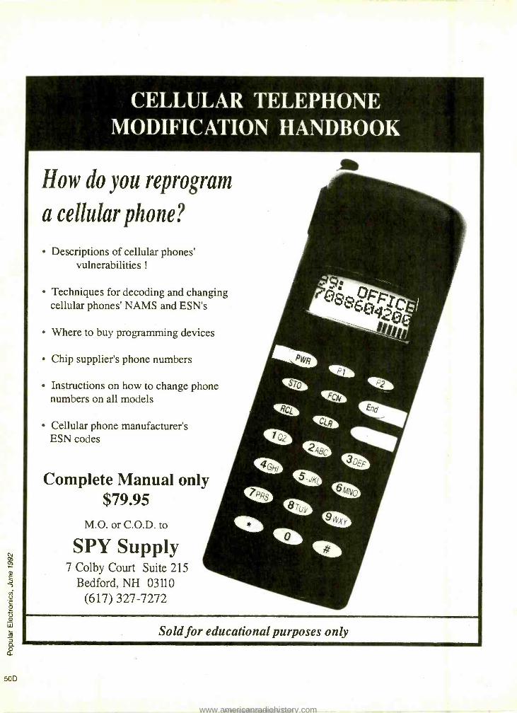
50D
CELLULAR TELEPHONE MODIFICATION HANDBOOK
How do you reprogram
a cellular phone?
Descriptions of cellular phones' vulnerabilities !
Techniques for decoding and changing cellular phones' NAMS and ESN's
Where to buy programming devices
Chip supplier's phone numbers
Instructions on how to change phone numbers on all models
Cellular phone manufacturer's ESN codes
Complete Manual only $79.95
M.O. or C.O.D. to
SPY Supply 7 Colby Court Suite 215
Bedford, NH 03110
(617) 327 -7272
Sold for educational purposes only
www.americanradiohistory.comAmericanRadioHistory.Com

Kelvin Meters backed by s 2 Yr Warrant - Parts A Labor
KELVIN DIGITAL MULTIMETERS
PRO 400 with 20MHz
Freq Counter
100 Basic 150 Basic+ 200 Advanced DC VOLTAGE DC VOLTAGE DC VOLTAGE FREQUENCY COUNTER AC VOLTAGE AC VOLTAGE AC VOLTAGE TO 20MHZ IDEAL FOR DC CURRENT DC CURRENT DC CURRENT TROUBLE SHOOTING RESISTANCE RESISTANCE AC CURRENT AC /DC VOLTAGE RANGES CONTINUITY - CONTINUITY - RESISTANCE AC /DC CURRENT RANGES Test- Buzzer Test-Buzzer CAPACITANCE 5 FREQUENCY RANGES DIODE TEST DIODE TEST CONTINUITY - 5 CAPACITANCE RANGES BATTERY TEST TRANSISTOR hFE Test- Buzzer LOGIC TEST
3h Digit LCD BATTERY TEST DIODE TEST CONTINUITY TESTER/BUZZER
LOW BATTERY 3h Dot LCD TRANSISTOR hFE DIODE CHECK ACCURACY - LOW BATTERY 316 Digit LCD TRANSISTOR hFE TEST .r -05 %RUG ACCURACY- LOW BATTERY LED TEST VERIFY GOOOEAD
IMPEDANCE -I Meg e - 0.5% RDG ACCURACY - DISPLAY -31,2 DIGIT LCD
KEVIN IMPEDANCE -I Meg . -05% RDG ACCURACY, 05%
100 Basic KELVIN IMPI_DANCE10Meg IMPEDANCE - la Mewe/lvr
'19." 150 Basic+ KE,. VIN KELVIN PRO 400 5 95 200 Advanced
$39.99 rotective ases For Models 100. 150. 200 54.95 Case For Model Pro 400 '9 ss
$69.95
Traine- Manual 1100 Pgsl gives detailed instructions. An excellent training tool covering topics for Hugh
School lOegnner Advancedl.
Trade School (Beginner Intermediate) & College.
FEATURES ONE DIGIT TRUE HEXADECIMAL DIS'LAY
WITH BUILT IN LOGIC (MEMORY. DECCDER, DRIVERS) FULL ALPHA CHARACTERS
TWO INDEPENDENT CLOCKS - USER ADJUSTABLE FREQUENCY 8 DUTY CYCLES
BREADBOARD:500 PT PROTO -TYPE ,aREA TWO POWER DISTRIBUTION BUSSES tONC. VCC)
4 DATA BIT SWITCHES MOMENTARY PUSH BUTTON SWITCH (EPDT) 4 LED DISPLAYS w IC DRIVERS POWER SUPPLY: WALL PLUG -IN TYPE U.L.
LISTED VOLTAGE REG:S VOLTS, SHORT CIR.
OVERLOAD PROTECT HOOK -UP WIRES COMPACT CARRYING CASE INSTRUCTION MANUAL FOR BEGINNER TO
ADVANCED USERS MADE WITH PRIDE IN THE USA
FREE COMPREHENSIVE TEACHER STUDENT LAB MANUAL
WALL TRANSFORMERS
WALL TRANSFORMER
STOCK NO. TYPE - Female
220069 9v DC/500 mA
220068 12V DC /500 mA
A PEFFECT FIT WITHIN ANY DIGITAL CURRICULUM
8 YOUR CLASSROOM TEXTBOOK
111E KELVIN L D T
Laptop Digital Trainer
ONE Y
$99 95 Stock No. 840460
BREADBOARDS
AUTHORIZED DEALER
FLUKE 87
FLUKE 70 Serles II
DISCOUNTED PRICES' BEST BUY NEW Series II
FLUKE 70 Series 9 $ 63
FLUKE 73 series II
FLUKE 75 series!!
FLUKE 77 Series N
FLUKE 79 Series II
FLUKE 83 FLUKE 85 FLUKE 87 True WS
FLUKE 86 AUTOMOTIVE
FLUKE 88 AUTOMOTIVE
$ 89 5127 $149
$169
$2119
$259 $289
$367 $423
FLUKE 45 $599
111.1..11 MI OM =I Y MD NO ISO - as
FLUKE 97 SCOPEMETER
NEW! SCOPEMETER °' SERIES
HAND HELD, 50 MHz, DUAL CHANNEL
FLUKE 93 $1035 FLUKE 95 $1395 FLUKE 97 FULLY LOADED _ 51695
SCOPES
LED CENTER SPECIAL SPECIAL
RED LED As Low As
Oty
JUMBO LED TYPE - T 1 34, 5mm
SPECIAL Soldering IRON with STAND, BLUE LONG LIFE TIP Stock No. 990098
$4.50 ea
260020 Red S.06ea /100+
260027 Green °.08ea/100+ 260026 Yellow .08 ea/100.
LED HOLDER for T 1 3/4 SIZE, BLACK Stock No. 250019
.10 ea! 100+ Oty
$ .06 ea / 1000+ Oty
. 1000. 01Y
s.05ea 5.07 ea $ A7 ea
0.37" 7 SEGMENT LED READOUT STOCK NO TYPE COST
260022 Anode 5.95 .. 260090 Cathode 51.25 w
0.6" 7 SEGMENT LED READOUT STOCK NO. Anode Jumbo 260021 COST $1.15.
20. Oty 99
MALE JACK STOCK NO. TYPE
370048 2.1 mm Male
5.49 ea s.39/10+
Stock No. TYPE YOUR COST
600021 555 TIMER $ .20 EA
600029 556 DUALTIMER $ .40 EA
600039 LM566 PLL $ .60 EA FUNCTION GENERATOR
600018 7410 OP -AMP . $ .30 EA INTERNALLY COMPENSATED
600026 1458 OP -AMP $ .35 EA DUAL MC OP -AMP DIP
630041 2N2222 5.18 EA
630383 PN2222 $ .08 EA
600023 7805 VOLTAGE REDS .36 EA
SILICON CONTROLLED RECTIFIER (Similar to GE C106C1) 4.0 AMP, 100 EN
600014 $ .89 EA $ .79 EÁ50+
680097 aO a0 O0
a1lLÜaiMa- YYatiiiWlWaa
680098 680100 Stock No. Pos Contacts ... YOUR COST
680093 0 500 $ 4.25
680097 0 840 s 5.95
580098 2 1380 $1175 580100 4 2390 $22 s WIRE JUMPER KIT Pre -cut, Pre -Stripped 330289 140 Piece Set ...$ 4.7' 330290 350 Piece Set ...$ 7.75
,wt . y' é A. J
20 MHz SCOPE $345 Dual Trace 2 Yr Warranty -Parts 8 Labor Stock No. 740085
SCOPE PROBES 60 MHz, X1 8 X10
SPECIAL 700072 ... $18.95 150 MHz, X10
700073 $39 95
575r 5.99 .a
RED LED DISPLAY
20 PIN Bar Graph Í STOCK NO. Color YOUR COST loe Qty
260058 Red $ 1.99 se 51.79 . 260088 Green $ 1.99 .. 51.79 ea
260089 Yellow 5 1.99 ea 51.79 .. MOVING SIGN DISPLAY for Fabricating Your Own Moving Sign DI.p aI
50 mm STOCK NO. 260001
$595..
P roject Speaker 2 ", 8 Ohm, .1 Wall Stock No. 350009
59 0 P ro e c t BUZZER ° 3 - 9 Volt DC, 80 db Stock No. 680089 '1.59 ea
$1.39 ea / t0+ Oty -5.y El H O R N ALARM
Loud Penetrating Sound Stock No. 640001 5.75 ea 9VDC $ .69 ea / 10+ Oty
DC MOTOR for SOLAR ROBOTIC Stock No. 852211 -
$.50 ea 1.5 to 6VDC
S .45 ea 120+ Oty
XENON STROBE Stock No. TUBE 260050 52.95 ea $2.50 ea / 20+ Oty
TRIGGER COIL for XenonStrobe Tube Stock No. 320037 $1.25 ea $ .89 ea / 20+ Oty
INFRARED LED IR Pair, LED infrared transmitter and receiver Stock No. 260061
$2.79 ea
NEON LAMP 062, Long Lands Stock No. 280003
.15 ea $.12 ealloc +Qty
PHOTO CELL CADMIUM SELENIDE Stock No. 260017
$ .99 ea
PHOTO CELL SULPHIDE Stock No. 260018
4.99 ea
PUSH -BUTTON SWITCH PUSH -ON, PUSH -OFF Stock No. 270021 5.55 ea $ .49 ea / 100+ Oty
$5.45 .. 20.
Duracell / Eveready 9V Alkaline Battery 51.95 ea
$1.75 ea/10+
9V Battery SNAP a HOLDER Snap 5.15 ea $.10 ea /100+
Holder '20 ea $ .10 ea /100+
KELVI .07,017 10 Hub Drive. Melville. N
IC CLIPS SOLDER TYPE SPRING LOADED Stock No. COLOR COST 25+ Oty 990104 BLACK s .65 ea 1.50 ea
990105 RED 5 .65 ea 5 .50 ea
IC TEST LEAD SET 5 COLOR CODED 18" LEADS WITH MINIATURE HOOK -ON
PROD AT BOTH ENOS Stock No. YOUR COST 990108 '8.95 ea
DOUBLE BANANA JACK
3+Oryy '8.25 ea
Stock No. YOUR COST 600056 52.30 ea
FEMALE BNC TO DUAL BANANA PLUG Stock No. YOUR COST 3+ Dry 990103 12.95 ea 52.75 ea
DUAL BANANA BINDING POST TO MALE BNC PLUG Stock No. YOUR COST 3+ Oty 600058 '5.95 ea 54.95 ea
BNC TEST CABLES 3 FT.
3+ Oty $2.07 ea
SUB- MINIATURE MOMENTARY SWITCH Stock No. 990002 5.35 ea $ .28 ea / 100+ Oty
MINIATURE TOGGLE SWITCH Stock No. 270034 5.90 ea Type - SPST
$ .79 ea / 50+ Oty
MALE TO MALE Stock No. YOUR COST 3+ OV 990101 '3.45 ea 52.95 ea
Established 1945 Electronics
11747
CIRCLE RESPONSE CARD o,
WRITE for our CATALOG lull of WHOLESALE PRICED ITEMS
OVER 10,000 ITEMS IN STOCK
ELECTRONIC COMPONENTS 8 TECHNOLOGY ACTIVITIES
i VISA 8 MASTERCARD ACCEPTED
$20 MINIMUM ORDER MINIMUM FREIGHT $5
Call: 1(800) 645 -9212
1(516) 756 -1750
Fax 1(516) 756 -1763
CIRCLE 143 ON FREE INFORMATION CARD
50E
www.americanradiohistory.comAmericanRadioHistory.Com

os
a
50F
1 -800- 344 -4465 -THE NUMBER THAT SAVES YOU MONEY!"
FIELD SERVICE KIT
The Legge Field Service Kit permits repair tecnicians to perform field repair on a staticfree surface. Complete with 2' x 2' work surface,
q wrist -band, 15 groundwith 1 -meg ohm resistor and cli .
Part No. 570 -0001 F 1q% $19 95 ea.
9600 BAUD FAX CARD Microtek MFAX96P Auto dial & receive Background Operatio Multi -page /Destination Polling. Operates any Microtek 300 dpi .
Scanner. Includes Fax Software. IBM PC,XT.AT Compatible Part No. 220 -3109 $99ea. TEMPEST LETTER QUALITY PRINTER 120/240VAC 49/63HZ RS 232C /MIL- STD -18 Serial Interface. Letter Quality Daisy Printwheel. Mfg. for Inteq by Qume FACTORY REFURBISHED 'Model LQP -5100B (AFP -7 -T). 55 CPS Print Speed .Wide Carriage
Part No. 220 -3702 $149ea. IBM PC /AT CASE Genuine IBM Case Full Size AT Case Accepts Mini or 1,1 Full Size Motherboards 0111lí °111Ní1 =I
Slide -off Top. 8 Slot Frame Made in U.S.A.
Part No. 220 -2759 $49ea. EXTERNAL DRIVE CASE Operates with PS /2 models 25, 30, 50, 60 and 80. Operates with Dos 3.3 on PS /2 models. Allows Data Exchange between PC /AT or PC /XT and PS /2. Powers On with Computer. Part No. 220 -2763F $2995ea. IBM PC /AT GUIDE TO OPERATIONS An ideal getting started guide for beginners. Complete with Exploring The IBM Personal Computer Software. Learn the basics: ..
keyboard commands, printer functions, disk storage, dos, basic programming and Funwriter a basic word processing package.
Includes IBM AT Diagnostics Disk. (IBM#6280102) Retail $9.95ea. Part No. 220 -0073
/ ! H S - - vís % VISA'
ALARM BOARD Great experimenting board. 24 lug and 6 lug terminal ` qr strips, 8 relays, 8 slide switches, over 30 ICs, 4 hh heatsinks, 2ft. four conductor telephone line cord and many other parts. $3 95 $2 95
Part No.100 -9990F (ea)
REGENCY TRAVEL SCANNER I
The INFORMANT. Great for the travelers, programed with frequencies for each state. Includes DC power cord and AC adapter included.
(10 +)
Part No. 660 -0018F $79 95
ROBOTIC EDUCATIONAL KIT A comprehensive introductory course on intelligent machines which encom- passes robotics,AI,computers and sensor systems.The course has five units of text,a sixth with experiments and,a final exam kit.
Part No. 370 -0006
Itl In; era imam
$9.95ea. 3 1/2" DISK DRIVE 360K Disk Drive MFG. By:Mitsumi Model No. M57BCL -1
Complete with mounting bracket and two S &K switches. Great for hobbyist and computer -3,/;\-f buffs. 34 pin data connection and 4 pin power connection. $9 95 $795
Part No. 220 -3415F (ea) (5 +)
PLASTIC PARTS BOX
.\ .
15 "x14 "x5" Great for under counter storage.
Part No. 580 -9998F
$5 00 $4.00 (ea) (10 +)
POWER CORD Very popular computer and monitor power cord. 18 -3 cord. 6' long.
Part No. 630 -0120F
$1 95 $1.65 (ea) (10 +)
3.5" SS DISKETTES
Complete with labels. Formatts to 720K.(DS /DD) Order in lots of 10.
Part No. 229 -7150F
39C 25° (10 +) (50 +)
Mendelson Electronics Co., Inc. 340 East First Street Dayton, Ohio 45402 800/422- 3525 513/461-3525 Fax 513/461 -3391
1- 800 -344 -4465 CIRCLE 149 ON FREE INFORMATION CARD
SOLDER TYPE D -SUBS
PINS 9
9
15
25 25 37 37 50 50
TYPE PART NO. Female 240 -1100F Male 240-1101F Male 240 -1093F Male 240-1311F Female 244 -1206F Male 240 -1096F Female 244 -7300F Female 244 -7064F Male 240 -1098F
1 -24
45e
450
65e
65e
650
85P,
85e
95e
950
25+ 30e 30e 45e 500 50e 65e 65e 75e 750
PLASTIC DB HOODS
Part No. 240- 1210F(9 PIN) Part No. 240- 1458F(15 PIN) Part No. 240- 1459F(25 PIN)
PLASTIC DB HOODS
'40 75c 55' (ea) (25+)
Part No. 240- 1091F(9 PIN) Part No. 240- 1092F(15 PIN)
75C 55o (ea) (25+)
14AWG HOOK -UP WIRE 2 Conductor(red & black) with PVC (black). Great for installations. 1-4 5+ Part No. 630-0661F(50') $8.95 $7.45 Part No. 630- 0662F(100') $15.95 $13.95 Part No. 630- 0663F(1000') $99.95 --
24AWG TELEPHONE WIRE 4 Conductor -. Outdoor approved. Part No. 630- 0761F(50') Part No. 630- 0762F(100') Part No. 630- 0763F(1000')
1 -9 $4.95 $6.95 $39.95
10+ $3.95 $5.95
DUAL RG -59U COAXIAL CABLE 78 %, 75 ohm, PVC. = -
Easily separated for single runs. 1 -9 10+ Part No. 630-0861F(50') $8.95 $6.95 Part No. 630- 0862F(100') $13.95 $10.95
7.5VDC, 100MA ADAPTOR
117VAC input, with 10ít. cord and 2.1mm DC coaxial plug. 7.5VDC, 100mA output.
Part No. 600 -6108F
LOOK FORAND SAVE!!
$2.45 $1 .95
(ea) (10 +)
STORE HOURS. 8:30- 5:00(Eastern Time) Monday MR, Saturday IBM PC /XT is a registered trademark of IBM Corp. TERMS. MASTERCARDNISANDISCOVER. CHECK, or MONEY ORDER (Checks allow Iwo weeks for clearance.) Ohio residents add 6.5% Slate la, shippnginandarg -UPS Chan Rate. $2.00(Mm.$3.90)(add 64.0011 ordering COD) Prices subject to charge mewl notice.
$20.00 Minimum Order Returns atlar 10 days sublecl to a 20% restocking fee (All returns most have RAS)
ACall or write for a free catalog.
www.americanradiohistory.comAmericanRadioHistory.Com

-AQE COMMUNICATIONS
Communications Radios SCANNER & SHORTWAVE
AOR AR1000XC $429.00 AM Broadcast to Microwave 1000 Channels 500KHz to 1300MHz coverage in a programmable hand held. Ten scan banks, ten search banks. Lockout on search and scan. AM plus narrow and broadcast FM. Priority, hold, delay and selectable search increments of 5 to 995KC. Permanent memory. 4 AA ni -cads and wall plus cig charger included along with belt clip case and. ant. & earphone. Size: 6 7/8 x 1 3/4 x 21/2. Wt. 12 oz.
AR2500 $499.00 2016 Channels 1MHz to 1300 MHz Computer Cotrol 62 Scan Banks, 16 Search Banks, 35 channels per second. Computer control for logging and spectrum display. AM, NFM, WFM, & BFO for CW/SSB. Priority bank, delay /hold and selectable search increments. Permanent memory. DC or AC with adaptors included. Size: 21/4 H x 5 5/8 W x 6 1/2D. Wt. 1 Ib. Mtng brkt & Ant incld.
AR3000 $1095.00 100KHz to 2036MHz 400 Channels Extreme coverage, excellent sensitivity, plus processor controlled band pass filtering and attenuation to elimmate interference. AM, NFM, Wide FM, LSB, USB, CW modes. RS232 control. Lockout in search. 4 priority channels. Delay & hold & Freescan modes. Size: 3 1/7 H x 5 2/5 W x77 /8 D. Wt. 2 lbs. 10 oz. Ant. & AC /DC pwr cords included.
Free Shipping and Handling 25 Day Satisfaction Guarantee Toll Free Service and Support
No Credit Card Surcharges Full Warranties
SCANNERS AOR AR900 $269.00 Lo, Hi, Air, UHF, 800 100 Channel Hand Held 5 Scan & 5 Search banks with permanent memory. Extremely compact. Unrestricted 800 coverage. Permanent memory, Delay, Hold, Priority. Supplied with Antennas, Charger, Ni -Cad Batts, Belt Clip.
Bearcat BC760 $269.95 Lo, Hi, Air, UHF, 800 100 Channel Mobile Five banks of 20 channels, weather scan, delay, priority, and search. AC /DC power cords, Ant., and mtng brkt included Bearcat BC200XLT $259.95 AOR AR950 $259.00 Bearcat BC55XLT $119.95 Bearcat BC560XLT $99.95 AOR AR880 $149.00 Bearcat BC210XLT $149.95 Bearcat BC7OXLT $129.95 Bearcat BC590XLT $199.95 Bearcat BC855XLT $199.95 Bearcat BC147XL $99.95 Bearcat BC172XL $139.95 Bearcat BC800XLT $2449.95
2 -WAY RH256 $319.00 REGENCY /RELM
!I
A.Vid
Keyboard programmable 16 channel 25watt transceiver with receive scan. Program CTCSS tone, range 148- 162MHz. Mic, mtng brkt, DC cord included. Size: 61/2 W x 101/2 D x 21/2 W Wt. 64 oz. RSP Prog. Hand Held VHF $419.00 HR3500 10 mtr Mobile $249.00 Ranger Marine Mobile $159.00 Ranger Marine Hand Held $179.00
SONY ICF2010 $349.00 The top selling shortwave receiver. Covers 150KHz to 30.0MHz with 76 to 108 FM and 116 to 136MHz Air. Keyboard programmable with 32 memories. Synchronous detection and selectable IF bandwidth. Size: 61/4 H x 113/8 D x 21/16 D Wt. 3 lbs 12 oz. Kenwood R5000 $879.00 Grundig SAT650 $849.00 Grundig SAT500 $499.00 Kenwood RZ1 $499.00 Sangean ATS803A $174.00
ACCESSORIES
Wide Band PT '
Preamp GW-2 $89.00 Impprove sensitivity of any receiver. -3 to +25db gain, adjustable. GaAsFET design, >1.5db NF, 100KHz to 1500MHz coverage. 9VDC power, battery included. Size: 3H x 17/8 W x 11 /8 D Wt. 50z. BNC cnctrs.
Interference Filter MPIF $59.00 Filters interference from TV, FM broadcast, Paging and Cellular. Size: 3 H x l 7/8 W x 11/8 D Wt. 5 oz. BNC cnctrs.
Wide Coverage Base Antenna DA300 $99.50 25- 1200MHz RX. TX or RX. 37" high. N adaptor with 50 ft. of cable to BNC adaptor.
Antennas, power adaptors, computer programs. Call for details.
WARRANTIES & SERVICE
Extended warranties available for many units Call toll free for details. Service available for many scanners and transceivers by ex- factory technicians. Call toll free for cost estimates.
To Order Call 1.800.445.7717 In All 50 States and Canada. 24 Hours a Day. Fax Orders: 1- 800 -448 -1084, 24 Hours a Day.
ACE Communications Monitor Division 10707 E. 106th Street, Fishers, IN 46038 Int'l Voice# 317 -842 -7115. Int'l Fax# 317 -849 -8794.
Service and Support Lines: Mon -Fri 9 a.m. to 9 p.m., Saturday 10 -4.EST MasterCard, Visa, American Express, Check, Approved P.O.'s & C.O.D. (add 5.00)
Price,specifications and availability subject to change.
.60 CIRCLE 45 ON FREE INFORMATION CARD
50G
www.americanradiohistory.comAmericanRadioHistory.Com

EASY ORDER
1- 800 -582 -4044
MOTOR I a Order # Price Description Pins MC1377P 2.65 Color TV RGB to PAL/NTSC Encoder 20 MC1408 -6 1.49 8 -Bit D/A Converter (DAC0806LCN) 16 MC1408.7 1.49 8 -Bit D/A Converter (DAC0807LCN) 16 MC1408 -8 1.49 8 -Bit D/A Converter (DAC0808LCN) 16 MC1496P .89 Balanced Mod. /Demodulator 14 MC1648P 3.95 MECL Voltage Controlled Oscillator 14 MC2672B4P 19.95 Programmable Video Timing Controller, 4MHz 40 MC2674B4P 19.95 Video Display Controller, 4MHz 40 MC3346P 1.45 General Purpose Transistor Array 14 MC3350P .75 Triple Independent Differential Amp 16 MC3470P 1.05 Floppy Disk Read Amp System 18 MC3479P 3.95 Biphase Stepper Motor Driver 16 MC3486P .99 Quad EIA- 422/423 Line Rec. with 3 -State Outputs 16 MC3487P .99 Quad EIA -422 Line Driver with 3 -State Outputs 16 MC4024P 2.75 Dual Voltage Control Multivibrator 14 MC4044P 2.75 Frequency Phase Detector 14 MC6875I 12.95 Two -Phase Clock Generator /Driver 16 MC10124P 1.45 Quad TTL to MECL Translator 16 MC10125P 1.45 Quad MECL to TTL Translator 16 MC14411P 7.95 Bit Rate Frequency Generator 24 MC14490P 4.25 Hex Contact Bounce Eliminator 16 MC14495P 3.95 BCD to 7- Segment Latch /Decoder /Driver 16 MC145026P 2.65 CMOS Remote Control Encoder
(Encodes 9 Bits and Sends Serially) 16 MC145027P 3.95 CMOS Remote Control Decoder 16 MC145028P 3.95 CMOS Remote Control Decoder (9 -Bit Address) 16 MC145151P 9.95 Parallel Input PLL Frequency Synthesizer 28 MC145406P 2.75 EIA- 232/V.28 CMOS Driver /Receiver 16 MC146818A 4.15 Real Time Clock Plus RAM 24 MC146818AFN 3.95 Real Time Clock Plus RAM PLCC 28 MC146818P 4.25 Real Time Clock Plus RAM 24 MC68000P12 11.95 16 -/32 -Bit MPU, 12MHz 64 MC68008P10 8.95 16 -Bit MPU with 8 -Bit Data Bus, 10MHz 48 MC68010P12 54.95 16 -/32 -Bit Virtual Memory MPU, 12MHz 64 MC6802ORC16E 139.95 32 -Bit Virtual Memory MPU, 16MHz PGA 114 MC6802ORC25E 189.95 32 -Bit Virtual Memory MPU, 25MHz PGA 114 MC6803ORC16B 229.95 Second Generation 32 -Bit Enhanced
Virtual Memory MPU, 16MHz PGA 128 MC68030RC25B 319.95 Second Generation 32 -Bit Enhanced
Virtual Memory MPU, 25MHz PGA 128 MC68230P10 8.95 Parallel Interface/Timer 48 MC68450L10 59.95 Direct Memory Access Controller 64 MC68488P 22.95 General Purpose Interface Adapter (1 MHz) 40 MC68661 PB 2.95 Enhanced Prog. Comm. Interface (SC2661 A or B) 28 MC68681 P 7.95 Dual Universal AsynchronousReceiver /Transmitter 40 MC68881 RC25B 114.95 HCMOS Floating -Point Coprocessor, 25MHz PGA 68 MC68882RC25A 149.95 HCMOS Enhanced Floating -Point
Coprocessor, 25MHz PGA 68 MC68701 16.75 8 -Bit MCU, 2048 Bytes EPROM, 128 Bytes RAM, /0....40 MC68705P3S 13.95 8 -Bit MCU, 1804 Bytes EPROM, 112 Bytes RAM, /0...28 MC68EC03ORP25B 99.95 32 -Bit Embedded Controller, 25MHz PGA 124 MC68HC000P12 17.95 Low Power HCMOS 16 -/32 -Bit MPU, 12MHz 64 MC68HC11A1P 18.95 8 -Bit HCMOS MCU with SPI, SCI, 8 -Bit ND
Cony., 512 Bytes EEPROM, 256 Bytes SRAM 48 MC68HC705C8P 19.95 8 -Bit MCU, 24 I/O Lines, SCI, SPI, 8K of
OTPROM, Internal Timer 40 MC68HC705C8S 29.95 8 -Bit MCU, 24 I/O Lines, SCI, SPI, 8K of EPROM,
Internal Timer 40
Order # Price Organization Pins 9346 2.75 1024 Bit Serial, 5V Read/Write 8 2816A35 3.45 2048x8 35ons, 5V Read/Write 24 2817A25 6.75 2048x8 250ns, 5V Read/Write (Pin 1- Ready/Busy) 28 2864A25 8.95 8192x8 250ns, 5V Read/Write (Pin 1 -N /C) 28 28C256 -25 26.95 32,768x8 250ns, 5V Read/Write CMOS 28
HARD - TO - FIND SOCKETS Order # Price Description Pins S28SMS 1.39 Machine Screw, .3" Wide (Skinny Dip) 28 S32LP .49 Low Profile, .6" Wide (Standard Size) 32 S48MS 1.55 Machine Screw, .6" Wide (Standard Size) 48
50H S64MS 1.95 Machine Screw, .9" Wide 64
EASY FAX
1- 800 -582 -1255
Order # Price Description Pins ADC0804LCN 2.95 8 -Bit ND Converter (1 LSB) 20 ADC0809CCN 3.75 8 -Bit A/D Converter with 8- Channel Multiplexer 28 ADC0817CCN 12.95 8 -Bit A/D Converter with 16- Channel Multiplexer 40 ADC0820CCN 8.95 8 -Bit High Speed A/D Cony. with Track/Hold Function 20 DAC0800LCN 1.95 8 -Bit D/A Converter (t1 LSB) 16 DAC0806LCN 1.49 8 -Bit D/A Converter (MC1408 -6) 16 DAC0807LCN 1.49 8 -Bit D/A Converter (MC1408 -7) 16 DA00808LCN 1.49 8 -Bit D/A Converter (MC1408 -8) 16 DAC0830LCN 4.95 8 -Bit Up D/A Converter (.05% Linear) 20 MB40576 3.55 6 -Bit Ultra -High Speed Video ND Converter 16 MB87020 34.95 16 -Bit CMOS ND or D/A Selectable Converter 40 TLC549IP 2.15 8 -Bit ND Converter (±0.5 LSB) 8 ZN427E8 14.95 8 -Bit Successive Approximation ND Converter 18 ZN428E8 7.95 8 -Bit Latched Input D/A Converter 16 ZN429E8 3.75 8 -Bit D/A Converter (±1/2 LSB) 14 ZN449E - 5.75 8 -Bit MPU Compatible ND Converter (1 LSB) 18
Order # Price Description Pins Z0803008PSD 9.50 Serial Communications Controller 8MHz 40 Z80A 1.25 CPU (MK3880 -4) (780C -1) 4MHz 40 Z80A -CTC 1.55 Counter Timer Circuit (MK3882 -4) 4MHz 28 Z80A -DART 3.95 Dual Asynchronous Receiver/Transmitter 4MHz 40 Z80A -P10 1.85 Parallel I/O Interface Controller (MK3881 -4) 4MHz ..40 Z80A -S10/0 3.95 Serial I/O (TxCB & RxCB Bonded) (MK3884 -4) 4MHz...40 Z80A -SI02 3.95 Serial I/O (Lacks SYNCB) (MK3887 -4) 4MHz 40 Z8OB 2.45 CPU (MK3880 -6) 6MHz 40 Z84C0008 5.95 CPU 8MHz (CMOS) 40 Z84C1008 10.95 DMA (Direct Memory Access) 8MHz (CMOS) 40 Z84C2008 5.95 PIO (Parallel I/O Interface Cont.) 8MHz (CMOS) 40 Z84C3008 5.95 CTC (Counter Timer Circuit) 8MHz (CMOS) 28 284C4008 8.95 SIO /0 8MHz (CMOS) 40 Z84C4108 8.95 SIO /1 8MHz (CMOS) 40 Z84C4208 8.95 SIO /2 8MHz (CMOS) 40 Z8530 4.55 Serial Communications Controller 40
MOTOROLA DATABOOKS* Order # DL138 7.95 Fact Data Weight: 1 lb. Over 400 pages on the 74AC /ACT serles. Order # HB205 8.95 MECL System Design Handbook Weight: 1 Ib. 234 pages about MECL operation. Order # M68HCO5AG 9.95 Mce9HCe5/HC7o5C8 Applications Guide Weight: 1 lb. 296 pages about microcontrollers with details about the MC68HC705C8. Order # M68HC11 RM 13.95 MC68HC11 Reference Manual Weight: 2 lbs. 484 pages on the MC68HC11 family. Order # M68000FR 12.95 MC68000 Family Reference Weight: 2 lbs. Over 700 pages covering the entire MC68000 family. Order # M68000PM 11.95 Programmer's Reference Manual Weight: 2 lbs. More than 500 pages of detailed information on each of the instructions used by the MPUs and coprocessors in the MC68000 family. Order # M68000UM 6.95 Microprocessors User's Manual ..Weight: .75 lbs. This 210 page manual provides hardware details and programming information for the MC68000, 68008, 68010 and 68HC000 microprocessors. Order # MC68020UM 7.95 MC68020 User's Manual Weight: 1.5 lbs. This 367 page user's manual describes the capabilities, operation and programming of the MC68020 MPU.
Order # MC68030UM 13.95 MC68030 User's Manual Weight: 2 lbs. This 590 page users manual describes the capabilities, operation and programming of the MC68030 MPU. Order # MC68EC03OUM 7.95 MC68EC030 Users Manual Weight: 2 lbs. This 472 page user's manual describes the capabilities, operation and programming of the MC68EC030.
Order # MC68881UM 13.95 MC68881/882 User's Manual Weight: 2 lbs. 395 pages on the MC68881/68882 Floating -Point Coprocessors.
ZILOG DATABOOKS* Order # Z29 9.95 Z80 CPU Technical Manual Weight: 1 lb. This 338 page manual contains everything you need to know about Zilog's Z80 CPU.
Order # Z2480 13.95 Intelligent Peripheral Controllers Weight: 2 lbs. More than 700 pages on Zilog's Intelligent Peripheral Controllers.
Order # 12503 13.95 Datacom ICs Weight: 2 lbs. Over 700 pages on Zilog's Data Communications ICs (Z8530, 8030, 80181, etc.).
Order # Z8275 16.95 Microcontrollers Weight: 3 lbs. Over 1300 pages of data sheets, appl. notes and tech. info. on Zilog's microcontrollers.
'Books are not returnable. We carry the newest versions available.
CIRCLE 31 ON FREE INFORMATION CARD
www.americanradiohistory.comAmericanRadioHistory.Com

'.Al -ikl t!-Tv; 7.K9.`I `4 Order #
Output Price Pwr. (W)
Input Pwr. (W)
Frequency Range (Mhz)
Gain db/Mhz *Package
MRF212 19.95 10 1.25 136-174 9/175 145A-09 MRF221 16.35 15 3.5 136-174 6.3/175 211-07 MRF224 17.75 40 14.3 136-174 4.5/175 211-07 MRF237 3.69 4 025 136-174 12/175 79-05 MRF238 15.95 30 3.7 136-174 9/175 145A-09 MRF239 16.95 30 3 136-174 10/175 145A-09 MRF240 17.49 40 5 136-174 9/175 145A-09 MRF240A 17.49 40 5 136-174 9/175 211-07 MRF247 24.75 75 15 136-174 7/175 316-01 MRF260 11.95 5 0.5 136-174 10/175 221A-04 MRF262 12.95 15 3.5 136-174 6.3/175 221A-04 MRF264 13.95 30 9.1 136-174 5.2/175 221A-04 MRF314A 35.95 30 3 30-200 10/150 145A-09 MRF315A 32.49 45 5.7 30-200 9/150 145A-09 MRF316 63.95 80 8 30-200 10/150 316-01 MRF317 64.95 100 12.5 30-200 9/150 316-01 M R F321 24.95 10 0.62 100-500 12/400 244-04 MRF327 63.95 80 14.9. 100-400 7.3/400 316-01 MRF340 9.95 8 0.4 30-200 13/136 221A-04 MRF450A 14.49 50 4 14-30 11/30 145A-09 MRF454 15.49 80 5 14-30 12/30 211-11 MRF455A 12.69 60 3 14-30 13/30 145A-09 MRF458 19.95 80 5 14-30 12/30 211-11 MRF515 2.95 0.75 0.12 400-512 8/470 79-04 MRF555 3.49 1.5 0.15 400-512 10/470 317D-02 MRF557 5.49 1.5 0.23 806-960 8/870 317D-02 MRF559 2.25 0.5 0.08 806-960 8/870 317-01 MRF607 2.49 1.75 0.12 136-174 11.5/175 79-04 MRF627 9.95 0.5 0.05 400-512 10/470 305A-01 MRF629 4.49 2 0.32 400-512 8/470 79-05 MRF630 3.95 3 0.33 400-512 9.5/470 79-05 MRF641 20.49 15 2.5 400-512 7.8/470 316-01 MRF644 23.95 25 5.9 400-512 6.2/470 316-01 MRF646 25.95 40 13.3 400-512 4.8/470 316-01 MRF648 30.95 60 22 400-512 4.4/470 316-01 MRF650 29.95 50 11.7 100-500 6.3/470 316-01 MRF652 11.49 5 0.5 400-512 10/512 244-04 MRF654 19.95 15 2.5 400-512 7.8/470 244-04 MRF660 13.95 7 2 400-512 5.4/470 221A-04 2N3553 2.95 2.5 - 136-174 10/175 79-04 2N3866 1.25 1 0.1 100-400 10/400 79-04 2N4427 1.25 1 0.1 136-174 10/175 79-04 2N5641 16.95 7 1 30-200 8.4/175 144B-05 2N5642 18.49 20 3 30-200 8.2/175 145A-09 2N5643 19.95 40 6.9 30-200 7.6/175 145A-09 2N5944 11.95 2 0.25 400-512 9/470 244-04 2N5945 11.95 4 0.64 400-512 8/470 244-04 2N5946 14.95 10 2.5 400-512 6/470 244-04 2N6080 9.89 4 0.25 136-174 12/175 145A-09 2N6081 11.95 15 3.5 136-174 6.3/175 145A-09 2N6082 14.95 25 6 136-174 6.2/175 145A-09 2N6083 14.95 30 8.1 136-174 5.7/175 145A-09 2N6084 14.95 40 14.3 136-174 4.5/175 145A-09
MOTOROLA RF SMALL SIGNAL TRANSISTORS
Order # Price Output Input Frequency
Range Gain
db /GHz Package 2.5/1 317 -01
12.5/1 317 -01 MRF901 MRF911
1.50 High Gain ....Small Signal....0.15- 1.5GHz 3.50 High Gain ....Small Signal 0.5 -5GHz
POPULAR 1.5 -30MHZ RF TRANSISTORS Output Power Input Gain db
Order # Price Watts (PEP /CW) Power Watts @ 30Mhz Package MRF401 13.49 25 1.25 13 145A -09 MRF406 14.99 20 1.25 12 211 -07 MRF421 29.95 100 10 10 211 -11
MRF422 35.95 150 15 10 211 -11
MRF426 19.49 25 0.16 22 211 -07 MRF427 16.95 25 0.4 18 211 -11 MRF428 59.95 150 7.5 13 211 -11 MRF429 44.95 150 7.5 13 211 -11
MRF433 12.49 12.5 0.125 20 211 -07 MRF448 72.95 250 15.7 12 211 -11
MRF464 24.95 80 2.53 15 211 -11
MRF466 34.95 40 1.25 15 211 -07 MRF475 9.95 12 1.2 10 221A -04 MRF476 3.95 3 0.1 15 221A -04 MRF477 13.75 40 1.25 15 221A -04 MRF479 14.95 15 0.95 12 221A -04 MRF485 19.95 15 1.5 10 221A -04
SIST0111111 25+ Description Order # 1-24 Case
MJE2955T .75 .69 PNP Power Transistor TO-220 MJE3055T .75 .69 NPN Power Transistor TO -220 MPF102 .45 .39 JFET (N Channel) RF, VHF, UHF, Amp TO-92 MPSA05 .25 .19 NPN Medium Power Amp and Switch TO -92 MPSA06 .19 .15 NPN Medium Power Amp and Switch TO -92 MPSA13 .25 .19 NPN Power Darlington TO-92 PN2222 .12 .10 NPN General Purpose TO -92 PN2907 .12 .10 PNP General Purpose TO -92 TIP29A .49 .39 NPN Power Transistor TO -220 TIP30A .49 .39 PNP Power Transistor TO -220 TIP31A .49 .39 NPN Power Transistor TO -220 TIP32A .49 .39 PNP Power Transistor TO -220 TIP41 A .55 .49 NPN Power Transistor TO -220 TIP42A .55 .49 PNP Power Transistor TO -220 TIP102 .65 .59 NPN Power Darlington TO -220 TIP120 .55 .45 NPN Power Darlington TO-220 TIP125 .55 .45 PNP Power Darlington TO -220 2N2219A .49 .39 NPN General Purpose TO -39 2N2222A .25 .23 NPN General Purpose TO -18 2N2907A .25 .23 PNP General Purpose TO -18 2N3055 .69 .65 NPN Power Transistor TO-3 2N3772 1.29 1.19 NPN Power Transistor TO-3 2N3903 .23 .19 NPN General Purpose TO -92 2N3904 .12 .10 NPN General Purpose TO -92 2N3906 .12 .10 PNP General Purpose TO -92 2N4123 .23 .19 NPN General Purpose TO -92 2N4401 .15 .13 NPN General Purpose TO -92 2N4403 .15 .13 PNP General Purpose TO -92 2N5087 .25 .22 PNP Low Level, High Gain, 50 -100mA TO-92 2N5089 .25 .22 NPN Low Level, High Gain, to 100mA TO -92 2N5951 .69 .59 JFET (N Channel) RF, VHF. UHF, Amp TO -92 á. Lá
IC Peak Ft Order # Price Polarity Vice (mA) (W) (MHz) Package BC328 .25 PNP 25 800 0.8 100 TO-92 BC547 .20 NPN 45 100 0.5 300 TO-92 BC549 .20 NPN 30 100 0.5 300 TO-92 BC549C .30 NPN 30 100 0.5 300 TO-92 BC557 .20 PNP 45 100 0.3 150 TO-92 BC558 .20 PNP 25 100 0.3 150 TO-92 BC639 .45 NPN 80 1000 1 130 TO-92 BC640 .45 PNP 80 1000 1 50 TO-92 BD139 .55 NPN 60 1000 8 250 TO-126 BD140 .55 PNP 80 1000 8 75 TO-126 BD681 1.05 NPN 100 4000 40 1 TO-126 BD682 1.05 PNP 100 4000 40 1 TO-126 BF199 .95 NPN 25 25 0.23 550 TO-92 BF469 .95 NPN 250 50 1.8 60 TO-126 BF470 .95 PNP 250 50 1.8 60 TO-126
2917 Bayview Drive
Fremont, CA 94538
Easy Order: 1- 800 -582 -4044 Easy Fax: 1- 800 -582 -1255
International Fax: 1- 510- 770 -2346 Customer Service: 1- 510 -770 -2345
Monday -Friday, lam - 5pm (PST) /10am -8pm (EST)
COD-No personal checks, US funds ($5.00 Surcharge)
USPS \' UPS \ Federal Express \ Airborne
Add approx. 5% of total for shipping UPS Ground ($3.00 m'.). Actual shipping charges based on weight.
Call or write today for your free copy of our 32 page catalog.
California res dents, add appropriate soles too. 12 month warranty on all lasyTech products.
30 day money back guarantee. We reserve the right to substitute manufacturers.
Prices subject to change without notice.
CIRCLE 31 ON FREE INFORMATION CARD
501
www.americanradiohistory.comAmericanRadioHistory.Com

50J
BIG PROFITS IN VIDEO REPAIR!
WORK FROM HOME -EARN $85 HR! -NO EXPERIENCE NECESSARY-
Only requirement: That you possess average mechanical ability and a desire to learn
With the tens of millions of VCRs and Camcorders in use, there currently is a serious shortage of trained techs to perform cleaning and repair jobs on these popular devices... Learn how you can start your own highly profitable, Home -Based video servicing business... And since up to 95% of all VCR and Camcorder malfunctions are due to a simple mechanical or electro- mechanical failure, you need not spend months or even years of complicated study before starting paid, professional service work! Let Viejo's Training Program show you
CALL TOLL -FREE
how!
1- 800 -537 -0589 24 HRS -7days a week or mail coupon today!
VIEJO PUBLICATIONS, INC. 4470 -107 Sunset Blvd., Suite 600
Los Angeles, CA 90027 -6304 Yes! Ruh me your FREE OPPORTUNITY KIT today!
(Check appropriate box) VCR Repair Camcorder Repair Advanced VCR Repair Fax Machine Repair
a Complete Training in Electronics Name Address
City /State Zip
Dept. UPMCJ
CIRCLE 44 ON FREE INFORMATION CARD
Tunable Notch Filters and Telephone Recording Equipment
Assembled and Tested Filters
as low as $16 each in quantities of 10 or more
Eliminates... Beeping and Buzzing Severe Interference
Micro Thinc. P.O. Box 63 -6025 Margate, Fl 33063 Brochure $1 (305)- 752 -9202
Kit Filters
as low as $8 each in quantities of 21 or mare
RADIONICS P:
1 SI?( Ir4
xc g ar d o , oCS o an gnebc there slit, diegnostie and preventive devices meal axpertmsntal). HMory, dooalptbns, plane dozens , systlebilities of Radionics Devices em wily to modem. Wldle drugs deal f Hundreds,
electricity costs pennies! $29.
/ .
CONSUMERTRONICS 2011 Crescent Dr, P.O. Drawer 537
Alamogordo, NM 80310 Add $4 SM NSA, Canada). All Mama M stock COD Add
cash only). VISA, MCard OK. New Cata- log is $2 with order, $4 without. In business since 1971. As seen on TV. John Williams . former Lockheed Senior Engineer, NMSU Computer Sol- ante Professor. Sold for educational purposes only,
HEAL THYSELF Some electronic and electromagnetic medical de- vices are now licensed by the FDA for therapies. Putts for three major device types that YOU can build end use yourself! Save S Thousendsl Plus de-
EM BRAINBLASTER Tutorial and lens for powerful ELECTROMAO- P NETIC WEAPONS & LAO DEVICES. Optimum circuits, hags.. waveforms, duty cycles and Intensi- ties. Comprehensive, MIND BOGGLING! $29. Al1 software supports all IBM -PC corn-
patible systems (8086 - 80486).
' Voice Line & Manuel Fax: BAM -9PM Mon- Sat, MST. Auto Fax: All other times.
(505) 434 -0234 FAX: (505)- 434 -0234 (orders only)
'
HIGH VOLTAGE DEVICES HV devices plans: Stun Gun, Tesar, Prod, Cana, Flasher, Blaster. Zapper, Audio /RF/ Radar Jammer, Jacob's Ladder, Plasma & Van de Graaft Gens., Fence Charger, Gel- gar Counter, Ozone Gen., Flsh Stunnsr, Plant Sllm., Klrllan, moral Shockingl f29.
Off- The -Shelf HARDWARE Van Eck System, Voice Disguiser, Shriek Module, Hearing Asslstor, EM Counter- measure, TENS, 8th. Sense Communise- for, Bumper Beeper, Radar Emitter, Sub- Ilm'nal Mixer, Hieronymus Machine, Neur- ophone - much morel Details in our Catalog.
HARD DRIVE MANUAL Covers et herd drive end controller Implementations (emphasis on PCs). How to select, Interlace, Initial- Ize, set up, use, maintain, troubleshoot end repair them. How to protect them from mistakes, sebo- lags, prying eyes and sticky fingers. How to recover damaged and lost files. How to prevent crashes to begin with. Includes software reviews. Loaded with Information advice IIs. 29.
SECRET & SURVIVAL RADIO Optimum survival and security radio equipment, methods, freq. allocations and voice /date scram - bling/encoding. Includes small receivers/transmit- tars, telemetry, antenna optimizations, remote monitoring & control, security, surveillance. and ut- lresonic, 8beroptic & Infrared commo. 70. ckcult plans, tables. $29.
VOICE DISGUISER Plans for neat devices to change voice pitches. EI- lective against snoops using voice analysers, for women, children & elderly living along, for anti -Intru- lion systems, for gags. Voice sounds natural. $19.
STEALTH TECHNOLOGY -o ce rasa , esc flat ng aso as error rates 10% -20%1 Every known error mode - method & ma- terial used to minimize radar reflections - tactic & strategy to fight unjust radar tickets (that coat you
detect in insurance and risk cancellation) . methods
to aired end .m s naffs - ful described! $29.
DISK SERVICE MANUAL
drives without special eso equipment .software - 3.S y/ drives 8, PC /XT /AT /388/488, Apple. Com- modore. Tandy, Atari, TI, HP, DEC, etc sys- tems. tems. All floppies need regular upkeep. $29. STOPPING POWER METERS
As reported on CBS 1e0 MINUTES': How cer- tain electrical loads (simply plugs Into an hour can slow down full loap - oath - hour meters - while using full loader Loads
describes be connected
meter to any outlets system. Also
describes mater tree, overload droo, etc. $19.
THE I.G. MANUAL Ext ern. magnetic ways (applied to the meter ltsef) to slow down and stop watthour meters while drew - log tun loads. $19.
KW -HR METERS How watlhout meters work, calibration. error modes (marry), ANSI Standards ate. Demand and Poly - Poly-
op meters Meters. Experimental results to slow and
DISK DRIVE TUTORIAL end practical facts on floppy drives, disks,
FOC,, formatting, software protection. Systems de- scribed above. Invaluable advice and tips on how to best select, Interface & use drives and disks. $19.
COMPUTER PHREAKING TROJA 'OR E , VIRUSE i WORMS, etc.
' and countermeasures. Includes disk with 3801( of hacker text files and utilities, and legendary FLUSHOTap protection system (Ed. Choice, PC Magazine). Dozens of computer crime and abuse methods and countermeasures. How systems are penetrated. BBS advise, pseoword defers, gins- eery - much morel Manuals a Disks. $39.
BEYOND VAN ECK PHREAKING Eavesdropping on VDT and TV video signals using an ordinary TVI Documented In security industry In. ereture. Range up to 1KM. Plane include both the CONSUMERTRONICS and the original TOP SECRET VAN ECK designs! $29.
LIBERATE GAS & WATER How gas and water meters can be ravened using commonly available household equipment. f19.
VORTEX GENERATOR Heat or cool with simple, amazing, 3 -port device. Uses no moving parts, electricity, fossil fuel. liquid, Ireon. Guaranteed scientifically sound! Plans. $14.
CRYPTANALYSIS TECHNIQUES Five powerful menu -driven crypto programs (in .COM and their .BAS sources) to analyze, decrypt 'secure' clphertexts. Worked -out examples. Rec- ommended In the prestigious COMPUTERS á SECURITY. Manual Disk' $29.
AUTOMATIC TELLER MACHINES ATM crimes, abuses, vulnerabilities and defeats exposed! 100. methods detailed, In- elude: Physical, Reg. E. cipher, PIN compromise, card counterfeiting, magnetic stripe, false front. TEMPEST, lapping, spooling. Inside job, super -
cod, vibration, pulser, high voltage, Van Eck - eth- ere. Case histories. law. countermeasures, detailed security checklist, labeled internal photos, figures. ATMs contain up to $250,000 In ceshl $350,000 ATM crime spree still unsoNedl $39.
CREDIT CARD SCAMS Cardholders, merchants and banks suffer f Billions in bases annually because of credit card fraud. De- scribes every known means of credit card fraud and scams. Protect yourself) $29.
CONS & SCAMS Cons & scams fleece Americans of $100. Billion per
growl á te emosd c odm prkienhdes nsivo
m e survival
a ssmaic
uto e l tm
high -tech. Details on hundreds and their many varla- lions. Protect yourself! $29.
SOFTWARE PROTECTION SYSTEM Unique system that highly discourages costly soft- ware piracy while not interfering with legit archival copies. No known way to defeat. No special equl mere required. Simple and automatic to install own
your distributed software. Can be used with any copy -prevention system. Manuel a Disk.' $59.
VOICE MAIL BOX HACKING 'ow roce 'a sox : systems are u and the specific ways they are hacked. Includes ASPEN, MESSAGE CENTER, BIX, EZ, SYDNEY, PHONE MAIL. AUDIX, etc. Abso- Arley required for all users and sysopsl $29
CELLULAR PHONE MANUAL ow ce u a phones are es , operat, and re-
phr
a ck r ammseed
,
Heow nd
cceolluulntare
rsymsteamsus ese .
vCuolnrnepele
e nto - sine descriptions on modifying NAMs & ESNs (in- d using specific info. on 30 popular models). scan. ping, scanner restorations (Includes UHF TV method), Iraq. & channel allocations, roaming. tracking, ECPA - morel $39.
SURVIVAL GUNS & AMMO The Ultimate Firearms Survival Manual! Describes optimum guns 6 ammo, convenions, el- !encore, explosive devices. Improvised weapons, End Times scenarios, retreats, etc.
PHONE COLOR BOXES As designed by Phone Phreaksl 15 phone color boxes described. Dozens of circuits, simulator pro- grams. Plus cell forwarding, conlarencing phreak history, 50 useful and legal phone circuit plans - morel $29.
ROCKET'S RED GLARE 'ow to eagn en u s n -grope ant amateur and survival rockets. Emphasis on the formulation, manufacture and Installation of propellants, motors, Igniters, etc. Includes list of commonly available materials, and the design of launch pads and test bed. and their electronics. $29.
ROBOFONE AUTODIALER Powerful, versatile, menu -driven Wergamae eutodieler lets you dial any number (up to 10K) or mix of local and long distance numbers in any order, over any length of time whether buey or answered (your choice) and log the times, commands and re- suits to monitor, printer and-or disk. Quick -dial dl- rectory of up to 600 numbers. BUSY radial options. Direct modem command á control. All Result Codes, including VOICE and RINGING. Optional shell to tor- mind program upon CONNECT. Exit to menu or DOS (for batching). Manual Disk* $29.
SPECIAL PROJECTS We design, build, repair, modify, maintain ender consult on any device, system, process, project (electrical, electronic, computerized. mechanical, optical, automotive). Invention proloyping. Conti- dentiality guaranteed. Describe and Include $25 lee (does not obligate you). We then provide you cost & time estimates.
CIRCLE 28 ON FREE INFORMATION CARD
www.americanradiohistory.comAmericanRadioHistory.Com

DONT GAMBLE when you want the best 21 Reasons To Buy OPTOELECTRONICS' MODEL 3000
1. RANGE- 10Hz to 3GHz. 2. Hi -Speed ASIC (Application Specific Integrated Circuit) State -Of -The -A
3. 256 Times Faster than other hand held counters. 4. 10 Digit LCD. Readability even in Bright Sunlight.
5. 6 Functions - Frequency, Period, Ratio, Time Interval, Average and Pre
6. RF Signal Strength Bargraph - 16 Segment, Zero & Full Scale Adjust. Excellent for locating Hidden Transmitters.
7. Four extremely Fast Gate Times .01, .1, 1, 10 sec.
8. Dual High Impedance Amplifiers. 9. Maximized Sensitivity
lo. Hold Switch - Locks in measurements FAST.
11. ± 1 PPM Accuracy 12. Direct Count - 1 Hz resolution to 220MHz 13. Sensitivity <1mv 10MHz - 200MHz, <5mv - 2GHz.
14. Single Shot Time Interval 100ns, .1 ns averaged. is. Push -button Input, Gate & Function selection.
1s. Extruded Aluminum Enclosure. 17. NiCad & Charger Included. la. Low Battery Indicator.
19. 1 Year Parts & Labor Warranty 2o. 30 day Money Back Guarantee. 21. OPTOELECTRONICS backs this with our 18 Years of
Dependability & Service.
All this and more for the Low Price - $375.
Also Available at Special Package Price: For A Limited Time Only
Model 3000, Backlight/Beeper, Carry Case & TA -100s Whip Antenna
All this for only $449.
OPTIONS: TCXO 30 ± ,2ppm TCXO $100. BLB30 Back light & two step audible signal level indicator .$ 75.
CC30 Carry Case $ 15.
TA100S Telescoping Whip Antenna $ 12.
A as
rt.
scale.
4.4"1"0".. AIP;10 111.0.11PIUMullika mow.
HANDI- COUNTER MODEL 3000 1011z -3GHz Universal Nandi- Counter
w 111111111111111
RARGIIAPN
INPUT
IVR FUNCTION
~VW% 1.1 IlmiPTAONk- I 0 `, & Factory Direct Order Line
1.800. 327.5912 (305)771 -2050 FAX(305) 2052 5821 NE 14th Ave. Ft. Lauderdale, FL 33334
5% Ship /Shandling (Max. $10) U.S. & Canada. 15% outside continental U.S. Visa & Master Card Accepted.
CIRCLE 145 ON FREE INFORMATICN CARD
YOU CANT LOSE!
www.americanradiohistory.comAmericanRadioHistory.Com

50L
CALL TOLL FREE
1- 800 -292 -7711
ELENCO PRODUCTS AT DISCOUNT PRICES
48 HOUR
SHIPPING
DIGITAL METERS True RMS 41/2
Digit Multimeter M -7000
$135 .05% DC Accuracy
.1% Resistance with Freq. Counter
and Deluxe Case
Multimeter with Capacitance &
Transistor Tester
$55 CM -1500B Reads Volts, Ohms
Current, Capacitors, Transistors and
Big 1' Display Diodes / with Case
Digital Capacitance Meter CM -1550B
$58.95 9 Ranges
.1 pf- 20,000ufd .5% basic accy.
Zero control w/ Case Big 1' Display
Digital LCR Meter LC -1801
$125 Measures:
Coils 1uH -200H Caps .1 pf -200uí
Res .01 -20M
Digital Multimeter $25 M -1000
.3 1/2 Dig
.7% Accuracy Reads;
AC /DC volts resistance, DC current
& Diodes
QUALITY AMERICAN MADE POWER SUPPLIES High Current Power Supply
0 s En
XP -800
$295 Digital
olt/Amp Meters Fully regulated, 0- 122VAC @ 2A, 0- 40VAC @ 10A or 0 -30VDC @ 10A. Fully variable, Short circuit protected.
Digital Triple Power Supply XP -765
$269 0 -20V @ IA 0 -20V @ 1A
5V @ 5A
Fully regulated, Short circuit protected with 2 limit control, 3 separate supplies
XP -660 with Analog Meters $195
Quad Power Supply XP -580
$59.95 2 -20V @ 2A 5V @ 3A 12V @1A -5V @.5A
Fully regulated and short circuit protected
GENERATORS & EDUCATIONA VIDEO PRODUCTS
Function Generator Blox
#9600
$28.95
Provides sine, triangle, square wave from 1 Hz to 1MHz
Kit $26.95 AM or FM capability
Color Convergence Generator
SG -250
$79.95 Kit $59.95
Finest in the industry 10 rock steady patterns
RF & Video output
Robotic Arm Kit
Model Y -01 $48.95 Teaches basics of robotics. Arm grabs & releases, lifts & lowers, 8 pivots from side to side
Triple Power Supply XP -620
Assembled $69
Kit $45 2to15V @1A,
-2ío -15V@ 1A
(or 4to30V @1A' and 5V @ 3A
All the desired features for doing experiments. Features short circuit protection, all supplies.
KITS - FUN & EASY TO BUILD
AM /FM Transistor Radio Kit
with Training Course Model AM /FM 108
$26.95 14 Transistors 5 Diodes
Easy to build because schematic is
printed right on the PCB Makes a great school project
Learn to Build and Program Computers with this kit
,....fr $129.00 v
Includes: All Parts, Assembly and
Lesson Manual
Model MM -8000
Starting from scratch you build a complete system. Our Micro- Master trainer teaches you to write into RAMs, ROMs and run a 8085 microprocessor, which uses similar machine language as IBM PC.
Wide Band Signal Generators
Ell SG-9000
$129 RF Freq 100K- 450MHz AM Modulation
of 1KHz Variable RF output SG -9500 w/ Digital Display &
150MHz built -In counter $249
GF -8016 Function Generator with Freq. Counter
$249 Sine, Square, Triangle
Pulse, Ramp, .2 to 2MHz Freq Counter .1 -10MHz
GF -8015 without Freq. Meter $179
Telephone Kit
Build this high -tech see -thru telephone. Learn theory on how telephones work and then proudly show off your work with
the transparent phone case. Complete with all parts and manual. Deluxe ver-
sion has flashing neon lamps when -phone rings.
(Deluxe) PT -223K $13.95
Built PT -223 $14.95
(Standard) PT -222K $12.95 Built PT -222 $13.95
XK -500 Digital I Analog Trainer A complete mini -lab for building, testing, prototyping analog and digital circuits Elenco's Digital / Analog Trainer is specially designed for school projects, with 5 built -in power supplies. Includes a function generator with continously variable, sine, triangular, square wave forms. All power supplies are regulated and protected against shorts. Power Supplies
Variable Power Supply +1.25 to 20VDC @ .5 Amp ( +1.25 to 15VDC @ 1 Amp) -1.25 to -20VDC @ .5 Amp ( -1.25 to -15VDC @ 1 Amp) +12VDC @ 1 Amp -12VDC @ 1 Amp +5VDC @ 1 Amp 30VAC Center tapped @ 15VAC @ 1 Amp
Analog - Section Function Generator Sine, Triangular, Square wave forms Frequency adjustable in five ranges from 1 to 100KHz Fine frequency adjust Amplitude adjust DC offset Modulation FM -AM
Digital Section Eight data swiches Two no bounce logic switches Eight LED readouts TTL buffered Clock frequency 1 to 100KHz Clock amplitude 5VPP square wave
Breadboards 2 breadboards, each contain: 840 tie points (total 1,680)
WE WILL NOT BE UNDERSOLD C &S SALES INC. UPS SHIPPING: 48 STATES 5 °0
1245 ROSEWOOD. DEERFIELD, IL 60015 IL RES 7.5% TAX ($3 min S10 max) OTHERS CALL FAX: 708-520-0085 (708) 541-0710
15 DAY MONEY BACK GUARANTEE 2 YEAR WARRANTY
WRITE FOR FREE CATALOG oRICES SUBJE -.Ct ro CHANGE
CIRCLE 46 ON FREE INFORMATION CARD
www.americanradiohistory.comAmericanRadioHistory.Com

s1 QßGNED PßP
ELENCO & HITACHI SCOPES AT
DISCOUNT PRICES
48h Sly '700 R
G
ELENCO OSCILLOSCOPES 25MHz and 40MHz Dual Trace, Dual Trigger 10 MS /S Sampling Rate (DS -203)
Vert Sensitivity from 1 mV /Div to 5V /Div
Sweep Rate from 10nS /Div to 15 /Div
Hold -off, X -Y Operation TV Sync Triggering 6" CRT with Internal Graticule Includes Probes
2 Year Warranty
S -1340 40MHz Dual Trace Oscilloscope
$495
2K word per channel Plotter output 8 bit vert resolution 2048 pts hor. resolution Much more
S -1325 25MHz Dual Trace Oscilloscope
$349
$795 DS -203 20MHz, 10MS /S Digital Storage Oscilloscope
-rrunrrrru,urar ---
All scopes include probes, schematics, operators manual and 3
year (2 years for Elenco scopes) world wide warranty on parts and labor. Many accessories available for all Hitachi scopes. Call or write for complete specifications on, these and many other fine scopes. lx, 10x scope probes: P -1 65MHz S19.95, P -2 100MHz $26.95
SPECIAL BUY HITACHI V -212
20MHz 2 Channel Includes probes $425
Hitachi Popular Series A favorite of field service personnel and educa- tion institutions around the world, these scopes have a reputation of quality and reliable perfor- mance. With dual channels, ± 3% accuracy and 1 mV /div sensitivity they have become the standard in portable analog oscilloscopes.
V -525 - 50MHz, Cursors $995 V -523 - 50MHz, Delayed Sweep $975 V -522 - 50MHz. DC Offset $875 V -422 - 40MHz, DC Offset $775 V -223 - 20MHz, Delayed Sweep $695 V -222 - 20MHz, DC Offset $625
Hitachi Compact Series Scopes This series provides many new functions such as CRT Readout, Cursor measurements (V- 1085/1065/665), Frequency Ctr (V- 1085), Sweeptime Autoranging, Delayed sweep and Tripper lock using a 6 -inch CRT. You don't feel the compactness in terms of performance and operation.
V -660 - 60MHz, Dual Trace $1,149 V -665 - 60MHz,DT, w /cursor $1,345 V -1060 - 100MHz, Dual Trace $1,395 V -1065 - 100MHz, DT, w /cursor $1,649 V -1085 - 100MHz, QT, w /cursor $1 995 V -1100A - 100MHz, Quad Trace $2,195 V -1150 - 150MHz, Quad Trace $2,695
Hitachi RSO Series (Portable Real -time Digital Storage Oscilloscopes)
RSO's from Hitachi feature roll mode, averag- ing, save memory, smoothing, interpolation, pretriggering, cursor measurements. These scopes enable more accurate, simplier obser- vation of complex waveforms, in addition to such functions as hardcopy via a plotter inter- face and waveform transfer via the RS -232C interface. Enjoy the comfort of analog and the power of digital.
VC-6023 - 20MHz, 20MS/s $1,695 VC-6024 - 50MHz, 20MS/s $1 995 VC-6025 - 50MHz, 20MS/s $2,195 VC-6045 - 100MHz, 40MS/s $2 995 VC-6145 - 100MHz, 100MS/s $4,495
C &S SALES INC. 1245 Rosewood Deerfield, IL 60015 708- 541 -0710 Fax: 708 -520 -0085
CALL TOLL FREE 15 Day Money Back Guarantee 2 Year Warranty P..ces So,t' C. arge
1-800-292-7711 WRITE FOR FREE CATALOG
CIRCLE 46 ON FREE INFORMATION CARD 50M
www.americanradiohistory.comAmericanRadioHistory.Com

r RS-232 BREAKOUT BOX WITH 24 SWITCHES AND 12 LINE MONITOR LEDS, THIS BREAKOUT BOX SIMPLIFIES CABLING TASKS.
TEN BI -POLAR LEDS MONITOR TF, RD, RTS, CTS, DSR, CD, TC, RC, DTR AND TC SIGNALS (2 SPARES)
24 SWITCHES FOR BREAKOUT AND PATCHING
INCLUDES JUMPER WIRES REQUIRES NO BATTERY
BRBOX -BO $34.95
RS-232 TESTER $14995 DISPLAYS ALL 25 LINES ON BOTH THE DTE AND DCE SIDE WITH TWO SETS OF LEDS. DIP SWITCHES ENABLE ALL 25 LINES, PLUS ALLOW SWITCHING LINES 2 AND 3.
100 LEDS DISPLAY ALL DTE AND DCE SIGNALS
29 DIP SWITCHES OPEN & CLOSE ALL CONNECTIONS & SWAP COMMON LINES SUCH AS PINS 2 -3
EASY LOOPBACK AND NULL MODEM TESTS
L.BRBOX -702 $149.95A
$24.95 J
J
$29.95 $29.95
A
DATARASE II EPROM ERASER CONVENIENT POCKET -SIZE!
ERASES ALL SIZES OF EPROM UP TO 4 AT A TIME WALL PLUG POWER SUPPLY
DATARASE II $39.95
PORTABLE IC TESTER EASY -TO- OPERATE AND COST EFFECTIVE UNIT. SUPPORTS THE FOLLOWING COMMON FAMILIES OF ICS: 74 SERIES TTL, 40 AND 45 SERIES CMOS AND 41/44 SERIES DRAM UP TO 1MB, AND RECOGNIZES 411000 DEVICES (1MBX1). CAN ALSO IDENITFY UNKNOWN PART NUMBERS.
MOD -HIC $129.95
PC INTERFACE DESIGN KIT JDR'S NEWEST ADDITION TO THE PROJECT DESIGN SERIES INCLUDES A SELF -POWERED SOLDERLESS BREADBOARD WITH INTERFACE FOR YOUR PC. A TUTORIAL PROVIDED TEACHES HOW TO MAKE YOUR PC INTERFACE WITH DIGITAL AND ANALOG DEVICES.
PDS1000 $399.9
THE JDR FRONTPANEL A BUS EXTENDER AND INSTRUCTION EXECUTION DETECTOR IN ONEI YOU SIMPLY SET THE ADDRESS AND OPERATION TO BE DE- TECTED ON THE SWITCHES AND WHEN THE PROCESSOR EXECUTES THE INSTRUCTION, AND AN INTERRUPT OCCURS.
NMI VIA IOCHECK LINE, OR IRO 2, 5, 7 CAN BE ASSERTED WHEN MATCH OCCURS ENABLE/DISABLE MATCH ON READ/WRITE, 10/MEM. DATA DMA, OR EXTERNAL EVENT
LFRONTPANEL $99.9
rPC PROTOTYPE CARDS
8-BIT SOLDERLESS 8088 BREADBOARD WITH DECODE
8 -BIT CARD GOLD -PLATED EDGE- CARD FINGERS BUFFERING 8 DECODE LAYOUT FR-4 EPDXY LAMINATE
JDR -PR2 $29.95 JDR -PR2 -PK OPTIONAL PARTS KIT $8.95 JDR -PR10 16 -BIT WITH VO DECODING LAYOUT $34.95 JDR- P010-PK OPTIONAL PARTS KIT $12.95 EXT -80286 286 -COMPATIBLE EXTENDER CARD $39.95 EXT -8088 8088- COMPATIBLE EXTENDER CARD $29.95
PC PROTOTYPING CARDS ADDRESS DECODING LOGIC. DATA BUFFERING, 2 LSI CIR-
CUITS FOR PROGRAMMABLE DIGITAL VO 8 COUNTER -TIMER FUNCTIONS
PDS-601 $79.95 PDS-600 ABOVE CARD WITHOUT DECODE $49.95 PDS-611 16 -BIT BUS BREADBOARD WITH DECODE $89.95
`PDS-610 ABOVE CARD WITHOUT DECODE $59.95)
50N
413 2233 SAMARITAN DRIVE, SAN JOSE CA 95124
Seu4ia9 ¡ Qcctce 1979
JDR Microdevices®
L- OW COST POWER SUPPUES 40 WATT POWER SUPPLY $1995
5V @4.8A, 12V@ 1.1A, -5V @ 0.12A
OPEN- FRAMED SWITCHING SUPPLY
100 -125 VAC @ 50/60 HERTZ INPUT
PS-TC24 $19.95
112 WATT POWER SUPPLY $2495 .5V @ 10A, +12V @ 3.5A, +12V @ 1.5A, -12 CO 200MA
5' X 8.5' X 1.97-
OPEN FRAMED POWER SUPPLY
PS- DPS -110AP
EPROMS PARTI SIZE
2716 -1 2048x8 2732A 4096x8 2764 8192x8 2764-250 8192x8 2764-200 8192x8 271288 -200 16384x8 27256 32768x8 27C256 32768x8 27512 65536x8 27C101.20 131072x8
SPEED
350ns 250ns 450ns 250ns 200ns 200ns 25Gns 2500$ 250ns 200ns
V. PINS PRICE
25V 24 4.95 21V 24 3.95
12.5V 28 3.95 12.5V 28 3.95 125V 28 4.49 12.5V 28 4.95 12.5V 28 4.95 12.5V 28 5.95 12.5V 28 5.95 12.5V 32 1295
STATIC RAM 1111111
PARTI SIZE SPEED PINSCMOS LP PRICE
HM6116-2 2048x8 120ns HM6116L17-4 2048x8 200ns HM6116LP3 2048x8 15008 HM6116LP-2 2048x8 12008 H8264LP-15 8192x8 1500s HM6264LP-12 8192x8 120ns HM6264LP-10 8192x8 100ns HM43256LP-15 32768x8 150ns HM43256LP-12 32768x8 120ns HM43256LP-10 32768x8 100115 28
24 24 24 24 28 28 28 28
Y Y
Y
Y Y
Y
Y Y
28 Y Y
N
Y Y
Y Y
Y Y Y Y Y
2.95 2.95 3.25 3.95 3.95 4.95 5.95 4.95 5.95 6.95
PALS goPo PARTI SPEED PINS IN OUT VOS FUNCTIONS PRICE 1818 16R4 1686 2018 20R4A 2088 2086 20X8
35ns 35ns 35ns 40ns 25ns 4005 40ns 50ns
20 10 2 6 AND -OR INV 2.95 20 8 4 4 AND -OR INV 2.95 20 8 6 2 AND -OR INV 295 24 14 2 6 AND -OR INV 2.95 24 12 4 2 AND -OR INV 3.49 24 12 6 2 AND -OR INV 2.95 24 12 8 - AND -OR INV 2.95 24 10 8 2 AND- OR -XOR INV 295
GALS Ileo PARTI SPEED PINS REPLACES IN OUT PRICE
L
16V8 161/8.15 20V8 20V8 -15 221/10 221/10.15
35ns 15ns 35ns 15ns 35ns 15ns
20 10L8 TO 16RP8 20 10L8 TO 16RP8 24 14L8 TO 16RP8 24 1418 TO 16RP8 24 PGM OUTPUTS 24 PGM OUTPUTS
8
8
20 20 22 22
8 8 8
10 10
2.49 2.95 3.49 4.65 6.95
19.95
CUSTOMER SERVICE 800-538-5001 TECHNICAL SUPPORT 800-538-5002 TOLL -FREE FAX ORDERS 800-559-5003
3.5 DIGIT DMM PROBE $4995 CUSTOM 80 PIN LSI CHIP FOR ACCURACY AND RELIABILITY IN A COMPACT SIZE. AUTORANGING, AUDIBLE CONTINUITY AND DATA HOLD FEATURES. CASE AND BATTERIES INCLUDED.
16 RANGES AUTORANGING BASIC DC ACCURACY: ±1.0%
MEASURES: DC VOLTAGE: .1MV -500V AC VOLTAGE: .1MV -500V RESISTANCE: .1G -2M0
INPUT IMPEDANCE: 10MO.
DPM- 1500 $49.95
3.5 DIGIT DMM MULTITESTER THIS FULL FUNCTION 3.5 DIGIT DMM OFFERS HIGHLY ACCU- RATE PERFORMANCE TO HELP YOU DO THE JOBI TEMPERA- TURE PROBE, TEST LEADS AND BATTERY INCLUDED.
34 RANGES BASIC DC ACCURACY: 30.25%
MEASURES: DC VOLTAGE: .IMV -1000V AC VOLTAGE: .IMV -750V RESISTANCE: .10 - 2M0 CAPACITANCE: .1 PF -20µF CONDUCTANCE: .INS - 20ONS TRANSISTOR HFE GAIN: 0 - 100 AC /DC CURRENT: .1µA - 10A
INPUT IMPEDANCE: 10M0
DMM -300 $79.95
POCKET -SIZE DMM CONVENIENT POCKET -SIZE DOESN'T COMPROMISE FEA- TURES OR ACCURACY. EASY TO READ 1/2' LCD DISPLAY. 200 -HOUR BATTERY LIFE WITH 9 -VOLT BATTERY. PROBES 8 BATTERY INCLUDED.
19 RANGES BASIC DC ACCURACY: ±0.5%
MEASURES: DC VOLTAGE: .IMV -1000V AC VOLTAGE: .1 MV -750V RESISTANCE: .10 -2M0 DC CURRENT:.1IA - 10A
DIODE TESTER INPUT IMPEDANCE: 10M0.
DMM -150
LDMM -200 3.5 DIGIT DMM 22 RANGES
rPULSER PROBES DETECT SIGNAL TRANSITIONS WITHIN YOUR CIRCUITS.
RED /GREEN LED INDICATES HIGH/LOW YELLOW LED INDICATES PULSE MINIMUM PULSE WIDTH: 3ONS
MAXIMUM INPUT FREQUENCEY: 17 MHZ'i
LOGIC 1: TTL 2.3V ± 0.2V CMOS 70% VCC LOGIC 0: TTL 0.8V 3 02V CMOS 30% VCC OVERLOAD PROTECTION: ±220V DC /AC
LP -100 6.1.....P-200 PULSER PROBE
1
$17.95 $19.95,
BUY WITH CONFIDENCE FROM JDR!
30 -DAY MONEY BACK GUARANTEE
1 YEAR WARRANTY
TOLL -FREE TECH SUPPORT MMC
BENCH TYPE DMM ;1991 EXTREMELY ACCURATE BENCH -TYPE MULTIMETER HAS A CONTINUITY ANNUNCIATOR THAT SOUNDS WHENEVER A SHORT IS DETECTED.
4 -1/2 DIGIT LCD DISPLAY
BASIC DC ACCURACY: ±0.05%
MEASURES: DC VOLTAGE: 100 - 1000V AC VOLTAGE: 100 - 750V RESISTANCE:. 010 -20M0.. AC/DC CURRENT: 10NA -10A
DIODE/CONTINUITY TESTER
DBM -500 $199.95
MULTIFUNCTION COUNTER PROVIDES FREQUENCY, PERIOD AND TOTALIZE MEASUREMENTS OVER A WIDE RANGE OF APPLICATIONS.
RANGE: 10HZ TO 10MHZ DIRECT, OMHZ TO 100MHZ PRESCALED BY 10 11102111111110 PERIOD MEASUREMENTS: 10HZ TO 2.5MHZ, WITH ACCURACY OF ±1 COUNT
DFC-100 $179.95
DFC -1000 1GHZ VERSION $199.95 DFG-600 SWEEP FUNCTION GENERATOR $189.95
35MHZ OSCILLOSCOPE EXCEPTIONALLY BRIGHT CRT TV SYNCH FILTER
DELAYED 8 SINGLE SWEEP MODES
FAST IONS RISE TIME
MODEL -3500 $499.95
MODEL -2000 25MHZ VERSION $389.95 L
LOCAL /INTERNATIONAL 408-559-1200 ORDER TOLL -FREE
800 - 538 -5000 LOCAL /INT'L FAX 408-559-0250 BBS (9600/2400/1200) 408-559-0253
MON. -FRI. 7 A.M. TO 5 P.M., SAT. 9 A.M. TO 3 P.M.
CIRCLE 36 ON FREE INFORMATION CARD
www.americanradiohistory.comAmericanRadioHistory.Com

16MHz MINI 286
$14995
NORTON 8114.0 LANDMARK AT SPEED 18.8 512MHZ KEYBOARD SELECTABLE SPEEDS EXPANDABLE
TO 4MB ON -BOARD USING BONS 256K OR 1MB SIMMS(0K INSTALLED) FIVE 16-BIT AND THREE 8-BIT SLOTS AMI BIOS SOCKETED FOR 80287 CO- PROCESSOR 85' X 8.75 SIZE FITS MINI -286 AND FULL-SIZE 288 CASES
MCT- M286-12 $129.95 MCT- M2861616MHZ VERSION $149.95 MCT -TURBO -10 10 MHZ 6068 $69.95
IDE FLOPPY /HARD CONTROLLER $2995 SUPPORTS 2 IDE HARD & 2 FLOPPY (360K, 720K, 1.2MB & 1.44MB) DRIVES
HARD DISK ACTIVITY LED SUPPORTED
MCT -IDEFH $29.95
1.44MB FLOPPY CONTROLLER $4996 SUPPORTS 2 FLOPPY ß60K. 720K, 1.2MB 8 1.44MB) DRIVES
SELECTABLE AS PRIMARY OR SECONDARY DRIVE CONTROLLER
MCT -FDC-HD $49.95 MCT- FDC -HD4 4 FLOPPY VERSION $59.95 MCT -HDC HARD DRIVE CONTROLLER $79.95 MCT -RLL RLL HARD DRIVE CONTROLLER $89.95 MCT -FAFH 16-BIT 1:1 FM CONTROLLER $99.95 MCI-AFH -RLL 16 -BIT F/H RLL CONTROLLER $149.95
MULTI I/O CARDS MCT- VGAEIO 1024X768 VGA, MULTI VO, IDE FM $249.95 MCT -IDEIO 18-BIT IDE MULTI I/O CARD $69.95 MCT -AIO 8 -BIT 286/386 MULTI VO CARD $49.95 AIO- SERIAL OPTIONAL 2ND SERIAL PORT $24.95
1024 x 768 VGA PACKAGE $46995
8088 6 286/388/488 COMPATIBLE CARD 8 1024 X 768 INTERLACED MONITOR
1:1 ASPECT RATIO
0.28 DOT PITCH
256 COLORS FROM 282,000
8/18 -BIT CARD HAS 512K VIDEO RAM EXPANDABLE TO 1MB
VGA -PKG -1024+ $469.95 VGA -PKG 640X 480 VGA PACKAGE $349.95
MORE MONITORS... NEC -3FGX NEC MULTISYNC 3FGX $749.00 VGA -MONITOR VGA MONITOR $299.95 MONO -VGA PAPERWHITE VGA MONITOR $149.95
JDR -AMBER 12 MONO -AMBER SCREEN $89.95
SOLDER STATION $5995 60 WATTS: THERMOSTATICALLY CONTROLLED HEAT FROM 200.900° F
°F AND °C GAUGE
SOLDER GUN, GUN -REST 8 COOLING TRAY
LEDS REPLACEABLE TIP
168.30 59.95
SOLDER /DESOLDER STATION
OIL -FREE VACUUM PUMP
REPLACEMENT PARTS AVAILABLE
ADJUSTABLE TEMPERATURE (200° -900° F) AND VACUUM (060CM/HG)
XY999SD $399.95
$39995
KESTER SOLDIER 80% TIN / 40% LEAD IN 1 LB. REELS.
SLDR-025 0.025" DIA. $9.95 SLDR -031 0.031' DIA $9.95 SLDR-060 0.050 DIA $9.95
CONDUCTIVE PEN MIPIBOIIMEMEIOI
LINK COMPONENTS, REPAIR DEFECTIVE TRACES, MAKE SMOOTH JUMPERS TRACES DRY IN MINUTES: CAN BE SOLDERED AT LOW TEMPS HOLDS APPROX. 100 FT.
PEN -2200 $9.95 PEN -3300 CONFORMAL COATING PEN $9.95
UNIVERSAL PROGRAMMER PROGRAMS EPROMS, EEPROMS,
PALS, GALS, BI-POLAR PROMS, 8748 AND 8751 SERIES DEVICES
TESTS T R. AND CMOS ICS, DYNAMIC AND STATIC RAM
TEXTOOL SOCKET ACCEPTS .3-
6' ICS FROM 8-40 PINS LOAD FILE, SAVE FILE, EDIT, BLANK CHECK, PROGRAM, AUTO, ROAD MASTER, VERIFY AND COMPARE COMPATIBLE WITH PAL SOFTWARE
MOD -MUP $499.95
ADAPTOR PROGRAMS 4 EPROMS AT ONCE
MOD- MUP -EA $99.95
HOST ADAPTOR CARD AND CABLE MOD -MAC (REQUIRED FOR OPERATION) $29.95
EPROM PROGRAMMER QUICKLY, EASILY PROGRAMS 24 TO 32 -PON EPROMS,
CMOS EPROMS, EEPROMS FROM 16K TO 1 MB HEX TO OBJ CONVERTER AUTO BLANK CHECK, PROGRAM AND VERIFY
MOD -MEP 1 -EPROM PROGRAMMER' $119.95 MOD -MEP-4 4 -EPROM PROGRAMMER' $169.95 MOD -MEP-8 8 -EPROM PROGRAMMER' $259.95 MOD -MAC HOST ADAPTOR CARD d CABLE $29.95 'NOTE : REQUIRES MOD -MAC HOST ADAPTOR CARD
PAL DEVELOPMENT SOFTWARE SUPPORTS 16L8, 16R4. 16R6, 16R8. 20L8, 20R4. 20R6, 20R8
AND 20X8 CUPL SIMULATOR TESTS FUNCTIONALITY OF DESIGNS PTOC (PALASM TO CUPL TRANSLATOR)
MOD -MPL -SOFT $99.95
UNIVERSAL PROGRAMMER
SUPPORTS DEVICES FROM ALTERA, AMD/MMI, AMI, ATMEL, CATALYST. CYPRESS, EXEL, FUJITSU, GOULD, HARRIS, HITACHI, HYUNDAI, ICT, INTEL, LATTICE, MATSU- SHITA, MICHROCHIP/GI, MITSUBISHI, MOTOROLA, NEC, NATIONAL SEMICONDUCTOR, OKI, RICOH, ROCKWELL, SAMSUNG. SEEG. SOS- THOMSON, SIGNETICS, TI. TOSHIBA, VLI, XICOR, XILINX AND ZILOG
MOD-EMUP $699.00 J
Sezvcuq you cucee 1 97 JDR Microdevices' ORDER TOLL -FREE 800 -538 -5000
r MOTHERBOARDS MODULAR CIRCUIT TECHNOLOGY
12MHz MINI 286
$12995
16MHz MINI 386-SX $24.0 005 NORTON S/ 15.3 LANDMARK AT SPEED 20.8
EXPANDABLE TO 8MB ON -BOARD AMI BIOS CHOOSE 0 OR 1 WAIT STATE FOR USE WITH SLOWER RAM FIVE 16-BIT AND THREE 8 -BIT SLOTS CHIPS 8 TECHNOLOGY 'NEAT" CHIPSET
SOCKET FOR 80387 CO- PROCESSOR 8.5" X13' SIZE FITS MINI -288 8 FULL-SIZE CASES
MCT -386SX 18 MHZ 388SX $249.95 MCT- 386SX -20 20 MHZ VERSION $299.95 MCT-M386-25 25 MHZ MINI 386 $399.95 MCT- C386 -33 MINI 33MHZ CACHE 386 $599.00 MCT- C386.40 40 MHZ CACHE 386 $699.00
CT- M486 -33 33 MHZ MINI 486 $995.00
SYSTEM DIAGNOSTICS CARD $4995
WORKS WHEN SOFTWARE CANNOT
286/386/486 COMPATIBLE
PLUG INTO SLOT, READ LED DISPLAY AND CHECK YOUR BIOS MANUAL FOR ERROR CODE
DUAL GAL CHIP DESIGN INSURES ULTRA -LOW CURRENT OPERATION AND LOW NOISE
VIEW LEDS ON -BOARD OR ON BACK -PANEL
PCODE $49.95 GATEKEEPER 8 -BIT PASSWORD SECURITY CARD $49.95
MEMORY CARDS SIMMPLY -RAM MEMORY EXPANSION CARD
MCT -E EMS 16-BIT EEMS CARD
MCT -EMS 8 -BIT EMS CARD 2MB CAPACITY
MCT -RAM 8 -BIT 578K RAM CARD DISPLAY CAROB
MCT -VGA -168/16 -BIT, 640 X 480 VGA CARD $49.95 MCT -VGA -1024+ 1024 X 768 IN 255 COLORS $149.95
LMCT -MGP MONOGRAPHICS/PRINTER CARD $49.95
$199.95 $149.95 $129.95 $49.95
HARD DRIVES Seagate 131MB $399
FORMAT FORM MODEL STORAGE AVG' PRICE
DE 3-1/2" ST-351A 42.0MB 28MS $209 DE 3-1/2" ST-3096A 89.1MB 18MS $319 DE 3-1/2" ST-3144A 131MB 16MS $399 DE 3-1/P" ST-1201A 177MB 15MS 5559 DE 5-1/4' ST-2383A 338MB 16MS $1159 DE 3-1/2" ST-1480A 426MB 14MS $1239
MFM 5-1/4" ST-225 21.4MB 65MS $199 MFM 5-1/4" ST-251.1 42.8MB 28MS $249 MFM 5-1/4" ST-4096 80.2MB 28MS $559
RLL 51/4" ST-238 32.7MB 65MS $219 RU. 5-1/4" ST-277-1 85.5MB 28MS $289
SCSI 5-1/4" ST-295N 84.9MB 28MS $389
B4/4 MOUNTINB KIT !DR MOST 8.1/1' DRIVES HDMHW $9.95
FLOPPY DRIVES FDD -1.44X I 44MB HD BLACK FACEPLATE $79.95 FDD -1.44A 1.44MB HD BEIGE FACEPLATE $79.95 FDD -360 5 -1/4- DOUBLE -SIDED DD 380K $69.95 FDD -1.2 5 -1 /4' DOUBLE -SIDED HD 12M $89.95 FD -55GFV TEAC 5 -1/4 DOUBLE -SIDED HD 12M $99.95 1 TERMS
LI.
._ JDR Mac rotlevices. SDR, the JDR logo and the MCT logo are registered trademarks of JOR MICRODEVIOES, INC Modular Omsk. Trrlemiogy is a Trademark of JDR MICRODEVICES INC Copyright 1992 JDR MICRODEVICES.
r 2400 BAUD MODEM $4995
2400/1200/300 BPS INTERNAL DATA MODEM FULL HAYES AT COMPATIBILITY INCLUDES PROCOMM SOFTWARE
MCT -241 $49.95 PCEM7296 INTEL 9600 BPS EXTERNAL $499.00 PCCB6201 INTEL SATISFAXTION FAX/MODEM $399.95 VIVA -24MNP 2400 BPS EXT MODEM W/MNP $149.95
BUY WITH CONFIDENCE FROM JDR!
30 -DAY MONEY BACK GUARANTEE
1 YEAR WARRANTY MMC TOLL -FREE TECH SUPPORT
CIRCLE 37 ON FREE INFORMATION CARD
500
www.americanradiohistory.comAmericanRadioHistory.Com

Toner Cartridge Recharge Kits -Supplies - Service
Everything you need to recharge toner cartridges used with Canon based laser printers and personal copiers. Use with HP: LaserJet, LaserJet II, IID, IIP, Ill, IIIP Apple: LaserWriter, LaserWriter IINT,IINTX, QMS: Kiss, PS -800, PS -810, Canon: LB- P8A1,A2,11, OKI, NEC, Ricoh, etc. With our Kits- Supplies -Service you can start your own profitable recharge business or just recharge your own cartridges.
Retail Model TR -300 TR -302 TR -304 TR -325 TR -370 4080 6000 9710 9730 8011 -Blue /Br 8057 Felt -CX,SX SS -CX,SX DPP EverDrumTM C2094
Recharge Kits /Supplies Dealers Please Call Recharge Kit for CX type laser printer engines. $21.95 Recharge Kit for SX type laser printer engines. $26.30 Recharge Kit for HP IIP (LPB -4) laser printer. $21.95 Recharge Kit for PC- 10/12/14/20/24/25 copier. $25.50 Recharge Kit for Sharp Z- 50/55/70 copier. $34.95 Replacement Toner Kit for Ricoh 4080 laser. $35.95ea/6 Replacement Toner Kit for Ricoh 6000 laser. $14.25ea/6 200 grms of high quality black toner for CX. $9.95ea/12 250 grms of high quality black toner for SX. $12.50ea/12 200 grms of Blue/Brown toner for CX & SX.$22.95ea /12 150 grms of high quality black toner for PC. $10.95ea/12 replacement treated felt for all models. $0.90ea/12 seal strips for sealing in toner for reshipping $0.85ea/12 Drum Padding Powder (pixie dust) $12.95 OPC drum life 'extender agent. 40+ applications $41.95 3M Toner Vacuum with attachments. $199.95
Instructions Available Free to Customers! Call 800 -221 -3516 ask for our catalog.
Chenesko Products, Inc. `s: 2221 Fifth Ave., S4, Ronkonkoma, NY 11779 PRO DUCTS Call: 516 -467 -3205, Fax: 516 -467 -3223
50P
Wind Generators Generator Rewinding Welder Plans Electric Scooters It's back! The LeJay manual originally published in the 1940's is now back in print with even more plans than before. This manual is now a complete collec- tion of LeJay's plans and general information on 6, 12, 24, 32 volt wind generators, generator re- winding and rebuilding, propeller building. battery powered spot welders, braising welders, solder- ing irons. fencers, scooters and bicycles, DC mo- tors, 110v welders, spot welders, generator wel- ders, insect exterminators, geiger counters, light plants, and much, much more! Written for the common person to understand, this manual is a
must to have for its educational value alone!!
To order send check or money order for $14.95 plus $2 shipping and handling
($4 shipping and handling outside USA and Canada) to: LJM Inc., P.O. Box 174, Dept. R, Lake City, MN 55041
PROFESSIONAL LOOKING ®EQUIPMENT REQUIRES
FINISHED HARDWARE HARDWARE KITS FOR CONSTRUCTORS: These hardware kits contain three sizes of electronic type hardware: in quantities of up to 50 pieces of each 2 -56, 4-40, and 8-32, with both pan head Phillips and flat head Phillips for a
professional look. The hardware kb are available in nickel or black nickel finish. The lengths available are 1/8', 1/4', 3/8', 1/2', 50, 3/4', and 1', with flat washers, nuts and KEPS nuts supplied In a mutt. compartment plastic box. There Is also a metric version available with ISO 2mm, 3mm, and 4mm with lengths of 2mm, 3mm, 6mro 8mm, 10mm, 12mm, 20mm, and 25mrrt, with flat washers, nuts and KEPS nuts.
GRAND ASSORTMENTS: GA -1 USA Standard 2 -56, 4-40, and 6.32 Nickel Rated $49.95 GA -2 USA Standard 2 -56, 4 -40, and 6-32 Back Nickel Plated $49.95 GA -3 ISO Standard 2mm, 3mm, and 4mm Nickel Plated $49.95 GA -4 ISO Standard 2mm, 3mm, and 4mm Black Nickel Plated $49.95 Twelve other assortments available and 100 lot replacements of all hardware. Write for cata/op.
5E5 sann
VISA
MINIATURE POWER TRANSFORMERS
Miniature printed circut type transformers for small projects requiring less than 1/3 of a watt of power. These transformers have dual primaries, 110/220 VAC, 50)60 Hz. Wiring details are included. A small foot print requiring a little more than one square inch of board space and abort one inch tall. Perfect for one or two op-amp circuits or small digital projects. Perfect for the all -in-one type projects.
1140 y 0438
4
t 0 500
0975' V-.- 1060
TWO ROWS ARE 500 APART. PINS ARE 200 FROM CENTER TO CENTER
PLACED IN THE CENTER OF THE UNIT
~ 0200 TYP
MODEL SECONDARY
VOLTAGE AC 9,14)
CURENT
SESCOM INC. 2100 WARD DPoVE
HENDEFSON, NV 99015.4249 U.SA.
800-634-3457(ORDERS) 702-565-3400
(FAX) 702. 565 -4926 PREPAID ORDERS
SHIPPED UPS GROUND NO CHARGE
2ND DAY AIR STO.00 NEXT DAY AIR $20.00
MPT5 MPT-12
MPT-24
MPT-D6
MPT-D9
MPT-012
MPT-015
5
12
24
6 -0-6
9 -0-9
12 -0-12
15 -0-15
14 10- 2412549 50-98
24 $10.00$8.33$7.34$6.90 10 10.50 8.42 7.71 7.25
5 10.75 8.95 7.89 7.42
10 10.50 8.42 7.71 7.25
6.7 10.75 8.95 7.89 7.42
5 10.75 8.95 7.89 7.42
4 11.00 9.16 8.07 7.59
MoMerCord WE ALSO ACCEPT VGA AND MASTERCARD. CALL FOR COMPLETE CATALOG AND ENGINEERING DIMENSIONS. WE ALSO STOCK PUNCHES AND INSTANT LETTERING.
ALUMINUM RACK AND CHASSIS BOXES
FEATURES: DESIGNED FOR SMALL LOT PRODUCTION EASY TO FABRICATE (DRILL OR PUNCH HOLES) SHIPPED UNASSEMBLED (FLAT) ALL MAIN PANELS ARE FLAT FRONT AND REAR ARE CLEAR BRUSHED ANODIZED, TOP AND BOTTOM PANELS ARE BLACK BRUSHED ANODIZED, END PANELS ARE BLACK ANODIZED
BLANK PANELS
OLIANITV
DISCOUNT
104910%
100ÚP 20%
MODEL DESCRIPTION PRICE
1 RPB 1.75 x 19 $9.95 2 RP 3.50x19 13.15 3 RP 5.25x19 17.35 4 RP 7.00x19 21.50
1 /8' Aluminum black anodized Dimensions shown in inches
CHASSIS BOXES MODEL W D H PRICE
MC-1A 4 3 2 $15.75 MC-2A 6 3 2 17.85 MC-3A 8 3 2 19.95 MC-4A 4 4 3 17.85 MC-5A 6 4 3 19.95 MC-6A 8 4 3 22.05 MC-7A 4 7 4 19.95 MC-8A 6 7 4 22.05 MC-9A 8 7 4 24.15
RACK BOX
RACK BOXES MODEL H D PRICE
1RU5 1.75 5 $29.40 1RU7 1.75 7 31.50
1RU10 1.75 10 33.60 2RU5 3.50 5 31.50 2RU7 3.50 7 33.60
2RU10 3.50 10 35.70 3RU5 5.25 5 39.90 3RU7 5 25 7 42.00
3RU10 5.25 10 44.10 imensions shown in inches. Dimensions shown in inches
W= Width, D= Depth, H= Height H= Height, D= Depth
CIRCLE 40 ON FREE INFORMATION CARD
www.americanradiohistory.comAmericanRadioHistory.Com

QUICKEN 5.0 For IBM and compatibles. Painlessly organizes fi- nances. Features include: easy installation, on- screen a tutorials, quick tour, mouse support, automatic setup, report insights, amor- tization calculations, spreadsheet. From Intuit.
$34.95 each
CAMBION WIRE WRAP TOOL #30 wire.
$1.95 ea. 111111111--- J113 FET
"N" channel JFET: analog switch, _"etc., with spec sheet.
12 for $9.95
18 "PC SCSI I/O CABLE
Not for Macintosh!
$3.99 each
Projection TV Lenses High quality light weight plastic lenses originally used in projection TV's.
Blowout Special - 3 for #19.95
ASTEC DC /DC CONVERTER +12 VDC in, -5 VDC out @ 200 mA. With spec sheets.
Two for $9.95
MXIMMISVO
17-
RED or
GREEN LAMP HLMP 2685 - Red
HLMP 2885 - Green 10 for $7.95
RCA SOLDERLESS
PLUG 10 for 996
LOW VOLTAGE OUTDOOR LIGHTING UNIT Model LV341T
24 -hour timer. Operates up to eight
eleven -Watt lamps. 12VAC output.
$24.95 each Model LV361T:
24 -hour timer. Operates up to six seven -Watt lamps. 12VAC output.
$17.95 each
RFM H9!``?
380 MHz OSCILLATOR
3 for $11.95
640 x 480 LCD DISPLAY 0.35 mm dot pitch. 174 x 23C mm viewing area. Full technical specifications.
$79.95 each
"DUKE'S DELIGHT" Five pounds of assorted electronic hardware: fasteners, nuts, bolts, screws brackets, springs, standoffs, arms, gears, pulleys and indescrib- able metal stuff from Silicon Valley's surplus to complement anyone's hardware hoard.
5 lbs. $4.95
STEPPER MOTOR
ASSORTMENT Ten for $16.95
3 mW HeNe LASER Power supply diagrams included.
$29.95
ROBOT KITTY This fun feline with an internal microprocessor control system is a mar- vel of state of the art technology, featuring DUAL DC DRIVE MO- TORS with GEAR RE- DUCTION and two -inch diameter RUBBER TREAD DRIVE WHEELS that provide excellent mobility and traction. Special integrated sound analysis and recognition circuitry allow you to command your Robot Kitty with simple hand claps. When your Robot Kitty hears your com- mands, it moves, meows and ipurrs, and its eyes light up! If you ignore it, it will "go to sleep" and then awaken at your command. Original retail price over $100.00!
$29.95
RESISTORS DALE GOLD BAR 120 W, 1%
10 0, 9.76 2.67 4, 3.32 4 or 1000(75 W) Your Choice
$12.95 ea.
51T1111 10 Q, 200 W - $6.00 5 52, 160 W - $6.00
0.3Q,140W-$4.00 5 Q, 100 W - $4.00
5 KQ, 225 W - $6.00
41.1111 25 Q, 55 W - $2.00 10 Q, 95 W - $4.00
Thousands of power resistors in stock! Fax your needs today!
SILICON VALLEY "GOLD" Over 50 pounds of printed circuit' boards from computers, monitors, modems, test, RF and mi- crowave equipment, all stuffed with goodies such as toroids, IC's, switches, sockets, connectors, oscillators, crystals, transistors, diodes, varactors, varistors, etc. A gold mine of useable parts.
50 Lbs. for $49.95
SWIVEL MAGNET 200 gauss neodymium magnet mounted on a
frame with ball bearing pivot.
6 for $9.95
BOOM MIKE Electret condenser type. This versatile micro- phone may be wired for Handy Talkie, telephone, base station, aircraft ra- dio, CB radio, motorcycle intercom, etc. A transistor radio type earphone may be installed in either or both muffs. The microphone unit can be easily removed and installed on another headset or helmet.
$4.95
MINIATURE SPEAKER This 1" speaker is an ideal companion for in- stallation in our boom mike featured above.
$1.49
Attention: Entrepreneurs! These mikes and speakers are easily assembled into a product that will retail for $20.00. The Boom Mike will work on nearly any radio: aircraft, ham, CB, etc. We are now offering a 100 -lot price on speakers and mikes for those who would as- semble and resell at hamfests, flea markets, etc. Call (408) 943 -9773 for details.
When in Reno visit
ASCII Electronics
020692
AL 2300 Za
VISA - MC - AMEX cards accepted, M
LTRONIC nker Road San Jose, CA
inimum order $12.00.California residents add 8.25% sales t
S 95131 ax. Freight additional on all orders.
Phone (408) 943 -9773 Fax (408) 943 -9776
Visit our Retail Store
M -F 9 -6 Sat. 10 -3
t/ CIRCLE 26 ON FREE INFORMATION CARD 50Q
www.americanradiohistory.comAmericanRadioHistory.Com

The Electronics Lab in a Computer!
CIRCI F 74N ON FRFF INFnRW1A7InN rann
Testing an analog three - stage amplifier with the simulated oscilloscope.
www.americanradiohistory.comAmericanRadioHistory.Com

.1111111.1111
Powerful software to build and simulate analog and digital circuits.
Building and testing circuits is fast and easy with Electronics Workbench. Just click- and -drag with a mouse to add parts, run wires, and adjust instruments. The traces on the simulated instruments are the same as
you'd get on real equipment.
Electronics Workbench really is an electronics lab in a computer. It's ideal for learning about electronics, experimenting, and prototy.:ping_::. circuits.
Includes: Analog Module with passive and active components including transistors, diodes, and op -amps; a function generator, an oscilloscope, a multimeter, and a Bode plotter.
Digital Module with gates, flip -flops, adders, a word generator, a multimeter, a logic analyzer, and a unique logic simplifier.
DOS Professional Version - $299 Macintosh Version - $199
(416) 361 -0333 Interactive Image Technologies Ltd. 908 Niagara Falls Boulevard, North Tonawanda, NY 14120 -2060 Fax (416) 368 -5799
Testing a gate implementation of three different ;/Yip flops.
"Electronics Workbench is pretty amazing." - Jerry Pournelle, Ph.D., Info World
"... Electronics Workbench is a marvelous learning and teaching tool for the study of electronics."
- Art Salsberg, Editor -in- Chief Modern Electronics Magazine
"Building a circuit is simple and intuitive." -Jeff Holtzman, Computer Editor, Radio - Electronics Magazine
"... if you're trying to learn electronics, you can do 10 times as many experiments with Electronics
Workbench ..." - ferry Pournelle, Ph.D., BYTE
INTERACTIVE
Electronics Workbench Professional Version runs on any IBM AT or PS /2 or true compatible with 640 kB RAM; Microsoft-compatible mouse; EGA/VGA graphics; hard disk; MS-DOS 3.0 or later.
Monochrome version also available. Macintosh Version (monochrome only) runs on Macintosh Plus or greater. All trademarks are the property of their respective owners.
Prices are in US dollars. Offer valid in the USA and Canada only.
CIRCLE 148 ON FREE INFORMATION CARD www.americanradiohistory.comAmericanRadioHistory.Com

ACCORD ELECTRONIC SYSTEMS 1001 NW 62nd Street, Suite 306 -F
Fort Lauderdale, FL 33309 Ph: (305)772 -2242 Fax: (305)772 -2568 MIN ORDER $25.00 / ADD $3.50 FOR S/H / FL RES ADD 6% TAX / COD OK
ECG123A (2N 2222A ) $0.21ea/ 10pcs
$0.19ea / 50+
PN2222A PN2907A / 2N3904
no 70 ea / 50pcs 2N3906
60 ea / 100+ 2N4401 no mixing 2N4403
ELECTROLYTIC CAPS 9C each 25pcs min
mixing
1 uF /50V 33uF/16V 2.2uF/50V 47uF/25V 4.7uF /50V 100uF/25V 22uF/35V 220uF/16V
3mm or 5mm RED LED $0.09ea / lopes $0.07ea;100+
YELLOW or GREEN $o.loea /lopes
no mixing $O.O8ea/ 100+
7805 - 7812 $o.35ea /5pcs 7824 $0.28ea / 100+
TANTALUM CAPS
15pes min no mixing
1 uF /35V 2.2uF/35V
MONO CAPS 50 each 25pcs min no mixing
0.01 uF /50V 0.1 uF /50V
. LM317T / $0.55ea / 5pcs , $0.48ea / 50+
DIP BRIDGE 50V/1 A
$0.40ea / 5pcs $0.27ea/50+ ICs
lopes min No Mixing LM311 $0.20 LM324 $0.35 LM358 $0.35 LM555 $0.25 LM556 $0.35 LM741 $0.25
1 11
1
CD4001 $0.25 CD4011 $0.25 CD4013 $0.25 CD4017 $0.25 cD4066 $0.25 CD4069 $0.25
MINI
SPDT on on DPDT
TOGGLE ja 100+
CERAMIC DISC CAPS 80 each 25pcs min no mixing
20pF /50V 100pF/50V 27pF /50V 1000pF /50V 62pF/50V 10KpF /50V
5 ç 400V/25A BRIDGE \ \O d $2.60 each
$2.20ea / 10+
$0.85 $0.70 $0.95 $0.80
DIP SWITCH r., 8 POS - SLIDE
I I $0.95ea / 5pcs I I $0.80ea/ 100+
BLINKING LED Ti 3/4 RED
$0.75ea /5pcs $0.7oea /too+
DIODES
lit 140 500+ 24 PIN
MACHINE vt .._.- ` 100+
$0.3oea / topes $0.20a / 100+
4700uF /40V FILTER CAP
$1.25ea (2pcs min)
5$ PUSH -BUTTON MINI - N.O.
$0.30ea / topes 1/4" panel hole $0.25ea / 100+
KESTER SOLDER SN6O /40 .031 DIA
$7.50ea 1 Lb ROLL
1N4148 0.05 0.03 0.02
1N4001 0.05 0.04 0.03
1N4004 0.07 0.06 0.05
1 N4007 0.09 0.08 0.07
CIRCLE 147 ON FREE INFORMATION CARD
CABLE TV DESCRAMBLERS!
CABLE KINGDOM!
*JEROLD* *OAK* *HAMLIN* *ZENITH* *PIONEER* *SCIENTIFIC ATLANTA *
IN STOCK
6 MONTH WARRANTY! WE SHIP COD!
ABSOLUTELY LOWEST WHOLESALE /RETAIL PRICES!
FREE CATALOG
J.P. VIDEO 1470 OLD COUNTRY RD., SUITE 315
PLAINVIEW, NY 11803 NO N.Y. SALES
50T CALL NOW! 1(800) 950 -9145 CIRCLE 146 ON FREE INFORMATION CARD
Enter A World Of Excitement with a Subscription to
Popular Electroiiics Get the latest electronic technology and information monthly!
Now you can subscribe to the magazine that plugs you into the exciting world of elec- tronics. With every issue of Popular Electronics you'll find a wide variety of electronics projects you can build and enjoy.
Popular Electronics brings you informative new product and literature listings, feature articles on test equipment and tools -all designed to keep you tuned in to the latest developments in electronics. So if you love to build fas-
cinating electronics, just call toll free the number below to
subscribe to Popular Electronics ... It's a power -house of
fun for the electronics enthusiast.
HOW RADIO GOT ITS VOICE
Popular Electrönies A Eeyiae
uÿeuoMM's maMeWa,e nt o A:nw In an nanny cee:e0
Dom Your Meter lie To lout Even the best meter ten texn
v wFayw waM1 mensunng
Build a Pre<ìsiuu Oual- ó:2!m Po e as"vY °n,'e The Light-Beam Communicator
vsWm:lalü yIgmt with
aae- . ntT.ne Ham aed Antique
: swum...
1 yr $18.95 2 yrs $36.95
FOR FAST SERVICE CALL TODAY
1- 800 -827 -0383 (7:30 AM -8 30 PM EASTERN STANDARD TIME)
APPF2
www.americanradiohistory.comAmericanRadioHistory.Com

4eetron c ProGold 100
GOLD CONDITIONER & PRESERVATIVE
Precision Metered Spray
DustArl Dts
Protects Gold Surfaces and Base Metals!
Improves Conductivity!
Reduces Intermittent Connection Failures!
Forms Protective Coating!
Reduces Wear & Abrasion!
Reduces Arcing and RFI!
ProGold 100 is a non -abra- sive /non -corrosive formula that conditions gold connectors, contacts and other precious metal surfaces, enhancing the conductivity characteristics to
efficiently transmit electrical signals.
ProGold 100 seals the entire contact surface and connec- tion, providing long-lasting pro- tection from abrasion, wearand atmospheric contamination. Non -flammable, non -toxic, non -corrosive, ozone -safe.
A DeoxlT
DeoxlT (Red) is a fast -acting de- oxidizing solution that cleans, pre- serves, lubricates and improves conductivity on all metal surfaces. Non -flammable, non - toxic, non- corrosive, ozone -safe.
A PreservlT
PreservlT (Blue) seals the metal surface and provides superior lu- bricating and preserving qualities for long- lasting protection from oxi- dation and contamination. For use on clean surfaces or ones pre - cleaned with DeoxlT. Non -flam- mable, non -toxic, non -corrosive, non -gumming, ozone -safe.
DeoxIPM and Preserv?ru contain active ingredients that do not rely on solvents (freon, alcohol, etc.) for performance. Both have excellent migration properties that coat the metal surfaces and protect them from future oxidation and contamination. On moving connectors /contacts, they re -coat the moving metal surfaces, providing continued protection and reduced wear & abrasion. Use on similar and dissimilar metals, stationary and moving connections /contacts. Reduces Intermittent Connection Failures, Reduces Arcing and RFI, Reduces Wear & Abrasion.
A DustALL Dt3 quickly and safely X -10 Instrument Oil - removes dust, lint and particles from Lubricates precision instruments, sensitive electronic equipment, corn- fine parts and mechanisms. Use puters, lab equipment, optical grade on all metals, i.e. gauges, gears, surfaces and other mechanisms and clocks, instruments, etc. Non - equipment. gumming, rust inhibiting, long last-
ing lubrication. Temperature range -65 °F to +250°F.
X -10S Instrument Oil - Contains silicone. Finest quality instrument oil for use on rubber, plastics and metals. Non -gum- ming, rust inhibiting, long lasting lubrication. Temperature range -
76bF to +450'F.
FreezALL Fz7 quickly and safely cools circuits to -54 °C. Lo- cates intermittent components (ca- pacitors, resistors, transistors, etc.) due to heat failure, hairline cracks on printed circuit boards and provides low temperature testing of electronic circuits.
A DegreasALL 27 Liquid and Spray - For sensitive equipment applications. For re- moval of oil, grease and ditt from surfaces. Harmless to metal, plastic or elastomeric parts. No residue, non -flammable.
DefluxALL 28 Liquid -
Degreaser and cleaning liquid removes organic contaminants including rosin flux from PCBs, components and metal parts. Use with ultrasonics and vapor degreasers. No residue, non- flammable.
CaiLube Pastes- Lubricat- ing & Protecting Greases for me- chanical & electrical applications
Accessories- Lint -free Cloth, Swabs, Paper, Cleaning Brushes, Extension Tubes, etc.
AG Flux & Solder- Silver solder and Flux for precice and difficult to solder applications.
Solder Pots, Hot Plates, Dip Coat-
ing & Wire Stripping Pots, Solder-
ability Testers, Controls, etc.
Caig Products ... used by those who demand the best!
Ampex General Electric IBM RCA
Boeing Grumman Aerospace John Fluke Mfg. Switchcraft
Capitol Records Hewlett Packard McIntosh Labs Texas Instruments
Dolby Laboratories Honeywell Motorola ... and Many More
CAIGi LABORATORIES, INC. "Environmentally Conscious"
16744 West Bernardo Drive Rancho Bernardo, CA 92127 -1904 Phone: (619) 451 -1799, FAX: (619) 451 -2799
CIRCLE 27 ON FREE INFORMATION CARD
www.americanradiohistory.comAmericanRadioHistory.Com

50V
Be an FCC LICENSED ELECTRONIC TECHNICIAN!
o-L
o0 ° Earn up to $30 an hour and more!
\
Learn at home in spare time. f I No previous experience needed!
No costly school. No commuting to class. The Original Home -Study course prepares you for the "FCC Commercial Radio- telephone License." This valuable license is your professional "ticket" to thousands of exciting jobs in Communications, Radio - TV, Microwave, Maritime, Radar, Avionics and more...even start your own business! You don't need a college degree to qualify, but you do need an FCC License. No Need to Quit Your Job or Go To School This proven course is easy, fast and low cost! GUARANTEED PASS You get your FCC License or money refunded. Send for FREE facts now. MAIL COUPON TODAY! r
1 COMMAMD PRODUCTIONS FCC LICENSE TRAINING, Dept. 240 P.O. Box 2824, San Francisco, CA 94126 Please rush FREE details immediately!
NAME
ADDRESS
CITY STATE ZIP
P -C -B ARTWORK MADE EASY I
Create and Revise PCB Art in a Flash
* For IBM's & COMPATIBLES * HERC, CGA, EGA, VGA, SUPER -VGA * AUTO GROUND PLANES * DOT- MATRIX, LASER and PLOTTER ART *GERBER and EXCELLON OUTPUT * CREATE YOUR OWN FILMS with 1XART * LIBRARIES * HELP SCREENS * MENUS * DOWNLOAD DEMOS from 24 hr. BBS!
PCBoards - layout program 99.00 PCBoards HP or HI PEN PLOTTER DRIVER 49.00
PCBoards GERBER & EXCELLON Disk 49.00
PCRoute - autorouter 99.00 SuperCAD - schematic ...starts at 99.00 Demo Pkg. - ( demos of all 3 programs) 10.00
Call or write for more information
PCBoards 2110 14th Ave. South, Birmingham, AL 35205
1(800)473 -PCBS/ (205)933 -1122
-1 BBS/ FAX (205)933 -2954
iiiiiiiiiiiiiiiiiiiii VIDEOPHONES! Visualize your Telephone Communications with
Phonvu Videophone Systems
Shown as an integrated system. Camera and monitor sold separately.
Bends still Black and White video Images over the phone line In 12 seconds.
Phonvu is a visual telephone communication system that enhances your telecommunication capabilities. Phonvu
provides extraordinary value, performance and compactness.
Captures any TV Camera, Camcorder VCR, NTSC Video output
Displays through video input of any N / VCR
Resolution of 200x242.5 pixels.
Grey scale of 50 levels
Total screen resolution 50.000 pixels.
Retail: '269.95 each (PAL Systems add S 10.001
Phonvu chip and system kit available
Subminiature CCD camera '199.95
For Orders & Information Please Contact: PMC ELECTRONICS
TEL: (310) 822 -5050 FAX: (310) 827 -1852 P.O. Box 11148 Marina Del Rey, CA 90292
www.americanradiohistory.comAmericanRadioHistory.Com

13406 Saticoy Street North Hollywood, CA 91605 -3475
(Call for free catalog)
ii
AN /USM 44C Signal Generator: General purpose, solid state, high frequency generator which pro- vides radio frequency (rf) signals used to test, evaluate and align radio receivers, rf equipment and amplifier. Direct replace- ment for HP 608 series. Frequency: 10 MHz to 480 MHz -2,0.5% in 6 bands. Modulation: Internal AM: 400 and 1000 Hz +10 %, 0 to 95% with 0.5 volt RF output. External AM: 0 to 95%, 0.5 volt output, 1.0volt RMS input @ 20 to 200 KHz. Pulse Modulation: 40 to 200
Price: $200.00
I
-
1
TS- 723A/U Spectrum Analyzer: Frequency range 20 Hz to 20 KHz. Fundamental frequency rejection, -80 dB. In- herent distortion <0.1 %, sensitivity 0.3% full -scale. Useable to 0.1 %. Input impedance 200K ohms 40 pf. Meter frame 0.3 to 300 volts fullscale. V1VM fre- quency range 10 Hz to 100 kHz + 3% flatness. VTVM input impedance 1M ohm, 3M ohm, 2.4M ohm, 37 pis dependent on range selected. Noise measurement -full scale 300 microvolts, mini mum-75 dBm, frequency -10 Hz to 20 KHz. Power Supply-115V/230V, 50 to 100 Hz, 90 watts.
Price: $100.00
I.R. TANK
PERISCOPE
Type M -24. Rugged military construc- tion. Contains two independent in- frared image con- verter tubes plus correction lenses,
The binocular view- to a prism-
tubes have dy- by a built -in adjusta-
unit requires 10 to operation. Unable
(Dimensions: 18" thick. Weight 17 lbs.)
Price: $200.00
/,
prisms, and eyepieces. ing system is directly connected type periscope. The image namic focus provided ble voltage divider. This 15 KV at low current for to supply power supply. high x 9" wide x 41/2"
Stock #OP 9001
HYPERION POWER SUPPLY MODEL HY T1- 36 -30C
Solid state output 0 -36 VDC, 0 -30 amps. Input 115
vac 55 to 60 cps. Current limit adjustable. Dual meters to monitor voltage and current strapped connections in back to allow remote control.
Price: $250.00
MODEL HP 180A Oscilloscope: Mil Spec At- /USM -281A, 8 x 10 CM display, 100 MHz response which ac- cepts standard 1800 series Plug -Ins. In- cludes Vertical Plug In: 1801A (PL- 1186), frequency BW 50 MHz, maximum sen- sitivity 5mV /DIV. Horizontal Plug -In: 1821A (PL- 1187), triggering to 100 MHz, minimum sweeptime 100 NS /DIV,
has delayed sweep capacity.
Price: $250.00
A.C. POWER SUPPLY
STACO MODEL E1010VA
This unit has been designed and con- structed for rigorous industrial, classroom or laboratory applications. These power supplies are brand new. Current list price $750.00. Specifications: Input: 120 VAC 50/60 HZ. Output: 0 -120 VAC 10 amps. In- cludes manual with schematics. Features: Ammeter, voltmeter, convenience outlet, power indicator and circuit breaker. Dimen- sion: 10" x 15" x 6 ". Weight: 22 lbs.
Price: $165.00
TEKTRONIX MODEL 5110N (also known as 5103N/D10)
General purpose, 2 MHz plug -in os- cilloscope. Includes 5613 Time -Base, 5A18 Dual -Trace vertical amplifier and 5A23 Hori- zontal amplifier. 612 inch rectangular dis- play. Sweep rates from 5 microseconds to .5
second per division. Vertical sensitivity from 1 mV to 5 V per division. Add, alternate or chopped operating modes. X -Y mode, within 1 degree from dc to 100 kHz.
Price: $225.00
R-1051B/URR SYNTHESIZED HF RECEIVER
2 -30 MHz LSB- USB- ISB- AM- CW -FSK radios. Tunes in 0.1 KHz increments plus vernier for virtual continuous tuning: 500 KHz IF. 50 ohm antenna input: 600 ohm audio out. Highly stable frequency control: rugged shipboard design. 7x17.4x18.9. 84 lbs sh. Used -checked. Price: $450.00
TEKTRONIX 465 PORTABLE OSCILLOSCOPE
This popular unit has been the standard of the industry for many years. Features dual trace input, DC to 100 MHz response, and SmV /div sensitivity. Sweep rates of 0.05 u.sec/div to 0.5 sec/div (Timebase A) and 0.05 u.sec/div to 50 msec /div ( Timebase B).
X10 magnifier extends maximum sweep rate to 5 nsec /div. Versatile triggering ca- pabilities. 8 x 10 cm CRT display. Weighs only 2244 lbs. Price: $800.00 With option DM40 or DM44 $950.00
(818) 787 -3334 (800) 235 -6222 FAX (818) 787 -4732 90 Day Unconditional Guarantee
CIRCLE 29 ON FREE INFORMATION CARD
50W
www.americanradiohistory.comAmericanRadioHistory.Com

50X
orders only) MARK V ELECTRONICS, INC. OUTSIDE oE)I B813.6858 Competitive Prices" Fast Shipping Since 1985 CATALOG & INFORMATION (217)888 -8988
indicates the level of difficulty in the assembling of our Products. Special offer will be given to the purchase of Amplifier i Metal Cabinet . Power Transformer'
300W HI -FI POWER AMPLIFIER (MONO) 100W + 100W NEW CLASS A DC STEREO TA -3600 AAA Power output: 300 watts RMS PRE AND MAIN AMP
into 8 ohms. 540 watts music TA -1500 power into 8 ohms Fre-
quency response. 10Hz to 20KHz Total harmonic dis- tortion: Less than 0.05%
Klt: $85.00 Intermodulahon distortion Assembled Less than 0.05% Sens- & Tested: $110.00 ftivity: 1 V rms at 47K Power requirements. 60 to 75 VDC at 8 amp Di- mensions: 807v "02',.-
120W MOSFET POWER AMPLIFIER (MONO) TA -477 AA T. H. D.: Less Than 9007%
Power output: 120 watts into 8 ohms RMS Frequency re-
sponse: 8Hz to 20KHz, a0 -0.4 dB Sensitivity: 1V Power requirements: 55 VDC rrr 3
amps. May use Mark V Model 003 Transformer.
Kit: $68.00 Assembled & Tested: $85.00
60W + 60W Stereo Power Amplifier (with Mic. input) SM -302 * Frequency response:
20Hz to 20KHz Total harmonic distortion:
Kit: $73.00 < 0.1% Power output:
Assembled 60W per channel into 4
& Tested: $85.00 ohm load 33W per channel into 8 ohm load Input sensitivity Mic 10mv Hi 380mv Lo 640mv Signal to noise ratio' Better than 70 dB Power consumption: 100W. Di- mensions: 360 mm x 75 mm o 200 mm.
PROFESSIONAL COLOR LIGHT CONTROLLER SM -328 *
Independent input signal control Professional styled control panel 4 independent outputs 4 independent dimmer Controls
Power Output. 80 watts per
channel into 8 ohms 100 watts
per channel into 4 Ohms Total harmonic distortion: Less than O .03% Frequency
^' response. Aux input: -5 to
Kit: $73.70 50.000 Hz +0.2dB. -2dB Fre-
Assembled quency response: Power am- 8 Tested: $95.81 pliber section: DC to 200KHz Sensitivity: Phono: 2.5 mV (ri 47K Aux: 150 mV pr 47K Mic: 6 mV rrr 10K Output Tape: 150 mV lu 47K Preamp: 1V or 60C ohms Power trans- former: 26V to 32V AC x 2 0, 6 A (Mark V Model 001) P.C. Board Dimensions: 10.5 x 6.13 x 2.25 Heal sink. 5.13 x 2.63 x 3' (Each) Use rack mount cabinet LG 1924 or LG 1925.
80W + 80W PURE DC STEREO MAIN POWER AMPLIFIER TA -802 AA
Klt:
Assembled & Tested: $59.72
Power output: 80 watts per channel Into 8 ohms
Total harmonic dis- tortion: Less than 0.05% at rated power Intermodulation distor-
$45.94 bon: Less than 0.05% at rated power Frequency response: DC to
200KHz. -0 dB. -3dB. Pr 1 watt Power require- ments: 30 VAC x 2 (,r 6 amp. May use Mark V model 001 transformer P. C. Board: 8 -1/2- x 5- x 1.1/8" Heat
sink: 5 -1/8- o 2 -5/8- x 3' (Each)
VIDEO /AUDIO SURROUND SOUND PROCESSOR SM -333 AAA* Frequency re-
sponse: 20Hz to 20KHz Total Her-
' Kit: -- $73.00 monic distortion: Assembled Front channel' & Tested: $85.00 0.05 %. Rear chan- nel, Less than0.25% Input signal voltage: 0.1 to
Chaser speed controls Assembled 8 3.5V Output: Front channel: 0.1 to 3.5V Rear
Automatic chaser operation Tested: $165.00 channel: 6.6V Delay time: 5 to 50 milliseconds 4 preset chaser programs Input impedance: 47K Power requirements: 100 -120
Clockwise chaser control VAC. 60Hz Dimensions: 147 wide. 4.82' deep, 2.1" high.
Anti -clockwise chaser control 120W a 120W AC/DC STEREO HI -FI & PA AMP. Match with any stepdown transformer from SM -720 A t2 to 24V AC, SPECIFICATIONS
setcmanoes Output Power: 120W x 2 P.M.P.O. Input sensitivity (music model 100mVl (music« rogramt p ( )
2V Output power 1170w per channel MAX. 4680 W total Input Sensitivity: Tape 300 mV Aux 300 mV Phono Power requirements 105.120V. 6011. Dimensions- 3 mV Mic 3 mV
1432' wide. 91 high. 319' deep ` Tone Control: Treble ± 8dB Bass. 8dB
Rack Mount Metal Cabinets with aluminium panel are suitable tor many projects and most of our kits.
Frequency Response: 20Hz -20KHz Power Requirements: AC110 /60Hz DC12 -161/ Dimensions: 10- 5/81x8 -1/8'x3- 1/8-(W x D x H)
We provide transformers for Kit:
$75,00 AEI! most al our Mark V ampli- Assembled her bits. $ Tested: $89.00'
MARK V ELECTRONICS, INC. 8019 E. Slauson Ave.. Montebello, CA 90640 -
CIRCLE 38 ON FREE INFORMATION CARD
THE ELECTRONIC GOLDMINE ATALOG
Tir Electronic Goldmine has one of the
greatest selections of unique electronic kits
available in the world! We have over 65 kits
and over 1,400 unique, bargain priced, cOmponer11S in our catalog!
PHASOR SOUND & LIGHT KIT
This kit produces the sound and It yruVe sear in the futuristic weapons used n most space movies. Operates from 9V battery (not included).
LIGHTNING BOLT STROBE LIGHT KIT
One d the most dazzing strobe lights you will ever see. The flash rate at high speed e faster Oran most strobes mid the 'freeze actin' e incredible! Operates on standard 120VAC.
AC REMOTE CONTROL New AC remote control bons on and off eletrical items from up to 100 feet away. Great for Imps, TV's. stereos, etc. 9V battery not included. _ . .
12VDC HIGH POWER VARIABLE STROBE LIGHT
High power variable rate stmbe!ignt is perfect for your next outdoor party! Brillant xenon ilashtube flashes at any rate from 60 to 350 times per mnute. Operates from 12VDC.
SURFACE MOUNT
LED Tiny leadless Red LEDS made by Hewelett
Packard (their part #HLMP-18620). Prime on tape 8 reel.
G2552 741.00 100412.00 15004150
BOX OF MAGNETS Box full of small ceramic magnets. Rectartgu-
r shape. a little smaller than 1' (ring bw o 1/81 square These are rot powerful, n fact drey are weak. However, they're tun
n
b play with. Polarity marked with red pant on one end
G2330 Bcot OF 77 à?
20W + 20W STEREO AMP KIT o o 11T17í9, o 0 0
sa VII) O Twa separate high power apps on one PC board Each amp has its own level control and puts out an incredible 20 watts RMS. Features red LED 'on' ndicator and bw distortion circuitry. Great stereo booster amp for your can sound system. Use with any speakers capable d handling at least 20 watts. Operates on 12VDC. Size of board. G e 225'
C6442 $19.95
MINIMUM ORDER: $10.00 plus $3 50 shipping and handling We accept MC. Visa and Money Orders.
SEND ORDERS TO: The Electronic Goldmine P.O. Box 5408 Scottsdale. AZ 85261
PHONE ORDERS (602) 451 -7454 FAX ORDERS (602) 451-9495
CIRCLE 32 ON FREE INFORMATION CARD
www.americanradiohistory.comAmericanRadioHistory.Com

F /OME OQI/-TROL QOn/6EF=.TS STAN SYMPTOMS: Shortness of breath, extreme
/-fq3 COME BEY excitement about
uncontrollable craving at extreme low prices.
47,O WN W/TN MAN CURE: Home Control
A SEVERE CL/'SE OF A Concepts has been ordered by our doctor
Stanley LightMaker sale ever seen automation.
Stanley LightMaker home controls, and an to sell top quality Stanley LightMaker products
to hold the most unbelievable in the history of home
Mobile Control & Base 8- button handheld reote done in sleek. 1 m
1990'sstyling. Transmits RF signal up''.,' r
to 100 ft. to plug -in base transceiver. Off white color. HCC -2553 0 N LY $3749
Power Timer / Radio -F Programmable timer can schedule 4 lights and appliances upto twice aday
Manual control of 8 devices. Security feature for random on /off titnes. Delay feature turns off selected device at a later time... great for late night TV viewing! AM/FM clock radio with alarm and snooze feature Illuminated ALL LIGHTS ON button. Attractive simulated woodgrain design. Battery backup. 180 units reserved
Limit 6 0 N LY $3495 HCC-2649
Motion Detector & Baser Indoor /outdoor wireless motion . r=-- -, detector mounts virtually
! Wall
anywhere. TransmitsONsignal Replaces to base transceiver up to 66 ft. P i Controls away. Operates 24 hrs. or only after dusk to 500 Sensitivity adjustment and variable OFF delay. button. Detects 40 ft. at 110" ONLY
$4495 reserved
arc. HCC -2653 now! Limit
WITHOUT BASE HCC -2652'2995 HCC -2475
Lamp Module 3 -Prong Appliance Plug -in lamp modulecontre s 1; Module incandescent lights up t i 'Plug- ¡nappliancemodule rated 500 Watt max. Off-white ':u- . 15A resistive. 500W lamps. 1
color. On1y672modulesreserved 3HP motors. Off -white. 672 for this promo. so order soon! reserved. Limit 16. HCC -2550 Limit 16. 99 99 HCC -247.10 N LY 8 ONLY LY 9 -
Motion Detector with Floods Detects motion, turnsonf{oodlights. andsendsuptofourXlOonsignals
! to modules located inside or outside t,`:? -sy._, the house. OFF delay (10 sec. to 35
min.). iuskldawn and sensitivity adjustments. Detects 40 ft. at 110" arc. Weatherproof. Bulbs not included. 450 units res rved for promo Limit fl -1CC -2651 ONLY LY e3999
Home Control Turns on: off up to 8 fights and appliances Has !Ilummated ALL LIGHTS ON button.
bus L 1 .Off ecol ant ALL d OFFbutto )s.Off- whitecolor.261reseved_ for promo Limit 12 0 N LY Q 99 HC° -255- j ()
Premier Home Control v same features as Home Control ,above }: controls 16 devices. Handsome simulated
\ ,wood rain design with smoked flip-up 9 9 P P board dust
cover. yHCC -2549. ONLY $16ás Power Timer
Samefeatures aa Power T!rner !Radio \ (above Lath without AM/FM radio.
` - .per,
ONLY $2495 HOC -2552 `,
HOME CONTROL CONCEPTS
STANLEY cup iß r x -to Compatible Home Controls
Switch Modul existing wall switch.
incandescent I¡ fits u lights up Watt max. Ivory color
Only 672 modules for this promo, so order
12
ONLY $999
- '^ 3-Way Wall y { °
i Switch Set
L `, Replacesexistingswitches
controlling incandescent ;,6 light from 2 locations. Ivory
color buttons HCC -2476
O N LY $1299
FreeHomeAutomationCoffeeMug Guaranteed Get this exclusive gift with every order! This Our incredible mug is great for drinking freshly brewed coffee you the lowest from your module-controlled coffee maker. beat anyone's
TOLL -FREE ORDER LINE (ORDERS
Lowest Prices Order Requirements Immediate Shipment sales volume allows us to offer $100 minimum per order. We accept Mastercard, Most orders are shipped same day. Federal prices... guaranteed! We can Visa, Discover, check & MO. Overseas orders Express or UPS overnight air or second day air
price! Call for details payable in US funds. Call forwarranty & return info. available upon request at additional charge.
ONLY) INFO, PRICING & CUSTOMER SERVICE
1- 619 1 -800- CONTROL LISA ost -698 -8887 Wireless RF Link X -10 Development Kit Motion Switch
Manufactured by Linear, this low cost HF link is Use to develop your own PC -based 'smart" home Heath Zenith switch senses motion ideal for wireless control of your own projects, automation system! Monitor status of home's Adjustable delay shut off. Great your home A cur alarm. und even Xl O modules lights & appliances and make intelligent decisions ments, garages, laundry rooms. (with addition of HCC -284 )! Set security code based on their onloff status. Develop a home Photocell adjusts for night O on transmitter& receiver, apply powerto receiver, control system with IF -THEN logic, event- button only operation. HCC -6106 ONLY & you're ready for wireless control! 100' range. macros! Add Stanley motion detectors to give
system input of room presence. Development PC to IR Interface TRANSMITTER' Tiny keycha ¡n software is interrupt based and includes compiled This kit is great tut developmenr '.
transmitter is approx. half the library routines &sampleC- languagesourcecode. infrared home control system! -- 3 height ofamatchbox! Transmitter "push buttons" on remote control! 'sikk ..-Jhas two buttons corresponding to Use with PC to Infrared Interface to develop a based home automation with
channels 1 and2. Includes two Lithium batteries. system which combines home automation and IR your TV (volume. channel, etc), _-'''' - control; any X -10 controller can control infrared! more! Add whole -house IR RECEIVER: Board level receiver,- ' -- Add Voice Master Key, for voice control of the
rneasuresapprox3 "square! ) # orne! UseX -10's Sundownerto ivedusk'dawn cone.
your entertainment Requires wersu I of '1$!'.37,8`..-ft
yp'k^- g For voice control of your entertainment Po supply , input to your system. Add PC phone mail for X-10
to 24 VDC or 12 to t8 VAC. Comb¡ newithX- 10DevelopmeraKetoallo-v control of your home from any phone in the world! 10 controller to control your infrared Two outputs (channels 1 and 2) can Requires IBM or compatible computer with parallel
each switch up to 300 mA @ 18 VDC maximum to port. Includes TW523 module. adapter, interface with voice nei system for remote
ground. Directlyactivate relays. drive bulbs, more. able, development software, demo program & anytelep!)oneintheworld! PossíbilAiesaretmdless!
technical infoidata. HCC -523K ONLY '69! Remote control links to PC's HCC -RF1 Set includes transmitter, receiver, and complete documentation. ONLY $39! Thermostat Setback Send lR program to transmit
HCC -284 X-10 Powerflash interface ONLY $19! X-10 energy saver! Pays for itself! Works with your The dos command Send IRTVMUTEwillmutethe
!9y y 1v!). Write your software around existing thermostat! Installs quickly and easily. Use frortt scratch usin sample source New! Leviton 6381 -U insummerandwinter!Bebw 9
X -10 compatible. Switch controls motor speed ! ONLY 5999 with interface. cable. development dealer cost HCC -2807 C -Ian ua a source code. technical (e.g. ceiling fan) and dims low voltage lighting 9 9
Rated 500W incandescent: motors A transform- We have GE Homeminders! documentation. Requires remote
ers 2/3 HP or500VA. White We believe we have the last 200 units in the All or 1- Control) and IBM or
or ivory. HCC -6381 U ONLY X48-- universe! Originally sold for over $500! X10 with serial port. HCC -PCIR
HCC -6291 Switch for fluorescents. & appliances `485 compatible: schedule your home on your TV! One -For AllUniversal Pictoral display of rooms & devices (coffee maker E n e r I og i e ES 1400e n kitchen, etc.} with on off status. Remote phone Replaces 12 remotes! TV, cable,
Intelligent X10 scheduler with 2-way interface. Fi, satellite converter, more! g y interface, memo pad, security mode, message Monitors powerline control sleep timers, more. X10 compatible
P system, password protection, more. Complete when used with HCC -3000. PC may be shutoff once system is programmed with infrared remote control, cables. & warranty. Use with HCC -2653 Stanley motion detectors! Limitedsupply &gorngfast S
price ever Powerful! New Model. $ so order now! HCC -G ONLY 149 HCC -RC5 ONLY $7995 New Software. HCC -1400 0 N LY 359 H6C
-16C With 2 Modules `159 HCC -3000 IR Command
& turns en light. New for hallways. base- by
bathrooms, more Popular
$ Cellar
49p and tions.
Kit ur own of your
Allows your PC to Combine PC
infrared control of stereo, VCR, and
repeater such as X- e
system! any X-
devices! Use control t I from
serial port Jse the infrared sign als (e.g.
SendlR or develop code. Complete
softwaresample infoidata and
control (One -For- compatible computer ONLY '69!
Remote
Automation Edition!
David Science,
INK, over 125
Reg
r Drapery This X -10 be used tocontrol
1, i
senses be stopped cycle. Motor powers motor's into an X
control. savings & close times Sundowner. close following cool. In following away, open/close in" appearance. while watching Schedulea to shut off alldra es. P
or end -user off!" Manufactured famous Over 40% HCC -DRP1
Book "How to Automate Your Home"
Gaddis. Excellent! Reviews in
Radio Electronics, Circuit & Electronic House. 150 pages
i1¡ustra -ONLY '2695 329.95
pe Y Controller compatible quiet motor can
draperies and vertical blinds. Installs in minutes. . Mounts on the
d wall and takes up the loop of the
pery cord. Automatically drapery full open/full close. Can any point in one has two AC cords; one "brains." the other plugs
-10 module or receptacle for Provides convenience, energy
security . Pre -schedule open! and/or use with an X -10
In summer have drapes the sun to keep home
winter have drapes open the sun to warm house. When
to give home "lived - Remotely close drapes TV to reduce glare.
midnight "sweep" command all appliances, lights, & close Slick for custom installer demos,
home automation for Kirsch, the
name in draperies & blinds. off retail'
ONLY '2 6 9
VCR. Hi Macros,
.._ Lowest
- ----; Center = 29.9'a!
LOW. PRICE GUARANTEE! DOUBLE WARRANTY! FREE GIFT! CIRCLE 34 ON FREE INFORMATION CARD 50Y
www.americanradiohistory.comAmericanRadioHistory.Com

50Z
PE MARKET [ENTER CLASSIFIEDS
MISCELLANEOUS ELECTRONICS FOR SALE
TV NOTCH filters. Brochure $1.00. Micro THinc, Box 63/6025, Margate, FL 33063. (305) 752 -9202.
EXOTIC TECHNICAL INFORMATION: Elec- tronic spying & countermeasures, computer hack- ing, power meter & telephone phreaking, cable & satellite phreaking, investigative electronics, alarms, locks, chemistry, and much more. Free brochure: Mentor Publications, Box 1549 -P, As- bury Park, NJ 07712.
GOVERNMENT SURPLUS test equipment, parts, tubes. Free catalog. EF Electronics, Box 326, Aurora, IL 60506.
REMOVE TAMPER resistant torx screws, deluxe torx set $29.95 plus $3.75 S &H. Send SASE for more information. Sunset Electronics, 12145 Alta Carmel Ct., Suite 250 -139, San Diego, CA 92128.
CB RADIO OWNERS! We specialize in a wide variety of technical information, parts and services for CB radios. 10 -Meter and FM conversion kits, repair books, plans, high -performance accessories. Thousands of satisfied customers since 1976! Catalog $2.
CBC INTERNATIONAL, INC. P.O. BOX 31500PS, PHOENIX, AZ 85046
HAM GEAR FOR SALE DIGITAL VOICE Recorder 60 seconds record/ playback time, user expandable to 4 minutes $84.95. Digital recorder chip with data sheets $12.95. VHF FM crystal controlled transmitter chip, 3 for $10.00. Add $3.00 for S &H. C & S Electronics, PO Box 2142, Norwalk, CT 06852 -2142. Phone (203) 866 -3208.
PLANS -KITS -SCHEMATICS BUILD OR buy assembled, four digit SWR & power meter, with alarm & set points. Plans avail- able. Free Information. Rupp Electronics, 5403 Westbreeze, Fort Wayne, IN 46804. (219) 432 -3049.
PASSIVE DEVICE sends VCR signals over exist- ing telephone wires in home. How -to guide, $19.95, JZO RESEARCH, Box 28131, Min- neapolis, MN 55428.
BUILD YOUR own neighborhood radio station with our high quality FM stereo transmitter kit, with case $42.95. Also available, two meter 144 MHz power amplifier kit 10X power gain $29.95. Add $3.75 S&H. Send $1.00 for complete catalog. Sunset Electronics, 12145 Alta Carmel Court, Suite 250 -139, San Diego, CA 92128.
BUG DETECTORS, plans $5.00; kits $25.00. FM transmitter, phone devices, more plans and kits available. Catalogs $2.00. Free S.H. Send check or money order to: Greg Larsen, Rt. 1 Box 231 -C2, Interlachen, FL 32148.
FM STEREO BROADCASTER kit. This kit out- performs the competition. Transmitter will broad- cast any audio signal from a CD player, VCR, or cassette player to FM stereo radios throughout your home and yard. All the complex circuitry is in the unique BA1404 integrated circuit. Tunable across the FM band, runs on 1.5 to 12 volts DC. Complete kit of PC board and components for $24.00. TENTRONIX, Dept. PM692, 3605 Broken Arrow, Coeur d'Alene, ID 83814.
INSTRUCTION FOR PLACING YOUR AD! HOW TO WRITE YOUR AD TYPE or PRINT your classified ad copy CLEARLY (not in
all capitals) using the form below. If you wish to place more than one ad, use a separate sheet for the additional ads (a photocopy of this form works well). Choose a category from the list below and write that category number into the space at the top of the order form. If you do not specify a
category, we will place your ad under Miscellaneous or whatever section we deem most appropriate.
We cannot bill for classified ads. Payment in full must accompany your order. We do permit repeat ad or multiple ads in the same issue, but in all cases, full payment must accompany your order.
WHAT WE DO The first two words of each ad are set in bold caps at no extra charge. No special positioning, centering, dots. extra space, etc. can be accommodated.
RATES Our classified ad rate is 40e per word. Minimum charge is
$6.00 per ad per insertion (15 words). Any words that you want set in bold or caps are 105 each extra. Bold caps are 200 each extra. Indicate bold words by underlining. Words normally written in all caps and accepted abbreviations are not charged as all -caps words. State abbreviations must be Post Office 2 -letter abbreviations. A phone number is
one word.
CONTENT All classified advertising in the PE Market Center is lim- ifed to electronics items only. All ads are subject to the publisher's approval. We reserve the right to reject or edit all ads.
DEADLINES Ads received by our closing date will run in the next issue. For example, ads received by April 14 will appear in the August, 1991 issue that is on sale June 18. Market Center ads will appear Aug., Oct.. Dec. etc. No cancellations permitted after the closing date. No copy changes can be made after we have typeset your ad. NO REFUNDS, advertising credit only. No phone orders.
AD RATES: 40c per word, Minimum S6.00.
Send your ads with payment to Popular Electronics Market Center, 500-B Bii- County Blvd. Farmingdale, NY 11735
CATEGORIES 100 - Antique Electronics 330 - Computer Software 570 - Plans -Kits- Schematics
130 - Audio -Video Lasers 360 - Education 600 - Publications 160 - Business Opportunities 390 - FAX 630 - Repairs- Services 190 - Cable TV 420 - Ham Gear For Sale 660 - Satellite Equipment 210 - CB- Scanners 450 - Ham Gear Wanted 690 - Security 240 - Components 480 - Miscellaneous Electronics For Sale 710 - Telephone 270 - Computer Equipment Wanted 510 - Miscellaneous Electronics Wanted 720 - Test Equipment 300 - Computer Hardware 540 - Music & Accessories
CLASSIFIED AD COPY ORDER FORM
Ad No. 1 -Place this ad in Category #
1 - $6.00 2 - $6.00 3 - $6.00 4 - $6.00 29 - $11.60 30 - $12.00 31 - $12.40 32 - $12.80
5 -$6.00 6 -$6.00 7 - $6.00 8 - $6.00 33 - $13.20 34 - $13.60 35 - $14.00 36 - $14.40
9 -$6.00 10 -$6.00 11 -$6.00 12 - $6.00 37 - $14.80 38 - $15.20 Ad No 1 -Total words
39- $15.60 40- $16.00 x .40 per word -$ -
13 -$6.00 14 -$6.00 15 -$6.00 16 - $6.40 All Caps words _x .10 per word -$
Bold words - x .10 per word -$
17 -$6.80 18 -$7.20 19 -$7.60 20 - $8.00 Bold Cap words _ x .20 per word -$
TOTAL COST OF AD No. 1 $ 21 - $8.40 22 - $8.80 23 - $9.20 24 - $9.60
25 - $10.00 26 - $10.40 27 - $10.80 28 - $11.20
Total classified ad Payment $ enclosed.
[ I Check [ I MasterCharge [ I Visa ($15.00 minimum credit card order)
Card # Expiration Date - - - - Signature
Name
Phone
Address
City State Zip L- J
www.americanradiohistory.comAmericanRadioHistory.Com

Amazing Pocket Reference! 4.80
74e
b
'y
ri
pages
Ul ' K r, ! is ¡ 'hfi' /as root'
and 9ee4ftØe&
J G/u
of it
t.cr
tables, maps, formulas, constants & conversions $9 fits in your shirt pocket! ( 3.2" x 5.4" x 0.6 ")
#rejczeocce ail all &xe/ Electrical Plumbing & Pipe General Information Electric Wire Size vs Load Rope, Cable, & Chain US & State Holidays Wire Classes & Insulation Signs of the Zodiac NEMA Motor Frames Steel & Metals Flowers of the Wire & Sheet Guages Geology Anniversary Names Electric HP vs Torque gy Radio Alphabet Resistor Color Codes Glues, Solvents, Morse & TEN capadtorColorcodes Paints and Finishes Paper Sizes (Intl) Pilot Lamp Specs Hardware
Military Rank Fuse & Battery Specs State Information RF Coil Winding Data Surveying & Mapping Climate Data Wire Size vs Turns/Inch Time Zones of
Tables Tools Time Zones of Telephone Area
Air Water World Airport
Automotive Weights of Materials Lost Credit Card Airline 1 -800
Carpentry & Construction Welding Temperature Intensities
Chemistry & Physics Computers & Printers Sounn
Math Computer ASCII Codes Wind Strength IBM PC Error Codes Wind Chill Factors
Mining & Milling IBM® Interrupts -10 Map Firewood Comparisons
Money & Currency IBM® Memory Map Frequency Spectrum
Physical Constants 3200 Conversion Factors Sun & Planet
Detailed Index
' 95
Months
Radio
& Grade
of the US the US the World
Codes Elevations
Phone Phone ti's Conversion
Scale
Data
Codes
ti's
LATEST INTELLIGENCE HOT OFF THE PRESS - IT'S HERE!
Pocket PC Ref Now, for the first time, the meanings of more phrases, abbreviations, and acronyms used in
ligence, law enforcement, military, and aeronautics have been compiled into one convenient, well- indexed have a scanner or shortwave receiver, LATEST James E. Tunnell will unlock a world of listening
Callsign Country Prefix Mystic Star Red Cross Network Pro Words TV, Audio, CB Frequendes Security Clearance Aircraft / Country Codes Country Codes Police 10 and 12 uen Secret Service Fire Border
Pat /Frequencies Border Patrol Frequencies
Cellular Telephone Frequendes CepearTele
$16.95 Civil Condition
Markings Road
Military liary Bas Codes
US Military Bases /Frequencies Goodyear Blimp Frequencies
than the
INTELLIGENCE, possibilities!
Frequencies
35,000 terms, international intel-
communities volume. If you
by
Basics
Frequencies
An incredible shirt pocket size reference book compatibles. If you're a PC service man, hacker, general user, BUY THIS BOOK !!! It contains find information that took 1000's of hours to collect. Glover and Millie M. Young.
MS -DOS® 5.0 Reference PC Industry Phone Book with over 2000 main and tech support numbers! Specs and configuration information for over 1200 Hard Drives I!
ASCII Codes, PC Error Codes $14.95 Interrupts -IC Map -Memory Map 80286 Hard Disk Types Printer Control Codes Cable Wiring, Modem Commands And MUCH, MUCH MORE
on IBM®
a wealth
PC's and hobbiest, or
of hard to By Thomas J.
Description Quantity Price Each Total
Order $ USA Shipping & Handling Sub Total Shipping & Handling (see table at left)
Sales tax (CO residents only), add 4.8% of Sub total +S &H
All payments must be in U.S. funds. ORDER TOTAL
$0 to $15.00 $2.00 $15.01 to $30.00 $4.25 $30.01 to $100 $6.00 Canada orders add $1 to above S &H
Name: Company:
Address: City /State /Zip: Phone:( )
Payment (circle one): Check Money Order Visa MasterCard Discover Prices subject to change without notice.
Card #: Exp.Date: Signature:
PRIZM Resources, inc., Dept 928, P.O.Box 557, Morrison, CO 80465
(303) 979 -6054 Toll Free Order Line (800) 873 -7157
CIRCLE 41 ON FREE INFORMATION CARD
www.americanradiohistory.comAmericanRadioHistory.Com

THE WORLD'S ONLY HOBBY KITS FOR CALLER I.D. CALLER I.D.
WORLD'S ONLY CALLER I.D. ELECTRONICS KR SEE WHO'S CALUNO BEFORE ANSWERING PHONE. DESIGNED FOR IBM -LIKE COMPUTERS, OUTPUTS RS -232 SERIAL TO COM1 OR COM2 (1200,N,8,1). INTERFACES TO COMPUTER/PRINTER - DOES NOT HAVE ITS OWN DISPLAY.
DECODER 6 CABLES - KIT. IMPC -CID -1 K $39.95 ASSEMBLED AND TESTED. IMPC- CID -IA $45.50 IBM -COMPATIBLE SOFTWARE TSR' POP -UP WINDOW PROGRAM SAVES CALL DATE, TIME á CALLING NUMBER TO DISK. IMPC- CID -SW $7.50
'PRINCIPLES OF CALLER IDENTIFICATION' BOOKLET - COMPLETE EXPLANATION OF CALLER I.D. INCLUDES FREQUENCIES, DATA FORMATS, SIGNAL WAVEFORMS, 6 SEVERAL DECODER CIRCUIT DIAGRAMS. CALLER I.D. GUIDE -38 PAGES. 8 ILLUSTRATIONS
IMPC -CID -1B $18.50 (WITH PURCHASE OF ANY CALLER I.D. PRODUCT- $13.95)
1- 800 -992 -3511 ORDERS ONLY
(SORRY, NO CATALOGS)
AND FM TRANSMITTER KITS FULL SCHEMATICS AND PARTS LIST ALWAYS INCLUDED
EASIEST TO TUNE - BEST SOUND QUALITY THESE ARE THE ONLY FM TRANSMITTERS WITH MULTI -TURN TUNING AND TRUE VARACTOR -DIODE OSCILLATORS. PRE- EMPHASIS NETWORK GUARANTEES PROFESSIONAL SOUND QUALITY. SURFACE MOUNT COMPONENTS ARE PRE -ASSEMBLED TO THE BOARD.
SUPERSENSITIVE MICROPHONE TRANSMITTER, IMPC -WM -1 $39.95 UNDETECTABLE PHONE TRANSMITTER AUTOMATIC SHUTOFF WHEN TELEPHONE IS NOT IN USE, IMPC -WTT -1 $39.95
RF FIELD -STRENGTH DETECTOR/METER YOU CAN USE ANY FM RADIO TO TUNE THE FREQ. OF FM TRANSMITTERS, BUT YOU NEED THIS DEVICE TO TUNE THE OUTPUT TANK ANO ANTENNA. SHOWS RELATIVE STRENGTH OF RF FIELDS FROM 80 TO 160 MHz. USE WITH ANY TRANSMITTER KIT TO TUNE FOR MAX OUTPUT AND CHECK FOR EFFECTIVE ANTENNA PLACEMENT.
VISUAL RF FIELD -STRENGTH CHECKER ADJUST YOUR TRANSMITTER FOR BRIGHTEST LED OUTPUT, IMPC -RFV -1 $24.95 AUDIO -VISUAL VERSION. ADJUST YOUR TRANSMITTER FOR BRIGHTEST LED OUTPUT OR HIGEST PITCH TONE, IMPC -RFA -1 $29.95
Caller I.D. not yet available everwhere. Check with your local phone company.
WE ARE THE SOURCE FOR
CALLER I.D.
ADD A COMPUTER INTERFACE TO YOUR CALLER I.D. BOX EASY TO INSTALL KIT ADDS RS-232 DATA OUTPUT PORT TO YOUR EXISTING CLASS® CALLER I.D.® OR !CUM DISPLAY BOX. USE WITH OPTIONAL SOFTWARE OR WRITE YOUR OWN PROGRAMS TO STORE THOUSANDS OF INCOMING PHONE NUMBERS TO AN ASCII DISK FILE. COMPLETE INSTALLATION INSTRUCTIONS 6 DIAGRAMS.
COMPUTER INTERFACE KIT, OPTO- COUPLED, DESIGNED TO COMPLY WITH FCC PARTS 15 AND 68.
IMPC -CID -1M $39.95 OR SHIP YOUR UNIT TO US, WE INSTALL AND TEST, 8 Mo. WARRANTY. IMPC- CID -21.1 562.50 COMPLETE MODIFIED UNIT, 1 YEAR WARRANTY.
IMPC- CID -3M $139.50
INTERNATIONAL MICROPOWER CORP. 3305 W. Spring Mountin Road, Suite 60
Las Vegas, NV 89102 VISA/MC (COD add $6. All others add $2.50 SM)
CIRCLE 35 ON FREE INFORMATION CARD
PE MARKET CENTER CLASSIFIEDS
NI -CAD ZAPPER can rejuvenate those unre- chargeable NI -CAD batteries. Instructions, sche- matic and parts list to construct the NI -CAD Zapper: $5.00. TENTRONIX, Dept. PM692, 3605 Broken Arrow, Coeur d'Alene, ID 83814.
HAM RADIO KITS & ASSEMBLIES for various OST & 73 construction articles. For catalog, send legal size SASE w/52 cents postage to A & A Engineering, 2521 W. LaPalma #K, Anaheim, CA 92801.
COMPUTER HARDWARE IBM PC and laptops video digitizer. Connects to cameracorder. 640 by 480 resolution. 256 gray levels $89.98. Demo disk $3.00. Information $1.00. Colorburst, Box 3091, Nashua, NH 03061. Phone (603) 891 -1588.
3.5" DISKETTE PUNCH. 1.44MB from 720K dis- kettes! 3.5" DD and HD diskettes are made from the same media. Punch sensing hole to make drive operate in HD mode. Heavy duty con- struction! 30 day money back guarantee! $17.95. We pay shipping! COMPUCRAFT, 9391 Mentor Ave., Suite 113, Mentor, OH 44060. Call (216) 255 -7027 Ext. 113 for information.
CABLE TV TV NOTCH filters. Brochure $1.00. Micro THinc, Box 63/6025, Margate, FL 33063. (305) 752 -9202.
IMPOSSIBLE CABLE systems. New user pro- grammable units authorize any or all features of Pioneer or Jerrold descramblers. Take Control
50B1 (800) 968 -4041.
"DISGUISE" AC WALL OUTLET
NEW! °99.00 FM TRANSMITTER KIT Looks and functions like a common outlet; uses power line for power and antenna (no batteries needed ever)! SURVEILLANCE CATALOG 65.00
CALL IDENTIFIER displays callers phone number, stores phone number with dale á time of cal1...$59.95eee.
RO. Box 337, Buffalo, NV 14226 1716) 6913476
SATELLITE EQUIPMENT FREE VC -2 module upgrade. TRACKER V IRO $879.00. We sell and SERVICE all major brands. Call for the LOWEST PRICES. We will not be undersold. MC, Visa. SATELLITE TELEVISION, 120 W. Centennial, Muncie, IN 47303. (317) 288 -0074 tech service and phone quotes 11 -5 E.
Cable A - Test
Orrirrs only 111 I s Loformatio 1- 800 -452 -7090 (11.3)867 -0081 Test chips for JERROLD, 7OCOM ZENITH SA. & more, Fully activates units in Jest minutes Easy inst- allation. Zenith only $39.95ea. Mast others only $5 A0 Ci edge Not fol oe In oak co own* l equip For mer caf Nd only
COMPONENTS HV CAPACITORS, parts, kits. $1.00 brings cata- log and coupon. Two Fox, POB 721, Pawling NY 12564.
BUSINESS OPPORTUNITIES LET THE Government finance your small busi- ness. Grants/loans to $500,000. Free recorded message: (707) 448-0270. (KJ8)
COMPUTERS AND ACCESSORIES! Mouse $9.00, keyboards $18.00! Buy direct from foreign manufacturers. Any quantity. Complete details, addresses, tips, etc. $12.00. SM I, Dept. PE, Lakeland, FL 33807.
PRINTED CIRCUIT KIT ER-4 PHOTO ETCH" kit lets you copy art tram this magazine onto your PC board. Includes everything but exposure bulbs. Shipped UPS to your street address for $41.00. ER -19 EXPOSURE BULB SET FOR ER-4. Contains 3400 °K reflector flood and 4800 °K long wave UV lamp for ordinary 120V socket. Shipped UPS to your street address for $18.45.
phone FREE CATALOG ofd trappnsfers and PC supplies. Write or
702-359-7474 FAX: 702- 359 -17494 parks, NV 89431.
PUBLICATIONS HIGH VACUUM technique, physical electronics, and related topics for the serious amateur experi- menter. Subscribe to the Bell Jar, a new quarterly journal. SASE for further information or $15.00 per year (US addresses) payable to Steve Hansen, 35 Windsor Drive, Amherst, NH 03031.
CB- SCANNERS NEW DEVICE INTERPRETS CELLULAR DATA transmissions (voice and control). Follow frequen- cy changes and much more. Send business size SASE: CCS, PO Box 11191, Milwaukee, WI 53211.
www.americanradiohistory.comAmericanRadioHistory.Com

A VISION OF AMERICA
When Americans head out on the open road,
we appreciate how great America really is,
and our freedom to travel. Now, more than
ever in the past, people from the world over can visit America.
Foreign visitors strengthen our global relations and in 1989,
they added $L13
billion * to our econ- omy. As our number one export, tourism improves the USA's
balance of trade with other nations.
Tourism Works For America .. .
and for you.
Preliminary 1989 Estimates. Source: U.S. Travel and Tourism Administration
iI;ISU
.,All lu( 11
he National TCv.el r4mirtsrri``waréness Coar+cM+
otion! Conned Muscle Wires' to a battery or other power
source and watch them contract in length up to five
percent! Remove power, and they relax and ore
ready for millions more cycles.
Create direct linear action without heavy gears,
coils, or motors. Use Muscle Wires in robots, models,
planes, railroads - anywhere you need small, strong
all -electric motion.
What Are Muscle Wires? Muscle Wires are highly processed strands of
a nickel -titanium alloy called nitinol. At room temperature they are easily stretched by up to 5% of their length. When conducting an electric current they heat and return to their original "unstretched" shape with a force thousands of times their own weight.
How strong are Muscle Wires? The force a wire pulls with varies with size,
from 35 to 330 grams. For more strength, use several wires in parallel.
How fast can Muscle Wires activate? They contract as fast as they are heated - as
quickly as 1 /1000 of a second. To relax, the wire must cool again. Rates up to several cycles per second are possible with active cooling.
Q&A
Flexinol Muscle Wire Specifications
Wire Diameter 50 pm 100 pm 150 pm Resistance 510 S2 /m 150 S2/ m 50 S2 /m
Contract Force 35 grams 150 grams 330 grams
Typical Current 50 mA 180 mA 400 mA
How much power do Muscle Wires need? Power varies with wire diameter, length, and
surrounding conditions. At room temperature typical currents range from 50 to 400 mA. Power levels can be higher, but once the wire has fully shortened, power should be reduced to prevent overheating.
What are the advantages of Muscle Wires? Muscle Wires have many advantages over
motors or solenoids including small size, light weight, low power, very high strength -to- weight ratio, precise control, AC or DC activation, long life and direct linear action.
These topics and dozens more are covered in detail in our new 96 page book, Working With Shape Memory Wires.
Get our new 96 page Book and moving Muscle
'Wire Sample Kit. It includes 20 cm of 50 pm, and 40
cm each of 100 and 150 pm diameter Muscle Wire
(1 meter total), crimps and complete instructions - everything you need to get moving today!
Order Toll Free, 24 Hours:
800- 374 -5764 VISA, MC, check, MO
Mondo - tronics 2476 Verna Court
San Leandro, CA 94577 Phone: 510 -351 -5930
Fax: 510-351-6955
Book and Sample Kit
only s29. 90 Plus $4.00 PAN
CA orders odd tax
EII:{III CA 16631
92714 Noyes
NEW !
ORDER NOW !! /
JI!ci: ei F
Learn ® Electron ics
_li
tip
Ave. Irvine 1 r1al
/ . A
/ MiT Hours
,,: As Featured Popular Electronics
FUN !
11111®
30 Projects -In -One Solderless Electronic Lab
BASIC ELECTRONIC Lab # 1101P _ -- ----
1111 ::aannynnnnn!..m, .._ a:u:n::nnnn
TT 1Fi fl
1 ft =_ =_oT
Projects LED Current Indicator LED Brightness Control Light Activated LED Storage Of Electrons Speaker Action Diode Tester SCR Checker NPN Transistor Checker PNP Transistor Checker Transistor Oscillator Blinking Light Burglar Alarm Automatic Night Light DC To DC Power Supply Electronic Metronome
With 48 Page
ONLY Perfect for Home, School,
9
You Build Electronic Motorcycle Railroad Lights Variable Speed Lights Continuity Tester Audio Generator Electronic Police Siren Wake -Up Alarm Variable Timer Moisture Detector Code Oscillator Audible Water Detector English Police Siren Electronic Canary Space Machine Gun Ultrasonic Pest Repeller
Project Manual
$22.95 Clubs, Boy Scout, etc.
Also Available From EKI Digital Mr Circuit
Lab #1201R Logic Gates Logic Probe Memory Circuits ON /OFF Touch Switch Binary 8 Decade Counters One -Shot Generator Dividers Photo -Electric Lap Counter Seven Segment Display Lottery Number Generator Seven Segment Decoder Digital Stepping Switch Up/Down Counters Digital Die and Many MORE Multiplexer / Demultiplexer Chasing Lights ONLY $ 39.95
To Order Call TOLL FREE
_- 1- 800 -453 -1708 33 Electronic Kits International Inc.
CIRCLE 33 ON FREE INFORMATION CARD
50C1
www.americanradiohistory.comAmericanRadioHistory.Com

BUILD THIS REGULATED
12VDC TO 120VAC
INVERTER
SELECT THE WATTAGE
YOU NEED-200W to 1000W Perfect for Campers or Emergencies
Send $29.95 for Complete Set of Plans & Theory of Operation to
INVERTER SCIENTIFIC Box 778, Suffern. N.Y. 10901
COUNTERSURVERLANCE Electronic Devices Catalog...$5.00 Miniahne Surveillance Transmitter Kits.. $39.95wa.
Voice Changers, Scramblers, Vehicle Tracking, Bug & Phone Tap Detectors. Books, Videos, á much more!
CALL IDENTIFIER displays callers phone number, stores phone number with date I time of call...$69.95pss
RO. Boa 337, Bunalq NY 14226 17161691-7476
FCC LICENSE PREPARATION
General Radiotelephone Radiotelegraph Amateur Radio Licenses
We offer the most up-to -date study materials available. Our formats include: tests, audio programs, and video programs.
WPT PUBLICATIONS 7015 N.E. 61st Ave.
Vancouver, WA 98661
(206) 750 -9933
CIRCLE 42 ON FREE INFORMATION CARD 50D1
$49 Four motor kit with computer interface
High speed <D$99 Closed loop Galvo kit Squares to 180 hz, & Circles to 900 hz
FREE catalog of Kits
Silicon Valley Surplus 1273 Industrial Prkwy West
Bldg 460 Hayward, Ca .94544 -7025
510 -582 -6602 CIRCLE 39 ON FREE INFORMATION CARD
RADON. THE HEALTH HAZARD IN YOUR HOME THAT HAS A
SIMPLE SOLUTION.
Call 1- 800 - SOS -RADON
to get your Radon test information.
&EPA u' I
PE MARKET CENTER CLASSIFIEDS
COMPUTER SOFTWARE LEARN ELECTRONICS Why spend thousands of dollars on an electronic course when you can learn electronics on your MSDOS -PC compatible computer? We offer modern Computer Aided In- struction programs to help you achieve your goal. Lessons are shipped every other month until you complete the course. Each lesson costs only $29.95 plus $3.00 S &H. Order lesson one today and receive a FREE safety program. Specify disk size. Satisfaction guaranteed. EES- PESO4, POB 1391, Lubbock, TX 79408.
PROGRAM THE 8051 microcontroller in Basic with this PC /compatible shareware collection. Disk contains Editor, Basic Compiler, Assembler, Disassembler, Procomm plus 3 surprise pro - grams. Only $7.00 from Suncoast Technologies, PO Box 5835PE, Spring Hill, FL 34606.
PC BOARD and schematic design software for the IBM PC /compatible. Create professional PCB layouts (with autoroutingg requires EGA) and electronic schematics (CGA) with these inexpen- sive shareware programs. Both for $7.00. Sun - coast Technologies, PO Box 5835PE, Spring Hill, FL 34606.
ELECTRONIC CIRCUIT and construction proj- ect references. PC /MSDOS software database, 1500 circuit and project citations compiled from 5 electronics magazines, 27 years publication. Search by subject or keyword, both disks in- cluded, HD required. $19.95. JRH & Associates, 4255 S. Buckley Rd. 181, Aurora, CO 80013. (303) 699 -5835.
AUDIO -VIDEO -LASERS IBM PC and laptops video digitizer. Connects to cameracorder. 640 by 480 resolution. 256 gray levels $89.98. Demo disk $3.00. Information $1.00. Colorburst, Box 3091, Nashua, NH 03061. Phone (603) 891 -1588.
MASTERCARD AND VISA are now accepted for payment of your advertising. Simply complete the form on the first page of this section and we will bill.
OBSERVE THE
WARNING SIGNS..
If you have chest pain lasting two
minutes or more, see a doctor.
°American Heart Association
www.americanradiohistory.comAmericanRadioHistory.Com

ALFA ELECTRONICS QUALITY TEST EQUIPMENT AFFORDABLE PRICE
DMM 2360
$129.95 DMM + LCR Meter Most Versatile DMM Inductance: 10-40H Capacitance: 1pF -40µF Frequency. 1Hz - 4MHz
Temperature: -40 - 302'F Logic Test: 20MHz Diode, Continuity Volt, Amp, Ohm
3999 count display Peak Hold Auto power off
DMM 135
$69.95 DMM measures Temperature
11 0' - 1400'F, -20'- 750'C, 0.1., 1' resolution Capacitance:1pF -20µF Resistance 0.1(1- 2000Mo Volt, Current, Continuity Diode. hFE tests Type K thermocouple included
LCR Meter 814
$199.95 The Best Handheld LCR Inductance:0.1 µH -200H Capaceance:0.1pF- 20,00CRF Resistance:l n13 -20ML3 1% basic accuracy Dissipation factor indicates leakage in capacitor and 0 factor in inductor Zero adjustment to reduce paraseics from test fixture Very good for high frequency RF
and surface mount components. 11=2331=1
LCR Meter 195
$119.95 Very popular LCR InductanceapH -200H Capacitance:0.1pF -200 µF Resetance:0.01Ç -20ML3 Basic accuracy:R:1 %, C:2%,
L:3% Test frequency 1 kHz
i -,as u..arun ono
20 MHz Oscilloscope with Delay
Sweep PS- 205 $419.95 Dual Trace, Component test, 6" CRT, X -Y Operation, TV Sync, Z Modulation, CH2 Output Graticule Ilium, 2 probes x1, x10
PS -200 20MHz BASIC $339.95 PS -405 40MHz DELAY $559.95 PS -605 60MHz DELAY $749.95
Clamp Meter 3012 $79.95 AC current 10mA- 1000Amp AC current range20, 200 1000A,
good for both high and low current ACV:200V, 750V. DCV:1000V Resistance:20001, 20k11, Continuity,
diode check Line frequency test:0 -2000Hz, with 1Hz resolution Peak Hold, Data Hold
Comes with leads, hard carrying case
Capacitance Meter
7705 $57.95 0.1 pF- 20,000µF in 9 ranges
0.5% basic accuracy
Zero adjustment ± 20pF to compensate paranoico from test fixture
20 MHz Digital Storage Oscilloscope DS -203 $749.95 Switchable between digital and analog 2 K word per channel storage Sampling rate: 10 M sample /sec
8 be vertical resolution (25 Leres/div) Expanded Timebase 10ms/dry - 05 s/div Reresh, Roll, Save all, Save CH2, Pre-Trig Pater Control
1,170070-11701. 64-111 ,K12,151MIMMEMIIIawipm
{
A
Power Supply PS -303 $169.95 0 -30 VDC , 0 -3A output 0.02% + 2mV line regulation 0.02% + 3mV load regulation 1 mVrms noise and ripple Short circuit and overload protected
0111111M11,411=111111111r1
Oti
Power Supply PS -1610 $299.95 0 -16 VDC , 0 -IOA output Constant voltage 8 constant current mode 0 2% +2mV line regulaton 0.04% +2mV bad regulation imVrms noise and ripple Short circuit and overload protected
RF SIGNAL GENERATOR
SG -4160B $124.95 100 kHz- 150MHz sinewave in 6 ranges Output 100mVrms to 35 MHz
Internal 1kHz, External 50Hz -20kHz modulation Audio output 1 kHz at 1 Vrms
RF SIGNAL GEN. /COUNTER SG- 4162AD $239.95 Generates RF signal same as SG -41608 Frequency counter 1Hz -150MHz Senseivey <50mV For internal and external sources
ALFA ELECTRONICS P.O. BOX 8089 Princeton, NJ 08543
AUDIO GENERATOR AG -2601A $124.95 10Hz - 1 MHz in 5 ranges Output: 8Vnns sine, 10Vp -p squerewave Synchronization: ±3% of oscillation frequency per Vrms Output distortion: 0.05% 500Hz - 50k1-z
0.5% 50Hz - 00kH Output impedance 600 ohm
AUDIO GEN. /COUNTER AG- 2603AD $239.95 Generates audio signal same as AG-21301A Frequency counter 1 Hz- 150MHz Sensitivity c50mV For internal and external sources
FUNCTION
GENERATOR
FG -2100A $169.95 0.2 Hz - 2 MHz in 7 ranges Sine, square, triangle, pulse and ramp Output: 5mV- 20Vp -p
1% distortion DC offset t 10V
VCF: 0 -10V control frequency to 1000:1
FUNCTION GEN. /COUNTER FG- 2102AD $239.95 Generates signal same as FG -2100A Frequency counter 4 digits Feature TEL and CMOS output
(800) 526 -ALFA 1 DAY MONEY BACK GUARANTEE
(609) 275 -0220 1 YEAR WARRANTY Visa, Master Card, American Express, COD, Purchase Order Welcome
CIRCLE 144 ON FREE INFORMATION CARD 50E1
www.americanradiohistory.comAmericanRadioHistory.Com

r
50F1
FREE 2 ROLLS 35mm Film Try this Exciting New Film! "While (this film) has sharpness and fine grain competitive with other films of its speed, its main forte is color reproduction. Nuances of color are held in the prints; You can see the difference between cherry red and tomato red" Photographic Magazine
100% Satisfaction Guaranteed
Now you can try the 35mm film Photographic Magazine calls the best 200 ASA print film in the World! For Free. To introduce you, we'll send you two rolls Free. Fine grain, rich color, wide exposure latitude - perfect for everyday shots. Shoot in bright or low light - indoors or outdoors. And you can order prints, slides, or both, from the same roll-without the high cost of slide film! Try this remarkable film today.
Prints or Slides from the same roll
SEND ME 2 ROLLS FREE! -i Rush me two 20- exposure rolls of your highly acclaimed 35mm film, one each at 200ASA and 400 ASA. Enclosed is $2.00 for shipping. Limit 2 rolls per household.
MINN MINI MEN
FIRST NAME LAST NAME
ADDRESS
CITY STATE ZIP
Mail to: Seattle FilmWorks 1260 16th Ave. W. P.O. Box 34056 Seattle, WA 98124 -1056
01991 Seattle FilmWorks. Free film offer does not include developing. Process SEW-XL.
24526
- - - - MMI - J www.americanradiohistory.comAmericanRadioHistory.Com
FREE / Satellite TV Catalog /Buyers Guide
(Ask for *Domestic(56 page) or International(16 page) version)
Complete Systems Upgrades 211 to 2411 Dishes
Parts Accessories Major Brands
Factory Fresh USA Warranty Fast Delivery
WORLD SATELLITE TV
AND SCRAMBUNG
METHODS
"The Technicians' Handbook" This thorough text is a must -buy for technicians,
satellite professionals and curious do-it- yourselfers. The design, operation and repair of satellite anten- nas, feeds, LNBs, receivers and modulators are examined in detail. An in -depth study of scrambling methods and broadcast formats including the VideoCipher II, Oak Orion, FilmNet, Sky Channel, EuroCypher, D2 MAC, BSB and Teledub Payview Ill. Circuit and block diagrams of all components are presented and dearly examined throughout the handbook. This information is a prelude to the chapters on troubleshooting and setting up a test bench. This expert guidance on testing, servicing and tuning is complimented by a wealth of detailed illustrations.
340 pages, 8 112x 10 3/8 over 200 photos, diagrams, wiring schematics and 16 tables / appendices / Index
S &H $5 (U.S.) $39.95
THE SKYVISION DO-IT-YOURSELF
INSTALLATION VIDEO "Now You Can Watch It Being Done"
Installing or "Tuning up" your satellite system made simple.
VHS or Beta....S &H $3 (U.S) $33.95
7h 8.5ft 10ft 10h H D. 12h
ORBITRON Mesh Dishes
"Quality Demonstrated by Performance"
dish & polar tracking mount $235 295 345 435 625
teo
ACTUATORS 18" Supe jack II S &H $14 24" Supe jack XL ball " 15 24" Venture acme " 15 51" JGS acme " 22
$89 139 129 219
Bulz -l- Tuning Meter Now with audio alert
DRAKE 1524
Sate D NEW "TOP OF THE LINE" quantities
limited Introducing the Drake 1524 IRD
(Integrated receiver decoder)
Pico dish Tuning Meter
TUNE YOUR DISH TO ITS'
MAXIMUM! A must for the serious dealer or satellite
system owner. Saves time, frustration and money. Use when installing a new system, moving your dish, re- alignment of a dish that has been moved by wind, frost heaves etc., gets you right on the satellite belt for the best possible pictures I
Pico meter S &H $6 Catalog price $89.95 Sale Price $79.95
Bulz -I -IV meter S &H $6 Catalog Price $149.95 Sale Price $139.95
r
ON
00°GúÁRAN
The new Drake 1524 is at present the ultimate in engineering achievement for IRDs. Picture quality is nothing less than fantastic. Most of the time as we review new product models, we find some new and exciting bells and whistles. They come with the Drake 1524 also, but this model goes beyond the usual. It has the best dang picture quality that we've ever seen.
Hooked up to a new 60" Hitachi rear projection TV you can see the difference. Wth other top -of- the -line IRD5 we see a lot of magnification of video noise. Not so with the Drake 1524...lt gives us sparkle free pictures on all but the weakest of transponders.
Use it with smaller satellite dishes and the 1524 continues to shine. It's low threshold (less than 7dB C /N) provides performance on a 7 foot dish that we used to see on a 10 footer.
We've seen them all (all major brands) and have them in stock. Right now the Drake 1524 leads the pack and best of all it's made in the U.S.A. If you're considering a new system or upgrading your present system...The top- of -the- line Drake 1524 IRD would be the intelligent choice. Your satisfaction is guaranteed!
45° LNB C-band 4GHz 40° LNB " "
30° LNB " 25° LNB " 1 .3dbLNB Ku 12GHz 1.2dbLNB " "
1.1dbLNB " 1.OdbLNB " 0.9dbLNB " 0.8dbLNB "
REDUCED,
LNBs LOW TEMP
"Herat Technology" "Commercial Grade"
S &H $6 $95 99
139 195
S &H $6 $109 119 129 139
" 199 239
All Major Credit
Cards Accepted ,Sr vision Inc: 1046 Frontier Drive, Fergus Falls, MN 56537 - Toll Free 800 -334 -6455 Mail in coupon or call Toll FREE today for the SKYVISION Satellite TV Product Catalog.
Delivered free to your mail box in U.S. and its possessions. * International requests add $8.00 to cover shipping and handling.
Send Skyvision Satellite TV Products Catalog
Name Phone ( )
Address
City State Zip
Install A System, Upgrade & Repair Yourself And Save $$$$
Call Toll Free 800 -334 -6455 International 1 -218 -739 -5231 Fax 218 -739 -4879 CIRCLE 150 ON FREE INFORMATION CARD 50G1
www.americanradiohistory.comAmericanRadioHistory.Com

GET THE LATEST ADVANCES IN ELECTRONICS WITH A SUBSCRIPTION TO
Radin
I!irtrvllfts® INCLUDES SPECIAL 84 -PAGE SECTION
S OPFER RadìQ
111!111v1111Js Y
TECHNO LUC Y - bIL)EC7 - STE CIE - COMPUTERS - SERVICE
BUILD THIS SVIIEERFUNCTION GENERATOR AND FREQUENCY COUNTER Square, triangle and sine waves to 25 MHz. and a 150 -MHz frequency counter!
CABLE TV's MAGIC BULLET Find out how it works
BUILD A MONITOR EXERCISER A convenient trouoleshooting tool for computer monitors
TURN ANY PHONE INTO A HIGH -QUALITY SPEAKERPHONE Build R -E's Speaker Mate!
PAN
.cFwnua
ANALOG -TO- DIGITAL
CONVERSION Experimenting with the IBM PC
Plus: * Hardware Hacker, * Video News
* Audio Update * And Lots More!
Radio -Electronics gives you exciting articles like:
ISDN: The Telephone Network of Tomorrow The Facts on FAX A Digital Phone Lock How To Design Switching Circuits
EIA -232 A real standard for serial interfacing? Build a synergy card for your PC '386 Power at a '286 price Build a biofeedback monitor More on Multiplexing
ENJOY THE WORLD OF ELECTRONICS EACH MONTH!
Now you can subscribe to the best elec- tronics magazine. The only one that brings you articles on electronics projects, tech- nology, circuit design, communications, new products and much more.
Radio- Electronics looks to the future and shows you what new video, audio and com- puter products are on the horizon. What's more you'll find helpful, monthly depart- ments such as Video News, Equipment Reports, Hardware Hacker, Audio Update, Drawing Board, Communications Corner. All designed to give you instruction, tips, and fun.
e Et rn BUILD A SIMPLE FM TRANSMITTER'
ROM
BUER'S GUIDE O T O OS
wn what
ñeáiióseom
INCLUDES SPEW &APACE SWAM "-- SHOPPER
aa+ rEiSáwwii s. DORA EMS
c SWEEP FUNCTION ËNERATGt DBB FREQUENCY COUNTER
an °qia: ñá:WWI°
CABLE TVs MAGIC BULLET Fold out how -mx.
BUILD A
MONITOR EAEeCISER
TURN AMY PNONE DAD A NIGeAWAIEFY ÿPPR°,
M°,
ANALOG-IDENCITAt CONVERSION
tne lam PC
fi,.P 1Ì
,ne°wn"°Mo-.
FOR FASTER SERVICE CALL TODAY
1-800-999-7139
DON'T DELAY SUBSCRIBE TODAY! Just fill out the order card in this magazine and mail it in today.
58M25
www.americanradiohistory.comAmericanRadioHistory.Com

SPECIALS LIMITED QUANTITIES
CABLE CONVERTERS SIGMA
SIGMA 550 -86 CHANNEL $99.95 EACH
TOP CHANNEL ROLLOVER, LAST CHANNEL MEMORY, PARENTAL LOCKOUT, FAVORITE CHANNEL, SURGE PROTECTION, 4 db AMP, DECODER COMPATIBLE, 1 YEAR WARRANTY.
$79.95 EACH 5 LOT
$75.00 EACH 10 LOT
$67.50 EACH 20 LOT
$65.00 EACH 50 LOT
VIEWSTAR IS HERE
MXC- 2520 -525 MHZ remote volume remote volume control
Audio /video Baseband Output, decoder loop
Parental Lockout
Favorite channel Remote Fine tuning
$129.95 ea.
$95.00 5 lot
$90.00 10 lot
$80.00 ea. 20 lot
NEW "North Coast"
`Excel' 66 channel remote $109.95 ea. Fine tune remote,
60 min. Sleep timer $85.00 5 lot Display dimmer.
Favorite channel $79.95 10 lot Parental Lockout,
HRC /STD Remote $75.00 20 lot Selectable Twinline A/B Select Optional
UNITED ELECTRONIC SUPPLY P.O. BOX 1206 -PE, ELGIN,IL 60121
(708) 697 -0600
CIRCLE 47 ON FREE INFORMATION CARD
5011
www.americanradiohistory.comAmericanRadioHistory.Com

50J1
AMAZING *- ELECTRONIC PRODUCTS and KITS
NEW CONCEPT!
Mystery Levitating Device
Remember War of the Worlds? Objects float in air and move to the touch. Defies gravity, amazing gift, conversation piece, magic trick or great science project. ANT1K Easy to Assemble Kit / Plans $19.50
Combination Solid State Tesla Coil & Variable 100,000VDC Generator
Experiments Using Tesla Coil: Plasma in a Jar/Tornado, Furnace
Kirlian Photography Wireless Energy Transmission
Operates 12 -19 VDC for Induction Fields Pyrotechnic Effects
Field Use a r is vac Corona and Brush Discharge
Energizer for Neon Plasma Tubes
Experiments Using Hi Volts DC: Plasma Blaster Driller /Cutter
Anti- Gravity /Force Fields Ion Reaction Motors
Lightning Generation High Ion Source
Ozone For Air Purification Electrification of People & Objects r` Particle Accelerators /Atom Smashing
High Energy Capacity Charging $10.00
$149.50 $79.50 $9.50
For Laboratory Use
HVM7 Plans Complete System HVM7K Complete System Kit/Plans TCL4K Tesla Coil Only Kit/Plans 115/19AC Wall Adapter for 115AC
Solar Power! All New! Free, Clean, Safe and Plenty for All
SOLI 4" Dia., .5V, 2A Silicon Cell & Plans ... $8.50 SOL2 6x12", 14V, .2A Amorphous Cell & Plans $7.50
Solar Energy Kits / Build The Following: SOLM1 Motor Kit For Science Fair $14.50 SOLITI 12" Multi -color Neon Outside Lite Kit $34.50 SOLCHI Charger Kit With 6V 9A Battery $24.50 SOLSHK1 Shocker Kit For Objects, Fence,
Bug Zapper $29.50
Solar Furnace Use the power of the sun to build a device that can melt metal! Easy to build, excellent science fair project. SOLFUR1+ Data Sheets, w /Big Fresnel Lens $14.50
Plasma Fire Saber
molt Produces the spectacular effect that captured the fantasy of millions of movie fans. Visible plasma field is controlled by grip pressure and adjusts saber length. Active energy field produces weird & bizarre effects. Excellent for special effects. Specify photon blue, neon red, phasor green, or starfire purple. PFS2 Plans .... $8.00 PFS2K K!VPlans $49.50 Special Offer PFS20 Assembled reg $8950, $59.50
Ç} f 1 t ' Jfj - At Last! Put PIErjfiin your favorite poster! Ready to use, safe and simple. Includes 26" red neon tube and special energizer. PLUS20X, With Neon Tube $39.50
Shocker Force Field / Vehicle Electrifier - Neat little device allows you to make hand and shock balls, shock wands and electrify objects, charge capacitors. Great pay back for those wise guys who have wronged you! SHK1 KM Easy To Assemble Electronic Kit . $24.50
100,000V Intimidator / Shock Wand Module Build an electrical device that is affective up to 20 feet. May be enclosed for handheld, portable field or laboratory applications. ITM2KM Easy to Assemble Electronic Kit ... $49.50 ITM2 Plans Only; Credit -able to Kit ..... $10.00
Ion Ray Gun Projects charged ions that induce shocks in people & objects without any connection! Great science project as well as a high tech party prank.
1003 Plans $10.00 1003K Kit/Plans $69.50
Invisible Pain Field Generator Shirt pocket size electronic device produces time variant complex shock waves of intense directional acoustic energy capable of warding off aggressive animals, etc. IPG7 Plans .... $6.00 IPG7K Kit / Plans $49.50 IPG70 Assembled $74.50
4111
Homing / Tracking Transmitter -
Beeper device, 3 mile range. HOD1 Plans .... $10.00 HOD1K Kit/Plans $49.50
Listen Thru Walls, Floors Highly sensitive stethoscope mike. STETHI Plans $6.00 STETH1K Kit/Plans$49.50
3 Mile FM Wireless Mike Subminiature! Crystal clear, ultra- sensitive pickup transmits voices and sounds to FM radio. Excellent security system, warns of intrusion. Become your neighborhood disk jockey! Monitor children and invalids. FMV1 Plans $7.00 FMV1K Kit/Plans . $39.50
Telephone Transmitter - 3 Miles! Automatically transmits both sides of a telephone conversation to an FM radio. Tunable Frequency
Undetectable on Phone Easy to Build & Use Up to 3 Mile Range Only transmits during phone use
VWPM7 Plans .... $6.00 VWPM7K Kit/Plans $39.50
Automatic Telephone Recording Device Connects between telephone and recorder No power needed
Undetectable Crystal Clear Extends Tape Time SPECIAL OFFER! Complete system including extended play recorder. TAXP2Z . $99.50
INFORMATION UNLIMITED Dept PEM -10 , Box 716, Amherst, NH 03031 Phone: 603 -673 -4730 FAX 603 -672 -5406 MC, VISA, COD, Checks Accepted. Please Add $5.00 Shipping & Handling
Sunglasses /FM Radio!
This high tech, all new device is NEW!
a full range, tune -able FM radio built in to a pair of sunglasses. Great for covert listening of wireless devices and regular entertainment. SUGLI Ready to Use, with batteries $24.50
TV & FM Joker / Jammer - Shirt pocket device allows you to totally control and remotely disrupt TV or radio reception. Great gag to play on family or friends. Discretion required. EJK1KM Eas to Assemble Electronic Kit . $19.50
Visible Beam Laser High brightness red HeNe laser visible for miles. Produce your own light show! Projects a beam or red lite clearly visible under most circumstances. Can be used to intimidate by projection of a red dot on target subject. Also may be used to "listen in utilizing our laser window bounce method #LLIS1 below. Easy to Build Modules Produce A Working Visible Laser LAS1 KM Kit w/1 mw Laser Tube, Class II . $69.50 LAS3KM Kit w /2.5mw Laser Tube Class IIIA 99.50
SALE! SALE! SALE! SALE! Low Power 0.5mw HeNe Laser Tube with plans to build a low cost visible red laser system. Great for low budget science fair project! LATO5 .. $24.50
Laser Pen - Great for movies, drive -ins, even science projects. LAPN1 Ready to Use $149.50
"Laser Bounce" Listener System allows you to hear sounds from an area via a lite beam reflected from a window or other similar object. System uses our ready -to -use LATR1 Laser Terminator gun site as the transmitter. The receiver section is supplied as an easy -to -build kit, including our cushioned HS10 headsets. Order # LLIST20 System, includes our LATR1 Ready -to-Use Laser Gun Site, LLR1K Special Receiver Kit, and HS10 Headset, all for only $299.50
Visible Red Laser Diodes 670NM Toshiba. All new, full spec, with plans to build a system. VRD1 3mw Laser Diode / Plans .. $49.50
VRD3 5mw Laser Diode / Plans ... $69.50
See In The Dark Viewing Device uses invisible infrared illumination for seeing in total darkness. Excellent for low cost night vision,along with observing lasers and other IR sources. Functional unit, many useful applications. SD5 Plans . ... $10.00 SD5K Kit / Tube I Plans $299.50 GPV10 Ready to Use Viewer $499.50 6032A Tube / Plans to build your own ... $99.50
sit
with many mors items
FREE with Order, Or Send $1 P &H
Order by Mail, or by 24 Hour
Orders -Only Phone: 800 -221 -1705
www.americanradiohistory.comAmericanRadioHistory.Com

One little chip can greatly simplify your next receiver circuit.
Here are the design tips you'll need to take full advantage of it.
A One -Chip Receiver Front -End
BY JOSEPH J. CARR
Every now and then chip man- ufacturers come up with a truly neat new product. Old timers in
electronics fondly remember the in- troduction of the Signetics 555 chip as one of those breathtaking devices, and that chip is still a "best- seller." The Signetics NE602 single -chip frequen- cy converter also falls into that "stellar" class. Depending on the circuit con- figuration, it can be used as a fre- quency converter in receivers or transmitters, a spectrum analyzer, a complete receiver front -end from very low frequencies up to the mid - VHF region, or even a complete re-
ceiver. Furthermore, the NE602 chip is,
unlike many radio -frequency (RF) de- vices, in that it's relatively easy for hob- byists to tame and use with limited test equipment.
The basis for the NE602 is the het- erodyning process used in most mod- ern radio receivers, and in other products. In heterodyning, Iwo signals are mixed together in a nonlinear mix- er circuit (see Fig. 1) to produce a col- lage of output frequencies including both the input signals (f1 and f2), plus the sum (f1 + f2) and difference (f., - f2)
frequencies. In point of fact, the har- monics of f1 and f2 also mix, so the output of a frequency mixer can be
characterized by:
fo = mf, ± nf2
where n and m are integers (1, 2, 3,
etc.). In a radio -receiver mixer, one of the
frequencies (say f,) will be an RF signal from a distant station, while the other frequency (f2) is generated by an os-
cillator in the receiver (called the "Lo- cal Oscillator," or "LO "). The purpose of making the frequency conversion is to selectively translate any incoming fre- quency to a single Intermediate Fre-
quency (IF). This is advantageous since the rest of the receiver need only supply the bulk of its gain and selectivity at the intermediate fre- quency. That keeps the receiver's cost low and its design simple. Nearly all modern broadcast radio, communi- cations, and television receivers use this process, and are thus called su-
perheterodyne receivers.
The NE602. The Signetics NE602 chip provides mixer and local os- cillator stages in a single package. The NE602N is the eight -pin DIP pack- age, while the NE602D is the Surface - Mounted Device (SMD) version. The NE602AD and NE602AN are improved versions of the basic NE602 units.
The mixer in the NE602 is a Gilbert Transconductance Cell (GTC), so it
qualifies as a Double- Balanced Mixer (or. DBM). GTC's are so useful that they are used in various analog multipliers and amplitude modulators. When you explore the arithmetic of the process they perform, you find that they are all multiplication circuits (i.e., the func- tions of the two input signals are multi- plied to get the output signal), so it is
not surprising thatthe GTC finds its way into mixer service.
Unlike other DBM circuits, which are usually made with diodes, the GTC is
based on active devices such as tran- sistors. The principal advantage of transistor construction is that the cir- cuit has very good sensitivity (down to the microvolt level), while at the same time (unlike other mixers) it suppress the LO and RF signals in the output. Other mixers pass those signals along to the output, so the circuit design must incorporate some means for se-
lecting the desired sum or difference signal. Furthermore, by not passing the high amplitude local- oscillator signal to the output, the NE602 can directly drive another receiver stage without overdriving it.
The sensitivity of the NE602 is truly startling for a device that does not 53
www.americanradiohistory.comAmericanRadioHistory.Com

Fig. I. In the heterodyning process two signals (f, and f,) are combined by a nonlinear mixer circuit to produce the sum (f, + f,) and difference (f1 -f,) output frequencies plus their harmonics.
include an RF amplifier. Since the de- vice is quite capable of handling sig-
nals down to the microvolt level, it is a candidate for use as a receiver front - end without any additional circuitry. The NE602 will handle signals up to -15 dBm, and prefers to see signals at - 25 dBm or less. These signal levels are neither terribly high nor terribly low (in a 50 -ohm load, -25 dBm equates to about 12.5 millivolts, which is high for a received radio signal, but low for other frequency- translation applications).
The NE602 devices seem to trade- off dynamic input -signal range (i.e.,
the difference between lowest and highest signal amplitude that can be accommodated) for spectrally purer output. The GTC mixer in the NE602 is
capable of operation to about 500 MHz.
The internal oscillator consists of a single, high -frequency NPN transistor that will oscillate to 200 MHz or so. The base and emitter terminals are avail- able to the outside world, so the tran- sistor can be incorporated into the external- circuit design. The collector circuitry and DC -bias network are built into the chip, so the circuit de- signer does not have to bother with the "housekeeping" chores of circuit design.
The pinouts for the NE602N, shown in Fig. 2, are as follows: pins 1 and 2 are the differential RF inputs, pin 3 is
ground, pins 4 and 5 are the push -pull outputs (either alone will also serve as
a single -ended output), pin 6 is the oscillator -transistor base terminal, pin 7 is the oscillator- transistor emitter ter- minal, and pin 8 is the power -supply terminal.
Power Connections. The NE602 is a low- voltage, low- current device. It re-
54 quires a DC supply voltage of be-
NE -802N
7 OSC. INTERNAL POWER
AND BIAS
IN A
EMITTER
LOCAL OSCILLATOR
6 OSC. BASE
4 GILBERT-
CELL MIXER
OUT A
5 OUT B IN B
3
GND
Fig. 2. This block diagram of internal NE602 circuitry reveals the two basic sections of the chip. Note that the local oscillator section is just a transistor.
tween 4.5 to 8 volts DC and will generally draw less than 3 mA. It works well with a 5 -volt supply, but may be stressed if a 9 -volt battery is used with- out precautions. Figure 3 shows sev-
eral different popular DC -power configurations.
In Fig. 3A, we see the use of a simple RF choke to decouple the power sup- ply from the NE602. The RF choke and the decoupling capacitor (C1) pre- vent RF from the NE602 from reaching other stages, or vice -versa. The RF
choke should be 2.5 mH if the fre-
Cl .047
'SEE TEXT
Cl .047
+4.5 -+8VDC
L1" RF
CHOKE
TO PIN 8
A
+ 9 -+ 22VDC
R1
1K D1"
"SEE TEXT TO PIN 8
D
Cl .047
quencies are under 3 MHz, 1 mH from 3 to 30 MHz, and 30 to 100 µH for VHF
signals. As always in such situations, the decoupling capacitor and RF
choke should be mounted as close as possible to the body of the NE602. The supply voltage in this instance must be strictly limited to 4.5 to 8 volts.
The circuit of Fig. 3B is somewhat more popular, and more practical. In
that circuit, DC power is supplied to the NE602 through a 100 -ohm resistor while Cl acts as a decoupling capac- itor. A variant of the same theme, shown in Fig. 3C, allows an NE602 to operate from a 9 -volt battery or other 9 -volt power source. The resistor pro- vides a small voltage drop to reduce the voltage received by the NE602.
In some circumstances, it is prudent to provide some voltage regulation to the NE602 device. In automotive ap- plications, for example, the voltage can normalcy range from 11 to 14.5 volts and can run as high as 18 volts if the car's voltage regulator fails. Fur-
ther, regulation is good for projects that rely on household current for power, as the AC -line voltage can range from 105 to 127 volts.
In such circumstances, the circuit in
Fig. 3D can be used to regulate and reduce the voltage from a 12 -volt (or higher) DC supply. In Fig. 3D, the volt- age is regulated by a 400 -mW or 1-
watt Zener diode that limits the volt- age applied to pin 8 of the NE602. Use
+4.5 -+BVDC +9VDC
R1
100f2
TO PIN 8
B
+9- +28VDC
Cl .047
R1
820f2 TO
1.2K
TO PIN 8
C
Fig. 3. These are just some of the DC power -circuits suitable to drive the NE602. Note that all of them contain at least one capacitor to suppress RF noise.
www.americanradiohistory.comAmericanRadioHistory.Com

a 5.6 -volt, 6.8 -volt, or 8.2 -volt Zener di- ode for Dl.
Alternatively, use a circuit such as
the one in Fig. 3E. There we see the use
of a 7805 three -terminal IC voltage regulator. The 7805 is a bit of overkill because it can handle 750 or 1000 mA (depending on the package), so
you can use the TO -5 or TO -99 low - power version, or a 78L05. You can also use 7806 or 78L06, but the output voltage will be 6 volts not 5. As in the other cases, the decoupling capaci- tor, Cl, should be placed near the NE602. Note that a noise -immunity capacitor (C2) is also used at the in-
put of the voltage -regulator chip.
Input Circuits. The NE602 uses dif- ferential inputs called IN A (pin 1) and IN B (pin 2). However, either one can be used alone to serve as a single - ended input. The input impedance of the NE602 is on the order of 1.5k at lower frequencies, and is somewhat lower than that in the VHF region. Keep in mind that AC circuits tend to work best when the source and load impedances are matched. An im- plication of this requirement is that 50- or 75 -ohm antenna inputs have to be transformed to 1,500 ohms for best efficiency.
Figure 4 shows several different basic input configurations for the NE602. Those circuits are not the only ones that will work, but they are popu- lar. The circuit in Fig. 4A can handle a high- impedance (1.5k), single -ended input, such as when the NE602 is used as a frequency converter in some project other than a radio receiver, or when the receiver design uses an RF
amplifier or RF preselector ahead of the NE602. The signal is coupled through Cl (which is used for DC blocking) to IA 1 on the NE602. The
alternate input, pin 2, is unused so it is
bypassed to ground through a de- coupling capacitor.
Figures 4B, 4C, and 4D are used for cases where the source impedance is
lower than the NE602 input imped- ance, for example in a radio receiver where the standard antenna imped- ance is either 50 or 75 ohms (the for- mer predominates). In Fig. 4B the impedance is matched by the split capacitor circuit composed of CA
and CB. The series combination of those two capacitors must resonate inductor L1 at the desired frequency.
o)i TO
SIGNAL .047 C2
Cl
SOURCE .047
TO
SIGNAL SOURCE
TO
SIGNAL SOURCE
0 Z
*SEE TEXT
"SEE TEXT
T1
T1
A
U1
NE802
Cl
NE802
C2
2.047
E
Fig. 4. Here are a few of the many possible RF input circuits for the NE602. Just about any tuned or broadband circuit will work.
TO
SIGNAL SOURCE
TO
SIGNAL SOURCE
o "SEE TEXT
T1'
'I` .047
B
nc.
'SEE TEXT
2
TO
SIGNAL SOURCE
'SEE TEXT
I Cl
T .047
D
1
U1
NE602
vT R1
15K 1 - C1 C3
047 .047
F
Thus, that circuit is most useful in sin-
gle- frequency, applications. The coil and the transformers used in the cir- cuits that follow can be wound on coil forms or on torroidal ( "doughnut" shaped) cores.
Another version is shown in Fig. 4C. There the impedance is matched by the turns ratio of the input transformer, T1. Capacitor Cl is used to resonate the secondary of T1 at the desired frequency. If Cl is made variable, then the input can be tuned over a fre- quency range that is determined by the range of Cl.
The circuit of Fig. 4D has an un- tuned, broadband RF transformer at its input so it can handle a wide band of input signals. These transformers are typically built on torroidal cores with bifilar -wound turns. The turns ratio of T1 determines the impedance ratio according to:
Nip/Ns = VZr/Zs
where N, is the number of turns in the primary, Ns is the number of turns in
the secondary, Z, is the impedance
reflected to the primary of T1, Zs is the impedance connected across the secondary of T1. If you work the arith- metic for 50 ohms and 1.5k, the values turn out such that Nip/Ns is 0.183, so
inverting, we find that (to make the impedance transformation) the sec- ondary needs 5.5 turns for every turn in the primary.
Figure 4E shows the use of a dif- ferent sort of tuned input transformer. In that circuit, the main tuning capaci- tor for the secondary is connected between the junction of pin land one end of T1's secondary and ground. As
long as capacitor C2 is also in the circuit, this connection effectively places the capacitor in parallel with the secondary winding of the trans- former, but is a little more amenable to most variable capacitors (which are mechanically designed to be grounded when mounted). A padder capacitor, Cx, may be connected ei- ther across Cl, or directly in shunt with the transformer winding as shown. That capacitor will set the minimum capacitance of the circuit, and helps 55
www.americanradiohistory.comAmericanRadioHistory.Com

Cl resonate with the inductance of T1.
In typical applications, Cx will set the frequency of the bottom of the band when Cl is fully meshed (e.g., at max- imum capacitance), and then Cl "bandspreads" across the desired band as it is tuned.
A modern variation on Fig. 4E is the voltage -variable scheme shown in Fig. 4F There the variable capacitor is
replaced with a voltage -variable ca- pacitance diode, also called a "Varactor." Such diodes have a junc- tion capacitance that is a function of the applied reverse voltage. When the tuning voltage (VT) is changed, it will change the capacitance of D1,
U1
NE602
4 OR 5'
'SEE TEXT
Ti
A
TO
NEXT STAGE
TO
NEXT STAGE
required. A tuned version of that cir- cuit is shown in Fig. 5C.
Another single -ended circuit is
shown in Fig. 5D. That one is based on a ceramic IF filter or a crystal filter (FILI). The filter is one of the standard very low cost 455 -kHz or 10.7 -MHz IF
filters used in broadcast radios. One can also use a 5.5 -MHz, 8.83 -MHz, or 9 -MHz crystal filter, or 455 -kHz, 260 -kHz or 500 -kHz mechanical filters (if you want to spend big bucks).
Local -Oscillator Circuits. For a su- perhetrodyne receiver to work prop- erly, the local- oscillator frequency must be set so that mixing it with the
Ui NE602
5
R1
B
Ti
Y
Cl .047
'SEE TEXT
C D
Fig. 5. If the NE602 is used as a mixer, its output must be tuned to the desired intermediate frequency. If the IC is used for direct conversion, you only need to AC couple its output.
.} TO
NEXT STAGE
TO
NEXT STAGE
and in turn changes the resonant fre- quency of the circuit.
NE602 Output Circuits. The output impedance of the NE602 is typically 1.5k (the same value as for the input impedance). The output terminals (la- beled OUT A and OUT B back in Fig. 2) are a push -pull pair, but can be oper- ated in a single -ended fashion simply by placing a DC blocking capacitor on the output you wish to use (either pin 4 or 5) and ignoring the remaining one (as shown in Fig. 5A). Unlike the equivalent input circuit, the unused output terminal does not need to be bypassed to ground.
The output circuit in Fig. 5B uses a broadband RF transformer (similar to that used back in Fig. 4D). The turns ratio of the transformer should be set to reflect 1.5k back to the primary as a function of the load impedance. Again, if the 50 -ohm standard imped-
56 ance is used, then a 5.5:1 turns ratio is
LO
FREQUENCY
700mV PEAK TO PEAK
Cl .047
T 6 01 NE602
A
Iui
XTAL1'
SEE TEXT
C3
.047
desired RF will produce the desired intermediate frequency (which can be either the sum or difference of the two). For example, in an AM super- heterodyne radio designed for a 455 - kHz IF when the user wants to receive a station on 1240 kHz, the local -os- cillator signal must be either 1695 kHz (because 1695 minus 1240 is 455) or 785 kHz (because 1240 minus 785 is
455). Usually the LO is selected to be above the operating frequency (but that's not a requirement), so the sum of RF and IF is used. In direct con- version "autodyne" receivers, the LO is
on or very near the radio frequency. In an NE602 circuit the LO can be
either internal or external, as required. In Fig. 6A, we see the connection scheme for an external LO circuit. The LO signal is coupled to pin 6 through a DC blocking capacitor. The signal should have an amplitude on the order of 700 mV peak -to -peak.
Internal variable- frequency os- cillators (VFO) are shown in Figs. BB
and 6C. The circuit in Fig. 6B is a Hartley oscillator, as indicated by the feedback being obtained from a tap on the tuning inductor, LI. The version shown in Fig. 6C is a Colpitts oscillator, which is identified by the feedback network being a tapped capacitive voltage divider consisting of C2 and C3. A parallel -mode crystal oscillator
B
'SEE TEXT
D E F
Fig. 6. Just about any standard oscillator (such as a Colpitts or Hartley configuration) can be used to generate the W frequency needed by the NE602.
www.americanradiohistory.comAmericanRadioHistory.Com

- C3
+9VDC R1
1K
C5
.047
T2`
15MHz I
WNV I
IN I
'SEE TEXT
XTAL1
16MHz
I
1MHz OUT
Fig. 7. This simple frequency converter mixes the 16 -MHz WWVIWWVH signal with a
15 -MHz signal from the LO to convert it down to I MHz so it can be heard on an AM-
band receiver.
ANY INPUT
CONFIGURATION
`SEE TEXT
Cl .047
C2
1
+
U1
NE002N
6 7
o
ANY OsC
CONFIGURATION
U3 78105
FILI
+12VDC
n C5
.1
C6 .01
R3 1K
R2
3.9K
NOW
R8 +1. C4 1005-2
T 4.7
-- 8
U2 MC1350P
- C7
0.1
7 3
5
i
T1'
+12 VDC
IF
OUT
R7 C9
`5-.-6-K1( C8 y
-
R4 4.7K
R5
10K R6 GAIN 5.1K
Fig. 8. This superheterodyne -receiver front end shows how valuable the NE602 can be in an RF circuit. By combining this circuit with any of the input and W circuits presented earlier, you'll be well on your way to having a complete receiver.
for fundamental frequencies (0.8 to 20 MHz) is shown in Fig. 6D. The values of the capacitors are approximately:
Cl= 100 /0f pF
Cl = 1000/f pF
When specifying crystals for this ap- plication, ask for parallel -mode oper- ation on the desired frequency, with a load capacitance of either 20 or 30 pE The optional variable capacitor shown (C3) will allow you to fine -tune the circuit's resonant frequency. This
method is typically used on fixed -fre- quency radios.
A circuit for an overtone oscillator is
shown in Fig. 6E. This circuit is used for
low -VHF applications. The inductor must be set to resonate at the over- tone frequency (i.e., the desired LO
frequency) with the series combina- tion of Cl and C2. The crystal is a third - overtone type, so be sure to specify the overtone frequency desired, not the fundamental frequency or the cir- cuit won't work as you desire or as you expect it to.
Finally, a voltage -variable LO circuit is shown in Fig. 6F. In the circuit, a varactor diode is used to tune coil L1
to the desired frequency. Capacitors Cl and C2 are connected to make this circuit into a Colpitts circuit nottoo unlike the one in Fig. 6C.
Applications. This article would not be complete without a few applica- tions for the NE602. The ones we'll dis-
cuss are not exhaustive, but are selected to be representative of the different jobs the chip can do.
A basic frequency converter is illus-
trated in Fig. 7. The circuit is a WWV/ WWVH- to -AM- broadcast -band con- verter. The circuit converts the 15 -MHz WWVANWVH frequency to 1 MHz -the middle of the AM- broadcast band. The 16 -MHz local oscillator is a funda- mental crystal type. A 16 -MHz LO fre- quency was selected because 16-
MHz crystals are used in personal computers, and as such are sold by a wide variety of mail -order and local parts distributors.
The input circuit is tuned by an RF
transformer who's secondary reso- nates at the RE Either a regular cylin- drical coil form or torroidal form may be used. Alternatively, a 10.7 -MHz IF
transformer -the sort that has the res-
onating capacitor in a hollow space in its base can be modified for this use. The capacitor must be crushed, and the debris cleared out, so that an external capacitor (CO can be used. These same tips apply to the output transformer, T2. Although designed for one particular application, the circuit can be used for any number of re- ceiver needs.
Figure 8 shows a combination of IC's that can be used to make a con- ventional superheterodyne receiver. In the circuit, frequency conversion is
performed by an NE602 augmented with any of the standard input and LO
configurations presented. The output circuit is the ceramic filter type shown earlier. The IF amplifier is a 60 -dB gain circuit based on the MC1350P IC, op- erating at 455 kHz. Potentiometer R5
acts as a sensitivity or gain control by providing an adjustable DC bias to pin 5 on the MC1350P
Because of the high frequencies in- volved there are two basic rules to follow when building the circuits. First,
keep all leads and wire between components short. Second, if you'll be using printed -cirtcuit board con- struction, create a ground plane around the circuit to use for all ground connections.
The NE602 is a unique device that makes a wide variety of RF projects open to those who are not deeply skilled in RF design. Try it, you'll like it. 57
www.americanradiohistory.comAmericanRadioHistory.Com

Whether you de- sign, construct, or repair elec-
tronic circuits, you've probably noticed that re- sistors are commonly available only in specific values. For example, it's
easy to find a 5 %- toler- once resistor of 470 or 510 ohms, but a simple 1/4-
watt, 500 -ohm resistor is
hard to find. In 1% toler- ances, you can get more precise values like 4.99 and 6.04 ohms, but many round values like 4, 5, or 6 ohms are unavailable.
The values commonly available are called stan- dard or preferred values, and they offer a compro- mise between prac- ticality and precision. Imagine a set of resistors containing every value from 1 ohm to 1 meg- ohm- 1,000,000 different values. It would be easy enough to choose any value you desire from this selection, but keeping this many different values on hand would be a chore and an expensive one at that.
By using only preferred values, your selection is more limited (a set of 5 %- tolerance resistors from 1 ohm to 1
megohm has just 145 differentvalues), but the choices aren't as restrictive as you might think, since the values are selected so that you can always find a resistor that is within a few percent (or less, for 1% tolerances) of any desired value.
If you need a resistor of a specific value, you can select the closest match from the preferred values. However, many circuits, including volt- age dividers, linear amplifiers, and others, require pairs of resistors in spe- cific ratios in order to achieve a desir- ed gain or attenuation. For these circuits, it's not always easy to see which combination will give the clos- est match to the desired ratio.
To help you find resistors to fit desir- ed ratios, this article contains a com- puter program called RESISTOR.BAS
that finds and displays resistor values to achieve any desired ratio, using preferred values for 5 %- and 1 % -tol-
58 erance resistors. Several examples Will
Resistor Calculations Made Easier
BY JAN AXELSON
IIIIIIIIIII 11111111111 11111111111 O
Use our simple program to find out what
real -world resistor values will give you
the resistor ratios you need.
show you how to use RESISTOR.BAS to help you design circuits.
Preferred Values. Tables 1 and 2
show the first two digits (the first two color bands) of common resistor val- ues with tolerances of 5% and 1 %, respectively. Five -percent -tolerance resistors are fine for general -purpose use, while 1% tolerances are normally reserved for circuits where exact val- ues are essential, as in critical measur- ing circuits, linear amplifiers, or other precision analog circuits.
Each 5 %- tolerance value is about 10% higher than the previous value, while each 1 %- tolerance value is
about 2% higher than its previous one. That explains why most of the values are clustered at the lower val- ues (with many values between 1 and 2 ohms) and fewer at the high end.
In practical terms, this arrangement means that you can find a 5 %- toler- ance resistor that is within about 5% of any desired value, or a 1 %- tolerance resistor that is within about 1% of any desired value. Of course, depending on the tolerance, the actual resis-
tance of a component may vary up from the rated value, and that must be taken into account as well.
Many suppliers offer special prices on resistor sets containing several of each preferred value for several decades, making it easy to supply a workshop with a wide range of resistor values with a single purchase.
Using RESISTOR.BAS. Listing 1 shows the pro- gram RESISTOR.BAS, which determines and displays preferred resistor values to fit the ratios you re- quest. The program dis- plays all resistor pairs that exactly match the desired ratio. If no exact match exists, the values that give the closest match are dis- played. In addition, when doing calculations for 5 %- tolerance resistors, the program also displays other resistor pairs that yield ratios within 2% of the desired ratio. That al-
lows you to find a combination close to what you want, even if you don't have the first -choice values on hand.
The program was written in Micro- soft's GW -BASIC for IBM -compatibles, but you should be able to run it in
other BASIC dialects with few modi- fications if any.
One typing tip: in line 310, be sure to type ' \ ", for integer division, not "I" sig- nifying floating -point division.
I'll first describe how to use RE-
SISTOR.BAS. At the end of this article I'll give a a description of how the pro- gram works, for those who want all the details.
When you run RESISTOR.BAS, you are asked to enter a number representing a resistor ratio, or 1 to toggle the re- sistor tolerance between 5% and 1 %, or 0 to exit the program (see Fig. 1). If
you enter a ratio -any positive number other than 0 or 1 -the pro- gram finds and displays the preferred values that best match your desired ratio, using the selected tolerance. The smaller of R1 and R2 is a value between 1 and 10, with the larger val- ue scaled as necessary. In Fig. 1, the program was asked to recommend 5 %- tolerance resistor pairs to get a ratio of 17. The program has found
www.americanradiohistory.comAmericanRadioHistory.Com

TABLE 1- COMMON 5% RESISTOR PREFIXES
1.0 2.2 4.7 1.1 2.4 5.1
1.2 2.7 5.6 1.3 3.0 6.2 1.5 3.3 6.8 1.6 3.6 7.5 1.8 3.9 8.2 2.0 4.3 9.1
that the resistor values 51 and 3 give an exact match, and six other close matches are displayed as well.
In selecting actual components, you can scale the values by multiply- ing both R1 and R2 by the same factor of 10. For example, instead of 51 ohms and 3 ohms, you may substitute 510
and 30, or 5,100 and 300 ohms, and so
on. How large you scale the values depends on the magnitude of the im-
pedance you desire. The practical limits of the compo-
nents you use will limit the size of the ratios you calculate. In other words, just because you can calculate re- sistor values for a ratio of 500,000 doesn't mean that the op -amp you use will be capable of a gain this high in your circuit. As always, you are re-
sponsible for knowing the limits of your circuits.
Example Uses. Figure 2 shows four example circuits where RESISTOR.BAS
would come in handy. Figure 2A shows an op -amp configured as an inverting amplifier. The ratio R1 /R2
equals the absolute value of the op- amp gain, or VouTN,N. So, for a gain of -35:
R1/R2 = 35
When you type that into the program, RESISTOR BAS will tell you that the 5 %-
tolerance values 56 and 1.6 fit this ratio exactly. For higher impedance (and lower current consumption), you could scale the values to, say, 56,000 ohms and 1,600 ohms.
Figure 2B shows an op -amp config- ured as a non -inverting amplifier, where:
R1 /R2 = Gain -1
For a gain of 15:
R1 /R2 = 14
and again using 5 %- tolerance val- ues, RESISTOR.BAS would recommend a best match of R1 equal to 18 and R2
equal to 1.3. Again, you may scale the values as desired by multiplying both
TABLE 2- COMMON 1% RESISTOR PREFIXES
1.00 1.47 2.15 3.16 4.64 6.81
1.02 1.50 2.21 3.24 4.75 6.98
1.05 1.54 2.26 3.32 4.87 7.15
1.07 1.58 2.32 3.40 4.99 7.32
1.10 1.62 2.37 3.48 5.11 7.50
1.13 1.65 2.43 3.57 5.23 7.68
1.15 1.69 2.49 3.65 5.36 7.87
1.18 1.74 2.55 3.74 5.49 8.06
1.21 1.78 2.61 3.83 5.62 8.25
1.24 1.82 2.67 3.92 5.76 8.45
1.27 1.87 2.74 4.02 5.90 8.66
1.30 1.91 2.8 4.12 6.04 8.87 1.33 1.96 2.87 4.22 6.19 9.09
1.37 2.00 2.94 4.32 6.34 9.31
1.40 2.05 3.01 4.42 6.49 9.53
1.43 2.10 3.09 4.53 6.65 9.76
values by the same factor of 10.
Figure 2C is a comparator that compares input VIN to reference volt-
age VREF . V0 is low when VIN is great-
er than VREF , and high when VIN is less
than VREF .
To set VREF to a specific volt- age, you substitute your desired VREF
and V+ into this equation:
R1 /R2 = VREF /(V+ VREF)
and ask RESISTOR.BAS to find values to match the resulting ratio. For example, if:
then:
VREF - 8 volts V+ = 15 volts
R1/R2 = 1.1429
Using 1 %- tolerance values, the closest match is with R1 at 10.7 and R2 equal
LISTING 1
10 CLS 20 PRINT " RESISTOR.BAS" 30 PRINT " by Jan Axelson"
40 PRINT 50 PRINT "Finds pairs of preferred (standard) resistor values to match desired
ratios." 60 PRINT "Enter ratios (R1 /R2) as single, positive numbers. Examples: 250,
1.8, .45" 70 PRINT "Enter 1 to toggle resistor tolerance (1 % -5%), enter 0 to quit."
80 PRINT 90 T =5:N =24 'default =5% tolerance 100 DR =2 'initialize DR (desired ratio) to begin WHILE loop
110 WHILE DR<>0 120 PRINT "Current resistor tolerance = ";T; " %"
130 INPUT "Enter desired resistor ratio (or i to change tolerance, 0 to quit):
",DR 140 IF DR =1 THEN IF T =5 THEN T= 1:N =96 ELSE T= 5:N =24 'on request, toggle
tolerance 150 PRINT 160 IF DR>0 AND DR<>1 THEN GOSUB 200 170 PRINT 180 WEND 190 END 200 ** * * * * * * * * * * * * * * ** * ** * *** *find resistor values * * * * * * * * * * * * * * * * * * * * * * * * **
210 INVERT =0:EXACTEXIST =0:MINERROR =100:C =.5 220 IF DR >1 THEN RATIO =1 /DR:INVERT =1: ELSE RATIO =DR 230 FOR I =1 TO N 240 EXACTMATCH =0 250 R1=10 "((I -1) /N) 'calculate sample R1 from formula
260 IF T =5 THEN M =10 ELSE M =100 'allow 2 or 3 significant digits in R1
270 IF T =5 THEN IF I>10 AND I<18 THEN C =1.5 ELSE C =.457 'correction for 5% R's
280 R1 =INT(R1 *M +C) /M 'round off
290 J= INT(N *( LOG(R1) / LOG (10) -LOG(RATIO) /LOG(10)) +1.5)
300 R2 =10 "((J -1) /N) 'find best match R2 for sample RI
310 M =10- (1- ((J- 1) \N)) 'allow 2 significant digits in R2
320 IF T =1 THEN M =M *10 'add 3rd digit if 1%
330 IF T =5 THEN IF (J MOD 24) >10 AND (J MOD 24) <18 THEN C =1.5 ELSE C =.457
340 R2= INT(R2 *M +C) /M 'round off
350 IF INVERT =1 THEN R1A= R2:R2A =R1 ELSE R1A= R1:R2A =R2 'if inverted, swap back
360 E =ABS(DR -R1A /R2A) /DR 'calculate error
370 IF E< =.0001 THEN PRINT " *Exact match: , "Rl = ";R1A, "R2 = ";R2A:EXACTEXIST =1:
EXACTMATCH =I: MINERROR =E 380 IF T =5 AND E< =.02 AND EXACTMATCH =0 THEN PRINT " Close match: ",INT(R1A /R2A*
1000 +.5)/1000, "R1 = ";R1A, "R2 =";R2A,"Error = ";INT(E *10000 +.5)/100; " %" 390 IF E-MINERROR<0 THEN MINERROR= E:RIBEST =RlA:R2BEST =R2A 'save if best so far
400 NEXT I
410 IF EXACTEXIST =O THEN GOSUB 430 'print best match if no exact match
420 RETURN 430 ' * * * * * * * * * * * * * * * * * * * * * * * * * ** *print best match * ** * * * * * * * * * * * * * * * ** * * * * * * * **
440 PRINT 450 PRINT "Best match = ",INT(RISEST /R2BEST *10000 +.5)/10000, 460 PRINT "R1 = ";R1BEST, "R2 = ";R2BEST, 470 PRINT "Error = ";INT(ABS(RIBEST/ R2BEST- DR) /DR *10000 +,5)/100; " %" 480 RETURN
59
www.americanradiohistory.comAmericanRadioHistory.Com

RESISTOR. BAS by Jan Axelson
Finds pairs of preferred (standard) resistor values to match desired ratios. Enter ratios (R1 /R2) as single, positive numbers. Examples: 250, 1.8, .45 Enter 1 to toggle resistor tolerance (1 % -5 %), enter 0 to quit.
Current resistor tolerance = 5 %
Enter desired resistor ratio (or 1 to change tolerance, 0 to quit): 17
Close match: 16.667 R1 = 20 R2 = 1.2 Error = 1.96 %
Close match: 16.923 R1 = 22 R2 = 1.3 Error = .45 %
Close match: 16.875 Rl = 27 R2 = 1.6 Error = .74 %
*Exact match: Rl = 51 R2 = 3
Close match: 16.97 Rl = 56 R2 = 3.3 Error = .18 %
Close match: 17.222 R1 = 62 R2 = 3.6 Error = 1.31 %
Close match: 17.333 R1 = 130 R2 = 7.5 Error = 1.96 %
Current resistor tolerance = 5 %
Enter desired resistor ratio (or 1 to change tolerance, 0 to quit):
Fig. 1. This is u sample session of RESISTOR.BAS. Here it yielded the 5 %- tolerance resistor values that give a nice match for a ratio of 17.
to 9.31.
Finally, 2D shows an LM317 adjusta- ble voltage regulator. The equation for the resistor ratio to achieve a desir- ed Vow is:
R1 /R2 = l V OUT 1.25)/1.25
For a Vow of 21 volts, the ratio is 15.8.
Using 1% tolerances, RESISTOR.BAS
recommends any of four resistor pairs, including R1 = 15.8 and R2 = 1, which may be scaled to 1,580 ohms and 100 ohms.
These are four common applica- tions where RESISTOR.BAS can be helpful. Any time you can express Iwo desired resistor values as a ratio, RE-
SISTOR.BAS will find values to fit.
About the Program. You can use RESISTOR.BAS without understanding how it works, but for those who are interested, here are some details:
Lines 110 -180 form the main pro- gram loop that asks for your response and decides what to do next. If you
V IN
R2
R1
A
c
Vour
OUT
enter "1," line 140 changes the value of T (tolerance) from 5 to 1 or from 1 to 5, and changes the number of pre- ferred values per decade to 24 or 96, as appropriate. If you enter "0," the program ends at line 190.
If you enter a positive number other than 1, line 160 branches to subroutine 200 to calculate resistor values to match the ratio you've entered. If your desired ratio (variable DR in the pro- gram) is greater than 1, line 220 inverts it. This ensures that all calculated re- sistors will be 1 ohm or greater.
Lines 230 -400 form a loop that steps through one decade of resistor values, finds the resistor value that best matches the desired ratio for each value, and compares each cal- culated value to the desired ratio.
The preferred resistor values may be calculated with this formula:
A R = 10 ((I -1)/N)
where R is the resistor value, N is the number of values in one decade (24
B
D
VOUS
VOLS
Fig. 2. Shown here are a few of the circuits that require resistor -ratio calculations. They are an inverting amplifier, a non -inverting amplifier, a voltage comparator, and a
60 programmable power supply.
or 96), and I is the number of the value in the series (from 1 to 24 or 96).
Line 250 uses the above formula to calculate the first value in the de- cade, and calls it Rl. In line 260, the variable M determines the number of significant digits in the value (2 digits for 5% values and 3 for 1% values).
Line 270 sets a correction value (denoted C) for 5% values. The 5% values require this extra step, since some of the preferred values vary slightly from the values calculated by the formula. Line 270 sets the value of C according to the count (I), so that the rounded -off value in line 280 will equal a preferred value. (The values to accomplish this were determined by experimentation.) The 1% values follow the formula exactly, and line 280 sets C = 0.5 for those values.
The rounded value in line 280 is the first of 24 or 96 sample RI's. Lines 290 -340 find the value of R2 that gives the closest match, along with the current sample R1, to the desired ratio. Line 290 uses logarithms to solve the following equation for J, the count of R2:
A desired ratio = R1/(10 ((J - 1)/N))
Line 300 calculates the value of R2,
and lines 310 -340 round the value and adjust it if necessary.
Lines 350 -390 compare the ratio of the sample R1 and R2 to the desired ratio. If the ratio was inverted in line 220, line 350 swaps R1 and R2 for the comparison. Line 360 calculates the error (denoted E) as the percent dif- ference between the sample and de- sired ratios.
If the sample ratio is within 0.01% of the desired ratio, line 370 displays the values and calls them an exact match. If the selected tolerance is 5% and the sample ratio is within 2% of the desired ratio, line 380 displays the values, calling them a close match. If
the sample ratio is the closest one so far to the desired ratio, line 390 saves the values as RIBEST and R2BEST.
The program then loops back to line 230 and repeats the process until all 24 or 96 RI's in the decade have been sampled.
When all of the sample ratios have been calculated, if no exact match was found, line 410 branches to sub- routine 430 to display the best match. The program then loops back to line 110 and asks for another ratio.
www.americanradiohistory.comAmericanRadioHistory.Com

Liquid- crystal displays are everywhere nowadays;
they're even used as TV screens. This article explores why they've become so
popular and how they work.
BY DANIEL KATZNELSON
The liquid -crystal display or LCD
made its commercial debut in
the early 1970's. It represented a quantum leap in display tech- nology that manufacturers of digital watches were quick to exploit. Today the LCD is the most widely used dis- play type except, of course, for the ancient CRT, which might be phased out before long: The introduction of color, combined with constantly im- proving resolution and speed has brought about the development of highly portable flat -screen 1V's and lap -top computers. We are undoubt- edly heading toward an age of tubeless consumer goods.
How LCD's Work. LCD's are amazingly efficient at performing their jobs. The smallest LED (light -emit- ting diode) display consumes a few milliwatts, while an LCD uses power measured in microwatts. For elec- tronic enthusiasts the implications are obvious -a project's display- current requirements can practically be ig- nored. Frequently, circuits that use LED's must be designed around the display because a glowing diode de-
TECHNOLOGY mands over 1000 times more power than a crystal segment.
The physical arrangement of an LCD is totally different from other dis- play devices because it does not pro- duce light. Instead it modifies avail- able ambient light to produce digits and characters.
Liquid crystals have some of the characteristics of a liquid and a solid. The liquid -crystal particles can be vi-
sualized as twisted ribbons that can be moved around. The crystalline me- dium in an LCD is an organic com- pound that is scientifically referred to as being "dielectrically anisotropic." That means the properties of the crys- tals change when an electric field is
present. If unenergized (i.e., with no potential present) the crystals "rotate" any incoming light around (which we'll explain in a little bit), when under the influence of a field, any passing light remains unaffected. As you'll see, that's a very important property.
For simplicity, you can imagine light as a wave moving up and down as it
travels forward. But in the real world one light wave might be traveling at you while moving up and down, while another wave wiggles left to right, and a slew of others have every orien- tation in between.
A polarizing filter allows only the light waves traveling with a particular orientation to pass through. If you place one polarizing filter behind an- other and position them so one per- mits only light wiggling up and down to pass, and the other will only accept light wiggling leff and right, then light will not be able to pass both filters. But,
if you take the "up- and -down" ori- ented light passing through the first
filter and "rotate" it so when its
reaches the second filter it wiggles left and right, it could then pass through the second filter. You can do just that by placing an unenergized liquid crystal of the right thickness between the filters. Light will travel through the first filter and be rotated by the crystal through 90° so it can pass through the second filter.
Then if we energize the crystals in a certain area, they will not rotate any light getting past the first filter, causing that light to slam into the second filter,
which won't allow it to pass. Thus if you try to look through the three layers (the first filter, the liquid crystal, and the second filter), the energized region will appear dark. That is how LCD's
work -each segment forming a digit is an energized region. A reflective coating is placed behind the second 61
www.americanradiohistory.comAmericanRadioHistory.Com

GLASS PLATE
N
LIGHT
FRONT POLARIZER
BACKPLANE ELECTRODE
POLYMERIC
SEAL
.... ::: ..................................................
REFLECTIVE
COATING
PATTERN ELECTRODE
PASSIVATION
LAYER
LIQUID CRYSTAL
PASSIVATION LAYER
ALLIGNMENT COATING
BACKPLANE
REAR POLARIZER
Fig. I. This is the layout of a typical LCD. In the position shown, the unit would be
read from above.
filter so no light has to be generated behind the display to make the dark area apparent. The coating reflects any light making it through the assem- bly back out again.
How LCD's Are Built. Figure 1 illus-
trates a single cell from the most com- mon type of LCD called a Twisted Nematic Liquid -Crystal display or TNLCD.
VDD OFF ON OFF
Vss - -- CONTROL
INPUT
32TO60Hz. J .. L SOUAREWAVE V
OSCILLATOR ss
)
VDD
PATTERN ELECTRODE
JUl_ BACKPLANE
LIQUID- CRYSTAL CELL
Fig. 2. This is the most popular drive circuit for an LCD. The gate's control input determines whether it inverts or buffers the oscillator signal.
LCD BACKPLANE (OSCILLATOR) VDD
Vss
LCD SEGMENT
RESULTANT LCD
DRIVE WAVEFORM
VDD
Vss
+ Vop Vss
- VDD yss
Ambient light of the correct orienta- tion passes through the front polarizer and the front glass. It then passes through a transparent pattern of infor- mation electrodes. Each electrode is
in the shape of a display segment and consists of a grid of fine wires composed of indium tin oxide. They are etched into the glass by a process called photolithography.
Another electrode (to the rear of the display) is the backplane or com- mon connection. As the name im- plies, it is electrically common to all segments in the display. The external connection for that electrode is
brought to the front of the display to be level with the connection points for the front pattern electrodes.
Note the passivation layer next to both electrodes. It acts to prevent cur- rent from flowing through the liquid - crystal layer, which would limit its life.
The light waves continue their jour- ney, penetrating the liquid -crystal layer and the second passivation layer. Finally it passes through the
r
SEGMENT OFF SEGMENT ON SEGMENT OFF
Fig. 3 These LCD drive waveforms should give you an idea of how the circuit works. 64 You can subtract the top wave from the one in the middle to get the bottom waveform.
alignment coating. That coating en- sures that the crystals will line up prop- erly when energized.
The light continues to pass through the component parts of the rear glass subassembly, which are essentially the same as the front half of the display. Light that has not been rotated be- cause it passed through energized re- gions of the liquid crystal doesn't make it though the rear polarizer. The rest of the light passes to the reflector at the back, which is often a coating of highly luminescent material or may be provided with some kind of back- lighting. The polymeric seal prevents the crystalline compound from leak- ing out. In multi-cell displays, it also separates the liquid in each cell.
LCD Drive Considerations. Many of our readers have undoubtedly built devices that use LED displays. When LED's are included as part of an over- all design, the prime consideration is
DC power consumption. If the reg- ulator can handle the load, your problems are over.
That is definitely not the case with LCD's. In fact, any DC voltages over 25 mV will quickly lead to a chemical meltdown. To make matters worse, you may not be immediately aware that something is wrong until a critical measurement fails to materialize on the display. To keep from taxing the display, an LCD should be driven by an oscillator producing a clean square - wave with a 50% duty cycle.
Figure 2 shows a widely accepted method used to drive LCD's. The basic idea is to apply a squarewave (with a frequency between 32 and 60 Hz) to both the pattern electrodes and backplane of an LCD. When the pulse train delivered to a pattern electrode is the same as the signal received by the common electrode (i.e., the con- trol input of the xoa gate is low), they have the same potential, thus the seg- ment controled by the pattern elec- trode does not appear. If you make the gate's control input high, it inverts the oscillator's output. Thus the pattern electrode is at some potential relative to the backplane (regardless of whether the clock is high or low), the crystals align, and a segment is
darkened. The signal action for that is
shown in Fig. 3. LCD's are typically op- erated at between 3- and 5 -volts rms.
(Continued on page 93)
www.americanradiohistory.comAmericanRadioHistory.Com

By Marc Ellis
Getting Started on
the Sky Buddy
Last month, we talked a little bit about the histo-
ry and evolution of the Hallicrafters Sky Buddy re- ceiver (Model S -19R), our current restoration project. Introduced in 1939, this bot- tom-of- the -line model was a popular starter set for teenage hams and short- wave listeners in the quiet years just prior to the onset of World War II. The set sold for $29.50, which sounds like a pittance to our mod- ern ears. But in an article in The Golden Years of Radio (Ham Radio Publishing Group, 1978), John J. Nagle, K4KJ, tells us that he worked
Front view of the model S -19R Sky Buddy with its covers removed for inspection and cleaning. The front panel has a very neat, attractive, and businesslike appearance.
almost an entire semester in the school cafeteria to come up with the money to buy a Sky Buddy.
The set we're going to be working on is one I picked up at a flea market a few years ago. I'd never before seen an old "silver dial" Hallicrafters up close, let alone had the opportunity to purchase one. So I was quite happy to add the S -19R to my collection for
the princely sum of fifteen bucks. After getting the set home, I put it away without working on it because I
thought the restoration would someday make a good project for this col- umn. And now the time has come!
CRACKING THE COVERS
One gains access to the S -19R Sky Buddy by un- screwing and removing the heavy -gauge metal covers forming the top and bot- tom of the cabinet. That exposes both sides of the chassis for inspection and repair. My first official act was to remove those covers so that I could make a complete visual assess- ment.
With the covers off, I
could see that the set is
evidently complete and in reasonable condition. Ex-
cept for a missing tube (an easy -to- replace 6SK7), all of the parts seem to be pres- ent. I couldn't see (or smell) any burned components and none of the wiring ap- pears to have been modified or tampered with.
About the worst thing I
can say about the ap- pearance of the radio is
that it definitely has a tired look. The finish is dirty and scuffed; the chassis is cov- ered with a sticky grime and -here and there - shows signs of corrosion; the bright metal parts, includ- ing the IF transformer cans and dial, have coatings of that varnish -like yellowish deposit often found on old radios (maybe it's grease from cooking or tar from cigarette smoke). Finally, the presence of some neatly
opened seed hulls suggests that a small rodent may once have made a com- fortable home under the chassis.
The removal of the covers has also exposed an odd constructional quirk. The
chassis can't be separated from the cabinet, but is per- manently attached - apparently by spot welding.
TESTING FOR LIFE SIGNS
Though the Sky Buddy's zip -cord power lead was brittle and cracked, I decid- ed that it was probably still
safe enough to carry power for a few initial checks. Ac- cordingly, I plugged it into the isolation transformer/ variable voltage source that I use for set testing.
The variable voltage fea- ture allows me to apply power gradually. This is a must for restoring the elec- trolytic filter capacitors in
the power supplies of long - unused sets. Such capaci- tors may well short out with sudden application of full power, but gradual ap- plication of power promotes an elec- trochemical rejuvenation or "forming" process.
Electrolytic capacitors are not permanent compo- nents; eventually the moist electrolyte inside dries out to the point where the unit will not function. After that, the only cure is replace- ment. However, if a long - unused electrolytic has any potential life left at all, an initial "forming" will proba- bly keep it going.
For my initial "signs of life" test, however, I usually pull the rectifier tube so that the DC power supply is not 63
www.americanradiohistory.comAmericanRadioHistory.Com

64
functioning. Hence, there is
no voltage on the elec- trolytic. With the Sky Buddy's type -80 rectifier removed and full line voltage ap- plied, I snapped on the power switch and was grat- ified to see the set's pilot light come on, illuminating the bandspread dial. I
could also see the filaments of the Iwo glass tubes light up.
That meant the power transformer's 6.3 -volt fila- ment winding was OK. I
used my multimeter to check the other windings, and was happy to observe that five volts was present at the filament pins of the type 80's socket and that well over 700 could be measured across the plate pins. So the power trans- former seems to be in good shape.
Now it was time to check the state of the electrolytic. I connected my multimeter to monitor the power sup- ply's DC output, plugged in the type 80, and powered up the set with a line volt- age of about 60. My eyes were glued to the meter, because if no DC voltage were to appear, or if it
appeared and suddenly dropped to a low value, the electrolytic would probably be shorted.
At first I was worried be- cause, even after several seconds of warm -up, no DC voltage appeared. But after quickly shutting off the set and thinking for a moment,
I realized what was wrong. The S -19R's "send- receive" switch was in the "send" position, which cuts the DC power in order to silence the receiver during periods when the operator is trans- mitting.
With the switch reset to "receive," I tried again. This
time, I watched the DC volt- age climb smoothly to 60 or 70 and hold there with no sign of fluctuation.
The rear view of the opened -up Sky Buddy shows the dirt and grime that has settled into this set. The chassis is not a separate unit, but a shelf -like assembly spot -welded to the cabinet front and sides.
SOUNDS FROM THE SPEAKER
Apparently the audio stages and loudspeaker were also working, because I could hear crashes in the speaker when rotating the set's very noisy volume con- trol. Increasing the line voltage to about 90 caused a further increase in DC voltage, and now I was able to hear a rush of static in the speaker as the radio's RF circuits began to func- tion.
The S -19R requires an ex- ternal antenna, and I didn't have one connected. But since the DC voltage was still holding steady, I tried tuning for broadcast -band stations with my finger on the antenna terminal. I also turned on the BFO (beat - frequency oscillator) switch to help me detect any faint signals that might come in.
For those who may not know, the BFO generates a low -power radio signal that mixes with incoming signals to create a heterodyne, or whistle. That is normally used for reception of Mor- se -code (CW) signals, which are formed by interrupting a radio "carrier wave." The pure carrier wave does not carry any sound. So without the BFO, CW signals would
be heard only as patterns of hisses.
As I tuned, I did hear some faint whistles, indicat- ing that stations were being picked up. With the BFO
turned off, however, the sig- nals disappeared, being
not, was our local nostalgia music station -which at the moment happened to be playing that moody '40's fa- vorite Tangerine. The sound was distorted, and even- tually faded to a very low level. But for a brief mo- ment, I seemed to be living out that science -fiction writ- er's fantasy: picking up antique -radio programs with an antique radio. It
was a neat experience!
TAKING STOCK So now we know that the
power supply is in good shape and that the elec- trolytic probably won't have to be changed. We also know that the audio stages and speaker are function- ing. The latter is quite a relief, because the S -19R has a dynamic speaker (one requiring a source of DC power in order to func- tion). These are subject to
This comfortable restoration shop belongs to Shayne Trowsse of Ontario, Canada. Note the TV set atop the oscilloscope at the left end of the bench, not to mention the adjoining hi-fi tuner and amp!
too faint to hear on their own. The set's DC voltage was still holding steady, so I
decided to boost the line voltage to the full 120. Now one broadcast station was coming in fairly loudly.
What I heard, believe it or
burn out with failure of the electrolytic capacitor, and exact replacements are hard to come by.
The major components in the RF section of the set are probably OK, too, since we
(Continued on page 77)
www.americanradiohistory.comAmericanRadioHistory.Com
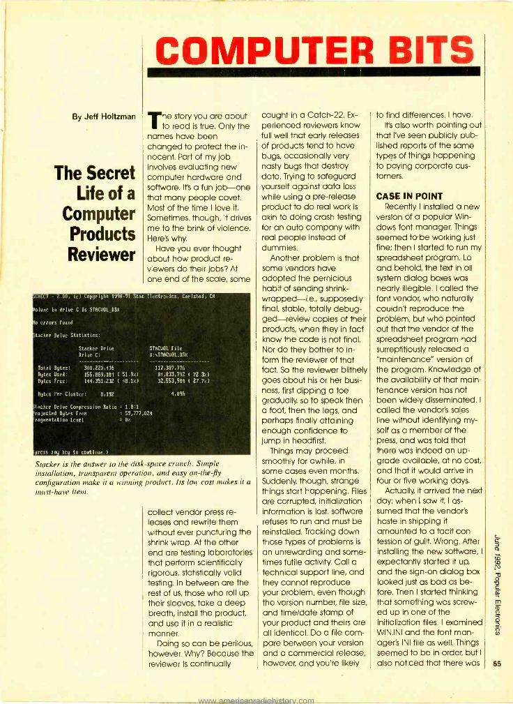
By Jeff Holtzman
The Secret Life of a
Computer Products Reviewer
COMPUTER BITS
The story you are about to read is true. Only the
names have been changed to protect the in- nocent. Part of my job involves evaluating new computer hardware and software. It's a fun job -one that many people covet. Most of the time I love it.
Sometimes, though, it drives me to the brink of violence. Here's why.
Have you ever thought about how product re- viewers do their jobs? At one end of the scale, some
.01, lc.l Copyright 1990 -91 Stec Electruvics, Cnrlsbn9, CO
viese in drive C is STOCUOL_DSR
o errors found
tacker Drive Statistics:
Stacker Drive
Drive C:
Total Bytes: 300,220,416
STACUOL File
D: \STACUOL.DSR
117,387,776
Bytes Used: 155,869,184 ( 51.9e) 84,833,792 ( 72.3e)
Bytes Free: 144,351,232 ( 48.10 32,553,984 ( 27.70
Bytes Per Cluster: 8,192 4,096
tacker Drive Compression Ratio = 1.8:1
'rejected Bytes Free = 59,777,024
raymentation Level = 0e
press any key to continue.)
Stacker is the answer to the disk -space crunch. Simple installation, transparent operation, and easy on-the-fly configuration make it a winning product. Its low cost makes it a must -have item.
collect vendor press re- leases and rewrite them without ever puncturing the shrink wrap. At the other end are testing laboratories that perform scientifically rigorous, statistically valid testing. In between are the rest of us, those who roll up their sleeves, take a deep breath, install the product, and use it in a realistic manner.
Doing so can be perilous, however. Why? Because the reviewer is continually
caught in a Catch -22. Ex-
perienced reviewers know full well that early releases of products tend to have bugs, occasionally very nasty bugs that destroy data. Trying to safeguard yourself against data loss
while using a pre -release product to do real work is
akin to doing crash testing for an auto company with real people instead of dummies.
Another problem is that some vendors have adopted the pernicious habit of sending shrink - wrapped-i.e., supposedly final, stable, totally debug- ged- review copies of their products, when they in fact know the code is not final. Nor do they bother to in- form the reviewer of that fact. So the reviewer blithely goes about his or her busi- ness, first dipping a toe gradually, so to speak then a foot, then the legs, and perhaps finally attaining enough confidence to jump in headfirst.
Things may proceed smoothly for awhile, in some cases even months. Suddenly, though, strange things start happening. Files
are corrupted, initialization information is lost, software refuses to run and must be reinstalled. Tracking down those types of problems is
an unrewarding and some- times futile activity. Call a technical support line, and they cannot reproduce your problem, even though the version number, file size,
and time /date stamp of your product and theirs are all identical. Do a file com- pare between your version and a commercial release, however, and you're likely
to find differences. I have. It's also worth pointing out
that I've seen publicly pub- lished reports of the same types of things happening to paying corporate cus- tomers.
CASE IN POINT Recently I installed a new
version of a popular Win- dows font manager. Things seemed tabe working just fine; then I started to run my spreadsheet program. Lo
and behold, the text in all system dialog boxes was nearly illegible. I called the font vendor, who naturally couldn't reproduce the problem, but who pointed out that the vendor of the spreadsheet program had surreptitiously released a "maintenance" version of the program. Knowledge of the availability of that main- tenance version has not been widely disseminated. I
called the vendor's sales line without identifying my- self as a member of the press, and was told that there was indeed an up- grade available, at no cost, and that it would arrive in
four or five working days. Actually, it arrived the next
day; when I saw it, I as- sumed that the vendor's haste in shipping it
amounted to a tacit con- fession of guilt. Wrong. After installing the new software, I
expectantly started it up, and the sign -on dialog box looked just as bad as be- fore. Then I started thinking that something was screw- ed up in one of the initialization files. I examined WIN.INI and the font man- ager's INI file as well. Things seemed to be in order, but I
also noticed that there was 65
www.americanradiohistory.comAmericanRadioHistory.Com

66
r FUN WITH
ELECTRONICS
[ 160 -COIL DESIGN &
CONSTRUCTION MANUAL .... S5.95. How to make RF, IF.
audio and power coils; chokes and transformers. Practically every possible type is dis- cussed.
PCP113 -THE PC MUSIC 111.
HANDBOOK .... $13.95. Learn the basics of computer music systems. For the pro-
fessional musician, gifted am-
ateur or just plain curious.
4 BP297- LOUDSPEAK- ERS FOR MUSICIANS .... $6.25. Loudspeaker design from the musician's point of view! All you need to know,
and you should be able to de- sign your own after reading this
BP277 -HIGH POWER AUDIO AMPLIFIER CON- STRUCTION ....$6.25. Here's background and practical de- sign information on high power audio amplifiers capable of 300.400 watts r.m.s. You'll find MOSFET and bipolar out- put transistors in inverting and non -inverting circuits.
4 BP302 -A CONCISE USER'S GUIDE TO LOTUS 1 -2 -3 RELEASE 3.1 .... $6.25. If you am a PC user and want to upgrade to Lotus 1 -2 -3 re- lease 3.1, this book can teach you how to do that in the short- est and most effective way.
Li BP298 -A CONCISE IN- p. TRODUCTION TO THE MAC- INTOSH SYSTEM AND FINDER .... $6.25. This intro- duction for those new to the Mac, this book also serves as a quick refresher for experi- enced owners that have not used the machine in some time.
MAIL TO: Electronic Technology Today, Inc. PO. Box 240 Massapequa Park, NY 11762 -0240
SHIPPING CHARGES IN USA AND CANADA
$0.01 to $5.00... $1.50 $30.01 to $40.00. $5.50 $5.01 to $10.00.. $2.50 $40.01 to $50.00. $6.50 $10.01 to $20.00. $3.50 $50.01 and above $8.00 $20.01 to $30.00. $4.50 SORRY, No orders accepted outside of USA and Canada
Total price of merchandise 5 Shipping (see chart) S
Subtotal S
Sales Tax (NYS only) S
Total Enclosed $
Name
Address
City State Zip
a lot of junk in WIN.INI that had been left behind by some software packages that I had at one time tested but long since de- leted.
VENDOR
Stac Electronics 5993 Avenida Encinas Carlsbad, CA 92008 619 -431 -7474
I deleted the junk, re- started Windows, and the problem recurred. In fact it was worse. When I started the word processor, it would not display anything right. In addition, the file manager/ launcher I used seemed to have lost its configuration information as well. Then I
thought it might be a virus. I
ran several virus scanning utilities; nothing.
At last, I remembered that the file manager had lost its configuration infor- mation once before-and that the only solution I'd found then was to reinstall it. So I disabled the file manager, returning to Win- dows' own Program Manager. Fired up Win- dows, then the word processor; everything checked out. Fired up the spreadsheet; it too now seemed to work just fine.
LESSONS LEARNED There are several lessons
here. One concerns vendor indifference toward re- viewers. The other concerns product security as related to install and uninstall pro- cedures. Vendor indifference is a tough one. Some companies go out of their ways to accommo- date reviewers; others take a positively hostile attitude. Most, however, fall some- where between those extremes; it is to them that these words are addressed: Please remember that
those of us who try to do a conscientious job use your products to do real work. In the interest of fairness, you should ship upgrade /bug -fix disks automatically. Re- member that most of us do face -to -face consulting and are liable in that situa- tion to report bugs that are uncovered subsequent to published reviews.
Product security is even tougher. For years, users have stood for awkward and destructive installation procedures that wantonly change system files, ignore system configuration, and don't clean up after them- selves. A general solution to the problem is required, one that is enforced by the operating system. Then ap- plication vendors would have to conform to stan- dards.
Vendors would be among the first to benefit from such an arrangement. By adopting a secured database approach to configuration and initializa- tion information, system files could not be changed in unspecified ways by unwit- ting (or even malicious) users. That would translate directly into lower tech- nical- support costs. It would also translate directly into better product quality, bet- ter press coverage, and greater customer loyalty.
STACKER REPRISE Stacker (mentioned last
time), from Stac Electronics, continues to amaze me. After several months of moderate use, I have dou- ble the disk space and have had no problems with compatibility or reliability. A friend has been using the software only version on a sexy little 386SX notebook, and he loves it. I've seen the software version for about $80, and the hard- ware version for about $140 by mail order.
www.americanradiohistory.comAmericanRadioHistory.Com

By Charles D. Rakes
Lc 100
AF C1
IN 1
Filter Circuits
R1
220K
CIRCUIT CIRCUS
isten up fellow cir- cuiteers be.cause this
time around we are going to share a few audio -en- hancement circuits. Just
about anything that we lis-
ten to that's not "in person" can often be electronically improved. Here are just a few examples of where shaping and filtering audio signals can improve our ability to understand and interpret what we hear:
If you are an avid short- wave listener or amateur - radio operator, the dif- ference in receiving or contacting a rare DX station
1
R5
4.7 K
C3 002 LM741
L42_ 7
C4 3 U1 .002
+ R9-a 50K
\ 68 10K
L
R3 470 K
t - +6-12v
-j- C5 R4 .002 470K
R2 C6 ---VSAry .002 220K
R6
4
I4 R7 4.7K R7
IC8 T47
50K
_a
C2
AF OUT
Fig. 1. This variable frequency, audio bandpass filter is built around two 74/ op -amps that are connected in cascade.
greatly depends on the IF-
bandwidth and audio- filter- ing capabilities of your receiver. Most receivers that don't have a selectable AF
filter can be improved im- mensely by using an add - on filter at the receiver's audio output.
The success of audio sur-
veillance with a long -range shot gun or parabolic mi- crophone is greatly enhanced by using one or more bandpass filters to se- lect and amplify only the desired signals.
BANDPASS FILTER Our first entry, see Fig. 1, is
a variable- frequency, audio bandpass filter. Two 741 op- amps are configured as
identical RC active filters and are connected in cas- cade for better selectivity. The filter's tuning range is
from 500 Hz to 1500 kHz. The
overall voltage gain is
slightly greater than one and the filter's Q is about 5.
The circuit can handle input signals of 4 volts peak -to- peak without being over- driven. The circuit's input impedance is over 200k and its output impedance is less than 1k.
The filter can be con-
MIKE
PRE -AMP STAGE
L
nected as shown in Fig. 2 to offer a variable bandpass to an existing amplifier by inserting the filter circuit be- tween the amp's preamp and output stage. The cir- cuits frequency - determining capacitors, C3, C4, C5, and C6 should be good quality 5% poly- styrene, and all resistors
should be 5 %.
SUPER BANDPASS FILTER
The filter circuit in Fig. 1 is
an excellent building block that can be expanded into a super bandpass filter. Such a circuit is shown in
Fig. 3. The circuit, which is
OUTI
o/oIN i Sl-a
TWO POLE FILTER
CKT
¡OUT
IN °,`' o S1-b
_./
AF
OUTPUT o
OUTPUT AMP
Fig. 2. The filter can be wired into an existing amplifier by
inserting the filter circuit between the amp's preamp and output stages as shown here.
PARTS LIST FOR THE BANDPASS FILTER
RESISTORS (All fixed resistors are %a -watt, 5% units.) R1, R2- 220,000 -ohm R3, Rh 470,000 -ohm R5, R6 -4700 -ohm R7, R8- 10,000 -ohm R9- 50,000 -ohm dual potentiometer
CAPACITORS Cl, C2- 0.1 -p.F, ceramic -disc C3 C6- .002 -p,F, 50 -WVDC, polystyrene or similar C7- 100 -p,F, I6 -WVDC, electrolytic C8 47 µF 16 -WVDC, electrolytic
ADDITIONAL PARTS AND MATERIALS UI, U2 -741 op -amp, integrated circuit SI -Power switch Perfboard materials, IC sockets, 6-12 -volt power source, knob,
wire, solder, hardware, etc. 67
www.americanradiohistory.comAmericanRadioHistory.Com
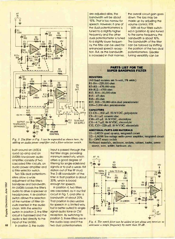
68
AF IN
o q
*R1 220K
J- C2
.002 CI
- 12
*1431K .7 K
R17 a
50K
R5 470K 1M
1/4 LM324
J_ C4 R6
R2
220K
R13 R14
10K 10K \ +C10 \\ T47 \
+9V \ ---
.002 470K
C3
.002
R10 4.7K
R 17-b 50K
+9V
4
U1-b
+ 11
1/4 = LM324
R3
220K
1 C6 002 R7
C5 470K
UO2 I \ --s-) s
*R11 4.7K
R 18-a 50K
R15 4712
M324
+9V
OUTPUT
OR PHONES{ TO SPEAKER
L
R4 220K C8
*AIN"-, .002
4-3 3 C7
1 '4 4.7K002? R 18-b
r50K : C12
C13 LM386
220
220
R8 470K YV
U1-d 14
1/4 LM324
+9V TO
CKT.
3F .76
50 Sl-a S1-b
6
5
R16 1012
C9 .1 Fig. 3. The filter an Fig. I can be expanded as shown here, by adding an audio power amplifier and a filter- selector switch.
R19 5K
VOLUME CONTROL
OFFo 1
C11 TO 9V BAT. 4.7 OR SUPPLY
built around an LM324 quad op -amp and an LM386 low -power audio amplifier, consists of Iwo cascaded filter circuits, an audio power amplifier and a filter -selector switch.
Two 50k dual potentiom- eters allow a wide adjustment of the filter's bandpass and bandwidth. An LM386 boosts the filter's audio to drive a speaker or headphones. A six -position switch allows the selection of the number of filter cir- cuits inserted in the audio chain. With the selector switch in position 2, the filter circuit is bypassed-and the audio is fed directly to the input of the LM386.
In position 3, the audio
input is passed through the first filter stage, providing minimum selectivity, which offers a good degree of filtering for single -sideband signals or to pull a weak AM station out of the RF mud. The 3 -dB bandwidth of the filter in that position is about 30 %, which is broad enough for speech.
In position 4, two filters are cascaded, as in our first circuit in Fig. 1, and offer a bandwidth of about 20 %. That position is also usable for speech in a limited way, but is better suited to single - signal audio tone or CW reception. By switching to position 5, three filters are in the audio loop and if the two dual potentiometers
are adjusted alike, the bandwidth will be about 15 %. That is too narrow for speech. However, if one of the dual potentiometers is
tuned to a slightly higher frequency and the other dual potentiometer is tuned to a slightly lower frequen- cy, the filter can be used for enhanced speech recep- tion. But, as the bandwidth is increased in that manner,
the overall circuit gain goes down. The loss may be made up by adjusting the volume control, R19.
With all four filters switch- ed in (position 6) and tuned to the same frequency, the bandwidth is about 10 %. The bandwidth of the filter can be tailored by shifting the position of the two dual potentiometers. Greater tuning versatility can be
PARTS LIST FOR THE SUPER BANDPASS FILTER
RESISTORS (All fixed resistors are 1/4-watt, 5% units.) R1-R4-220,000-ohm R5 -R8- 470,000 -ohm R9-R12-4700-ohm R13, R14- 10,000 -ohm R15-47 -ohm RIb -l0 -ohm R17, R18- 50,000 -ohm dual potentiometer R19- 5,000 -ohm potentiometer
CAPACITORS CI-C8- .002 -µF, 50 -WVDC, polystyrene C9- 0.1 -11F, ceramic -disc C10 47 -RF, 16 -WVDC, electrolytic Cll- 4.7 -.&F, 16 -WVDC, electrolytic 02, C13- 220 -µF 16 -WVDC, electrolytic
ADDITIONAL PARTS AND MATERIALS Ul -LM324 quad op -amp, integrated circuit U2 -LM386 low- voltage audio -power amplifier, integrated circuit Sl -DP6T rotary switch Perfboard materials, enclosure, sockets, cabinet, knobs, power
source, wire, solder, hardware, etc.
C5
AF IN
. R3
10K 1 500Hz A 1kHz T0 3 kHz L
T01.5kHz Y r X
-0 B C2 Cl I S1-a 005 005
I
R1 R2
47K I 100K I C3 1/W I .005
I
RO B 10K .005 R8 TUNE 1K
Fig. 4. The notch filter can be added to just about any receiver to attenuate a single frequency by more than 30 dB.
www.americanradiohistory.comAmericanRadioHistory.Com

PARTS LIST FOR THE NOTCH FILTER
RESISTORS (All fixed resistors are 1/4-watt, 5% units.) R I- 47,000 -ohm R2- 100,000 -ohm R3 R7- 10,000 -ohm R8 -1000 -ohm R9- 10,00 -ohm potentiometer
CAPACITORS CI -C4- .005 µF, 50 -WVDC, polystyrene (see text) C5, C6 0.1 -µF ceramic -disc C7- 47 -µF, 16 -WVDC, electrolytic C8- 220 -p.F, I6 -WVDC, electrolytic
ADDITIONAL PARTS AND MATERIALS Ul -LM324 quad op -amp, integrated circuit SI -DPDT switch Perfboard materials, enclosure, IC sockets, power source, wire,
solder, hardware, etc.
had by replacing the Iwo dual potentiometers with four separate 50k units.
NOTCH FILTER The bandpass filter is a
big asset in selecting signals that we want to hear but can do little in removing a single frequency tone that we don't want to hear. If
you do a lot of shortwave listening, there's little doubt that at least some of your favorite stations have been plagued by an interfering heterodyne tone. Some of the better shortwave re- ceiver's have a built -in notch filter that can be used to tune out or at least reduce an annoying het- erodyne tone without significantly reducing the desired signal.
The notch filter shown in
Fig. 4 can be added to just about any receiver and will reduce a single frequency tone by more than 30 dB. The filter circuit as shown can be connected to a receiver's internal circuitry; or externally by adding the LM386 audio -amplifier portion of the circuit shown in Fig. 3 to drive an external speaker. The second option might be more convenient.
The notch filter tunes from 500 Hz to over 3 kHz in Iwo
ranges. The tuning range can be changed by either increasing the values of Cl and C4 or C2 and C3 to lower the frequency or by decreasing the values to increase the frequency. The capacitors should have a 5% tolerance or better and be a good quality poly- ester-, polystyrene -, polypropylene -, or mylar- type capacitors.
The circuit's input imped- ance is about 10k and will handle a maximum input signal of 1 -volt peak -to- peak with a 9 -volt power supply (which can be a 9- volt battery if you wish). The filter's voltage gain is about 1 and the output imped- ance is less than 1k. An additional notch filter circuit can be formed from the Iwo remaining op -amps in
the LM324 package and used to assist in removing two interfering tones. Just cascade the Iwo filters by connecting the output of the first notch filter to the input of the second.
Looks like it's time to close for this visit. So until next month, when I return with more circuits for your work bench and soldering iron, I
hope you enjoy better re- ception and happy listening.
Be an FCC LICENSED ELECTRONIC TECHNICIAN!
Earn up to $30 an hour and more! i
Learn at home in spare time. No previous experience needed!
No costly school. No commuting to class. The Original Home -Study course prepares you for the "FCC Commercial Radio- telephone License. "This valuable license is your professional "ticket" to thousands of exciting jobs in Communications, Radio - TV, Microwave, Maritime, Radar, Avionics and more...even start your own business! You don't need a college degree to qualify, but you do need an FCC License. No Need to Quit Your Job or Go To School This proven course is easy, fast and low cost! GUARANTEED PASS You get your FCC License or money refunded. Send for FREE facts now. MAIL COUPON TODAY!
commanD PRODUCTIOnS FCC LICENSE TRAINING, Dept. 100 P.O. Box 2824. San Francisco. CA 94126 Please rush FREE details immediately!
NAME ADDRESS
CITY STATE L
ZIP J
Over 750,000 readers of earlier editions of
The Forrest Mims Engineer's Notebook
V«
agree -nobody knows practical IC applications like Forrest Mims! This newly- revised edition contains hundreds of proven, tested circuits -hand- drawn by Forrest -using today's most popular linear, TTL, and CMOS ICs. Forrest gives you full data for each device and circuit - pin numbers, logic tables, supply voltages, and signal waveforms - so you can quickly duplicate each circuit. There's also practical in- formation on construction meth- ods, troubleshooting, and inter- facing different IC families. If you work with ICs you gotta get this book!
Only $14.95 at bookstores or electronic parts dealers. Or order direct from HighText! Add $3 shipping ($4 to Canada. $5 elsewhere). CA please add sales tax. U.S. funds only please.
HighText -itt Miramar Road spite I51.
.. , , a , o San Diego, CA 92121 69
www.americanradiohistory.comAmericanRadioHistory.Com

By John J. Yacono
More Tips
70
THINK TANK
his month, I will con- tinue to present some
of the helpful tips provided by some of you readers. First, however, I would like to clear up a couple of errors that have crept their way into this column.
The first one appeared in
the January 1992 issue. To
refresh your memory, that was one of the Think Tank
columns devoted to op- amp operation. While the column was being pre- pared for publication, an "R" was dropped from some of the equations. To
amend this error, all the equations presented in the column have been listed in
their correct form in the boxed text entitled "Op- Amp Equations."
By the way, I have re- ceived some favorable response about presenting a little math in the column. If you have an opinion about whether or not I
should do more derivations, write -in and let me know. If
you want to see more cir- cuit theory, let me know what you would like cov- ered.
I have been more or less
flooded with letters regard- ing an error in the March 1992 Think Tank column, which was dedicated to automotive electronics. (Ap- parently, I did not over estimate the importance and interest people invest in cars.) Figure 5 that month lost a ground symbol on the way to these pages. It
should have been at- tached to the unconnected terminal of the relay in the figure. See Fig. 1 for the corrected schematic di- agram.
Since the automotive-
electronics topic seemed so popular, I will try to do another column on it in the
K1f O J 12V
50mA .l. BZ1
12VOC
R1
470E2 1/2W
TO POSITIVE TERMINAL ON
TO = A HEADLIGHT
IGNITION SWITCH
Fig. 1. This is how the headlight- reminder circuit should have looked. Note: The ground connection is important for the device's operation.
future. To help me out, please send your car -re- lated (or other) circuits to Think Tank, Popular Elec- tronics, 500 -B Bi- County Blvd., Farmingdale, NY
11735. All the submissions used will receive a "Think Tank II" or other book.
Now let's get to those helpful hints. As usual, I'll kick things off.
A CABLE RACK I have quite an assort-
ment of cables in my workshop, all with various connectors on the ends. The large number and vari- ety makes interconnecting equipment quick and easy, but wading through the as-
sortment, looking for just the right cable, is a chore in itself. There are commer- cially sold cable racks that are designed to solve that problem by neatly suspend- ing the cables from one end, but they are expensive (or perhaps I'm just too cheap to buy one).
So, in the true hobbyist spirit, I made one of my own (see Fig. 2) out of a screen -door spring. The springs are readily avail- able from hardware and home -care stores, and can be prepared for use in a matter of minutes.
Start by securing a flat- head nail, head -up in a bolted -down vice. Loop one end of the spring over the head of the nail, and insert a screw driver in the loop at the other end. Grip the handle of the screw- driver with one hand and the stem with the other. Pull
the screwdriver firmly to- ward you tilting it slightly so that the loop of the spring slides down toward the handle. The tilt will keep the spring away from the hand you placed on the stem. Firmly stretch the spring until the space between wind- ings is about equal to the thickness of most of your cables. To accommodate
SECTION SECTION FOR WIDE FOR THIN
CABLE CABLE
FINISHING NAIL
SCREEN -DOOR SPRING
FINISHING NAIL
Fig. 2. A quick and easy cable rack can be made from an inexpensive screen -door spring. All it takes is a little muscle.
www.americanradiohistory.comAmericanRadioHistory.Com

thicker cables you can make a section of the spring larger by altering the loop you attach to the nail so that you stretch only a portion of the spring.
I recommend that you mount the spring to a con- venient surface in your workshop by placing a finishing nail through the loop at each end. Angle the nails slightly away from the spring to prevent it from escaping. By using finishing nails in that fashion, you can always take down the rack (spring) and drop it, cable and all, into your tool box for field work. Now let's get to the helpful tips pro- vided by you readers.
SOCK IT AWAY I have a helpful tip for
auto -stereo enthusiasts. Be- fore installing car speakers, I
have always covered them with panty hose. The hose provides the speakers with protection against dust, bugs, sand, etc., which usu- ally fall on them causing distortion and reducing speaker life. It just takes a little work to slip them over; once you get them on, you will need to cut a little slot for each wire connection. I
have taken that tip for granted for a number of years, but lately I have been surprised to find that a number of people have never heard of it.
-Scott Partridge, Vicksburg, MS
That's a pretty nice way to recycle used panty hose. You can also use Them as dust screens in projects re- quiring a cooling fan. They really keep the lint out. The plastic eggs that some of them come in can be used as unusual project cases, too.
BATTERY CLIPS Most of the circuits that I
build require 9 -volt tran- sistor -radio batteries, so I
never seem to have enough suitable battery clips on hand. Instead of making more trips to the store, I have found a way to make them for myself. To
start, take a dead 9 -volt battery and pry off the metal casing. Then liff off the terminal assembly at the top of the battery (as shown in Fig. 3) and cut the wires that connect it to the cells of the battery.
You can easily solder wires to the back of the terminal's connector and use the assembly as a bat- tery clip. Just remember to
CUT THESE WIRES TERMINAL ASSEMBLY 9VO LT
BATTERY CASE
PLASTIC BOTTOM
Fig. 3. This is an internal view of a 9 -volt battery. Note that the separate cells in the battery are wired in series by stacking them on top of one another.
solder a red wire (or other positive lead) to the termi- nal that used to be the negative terminal of the battery so that the polarity is correct. The resulting bat- tery clips are stronger than store -bought ones and you should have no trouble finding the raw materials.
-Jim Tschanz Liber- tyville, IL
Definitely a neat idea, but one that should be tried with caution. If you want to fry that trick be careful not to cut yourself on the metal of the battery case. And be sure to wash your hands and work surface Thor- oughly when done. Also be
OP -AMP EQUATIONS
Vo=AoL - )
= Vo R2/(R1 + R2)
Vo = AoL (V;,,+ - Vo R2/(R1 + R2)) Vo/AoL = (V;,+ - Vo R2/(R1 + R2))
1/A0L = (V;,,, - Vo R2/(R1 + R2))No 1/A0L + R2/(R1 +R2) =
R2/(R1 +R2) = V;,,+/Vo (R1+R2)/R2 = VONín'
sure never to dismantle a rechargeable battery, they might contain very haz- ardous chemicals.
There is something else you can make out of old batteries: oxygen! Before you discard The battery en- trails, remove the black powder from each of its
cells. The substance is
called manganese -dioxide. If you sprinkle some of that powder in a glass con- taining hydrogen peroxide, the mixture will produce bubbles of oxygen. A word of caution is in order how- ever: never deliberately try to concentrate the oxygen produced. Remember oxy- gen is the key ingredient for combustion; having too much of it in one place invites disaster. For that same reason, do not try the experiment near an open flame.
If that experiment and the battery -clip tip don't seem like good enough reasons to rip an old 9 -volt battery apart, then what about this next idea?
A TRIMMER TOOL If you build projects that
contain trimmer capacitors, adjusting them can be really frustrating without the right tool. But don't fret; if you have a dead 9 -volt battery around, you can make an insulated adjust- ment tool out of it.
First check the bottom of the battery to make sure it is not metal. Then carefully use a pair of pliers to re- move the battery's metal
casing without cutting your- self. Discard all but the insulating bottom of the battery. Cut Iwo notches into the insulating material
FILE DOWN REMOVE TIP
BOTTOM OF BATTERY CASE
Fig. 4. If you need a trimmer -capacitor adjustment tool, don't throw out those old 9 -volt batteries. They have a plastic part that can easily be modified for the job.
so it looks like Fig. 4. Finally, file down the tip so that it can fit into the slot on a trimmer capacitor -don't file too much or the tip will break off.
-Unsigned, Sapulpa, OK Anyone attempting to
make one of those adjust- ment tools should observe the same cautions men- tioned for building the battery clips (beware of sharp metal, don't use re- chargeable batteries, etc)
I'm sorry I couldn't pro- vide a name with that last letter, but it was received unsigned (it contained only the address) and the enve- lope for the letter was misplaced. Nonetheless, the author's Think Tank II book is on the way to him/ her.
THE CUTTING EDGE Most of us don't give our (Continued on page 88) 71
www.americanradiohistory.comAmericanRadioHistory.Com

72
By Don Jensen
Brazilian DX On A
Rollercoaster Ride
DX LISTENING Brazil for years has been one of the most active
countries on the shortwave bands. Although some sta- tions have shifted to medium -wave AM and VHF -
FM bands, there remain more than 150 shortwave outlets in this, the largest of the South American nations. For SWL's, the best known Brazilian SW'er is govern- ment- operated Radiobras.
In 1958, Iwo years before Brasilia, a planned city carved out of the Amazo- nian wilds to be the country's new capital, was even completed, the equally new shortwave sta-
In earlier years, Radio Nacional de Brasilia, the forerunner of today's International Service Radiobras, directed much of its shortwave effort to reaching audiences in the Brazilian Amazon.
tion went on the air. Radio Nacional de Brasilia aired its first official broadcast on May 31 of that year.
Programs during the early years focused on public service to those who had flocked to the frontier area. The radio helped to link the settlers to their families elsewhere in Brazil. Several years later, Radio Nacional de Brasilia was merged with Radio Nacional de Rio de Janeiro, which was one of the nation's oldest and best known broadcasters.
International shortwave programming, on an ex-
perimental basis, started in
June 1972, with English test broadcasts to Europe. An International Service of- ficially began several months later, with four one - hour programs in English,
German, Portuguese, and Spanish. French and Italian programs were added. That early effort to reach over- seas listeners wasn't successful, since Radio Na- cional de Brasilia's shortwave transmitter was only a 10- kilowatt unit, far too weak to compete with other international broad- casters.
But that changed in 1974,
when a "world-class" 250 - kilowatt transmitter came on line. But by then, RNB
was facing financial prob- lems, forcing a cutback in
broadcasting hours and services. In fact, in June 1977, the foreign broad- casts were suspended entirely, as the focus shifted to a new internal SW -radio service directed to Bra-
zilians living in the vast Amazon region.
The International Service was resumed in 1979, with a one -hour daily English pro- gram to North America. Shortly therafter it was ex- panded again with additional English broad- casts to Europe and Portuguese programming to southern Europe and Af- rica. In the early 1980's,
some Spanish- and Ger- man- language programming returned. In
addition, the station leased air time to other countries, such as Germany and neighboring Surinam, allow- ing those broadcasters to relay their programs to
western -hemisphere au- diences over the Brazilian facilities.
The International Service of RNB -which by then stood for Radio Nacional de Brasil- resumed a full - fledged service in July 1990,
with 80- minute daily pro- grams in its four programming languages. But in a baffling move, the station later shifted the tim- ing of its 11.745 -kHz English program to North America from a prime -time evening slot (0200 UTC) to the early morning (1200 UTC) when there are fewer listeners. In-
stead, you might try the European beam from Radi- obras on 15,265 kHz, 1800 to 1920 UTC.
Your reception reports may be sent to Radiobras, Caixa Postal 04/0340, 70323 Brasilia, Brazil.
IN THE MAIL Larry Martinson writes
from Spartanburg, SC:
"Strange as it may seem, over the last couple of years, I've become some- thing of a fan of Radio Moscow. What is going to happen to this venerable shortwave service ?"
I wish I knew, Larry. For
longtime SWL's, the changes -and most of them were improvements - in Radio Moscow's pro- gramming during the glasnost era were nothing short of amazing. So I, too, found myself tuning in far more frequently than in the earlier Cold -War years.
Already there have been some significant program- ming changes, notably the loss of the North American Service. Budget constraints, which doubtless will con- tinue to be a problem, last
www.americanradiohistory.comAmericanRadioHistory.Com

December resulted in the folding of that service into Radio Moscow's World Ser- vices. Fortunately, some of the better programs sur- vived; shows like Joe Adamov's Mailbag, Russian by Radio, Culture and the Arts.
Station staffers, reported- ly, still have concerns about the future and possible ad- ditional cutbacks. But I
expect that Radio Moscow, or something like it, will con- tinue to broadcast on shortwave to English- speak- ing listeners.
Brad Davies lives in the Pacific Northwest, one of the best areas in the U.S. for DX'ing Indonesia. And our reader in Yakima, WA has found that out himself. "I've really become hung up on listening to the Indonesian stations. During the spring, I
logged quite a few of the home -service Radio Re- publik Indonesia outlets on the lower shortwave fre- quencies. Some are real DX'ing challenges!"
Although often difficult to hear (especially in parts of eastern North America), In- donesia's RRI home -service SW stations, located from Sumatra to Irian Jaya, the western part of New Guinea, are favorite targets of experienced, serious DX'ers.
Perhaps the best bet for listeners in most parts of the U.S. and Canada is the RRI
station at Ujung Pandang, in Indonesia's Celebes Islands (Sulawesi). Look for it just before dawn on 4,753 kHz. I
also recommend a couple of reference books. The 25- page Survey Of Broadcast- ing Activity In Indonesia is a highly accurate listing of 280 different SW stations, their frequencies, and ob- served schedules. A companion book is The Dx'ers Handbook: Indo- nesia, which includes a profile of this Asian island
nation and its broadcasting, a guide to Indonesian lan- guage station identifications, tips on ob- taining QSL's, detailed maps to help you locate the sta- tions you hear, and much more.
These publications are of- fered as a special package for $12, postage included, by FT Special Publications, C/0 Bryant, Rt. 5, Box 14,
Stillwater, OK 74074. That's mail call for this
month. Remember that your letters are always wel- come. Write if you have questions or comments about shortwave listening. Or drop us a note telling the rest of us what you're hearing on SW these days. The address, as always, is
DX Listening, Popular Elec- tronics, 500 -B Bi- County Blvd., Farmingdale, NY
11735.
DOWN THE DIAL Here are some SW listen-
ing choices: HONDURAS -Sani Radio
has been heard on 6,300 kHz with Spanish- language programming until sign off at 0000 UTC.
HONG KONG -If you come across English -lan- guage British Broadcasting Corporation programs on 11,820 kHz during the 1430 to 1500 UTC time block, the signals actually are coming from a BBC relay transmitter at Hong Kong.
INDIA-All India Radio is
heard in English on 9,950 kHz with a health program from 2215 until 2230 UTC
sign off.
*Credits: D.J. Prisco, PA; Gerald Hart, MN; Bob Brown, PA; John Carson, OK; Jerry Berg, MA; Doug Robertson, CA; Harold Levison, PA; George Vadino, WA; Brian Alexander, PA; North American SW Association, 45 Wildflower Road, Levittown, PA 19057; World DX Club, North American Representative, Richard D'Angelo, 2216 Burkey, Wyomissing, PA 19610.
IRAQ -Radio Baghdad operates on 15,601 kHz in Arabic at 2120 UTC.
PHILIPPINES -Radio Fil-
ipinas is relayed on 21,580 kHz by a Voice of America transmitter at Tinang in the Philippines. It has been noted in English at 0230 UTC. The programming also can be found on a parallel frequency of 17,760 kHz.
RUSSIA -One of the new Russian SW broadcasters that has gone on the air in
recent months is Radio Ala, which operates from St. Pe-
tersburg, the former Leningrad. It has been log- ged on 7,400 kHz by east - coast U.S. listeners signing on, in Russian, shortly after 0700 UTC.
SWEDEN -Radio Sweden International is heard on 11,705 kHz, broadcasting in English, with "60 Degrees North," during the 0200 UTC
program block.
UKRAINE -Radio Kiev has been logged on 11,790 kHz
after 0100 UTC with English - language news, commen- tary, and 'stop 10" music.
USA-Shoriwaver WWCR now has a two hour block of programming especially for the DX'ing enthusiast. It is
called "Signals" and it is
heard Sundays, beginning at 0430 UTC.
VENEZUELA -How about some good Latin music? Try
listening for Radio Rumbos on 4,970 kHz at around 0430 UTC.
VIETNAM -7A17 kHz. An- other tip for listeners on the western coast of North America is the Voice of Viet- nam, noted ending a program in the Lao Lan- guage at around 1425 UTC.
After a brief silence, pro- gramming continued in
Chinese at 1430 UTC. The station is on 9,732 kHz at the same time.
I LtI VIM CLEANING /MAINTENANCE /REPAIR EARN UP TO $1000 A WEEK,WORKING PART TIME FROM YOUR OWN HOME!
Secrets Revealed!
NO Special Tools or
Equipment Needed.
THE MONEY MAKING OPPORTUNITY OF THE 1990'S
IF you are able to work with common small hand tools, and are familiar with basic electronics i.e. able to use a voltmeter, understand DC electronics)... IF you possess average mechanical ability, and have a VCR on which to practice and learn...then we can teach YOUVCR maintenance and repair! FACT: up to 90% of All VCR malfunctions are due to simple MECHANICAL or ELECTRO- MECHANICAL breakdowns! FACT: over 77 million VCRs in use today nationwide! Average VCR needs service or repair every 12 to 18 months! Viejo's 400 PAGE TRAINING MANUAL (over 500 pho- tos and illustrations) and AWARD -WINNING VIDEO TRAINING TAPE reveal the SECRETS of VCR mainte- nance and repair -'real world" information that is NOT available elsewhere! Also includes all the info you'll need regarding the BUSINESS -SIDE of running a successful service operation!
FREE INFORMATION CALL TOLL -FREE 1- 800 -537 -0589 Or write to: Viejo Publications Inc.
4470 -107 Sunset Blvd., Suite 600, Dept. PE Los Angeles, CA 90027
CIRCLE 9 ON FREE INFORMATION CARD
73
www.americanradiohistory.comAmericanRadioHistory.Com

74
By Joseph J. Carr, K4IPV
Receiving Loop
Antennas
HAM RADIO oop antennas are used for a variety of pur-
poses, ranging from limited - space transmitting to radio - direction finding to low - QRM receiving, especially on 30- meters and below (160 -meter to 20 -meter ham bands, plus adjacent shortwave- broadcast bands). Shortwave listeners are very familiar with small loop antennas for receiver QRM reduction, but hams
Palomar' Loop Antenna
Palomar Engineers LA -1 loop antenna is intended for the AM broadcast band (550 to 1630 kHz). Other models, which will mate with the LA -1 loop amplifier, are available for the shortwave amateur -radio and international -broadcast bands.
don't use such antennas very often. It's a shame be- cause the receiving loop has some charming at- tributes, particularly ferrite - core loopstick antennas.
Unfortunately, using such receiving antennas de- mand ether a separate receiver and a separate transmitter (as opposed to a transceiver), a separate receiver for monitoring the band with a transceiver for operating, a transceiver with an extra receive -only antenna jack (several mod- els have that feature), or an antenna -switching scheme that is keyed to the transmit/ receive relay. Many hams use two receivers, es- pecially when tracking DX.
LOOPSTICK ANTENNAS A loopstick antenna (refer
to Fig. 1) consists of a ferrite rod wrapped with wire and then covered with tape to keep the wire in place. The wideband variety of loopstick does not resonate the loop. A loopstick anten- na can be made by, first, wrapping a ferrite rod (such as an Amidon Associates - PO BOX 956, Torrance, CA 90508; Tel. 213- 763 -5770- FB -43 -101 ferrite rod) with a single layer of either black electrical tape, or the white Teflon tape used to water- proof plumbing -pipe threads. After that, two coils of enameled or Formvar- covered wire ( #24 or #26, for example) are wound onto the insulated rod. From the center, the ferrite rod is
WINDING A
wrapped with about three feet of the wire in each direction (leaving about 1/s
to 1/4 inch of rod free at the ends). The excess is then cut off, and the wire is covered with an additional layer of tape to keep the wire in
place. The Iwo windings (A and
B, in Fig. 1) are connected together, and then soldered to the center conductor of a length of coaxial cable or a coax connector. In some cases, the shield of the coax is not grounded. You
can experiment with it to see which way works best for you. I've found that con- necting the shield to ground at the receiver end sometimes reduces signal levels, but at other times it
did not; the effect of grounding seems to be fre- quency related.
Loopstick antennas suffer from a malady known as antenna effect i.e., the in- teraction of the loop with local conductors and ground. That can be over- come by using an open U-
shaped shielded enclosure, like that shown in Fig. 2. In
making my shortwave loopstick antenna, I used a cover salvaged from a large (about 9 inches) LMB
chassis box that had been used in another project some years ago. When the
WINDING B
ïlí!!!!!l;!llsl:l!!'!!!' iiililfli!!!!!!!!!!i!!!i{!I!!!!!!!
FERRITE ROD COAX TO
RECEIVER
Fig. 1. A loopstick is comprised of two coils (A and B) wound on a ferrite rod. The two windings are connected together, and then soldered to the center conductor of a length of coaxial cable.
www.americanradiohistory.comAmericanRadioHistory.Com

CABLE CLAMP (NYLON)
FERRITE ANTENNA
(END VIEW) NYLON
SCREW
U- SHAPED NYLON METAL SHIELD HEX NUT
NYLON, PLASTIC OR WOOD INSULATOR
Fig. 2. To counteract the interaction with local conductors and ground, loopsticks can be mounted in an open U- shaped shielded enclosure.
U- shaped chassis is used, the rod is mounted to an insulated stand -off with nylon machine screws and hex nuts. The loop is held to the stand -off using a plastic or nylon cable clamp.
WHY USE A LOOPSTICK?
Perhaps the best reason to use a loopstick antenna is that it is capable of null- ing interfering signals. That feature is due to the nulled patterns associated with loops. A single loop anten- na manifests a figure -8 pattern, like that shown in Fig. 3A. The two directions of maximum reception are perpendicular to the loopstick rod, while the null directions are off the ends.
Figure 3B shows a case where the antenna pattern is a cardioid (i.e., heart shaped); the antenna pat- tern has been altered from the figure -8 pattern by using a sense antenna. The sense antenna is an om- nidirectional whip, about 14
to 24 inches long, that is
connected to the antenna circuit through a phasing potentiometer (see Fig. 4). A portable -radio replace- ment whip or homemade whip will suffice for the
sense antenna. The sense antenna is used to reduce one lobe and make the antenna essentially mono - directional (see Fig. 3B). That configuration is
needed for direction find- ing, but for amateur -radio receiver -antenna applica- tions, it is unnecessary.
The idea when using a loopstick antenna is to place the null in the direc- tion of an interfering signal. By nulling out the strong QRM, one will often expose underlying weaker signals that would otherwise be obscured. You may be sur- prised at how that effect improves your operating pleasure.
Of course, if you're not into building loopstick an- tennas, then there are commercial models avail- able. I've used the Palomar Engineers (PO. Box 455, Es-
condido, CA 92033; Tel.
619 -747 -3343) model LA -1
loop amplifier and frequen- cy- selective loop. That
MAXIMUM RECEPTION
NULL DIRECTION
SENSE ANTENNA
PHASING R1
S1 10K
-'0000000000V- LOOPSTICK ANTENNA
TO
RECEIVER
Cl
Fig. 4. The sense antenna is an omnidirectional whip, about 14 to 24 inches long, that is connected to the antenna circuit through a phasing potentiometer, as shown here.
particular loop is intended for the AM- broadcast band (550 to 1630 kHz). Other models, which will mate with the LA -1 loop amplifier, are available for the ama- teur, shortwave- radio, and international- broadcast bands.
The Palomar loop is a resonant type. A tuning control on the LA -1 allows the operator to resonate the loopstick to the re-
A
MAXIMUM RECEPTION DIRECTION
NULL
NULL DIRECTION
MAXIMUM RECEPTION DIRECTIONS
B
Fig. 3. A single loop antenna exhibits a figure -8 pattern (A), which can be altered (B) by using a sense antenna.
ceived signal frequency. The loop can be adjusted for azimuth by rotating it in
the horizontal direction. It
can also be rotated 90 de- grees in elevation. The latter ability is useful on most bonds because the skywave may arrive at an angle other than horizontal.
THANKS MUCH Many readers have re-
sponded to my offers of a schematic for the digital sawtooth generator (see the May, 1992 column) and the BASIC program listing for the loaded dipole de- sign problem. Some readers noted that I failed to tell them the dialect of BASIC that the program is
written in, so here goes. It was written in GW- BASIC,
and tested using MS -DOS BASICA as well. However, most of the variable names and BASIC commands are common to other BASIC di- alects. I still have some program listings, and it's
also available on the RE -BBS
(516- 293 -2283; 8, N, I).
Readers who want both list-
able and executable versions, as well as around twenty other MS -DOS pro- grams that are of use to radio buffs, can write to me at PO. Box 1099, Falls
Church, VA, 22041. The price is $20. Specify 3.5- inch or 5.25 -inch diskettes. 75
www.americanradiohistory.comAmericanRadioHistory.Com

76
By Marc Saxon
Give Your Handheld a
Boost!
SCANNER SCENE
If you're like me, now that good weather has ar-
rived upon the land, you'll carry your handheld scan- ner from place to place. And you might also be dis- appointed when signals fail to be loud and clear be- cause you've moved out of range of the stations you want to copy. Your local Radio Shack store may have a quick, simple, inex- pensive, and effective solution to this common
Give your scanner a big "boost" without spending big bucks, with Radio Shack's Amplified VHF /UHF /FM Portable Antenna.
problem, and it's not a solu- tion that might readily come to mind.
Radio Shack recently in- troduced the Archer Amplified VHF /UHF /FM Porta- ble Antenna (Cat. No. 15 -1607) that retails for $24.95 and is intended to
improve reception on pocket- sized, small- screen TV receivers or FM porta- bles. What it was designed to do, it does well. It looks good, too, with its black matte finish. Slightly larger than a deck of playing cards, the twin nine -section telescoping antennas can be folded down along both sides of the amplifier. The device operates on two "M" batteries, or with the AC -power adapter that is
supplied with the unit. When the AC is connected, the battery is disconnected. The unit is lightweight and can be carried in a shirt pocket.
The specifications advise that the frequency range of this signal- boosting anten- na is 50 to 900 MHz, which is ideal for most scanners. Extending the twin anten- nas mounted on the amplifier produces highly directional reception, and when extended parallel to one another, the antennas act like an omnidirectional ground plane. In either mode, the device behaves like an expensive active - antenna system.
The device can be easily matched to most handheld scanners using the Archer RFAdapter (Radio Shack Cat. No. 278 -254) for the BNC (scanner) end, and the 1/8 -inch (3.5 -mm) Mini Phone Plug to Phono Plug (Cat. No. 274 -326A) to ac- cept the 3.5 -mm cord and plug that feeds signals from the amplifier. These two connectors add about $4 to the package. If your scanner doesn't use a stan- dard BNC antenna
connector, Radio Shack of- fers a wide enough assortment of adapters to fill your needs.
The Archer Portable An- tenna has a bypass switch that allows you to use the antenna without the ampli- fier, and it can be switched into "boost" pósition when you want to increase re- ception. For those who would like to use it at a fixed location, or with a regular desktop scanner, the amplifier was designed with an adjustable stand so that it may be used flat on its back or in an upright position.
By slightly adjusting the lengths of the twin anten- nas, you can maximize signal pickup in specific bands. A little experimenta- tion will show you the best length for each band.
The gain of the amplifier is 10 dB (minimum) from 50 to 470 MHz, and 8 dB (mini- mum) above 470 MHz. Add to that a maximum power - output level of 89 dBu plus more than 50 hours of con- tinuous battery life and you'll quickly recognize this as a handy scanning ac- cessory.
The amplified antenna was brought to our atten- tion by James E. Tunnel!, of Silicon Technologies, Walnut Creek, CA. James tells us
that, using this unit with his
handheld scanner, he has monitored naval vessels op- erating 100 miles offshore. Near Nellis AFB in Nevada, he was able tq pick up stations deep within the fa- cility (which occupies almost 3,000 square miles).
James writes that the real
www.americanradiohistory.comAmericanRadioHistory.Com

satisfaction of using this unit is when you set your scan- ner to a known active frequency but hear nothing because of the distance. Then, you switch to "boost" and your scanner suddenly becomes alive with chatter on that frequency.
FREQUENCY MATTERS In North Carolina, the
Cary Towne Center mall in- creased in size about fourfold and is now a gi- gantic complex. The security frequency there is
467.1125 MHz. Also in North Carolina, the Raleigh Beltline (Route I -440) is
being rebuilt and widened. This major project is sched- uled to take about another six years to complete. Most of the construction takes place at night, and 461.50 MHz is where to scan to hear them putting the road together. This information came in from Sam Cederas, of Cary, North Carolina.
A commonly asked read- er question concerns the so- called UHF -T band (470 to 512 MHz), and how it differs from the regular UHF communications band (450 to 470 MHz). When the FCC established the 450-470 - MHz band, it appeared that the amount of spectrum set aside would be adequate to meet the needs of two - way users. As technology improved, the UHF channels began to fill with stations. In metropolitan areas, there was an actual shortage of frequencies for use by new licensees, without reaching an over -saturation point.
Around 1970, the FCC decided to allow limited use of a few UHF -TV chan- nels in some areas for two - way users. Those channels were between 470 and 512 MHz and became known to communications people as the UHF -T (for television) band.
Two -way licensees in this band operate only on se- lected UHF -TV channels in the 470-512 -MHz range in thirteen specific metro- politan areas, and on the condition that they don't cause interference to TV
broadcast licensees on those frequencies in other cities. That means that Iwo - way licenses there are sub- ject to power and antenna height /gain restrictions more stringent than in the regular UHF communica- tions band in order to limit their signal coverage.
As an example, commu- nications in Chicago in the 470 -476 -MHz range (IV Channel 14) can't cause interference to Channel 14
in Jacksonville, IL.
SOMETHING FISHY Here's a helpful hint to
those who like to take a scanner along during fish- ing trips in small boats. Maybe you have a fear that the scanner will get splash- ed, or become covered with the kinds of yicky stuff encountered while pursuing fresh- or salt -water fish. No problem.
Get some large -size sea- lable vinyl freezer or sandwich bags. Cut a hole for the antenna, and then seal the handheld right in- side the bag. You can open the bag to get at the con- trols, and some controls can be accessed right through the bag. The bag protects the set from splashes and gook. To be extra safe, you could also put a little clear plastic tape at the hole for the antenna.
MAIL CALL We would like to hear
from you with frequencies, clippings, comments, and questions. Write to us at Scanner Scene, Popular Electronics, 500 -B Bi -Coun- ty Blvd., Farmingdale, NY
11735.
ANTIQUE RADIO (Continued from page 64)
were able to hear some kind of a signal. Finally, I did run all the tubes through a tube checker without un- covering any serious problems. The 80 rectifier did show somewhat low emission on both plates, but I doubt that the condition is
serious enough to affect the radio's performance. Eventually, however, I'll
probably substitute a better one.
The next step for the Sky
Buddy will be a serious housekeeping and deep - cleaning job. It doesn't pay to troubleshoot a set as neglected as this one be- cause dirty contacts at switch terminals, tube pins, and potentiometer wipers can cause mysterious symptoms that make the real problems hard to find. Once that's done, we can get serious about any major problems that may remain.
I plan to remove all the tubes, as well as certain other chassis -mounted components. Those include the speaker (which is a sep- arate housekeeping project all by itself) and the sub - chassis holding the tuning capacitor and dial drives. The latter disassembly is
necessary to replace the four hardened shock - mounting grommets intend- ed to cushion the tuning assembly, as well as to re- string the dial cords.
Since the main chassis can't be separated from the cabinet, removal of this subchassis is about the only way to obtain access to pulleys and shafts for re- stringing. Though the dial cords are OK now, sad ex- perience has taught me that these old cords will probably snap soon after the set is put back into service. Better to replace them while the set is al-
ready disassembled for cleaning rather than later, after the project is com- pleted.
Following this partial dis- assembly, I'll wash the grime from the cabinet and chas- sis, clean the speaker and tuning- capacitor assembly, and restore the latter as outlined. I'll also treat all switches, controls, and tube pins with contact cleaner. Then we'll reassemble the set, connect it to a good antenna and see what problems still remain.
MORE CONTEST RESULTS
When I reported on the results of our "With The Col- lectors" contest (February, 1992 issue), I was only able to award five of the eight prizes because I had re- ceived only five entries! For that reason, I offered to extend the contest cutoff date until at least three more people could write in to tell me about their an- tique -radio collections, display methods, collecting habits, and interactions with the rest of the family. I'm happy to announce that I
now have three more en- tries in my hands, all with good pictures included. Those folks will receive the three unawarded prizes.
We'll get into their stories next time, when we have the room to do them jus- tice. But, as a sneak preview, I'm running a shot of the well- organized work- room of one of our new winners. He's Shayne Trowsse of Casselman, On- tario, Canada. More about Shayne and the other two winners, next time. Thanks for your entries, folks. We're all going to enjoy them!
In the meantime, I'll be waiting to hear from you. Write me c/o Antique Radio, Popular Electronics, 500 -B
Bi- County Blvd., Farm- ingdale, NY 11735. 77
www.americanradiohistory.comAmericanRadioHistory.Com

78
The ARRL Operating
Manual edited by Steve Ford, WB8IMY
ELECTRONICS LIBRARY
Subtitled "The most complete book about amateur radio on- the -air operating ever pub- lished," the book tries to fill the need for a single volume that encompasses the wide variety of on- the -air activities, and pro- vides a wealth of information for experienced hams as well as beginners. The fourth edition offers current information, writ- ten by authors who are experts in their fields, on such subjects
as shortwave listening, basic operating techniques, antenna orientation, DX'ing, DXpedi- tions, contests, operating awards, RTTY and AMTOR, packet radio, FM and repeaters, VHF and UHF operating, satel- lites, emergency communications, traffic han-
dling, slow and fast scan television, and fax. In addition, a
comprehensive reference sec- tion includes call -sign outline maps, sunrise /sunset tables, ARRL award applications, azimuthal equidistant maps, and more.
The ARRL Operating Manual costs $18.00 and is published by The American Radio Relay League, 225 Main Street, New- ington, CT 06111.
CIRCLE 90 ON FREE INFORMATION CARD
EVERYMAN'S DATABASE PRIMER Featuring dBASE IV 1.1 by Robert A. Byers & Cary N.
Prague
This "official guide" to Ashton - Tate's dBASE IV provides an in-
depth introduction to relational database software. Its profes- sional advice is presented in
easy -to- understand text, useful program examples, and sample screen shots intended to help beginners to quickly become proficient. The book begins with a tutorial demonstrating how to
plan and create a small -busi- ness inventory system, and goes on to explain how to use
the Control Center menus, mas- ter queries and query -by- example, generate reports with the new dBASE IV report writer,
set and use relations, and pro- duce mailing labels and mail - merge documents. In addition, the book explains how to create forms for data entry; enter,
change, and delete data; ac-
cess valuable information; and import and export data between programs. The book's last sec- tion is an introduction to
programming and applications. It also explains the difference between applications and pro- grams and explains how to
create a complete menu -driven system using the Applications Generator.
Everyman's Database Primer
Featuring dBASE IV 1.1 costs $24.95 and is published by Sams, 11711 North College Ave- nue, Carmel, IN 46032; Tel:
800 -257 -5744 CIRCLE 95 ON FREE INFORMATION CARD
DESIGN & BUILD ELECTRONIC POWER SUPPLIES by Irving M. Gottlieb
Due to recently developed tech- niques that allow higher switching rates with no signifi- cant loss in performance, power -supply technology has come a long way in the last few
years. This practical guide to modern power -supply design and new construction tech- niques, written for technicians, engineers, and hobbyists, pro- vides a complete overview of those important changes. Its
emphasis is on practical, real - world applications rather than mathematical theory. And rather than present a bunch of "how - to- build" projects, the book pro-
vides guidance and insights to encourage those who are tech- nologically knowledgeable to
.Design & Budd ELECTRONIC POWER SUPPLIES
experiment in the design and
construction of their own power
supplies. The book includes full
coverage of the older 20 -kHz
www.americanradiohistory.comAmericanRadioHistory.Com

power- switch standard, and also brings readers up to date on today's most advanced power - supply circuits, components, and measurement procedures. It includes discussions of elec- tronic and synchronous rectification, resonant -mode switching, sine -wave power sup- plies, current -mode control, IGBT power switches, and MCT thyristors.
Design & Build Electronic Power Supplies costs $17.95 and is published by TAB Books, Division of McGraw -Hill Inc., Blue Ridge Summit, PA
17294 -0850; Tel.
1- 800 -822 -8138. CIRCLE 104 ON FREE INFORMATION CARD
SHORTWAVE LISTENER'S GUIDE FOR APARTMENT/ CONDO DWELLERS by Edward M. Noll, W3FQJ
Written for the beginner short- wave listener and broadcast - band listener -and, in par- ticular, those who have been stymied by poor results using indoor antennas -this book pro- vides an introduction to shortwave program listening and specific advice on the prop- er use of indoor antennas. In most cases, results can be im- proved with a more effective indoor antenna. The book also discusses such devices as tuners, switches, and amplifiers that can help improve reception. The information can help read- ers to plan their installations and to take the best advantage of indoor situations.
While the book is aimed at those who live in the worst listening situations- high -rise apartment or condo buildings with their high metal content, or row houses hemmed in by such high- rises -the material cov- ered can also benefit SWL's in better (but still difficult) listening situations, such as a mobile - home park or a housing de- velopment with a no- antenna restriction.
A large portion of the book covers shortwave programming, including SW broadcast fre- quencies and their characteristics, English -lan- guage listening from around the world, US shortwave stations, some station profiles, and
Shortwave rListener 's Guide /or A m +uricaeda ti ar a
organizing your listening. The book explains how to tell UTC time and offers tips on DX tun- ing, QSL'ing, and medium -wave broadcast DX'ing. Information is presented about the charac- teristics and use of a wide variety of antennas and ac- cessories, including a starter random -length wire antenna, a random -length wire shortwave tuner, antenna bridges, loop an- tennas and variations, signal intensifiers, active antennas, fer- rite loop antennas, noise and interference filters, and medi- um -wave antennas. The books appendices include antenna di- mension tables and equations and time -zone charts.
The Shortwave Listener's Guide for Apartment/Condo Dwellers costs $9.95 (plus $3 shipping) and is published by MFJ books, P.O. Box 494, Mis- sissippi State, MS 39762.
CIRCLE 93 ON FREE INFORMATION CARD
MONITORING NASA COMMUNICATIONS: How to Tune in the National Aeronautics & Space Administration on Shortwave, VHF, UHF, and Satellites by Anthony R. "Tony" Curtis, K3RXK
The major media doesn't devote much time to coverage of NASA and the space program, but space enthusiasts can stay up to date with information direct from the source, by monitoring NASA's communications on the ground and in space. This book, which includes what its author calls "the world's largest list of NASA radio frequencies," pro- vides all the information needed for such monitoring. NASA sta- tions are broken down by usage, and there are tips on the
equipment needed to receive the transmissions. The book of- fers a quick- tuning guide to space -shuttle and amateur -ra- dio shuttle retransmissions. In
addition, it includes a history of rocketry and how NASA came into existence, as well as dis- cussions of space satellites in
general and communications satellites, space shuttles, deep - space probes, and navigation satellites.
Monitoring NASA Communi- cations costs $14.95 (plus $2 shipping) and is published by Tiare Publications, P.O. Box 493, Lake Geneva, WI 53147; Tel: 414 -248 -4845.
CIRCLE 103 ON FREE INFORMATION CARD
TEST & MEASUREMENT CATALOG 1992 from Fluke and Philips
Integrating the product lines of John Fluke Mfg. Co. and Philips Test and Measurement into 17
major categories, this 440 -page catalog includes descriptions, photos, specifications, and or- dering information for more than 600 products and customer - support services. A full -color in-
troduction section highlights new products such as digital multimeters, oscilloscopes, ScopeMeters, reference stan- dards, board -test systems, timers /counters, power sup- plies, and software. Listings of application literature, sales of- fices, technical centers, and distributors are also included.
The Test & Measurement Cat- alog 1992 is free upon request from John Fluke Mfg. Co., Inc., P.O. Box 9090, Everett, WA
98206; Tel: 800 -44- FLUKE. CIRCLE 100 ON FREE INFORMATION CARD
METAL DETECTORS CATALOG from Fisher Research Laboratory
This 16 -page, full -color catalog features metal detectors for treasure hunting, underwater searching, prospecting, relic hunting, and competition hunt- ing. Four new models include an improved entry -level metal detector, a QuickSilver target -ID machine, the deep- seeking 1266 -X, and a break -down ver- sion of the 1266 -X that can fit in
a small carrying case. The cata-
log also includes a full -page "Fisher Features" chart that compares 82 features ranging from optical search coils to pushbutton pinpoint controls. A selection of accessories is also described.
The Metal Detectors Catalog is free upon request from Fisher Research Laboratory, Dept. PE, 200 West Willmott Road, Los Banos, CA 93635; Tel: 209 -9826 -3292; Fax: 209 - 826 -0416.
CIRCLE 102 ON FREE INFORMATION CARD
SURFACE MOUNT & IC TEST ACCESSORIES from ITT Pomona
This 14 -page brochure de- scribes Pomona's complete line of SMT /IC test accessories, kits, and probe sets. Highlights in- clude the company's new DIP/ SOIC, PLCC, QFP, and SMD micro test clips and assemblies; miniature pincer and hooked test clips; standard hooked test clips; alligator test clips; coaxial cable assemblies; test -lead kits; and adapters, breakouts, and interfaces. The products are ar- 79
www.americanradiohistory.comAmericanRadioHistory.Com

80
ranged in fifteen major categories and are presented with an easy -to -use index.
The Surface Mount & IC Test
Accessories catalog is free
upon request from ITT Pomona
Electronics, 1500 East Ninth Street, P.O. Box 2767, Pomona, CA 91769; Tel: 714 -469 -2900; Fax: 714 - 629 -3317.
CIRCLE 91 ON FREE INFORMATION CARD
PASSIVE COMPONENTS: A User's Guide by I.R. Sinclair
Although the use of integrated circuits has increased dramat- ically over the past ten years, passive components -including any component that is incapa- ble of power amplification, and not just resistors and capaci- tors continue to be the
.mainstay of the electronics in-
dustry. With most educational courses strongly emphasizing semiconductors, the subject of
passive components has been neglected to the point that many technicians wouldn't know how to wind a 10 -µH coil without
consulting an amateur -radio handbook. That lack of knowl- edge can also lead to such time- and money -wasting prob- lems as resistors of an incorrect dissipation rating being used in
servicing and capacitors of high -loss factor being put into
oscillating circuits. Furthermore, the use of passive components in feedback loops and bias
chains means that the overall
performance depends on the passive components. To remedy that lack of information this book focuses exclusively on passive components. It discusses their fundamental action, param- eters, variation with temperature, tolerances, sta- bility, reliability, manufacturing methods, and standards. The book includes chapters on fixed resistors; variable resistors, po- tentiometers, and diodes; capacitors; inductors and induc- tive components; inductive devices; transducing compo- nents; and hardware, including terminals, connectors, knobs, switches, fuses, and circuit boards.
Passive Components: A
User's Guide costs $21.95 and is published by Butterworth - Heinemann, 80 Montvale Ave-
nue, Stoneham, MA 02180; Tel:
800 -366 -BOOK. CIRCLE 101 ON FREE INFORMATION CARD
PANEL INSTRUMENTS CATALOG from Simpson Electric Company
Simpson's wide selection of
analog and digital panel meters, meter relays, and controllers are
described in this 32 -page, fully illustrated catalog. A special section is devoted to the re-
cently introduced Hawk series of digital on /off controllers /in-
dicators for start, stop, or limit
control of a wide range of pro-
cess variables. Both AC and DC
digital panel meters are de- scribed in the catalog, which
also includes descriptions of
analog AC and DC panel meters including Wide -Vue,
Century, designer, segmented scale, and round and rec-
tangular models. Analog Pyrometers, "Rugged Seal" controllers, edgewise instru- ments, and accessories are
also featured. The catalog pro- vides users with ranges and
specification charts and dimen- sional drawings and photographs for each unit.
The Panel Instruments Cata- log is free upon request from Simpson Electric Company, 853 Dundee Avenue, Elgin, IL
60120 -3090; Tel: 708 -697 -2260; Fax: 708 -697 -2272.
CIRCLE 92 ON FREE INFORMATION CARD
INTRODUCTION TO PERSONAL COMPUTERS 2nd Edition by Katherine Murray
Even though computers have become commonplace, almost indispensable tools in offices and homes, they can still be intimidating to newcomers. Part
of the cause stems from their versatility -they can be used for jobs involving words, numbers, pictures, sounds, or combina- tions of those elements. Selecting a computer depends to a large extent on what you
plan to use it for.
Introduction to Personal Com- puters is aimed at two groups of
people: those who are planning to buy their first computers, and those who recently "inherited" a
computer at the office or at
home. Providing a non- threaten- ing introduction to the workings and capabilities of various per-
sonal computers, the book answers such questions as:
What can a computer do for me ?; What equipment will I
need ?; How do I set up a
system ?: and What software will I need? Readers are lead
through a basic course in com- puters, beginning with general information and progressing to
specifics about various compo- nents and software programs. Divided into four sections, the book begins with a discussion of computer basics in which the different types of computers (IBM -PC, Apple, Amiga, Macin- tosh, and clones) are briefly described, basic terminology is
explained, and the tasks that computers can do are outlined, and computer components and their functions are covered.
The second section is de- voted to purchasing considerations, and is intended to help the reader determine his
computing needs and make a
wise decision within his budget. Part three provides quick -start tutorials for PC's, Macintosh, and Apple IIG's, and includes information on setting up a com- puter, learning to use the operating system, and using the
computer. Software for IBM, Ap- ple, Macintosh, and Amiga computers is discussed in the fourth section, which includes reviews of spreadsheets, word processors, data management programs, desktop publishing, integrated software, graphic programs, communications packages, and games, and ed- ucational software. A glossary contains clear definitions of common computer terms.
Introduction to Personal Com- puters; 2nd Edition costs $19.95 and is published by Que, 11711
North College Avenue, Suite 140, Carmel, IN 46032; Tel:
1- 317 -573 -2500. CIRCLE 105 ON FREE INFORMATION CARD
FULL PRODUCT-LINE CATALOG from Sencore Electronics
This 68 -page color catalog in-
cludes the latest test equipment for analyzing VCR's, computer monitors, televisions, and cable
systems. Specifications are pro-
vided for all products, along with
application information, and de-
tailed descriptions of the features and functions of each item.
The Full Product Line Catalog is free upon request from Sen -
core Electronics, 3200 Sencore Drive, Sioux Falls, SD 57107; Tel: 1-800-SENCORE.
CIRCLE 106 ON FREE INFORMATION CARD
www.americanradiohistory.comAmericanRadioHistory.Com

Shielded Bookshelf Speakers
NEW PRODUCTS Designed specifically for video and home- theater applications, Signet's SL240B /U compact loudspeaker is magnetically shielded so that it will not distort the television picture even when placed close to the set. That means that a single SL240B /U speaker can be placed on top of a TV receiver to serve as the center channel for a video sur- round -sound system. A pair of the speakers, placed on top of a stereo television, will enhance the sound -staging capabilities of stereo -TV broadcasts.
The speaker features a 3/4-
inch metallized polycarbonate ferrofluid- cooled dome tweeter for handling the high- impact, high- frequency transients of music and soundtracks. A 51/4-
inch long -throw paper -cone woofer, treated to damp reso- nance and reduce distortion, offers accurate bass response, and a foam surround is used to provide wider dynamic range and to minimize distortion and sound coloration. The 7 x101/4 x 6 -inch loudspeaker is finished
in wood -grain black vinyl. The SL240B /U bookshelf
loudspeaker costs $120 each. For more information, contact Signet, 4701 Hudson Drive, Stow, OH 44224; Tel: 216 -688 -9400.
CIRCLE 108 ON FREE INFORMATION CARD
SELF -TUNING TEST RECEIVER
A self- tuning radio from Optoelectronics, the Model R -10 communications test receiver, finds and demodulates signals. As an easy -to -use, inexpensive alternative to costly modulation meters, the R -10 can be used to test the modulation quality of mobile voice transmitters, to verify the accuracy of audio signaling tones including DTMF
(dual -tone multi- frequency) and CTCSS (continuous tone -coded squelch systems), and to search for "bugs' in countersur- veillance operations.
The R -10 can automatically accommodate the enormous difference ratio between an un- known carrier of up to 1000 MHz and a modulating frequen- cy as low as 50 Hz; no manual tuning is necessary. The test receiver automatically deter- mines and locks onto the strongest carrier signal in a 100 - foot range, and then demodu- lates whatever FM audio is present on the carrier. That au- dio is output to an internal power amplifier /speaker and to the BNC output jack. A frequen- cy counter or oscilloscope can be used to evaluate the audio output for DTMF and CTCSS testing. The user can determine by simply listening to the de- modulated audio if a surreptitious transmitter is near- by.
The unit has two modes of operation: search and lock -on. Other features include a sen- sitivity control and audio -gain, power, and low- battery indica- tors.
The model R -10 communica-
tions test receiver costs $359. For more information, contact Optoelectronics Inc., 5821 NE 14th Ave., Ft. Lauderdale, FL 33334; Tel: 800 -327 -5912 or 305 -771 -2050; Fax: 305 -771 -2052.
CIRCLE 109 ON FREE INFORMATION CARD
OPTICAL VOICE LINK KIT
The Optical Voice Link kit from Industrial Fiber Optics provides a fun and easy introduction to the mysteries of fiber -optic light transmission while teaching the scientific principles behind it.
Once assembled, the kit has a
transmitter module for convert- ing voice signals into light that is
coupled into the optical fiber. The receiver module collects the light from the fiber and converts it to audio signals that can be heard from the speaker. The kit, which was designed for a variety of educational, com- mercial, and industrial applications, contains printed wiring boards, switches, elec-
tronics, a microphone, an 8- ohm speaker, 10 feet of plastic fiber cable, a tutorial guide, and step -by -step assembly instruc- tions. No special tools or prior experience with fiber optics is
required to use or build the kit. The Optical Voice Link runs on two 9 -volt batteries. A fully as- sembled version is also available.
The Optical Voice Link costs $49.95 in kit form (order number P/N IF- OVL10) and $79.95 assembled (order number P/N IF- OVL10A). For additional information, contact 81
www.americanradiohistory.comAmericanRadioHistory.Com

82
Industrial Fiber Optics, P.O. Box 3576, Scottsdale, AZ 85271; Tel: 602 -731 -8459.
CIRCLE 110 ON FREE INFORMATION CARD
CAPACITANCE METER
With nine ranges that measure from 0.1 pF to 20,0001.1F,
Extech Model JAC380123 is a
handy tool for measuring capac- itors. The capacitance meter is
fast and accurate, with a 0.5- second sampling time and 0.5% accuracy on low ranges. Excita- tion voltage is 2.8 volts peak maximum. The compact meter measures 7.3 x 3.4 x1.5 inches
and weighs just 10 ounces. It is
packaged in a safety -yellow case with a large LCD readout. The capacitance meter comes with alligator test clips, a spare 200 -mA fuse, a 9 -volt battery, and instructions. Available op- tions include test leads and a
carrying case. The model JAC380123 ca-
pacitance meter costs $99; test leads cost $10; and the carrying case costs $15. For further in-
formation, contact Extech Instruments Corporation, 335 Bear Hill Road, Waltham, MA 02154; Tel: 617 -890 -7440; Fax:
617 -890 -7864. CIRCLE 111 ON FREE INFORMATION CARD
STANDBY POWER SYSTEMS
The first two models in the Patriot line of standby power systems from Best Power Tech-
nology feature enhanced power - protection capabilities, small size, and low cost. Both the
250 -VA and 450 -VA models pro-
vide full -time lightning and surge protection. The Patriot is
UL -1449 listed -a rating nor- mally reserved for quality surge protectors -and also passes ANSI /IEEE C62.41 for both Cat- egory A and the higher Category B impulses. The power system protects comput- ers, LAN's, and other electronic equipment against high -voltage conditions by switching the load from line to inverter. Even when it is not operating on inverter,
Patriot filters noise from incom- ing power. Its advanced, multi- stage filter provides 33 dB nor-
mal -mode noise isolation. Two
audible alarms and a triple - mode status indicator light warn users of overloads or a low
battery. The 250 -VA model supports
small, single -user PC's, for a
Macintosh SE /30 up to an IBM
PS /2 Model 55 with VGA monitor. It can support an IBM
PS /2 Model 30 with VGA for 22 minutes. The 450 -VA model can support a PS /2 Model 55 with VGA for 18 minutes, or a Sun
3/60 system for 12 minutes. It
features an interface port that lets it trigger a safe, orderly shutdown on many popular
computer systems. Optional CheckUPS software and shut- down kits are available for DOS, OS /2, AS /400, RS /6000 AIX, Novell NetWare, LAN Manager, UNIX/Xenix, Lantastic, Banyan VINES, Prime, and more.
The Patriot 250 -VA and 450 - VA cost $169 and $279, respec- tively. For further information, contact Best Power Technology, Inc., P.O. Box 280, Necedah, WI 54646; Tel: 800 -356 -5794; Fax: 608-565-2929.
CIRCLE 112 ON FREE INFORMATION CARD
WIRELESS DOORBELL
Installing a conventional door-
bell can be both time-
consuming and inconvenient, but Heath Zenith's Reflex SL -6153 Wireless Doorbell makes easy work of adding or replacing a doorbell. The bat- tery- powered unit looks and acts like a real doorbell, but takes only a few minutes to install. Instead of wires, the de- vice uses radio signals to transmit between the pushbut- ton and chime. The signals
have an effective range of up to 50 feet, and pass through doors, walls, and floors.
The weatherproof transmitter can be mounted outdoors with screws or with double -faced tape included in the package. The chime, which can be mounted on a ceiling or a wall, has a 21/2-inch magnetic speak- er. Users can select either a
single - or a double -chime tone and can select from among three different transmission channels, to permit more than one Wireless Doorbell to be used in the same home -for instance, at the front and back doors.
The SL -6153 Wireless Door-
bell has a suggested retail price of $29.97. For more information, contact Heath Zenith, Reflex Brand Group, 455 Riverview Drive, Benton Harbor, MI 49022.
CIRCLE 113 ON FREE INFORMATION CARD
DIGITAL MULTIMETERS
Two new digital multimeters from Philips ECG are each de-
signed to fill a particular electronic -servicing need. The DM -37 combines an extra -large (0.9 -inch) 31/2 -digit display, drop - proof construction, and all pri- mary functions in one compact meter, making it well- suited to industrial plant and field mainte- nance. Its functions include voltage to 750 VAC /1000 VDC,
current to 20 amps AC /DC, re-
sistance to 20 megohms, plus diode and continuity tests. Its
basic DC accuracy is 0.5 %. The DM -38 is a multifunction
meter that combines the nine most frequently needed func- tions and ranges in one dependable handheld instru- ment. It offers such features as a 344-digit LCD readout, peak data hold, and rugged con- struction. The DM -38 measures capacitance up to 40 µF, fre- quency to 4 MHz, TTL logic levels, transistor hFE, voltage to 750 VAC /1000 VDC, current to
20 amps AC /DC, resistance to 400 megohms, semiconductor junctions, and continuity (audi- bly). Ideal for field, lab, and shop use, the dependable DM -38 provides 0.5% basic DC
accuracy. The DM -37 and DM -38 digital
multimeters, which are supplied with test leads, cost $48.95 and $88.95, respectively. For more information, contact Philips ECG, 1025 Westminster Drive, Williamsport, PA 17701; Tel:
800 -526 -9354. CIRCLE 114 ON FREE INFORMATION CARD
MOBILE ANTENNA ADAPTOR
Getting good shortwave and scanner reception while driving in your car can be difficult, but
your existing car radio antenna can make a fine receiving an- tenna if it's connected to Electron Processing's MSW -1
antenna interface. The antenna connector covers all frequencies from 0.5 to 1000 MHz and has
an internal 10 -dB amplifier. Using the supplied Motorola - type connectors, the MSW -1
can be quickly and simply in-
stalled in the antenna line of your car -radio antenna. You
need only plug the unit into the antenna line and attach a 12V
(Continued on page 86)
www.americanradiohistory.comAmericanRadioHistory.Com

I flecirenics
Rams Tiisz.3.3 9
troubleshooting with your
TR1GGERED-SWEEP
CSCILLOSCOPE
$669 $27.95
soo.
" 0:t 3258 928.95
Basic Electronics
Course
2613 5, 5, SOttco..,
3589 927.95 -
ELECTRONICS riiMAPAK
2843 $18.95 Softcovet
EtECIRONIC
WHONENTS
1.1,1,11ve
3671 929.95
BEGINNER'S GUIDE TO READING
SCHEMATICS SECOND EDITION
3632 518.95
Pr.
Tura riropol,J 1311111
342 923.95
Hoer to Tact Almon Every 4tNng
Elettroner
Er25 $10.35 Sottcorrer
ECRETS
RF CIRCUIT DESIGN
3710 $3215 -Countess 2
THE Benclitop
Electronics lefereace
MANUAL Second &Shoo
How 70 Reed Electronic Circuit
Die trams
2880 $14.90 Softtover
Kt- lftf 1)e
588920 $24.95
ROBOT BUILDER'S OMAN ZA
99 INEXPENSIVE 9060111S PRO
and choose a 6th book FREE
when you prepay your order
when you join the Elect'oncs Book Clubm
21.,00 916,95 Sotrcover
THE GIANT 80060F ELECTRONICS
PROJECTS
1367 $29.95 Sottcover
The ILLUSTRATED DICTIONARY
ELECTRONICS FIF1-1 EDITION
33.5 939 95 ,... AUDIO FOAM N I
2867 818.95 S9ttcover
TrouoIsthootIng & Re,paitIng
VCRS°
804 921.95 Sottcover./Counts ist 2
COMPACT
2796 115.95 Sott=ver
lt0U19190011116 1063amna6
NAT
3804 819.95 Sonoma,
3627 929.95
3777 132.95 CaunItt et 2 _
I" ENCYCLCPeO1A OF
ELECT RONIC CIRCUITS
3677 913495 Coro-Ms as 2
1938 560.00 9290 936.00 Counts as 3 Counts as 2
II card is missing, use this address to join Electronics Book Club, Blue Ridge Summit, PA 17294-0810 All books are hardcover unless othenvis9 noted. Publishers Prices S5own) A shipping/handling charge and sales fair oui bs added to all orders. ©1992 EBC
i ALARMS
2996 514.95 Sottcover
MASTER HANDBOOK
PRACTICAl ELECTRONIC
CIPCUITS
2980 $19.95 Sohcover
TROUBLESHOOTING AM/ REPAIRING SOLID STATE TVr
Second Edition
3700 93, Counts as
2337 535.95 :ounts as 2
20 /. NOVI IV:
fLET,IRONCS
H
J 1547 $13 s.
Softcover
3550 034.95 Counts as 2
As a member of the Electronics Book Club ...
youll enjoy ;eceiving Club bulletins every 3-4 weeks containinc exciting offers on the latest books in the field at savings of up to 500/c off regular publisher's prices. If you want the Main Selection do nothing and it will be shipped autom4cally. If you want another book, or no book at all, simply return the Reply Form to us by the date specified. You'll always nave at least 10 days to decide. "our only obligation is to purchase 3 more books during the next 12 months, after which you may cancel your membership at any time. PE692
Your most complete and comprehensive source for the finest
electronics books 85
www.americanradiohistory.comAmericanRadioHistory.Com

86
NEW PRODUCTS (Continued from page 82)
DC power supply. The car ra-
dio's reception is not affected by
the addition of the MSW -1. A
female BNC jack is provided for
connection to your receiver.
The MSW -1 mobile antenna adaptor costs $70, plus $5 for
shipping and handling. For addi- tional information, contact Electron Processing, Inc., P.O.
Box 68, Cedar, MI 94621; Tel:
616 -228 -7020. CIRCLE 115 ON FREE INFORMATION CARD
CLAMP -ON CURRENT METERS
With the increased use of per-
sonal computers, adjustable - speed drives, and other non-
linear loads devices that can draw high -peak currents in short pulses, causing harmonics to
appear in the current- harmon- ics have become a major concern for electrical profes- sionals. Harmonics, which can cause such problems as over-
heated transformers, neutral conductors, and unexplained
tripping of circuit breakers, can
only be accurately measured with a true -rms measuring tool. The 30 Series Current Masters from John Fluke Mfg. Co. can
solve the complicated current - measurement and power -quality
problems associated with non-
linear loads. The clamp -on
meters measure true -rms cur-
rent up to 700A and frequency to 10 kHz to help technicians track down the hot spots before they become major problems.
Both the Fluke 31 and 33 offer such current- troubleshoot- ing features as manual and
autorange modes, display hold,
sleep mode (for battery con- servation), and a power -up self - test. A combination analog /dig- ital display includes real -time current, even while reading fre-
quency or in the hold mode. Their rugged, angular design makes them compact enough to
easily maneuver in crowded breaker boxes yet large enough to surround large- diameter con- ductors. A protective holster that can be attached to a work belt is included with each unit.
The Fluke 31 offers both true - rms frequency and current read- ings, making it well- suited for use in the measurement of tra-
ditional and non -linear loads. When used with a digital multi -
meter, it allows simultaneous current measurement while the
DMM is used for voltage. The Fluke 33 adds features that en-
able the technician to perform more in -depth current testing and to automatically record data for up to 24 hours. The min /max feature records the minimum and maximum and calculates the average for both rms current and frequency. Its "smoothing" feature calculates and displays a three -second running average reading for both frequency and
current, which is useful when working on circuits with fluctuat- ing currents. A crest measurement detects the half -
cycle peak, and can be used to
determine the crest factor,
showing if the waveform is dis-
torted or sinusoidal. The Fluke 31 and 33 cost
$179 and $249, respectively. For more information, contact John Fluke Mfg. Co., Inc., P.O.
Box 9090, Everett, WA 98206; Tel: 800 -44- FLUKE.
CIRCLE 116 ON FREE INFORMATION CARD
THIRD HAND
Recognizing that some jobs re-
quire more than two hands,
Jensen Tools is offering the
Third Hand. The device has two
adjustable arms anchored in a
heavy base to prevent move- ment, and firm alligator jaws to
hold small parts. The versatile
tool can be adjusted to almost any position, freeing the user's hands for soldering and fine adjustment work.
The Third Hand costs $13.92. For additional information, con- tact Jensen Tools, Inc., 7815
South 46th Street, Phoenix, AZ 85044; Tel: 612 -968 -6231.
CIRCLE 117 ON FREE INFORMATION CARD
DATA -ACQUISITION BOARD
Its combination of small size, low cost, and high performance makes BSOFT Engineering's ANA100 attractive to engineers, educators, hobbyists, and stu-
dents who need a high -speed bus data -acquisition I/O PC
board. Available for IBM- PC /XT/ AT and compatibles in either 8-
jumpered for a full -scale range of 2.5, 5, or 10 volts. That provides a resolution of 9.8, 19.5, or 39.1 mV. Each board comes with a user's manual including hardware description, and a disk containing program- ming examples, written in
BASIC, for controlling the ANA100. Typical applications in-
clude waveform and pattern generation, automated testing, speech digitizing, robotics, au-
dio instrumentation, and high-
speed data -acquisition and pro-
cess control. The ANA100 analog I/O
board costs $99. For more infor-
mation, contact BSOFT Engineering, 444 Colton Road,
Columbus, OH 43207; Tel:
614 -491 -0832; Fax:
614 -497 -9971. CIRCLE 118 ON FREE INFORMATION CARD
TVRO SINGLE RECEIVER NOTCH FILTER
The multi- tuning knob on
Microwave Filter Company's model 8976 single- receiver notch filter lets you tune the entire blockband to notch out terrestrial interference while re-
moving minimum signal bandwidth. The filter operates over the bandwidth of 900 -1450 MHz. The single knob tunes a
or 16 -bit half or full slots, the board offers single -channel con- version speeds as fast as 2.5 microseconds. The ANA100 features an on -board 8 -bit ana- log-to- digital "Flash" converter; 14 TTL digital I/O lines that can be used for activating relays, reading logic status, etc.; and a
single -channel, analog- output, 8 -bit D/A converter that can be
narrow 15 -dB notch through the entire band to suppress any downconverted 4 -GHz carrier.
The model 8976 TVRO sin- gle- receiver notch filter has a list price of $275. For further infor- mation, contact Microwave Filter Company, Inc., 6743 Kinne Street, East Syracuse, NY 13057; Tel: 1- 800 -448 -1666 or 315 -437 -3953 (in New York,
Hawaii, and Alaska); Fax:
315 -463 -1467.
CIRCLE 129 ON FREE INFORMATION CARD
www.americanradiohistory.comAmericanRadioHistory.Com

VIDEO DIGITIZER (Continued from page 22)
use a DB -25 connector, you will prob- ably not be able to use the SV1000 on your machine.
Colorburst also offers their SV1500, which permits you to conveniently switch between the SV1000 digitizer and your printer. It has the SV1000 in- side an A -B switch box. (Check with Colorburst for price.)
With either unit you can use any composite NTSC video source that can provide a still frame of video (such as a camcorder or 4 -head VCR). A still video image is required because the units are not "frame - grabbers" that capture a single video frame. Instead, images are captured by scanning the video input over a period of time-10 seconds for low - resolution (320 x 200 pixel) images or 20 seconds for high -resolution (640 x 480 pixel) images. Pictures are cap- tured in black and white with 256 gray levels in either resolution. The video source plugs into the RCA jack.
Documentation and Software. Documentation is supplied with your purchase, unfortunately, ifs only five pages long, and somewhat difficult to follow. However, free technical tele- phone support (see the phone num- ber for Colorburst elsewhere this article) is available directly from Frank Lyman Ill, the designer of the SV1000.
The necessary software for initial capture, display, and re- display of im- ages is included with the SV1000 board. It comes on either a 5.25 -inch 360K or a 720K 3.5 -inch floppy disk. It is
menu driven, and includes some di- agnostics to check both the SV1000 board and the video source. It allows juggling of gray levels so the bright- ness and contrast of the displayed picture can be varied. The software saves digitized pictures as BSAVE -for- matted disk files. Having a hard -disk drive is a good idea, as mentioned before, because a single high- resolu- tion picture uses 320K of disk space. A low resolution file, on the other hand, takes only 64K of disk space. Further- more, low resolution images are easi- er to print out and convert to other formats (more on that in a moment).
A software -demo disk is available for $3 postpaid. It has an abbreviated
menu and some samples of both low and high resolution digitized pictures. While the demo will not capture new pictures, you can use other software to capture and convert the sample images to see how they look in your application.
Additional Software. The bundled software does a lot, however, it's up to you to provide display -capture and file- conversion software to suit your application. Colorburst recommends two software packages from other vendors to enhance or print the pic- ture produced by the SV1000. The first, the PC Image -Processing Package for $58 from ImTek (7088 Wiltshire Drive, Lambertville, MI 48144; Tel. 313 -856 -2200) enhances digitized im- ages to bring them greater clarity, in the same manner that JPL software processes NASA pictures from space. The software performs 25 operations, such as filtering, edge detection, his- togram equalization, dilate, shrink, his- togram display and image combin- ing operations. Special programs are also provided to process SV1000 im- ages, to generate TIFF- or PCX -com- patible files.
Alternatively, you can have ImTek make file- format conversions for you. You can call them to get a quote for doing exactly what you want. That is
important as there are dozens of in- compatible screen- capture formats, even though they have the same ex- tension. ImTek also provides a service to digitize 35mm slides at a cost of $6 each. Contact them for more details.
Colorburst also recommends EGAD for capturing a screen and printing it out. This is a $35, highly flexible screen - print package from Lindley Systems (4257 Berwick Place, Woodbridge, VA 22192 -5119; Tel. 703 -590 -8890). It al- lows you to crop, enlarge, reduce, and print CGA, EGA or VGA color screens with color -on -color printers. For black- and -white printers, eight shades of gray are available. It sup- ports most popular printers.
The SV1000 Video Digitizer is avail- able for $89.98 (postpaid) from Color - burst. They accept payment by check or money order. C.O.D. orders must add $5. Please specify whether you need a 5.25- or 3.5 -inch disk. For more information, contact them directly, or circle No. 119 on the Free Information Card.
LEARN to
CLEAN MAINTAIN REPAIR
CAMCORDERS
HUGE EXPANDING MARKET! Work from your home - part -time or full -tinier
No prior experience needed - Average mechanical ability only requ renient for your success! Over 15 million camcorders in use - Over .5 million expected to he sold in 1991 alone!
It is a taut that the vast majority of camcorder malfunctions (just like VCRs!) are due to simple Me- chanical failure... We can show you how to easily fix those breakdowrs and earn an average of $85.00 /Hr. while working at home!
Get In Now - Soon camcorders will he like VCRs, i.e., one in almost every home.
For a camcorder cleat hing job you can earn $65.00 tor less than 30 minutes work.
Fora camcorder repair job you can earn over $100.00.
FREE INFORMATION PACKAGE call or write: Toll -Free J -800 -537 -0589
Viejo Publications, Inc. 4470 -107 Sunset Blvd. #600
I.os Angeles, CA 90027, Dept. PEC
CIRCLE 10 ON FREE INFORMATION CARD
r
LEARN COMPUTERS!
Home sturdy. Become an expert with personal computers for home or business use. Step -by -step instruction is easy to un- derstand, even if you have little or no com- puter experience_ Learn in your spare time, at your own pace, Send or call today for your free career literature.
CALL 800-223-4542 Name
Address
' City State Zip
SCHOOL OFCOMPUTER TRAINING 87 2245 Perimeter Park
LDept. K6341, Atlanta, Georgia 30341 J www.americanradiohistory.comAmericanRadioHistory.Com

88
CIRCLE 7 ON FREE INFORMATION CARD
DAEWOO DVP -1060N (Continued from page 27)
which is at the low end of the scale for typical VHS
machines. Color accuracy seemed very good, how- ever, and the few special effects and features pro- vided on this player worked as they should. We par- ticularly liked the encore feature. How often have you missed a small portion of a taped program be- cause of a phone call, the need to get some refresh- ments, or other factors that require you to leave your viewing seat. At the slowest SLP speed, the 8- second rewind resulted in a repeat playback of about 3 min- utes of programming - which is just long enough to take care of a typical inter-
ruption. We used the player,
hooked up to a small por- table TV monitor, in an automobile, powering it with the supplied DC ciga- rette- lighter cord. Daewoo was smart enough to make the DC power cord long enough so that the ma- chine could be placed on the back seat of the car.
If you really aren't inter- ested in making your own video recordings and only want to rent or buy pre- recorded video tapes, using a compact, inexpen- sive video player such as this Daewoo unit makes sense. For more information on the DVP -1060N Video Player, contact Daewoo (100 Daewoo Place, Car- lstadt, NJ 07072) directly, or circle no. 120 on the Free Information Card.
the snap action. Even when You use shear -cut cutters, it
is highly recommended that you wear eye protec- tion and use wire -stub retainers (available from Snap -on Tools). The re- tainers slide right onto your cutters and eliminate the risk of flying leads.
Shear -cut cutters might not only save semiconduc- tors, but your eyes. Let's
keep our hobby safe. -Mike Giamportone,
Yale, MI Thais good advice. I
know for example, that os- chafing crystals can be very easily damaged by shock during cutting.
ALL -PURPOSE INSULATION
For those of you who need a good insulator at a very reasonable price, here is a tip that I have picked up in my career as an instrument -control techni- cian: Common household silicon caulk (available at almost any home -supply
store like K -mart or Wal- mart, or hardware store) works quite well. It insulates and lasts for quite a sub- stantial amount of time (around 35 years).
In the industry, it is known as Ply or room -tempera - Lure vulcanizing material because it cures at room temperature. However, it
can withstand tempera- tures of around 500-600°F and it even acts as a heat sink to a good degree. It
works very well even on high -voltage components.
One thing you should know about RTV is it won't stick to plastic wrap, so you can use the wrap to help mold the silicon into any shape desired and it can
be easily peeled away when it cures. Use caution though, as RTV will stick to just about anything else.
-Scott Partridge, Vicksburg, MS
I share your respect for the material. It is the in- sulator of choice in research involving high volt - age. One thing to keep in mind, Though, use pure sil- icon caulk. Stay away from the stuff with hardening agents like epoxies, they become brittle and flake away and have few of The
good qualities of pure sil- icon caulk
Well, that brings us to the end of another one. Until next time, keep the wheels of invention turning.
THINK TANK (Continued from page 71)
common tools much thought, but the next time that you cut the leads off a component, you should think a bit about the tool you are using. What does it
matter? Well, wire cutters have three classifications: true- flush, semi -flush, and shear -cut. When you cut a lead off a component using true- or semi -flush cut - ters, the blades of the cutter pinch the lead in
such a way that it snaps off and flies dangerously away. Note that the same force that turned the lead into a projectile was also transmit- ted in the opposite direction, into the compo- nent.
To prevent that from hap- pening, cutters with shear- cut blades are recom- mended. Instead of focussing all the pinching force in one small area, they spread it out, reducing
-- , . , , ;
q X11 ( _. 1,
AL )
wrWr¡,, :, _ ( y,1,,,ß ;. i
/ `R 1 r' V
-
www.americanradiohistory.comAmericanRadioHistory.Com

ROAD TO TOMORROW (Continued from page 7)
feature. If you experience car trouble, a
push of a button lets the command center know that you need help and precisely where to send the tow truck.
As sophisticated as car electronics have become, the automobile has remained the same, gas -powered, combustion -engine machine. Now, however, the electric car is making its debut, spurred by legislation like that passed recently in California, re- quiring that a certain percentage of cars sold in the state emit no airborne pollu- tants, and even requiring new commercial buildings to provide charge stations in their parking lots. The benefits of electric cars are obvious: less air pollution and reduced dependence on foreign oil sources. But, until recently, there have been problems that outweighed those ad- vantages: short range and long recharging times. Who'd want to stop every couple of hours to recharge the family car for several hours while on vacation? Especially if that car also was slow to accelerate and had trouble keeping up with the gas guzzlers on the highway.
Automotive manufacturers have been working on those problems. Ford, Chrysler, and General Motors have teamed together in the United States Advanced Battery Consortium, whose goal is to de- velop a better energy source for electric cars. Nissan claims to have developed a
battery that requires only a 15- minute re- charge. GM's Impact is powered by a lead - acid battery similar to those used in gas- powered cars. While boasting an 8- second 0-60 -mph acceleration rate, a top speed of 75 mph, and a 100 -mile range at 55 mph, the Impact still requires eight hours of recharging on a standard 220 -volt house- hold outlet and is expected to cost more than similar sized GM cars. Ford is de- veloping a small electric truck powered by a sodium -sulfur battery, and Chrysler is working on a minivan that uses a nickel - iron battery.
Although the car of the tomorrow will undoubtedly be exciting, today's car can be pretty exciting itself. Following are re- views of some current products that might make you feel as if you're driving a car of the future.
Popular Electronics BOOKSTORE
222 Popular Electronics (1992 back issues) $4.00 Write in issues desired
107 Radio- Electronics (1987 back issues) .
Write in issues desired $5.50
221 Popular Electronics (1991 back issues) $4.50 Write in issues desired
REPRINTS REPRINTS
169 Think Tank (133 Circuits) ...... $3.50
169A Think Tank Vol. 2 $3.00
168 Fact Cards ( #34 -66) $4.00
168C Fact Cards ( #67 -99) $3.50
168D Fact Cards ( #100 -132) $3.50
167 Designing With IC's $4.00
166 Collected Works of Mohammed Ullyses Fips (62 pages, April Fools Collection) $5.00
165 How to Repair CD Disc Players $5.00
164 Modern Electrics (April 1908) 53.00
163 Receiving Satellite TV $5.00
162 Build Your Own Satellite TV Receiver $5.00
161 Descrambling (Feb. 1984) $4.00
160 New Ideas - 42 Circuits $3.50
159 Low Frequency Receiving Techniques
Building and using VLF Antennas $5.00
158 Electro Importing Co. Catalog (Circa 1918) $5.95
157 All About Kits $2.00
156 How To Make PC Boards . $2.00
155 IBM Typewriter To Computer $2.00
154 How To Repair VCR's $3.50
150 Pay TV Decoder (1981) $3.00
220 Popular Electronics (1990 back issues) $4.75 Write in issues desired
119 Popular Electronics (1989 back issues) $5.00 Write in issues desired
118 Hands -On Electronics (1988 back issues) $5.25
Write in issues desired
117 Hands -On Electronics (1987 back issues) $5.50 Write in issues desired
EH92 Experimenters Handbook (1992) $4.50
EH91 Experimenters Handbook (1991) $5.00
EH90 Experimenters Handbook (1990) $5.50
EH88 Experimenters Handbook (1988 -89) $6.00
EH87 Experimenters Handbook (1987) $6.50
HH92 Hobbyist Handbook (1992) $5.00
HH91 Hobbyist Handbook (1991) $5.50
HH90 Hobbyist Handbook (1990) $6.00
HH89 Hobbyist Handbook (1989) $6.50
212 Radio -Electronics (1992 back issues) $4.00
211 Radio -Electronics (1991 back issues) . $4.50 Write in issues desired
210 Radio -Electronics (1990 back issues) . $4.75 Write in issues desired - -
109 Radio -Electronics (1989 back issues) . $5.00 Write in issues desired
108 Radio- Electronics (1988 back issues) . $5.25 Write in issues desired
To order any of the items indicated above, check off the ones you want. Complete the order form below, Include your payment, check or money order (DO NOT SEND CASH), and mail to Claggk Inc., Reprint Department, P.O. Box 4079, Farmingdale, NY 11735. Please allow 4 -6 weeks for delivery.
If you need a copy of an article that is in an issue we indicate is unavailable you can order it directly from us. We charge 500 per page. Indicate the issue (month &
year), pages and article desired. Include payment in
full, plus shipping and handling charge. Make checks payable to Gernsback Publications, Inc.
ARTICLE
PAGES MONTH YEAR
TOTAL PAGES @50Q each TOTAL PRICE
MAIL TO: Claggk Inc.
Reprint Bookstore, P.O. Box 4099, Farmingdale NY 11735 SHIPPING CHARGES IN USA & CANADA $0.01 to $5.00 $1.50 $30.01 to 40.00 ....$5.50 $5.01 to $10.00 $2.50 $40.01 to 50.00 ....$6.50 $10.01 to 20.00 $3.50 $50.01 and above ... $8.00 $20.01 to 30.00 $4.50 Total price of merchandise Shipping Charge (see chart) Subtotal Sales Tax (New York State Residents only)
Name
Address
City State lip
All payments must be In U.S. funds
SORRY - We only ship to USA & Canada
$
Total Enclosed $
PE692 89
www.americanradiohistory.comAmericanRadioHistory.Com

VOLGAGE ADAPTER (Continued from page 48)
Put an "S "- shaped kink in the wires to the switch to allow them to fold over once they are put in the lighter plug. Now insert the assembly, switch- first,
into the lighter plug. As you do so, fold back the wire that goes to the center contact of the lighter plug. Make sure
that the switch's body is perpendicular to the hole for the coax. That allows the switch to slide over the coax with- out pinching it. Once the switch is all
TO PL1
TO PL2
across the lighter plug's contacts. It
should read about 6000 ohms. If you get zero or an off-scale reading, check for an open or short in the cir- cuit, respectively. If all is well, plug the unit into your car's cigarette -lighter socket and measure its output with a voltmeter. Unless you've redesigned the unit for different outputs, with the switch in the center position, the de- vice should yield 9 volts. The other po- sitions should give 6 and 3 volts.
If you get nothing out, check the ground and Vot connections. If you get three incorrect voltages, check
U1
LM317 WITHOUT HEATSINK
CUT OFF TAB OF
REGULATOR
Fig. 3. Here is the best way to lay out the parts to form a neat, compact package. You
should use heat -shrink tubing to insulate all the connections.
The inside of the Car -Power Adapter is laid out like this. As you can tell, the compact
design requires precise lead lengths to fit properly in the plug.
the way in, turn it to align it with the coax. Push the clip the rest of the way in and screw on the cap containing the center contact.
The plug you connect at the far end of the power cord (PL2) and its polar- ity is up to you. I chose to use an RCA
phono plug because I have a few adapters that can convert it for use
with the devices I have. Once you have connected PL2 you're all done.
Testing. Before plugging the unit into 90 your car, take a resistance reading
the connections to R1 and R2. If the maximum voltage (9 volts for the au- thors model) is correct, but one or
both of the other voltages are wrong, check R3 and /or R4 as necessary.
Once ready, your Car -Power Adapt- er should bring you many hours of lis-
tening pleasure. As you'll probably discover, it can be used for more than just audio and is perfect for working on a laptop by the shore, or to give your-
self a quick shave before an important appointment. You're bound to come up with more uses on your own.
TINY TUNER (Continued from page 46)
(maximum capacitance), then apply a few drops of quick- setting epoxy to the flat knob, and mount a conven- tional knob, centering it over the flat one. The right knob will fit perfectly over the capacitor's flat knob. Make sure that the conventional knob is po- sitioned so that its pointer is oriented where you want the maximum ca- pacitance position to be. Next, mount S1 and the switch /inductor assembly to the front panel, and place a matching knob on the shaft of S2 (the inductor /switch combo), making sure that the zero -inductance position is
where you want it. After that, mount JI and J2 (two
BNC jacks). Those connectors can be mounted at any location on the plas- tic portion of the enclosure. In the au- thor's prototype, the jacks were mounted opposite to the front panel, one on top of the other. Once all of the components have been mounted, it is time to interconnect them. The physical wiring is shown in
Fig. 5. Miniature shielded microphone cable should be used to connect the circuit's input and output to JI and J2.
Make sure the shields of the Iwo coax cables are connected together (in
CENTER CONDUCTOR
SHIELDING
TO J2
TO J1
Fig. 5. Once all of the components have been mounted to the enclosure, use this diagram as an aid is the final wiring of the circuit.
r:;:.,:.
www.americanradiohistory.comAmericanRadioHistory.Com

the author's unit, that was handled through the capacitor's ground termi- nals) and to the shell of the BNC con- nectors.
While the circuit is very simple and nothing should go wrong, its a good idea to check your work for wiring er- rors anyway. If all appears okay, your tuner is complete and you can close up the enclosure.
Here is the fully wired Tiny Tuner prior to the sealing of its enclosure. Note that L/ obscures the rotary switch to which it is mounted.
Conclusion. Now you have an an- tenna tuner for QRP operation that is
small enough to literally fit in your pocket. The Tiny Tuner can be left per- manently in the line since it is by- passed when the inductance switch is
set to minimum, and the center -off toggle switch is in the center position. With the inductance set to zero, you can tune out inductive reactances with the variable capacitor. With the switch set to off, you can tune out ca- pacitive reactances with the tapped inductor. You electrically reverse the tuner by flipping the capacitor switch from "I" to "O;" thereby, permitting you to match high or low impedances. And while the power -handling ca- pability is not very high, it is certainly high enough for almost any QRP rig that you might wish to use.
STEPPER MOTOR (Continued from page 44)
might occur: your motor might go spinning merrily on its way, or it might sit there chattering at you. The reason for that is that the speed at which the step sequences are being sent to the printer port depends on the speed of your computer. If the pulses arrive at a speed that is faster than the maximum rate the motor is designed for, the motor will be unable to remain in sync with the incoming pulses. At best, this means that the "step integrity" of the system is lost (i.e., there is no longer a one -to -one correspondence be- tween the signals sent to the motor and the steps the motor takes). At worst, the motor is so confused that it
just sits there and groans. If that is the case for you, your pro-
gram needs to pause between each output command. Modify the pro- gram so it reads like this:
10 OUT 888, 10
15 GOSUB 100 20 OUT 888, 9 25 GOSUB 100 30 OUT 888, 5 35 GOSUB 100 40 OUT 888, 6 45 GOSUB 100 50 GOTO 10
100 FOR X = 1to10 110 NEXT X
120 RETURN
Glossary
Step Angie -The motion of the shaft, in de- grees, for each input signal applied to the motor windings.
Holding Torque -The maximum braking torque available from a motor at standstill, with rated current applied to the windings.
Dynamic Torque -The torque developed by the motor while stepping at low to nor- mal speeds.
Detent Torque -The torque developed by an unenergized motor, due to residual magnetism.
Start -Stop Region -The speed at which the motor can still instantly stop or start, without losing synchronization with the controller signal.
Slew Mode -High speed rotation, beyond the start-stop region. The motor is still run- ning in sync with the controller pulses, but can no longer instantly start or stop,
PARTS LIST FOR THE PC/ STEPPER -MOTOR
INTERFACE
SEMICONDUCTORS Ul- U4- NTE3044 Darlington- output
optoisolator /coupler, integrated circuit
QI Q4 2N3053 NPN power transistor
LEDI -LEDI Subminature light - emitting diode
RESISTORS (All resistors are /3 -watt, 5% units
unless otherwise specified.) Rl -R12 -470 -ohm (see text) R13 -20 -ohm, 5 -watt
ADDITIONAL PARTS AND MATERIALS
PLI -Male DB25 connector MOTI -5 -volt stepper motor (see
text) Printed -circuit board or perfboard
materials, 5 -volt power supply, solder, etc.
Now, rather than simply dropping down to the next line after each out- put, our program flow is interrupted by a GOSUB. The only function of the GOSUB is to waste a little time be- tween each step. By varying the value in line 100, we can change the amount of the inter -step pause, tailor- ing the system to our own computer. By using an initial INPUT statement, the program could ask for left or right ro- tation, and then branch to a 10 -9 -5 -6 sequence for clockwise rotation, or a 6- 5 -9 -10 for counter -clockwise.
With a little bit of imagination, it's
fairly simple to create a BASIC pro- gram that simulates a machining op- eration. The computer can prompt the user for ten different movements, each one having a different direction and length (number of signals). This
can be seen as moving a carriage back and forth in a milling operation. Pauses could be inserted between movements (say, five seconds for a drilling operation.) Ramping could be optional with each movement, if a high -inertial load was being moved.
In fact, practically any real -world job can be simulated (or actually per- formed) with this controller. Once you work through the above process, your knowledge of stepper motors will be greatly increased, allowing you to de- sign, maintain, and troubleshoot real systems. 91
www.americanradiohistory.comAmericanRadioHistory.Com

92
GET THE LATEST ADVANCES IN ELECTRONICS
WITH A SUBSCRIPTION TO
Radin
Itlectrunws® INCLUDES SPECULL 64.PAGE SECTION
SHOPPER Radin
£Iurtiviiiiis TECHNOLOGY - VIDEO - STEREO - COMPUTERS - SERVICE
BMA TRiS EPIfUNCTION
ENERATOR AND REQUENCY COUNTER
...Square, triangle and sine waves ...
_ to 25 MHz, and a lSO -MHZ frequency counter! CABLE TV's MAGIC BULLET Find out how it works
BUILD A
MONITOR EXERCISER A convenient troubleshooting tool for computer monitors
TURN ANY PHONE INTO
A HIGH -QUALITY SPEAKERPHONE Build R -E's Speaker Mate!
sir, Us un Cau
ANALOG -TO-DIGITAL CONVERSION Experimenting with the IBM PC
Plus: * Hardware Hacker 1, * Video News * Audio Update
* And Lots Morel
Radio -Electronics gives you exciting articles like:
ISDN: The Telephone Network of Tomorrow The Facts on FAX A Digital Phone Lock How To Design Switching Circuits
EIA -232 A real standard for serial interfacing? Build a synergy card for your PC
'386 Power at a '286 price Build a biofeedback monitor More on Multiplexing
ENJOY THE WORLD OF ELECTRONICS EACH MONTH!
Now you can subscribe to the best elec- tronics magazine. The only one that brings you articles on-electronics projects, tech- nology, circuit design, communications, new products and much more.
Radio- Electronics looks to the future and shows you what new video, audio and com- puter products are on the horizon. What's more you'll find helpful, monthly depart- ments such as Video News, Equipment Reports, Hardware Hacker, Audio Update, Drawing Board, Communications Corner. All designed to give you instruction, tips, and fun.
BUYER'S GUIDE TO DSO's P mu L -up of
Wu nee"
lo MoM helau
p9 ulr" sleep,
nine ñeanheal P
ooPPLER
u srrtOtO1L
Mare rauslc OH
isol oie ru roar e
4ouVleshool microps
oou,
MICRO MOOROR
I - RM SHOPPER rFFCíç MIXEN FOR dIQ HOW
uECORL1rIPsÇ ctonis . SNREPFURCnON . '
CABLE TVs MAGIC Butour
BURL A
MONITOR EXERCISER
loot tor Tconnp
, comm,m. mum,,,,
TURN ANY PHONE INTO A HICK RIALITY SSPEMtapeucEke,
awm!
ANALOL-N -0IOITAL CONVERSION
Fné iela nCloa..on
a Am upan.
FOR FASTER SERVICE CALL TODAY
1- 800 -999 -7139
DON'T DELAY SUBSCRIBE TODAY! Just fill out the order card in this magazine and mail it in today.
5PF20
www.americanradiohistory.comAmericanRadioHistory.Com

SOLID STATE LIGHT SOURCES (Continued from page 33)
predetermined value, then LEDI will turn on as long as V1 < V2, and LED2
will turn on (and LEDI turns off) when V1 > V2. The reference voltage for V2 can be provided by a potentiometer, resistive voltage divider, a Zener di- ode, or a voltage regulator.
A simpler voltage -level indicator is
shown in Fig. 10. This circuit consists of a Zener diode (D1) and an LED. As long as the applied voltage (V) is less than the sum of the Zener -diode potential of D1 (V7) and the forward bias poten- tial of LEDI (about 1.8 volts as men- tioned earlier), then the LED is off. But
once V is greater than Vz +VLED, the Zener begins to conduct and the LED
turns on.
Some Other Interesting Circuits. An optocoupler is a device that allows one device to control another while providing current isolation between the two circuits. For example, a circuit might operate at a high DC voltage that is incompatible with the low -volt- age operation of the other circuits The optocoupler will permit an op- tical signal to pass from one side to the other without there being an elec- trical connection.
Figure 11 shows a method for mak- ing one of these devices at home. An LED is positioned so that it touches the optical window of a phototransistor. Both of the components are placed inside a piece of black heat -shrink tubing, which is then heated until it
shrinks. The assembly is then sealed at the ends with black silicone sealant.
You could also make a simple dig- ital -logic probe. That is a device that allows a circuit troubleshooter to de- termine whether a logic output is high or low. In TTL circuits, a logic high is
represented by a signal of + 2.4 to +5.2 volts; a logical -low is repre- sented by 0 to 0.8 volts. In CMOS cir- cuits, the high level may be the same as in TTL, or it may be different. For example, 0 volts for low and + 12 volts for high, or -12 volts for low and + 12
volts for high. Troubleshooting these circuits makes it necessary to know which level is present at any given point.
Figure 12 shows the circuit for a sim- ple logic probe based on an LED in-
dicator and a pair of 2N2222 NPN
transistors. The Iwo transistors are con- nected in a Darlington -pair config- uration. The result of the Darlington configuration is a circuit with an ex- tremely high gain. The overall gain of a Darlington pair is the product of the gains of the individual transistors. For
example, if two transistors each with a gain of 100 are connected in a Darlington configuration, the overall gain is 10,000. The Darlington pair can be treated as if it were a single tran- sistor with a gain equal to the product of the gains of the Iwo transistors.
The circuit of Fig. 12 shows the Darlington pair being used as a tran- sistor switch. The transistors are turned on by applying a high logic level to the input, and when the transistors are turned on hard, the LED is grounded so current will flow through the LED.
Although the value of R1 is shown as 20 kilohms, it can be anywhere be- tween 18 to 24 kilohms.
As you can see, LED's can be used to create many interesting circuits. By
now you should understand how LED's
can be used to dress up your own projects.
LCD TECHNOLOGY (Continued from page 62)
There are many specialized IC's de- signed to drive LCD's. Two such CMOS chips are readily available from most component catalogs: The CD4543, called a BCD -to 7- segment latch /de- coder /driver for LCD's, sells for under $1; the high speed version, the 74HC4543, costs around $1.50. I sug- gest you experiment with one of those IC's as a good starting point.
Finally, although TNLCD's are mass produced in huge quantities and can be purchased at rock -bottom prices, they are by no means the only display type that uses liquid -crystal material. Stricter requirements, such as for color- reproduction and faster re- sponse time, have contributed to the expansion of the LCD family. Better contrast ratios combined with wider viewing angles have made neces- sary other LCD formats besides the twisted nematic. Some of those other types are Thin -Film Transistor (TFTLCD),
Metal- Insulator -Metal (MIMLCD), Dynamic Scattering, and Smectic LCD's.
REMOTE -CONTROL ANALYZER (Continued from page 40)
mum. What that means is that the ris-
ing edge of the first pulse in the first
burst causes the Schmitt trigger out- put to go low. The Schmitt trigger is
designed so that its output will not go high again until the signal drops close to zero. So the remaining pulses in the burst have no effect on the circuit's output.
When the first burst is complete, the integrator has enough time to go to zero, and the Schmitt trigger goes high again. The entire process is re- peated for the second burst, and the demodulated signal (which is shown in Fig. 10) is output at pin 1 of MODI in
Fig. 2.
Construction. Building the project is
very easy because it uses very few components, which can all be pur- chased from Radio Shack. Also, be- cause you won't be looking to win any awards for the device's appearance, it can be installed inside any kind of project case.
The prototype circuit was built on a piece of perfboard using point -to- point wiring according to the sche- matic shown in Fig. 2. Both the IR -de- tection circuit itself, as well as the 5- volt power supply, including the trans- former, mount on the same board. There are only a few things that you must keep in mind when assembling the unit: The IR module must be posi- tioned on the board so that a remote control can be aimed at it, that the connector the you use for PL2 mates with whatever connector or adapter you plan on connecting it to, and last remember to ground the module's case. The authors used a BNC con- nector for PL2 because that type would easily mate with the input con- nectors on their oscilloscope. The project's circuit board was housed in a plastic project box, but any case can be used.
Using the unit couldn't be simpler. Plug in the unit, turn on the power, and connect the circuit to your scope in- put via PL2. Then all you have to do is
point a remote control at the IR de- tector and shoot. Provided that your scope is on and set properly, you should see the pulse train on the os- cilloscope's screen. 93
www.americanradiohistory.comAmericanRadioHistory.Com

TRACKING TRANSMITTER (Continued from page 30)
spread. Spreading the windings will
alter the inductance of the coil, thus
changing the frequency range of the transmitter. That could make it impos-
sible to tune in the designed FM range.
Once all of the on -board compo- nents have been mounted, connect the antenna. The antenna is nothing more than a 12 -inch length of #22 stranded insulated hook -up wire. At
this point, connect a 9 -volt battery snap to the circuit. If you wish, you can add an on /off switch to the circuit by
connecting the switch in series with
one of the battery leads. Although the Tracking Transmitter is
designed to be used without a chassis
box, you can house the unit in a small
plastic or metal box (recommended if you will be including an on /off switch
in the circuit). A metal box is the pre- ferred enclosure; it will make the trans-
mitted frequency much more stable and easier to set.
Checkout. Check over your work for
proper assembly and short circuits. Make sure that each transistor is cor- rectly oriented and in its proper place. Check each resistor and make sure
the resistor values are in the proper location as well. Connect a 9 -volt bat- tery to the circuit.
Use an oscilloscope to look at the signal at the collector of 02. You
should see a pulse train with a peak - to -peak amplitude of approximately 8 volts. The positive -going pulses should be approximately 300- millise-
conds wide and should be separated by approximately 1500 -millisecond spaces. If you don't have an os-
cilloscope, connect the ground lead of an analog (non -digital) voltmeter to the negative terminal of the bat- tery. Set the voltmeter for 10 volts or
higher. Connect the positive lead of the voltmeter to the collector of Q2.
The meter reading should repeatedly pulse from about 1 to about 9 volts.
Next, tum on an FM receiver and set it
to a clear (unused) frequency between 88 and 108 MHz. Using a non -con- ductive alignment tool adjust C7 and C6 until you hear the transmitter on the receiver. You may have to squeeze or
spread L2 to insure that the Tracking
Transmitter tunes from the low end to
94 the high end of the band.
BUILD A PRECISION ANTENNA (Continued from page 37)
et. Turn S1 to on again and perform continuity checks to make sure the relays are disengaged (test all con- tacts to be sure).
Turn S1 off and this time jumper pin 4
to pin 7 before applying power. Verify
that LEDI is illuminated while LED2 is
extinguished. Continuity tests should
reveal that K2 is engaged. Switch S1
off and remove the jumper. Turn S1 back on, and verify that
each IC socket pin voltage is be- tween 0 and 5 volts with the exception of pins 4 and 11 (which are at + V and -V respectively). Make sure both LED's
are out and turn off S1.
Install U1 and flip on S1. Turn R12
(close to its center position) until both LED's go dark. Rotate R121/4 -turn clock- wise. LEDI should light (if not, try rotat- ing R8 counterclockwise to decrease the circuit's hysterisis.) LED2 should be extinguished. Now turn R7 clockwise (about a 1/4 turn) until LEDI goes out.
Make sure LED2 is still off. Rotate R12 a
1/4 -turn counterclockwise (back to center). At this point LED2 should be illuminated while LEDI is extinguished. Now turn R7 counterclockwise (about 1/4 turn) until LED2 is extinguished. LEDI
should still be extinguished. Adjust R8 to a comfortable level of
hysterisis. Position its wiper so that the LED's do not light -up at the same time or toggle on and off.
Position R12 fully counterclockwise. LED2 should be lit while LEDI is off. Turn
R7 counterclockwise until LED2 goes out. LEDI should still be extinguished and M1 should indicate a zero read- ing. Move R12 fully clockwise and make sure LEDI is on and LED2 is off.
Rotate R7 clockwise until LEDI goes dark and make sure LED2 is still out.
Adjust R11 for a full -scale reading on
M1. Turn R12 and R7 fully counterclock- wise. Check to see that LED2 is off (you
can ignore LEDI). If all has gone well,
you can install the circuit in an appro- priate case and mount the assembly for R7 near the antenna mast.
Installation. If you must snake the cable for R7 through walls and ceil- ings, disconnect it from the circuit, run
the cable, and reconnect it to the cir-
cuit. If you have not already done so,
use the standard rotor control box to
rotate the antenna all the way coun-
terclockwise to North. When done, at- tach the control circuit to the rotor leads (with the power off).
Secure the switch box to the roof near the antenna mast. Make the drive belt from waxed cotton and a
spring similar to that used for radio dials. It should be long enough to pro- vide a full turn around both the anten- na mast and the drive pulley. Wrap the drive belt accordingly, and fie its
ends to the spring, which should be stretched slightly to provide some drive -belt tension.
Turn R7 fully counterclockwise, turn
R12 90° away from its fully coun- terclockwise position, and turn on S1
for ten seconds. Go back to the an- tenna and confirm that there has
been some clockwise rotation (as
viewed from above); if not, swap the leads running from K2 to the rotor. It
should work now. If the rotor seems to hunt back and
forth too much, tweak R8 to augment the hysterisis. Letter and index all sta-
tion locations on the meter's dial and you're all done.
The author placed a different ver-
sion of the unit in operation as a
freeze- protection circuit on his solar
water heater. A recent cold spell froze
the draindown system. I came home one night and found a note tacked to the front door telling me the city had turned off the water feed after the pipes burst. A collector- mounted re-
sistor /thermistor pair replaced R7 in
the antenna -control circuit and the pump is now activated by K1 to keep that from happening again. There
may be numerous other applications for this sensitive control circuit, but I'll
leave it up to you to discover what they are.
The computer ordered the laser printer to fire photon torpedoes.
www.americanradiohistory.comAmericanRadioHistory.Com

ELECTRONICS MARKET PLACE
FOR SALE CABLE descrambler liquidation. Major makes and models available. Industry pricing! (Example: Hamlin Combo's, $44 each... Minimum 10 orders). Call WEST COAST ELECTRONICS, 1 (800) 628 -9656.
JERROLD, Tocom and Zenith "test" chips. Fully activates unit. $50.00. Cable de- scramblers from $40.00. Orders 1 (800) 452 -7090. Information (310) 867-0081.
SPEAKER repair. All makes. Stereo & profession- al kits available. Refoaming $18.00. ATLANTA AUDIO LABS, 1 (800) 568 -6971.
CLASSIFIED AD ORDER FORM
To run your own classified ad, put one word on each of the lines below and send this form along with your check to
Popular Electronics Classified Ads, 500 -B Bi- County Boulevard, Farmingdale, N.Y. 11735
PLEASE INDICATE in which category of classified advertising you wish your ad to appear. For special headings, there is a surcharge of $11.00. ( ) Plans /Kits ( ) Business Opportunities ( ) For Sale ( ) Education /Instruction ( ) Wanted ( ) Satellite Television ( )
Special Category: $11.00
PLEASE PRINT EACH WORD SEPARATELY, IN BLOCK LETTERS. (No refunds or credits for typesetting errors can be made unless you clearly print or type your copy.) Rates indicated are for standard style classified ads only. See below for additional charges for special ads. Minimum: 15 words.
1 2 3 4 5
6 7 8 9 10
11 12 13 14 15 ($23.25)
16 ($24.80) 17 ($26.35) 18 ($27.90) 19 ($29.45) 20 ($31.00)
21 ($32.55) 22 ($34.10) 23 ($35.65) 24 ($37.20) 25 ($38.75)
26 ($40.30) 27 ($41.85) 28 ($43.40) 29 ($44.95) 30 ($46.50)
31 ($48.05) 32 ($49.60) 33 ($51.15) 34 ($52.70) 35 ($54.25)
We accept MasterCard and Visa for payment of orders. If you wish to use your credit card to pay for your ad fill in the following additional information (Sorry, no telephone orders can be accepted.):
Card Number Expiration Date
PRINT NAME SIGNATURE
IF YOU USE A BOX NUMBER YOU MUST INCLUDE YOUR PERMANENT ADDRESS AND PHONE NUMBER FOR OUR FILES. ADS SUBMITTED WITHOUT THIS INFORMATION WILL NOT BE ACCEPTED. CLASSIFIED COMMERCIAL RATE: (for firms or individuals offering commercial products or services) $1.55 per word prepaid (no charge for ZIP code)... MINIMUM 15 WORDS. 5% discount for same ad in 6 issues within one year; 10% discount for 12 issues within one year if prepaid. NON -COMMERCIAL RATE: (for individuals who want to buy or sell a personal item) $1.25 per word, prepaid.... no minimum. ONLY FIRST WORD AND NAME set in bold caps at no extra charge. Additional bold face (not available as all caps) 30c per word additional. Entire ad in boldface, $1.85 per word. TINT SCREEN BEHIND ENTIRE AD: $1.90 per word. TINT SCREEN BEHIND ENTIRE AD PLUS ALL BOLD FACE AD: $2.25 per word. EXPANDED TYPE AD: $2.05 per word prepaid. Entire ad in boldface, $2.45 per word. TINT SCREEN BEHIND ENTIRE EXPANDED TYPE AD: $2.55 per word. TINT SCREEN BEHIND ENTIRE EXPANDED TYPE AD PLUS ALL BOLD FACE AD: $2.95 per word. DISPLAY ADS: 1" x 2/4"- $205.00; 2" . 21/4- $410.00:3" , 2v< "- $615.00. General Information: Frequency rates and prepayment discounts are available. ALL COPY SUBJECT TO PUBLISHERS APPROVAL. ADVERTISEMENTS USING P.O. BOX ADDRESS WILL NOT BE ACCEPTED UNTIL ADVERTISER SUPPLIES PUBLISHER WITH PERMANENT ADDRESS AND PHONE NUMBER. Copy to be in our hands on the 18th of the fourth month preceding the date of issue (i.e.; Sept. issue copy must be received by May 18th). When normal closing date falls on Saturday, Sunday or Holiday, issue closes on preceding work day. Send for the classified brochure. Circle Number 49 on the Free Information Card.
CABLE TV descramblers, converters, lowest prices guaranteed, best quality, free catalog, CNC CONCEPTS INC., Box 34503, Min- neapolis, MN 55434.1 (800) 535 -1843.
HUGE 92 page communications catalog of short- wave, amateur and scanner equipment. Anten- nas, books and accessories too. Send $1.00 to: UNIVERSAL RADIO, 1280 Aida Dr., Dept. PE, Reynoldsburg, OH 43068.
CABLE TV DESCRAMBLERS * CONVERTERS *
and ACCESSORIES.
PANASONIC, PIONEER, JERROLD, OAK, SCIENTIFIC ATLANTA AND MORE. LOWEST PRICES.
FREE CATALOG.
(800) 234 -1006 CABLE READY COMPANY
PRINTED circuit boards - etched, drilled, tin plated. Single sided $1.25 /sq. inch. No set up charge. CHELCO ELECTRONICS, 61 Water Street, Mayville, NY 14757. 1 (800) 388 -8521.
THE most advanced hi -tech security, sur- veillance, and counter -surveillance equipment available anywhere. All affordable. Send $10.00 for complete catalog, (refunded on first purchase over $100.00 ) to: COMCON SYSTEMS, 501 Boston Post Rd., Dept. 153, Orange, CT 06477.
CB RADIO OWNERS! We specialize in a wide variety of technical information, parts and services for CB radios. 10 -Meter and FM conversion kits, repair books, plans, high -performance accessories. Thousands of satisfied customers since 1976! Catalog $2.
CBC INTERNATIONAL P.O. BOX 31500PE, PHOENIX. AZ 85046
ARGON laser tubes, bluish green beam, 30 milli - watt. $325.00. Includes plans for inexpensive power supply, $10.00 separately. TWIN CITY LASERS, 720 Armstrong Street, St. Paul, MN 55102. Call (612) 227 -5517.
FREE CATALOG FAMOUS "FIRESTIK" BRAND CB ANTENNAS
AND ACCESSORIES. QUALITY PRODUCTS FOR THE SERIOUS CB'er. SINCE 1962
FIRESTIK ANTENNA COMPANY 2614 EAST ADAMS
PHOENIX, ARIZONA 85034 95
www.americanradiohistory.comAmericanRadioHistory.Com

96
Quality Microwave TV Antennas WIRELESS CABLE - IFTS - MMDS - Amateur TV Ultra High Gain 500( +) Tuneable 1.9 to 2.7 Ghz.
55- Channel Dish System $199.95 36- Channel Dish System $149.95 20- Channel Dish System $124.95 Optional Commercial Grid Antenna (not shown) Add 950 00 Vagi Antennas Components, Custom Tuning Available Cali or write ISASEI for' FREE" Catalog
PHIWPS -TECH ELECTRONICS Dish System PA. Box 8533 Scottsdale, AZ 85252
LIFETIME (602) 947-7700 ($3.00 Credit all phone orders) WARRANTY MasterCard Visa American Express COO's Oaam tty Pricing
THERMOPLASTIC mold forming machine for many uses. $1.00 for sample. FORMWORKS, Box 721, Glendora, CA 91740.
PLANS & KITS HOBBY/broadcasting/ham/CB/surveillance transmitters, amplifiers, cable TV, science, bugs, other great projects! Catalog $1.00 PANAXIS, Box 130 -H6, Paraise, CA 95967.
BUILD - five -digit, ohms, capacitance, frequen- cy, pulse, multimeter. Board, and instructions $9.95. BAGNALL ELECTRONICS, 179 May, Fairfield, CT 06430.
FASCINATING Electronic Devices! Dazers! Lasers! FM /AM /phone transmitters! Detectors! Kits /assembled! Catalog $2.00. QUANTUM RE- SEARCH, 16645-113 Avenue, Edmonton, Alberta T5M 2X2.
RECEIVING TUBES OVER 3000 TYPES IN STOCK! Also hard -to -find transformers, capaci- tors and parts for tube equipment. Send $2.00 for our 32 page catalog.
ANTIQUE ELECTRONIC SUPPLY 6221 S. Maple Ave.Tempe, AZ 85283.602- 820 -5411
DESCRAMBLER kits. Complete cable kit $44.95. Complete satellite kit $49.95. Add $5.00 shipping. Free brochure. No New York sales. SUMMIT PE, Box 489, Bronx, NY 10465.
KITS, sound, light, high tech and unusual. Send for free catalog. JM ELECTRONICS, Box 150454, Altamonte Springs, FL 32715 -0454.
PC boards etched and drilled for .70 cents per square inch. Send your requirements to JM ELECTRONICS, Box 150454, Altamonte Springs, FL 32715 -0454. Or call (407) 767 -8196.
SURVEILLANCE transmitter kits tune from 65 to 305 MHz. Mains powered duplex, telephone, room, combination telephone /room. Catalog with Popular Communications, Popular Elec- tronics and Radio-Electronics book reviews of "Electronic Eavesdroppping Equipment De- sign," $2.00. SHEFFIELD ELECTRONICS, PO Box 377785 -A, Chicago, IL 60637 -7785.
i
SATELLITE TV
BUYING GUIDE
\ CALL FOR
SATELLITE TV NAME BRANDS AT 50% DISCOUNT This FREE 24 page Consumer Buying Guide tells all about Satellite TV and lists guaranteed lowest prices.
Satinan Inc 6310 N University No 3798 Peoria, IL 61612
1- 800 -472 -8626
BUILD your own robot! Complete plans $12.00, details $1.00. KEY PUBLICATIONS, Box 971, Elfers, FL 34680.
RADIO control conversion for push lawn mower, plans $5.00. SCHNELL ENTERPRISES, 5809 Kircher Rd., Columbia, MO 65202.
75,000 volts from a pop bottle! For complete in- structions send $6.00 check or money order to: ELECTRONIC WONDERS, PO Box 538, Colum- bia Station, OH 44028.
FM stereo transmitter kit. Broadcast any audio signal, CD player, VCR to FM stereo radios throughout home /yard. PC board and compo- nents: $24.00. TENTRONIX, Dept. PC692, 3605 Broken Arrow, Coeur d'Alene, ID 83814.
IR remote interface for your IBM or compatible PC. Control TV, VCR, CD etc. Simple con- struction, all parts available locally. Uses printer parallel port. Specify 3 1/2" or 5 1/4." Complete plans, software $15.00. LABSoft, 36274 Bordman Rd., Memphis, MI 48041. (313) 392 -3228.
TRANSMIT Output from any audio source. En- joy listening to your collection of CD's, tapes or albums out doors on any ordinary FM receiver while keeping them safe and clean inside your home. Or listen to your favorite TV program or sporting event on your Walkman with crystal clar- ity while you mow the lawn. This transmitter is so powerful It can transmit right through your home or building. No more need to open your doors or windows to hear your home stereo products out- side! X -MTR kit includes: instructions, all compo- nents, PC board, enclosure and power supply. $49.95 plus $2.00 S &H. Send check or money order. No CODs. INNOVONICS, PO Box 990, Elgin, IL 60120.
ETCH PCB's yourself, no chemicals, easy, cheap, full instructions, $2.00, SASE, NICKNAP, PO Box 593, Howell, NJ 07731.
T.V. FILTERS T.V. notch filters, phone recording equipment, bro- chure $1.00. MICRO THinc., Box 63/6025, Margate, FL 33063. (305) 752 -9202.
BEST BY MAIL Rates: Write National, Box 5, Sarasota, FL 34230
OF INTEREST TO ALL
ELECTRONIC AND COMPUTER Jewelry! Unique, Hi -Tech, Fashionable Items. Free Brochure. Fads & Fancies, Box 576 -(A), New York, NY 10028.
RETIRE EARLY 1. 900. 778.3348 CODE AB 5180 Mention Code ($6.95). HAIR PROBLEMS? THINNING, FALLING, BREAKING. Hair Helpers promises results. 1- 800-4- HAIR -10.
1,200 HOME BUSINESS: 693 Ways To Save! Send $5.00: Information, Box 883, White Cloud, MI 49349.
RECYCLE PERSONAL COPIERS Cartridges. Instructions $14.95. Charles Bruns, Box 543, Applegate, CA 95703.
CLEAN UPI LEARN Computer Maintenance. Complete Course, Materials. P -CARE, B323 -PE, CHESTER, VT 05143-0323. FREE INFORMATION. DISCONNECT from utility com- panies. Bypass gasoline stations. Recording: 1- 800 -627 -3616.
BOOKS-CATALOGS-MAGAZINES ELECTRONIC ENGINEERING. 8 volumes complete. $109.95. No prior knowledge required. Free brochure. BANNER TECHNICAL BOOKS, 1203 Grant Ave., Rockford, IL 61103.
SAVEZ SAVEZ SAVEZ Learn How To Reduce Mortgage Loans By THOUSANDS OF DOLLARS, Cut Rates On Con- sumer Loans, And Much More! Send Check Or Money Order For $22 + $3.00 S/H To: Information Resource Management, PO Box 44001, San Francisco, CA 94144. Allow 6-8 Weeks For Delivery. IFAST CASH! GUARANTEED: 614 -239 -8284 Ext 1. Box 32431, Columbus, OH 43232.
BUSINESS OPPORTUNITIES
CASH PAID FOR Old High School Rings, Wedding Bands, Broken Jewelry. 24 hour message: (508)691 -5006.
MONEYMAKING OPPORTUNITIES
WORK AT HOME! Easy assembly work, up to $250 per week/part-time guaranteed. 1-800-285-4500 Ext. 515.
MULTILEVEL MARKETING - Big Profits - Tiny Investment -Details $1.00: P &P Services, Box 301 -(PE), Staten Island, NY 10308. "EASY MONEY" TAKING Snapshots. Send LSASE To: Global, 1404 -(PE) Ouachita 67, Camden, AR 71701.
LAZY PERSON'S SECRETS To Wealth. Amazing Report. 53.00. AK Enterprises, Box 11651, Edmonton, AB. T5J 3KB Canada. 5800.00 WEEKLY POSSIBLE! Working at home! 37 Dif- ferent Opportunities. Rush $1.00 and self addressed stamped envelope to: Larry Hansen, 1144 East Travelers Trail, Burnsville, MN 55337.
VACATIONS
FREE LODGING WAIKIKI - Acapulco - Orlando - Vegas. Free Info! Carriage Travel Service, 3043 -(PE) Cedar St., Phila, PA 19134.
ANTIQUE RADIO CLASSIFIED Free Sample!
Antique Radio's Largest Circulation Monthly. Articles, Ads & Classifieds. 6 -Month Trial: $15. 1 -Yr: $27($40 -1st Class). A.R.C., P.O. Box 802 -L8, Carlisle, MA 01741
J, .,o- Ìf e BUSINESS OPPORTUNITIES
YOUR own radio station! Licensed /unlicensed. AM, FM, TV, cable. Information $1.00 BROAD- CASTING, Box 130 -H6, Paradise, CA 95967.
EASY work! Excellent pay! Assemble products at home. Call toll free 1 (800) 467 -5566 Ext. 5730.
MAKE $75,000.00 to $250,000.00 yearly or more fixing IBM color monitors. No invest- ment, start doing it from your home (a tele- phone required). Information, USA, Canada $2.00 cash for brochure, other countries $10.00 US funds. RANDALL DISPLAY, Box 2168 -H, Van Nuys, CA 91404, USA. Fax (818) 990 -7803.
HOME assembly work available! Guaranteed easy money! Free details! HOMEWORK -P, Box 520, Danville, NH 03819.
MAKE $$$! Become an American electronics dealer! Profit opportunities since 1965. Call WAY - NE MARKS, 1 (800) 872 -1373.
EARN extra money working from home. Assem- ble products, mail brochures. Information: LEE, Box 2048, Winnetka, CA 91306 -2048.
COMPUTER service business. New market, great profits. Information $4.00. CC ELEC- TRONICS, Box 1441, Hereford, TX 79045.
WANTED INVENTIONS /new products /ideas wanted: Call TLCI for free information /inventors newsletter. 1
(800) 468 -7200. 24 hrs /day- USA/Canada.
HAVE an idea ?! Inventors for free information package/free review. Call FREEDOM MARKET- ING, INC. 1 (800) 932 -4298.
SATELLITE TV FREE Catalog - Lowest prices worldwide. SKY - VISION, 1048 Frontier, Fergus Falls, MN 56537. 1
(800) 334 -6455. (See full page ad the Market Center)
SATELLITE TV the lowest prices guaranteed. Tracker V $899.00, Startrack 6 $725.00. All major brands sold & serviced. Used equipment avail- able. Phone, quote, & tech service: SATELLITE TV, 120 W. Centennial, Muncie, IN 47303. (317) 288 -0074 11 -5 E.
You Need Tree City USA
C ity trees add the soft touch of nature to
our busy lives. Support Tree City
USA where you live. For your free booklet, write: Tree City USA, The National Arbor Day Foundation, Nebraska City, NE 68410.
W. The National Arbor Day Foundation
www.americanradiohistory.comAmericanRadioHistory.Com

# -Or #itPRESENTING if * CABLE TV
DESCRAMBLERS *#ir STARRING #ir #irir JERROLD, HAMLIN, OAK
AND OTHER FAMOUS MANUFACTU.tERS
FINEST WARRANTY PROGRAM AVAILABLE LOWEST RETAIL I WHOLESALE PRICES IN U.S. ORDERS SHIPPED FROM STOCK WITHIN 24 HRS. ALL MAJOR CREDIT CARDS ACCEPTED
FOR FREE CATALOG ONLY 1400-3454927 FOR ALL INFORMATION 1818-709-9937
PACIFIC CABLE CO.. INC. 7325' 2 Reseda Blvd.. Dept. 2015
Reseda. CA 91335
ELECTRONICS SOFTWARE ELECTRONICS software. From $2.00 per disk. IBM 5.25 ". Free catalog on disk. STACKHOUSE, POB 502, Dayton, OH 45401 -0502.
BATTERIES BATTERIES, Huge savings on Ni -cad, Alkaline and hard to find batteries. Custom made battery packs to your specifications. Camcorder, R/C electric model, cordless phone and other bat- teries. Catalog $2.00. B &J, PO Box 1833, Snohomish, WA 98291 -1833.
EDUCATION /INSTRUCTION LEARN IBM PC assembly language. Disk $5.00. Book $18.00. ZIPFAST, Box 12238, Lex- ington, KY 40581 -2238.
VCR repair. Save money - make big profits! Learn how from How to Keep Your VCR Alive. "This detailed, step -by -step manual enables any- one with no previous knowledge or experience to fix most VCR problems easily, quickly, and inex- pensively with a few simple tools." - Small Press Review. Highly recommended by Electronic Ser- vicing and Technology, Modern Electronics, Popu- lar Electronics, Popular Communications, Vid- eomaker, Video, Nuts and Volts, and many other electronics and video magazines "Far better than Viejo at 1/7 the cost." 403 page book, with 704 illustrations, plus professional head -cleaning tool. Check B. Daltons (ISBN 9618359 -5 -8), or send $24.95 to WORTHINGTON PUBLISHING, 6907 -202H Halifax River Drive, Tampa, FL 33617. Publisher pays S &H. Money -back satisfaction guarantee!
MAKE a thing... Make a living... Study Industrial Design Technology and bring your ideas to life. Learn to problem -solve, sketch, render and de- sign. Develop models, create prosthetic appli- ances. Build your future in movie and theater special effects, toy and product, exhibit, transpor- tation, furniture /fixture, architectural and amuse- ment environmental design at The Art Institutes of Pittsburgh, Fort Lauderdale, Seattle or The Colorado Institute of Art. For information write 526 Penn Avenue, Dept. 34, Pittsburgh, PA 15222 or call 1 (800) 525 -1000.
BUILDING A Robot: A Straightforward Ap- proach. 152 pages fully illustrated. Instructions how you can easily construct a robot. Check or money order. $19.95 plus $3.00 shipping. HU- MANFORM ROBOTICS, PO Box 158486, Nashville, TN 37215.
FCC general radiotelephone operator license study material. Theories, formulas, and regula- tions. Send $27.00, check or M.O., to: BUSSER DEBARR PRODUCTION AND DESIGN, PO Box 902, Webster Station, Alameda, CA 94501.
ELECTRONICS tutorial software. Nine diskettes. Over 1000 screens of information and help on DC, AC, analog and digital. O &A format. IBM $25.00. TUTOR -TECH, 5591 Kimberly St., San Jose, CA 95129. (408) 252 -3223.
rFULL OR PART -TIME JOBBUSINESS:
Learn VCR repair! Professional -level home
study program. Master easy -to- learn, high -profit repairs without investing in costly high -tech instru- ments. Send or call today.
Free career kit: 800 -223 -4542 Name
Address
City state Zip
The School of VCR Repair, Dept. VG341
L 2245 Perimeter Park, Atlanta, GA 30341
FREE CATALOG! 1- 800 - 648 -7938
JERROLD HAMLIN OAK ETC
CABLE TV ESCRAMBLER
Special Dealer Prices! Compare our Low Retail Prices! Guaranteed Prices & Warranties.' Orders Shipped Immediately.'
REPUBLIC CABLE PRODUCTS. INC. 4080 Paradise Rd. #15, Dept. FE692
Las Vegas, NV 89109 For all other information (702) 362 -9026
FREE information available for annual cross refer- ence index to electronics articles printed in sev- eral magazines. Send sase to LOCK - TRONICS PRINT, 5207 Sherwood, Lawton, OK 73505.
pELECTRONIC enPPgineeringg. 8gg volumes com-
brochu e. BANNER rTECHNICAL BOOKS, 1203 Grant Avenue, Rockford, IL 61103.
COMPUTER, fax machine, laser printer service and maintenance. In one training package. Call today 1 (800) 568 -3362.
CABLE TV "BOXES"
Converters -Descramblers Remote Controls -Accessories
* Guaranteed Best Prices * * 1 Year Warranty - C.O.D.'s *
* Immediate Shipping * * FREE CATALOG *
Call or Write
NAS /TRANS -WORLD CABLE CO. 3958 North Lake Blvd. Su to 255
Lake Park, Florida 33403 1- 800 -442 -9333 1- 800 -848 -3997
HOME EXTERMINATION NEW book: "Become Roach -Free" Exter- minator explains: in detail. $20.00 EPE., POB 74C, Calhoun, LA 71225 -0074.
r SPECIAL FROM ETT
PCP101- PRACTICAL DIGITAL ELECTRONICS HANDBOOK ... $9.95. In- troduces digital circuits, logic gates, bistables and timers, as well as micro- processors, memory and input/output devices. Spe- cial section on digital test gear projects.
' 1 PCP102- INTRODUC- ING DIGITAL AUDIO ... $9.95 Shows what is in- volved in the digital part of audio signals, particularly in the newest devices such as CD, DAT and sampling. Bridges the gap of under -
standing for the technician and enthusiast.
PCP103- PRACTICAL MIDI HANDBOOK .. $9.95. Covers all MIDI based equipment you can use -keyboards, drum machines, sequencers, effects units, mixers, drum pads and guitars. Also a section on comput- er music that covers soft- ware and more.
PCP104 -ELEC- TRONICS BUILD &
LEARN, Second Edition ... $9.95. You start by as- sembling a circuit demon- strator that is then used to build and investigate a va- riety of useful circuits in- cluding oscillators, multi - = vibrators, bistables and
PCP ' logic circuits
PCP105 -MAKE MONEY FROM HOME RE-
CORDING ... $10.00. Now that you've spent all that money on all that record- ing gear, wouldn't it be nice to get some of it back? Well here's the book that can show you how.
n PCP106- SYNTHE- SIZERS FOR MUSICIANS ... $10.00. All current popular forms of syn- thesis explained; LA, ad-
ditive, phase distortion, FM and sampling. Get the sounds you want from your synth. Written es- pecially for musicians.
Moko moog fron
HOME RECORDING
MAIL TO: Electronic Technology Today, Inc. PO. Box 240 Massapequa Park, NY 11762 -0240
SHIPPING CHARGES IN USA AND CANADA
$0.01 to $5.00...$1.50 $30.01 to $40.00. $5.50 $5.01 to $10.00..$2.50 $40.01 to $50.00. $6.50 $10.01 to $20.00. $3.50 $50.01 and above $8.00 $20.01 to $30.00. $4.50 SORRY, No orders accepted outside of USA and Canada
Total price of merchandise $ Shipping (see chart) S
Subtotal S
Sales Tax (NYS only) S
Total Enclosed S
Name
Address
City State Zip
97
www.americanradiohistory.comAmericanRadioHistory.Com

e
aV.lcctrmnice ` 4` -' r4_ " 1y
Your Ticket To
SiJ(,C1ìSS Over 28,000 technicians have gained admit- tance worldwide as certified professionals. Let your ticket start opening doors for you.
ISCET offers Journeyman certification in Consumer Electronics, Industrial, Medical, Communications, Radar, Computer and Video. For more information, contact the International Society of Certified Electro- nics Technicians, 2708 West Berry Street. Fort Worth, TX 76109; (8171 921 -9101.
Name
Address
City
State Zip
Send material about ISCET and becoming certified.
Send one "Study Guide for the Associate Level CET Test." En-
Lclosed is $10 (inc. postage). J
ADVERTISING INDEX POPULAR ELECTRONICS magazine does not assume any responsibility for errors that may appear in the index below.
Free Information No. Page
7 AMC Sales 87 - HighText Publications, Inc. 69
Antique Electronic Supply 96 - ISCET 98
Antique Radio Classified 96 - NAS/TransWorld 96
Business INFOLINE 98 - NRI Schools 17
- CBC International 95 - Pacific Cable 97
CIE 25 - Phillips Tech 96
Cable Ready Company 95 - P.E. Reprint Bkstore 89
Command Productions 69 - Radio -Electronics Video Offer . CV4
EIA CV3 Republic Cable 97
Electronic Tech. Today CV2 Satman, Inc 96
Electronics Book Club 21, 85 The School of VCR Repair ... 88, 97
ETT 66, 97 6 U.S. Cable 11
Firestik II 96 9,10 Viejo Publications 73, 87
Grantham College 9 5 Zentek Corp. 11
98
Need Information about Businesses? Call the Business INFOLINE!
There are over 9 million businesses in the U.S. - and finding information
about them can be virtually impossible, especially when you need it fast. But
now there's a way...a revolutionary new service called Business INFOLINE!
Need to know the address and phone number for "XYZ Company" somewhere in Florida, or the name and phone number of a "Cadillac Dealer"
in Palm Beach? Even telephone company directory assistance can't help you
in these situations...but we can!
For example... "Your BMW breaks down on the interstate, and you need to know if there's a dealer in
the next town."
"An out -of -town company is trying to sell you vinyl siding for your house, and you need more information about them - how long the company has been in business, and how
many employees they have."
"You're planning a vacation in the Pacific Northwest, and you want to line up things
for the kids to do. So you need to find the amusement parks and zoos in Oregon and Washington."
"A friend gave you a tip that "Apex Industries" would be a good stock investment, but
you want to know more. What do they do? What are their approximate annual sales ?"
The Business INFOLINE is indispensable for home or office! And the cost
is only $3.00 for the first minute and $1.50 for each additional minute,
conveniently billed to your phone number. The service is available Monday
through Friday, 7:00 a.m. to 6:00 p.m., Central Time.
Dial 1- 900 -896 -0000 Ask for Ext. # 258
Money -back Guarantee if not satisfied.
A Service of American Business Information 5711 So. 86th Circle Omaha, NE 68127
ADVERTISING SALES OFFICE
Gernsback Publications, Inc. 500 -B Bi- County Blvd. Farmingdale, NY 11735 14516) 293 -3000 President: Larry Steckler Assistant to the President: Christina Estrada
For Advertising ONLY 516-293-3000 Fax 1.516- 293 -3115 Larry Steckler
publisher Arline Fishman
advertising director Denise Haven
advertising assistant Kelly McQuade
credit manager
Customer Service /Order Form I -800- 435 -0715 1 -800- 892 -0753 7:30 AM - 8:30 PM EST
SALES OFFICES
EAST /SOUTHEAST Stanley Levitan, Eastern Sales Manager 1 Overlook Ave. Great Neck, NY 11021
1 -516- 487.9357, 1-516-293-3000 Fax 1 -516 -487 -8402
MID W EST/Texas/Arkansas/Okla. Ralph Bergen, Midwest Sales Manager One Northfield Plaza, Suite 300 Northfield. IL 60093 -1214 1- 708 -446 -1444 Fax 1- 708 -559 -0562
PACIFIC COAST /Mountain States Marvin Green, Pacific Sales Manager 5430 Van Nuys Blvd. Suite 316 Van Nuys, CA 91401 1- 818- 986 -2001 Fax 1 -818- 986 -2009
www.americanradiohistory.comAmericanRadioHistory.Com

The Importance Of Setting Standards.
Without standardization in electronics, television wouldn't be seen, radio wouldn't be heard, computers
wouldn't share information. Fortunately the Electronic Industries Association (EIA) has been setting electronics standards since 1924 for everything from early tube radios
to today's cellular telephones and stereo TV's. Standards create markets and jobs. Today EIA, an internationally accred- ited standards making body, is helping to make HDTV a reality by working with the federal government and other industry organizations, to develop a timely, uniquely American transmission standard. For home automation,
EIA also is close to completing a standard which will permit all home electronic products to communicate with each other.
Our more than 1,000 member companies are manufacturers representing every facet of the American electronics industry -from defense
to consumer products. EIA is proud of the contributions it has made through its standards making
process toward the growth and vitality of the U.S. electronics industries. Setting the standard for more than 66 years.
ELECTRONIC INDUSTRIES ASSOCIATION 1722 Eye Street, N.W., Suite 300, Washington, D.C. 20006
www.americanradiohistory.comAmericanRadioHistory.Com

Countersurveillance Never before has so much professional information on the art of detecting and eliminating electronic snooping devices -and how to defend against experienced information thieves -been placed in one VHS video. If you are a
Fortune 500 CEO, an executive in any hi -tech industry, or a novice seeking entry into an honorable, rewarding field of work in countersurveillance, you must view this video presentation again and again.
Wake up! You may be the victim of
stolen words -precious ideas that would
have made you very wealthy! Yes, profes-
sionals, even rank amateurs, may be lis-
tening to your most private con- versations.
Wake up.! If you are not the victim, then you are surrounded by countless vic-
tims who need your help if you know how
to discover telephone taps, locate bugs, or
"sweep" a room clean. There is a thriving professional service
steeped in high -tech techniques that you
can become a part of! But first, you must know and understand Countersurveilance Technology. Your very first insight into this highly rewarding field is made possi-
ble by a video VHS presentation that you
cannot view on broadcast television, sat-
ellite, or cable. It presents an informative program prepared by professionals in the field who know their industry, its tech-
niques, kinks and loopholes. Men who
can tell you more in 45 minutes in a
straightforward, exclusive talk than was
ever attempted before.
Foiling Information Thieves Discover the targets professional
snoopers seek out! The prey are stock
brokers, arbitrage firms, manufacturers, high -tech companies, any competitive industry, or even small businnesses in the
same community. The valuable informa-
tion they filch may be marketing strat- egies, customer lists, product formulas, manufacturing techniques, even adver-
tising plans. Information thieves eaves-
drop on court decisions, bidding information, financial data. The list is
unlimited in the mind of man-es - pecially if he is a thief
You know that the Russians secretly installed countless microphones in the
concrete work of the American Embassy building in Moscow. They converted
CALL NOW!
1- 516- 293 -3751 HAVE YOUR
VISA or MC CARD AVAILABLE
what was to be an embassy and private residence into the most sophisticated re-
cording studio the world had ever known. The building had to be torn down in order to remove all the bugs.
Stolen Information The open taps from where the informa-
tion pours out may be from FAX's, com- puter communications, telephone calls,
and everyday business meetings and lunchtime encounters. Businessmen need
counselling on how to eliminate this in-
formation drain. Basic telephone use cou-
pled with the user's understanding that someone may be listening or recording vital data and information greatly reduces
the opportunity for others to purloin meaningful information.
CLAGGK INC. P.O. Box 4099 Farmingdale, NY 11735
PE
Please rush my copy of the Countersurveillancc Techniques
Video VHS Cassette for a total cost of $53.95 ( which includes
$4.00 postage and handling ).
No. of Cassettes ordered
Amount of payment $
Bill my VISA MasterCard
Card Ni, Expire Date
Signature Name Address
City State ZIP
All payments in U.S.A. funds. Canadians add $4.00 per VHS
cassette. No foreign orders. New York State residents add
applicable sales tax to S53.95.
The professional discussions seen on
the TV screen in your home reveals how
to detect and disable wiretaps, midget radio -frequency transmitters, and other bugs, plus when to use disinformation to
confuse the unwanted listener, and the
technique of voice scrambling telephone communications. In fact, do you know
how to look for a bug, where to look for a
bug, and what to do when you find it?
Bugs of a very small size are easy to
build and they can be placed quickly in a
matter of seconds, in any object or room.
Today you may have used a telephone handset that was bugged. It probably contained three bugs. One was a phony bug to fool you into believing you found a
bug and secured the telephone. The sec-
ond bug placates the investigator when he finds the real thing! And the third bug is found only by the professional, who
continued to search just in case there were
more bugs. The professional is not without his
tools. Special equipment has been de-
signed so that the professional can sweep
a room so that he can detect voice -acti- vated (VOX) and remote -activated bugs.
Some of this equipment can be operated
by novices, others require a trained coun- tersurveillance professional.
The professionals viewed on your tele-
vision screen reveal information on the
latest technological advances like laser -
beam snoopers that are installed hun- dreds of feet away from the room they
snoop on. The professionals disclose that computers yield information too easily.
This advertisement was not written by
a countersurveillance professional, but by
a beginner whose only experience came
from viewing the video tape in the pri- vacy of his home. After you review the video carefully and understand its con-
tents, you have taken the first important step in either acquiring professional help with your surveillance problems, or you
may very well consider a career as a coun- tersurveillance professional.
The Dollars You Save To obtain the information contained in
the video VHS cassette, you would attend a professional seminar costing $350 -750 and possibly pay hundreds of dollars more
if you had to travel to a distant city to
attend. Now, for only $49.95 (plus $4.00 P &H) you can view Countersur- veillance Techniques at home and take
refresher views often. To obtain your
copy, complete the coupon below or call
toll free.
www.americanradiohistory.comAmericanRadioHistory.Com