A Robot with Decoupled Mechanical Structure and Adapted ...
16
applied sciences Article A Robot with Decoupled Mechanical Structure and Adapted State Machine Control for Both Ground and Staircase Situations Hao Wen 1 , Hongcheng Yang 2,3 , Yu Chen 2,3, * , Lin Zhou 1 and Di Wu 1 1 State Key Laboratory of Power Transmission Equipment & System Security and New Technology, Chongqing University, Chongqing 400044, China; [email protected] (H.W.); [email protected] (L.Z.); [email protected] (D.W.) 2 State Key Laboratory of Advanced Electromagnetic Engineering and Technology (AEET), Huazhong University of Science and Technology (HUST), Wuhan 430074, China; [email protected] 3 School of Electrical and Electronics Engineering (SEEE), Huazhong University of Science and Technology (HUST), Wuhan 430074, China * Correspondence: [email protected]; Tel.: +86-1507-237-1810 Received: 13 October 2019; Accepted: 25 November 2019; Published: 29 November 2019 Featured Application: Power-line inspection robot; security robot; automatic cleaning robot. Abstract: The rapid development of e-commerce makes the last-mile problem more and more prominent. To meet the requirements of such a scenario, this paper proposes a robot with a decoupled mechanical structure. Such a hexapod robot is divided into a chassis frame with a pair of auxiliary wheel-legs for horizontal movement, a tetrapod for vertical movement, and a slide-and-rail mechanism to connect the former two parts. Such a structure is simple and, thus, cost-efficient; by managing the horizontal and vertical movements, such a robot can keep the balance and safety of the load in the various operation environments, such as roads, staircases, and even indoor ones. Meanwhile, a state-machine-based controller, which adapts well to the unique structure of the proposed robot, is also proposed, simplifying the sequential control of the robot. A prototype robot with 30-kg load ability was built, and the experimental results prove the validity of the design. Keywords: delivery robot; decoupled mechanical structure; stair-climbing; state machine 1. Introduction With the rise of e-commerce, the last-mile problem of the express delivery industry is particularly prominent [1]. After the online order is completed, it is always expected to be delivered as soon as possible by customers [2]. For solution of the last-mile problem of the express delivery, unattended home delivery can not only reduce the failure rate of the first delivery, but also save delivery time [3]. Currently, robots are gradually replacing humans in various aspects [4]. Therefore, the application of robots to realize unattended delivery is a labor-saving and time-saving solution. Based on this, many scholars proposed a drone-based distribution method to solve the last-mile problem [5–7]. Although the drone-based distribution system is considered to be a very effective way, it suffers from many technical and legal problems such as endurance, load, coordination of unmanned aerial vehicles (UAVs), and air traffic control (no-fly zones). Even in densely populated high-rise residential areas, there is no suitable “front door” in high-rise housing to receive deliveries via UAV [8,9]. By contrast, for logistics robots running on the ground, the limit of endurance and load is negligible and, thus, there is no “front door” problem. Therefore, in this context, logistics robots are a more feasible solution to the last-mile problem. Appl. Sci. 2019, 9, 5185; doi:10.3390/app9235185 www.mdpi.com/journal/applsci
-
Upload
khangminh22 -
Category
Documents
-
view
1 -
download
0
Transcript of A Robot with Decoupled Mechanical Structure and Adapted ...
applied sciences
Article
A Robot with Decoupled Mechanical Structure andAdapted State Machine Control for Both Ground andStaircase Situations
Hao Wen 1, Hongcheng Yang 2,3, Yu Chen 2,3,* , Lin Zhou 1 and Di Wu 1
1 State Key Laboratory of Power Transmission Equipment & System Security and New Technology,Chongqing University, Chongqing 400044, China; [email protected] (H.W.); [email protected] (L.Z.);[email protected] (D.W.)
2 State Key Laboratory of Advanced Electromagnetic Engineering and Technology (AEET),Huazhong University of Science and Technology (HUST), Wuhan 430074, China; [email protected]
3 School of Electrical and Electronics Engineering (SEEE), Huazhong University of Science andTechnology (HUST), Wuhan 430074, China
* Correspondence: [email protected]; Tel.: +86-1507-237-1810
Received: 13 October 2019; Accepted: 25 November 2019; Published: 29 November 2019 �����������������
Featured Application: Power-line inspection robot; security robot; automatic cleaning robot.
Abstract: The rapid development of e-commerce makes the last-mile problem more and moreprominent. To meet the requirements of such a scenario, this paper proposes a robot with a decoupledmechanical structure. Such a hexapod robot is divided into a chassis frame with a pair of auxiliarywheel-legs for horizontal movement, a tetrapod for vertical movement, and a slide-and-rail mechanismto connect the former two parts. Such a structure is simple and, thus, cost-efficient; by managingthe horizontal and vertical movements, such a robot can keep the balance and safety of the load inthe various operation environments, such as roads, staircases, and even indoor ones. Meanwhile,a state-machine-based controller, which adapts well to the unique structure of the proposed robot, isalso proposed, simplifying the sequential control of the robot. A prototype robot with 30-kg loadability was built, and the experimental results prove the validity of the design.
Keywords: delivery robot; decoupled mechanical structure; stair-climbing; state machine
1. Introduction
With the rise of e-commerce, the last-mile problem of the express delivery industry is particularlyprominent [1]. After the online order is completed, it is always expected to be delivered as soon aspossible by customers [2]. For solution of the last-mile problem of the express delivery, unattendedhome delivery can not only reduce the failure rate of the first delivery, but also save delivery time [3].Currently, robots are gradually replacing humans in various aspects [4]. Therefore, the application ofrobots to realize unattended delivery is a labor-saving and time-saving solution. Based on this, manyscholars proposed a drone-based distribution method to solve the last-mile problem [5–7]. Althoughthe drone-based distribution system is considered to be a very effective way, it suffers from manytechnical and legal problems such as endurance, load, coordination of unmanned aerial vehicles(UAVs), and air traffic control (no-fly zones). Even in densely populated high-rise residential areas,there is no suitable “front door” in high-rise housing to receive deliveries via UAV [8,9]. By contrast,for logistics robots running on the ground, the limit of endurance and load is negligible and, thus,there is no “front door” problem. Therefore, in this context, logistics robots are a more feasible solutionto the last-mile problem.
Appl. Sci. 2019, 9, 5185; doi:10.3390/app9235185 www.mdpi.com/journal/applsci

Appl. Sci. 2019, 9, 5185 2 of 16
To realize home delivery with the robot and better fit the logistics robot into the express deliveryindustry, several requirements should be met, as shown in Table 1.
Table 1. Requirements for robot to realize home delivery.
From the Perspectives of Requirements
Customers
• Fast delivery• Ensure the safety of goods during the
distribution process
Express company
• Reduce the costs of manufacturingand maintenance
• The ability to climb stairs with goods
Property management department
• Reduce the damage to the stairsduring stair-climbing
• Not get in the way of the crowd
Stair-climbing is a key function to satisfy the requirements mentioned in Table 1. Althoughmany scholars proposed a variety of applications of stair-climbing robots in reconnaissance [10,11],emergency [12,13], corridor cleaning [14,15], etc., these robots were designed without considering thecapability of stair-climbing with goods. Hence, all of them cannot be applied to unattended delivery.
To meet the above requirements, a humanoid robot is the first option. Digit from AgilityRobotics [16], Atlas from Boston Dynamics, and Asimo from Honda are all humanoid robots withexcellent performance [17], but the biggest problem is the high complexity of their structure and controlsystem, which also means high costs. Although some scholars proposed a more simplified humanoidrobot structure and control strategy [18], the simplified mechanical structure increases the area of itsfeet, almost occupying the platform of an entire stair during stair-climbing, which impacts peoplepassing on the stairs. Additionally, there are many bionic-legged robots, such as the four-legged [19]and six-legged [20] robots. Although these robots can climb stairs in the fastest and most flexible ways,their movement efficiency on the ground is low, which is not applicable for actual delivery.
Other researchers proposed some stair-climbing robots with new mechanical structures.Reference [21] proposed a quadruped tri-star wheeled stair-climbing robot, and these wheels enableit to move on a flat surface and climb stairs. Nevertheless, such a design also has its shortcomings.Firstly, the tri-star wheels’ mobility on the flat ground is worse than that of general wheels. Secondly,the position change of the center of gravity caused by the movement of the tri-star wheels would resultin inefficiency, and the goods would be bumped, which influences the safety of the goods. Finally, thiskind of design is unable to deal well with stairs of different heights. Therefore, this tri-star wheel is notsuitable for unattended delivery.
In addition to the above robots’ mechanical structures, tracked and hybrid structures are alsoeffective [22]. For tracked robots, the control is simple, but the edges of the stairs suffer from largestress [23] and might be damaged. Furthermore, the tracked robot’s running speed on the ground isnot high as that of the wheeled robot [24]. As for the hybrid robots, the wheel-legged robot is preferred.In Reference [25], a wheel-legged robot was proposed, and it was able to balance its own platformat all times during climbing. This function meets the safety requirement of cargo. Nevertheless, itsdriving wheels are installed at the end of the leg, and this kind of installation applies shear stress onthe leg with a driving wheel when the robot is driven horizontally. In particular, when the robot isloaded and operates for a long time, the shear stress would bring unrecoverable damage.

Appl. Sci. 2019, 9, 5185 3 of 16
As mentioned above, there is little research on logistics robots which can realize the entire processof express delivery, even home delivery. Therefore, the robot proposed in this paper is designed to havenot only mobility on the ground but also omnidirectional mobility indoors. Furthermore, it should alsorealize stair-climbing and maintain the safety of the goods and the robot itself during stair-climbing.Based on these factors, the wheel-legged robot is an ideal solution. Meanwhile, to overcome theexisting shortcomings of wheel-legged robots, this paper proposes a hexapod wheel-legged robot, asshown in Figure 1, whose innovations are as follows:
• The hexapod structure is divided into three parts: a tetrapod with electromotive handspikes(EHs), which is used to drive the robot vertically, as well as a chassis frame with a pair of auxiliarywheel-legs and Mecanum wheels, which is used to drive the robot itself horizontally, and theslide-and-rail mechanism, which is used to connect the former two parts;
• The chassis with Mecanum wheels not only enables the robot the same mobility as a car on theground and omnidirectional mobility indoors, but it also helps to realize posture adjustment onthe stairs;
• Through the proposed decoupled movements and by adopting a simple timing-state-based controlstrategy, the robot can realize stair-climbing with loads. Moreover, in the process of climbing, thebalance of the robot platform can be guaranteed.Appl. Sci. 2019, 9, x FOR PEER REVIEW 3 of 17
Figure 1. The structure of the robot.
The chassis with Mecanum wheels not only enables the robot the same mobility as a car on the ground and omnidirectional mobility indoors, but it also helps to realize posture adjustment on the stairs;
Through the proposed decoupled movements and by adopting a simple timing-state-based control strategy, the robot can realize stair-climbing with loads. Moreover, in the process of climbing, the balance of the robot platform can be guaranteed.
2. Overview of the Robot’s Design
A so-called home delivery is where the robot can deliver goods from the distribution center to the customers’ door. When delivering, the road becomes the first operating environment that the robot faces, the second is the staircase, and the third is an indoor one. Therefore, the robot must be able to adapt to these three environments, which must be taken into account in mechanical design. Hence, on the one hand, the robot is based on a chassis installed with four Mecanum wheels which brings great mobility; on the other hand, the horizontal movement and the vertical movement are decoupled in the robot’s design to deal with the discontinuity of stairs during stair-climbing. Based on these points, the design of the robot proposed in this paper is shown in Figure 2 and explained below.
2.1. The Chassis Frame with Auxiliary Wheel-Legs: Design for Horizontal Movement
When moving on the ground, the robot is driven by a chassis installed with four Mecanum wheels, which are powered by independent motors. At the rear of the chassis frame, a pair of retractable EHs are mirror-symmetrically installed, and two directional wheels are installed at the foot of EH C. This combination of EH C and the wheels is regarded as a pair of auxiliary wheel-legs. When the robot chassis goes across multiple steps on the stairs during the stair-climbing process, the step height difference can be compensated for automatically by the expansion of wheel-legs, which balances the robot platform. It is important to note that the wheel-legs fixed on the chassis frame are auxiliary structures for stair-climbing actions, and they do not power the stair-climbing.
2.2. The Tetrapod: Design for Vertical Movement
The tetrapod is the only part used for the vertical movement. In contrast with the wheel-legs fixed on the chassis frame, the legs of the tetrapod are mainly used for stair-climbing. The four legs are EHs (classified as EH A and EH B), and, through a stretching motion, the robot can lift the loaded goods and itself vertically. To ensure that the robot does not fall down on the stairs, the distance
Figure 1. The structure of the robot.
2. Overview of the Robot’s Design
A so-called home delivery is where the robot can deliver goods from the distribution center to thecustomers’ door. When delivering, the road becomes the first operating environment that the robotfaces, the second is the staircase, and the third is an indoor one. Therefore, the robot must be able toadapt to these three environments, which must be taken into account in mechanical design. Hence, onthe one hand, the robot is based on a chassis installed with four Mecanum wheels which brings greatmobility; on the other hand, the horizontal movement and the vertical movement are decoupled in therobot’s design to deal with the discontinuity of stairs during stair-climbing. Based on these points, thedesign of the robot proposed in this paper is shown in Figure 2 and explained below.

Appl. Sci. 2019, 9, 5185 4 of 16
Appl. Sci. 2019, 9, x FOR PEER REVIEW 4 of 17
between EH A and EH B, lt, was designed to make the robot able to stand on two adjacent stairs. Meanwhile, with a specific balance algorithm mainly based on the sensor data of a gyroscope, the tetrapod can maintain the balance of the robot platform when the chassis is lifted.
Figure 2. Details of the robot structure.
2.3. The Slide-and-Rail Mechanism: Connection between the Former Parts
The slide-and-rail mechanism is regarded as a connector between the chassis frame and the tetrapod. The rails are fixed on the top of the chassis frame, while the slides are fixed on the tetrapod. Consequently, the chassis frame and the tetrapod can slide relative to each other. To provide power to the relative slide between them, an auxiliary EH, named EH D, is added (the stereo view of EH D can be seen in Figure 1, see ③ slides-and-rails). The connections A and B of the EH D are fixed on the chassis frame and the tetrapod, respectively, and, through EH D’s lengthening and shortening, this relative slide can be realized. This alternating action realized by the relative slide is inspired by human stair-climbing. In view of the fact that people finish stair-climbing by alternating their legs, by alternating the chassis frame and the tetrapod, the robot performs stair-climbing actions. It is worth noting that this alternating action is a little different from a human’s, which is elaborated in the next section.
3. Decomposition and Design of Basic Actions
Based on the mechanical structure of the robot, basic actions can be designed. When the robot is running in different operation environments, by performing an action set combined with some of these basic actions, the robot can handle all challenges from the environment.
Figure 2. Details of the robot structure.
2.1. The Chassis Frame with Auxiliary Wheel-Legs: Design for Horizontal Movement
When moving on the ground, the robot is driven by a chassis installed with four Mecanum wheels,which are powered by independent motors. At the rear of the chassis frame, a pair of retractableEHs are mirror-symmetrically installed, and two directional wheels are installed at the foot of EH C.This combination of EH C and the wheels is regarded as a pair of auxiliary wheel-legs. When therobot chassis goes across multiple steps on the stairs during the stair-climbing process, the step heightdifference can be compensated for automatically by the expansion of wheel-legs, which balances therobot platform. It is important to note that the wheel-legs fixed on the chassis frame are auxiliarystructures for stair-climbing actions, and they do not power the stair-climbing.
2.2. The Tetrapod: Design for Vertical Movement
The tetrapod is the only part used for the vertical movement. In contrast with the wheel-legs fixedon the chassis frame, the legs of the tetrapod are mainly used for stair-climbing. The four legs are EHs(classified as EH A and EH B), and, through a stretching motion, the robot can lift the loaded goodsand itself vertically. To ensure that the robot does not fall down on the stairs, the distance between EHA and EH B, lt, was designed to make the robot able to stand on two adjacent stairs. Meanwhile, with aspecific balance algorithm mainly based on the sensor data of a gyroscope, the tetrapod can maintainthe balance of the robot platform when the chassis is lifted.
2.3. The Slide-and-Rail Mechanism: Connection between the Former Parts
The slide-and-rail mechanism is regarded as a connector between the chassis frame and thetetrapod. The rails are fixed on the top of the chassis frame, while the slides are fixed on the tetrapod.

Appl. Sci. 2019, 9, 5185 5 of 16
Consequently, the chassis frame and the tetrapod can slide relative to each other. To provide powerto the relative slide between them, an auxiliary EH, named EH D, is added (the stereo view of EH Dcan be seen in Figure 1, see 3O slides-and-rails). The connections A and B of the EH D are fixed onthe chassis frame and the tetrapod, respectively, and, through EH D’s lengthening and shortening,this relative slide can be realized. This alternating action realized by the relative slide is inspired byhuman stair-climbing. In view of the fact that people finish stair-climbing by alternating their legs,by alternating the chassis frame and the tetrapod, the robot performs stair-climbing actions. It isworth noting that this alternating action is a little different from a human’s, which is elaborated in thenext section.
3. Decomposition and Design of Basic Actions
Based on the mechanical structure of the robot, basic actions can be designed. When the robot isrunning in different operation environments, by performing an action set combined with some of thesebasic actions, the robot can handle all challenges from the environment.
3.1. The Chassis Frame Moving on the Ground
When the robot is running on the ground, two different scenes can be found. Firstly, on the road,the robot is supposed to have the ability to steer flexibly like a car; secondly, for the indoor environment,the robot is required to move omnidirectionally in a narrow space. Therefore, it is necessary to establishan inverse kinematic model of the robot with Mecanum wheels. As shown in Figure 3, these fourwheels are denoted as W1, W2, W3, and W4, respectively, and, at the center of the chassis, the robot’svelocity can be decomposed into the velocities in the horizontal plane, vx and vy, and the speed ofrotation, ω. According to Reference [26], the inverse kinematic model of the chassis is as follows:
vω1 = vy − vx − (L + d)ω/2vω2 = vy + vx + (L + d)ω/2vω3 = vy + vx − (L + d)ω/2vω4 = vy − vx + (L + d)ω/2
, (1)
where L is the wheelbase, d is the track, and vωn (n = 1, 2, 3, 4) is the rotation velocity of the correspondingwheel Wn.
Appl. Sci. 2019, 9, x FOR PEER REVIEW 5 of 17
3.1. The Chassis Frame Moving on the Ground
When the robot is running on the ground, two different scenes can be found. Firstly, on the road, the robot is supposed to have the ability to steer flexibly like a car; secondly, for the indoor environment, the robot is required to move omnidirectionally in a narrow space. Therefore, it is necessary to establish an inverse kinematic model of the robot with Mecanum wheels. As shown in Figure 3, these four wheels are denoted as W1, W2, W3, and W4, respectively, and, at the center of the chassis, the robot’s velocity can be decomposed into the velocities in the horizontal plane, vx and vy, and the speed of rotation, ω. According to Reference [26], the inverse kinematic model of the chassis is as follows:
1
2
3
4
- ( ) 2+ ( ) 2
+ ( ) 2- ( ) 2
y x
y x
y x
y x
v v v L dv v v L dv v v L dv v v L d
ω
ω
ω
ω
ωωωω
= − + = + + = − + = + +
, (1)
where L is the wheelbase, d is the track, and vωn (n = 1, 2, 3, 4) is the rotation velocity of the corresponding wheel Wn.
Figure 3. The model of the chassis with Mecanum wheels.
As shown in Table 2, according to the specific movement requirements in different scenes, vωn can be obtained by substituting vx, vy, and ω into Equation (1). ωsteering is the steering speed of the robot, and v is the longitudinal velocity of the robot.
Table 2. Moving models in different scenes.
Description of Scenes Velocities On the road: Car-like movement with longitudinal velocity and
steering speed vx = 0, vy = v, ω∝
ωsteering Indoors: Omnidirectional movement No limit
Spot steering: Rotation around the center of the robot’s chassis until it is perpendicular to the stairs
vx = 0, vy = 0, ω∝ωsteering
3.2. Basic Actions on Stairs
As mentioned before, the stair-climbing motion is inspired by humans’ alternating action. However, the alternating action is a combination of a series of basic actions. To realize stair-climbing, four cases of moving upstairs are illustrated in detail as examples, shown in Figure 4, and they are
Figure 3. The model of the chassis with Mecanum wheels.

Appl. Sci. 2019, 9, 5185 6 of 16
As shown in Table 2, according to the specific movement requirements in different scenes, vωn canbe obtained by substituting vx, vy, and ω into Equation (1). ωsteering is the steering speed of the robot,and v is the longitudinal velocity of the robot.
Table 2. Moving models in different scenes.
Description of Scenes Velocities
On the road: Car-like movement with longitudinalvelocity and steering speed
vx = 0, vy = v, ω ∝ ωsteering
Indoors: Omnidirectional movement No limit
Spot steering: Rotation around the center of therobot’s chassis until it is perpendicular to the stairs
vx = 0, vy = 0, ω ∝ ωsteering
3.2. Basic Actions on Stairs
As mentioned before, the stair-climbing motion is inspired by humans’ alternating action. However,the alternating action is a combination of a series of basic actions. To realize stair-climbing, four casesof moving upstairs are illustrated in detail as examples, shown in Figure 4, and they are explainedbelow. For the stairs, the width and the height of the step are indicated as w and h, respectively.
Appl. Sci. 2019, 9, x FOR PEER REVIEW 6 of 17
explained below. For the stairs, the width and the height of the step are indicated as w and h, respectively.
Case I: The two front Mecanum wheels are close to the step, and the robot cannot go forward (see Case I(a)). Therefore, to continue the stair-climbing process, as shown in Case I(b), EH A and EH B on the tetrapod start stretching (action 1), lifting the robot up until the button of the front wheels and the wheel-legs is higher than the upper step. Then, the chassis frame slides forward until the front Mecanum wheels and the wheel-legs reach their new step (action 2). As shown in Case I(c), EH A and EH B start shortening (action 3), leaving the wheel-legs to keep the balance of the chassis frame (action 4).
Case II: In this case, both front Mecanum wheels and/or the wheel-legs are close to the step. The actions are almost the same as those in Case I, except some preconditions are different. These preconditions are further discussed in the next section.
Figure 4. The actions for stair-climbing. Case I: the actions when the front wheels are close to the step; Case II: the actions when the front wheels and/or the wheel-legs are close to the step; Case III: the actions when the EH A cannot touch the upper step; Case IV: the actions when only the wheel-legs are close to the step.
Figure 4. The actions for stair-climbing. Case I: the actions when the front wheels are close to the step;Case II: the actions when the front wheels and/or the wheel-legs are close to the step; Case III: theactions when the EH A cannot touch the upper step; Case IV: the actions when only the wheel-legs areclose to the step.

Appl. Sci. 2019, 9, 5185 7 of 16
Case I: The two front Mecanum wheels are close to the step, and the robot cannot go forward (seeCase I(a)). Therefore, to continue the stair-climbing process, as shown in Case I(b), EH A and EH B onthe tetrapod start stretching (action 1), lifting the robot up until the button of the front wheels andthe wheel-legs is higher than the upper step. Then, the chassis frame slides forward until the frontMecanum wheels and the wheel-legs reach their new step (action 2). As shown in Case I(c), EH Aand EH B start shortening (action 3), leaving the wheel-legs to keep the balance of the chassis frame(action 4).
Case II: In this case, both front Mecanum wheels and/or the wheel-legs are close to the step.The actions are almost the same as those in Case I, except some preconditions are different. Thesepreconditions are further discussed in the next section.
Case III: The front Mecanum wheels still have space to move forward until they are close to thestep (action 1). However, EH A cannot touch the upper step; thus, the tetrapod slides forward alongthe rails (action 2). Finally, EH A and EH B on the tetrapod start stretching (action 3).
Case IV: In this case, only the wheel-legs are close to the step. Therefore, the wheel-legs (alsoEH C) are shortened by h. If there is still a step in front of the wheel-legs, the robot needs to firstlydeal with it as described for Case II. Then, after the tetrapod is ready, the wheel-legs start shortening(action I), and the chassis frame slides forward (action 2). Finally, EH A and EH B are shortened so thatthe four Mecanum wheels land.
The process of moving downstairs is basically the inverse process of moving upstairs. In otherwords, the execution sequence of each case above starts from (c) and ends with (a), and the movementdirection is also inversed. However, to avoid the risk of falling down, the detection of being “closeto the step” when going upstairs is changed to the detection of being “close to the edge of the step”.Every time the robot’s front and rear ends are close to the edge of the step, the robot must stop movingusing the wheels immediately. Then, the tetrapod helps the chassis frame to land on the lower stepsafely. In a similar manner, the basic actions of moving downstairs can also be established, which canbe denoted as Case I’, Case II’, Case III’, and Case IV’.
By combining the aforementioned cases according to the different preconditions, the stairs withdifferent steps can be dealt with. The preconditions and the combinations are discussed in thenext section.
3.3. Posture Adjustment for Stair-Climbing
Due to the accumulated error from the motion and sensors during climbing, the robot’s orientationwould be not perpendicular to the stairs, especially when the staircase has a large number of steps. Aposture adjustment is, thus, required [15,27,28]. As shown in Figure 5, two cases can be found, whichare analyzed below.
Appl. Sci. 2019, 9, x FOR PEER REVIEW 7 of 17
Case III: The front Mecanum wheels still have space to move forward until they are close to the step (action 1). However, EH A cannot touch the upper step; thus, the tetrapod slides forward along the rails (action 2). Finally, EH A and EH B on the tetrapod start stretching (action 3).
Case IV: In this case, only the wheel-legs are close to the step. Therefore, the wheel-legs (also EH C) are shortened by h. If there is still a step in front of the wheel-legs, the robot needs to firstly deal with it as described for Case II. Then, after the tetrapod is ready, the wheel-legs start shortening (action I), and the chassis frame slides forward (action 2). Finally, EH A and EH B are shortened so that the four Mecanum wheels land.
The process of moving downstairs is basically the inverse process of moving upstairs. In other words, the execution sequence of each case above starts from (c) and ends with (a), and the movement direction is also inversed. However, to avoid the risk of falling down, the detection of being “close to the step” when going upstairs is changed to the detection of being “close to the edge of the step”. Every time the robot’s front and rear ends are close to the edge of the step, the robot must stop moving using the wheels immediately. Then, the tetrapod helps the chassis frame to land on the lower step safely. In a similar manner, the basic actions of moving downstairs can also be established, which can be denoted as Case I’, Case II’, Case III’, and Case IV’.
By combining the aforementioned cases according to the different preconditions, the stairs with different steps can be dealt with. The preconditions and the combinations are discussed in the next section.
3.3. Posture Adjustment for Stair-Climbing
Due to the accumulated error from the motion and sensors during climbing, the robot’s orientation would be not perpendicular to the stairs, especially when the staircase has a large number of steps. A posture adjustment is, thus, required [15,27,28]. As shown in Figure 5, two cases can be found, which are analyzed below.
(a) (b)
Figure 5. The process of posture adjustment during stair-climbing: (a) before climbing; (b) on stairs.
Case 1: As shown in Figure 5a, before the robot starts to climb, the robot’s four Mecanum wheels are on the ground; thus, the control model is no different from the model in Section 3.1. In other words, the rotating velocity of each wheel vωn can be obtained by substituting vx = vy = 0 and ω = ωad1 into Equation (1), where ωad1 is the rotation velocity of the robot when adjusting pose. Then, the robot rotates around the center of the robot’s chassis with a radius of R1 until it is perpendicular to the stairs.
Case 2: As shown in Figure 5b, the robot is on the stair; thus, the rear two Mecanum wheels float, and the front two Mecanum wheels and EH C support the robot platform. In order to use a similar control model to Equation (1) to simplify the control, an elegant method is adopted. That is, the wheelbase L is replaced by L′, the distance between the center of the two front Mecanum wheels and the center of the two wheel-legs. Then, the inverse kinematic model of the chassis would be the same as that in Equation (1), where only the former two equations are reserved.
1 2
2 2
- ( ' ) 2+ ( ' ) 2
y x ad
y x ad
v v v L dv v v L d
ω
ω
ωω
= − + = + +
, (2)
Figure 5. The process of posture adjustment during stair-climbing: (a) before climbing; (b) on stairs.
Case 1: As shown in Figure 5a, before the robot starts to climb, the robot’s four Mecanum wheelsare on the ground; thus, the control model is no different from the model in Section 3.1. In other words,the rotating velocity of each wheel vωn can be obtained by substituting vx = vy = 0 and ω = ωad1 into

Appl. Sci. 2019, 9, 5185 8 of 16
Equation (1), where ωad1 is the rotation velocity of the robot when adjusting pose. Then, the robotrotates around the center of the robot’s chassis with a radius of R1 until it is perpendicular to the stairs.
Case 2: As shown in Figure 5b, the robot is on the stair; thus, the rear two Mecanum wheelsfloat, and the front two Mecanum wheels and EH C support the robot platform. In order to use asimilar control model to Equation (1) to simplify the control, an elegant method is adopted. That is, thewheelbase L is replaced by L′, the distance between the center of the two front Mecanum wheels andthe center of the two wheel-legs. Then, the inverse kinematic model of the chassis would be the sameas that in Equation (1), where only the former two equations are reserved.{
vω1 = vy − vx − (L′ + d)ωad2/2vω2 = vy + vx + (L′ + d)ωad2/2
, (2)
where L′ is twice the distance between the center of the front wheel and the new rotation center inFigure 5b in the y-direction, and ωad2 is the rotation velocity of the robot when adjusting pose inthis case.
According to Equation (2), by substituting vx = vy = 0, the rotation speed of the front two Mecanumwheels can be obtained. In other words, the front two Mecanum wheels are driven by treating the reartwo directional wheels as central with a radius R2.
4. State Machine for the Robot
Based on the basic actions designed in Section 3, a state machine is further proposed to managethe robot’s movement in this section. Each state in the state machine can be defined as a class witha property (the data of the corresponding sensors) and method (basic actions), which can be easilyrealized with an object-oriented language.
4.1. The Sensors for State Machine
Before analyzing the states of the state machine, the “properties” of the states should be obtainedby the sensors installed on the robot. These “properties” are used to determine which “method” shouldbe executed. All the sensors installed in our robot and their details are summarized in Table 3, and thesensors’ detailed descriptions are listed below (note that “L” in variable subscript of Table 3 indicatesleft, while the “R” indicates right).
Table 3. The sensor data. EH—electromotive handspike.
Sensor Description Installation Variable Function
Four encoders of theMecanum wheels
On the front right wheel vω1Measure the rotational
speed of eachMecanum wheel
On the front left wheel vω2
On the rear left wheel vω3
On the rear right wheel vω4
Encoders embedded inthe EHs In EHs A, B, C, D lAL, lAR, lBL, lBR, lCL, lCR,
lDMeasure the absolutelength of the each EH
Laser ranging sensors
Above the front twoMecanum wheels d1L, d1R Detect the distances
between the step andthemselves or if the robot
is close to the edge ofthe step
On the wheel-legs d2L, d2R
On the two ends of therobot
d f ront, drear
Four encoders of the Mecanum wheels: For the mode on the ground, the precise rotational speedof every Mecanum wheel and displacement of the robot are controlled and measured; thus, an encoderis installed on each Mecanum wheel to measure the rotation in a small fixed interval.

Appl. Sci. 2019, 9, 5185 9 of 16
• Encoders embedded in the EHs: When climbing a staircase, the robot’s chassis frame not onlyneeds to move a specific distance forward, but all the EHs (including the EHs on the tetrapod,the chassis frame, and the slide-and-rail mechanism) also need to shorten and lengthen by aspecific length. Therefore, in the same way as the encoders of the Mecanum wheels, an encoder isembedded for each EH to measure the absolute length;
• Laser ranging sensors: On the one hand, for the stair-climbing action, laser ranging sensors arerequired to detect how close the front two Mecanum wheels are to the upper step, and their dataare used as the trigger conditions for the stair-climbing actions; the same sensors are also requiredfor the wheel-legs. On the other hand, for the action of moving downstairs, laser ranging sensorsare required to detect if the two ends of the robot are close to the edge of the step; thus, they areinstalled on the two ends of the robot, and their directions are both downward.
4.2. State Machine Design
The overall state machine is given in Figure 6. To allow the states in the state machine to betransferred as desired, the switch conditions (SCs) should be designed based on the feedback of thesensors, and the details of such SCs are given in Table 4.
Appl. Sci. 2019, 9, x FOR PEER REVIEW 9 of 17
Laser ranging sensors
Above the front two Mecanum
wheels 1Ld , 1Rd Detect the distances between the
step and themselves or if the robot is close to the edge of the step On the wheel-legs 2Ld , 2Rd
On the two ends of the robot frontd , reard
4.2. State Machine Design
The overall state machine is given in Figure 6. To allow the states in the state machine to be transferred as desired, the switch conditions (SCs) should be designed based on the feedback of the sensors, and the details of such SCs are given in Table 4.
Table 4. The conditions of the transition of the states.
SCs Conditions Related Basic Actions SC1 No stairs detected Mode on the ground SC2 Stairs and 1 1L R add d d− ≥ Δ Posture adjustment: case 1
SC3 1 1L R add d d− ≥ Δ || 2 2L R add d d− ≥ Δ Posture adjustment: case 2
SC4 1L upd d< Δ and 1R upd d< Δ Stair-climbing: case I
SC5 ( 1L upd d< Δ & 1R upd d< Δ ) || ( 2L upd d< Δ & 2R upd d< Δ ) Stair-climbing: case II
SC6 2L upd d< Δ and 2R upd d< Δ Stair-climbing: case IV SC7 SC4 || SC5 || SC6 Stair-climbing: case III
Figure 6. The state machine of moving upstairs.
In Table 4, Δdad and Δdup are the distance constraints that are set up according to the experiments. Based on the SCs, the robot can be switched between different modes defined in Section 3 by using the state machine shown in Figure 6, and the operations of such a state machine are briefly described as follows:
When the robot gets the start signal, it firstly operates in the ground mode, unless SC2 is met. In ground mode, the function of path planning and obstacle avoidance is enabled, and, since these issues are not the topic of this paper, they are not discussed;
Figure 6. The state machine of moving upstairs.
Table 4. The conditions of the transition of the states.
SCs Conditions Related Basic Actions
SC1 No stairs detected Mode on the groundSC2 Stairs and |d1L − d1R| ≥ ∆dad Posture adjustment: case 1SC3 |d1L − d1R| ≥ ∆dad || |d2L − d2R| ≥ ∆dad Posture adjustment: case 2SC4 d1L < ∆dup and d1R < ∆dup Stair-climbing: case I
SC5 (d1L < ∆dup & d1R < ∆dup) || (d2L < ∆dup& d2R < ∆dup) Stair-climbing: case II
SC6 d2L < ∆dup and d2R < ∆dup Stair-climbing: case IVSC7 SC4 || SC5 || SC6 Stair-climbing: case III
In Table 4, ∆dad and ∆dup are the distance constraints that are set up according to the experiments.Based on the SCs, the robot can be switched between different modes defined in Section 3 by usingthe state machine shown in Figure 6, and the operations of such a state machine are briefly describedas follows:
Appl. Sci. 2019, 9, 5185 10 of 16
• When the robot gets the start signal, it firstly operates in the ground mode, unless SC2 is met. Inground mode, the function of path planning and obstacle avoidance is enabled, and, since theseissues are not the topic of this paper, they are not discussed;
• When the SC2 is met, the state machine goes to Case 1; thus, the robot adjusts its pose. Afterfinishing the posture adjustment, the robot’s front wheels are close to the stairs, allowing thetetrapod to land on the ground to prepare for the chassis frame stepping up on the upper stair;then, SC7 is triggered;
• Once SC7 is triggered, the state machine goes to Case III and begins to climb the stair. Then, therobot switches to one case of Case 1, Case 2, or Case 4 according to the SCs;
• Specifically, after Case I is finished, SC3 is used to check the posture of the robot. Once SC3 istrigged, the state machine goes to Case 2; thus, the robot undergoes posture adjustment on thestair. It is worth mentioning that the posture adjustment is executed only when the error of themotion is accumulated to a certain value;
• If the state marching is in Case IV, this implies that the robot is almost on the ground again. OnceSC1 is triggered, the state machine turns to ground mode. In our design, the robot is allowed tobe turned off only when the robot is in ground mode to avoid the risk of staying on the stair.
Based on the state machine, the robot can finish climbing any number of steps.The state machine of moving downstairs can also be established using Case 1′, Case 2′, Case I′,
Case II′, Case III′, and Case IV′, as shown in Figure 7. The state flow can be analyzed in a similarmanner; thus, the details are not repeated here.
Appl. Sci. 2019, 9, x FOR PEER REVIEW 10 of 17
When the SC2 is met, the state machine goes to Case 1; thus, the robot adjusts its pose. After finishing the posture adjustment, the robot’s front wheels are close to the stairs, allowing the tetrapod to land on the ground to prepare for the chassis frame stepping up on the upper stair; then, SC7 is triggered;
Once SC7 is triggered, the state machine goes to Case III and begins to climb the stair. Then, the robot switches to one case of Case 1, Case 2, or Case 4 according to the SCs;
Specifically, after Case I is finished, SC3 is used to check the posture of the robot. Once SC3 is trigged, the state machine goes to Case 2; thus, the robot undergoes posture adjustment on the stair. It is worth mentioning that the posture adjustment is executed only when the error of the motion is accumulated to a certain value;
If the state marching is in Case IV, this implies that the robot is almost on the ground again. Once SC1 is triggered, the state machine turns to ground mode. In our design, the robot is allowed to be turned off only when the robot is in ground mode to avoid the risk of staying on the stair.
Based on the state machine, the robot can finish climbing any number of steps. The state machine of moving downstairs can also be established using Case 1′, Case 2′, Case I′,
Case II′, Case III′, and Case IV′, as shown in Figure 7. The state flow can be analyzed in a similar manner; thus, the details are not repeated here.
Figure 7. The state machine of moving downstairs.
4.3. Time Cost for Stair-Climbing
The motion during stair-climbing can be illustrated as shown in Figure 8. Since the stairs have distances in two directions, namely, the horizontal direction y and the vertical direction z, the side view of the stairs can be depicted as shown in Figure 8a. The contact point between the front wheel and the ground is the origin of the coordinate, and the stairs are assumed to be of uniform width w and height h. To better express the process of climbing stairs, the position–time plots in the horizontal and vertical directions are given, as shown in Figures 8b,c, respectively. Furthermore, the z(t)-axis of graph (b) is aligned with the z-axis of graph (a), and the y(t)-axis of graph (c) is aligned with the y-axis of graph (a) to show a clear positional relationship. Hence, with a t-axis, the change of the robot’s position on the stairs can be shown directly. Thus, the robot’s horizontal velocity vy and vertical velocity vz are constant values, as shown in Figure 8d. Then, the time to climb one stair is calculated as follows:
Figure 7. The state machine of moving downstairs.
4.3. Time Cost for Stair-Climbing
The motion during stair-climbing can be illustrated as shown in Figure 8. Since the stairs havedistances in two directions, namely, the horizontal direction y and the vertical direction z, the side viewof the stairs can be depicted as shown in Figure 8a. The contact point between the front wheel and theground is the origin of the coordinate, and the stairs are assumed to be of uniform width w and heighth. To better express the process of climbing stairs, the position–time plots in the horizontal and verticaldirections are given, as shown in Figure 8b,c, respectively. Furthermore, the z(t)-axis of graph (b) isaligned with the z-axis of graph (a), and the y(t)-axis of graph (c) is aligned with the y-axis of graph(a) to show a clear positional relationship. Hence, with a t-axis, the change of the robot’s position on

Appl. Sci. 2019, 9, 5185 11 of 16
the stairs can be shown directly. Thus, the robot’s horizontal velocity vy and vertical velocity vz areconstant values, as shown in Figure 8d. Then, the time to climb one stair is calculated as follows:
T = Ty + Tz, (3)
where Ty = w/vy, Tz = h/vz.
Appl. Sci. 2019, 9, x FOR PEER REVIEW 11 of 17
y zT T T= + , (3)
where /y yT w v= , /z zT h v= .
Figure 8. The motion curves of stair-climbing: (a) the model of the staircase; (b) the position-time plot in the vertical direction; (c) the position-time plot in the horizontal direction; (d) the velocity-
time plot of the robot’s moving in the direction y and z.
For a stair with n steps, the distances in y and z are described as follows:
( ) ( ) ( 1) ( )y y y y
y y y
v t nT nv T nT t nT T n Ny
nv T nT T t n T n N− + ≤ ≤ + ∈
= + ≤ ≤ + ∈ (4)
( ) ( 1) ( ) ( )
z z z y
z z y
v t nT nv T nT T t n T n Nz
nv T nT t nT T n N− + + ≤ ≤ + ∈
= ≤ ≤ + ∈ (5)
For Equations (4) and (5), on the one hand, they are established without considering the time spent for the posture adjustment; on the other hand, in the practical design, both vy and vz depend on the EH power, and the power should be determined from the trade-off between the speed and the stability of stair-climbing. According to Equations (4) and (5), the relationship between n steps and the number of stair-climbing action cycles can be obtained, as shown in Table 5.
Table 5. The relationship between n steps and the number of stair-climbing action cycles.
Stair Steps Number of Stair-Climbing Action Cycles 1 step 2 2 steps 4 3 steps 5 4 steps 6 n steps n + 2
5. Prototype and Experimental Results
5.1. Prototype Design
Figure 8. The motion curves of stair-climbing: (a) the model of the staircase; (b) the position-time plotin the vertical direction; (c) the position-time plot in the horizontal direction; (d) the velocity-time plotof the robot’s moving in the direction y and z.
For a stair with n steps, the distances in y and z are described as follows:
y =
{vy(t− nT) + nvyTy nT ≤ t ≤ nT + Ty (n ∈ N)
nvyTy nT + Ty ≤ t ≤ (n + 1)T (n ∈ N)(4)
z =
{vz(t− nT) + nvzTz nT + Ty ≤ t ≤ (n + 1)T (n ∈ N)
nvzTz nT ≤ t ≤ nT + Ty (n ∈ N)(5)
For Equations (4) and (5), on the one hand, they are established without considering the timespent for the posture adjustment; on the other hand, in the practical design, both vy and vz depend onthe EH power, and the power should be determined from the trade-off between the speed and thestability of stair-climbing. According to Equations (4) and (5), the relationship between n steps and thenumber of stair-climbing action cycles can be obtained, as shown in Table 5.
Table 5. The relationship between n steps and the number of stair-climbing action cycles.
Stair Steps Number of Stair-Climbing Action Cycles
1 step 22 steps 43 steps 54 steps 6n steps n + 2

Appl. Sci. 2019, 9, 5185 12 of 16
5. Prototype and Experimental Results
5.1. Prototype Design
In order to verify the validity of the design, a prototype with 30-kg load ability was built, as shownin Figure 9. To apply our robot for delivery, the robot had functions of object recognition, automaticnavigation, and so on, which enabled it to be operated in the right way. However, these functions arenot the focus of this paper; thus, they are not discussed here. For the design of the robot, there werethree key points, described below.
Appl. Sci. 2019, 9, x FOR PEER REVIEW 12 of 17
In order to verify the validity of the design, a prototype with 30-kg load ability was built, as shown in Figure 9. To apply our robot for delivery, the robot had functions of object recognition, automatic navigation, and so on, which enabled it to be operated in the right way. However, these functions are not thedesign of the robot, there were three key points, described below.
(a) (b)
Figure 9. The prototype of the robot: (a) without a shell; (b) with a shell.
5.1.1. The Size of the Mecanum Wheels
For the chassis of the robot, on the one hand, the Mecanum wheels should have enough load capacity to carry goods; on the other hand, these wheels should not only be able to overcome speed bumps, but also adapt to the narrow space on the stair surface. Therefore, the diameter of the Mecanum wheels, dwheel, should meet the condition 2hmax < dwheel < wmin, where hmax is the maximal height of the speed bumps, and wmin is the minimal width of the stairs. According to the Chinese standard [29,30], the diameter of our robot’s Mecanum wheels was finally chosen as 12.5 cm.
5.1.2. The Elongation of the EHs
According to the basic action in Section 3, during stair-climbing, the maximal elongation of each EH should be a little bigger than 2h. According to Reference [30], h < 200 mm should be satisfied; thus, the designed elongation Δlmax was chosen as 400 mm.
5.1.3. The Elongation of the EHs
Similarly, according to Reference [30], to allow the robot to adapt to more staircases with different width, as shown in Figure 10, the robot was designed to adapt to staircases with widths between 280 mm and 340 mm. According to the analysis in Section 3, the robot’s capability of climbing the stairs with different widths depends on the two extreme cases shown in Table 6, where Δlslide is the distance of the relative slide, and it is determined to ensure the robot’s success in climbing to the upper step under the premise of the stability of the center of gravity of the robot.
Figure 9. The prototype of the robot: (a) without a shell; (b) with a shell.
5.1.1. The Size of the Mecanum Wheels
For the chassis of the robot, on the one hand, the Mecanum wheels should have enough loadcapacity to carry goods; on the other hand, these wheels should not only be able to overcome speedbumps, but also adapt to the narrow space on the stair surface. Therefore, the diameter of the Mecanumwheels, dwheel, should meet the condition 2hmax < dwheel < wmin, where hmax is the maximal height of thespeed bumps, and wmin is the minimal width of the stairs. According to the Chinese standard [29,30],the diameter of our robot’s Mecanum wheels was finally chosen as 12.5 cm.
5.1.2. The Elongation of the EHs
According to the basic action in Section 3, during stair-climbing, the maximal elongation of eachEH should be a little bigger than 2h. According to Reference [30], h < 200 mm should be satisfied; thus,the designed elongation ∆lmax was chosen as 400 mm.
5.1.3. The Elongation of the EHs
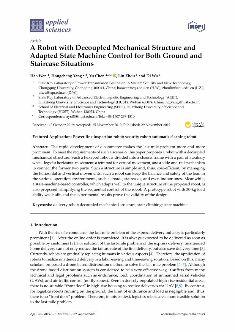
Similarly, according to Reference [30], to allow the robot to adapt to more staircases with differentwidth, as shown in Figure 10, the robot was designed to adapt to staircases with widths between280 mm and 340 mm. According to the analysis in Section 3, the robot’s capability of climbing thestairs with different widths depends on the two extreme cases shown in Table 6, where ∆lslide is thedistance of the relative slide, and it is determined to ensure the robot’s success in climbing to the upperstep under the premise of the stability of the center of gravity of the robot.
Appl. Sci. 2019, 9, 5185 13 of 16Appl. Sci. 2019, 9, x FOR PEER REVIEW 13 of 17
(a) (b)
Figure 10. The extreme cases of stair width: (a) w = 280 mm; (b) w = 340 mm.
Table 6. The description of the two cases.
Width of the Stairs w = 280 mm w = 340 mm Structure close to the step Front wheels Wheel-legs
Distance of the relative slide Δlslide = 170 mm
5.2. Experimental Results
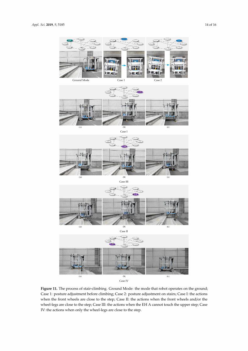
To implement the stair-climbing experiment for our robot, an outdoor staircase was chosen. Its width was 33 cm, and its height was 14 cm. The results are listed in Table 7, and the process is recorded in Figure 11. It can be seen that the robot could implement all the designed actions. It could adjust its posture if necessary (see the subfigures in which C-1 and C-2 are highlighted, where “C” denotes the abbreviation of “Case”), and it could climb up a four-step staircase successfully by choosing the four states (see the subfigures in which C-I, C-II, C-III, and C-IV are highlighted).
Table 7. The stair parameters and the time cost.
Steps 1 3 4 4 5 Width (cm) 28 30 28 32 30 Height (cm) 16 15 18 16 16
Time (s) 25 52 65 62 75
Ground Mode Case 1 Case 2
Figure 10. The extreme cases of stair width: (a) w = 280 mm; (b) w = 340 mm.
Table 6. The description of the two cases.
Width of the Stairs w = 280 mm w = 340 mm
Structure close to the step Front wheels Wheel-legsDistance of the relative slide ∆lslide = 170 mm
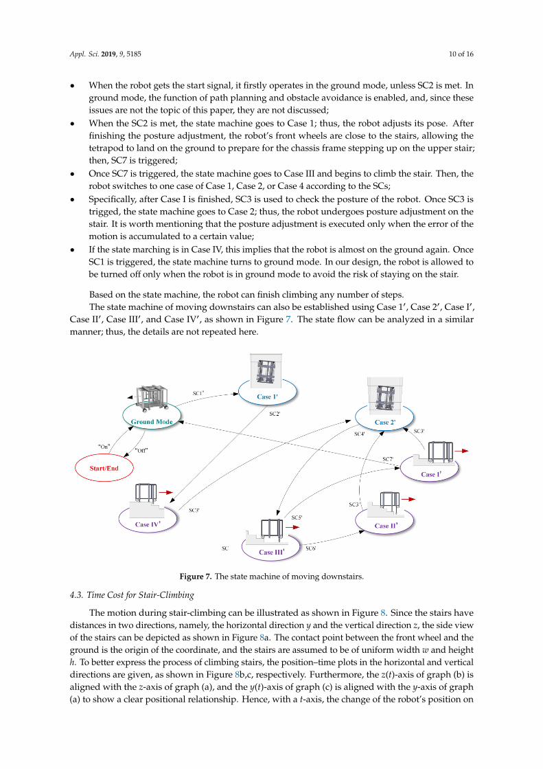
5.2. Experimental Results
To implement the stair-climbing experiment for our robot, an outdoor staircase was chosen. Itswidth was 33 cm, and its height was 14 cm. The results are listed in Table 7, and the process is recordedin Figure 11. It can be seen that the robot could implement all the designed actions. It could adjust itsposture if necessary (see the subfigures in which C-1 and C-2 are highlighted, where “C” denotes theabbreviation of “Case”), and it could climb up a four-step staircase successfully by choosing the fourstates (see the subfigures in which C-I, C-II, C-III, and C-IV are highlighted).
Table 7. The stair parameters and the time cost.
Steps 1 3 4 4 5
Width (cm) 28 30 28 32 30Height (cm) 16 15 18 16 16
Time (s) 25 52 65 62 75
Appl. Sci. 2019, 9, 5185 14 of 16
Appl. Sci. 2019, 9, x FOR PEER REVIEW 13 of 17
(a) (b)
Figure 10. The extreme cases of stair width: (a) w = 280 mm; (b) w = 340 mm.
Table 6. The description of the two cases.
Width of the Stairs w = 280 mm w = 340 mm Structure close to the step Front wheels Wheel-legs
Distance of the relative slide Δlslide = 170 mm
5.2. Experimental Results
To implement the stair-climbing experiment for our robot, an outdoor staircase was chosen. Its width was 33 cm, and its height was 14 cm. The results are listed in Table 7, and the process is recorded in Figure 11. It can be seen that the robot could implement all the designed actions. It could adjust its posture if necessary (see the subfigures in which C-1 and C-2 are highlighted, where “C” denotes the abbreviation of “Case”), and it could climb up a four-step staircase successfully by choosing the four states (see the subfigures in which C-I, C-II, C-III, and C-IV are highlighted).
Table 7. The stair parameters and the time cost.
Steps 1 3 4 4 5 Width (cm) 28 30 28 32 30 Height (cm) 16 15 18 16 16
Time (s) 25 52 65 62 75
Ground Mode Case 1 Case 2 Appl. Sci. 2019, 9, x FOR PEER REVIEW 14 of 17
Case I
Case III
Case II
Case IV
Figure 11. The process of stair-climbing. Ground Mode: the mode that robot operates on the ground; Case 1: posture adjustment before climbing; Case 2: posture adjustment on stairs; Case I: the actions Figure 11. The process of stair-climbing. Ground Mode: the mode that robot operates on the ground;
Case 1: posture adjustment before climbing; Case 2: posture adjustment on stairs; Case I: the actionswhen the front wheels are close to the step; Case II: the actions when the front wheels and/or thewheel-legs are close to the step; Case III: the actions when the EH A cannot touch the upper step; CaseIV: the actions when only the wheel-legs are close to the step.
Appl. Sci. 2019, 9, 5185 15 of 16
6. Conclusions
According to the results of the experiment, the proposed robot can realize stair-climbing stably.Meanwhile, the figure of the climbing process shows the decoupled structure and actions. Combinedwith the novel design of the mechanical structure, the proposed state machine allows simple control ofthe robot, even for complicated tasks, such as stair-climbing or omnidirectional movement indoors.Furthermore, during stair-climbing, the robot can maintain the balance of its platform, which meetsthe requirements of safe delivery mentioned in Section 1. Hence, it can realize real unmanned delivery,even home delivery. Furthermore, it can also be applied for emergencies and wheelchairs; however, thespeed of stair-climbing would be a key requirement. Therefore, improving the speed of stair-climbingunder the premise of the robot’s safety will be addressed in our future work.
7. Patents
The design was patented and published by the Chinese State Patent Office (publication numbersZL201822109903X and CN109515546A).
Author Contributions: Conceptualization, H.W. and H.Y.; methodology, H.W. and H.Y.; validation, H.Y.; formalanalysis, D.W. and H.Y.; investigation, H.Y.; resources, D.W.; data curation, H.Y.; writing—original draftpreparation, H.W.; writing—review and editing, Y.C. and H.Y.; visualization, Y.C.; supervision, Y.C.; projectadministration, Y.C.; funding acquisition, L.Z.
Funding: This research was funded by the National “111” Project of China under Grant B08036.
Acknowledgments: First and foremost, I would like to show my deepest gratitude to my team and my family.They are always saving me from confusion and helping me do what I insist on. I extend my thanks to my seniorfellow apprentice for his help and encouragement. Last but not least, I would like to thank my future girlfriendfor her stimulation.
Conflicts of Interest: The authors declare no conflicts of interest.
References
1. Sun, Y.; Wei, K.; Qiao, Z.; Wen, J.; Jiang, T. A personalized service for scheduling express delivery usingcourier trajectories. In Proceedings of the 2016 IEEE International Conference on Web Services (ICWS),San Francisco, CA, USA, 27 June–2 July 2016; pp. 220–227.
2. Niels, T.; Hof, M.T.; Bogenberger, K. Design and Operation of an Urban Electric Courier Cargo Bike System.In Proceedings of the 2018 21st International Conference on Intelligent Transportation Systems (ITSC), Maui,HI, USA, 4–7 November 2018; pp. 2531–2537.
3. Tiwapat, N.; Pomsing, C.; Jomthong, P. Last Mile Delivery: Modes, Efficiencies, Sustainability, and Trends.In Proceedings of the 2018 3rd IEEE International Conference on Intelligent Transportation Engineering(ICITE), Singapore, 3–5 September 2018; pp. 313–317.
4. Rubio, F.; Valero, F.; Llopis-Albert, C. A review of mobile robots: Concepts, methods, theoretical framework,and applications. Int. J. Adv. Robot. Syst. 2019, 16, 1729881419839596. [CrossRef]
5. Sawadsitang, S.; Niyato, D.; Tan, P.-S.; Wang, P. Joint Ground and Aerial Package Delivery Services: AStochastic Optimization Approach. IEEE Trans. Intell. Transp. Syst. 2018, 20, 2241–2254. [CrossRef]
6. Lee, J. Optimization of a modular drone delivery system. In Proceedings of the 2017 Annual IEEE InternationalSystems Conference (SysCon), Montreal, QC, Canada, 24–27 April 2017; pp. 1–8.
7. Marinelli, M.; Caggiani, L.; Ottomanelli, M.; Dell’Orco, M. En route truck–drone parcel delivery for optimalvehicle routing strategies. IET Intell. Transp. Syst. 2017, 12, 253–261. [CrossRef]
8. Barmpounakis, E.N.; Vlahogianni, E.I.; Golias, J.C. Technology. Unmanned Aerial Aircraft Systems fortransportation engineering: Current practice and future challenges. Int. J. Transp. Sci. Technol. 2016, 5,111–122. [CrossRef]
9. Murray, C.C.; Chu, A.G. The flying sidekick traveling salesman problem: Optimization of drone-assistedparcel delivery. Transp. Res. Part C Emerg. Technol. 2015, 54, 86–109. [CrossRef]
10. Yang, D.; Bewley, T. A minimalist Stair Climbing Robot (SCR) formed as a leg balancing & climbing MobileInverted Pendulum (MIP). In Proceedings of the 2018 IEEE/RSJ International Conference on IntelligentRobots and Systems (IROS), Madrid, Spain, 1–5 October 2018; pp. 2464–2469.

Appl. Sci. 2019, 9, 5185 16 of 16
11. Chandu, K.H.; Narayana, P.H.; Teja, K.C.; Sai, B.; Mohan, Y.M. Design and Fabrication of Rocker BogieMechanism. Int. J. Sci. Eng. Technol. Res. 2018, 7, 781–784.
12. Schwarz, M.; Rodehutskors, T.; Schreiber, M.; Behnke, S. Hybrid driving-stepping locomotion with thewheeled-legged robot Momaro. In Proceedings of the 2016 IEEE International Conference on Robotics andAutomation (ICRA), Stockholm, Sweden, 16–21 May 2016; pp. 5589–5595.
13. Tanaka, M.; Nakajima, M.; Suzuki, Y.; Tanaka, K. Development and control of articulated mobile robot forclimbing steep stairs. IEEE/ASME Trans. Mechatron. 2018, 23, 531–541. [CrossRef]
14. Yuyao, S.; Elara, M.R.; Kalimuthu, M.; Devarassu, M. sTetro: A modular reconfigurable cleaning robot. InProceedings of the 2018 International Conference on Reconfigurable Mechanisms and Robots (ReMAR),Delft, The Netherlands, 20–22 June 2018; pp. 1–8.
15. Zhang, L.; Yang, Y.; Gu, Y.; Sun, X.; Yao, X.; Shuai, L. A new compact stair-cleaning robot. J. Mech. Robot.2016, 8, 45001. [CrossRef]
16. Hurst, J. Walk this way: To be useful around people, robots need to learn how to move like we do. IEEESpectr. 2019, 56, 30–51. [CrossRef]
17. Liu, J.; Gao, F.; Chen, X. Design of a New Waist for a Hexapod Robot with Parallel Leg Mechanism toIncrease its Stair-Climbing Capability. In Proceedings of the ASME 2017 International Design EngineeringTechnical Conferences and Computers and Information in Engineering Conference, Cleveland, OH, USA,6–9 August 2017.
18. Behera, P.K.; Gupta, A. Novel design of stair climbing wheelchair. J. Mech. Sci. Technol. 2018, 32, 4903–4908.[CrossRef]
19. Meng, X.; Wang, S.; Cao, Z.; Zhang, L. A review of quadruped robots and environment perception.In Proceedings of the 2016 35th Chinese Control Conference (CCC), Chengdu, China, 27–29 July 2016;pp. 6350–6356.
20. Fang, L.; Gao, F. Type Design and Behavior Control for Six Legged Robots. Chin. J. Mech. Eng. 2018, 31, 59.[CrossRef]
21. Dalvand, M.M.; Moghadam, M.M. Stair climber smart mobile robot (MSRox). Auton. Robot. 2006, 20, 3–14.[CrossRef]
22. Liu, J.; Wu, Y.; Guo, J.; Chen, Q. High-order sliding mode-based synchronous control of a novel stair-climbingwheelchair robot. J. Control Sci. Eng. 2015, 2015, 46. [CrossRef]
23. Morales, R.; Feliu, V.; González, A.; Pintado, P. Kinematic model of a new staircase climbing wheelchair andits experimental validation. Int. J. Robot. Res. 2006, 25, 825–841. [CrossRef]
24. Turlapati, S.H.; Shah, M.; Teja, S.P.; Siravuru, A.; Shah, S.V. Stair climbing using a compliant modular robot.In Proceedings of the 2015 IEEE/RSJ International Conference on Intelligent Robots and Systems (IROS),Hamburg, Germany, 28 September–2 October 2015; pp. 3332–3339.
25. Yuan, J.; Hirose, S. Research on leg-wheel hybrid stair-climbing robot, Zero Carrier. In Proceedings of the2004 IEEE International Conference on Robotics and Biomimetics, Shenyang, China, 22–26 August 2004;pp. 654–659.
26. Viboonchaicheep, P.; Shimada, A.; Kosaka, Y. Position rectification control for Mecanum wheeledomni-directional vehicles. In Proceedings of the IECON’03. 29th Annual Conference of the IEEE IndustrialElectronics Society (IEEE Cat. No. 03CH37468), Roanoke, VA, USA, 2–6 November 2003; pp. 854–859.
27. Mourikis, A.I.; Trawny, N.; Roumeliotis, S.I.; Helmick, D.M.; Matthies, L. Autonomous stair climbing fortracked vehicles. Int. J. Robot. Res. 2007, 26, 737–758. [CrossRef]
28. Muhammad, I.; Sivanantham, V.; Devarassu, M.; Ramalingam, B.; Elara, M.R. A Novel Method for 3DAbsolute Localization and Orientation of a Stair Cleaning Robot Using Staircase Geometry and OnboardSensors. Preprints 2018, 2018110295. [CrossRef]
29. JT/T.713–2008. Pavement Rubber Pump; Standards Press of China: Beijing, China, 2008.30. JG/T.405–2013. Stair for upholstery of domicile; Standards Press of China: Beijing, China, 2013.
© 2019 by the authors. Licensee MDPI, Basel, Switzerland. This article is an open accessarticle distributed under the terms and conditions of the Creative Commons Attribution(CC BY) license (http://creativecommons.org/licenses/by/4.0/).