
A six-phase series-connected two-motor drive with decoupled dynamic control
11
1056 IEEE TRANSACTIONS ON INDUSTRY APPLICATIONS, VOL. 41, NO. 4, JULY/AUGUST 2005 A Six-Phase Series-Connected Two-Motor Drive With Decoupled Dynamic Control Martin Jones, Slobodan N. Vukosavic, Member, IEEE, Emil Levi, Senior Member, IEEE, and Atif Iqbal Abstract—This paper analyzes a six-phase two-motor drive, consisting of a six-phase voltage-source inverter (VSI), a six-phase induction machine, and a three-phase induction machine. Stator windings of the two machines are connected in series in an ap- propriate manner. This enables full decoupling of the dynamics of the two machines by means of vector control. Detailed math- ematical modeling of the system is performed and the set of – equations, describing the two machines connected in series to a six-phase VSI, is developed. The resulting model clearly shows the possibility of independent vector control of the two machines, although a single VSI is used as the supply. An experimental rig is constructed and existence of the decoupled dynamic control of the two machines supplied from a single VSI is fully verified by extensive experimental testing. Index Terms—Multimotor drives, multiphase machines, six-phase, vector control. I. INTRODUCTION S IX-PHASE ac motor drives are often considered as viable solutions when reduction of the inverter per-phase rating is required due to the high motor power. Although the basic concept is old [1], there has been an upsurge in the interest in this type of ac motor drive in recent time [2]–[5]. The stan- dard choice is a six-phase induction or synchronous machine with two three-phase windings on the stator. The spatial dis- placement between the two three-phase windings is 30 (so- called quasi-six-phase machine) and neutral points of the two windings can be isolated or connected. The main reason for se- lecting the asymmetrical six-phase winding instead of the true six-phase winding (60 displacement between any two consec- utive phases), elimination of the sixth harmonic from the torque [1], was important in the pre-pulsewidth-modulation (PWM) era of voltage-source inverter (VSI) control. It is nowadays less rele- vant since good inverter current control in PWM mode can elim- inate low-order harmonics from the inverter output currents. A true six-phase induction motor is used in the work described here, with the underlying idea of realizing a two-motor drive Paper IPCSD-05-028, presented at the 2004 Industry Applications Society Annual Meeting, Seattle, WA, October 3–7, and approved for publication in the IEEE TRANSACTIONS ON INDUSTRY APPLICATIONS by the Industrial Drives Committee of the IEEE Industry Applications Society. Manuscript submitted for review July 8, 2004 and released for publication April 6, 2005. This work was supported by the Engineering and Physical Sciences Research Council under Standard Research Grant GR/R64452/01 and by Semikron Ltd. The work of M. Jones was also supported by the Institution of Electrical Engineers, U.K. (IEE), through the IEE Robinson Research Scholarship. The authors are with the School of Engineering, Liverpool John Moores University, Liverpool, L3 3AF, U.K. (e-mail: [email protected]; [email protected]; [email protected]; [email protected]). Digital Object Identifier 10.1109/TIA.2005.851020 system with independent vector control, while utilizing a single six-phase VSI as the supply. The two-motor drive system is realized by connecting in series with such a six-phase induction machine, the second, three-phase induction machine. The appropriate series connec- tion of the stator windings of the two machines should enable, according to [6], independent and decoupled vector control of the two machines, although a single six-phase inverter supply is used. The six-phase series-connected two-motor drive is one particular case of a much wider concept, which is applicable to any phase number greater than or equal to five. It relies on the fact that any -phase ac machine, regardless of the type, requires only two currents for independent flux and torque control [6], [7]. A general study for all the possible even phase numbers has been reported in [6] while a corresponding study for odd phase numbers can be found in [7]. Studies reported in [6] and [7] were based on physical and intuitive reasoning and they provide verification of the concept by simulation. Detailed mathematical models of series-connected multiphase multi- motor drive systems of [6], [7] do not exist at present, except for the two-motor five-phase drive [8]. Moreover, the concept has never been proved before by experimental investigation for any phase number. The purpose of this paper is twofold. In the first part of the paper (Sections II–IV), a rigorous mathematical modeling of the six-phase series-connected two-motor drive system is reported. The final result is a model in the rotor flux oriented reference frames of the two machines. This model confirms mathemati- cally the existence of means for independent rotor flux oriented control of the two-motor drive system. The second part of the paper (Sections V and VI) at first describes the experimental rig, constructed with the aim of verifying the existence of the com- pletely decoupled dynamic control of the two machines. This is followed by presentation of results collected from the rig for rel- evant transients (acceleration, deceleration, reversing, and step loading/unloading). The complete decoupling of the dynamics of the two machines is thus confirmed experimentally. Conclu- sions are drawn in VII The six-phase series-connected two-motor drive is seen as well suited for applications where a six-phase motor drive is used anyway due to high power requirements. In many such situations there is a need for an auxiliary low-power motor drive, which has to be controlled independently. In such cases proposed series connection enables control of the second ma- chine at no extra cost, since the existing inverter can be utilized. One possible application of this type is in locomotive traction, where high-power six-phase machines are already utilized as main driving motors. The two-motor arrangement of this paper 0093-9994/$20.00 © 2005 IEEE
-
Upload
independent -
Category
Documents
-
view
5 -
download
0
Transcript of A six-phase series-connected two-motor drive with decoupled dynamic control

1056 IEEE TRANSACTIONS ON INDUSTRY APPLICATIONS, VOL. 41, NO. 4, JULY/AUGUST 2005
A Six-Phase Series-Connected Two-Motor DriveWith Decoupled Dynamic Control
Martin Jones, Slobodan N. Vukosavic, Member, IEEE, Emil Levi, Senior Member, IEEE, and Atif Iqbal
Abstract—This paper analyzes a six-phase two-motor drive,consisting of a six-phase voltage-source inverter (VSI), a six-phaseinduction machine, and a three-phase induction machine. Statorwindings of the two machines are connected in series in an ap-propriate manner. This enables full decoupling of the dynamicsof the two machines by means of vector control. Detailed math-ematical modeling of the system is performed and the set of –equations, describing the two machines connected in series to asix-phase VSI, is developed. The resulting model clearly showsthe possibility of independent vector control of the two machines,although a single VSI is used as the supply. An experimental rigis constructed and existence of the decoupled dynamic control ofthe two machines supplied from a single VSI is fully verified byextensive experimental testing.
Index Terms—Multimotor drives, multiphase machines,six-phase, vector control.
I. INTRODUCTION
S IX-PHASE ac motor drives are often considered as viablesolutions when reduction of the inverter per-phase rating
is required due to the high motor power. Although the basicconcept is old [1], there has been an upsurge in the interest inthis type of ac motor drive in recent time [2]–[5]. The stan-dard choice is a six-phase induction or synchronous machinewith two three-phase windings on the stator. The spatial dis-placement between the two three-phase windings is 30 (so-called quasi-six-phase machine) and neutral points of the twowindings can be isolated or connected. The main reason for se-lecting the asymmetrical six-phase winding instead of the truesix-phase winding (60 displacement between any two consec-utive phases), elimination of the sixth harmonic from the torque[1], was important in the pre-pulsewidth-modulation (PWM) eraof voltage-source inverter (VSI) control. It is nowadays less rele-vant since good inverter current control in PWM mode can elim-inate low-order harmonics from the inverter output currents. Atrue six-phase induction motor is used in the work describedhere, with the underlying idea of realizing a two-motor drive
Paper IPCSD-05-028, presented at the 2004 Industry Applications SocietyAnnual Meeting, Seattle, WA, October 3–7, and approved for publication inthe IEEE TRANSACTIONS ON INDUSTRY APPLICATIONS by the Industrial DrivesCommittee of the IEEE Industry Applications Society. Manuscript submitted forreview July 8, 2004 and released for publication April 6, 2005. This work wassupported by the Engineering and Physical Sciences Research Council underStandard Research Grant GR/R64452/01 and by Semikron Ltd. The work ofM. Jones was also supported by the Institution of Electrical Engineers, U.K.(IEE), through the IEE Robinson Research Scholarship.
The authors are with the School of Engineering, Liverpool John MooresUniversity, Liverpool, L3 3AF, U.K. (e-mail: [email protected];[email protected]; [email protected]; [email protected]).
Digital Object Identifier 10.1109/TIA.2005.851020
system with independent vector control, while utilizing a singlesix-phase VSI as the supply.
The two-motor drive system is realized by connecting inseries with such a six-phase induction machine, the second,three-phase induction machine. The appropriate series connec-tion of the stator windings of the two machines should enable,according to [6], independent and decoupled vector control ofthe two machines, although a single six-phase inverter supplyis used. The six-phase series-connected two-motor drive is oneparticular case of a much wider concept, which is applicableto any phase number greater than or equal to five. It relies onthe fact that any -phase ac machine, regardless of the type,requires only two currents for independent flux and torquecontrol [6], [7]. A general study for all the possible even phasenumbers has been reported in [6] while a corresponding studyfor odd phase numbers can be found in [7]. Studies reported in[6] and [7] were based on physical and intuitive reasoning andthey provide verification of the concept by simulation. Detailedmathematical models of series-connected multiphase multi-motor drive systems of [6], [7] do not exist at present, exceptfor the two-motor five-phase drive [8]. Moreover, the concepthas never been proved before by experimental investigation forany phase number.
The purpose of this paper is twofold. In the first part of thepaper (Sections II–IV), a rigorous mathematical modeling of thesix-phase series-connected two-motor drive system is reported.The final result is a model in the rotor flux oriented referenceframes of the two machines. This model confirms mathemati-cally the existence of means for independent rotor flux orientedcontrol of the two-motor drive system. The second part of thepaper (Sections V and VI) at first describes the experimental rig,constructed with the aim of verifying the existence of the com-pletely decoupled dynamic control of the two machines. This isfollowed by presentation of results collected from the rig for rel-evant transients (acceleration, deceleration, reversing, and steploading/unloading). The complete decoupling of the dynamicsof the two machines is thus confirmed experimentally. Conclu-sions are drawn in VII
The six-phase series-connected two-motor drive is seen aswell suited for applications where a six-phase motor drive isused anyway due to high power requirements. In many suchsituations there is a need for an auxiliary low-power motordrive, which has to be controlled independently. In such casesproposed series connection enables control of the second ma-chine at no extra cost, since the existing inverter can be utilized.One possible application of this type is in locomotive traction,where high-power six-phase machines are already utilized asmain driving motors. The two-motor arrangement of this paper
0093-9994/$20.00 © 2005 IEEE
JONES et al.: SIX-PHASE SERIES-CONNECTED TWO-MOTOR DRIVE WITH DECOUPLED DYNAMIC CONTROL 1057
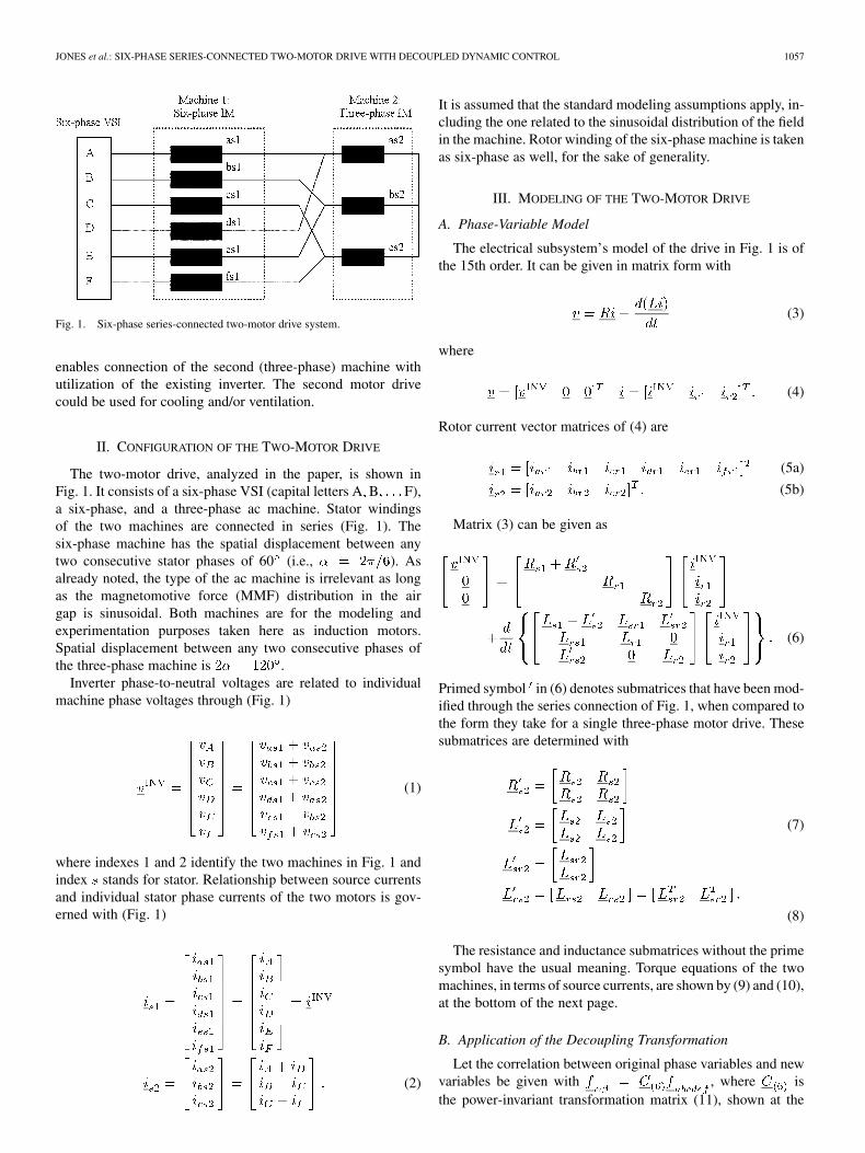
Fig. 1. Six-phase series-connected two-motor drive system.
enables connection of the second (three-phase) machine withutilization of the existing inverter. The second motor drivecould be used for cooling and/or ventilation.
II. CONFIGURATION OF THE TWO-MOTOR DRIVE
The two-motor drive, analyzed in the paper, is shown inFig. 1. It consists of a six-phase VSI (capital letters A B F),a six-phase, and a three-phase ac machine. Stator windingsof the two machines are connected in series (Fig. 1). Thesix-phase machine has the spatial displacement between anytwo consecutive stator phases of 60 (i.e., ). Asalready noted, the type of the ac machine is irrelevant as longas the magnetomotive force (MMF) distribution in the airgap is sinusoidal. Both machines are for the modeling andexperimentation purposes taken here as induction motors.Spatial displacement between any two consecutive phases ofthe three-phase machine is .
Inverter phase-to-neutral voltages are related to individualmachine phase voltages through (Fig. 1)
(1)
where indexes 1 and 2 identify the two machines in Fig. 1 andindex stands for stator. Relationship between source currentsand individual stator phase currents of the two motors is gov-erned with (Fig. 1)
(2)
It is assumed that the standard modeling assumptions apply, in-cluding the one related to the sinusoidal distribution of the fieldin the machine. Rotor winding of the six-phase machine is takenas six-phase as well, for the sake of generality.
III. MODELING OF THE TWO-MOTOR DRIVE
A. Phase-Variable Model
The electrical subsystem’s model of the drive in Fig. 1 is ofthe 15th order. It can be given in matrix form with
(3)
where
(4)
Rotor current vector matrices of (4) are
(5a)
(5b)
Matrix (3) can be given as
(6)
Primed symbol in (6) denotes submatrices that have been mod-ified through the series connection of Fig. 1, when compared tothe form they take for a single three-phase motor drive. Thesesubmatrices are determined with
(7)
(8)
The resistance and inductance submatrices without the primesymbol have the usual meaning. Torque equations of the twomachines, in terms of source currents, are shown by (9) and (10),at the bottom of the next page.
B. Application of the Decoupling Transformation
Let the correlation between original phase variables and newvariables be given with , where isthe power-invariant transformation matrix (11), shown at the

1058 IEEE TRANSACTIONS ON INDUSTRY APPLICATIONS, VOL. 41, NO. 4, JULY/AUGUST 2005
bottom of the page. The corresponding matrix for the three-phase system is
(12)
Application of the transformation matrix (11) in conjunctionwith the first two rows of (6) and application of (12) in conjunc-tion with the third row of (6) lead to the decoupled model of thesix-phase two-motor drive system. Rotor voltage equations ofthe six-phase machine become
(13)
Similarly, for the rotor of the three-phase machine one obtains
(14)
Source voltage equations, which include equations of the twostator windings connected in series, can be given as
(15)
Magnetizing inductances in (13)–(15) are and, index stands for leakage inductances, and
are stator and rotor self-inductances.
(9)
(10)
(11)

JONES et al.: SIX-PHASE SERIES-CONNECTED TWO-MOTOR DRIVE WITH DECOUPLED DYNAMIC CONTROL 1059
Application of the decoupling transformation on the torqueequations (9) and (10) yields
(16)
According to (15) and (16), flux/torque-producing stator cur-rents of the six-phase machine are the inverter – current com-ponents, while the flux/torque-producing stator currents of thethree-phase machine are the inverter – current components.This indicates the possibility of independent vector control oftwo machines, as predicted in [6]. Inverter voltage equations(15) can be given in terms of axis voltage components of thetwo machines as
(17)
Similarly, individual flux/torque-producing currents of thetwo machines are related with the inverter current axis compo-nents by
(18)
C. Model in the Stationary Common Reference Frame
The rotational transformation, leading to the - system ofequations, is applied next in conjunction with the rotor equa-tions. The matrix for the six-phase machine is given with
(19)
where is the diagonal 4 4 unity matrix. The transformationmatrix for the three-phase machine is of the same form, exceptthat the rotor angular position is and the matrix dimensionsare 3 3.
Since, according to (13) and (14), rotor equations for – andzero-sequence components are completely decoupled from therest of the system and these circuits cannot be excited, these
equations can be omitted from further consideration. Upon ap-plication of the rotational transformation the voltage equationsfor the two rotor windings in the stationary common referenceframe become
(20)
(21)
while the source equations are given with
(22)
Torque equations (16) become
(23)
Equations (17) and (18) remain to be valid in an unchangedform, with the replacement of indexes with .
Model (20)–(23) in the stationary reference frame shows thatthe rotor of the six-phase machine is coupled only with inverter
- currents, while rotor of the three-phase machine coupleswith inverter – currents. Consequently, inverter – currentsgovern the torque production of the six-phase machine, whiletorque production of the three-phase machine is determinedwith inverter – currents. It therefore follows that the specificconnection of the stator windings, shown in Fig. 1, can enableindependent dynamic control of the two series-connectedmachines, using vector control principles.

1060 IEEE TRANSACTIONS ON INDUSTRY APPLICATIONS, VOL. 41, NO. 4, JULY/AUGUST 2005
D. Model in Rotor-Flux-Oriented Reference Frames
The simplest way to proceed further is to take the equationsin the stationary reference frame (20)–(22) and define the fol-lowing space vectors:
(24)
The first four equations of (22) can then be written in compactform as
(25)
Transformation is done next separately for the inverter –equations and rotor equations of the six-phase machine, and theinverter – equations and rotor equations of the three-phasemachine. This is possible since there exists full decouplingbetween the inverter – and - currents. Rotor-flux-orientedreference frames are defined with the angle of transformationand angular speed using andfor the two machines, respectively. Correlation between cur-rent and voltage space vectors in the stationary and in therotor-flux-oriented reference frames is given with
(26)
Application of (26) in conjunction with the model in thestationary reference frame (20)–(22) yields the equations in therotor-flux-oriented reference frames. Inverter - equations androtor equations of the six-phase machine are expressed in thereference frame fixed to the rotor flux of the six-phase machine[additional superscript (1)]. Similarly, inverter – voltageequations and rotor equations of the three-phase machine aregiven in the reference frame attached to the rotor flux of thethree-phase machine [additional superscript (2)]. The zero-se-quence equations remain the same as in (22) and are, therefore,not repeated. The final model is given with
(27)
(28)
Fig. 2. Indirect (feedforward) rotor-flux-oriented controller for the six-phaseinduction machine (K = 1=(T i ); p � d=dt).
(29)
Torque equations of the two machines (23) essentially do notchange the form
(30)
IV. VECTOR CONTROL OF THE TWO-MOTOR DRIVE
As the model (27)–(30) indicates, the two series-connectedmachines can be controlled independently using rotor-flux-ori-ented control principles. Flux and torque of the six-phase ma-chine are controllable by inverter - -axis current components,while flux and torque of the three-phase machine can be con-trolled using inverter – current components. Indirect (feed-forward) rotor-flux-oriented control is considered and currentcontrol in the stationary reference frame is assumed and exer-cised upon the inverter phase currents. The vector controller isof the same structure for both machines and is illustrated for thesix-phase machine in Fig. 2. Individual phase current referencesof the two machines are given with
(31a)
(31b)
Phase current references for the two machines need further tobe summed in order to create overall inverter phase current ref-

JONES et al.: SIX-PHASE SERIES-CONNECTED TWO-MOTOR DRIVE WITH DECOUPLED DYNAMIC CONTROL 1061
Fig. 3. Experimental rig: the six-phase voltage-source inverter and thesix-phase (front) and three-phase (back) machine.
erences. Since each phase of the three-phase machine is con-nected to two phases of the six-phase machine, each inverterphase current reference has to consist of the sum of the six-phasemachine phase current reference and one-half of the three-phasemachine current reference. The inverter phase current referencesare, hence, created with the aid of the connection diagram ofFig. 1 in the following manner:
(32)
V. EXPERIMENTAL SETUP
The experimental rig, illustrated in Fig. 3, utilizes twothree-phase inverters with the common dc link, each of whichis equipped with a digital signal processor (DSP). The invertersare rated at 14/42 A/A (continuous rms/peak). Each of themis equipped with a Texas Instruments TMS320F240 DSP.The first three-phase inverter supplies phases A, C, and E,while the second inverter supplies phases B, D, and F. Allsix currents are measured using LEM sensors. The currentcontrol rate and the inverter switching frequency are 10 kHz.PWM ripple is filtered out in the DSPs using finite-impulseresponse (FIR) filters, which average equidistant samples
taken during one switching period. The current signal, whichis now PWM-ripple-free, is further used as the input of thecurrent controllers. The inverter DSPs perform closed-loopcurrent control in the stationary reference frame using theramp-comparison method in the most basic form [9] (hence,the problem of deviation of the actual motor phase currentwith respect to its reference will be experienced at higheroperating frequencies [9]; this could be removed by employingimproved current regulators [10], however, such a modificationof the current controllers is beyond the scope of this paper).The inverter current references are passed to the DSPs froma PC, through a dedicated interface card. The control code iswritten in C. It performs closed-loop speed control and indirectrotor-flux-oriented control according to Fig. 2, in parallel forthe two machines. Phase current references are calculatedfor the two machines using (31) and inverter phase currentreferences are finally generated by means of (32).
The six-phase induction machine is obtained by rewindingthe stator of a three-phase machine and is 50 Hz, six-pole. Ratedphase-to-neutral voltage is 110 V and other relevant ratings are1.1 kW, 2.7 A, and 900 r/min. The three-phase induction ma-chine is an industrial servo-drive (1 kW, 120 Hz, four-pole, 325V line-to-line). Both machines are equipped with resolvers andcontrol operates in the speed-sensored mode. Closed-loop speedcontrol is analyzed in experiments.
Various experimental tests are performed in order to verify theindependence of the control of the two machines. The results arereported in the following section. Operation in the base speedregion only is considered and the stator -axis current referencesof both machines are constant at all times (1.5 A rms for eachmachine). Both machines are running under no-load conditions(except for the load torque application/removal transients).
VI. EXPERIMENTAL RESULTS
The following approach is adopted in testing, with the ideaof proving the decoupling of control of the two machines. Bothmachines are initially brought to a certain steady-state speed.A speed transient is initiated next for either the six-phase or thethree-phase machine, while the operating speed of the other ma-chine remains unchanged. Full decoupling of control will exist ifand only if the speed and, more importantly, stator -axis currentcommand of the machine whose speed reference has not been al-tered do not change. The transients examined in experiments areacceleration, deceleration, reversing (which all take place underno-load conditions), and step loading/unloading transients.
In the first test the six-phase machine runs at 500 r/min (25Hz) in the reverse direction, while the speed reference of thethree-phase machine is initially 0 r/min. The speed reference ofthe three-phase machine is at s stepped to 300 r/min(10 Hz). Fig. 4 illustrates speed responses and stator -axis cur-rent references of the two machines. The corresponding phasecurrent references of the two machines are shown in Fig. 5(a).Fig. 5(b) shows a comparison between inverter current refer-ence created using (32) and the actual inverter phase current.It can be seen in Fig. 4 that initiation of a speed transient forthe three-phase machine has no impact on the behavior of thesix-phase machine since neither the speed nor the stator -axis

1062 IEEE TRANSACTIONS ON INDUSTRY APPLICATIONS, VOL. 41, NO. 4, JULY/AUGUST 2005
Fig. 4. Speed responses and stator q-axis current commands for anacceleration transient: six-phase machine runs at �500 r/min, while thethree-phase machine is accelerated from 0 to 300 r/min.
current reference change. This is further confirmed by inspec-tion of the phase current reference in Fig. 5(a) for the six-phasemachine, which does not exhibit any change whatsoever duringthe transient of the three-phase machine. The inverter current[Fig. 5(b)] is in the previous steady state a sinusoidal function ofapproximately 25-Hz frequency with a dc offset caused by thestator -axis current (magnetizing current) of the three-phasemachine (which is at standstill). Upon completion of the tran-sient, the inverter current is a sum of two sinusoidal functionsof (31) with different frequencies and magnitudes that are ob-tained using (32). As can be seen from Fig. 5(b), measured andreference inverter current are in very good agreement.
In the second test, the role of the two machines is reversed,meaning that the transient is initiated for the six-phase machine.Deceleration is considered this time. The three-phase machineruns at constant 600-r/min (20 Hz) speed, while the six-phasemachine is decelerated from an initial 800 r/min (40 Hz) tozero speed. Speed responses and stator -axis current referencesfor this transient are depicted in Fig. 6. It is evident from Fig. 6that the speed of the three-phase machine remains unaffected bythe transient of the six-phase machine. The same observationfollows from traces of stator -axis current references, whereonly a minor change in the ripple frequency (but not in magni-tude) of the three-phase motor -axis current reference can be
Fig. 5. (a) Stator phase current references for the two machines. (b)Comparison of measured and reference inverter phase current. Conditions ofFig. 4 apply.
observed. This is due to the change in the inverter noise char-acteristic that depends on the operating frequencies of both ma-chines.
Some further reversing tests are conducted next to furtherverify decoupling of the control of the two machines. Fig. 7 dis-plays results for the case when the speed of the three-phase ma-chine is kept at zero, while the six-phase machine is reversedfrom 500 to 500 r/min. Both speed and stator -axis currentreference of the three-phase machine remain essentially unaf-fected by the reversing of the six-phase machine. The identicalconclusion follows from Fig. 8 where the six-phase machinespeed is kept at zero while the three-phase machine is reversedfrom 600 to 600 r/min. On this occasion, the six-phase ma-chine is not affected by the transient of the three-phase machineas evidenced from the speed response and stator -axis currentreference of the six-phase machine. A comparison of measuredand reference inverter current is included in both figures. Theseare, once more, in very good agreement.
A further test consists of the step load torque application onthe three-phase machine, running at 1000 r/min. The six-phasemachine runs at 400 r/min and the load torque applied to the

JONES et al.: SIX-PHASE SERIES-CONNECTED TWO-MOTOR DRIVE WITH DECOUPLED DYNAMIC CONTROL 1063
Fig. 6. Speed responses and stator q-axis current commands for a decelerationtransient: three-phase machine runs at 600 r/min, while the six-phase machineis decelerated from �800 to 0 r/min.
three-phase machine is around 40%–45% of the rated torque.The speed responses and stator -axis current references areshown in Fig. 9. No variation whatsoever can be observed ineither the six-phase machine speed trace or the six-phase ma-chine’s -axis current reference. Since the three-phase machineflux/torque-producing currents flow through the windings of thesix-phase machine, this test, which asks for practically instan-taneous change of the three-phase motor currents, can be takenas an ultimate proof of the truly independent control of the twomachines.
The last test, illustrated in Fig. 10, is the step unloading ofthe six-phase machine at 500 r/min with the three-phase ma-chine running at 800 r/min. In addition to the speed and stator-axis current reference traces, measured and reference inverter
currents, as well as current references for one phase of each ma-chine, are included as well. It is evident from Fig. 10 that stepunloading of the six-phase machine does not cause any distur-bance in the three-phase machine’s speed and stator -axis cur-rent reference traces.
Some asymmetry is evident in the trace of the six-phase ma-chine phase current reference (Fig. 10) before step unloading.This is the consequence of the stator -axis current ripple. Al-though the ripple is practically the same in both no-load andloaded operation, its impact on the stator phase current peak
Fig. 7. Speed responses, stator q-axis current references, and a comparisonbetween measured and reference inverter current for a reversing transient:three-phase machine at standstill, six-phase machine reversed from �500 to500 r/min.
value increases with loading, due to an increase in the averagestator -axis current. Hence, the phase current reference ex-hibits some variation in the peak values, determined with thefrequency of the ripple in the stator -axis current.
It is felt that the origin of the torque (stator -axis current)ripple in the six-phase machine deserves an explanation. Al-though transients of the three-phase machine do not cause a dis-turbance in the six-phase machine’s torque (stator -axis cur-

1064 IEEE TRANSACTIONS ON INDUSTRY APPLICATIONS, VOL. 41, NO. 4, JULY/AUGUST 2005
Fig. 8. Speed responses, stator q-axis current references, and a comparisonbetween measured and reference inverter current for a reversing transient:six-phase machine at 0 r/min, three-phase machine 600 to �600 r/min.
rent), the ripple at nonzero speeds (Figs. 4, 6, 7, 9, and 10) ex-ceeds the amount that could be assigned to the measurementnoise. However, the ripple is not caused by the series connectionof the two machines, since it exists even when the six-phase ma-chine is operated as a single vector-controlled drive (i.e., whenthe three-phase machine is disconnected). To prove this state-ment, Fig. 11 illustrates a speed reversal of the six-phase induc-tion machine from 500 to 500 r/min (25 Hz). The three-phase
Fig. 9. Speed responses and stator q-axis current references during steploading of the three-phase motor running at 1000 r/min (six-phase machineruns at 400 r/min).
machine has been removed from the setup for this experiment.The stator current spectrum in final steady state at 25 Hz is in-cluded as well. Torque ripple in Fig. 11 practically coincideswith the ripple in Fig. 4 where the machine was running at
500 r/min. This confirms that the torque ripple is inherentto the six-phase machine. The stator current spectrum showsthe presence of subharmonics at frequencies 1/3 (backward ro-tating field) and 5/3 (forward rotating field) of the fundamentalfrequency, which combine to yield a torque ripple with a fre-quency of 2/3 of the fundamental frequency under no-load con-ditions. On the basis of these considerations it is concluded thatthe torque ripple in the six-phase machine is caused by dynamiceccentricities of the second order.
VII. CONCLUSION
This paper has analyzed a six-phase series-connected two-motor drive system. The phase-variable model was initially in-troduced and the detailed modeling procedure was presented.The model is transformed using transformations of the generaltheory of electrical machines and the – -axis model in the sta-tionary reference frame was developed. Properties of this modelare such that they unambiguously show the possibility of decou-pled vector control of the system, using

JONES et al.: SIX-PHASE SERIES-CONNECTED TWO-MOTOR DRIVE WITH DECOUPLED DYNAMIC CONTROL 1065
Fig. 10. Step unloading of the six-phase machine at 500 r/min with three-phasemachine running at 800 r/min.
Fig. 11. Six-phase machine’s speed reversal from �500 to 500 r/min andstator phase current spectrum at 500 r/min (25 Hz). The three-phase machinewas disconnected in this experiment.
a single six-phase VSI. The model is finally transformed intorotor-flux-oriented reference frames of the two machines. Onthe basis of the resulting model, indirect vector control prin-ciples were developed for the two-motor structure that assumecurrent control in the stationary reference frame.
An experimental rig was further described. This was followedby presentation of detailed experimental results for a numberof transients. These include acceleration, deceleration, and re-versing, as well as the loading transient. The results show thatit is possible to independently operate two induction machinesfrom a single inverter with completely decoupled control.
As already noted in Section I, the six-phase series-connectedtwo-motor drive is well suited for applications where a six-phase motor drive is used anyway due to high power require-ments. Since the six-phase inverter is then already in existence,the addition of the second machine does not require any newhardware. It is only necessary to slightly modify the software,which means that the investment in the control and supply of thesecond (three-phase) motor drive is practically nonexistent. Thisremark applies provided that the three-phase machine is of a rea-sonably low voltage rating, so that the inverter voltage marginis not jeopardized by the connection of the second machine.The three-phase machine has to be of a considerably smaller

1066 IEEE TRANSACTIONS ON INDUSTRY APPLICATIONS, VOL. 41, NO. 4, JULY/AUGUST 2005
power rating than the six-phase machine, since the six-phasemachine’s stator winding losses increase due to the series con-nection with the three-phase machine (the three-phase machineis not adversely affected in any way by the series connectionwith the six-phase machine).
REFERENCES
[1] R. H. Nelson and P. C. Krause, “Induction machine analysis for arbitrarydisplacement between multiple winding sets,” IEEE Trans. Power App.Syst., vol. PAS-93, no. 3, pp. 841–848, may/Jun. 1974.
[2] R. Bojoi, M. Lazzari, F. Profumo, and A. Tenconi, “Digital field orientedcontrol for dual three-phase induction motor drives,” in Proc. IEEE-IASAnnu. Meeting, Pittsburgh, PA, 2002, CD-ROM, Paper 22P1.
[3] D. Hadiouche, H. Razik, and A. Rezooug, “Design of novel windingconfigurations for VSI fed dual-stator induction machines,” in Proc.Electrimacs, Montreal, QC, Canada, 2002, CD-ROM, Paper 263.
[4] R. Bojoi, A. Tenconi, F. Profumo, G. Griva, and D. Martinello, “Com-plete analysis and comparative study of digital modulation techniquesfor dual three-phase AC motor drives,” in Proc. IEEE PESC’02, Cairns,Australia, 2002, CD-ROM, Paper 10159.
[5] R. O. C. Lyra and T. A. Lipo, “Torque density improvement in asix-phase induction motor with third harmonic current injection,” IEEETrans. Ind. Applicat., vol. 38, no. 5, pp. 1351–1360, Sep./Oct. 2002.
[6] E. Levi, M. Jones, and S. N. Vukosavic, “Even-phase multi-motor vectorcontrolled drive with single inverter supply and series connection ofstator windings,” Proc. IEE—Elect. Power Appl., vol. 150, pp. 580–590,2003.
[7] E. Levi, M. Jones, S. N. Vukosavic, and H. A. Toliyat, “A novel conceptof a multiphase, multi-motor vector controlled drive system suppliedfrom a single voltage source inverter,” IEEE Trans. Power Electron., vol.19, no. 2, pp. 320–335, Mar. 2004.
[8] E. Levi, A. Iqbal, S. N. Vukosavic, and H. A. Toliyat, “Modeling andcontrol of a five-phase series-connected two-motor drive,” in Proc. IEEEIECON’03, Roanoke, VA, 2003, pp. 208–213.
[9] D. M. Brod and D. W. Novotny, “Current control of VSI-PWMinverters,” IEEE Trans. Ind. Appl., vol. IA-21, no. 4, pp. 562–570,Jul./Aug. 1985.
[10] T. M. Rowan and R. J. Kerkman, “A new synchronous current regulatorand an analysis of current-regulated PWM inverters,” IEEE Trans. Ind.Appl., vol. IA-22, no. 4, pp. 678–690, Jul./Aug. 1986.
Martin Jones was born in Liverpool, U.K., in 1970.He received the B.Eng. degree (First Class Honors)and the Ph.D. degree from the Liverpool John MooresUniversity, Liverpool, U.K., in 2001 and 2005, re-spectively.
In September 2001, he became a Research Studentat the Liverpool John Moores University, where heis currently a Post-Doctoral Research Associate. Hisareas of research interest are vector control of ac ma-chines and power electronics.
Dr. Jones was a recipient of the IEE Robinson Re-search Scholarship for his Ph.D. studies.
Slobodan N. Vukosavic (M’93) was born in Sara-jevo, Bosnia, and Hercegovina, Yugoslavia, in 1962.He received the B.S., M.S., and Ph.D. degrees fromthe University of Belgrade, Belgrade, Yugoslavia, in1985, 1987, and 1989, respectively.
He was with the Nikola Tesla Institute, Belgrade,Yugoslavia, until 1988, when he joined the ESCDLaboratory of Emerson Electric, St. Louis, MO.Since 1991, he has been the Project Leader at theVickers Company, Milan, Italy. He currently holdsthe post of a Professor at the University of Belgrade.
He has published extensively and has completed over 40 large R/D andindustrial projects.
Emil Levi (S’89–M’92–SM’99) was born in Zren-janin, Yugoslavia, in 1958. He received the Dipl.Ing.degree from the University of Novi Sad, Novi Sad,Yugoslavia, in 1982, and the M.Sc. and Ph.D. de-grees from the University of Belgrade, Belgrade, Yu-goslavia, in 1986 and 1990, respectively.
From 1982 to 1992, he was with the Departmentof Electrical Engineering, University of Novi Sad.In May 1992, he joined the Liverpool John MooresUniversity, Liverpool, U.K., where, since September2000, he has been a Professor of Electric Machines
and Drives. He has published over 150 papers, including more than 40 in majorjournals.
Atif Iqbal was born in India in 1971. He receivedthe B.Sc. and M.Sc. degrees from Aligarh MuslimUniversity, Aligarh, India, in 1991 and 1996, respec-tively. He is currently working toward the Ph.D. de-gree at the Liverpool John Moores University, Liver-pool, U.K.
He has been a Lecturer in the Department of Elec-trical Engineering, Aligarh Muslim University, since1991. His principal research concerns inductionmotor drives.