Operating manual - TW160 drive
112
thyssenkrupp Aufzugswerke Operating manual TW160 drive
-
Upload
khangminh22 -
Category
Documents
-
view
0 -
download
0
Transcript of Operating manual - TW160 drive

thyssenkrupp Aufzugswerke
Operating manual TW160 drive

Legal information
All rights reserved
© Copyright by thyssenkrupp Aufzugswerke GmbH
Note on industrial property rights ISO 16016
Printed in Germany
This document – including excerpts – may only be reprinted or otherwise copied with the express approval in writing of thyssenkrupp Aufzugswerke GmbH.
Any duplication, dissemination or storage on data media unauthorised by thyssenkrupp Aufzugswerke GmbH is an infringement of copyright and shall give rise to prosecution.
Subject to change without notice
We expressly reserve the right to make changes of a technical nature for the purpose of improving our products or enhancing the safety standard - even without a separate announcement.
Choice of colours
The choice of colours used in our documents for the components is solely for illustration purposes in the documentation.
Contact your thyssenkrupp Aufzugswerke sales partner for details of colours for your specific products.
Form of address
To improve readability, a gender-specific form of address has not been used. Gender-specific pronouns therefore refer to both men and women.
Issued by
thyssenkrupp Aufzugswerke GmbH
Bernhäuser Strasse 45
73765 Neuhausen a. d. F.
Germany
Tel.: +49 7158/12-0
E-mail: [email protected]
Internet: www.thyssenkrupp-elevator-eli.de

Operating manual Table of Contents
TW160 drive
thyssenkrupp Aufzugswerke Version 03/2019
Table of Contents
1 About these instructions ................................................... 7
1.1 Guide to layout ................................................................................ 7
2 Safety .................................................................................. 8
2.1 Warning notes ................................................................................. 8
2.2 Safety requirements ........................................................................ 9
2.3 Warranty and liability ......................................................................10
2.4 Dangers in handling the product ....................................................11
2.5 International occupational health and safety regulations ................12
2.6 Personal protective equipment .......................................................13
3 Product Description ......................................................... 14
3.1 Standards and legal requirements ..............................................14
3.2 Description .....................................................................................15
3.3 Version with emergency brake - NBS .............................................16
3.4 Version for traction sheave in the shaft SA9 ..................................17
3.5 Version for vapour-proof partition wall SA4 ....................................18
3.6 Special versions SA2 / SA3 / SA3.1 / SA11 / SA12/SA15 ..............19
3.7 Version with safeguard measures complying with EN81-77 ...........20
3.8 Functional description ....................................................................20
4 Technology ....................................................................... 22
4.1 Technical data ................................................................................22
4.2 Dimensions of machine ..................................................................27
4.3 Type plate ......................................................................................31
4.4 Motor data ......................................................................................31
4.5 Machine base frame .......................................................................31
4.6 Machine base frame dimension sheets ..........................................41
4.7 Encoder ..........................................................................................50
5 Transportation and storage ............................................ 51
5.1 Packaging ......................................................................................51
5.2 Transport ........................................................................................52
5.3 Checking the delivery .....................................................................54
5.4 Packaging materials .......................................................................54
5.5 Ambient conditions .........................................................................54
5.6 Standstill maintenance ...................................................................55

Operating manual Table of Contents
TW160 drive
thyssenkrupp Aufzugswerke Version 03/2019
6 Installation ........................................................................ 56
6.1 Setting up the machine base frame ................................................56
6.2 Aligning the machine ......................................................................56
6.3 Installation (frame with rope pulley) ................................................57
6.4 Mounting the rope guard ................................................................59
6.5 Mounting the rope guard complying with EN81-77 .........................60
6.6 Mounting the shift protection complying with EN81-77 ...................61
6.7 Connecting motors .........................................................................62
7 Commissioning ................................................................ 65
7.1 Work steps .....................................................................................65
7.2 Emergency operation .....................................................................66
8 Servicing and Maintenance............................................. 68
8.1 Maintenance period ........................................................................68
8.2 Maintenance measures ..................................................................68
8.3 Lubrication ......................................................................................69
8.4 Checking the backlash ...................................................................71
8.5 Replacing the brake shoes .............................................................73
8.6 Setting and checking the brake shoe stroke and armature base
plate ...............................................................................................74
8.7 Braking deceleration setting ...........................................................77
8.8 Brake readjustment in the event of brake lining wear .....................77
8.9 Replacing the traction sheave ........................................................78
8.10 Replacing the motor .......................................................................80
8.11 Replacing the Encoder ...................................................................83
8.12 Check for escaping grease / oil ......................................................86
8.13 Check of the brake linkage .............................................................88
9 Special versions (optional) ............................................. 89
9.1 Overview of special versions ..........................................................89
9.2 Brake monitoring circuit ..................................................................90
10 Appendix ........................................................................... 94
10.1 Blocking clamp ...............................................................................94
10.2 Tightening torques ..........................................................................95
10.3 Manufacturer specifications for Wachendorf ..................................96
10.4 Manufacturer specifications for Centaflex coupling ......................102
10.5 Manufacturer information Radio Energie ......................................104

Operating manual Table of Contents
TW160 drive
thyssenkrupp Aufzugswerke Version 03/2019
10.6 Manufacturer specifications for Bernstein switch .........................105
10.7 Details regarding ABV, ESV, EU-BD as well as shaft
calculations ..................................................................................111


Operating manual About these instructions
TW160 drive
thyssenkrupp Aufzugswerke 7 Version 03/2019
1 About these instructions
1.1 Guide to layout
Sequence of actions involving several steps
First action.
Second action.
Interim result (optional)
Third action.
Final action step with end marker.
Result of action (optional)
Course of action with independent steps
Action step.
Action step.
Action step.
Information
Information must always be read and observed.
Reference
Chapter 2
List
Superordinate item of a list
Subordinate item of a list
Subordinate item of a list
Superordinate item of a list

Operating manual Safety
TW160 drive
thyssenkrupp Aufzugswerke 8 Version 03/2019
2 Safety
2.1 Warning notes
Warning notes are intended for the protection of persons and property.
Warning notes must be read and observed by every person who works on the
product.
Warning notes precede activities that pose a hazard for people and the product.
2.1.1 Structure
SIGNAL WORD AND SIGNAL COLOUR
Type and source of danger!
Consequences if danger disregarded.
Measures to avert the danger.
2.1.2 Indications of danger to persons
DANGER
Danger with a high degree of risk!
If ignored, leads to death or serious injury.
Read and observe warning.
WARNING
Danger with a medium degree of risk!
If ignored, may lead to death or serious injury.
Read and observe warning.
CAUTION
Danger with a low degree of risk!
If ignored, may lead to minor or moderate injury.
Read and observe warning.
2.1.3 Indication of possible damage to property
NOTE
Hazard with possible damage to property!
If ignored, may lead to product function impairments or function loss.
Read and observe warning.
Operating manual Safety
TW160 drive
thyssenkrupp Aufzugswerke 9 Version 03/2019
2.2 Safety requirements
This document contains important information for safe operation of the product.
Keep this document and all other applicable documents at the location of use for
the entire working life of the product.
2.2.1 Area of applicability
This document applies only to the product described here.
Other applicable documents
International occupational health and safety regulations
2.2.2 Basic requirements for safety
All existing safety devices are to be tested regularly in accordance with the
maintenance schedule.
This document, in particular the chapter entitled “Safety", together with the
warning notes and all other applicable documents must be observed by all
persons who work with the product.
Supplementary to this document, the rules at the location of use with regard to
environmental protection, and the regulations of work safety and accident
prevention must be observed.
All safety and hazard notices on the installation must be kept in legible condition.
Safety information and instructions required by law must be displayed to users in
plain view.
A requirement for safe handling and non-disruptive operation of this product is
knowledge of the fundamental safety regulations.
2.2.3 Obligations of the operating company and installation firm
Only deploy trained and instructed qualified personnel.
Provide personnel with the required personal protective equipment.
Check personnel at regular intervals to ensure that they follow safety-conscious
work practices and comply with national provisions.
Make all other applicable documents as well as this document available to
personnel.
2.2.4 Duties of personnel
Clearly establish all areas of responsibility prior to any activity.
Always wear the personal protective equipment made available to you.

Operating manual Safety
TW160 drive
thyssenkrupp Aufzugswerke 10 Version 03/2019
2.3 Warranty and liability
The 'General Terms of Sale and Delivery' of thyssenkrupp Aufzugswerke GmbH apply.
The product is configured in the factory and delivered ready for operation.
Warranty and liability claims in the event of injury or damage to property will be invalidated if attributable to at least one of the following causes:
Improper use that is not in line with the intended purpose of the product.
Chapter 2.3.1
Improper installation, commissioning, operation and maintenance of the product
Operation of the product with defective or inoperative safety devices, guards or
protection devices
Noncompliance with the information and instructions in the operating manual in
respect of transport, storage, installation, assembly, commissioning, operation
and maintenance
Structural modification to the product without agreement or approval
Modification to product features without agreement or approval
Deficient monitoring of parts that are subject to wear
Repairs that are carried out improperly
Cases of catastrophe due to third-party interference or force majeure
Use on non-approved auxiliary materials and operating fluids
2.3.1 Use in line with intended purpose
The product has been constructed using state-of-the-art technology and in line with the recognised technical safety regulations. It may only be used in accordance with its intended purpose and when the technical safety devices are in satisfactory condition. Any other or additional form of use shall be regarded as non-compliant with the intended use. thyssenkrupp Aufzugswerke GmbH shall not be liable for any damage arising from such use and any damage arising due to operator errors.
To comply with the intended use of the product:
Use the product only as a drive for elevators.
Read and comply with the document, in particular the chapter entitled “Safety",
together with the warning notes and all other applicable documents.
Follow the commissioning instructions, observe the installation description and
maintain the required inspection and maintenance work.

Operating manual Safety
TW160 drive
thyssenkrupp Aufzugswerke 11 Version 03/2019
2.4 Dangers in handling the product
The traction sheave and handwinding wheel of the TW160 are designed without
safety covers. This means that the drive may only be operated in a closed room.
It must be ensured when persons are in the vicinity of the machine that there is
adequate safety clearance to all revolving parts (marked in yellow).
With the vertical version, do not place any objects (e.g. tools etc.) on the
handwinding wheel, as there is a risk of injury as a result of parts being thrown.
In the event of improper use, there is a risk of personal injury or to the life of the
user or third parties, or impairment on the subassembly or other assets can
arise. Malfunctions that can impair safety must be rectified immediately.
When working on the drive, it must be de-energised before work is started, and
the system must be secured against inadvertent switching on.
A sign indicating that maintenance work is under way on the drive must be
attached in the area of the main switch.
Emergency brake, NBS: if an emergency brake NBS is fitted, the sequence and
procedure for emergency rescue change. This also applies to testing and setting
up procedures. Follow the instructions in the separately supplied operating
manual.
It must be ensured that a fault generated by the encoder, the brake or the brake
activation is detected by the elevator control or frequency inverter. The control
system must immediately place the elevator in a safe state.
The elevator system must be fitted with a safety device complying with EN81 or
that detects unintended elevator car movement with the door opened and
initiates suitable measures.

Operating manual Safety
TW160 drive
thyssenkrupp Aufzugswerke 12 Version 03/2019
2.5 International occupational health and safety regulations
Table 2.5-1
International rules for occupational health and safety can also be found in various languages on our ELI web platform and can be downloaded at: http://www.thyssenkrupp-elevator-eli.de/nc/de/downloads.html

Operating manual Safety
TW160 drive
thyssenkrupp Aufzugswerke 13 Version 03/2019
2.6 Personal protective equipment
Danger Cause (examples) Risks Remedy Equipment
Unprotected shaft Fall
Safety harness
WARNING: Do not walk underneath suspended loads!
Falling tool
Transport of heavy load
Sharp-pointed objects
Head injury
Head protection
WARNING: Do not walk underneath suspended loads!
Falling tool
Transport of heavy load
Sharp-pointed objects
Danger of crushing in the foot area
Cut or stab injury in the foot area
Foot protection
Sharp objects
Mechanical parts
Sharp-pointed objects
Caustic substances
Danger of crushing in the hand area
Cut or stab injury in the hand area
Acid / alkali burns
Hand protection
Severe noise pollution Noise damage
Ear protection
Flying parts
Flying particles
Laser beams
Optical beams
Eye injury
Loss of sight/blinding
Eye protection
Electrical voltage Electric shock
Enable source of energy
Table 2.6-1

Operating manual Product Description
TW160 drive
thyssenkrupp Aufzugswerke 14 Version 03/2019
3 Product Description
3.1 Standards and legal requirements
EN81-1:2010-06 and EN81-20/50
The TW160 machines comply with the European standard EN81-1:2010-06 and EN81-20/50
The drive is part of the protection device according to DIN EN81-1:2010-06 / 9.11 and EN81-20/50/5.6.7.

Operating manual Product Description
TW160 drive
thyssenkrupp Aufzugswerke 15 Version 03/2019
3.2 Description
3.2.1 Standard version

Operating manual Product Description
TW160 drive
thyssenkrupp Aufzugswerke 16 Version 03/2019
Item Designation Item Designation
1 Driving gear 2 Traction sheave (standard version)
3 Motor (version V3F, frequency controller)
4 Operational brake
5 Actual-value sensor (type WDG100)
6 Handwinding wheel
7 Rope guard (adjustable) 8 Oil drain (3/4")
9 Oil filling hole with cover 10 Oil level monitor (dipstick) and ventilation
11 Traction sheave mount 12 Brake release lever (mounted)
13 Motor terminal box with connection
14 Mounting surface for machine base frame
15 Internal ventilator for motor cooling
16 Air vents for motor
17 Inspection opening with cover for gear teeth check
Fig. 3.2-1
3.3 Version with emergency brake - NBS
Item Designation Item Designation
1 Disc brake, emergency brake system
2 Cover plate for brake
3 Socket wrench for manual release 4 Screws for manual release (screw head marked in red)
5 Brake test switch with connection line
6 Connection line, brake voltage
7 Protective cover for brake
Fig. 3.3-1

Operating manual Product Description
TW160 drive
thyssenkrupp Aufzugswerke 17 Version 03/2019
3.4 Version for traction sheave in the shaft SA9
Item Designation Item Designation
1 TW160 machine SA9 2 Traction sheave shaft, SA4/9 version
3 External bearing (bearing housing with self-aligning bearing on adapter sleeve)
4 Traction sheave, SA4/9 version
5 Compensating support (for statically defined machine mounting)
6 Mounting surfaces for machine base frame
Fig. 3.4-1
TW160_23001_GER

Operating manual Product Description
TW160 drive
thyssenkrupp Aufzugswerke 18 Version 03/2019
3.5 Version for vapour-proof partition wall SA4
Item Designation Item Designation
1 TW160 machine SA4 2 Traction sheave shaft, SA4/9 version
3 External bearing (bearing housing with self-aligning bearing on adapter sleeve)
4 Traction sheave, SA4/9 version
5 Compensating support (for statically defined machine mounting)
6 Mounting surfaces for machine base frame
7 Partition wall with seal for TW160 machine base frame SA4
Fig. 3.5-1
TW160_24001_GER
Operating manual Product Description
TW160 drive
thyssenkrupp Aufzugswerke 19 Version 03/2019
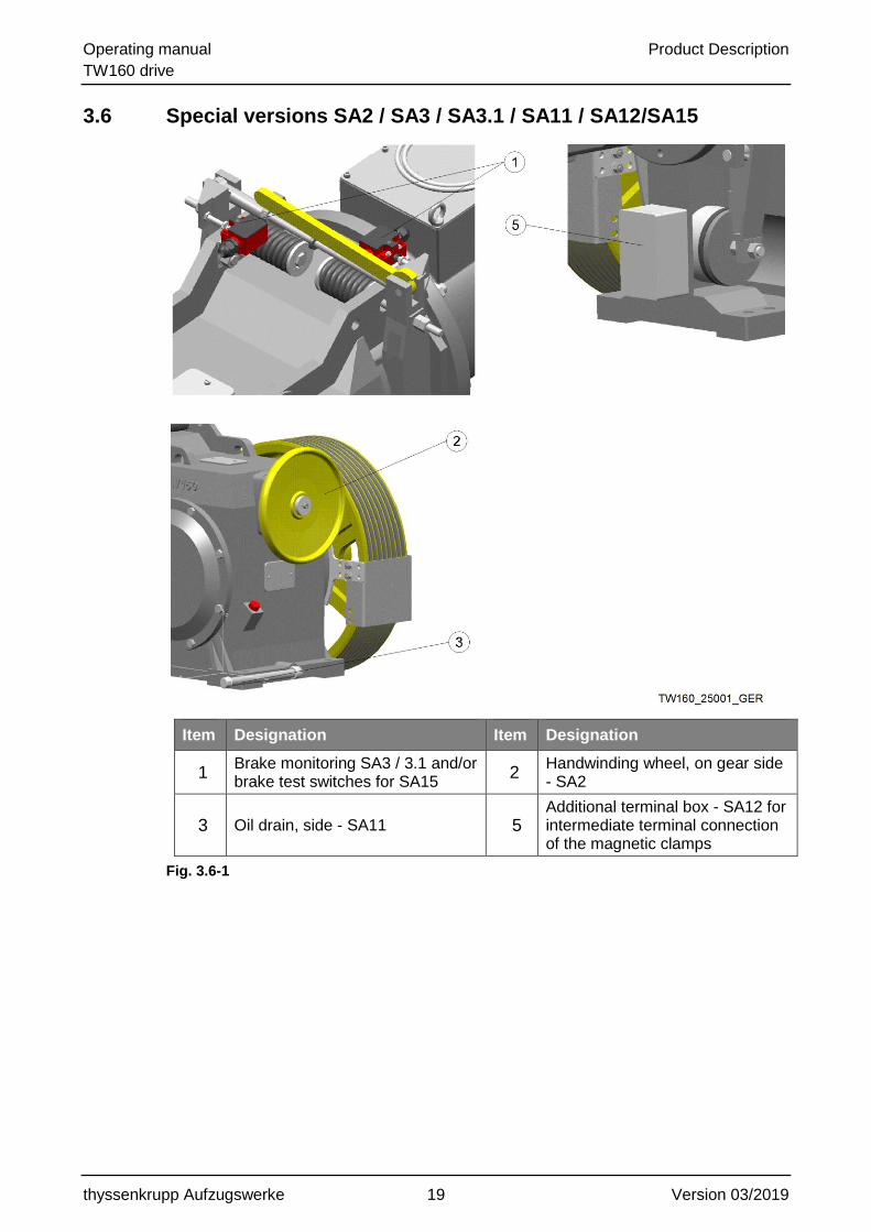
3.6 Special versions SA2 / SA3 / SA3.1 / SA11 / SA12/SA15
Item Designation Item Designation
1 Brake monitoring SA3 / 3.1 and/or brake test switches for SA15
2 Handwinding wheel, on gear side - SA2
3 Oil drain, side - SA11 5 Additional terminal box - SA12 for intermediate terminal connection of the magnetic clamps
Fig. 3.6-1

Operating manual Product Description
TW160 drive
thyssenkrupp Aufzugswerke 20 Version 03/2019
3.7 Version with safeguard measures complying with EN81-77
Installation in the machine room, with earthquake safeguard complying with EN81-77.
Item Designation Item Designation
1 Traction sheave (D640/D720/D800)
2 Earthquake safeguard complying with EN81-77
Fig. 3.7-1
3.8 Functional description
The TW 160 machine consists of a worm gear (gear drive) with flange-connected motor.
Power transmission takes place on motors of the IMB9 model series (flanged-on design with 1 bearing) via a rigid connection between the motor and worm shaft via worm wheel, traction sheave shaft to the traction sheave.
In the case of motors of the IMB5 model series (flanged-on design with 2 bearings), a
flexible coupling (SA14) is required between the motor and gear drive.
Brake
The dual-circuit outside shoe brake is spring actuated. Two independently acting brake shoe press the brake lining with preset spring force onto the brake disc.
The braking force is configured in such a way that one of the brake shoes is sufficient to bring an elevator car loaded with full weight to a standstill.
The brake is released by electrically operated magnetic clamps with armature base plate.
For manual operation, a brake release lever is fitted.
Gear housing
The TW160 has a monobloc housing with two fitted and screw-connected bearing brackets. The motor flange is cast onto the housing.
The right-hand or left-hand version of the traction sheave is created with the
corresponding installation of the bearing brackets in the housing.
The gear housing is cast from EN-GJL 250.

Operating manual Product Description
TW160 drive
thyssenkrupp Aufzugswerke 21 Version 03/2019
Drive motor
Flange-mounted type B9 and IMB5 three-phase motors are used.
The motor shaft-worm shaft connection is established in the type B9 versions using a bolted rigid coupling and in the type IMB5 versions using a flexible coupling.
Emergency braking device NBS
An additional protection device that works as an emergency brake in the event of overspeed upwards is optional.
Traction sheave
The one-part traction sheaves are fastened overhung on the drive shaft by using a cone (1:15) and a mounting plate including 3 screws (M16-8.8 microencapsulated with locking washer). Chapter 8.8
Actual-value sensor
The actual-value sensor is located before the handwinding wheel, mounted on the motor shaft. Chapter 4.7
Ambient conditions
In order to ensure the function of the product as intended, it is presupposed that
the mean temperature at the final usage site is kept between +5°C and +40°C.
Air humidity must not exceed an annual average of 70% (no dewfall and no
freezing).
Safeguard measures complying with EN81-77
The additional safeguard measures complying with EN81-77 are available as options.

Operating manual Technology
TW160 drive
thyssenkrupp Aufzugswerke 22 Version 03/2019
4 Technology
4.1 Technical data
name unit technical data
manufacturer ThyssenKrupp Elevator
gear type TW160
axle distance mm 225
ratios 50:1 / 42:1 / 35:1 / 57:2 / 51:2 / 45:2 / 41:3
oil filling l approx. 16.5
synthetic gear oil
(polyalkyleneglycol with additives)
designation SM1
circumfer. backlash ° 0.015 - 0.06
weight kg approx. 540
TW160_30101_ENG
type of oil
Table 4.1-1
4.1.1 Load data - traction sheave shaft
The load values Ftperm set out below represent the limit value of the permissible radial load on the traction sheave shaft calculated from the overall masses present at the installation.
Traction sheave shaft - standard version: Ft 97 kN
Traction sheave shaft - emergency brake (NBS): Ft 97 kN
Traction sheave shaft - SA 4/9 (with external bearing): Ft 77 kN
4.1.2 Mass moment of inertia
The value for the mass moment of inertia includes the driving gear with brake disc and coupling element as well as a proportion for the traction sheave.
Mass moment of inertia: Jrot = 0.158 kg/m²
It does not include the mass moment of inertia for the motor with handwinding wheel or flywheel rim hub as well as the flywheel rim for AC2 versions.
The value for the mass moment of inertia of the motor can be taken in the case of:
Standardised versions in accordance with product catalogue "Elevator motors"
custom-order motors from the motor lists (e.g. Siemens, Koncar etc.)
Additional flywheel masses
In the case of machines with pole-changing motor versions (AC2), additional flywheel masses are required on the motor shaft depending on the installation data.
The additional flywheel mass consists of a flywheel rim hub and a bolted flywheel rim.

Operating manual Technology
TW160 drive
thyssenkrupp Aufzugswerke 23 Version 03/2019
Unit
mm 330 360 370 380 400 410 430 455 480 510
0.285 0,458 0.533 0,600 0.758 0,900 1,070 1.435 1,750 2,280
0,342 0,515 0,590 0,657 0,815 0,957 1,127 1,492 1,807 2,337
TW63_30707_ENG
Designation Mass moment of inertia Jrot [kgm2]
Flywheel rim0.057 0.057
Total
kgm2hub
Flywheel rim
0.057
Table 4.1-2
4.1.3 Brake data
Redundant electromagnetic dual-circuit outside shoe brake on the motor / worm shaft integrated in the gear or motor flange. The electric release of the brake circuit takes place via magnetic clamps. The magnetic clamps are available in standard and in explosion-proof versions.
A coupling is integrated on the brake disc for connecting the motor and worm shafts; depending on the motor type used, this coupling may be rigid (for the B9 type) or flexible (for the IMB5 type).
Unit
Nm
mm
mm
N
A
m1) Version for explosion protection TW160_30201_ENG
II 2 D Ex mb IIIC T95°C Db 1)
Type approval codewithout on standard version
IBExU17ATEX1137 X 1)
Connection cable length 1.7 1.5 1)
Rated current 1.8 / 1.79 1)
Monitoring devices Brake test switches
Manual release Brake release lever (mounted)
Protection type, magnetic clamps
IP65 (standard version)
II 2 G Ex mb IIC T5 Gb 1)
Nominal force - magnetic clamps 5000
Operating voltage VDC180 - overexcitation
90 - holding voltage
Brake disc diameter 275
Air gap 0.3
Air gap setting possible
Electrical release 1 magnetic clamp per brake circuit
(2 magnetic clamps connected in series)
Braking torque max. 2 x 245
Braking torque setting possible
DesignDual-circuit outside brake shoe
with brake disc made of EN-GJL 250
Brake linings Asbestos-free
Designation Technical data
Manufacturer thyssenkrupp Aufzugswerke
Type TW160
Table 4.1-3

Operating manual Technology
TW160 drive
thyssenkrupp Aufzugswerke 24 Version 03/2019

Operating manual Technology
TW160 drive
thyssenkrupp Aufzugswerke 25 Version 03/2019
4.1.4 Emergency brake
More detailed information as well as technical information for setting up and operation of machines with NBS emergency brake can be found in a separate operating manual. These are delivered with drives with emergency brake system equipment.
The part number for the German instructions is: 65 990 01 86 0
The part number for the English instructions is: 65 990 02 86 0
The part number for the French instructions is: 9710 000 9229
4.1.5 Traction sheave
Different versions of traction sheave are used, depending on the location of the machine.
Standard version: traction sheave position in the machine room
Special version SA4/9 - vapour-proof partition wall in the machine room / traction
sheave position in the shaft
The traction sheaves for the standard versions differ from the SA4/9 versions in the dimensional assignment of traction sheave middle to cone and rim width. The use of SA4/9 versions in machines for the machine room - and vice versa - is not possible.
unit
mm 640 720 800 640 720 800
mm
°
kg 140 160 190 130 150 180
1) Version in accordance w ith product description groove profiles w ith hardened groove flanks (min. 50 HRc).
2) With minimum groove clearance - RAmin in accordance w ith product description groove profiles
TW160_30301_ENG
technical dataname
machine version
diameter - DT
max. number of grooves - z x d 2)
10 x 10 9 x 10
9 x 11/12 8 x 11/12
8 x 13 / 8 x 1/2"
standard SA 4/9
160180rim width - B
groove type
weight
seat / vee groove 1)
material
depends on project specs 1)
special alloyed EN-GJL 250
7 x 13 / 7 x 1/2"
7 x 14/15 6 x 14/15
7 x 16 / 7 x 5/8"
vee groove angle
6 x 16 / 6 x 5/8"
Table 4.1-4

Operating manual Technology
TW160 drive
thyssenkrupp Aufzugswerke 26 Version 03/2019
4.1.6 Weight data
ZB machine TW160 1) 540 x x x x x x
accessories for SA9 60 x x
accessories for NBS 150 x x
traction sheave D720 2), 3) 160 x x x x x x
motor DTE180 4) 225 x x x
ZB machine complete 700 760 850 925 985 10751) without motor 2) weight for traction sheave D640 approx. 140 kg and D800 approx. 190 kg3) weight for traction sheaves - SA9 minus 10 kg4) weight for other motor versions see chapter - motor versions TW160_30708_ENG
name unit weight2)
kg
machine version
with motor DTE180 without motor
Table 4.1-5
The weight data for the type IMB5/V1 motor can be taken in the case of:
Normalised versions in accordance with a factory standard (see notes on factory
standards in the chapter - Type IMB5/V1 motors)
custom-order motors from the motor lists (e.g. Siemens, Koncar etc.)
In the case of pole-changing version machines (AC2), the weight data are increased to include the values of the additional flywheel masses.
Unit
330 360 370 380 400 410 430 455 480 510
kg 14 20 22 24 28 31 35 42 48 57
TW63_30709_ENG
Designation Weight m [kg]
mmFlywheel rim
Table 4.1-6
4.1.7 Acoustic specifications
The airborne noise levels in the machine room at a distance of 1 m for the standard
version of the machine during operation at normal rating are: 74 dB(A)
The specified electrical data apply to the following site conditions:
Maximum altitude 1000 m amsl
Maximum temperature + 40° C at maximum 50% air humidity
Max. relative air humidity 70% at 20 °C
If the conditions stated above are exceeded, the deratings in accordance with VDE0530 apply.

Operating manual Technology
TW160 drive
thyssenkrupp Aufzugswerke 27 Version 03/2019
4.2 Dimensions of machine
4.2.1 Standard version
Item Designation Item Designation
1 Additionally for SA1 2 Pictured: traction sheave position right / left mirror-inverted to A-A
Fig. 4.2-1

Operating manual Technology
TW160 drive
thyssenkrupp Aufzugswerke 28 Version 03/2019
4.2.2 Version with emergency brake - NBS
Fig. 4.2-2

Operating manual Technology
TW160 drive
thyssenkrupp Aufzugswerke 29 Version 03/2019
4.2.3 Version for traction sheave in the shaft (SA9)
Item Designation Item Designation
1 Centre, rolling bearing 2 Centre, bearing housing
Fig. 4.2-3

Operating manual Technology
TW160 drive
thyssenkrupp Aufzugswerke 30 Version 03/2019
4.2.4 Version for vapour-proof partition wall SA4 (Partial Ex)
Item Designation Item Designation
1 Centre, rolling bearing 2 Centre, bearing housing
Fig. 4.2-4

Operating manual Technology
TW160 drive
thyssenkrupp Aufzugswerke 31 Version 03/2019
4.2.5 Special versions SA2/SA11/SA12
Fig. 4.2-5
4.3 Type plate
The current type and the technical data are specified on the type plate of the product.
4.4 Motor data
The technical data can be found on the type plate.
4.5 Machine base frame
The machine base frames with and without rope pulley described below are intended for installation of the machine in the machine room above the shaft.

Operating manual Technology
TW160 drive
thyssenkrupp Aufzugswerke 32 Version 03/2019
4.5.1 Assembly, machine base frame TW160 - 62 340 01 10 0
Machine base frame version without rope pulley for use in:
Installations with 1:1 rope suspension and direct rope departure for an elevator
car - counterweight rope distance ASL (DT + 100) mm depending on the
traction sheave diameter
Installations with 2:1 or 4:1 rope suspension
Item Designation Item Designation
1 TW 160 machine 2 TW160 machine base frame
3 Insulation elements 4 Mounting parts for machine / base frame
Fig. 4.5-1
The complete machine base frame comprises the following components:
Machine base frame made from welded rolled profiles
Hole pattern for machine mounting as per order, depending on DT and ASL
Technical data
Weight of machine base frame: approx. 150 kg
Project planning dimensions
Project planning dimensions, see dimension sheet
TW160_31010_GER

Operating manual Technology
TW160 drive
thyssenkrupp Aufzugswerke 33 Version 03/2019
4.5.2 Assembly, machine base frame TW160 - 62 340 02 10 0
Machine base frame in version with rope pulley on supports depending on the pulley hub position in left-hand or right-hand configuration for use with:
Installations with 1:1 rope suspension and elevator car - counterweight rope
distance ASL = 795 1400 mm in conjunction with traction sheaves dia. 640,
720 and 800 mm
The versions D450-7/8x10. D540-7/8x13 and D640 (for rope pulleys, see factory standard 60 720 12 00 0) are used for the rope pulley. The rope pulleys have maintenance-free rolling bearings.
Item Designation Item Designation
1 Machine TW160 2 Upper section, machine base frame
3 Pedestal bearing for rope pulley 4 Rope pulley
5 Upper section, machine base frame
6 Supports for insulation elements
7 Insulation elements
Fig. 4.5-2
TW160_31001_GER

Operating manual Technology
TW160 drive
thyssenkrupp Aufzugswerke 34 Version 03/2019
The complete machine base frame comprises the following components:
Machine base frame made from welded rolled profiles
Hole pattern for machine mounting as per order, depending on DT and ASL
Pedestal bearing (bolted) for the rope pulley holder with axle; version based on
the rope pulley used
Rope pulley D450, 540 or 640
Supports (6 pcs. bolted) for mounting the insulation elements.
It is possible through appropriate mounting of the bolted supports to position the
pulley hub on the right or left in the machine base frame.
Technical data
Weight of machine base frame
m
TW160_31007_ENG
weight incl. rope pulley
420D450
D640
rope pulley version [mm]
550
D540 kg 470
Table 4.5-1
Project planning dimensions
Project planning dimensions, see dimension sheet
4.5.3 Assembly, machine base frame TW160 - 62 340 03 10 0
Machine base frame version with rope pulley on concrete foundations - depending on whether the rope pulley position is on the left or right for use in:
Installations with 1:1 rope suspension and elevator car - counterweight rope
distance ASL = 795 1400 mm in conjunction with traction sheaves dia. 640,
720 and 800 mm
The versions D450-7/8x10. D540-7/8x13 and D640 (for rope pulleys, see factory
standard 60 720 12 00 0) are used for the rope pulley. The rope pulleys have
maintenance-free rolling bearings.
Operating manual Technology
TW160 drive
thyssenkrupp Aufzugswerke 35 Version 03/2019
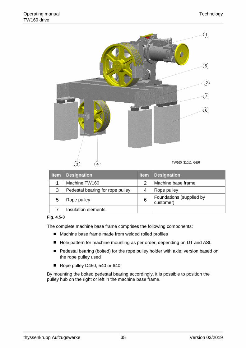
Item Designation Item Designation
1 Machine TW160 2 Machine base frame
3 Pedestal bearing for rope pulley 4 Rope pulley
5 Rope pulley 6 Foundations (supplied by customer)
7 Insulation elements
Fig. 4.5-3
The complete machine base frame comprises the following components:
Machine base frame made from welded rolled profiles
Hole pattern for machine mounting as per order, depending on DT and ASL
Pedestal bearing (bolted) for the rope pulley holder with axle; version based on
the rope pulley used
Rope pulley D450, 540 or 640
By mounting the bolted pedestal bearing accordingly, it is possible to position the pulley hub on the right or left in the machine base frame.
TW160_31011_GER

Operating manual Technology
TW160 drive
thyssenkrupp Aufzugswerke 36 Version 03/2019
Technical data
Weight of machine base frame
m
TW160_31008_ENG
weight incl. rope pulley
340D450
D640
rope pulley version [mm]
470
D540 kg 390
Table 4.5-2
Project planning dimensions
Project planning dimensions, see dimension sheet

Operating manual Technology
TW160 drive
thyssenkrupp Aufzugswerke 37 Version 03/2019
4.5.4 Assembly, machine base frame TW160 - 62 340 04 10 0
Machine base frame for "Partial Ex" installations with vapour-proof wall duct (SA4) in a version without a rope pulley for use in:
Installations with 1:1 rope suspension and direct rope departure for an elevator
car - counterweight rope distance ASL (DT + 100) mm depending on the
traction sheave dia. DT used.
Installations with 2:1 or 4:1 rope suspension
TW160_31012_GER

Operating manual Technology
TW160 drive
thyssenkrupp Aufzugswerke 38 Version 03/2019
Item Designation Item Designation
1 TW160 machine - SA4 2 Compensating supports
3 Pedestal bearing housing (external bearing)
4 Base frame
5 Frame yoke 6 Sealing plate
7 Rope guard 8 Mounting parts for machine / base frame
9 Mounting parts for machine base frame
10 Vapour-proof partition wall (supplied by customer)
11 Machine room floor
Fig. 4.5-4
The machine base frame consists of a base frame with welded bearing bracket and a frame yoke for holding the rope guards and the bolted sealing plate. The hole pattern for mounting the machine and the position of the frame yoke are dependent on the traction sheave diameter - DT and the traction sheave position - left or right.
It is possible for the customer to provide a vapour-proof enclosure of the entire machine base frame by using side plates on the base frame and by using the profile section of the frame yoke (U140).
The base frame is bolted to the machine room floor with heavy-load anchors (6 pieces supplied). The arrangement is sealed against the machine room floor by the customer.
Technical data
Weight of machine base frame: approx. 350 kg
4.5.5 Mounting parts, TW160 base-frame-mounted machine
A set of bolting elements (4 x M20-8.8) is available (AY mounting parts 62 340 03 98 0) for mounting the TW160 machine on the standardised machine base frame with / without rope pulley.
A reinforced mounting (6 x M20-8.8 / 2 x M16-8.8) is used (assembly, mounting parts 62 340 03 98 0) is used for individual applications of the TW160 machine with horizontal or vertically upward rope departure - except for the special versions SA4/9.

Operating manual Technology
TW160 drive
thyssenkrupp Aufzugswerke 39 Version 03/2019
4.5.6 Version with earthquake safeguard complying with EN81-77
Optional components are available for the TW160 O SR and TW160 M SR base frames; these meet the requirements for protection devices complying with EN81-77.
Item Designation Item Designation
1 W160 machine 2 Rope guard complying with EN81-77 for traction sheave
3 TW160 M SR machine base frame
4 Rope guard complying with EN81-77 for rope pulley dia. D450, D540, D640
5 Shift protection complying with EN81-77
Fig. 4.5-5
The safeguard measures are only suitable for machine base frames with locations in the machine room.
The protection device consists of a change rope guard for rope pulleys dia. D450, D540 or D640 which prevent the ropes departing from the grooves.
Item Designation Item Designation
1 TW160 M SR machine base frame
2 Rope guard complying with EN81-77 for rope pulley dia. D450, D540, D640
3 Rope pulley dia. D640
Fig. 4.5-6

Operating manual Technology
TW160 drive
thyssenkrupp Aufzugswerke 40 Version 03/2019
The safeguard measures also consist of shift protection devices that prevent the machine from changing its position
Item Designation Item Designation
1 Shift protection complying with EN81-77
2 TW160 M SR machine base frame
Fig. 4.5-7
In the case of deployment of the machine in earthquake categories 2 and 3, additional safeguard measures in accordance with EN81-77 are necessary.

Operating manual Technology
TW160 drive
thyssenkrupp Aufzugswerke 41 Version 03/2019
4.6 Machine base frame dimension sheets
4.6.1 Version without rope pulley
Item Designation Item Designation
1 Machine with traction sheave position - left
2 Machine with traction sheave position - right
S Centre of gravity
Fig. 4.6-1

Operating manual Technology
TW160 drive
thyssenkrupp Aufzugswerke 42 Version 03/2019
Project planning dimensions:
Project planning dimension L dependent on traction sheave diameter DT and traction sheave position - left or right - of the machine.
640
720
800
TW160_31002_ENG
traction sheave version
DT
project planning dimension L
mm
295 200
240
280
255
215
traction sheave position
left right
unit
Table 4.6-1
Position and number of insulation elements depending on the static shaft load
90 2 2 2 2 1 1
75 2 2 1 1 1 1
60 2 2 1 1 1 1
30 1 1 - - 1 1
TW160_31004_ENG
Ft [kN]
III
number of isolation elements
IV V VIposition for
isolation elementI II
static
shaft load
Table 4.6-2

Operating manual Technology
TW160 drive
thyssenkrupp Aufzugswerke 43 Version 03/2019
4.6.2 Version with rope pulley / machine base frame with supports
Version with rope pulley position on left
Item Designation Item Designation
1 With rope pulley D540 2 With rope pulley D640
3 With rope pulley D450 4 Machine with traction sheave position - left
5 Machine with traction sheave position - right
S Centre of gravity, machine base frame
Fig. 4.6-2
TW160_31102_GER
185
250
Operating manual Technology
TW160 drive
thyssenkrupp Aufzugswerke 44 Version 03/2019
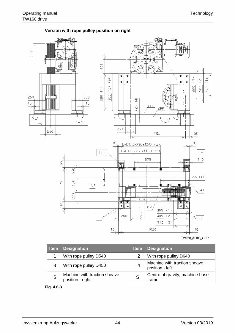
Version with rope pulley position on right
Item Designation Item Designation
1 With rope pulley D540 2 With rope pulley D640
3 With rope pulley D450 4 Machine with traction sheave position - left
5 Machine with traction sheave position - right
S Centre of gravity, machine base frame
Fig. 4.6-3
TW160_31103_GER

Operating manual Technology
TW160 drive
thyssenkrupp Aufzugswerke 45 Version 03/2019
Project planning dimensions
Project planning dimension L dependent on traction sheave diameter DT and traction sheave position - left or right - of the machine
TW160_31005_ENG
955
1400
ASLmax
800
traction sheave version rope distance elevator car - counterweight
DT
640
720 mm
795
ASLmin
875
Table 4.6-3
Position and number of insulation elements depending on the static shaft load
and rope pulley and traction sheave positions
I II III IV I II III IV I II III IV I II III IV
90 2 4 1 2 3 4 2 2 4 3 2 2 4 2 2 1
75 2 4 1 2 3 3 1 2 3 3 2 1 4 2 2 1
60 2 3 1 2 2 3 1 1 3 2 1 1 3 2 2 1
30 2 2 1 2 2 2 1 1 2 1 1 1 2 1 1 1
TW160_31006_ENG
position for
isolation element
number of isolation elements
static
shaft load
Ft [kN]
800 1000 1200 1400
rope distance elevator car - counterweight ASL [mm]
Table 4.6-4

Operating manual Technology
TW160 drive
thyssenkrupp Aufzugswerke 46 Version 03/2019
4.6.3 Version with rope pulley / machine base frame on concrete foundation
Version with rope pulley position on left
Item Designation Item Designation
1 With rope pulley D540 2 With rope pulley D640
3 With rope pulley D450 4 Machine with traction sheave position - left
5 Machine with traction sheave position - right
S Centre of gravity, machine base frame
Fig. 4.6-4
TW160_31104_GER
185
250

Operating manual Technology
TW160 drive
thyssenkrupp Aufzugswerke 47 Version 03/2019
Version with rope pulley position on right
Item Designation Item Designation
1 With rope pulley D540 2 With rope pulley D640
3 With rope pulley D450 4 Machine with traction sheave position - left
5 Machine with traction sheave position - right
S Centre of gravity, machine base frame
Fig. 4.6-5
TW160_31105_GER

Operating manual Technology
TW160 drive
thyssenkrupp Aufzugswerke 48 Version 03/2019
Project planning dimensions
Project planning dimension L dependent on traction sheave diameter DT and
traction sheave position - left or right - of the machine
TW160_31005_ENG
955
1400
ASLmax
800
traction sheave version rope distance elevator car - counterweight
DT
640
720 mm
795
ASLmin
875
Table 4.6-5
Position and number of insulation elements depending on the static shaft load
and rope pulley and traction sheave positions
I II III IV V VI VII VIII I II III IV V VI VII VIII
90 1 1 - 2 1 2 1 1 1 1 1 1 1 2 1 1
75 1 1 - 1 1 1 1 1 1 1 1 1 1 1 1 1
60 1 1 - 1 - 1 1 1 1 1 - 1 1 1 1 1
30 1 1 - - - - 1 1 1 1 - - - - 1 1
I II III IV V VI VII VIII I II III IV V VI VII VIII
90 1 1 1 1 2 1 1 1 1 1 2 - 2 1 1 1
75 1 1 1 1 1 1 1 1 1 1 1 - 2 1 1 1
60 1 1 1 - 1 1 1 1 1 1 1 - 1 - 1 1
30 1 1 - - - - 1 1 1 1 - - - - 1 1
TW160_31009_ENG
number of isolation elements
static
shaft load
Ft [kN]
isolation element 1200 1400
isolation element 800
position for rope distance elevator car - counterweight ASL [mm]
rope distance elevator car - counterweight ASL [mm]
number of isolation elements
1000
static
shaft load
Ft [kN]
Table 4.6-6

Operating manual Technology
TW160 drive
thyssenkrupp Aufzugswerke 49 Version 03/2019
4.6.4 Version with vapour-proof partition wall (SA4)
Item Designation Item Designation
1 Machine with traction sheave position - left
2 Machine with traction sheave position - right
S Centre of gravity
Fig. 4.6-6

Operating manual Technology
TW160 drive
thyssenkrupp Aufzugswerke 50 Version 03/2019
4.7 Encoder
The installation and connection are described in Chapter 10 external operating manual in the Appendix
Encoders are distinguished by type depending on the control system deployed.
The following encoders are available for the TW160.
Encoder type Pulses Use
1024
4096
4096 LiftEquip for ships' elevators
4096 LiftEquip for CT inverter E300
1024 tk Brazil 1)
HTL 1024 External controls and/or inverters
Sine, cosine 1024 External controls and/or inverters
1) Version with adapted connector for tk Brazil
MOTOREN_34300_ENG
TTL
tkAW inverters and third-party inverters
Table 4.7-1

Operating manual Transportation and storage
TW160 drive
thyssenkrupp Aufzugswerke 51 Version 03/2019
5 Transportation and storage
5.1 Packaging
The packaging varies depending on the version of the drive that is delivered. The illustration shows the standard version.
Standard version: special pallet 1680 x 850 mm
Special versions SA4/SA9: special pallet 1700 x 1240 mm
Version with emergency brake system: special pallet 1680 x 1100 mm
Wooden blocks are placed under the gear housing and the gear housing is bolted onto the pallet.
For the special versions SA4 and SA9, the compensating supports are packaged separately and secured to the pallet.
Fig. 5.1-1
Further packaging depends on the order and is country-specific (air/sea/land freight).
1. Refer to the delivery note for the dimensions and weight.
2. Observe the symbols attached to the packaging or in visible locations.
3. Dispose of used packing material in an environmentally responsible manner.
4. Consult the technical data for the approximate details. Chapter4.1
Specific transport equipment and shipping braces remain with the customer

Operating manual Transportation and storage
TW160 drive
thyssenkrupp Aufzugswerke 52 Version 03/2019
5.2 Transport
NOTICE
Improper transport!
Damage and possibly loss of function of the machine.
Do not place heavy objects on the assembly when packaged.
Protect it against impacts and falling.
Protect it against water and extreme temperatures .
Comply with safety regulations.
Pay attention to the centre of gravity of the product.
Do not lift the machine by the motor or pedestal bearings.
Always lift the machine by both transport hangers.
NB: machine is filled with oil. It may only be transported and stored upright.
5.2.1 Transport by fork lift
WARNING
Protruding or tilting parts
Falling transported goods can lead to severe crushing injuries or cuts and
possibly fatal injuries.
When effecting transport with a fork lift, use adequately long forks
to prevent tipping over.
Always pick up at the frame or transport pallet with the forks, not
the machine itself.
During transport, keep a safe distance to persons.

Operating manual Transportation and storage
TW160 drive
thyssenkrupp Aufzugswerke 53 Version 03/2019
5.2.2 Crane transport
WARNING
Suspended load!
Falling transported goods can lead to severe crushing injuries and possibly fatal injuries.
Do not walk underneath suspended loads.
Only use tested and adequately dimensioned lifting gear.
The specified means of transport are only configured for
transportation of the machine, the installed brake and traction
sheave. Do not use them to transport any other loads.
On the version with emergency brake system (NBS), the transport hanger is mounted the other way around, as here the centre of gravity is on the other side of the machine.
Item Designation Item Designation
1 Transport hanger
Fig. 5.2-1
Attach the rope with a closed transport hook on the transport hanger.
1

Operating manual Transportation and storage
TW160 drive
thyssenkrupp Aufzugswerke 54 Version 03/2019
5.3 Checking the delivery
WARNING
Severe transport damage to the product.
Can lead to a malfunction of the product and thus to death or serious injury.
Before commissioning, ensure that there is no severe damage to the product.
1. Check the completeness of the delivery.
2. Compare the order and delivery documents.
3. Check the packaging for damage and any other conspicuous anomalies.
In the case of damage
1. Do not commission a damaged product.
2. Any damage that is determined is to be documented immediately by means of a
sketch, photo or description of the damage.
3. Report damage to the manufacturer.
5.4 Packaging materials
Specific transport equipment and shipping braces remain with the customer.
Dispose of packaging materials in an environmentally compatible manner.
5.5 Ambient conditions
5.5.1 Intermediate storage
Bare parts have no long-term preservation.
The product may be exposed to a maximum relative air humidity of 60% (at 20
°C).
Store the product carefully in a protected location.
Protect it against the formation of condensation and moisture.
Protect against dirt in the machine.
5.5.2 During operation
The environment at the final location must correspond to normal indoor climate
conditions for elevator machines and pulley rooms (in accordance with EN81,
between + 5 °C and + 40 °C).

Operating manual Transportation and storage
TW160 drive
thyssenkrupp Aufzugswerke 55 Version 03/2019
5.6 Standstill maintenance
If the drive is not installed for a longer period, the following measures are to be carried out annually:
1. Release the operational brake manually by means of the brake release lever
and (if present) the emergency break manually by releasing the emergency
release screws.
2. Turn the traction sheave disc by means of the handwheel at the motor by 3
revolutions in both directions.
3. Depending on the storage conditions, replace the corrosion protection of the
bare parts (for example with Rivolta KSP 317 corrosion protection wax).
Operating manual Installation
TW160 drive
thyssenkrupp Aufzugswerke 56 Version 03/2019
6 Installation
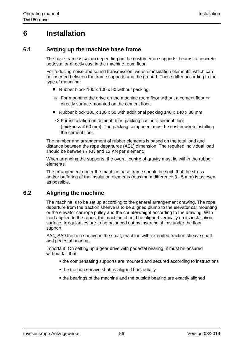
6.1 Setting up the machine base frame
The base frame is set up depending on the customer on supports, beams, a concrete pedestal or directly cast in the machine room floor.
For reducing noise and sound transmission, we offer insulation elements, which can be inserted between the frame supports and the ground. These differ according to the type of mounting:
Rubber block 100 x 100 x 50 without packing.
For mounting the drive on the machine room floor without a cement floor or
directly surface-mounted on the cement floor.
Rubber block 100 x 100 x 50 with additional packing 140 x 140 x 80 mm
For installation on cement floor, packing cast into cement floor
(thickness ≤ 60 mm). The packing component must be cast in when installing
the cement floor.
The number and arrangement of rubber elements is based on the total load and distance between the rope departures (ASL) dimension. The required individual load should be between 7 KN and 12 KN per element.
When arranging the supports, the overall centre of gravity must lie within the rubber elements.
The arrangement under the machine base frame should be such that the stress and/or buffering of the insulation elements (maximum difference 3 - 5 mm) is as even as possible.
6.2 Aligning the machine
The machine is to be set up according to the general arrangement drawing. The rope departure from the traction sheave is to be aligned plumb to the elevator car mounting or the elevator car rope pulley and the counterweight according to the drawing. With load applied to the ropes, the machine should be aligned vertically on its installation surface. Irregularities are to be balanced out by inserting shims under the floor support.
SA4, SA9 traction sheave in the shaft, machine with extended traction sheave shaft and pedestal bearing.
Important: On setting up a gear drive with pedestal bearing, it must be ensured without fail that
the compensating supports are mounted and secured according to instructions
the traction sheave shaft is aligned horizontally
the bearings of the machine and the outside bearing are exactly aligned

Operating manual Installation
TW160 drive
thyssenkrupp Aufzugswerke 57 Version 03/2019
Installation of the compensating support for SA4/SA9
Fig. 6.2-1
Screw the supplied compensating supports onto the housing of the machine
from below with 6 x M16x90 bolts and nuts as well as 2 x M16x40 washers
(tightening torque 190 Nm).
6.3 Installation (frame with rope pulley)
Fig. 6.3-1
86
0(
be
i/a
t D
p=
54
0)
(b
ei/
at
Dp
=4
50
/64
0)
96
0
54
0(
be
i/a
t D
p=
54
0)
(b
ei/
at
Dp
=6
40
)5
87
(b
ei/
at
Dp
=4
50
)6
60
8-9-10-11-12Ma = 190 Nm
Dp
1 2
3
1640( )
11
05
()
34
5
3 55( bei /at Dp=540)
( bei /at Dp=450)310
( bei /at Dp=640)4051010
4-5-6-7Ma = 370 Nm
A
1 A
Lage der Seilrolle - rechts
position of rope pulley - right hand
Lage der Seilrolle - links
position of rope pulley - left hand
Operating manual Installation
TW160 drive
thyssenkrupp Aufzugswerke 58 Version 03/2019
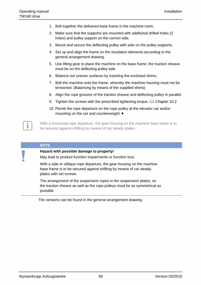
1. Bolt together the delivered base frame in the machine room.
2. Make sure that the supports are mounted with additional drilled holes (2
holes) and pulley support on the correct side.
3. Mount and secure the deflecting pulley with axle on the pulley supports.
4. Set up and align the frame on the insulation elements according to the
general arrangement drawing.
5. Use lifting gear to place the machine on the base frame; the traction sheave
must be on the deflecting pulley side
6. Balance out uneven surfaces by inserting the enclosed shims.
7. Bolt the machine onto the frame, whereby the machine housing must not be
tensioned. (Balancing by means of the supplied shims)
8. Align the rope grooves of the traction sheave and deflecting pulley in parallel.
9. Tighten the screws with the prescribed tightening torque. Chapter 10.2
10. Plumb the rope departure on the rope pulley at the elevator car and/or
mounting on the car and counterweight.
With a horizontal rope departure, the gear housing on the machine base frame is to
be secured against shifting by means of car steady plates.
NOTE
Hazard with possible damage to property!
May lead to product function impairments or function loss.
With a side or oblique rope departure, the gear housing on the machine
base frame is to be secured against shifting by means of car steady
plates with set screws.
The arrangement of the suspension ropes in the suspension plates, on
the traction sheave as well as the rope pulleys must be as symmetrical as
possible.
The versions can be found in the general arrangement drawing.

Operating manual Installation
TW160 drive
thyssenkrupp Aufzugswerke 59 Version 03/2019
6.4 Mounting the rope guard
1. Use the enclosed screws to bolt the rope guard onto the rope guard carrier.
2. Pivot the rope guard carrier to set the guard in such a way that the gap between
the rope and guard on the rope run-in and run-out side of the traction sheave is
as small as possible. (1 -2 mm)
3. With inclined pulling, adapt the location of the rope guard carrier by remounting
the changed rope pull direction.
Tighten the securing bolts of the rope guard carrier on the gear drive after alignment with the prescribed tightening torque. Chapter 10.2
Item Designation Item Designation
1 Rope guard carrier 2 Rope guard
Fig. 6.4-1
CAUTION
Danger with a low degree of risk!
May lead to minor or moderate injury.
For machines with rope run-in direction from 0 - 90°above horizontal (e.g. machine arrangement down/up beside), an additional rope guard is required to prevent foreign bodies penetrating between the rope and grooves.
If the rope run-in zone is protected within the machine base frame, the function "protection against injury" is not required.
For SA9 traction sheave in the shaft, no rope guard is fitted at the plant.
1
2 1
2
max. 1-2 mm

Operating manual Installation
TW160 drive
thyssenkrupp Aufzugswerke 60 Version 03/2019
6.5 Mounting the rope guard complying with EN81-77
1. Use the enclosed screws to bolt the rope guard onto the rope guard carrier.
2. Set the rope guard by pivoting or remounting in such a way that the clearance
between the rope and hoop guard does not exceed a maximum of 2 mm over
the entire width of the traction sheave.
3. To align the rope guard, push the enclosed shims between the rope guard
carrier and rope guard.
4. The rope guards on the rope run-in and rope departure positions must not be
mounted more than 15° away from the rope run-in and rope departure
positions.
5. If the angle between the rope run-in and rope departure positions is greater
than 90°, mount a third rope guard in such a way that the angle between all
rope guards is not more than 90°.
6. With inclined pulling, adapt the location of the rope guard carrier by remounting
the changed rope pull direction.
Tighten the securing bolts of the rope guard carrier on the gear drive after alignment with the prescribed tightening torque.
Item Designation Item Designation
1 Rope guard carrier 2 Rope guard, long
3 Rope guard, long 4 Rope guard, small
Fig. 6.5-1
For machines with rope run-in direction from 0 - 90°above horizontal (e.g. machine arrangement down/up beside), an additional rope guard is required to prevent foreign bodies penetrating between the rope and grooves.
If the rope run-in zone is protected within the machine base frame, the function "protection against injury" is not required.
The rope guards on the rope pulley are to be mounted according to the same specifications.
max. 2 mm

Operating manual Installation
TW160 drive
thyssenkrupp Aufzugswerke 61 Version 03/2019
6.6 Mounting the shift protection complying with EN81-77
1. Secure each of the shift protection devices with 2 tie bolts (Hilti HST M16/25 or
Fischer M16/25 FAZII) at the installation site.
2. Secure the shift protection devices to the bare concrete.
3. Before drilling, ensure that no reinforcing steel at the positions of the holes
hinders the drilling.
If this is the case, use one of the alternative holes that are already on the shift
protection device.
The fastening materials are included in the scope of supply. The installation instructions of the manufacturers are to be strictly complied with!
4. Align the shift protection in such a way that the rubber elements of the shift
protection devices do not touch the machine base frame.
5. Set the clearance to a maximum of 5 mm.
The shift protection is configured for the following machine insulations:
Insulation elements without underlay for machine room without floor pavement.
Insulation elements with underlay for machine room with floor pavement (≤ 60
mm high); underlay made from Multiplex laminated wood 140 x 140/80 / mm
high.
Fig. 6.6-1
Item Designation Item Designation
1 Shift protection 2 Machine base frame
3 Tie bolts 4 Alternative holes
Fig. 6.6-2
max. 5 mm

Operating manual Installation
TW160 drive
thyssenkrupp Aufzugswerke 62 Version 03/2019
6.7 Connecting motors
On connecting the motor, the enclosed terminal connecting plan in the motor terminal box and/or the wiring diagram in this operating manual and corresponding building codes are to be complied with.
6.7.1 Terminal connecting plan for motor and magnetic clamps
Comply with the documents supplied with the motor and the information in the terminal strip.
Terminal connecting plan of DTE / DTL motors
An intermediate connection is set up for the brake in the terminal box of the motor.
Fig. 6.7-1 DTE motor

Operating manual Installation
TW160 drive
thyssenkrupp Aufzugswerke 63 Version 03/2019
Terminal connecting plan for Motorlift motors
Fig. 6.7-2

Operating manual Installation
TW160 drive
thyssenkrupp Aufzugswerke 64 Version 03/2019
6.7.2 Wiring diagram DTE132/140/180, motorlift CMRFL1 und motors made by
EMOD
Item Designation Item Designation
1 Motor 2 Posistor
3 Encoder 4 Brake (intermediate terminal connection)
Fig. 6.7-3 Survey diagram for DTE 132/140/180 motors
6.7.3 Wiring diagram DTL
Item Designation Item Designation
1 Motor 2 Posistor
3 Encoder 4 Brake (intermediate terminal connection)
5 Forced ventilation (only for DTL180)
Fig. 6.7-4 Survey diagram for DTL180 motors
41 2 3
Motoren_34211_GER
5

Operating manual Commissioning
TW160 drive
thyssenkrupp Aufzugswerke 65 Version 03/2019
7 Commissioning
7.1 Work steps
For assembly, use only original construction and mounting parts from thyssenkrupp Aufzugswerke GmbH, as otherwise no warranty can be provided.
Before commissioning the machine, the following points must be checked and carried out:
OK Work step
1. Remove safety, auxiliary and installation tools from the danger
zone.
2. Check setup and alignment of machine, base frame, rope
departure and base.
3. Check the oil drain pipe is seated securely and leak-tight.
(Machine is filled with oil at the plant)
4. Check the gear oil level. 8.3.3
5. Check the secure mounting of the machine and base frame.
6. With a side or oblique rope departure, the gear housing is
secured against moving with end stops and set screws.
7. Make sure that the bolts are tightened with the prescribed
torque and secured. 10.2
8. Check the brake shoe stroke and setting 8.6
9. With SA3, SA3.1 and SA15 , check the setting and function of
the brake test switches. 9.2
10. Conduct a brake test with one brake shoe in each case. 8.7
11. Check the function and setting of the handbrake release 7.2
12. Fit the rope guard and set the distance to the traction sheave. 6.4 resp. 6.5
13. Check whether the power connections and earthing of the
motor, forced ventilation and brake magnet are connected and secured.
14. Stick the direction arrow (Up / Down) clearly visible on the
motor near the handwinding wheel according to the direction of travel.
Table 7.1-1

Operating manual Commissioning
TW160 drive
thyssenkrupp Aufzugswerke 66 Version 03/2019
If the traction sheave and rope pulley are delivered separately, they are to be mounted properly.
If the machine was dismantled due to weight, transport or space, removed parts are to be reassembled to their original state and the mounting parts tightened with the corresponding tightening torque. Chapter 10.2.
7.2 Emergency operation
The TW160 is equipped for emergency operation with a handwinding wheel and a brake release lever.
The brake release lever and pressure piece with pressure rod are mounted on the brake shoes with notched impact pins. On the version with vertical motor position, the brake release lever is additionally secured in the rest position with a retaining clip. The brake lever is set in the operation position approx. 5 - 10° above the horizontal as shown in the following illustration:
Operation position Rest position
Fig. 7.2-1
Emergency rescue of trapped persons
1. Open the brake by moving the brake release lever into the operation position
and actuate the lever against the pressure rod until the brake shoes are
released.
2. The handwinding wheel might also have to be moved to bring the elevator car
into the nearest landing.
3. Depending on the load, the elevator car can begin to move quickly after
opening the brake.
4. Immediately let go of the handwinding wheel and control the speed of the
elevator car by pressing the brake release lever with varying degrees of force.
5. Following the rescue operation, put the brake release lever back in the rest
position.
5°-10°

Operating manual Commissioning
TW160 drive
thyssenkrupp Aufzugswerke 67 Version 03/2019
CAUTION
Abrasion injuries
If the handwinding wheel is used for installation and maintenance purposes (e.g. pulling out of the safety gear), the person performing the operation must ensure they have a firm and safe stance.
There is also a risk of injury when simultaneously operating electrical recall.
Pay special attention.

Operating manual Servicing and Maintenance
TW160 drive
thyssenkrupp Aufzugswerke 68 Version 03/2019
8 Servicing and Maintenance
8.1 Maintenance period
Maintenance of the machine should take place within the framework of central maintenance of the elevator, at least once a year.
8.2 Maintenance measures
OK Work step
1. Check the oil level and top up if necessary.
Chap. 8.3.3
2. Change the oil when the change date is reached. Chap. 8.3.2
3. Re-lubricate the pedestal bearings. Chap. 8.3.1
4. Check the brake shoes for wear; the remaining lining
thickness must be at least 3 mm.
Chap. 8.5
5. Check the brake setting; the shoe stroke should be
0.3 + 0.1 mm.
Chap. 8.6
6. Check the braking deceleration.
Chap. 8.7
7. Check the backlash between the worm shaft and worm
wheel.
Chap. 8.6
8. Check the groove profile on the traction sheave for damage
and wear.
9. Check that the bolts of the traction sheave mount are
securely seated.
Chap. 10.2
10. Check rope pulley grooves for damage and wear.
11. Check proper and adequate condition and safety of
electrical connections.
12. Check that protective and safety devices are present and
correctly set.
Table 8.2-1

Operating manual Servicing and Maintenance
TW160 drive
thyssenkrupp Aufzugswerke 69 Version 03/2019
8.3 Lubrication
NOTICE
Bearing damage!
Damage to the bearings due to unsuitable lubricant
Use only the specified lubricant
8.3.1 Outside bearing
On delivery, the initial filling took place at the plant.
Rolling bearing grease F1 multipurpose grease can be obtained from thyssenkrupp Aufzugswerke GmbH.
Part number Designation Amount of grease
60 300 27 900 AY multipurpose grease F1 cartridge 400 gr
Annually:
110 g re-lubrication
SAP 8.3-1
8.3.2 Gear
On delivery, the initial filling took place at the plant.
Synthetic gear oil SM1 can be obtained from thyssenkrupp Aufzugswerke GmbH.
Lubricant Replacement interval Motor position = filling
amount
Synthetic gear oil SM1 For the first time after 3 years
then every 6 years 17 litres
Table 8.3-1
Never mix different types of oil.
Do not let any oil seep through to the groundwater.
Dispose of old oil as well as cloths contaminated with oil and grease according to
prevailing regional regulations.
Only use lubricants approved by THYSSENKRUPP AUFZUGSWERKE GmbH
oil change
1. Before the oil change, run the gear until it reaches operating temperature (at
least 35°C).
2. Discharge the gear oil by removing the cap on the oil drain pipe and collect the
old oil in a container specifically designed for the purpose.

Operating manual Servicing and Maintenance
TW160 drive
thyssenkrupp Aufzugswerke 70 Version 03/2019
WARNING
Risk of scalding!
Caution: hot oil represents a risk of scalding!
Be particularly careful.
3. Close the oil drain after discharging the gear with sealing tape and the cap.
4. Fill the machine with the prescribed oil quantity through the upper opening on
the gear housing (fill opening cap, see Fig. 3.2-1
5. Check the level with the oil dipstick (see Fig. 8.3-1).
Only rest the oil dipstick, do not screw in.
6. Enter the date for the next oil change in the type plate on the gear housing.
Item Designation Item Designation
1 Oil filling hole see Fig. 3.2-1 item 9
2 Oil dip stick
3 Oil drain
Fig. 8.3-1
8.3.3 Checking the oil level
Only place the oil dip stick (red cap) in position to check the oil level; do not screw in. The oil level should be between the two markings.
2
1
3

Operating manual Servicing and Maintenance
TW160 drive
thyssenkrupp Aufzugswerke 71 Version 03/2019
8.4 Checking the backlash
If the running performance deteriorates, this might have been caused by excessive backlash in the worm gear toothing.
Wear on the worm wheel gear teeth changes the existing tooth thickness and this can be determined using the following measurement of the backlash.
WARNING
Deformation and/or breakage of the teeth on the worm wheel or worm shaft due to excessive backlash.
The braking effect deteriorates.
Measure the backlash at least every 3 years and/or if running performance deteriorates (noises, jolting, etc.)
When a wear limit value (backlash) of 1.5 mm is reached, the gear drive must be replaced.
Measurement possibility:
1. Take load off the ropes: move the counterweight onto the buffers and lift the
elevator car with lifting gear.
The traction sheave must be free to move.
2. Run the measuring operation with the operational brake closed.
3. Release the emergency brake, if present.
4. Fit a measuring attachment to the traction sheave; e.g. screw clamp.
5. Specify the measured radius (M).
6. Mark the measuring point.
The radius (r) for the TW160 = 186 mm.
7. Attach a dial gauge with magnet stator at the gear drive housing and align to
the measuring point (M).
8. Turn the traction sheave by hand until the dial gauge pointer moves.
9. Move the traction sheave back and forth until resistance is felt in both
directions.
10. Read off the movement of the dial gauge.
11. Use the formula below to calculate the backlash.

Operating manual Servicing and Maintenance
TW160 drive
thyssenkrupp Aufzugswerke 72 Version 03/2019
Fig. 8.4-1
M = measured radius
ME = measurement result
r = radius - worm wheel All dimensions in mm
Backlash = ME * r M
Dial gauge
Traction sheave
Worm wheel

Operating manual Servicing and Maintenance
TW160 drive
thyssenkrupp Aufzugswerke 73 Version 03/2019
8.5 Replacing the brake shoes
With a remaining lining thickness of ≤ 3 mm, or if the linings are damaged (e.g. glazing), the brake shoes and brake linings must be replaced.
8.5.1 Disassembly
1. Switch off the installation power supply.
2. Secure the car and counterweight before starting work.
3. Loosen the two nuts on the bolt on which the compression springs for the pre-
tension are located.
4. Undo the two M8 bolts that hold the brake shoe pin in place.
5. Push the cover ring over the magnetic clamp and armature base plate
6. Undo the lock nuts on the armature screw and turn the armature screw together
with the armature base plate slightly back to enlarge the gap between the
magnetic clamp and armature base plate.
7. Screw one of the M8 screws into the front of the brake shoe bolt and pull it out of
the housing.
8. Remove the bolt, including compression springs and spring plates.
9. Remove the brake shoe.

Operating manual Servicing and Maintenance
TW160 drive
thyssenkrupp Aufzugswerke 74 Version 03/2019
8.5.2 Installation
1. Mount the armature base plate with armature screw onto a new brake shoe
2. If required, lightly grease the sliding surface between the armature base plate
and armature screw.
3. Secure setting of the armature base plate pre-tension by tightening the lock
nuts.
4. Install the pre-assembled brake shoes; do not tighten the nuts on the
compression springs.
5. Refit the pin and locking screws.
6. Pre-tension the compression springs by approx. 20.5 mm and secure the
setting with the lock nuts.
7. Set the brake shoe stroke by adjusting the armature base plate screw on the
brake shoe. The brake shoe stroke should be 0.3 mm + 0.1 mm, measured to
the middle of the brake disc.
8. Push the cover ring over the gap between magnetic clamp and armature base
plate.
9. After replacement of the brake shoes, run the lift with electrical recall and
observe whether the both brake shoes open uniformly.
10. Set the operation position of the brake release lever with 5-10° above the
horizontal.
8.6 Setting and checking the brake shoe stroke and armature base
plate

Operating manual Servicing and Maintenance
TW160 drive
thyssenkrupp Aufzugswerke 75 Version 03/2019
Item Designation Item Designation
1 Magnetic clamp 2 Armature base plate
3 Working stroke of shoes 0.3 mm + 0.1 mm on the middle of the brake disc
4 Brake disc
5 Brake release lever Pressure piece with pressure rod
6 Rubber disc
7 Washer 8 Hexagon nut
9 Lock nut 10 Armature screw
11 Cover ring
Fig. 8.6-1
Before first commissioning and during monitoring, the working stroke of the brake shoes, the pretension of the brake springs and movement of the armature base plates are to be checked.

Operating manual Servicing and Maintenance
TW160 drive
thyssenkrupp Aufzugswerke 76 Version 03/2019
Sequence:
Check ease of movement of the armature base plate
1. After a longer period of use, it can occur that the rubber disc settles between
the armature base plate and brake shoe (Fig. 8.6-1, item 6). This means that
the pretension of the armature base plate becomes insufficient.
To restore the pretension, the lock nuts (Fig. 8.6-1, Item 8) between the brake
shoe and armature base plate must be adjusted.
2. Correct pretension is achieved when the armature base plate can be turned on
the armature screw despite light suction.
Check the stroke.
1. Align a dial gauge on the brake shoe at the height of the centre of the brake disc.
2. Switch the drive to operate the brake shoes while checking the stroke of the
brake shoes. The path should be 0.3 mm + 0.1 mm.
Adjust the stroke
1. In the event of deviations, loosen the lock nuts (Fig. 8.6-1, Item 9)
2. Adjust the anchor bolt with an Allen key. On opening the brakes, make sure that
both brake shoes work with the same stroke.
3. Then secure the settings with the lock nut
Set the initial tension of the springs
A correct setting of the initial tension is only possible within the framework of a deceleration measurement. In doing so, do not exceed the maximum initial tension distance of 20.4 mm.
If brake test switches (SA3,SA3.1 and SA15) are present, these must be checked or adjusted after brake adjusting. Chapter 9.2.2

Operating manual Servicing and Maintenance
TW160 drive
thyssenkrupp Aufzugswerke 77 Version 03/2019
8.7 Braking deceleration setting
The brake adjustment is to be carried out only with one effective brake shoe with the elevator car loaded with the rated load on a descending run (full down) or with an empty elevator car on an ascending run (empty up) according to the deceleration values in the table below.
The braking torque must be set on uniformly on both brake shoes by pre-tensioning the brake spring depending on the installation.
Braking deceleration Machine with
flywheel mass
Machine with handwinding
wheel
v in m/s 0.63 1.25 0.63 1.25 1.25
a in m/s2 (full down) 0.2 0.3 0.3 0.4 0.50
a in m/s2 (empty up) 0.4 0.5 0.5 0.6 0.75
Table 8.7-1
If brake test switches SA3 / SA3.1 are present, these must be checked or adjusted after brake adjusting. See chapter 9.2
8.8 Brake readjustment in the event of brake lining wear
With wear on the brake linings, the stroke of the brake shoes increases compared with the reference state (0.3 mm + 0.1 mm). As of a limit value of 0.6 mm, the following settings on the brake are to be checked and, if required, corrected:
1. Armature base plate pre-tension: check and, if required, adjustment of the pre-tension
2. Stroke of the brake shoes: setting to reference value 0.3 mm +0.1 mm to middle of brake disc
3. Pre-tension of the compression springs: setting of the reference value to a maximum of 20.5 mm, as well as check of the deceleration Chapter 8.5.2
4. Setting for brake test switches
5. Operation position of the brake release lever: setting to 5 - 10° above the horizontal. For readjustment, the lock nut on the pressure rod must be released and the rod in the pressure piece adjusted. Subsequently secure the setting by tightening the lock nut.
Operation position Rest position
5°-10°

Operating manual Servicing and Maintenance
TW160 drive
thyssenkrupp Aufzugswerke 78 Version 03/2019
8.9 Replacing the traction sheave
8.9.1 Disassembly
1. Switch off the installation power supply.
2. Secure the car and counterweight before starting work.
3. Take the load off the traction sheave and disengage the ropes.
4. Use a rope or chain to secure the traction sheave on the lifting gear.
5. Undo the 3 screws on the mounting plate for the traction sheave and loosely
screw them in the outer circle of holes of the traction sheave into the traction
sheave hub (see Fig. 8.9-1, Item 2).
6. Place a spacer (approx. 5 – 10 mm thick, smaller than inner diameter of hub)
between the shaft end and the sheave.
7. By tightening the screws diagonally and evenly, remove the traction sheave
from the shaft.
WARNING
Falling traction sheave!
The traction sheave can suddenly come loose.
Secure the traction sheave with chains or ropes.
For the SA9, the worm wheel shaft must be supported (self-aligning bearing!) before removing the outside bearing.
8.9.2 Installation
DANGER
Traction sheave not resting properly on cone (is loose)!
Traction sheave tumbles and can come loose. Elevator car can crash.
Do not change the dimension of the feather key, groove, cone
shaft or traction sheave bore hole under any circumstances.
Avoid damage and contamination of the traction sheave.
Ensure correct installation.
The cone of the traction sheave and shaft must be free of grease,
oil and paint, and must be undamaged
In the case of traction sheave replacement, the new bolts that are supplied must be used.
Ensure bolts are secure and tightening torque is correct!

Operating manual Servicing and Maintenance
TW160 drive
thyssenkrupp Aufzugswerke 79 Version 03/2019
1. Place the new traction sheave on the conical shaft end of the worm wheel shaft.
6. Align the locations of the feather key and groove in relation to one another.
7. Push the traction sheave onto the worm wheel shaft.
8. Screw on a disc with the supplied screws (microencapsulated) and detent edged
washers on the inner circle of holes of the sheave. Tighten the screws evenly
and alternately.
DANGER
Insecure threaded connection!
Death or severe physical injury due to parts coming loose.
When mounting the traction sheave, care must be taken to ensure that the prescribed bolt / screw strength of 10.9 and tightening torques of 250 Nm are complied with Chapter 10.2.
m Designation Item Designation
1 Traction sheave 2 Hole for pressure screw (3x)
3 Securing bolt (3x) 4 Mounting plate
Fig. 8.9-1
1
4
2
3

Operating manual Servicing and Maintenance
TW160 drive
thyssenkrupp Aufzugswerke 80 Version 03/2019
8.10 Replacing the motor
Order a motor with clutch hub
8.10.1 Disassembly
1. Switch off the installation power supply.
2. Secure the car and counterweight before starting work.
3. Attach and secure the motor to the lifting gear.
4. Unplug the electrical connections.
5. Disconnect the lines from the motor (motor and magnetic clamp connection).
6. Remove the 4 axial screws for the flexible coupling and/or 4 nuts on the rigid
coupling. In the case of the flexible coupling, the elastomer part of the coupling
remains screw-connected to the brake disc.
7. In the case of the rigid coupling, the spacer washers remain between the clutch
hub and brake disc.Remove the nuts on the flange between the motor and gear
Structural shape IMB5 with flexible coupling.
chapter 10.4.
Structural shape IMB9 with rigid coupling
Carefully pull off the motor from the studs and place on the floor.
Both structural shapes
8. If the replacement motor was delivered without a handwinding wheel and
encoder or flywheel rim, remove these and use them for the new motor.
Installation instructions for encoder and handwinding wheel in Cap.8.11

Operating manual Servicing and Maintenance
TW160 drive
thyssenkrupp Aufzugswerke 81 Version 03/2019
8.10.2 Installation
1. Compare the motor data of both motors.
2. Attach and secure the replacement motor to the lifting gear.
3. Raise the motor using the lifting gear and align the motor coupling to the brake
disc.
4. Push the motor into the gear flange and tighten the nuts.
Structural shape IMB5 with flexible coupling
Fig. 8.10-1
Mount the 4 radial screws between the coupling element and clutch hub in
line with °Chapter 10.4

Operating manual Servicing and Maintenance
TW160 drive
thyssenkrupp Aufzugswerke 82 Version 03/2019
Structural shape IMB9 with rigid coupling
Fig. 8.10-2
Check the dimension 95 +/- 0.5 at the spacer washers.
Fit the nuts to mount the clutch hub onto the brake disc. ( Chapter 10.2)
Both structural shapes
5. Plug in the electrical connections, see Chapter 6.3

Operating manual Servicing and Maintenance
TW160 drive
thyssenkrupp Aufzugswerke 83 Version 03/2019
8.11 Replacing the Encoder
To replace the encoder, the handwinding wheel must be removed first. Depending on the motor use, there are three ways to fasten the handwinding wheel.
Item Designation Item Designation
1 Handwinding wheel 2 Locking washer
3 Flat countersunk nib bolt 4 Stud
5 Actual-value sensor 6 Motor
7 Encoder connection cable 8 Cable ties
9 Encoder mount
Fig. 8.11-1
8.11.1 Disassembly
Preparatory measures
1. Before starting work, switch off the power to the installation and secure against reactivation.
2. Unplug the encoder connection cable at the frequency inverter
8
9
1
2
4
3
5 6 7

Operating manual Servicing and Maintenance
TW160 drive
thyssenkrupp Aufzugswerke 84 Version 03/2019
Handwinding wheel hub with feather key and disc screw-connected on the shaft
end
1. Remove the locking washer on the handwinding wheel by removing the
middle flat countersunk nib bolt M8 x 20.
2. Pull the handwinding wheel off the motor shaft.
3. Remove the feather key for fixation of the handwinding wheel.
Handwinding wheel hub pinned on the shaft end with adapter sleeve
1. Remove the bolt mounting of the handwinding wheel to the hub.
2. Pull the handwinding wheel off the hub.
3. Support the motor shaft; drive out the spring-type straight pin with a drift
punch; pull off the hub
Handwinding wheel hub with axial adapter sleeve (Motorlift motors)
1. Remove the screw in the middle of the handwinding wheel.
2. Pull the handwinding wheel and hub off together.
Encoder
1. Use an Allen key (2 mm) to loosen the two studs on the collar of the encoder
inner ring (do not remove).
2. Unscrew the slotted pan head tapping screw at the bracket of the encoder
mount.
3. Remove the cable ties holding back the cables.
4. Pull the encoder off the end of the motor shaft.
5. Check that the technical data of the new encoder match.
8.11.2 Installation
Encoder
1. Fit the encoder mount of the removed encoder onto the new encoder.
2. Push the new encoder onto the clean shaft end of the motor until it makes
contact with the shaft collar.
The mounting collar must point towards the shaft end.
3. Screw on the encoder mount at the motor.
4. Secure the encoder inner ring by tightening the stud on the motor shaft.
Operating manual Servicing and Maintenance
TW160 drive
thyssenkrupp Aufzugswerke 85 Version 03/2019
Handwinding wheel hub with feather key and cover screw-connected on the
shaft end
There are two feather key grooves in the handwinding wheel borehole. When pushing on the handwinding wheel, use the groove that matches one of the three cast-on reinforcement ribs in the inside of the handwinding wheel (reduces unbalanced mass at the handwinding wheel)
1. Insert the feather key in the groove.
2. Push the handwinding wheel onto the shaft end.
3. Mount the locking washer on the new handwinding wheel.
4. Use the flat countersunk nib bolt to secure it in the motor shaft borehole.
Handwinding wheel hub pinned on the shaft end with adapter sleeve
1. Push the hub onto the shaft end.
2. Align to the borehole.
3. Support the shaft end.
4. Mount the adapter sleeve 8x45 DIN 1481.
5. Push the handwinding wheel onto the hub.
6. Secure with Allen screws M8x16 DIN 7984.
Handwinding wheel hub with axial adapter sleeve (Motorlift motors)
1. Push the handwinding wheel and hub together onto the shaft end, pushing
the borehole in the hub onto the adapter sleeve.
2. Attach the screw in the middle of the handwinding wheel.
Concluding work
1. Secure the connection line to the motor with cable ties.
2. Connect the encoder connection cable to the frequency inverter.
3. Switch on the installation and perform a teach-in run for adjustment.

Operating manual Servicing and Maintenance
TW160 drive
thyssenkrupp Aufzugswerke 86 Version 03/2019
8.12 Check for escaping grease / oil
DANGER
Loss of the brake function!
Can lead to the elevator car falling.
Grease or oil must never come into contact with the brake disc or other components of the brake.
Replace brake linings that are contaminated with oil.
Examine the area around the bearing cover, brake drum and brake linings
for traces of oil.
Degree of soiling Procedure
No escaping oil / grease
determined
Check regularly within the
framework of maintenance
Every 3 months
(6 months in case of
reduced frequency,
< 50,000 runs per year)
If a small amount of escaping
oil / grease is determined
Clean and check regularly within
the framework of maintenance
Every 3 months
(6 months in case of
reduced frequency,
< 50,000 runs per year)
If a large amount of escaping
oil / grease is determined or
brake disc/brake linings
already fouled with oil / grease
present
Clean the drive and, if necessary,
the brake and carry out short-term
repairs.
Before continuing operation until
modification, run a brake test. If
the braking effect is inadequate,
shut down the installation.
If necessary, check on a daily
basis whether oil / bold is still
escaping. If this is the case: shut
down the installation.
Repair after 4 weeks at
the latest
Table 8.12-1
NOTE
Use of incorrect cleaning agent!
Damage to the break
For cleaning work on the brake, only use the cleaning agent isopropanol (isopropyl alcohol).
Only carry out cleaning work on the brake surfaces.

Operating manual Servicing and Maintenance
TW160 drive
thyssenkrupp Aufzugswerke 87 Version 03/2019
Item Designation Item Designation
1 Brake drum 2 Bearing cover
3 Shaft sealing ring 4
Fig. 8.12-1
2
1
1
3

Operating manual Servicing and Maintenance
TW160 drive
thyssenkrupp Aufzugswerke 88 Version 03/2019
8.13 Check of the brake linkage
The brake linkages could chafe against the cast edge of the brake shoe.
In the process, material could be removed and the braking effect impaired.
Make sure that the brake linkages are "free" and unable to chafe.
Item Designation
1 Break the cast edge at the brake shoe (debur or radius)
2 Examine the brake release pressure rod for traces of chafing; grease if necessary
Fig. 8.13-1
If necessary, debur the cast edge with a file so that there is no longer a sharp edge at this position and the brake linkages do not get stuck. If necessary, twist, align or grease the brake linkage.
1
2

Operating manual Special versions (optional)
TW160 drive
thyssenkrupp Aufzugswerke 89 Version 03/2019
9 Special versions (optional)
9.1 Overview of special versions
Overview:
SA 1 reinforced mounting parts for horizontal or inclined pulling
SA2 extended worm shaft for handwinding wheel on gear drive
SA 3* with brake monitoring (light barrier sensor)
SA 3.1*with brake monitoring (microswitch)
SA 4 with wall bearing and extended worm drive shaft
SA 9 Traction sheave position in the shaft (extended drive shaft with pedestal bearing and machine on compensating supports for statically defined mounting / mounting of the drive shaft
SA11 with side oil drain
SA12 for drive with frequency inverter
SA14 with flexible coupling for motors in design B5
SA15 Gear, magnetic clamps and brake test switches* in full Ex version; motor and encoder in full Ex version
The special versions marked with * are delivered separately due to the risk of damage.
Explanation:
SA3 Brake test switch (light barrier sensor) to check the brake shoe position (opened-closed) and the brake lining wear.
Note: After adjusting the brake, the setting of the brake test switches must be checked and readjusted if necessary.
Description of setting, see 8.2.2 SA3 brake monitoring circuit
SA3.1 Brake test switch (microswitch) to check the brake shoe position (opened- closed) and the brake lining wear.
SA 4 Version for vapour-proof partition wall with extended drive shaft for spatial separation of drive and shaft. A sealing bearing bracket in the partition wall achieves partial Ex protection. The drive shaft is supported here by a bearing.
SA 9 Traction sheave position in the shaft (extended drive shaft) with arrangement of the traction sheave directly in the shaft. The drive shaft is supported here by a bearing.
SA11 Oil drain pipe with angled pipe leading away from the machine to the side.
SA12 Additional terminal box to connect the brake magnets if there is no possibility in the motor terminal box.
SA14 With the motor shaft double-supported by bearings (model series IMB5), any alignment irregularities are balanced out with the help of a flexible coupling. Description, see Chapter 10 Flexible coupling.
SA15 Gear, magnetic clamps and brake test switch in full Ex version; motor and encoder in full Ex version

Operating manual Special versions (optional)
TW160 drive
thyssenkrupp Aufzugswerke 90 Version 03/2019
More detailed information as well as technical information for setting up and operation of full or partial Ex drives can be found in separate operating instructions. These are delivered with drives with Ex equipment.
Part number for the German instructions: 60 000 20 86 0 Part number for the English instructions: 60 000 21 86 0
9.2 Brake monitoring circuit
The brake monitoring circuit checks the brake shoes.
It prevents motor movements when the brake is partially or fully closed and
enables detection of any brake lining wear at an early stage.
Switches (sensors SA3 or microswitches SA3.1/SA15) are used to check
whether the brake shoes are closed, open, or worn.
The travel signal - derived from the W/W1 contactor - is used for the evaluation.
It is indicated by means of light emitting diodes
on the sensors (SA3 only).
on the brake monitoring in the control cabinet and/or by deactivation of the
drive.
If a Teleservice device is connected, the fault is shown on the display.
9.2.1 Installation
Switch mounting SA3 / SA3.1 on machine TW160
7 4
3 2 2 1
8
9
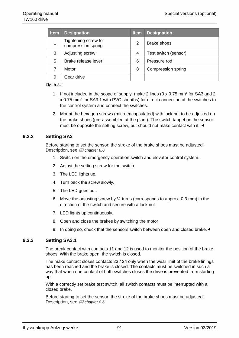
Operating manual Special versions (optional)
TW160 drive
thyssenkrupp Aufzugswerke 91 Version 03/2019
Item Designation Item Designation
1 Tightening screw for compression spring
2 Brake shoes
3 Adjusting screw 4 Test switch (sensor)
5 Brake release lever 6 Pressure rod
7 Motor 8 Compression spring
9 Gear drive
Fig. 9.2-1
1. If not included in the scope of supply, make 2 lines (3 x 0.75 mm² for SA3 and 2
x 0.75 mm² for SA3.1 with PVC sheaths) for direct connection of the switches to
the control system and connect the switches.
2. Mount the hexagon screws (microencapsulated) with lock nut to be adjusted on
the brake shoes (pre-assembled at the plant). The switch tappet on the sensor
must be opposite the setting screw, but should not make contact with it.
9.2.2 Setting SA3
Before starting to set the sensor; the stroke of the brake shoes must be adjusted! Description, see chapter 8.6
1. Switch on the emergency operation switch and elevator control system.
2. Adjust the setting screw for the switch.
3. The LED lights up.
4. Turn back the screw slowly.
5. The LED goes out.
6. Move the adjusting screw by ¼ turns (corresponds to approx. 0.3 mm) in the
direction of the switch and secure with a lock nut.
7. LED lights up continuously.
8. Open and close the brakes by switching the motor
9. In doing so, check that the sensors switch between open and closed brake.
9.2.3 Setting SA3.1
The break contact with contacts 11 and 12 is used to monitor the position of the brake shoes. With the brake open, the switch is closed.
The make contact closes contacts 23 / 24 only when the wear limit of the brake linings has been reached and the brake is closed. The contacts must be switched in such a way that when one contact of both switches closes the drive is prevented from starting up.
With a correctly set brake test switch, all switch contacts must be interrupted with a closed brake.
Before starting to set the sensor; the stroke of the brake shoes must be adjusted! Description, see chapter 8.6

Operating manual Special versions (optional)
TW160 drive
thyssenkrupp Aufzugswerke 92 Version 03/2019
1. Connect the continuity test device to contacts 11 and 12 of the break contact.
The adjusting screw must not touch the control tappet.
2. In home position of the drive (brake magnet without current) unscrew the
adjusting screw for the brake test from the brake shoe in direction control tappet
until opening of the contact is indicated by a signal interruption at the continuity
test device.
3. Continue unscrewing the adjusting screw a further approx. 1/4 revolution.
4. Secure this setting by tightening the lock nut.
5. Repeat the setting procedure at the second brake test switch.
Checking setting:
Open and close the brakes by switching the motor. Observe whether the switch at the contacts corresponds to the procedure described above.
Push the feeler gauge between adjusting screw and control tappet. Select the thickness of the feeler so that contact 23/24 is closed.
When one of the contacts is closed, it must no longer be possible to start up the drive.
Terminal connecting diagram - brake test switch
SA3 - version
Item Designation Item Designation
1 Button 1 2 Button 2
3 A (black) 4 - (blue)
5 + (brown)
Fig. 9.2-2

Operating manual Special versions (optional)
TW160 drive
thyssenkrupp Aufzugswerke 93 Version 03/2019
SA3.1 - version
Item Designation Item Designation
1 Button 1 2 Button 2
Fig. 9.2-3
9.2.4 switch mounting SA15 (Full-EX)
Fig. 9.2-4
The switch mounting for SA15 is described in the operating manual 'Explosion protection for machines (ATEX)'.
Schaltwege EIN AUS
Schaltbild
0
1,5
3
5,5mm
11
-12
23-2
4
12 (BU)(BN) 11
(GY) 23 24 (BK)

Operating manual Appendix
TW160 drive
thyssenkrupp Aufzugswerke 94 Version 03/2019
10 Appendix
10.1 Blocking clamp
NOTE
Leaving the blocking clamp fitted after completion of the installation work!
Can damage the installation.
Remove the blocking clamp after completion of the installation work.
A blocking clamp that matches the traction sheave (rim width and design) is part of each machine
Deployment of the blocking clamp:
During installation work on the elevator car or counterweight to prevent
movement due to slipping ropes.
In the case of work where the rope traction of the system is insufficient, e.g.
removing from the safety gear, use the blocking clamp.
The blocking clamp is to be tensioned via the screwed connection until it is excluded that ropes will slip.
Item Designation Item Designation
1 Traction sheave 2 Pressure piece
3 Hexagon nut 4 washer
5 Clamp clip
Fig. 10.1-1

Operating manual Appendix
TW160 drive
thyssenkrupp Aufzugswerke 95 Version 03/2019
10.2 Tightening torques
DANGER
Insecure threaded connection!
Death or severe physical injury due to parts coming loose.
When working on the machine or in the case of parts replacement, comply with the prescribed bolt tightness and tightening torques.
Only use suitable tools (torque wrench).
Non-microencapsulated bolts / screws are to be secured against unwanted loosening during installation using detent edged washers or Loctite 243 and a similar means of securing bolts / screws.
Microencapsulated screws are to be replaced after they have been used once.
The tightening torques given here apply for screwed connections without specifications at the corresponding location.
If in the drawing or elsewhere in the document other tightening torques are predefined for the particular bolt size, these have to be observed!
The values listed below apply to screwed connections with regular threads (not fine threads):
Hexagon socket bolts DIN 912 ISO 4762
Hexagon head bolts DIN 931/933 ISO 4014/4017
Tightness 8.8 10.9 12.9
Dimensions Tightening torque MA (Nm)
M4 2.6 - -
M5 5.3 - -
M6 9.0 12 15
M8 20 30 35
M10 40 60 75
M12 75 105 130
M14 120 170 205
M16 190 265 320
M20 370 520 620
M24 640 900 1080
M30 1300 1800 2150
Table 10.2-1
For assembly, use only original construction and mounting parts from thyssenkrupp Aufzugswerke GmbH, as otherwise no warranty can be provided.

Hohlwellen - Drehgeber WDG 100H
Maßzeichnung WDG 100 H, Angaben in mm
Ausgangsschaltung 5 VDC: I05
Bestell-Nr.: WDG 100H-XX-YYYY-ABN-I05-K3-D56
YYYY = XX = Hohlwellendurchmesser: 30, 38 mm
Empfohlene Wellenanpassung:für Hohlwellendurchmesser D (XX) = 38: 38m6 (k6, j6)für Hohlwellendurchmesser D (XX) = 30: 30m6 (k6, j6)Max. Rundlaufabweichung der Antriebswelle: 0,05 mm
Thyssen-Sachnummer: 9950 000 6021 für 1024 Striche9950 000 6022 für 4096 Striche
Impulszahl = 1024, 2048, 4096
Impulsfolge bei Blick auf Nabe, Drehung im Uhrzeigersinn.
18.08.2016/Angaben ohne Gewähr Irrtümer und Änderungen vorbehalten.
Elektrische Daten:
Versorgung: 4,75 ... 5,5 VDCStromaufnahme: max. 70 mAKanäle: A, B,N und
ABN inv.Ausgang: GegentaktBelastung: max. 40 mAPegel: bei 20 mA
H > 2,5 VDCL < 1,2 VDC
Impulsfrequenz: max. 200 kHzAnschlussschutz: nein
A
A
B
B
N
N
0° 360°90°
Spezifikationen
Mechanische DatenGehäuse
- Flansch: Aluminium- Rückseite: Aluminium- Durchmesser: 100 mm- Tiefe: 42 mm- Befestigung: über Hohlwelle mit
2 Gewindestiften M4
Hohlwelle
- Material: Edelstahl- Durchmesser: 30, 38 mm- Belastung am max. 200 N radial Wellenende: max. 100 N axial- Anlaufmoment: 1,5 NcmBefestigung: 2 x M4, DIN 913
Lager - Typ: 2 Präzisionskugellager
10- Lebensdauer: 3 x 10 U bei 100%
Lagerlast11
4 x 10 U bei 40%12
3 x 10 U bei 20%Drehzahl: max. 3.500 U/minGewicht: ca. 720 gAnschluss: radialer Kabelabgang
mit 10m Kabel undkonfektioniertem, metallisiertem 9-pol.SubD-Stecker mitRändelschraube UNC 4-40
Elektrische Daten Allgemeine Auslegung: gem. DIN VDE 0160
Versorgung/Ausgänge: ® AusgangsschaltungKabellänge: max. 100 m
OptikLichtquelle: IR - LEDLebensdauer: typ. 100.000 Std.Abtastung: differentiell
Genauigkeit in % einer Periodendauer des Signals A
Phasenversatz: 90° + 4,2%Impuls-/Pausen -verhältnis: 50% + 4,2%
Umwelt - Daten
bei geerdetem Gehäuse und gegen imEingebauten Zustand berührbare Teile.
ESD (EN 61000-4-2): 8 kVBurst (EN 61000-4-4) 2 kVSchutzart (EN 60529): IP 54Vibration (IEC 68-2-6): 50m/s² (10-2000 Hz)Stoß (IEC 60068-2-27): 1000m/s² (6 ms)Arbeitstemperatur: -20 - +80°CLagertemperatur -30 - +80°C
WD
G
5 V
Signal
Masse
Ausw
ert
ung
Schirm
26ET3126LS32A,B,N
A,B,N
1kW
1kW
100
W
3
11
15°
37
42
63
+0,03
40
2 x GewindestiftM 4 x 4 DIN 913
+0,05
SteckerbelegungFunktion Pin FarbeMinus 7 weißPlus 9 braunA 2 grünA inv. 1 rotB 3 gelbB inv. 4 schwarzN 5 grauN inv. 6 violettSchirm 8 Litze + Gebergehäuse
+ Steckergehäuse
31
,8
25
UN
C 4
/40
46,5
39,5
5
15,4
1 2
3 4
5
6 7
8 9
Wachendorff Automation GmbH & Co. KGIndustriestrasse 7D-65366 GeisenheimTel.: +49 (0) 67 22 / 99 65 - 25Fax: +49 (0) 67 22 / 99 65 - 70www.wachendorff-automation.de

WDG100H-xx-yyyy-ABN-I05-K3-D56-zzzxx = Ø 25, 25.4, 28, 30, 38, 40, 42, 45yyyy = PPR = 1024, 2048, 4096zzz = 130 = 13m, 200 = 20m, blank = 10m
Technical SupportGermany:Tel.: +49 (0) 67 22 / 99 65 131Fax: +49 (0) 67 22 / 99 65 70email: [email protected]
Other countries, please contact your distributor.Autres pays, veuillez contacter votre distributeur.Otros paises, rogamos contacten a su distribuidor.Per gli altri paesi si prega di contattare il vostrodistributore.
18.08.2016
SUBD99-pin
7
9
2
5
1
4
6
8
WH
BN
GN
YE
GY
-
RD
BK
VT
Litze, Flex, Toron,
Cordón,Cavetto
3
Kabel, cable, Câble,Cable, cavo
K3
1 2 3 4 5
6 7 8 9
Steckergehäuse/Schirmmit Gebergehäuse leitendverbunden
Connector housing/shieldelectrically connected toencoder housing
Bôtier de connexion/Ecran avec boîtier d’ementteur liés de manière conductrice
Caja de conector/Pantallsconectada en conductancia com caja de transmisor
scatola prese/Schemo conscatola transmettitore collegata da condure
31,8
25
UN
C 4
/40
46,5
39,5
5
15,4
1 2
3 4
5
6 7
8 9
4,2
4,2
TTL / RS422
Wachendorff Automation GmbH & Co. KGIndustriestraße 7 • D-65366 GeisenheimTel.: +49(0)6722/99 65 -25Fax: +49(0)6722/99 65-70eMail: [email protected]
D56

Hollow shaft Encoder WDG 100H
Dimensional drawing WDG 100H Dimensional specifications, in mm.
Output circuit: 5 VDC: R05
Order-No.: WDG 100H-38-1024-AB-R05-K3-J66-100
Suggested shaft adjustment:about hollow shaft diameter 38mm: 38m6 (k6, j6)Max. concentricity deviation of motor shaft: 0,05 mm
Thyssen-No.: 9950 001 1304
View from shaft end, rotating clockwise.
19.05.14/Specifications without engagement, subject to errors and
Electrical data:
Power supply: 4,75 ... 5,5 VDCCurrent consumption: max. 70 mA Channels: A, B and
AB inv. Output: push-pullLoad: max. 40 mA Signal level: bei 20 mA
H > 2,5 VDCL < 1,2 VDC
Pulse frequency: max. 200 kHzCircuit protection: no
Specifications
: 38 mm
ca. 720 g
Electrical Data General Layout: DIN VDE 0160
Supply / Output: ® Output circuitCable lenght: max. 100 m
in % einer Periodendauer des Signals A
.
Mechanical Data
Housing
- Servo flange: Aluminium- Housing: Aluminium,- Depth: 42 mm- Attachment: about Hollow-shaft with
2 set screw M4Hollow shaft
- Material: Stainless steel- Diameter:- Loading on shaft- max. 200 N radial end: max. 100 N axial- Starting torque: approx.1.5 Ncm at
ambient temperaturAttachment: 2 x Hub M4, DIN 913
Bearings
- Type: 2 precision ball bearings
10- Service life: 3 x 10 revs. at 100%
of full rated shaft load11
4 x 10 revs. at 40%12
3 x 10 revs. at 20%Speed: max. 3.500 r.p.m.Weight:Connection: radial with 10 m
shielded cable withconnector(7-pol. Phönix terminal)
Optics
Light source: IR - LEDService life: typ. 100.000 hrs.Scanning: differential
Accuracy
Quadratue phasing: 90° + 7,5% Pulse on/off ratio: 50% + 7%
Environmental Data
Measured mounted and housing grounded
ESD (DIN EN 61000-4-2): 8 kV Burst (DIN EN 61000-4-4): 2 kVProtection rating (EN 60529): IP54Vibration 50m/s² (10-2000 Hz)(DIN EN 60068-2-6): Shock 1000m/s² (6 ms)(DIN EN 60068-2-27): Operating temperature: -20°C to +80°CStorage temperature: -30°C to +80°C
2 x set screwM 4 x 4 DIN 913
WD
G
5 V
Signal
Ground
Eva
lua
tion
Shield
26ET3126LS32A,B
A,B
1kW
1kW
10
0W
Wachendorff Automation GmbH & Co. KGIndustriestrasse 7D-65366 GeisenheimTel.: +49 (0) 67 22 / 99 65 - 25Fax: +49 (0) 67 22 / 99 65 - 70www.wachendorff.de
3
11
15°
37
42
63
+0,03
40
+0,05
10
01
00
00
100
R05A
A
B
B
Pin arrangemant:Function Pin Colour
Negative 6 whitePositiv 7 brownA 5 greenA inv. 4 greyB 3 yellowB inv. 2 pinkShield 6 braiding
Cable connection, 10 m shielded cable

Hohlwellen - Drehgeber WDG 100H
Maßzeichnung WDG 100 H, Angaben in mm
Ausgangsschaltung 10-30 VDC: I24
Bestell-Nr.: WDG 100H-XX-1024-ABN-I24-K3-C07
Impulszahl: 1024 I/UXX = Hohlwellendurchmesser: 38 mm (28,40,42)*Thyssen-Sachnummer: 0099016030*ohne Sachnummer
Impulsfolge bei Blick auf Nabe, Drehung im Uhrzeigersinn.
Kabelbelegung
Funktion FarbePlus braunA grünB gelbN grauA inv. rotB inv. schwarzN inv. ViolettMinus weißSchirm Litze
18.08.2016/Angaben ohne Gewähr Irrtümer und Änderungen vorbehalten.
Spezifikationen
Mechanische DatenGehäuse
- Flansch: Aluminium- Rückseite: Aluminium- Durchmesser: 100 mm- Tiefe: 42 mm- Befestigung: über Hohlwelle mit
2 Gewindestiften M4
Hohlwelle
- Material: Edelstahl- Durchmesser: 38 mm- Belastung am max. 200 N radial Wellenende: max. 100 N axial- Anlaufmoment: 1,5 NcmBefestigung: 2 x M4, DIN 913
Lager - Typ: 2 Präzisionskugellager
10- Lebensdauer: 3 x 10 U bei 100%
Lagerlast11
4 x 10 U bei 40%12
3 x 10 U bei 20%Drehzahl: max. 3.500 U/minGewicht: ca. 720 gAnschluss: radialer Kabelabgang
mit 10m Kabel mitAderendhülsen
Elektrische Daten Allgemeine Auslegung: gem. DIN VDE 0160
Versorgung/Ausgänge: ® AusgangsschaltungKabellänge: max. 100 m
OptikLichtquelle: IR - LEDLebensdauer: typ. 100.000 Std.Abtastung: differentiell
Genauigkeit in % einer Periodendauer des Signals A
Phasenversatz: 90° + 7,5%Impuls-/Pausen -verhältnis: 50% + 7%
Umwelt - Datenbei geerdetem Gehäuse und gegen im eingebauten Zustand berührbare Teile.
ESD (EN 61000-4-2): 8 kVBurst (EN 61000-4-4)- auf Versorgung: 2 kVSchutzart (EN 60529): IP 54Vibration (IEC 68-2-6): 50m/s² (10-2000 Hz)Stoß (IEC 68-2-27): 1000m/s² (11 ms)Betriebstemperatur: -10 - +70°CLagertemperatur -30 - +80°C
Elektrische Daten:
Versorgung: 10 - 30 VDCStromaufnahme: max. 60 mAKanäle: A, B, N, ABN inv.Ausgang: HTL-
DifferentialtreiberBelastung: max. 40 mAPegel: bei 20 mA
H > U - 2,5 VDCB
L < 2,5 VDCImpulsfrequenz: max. 200 kHzAnschlussschutz: neinFrühwarn- Ausgang: NPN OC, 10 mA
U = 30 VDCmax
Kabellänge: max. 100 m
A
A
B
B
N
N
0° 360°90°
WD
G
Schirm
Ausw
ert
ung
Masse
Signal
10-30 V
A,B,N
A,B,N
Wachendorff Automation GmbH & Co. KGIndustriestrasse 7D-65366 GeisenheimTel.: +49 (0) 67 22 / 99 65 - 25Fax: +49 (0) 67 22 / 99 65 - 70www.wachendorff-automation.de

WDG100H-xx-yyyy-ABN-I24-K3-C07xx = Ø 28, 38, 40, 42mmyyyy = PPR 1024, 4096
Technical SupportGermany:Tel.: +49 (0) 67 22 / 99 65 131Fax: +49 (0) 67 22 / 99 65 70email: [email protected]
Other countries, please contact your distributor.Autres pays, veuillez contacter votre distributeur.Otros paises, rogamos contacten a su distribuidor.Per gli altri paesi si prega di contattare il vostrodistributore.
18.08.2016
Steckergehäuse/Schirmmit Gebergehäuse leitendverbunden (Nicht S7, K1, K2, K3)
Connector housing/shieldelectrically connected toencoder housing (not S7, K1, K2, K3)
Bôtier de connexion/Ecran avec boîtier d’ementteur liés de manière conductrice (No S7, K1, K2, K3)
Caja de conector/Pantallsconectada en conductancia com caja de transmisor(No S7, K1, K2, K3)
scatola prese/Schemo conscatola transmettitore collegata da condure(No S7, K1, K2, K3)
BU:
-
-
-
-
-
-
-
-
-
WH
BN
GN
YE
GY
-
RD
BK
VT
Litze, Flex, Toron,
Cordón,Cavetto
-
Kabel, cable, Câble,Cable, cavo
-
, ,,
-
Wachendorff Automation GmbH & Co. KGIndustriestraße 7 • D-65366 GeisenheimTel.: +49(0)6722/99 65 -25Fax: +49(0)6722/99 65-70eMail: [email protected]
C07


.


Tachogenerator RE.0444 zu SA 1
Anschlusshinweis

6085103100 / 2620-16
BERNSTEIN AG . Hans-Bernstein-Straße 1 . 32457 Porta Westfalica . www.bernstein.eu
Technical modifications and errors excepted.
The technical datasheet corresponds to the technical state as of 2016-10-24 and will not be removed in case of changes.
Page 1 of 2
Technical Data
Plastic bodied limit switch
Series BI2
Operating symbol
Operating diagram
Description BI2-U1Z W Article number 6085103100
Tolerance:Operating Point ± 0,25 mm;Operating force ± 10 %On Off
Electrical Data
Rated insulation voltage Ui 400 V ACConv. thermal current Ithe 10 A
Rated operational voltage acc. to CCSAUS
UeUe
240 V AC300 V AC
Utilization category AC15 Ue / Ie 240 V / 3 ADirect opening action p acc. to IEC/EN 60947-5-1, annex KShort-circuit protective device Fuse 10 A gGProtection class II (totally insulated)
Fixed positioning with e.g. fixing screw M5
according to the standard DIN EN ISO 4762.

6085103100 / 2620-16
BERNSTEIN AG . Hans-Bernstein-Straße 1 . 32457 Porta Westfalica . www.bernstein.eu
Technical modifications and errors excepted.
The technical datasheet corresponds to the technical state as of 2016-10-24 and will not be removed in case of changes.
Page 2 of 2
Technical Data
Mechanical data
Enclosure Thermoplastic, glass fibre reinforcedCover Thermoplastic, glass fibre reinforcedActuator plunger (Thermoplastic)Ambient air temperature -30 °C ... +80 °CContact type 1 NC, 1 NO (Zb)Mechanical life 10 x 106 operating cyclesSwitching frequency ≤ 100 / min.Assembly 2 x M4 / 2 x M5 / 2 x M3 front mountingConnection 4 screw connections (M3,5)
Conductor cross-sections Solid: 0,5 ... 1,5 mm²Litz wire with ferrules: 0,5 ... 1,5 mm²
Cable entrance 2 x M16 x 1,5Weight ≈ 0,08 kgInstallation position operator definableProtection type IP65 acc. to IEC/EN 60529; DIN VDE 0470 T1
ID for safety engineering
B10d 20 x 106 cycles
Standards
VDE 0660 T100, DIN EN 60947-1, IEC 60947-1VDE 0660 T200, DIN EN 60947-5-1, IEC 60947-5-1DIN EN ISO 13849-1
EU Conformity
acc. to directive 2014/35/EU
Notes
The degree of protection specified (IP code) applies only to a properly closed protective guard and the use of an equivalent cable gland with adequate cable.
Actuation
The push bolt actuator is mainly intended to be actuated along its axis.Side actuation will considerably reduce switch life.
Approvals
CCSAUS A300, Q300CCC


Technische Daten Kontaktloser Taster im Biggy-Gehäuse
Dieses Dokument wird nicht Vertragsgrundlage; die darin enthaltenen Angaben stellen keine Beschreibungen zu erwartender Beschaffenheiten dar, so dass eine Sachmängelhaftung wegen eventueller Abweichungen der tatsächlichen von der hier beschriebenen Beschaffenheit ausgeschlossen ist. Änderungen bleiben vorbehalten.
Ausgabedatum : 29.03.2011 / Blatt 1 von 2 Dokument : 6659381003_de / Stand : 1 / 0152-11
Baureihe OR81
Typbezeichnung OR81GL-DHTN-0005-ALX Artikelnummer 6659381003
Anschlussschema
+ + A
-
not connected
T
-
Schaltweg (Betätigungsrichtung, -kraft in Stößelrichtung)
Befestigungsschraube M5 nach DIN 912
oder DIN EN ISO 4762 Betätigungskraft F ≤ 12N
Bernstein AG, Tieloser Weg 6, D-32457 Porta Westfalica / www.bernstein.eu Vorlage : 0850174277 Orig. 3

Technische Daten Kontaktloser Taster im Biggy-Gehäuse
Kennzeichnende Merkmale nach EN 60947-5-2
Elektrische Daten
Schaltelementfunktion NPN - Schließer Hysterese H ≈ 0,05 mm Bemessungsbetriebsspannung Ue 24 VDC Bemessungsbetriebsspannungsbereich UBB 20,4 – 27,6 VDC Bemessungsisolationsspannung Ui 75 VDC Bemessungsstoßspannungsfestigkeit Uimp 500 VAC Gebrauchskategorie DC 12 Bemessungsbetriebsstrom le 50 mA Kleinster Betriebsstrom Im 1 mA Leerlaufstrom lo ≤ 20 mA Reststrom Ir ≤ 0,2 mA Max. Laststrom 200 mA Art des Kurzschlussschutzes rastend Schaltfrequenz f ≤ 6000 / h Verpolschutz ja Bereitschaftsverzug tv ≤ 4 ms bei UB = 24 VDC B
Einschaltverzug ton < 1 ms Elektromagnetische Verträglichkeit (EMV)
Hochfrequenzbeeinflussungsfestigkeit IEC 61000-4-3 Elektrostatische Entladungsfestigkeit IEC 61000-4-2 Schnelle Transientenfestigkeit (Burst) IEC 61000-4-4 Stoßspannungsfestigkeit (Surge) IEC 61000-4-5 Störaussendung CISPR 11
Mechanische Daten
Gehäuse PA6, rot Deckel PA66, schwarz Stößel Betätigung POM, natur Manschette CR, schwarz Befestigung 2 x M4 / 2 x M5 / 2 x M3 Frontbefestigung Betriebstemperatur 0 °C ... +60°C Lagertemperatur -20 °C ... +80°C Schutzart IP65 Verschmutzungsgrad 3 Anzeigen LED gelb Anschlussart Schraubklemmen (M3,5) Leiterquerschnitte Eindrähtig 0,5 – 1,5mm² oder Litze mit Aderendhülse 0,5 – 1,5mm² Kabeleinführung 2 x M16x1,5 (Kabelverschraubung, Blindkappe)
EG-Konformität
Bemerkungen
Etikett nach Kundenvorgabe zusätzlicher Aufdruck des Fertigungskodes nach Artikelnummer
0099216070
6659381003
Dieses Dokument wird nicht Vertragsgrundlage; die darin enthaltenen Angaben stellen keine Beschreibungen zu erwartender Beschaffenheiten dar, so dass eine Sachmängelhaftung wegen eventueller Abweichungen der tatsächlichen von der hier beschriebenen Beschaffenheit ausgeschlossen ist. Änderungen bleiben vorbehalten.
Ausgabedatum : 29.03.2011 / Blatt 2 von 2 Dokument : 6659381003_de / Stand : 1 / 0152-11
Bernstein AG, Tieloser Weg 6, D-32457 Porta Westfalica / www.bernstein.eu Vorlage : 0850174277 Orig. 3

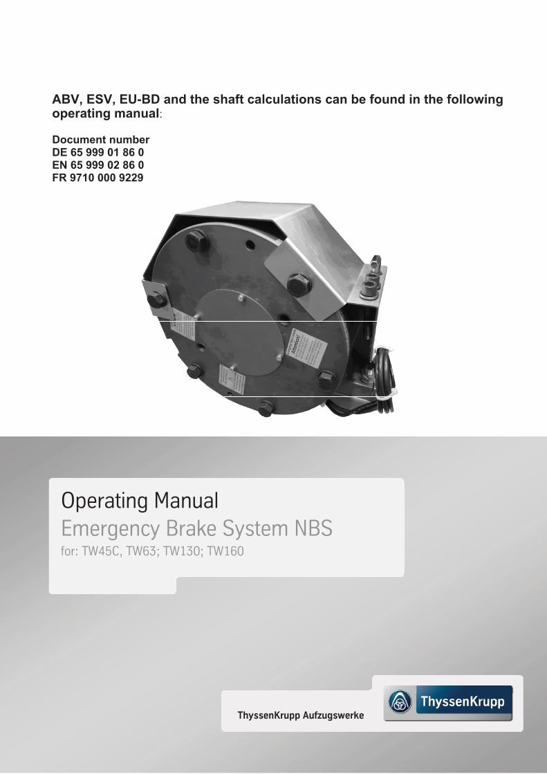
ABV, ESV, EU-BD and the shaft calculations can be found in the following operating manual:
Document number DE 65 999 01 86 0 EN 65 999 02 86 0 FR 9710 000 9229
ThyssenKrupp Aufzugswerke
Operating Manual Emergency Brake System NBS for: TW45C, TW63; TW130; TW160

thyssenkrupp Aufzugswerke GmbH
Bernhäuser Strasse 45
73765 Neuhausen a. d. F.
Germany
E-mail: [email protected]
Internet: www.thyssenkrupp-elevator-eli.com
Ve
rsio
n 0
3/2
019
No
. 6
2 3
40 0
2 8
6 0