
MAT 253 OPERATING MANUAL - IsoLab
402
Issue 04/2002 Ident. No. 114 9090 MAT 253 OPERATING MANUAL
-
Upload
khangminh22 -
Category
Documents
-
view
0 -
download
0
Transcript of MAT 253 OPERATING MANUAL - IsoLab

Issue 04/2002
Ident. No. 114 9090
MAT 253
OPERATING MANUAL


Thermo Finnigan MAT GmbHPostfach 1401 62
28088 BremenGermany
Reparatur-Begleitkarte*)Repair-Covering Letter
Absender: Geräte-Type:Despachter: Instrument Type:
__________________________________ _________________________________
__________________________________ Service-Nr.: Service No
Sie erhalten zur Reparatur unter unserer Bestell-Nr.:You receive for repair under our order no.:
Festgestellte Mängel oder deren Auswirkung:Established defect or its effect:
Bitte detaillierte Angaben machen / Please specify in detail
Ein Austauschteil haben wir erhalten unter Kommissions-Nr.:An exchange part already received with commission no.:
Ja/Yes Nein/No
Die Anlage ist außer Funktion The system is out of function Ja/Yes Nein/No
Durch die nachfolgende Unterschriftbestätige(n) ich /wir, daß die o.g. Teile frei vongesundheitsschädlichen Stoffen sind, bzw. vorihrer Einsendung an Thermo Finnigan MATdekontaminiert wurden, falls die Teile mit giftigen Stoffen in Verbindung gekommen sind.
By signing this document I am/ we are certifyingthat the a. m. parts are free from hazardousmaterials. In case the parts have been used forthe analysis of hazardous substances I/weattest that the parts have been decontaminatedbefore sending them to Thermo Finnigan MAT.
__________________________________ _________________________________Datum / date Unterschrift / signature
*) Bitte vollständig ausfüllen / Please fill in completely


MAT 253 O P E R A T I N G M A N U A L
0 – 1
Issue 04/2002
TABLE OF CONTENTS
1 GETTING STARTED
1.1 Introduction 1 – 1 1.1.1 Basic Instrument 1 – 1 1.1.2 ISODAT Software 1 – 3 1.2 Getting started: Hardware 1 – 5 1.3 Getting started: Software 1 – 361.3.1 System Requirements 1 – 361.3.1.1 Software Requirements 1 – 361.3.1.2 Hardware Requirements 1 – 361.3.2 Installing ISODAT NT 1 – 371.4 Principle of Focusing 1 – 441.4.1 Reasons to perform Focusing 1 – 44
2 Analyzer
2.1 General 2 – 1 2.2 Ion Source 2 – 4 2.3 Ion Source Control Unit 2 – 7 2.3.1 Emission Regulator 2 – 11 2.3.2 High Voltage Supply 2 – 11 2.3.3 Focusing of the Mass Spectrometer 2 – 12 2.4 Ion Deflection 2 – 16 2.4.1 Electromagnet 2 – 16 2.4.2 Magnet Current Regulator 2 – 16 2.5 Ion Detection - Collector System 2 – 16 2.5.1 General 2 – 16 2.5.2 Amplifier 2 – 18 2.5.3 Collector Systems 2 – 20 2.5.3.1 MEMCO Collector System 2 – 20 2.5.3.2 Universal CNOS Collector System 2 – 21 2.5.3.3 HD Collector System 2 – 22

MAT 253 O P E R A T I N G M A N U A L
0 – 2
Issue 04/2002
3 Vacuum System
3.1 Pumping System 3 – 1 3.2 Vacuum System Control Unit 3 – 1 3.2.1 Vacuum in Amplifier Housing 3 – 2 3.2.1.1 Guidance for Troubleshooting 3 – 6 3.3 Turbomolecular Pump 3 – 6 3.3.1 General 3 – 6 3.3.2 Control electronics and power supply 3 – 7
4 Electronic Devices
4.1 Overview of the Electronic Devices 4 – 1 4.2 Power Distribution 4 – 3 4.3 Inlet Controller 4 – 5 4.4 The Plug and Measure Concept 4 – 7 4.4.1 The Plug and Measure Adapter 4 – 7 4.4.2 Grounding Cable for Peripherals 4 – 8 4.4.3 Configuring the Plug and Measure Devices 4 – 8 4.4.4 Using the Options Gas Bench, PreCon and Tubecracker with another
Mass Spectrometer 4 – 10
4.5 Data Acquisition 4 – 12 4.5.1 Data Logger 4 – 12 4.5.2 Groundplane 4 – 13 4.5.3 Amplifier & VFC 4 – 14 4.5.4 Changing the Amplifier 4 – 16 4.5.4.1 Working with the Collector - Removing the Amplifier Housing 4 – 16 4.5.4.2 Working with the Collector - Mounting the Amplifier Again 4 – 17 4.5.5 Power Supply 55 V 4 – 18 4.6 Ion Source Controller 4 – 19 4.6.1 Emission Regulator 4 – 20 4.6.2 High Voltage Potential Controller 4 – 20 4.6.3 High Voltage Supply 4 – 21 4.6.4 Bus Controller 4 – 22 4.7 Magnet Current Regulator 4 – 23 4.8 DEL-PCI Controller 4 – 24

MAT 253 O P E R A T I N G M A N U A L
0 – 3
Issue 04/2002
5 Dual Inlet System
5.1 General Description of the Dual Inlet System 5 – 1 5.2 Valve System 5 – 3 5.3 Changeover Valve 5 – 6 5.3.1 Basic Module 5 – 6 5.3.2 Extension Module 5 – 6 5.4 Multiport 5 – 7 5.5 Microvolume 5 – 8 5.5.1 Autocool Unit 5 – 11 5.5.2 Autocool Refill Device 5 – 13 5.5.2.1 General Remarks 5 – 13 5.5.2.2 Control of the Refill Device 5 – 14 5.5.2.3 Safety Warnings 5 – 15 5.5.2.4 Working Principle 5 – 16 5.5.2.5 Maintenance 5 – 17 5.5.2.6 Checking the Liquid Nitrogen Evaporation Rate 5 – 17 5.5.2.7 Operating Instructions 5 – 18 5.5.3 Standard Refill (Reference Gas Refill) 5 – 19
6 Measurements
6.1 General Remarks 6 – 1 6.1.1 Procedure before Starting any Measurements 6 – 1 6.1.2 If no Configuration is available 6 – 1 6.1.3 How to create a new Gas Configuration 6 – 3 6.1.4 How to create a new Method 6 – 4 6.1.5 How to create a new Sequence 6 – 5 6.2 Zero Enrichment (Standard on/off test) 6 – 7 6.3 Simple Dual Inlet Measurement 6 – 11 6.3.1 Defining a Configuration 6 – 11 6.3.2 Using a predefined Method 6 – 13 6.3.3 Using a predefined Sequence 6 – 21 6.4 Dual Inlet Measurement including Multiport 6 – 24 6.4.1 Defining a Configuration 6 – 24 6.4.2 Using a predefined Method 6 – 26 6.4.3 Using a predefined Sequence 6 – 30 6.5 Dual Inlet Measurement including Microvolume 6 – 33

MAT 253 O P E R A T I N G M A N U A L
0 – 4
Issue 04/2002
6.5.1 Microvolume - Measurement Principle 6 – 33 6.5.1.1 Microvolume without Multiport - Measurement Principle 6 – 33 6.5.1.2 Microvolume via Multiport - Measurement Principle 6 – 34 6.5.1.3 Expansion Mode - General Remarks 6 – 34 6.5.1.4 Expansion Mode - Before Measurement 6 – 35 6.5.1.5 Expansion Mode - Measurement with Bank 6 – 36 6.5.1.6 Expansion Mode - Measurement with Bank and Transferline 6 – 38 6.5.1.7 Expansion Mode - Measurement with Bank, Transferline and Bellow 6 – 39 6.5.1.8 Freeze Direct Mode 6 – 41 6.5.2 Defining a Configuration 6 – 43 6.5.3 Using a predefined Method 6 – 45 6.5.4 Using a predefined Sequence 6 – 49 6.6 Dual Inlet Measurement including Multiport and Microvolume 6 – 52 6.6.1 Defining a Configuration 6 – 52 6.6.2 Using a predefined Method 6 – 54 6.6.3 Using a predefined Sequence 6 – 58 6.7 Dual Inlet Measurement including Multiport and Reference Refill 6 – 61 6.7.1 Defining a Configuration 6 – 61 6.7.2 Using a predefined Method 6 – 63 6.7.3 Using a predefined Sequence 6 – 69 6.8 Dual Inlet Measurement including Multiport and Buffered Refill 6 – 72 6.8.1 Defining a Configuration 6 – 72 6.8.2 Using a predefined Method 6 – 74 6.8.3 Using a predefined Sequence 6 – 80 6.9 Dual Inlet Measurement including H-Device and Autosampler A 200 S 6 – 83 6.9.1 Defining a Configuration 6 – 83 6.9.2 Using a predefined Method 6 – 85 6.9.3 Using a predefined Sequence 6 – 91 6.10 Fundamental Procedures before any Measurement 6 – 94 6.11 Handling of Results 6 – 95 6.12 Excel Export of Results 6 – 102 6.12.1 Principle of Excel Export 6 – 102 6.12.2 Creating an Export Template 6 – 103 6.12.3 Saving an Export Template 6 – 107 6.12.4 Applying an Export Template 6 – 108

MAT 253 O P E R A T I N G M A N U A L
0 – 5
Issue 04/2002
7 Diagnosis
7.1 Checking Performance Data 7 – 1 7.2 How to Start Diagnosis 7 – 2 7.2.1 Absolute Sensitivity 7 – 3 7.2.2 Abundance 7 – 9 7.2.3 Amplifier Test 7 – 14 7.2.4 Compression Factor 7 – 18 7.2.5 Linearity 7 – 23 7.2.6 Peak Flatness 7 – 27 7.2.7 Relative Sensitivity 7 – 33 7.2.8 Resolution 7 – 36 7.2.9 Signal Stability 7 – 42 7.2.10 System Stability 7 – 47 7.3 Conversion to other Gases 7 – 53 7.4 Heating Inlet Capillaries 7 – 54 7.5 Replacing Inlet Capillaries 7 – 56
8 Technical Information
8.1 Introduction 8 – 1 8.1.1 General Remarks 8 – 1 8.1.1.1 Maintenance 8 – 2 8.1.1.2 Spare Parts Lists 8 – 2 8.1.1.3 Service Instructions 8 – 2 8.1.1.4 Repair Request Forms 8 – 2 8.1.1.5 Shipment Lists 8 – 2 8.1.1.6 Technical Modifications 8 – 2 8.1.2 Safety Rules for the Repair Service 8 – 3 8.2 Installation of Board Drivers 8 – 4 8.2.1 "Serial Solutions" COM Port Extension Board driver 8 – 4 8.2.1.1 Reinstalling a previously installed Serial Solutions driver 8 – 9 8.2.2 Installing IEEE Interface Board drivers 8 – 10 8.2.2.1 "National Instruments" GPIB PCIIA ISA IEEE Interface Board 8 – 10 8.2.2.2 "National Instruments" GPIB PCI IEEE Board - Installation 8 – 11 8.2.2.3 "National Instruments" GPIB PCI IEEE Board - Configuration 8 – 17 8.2.2.4 "National Instruments" GPIB PCI IEEE Board - Verification 8 – 19 8.2.2.5 "National Instruments" GPIB PCI IEEE Board - Visa Installation 8 – 20

MAT 253 O P E R A T I N G M A N U A L
0 – 6
Issue 04/2002
8.2.3 Installation of the Sound Card Driver 8 – 24 8.2.4 Installation of the "Analog Joystick" driver 8 – 25 8.2.4.1 Calibrating the Joystick Driver 8 – 28 8.2.4.2 Testing the Joystick's calibration 8 – 31 8.2.5 GC and Autosampler Requirements 8 – 33 8.2.5.1 HP 6890 GC 8 – 33 8.2.5.2 Trace GC 8 – 34 8.2.5.3 Any other "generic" GC 8 – 34 8.2.5.4 A200S or PAL Autosampler 8 – 34 8.3 Maintenance 8 – 35 8.3.1 Basic Rules for Cleaning 8 – 35 8.4 Analyzer System 8 – 37 8.4.1 Basic Unit 8 – 37 8.4.2 Analyzer Head 8 – 39 8.5 Vacuum System 8 – 41 8.5.1 General Remarks 8 – 41 8.5.1.1 Flanges with Metal Gaskets 8 – 41 8.5.1.2 Flanges with Viton Gaskets 8 – 42 8.5.1.3 PVC Hoses of Fore Vacuum Lines 8 – 42 8.5.1.4 Cleaning the Vacuum Components 8 – 42 8.5.1.5 Leak Detection 8 – 43 8.5.1.6 Ion Gauge 8 – 44 8.5.2 Pumping System 8 – 45 8.6 Ion Source 8 – 48 8.6.1 Removal of the Ion Source 8 – 48 8.6.2 Reinstallation of the Ion Source 8 – 48 8.6.3 Exchange of the Cathode Unit 8 – 49 8.6.4 Disassembly of the Ion Source 8 – 49 8.6.5 Cleaning the Ion Source Parts 8 – 50 8.6.5.1 Cleaning the Metallic Parts 8 – 50 8.6.5.2 Cleaning the Ceramic Insulators 8 – 51 8.6.6 Assembling the Ion Source 8 – 51 8.6.7 Checking the Ion Source 8 – 53 8.6.8 Parts of the Ion Source 8 – 54 8.7 Inlet Systems 8 – 69 8.7.1 Autocool 8 – 77 8.7.2 Accessories 8 – 78

Issue 04/2002
MAT 253
OPERATING MANUAL
GETTING STARTED


MAT 253 O P E R A T I N G M A N U A L 1
1 – 1
Issue 04/2002
1.1 INTRODUCTIONThis manual describes the functions and the fundamental measuring procedures of your
Thermo Finnigan MAT 253 mass spectrometer. In addition, specific manuals for the
purchased peripheral equipment are supplied.
To obtain a good understanding of the complete system, it is necessary to study the operating
manual and the online-help of the software before starting up your instrument. A basic
knowledge of handling computers and of the ISODAT NT software is assumed for proper
operation of the Thermo Finnigan MAT 253.
To reach a high level of performance with the Thermo Finnigan MAT 253, we recommend
making use of the operator courses provided by us at our facilities in Bremen, and/or onsite.
For more information, please contact your local Thermo Finnigan MAT service office or
contact directly:
Thermo Finnigan MAT Barkhausenstr. 2 28197 Bremen, Germany Phone: +49-421-5493-0 Fax: +49-421-5493-396 Internet: www.thermo.com
1.1.1 BASIC INSTRUMENTWith the Thermo Finnigan MAT 253, you can measure gas isotope ratio of
H/D, 13C/12C, 15N/14N, 180/160, 32S/34S (from SO2 and SF6), 28Si/29Si as well as Ar, Kr, and Xe.
The MAT 253 provides a flexible and open platform for the connection of inlet systems and
preparation devices. Thermo Finnigan-supplied inlet systems are automatically recognized by

MAT 253 O P E R A T I N G M A N U A L 1
1 – 2
Issue 04/2002
a "plug and measure" concept. In addition, the system is open for easy connection and
control of custom inlet/preparation systems.
The basic instrument is equipped with a dual inlet system for classical applications. It has a
modular design for the adaptation of different inlet modules. This enables a configuration of
the instrument tailored to the requirement of the users.
On the sample side can be connected:
a second inlet system for variable sample volumes, a multiport with or without a tube
cracker installation,
microvolumes for very small samples,
multisample inlets for separating and purifying samples or,
installations for "on-line" coupling to gas chromatographs, elemental analyzer or other
peripherals.
The configuration of the inlet systems is described in this manual. Detailed information about
other inlet systems such as the "on line" coupling to gas chromatographs or to elemental
analyzers you will find in the manual describing the peripheral equipment.
Please make yourself familiar with all the controls on front and all the connection and
installations on the rear of your instrument.

MAT 253 O P E R A T I N G M A N U A L 1
1 – 3
Issue 04/2002
Fig. 1-1: Front view of the MAT 253
1.1.2 ISODAT NT SOFTWAREISODAT NT is a software suite for system control, data acquisition and data evaluation that is
an integral part of the system architecture.
System control All aspects of the mass spectrometer are controlled by software, including ion
generation, mass separation and ion detection. Control of the ion source allows
manual tuning, auto tuning, as well as storage and retrieval of ion source parameters.
Different configurations representing different analytical setups can be stored and
retrieved. Up to eight simultaneous data acquisition streams are supported.

MAT 253 O P E R A T I N G M A N U A L 1
1 – 4
Issue 04/2002
AutomationThe system is designed to fully automatically execute pre-defined procedures and run
sequences of analyses, including customized reporting.
Open architecture ISODAT Script Language (ISL) is the tool giving the expert user full access to the
mass spectrometer, the inlet systems and additional user-supplied devices. An input-
output module allows connection and control of up to five interfaces. Scripts can be
developed for customized applications.
Data evaluation and display ISODAT NT provides a comprehensive set of customizable data evaluation routines.
Standard report forms are provided according to the application. In addition, reports
can be easily customized using ISODAT NT's unique Result Workshop.
Technical information contained in this publication is for reference purposes only and is
subject to change without notice. Every effort has been made to supply complete and
accurate information. However, Thermo Finnigan assumes no responsibility and will not be
liable for any errors, omissions, damage, or loss that might result from any use of this manual
or the information contained therein (even if this information is properly followed and
problems still arise).
This publication is not part of the Agreement of Sale between Thermo Finnigan and the
purchaser of a Thermo Finnigan MAT system. In the event of any conflict between the
provisions of this document and those contained in Thermo Finnigan's Terms and Conditions,
the provisions of the Terms and Conditions will govern.
Reference to System Configurations and Specifications supersede all previous information
and are subject to revision without notice.

MAT 253 O P E R A T I N G M A N U A L 1
1 – 5
Issue 04/2002
1.2 GETTING STARTED: HARDWAREThis paragraph explains the hardware related steps to be performed before any measure-
ment can be started.
First steps
Unpack your IRMS and arrange it at the desired place in your laboratory.
Connect the end of the hose for compressed air (i.e. a thin transparent hose) that lea-
ves the IRMS at its rear panel to your wall outlet or a compressor for compressed air.
You need at least 5 bar.
wall outlet for
compressed air
to wall outlet
to pressureregulator
hose for compressed air
- leaves IRMS at its rear panel
- leads to wall outlet for compressed air and manometer
The other end of the hose for compressed air must be connected to the pressure regulator
behind the front panel of the IRMS as shown below.

MAT 253 O P E R A T I N G M A N U A L 1
Usually, the pressure regulator is factory-set via the pressure regulating screw to display
4 bar. To vary the pressure, pull out the pressure regulating screw and turn it.
distributor
with ports
pressureregulator
hose for com-pressed air
pressureregulatingscrew
hose for com-pressed air
pressureregulator
Insert your peripherals at the distributor (down right behind the front panel). As the
ports of the distributor are equivalent, it is unimportant which peripheral to insert at
which port.
distributor
with ports
1 – 6
Issue 04/2002

MAT 253 O P E R A T I N G M A N U A L 1
1 – 7
Issue 04/2002
Lay the waste gas tube (at the output of the vacuum pumps) outdoors in order to
prevent accumulation of oil mist and perilous gases (e.g. CO, H2).
to Fore VacuumPump
outward to Fore Vacuumpump
outward
Power supplyPower supply
Connect your IRMS to the power supply.Connect your IRMS to the power supply.
topowersupply
to IRMS

MAT 253 O P E R A T I N G M A N U A L 1
1 – 8
Issue 04/2002
At the rear side of the instruments are sockets to connect peripherals, if available. For
first tests, the IRMS is checked without any peripherals connected to it. Later on, the
peripherals are connected one at a time.
sockets for connection
of peripherals
Turn on the IRMS by setting the main switch to position ON. The main switch is loca-
ted at the electronic cabinet’s rear panel.

1 – 9
Issue 04/2002
MAT 253 O P E R A T I N G M A N U A L 1
Pumping system
1 2 3
Three Fore Vacuum Pumps are used:
Before starting the pumping system, it is assumed that:
Pfeiffer “Duo 5” for the Source (1)
Pfeiffer “Duo 2.5” for the Analyzer (2)
Pfeiffer “Duo 2.5” for the Inlet System (3)
For detailed information - e.g. concerning handling and maintenance - refer to the Pfeiffer
Operating Instructions of your pumps.
the Fore Vacuum pumps are filled with oil,
they are connected to the power supply, and
their gas ballast is shut.
Normally, the fill level of the oil must range between the upper and the lower line, optimally at
half height of the level indicator. A total oil change is recommended twice a year (refer to the
Pfeiffer Operating Instructions of your pumps).

MAT 253 O P E R A T I N G M A N U A L 1
1 – 10
Issue 04/2002
The gas ballast is shut by turning the switch to position 0. In case of Pfeiffer “Duo 5”, i.e. (1)
the switch is located on top of the pump. In case of Pfeiffer “Duo 2.5”, i.e. (2, 3) the switch is
located sidewise (refer to the Pfeiffer Operating Instructions of your pumps).
2, 3
1
The Control Panel at the front panel of the electronic cabinet shows switches for operating
the pumps. The corresponding LEDs are described below.

MAT 253 O P E R A T I N G M A N U A L 1
1 – 11
Issue 04/2002
Turn on the pumps by pressing the Analyzer Pumps switch.
The Inlet Pumps switch must only be additionally pressed in case of a Dual Inlet Sys-
tem.
NOTE: All the LEDs will still be turned off with the exception of the Power LED,which will be red.
After 15 min, the green LEDs “Analyzer Pumps: Turbo Pumps > 80%” and
“Inlet Pumps: Turbo Pump > 80%” must be on.
If one of the turbo pumps does not reach 80% of the rotation speed after a
specific period of time, the pumping system will shut down automatically.
The red LEDs “Main Pump Error”, “Sec. Pump Error“ and “Inlet Pump Error”
indicate errors concerning the turbo pumps (e.g. after about 15 min, the se-
curity threshold of 3 * 10 -5 mbar has not been reached).
NOTE: If properly functioning, the red LEDs must not be on!
Source heater
The LEDs of the source heater are located at left side of the IRMS, in the top right corner.
When the source heater is turned on, both LEDs must be on. Otherwise, one of the heaters
might be defective.

1 – 12
Issue 04/2002
MAT 253 O P E R A T I N G M A N U A L 1
Heater of the Changeover valve and/or needle valve
Switch on the heater of the Changeover valve and/or the heater of the needle valve (in case
of Continuous Flow applications). This will help to prevent water condensation.
1 needle valve including needle
valve heater
2 Changeover valve (COV)
including Changeover valve
heater
3 2
1
3 device for crimp adjustment

MAT 253 O P E R A T I N G M A N U A L 1
1 – 13
Issue 04/2002
needle valve including needle valve
heater (side view)
a to needle valve heater
b port for capillary a
b
device for
crimp adjust-
ment
to needle valve
heater
(inside metal
block)
needle valve
(frontal view)
to Changeover valve
heater
(inside metal block)
IRMS - computer connection
To ensure data transfer between IRMS and computer, connect the fiber line to the respective
port at the computer’s rear panel.

MAT 253 O P E R A T I N G M A N U A L 1
1 – 14
Issue 04/2002
fiber line
interface
fiber line
fiber line
Connect the other end of the fiber line to the IRMS by inserting the blue plug into the
blue connector and the gray plug into the gray connector.
To verify whether the quality of the established vacuum is sufficient, start ISODAT NT
by double-clicking on the ISODAT NT Icon on your desktop.
For detailed information refer to the ISODAT NT Help System.
When connected, the LED “Host Connection” at the front panel will be on.
NOTE: If the “Host Connection” LED does not gleam with ISODAT NT being started,no connection between IRMS and computer has been established.

MAT 253 O P E R A T I N G M A N U A L 1
1 – 15
Issue 04/2002
IRMS-peripherals connection
To connect peripherals to the IRMS use one of the
five identical SUB D ports at the rear panel of the
IRMS.
Peripherals are identified automatically by a plugand measure concept (see Chapter 4.4).
If ISODAT NT is trying to get access to a peripheral and cannot identify it, an error
message occurs (refer to the ISODAT NT Help System).
Start Configurator
To select a suitable (Hardware) Configuration containing your hardware equipment,
i.e. your IRMS and the peripheral devices, start the Configurator by a double-click on
the Configurator Icon.
First, ISODAT NT requires some information concerning your hardware equipment:
When starting the Configurator the very first time (or after reset of the IRMS), your type of
IRMS is required. Then press OK.

MAT 253 O P E R A T I N G M A N U A L 1
1 – 16
Issue 04/2002
Select your IRMS type.
Press OK to confirm.
Check, whether the correct cups are
installed.
Check, whether the correct cups
are available for peak center.
Check, whether the resistor values
are correct.
Confirm by OK.
NOTE: Up to eight channels can be used simultaneously!

MAT 253 O P E R A T I N G M A N U A L 1
1 – 17
Issue 04/2002
Check the available Gas Configurations. You can edit them by clicking on the fields
(for detailed information refer to the ISODAT NT Help System).
Finally, press Save & Close.
Select one of the Configurations preset by Thermo Finnigan MAT or add a new Confi-
guration using the Add Configuration button.
Give it a significant name (e.g. “Dual Inlet” in case of a
MAT 253 with a Dual Inlet System).
Open the tree structure by a click on at
On the right pane,
select Dual Inlet.
Drag it to the Source port of the new Configuration.

MAT 253 O P E R A T I N G M A N U A L 1
1 – 18
Issue 04/2002
A sign appears:
The Dual Inlet device has been attached to the Source.
Close the Configurator window.
All settings will be saved automatically.
Start Instrument Control
Start Instrument Control by double-clicking on the Instrument Control Icon.
The Scan window appears.

MAT 253 O P E R A T I N G M A N U A L 1
1 – 19
Issue 04/2002
Select your Configuration, e.g. Dual Inlet.
Select your Gas Configuration, e.g. CO2.
Right-click on the Instrument Control window’s title bar. Select Properties.

MAT 253 O P E R A T I N G M A N U A L 1
1 – 20
Issue 04/2002
In the Properties box, activate
Configuration, Smart Isotope MS
and Source Vacuum.
Then confirm by OK.
Check the quality of the vacuum being established: the HV Source display reveals the
current source vacuum in mbar.
Evacuating the Dual Inlet system
Activate the Dual Inlet System window by clicking on Window > Dual Inlet System.

MAT 253 O P E R A T I N G M A N U A L 1
1 – 21
Issue 04/2002
The individual parts of the Dual Inlet System must now successively be evacuated:
second
first
Usually, standard gas is connected to the right inlet side, while the sample gas is
connected to the left inlet side.

MAT 253 O P E R A T I N G M A N U A L 1
1 – 22
Issue 04/2002
Open the respective valves and evacuate the feed lines between gas reservoir and
IRMS (e.g. capillaries), which are still at atmospheric pressure. After evacuation close
them again.
After a small waiting period in order to prevent gas fractionation successively fill the
feed lines with CO2 from the reservoir (e.g. the capillary). Beginning at the outside,
proceed stepwise from valve to valve directed inward. It is not recommended to let the
gas flow directly into the source.
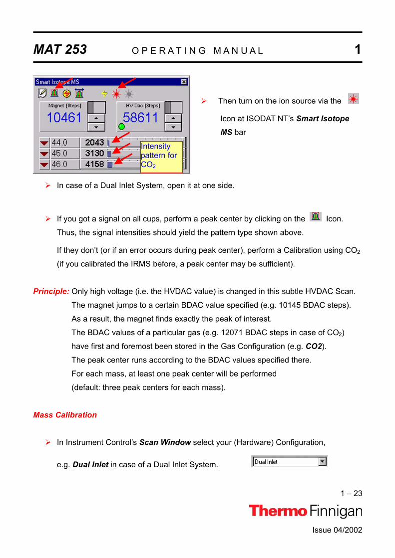
Thus, the gas finally enters the source. The intensity pattern characteristic for CO2 is dis-
played at the Smart Isotope MS bar: the intensity for mass 44 is smaller than the one on
mass 45, which in turn is smaller than the one on mass 46.
NOTE: Before starting a measurement, after pumping 15 minutes, a pressure be-tween the lower 10 –6 mbar and the upper 10 –7 mbar range should be reached.
This pressure should even drop between the lower 10 –7 mbar and the upper 10 –8 mbar range as pumping continues for a longer time (if all valves are closed).
If after 15 minutes of pumping a pressure of 1 * 10 –5 mbar cannot be reached, probably a leak exists. As a safety measure, the cathode turns off at pressures above 3 * 10 –5 mbar.
Open the needle valve (if you have got one).
MAT 253 O P E R A T I N G M A N U A L 1
1 – 23
Issue 04/2002
Then turn on the ion source via the
Icon at ISODAT NT’s Smart Isotope MS bar
Intensitypattern forCO2
In case of a Dual Inlet System, open it at one side.
If you got a signal on all cups, perform a peak center by clicking on the Icon.
Thus, the signal intensities should yield the pattern type shown above.
If they don’t (or if an error occurs during peak center), perform a Calibration using CO2
(if you calibrated the IRMS before, a peak center may be sufficient).
Principle: Only high voltage (i.e. the HVDAC value) is changed in this subtle HVDAC Scan.
The magnet jumps to a certain BDAC value specified (e.g. 10145 BDAC steps).
As a result, the magnet finds exactly the peak of interest.
The BDAC values of a particular gas (e.g. 12071 BDAC steps in case of CO2)
have first and foremost been stored in the Gas Configuration (e.g. CO2).
The peak center runs according to the BDAC values specified there.
For each mass, at least one peak center will be performed
(default: three peak centers for each mass).
Mass Calibration
In Instrument Control’s Scan Window select your (Hardware) Configuration,
e.g. Dual Inlet in case of a Dual Inlet System.

MAT 253 O P E R A T I N G M A N U A L 1
1 – 24
Issue 04/2002
Select your Gas Configuration, e.g. CO2.
Normally, CO2 is used for the first Mass Calibration, thus serving as a basis for later
ones, which possibly may use other gases.
From the Scan Menu select Calibrate.
You are reminded to ensure that Reference
Gas is open.
Therefore, check the signal intensity at the
Smart Isotope MS bar. If the signal intensity
is sufficient (e.g. > 1 V), click Yes.

MAT 253 O P E R A T I N G M A N U A L 1
1 – 25
Issue 04/2002
At the Scan Basic box select 2000
steps and 12000 steps as a range
for the Magnet Scan.
Accept the other default values.
Finally, press OK.
Principle: The masses 12, 28 and 44 will be searched. A proposal about their position
is then offered. On demand, additional masses can be inserted into the proposal
list. If the positions don’t match satisfactorily, they are slightly moved later.
Click on this
area before
pressing the
Info button!

MAT 253 O P E R A T I N G M A N U A L 1
1 – 26
Issue 04/2002
Sometimes, the proposals for the mass peak positions in the left pane are matching and
sometimes they don’t. During the very first Calibration, the proposals usually must be cor-
rected: assign the calibration masses to their peaks by drag and drop of the vertical lines us-
ing your mouse, snapping the lines to the mass peaks.
During later Calibrations, the proposals mostly don’t need to be corrected via drag and drop.
Activate the area containing the mass proposals by clicking on it!
Control whether you chose the correct masses using the Info button.
The curve should be approximately
linear within the interval.
After having corrected the proposals, press the Finish Calibration button.
The magnet is alternately set to low and high BDAC values several times. It will try to retrieve
the peaks by jumping to them. Due to hysteresis, the peaks can’t exactly be retrieved.
A peak center follows.

MAT 253 O P E R A T I N G M A N U A L 1
1 – 27
Issue 04/2002
Crimp adjustment
Open the entire Inlet System.
Let flow 50 mbar of CO2 into
each bellow (“equilibration”).
Adjust the crimps until this
bellow pressure of leads to a
signal of 5 V ( 10 mbar cor-
respond to 1 V in case of CO2).
Crimp adjustment ensures an approximately constant and slight gas flow. Therefore, gas
consumption will be low.
Bellow Calibration
Prior to a Dual Inlet Acquisition, a Bellow Calibration must be performed as follows:
It is presumed, that the source has been switched on and focusing has been performed.
Start Instrument Control by double-clicking on the Instrument Control Icon.
The Scan window appears.

MAT 253 O P E R A T I N G M A N U A L 1
1 – 28
Issue 04/2002
Select your Configuration, e.g. Dual Inlet.
Select your Gas Configuration, e.g. CO2.

MAT 253 O P E R A T I N G M A N U A L 1
1 – 29
Issue 04/2002
NOTE: Activate the Dual Inlet System window by a click on its title bar!
Thus, the title bar will turn from grey (i.e. inactive) to blue (i.e. active).
Access to the Calibrate Menu won’t be possible while this window is inactive.
From the Calibrate Menu, select Bellows.
Bellow Calibration must be performed in two steps:
Step 1 Hardware Calibration of the bellows
In Hardware Calibration, the bellows are opened as far as it will go (i.e. 100 %) and closed
again (i.e. 0 %).
Enable the Hardwareradio button.
Press OK.

MAT 253 O P E R A T I N G M A N U A L 1
1 – 30
Issue 04/2002
NOTE: A Hardware Calibration deletes a Signal Calibration. Therefore, Hardware
Calibration must always be performed prior to Signal Calibration!
Press Yes to continue.
The Hardware Calibration of the bellows has been
finished. Press OK.
Step 2 Signal Calibration of the bellows
NOTE: Signal Calibration requires a signal intensity of at least 3 V!
WARNING: If Signal Calibration has not been performed, the Diagnosis tests can’t be run!
In Signal Calibration, the signal intensity is checked with partially filled bellows
(at 25 % and at 75 %). Therefore, Signal Calibration must always be performed
after Hardware Calibration.
Activate the Dual Inlet System window again by a click on its title bar.
Then, from the Calibrate Menu, select Bellows again.
Before starting Signal Calibration, an amount of gas must be let into the bellows, which re-
sults in a pressure of about 10 mbar - 20 mbar on each side. This gas amount is necessary to
obtain a certain signal intensity. If the gas amount should be either too small (e.g.< 10 mbar)
or too large, warning messages will occur.

MAT 253 O P E R A T I N G M A N U A L 1
1 – 31
Issue 04/2002
Enable the Signalradio button.
Select Automatic and
press OK.
The signal intensity of the particular gas will be measured depending on the bellow volume.
FocusingThe ion beam must now be focused (see Chapter 1.4). Thermo Finnigan MAT has already
performed a focusing procedure. The obtained parameters, which can be seen on the Focustoolbar, have been assigned to the respective Gas Configuration.

MAT 253 O P E R A T I N G M A N U A L 1
1 – 32
Issue 04/2002
On top of the Focus window, note the Focus Toolbar shown below:
Among others, it contains the following buttons:
Load: opens a “Focus Settings” document (*.fcs).
Save: saves the actual Focus Settings as “Focus Settings” document
(*.fcs).
Undo: the last command is undone.
Redo: the last command is redone.
Pass to GC: attaches the current Focus Setting to the current Gas Configura-
tion.
Reset HV: switches on high voltage.
Source On: turns on the entire source electronics.
Source Off: turns off the entire source electronics.
Autofocus: calls up an Autofocus Script.
If you changed parameters at the Focus window, or after you finished your own focusings,
you can assign them to the active Gas Configuration by .
Besides, you can save new parameters by to load them again later by .
NOTE: For each Gas Configuration, a specific focus can be set and saved.

MAT 253 O P E R A T I N G M A N U A L 1
1 – 33
Issue 04/2002
Focusing can now be started:
In the beginning, you should use the focusing settings Thermo Finnigan MAT
has preset (see the Focus bar). Usually, focusing will be performed automati-
cally (Autofocus). Only trained users should do this by themselves.
To optimize the focusing settings by yourself, start a Tune Scan, which continu-
es during the whole focusing process. A Tune Scan reveals the course of inten-
sity over time while changing the parameters in the Focus window: At the Scan window, select Tune Scan.
Furthermore, you can select a particular cup (e.g. mass 44, mass 45 or mass 46).
Example: If you select Cup 1, the intensity at Cup 1 will be monitored over time.
For the Tune Scan recommended here, it doesn’t matter, which cup is used.
Focusing aims at gaining the maximum intensity value (which is revealed by
the Tune Scan). In case of Dual Inlet, 100 mV approximately correspond to
1 mbar.

MAT 253 O P E R A T I N G M A N U A L 1
1 – 34
Issue 04/2002
Linearity focusing: To achieve maximum linearity, the extraction voltage pre-
vailing at the extraction lens must be increased. It extracts
the ions out of the ionization volume by acceleration. Addi-
tionally, the ions thus obtain a direction. Therefore, fewer
collisions between molecules and ions occur.
Sensitivity focusing: To achieve maximum sensitivity, the extraction voltage (at
maximum intensity) must be set to zero. As the accelera-
tion out of the source doesn’t exist, more ions stay in the
source. The number of ions per molecule is lower. Many
ions exist having different energies (secondary ionization
processes), providing a wide energy distribution.
Linearity focusing must be performed here: while the extraction voltage is increased,
all other lenses are tuned until maximum intensity is reached (monitored by the Tune
Scan).
NOTE: If linearity focusing is unsuccessful, change the Extraction value at theFocus bar until the intensity pattern of CO2 is satisfactory.
The Autofocus settings preset by Thermo Finnigan MAT have been established on the basis
of a reasonable pattern. A gas (e.g. CO2) has its own pattern. Hence, various gases differ
with respect to their patterns. The pattern of a particular gas is always the same.
NOTE: If Autofocusing has not lead to the desired maximum intensity, perform Fo-cusing manually.

MAT 253 O P E R A T I N G M A N U A L 1
1 – 35
Issue 04/2002
Diagnosis
Without Bellow Calibration, Diagnosis Tests won’t be possible. After the bellows have been
calibrated, you can run the Diagnosis tests. For details, see Chapter 7.
Starting a Measurement
After performing Diagnosis tests, you can start a measurement, i.e. a Dual Inlet Acquisition.For details, see Chapter 6.
MAT 253 O P E R A T I N G M A N U A L 1
1 – 36
Issue 04/2002
1.3 GETTING STARTED: SOFTWARE
1.3.1 SYSTEM REQUIREMENTSTo use ISODAT NT optimally, meet some system prerequisites. ISODAT NT needs certain
Software requirements and
Hardware requirements.
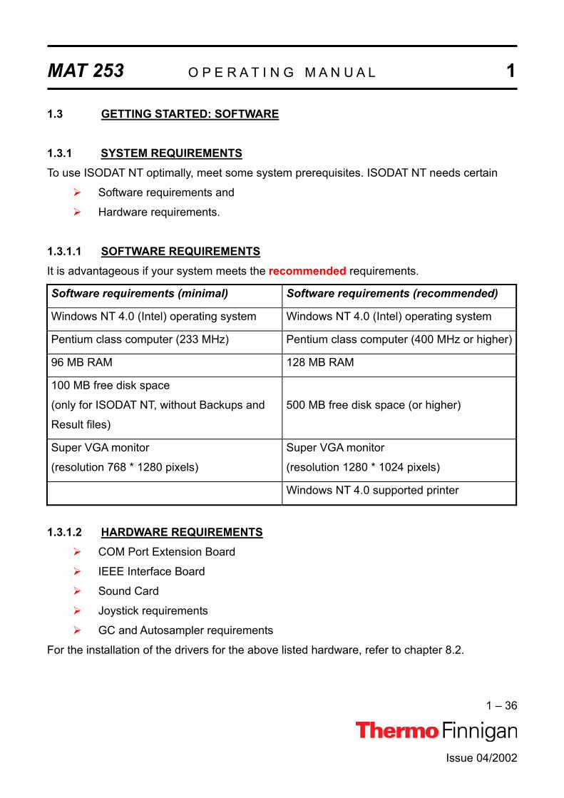
1.3.1.1 SOFTWARE REQUIREMENTSIt is advantageous if your system meets the recommended requirements.
Software requirements (minimal) Software requirements (recommended)
Windows NT 4.0 (Intel) operating system Windows NT 4.0 (Intel) operating system
Pentium class computer (233 MHz) Pentium class computer (400 MHz or higher)
96 MB RAM 128 MB RAM
100 MB free disk space
(only for ISODAT NT, without Backups and
Result files)
500 MB free disk space (or higher)
Super VGA monitor
(resolution 768 * 1280 pixels)
Super VGA monitor
(resolution 1280 * 1024 pixels)
Windows NT 4.0 supported printer
1.3.1.2 HARDWARE REQUIREMENTSCOM Port Extension Board
IEEE Interface Board
Sound Card
Joystick requirements
GC and Autosampler requirements
For the installation of the drivers for the above listed hardware, refer to chapter 8.2.

MAT 253 O P E R A T I N G M A N U A L 1
1 – 37
Issue 04/2002
1.3.2 INSTALLING ISODAT NTNow install ISODAT NT (shipped on the CD). This can be done via the Startup Screen.
Close all applications (especially older versions of ISODAT NT if already installed and running)!Otherwise, a message will indicate that Setup of ISODAT NT is not possible
while older versions of ISODAT NT are running (see: how to shut down the
system).
1. Open your CD drive and insert the ISODAT NT CD.
2. Close it.
If your CD ROM drive is set to "Autostart", the file "startup.html" on the ISODAT
NT CD will be executed and the gray HTML startup screen will appear.
3. From the gray Startup Screen, select "Install
ISODAT NT".

MAT 253 O P E R A T I N G M A N U A L 1
1 – 38
Issue 04/2002
4. Select "Run this program from its
current location". Then press OK.
5. Click Yes.
6. Wait while Setup is preparing the
InstallShield® Wizard.

MAT 253 O P E R A T I N G M A N U A L 1
1 – 39
Issue 04/2002
7. Respond with Yes (No will not create a backup).
Make sure that you have enough free disk space for the
backup that includes your Result files.
8. A backup of the current version of ISODAT NT is
created and stored in a subdirectory, e.g. "Ver-
sion_0.50", of the folder C:\Isodat_Backups (if you
cancel the backup, a message occurs).
Each backup includes your Result files and is stored in a subdirectory of its own
in the folder C:\Isodat_Backups.
Backups can be created and restored by using the Version Handler in the folder
C:\Isodat_Backups.
9. Respond with Yes to delete a previous ver-
sion.
Yes leads to loss of Configurations and measurement data.
No will overwrite the previous version. Data, Configurations and Mass Calibrations
will remain untouched.
Even though, it is recommended to delete old versions until unequivocal compati-
bility between the old and the new version is ensured.
10. No will overwrite the previous version. Data, Configurations
and Mass Calibrations will remain untouched. Even
though, it is recommended to delete old versions until un-
equivocal compatibility between the old and the new ver-
sion is ensured.
Confirm again with Yes to delete.

MAT 253 O P E R A T I N G M A N U A L 1
1 – 40
Issue 04/2002
11. Read the text carefully and click Next.
12. Read the software license agreement care-
fully and click Yes.
13. Fill in your name and company. Then click
Next.

MAT 253 O P E R A T I N G M A N U A L 1
1 – 41
Issue 04/2002
14. On the next window, you have to indicate
whether you have interfaces installed.
As default, both checkboxes are selected.
Select the checkbox(es) that correspond to
your equipment, and then press Next.When you have ticked the checkbox
Fiber Line Interface, proceed with
step 18.
When you have ticked the checkbox
IEEE (GBIB) Interface, proceed with
step 16. This is also the case, when you
have ticked both checkboxes.
15. When you have deselected both
checkboxes in step 14, the following
window appears. Select the radio button
DeltaPlusXP/Advantage/253 and press
Next. This will install the Fake Mode, which
can be used for offline computer systems
and software testing purposes.
Proceed with step 18.
16. Select your MS Interface Board for IEEE
connection to the IRMS (on the rear side of
your computer). Click on Next.The "National Instruments" PC IIA (ISA)
driver will automatically be installed.
The "National Instruments" PCI-GPIB
(PCI) driver must be installed separately
later.

MAT 253 O P E R A T I N G M A N U A L 1
1 – 42
Issue 04/2002
17. Having chosen PCI-GPIB (PCI) in step 16, you are
reminded that the "National Instruments" PCI-GPIB
driver must be installed separately later using the
"National Instruments" CD.
Ensure that the appropriate IEEE Interface board
driver has been installed. The required cables are
part of the delivered equipment.
Press OK.
18. Accept the proposed folder or choose an-
other one by the Browse button. Then
press Next.
19. Wait while Setup is updating the registry.
20. Wait while Setup is copying ISODAT NT onto
your harddisk.

MAT 253 O P E R A T I N G M A N U A L 1
1 – 43
Issue 04/2002
21. Choose Yes, I want to restart my computer
now.
Remove the CD.
Click Finish to reboot. ISODAT NT is now
installed on your computer.

MAT 253 O P E R A T I N G M A N U A L 1
1 – 44
Issue 04/2002
1.4 PRINCIPLE OF FOCUSING
1.4.1 REASONS TO PERFORM FOCUSING
Focusing has to be performed
to overcome the tiny remaining mechanical tolerances
to overcome the gradual degradation of the ion source (e.g. due to metal
deposition by sputtering)
to overcome the different ion-optical properties of various gases (e.g. for H2, a
slightly different focusing compared to CO2 yields better results).
to optimize the system for various applications (e.g. reduce or increase
sensitivity, optimize linearity)
How to perform focusing - (a) Autofocusing Depending on your choice, all or only selected potentials might be varied.
For detailed information, refer to chapter 2.3.3.
1 It may be advantageous to set some potentials to default values, e.g.
Trap to maximum
Electron energy to maximum
Emission to maximum or lower
Extraction to about 2700 V for linearity focusing
2 Start Autofocusing by pressing the AF button.
3 At Autofocus default, select the potentials to be changed.
4 Press OK.

MAT 253 O P E R A T I N G M A N U A L 1
1 – 45
Issue 04/2002
How to perform focusing - (b) Manual Focusing
NOTE: Be careful! In case of doubt, preferably perform Autofocusing! Manual Focusing and Autofocusing can also be performed in turn (e.g. beginning with a gross Manual Focusing which is followed by a fine Autofocusing).
Use the “Undo” and “Redo” buttons on the Focus Toolbar to correct
inadvertently false edited parameters of the Focus window.
As a parameter value increases, the colored part of its field grows.
The five following equivalent possibilities are available for data editing:
Click on the field to be edited. Then use the right or left cursor button to
increase or decrease the value.
Double-click the field to be edited. Then, simply type in the new value.

MAT 253 O P E R A T I N G M A N U A L 1
1 – 46
Issue 04/2002
Point to a field leftmost to decrease or rightmost to increase its value.
or
Clicking the right mouse button then allows selecting a step width.
The actual step width is marked.

MAT 253 O P E R A T I N G M A N U A L 1
1 – 47
Issue 04/2002
Point to the field to be edited. A symbol consisting of two arrows occurs (one
bottom-up and one top down). Click into the field. Then move your mouse to
change the value. This procedure allows subtle corrections.
Point to the separation line between colored area and uncolored area of a field.
An arrow occurs. Drag it to the right to increase or to the left to decrease the
value. This procedure allows rough corrections.

MAT 253 O P E R A T I N G M A N U A L 1
1 – 48
Issue 04/2002

Issue 04/2002
MAT 253
OPERATING MANUAL
ANALYZER


MAT 253 O P E R A T I N G M A N U A L 2
2 – 1
Issue 04/2002
2.1 GENERALThe gaseous sample to be analyzed is fed into the ion source via the inlet system. In the ion
source, ions are generated in a high vacuum by the impact of electrons. The ions are then
accelerated to energies of up to 10 keV and focused by electrostatic lenses to form a beam
(for details, see fig. 2-3).
Fig. 2-1 Partial view of the instrument showing the arrangement of the analyzer
The ion beam exits the ion source into the magnetic field through a slit with a fixed width of
0.2 mm. It enters the magnetic field boundary at an angle of 26.5° and traverses the 90°
magnetic sector field. A part of the ion beam exits at the same angle of 26.5° (see also
fig. 2-2).

MAT 253 O P E R A T I N G M A N U A L 2
2 – 2
Issue 04/2002
Due to shaping and dimensions of the magnet, not only a focusing in X-direction but also in
Y-direction is achieved. The refraction power (X-direction) is half as much as compared to
the same magnet without shaping it. The focal length decreases and its value is the same for
X- and Y-direction. Consequently, mass dispersion increases compared to the conventional
arrangement, where the beam enters and exits the field normal to the boundaries. Thus, the
23 cm radius system has the same mass dispersion as the conventional 46 cm arrangement
(where the beam enters and exits the field normal to the boundaries with a sector radius of
46 cm).
Fig. 2-2 The scheme of the ion path
The magnetic sector field is generated by an electro magnet with a maximum field strength of
0.75 Tesla. It covers a mass range up to m/z = 150 at full accelerating voltage.
The mass setting is achieved by variation of the magnetic field strength and/or of the accel-
erating voltage.

MAT 253 O P E R A T I N G M A N U A L 2
2 – 3
Issue 04/2002
The relation between the mass number m/z of the ions reaching the ion collector and the
magnetic field strength H is given by: 2M Hk/m ⋅=z
where z: elementary charge
const.U2
rk2
M ≠=
r: nominal radius of ion path (r = 23 cm = const.)
U: accelerating voltage (not constant)
Due to the variable accelerating voltage U, kM is also not a constant value but a function of U
Example: For the special case of U = 10 kV, kM = 26.45 * 10-6 m2/V results.
The HD collectors are positioned in the middle of the flight tube due to the small radius of
deflection for the light H and D ions. The minimum exit slit width is 2 mm and results in a
resolution of
valley)(10%25m
m =
The collector slit widths for the universal (CNOS, MEMCO) or user-tailored collectors are
available in a range from 0.6 (e.g. for measuring SF6 or Xe) to 3.5 mm and result in a
resolution of
valley)(10%200m
m = for 1.5 mm cups.
Details on the various collector types are given in chapter 2.5, Ion Detection - Collector
System.
The electronic units supply the analyzer system operating voltages and control the analysis.
They are described in detail in chapter 2.3, Ion Source Control Unit.

MAT 253 O P E R A T I N G M A N U A L 2
2 – 4
Issue 04/2002
2.2 ION SOURCEThe ion source of the Thermo Finnigan MAT 253 is designed for high sensitivity (due to high
gas density) and linearity as well as low H3+ production at the same time. To ensure high
sensitivity, the ion source is of gas tight design. The sample gas enters the ionization
chamber through a ceramic tube and leaves it only via small apertures. These are required
as a passage for the electron beam and the ions exiting into the analyzer.
The conductivity of these openings is much lower than the pumping speed of the vacuum
pumps. Thus, the pressure within the ionization chamber is about 100 times higher than
outside, which leads to high ion yields. The ions are generated in the source by electron
impact ionization. The ionizing electrons are emitted by a thermionic cathode. The emission
current is held constant by the emission regulator unit (see chapter 2.3).
An additional feature is the Variable Ion Source Conductance (VISC), or "Sulfur window".
With the VISC installed, the ion source conductance can be varied from outside without
breaking vacuum. High conductance operation is advantageous for SO2 analyses to reduce
memory effects and to achieve short idle times.
A variable conductance is also required to optimize the flow characteristics of carrier gas /
sample peak mixtures for dynamic inlet techniques, such as continuous flow isotope ratio
monitoring.
Two small permanent magnets are mounted to the ionization chamber (see figure 2-3),
generating a magnetic field parallel to the electron beam. Due to the magnetic field, the
electrons are moving along spiral trajectories, which increases their probability in the
ionization volume. Thus, the probability to generate an ion with the aid of one single electron
increases.
The energy of the ionizing electrons is determined by the potential difference between
cathode and ionization chamber. It has a range between 70 and 124 eV.
The electron beam leaves the ionization chamber via a small opening opposite to the
cathode. It is collected in the electron trap, which is held on a positive potential relative to the
ionization chamber.

MAT 253 O P E R A T I N G M A N U A L 2
2 – 5
Issue 04/2002
Extraction plates accelerate ions out of the ionization chamber. The following lens system of
different lenses focuses the ion beam onto the source slit.
Mechanical tolerances might cause a slight out-of-axis deflection of the ion beam. Some of
the system's lenses are half sections, which are insulated from each other. This construction
allows for compensation by applying different potentials to the halves of the lenses. Fig. 2-3
shows schematically the lens arrangement and the potentials applied to them with an ion
accelerating voltage set to 10 kV.
Fig. 2-3 Potentials (vs. ground) of the ion source at 10 kV ion acceleration voltage
Using ISODAT NT, you can set continuous values for the ion accelerating voltage. If it is
changed, the lens potentials are changed proportionally with the exception of those of the
trap and cathode voltages.

MAT 253 O P E R A T I N G M A N U A L 2
2 – 6
Issue 04/2002
Setting the accelerating voltage to lower values results in an enhancement of the mass range
beyond 150. For example: a setting to
8.0 kV results in a mass range up to 190,
6.6 kV results in a mass range up to 230.
The ion source is mounted on the front flange for easy maintenance. A correct alignment of
the ion source relative to the analyzer tube is achieved by a mating surface with the analyzer
head. Details of the ion source, e.g. the feedthroughs and correlation of lenses, are given in
the chapter 8, "Technical Information".
Fig. 2-4 Coupling of the inlet system to the ion source

MAT 253 O P E R A T I N G M A N U A L 2
2 – 7
Issue 04/2002
2.3 ION SOURCE CONTROL UNIT
CAUTION: Opening the electronics cabinet is only allowed for maintenance purposes by qualified personnel.
Fig. 2-5 Control panel and main switch of the MAT 253
Analyzer Pumps Main pump (i.e. source pump) and secondary pump (i.e. differential
pump). They are both connected to a Fore Vacuum pump (e.g. #1).
Power turns on, if 1. the power plug has been inserted into the socket,
2. the Main Switch has been switched on and
3. the three fuses above the Main Switch have been
switched on.
Host Connection turns on, if IRMS and computer have been connected.
Turbo Pumps > 80 % turns on, if the turbo pumps have reached 80 % of their rotational
speed.
Main Pump Error turns on, if an error at the main pump has occurred.
Main switch
Fuses
Plug connec-
tion to socket
Five identical
SUB D ports

MAT 253 O P E R A T I N G M A N U A L 2
2 – 8
Issue 04/2002
Sec. Pump Error turns on, if an error at the differential pump has occurred.
High Vacuum OK turns on, if a pressure below 10-4 mbar has been reached.
The penning can only start vacuum measurement below
this pressure.
Fig. 2-5 a
Main pump
(i.e. source pump)
Fig. 2-5 b
Secondary pump (i.e. differential pump)
green LED red LED

MAT 253 O P E R A T I N G M A N U A L 2
2 – 9
Issue 04/2002
Inlet Pumps Turbo pump of the Inlet System. It is connected to two fore vacuum
pumps (e.g. #2 and #3).
Turbo Pump > 80 % turns on, if the turbo pump has reached 80 % of its rotational
speed.
Inlet Pump Error turns on, if an error at the inlet pumps has occurred.
Accel Voltage turns on, if the acceleration voltage for the ion source has been
switched on.
Emission turns on, if the ion source has been switched on for emission.
The turbo pump of the Inlet System (only available in case of Dual Inlet) is located in the
lower section of the cabinet’s front panel under the bellows block.
Turbo pump of
the Inlet System

MAT 253 O P E R A T I N G M A N U A L 2
2 – 10
Issue 04/2002
Fig. 2-5 c
NOTE: Accel Voltage and Emission can only be set via ISODAT NT. The other parameters can be set manually.
NOTE: On the Smart Isotope MS toolbar, both high voltage and emission
can be switched on via and switched off via . High voltage
can be switched on via and switched off via .
In case of all three turbo pumps (i.e. turbo pump of the source, differential turbo pump, turbo
pump of Inlet System; see LEDs in fig. 2.5 a) note:
If a pump is off, the green LED blinks.
If a pump is on, the green LED is turned on permanently. No information is
revealed about the rotational speed of the pump.
If a pump did not start up, the red LED is turned on permanently.
Fore vacuum pump
(Analyzer, e.g. #1)
Fore vacuum pump
(Dual Inlet, e.g. #2)
Fore vacuum pump
(waste of Dual Inlet;
e.g. #3)

MAT 253 O P E R A T I N G M A N U A L 2
2 – 11
Issue 04/2002
2.3.1 EMISSION REGULATOR
The emission regulator controls the current, which heats the cathode of the ion source and is
switched on via ISODAT NT. The ionizing electron current, i.e. emission current, can be se-
lected via ISODAT NT (maximum value: 1.5 mA). The cathode heating current is about 6 A. If
the emission regulator is activated, the LED Emission on the front panel of the instrument
turns on.
2.3.2 HIGH VOLTAGE SUPPLY
The high voltage unit provides the ion accelerating voltage. A current overload circuit
switches off the high voltage supply, if the load current exceeds 0.2 mA. A switch-off caused
by an overload is indicated: the green LED Accel Voltage located on the front panel then
turns off.
NOTE: A switch-off of the high voltage unit in case of an overload is a protective measure! Thus, you must perform troubleshooting:
A short circuit in the feed line of the source might have occurred (e.g. after cleaning or reinserting the source.
Alternatively, after a longer time the source might have become dirty and must thus be dismantled, cleaned and finally reinserted.
Before you start to adjust the potentials, make sure that you have
switched on the ion source (button on
the Focus bar in ISODAT NT),
switched on Tune Scan (menu Scan | Tune) in ISODAT NT
admitted gas into the inlet system and a
sufficient amount of gas to the ion source.
(See also chapter 5, "Dual Inlet System").
Focusing of the ion beam is performed via ISODAT NT.

MAT 253 O P E R A T I N G M A N U A L 2
2 – 12
2.3.3 FOCUSING OF THE MASS SPECTROMETERYou can perform the focusing either manually or with the autofocus (AF). A compressed de-
scription of the focusing can be found in chapter 1, "Getting Started". Details about the han-
dling of the software can be found in chapter 6, "Measurements".
NOTE: If you are not experienced with focusing we recommend using the autofocus.
Detailed description of manual focusing
A first type of manual focusing, intensity focusing (also called peak shape focusing or sen-sitivity focusing) is seldom performed. Sensitivity and peak shape are both improved, when
the extraction voltage (i.e. Extraction) is decreased.
In the vast majority of cases however, the so-called linearity focusing is performed as one
particular type of manual focusing. It requires relatively high extraction voltages (i.e. high
value of Extraction) in order to extract the ions out of the ionization housing. It will be de-
scribed below.
1. Basic Adjustment of Parameters
Before the first focusing run, the following
parameters should be preset:
Set Trap to 40 V.
Set Electron Energy to the maximum
value.
Set Emission to 1 mA (i.e. to 50 % below
the maximum value of 1.5 mA).
Set Extraction to a middle position (e.g. to
2600 V).
Issue 04/2002

MAT 253 O P E R A T I N G M A N U A L 2
2 – 13
Issue 04/2002
Set X-Focus 1 and X-Focus 2 to a value
smaller than middle position.
Set R-Plate to a middle position.
Set Y-Deflection 1 and Y-Deflection 2 to a middle position.
NOTE: In case of doubt, it is recommended to accept the default parameter values preset by Thermo Finnigan MAT’s Final Test group, if you perform manual fo-cusing!
2 Ensure that intensity signal is monitored on a cup which can be used for peak centering
(e.g. middle cup of universal triple collector cup):
Be sure that gas is flowing into the source (e.g. CO2)
If the mass scale is already calibrated, jump to mass (i.e. 45 on middle cup of univer-
sal triple cup). Perform a Peak center. If signal is too low to proceed (below 50 mV),
jump to other mass (i.e. 44 on middle cup of universal triple collector cup)
If no Mass Calibration is available, perform a Mass Scan. Then seek a peak for ion
source optimization. Afterwards, perform a Mass Scan again. Finally, perform a Mass
Calibration.
Switch on Tune Scan in ISODAT NT’s Instrument Control Mode.

MAT 253 O P E R A T I N G M A N U A L 2
2 – 14
Issue 04/2002
3 FocusingThe following steps are one proven possibility for achieving the optimum focusing parame-
ters. Other procedures may yield just as satisfying results.
For all steps where two potentials are simultaneously adjusted for maximum signal in-
tensity (3b, 3c, 3e, 3f): repeatedly adjust both potentials to maximum signal intensity,
until signal cannot be increased further
If the signal exceeds 50V, either
decrease the gas flow into the IRMS or
use another mass (e.g. mass 44 instead of mass 45).
a Intensity focusing: Set Extraction voltage to 50 V below acceleration voltage.
Perform a peak center.
Maximize signal using Trap Voltage and Electron Energy.
a1Linearity focusing: Set Extraction voltage to 300 V below acceleration voltage.
Perform a peak center.
Set Trap Voltage and Electron Energy to maximum. If the signal
should become unstable, slightly decrease the Electron Energybelow maximum.
NOTE: The signals must always be optimized separately in turn (e.g. X-Focus 1 and X - Focus 2 are changed simultaneously by the same step width). After no more signal increase can be achieved, only change either of them until the maximum is found.
NOTE: In the lens system, proceed outwards starting from the inside (according to fig. 2.3).
MAT 253 O P E R A T I N G M A N U A L 2
2 – 15
Issue 04/2002
b Maximize the signal using Extraction lens and X-focusing voltages.
c Adjust X-Focus lenses to maximum signal intensity.
d Maximize signal using Trap voltage and Electron Energy.
e Adjust Y-Deflection lenses to maximum signal intensity.
f Adjust R-Plate to maximum signal intensity.
g Repeat steps 3b through 3f until the intensity cannot be increased further
h Try to increase the intensity further by slightly adjusting the Extraction voltage
i If the sensitivity, which can be measured using Dual Inlet system in ISODAT NT, is too low,
increase Emission up to the maximum value. If the signal should become unstable, de-
crease Emission until the signal becomes stable. Then repeat steps 3a to 3h.

MAT 253 O P E R A T I N G M A N U A L 2
2 – 16
Issue 04/2002
2.4 ION DEFLECTION2.4.1 ELECTROMAGNETThe magnetic field providing the ion deflection is generated by an electromagnet with
maximum field strength of 0.75 Tesla. The selection of the different masses is achieved by
changing the magnetic field. In addition, the covered mass range can be extended by
continuously varying the acceleration voltage.
2.4.2 MAGNET CURRENT REGULATORThe magnet current regulator provides the current required to generate the electromagnetic
field. For further information (e.g. the schematics of the signal path regulating the magnet
current), refer to chapter 4, "Electronic Devices".
The relationship between magnet current and mass number is determined and stored by
means of the mass calibration procedure. For more details, see the ISODAT NT online help.
2.5 ION DETECTION - COLLECTOR SYSTEM2.5.1 GENERALSeveral configurations of ion collector systems are available, the MEMCO and the universal
CNOS collector system. It is also possible to install user-tailored systems. Additional
information can be found in chapter 8, "Technical Information".
The collector system is installed in the collector system housing (See fig. 2-1). For HD
isotope analysis, an optional collector system with two Faraday collector cups and amplifiers
is available. The HD collector system has a separate housing, which is installed in the center
of the analyzer region (to be flanged to the flight tube).
Each collector cup has its own amplifier (cp. universal CNOS collector) and the feedback
resistor of the amplifier can be matched to the abundance of the isotope to be collected in
this cup (see table 2-1).
Each collector cup and its amplifier are connected to a voltage-to-frequency converter (VFC).
The amplifier and the VFC are located on the preamplifier board. There are up to six VFCs
for the MEMCO or CNOS collector system and two VFCs for the HD collector system
available. They are allotted to one of the eight counters, so forming a measuring channel as
shown in figure 2-6.

MAT 253 O P E R A T I N G M A N U A L 2
2 – 17
Issue 04/2002
Fig. 2-6 Components that form a measuring channel
The converters transform the analog ion current signals into pulses. These pulses are fed to
counters for a preselected integration time. At the end of each integration interval, the
computer reads the number of counts and calculates the ion current ratios (see fig. 2-7).
Fig. 2-7 Function schematic of the ion detection system

MAT 253 O P E R A T I N G M A N U A L 2
2 – 18
Issue 04/2002
2.5.2 AMPLIFIERThe DC amplifiers have 100% inverse feedback. Their output voltage (50 V maximum) is the
product of the input current and a feedback resistor.
The feedback resistor has to match the abundance of the isotope to be collected in the
respective collector cup. Table 2-1 shows the resistance values to be used for the isotopes of
the different gases.
NOTE: Use ISODAT NT’s Smart Isotope MS bar shown below to switch between resistors: a click on (i.e. low resistance) changes the symbol to (i.e. high resistance) and vice versa.
To minimize the influence of environmental changes on the amplifier stability, the amplifier
housing is evacuated to a pressure below 10-4 mbar. This is achieved by connecting the
amplifier respectively its housing to the forevacuum pump of the inlet system, and then to the
side port of the turbomolecular pump.

MAT 253 O P E R A T I N G M A N U A L 2
2 – 19
Issue 04/2002
Table 2-1 Values of the feedback resistors matching the natural abundance of the listed
isotopes
Gas m/z Resistor [ ] Capacity [pF]
H2 2 1 * 109 150
3 1 * 1012 2
N2 28 3 * 108 470
29 3 * 1010 5
30 1 * 1011 2
O2 32 3 * 108 470
33 1 * 1012 2
34 1 * 1011 2
CO2 44 3 * 108 470
45 3 * 1010 5
46 1 * 1011 2
SO2 64 3 * 108 470
66 1 * 1010 15
The product R * C is approximately a constant equaling the time constant of the amplifier.
Usually, it amounts to 0.15 s - 0.2 s.
CAUTION: Never touch the surface of the high ohmic switchable resistors! Already a slight touch of a fingertip would contaminate the resistors resulting in signal instability.If you nevertheless accidentally once touched them, clean them using al-cohol.

MAT 253 O P E R A T I N G M A N U A L 2
2 – 20
Issue 04/2002
2.5.3 COLLECTOR SYSTEMSThe collector systems cover the mass range from 1 to 150 m/z at 10 kV accelerating voltage,
allowing a resolution of m/ m = 200 (10% valley) with 1.5 mm cups.
Owing to the high dispersion of the analyzer system, the distance between the collectors is
extremely large (e.g. approx. 4 mm between masses 44 and 45). Thus, it was possible to
design the Faraday collectors as deep, shielded buckets with integrated secondary electron
suppression shields (fig. 2-8). As a result, effects are eliminated that might degrade the ion
current measurement.
Fig. 2-8 Design of a Faraday collector cup
2.5.3.1 MEMCO COLLECTOR SYSTEMThe MEMCO (Multi Element Multi COllector) collector system comprises three to six identical
cups.
The 3-cup version (fig. 2-9) allows simultaneous measurement of two isotope ratios from the
same sample, e.g. 13C/12C and 18O/16O of CO2.

MAT 253 O P E R A T I N G M A N U A L 2
2 – 21
Issue 04/2002
Fig. 2-9 Design of a 3-cup MEMCO
The 6-cup version permits the cup configuration to be preset for the consecutive
measurement of different gases. This way, it is not necessary to break vacuum in order to
alter the positions of the cups. As with the 3-cup version, simultaneous measurement of two
isotope ratios of the same gas can be performed.
NOTE: Different gases may jointly use one cup in order to reduce the total number of cup measuring channels.
2.5.3.2 UNIVERSAL CNOS COLLECTOR SYSTEMThe universal CNOS collector system is suitable for the measurement of N2, O2, CO2, and
SO2. This collector (see fig. 2-10) consists of five individually shielded deep Faraday cups. A
central small cup is combined with two pairs of differing cups. Each pair comprises a small
cup on the inner side and a wide cup on the outer side. Both cups of a pair are electrically
connected i.e. the cups 1 / 2 are connected with an amplifier and the cups 4 / 5 are
connected with another amplifier. The central cup 3 is connected with a third amplifier. This

MAT 253 O P E R A T I N G M A N U A L 2
2 – 22
Issue 04/2002
way the two cups work as one wide cup without having the disadvantages of a single cup
with the required width (e.g. insufficient suppression of secondary electrons).
Fig. 2-10 Principle of the universal CNOS collector system
With this combination, there is no need to change the feedback resistors when e.g. changing
from the analysis of CO2 to that of N2. The cup configuration is automatically switched by the
ISODAT NT software. In case of switching to SO2 analysis, the amplification factor for
mass 66 has to be changed. The resistors are changed and adjusted (including high voltage)
via ISODAT NT. Refer to table 2-1.
The CNOS collector system can be accessed together with the optional HD collector system
during one experiment (e.g. for background checks).
2.5.3.3 HD COLLECTOR SYSTEMThe HD collector system is a dual Faraday collector assembly for hydrogen isotope meas-
urement on a same ion path, operating in parallel to the MEMCO or universal CNOS collector
systems. The HD collector is located in the middle of the analyzer tube and covers the mass
range from 1.5 to 14. The HD collector cups are designed like those of the MEMCO system.

Issue 04/2002
MAT 253
OPERATING MANUAL
VACUUM SYSTEM


MAT 253 O P E R A T I N G M A N U A L 3
3 – 1
Issue 04/2002
3.1 PUMPING SYSTEMThe Thermo Finnigan MAT 253 is supplied with two optional pumping systems. The instru-
ment is equipped either with or without a differential pumping system.
a. The standard version comes with a turbomolecular pump to evacuate the analyzer sys-
tem at a rate of 210 l/s (type: TMH 262, manufacturer: Pfeiffer). The required forevacuum
is provided by a rotary pump rated at 5 m3/h (type: DUO 5, manufacturer: Pfeiffer).
b. The optional differential pumping system with an additional turbomolecular pump im-
proves the vacuum in the analyzer system of the instrument. This improvement is required
to reduce the high portion of He carrier gas of peripherals such as an elemental analyzer
or a GC. The results are better abundance sensitivity, better peak shape and improved
signal to background ratio at high ion source pressures.
A vacuum lock or flow restriction separates the ion source section from the analyzer re-
gion. The additional turbomolecular pump evacuates the analyzer region at a rate of 60 l/s
(type: TMH 071P, manufacturer: Pfeiffer).
The required forevacuum for both pumps is provided by a rotary pump rated at 5 m3/h
(type: DUO 5, manufacturer: Pfeiffer).
The inlet system is pre-evacuated by a forevacuum pump rated at 1.3 m3/h (type: DUO 2.5,
manufacturer: Pfeiffer).
The wasteline turbomolecular pump (type: TMH 071P) backed by a forevacuum pump (type:
DUO 2.5) is used to provide high vacuum conditions in the inlet system.
For more information, see also paragraph 3.3, Turbomolecular Pump.
3.2 VACUUM SYSTEM CONTROL UNITThe high vacuum of the pumping system is monitored by a Penning vacuum gauge, which is
attached to the left side of the ion source housing. The forevacuum is controlled by a Pirani
vacuum gauge located in the inlet system.

MAT 253 O P E R A T I N G M A N U A L 3
3 – 2
3.2.1 VACUUM IN AMPLIFIER HOUSINGTo improve the stability of the amplifiers, the amplifier housings can be evacuated. Using a
3-port valve (see fig. 3-1), the following steps are required:
Fig. 3-1 3-port valve
1. Turn control knob anti-clockwise from 0 to FV.
2. After approx. 30 minutes turn control knob clockwise from FV to HV. The housing is
evacuated.
3. Before exchanging resistors on the amplifier, turn control knob clockwise from HV to Vent.
After having vented the housing, the cover can be removed.
4. In case of a pump breakdown, restart the turbo pump. To do so, press the pump switch
twice.
In case the MAT 253 has an HD col-
lector system installed, separate 3-port
valves for the HD amplifier housing
(bottom) and the MEMCO amplifier
housing (top) are available. They are
located at the right side of the IRMS.
NOTE: Each amplifier housing has to be evacuated separately.
Issue 04/2002

MAT 253 O P E R A T I N G M A N U A L 3
3 – 3
Issue 04/2002
Fig. 3-2 Schematic view of the differential pumping system

MAT 253 O P E R A T I N G M A N U A L 3
3 – 4
Issue 04/2002
Fig. 3-2 Control Panel
The row of LEDs is lit when the turbomolecular pumps reach 50% of their nominal rotational
speed. The green LEDS indicate the proper function of the respective system part. The red
LEDs indicate an error in the respective system part.
Pushbuttons switches: ANALYZER
PUMPSstarts pumping system (turbomolecular pumps and forevacuum pump for
analyzer system).
INLET PUMPS starts the turbomolecular pump and the forevacuum pump for the wasteline
and the inlet system.
NOTE: In case of problems, e.g. a high vacuum > 1O-4 mbar, the source is cut off automatically.

MAT 253 O P E R A T I N G M A N U A L 3
3 – 5
Issue 04/2002
LEDs:
POWER indicates the supply of main voltage
HOST CONNECTION indicates that the DSP program located on the DSP/PCI
card on the computer is started
NOTE: If the LED is not lit with ISODAT NT started, no connection between the IRMS and the computer has been established.
TURBO PUMPS > 80% indicates that the turbomolecular pumps of the analyzer
have reached more than 80% of their nominal rotational
speed
MAIN PUMP ERROR indicates an error of the analyzer main pump
SEC PUMP ERROR indicates an error of the secondary analyzer turbo-
molecular pump
NOTE: In case the instrument is not equipped with a differential pumping system, this LED is not functional.
AN
ALY
ZER
PU
MPS
HIGH VACUUM OK indicates that the vacuum has fallen below the set point
of the Penning gauge
NOTE: The ion source can only be switched on when this LED is lit.
TURBO PUMP > 80% indicates that the turbomolecular pump of the inlet sys-
tem has reached more than 80% of its nominal rota-
tional speed INLE
TPU
MPS
INLET PUMP ERROR indicates an error of the inlet turbomolecular pump
ACCEL VOLTAGE lit when high voltage is provided to ion source
EMISSION only lit when filament of the ion source operates
NOTE: If the vacuum system works properly the red LEDs are not lit!

MAT 253 O P E R A T I N G M A N U A L 3
3 – 6
Issue 04/2002
3.2.1.1 GUIDANCE FOR TROUBLESHOOTINGIf either one of the green vacuum control LEDs units is not lit or one of the red LEDS is lit, the
instrument should be checked immediately.
HIGH VACUUM OK
LED off:
(or too much back-
ground for
m/z=28/40 is meas-
ured in the mass
spectrometer)
a. There might be a leak in the system.
b. There might be a malfunction of the Penning gauge.
ACCEL VOLTAGE
LED on:EMISSION
LED off:
The cathode might be burned out. Checking and removal of the fila-
ment is described in detail in chapter 8, Technical Information.
ACCEL VOLTAGE
LED off:EMISSION
LED on:
The high voltage is tripped when the current exceeds 0.2 mA. This
may be caused either by sparking or by a short circuit in the source
or the connections to the source.
ACCEL VOLTAGE
LED off:EMISSION
LED off:
The ion source is not switched on. Reset and switch on the ion
source via software. When LED "HIGH VACUUM OK" is not lit, see
above.
3.3 TURBOMOLECULAR PUMP3.3.1 GENERALThe turbomolecular pump works completely mechanically by rotor disks imparting momentum
to the gas molecules. Baffles or cryogenic traps are not necessary for retention of pump fluid
vapors. The vacuum system is roughed by rotary pumps through the turbomolecular pumps.
Furthermore, the turbomolecular pumps are started at atmospheric pressure. Hence, this ar-
MAT 253 O P E R A T I N G M A N U A L 3
3 – 7
Issue 04/2002
rangement also obviates the need for a high vacuum pump valve. Thus, the rated capacity of
pump speed is available without restriction at the connecting flange of the source housing.
Because the molecular pump principle works in the molecular flow region only, the turbo-
molecular pumps require a forevacuum pump. This pump is roughing the vacuum system
through the turbomolecular pump down to the upper limit of the turbomolecular pump operat-
ing range.
The turbomolecular pumps installed in the instrument are air-cooled. In case of a mains fail-
ure there is a delayed venting provided by a venting valve. When starting the turbomolecular
pump the venting valve is closed immediately. After stopping (by mains failure or switch-off),
delayed venting is performed. The vent valve remains open until the next start cycle of the
electronic unit. In absence of current, the valve is open.
For details regarding function and design of the turbomolecular pumps, see the operating
manual of the manufacturers.
3.3.2 CONTROL ELECTRONICS AND POWER SUPPLYEach turbomolecular pump has an integrated control electronics and power supply. The
pumps are started with the switches on the control panel. In addition to the LEDs on the con-
trol panel, several LEDS for error indication are directly attached to the turbomolecular
pumps. For type of error, see operating instructions of the pump manufacturer (Pfeiffer).


Issue 04/2002
MAT 253
OPERATING MANUAL
ELECTRONIC DEVICES


MAT 253 O P E R A T I N G M A N U A L 4
4 – 1
Issue 04/2002
4.1 OVERVIEW OF THE ELECTONIC DEVICESVarious electronic installations are required to carry out the procedures of the Thermo Finni-
gan MAT 253. These comprise the following boards:
Power Distribution
Internal & External Inlet Controller
Plug & Measure Adapter
Data Acquisition
Data logger
Groundplane
Preamplifier board
55V Power Supply
Ion Source Controller
Emission Regulator
High Voltage Potential Controller
High Voltage Supply
Bus Controller
Magnet Current Regulator
DEL-PCI Controller
The electronics of the MAT 253 mass spectrometers contain complicated and numerous cir-
cuits. Therefore, only qualified and skilled electronics engineers should perform servicing.
It is recommended to call for the Thermo Finnigan MAT Service if servicing is required. It is
further recommended to use Thermo Finnigan MAT spare parts only, since many parts are
specially selected. When replacing fuses, only use the correct type.
Before calling the Thermo Finnigan MAT Service, please try to localize the defect. A precise
description of the defect will ease the repair and reduce the costs.
WARNING: Opening the electronics cabinet is only allowed for maintenance purposes by qualified personal. Be careful when removing the protective covers from plugs, cables and other parts.DANGER HIGH VOLTAGE!

MAT 253 O P E R A T I N G M A N U A L 4
4 – 2
Issue 04/2002
6
3
1
5
2
4
Most of the electronic boards listed above are parts of the electronics cabinet that is located
on the rear side of the IRMS. This chapter describes the basic structure of the electronic
equipment. Figure 4-1 shows the electronics cabinet of the Thermo Finnigan MAT 253.
Fig. 4-1 Electronics cabinet
For a description of selected board parts, see the following explanations after the
corresponding numbers.
1 Power supply 55 V 2 External Inlet Controller 3 Power Distribution 4 Power supply 24 V 5 Magnet Current Regulator 6 Data logger
On the following pages are described selected boards that are located in the electronics
cabinet as well as in other parts of the MAT 253.

MAT 253 O P E R A T I N G M A N U A L 4
4 – 3
Issue 04/2002
4.2 POWER DISTRIBUTIONThe power distribution board (Part No. 204 1280) is located in the right side of the electronics
cabinet.
Fig. 4-2 Power distribution
For a description of selected board parts, see the following explanations after the correspond-
ing characters.
4b
1a1b1c
6
2 3
7
5
4a 4
D A
LEDS TRIMMER
a b c d e f g h i j k l

MAT 253 O P E R A T I N G M A N U A L 4
4 – 4
Issue 04/2002
1a Connection to turbo pump analyzer
1b Connection to turbo pump ion source
1c Connection to turbo pump inlet system
2 Connection to front panel
3 Connection to serial interface
4 Connection to penning gauge The penning gauge for the high vacuum measurement is connected here. This is important for the proper function of the high vacuum security.
4a Vacuum Sensors Additional vacuum gauges can be connected here. Anyway, the vacuum security is not affected.
4b Tapping points for penning gauge The threshold (D) and actual (A) current values of the penning gauge can be re-measured here.
5 Connection to magnet current regulator
6 Controls for refill equipment The settings of the trimmers determine the trigger thresholds. The LED "N2 OFF" is lit when the liquid nitrogen has reached the maximum level. The LED "N2 ON" is lit when the liquid nitrogen has fallen below the minimum level. The LED "N2ALERT" is lit when the liquid nitrogen has reached a critical level. The LED "REFILL" is lit when the refill is switched on.
7abcdefghijkl
Connections to all 230 V consumers Current input Power supply 24 V Power supply 55 V Socket J503 Refill equipment Inlet valve heater Socket J1112 Ion source controller Socket J322 Ion source heater Socket J1114 Source heating Inlet system heater Socket J1110/J1111 Inlet pump Socket J1109 Pump source & analyzer Socket J1108 MS heater Socket J1113

MAT 253 O P E R A T I N G M A N U A L 4
4 – 5
Issue 04/2002
1
2
3
6
5
4
internal external
2
2
4.3 INLET CONTROLLERThe IRMS is provided with two variants of the inlet controller board (Part No. 204 1300). The
internal board is located at the top right side of the electronics cabinet. The external board is
located on the right side of the IRMS.
Fig. 4-3 Inlet Controller
For a description of selected board parts, see the following explanations after the
corresponding numbers.

MAT 253 O P E R A T I N G M A N U A L 4
4 – 6
Issue 04/2002
1 Power supply 24 V
2 These LEDs are lit when the supply current is available.
3 Connection to serial data link
4 Control of the internal/external valve banks
5 Connection to optional pressure sensors
6 Connection to microvolume
The inlet controller board has the following functions:
Control of the valve banks
Connection for three additional vacuum gauges
Connection for the operation device for the cooling trap
Motion control of the bellows

MAT 253 O P E R A T I N G M A N U A L 4
4 – 7
Issue 04/2002
SwitchS1
JumperJ2 To SUB D port
Side view: pnm-adapterconfigured
for ConFlo III
Jumper
Cable to ConFlo III
JumperJ3
SwitchS2
4.4 THE PLUG AND MEASURE CONCEPTEach peripheral device has its own plug and measure code.
This code is encoded:
either in the cable to the device
or in a plug and measure adapter
This is also used for downward compatibility using an old peripheral device in combination
with the new MAT 253 electronics.
Each peripheral device can be connected to any of the five SUB-D ports (up to five devices
simultaneously). The instrument recognizes the kind of peripheral device and the SUB-D port
used for it automatically, when a Configuration requires this device. Otherwise (e.g. when the
device cable is unplugged accidentally), an error message will be displayed.
4.4.1 THE PLUG AND MEASURE ADAPTERFig. 4-4 PNM-Adapter
The plug & measure adapter (pnm-adapter) is used for the connection of the peripherals. It is
pre-configured at the Thermo Finnigan factory for a defined option (e.g. ConFlo). A supple-
mentary reconfiguration by the user is not recommended. The plug & measure adapter
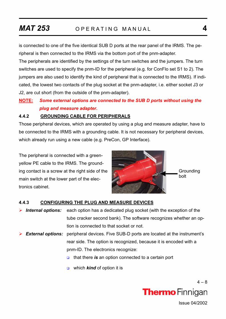
MAT 253 O P E R A T I N G M A N U A L 4
4 – 8
is connected to one of the five identical SUB D ports at the rear panel of the IRMS. The pe-
ripheral is then connected to the IRMS via the bottom port of the pnm-adapter.
The peripherals are identified by the settings of the turn switches and the jumpers. The turn
switches are used to specify the pnm-ID for the peripheral (e.g. for ConFlo set S1 to 2). The
jumpers are also used to identify the kind of peripheral that is connected to the IRMS). If indi-
cated, the lowest two contacts of the plug socket at the pnm-adapter, i.e. either socket J3 or
J2, are cut short (from the outside of the pnm-adapter).
NOTE: Some external options are connected to the SUB D ports without using the plug and measure adapter.
4.4.2 GROUNDING CABLE FOR PERIPHERALSThose peripheral devices, which are operated by using a plug and measure adapter, have to
be connected to the IRMS with a grounding cable. It is not necessary for peripheral devices,
which already run using a new cable (e.g. PreCon, GP Interface).
Groundingbolt
The peripheral is connected with a green-
yellow PE cable to the IRMS. The ground-
ing contact is a screw at the right side of the
main switch at the lower part of the elec-
tronics cabinet.
4.4.3 CONFIGURING THE PLUG AND MEASURE DEVICESInternal options: each option has a dedicated plug socket (with the exception of the
tube cracker second bank). The software recognizes whether an op-
tion is connected to that socket or not.
External options: peripheral devices. Five SUB-D ports are located at the instrument’s
rear side. The option is recognized, because it is encoded with a
pnm-ID. The electronics recognize:
that there is an option connected to a certain port
which kind of option it is
Issue 04/2002

MAT 253 O P E R A T I N G M A N U A L 4
4 – 9
Issue 04/2002
Peripheral pnm-ID 2nd ID Jumper pin
9/10New cable
ConFlo2/3 0x02 0x03 J3
GCC2/3 0x04 0x05 J3
GasBench 0x08 0x09
PreCon 0x0A 0x0B Yes
ProRef 0x0C 0x0D J3
MultiInlet 0x0E 0x0F
AcidPump 0x18 0x19 J2
GC/GP 0x10 0x10 Yes
Dual Inlet
MP1
MP2
TC1
TC2 0x12 0x13
pnm-ID: by switches inside the pnm-adapter or by shortcuts inside the cable
2nd ID: if two instruments of the same type are installed
Jumper pin 9/10: if indicated, the lowest two contacts of the plug socket at the pnm-
adapter, i.e. either socket J3 or J2, are cut short (from the outside of the
pnm-adapter).
New cable: No pnm-adapter. Instead, an exchange of the cable is necessary.
NOTE: The Tube Cracker (TC) second bank is applied to two ports of the inlet board for external option. Therefore, it has a pnm number.

MAT 253 O P E R A T I N G M A N U A L 4
4 – 10
Issue 04/2002
4.4.4 USING THE OPTIONS GAS BENCH, PRECON AND TUBECRACKER WITH ANOTHER MASS SPECTROMETER
The three options Gas Bench, PreCon or TubeCracker are available in two versions:
One for the DELTAplusXP, DELTAplusAdvantage or MAT 253 and
one for the DELTAplus, DELTAplusXL or MAT 252.
Praxis has shown that in some laboratories are not always connected to the same mass
spectrometer, especially the continuous flow options like the Gas Bench and PreCon. De-
pending on the analytical problem, they are sometimes transferred from one mass spec-
trometer to another. It is possible to switch between the newer generation mass spectrome-
ters (DELTAplusXP, DELTAplusAdvantage or MAT 253) and the older generation, when the
subsequent important guidelines are followed.
1. Applying an older peripheral device to a newer generation mass spectrometerUse a plug and measure device, in case of the PreCon and the GP-Interface use a new
connection cable.
a. Each option delivered after June 2002 is delivered with the necessary hardware.
b. For older devices, order a plug and measure device (Part No. 205 2660) or a connec-
tion cable.
2. Applying a peripheral device ordered with or for a newer generation mass spec-trometer to an older generation mass spectrometerConnect the connection cable to the driver board (see figure 4-4a).
a. For most peripheral devices the driver board supplied with the older generation mass
spectrometer can be used directly
b. For devices like Gas Bench, PreCon or TubeCracker it is recommended to order a
dedicated driver board (Part No 202 5001).
Alternatively, a new address can be assigned to the driver board delivered with the
older generation mass spectrometer (see figure 4-4a).

MAT 253 O P E R A T I N G M A N U A L 4
4 – 11
Issue 04/2002
ATTENTION: NEVER put the plugs of the peripheral device connection cable into the wrong socket on the driver board; serious damage of the driver board may occur, which is not covered by any warranty. On the other hand, if the jumpers a set to a wrong address, the de-vice cannot be addressed, but nothing will be damaged.
3. Applying an option using an IEEE interface (Carbonate device/ HDO device) deliv-ered with an older generation mass spectrometer to a newer generation oneInstall an additional IEEE interface (Part No 079 9130).
Figure 4-4a Driver board
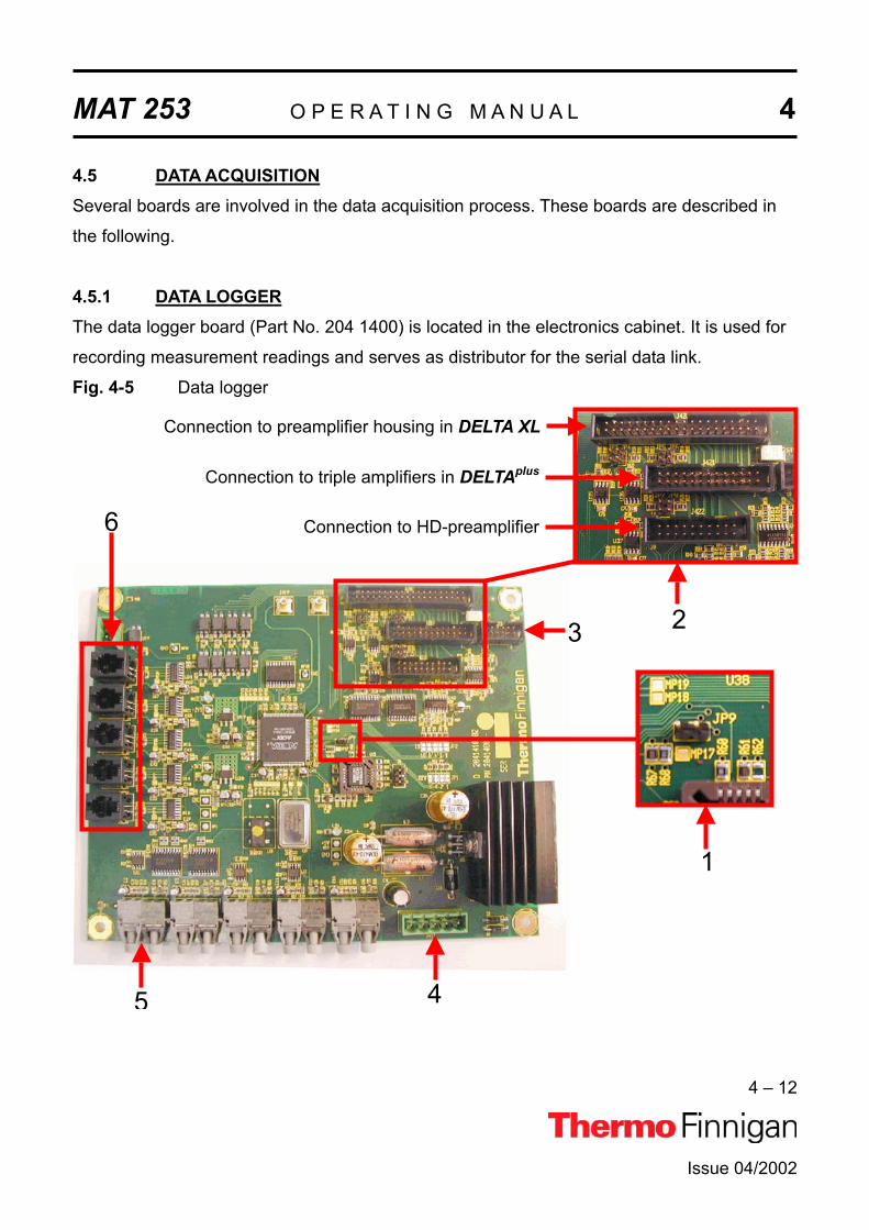
MAT 253 O P E R A T I N G M A N U A L 4
4 – 12
Issue 04/2002
4.5 DATA ACQUISITIONSeveral boards are involved in the data acquisition process. These boards are described in
the following.
4.5.1 DATA LOGGERThe data logger board (Part No. 204 1400) is located in the electronics cabinet. It is used for
recording measurement readings and serves as distributor for the serial data link.
Fig. 4-5 Data logger
5 4
3
6
1
2
Connection to preamplifier housing in DELTA XL
Connection to triple amplifiers in DELTAplus
Connection to HD-preamplifier

MAT 253 O P E R A T I N G M A N U A L 4
4 – 13
Issue 04/2002
For a description of selected board parts, see the following explanations after the
corresponding characters.
1 This jumper (JP9) is used to switch on the power supply of the amplifiers when the
amplifier housing is open.
ATTENTION: The amplifiers can be damaged when they are exchanged while the power supply is switched on.
2 Connections to other boards
3 Connection to 55 V power supply
4 Connection to 24 V supply
5 Connection from serial interface to PC (DEL-PCI controller) via optical fiber
6 Serial data link to all other boards (e.g. power distributor, inlet control)
4.5.2 GROUNDPLANEThe groundplane (Part No. 204 1900) is located in the amplifier housing. It carries the eight
preamplifier boards with amplifiers and VFCs. It connects the amplifiers to the data logger.
The photo diode switches off the supply voltage when the lid of the amplifier housing is
removed. It serves as an additional precaution and only works properly when the workplace
is sufficiently lit.

MAT 253 O P E R A T I N G M A N U A L 4
4 – 14
Issue 04/2002
Port for preamplifier
board (one of eight)
Photo diode
Fig. 4-6 Groundplane
4.5.3 AMPLIFIER & VFCFor each of the eight acquisition channels a preamplifier board (Part No. 204 1880) is at-
tached to the groundplane. It carries the amplifier extended by a resistor switch as well as the
voltage-to-frequency converter (VFC). Here, the signals coming from the cups are amplified
and converted and then transferred to the counters.
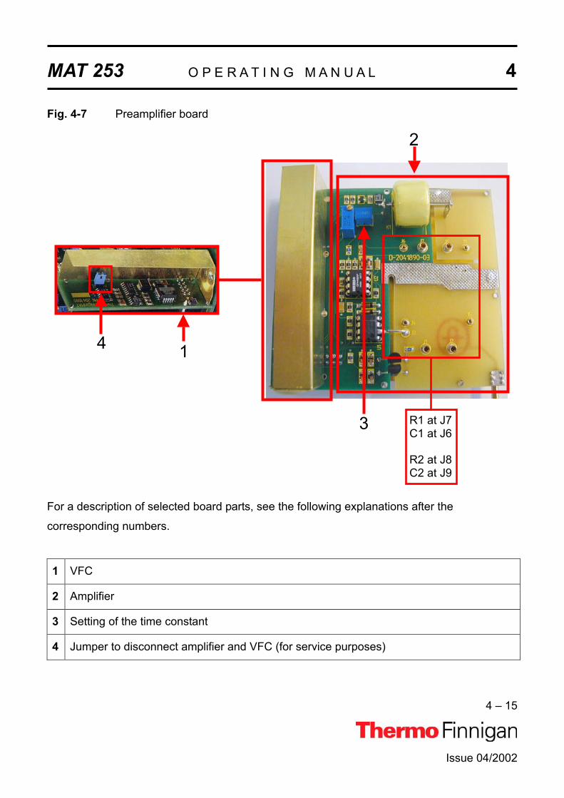
MAT 253 O P E R A T I N G M A N U A L 4
4 – 15
Issue 04/2002
1
3
2
R1 at J7 C1 at J6
R2 at J8 C2 at J9
4
Fig. 4-7 Preamplifier board
For a description of selected board parts, see the following explanations after the
corresponding numbers.
1 VFC
2 Amplifier
3 Setting of the time constant
4 Jumper to disconnect amplifier and VFC (for service purposes)

MAT 253 O P E R A T I N G M A N U A L 4
4 – 16
Issue 04/2002
4.5.4 CHANGING THE AMPLIFIERWhen working with the amplifier, take care of the spanner clamp: it must be fixed at the
flange beneath the amplifier housing and closed.
Fig. 4 - 8: Bottom side of amplifier housing
NOTE: If the spanner clamp is not fixed attach it to the flange before continuing your work.
This ensures that the amplifier cover can be removed without stripping the amplifier ground-
plane with the preamplifier boards from the collector.
4.5.4.1 WORKING WITH THE COLLECTOR - REMOVING THE AMPLIFIER HOUSINGIf it is necessary to work directly at the collector or its housing, proceed as follows:
1 Control, whether the spanner clamp fits correctly.
2 Remove the amplifier lid.
Amplifier Lid
Spanner Clamp

MAT 253 O P E R A T I N G M A N U A L 4
4 – 17
Issue 04/2002
3 Remove each preamplifier board from the groundplane separately and mark its posi-
tion.
4 Unclip the spanner clamp by tearing or pressing slightly.
5 If the amplifier bottom has to be removed totally, unfix the data cable and the vacuum
tube.
4.5.4.2 WORKING WITH THE COLLECTOR - MOUNTING THE AMPLIFIER AGAINTo mount the amplifier again, proceed as follows:
1 Position the open spanner clamp on the flange.
2 Attach the data cable and the vacuum tube to the amplifier bottom.
3 Place the amplifier bottom precisely upon the flange and secure it with the spanner
clamp,
4 Carefully re-insert the preamplifier boards upon the corresponding contact pin of the
collector and the port of the groundplane (as it was arranged before).
CAUTION: Remove the plug of the 55 V power supply before you re-insert the preamplifier board on the groundplane. Otherwise, a damage may be caused when the preamplifier board is not exactly positioned on the corresponding contact pin.
5 Secure the preamplifier boards by screws.
6 Put on the amplifier lid again.

MAT 253 O P E R A T I N G M A N U A L 4
4 – 18
Issue 04/2002
4.5.5 POWER SUPPLY 55 VThe 55 V power supply (Part No. 204 1920) is located at the top middle of the electronics
cabinet. It provides the voltages (-55 V, +15 V, -15 V) that are required by the amplifiers.
Fig. 4-9 Power supply 55 V
The four LEDs on the right side of the board are all lit
when the supply voltages are available.
-55 V
+15 V
+15 V
-15 V

MAT 253 O P E R A T I N G M A N U A L 4
4 – 19
Issue 04/2002
4.6 ION SOURCE CONTROLLERThe ion source controller (Part No. 204 5880) is located on the left side of the IRMS. The ion
source controller comprises three main parts (see fig. 4-10) that have the following functions:
Emission regulation (see fig. 4-10a)
Creation of all required potentials as X-focus, deflection, etc. (see fig. 4-10b)
High voltage supply (see fig. 4-10c)
Fig. 4-10 Parts of the ion source controller
For a description of selected parts of the ion source controller, see the following explanations
after the corresponding numbers.
1 Emission regulator
2 High voltage potential controller
3 High voltage supply
On the next pages, you will find a more detailed description of the parts of the ion source
controller of the MAT 253.
1
23

MAT 253 O P E R A T I N G M A N U A L 4
4 – 20
Issue 04/2002
4.6.1 EMISSION REGULATORThe emission regulator (Part No. 204 2040) keeps the current constant that heats the cath-
ode of the ion source. It is located on the top of the ion source controller. A bus controller
(Part No. 204 1450) provides the connection via data logger to the DEL-PCI controller in the
computer.
Fig. 4-10a Emission controller
4.6.2 HIGH VOLTAGE POTENTIAL CONTROLLERVarious components (e.g. extraction plates, lens systems) focus the ion beam by adjustable
electric potentials. The high voltage potential controller (Part No. 204 1520) provides the
power supplies for the ten high voltage potential modules. It controls these modules and the
high voltage supply with the help of the bus controller board. It communicates with the con-
nected boards via analogous and digital controlling and feedback signals.
The high voltage potential module (Part No. 204 1500) enables the ground-potential based
computer-controlled activation of a focusing potential for ion sources. It is used for the poten-
tial separation (in the transmitter) up to 10 kV and supplies a maximum of either 250 V or 500
V alternatively. The polarity of the output voltage is determined by the corresponding connec-
tion of the voltage divider.
Bus controller

MAT 253 O P E R A T I N G M A N U A L 4
4 – 21
Issue 04/2002
On each module, a voltage divider (Part No. 204 1480) generates the corresponding potential
from the high voltage. The voltage divider is connected to the 10 kV accelerating voltage and
creates the base potentials for the focusing of the ion source. When the yellow control LEDs
are lit the potential of the component is off range. Then use the software to set the potential
to a middle position. If the LEDS are still lit the corresponding component has to be replaced.
Fig. 4-10b High voltage potential controller
For a description of selected parts of the high voltage potential controller, see the following
explanations after the corresponding numbers.
2a Voltage divider
2b Potentials controls
2c Control LEDs
2d Bus controller
4.6.3 HIGH VOLTAGE SUPPLYThe high voltage supply (Part No. 204 2020) creates an adjustable high voltage up to 10 kV
for the ion source, the voltage divider and the emission controller. It is located on the left side
of the ion source controller. Green LEDs are lit when the high voltage is switched on.
2d2c
2b
2a

MAT 253 O P E R A T I N G M A N U A L 4
4 – 22
Issue 04/2002
3a
3b
Fig. 4-10c Parts of the high voltage supply
For a description of selected parts of the high voltage supply, see the following explanations
after the corresponding numbers.
3a On/off switch
3b Control LEDs
4.6.4 BUS CONTROLLERThe bus controller is a universal control unit. Two boards of this type are located on the ion
source controller, the first one (Part No. 204 1450) on the emission regulator and the second
one (Part No. 205 5020) on the high voltage potential controller.
The serial data link provides two ports that are connected to the data logger. One port is
dedicated to emission, the other one for the potentials. By using optical fibers instead of me-
tallic conductors, the signals for the two ports are galvanically isolated from the rest of the
electronics. This design obviates mutual interferences of the conductors especially in case of
line surges.

MAT 253 O P E R A T I N G M A N U A L 4
4 – 23
Issue 04/2002
SerialDataLink
Fig. 4-11 Bus controller
4.7 MAGNET CURRENT REGULATORThe magnet current regulator (Part No. 205 2860) is located in the bottom left side of the
instrument's electronic cabinet. It provides the current required to generate the
electromagnetic field. The current is computer-controlled via the DAC printed circuit board
(digital-to-analog converter).
The computer feeds the information of the specified mass number via the optical bus and the
data logger to the microprocessor, which controls the DAC on the power distribution. Here,
this information is converted into an output voltage, which controls the power supply of the
magnet current regulator.

MAT 253 O P E R A T I N G M A N U A L 4
4 – 24
Issue 04/2002
Fig. 4-12 Magnet current regulator
WARNING; Parts of the board are at 230 V voltage. Never touch this board without safety measures.
4.8 DEL-PCI CONTROLLERThe DEL-PCI controller (Part No. 205 2580) is plugged in a PCI slot of the computer that is
delivered with the IRMS. It is connected to the bus controllers in the IRMS via optical fibers.
This board is the instrument controller and contains the front-end processor.

MAT 253 O P E R A T I N G M A N U A L 4
4 – 25
Issue 04/2002
2
1
Fig. 4-13 DEL-PCI controller
For a description of selected parts of the DEL-PCI controller, see the following explanations
after the corresponding numbers.
1 Serial data link to IRMS via optical fibers
2 Connection to PCI slot of computer


Issue 04/2002
MAT 253
OPERATING MANUAL
DUAL INLET SYSTEM


MAT 253 O P E R A T I N G M A N U A L 5
5 – 1
5.1 GENERAL DESCRIPTION OF THE DUAL INLET SYSTEM
The Dual Inlet system of the MAT 253 isotope ratio mass spectrometer has a symmetric de-
sign to allow alternating measurements of a sample and a standard gas.
If the instrument is equipped with a Dual Inlet system, the configuration is identical for the
sample side and the standard side, which enables a balanced flow. Each inlet side has two
ports and a variable volume (bellow) with the respective inlet capillary leading to the
changeover valve. For very small samples, a Microvolume with its own capillary is installed.
Fig. 5.1 Dual Inlet System
Issue 04/2002

MAT 253 O P E R A T I N G M A N U A L 5
5 – 2
Before measurements can be performed and results be compared, equal gas conditions - as
pressure and flow - must be provided for both sample and standard gas to obtain a balanced
ion beam intensity. Pressure adjustment for sample and standard gas is performed in reser-
voirs (bellows), which are adjustable in volume. These variable volumes are bellows, which
are operated by software-controlled motors. An automated procedure balances the volumes
to such an extent that the ion beam intensity of a selected mass attains a preset value. As it
is not possible via computer in some cases, balancing of the volumes can also be performed
manually. The bellows are adjustable from about 3.5 ml to 40 ml each.
Fig. 5.2 Schematic of the Dual Inlet System
Precise isotope ratio determination via Dual Inlet requires a stable gas flow into the ion
source. To obtain this, bellow balancing of both sides is essential (the ISODAT NT software
description for bellow balancing is called Pressure Adjust). If sample gas flows into the ion
source, an equal amount of a standard gas is evacuated simultaneously by the wasteline
pump system - or vice versa. The flow conditions thus remain identical during measurement.
Issue 04/2002

MAT 253 O P E R A T I N G M A N U A L 5
5 – 3
Issue 04/2002
Flow conditions are also matched by adjusting the flow resistance through the capillaries to
the ion source. The flow resistance is set to equal conditions by crimping the capillaries in
front of the inlet port of the changeover valve.
The crimps of the capillaries are factory-set, but must be set new when a capillary is re-
placed. How to crimp a capillary to a specific flow resistance is described in Chapters 7.4
(“Heating Inlet Capillaries”) and 7.5 (“Replacing Inlet Capillaries”).
The variable volumes adjust the pressure for larger samples (> 50 barµl). Very small sam-
ples, as low as 5 barµl, can be analyzed using the optional Microvolume inlet. For more de-
tails, refer to Chapter 5.5 (“Microvolume”).
To avoid any condensation, to remove impurities or to measure SO2, the Inlet system includ-
ing the changeover valve and the ion source housing can be heated to a temperature of up
to 80°C.
5.2 VALVE SYSTEM
The inlet system is operated by pneumatic valves with a nominal closing pressure of 4 bar.
The compressed air is supplied either by an optional compressor attached to the Mass Spec-
trometer or by a user supplied pressure-air line.
The metal valves are equipped with gold gaskets and gold seats acting on knife-edges. Up
to six valves are machined into one monoblock thus considerably reducing the volume in
plumbing as well as possible leakage of the installation. This type of valve blocks is used
throughout all inlet modules. For plumbing the valve blocks are fitted with 1/4" Swagelok
connectors. Compressed air is fed to the pneumatically operated valves by solenoid valves.
These are controlled by dedicated electronics linked to the computer via a data bus.

MAT 253 O P E R A T I N G M A N U A L 5
5 – 4
Issue 04/2002
Fig. 5.3 Schematic view of a double valve block
Four of the solenoid three-way valves are located on a "Manifold" block. The solenoid valves
are operated with a voltage of 24 V. The voltage is supplied by one of the inlet boards. The
solenoid valves are normally open and the working condition is signaled by a red LED lo-
cated on the printed board.
Fig. 5.4 A "Manifold" block with 4 solenoid valves.
The cable connections are as follows (for the appropriate valve connections, refer to the
Service Manual). In case of a power failure, all solenoid valves open automatically. Thus, the
pneumatic valves close avoiding contamination of the inlet system.

MAT 253 O P E R A T I N G M A N U A L 5
5 – 5
Issue 04/2002
Fig. 5.5 Driver board with distributor function
NOTE: Both Inlet System and Options are now arranged on one single board, i.e. the Inlet board for the Internal Options. (no longer on several boards).
NOTE: Only two further cables connect the remaining electronics to the board: control line and power supply.

MAT 253 O P E R A T I N G M A N U A L 5
5 – 6
Issue 04/2002
5.3 CHANGEOVER VALVE
5.3.1 BASIC MODULE
The basic module of a changeover valve consists of a single block attached to the analyzer
housing and accepts the coupling of capillaries for sample and standard gas. The change-
over valve is operated automatically by ISODAT NT or manually via the monitor display of
the inlet schematic.
Fig. 5.6 Basic module of changeover valve block
5.3.2 EXTENSION MODULE
An extension module may be added to the changeover valve as an option. The extension
module is flanged to the changeover valve by ¼" Swagelok connectors. It provides two addi-
tional inlet ports allowing the coupling of further inlet system options, e.g. a carbonate sys-
tem. To monitor and to operate the extended changeover valve the respective ISODAT NT
routine must be activated.

MAT 253 O P E R A T I N G M A N U A L 5
5 – 7
Issue 04/2002
Fig. 5.7 Extension module attached to the basic module of the changeover valve
5.4 MULTIPORT
The Multiport is a sample manifold inlet system consisting of one or two banks of 10 ports
each. It may be optionally equipped with tube crackers (see Chapter 8). When using the
Multiport as an inlet system, the Multiport is connected directly to the sample side of the Inlet
System valve # 12 (left inlet port). The Multiport valve system is shown in the following
figure.
The valves of the Multiport are operated the same way as the components of the Dual Inlet
system, i.e. automatically by the computer or manually via the monitor display.
To monitor and to operate the Multiport valve system on screen the respective ISODAT NT
routine has to be activated.

MAT 253 O P E R A T I N G M A N U A L 5
5 – 8
Issue 04/2002
Fig. 5.8 Schematic of a Dual Inlet System with Multiport and Microvolume
Measurement using a Multiport as an Inlet System is described in chapter 6.4.
5.5 MICROVOLUME
The Microvolume or "cold finger" is an optional Inlet module for very small samples and may
be installed in combination with a Dual Inlet system or a Multiport. In both cases, the Micro-
volume is connected to the left port (valve # 12) of the Dual Inlet system (see Fig. 5.2
”Schematic of the Dual Inlet System” and Fig. 5.8 “Schematic of a Dual Inlet System with
Multiport and Microvolume” above).

MAT 253 O P E R A T I N G M A N U A L 5
5 – 9
Issue 04/2002
Fig. 5.8a Schematic of a Multiport
Fig. 5.8b Schematic of a Microvolume

MAT 253 O P E R A T I N G M A N U A L 5
A Microvolume consists of a "cold finger", a valve block, an Autocool unit and a separate
capillary. This capillary leads directly to the changeover valve of the system.
Fig. 5.9 Parts of a Microvolume to be inserted into an Autocool unit
The total volume in front of the capillary crimp, i.e. "cold finger" volume plus the connections
including the capillary, is about 250 µl. Due to the viscous flow conditions, which require a
pressure of at least 15 mbar in front of the capillary, a sample of 5 to 50 barµl must be con-
centrated into a small volume. The "cold finger" volume can be reduced (for even smaller
samples) by inserting small steel spheres. The concentration in a Microvolume is performed
by freezing the small sample using liquid nitrogen and expanding it again by subsequent
heating.
Two different types of Microvolumes can be used depending on the gas to be measured. For
CO2 a smaller Microvolume is required, and for N2 a larger one is used. The larger one con-
tains a molecular sieve to freeze out N2 at liquid nitrogen temperature.
The valves of the Microvolume are operated in the same way as the other components of
the Dual System, i.e. automatically via computer or manually via monitor display. Using the
Autocool unit the temperature can be set individually within a range of about -180 °C and
+155 °C.
5 – 10
Issue 04/2002

MAT 253 O P E R A T I N G M A N U A L 5
5 – 11
Issue 04/2002
5.5.1 AUTOCOOL UNITThe temperature of the Autocool unit, which cools the "cold finger”, can be set via ISODAT
NT’s Microvolume control (i.e. via the “Instrument” tab’s “Microvolume” part; refer to chapter
6.5). A temperature range between -180 °C and +155 °C can be covered.
The time to get from: + 50 °C down to - 180 °C is less than 2 min,
- 180 °C up to + 50 °C is about 1 min.
The Microvolume fits into a thermal contact pipe attached to the lid of a Dewar. The Dewar
contains liquid nitrogen. An electrical heater element, a temperature sensor and a cascade
arrangement of three small bowls are fitted to the contact pipe (see Fig. 5.10). All parts of
the assembly are made of a material of high thermal conductivity and are placed in close
thermal contact to each other. Thus, a quick changeover from one temperature to another is
provided. To heat the Microvolume to a defined temperature, the heater element is
activated. The heating phase is controlled by the temperature sensor. The three thermistors
(7) are Pt 100 resistors (i.e. 100 ).
Fig. 5.10 Schematic view of an Autocool unit

MAT 253 O P E R A T I N G M A N U A L 5
5 – 12
Issue 04/2002
To cool the Microvolume, another electrical heater element immersed in liquid nitrogen is
activated and causes both evaporation and agitation.
Above the heater element, a funnel-shaped hood of a standpipe is positioned, which leads
to the uppermost bowl of the cascaded arrangement. This arrangement enables about one
droplet of liquid nitrogen per second to be carried by the stream of evaporated nitrogen.
Small holes in the bottom of the bowls yield a constant trickle of liquid nitrogen back into the
Dewar, and the continuous flow of liquid nitrogen rapidly cools down the Microvolume. By
suitable balancing of the liquid nitrogen flow and heating the Microvolume, any temperature
within the range can be attained.
Due to the very small quantity of liquid nitrogen held in the cascaded bowl arrangement the
Microvolume temperature rises very quickly when the immersion heater is switched off and
the pipe heater is switched on. A constant liquid nitrogen level in the Dewar vessel is main-
tained by means of the liquid nitrogen refill device.

MAT 253 O P E R A T I N G M A N U A L 5
5 – 13
Issue 04/2002
5.5.2 AUTOCOOL REFILL DEVICE5.5.2.1 GENERAL REMARKSThe refill device provides a constant level of liquid nitrogen in the Dewar of the Autocool unit.
It consists of a storage Dewar of 75 I or 25 I capacity and is equipped with the safety devices,
valves and pressure gauges required for a safe handling of liquid nitrogen.
The transfer line to the Dewar of the Autocool unit is controlled by a solenoid-operated refill
valve (N 12). The refill valve (N 12) is directly connected to the liquid fill and decant valve of
the refill device.
The refill device is activated by a level sensor installed in the Dewar of the Autocool unit. The
level sensor consists of three sensing thermistors, one each for the maximum, the minimum
and the alert level.
Fig. 5.11 Schematic view of a refill device
The power distribution board of the refill device evaluates the signals of the sensors and ac-
tivates the refill valve (N 12) to start or to end the nitrogen transfer.
On the power distribution board, three yellow LEDs indicate which thermistor is sensing, and
the status of the liquid nitrogen level of the Autocool unit can be controlled. In addition, these
three LEDs are visualized in ISODAT NT.’s State window as follows:
located on the power distribution

MAT 253 O P E R A T I N G M A N U A L 5
5 – 14
yellow LED signals (upper position):
high liquid nitrogen level, indicates end of refill.
yellow LED signals (middle position):
low liquid nitrogen level, indicates start of refill.
yellow LED signals:
alarm level, no refill has been performed.
If the signal of the thermistor positioned in the middle does not result in a refill and the lo-
west level is reached (i.e. the storage Dewar of the refill device is also empty) the level sen-
sor activates:
the yellow LED on the control board panel,
a warning message of the system on the monitor,
an interruption of the measurement
5.5.2.2 CONTROL OF THE REFILL DEVICE
Indicates that Refill is switchedon.
Indicates that the N2 level has reached a critical fill level.
Indicates that the minimum N2level has been fallen below.
Indicates that the maximum N2level has been reached.
Issue 04/2002

MAT 253 O P E R A T I N G M A N U A L 5
5 – 15
Issue 04/2002
5.5.2.3 SAFETY WARNINGS
NOTE: Keep in mind: Safety First!
Before operating the refill device, carefully read these notes as well as the
manufacturer's handling instructions.
The refill device contains extremely cold liquid gas. Careless handling might
cause severe personal injury including frostbite.
Wear protective clothing when operating this equipment, including protective
gloves and face shield. Do not overfill or tilt the refill device. Prevent spills.
Use the refill device only in well-ventilated areas. Poor ventilation might cause
suffocation. Follow correct First Aid procedures. If gas was inhaled, remove vic-
tim to fresh air. If necessary give artificial respiration and seek medical assis-
tance immediately.
Make sure that only authorized and fully trained operators use this equipment
and they are fully conversant with these safety notes.
Only use the cryogenic liquid specified on the label on the refill device.

MAT 253 O P E R A T I N G M A N U A L 5
5 – 16
Issue 04/2002
5.5.2.4 WORKING PRINCIPLE
The transfer of liquid nitrogen is affected by a pressure build-up in the self-pressurizing
Dewar of the refill device. The pressure builds up by vaporization of liquid nitrogen in a
coiled pressure raising tube located in the Dewar's vacuum interspace when the gas vent
valve is closed and the pressure-raising valve is opened.
A pressure gauge monitors the pressure. A pressure of 5 psi should be sufficient to transfer
liquid nitrogen. A pressure of 10 psi will transfer liquid at about 10 I/min. A higher pressure is
not necessary and even squandering.
As soon as a preset pressure is reached, the pressure regulator installed in the circulation
cuts the flow through the coiled pressure raising tube. The working pressure can be set to
an optimal level using the pressure regulator.
The blow-off valve is set to a limit of about 1.5 bar. An additional burst membrane prevents
from building up a dangerous pressure. The gas vent valve allows bleeding excessive
pressure, if necessary. The function schematic of the liquid nitrogen refill device is shown in
Fig. 5.11.
The 75 I storage Dewar is equipped with a level indicator monitoring the liquid nitrogen
content.

MAT 253 O P E R A T I N G M A N U A L 5
5 – 17
Issue 04/2002
5.5.2.5 MAINTENANCEHardly any routine maintenance is required. However, the components of the refill device
should be regularly checked for damage or possible freeze-up. If it is necessary to dry and
clean items or to replace them, make sure that they are thoroughly degreased and dried, as
moisture or lubricants will freeze at cryogenic temperatures. Do not use thread-sealing com-
pounds. Use PTFE tape, e.g. Teflon®, or other approved oxygen-safe compounds instead.
Occasionally, the pressure should be increased up to the relief valve setting to ensure
satisfactory functioning of this safety device. Setting the pressure control regulator is
performed as follows:
Step 1 Loosen hexagon locking nut below adjusting screw.
Step 2 Rotate adjusting screw counter-clockwise to set to zero.
Step 3 Close vent valve and liquid valve and open pressure building valve.
Step 4 Rotate adjusting screw clockwise to increase vessel pressure until gas es-
capes through the vent hole. Rotate adjusting screw counter-clockwise again
until gas stops escaping through the vent hole.
Step 5 The pressure is now set. Tighten locking nut to prevent further rotation or
tampering of the adjusting screw.
5.5.2.6 CHECKING THE LIQUID NITROGEN EVAPORATION RATEIf you suspect that the evaporation rate of the refill device is excessive, note down the de-
crease of the liquid nitrogen level for some time. To check the loss rate, close the pressure
raising valve and open the Trycock/vent valve. After the contents are fully vented down to
atmospheric pressure, measure the boil off rate using a simple flow meter. The normal boil-
off rate for nitrogen is:
1 liter per minute for gas, i.e. about 2 liters of liquid per day.
The reason for a higher rate might be an abnormal cold or frost formation at the lower dished
end of the outer casing, which should be removed.
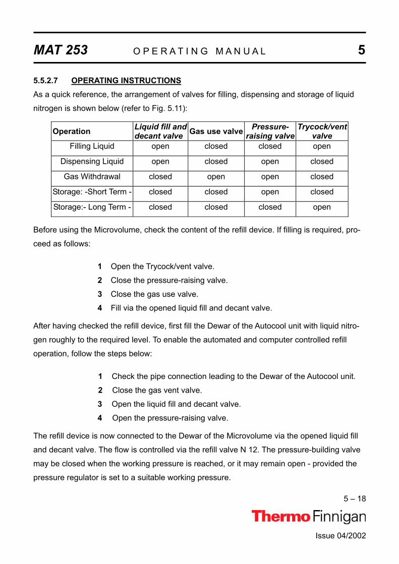
MAT 253 O P E R A T I N G M A N U A L 5
5 – 18
Issue 04/2002
5.5.2.7 OPERATING INSTRUCTIONSAs a quick reference, the arrangement of valves for filling, dispensing and storage of liquid
nitrogen is shown below (refer to Fig. 5.11):
Operation Liquid fill and decant valve Gas use valve Pressure-
raising valve Trycock/vent
valveFilling Liquid open closed closed open
Dispensing Liquid open closed open closed
Gas Withdrawal closed open open closed
Storage: -Short Term - closed closed open closed
Storage:- Long Term - closed closed closed open
Before using the Microvolume, check the content of the refill device. If filling is required, pro-
ceed as follows:
1 Open the Trycock/vent valve.
2 Close the pressure-raising valve.
3 Close the gas use valve.
4 Fill via the opened liquid fill and decant valve.
After having checked the refill device, first fill the Dewar of the Autocool unit with liquid nitro-
gen roughly to the required level. To enable the automated and computer controlled refill
operation, follow the steps below:
1 Check the pipe connection leading to the Dewar of the Autocool unit.
2 Close the gas vent valve.
3 Open the liquid fill and decant valve.
4 Open the pressure-raising valve.
The refill device is now connected to the Dewar of the Microvolume via the opened liquid fill
and decant valve. The flow is controlled via the refill valve N 12. The pressure-building valve
may be closed when the working pressure is reached, or it may remain open - provided the
pressure regulator is set to a suitable working pressure.
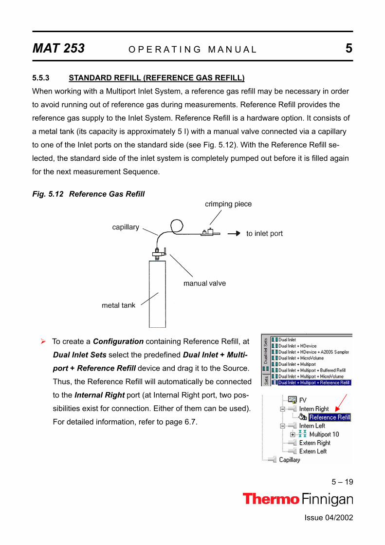
MAT 253 O P E R A T I N G M A N U A L 5
5 – 19
Issue 04/2002
5.5.3 STANDARD REFILL (REFERENCE GAS REFILL)When working with a Multiport Inlet System, a reference gas refill may be necessary in order
to avoid running out of reference gas during measurements. Reference Refill provides the
reference gas supply to the Inlet System. Reference Refill is a hardware option. It consists of
a metal tank (its capacity is approximately 5 I) with a manual valve connected via a capillary
to one of the Inlet ports on the standard side (see Fig. 5.12). With the Reference Refill se-
lected, the standard side of the inlet system is completely pumped out before it is filled again
for the next measurement Sequence.
Fig. 5.12 Reference Gas Refill
To create a Configuration containing Reference Refill, at
Dual Inlet Sets select the predefined Dual Inlet + Multi-port + Reference Refill device and drag it to the Source.
Thus, the Reference Refill will automatically be connected
to the Internal Right port (at Internal Right port, two pos-
sibilities exist for connection. Either of them can be used).
For detailed information, refer to page 6.7.

MAT 253 O P E R A T I N G M A N U A L 5
5 – 20
Issue 04/2002
Creating a new Method or using a predefined one, note the Instrument tab, where
some peculiar information concerning Reference Refill is summarized:
For detailed information, see Chapter 6.7.
Creating a new Sequence or using a predefined one, note the Sequence list.
If Reference Refill is to be used, a checkbox must be activated per sample by a in
the column.

Issue 04/2002
MAT 253
OPERATING MANUAL
MEASUREMENTS


MAT 253 O P E R A T I N G M A N U A L 6
6 – 1
6.1 GENERAL REMARKS
6.1.1 PROCEDURE BEFORE STARTING ANY MEASUREMENTSBefore starting any measurements, three steps must be performed:
1
2
3
Define a (Hardware-) Configuration
Define a Method
Define a Sequence
These three basic steps will be described chronologically for several peripherals in this chap-
ter.
6.1.2 IF NO CONFIGURATION IS AVAILABLEAs first step, a Configuration containing the Dual Inlet System and your con-
nected peripheral(s) must exist.
If no Configuration at all is available (e.g. you have either never before cre-
ated one or you have just reset your IRMS), ISODAT NT requires some infor-
mation about your hardware equipment first:
Your type of IRMS is required.
Select MAT 253.
Press OK.
Issue 04/2002
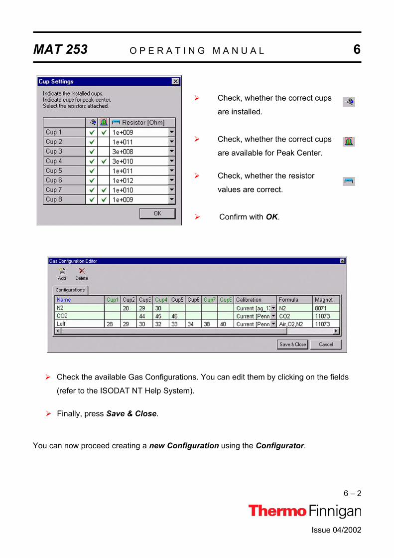
MAT 253 O P E R A T I N G M A N U A L 6
6 – 2
Issue 04/2002
Check, whether the correct cups
are installed.
Check, whether the correct cups
are available for Peak Center.
Check, whether the resistor
values are correct.
Confirm with OK.
Check the available Gas Configurations. You can edit them by clicking on the fields
(refer to the ISODAT NT Help System).
Finally, press Save & Close.
You can now proceed creating a new Configuration using the Configurator.

MAT 253 O P E R A T I N G M A N U A L 6
6 – 3
Issue 04/2002
6.1.3 HOW TO CREATE A NEW GAS CONFIGURATIONPrior to defining a new Gas Configuration ensure the connected IRMS has the cups set for
the simultaneous detection of masses 44, 45 and 46 and mass calibration for these cups has
already been performed.
For a measurement, a new Gas Configuration has to be created for the masses 44
(12C16O16O), 45 (13C16O16O) and 46 (12C16O 18O).
To create a new Gas Configuration, open the Dual Inlet module.
Then open the Gas Configuration Editor.
Add a Gas Configuration.
Type CO2 for the Name.
Select Gas Configuration CO2 as Template.
Confirm with OK.
Select a Calibrationvalid for the selected
cups.
Press Save & Close.

MAT 253 O P E R A T I N G M A N U A L 6
6 – 4
Issue 04/2002
The Dual Inlet application software allows fully automated isotope ratio determination of dif-
ferent elements of bulk samples (C, N, O, S). All parameters relevant for data acquisition of a
sample are stored in a Method. Two different ways exist to get access to a Method or a Se-
quence:
Select a predefined Method and Sequence using the File Browser or
Create a new Method and Sequence on your own.
Selecting a predefined Method and Sequence is the usual way described in detail for the dif-
ferent measurement types later in this chapter. The following information is needed, if you
want to create a new Method or Sequence:
6.1.4 HOW TO CREATE A NEW METHOD
Open the Dual Inlet module.
Select the Configuration for your application (e.g. “Dual Inlet”).
Select the Gas Configuration (e.g. CO2).
Press the New button.
Press the Method Icon.
The new Method is structured in Tab pages: Instrument, Peripherals, Evaluation, Printout and
Dyn. Externals. Methods are described in detail later in this chapter.

MAT 253 O P E R A T I N G M A N U A L 6
6 – 5
Issue 04/2002
6.1.5 HOW TO CREATE A NEW SEQUENCEAfter having defined a new Method, a new Sequence can be created as follows:
Press the New button.
Press the Sequence Icon.
Define the number of samples (e.g.: 3).
Edit the Sequence list.
Peak Center Enable to perform a Peak Center prior to measurement.
Press Adjust Enable to perform a pressure adjust.
Background Enable to perform a background measurement.
Identifier 1 Edit text to identify sample.
Method Select IRMS Method (for each sample, e.g. “CO2.met”).

MAT 253 O P E R A T I N G M A N U A L 6
6 – 6
Issue 04/2002
Press the Start button.
Type a new significant File name
retaining the extension .seq
(e.g. “CO2.seq”).
Press Save.
Define parameters for:
Results Export
Printout
Sequence Scripts
Press OK to start Sequence
Acquisition.

MAT 253 O P E R A T I N G M A N U A L 6
6 – 7
Issue 04/2002
6.2 ZERO ENRICHMENT (STANDARD ON / OFF TEST)
We assume that the user already has working experience with the Dual Inlet System, the
Dual Inlet devices and with IRMS. It is recommended to perform a simple check in order to
test the analytical condition of the complete system before measuring any samples.
Proceed as follows for zero enrichment:
If the File Browser cannot be seen, press the Options button.
Activate the File Browser check
box.
Click OK.
On the File Browser, select the
Methods tab (default).

MAT 253 O P E R A T I N G M A N U A L 6
6 – 8
Issue 04/2002
From the predefined Methods
choose “CO2_zero.met” by double-
click.
NOTE: The Method “CO2_zero.met” for zero enrichment will be described here.It must be used, when both bellows are measured against each other.
The Method “CO2_zero left.met” is used, when only the left bellow is meas-ured (against itself).
The Method “CO2_zero right.met” is used, when only the right bellow is measured (against itself).
The three Methods only differ from the Script.
If the Standards in the Method to be
opened are older than the actual ones
in the Standard Database, or if the
user has changed the Method, the
warning beside appears.
Press OK. Thus, the Method will be corrected: the actual values of the Standard
Database (e.g. the laboratory Standard has changed or been replaced by another
one) are transferred to the Method.

MAT 253 O P E R A T I N G M A N U A L 6
6 – 9
Issue 04/2002
The Instrument tab of the
Method “CO2_zero.met”
appears.
For details, see chapter 6.3.
NOTE: Ensure that the proper peak center cup is selected. If necessary, correct the default cup (e. g. Cup 4)!
At Peripherals tab, see
chapter 6.3 for details.

MAT 253 O P E R A T I N G M A N U A L 6
6 – 10
Issue 04/2002
At Evaluation@CO2 tab,
see chapter 6.3 for details.
Select “None” or “Sigma” as
Outlier test.
In case of “Sigma”, specify
the k-fold of the standard
deviation using .
NOTE: At Std. Name, choose a suitable Standard!
At Printout tab, see chapter
6.3 for details.

MAT 253 O P E R A T I N G M A N U A L 6
6 – 11
Issue 04/2002
6.3 SIMPLE DUAL INLET MEASUREMENT
6.3.1 DEFINING A CONFIGURATION
Before operating, a Configuration containing the simple Dual Inlet System
must be created in the Configurator as follows.
Add a new Configuration using the Add Configuration button.
Give it a significant name, e.g. “Dual Inlet”.
Open the tree structure by a click on at
On the right pane,
select Dual Inlet.
Drag it to the Source port of the new Configuration.
A sign appears:

MAT 253 O P E R A T I N G M A N U A L 6
6 – 12
Issue 04/2002
The Dual Inlet device has been attached to the Source.
Close the Configurator window.
All settings will be saved automatically.

MAT 253 O P E R A T I N G M A N U A L 6
6 – 13
Issue 04/2002
6.3.2 USING A PREDEFINED METHOD
If the File Browser cannot be seen, press the Options button.
Activate the File Browser check box.
Click OK.
On the File Browser, select the
Methods tab (default).

MAT 253 O P E R A T I N G M A N U A L 6
6 – 14
Issue 04/2002
From the predefined Methods
choose a suitable one by double-
click (e.g. “CO2.met”).
If the Standards in the Method to be
opened are older than the actual ones
in the Standard Database, or if the
user has changed the Method, the
warning beside appears.
Press OK. Thus, the Method will be corrected: the actual values of the Standard
Database (e.g. the laboratory Standard has changed or been replaced by another
one) are transferred to the Method.
InstrumentSelect the Gas Configuration
for your determination type
(e.g. “CO2”).
The Main Script controls the
acquisition cycle.
NOTE: It should only be edited by users trained on script editing.

MAT 253 O P E R A T I N G M A N U A L 6
6 – 15
Issue 04/2002
ISOTOPE MS
Select the Peak Center Cup, e.g. Cup 4 for a universal triple collector on a
MAT 253 (narrow cup for m/z 45).
Peak Center Predelay is the time the system waits between activation of the
reference gas and start of the peak center cycle (e.g. 5 s).
Peak Center Postdelay is the time the system waits between the end of the peak
center cycle and the start of the data acquisition (e.g. 0 s).
Integration time is the time integrated to form a data point triplet (e.g. 8 s). It is
needed to measure each individual ion intensity of the masses 44, 45 and 46.
PeripheralsDual Inlet System
Reference denotes, which bellow will contain the standard gas (default: right bellow). The other bel-low will contain the sample.
Number of cycles indicates, how often a sample will be measured successively (e.g. 8 cycles means, that eight times the standard and eight times the sample is measured).

MAT 253 O P E R A T I N G M A N U A L 6
6 – 16
Issue 04/2002
Pre-Standard one cycle Mean of two Standards
is compared to sample between.
A cycle is a series consisting of a standard measurement followed by a sample
measurement. Thus, two standards flank every sample, one before it and one after it:
St1 Sa1 St2 Sa2 St3 Sa3 St4 Sa4…..
The first standard is called pre-standard (i.e. St1). The mean of two consecutive stan-
dards is calculated and compared to the flanked sample (e.g. mean of St1 and St2 is
compared to Sa1).
Idle time is the waiting time after having switched the changeover from sample to
standard side (or vice versa) before the ion intensities of the masses 44, 45 and 46
will be integrated. The gas needs a certain time to flow away, before the measurement
can be started.
FV pump time is the time interval during which the Fore Vacuum pump will be active
after it has started the pumping process (e.g. 10 s).
FV threshold is the pressure value that must be fallen below during Fore Vacuum
pump activity (e.g. 0.03 mbar). If this value has been reached during FV pump time,
the High Vacuum pump starts. If this value has not been reached, the system stops.
HV pump time is the time interval during which the High Vacuum pump is active after
the FV threshold has been reached (e.g. 60 s).

MAT 253 O P E R A T I N G M A N U A L 6
6 – 17
Issue 04/2002
Background
Background Predelay is the waiting time after
closing the changeover valves until the back-
ground measurement begins.
Background Integration Cycles denotes, how
long the background measurement will be per-
formed (default: 1 cycle). k integration cycles
specify that background measurement spans the
k-fold integration time.
Pressure AdjustIf standard pressure and sample pressure are varying considerably, a pressure adjust will be
necessary. It ensures that standard and sample are measured nearly at the same intensity.
on cup: cup on which the pressure adjust will be
performed. Normally, it is the cup, where mass 44
is measured.
Delay time is the waiting time after changing from
sample to standard gas (or vice versa) before
matching the standard bellow to sample ion inten-
sity.
Tolerance denotes the precision of the pressure adjust. It is the maximally accept-
able deviation of the ion intensities between the sample signal and the standard
signal after matching. If the deviation is less than or equals the value (e.g. 100 mV,
this means ± 50 mV), the press adjust is finished successfully.

MAT 253 O P E R A T I N G M A N U A L 6
6 – 18
Issue 04/2002
Bellow/Bellow
Master: the bellow that predefines the pressure,
whereas the other bellow has to follow. Choose
between “Left”, “Right” and “Manual”.
In most cases, the sample bellow is defined as master. Thus, the sample enters the system
with a certain predefined pressure p to which the standard will be compressed.
NOTE: The standard bellow will be adjusted to the level of sample ion intensity minussignal up ± tolerance.
If you select “Manual”, you can edit the pressure
level (intensity) that must be reached in both
bellows.
Capillary/Bellow
Signal up: match the ion intensity of the standard
gas less than the given value before closing valve
25 and starting data acquisition.

MAT 253 O P E R A T I N G M A N U A L 6
6 – 19
Issue 04/2002
Evaluation
Select an Ion Correction type (e.g.
“CO2 Santrock et al.”).
Choose the type of Outlier Test.(Rejection criterion for possible out-
liers: None or Sigma).
Std. Name: Select a Standard Name or edit the related delta values (user defined).
The standards are predefined in the standard table. These values are isotope
ratios of carbon and oxygen of your standard gas.
Outlier Test: If you select “None”, only mean and standard deviation of the obtained delta
values will be calculated. Outliers will not be identified.
If you select “Sigma”, those delta values beyond k times of the standard devia-
tion will be identified and rejected.
If you selected “Sigma”, the button
on the right side becomes available.
Click it.
Select the k-fold standard deviation
(default: k = 1).

MAT 253 O P E R A T I N G M A N U A L 6
6 – 20
Issue 04/2002
Printout
Printout Templates
Single Print selects a print template
from the Result Workshop for an in-
dividual printout per sample.
Sequence Print selects a print tem-
plate from the Result Workshop for a
reduced print per sample within a
sequence summary.
WK1 Export Templates
As with the above Printout Templates, WK1 Export Templates can be selected for an Excel-
Export of the data.
Single Print selects an Excel-Export
Template from the Result Workshop
for an individual printout per sample.
Sequence Print selects an Excel-
Export Template from the Result
Workshop for a reduced print per
sample within a sequence summary.
Dyn. Externals: will follow soon.
The Method for measurements using a simple Dual Inlet has now been established. As next
step, either use a predefined Sequence (refer to chapter 6.3.3) or create a new Sequence(refer to chapter 6.1.5).

MAT 253 O P E R A T I N G M A N U A L 6
6 – 21
Issue 04/2002
6.3.3 USING A PREDEFINED SEQUENCE
If the File Browser cannot be seen, press the Options button.
Activate the File Browser check box.
Click OK.
On the File Browser, select the
Sequences tab(default: Methods tab).

MAT 253 O P E R A T I N G M A N U A L 6
6 – 22
Issue 04/2002
From the predefined Sequences,
choose a suitable one by double-
click (e.g.“CO2.seq”).
In the “Method” column, the Method
chosen in chapter 6.3.2 occurs as
default (“CO2.met”).
Normally, the Sequence List needs not to be edited further. It is possible, however,
to select another Method from the “Method” column.
Press the Start button.

MAT 253 O P E R A T I N G M A N U A L 6
6 – 23
Issue 04/2002
Define parameters for:
Results Export PrintoutSequence Scripts
Press OK to start
Sequence Acquisition.

MAT 253 O P E R A T I N G M A N U A L 6
6 – 24
Issue 04/2002
6.4 DUAL INLET MEASUREMENT INCLUDING MULTIPORT
6.4.1 DEFINING A CONFIGURATION
Before operating, a Configuration containing the Dual Inlet System and
the Multiport must be created in the Configurator as follows.
Add a new Configuration using the Add Configuration button.
Give it a significant name, e.g. “Dual Inlet & Multiport”.
Open the tree structure by a click on at
On the right pane, select
Dual Inlet + Multiport.
Drag it to the Source port of the new Configuration.
A sign appears:

MAT 253 O P E R A T I N G M A N U A L 6
6 – 25
Issue 04/2002
The Dual Inlet device has been attached to the Source.
The Multiport has been attached to the Intern Left Port.
Close the Configurator window.
All settings will be saved automatically.

MAT 253 O P E R A T I N G M A N U A L 6
6 – 26
Issue 04/2002
6.4.2 USING A PREDEFINED METHOD
If the File Browser cannot be seen, press the Options button.
Activate the File Browser check box.
Click OK.
On the File Browser, select the
Methods tab (default).

MAT 253 O P E R A T I N G M A N U A L 6
6 – 27
Issue 04/2002
From the predefined Methods
choose “CO2_multi.met” by dou-
ble-click.
If the Standards in the Method to be
opened are older than the actual ones
in the Standard Database, or if the
user has changed the Method, the
warning beside appears.
Press OK. Thus, the Method will be corrected: the actual values of the Standard
Database (e.g. the laboratory Standard has changed or been replaced by another
one) are transferred to the Method.
The Instrument tab of
the Method
“CO2_multi.met” ap-
pears.
For details, see chapter 6.3.2.
NOTE: Ensure, that the proper peak center cup is selected. If necessary, correct the default cup (i.e. Cup 4)!

MAT 253 O P E R A T I N G M A N U A L 6
6 – 28
Issue 04/2002
See chapter 6.3.2 for details
at Peripherals tab.
NOTE: For measurements including Multiport two additional parameters occur:
Gas Transfer Time: time the sample gas needs to pass from the Multiport to the sample bellow (e.g. 60 s). The valves “bank”, “12”, “14” and “15” are opened.
Expansion Threshold: when the sample has entered its bellow, the sample gas pressure within it must not exceed the Expansion Threshold at bellow 100 % open (e.g. 70 mbar). If the pressure exceeds the threshold, sample gas will be pumped off stepwise in at the most 10 consecutive trials. If the pressure still exceeds the threshold after these trials, the system stops. In this case, use less substance.

MAT 253 O P E R A T I N G M A N U A L 6
6 – 29
Issue 04/2002
At Evaluation @CO2 tab, see
chapter 6.3.2 for details.
Select “None” or “Sigma” as
Outlier test. In case of “Sigma”,
specify the k-fold of the stan-
dard deviation using .
NOTE: At Std. Name, choose a suitable Standard!
At Printout tab, see chapter
6.3.2 for details.
The Method for measurements using Dual Inlet in combination with a Multiport has now been
established. As next step, either use a predefined Sequence (refer to chapter 6.4.3) or cre-
ate a new Sequence (refer to chapter 6.1.5).

MAT 253 O P E R A T I N G M A N U A L 6
6 – 30
Issue 04/2002
6.4.3 USING A PREDEFINED SEQUENCE
If the File Browser cannot be seen, press the Options button.
Activate the File Browser check box.
Click OK.
On the File Browser, select the
Sequences tab(default: Methods tab).

MAT 253 O P E R A T I N G M A N U A L 6
6 – 31
Issue 04/2002
From the predefined Sequences
choose “Multiport.seq” by double-
click.
In the “Method” column, the Method
chosen in chapter 6.4.2 occurs as
default (“CO2_Multi.met”).
Normally, the Sequence List needs not to be edited further. It is possible, however,
to select another Method from the “Method” column.
NOTE: A new column, “Multiport Inlet”, occurs. It defines, which Multiport Inlet port will be connected to which sample (e.g. Inlet port 8 to Sam-ple 8). It is possible to measure a sample repeatedly (e.g. connect both Sample 3 and Sample 4 to the Multiport Inlet port 3).
Press the Start button.

MAT 253 O P E R A T I N G M A N U A L 6
6 – 32
Issue 04/2002
Define parameters for:
Results Export PrintoutSequence Scripts
Press OK to start
Sequence Acquisition.

MAT 253 O P E R A T I N G M A N U A L 6
6 – 33
Issue 04/2002
6.5 DUAL INLET MEASUREMENT INCLUDING MICROVOLUME6.5.1 MICROVOLUME - MEASUREMENT PRINCIPLE6.5.1.1 MICROVOLUME WITHOUT MULTIPORT - MEASUREMENT PRINCIPLE

MAT 253 O P E R A T I N G M A N U A L 6
6 – 34
Issue 04/2002
6.5.1.2 MICROVOLUME VIA MULTIPORT - MEASUREMENT PRINCIPLE
Two fundamental measuring modes exist for using a Microvolume (via Multiport):
Expansion mode
Freeze direct mode
6.5.1.3 EXPANSION MODE – GENERAL REMARKSExpansion mode is used, if the amount of gas to be measured is unknown. Depending on the
unknown gas amount, the gas can be expanded into three different volumes:
Bank: Volume between valves 11, 12, 13 and 14
Bank and Transferline: Bank + volume between valve 12 and left valve
of Microvolume
Bank, Transferline and Bellow: Bank + Transferline + Bellow, which is opened
to x % (i.e. Bellow Pos. [%]).

MAT 253 O P E R A T I N G M A N U A L 6
6 – 35
Issue 04/2002
6.5.1.4 EXPANSION MODE – BEFORE MEASUREMENT
1 Attach the sample to be measured to a sample valve (e.g. valve 1).
2 Pump the volume between valve 1 and the sample valve. Close valve 1 and open
sample valve.
3 Ensure that on the Standard side enough gas is available.
4 If Reference Refill is planned, activate in the Sequence list.
5 Start the Acquisition.
6 After starting the Acquisition, the bellow of the Sample side (i.e. mostly left) will be
opened fully, i.e. to 100 %.
7 A first evacuation step by means of the fore vacuum pump takes places over the base-
line (if after a certain time, which you can edit via a Script, the vacuum has not
reached FV Threshold, the measurement will be canceled. An error message then ap-
pears).
8 If FV Threshold has been reached, the fore vacuum pump continues to pump until FV
Pump Time (e.g. 10 s) has elapsed.
9 The bank valve, wasteline valve, left valve of Microvolume, right valve of Microvolume
are opened as well as the valves 12, 13, 14, 15, 16 and 39.
10 These opened valves are evacuated stepwise by means of the fore vacuum pump:
first, only the bellow is evacuated. When FV Threshold has been reached in the bel-
low, the bank valve and then all other valves are evacuated one by one. To proceed
evacuation, attainment of FV Threshold is required on every step: if FV Threshold is
not reached on one of the steps, measurement will be canceled. An error message
then appears.

MAT 253 O P E R A T I N G M A N U A L 6
6 – 36
Issue 04/2002
11 A switch to High Vacuum is performed. A second evacuation step takes now place by
means of the high vacuum pump until HV Pump Time has elapsed (e.g. 60 s). All
valves are opened with the exception of valve 39. Valve 40 is set to “Toggle Switch”.
ISODAT NT opens valve 39 while closing valve 40 and vice versa.
12 Bank valve, wasteline valve, left valve of Microvolume, right valve of Microvolume are
closed as well as valves 12, 13, 14, 16 and 40. Only valve 15 remains opened.
13 The sample valve of the Multiport (e.g. valve 1) is opened. The system waits until
Sample Equilibration Time has elapsed (e.g. 60 s). The pressure p is measured via the
sensor.
14 If you selected only Expansion mode (i.e. “Bank”), the sample gas will only be transfer-
red into the bank volume.
If you selected “Bank and Transferline”, the bank valve must be opened additionally in
order to transfer the sample gas into bank volume plus transferline.
If you selected “Bank, Transferline and Bellow”, the bank valve, valve 12 and valve 14
must be opened to transfer the sample gas throughout the whole system.
15 The pressure p is determined using a pressure-meter (i.e. sensor).
6.5.1.5 EXPANSION MODE – MEASUREMENT WITH BANK
1 The pressure p is measured using a pressure-meter (i.e. sensor).
2 If p > Freeze Bank Threshold (e.g. p > 6 mbar), the pressure is too high.

MAT 253 O P E R A T I N G M A N U A L 6
6 – 37
Issue 04/2002
3 To reduce p, the gas in the bank volume has to be pumped off. Therefore, the sample
valve, e.g. valve 1, is closed (all valves for the other samples, which currently are out
of interest, are closed anyway).
4 The gas in the bank volume is pumped off.
5 The sample valve, e.g. valve 1, is opened (of course, all other sample valves remain
closed). The sample gas expands into the bank volume.
6 It is waited until Sample Equilibration Time has elapsed (e.g. 60 s).
7 The pumping time depends on the three parameters
FV Threshold [mbar]
HV Pump Time [s]
FV Pump Time [s]

MAT 253 O P E R A T I N G M A N U A L 6
6 – 38
Issue 04/2002
8 After pumping the sample valve (e.g. valve 1) is opened. Again, the gas expands into
the Bank volume. Again, it is waited, until the Sample Equilibration Time (e.g. 60 s)
has elapsed.
9 The decreased pressure p is measured again and compared to the Freeze Bank
Threshold.
Case 1: If Freeze All Threshold < p < Freeze Bank Threshold, the sample valve
(e.g. valve 1) is closed. The transfer process of the sample into the
Microvolume - which is explained elsewhere - starts. Measurement begins.
Case 2: If p < Freeze All Threshold, only so few gas is available that it can be
transferred immediately and measured as a whole (the sample valve, e.g.
valve 1, will not be closed any longer).
6.5.1.6 EXPANSION MODE – MEASUREMENT WITH BANK AND TRANSFERLINE
The working principle is the same as described at “Expansion Mode - Bank”. Only the route
of the sample gas is longer.
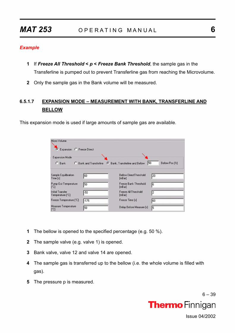
MAT 253 O P E R A T I N G M A N U A L 6
6 – 39
Issue 04/2002
Example
1 If Freeze All Threshold < p < Freeze Bank Threshold, the sample gas in the
Transferline is pumped out to prevent Transferline gas from reaching the Microvolume.
2 Only the sample gas in the Bank volume will be measured.
6.5.1.7 EXPANSION MODE – MEASUREMENT WITH BANK, TRANSFERLINE AND BELLOW
This expansion mode is used if large amounts of sample gas are available.
1 The bellow is opened to the specified percentage (e.g. 50 %).
2 The sample valve (e.g. valve 1) is opened.
3 Bank valve, valve 12 and valve 14 are opened.
4 The sample gas is transferred up to the bellow (i.e. the whole volume is filled with
gas).
5 The pressure p is measured.

MAT 253 O P E R A T I N G M A N U A L 6
6 – 40
Issue 04/2002
Case 1: If p > Bellow Direct Threshold, the sample is measured via the bellow.
Case 2: If Freeze Bank Threshold < p < Bellow Direct Threshold, the sample
valve (e.g. valve 1) is closed. The whole gas is pumped out. If nevertheless
Freeze Bank Threshold < p < Bellow Direct Threshold is still valid, the pro-
cess will be repeated.
Case 3: If Freeze All Threshold < p < Freeze Bank Threshold, Bank valve and
sample valve (e.g. valve 1) are closed. After pumping off a part of the gas,
only the gas in the bank volume will be frozen.
Case 4: If p < Freeze All Threshold, only few gas is available. Therefore, the whole
gas amount will be frozen.

MAT 253 O P E R A T I N G M A N U A L 6
6 – 41
Issue 04/2002
6.5.1.8 FREEZE DIRECT MODE
Freeze direct mode is used
if the amount of sample gas to be analyzed is known
in case of very small gas samples
The sample gas will not be expanded but transferred to the Microvolume directly. There, it will
be frozen according to the parameter values and finally be measured. Therefore, note that
the fields related to Expansion mode are inactive:
1 The sample valve (e.g. valve 1) is opened.
2 The gas in the bank volume is equilibrated until Sample Equilibration Time has
elapsed.
3 Simultaneously, the Microvolume is heated to Pump Out Temperature (e.g. 50 ºC). At
this slightly elevated temperature, evaporation of impurities and water is facilitated.
They are pumped off. Thus, the Microvolume is cleansed.
4 The Microvolume is cooled down until Initial Transfer Temperature (e.g. - 50 ºC) is
reached.

MAT 253 O P E R A T I N G M A N U A L 6
6 – 42
Issue 04/2002
5 At Initial Transfer Temperature (e.g. -50 ºC), bank valve and left valve of Microvolume
are opened. Thus, the sample gas is transferred to the Microvolume.
6 The sample gas having just entered the Microvolume is cooled down further until
Freeze Temperature (e.g. -175 ºC) is reached.
7 The system waits, until Freeze Time has elapsed (e.g. 60 s).
8 Then, bank valve and left valve of Microvolume are closed.
9 The Microvolume is heated up to Measure Temperature (e.g. 50 ºC).
10 The system waits until Delay Before Measure has elapsed.
11 Measurement starts.

MAT 253 O P E R A T I N G M A N U A L 6
6 – 43
Issue 04/2002
6.5.2 DEFINING A CONFIGURATION
Before operating, a Configuration containing the Dual Inlet System and
the Microvolume must be created in the Configurator as follows.
Add a new Configuration using the Add Configuration button.
Give it a significant name, e.g. “Dual Inlet & Micro-volume”.
Open the tree structure by a click on at
On the right pane, select
“Dual Inlet + Micro-volume”.
Drag it to the Source port of the new Configuration.
A sign appears:

MAT 253 O P E R A T I N G M A N U A L 6
6 – 44
Issue 04/2002
The Dual Inlet device has been attached to the Source.
The Microvolume has been attached to the Direct COVPort.
Close the Configurator window.
All settings will be saved automatically.

MAT 253 O P E R A T I N G M A N U A L 6
6 – 45
Issue 04/2002
6.5.3 USING A PREDEFINED METHOD
If the File Browser cannot be seen, press the Options button.
Activate the File Browser check box.
Click OK.
On the File Browser, select the
Methods tab (default).

MAT 253 O P E R A T I N G M A N U A L 6
6 – 46
Issue 04/2002
From the predefined Methods
choose “Microvolume_only.met”by double-click.
If the Standards in the Method to be
opened are older than the actual ones
in the Standard Database, or if the user
has changed the Method, the warning
beside appears.
Press OK. Thus, the Method will be corrected: the actual values of the Standard
Database (e.g. the laboratory Standard has changed or been replaced by another
one) are transferred to the Method.

MAT 253 O P E R A T I N G M A N U A L 6
6 – 47
Issue 04/2002
The Instrument tab of the
Method “Micro-
volume_only.met” appears.
For details, see chapter 6.3.2.
NOTE: Ensure, that the proper peak center cup is selected. If necessary, correct the default cup (i.e. Cup 4)!
For details about the Peripherals
tab’s Dual Inlet part, see chapter
6.3.2.
For details about the Peripher-
als tab’s Microvolume part,
see chapter 6.3.2.
Peripherals tab: Dual Inlet part
Peripherals tab: Microvolume part

MAT 253 O P E R A T I N G M A N U A L 6
6 – 48
Issue 04/2002
At Evaluation @CO2 tab, se-
lect an Ion Correction type
(e.g. “CO2 Santrock et al.”).
Select “None” or “Sigma” as
Outlier test. In case of
“Sigma”, specify the k-fold of
the standard deviation using
.
For details, see chapter 6.3.2.
NOTE: At Std. Name, choose a suitable Standard!
For details at the Printouttab, see chapter 6.3.2.
The Method for measurements using Dual Inlet in combination with a Microvolume has now
been established. As next step, either use a predefined Sequence (refer to chapter 6.5.4) or
create a new Sequence (refer to chapter 6.1.5).

MAT 253 O P E R A T I N G M A N U A L 6
6 – 49
Issue 04/2002
6.5.4 USING A PREDEFINED SEQUENCE
If the File Browser cannot be seen, press the Options button.
Activate the File Browser check box.
Click OK.
On the File Browser, select the
Sequences tab(default: Methods tab).

MAT 253 O P E R A T I N G M A N U A L 6
6 – 50
Issue 04/2002
From the predefined Sequences
choose “Microvolume_only.seq” by double-click.
In the “Method” column, the Method
chosen in chapter 6.5.3 occurs as
default (“CO2_Multi.met”).
Normally, the Sequence List needs not to be edited further. It is possible, however,
to select another Method from the “Method” column.
Press the Start button.

MAT 253 O P E R A T I N G M A N U A L 6
6 – 51
Issue 04/2002
Define parameters for:
Results Export PrintoutSequence Scripts
Press OK to start
Sequence Acquisition.

MAT 253 O P E R A T I N G M A N U A L 6
6 – 52
Issue 04/2002
6.6 DUAL INLET MEASUREMENT INCLUDING MULTIPORT AND MICROVOLUME
6.6.1 DEFINING A CONFIGURATION
Before operating, a Configuration containing the Dual Inlet System, the
Multiport and the Microvolume must be created in the Configurator as
follows.
Add a new Configuration using the Add Configuration button.
Give it a significant name, e.g. “Dual Inlet & Multiport & Microvolume”.
Open the tree structure by a click on at
On the right pane, select
Dual Inlet +Multiport +
Microvolume.
Drag it to the Source port of the new Configuration.
A sign appears:
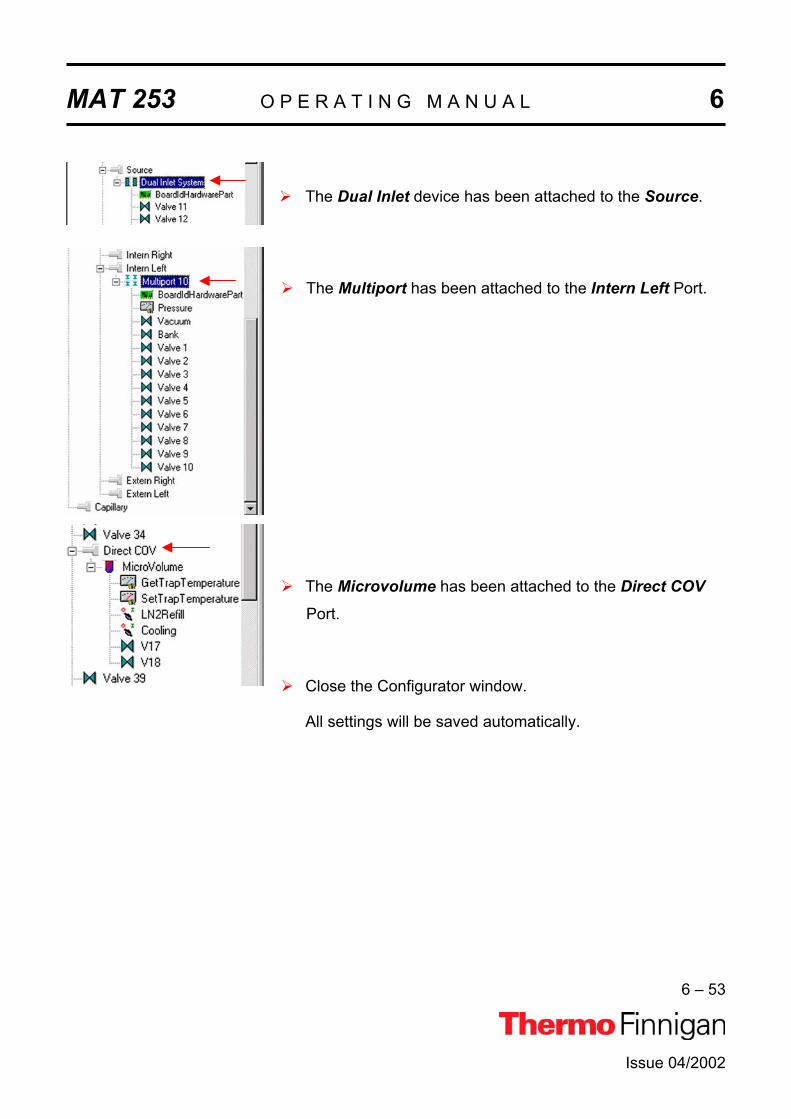
MAT 253 O P E R A T I N G M A N U A L 6
6 – 53
Issue 04/2002
The Dual Inlet device has been attached to the Source.
The Multiport has been attached to the Intern Left Port.
The Microvolume has been attached to the Direct COVPort.
Close the Configurator window.
All settings will be saved automatically.

MAT 253 O P E R A T I N G M A N U A L 6
6 – 54
Issue 04/2002
6.6.2 USING A PREDEFINED METHOD
If the File Browser cannot be seen, press the Options button.
Activate the File Browser check box.
Click OK.
On the File Browser, select the
Methods tab (default).

MAT 253 O P E R A T I N G M A N U A L 6
6 – 55
Issue 04/2002
From the predefined Methods
choose “Multiport + Micro-volume.met” by double-click.
If the Standards in the Method to be
opened are older than the actual ones
in the Standard Database, or if the user
has changed the Method, the warning
beside appears.
Press OK. Thus, the Method will be corrected: the actual values of the Standard
Database (e.g. the laboratory Standard has changed or been replaced by another
one) are transferred to the Method.

MAT 253 O P E R A T I N G M A N U A L 6
6 – 56
Issue 04/2002
Peripherals tab: Microvolume part
Peripherals tab: Dual Inlet part
The Instrument tab of the
Method “Multiport + Micro-
volume.met” appears.
For details see page chap-
ter 6.3.2
NOTE: Ensure, that the proper peak center cup is selected.If necessary, correct the default cup!
For details at the Peripherals
tab’s Dual Inlet part, see
chapter 6.3.2.
For details at the Peripherals
tab’s Microvolume part, see
chapter 6.5.3.

MAT 253 O P E R A T I N G M A N U A L 6
6 – 57
Issue 04/2002
For details at the Peripherals
tab’s Multiport part, see
chapter 6.4.2.
At Evaluation @CO2 tab,
Select an Ion Correct type,
e.g. “CO2 Santrock et al.”.
Select “None” or “Sigma” as
Outlier test. In case of
“Sigma”, specify the k-fold of
the standard deviation using
.
For details, see chapter 6.3.2.
NOTE: At Std. Name, choose a suitable Standard!
For details at Printout tab,
see chapter 6.3.2.
The Method for measurements using Dual Inlet in combination with a Multiport and a Micro-
volume has now been established. As next step, either use a predefined Sequence (refer to
chapter 6.6.3) or create a new Sequence (refer to chapter 6.1.5).
Peripherals tab: Multiport part

MAT 253 O P E R A T I N G M A N U A L 6
6 – 58
Issue 04/2002
6.6.3 USING A PREDEFINED SEQUENCE
If the File Browser cannot be seen, press the Options button.
Activate the File Browser check box.
Click OK.
On the File Browser, select the
Sequences tab(default: Methods tab).

MAT 253 O P E R A T I N G M A N U A L 6
6 – 59
Issue 04/2002
From the predefined Sequences
choose “Multiport + Micro-volume.seq” by double-click.
In the “Method” column, the Method
chosen in chapter 6.6.2 occurs as
default (“Multiport + Micro-
volume.met”).
Normally, the Sequence List needs not to be edited further. It is possible, however,
e.g. to select another Method from the “Method” column or to modify the “Multiport
Inlet” column. For details, see chapter 6.3.3.
Press the Start button.
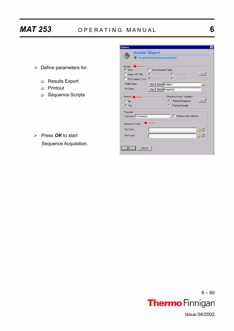
MAT 253 O P E R A T I N G M A N U A L 6
6 – 60
Issue 04/2002
Define parameters for:
Results Export PrintoutSequence Scripts
Press OK to start
Sequence Acquisition.

MAT 253 O P E R A T I N G M A N U A L 6
6 – 61
Issue 04/2002
6.7 DUAL INLET MEASUREMENT INCLUDING MULTIPORT AND REFERENCE REFILL
6.7.1 DEFINING A CONFIGURATION
Before operating, a Configuration containing the Dual Inlet System, Multi-
port and Reference Refill must be created in the Configurator as follows.
Add a new Configuration using the Add Configuration button.
Give it a significant name, e.g. “Dual Inlet & Multiport & Reference Refill”.
Open the tree structure by a click on at
On the right pane, select
Dual Inlet + Multiport + Reference Refill.
Drag it to the Source port of the new Configuration.
A sign appears:
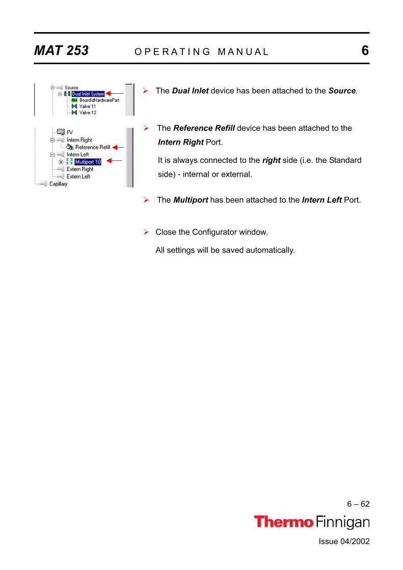
MAT 253 O P E R A T I N G M A N U A L 6
6 – 62
Issue 04/2002
The Dual Inlet device has been attached to the Source.
The Reference Refill device has been attached to the
Intern Right Port.
It is always connected to the right side (i.e. the Standard
side) - internal or external.
The Multiport has been attached to the Intern Left Port.
Close the Configurator window.
All settings will be saved automatically.

MAT 253 O P E R A T I N G M A N U A L 6
6 – 63
Issue 04/2002
6.7.2 USING A PREDEFINED METHOD
If the File Browser cannot be seen, press the Options button.
Activate the File Browser check box.
Click OK.
On the File Browser, select the
Methods tab (default).

MAT 253 O P E R A T I N G M A N U A L 6
6 – 64
Issue 04/2002
From the predefined Methods choose a
suitable Method (e.g. “Multiport + Reference Refill.met”) by double-click.
If the Standards in the Method to be opened
are older than the actual ones in the Standard
Database, or if the user has changed the
Method, the warning beside appears.
Press OK. Thus, the Method will be corrected: the actual values of the Standard Database
(e.g. the laboratory Standard has changed or been replaced by another Standard) are
transferred to the Method.
Instrument tab
The Instrument tab of the Method “Multiport + Reference Refill.met” appears.

MAT 253 O P E R A T I N G M A N U A L 6
6 – 65
Issue 04/2002
As Gasconfiguration select “CO2”.
The Main Script controls the acquisition cycle.
NOTE: It should only be edited by users trained on script editing.
Integration time: The time needed to measure each individual ion
intensity of the masses 44, 45 and 46.
Select the Peak Center Cup (e.g. Cup 3).
Peak Center Pre Delay: Waiting time between activation of reference gas
and start of peak center cycle (e.g. 60 s).
Peak Center Post Delay: Waiting time between end of peak center cycle and
start of data acquisition.
NOTE: The above information is specific for Reference Refill applications.The values depend - among others - on the diameter of the Reference
Refill capillary.
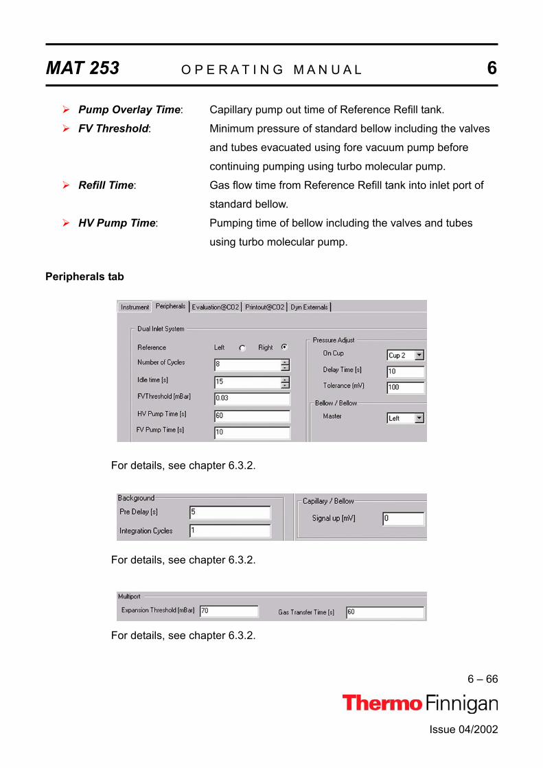
MAT 253 O P E R A T I N G M A N U A L 6
6 – 66
Issue 04/2002
Pump Overlay Time: Capillary pump out time of Reference Refill tank.
FV Threshold: Minimum pressure of standard bellow including the valves
and tubes evacuated using fore vacuum pump before
continuing pumping using turbo molecular pump.
Refill Time: Gas flow time from Reference Refill tank into inlet port of
standard bellow.
HV Pump Time: Pumping time of bellow including the valves and tubes
using turbo molecular pump.
Peripherals tab
For details, see chapter 6.3.2.
For details, see chapter 6.3.2.
For details, see chapter 6.3.2.

MAT 253 O P E R A T I N G M A N U A L 6
6 – 67
Issue 04/2002
Evaluation tab
Select the Ion Correction Type (e.g. “CO2 Santrock et al.”).
As Outlier test select “None” or “Sigma”. In case of “Sigma”, specify the k-fold of
the standard deviation using . For details, see chapter 6.3.2.
At Std. Name, choose a suitable Standard.

MAT 253 O P E R A T I N G M A N U A L 6
6 – 68
Issue 04/2002
Printout tab
For details, see chapter 6.3.2.
For details, see chapter 6.3.2.
The Method for measurements using Dual Inlet in combination with a Multiport and a
Reference Refill has now been established. As next step, either use a predefined Sequence (refer to chapter 6.7.3) or create a new Sequence (refer to chapter 6.1.5).
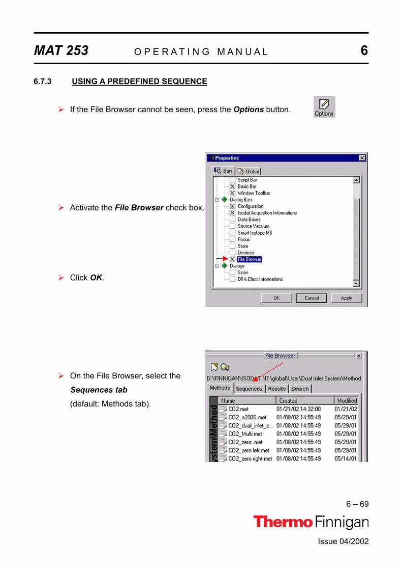
MAT 253 O P E R A T I N G M A N U A L 6
6 – 69
Issue 04/2002
6.7.3 USING A PREDEFINED SEQUENCE
If the File Browser cannot be seen, press the Options button.
Activate the File Browser check box.
Click OK.
On the File Browser, select the
Sequences tab(default: Methods tab).

MAT 253 O P E R A T I N G M A N U A L 6
6 – 70
Issue 04/2002
From the predefined Sequences
choose “Multiport + ReferenceRefill.seq” by double-click.
In the Method column, the Method chosen in chapter 6.7.2 occurs as default
(“Multiport + Reference Refill.met”).
Normally, the Sequence List needs not to be edited further. It is possible, however,
e.g. to select another Method from the “Method” column or to modify the “Multiport
Inlet” column.
The Multiport Inlet column defines the Multiport Inlet Port from which a particular
sample is taken (e.g. Sample 2 enters via Multiport Inlet Port 2).
If enough sample is available, it is possible to measure repeatedly out of the same
port.

MAT 253 O P E R A T I N G M A N U A L 6
6 – 71
Issue 04/2002
If a Reference Refill is to be performed, the column must be activated by
for the particular sample (e.g. for Sample 1).
Press the Start button.
Define parameters for:
Results Export PrintoutSequence Scripts
Press OK to start
Sequence Acquisition.

MAT 253 O P E R A T I N G M A N U A L 6
6 – 72
Issue 04/2002
6.8 DUAL INLET MEASUREMENT INCLUDING MULTIPORT AND BUFFERED REFILL
6.8.1 DEFINING A CONFIGURATION
Before operating, a Configuration containing the Dual Inlet System, Multi-
port and Buffered Refill must be created in the Configurator as follows.
Add a new Configuration using the Add Configuration button.
Give it a significant name, e.g. “Dual Inlet & Multiport & Buffered Refill”.
Open the tree structure by a click on at
On the right pane, select
Dual Inlet + Multi-port + Buffered Refill.
Drag it to the Source port of the new Configuration.
A sign appears:

MAT 253 O P E R A T I N G M A N U A L 6
6 – 73
Issue 04/2002
The Dual Inlet device has been attached to the Source.
The Buffered Refill device has been attached to the
Intern Right Port.
The Multiport device has been attached to the Intern LeftPort.
Close the Configurator window.
All settings will be saved automatically.

MAT 253 O P E R A T I N G M A N U A L 6
6 – 74
Issue 04/2002
6.8.2 USING A PREDEFINED METHOD
If the File Browser cannot be seen, press the Options button.
Activate the File Browser check box.
Click OK.
On the File Browser, select the
Methods tab (default).

MAT 253 O P E R A T I N G M A N U A L 6
6 – 75
Issue 04/2002
From the predefined Methods
choose a suitable Method (e.g.
“Multiport + Buffered Refill.met”)
by double-click.
If the Standards in the Method to be
opened are older than the actual ones
in the Standard Database, or if the
user has changed the Method, the
warning beside appears.
Press OK. Thus, the Method will be corrected: the actual values of the Standard
Database (e.g. the laboratory Standard has changed or been replaced by another
Standard) are transferred to the Method.
Instrument tab
The Instrument tab of the Method “Multiport + Buffered Refill.met” appears.

MAT 253 O P E R A T I N G M A N U A L 6
6 – 76
Issue 04/2002
As Gasconfiguration select “CO2”.
The Main Script controls the acquisition cycle.
NOTE: It should only be edited by users trained on script editing.
Integration time: The time needed to measure each individual ion inten-
sity of the masses 44, 45 and 46 (e.g. 8 s).
Peak Center Cup: Select the Peak Center Cup (e.g. Cup 3).
Peak Center Pre Delay: Waiting time between activation of reference gas and
start of peak center cycle (e.g. 60 s).
Peak Center Post Delay: Waiting time between end of peak center cycle and start
of data acquisition (e.g. 60 s).
NOTE: The above information is specific for Buffered Refill applications.
Refill Time: Gas flow time from Buffered Refill tank into inlet port of
standard bellow (e.g. 10 ms).

MAT 253 O P E R A T I N G M A N U A L 6
6 – 77
Issue 04/2002
Peripherals tab
For details, see chapter 6.3.2.
For details, see chapter 6.3.2.
For details, see chapter 6.3.2.
Evaluation tab
Select the Ion Correction Type (e.g. “CO2 Santrock et al.”).

MAT 253 O P E R A T I N G M A N U A L 6
6 – 78
Issue 04/2002
As Outlier test select “None” or “Sigma”. In case of “Sigma”, specify the k-fold of
the standard deviation using .
At Std. Name, choose a suitable Standard.

MAT 253 O P E R A T I N G M A N U A L 6
6 – 79
Issue 04/2002
Printout tab
For details, see chapter 6.3.2.
For details, see chapter 6.3.2.
The Method for measurements using Dual Inlet in combination with a Multiport and a Buff-
ered Refill has now been established. As next step, either use a predefined Sequence (refer
to chapter 6.8.3) or create a new Sequence (refer to chapter 6.1.5).

MAT 253 O P E R A T I N G M A N U A L 6
6 – 80
Issue 04/2002
6.8.3 USING A PREDEFINED SEQUENCE
If the File Browser cannot be seen, press the Options button.
Activate the File Browser check box.
Click OK.
On the File Browser, select the
Sequences tab(default: Methods tab).

MAT 253 O P E R A T I N G M A N U A L 6
6 – 81
Issue 04/2002
From the predefined Sequences
choose Multiport + Buffered Re-fill.seq by double-click.
In the Method column, the Method chosen in chapter 6.8.2 occurs as default (“Mul-
tiport + Buffered Refill.met”).
Normally, the Sequence List needs not to be edited further. It is possible, however,
e.g. to select another Method from the “Method” column or to modify the “Multiport
Inlet” column.
The Multiport Inlet column defines the Multiport Inlet Port from which a particular
sample is taken (e.g. Sample 2 enters via Multiport Inlet Port 2).
If enough sample is available, it is possible to measure repeatedly out of the same
port.

MAT 253 O P E R A T I N G M A N U A L 6
6 – 82
Issue 04/2002
If a Buffered Refill is to be performed, the column must be activated by
for the particular sample (e.g. for Sample 1).
Press the Start button.
Define parameters for:
Results Export PrintoutSequence Scripts
Press OK to start
Sequence Acquisition.
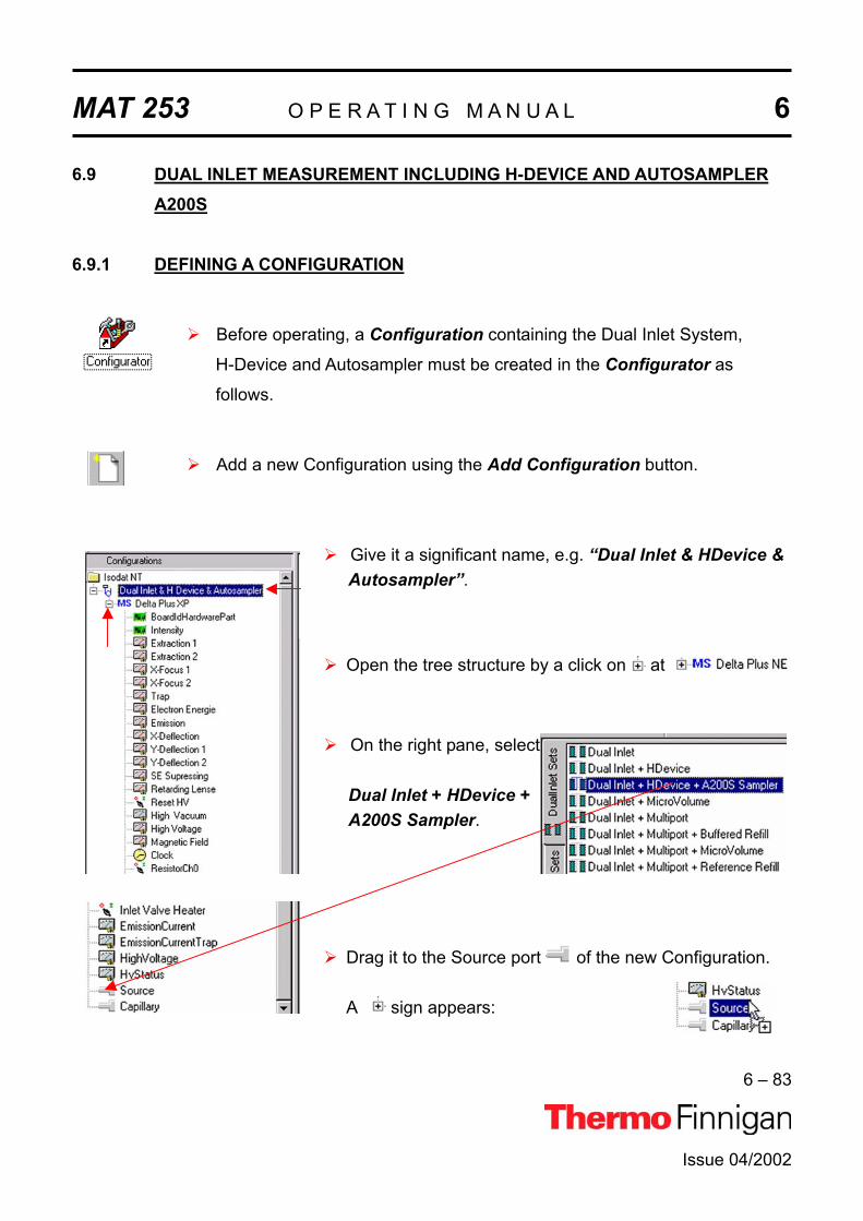
MAT 253 O P E R A T I N G M A N U A L 6
6 – 83
Issue 04/2002
6.9 DUAL INLET MEASUREMENT INCLUDING H-DEVICE AND AUTOSAMPLER A200S
6.9.1 DEFINING A CONFIGURATION
Before operating, a Configuration containing the Dual Inlet System,
H-Device and Autosampler must be created in the Configurator as
follows.
Add a new Configuration using the Add Configuration button.
Give it a significant name, e.g. “Dual Inlet & HDevice & Autosampler”.
Open the tree structure by a click on at
On the right pane, select
Dual Inlet + HDevice +A200S Sampler.
Drag it to the Source port of the new Configuration.
A sign appears:

MAT 253 O P E R A T I N G M A N U A L 6
6 – 84
Issue 04/2002
The Dual Inlet device has been attached to the Source.
The H-Device has been attached to the Extern Left Port.
The A200S Autosampler has been attached to the Sam-pler Port.
Close the Configurator window.
All settings will be saved automatically.

MAT 253 O P E R A T I N G M A N U A L 6
6 – 85
Issue 04/2002
6.9.2 USING A PREDEFINED METHOD
If the File Browser cannot be seen, press the Options button.
Activate the File Browser check box.
Click OK.
On the File Browser, select the
Methods tab (default).
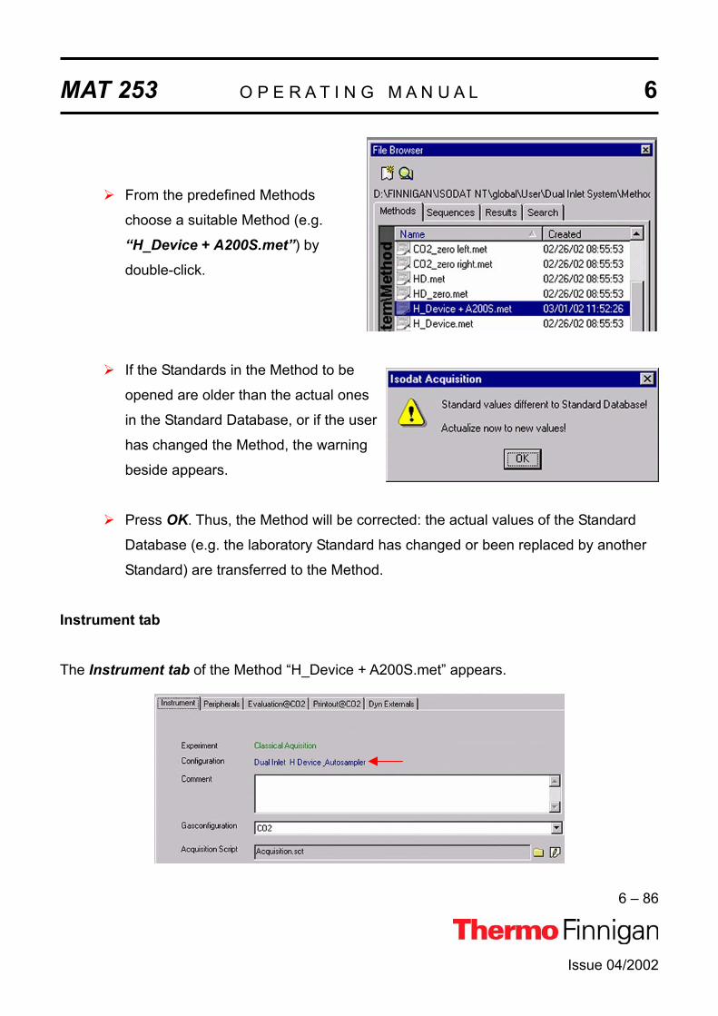
MAT 253 O P E R A T I N G M A N U A L 6
6 – 86
Issue 04/2002
From the predefined Methods
choose a suitable Method (e.g.
“H_Device + A200S.met”) by
double-click.
If the Standards in the Method to be
opened are older than the actual ones
in the Standard Database, or if the user
has changed the Method, the warning
beside appears.
Press OK. Thus, the Method will be corrected: the actual values of the Standard
Database (e.g. the laboratory Standard has changed or been replaced by another
Standard) are transferred to the Method.
Instrument tab
The Instrument tab of the Method “H_Device + A200S.met” appears.

MAT 253 O P E R A T I N G M A N U A L 6
6 – 87
Issue 04/2002
As Gasconfiguration select “CO2”.
The Main Script controls the acquisition cycle.
NOTE: It should only be edited by users trained on script editing.
Integration time: The time needed to measure each individual ion in-
tensity of the masses 44, 45 and 46 (e.g. 8 s).
Peak Center Cup: Select the Cup for peak center (e.g. Cup 3).
Peak Center Pre Delay: Waiting time between activation of reference gas and
start of peak center cycle (e.g. 60 s).
Peak Center Post Delay: Waiting time between end of peak center cycle and
start of data acquisition (e.g. 60 s).
Peripherals tab
For details see chapter 6.3.2.

MAT 253 O P E R A T I N G M A N U A L 6
6 – 88
Issue 04/2002
For details, see chapter 6.3.2.
NOTE: The above information is specific for H-Device applications.
Reaction Time: Time for the injected substance to react with chromium (e.g. 60 s). Reaction time differs between substances. Water only needs 20 to 60 s to react, whereas organic compounds need longer times, which must be determined empirically.
NOTE: Valve 11 must be closed!
Transfer Time: Time for the gas to expand from the expansion volume into the bellow (e.g. 60 s).
Equilibration Time: Valve 11 is opened and the gas mixture is allowed to ex-pand into the intermediate or expansion volume (connect-ing metal hose plus valve body). An equilibration time of 30 s is recommended for 800 ºC to 850 ºC. For other tem-peratures, this needs to be tested empirically.

MAT 253 O P E R A T I N G M A N U A L 6
6 – 89
Issue 04/2002
Evaluation tab
Select the Ion Correction Type (e.g. “CO2 Santrock et al.”).
As Outlier test select “None” or “Sigma”. In case of “Sigma”, specify the k-fold of
the standard deviation using .
For details, see chapter 6.3.2.
At Std. Name, choose a suitable Standard.

MAT 253 O P E R A T I N G M A N U A L 6
6 – 90
Issue 04/2002
Printout tab
For details, see chapter 6.3.2.
For details, see chapter 6.3.2.
The Method for measurements using Dual Inlet in combination with a H-Device and an
A200S Autosampler has now been established. As next step, either use a predefinedSequence (refer to chapter 6.9.3) or create a new Sequence (refer to chapter 6.1.5).

MAT 253 O P E R A T I N G M A N U A L 6
6 – 91
Issue 04/2002
6.9.3 USING A PREDEFINED SEQUENCE
If the File Browser cannot be seen, press the Options button.
Activate the File Browser check box.
Click OK.
On the File Browser, select the
Sequences tab(default: Methods tab).

MAT 253 O P E R A T I N G M A N U A L 6
6 – 92
Issue 04/2002
From the predefined Sequences
choose a suitable one (e.g.
H_Device + A200S.seq) by double-
click.
Normally, the Sequence List needs not to be edited further. It is possible, however,
e.g. to select another Method from the “Method” pulldown menu.
AS Sample: Type in the sample position in the Autosampler tray.
AS Method: Select Autosampler Method.
Identifier 1: Edit text to identify the sample.
Method: Select IRMS Method. The Method chosen in chapter 6.9.2 occurs
as default (“H_Device + A200S.met”).

MAT 253 O P E R A T I N G M A N U A L 6
6 – 93
Issue 04/2002
Press the Start button.
Define parameters for:
Results Export PrintoutSequence Scripts
Press OK to start
Sequence Acquisition.

MAT 253 O P E R A T I N G M A N U A L 6
6 – 94
Issue 04/2002
6.10 FUNDAMENTAL PROCEDURES BEFORE ANY MEASUREMENT
Before starting any acquisition make sure, the following procedure has been performed:
1 Electronic offset has been measured and saved.
2 All peripherals have been configured.
3 The Mass Calibration for all gases to be measured has been performed.
4 In case of a Dual Inlet application, the Bellow Calibration has been
performed.
5 In case of hydrogen collectors, the H3 factor for Continuous Flow and Dual
Inlet application has been determined.
6 In case of Elemental Analyzer application for C/N or H/O analysis, the Jump
Calibration has been performed and saved.
7 In case of a Liquid Autosampler, the COM port and the other parameters are
set.

MAT 253 O P E R A T I N G M A N U A L 6
6 – 95
Issue 04/2002
6.11 HANDLING OF RESULTSToolbar Commands
After the measurement has been started by , a classical acquisition file, i.e. *.caf,is generated (e.g. “Acquisition-7.caf”). The Acquisition window opens. It contains the toolbar
shown below with the following Icons:
A running Dual Inlet data acquisition can be stopped.
The data are shown both in a data grid and graphically
(i.e. both in medium size).
The graphical representation of the raw data is shown
in maximum size (i.e. without data grid).
The result grid is shown in maximum size (i.e. without
graphical representation).
Some parameters of the Method can be changed (not
the Method itself). Afterwards, the recorded data are
reevaluated using the new parameter values.
Opens a Result Workshop Template containing the
data (e.g. for preparing a printout).

MAT 253 O P E R A T I N G M A N U A L 6
6 – 96
Issue 04/2002
Sequence line
A particular line of the chosen Sequence is shown. It denotes the currently measured sample.
The tabs of the Acquisition window The Acquisition window offers the following tabs for data interpretation:
Raw tab
In case of Dual Inlet applications, intensity values are determined (while in case of Con-tinuous Flow applications, peak areas are calculated).
In the leftmost column, the sample number is displayed (e.g. “Pre” and “1” to “8”; cf. the lines
of the chosen Sequence). Besides, the raw data grid contains the following columns:
1. Int Sample Sample intensity of a particular mass in mV (e.g. mass 44).
Each sample mass has a column of its own.
2. Int. Standard Standard intensity of a particular mass in mV (e.g. mass 44).
Each standard mass has a column of its own.
1 1 2 2 3 4 45 5 6

MAT 253 O P E R A T I N G M A N U A L 6
6 – 97
Issue 04/2002
3. rR Raw ratio of two masses, i.e. ratio of the intensities of these two masses
(e.g. rR 45/44).
4. rDelta Raw Delta of two molecular masses (in ‰) vs. a secondary standard -
i.e. vs. a user standard. E.g.: rDelta [45 CO2/44 CO2] vs. CO2_zero.
These values are molecule deltas and are calculated from the raw
ratios.
5. Delta Delta value of two element isotopes (in ‰) vs. a primary standard. E.g.:
Delta [13C/12C] vs. V-PDB or Delta [18O/16O] vs. V-SMOW.
These values are element deltas and are calculated from the true
element sample ratios and the true element standard ratios. The true
element standard ratios are read from primary standards defined in the
primary standard database.
6. At % Atomic percentage value of an isotope, e.g.: At % [13C] or At % [18O].
It is calculated from the element delta and the corresponding absolute
element ratio of the standard.
Kinds of data in the raw data grid
A red value indicates that during integration the
timeout criterion was reached. Red numbers only
occur in case of intensities, i.e. in the columns Int. Sample and Int. Standard.
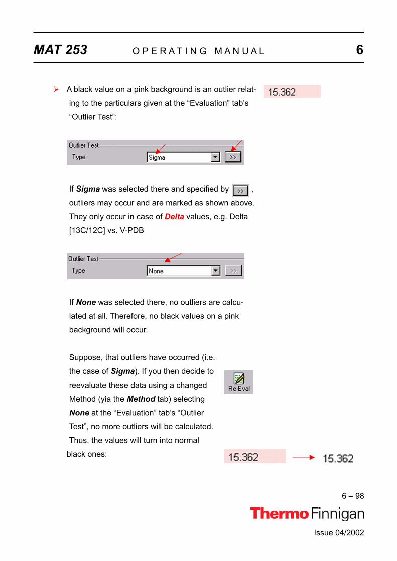
MAT 253 O P E R A T I N G M A N U A L 6
6 – 98
Issue 04/2002
A black value on a pink background is an outlier relat-
ing to the particulars given at the “Evaluation” tab’s
“Outlier Test”:
If Sigma was selected there and specified by ,
outliers may occur and are marked as shown above.
They only occur in case of Delta values, e.g. Delta
[13C/12C] vs. V-PDB
If None was selected there, no outliers are calcu-
lated at all. Therefore, no black values on a pink
background will occur.
Suppose, that outliers have occurred (i.e.
the case of Sigma). If you then decide to
reevaluate these data using a changed
Method (yia the Method tab) selecting
None at the “Evaluation” tab’s “Outlier
Test”, no more outliers will be calculated.
Thus, the values will turn into normal
black ones:
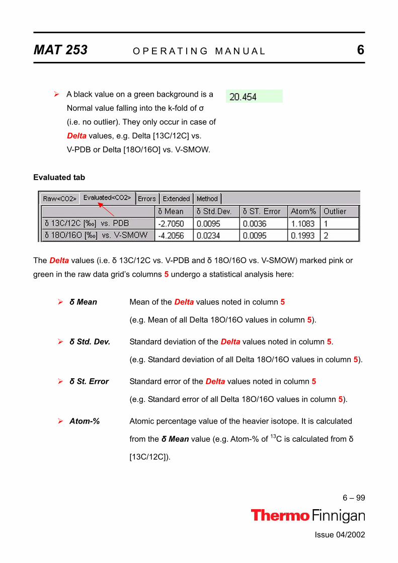
MAT 253 O P E R A T I N G M A N U A L 6
6 – 99
Issue 04/2002
A black value on a green background is a
Normal value falling into the k-fold of
(i.e. no outlier). They only occur in case of
Delta values, e.g. Delta [13C/12C] vs.
V-PDB or Delta [18O/16O] vs. V-SMOW.
Evaluated tab
The Delta values (i.e. 13C/12C vs. V-PDB and 18O/16O vs. V-SMOW) marked pink or
green in the raw data grid’s columns 5 undergo a statistical analysis here:
Mean Mean of the Delta values noted in column 5
(e.g. Mean of all Delta 18O/16O values in column 5).
Std. Dev. Standard deviation of the Delta values noted in column 5.
(e.g. Standard deviation of all Delta 18O/16O values in column 5).
St. Error Standard error of the Delta values noted in column 5
(e.g. Standard error of all Delta 18O/16O values in column 5).
Atom-% Atomic percentage value of the heavier isotope. It is calculated
from the Mean value (e.g. Atom-% of 13C is calculated from
[13C/12C]).

MAT 253 O P E R A T I N G M A N U A L 6
6 – 100
Issue 04/2002
Outlier Number of outliers in column 5 entering into calculation of
Mean, Std. Dev and St. Error (e.g. 2).
Errors tab
The “Errors” tab contains detailed information about errors that occurred during Data
Acquisition:
Number The consecutive number of the error (i.e. 1; 2; 3…)
Status The quality or gravidity of the error (e.g. fatal; warning; error)
Object Object in the Script that caused the particular error
Information Explanation concerning the error
Script Script that caused the error
Extended tab

MAT 253 O P E R A T I N G M A N U A L 6
6 – 101
Issue 04/2002
In the “Extended” tab, a measurement protocol is presented: detailed information is given
about particular results during measurement progression (e.g. Peak Center results or Pres-
sure Adjustment results). The kind of information depends on the selected Configuration;
e.g. different information in case of “Dual Inlet + Microvolume” compared to “Dual Inlet + H-
Device”.
Method tab
For Data Reevaluation purposes, some parameters of the Method selected prior to meas-
urement start can be modified (mainly in the “Peripherals” tab and the “Evaluation” tab; click
the tabs in order to determine the changeable parameters and then type in the new corrected
values). After the parameters of interest have been modified, reevaluation of the data can be
started. Therefore, press the Re-Eval button.

MAT 253 O P E R A T I N G M A N U A L 6
6 – 102
Issue 04/2002
6.12 EXCEL EXPORT OF RESULTS
6.12.1 PRINCIPLE OF EXCEL EXPORT
Principle: Measurement parameters and results are exportable as an Excel file. The
Excel export can easily be tailored to your individual needs. Therefore, rules
must be established to determine how to perform the export. These export
rules are described in an export template (i.e. a wke file).
Various selectors, which group Identifiers, are used to create an export
template. For an export, more than one template can be selected. Multiple
templates can be used simultaneously. Every single template (i.e. every wke
file) finally leads to an export file of its own, its wk1 file. Every wk1 file is
created according to the rules of the wke file.
Advantages: Although measurement data are stored in one result file, the data concern-
ing every single gas type can be exported separately to an export file of
their own (e.g. multigas measurement).
Single parts of a measurement can be exported to an export file of their
own (e.g. only the Method parameters).
Some types of data can be specified further using query tabs, where so-
phisticated export properties are defined (e.g. peak relevant data).

MAT 253 O P E R A T I N G M A N U A L 6
6 – 103
Issue 04/2002
6.12.2 CREATING AN EXPORT TEMPLATE
On the Dual Inlet window’s toolbar, press the New button.
Click Data Export and confirm by OK.
Thus, a new export template can be edited.
Four selector types
can be selected.
The four selector types for template creation
Selectors facilitate the Excel-Export: the list of exportable data can be shortened (see the
Identifiers in the left pane). Without selectors, all exportable data are visible.

MAT 253 O P E R A T I N G M A N U A L 6
6 – 104
Issue 04/2002
available pool of
Identifers (columns) Identifiers (columns) to be exported
NOTE: Selectors are always combined by a conjunction (i.e. by an AND relation).
NOTE: (De-)activation of Selectors can be changed during template creation.The export columns will not be affected.
1
2
Acquisition Mode
If Acquisition Mode is activated, choose via click between parameters, which are only rele-
vant for Dual Inlet Acquisition and those only relevant for Continuous Flow Acquisition.
As default, both parameter types are selected, i.e. no selector.
Included String
If Included String is activated and you type a string (e.g. “Delta”), the entries in the left pane
(“pool”) will be selected according to that string after pressing Apply. The entries that match
the string will be displayed in the right pane.
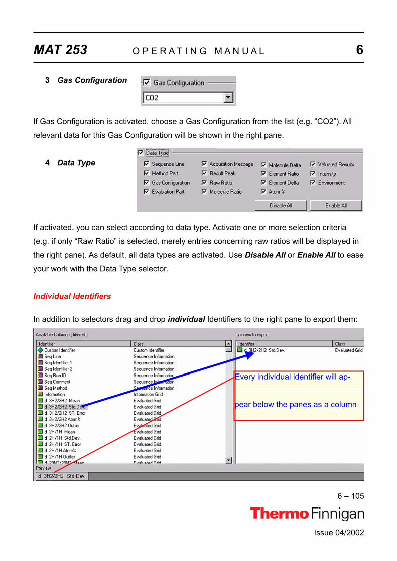
MAT 253 N U A L 6
6 – 105
Issue 04/2002
O P E R A T I N G M A
3
4
Gas Configuration
If Gas Configuration is activated, choose a Gas Configuration from the list (e.g. “CO2”). All
relevant data for this Gas Configuration will be shown in the right pane.
Data Type
If activated, you can select according to data type. Activate one or more selection criteria
(e.g. if only “Raw Ratio” is selected, merely entries concerning raw ratios will be displayed in
the right pane). As default, all data types are activated. Use Disable All or Enable All to ease
your work with the Data Type selector.
Individual Identifiers
In addition to selectors drag and drop individual Identifiers to the right pane to export them:
Every individual identifier will ap-
pear below the panes as a column

MAT 253 O P E R A T I N G M A N U A L 6
6 – 106
Issue 04/2002
Drag and drop of the Custom Identifier allows inserting a column that contains no data. You
can give it a name of your own choice. Later on, you can, for example, import data into this
column. During drag and drop of the Custom Identifier from the left to the right pane, the box
shown below appears.
Type a significant name for the custom
identifier (e.g. “Identifier 1”).
Press OK.
The Custom Identifier also appears as a column in the wk1 Excel sheet. To create additional
empty columns, proceed with the next Custom Identifier(s) by repeating the steps above.
To remove one or more Identifiers (Custom Identifiers or other ones) from the right pane,
mark them there. Then right-click them.

MAT 253 O P E R A T I N G M A N U A L 6
6 – 107
Issue 04/2002
Select Delete Identifier.
To remove the Identifier(s) confirm by Yes.
The selected Identifier(s) will be removed from the right pane together with the provided
empty columns in the Excel sheet.
6.12.3 SAVING AN EXPORT TEMPLATE
After creating an export template (i.e. a wke file) it must be saved. Therefore, on the Dual
Inlet window’s toolbar press the Save or Save As button .

MAT 253 O P E R A T I N G M A N U A L 6
6 – 108
Issue 04/2002
Save the export template in thefolder Wk1 Export Templates!
In the File Name field, type a signi-
ficant name for the export template
(e.g. Dual Inlet 1).
In the Save as type field, accept the
extension .wke and press Save.
6.12.4 APPLYING AN EXPORT TEMPLATE
A Sequence is always exported as several samples can thus be bundled into a single export
file. To apply an export template, open a new Sequence via the New button .
Then click the Sequence Icon.
Confirm by OK.

MAT 253 O P E R A T I N G M A N U A L 6
6 – 109
Issue 04/2002
Type your number of samples (e.g. 3).
Confirm by OK.
The Sequence of your choice is displayed.
Press the Start button .
Since no export templates have
been selected yet, the Export WK1.
File box is inactive.
Press the button.
Since no export templates have
been selected yet, the Export Temp-
late list is empty.
Press the button.

MAT 253 O P E R A T I N G M A N U A L 6
6 – 110
Issue 04/2002
In the folder WK1 Export Templa-
tes, select your Export Template
(e.g. Dual Inlet 1.wke).
Press Open.
Select your Export Template
(e.g. Dual Inlet 1.wke).
Confirm by OK.
Note that the Export WK1 File box
has now become active.
Confirm by OK.

MAT 253 O P E R A T I N G M A N U A L 6
6 – 111
Issue 04/2002
The options specified in the Sequence are now set and Data Acquisition starts.
NOTE: The Excel Export will be performed online, i.e. during the measurement. This is different from a Re-evaluation, where the Excel Export takes place offline, i.e. after a measurement.


Issue 04/2002
MAT 253
OPERATING MANUAL
DIAGNOSIS


MAT 253 O P E R A T I N G M A N U A L 7
7 – 1
Issue 04/2002
7.1 CHECKING PERFORMANCE DATAThermo Finnigan MAT has developed several test routines to check the performance data of
the MAT 253 isotope ratio mass spectrometer.
For user's convenience, the program “Diagnosis” covering these test routines is included in
the supplied version of ISODAT NT. It must be noted that operating some of the test routines
requires technical knowledge of the instrument's internals. In addition, successful execution
of some of the tests depends upon instrument preconditions.
When running the test routines, a highly sensitive focusing of your instrument will lead to the
best specifications results (see chapter 1.4 about how to focus the ion source).
The program Diagnosis contains the following test routines:
1 Absolute Sensitivity
2 Abundance
3 Amplifier Test
4 Compression Factor
5 Linearity
6 Peak Flatness
7 Relative Sensitivity
8 Resolution
9 Signal Stability
10 System Stability
NOTE: Reference gas for all performance data is CO2.Make sure to have properly filled CO2 reservoirs attached to the inlet system before starting the “Diagnosis” program.

MAT 253 O P E R A T I N G M A N U A L 7
7 – 2
Issue 04/2002
7.2 HOW TO START DIAGNOSIS
Start ISODAT NT by double-clicking the Icon on your desktop.
Double-click the Diagnosis Icon.
Mark the test routine to be performed
(e.g. “Abundance”).
Press OK.

MAT 253 O P E R A T I N G M A N U A L 7
7 – 3
Issue 04/2002
7.2.1 ABSOLUTE SENSITIVITYNOTE: Testing Absolute Sensitivity requires a Dual Inlet systemAbsolute Sensitivity is defined as the number of molecules needed to generate an ion, which
is then registered at the collector (e.g. one ion of mass 44 at the corresponding collector
cup). It is thus dimensionless and measured in molecules per ion.
Based on a defined volume, the ion current is determined during a defined time period as a
function of sample consumption (i.e. sample loss). The small, defined volume is located be-
tween valve 25 of the inlet system and the inlet capillary. It amounts to approximately 250 µl.
Integrating the ion current over time yields the number of ions. From the signal drop during
measurement the number of molecules necessary to generate this ion amount is calculated.
To obtain Absolute Sensitivity, the number of molecules is divided by the number of ions.
Positively charged ions are produced in the ion source by electron bombardment. This elec-
tron impact (EI) ionization is described by:
−+− +→+ eABeAB 2 (ionization)
−+− ++→+ eBAeAB 2 (ionization and dissociation)
Definition of Absolute Sensitivity AS:
)/( ionmoleculesn
sASion
∆=
where s: sample gas consumption
nion: number of detected ions

MAT 253 O P E R A T I N G M A N U A L 7
7 – 4
Issue 04/2002
The number of consumed sample molecules n is calculated via the ideal gas law:
TRnVp =
where: R: universal gas constant
T: temperature
p: pressure
n: number of sample molecules
V: volume (here 250 µl)
The amount of detected ions nion in the collector cup can be calculated via the electrons
needed to neutralize the positive ions:
dtIQt
tñ=2
1
where: Q: charge I: intensity
To test this parameter:
1 Measurement starts with a determination of pressure and intensity.
2 The volume is reduced to the defined volume by closing valve 25 of the inlet
system. The system is in a waiting position until the start pressure and intensity
are reached.
3 The ion current is measured for the preset time.
NOTE: Absolute Sensitivity should be about 800 molecules CO2 per mass 44 at the collector cup.
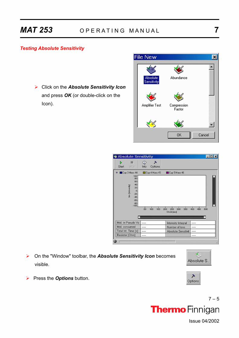
MAT 253 O P E R A T I N G M A N U A L 7
7 – 5
Issue 04/2002
Testing Absolute Sensitivity
Click on the Absolute Sensitivity Iconand press OK (or double-click on the
Icon).
On the "Window" toolbar, the Absolute Sensitivity Icon becomes
visible.
Press the Options button.

MAT 253 O P E R A T I N G M A N U A L 7
7 – 6
Issue 04/2002
Accept the defaults or from the pulldown menus, enter
a value for "Stop [s]" and choose a value for "Delay
[ms]" between 100 ms and 20000 ms from the list.
In Advanced Mode, all values can be edited:
Integration time in ms
Start Intensity value ("Start [mV]")
Minimum Intensity [mV]
Channel: a recording channel consists of an amplifier, a voltage-frequency (VF) con-
verter and a counter.
"Press Adjust Manual": activate it, if you wish to adjust pressure and peak center
manually (if it is activated, you are requested to adjust to e.g.
8000 mV manually).
Finally, click OK.
Press the Start button.

MAT 253 O P E R A T I N G M A N U A L 7
7 – 7
Issue 04/2002
Testing starts with a Peak Center on the
selected Cup, e.g. mass 45, Cup3.
The bellow is reduced stepwise until the
start level intensity (e.g. 8000 mV) is
reached. Then, intensity and pressure
are measured for the preset time (e.g.
500 s).
Finally, Absolute Sensitivity
and other parameters are
calculated.

MAT 253 O P E R A T I N G M A N U A L 7
7 – 8
Issue 04/2002
Press the Info button.
Original measurement and regression line
are shown.
When closing the "Absolute Sensi-
tivity" window you are asked,
whether to save the changes.

MAT 253 O P E R A T I N G M A N U A L 7
7 – 9
Issue 04/2002
7.2.2 ABUNDANCEAbundance denotes the contribution of a mass to a neighbor mass (e.g. the amount of ions
for mass 44 falling into cup 45). Thus, the intensity of a mass (e.g. mass 44) is compared to
the intensity of the neighboring peak (e.g. mass 45).
In case of CO2, divide the amount of ion current of mass 44 falling into the mass 45 cup by
the ion current of mass 44 falling into the mass 44 cup.
Measured as ratio of two ion currents it is dimensionless and quoted in % or ppm. It should
not exceed 2 * 10-6 for a MAT 253 with Dual Inlet system. The Abundance test is performed
with CO2, and the device must be calibrated. Peak center is performed on Channel 2 (i.e.
narrow cup) before the measurement starts.
To test this parameter
1 Signal height (i.e. intensity) on mass 44 is determined in the appropriate collector
cup (e.g. Cup 3).
2 The background signal on mass 45 is measured (i.e. electronic noise with no gas)
from mass 44 to mass 45.5.
3 With CO2 as sample gas, the magnetic field is scanned from mass 44 to mass 45.5,
and the intensities are measured on the neighboring Cup of mass 45 (e.g. Cup 4,
with bigger resistor value in order to keep the signal in the detection range).
4 Extrapolate the abundance (of mass 44 onto mass 45) from the signal to the left and
to the right of mass 45 peak.
5 Calculate the abundance as described above.

MAT 253 O P E R A T I N G M A N U A L 7
7 – 10
Issue 04/2002
Sources of error
Resistor values are not configured correctly.
Due to electrons on the left and on the right side of the peak, a negative signal may
result. This problem can be overcome by manual adjustment.
Testing Abundance
Click on the Abundance Icon and press
OK (or doubleclick the Icon).
The left window detects mass
44 ions in the correct cup. The
right window detects mass 44
ions in the neighbor cup (i.e.
cup of mass 45).

MAT 253 O P E R A T I N G M A N U A L 7
7 – 11
Issue 04/2002
On the "Window" toolbar, the Abundance Icon becomes visible.
Press the Options button.
Accept the defaults, or type appropriate values for
"Press Adjust [mV]" and "Peak Width [Dalton]".
The selected cup for the Abundance test is
connected with the indicated recording channel (e.g.
choose channel 2 from the pulldown list).
Choose a "Delay [ms]" value between 100 ms and
20000 ms. The measurement start will be delayed
by it.
In Standard Mode, the inactive, i.e. gray, variables
cannot be edited. The Advanced Mode allows
experienced users to set them all:
the start mass for the magnet field scan ("Start [Dalton]"),
the end mass, where the magnet stops scanning ("Stop [Dalton]")
the step width for the magnet scan ("Step [Dalton]")
the "Adjust Manual" check box - if it is activated, signal intensity and peak
center must be performed manually.
Finally, click OK.
Start the Abundance test by the Start button.

MAT 253 O P E R A T I N G M A N U A L 7
7 – 12
Issue 04/2002
Testing starts with a Peak Center
on the selected cup (e.g. mass 45,
cup 3).
It might be helpful to activate the
Advanced Mode, press the Op-tions button and enhance the in-
terval between "Start" and "Stop"
values (i.e. decrease "Start" and
increase "Stop" values).
Values for Abun-
dance, Intensity, U
and slope are dis-
played.

MAT 253 O P E R A T I N G M A N U A L 7
7 – 13
Issue 04/2002
When closing the "Abundance"
window you are asked whether
to save the changes.

MAT 253 O P E R A T I N G M A N U A L 7
7 – 14
Issue 04/2002
7.2.3 AMPLIFIER TESTThe Amplifier Test (formerly called UFC-Test) checks the ion detection performance of the
IRMS with no ions present. It thus informs about the background noise of electronic devices.
The amplifier baseline must be determined without an interfering signal. Thus, the ion source
is switched off before measurement starts (i.e. ion current equals zero). The signal intensity
of every cup is individually measured at least 200 times for a defined integration time. Finally,
mean and standard deviation are calculated.
Testing Amplifiers
Click the Amplifier Test Icon and press OK(or doubleclick the Icon).
Wait, while the available Gas Configurations are
scanned.

MAT 253 O P E R A T I N G M A N U A L 7
7 – 15
Issue 04/2002
On the "Window" toolbar, the Amplifier becomes visible.
Press the Options button.
With the exception of Delay, all parameters are preset and not
changeable in Standard Mode.
The Advanced Mode allows experienced users to modify
all parameters.
Accept the default value of Integration Time (in ms).
Scan Time (in s) denotes the duration of the scan.
The measurement start is delayed by the displayed default
value of Delay time (in ms). Accept it, or from the pulldown
menu, select a suitable value between 100 ms and
35000 ms.
NOTE: In one of the next versions, the process will be simplified: all amplifiers can then be measured us-ing one single Scan.

MAT 253 O P E R A T I N G M A N U A L 7
7 – 16
Issue 04/2002
Cycles denotes the number of measurements. The intensities of the channel are
measured for indicated cycles with a definite cycle time.
Finally, press OK.
Press the Start button.
Switch off High Voltage (on the Focus bar).
Then press OK.
The amplifiers of the cups activated in step 5 are being tested,
e.g. cup 1, mass 2, brown and cup 8, mass 3, green.
If you press the Options button during measurement, a green
arrow informs you about what is currently done.

MAT 253 O P E R A T I N G M A N U A L 7
7 – 17
Issue 04/2002
The correspondent intensity vs.
time diagram is shown.
The baselines of the cups are
shown with no ions present.
Standard deviation [mV], mean
[mV] and resistance [Ohm] of each
selected cup are displayed.
The procedure is repeated for the other masses.
When closing the "Amplifier Test"
window you are asked, whether to
save the changes.

MAT 253 O P E R A T I N G M A N U A L 7
7 – 18
Issue 04/2002
7.2.4 COMPRESSION FACTORNOTE: Testing Compression Factor requires a Dual Inlet system.
The Compression Factor, formerly called Pressure Ratio, is defined as intensity ratio and is
thus dimensionless [mV/mV]:
start
end
IntIntComp =
where:
Intend: Intensity at the end of measurement
Intstart: Intensity at measurement start
The Compression Factor determines the dynamic range of the two bellows informing about their tightness and linearity. The ion signal (i.e. intensity) is measured at different bellow compressions: an intensity vs. volume diagram results. The standard deviation around the signal's mean is calculated.
NOTE: The bellows must be calibrated before performing the test.
To test this parameter, the peak intensity for a mass (e.g. 44) is measured starting at the maximum (i.e. 100 %) down to the minimum (i.e. 0 %). A minimum death volume of about 3 ml is still remaining at 0 % volume. A certain level (e.g. 200 mV) serves as starting point of the measurement. The signal for the bellow expanded to maximum should be at this level. If it is not the case, the inlet system is expanded and pumped automatically until the reference level is reached.
NOTE: The Compression Factors should be about the same for both bellows:at least 1:10 or higher.
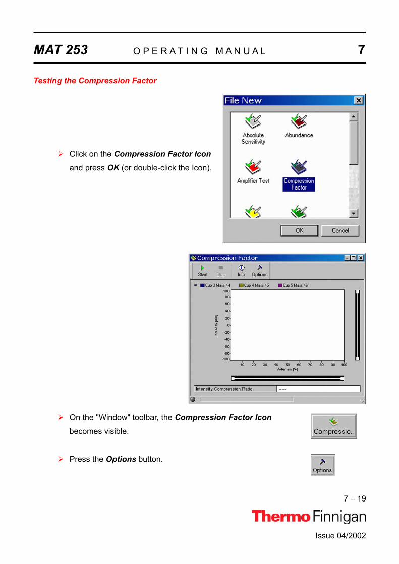
MAT 253 O P E R A T I N G M A N U A L 7
7 – 19
Issue 04/2002
Testing the Compression Factor
Click on the Compression Factor Iconand press OK (or double-click the Icon).
On the "Window" toolbar, the Compression Factor Iconbecomes visible.
Press the Options button.

MAT 253 O P E R A T I N G M A N U A L 7
7 – 20
Issue 04/2002
In Standard Mode, you are only able to select a
channel from the pulldown menu.
In Advanced Mode, also the other variables can
be edited:
Integration time [ms],
Steps: the volume of the bellows is varied
stepwise, e.g. in 10 steps,
Delay [ms]: the measurement start is delayed
by the displayed value.
Finally, press OK.
Press the Start button.
Testing starts with a Peak Center for the
first bellow (e.g. Sample).

MAT 253 O P E R A T I N G M A N U A L 7
7 – 21
Issue 04/2002
When the Peak Center is finished,
signal intensity is shown during the
volume change of the bellows (for
the different masses).
Finally, the Intensity-Compression
ratio is calculated for the first
bellow, e.g. Sample.
The procedure is repeated for the second
bellow (e.g. Standard): a Peak Center is
performed.

MAT 253 O P E R A T I N G M A N U A L 7
7 – 22
Issue 04/2002
The procedure is repeated for the
second bellow (e.g. Standard).
When the Peak Center is
finished, an Intensity vs. Volume
diagram for the different masses
is shown. Finally, the Intensity
Compression ratio is calculated
for the second bellow (e.g.
Standard).
When closing the "Compression
Factor" window you are asked,
whether to save the changes.

MAT 253 O P E R A T I N G M A N U A L 7
7 – 23
Issue 04/2002
7.2.5 LINEARITYAt Linearity test, synonymously called Ratio Linearity, over a range of varying signals, signal
linearity is checked vs. beam intensity (i.e. intensity of the main ion current). The signal inten-
sity is measured, and the isotope ratios are displayed vs. beam intensity. Linearity is calcu-
lated as slope of the regression line [‰/V]. The ratios are monitored between 2 V and 8 V in
1 V steps. For each data point, the background is subtracted.
Source of error: Resistor values must be configured correctly.
Testing Linearity
Click the Linearity Icon and press OK
(or double-click the Icon).

MAT 253 O P E R A T I N G M A N U A L 7
7 – 24
Issue 04/2002
On the "Window" toolbar, the Linearity Icon becomes visible.
Press the Options button.
From the pulldown menus select:
a channel and a value between 100 ms and
20000 ms for "Delay [ms]".
The other variables are preset in Standard Mode (to
be accepted), but editable in Advanced Mode:
Integration time [ms], Start [mV], Stop [mV] Step width
[mV], V-Window [mV]
Adjust Manual: activate it, if the intensities (i.e.
voltage steps) between 2 V and
8 V are to be set manually.
Finally, press OK.
Press the Start button.

MAT 253 O P E R A T I N G M A N U A L 7
7 – 25
Issue 04/2002
Testing starts with a Peak Center on cup 3
as the narrow cup.
If no peak could be found, the measure-
ment will be terminated.
Two linearity values
[‰/V] are calculated: one
for mass 45/44 and one
for mass 46/44.
NOTE: Linearity must be less than 0.06 ‰/V!

MAT 253 O P E R A T I N G M A N U A L 7
7 – 26
Issue 04/2002
Press the Info button.
Mean and slope values are displayed.
MAT 253 O P E R A T I N G M A N U A L 7
7 – 27
Issue 04/2002
7.2.6 PEAK FLATNESSAs slope of the peak plateau, Peak Flatness reflects the quality of the ion stream. A correction
is necessary to eliminate effects of descending peak plateau with increasing high voltage.
This is done by measuring the peak twice - first with increasing and then with decreasing high
voltage. The resulting peak represents the mean values of both runs. The measured intensity
is a function of the acceleration voltage (i.e. ion energy). Therefore, during a high voltage
scan the intensity is slightly affected by this effect. To overcome this an "energy correction" is
performed. The ion intensity on top of the peak (i.e. at a parameterized mass range around
the center) is measured. Peak Flatness can be determined for different gases and different
collector cups (e.g. for a CO2-peak at mass 45 at Cup 2).
Two results are obtained:
Maximal intensity deviation divided by the intensity
Slope of the regression line [1/Da]
Differences to ISODAT OldSlope of the regression line as additional result Dividing System Stability by this slope yields a measure for Signal Stability with re-
spect to high voltage or magnet current instabilities.
It is complementary to the Diagnosis parameter Signal Stability that is also sensi-
tive to emission fluctuations.
Parameterized mass range In ISODAT Old, a certain proportion of the peak top (30%) is used instead of a pa-
rameterized mass range. However, to know how much the measurement is af-
fected by a certain system drift, remember that this is a proportion of mass scale
rather than of cup width. The default mass range is set in such a way that the final
result is comparable to the one of ISODAT Old using a typical cup width.

MAT 253 O P E R A T I N G M A N U A L 7
7 – 28
Issue 04/2002
Testing Peak Flatness
Click on the Peak Flatness Icon and press
OK (or doubleclick on the Icon).
On the "Window" toolbar, the Peak Flatness Icon becomes visible.
Press the Options button.

MAT 253 O P E R A T I N G M A N U A L 7
7 – 29
Issue 04/2002
Accept the defaults or from the pulldown menus, select
a Channel and a Delay value between 100 ms and
20000 ms.
Accept the default, or choose an appropriate Peak
Width value by the < or > buttons.
If you simply want to accept the Peak Detection
parameters without a glance, do not press the PeakParameter button. Instead, click OK.
However, as a sophisticated user, you may want to look
at the Peak Detection parameters. To do so, press the
Peak Parameter button.
Change the values according to your needs.
Then click OK.
Press the Start button.

MAT 253 O P E R A T I N G M A N U A L 7
7 – 30
Issue 04/2002
Testing starts with a Peak Center on the
selected cup (e.g. mass 45, cup 3).
If no peak can be found, the measurement
will be stopped.
In this case, press Cancel to proceed.
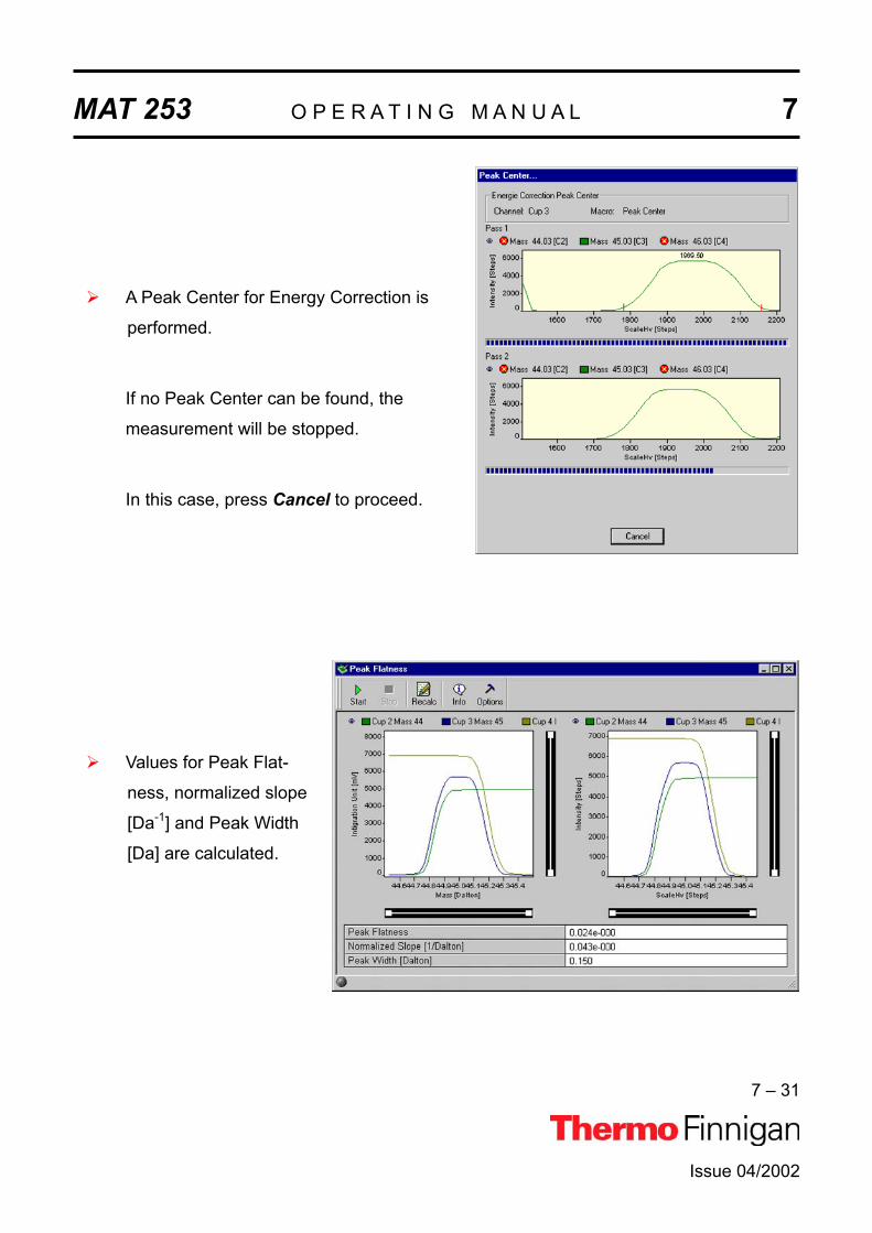
MAT 253 O P E R A T I N G M A N U A L 7
7 – 31
Issue 04/2002
A Peak Center for Energy Correction is
performed.
If no Peak Center can be found, the
measurement will be stopped.
In this case, press Cancel to proceed.
Values for Peak Flat-
ness, normalized slope
[Da-1] and Peak Width
[Da] are calculated.

MAT 253 O P E R A T I N G M A N U A L 7
7 – 32
Issue 04/2002
Press the Graphic tab to view relevant data.
Press the Graphic 2 tab to view relevant data.
When closing the "Peak Flatness"
window you are asked whether to
save the changes.

MAT 253 O P E R A T I N G M A N U A L 7
7 – 33
Issue 04/2002
RU
pSrel
169.01=
7.2.7 RELATIVE SENSITIVITYRelative Sensitivity (Srel) describes the dependency of signal intensity (i.e. ion current) on the
ion source pressure and is thus given in A/mbar:
where:
U: voltage measured at the amplifier of the collector cup (e.g. Cup 3, mass 44)
R: resistor value (e.g. 3 * 108 for mass 44). This value is the same for N2 and
CO2 as reference gases. It needs to be changed in special cases only.
p: pressure difference between a measurement with and without reference gas.
0.69: correction factor for CO2. The ion gauge is calibrated with N2, however, which
has a different ionizing probability. The correction factor takes this into account.
To calculate it, intensities (i.e. ion currents) and pressures are measured with
and without reference gas.
NOTE: Two different Relative Sensitivity values exist depending on whether the in-strument is equipped with a differential pumping system or not. The differ-ence is due to different pressure readings at the same flow. The Absolute Sensitivity (given in molecules/ion) however, is the same.
After a cycle of e.g. three measurements and calculations of Relative Sensitivity, a mean
value is displayed. This value should be about 0.2 A/mbar for a standard system and about
0.5 A/mbar in case of a differentially pumped system. They depend on the pumping capacity
of the turbomolecular pumps. Each cup (i.e. each mass) is characterized by a Relative Sensi-
tivity value of its own.
Different values of Relative Sensitivities can only be compared, if pumping speed, conduc-
tance, location of the ion gauge etc. are identical. Therefore, it is senseless to compare dif-
ferent types of instruments.

MAT 253 O P E R A T I N G M A N U A L 7
7 – 34
Issue 04/2002
Sources of error
Resistor values must be configured correctly.
Relative Sensitivity depends on the accuracy of the high vacuum pressure gauge’s
accuracy, which is limited.
Testing Relative Sensitivity
Click the Relative Sensitivity Icon and
press OK (or double-click the Icon).
The cups with the corresponding masses and resistor values are shown.

MAT 253 O P E R A T I N G M A N U A L 7
7 – 35
Issue 04/2002
On the "Window" toolbar, the Relative Sensitivity Icon becomes visible.
Press the Options button.
Press OK.
Experienced users can change the values via the
Advanced Mode.
Click the Start button.
Finally, for each cup, the values of three cycles and their mean are displayed.
When closing the "Relative Sensi-
tivity" window you are asked,
whether to save the changes.

MAT 253 O P E R A T I N G M A N U A L 7
7 – 36
Issue 04/2002
7.2.8 RESOLUTION
Resolution describes the masses, which can be separated from each other (i.e. the minimal
relative distance between two masses, which can be resolved). Different definitions of resolu-
tion are used in mass spectrometry.
The 10% valley definition, commonly used for dou-
ble focusing sector field mass spectrometers,
means:
Resolution can be defined as:
1 Mass divided by the mass difference of two neighboring peaks, if the valley between
the peaks drops to 10% of the peak height, or as
2 Mass divided by the peak width (in Dalton) at 5% of peak height.
According to the 10% valley definition, it is dimensionless (given in m/ m):
mmR
∆=
where:
R: Resolution
m: Mass of the interesting isotope
m: Mass difference between neighboring peaks
In Dual Peak mode, the distance between Peak Centers of two neighboring peaks is meas-
ured [Da]. The peak width of one peak is measured at 5% peak height.
In Single Peak mode, the distance between neighboring peaks is set to 1 Da. In both
modes, Resolution can be calculated as follows (the mass difference is usually 1 Da):

MAT 253 O P E R A T I N G M A N U A L 7
7 – 37
Issue 04/2002
ba
mmR
∆=
where:
a: distance between peak centers
b: peak width of the isotope of interest
Resolution is determined using the narrowest cup (i.e. usually Cup 2). Mass 45 is used.
Example
For a resolution of 88 and mass 44, a peak with a distance of (44/88) Da = 0.5 Da could be
resolved using the 10% criterion.
Start mass and end mass of the magnetic field scan can be edited. In case of CO2, the mass
ranges from about 43 to 45.5. The BDAC values referring to the masses 44 and 45 are de-
termined and the Resolution is calculated.
Testing Resolution
Click on the Resolution Icon and press OK(or double-click the Icon).
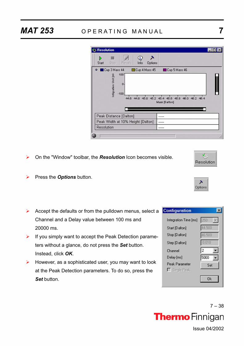
MAT 253 O P E R A T I N G M A N U A L 7
7 – 38
Issue 04/2002
On the "Window" toolbar, the Resolution Icon becomes visible.
Press the Options button.
Accept the defaults or from the pulldown menus, select a
Channel and a Delay value between 100 ms and
20000 ms.
If you simply want to accept the Peak Detection parame-
ters without a glance, do not press the Set button.
Instead, click OK.
However, as a sophisticated user, you may want to look
at the Peak Detection parameters. To do so, press the
Set button.

MAT 253 O P E R A T I N G M A N U A L 7
7 – 39
Issue 04/2002
Change the values or accept the defaults.
Then click OK.
Press the Start button.
Testing starts with a Peak Center on the se-
lected cup (e.g. mass 45, cup 3).
If no peak could be detected, the meas-
urement is stopped.
If not enough peaks could be detected,
an error message occurs.

MAT 253 O P E R A T I N G M A N U A L 7
7 – 40
Issue 04/2002
Finally, the values of Peak Distance [Da], Peak Width at 10% Height [Da] and Resolu-
tion are displayed.
Click the Info button.
Press the Graphik tab.

MAT 253 O P E R A T I N G M A N U A L 7
7 – 41
Issue 04/2002
Press the Peaks tab.
When closing the "Resolution" win-
dow you are asked, whether to
save the changes.

MAT 253 O P E R A T I N G M A N U A L 7
7 – 42
Issue 04/2002
7.2.9 SIGNAL STABILITYSignal Stability describes the stability of the intensity (i.e. peak height). The intensity on top of
the peak is measured for a limited period of time (e.g. 5 min). Note the similarity to the
System Stability, but here, the stability is not measured at the peak flank, but at the peak
center. The value of Signal Stability should be about 2*10-4 (for 5 min).
Two results are obtained:
Slope of the regression line (normalized by the intensity)
Standard deviation of the regression line (normalized by the intensity)
Testing Signal Stability requires a signal of 3 V or more!
SOURCES OF ERROR
The slope is usually due to gas consumption during measurement. However, it
should be checked, if an unusual result is obtained.
Instabilities of the emission may cause an unstable signal although a stable high
voltage and magnetic field are given.
Pressure fluctuations (check the oil of the forevacuum pumps!) or temperature
fluctuations particularly at the crimps.
DIFFERENCES TO ISODAT OLD
1. In ISODAT Old, maximum deviation is reported instead of standard deviation.
2. However, for a statistical process standard deviation is more relevant as it is less
sensitive to measuring time and outliers.
3. Conversion of results to the ISODAT Old scale: Multiplication by a factor of
approximately four.

MAT 253 O P E R A T I N G M A N U A L 7
7 – 43
Issue 04/2002
Testing Signal Stability
Click the Signal Stability Icon and press
OK (or double-click the Icon).
On "Window" toolbar, the Signal Stability Icon becomes visible.
Press the Options button.

MAT 253 O P E R A T I N G M A N U A L 7
7 – 44
Issue 04/2002
From the pulldown menu, select a delay value between
100 ms and 20000 ms.
Click OK.
Press the Start button.
Testing starts with a Peak Center on the
selected Cup (e.g. mass 45, Cup 3).

MAT 253 O P E R A T I N G M A N U A L 7
7 – 45
Issue 04/2002
Another Peak Center is performed.
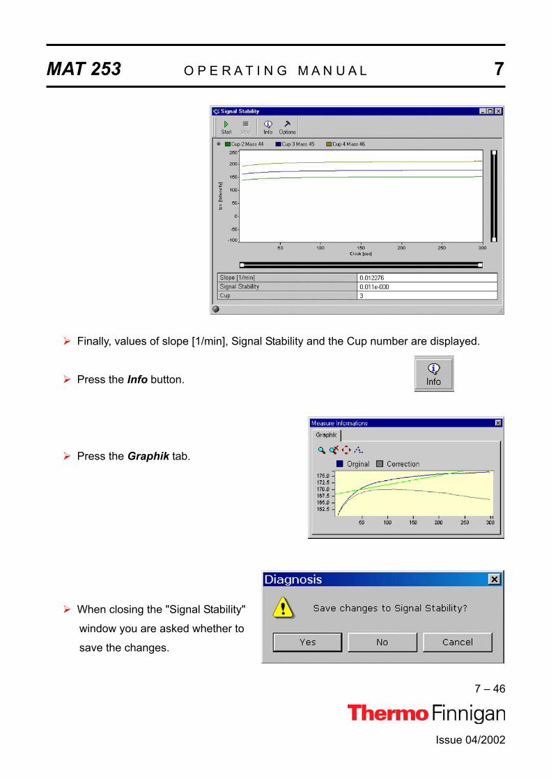
MAT 253 O P E R A T I N G M A N U A L 7
7 – 46
Issue 04/2002
Finally, values of slope [1/min], Signal Stability and the Cup number are displayed.
Press the Info button.
Press the Graphik tab.
When closing the "Signal Stability"
window you are asked whether to
save the changes.

MAT 253 O P E R A T I N G M A N U A L 7
7 – 47
Issue 04/2002
7.2.10 SYSTEM STABILITYSystem Stability informs about high voltage stability and thus magnetic field stability. Already
small variations of high voltage or magnetic field dramatically influence signal intensity: They
cause peak shifts. The fluctuations of high voltage or the magnetic field strength are meas-
ured at the peak flank, because they exert a much higher impact on peak intensity at the
flank than on top.
The System Stability test comprises the following steps:
Determination of peak center and peak flanks
Set magnetic field to 50% of peak height (at the peak flank).
Measurement of signal intensity (high voltage fluctuation) at the peak flank for a de-
fined period of time (e.g. 15 min).
New peak center procedure
Calculation of System Stability [min-1] and Relative Mass Drift [min-1] (either elec-
tronic or to magnetic drift) using the slope of the peak flank.
Testing System Stability requires a signal of 3 V or more!
Two results are obtained:
1. Slope of relative mass drift vs. time (time drift)
2. Standard deviation of this slope (scatter of the mass)
A value of 5*10-4 measured for a period of 15 min reflects a good System Stability.

MAT 253 O P E R A T I N G M A N U A L 7
7 – 48
Issue 04/2002
Differences to ISODAT Old
The slope is a new, but important parameter, as it shows the effect of slow fluctua-
tions in temperature, supplied voltage etc.
In ISODAT Old, maximum deviation is reported instead of standard deviation.
However, for a statistical process, standard deviation is more relevant as it is less
sensitive to measuring time and outliers.
Conversion of the Results to the ISODAT Old scale: multiplication by a factor.
Testing Signal Stability
Click the System Stability Icon and press OK(or double-click the Icon).

MAT 253 O P E R A T I N G M A N U A L 7
7 – 49
Issue 04/2002
On the "Window" toolbar, the System Stability Icon becomes visible.
Press the Options button.
If you simply want to accept the Peak parameters
without glancing at them, do not press the PeakParameter button. Instead, click OK.
However, as an experienced user, you may want to look
at the Peak parameters. To do so, press the PeakParameter button.
Experienced users may further want to change the gray
default values (from Integration Time to Scan Time).
This can be achieved via the Advanced Mode.
Make your changes or accept the defaults.
Then press OK.

MAT 253 O P E R A T I N G M A N U A L 7
7 – 50
Press the Start button.
Testing starts with a Peak Center on the
selected Cup, e.g. mass 45, Cup 3.
Issue 04/2002

MAT 253 O P E R A T I N G M A N U A L 7
7 – 51
Testing continues with another Peak
Center on the selected Cup.
Finally, values for System Stability [min-1] and Relative Mass Drift [min-1] are displayed.
Issue 04/2002

MAT 253 O P E R A T I N G M A N U A L 7
7 – 52
Issue 04/2002
Press the Info button.
Pressing the Graphik tab, the
diagram for calculating Slope and
Mass Drift is shown together with
the respective values.
When closing the "System
Stability" window you are asked
whether to save the changes.

MAT 253 O P E R A T I N G M A N U A L 7
7 – 53
Issue 04/2002
7.3 CONVERSION TO OTHER GASESDepending on the number of collector cups installed it may be necessary to switch the
feedback resistor of an amplifier when intending to analyze different gases. This is done
automatically. An example of a collector assignment with six cups is given below:
Example: Assignment of a collector with six cups (i.e. MEMCO 6)
MeasuringChannel
1 2 3 4 5 6
VF-converter 1 2 3 4 5 6
element and mass
N2 28 29 30
CO2 44 45 46
SO2 64 66
With this combination, there is no need to switch the feedback resistors when changing from
CO2 analysis to N2 analysis. The switching is done automatically by ISODAT NT changing
the cup configuration. Only in case of switching to SO2 analysis, it is necessary to switch the
amplification factor (done automatically by switching the Gas Configuration).

MAT 253 O P E R A T I N G M A N U A L 7
7 – 54
Issue 04/2002
7.4 HEATING INLET CAPILLARIES
NOTE: The heating system can be regulated via ISODAT NT.
NOTE: ISL Scripts can be used to create time programs for the heating process
If a contamination of the instrument is detected, also the inlet capillaries should be heated.
Together with the instrument, a transformer (90VA / 220V/ 7. 7 V/12 A) is supplied for heating
purposes. To heat all capillaries simultaneously, it is advisable to acquire additional heating
transformers.
Step 1 Before heating the capillary itself, the surrounding of the capillary has to be
heated to approximately 80 °C for about 30 to 60 minutes, i.e. the valves of the
inlet system (incl. the valves of a Multiport, if in use), the changeover valve, the
ion source and the analyzer housing.
During the heating period, all valves must be open. Swagelok connectors should
be heated separately for a short while using a flame or a heat gun.
Step 2 Plug two cables parallel to one socket of the transformer and clip on the ends with
the alligator clips to each end of the capillary to be heated or to the related
Swagelok connector.
Plug the third cable to the second socket and connect the clip to the middle of the
capillary. Capillaries supplied by Thermo Finnigan MAT have a metal sleeve at-
tached in the middle providing better electrical contact.
CAUTION: After the capillary has been wired make sure, the capillary (with or without insulation) has no contact to any plastic surface of hoses, housings, ca-bles etc. to avoid melting or smoldering caused by a hot capillary.
Step 3 Connect the transformer to the mains and switch it on. The heating phase should
be controlled by monitoring the signal intensity of H2O (mass 18, measured on the
channel for mass 45; see “Instrument Control”).
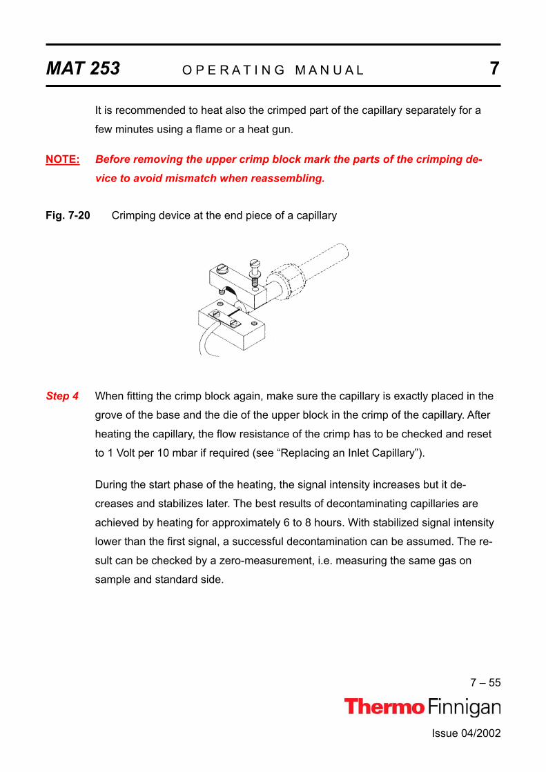
MAT 253 O P E R A T I N G M A N U A L 7
7 – 55
Issue 04/2002
It is recommended to heat also the crimped part of the capillary separately for a
few minutes using a flame or a heat gun.
NOTE: Before removing the upper crimp block mark the parts of the crimping de-vice to avoid mismatch when reassembling.
Fig. 7-20 Crimping device at the end piece of a capillary
Step 4 When fitting the crimp block again, make sure the capillary is exactly placed in the
grove of the base and the die of the upper block in the crimp of the capillary. After
heating the capillary, the flow resistance of the crimp has to be checked and reset
to 1 Volt per 10 mbar if required (see “Replacing an Inlet Capillary”).
During the start phase of the heating, the signal intensity increases but it de-
creases and stabilizes later. The best results of decontaminating capillaries are
achieved by heating for approximately 6 to 8 hours. With stabilized signal intensity
lower than the first signal, a successful decontamination can be assumed. The re-
sult can be checked by a zero-measurement, i.e. measuring the same gas on
sample and standard side.

MAT 253 O P E R A T I N G M A N U A L 7
7 – 56
Issue 04/2002
7.5 REPLACING AN INLET CAPILLARY
Replacement of an inlet capillary may become necessary in case of contamination or me-
chanical damage. After replacement, the flow rate of the new capillary has to be set by
crimping. The crimping device consists of two metal blocks. The base is attached to the end
piece of the new capillary, which has to be fitted to the changeover valve. The second block,
to be bolted on top of the base block, holds a metal pin in a spacing, which will squeeze the
capillary when bolting the two blocks together. To replace a capillary proceed as follows:
NOTE: Make sure that all valves are closed before venting the surrounding area of the capillary, which is to be exchanged.
Step 1 Vent the parts of the inlet system and the changeover valve, which are connected
by the capillary.
Step 2 Loosen the Swagelok fittings holding both end pieces of the capillary to be ex-
changed. New capillaries are delivered with close ends. Use a diamond file to cut
a capillary end at opposite sides before breaking off the tip. Then smoothen the
end of the capillary.
Step 3 Fasten the end pieces of the new capillary with the Swagelok connectors. The
end piece with the crimp block has to be connected to the changeover valve. Fas-
ten the upper crimp block loosely onto the base with the capillary.
Step 4 Pump out the inlet system.
Step 5 Admit a proper amount of CO2 into the inlet system, so that the storage reservoir
pressure is about 20 mbar on both sides of the capillary.
Step 6 Start ISODAT NT’s Instrument Control.

MAT 253 O P E R A T I N G M A N U A L 7
7 – 57
Issue 04/2002
Activate the Scanwindow by a click
on its frame.
Select Tune Scan.
Press the Start Scan button.
Step 7 Tighten the screws of the crimp block carefully and squeeze the capillary until the
output signal reaches 1 Volt per 10 mbar with CO2 used for measurement.
Step 8 After crimping the capillary has to be heated (see Chapter 7.2.12 “Heating Inlet
Capillaries”).


Issue 4/2002
MAT 253
OPERATING MANUAL
TECHNICAL INFORMATION


MAT 253 O P E R A T I N G M A N U A L 8
8 – 1
8.1 INTRODUCTIONThis chapter contains information required for maintenance and repair of the MAT 253 mass
spectrometer. It also includes schematic drawings and spare parts lists as well as instructions
for the installation of various hardware drivers.
8.1.1 GENERAL REMARKSThe MAT 253 mass spectrometer contains elaborate and expensive components. Only quali-
fied and skilled personnel, therefore, should perform servicing. It is recommended that the
Thermo Finnigan MAT service by called if there are any uncertainties or if difficulties arise. It
is further recommended to use original Thermo Finnigan MAT spare parts only. Note that
many adjustments can be made only by the use of special tools and instruments, which are
not supplied with the system. (See for references within the manuals.)
Before starting maintenance and repair, please read the appropriate chapters of the manuals.
Before calling the Thermo Finnigan MAT service, please try to localize the defect! A precise
description of the defect will ease the repair and reduce the costs.
WARNING: Some parts of the MAT 253 mass spectrometer are at dangerously high voltages! Therefore, opening the electronics cabinet is only allowed formaintenance purposes by qualified service personal.
CAUTION: When replacing fuses, only use the correct types! Be careful when servicing the vacuum system. Abrupt opening to atmos-phere might destroy the filament or damage the collector system and other expensive parts.
When working with solvents might and sample residuals, please consider your re-gional safety instructions!
Issue 04/2002
MAT 253 O P E R A T I N G M A N U A L 8
8 – 2
8.1.1.1 MAINTENANCETo maintain optimum mass spectrometer performance, the user must perform routine preven-
tive maintenance. Please, see chapter 8.3 of this manual.
8.1.1.2 SPARE PARTS LISTSIn the diagrams attached to the spare parts lists, the individual spare parts are shown with
item numbers. The parts are classified by these item numbers in the corresponding lists and
provided with a designation and a part number.
When ordering a part, always give the designation and the part number. Please, also provide
the service number of the instrument in question. In this way, the processing of your order will
be expedited.
8.1.1.3 SERVICE INSTRUCTIONSWherever necessary, service instructions supplement the spare parts lists.
8.1.1.4 REPAIR REQUEST FORMSIf parts are to be returned to the factory for repair, please fill in the repair request form and
enclose it with the shipment. In this way, you will help to avoid delays frequently caused by
inquiries, which become necessary if parts are returned to us without reference to the instru-
ment to which they belong or without any details about the faults observed.
8.1.1.5 SHIPMENT LISTSBecause of our modular instrument concept it might happen that parts are listed which are
not supplied with your instrument. Please note that listing a part does not imply that this part
is necessary required for your particular instrument configuration.
8.1.1.6 TECHNICAL MODIFICATIONSContinuous improvement of the performance of our products may result in technical modifica-
tions.
We are always striving to have the spare parts lists up-to-date.
Issue 04/2002

MAT 253 O P E R A T I N G M A N U A L 8
8 – 3
Issue 04/2002
8.1.2 SAFETY RULES FOR THE REPAIR SERVICEThermo Finnigan MAT mass spectrometers frequently are used for analyzing materials,
which are insalubrious. In these cases, usually certain parts of the system will be contami-
nated.
To protect the health of our employees we ask you for some special precautions when return-
ing those parts for exchange or repair.
Mass spectrometer parts, which have been contaminated by hazardous materials, we can
accept only if they have been decontaminated prior to return. Hazardous materials are those
materials listed up on the MAK list (Maximale Arbeitsplatzkonzentration) and on the EPA
(Environmental Protection Agency) priority list.
Additionally such materials are enclosed which due to their structure and the applied concen-
tration might be toxic or which in publication are reported to be toxic. Finally, such materials
are concerned which in combination with other present materials will generate synergetic
hazardous effects.
Please, take care, that vacuum pumps and all other parts which had been in contact to haz-
ardous materials, will be properly decontaminated prior to return to Thermo Finnigan MAT.
Parts contaminated by radioisotopes are not subject to return to Thermo Finnigan MAT neither under warranty nor under the exchange part program. When returning parts to Thermo Finnigan MAT the use of our repair-covering letters is obliga-
tory.
Please, state by your signature on this repair-covering letter, that the returned part had been
decontaminated and is free of hazardous materials.
We hope that the analysts of our customers will understand these safety regulations.

MAT 253 O P E R A T I N G M A N U A L 8
8 – 4
8.2 INSTALLATION OF BOARD DRIVERSThe following pages contain descriptions for the installation of drivers for the various exten-
sion boards of the computer.
8.2.1 "SERIAL SOLUTIONS" COM PORT EXTENSION BOARD DRIVERThe PCI Dual RS 232 Card is already part of your computer. Its driver by "Serial Solutions
Products" makes available two additional COM Ports. Thus, install it only, if your computer is
equipped with merely one COM Port.
Install it once only, namely when you newly install your operating system.
Close all other applications! Otherwise, an error message might occur.
NOTE: If your computer hangs up during either installation or reboot, shut it down and try to install again.If your system hangs up again, plug the PCI Dual RS 232 Card to
another slot. Then only start your system without reinstallation.
To install the driver, insert the "Serial Solutions" CD into your drive and close it. The CD is
shipped with your system.
If Auto Run is deactivated on your computer, press the Startbutton and then Run. If Auto Run is activated on your computer,
proceed with Step 2 (8).
Click Browse.
Issue 04/2002

MAT 253 O P E R A T I N G M A N U A L 8
8 – 5
Issue 04/2002
Select your CD drive e.g.
"E:\Vscomdriver". From the "Files of
type" pulldown menu choose "All Files
(*.*)". Click the file "Start.html" and
then Open (or double-click
"Start.html").
Press "OK".
Wait, while the DemoShield is initializing.
On the Installation Screen, click Software.

MAT 253 O P E R A T I N G M A N U A L 8
8 – 6
Issue 04/2002
Press Current.
Click Windows NT.
Press Install.

MAT 253 O P E R A T I N G M A N U A L 8
8 – 7
Issue 04/2002
Wait, while Setup is preparing the InstallShield®
Wizard.
Carefully read the instructions about closing all
applications and copyright law. Click Next to
continue.
(If Setup has found a previously installed
version, continue as described below).
Wait, while Setup is copying the files.

MAT 253 O P E R A T I N G M A N U A L 8
8 – 8
Issue 04/2002
"Serial Solutions for Win NT" has been
installed on your computer.
Click Finish to complete Setup.
Press the House button.
Click Quit. Then reboot your system.

MAT 253 O P E R A T I N G M A N U A L 8
8 – 9
Issue 04/2002
8.2.1.1 REINSTALLING A PREVIOUSLY INSTALLED "SERIAL SOLUTIONS" DRIVER"Serial Solutions" Setup has detected a previ-
ously installed version.
Choose Re-install.
Select Yes, I want to restart my computer nowand press OK to reboot.
NOTE: If your computer hangs up during either installation or reboot, shut it down and try to install again. If your system hangs up again, plug the PCI Dual RS 232 Card to another slot. Then restart your system without reinstallation

MAT 253 O P E R A T I N G M A N U A L 8
8 – 10
Issue 04/2002
8.2.2 INSTALLING IEEE INTERFACE BOARD DRIVERSSome peripherals (e.g. equilibration unit, carbonate device) require the installation of an IEEE
board in the computer. If this is the case, follow the subsequent instructions.
1. Install "National Instruments" PCIIA IEEE Interface Card or
2. Install "National Instruments" GPIB-PCI IEEE Interface Card
8.2.2.1 "NATIONAL INSTRUMENTS" GPIB PCIIA ISA IEEE INTERFACE BOARDDo not use Disk Kit, National Instruments NI-488.2 Software!
During the installation of ISODAT NT, a driver for this interface card is installed. To run this
card under Windows NT some settings must be changed in the BIOS.
1. Therefore, restart the computer.
2. During the initial BIOS initialization phase press F1 to enter the BIOS editor. At "Ad-
vanced", the entry "Resource Configuration" becomes visible. Here, the interrupt 7 can be
locked exclusively for ISA.
3. Switch the entry from "Available" to "Reserved" (i.e. position the cursor on the line of inter-
rupt 7 and press Enter).
Interrupt 7 is normally reserved for printer.
4. Therefore, leave the "Resource Configuration" with Esc and enter the "Peripheral Con-
figuration". At the entry "Parallel Port", the subentry "Interrupt" is visible. It is normally set
to "IRQ7". After reserving the IRQ 7 for the PCIIA card, this entry shows an asterisk indi-
cating a resource conflict.
5. Change the interrupt to "IRQ5". The asterisk should disappear. Leave all other parameters
unchanged.
6. Quit the "Peripheral Configuration" Menu and the "Advanced" Menu by "Esc" and enter
"Exit" Menu.
7. Exit the BIOS editor by "Exit Saving Changes". The PCIIA card is jumpered to interrupt 7
as default.
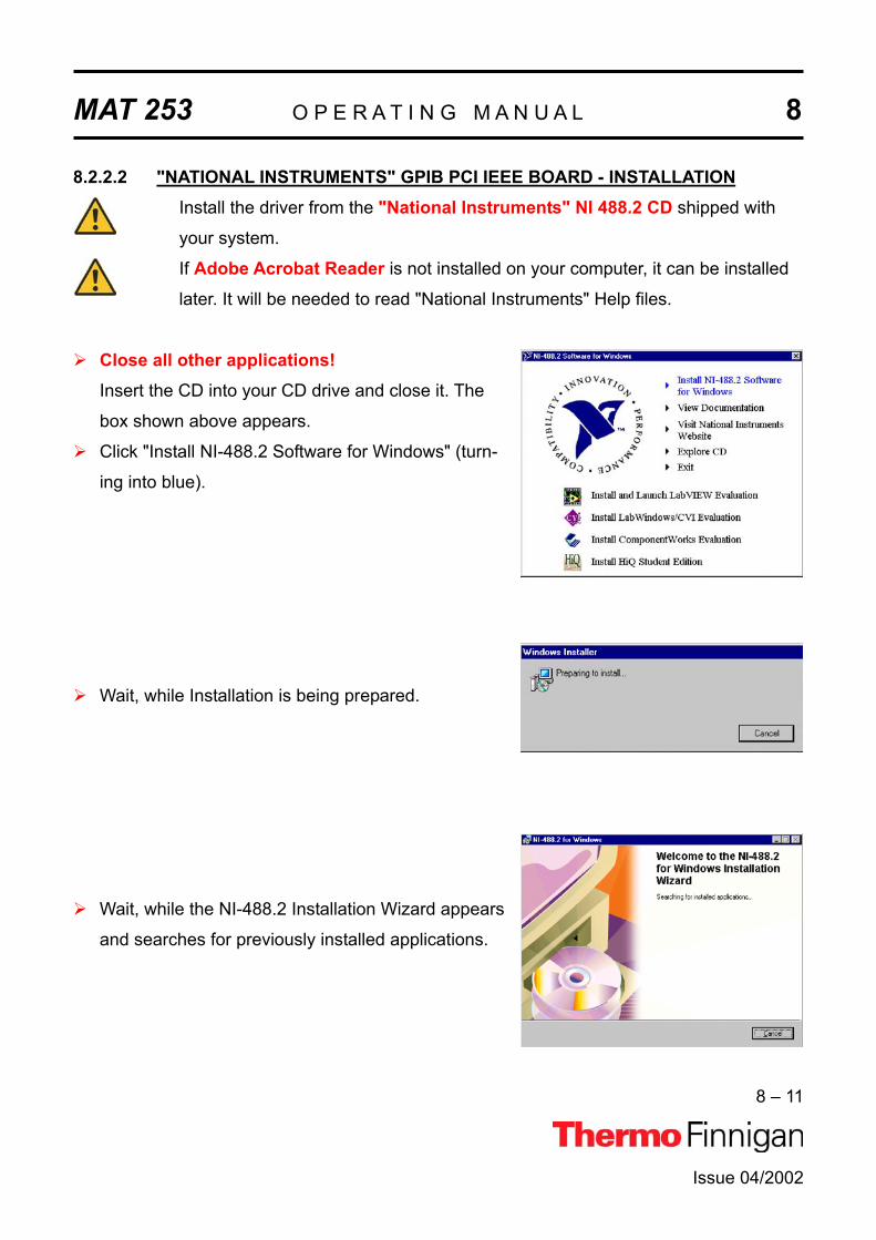
MAT 253 O P E R A T I N G M A N U A L 8
8 – 11
Issue 04/2002
8.2.2.2 "NATIONAL INSTRUMENTS" GPIB PCI IEEE BOARD - INSTALLATIONInstall the driver from the "National Instruments" NI 488.2 CD shipped with
your system.
If Adobe Acrobat Reader is not installed on your computer, it can be installed
later. It will be needed to read "National Instruments" Help files.
Close all other applications!Insert the CD into your CD drive and close it. The
box shown above appears.
Click "Install NI-488.2 Software for Windows" (turn-
ing into blue).
Wait, while Installation is being prepared.
Wait, while the NI-488.2 Installation Wizard appears
and searches for previously installed applications.

MAT 253 O P E R A T I N G M A N U A L 8
8 – 12
Issue 04/2002
Click Next.
Carefully read the "National Instruments" Software
License Agreement. To continue press Yes.
Take your registration decision. Then press Next.

MAT 253 O P E R A T I N G M A N U A L 8
8 – 13
Issue 04/2002
To select the destination directory, either accept the
proposed path and press Next or select another one
by the Browse button.
If you pressed the Browse button (8b), a box
appears. From the Location of folder pulldown
menu, choose the alternative destination folder.
Note the according entry in the Selected Path box.
Finally, press OK.
Select the Installation type.
Typical is recommended for most users, while
Custom is recommended for advanced users.
Finally, press Next.
The NI-488.2 software is now ready to be installed.
To begin the Installation press Next.

MAT 253 O P E R A T I N G M A N U A L 8
8 – 14
Issue 04/2002
Wait, while Initialization begins.
If you did not close all other applications yet (as was
recommended in 1), you are reminded to do it now:
Click on the open applications' entries right to the
Start button and close all of them.
Finally, press Retry.
Wait while Initialization is terminated.

MAT 253 O P E R A T I N G M A N U A L 8
8 – 15
Wait, while the files are copied.
Possibly, you might be reminded that Acrobat
Reader 3.0 (or higher) was not found on your sys-
tem.
It is necessary to read "National Instruments" docu-
mentation files, but you can install them later.
Press Next.
This box informs about the separate NI-VISA Instal-
lation. This will be done after this installation is fin-
ished (see chapter 8.2.2.5).
Click Next.
Issue 04/2002

MAT 253 O P E R A T I N G M A N U A L 8
8 – 16
Issue 04/2002
The NI-488.2 Software has been successfully
installed. Click Finish.
On your desktop, note the new NI-Icon.

MAT 253 O P E R A T I N G M A N U A L 8
8 – 17
8.2.2.3 "NATIONAL INSTRUMENTS" GPIB PCI IEEE BOARD - CONFIGURATIONAfter having installed the GPIB PCI driver, configure it now as shown below.
To configure it press Start >Programs > National Instruments > NI 488.2 > Getting Started.
Point with the mouse at Configure your GPIB interface and click.
On the next window, click on the Next button to
begin the Configuration.
On the following window, press the Board Typebutton.
Issue 04/2002

MAT 253 O P E R A T I N G M A N U A L 8
8 – 18
From the Board Type pulldown list on the right, select
PCI-GPIB. Press OK.
Press Configure.
Press Software >>.
On the next window, tick the
checkboxes as shown in the figure right.
Then click the OK button and confirm
with OK on the following window (see
above).
Issue 04/2002
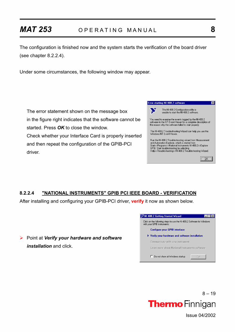
MAT 253 O P E R A T I N G M A N U A L 8
8 – 19
The configuration is finished now and the system starts the verification of the board driver
(see chapter 8.2.2.4).
Under some circumstances, the following window may appear.
The error statement shown on the message box
in the figure right indicates that the software cannot be
started. Press OK to close the window.
Check whether your Interface Card is properly inserted
and then repeat the configuration of the GPIB-PCI
driver.
8.2.2.4 "NATIONAL INSTRUMENTS" GPIB PCI IEEE BOARD - VERIFICATIONAfter installing and configuring your GPIB-PCI driver, verify it now as shown below.
Point at Verify your hardware and software installation and click.
Issue 04/2002

MAT 253 O P E R A T I N G M A N U A L 8
8 – 20
Issue 04/2002
The NI-488.2 Software, GPIB Hardware and GPIB
Interface(s) are successively being verified.
A blue mark ( ) indicates successful verification. A
red mark ( ) indicates that verification failed.
If the red mark indicates that verification of your
GPIB interface failed, press Help and finally Retest.
8.2.2.5 "NATIONAL INSTRUMENTS" GPIB PCI IEEE BOARD - VISA INSTALLATION
After having installed the NI-488.2 Software, the program "NI-Visa" will now be installed.
Close all applications!
Press the Start button on the taskbar.
Press Browse.

MAT 253 O P E R A T I N G M A N U A L 8
8 – 21
Issue 04/2002
At the "Look in" pulldown menu, select your CD
drive [e.g. Ni4882 (F:)].
Select "SetupVisa.exe" and press Open (or double-
click "SetupVisa.exe").
The path to "SetupVisa.exe" appears. Click OK.
Wait, while the Installation program is being
prepared.
You are reminded to close all applications.
To do so, if necessary, see how to exit Visa Setup.
Then press Next.

MAT 253 O P E R A T I N G M A N U A L 8
8 – 22
Issue 04/2002
If the Setup program detects previously installed NI-
Visa components, either add / remove some of them
or choose reinstall / reinstall mode.
Read the License Agreement carefully and click
"Agree" to proceed.
"Disagree" would lead to exit Visa Setup.
The Installation program proposes a destination
folder for the NI-Visa Software (e.g. C:\VXlpnp\). To
choose another folder, press the upper "Browse"
button.
In case of a previous NI-Visa installation, this button
is disabled and the NI-Visa Software will be installed
in the proposed folder.
Beneath it, another folder is proposed for the
installation of other NI Software (e.g. C:\Program
Files\National Instruments\).
To choose another folder use the lower Browsebutton. Finally, click Next.

MAT 253 O P E R A T I N G M A N U A L 8
8 – 23
Issue 04/2002
Choose a folder (for the other NI Software). In the
"Folder Name" box, the respective path is displayed.
Press OK.
To install all features select Complete(recommended usually) and press Next or use
Custom (for advanced users) to install selected
features and press Next.
To start installing the files press Next.
Wait, while the initializing takes place.
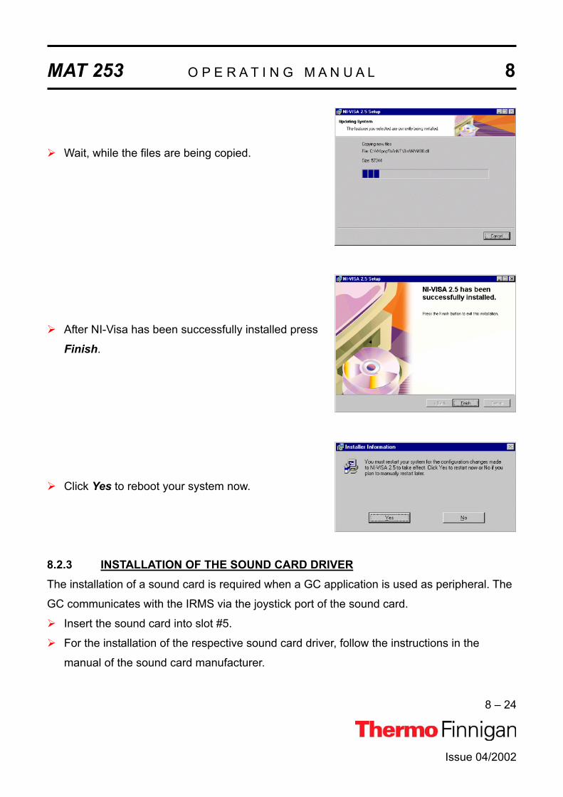
MAT 253 O P E R A T I N G M A N U A L 8
8 – 24
Issue 04/2002
Wait, while the files are being copied.
After NI-Visa has been successfully installed press
Finish.
Click Yes to reboot your system now.
8.2.3 INSTALLATION OF THE SOUND CARD DRIVERThe installation of a sound card is required when a GC application is used as peripheral. The
GC communicates with the IRMS via the joystick port of the sound card.
Insert the sound card into slot #5.
For the installation of the respective sound card driver, follow the instructions in the
manual of the sound card manufacturer.

MAT 253 O P E R A T I N G M A N U A L 8
8 – 25
Issue 04/2002
8.2.4 INSTALLATION OF THE "ANALOG JOYSTICK" DRIVERThe following GC applications additionally require the "Analog Joystick" driver. The GC
communicates with the IRMS via the joystick port of the sound card.
HP 6890 GC
Trace GC
any other "generic" GC
NOTE: The successful installation of a sound card with the appropriate driver is a prerequisite for the installation of the joystick driver.
For Joystick driver handling follow the steps below:
To install it insert the "Operating System Backup CD" and follow the steps below.
Close the appearing box via the button ( ) at the
top right corner.
Press Start > Settings > Control Panel.

MAT 253 O P E R A T I N G M A N U A L 8
8 – 26
Issue 04/2002
Double-click the Multimedia Icon.
Click the Devices tab.
Press the Add button.
Select Unlisted or updated driver and click OK.

MAT 253 O P E R A T I N G M A N U A L 8
8 – 27
Issue 04/2002
Insert the "Operating System Backup CD" containing the
driver - as was already recommended in Step 1. Type the
letter of your CD drive (e.g. e:\) and click Browse. From the
Drives pulldown list select your CD drive (e.g. e: NTWKS
40A). In the Directories pulldown list double-click the folders,
which successively lead to the Joystick drivers (e.g.
e:\drvlib\multimed\joystick\x86).
Click OK.
Click OK.
Select Analog Joystick Driver and click
OK.
If the required joystick.dll driver is already
installed:
press New to install a new driver, or press
Current to use the current driver.

MAT 253 O P E R A T I N G M A N U A L 8
8 – 28
Issue 04/2002
In both cases, the box above appears.
The different settings determine the commu-
nication of Windows with the joystick(s).
If you are unsure of which settings to use,
keep the default settings.
Then click OK.
Click Restart Now.
8.2.4.1 CALIBRATING THE JOYSTICK DRIVERAfter the installation of the Joystick driver, it must now be calibrated and finally tested.
To calibrate it, follow the steps below.
Press Start > Settings > Control Panel.

MAT 253 O P E R A T I N G M A N U A L 8
8 – 29
Issue 04/2002
Double-click on the Joystick icon.
At Joystick Configuration, select the
Calibrate button.
An error message occurs, if the joystick is
not correctly connected.

MAT 253 O P E R A T I N G M A N U A L 8
8 – 30
Issue 04/2002
To set the joystick's position, leave its handle
centered.
Then press one of the joystick's buttons.
Click Next.
To set the joystick's motion range, move the
handle in complete circles several times.
Then press one of the joystick's buttons.
The joystick has been calibrated successfully.
Click Finish to save your calibration settings.
Test the calibration.

MAT 253 O P E R A T I N G M A N U A L 8
8 – 31
Issue 04/2002
8.2.4.2 TESTING THE JOYSTICK'S CALIBRATION
Press Start > Settings > Control Panel.
Double-click on the Joystick icon.

MAT 253 O P E R A T I N G M A N U A L 8
8 – 32
Issue 04/2002
At Joystick Configuration, select the Testbutton.
An error message occurs, if the joystick is
not correctly connected.
To test the Joystick's calibration, move the
Joystick.
Click OK.
Press one of the Joystick's buttons.

MAT 253 O P E R A T I N G M A N U A L 8
8 – 33
Issue 04/2002
One of the fields is lighted red (e.g. "Button 1").
Press the other button.
The other field is lighted red (e.g. "Button 2").
Press OK.
8.2.5 GC AND AUTOSAMPLER REQUIREMENTS
8.2.5.1 HP 6890 GCGameport Interface (in the PC)
Gameport cable (ATT: modified version, two resistors)
Serial cable from PC to HP 6890 (Null Modem 2X3) - Default: COM 2

MAT 253 O P E R A T I N G M A N U A L 8
8 – 34
Issue 04/2002
8.2.5.2 TRACE GCGameport Interface (in the PC)
Gameport cable from PC to Trace GC
Serial cable from PC to Trace GC (Null Modem 2X3) - Default: COM 2
8.2.5.3 ANY OTHER "GENERIC" GCGameport Interface (in the PC)
Gameport cable from PC to any other "generic" GC (only Trigger Mode)
8.2.5.4 A200S OR PAL AUTOSAMPLERSerial cable from PC to A200S Autosampler - Default: COM 1
Cable for "GC ready" status from Autosampler to GC

MAT 253 O P E R A T I N G M A N U A L 8
8 – 35
Issue 04/2002
8.3 MAINTENANCERegular maintenance including functional checks and service routines is required to maintain
trouble free and continuous operation.
These maintenance operations are listed in the table.
Part Maintenance Operation Frequency
Rotary pump Check oil level
Exchange oil
Refer to manufacturer's in-
structions
Refer to manufacturer's in-
structions
Turbomolecular pump Exchange oil reservoir
Refer to manufacturer's in-
structions
Refer to manufacturer's in-
structions
Compressed air service unit Check oil level
Drain condensate and clean
filter
Monthly
If required
Safety circuit Check function Every 6 months
8.3.1 BASIC RULES FOR CLEANINGDo not economize with the cleaning agent! Renew the cleaning bath frequently.
Method of checking highly volatile cleaning agents (cyclohexane, acetone): Dip a polished
metal plate into the bath and take out again so that as much liquid as possible remains be-
hind on the plate (preferable bend the plate to a concave shape). Allow the bath liquid to
evaporate. No residue should be left on the plate. Otherwise, change the bath liquid.
(Use slightly contaminated bath liquids for preliminarily washing severely contaminated
parts!).
Do not rinse with water if using volatile cleaning agents!

MAT 253 O P E R A T I N G M A N U A L 8
8 – 36
Issue 04/2002
Rinse with a lot of water if using cleaning agents in aqueous solution! Use warm water, finally
rinse with distilled (or de-ionized) water!
Dry the parts, which have been rinsed in water, well in a dust free area, preferably in a vac-
uum drying oven! In the case of drying ovens with forced air circulation, the air must be free
of dust. If necessary, wrap the parts loosely in tissue paper and place them in the oven.
Because contaminations on ceramic parts consist of evaporated-on metal layers, they cannot
be removed with volatile cleaning agents. For this reason, use a high percentage aqueous
solution of RBS 50 (Trade name of the firm Carl Roth, Karlsruhe).
The use of an ultrasonic bath increases the probability of a successful removal of the con-
taminations.
Even with RBS 50, a successful removal of contaminations from ceramic parts may not al-
ways be possible. In this case, replace these parts by new ones.
If new parts are not available, strongly adhering layers can be removed as follows:
By filing down with a diamond file. After being filed, the parts must be washed. The dia-
mond file can easily be cleaned again with an erasing rubber.
By annealing at red heat in a propane-oxygen flame. Too high temperature may cause
distortion of ceramic parts. Therefore, avoid the white heat range!
Do not wash any parts after they have been annealed.
CAUTION: Ceramic parts, which cannot be disconnected from metal parts, must not be annealed.
When re-assembling, do not touch the washed parts with naked hands! Use non-fibrous
gloves and clean tools!
In the case of difficult assembly jobs, it may be necessary to work without gloves. Then thor-
oughly wash your hands and remove any fat or grease from the fingertips with a solvent. The
parts should then be touched only with degreased fingertips.
In order to avoid any damage to the skin, rub the fingertips over with a fatty skin cream when
the work is completed!

MAT 253 O P E R A T I N G M A N U A L 8
8 – 37
8.4 ANALYZER SYSTEMThis chapter contains drawings and spare part lists of the analyzer system. For the analyzer
control, see chapter 4.
Fig. 8 - 1 Basic Unit (Part No. 113 6000)
34
5
6
2
1
Pos. 7 not shown
Issue 04/2002
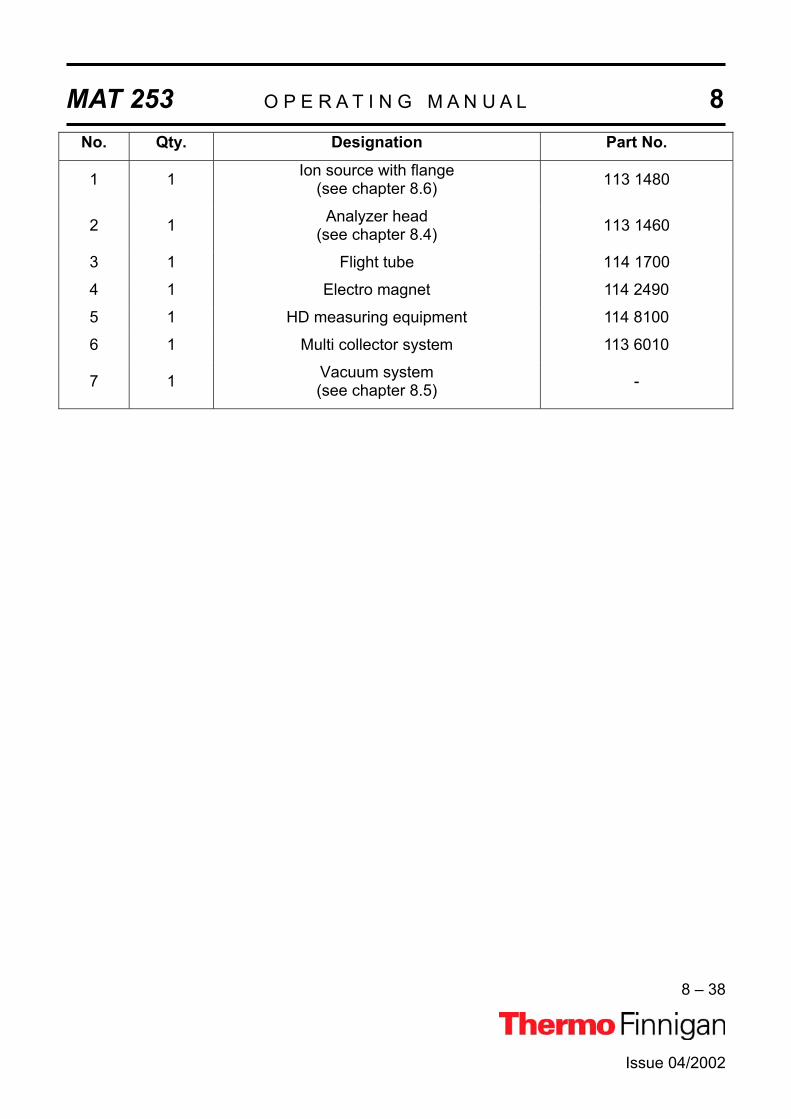
MAT 253 O P E R A T I N G M A N U A L 8
8 – 38
Issue 04/2002
No. Qty. Designation Part No.
1 1 Ion source with flange (see chapter 8.6) 113 1480
2 1 Analyzer head (see chapter 8.4) 113 1460
3 1 Flight tube 114 1700
4 1 Electro magnet 114 2490
5 1 HD measuring equipment 114 8100
6 1 Multi collector system 113 6010
7 1 Vacuum system (see chapter 8.5) -

MAT 253 O P E R A T I N G M A N U A L 8
8 – 39
Fig.: 8-2 Analyzer Head (Part No.: 113 1460)
Issue 04/2002

MAT 253 O P E R A T I N G M A N U A L 8
8 – 40
No. Qty. Designation Part No
1 1 Analyzer housing 113 1470 2 1 Source carrier 100 3540 3 1 Angle 111 84804 1 Entrance plate 100 3670 5 1 Nipple 100 35907 1 Gas inlet 111 3980 8 2 Heater 079 29909 1 Adapter 100 3570
10 1 Spacer ring, NW 32 095 1170 11 1 Gasket, gold; 49,5 NW 32 055 1700 12 8 Screw, M 6x25 DIN 933 A4 045 4380 13 8 Washer, 6,4 DIN 125 A2 047 0060 14 1 Spacer ring, NW 25 095 1250 15 1 Gasket, gold; 38 054 5270 16 8 Screw, M 5x20 DIN933 A4 045 4500 17 8 Washer; 5,3 DIN125 - 1.4301 047 0060 18 1 Spacer, NW 6 095 1600 19 1 Gasket, gold; 11,5 NW 6 055 1240 20 4 Screw, M 4x10 064 3010 21 2 Washer; 3,2 DIN 125 A4 047 0030 23 2 Screw, M 3x6 DIN 84 A4 045 0750 25 12 Washer; 8,4 DIN 125 A2 047 0070 28 1 Pin, 3x10 DIN7 A4 048 0110 29 1 Pin, 2x8 DIN7 A4 048 0050 30 1 Spacer ring, NW 100 095 1380 31 1 Gasket, gold; 117,5 NW 100 055 1600 32 12 Screw, M 8x35 DIN 931 A4 045 4400 34 1 Variable ion source conductance 055 9900 36 1 Flange sealing, DN 63 069 3220 37 1 Flange sealing, DN 100 056 9119
Issue 04/2002

MAT 253 O P E R A T I N G M A N U A L 8
8 – 41
8.5 VACUUM SYSTEMThis chapter contains remarks, drawings and spare part lists for the vacuum system.
8.5.1 GENERAL REMARKSThe final pressure should be checked daily. About 24 hours after start, without sample inflow
the pressure should be in the 10-8 mbar range.
The main reasons of troubles with the vacuum system are leaks and contaminations:
Leaks may be caused:
If flange connections and sealings are not properly treated during service operations.
Accidentally during cooling down periods after baking.
If heavily treated sealing components are worn out.
As leak detection is rather time-consuming, make sure that flange connections are carefully
and properly assembled during service.
Additionally, watch the pressure during cooling down after baking. If necessary, retighten the
flanges.
Contaminations may be caused:
By water vapor stemming from the sample preparation devices.
By use of improper elastomer gaskets especially when operated at elevated tempera-
tures. We recommended ordering spare gaskets from Thermo Finnigan MAT only.
By introducing solvents which had not been removed carefully after cleaning.
For distinguishing, whether elevated pressures are caused by leaks or by contamination, take
a background spectrum.
WARNING: Never use silicon oils or silicon greases! Silicon layers lead to surface charges and are difficult to eliminate!
8.5.1.1 FLANGES WITH METAL GASKETSBefore mounting the flange connection, make sure that the sealing surface of the flanges are
clean and that the gaskets are clean and intact.
Afterwards put the spacer ring onto the protruding edge of the flange, place the metal gasket
inside the spacer ring and insert the counter flange into the spacer ring. Make sure, that the
Issue 04/2002

MAT 253 O P E R A T I N G M A N U A L 8
8 – 42
flanges are not canted, that flanges and spacer ring are centered in the right way and have
equal distances. Then insert and manually tighten the screw. Afterwards use a wrench and
tighten the screw crosswise within at least two procedures. Check, that flanges and spacer
ring have equal distances. Stop tightening, when the flanges touch the spacer ring.
If using the metal gaskets for more than one time, do not take off the gasket from the spacer
ring. Make sure that the gaskets are not damaged. Note that the probability for leakage in-
creases with increasing use.
Note: Do not re-use a baked metal gasket.
8.5.1.2 FLANGES WITH VITON GASKETSWhen changing the Viton gasket, do not use other materials. The Viton used must be of good
and preheated quality. For this reason, we recommended to order spare gaskets from
Thermo Finnigan MAT only.
Before using the gasket, make sure that the gasket and the sealing surfaces are clean and
that the gasket surfaces are not injured. For Cleaning, wipe the gasket with clean paper. Do
not use vacuum grease, and do not clean Viton gaskets with solvents.
Note that Viton must not be operated at temperatures above 1500 °C.
8.5.1.3 PVC-HOSES OF FORE VACUUM LINESIf the hoses are contaminated by fore pump oil, replace with new hoses. Never clean PVC
hoses with solvents.
Note that PVC-hoses are sensitive to elevated temperatures. Therefore, make sure that
these hoses do not contact hot parts.
8.5.1.4 CLEANING THE VACUUM COMPONENTSCleaning the parts of the high vacuum regions is described in section 8.6 (ion source).
For cleaning parts of the vacuum region, many different methods are known.
Issue 04/2002

MAT 253 O P E R A T I N G M A N U A L 8
8 – 43
The best cleaning is obtained when using a hot ultra sonic bath.
The following recommendations should be observed:
Use pure solvents only.
When cleaning with solvents, use a hood.
Pay attention to your country's safety regulations.
After cleaning, dry the parts carefully.
Do not touch the cleaned parts with your fingers (use lint-free gloves).
8.5.1.5 LEAK DETECTIONTwo different methods are recommended:
1. Mass spectrometric leak detection can be applied if the leak permits mass spectrometer
operation (pressure 6 x 10⁻⁴ mbar). Use a container with suitable leak detection gas
(e.g. argon). Connect the reducing valve to a PVC hose and the open end of the hose to a
fine capillary (e.g. glass or metal tubing). Set the mass spectrometer to the argon peak
(m/z=40) and blow a fine argon beam onto those parts, where leaks are suspected. The
argon peak will rise when the leak has been detected.
Note that at small leaks (creeping leaks) it might last a certain time until the test gas has
entered the vacuum system. In case of very small leaks, it might be necessary to enclose
the suspicious part with a plastic sheet, to fill the plastic sheet with testing gas and to wait
for peak rising.
If the instrument is equipped with the HD collector, helium may be used as the test gas. In
this case, set the analyzer system to mass 4.
2. For leak detection in the forevacuum section, or if the pressure is too high for mass spec-
trometer operation, proceed as follows:
Use a small washing bottle with ethanol and spray a fine ethanol beam onto those con-
nections where a leak is suspected. When hitting the leak, the pressure, after a short time
of delay, will decrease at first and afterwards will increase rapidly. Use the ion gauge for
pressure reading.
Warning: Ethanol vapors are explosive. Do not smoke or handle with open fire dur-ing leak detection. After leak detection, ventilate the laboratory carefully.
Issue 04/2002

MAT 253 O P E R A T I N G M A N U A L 8
8 – 44
Issue 04/2002
8.5.1.6 ION GAUGEThe ion gauge is used for vacuum protection. As soon as the filament (cathode) of the ion
gauge is burnt out, the vacuum protected part of the mass spectrometer is turned off auto-
matically.
In this case, replace the ion gauge tube with a new one. When replacing the ion gauge tube,
take care that the filament is placed in the downward direction. Otherwise a short circuit may
occur.
A general description of cleaning, generally used parts, expendable materials and tools is
given in chapter 8.3.1.

MAT 253 O P E R A T I N G M A N U A L 8
8 – 45
8.5.2 PUMPING SYSTEMFig.: 8-3 Pumping Scheme
Issue 04/2002

MAT 253 O P E R A T I N G M A N U A L 8
8 – 46
No. Qty. Designation Part No1 1 Fore vacuum pump, DUO 005 109 7510 2 1 Vacuum gauge, Pirani 102 7320 3 1 Connection cable for pos. 2 103 9280 4 1 Turbomolecular pump, TMH 262 114 1600 5 1 Vacuum gauge, Penning 111 8320 6 1 Air cooling f. pos. 4 069 4150 8 1 Vent valve 108 4890 9 3 Centering ring, NW 16/10 052 2200 10 7 Clamping ring, NW 10/16 KF 052 1830 11 1 Blind flange 052 2090 12 1 Cross piece 100 3780 13 1 Hose 069 129014 1 Line 102 954015 1 Hose clamp 037 0190 16 2 T piece 095 3460 17 2 Hose 052 211018 4 Centering ring 052 2140 19 5 m Hose: 7 x 3.0, PVC 069023020 Hose, 13 x 3.5 069072021 1 T piece, 8 mm 052 0350 22 4 Centering ring 052 2170 23 2 Hose clamp 051 2344 24 4 Clamping ring 052 1560 25 4 Centering ring 052 2150 26 1 Flange 108 762027 1 Flange 065 262028 1 Edge sealing 069 3220 29 16 Clamping screw 102 8380 30 2 Edge sealing 056 9110 31 2 Fore vacuum pump, DUO 2.5 109 595032 1 Turbomolecular pump TMH 071 P 114 1500
Issue 04/2002

MAT 253 O P E R A T I N G M A N U A L 8
8 – 47
Fig. 8 - 4: Differential Pumping System (Part No.: 111 1121)
No. Qty. Designation Part No.
1 1 Turbo molecular pump TMH 071 P 114 1500
7 1 Air cooling for pos. 1 079 2900
9 1 Differential pressure plate 100 3710
10 1 Sealing centering ring: NW 32/40, aluminum 055 2940
11 1 Metal hose, KF NW 16 x 500 053 4500
12 2 Clamping ring, NW 10 /16 KF 052 1830
13 2 Centering ring, NW 16/10 052 2200
15 2 Screw; M 2 x 4, DIN 84 045 0690
16 2 Washer; 2,5 DIN 125 047 0090
20 1 Clamping ring 047 2510
Issue 04/2002

MAT 253 O P E R A T I N G M A N U A L 8
8 – 48
8.6 ION SOURCEThe following chapter describes the ion source connections, the removal and the insertion of
the ion source, the replacement of the filament, the disassembling of the ion source, the
cleaning procedure and the reassembly of the ion source.
The exploding views and the spare parts lists indicate the location and the ordering numbers
of the different ion source parts.
8.6.1 REMOVAL OF THE ION SOURCE1. Pull out the ion source plug on the ion source flange.
2. Unscrew the 12 bolts of the ion source flange and remove the ion source carefully, with-
out knocking against the ion source housing.
3. In case the ion source shall be removed for a longer period of time, e.g. for cleaning,
close the opening of the analyzer head by suitable means in order to prevent foreign par-
ticles from entering the ion source chamber.
8.6.2 REINSTALLATION OF THE ION SOURCEWhen the ion source section has been baked repeatedly or for a longer period at maximum
baking temperature, a new gold wire gasket must be used. In case of no baking or baking at
moderate temperature the gasket can be used repeatedly, provided it has not been damaged
during removal.
1. Inspect the gasket carefully for absence of scratches and lint.
2. Place the spacer ring (see fig. 8 - 8, pos. 5) on the flange of the analyzer head and insert
the gasket (pos. 4). Insert the source, with the inlet line connector upside, into the ana-
lyzer head. Take care that the pin in the flange points upwards. Engage this pin with the
hole of the analyzer housing. When inserted, ion source flange and making flange should
be aligned in parallel.
3. Press the ion source in the direction of the analyzer and tighten the screws hand tight.
Check for short circuits. Afterwards use a wrench and tighten the screws crosswise within
at least two procedures. Check, that flanges and spacer ring are equally spaced. Do not
proceed tightening if the flanges touch the spacer ring!
Issue 04/2002

MAT 253 O P E R A T I N G M A N U A L 8
8 – 49
8.6.3 EXCHANGE OF THE CATHODE UNITNOTE: Use lint-free gloves and clean tools for the exchange.1. Remove the ion source as described in chapter 8.6.1.
2. Unscrew the supply line K connecting plug (see fig. 8 - 6).
3. Unscrew the two cylinder screws (pos. 6, see fig. 8 - 11) and take off the magnet and the
cathode (pos. 7).
4. Insert a new cathode and the magnet.
5. Reconnect the supply lines.
6. Perform the source check as described in chapter 8.6.7.
7. Reinstall the ion source as described in chapter 8.6.2.
8.6.4 DISASSEMBLY OF THE ION SOURCE1. Preparing the disassembly:
a. Use a table with clean and smooth surface.
b. Put a white and clean paper onto this table.
c. Prepare receptacles for the small ion source parts. Separate metal and ceramic parts.
2. Remove the ion source as described in chapter 8.6.1.
3. Remove the cathode as described in chapter 8.6.3.
4. Remove the electron collector (pos.10) and the magnet (pos. 8, see fig. 8 - 11).
5. Pull off carefully the connector from the ion source and bend the lead wires somewhat
apart. Take care not to alter the curved shape of the lead wires as this facilitates correct
reconnection.
6. If not necessary, do not pull off the lead wires from the feedthrough connectors of the
flange. This will save time and will ease the later assembly.
7. Unscrew the cylinder head screws (pos.1, see fig. 8 - 8) and remove the ion source from
its supporting rods.
8. Unscrew the screws (pos. 19) and take off carefully the spacing piece (pos. 15). Pull out
the ceramic tube (pos. 22) (see fig. 8 - 10).
9. Slacken the four threaded sleeves (pos. 1) (see fig. 8 - 10).
Issue 04/2002

MAT 253 O P E R A T I N G M A N U A L 8
8 – 50
10.Pull out the four cylinder pins (pos. 5) (see fig. 8 - 11), which fix the other end of the ce-
ramic rods (pos. 2, see fig. 8 - 10) to the ionization housing (pos. 4).
11.Remove the ionization housing (pos. 4) from the ceramic rods.
12.Remove all plates from the ceramic rods.
NOTE: Remove the plates without tilting them. If the plates are tilted, it is very dif-ficult to remove them. It also gives rise to metal abrasion on the ceramic rods, which causes leakage currents between the plates. There is also the danger that the ceramic rods will break.
13.Unscrew the cylinder screws (pos.9); remove the slit (pos.13) from the ion source base
(pos.6, see fig. 8 - 9).
8.6.5 CLEANING THE ION SOURCE PARTS8.6.5.1 CLEANING THE METALLIC PARTSGrind all contaminated and discolored metal parts with fine emery paper (use 360 grain or
finer).
A chemical cleaning as described in the following must follow the mechanical cleaning de-
scribed above.
For chemical cleaning, distinguish between the different types of metallic parts:
All parts must be cleaned within a grease-dissolving bath (e.g. cyclohexane). Use a bath
temperature of about 60 °C. An ultrasonic bath will improve and accelerate the cleaning pro-
cedure.
CAUTION: Do not use ultrasonic when cleaning the ion source magnets! The basic rules for cleaning are described in chapter 8.3.1. The cleaning described there will be sufficient for all parts with minor contamination, which areout of the ion and the electron paths. Afterwards all parts made of stainless steel should be cleaned in a 30% RBS solution at 60 °C for about 1 or 2 hours. Before drying, the RBS cleaned parts must be thoroughly rinsed twice within distilled water at 60 - 70 °C. Additionally see for the basic rules of cleaning in chapter 8.3.1.
Issue 04/2002
MAT 253 O P E R A T I N G M A N U A L 8
8 – 51
CAUTION: The following parts must not be cleaned in RBS: - Parts, which are not made of stainless steel. - The ion source magnets. These parts must be cleaned with cyclohexane as described above.
After cleaning in RBS and in distilled water, the parts should be dried chemically within a
Freon bath or pure alcohol.
After chemical drying, the parts should be additionally dried by a fan or a drying oven to
eliminate solvent residuals.
8.6.5.2 CLEANING THE CERAMIC INSULATORSUse a clean diamond file for eliminating metal abrasion and evaporated films. Use this
method only for cleaning the ceramic insulator of the cathode and the electron collector.
Heavily contaminated ceramic parts may be cleaned later in RBS solution (do not use RBS
for the cathode and the electron collector).
Anneal the ceramic spacer rings to soft red heat. Use a propane/oxygen flame or a muffle
furnace for annealing (maximum temperature: 800 - 1000 °C).
CAUTION: At too high temperature (white heat) the parts may be deformed!Do not anneal ceramic parts containing metal connections like the ce-ramic rods! Do not touch annealed parts with bare fingers and prevent wetting!
8.6.6 ASSEMBLING THE ION SOURCETouch the ion source parts with clean, lint-free gloves only. Use clean tools only!
Before assembling the ion source, arrange the parts and the tools in a clear manner on white
clean paper.
1. Assemble the ion source base according to fig. 8 - 9.
2. Loosely screw on the threaded sleeves (see fig. 8 - 10, pos. 1) to the ceramic rods and
insert the rods from the lower side into the ion source base plate.
3. Pass the four ceramic rods (pos. 2) through the hoes of the ion source base (pos. 5) such
that the punched numbers are visible from above.
Issue 04/2002

MAT 253 O P E R A T I N G M A N U A L 8
8 – 52
4. Afterwards insert the spacer tubes, the ion source plates and ionization housing to the ce-
ramic rods as shown in fig. 8 - 10 and 8 - 11.
Insert the parts carefully
Avoid metallic abrasion
Spacer rings and plates must fit tightly together
The base plate, the plates and the ionization housing are numbered. The numbers
must be arranged with ascending sequence and in the same direction.
5. Turn the four ceramic rods (fig. 8 - 10, pos. 2, see) such that the slot grinded into their up-
per end is aligned with the boreholes in the ionization housing (fig. 8 - 11, pos. 4), allow-
ing the four pins (pos. 5) to be pushed in smoothly.
Tighten the four threaded sleeves carefully with the special tool contained in the instru-
ment tool kit as fast as it is necessary to have the parts of the ion source clamped firmly
together.
6. Insert the bush (fig. 8 - 10, pos. 21) into the support (pos. 18). Position the convex surface
as shown on fig. 8 - 10.
7. Slip the spring (pos. 17) over the bush (pos. 21) and then fasten the spring (pos. 17) to
the support (pos. 18) with the screws (pos. 20) and nuts (pos. 16).
8. Insert the tube (pos. 22) into the bush (pos. 21).
9. Mount the support (pos. 18) and the spacing piece (pos. 15) with the cylinder screw
(pos. 19) to the ion source base (pos. 5).
10.Assemble the parts of the electron collector pos. 11 to 15 (see fig. 8 - 11).
11.Attach the rod magnets (pos. 8) together with the electron collector resp. the filament
(pos. 7) with the cylinder screw pos. 17 and 7. Pay attention to correct polarity!
12.Screw on the four threaded rods (fig. 8 - 12, pos. 2) into the ion source base.
13.Slip the parts pos. 3 to 7 onto the threaded rods (pos. 2) and screw on the nuts (pos. 8)
(see fig. 8 - 12).
14.The ion source now must have its correct height. The distance between the base plate
and the middle of the bush part must be 60 ± 0.1 mm.
15.Connect the ion source connection leads to the pins of the source (see fig. 8 - 6). The
plugs must fit tightly onto the pins. If necessary, compress the plugs a little.
Issue 04/2002

MAT 253 O P E R A T I N G M A N U A L 8
8 – 53
Issue 04/2002
16.Connect the ion source connection leads (if they had been disconnected) to the
feedthroughs of the ion source flange (see fig. 8 - 5).
NOTE: Hold the pins of the feedthroughs with small pliers while inserting the plugs.
CAUTION: The feedthroughs contain delicate ceramics. Do not break!
8.6.7 CHECKING THE ION SOURCECarefully check the position of the connection wires. The wires must not:
contact each other,
contact the ionization housing or the ion source plates,
contact the inner walls of the analyzer head after insertion. To avoid this contact, the
wires must be inside a virtual cylinder, which is defined by the central axis of the support-
ing rods.
Use an ohmmeter and check the connection between the pins of the ion source socket and
the ion source electrodes. The schematic diagram for the ion source connection is shown in
fig. 8 - 6.
Check the filament of the cathode unit: The resistance between pin +K and -K source socket
must be about 0.1 .
The insulation resistance of the ion source plates, with respect to each other and to ground
must exceed 1012 (unless these are interconnected internally).
NOTES: The insulation resistances may be decreased by humidity. In this case, the resistance increases as soon as the ion source is evacuated and warmed up. If no ohmmeter is available for measuring such high resistances, at least check the source for short circuits. Check the gasket and the sealing surfaces of the ion source flange before inserting the ion source into the analyzer head.

MAT 253 O P E R A T I N G M A N U A L 8
8 – 54
Issue 04/2002
8.6.8 PARTS OF THE ION SOURCEFig. 8 - 5: Source Feedthroughs
Feedthrough, view from ion source
(from inside)
Feedthrough, view towards ion source
(from outside)

MAT 253 O P E R A T I N G M A N U A L 8
8 – 55
Fig. 8 - 6: Connection Schematics of the Ion Source
Issue 04/2002

MAT 253 O P E R A T I N G M A N U A L 8
8 – 56
Fig. 8 - 7: Connection Lines (Part. No. 114 7580)
1 2 3 5
6 7 8 9
16
10 11 12 11a/12a
Issue 04/2002

MAT 253 O P E R A T I N G M A N U A L 8No. Qty. Designation
1 1 Wiring connection Electron collector
2 1 Wiring connection Ionization housing
3 1 Wiring connection Extraction plate
5 1 Wiring connection Shield
6 1 Wiring connection Lens, left
7 1 Wiring connection Lens, right
8 1 Wiring connection R - plate
9 1 Wiring connection Z - deflection, above
10 1 Wiring connection Z - deflection, below
11 1 Wiring connection Einzel lens
11a 1 Wiring connection Einzel lens
12 1 wiring connectionEinzel lens
12a 1 Wiring connection Einzel lens
16 1 Wiring connection grounding plate
a 1 Bushb 1 Bush with ring
c 1 Wire, nickel 0,8 (specify length required)
NOTE: Drawings on page 8-56 do not scale. All dimensions are in mm.
8 – 57
Issue 04/2002

MAT 253 O P E R A T I N G M A N U A L 8
8 – 58
Fig. 8 - 8: Ion Source with Flange (Art. No.: 113 1480)
Issue 04/2002

MAT 253 O P E R A T I N G M A N U A L 8
8 – 59
No. Qty Designation Part No.1 2 Cylinder screw, stainless steel 045 0780
2 2 Compression spring 043 0570
3 1 Ion source, see fig. 8 - 9 to 8 - 12 113 1490
4 1 Gasket; gold, DN 100 055 1600
5 1 Spacer ring, DN 100 095 1380
6 1 Feedthrough flange, with pos. 1, 2, 4, 5, 7 to 10 046 9080
7 13 Washer; stainless steel, I.D. 8.4 047 0070
8 13 Hexagonal screw; stainless steel, M 8x 35 045 4400
9 3 Cylinder screw; stainless steel, M 3 x 6 045 0750
10 2 Cylinder screw; stainless steel, M 4 x 12 045 0810
11 2 Washer; stainless steel, I.D. 4.3 047 0940
12 34 Threaded pin 045 2330
13 17 Clamp 032 1560
14 1 Connection cable with plug 101 5650
15 2 Cylinder screw; stainless steel, M 2 x 6 045 0710
16 2 Washer; stainless steel, I.D. 2.2 047 0010
17 1 Silicon hosesupplied by the meter 034 0330
18 - Wiring connections, see figure 8 - 7 114 7580
Issue 04/2002

MAT 253 O P E R A T I N G M A N U A L 8
8 – 60
Fig. 8 - 9: Ion Source Base
Issue 04/2002

MAT 253 O P E R A T I N G M A N U A L 8
8 – 61
No. Qty. Designation Part No.1 2 Contact screw 043 9760
2 2 Connection lug with pin 050 5990
3 4 Spacer tube; ceramic, 6 x 4.2 x 4 056 0780
4 2 Supporting tube 016 8170
5 2 Cylinder screw;stainless steel, M 3 x 6
045 0750
6 1 Ion source base 043 9600
7 2 Cylinder pin;stainless steel, 2 x 18 long
048 0360
8 1 Cylinder pin; 2 x 4 long 048 0350
9 2 Cylinder screw;stainless steel, M 2 x 4
045 0690
10 2 Spacer tube; ceramic, 4 x 2.1 x 10 056 0570
11 2 Washer; stainless steel, I.D. 2.5 047 0090
12 2 Nut; stainless steel, M 2 046 0060
13 1 Slit, 0.5 mm 043 9550
Issue 04/2002

MAT 253 O P E R A T I N G M A N U A L 8
8 – 62
Fig. 8 - 10: Ion Source, Lower Part
Issue 04/2002

MAT 253 O P E R A T I N G M A N U A L 8
8 – 63
No. Qty. Designation Part No.1 4 Threaded sleeve; stainless steel, M 8 x 0.5 091 0450
2 4 Rod; ceramic, length 69.5 043 9530
3 4 Washer; stainless steel, 044 6150
4 4 Compression spring 043 0680
5 1 Ion source base -
6 1 Spacer tube with slide 079 4750
7 2 Grounding plate 043 9640
8 4 Spacer tube; quartz glass, 35.6 x 30 x 5 078 3920
9 1 Plate, z - deflection 043 9650
10 1 Plate, r - deflection 043 9620
11 1 Spacer tube; quartz glass, 35.6 x 30 x 10 078 3910
12 1 Lens 043 9540
13 1 Shield 043 9630
14* 2 Spacer tube; quartz glass, 35.6 x 30 x 2 078 3930
15 1 Holding block 043 9720
16 2 Nut; stainless steel, M 2 046 0060
17 1 Spring plate 044 6300
18 1 Support, stainless steel 043 9710
19 2 Cylinder screw; stainless steel, M 2 x 16 045 5400
20 2 Cylinder screw, M 2 x 8 045 0720
21 1 Bush, stainless steel 043 9700
22 1 Tube; quartz glass, length 23 cm 078 3900
ATTENTION: Open the spacer tube (Pos. 6) for SO2 operation!
NOTE: The parts marked with an asterisk (*) frequently break. It is recom-mended to provide for replacements before the source is opened.
Issue 04/2002

MAT 253 O P E R A T I N G M A N U A L 8
8 – 64
Fig. 8 - 11: Ion Source, Upper Part
Issue 04/2002

MAT 253 O P E R A T I N G M A N U A L 8
8 – 65
No. Qty. Designation Part No.
1 1 Extraction plate 043 9610
2* 1 Spacer tube;quartz glass, 35.6 x 30 x 2
078 3930
3 1 Cover plate 043 9680
4 1 Ionization housing 113 5710
5 4 Cylinder pin;stainless steel, 2 x 12
015 6600
6 2 Cylinder screw;stainless steel, M 2 x 6
045 0710
7* 1 Cathode unit (Filament), tungsten wire
067 2460
8 1 Source magnet (one pair) 044 8030
9 1 Magnet support 043 9820
10 1 Electron collectorwith pos. no. 11 to 15
043 9790
11 1 Collector (Trap) 043 9810
12* 2 Spacer tube;ceramic, 3.9 x 2.2 x 2
056 1180
13 1 Collector plate 043 9800
14 1 Connection lug 111 9260
15 1 Nut; stainless steel, M 2 046 0060
16 2 Spacer tube, stainless steel 043 9490
17 2 Cylinder screw;stainless steel, M 2 x 8
045 0720
NOTE: The parts marked with an asterisk (*) frequently break. It is recom-mended to provide for replacements before the source is opened.
Issue 04/2002

MAT 253 O P E R A T I N G M A N U A L 8
8 – 66
Fig. 8 - 12: Ion Source with Grounding Plates
Issue 04/2002

MAT 253 O P E R A T I N G M A N U A L 8
8 – 67
No. Qty. Designation Part No.1 1 Ion source -
2 4 Rod, stainless steel 043 9770
3 2 Grounding plate 043 9660
4* 4 Spacer tube; ceramic, 4 x 2.1 x 8 056 0760
5* 8 Spacer tube; ceramic, 6 x 4.2 x 4 056 0780
6 1 Einzel lens 043 9670
7 4 Washer; stainless steel, I.D. 2.5 044 6150
8 4 Nut; stainless steel, M 2 046 0060
NOTE: The parts marked with an asterisk (*) frequently break. It is recom-mended to provide for replacements before the source is opened.
Issue 04/2002

MAT 253 O P E R A T I N G M A N U A L 8
8 – 68
Fig. 8 -13: Connection Scheme for Lamps
Fig. 8 - 14: Connection Lines for Lamps
15 14 13
NOTE: Drawings do not scale. All dimensions are in mm.
Pos. No. Qty. Designation Part No. 1 3 Terminal, female 14 long 032 1280
2 100 cm Wire: 0.5 thick, Ni 062 0500
3 4 Capillary tube, 0.5 x 6 mm 060 5560
4 4 Wrap connection 113 2140
6 1 Connection lines, see above 114 7320
7 2 Halogen lamp 10 W, 12 V 108 5040
Issue 04/2002

MAT 253 O P E R A T I N G M A N U A L 8
8 - 69
8.7 INLET SYSTEMSFig. 8 - 15: Compressed Air Supply (Part No. 108 2520)
Pos. No. Qty. Designation Part No.
1 1 Compressed air distributor 106 8410 2 1 Compressed air service unit 052 1630 3 1 Compressed air store 049 3830
4 5 Valve control unit manifold card 108 3241
Accessory2 Swivel joint 052 1730 1 Quick connection 052 1620
6 m Hose 069 0740 4 Screw 045 21304 Washer 047 005011 Sealing ring 050 5260 5 Blind stopper 052 1950 4 Coupling compl. 067 4652
Issue 04/2002

MAT 253 O P E R A T I N G M A N U A L 8
8 - 70
Fig. 8 - 16: Basic Module Changeover (Part No. 108 2630)
V Valve unit, pos. 2
jbh
dac ge if
Pos. No. Qty. Designation Part No.1 1 Valve body 108 2620 2 4 Valve unit 065 3001
a 1 Membrane 065 3010b 1 Pressure unit 065 3050
c 1 Piston 065 3030d 1 Stamp, gold 065 3041
e 1 Cover 065 3060f 4 Screw; M 6 x 20 045 3420 g 1 Guard ring; 10 x 1 047 3430 h 8 Plate spring; 20 x 10.2 x 0.4 043 1570 i 1 Jacket ring 055 3140 j 1 Gasket; gold, 38 054 5270 k 1 Lithium fat 079 1140
3 4 Connecting fitting 070 3780 4 4 Gasket 050 52605 8 Cap nut 052 11606 8 Front ferrule 079 2800 7 8 Back ferrule 079 2810 8 1 Manifold Card 108 3241
Issue 04/2002

MAT 253 O P E R A T I N G M A N U A L 8
8 - 71
Fig. 8 - 17: Variable Volume (Part No. 108 2681)
8
7
Issue 04/2002

MAT 253 O P E R A T I N G M A N U A L 8
Pos. No. Qty. Designation Part No.
1 1 Motor, compl. 070 3330
2 1 Valve unit 108 2670
3 1 Manometer 101 6802
4 1 Capillary 067 1182
5 1 Potentiometer 070 3540
6 1 O ring 055 3180
7 1 Limit stop 070 3610
8 1 Bellows unit, small 070 3310
8 - 72
Issue 04/2002

MAT 253 O P E R A T I N G M A N U A L 8
8 – 73
Fig. 8 - 18: Micro Volume (Part No. 108 2900)
Pos. No. Qty. Designation Part No.
2 1 Valve 106 8970
3 1 Cold finger; CO2 078 3330
4 1 Cold finger; N2 078 3340
5 1 Cooling plate; CO2 041 2300
6 1 Cooling plate; N2 058 3290
7 1 Capillary tube, heatable 067 1182
8 1 Gasket; gold, 6.3 055 1010
Issue 04/2002

MAT 253 O P E R A T I N G M A N U A L 8
8 - 74
Fig. 8 - 19: Pumping Unit (Part No. 108 3300)
Pos. No. Qty. Designation Part No.
1 1 Valve body 059 3410
2 2 Valve unit 065 3001
3 2 Gasket 050 5260
Issue 04/2002

MAT 253 O P E R A T I N G M A N U A L 8
8 - 75
Fig. 8 - 20: Multiport Module (Part No. 108 3200)
Pos. 2 and 7 are not shown
Pos. No. Qty. Designation Part No.
1 2 Valve bloc 106 8770
2 1 Manometer 101 6801
3 5 Nut 052 1160
4 5 Front ferrule 079 2800
5 5 Back ferrule 0792810
6 3 Manifold card 108 3241
7 5 m Silicon hose 101 5830
Issue 04/2002

MAT 253 O P E R A T I N G M A N U A L 8
8 - 76
Fig. 8-21: Tube Cracker (Part No. 108 2840)
Pos. 2 is not shown
Pos. No. Qty. Designation Part No.
1 3 Manifold Card 109 7750
2 5 m Silicon hose 101 5830
3 2 O ring 055 2180
Issue 04/2002

MAT 253 O P E R A T I N G M A N U A L 8
8 - 77
8.7.1 AUTOCOOLFig. 8 - 22: Autocool (Part No. 049 3661)
17
Pos. 16 is not shown
Pos. No. Qty. Designation Part No.1 1 Cooling unit 079 2400 2 1 Blank flange 059 7380 3 1 Cover 059 65304 1 Insulating case 054 2830 5 1 Lifting device 060 9260 6 1 Filler cap 112 8230 7 1 Sleeve 075 48508 1 Insert 075 47109 1 Refill device 039 5441
10 1 Magnet valve, for LN2 041 413011 1 Manifold, for LN2 048 261012 1 Hose for refill box 059 9610 13 1 Screw; M 4 x 10 045 088 14 4 Nut; M 4 046 0220 15 2 Screw; M 4 x 25 045 0500 16 1 Connection cable f. trap 025 3791 17 1 Container 75 l, f. LN2 079 4700
Issue 04/2002

MAT 253 O P E R A T I N G M A N U A L 8
8 - 78
8.7.2 ACCESSORIESFig. 8 - 23: Accessories
Pos. No. Qty. Designation Part No.
1 1 Sample vial (5 ml) 100 3560
2 1 Sample vial (10 ml) 100 3840
3 1 Sample vial (200 ml) 025 4650
Issue 04/2002


Technical information contained in this publication is for reference purposes only and is subject to change without notice. Every effort has been made to supply complete and accurate information; however, Thermo Finnigan assumes no responsibility and will not be liable for any errors, omissions, damage, or loss that might result from any use of this manual or the information contained therein (even if this information is properly followedand problems still arise). This publication is not part of the Agreement of Sale between Thermo Finnigan and the purchaser of a MAT 253 system. In the event of any conflict between the provisions of this document and those contained in Thermo Finnigan's Terms and Conditions, the provisionsof the Terms and Conditions shall govern.Reference to System Configurations and Specifications supersede all previous information and are subject to revision without notice.
Worldwide represented by
Australia, Thermo Finnigan Australia Pty. Ltd, Unit 14, 38-46 South Street, P.O. Box 239, Rydalmere, N.S.W 2116 Phone +61-2-98989000
Belgium, Thermo Finnigan BVBA, Groenenborgerlaan 84, 2610 Antwerp-Wilrijk Phone +32-3-8250670
France, Thermo Finnigan France SA, Hightec Sud, 12 av. des Tropiques, ZA de Courtaboeuf - BP 141, 91944 Les ULIS Cedex Phone +33-1-69188810
Germany, Thermo Finnigan GmbH, Boschring 12, 63329 Egelsbach Phone +49-6103-408-0
Italy, Thermo Finnigan APG Italy, Strada Rivoltana, 20090 Rodano (MI) Phone +39-02-95059-1
Japan, ThermoQuest K.K., Nishi-Shinjuku Toyokuni Bldg., 2-5-8 Hatsudai, Shibuya-Ku, Tokyo 151-0061 Phone +81-3-3372-3001
The Netherlands, Thermo Finnigan BV, Druivenstraat 33, 4816 KB Breda Phone +31-76-5878722
People's Republic Thermo Finnigan Beijing Rep. Office, Room 912, Ping-an Mansion, No. 23, Finance Street, Beijing 100032 of China, Phone +86-10-66210839, -846
Spain, Thermo Finnigan S.A., Avenida de Valdelaparra 27, Edificio Alcor, planta 2, 28108 Alcobendas (Madrid) Phone +34-91-6574930
Sweden, Thermo Finnigan AB, Pyramidbacken 3, 141 75 Kungens KurvaPhone +46-8-5564 6800
United Kingdom, Thermo Finnigan Limited, Stafford House, Boundary Park, Boundary Way, Hemel Hempstead, Herfordshire HP2 7GE Phone +44-1442-233555
U.S.A., Thermo Finnigan LLC, 355 River Oaks Parkway, San Jose, CA 95134 Phone +1-408-965-6800
In countries not contained in the above list Thermo Finnigan is represented by renowned instrument distributors. Information and specifications herein are subject to revision without prior notice. Availability of components and options subject to verification by local representatives.
MANUAL HISTORY April 2002 Rev. 0 - Issue 04/2002
For additional information, please check our home page: http://www.thermo.com
Thermo Finnigan MAT GmbH is a Thermo Electron business. Copyright 2002© by Thermo Finnigan MAT GmbH. All rights reserved. Printed in Germany
MAT 253 Operating Manual - Rev. 0 - Issue 04/2002