
OPERATING & MAINTENANCE MANUAL - Impexron GMBH
36
Doc No: OMMB00196 Revision: 2 – APR 2017 Model B Valve Thermostatic valve for diverting and mixing applications Installation, Operation and Maintenance Manual
-
Upload
khangminh22 -
Category
Documents
-
view
3 -
download
0
Transcript of OPERATING & MAINTENANCE MANUAL - Impexron GMBH
Doc No: OMMB00196 Revision: 2 – APR 2017
Model B Valve Thermostatic valve for diverting and mixing
applications Installation, Operation
and Maintenance Manual


3
Table of Contents
Doc No: OMMB00196 Revision: 2 – APR 2017
Section 1
Table of Contents
Section 1 ......................................................................................... 3 Section 2 ......................................................................................... 5
2.1 Scope ................................................................................... 5 2.2 Safety ................................................................................... 5 2.3 Product support ...................................................................... 5
Section 3 ......................................................................................... 7 3.1 Overview ............................................................................... 7
3.1.1 Manual override .............................................................. 7 3.2 Features ................................................................................ 7 3.3 Valve Selection ...................................................................... 8 3.4 Identification of Model Number................................................. 8
Section 4 ........................................................................................13 4.1 Pressure Equipment Directive (PED) ........................................13 4.2 Hazardous Areas ...................................................................14
4.2.1 Hazardous Area Directive (ATEX) .....................................14 4.2.2 Special conditions for Safe Use ........................................16
4.3 Machinery Directive ...............................................................16 Section 5 ........................................................................................17
5.1 Installing the valve ................................................................17 5.1.1 Before starting installation ..............................................17 5.1.2 Mounting the Valve in the Pipe ........................................18 5.1.3 Start up ........................................................................18
Section 6 ........................................................................................19 6.1 Operation .............................................................................19
6.1.1 Diverting applications .....................................................20 6.1.2 Mixing applications .........................................................20 6.1.3 Manual override (if fitted) ...............................................21
Section 7 ........................................................................................23 7.1 Dismantling the valve ............................................................24 7.2 Reassembling the valve ..........................................................25 7.3 User maintenance parts .........................................................26
Section 8 ........................................................................................29 8.1 System temperature too cold ..................................................29 8.2 System temperature too hot ...................................................29
Section 9 ........................................................................................31 9.1 General valve specification .....................................................31
9.1.1 Materials .......................................................................31 9.1.2 Maximum working pressure (bar) ....................................31 9.1.3 Maximum working temperature .......................................31 9.1.4 Valve handling ...............................................................32 9.1.5 Storage ........................................................................32

4
Table of Contents
Revision: 2 – APR 2017 Doc No: OMMB00196
5
Introduction
Doc No: OMMB00196 Revision: 2 – APR 2017
Section 2
Introduction
2.1 Scope
This manual details the installation, operation and maintenance of the AMOT Model B Valve range.
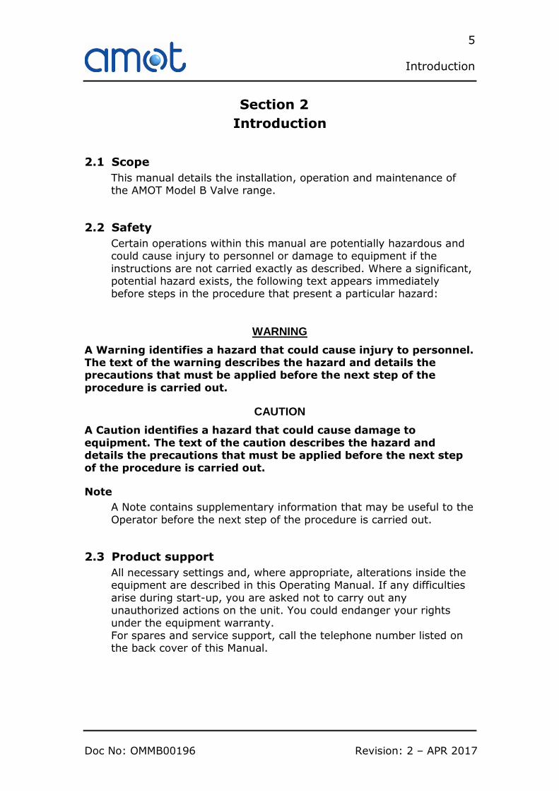
2.2 Safety
Certain operations within this manual are potentially hazardous and could cause injury to personnel or damage to equipment if the
instructions are not carried exactly as described. Where a significant, potential hazard exists, the following text appears immediately before steps in the procedure that present a particular hazard:
WARNING
A Warning identifies a hazard that could cause injury to personnel. The text of the warning describes the hazard and details the precautions that must be applied before the next step of the
procedure is carried out.
CAUTION
A Caution identifies a hazard that could cause damage to
equipment. The text of the caution describes the hazard and details the precautions that must be applied before the next step of the procedure is carried out.
Note
A Note contains supplementary information that may be useful to the
Operator before the next step of the procedure is carried out.
2.3 Product support
All necessary settings and, where appropriate, alterations inside the equipment are described in this Operating Manual. If any difficulties
arise during start-up, you are asked not to carry out any unauthorized actions on the unit. You could endanger your rights
under the equipment warranty. For spares and service support, call the telephone number listed on the back cover of this Manual.

6
Introduction
Revision: 2 – APR 2017 Doc No: OMMB00196

7
Description
Doc No: OMMB00196 Revision: 2 – APR 2017
Section 3
Description
3.1 Overview
The Model B Valve is designed to provide fully automatic, 3-way fluid temperature control for diverting or mixing applications. Typical applications include engine water jackets, lubricating oil cooling
systems, and mixing and diverting of fluids in process control and industrial applications.
The thermostatic element (also referred to as ‘element’) in a Model B valve is fully enclosed and factory set, providing tamper-proof operation. For maintenance or to achieve a different set temperature
the element can be changed, although this requires removal of the valve from its pipe work except the Model 8B Valve where the
elements are accessible whilst the valve is in position. Elements are available with set temperatures from 13 to 116°C (55 to 240°F). Valves are available in nine sizes, and a variety of materials to suit
different fluids.
3.1.1 Manual override
As an option, Model B Valves can be fitted with a manual override, which allows the operator to drive the elements towards the
maximum cooling position. On the larger sizes with multiple elements, each has its own override. Manual override should only be
used in emergencies; however on valves with multiple elements sometimes one element can be locked partially open to prevent the cooler from freezing and to change operating temperature slightly.
3.2 Features
Typical applications
• Lubricating oil temperature control • Jacket water high temperature (HT) • Secondary water low temperature (LT)
• Heat recovery • Water saving applications
• Boiler inlet temperature control • Co-generation, cooling towers
• Temperature mixing or diverting • Engine and compressor cooling system
Key benefits • No external power source required – simple low cost
installation. • No user setting needed – ‘fit and forget’ solution. • Small No of parts – simple maintenance and low cost
ownership. • Robust design capable of high vibration and shock
applications
8
Description
Revision: 2 – APR 2017 Doc No: OMMB00196
3.3 Valve Selection
A wide range of valve sizes and materials of construction are available,
covering the applications in Section 3.2. An AMOT B Valve datasheet containing information on selection of the appropriate valve type is available, contact AMOT for a copy.
It is the responsibility of the end user to ensure suitability of the valve
with its intended use. The valve, element, and seal materials in particular should be carefully selected to ensure compatibility with the process fluid and the installation.
For further help in selecting the correct valve for the application, contact
AMOT (contact details available on the back cover of this manual).
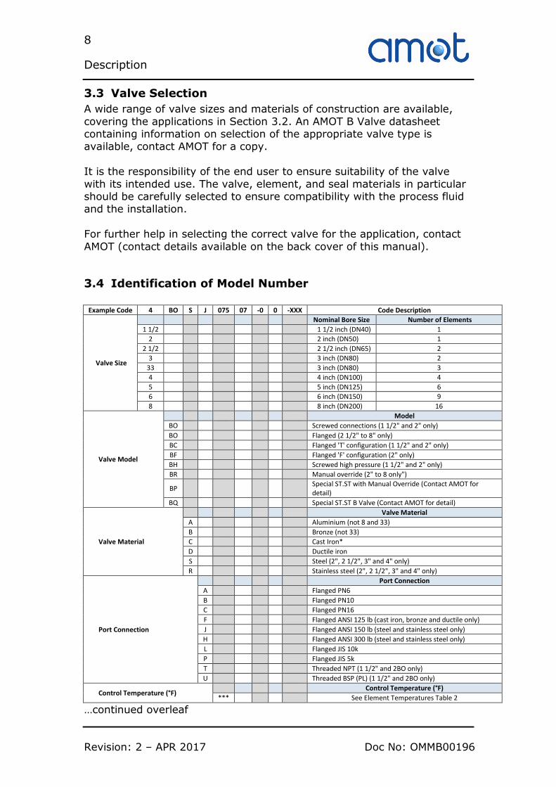
3.4 Identification of Model Number
Example Code 4 BO S J 075 07 -0 0 -XXX Code Description
Valve Size
Nominal Bore Size Number of Elements
1 1/2 1 1/2 inch (DN40) 1
2 2 inch (DN50) 1
2 1/2 2 1/2 inch (DN65) 2
3 3 inch (DN80) 2
33 3 inch (DN80) 3
4 4 inch (DN100) 4
5 5 inch (DN125) 6
6 6 inch (DN150) 9
8 8 inch (DN200) 16
Valve Model
Model
BO Screwed connections (1 1/2" and 2" only)
BO Flanged (2 1/2" to 8" only)
BC Flanged 'T' configuration (1 1/2" and 2" only)
BF Flanged 'F' configuration (2" only)
BH Screwed high pressure (1 1/2" and 2" only)
BR Manual override (2" to 8 only")
BP Special ST.ST with Manual Override (Contact AMOT for detail)
BQ Special ST.ST B Valve (Contact AMOT for detail)
Valve Material
Valve Material
A Aluminium (not 8 and 33)
B Bronze (not 33)
C Cast Iron*
D Ductile iron
S Steel (2", 2 1/2", 3" and 4" only)
R Stainless steel (2", 2 1/2", 3" and 4" only)
Port Connection
Port Connection
A Flanged PN6
B Flanged PN10
C Flanged PN16
F Flanged ANSI 125 lb (cast iron, bronze and ductile only)
J Flanged ANSI 150 lb (steel and stainless steel only)
H Flanged ANSI 300 lb (steel and stainless steel only)
L Flanged JIS 10k
P Flanged JIS 5k
T Threaded NPT (1 1/2" and 2BO only)
U Threaded BSP (PL) (1 1/2" and 2BO only)
Control Temperature (°F) Control Temperature (°F)
*** See Element Temperatures Table 2
…continued overleaf

9
Description
Doc No: OMMB00196 Revision: 2 – APR 2017
Example Code 4 BO S J 075 07 -0 0 -XXX Code Description
Element Type Element Type
** See Element / Seal Types Table 3
Leakhole sizes
Leakhole sizes inches
0 None
A 1/2" Dia
B 1/4" Dia
C 3/8" Dia
D 1/8" Dia
E 1/16" Dia
F 3/32" Dia
G 3/16" Dia
H 5/16" Dia
Leakhole Quantity
No. of elements with Leakhole
0 None
1 One (Max for 2" Size)
2 Two (Max for 2 1/2" & 3" sizes)
3 Three
4 Four (Max for 4" size)
5 Five
6 Six (Max for 5” size)
7 Seven
8 Eight
9 Nine (Max for 4" size)
Customer Special Requirements
Customer Special Requirements
-AA Standard Product
-*** Customer special code assigned
Table 1 - Model Identification
* AMOT reserves the right to substitute a ductile iron product in place of
cast iron to meet customer delivery requirements. Other Flange connections are available. Contact AMOT for details.
10
Description
Revision: 2 – APR 2017 Doc No: OMMB00196
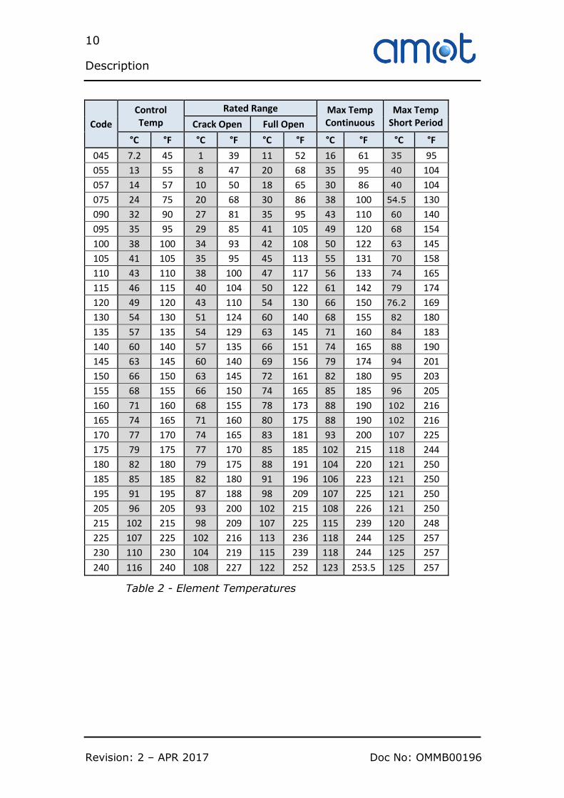
Code
Control Temp
Rated Range Max Temp Continuous
Max Temp Short Period Crack Open Full Open
°C °F °C °F °C °F °C °F °C °F
045 7.2 45 1 39 11 52 16 61 35 95
055 13 55 8 47 20 68 35 95 40 104
057 14 57 10 50 18 65 30 86 40 104
075 24 75 20 68 30 86 38 100 54.5 130
090 32 90 27 81 35 95 43 110 60 140
095 35 95 29 85 41 105 49 120 68 154
100 38 100 34 93 42 108 50 122 63 145
105 41 105 35 95 45 113 55 131 70 158
110 43 110 38 100 47 117 56 133 74 165
115 46 115 40 104 50 122 61 142 79 174
120 49 120 43 110 54 130 66 150 76.2 169
130 54 130 51 124 60 140 68 155 82 180
135 57 135 54 129 63 145 71 160 84 183
140 60 140 57 135 66 151 74 165 88 190
145 63 145 60 140 69 156 79 174 94 201
150 66 150 63 145 72 161 82 180 95 203
155 68 155 66 150 74 165 85 185 96 205
160 71 160 68 155 78 173 88 190 102 216
165 74 165 71 160 80 175 88 190 102 216
170 77 170 74 165 83 181 93 200 107 225
175 79 175 77 170 85 185 102 215 118 244
180 82 180 79 175 88 191 104 220 121 250
185 85 185 82 180 91 196 106 223 121 250
195 91 195 87 188 98 209 107 225 121 250
205 96 205 93 200 102 215 108 226 121 250
215 102 215 98 209 107 225 115 239 120 248
225 107 225 102 216 113 236 118 244 125 257
230 110 230 104 219 115 239 118 244 125 257
240 116 240 108 227 122 252 123 253.5 125 257
Table 2 - Element Temperatures
11
Description
Doc No: OMMB00196 Revision: 2 – APR 2017
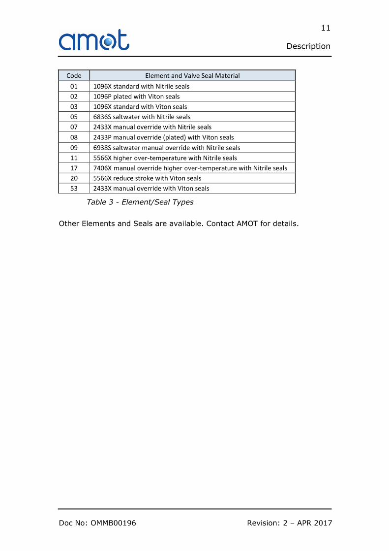
Code Element and Valve Seal Material
01 1096X standard with Nitrile seals
02 1096P plated with Viton seals
03 1096X standard with Viton seals
05 6836S saltwater with Nitrile seals
07 2433X manual override with Nitrile seals
08 2433P manual override (plated) with Viton seals
09 6938S saltwater manual override with Nitrile seals
11 5566X higher over-temperature with Nitrile seals
17 7406X manual override higher over-temperature with Nitrile seals
20 5566X reduce stroke with Viton seals
53 2433X manual override with Viton seals
Table 3 - Element/Seal Types
Other Elements and Seals are available. Contact AMOT for details.

12
Description
Revision: 2 – APR 2017 Doc No: OMMB00196
13
Use within the European Union (EU)
Doc No: OMMB00196 Revision: 2 – APR 2017
Section 4
Use within the European Union (EU)
4.1 Pressure Equipment Directive (PED)
The Pressure Equipment Directive (PED) is applicable to the design, manufacture and conformity of pressure equipment and assemblies
of pressure equipment with a maximum allowable pressure greater than 0.5 bar.
In its design application of a thermostatic valve, this equipment is defined as a Pressure Accessory under the terms of the EU Pressure
Equipment Directive (PED).
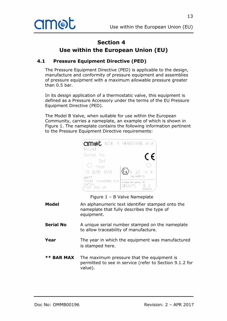
The Model B Valve, when suitable for use within the European Community, carries a nameplate, an example of which is shown in Figure 1. The nameplate contains the following information pertinent
to the Pressure Equipment Directive requirements:
Figure 1 – B Valve Nameplate
Model An alphanumeric text identifier stamped onto the
nameplate that fully describes the type of equipment.
Serial No A unique serial number stamped on the nameplate to allow traceability of manufacture.
Year The year in which the equipment was manufactured
is stamped here.
** BAR MAX The maximum pressure that the equipment is
permitted to see in service (refer to Section 9.1.2 for value).

14
Use within the European Union (EU)
Revision: 2 – APR 2017 Doc No: OMMB00196
Name and address Equipment complying with the Pressure Equipment
Directive must be marked with the name and
address of the manufacturer and where appropriate, of his authorised representative established with the
European Community.
Suitable for liquids to Groups 1 & 2 and CE Marking When used with liquids defined as Groups 1 or 2, the Model B Valve falls into the PED Sound Engineering
Practice (SEP) category. Note that 8” B Valves, and B Valves with Class 300lb flanges (Port Connection
“H” – See Table 1, Section 3.4) are only suitable for use with liquids defined as Group 2, and the nameplate is marked accordingly for these versions.
Units must not be CE marked in the SEP category (although are CE marked for compliance with the
ATEX Directive (see Section 4.2)).
Users who are uncertain as to the applicability of the Pressure
Equipment Directive should contact AMOT, particularly if using more hazardous (Group 1) fluids.
4.2 Hazardous Areas
4.2.1 Hazardous Area Directive (ATEX)
The ATEX Directive is applicable to all equipment both electrical and mechanical that is put into service in a designated hazardous area.
The Model B Valve, as mechanical equipment, has been assessed in
accordance with EN13463-1 and has been designated as Group II equipment. Group II equipment is suitable for use in places where a potentially explosive atmosphere may be present. Group II
equipment shall not be used underground in mines, or in the surface installations of such mines that are susceptible to firedamp or
combustible dust. The Model B Valve has been assessed for use in places designated as
containing hazardous gas; they shall not be used in places designated as containing hazardous dust.
The Model B Valve, when suitable for use within the European Community, carries a nameplate, an example of which is shown in
Figure 1. The nameplate contains the following information pertinent to the ATEX Hazardous Area Directive requirements:

15
Use within the European Union (EU)
Doc No: OMMB00196 Revision: 2 – APR 2017
Model An alphanumeric text identifier stamped
onto the nameplate that fully describes the type of equipment.
Serial No A unique serial number stamped on the
nameplate to allow traceability of
manufacture.
Year The year in which the equipment was
manufactured is stamped here.
Ex Symbol The EU Mark for hazardous area application.
Equipment designation:
II Equipment Group (non-mining applications).
2 Equipment Category (high protection
level). G Hazardous Area Type (hazardous gas
environments). TX Max surface temp (maximum surface
temperature depends on not on the
equipment itself but on the operating conditions, and a single temperature
class cannot be marked by the manufacturer).
X Special Conditions for safe use (Special conditions for safe use apply, including the Ambient Temperature
Range below, see Section 4.2.2).
CML 15ATEXT172 Confidential Technical File reference (c/o Notified Body).
CE Marking All equipment used in a hazardous area under the ATEX Directive must be CE
marked. Mechanical equipment in Group II Category 2 is self-assessed, and a confidential Technical File lodged with a
Notified Body (per Technical File ref. above). Equipment that is CE marked must
comply with all relevant EU Directives. The CE mark on the AMOT B Valve only represents compliance to the ATEX
Directive and not to other EU Directives.
Name and address Equipment complying with the Hazardous Area Directive must be marked with the

16
Use within the European Union (EU)
Revision: 2 – APR 2017 Doc No: OMMB00196
name and address of the manufacturer and where appropriate, of his authorised representative established with the
European Community.
For safe and trouble-free use within hazardous areas the instructions within this Operating and Maintenance Manual must be strictly
adhered to. The maximum temperature and internal pressure that this equipment
is permitted to work at is contained within Section 9.1.
The conditions for safe installation and commissioning of this equipment are contained in Section 5.
The equipment must be maintained in accordance with Section 7 and between maintenance periods it should be kept clean in accordance
with Section 4.2.2. Users who are uncertain as to the applicability of the ATEX Directive
should contact AMOT for further advice.
4.2.2 Special conditions for Safe Use
1. The equipment is designed for use in an extended ambient
temperature range of -20°C to +60°C.
2. The equipment contains no heat generating parts and assumes the temperature of the fluid inside it, as denoted by the “TX” marking. The fluid temperature must remain within the limit specified in
Section 9.1.3.
3. Cleaning of equipment must only be completed using a damp cloth or anti-static cloth.
4. Process fluids capable of generating ionising radiation (such as radioactive substances) are not suitable for use with the equipment.
5. The equipment is not suitable for use with process fluids that could
cause exothermic reactions within the equipment or with the
equipment and its materials.
4.3 Machinery Directive
The Model B Valve supplied by AMOT is classified as a component.
The equipment falls outside the scope of the machinery directive. Components are only intended to be incorporated into or assembled with other machinery or equipment thereby forming Machinery.

17
Installation
Doc No: OMMB00196 Revision: 2 – APR 2017
Section 5
Installation
WARNING
The valve is heavy; refer to Section 9.1.4. The appropriate manual
handling precautions must be applied to avoid personnel injury.
5.1 Installing the valve
5.1.1 Before starting installation
1. Upon receipt, the valve should be checked for damage sustained in shipping. All AMOT valves have nameplates attached, which are stamped with the valve model number
and serial number. 2. Understand the intended use of the valve as described in
Section 3. 3. Before installation, ensure that the valve is suitable for the
purpose, checking temperature, pressure and material
parameters, and any special approval requirements (refer to Section 3.3). Check that the intended pipe fittings are
suitable for the application. 4. Check that the valve size has been selected in accordance
with the anticipated flow rate through the valve (refer to
Section 3.3). To maintain good temperature regulation the pressure drop across the valve should be in the 0.14 to 0.5
bar (2 to 7 psi) range. 5. If the valve is to be fitted at a high point in the system, the
system should be vented to prevent trapped air around the
temperature elements. 6. For optimum temperature regulation the system should be
designed so that the element is in the mid-position under nominal conditions. To achieve this it may be necessary to balance the fluid flow by inserting an orifice in the by-pass
circuit. 7. If appropriate, read and understand the legal requirements
of installing the valve within the European Union as described in Section 4.

18
Installation
Revision: 2 – APR 2017 Doc No: OMMB00196
5.1.2 Mounting the Valve in the Pipe
The valve may be mounted in any orientation; but should be properly
supported and not subjected to excessive bending. Ensure the pipe flange connections are correctly aligned to avoid stressing the valve
body.
For the main flanged ports bolting and gaskets should comply with the relevant standard.
All relevant local regulations must also be observed.
5.1.3 Start up
Upon installation and on start-up of the system, all parts of the
circuit should be closely monitored to ensure correct performance. A system in which the valve has been properly selected for the
anticipated flows should operate very closely to the valve’s nominal temperature rating.
Water cooling systems will usually operate at or slightly below the nominal temperature. Lubricating oils and most other higher viscosity
fluids will operate at or slightly above the nominal temperature. In any system where the indicated temperatures are more than
2.7°C (5°F) from the nominal temperature, then an effort should made to locate the cause.
Any system operating at an indicated 5.5°C (10°F) or more from the nominal anticipated temperatures may well be malfunctioning and
the cause should be located and rectified immediately. See trouble-shooting section for possible causes.

19
Operation
Doc No: OMMB00196 Revision: 2 – APR 2017
Section 6
Operation
6.1 Operation
The Model B Valve is completely automatic in operation, and needs no power supply
The temperature control power is created by the expansion of a wax/copper mixture which is highly sensitive to temperature changes. Large forces are created by the warming/expansion of the
mixture which in turn acts upon the sliding valve, thus regulating the flow.

20
Operation
Revision: 2 – APR 2017 Doc No: OMMB00196
6.1.1 Diverting applications
(controls outlet temp from load source)
In diverting applications temperature is sensed at port A, which remains open to port B (bypass) until the fluid temperature reaches a point 3-6°C (5-10°F) below the nominal setting, when the valve
will start to move, progressively closing port B and opening port C (the cooler connection). If the temperature continues to rise, port B
will be fully closed 4 to 6°C (8-10°F) above the set temperature.
6.1.2 Mixing applications (controls inlet temp to load source)
In mixing applications the hot supply is connected to port B, the cold
supply to port C, and the mixed flow appears, via the temperature sensor, at port A. Because of the position of the controlling wax ‘pill’, in mixing applications the controlled temperature may be 2-3°C
above the nominal.
21
Operation
Doc No: OMMB00196 Revision: 2 – APR 2017
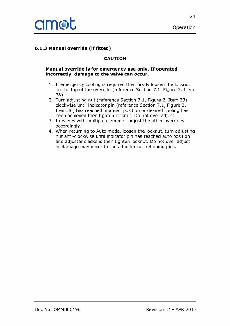
6.1.3 Manual override (if fitted)
CAUTION
Manual override is for emergency use only. If operated incorrectly, damage to the valve can occur.
1. If emergency cooling is required then firstly loosen the locknut on the top of the override (reference Section 7.1, Figure 2, Item
38). 2. Turn adjusting nut (reference Section 7.1, Figure 2, Item 33)
clockwise until indicator pin (reference Section 7.1, Figure 2,
Item 36) has reached ‘manual’ position or desired cooling has been achieved then tighten locknut. Do not over adjust.
3. In valves with multiple elements, adjust the other overrides accordingly.
4. When returning to Auto mode, loosen the locknut, turn adjusting
nut anti-clockwise until indicator pin has reached auto position and adjuster slackens then tighten locknut. Do not over adjust
or damage may occur to the adjuster nut retaining pins.

22
Operation
Revision: 2 – APR 2017 Doc No: OMMB00196
23
Maintenance
Doc No: OMMB00196 Revision: 2 – APR 2017
Section 7
Maintenance
To obtain maximum service life from the valve, periodic inspection
and cleaning should be incorporated into a normal preventative maintenance program. Properly applied and installed AMOT
thermostatic valves require minimal maintenance. Inspection at 2 year intervals is adequate to detect normal wear.
CAUTION
Before starting any maintenance, understand the intended
use of the valve as described in Section 3.
If appropriate, read and understand the requirements associated with use of the valve within the European Union
as described in Section 4.
Most valves must be removed from the system pipework before commencement of maintenance. Elements in the 8” B Valve may however be removed with the valve still in the pipework.
Ensure replacement seal kits are available (Table 7) before
maintenance begins.
WARNING
Ensure that all pressure is relieved from within the valve and ancillary equipment and drain system (or isolate valve) before commencing any maintenance work.

24
Maintenance
Revision: 2 – APR 2017 Doc No: OMMB00196
7.1 Dismantling the valve
Figure 2 - Diagram showing 4” B valve with manual override
1. Refer to Figure 2. Remove housing nuts (Item 12) and split valve. Remove the lower housing (Item 2) taking care not to damage the elements. Remove and discard housing gasket
(Item 9) ensuring any traces of the gasket are removed from the housing mating faces. Note that in some sizes of Model B
Valves ‘O’ rings are used instead of gaskets. 2. If removing element from BO valve (non manual override)
simply pull the element from the upper housing. Go to step 9. 3. If removing element from BR valve (manual override) only
dismantle one at a time to eliminate the chance of the manual
override parts being mixed up. 4. Carefully remove the indicator pin (item 36).
5. Remove the locknut (Item 38) from the override stem (Item 21).
6. Remove override housing retaining screws (Item 28).
7. Unscrew override housing from the override stem (Item 21) and set aside the shims.
8. Pull the element from the upper housing and if changing the element un-pin the override stem from the element link.
9. Remove ‘O’ rings. BO valve item 7. BR valve item 7 & 17.
25
Maintenance
Doc No: OMMB00196 Revision: 2 – APR 2017
10. Inspect valve seat for wear or damage. If required replace valve
seat (Item 3), remove by unscrewing bushing (Item 5). Bushing A/F 7/8”.
7.2 Reassembling the valve
1. Where fitted, lubricate gasket (Item 9) liberally with a good grade of petroleum grease, allow to soak.
2. If valve seat changed, refit bushing with Loctite 2400 locking compound.
3. Lightly grease and stretch new ‘O’ ring (Item 7) and fit into upper
housing. Position ‘O’ ring concentrically to assist element assembly.
4. If replacing a BR valve element, then fit override stem (Item 21) to element link with pin (Item 20).
5. Insert element into the upper housing taking care not to damage
the ‘O’ ring. 6. For BO valves go to step 10
7. For BR valves. Lightly grease ‘O’ ring (Item 17) and slide over override stem and seat into recess in the stem adaptor followed by the ‘O’ ring retainer (Item 37).
8. Screw manual override housing onto override stem. Refit shims (Item 24). Ensure indicator plates are facing outward, on 6BR one
row to face nameplate and two rows to face other side. Secure housing to stem adaptor with screws (Item 28) and Loctite 241.
Fit indicator pin (Item 36) into override stem, ensuring element assembly still closes.
9. Wind manual operator nut and check sliding valve fully closes
onto seat. Return valve to auto position and secure operating nut with locknut (Item 38). Ensure washer (Item 32) is free.
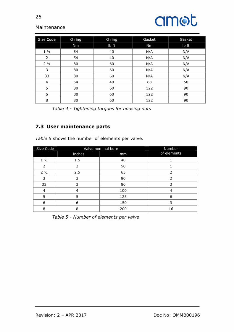
10. Position lubricated gasket (where fitted) on upper housing joint face, or lightly grease and fit replacement ‘O’ Rings in upper housing joint face element recess(es). Position lower housing over
upper housing, and secure with nuts and washers (Items 12 & 11). For nut torque settings, see Table 4.
26
Maintenance
Revision: 2 – APR 2017 Doc No: OMMB00196
Size Code O ring O ring Gasket Gasket
Nm lb ft Nm lb ft
1 ½ 54 40 N/A N/A
2 54 40 N/A N/A
2 ½ 80 60 N/A N/A
3 80 60 N/A N/A
33 80 60 N/A N/A
4 54 40 68 50
5 80 60 122 90
6 80 60 122 90
8 80 60 122 90
Table 4 - Tightening torques for housing nuts
7.3 User maintenance parts
Table 5 shows the number of elements per valve. Size Code Valve nominal bore Number
Inches mm of elements
1 ½ 1.5 40 1
2 2 50 1
2 ½ 2.5 65 2
3 3 80 2
33 3 80 3
4 4 100 4
5 5 125 6
6 6 150 9
8 8 200 16
Table 5 - Number of elements per valve

27
Maintenance
Doc No: OMMB00196 Revision: 2 – APR 2017
Table 6 provides the part numbers for spare element assemblies.
Part
Number Description Qty
1096X(°F) Element assembly
See Table 5
1096P(°F) Plated element assembly
2433X(°F) Element assembly with manual override
2433P(°F) Plated element assembly with manual override
5566X(°F) Element assembly, higher over-temperature
7406X(°F) Element assembly, higher over-temperature with manual override
6836S(°F) Element assembly, ‘Saltwater’ plated
6938S(°F) Element assembly, ‘Saltwater’ plated, with manual override
Table 6 - Element assembly part numbers
Other Elements are available. Contact AMOT for details.
Table 7 provides the part numbers for spare seal kits, containing the required seals to maintain a complete valve.
Seal Kits
Size Material
BO/BC/BF/BH BR Nitrile Viton Neoprene Nitrile Viton Neoprene
1.1/2” 46342X151 46342X152 46342X153 46342X154 46342X155 46342X156
2” 46342X201 46342X202 46342X203 46342X204 46342X205 46342X206
2.1/2” 46342X251 46342X252 46342X253 46342X254 46342X255 46342X256
3”
3BO,3BR 46342X301 46342X302 46342X303 46342X304 46342X305 46342X306
3”
33BO, 33BR 46342X331 46342X332 46342X333 46342X334 46342X335 46342X336
4”
4BOA,4BOB 4BOC,4BOD
46342X401 46342X402 46342X403 46342X404 46342X405 46342X406
4”
4BOR,4BOS 4BRR,4BRS
46342X411 46342X412 46342X413 46342X414 46342X415 46342X416
5” 46342X501 46342X502 46342X503 46342X504 46342X505 46342X506
6” 46342X601 46342X602 46342X603 46342X604 46342X605 46342X606
8” 46342X801 46342X802 46342X803 46342X804 46342X805 46342X806
Table 7 - Seal kit part numbers
Note that as of 2010, 4” and 5” B valves, and as of 2011, 6” and 8” B
Valves, use ‘O’ rings to seal the upper and lower housing. The seal kits for these valves contain the original type gasket and the ‘O’ rings to suit both types of sealing configuration.
28
Maintenance
Revision: 2 – APR 2017 Doc No: OMMB00196
29
Trouble shooting
Doc No: OMMB00196 Revision: 2 – APR 2017
Section 8
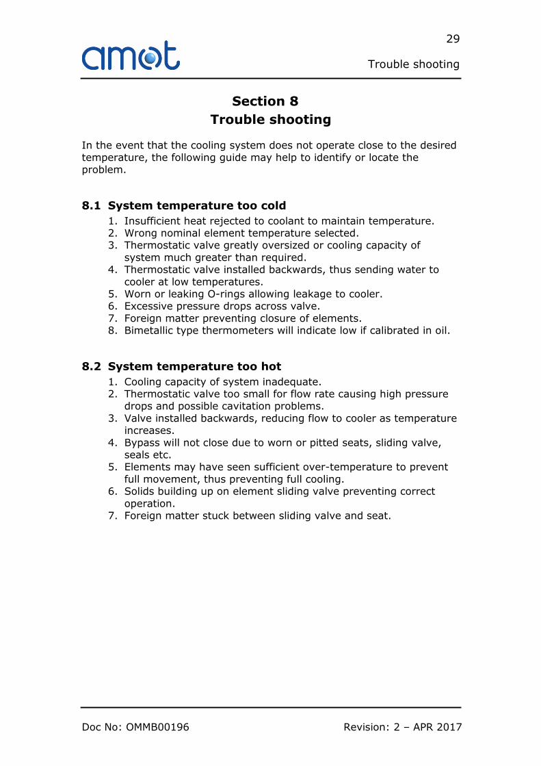
Trouble shooting In the event that the cooling system does not operate close to the desired
temperature, the following guide may help to identify or locate the problem.
8.1 System temperature too cold
1. Insufficient heat rejected to coolant to maintain temperature. 2. Wrong nominal element temperature selected. 3. Thermostatic valve greatly oversized or cooling capacity of
system much greater than required. 4. Thermostatic valve installed backwards, thus sending water to
cooler at low temperatures. 5. Worn or leaking O-rings allowing leakage to cooler. 6. Excessive pressure drops across valve.
7. Foreign matter preventing closure of elements. 8. Bimetallic type thermometers will indicate low if calibrated in oil.
8.2 System temperature too hot
1. Cooling capacity of system inadequate. 2. Thermostatic valve too small for flow rate causing high pressure
drops and possible cavitation problems.
3. Valve installed backwards, reducing flow to cooler as temperature increases.
4. Bypass will not close due to worn or pitted seats, sliding valve, seals etc.
5. Elements may have seen sufficient over-temperature to prevent
full movement, thus preventing full cooling. 6. Solids building up on element sliding valve preventing correct
operation. 7. Foreign matter stuck between sliding valve and seat.

30
Trouble shooting
Revision: 2 – APR 2017 Doc No: OMMB00196

31
Technical Specification
Doc No: OMMB00196 Revision: 2 – APR 2017
Section 9
Technical Specification
9.1 General valve specification
9.1.1 Materials
Body materials .................................. Aluminium, Bronze, Cast Iron, Ductile Iron,
Steel, Stainless steel
Internal materials (elements) .................................... Stainless Steel and Bronze
Option: Nickel plating
Seal material ................................................... Nitrile, FKM (Viton), Neoprene or
Ethylene propylene rubber
9.1.2 Maximum working pressure (bar)
Table 8 - Maximum working pressure
9.1.3 Maximum working temperature The maximum continuous temperature that the valve can operate at is
determined by the temperature element(s) fitted to the valve. This information is contained in Section 3.4, Table 2.
The element(s) in the valve may be subjected to slightly higher maximum
temperature for a short term period, the value for which is also stated in Section 3.4, Table 2. The process fluid must be reduced to the maximum continuous temperature within 30 minutes however, or permanent
damage to the element(s) may occur.
Type Bronze Cast Iron Ductile Iron Steel Stainless Steel Aluminium
1½” 10 10 N/A N/A N/A N/A
2”BC/BR 10 10 16 45 45 10
2”BH N/A 22 N/A N/A N/A N/A
2 ½” 10 10 16 45 45 10
3” 10 10 16 45 45 10
33 N/A 6 N/A N/A N/A 6
4” 10 10 16 20 20 10
5” 10 10 10 N/A N/A 10
6” 10 10 10 N/A N/A 10
8” 10 10 10 N/A N/A N/A
32
Technical Specification
Revision: 2 – APR 2017 Doc No: OMMB00196
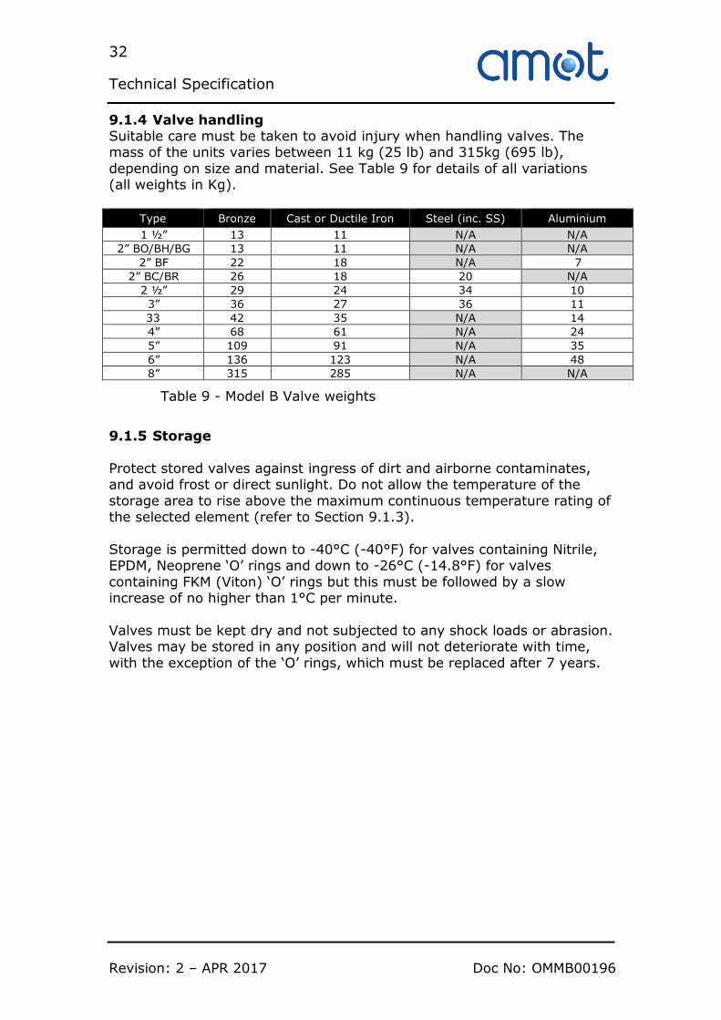
9.1.4 Valve handling Suitable care must be taken to avoid injury when handling valves. The mass of the units varies between 11 kg (25 lb) and 315kg (695 lb),
depending on size and material. See Table 9 for details of all variations (all weights in Kg).
Type Bronze Cast or Ductile Iron Steel (inc. SS) Aluminium
1 ½” 13 11 N/A N/A
2” BO/BH/BG 13 11 N/A N/A
2” BF 22 18 N/A 7
2” BC/BR 26 18 20 N/A
2 ½” 29 24 34 10
3” 36 27 36 11
33 42 35 N/A 14
4” 68 61 N/A 24
5” 109 91 N/A 35
6” 136 123 N/A 48
8” 315 285 N/A N/A
Table 9 - Model B Valve weights
9.1.5 Storage
Protect stored valves against ingress of dirt and airborne contaminates, and avoid frost or direct sunlight. Do not allow the temperature of the
storage area to rise above the maximum continuous temperature rating of the selected element (refer to Section 9.1.3).
Storage is permitted down to -40°C (-40°F) for valves containing Nitrile, EPDM, Neoprene ‘O’ rings and down to -26°C (-14.8°F) for valves
containing FKM (Viton) ‘O’ rings but this must be followed by a slow increase of no higher than 1°C per minute.
Valves must be kept dry and not subjected to any shock loads or abrasion. Valves may be stored in any position and will not deteriorate with time,
with the exception of the ‘O’ rings, which must be replaced after 7 years.

33
Technical Specification
Doc No: OMMB00196 Revision: 2 – APR 2017


Contact
Americas
Europe and Africa
AMOT USA 8824 Fallbrook Dr
Houston Texas 77064 USA
Tel: +1 (281) 940 1800 Fax: +1 (713) 559 9419
Email: [email protected]
AMOT UK Western Way
Bury St Edmunds Suffolk, IP33 3SZ England
Tel: +44 (0) 1284 762222 Fax: +44 (0) 1284 760256
Email: [email protected]
AMOT Controls GmbH Rondenbarg 25
Asia and Australasia
22525 Hamburg
Germany
AMOT China
Rm 4102 – 4104, United Plaza 1468 Nanjing Road West Shanghai 200040
China Tel: +86 (0) 21 6279 7700
Fax: +86 (0) 21 5237 8560 Email: [email protected]
AMOT Singapore
10 Eunos Road 8 #12-06 Singapore Post Centre Singapore 408600
Tel: +65 (0) 6408 6265 Fax: +65 (0) 6293 3307
Email: [email protected]
www.amot.com
Tel: +49 (0) 40 8537 1298
Tel: +49 (0) 40 8537 1331 Email: [email protected]