General Cataloge - BENEDICT GmbH
364
General Cataloge D946E174 Quality made in Austria
-
Upload
khangminh22 -
Category
Documents
-
view
7 -
download
0
Transcript of General Cataloge - BENEDICT GmbH

D946D173
quick access to www.benedict.at
General Cataloge
D946E174
Quality made in Austria
2017
Lieblgasse 7, A-1220 Wien Tel.: + 4 3 1 2 5 1 5 1 0Fax: + 4 3 1 2 5 1 5 1 89e-mail: [email protected] w w . b e n e d i c t . a t
Qualität aus Österreich
Cover_fuer_Druck.indd 1 29.11.2016 08:02:43

D946E 1
Index Page Contactors, Motor-Starter (D677E) 3 Micro Contactors 11 Mini Contactors 25 Contactor Relays 39 Contactors 45 Starters 91 D.O.L. Starters 111 Overload Relays 119 Modular Contactors 133 Contactors for DC-Switching (D911E) 141 Contactors RAST 5 (D778E) 145
Circuirt Breakers (D795E) 165 Circuit-Breakers M4 for motor protection 166 Auxiliary contacts, Signalling switch, Auxiliary releases 167 Insulated 3-pole busbar system, Terminal block 168 DIN-rail adapters, Busbar adapters 169 Link modules, Contactors for Circuit-Breakers M4 171
Manual Motor-Starters (D509E) 187 Manual Motor-Starters, Auxiliary Contact Blocks 188 Trip Alarm Aux. Switch, Shunt Release 188 Under-voltage Release, Accessories 189 Busbar Connectors, Enclosures 189
Switches (D371E) 193 Cam Switches 198 Mini-Cam Switches 236 Load switches 240 Handles and plates 242 Optional Extras 249 Special Switches 257
AC-Main Switches (D656E) 277 Main Switches for Panel Mounting 280 Main Switches for Base Mounting with Door Clutch 282 Main Switches-Emergency-Stop for Panel Mounting 286 Main Switches-Emergency-Stop for Single Hole Mounting 287 Main Switches-Emergency-Stop for Base Mounting with Door Clutch 288 Main Switches-Emergency-Stop for Distribution Boards 290 Maintenance and Safety Switches, in Plastic Enclosures 290 Switch Disconnectors for Panel Mounting 292 Switch Disconnectors for Distribution Boards 295 Switch Disconnectors in Plastic Enclosures 296 Add-on modules 297
DC Switch Disconnectors for Photovoltaic (D911E) 303 ON-OFF Switches for Panel Mounting 306 ON-OFF Switches for Single Hole Mounting 307 ON-OFF Switches for Base Mounting with Door Clutch 308 ON-OFF Switches for Distribution Boards 309 Main Switches for Panel Mounting 310 Main Switches for Single Hole Mounting 311 Main Switches for Base Mounting with Door Clutch 312 Main Switches for Distribution Boards 313 Main Switches in Plastic Enclosure 313
Technical data, dimension sketches, illustration and weights given in our list and printed matter, are subject to changed without notice.

2 D946E
Index Page
Push Buttons (D580E) 329 Program B3 330 Push Buttons 331 EMERGENCY STOP Button 332 Key Operated Rotary Switches 332 Rotary Knobs and Swing Knobs 333 Illuminated Rotary Knobs and Swing Knobs 333 Illuminated Push Buttons 334 Double Push Buttons 334 Lens Caps 334 Monoblock-Multi-LED 335 Push Button-Sets 336 Illuminated Push Button-Sets 336 Pilot Lights 336 Connectors 338 Actuator inserts 338 Contact Blocks and Lamp Holders 338 Lamps, LED Lamps 339 Accessories 339 Label Holder, Legend Plates, Actuator Caps 340 Program B5 342 Push Buttons 343 Rotary Knobs and Swing Knobs 344 Key Operaed Rotary Switches 345 Illuminated Push Button 345 Lens Caps 345 Connectors 346 Contact Blocks and Lamp Holders 346 Lamps, Accessories 347 Units for Surface Mounting 349 Assembled Units IP65 349 Enclosures BG. 350 Contact Blocks and Lamp Holders for Enclosures BG.. 350 Push Buttons for Enclosures 351 Extensions for Push Buttons 351
Representatives and Suppliers 359
Technical data, dimension sketches, illustrations and weights given in our list and printed matter are subject to change without notice.

D946E 3
Technical data, dimension sketches, illustrations and weights given in our list and printed matter are subject to change without notice.
Index Page
General 4 Approvals 5 Technical Information 9 Mounting Information 10
Micro Contactors 11 Micro Contactors 12 Micro Contactor Relays 14 Micro Reversing Contactors 18 Technical Information 20 Dimensions 24
Mini Contactors 25 Mini Contactors 26 Interface Contactors 26 Micro Reversing Contactors 32 Technical Information 33 Dimensions 36
Contactor Relays 39 Contactor Relays 40 Technical Information 40 Dimensions 44
Contactors 45 Contactors Overview 46 Contactors, 3-pole 48 Contactors, 4-pole 50 Capacitor Switching Contactors 51 Accessories 52 Technical Information 62 Dimensions 82
Starters 91 Star-Delta Starters 92 Reversing Contactors 96 Pole Changing Starters 98 Technical Information 100 Dimensions 107
D.O.L. Starters 111 D.O.L. Starters 112 Enclosures 113 Accessories 113 Technical Information 115 Dimensions 116
Overload Relays 119 Thermal Overload Relays 121 Accessories 123 Technical Information 125 Dimensions 129
Modular Contactors 133 Contactors 134 Accessories 135 Technical Information 138 Dimensions 140
Contactors for DC-Switching 141Contactors RAST 5 145

4 D946E
Marking of auxiliary contactsAt several devices in UL-data are two voltages for auxiliary contacts men-tioned (e. g.: 600 volts at same potential, 150 volts at different potentials). That means, if the voltage is higher than 150 volts, the control voltage applied to input terminals must be at the same potential.
Marking of Max. rated values per pole Contactauxiliary contacts Voltage Current Cont. Rating according to Make Break Current CodeCSA and UL V A A A Designation
Heavy Duty AC 120 60 6 10 A150 (HD or HVY DTY) AC 240 30 3 10 A300 AC 480 15 1,5 10 A600 AC 600 12 1,2 10 A600
DC 125 2,2 2,2 10 N150 DC 250 1,1 1,1 10 N300 DC 600 0,4 0,4 10 N600
Standard Duty AC 120 30 3 5 B150 (SD or STD DTY) AC 240 15 1,5 5 B300 AC 480 7,5 0,75 5 B600 AC 600 6 0,6 5 B600
DC 125 1,1 1,1 5 P150 DC 250 0,55 0,55 5 P300 DC 600 0,2 0,2 5 P600
- AC 120 15 1,5 2,5 C150 AC 240 7,5 0,75 2,5 C300 AC 480 3,75 0,375 2,5 C600 AC 600 3 0,3 2,5 C600
DC 125 0,55 0,55 2,5 Q150 DC 250 0,27 0,27 2,5 Q300 DC 600 0,1 0,1 2,5 Q600
- AC 120 3,6 0,6 1 D150 AC 240 1,8 0,3 1 D300 DC 125 0,22 0,22 1 R150 DC 250 0,11 0,11 1 R300
- AC 120 1,8 0,3 0,5 E150
Low voltage switchgear for auxiliary circuits (e. g. contactor relays, control units, auxiliary contacts in general) usually approved for "Heavy Duty" or "Standard Duty" UL and besides these marked with the admissible max. voltage or with short codes (see table).
Discernment at UL-Standards
Recognized Component ListedIndustrial Control Equipment Industrial Control Equipment
UL issues yellow "Guide cards" UL issues white "Guide cards" with Guide- and File-No. with Guide- and File-No.
Devices have permission to be Devices have to be markedmarked with with theon the label "UL-Listing Mark"
Devices as components approved for Devices approved for "field wiring","factory wiring":devices for employment in controlpanels, when they are selected, a) devices for employmentmounted and wired according to in control panels, when the charging conditions by skilled they are mounted and worker. wired by skilled worker. b) devices for retail in USA
Valid UL-Standards: Valid UL-Standards:UL 508 "Standard for Industrial UL 508 "Standard for Industrial Control Control Equipment" Equipment" (unlimited) (partly limited)
Are devices approved as "Listed Equipment" the approval is also valid for using as "Recognized Component" .
General
CE-Marking
The manufacturer has to sign his products with the CE-Marking. With the CE-Marking the manufacturer confirms the accordance with the different EEC Directives. The CE-Marking is absolutely necessary to sell the products in the EEC. Below you find the EEC Directives concerning our products.Low Voltage Directive 2006/95/ECEMC Directive 2004/108/ECRoHS + WEEE 2002/95/EC + "002/96/EC
Test Authorities, Registration Mark, Approvals
Low voltage switchgear from Benedict GmbH is built and tested to national and international specifications. All devices suit all important specifications without any test obligation, like VDE, BS and also relative to IEC Recommendations and to European Standards like IEC 947 and EN 60947.It is for this reason of our Low voltage switchgear is used all over the world. In order to provide special versions, limitations to the max. voltages, currents and power ratings or special markings are sometimes necessary.
Quality Control System
Since November 1991 Benedict GmbH has been certified according to the quality control system ÖNORM EN ISO 29001. The target of the ISO-certification is, to grant the customer the quality of the performance of his supplier, who is audited in accordance with this standard.
Country North America Russia China
State deputy or private examination UL EAC CCC(state admitted) Canada, USA
Label marking Listedof examination boards Component
Duty of approvals all switchgear all switchgear all switchgear
Explanations for choice and supply of low voltage switchgear in Canada and USA

D946E 5
ApprovalsCountry North America Switzerland Europe Russia China CENELEC EAC CB-Certificates UL SEV Type
Micro Contactor Relays, Micro Contactors K0, Micro Reversing Contactors and Accessories
K0-04D.. - - - o - - -K0-05D.. o - - o - - -K0W05D.. o - - o - - -
Mini Contactor Relays, Mini Contactors, Mini Reversing Contactors K1 and Accessories
K1-07D..(=) o - - o o - o K1-07L..(=) - o - o o - o K1-07F..(=) - o - o o - -
K1-09D..(=) o - - o o o o K1-09L..(=) - o - o o o o K1-09F..(=) - o - o o o -
K1-12D..(=) o - - o o o -
K1W09D01(=) o - - o o o - K1W12D01(=) o - - o o o - K1W09L01(=) - o - o o o -
HK.., HKM.. o - - o o - oRC-K1 o - - o o - -
Contactor Relays, Contactors Series K3
K3-07ND..(=) o - - o o - - K3-10N..(=) o - o o o o o K3-14N..(=) o - o o o o o K3-18N..(=) o - o o o o o K3-22N..(=) o - o o o o o
K3-24A..(=) o - o o o o o K3-32A..(=) o - o o o o oK3-40A..(=) o - o o o o o
K3-50A..(=) o - o o o o o K3-62A..(=) o - o o o o o K3-74A..(=) o - o o o o o
K3-90A..(=) o - - o o o - K3-115A..(=) o - - o o o -
K3-151A..(=) o - - o o - - K3-176A..(=) o - - o o - -
K3-210A..(=) x - - o o - - K3-260A..(=) x - - o o - - K3-316A..(=) x - - o o - -
K3-450A..(=) o - - o o - - K3-550A..(=) o - - o o - -
K3-700A..(=) o - - o o - - K3-860A..(=) o - - o o - - K3-1000A..(=) - - - o o - - K3-1200A..(=) o - - o o - -
Contactor Relays, Contactors DC operated Series KG3
KG3-07.. o - - o o - o KG3-10.., -14.. o - - o o - o KG3-18.., -22.. o - - o o - o KG3-24.., -32.. o - - o o - o KG3-40.. o - - o o - o
Capacitor Contactors Series K3
K3-18K.. o - - o o o o K3-24K.. o - - o o o o K3-32K.. o - - o o o o
K3-50K.. o - - o o o o K3-62K.. o - - o o o o K3-74K.. o - - o o o oK3-90K.. o - - o o o - K3-115K.. o - - o o o -
Aux. Contacts
HN.., HTN.. o - - o o o oHA.. o - - o o - oHB.. o - - o o o oK2-DK, K2-SK o - - o o - -
HKA.., HKT.. o - - o o - - HKF22 - - - o o - -
o approved in standard version x pending - not provided to be tested

6 D946E
Approvals
Country North America Switzerland Europe Russia China CENELEC EAC CB-Certificates UL SEV Typ
Accessories
K2-T..E, -A - - - o o - - K2-TP o - - o o - - K2-L o - - o o - -
K2-IN. o - - o o - - K2-UN. o - - o o - -
K2-IM - - - o o - - K2-E o - - o o - - VG-K2 - - - o o - -
RC-K3 o - - o o - -
Reversing Contactors Series K3NWU
K3NWU-10 o - - o o - - K3NWU-14 o - - o o - - K3NWU-18 o - - o o - - K3NWU-22 o - - o o - -
K3WU-24 o - - o o - - K3WU-32 o - - o o - - K3WU-40 o - - o o - -
D.O.L Starters
P1.. o - - o o - -
Thermal Overload Relays
U3/32 o - - o o - oU3/42 o - - o o - oU3/74 o - - o o - o
U12/16E o - - o o - o U12/16A - - - o o - o U12/16EM - - - o o - o U12/16EQ - - - o o - o
U32 o - - o o - o U60 o - - o o - o U85 o - - o o - o
U180 x - - o o - - U320 x - - o o - - U800 - - - o o - -
Modular Contactors
R20 o - o o o - o R25 o - o o o - oR40 o - o o o - o R63 o - o o o - o
R40, R63 2-polig - - - o o - o RH11 o - - o o - o
Push Buttons B(C,K,S)3/4/5D o - - o o - o
Contactor Relays and Contactors Series K3 (RAST 5) K3-10/14/18/22NR o - - o o o o
Contactors for DC-Loads K3DC-20 bis 80 o - - o o - o K3DC-100 - - - o o - o K3PV-30 bis 60 - - - o o - o K3PV-80 o - - o o - o K3PV-100 - - - o o - o K3PV-150 bis 450 o - - o o - o Main Contactors Series K3
K3-10/14/18/22NBD - - - o o - o
o approved in standard version x pending - not provided to be tested

D946E 7
Approvals
Country North America Switzerland Europe Russia China CENELEC EAC CB-Certificates UL SEV Typ
Motor Protection Circuit Breakers Series M4-..
M4-32T o - - o o - - M4-32R o - - o o - - M4-63R o - - o o - - M4-100R o - - o o - - Zubehör M4 HQ o - - o o - - M4 HS o - - o o - - M4 MA o - - o o - - M4 M o - - o o - - M4 U o - - o o - -M4 A o - - o o - - Motor Protection Circuit Breakers Series MU25A-.. MU25A o - - o - - - Accessories MU25A-PS o - - o - - - MU25A-PV o - - o - - - MU25A-A o - - o - - - MU25A-U o - - o - - -
Mini DC-Isolators
LSM16/25 o o - - o - -
DC-Switch Disconnectors, 2, 2+2, 4 pole
LS16/20/25/32 o - - o o o oLS40/55 o - - o o o o
DC-Switch Disconnectors, 3+2, 4+2, 6, 8 pole
LS16/20/25/32 o o - o o o -LS40/55 o o - o o o -
AC-Main Switches
LTS20/25/32/40 o - - o o - o LTS63/80 o - - o o - oLTS85/100/125 o - - o o - o
AC-Cam Switches
M4H o - - o o - o M10 o - - o o - oM10H(D) o - - o o - oM20 o - - o o - oN33F o - - o o - oN40 o - - o o - oN60 o - - o o - oN61 o - - o o - oN80 o - - o o - oN100 o - - o o - oN200 o - - o o - oL400 o - - o o - o
o approved in standard version x pending - not provided to be tested

8 D946E
- und - Guide- und File-No.These data are important for UL-inspectors.Devices Guide-No. File-No.
Canada USA Canada USA
Contactors NLDX7 NLDX NLDX8 NLDX2 E41502 Revering Contactors NLDX7 NLDX - - E41502 Contactor Relays, Accessories NKCR7 NKCR NKCR8 NKCR2 E66273
Thermal Overload Relays NKCR7 NKCR - - E66273 Cam Switches NLRV7 NLRV - - E129916Circuit Breakers as Manual Motor Controller NLRV7 NLRV - - E129916
Circuit Breakers as Combination Motor Controller NKJH7 NKJH - - E197641Bus Bar Assemblies NLRV7 NLRV - - E129916Accessories for Circuit Breakers NKCR7 NKCR - - E66273

D946E 9
Technical Information
Degree of protection acc. to IEC 60947-1
Protection ratings are prefixed by the internationally agreed letters IP followed by two digits.
1 st digit: Pertains to solid objects2 nd digit: Pertains to water.
1 st Short description Definitiondigit
1 Protected against Excludes solid objects exceeding 50 mm solid objects in diameter and protects against contact greater than 50 mm with live and moving parts by a large body sur face such as a hand (but not against deliberate access).
2L Protected against Excludes solid objects exceeding solid objects 12,5 mm in diameter and protects against greater than contact with live and moving parts by a 12,5 mm and standard test finger or similar objects against contact by not exceeding 80 mm in length. standard test finger
3 Protected against Excludes solid objects exceeding 2,5 mm solid objects in diameter or thickness. greater than 2,5mm
4 Protected against Excludes solid objects exceeding 1 mm solid objects in diameter or thickness. greater than 1 mm
5 Dust protected Prevents ingress of dust in quantities and locations that would interfere with the intended operation of the equipment.
6 Dust tight Prevents ingress of dust.
Terminal markings acc. to EN50011
Auxiliary contacts of AC contactors and contacts of contactor relays and thermal overload relays are particularly marked. The terminal markings of normally-open contacts are printed as positive figures, they of normally-closed contacts as negative figures.This gives a clear indication of the function of the contacts.The figure below illustrates the determination of terminal markings for contactors with auxiliary contact blocks.
Sequence number
Function number
The complete terminal marking according to EN 50011 and EN 50012 results from the sequence numbers on the contactor relay or ac contactor (2., 3.) and the function numbers on the auxiliary contact blocks (e. g. .1, .2, or .3, .4).
2 nd Short description Definitiondigit
1 Protected against Dripping water (vertically falling drops) dripping water shall have no harmful effect.
2 Protected against Vertically dripping water shall have no dripping water harmful effect when the enclosure is tilted when tilted at any angle up to 15° from its normal up to 15° position.
3 Protected against Water falling as a spray at an angle up spraying water to 60° from the vertical shall have no harmful effect.
4 Protected against Water splashed against the enclosure splashing water from any direction shall have no harmful effect.
5 Protected against Water protected by a nozzle against the water jets enclosure from any direction shall have no harmful effect.
6 Protected against Water from heavy seas or water heavy seas projected in powerful jets shall not enter the enclosure in harmful quanties.
7 Protected against Ingress of water in a harmful quantity the effects of shall not be possible when the immersion enclosure is immersed in water under standard conditions of pressure and time.
8 Protected against No ingress of water. submersion
Resistance to climatic conditions acc. to IEC60068
Open-type devices are climate-resistant in the constant climate according to IEC60068-2-78 (this is a climate with an ambient temperature of 40°C and an atmospheric humidity of 90 to 95%).Enclosed devices are climate-resistant in an alternating climate according to IEC 68-2-30 (this is a moist alternating climate with a 24-hour cycle between climates with an ambient temperature of 25°C, and an atmo-spheric humidity of 95 to 100% and an ambient temperature of 40°C, and an atmospheric humidity of 90 to 96% in the presence of condensation during rises in temperature).Data are valid up to an altitude of 2000m above sea level.
Short circuit protection
Back up fuses should be used to protect contactors and starters against short circuits. For starters the device with the smaller admissible fuse at the main and at the control circuit (contactor or thermal overload) determines the fuse size.After a short circuit devices have to be checked for correct operation.Disconnect power before proceeding with any work on the equipment!

10 D946E
Technical Information
Mounting positions of contactors
K0-.. / K1-.. K2-..A00-40, K(G)3-07 bis K3-115, R.. K3-151.. bis K3-1200..
Terminal screws
Devices Kind of connection Screw with Screw with Screw Screw driver Tightening torqueType washer clamp box w. nut Nm lb. inch
Micro Contactors, all conductors K0-.. M2,5 - - - Pz1 0.6 - 0,8 5 - 7
Mini Contactors, all conductors K1-.. M3,5 - - - Pz2 0,8 - 1,4 7 - 12
Contactor Relays, all conductors K(G)3-07.. M3,5 - - - Pz2 0,8 - 1,4 7 - 12
Contactors Main conductor K(G)3-10.. bis K3-22.. M3,5 - - - Pz2 0,8 - 1,4 7 - 12K(G)3-24.. bis K3-40.. - M5 - - Pz2 2,5 - 3 22 - 26K3-50.. bis K3-74.. - M6 - - Pz3 3,5 - 4,5 31 - 40
K2-23, -30, -37A00-40 M4 - - - Pz2 1,2 - 1,8 11 - 16K2-45, -60A00-40 - M6 - - Pz3 3,5 - 4,5 31 - 40
K3-90, K3-115 - - M8 - 4mm hex socket 4 - 6,5 35 - 57
K3-116.. bis K3-176.. - - - M8 17 150K3-210.. bis K3-316.. - - - M10 35 315K3-450.. bis K3-700.. - - - M12 60 540K3-860.. - - - M14 75 675K3-1000.., K3-1200.. - - - M12 60 540
Auxiliary conductor K(G)3-10 bis K3-22 M3,5 - - - Pz2 0,8 - 1,4 7 - 12
Coil conductor K(G)3-10 bis K3-1200 M3,5 - - - Pz2 0,8 - 1,4 7 - 12
Accessories HK, HKM M3,5 - - - Pz2 0,8 - 1,4 7 - 12HA, HN, K2-.., HB.. M3,5 - - - Pz2 0,8 - 1,4 7 - 12
Thermal Overload Relays Main conductor U12/16 M4 - - - Pz2 1,2 - 1,8 11 - 16
U3/32 M3,5 - - - Pz2 0,8 - 1,4 7 - 12U3/42 M5 - - - Pz2 2,5 - 3 22 - 26U3/74 - M6 - - Pz3 3,5 - 4,5 31 - 40
UAT21 - M4 - - Size 3, 4 1,2 - 1,8 11 - 16 UAT22 - M4 - - Size 3, 4 1,2 - 1,8 11 - 16UAT23 - M5 - - Size 3, 4, 5 2,5 - 3 22 - 26
Auxiliary conductor All devices M3,5 - - - Pz2 0,8 - 1,4 7 - 12
Contactors for Distribution Boards Conductors R20, R25 - M3,5 - - Pz1 0,8 - 1,4 7 - 12R40, R63 - M5 - - Pz2 2,5 - 3 22 - 26K1R M3,5 - - - Pz2 0,8 - 1,4 7 - 12
Coil conductor R20, R25 - M3 - - Pz1 0,6 - 1,2 5 - 11R40, R63 - M3 - - Pz2 0,6 - 1,2 5 - 11K1R M3,5 - - - Pz2 0,8 - 1,4 7 - 12
RH11 - M3 - - Pz1 0,6 -1,2 5 - 11

D946E 11
Micro Contactors
Micro Contactor Relays 12
Micro Contactors 14
Micro Contactors With Solder Pins 16
Coil voltages 16
Micro Reversing Contactor 18
Technical Data 20
Dimensions 24

12 D946E
Micro Contactor Relays 4-pole AC Operated
Ratings Therm. Contacts 2) Type Coil voltage 1)
Distinc. Additional 24 24V 50/60Hz Number Contact 230 220-240V 50Hz/60Hz AC15 Rated Current 230V 400V Ith acc. to Blocks Pack Weight A A A NO NC EN50011 Type t pcs. kg/pc.
4-pole, with Screw Terminals
3 1,5 5 4 - 40E - K0-04D40 . . . 10 0,07
3 1,5 5 3 1 31E - K0-04D31 . . . 10 0,07
3 1,5 5 2 2 22E - K0-04D22 . . . 10 0,07
K0-04D40 K0-04D31 K0-04D22
1) Other coil voltages on request.2) Contacts suitable for electronic circuits, according to EN947-5-4 for rated voltage 24V DC (test ratings 17V DC, 5mA). Mirror contacts acc. IEC60947-4-1 Annex F.

D946E 13
Micro Contactor Relays 4-pole DC Operated
Ratings Therm. Contacts 2) Type Coil voltage 1)
Distinc. Additional = 24 24V=DC Number Contact AC15 Rated Current 230V 400V Ith acc. to Blocks Pack Weight A A A NO NC EN50011 Type pcs. kg/pc.
4-pole, with Screw Terminals
3 1,5 5 4 - 40E - K0-04D40= . . . 10 0,09
3 1,5 5 3 1 31E - K0-04D31= . . . 10 0,09
3 1,5 5 2 2 22E - K0-04D22= . . . 10 0,09
K0-04D40 K0-04D31 K0-04D22
1) Other coil voltages on request.2) Contacts suitable for electronic circuits, according to EN947-5-4 for rated voltage 24V DC (test ratings 17V DC, 5mA). Mirror contacts acc. IEC60947-4-1 Annex F.

14 D946E
Micro Contactors AC Operated
Power Ratings Rated Aux. Contacts2) Type Coil voltage 1)
Current Built-in Additional 24 24V 50/60Hz 230 220-240V 50Hz/60Hz AC2, AC3 AC1 380V 400V 660V 415V 690V 440V Blocks Pack Weight kW kW A NO NC Type pcs. kg/pc.
3-pole, with Screw Terminals
2,2 - 12 1 - - K0-05D10 . . . 10 0,07
2,2 - 12 - 1 - K0-05D01 . . . 10 0,07
4-pole, With Screw Terminals
2,2 - 12 - - - K0-05D00-40 . . . 10 0,07
K0-05D10 K0-05D01 K0-05D00-40
1) Other coil voltages see page 14.2) Contacts suitable for electronic circuits, according to EN947-5-4 for rated voltage 24V DC (test ratings 17V DC, 5mA). Mirror contacts acc. IEC60947-4-1 Annex F.

D946E 15
Snap-On Adapter
For Type Specification Type Pack Weight pcs.. kg/pc.
K0 Snap on Adapter for K0 P1039 10 0,0061 for snap-on mounting of contactor K0 on 35mm DIN-rail acc. DIN EN 50022
1) Other coil voltages see page 14.2) Contacts suitable for electronic circuits, according to EN947-5-4 for rated voltage 24V DC (test ratings 17V DC, 5mA). Mirror contacts acc. IEC60947-4-1 Annex F.
Micro Contactors DC Operated
Power Ratings Rated Aux. Contacts 2) Type Coil voltage 1)
Current Built-in Additional = 24 24V= DC AC2, AC3 AC1 380V 400V 660V 415V 690V 440V Blocks Pack Weight kW kW A NO NC Type pcs. kg/pc.
3-pole, with Screw Terminals
2,2 - 12 1 - - K0-05D10= . . . 10 0,09
2,2 - 12 - 1 - K0-05D01= . . . 10 0,09
4-pole, With Screw Terminals
2,2 - 12 - - - K0-05D00-40= . . . 10 0,09
K0-05D10 K0-05D01 K0-05D00-40

16 D946E
Micro Contactors AC Operated
Power Ratings Rated Aux. Contacts2) Type Coil voltage 1)
Current Built Additional 24 24V 50/60Hz in 230 220-240V 50Hz/60Hz AC2, AC3 AC1 380V 400V 660V 415V 690V 440V Pack Weight kW kW A NO NC Type pcs. kg/pc.
3-pole, with Solder Pins Ø1,15 for Printed Circuit Applications
2,2 - 9 1 - - K0-05L10 . . . 10 0,07
2,2 - 9 - 1 - K0-05L01 . . . 10 0,07
4-pole, with Solder Pins Ø1,15 for Printed Circuit Applications
2,2 - 9 - - - K0-05L00-40 . . . 10 0,07
K0-05L10 K0-05L01 K0-05L00-40
1) Other coil voltages see page 14.2) Contacts suitable for electronic circuits, according to EN947-5-4 for rated voltage 24V DC (test ratings 17V DC, 5mA). Mirror contacts acc. IEC60947-4-1 Annex F.
Suffix Voltage Marking Rated Control Voltage Us to contactor at the coil range type for for for 50Hz for 60Hz e.g. 50Hz 60Hz min. max. min. max. K0-05D10 230 V V V V V V
200 200 200-220 195 205 200 220 210 205-215 220-230 205 215 220 230 220 210-220 220-240 210 220 220 240 230 220-230 230-250 220 230 230 250
240 230-240 230 240 250 260
Standard voltages in bold type lettersOperating range of magnet-coils: 0,85 x Us (min. value of rated control voltage) up to 1,1 x Us (max. value of rated control voltage)
Coil not exchangeable
Suffix Voltage Marking Rated Control Voltage Us to contactor at the coil range type for for for 50Hz for 60Hz e.g. 50Hz 60Hz min. max. min. max. K0-05D10 24 V V V V V V
12 12 12 11 12 12 12 24 24 24 22 24 24 24 42 42 42 38,5 42 42 42 48 48 48 48 50 48 52
90 100 100 90 100 100 105 95 95-100 105-110 95 100 105 110 100 100 110-115 100 105 110 115
105 105-110 115-120 105 110 115 120 110 110-115 120-125 110 115 120 125 180 200 200 185 200 200 210
Coil voltages for AC operated contactors

D946E 17
Micro Contactors DC Operated
Power Ratings Rated Aux. Contacts2) Type Coil voltage 1)
Current Built Additional = 24 24V= DC in AC2, AC3 AC1 380V 400V 660V 415V 690V 440V Pack Weight kW kW A NO NC Type pcs. kg/pc.
3-pole, with Solder Pins Ø1,15 for Printed Circuit Applications
2,2 - 9 1 - - K0-05L10 . . . 10 0,07
2,2 - 9 - 1 - K0-05L01 . . . 10 0,07
4-pole, with Solder Pins Ø1,15 for Printed Circuit Applications
2,2 - 9 - - - K0-05L00-40 . . . 10 0,07
K0-05L10 K0-05L01 K0-05L00-40
1) Other coil voltages see page 14.2) Contacts suitable for electronic circuits, according to EN947-5-4 for rated voltage 24V DC (test ratings 17V DC, 5mA). Mirror contacts acc. IEC60947-4-1 Annex F.

18 D946E
Micro Reversing Contactors, Mechanical Interlocked AC Operated
Power Ratings Rated Aux. Contacts2) Type Coil voltage 1)
Current Built-in Additional 24 24V 50/60Hz on left on right 230 220-240V 50Hz/60Hz hand side hand side AC2, AC3 AC1 Contactor Contactor 380V 400V 660V 415V 690V 440V K1 K2 Pack Weight kW kW A NO NC Type Type t pcs. kg/pc.
3-pole, with Screw Terminals
2,2 - 12 - 1 - - K0W05D01MC . . . 1 0,14
2,2 - 12 1 - - - K0W05D10MC . . . 1 0,14
4-pole, with Screw Terminals
2,2 - 12 - - - - K0W05D00-40MC . . . 1 0,14
3-pole, with Solder Pins Ø1,15 for Printed Circuit Applications 2,2 - xxx3) - 1 - - K0W05L01MC . . . 1 0,14
2,2 - xxx3) 1 - - - K0W05L10MC . . . 1 0,14
K0W05D01MC K0W05D10MC K0W05D00-40MC
1) Other coil voltages see page 14.2) Contacts suitable for electronic circuits, according to EN947-5-4 for rated voltage 24V DC (test ratings 17V DC, 5mA). Mirror contacts acc. IEC60947-4-1 Annex F.3) Data on request.

D946E 19
Micro Reversing Contactors, Mechanical Interlocked DC Operated
Power Ratings Rated Aux. Contacts2) Type Coil voltage 1)
Current Built-in Additional = 24 24V= DC on left on right hand side hand side AC2, AC3 AC1 Contactor Contactor 380V 400V 660V 415V 690V 440V K1 K2 Pack Weight kW kW A NO NC Type Type t pcs. kg/pc.
3-pole, with Screw Terminals
2,2 - 12 - 1 - - K0W05D01MC . . . 1 0,14
2,2 - 12 1 - - - K0W05D10MC . . . 1 0,14
4-pole, with Screw Terminals
2,2 - 12 - - - - K0W05D00-40MC . . . 1 0,14
3-pole, with Solder Pins Ø1,15 for Printed Circuit Applications 2,2 - xxx3) - 1 - - K0W05L01MC . . . 1 0,14
2,2 - xxx3) 1 - - - K0W05L10MC . . . 1 0,14
K0W05D01MC K0W05D10MC K0W05D00-40MC
1) Other coil voltages see page 14.2) Contacts suitable for electronic circuits, according to EN947-5-4 for rated voltage 24V DC (test ratings 17V DC, 5mA). Mirror contacts acc. IEC60947-4-1 Annex F.3) Data on request.

20 D946E
Micro Contactors Data according to IEC 60947-4-1, VDE 0660, EN 60947-4-1
Main Contacts Type K0-05D.. K0-05L..
Rated insulation voltage Ui V AC 440 1) 440 1)
Making capacity Ieff at Ue = 440V AC A 65 65 Breaking capacity Ieff 400V AC A 50 50cosϕ = 0,65
Utilization category AC1 Switching of resistive load Rated operational current Ie (=Ith) at 40°C, open A 12 9
Rated operational power of three-phase resistive loads 230V kW 4,7 3,550-60Hz, cosj = 1 240V kW 4,8 3,7 400V kW 8,3 3,3 415V kW 8,6 6,4 440V kW 9,0 6,8
Rated operational current Ie (=Ith) at 60°C, enclosed A 8 6 Rated operational power of three-phase resistive loads 230V kW 3,1 2,350-60Hz, cosj = 1 240V kW 3,3 2,4 400V kW 5,5 4,1 415V kW 5,7 4,3 440V kW 6,0 4,5
Minimum cross-section of conductor at load with Ie (=Ith) mm² 1,5 -
Utilization category AC2 and AC3 Switching of three-phase motors Rated operational current Ie 220V A 6,2 6,2open and enclosed 230V A 6,2 6,2 240V A 5,6 5,6
380-400V A 5 5 415-440V A 5 5
Rated operational power of three-phase motors 220-240V kW 1,5 1,550-60Hz 380-440V kW 2,2 2,2
Utilization category AC4 Switching of squirrel cage motors, inching Rated operational current Ie 220V A 4,9 4,9open and enclosed 230V A 4,9 4,9 240V A 4,1 4,1
380-400V A 3,5 3,5 415-440V A 3,5 3,5
Rated operational power of three-phase motors 220-240V kW 1,1 1,150-60Hz 380-440V kW 1,5 1,5
Utilization category AC5a Switching of gas discharge lamps Rated operational current Ie per pole at 220/230V
Fluorescent lamps, uncompensated and serial compensated A 6 6 parallel compensated A 0,5 0,5dual-connection A 9 9
Metal halide lamps2), uncompensated A 6 6parallel compensated A 0,5 0,5
Mercury-vapour lamps3), uncompensated A 9 9parallel compensated A 0,5 0,5
Mixed light lamps4) A 9 9
LED-Lamps inrush current of contactorconsider the inrush current of the lamp ballast max. lamps per pole (InLED ≤ Ith)=and cosϕ of the lamp inrush current of lamp/EVG
max inrush current of contactor A 91 91
Utilization category AC5b Switching of incandescent lamps5)
Rated operational current Ie per pole at 220/230V A 3 3
1) Suitable for: earthed-neutral systems, overvoltage category I to III, pollution degree 3 (standard-industry): Uimp = 4kV. Data for other conditions on request.2) Metal halide lamps and sodium-vapour lamps (high- and low-pressure lamps)3) High-pressure lamps4) Blended lamps, containing a mercury high-pressure unit and a tungsten helix in a flourescent glass bulb (daylight lamps)5) Current inrush approx. 16 x Ie

D946E 21
Micro Contactors
Data according to IEC 60947-4-1, VDE 0660, EN 60947-4-1
Main Contacts Type K0-05D.. K0-05L..
Utilization category DC1Switching of resistive load 1 pole 24V A 12 9Time constant L/R ≤1ms 60V A 12 9Rated operational current Ie 110V A - - 220V A - - 3 poles in series 24V A 12 9 60V A 12 9 110V A 12 9 220V A - -
Utilization category DC3 and DC5 Switching of shunt motors 1 pole 24V A 12 9and series motors 60V A - -Time constant L/R ≤15ms 110V A - -Rated operational current Ie 220V A - - 3 Pole in Serie 24V A 12 9 60V A 12 9 110V A 12 9 220V A - -
Maximum ambient temperatureOperation open °C -40 to +60 (+90) 1)
enclosed °C -40 to +40with therminal overload relay open °C -25 to +60 enclosed °C -25 to +40 Storage °C -50 to +90
Short circuit protection for contactors without thermal overload relay
Coordination-type "1" according to IEC 947-4-1Contact welding without hazard of personsmax. fuse size gL (gG) A 32 32
Coordination-type “2” according to IEC 947-4-1Light contact welding acceptedmax. fuse size gL (gG) A - -
Contact welding not accepted max. fuse size gL (gG) A - -
For contactors with thermal overload relay thedevice with the smaller admissible backup fuse(contactor or thermal overload relay) determines the fuse size.
Cable cross-sections for contactors main connector solid or stranded mm² 0,5 - 1,5 Solder Connector flexible mm² 0,5 - 1,5 Ø 1,15 flexible with multicore cable end mm² 0,5 - 1,5 Cables per clamp 2 -
solid or stranded AWG 20 - 14
Frequency of operation z without load 1/h 10000 10000 contactors without therminal oberload relay AC3, Ie 1/h 600 600 AC4, Ie 1/h 120 120 DC3, Ie 1/h 600 600
Mechanical life AC operated S x106 3 3 DC operated S x106 4 4
Short time current 10s-current A 50 50
Power loss per pole at Ie /AC3 400V W 0,2 0,2
Resistance to shock according to IEC 68-2-27 Shock time 20ms sine-wave AC operated NO g 2,5 2,5 NC g 2,5 2,5
1) With reduced control voltage range 0,9 up to 1,0 x Us and with reduced rated current Ie /AC1according to Ie /AC3.

22 D946E
Micro Contactors
Data according to IEC 60947-5-1, VDE 0660, EN 60947-5-1
Auxiliary Contacts Type K0-04D.. K0-04L.. K0-05D.. K0-05L..
Rated insulation voltage Ui VAC 440 1) 440 1)
Thermal rated current Ith to 440VAmbient temperature 40°C A 5 5 60°C A 3 3
Verlustleistung pro Pol bei Ith W 0,25 0,25
Utilization category AC15Rated operational currrent Ie 220-240V A 3 3 380-415V A 1,5 1,5 440V A 1 1
Utilization category DC13Rated operational current Ie 24V A 1 1 - - - -
Maximum ambient temperatureOperation open °C -40 to +60 (+90) 2)
enclosed °C -40 to +40 Storage °C -40 to +90
Short circuit protectionshort-circuit current 1kA, contact welding not acceptedmax. fuse size gL (gG) A 10 10
For contactors with thermal overload relay thedevice with the smaller admissible control fuse(contactor or thermal overload relay)determines the fuse size.
Power consumption of coils AC operated inrush VA 9 9 sealed VA 4 4 W 1,8 1,8
DC operated inrush W 2,5 2,5 sealed W 2,5 2,5
Operation rage of coils in multiples of control voltage Us AC 0,85 - 1,1 0,85 - 1,1 DC 0,8 - 1,1 0,8 - 1,1
Switching time at control voltage Us ±10% 3) 4) AC operated make time ms 13 - 18 13 - 18 release time ms 5 - 10 5 - 10 arc duration ms 10 - 15 10 - 15
DC operated make time ms 10 - 20 10 - 20 release time ms 2 - 10 2 - 10 arc duration ms 10 - 15 10 - 15
Cablecross-sectionall connectors solid mm2 0,5 - 1,5 Solder Connector flexible mm² 0,5 - 1,5 Ø 1,15 flexible with multicore cable end mm2 0,5 - 1,5 Clamps per pole 2 - solid or stranded AWG 20 - 14 -
1) Suitable at 690V for: earthed-neutral systems, overvoltage category I to III, pollution degree 3 (standard-industry): Uimp = 4kV. Data for other conditions on request. 2) With reduced control voltage range 0,9 up to 1,0 x Us and with reduced thermal rated current Ith to Ie /AC15.3) Summary switching time = release time + arc duration.4) Release time of NC make time of NO increase when suppressor units for voltage peak protection are used (Varistor, RC-units, Diode units).5) Data on request.

D946E 23
½6
Micro Contactors for North America
Data according to UL508
Main Contacts (cULus) Type K0-05D.. K0-04D.. K0-05L.. K0-04L.. K0W05D01..
Rated operational current "General Use" A 12 5 9 5 Rated operational power of three motors 110-120V hp ½ - ½ -at 60Hz (3ph) 200-208V hp 1 - 1 - 220-240V hp 1 - 1 - 277V hp 1½ - 1½ -
Rated operational power of AC motors 110-120V hp - -at 60Hz (1ph) 200-208V hp ½ - ½ - 220-240V hp ¾ - ¾ -
Fuse / Short-circuit current A/kA 30/5 - 30/5 -Rated voltage VAC 300 300 300 300
Auxiliary Contacts (cULus) heavy pilot duty AC B300 B300 B300 B300 standard pilot duty DC R300 R300 R300 R300
Motor Rating Motor Rating Breaking CurrentPn = AC4 Pn = AC3 Ia ( = Ie = AC1) A
Millions of Operations
½6

24 D946E
Micro Contactors
Dimensions
AC or DC operated Snap-On Adapter P1039with screw terminals
K0-04D.. (=) K0-05D.. (=)
Reversing Contactors K0-..D.. with Snap-On Adapter P1039with screw terminals
K0W05D..MC
AC or DC operated with solder connections K0-04L.. (=) K0-05L.. (=)
Reversing Contactors with solder connections
K0W05L..MC

D946E 25
Mini Contactors
Mini Contactor Relays 4-pole 26Auxiliary Contact Blocks
Interface Contactor Relays 27
Mini Contactors 28Auxiliary Contact Blocks
Mini Contactors With Fast On Tab Connectors 30
Mini Contactors With Solder Pins 30
Coil voltages 30
Mini Reversing Contactors 32Auxiliary Contact Blocks
Technical Data 33
Dimensions 38

26 D946E
Mini Contactor Relays 4-pole AC Operated
Ratings Therm. Contacts 2) Type Coil voltage 1)
Distinc. Additional 24 24V 50/60Hz Number Contact 230 220-230V 50Hz 24VS 24V 50/60Hz w. protection 3)
230VS 220-230V 50Hz w. protection 3)
AC15 Rated 24VM 24V 50/60Hz 24V= DC Current 230VM 220-240V 50/60Hz 220V= DC 230V 400V Ith acc. to Blocks Pack Weight A A A NO NC EN50011 Type pcs. kg/pc.
4-pole, With Screw Terminals
3 2 10 4 - 40E 1 HK.. K1-07D40 . . . 10 0,16
3 2 10 3 1 31E 1 HK.. K1-07D31 . . . 10 0,16
3 2 10 2 2 22E 1 HK.. K1-07D22 . . . 10 0,16
Auxiliary Contact Blocks For Contactor Relays
Ratings Thermal Contacts 2) Type AC15 Rated 230V 400V Current Pack Weight A A A NO NC pcs. kg/pc.
3 2 10 1 1 HK11 10 0,04 3 2 10 - 2 HK02 10 0,04 3 2 10 2 - HK20 10 0,04
3 2 10 4 - HK40 10 0,04 3 2 10 2 2 HK22 10 0,04 3 2 10 - 4 HK04 10 0,04
Aux. Contact Blocks HK11 HK02 HK20 HK40 HK22 HK04
Wiring Diagrams
Distinc. Number according to EN50011for Contactor Relay with Auxiliary Contact Block
K1-07D40 51E 42E 60E 80E 62E 44EK1-07D31 42Y 33Y 51Y 71Y 53Y 35Y K1-07D22 33Y 24Y 42Y 62Y 44Y 26Y
Preferable combinations with distinctive letter "..E" according to DIN EN 50011
1) Other coil voltages see page 302) Contacts suitable for electronic circuits, according to EN947-5-4 for rated voltage 24V DC (test ratings 17V DC, 5mA) Mirror contacts acc. IEC60947-4-1 Annex F. 3) with built-in coil suppressor (varistor)

D946E 27
DC Solenoid Operated
Type Coil voltage 1) Contacts 2) Additional 24 24V= DC Distinc. Contact 24VS 24V= DC with Number Blocks protection 2) acc. to Pack Weight NO NC EN50011 Type pcs. kg/pc. Wiring Diagrams
4-pole, With Screw Terminals, Coil 2,5W
K1-07D40= ... 4 - 40E 1 HK.. 10 0,19
K1-07D31= ... 3 1 31E 1 HK.. 10 0,19
K1-07D22= ... 2 2 22E 1 HK.. 10 0,19
4-pole, With Screw Terminals, Coil 1,5W, 19 to 30V DC with suppressor 3)
K1-07D40= 24VR 4 - - 10 0,20
K1-07D31= 24VR 3 1 - 10 0,20
K1-07D22= 24VR 2 2 - 10 0,20
1) Other coil voltages on request2) Contacts suitable for electronic circuits, according to EN947-5-4 for rated voltage 24V DC (test ratings 17V DC, 5mA) Mirror contacts acc. IEC60947-4-1 Annex F. 3) with integrated coil suppressor (Transient Voltage Suppressor Diode)

28 D946E
Mini Contactors AC Operated
Power Ratings Rated Aux. Contacts2) Type Coil voltage 1)
Current Built-in Additional 24 24V 50/60Hz 230 220-230V 50Hz 24VS 24V 50/60Hz w. protection 3)
AC2, AC3 AC1 230VS 220-230V 50Hz w. protection 3)
380V 24VM 24V 50/60Hz 24V= DC 400V 660V 230VM 220-240V 50/60Hz 220V= DC 415V 690V 690V Pack Weight kW kW A NO NC Type pcs. kg/pc.
3-pole, With Screw Terminals
4 4 20 1 - 1 HKM.. K1-09D10 . . . 10 0,16 5,5 5,5 20 1 - 1 HKM.. K1-12D10 . . . 10 0,16
4 4 20 - 1 1HK.. K1-09D01 . . . 10 0,16 5,5 5,5 20 - 1 1HK.. K1-12D01 . . . 10 0,16
4-pole, With Screw Terminals
4 4 20 - - 1HK.. K1-09D00-40 . . . 10 0,16 5,5 5,5 20 - - 1HK.. K1-12D00-40 . . . 10 0,16
Auxiliary Contact Blocks for Contactors K1-..
Ratings Thermal Contacts 2) Type AC15 Rated 230V 400V Current Pack Weight A A A NO NC pcs. kg/pc.
3 2 10 1 1 HKM11 10 0,04 3 2 10 - 2 HKM02 10 0,04 3 2 10 2 2 HKM22 10 0,04
Aux. Contact Blocks HKM11 HKM02 HKM22 HK11 HK02 HK40 HK22
Wiring Diagrams
Contactors with Auxiliary Contact BlockContacts according to EN50012 K1-..D10 21 12 32 - - - - Contacts according to DIN EN50005 K1-..D01 - - - 12 03 41 23 K1-..D00-40 - - - 11 02 40 22
Prefer combinations according to EN50012
Suppressor Units for Contactors K1-..
Voltage Range Type Pack Weight V pcs. kg/pc.
12 - 48V AC/DC 1600nF / 22 Ohm RC-K1 24 10 0,01 48 - 127V AC/DC 680nF / 270 Ohm RC-K1 110 10 0,01 110 - 250V AC/DC 220nF / 2200 Ohm RC-K1 230 10 0,01
1) Other coil voltages see page 302) Contacts suitable for electronic circuits, according to EN947-5-4 for rated voltage 24V DC (test ratings 17V DC, 5mA) Mirror contacts acc. IEC60947-4-1 Annex F. 3) with built-in coil suppressor (varistor)

D946E 29
DC Solenoid Operated
Type Coil voltage 1) Aux. Contacts 2) Additional 24 24V= DC Built Additional Overload 24VS 24V= DC with in Relay protection 3) see page114 Pack Weight NO NC Type pcs. kg/pc. Wiring Diagrams
3-pole, With Screw Terminals, Coil 2,5W
K1-09D10= . . . 1 - 1 HKM.. U12/16..K1 10 0,19 K1-12D10= . . . 1 - 1 HKM.. U12/16..K1 10 0,19
K1-09D01= . . . - 1 1 HK.. U12/16..K1 10 0,19 K1-12D01= . . . - 1 1 HK.. U12/16..K1 10 0,19
4-pole, With Screw Terminals, Coil 2,5W
K1-09D00-40= . . . - - - U12/16..K1 10 0,19 K1-12D00-40= . . . - - - U12/16..K1 10 0,19
3-pole, With Screw Terminals, Coil 1,5W, 19 to 30V DC with suppressor 3)
K1-09D10=24VR 1 - - U12/16..K1 10 0,20
K1-09D01= 24VR - - 1 - U12/16..K1 10 0,20
1) Other coil voltages on request2) Contacts suitable for electronic circuits, according to EN947-5-4 for rated voltage 24V DC (test ratings 17V DC, 5mA) Mirror contacts acc. IEC60947-4-1 Annex F. 3) with integrated coil suppressor (Transient Voltage Suppressor Diode)

30 D946E
Mini Contactors AC Operated
Power Ratings Rated Aux. Contacts2) Type Coil voltage 1)
Current Built Additional 24 24V 50/60Hz in 230 220-230V 50Hz 24VS 24V 50/60Hz w. protection 2)
AC2, AC3 AC1 230VS 220-230V 50Hz w. protection 2)
380V 24VM 24V 50/60Hz 24V DC 400V 660V 230VM 220-240V 50/60Hz 220V DC 415V 690V 690V Pack Weight kW kW A NO NC Type pcs. kg/pc.
3-pole, with Fast On Tab Connectors 1 x 6,3mm or 2 x 2,8mm
4 4 16 1 - 1 HKM.. K1-09F10 . . . 10 0,16
4 4 16 - 1 1 HK.. K1-09F01 . . . 10 0,16
3-pole, with Solder Pins Ø1,15 for Printed Circuit Applications
4 4 16 1 - - K1-09L10 . . . 10 0,16
4 4 16 - 1 - K1-09L01 . . . 10 0,16
4-pole, with Solder Pins Ø1,15 for Printed Circuit Applications
4 4 16 - - - K1-09L00-40 . . . 10 0,16
1) Other coil voltages see page 282) Contacts suitable for electronic circuits, according to EN947-5-4 for rated voltage 24V DC (test ratings 17V DC, 5mA) Mirror contacts acc. IEC60947-4-1 Annex F. 3) with built-in coil suppressor (varistor)
Suffix Voltage Marking Rated Control Voltage Us to contactor at the coil range type for for for 50Hz for 60Hz e.g. 50Hz 60Hz min. max. min. max. K1-09D10 230 V V V V V V
200 200 200-220 195 205 200 220 210 205-215 220-230 205 215 220 230 220 210-220 220-240 210 220 220 240 230 220-230 230-250 220 230 230 250
240 230-240 240-260 230 240 240 260 400 380-400 400-440 380 400 400 440 500 475-500 520-545 475 500 520 545 550 525-550 600 525 550 570 600
Standard voltages in bold type lettersOperating range of magnet-coils: 0,85 x Us (min. value of rated control voltage) up to 1,1 x Us (max. value of rated control voltage)
Coil not exchangeable
Suffix Voltage Marking Rated Control Voltage Us to contactor at the coil range type for for for 50Hz for 60Hz e.g. 50Hz 60Hz min. max. min. max. K1-09D10 24 V V V V V V
12 12 12 11 12 12 12 24 24 24 22 24 24 24 42 42 42 38,5 42 42 42 48 48 48 48 50 48 52
90 100 100 90 100 100 105 95 95-100 105-110 95 100 105 110 100 100 110-115 100 105 110 115
105 105-110 115-120 105 110 115 120 110 110-115 120-125 110 115 120 125 180 200 200 185 200 200 210

D946E 31
DC Solenoid Operated
Type Coil voltage 1) Aux. Contacts 2) Additional 24 24V= DC Built Additional Overload 24VS 24V= DC with in Relay see protection 3) pages 115, 117 Pack Weight NO NC Type pcs. kg/pc. Wiring Diagrams
3-pole, with Fast On Tab Connectors 1 x 6,3mm or 2 x 2,8mm
K1-09F10= . . . 1 - 1 HKM.. 4) 10 0,19
K1-09F01= . . . - 1 1 HK.. 4) 10 0,19
3-pole, with Solder Pins Ø1,15 for Printed Circuit Applications
K1-09L10= . . . 1 - - - 10 0,19
K1-09L01= . . . - 1 - - 10 0,19
4-pole, with Solder Pins Ø1,15 for Printed Circuit Applications
K1-09L00-40= . . . - - - - 10 0,19
1) Other coil voltages on request2) Contacts suitable for electronic circuits, according to EN947-5-4 for rated voltage 24V DC (test ratings 17V DC, 5mA) Mirror contacts acc. IEC60947-4-1 Annex F. 3) with integrated coil suppressor (Transient Voltage Suppressor Diode) 4) U12/16E K3 with U12SMK3 for single mounting

32 D946E
Mini Reversing Contactors, Mechanical Interlocked AC Operated
Power Ratings Rated Aux. Contacts2) Type Coil voltage 1)
Current Built-in Additional 24 24V 50/60Hz on left on right 230 220-230V 50Hz hand side hand side 24VS 24V 50/60Hz w. protection 3)
AC2, AC3 AC1 Contactor Contactor 230VS 220-230V 50Hz w. prot. 3)
380V 24VM 24V 50/60Hz 24V DC 400V 660V 230VM 220-240V 50/60Hz 220V DC 415V 690V 690V K1 K2 Pack Weight kW kW A NO NC Type Type pcs. kg/pc.
3-pole, with Screw Terminals
4 4 20 - 1 HKM11V HKM11X K1W09D01MC . . . 1 0,32 5,5 5,5 20 - 1 HKM11V HKM11X K1W12D01MC . . . 1 0,32
4 4 20 1 - - HKM.. K1W09D10MC . . . 1 0,32 5,5 5,5 20 1 - - HKM.. K1W12D10MC . . . 1 0,32
4-pole, with Screw Terminals
4 4 20 - - - HKM.. K1W09D00-40MC . . 1 0,32 5,5 5,5 20 - - - HKM.. K1W12D00-40MC . . 1 0,32
3-pole, with Solder Pins Ø1,15 for Printed Circuit Applications
4 4 16 - 1 - - K1W09L01MC . . . 1 0,32
4 4 16 1 - - - K1W09L10MC . . . 1 0,32
Auxiliary Contact Blocks for Mini Reversing Contactors K1-..
Ratings Thermal Contacts 2) Type AC15 Rated 230V 400V Current Pack Weight A A A NO NC pcs. kg/pc.
3 2 10 1 1 HKM11V 10 0,04 3 2 10 1 1 HKM11X 10 0,04
Aux. Contact BlocksAux. Contact Blocks HKM11V HKM11X
Wiring Diagrams
Reversing Starter Connector
For Reversing Starter Types, incl. Coil Connector Type Pack Weight pcs. kg/pc.
K1W09D..MC, K1W12D..MC K1W-VB 1 0,01
1) Other coil voltages see page 302) Contacts suitable for electronic circuits, according to EN947-5-4 for rated voltage 24V DC (test ratings 17V DC, 5mA) Mirror contacts acc. IEC60947-4-1 Annex F. 3) with built-in coil suppressor (varistor)

D946E 33
DC Solenoid Operated
Type Coil voltage 1) Additional 24 24V= DC Overload 24VS 24V= DC with Relay protection 2) see page114 Pack Weight Type pcs. kg/pc. Wiring Diagrams 3-pole, with Screw Terminals
K1W09D01MC= . . . U12/16..K1 1 0,32 K1W12D01MC= . . . U12/16..K1 1 0,32
K1W09D10MC= . . . U12/16..K1 1 0,32 K1W12D10MC= . . . U12/16..K1 1 0,32
4-pole, with Screw Terminals
K1W09D00-40MC= . . U12/16..K1 1 0,32 K1W12D00-40MC= . . U12/16..K1 1 0,32
3-pole, with Solder Pins Ø1,15 for Printed Circuits Applications K1W09L01MC= . . . - 1 0,32
K1W09L10MC= . . . - 1 0,32
1) Other coil voltages on request2) with integrated coil suppressor (Transient Voltage Suppressor Diode)

34 D946E
Mini Contactors Data according to IEC 947-4-1, VDE 0660, EN 60947-4-1Main Contacts Type K1-09D.. K1-09F.. K1-09L.. K1-12D..
Rated insulation voltage Ui V AC 690 1) 690 1) 690 2) 690 1)
Making capacity Ieff at Ue = 690V AC A 165 165 165 165 Breaking capacity Ieff 400V AC A 100 100 100 100cosϕ = 0,65 500V AC A 90 90 90 90 690V AC A 80 80 80 80
Utilization category AC1 Switching of resistive load Rated operational current Ie (=Ith) at 40°C, open A 20 16 16 20
Rated operational power of three-phase resistive loads 230V kW 7,9 6 6 7,950-60Hz, cosϕ = 1 240V kW 8,3 6,5 6,5 8,3 400V kW 13,8 11 11 13,8 415V kW 14,3 11,5 11,5 14,3
Rated operational current Ie (=Ithe) at 60°C, enclosed A 16 12 12 16 Rated operational power of three-phase resistive loads 230V kW 6,3 4,5 4,5 6,350-60Hz, cosϕ = 1 240V kW 6,7 5 5 6,7 400V kW 11 8 8 11 415V kW 11,5 8,5 8,5 11,5
Minimum cross-section of conductor at load with Ie (=Ith) mm² 2,5 2,5 - 2,5
Utilization category AC2 and AC3 Switching of three-phase motors Rated operational current Ie 220V A 12 12 12 15open and enclosed 230V A 11,5 11,5 11,5 14,5 240V A 11 11 11 14 380-400V A 9 9 9 12 415-440V A 8 8 8 11 500V A 7 7 7 9 660-690V A 5 5 5 6,5Rated operational power of three-phase motors 220-240V kW 3 3 3 450-60Hz 380-440V kW 4 4 4 5,5 500-690V kW 4 4 4 5,5
Utilization category AC4 Switching of squirrel cage motors, inching Rated operational current Ie 220V A 12 12 12 15open and enclosed 230V A 11,5 11,5 11,5 14,5 240V A 11 11 11 14 380-400V A 9 9 9 12 415-440V A 8 8 8 11 500V A 7 7 7 9 660-690V A 5 5 5 6,5Rated operational power of three-phase motors 220-240V kW 3 3 3 450-60Hz 380-440V kW 4 4 4 5,5 500-690V kW 4 4 4 5,5
Utilization category AC5a Switching of gas discharge lamps Rated operational current Ie per pole at 220/230V Fluorescent lamps, uncompensated and serial compensated A 10 10 10 10parallel compensated A 2 2 2 2dual-connection A 16 16 16 16
Metal halide lamps3), uncompensated A 10 10 10 10parallel compensated A 2 2 2 2
Mercury-vapour lamps4), uncompensated A 16 16 16 16parallel compensated A 2 2 2 2
Mixed light lamps5) A 16 61 16 16
LED-Lamps inrush current of contactorconsider the inrush current of the lamp ballast max. lamps per pole (InLED ≤ Ith) =and cosϕ of the lamp inrush current of lamp/EVG
max inrush current of contactor A 233 233 233 233
Utilization category AC5b Switching of incandescent lamps 6)
Rated operational current Ie per pole at 220/230V A 8 8 8 81) Suitable at 690V for: earthed-neutral systems, overvoltage category I to IV, pollution degree 3 (standard-industry): Uimp = 8kV. Data for other conditions on request.2) Suitable at 690V for pollution degree 2, Uimp = 6kV. Pollution degree 3 Ui = 690V non-tracking of the printed circuit CTI ≥600 Pollution degree 3 Ui = 500V non-tracking of the printed circuit CTI ≥400 Pollution degree 3 Ui = 400V non-tracking of the printed circuit CTI ≥1003) Metal halide lamps and sodium-vapour lamps (high- and low-pressure lamps)4) High-pressure lamps5) Blended lamps, containing a mercury high-pressure unit and a tungsten helix in a flourescent glass bulb (daylight lamps)6) Current inrush approx. 16 x Ie

D946E 35
Mini Contactors
Data according to IEC 947-4-1, VDE 0660, EN 60947-4-1
Main Contacts Type K1-09D.. K1-09F.. K1-09L.. K1-12D..
Utilization category DC1Switching of resistive load 1 pole 24V A 20 16 16 20Time constant L/R ≤1ms 60V A 20 16 16 20Rated operational current Ie 110V A 5 5 5 5 220V A 0,6 0,6 0,6 0,6 3 poles in series 24V A 20 20 20 20 60V A 20 20 20 20 110V A 20 20 20 20 220V A 16 16 16 16
Utilization category DC3 and DC5 Switching of shunt motors 1 pole 24V A 20 16 16 20and series motors 60V A 5 5 5 5Time constant L/R ≤15ms 110V A 1 1 1 1Rated operational current Ie 220V A 0,15 0,15 0,15 0,15 3 poles in series 24V A 20 16 16 20 60V A 20 16 16 20 110V A 20 16 16 20 220V A 2 2 2 2
Maximum ambient temperatureOperation open °C -40 to +60 (+90) 1)
enclosed °C -40 to +40with thermal overload relay open °C -25 to +60 enclosed °C -25 to +40 Storage °C -50 to +90
Short circuit protection for contactors without thermal overload relay
Coordination-type "1" according to IEC 947-4-1Contact welding without hazard of personsmax. fuse size gL (gG) A 40 40 40 40
Coordination-type “2” according to IEC 947-4-1Light contact welding acceptedmax. fuse size gL (gG) A 25 25 25 25
Contact welding not accepted max. fuse size gL (gG) A 10 10 10 10
For contactors with thermal overload relay thedevice with the smaller admissible backup fuse(contactor or thermal overload relay) determines the fuse size.
Cable cross-sections for contactors without thermal overload relay main connector solid or stranded mm² 0,5 - 2,5 Fast on Solder connector 0,5 - 2,5 flexible mm² 0,5 - 2,5 1x 6,3 x 0,8 Ø 1,15 0,5 - 2,5 flexible with multicore cable end mm² 0,5 - 1,5 or 0,5 - 1,5Cables per clamp 2 2x 2,8 x 0,8 - 2
solid or stranded AWG 18 - 14 18 - 14
Frequency of operations z without load 1/h 10000 10000 10000 10000 Contactors without thermal overload relay AC3, Ie 1/h 600 600 600 700 AC4, Ie 1/h 120 120 120 150 DC3, Ie 1/h 600 600 600 700
Mechanical life AC operated S x 106 5 5 5 5 DC operated S x 106 15 15 15 15
Short time current 10s-current A 96 96 96 120
Power loss per pole at Ie/AC3 400V W 0,15 0,15 0,15 0,25
Resistance to shock according to IEC 68-2-27Shock time 20ms sine-wave AC operated NO g 5 5 5 5 NC g 5 5 5 5
DC operated NO g 8 8 8 8 NC g 6 6 6 6
1) With reduced control voltage range 0,9 up to 1,0 x Us and with reduced rated current Ie /AC1according to Ie /AC3

36 D946E
Mini Contactors
Data according to IEC 947-5-1, VDE 0660, EN 60947-5-1
Auxiliary Contacts Type K1-07D.. K1-07D..= K1-09D.. K1-09D..= K1-07D..= 24VR K1-07L..(=) K1-12D.. K1-12D..= K1-09D..= 24VR K1-09F..(=) K1-09L..(=) HK..
Rated insulation voltage Ui V AC 690 1) 690 1) 690 1) 690 1) 690 2) 690 1)
Thermal rated current Ith to 690VAmbient temperature 40°C A 10 10 10 10 10 10 60°C A 6 6 6 6 6 6
Power loss per pole at Ith W 0,5 0,5 0,5 0,5 0,5 0,5
Utilization category AC15Rated operational current Ie 220-240V A 3 3 3 3 3 3 380-415V A 2 2 2 2 2 2 440V A 1,6 1,6 1,6 1,6 1,6 1,6
500V A 1,2 1,2 1,2 1,2 1,2 1,2 660-690V A 0,6 0,6 0,6 0,6 0,6 0,6
Utilization category DC13Rated operational current Ie 60V A 2 2 2 2 2 2 110V A 0,4 0,4 0,4 0,4 0,4 0,4 220V A 0,1 0,1 0,1 0,1 0,1 0,1
Maximum ambient temperatureOperation open °C -40 to +60 (+90) 3)
enclosed °C -40 to +40Storage °C -40 to +90
Short circuit protectionshort-circuit current 1kA, contact welding not acceptedmax. fuse size gL (gG) A 20 20 20 20 20 20For contactors with thermal overload relay thedevice with the smaller admissible control fuse(contactor or thermal overload relay)determines the fuse size.
Power consumption of coils AC operated inrush VA 25 - - 25 25 - sealed VA 4 - 5 - - 4 - 5 4 - 5 - W 1,2 - - 1,2 1,2 -
DC operated inrush W - 2,5 1,5 2,5 2,5 -and ...VM (AC/DC) sealed W - 2,5 1,5 2,5 2,5 -
Operation range of coils 19 - 30V DCin multiples of control voltage Us 0,85 - 1,1 0,8 - 1,1 0,85 - 1,1 0,85 - 1,1 -
Switching time at control voltage Us ±10% 4) 5) AC operated make time ms 15 - 19 - - 15 - 19 15 - 19 - release time ms 8 - 25 - - 8 - 25 8 - 25 - arc duration ms 10 -15 - - 10 -15 10 -15 -
DC operated make time ms - 15 - 25 15 - 25 15 - 25 15 - 25 - release time ms - 8 - 25 8 - 25 8 - 25 8 - 25 - arc duration ms - 10 -15 10 -15 10 -15 10 -15 -
Cable cross-sectionall connectors solid mm2 0,5 - 2,5 0,5 - 2,5 0,5 - 2,5 Fast on Solder connector 0,5 - 2,5 flexible mm2 0,5 - 2,5 0,5 - 2,5 0,5 - 2,5 1x 6,3 x 0,8 Ø 1,15 0,5 - 2,5 flexible with multicore cable end mm2 0,5 - 1,5 0,5 - 1,5 0,5 - 1,5 or 0,5 - 1,5 2x 2,8 x 0,8Clamps per pole 2 2 2 - - 2
solid or stranded AWG 18 - 14 18 - 14 18 - 14 18 - 14
1) Suitable at 690V for: earthed-neutral systems, overvoltage category I to IV, pollution degree 3 (standard-industry): Uimp = 8kV. Data for other conditions on request.2) Suitable at 690V for pollution degree 2, Uimp = 6kV. Pollution degree 3 Ui = 690V non-tracking of the printed circuit CTI ≥600 Pollution degree 3 Ui = 500V non-tracking of the printed circuit CTI ≥400 Pollution degree 3 Ui = 400V non-tracking of the printed circuit CTI ≥1003) With reduced control voltage range 0,9 up to 1,0 x Us and with reduced thermal rated current Ith to Ie /AC154) Summary switching time = release time + arc duration5) Release time of NC make time of NO increase when suppressor units for voltage peak protection are used (Varistor, RC-units, Diode units).

D946E 37
Mini Contactors for North America
Data according to UL508
Main Contacts (cULus) Type K1-09D.. K1-09F.. K1-09L.. K1-07D.. K1-12D.. HK.. K1W09D01 K1W12D01
Rated operational current "General Use" A 15 15 20 10 20 10 Rated operational power of three-phase motors 110-120V hp 1½ 1½ 1½ - 2 -at 60Hz (3ph) 200-208V hp 3 3 3 - 3 - 220-240V hp 3 3 3 - 3 -
440-480V hp 5 5 5 - 7½ - 550-600V hp 7½ 7½ 7½ - 10 -
Rated operational power of of AC motors 110-120V hp ½ ½ ½ - ¾ -at 60Hz (1ph) 200-208V hp 1 1 1 - 1½ - 220-240V hp 1½ 1½ 1½ - 2 -
Fuse / Short-circuit current A/kA 30/5 30/5 30/5 - 30/5 -
Rated voltage V AC 600 600 600 1) 600 600 600
Auxiliary Contacts (cULus) heavy pilot duty AC A600 A600 A600 A600 A600 A600 standard pilot duty DC Q600 Q600 Q600 Q600 Q600 Q600
1) Pollution degree CTI - PWB Ui
2 ≥ 100 600V 3 ≥ 400 480V 3 100 - 400 240V
Motor Rating Motor Rating Breaking CurrentPn = AC4 Pn = AC3 Ia ( = Ie = AC1) A
Millions of Operations

38 D946E
Mini Contactors
Dimensions
AC and DC operatedwith screw terminals with fast on terminals AC and DC operated with solder connectionsK1-07D.. K1-07F.. K1-07L..K1-09D.. K1-09F.. K1-09L..K1-12D..
Auxiliary Contact Blocks Suppressor Units HK.. RC-K1
Reversing Contactors Reversing Contactors
K1W09D..MC K1W09L..MCK1W12D..MC
K1-09 + U12/16.. K1 K1W09D..MC + U12/16E K1K1-12 K1W09D..MC + U12/16E K1

D946E 39
Contactor Relays
Contactor Relays 4-pole, AC Operated 40
Auxiliary Contact Blocks 1-pole 40
Contactor Relays 4-pole, DC Operated 41
Technical Data 42
Dimensions 44

40 D946E
Contactor Relays AC Operated
Ratings Contacts Type Coil voltage 1)
Therm. Built-in Distinc. Additional 24 24V 50/60Hz Rated Number Contact 110 110V 50Hz 110-120V 60Hz Current acc. to Blocks 230 220-240V 50Hz 230-264V 60Hz AC15 400 380-415V 50Hz 400-440V 60Hz 230V 400V Ith Pack Weight A A A NO NC EN50011 Type pcs. kg/pc.
4-pole, contacts suitable for electronic circuits according to EN947-5-42)
4 2 10 4 - 40E max. 4 K3-07ND40 . . . 1 0,22 4 2 10 3 1 31E HN.. K3-07ND31 . . . 1 0,22 4 2 10 2 2 22E K3-07ND22 . . . 1 0,22 4 2 10 - 4 04E K3-07ND04 . . . 1 0,22
Auxiliary Contact Blocks 3)
Ratings Thermal Contacts 2) Type AC15 Rated 230V 400V Current Pack Weight A A A NO NC EM LB pcs. kg/pc.
1-pole, contacts suitable for electronic circuits according to EN947-5-42)
3 2 10 1 - - - HN10 10 0,02 3 2 10 - 1 - - HN01 10 0,02 3 2 10 - - 1 - HN10U 10 0,02 3 2 10 - - - 1 HN01U 10 0,02
1-pole, for high switching capacity
6 3 25 1 - - - HA10 10 0,03 6 3 25 - 1 - - HA01 10 0,03
Accessories see page 52 - 55
1) Other coil voltages see page 572) Contacts suitable for electronic circuits, according to EN947-5-4 for rated voltage 24V DC (test ratings 17V DC, 5mA) Mirror contacts acc. IEC60947-4-1 Annex F. 3) Technical Data see page 62

D946E 41
DC Operated
Type Coil voltage 1) Contacts 24 24V DC Built-in Distinc. Additional 48 48V DC Number Contact 110 110V DC acc. to Blocks 220 220V DC Pack Weight NO NC EN50011 Type pcs. kg/pc. Wiring Diagrams
3W Coil power, for high switching capacity 3)
KG3-07A40 . . . 4 - 40E max. 4 1 0,53 A40, D40 KG3-07A31 . . . 3 1 31E HN.. 1 0,53 KG3-07A22 . . . 2 2 22E oder 1 0,53 KG3-07A04 . . . - 4 04E HA.. 1 0,53
A31, D31
3W Coil power, for electronic circuits 2)3)
KG3-07D40 . . . 4 - 40E max. 4 1 0,53 KG3-07D31 . . . 3 1 31E HN.. 1 0,53 A22, D22 KG3-07D22 . . . 2 2 22E 1 0,53 KG3-07D04 . . . - 4 04E 1 0,53
A04, D04
with double winding coil, for electronic circuits 2)
K3-07ND40= . . . 4 - 40E max. 3 1 0,25 ND40= K3-07ND31= . . . 3 1 31E HN.. 1 0,25 K3-07ND22= . . . 2 2 22E 1 0,25 K3-07ND04= . . . -4 04E 1 0,25
ND31=
ND22=
ND04=
1) Other coil voltages on request2) Contacts suitable for electronic circuits, according to EN947-5-4 for rated voltage 24V DC (test ratings 17V DC, 5mA) Mirror contacts acc. IEC60947-4-1 Annex F. 3) with integrated coil suppressor (Transient Voltage Suppressor Diode)

42 D946E
1) Suitable at 690V for: earthed-neutral systems, overvoltage category I to IV, pollution degree 3 (standard-industry): Uimp = 8kV. Data for other conditions on request.2) With reduced control voltage range 0,9 up to 1,0 x Us and with reduced thermal rated current Ith according to Ie /AC15 3) with built-in coil suppressor
Contactor Relays
Data according to IEC 947-5-1, VDE 0660, EN 60947-5-1
Type K3-07ND K3-07ND= KG3-07A KG3-07D
Rated insulation voltage Ui 1) V AC 690 690 690 690
Thermal rated current Ithto 690VAmbient temperature 40°C A 10 10 20 10 60°C A 6 6 16 6
Frequency of operations z 1/h 10000 10000 10000 10000 Mechanical life S x 106 10 10 10 50
Utilization category AC15Rated operational 220-240V A 4 4 12 4 current Ie 380-415V A 2 2 4 2 440V A 1,6 1,6 4 1,6
500V A 1,2 1,2 3 1,2 660-690V A 0,6 0,6 1 0,6
Utilization category DC13Rated operational 24-60V A 3,5 3,5 8 3,5 current Ie 110V A 0,5 0,5 1 0,5 per pole 220V A 0,1 0,1 0,1 0,1
Power consumption of coils AC operated inrush VA 30 - 45 - - - sealed VA 7 - 10 - - - W 2,6 - 3 - - -
DC operated inrush W - 75 3 3 sealed W - 2 3 3
Operation range of coilsin multiples of control voltage Us 0,85 - 1,1 0,8 - 1,1 0,8 - 1,1 0,8 - 1,1
Switching time at control voltage Us±10% make time ms 8 - 16 8 - 16 65 - 85 65 - 85 release time ms 5 - 13 5 - 13 20 - 30 3) 20 - 30 3)
Maximum ambient temperatureOperation open °C -40 to +60 (+90) 2)
enclosed °C -40 to +40Storage °C -40 to +90
Short circuit protectionshort-circuit current 1kA, contact welding not acceptedmax. fuse size gL (gG) A 20 20 25 20
Cable cross-sectionConnector solid mm2 0,75 - 6 flexible mm2 1 - 4 flexible with multicore cable end mm2 0,75 - 4
Magnet coil solid mm2 0,75 - 2,5 flexible mm2 0,75 - 2,5 flexible with multicore cable end mm2 0,5 - 1,5
Clamps per pole 2
Connector solid AWG 18 - 10 flexible AWG 18 - 10 Clamps per pole 2
Magnet coil solid AWG 14 - 12
flexible AWG 18 - 12 Clamps per pole 2
Data according to UL508
Rated operational current A 10 10 20 10 "General Use"Rated operational voltage max. V AC 600 600 600 600
Auxiliary Contacts heavy pilot duty A600 A600 A600 A600

D946E 43
Contactor Relays
Position of Terminals
AC operated DC operated with double wound coil K3-07ND22 K3-07ND31 K3-07ND40 K3-07ND04 K3-07ND22= K3-07ND31= K3-07ND40= K3-07ND04=
DC solenoid operated
KG3-07A22 KG3-07A31 KG3-07A40 KG3-07A04 KG3-07D22 KG3-07D31 KG3-07D40 KG3-07D04

44 D946E
Contactor Relays
Dimensions
AC operated DC solenoid operated
K3-07ND.. KG3-07..
DC operated with double winding coil
K3-07ND.. =
Auxiliary contact blocks
HN10, HN01 HA10, HA01

D946E 45
Contactors
Contactor overview 46
Contactors 3-pole, AC Operated 48
Contactors 3-pole, DC Operated 49
Contactors 4-pole 50
Capacitor Switching Contactors 51
Auxiliary Contact Blocks 52Snap-on Momentary ContactsAdditional Fourth Poles for Contactors
Pneumatic Timers 53Electronic Timers On-delayElectronic Timers Off-delay
Mechanical Interlocks 54LatchesAdditional Terminals, Parallel Connectors
Indicator Units 55Fuse HoldersSuppressor Units
Interface 56Terminal CoversMounting Parts
Control Voltages 57
Spare Coils AC-operated 58Feeder Groups
Spare Coils DC-operated 59Spare Contacts
Technical Data 62
Dimensions 82

46 D946E
Contactors 3-pole
Up to 1200A AC3 Up to 1350A AC1 DIN-rail mounting up to AC3 115A International Approvals Data according to IEC 947 / EN 60947
Ratings AC3 400V Motor 10A 14A 18A 22A 24A 32A 40A 50A 62A 74A 90A 115A
380-400V 4kW 5,5kW 7,5kW 11kW 11kW 15kW 18,5kW 22kW 30kW 37kW 45kW 55kW 660-690V 5,5kW 7,5kW 10kW 10kW 15kW 18,5kW 18,5kW 30kW 37kW 45kW 55kW 55kW
AC1 690V at 40°C 25A 25A 32A 32A 50A 65A 80A 110A 120A 130A 160A 200A
Type K3- 10ND10 14ND10 18ND10 22ND10 24A00 32A00 40A00 50A00 62A00 74A00 90A00 115A00 Auxiliary contacts 1NO 1NO 1NO 1NO - - - - - -
Type K3- 10ND01 14ND01 18ND01 22ND01 Auxiliary contacts 1NC 1NC 1NC 1NC
Cable cross-section Solid mm2 0,75 - 6 1,5 - 25 4 - 50 10 - 120 Flexible mm2 1 - 4 2,5 - 16 10 - 35 10 - 95
Auxiliary contact Ith 40°C A 10 - - - AC15 230V A 3 - - - 400V A 2 - - -
Power consumption Inrush VA 33 - 45 90 - 115 140 - 165 280 of coils hold VA 7 - 10 9 - 13 13 - 18 5 Operation range of coils 0,85 - 1,1 0,85 - 1,1 0,85 - 1,1 0,85 - 1,1
Mounting 35mm DIN-rail or base 2x DIN-rail or base
Additional aux. contact blocks Front mounting Type HN10 HN01 HA10 HA01 max. max. contacts 1NO 1NC 1NO 1NC 4 HN.. 7 HN.. f. low level f. low level 25A Ith 25A Ith or or switching switching 4 HA.. 7 HA..
Additional aux. contact blocks Side mounting Type - - - - HB11 HB02 max. contacts 1NO+1NC 2NC 2 HB.. f. low level f. low level switching switching
Overload Relay (thermal) Single phase protection Temperature compensation Trip and alarm contacts
Type U3/32 U3/74 U85 U12/16..K3 U3/42
Number of Setting Ranges 16 16 4 5 2 from 0,12 - 30A 0,12 - 32A 10 - 42A 20 - 74A 60 - 120A
Busbar sets - - - - -

D946E 47
150A 175A 210A 260A 315A 450A 550A 700A 860A 1000A 1200A
75kW 90kW 110kW 132kW 160kW 250kW 300kW 400kW 500kW 580kW 680kW 90kW 110kW 160kW 210kW 250kW 375kW 475kW 630kW 700kW 850kW 1000kW
250A 300A 350A 450A 600A 700A 800A 1000A 1100A 1200A 1350A
151A00 176A00 210A00 260A00 316A00 450A22 550A22 700A22 860A22 1000A12 1200A12 - - - - - 2NO+2NC 2NO+2NC 2NO+2NC 2NO+2NC 1NO+2NC 1NO+2NC
2 x 16-120 busbar busbar busbar busbar busbar busbar busbar busbar busbar 2 x 16-120 30x6 30x6 30x6 30x5 40x6 50x8 50x8 50x10 50x10
- - 10 10 - - 3 3 - - 2 2
350 350 360 360 360 800-950 800-950 1350-1600 1350-1600 2400 2400 5 5 5 5 5 9-11 9-11 21-25 21-25 70 70 0,85 - 1,1 0,85 - 1,1 0,85 - 1,1 0,85-1,1
base
HKT11 HKT22 HKF22 HKB11 1NO+1NC 2NO+2NC 2NO+2NC 1NO+1NC max. 1 pc. max. 1 pc. max. 2 pcs.
HKA11 - - - - - - 1NO+1NC max. 2 pcs.
U180 U320 U800
1 2 3 120 - 180A 144 - 320A 240 - 800A
integrated integrated SU840/550 SU840/860

48 D946E
Contactors 3-pole AC Operated
Ratings Rated Aux. Contacts Type Coil voltage 1)
AC2, AC3 Current Built-in Additional 24 24V 50/60Hz 380V see 110 110V 50/60Hz 400V 660V AC1 page 52 230 220-240V 50Hz 415V 690V 690V 400 380-415V 50Hz Pack Weight kW kW A NO NC Typ pcs. kg/pc.
4 5,5 25 1 - max. 4 K3-10ND10 . . . 1 0,23 4 5,5 25 - 1 HN.. or K3-10ND01 . . . 1 0,23 HA.. 5,5 7,5 25 1 - K3-14ND10 . . . 1 0,23 5,5 7,5 25 - 1 K3-14ND01 . . . 1 0,23 7,5 10 32 1 - K3-18ND10 . . . 1 0,23 7,5 10 32 - 1 K3-18ND01 . . . 1 0,23
11 10 32 1 - K3-22ND10 . . . 1 0,23 11 10 32 - 1 K3-22ND01 . . . 1 0,23
11 15 50 - - max. 4 K3-24A00 . . . 1 0,48 15 18,5 65 - - HN.. or K3-32A00 . . . 1 0,48 18,5 18,5 80 - - HA.. K3-40A00 . . . 1 0,48 and 2HB..
22 30 110 - - max. 4 (3)4) K3-50A00 . . . 1 0,85 30 37 120 - - HN.. or K3-62A00 . . . 1 0,85 37 45 130 - - HA.. K3-74A00 . . . 1 0,85 and 2HB..
45 55 160 - - max. 7 K3-90A00 . . . 2) / VS 3) 1 2,2 55 55 200 - - HN.. or K3-115A00 . . . 2) / VS 3) 1 2,2 HA.. and 2HB..
75 110 250 - - 1 HKT.. K3-151A00 . . . 2) 1 4 90 132 300 - - and K3-176A00 . . . 2) 1 4 2 HKA11
110 160 350 - - K3-210A00 . . . 2) 1 7,2 132 210 450 - - K3-260A00 . . . 2) 1 7,2 160 250 600 - - K3-316A00 . . . 2) 1 7,2
250 375 700 2 2 1 HKF22 K3-450A22 . . . 2) 1 13 300 475 800 2 2 K3-550A22 . . . 2) 1 13,5
400 630 1000 2 2 K3-700A22 . . . 2) 1 26,5 500 700 1100 2 2 K3-860A22 . . . 2) 1 27,6
580 850 1200 1 2 2 HKB11 K3-1000A12 . . . 1 49 680 1000 1350 1 2 K3-1200A12 . . . 1 53
1) Coil voltage range and other coil voltages see page 572) Type for AC- and DC-operating: e.g.: 230: 220-240V 50/60Hz and 220V DC (with integrated coil suppressor)3) Type 230VS for AC-operating 220-240V 50Hz (with integrated coil suppressor)4) max. 3 HN.. or HA.. for DC-operated Contactors

D946E 49
DC Operated
Type Coil Additional Wiring Diagram Coil voltage 1) power Overload 24 24V DC Relay Coil Circuits 48 48V DC inrush/ see see page 53 110 110V DC hold page 114 220 110V DC Pack Weight W/W Type pcs. kg/pc. Terminal Markings
KG3-10A10 . . . 5) 3/3 U3/32 1 0,53 D10, A10 KG3-10A01 . . . 5) 3/3 U12/16E 1 0,53 U12/16EQ KG3-14A10 . . . 5) 3/3 UAT21 1 0,53 KG3-14A01 . . . 5) 3/3 1 0,53 KG3-18A10 . . . 5) 3/3 1 0,53 D01, A01 KG3-18A01 . . . 5) 3/3 1 0,53 KG3-22A10 . . . 5) 3/3 1 0,53 KG3-22A01 . . . 5) 3/3 1 0,53
KG3-24A00 . . . 5) 4/4 U3/32 1 0,57 A00 KG3-32A00 . . . 5) 4/4 U3/42 1 0,57 KG3-40A00 . . . 5) 4/4 UAT.. 1 0,57
A00= K3-50A00= . . . 200/6 U3/74 1 0,9 K3-62A00= . . . 200/6 1 0,9 K3-74A00= . . . 200/6 1 0,9
K3-90A00 . . . 2) 280/5 U85 1 2,2 A00 K3-115A00 . . . 2) 280/5 1 2,3
K3-151A00 . . . 2) 350/5 U180 1 4 K3-176A00 . . . 2) 350/5 1 4
K3-210A00 . . . 2) 360/5 U320 1 7,2 K3-260A00 . . . 2) 360/5 1 7,2 K3-316A00 . . . 2) 360/5 1 7,2
K3-450A22 . . . 2) 800/10 U800 1 13 A22 K3-550A22 . . . 2) 800/10 +SU840/550 1 13,5
K3-700A22 . . . 2) 1500/20 U800 1 26,5 K3-860A22 . . . 2) 1500/20 +SU840/860 1 27,6
K3-1000A12= . . . 2100/60 1 49 A12 K3-1200A12= . . . 2100/60 1 53
1) Other coil voltages on request2) Type for AC- and DC-operating: e.g.: 24: 24V 50/60Hz and 24V DC (with integrated coil suppressor)5) with integrated coil suppressor

50 D946E
Contactors 3-pole DC Operated with double winding coil
Ratings Rated Aux. Contacts Type Coil voltage 1)
AC2 Current Built-in Additional 24 24V= DC AC3 see 48 48V= DC 380V AC1 page 52 110 110V= DC 400V 660V 220 220V= DC 415V 690V 690V Pack Weight Wiring Diagram kW kW A NO NC Type pcs. kg/pc.
4 5,5 25 1 - max. 3 K3-10ND10= . . . 1 0,25 D10= 4 5,5 25 - 1 HN.. K3-10ND01= . . . 1 0,25 or 5,5 7,5 25 1 - HA.. K3-14ND10= . . . 1 0,25 5,5 7,5 25 - 1 K3-14ND01= . . . 1 0,25 7,5 10 32 1 - K3-18ND10= . . . 1 0,25 D01= 7,5 10 32 - 1 K3-18ND01= . . . 1 0,25
11 10 32 1 - K3-22ND10= . . . 1 0,25 11 10 32 - 1 K3-22ND01= . . . 1 0,25
11 15 50 - - max. 4 K3-24A00= . . . 1 0,55 ... A00= 15 18,5 65 - - HN.. or K3-32A00= . . . 1 0,55 18,5 18,5 80 - - HA.. K3-40A00= . . . 1 0,55 + 2HB..
Contactors 4-pole AC or DC Operated
Ratings Rated Aux. Contacts Type Coil voltage 2)
AC2 AC1 Current Built-in Additional 24 24V 50/60Hz AC3 see 110 110V 50/60Hz 380V AC1 page 52 230 220-240V 50Hz 400V 400 380-415V 50Hz 415V 400V 690V = 24 24V= DC 3) Pack Weight Wiring Diagram kW kW A NO NC Type pcs. kg/pc.
4 17,5 25 - - max. 4 3) K3-10NA00-40 . . .3) 1 0,23 A00-40 4 17,5 25 - - HN.. or K3-10NA00-22 . . .3) 1 0,23 4 17,5 25 - - HA.. K3-10NA00-04 . . .3) 1 0,23
5,5 17,5 25 - - K3-14NA00-40 . . .3) 1 0,23 5,5 17,5 25 - - K3-14NA00-22 . . .3) 1 0,23 5,5 17,5 25 - - K3-14NA00-04 . . .3) 1 0,23 7,5 22 32 - - K3-18NA00-40 . . .3) 1 0,23 A00-22 7,5 22 32 - - K3-18NA00-22 . . .3) 1 0,23 7,5 22 32 - - K3-18NA00-04 . . .3) 1 0,23
11 22 32 - - K3-22NA00-40 . . .3) 1 0,23
11 31 45 - - max. 4 K2-23A00-40 . . .3) 1 0,65 15 34,5 50 - - HN.. K2-30A00-40 . . .3) 1 0,65 18,5 34,5 50 - - or HA.. K2-37A00-40 . . .3) 1 0,65 A00-04 22 55 80 - - max. 6 K2-45A00-40 . . .3) 1 1,1 30 69 100 - - HN.. K2-60A00-40 . . .3) 1 1,1 or HA.. 15 43 63 - - 1HKT.. K3-41A00-04 . . . 4) 1 1,4 15 43 63 - - + K3-41A00-22 . . . 4) 1 1,4 2xHKA11 30 85 125 - - K3-96A00-04 . . . 4) 1 2,42 30 85 125 - - K3-96A00-22 . . . 4) 1 2,42 45 94 135 - - K3-96A00-40 . . . 4) 1 2,42
55 139 200 - - K3-116A00-40 . . .5) 1 4,7 75 159 230 - - K3-151A00-40 . . .5) 1 4,7 90 173 250 - - K3-176A00-40 . . .5) 1 4,7
110 242 350 - - K3-210A00-40 . . .5) 1 8 132 310 450 - - K3-260A00-40 . . .5) 1 8 160 346 500 - - K3-316A00-40 . . .5) 1 8
Latch for Contactors 4-pole see page 54
1) Other coil voltages on request 4) other technical data on request 2) Coil voltage range and non-standard coil voltages see page 57 5) with integrated coil suppressor

D946E 51
Capacitor Switching Contactors
for use with reactive or non-reactive capacitor banks
Rated Operational Power at 50/60Hz Aux. Type Ambient Temperature Contacts 50°C 60°C Built-in Add. Coil voltage 1) 380V 415V 660V 380V 415V 660V 230 220-240V 50Hz 400V 440V 690V 400V 440V 690V Pack Weight kVAr kVAr kVAr kVAr kVAr kVAr NO NC pcs. pcs. kg/pc.
0-12,5 0-13 0-20 0-12,5 0-13 0-20 1 - 1 2) K3-18NK10 . . . 1 0,34 0-12,5 0-13 0-20 0-12,5 0-13 0-20 - 1 1 2) K3-18NK01 . . . 1 0,34
10-20 10,5-22 17-33 10-20 10,5-22 17-33 - - 3 3) K3-24K00 . . . 1 0,62 10-25 10,5-27 17-41 10-25 10,5-27 17-41 - - 3 3) K3-32K00 . . . 1 0,62
20-33,3 23-36 36-55 20-33,3 23-36 36-55 - - 3 3) K3-50K00 . . . 1 1,0 20-50 23-53 36-82 20-50 23-53 36-82 - - 3 3) K3-62K00 . . . 1 1,0 20-754) 23-754) 36-1204) 20-60 23-64 36-100 - - 3 3) K3-74K00 . . . 1 1,0
33-80 36-82 57-120 33-75 36-77 57-120 - - 6 5) K3-90K00 . . . / VS 7) 1 2,3 33-1006) 36-1036) 57-1486) 33-906) 36-936) 57-1486) - - 6 5) K3-115K00 . . . / VS 7) 1 2,3
Specification: Contactors K3-..K are suitable for switching low-inductive and low loss capacitors in capacitor banks (IEC70 and 831, VDE 0560) without and with reactors.Capacitor switching contactors are fitted with early make contacts and damping resistors, to reduce the value of make current <70 x Ie.Operating Conditions: Capacitor switching contactors are protected against contact welding for a prospective making current of 200 x Ie.
Technical Data acc. to IEC 947-4-1, IEC 947-5-1, EN 60947-4-1, EN 60947-5-1, VDE 0660
Type K3-18K K3-24K K3-32K K3-50K K3-62K K3-74K K3-90K K3-115K
Max. frequency of operations z 1/h 120 120 120 120 120 80 80 80
Contact life non reactive capacitor banks S x 103 250 150 150 150 150 120 120 120 reactive capacitor banks S x 103 400 300 300 300 300 200 200 200
Rated operational current Ie at 50°C A 0-18 14-28 14-36 30-48 30-72 30-108 50-115 50-144AC6b at 60°C A 0-18 14-28 14-36 30-48 30-72 30-87 50-108 50-130
Rated operational current Ith at 50°C A 32 45 60 100 110 120 155 190AC1 at 60°C A 32 40 55 90 100 110 145 170
Overload factor at 50°C % 78 60 67 108 53 11 35 32acc. to EN 61921: 30% min. at 60°C % 78 43 53 88 39 26 34 31
Fuses gL (gG) from / to A 35 / 63 50 / 80 63 / 100 80 / 160 125 / 160 160/200 160/200 160/250
Typical Wiring Diagram for Circuit Diagram Quick Discharge Resistors
Make sure that the current of the discharge resistors is not higher than the rated current (AC1) of the auxiliary contacts
Mounting instructions:In the area of capacitor switching contactors, difficulty inflammable and self-extinguishing materials shall be used only, because abnormal temperatures within the area of the resistor spirals cannot be excluded.
1) Coil voltage range and non-standard coil voltages see page 572) 1 HN.. or HA.. snap-on 3) 2HB.. for side mounting and 1 HN.. or HA.. snap-on4) Consider the max. thermal current of the contactor K3-74A: Ith 130A5) 2 HB.. on the left or right side and 4 HN.. or HA.. snap-on6) Consider the min. cross-section of conductor at max. load 7) Type 230 for AC- and DC-operating 220-240V 50/60Hz and 220V DC (with integrated coil suppressor) Type 230VS for AC-operating 220-240V 50Hz (with integrated coil suppressor)

52 D946E
Auxiliary Contact Blocks for contactors K(G)3-07.. to K3-115.., type HN.. for low level switching 1)
Rated Operational Current Contacts Type AC15 AC15 AC1 230V 400V 690V Pack Weight A A A NO NC EM LB pcs. kg/pc.
3 2 10 1 - - - HN10 10 0,02 3 2 10 - 1 - - HN01 10 0,02
3 2 10 - - 1 - HN10U 10 0,02 3 2 10 - - - 1 HN01U 10 0,02
6 3 25 1 - - - HA10 10 0,03 6 3 25 - 1 - - HA01 10 0,03
Auxiliary Contact Block for contactors K3-24.. to K3-115.., for low level switching 1)
Rated Operational Current Contacts Type AC15 AC15 AC1 mounting: 230V 400V 690V 1 HB.. on left side Pack Weight A A A and 1 HB.. on right side NO NC pcs. kg/pc.
3 2 10 1 1 HB11 10 0,02 3 2 10 - 2 HB02 10 0,02
Auxiliary Contact Blocks for contactors K3-116.. to K3-1200.., for low level switching 1)
Rated Operational Current Contacts Type AC15 AC15 AC1 230V 400V 690V Pack Weight A A A For contactors NO NC pcs. kg/pc.
3 2 10 K3-116 to K3-316 top 1 1 HKT11 1 0,04 3 2 10 K3-116 to K3-316 top 2 2 HKT22 1 0,05 3 2 10 K3-116 to K3-316 outside 1 1 HKA11 1 0,05
6 3 16 K3-200 to K3-860 2) 2 2) 2 HKF22 1 0,12 6 3 16 K3-1000, K3-1200 inside 1 1 HKB11 1 0,17
Snap-on Momentary Contacts for K(G)3-07.. to K3-115.. for low level switching1)
Rated Operational Current Contacts Type AC15 AC15 AC1 230V 400V 690V Pack Weight A A A Specification NO NC pcs. kg/pc.
3 2 10 manual operated 1 - HTN10 10 0,02 3 2 10 manual operated - 1 HTN01 10 0,02
Terminal Blocks for contactors K(G)3-07.. to K3-115.. and K2-..
Specification Thermal Current Ith Type Pack Weight A pcs. kg/pc.
2 terminals interconnected 26 K2-DK 10 0,02 2 terminals insulated 26 K2-SK 10 0,02
1) Contacts suitable for electronic circuits, according to IEC60947-5-4 for rated voltage 24V DC (test ratings 17V DC, 5mA) Mirror contacts acc. IEC60947-4-1 Annex F. Technical data see page 802) Contact travel of make contacts adjustable, see page 81

D946E 53
Elektronic Timer
for mounting on DIN-rail, Control voltage 24-240V AC/DC, 1 changeover contactOFF-delay without auxiliary voltageReplace Pneumatic Timer K2-TP.. and K2-TA
5 Functions 4 Time ranges Rated Current Type in one device in one device AC1 250V Pack Weight s A pcs. kg/pc.
ON-delay, 0,1 - 1, 5 K3-T180 240 1 0,085 OFF-delay, 1 - 10, Single shot trailing edge, 6 - 60 a. Single shot leding edge, 18 - 180 Single shot leading and trailing edge
Electronic Timer On-delay for contactors K(G)3-07.. to K3-115.. and K2-..
Timer will be connected with the contactor coil, can be snapped onto the contactor and occupies 2 add-on spaces. Contactor switches On-delay.
Operational Time Range Rated Current Type Voltage AC15 Pack Weight V s A pcs. kg/pc.
24 - 60V AC/DC 1 - 30 0,75 K2-TE30 60 1 0,08 100 - 250V AC/DC 1 - 30 0,75 K2-TE30 250 1 0,08
24 - 60V AC/DC 10 - 180 0,75 K2-TE180 60 1 0,08 100 - 250V AC/DC 10 - 180 0,75 K2-TE180 250 1 0,08
24 - 60V AC/DC 30 - 600 0,75 K2-TE600 60 1 0,08 100 - 250V AC/DC 30 - 600 0,75 K2-TE600 250 1 0,08
Operation Range 0,8 - 1,1 x UsTime repeat accuracy ≤1%Recovery time (typical) 50ms
Voltage Drop after the time delay te <3V(Control voltage 24V: use contactor with 20V-coil) Max. inrush current (peak value) 25A <10ms
Duty Cycle 100%Ambient temperature -40o - +60oCShort circuit protection 2A
Wiring Diagram Timing Chart
Control voltage
LED
brown Contactor

54 D946E
Interface for contactors K3-07.. to K3-74.. and K2-07.. to K2-60..
Input Power Rated Current Ie AC15 Type Pack Weight Voltage Ue Consumption 250V AC 400V AC pcs. kg/pc.
24V DC 0,35W 0,75A 0,5A K2-IM 1 0,03Amplifier element for contactor control by programmable controller
Fuse Holders for contactors K(G)3-07.. to K3-115.. and K2-..
Specifications Rated Voltage Type Pack Weight pcs. kg/pc.
Fuse holder for fuse 5x20mm (max. 6,3A) 250V AC K2-F 1 0,02 Fuses are not included.
Rectifier with Fuse Holder for contactors K(G)3-07.. to K3-115.. and K2-..
Specifications Rated Voltage Type Pack Weight pcs. kg/pc.
with built-in rectifier 1A 250V AC K2-RF1 1 0,03 with built-in rectifier 3A 250V AC K2-RF3 1 0,03
Latch for contactors K(G)3-07.. to K3-74.. and K2-..
with NC aux. contact Type Coil voltage 24 22-26V 50/60Hz power consumption max. 30VA 110 100-120V 50/60Hz 230 210 -250V 50/60Hz 400 360-440V 50/60Hz Pack Weight For Contactors pcs. kg/pc.
K3-07 to K3-22, K2-07 to K2-16 K2-L22 . . . 1 0,08
K3-24 to K3-40, K2-23 to K2-37, KG3-10 to KG3-40 K2-L40 . . . 1 0,08
K3-50 to K3-74, K2-45 to K2-60 K2-L74 . . . 1 0,08
Technical data see page 74 Latch / Magnetic latch for Contactors K3-151 to K3-1200 on request
Indicator Units for contactors K(G)3-07.. to K3-115.. and K2-..
Specifications Voltage Type Pack Weight Range pcs. kg/pc.
Coil Current Indicator, green (LED) 24 - 660V AC/DC K2-ING 10 0,02 Coil Current Indicator, red (LED) 24 - 660V AC/DC K2-INR 10 0,02 To connect in series with the contactor coil. In case of coil interruption the indication goes out. Voltage drop appr. 2 volts
Voltage Indicator, clear (glow-disc. l.) 220 - 415V AC/DC K2-UN 10 0,02 Voltage Indicator, red (LED) 24 - 120V AC/DC K2-UNR 10 0,02 To connect parallel to the contactor coil. In case of applied voltage the indication also lights at coil interruption.
Snap-On Adapter
For Type Specification Type Pack Weight pcs. kg/pc.
K2-DK, K2-SK, K2-TE, K2-TA for snap-on mounting of K2-SM 10 0,009 K2-IM, K2-F, K2-RF accessories on 35mm K2-IN., K2-UN. DIN-rail acc. DIN EN 50022

D946E 55
Additional 4th Poles for contactors K3-315.. to K3-1200
For Ccontactors Thermal Current Ith Type Pack Weight A pcs. kg/pc.
K3-315, K3-450, K3-550 325 NP325 1 0,7 K3-315, K3-450, K3-550 500 NP500 1 1,3 K3-450, K3-550 760 NP760 1 1,4
K3-700, K3-860 500 NP501 1 1,3 K3-700, K3-860 1000 NP1000 1 1,6 K3-1000, K3-1200 1000 NP1001 1 1,6
Mechanical Interlocks
Interlocks contactor with contactor Mounting Type Pack Weight Type Type pcs. kg/pc.
K3-07 to K3-40 K3-07 to K3-40 horizontal LG10889 1) 10 0,006 KG3-07 to KG3-22 KG3-07 to KG3-22 KG3-24 to KG3-40 KG3-24 to KG3-40 K2-07 to K2-37 K2-07 to K2-37
K3-24 to K3-74 K3-50 to K3-74 horizontal LG10890 1) 1 0,010 K2-23 to K2-60 K2-45 to K2-60 K3-90, K3-115 K3-90, K3-115 horizontal LG11478 1) 1 0,010
K65 to K110 K65 to K110 horizontal LG8511 1 0,076
K3-116 to K3-316 K3-116 to K3-316 horizontal LG11223H 1 0,06 K3-315 to K3-550 K3-315 to K3-550 horizontal LG10400H 1 0,8 K3-315 to K3-550 K3-315 to K3-550 vertical LG10400V 1 0,8 K3-450, K3-550 K3-700, K3-860 horizontal LG10399H 1 1,6 K3-450, K3-550 K3-700, K3-860 vertical LG10399V 1 0,9
K3-700, K3-860 K3-700, K3-860 horizontal LG10402H 1 1,5 K3-700, K3-860 K3-700, K3-860 vertical LG10402V 1 0,9 K3-700, K3-860 K3-1000, K3-1200 horizontal LG10401H 1 1,9 K3-700, K3-860 K3-1000, K3-1200 vertical LG10401V 1 1,6
K3-1000, K3-1200 K3-1000, K3-1200 horizontal LG10403H 1 1,81) clamps for mounting incl. K3-1000, K3-1200 K3-1000, K3-1200 vertical LG10403V 1 1,5
Terminal Covers for terminal protection according to DIN 57106, VBG 4
For Contactors Specification Type Pack Weight pcs. kg/pc.
K65 to K110 (spare part) for 6 terminals LG9333 1 0,045
K3-151, K3-176 3-pole for 3 terminals LG10404 1 0,12 K3-116 to K3-176 4-pole for 4 terminals LG104044 1 0,14 K3-210, K3-260, K3-316 for 3 terminals LG11457 1 0,14
K3-200 for 3 terminals LG10405 1 0,18 K3-315, K3-450 for 3 terminals LG10406 1 0,28
K3-550 for 3 terminals LG10407 1 0,34 K3-700 for 3 terminals LG10408 1 0,39 K3-860 for 3 terminals LG10409 1 0,49
Additional Terminals
For Contactors Cable Cross-sections to clamp mm² Type Pack Weight solid or flex. with multi- stranded flexible core cable end pcs. kg/pc.
Additional Terminal Single Pole, with fingertouch protection K(G)3-10 to K(G)3-22 0,75 - 10 0,75 - 6 0,75 - 6 LG9339N 6 0,009 K2-09 to K2-16 K3-151 to K3-176 16 - 120 + 16 - 95 LG11224 1 0,10

56 D946E
Parallel Connectors
For Contactors Cable Cross-sections to clamp mm² Type solid or flex. with multi- Pack Weight stranded flexible core cable end pcs. kg/pc.
Parallel Connectors, 3 Poles Parallel Current-carrying capacity: 2,5 x AC1-value of the contactor K(G)3-10 to K(G)3-22 terminal hole for screw M5 LG9241 50 0,004 K2-09 to K2-16 K2-23 to K2-37 4 - 35 6 - 25 4 - 25 LG5587 10 0,022 Parallel Connectors, 4 Poles Parallel Current-carrying capacity: 3,2 x AC1-value of the contactor K(G)3-10 to K(G)3-22 terminal hole for screw M5 LG7360 10 0,006 K2-09 to K2-16
Suppressor Units
Voltage Range Mounting Type Pack Weight V pcs. kg/pc.
RC-units for contactors K3-07 - K3-74
12 - 48V AC/DC to snap 1600nF / 22 Ohm RC-K3N 24 10 0,01 48 - 127V AC/DC on the 680nF / 270 Ohm RC-K3N 110 10 0,01 110 - 230V AC/DC contactor 220nF / 2200 Ohm RC-K3N 230 10 0,01 230 - 415V AC/DC 120nF / 620 Ohm RC-K3N 400 10 0,01
RC-units for contactors K3-07 - K3-74 and reversing contactors K3NWU10 - K3WU74
12 - 48V AC/DC to snap 1600nF / 22 Ohm RC-K3NW 24 10 0,01 48 - 127V AC/DC on the 680nF / 270 Ohm RC-K3NW 110 10 0,01 110 - 230V AC/DC contactor 220nF / 2200 Ohm RC-K3NW 230 10 0,01 230 - 415V AC/DC 120nF / 620 Ohm RC-K3NW 400 10 0,01
Mounting Parts
Description For Type Specification Type Pack Weight pcs. kg/pc.
Clamp, K3-07 to K3-115 To join contactors P426-1 50 0,001 no distance K2-07 to K2-37 without distance, 2 pieces required Clamp, K3-07 to K3-115 To join contactors P418-1 10 0,002 7mm distance K2-07 to K2-37 with 7mm distance, 2 pieces required
Clamp, K3-07 to K3-115 To join contactors P807-1 10 0,002 12mm distance K2-07 to K2-37 with 12mm distance, 2 pieces required
Clamp K3-07 to K3-40 To join contactors P785-1 10 0,002 asymmetric with K3-50 - K3-74 with 12mm distance, 2 pieces required
Marking System for contactors K3-07.. to K3-115.., K2-.. and aux. contact blocks HN and HA
Description Specification Type Pack Weight pcs. kg/100pc
Marking Plate 2-section without marking, divisible P487-1 100 0,025 Marking Plate 3-section without marking, divisible P971-1 100 0,038 Marking Plate 4-section without marking, divisible P245-1 100 0,050
Marking Plate marked, choice of K1...K32 P245-K.. 100 0,013

D946E 57
Type-suffix for coil-types K6/.. to K45/... for contactor-types K3-07.. to K3-74
Suffix Voltage Marking Rated Control Voltage Usto to contactor coil at the coil rangetype type for for for 50Hz for 60Hz 50Hz 60Hz min. max. min. max. V V V V V V
6 41.6 6 6 6,6 6,6 7,3 6,6 41.6,6 6,6 6,6 7,3 7,3 8 7,3 41.7,3 7,3 7,3 8 8 9 8 41.8 8 8 9 9 10 9 41.9 9 9 10 10 11 10 41.10 10 10 11 11 12
11 41.11 11 12 11 12 12 13,2 12 41.12 12 12 13,2 13,2 14,5 13,2 41.13 13,2 13,2 14,5 14,5 16
14,5 41.14 14,5 14,5 16 16 18 16 41.16 16 16 18 18 20 18 41.18 18 18 20 20 22
20 41.20 20 20 22 22 24 24 4.24 24 24 22 24 24 27 25 41.25 25 24 27 27 30
27 41.27 27 32 27 30 30 33 32 41.32 32 36 30 33 33 36 33 41.33 36 36 33 36 36 39
36 41.36 36 42 36 39 39 42 40 41.40 42 42 39 42 42 47 42 4.42 42 48 42 47 47 52
48 41.48 48 48 44 48 48 52 55 41.55 55 60 52 58 58 65 60 41.60 60 58 65 65 72
65 41.65 65 65 72 72 80 75 41.75 75 72 80 80 90 85 41.85 85 80 90 90 100
90 41.90 100 100 90 100 100 110 110 4.110 110 110-120 100 110 110 122 115 41.115 115 125 110 122 122 135
127 41.127 127 122 135 135 150 140 41.140 140 135 150 150 165 150 41.150 150 150 165 165 180
165 41.165 165 180-208 165 180 180 208 180 41.180 180-2101) 200-2401) 180 2101) 200 2401)
190R2) 41.190 200-240 200-240 200 240 200 240
200 41.200 200-2301) 220-240 200 2301) 220 240 230 4.230 220-240 230-264 220 240 230 264 254 41.254 254 277 240 264 264 290
270 41.270 270 264 290 290 315 300 41.300 300 290 315 315 345 320 41.320 320 315 345 345 380
345 41.345 345-4001) 380-4401) 345 4001) 380 4401)
390R2) 41.390 400-480 400-480 400 480 400 480 400 4.400 380-415 400-440 380 415 400 460
415 41.415 415-440 440-480 400 440 440 480 440 41.440 440-480 480-500 440 480 480 530 480 41.480 480-500 530-580 480 530 530 580
500 41.500 500-550 550-600 500 550 550 600 550 41.550 550-600 600 550 600 600 (650)
Standard voltages in bold type letters
Type-suffix for coil-types K85/... and K110/... for contactor-types K85 to K110
Suffix Voltage Marking Rated Control Voltage Usto to contactor coil at the coil rangetype type for for for 50Hz for 60Hz 50Hz 60Hz min. max. min. max. V V V V V V
20 4.20 20 24 20 22 24 26 24 4.24 24 24 27 29 32 42 4.42 42 42 47 50 56
110 4.110 110-120 110 122 132 146 230 4.230 220-240 277 220 240 264 288 400 4.400 380-415 460-480 380 415 455 498
Type-suffix for coil-types K3-1200/.. for contactor-types K3-1000.. to K3-1200..
110 4.110 110-115 - 110 115 110 115 230 4.230 220-230 - 220 230 220 230 400 4.400 380-400 - 380 400 380 400
440 4.440 440 - 440 440 440 440
Coil voltages for AC and DC operated contactors
Type-suffix for coil-types K3-115/.. to K3-860/.. for contactor-types K3-90.. to K3-860..
Suffix Voltage Marking Rated Control Voltage Usto to contactor coil at the coil rangetype type for for for 50Hz for 60Hz 50/60Hz DC min. max. min. max. V V V V V V
24 4.24 24 24 22 24 22 24 48 4.48 48 48 44 48 44 48 110 4.110 110-120 110 110 120 110 120
230 4.230 220-240 220 220 240 220 240 400 4.400 380-415 - 380 415 380 415
Coil voltages for AC operated contactors
Type-suffix for coil-types K3-115/..AC for contactor-types K3-90..AC to K3-115..AC
Suffix Voltage Marking Rated Control Voltage Usto to contactor coil at the coil rangetype type for for for 50Hz for 60Hz 50Hz 60Hz min. max. min. max. V V V V V V
110AC 4.110AC 110-122 132-146 110 122 132 146 230AC 4.230AC 220-240 277 220 240 264 288
Other coil voltages on request
Operating range of magnet-coils: 0,85 x Us (min. value of rated control voltage) up to 1,1 x Us (max. value of rated control volta-ge)
With reduced control voltage range 0,9 up to 1,0 x Us at ambient tem-perature 60 - 90°C
1) Operating range of magnet-coils: 0,85 x Us (min. value of rated control voltage) up to 1,05 x Us (max. value of rated control voltage)2) Reduction of mechanical life to 10% of normal life. It is not admissible as a spare coil in a contactor for different coil voltages.

58 D946E
Spare Coils for AC operated contactors
Type Coil voltage 1)
4.24 24V 50Hz 4.42 42V 50Hz 4.110 110V 50Hz 41.180 180V 50Hz, 220V 60Hz 4.230 220-240V 50Hz 4.400 380-415V 50Hz Pack Weight For Contactors pcs. kg/pc.
K3-07N.. up to K3-22N.. K10N/ . . .EUR 1 0,053 K3-07.. up to K3-22.. K3-6/ . . . 10 0,040 K2-07.. up to K2-16.. K6/ . . . 10 0,040
K3-24.. up to K3-40.. K24/ . . . 1 0,085 K2-23.. up to K2-37.. K23/ . . . 1 0,085 K3-50.. up to K3-74.., K2-45.., K2-60.. K45/ . . . 1 0,110
K65.., K85.. K85/ . . . 1 0,215 K110.. K110/ . . . 1 0,220
Type Coil voltage 1)
4.110 110V 50Hz, 110-115V 60Hz 4.230 220-230V 50Hz 4.400 380-400V 50Hz For Contactors pcs. kg/pc.
K3-150.., K3-175.. K3-175/ . . . 1 0,38 K3-1000.., K3-1200.. without feeder group 2) K3-1200/ . . . 1 3,12
Spare Coils for AC and DC operated contactors
Type Coil voltage 1)
4.24 24V 50/60Hz / 24V DC 4.110 110-120V 50/60Hz / 110V DC 4.230 220-240V 50/60Hz / 220V DC 4.400 380-415V 50/60Hz For Contactors pcs. kg/pc.
K3-90.., K3-115.. with feeder group K3-115/ . . . 1 0,30 K3-151.., K3-176.. with feeder group K3-176/ . . . 1 0,68 K3-210.., K3-316.. with feeder group K3-316/ . . . 1 0,68
K3-450.., K3-550.. without feeder group 2) K3-550/ . . . 1 1,63 K3-700.., K3-860.. without feeder group 2) K3-860/ . . . 1 2,44
Spare Feeder Groups for contactors K3-450.. to K3-860..
In case of changing control voltage, Type Coil voltage 1)
change coil and feeder group too 110 110-120V 50/60Hz / 110V DC 230 220-240V 50/60Hz / 220V DC 400 380-415V 50/60Hz Pack Weight For Contactors for coils pcs. kg/pc.
K3-450.., K3-550.. K3-550/4... K3-550/FG . . . 1 0,33 K3-700.., K3-860.. K3-860/4.. K3-860/FG . . . 1 0,54
1) Coil voltage range and non-standard coil voltages see page 572) In case of changing control voltage, change coil and feeder group too

D946E 59
Spare Coils for DC operated contactors
Aux. Contact Block Type Coil voltage 1)
for double winding coil 47.24 24V DC 47.48 48V DC 47.110 110V DC 47.220 220V DC Pack Weight For Contactors pcs. kg/pc.
K3-07N..= up to K3-22N..= HN01U K10N/ . . . 1 0,052 K3-07..= up to K3-22..= HN01U K3-6/ . . . 1 0,042 K2-07..= up to K2-16..= HN01U K6/ . . . 1 0,042
K3-24..= up to K3-40..= HN01X K24/ . . . 1 0,090 K2-23..= up to K2-37..= HN01X K23/ . . . 1 0,090 K3-50..= up to K3-74..=, K2-45..=, K2-60..= HN01Z K45/ . . . 1 0,115
K65..=, K85..= - K85/ . . . 1 0,220 K110..= - K110/ . . . 1 0,225
Type Coil voltage 1)
43.110 110V DC 43.220 220V DC Pack Weight For Contactors pcs. kg/pc.
K3-1000..=, K3-1200..= without feeder group 2) K3-1200/ . . . 1 3,12
Wiring Diagrams for Coil Circuit
AC operated, DC operated DC operated with double winding coil K3-07.. K3-07..= KG3..up to K110.. up to K3-22..=
AC and DC operated AC and DC operated with double winding coil K3-24..= with series resistorK3-90A00, K3-115A00 to K3-200A21K3-151A00, K3-176A00 K3-74..= K3-315A21K3-210A00 to K3-316A00
K85..= K110..=
AC and DC operated DC operated AC operatedwith series resistor with DC coil with DC coilK3-450.. up to K3-860.. K3-1000.., K3-1200.. K3-1000.., K3-1200..
Adjustable dropout operating time for K3-450.. to K3-860..: Contactor K3-1000.., K3-1200..: 150-200ms: Wiring see above (delivery standard) For control voltages up to 125V 500-1000ms: Jumper device "Z" NC contacts 21-22 and 11-12 are connected parallel,approx. 20ms: Special wiring see package folder for higher voltages contacts are connected in series (delivery standard).
1) Other coil voltages on request2) In case of changing control voltage, change coil and feeder group too

60 D946E
Spare Contacts
Main Contacts Type Pack Weight for Contactors pcs. kg/pc.
K85.. EK85/1 3 0,235 K110.. EK110/1 3 0,275
K3-150.. EK3-150/10 1 0,32 K3-151.. EK3-151/10 1 0,16 K3-175.. EK3-175/10 1 0,32
K3-176.. EK3-176/10 1 0,16 K3-200.. EK3-200/10 1 0,18 K3-210.. EK3-210/10 1 0,18
K3-260.. EK3-260/10 1 0,30 K3-315.. EK3-315/10 1 0,34 K3-316.. EK3-316/10 1 0,34
K3-450.. EK3-450/10 1 0,35 K3-550.. EK3-550/10 1 0,35 K3-700.. EK3-700/10 1 0,85
K3-860.. EK3-860/10 1 1,0 K3-1000.. EK3-1000/10 1 1,4 K3-1200.. EK3-1200/10 1 1,4

D946E 61
Approximate Values for three-phase Motors
Motor Full Load Currents
Approximate values of motor F.L.C. and minimum "slow blow" respectively "gL" short-circuit fuse Motor Range 220-230V Value 240V Value 380-400V Value 415V Valuerating according to Motor of fusing at Motor of fusing at Motor of fusing at Motor of fusing at BS for motor start motor start motor start motor start 415V F.L.C. D.O.L. YD F.L.C. D.O.L. YD F.L.C. D.O.L. YD F.L.C. D.O.L. YDkW PS~hp hp cosϕ % A A A A A A A A A A A A 0,06 0,08 - 0,7 59 0,38 1 1 0,35 1 1 0,22 1 1 - - - 0,09 0,12 - 0,7 60 0,55 2 2 0,5 2 2 0,33 1 1 - - - 0,12 0,16 - 0,7 61 0,76 2 2 0,68 2 2 0,42 2 2 - - - 0,18 0,24 - 0,7 61 1,1 2 2 11 2 2 0,64 2 2 - - - 0,25 0,34 - 0,7 62 1,4 4 2 1,38 4 2 0,88 2 2 - - - 0,37 0,5 - 0,72 64 2,1 4 4 1,93 4 4 1,22 4 2 - - - 0,55 0,75 - 0,75 69 2,7 4 4 2,3 4 4 1,5 4 2 - - - 0,75 1 1 0,8 74 3,3 6 4 3,1 6 4 2 4 4 2 4 4 1,1 1,5 1,5 0,83 77 4,9 10 6 4,1 6 6 2,6 4 4 2,5 4 4 1,5 2 2 0,83 78 6,2 10 10 5,6 10 10 3,5 6 4 3,5 6 4 2,2 3 3 0,83 81 8,7 16 10 7,9 16 10 5 10 6 5 10 6 2,5 3,4 - 0,83 81 9,8 16 16 8,9 16 10 5,7 10 10 - - - 3 4 4 0,84 81 11,6 20 16 10,6 20 16 6,6 16 10 6,5 16 10 3,7 5 5 0,84 82 14,2 25 20 13 25 16 8,2 16 10 7,5 16 10 4 5,5 - 0,84 82 15,3 25 20 14 25 20 8,5 16 10 - - - 5,5 7,5 7,5 0,85 83 20,6 35 25 18,9 35 25 11,5 20 16 11 20 16 7,5 10 10 0,86 85 27,4 35 35 24,8 35 35 15,5 25 20 14 25 16 8 11 - 0,86 85 28,8 50 35 26,4 35 35 16,7 25 20 - - - 11 15 15 0,86 87 39,2 63 50 35,3 50 50 22 35 25 21 35 25 12,5 17 - 0,86 87 43,8 63 50 40,2 63 50 25 35 35 - - - 15 20 20 0,86 87 52,6 80 63 48,2 80 63 30 50 35 28 35 35 18,5 25 25 0,86 88 64,9 100 80 58,7 80 63 37 63 50 35 50 50 20 27 - 0,86 88 69,3 100 80 63,4 80 80 40 63 50 - - - 22 30 30 0,87 89 75,2 100 80 68 100 80 44 63 50 40 63 50 25 34 - 0,87 89 84,4 125 100 77,2 100 100 50 80 63 - - - 30 40 40 0,87 90 101 125 125 92,7 125 100 60 80 63 55 80 63 37 50 50 0,87 90 124 160 160 114 160 125 72 100 80 66 100 80 40 54 - 0,87 90 134 160 160 123 160 160 79 100 100 - - - 45 60 60 0,88 91 150 200 160 136 200 160 85 125 100 80 100 100 51 70 - 0,88 91 168 200 200 154 200 200 97 125 100 - - - 55 75 - 0,88 91 181 250 200 166 200 200 105 160 125 - - - 59 80 80 0,88 91 194 250 250 178 250 200 112 160 125 105 160 125 75 100 100 0,88 91 245 315 250 226 315 250 140 200 160 135 200 160 90 125 125 0,88 92 292 400 315 268 315 315 170 250 200 165 200 200 110 150 150 0,88 92 358 500 400 327 400 400 205 250 250 200 250 250 129 175 175 0,88 92 420 500 500 384 500 400 242 315 250 230 315 250 132 180 - 0,88 92 425 500 500 393 500 500 245 315 250 - - - 147 200 200 0,88 93 472 630 630 432 630 500 273 315 315 260 315 315 160 220 - 0,88 93 502 630 630 471 630 630 295 400 315 - - - 184 250 250 0,88 93 590 800 630 541 630 630 340 400 400 325 400 400 200 270 - 0,88 93 626 800 800 589 800 630 370 500 400 - - - 220 300 300 0,88 93 700 1000 800 647 800 800 408 500 500 385 500 400 250 340 - 0,88 93 803 1000 1000 736 1000 800 460 630 500 - - - 257 350 350 0,88 93 826 1000 1000 756 1000 800 475 630 630 450 630 500 295 400 400 0,88 93 948 1250 1000 868 1000 1000 546 800 630 500 630 630 315 430 - 0,88 93 990 1250 1250 927 1250 1000 580 800 630 - - - 355 483 - 0,89 95 - - - - - - 636 800 800 - - - 400 545 - 0,89 96 - - - - - - 710 1000 800 - - -
Approximate values of motor F.L.C. according to CSA and UL
Motor Motor F.L.C. at 110-120V Motor F.L.C. at 220-240V1) Motor F.L.C. at 440-480V Motor F.L.C. at 550-600Vrating 1-phase 2-phase 3-phase 1-phase 2-phase 3-phase 1-phase 2-phase 3-phase 1-phase 2-phase 3-phasehp A A A A A A A A A A A A 1/2 9.8 4.0 4.4 4.9 2.0 2.2 2.5 1.0 1.1 2.0 0.8 0.9 3/4 13.8 4.8 6.4 6.9 2.4 3.2 3.5 1.2 1.6 2.8 1.0 1.3 1 16.0 6.4 8.4 8.0 3.2 4.2 4.0 1.6 2.1 3.2 1.3 1.7 1 -1/2 20.0 9.0 12.0 10.0 4.5 6.0 5.0 2.3 3.0 4.0 1.8 2.4 2 24.0 11.8 13.6 12.0 5.9 6.8 6.0 3.0 3.4 4.8 2.4 2.7 3 34.0 16.6 19.2 17.0 8.3 9.6 8.5 4.2 4.8 6.8 3.3 3.9 5 56.0 26.4 30.4 28.0 13.2 15.2 14.0 6.6 7.6 11.2 5.3 6.1 7 -1/2 80.0 38.0 44.0 40.0 19.0 22.0 21.0 9.0 11.0 16.0 8.0 9.0 10 100.0 48.0 56.0 50.0 24.0 28.0 26.0 12.0 14.0 20.0 10.0 11.0 15 135.0 72.0 84.0 68.0 36.0 42.0 34.0 18.0 21.0 27.0 14.0 17.0 20 - 94.0 108.0 88.0 47.0 54.0 44.0 23.0 27.0 35.0 19.0 22.0 25 - 118.0 136.0 110.0 59.0 68.0 55.0 29.0 34.0 44.0 24.0 27.0
30 - 138.0 160.0 136.0 69.0 80.0 68.0 35.0 40.0 54.0 28.0 32.0 40 - 180.0 208.0 176.0 90.0 104.0 88.0 45.0 52.0 70.0 36.0 41.0 50 - 226.0 260.0 216.0 113.0 130.0 108.0 56.0 65.0 86.0 45.0 52.0 60 - - - - 133.0 145.0 - 67.0 77.0 - 53.0 62.0 75 - - - - 166.0 192.0 - 83.0 96.0 - 66.0 77.0 100 - - - - 218.0 248.0 - 109.0 124.0 - 87.0 99.0 125 - - - - - 312.0 - 135.0 156.0 - 108.0 125.0 150 - - - - - 360.0 - 156.0 180.0 - 125.0 144.0 200 - - - - - 480.0 - 208.0 240.0 - 167.0 192.0 250 - - - - - 602.0 - - 302.0 - - 242.0 300 - - - - - - - - 361.0 - - 289.0 350 - - - - - - - - 414.0 - - 336.0 400 - - - - - - - - 477.0 - - 382.0 500 - - - - - - - - 590.0 - - 472.0
The motor F.L.C. be valid for standard internal and surface cooled three-pole motors with 1500 min-1. The fuses values be valid for the motor F.L.C. shown in the table and D.O.L.-start: starting current max. 6x motor F.L.C., starting time max. 5s; star-delta-start: starting current max. 2x motor F.L.C., starting time max. 15s
For motors with higher F.L.C., higher starting current and / or longer starting time, larger short-circuit fuses are required. The maximum admissible value is dependent on the switchgear respectively thermal overload relay.
500V Value 660-690V ValueMotor of fusing at Motor of fusing at motor start motor startF.L.C. D.O.L. YD F.L.C. D.O.L. YDA A A A A A 0,16 1 1 - - - 0,24 1 1 - - - 0,33 1 1 - - - 0,46 1 1 - - - 0,59 2 2 - - - 0,85 2 2 0,7 2 2 1,2 4 2 0,9 2 2 1,48 4 2 1,1 2 2
2,1 4 4 1,5 4 2 2,6 4 4 2 4 4 3,8 6 6 2,9 6 4 4,3 6 6 - - - 5,1 10 10 3,5 6 4 6,2 16 10 - - - 6,5 16 10 4,9 10 6 8,9 16 10 6,7 16 10 11,9 20 16 9 16 10 12,7 20 16 - - - 16,7 25 20 13 25 16 19 35 25 - - - 22,5 35 25 17,5 25 20 28,5 50 35 21 35 25 30,6 50 35 - - - 33 50 50 25 35 35 38 63 50 - - - 44 63 50 33 50 35 54 80 63 42 63 50 60 80 63 - - - 64,5 100 80 49 63 63 73,7 100 80 - - - 79 125 100 60 80 63 85,3 125 100 - - - 106 160 125 82 125 100 128 160 160 98 125 125 156 200 200 118 160 125 184 250 200 - - - 186 250 200 140 200 160 207 250 250 - - - 220 315 250 170 200 200 259 315 315 - - - 278 315 315 215 250 250 310 400 400 - - - 353 500 400 268 315 315 363 500 400 - - - 416 500 500 - - - 445 630 500 337 400 400 483 630 630 366 500 400 538 630 630 410 500 500
1) Determine the motor current for 200V and 208V by increasing the values for 220-240V at 200V about 15% and for 208V about 10%.

62 D946E
1) Suitable at 690V for: earthed-neutral systems, overvoltage category I to IV, pollution degree 3 (standard-industry): Uimp = 8kV. Data for other conditions on request.
Contactors
Data according to IEC 947-4-1, EN 60947-4-1, VDE 0660
Main Contacts Type K(G)3-10 K(G)3-14 K(G)3-18 K(G)3-22 K(G)3-24 K(G)3-32 K(G)3-40 K3-50 K3-62 K3-74
Rated insulation voltage Ui 1) V AC 690 690 690 690 690 690 690 830 830 830
Making capacity Ieff at Ue = 690V AC A 200 200 200 200 400 500 500 700 900 900 1000V AC A - - - - - - - - - -Breaking capacity Ieff 400V AC A 180 180 200 200 380 400 400 600 800 800K3-10 to K3-22 cosϕ= 0,65 500V AC A 150 150 180 180 300 370 370 500 700 700K3-24 to K3-1200 cosϕ= 0,35 690V AC A 100 100 150 150 260 340 340 400 500 500 1000V AC A - - - - - - - - - -
Utilization category AC1 Switching of resistive load Rated operational current Ie (=Ith) 690V A 25 25 32 32 50 65 80 110 120 130at 40°C, open Rated operational power 220V kW 9,5 9,5 12,2 12,2 19,0 24,7 30,4 41,9 45,7 49,5 of three-phase resistive loads 230V kW 9,9 9,9 12,7 12,7 19,9 25,9 31,8 43,8 47,7 51,7 50-60Hz, cosϕ= 1 240V kW 10,4 10,4 13,3 13,3 20,8 27,0 33,2 45,7 49,8 54,0 380V kW 16,4 16,4 21,0 21,0 32,9 42,7 52,6 72,3 78,9 85,5 400V kW 17,3 17,3 22,1 22,1 34,6 45,0 55,4 76,1 83,0 90,0 415V kW 17,9 17,9 23,0 23,0 35,9 46,7 57,4 79,0 86,2 93,3
440V kW 19,0 19,0 24,4 24,4 38,1 49,5 60,9 83,7 91,3 99,0 500V kW 21,6 21,6 27,7 27,7 43,3 56,2 69,2 95,2 103,8 112,5 660V kW 28,5 28,5 36,5 36,5 57,1 74,2 91,3 125,6 137,0 148,4 690V kW 29,8 29,8 38,2 38,2 59,7 77,6 95,5 131,3 143,2 155,2 1000V kW - - - - - - - - -
Rated operational current Ie (=Ith) 690V A 25 25 32 32 40 55 65 90 100 110at 60°C, enclosed Rated operational power 220V kW 9,5 9,5 12,2 12,2 15,2 20,9 24,7 34,3 38,1 41,9 of three-phase resistive loads 230V kW 9,9 9,9 12,7 12,7 15,9 21,9 25,9 35,8 39,8 43,8 50-60Hz, cosϕ= 1 240V kW 10,4 10,4 13,3 13,3 16,6 22,8 27,0 37,4 41,5 45,7
380V kW 16,4 16,4 21,0 21,0 26,3 36,2 42,7 59,2 65,7 72,3 400V kW 17,3 17,3 22,1 22,1 27,7 38,1 45,0 62,3 69,2 76,1 415V kW 17,9 17,9 23,0 23,0 28,7 39,5 46,7 64,6 71,8 79,0
440V kW 19,0 19,0 24,4 24,4 30,4 41,9 49,5 68,5 76,1 83,7 500V kW 21,6 21,6 27,7 27,7 34,6 47,6 56,2 77,9 86,5 95,2 660V kW 28,5 28,5 36,5 36,5 45,7 62,8 74,2 102,8 114,2 125,6 690V kW 29,8 29,8 38,2 38,2 47,7 65,7 77,6 107,4 119,4 131,3 1000V kW - - - - - - - - -Minimum cross-section of conductor at load with Ie (=Ith) mm² 4 4 6 6 10 16 25 35 50 50
Utilization category AC2 and AC3 Switching of three-phase motors Rated operational current Ie 220V A 12 15 18 22 24 32 40 50 63 74open and enclosed 230V A 11,5 14,5 18 22 24 32 40 50 62 74 240V A 11 14 18 22 24 32 40 50 62 74
380-400V A 10 14 18 22 24 32 40 50 62 74 415V A 9 14 18 22 23 30 40 50 62 74 440V A 9 14 18 22 23 30 40 50 62 74
500V A 8,9 11,9 15 15 22,5 28,5 28,5 44 54 64,5 660-690V A 6,7 9 12 12 17,5 21 21 33 42 49 1000V A - - - - - - - - -
Rated operational power 220-230V kW 3 4 5 6 6 8,5 11 12,5 18,5 22of three-phase motors 240V kW 3 4 5 7 7 9 11,5 13,5 19 2350-60Hz 380-400V kW 4 5,5 7,5 11 11 15 18,5 22 30 37
415V kW 4,5 6 8,5 12 12 16 20 24 33 40 440V kW 4,5 6 8,5 12 12 16 20 24 33 40 500V kW 5,5 7,5 10 10 15 18,5 18,5 30 37 45 660-690V kW 5,5 7,5 10 10 15 18,5 18,5 30 37 45 1000V kW - - - - - - - - - -

D946E 63
Contactors
Data according to IEC 947-4-1, EN 60947-4-1, VDE 0660
Type K3-90 K3-115 K3-116 K3-151 K3-176 K3-210 K3-260 K3-316 K3-450 K3-550 K3-700 K3-860 K3-1000 K3-1200
V AC 1000 1000 1000 1000 1000 1000 1000 1000 1000 1000 690 690 690 690
A 1100 1200 1200 1500 2000 2100 2600 3200 4500 5500 7000 8600 10000 12000A 540 600 600 720 840 1020 1200 1500 2400 3000 - - - -A 950 1100 1000 1200 1500 1600 2100 2600 4500 5500 7000 8000 8000 10000A 850 1000 1000 1200 1500 1600 2100 2600 4500 5500 7000 8000 8000 10000A 600 600 800 1000 800 1200 1900 2300 3200 4400 5600 6900 7000 8000A 450 450 400 500 600 700 850 1000 - - - - - -
A 160 200 200 250 300 350 450 600 700 800 1000 1100 1200 1350
kW 60 76 76 95 114 133 171 228 266 304 381 419 457 514kW 63 79 79 99 119 139 179 238 279 318 398 438 478 537kW 66 83 83 103 124 145 187 249 291 332 415 457 498 561
kW 105 131 131 165 197 230 296 394 460 526 658 724 789 888kW 110 138 138 173 208 242 311 415 485 554 692 762 831 935kW 115 143 143 179 215 251 323 430 503 574 718 790 862 970 kW 121 152 152 190 228 266 342 456 533 609 762 838 914 1028kW 138 173 173 216 260 303 389 518 606 692 866 952 1039 1169kW 182 228 228 285 343 400 514 684 800 914 1143 1257 1371 1543
kW 191 239 239 298 358 418 537 715 836 955 1195 1314 1434 1613kW 221 277 216 345 415 433 546 727 692 911 - - - -
A 145 170 170 180 200 280 360 400 550 600 800 875 960 1080
kW 55 64 64 68 76 106 137 152 209 228 304 333 365 411kW 57 67 67 71 79 111 143 159 219 239 318 348 382 430kW 59 70 70 74 83 116 150 166 228 249 332 363 399 448
kW 95 111 111 118 131 184 237 263 362 395 526 575 631 710kW 100 117 117 124 138 193 249 277 381 415 554 606 665 748kW 104 122 122 129 143 201 259 287 395 431 575 628 690 776 kW 110 129 129 137 152 213 274 304 419 457 609 666 731 823kW 125 147 147 155 173 242 312 346 476 519 692 757 831 935kW 165 194 194 205 228 320 412 457 628 685 914 1000 1097 1234
kW 173 202 202 215 239 334 430 478 657 717 956 1045 1147 1290kW 166 187 216 277 346 388 499 554 692 866 - - - - mm² 95 120 95 95 120 240 2x150 2x(30x6) 2x(40x5) 2x(50x5) 2x(60x5) 2x(60x6) 2x(60x6) 2x(60x8)
A 90 115 115 150 175 210 260 315 450 550 700 860 1000 1200A 90 115 115 150 175 210 260 315 450 550 700 860 1000 1200A 90 115 115 150 175 210 260 315 450 550 700 860 1000 1200
A 90 115 115 150 175 210 260 315 450 550 700 860 1000 1200A 90 115 115 150 175 210 260 315 450 550 700 860 1000 1200A 90 115 115 150 175 210 260 315 450 550 700 860 1000 1200
A 79 79 115 150 175 210 260 315 450 550 700 860 1000 1200A 60 60 100 120 140 150 180 240 400 500 630 700 860 1000A 45 45 45 60 70 85 100 125 200 250 - - - -
kW 25 33 30 40 50 60 75 90 132 175 225 280 325 390kW 27 35 35 45 55 65 80 100 140 185 235 290 335 400kW 45 55 55 75 90 110 132 160 250 300 400 500 580 680
kW 49 63 59 80 95 115 140 180 257 315 415 515 600 710kW 49 63 63 85 100 125 150 190 270 335 450 530 630 750kW 55 55 75 90 100 132 160 210 300 375 500 600 720 850
kW 55 55 90 110 132 132 160 210 375 500 630 700 850 1000kW 55 55 55 75 90 110 132 160 280 355 - - - -

64 D946E
1) Metal halide lamps and sodium-vapour lamps (high- and low-pressure lamps)2) High-pressure lamps3) Blended lamps, containing a mercury high-pressure unit and a tungsten helix in a flourescent glass bulb (daylight lamps)4) Current inrush approx. 16 x Ie
Contactors
Data according to IEC 947-4-1, EN 60947-4-1, VDE 0660
Main Contacts Type K(G)3-10 K(G)3-14 K(G)3-18 K(G)3-22 K(G)3-24 K(G)3-32 K(G)3-40 K3-50 K3-62 K3-74
Utilization category AC4 Switching of squirrel cage motors, inching Rated operational current Ie 220V A 12 15 18 18 24 30 40 50 63 63open and enclosed 230V A 11,5 14,5 18 18 24 30 40 50 62 62 240V A 11 14 18 18 24 32 40 50 62 62
380-400V A 10 14 18 18 24 32 40 50 62 62 415V A 9 14 18 18 23 30 37 45 60 60 440V A 9 14 18 18 23 30 37 45 55 55
500V A 9 12 16 16 17,5 21 21 33 42 42 660V A 7 9 9 9 17 20 20 31 40 40 690V A 6,5 8,5 8,5 8,5 17 20 20 31 40 40 1000V A - - - - - - - - - -
Rated operational power 220-230V kW 3 4 5 5 6 8,5 11 12,5 18,5 18,5of three-phase motors 240V kW 3 4 5 5 7 9 11,5 13,5 19 1950-60Hz 380-400V kW 4 5,5 7,5 7,5 11 15 18,5 22 30 30
415V kW 4,5 6 8,5 8,5 12 16 20 24 33 33 440V kW 4,5 6 8,5 8,5 12 16 20 24 33 33 500V kW 5,5 7,5 10 10 15 18,5 18,5 30 37 37 660-690V kW 5,5 7,5 10 10 15 18,5 18,5 30 37 37 1000V kW - - - - - - - - - -
Utilization category AC5a Switching of gas discharge lampsRated operational current Ie per pole at 220/230V
Fluorescent lamps, uncompensated and serial compensated A 20 20 25 25 40 52 64 88 96 104parallel compensated A 7 9 9 9 18 22 22 30 40 40dual-connection A 22,5 22,5 28 28 45 58 72 98 108 117
Metal halide lamps1), uncompensated A 12 15 19 19 30 39 48 66 72 78parallel compensated A 7 9 9 9 18 22 22 30 40 40
Mercury-vapour lamps2), uncompensated A 22,5 25 28 28 45 58 72 99 108 117parallel compensated A 7 9 9 9 18 22 22 30 40 40
Mixed light lamps3) A 20 20 25 25 40 52 64 88 96 104
LED-Lamps inrush current of contactorconsider the inrush current of the lamp ballast max. lamps per pole (InLED ≤ Ith) = and cosϕ of the lamp. inrush current of lamp/EVG
max inrush current of contactor A 282 282 282 282 564 705 705 987 1269 1268
Utilization category AC5b Switching of incandescent lamps 4)
Rated operational current Ie per pole at 220/230V A 12,5 12,5 12,5 12,5 25 31 31 43 56 56

D946E 65
Contactors
Data according to IEC 947-4-1, EN 60947-4-1, VDE 0660
Type K3-90 K3-115 K3-151 K3-176 K3-210 K3-260 K3-316 K3-450 K3-550 K3-700 K3-860 K3-1000 K3-1200
A 85 98 55 63 85 100 120 150 180 230 280 340 400A 85 98 55 63 85 100 120 150 180 230 280 340 400A 85 98 55 63 85 100 120 150 180 230 280 340 400
A 85 85 55 63 85 100 120 150 180 230 280 340 400A 85 85 55 63 85 100 120 150 180 230 280 340 400A 85 85 55 63 85 100 120 150 180 230 280 340 400
A 85 85 - - - - - - - - - - -A 60 60 - - - - - - - - - - -A 57,5 57,5 - - - - - - - - - - -A - - - - - - - - - - - - -
kW 25 30 15 18,5 25 30 37 45 51 68 80 110 132kW 27 32 15,5 19 26 31 38 47 53 71 83 115 137kW 45 45 25 30 45 55 63 75 90 120 150 185 220
kW 49 49 25 33 45 55 65 80 100 132 160 200 230kW 49 49 30 34 48 55 67 85 100 132 160 200 230kW 55 55 25 30 55 65 75 100 110 150 185 220 257
kW 55 55 25 30 55 65 75 100 110 150 185 220 257kW - - - - - - - - - - - - -
A 100 120 120 140 180 220 280 360 450 570 700 850 1000A 55 70 85 100 130 160 200 300 360 460 550 660 800A 112 144 120 140 180 220 280 360 450 570 700 850 1000
A 85 90 95 110 140 180 230 300 380 490 610 750 890A 55 70 75 85 110 140 170 260 300 400 480 580 700
A 112 144 120 140 180 220 280 360 450 570 700 850 1000A 55 70 75 85 110 140 170 260 300 400 480 580 700
A 100 120 100 120 160 200 250 320 400 500 600 700 800
inrush current of contactor max. lamps per pole (InLED ≤ Ith) = inrush current of lamp/EVG
A 1551 1692 2115 2820 2961 3666 4512 6345 7755 9870 12126 14100 16920
A 69 75 100 120 160 190 220 260 315 440 500 560 630

66 D946E
Contactors
Data according to IEC 947-4-1, EN 60947-4-1, VDE 0660
Main Contacts Type K(G)3-10 K(G)3-14 K(G)3-18 K(G)3-22 K(G)3-24 K(G)3-32 K(G)3-40 K3-50 K3-62 K3-74
Utilization category AC6a Transformer primary switching at inrush n 30 30 30 30 30 30 30 30 30 30Rated operational current Ie 400V A 4,5 5,5 7,5 7,5 10,5 13,5 13,5 20 27 33 Rated operational power 220-230V kVA 1,8 2,2 3 3 4,2 5,4 5,4 8 10,7 13 dependent on inrush n 240V kVA 1,9 2,3 3,1 3,1 4,3 5,6 5,6 8,3 11,2 13,5 380-400V kVA 3,1 3,8 5,2 5,2 7,3 9,3 9,3 13,5 18,5 22,5 For different inrush-factors x 415-440V kVA 3,4 4,2 5,7 5,7 8 10,2 10,2 15 20,5 25 use the following formula: 500V kVA 3,9 4,8 6,5 6,5 9 11,5 11,5 17 23 28 Px=Pn*(n/x) 660-690V kVA 5,4 6,5 9 9 12,5 16 16 24 32 39
Utilization category AC6b Switching of three-phase capacitors Maximum inrush current (peak value)as multiple k of thecapacitor rated current k 35 25 20 20 25 25 25 25 25 20 Rated operational current Ie 500V A 8 12 15,5 15,5 23 32 32 45 60 70 Rated operational current 220-230V kVAr 3 4,5 6 6 8,5 12 12 17 24 28(sinϕ→1) 240V kVAr 3,5 5 6,5 6,5 9,5 13 13 18,5 25 29 380-400V kVAr 5 7,5 10 10 15 20 20 29 39 46 For different multiples x 415-440V kVAr 5,5 8 11 11 16 22 22 32 43 50use the following formula: 500V kVAr 7 10 13 13 20 26 26 39 50 58Px=Pk*(k/x) 660-690V kVAr 7 10 13 13 20 26 26 40 50 58
Switching of reactive capacitor banksRated operational current Ie 690V A 8 13 18 20 28 36 42 48 72 108 1)
Rated operational power 220-230V kVAr 2,9 5 7 7,5 11 14 16 20 28 33 240V kVAr 3,1 5,4 7 8 11 14 17 20 28 36 380-400V kVAr 5 9 12,5 13 20 25 27,5 33,3 50 75 1) 415-440V kVAr 5,5 9,5 13 14 22 27 30 36 53 75 1)
500V kVAr 6 11 15 17 25 30 36 40 60 75 660-690V kVAr 8 15 20 22 33 41 48 55 82 100 1000V kVAr - - - - - - - - - -
Utilization category DC1 Switching of resistive load Time constant L/R ≤1ms Rated operational current Ie 1 pole 24V A 20 25 32 32 50 65 80 110 120 130 60V A 20 25 32 32 50 65 80 110 120 130 110V A 6 6 6 6 10 10 10 12 12 12 220V A 0,8 0,8 0,8 0,8 1,4 1,4 1,4 1,4 1,4 1,4 3 poles in series 24V A 20 25 32 32 50 65 80 110 120 130 60V A 20 25 32 32 50 65 80 110 120 130 110V A 20 25 32 32 50 65 80 110 120 130 220V A 16 20 20 20 30 35 35 63 80 80
Utilization category DC3 and DC5 Switching of shunt motors and series motors Time constant L/R ≤15ms Rated operational current Ie 1 pole 24V A 20 25 32 32 50 65 80 110 120 130 60V A 6 6 6 6 30 30 30 60 60 60 110V A 1,2 1,2 1,2 1,2 1,8 1,8 1,8 1,8 1,8 1,8 220V A 0,2 0,2 0,2 0,2 0,2 0,2 0,2 0,25 0,25 0,25 3 poles in series 24V A 20 25 32 32 50 65 80 110 120 130 60V A 20 25 32 32 40 40 40 80 80 80 110V A 20 20 20 20 40 40 40 80 80 80 220V A 2,5 2,5 2,5 2,5 4 4 4 5 5 5
1) Consider resistive load (Ith). see page 62

D946E 67
Contactors
Data according to IEC 947-4-1, EN 60947-4-1, VDE 0660
Type K3-90 K3-115 K3-151 K3-176 K3-210 K3-260 K3-316 K3-450 K3-550 K3-700 K3-860 K3-1000 K3-1200
n 30 30 30 30 30 30 30 30 30 30 30 30 30A 38 50 65 80 90 120 142 203 248 315 390 450 540
kVA 15 20 25 30 34 45 54 77 95 120 148 170 200kVA 15,5 20,5 27 33 37 50 59 80 100 130 160 185 220kVA 26 34 45 55 60 80 95 140 170 210 270 310 370
kVA 29 38 46 57 63 85 100 145 175 220 280 320 380kVA 33 43 55 69 75 100 120 170 210 270 330 380 460kVA 45 60 56 69 100 135 160 200 250 320 350 500 600
k 20 20 20 20 25 20 20 20 20 20 20 20 20A 87 100 120 155 195 225 255 300 370 440 520 680 760
kVAr 33 38 45 60 75 90 100 115 145 170 200 260 290kVAr 36 42 52 62 78 94 104 120 150 175 205 270 300kVAr 57 65 80 100 130 155 170 200 250 300 350 450 500 kVAr 60 70 95 110 135 165 175 210 260 310 360 465 520kVAr 70 80 100 130 170 194 220 260 320 380 450 590 660kVAr 70 80 100 130 170 194 220 260 320 380 450 590 660
A 115 144 115 140 200 225 250 330 420 550 600 680 760
kVAr 45 55 43 53 76 85 95 125 160 209 228 260 290kVAr 45 55 45 55 80 90 100 130 170 220 240 280 310kVAr 80 100 75 90 130 145 160 210 270 350 390 440 480 kVAr 100 120 80 100 140 160 170 230 290 380 420 470 530kVAr 105 125 95 120 170 190 210 280 350 450 500 570 640kVAr 120 148 125 150 200 230 260 350 450 600 650 700 800kVAr 160 200 155 200 300 340 400 500 650 - - - -
A 160 200 - - - - - - - - - - -A 160 200 - - - - - - - - - - -A 20 25 - - - - - - - - - - -A 2 2,5 - - - - - - - - - - -
A 160 200 200 250 350 400 450 600 760 1000 1100 1200 1350A 160 200 200 250 350 400 450 600 760 1000 1100 1200 1350A 160 200 150 170 250 280 315 400 480 560 630 800 900A 100 160 80 100 150 180 200 250 315 400 450 500 600
A 160 200 - - - - - - - - - - -A 85 110 - - - - - - - - - - -A 2 2,5 - - - - - - - - - - -A 0,5 0,5 - - - - - - - - - - -
A 160 200 - - - - - - - - - - -A 100 110 - - - - - - - - - - -A 100 110 - - - - - - - - - - -A 7 8 - - - - - - - - - - -

68 D946E
1) With reduced control voltage range 0,9 up to 1,0 x Us and with reduced rated current Ie /AC1according to Ie /AC3
Contactors
Data according to IEC 947-4-1, EN 60947-4-1, VDE 0660
Main Contacts Type K(G)3-10 K(G)3-14 K(G)3-18 K(G)3-22 K(G)3-24 K(G)3-32 K(G)3-40 K3-50 K3-62 K3-74
Maximum ambient temperature Operation open °C -40 to +60 (+90) 1) enclosed °C -40 to +40 with thermal overload relay open °C -25 to +60 enclosed °C -25 to +40 Storage °C -50 to +90
Short circuit protection for contactors without thermal overload relay
Coordination-type "1" according to IEC 947-4-1Contact welding without hazard of personsmax. fuse size gL (gG) A 63 63 63 63 100 100 100 160 160 160
Coordination-type “2” according to IEC 947-4-1Light contact welding acceptedmax. fuse size gL (gG) A 25 35 35 35 50 50 50 100 125 125
Contact welding not accepted max. fuse size gL (gG) A 16 16 16 16 25 35 35 50 63 63For contactors with thermal overload relay thedevice with the smaller admissible backup fuse(contactor or thermal overload relay) determines the fuse size.
Cable cross-sections for contactors without thermal overload relay1 cable per clamp main connector solid or stranded mm² 0,75 - 6 1,5 - 25 4 - 50
flexible mm² 1 - 4 2,5 - 16 10 - 35
flexible with multicore cable end mm² 0,75 - 4 1,5 - 16 6 - 35
2 cables per clamp solid or stranded mm² 6+(1-6) / 4+(0,75-4) 16+(2,5-16) / 10+(4-16) 50+4 / 35+6 / 25+(6-16)
2,5+(0,75-2,5) / 1,5+(0,75-1,5) 6+(4-16) / 4+(2,5-16) 16+(6-16) / 10+(6-16) flexible mm² 6+(1,5-4) / 4+(1-4) 16+(2,5-6) / 10+(4-10) 50+(4-10) / 35+(4-16)
2,5+(0,75-2,5) / 1,5+(0,75-1,5) 6+(4-16) / 4+(2,5-16) 25+(4-25) / 16+(4-16)
1 cable per clampmain connector solid AWG 18 - 10 16 - 10 12 - 10
flexible AWG 18 - 10 14 - 4 10 - 0
2 cables per clamp solid AWG 10+(16-10) / 12+(18-12) 10+(16-10) / 12+(18-12) 10+(12-10) / 12+12 14+(18-14) / 16+(18-16) 14+(18-14) / 16+(18-16) flexible AWG 10+(14-10) / 12+(18-12) 4+(18-12) / 6+(18-8) 1+(12-10) / 2+(8-12)
14+(18-14) / 16+(18-16) 8+(18-8) / 10+(18-12) 3+(12-8) / 4+(10-6)
Frequency of operations z Contactors without thermal overload relay without load 1/h 10000 7000 7000 AC3, Ie 1/h 600 600 400 AC4, Ie 1/h 120 120 120 DC3, Ie 1/h 600 600 400
Mechanical life AC operated S x 106 10 10 10DC operated S x 106 10 10 10DC-solenoid operated (KG3) S x 106 50 50 -
Short time current 10s-current A 96 120 144 176 184 240 296 450 504 592 120s-current A 42 52 58 66 80 97 110 195 203 222
Power loss per pole at Ie/AC3 400V W 0,21 0,35 0,5 0,75 0,7 1,3 2 2,2 3,9 5,5contact resistance mOhm 2,1 1,8 1,5 1,5 1,2 1,2 1,2 1 1 1
Resistance to shock acc. to IEC 68-2-27 Shock time 20ms sine-wave NO g 10 10 10 10 8 8 8 8 8 8 NC g 6 6 6 6 - - - - - -

D946E 69
1) With reduced control voltage range 0,9 up to 1,0 x Us and with reduced rated current Ie /AC1according to Ie /AC32) With reduced control voltage range 1,0 x Us and with reduced rated current Ie /AC1according to Ie /AC33) After each 1x10⁶ operations magnetic core and built-in auxiliary contact block must be changed
Contactors
Data according to IEC 947-4-1, EN 60947-4-1, VDE 0660
Type K3-90 K3-115 K3-116 K3-151 K3-176 K3-210 K3-260 K3-316 K3-450 K3-550 K3-700 K3-860 K3-1000 K3-1200
°C -40 bis +60 (+90)1) -25 to +55 (+70) 2)
°C -40 to +40 -25 to +40°C -25 to +60 -25 to +55°C -25 to +40 -25 to +40°C -50 to +90 -55 to +80
A 250 250 200 250 315 400 450 500 630 630 800 1000 1000 1250
A 160 200 160 200 250 315 400 400 500 560 - - - -
A 100 125 125 160 200 250 315 - - - - - - -
busbar busbar busbar busbar busbar busbar busbar mm² 0,5 - 95 10 - 120 18 x 4 25 x 6 30 x 5 40 x 6 50 x 8 50 x 8 50 x 10mm² 0,5 - 70 25 - 95 screw screw screw screw screw screw screwmm² 0,5 - 70 10 - 95 M8 M10 M12 M12 M12 M14 2 x M12
mm² 0,5 - 95 + 10 - 120 mm² mm² 0,5 - 70 + 25 - 95
AWG 18 - 10 - AWG 18 - 3/0 8 - 4/0 AWG -
AWG 18 - 3/0 + 8 - 4/0
1/h 3000 1200 1200 1200 3001/h 300 240 150 50 20 1/h 120 - - 25 - 1/h 300 - - - -
S x 106 5 10 5 5 5 3) S x 106 5 10 5 5 5 3) S x 106 - - - - -
A 680 880 920 1200 1400 1800 2200 2600 3600 4400 5600 6900 8000 9600A 275 330 410 500 575 800 900 1000 1400 1750 2200 2600 3000 3600
W 4,8 7,9 7,9 9 11 8 11 14,9 26,3 33,3 49 59,2 60 72mOhm 0,6 0,5 0,5 0,4 0,35 0,18 0,16 0,15
g 7 7 - - - - - - - - - - - -g 5 5 - - - - - - - - - - - -

70 D946E
1) Suitable for: earthed-neutral systems, overvoltage category I to IV, pollution degree 3 (standard-industry): Uimp = 8kV. Data for other conditions on request2) Total breaking time = release time + arc duration3) Values for delay of the release time of the make contact and the make time of the break contact will be increased, if magnet coils are protected against voltage peaks (varistor, RC-unit, diode-unit)4) with built-in coil suppressor 5) for contactors KG3-..A.. only
Contactors
Data according to IEC 947-4-1, EN 60947-4-1, VDE 0660
Auxiliary Contacts Type K(G)3-10 K(G)3-14 K(G)3-18 K(G)3-22 K(G)3-24 K(G)3-32 K(G)3-40 K3-50 K3-62 K3-74
Rated insulation voltage Ui 1) V~ 690 - -
Thermal rated current Ith to 690V Ambient temperature 40°C A 10 (16)5) - - 60°C A 6 (12)5) - -
Utilization category AC15 Rated operational current Ie 220-240V A 3 (12)5) - - 380-415V A 2 (4)5) - - 440V A 1,6 (4)5) - -
500V A 1,2 (3)5) - - 660-690V A 0,6 (1)5) - -
Utilization category DC13 Rated operational current Ie 60V A 3,5 (8)5) - - 110V A 0,5 (1)5) - - 220V A 0,1 - -
Short circuit protectionshort-circuit current 1kA,contact welding not accepted max. fuse size gL (gG) A 20 (25)5) - -
Control CircuitPower consumption of coils AC operated inrush VA 33-45 90-115 140-165 sealed VA 7-10 9-13 13-18 W 2,6-3 2,7-4 5,4-7
DC operated inrush W 75 140 200double winding coil sealed W 2 2 6
DC solenoid operated inrush W 3 4 -(KG3) sealed W 3 4 -
Operation range of coils in multiples of control voltage Us AC operated 0,85-1,1 0,85-1,1 0,85-1,1 DC operated 0,8-1,1 0,8-1,1 0,8-1,1
Switching time at control voltage Us ±10% 2) 3) AC operated make time ms 8-16 10-25 12-28 release time ms 5-13 8-15 8-15 arc duration ms 10-15 10-15 10-15
DC operated make time ms 8-12 10-20 12-23double winding coil release time ms 8-13 10-15 10-18 arc duration ms 10-15 10-15 10-15
DC solenoid operated make time ms 65 - 85 65 - 85 -(KG3) release time ms 20 - 30 4) 20 - 30 4) - arc duration ms 10-15 10-15 -
Cable cross-section Auxiliary connector solid mm² 0,75-6 - - flexible mm² 1-4 - - flexible with multicore cable end mm² 0,75-4 - -
Magnet coil solid mm² 0,75-2,5 0,75-2,5 0,75-2,5 flexible mm² 0,5-2,5 0,5-2,5 0,5-2,5 flexible with multicore cable end mm² 0,5-1,5 0,5-1,5 0,5-1,5Clamps per pole 2 2 2
Auxiliary connector solid AWG 18 - 10 - - flexible AWG 18 - 10 - -
Magnet coil solid AWG 14 - 12 14 - 12 14 - 12 flexible AWG 18 - 12 18 - 12 18 - 12Clamps per pole 2 2 2
For contactors with thermal overload relay the device with the smaller admissible control fuse (contactor or thermal overload relay) determines the fuse.

D946E 71
Contactors
Data according to IEC 947-4-1, EN 60947-4-1, VDE 0660
Type K3-90 K3-115 K3-116 K3-151 K3-176 K3-210 K3-260 K3-316 K3-450 K3-550 K3-700 K3-860 K3-1000 K3-1200
V~ - - - 690 690 690
A - - - 10 10 10A - - - - - - - - - - - - -
A - - - 3 3 3A - - - 2 2 2A - - - 1,5 1,5 1,5
A - - - 1,5 1,5 1,5A - - - 1 1 1
A - - - - - -A - - - 1 1 1A - - - 0,5 0,5 0,5
A - - - 10 10 10
VA 165-220 350 360 800-950 1350-1600 2400VA 2,5-5 5 5 9-11 21-25 70W 2,5-5 5 5 9-11 21-25 70
W 250 350 360 700-850 1300-1550 2100W 5 5 5 8-10 18-22 60
W - - - - - - W - - - - - -
0,85-1,1 0,85-1,1 0,85-1,1 0,85-1,1 0,85-1,1 0,8-1,1 0,85-1,1 0,85-1,1 0,85-1,1 0,85-1,1
ms 20-35 30-60 40-60 50-100 50-100ms 35-50 30-80 15-45 150-200 / 500-10001) 25-50ms 10-15 - - -
ms 20-35 30-60 40-60 - -ms 35-50 30-80 15-45 - - ms 10-15 - - - -
ms - - - - - ms - - - - - ms - - - - -
mm² - - - 0,75-2,5 0,75-2,5mm² - - - 0,75-2,5 0,75-2,5mm² - - - - -
mm² 0,75-2,5 1-2,5 1-2,5 1-2,5 1-2,5mm² 0,5-2,5 1-2,5 1-2,5 1-2,5 1-2,5mm² 0,5-1,5 - - - - 2 2 2 2 2
AWG - - - 16 - 12 16 - 12AWG - - - 16 - 12 16 - 12
AWG 14 - 12 16 - 12 16 - 12 16 - 12 16 - 12AWG 18 - 12 16 - 12 16 - 12 16 - 12 16 - 12 2 2 2 2 2
1) Normal or delayed drop is adjustable

72 D946E
1) Suitable at 690V for: earthed-neutral systems, overvoltage category I to IV, pollution degree 3 (standard-industry): Uimp = 8kV. Data for other conditions on request.
Contactors
Data according to IEC 947-4-1, EN 60947-4-1, VDE 0660
Main Contacts Type K2-09 K2-12 K2-16 K2-23 K2-30 K2-37 K2-45 K2-60 K85 K110
Rated insulation voltage Ui 1) V~ 690 690 690 690 690 690 690 690 750 750
Making capacity Ieff at Ue = 690V~ A 200 200 200 400 500 500 700 900 1100 1200 Breaking capacity Ieff 400V~ A 180 180 200 380 400 400 600 800 950 1100K2-09 to K2-16 cosϕ = 0,65 500V AC A 150 150 180 300 370 370 500 700 850 1100K2-23 to K3-1200 cosϕ = 0,35 690V AC A 100 100 150 260 340 340 400 500 600 600 1000V~ A - - - - - - - - - -
Utilization category AC1 Switching of resistive load Rated operational current Ie (=Ith) A 25 25 25 45 50 50 80 100 150 170at 40°C, open Rated operational power 220V kW 9,5 9,5 9,5 17 19 19 30 38 57 64of three-phase resistive loads 230V kW 10 10 10 18 20 20 31,5 40 59 6750-60Hz, cosϕ = 1 240V kW 10,5 10,5 10,5 18,5 20,5 20,5 33 41 62 70 380V kW 16,5 16,5 16,5 29,5 33 33 52 65 98 111 400V kW 17,5 17,5 17,5 31 34,5 34,5 55 69 103 117 415V kW 18 18 18 32 36 36 57 71 107 122
440V kW 19 19 19 34 38 38 61 76 114 129 500V kW 21,5 21,5 21,5 39 43 43 69 86 130 147 660V kW 28,5 28,5 28,5 51 57 57 91 114 171 194 690V kW 29,5 29,5 29,5 53,5 60 60 95 119 179 203
Rated operational current Ie (=Ithe) A 20 25 25 35 40 40 63 80 100 125at 60°C, enclosed Rated operational power 220V kW 7,5 9,5 9,5 13 15 15 24 30 38 47of three-phase resistive loads 230V kW 8 10 10 13,5 16 16 25 31,5 40 4950-60Hz, cosϕ = 1 240V kW 8 10,5 10,5 14,5 16,5 16,5 26 33 41 52
380V kW 13 16,5 16,5 23 26 26 41 52 65 82 400V kW 13,5 17,5 17,5 24 27,5 27,5 43 55 69 86 415V kW 14 18 18 25 28,5 28,5 45 57 71 89
440V kW 15 19 19 26,5 30 30 48 61 71 95 500V kW 17 21,5 21,5 30 34 34 54 69 86 116 660V kW 22,5 28,5 28,5 40 45 45 72 91 114 142 690V kW 23,5 29,5 29,5 42 48 48 75 95 119 149Minimum cross-section of conductor at load with Ie (=Ith) mm² 4 4 4 10 10 10 25 35 50 70
Utilization category AC2 and AC3 Switching of three-phase motors Rated operational current Ie 220V A 12 15 18 23 30 37 45 63 85 110open and enclosed 230V A 11,5 14,5 17,5 23 30 37 45 61 85 110 240V A 11 14 17 23 30 37 45 60 85 110
380-400V A 10 12 16 23 30 37 45 60 85 110 415-440V A 9 12 16 23 30 37 45 60 85 110 500V A 9 12 16 23 30 30 45 55 85 110
660V A 7 9 9 17,5 21 21 33 42 60 60 690V A 6,5 8,5 8,5 17 20 20 31 40 58 58
Rated operational power 220-230V kW 3 4 5 6 8,5 11 12,5 18,5 25 33of three-phase motors 240V kW 3 4 5 7 9 11,5 13,5 19 27 3550-60Hz 380-400V kW 4 5,5 7,5 11 15 18,5 22 30 45 55
415V kW 4,5 6 8,5 12 16 20 24 33 49 63 440V kW 4,5 6 8,5 12 16 20 24 33 49 63 500V kW 5,5 7,5 10 15 18,5 18,5 30 37 55 55 660-690V kW 5,5 7,5 7,5 15 18,5 18,5 30 37 55 55

D946E 73
1) Metal halide lamps and sodium-vapour lamps (high- and low-pressure lamps)2) High-pressure lamps3) Blended lamps, containing a mercury high-pressure unit and a tungsten helix in a flourescent glass bulb (daylight lamps)4) Current inrush approx. 16 x Ie5) With central compensation pay attention to the current inrush (capacitor switching contactors)
Contactors
Data according to IEC 947-4-1, EN 60947-4-1, VDE 0660
Main Contacts Type K2-09 K2-12 K2-16 K2-23 K2-30 K2-37 K2-45 K2-60 K85 K110
Utilization category AC4 Switching of squirrel cage motors, inching Rated operational current Ie 220V A 12 15 16 23 30 37 45 63 85 98open and enclosed 230V A 11,5 14,5 16 23 30 37 45 61 85 98 240V A 11 14 16 23 30 37 45 60 85 98
380-400V A 10 12 16 23 30 37 45 60 85 85 415V A 9 12 16 21 28 37 45 60 85 85 440V A 9 12 16 21 28 37 45 60 85 85
500V A 9 12 16 17 23 23 45 55 85 85 660V A 7 9 9 13 17 17 33 42 60 60 690V A 6,5 8,5 8,5 12,5 16,5 16,5 31 40 57,5 57,5
Rated operational power 220-230V kW 3 4 5 6 8,5 11 12,5 18,5 25 30of three-phase motors 240V kW 3 4 5 7 9 11,5 13,5 19 27 3250-60Hz 380-400V kW 4 5,5 7,5 11 15 18,5 22 30 45 45
415-440V kW 4,5 6 8,5 11 15 20 24 33 49 49 500V kW 5,5 7,5 10 11 15 15 30 37 55 55 660-690V kW 5,5 7,5 7,5 11 15 15 30 37 55 55
Utilization category AC5a Switching of gas discharge lampsRated operational current Ie per pole at 220/230V
Fluorescent lamps, uncompensated A 20 20 20 35 40 40 65 85 100 120Fluorescent lamps, compensated A 7 9 9 18 22 22 30 40 55 70Fluorescent lamps, dual-connection A 22,5 22,5 22,5 41 45 45 72 90 112 144
Metal-halide lamps1), uncompensated A 12 15 15 28 30 30 50 62 85 90Metal-halide lamps1), compensated A 7 9 9 18 22 22 30 40 55 70
Mercury-vapour lamps2), uncompensated A 22,5 25 25 41 45 45 72 90 112 144Mercury-vapour lamps2), compensated A 7 9 9 18 22 22 30 40 55 70
Mixed light lamps3 A 20 20 20 35 40 40 65 85 100 120
Utilization category AC5b Switching of incandescent lamps4)
Rated operational current Ie per pole at 220/230V A 12,5 12,5 12,5 25 31 31 43 56 69 75
Utilization category AC6a Transformer primary switching at inrush n 30 30 30 30 30 30 30 30 30 30Rated operational current Ie 400V A 4,5 5,5 7,5 10,5 13,5 13,5 20 27 38 50 Rated operational power 220-230V kVA 1,8 2,2 3 4,2 5,4 5,4 8 10,7 15 20 dependent on inrush n 240V kVA 1,9 2,3 3,1 4,3 5,6 5,6 8,3 11,2 15,5 20,5 380-400V kVA 3,1 3,8 5,2 7,3 9,3 9,3 13,5 18,5 26 34 For different inrush-factors x 415-440V kVA 3,4 4,2 5,7 8 10,2 10,2 15 20,5 29 38 use the following formula: 500V kVA 3,9 4,8 6,5 9 11,5 11,5 17 23 33 43 Px=Pn*(n/x) 660-690V kVA 5,4 6,5 9 12,5 16 16 24 32 45 60
Utilization category DC1 Switching of resistive load Time constant L/R ≤1ms 1 pole 24V A 20 25 25 45 50 50 80 100 150 170Rated operational current Ie 60V A 20 25 25 45 50 50 80 100 150 170 110V A 6 6 6 10 10 10 12 12 20 25 220V A 0,8 0,8 0,8 1,4 1,4 1,4 1,4 1,4 2 2,5 2 poles in series 24V A 45 50 50 60V A 45 50 50 110V A 45 50 50 220V A 10 10 10 3 poles in series 24V A 20 25 25 45 50 50 80 100 150 170 60V A 20 25 25 45 50 50 80 100 150 170 110V A 20 25 25 45 50 50 80 100 150 170 220V A 16 20 20 30 35 35 63 80 100 160

74 D946E
1) With reduced control voltage range 0,9 up to 1,0 x Us and with reduced rated current Ie /AC1according to Ie /AC32) Maximum cable cross-section with prepared conductor
Contactors
Data according to IEC 947-4-1, EN 60947-4-1, VDE 0660
Main Contacts Type K2-09 K2-12 K2-16 K2-23 K2-30 K2-37 K2-45 K2-60 K85 K110
Utilization category DC3 and DC5 Switching of shunt motors and series motors Time constant L/R ≤15ms 1 pole 24V A 20 25 25 45 50 50 80 100 150 170 Rated operational current Ie 60V A 6 6 6 30 30 30 60 60 85 110 110V A 1,2 1,2 1,2 1,8 1,8 1,8 1,8 1,8 2 2,5 220V A 0,2 0,2 0,2 0,2 0,2 0,2 0,25 0,25 0,5 0,5
2 poles in series 24V A 45 50 50 60V A 45 50 50 110V A 30 30 30 220V A 1,8 1,8 1,8 3 poles in series 24V A 20 25 25 45 50 50 80 100 150 170 60V A 20 25 25 40 40 40 80 80 100 110 110V A 20 20 20 40 40 40 80 80 100 110 220V A 2,5 2,5 2,5 4 4 4 5 5 7 8
Maximum ambient temperature Operation open °C -40 to +60 (+90) 1) enclosed °C -40 to +40 with thermal overload relay open °C -25 to +60 enclosed °C -25 to +40 Storage °C -50 to +90
Short circuit protection for contactors without thermal overload relay
Coordination-type "1" according to IEC 947-4-1Contact welding without hazard of personsmax. fuse size gL (gG) A 63 63 63 80 80 80 160 160 250 250
Coordination-type “2” according to IEC 947-4-1Light contact welding acceptedmax. fuse size gL (gG) A 25 35 35 50 50 50 100 125 160 200
Contact welding not accepted max. fuse size gL (gG) A 16 16 16 25 35 35 50 63 100 125For contactors with thermal overload relay thedevice with the smaller admissible backup fuse(contactor or thermal overload relay) determines the fuse size.
Cable cross-sections for contactors without thermal overload relay main connector solid or stranded mm² 0,75 - 4 1,5-10 + 1,5-6 4 - 35 2) 10 - 70 2)
flexible mm² 0,75 - 2,5 1,5-6 + 1,5-4 6 - 25 2) 10 - 70 2)
flexible with multicore cable end mm² 0,5 - 2,5 1,5-6 + 1,5-4 4 - 25 10 - 35Cables per clamp 2 1+1 1 1
main connector solid AWG 14 - 10 14 - 10 + 14 - 10 10 10 flexible AWG 18 - 10 14 - 8 + 14 - 10 10 - 2 6 - 0Cables per clamp 2 1+1 1 1
Frequency of operations z Contactors without thermal overload relay without load 1/h 10000 7000 7000 3000 AC3, Ie 1/h 600 600 400 300 AC4, Ie 1/h 120 120 120 120 DC3, Ie 1/h 600 600 400 300
Mechanical life AC operated S x 106 10 10 10 5DC operated with economy resistor S x 106 10 10 10 5
Short time current 10s-current A 96 120 144 184 240 296 360 504 680 880
Power loss per pole at Ie/AC3 400V W 0,21 0,26 0,4 0,63 1,1 1,7 1,8 3,6 4,3 6,0
Resistance to shock acc. to IEC 68-2-27 Shock time 20ms sine-wave NO g 10 10 10 8 8 8 8 8 7 7 NC g 6 6 6 5 5 5 - - 5 5

D946E 75
1) Suitable for: earthed-neutral systems, overvoltage category I to IV, pollution degree 3 (standard-industry): Uimp = 8kV. Data for other conditions on request2) Total breaking time = release time + arc duration3) Values for delay of the release time of the make contact and the make time of the break contact will be increased, if magnet coils are protected against voltage peaks (varistor, RC-unit, diode-unit)
Contactors
Data according to IEC 947-4-1, EN 60947-4-1, VDE 0660
Auxiliary Contacts Type K2-09 K2-12 K2-16 K2-23 K2-30 K2-37 K2-45 K2-60 K85 K110
Rated insulation voltage Ui 1) V AC 690 690 - 690
Thermal rated current Ith to 690V Ambient temperature 40°C A 16 16 - 16 60°C A 12 12 - 12
Utilization category AC15 Rated operational current Ie 220-240V A 12 12 - 12 380-415V A 4 4 - 6 440V A 4 4 - 6 500V A 3 3 - 4 660-690V A 1 1 - 2
Utilization category DC13 Rated operational current Ie 60V A 8 8 - 8 110V A 1 1 - 1 220V A 0,1 0,1 - 0,1
Short circuit protectionshort-circuit current 1kA,contact welding not accepted max. fuse size gL (gG) A 25 - - 25For contactors with thermal overload relay thedevice with the smaller admissible control fuse(contactor or thermal overload relay)determines the fuse.
Control Circuit
Power consumption of coils AC operated inrush VA 33-45 90-115 140-165 280-350 350-420 sealed VA 7-10 9-13 13-18 16-23 23-29 W 2,6-3 2,7-4 5,4-7 4-6 6-7,3
DC operated inrush W 75 140 200 170 320with economic circuit sealed W 2 2 6 2 4
Operation range of coils in multiples of control voltage Us AC operated 0,85-1,1 0,85-1,1 0,85-1,1 0,85-1,1 DC operated 0,8-1,1 0,8-1,1 0,8-1,1 0,8-1,1
Switching time at control voltage Us ±10% 2) 3) AC operated make time ms 8-16 10-25 12-28 13-30 release time ms 5-13 8-15 8-15 8-15 arc duration ms 10-15 10-15 10-15 10-15
DC operated make time ms 8-12 10-20 12-23 20-30with AC magnet system release time ms 8-13 10-15 10-18 10-18 arc duration ms 10-15 10-15 10-15 10-15
Cable cross-section Auxiliary connector solid mm² 0,75-4 - - 0,75-2,5 flexible mm² 0,75-2,5 - - 0,75-2,5 flexible with multicore cable end mm² 0,5-2,5 - - 0,5-1,5
Magnet coil solid mm² 0,75-2,5 0,75-2,5 0,75-2,5 0,75-2,5 flexible mm² 0,5-2,5 0,5-2,5 0,5-2,5 0,5-2,5 flexible with multicore cable end mm² 0,5-1,5 0,5-1,5 0,5-1,5 0,5-1,5
Clamps per pole 2 2 2 2

76 D946E
Contactors for North America
Data according to UL508
Main Contacts (cULus) Type K(G)3-10 K(G)3-14 K(G)3-18 K(G)3-22 K(G)3-24 K(G)3-32 K(G)3-40 K3-50 K3-62 K3-74
Rated operational current A 25 25 30 30 50 65 80 110 120 130"General Use"
Motor DOL 3-phase at 60Hz Rated operational current 600V A 10 14 18 22 22 27 34 44 52 66
Rated operational power 110-120V hp 1½ 2 2 3 5 5 7½ 10 10 10 200V hp 3 3 5 5 7½ 10 10 15 20 25 220-240V hp 3 3 7½ 7½ 10 10 15 20 25 30 277V hp 3 5 7½ 7½ 7½ 10 15 20 25 30 380-415V hp 5 5 10 10 10 15 20 25 30 40 440-480V hp 5 7½ 10 15 15 20 25 30 40 50 550-600V hp 7½ 10 15 20 20 25 30 40 50 50
Motor DOL 1-phase at 60Hz Rated operational current 600V A 10 14 18 22 22 27 34 44 52 66
Rated operational power 110-120V hp ½ ¾ 1 1½ 1½ 2 3 3 5 7½of AC motors 200V hp 1 1,5 2 3 3 5 7½ 7½ 10 15at 60Hz (1ph) 220-240V hp 1½ 2 3 3 5 5 7½ 10 15 15 277V hp 2 3 3 5 5 7½ 10 10 15 15 380-415V hp 3 3 5 5 5 7½ 10 15 20 20 440-480V hp 3 5 5 7½ 7½ 10 15 20 25 25 550-600V hp 3 5 7½ 10 10 15 20 25 30 30
Motor DOL 3-phase according to ANSI A17.5 Rated operational current 600V A - - - - 15 22 - 27 37 -
Rated operational power 110-120V hp - - - - 2 3 - 3 5 -of 3-phase motors for elevators 200V hp - - - - 3 5 - 7½ 10 -(500.000 operations) 220-240V hp - - - - 5 7½ - 7½ 10 - 440-480V hp - - - - 10 15 - 20 25 - 550-600V hp - - - - 10 20 - 25 30 -
Rated current 2 series contacts 600V A - - - - 22 27 - 44 52 66
Fuse Class RK5 / Short-circuit current A/kA 50/5 50/5 70/5 90/5 90/5 125/5 175/5 200/5 250/5 300/5
Fuse Class T / Short-circuit current A/kA 45/100 50/100 70/100 90/100 110/100 150/100 150/100 175/100 175/100 175/100Rated voltage V 600 600 600 600 600 600 600 600 600 600
Auxiliary Contacts (cULus) A600 A600 A600 A600 - - - - - -
Main Contacts (cULus) Type K2-09 K2-12 K2-16 K2-23 K2-30 K2-45 K2-60 K85 K110
Rated operational current A 25 25 25 40 40 72 90 125 150"General Use"
Motor DOL 3-phase at 60Hz Rated operational power 110-120V hp 1½ 2 2 3 5 - - 15 - 200V hp 2 3 3 5 7½ 10 15 - 30 220-240V hp 3 3 5 7½ 10 15 20 35 40 440-480V hp 5 7½ 10 15 20 30 40 65 75 550-600V hp 7½ 10 15 20 25 40 50 85 100
Motor DOL 1-phase at 60Hz Rated operational power 110-120V hp ½ ¾ 1 1½ 2 3 5 8 10 200V hp 1 2 2 3 3 5 7½ - 20 220-240V hp 1½ 2 3 3 5 7½ 10 20 20
Fuse / Short-circuit current A/kA 30/5 40/5 50/5 60/5 110/5 175/5 175/5 - 300/5
Rated voltage V 600 600 600 600 600 600 600 600 600
Auxiliary Contacts (cULus) A600 A600 A600 A600 A600 - - A600 A600

D946E 77
Contactors for North America
Data according to UL508
Type K3-90 K3-115 K3-116 K3-151 K3-176 K3-210 K3-260 K3-316 K3-450 K3-550 K3-700 K3-860 K3-1000 K3-1200
A 160 200 150 180 220 250 300 350 420 520 700 810 - 1215
A 85 99 125 150 190 240 300 300 400 550 700 - 1000
hp 15 20 - - - - - - - - - - -hp 25 35 30 40 50 60 75 100 125 150 200 250 - 450hp 35 40 40 50 60 75 100 125 125 150 250 300 - 450hp - - - - - - - - - - - - - -
hp 50 60 - - - - - - - - - - - -hp 65 75 75 100 125 150 200 250 250 350 500 600 - 900hp 85 100 100 125 150 200 250 300 250 350 500 600 - 900
A 86 103 125 150 - - - - - - - - -
hp 8 10 10 15 25 - - - - - - - - -hp 15 20 20 - - - - - - - - - - -hp 20 25 - 25 30 40 50 50 - - - - - -hp 20 25 - - - - - - - - - - - -
hp 30 40 - - - - - - - - - - - -hp 40 50 - - - - - - - - - - - -hp 50 60 - - - - - - - - - - - -
A - - - - - - - - - - - - - -
hp - - - - - - - - - - - - - -hp - - - - - - - - - - - - -hp - - - - - - - - - - - - - -
hp - - - - - - - - - - - - - -hp - - - - - - - - - - - - - -
A - - - - - - - - - - - - - -
A/kA 300/10 300/10 225/10 300/10 350/10 400/18 500/18 500/18 1200/18 1200/18 2000/30 2000/30 - 2000/42
A/kA 300/100 3) 300/100 3) - - - - - - - - - - - -V 600 600 600 600 600 600 600 600 600 600 600 600 - 600
- - - - - - - - A600 A600 A600 A600 - A600
Main Contacts (cULus) Type K3-18NK K3-24K K3-32K K3-50K K3-62K K3-74K K3-90K K3-115K
Rated operational power of 3-phase capacitor banks 110-120V kVAr 0-3,5 3-5,5 3-7 6,5-10 6,5-15 6,5-18 1) 10-24 10-28 2)
at 60Hz (3ph) 200V kVAr 0-6 4,5-10 4,5-12,5 10-16,7 10-25 10-32 1) 17-40 17-46 2)
220-240V kVAr 0-7 5,5-11 5,5-15 12,5-20 12,5-30 12,5-36 1) 20-47 20-56 2)
440-480V kVAr 0-15 11,5-25 11,5-30 25-40 25-60 25-72 1) 40-95 40-114 2)
550-600V kVAr 0-18 14,5-30 14,5-35 31-50 31-75 31-90 1) 50-120 50-143 2)
Fuse Class RK5 / Short-circuit current A/kA 70/5 90/5 125/5 200/5 250/5 300/5 300/10 300/10
Fuse Class T / Short-circuit current A/kA 80/100 110/100 150/100 175/100 175/100 175/100 300/100 3) 300/100 3)
Rated voltage V 600 600 600 600 600 600 600 600
Auxiliary Contacts (cULus) A600 - - - - - - -
1) Consider the max. thermal current of the contactor K3-74A: Ith 130A2) Consider the min. cross-section of conductor at max. load 3) Class T and Class RK1

78 D946E
For contactors frequently used under AC3/AC4-mixed service conditions calculate contact life with the formula:
M = Contact life (switching cycles) for AC3/AC4-mixed operationsAC3 = Contact life (switching cycles) for AC3 operations (normal switching condi-tions). Breaking current Ia = rated motor current In.AC4 = Contact life (switching cycles) for AC4 operations (inching).Breaking current Ia= multiples of rated motor current In.%AC4 = Percents of AC4-operations related to the total cycles.
Contact Life
For selection of the suitable contactor-type according to supply voltage, power rating and application (utilization category AC1, AC3 or AC4) use contact life characteristic diagram.For the most common supply voltages four scales of power ratings Pn are provided for each utilization category.Select contactor-type according to utilization category AC3 (breaking current Ia = Ie) using the motor rating scales to the right, according to utilization category AC4 (breaking current Ia = 6 x Ie) using the motor rating scales to the left. 1)
Select contactor-type according to utilization category AC1 (breaking current Ia = Ie/AC1) using the breaking current scale. 1)
M = 1+ -1 x( )
Motor Rating Motor Rating Breaking CurrentPn = AC4 Pn = AC3 Ia ( = Ie = AC1) A
Millions of Operations
Motor Rating Motor Rating Breaking CurrentPn = AC4 Pn = AC3 Ia ( = Ie = AC1) A
Millions of Operations
AC3
%AC4 AC3 100 AC4
1) Pay attention to the approved rated values of the selected contactor according to the national approvals
Contactors

D946E 79
Contactors
Utilization Categories
Type of Cate- Typical applications Rated Test conditions for the number of Test conditions forcurrent gory operational on-load operating cycles making and breaking capacities current Make Break Make Break I/Ie U/Ue cosϕ Ic/Ie Ur/Ue cosϕ I/Ie U/Ue cosϕ Ic/Ie Ur/Ue cosϕ
Alter- Non-inductive ornating AC1 slightly inductive loads all values 1 1 0,95 1 1 0,95 1,5 1,05 0,8 1,5 1,05 0,8Current resistance furnaces
Slip-ring motors: AC2 starting, switching off all values 2,5 1 0,65 2,5 1 0,65 4 1,05 0,65 4 1,05 0,65
Squirrel-cage motors: Ie≤ 17A 6 1 0,65 1 0,17 0,65 10 1,05 0,45 8 1,05 0,45 AC3 starting, switching off 17A< Ie≤ 100A 6 1 0,35 1 0,17 0,35 10 1,05 0,45 8 1,05 0,45 motors during running Ie> 100A 6 1 0,35 1 0,17 0,35 10 1,05 0,35 8 1,05 0,35
Squirrel-cage motors: Ie≤ 17A 6 1 0,65 6 1 0,65 12 1,05 0,45 10 1,05 0,45 AC4 starting, plugging, 17A< Ie≤ 100A 6 1 0,35 6 1 0,35 12 1,05 0,45 10 1,05 0,45 inching Ie> 100A 6 1 0,35 6 1 0,35 12 1,05 0,35 10 1,05 0,35
Switching of electric AC5a discharge lamp controls all values - - - - - - 3 1,05 0,45 3 1,05 0,45
Switching of AC5b incandescent lamps all values - - - - - - 1,5 1,05 1) 4 1,05 1)
Switching of AC6a transformers Ie≤ 100A - - - - - - 4,5 1,05 0,45 3,6 1,05 0,45 Ie> 100A - - - - - - 4,5 1,05 0,35 3,6 1,05 0,35
Switching of AC6b capacitors - - - - - - - 2) 2)
Slightly inductive loads AC7a in household appliances all values - - - - - - 1,5 1,05 0,8 1,5 1,05 0,8 and similar applications
Motor loads AC7b for household applications Ie≤ 100A - - - - - - 8 1,05 0,45 6 1,05 0,45 Ie> 100A - - - - - - 8 1,05 0,35 6 1,05 0,35
Hermetic refrigerant compressor AC8a motor control with manual Ie≤ 100A - - - - - - 6 1,05 0,45 6 1,05 0,45 resetting of overload releases Ie> 100A - - - - - - 6 1,05 0,35 6 1,05 0,35
Hermetic refrigerant compressor AC8b motor control with automatic Ie≤ 100A - - - - - - 6 1,05 0,45 6 1,05 0,45 resetting of overload releases Ie> 100A - - - - - - 6 1,05 0,35 6 1,05 0,35
Control of resistive loads and AC12 solid state loads with all values - - - - - - 1 1 0,9 1 1 0.9 isolation by opto couplers
Control of AC13 solid state loads with all values - - - - - - 10 1,1 0,65 1,1 1,1 0,65 transformer isolation
Control of AC14 small electromagnetic loads - - - - - - - 6 1,1 0,7 6 1,1 0,7 (≤72VA)
Control of AC15 electromagnetic load - 10 1 0,7 1 1 0,4 10 1,1 0,3 10 1,1 0,3 (>72VA)
Make L/R Break L/R Make L/R Break L/R I/Ie U/Ue [ms] Ic/Ie Ur/Ue [ms] I/Ie U/Ue [ms] Ic/Ie Ur/Ue [ms]
Direct Non-inductive orCurrent DC1 slightly inductive loads all values 1 1 1 1 1 1 1,5 1,05 1 1,5 1,05 1 resistance furnaces
Shunt-motors: DC3 starting, plugging, inching all values 2,5 1 2 2,5 1 2 4 1,05 2,5 4 1,05 2,5 dynamic braking of d.c. motors
Series-motors: DC5 starting, plugging, inching all values 2,5 1 7,5 2,5 1 7,5 4 1,05 15 4 1,05 15 dynamic braking of d.c. motors
Switching of DC6 incandescent lamps all values - - - - - - 1,5 1,05 1) 4 1,05 1)
Control of resistive loads and DC12 solid state loads with all values - - - - - - 1 1 1 1 1 1 isolation by opto couplers
Control of DC13 electromagnets all values 1 1 ≤300 1 1 ≤300 1,1 1,1 ≤300 1,1 1,1 ≤300
Control of DC14 electromagnetic loads having all values - - - - - - 10 1,1 15 10 1,1 15 economy resistors in circuit
Ue Rated operational voltage, U Voltage before make, Ur Recovery voltage, Ie Rated operational current, I Current make, Ic Current broken
1) Test with incandescent lamps2) Test conditions according to standard
For easier choice of devices and in order to make the comparison of different products simplier are utilization categories for contactors and motor-starters according to IEC 947-4-1 and VDE 0660 Part
102, for control circuit devices and switching elements according toIEC 947-5-1 and VDE 0660 Part 200 determind. The table offers different utilization categories, typical applications and assorted test conditions.

80 D946E
1) Suitable for: earthed-neutral systems, overvoltage category I to IV, pollution degree 3 (standard-industry): Uimp = 8kV. Data for other conditions on request.2) Command duration min. 30ms, 10% duty cycle, max. 30 eec.
Accessories
Data according to IEC 947-5-1, EN 60947-5-1, VDE 0660
Type HN HTN HA HB HKT HKF K2-DK K2-TP K2-L 2)
HKA HKB K2-SK
Rated insulation voltage Ui 1) V AC 690 690 690 690 690 690 690 690 690
Thermal rated current Ith to bis 690VAmbient temperature max. 40°C A 10 10 25 10 10 16 26 10 10 max. 60°C A 6 6 20 6 - - - - 6
Frequency of operations z 1/h 3000 - 3000 3000 - - - 1200 3000Mechanical life S x 106 10 10 10 10 - - - 1 10
Power loss per pole at Ie/AC1 W 0,5 0,5 1,5 0,5 - - - -
Utilization category AC15 Rated operational 220-240V A 3 3 6 3 3 3 - 4 3current Ie 380-400V A 2 2 3 2 2 2 - 3 2 440V A 1,6 1,6 2 1,6 1,5 1,5 - 2 1,6
500V A 1,2 1,2 2 1,2 1,5 1,5 - 2 1 660-690V A 0,6 0,6 1 0,6 1 1 - 2 0,5
Utilization category DC13 Rated operational 60V A 2 2 8 2 - - - 2,5 2current Ie 110V A 0,4 0,4 1 0,4 0,5 0,5 - 1,5 0,4 220V A 0,1 0,1 0,1 0,1 0,2 0,2 - 0,2 0,1
Short circuit protectionshort-circuit current 1kA, contact welding not acceptedmax. fuse size gL (gG) A 20 20 25 20 10 10 - 10 10
For contactors with thermal overload relay or auxiliary contacts the device with the smaller admissible control fuse (contactor or thermal overload relay) determines the fuse size.
Cable cross-sections solid or stranded mm² 0,75-2,5 0,75-2,5 0,75-2,5 0,75-2,5 0,75-2,5 0,75-2,5 0,75-2,5 1-2,5 0,75-2,5 flexible mm² 0,75-2,5 0,75-2,5 0,75-2,5 0,75-2,5 0,75-2,5 0,75-2,5 0,75-2,5 0,75-2,5 0,75-2,5 flexible with multicore cable end mm² 0,5-1,5 0,5-1,5 0,5-1,5 0,5-1,5 0,5-1,5 0,5-1,5 0,5-1,5 0,75-2,5 0,5-1,5
solid AWG 14 - 12 14 - 12 14 - 12 14 - 12 14 - 12 14 - 12 14 - 12 14 - 12 14 - 12 flexible AWG 18 - 12 18 - 12 18 - 12 18 - 12 18 - 12 18 - 12 18 - 12 18 - 12 18 - 12
Cables per clamp 2 2 2 2 2 2 2 2 2
Data according to CSA, UL and CUL
Type HN HTN HA HB.. HKA, HKT K2-DK K2-TP K2-L 2)
HKF K2-SK
Rated operational current A 10 10 16 10 10 - 10 -"General Use"Rated operational voltage max. V AC 600 600 600 600 600 - 600 600
Auxiliary Contacts A600 A600 A600 A600 A600 - A600 Intermittent duty

D946E 81
Contactors and Accessories
Wiring diagrams
Auxiliary contact blocks Snap-on momentary contact blocks
HN10 HN01 HN10U HN01U HTN10 HTN01HA10 HA01
HKS11 HB11 HB02 HKT11 HB11, HB02: HKA11 Correct terminal marking is given by mounting.
HKF22 HKT22
Indicator units Electronic timer Coil current indicator Voltage indicator
K3-T180 240 K2-ING K2-UN K2-INR K2-UNR
red
red
Latch Fuse holder Interface with rectifier
K2-L.. K2-F K2-RF1 K2-IM K2-RF3
Regulation of switch position of aux. contakt block HKF22 for contactors K3-450 to K3-860
state of delivery NO/NC overlapped NO delayed
HKF22 NC NC NC
HKF22 NO NO NO
Contactor position: open
Standard position of regulation screw Regulation screw position (unscrew by 4 turns) Regulation screw position (screw by 4 turns)
red black Colours mentioned in wiring diagram refer to the outgoing connection wires of the device.
18 16 14 12 10 8 6 4 2 0 18 16 14 12 10 8 6 4 2 0 18 16 14 12 10 8 6 4 2 0

82 D946E
Contactors
Dimensions
AC operated DC operated
K3-10N.. KG3-10..K3-14N.. KG3-14..K3-18N.. KG3-18.. K3-22N.. KG3-22..
K3-24.. KG3-24..K3-32.. KG3-32..K3-40.. KG3-40..
K3-50.. K3-50..=K3-62.. K3-62..=K3-74.. K3-74..=
AC and DC operated
K3-90..
1)
1) Minimum side distance toconductive parts for coil voltage:500V Uimp=6kV 2mm 660-690V Uimp=8kV 4,5mm

D946E 83
Contactors
Dimensions
AC operated, DC operated
K3-151.. K3-176..
HKA11 HKT..
K3-210.. K3-260.. K3-316..
HKA11 HKT..
K3-450.. K3-550..
Typ A B C H N
K3-450 40 10,5 4 233 206 K3-550 40 12,5 6 258 228

84 D946E
Contactors
Dimensions
AC and DC operated
K3-700.. K3-860..
Typ B H N
K3-700 13 310 277 K3-860 15 361 325
K3-1000..K3-1200.. 1) for K3-1200 in UL conformity application only
Capacitor switching contactors, AC operated
K3-18NK.. K3-24K.. K3-32K..
K3-50K.. K3-90K.. K3-62K.. K3-115K.. K3-74K..

D946E 85
Contactors
Dimensions
Contactors DC operated
K3-10N..= K3-24..= K3-14N..= K3-32..= K3-18N..= K3-40..= K3-22N..=
Contactors 4-pole, AC operated / DC operated
K3-10NA00-40 K2-23A00-40K3-14NA00-40 DC operated K2-30A00-40 DC operatedK3-18NA00-40 K2-37A00-40K3-22NA00-40
Contactors 4-pole, AC operated / DC operated
K2-45A00-40 DC operated K3-41A00-40 K2-60A00-40
K3-96A00-40 K3-116A00-40 K3-151A00-40 K3-176A00-40

86 D946E
Contactors
Contactors 4-pole, AC and DC operated
K3-210A00-40 K3-260A00-40 K3-316A00-40
Dimensions Accessories
Aux. cont. blocks, terminal blocks Snap-on momentary cont. blocks Auxiliary contact blocks
HN10, HN01 K2-SK, K2-DK HTN10, HTN01 HA10, HA01 HB11, HB02
4. pole for contactors K3-200 to K3-1200
Type A B C D E F G H
NP175 223 148 26 52 98 5 122 M8 NP350 223 148 26 52 98 5 122 M8
NP325 262 148 26 55 116 5 122 M10 NP500 294 220 53 72 138 5 152 M12 NP760 294 220 53 72 138 5 152 M12
NP501 348 220 53 73 145 5 152 M12 NP1000 348 220 53 73 145 8 152 M12
NP1001 410 220 53 110 157 8 152 M12
Electronic timer Electronic timer on-delay Electronic timer off-delay
K3-T180 240 K2-TE.. K2-TA..

D946E 87
Contactors
Dimensions Accessories
Mechanical interlocks
Type Contactor 1 Contactor 2 A1 A2 A3 B1 B2 C1 C2 C3 D1 D2
LG10889 K3-07 to K3-40 K3-07 to K3-40 45 7 45 50 50 35 17 35 4,5 4,5LG10889 KG3-07 to KG3-22 KG3-07 to KG3-22 45 7 45 80 50 35 17 35 4,5 4,5LG10889 KG3-24 to KG3-40 KG3-22 to KG3-40 45 7 45 80 50 35 17 35 4,5 4,5
LG10890 K3-50 to K3-74 K3-24 to K3-40 60 12 55 100 65 50 22 45 5,5 4,5LG10890 K3-50 to K3-74 K3-50 to K3-74 60 12 60 100 100 50 22 50 5,5 5,5
LG11478 K3-90 bis K3-115 K3-90 bis K3-115 90 12 90 100 100 75 27 75 5,5 5,5
LG8511 K65 - K110 K65 - K110 90 12 90 100 100 75 27 75 6 6
LG11223H K3-151, -176 K3-151, -176 110 30 110 130 130 100 40 100 6 6 3-pole contactorLG11223H K3-116,-151, -176 K3-116,-151, -176 147 30 147 130 130 135 42 135 6 6 4-pole contactor
LG11223H K3-210, -260, -316 K3-210, -260, -316 145 30 145 160 160 120 55 120 6 6 3-pole contactorLG11223H K3-210, -260, -316 K3-210, -260, -316 193 30 193 160 160 170 55 170 6 6 4-pole contactor
LG10400H K3-450, K3-550 K3-450, K3-550 220 42 220 220 220 110 152 110 9 9LG10402H K3-700, -860 K3-700, -860 280 32 280 280 280 175 137 175 11 11
LG10403H K3-1000, -1200 K3-1000, -1200 334 46 334 380 380 120 260 120 13,5 13,5LG10399H K3-450, -550 K3-700, -860 220 37 280 220 280 110 144,5 175 9 11 LG10401H K3-700, -860 K3-1000, -1200 280 73 334 280 380 175 232,5 120 11 13,5
LG10400V, LG10402V LG10399V LG10403V, LG10401V
Type Contactor 1 Contactor 2 A A1 B1 B2 B3 C1 C2 C3 C4 D1 D2
LG10400V K3-315 - K3-550 K3-315 - K3-550 250 134 220 94 220 110 110 - - 9 9LG10402V K3-700, -860 K3-700, -860 302 162 280 200 280 175 175 - - 11 11
LG10403V K3-1000, -1200 K3-1000, -1200 - - 380 280 380 120 120 - - 13,5 13,5LG10399V K3-450, -550 K3-700, -860 302 - 220 150 280 110 175 51 74,5 9 11 LG10401V K3-700, -860 K3-1000, -1200 - - 280 240 380 175 120 - - 11 13,5

88 D946E
Contactors
Dimensions Accessories
Latch
K2-L..
Contactors with additional terminals
LG9339N (2 x 3 pieces) for K3-10N. to K3-22N.
Indicator units Fuse holder Fuse holder with rectifier
K2-ING, K2-INR K2-RF K2-RF1K2-UN, K2-UNR K2-RF3

D946E 89
Contactors
Dimensions Accessories
Interface Snap-on adapter
K2-IM K2-SM
Suppressor units
RC-K3N .. RC-K3NW ..
Marking systems
marking label P487-1 or P245-.

90 D946E
Contactors
Position of terminals
K3-10ND10 K3-10ND01 K3-24A00, K3-24K00 K3-50A00, K3-50K00 K3-10NA00-40 K85A22K3-14ND10 K3-14ND01 K3-32A00, K3-32K00 K3-62A00, K3-62K00 K3-14NA00-40 K110A22K3-18ND10 K3-18ND01 K3-40A00 K3-74A00, K3-74K00 K3-18NA00-40K3-22ND10 K3-22ND01 K3-22NA00-40K3-18NK10 K3-18NK01 K2-23A00-40 to K2-60A00-40
K3-116A00-40 K3-90A00 K3-151A00 K3-151A00-40 K3-450A22 K3-1000A12K3-115A00 K3-176A00 K3-176A00-40 K3-550A22 K3-1200A12 K3-210A00 K3-210A00-40 K3-700A22 K3-260A00 K3-260A00-40 K3-860A22 K3-316A00 K3-316A00-40
KG3-10A10 KG3-10A01 KG3-10A00-40 KG3-24A00 KG3-14A10 KG3-14A01 KG3-14A00-40 KG3-32A00 KG3-18A10 KG3-18A01 KG3-18A00-40 KG3-40A00 KG3-22A10 KG3-22A01 KG3-22A00-40
K3-10ND10= K3-10ND01= K3-24A00= K3-50A00= K85A21= K3-1000A12= K3-14ND10= K3-14ND01= K3-32A00= K3-62A00= K110A21= K3-1200A12=K3-18ND10= K3-18ND01= K3-40A00= K3-74A00=K3-22ND10= K3-22ND01=
1) Type-suffux "EUR" with additional coil terminal Ordering example: K3-10ND10 EUR 230

D946E 91
Motor Starters
Star-Delta Starters Open Type 92
Star-Delta Starters Enclosed 94Enclosure for Star-Delta Starters 94
Accessories 95
Reversing Contactors 96
Pole Changing Starters 98
Technical Data 100
Wiring Diagrams 103
Dimensions 107

92 D946E
Star-Delta Starters Open Type AC Operated
Ratings Rated order separately Type Coil voltage 1)
AC3 Current 230 220-240V 50Hz 380V 400 380-415V 50Hz 400V 660V AC3 Overload Relay 415V 500V 690V 400V Pack Weight kW kW kW A Type pcs. kg/pc.
7,5 7,5 11 16 U3/32 K3NY15 . . . 1 0,9 U12/16E K3
15 18,5 15 30 K3NY26 . . . 1 0,9
22 30 22 45 U3/42 K3Y40 . . . 1 1,4
30 37 30 60 K3Y52 . . . 1 1,8
45 55 45 85 U3/74 K3Y80 . . . 1 3,5
55 75 55 109 K3Y100 . . . 1 3,7
75 90 90 150 U85 K3Y140 . . . 1 6,6
110 132 110 205 K3Y200 . . . 1 7
132 160 160 240 U180 K3Y240 . . . 1 15
160 180 180 300 K3Y300 . . . 1 15
Star-delta starters are wired to accept thermal overload relay. The thermal overload relay has to be ordered separately. For full load current setting use the YD-dial of thermal overload relay.
Ordering Example: Star-Delta Starter, open type, rated AC3 at 400V 205A rated control voltage 230V 50Hz - Order Type: K3Y200 230 + U85 120
Thermal Overload Relays
Rated Motor Current Type Pack Weight A pcs. kg/pc. Wiring Diagram
For Star-Delta Starters K3NY15.. to K3Y40..
7 - 10,5 U12/16E 6 K3 1 0,10 10,5 - 15,5 U12/16E 9 K3 1 0,10 14 - 19 U12/16E 11 K3 1 0,10
18 - 24 U12/16E 14 K3 1 0,10 23 - 31 U12/16E 18 K3 1 0,10
For Star-Delta Starters K3NY15.. to K3Y52..
7 - 10,5 U3/32 6 1 0,14 10,5 - 15,5 U3/32 9 1 0,14 14 - 19 U3/32 11 1 0,14
18 - 24 U3/32 14 1 0,14 23 - 31 U3/32 18 1 0,14 30 - 41 U3/32 24 1 0,14
40 - 55 U3/32 32 1 0,14
For Star-Delta Starters K3Y40.., K3Y52..
24 - 35 U3/42 20 1 0,30 35 - 48 U3/42 28 1 0,30 48 - 73 U3/42 42 1 0,30
1) Coil voltage range and other coil voltages see page 100
manual and auto reset
manual and auto reset
manual reset

D946E 93
Components for Combinations Auxiliary Contacts Free Space forLine Delta Star Electronic Mechanical Star-Delta Built-in for use Aux. Contact BlocksContactor Contactor Contactor Timer Interlock Starter on Contactor on Contactor between Connector Line Delta Star Line Delta StarK1 K2 K3 K4 K2 and K3 K1 K2 K3 K1 K2 K3Type Type Type Type Type Type NO/NC NO/NC NO/NC HN.. or HA..
K3-10ND01 K3-10ND01 K3-10ND10 Y9A LG10889 K3NY-VB10 - - - 3 4 2+ HN10 + HN10 + HN01
K3-18ND01 K3-18ND01 K3-14ND10 Y9A LG10889 K3NY-VB10 - - - 3 4 2+ HN10 + HN10 + HN01
K3-24A00 K3-24A00 K3-24A00 Y9A LG10889 K3Y-VB24 - - - 2 3 1+ HN10 + HN01 + HN01 + 2HN10 + HN01
K3-32A00 K3-32A00 K3-24A00 Y9A LG10889 K3Y-VB24 - - - 2 3 1+ HN10 + HN01 + HN01 + 2HN10 + HN01
K3-50A00 K3-50A00 K3-32A00 Y9A LG10890 - - - - 2 3 1+ HN01 + HN10 + HN01 + 2HN10 + HN01
K3-62A00 K3-62A00 K3-50A00 Y9A LG10890 - - - - 2 3 1+ HN01 + HN10 + HN01 + 2HN10 + HN01
K3-90A00 K3-90A00 K3-90A00 Y9AL LG11478 - - - - 5 6 4+ HN01 + HN10 + HN01 + 2HN10 + HN01
K3-115A00 K3-115A00 K3-90A00 Y9AL LG11478 - - - - 5 6 4+ HN01 + HN10 + HN01 + 2HN10 + HN01
K3-151A00 K3-151A00 K3-151A00 Y9AL LG11223H - - 1/- -/1 2 1 1+ HKT11 + HKT11 + HKT22
K3-176A00 K3-176A00 K3-151A00 Y9AL LG11223H - - 1/- -/1 2 1 1+ HKT11 + HKT11 + HKT22
Thermal Overload Relays
Rated Motor Current Type Pack Weight A pcs. kg/pc. Wiring Diagram
For Star-Delta Starters K3Y80.., K3Y100..
35 - 48 U3/74 28 1 0,40 48 - 73 U3/74 42 1 0,40 70 - 90 U3/74 52 1 0,40
90 - 112 U3/74 65 1 0,40
For Star-Delta Starters K3Y140.., K3Y200..
104 - 156 U85 90 1 0,90 140 - 207 U85 120 1 0,90
For Star-Delta Starters K3Y240.., K3Y300..
208 - 312 U180 180 1 1,5
Applications
The star-delta starting method is only practicable in such cases where the motor windings are connected in delta configuration for normal operation and the torque which is needed during the starting period is not higher than approx. 30% of the rated torque. The starting current drawn from the line will be approx. 2 to 2,7 times the rated motor current.
Time setting
The transition from start (star configuration) to normal operation (delta configuration) should be after the motor achieves practically full rotational speed. The use of star-delta timer Y9A with a dwell period of approx. 25ms provides a careful operation of motor and drive equipment.
manual and auto reset
manual reset
manual and auto reset

94 D946E
Star-Delta Starters Enclosed Type AC Operated
Ratings Rated Optional Wired Type Coil voltage 1)
AC3 Current Extras to accept 230 220-240V 50Hz 380V Overload 400 380-415V 50Hz 400V 660V AC3 Relay 415V 500V 690V 400V Pack Weight kW kW kW A Type pcs. kg/pc.
Plastic Enclosed, protected to IP65
7,5 7,5 11 16 ST U3/32 K3NY15P . . . 1 1,8
15 18,5 15 30 ST K3NY26P . . . 1 1,8
22 30 22 45 ST, H U3/42 K3Y40P . . . 1 3,8
30 37 30 60 ST, H K3Y52P . . . 1 4,2
45 55 45 85 ST, H U3/74 K3Y80P . . . 1 5,9
55 75 55 109 ST, H K3Y100P . . . 1 8,7
Sheet Steel Enclosed, protected to IP54
7,5 7,5 11 16 ST,H U3/32 K3NY15B . . . 1 2,8
15 18,5 15 30 ST, H K3NY26B . . . 1 2,8
22 30 22 45 ST, H U3/42 K3Y40B . . . 1 4,8
30 37 30 60 ST, H K3Y52B . . . 1 5,2
45 55 45 85 ST, H U3/74 K3Y80B . . . 1 15
55 75 55 109 ST, H K3Y100B . . . 1 15
75 90 90 150 ST, H U85 K3Y140B . . . 1 22
110 132 110 205 ST, H K3Y200B . . . 1 22 1) Coil voltage range and other coil voltages see page 100
Type-suffix for optional extras Start-Stop Push Buttons . . . . . . .T . . . Selector Switch . . . . . . .W . . . Typical wiring diagrams see page 103-106 Control Circuit Fuse <250V (1 piece) . . . . . . .ST . . . >250V (2 pieces) . . . . . . .ST . . . Run Hour Meter . . . . . . .H . . .
Ordering Example: Star-Delta Starter, steel sheet enclosed, with selector switch and run hour meter rated AC3 at 400V 82A, rated control voltage 230V 50Hz - Order Type: K3Y80BWH 230 + U3/74 52
Enclosures for Star Delta Starter accept Type Pack Weight for Starter Overload Relay pcs. kg/pc.
Plastic IP65
K3NY15, K3NY26 U3/32 K3Y26P-G3 1 1,0 K3Y40, K3Y52 U3/42, U3/32 K3Y40/52P-G3 1 2,4
Sheet Steel IP54
K3NY15, K3NY26 U3/32 K3Y26B-G3 1 3,4 K3Y40, K3Y52 U3/42, U3/32 K3Y40/52B-G3 1 3,4

D946E 95
Star-Delta Starter Connector
For Star-Delta Starter Types Type Pack Weight pcs. kg/pc.
K3NY15, K3NY26 K3NY-VB10 1 0,02 K3Y40, K3Y52 K3Y-VB24 1 0,03
Additional Terminals
For Star-Delta Starter Types Cable Type Line Conn. Motor Conn. cross-section Pack Weight Line Contactor Overload Relay mm² pcs. kg/pc.
Single pole with Fingertouch Protection
K3NY15, K3NY26 U12/16 0,75 - 10 solid LG9339 6 0,009 0,75 - 6 flex.
Three-pole with Fingertouch Protection
U3/42 4 - 35 strand. LG7559 1 0,052 4 - 25 flex.
Electronic Timers for Star-Delta Starters1)
Rated Control Time Range Delay Time Rated Current AC15 Type Voltage 230V 400V Pack Weight V s ms A A pcs. kg/pc.
24 - 60V AC 1 - 20 20 - 25 6 4 Y9A 60 1 0,075 110 - 415V AC 1 - 20 20 - 25 6 4 Y9A 415 1 0,075
24 - 60V~ 1 - 20 40 - 80 6 4 Y9AL 60 1 0,075 110 - 415V~ 1 - 20 40 - 80 6 4 Y9AL 415 1 0,075
Time repeat accuracy ± 1% Power consumption at 24V 0,2VA 60V 5VAMinimum interval between operations 2s 220-240V 2VAShort circuit protection 4A gl (gG) 380-415V 7VA
1) not suitable for contactors K3-450 - K3-1200
Mounting Bar
Specification Type Pack Weight pcs. kg/pc.
For screw mounting of electronic timer Y9.. LG7735 10 0,09
Star-Delta Starters in Special Versions
Starters for Longer Starting Time
For longer starting times the thermal overload relay is mounted on delta-contactor. The motor is not protected in Y-connection. The timer used for this starter-type is the type Y91A, time range is 10 to 60s.
Principal wiring diagram see page 104.
Ordering Example: K3YL52 230
Starters with two Thermal Overload Relays on request
Basic circuit diagram see page 104

96 D946E
Reversing Contactors with Mechanical Interlock AC Operated
Ratings Rated Vorbereitet Wired Type Coil voltage 1)
AC3 Current für Einbau to accept 110 110V 50Hz 380V Overload 230 220-240V 50Hz 400V 660V AC3 Relay 400 380-415 50Hz 415V 500V 690V 400V page 120 Pack Weight kW kW kW A Type pcs. kg/pc.
Open Type
4 5,5 5,5 10 U3/32 K3NWU10 . . . 1 0,6 U12/16E K3
7,5 10 7,5 18 K3NWU18 . . . 1 0,6
11 15 15 24 U3/42 K3WU24 . . . 1 1,2
15 18,5 18,5 32 K3WU32 . . . 1 1,4 18,5 18,5 18,5 40 K3WU40 1 1,4
22 30 30 50 U3/74 K3WU50 . . . 1 2,5
30 37 37 62 K3WU62 . . . 1 2,5
37 45 45 74 K3WU74 . . . 1 2,5
Sheet Steel Enclosed, protected to IP54
4 5,5 5,5 10 U3/32 K3NWU10B . . . 1 3,9
7,5 10 7,5 18 K3NWU18B . . . 1 4,1
11 15 15 24 U3/42 K3WU24B . . . 1 4,5
15 18,5 18,5 32 K3WU32B . . . 1 4,7
22 30 30 50 U3/74 K3WU50B . . . 1 7,1
30 37 37 62 K3WU62B . . . 1 7,1
Reversing Starter Connector
For Reversing Starter Types Type Pack Weight pcs. kg/pc.
K3NWU10, K3NWU18 K3NW-VB10 1 0,02 K3WU24, K3WU32 K3W-VB24 1 0,025
1) Other coil voltages see page 57

D946E 97
Components for Combinations Auxiliary Contacts Free Space forLeft Hand Side Right Hand Side Mechanical Reversing Built-in for use Aux. Contact BlocksContactor Contactor Interlock Starter on Contactor on Contactor ConnectorK1 K2 K1 K2 K1 K2 Type Type Type Type NO/NC NO/NC HN.. or HA..
K3-10ND10 K3-10ND10 LG10889 K3NW-VB10 - - 3 3 + HN01 + HN01
K3-18ND10 K3-18ND10 LG10889 K3NW-VB10 - - 3 3 + HN01 + HN01
K3-24A00 K3-24A00 LG10889 K3W-VB24 - - 2 2 + HN10 + HN01 + HN10 + HN01
K3-32A00 K3-32A00 LG10889 K3W-VB24 - - 2 2 + HN10 + HN01 + HN10 + HN01 K3-40A00 K3-40A00 LG10889 K3W-VB24 - - 2 2 + HN10 + HN01 + HN10 + HN01
K3-50A00 K3-50A00 LG10890 - - - 2 2 + HN10 + HN01 + HN10 + HN01
K3-62A00 K3-62A00 LG10890 - - - 2 2 + HN10 + HN01 + HN10 + HN01
K3-74A00 K3-74A00 LG10890 - - - 2 2 + HN10 + HN01 + HN10 + HN01
K3-10ND10 K3-10ND10 LG10889 K3NW-VB10 - - 3 3 + HN01 + HN01
K3-18ND10 K3-18ND10 LG10889 K3NW-VB10 - - 3 3 + HN01 + HN01
K3-24A00 K3-24A00 LG10889 K3W-VB24 - - 2 2 + HN10 + HN01 + HN10 + HN01
K3-32A00 K3-32A00 LG10889 K3W-VB24 - - 2 2 + HN10 + HN01 + HN10 + HN01
K3-50A00 K3-50A00 LG10890 - - - 2 2 + HN10 + HN01 + HN10 + HN01
K3-62A00 K3-62A00 LG10890 - - - 2 2 + HN10 + HN01 + HN10 + HN01

98 D946E
Pole Changing Starters AC Operated
Ratings Rated Wired Type Coil voltage 1)
AC3 Current to accept 230 220-240V 50Hz 380V Overload 400 380-415 50Hz 400V 660V AC3 Relay 415V 500V 690V 400V page 120 Pack Weight kW kW kW A Type pcs. kg/pc.
Open Type
7,5 10 10 18 2 x U3/32 K3NPU18 . . . 1 1,0 2 x U12/16E K3
11 15 15 24 K3NPU24 . . . 1 1,5
15 18,5 18,5 32 2 x U3/32 K3PU32 . . . 1 1,9
22 30 30 50 2 x U3/74 K3PU50 . . . 1 3,9
30 37 37 62 K3PU62 . . . 1 3,9
Sheet Steel Enclosed, protected to IP54
7,5 10 7,5 18 2x U3/32 K3NPU18B . . . 1 1,0
11 15 15 24 K3NPU24B . . . 1 1,5
15 18,5 18,5 32 K3PU32B . . . 1 1,9
Ordering Example: Pole Changing Starter, open version, rated AC3 at 400V 28A and 15A, control voltage 230V 50Hz Order Type: K3PU32 230 + U3/32 32 + U3/32 18
Pole Changing Starters for Star-Delta Operation on request
1) Other coil voltages see page 57

D946E 99
Components for Combinations Free Space forHigh Low Star Aux. Contact Blocks on ContactorSpeed Speed Contactor High Low Star Speed Speed K1 K2 K3 K1 K2 K3Type Type Type HN.. or HA..
K3-18ND01 K3-18ND01 K3-14ND10 2 3 4+ 2 x HN10 + HN10
K3-24A00 K3-24A00 K3-18ND10 1 2 4+ HN01 + 2 x HN10 + HN01 + HN10
K3-32A00 K3-32A00 K3-24A00 1 2 3+ HN01 + 2 x HN10 + HN01 + HN10 + HN10
K3-50A00 K3-50A00 K3-32A00 1 2 3+ HN01 + 2 x HN10 + HN01 + HN10 + HN10
K3-62A00 K3-62A00 K3-50A00 1 2 3+ HN01 + 2 x HN10 + HN01 + HN10 + HN10
K3-18ND01 K3-18ND01 K3-14ND10 2 3 4+ 2 x HN10 + HN10
K3-24A00 K3-24A00 K3-18ND10 1 2 4+ HN01 + 2 x HN10 + HN01 + HN10
K3-32A00 K3-32A00 K3-24A00 1 2 3+ HN01 + 2 x HN10 + HN01 + HN10 + HN10

100 D946E
Star-Delta Starters
Data according to IEC 947-4-1, VDE 0660, EN 60947-4-1
Type K3NY15 K3NY26 K3Y40 K3Y52 K3Y80 K3Y100 K3Y140 K3Y200 K3Y240 K3Y300
Main ContactsRated insulation voltage Ui
1) V AC 690 690 690 690 690 690 690 690 690 690
Frequency of operations z AC3, Ie 1/h 15 Change-over time max. (Y-step) s 20 (Type K3YL ... 60)
Utilization category AC3Switching of three-phase motorsRated operational 220-230V A 16 30 45 60 85 109 150 205 240 300current Ie 240V A 16 30 45 60 85 109 150 205 240 300 380-400V A 16 30 45 60 85 109 150 205 240 300
415-440V A 15 30 45 60 85 109 150 205 240 300 500V A 15 30 45 60 85 95 150 205 190 240 660-690V A 13 17 30 36 57 72 103 118 147 180
Rated operational power 220-230V kW 4 7,5 11 15 22 30 45 55 75 90of three-phase motors 240V kW 5,5 11 15 18,5 22 30 45 55 75 9050-60Hz 380-400V kW 7,5 15 22 30 45 55 75 110 132 160
415-440V kW 7,5 15 22 30 45 55 75 110 140 170 500V kW 7,5 18,5 30 37 55 75 90 132 132 180 660-690V kW 11 15 22 30 45 55 90 110 132 180
Cable cross-sectionsLine solid or stranded mm² 1,5 - 6 2) 1,5 - 16 10 - 70 3) 10 - 120 busbar flexible mm² 1,5 - 4 2) 1,5 - 16 16 - 50 3) 10 - 95 18x5 flexible with multicore cable end mm² 1,5 - 4 2) 1,5 - 16 10 - 35 10 - 95 M8
Motor solid or stranded mm² 1,5 - 6 1,5 - 16 4 - 35 3) 10 - 120 busbar flexible mm² 1,5 - 4 1,5 - 16 6 - 25 3) 10 - 95 18x5 flexible with multicore cable end mm² 1,5 - 4 1,5 - 16 4 - 25 10 - 95 M8
Power consumption of the combination inrush and change-over VA 55 130 183 560 700 sealed VA 20 26 36 10 10 W 6 8 14 10 10
Coil Voltage Ranges and Non Standard Voltages for Star-Delta Starters
K3NY15.. to K3Y100..
Suffix to Rated Control Voltage UsStar-Delta Starter range for 50Hz range for 60Hztype min. max. min. max.e.g. K3Y80 400 V V V V
24 24 24 24 27 42 42 47 47 52 110 100 110 110 122
180 180 210 200 240 230 220 240 230 264 400 380 415 400 415
Standard voltages in bold type letters
1) Suitable for: earthed-neutral systems, overvoltage category I to IV, pollution degree 3 (standard-industry): Uimp = 8kV. Data for other conditions on request.2) Additional terminals see page 953) Maximum cable cross-section with prepared conductor
K3Y140, to K3Y300..
Suffix to Rated Control Voltage UsStar-Delta Starter range for 50Hz range for 60Hz for DCtype min. max. min. max.e.g. K3Y300 230 V V V V V
24 24 24 24 24 24 48 48 48 48 48 48 110 110 120 110 120 110
230 220 240 220 240 220 400 380 415 380 415 -

D946E 101
Reversing Starters
Data according to IEC 947-4-1, VDE 0660, EN 60947-4-1
Type K3NWU10 K3NWU18 K3WU24 K3WU32 K3WU50 K3WU62 K3WU74
Main ContactsRated insulation voltage Ui
1) V AC 690 690 690 690 690 690 690
Utilization category AC3Switching of three-phase motorsRated operational current Ie 220V A 12 18 23 30 45 63 230V A 11,5 18 24 32 50 62 74 240V A 11 18 24 32 50 62 74
380-400V A 10 18 24 32 50 62 74 415-440V A 9 18 23 30 50 62 74 500V A 9 16 23 30 45 60 74 660-690V A 6,5 8,5 17 20 31 40 40
Rated operational power 220-230V kW 3 5 6 8,5 12,5 18,5 of three-phase motors 240V kW 3 5 7 9 13,5 19 23 50-60Hz 380-400V kW 4 7,5 11 15 22 30 37
415-440V kW 4,5 8,5 12 16 24 33 40 500V kW 5,5 10 15 18,5 30 37 45 660-690V kW 5,5 10 15 18,5 30 37 45
Cable cross-sections Line solid or stranded mm² 0,75 - 6 1,5 - 25 4 - 50
flexible mm² 1 - 4 2,5 - 16 6 - 35
flexible with multicore cable end mm² 0,75 - 4 1,5 - 16 6 - 35 Cables per clamp 1 1 1
Power consumption of the combination inrush and change-over VA 33 - 45 90 - 115 140 - 185 sealed VA 7 - 10 9 - 13 13 - 18 W 2,6 - 3 2,7 - 4 5,4 - 7
Technical Data according to UL508
Main Contacts (cULus) Type KNW3-10 KNW3-18 KW3-24 KW3-32 KW3-40
Rated operational power 110-120V hp 1½ 2 5 5 7½ of three-phase motors 200V hp 3 5 7½ 10 10 at 60Hz (3ph) 220-240V hp 3 7½ 10 10 15 277V hp 3 7½ 7½ 10 15 380-415V hp 5 10 10 15 20 440-480V hp 5 10 15 20 25 550-600V hp 7½ 15 20 25 30
Fuse / Short-circuit current A/kA 30/5 50/5 90/5 125/5 175/5
Rated voltage V 600 600 600 600 600
Auxiliary Contacts (cULus) A600 A600 A600 A600 A600
Cable cross-sections for main connectors solid AWG 18 - 10 16 - 10 flexible AWG 18 - 10 14 - 4 Cables per clamp 1 1
1) Suitable for: earthed-neutral systems, overvoltage category I to IV, pollution degree 3 (standard-industry): Uimp = 8kV. Data for other conditions on request.

102 D946E
Pole Changing Starters
Data according to IEC 947-4-1, VDE 0660, EN 60947-4-1
Type K3NPU18 K3NPU24 K3PU32 K3PU50 K3PU62
Main ContactsRated insulation voltage Ui
1) V AC 690 690 690 690 690
Utilization category AC3Switching of three-phase motorsRated operational current Ie 220V A 18 23 30 45 63 230V A 17,5 23 30 45 60 240V A 17 23 30 45 60
380-400V A 16 23 30 45 60 415V A 16 23 30 45 60 440V A 16 23 30 45 60
500V A 16 23 30 45 55 660V A 9 17,5 21 33 42 690V A 8,5 17 20 31 40
Rated operational power 220-230V kW 5 6 8,5 12,5 18,5 of three-phase motors 240V kW 5 7 9 13,5 19 50-60Hz 380-400V kW 7,5 11 15 22 30
415-440V kW 8,5 12 16 24 33 500V kW 10 15 18,5 30 37 660-690V kW 7,5 15 18,5 30 37
Cable cross-sectionsLine solid or stranded mm² 0,75 - 6 1,5 - 25 4 - 50
flexible mm² 1 - 4 2,5 - 16 6 - 35
flexible with multicore cable end mm² 0,75 - 4 1,5 - 16 6 - 35 Cables per clamp 1 1 1
Power consumption of the combination inrush and change-over VA 55 128 178 sealed VA 20 26 31 W 6 8 11
1) Suitable for: earthed-neutral systems, overvoltage category I to IV, pollution degree 3 (standard-industry): Uimp = 8kV. Data for other conditions on request.

D946E 103
Star-Delta Starters
Wiring Diagrams Main Circuit
Terminal markings of contactors and relays according to DIN EN 50012Connections shown in main and circuits as broken lines are not included.
K3NY15 to K3Y100 K3Y140 to K3Y300with thermal overload relay U3/.. or U12/16 with thermal overload relay U85 or U180
Wiring Diagrams Control Circuit
K3NY15 to K3Y52 K3NY15 to K3Y52 K3Y80 to K3Y200operating with control switch operating with push buttons operating with control switch
K3Y80 to K3Y200 K3Y240 to K3Y300 K3Y240 to K3Y300operating with push buttons operating with control switch operating with push buttons

104 D946E
Star-Delta Starters
Wiring Diagrams Main Circuit
Terminal markings of contactors and relays according to DIN EN 50012Connections shown in main and control circuits as broken lines are not included.
K3YL.. K3Y.. with 2 Thermal Overload RelaysTypical circuit diagram Typical circuit diagram
Wiring Diagrams Control Circuit
with selector switch with push buttons K3Y..W K3Y..TTypical circuit diagram Typical circuit diagram Typical circuit diagramoperating with control switch operating with push buttons

D946E 105
Reversing Contactors
Wiring Diagrams Main Circuit
Terminal markings of contactors and relays according to DIN EN 50012Connections shown in main and control circuits as broken lines are not included.
K3NWU10 to K3WU74 with thermal overload relay U3/32, U3/42 or U3/74
Wiring Diagrams Control Circuit
K3NWU10 to K3WU32 operating with control switch operating with push buttons Reversing over off-position Reversing direct
K3WU50, K3WU62, K3WU74

106 D946E
Pole Changing Starters
Wiring Diagrams
Terminal markings of contactors and relays according to DIN EN 50012Connections shown in main and control circuits as broken lines are not included.
Main Circuit Principal Control Circuit Wiring Diagram operating with control switch operating with push buttons
Low High Low High speed speed speed speed
Operation Delta Double-Star Star Double-StarSpeed relation 1 2 1 2Power relation 1 1,5 - 1,8 0,3 1

D946E 107
Star-Delta Starters
Dimensions
Star-Delta Starters, AC operated, open type
K3NY15 + U3/32 K3NY15 + U12/16E G3K3NY26 K3NY26
K3Y40 + U3/32 K3Y40 + U3/42K3Y52 + U3/32 K3Y52 + U3/42
K3Y80 + U3/74 K3Y100 + U3/74
K3Y140 + U85 K3Y240 + U180 + SU180/176 K3Y200 K3Y300

108 D946E
Star-Delta Starters
Dimensions
Star-Delta Starters, plastic enclosed, protected to IP65
K3NY26P K3Y40P to K2Y100P
2 x Ø50,5/25,5 + Ø20,5
Type A B C D E Ø F Ø G H J
K3Y40P 300 346 180 272 320 6,5 32,5 32,5 60 60K3Y52P 300 346 180 272 320 6,5 32,5 32,5 60 60
K3Y80P 300 446 180 272 420 6,5 40,5 40,5 70 70K3Y100P 300 446 180 272 420 6,5 50,5 40,5 70 70
Star-Delta Starters, sheet steel enclosed, protected to IP54
K3Y26B to K3Y52B
Type Ø F Ø G
K3NY26B 25,5 25,5 K3Y40B 32,5 32,5 K3Y52B 32,5 32,5
Mounting by included fixing link
K3Y80B to K2Y200B
Type A B C D E L M
K3Y80B 380 380 210 340 340 8,7 65K3Y100B 380 380 210 340 340 8,7 65
K3Y140B 380 600 210 560 340 8,7 65K3Y200B 380 600 210 560 340 8,7 65
Type Ø F Ø G H J K
K3Y80B 40,5 40,5 70 70 60K3Y100B 50,5 40,5 80 70 60
K3Y140B 50,5 50,5 80 80 70K3Y200B 50,5 50,5 80 80 70

D946E 109
Reversing Contactors
Dimensions
Reversing Starters, AC operated, open type
K3NWU10 + U3/32 K3NWU10 + U12/16E G3 K3NWU18 K3NWU18
K3WU24 + U3/32 K3WU24 + U3/42K3WU32 K3WU32K3WU40 K3WU40
K3WU50 + U3/74 K3WU62 K3WU74
Reversing Contactors, sheet steel enclosed, protected to IP54
Type A B C D E F G H K
K3NWU18B 300 300 150 250 250 30 30 Ø25,5 41K3WU24B 300 300 150 250 250 30 30 Ø32,5 41K3WU32B 300 300 150 250 250 30 30 Ø32,5 41
K3WU50B 300 300 150 250 250 40 40 Ø32,5 59K3WU62B 300 300 150 250 250 40 40 Ø32,5 59
Mounting by included fixing link
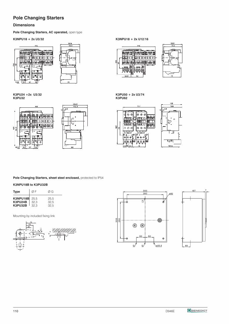
110 D946E
Pole Changing Starters
Dimensions
Pole Changing Starters, AC operated, open type
K3NPU18 + 2x U3/32 K3NPU18 + 2x U12/16
K3PU24 +2x U3/32 K3PU50 + 2x U3/74K3PU32 K3PU62
Pole Changing Starters, sheet steel enclosed, protected to IP54
K3NPU18B to K3PU32B
Type Ø F Ø G
K3NPU18B 25,5 25,5 K3PU24B 32,3 32,5 K3PU32B 32,3 32,5
Mounting by included fixing link

D946E 111
D.O.L. Starters
D.O.L. Starters With Start-Stop Buttons 112
D.O.L. Starters With Selector Switch 112
D.O.L. Starters With Selector Switch And 112Pneumatic Switch For Use In Moist Rooms
Enclosures 113
Accessories 113
Wiring Diagrams 115
Dimensions 116

112 D946E
D.O.L. Starters In Plastic Enclosure
Ratings Included Free order Protec- Conduit Type Coil voltage 1)
AC3 at Contactor Space extra tion Entries 230 220-240V 50Hz 230-264V 60Hz 380V f. Aux. Degree 400 380-415V 50Hz 400-440V 60Hz 400V Cont. Overload 415V HN.. Relay Pack Weight kW Type pcs. Type pcs. kg/pc.
D.O.L. Starters with Start-Stop/Reset Push Buttons
4 K3-10ND10 2 U12/16 K3 IP65 Ø 20,5mm P1T10 . . . 1 0,6
7,5 K3-18ND10 2 U12/16 K3 IP65 Ø 20,5mm P1T18 . . . 1 0,6
11 K3-22ND10 2 U12/16 K3 IP65 Ø 20,5mm P1T22 . . . 1 0,6
D.O.L. Starters with Selector Switch
4 K3-10ND10 2 U12/16 K3 IP65 Ø 20,5mm P1W10 . . . 1 0,6
7,5 K3-18ND10 2 U12/16 K3 IP65 Ø 20,5mm P1W18 . . . 1 0,6
11 K3-22ND10 2 U12/16 K3 IP65 Ø 20,5mm P1W22 . . . 1 0,6
D.O.L. Starters with Selector Switch and Pneumatic Switch for moist rooms
7,5 K3-18ND10 2 U12/16 K3 IP65 Ø 20,5mm P1W18P . . . 1 0,6
Push button and tube on request
Ordering Example: D.O.L. Starter with selector switch, plastic enclosed, rated AC3 at 400V 15,5A, rated control voltage 230V 50Hz - Order Type: P1W18 230 + U12/16E 18 K3
Pneumatic Button P1LT 1
Air Pressure Hose Length 5m P1LS-5 1
Pneumatic Switch
for refill of D.O.L. Starter P1W.. to P1W..P P1-LDR 1 0,02
Thermal Overload Relays Setting range Type Pack Weight A pcs. kg/pc.
0,12 - 0,18 U12/16E 0,18 K3 1 0,10 0,18 - 0,27 U12/16E 0,27 K3 1 0,10 0,27 - 0,4 U12/16E 0,4 K3 1 0,10 0,4 - 0,6 U12/16E 0,6 K3 1 0,10 0,6 - 0,9 U12/16E 0,9 K3 1 0,10 0,8 - 1,2 U12/16E 1,2 K3 1 0,10
1,2 - 1,8 U12/16E 1,8 K3 1 0,10 1,8 - 2,7 U12/16E 2,7 K3 1 0,10 2,7 - 4 U12/16E 4 K3 1 0,10
4 - 6 U12/16E 6 K3 1 0,10 6 - 9 U12/16E 9 K3 1 0,10 8 - 11 U12/16E 11 K3 1 0,10
10 - 14 U12/16E 14 K3 1 0,10 13 - 18 U12/16E 18 K3 1 0,10 17 - 23 U12/16E 23 K3 1 0,10
22 - 30 U12/16E 30 K3 1 0,13
Overload Relays with Quick Tripping Characteristic see page 120,121Technical data see contactors page 62 and thermal overload relays page 1251) Non-standard coil voltages see page 57
manual reset

D946E 113
Enclosures for Contactors
Suitable for Protection Conduit Entries Type Pack Weight contactor Degree Top Bottom pcs. kg/pc.
K3-07.. to K3-22.. IP65 2 x Ø 20,5mm 2 x Ø 20,5mm P1 1 0,35 K3-24..1) to K3-40..1)
with Reset Button
Suitable for Protection Conduit Entries Type Pack Weight contactor Degree Top Bottom pcs. kg/pc.
K3-10.. to K3-22.. IP65 2 x Ø 20,5mm 2 x Ø 20,5mm P1R 1 0,35 +U12/16.. K3
with Selector Switch
Suitable for Protection Conduit Entries Type Pack Weight contactor Degree Top Bottom pcs. kg/pc.
K3-10.. to K3-22.. IP65 2 x Ø 20,5mm 2 x Ø 20,5mm P1W 1 0,35 +U12/16.. K3
with Start-Stop Push Button
Suitable for Protection Conduit Entries Type Pack Weight contactor Degree Top Bottom pcs. kg/pc.
K3-10.. to K3-22.. IP65 2 x Ø 20,5mm 2 x Ø 20,5mm P1T 1 0,35 +U12/16.. K3
Indicator Units
Specifications Voltage Range Type Pack Weight pcs. kg/pc.
Coil Current Indicator, green (LED) 24 - 660V AC/DC K2-ING 10 0,02 Coil Current Indicator, red (LED) 24 - 660V AC/DC K2-INR 10 0,02 To be connected in series with the contactor coil. In case of coil interruption the indicator goes out. Voltage drop approx. 2 volts
Voltage Indicator, clear (glow-disc. l.) 220 - 415V AC/DC K2-UN 10 0,02 Voltage Indicator, red (LED) 24 - 120V AC/DC K2-UNR 10 0,02 To be connected parallel to the contactor coil. In case of applied voltage the indicator also lights at coil interruption.
Lens Caps For Indicator Units
Lens cap transparent LG9743T 10 0,005 Lens cap red LG9743R 10 0,005 Lens cap green LG9743GR 10 0,005 Mounting instructions see page 118
Heating Element
Specifications Voltage Range Type Pack Weight Power Consumption pcs. kg/pc.
To avoid condensed water on places 380 - 415V, 1,5W K2-HR 10 0,02 where high humidity is given together 220 - 240V, 1,5W K2-HR 230 10 0,02 with alterations of ambient temperature
Additional Terminals, Start Contact
Specification Cable Cross-sections to clamp mm² Type solid or flexib. w. multi- Pack Weight stranded flexible core cable end pcs. kg/pc.
Neutral Terminal 2 x 0,75-4 2 x 0,75-2,5 2 x 0,5-2,5 LG9744 10 0,009 Earth Terminal 2,5-16 1,5-10 1,5-10 LG9750 10 0,052 Mounting instructions see page 116
Start Contact for contactor to be snapped on top of LG9319-K3 10 0,03 K3-10 to K3-22 the auxiliary contact
1) without auxiliary contact blocks

114 D946E
D.O.L. Starters
Wiring Diagrams Main Circuit
All fuses F0 shown in the main circuits are not included.Terminal markings according to EN 50012
P1... Wiring for single phase motorswith overload relay U12/16.. K3
Wiring Diagrams Control Circuit
Coil connectors Coils for 380-415V 50Hz and 400-440V 60Hz: The starter is supplied with control circuit connectors between terminals1 (L1) and 5 (L3).Coils for 220-240V 50Hz and 230-264V 60Hz: The starter is supplied with control circuit connectors between terminals 95 and 5 (L3). Connect neutral wire to terminal A1.Coils for other voltages: Without connectors between supply and control circuit. Connect supply to terminals A1 and 95.
Coil phase to phase Coil phase to neutral(380-415V 50Hz) (220-240V 50Hz)
Separate coil supplyCoils for 380-415V 50Hz and 400-440V 60Hz: Remove connectors A1-1 and 95-5, connect supply to terminals A1 and 95.Coils for 220-240V 50Hz and 230-264V 60Hz: Remove connectors 95-5 connect supply to terminals A1 and 95.Coils for other voltages: Connect supply to terminals A1 and 95.
Coil phase to phase Coil phase to neutral
local controlor remote control
local controlor remote control
local controlor remote control
local controlor remote control
D.O.L. Starters with remote control
P1..Remote 2-wire (switch) control Remote 3-wire (push button) control Remote start-stop control (3 control stations)

D946E 115
D.O.L. Starters
Wiring Diagrams Control Circuits
Typical circuit diagram (for separate coil supply, control circuit connected between L1 and N)Terminal markings according to EN 50012
D.O.L. Starters with Start-Stop/Reset Push Buttons
P1T10, P1T18, P1T22 P1T10, P1T18, P1T22 with overload relay U12/16.. K3 with external push buttons
D.O.L. Starters with Selector Switch
P1W10, P1W18, P1W22 P1W10, P1W18, P1W22 with external control switch with external push buttons
D.O.L. Starters with Selector Switch and Pneumatic Switchfor Swimmingpool Control Gear and for use in Moist RoomsP1W18P with overload relay U12/16.. K3
push buttonON/OFF

116 D946E
D.O.L. Starters
Dimensions
D.O.L. Starters with Start-Stop/Reset Push Buttons, Plastic Enclosed D.O.L. Starters with Selector Switch, Plastic Enclosed
P1T.., P1TP.. P1W.., P1W18P
P1W18P: plug-in for air tube inside diameter 3mm
Rear Conduit Entries
knockouts 4 x Ø 23
Earth Terminal LG9750 for K2-23 and K2-30 in Enclosure P1 Neutral Terminal LG9744
for K2-23 and K2-30 remove spacing piece
LG9750
LG9744
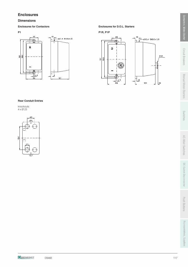
D946E 117
Enclosures
Dimensions
Enclosures for Contactors Enclosures for D.O.L. Starters
P1 P1R, P1P
Rear Conduit Entries
knockouts 4 x Ø 23

118 D946E
D.O.L. Starters
Mounting and Wiring Instructions
Indicators and Lens Caps for D.O.L. Starters P1
K2-UN., K2-IN.
LG9743.
Wiring Examples
Coil Current Indicator Voltage Indicator Heating Element K2-ING K2-UN K2-HR K2-HR 230K2-INR K2-UNR
red red
Colour mentioned in wiring diagrams refer to the outgoing connection wire of the device.
Start Contact LG9319-K3 for K3-10ND10 up to K3-22ND10

D946E 119
Thermal Overload Relays
Thermal Overload Relays for Direct Mounting 120
Thermal Overload Relays for Separate Mounting 122
Accessories 123
Technical Data 125
Dimensions 129

120 D946E
Thermal Overload Relays for plug-in mounting
Setting Range Type Pack Weight D.O.L. (A) (A) pcs. kg/pc. Wiring Diagram
With Manual Reset, for contactors K1-..
0,12 - 0,18 - U12/16E 0,18 K1 1 0,10 0,18 - 0,27 - U12/16E 0,27 K1 1 0,10 0,27 - 0,4 - U12/16E 0,4 K1 1 0,10 0,4 - 0,6 - U12/16E 0,6 K1 1 0,10 0,6 - 0,9 - U12/16E 0,9 K1 1 0,10 0,8 - 1,2 - U12/16E 1,2 K1 1 0,10
1,2 - 1,8 - U12/16E 1,8 K1 1 0,10 1,8 - 2,7 - U12/16E 2,7 K1 1 0,10 2,7 - 4 - U12/16E 4 K1 1 0,10
4 - 6 7 - 10,5 U12/16E 6 K1 1 0,10 6 - 9 10,5 - 15,5 U12/16E 9 K1 1 0,10 8 - 11 14 - 19 U12/16E 11 K1 1 0,10
10 - 14 18 - 24 U12/16E 14 K1 1 0,10
With Auto Reset, for contactors K1-..
0,12 - 0,18 - U12/16A 0,18 K1 1 0,10 0,18 - 0,27 - U12/16A 0,27 K1 1 0,10 0,27 - 0,4 - U12/16A 0,4 K1 1 0,10 0,4 - 0,6 - U12/16A 0,6 K1 1 0,10 0,6 - 0,9 - U12/16A 0,9 K1 1 0,10 0,8 - 1,2 - U12/16A 1,2 K1 1 0,10
1,2 - 1,8 - U12/16A 1,8 K1 1 0,10 1,8 - 2,7 - U12/16A 2,7 K1 1 0,10 2,7 - 4 - U12/16A 4 K1 1 0,10
4 - 6 7 - 10,5 U12/16A 6 K1 1 0,10 6 - 9 10,5 - 15,5 U12/16A 9 K1 1 0,10 8 - 11 14 - 19 U12/16A 11 K1 1 0,10
10 - 14 18 - 24 U12/16A 14 K1 1 0,10
With Quick Tripping Characteristic for EEx e motors and submersible pumps, f. contactors K1-..
0,4 - 0,6 - U12/16EQ 0,6 K1 1 0,10 0,6 - 0,9 - U12/16EQ 0,9 K1 1 0,10 0,8 - 1,2 - U12/16EQ 1,2 K1 1 0,10
1,2 - 1,8 - U12/16EQ 1,8 K1 1 0,10 1,8 - 2,7 - U12/16EQ 2,7 K1 1 0,10 2,7 - 4 - U12/16EQ 4 K1 1 0,10
4 - 6 7 - 10,5 U12/16EQ 6 K1 1 0,10 6 - 9 10,5 - 15,5 U12/16EQ 9 K1 1 0,10 8 - 11 14 - 19 U12/16EQ 11 K1 1 0,10
10 - 14 18 - 24 U12/16EQ 14 K1 1 0,10
manual reset
manual reset
auto resetor manual reset

D946E 121
Thermal Overload Relays for plug-in mounting
Setting Range Type Pack Weight D.O.L. (A) (A) pcs. kg/pc. Wiring Diagram With Manual Reset, for contactors K(G)3-10.. to K(G)3-22.. ..
0,12 - 0,18 - U12/16E 0,18 K3 1 0,10 0,18 - 0,27 - U12/16E 0,27 K3 1 0,10 0,27 - 0,4 - U12/16E 0,4 K3 1 0,10 0,4 - 0,6 - U12/16E 0,6 K3 1 0,10 0,6 - 0,9 - U12/16E 0,9 K3 1 0,10 0,8 - 1,2 - U12/16E 1,2 K3 1 0,10
1,2 - 1,8 - U12/16E 1,8 K3 1 0,10 1,8 - 2,7 - U12/16E 2,7 K3 1 0,10 2,7 - 4 - U12/16E 4 K3 1 0,10
4 - 6 7 - 10,5 U12/16E 6 K3 1 0,10 6 - 9 10,5 - 15,5 U12/16E 9 K3 1 0,10 8 - 11 14 - 19 U12/16E 11 K3 1 0,10
10 - 14 18 - 24 U12/16E 14 K3 1 0,10 13 - 18 23 - 31 U12/16E 18 K3 1 0,10 17 - 23 30 - 40 U12/16E 23 K3 1 0,10
22 - 30 38 - 52 U12/16E 30 K3 1 0,13
With quick Tripping Characteristic for EEx e motors and under water pumps
0,4 - 0,6 - U12/16EQ 0,6 K3 1 0,10 0,6 - 0,9 - U12/16EQ 0,9 K3 1 0,10 0,8 - 1,2 - U12/16EQ 1,2 K3 1 0,10
1,2 - 1,8 - U12/16EQ 1,8 K3 1 0,10 1,8 - 2,7 - U12/16EQ 2,7 K3 1 0,10 2,7 - 4 - U12/16EQ 4 K3 1 0,10
4 - 6 7 - 10,5 U12/16EQ 6 K3 1 0,10 6 - 9 10,5 - 15,5 U12/16EQ 9 K3 1 0,10 8 - 11 14 - 19 U12/16EQ 11 K3 1 0,10
10 - 14 18 - 24 U12/16EQ 14 K3 1 0,10
For contactors K(G)3-10.. to K(G)3-40A..
0,12 - 0,18 - U3/32 0,18 1 0,14 0,18 - 0,27 - U3/32 0,27 1 0,14 0,27 - 0,4 - U3/32 0,4 1 0,14
0,4 - 0,6 - U3/32 0,6 1 0,14 0,6 - 0,9 - U3/32 0,9 1 0,14 0,8 - 1,2 - U3/32 1,2 1 0,14
1,2 - 1,8 - U3/32 1,8 1 0,14 1,8 - 2,7 - U3/32 2,7 1 0,14 2,7 - 4 - U3/32 4 1 0,14
4 - 6 7 - 10,5 U3/32 6 1 0,14 6 - 9 10,5 - 15,5 U3/32 9 1 0,14 8 - 11 14 - 19 U3/32 11 1 0,14
10 - 14 18 - 24 U3/32 14 1 0,14 13 - 18 23 - 31 U3/32 18 1 0,14 17 - 24 30 - 41 U3/32 24 1 0,14
23 - 32 40 - 55 U3/32 32 1 0,14
For contactors K(G)3-24A.. to K(G)3-40A ..
10 - 14 18 - 24 U3/42 14 1 0,30 14 - 20 24 - 35 U3/42 20 1 0,30
20 - 28 35 - 48 U3/42 28 1 0,30 28 - 42 48 - 73 U3/42 42 1 0,30
manual reset
manual and auto reset
manual and auto reset
manual reset

122 D946E
Thermal Overload Relays for plug-in mounting
Setting Range Type Pack Weight D.O.L. (A) (A) pcs. kg/pc. Wiring Diagram
For contactors K3-50A.. to K3-74A..
20 - 28 35 - 48 U3/74 28 1 0,40 28 - 42 48 - 73 U3/74 42 1 0,40 40 - 52 70 - 90 U3/74 52 1 0,40
52 - 65 90 - 112 U3/74 65 1 0,40 60 - 74 104 - 128 U3/74 74 1 0,40
Thermal Overload Relays for separate mounting
Setting Range Type Pack Weight D.O.L. (A) (A) pcs. kg/pc. Wiring Diagram For contactors K3-90, K3-115, K85, K110
60 - 90 104 - 156 U85 90 1 0,90 80 - 120 140 - 207 U85 120
For contactors K3-151.. and K3-176.., busbars included
120 - 180 208 - 312 U180 180 1 1,5
For contactors K3-210.. up to K3-316.., busbars included
144 - 216 250 - 374 U320 216 1 1,8 216 - 320 374 - 554 U320 320
For contactors K3-315.. , K3-450.. , K3-550.. , K3-700.. , K3-860..
240 - 360 416 - 623 U800 360 1 4,1 360 - 540 623 - 935 U800 540 1 4,1
540 - 800 935 - 1385 U800 800 1 4,1
With Slow Tripping Characteristic for heavy duty starting with long run up times For separate mounting, suitable for all contactors 0,8 - 1,2 1,2 - 2,1 UAT21 1,2 1 1,0 1,2 - 1,8 2,1 - 3,1 UAT21 1,8 1 1,0 1,6 - 2,4 2,8 - 4,2 UAT21 2,4 1 1,0
2,4 - 3,7 4,2 - 6,4 UAT21 3,7 1 1,0 3,7 - 5,7 6,4 - 9,9 UAT21 5,7 1 1,0 5,3 - 8,2 9,2 - 14,2 UAT21 8,2 1 1,0
8 - 12 13,9 - 20,1 UAT21 12 1 1,0 12 - 18 20,1 - 31,2 UAT21 18 1 1,0
16 - 24 27,7 - 41,6 UAT22 24 1 1,1
24 - 37 41,6 - 64 UAT23 37 1 1,3 32 - 49 55,4 - 85 UAT23 49 1 1,3 48 - 72 83 - 125 UAT23 72 1 1,3
manual reset
manual and auto reset
manual reset
manual and auto reset

D946E 123
Accessories
Type Pack Weight for overload relays for contactors set kg/set
Busbar Sets U800 K3-450.. , K3-550.. SU840/550 1 1,7 U800 K3-700.. , K3-860.. SU840/860 1 2,1
Cable Cross-section (mm2) Type solid or Pack Weight for overload relay stranded flexible pcs. kg/pc.
Set for Single Mounting on DIN-rail with terminals
U12/16..K3 0,75 - 6 0,75 - 4 U12SM K3 1 0,035
Additional Terminals with fingertouch protection
U3/32 0,75 - 6 0,75 - 4 U3/32SM 1 0,035
Set for Single Mounting on DIN-rail
U3/42, U3/74 - - U3/42G 1 0,030
Connecting Wire Set for U3/42, U3/74 with Single Mounting
U3/42, U3/74 150mm lang 10mm2 LG5830-4 1 0,060 U3/42, U3/74 250mm lang 10mm2 LG5830-2 1 0,100
Additional Terminals with fingertouch protection
1-pole f. U12/16, U3/32 0,75 - 10 0,75 - 6 LG9339 1 0,009
3-pole for U3/42 4 - 35 6 - 25 LG7559 1 0,052

124 D946E
Thermal Overload Relays, tripping times for selection to motors of protection degree EEx e
Labels of tripping curves for each setting range, sized 148x105mm (self-adhesive) are available on request.Order No. D588, specify type and setting range.
ratio IA/IN
Time tE /Tripping times
Example of selection for thermal overload relay:Technical data of a motor protection EEx ePN= 1,5kW IN = 3,6A IA/IN = 5 tE time = 8s
1) U12/16E 4 (2,7 - 4A)Tripping time at 5 x IN = 9,9s9,9s + 20% tolerance = 11,9s > tE Motor = 8sThe device U12/16E 4 is not suitable.
2) U12/16EQ 4 (2,7 - 4A)Tripping time at 5 x IN = 4,1s4,1s + 20% tolerance = 4,9s < tE Motor = 8sThe device U12/16EQ 4 is therefore suitablefor motor protection
Typical tripping curve for overload relay U12/16E
Minimum values oftE time (motor)acc. to EN50019
Typical tripping curve for overload relay U12/16EQ
Relays With Standard Tripping Characteristic
Setting Range Tripping time depending on the multiple of the current setting from cold condition (tolerance ±20% of the tripping time) IA/IN IA/IN IA/IN IA/IN IA/IN IA/IN
A A 3 4 5 6 7,2 8
U3/32 .. s s s s s s
0,12 - 0,18 16,1 9,6 6,8 5,3 4,2 3,7 0,18 - 0,27 16,6 9,7 6,7 5,2 4,1 3,6 0,27 - 0,4 19,4 11,4 7,9 6,1 4,7 4,2 0,4 - 0,6 18,7 10,9 7,6 5,9 4,6 4,0
0,6 - 0,9 19,2 11,2 7,7 5,9 4,6 4,1 0,8 - 1,2 20,8 12,3 8,5 6,6 5,2 4,6 1,2 - 1,8 25,5 14,1 9,8 7,6 5,9 5,2 1,8 - 2,7 26,6 15,6 10,9 8,3 6,5 5,7
2,7 - 4 22,7 13,6 9,5 7,4 5,8 5,1 4 - 6 22,2 13,3 9,3 7,1 5,6 4,9 6 - 9 20,4 11,9 8,2 6,1 4,7 4,0 8 - 11 20,9 11,8 7,9 5,7 4,3 3,5
10 - 14 21,3 11,7 7,4 5,1 3,7 3,0 13 - 18 21,2 12,1 8,0 6,2 4,6 4,1 17 - 24 20,4 12,0 8,6 6,3 4,5 3,7 23 - 32 20,2 10,2 6,7 4,7 3,4 2,8
U3/42 s s s s s s
10 - 14 21,8 11,4 7,0 5,0 3,7 2,8 14 - 20 22,4 11,2 6,7 4,5 3,2 2,4 20 - 28 21,8 10,8 6,5 4,5 3,3 2,5 28 - 42 25,2 13,3 8,0 5,5 4,0 3,1
U3/74 s s s s s s
20 - 28 21,8 10,8 6,5 4,5 3,3 2,5 28 - 42 25,2 13,3 8,0 5,5 4,0 3,1 40 - 52 18,3 9,2 5,6 3,9 2,8 2,2 52 - 65 17,8 8,7 5,2 3,4 2,5 1,9
U85 .. s s s s s s
60 - 90 19,5 13,5 11,0 10,0 9,5 8,5 80 - 120 18,0 11,0 10,0 9,0 8,5 8,0
U840 .. s s s s s s
260 - 360 23,3 14,1 10,0 7,6 6,1 5,4 340 - 480 23,0 13,8 9,6 7,6 6,1 5,4 440 - 620 20,5 12,4 9,0 7,0 5,5 5,0 560 - 800 21,0 12,5 9,0 7,0 5,6 5,2
U12/16E(A) .. s s s s s s
0,12 - 0,18 18,5 10,4 7,2 5,5 4,3 3,6 0,18 - 0,27 16,7 9,8 6,5 5,0 4,1 3,5 0,27 - 0,4 19,4 12,1 8,2 5,9 4,9 4,2 0,4 - 0,6 18,7 11,2 8,0 6,0 4,9 4,1
0,6 - 0,9 19,7 11,6 8,1 6,1 4,9 4,2 0,8 - 1,2 22,9 13,6 10,0 7,3 6,0 5,2 1,2 - 1,8 22,2 13,2 9,2 7,6 5,8 5,3 1,8 - 2,7 23,0 13,7 9,3 7,6 5,7 5,1
2,7 - 4 24,0 14,4 9,9 7,8 5,9 5,1 4 - 6 24,7 13,8 9,9 7,3 5,6 4,8 6 - 9 22,0 13,4 8 5,7 4,1 3,5 8 - 11 17,4 9,2 5,9 4,1 2,9 2,3
10 - 14 26,4 12,9 7,6 5,2 3,5 2,8 13 - 18 14,7 7,7 4,8 3,2 2,3 1,7 17 - 23 16,2 8,4 5,0 3,6 2,4 1,8 22 - 30 16,8 8,5 5,0 3,6 2,3 1,9
Relays With Quick Tripping Characteristicpreferably for motors with short tE time and for submersible pumps
Setting Range Tripping time depending on the multiple of the current setting from cold condition (tolerance ±20% of the tripping time) IA/IN IA/IN IA/IN IA/IN IA/IN IA/IN
A A 3 4 5 6 7,2 8
U12/16EQ .. s s s s s s
0,4 - 0,6 13,6 8,4 5,9 4,2 3,3 3,0 0,6 - 0,9 13,8 7,8 5,2 4,1 3,2 2,7 0,8 - 1,2 13,1 7,5 5,2 3,9 3,1 2,7 1,2 - 1,8 14,6 8,7 6,0 4,6 3,6 3,2
1,8 - 2,7 13,5 7,6 5,3 3,9 3,1 2,7 2,7 - 4 11,0 6,0 4,1 2,6 1,7 1,4 4 - 6 9,6 5,3 3,3 2,3 1,6 1,3 6 - 9 10,2 5,4 3,4 2,3 1,6 1,3
8 - 11 12,0 6,2 3,9 2,5 1,8 1,3 10 - 14 12,8 6,6 4,0 2,6 1,8 1,4
All tripping times of overload relays U12/16EQ are shorter than the minimum values of the tE time for motors of protection degree EEx e acc. to EN 50019 and therefore are suitable for all motors of protection degree EEx e. For these overload relays the selection on basis of tripping curves is thereby not necessary.
When selecting a standard overload, refer to the tripping curve. Deter-mine the values of the starting current ratio IA/IN and the time tE which is marked on the label of the motor. The overload must trip within the tE time, which means that the tripping curve from cold condition must be (20% due to tolerance) below the co-ordination point IA/IN and the time tE.IA = Starting current of motor IN = Rated current of motortE = tE-time of motor

D946E 125
1) Coordination-type according to IEC 947-4-1: "2": Light contact welding accepted. Thermal overload relay must not be damaged. "1": Welding of contactor and damage of the thermal overload relay allowed.2) Miniature fuse 3) Suitable for use on a capability of delivering not more than
with two-pole load
Tripping time (Typical tolerance curvemin. s from cold condition)
Pro
ceed
ing
from
ser
vice
con
ditio
n th
e tim
es d
ecre
ase
to 7
0-80
% o
f the
cha
ract
eris
tic v
alue
sTripping Characteristics for U3/32, U3/42, U3/74 and U12/16EDetailed tripping times for each range see table page 124
with three-phase load
Tripping time (Average value of typical tolerance curvesmin. s from cold condition)
K =Imax /Ie Imax = max. phase current Ie = max. scale value
F. L. C. multiplication factor
Pro
ceed
ing
from
ser
vice
con
ditio
n th
e tim
es d
ecre
a-se
to 2
0-30
% o
f the
cha
ract
eris
tic v
alue
s
Thermal Overload Relays
Fuses for U3/32, U3/42, U3/74, U12/16E, U85, U180, U320 and U800
Max. Fuse Size According to Coordination-type Fuse UL SCCRType Setting Range "2" 1) "1" 1) DOL quick slow, gL(gG) slow, gL(gG) aM A A A A A A A kA
U3/32 0,12 - 0,18 - 0,5 2) 0,5 2) 25 - 15 5(U12/16E) 0,18 - 0,27 - 1,0 2) 1,0 2) 25 - 15 5 0,27 - 0,4 - 2 2 25 - 15 5 0,4 - 0,6 - 2 2 25 - 15 5 0,6 - 0,9 - 4 4 25 - 15 5 0,8 - 1,2 - 4 4 25 2 15 5 1,2 - 1,8 - 6 6 25 2 15 5 1,8 - 2,7 - 10 10 25 4 15 5 2,7 - 4 - 16 10 25 4 15 5 4 - 6 7 - 10,5 20 16 25 6 15 5 6 - 9 10,5 - 15,5 35 25 35 10 25 5 8 - 11 14 - 19 35 25 35 16 30 5 10 - 14 18 - 24 50 35 63 16 40 5 13 - 18 23 - 31 50 35 63 20 50 5 17 - (23)24 30 - (40)41 63 50 63 25 60 5 (22)23 - (30)32 (38)40 - (52)55 80 63 80 35 70 5
U3/42 10 - 14 18 - 24 50 35 80 16 40 5 14 - 20 24 - 35 63 50 80 25 60 5 20 - 28 35 - 48 80 63 80 35 80 5 28 - 42 48 - 73 100 80 150 50 110 5
U3/74 20 - 28 35 - 48 100 80 150 35 80 5 28 - 42 48 - 73 125 100 150 50 110 5 40 - 52 70 - 90 160 100 150 63 200 5 52 - 65 90 - 112 160 125 150 80 250 10 60 - 74 104 - 128 160 125 150 80 250 10
U85 60 - 90 104 - 156 300 10 80 - 120 140 - 207 - 10 For short circuit protecting overload relays withU180, U320 all ranges current transformer use fuse according to the - - U800 all ranges contactor of the combination. - -

126 D946E
Thermal Overload Relays Tripping Characteristics for U85, U180, U320, and U800 Detailed tripping times for each range of U85 see table page 124
U85 with three-phase load U180, U320 with three-phase load U800 with three-phase load
Tripping time (Average value of typical tolerance Tripping time (Average value of typical tolerance Tripping time (Average value of typical tolerance min. s curves from cold condition) min. s curves from cold condition) min. s curves from cold condition)
U85 with two-pole load
Tripping time (Typical tolerance curve min. s from cold condition)
Position of Terminals
U3/32 U12/16E, U12/16EM, U12/16EQ U12/16A U3/42, U3/74
Pro
ceed
ing
from
ser
vice
con
ditio
n th
e tim
es d
ecre
ase
to 7
0-80
% o
f the
cha
ract
eris
tic v
alue
s
F. L. C. multiplication factor F. L. C. multiplication factor
Pro
ceed
ing
from
ser
vice
con
ditio
n th
e tim
es d
ecre
a-se
to 2
0-30
% o
f the
cha
ract
eris
tic v
alue
s
Pro
ceed
ing
from
ser
vice
con
ditio
n th
e tim
es d
ecre
a-se
to 2
0-30
% o
f the
cha
ract
eris
tic v
alue
s
K =Imax /Ie Imax = max. phase current Ie = max. scale value
Pro
ceed
ing
from
ser
vice
con
ditio
n th
e tim
es d
ecre
a-se
to 2
0-30
% o
f the
cha
ract
eris
tic v
alue
s
F. L. C. multiplication factor

D946E 127
1) Coordination-type according to IEC 947-4-1: "2": Light contact welding accepted. Thermal overload relay must not be damaged. "1": Welding of contactor and damage of the thermal overload relay allowed.
Tripping Characteristic for U12/16EQDetailed tripping times for each range see table page 124
with three-phase load
range 0,4-0,6 to 1,8-2,7ATripping time (Typical tolerance curvemin. s from cold condition)
Tripping Characteristic for U12/16EM
with three-phase load
Tripping time (Average value of typical tolerance min. s curves from cold condition)
range 2,7-4 to 10-14ATripping time (Typical tolerance curvemin. s from cold condition)
Fuse for UAT21, UAT22, UAT23
For short circuit protecting thermal overload relays with current trans-former use fuse according to the contactor of the combination.
Lower scale valueUpper scale value
Tripping characteristic for UAT21, UAT22, UAT23
with three-phase load
Tripping time in s (Typical tolerance curve from cold condition)
F. L. C. multiplication factor
F. L. C. multiplication factor
Pro
ceed
ing
from
ser
vice
con
ditio
n th
e tim
es d
ecre
ase
to 2
0-30
% o
f the
cha
ract
eris
tic v
alue
sP
roce
edin
g fro
m s
ervi
ce c
ondi
tion
the
times
dec
reas
e to
20-
30%
of t
he c
hara
cter
istic
val
ues
Pro
ceed
ing
from
ser
vice
con
ditio
n th
e tim
es d
ecre
ase
to 2
0-30
% o
f the
cha
ract
eris
tic v
alue
s
Proceeding from service condition the times decrease to 20-30% of the characteri-stic values
F. L. C. multiplication factor
F. L. C. multiplication factor
Thermal Overload Relays in Special Version
Fuse for U12/16EQ
Setting Range Maximum Fuse Acc. to Coordination-type "2" 1) "1" 1) quick slow, gL(gG) slow, gL(gG) A A A A
0,4 - 0,6 2 2 25 0,6 - 0,9 4 4 25 0,8 - 1,2 4 4 25
1,2 - 1,8 6 6 25 1,8 - 2,7 10 10 25 2,7 - 4 16 10 25
4 - 6 20 16 25 6 - 9 35 25 35 8 - 11 35 25 35
10 - 14 50 35 63
Fuse for U12/16EM
Setting Range Maximum Fuse Acc. to Coordination-type "2" 1) 380-400V 500V 660-690V slow, gL(gG) slow, gL(gG) slow, gL(gG) A A A A
0,12 - 0,18 none none on request 0,18 - 0,27 none none on request 0,27 - 0,4 none none on request
0,4 - 0,6 none none on request 0,6 - 0,9 none none on request 0,8 - 1,2 none 10 on request 1,2 - 1,8 none 16 on request 1,8 - 2,7 20 20 on request 2,7 - 4 35 35 on request

128 D946E
Example: Ambient temperature 70°C, full load motor current 7A (70 - 20) x 0,125 = 6,25% Setting value: 7A + 6,25% = 7,44A
Temperature Compensation
In case of higher ambient temperature use the following formula:(Ambient temperature - 20) x 0,125 = correction factor in % of the full load motor current
1) Suitable for: earthed-neutral systems, overvoltage category I to III, pollution degree 3 (standard-industry): Uimp = 4kV (at 440V), 6kV (at 690V). Data for other conditions on request.2) Maximum cable cross-section with prepared conductor3) Without terminals, suitable for bushing one connector 70mm² (stranded) per phase4) Switching capacity of the start contact: AC15 300VA, max. 1,5A, DC13 (max. 220V) 30W, max. 1,5A5) Switching capacity of the make contact: AC15 400VA, max. 1,7A, DC13 (max. 220V) 10W, max. 1A6) U12/16E 30: Cable cross-section for main connector like type U3/42, one connector only7) Busbar sets see accessories page 123
Thermal Overload Relays
Data according to IEC 947-4-1, IEC 947-5-1, VDE 0660, EN 60947-4-1, EN 60947-5-1
Type U3/32 U12/16 6) U3/42 U3/74 U85 U180 U320 U800 UAT21 UAT22 UAT23
Rated insulation voltage Ui 1)
V~ 690 690 690 690 750 1000 1000 1000 690 690 690Permissible ambient temperature operation open °C -25 to +60 -25 to +55 -25 to +60storage °C -50 to +70 -40 to +70 -50 to +70
Trip class according to IEC 947-4-1 10A 10A 10A 10A 10A 20 10A 10A 10 30 30 30
Cable cross-section main connector solid or stranded mm² 0,75-6 0,75-6+0,75-2,5 2) 0,75-10 4-35 2) 3) 7) - 7) 0,5-10 0,5-16 0,5-25 flexible mm² 1-4 0,75-4+0,5-2,5 2 ) 0,75-6 6-25 2) 0,5-6 0,5-10 0,5-16 flexible with multicore cable end mm² 0,75-4 0,5-2,5+0,5-1,5 0,75-6 4-25 0,5-6 0,5-10 0,5-16Cables per clamp number 2 1+1 2 1 1 1 1
auxiliary connector solid mm² 0,75-2,5 2) 1-2,52) 0,75-2,5 2)
flexible mm² 0,5-2,5 2) 1-2,5 2) 0,5-2,5 2)
flexible with multicore cable end mm² 0,5-1,5 1-2,5 2) 0,5-1,5Cables per clamp number 2 2 2
Type U3/32 U12/16A U12/16E U12/16EQ U3/42 U85 U180 U800 UAT21 U12/16EM U3/74 U320 UAT22Auxiliary contacts UAT23Rated insulation voltage Ui
1)
same potential V~ 690 690 690 690 690 690 690 500 690different potential V~ 440 - 440 440 250 440 440 500 440
Utilization category AC15 Rated operational 24V A 3 4 5 5 4 5 3 4 5) 5current Ie 230V A 2 2,5 3 3 2,5 3 2 2,5 3 400V A 1 1,5 2 2 1,5 2 1 1,5 2 690V A 0,5 0,6 0,6 0,6 0,6 0,6 0,5 0,6 0,6
Utilization category DC13 Rated operational 24V A 1 1,2 1,2 1,2 1,2 1,2 1 1,2 1,2current Ie 110V A 0,15 0,15 0,15 0,15 0,15 0,15 0,15 0,15 0,15 220V A 0,1 0,1 0,1 0,1 0,1 0,1 0,1 0,1 0,1
Short circuit prot. (without welding 1kA)highest fuse rating gL (gG) A 4 4 6 6 6 6 4 6 6
Type U3/32 U12/16 U12/16E U3/42 U3/42 U3/74 U3/74 U85Setting range all to 23A 22 - 30A to 28A 28 - 42A to 52A 52 - 65A all
Power loss per current path (max.) minimum setting value W 1,1 1,1 1,7 1,3 1,3 2,0 2,9 1,1maximum setting value W 2,3 2,3 3,7 2,6 3,3 3,7 4,5 2,5
Data according to cULus
Type U3/32 U12/16A U12/16E U12/16EQ U3/42 U3/74 U85
Rated insulation voltage V~ 600 600 600 600 600 600 600Rated current A 32 23 23 23 42 75 85 Auxiliary contactsRated voltagesame potential V~ 600 600 600 600 600 600 600different potential V~ 150 - 150 150 150 150 150
Switching capacity AC VA 500 500 500 500 600 600 600of aux. contacts A 2 3 4 4 4 4 4

D946E 129
Thermal Overload Relays
Dimensions
K3-10N + U3/32 KG3-10 + U3/32K3-14N KG3-14K3-18N KG3-18K3-22N KG3-22
K3-24 + U3/32 KG3-24 + U3/32K3-32 KG3-32K3-40 KG3-40
K3-24 + U3/42 KG3-24 + U3/42K3-32 KG3-32K3-40 KG3-40
U3/32SM U3/42G +LG5830-. Changing of connecting wire with 1,8Nm

130 D946E
Thermal Overload Relays
Dimensions
K1-09 + U12/16.. K1 K3-10 + U12/16..K3K1-12 K3-14 K3-18 K3-22
K3-10N + U12/16..K3 KG3-10 + U12/16..K3K3-14N KG3-14K3-18N KG3-18K3-22N KG3-22
U12SM K3
U12/16..K3 + U12SM K3 for snap-on 35mm DIN-rail according to DIN EN50022 and screw mounting (single mounting)
K3-50 + U3/74 K3-62 K3-74

D946E 131
Thermal Overload Relays
Dimensions
K3-90A + U85K3-115A
K3-151A00 + U180 Mounting holes K3-176A00
K3-210A00 + U320 Mounting holes K3-260A00 K3-316A00

132 D946E
Thermal Overload Relays
Dimensions
U800
U800 with A B C D E F G H J K
K3-450 220 372 110 220 158 40 185 225 12,5 9K3-550 220 395 110 220 158 40 196 225 12,5 9
K3-700 280 487 175 280 202 50 257 291 14,5 11K3-860 280 540 175 280 202 50 280 291 14,5 11
UAT21 UAT22
UAT23
Type Setting Range A B
UAT23 37 23-37A 105,5 97,5UAT23 49 32-49A 94 86UAT23 72 48-72A 94 86

D946E 133
Modular Contactors
Modular Contactors 134
Auxiliary Contact Block 135Accessories 135
Day-Night Reloading Contactors 136
Switching Of Lamps 136
Technical Data 138
Dimensions 140
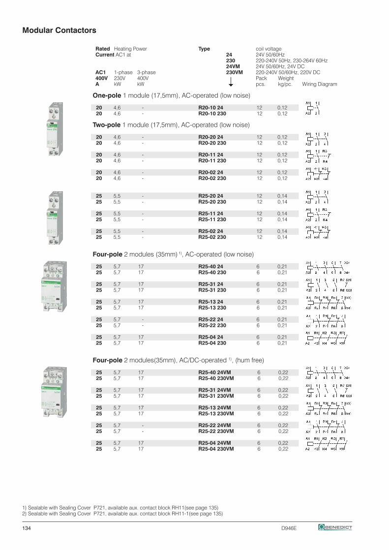
134 D946E
Modular Contactors
Rated Heating Power Type coil voltage Current AC1 at 24 24V 50/60Hz 230 220-240V 50Hz, 230-264V 60Hz 24VM 24V 50/60Hz, 24V DC AC1 1-phase 3-phase 230VM 220-240V 50/60Hz, 220V DC 400V 230V 400V Pack Weight A kW kW pcs. kg/pc. Wiring Diagram
One-pole 1 module (17,5mm), AC-operated (low noise)
20 4,6 - R20-10 24 12 0,12 20 4,6 - R20-10 230 12 0,12
Two-pole 1 module (17,5mm), AC-operated (low noise)
20 4,6 - R20-20 24 12 0,12 20 4,6 - R20-20 230 12 0,12
20 4,6 - R20-11 24 12 0,12 20 4,6 - R20-11 230 12 0,12
20 4,6 - R20-02 24 12 0,12 20 4,6 - R20-02 230 12 0,12
25 5,5 - R25-20 24 12 0,14 25 5,5 - R25-20 230 12 0,14
25 5,5 - R25-11 24 12 0,14 25 5,5 - R25-11 230 12 0,14
25 5,5 - R25-02 24 12 0,14 25 5,5 - R25-02 230 12 0,14
Four-pole 2 modules (35mm) 1), AC-operated (low noise)
25 5,7 17 R25-40 24 6 0,21 25 5,7 17 R25-40 230 6 0,21
25 5,7 17 R25-31 24 6 0,21 25 5,7 17 R25-31 230 6 0,21
25 5,7 17 R25-13 24 6 0,21 25 5,7 17 R25-13 230 6 0,21
25 5,7 - R25-22 24 6 0,21 25 5,7 - R25-22 230 6 0,21
25 5,7 17 R25-04 24 6 0,21 25 5,7 17 R25-04 230 6 0,21
Four-pole 2 modules(35mm), AC/DC-operated 1), (hum free)
25 5,7 17 R25-40 24VM 6 0,22 25 5,7 17 R25-40 230VM 6 0,22
25 5,7 17 R25-31 24VM 6 0,22 25 5,7 17 R25-31 230VM 6 0,22
25 5,7 17 R25-13 24VM 6 0,22 25 5,7 17 R25-13 230VM 6 0,22
25 5,7 - R25-22 24VM 6 0,22 25 5,7 - R25-22 230VM 6 0,22
25 5,7 17 R25-04 24VM 6 0,22 25 5,7 17 R25-04 230VM 6 0,22
1) Sealable with Sealing Cover P721, available aux. contact block RH11(see page 135)2) Sealable with Sealing Cover P721, available aux. contact block RH11-1(see page 135)

D946E 135
Modular Contactors
Rated Heating Power Type coil voltage Current AC1 at 24 24V 50/60Hz AC1 1-phase 3-phase 230 220-240V 50Hz, 230-264V 60Hz 400V 230V 400V Pack Weight A kW kW pcs. kg/pc. Wiring Diagram
Two-pole 2 modules (35mm), AC-operated (low noise)
40 9 - R40-20 24 6 0,23 40 9 - R40-20 230 6 0,23
40 9 - R40-02 24 6 0,23 40 9 - R40-02 230 6 0,23
63 14,3 - R63-20 24 6 0,23 63 14,3 - R63-20 230 6 0,23
63 14,3 - R63-02 24 6 0,23 63 14,3 - R63-02 230 6 0,23
Four-pole 3 modules (52,5mm) 1), AC-operated (low noise)
40 9 27,5 R40-40 24 4 0,35 40 9 27,5 R40-40 230 4 0,35
40 9 27,5 R40-31 24 4 0,35 40 9 27,5 R40-31 230 4 0,35
40 9 - R40-22 24 4 0,35 40 9 - R40-22 230 4 0,35
40 9 27,5 R40-04 24 4 0,35 40 9 27,5 R40-04 230 4 0,35
63 14,3 43 R63-40 24 4 0,36 63 14,3 43 R63-40 230 4 0,36
63 14,3 43 R63-31 24 4 0,36 63 14,3 43 R63-31 230 4 0,36
63 14,3 - R63-22 24 4 0,36 63 14,3 - R63-22 230 4 0,36
63 14,3 43 R63-04 24 4 0,36 63 14,3 43 R63-04 230 4 0,36
Auxiliary Contact Block ½ module (8,8mm) for contactor R25 (4p.), R40, R63 (max. 1pc.)
Rated current Type AC15 AC15 AC1 230V 400V 400V Pack Weight A A A for contactor pcs. kg/pc. Wiring Diagram
3 2 10 R25 2), R40, R63 RH11 3 0,026
3 2 10 R25-..VM RH11-1 3 0,026 Accessories Type Pack Weight pcs. kg/pc.
RC-unit 2x for R20.. to R63.. RC-R 230 2 0,05 for 12V to 250V AC 220nF / 100 Ohm not for R25-..VM
Spacing piece ½ module (8,8mm) P730 10 0,012 for R20.. to R63.. for ambient temperature >40°C
Sealing cover for R25.. (4p.) P721 10 0,002 Sealing cover for R40.., R63.. P690 10 0,003
1) Sealable with Sealing Cover P690, available aux. contact block RH112) AC-operated R25-.., 4-pole
≤ 40°C
40 - 60°C
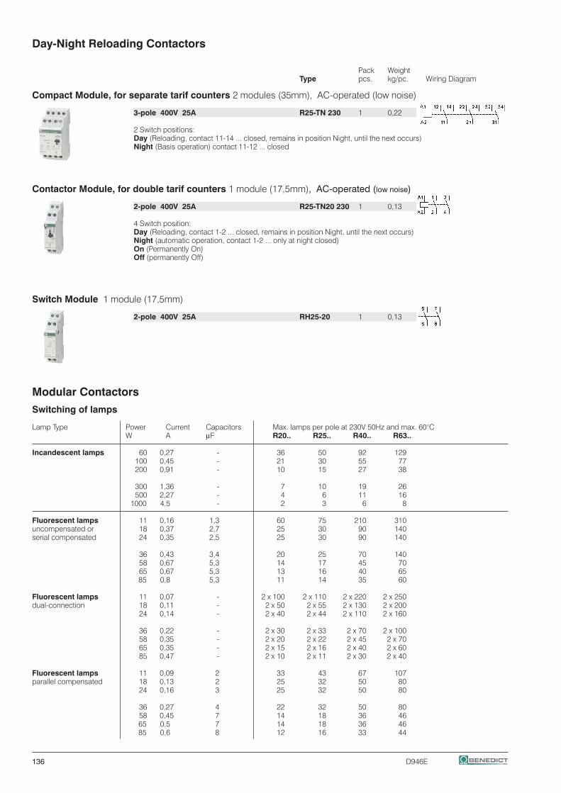
136 D946E
Day-Night Reloading Contactors
Pack Weight Type pcs. kg/pc. Wiring Diagram
Compact Module, for separate tarif counters 2 modules (35mm), AC-operated (low noise)
3-pole 400V 25A R25-TN 230 1 0,22
2 Switch positions: Day (Reloading, contact 11-14 ... closed, remains in position Night, until the next occurs) Night (Basis operation) contact 11-12 ... closed
Contactor Module, for double tarif counters 1 module (17,5mm), AC-operated (low noise)
2-pole 400V 25A R25-TN20 230 1 0,13
4 Switch position: Day (Reloading, contact 1-2 ... closed, remains in position Night, until the next occurs) Night (automatic operation, contact 1-2 ... only at night closed) On (Permanently On) Off (permanently Off)
Switch Module 1 module (17,5mm) 2-pole 400V 25A RH25-20 1 0,13
Modular Contactors
Switching of lamps
Lamp Type Power Current Capacitors Max. lamps per pole at 230V 50Hz and max. 60°C W A µF R20.. R25.. R40.. R63..
Incandescent lamps 60 0,27 - 36 50 92 129 100 0,45 - 21 30 55 77 200 0,91 - 10 15 27 38
300 1,36 - 7 10 19 26 500 2,27 - 4 6 11 16 1000 4,5 - 2 3 6 8
Fluorescent lamps 11 0,16 1,3 60 75 210 310 uncompensated or 18 0,37 2,7 25 30 90 140 serial compensated 24 0,35 2,5 25 30 90 140
36 0,43 3,4 20 25 70 140 58 0,67 5,3 14 17 45 70 65 0,67 5,3 13 16 40 65 85 0,8 5,3 11 14 35 60
Fluorescent lamps 11 0,07 - 2 x 100 2 x 110 2 x 220 2 x 250 dual-connection 18 0,11 - 2 x 50 2 x 55 2 x 130 2 x 200 24 0,14 - 2 x 40 2 x 44 2 x 110 2 x 160
36 0,22 - 2 x 30 2 x 33 2 x 70 2 x 100 58 0,35 - 2 x 20 2 x 22 2 x 45 2 x 70 65 0,35 - 2 x 15 2 x 16 2 x 40 2 x 60 85 0,47 - 2 x 10 2 x 11 2 x 30 2 x 40
Fluorescent lamps 11 0,09 2 33 43 67 107 parallel compensated 18 0,13 2 25 32 50 80 24 0,16 3 25 32 50 80
36 0,27 4 22 32 50 80 58 0,45 7 14 18 36 46 65 0,5 7 14 18 36 46 85 0,6 8 12 16 33 44

D946E 137
Modular Contactors
Switching of lamps
Lamp Type Power Current Capacitors Max. lamps per pole at 230V 50Hz and max. 60°C W A mF R20.. R25.. R40.. R63..
Fluorescent lamps 18 0,09 - 40 40 100 150 with electronic fluorescent 36 0,16 - 20 20 52 75 lamp ballast 58 0,25 - 15 15 30 55 80 0,4 - 7 10 20 30 2 x 18 0,17 - 20 20 50 60 2 x 28 0,25 - 15 15 37 45 2 x 36 0,32 - 10 10 25 30 2 x 58 0,49 - 7 7 15 20 2 x 80 0,7 - 4 4 8 10
Transformers 20 0,09 - 40 52 110 174 for metal halid 50 0,22 - 20 24 50 80 low voltage lamps 75 0,33 - 13 16 35 54
100 0,43 - 10 12 27 43 150 0,65 - 7 9 19 29 200 0,87 - 5 5 14 23 300 1,3 - 3 4 9 14
Mercury-vapour lamps 50 0,61 - 16 21 38 55 (high-pressure lamps), 80 0,8 - 12 16 29 40 uncompensated 125 1,15 - 8 11 20 28 e. g. HQL, HPL 250 2,15 - 4 6 11 15 400 3,25 - 3 4 7 10 700 5,4 - 1 2 4 6 1000 7,5 - 1 1 3 4
Mercury-vapour lamps 50 0,28 7 14 18 36 50 (high-pressure lamps), 80 0,41 8 12 16 31 44 compensated 125 0,65 10 10 13 25 35 e. g. HQL, HPL 250 1,22 18 5 7 14 19 400 1,95 25 4 5 10 14 700 3,45 45 2 3 6 8 1000 4,8 60 1 2 4 6
Metal halide lamps 35 0,53 - 22 24 57 65 uncompensated 70 1 - 12 14 30 35 e. g. HQI, HPI, CDM 150 1,8 - 6 8 17 18
250 3 - 4 5 10 12 400 3,5 - 3 4 8 10 1000 9,5 - 1 1 3 4 2000 16,5 - - - 2 2
400V per pole 2000 10,5 - - - 2 2 3500 18 - - - 1 1
Metal halide lamps 35 0,25 6 16 21 42 58 compensated 70 0,45 12 8 11 21 29 e. g. HQI, HPI, CDM 150 0,75 20 5 7 13 18
250 1,5 33 3 4 9 11 400 2,1 35 2 4 9 10 1000 5,8 95 1 1 3 4 2000 11,5 148 - - 2 2
400V per pole 2000 6,6 58 - - 3 4 3500 11,6 100 - - 2 3
Metal halide lamps 20 0,1 integrated 9 9 18 20 with electronic fluorescent 28 0,15 integrated - - - 18 with electronic fluorescent 35 0,2 integrated 6 6 11 13 lamp ballast (e. g.: PCI) 70 0,36 integrated 5 5 10 12 50-125 x In lamp for 0,6ms 150 0,7 integrated 4 4 8 10
Sodium-vapour lamps 35 1,5 - 7 9 22 30 (low pressure lamps), 55 1,5 - 7 9 22 30 uncompensated 90 2,4 - 4 6 13 19
135 3,3 - 3 4 10 14 150 3,3 - 3 4 10 14 180 3,3 - 3 4 10 14 200 3,3 - 3 4 10 14

138 D946E
Modular Contactors
Switching of lamps
Lamp Type Power Current Capacitors Max. lamps per pole at 230V 50Hz and max. 60°C W A µF R20.. R25.. R40.. R63..
Sodium-vapour lamps 35 0,31 20 5 6 15 18 (low pressure lamps), 55 0,42 20 5 6 15 18 compensated 90 0,63 30 3 4 10 12
135 0,94 45 2 3 7 8 150 1 40 2 3 8 9 180 1,16 40 2 3 8 9 200 1,32 25 - - 10 12
Sodium-vapour lamps 150 1,8 - 5 8 17 22 (high pressure lamps), 250 3 - 4 5 10 13 uncompensated 330 3,7 - 3 4 8 10
400 4,7 - 2 3 6 8 1000 10,3 - 1 1 3 4
Sodium-vapour lamps 150 0,83 20 5 7 20 25 (high pressure lamps), 250 1,5 33 3 4 12 15 compensated 330 2 40 2 3 10 13
400 2,4 48 2 2 8 12 1000 6,3 106 1 1 4 6
Sodium-vapour lamps 20 0,1 integrated 9 9 18 20 (high pressure lamps) 35 0,2 integrated 6 6 11 13 with serial electronic 70 0,36 integrated 5 5 10 12 (e. g.: PCI) 150 0,7 integrated 4 4 8 10 50-125 x Inlamp for 0,6ms
LED-Lamps max. inrush current of contactor [A] 195A 233A 424A 565Aconsider the inrush current inrush current of contactor of the lamp ballast and = max. lamps per pole at 230V 50Hz and max. 60°C the cosϕof the lamp inrush current of lamp/EVG
Data according to IEC60 947-4-1, IEC 60947-5-1, VDE 0660-5-1
2-pole 4-poleType R20 R25 R40 R63 R25 R40 R63 RH11
Main Contacts 5) 6) 7)
Rated insulation voltage Ui V~ 440 2) 440 2) 440 2) 440 2) 440 2) 440 2) 440 2) 440 2)
Rated operation voltage Ue V~ 440 440 440 440 440 440 440 440
Frequency of operations z AC1, AC3 1/h 300 300 600 600 300 600 600 600Mechanical life S x 106 1 1 1 1 1 1 1 1
Utilization category AC1 / AC7aSwitching of resistive load Rated operational current Ie (=Ith)open at 60°C A 20 25 40 63 25 40 63 -
Contact life S x 106 0,1 0,1 0,1 0,1 0,1 0,1 0,1 -Minimum Switch Voltage V/mA 24/100 24/100 24/100 24/100 24/100 24/100 24/100 17/5Short time current 10s-current A 72 72 216 240 72 216 240 -Power loss per pole at Ie/AC1 W 2 3 3 7 2 3 7 0,5
Utilization category AC2 and AC3 / AC7b Switching of three-phase motors Rated operational current Ie A - - - - 9 27 30 -
Rated operational power of three-phase motors 220V kW - - - - 2,2 7,5 8 -50-60Hz 230-240V kW - - - - 2,5 8 8,5 - 380-415V kW - - - - 4 12,5 15 -
2-pole motors 230V kW 1,1 1,3 2,6 5 - - - -
Contact life S x 106 0,15 0,15 0,15 0,15 0,15 0,15 0,15 -
Power consumption of coils AC operated inrush VA 7 - 9 7 - 9 20 - 25 33 - 45 33 - 45 - sealed VA 2,2 - 4,2 2,2 - 4,2 5 - 7 5 - 7 4 - 6 6 - 8 6 - 8 - W 0,8 - 1,6 0,8 - 1,6 1,5 - 2,5 2,6 2,6 -AC and DC-operated W - - 3 - 4 - - -
Operation range of coilsin multiples of control voltage Us (-40° – +40°C) 0,85 - 1,1 0,85 - 1,1 0,85 - 1,1 0,85 - 1,1 0,85 - 1,1 0,85 - 1,1 0,85 - 1,1 -
1) Suitable for: earthed-neutral systems, overvoltage category I to IV, pollution degree 3 (standard-industry): Uimp = 8kV.2) Suitable for: earthed-neutral systems, overvoltage category I to III, pollution degree 3 (standard-industry): Uimp = 4kV.3) Maximum cable cross-section with prepared conductor 5) Rated frequency 50/60Hz 6) Max. occ. switching overvoltage <4kV 7) Duty cycle: 100%

D946E 139
Modular Contactors
Data according to IEC60 947-4-1, IEC 60947-5-1, VDE 0660-5-1
Type R20 R25 (2p.) R25 (4p.) R25-..VM R40 (2p./4p.) R63 (2p./4p.) RH11
Maximum ambient temperature Operation open °C -40 to + 60 enclosed °C -40 to + 40 Storage °C -50 to + 90
Short circuit protection max. fuse Coordination-type "1" gL (gG) A 35 35 35 35 63 80 -Rated short circuit current "r" kA 3 3 3 3 3 3 - "Iq" kA 3 3 10 10 10 10 -
Switching time at control voltage Us ±10% make time ms 7 - 16 7 - 16 9 - 15 17 - 24 11 - 15 11 - 15 - release time ms 6 - 12 6 - 12 4 - 8 17 - 23 6 - 13 6 - 13 - arc duration ms 10 - 15 10 - 15 10 - 15 10 - 15 10 - 15 10 - 15 -
Cable cross-sections Main connector solid or stranded mm² 1,5 - 10 1,5 - 10 1,5 - 10 1,5 - 10 2,5 - 25 2,5 - 25 0,5 - 2,5 3)
flexible mm² 1,5 - 6 1,5 - 6 1,5 - 6 1,5 - 6 2,5 - 16 2,5 - 16 0,5 - 2,5 3)
flexible with multicore cable end mm² 1,5 - 6 1,5 - 6 1,5 - 6 1,5 - 6 2,5 - 16 2,5 - 16 0,5 - 1,5Clamps per pole 1 1 1 1 1 1 2
Magnetic coil solid or stranded mm² 0,75 - 2,5 0,75 - 2,5 0,75 - 2,5 0,75 - 2,5 0,75 - 2,5 0,75 - 2,5 - flexible mm² 0,5 - 2,5 0,5 - 2,5 0,5 - 2,5 0,5 - 2,5 0,5 - 2,5 0,5 - 2,5 - flexible with multicore cable end mm² 0,5 - 1,5 0,5 - 2,5 0,5 - 1,5 0,5 - 1,5 0,5 - 1,5 0,5 - 1,5 -Clamps per pole 1 1 1 1 1 1 -
Auxiliary Contacts 5) 6) 7)
Rated insulation voltage Ui 1) V AC - - 440 2) 440 2) 440 2) 440 2) 440 2)
Thermal rated current Ith 40°C A - - 25 25 40 63 10Ambient temperature 60°C A - - 25 25 40 63 6
Utilization category AC15Rated operational 220-240V A - - 3 3 3 3 3current Ie 380-415V A - - 2 2 2 2 2 440V A - - 1,6 1,6 1,6 1,6 1,6
Utilization category DC13Rated operational 24-60V A - - 2 2 2 2 2current Ie 110V A - - 0,4 0,4 0,4 0,4 0,4per pole 220V A - - 0,1 0,1 0,1 0,1 0,1
Short circuit protectionshort-circuit current 1kA, contact welding not acceptedmax. fuse size gL (gG) A - - 10 10 10 10 10
Data according to UL508
Main Contacts (cULus) Type R20 R25 (2p.) R25 (4p.) R40 (2p./4p.) R63 (2p./4p.) RH11
Rated operational current "General Use" A 20 25 25 40 63 10 Rated operational power of three-phase motors 110-120V hp - - 1 2 3 -at 60Hz (3ph) 200-208V hp - - 2 5 7½ - 220-240V hp - - 3 7½ 10 - 265-277V hp - - 3 7½ 10 -
Rated operational power of of AC motors 110-120V hp ½ ½ ½ 1 1½ -at 60Hz (1ph) 200-208V hp 1 1 1 2 3 - 220-240V hp 1½ 1 ½ 1½ 3 5 - 265-277V hp 1½ 2 2 3 5 -
Fuses A 40 40 40 80 80 -Suitable for use on a capability of delivering not more than rms A 5000 5000 5000 5000 5000 - V 300 300 300 300 300 300
Rated operation voltage V~ 300 300 300 300 300 300
Auxiliary Contacts (cULus) heavy pilot duty AC - - - - - C300
2) Suitable for: earthed-neutral systems, overvoltage category I to III, pollution degree 3 (standard-industry): Uimp = 4kV.3) Maximum cable cross-section with prepared conductor 4) AC7b motor 2-pole 230V 1,1kW5) Rated frequency 50/60Hz 6) Max. occ. switching overvoltage <4kV 7) Duty cycle: 100%
40 - 60°C
≤ 40°C

140 D946E
Modular Contactors
Dimensions
R20-.., R25-.. (2-pole) R25-TN R25-.. (4-pole) (+RH11)RC-R 230, RH25-20 R25-..VM (+RH11-1)
R40-.. (2-pole) R40-.. (4-pole) (+RH11) Aux. contact blockR63-.. (2-pole) R63-.. (4-pole) (+RH11) RH11, RH11-1

D946E 141
Contactors for DC-Switching AC-operated
Rated Operational Current Coil voltage 1) DC1 Additional 230 220-230V 50Hz, 240V 60Hz Aux. Pack Weight 600V 1000V 1200V Contacts Type pcs. kg/pc. Wiring diagram
20A - - 2 HKA11 K3DC-20A00 ... 1 0,5 50A - - +1 HKT. K3DC-48A00 ... 1 0,5
60A 30A - 2 HKA11 K3DC-60A00... 1 1,2 80A 60A - +1 HKT. K3DC-80A00 ... 1 1,2 100A - - K3DC-100A00 ... 1 1,8
12A 12A 6A 2 HKA11 K3PV-12A00 ... 1 0,8 +2 HKT.
30A 30A - 2 HKA11 K3PV-30A00 ... 1 0,9 60A 60A - +2 HKT. K3PV-60A00 ... 1 0,9
80A 80A - 2 HKA11 K3PV-80A00 ... 1 1,5 100A 100A - +1 HKT. K3PV-100A00 ...2) 1 2,3
150A 150A - 2 HKA11 K3PV-150A00 ...2) 1 5 200A 200A - +1 HKT. K3PV-200A00 ...2) 1 5 240A 240A - K3PV-240A00 ...2) 1 5
300A 300A - 2 HKA11 K3PV-300A00 ...2) 1 7,5 400A 400A - +1 HKT. K3PV-400A00 ...2) 1 7,5 450A 450A - K3PV-450A00 ...2) 1 7,5
1) Other coil voltages from 24 to 600V AC, on request 2) Type for AC- and DC-operating: e.g.: 230: 220-240V 50/60Hz and 220V=
Contactors for DC-Switching for PV-installations, as remote controlled fire protection defeat device
In most Photovoltaic-installations, the switch disconnectors according to IEC 60364-7-712 are integrated in the DC/AC-inverter. So the wires between solar-panels and inverter are continuosly under voltage.According to ÖVE-R11-1: 2013, Photovoltaic-installations must have a fire protection defeat device.For this purpose, BENEDICT contactors for DC-switching, used as a fire protection defeat device, can switch off the Photovoltaic-installation with a remote controlled fire brigade Emergency-Stop-button.
Contactor for DC-switching
Inverter
Fire brigadeEmergency-Stop-Button
Switch diagram (4 contacts) Connection diagram1-pole For using as two-poles contactor remove connection A-B

142 D946E
1) Other coil voltages from 24 to 250V DC, on request 2) Type for AC- and DC-operating: e.g.: 24: 24V 50/60Hz and 24V= 3) opener positive opening acc. IEC/EN60947-5-1 4) Contacts suitable for electronic circuits, according to IEC60947-5-4 for rated voltage 24V DC (test ratings 17V DC, 5mA) Mirror contacts acc. IEC60947-4-1 Annex F. Technical data see page 78
Contactors for DC-Switching DC-operated Coil voltage 1) Aux.Contacts 24 24V DC build in additional NO NC Pack Weight Type Type pcs. kg/pc. Wiring diagram
K3DC-20A10= ... 1 - 1 HKA11 1 0,5 K3DC-48A10= ... 1 - +1 HKT. 1 0,5
K3DC-60A00=... - - 1 HKA11 1 1,2 K3DC-80A00= ... - - +1 HKT. 1 1,2 K3DC-100A00= ... - - 1 1,8
K3PV-12A10= 1 - 1 HKA11 1 0,85 +2 HKT.
K3PV-30A10= ... 1 - 1 HKA11 1 0,95 K3PV-60A10= ... 1 - +2 HKT. 1 0,95
K3PV-80A00= ... - - 2 HKA11 1 1,5 K3PV-100A00 ... 2) - - +1 HKT. 1 2,3
K3PV-150A00 ... 2) - - 2 HKA11 1 5 K3PV-200A00 ... 2) - - +1 HKT. 1 5 K3PV-240A00 ... 2) - - 1 5
K3PV-300A00 ... 2) - - 2 HKA11 1 7,5 K3PV-400A00 ... 2) - - +1 HKT. 1 7,5 K3PV-450A00 ... 2) - - 1 7,5
Auxiliary Contact Blocks for contactors K3DC-.. and K3PV-.., for low level switching4)
Rated Operational Current AC15 AC15 AC1 230V 400V 690V Pack Weight A A A For contactors Type pcs. kg/pc. Wiring diagram
3 2 10 K3DC, K3PV-.. top HKT11 1 0,04
3 2 10 K3DC, K3PV-.. top HKT22 1 0,05
3 2 10 K3DC, K3PV-.. outside HKA11 1 0,05
Accessories Fire Brigade-EMERGENCY STOP BG10P44S3-11 +SK 1 0,22 3)
key operated button Ø40mm, according to EN418, unlock by key

D946E 143
Technical Data
Data according to IEC 60947-4-1, VDE 0660
Type K3DC- K3DC- K3DC- K3DC- K3DC- K3PV- K3PV- K3PV- K3PV- K3PV- K3PV- K3PV- K3PV- K3PV- K3PV- K3PV- 20.. 48.. 60.. 80.. 100.. 12.. 30.. 60.. 80.. 100.. 150.. 200.. 240.. 300.. 400.. 450.. Rated insulation voltage V= 600 600 1000 1000 600 1200 1000 1000 1000 1000 1000 1000 1000 1000 1000 1000Uimp kV 8 8 8 8 8 8 8 8 8 8 8 8 8 8 8 8
poles in series 3 3 3 3 3 8 6 6 4 4 3 3 3 3 3 3 DC1 600V dc Ie A 20 50 60 80 100 12 30 60 80 100 150 200 240 300 400 450DC1 1000V dc Ie A - - 30 60 - 12 30 60 80 100 150 200 240 300 400 450DC1 1200V dc Ie A - - - - - 6 - - - - - - - - - -DC3/5 310V dc Ie A - - - 40 60 - 15 24 40 90 125 170 200 230 270 300DC3/5 460V dc Ie A - - - - - - 15 24 40 40 125 170 200 230 270 300DC3/5 600V dc Ie A - - - - - - - - - - 50 60 75 120 160 200 Main pole resistance mOhm 1,8 1,8 1,4 1,2 1 2,2 1,8 1,8 1,2 1 0,5 0,5 0,35 0,15 0,15 0,15poles in seriesresistance mOhm 5,4 5,4 4,2 3,6 3 17,6 10,8 10,8 4,8 4 1,5 1,5 1,1 0,5 0,5 0,5 Mechanical life 106 10 10 8Protection degree IP20 IP00 / IP20 1) IP00 / IP20 1)
Main poles
Cable cross mm2 2 x 1,5 - 10 2,5 - 35 4 - 35 2x 2 x 1,5 - 10 2,5-35 4 - 35 Busbar 18 x 4 Busbar 25 x 6sections +4-50 1,5-2,5 +4 - 50 Screw M8 Screw M10 Tightening torque Nm 2,3 - 2,7 5 - 6 8 - 9,6 1,4 - 1,6 2,3 - 2,7 5 - 6 8 - 9,6 17 - 20 35 - 42 Mounting DIN-rail or screw screws DIN-rail or screws Screws Screws Screws Operating rangeof coils Uc 0,85 - 1,1 Power consumptionof coilsAC inrush VA 90 250 180 250 350 360 sealed VA/W 9 / 3 18 / 4 18 / 6 18 / 4 5 / 5 6 / 6DC inrush W 120 230 230 230 350 360 sealed W 2 4 5 4 5 6Supressor Unit Coil AC - - - - x x xx ... integrated DC x x - - x x x Switching time AC make time ms 10 - 25 12 - 30 12 - 30 10 - 25 12 - 30 15 - 50 30 - 60 40 - 60 realease time ms 6 - 18 6 - 15 6 - 15 6 - 18 6 - 15 30 - 80 30 - 80 40 - 60DC make time ms 15 - 25 15 - 25 20 - 30 15 - 25 15 - 25 15 - 50 30 - 60 40 - 60 realease time ms 40 - 70 10 - 25 10 - 25 40 - 70 10 - 25 30 - 80 30 - 80 40 - 60 Maximum ambienttemperatur e Operation °C -40 to+40 (+70) 2)
Storage °C -40 to+70
Short circuit protection for contactors
Coordination-type „1“ max. fuse size gPV 600VDC A 63 80 - - 160 - - - - - 160 200 250 - - - 1000VDC A - - - - - 12 63 100 - 160 160 200 250 315 400 500
Coordination-type „2“ max. fuse size gPV 600VDC A 50 63 80 100 125 - - - 100 - - - - - - - 1000VDC A - - 80 100 - - 50 80 100 125 - - - - - -
Short-circuit current kA 3 3 3 3 5 3 3 3 5 5 10 10 10 10 10 10
1) IP20 w. terminal lug.2) > 40° ... 1% / C° de-rating (eg. at 60°C 20% de-rating)
Data according to UL60947-4-1
Type K3DC- K3DC- K3DC- K3DC- K3PV- K3PV- K3PV- K3PV- K3PV- K3PV- K3PV- 20.. 48.. 60.. 80.. 80.. 150.. 200.. 240.. 300.. 400.. 450.. General Use Ie [A] 600V DC 20 40 60 80 80 130 160 200 300 330 360 1000V DC - - 30 60 80 130 160 200 300 330 360 Motor Control Ie [A] 220-240V DC 12 20 38 55 72 89 106 140 173 206 255 500V DC 12 16 34 51 67 83 99 123 164 205 246 550-600V DC 12 16 38 46 61 90 111 148 185 222 294

HKT11, HKT22
HKA11 HKA11
HKT11, HKT22
Dimensions (mm)
K3DC-20A00, K3DC-48A00 K3DC-20A10=, K3DC-48A10=
K3DC-60A00(=), K3DC-80A00(=), K3DC-100A00(=)
K3PV-12A00 K3PV-12A10=
K3PV-30A00, K3PV-60A00 K3PV-30A10=, K3PV-60A10=
K3PV-80A00(=) K3PV-100A00(=)
K3PV-150A00(=), K3PV-200A00(=), K3PV-240A00(=) K3PV-300A00(=), K3PV-400A00(=), K3PV-450A00(=)
144 D946E
EN 50022 rail
HKA11 HKA11 EN 50022 rail
HKA11 HKA11 HKT11, HKT22
HKA11 HKA11 HKT11, HKT22 HKA11 HKA11 HKT11, HKT22
HKA11 HKA11 HKT11, HKT22
HKT11, HKT22
HKA11 HKA11

D946E 145
RAST 5
Contactors RAST 5 147 Contactor Relays 147 Contactors 147
Accessories 147 Auxilliary Contact Blocks 147
Combinations 148 Contactors for Fuseless Load Feeder 148 Contactors for Overload Relays 148 Industry Standard RAST 5 Contactor-Housing 149 Coil-Housing 150 Auxilliary Contact Block-Housing 157
System Stocko RAST 5 Contactor-Housing 151 Coil-Housing 152 Auxilliary Contact Block-Housing 158
System Tyco RAST 5 Contactor-Housing 153 Coil-Housing 154 Auxilliary Contact Block-Housing 159
System Lumberg RAST 5 Contactor-Housing 155 Coil-Housing 156 Auxilliary Contact Block-Housing 160
Dimensions / Color Codes 161
Technical Information 162

146 D946E
RAST 5 - exclusiv for OEM-Partner 5 mm pitch connector system
Contactors are available for plugs of many different producers
65,5
mm
45 mm
59 m
m
Combining switchgears with plug-in connections and screw connections
RAST 5 - Accessories
Advantages RAST 5 - Technology
Time saving installation Easy assembly without tools Tailor-made sockets, custom - designed codes Ambient temperatures up to +90°C/194°F Smallest sizes Plug technology up to 32 A / 415 V color coding for power ratings color coding for coil voltages

D946E 147
Technical data are subject to change without notice
Contactors, RAST 5 AC operated
Ratings Rated- Auxilliary Auxilliary Type AC2, AC3 Current Contacts Contacts 380V built in snap on 400V 220V AC1 415V 230V 240V 415V kW kW kW A NO NC HN10R.. Pack Weight pcs. kg/pc.
Contactor Relays
- - - 10 4 - 2 K3-07NDR40 . . . . . . . . 1 0,23 - - - 10 2 2 2 K3-07NDR22 . . . . . . . . 1 0,23
Contactors
4 3 3 25 1 - 2 K3-10NDR10 . . . . . . . . 1 0,23 4 3 3 25 - 1 2 K3-10NDR01 . . . . . . . . 1 0,23
5,5 4 4 25 1 - 2 K3-14NDR10 . . . . . . . . 1 0,23 5,5 4 4 25 - 1 2 K3-14NDR01 . . . . . . . . 1 0,23
7,5 5 5 32 1 - 2 K3-18NDR10 . . . . . . . . 1 0,23 7,5 5 5 32 - 1 2 K3-18NDR01 . . . . . . . . 1 0,23
11 6 7 32 1 - 2 K3-22NDR10 . . . . . . . . 1 0,23 11 6 7 32 - 1 2 K3-22NDR01 . . . . . . . . 1 0,23
Auxilliary Auxilliary Contact Blocks for Contactors AC15 I th Contacts Type 230V A A Pack Weight NO NC pcs. kg/pc.
K3-..R.. 3 10 1 - HN10R 10 0,02 K3-..R.. 3 10 - 1 HN01R 10 0,02
Coi
l Vol
tage
Cod
e H
ousi
ng C
oil
Cod
e H
ousi
ng O
UT
(T)
Cod
e H
ousi
ng IN
(L)
Housing IN (L)
Housing OUT (T)
Housing Coil
Order Example for Contactors:
Coil Voltage
Code Housing Coil ... see page 152, 152, 154, 156
Code Housing IN (L)... see page 149, 151, 153, 155
Contactor Code Housing OUT (T)... see page 149, 151, 153, 155
K3-14NDR10 230 B01B02B01

148 D946E
Coi
l Vol
tage
Cod
e H
ousi
ng C
oil
Contactors, RAST 5 Combinations AC operated Motor Type AC2, AC3 380V AC3 400V 400V for 415V 415V Overload Relays kW A U12/16E.. and U3/32... Pack Weight pcs. kg/pc.
Contactors for Overload Relays
4 10 U12/16E 0,18-..23 K3 und U3/32 0,18-..32 K3-10NDR10 . . . . . .PZ 1 0,23 4 10 U12/16E 0,18-..23 K3 und U3/32 0,18-..32 K3-10NDR01 . . . . . .PZ 1 0,23
5,5 14 U12/16E 0,18-..23 K3 und U3/32 0,18-..32 K3-14NDR10 . . . . . .PZ 1 0,23 5,5 14 U12/16E 0,18-..23 K3 und U3/32 0,18-..32 K3-14NDR01 . . . . . .PZ 1 0,23
7,5 18 U12/16E 0,18-..23 K3 und U3/32 0,18-..32 K3-18NDR10 . . . . . .PZ 1 0,23 7,5 18 U12/16E 0,18-..23 K3 und U3/32 0,18-..32 K3-18NDR01 . . . . . .PZ 1 0,23
11 22 U12/16E 0,18-..23 K3 und U3/32 0,18-..32 K3-22NDR10 . . . . . .PZ 1 0,23 11 22 U12/16E 0,18-..23 K3 und U3/32 0,18-..32 K3-22NDR01 . . . . . .PZ 1 0,23
Cod
e H
ousi
ng IN
(L)
Scr
ew C
onne
ctio
n O
UT
(T)
Pozidriv . . . PZTorx . . . . . . TX

D946E 149
Selection of Contactor-Housings for Standard plugs acc. Industry Standard RAST 5
T1 T2 T3 14
L2L1 L3 13
T1 T2 T3 141. 2. 3. 4.
4. 3. 2. 1.13 L3 L2 L1
T1 T2 T3 141. 2. 3. 4.
4. 3. 2. 1.13 L3 L2 L1
ContactorHousings
IN (L)
OUT (T)
Standard plugsacc. Industry Standard RAST 5
Coi
l Vol
tage
Cod
e H
ousi
ng C
oil .
..see
pag
e 15
0, 1
52, 1
54, 1
56
Cod
e H
ousi
ng IN
(L)..
. see
pag
e 14
9, 1
51, 1
53, 1
55
Cod
e H
ousi
ng O
UT
(T)..
.see
pag
e 14
9, 1
51, 1
53, 1
55
K3-14NR10 230 B01 B02 B01
Con
tact
or
Order Example for Contactors:
Code Contactor-Housings B01 B02 B03 B04 urther housings on request
8-pole
6-poleleft
6-poleright
4-poleleft
4-poleright
2-poleleft
2-polecenter left
2-polecenter right
2-poleright

150 D946E
Standard plugsacc. Industry Standard RAST 5
Selection of Coil-Housings for Standard plugs acc. Industry Standard RAST 5
Code Coil-Housings B01 B02 B03 B04 B05
A1A2
A2 A1 A2 A1 A2 A1
Coil-Housings
further housings on request
4-pole
3-poleleft
3-poleright
2-polecenter

D946E 151
Code Coil-Housings B01 B02 B03 B04 B05
Standard plugsacc. System Stocko RAST 5
Selection of Contactor-Housings for Standard plugs acc. System Stocko RAST 5
see... Industry Standard RAST 5
T1 T2 T3 14
L2L1 L3 13
T1 T2 T3 141. 2. 3. 4.
4. 3. 2. 1.13 L3 L2 L1
T1 T2 T3 141. 2. 3. 4.
4. 3. 2. 1.13 L3 L2 L1
ContactorHousings
IN(L)
OUT (T)
Coi
l Vol
tage
Cod
e H
ousi
ng C
oil .
..see
pag
e 15
0, 1
52, 1
54, 1
56
Cod
e H
ousi
ng IN
(L)..
. see
pag
e 14
9, 1
51, 1
53, 1
55
Cod
e H
ousi
ng O
UT
(T)..
.see
pag
e 14
9, 1
51, 1
53, 1
55
K3-14NR10 230 B01 B02 B01
Con
tact
or
Order Example for Contactors:
Code Contactor-Housings B01 B02 B03 B04 further housings on request
8-pole
6-poleleft
6-poleright
4-poleleft
4-poleright
2-pole

152 D946E
Standard plugsacc. System Stocko RAST 5
Selection of Coil-Housings for Standard plugs acc. System Stocko RAST 5
A1A2
A2 A1 A2 A1 A2 A1 A2 A1 A2 A1 A2 A1
Code Coil-Housings B01 B02 B03 B01 B02 B03
Coil-Housings
see... Industry Standard RAST 5
3-poleright
2-polecenter
4-pole
3-poleleft

D946E 153
Code Coil-Housings B01 B02 B03 B01 B02 B03
Standard plugsacc. System Tyco RAST 5
Selection of Contactor-Housings for Standard plugs acc. System Tyco RAST 5
T1 T2 T3 14
L2L1 L3 13
T1 T2 T3 141. 2. 3. 4.
4. 3. 2. 1.13 L3 L2 L1
T1 T2 T3 141. 2. 3. 4.
4. 3. 2. 1.13 L3 L2 L1
ContactorHousings
IN (L)
OUT (T)
Coi
l Vol
tage
Cod
e H
ousi
ng C
oil .
..see
pag
e 15
0, 1
52, 1
54, 1
56
Cod
e H
ousi
ng IN
(L)..
. see
pag
e 14
9, 1
51, 1
53, 1
55
Cod
e H
ousi
ng O
UT
(T)..
.see
pag
e 14
9, 1
51, 1
53, 1
55
K3-14NR10 230 B01 B02 B01
Con
tact
or
Order Example for Contactors:
Code Contactor-Housings B01 B02 B03 B04 further housings on request
4-pole
6-poleleft
6-poleright
4-poleleft
4-poleright
2-poleleft
2-polecenter left
2-polecenter right
2-poleright

154 D946E
Standard plugs acc. System Tyco RAST 5
Selection of Coil-Housings for Standard plugs acc. System Tyco RAST 5
Code Coil-Housings B01 B02 B03 B04 B05
A1A2
A2 A1 A2 A1 A2 A1
Coil Housings
further housings on request
4-pole
3-poleleft
3-poleright
2-polecenter

D946E 155
Code Coil-Housings B01 B02 B03 B04 B05 Code Schütz- Wannen B01 B02 B03 B04
Standard plugsacc. System Lumberg RAST 5
Selection of Contactor-Housings for Standard plugs acc. System Lumberg RAST 5
T1 T2 T3 14
L2L1 L3 13
T1 T2 T3 141. 2. 3. 4.
4. 3. 2. 1.13 L3 L2 L1
T1 T2 T3 141. 2. 3. 4.
4. 3. 2. 1.13 L3 L2 L1
ContactorHousings
IN (L)
OUT (T)
weitere Wannen auf Anfrage
Coi
l Vol
tage
Cod
e H
ousi
ng C
oil .
..see
pag
e 15
0, 1
52, 1
54, 1
56
Cod
e H
ousi
ng IN
(L)..
. see
pag
e 14
9, 1
51, 1
53, 1
55
Cod
e H
ousi
ng O
UT
(T)..
.see
pag
e 14
9, 1
51, 1
53, 1
55
K3-14NR10 230 B01 B02 B01
Con
tact
or
Order Example for Contactors:
Code Contactor-Housings B01 B02 B03 B04 further housings on request
8-pole
6-poleleft
6-poleright
4-poleleft
4-poleright
2-poleleft
2-polecenter left
2-polecenter right
2-poleright

156 D946E
A2 A1
Standard plugsacc. System Lumberg RAST 5
Selection of Coil-Housings for Standard plugs acc. System Lumberg RAST 5
Code Coil-Housings B01 B02 B03 B04 B05
A1A2
A2 A1 A2 A1
Coil Housings
further housings on request
4-pole
3-poleleft
3-poleright
2-polecenter

D946E 157
Code Coil-Housings B01 B02 B03 B04 B05
Standard plugsacc. Industry Standard RAST 5
Selection of Auxiliary Contact Block-Housings for Standard plugs acc. Industry Standard RAST 5
Code Auxilliary- Contact Block-Housings 803 0I3
Auxilliary Con-act Block- 803 0I3 Housings
.3
.2
.4
.1.3
.2
.4
.1IN
OUT
further housings on request
HN10R 8030I3
Aux
illia
ry C
onta
ct B
lock
Cod
e A
ux. B
lock
Hou
sing
IN
(.1,
.3)
Order Example for Aux. Contact Blocks:
Cod
e A
ux. B
lock
Hou
sing
OU
T (.2
,.4)
2-pole

158 D946E
Standard plugsacc. System Stocko RAST 5
Selection of Auxiliary Contact Block-Housings for Standard plugs acc. System Stocko RAST 5
Code Auxilliary- Contact Block-Housings 803 0I3
Auxilliary Con-tact Block- 803 0I3 Housings
.3
.2
.4
.1.3
.2
.4
.1IN
OUT
further housings on request
HN10R 8030I3
Aux
illia
ry C
onta
ct B
lock
Cod
e A
ux. B
lock
Hou
sing
IN
(.1,
.3)
Order Example for Aux. Contact Blocks:
Cod
e A
ux. B
lock
Hou
sing
OU
T (.2
,.4)
2-pole

D946E 159
Code Auxilliary- Contact Block-Housings 803 0I3
Standard plugsacc. System Tyco RAST 5
Selection of Auxiliary Contact Block-Housings for Standard plugs acc. System Tyco RAST 5
Code Auxilliary- Contact Block-Housings 803 0I3
Auxilliary Con-tact Block- 803 0I3 Housings
IN
OUT
.3
.2
.4
.1.3
.2
.4
.1
further housings on request
HN10R 8030I3
Aux
illia
ry C
onta
ct B
lock
Cod
e A
ux. B
lock
Hou
sing
IN
(.1,
.3)
Order Example for Aux. Contact Blocks:
Cod
e A
ux. B
lock
Hou
sing
OU
T (.2
,.4)
2-pole

160 D946E
Standard plugsacc. System Lumberg RAST 5
Selection of Auxiliary Contact Block-Housings for Standard plugs acc. System Lumberg RAST 5
Code Auxilliary- Contact Block-Housings 803 0I3
Auxilliary Con-tact Block- 803 0I3 Housings
IN
OUT
.3
.2
.4
.1.3
.2
.4
.1
HN10R 8030I3
Aux
illia
ry C
onta
ct B
lock
Cod
e A
ux. B
lock
Hou
sing
IN
(.1,
.3)
Order Example for Aux. Contact Blocks:
Cod
e A
ux. B
lock
Hou
sing
OU
T (.2
,.4)
further housings on request
2-pole

D946E 161
Code Auxilliary- Contact Block-Housings 803 0I3
Technical data are subject to change without notice
K3-..NDR.. +HN..R
K3-..NDR......PZ + U3/32..
K3-..NDR......PZ + U12/16E.. K3
Dimensions

162 D946E
Data acc. to IEC 60947-4-1, VDE 0660
Main Contacts Type K3-07NDR K3-10NDR K3-14NDR K3-18NDR K3-22NDR
Rated insulation voltage Ui 1) V~ 415 415 415 415 415
Making capacity Ieff at Ue = 415V~ A - 200 200 200 200 Breaking capcity Ieff at Ue = 415V~ A - 180 180 200 200 cosϕ= 0,65
Utilization category AC1 Switching of resistive load Rated operational current Ie (=Ith) 415V A 10 25 25 32 32 at 40°C, open Rated operation power 220V kW - 9,5 9,5 12,2 12,2 of three-phase resistive loads 230V kW - 9,9 9,9 12,7 12,7 50-60Hz, cosϕ = 1 240V kW - 10,4 10,4 13,3 13,3 380V kW - 16,4 16,4 21,0 21,0 400V kW - 17,3 17,3 22,1 22,1 415V kW - 17,9 17,9 23,0 23,0
Rated operational current Ie (=Ith) 415V A 6 25 25 32 32 at 60°C, enclosed Rated operational power 220V kW - 9,5 9,5 12,2 12,2 of three-phase resistive loads 230V kW - 9,9 9,9 12,7 12,7 50-60Hz, cosϕ = 1 240V kW - 10,4 10,4 13,3 13,3
380V kW - 16,4 16,4 21,0 21,0 400V kW - 17,3 17,3 22,1 22,1 415V kW - 17,9 17,9 23,0 23,0
Minimum cross-section of conductorat load with Ie (=Ith) mm² 2 x 1,5 2 2 x 1,5 2 2 x 1,5 2 2 x 2,5 2 2 x 2,5 2
Utilization category AC2 and AC3 Switching of three-phase motors Rated operational current Ie 220V A - 12 15 18 22 open and enclosed 230V A - 11,5 14,5 18 22 240V A - 11 14 18 22
380-400V A - 10 14 18 22 415V A - 9 14 18 22
Rated operational power 220-230V kW - 3 4 5 6 of three-phase motors 240V kW - 3 4 5 7 50-60Hz 380-400V kW - 4 5,5 7,5 11
415V kW - 4,5 6 8,5 12
Auxilliary Contacts
Rated insulation voltage Ui V~ 415 415 415 415 415
Thermal rated current Ith up to 415V Ambient temperature 40°C A 10 10 10 10 10 60°C A 6 6 6 6 6
Utilization category AC15 Rated operational current Ie 220-240V A 3 3 3 3 3 380-415V A 2 2 2 2 2
Utilization categoryDC13 Rated operational current Ie 60V A 3,5 3,5 3,5 3,5 3,5 110V A 0,5 0,5 0,5 0,5 0,5 220V A 0,1 0,1 0,1 0,1 0,1
Short circuit protection gL (gG) A 20 20 20 20 20
1)Suitable for: earthed -neutral systems, overvoltage category I to III, pollution degree 3 (Industry-Standard): Uimp = 4kV. Data for other conditions on request.

D946E 163
Data acc. to IEC 60947-4-1, VDE 0660
Main Contacts Type K3-07NDR K3-10NDR K3-14NDR K3-18NDR K3-22NDR
Rated insulation voltage Ui 1) V~ 415 415 415 415 415
Making capacity Ieff at Ue = 415V~ A - 200 200 200 200 Breaking capcity Ieff at Ue = 415V~ A - 180 180 200 200 cosϕ= 0,65
Utilization category AC1 Switching of resistive load Rated operational current Ie (=Ith) 415V A 10 25 25 32 32 at 40°C, open Rated operation power 220V kW - 9,5 9,5 12,2 12,2 of three-phase resistive loads 230V kW - 9,9 9,9 12,7 12,7 50-60Hz, cosϕ = 1 240V kW - 10,4 10,4 13,3 13,3 380V kW - 16,4 16,4 21,0 21,0 400V kW - 17,3 17,3 22,1 22,1 415V kW - 17,9 17,9 23,0 23,0
Rated operational current Ie (=Ith) 415V A 6 25 25 32 32 at 60°C, enclosed Rated operational power 220V kW - 9,5 9,5 12,2 12,2 of three-phase resistive loads 230V kW - 9,9 9,9 12,7 12,7 50-60Hz, cosϕ = 1 240V kW - 10,4 10,4 13,3 13,3
380V kW - 16,4 16,4 21,0 21,0 400V kW - 17,3 17,3 22,1 22,1 415V kW - 17,9 17,9 23,0 23,0
Minimum cross-section of conductorat load with Ie (=Ith) mm² 2 x 1,5 2 2 x 1,5 2 2 x 1,5 2 2 x 2,5 2 2 x 2,5 2
Utilization category AC2 and AC3 Switching of three-phase motors Rated operational current Ie 220V A - 12 15 18 22 open and enclosed 230V A - 11,5 14,5 18 22 240V A - 11 14 18 22
380-400V A - 10 14 18 22 415V A - 9 14 18 22
Rated operational power 220-230V kW - 3 4 5 6 of three-phase motors 240V kW - 3 4 5 7 50-60Hz 380-400V kW - 4 5,5 7,5 11
415V kW - 4,5 6 8,5 12
Auxilliary Contacts
Rated insulation voltage Ui V~ 415 415 415 415 415
Thermal rated current Ith up to 415V Ambient temperature 40°C A 10 10 10 10 10 60°C A 6 6 6 6 6
Utilization category AC15 Rated operational current Ie 220-240V A 3 3 3 3 3 380-415V A 2 2 2 2 2
Utilization categoryDC13 Rated operational current Ie 60V A 3,5 3,5 3,5 3,5 3,5 110V A 0,5 0,5 0,5 0,5 0,5 220V A 0,1 0,1 0,1 0,1 0,1
Short circuit protection gL (gG) A 20 20 20 20 20
1)Suitable for: earthed -neutral systems, overvoltage category I to III, pollution degree 3 (Industry-Standard): Uimp = 4kV. Data for other conditions on request.
Data acc. to IEC 60947-4-1, VDE 0660
Main Contacts Type K3-07NDR K3-10NDR K3-14NDR K3-18NDR K3-22NDR Maximum ambient temperature Operation open °C -40 up to +60 (+90) 1) enclosed °C -40 up to +40 with thermal overload relay open °C -25 up to +60 enclosed °C -25 up to +40 Storage °C -50 up to +90
Short circuit protection for contactors without themal overload relay
Coordination-Type „1“ acc. to IEC 947-4-1,Contact welding withouthazard of personsmax. fuse size gL (gG) A 20 63 63 63 63
Coordination-Type “2” acc. to IEC 947-4-1,light Contact welding accepted max. fuse size gL (gG) A 25 35 35 35
Contact welding not accepted max. fuse size gL (gG) A 16 16 16 16
for Contactors with thermal overload relay thedevice with the smaller admissible backup fuse (contactor or thermal overload relay) determines the fuse size.
Frequency of operations z Contactors without thermal overload relay without load 1/h 10000 10000 10000 10000 10000 AC3, Ie 1/h 600 600 600 600 AC4, Ie 1/h 120 120 120 120 DC3, Ie 1/h 600 600 600 600
Mechanical life AC-operated S x 106 10 10 10 10 10 DC-operated S x 106 10 10 10 10 10
Short time current 10sec.-current A 96 120 144 176
Power loss per pole at Ie/AC3 400V W 0,21 0,35 0,5 0,75
Resistance to shock acc. to IEC 68-2-27 Shock time 20ms sine-wave NO g 10 NC g 6
Control Circuit
Power consumption of coils AC operated inrush VA 33-45 sealed VA 7-10 W 2,6-3
DC operated inrush W 75 sealed W 2
Operating range of coils in multiples of control voltage Us AC operated 0,85-1,1 DC operated 0,8-1,1
Switching time at control voltage Us ±10% 2) 3) AC operated make time ms 8-16 release time ms 5-13 arc duration ms 10-15
DC operated make time ms 8-12 release time ms 8-13 arc duration ms 10-15
1) With reduced control voltage range 0,9 bis 1,0 x Us and with reduced rated current Ie /AC1 acc. to Ie /AC3 2) Total breaking time = release time + arc duration3) Values for delay of the release time of the make contact and the make time of the break contact will be increased,if magnet coils are protected with coil suppressor (Varistor, RC-Unit, Diode-Unit).
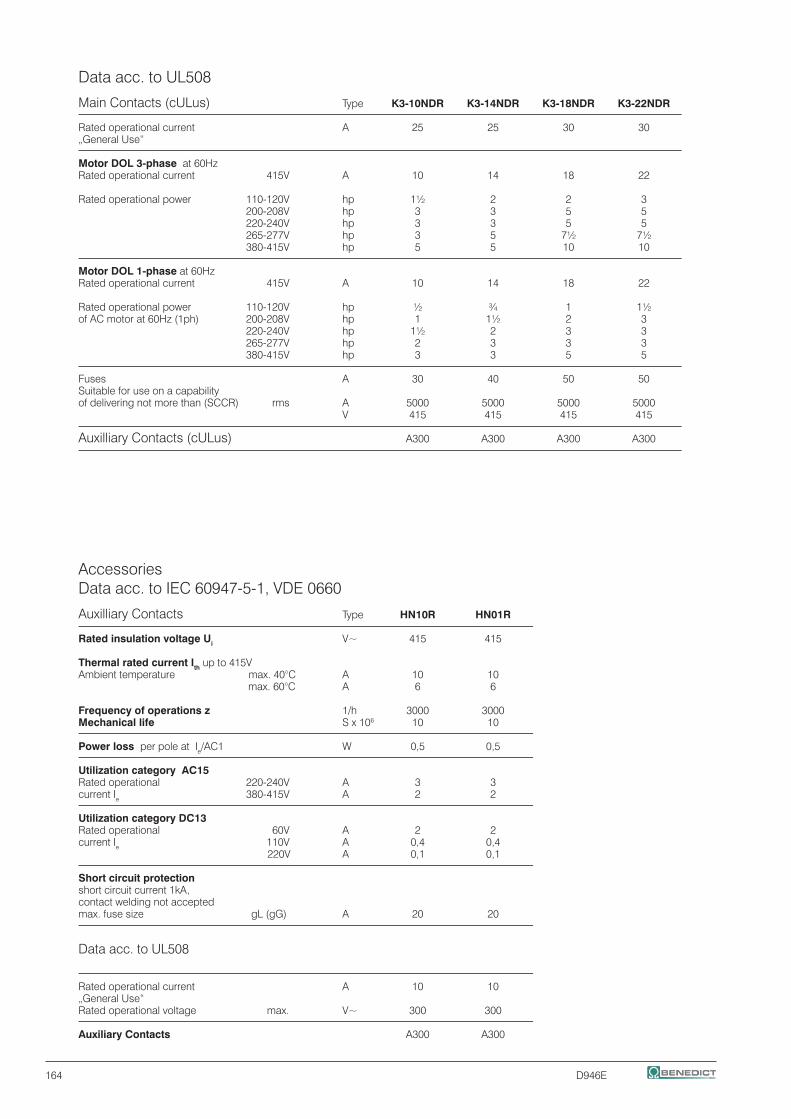
164 D946E
Data acc. to UL508
Main Contacts (cULus) Type K3-10NDR K3-14NDR K3-18NDR K3-22NDR
Rated operational current A 25 25 30 30 „General Use“
Motor DOL 3-phase at 60Hz Rated operational current 415V A 10 14 18 22
Rated operational power 110-120V hp 1½ 2 2 3 200-208V hp 3 3 5 5 220-240V hp 3 3 5 5 265-277V hp 3 5 7½ 7½ 380-415V hp 5 5 10 10
Motor DOL 1-phase at 60Hz Rated operational current 415V A 10 14 18 22
Rated operational power 110-120V hp ½ ¾ 1 1½ of AC motor at 60Hz (1ph) 200-208V hp 1 1½ 2 3 220-240V hp 1½ 2 3 3 265-277V hp 2 3 3 3 380-415V hp 3 3 5 5
Fuses A 30 40 50 50 Suitable for use on a capabilityof delivering not more than (SCCR) rms A 5000 5000 5000 5000 V 415 415 415 415
Auxilliary Contacts (cULus) A300 A300 A300 A300
Accessories Data acc. to IEC 60947-5-1, VDE 0660
Auxilliary Contacts Type HN10R HN01R
Rated insulation voltage Ui V~ 415 415
Thermal rated current Ith up to 415V Ambient temperature max. 40°C A 10 10 max. 60°C A 6 6 Frequency of operations z 1/h 3000 3000Mechanical life S x 106 10 10
Power loss per pole at Ie/AC1 W 0,5 0,5
Utilization category AC15 Rated operational 220-240V A 3 3 current Ie 380-415V A 2 2
Utilization category DC13 Rated operational 60V A 2 2 current Ie 110V A 0,4 0,4 220V A 0,1 0,1
Short circuit protection short circuit current 1kA, contact welding not accepted max. fuse size gL (gG) A 20 20
Data acc. to UL508
Rated operational current A 10 10 „General Use“ Rated operational voltage max. V~ 300 300
Auxiliary Contacts A300 A300

D946E 165
Index Page
Circuit-Breakers M4 166 for motor protection
Auxiliary contacts 167 Signalling switch Auxiliary releases
Insulated 3-pole busbar system 168 Terminal block
DIN-rail adapters 169 Busbar adapters Link modules
Technical Data 171
Characteristics 176 Installation Accessories 178
Dimensions 182

166 D946E
Circuit Breakers M4 for Motor Control
Rated Suitable Setting range Instantaneous Short Circuit Current for Thermal Short Circuit Breaking In motors 1) Overload Release Capacity at Weight 3~400V Release 3~400V Pack approx. A kW A A kA (Icu) Type pcs. kg/pc.
Circuit Breaker M4-32T-..
0,16 - 0,10 – 0,16 2,1 100 M4-32T-0,16 1 0,32 0,25 0,06 0,16 – 0,25 3,3 100 M4-32T-0,25 1 0,32 0,4 0,09 0,25 – 0,4 5,2 100 M4-32T-0,4 1 0,32
0,63 0,18 0,4 – 0,63 8,2 100 M4-32T-0,63 1 0,32 1 0,25 0,63 – 1 13 100 M4-32T-1 1 0,32switch type 1,6 0,55 1 – 1,6 20,8 100 M4-32T-1,6 1 0,32
2,5 0,75 1,6 – 2,5 32,5 100 M4-32T-2,5 1 0,32 4 1,5 2,5 – 4 52 100 M4-32T-4 1 0,32 6 2,2 4 – 6 78 100 M4-32T-6 1 0,32
8 3 5 – 8 104 100 M4-32T-8 1 0,32 10 4 6 – 10 130 50 M4-32T-10 1 0,32 13 5,5 9 – 13 169 50 M4-32T-13 1 0,32
17 7,5 11 – 17 221 20 M4-32T-17 1 0,32 22 7,5 14 – 22 286 15 M4-32T-22 1 0,32 26 11 18 – 26 338 15 M4-32T-26 1 0,32
32 15 22 – 32 416 15 M4-32T-32 1 0,32
Circuit Breaker M4-32R-..
0,16 - 0,10 – 0,16 2,1 100 M4-32R-0,16 1 0,36 0,25 0,06 0,16 – 0,25 3,3 100 M4-32R-0,25 1 0,36 0,4 0,09 0,25 – 0,4 5,2 100 M4-32R-0,4 1 0,36 0,63 0,18 0,4 – 0,63 8,2 100 M4-32R-0,63 1 0,36 1 0,25 0,63 – 1 13 100 M4-32R-1 1 0,36rotary type 1,6 0,55 1 – 1,6 20,8 100 M4-32R-1,6 1 0,36 2,5 0,75 1,6 – 2,5 32,5 100 M4-32R-2,5 1 0,36 4 1,5 2,5 – 4 52 100 M4-32R-4 1 0,36 6 2,2 4 – 6 78 100 M4-32R-6 1 0,36 8 3 5 – 8 104 100 M4-32R-8 1 0,36 10 4 6 – 10 130 100 M4-32R-10 1 0,36 13 5,5 9 – 13 169 100 M4-32R-13 1 0,36
17 7,5 11 – 17 221 50 M4-32R-17 1 0,36 22 7,5 14 – 22 286 50 M4-32R-22 1 0,36 26 11 18 – 26 338 50 M4-32R-26 1 0,36 32 15 22 – 32 416 50 M4-32R-32 1 0,36
Circuit Breaker M4-63R-..
26 12,5 18 – 26 338 50 M4-63R-26 1 1,0 32 15 22 – 32 416 50 M4-63R-32 1 1,0 40 18,5 28 – 40 520 50 M4-63R-40 1 1,0
50 22 34 – 50 650 50 M4-63R-50 1 1,0 63 30 45 – 63 819 50 M4-63R-63 1 1,0rotary type
Circuit Breaker M4-100R-..
63 30 45 – 63 819 50 M4-100R-63 1 2,2 75 37 55 – 75 975 50 M4-100R-75 1 2,2 90 45 70 – 90 1170 50 M4-100R-90 1 2,2
100 - 80 – 100 1300 50 M4-100R-100 1 2,2
rotary type 1) Approximate values of standard motors

D946E 167
Accessories
Contacts Rated Operational Current AC15 AC1 Weight 24V 240V 240V Pack approx. NO NC A A A Type pcs. kgpc
Transverse Auxiliary Contact Block, max. 1 pc. per circuit-breaker 1)
1 1 3 2 5 M4 HQ11 1 0,02 2 - 3 2 5 M4 HQ20 1 0,02 - 2 3 2 5 M4 HQ02 1 0,02
Auxiliary Contact Block for left hand side mounting, 1 or 2 pcs. per circuit-breaker 1)
1 1 6 4 10 M4 HS11 1 0,03 2 - 6 4 10 M4 HS20 1 0,03 - 2 6 4 10 M4 HS02 1 0,03
Alarm Switch (any tripping) for left hand side mounting, max. 1 pc. per circuit-breaker 1)
1 1 for M4-32T, -32R 6 4 10 M4 MA11 1 0,04 1 1 for M4-63R, -100R 6 4 10 M4 MA11 63 1 0,04
Alarm Switch (short circuit) for left hand side mounting, max. 1 pc. per circuit-breaker 1)
1 1 6 4 10 M4 M11 1 0,04
Operates in case of short circuit accidents that is over 20 times of the rated current of the circuit breaker.
Undervoltage Releases for right hand side mounting, max. 1 pc. per circuit-breaker 1)
Trips the circuit-breaker when the voltage is interrupted. Prevents the motor from being restarted accidentally when the voltage is restored, suitable for EMERGENCY STOP acc. to IEC 60204
24V 50Hz, 28V 60Hz M4 U24 1 0,11 110-127V 50Hz, 120V 60Hz M4 U110 1 0,11 220-230V 50Hz, 240-260V 60Hz M4 U230 1 0,11
240V 50Hz, 277V 60Hz M4 U240 1 0,11 380-400V 50Hz, 440-460V 60Hz M4 U400 1 0,11 415-440V 50Hz, 460-480V 60Hz M4 U415 1 0,11
Shunt Releases for right hand side mounting, max. 1 pc. per circuit-breaker 1)
Trips the circuit-breaker when the release coil energized. 100% ON max. 5sec. ON
20-24V 50Hz, 28V 60Hz 20-70V 50/60Hz DC M4 A24 1 0,12 75-127V 50Hz, 120V 60Hz 75-190V 50/60Hz DC M4 A110 1 0,12 190-230V 50Hz, 240-260V 60Hz 190-330V 50/60Hz DC M4 A230 1 0,12
200-240V 50Hz, 277V 60Hz 200-330V 50/60Hz DC M4 A240 1 0,12 300-400V 50Hz, 440-460V 60Hz 300-500V 50/60Hz DC M4 A400 1 0,12 330-440V 50Hz, 460-480V 60Hz 330-500V 50/60Hz DC M4 A415 1 0,12
Enclosure for circuit breaker M4 32R protection degree IP65
Plastic enclose with rotary operating mechanism black-grey M4 32R PFH4 1 0,53 lockable, with N- and PE-terminal space for 1 transverse and side aux. contact + release
Enclose with rotary operating mechanism yellow - red, lockable M4 32R PFHN4 1 0,53 with N- and PE-terminal space for 1 transverse and side aux. contact + release
1) Number and position see page 179

168 D946E
Accessories and Busbars
for Type Weight circuit- Pack approx. breaker pcs. kg/pc.
Accessories
Scale cover for covering the M4-32...100 M4 K 10 0,003 sealable current setting scale
Push-in lugs M4-32 M4 32 L 10 0,01 for screwing the circuit-breaker onto mounting plates. 2 units required (1 bag with 10 units)
Spade terminal block up to 600V acc.UL 489 M4-32R M4 32R E on request Pin terminal block up to 600V acc.UL 489 M4-32R M4 32R EV on request
Insulation barriers up to 600V acc.UL 489 M4-100 M4 100 E 2 0,01 for increased distances and clearances acc. to UL Type "E", 2 pcs per device (on input side)
Door-coupling rotary mechanisms IP65
The door locking device prevents accidental opening of the cubicle door in the ON position of the circuit-breaker. The OFF position can be locked with up to 3 padlocks. Door-coupling rotary extension shaft 115mm M4-32R M4 32R EH1 115 1 0,1 mechanism black extension shaft 315mm M4-32R M4 32R EH1 315 1 0,2 extension shaft 115mm M4-63R M4 63R EH1 115 1 0,1 extension shaft 315mm M4-63R M4 63R EH1 315 1 0,2 extension shaft 115mm M4-100R M4 100R EH1 115 1 0,1 extension shaft 315mm M4-100R M4 100R EH1 315 1 0,2
Emergency-Stop extension shaft 115mm M4-32R M4 32R EHN1 115 1 0,1 Door-coupling rotary extension shaft 315mm M4-32R M4 32R EHN1 315 1 0,2 mechanism; red/yellow extension shaft 115mm M4-63R M4 63R EHN1 115 1 0,1 extension shaft 315mm M4-63R M4 63R EHN1 315 1 0,2 extension shaft 115mm M4-100R M4 100R EHN1 115 1 0,1 extension shaft 315mm M4-100R M4 100R EHN1 315 1 0,2
Protection Type Pack Weight degree pcs. kg/pc.
Insulated 3-phase busbar system
For feeding several modular circuit-breakers M4-32. on standard mounting rails, insulated Rated operational voltage max. 690 V, 63 A, with spade connection, modular spacing 45mm (54mm on request)
3-phase busbars for 2 circuit-breakers IP20 M4 32 S2 1 0,03 for 3 circuit-breakers IP10 M4 32 S3 1 0,05 for 4 circuit-breakers IP10 M4 32 S4 1 0,07 for 5 circuit-breakers IP10 M4 32 S5 1 0,10
Line side terminal Conductor cross-section IP10 M4 32 SE 1 0,04 3-pole, connection solid or stranded 6-25mm² from above with end sleeve 4-16mm²
Cover for tags Touch guard for emptyspaces M4 32 SF 1 0,003
For feeding several modular circuit-breakers M4-32. on standard mounting rails, insulated Rated operational voltage max. 690 V, 63 A, with pin connection, modular spacing 45mm (54mm on request)
3-phase busbars for 2 circuit-breakers IP20 M4 32 S2V 1 0,03 for 3 circuit-breakers IP20 M4 32 S3V 1 0,05 for 4 circuit-breakers IP20 M4 32 S4V 1 0,07 for 5 circuit-breakers IP20 M4 32 S5V 1 0,10
Line side terminal Conductor cross-section IP20 M4 32 SEV 1 0,04 3-pole, connection solid or stranded 6-25mm² from above with end sleeve 4-16mm²
Cover for tags Touch guard for emptyspaces M4 32 SFV 1 0,003
For feeding several modular circuit-breakers M4-63. on standard mounting rails, insulated Rated operational voltage max. 690 V, with pin connection, modular spacing 55mm
3-phase busbars for 2 circuit-breakers IP20 M4 63 S2 1 0,15

D946E 169
Mounting Parts for Fuseless Load Feeders
Type Weight Pack approx. pcs. kg/pc.
DIN-rail adapters with DIN-rail for contactor
for M4-32.. M4 32 HU1 1 0,1 DIN-rails moveable for easy mounting and replacing can be connected on one 35 mm DIN-rail (high 15mm) or two 35 mm-DIN-rails (125mm distance) suitable for contactors K1-.., K(G)3-10 to K(G)3-40
Adapter, for M4-63.. M4 63 HU1 1 0,2 can be connected on two 35 mm DIN-rails (125mm distance) or one 75 mm DIN-rail, or screw mounting suitable for contactors K(G)3-24 to K(G)3-40, K3-50 to K3-74
Adapter, for M4-100.. M4 100 HU1 1 0,2 can be connected on two 35 mm DIN-rails (125mm distance) or one 75 mm DIN-rail, or screw mounting suitable for contactors K3-50 to K3-74
Busbar adapters for 60-mm-system, 3 copper busbars acc. to DIN 46433
for M4-32 M4 32 SA60 1 0,18 up to 25A, 690V 45mm width, 182mm long bar width: 12 und 15mm bar thickness: 5 and 10mm
Link modules, for mechanical and electrical connection between circuit-breaker and contactor
for M4-32.. with contactors K1-.. max. 32A M4 32 VK1 1 0,015
for M4-32.. with contactors K3-10 to K3-22 max. 32A M4 32 VK3 1 0,02
for M4-32.. with contactors KG3-10 to KG3-22 max. 32A M4 32 VKG3 1 0,02
Link modules, for electrical connection between circuit-breaker and contactor
for M4-32.. with contactors K(G)3-24to K(G)3-40 max. 32A M4 32 VD 1 0,01 for M4-63R. with contactors K3-24 to K3-74 max. 63A M4 63 VD 1 0,02
for M4-63R. with contactors KG3-24 to KG3-40 max. 63A M4 63 VDG 1 0,02 for M4-100R. with contactors K3-50 to K3-74 max. 100A M4 100 VD 1 0,02

170 D946E
Components for Fuseless Load Feeders, DIN-Rail Mounting
Type of coordination "1" 3x415V 10kA 1)
Motor Setting range Circuit-breaker Link Contactor 2) DIN-rail 3~400V page 166 module 220-230V 50Hz adapter kW A Type Type Type Type
- 0,10 – 0,16 M4-32T-0,16 M4 32 VK1 K1-09D10 230 - 0,06 0,16 – 0,25 M4-32T-0,25 M4 32 VK1 K1-09D10 230 - 0,09 0,25 – 0,4 M4-32T-0,4 M4 32 VK1 K1-09D10 230 - 0,18 0,4 – 0,63 M4-32T-0,63 M4 32 VK1 K1-09D10 230 - 0,25 0,63 – 1 M4-32T-1 M4 32 VK1 K1-09D10 230 - 0,55 1,0 – 1,6 M4-32T-1,6 M4 32 VK1 K1-09D10 230 - 0,75 1,6 – 2,5 M4-32T-2,5 M4 32 VK1 K1-09D10 230 - 1,5 2,5 – 4 M4-32T-4 M4 32 VK1 K1-09D10 230 - 2,2 4 – 6 M4-32T-6 M4 32 VK1 K1-09D10 230 - 3 5 – 8 M4-32T-8 M4 32 VK1 K1-09D10 230 - 4 6 – 10 M4-32T-10 M4 32 VK1 K1-09D10 230 - 5,5 9 – 13 M4-32T-13 M4 32 VK1 K1-12D10 230 -
7,5 11 – 17 M4-32T-17 M4 32 VK3 K3-18ND10 230EUR - 7,5 14 – 22 M4-32T-22 M4 32 VK3 K3-22ND10 230EUR - 11 18 – 26 M4-32T-26 M4 32 VK3 K3-22ND10 230EUR - 15 22 – 32 M4-32T-32 M4 32 VD K3-32A00 230 M4 32 HU1
- 0,10 – 0,16 M4-32R-0,16 M4 32 VK3 K3-10ND10 230EUR - 0,06 0,16 – 0,25 M4-32R-0,25 M4 32 VK3 K3-10ND10 230EUR - 0,09 0,25 – 0,4 M4-32R-0,4 M4 32 VK3 K3-10ND10 230EUR - 0,18 0,4 – 0,63 M4-32R-0,63 M4 32 VK3 K3-10ND10 230EUR - 0,25 0,63 – 1 M4-32R-1 M4 32 VK3 K3-10ND10 230EUR - 0,55 1,0 – 1,6 M4-32R-1,6 M4 32 VK3 K3-10ND10 230EUR - 0,75 1,6 – 2,5 M4-32R-2,5 M4 32 VK3 K3-10ND10 230EUR - 1,5 2,5 – 4 M4-32R-4 M4 32 VK3 K3-10ND10 230EUR - 2,2 4 – 6 M4-32R-6 M4 32 VK3 K3-10ND10 230EUR - 3 5 – 8 M4-32R-8 M4 32 VK3 K3-10ND10 230EUR - 4 6 – 10 M4-32R-10 M4 32 VK3 K3-10ND10 230EUR - 5,5 9 – 13 M4-32R-13 M4 32 VK3 K3-14ND10 230EUR -
7,5 11 – 17 M4-32R-17 M4 32 VK3 K3-18ND10 230EUR - 7,5 14 – 22 M4-32R-22 M4 32 VK3 K3-22ND10 230EUR - 11 18 – 26 M4-32R-26 M4 32 VK3 K3-22ND10 230EUR - 15 22 – 32 M4-32R-32 M4 32 VD K3-32A00 230 M4 32 HU1
12,5 18 – 26 M4-63R-26 M4 63 VD K3-32A00 230 M4 63 HU1 15 22 – 32 M4-63R-32 M4 63 VD K3-32A00 230 M4 63 HU1 18,5 28 – 40 M4-63R-40 M4 63 VD K3-40A00 230 M4 63 HU1
22 34 – 50 M4-63R-50 M4 63 VD K3-50A00 230 M4 63 HU1 30 45 – 63 M4-63R-63 M4 63 VD K3-62A00 230 M4 63 HU1
30 45 – 63 M4-100R-63 M4 100 VD K3-62A00 230 M4 100 HU1 37 55 – 75 M4-100R-75 M4 100 VD K3-74A00 230 M4 100 HU1 45 70 – 90 M4-100R-90 - K3-90A00 230 -
- 80 – 100 M4-100R-100 - K3-115A00 230 -
1) Other conditions on request2) Contactors K1.. 220-230V 50Hz, Contactors K3.. 220-240V 50Hz, further technical data see Catalog D677..

D946E 171
This table shows the rated ultimate short-circuit breaking capacity Icu and the rated service short-circuit breaking capacity Ics of the M4 circuit-breakers with different operational voltages as a function of the rated current In of the circuit-breakers.The circuit-breakers can be fed at the top or bottom supply terminals without any reduction of the rated data.
If the short-circuit current exceeds the rated short-circuit breaking capacity of the circuit-breaker specified in the tables at the installation point, a back-up fuse is to be used. The maximum rated current for the back-up fuse is specified in the tables. These fuses are only suitable for the short-circuit-currents as indicated on the fuses.
-- No back-up fuse required1) Back up fuse required if short-cicuit current at installation point > Icu2) 10 % overvoltage3) 5 % overvoltage
Technical Data according to IEC/EN 60947-1, 60947-2, 60947-4-1 and VDE 0660
Circuit- Rated- up to AC 240V 2) up to AC 400V 2) up to AC 440V 2) up to AC 500V 2) up to AC 690V 2)
breaker strom In up to AC 415V 3) up to AC 460V 3) up to AC 525V 3) Icu Ics max. Icu Ics max. Icu Ics max. Icu Ics max. Icu Ics max. fuse 1) fuse 1) fuse 1) fuse 1) fuse 1)
(gL/gG)) (gL/gG) (gL/gG) (gL/gG) (gL/gG) Type A kA kA A kA kA A kA kA A kA kA A kA kA A
M4-32T 0,16 ... 0,63 100 100 -- 100 100 -- 100 100 -- 100 100 -- 100 100 -- 1 100 100 -- 100 100 -- 100 100 -- 100 100 -- 100 100 -- 1,6 100 100 -- 100 100 -- 100 100 -- 100 100 -- 3 3 20
2,5 100 100 -- 100 100 -- 100 100 -- 50 38 50 3 3 35 4 100 100 -- 100 100 -- 50 38 50 15 11 40 3 3 40 6 100 100 -- 100 100 -- 15 11 50 10 8 50 3 3 50
8 100 100 -- 100 100 -- 15 11 63 10 8 63 3 3 63 10 100 100 -- 50 38 80 15 11 63 6 5 63 3 3 63 13 100 100 -- 50 38 80 10 8 80 6 5 80 3 3 63
17 50 38 -- 20 15 100 10 8 80 6 5 80 3 3 63 22 40 30 125 15 11 100 8 6 100 6 5 80 3 3 63 26 40 30 125 15 11 100 8 6 100 6 5 80 3 3 63
32 30 22 125 15 11 100 6 4 100 5 4 80 3 3 63
M4-32R 0,16 ... 1,0 100 100 -- 100 100 -- 100 100 -- 100 100 -- 100 100 -- 1,6 100 100 -- 100 100 -- 100 100 -- 100 100 -- 100 100 -- 2,5 100 100 -- 100 100 -- 100 100 -- 100 100 -- 8 8 35
4 100 100 -- 100 100 -- 100 100 -- 100 100 -- 8 8 40 6 100 100 -- 100 100 -- 100 100 -- 100 100 -- 6 6 50 8 100 100 -- 100 100 -- 50 38 80 50 38 63 6 6 63
10 100 100 -- 100 100 -- 50 38 80 50 38 80 6 6 63 13 100 100 -- 100 100 -- 50 38 80 42 32 80 6 6 63 17 100 100 -- 50 38 100 20 15 80 10 8 80 4 4 63
22 100 100 -- 50 38 125 20 15 100 10 8 80 4 4 63 26 100 100 -- 50 38 125 20 15 100 10 8 80 4 4 63 32 100 100 -- 50 38 125 20 15 100 10 8 80 4 4 63
M4-63R 26 100 100 -- 50 50 125 35 27 125 12 9 100 5 5 80 32 100 100 -- 50 50 125 35 27 125 10 8 100 5 5 80 40 100 100 -- 50 50 160 35 27 125 10 8 100 5 5 80
50 100 100 -- 50 50 160 35 27 125 10 8 100 5 5 80 63 100 100 -- 50 50 160 35 27 160 10 8 100 5 5 80
M4-100R 63 100 100 -- 50 38 160 40 30 160 12 9 100 6 5 80 75 100 100 -- 50 38 160 40 30 160 8 6 125 5 4 100 90 100 100 -- 50 38 160 40 30 160 8 6 125 5 4 125
100 100 100 -- 50 38 160 40 30 160 8 6 125 5 4 125

172 D946E
1) Suitable at 690V for: earthed-neutral systems, overvoltage category I to IV, pollution degree 3 (standard-industry): Uimp = 6kV. 2) Suitable at 1000V for: earthed-neutral systems, overvoltage category I to IV, pollution degree 3 (standard-industry): Uimp = 8kV. 3) Data for other conditions on request.
Approvals
Country USA, Canada Switzerland Europe CB/CCA-Type UL SEV CCC Certificates
M4-32T o o / o M4-32R o o / o M4-63R o o / oM4-100R o o / o
M4 H.. o - / -M4 M.. o - / -M4 U.. o - / -M4 A.. o - / -
o In standard version approved / No testing required CE x In test- Not provided for test till now
Technical Data according to IEC/EN 60947-1, 60947-2, 60947-4-1 and VDE 0660
Main Circuit
Type M4-32T M4-32R M4-63R M4-100R
Number of poles 3 3 3 3
Max. rated current Inmax (=max. rated operational current Ie) A 32 32 63 100
Permissible ambient temperature Storage/transport °C -50 to +80 -50 to +80 -50 to +80 -50 to +80Operation °C -20 to +60 -20 to +60 -20 to +60 -20 to +60 Storage/transport °F -58 to+176 -58 to+176 -58 to+176 -58 to+176 Operation °F -4 to +140 -4 to +140 -4 to +140 -4 to +140 Rated insulation voltage Ui V 690 1) 690 1) 1000 2) 1000 2)
Rated impulse withstand voltage Uimp kV 6 6 8 8
Rated operational voltage Ue V 690 690 690 690
Rated frequency Hz 50/60 50/60 50/60 50/60
Utilization category IEC 60947-2 (circuit-breaker) A A A AIEC 60947-4-1 (motor starter) AC3 AC3 AC3 AC3
Class acc. to IEC 60947-4-1 10 10 10 10
Power loss Pv per circuit-breaker In -> up to 4 A W 9,8 9,8 - -dependent on rated current In In -> 6 up to 26 A W 8 8 - -(upper setting range) In -> 32 A W 3,9 3,9 - -
R per conducting path = P/I² × 3 In -> 26 up to 63 A W - - 12,6 -
In -> up to 63 A W - - - 11,9 In -> 75 up to 100 A W - - - 15
Shock resistance acc. to IEC 60068 Teil 2-27 g 25 25 25 25
Degree of protection acc. to IEC 60529 IP 20 IP 20 IP 20 IP 20Shock hazard protection acc. to DIN VDE 0106 Part 100 safe against safe against safe against safe against finger touch finger touch finger touch finger touch
Temperature compensation acc. to IEC 60947-4-1 °C -20 to +60 -20 to +60 -20 to +60 -20 to+60
Mechanical endurance operating cycles 100 000 100 000 50 000 50 000Electrical endurance 100 000 100 000 25 000 25 000Max. operating frequency per hour (motor starts) 1/h 25 25 25 25

D946E 173
1) M4 HQ.. 1 solid conductor only
Technische Daten nach IEC/EN 60947-1, 60947-2, 60947-4-1 und VDE 0660
Conductor cross-sections for main circuit
Terminal Conductor, Conductor, Conductor, type, cross-sections cross-sections cross-sections screw type Tightening torque solid stranded flexible
Type Nm Ib - in mm2 AWG mm2 AWG mm2 AWG
M4-32T Pz2 0,8 - 2,5 7 - 22 1 x (1 - 10) 1 x (18 - 8) 1 x (1 - 6) 1 x (18 - 10) 1 x (1 - 6) 1 x (18 - 10) 2 x (1 - 6) 2 x (18 - 10) 2 x (1 - 6) 2 x (18 - 10) 2 x (0,75 - 4) 2 x (18 - 10)
M4-32R Pz2 0,8 - 2,5 7 - 22 1 x (1 - 10) 1 x (18 - 8) 1 x (1 - 6) 1 x (18 - 10) 1 x (1 - 6) 1 x (18 - 10) 2 x (1 - 6) 2 x (18 - 10) 2 x (1 - 6) 2 x (18 - 10) 2 x (0,75 - 4) 2 x (18 - 10)
M4-63R Pz2 3 - 4,5 26 - 39 1 x (0,75 - 35) 1 x (18 - 2) 1 x (0,75 - 35) 1 x (18 - 2) 1 x (0,75 - 25) 1 x (18 - 4) 2 x (0,75 - 25) 2 x (18 - 4) 2 x (0,75 - 25) 2 x (18 - 4) 2 x (0,75 - 16) 2 x (18 - 6)
M4-100R 4mm 4 - 6 35 - 53 1 x (2,5 - 70) 1 x (12 - 2/0) 1 x (2,5 - 70) 1 x (12 - 2/0) 1 x (2,5 - 50) 1 x (12 - 1/0) hexagon 2 x (2,5 - 50) 2 x (12 - 1/0) 2 x (2,5 - 50) 2 x (12 - 1/0) 2 x (2,5 - 35) 2 x (10 - 2) socket screw
Auxiliary switches Rated Rated Rated Rated Rated operational operational operational operational operational voltage current current voltage current Ue Ie/AC-15 e/AC-12 Ith Ue Ie/DC-13 DC L/R 200 ms
Type V A A V A
Front transverse auxiliary switch M4 HQ.. 24 240 3 3 5 5 24 220 1 0,1
Lateral auxiliary switch and signalling switch M4 HS..
M4 M.. 24 240 6 4 10 10 24 220 2 0,25
Power consumption Response voltage Response voltage acc. to
during pick-up uninterrupted duty trip pick-up IEC 60947-1
Type VA/W V V
Undervoltage release M4 U.. 8,5/6 3/1,2 0,7 - 0,35xUs 0,85 - 1,1xUs
Shunt release M4 A.. 8,5/6 3/1,2 0,7 - 1,1xUs
Fuse Miniature solid flexible AWG- flexible circuit wires, breaker solid
gL/gG C-charac- teristic
A A mm2 mm2 AWG AWG
Short-circuit protection for auxiliary and control circuits 16 6
Conductor cross-sections for auxiliary and control circuits 1 x (0,5 - 2,5) 1 x (0,5 - 4) 1 x (20 - 14) 1 x (20 - 10) 2 x (0,5 - 2,5) 1) 2 x (0,75 - 2,5) 2 x (20 - 14) 1) 2 x (18 - 14)

174 D946E
Permissible ratings of devices approved for North America
Circuit breakers M4 as „Manual Motor Starter“ If used as „Manual Motor Starter“ the circuit breaker is always operated in combination with a short circuit device. For use with approbated fuses or circuit breakers according to UL489 or CSA22.2 No. 5 only. The sizes are selected according to National Electrical Code (UL), or Canadian Electrical Code (CSA).
Rated Max. short-circuit current Motor load Motor load Max. Max. operational 1-phase 3-phase rated breaker current fuse size Ie 240V 480V 600V 115V 230V 200V 230V 460V 600V Typ A kA kA kA HP HP HP HP HP HP A A
M4-32T 0,16 ... 0,63 100 50 10 - - - - - - 1 15
1 100 50 10 - - - - - 1/2 3 15 1,6 100 50 10 - 1/10 - - 3/4 3/4 6 15 2,5 100 50 10 - 1/6 1/2 1/2 1 1 1/2 10 15 4 100 50 5 1/8 1/3 3/4 3/4 2 3 15 15 6 100 25 5 1/4 1/2 1 1 1/2 3 5 20 20 8 100 25 5 1/3 1 2 2 5 5 30 30 10 50 10 5 1/2 1 1/2 2 3 5 7 1/2 40 40 13 50 10 5 1/2 2 3 3 7 1/2 10 50 50 17 40 10 5 1 3 3 5 10 15 60 60 22 30 10 5 1 1/2 3 5 7 1/2 15 20 80 80 26 30 7,5 5 2 3 7 1/2 7 1/2 15 20 100 100 32 20 7,5 5 2 5 7 1/2 10 20 30 125 125
M4-32R 0,16 ... 0,63 100 50 10 - - - - - - 1 15
4 100 50 10 1/8 1/3 3/4 3/4 2 3 15 15 6 100 50 10 1/4 1/2 1 1 1/2 3 5 20 20 8 100 50 10 1/3 1 2 2 5 5 30 30 10 100 50 10 1/2 1 1/2 2 3 5 7 1/2 40 40 13 100 50 10 1/2 2 3 3 7 1/2 10 50 50 17 100 30 10 1 3 3 5 10 15 60 60 22 100 30 10 1 1/2 3 5 7 1/2 15 20 80 80 26 100 30 10 2 3 7 1/2 7 1/2 15 20 100 100 32 100 30 10 2 5 7 1/2 10 20 30 125 125
M4-63R 26 100 50 10 2 3 7 1/2 7 1/2 15 20 100 100
32 100 50 10 2 5 7 1/2 10 20 30 125 125 40 100 50 10 3 7 1/2 10 10 30 30 150 150 50 100 50 10 5 10 15 15 30 40 200 200 63 100 50 10 5 10 20 20 40 60 250 250
M4-100R 63 100 25 10 5 10 20 20 40 60 250 250
75 100 25 10 5 15 20 25 50 60 300 300 90 100 25 10 7 1/2 20 25 30 60 75 350 350 100 100 25 10 10 20 30 30 75 100 400 400

D946E 175
Permissible ratings of devices approved for North America
Circuit breakers M4 as „Combination Motor Controller Type E“ and "Suitable for Group Installation"Acc to UL508 demands a line-side 1 inch air and 2 inch creepage distance for „Combination Motor Controller Type E“ is necessary. Therefor circuit-breaker M4-32R is approved to UL 508 in combination with the Terminal block M4 32R E. Circuit-breakers M4-100 are approved to UL 508 in combination with the insulation barriers M4 100 E. According to CSA these terminal blocks can be omitted when the device is used as „Combination Motor Controller Type E“.
Rated Max. short-circuit current Motor load Motor load Max. Max. operational 1-phase 3-phase rated breaker current Ie fuse 240V 480V 600V 115V 230V 200V 230V 460V 600V Type A kA kA kA HP HP HP HP HP HP A A
M4-32R 0,16 ... 0,63 100 65 25 - - - - - - 500 500
(+M4 32R E) 1 100 65 25 - - - - - 1/2 500 500 1,6 100 65 25 - 1/10 - - 3/4 3/4 500 500 2,5 100 65 25 - 1/6 1/2 1/2 1 1 1/2 500 500 4 100 65 25 1/8 1/3 3/4 3/4 2 3 500 500 6 100 65 25 1/4 1/2 1 1 1/2 3 5 500 500 8 100 65 25 1/3 1 2 2 5 5 500 500 10 100 65 25 1/2 1 1/2 2 3 5 7 1/2 500 500 13 100 65 25 1/2 2 3 3 7 1/2 10 500 500 17 100 30 10 1 3 3 5 10 15 500 500 22 100 30 10 1 1/2 3 5 7 1/2 15 20 500 500 26 100 30 10 2 5 7 1/2 7 1/2 15 20 500 500 32 100 30 10 2 5 7 1/2 10 20 30 500 500
M4-63R 26 100 50 10 2 3 7 1/2 7 1/2 15 20 600 600
32 100 50 10 2 5 7 1/2 10 20 30 600 600 40 100 50 10 3 7 1/2 10 10 30 30 600 600 50 100 50 10 5 10 15 15 30 40 600 600 63 100 50 10 5 10 20 20 40 60 600 600
M4-100R 63 100 40 10 5 10 20 20 40 60 1000 1000
(+M4 100 E) 75 100 40 10 5 15 20 25 50 60 1000 1000 90 100 40 10 7 1/2 20 25 30 60 75 1000 1000 100 100 40 10 10 20 30 30 75 100 1000 1000
Ratings of auxiliary switches and alarm switches
Breaking capacity Rated operational Rated operational voltage current
AC DC max. V AC A
Lateral auxiliary M4 HS.. and signalling switch M4 M.. A600 Q300 600 10
Transversal auxiliary switch M4 HQ.. A300 R300 240 5

176 D946E
Description
Releases Circuit-breakers M4 are equipped with bimetallic-based, inverse-time delayed overload releases and with instantaneous overcurrent releases (elec-tromagnetic short-circuit releases). The overload releases can be set in accordance with the load current. The overcurrent releases are permanently set to a value 13 times the rated current and thus enable trouble-free start-up of motors. The scale cover can be sealed to prevent unauthorized adjustments to the set current.
Operating mechanismsCircuit-breakers M4-32T are actuated via a rocker operating mechanism and circuit-breakers M4-32R, M4-63R and M4-100R via a rotary operating mechanism. An electrical signal can be output, at all Circuit-breakers, via a signalling switch to indicate that the Circuit-breaker has tripped. All operating mechanisms can be locked in the 0 position with a padlock (shackle diameter 3.5 to 4.5 mm). The M4 Circuit-breakers fulfil the isolation characteristics specified in IEC 60947-2.
Operating conditionsCircuit-breakers M4 are suitable for use in any climate. To avoid error tripping we recommend to protect the Circuit Breakers M4 against fresh and cold air (caused by air condition etc.) They are designed for operation in enclosed rooms under normal conditions (e. g. no dust, corrosive vapours or harmful gases). Suitable enclosures must be provided for installation in dusty or damp rooms. Circuit-breakers M4 can also be fed from below. In order to prevent premature tripping due to phase failure sensitivity, the three conducting paths must always be uniformly loaded. The conducting paths must be connected in series in the case of single-phase loads.
Short-circuit protectionThe short-circuit releases of M4 circuit-breakers disconnect the faulty load feeder from the system in the event of a short circuit and thus prevent any further damage from being caused. Circuit-breakers with a short-circuit breaking capacity of 50 kA or 100 kA at a voltage of 400 V AC are practically short-circuit-proof at this voltage, as higher short-circuit currents are not usually encountered at the installation point. Back-up fuses are only necessary if the short-circuit current at the installation point exceeds the rated ultimate short-circuit breaking capacity of the circuit-breakers.
Motor protectionThe tripping characteristics of M4 circuit-breakers are designed mainly to protect three-phase induction motors. The circuit-breakers are therefore also referred to as Manual Motor Starters. The current of the motor to be protected is set with the aid of the scale.
Line protectionM4 Circuit-breakers for motor protection are also suitable for line protection. The M4 Circuit-breakers fulfil the isolation conditions of IEC 60 947-3 as well as the additional test conditions for circuit-breakers with isolation characteristics specified in IEC 60947-2. Taking IEC 60 204-1 into consideration, they can thus be implemented as main and EMERGENCY STOP switches. Door-coupling rotary operating mechanism do not fulfil the isolation characteristics.
Tripping-Characteristics
M4-32 M4-63R, M4-100R
I The curve shows the mean operating current at an ambient temperature of 20°C starting from cold.II The tripping characteristic of electromagnetic overcurrent releases (short-circuit releases)
The tripping characteristic of the inverse-time delayed overload releases apply for DC and AC with a frequency of 0 to 400 Hz.At operating temperature, the tripping times of the thermal releases are reduced to approximately 25 %.
The characteristic shown here is a schematic representation of circuit-breakers for all ranges.Current limiting characteristics and I²t characteristics are available on request.

D946E 177
Icc rms (kA) Icc rms (kA)
Sum
of I
²t (k
A²s
)
Let-through Energy (I²t / kA2s) and Peak Current (Ip / kA) at Ue=415V)
M4-32R
M4-63R
M4-100R
Sum
of I
²t (k
A²s
)
Peak
Cur
rent
(Ip
/ kA
)
Sum
of I
²t (k
A²s
)
Peak
Cur
rent
(Ip
/ kA
)Pe
ak C
urre
nt (I
p / k
A)
Icc rms (kA) Icc rms (kA)
Icc rms (kA) Icc rms (kA)

178 D946E
Mounting
DIN-rail mounting Operating positions
Wiring diagrams
Circuit breaker M4...
Traverse Aux. Contact Block M4 HQ11 M4 HQ20 M4HQ02
Aux. Contact Block (side mounted) M4 HS11 M4 HS20 M4 HS02
Alarm Switch M4 M11 M4 MA11
Undervolatage Release M4 U...
Shunt Release M4 A...
Current setting (dont rotate the dial out of the shown range) Connectioin of 1-phase motor

D946E 179
Installation of accessories
M4-32TM4-32R
M4-63RM4-100R

180 D946E
Dimensions
Circuit-breaker M4-32T
1) Side aux. contact 2) Magnetic trip alarm 3) Shunt or undervoltage release of arcingHeight of arcing spaces (clearance from earthed parts ) 4) Transverse aux. contact 5) Push-in Lugs for screw mountingat Ue (V) 240 415 460 525 690 6) 35mm DIN-rail acc. to EN 50022mm 20 20 20 20 20 inch 0,8 0,8 0,8 0,8 0,8
Circuit-breaker M4-32R
1) Side aux. contact 2) Magnetic trip alarm 3) Shunt or undervoltage release of arcing Height of arcing spaces (clearance from earthed parts ) 4) Transverse aux. contact 5) Handle lock in OFF-position (Ø 5mm)at Ue (V) 240 415 460 525 690 6) Push-in Lugs for screw mountingmm 30 30 30 30 50 7) 35mm DIN-rail acc. to EN 50022inch 1,18 1,18 1,18 1,18 2

D946E 181
Dimensions
Circuit-breaker M4-63R
1) Side aux. contact 2) Magnetic trip alarm 3) Shunt or undervoltage releaseHeight of arcing spaces (clearance from earthed parts ) 4) Transverse aux. contact 5) Handle lock in OFF-position (Ø 5mm)at Ue (V) 240 415 460 525 690 6) 35mm DIN-rail acc. to EN 50022mm 50 50 50 50 50 inch 2 2 2 2 2
Circuit-breaker M4-100R
1) Side aux. contact 2) Magnetic trip alarm 3) Shunt or undervoltage releaseHeight of arcing spaces (clearance from earthed parts ) 4) Transverse aux. contact 5) Handle lock in OFF-position (Ø 5mm)at Ue (V) 240 415 460 525 690 6) 35mm DIN-rail acc. to EN 50022mm 50 70 70 110 150 7) 70mm DIN-rail acc. to EN 50023inch 2 2¾ 2¾ 4,33 6 8) 4mm hexagon socket screw

182 D946E
Dimensions
Link Module M4 32 VK1
M4-32T + K1-. . M4-32R + K1-. .
Link Module M4 32 VK3
M4-32T + K3-10ND. . M4-32T + K3-14ND. . M4-32R + K3-10ND. . M4-32R + K3-14ND. .M4-32T + K3-18ND. . M4-32T + K3-22ND. . M4-32R + K3-18ND. . M4-32R + K3-22ND. .
Link Module M4 32 VKG3
M4-32T + KG3-10. . M4-32T + KG3-14. . M4-32R + KG3-10. . M4-32R + KG3-14. .M4-32T + KG3-18. . M4-32T + KG3-22. . M4-32R + KG3-18. . M4-32R + KG3-22. .

D946E 183
Dimensions
DIN-rail adapter M4 32 HU1
M4-32T + K3-24 + M4 32VD M4-32R + K3-24 + M4 32VDM4-32T + K3-32 + M4 32VD M4-32R + K3-32 + M4 32VD
DIN-rail adapter M4 32 HU1
M4-32T + KG3-24 + M4 32 VD M4-32R + KG3-24 + M4 32 VDM4-32T + KG3-32 + M4 32 VD M4-32R + KG3-32 + M4 32 VD

184 D946E
Dimensions
DIN-rail adapter M4 63 HU1
M4-63T + K3-32 + M4 63 VD M4-63T + KG3-32 + M4 63 VDG M4-63T + K3-40 + M4 63 VD M4-63T + KG3-40 + M4 63 VDG
DIN-rail adapter M4 63 HU1 DIN-rail adapter M4 100 HU1
M4-63T + K3-50 + M4 63 VD M4-100R + K3-62 + M4 100 VDM4-63T + K3-62 + M4 63 VD M4-100R + K3-74 + M4 100 VD

D946E 185
Dimensions
Enclosures
M4 32R PFH4 M4 32R PFHN4
Door-coupling rotary mechanisms Mounting holes
Type A
M4 32R EH1 115 149 - 210M4 32R EHN1 115 149 - 210 M4 32R EH1 315 149 - 410 M4 32R EHN1 315 149 - 410
Type A
M4 63R EH1 115 194 - 255M4 63R EHN1 115 194 - 255 M4 63R EH1 315 194 - 455 M4 63R EHN1 315 194 - 455
Type A
M4 100R EH1 115 220 - 282M4 100R EHN1 115 220 - 282 M4 100R EH1 315 220 - 482 M4 100R EHN1 315 220 - 482
Insulated 3-phase busbar system
M4 32 S.. M4 32 SE
186 D946E

D946E 187
Index Page
Manual Motors Starters 188
Auxilliary Contact Blocks 188
Trip Alarm Aux. Switch 188
Shunt Release 188
Under-voltage Release 189
Accessories 189
Busbar Connectors 189
Enclosures 189
Technical Data 190
Dimensions 191
Tripping Charactaristic 191

188 D946E
Manual Motor Starters
Thermal Ratings Magnetic Type Overload Release AC3 at short circuit trip Setting Range 400V 690V Pack Weight A kW kW A pcs. kg/pc.
0,1 - 0,16 0,02 0,06 1,92 MU25A-0,16 1 0,25 0,16 - 0,25 0,06 0,12 3,0 MU25A-0,25 1 0,25 0,25 - 0,4 0,09 0,18 4,8 MU25A-0,4 1 0,25
0,4 - 0,63 0,12 0,25 7,6 MU25A-0,63 1 0,25 0,63 - 1 0,25 0,55 12,0 MU25A-1 1 0,25 1 - 1,6 0,55 1,1 19,2 MU25A-1,6 1 0,25
1,6 - 2,5 0,75 1,5 30 MU25A-2,5 1 0,25 2,5 - 4 1,5 3 48 MU25A-4 1 0,25 4 - 6,3 2,5 4 75,6 MU25A-6,3 1 0,25
6,3 - 10 4 7,5 120 MU25A-10 1 0,25 10 - 16 7,5 11 192 MU25A-16 1 0,25 16 - 20 9 12 240 MU25A-20 1 0,25
20 - 25 12,5 22 300 MU25A-25 1 0,25 25 - 32 15 384 MU25A-32 1 0,25
Auxiliary Contact Blocks, for side mounting, max. 2 pieces
Contacts Rated Operational Current Type AC15 AC1 230V 400V 500V Pack Weight NO NC EM 1) A A A pcs. kg/pc.
1 - - - 3,5 2 6 MU25A-PS10 10 0,03 - 1 - - 3,5 2 6 MU25A-PS01 10 0,03 2 - - - 3,5 2 6 MU25A-PS20 10 0,03 1 1 - - 3,5 2 6 MU25A-PS11 10 0,03
- 2 - - 3,5 2 6 MU25A-PS02 10 0,03 - 1 1 - 3,5 2 6 MU25A-PV11 10 0,03 - - 2 - 3,5 2 6 MU25A-PV20 10 0,03
Transverse Auxiliary Contact Block, max. 1 piece
Contacts Rated Operational Current Type AC15 AC1 230V 230V Pack Weight NO NC EM 1) A A pcs. kg/pc.
1 1 - - 1 5 MU25A-PA11 10 0,02
Auxiliary Contact Blocks for mounting under the cover, max. 1 piece
Contacts Rated Operational Current Type AC15 AC1 230V 400V 500V Pack Weight NO NC EM 1) A A A pcs. kg/pc.
1 1 - - 3,5 2 6 MU25A-PE11 10 0,02
Trip Alarm Auxiliary Switch for mounting under the cover, max. 1 piece
Contacts Rated Operational Current Type AC15 AC1 230V 400V 500V Pack Weight NO NC EM 1) A A A pcs. kg/pc.
1 - - - 3,5 2 6 MU25A-PM10 10 0,02 - 1 - - 3,5 2 6 MU25A-PM01 10 0,02
1) early make

D946E 189
Shunt Release for mounting under the cover
Rated Control Voltage Power Consumption Type and Frequency Pack Weight V VA W pcs. kg/pc.
24V 50/60Hz 2,7 1,8 MU25A-A24 10 0,06 110V 50Hz, 110-120V 60Hz 2,7 1,8 MU25A-A110 10 0,06 220-230V 50Hz, 240V 60Hz 2,7 1,8 MU25A-A230 10 0,06 380-415V 50Hz, 440V 60Hz 2,7 1,8 MU25A-A400 10 0,06
Under-voltage Release for mounting under the cover
Rated Control Voltage Power Consumption Type and Frequency Pack Weight V VA W pcs. kg/pc.
24V 50/60Hz 2,7 1,8 MU25A-U24 10 0,06 110V 50Hz, 110-120V 60Hz 2,7 1,8 MU25A-U110 10 0,06 220-230V 50Hz, 240V 60Hz 2,7 1,8 MU25A-U230 10 0,06 380-415V 50Hz, 440V 60Hz 2,7 1,8 MU25A-U400 10 0,06
Accessories
Description Specification Type Pack Weight pcs. kg/pc.
Busbar Connector Fully Isolated, Ui 690V, Iu 63A
Busbar For 2 units 3-pole, 99mm long MU25A-D99 10 0,036 Busbar For 3 units 3-pole, 154mm long MU25A-D154 10 0,060
Busbar For 4 units 3-pole, 208mm long MU25A-D208 10 0,084 Busbar For 5 units 3-pole, 262mm long MU25A-D262 10 0,107
Supply Block 3-pole for use with busbar connector MU25A-DB 10 0,034
Spacing piece ½TE for ambient temperature >40°C P730 10 0,013
Enclosures
Moulded Enclosure Protection to IP55 MU25A-O55 1 0,24 Moulded Front Plate Protection to IP55 MU25A-C55 1 0,16
Locking Bracket Suitable for 3 padlocks in MU25A-Z 1 0,10 "OFF"-position, stirrup diameter of the padlock max. 8 mm
Stop Button Mushroom head MU25A-NAT 1 0,04 Emergency Stop Button latch, release by turning MU25A-NAV 1 0,04 Emergency Stop Button latch, release by key MU25A-NAS 1 0,04
Neutral Conductor Block for mounting in enclosure MU25A-NL 10 0,01 and front plate Wiring cross section 0,75 - 2,5mm²
Moulded Enclosure Protection to IP54 MU25A-GC1 1 0,40 for 5-pole CEE-plug with phase changing

190 D946E
Manual Motor Starters
Data according to IEC 947, IEC 204, EN 60947, EN 60204, VDE 0660, VDE 0113
Type MU25A
Main ContactsRated insulation voltage Ui V~ 1) 690
Rated operational current Ie (=Ith) open, at 50°C A 25
Mechanical life S x 106 0,1Contact life at Ie /AC3 S x 106 0,1
Tripping class according to IEC 60947-4-1 10A
Rated ultimate short-circuit breaking capacity Icu 220-240V AC 380-415V AC 500V AC 660-690V ACValues for open unit, when incoming supply on upper terminals Setting range to 1A kA 100 100 100 100 1 - 1,6A kA 100 100 100 100 1,6 - 2,5A kA 100 100 3 2,5
2,5 - 4A kA 100 100 3 2,5 4 - 6,3A kA 100 100 3 2,5 6,3 - 10A kA 100 6/50 2) 3 2,5
10 - 16A kA 10/100 2) 6/50 2) 2,5 2 16 - 20A kA 10/100 2) 6/50 2) 2,5 2 20 - 25A kA 10/100 2) 6/50 2) 2,5 2 25 - 32A kA 10/100 2) 6/50 2) 2,5 2
Short circuit protection 220-240V AC 380-415V AC 500V AC 660-690V ACSetting range to 1A A - - - - 1 - 1,6A A - - - - 1,6 - 2,5A A - - 25 20
2,5 - 4A A - - 35 25 4 - 6,3A A - - 50 35 6,3 - 10A A - 80 50 35
10 - 16A A 80 80 63 35 16 - 20A A 80 80 63 50 20 - 25A A 80 80 63 50 25 - 32A A 80 80 63 50
Maximum ambient temperatureOperation open °C -25 to +55 enclosed °C -25 to +40Temperature compensation °C -20 to +55
Power loss at rated current, warm condition W 6 - 8
Auxiliary ContactsRated insulation voltage Ui V~ 500
Thermal rated current Ith Ambient temperature max. 50°C A 6
Utilization category AC15Rated operational current Ie 220-240V A 3,5 380-415V A 2 500V A 1
Short circuit protectionmax. fuse size gL (gG) A 6
Cable cross-sectionMain connector solid or stranded mm² 0,75 - 4 flexible mm² 0,75 - 2,5 flexible with multicore cable end mm² 0,75 - 2,5 Cables per clamp 2
Auxiliary connector solid or stranded mm² 0,75 - 2,5 flexible mm² 0,75 - 1,5 flexible with multicore cable end mm² 0,75 - 1,5 Cables per clamp 2
Resistance to shock according to IEC 68-2-27 Operation g / ms 4 / 11 Solidity g / ms 30 / 18
1) Suitable for: earthed-neutral systems, overvoltage category I to III, pollution degree 3 (standard-industry): Uimp = 6kV.2) with current limiter MBS25-ID50 up to 415V AC
Fuse gL(gG) only necessary if the short circuit current could be greater thanthe rated ultimate short-circuit breaking capacity

D946E 191
Tripping Charactaristic
Manual Motor Starters
Dimensions
Manual Motor Starter Moulded Enclosure MU25A MU25A-O55
Moulded Front Plate Moulded Enclosure for 5-pole CEE-plugMU25A-C55 MU25A-GC1
Mounting with clamps with screws
Temperature Compensation
In case of higher ambient temperature use the following formula:(Ambient temperature - 20) x 0,3 = correction factor in % of the full load motor current
Example: Ambient temperature 60°C, full load motor current 5A (60 - 20) x 0,3 = 12% Setting value: 5A + 12% = 5,6A
3-pole
2-pole electromagneticshort circuit relais at higher value
lower value
x rated current
seco
nds
min
utes
3-pole
2-pole
x rated current
seco
nds
min
utes
Rail according to DIN EN 50 022
Aux. contact

192 D946E
System MU25A
Approvals
Country USA, Canada Switzerland Europe CB/CCA- UL SEV Certificates
Type
MU25A o o / -
o In standard version approved / No testing required CE x In test - Not provided for test till now

D946E 193
Index Page
General 194 Approvals 195 Informations 196 Cam Switches 198 Basic designs 200
Cam Switches 203 On-Off switches, Changeover switches 203 Star-Delta switches 207 Multi speed switches 211 Control switches 215 Voltmeter selector switches 218 Ammeter switches 219 Gang switches 221 Multi step switches 224
Mini-Cam Switches 236 Technical data 236 On-Off switches, Changeover switches 237 Star-Delta switches 237 Control switches 237 Voltmeter selector switches, Ammeter switches 238 Gang switches, Multi step switches 238
Load switches 240 On-Off switches 240 Changeover switches 241
Handles and plates 242 Operating knobs and handles 242 Escutcheon plates 243 Angles of rotation 247
Optional Extras 249 Drive units 249 Door couplings 250 Key operated switches 251 Padlock devices 252 Switch interlocks 253 Couplings 254 Accessories 256
Special switches 257
Technical data 259 Cam switches 259 Load switches 260
Dimensions 262 Cam switches 262 Load switches 266 Accessories 267

194 D946E
Marking of auxiliary contactsAt several devices in UL-data are two voltages for auxiliary contacts men-tioned (e. g.: 600 volts at same potential, 150 volts at different potentials). That means, if the voltage is higher than 150 volts, the control voltage applied to input terminals must be at the same potential.
Marking of Max. rated values per pole Contactauxiliary contacts Voltage Current Cont. Rating according to Make Break Current CodeCSA and UL V A A A Designation
Heavy Duty AC 120 60 6 10 A150 (HD or HVY DTY) AC 240 30 3 10 A300 AC 480 15 1,5 10 A600 AC 600 12 1,2 10 A600
DC 125 2,2 2,2 10 N150 DC 250 1,1 1,1 10 N300 DC 600 0,4 0,4 10 N600
Standard Duty AC 120 30 3 5 B150 (SD or STD DTY) AC 240 15 1,5 5 B300 AC 480 7,5 0,75 5 B600 AC 600 6 0,6 5 B600
DC 125 1,1 1,1 5 P150 DC 250 0,55 0,55 5 P300 DC 600 0,2 0,2 5 P600
- AC 120 15 1,5 2,5 C150 AC 240 7,5 0,75 2,5 C300 AC 480 3,75 0,375 2,5 C600 AC 600 3 0,3 2,5 C600
DC 125 0,55 0,55 2,5 Q150 DC 250 0,27 0,27 2,5 Q300 DC 600 0,1 0,1 2,5 Q600
- AC 120 3,6 0,6 1 D150 AC 240 1,8 0,3 1 D300 DC 125 0,22 0,22 1 R150 DC 250 0,11 0,11 1 R300
- AC 120 1,8 0,3 0,5 E150
Low voltage switchgear for auxiliary circuits (e. g. contactor relays, control units, auxiliary contacts in general) usually approved for "Heavy Duty" or "Standard Duty" UL and besides these marked with the admissible max. voltage or with short codes (see table).
Discernment at UL-Standards
Recognized Component ListedIndustrial Control Equipment Industrial Control Equipment
UL issues yellow "Guide cards" UL issues white "Guide cards" with Guide- and File-No. with Guide- and File-No.
Devices have permission to be Devices have to be markedmarked with with theon the label "UL-Listing Mark"
Devices as components approved for Devices approved for "field wiring","factory wiring":devices for employment in controlpanels, when they are selected, a) devices for employmentmounted and wired according to in control panels, when the charging conditions by skilled they are mounted and worker. wired by skilled worker. b) devices for retail in USA
Valid UL-Standards: Valid UL-Standards:UL 508 "Standard for Industrial UL 508 "Standard for Industrial Control Control Equipment" Equipment" (unlimited) (partly limited)
Are devices approved as "Listed Equipment" the approval is also valid for using as "Recognized Component" .
General
CE-Marking
The manufacturer has to sign his products with the CE-Marking. With the CE-Marking the manufacturer confirms the accordance with the different EEC Directives. The CE-Marking is absolutely necessary to sell the products in the EEC. Below you find the EEC Directives concerning our products.Low Voltage Directive 2006/95/ECEMC Directive 2004/108/ECRoHS + WEEE 2002/95/EC + "002/96/EC
Test Authorities, Registration Mark, Approvals
Low voltage switchgear from Benedict GmbH is built and tested to national and international specifications. All devices suit all important specifications without any test obligation, like VDE, BS and also relative to IEC Recommendations and to European Standards like IEC 947 and EN 60947.It is for this reason of our Low voltage switchgear is used all over the world. In order to provide special versions, limitations to the max. voltages, currents and power ratings or special markings are sometimes necessary.
Quality Control System
Since November 1991 Benedict GmbH has been certified according to the quality control system ÖNORM EN ISO 29001. The target of the ISO-certification is, to grant the customer the quality of the performance of his supplier, who is audited in accordance with this standard.
Country North America Russia
State deputy or private examination UL EAC (state admitted) Canada, USA
Label marking Listedof examination boards Component
Duty of approvals all switchgear all switchgear
Explanations for choice and supply of low voltage switchgear in Canada and USA

D946E 195
Approvals
Country USA, Canada Europe Russia CB/CCA- UL EAC Certificates
Type
Cam Switches (UL-Listed as MANUAL MOTOR CONTROLLER and suitable as MOTOR DISCONNECT)
M10 o o o o M10H o o o o M20 o o o o
N20 o o o o N33F o o o o
N40 - o o oN61 - o o oN80 o o o o
N100 o o o oN200 o o o oL400 o o - -
o In standard version approved / No testing required CE x In test- Not provided for test till now

196 D946E
Technical Information
Degree of protection acc. to IEC 60947-1
Protection ratings are prefixed by the internationally agreed letters IP followed by two digits.
1 st digit: Pertains to solid objects2 nd digit: Pertains to water.
1 st Short description Definitiondigit
1 Protected against Excludes solid objects exceeding 50 mm solid objects in diameter and protects against contact greater than 50 mm with live and moving parts by a large body surface such as a hand (but not against deliberate access).
2L Protected against Excludes solid objects exceeding solid objects 12,5 mm in diameter and protects against greater than contact with live and moving parts by a 12,5 mm and standard test finger or similar objects against contact by not exceeding 80 mm in length. standard test finger
3 Protected against Excludes solid objects exceeding 2,5 mm solid objects in diameter or thickness. greater than 2,5mm
4 Protected against Excludes solid objects exceeding 1 mm solid objects in diameter or thickness. greater than 1 mm
5 Dust protected Prevents ingress of dust in quantities and locations that would interfere with the intended operation of the equipment.
6 Dust tight Prevents ingress of dust.
Resistance to climatic conditions acc. to IEC60068
Open-type devices are climate-resistant in the constant climate according to IEC60068-2-3 (this is a climate with an ambient temperature of 40°C and an atmospheric humidity of 90 to 95%).Enclosed devices are climate-resistant in an alternating climate according to IEC 68-2-30 (this is a moist alternating climate with a 24-hour cycle between climates with an ambient temperature of 25°C, and an atmo-spheric humidity of 95 to 100% and an ambient temperature of 40°C, and an atmospheric humidity of 90 to 96% in the presence of condensation during rises in temperature).Data are valid up to an altitude of 2000m above sea level.
Short circuit protection
Back up fuses should be used to protect contactors and starters against short circuits. For starters the device with the smaller admissible fuse at the main and at the control circuit (contactor or thermal overload) determines the fuse size.After a short circuit devices have to be checked for correct operation.Disconnect power before proceeding with any work on the equipment!
Mounting positions
No limitations, all kind of postitions allowed.
2 nd Short description Definitiondigit
1 Protected against Dripping water (vertically falling drops) dripping water shall have no harmful effect.
2 Protected against Vertically dripping water shall have no dripping water harmful effect when the enclosure is tilted when tilted at any angle up to 15° from its normal up to 15° position.
3 Protected against Water falling as a spray at an angle up spraying water to 60° from the vertical shall have no harmful effect.
4 Protected against Water splashed against the enclosure splashing water from any direction shall have no harmful effect.
5 Protected against Water protected by a nozzle against the water jets enclosure from any direction shall have no harmful effect.
6 Protected against Water from heavy seas or water heavy seas projected in powerful jets shall not enter the enclosure in harmful quanties.
7 Protected against Ingress of water in a harmful quantity the effects of shall not be possible when the immersion enclosure is immersed in water under standard conditions of pressure and time.
8 Protected against No ingress of water. submersion
Suitable ambient temperatures:
Operation open °C -40 up to +60 enclosed °C -40 up to +40
Storage °C -50 up to +90

D946E 197
Technical Information
Terminal screws
Devices Kind of connection Screw with Screw with 2 Screw s Screw with Screw driver Tightening torqueType washer clamp box w. nut Nm lb. inch
Cam Switches
M4H.. M2,5 - - - Pz1 0,6 5
M10 M3 - - - Pz2 0,6 - 1,2 5 - 11
M10H M3,5 - - - Pz2 0,8 - 1,4 7 - 12
M20, N20, N33F M4 - - - Pz2 1,2 - 1,8 11 - 16
N40 M5 - - - Pz2 2,5 - 3 22 - 26
N61, N80 - - 2 x M5 - Pz2 2,5 - 3 22 - 26
N100 - - 2 x M6 - Pz3 3,5 - 4,5 31 - 40
N200 - - - M10 10 88
L100 - - 2 x M5 - Pz2 2,5 - 3 22 - 26
L160 - - - M8 4 - 6,5 35 - 57
L400 - - - M12 16 140
L600 - - - M16 24 210
L800 - - - M16 24 210
L1200 - - - M16 24 210

198 D946E
Ratings Designs Panel moun. Single hole mount. Ø22,5mm Flush mount. Protection degree from front M10H, M20 IP65 with Plate without Plate IP40 in mounted position IP40 IP65 IP65
Rated current Motor Plate Therm. AC3 AC23 Ith open AC21 atUe 3~400V 3~400V Typ A A V kW A kW mm
M4H 10 10 440 2,2 6 3 30p M4H E •♦ M4H Z •♦ M4H ZO •♦ -
M10H 20 20 690 5,5 16 7,5 48p M10H E •♦ M10H Z •♦ M10H ZO •♦ - M10 20 20 440 5,5 16 7,5 48p - - - M10 UP •♦ M20 32 32 690 11 30 15 48p M20 E •♦ M20 Z •♦ M20 ZO •♦ -
N20 32 32 690 11 30 15 64p N20 E •♦ - - - N33F 50 50 690 15 45 22 64p N33F E •♦ N33F Z •♦ - -
N40 63 63 690 15 45 22 88p N40 E •♦ - - - N61 90 85 690 25 60 30 88p N61 E •♦ - - - N80 115 115 690 30 85 45 88p N80 E •♦ - - -
L100 125 125 690 15 45 22 88p L100 E •♦ - - - L160 180 180 690 25 60 30 88p L160 E •♦ - - -
N100 150 150 690 40 110 55 132p N100 E •♦ - - - N200 250 250 690 70 140 70 132p N200 E •♦ - - -
L400 400 400 690 70 140 70 132p L400 E •♦ - - - L600 600 400 690 70 140 70 132p L600 E •♦ - - -
L800 800 400 690 70 140 70 132p L800 E •♦ - - - L1200 1200 400 690 70 140 70 132p L1200 E •♦ - - -
Load switch L.. 125 - 1200A
Load switches are primarily employed where resistive or slightly inductive current loads are to be switched on and off, or switching takes place without loading.Load switches are assembled by parallel switching of two or more of cam switch contacts.With customer built main terminal protection, load switch L.. can also be used as main switch.
Cam Switches 10 - 250A
Cam switches can be used for virtually all purposes, e.g. as motor, main, control or instrument switches. Over and above the switching programs mentioned in the list, an effectively limitless number of special programs can be implemented.
- Cam Switches
. . . . E . . . . . . Z . . . . . . V. . . . . . SM . .
Four-hole mountingor single-hole mounting Ø 22,5 mmor base mounting or DIN-rail mounting
Handle
Escutcheon plate
Escutcheon frame
Latching mechanism determinesthe switch position (30°,45°,60°,90°)
Up to 25 Switching cells - two poles- double interruption per pole
Drive shaftof solid aluminium

D946E 199
Designs Base mounting DIN-rail Modular Plastic enclosed Motor switch Terminal box Cast enclosed IP40 mounting IP40 ..P.. IP40 horizontal, IP65 enclosed mounting ..G.. IP40 IP40 ..PF.. IP65 IP65 IP65 ..GF.. IP65
- - - - - - - -
M10H V •♦ M10H SM •♦ M10H SMA •♦ - - M10H PM •♦ - - - - - M10 P(F) •♦ - - M10 KE •♦ - M20 V •♦ M20 SM •♦ M20 SMA •♦ - - - - -
N20 V •♦ N20 SM •♦ - N20 P(F) •♦ - N20 PM •♦ N20 KE •♦ N20 G(F) •♦ N33F V •♦ N33F SM •♦ - N33F P(F) •♦ - N33F PM •♦ N33F KE •♦ -
N40 V •♦ - - N40 P(F) •♦ N40 PLF •♦ - - - N61 V •♦ - - N61 P(F) •♦ N61 PLF •♦ - - - N80 V •♦ - - N80 P(F) •♦ N80 PLF •♦ - - -
L100 V •♦ - - - - - - - L160 V •♦ - - - - - - -
N100 V •♦ - - N100 PF •♦ - - - - N200 V •♦ - - N200 PF •♦ - - - -
L400 V •♦ - - - - - - - L600 V •♦ - - - - - - -
L800 V •♦ - - - - - - - L1200 V •♦ - - - - - - -
Ordering
SWITCH TYPE •• DESIGN ••
SWITCH PROGRAM • NUMBER OF STEPS • NUMBER OF POLES ♦ ACCESSORIES +•• On-Off-switch •••• A♦ M10H E A3+GFP Changeover switch with Off position •••• U♦ Changeover switch without Off position •••• W♦ 20A Panel mounting Changeover switch with spring return to Off •••• UR♦ On-Off-switch 3-pole Reversing switch •••• WU♦ + large front plate Star-Delta-switch •••• SD Multi speed switch •••• P.. Start switch •••• SE♦ Stop switch •••• SA♦ Voltmeter selector switch •••• V. Ammeter selector switch •••• M.. Gang switch •••• GR.. Multi step switch without Off position •••• ST•♦ Multi step switch with Off position •••• ST0•♦

200 D946E
Panel mounting designs
Design
Description
Panel mountingFor installation in control panels, ma-chines and equipment. For panel thickness of over 5mm, an extended switch shaft is required (appendix +VW).Protection from front:M10H, M20 IP65all others IP40
Central fixing 22,5mmSwitch for mounting with standard 22,5mm mounting holes and 1-4mm panel thickness.Protection from front: IP65Wrench J7049 necessary
Central fixing 22,5mmSwitch without escutcheon plate, for installation with standard 22,5mm mounting holes and 1-4mm panel thickness. Protection from front: IP65Wrench J7049 necessary
Flush mounting versionSwitch with white instrument knob, cream escutcheon plate with black markings, for installation in 65mm flush mounting boxes and use of Unitas plate. Supplied with flush mounting box: appendix +UP. Maximum number of cells with: M10 FM box 45mm deep 2 FM box 65mm deep 4
Possible switch sizes N40 Type N20 N61 N100 appendix M10H M20 N33F N80 N200 L...
E X X X X X X
Z X X X 2) - - -
ZO X X - - - -
UP X 1) - - - - -
- Cam Switches
1) Switches are delivered with switch type M102) For switch types N33F only, max. 3 poles and 3 cells
Switches of the panel mounting designs listed below have protection from front IP40. Where a shaft seal (appendix +WD) is used, the protection is increased to IP54. Use of a moisture proofing cap (appendix +FR) results in an increase in rear protection to IP54. In the standard version, the switches are delivered with a square escutcheon plate and black instrument knob. Forward mounting is possible for some of the design
E switches. The position of the terminals of the standard switches is left and right, at switch M10H the terminals are above and below. Where a knob insert is turned by 90° (can easily be performed after delivery), the position of the terminals can be changed. Dimensions see page 262.

D946E 201
Base mounting designs
Design
Description
Base mountingFor screw mounting to the back wall or floor of distributor boxes, or of appliances with removable lids.Additional it is necessary to state the installation depth - that is the distance between mounting level of the switch and the inside edge of the door (dimension T).
Door couplings see page 250
Snap-on mounting on DIN-railSwitch with square escutcheon plate, for snap-on mounting on standard DIN EN 50022 rail. Additional it is necessary to state the installation depth - that is the distance between mounting level of the switch and the inside edge of the door (dimension T).
Door couplings see page 250
Snap-on mounting on DIN-railwith installation cover for standard opening and toggle knob. The lay-out of the terminals of the standard switches is above and below.Dimensions for Switch typesM10H SMA .. with1-3 cellsM20 SMA .. with1 or 2 cells
further dimensions see page 263
- Cam Switches
Possible switch sizes N40 Type N20 N61 N100 appendix M10H M20 N33F N80 N200 L...
V ... +T/... X X X X X X
SM ... +T/... X X X - - -
SMA X X - - - -
Switches of the designs listed below have protection from front IP40. When a shaft seal (appendix +WD) is used, the front protection type is increased to IP54. In the standard version, the switches are delivered with a square escutcheon plate and black instrument knob (design SMA with grey cover and grey toggle knob). Door couplings are advisable for switchgear cabinets with hinged doors.
The position of the terminals of the standard switches is left and right, at switch M10H the terminals are above and below. Where a knob insert is turned by 90° (can easily be performed after delivery), the position of the terminals can be changed. Dimensions see page 263.

202 D946E
Possible switch sizes Type appendix M10H N20 N33F N40 N61 N80 N100 N200
P X X X X X - - -
6 6 6 6 2
PF X X X X X X X X
6 6 6 6 5 5 4 3
PLF - - - X X X - -
- - - 10 6 6
G - X - - - - - - - 6
GF - X - - - - - -
- 6 KE X X X - - - - -
12 12 12
PM - X - - - - - _
6
Plastic enclosed switches Cast aluminium enclosed switches
Design
Description
Plastic enclosure light greyProtection class IP40Maximum number of cells
Plastic enclosure light greyMoisture protectionProtection class IP65Maximum number of cells
Plastic enclosure horizontal light grey Moisture protectionProtection class IP65Maximum number of cells
Cast enclosureProtection class IP40Maximum number of cells
Cast enclosureMoisture protectionProtection class IP65Maximum number of cells
Terminal box mountingProtection class IP65These switches are front mounted on a terminal box. The switch cells protrude through a hole into the terminal compartment. Maximum number of cells
Plastic motor switch enclosureMoisture protectionProtection class IP65Maximum number of cells
The switches, which have durable plastic enclosures, are intended for wall mounting or attachment to machines. In the standard version, they are supplied with a light-grey enclosure, square escutcheon plate, black markings on a silver background, and a black instrument knob. Other colours and colour combinations are available for most enclos-ure types. It is not possible to mount an additional rectangular plate. The enclosure base is equipped with 4 entry glands with heavy-gauge conduit threads (see drawings). In all types of plastic enclosures, two terminals that are connected and insulated from switch column can be provided for a PE conductor (appendix +PE). In addition, 1 or 2 pilot lamps (appendix +SL..) with neon lights can be installed.Dimensions see page 264.
The switches with cast aluminium enclosures are intended for wall mounting or attachment to machines, under heavy-duty operating conditions. The switches are delivered with a square escutcheon plate, black markings on a silver background, and a black instrument knob. It is not possible to mount an additional rectangular plate. The enclosure base makes provision for 2 (4) entry glands with heavy-gauge conduit threads. If a switch with an aluminium enclosure is to be mounted directly on the terminal box of a motor, a 35mm or 50mm hole can be made in the floor of the switch enclosure. Design PLF is the replacement for designs G and GF at types N40 to N80.Dimensions see page 265.

Description Wiring diagram Switching angle Number of cells Type Design Switch Escutcheon ↓ Size see page 6-8 pro- plate ↓ AC21 E. Z. V. SMA. P. G. gram
Switching programs
D946E 203
On-Off-switches A
1-pole 60° 1 48 r 20A M10H . x x x x x1) - . A1 32A M20 . x x x x - - . A1 64 r 32A N20 . x - x - x x . A1 50A N33F . x x x - x - . A1 88 r 63A N40 . x - x - x - . A1 +003 90A N61 . x - x - x - . A1 115A N80 . x - x - - - . A1 132r 150A N100 . x - x - - - . A1 250A N200 . x - x - - - . A1
2-pole 60° 1 48 r 20A M10H . x x x x x1) - . A2 32A M20 . x x x x - - . A2 64 r 32A N20 . x - x - x x . A2 50A N33F . x x x - x - . A2 88 r 63A N40 . x - x - x - . A2 +003 90A N61 . x - x - x - . A2 115A N80 . x - x - - - . A2 132r 150A N100 . x - x - - - . A2 250A N200 . x - x - - - . A2
3-pole 60° 2 48 r 20A M10H . x x x x x1) - . A3 32A M20 . x x x x - - . A3 64 r 32A N20 . x - x - x x . A3 50A N33F . x x x - x - . A3 88 r 63A N40 . x - x - x - . A3 +003 90A N61 . x - x - x - . A3 115A N80 . x - x - - - . A3 132r 150A N100 . x - x - - - . A3 250A N200 . x - x - - - . A3
4-pole 60° 2 48 r 20A M10H . x x x x x1) - . A44. pole early make 32A M20 . x x x x - - . A4 64 r 32A N20 . x - x - x x . A4 50A N33F . x - x - x - . A4 88 r 63A N40 . x - x - x - . A4 +003 90A N61 . x - x - x - . A4 115A N80 . x - x - - - . A4 132r 150A N100 . x - x - - - . A4 250A N200 . x - x - - - . A4
6-pole 60° 3 48 r 20A M10H . x x x x x1) - . A6 32A M20 . x x x x - - . A6 64 r 32A N20 . x - x - x x . A6 50A N33F . x - x - x - . A6 88 r 63A N40 . x - x - x - . A6 +003 90A N61 . x - x - x - . A6 115A N80 . x - x - - - . A6 132r 150A N100 . x - x - - - . A6 250A N200 . x - x - - - . A6
Ordering example: AC21 250A panel mounting, On-Off-switch 6-pole, Escutcheon plate OFF - ON N200 E A6+003
1) Plastic enclosed switches are delivered with switch type M10.

Description Wiring diagram Switching angle Number of cells Type Design Switch Escutcheon ↓ Size see page 6-8 pro- plate ↓ AC21 E. Z. V. SMA. P. G. gram
Switching programs
204 D946E
Changeover switches U
1-pole 60° 1 48 r 20A M10H . x x x x x 1) . U1 32A M20 . x x x x - - . U1 64 r 32A N20 . x - x - x x . U1 50A N33F . x x x - x - . U1 88 r 63A N40 . x - x - x - . U1 +007 90A N61 . x - x - x - . U1 115A N80 . x - x - - - . U1 132r 150A N100 . x - x - - - . U1 250A N200 . x - x - - - . U1
2-pole 60° 2 48 r 20A M10H . x x x x x1) - . U2 32A M20 . x x x x - - . U2 64 r 32A N20 . x - x - x x . U2 50A N33F . x x x - x - . U2 88 r 63A N40 . x - x - x - . U2 +007 90A N61 . x - x - x - . U2 115A N80 . x - x - . U2 132r 150A N100 . x - x - - - . U2 250A N200 . x - x - - - . U2
3-pole 60° 3 48 r 20A M10H . x x x x x1) - . U3 32A M20 . x x x x - - . U3 64 r 32A N20 . x - x - x x . U3 50A N33F . x x x - x - . U3 88 r 63A N40 . x - x - x - . U3 +007 90A N61 . x - x - x - . U3 115A N80 . x - x - - - . U3 132r 150A N100 . x - x - - - . U3 250A N200 . x - x - - - . U3
4-pole 60° 4 48 r 20A M10H . x x x x x1) - . U44. pole early make 32A M20 . x x x x - - . U4 64 r 32A N20 . x - x - x x . U4 50A N33F . x - x - x - . U4 88 r 63A N40 . x - x - x - . U4 +007 90A N61 . x - x - x - . U4 115A N80 . x - x - - - . U4 132r 150A N100 . x - x - - - . U4 250A N200 . x - x - - - . U4
6-pole 60° 6 48 r 20A M10H . x x x - x1) - . U6 32A M20 . x x x - - - . U6 64 r 32A N20 . x - x - x x . U6 50A N33F . x - x - x - . U6 88 r 63A N40 . x - x - x - . U6 +007 90A N61 . x - x - x - . U6 115A N80 . x - x - - - . U6 132r 150A N100 . x - x - - - . U6 250A N200 . x - x - - - . U6
Ordering example: AC21 250A panel mounting, changeover switch 6-pole, Escutcheon plate 1 - OFF - 2 N200 E U6+007
1) Plastic enclosed switches are delivered with switch type M10.

Description Wiring diagram Switching angle Number of cells Type Design Switch Escutcheon ↓ Size see page 6-8 pro- plate ↓ AC21 E. Z. V. SMA. P. G. gram
Switching programs
D946E 205
Changeover switches without off W
1-pole 60° 1 48 r 20A M10H . x x x x x1) - . W1 32A M20 . x x x x - - . W1 64 r 32A N20 . x - x - x x . W1 50A N33F . x x x - x - . W1 88 r 63A N40 . x - x - x - . W1 90A N61 . x - x - x - . W1 115A N80 . x - x - - - . W1 132r 150A N100 . x - x - - - . W1 250A N200 . x - x - - - . W1
2-pole 60° 2 48 r 20A M10H . x x x x x1) - . W2 32A M20 . x x x x - - . W2 64 r 32A N20 . x - x - x x . W2 50A N33F . x x x - x - . W2 88 r 63A N40 . x - x - x - . W2 90A N61 . x - x - x - . W2 115A N80 . x - x - - - . W2 132r 150A N100 . x - x - - - . W2 250A N200 . x - x - - - . W2
3-pole 60° 3 48r 20A M10H . x x x x x1) - . W3 32A M20 . x x x x - - . W3 64 r 32A N20 . x - x - x x . W3 50A N33F . x x x - x - . W3 88 r 63A N40 . x - x - x - . W3 90A N61 . x - x - x - . W3 115A N80 . x - x - - - . W3 132r 150A N100 . x - x - - - . W3 250A N200 . x - x - - - . W3
4-pole 60° 4 48 r 20A M10H . x x x x x1) - . W44. pole early make 32A M20 . x x x x - - . W4 64 r 32A N20 . x - x - x x . W4 50A N33F . x - x - x - . W4 88 r 63A N40 . x - x - x - . W4 90A N61 . x - x - x - . W4 115A N80 . x - x - - - . W4 132r 150A N100 . x - x - - - . W4 250A N200 . x - x - - - . W4
6-pole 60° 6 48 r 20A M10H . x x x - x1) - . W6 32A M20 . x x x - - - . W6 64 r 32A N20 . x - x - x x . W6 50A N33F . x - x - x - . W6 88 r 63A N40 . x - x - x - . W6 90A N61 . x - x - x - . W6 115A N80 . x - x - - - . W6 132r 150A N100 . x - x - - - . W6 250A N200 . x - x - - - . W6
Ordering example: AC21 250A panel mounting, changeover switch without off 6-pole, N200 E W6
1) Plastic enclosed switches are delivered with switch type M10.

Description Wiring diagram Switching angle Number of cells Type Design Switch Escutcheon ↓ Size see page 6-8 pro- plate ↓ AC21 E. Z. V. SMA. P. G. gram
Switching programs
206 D946E
Reversing switches WU
2-pole 60° 2 48 r 20A M10H . x x x x x1) - . WU2 32A M20 . x x x x - - . WU2 64 r 32A N20 . x - x - x x . WU2 50A N33F . x x x - x - . WU2 88 r 63A N40 . x - x - x - . WU2 +007 90A N61 . x - x - x - . WU2 115A N80 . x - x - - - . WU2 132r 150A N100 . x - x - - - . WU2 250A N200 . x - x - - - . WU2
2-pole 60° 2 48 r 20A M10H . x x x x x1) - . WK2 without off 32A M20 . x x x x - - . WK2cross switch 64 r 32A N20 . x - x - x x . WK2 50A N33F . x x x - x - . WK2 88 r 63A N40 . x x - x - . WK2 90A N61 . x - x - x - . WK2 115A N80 . x - x - - - . WK2 132r 150A N100 . x - x - - - . WK2 250A N200 . x - x - - - . WK2
2-pole 30° 2 48 r 20A M10H . x x x x x1) - . WU2R2with spring return from 32A M20 . x x x x - - . WU2R2both sides to off 64 r 32A N20 . x - x - x x . WU2R2 50A N33F . x x x - x - . WU2R2 88 r 63A N40 . x - x - x - . WU2R2
2-pole 60°+30° 2 48 r 20A M10H . x x x x x1) - . WU2R1position 1 latched 32A M20 . x x x x - - . WU2R1position 2 with spring return to off 64 r 32A N20 . x - x - x x . WU2R1 50A N33F . x x x - x - . WU2R1 88 r 63A N40 . x - x - x - . WU2R1
3-pole 60° 3 48 r 20A M10H . x x x x x1) - . WU3 32A M20 . x x x x - - . WU3 64 r 32A N20 . x - x - x x . WU3 50A N33F . x x x - x - . WU3 88 r 63A N40 . x - x - x - . WU3 +007 90A N60 . x - x - x - . WU3 115A N80 . x - x - - - . WU3 132r 150A N100 . x - x - - - . WU3 250A N200 . x - x - - - . WU3
3-pole 30° 3 48 r 20A M10H . x x x x x1) - . WU3R2with spring return from 32A M20 . x x x x - - . WU3R2both sides to off 64 r 32A N20 . x - x - x x . WU3R2 50A N33F . x x x - x - . WU3R2 88 r 63A N40 . x - x x - . WU3R2
3-pole 60°+30° 3 48 r 20A M10H . x x x x x1) - . WU3R1position 1 latched 32A M20 . x x x x - - . WU3R1position 2 with spring return to off 64 r 32A N20 . x - x - x x . WU3R1 50A N33F . x - x - x - . WU3R1 88 r 63A N40 . x - x - x - . WU3R1
Ordering example: AC21 63A base mounting, reversing switch 3-pole, position 2 with spring to off N40 V WU3R11) Plastic enclosed switches are delivered with switch type M10.

Description Wiring diagram Switching angle Number of cells Type Design Switch Escutcheon ↓ Size see page 6-8 pro- plate ↓ AC21 E. Z. V. SMA. P. G. gram
Switching programs
D946E 207
Star-Delta switches SD
1 rotary direction 60° 4 48 r 20A M10H . x x x x x1) - . SD 32A M20 . x x x x - - . SD 64 r 32A N20 . x - x - x x . SD 50A N33F . x - x - x - . SD 88 r 63A N40 . x - x - x - . SD 90A N61 . x - x - x - . SD 115A N80 . x - x - - - . SD 132r 150A N100 . x - x - - - . SD 250A N200 . x - x - - - . SD
both rotary directions 45° 5 48 r 20A M10H . x x x x x1) - . SDR 32A M20 . x x x x - - . SDR 64 r 32A N20 . x - x - x x . SDR 50A N33F . x - x - x - . SDR 88 r 63A N40 . x - x - x - . SDR 90A N61 . x - x - x - . SDR 115A N80 . x - x - - - . SDR 132r 150A N100 . x - x - - - . SDR 250A N200 . x - x - - - . SDR
1 rotary direction 30°+60° 4 48 r 20A M10H . x x x x x1) - . SRD spring return from 32A M20 . x x x x - - . SRDto off 64 r 32A N20 . x - x - x x . SRD 50A N33F . x - x - x - . SRD 88 r 63A N40 . x - x - x - . SRD 90A N60 . x - x - x - . SRD 115A N80 . x - x - - - . SRD 132r 150A N100 . x - x - - - . SRD 250A N200 . x - x - - - . SRD
1 rotary direction 60° 5 48 r 20A M10H . x x x x x1) - . SDRU with clockwise operation 32A M20 . x x x x - - . SDRUand backswitch interlock 64 r 32A N20 . x - x - x x . SDRU 50A N33F . x - x - x - . SDRU 88 r 63A N40 . x - x - x - . SDRU 90A N60 . x - x - x - . SDRU 115A N80 . x - x - - - . SDRU 132r 150A N100 . x - x - - - . SDRU 250A N200 . x - x - - - . SDRU
Star-Delta selector 60° 4 48 r 20A M10H . x x x x x1) - . SDUswitch 32A M20 . x x x x - - . SDU 64 r 32A N20 . x - x - x x . SDU 50A N33F . x - x - x - . SDU 88 r 63A N40 . x - x - x - . SDU 90A N60 . x - x - x - . SDU 115A N80 . x - x - - - . SDU 132r 150A N100 . x - x - - - . SDU 250A N200 . x - x - - - . SDU
Ordering example: AC21 32A cast enclosed, star-delta selector switch N20 G SDU
1) Plastic enclosed switches are delivered with switch type M10.

Description Wiring diagram Switching angle Number of cells Type Design Switch Escutcheon ↓ Size see page 6-8 pro- plate ↓ AC21 E. Z. V. SMA. P. G. gram
Switching programs
208 D946E
Star-Delta switches SD
with double outfeed 60° 4 48 r 20A M10H . x x x x x1) - . SDMO phases for use with 32A M20 . x x x x - - . SDMOmanual motor starter 64 r 32A N20 . x - x - x x . SDMO 50A N33F . x - x - x - . SDMO 88 r 63A N40 . x - x x - . SDMO 90A N61 . x - x - x - . SDMO 115A N80 . x - x - - - . SDMO 132r 150A N100 . x - x - - - . SDMO 250A N200 . x - x - - - . SDMO
with auxiliary contacts 90° 4 48 r 20A M10H . x x x x x1) - . SDJ1 for contactor control, 32A M20 . x x x x - - . SDJ1without main contacts, automatic zero setting in 64 r 32A N20 . x - x - x x . SDJ1 event of mains break- 50A N33F . x - x - x - . SDJ1down 88 r 63A N40 . x - x - x - . SDJ1 90A N61 . x - x - x - . SDJ1 115A N80 . x - x - - - . SDJ1 132r 150A N100 . x - x - - - . SDJ1 250A N200 . x - x - - - . SDJ1
with auxiliary contacts 90°+30° 4 48 r 20A M10H . x x x x x1) - . SDJ2 for contactor control, 32A M20 . x x x x - - . SDJ2without main contacts, automatic zero setting in 64 r 32A N20 . x - x - x x . SDJ2 event of mains break- 50A N33F . x - x - x - . SDJ2down, spring return to 88 r 63A N40 . x - x - x - . SDJ2 90A N61 . x - x - x - . SDJ2 115A N80 . x - x - - - . SDJ2 132r 150A N100 . x - x - - - . SDJ2 250A N200 . x - x - - - . SDJ2
as type SDJ1 60° 7 48 r 20A M10H . x x x - - - . SDRJ1 but for both rotary 32A M20 . x x x - - - . SDRJ1directions 64 r 32A N20 . x - x - x x . SDRJ1 50A N33F . x - x - - - . SDRJ1 88 r 63A N40 . x - x - x - . SDRJ1 90A N61 . x - x - - - . SDRJ1 115A N80 . x - x - - - . SDRJ1 132r 150A N100 . x - x - - - . SDRJ1 250A N200 . x - x - - - . SDRJ1
with brake position 45°+30° 5 48 r 20A M10H . x x x x x1) - . SDB (counter current 32A M20 . x x x x - - . SDBbraking) brake position is a momentary 64 r 32A N20 . x - x - x x . SDB operation 50A N33F . x - x - x - . SDB 88 r 63A N40 . x - x - x - . SDB 90A N61 . x - x - x - . SDB 115A N80 . x - x - - - . SDB 132 r 150A N100 . x - x - - - . SDB 250A N200 . x - x - - - . SDB
Ordering example: AC21 250A panel mounting star-delta switch with brake position N200 E SDB
1) Plastic enclosed switches are delivered with switch type M10.

Description Wiring diagram Switching angle Number of cells Type Design Switch Escutcheon ↓ Size see page 6-8 pro- plate ↓ AC21 E. Z. V. SMA. P. G. gram
Switching programs
D946E 209
Split phase switches HP
for starting up 30°+60° 2 48 r 20A M10H . x x x x x1) - . HP1 single-phase motors 32A M20 . x x x x - - . HP1with split-phase, spring return from 64 r 32A N20 . x - x - x x . HP1 START to Off 50A N33F . x - x - x - . HP1 88 r 63A N40 . x - x - x - . HP1
for starting up 90°+30° 2 48 r 20A M10H . x x x x x1) - . HP2 single-phase motors 32A M20 . x x x x - - . HP2with split-phase, spring return from 64 r 32A N20 . x - x - x x . HP2 START to 1 50A N33F . x - x - x - . HP2 88 r 63A N40 . x - x - x - . HP2
for starting up 60°+30° 3 48 r 20A M10H . x x x x x1) - . HPR1 single-phase motors 32A M20 . x x x x - - . HPR1with split-phase, both rotary directions 64 r 32A N20 . x - x - x x . HPR1 50A N33F . x - x - x - . HPR1 88 r 63A N40 . x - x - x - . HPR1
as type HPR1 60°+30° 4 48 r 20A M10H . x x x x x1) - . HPR2 with starting and 32A M20 . x x x x - - . HPR2phase-shifting capacitor 64 r 32A N20 . x - x - x x . HPR2 50A N33F . x - x - x - . HPR2 88 r 63A N40 . x - x - x - . HPR2
Ordering example: AC21 63A panel mounting, split phase switch, both rotary directions N40 E HPR1
1) Plastic enclosed switches are delivered with switch type M10.

Description Wiring diagram Switching angle Number of cells Type Design Switch Escutcheon ↓ Size see page 6-8 pro- plate ↓ AC21 E. Z. V. SMA. P. G. gram
Switching programs
210 D946E
Multi speed switches P
1 Dahlander winding 60° 4 48 r 20A M10H . x x x x x1) - . P61 1 rotary direction 32A M20 . x x x x - - . P61 64 r 32A N20 . x - x - x x . P61 50A N33F . x - x - x - . P61 88 r 63A N40 . x - x - x - . P61 90A N61 . x - x - x - . P61 115A N80 . x - x - - - . P61 132r 150A N100 . x - x - - - . P61 250A N200 . x - x - - - . P61
1 Dahlander winding 60° 4 48 r 20A M10H . x x x x x1) - . P62 1 rotary direction 32A M20 . x x x x - - . P62 64 r 32A N20 . x - x - x x . P62 50A N33F . x - x - x - . P62 88 r 63A N40 . x - x - x - . P62 +007 90A N61 . x - x - x - . P62 115A N80 . x - x - - - . P62 132r 150A N100 . x - x - - - . P62 250A N200 . x - x - - - . P62
1 Dahlander winding 45° 7 48 r 20A M10H . x x x - - - . P61R both rotary directions 32A M20 . x x x - - - . P61R 64 r 32A N20 . x - x - x - . P61R 50A N33F . x - x - - - . P61R 88 r 63A N40 . x - x - x - . P61R 90A N61 . x - x - - - . P61R 115A N80 . x - x - - - . P61R 132r 150A N100 . x - x - - - . P61R 250A N200 . x - x - - - . P61R
1 Dahlander winding 60° 5 48 r 20A M10H . x x x x x1) - . P61RU 1 rotary direction, 32A M20 . x x x x - - . P61RUclockwise operation 64 r 32A N20 . x - x - x x . P61RU 50A N33F . x - x - x - . P61RU 88 r 63A N40 . x - x - x - . P61RU 90A N61 . x - x - x - . P61RU 115A N80 . x - x - - - . P61RU 132r 150A N100 . x - x - - - . P61RU 250A N200 . x - x - - - . P61RU
1 Dahlander winding 60° 5 48 r 20A M10H . x x x x x1) - . P61J 1 rotary direction, 32A M20 . x x x x - - . P61Jwith auxiliary contacts for contactor control 64 r 32A N20 . x - x - x x . P61J 50A N33F . x - x - x - . P61J 88 r 63A N40 . x - x - x - . P61J 90A N61 . x - x - x - . P61J 115A N80 . x - x - - - . P61J 132r 150A N100 . x - x - - - . P61J 250A N200 . x - x - - - . P61J
Ordering example: AC21 32A cast enclosed, multi speed switch, 1 Dahlander winding, 1 rotary direction N20 G P61
1) Plastic enclosed switches are delivered with switch type M10.

Description Wiring diagram Switching angle Number of cells Type Design Switch Escutcheon ↓ Size see page 6-8 pro- plate ↓ AC21 E. Z. V. SMA. P. G. gram
Switching programs
D946E 211
Multi speed switches P
open Dahlander winding 45° 6 48 r 20A M10H . x x x - x1) - . P91 1 rotary direction 32A M20 . x x x - - - . P91low speed with star-delta-start 64 r 32A N20 . x - x - x x . P91 50A N33F . x - x - x - . P91 88 r 63A N40 . x - x - x - . P91 90A N61 . x - x - x - . P91 115A N80 . x - x - - - . P91 132r 150A N100 . x - x - - - . P91 250A N200 . x - x - - - . P91
open Dahlander winding 30° 8 48 r 20A M10H . x x x - - - . P91R both rotary directions 32A M20 . x x x - - - . P91Rlow speed with star-delta-start 64 r 32A N20 . x - x - x - . P91R 50A N33F . x - x - - - . P91R 88 r 63A N40 . x - x - x - . P91R 90A N61 . x - x - - - . P91R 115A N80 . x - x - - - . P91R 132r 150A N100 . x - x - - - . P91R 250A N200 . x - x - - - . P91R
open Dahlander winding 30° 7 48 r 20A M10H . x x x - - - . P91W 1 rotary direction, 32A M20 . x x x - - - . P91Wlow speed with star-delta-start, with 64 r 32A N20 . x - x - x - . P91W additional start position 50A N33F . x - x - - - . P91W(starting resistor) 88 r 63A N40 . x - x - x - . P91W 90A N61 . x - x - - - . P91W 115A N80 . x - x - - - . P91W 132r 150A N100 . x - x - - - . P91W 250A N200 . x - x - - - . P91W
Ordering example: AC21 250A panel mounting, multi speed switch, 1 rotary direction, low speed with star-delta-start N200 E P91
1) Plastic enclosed switches are delivered with switch type M10.

Description Wiring diagram Switching angle Number of cells Type Design Switch Escutcheon ↓ Size see page 6-8 pro- plate ↓ AC21 E. Z. V. SMA. P. G. gram
Switching programs
212 D946E
Multi speed switches P
2 separate windings 60° 3 48 r 20A M10H . x x x x x1) - . P63 1 rotary direction 32A M20 . x x x x - - . P63 64 r 32A N20 . x - x - x x . P63 50A N33F . x - x - x - . P63 88 r 63A N40 . x - x - x - . P63 90A N61 . x - x - x - . P63 115A N80 . x - x - - - . P63 132r 150A N100 . x - x - - - . P63 250A N200 . x - x - - - . P63
2 separate windings 60° 3 48 r 20A M10H . x x x x x1) - . P64 1 rotary direction 32A M20 . x x x x - - . P64 64 r 32A N20 . x - x - x x . P64 50A N33F . x - x - x - . P64 88 r 63A N40 . x - x - x - . P64 +007 90A N61 . x - x - x - . P64 115A N80 . x - x - - - . P64 132r 150A N100 . x - x - - - . P64 250A N200 . x - x - - - . P64
2 separate windings 60° 5 48 r 20A M10H . x x x x x1) - . P66 both rotary directions 32A M20 . x x x x - - . P66 64 r 32A N20 . x - x - x x . P66 50A N33F . x - x - x - . P66 88 r 63A N40 . x - x - x - . P66 90A N61 . x - x - x - . P66 115A N80 . x - x - - - . P66 132r 150A N100 . x - x - - - . P66 250A N200 . x - x - - - . P66
2 separate windings 60° 4 48 r 20A M10H . x x x x x1) - . P71 1 opened 32A M20 . x x x x - - . P711 rotary direction 64 r 32A N20 . x - x - x x . P71 50A N33F . x - x - x - . P71 88 r 63A N40 . x - x - x - . P71 90A N61 . x - x - x - . P71 115A N80 . x - x - - - . P71 132r 150A N100 . x - x - - - . P71 250A N200 . x - x - - - . P71
2 separate windings 45° 6 48 r 20A M10H . x x x - x1) - . P96 1 rotary direction 32A M20 . x x x - - - . P96low speed with star-delta-start 64 r 32A N20 . x - x - x x . P96 50A N33F . x - x - x - . P96 88 r 63A N40 . x - x - x - . P96 90A N61 . x - x - x - . P96 115A N80 . x - x - - - . P96 132r 150A N100 . x - x - - - . P96 250A N200 . x - x - - - . P96
Ordering example: AC21 250A panel mounting, multi speed switch, 2 separate windings, low speed with star-delta-start N200 E P96
1) Plastic enclosed switches are delivered with switch type M10.

Description Wiring diagram Switching angle Number of cells Type Design Switch Escutcheon ↓ Size see page 6-8 pro- plate ↓ AC21 E. Z. V. SMA. P. G. gram
Switching programs
D946E 213
Multi speed switches P
2 separate windings 45° 8 48 r 20A M10H . x x x - - - . P122 1 rotary direction 32A M20 . x x x - - - . P122both speeds with star-delta-start 64 r 32A N20 . x - x - x - . P122 50A N33F . x - x - - - . P122 88 r 63A N40 . x - x - x - . P122 90A N61 . x - x - - - . P122 115A N80 . x - x - - - . P122 132r 150A N100 . x - x - - - . P122 250A N200 . x - x - - - . P122
1 Dahlander winding A 45° 6 48 r 20A M10H . x x x - x1) - . P93 1 normal winding B 32A M20 . x x x - - - . P933 speeds 1 rotary direction 64 r 32A N20 . x - x - x x . P93 50A N33F . x - x - x - . P93 88 r 63A N40 . x - x - x - . P93 +127 90A N61 . x - x - x - . P93 115A N80 . x - x - - - . P93 132r 150A N100 . x - x - - - . P93 250A N200 . x - x - - - . P93
1 Dahlander winding A 45° 6 48 r 20A M10H . x x x - x1) - . P94 1 normal winding B 32A M20 . x x x - - - . P943 speeds 1 rotary direction 64 r 32A N20 . x - x - x - . P94 50A N33F . x - x - x - . P94 88 r 63A N40 . x - x - x - . P94 +127 90A N61 . x - x - x - . P94 115A N80 . x - x - - - . P94 132r 150A N100 . x - x - - - . P94 250A N200 . x - x - - - . P94
1 Dahlander winding A 45° 6 48 r 20A M10H . x x x - x1) - . P95 1 normal winding B 32A M20 . x x x - - - . P953 speeds 1 rotary direction 64 r 32A N20 . x - x - x x . P95 50A N33F . x - x - x - . P95 88 r 63A N40 . x - x - x - . P95 +127 90A N61 . x - x - x - . P95 115A N80 . x - x - - - . P95 132r 150A N100 . x - x - - - . P95 250A N200 . x - x - - - . P95
1 Dahlander winding A 45° 9 48 r 20A M10H . x x x - - - . P93R 1 normal winding B 32A M20 . x x x - - - . P93R3 speeds both rotary directions 64 r 32A N20 . x - x - - - . P93R 50A N33F . x - x - - - . P93R 88 r 63A N40 . x - x - - - . P93R 90A N61 . x - x - - - . P93R 115A N80 . x - x - - - . P93R 132r 150A N100 . x - x - - - . P93R 250A N200 . x - x - - - . P93R
Ordering example: AC21 250A panel mounting, multi speed switch, 1 Dahlander winding A, 1 normal winding B, 3 speeds, both rotary directions N200 E P93R
1) Plastic enclosed switches are delivered with switch type M10.

Description Wiring diagram Switching angle Number of cells Type Design Switch Escutcheon ↓ Size see page 6-8 pro- plate ↓ AC21 E. Z. V. SMA. P. G. gram
Switching programs
214 D946E
Multi speed switches P
1 Dahlander winding A 45° 9 48 r 20A M10H . x x x - - - . P94R 1 normal winding B 32A M20 . x x x - - - . P94R3 speeds both rotary directions 64 r 32A N20 . x - x - - - . P94R 50A N33F . x - x - - - . P94R 88 r 63A N40 . x - x - - - . P94R 90A N61 . x - x - - - . P94R 115A N80 . x - x - - - . P94R 132r 150A N100 . x - x - - - . P94R 250A N200 . x - x - - - . P94R
1 Dahlander winding A 45° 8 48 r 20A M10H . x x x - - - . P95R 1 normal winding B 32A M20 . x x x - - - . P95R3 speeds both rotary directions 64 r 32A N20 . x - x - x - . P95R 50A N33F . x - x - - - . P95R 88 r 63A N40 . x - x - x - . P95R 90A N61 . x - x - - - . P95R 115A N80 . x - x - - - . P95R 132r 150A N100 . x - x - - - . P95R 250A N200 . x - x - - - . P95R
2 Dahlander windings 30° 8 48 r 20A M10H . x x x - - - . P124 4 speeds 32A M20 . x x x - - - . P1241 rotary direction 64 r 32A N20 . x - x - x - . P124 50A N33F . x - x - - - . P124 88 r 63A N40 . x - x - x - . P124 +112 90A N61 . x - x - - - . P124 115A N80 . x - x - - - . P124 132r 150A N100 . x - x - - - . P124 250A N200 . x - x - - - . P124
2 Dahlander windings 30° 12 48 r 20A M10H . x x x - - - . P124R 4 speeds 32A M20 . x x x - - - . P124Rboth rotary directions 64 r 32A N20 . x - x - - - . P124R 50A N33F . x - x - - - . P124R 88 r 63A N40 . x - x - - - . P124R 90A N61 . x - x - - - . P124R 115A N80 . x - x - - - . P124R 132r 150A N100 . x - x - - - . P124R 250A N200 . x - x - - - . P124R
Ordering example: AC21 250A Base mounting, multi speed switch, 2 Dahlander windings, 4 speeds, 1 rotary direction N200 V P124

Description Wiring diagram Switching angle Number of cells Type Design Switch Escutcheon ↓ Size see page 6-8 pro- plate ↓ AC21 E. Z. V. SMA. P. G. gram
Switching programs
D946E 215
Changeover switches with spring return to off UR
1-pole 30° 1 48 r 20A M10H . x x x x x1) - . UR1 32A M20 . x x x x - - . UR1 64 r 32A N20 . x - x - x x . UR1 50A N33F . x - x - x - . UR1 88 r 63A N40 . x - x - x - . UR1 +264
2-pole 30° 2 48 r 20A M10H . x x x x x1) - . UR2 32A M20 . x x x x - - . UR2 64 r 32A N20 . x - x - x x . UR2 50A N33F . x - x - x - . UR2 88 r 63A N40 . x - x - x - . UR2 +264
3-pole 30° 3 48 r 20A M10H . x x x x x1) - . UR3 32A M20 . x x x x - - . UR3 64 r 32A N20 . x - x - x x . UR3 50A N33F . x - x - x - . UR3 88 r 63A N40 . x - x - x - . UR3 +264
Changeover switches with 1 latched and 1 momentary position UK
1-pole 60°+30° 1 48 r 20A M10H . x x x x x1) - . UK1 position 1 latched 32A M20 . x x x x - - . UK1position 2 with spring return 64 r 32A N20 . x - x - x x . UK1 50A N33F . x - x - x - . UK1 88 r 63A N40 . x - x - x - . UK1
2-pole 60°+30° 2 48 r 20A M10H . x x x x x1) - . UK2 position 1 latched 32A M20 . x x x x - - . UK2position 2 with spring return 64 r 32A N20 . x - x - x x . UK2 50A N33F . x - x - x - . UK2 88 r 63A N40 . x - x - x - . UK2
3-pole 60°+30° 3 48 r 20A M10H . x x x x x1) - . UK3 position 1 latched 32A M20 . x x x x - - . UK3position 2 with spring return 64 r 32A N20 . x - x - x x . UK3 50A N33F . x - x - x - . UK3 88 r 63A N40 . x - x - x - . UK3
Ordering example: AC21 63A panel mounting, changeover switch, position 1 latched, position 2 with spring return, 3-pole: N40 E UK3
1) Plastic enclosed switches are delivered with switch type M10.

Description Wiring diagram Switching angle Number of cells Type Design Switch Escutcheon ↓ Size see page 6-8 pro- plate ↓ AC21 E. Z. V. SMA. P. G. gram
Switching programs
216 D946E
Double throw switches with spring return to off WR
1-pole 30° 1 48 r 20A M10H . x x x x x1) - . W1R 32A M20 . x x x x - - . W1R 64 r 32A N20 . x - x - x x . W1R 50A N33F . x - x - x - . W1R 88 r 63A N40 . x - x - x - . W1R
2-pole 30° 2 48 r 20A M10H . x x x x x1) - . W2R 32A M20 . x x x x - - . W2R 64 r 32A N20 . x - x - x x . W2R 50A N33F . x - x - x - . W2R 88 r 63A N40 . x - x - x - . W2R
3-pole 30° 3 48 r 20A M10H . x x x x x1) - . W3R 32A M20 . x x x x - - . W3R 64 r 32A N20 . x - x - x x . W3R 50A N33F . x - x - x - . W3R 88 r 63A N40 . x - x - x - . W3R
Start-Stop switches S
Start-switch,1-pole 30° 1 48 r 20A M10H . x x x x x1) - . SE 32A M20 . x x x x - - . SE 64 r 32A N20 . x - x - x x . SE 50A N33F . x - x - x - . SE
Start-switch, 2-pole 30° 1 48 r 20A M10H . x x x x x1) - . S2E 32A M20 . x x x x - - . S2E 64 r 32A N20 . x - x - x x . S2E 50A N33F . x - x - x - . S2E
Start-switch, 3-pole 30° 2 48 r 20A M10H . x x x x x1) - . S3E 32A M20 . x x x x - - . S3E 64 r 32A N20 . x - x - x x . S3E 50A N33F . x - x - x - . S3E
Bestellbeispiel: AC21 50A base mounting, Start-switch, 3-pole N33F V S3E
1) Plastic enclosed switches are delivered with switch type M10.

Description Wiring diagram Switching angle Number of cells Type Design Switch Escutcheon ↓ Size see page 6-8 pro- plate ↓ AC21 E. Z. V. SMA. P. G. gram
Switching programs
D946E 217
Start-Stop switches S
Stop-switch,1-pole 30° 1 48 r 20A M10H . x x x x x1) - . SA 32A M20 . x x x x - - . SA 64 r 32A N20 . x - x - x x . SA 50A N33F . x - x - x - . SA 88 r 63A N40 . x - x - x - . SA
Stop-switch, 2-pole 30° 1 48 r 20A M10H . x x x x x1) - . S2A 32A M20 . x x x x - - . S2A 64 r 32A N20 . x - x - x x . S2A 50A N33F . x - x - x - . S2A 88 r 63A N40 . x - x - x - . S2A
Stop-switch, 3-pole 30° 2 48 r 20A M10H . x x x x x1) - . S3A 32A M20 . x x x x - - . S3A 64 r 32A N20 . x - x - x x . S3A 50A N33F . x - x - x - . S3A 88 r 63A N40 . x - x - x - . S3A
Start-Stop-switch, 30° 1 48 r 20A M10H . x x x x x1) - . SEA 1-pole 32A M20 . x x x x - - . SEA 64 r 32A N20 . x - x - x x . SEA 50A N33F . x - x - x - . SEA
Start-Stop-switch, 90°+30° 1 48 r 20A M10H . x x x x x1) - . S392 1-pole 32A M20 . x x x x - - . S392position START with spring return to 1 64 r 32A N20 . x - x - x x . S392 50A N33F . x - x - x - . S392
Start-Stop-switch, 60°+30° 2 48 r 20A M10H . x x x x x1) - . S2EA 1-pole for 32A M20 . x x x x - - . S2EAreversing contactors 64 r 32A N20 . x - x - x x . S2EA 50A N33F . x - x - x - . S2EA
Start-Stop-switch, 30° 2 48 r 20A M10H . x x x x x1) - . S22 1-pole for 32A M20 . x x x x - - . S22reversing contactors with limit switches 64 r 32A N20 . x - x - x x . S22 50A N33F . x - x - x - . S22
Ordering example: AC21 50A panel mounting, Start-Stop-switch,1-pole for reversing contactors N33F E S2EA
1) Plastic enclosed switches are delivered with switch type M10.

Description Wiring diagram Switching angle Number of cells Type Design Switch Escutcheon ↓ Size see page 6-8 pro- plate ↓ AC21 E. Z. V. SMA. P. G. gram
Switching programs
218 D946E
Voltmeter selector switches V
3 line voltages 45° 2 48 r 20A M10H . x x x x x1) - . V3 32A M20 . x x x x - - . V3 64 r 32A N20 . x - x - x x . V3 50A N33F . x x x - x - . V3
3 phase voltages 45° 2 48 r 20A M10H . x x x x x1) - . V0 32A M20 . x x x x - - . V0 64 r 32A N20 . x - x - x x . V0 50A N33F . x x x - x - . V0
3 line voltages and 30° 3 48 r 20A M10H . x x x x x1) - . V1 3 phase voltages 32A M20 . x x x x - - . V1 64 r 32A N20 . x - x - x x . V1 50A N33F . x x x - x - . V1
2 3-phase systems 45° 4 48 r 20A M10H . x x x x x1) - . V32 2 x 3 line voltages 32A M20 . x x x x - - . V32 64 r 32A N20 . x - x - x x . V32 50A N33F . x - x - x - . V32
3 line voltages and 45° 3 48 r 20A M10H . x x x x x1) - . V13 1 phase voltage 32A M20 . x x x x - - . V13 64 r 32A N20 . x - x - x x . V13 50A N33F . x x x - x - . V13
Ordering example: AC21 50A panel mounting, Voltmeter selector switch, 3 line voltages and 1 phase voltage N33F E V131) Plastic enclosed switches are delivered with switch type M10.

Description Wiring diagram Switching angle Number of cells Type Design Switch Escutcheon ↓ Size see page 6-8 pro- plate ↓ AC21 E. Z. V. SMA. P. G. gram
Switching programs
D946E 219
Ammeter selector switches M
1-pole, for 90° 1 48 r 20A M10H . x x x x x1) - . M11 current transformer 32A M20 . x x x x - - . M11 64 r 32A N20 . x - x - x x . M11 50A N33F . x x x - x - . M11 88 r 63A N40 . x - x - x - . M11
2-pole, for 90° 2 48 r 20A M10H . x x x x x1) - . M12 1 current transformer 32A M20 . x x x x - - . M12or direct current measurement 64 r 32A N20 . x - x - x x . M12 50A N33F . x x x - x - . M12 88 r 63A N40 . x - x - x - . M12 90A N60 . x - x - x - . M12 115A N80 . x - x - - - . M12 132r 150A N100 . x - x - - - . M12 250A N200 . x - x - - - . M12
1-pole, for 90° 2 48 r 20A M10H . x x x x x1) - . M21 2 current transformers 32A M20 . x x x x - - . M21 64 r 32A N20 . x - x - x x . M21 50A N33F . x x x - x - . M21 88 r 63A N40 . x - x - x - . M21
2-pole, for 90° 3 48 r 20A M10H . x x x x x1) - . M22 2 current transformers 32A M20 . x x x x - - . M22or direct current measurement 64 r 32A N20 . x - x - x x . M22 in 2 phases 50A N33F . x x x - x - . M22 88 r 63A N40 . x - x - x - . M22 90A N60 . x - x - x - . M22 115A N80 . x - x - - - . M22 132r 150A N100 . x - x - - - . M22 250A N200 . x - x - - - . M22
1-pole, for 90° 3 48 r 20A M10H . x x x x x1) - . M31 3 current transformers 32A M20 . x x x x - - . M31 64 r 32A N20 . x - x - x x . M31 4 50A N33F . x - x - x - . M31 88 r 63A N40 . x - x - x - . M31
Ordering example: AC21 63A panel mounting, ammeter selector switch, for 3 current transformers 1-pole N40 V M31
1) Plastic enclosed switches are delivered with switch type M10.

Description Wiring diagram Switching angle Number of cells Type Design Switch Escutcheon ↓ Size see page 6-8 pro- plate ↓ AC21 E. Z. V. SMA. P. G. gram
Switching programs
220 D946E
Ammeter selector switches M
2-pole, for 90° 6 48 r 20A M10H . x x x x x1) - . M32 3 current transformers 32A M20 . x x x - - - . M32or direct current measurement 64 r 32A N20 . x - x - x x . M32 in 3 phases 50A N33F . x - x - x - . M32 88 r 63A N40 . x - x - x - . M32 90A N61 . x - x - x - . M32 115A N80 . x - x - - - . M32 132r 150A N100 . x - x - - - . M32 250A N200 . x - x - - - . M32
1-pole, for 90° 4 48 r 20A M10H . x x x x x1) - . M41 4 current transformers 32A M20 . x x x x - - . M41 64 r 32A N20 . x - x - x x . M41 50A N33F . x - x - x - . M41 88 r 63A N40 . x - x - x - . M41
2-pole, for 90° 6 48 r 20A M10H . x x x x x1) - . M42 4 current transformers 32A M20 . x x x - - - . M42or direct current measurement 64 r 32A N20 . x - x - x x . M42 in 4 phases 50A N33F . x - x - x - . M42 88 r 63A N40 . x - x - x - . M42 90A N61 . x - x - x - . M42 115A N80 . x - x - - - . M42 132r 150A N100 . x - x - - - . M42 250A N200 . x - x - - - . M42
f. output measurement 90° 5 48 r 20A M10H . x x x x x1) - . M2W in 3-phase ystems by 32A M20 . x x x x - - . M2W2-wattmeter method 64 r 32A N20 . x - x - x x . M2W 50A N33F . x - x - x - . M2W 88 r 63A N40 . x - x - x - . M2W 90A N61 . x - x - x - . M2W 115A N80 . x - x - - - . M2W 132r 150A N100 . x - x - - - . M2W 250A N200 . x - x - - - . M2W
Ordering example: AC21 63A panel mounting, ammeter selector switch, for 4 current transformers 1-pole N40 V M41
1) Plastic enclosed switches are delivered with switch type M10.

Description Wiring diagram Switching angle Number of cells Type Design Switch Escutcheon ↓ Size see page 6-8 pro- plate ↓ AC21 E. Z. V. SMA. P. G. gram
Switching programs
D946E 221
Gang switches GR
2 circuits A and B 45° 1 48 r 20A M10H . x x x x x1) - . GR11 1-pole 32A M20 . x x x x - - . GR110 - A - A+B 64 r 32A N20 . x - x - x x . GR11 50A N33F . x x x - x - . GR11 88 r 63A N40 . x - x - x - . GR11 +126 90A N61 . x - x - x - . GR11 115A N80 . x - x - - - . GR11 132r 150A N100 . x - x - - - . GR11 250A N200 . x - x - - - . GR11
2 circuits A and B 45° 1 48 r 20A M10H . x x x x x1) - . GR12 1-pole 32A M20 . x x x x - - . GR120 - A - B - A+B 64 r 32A N20 . x - x - x x . GR12 50A N33F . x x x - x - . GR12 88 r 63A N40 . x - x - x - . GR12 +127 90A N61 . x - x - x - . GR12 115A N80 . x - x - - - . GR12 132r 150A N100 . x - x - - - . GR12 250A N200 . x - x - - - . GR12
2 circuits A and B 45° 2 48 r 20A M10H . x x x x x1) - . GR21 2-pole 32A M20 . x x x x - - . GR210 - A - A+B 64 r 32A N20 . x - x - x x . GR21 50A N33F . x x x - x - . GR21 88 r 63A N40 . x - x - x - . GR21 +126 90A N61 . x - x - x - . GR21 115A N80 . x - x - - - . GR21 132r 150A N100 . x - x - - - . GR21 250A N200 . x - x - - - . GR21
2 circuits A and B 45° 2 48 r 20A M10H . x x x x x1) - . GR22 2-pole 32A M20 . x x x x - - . GR220 - A - B - A+B 64 r 32A N20 . x - x - x x . GR22 50A N33F . x x x - x - . GR22 88 r 63A N40 . x - x - x - . GR22 +127 90A N61 . x - x - x - . GR22 115A N80 . x - x - - - . GR22 132r 150A N100 . x - x - - - . GR22 250A N200 . x - x - - - . GR22
2 circuits A and B 45° 3 48 r 20A M10H . x x x x x1) - . GR31 3-pole 32A M20 . x x x x - - . GR310 - A - A+B 64 r 32A N20 . x - x - x x . GR31 50A N33F . x - x - x - . GR31 88 r 63A N40 . x - x - x x . GR31 +126 90A N61 . x - x - x - . GR31 115A N80 . x - x - - - . GR31 132r 150A N100 . x - x - - - . GR31 250A N200 . x - x - - - . GR31
Ordering example: AC21 250A panel mounting, gang switch, 2 circuits A and B, 3-pole N200 E GR31
1) Plastic enclosed switches are delivered with switch type M10.

Description Wiring diagram Switching angle Number of cells Type Design Switch Escutcheon ↓ Size see page 6-8 pro- plate ↓ AC21 E. Z. V. SMA. P. G. gram
Switching programs
222 D946E
Gang switches GR
2 circuits A and B 45° 3 48 r 20A M10H . x x x x x1) - . GR32 3-pole 32A M20 . x x x x - - . GR320 - A - B - A+B 64 r 32A N20 . x - x - x x . GR32 50A N33F . x - x - x - . GR32 88 r 63A N40 . x - x - x - . GR32 +127 90A N61 . x - x - x - . GR32 115A N80 . x - x - - - . GR32 132r 150A N100 . x - x - - - . GR32 250A N200 . x - x - - - . GR32
3 circuits A, B and C 45° 2 48 r 20A M10H . x x x x x1) - . GR14 1-pole 32A M20 . x x x x - - . GR140 - A - A+B - A+B+C 64 r 32A N20 . x - x - x x . GR14 50A N33F . x - x - x - . GR14 88 r 63A N40 . x - x - x - . GR14 +127 90A N61 . x - x - x - . GR14 115A N80 . x - x - - - . GR14 132r 150A N100 . x - x - - - . GR14 250A N200 . x - x - - - . GR14
3 circuits A, B and C 45° 3 48 r 20A M10H . x x x x x1) - . GR23 2-pole 32A M20 . x x x x - - . GR230 - A - A+B - A+B+C 64 r 32A N20 . x - x - x x . GR23 50A N33F . x - x - x - . GR23 88 r 63A N40 . x - x - x - . GR23 +127 90A N61 . x - x - x - . GR23 115A N80 . x - x - - - . GR23 132r 150A N100 . x - x - - - . GR23 250A N200 . x - x - - - . GR23
3 circuits A, B and C 45° 5 48 r 20A M10H . x x x x x1) - . GR33 3-pole 32A M20 . x x x x - - . GR330 - A - A+B - A+B+C 64 r 32A N20 . x - x - x x . GR33 50A N33F . x - x - x - . GR33 88 r 63A N40 . x - x - x - . GR33 +127 90A N61 . x - x - x - . GR33 115A N80 . x - x - - - . GR33 132r 150A N100 . x - x - - - . GR33 250A N200 . x - x - - - . GR33
Ordering example: AC21 250A panel mounting, gang switch, 3 circuits A, B and C, 3-pole N200 E GR33
1) Plastic enclosed switches are delivered with switch type M10.

Description Wiring diagram Switching angle Number of cells Type Design Switch Escutcheon ↓ Size see page 6-8 pro- plate ↓ AC21 E. Z. V. SMA. P. G. gram
Switching programs
D946E 223
Series-Parallel switches SP
2 circuits A and B 45° 2 48 r 20A M10H . x x x x x1) - . SP1 2-pole 32A M20 . x x x x - - . SP10 - A + B - A,B (parallel) 64 r 32A N20 . x - x - x x . SP1 50A N33F . x x x - x - . SP1 88 r 63A N40 . x - x - x - . SP1 +126 90A N61 . x - x - x - . SP1 115A N80 . x - x - - - . SP1 132r 150A N100 . x - x - - - . SP1 250A N200 . x - x - - - . SP1
2 circuits A and B 90° 3 48 r 20A M10H . x x x x x1) - . SP4 2-pole 32A M20 . x x x x - - . SP40 - A,B (parall.) - A - A+B 64 r 32A N20 . x - x - x x . SP4 50A N33F . x x x - x - . SP4 88 r 63A N40 . x - x - x - . SP4 +270 90A N61 . x - x - x - . SP4 115A N80 . x - x - - - . SP4 132r 150A N100 . x - x - - - . SP4 250A N200 . x - x - - - . SP4
2 circuits A and B 30° 2 48 r 20A M10H . x x x x x1) - . SP3 for 3-phase systems 32A M20 . x x x x - - . SP30 - A+B - A - B - A,B 64 r 32A N20 . x - x - x x . SP3 50A N33F . x x x - x - . SP3 88 r 63A N40 . x - x - x - . SP3 +112 90A N61 . x - x - x - . SP3 115A N80 . x - x - - - . SP3 132r 150A N100 . x - x - - - . SP3 250A N200 . x - x - - - . SP3
Ordering example: AC21 250A panel mounting, series-parallel switch, 2 circuits for 3-phase systems N200 E SP3
1) Plastic enclosed switches are delivered with switch type M10.

Description Wiring diagram Switching angle Number of cells Type Design Switch Escutcheon ↓ Size see page 6-8 pro- plate ↓ AC21 E. Z. V. SMA. P. G. gram
Switching programs
224 D946E
Multi step switches 1-pole without Off ST.1
3 steps 60° 2 48 r 20A M10H . x x x x x1) - . ST31 32A M20 . x x x x - - . ST31 64 r 32A N20 . x - x - x x . ST31 50A N33F . x x x - x - . ST31 88 r 63A N40 . x - x - x - . ST31 90A N61 . x - x - x - . ST31 115A N80 . x - x - - - . ST31 132r 150A N100 . x - x - - - . ST31 250A N200 . x - x - - - . ST31
4 steps 60° 2 48 r 20A M10H . x x x x x1) - . ST41 32A M20 . x x x x - - . ST41 64 r 32A N20 . x - x - x x . ST41 50A N33F . x x x - x - . ST41 88 r 63A N40 . x - x - x - . ST41 90A N61 . x - x - x - . ST41 115A N80 . x - x - - - . ST41 132r 150A N100 . x - x - - - . ST41 250A N200 . x - x - - - . ST41
5 steps 60° 3 48 r 20A M10H . x x x x x1) - . ST51 32A M20 . x x x x - - . ST51 64 r 32A N20 . x - x - x x . ST51 50A N33F . x x x - x - . ST51 88 r 63A N40 . x - x - x - . ST51 90A N61 . x - x - x - . ST51 115A N80 . x - x - - - . ST51 132r 150A N100 . x - x - - - . ST51 250A N200 . x - x - - - . ST51
6 steps 60° 3 48 r 20A M10H . x x x x x1) - . ST61 32A M20 . x x x x - - . ST61 64 r 32A N20 . x - x - x x . ST61 50A N33F . x x x - x - . ST61 88 r 63A N40 . x - x - x - . ST61 90A N61 . x - x - x - . ST61 115A N80 . x - x - - - . ST61 132r 150A N100 . x - x - - - . ST61 250A N200 . x - x - - - . ST61
7 steps 45° 4 48 r 20A M10H . x x x x x1) - . ST71 32A M20 . x x x x - - . ST71 64 r 32A N20 . x - x - x x . ST71 50A N33F . x - x - x - . ST71 88 r 63A N40 . x - x - x - . ST71 90A N61 . x - x - x - . ST71 115A N80 . x - x - - - . ST71 132r 150A N100 . x - x - - - . ST71 250A N200 . x - x - - - . ST71
Ordering example: AC21 250A panel mounting, multi step switch 1-pole without off, 7 steps N200 E ST71
1) Plastic enclosed switches are delivered with switch type M10.

Description Wiring diagram Switching angle Number of cells Type Design Switch Escutcheon ↓ Size see page 6-8 pro- plate ↓ AC21 E. Z. V. SMA. P. G. gram
Switching programs
D946E 225
Multi step switches 1-pole without Off ST.1
8 steps 45° 4 48 r 20A M10H . x x x x x1) - . ST81 32A M20 . x x x x - - . ST81 64 r 32A N20 . x - x - x x . ST81 50A N33F . x - x - x - . ST81 88 r 63A N40 . x - x - x - . ST81 90A N61 . x - x - x - . ST81 115A N80 . x - x - - - . ST81 132r 150A N100 . x - x - - - . ST81 250A N200 . x - x - - - . ST81
9 steps 30° 5 48 r 20A M10H . x x x x x1) - . ST91 32A M20 . x x x x - - . ST91 64 r 32A N20 . x - x - x x . ST91 50A N33F . x - x - x - . ST91 88 r 63A N40 . x - x - x - . ST91 90A N61 . x - x - x - . ST91 115A N80 . x - x - - - . ST91 132r 150A N100 . x - x - - - . ST91 250A N200 . x - x - - - . ST91
10 steps 30° 5 48 r 20A M10H . x x x x x1) - . ST101 32A M20 . x x x x - - . ST101 64 r 32A N20 . x - x - x x . ST101 50A N33F . x - x - x - . ST101 88 r 63A N40 . x - x - x - . ST101 90A N61 . x - x - x - . ST101 115A N80 . x - x - - - . ST101 132r 150A N100 . x - x - - - . ST101 250A N200 . x - x - - - . ST101
11 steps 30° 6 48 r 20A M10H . x x x - x1) - . ST111 32A M20 . x x x - - - . ST111 64 r 32A N20 . x - x - x x . ST111 50A N33F . x - x - x - . ST111 88 r 63A N40 . x - x - x - . ST111 90A N61 . x - x - x - . ST111 115A N80 . x - x - - - . ST111 132r 150A N100 . x - x - - - . ST111 250A N200 . x - x - - - . ST111
12 steps 30° 6 48 r 20A M10H . x x x - x1) - . ST121 32A M20 . x x x - - - . ST121 64 r 32A N20 . x - x - x x . ST121 50A N33F . x - x - x - . ST121 88 r 63A N40 . x - x - x - . ST121 90A N61 . x - x - x - . ST121 115A N80 . x - x - - - . ST121 132r 150A N100 . x - x - - - . ST121 250A N200 . x - x - - - . ST121
Ordering example: AC21 250A panel mounting, multi step switch 1-pole without off, 12 steps N200 E ST121
1) Plastic enclosed switches are delivered with switch type M10.

Description Wiring diagram Switching angle Number of cells Type Design Switch Escutcheon ↓ Size see page 6-8 pro- plate ↓ AC21 E. Z. V. SMA. P. G. gram
Switching programs
226 D946E
Multi step switches 1-pole with Off ST0.1
2 steps 60° 1 48 r 20A M10H . x x x x x1) - . ST021 32A M20 . x x x x - - . ST021 64 r 32A N20 . x - x - x x . ST021 50A N33F . x x x - x - . ST021 88 r 63A N40 . x - x - x - . ST021 +422 90A N61 . x - x - x - . ST021 115A N80 . x - x - - - . ST021 132r 150A N100 . x - x - - - . ST021 250A N200 . x - x - - - . ST021
3 steps 45° 2 48 r 20A M10H . x x x x x1) - . ST031 32A M20 . x x x x - - . ST031 64 r 32A N20 . x - x - x x . ST031 50A N33F . x x x - x - . ST031 88 r 63A N40 . x - x - x - . ST031 +127 90A N61 . x - x - x - . ST031 115A N80 . x - x - - - . ST031 132r 150A N100 . x - x - - - . ST031 250A N200 . x - x - - - . ST031
4 steps 30° 2 48 r 20A M10H . x x x x x1) - . ST041 32A M20 . x x x x - - . ST041 64 r 32A N20 . x - x - x x . ST041 50A N33F . x x x - x - . ST041 88 r 63A N40 . x - x - x - . ST041 +112 90A N61 . x - x - x - . ST041 115A N80 . x - x - - - . ST041 132r 150A N100 . x - x - - - . ST041 250A N200 . x - x - - - . ST041
5 steps 45° 3 48 r 20A M10H . x x x x x1) - . ST051 32A M20 . x x x x - - . ST051 64 r 32A N20 . x - x - x x . ST051 50A N33F . x x x - x - . ST051 88 r 63A N40 . x - x - x - . ST051 +423 90A N61 . x - x - x - . ST051 115A N80 . x - x - - - . ST051 132r 150A N100 . x - x - - - . ST051 250A N200 . x - x - - - . ST051
6 steps 45° 4 48 r 20A M10H . x x x x x1) - . ST061 32A M20 . x x x x - - . ST061 64 r 32A N20 . x - x - x x . ST061 50A N33F . x - x - x - . ST061 88 r 63A N40 . x - x - x - . ST061 +128 90A N61 . x - x - x - . ST061 115A N80 . x - x - - - . ST061 132r 150A N100 . x - x - - - . ST061 250A N200 . x - x - - - . ST061
Ordering example: AC21 250A panel mounting, multi step switch 1-pole with off, 6 steps N200 E ST061
1) Plastic enclosed switches are delivered with switch type M10.

Description Wiring diagram Switching angle Number of cells Type Design Switch Escutcheon ↓ Size see page 6-8 pro- plate ↓ AC21 E. Z. V. SMA. P. G. gram
Switching programs
D946E 227
Multi step switches 1-pole with Off ST0.1
7 steps 45° 4 48 r 20A M10H . x x x x x1) - . ST071 32A M20 . x x x x - - . ST071 64 r 32A N20 . x - x - x x . ST071 50A N33F . x - x - x - . ST071 88 r 63A N40 . x - x - x - . ST071 +129 90A N61 . x - x - x - . ST071 115A N80 . x - x - - - . ST071 132r 150A N100 . x - x - - - . ST071 250A N200 . x - x - - - . ST071
8 steps 30° 5 48 r 20A M10H . x x x x x1) - . ST081 32A M20 . x x x x - - . ST081 64 r 32A N20 . x - x - x x . ST081 50A N33F . x - x - x - . ST081 88 r 63A N40 . x - x - x - . ST081 +114 90A N61 . x - x - x - . ST081 115A N80 . x - x - - - . ST081 132r 150A N100 . x - x - - - . ST081 250A N200 . x - x - - - . ST081
9 steps 30° 5 48 r 20A M10H . x x x x x1) - . ST091 32A M20 . x x x x - - . ST091 64 r 32A N20 . x - x - x x . ST091 50A N33F . x - x - x - . ST091 88 r 63A N40 . x - x - x - . ST091 +115 90A N61 . x - x - x - . ST091 115A N80 . x - x - - - . ST091 132r 150A N100 . x - x - - - . ST091 250A N200 . x - x - - - . ST091
10 steps 30° 6 48 r 20A M10H . x x x - x1) - . ST0101 32A M20 . x x x - - - . ST0101 64 r 32A N20 . x - x - x x . ST0101 50A N33F . x - x - x - . ST0101 88 r 63A N40 . x - x - x - . ST0101 +116 90A N61 . x - x - x - . ST0101 115A N80 . x - x - - - . ST0101 132r 150A N100 . x - x - - - . ST0101 250A N200 . x - x - - - . ST0101
11 steps 30° 6 48 r 20A M10H . x x x - x1) - . ST0111 32A M20 . x x x - - - . ST0111 64 r 32A N20 . x - x - x x . ST0111 50A N33F . x - x - x - . ST0111 88 r 63A N40 . x - x - x - . ST0111 +117 90A N61 . x - x - x - . ST0111 115A N80 . x - x - - - . ST0111 132r 150A N100 . x - x - - - . ST0111 250A N200 . x - x - - - . ST0111
Ordering example: AC21 250A panel mounting, multi step switch 1-pole with off, 11 steps N200 E ST0111
1) Plastic enclosed switches are delivered with switch type M10.
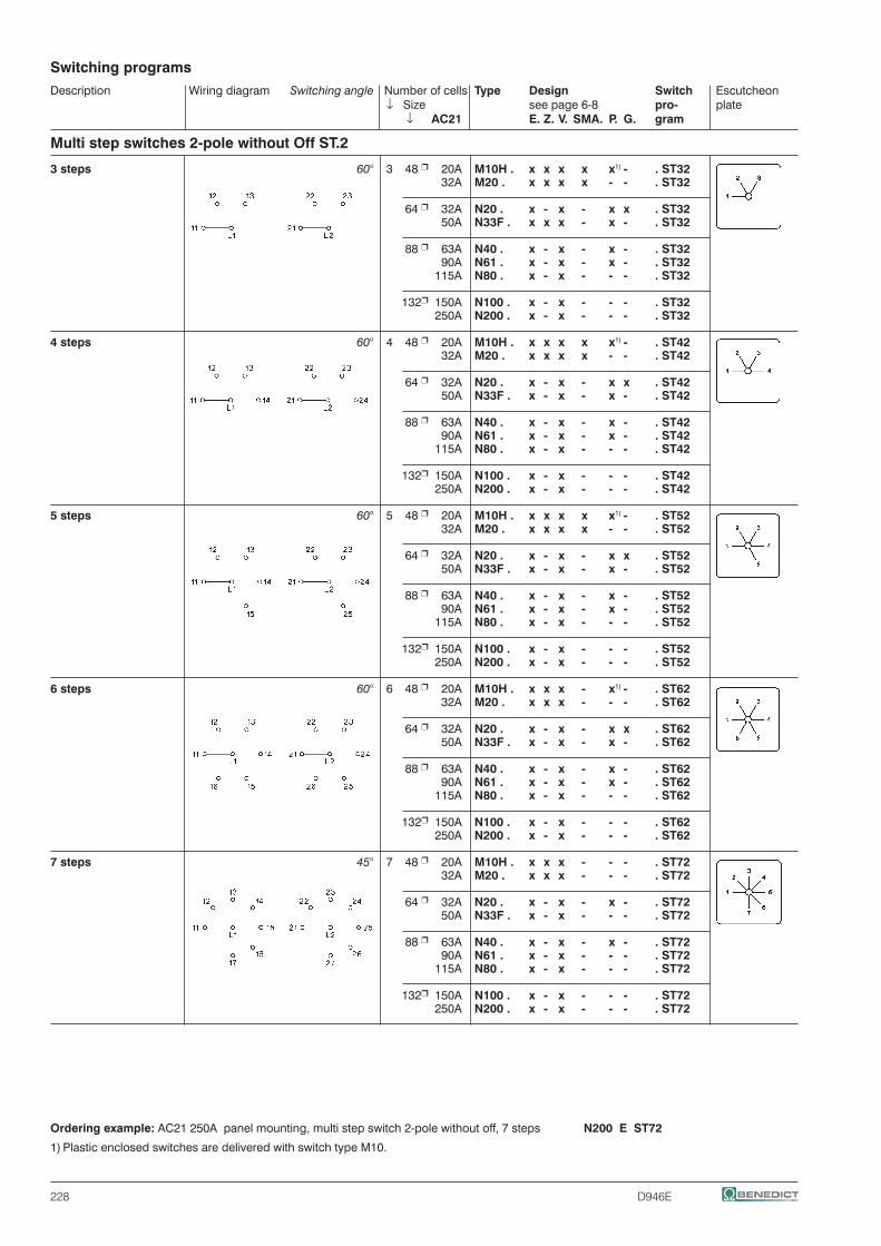
Description Wiring diagram Switching angle Number of cells Type Design Switch Escutcheon ↓ Size see page 6-8 pro- plate ↓ AC21 E. Z. V. SMA. P. G. gram
Switching programs
228 D946E
Multi step switches 2-pole without Off ST.2
3 steps 60° 3 48 r 20A M10H . x x x x x1) - . ST32 32A M20 . x x x x - - . ST32 64 r 32A N20 . x - x - x x . ST32 50A N33F . x x x - x - . ST32 88 r 63A N40 . x - x - x - . ST32 90A N61 . x - x - x - . ST32 115A N80 . x - x - - - . ST32 132r 150A N100 . x - x - - - . ST32 250A N200 . x - x - - - . ST32
4 steps 60° 4 48 r 20A M10H . x x x x x1) - . ST42 32A M20 . x x x x - - . ST42 64 r 32A N20 . x - x - x x . ST42 50A N33F . x - x - x - . ST42 88 r 63A N40 . x - x - x - . ST42 90A N61 . x - x - x - . ST42 115A N80 . x - x - - - . ST42 132r 150A N100 . x - x - - - . ST42 250A N200 . x - x - - - . ST42
5 steps 60° 5 48 r 20A M10H . x x x x x1) - . ST52 32A M20 . x x x x - - . ST52 64 r 32A N20 . x - x - x x . ST52 50A N33F . x - x - x - . ST52 88 r 63A N40 . x - x - x - . ST52 90A N61 . x - x - x - . ST52 115A N80 . x - x - - - . ST52 132r 150A N100 . x - x - - - . ST52 250A N200 . x - x - - - . ST52
6 steps 60° 6 48 r 20A M10H . x x x - x1) - . ST62 32A M20 . x x x - - - . ST62 64 r 32A N20 . x - x - x x . ST62 50A N33F . x - x - x - . ST62 88 r 63A N40 . x - x - x - . ST62 90A N61 . x - x - x - . ST62 115A N80 . x - x - - - . ST62 132r 150A N100 . x - x - - - . ST62 250A N200 . x - x - - - . ST62
7 steps 45° 7 48 r 20A M10H . x x x - - - . ST72 32A M20 . x x x - - - . ST72 64 r 32A N20 . x - x - x - . ST72 50A N33F . x - x - - - . ST72 88 r 63A N40 . x - x - x - . ST72 90A N61 . x - x - - - . ST72 115A N80 . x - x - - - . ST72 132r 150A N100 . x - x - - - . ST72 250A N200 . x - x - - - . ST72
Ordering example: AC21 250A panel mounting, multi step switch 2-pole without off, 7 steps N200 E ST72
1) Plastic enclosed switches are delivered with switch type M10.

Description Wiring diagram Switching angle Number of cells Type Design Switch Escutcheon ↓ Size see page 6-8 pro- plate ↓ AC21 E. Z. V. SMA. P. G. gram
Switching programs
D946E 229
Multi step switches 2-pole without Off ST.2
8 steps 45° 8 48 r 20A M10H . x x x - - - . ST82 32A M20 . x x x - - - . ST82 64 r 32A N20 . x - x - x - . ST82 50A N33F . x - x - - - . ST82 88 r 63A N40 . x - x - x - . ST82 90A N61 . x - x - - - . ST82 115A N80 . x - x - - - . ST82 132r 150A N100 . x - x - - - . ST82 250A N200 . x - x - - - . ST82
9 steps 30° 9 48 r 20A M10H . x x x - - - . ST92 32A M20 . x x x - - - . ST92 64 r 32A N20 . x - x - - - . ST92 50A N33F . x - x - - - . ST92 88 r 63A N40 . x - x - - - . ST92 90A N61 . x - x - - - . ST92 115A N80 . x - x - - - . ST92 132r 150A N100 . x - x - - - . ST92 250A N200 . x - x - - - . ST92
10 steps 30° 10 48 r 20A M10H . x x x - - - . ST102 32A M20 . x x x - - - . ST102 64 r 32A N20 . x - x - - - . ST102 50A N33F . x - x - - - . ST102 88 r 63A N40 . x - x - - - . ST102 90A N61 . x - x - - - . ST102 115A N80 . x - x - - - . ST102 132r 150A N100 . x - x - - - . ST102 250A N200 . x - x - - - . ST102
11 steps 30° 11 48 r 20A M10H . x x x - - - . ST112 32A M20 . x x x - - - . ST112 64 r 32A N20 . x - x - - - . ST112 50A N33F . x - x - - - . ST112 88 r 63A N40 . x - x - - - . ST112 90A N61 . x - x - - - . ST112 115A N80 . x - x - - - . ST112 132r 150A N100 . x - x - - - . ST112 250A N200 . x - x - - - . ST112
12 steps 30° 12 48 r 20A M10H . x x x - - - . ST122 32A M20 . x x x - - - . ST122 64 r 32A N20 . x - x - - - . ST122 50A N33F . x - x - - - . ST122 88 r 63A N40 . x - x - - - . ST122 90A N61 . x - x - - - . ST122 115A N80 . x - x - - - . ST122 132r 150A N100 . x - x - - - . ST122 250A N200 . x - x - - - . ST122
Ordering example: AC21 250A panel mounting, multi step switch 2-pole without off, 12 steps N200 E ST122

Description Wiring diagram Switching angle Number of cells Type Design Switch Escutcheon ↓ Size see page 6-8 pro- plate ↓ AC21 E. Z. V. SMA. P. G. gram
Switching programs
230 D946E
Multi step switches 2-pole with Off ST0.2
2 steps 60° 2 48 r 20A M10H . x x x x x1) - . ST022 32A M20 . x x x x - - . ST022 64 r 32A N20 . x - x - x x . ST022 50A N33F . x x x - x - . ST022 88 r 63A N40 . x - x - x - . ST022 +422 90A N61 . x - x - x - . ST022 115A N80 . x - x - - - . ST022 132r 150A N100 . x - x - - - . ST022 250A N200 . x - x - - - . ST022
3 steps 45° 3 48 r 20A M10H . x x x x x1) - . ST032 32A M20 . x x x x - - . ST032 64 r 32A N20 . x - x - x x . ST032 50A N33F . x x x - x - . ST032 88 r 63A N40 . x - x - x - . ST032 +127 90A N61 . x - x - x - . ST032 115A N80 . x - x - - - . ST032 132r 150A N100 . x - x - - - . ST032 250A N200 . x - x - - - . ST032
4 steps 30° 4 48 r 20A M10H . x x x x x1) - . ST042 32A M20 . x x x x - - . ST042 64 r 32A N20 . x - x - x x . ST042 50A N33F . x - x - x - . ST042 88 r 63A N40 . x - x - x - . ST042 +112 90A N61 . x - x - x - . ST042 115A N80 . x - x - - - . ST042 132r 150A N100 . x - x - - - . ST042 250A N200 . x - x - - - . ST042
5 steps 45° 6 48 r 20A M10H . x x x - x1) - . ST052 32A M20 . x x x - - - . ST052 64 r 32A N20 . x - x - x x . ST052 50A N33F . x - x - x - . ST052 88 r 63A N40 . x - x - x - . ST052 +423 90A N61 . x - x - x - . ST052 115A N80 . x - x - - - . ST052 132r 150A N100 . x - x - - - . ST052 250A N200 . x - x - - - . ST052
6 steps 45° 7 48 r 20A M10H . x x x - x1) - . ST062 32A M20 . x x x - - - . ST062 64 r 32A N20 . x - x - x - . ST062 50A N33F . x - x - - - . ST062 88 r 63A N40 . x - x - x - . ST062 +128 90A N61 . x - x - - - . ST062 115A N80 . x - x - - - . ST062 132r 150A N100 . x - x - - - . ST062 250A N200 . x - x - - - . ST062
Ordering example: AC21 250A panel mounting, multi step switch 2-pole with off, 6 steps N200 E ST062
1) Plastic enclosed switches are delivered with switch type M10.

Description Wiring diagram Switching angle Number of cells Type Design Switch Escutcheon ↓ Size see page 6-8 pro- plate ↓ AC21 E. Z. V. SMA. P. G. gram
Switching programs
D946E 231
Multi step switches 2-pole with Off ST0.2
7 steps 45° 8 48 r 20A M10H . x x x - - - . ST072 32A M20 . x x x - - - . ST072 64 r 32A N20 . x - x - x - . ST072 50A N33F . x - x - - - . ST072 88 r 63A N40 . x - x - x - . ST072 +129 90A N61 . x - x - - - . ST072 115A N80 . x - x - - - . ST072 132r 150A N100 . x - x - - - . ST072 250A N200 . x - x - - - . ST072
8 steps 30° 9 48 r 20A M10H . x x x - - - . ST082 32A M20 . x x x - - - . ST082 64 r 32A N20 . x - x - - - . ST082 50A N33F . x - x - - - . ST082 88 r 63A N40 . x - x - - - . ST082 +114 90A N61 . x - x - - - . ST082 115A N80 . x - x - - - . ST082 132r 150A N100 . x - x - - - . ST082 250A N200 . x - x - - - . ST082
9 steps 30° 10 48 r 20A M10H . x x x - - - . ST092 32A M20 . x x x - - - . ST092 64 r 32A N20 . x - x - - - . ST092 50A N33F . x - x - - - . ST092 88 r 63A N40 . x - x - - - . ST092 +115 90A N61 . x - x - - - . ST092 115A N80 . x - x - - - . ST092 132r 150A N100 . x - x - - - . ST092 250A N200 . x - x - - - . ST092
10 steps 30° 11 48 r 20A M10H . x x x - - - . ST0102 32A M20 . x x x - - - . ST0102 64 r 32A N20 . x - x - - - . ST0102 50A N33F . x - x - - - . ST0102 88 r 63A N40 . x - x - - - . ST0102 +116 90A N61 . x - x - - - . ST0102 115A N80 . x - x - - - . ST0102 132r 150A N100 . x - x - - - . ST0102 250A N200 . x - x - - - . ST0102
11 steps 30° 12 48 r 20A M10H . x x x - - - . ST0112 32A M20 . x x x - - - . ST0112 64 r 32A N20 . x - x - - - . ST0112 50A N33F . x - x - - - . ST0112 88 r 63A N40 . x - x - - - . ST0112 +117 90A N61 . x - x - - - . ST0112 115A N80 . x - x - - - . ST0112 132r 150A N100 . x - x - - - . ST0112 250A N200 . x - x - - - . ST0112
Ordering example: AC21 250A panel mounting, multi step switch 2-pole with off, 11 steps N200 E ST0112

Description Wiring diagram Switching angle Number of cells Type Design Switch Escutcheon ↓ Size see page 6-8 pro- plate ↓ AC21 E. Z. V. SMA. P. G. gram
Switching programs
232 D946E
Multi step switches 3-pole without Off ST.3
3 steps 60° 5 48 r 20A M10H . x x x x x1) - . ST33 32A M20 . x x x x - - . ST33 64 r 32A N20 . x - x - x x . ST33 50A N33F . x - x - x - . ST33 88 r 63A N40 . x - x - x - . ST33 90A N61 . x - x - x - . ST33 115A N80 . x - x - - - . ST33 132r 150A N100 . x - x - - - . ST33 250A N200 . x - x - - - . ST33
4 steps 60° 6 48 r 20A M10H . x x x - x1) - . ST43 32A M20 . x x x - - - . ST43 64 r 32A N20 . x - x - x x . ST43 50A N33F . x - x - x - . ST43 88 r 63A N40 . x - x - x - . ST43 90A N61 . x - x - x - . ST43 115A N80 . x - x - - - . ST43 132r 150A N100 . x - x - - - . ST43 250A N200 . x - x - - - . ST43
5 steps 60° 8 48 r 20A M10H . x x x - - - . ST53 32A M20 . x x x - - - . ST53 64 r 32A N20 . x - x - x - . ST53 50A N33F . x - x - - - . ST53 88 r 63A N40 . x - x - x - . ST53 90A N61 . x - x - - - . ST53 115A N80 . x - x - - - . ST53 132r 150A N100 . x - x - - - . ST53 250A N200 . x - x - - - . ST53
6 steps 60° 9 48 r 20A M10H . x x x - - - . ST63 32A M20 . x x x - - - . ST63 64 r 32A N20 . x - x - - - . ST63 50A N33F . x - x - - - . ST63 88 r 63A N40 . x - x - - - . ST63 90A N61 . x - x - - - . ST63 115A N80 . x - x - - - . ST63 132r 150A N100 . x - x - - - . ST63 250A N200 . x - x - - - . ST63
7 steps 45° 11 48 r 20A M10H . x x x - - - . ST73 32A M20 . x x x - - - . ST73 64 r 32A N20 . x - x - - - . ST73 50A N33F . x - x - - - . ST73 88 r 63A N40 . x - x - - - . ST73 90A N61 . x - x - - - . ST73 115A N80 . x - x - - - . ST73 132r 150A N100 . x - x - - - . ST73 250A N200 . x - x - - - . ST73
Ordering example: AC21 250A panel mounting, multi step switch 3-pole without off, 7 steps N200 E ST73
1) Plastic enclosed switches are delivered with switch type M10.

Description Wiring diagram Switching angle Number of cells Type Design Switch Escutcheon ↓ Size see page 6-8 pro- plate ↓ AC21 E. Z. V. SMA. P. G. gram
Switching programs
D946E 233
Multi step switches 3-pole without Off ST.3
8 steps 45° 12 48 r 20A M10H . x x x - - - . ST83 32A M20 . x x x - - - . ST83 64 r 32A N20 . x - x - - - . ST83 50A N33F . x - x - - - . ST83 88 r 63A N40 . x - x - - - . ST83 90A N61 . x - x - - - . ST83 115A N80 . x - x - - - . ST83 132r 150A N100 . x - x - - - . ST83 250A N200 . x - x - - - . ST83
9 steps 30° 14 48 r 20A M10H . x - x - - - . ST93 32A M20 . x - x - - - . ST93 64 r 32A N20 . x - x - - - . ST93 50A N33F . x - x - - - . ST93 88 r 63A N40 . x - x - - - . ST93 90A N61 . x - x - - - . ST93 115A N80 . x - x - - - . ST93 132r 150A N100 . x - x - - - . ST93 250A N200 . x - x - - - . ST93
10 steps 30° 15 48 r 20A M10H . x - x - - - . ST103 32A M20 . x - x - - - . ST103 64 r 32A N20 . x - x - - - . ST103 50A N33F . x - x - - - . ST103 88 r 63A N40 . x - x - - - . ST103 90A N61 . x - x - - - . ST103 115A N80 . x - x - - - . ST103 132r 150A N100 . x - x - - - . ST103 250A N200 . x - x - - - . ST103
11 steps 30° 17 48 r 20A M10H . x - x - - - . ST113 32A M20 . x - x - - - . ST113 64 r 32A N20 . x - x - - - . ST113 50A N33F . x - x - - - . ST113 88 r 63A N40 . x - x - - - . ST113 90A N61 . x - x - - - . ST113 115A N80 . x - x - - - . ST113 132r 150A N100 . x - x - - - . ST113 250A N200 . x - x - - - . ST113
12 steps 30° 18 48 r 20A M10H . x - x - - - . ST123 32A M20 . x - x - - - . ST123 64 r 32A N20 . x - x - - - . ST123 50A N33F . x - x - - - . ST123 88 r 63A N40 . x - x - - - . ST123 90A N61 . x - x - - - . ST123 115A N80 . x - x - - - . ST123 132r 150A N100 . x - x - - - . ST123 250A N200 . x - x - - - . ST123
Ordering example: AC21 250A panel mounting, multi step switch 3-pole without off, 12 steps N200 E ST123

Description Wiring diagram Switching angle Number of cells Type Design Switch Escutcheon ↓ Size see page 6-8 pro- plate ↓ AC21 E. Z. V. SMA. P. G. gram
Switching programs
234 D946E
Multi step switches 3-pole with Off ST0.3
2 steps 60° 3 48 r 20A M10H . x x x x x1) - . ST023 32A M20 . x x x x - - . ST023 64 r 32A N20 . x - x - x x . ST023 50A N33F . x x x - x - . ST023 88 r 63A N40 . x - x - x - . ST023 +422 90A N61 . x - x - x - . ST023 115A N80 . x - x - - - . ST023 132r 150A N100 . x - x - - - . ST023 250A N200 . x - x - - - . ST023
3 steps 45° 5 48 r 20A M10H . x x x x x1) - . ST033 32A M20 . x x x x - - . ST033 64 r 32A N20 . x - x - x x . ST033 50A N33F . x - x - x - . ST033 88 r 63A N40 . x - x - x - . ST033 +127 90A N61 . x - x - x - . ST033 115A N80 . x - x - - - . ST033 132r 150A N100 . x - x - - - . ST033 250A N200 . x - x - - - . ST033
4 steps 30° 6 48 r 20A M10H . x x x - x1) - . ST043 32A M20 . x x x - - - . ST043 64 r 32A N20 . x - x - x x . ST043 50A N33F . x - x - x - . ST043 88 r 63A N40 . x - x - x - . ST043 +112 90A N61 . x - x - x - . ST043 115A N80 . x - x - - - . ST043 132r 150A N100 . x - x - - - . ST043 250A N200 . x - x - - - . ST043
5 steps 45° 9 48 r 20A M10H . x x x - - - . ST053 32A M20 . x x x - - - . ST053 64 r 32A N20 . x - x - - - . ST053 50A N33F . x - x - - - . ST053 88 r 63A N40 . x - x - - - . ST053 +423 90A N61 . x - x - - - . ST053 115A N80 . x - x - - - . ST053 132r 150A N100 . x - x - - - . ST053 250A N200 . x - x - - - . ST053
6 steps 45° 11 48 r 20A M10H . x x x - - - . ST063 32A M20 . x x x - - - . ST063 64 r 32A N20 . x - x - - - . ST063 50A N33F . x - x - - - . ST063 88 r 63A N40 . x - x - - - . ST063 +128 90A N61 . x - x - - - . ST063 115A N80 . x - x - - - . ST063 132r 150A N100 . x - x - - - . ST063 250A N200 . x - x - - - . ST063
Ordering example: AC21 250A panel mounting, multi step switch 3-pole with off, 6 steps N200 E ST063
1) Plastic enclosed switches are delivered with switch type M10.

D946E 235
Multi step switches 3-pole with Off ST0.3
7 steps 45° 12 48 r 20A M10H . x x x - - - . ST073 32A M20 . x x x - - - . ST073 64 r 32A N20 . x - x - - - . ST073 50A N33F . x - x - - - . ST073 88 r 63A N40 . x - x - - - . ST073 +129 90A N61 . x - x - - - . ST073 115A N80 . x - x - - - . ST073 132r 150A N100 . x - x - - - . ST073 250A N200 . x - x - - - . ST073
8 steps 30° 14 48 r 20A M10H . x - x - - - . ST083 32A M20 . x - x - - - . ST083 64 r 32A N20 . x - x - - - . ST083 50A N33F . x - x - - - . ST083 88 r 63A N40 . x - x - - - . ST083 +114 90A N61 . x - x - - - . ST083 115A N80 . x - x - - - . ST083 132r 150A N100 . x - x - - - . ST083 250A N200 . x - x - - - . ST083
9 steps 30° 15 48 r 20A M10H . x - x - - - . ST093 32A M20 . x - x - - - . ST093 64 r 32A N20 . x - x - - - . ST093 50A N33F . x - x - - - . ST093 88 r 63A N40 . x - x - - - . ST093 +115 90A N61 . x - x - - - . ST093 115A N80 . x - x - - - . ST093 132r 150A N100 . x - x - - - . ST093 250A N200 . x - x - - - . ST093
10 steps 30° 17 48 r 20A M10H . x - x - - - . ST0103 32A M20 . x - x - - - . ST0103 64 r 32A N20 . x - x - - - . ST0103 50A N33F . x - x - - - . ST0103 88 r 63A N40 . x - x - - - . ST0103 +116 90A N61 . x - x - - - . ST0103 115A N80 . x - x - - - . ST0103 132r 150A N100 . x - x - - - . ST0103 250A N200 . x - x - - - . ST0103
11 steps 30° 18 48 r 20A M10H . x - x - - - . ST0113 32A M20 . x - x - - - . ST0113 64 r 32A N20 . x - x - - - . ST0113 50A N33F . x - x - - - . ST0113 88 r 63A N40 . x - x - - - . ST0113 +117 90A N61 . x - x - - - . ST0113 115A N80 . x - x - - - . ST0113 132r 150A N100 . x - x - - - . ST0113 250A N200 . x - x - - - . ST0113
Ordering example: AC21 250A panel mounting, multi step switch 3-pole with off, 11 steps N200 E ST0113
Description Wiring diagram Switching angle Number of cells Type Design Switch Escutcheon ↓ Size see page 6-8 pro- plate ↓ AC21 E. Z. V. SMA. P. G. gram
Switching programs

236 D946E
Panel mounting E, IP40 Central fixing Z Central fixing without escutcheon plate ZO
Central fixing 16mm
lock
unlock Central fixing 22mm
Mounting holes
Single hole mountings are generally delivered for a 16mm (.64") mounting. Using the forwarded adapter ring, it is possible to alter the single hole mountings from 22mm (.88"). For that purpose the adapter ring has to be attatched onto the threded part of the body in such a manner, that 1. the flat side of the adapter ring shows towards the front seal and 2. the inner nose fits into the notch of the body. The adapter ring has to be pushed towards the front seal.
Optional extras ordering for M4H Z ... +SRE M4H Z ... +SA. M4H ZO ... +SA. M4H Z ... +SRE+SA. code design
Additional escutcheon +SRE E, Z, ZOplate
Additional escutcheon +SRE2 E, Z, ZOplate
Key operated switch with lock KABA +SA1 Z, ZOwith lock Ronis +SA2 Z, ZO
Panel mounting E Central fixing Z, ZO ZO Z
Dimension L for ... cells Type A B D M 1 2 3 4 5 6 7 8
M4H mm 30 28 29,5 12,5 38,5 50,5 62,5 74,5 86,5 98,5 110,5 122,5
Technical dataType according to AC21A AC15 Motor rating AC3 specifications 110V 380V 3 phase 3-pole 1 phase 2-pole 240V 440V Volt 110 220 380 110 220 380 General use Pilot Duty 120 240 440 120 240 277 440
M4H IEC, VDE, BS, SEV 10A/500V 2,5A 1,5A kW 0,65 1,5 2,2 0,3 0,55 - 0,75 UL, CSA 10A/300V A300 HP 0,75 1 - 0,33 0,75 0,75 -
Type according to Motor rating AC23 specifications 3-pole 2-pole Volt 110 220 380 110 220 380 120 240 440 120 240 440
M4H IEC, VDE, BS, SEV kW 0,75 1,8 3 0,37 0,75 1,1 UL, CSA HP - - - - - -
additional data for wiring according to UL and CSA
Type type of temp. rating torque value for wire of wire field wiring terminalsM4H copper 60/75°C 0,6Nm / 5lb - inch
wire only
Wrench J7400for switches M4H with central fixing is necessary
Mini-Cam Switches M4H

D946E 237
Description Wiring diagram AC21 500V 10A escutch. numb. Type Design Switch AC15 230V 2,5A 30 x 30 of .E. .Z. .ZO. pro- AC3 4x400V 2,2kW cells ↓ ↓ ↓ gram
On-Off-switch A 1-pole 1 M4H . x x x . A12-pole 1 M4H . x x x . A23-pole 2 M4H . x x x . A34-pole 2 M4H . x x x . A46-pole 3 M4H . x x x . A6
Changeover switch U 1-pole 1 M4H . x x x . U12-pole 2 M4H . x x x . U23-pole 3 M4H . x x x . U34-pole 4 M4H . x x x . U4
Changeover switch without off W 1-pole 1 M4H . x x x . W12-pole 2 M4H . x x x . W23-pole 3 M4H . x x x . W34-pole 4 M4H . x x x . W4
6-pole 6 M4H . x x x . W6
Reversing switch WU 2-pole 2 M4H . x x x . WU2
3-pole 3 M4H . x x x . WU3
3-pole 3 M4H . x x x . WU3R2with spring return to 0
Star-delta switch SD 1 rotary direction 4 M4H . x x x . SD
both 5 M4H . x x x . SDRrotary directions
Changeover with spring return UR 1-pole 1 M4H . x x x . UR12-pole 2 M4H . x x x . UR23-pole 3 M4H . x x x . UR3
Start switch 1-pole 1 M4H . x x x . SE
Stop switch 1 M4H . x x x . SA1-pole
Ordering example: Stop switch, 1-pole, Central fixing: M4H Z SA
Switch programs
Mini-Cam Switches M4H

238 D946E
Description Wiring diagram AC21 500V 10A escutch. numb. Type Design Switch AC15 230V 2,5A 30 x 30 of .E. .Z. .ZO. pro- AC3 4x400V 2,2kW cells ↓ ↓ ↓ gram
Start-Stop switch 1 M4H . x x x . SEA
Start-Stop switch 1 M4H . x x x . S392position START withspring return to 1
Start-Stop switch 2 M4H . x x x . S2EAfor reversing contactors
Voltmeter selector switch V 3 line voltages 2 M4H . x x x . V3
3 phase voltages 2 M4H . x x x . V0
3 line voltages 3 M4H . x x x . V13 phase voltages
Ammeter selector switch A 1-pole, 3 current 4 M4H . x x x . M31transformer
Gang switch GR 2 circuits A and B 1 M4H . x x x . GR111-pole 0 - A - A+B
2 circuits A and B 1 M4H . x x x . GR121-pole 0 - A - B - A+B
3 circuits A, B and C 2 M4H . x x x . GR141-pole
Multi step switch without 0 ST 3 steps, 1-pole 2 M4H . x x x . ST31
3 steps, 2-pole 3 M4H . x x x . ST32
3 steps, 3-pole 5 M4H . x x x . ST33
Ordering example: Multi step switch without 0, 3 steps, 3-pole, panel mounting: M4H E ST33
Switch programs
Mini-Cam Switches M4H

D946E 239
Switch programs Description Wiring diagram AC21 500V 10A escutch. numb. Type Design Switch AC15 230V 2,5A 30 x 30 of .E. .Z. .ZO. pro- AC3 4x400V 2,2kW cells ↓ ↓ ↓ gram
Multi step switch without 0 ST 4 steps, 1-pole 2 M4H . x x x . ST414 steps, 2-pole 4 M4H . x x x . ST424 steps, 3-pole 6 M4H . x x x . ST43
5 steps, 1-pole 3 M4H . x x x . ST515 steps, 2-pole 5 M4H . x x x . ST52
6 steps, 1-pole 3 M4H . x x x . ST616 steps, 2-pole 6 M4H . x x x . ST62
Multi step switch with 0 ST0. 2 steps, 1-pole 1 M4H . x x x . ST0212 steps, 2-pole 2 M4H . x x x . ST0222 steps, 3-pole 3 M4H . x x x . ST023
3 steps, 1-pole 2 M4H . x x x . ST0313 steps, 2-pole 3 M4H . x x x . ST032
3 steps, 3-pole 5 M4H . x x x . ST033
4 steps, 1-pole 2 M4H . x x x . ST0414 steps, 2-pole 4 M4H . x x x . ST0424 steps, 3-pole 6 M4H . x x x . ST043
5 steps, 1-pole 3 M4H . x x x . ST0515 steps, 2-pole 5 M4H . x x x . ST052
6 steps, 1-pole 4 M4H . x x x . ST061
7 steps, 1-pole 4 M4H . x x x . ST071
8 steps, 1-pole 5 M4H . x x x . ST081
9 steps, 1-pole 5 M4H . x x x . ST091
10 steps, 1-pole 6 M4H . x x x . ST0101
Ordering example: Multi step switch with 0, 10 steps, 1-pole, Central fixing without escutcheon plate: M4H ZO ST0101
Mini-Cam Switches M4H

240 D946E
For switches with the design V.. it is necessary to state the installation depth - that is, the distance between mounting level of the switch and the inside edge of the door (dimension T).
Further informations page
Technical Data 261 Dimensions 266
On-Off-switches A
Description Wiring diagram Switching angle Number of cells Type Design Switch Escutcheon ↓ Size .E. .V. pro- plate ↓ AC21 ↓ ↓ gram
Load Switches for resistive or slightly inductive loads or switching without load
1-pole 60° 2 88 r 125A L100 . x x . A1 1 180A L160 . x x . A1 1 132r 400A L400 . x x . A1 3 600A L600 . x x . A1 2 800A L800 . x x . A1 3 1200A L1200 . x x . A1
2-pole 60° 2 88 r 125A L100 . x x . A2 2 180A L160 . x x . A2 2 132r 400A L400 . x x . A2 3 600A L600 . x x . A2 4 800A L800 . x x . A2 6 1200A L1200 . x x . A2
3-pole 60° 4 88 r 125A L100 . x x . A3 3 180A L160 . x x . A3 3 132r 400A L400 . x x . A3 6 600A L600 . x x . A3 6 800A L800 . x x . A3 9 1200A L1200 . x x . A3
4-pole 60° 4 88 r 125A L100 . x x . A4 4. pole early make 4 180A L160 . x x . A4 4 132r 400A L400 . x x . A4 6 600A L600 . x x . A4 8 800A L800 . x x . A4 12 1200A L1200 . x x . A4
6-pole 60° 6 88 r 125A L100 . x x . A6 6 180A L160 . x x . A6 6 132r 400A L400 . x x . A6 9 600A L600 . x x . A6 12 800A L800 . x x . A6 18 1200A L1200 . x x . A6

D946E 241
Description Wiring diagram Switching angle Number of cells Type Design Switch Escutcheon ↓ Size .E. .V. pro- plate ↓ AC21 ↓ ↓ gram
Load Switches for resistive or slightly inductive loads or switching without load
Changeover switches U
1-pole 60° 2 88 r 125A L100 . x x . U1 2 180A L160 . x x . U1 2 132r 400A L400 . x x . U1 3 600A L600 . x x . U1 4 800A L800 . x x . U1 6 1200A L1200 . x x . U1
2-pole 60° 4 88 r 125A L100 . x x . U2 4 180A L160 . x x . U2 4 132r 400A L400 . x x . U2 6 600A L600 . x x . U2 8 800A L800 . x x . U2 12 1200A L1200 . x x . U2
3-pole 60° 6 88 r 125A L100 . x x . U3 6 180A L160 . x x . U3 6 132r 400A L400 . x x . U3 9 600A L600 . x x . U3 12 800A L800 . x x . U3 18 1200A L1200 . x x . U3
4-pole 60° 8 88 r 125A L100 . x x . U4 4. pole early make 8 180A L160 . x x . U4 8 132r 400A L400 . x x . U4 12 600A L600 . x x . U4 16 800A L800 . x x . U4 24 1200A L1200 . x x . U4
Changeover switches without off W
Ordering example: AC1 1200A panel mounting, changeover switch without off 4-pole L1200 E W4
1-pole 60° 2 88 r 125A L100 . x x . W1 2 180A L160 . x x . W1 2 132r 400A L400 . x x . W1 3 600A L600 . x x . W1 4 800A L800 . x x . W1 6 1200A L1200 . x x . W1
2-pole 60° 4 88 r 125A L100 . x x . W2 4 180A L160 . x x . W2 4 132r 400A L400 . x x . W2 6 600A L600 . x x . W2 8 800A L800 . x x . W2 12 1200A L1200 . x x . W2
3-pole 60° 6 88 r 125A L100 . x x . W3 6 180A L160 . x x . W3 6 132r 400A L400 . x x . W3 9 600A L600 . x x . W3 12 800A L800 . x x . W3 18 1200A L1200 . x x . W3
4-pole 60° 8 88 r 125A L100 . x x . W4 4. pole early make 8 180A L160 . x x . W4 8 132r 400A L400 . x x . W4 12 600A L600 . x x . W4 16 800A L800 . x x . W4 24 1200A L1200 . x x . W4

242 D946E
Operating Knobs and Handles
All operating knobs can be moved on the hexagonal shaft, to permit adaptation to different sheet thicknesses, etc.
Type N100 N40 N200 N61 L400 M10 N80 L600 M10H N20 L100 L800 M20 N33F L160 L1200
Knob movement mm 5 5 7 9Hexagonal shaft dimension mm 5 7 9 12
Ordering example: Cam switch N61 V U3 with Instrument knob redOrder type: N61 V U3 +G3Dimensions see page 267
Types of handles
In the standard version, the switches are supplied with a black twist knob or instrument knob (M10H - N33F), except for design SMA, which has a grey toggle knob. Switches of size L, which consist of 2 or 3 switch columns, come with a black hand wheel. If required, the switch can be supplied with other knobs, which can later easily be exchanged.All operating knobs have an insert, which sets the position of the knob in relation to the switch shaft. This insert can be mounted in 8 different positions (at intervals of 45°), causing the angle of each individual switch setting to be rotated by 45°.
In the standard version, the switch terminals are posi-tioned left and right (except M10H). When the knob insert is turned by 90°, the lay-out of the terminals changes to top and bottom.
N100 N40 N200 N61 L400 M10 N80 L600Knobs and handles Ordering M10H N20 L100 L800Description Colour Code M20 N33F L160 L1200
Instrument knob grey +G1 X X Standard for M10 to N200 black +G2 X X X X red +G3 X X white +G5 X X
Toggle knob grey +K1 X X black +K2 X X red +K3 X X white +K5 X X blue +K6 X
Hand wheel black +HR X

D946E 243
Escutcheon Plates
TELUX-Cam Switches in designs E, V, P, PF, SM, UP, Z and KE are supplied with a square escutcheon plate consisting of a black frame and plexi insert plate. The markings are printed in black are on the back of the insert plate. To protect the markings so that they remain easy to read, the back of the insert plate is lined with silver foil. In addition, rectangular plates can be provided for all switch sizes, which can fitted on all switches after mounting.
Square plate Rectangular plate (with square plate)
TELUX-Cam Switches in design SMA, for distribution boards with 45mm inside edge of installation cover, is supplied with a grey cover and black markings.
Special engraved markings on escutcheon plates are limited by the available space. In the case of relatively large production runs or frequent use of the text, we recommend ordering of a printing block. This will be invoiced at cost price, and the engraving will not be charged for. This investment generally pays with batches from 50 pieces upwards.The "escutcheon plate" column of the selection and ordering tables for switch programs indicates the standard plate and, in some cases, an additional plate that is often used for the programs in question. If such a plate, listed in the selection table, is desired, the appropriate code number should be stated when ordering a switch and switch program.
Should only plates or parts of the latter be ordered, the order type is assembled as shown by the following example.
Code letter of switch sizes
M10, M10H, M20 AN20, N33F EN40, N61, N80, L100, L160 HN100, N200, L400, L600, L800, L1200 L Ordering example: Escutcheon plate silver, complete, for cam switch M10, marked with MAN OFF AUTO, angle of rotation 60°
Order type:
However, if a switch with non-standard lettering is required, only three-digit code number for the marking need be added to the order type (see next page).
Dimensions see page 267
Description Order type Switch size Plate Marking Code letter Art.No. Code number
Escutcheon plate for designs E, V, P., Z, SM, KE and UPEscutcheon frame black, plexi insert plate silver, markings black
Plexi insert plate silver A E H L .85... ... (see pp. 244-248)Plexi insert plate yellow A E H L .80... ... (see pp. 244-248)Escutcheon frame black A E H L .8203 -
Rectangular escutcheon plate for designs E, V, Z and SMEscutcheon frame black, plexi insert plate silver, markings black
Plexi insert plate silver A E H L .885.. ... (see pp. 244-248)Plexi insert plate yellow A E H L .895.. ... (see pp. 244-248)Escutcheon frame black A E H L .8503 -
Installation cover for design SMA
grey cover, markings black A - - - .68... ... (see page 246)
A85009 Switch size Plate Marking Code letter Art.No. for Code number for M10, M10H standard plate with label and M20 with markings, MAN OFF AUTO complete angle of rot. 60°

244 D946E
Escutcheon Plates
Code letter of switch sizes
M10, M10H, M20 AN20, N33F EN40, N61, N80, L100, L160 HN100, N200, L400, L600, L800, L1200 L
Selected standard markingsThe markings that are most commonly required are shown below, together with code letters for the switch size and the code number.Ordering example: Switch type M10H E A3 with escutcheon plate "OFF ON" and additional rectangular escutcheon plate "PUMP"Order type: M10H E A3 +003 +516
Blank escutcheon plates
000 001
A E H L A E H L
Switching angle 30o
012 013 014 016 026 034 043 044 067 068
A E H A E A A A A A A A A
077 086 097 101 102 103 104 105 106 107
A A A A E H A E A E A E A E A E A
108 109 110 111 112 113 114 153 157 191
A E A E A E A A E A E A E A E
219 264 370 371 405 438 455 648 714 749
A A A E A A E A A A E E A
Switching angle 45o
018 019 021 022 025 031 032 036 041 042
A E A E H L A E E A A E A A E
045 051 118 119 120 121 122 123 124 125
A A E A E A E E A E A E A E H L A E A E
126 127 128 129 131 160 221 243 244 247
A E A E A E A E E H A A E A E A E

D946E 245
Escutcheon Plates
Switching angle 45o
248 249 250 303 304 336 421 423
A A E A E A E A A E A E
Switching angle 60o
002 003 004 006 007 008 009 010 011 015
A E H L A E H L A E H L A E H L A E H L A A A E H L A E H L A E
081 082 088 095 132 133 134 136 140 143
A E A E A E H A E A E H A E A E A A A
162 163 166 175 185 186 195 211 241 251
A E A E A E H L A A E E H L A A E
252 266 273 277 279 292 334 338 355 408
A A E A A A E H A A A E A A
416 417 418 419 420 422 439 446 448 489
A E A E A E A E A E A E A A E A A
634 635 636 675 699 702 706 739 798
A A A E H A A H A A A

246 D946E
Escutcheon Plates
Switching angle 90o
028 029 030 056 083 087 089 144 145 217
A E A E A E A A E H L A E A E A E H E A
230 246 270 330
A E A E A A
Miscellaneous
020 054 071 092 147 148 149 172 225 289
E A A E A E H A E E A E A A
760
A
Rectangular additional escutcheon plates
500 501 503 504 505 506 509 519 520 524 A E H L A E A E A E A A E A E E A E
534 535 542 543 546 549 550 551 552 556
A A A E A A A A A A E E
557 A
Covers for design SMA
001 002 003 004 006 009 012 013 014 015
028 81 82 106 111 122 123 132 143 221
234 243 355 370 416 417 420 636 637 717

D946E 247
Switching angles
Arrangement of switch settings
All feasible arrangements of switch settings are shown, and defined by position numbers, in the following tables. Not only the switching angles, but also switches with latched or momentary settings, or combinations of the two, are distinguished from one another.Knowledge of the following variations is particularly important when planning special switches. It is necessary to state the position number when ordering special switches, as the cheapest version will otherwise be selected.All the switches types listed can be supplied with switching angles other than those indicated, provided that they are permitted by the switch program (additional charge).
Switching angle 30o
PN01 PN02 PN03 PN04 PN05 PN06 PN07 PN08 PN09 PN10
PN11 PN12 PN13 PN14 PN15 PN16 PN17 PN18 PN19 PN20
PN21 PN22 PN23 PN24 PN25 PN26 PN27 PN28
Switching angle 45o
PN30 PN31 PN32 PN33 PN34 PN35 PN36 PN37 PN38 PN39
PN40 PN41 PN42 PN43 PN44 PN45 PN46 PN47 PN48 PN49
Switching angle 60o
PN50 PN51 PN52 PN53 PN54 PN55 PN56 PN57 PN58 PN59
PN76 PN77 PN78 PN79 PN150 PN151
Switching angle 45/90o
PN70 PN71 PN72 PN73
+) Not available for switch types M10, M10H and M20

248 D946E
Switching angle 90o
PN60 PN61 PN62 PN63 PN64 PN65 PN66 PN67 PN68 PN69
Momentary settings and special combinations
PN80 PN82 PN83 PN84 PN85 PN86 PN87 PN88 PN89 PN90
Spring return over several settings
PN110 PN111 PN112 PN113 PN114 PN115 PN116 PN117 PN118 PN119
PN120 PN121 PN122 PN123
Switching angles
+) Not available for switch types M10, M10H and M20
PN91 PN92 PN93 PN94 PN95 PN96 PN97 PN98 PN99 PN100
PN101 PN102 PN103 PN104 PN105 PN106 PN107 PN108 PN109 PN124
PN125 PN126 PN127 PN128 PN129 PN130 PN131

D946E 249

250 D946E
Door couplingsDoor couplings are available for switches to be installed in switchgear cabinets or distribution boards with hinged doors. These permit the doors to be openened without removal of the operating knobs.
Ordering example: Cam switch N100 V A3 with lockable door coupling, moisture protected IP65, dimension T=580mmOrder type: N100 V A3 +TK2FR/580
Dimensions see page 269
For switches with door couplings it is necessary to state the installation depth - that is, the distance between mounting level of the switch and the inside edge of the door (dimension T).
Ordering Suitable Suitable for Code for designs switch type
+TKE/... V, SM M10H, M20, N20, N33F
+TK2E/... V, SM M10H, M20, N20, N33F
+TK2Z/... V, SM M10H, M20, N20, N33F
+TK/... V N40, N61, N80, N100, N200 L100, L160, L400, L600 L800
+TKFR/... V N40, N60, N80, N100, N200 L100, L160, L400, L600 L800
+TK2/... V N40, N61, N80, N100, N200 L100, L160, L400, L600 L800
+TK2FR/... V N40, N61, N80, N100, N200 L100, L160, L400, L600 L800
Door couplingProtection class from front: IP655-hole mounting
Door coupling lockedProtection class from front: IP655-hole mountingDoors only open at a given switch setting: unless otherwise stated, the "OFF" setting.
Door coupling lockedProtection class from front: IP65Central fixing Ø22mmDoors only open at a given switch setting: unless otherwise stated, the "OFF" setting.
Door couplingProtection class from front: IP405-hole mounting
Door couplingProtection class from front: IP545-hole mounting
Door coupling lockedProtection class from front: IP405-hole mountingDoors only open at a given switch setting: unless otherwise stated, the "OFF" setting.
Door coupling lockedProtection class from front: IP545-hole mountingDoors only open at a given switch setting: unless otherwise stated, the "OFF" setting.

D946E 251
Lockable switchesOrdering example: Cam switch N20 E A3 key operatedOrder type: N20 E A3 +SA
Dimensions see page 270 and 271
Key-operated and lockable switches are supplied with two keys. Additional keys or other types of lock on request.
Ordering Suitable Suitable for Code for designs switch type
+SA E, V, SM M10H, M20, N20, N33F E, V N40, N61 P M10, N20, N33F, N40, N60 SMA M10H, M20 UP M10
+SA/.
+SA Z, ZO M10H, M20
+SA/.
+SAK E M10H, M20 +SAK/.
+SASI E M10H, M20 P M10, M20 UP M10, M20
+SASO E M10H, M20 P M10, M20 UP M10, M20
Key operated switchLock Willenhal FT101, key removable in all lockable settings.Other types of lock on request. Maximum number of cellsM10 - N33F: 6 N40, N61: 2Key operated switch, key removable only in some settings. Add letter ofsettingwhere key is removable to ordering code according to the scetch belove.
Key operated switch IP65Lock Ronis R455, key removable in all lockable settings.Key operated switch, key removable only in some settings. Add letter of settingwhere key is removable to ordering code according to the scetch above.
Key operated switchLock KABA8, key removable in all lockable settings.Key operated switch, key removable only in some settings. Add letter of settingwhere key is removable to ordering code according the scetch belove.
Key operated switch with barrelfor special security functionsLock EVVA EHZ50/5 Nickel mattSpecial version which prevents not only switching but also access to the cable ends and removal of the switch when locked.Maximum number of cellsDesign E, P: 4Design UP : 3
Key operated switch for special security functions without lockfor use of lock EVVA EHZ50/5 or with same dimensionsMaximum number of cellsDesign E, P: 4Design UP : 3

252 D946E
Padlock devices
A range of padlock devices designed to prevent from being turned on by unauthorized personnel, or during maintenance and repair work, can be supplied.Dimensions see page 272
Ordering example: Cam switch N33F E A3 with interlocking device SV3 suitable for 3 padlocksOrder type: N33F E A3 +SV3
Padlock device Description
Padlock deviceStandard version black,otherwise red,for 1 or 2 padlocks.Shackles up to Ø6mmStandard version black 64 x 64mm,otherwise red 64 x 64mm
Padlock deviceStandard version black, otherwiseyellow insert plate and red twist knobfor 1-3 padlocks.Shackles up to Ø8,5mmPrior to insertion of the first padlock, a red locking ledge must be depressed. This indicates that the switch is locked.
Padlock deviceStandard base grey, locking ring black,or with yellow base and red locking ring.Locking ring for 1-3 padlocks.Shackles up to Ø6mmStandard base grey, locking ring black 88 x 88mm,or with yellow base and red locking ring 88 x 88mm
Key lock deviceWith a cylinder lock in the lock attach-ment, one or more switch settings are lockable (state when ordering). The operating knob can only be turned when unlocked. The key can be withdrawn wheter locked or unlocked.Special versions, in which the key cannot be withdrawn when in some (unlockable) settings can be supplied.
Key lock deviceSpecial version for on-off switches, in which it is possible to switch off without a key.
Ordering Suitable Suitable for Code for designs switch type
+SV1 E, V, SM M10H, M20 +SV1R P, PF M10
+SV164 E, V M10H, N20, N33F +SV164R P, PF N20, N33F
+SV3 E, V N40, N61, N80, L100, L160 +SV3R E, V N100, N200, L400, L600, E, V L800, L1200 PF N40, N61, N80, N100, N200
+SV4 E, V M10H, N20, N33F +SV4R SM M10H, N20, N33F P, PF N20, N33F
+SV488 E, V N20, N33F E, V N40, N61, N80 +SV488R P, PF N40, N61, N80
+SZ E, V alle SM M10H, M20, N20, N33F
+SZ2 E, V alle SM M10H, M20, N20, N33F

D946E 253
Switch interlocks
A wide range of locks and interlocking devices, designed to prevent accidental or hazardous switching, can be supplied.
Dimensions see page 273
Ordering example: Cam switch N20 E A3 with push button switch lockOrder type: N20 E A3 +DV
Description
Push button interlockThe switch can only be actuated when the pushbutton is simultaneously de-pressed (two-handed operation).
Interlock with electrical contactThe switch can only be actuated when the pushbutton, which also operates a make and break contact, is actuated (for external interlocking devices or safety measures).
Magnetic interlockThe switch can only be actuated when an electromagnet is simultaneously excited. When ordering, voltage and percentage duty cycle of the magnet coll should be stated.
Circular switchSwitches that have the maximum num-ber of settings for a given switching angle can be made without a stop position, permitting direct switching from the last to the first setting.
Backswitch 1Special version of the circular switch, in which the switch can only be turned in one direction.
Backswitch 2Special version of the circular switch, in which, in given positions, the switch can only be operated in one direction.
Ordering Suitable Suitable for Code for designs switch type +DV E, V all
+ET E, V all
+MV E N20, N33F, N40, N61, N80 N100, N200
+RU all all
+RS1 all all
+RS2 all all

254 D946E
Couplings and stop mechanism
Description
Coupling of two columnsFor simultaneous drive of two switch columns (with very large number of switch cells or limited installation depth).
Coupling of three columnsFor simultaneous drive of three switch columns.
Coupling of different switch sizesFor attachment of control switches (auxiliary contacts) to larger switches.M10H, M20 in sizes E and H.N20 to N80 in size L.
Delayed action switchUsing a delayed action coupling, two switch shafts - a main shaft and delayed shaft - can be coupled, such that the delayed shaft is rotated together with the main shaft once a given angle of rotation is reached (e.g. for off-load return of switches used with pole-changing motors).
Second stop mechanismWith switches in which a large number of contacts is simultaneously operated, use of a second stop mechanism is sometimes necessary, in order to ensure precise switching to the next setting.
Metal stop mechanismfor extreme mecanical stress on the stop mechanism, e.g. where many contacts are switched at the same time.Not for PN110 to PN123
Ordering Suitable Suitable for Code for designs switch type +ZK2 E, V all
+ZK3 E, V all
+ZWK E N40, N61, N80, L100, L160 N100, N200, L400, L600, L800, L1200
+SK E, V N20, N33F, N40, N61, N80 G, GF N20
+RW2 all all
+MRW E, V N40, N61, N80, L100, L160 E, V N100, N200, L400, L600, E, V L800, L1200 G, GF N20
A range of couplings and stop mechanisms for trouble-free operation of switches with a very large number of contacts can be supplied.Dimension see page 274
Ordering example: Cam switch N200 V ST0113 spread over three columns interconnected by gearsOrder type: N200 V ST0113 +ZK3

D946E 255
Special versions
A number of special versions can be supplied for adaptation of switches to various conditions of use.
Ordering example: Cam switch M10H E U3 with large front plateOrder type: M10H E U3 +GFP
Ordering Suitable Suitable for Code for designs switch type +WD E, V N20 to L1200 SM N20, N33F
+FPWD E, V, SM N20, N33F
+VW/... E, V all SM M10H, M20, N20, N33F
+GFP E, V, SM M10H, N20, N33F
E all +SLR/230 P M10, N20, N33F, N40, N61 +SLR/400 UP M10, N20 +SLG/230 +SLG/400
+GK all M10H, M20, N20, N33F
+TR all all
+FEU E N20, N33F
Description
Switch shaft sealingFor increased front protection class on IP54.
Front plate/switch shaft sealingFor increased front protection class on IP65. In this version, a wider hole is required for the shaft. Dimensions see page 272
Extended switch shaftFor adaptation of switch designs V and SM to the enclosure depth. State additional shaft length when ordering.
Large front plateSwitch with front plate and operating knob of the next size (for replacement of older, larger switches or aesthetic reasons).
Switch with pilot lamplamp red, 230Vlamp red, 400Vlamp green, 230Vlamp green, 400V
Gold plated contactsFor electronic circuits with low voltages and currents.
Tropical proof type
Neon safety switchFor all-pole switching off of neon adver-tisement circuits by the Fire Brigade.Dimensions see page 274

256 D946E
Accessories
Ordering example: Cam switch N20 E A3 with terminal cover plateOrder type: N20 E A3 +KLAD
A number of special versions can be supplied for adaptation of switches to various conditions of use.Dimensions see page 273
Description
Terminal cover platePrevents accidental touching of live terminals (requirement for main switches according to VDE 0113)only for 2 cellsfor all cells
Moisture proofing capsProtection class from rear: IP54.For protection of the switch from dust and moisture (e.g. when installed in ma-chine pedestals). For switch mounting from the front and rear. Conical cable entry glands.Maximum number of cells:M10H 7N20 5N40 4 N61 2 Angled terminalsFor easy connection of inaccessible switches.Unless otherwise stated, all terminals specified with markings are equipped in this manner.A distinction is drawn between left and right angled terminals. Seen from the switch end, the left terminals are located above left and below right; conversely, right terminals are above right and below left.
Fast-on connectorsFor 6,3 x 0,8mm plugs.
Earth terminals2 terminals, connected with one another, insulated from switch column: for earth conductors.
Additional rectangular escutcheon plate 1 line Dimensions see page 267
Big additional rectangular escutcheon plate for 2 linesDimensions see page 267
Spare key for key operated switcheswith Lock Willenhal FT101
Spare key for key operated switcheswith Lock Ronis R455
Wrenchfor switches with central fixing
Ordering Suitable Suitable for Code for designs switch type +KLAD E, V N20, N40, N61, N80 N100, N200
+KLAD E, V N33F
+FR E M10H, N20, N40, N61
+WK E,V M20, N20, N40, N61, N80, N100
+AMPZ E, V M20, N20
+PE E, V, all P, PF M10, N20, N33F, N40, N61 PF N80, N100, N200 G, GF N20 SRE E, Z, V, SM all
SRE2 E, V M10H, M20, N20, N33F
J7101 E, V, P M10H, M20, N20, N33F,N40 SMA M10H, M20
B4-R455 Z, ZO M10H, M20
J7049 Z, ZO M10H, M20

D946E 257
Switching Programs according to Customer Requirements
As a result of their modular construction, TELUX cam switches are particularly suitable for manufacturing of special variants. According to its function, each pair of contacts in the switch is adapted to the desired program by appropriate design of the cam plate. In the case of switches with an overall switching angle of more than 180°, provisi-on must made for a cam plate in each switching cell, controlling two opposite, independent contact pairs with matching programs (does not apply to M10, M10H, M20 and N20).Depending on the desired contact program for the special switch, it may often be impossible to make full use of all switching cells, that is, to include the maximum possible number of contacts. In determining the number of cells or switch length, one-contact cells will sometimes be resorted to.Switch sizes M10, M10H, M20 and N20 are exceptions to this rule. Here, two cam plates can be built into each cell, so that both contacts are independently controlled (full use of the cells with special programs).
In all special switches with overall switching angles of less than 180°, the number of cells required is calculated by having the total number of contacts in the switching program.When planning for switches with special programs, choice of the optimum switching angle thus plays an important part. The listing of all the options for lay-out of switch settings, on pages 247 and 248, should be an aid to planning (position numbers PN).If special markings are to be engraved on the escutcheon plates, it is vital to take account of the available space. It is advisable to use abbreviations.We provide forms (see page 275) on request, free of charge, to give a clear overview when special programs are being defined. Switch size, design, type of operating knob and desired switching angle, as well as the function of the contacts, are entered on these forms. Provision has also been made in them for entry of details as to escutcheon plate engravings or other special requirements.
Ordering Example
Order sheet A4 see page 275

258 D946E
Kind of Category Typical Rated Test conditions for the number Test conditions for making current fre- infre- applications operational of on-load operating cycles and breaking capacities quent quent current (normal service) (operation in fault case) oper- oper- Make Break Make Break ation ation I/Ie U/Ue cosϕ Ic/Ie Ur/Ue cosϕ I/Ie U/Ue cosϕ Ic/Ie Ur/Ue cosϕ
AC20A AC20B No-load conditions all values - - - - - - - - - - - -
Alter- Switching of resistive loadsnating AC21A AC21B including moderate all values 1 1 0,95 1 1 0,95 1,5 1,05 0,95 1,5 1,05 0,95Current overloads
Switching of mixed resistive AC22A AC22B and inductive loads all values 1 1 0,8 1 1 0,8 3 1,05 0,65 3 1,05 0,65 including moderate overloads
Switching of motor loads 0<Ie≤100A 10 1,05 0,45 8 1,05 0,45 AC23A AC23B or other highly inductive all values 1 1 0,65 1 1 0,65 loads 100A<Ie 10 1,05 0,35 8 1,05 0,35
Slip-ring motors: AC2 Starting, plugging all values 2,5 1 0,65 2,5 1 0,65 4 1,05 0,65 4 1,05 0,65
Squirrel-cage motors: 0<Ie≤100A Ie≤17A 0,65 Ie≤17A 0,65 0,45 0,45 AC3 Starting, switching off all values 6 1 1 0,17 10 1,05 8 1,05 motors during runing 100A<Ie Ie>17A 0,35 Ie>17A 0,35 0,35 0,35 Squirrel-cage motors: 0<Ie≤100A Ie≤17A 0,65 Ie≤17A 0,65 0,45 0,45 AC4 Starting, plugging, all values 6 1 6 1 12 1,05 10 1,05 inching 100A<Ie Ie>17A 0,35 Ie>17A 0,35 0,35 0,35
Control of electromagnetic AC15 loads (> 72VA) - 10 1 0,7 1 1 0,4 10 1,1 0,3 10 1,1 0,3
I/Ie U/Ue L/R1) Ic/Ie Ur/Ue L/R1) I/Ie U/Ue L/R1) Ic/Ie Ur/Ue L/R1)
DC20A DC20B No-load conditions all values - - - - - - - - - - - -
Direct Switching of resistive loadscurrent DC21A DC21B including moderate all values 1 1 1 1 1 1 1,5 1,05 1 1,5 1,05 1 overloads
Switching of mixed resistive DC22A DC22B a. induct. loads incl. moderate all values 1 1 2 1 1 2 4 1,05 2,5 4 1,05 2,5 overloads (shunt motors)
Switching of highly inductive DC23A DC23B loads (e.g. series motors) all values 1 1 7,5 1 1 7,5 4 1,05 15 4 1,05 15
Shunt-motors: DC3 Starting, plugging, all values 2,5 1 2 2,5 1 2 4 1,05 2,5 4 1,05 2,5 inching
Series-motors: DC5 Starting, plugging, all values 2,5 1 7,5 2,5 1 7,5 4 1,05 15 4 1,05 15 inching
Ue Rated operational voltage, U Voltage before make, Ur Recovery voltage, Ie Rated operational current, I Current made, Ic Current broken 1) Time in milliseconds (ms)
Note:By plugging, is understood stopping or reversing the motor rapidly by reversing motor primary connections while the motor is running.
By inching (jogging), is understood energizing a motor once or repeatly for short periods to obtain small movements of the driven mechanism.
Utilization Categories
For easier choice of devices and in order to make the comparisonof different products simplier are utilization categories for cam switchesaccording to IEC 947-3, VDE 0660 Part 107 and
auiliary contactsaccording to IEC 947-5-1 and VDE 0660 Part 200 determind. The Table below offers divers utilization catagories and assorted test conditions.

D946E 259
Technical Data
Data according to IEC 947-3, IEC 947-5-1, VDE 0660, EN 60947-3, EN 60947-5-1
Type M10 P M10H M20 N20 N33F N40 N61 N80 N100 N200 Rated therm. current Ith open A 20 20 32 32 50 63 90 115 150 250 Rated therm. current Ithe encl. A 20 20 32 32 50 63 90 115 150 250 Rated operational voltage Ue V 440 690 1) 690 1) 690 1) 690 1) 690 1) 690 1) 690 1) 690 1) 690 1)
Disconnection property 2)
acc. to VDE, IEC up to V 440 440 440 440 440 690 440 440 690 690 Breaking capacity Ieff 3 x 220-440V A 160 160 220 220 260 380 520 740 900 1100 3 x 500V A - 100 160 160 200 290 380 560 680 850 3 x 660-690V A - 80 120 120 150 200 290 520 450 - Utilization categ. AC21A, AC21BSwitching of resistive loadsincluding moderate overloadsRated operational current Ie A 20 20 32 32 50 63 90 115 150 250 Utilization categ. AC23A, AC23BSwitching of motor loadsor other highly inductive loadsRated current Ie 400V A 16 16 30 30 45 45 60 85 105 135 Power rating 220-240V kW 4 4 7,5 7,5 11 15 22 30 40 403-phase 3-pole 380-440V kW 7,5 7,5 15 15 22 22 30 45 55 70 500V kW - 7,5 15 15 22 22 30 45 55 70 660-690V kW - 7,5 15 15 22 18,5 30 45 45 - Star-Delta-Switchesfor squirrel cage motorsPower rating 3-phase 3-pole 220-240V kW 3,7 3,7 7,5 7,5 8 11 15 18,5 37 40 380-415V kW 7,5 7,5 15 15 18,5 18,5 25 30 40 70 Utilization category AC3Switching of three-phase motorsRated current Ie 400V A 12 12 22 22 30 30 50 60 80 135 Power rating 220-240V kW 3 3 5,5 5,5 7,5 7,5 15 18,5 37 403-phase 3-pole 380-440V kW 5,5 5,5 11 11 15 15 25 30 40 70
500V kW - 5,5 11 11 15 15 25 30 40 70 660-690V kW - 5,5 11 11 15 15 25 30 40 - Utilization category AC4squirrel cage motors, inchingPower rating 220-240V kW 0,55 0,55 2,2 2,2 3,7 4 5,5 6 11 18,53-phase 3-pole 380-440V kW 1,5 1,5 4 4 5,5 7,5 11 15 18,5 35
500V kW - 1,5 4 4 5,5 7,5 11 15 22 35 660-690V kW - 1,5 4 4 5,5 7,5 11 15 22 - Utilization category AC15Control of electromagnetic loads, contactors,Rated current Ie up to 240V A 6 6 12 12 16 - - - - - 380 - 440V A 4 4 6 6 7 - - - - -2-pole in series 500V A - 5 8 8 10 - - - - - Utilization categ. DC21A, DC21BSwitching of resistive loadsTime constant L/R≤1msRated current Ie1-pole 30V A 20 20 32 32 40 63 80 100 150 250 60V A 4 4 6 6 20 30 30 30 - - 110V A 0,6 0,6 3 3 4 6 6 6 - - 220V A 0,5 0,5 0,8 0,8 0,8 1,3 1,3 1,3 2,5 2,5 440V A - - 0,4 0,4 0,4 0,6 0,6 0,6 0,7 0,7 Utilization category DC3 - DC5Switching of shunt motorsand series motorsTime constant L/R≤15msRated current Ie1-pole 30V A 8 8 13 13 16 25 32 40 60 100 60V A 1 1 2,4 2,4 4 12 12 12 - - 110V A 0,3 0,3 0,5 0,5 1,6 2,4 2,4 2,4 - - Protection class ot terminals 1) IP00 IP20 IP00 IP00 IP20 IP00 IP00 IP00 IP00 IP00
1) suitable for: earthed-neutral systems, overvoltage category I to III, pollution degree 3 (standard-industry): Uimp = 6kV. Data for other conditions on request2) valid for lines with grounded common neutral termination, overvoltage category III , pollution degree 3.3) Protection degree of the terminals with connected insulated conductor. Additional protection with terminal cover (KLAD).

260 D946E
Technical Data
Data according to IEC 947-3, IEC 947-5-1, VDE 0660, EN 60947-3, EN 60947-5-1
Type M10 P M10H M20 N20 N33F N40 N61 N80 N100 N200
Cable cross-sectionssolid mm2 1-2,5 1-2,5 1) 1,5-6 1,5-6 2,5-10 2,5-16 1) 6-25 1) 6-35 10-50 1) 50-150flexible mm2 0,75-2,5 0,75-2,51) 1-4 1-4 1,5- 6 2,5-10 1) 6-25 1) 6-35 10-35 1) 35-120flexible w. multicore cable end mm2 0,75-2,5 0,75-1,5 1-4 1-4 1,5- 6 2,5-6 6-16 6-35 10-25 -Conductors to clamp per pole 2 2 2 2 2 2 1 1 1 1
Size of terminal screw M3 M3,5 M4 M4 M4 M5 2xM5 2xM5 2xM6 M10
Tightening torque Nm 0,6-1,2 0,8-1,4 1,2-1,8 1,2-1,8 1,2-1,8 2,5-3 2,5-3 2,5-3 3,5-4,5 10 lb.inch 5-11 7-12 11-16 11-16 11-16 22-26 22-26 22-26 31-40 88
Short circuit protectionMax. fuse size gL (gG) A 20 20 35 35 50 63 100 125 160 250Rated short-time withstand current(1sec. current) A 250 250 400 400 500 800 1000 1400 1800 3000Rated conditional short-circuit current kAeff 10 10 10 10 10 10 10 10 10 10
Short-time capacityLoad duration 3s A 100 100 200 200 350 400 600 720 1000 2000 10s A 60 60 130 130 230 250 400 480 600 1200Note: Ratings applies to 30s A 35 35 85 85 110 160 250 300 500 600 contacts already closed 60s A 25 25 65 65 80 110 200 250 370 480
Power loss at AC21A A 20 20 32 32 50 63 85 115 150 250per pole W 0,6 0,5 0,9 1,1 1,9 2 2,8 4,4 5,7 21
Switching of capacitive loadsmaximum making capacityup to 500V A 140 140 300 300 350 400 600 700 900 1800
Data according to UL and cUL
Type M10 P M10H M20 N20 N33F N61 N80 N100 N200 L400
Rated voltage V~ 300 600 600 600 600 600 600 600 600 600
Rated operational current "General Use" A 20 20 35 35 60 90 115 130 250 350 with jumper A 15 - 25 25 40 60 80 - - -
DOL-Rating 3-phase 110-120V hp 1½ 1½ 5 5 7½ - 10 15 15 15 200-208V hp 2 2 5 5 10 - 15 25 25 25 220-240V hp 3 3 5 5 15 - 20 30 30 30
440-480V hp - 5 10 10 25 - 40 40 60 60 550-600V hp - 7½ 15 15 30 40 50 50 75 75
DOL-Rating 1-phase 110-120V hp ½ ½ 1½ 1½ 3 - 5 7½ 7½ 7½ 200-208V hp 1 1 3 3 5 - 7½ 15 15 15 220-240V hp 1½ 1½ 5 5 7½ - 10 15 20 20
Fuse size (RK5) Manual Motor Controller A 40 2) 40 80 80 150 - 200 300 350 3505kA / 600V and Motor Disconnect
Heavy pilot duty AC A300 A600 A600 A600 A600 - - - - -
Cable cross sectionssolid AWG 12 - 20 12 - 20 10 - 18 10 - 18 10 - 12 10 - 12 10 - 12 10 - 14 - -flexible AWG 14 - 20 14 - 20 8 - 18 8 - 18 6 - 12 2 - 12 2 - 12 1 - 14 250kcmil 500kcmil
Tightening torque Nm 1.7 1-1.7 1.7-2.8 1.7-2.8 2.3-2.8 2.8 2.8 4.5 - - lb.inch 15 9-15 15-25 15-25 20-25 25 25 40 - -
1) Maximum cable cross-section with prepared conductor2) 5kA / 300V

D946E 261
Technical Data
Data according to IEC 947-3, IEC 947-5-1, VDE 0660, EN 60947-3, EN 60947-5-1
Type L100 L160 L400 L600 L800 L1200 Rated insulation voltage Ui
V 690 2) 690 2) 690 2) 690 2) 690 2) 690 2)
Rated thermal current Ith open A 125 180 400 600 800 1200Rated thermal current Ithe encl. A 125 180 400 600 800 1200 busbar busbarwith conductor mm2 50 70 40x5 40x10 2x40x10 2x50x10 Utilization category AC21A, AC21BSwitching of resistive loads,including moderate overloadsRated operational current Ie A 125 180 400 400 400 400 Shot-time current-carrying capacityLoad duration 1s - - 4800 6500 8500 10000 3s 800 1200 3600 5000 6500 8000 10s 500 800 2000 3200 4000 5800Note: Ratings applies to 30s 320 480 1200 1700 2200 3200contacts already closed 60s 180 380 960 1300 1700 2300 Cable cross-sectionssolid or stranded mm2 25-50 1) cable lug busbar busbar busbar busbarflexible mm2 25-50 1) 70 40x5 40x10 2x40x10 2x50x10flexible with multicore cable end mm2 25-35 - - - - -
Size of terminal screw 2xM5 M8 M12 M16 M16 M16
Number of conductors to clamp per pole 1 1 1 2 1 1 Short circuit protection Max. fuse size slow, gL (gG) A 125 200 400 630 800 1250
1) Maximum cable cross-section with prepared conductor2) suitable for: earthed-neutral systems, overvoltage category I to III, pollution degree 3 (standard-industry): Uimp = 6kV. Data for other conditions on request

262 D946E
Dimensions (mm)
Panel mounting EM10 - N100 N200
Type A B C D D1 D2 D3 E G H K S Mounting holes: built in from ear
M10H 48 36 5 44 1) 5 8 - 4 3,5 9,5 19 SW5 1) 44,5 x 42 Mountig screw: J3631N M=1,2-1,4 NmM20 48 36 5 56 5 8 57 4 3,5 12,5 19 SW5
N20 64 48 5 56 5 12 57 4,2 3 12,5 20 SW7N33F 64 48 5 58 2) 5 12 - 4,2 3 15,5 20 SW7 2) 58 x 58
N40 86 68 7 80 6 12 82 5,2 3,5 18 24,5 SW9N61 86 68 7 80 6 12 82 5,2 3,5 29,5 24,5 SW9N80 86 68 7 80 6 12 82 5,2 3,5 29,5 24,5 SW9
N100 132 110 9 128 7 16 129 6,2 5 30 37 SW12N200 132 110 9 128 7 16 - 6,2 5 40 37 SW12
Dimension L with .. cellsType 1 2 3 4 5 6 7 8 9 10 11 12 13 14 15 Mounting holes: built in from front
M10H 36,5 46 55,5 65 74,5 84 93,5 103 112,5 122 131,5 141 - - -M20 38,5 51 63,5 76 88,5 101 113,5 126 138,5 151 163,5 176 - - -
N20 40,5 53 65,5 78 90,5 103 115,5 128 140,5 153 165,5 178 190,5 203 215,5N33F 44 59,5 75 90,5 106 121,5 137 152,5 168 183,5 199 214,5 230 245,5 261
N40 52,5 70,5 88,5 106,5 124,5 142,5 160,5 178,5 196,5 214,5 232,5 250,5 268,5 286,5 304,5N61 64 93,5 123 152,5 182 211,5 241 270,5 300 329,5 359 388,5 - - -N80 64 93,5 123 152,5 182 211,5 241 270,5 300 329,5 359 388,5 - - -
N100 88 118 148 178 208 238 268 298 328 358 388 418 - - -N200 96 136 176 216 256 296 336 376 416 456 496 536 - - -
Central fixing Z Central fixing without escutcheon plate ZOM10H, M20, N33F M10H, M20 Mounting hole:
Further dimensions see tables above
Mini-Cam Switches M4H
Panel mounting E Central fixing Z, ZO ZO Z
Dimension L with .. cells Typ A B D M 1 2 3 4 5 6 7 8
M4H mm 30 28 29,5 12,5 38,5 50,5 62,5 74,5 86,5 98,5 110,5 122,5
Mounting holes see page 236

D946E 263
- Cam Switches
Flush mounting UPM10
Base mounting VM10H - N100 N200
Type A B D D1 D2 E G H I K K1 Mounting holes: for escutcheon plate
M10 48 36 39 5 8 4 3,5 9,5 6 19 41 SW5M10H 48 36 44 1) 5 8 4,2 3 9,5 6 19 41 SW5 1) 42 x 44,5M20 48 36 56 5 8 4,2 3 12,5 6 19 47 SW5
N20 64 48 56 5 12 4,2 3 12,5 0 20 29 SW7N33F 64 48 58 2) 5 12 4,2 3 15,5 0 20 31,5 SW7 2) 58 x 58
N40 86 68 80 6 12 5,2 3,5 18 - - 38,5 SW9N61 86 68 80 6 12 5,2 3,5 29,5 - - 49,5 SW9N80 86 68 80 6 12 5,2 3,5 29,5 - - 49,5 SW9
N100 132 110 128 7 16 6,2 5 30 - - 79,5 SW12N200 132 110 128 7 16 6,2 5 40 - - 104 SW12
Dimensions L with .. cellsType 1 2 3 4 5 6 7 8 9 10 11 12 13 14 15
M10 34,5 44 53,5 63 72,5 82 91,5 101 110,5 120 129,5 139 - - - M10H 36,5 46 55,5 65 74,5 84 93,5 103 112,5 122 131,5 141 - - -M20 38,5 51 63,5 76 88,5 101 113,5 126 138,5 151 163,5 176 - - -
N20 40,5 53 65,5 78 90,5 103 115,5 128 140,5 153 165,5 178 190,5 203 215,5N33F 44 59,5 75 90,5 106 121,5 137 152,5 168 183,5 199 214,5 230 245,5 261
N40 52,5 70,5 88,5 106,5 124,5 142,5 160,5 178,5 196,5 214,5 232,5 250,5 268,5 286,5 304,5N61 64 93,5 123 152,5 182 211,5 241 270,5 300 329,5 359 388,5 - - -N80 64 93,5 123 152,5 182 211,5 241 270,5 300 329,5 359 388,5 - - -
N100 88 118 148 178 208 238 268 298 328 358 388 418 - - -N200 96 136 176 216 256 296 336 376 416 456 496 536 - - -
Snap-on mounting SM Swich with installation cover SMAM10H - N33F for 35mm DIN-rail mounting according to DIN EN 50022 M10H, M20 for 35mm DIN-rail mounting according to DIN EN 50022
Dimension X with .. cells Dimension Y with .. cells Dimensions see tables above Type 1, 2 3 4 5 1, 2 3 4 5 M10H 44 44 61 76 60 60 75 90 M20 44 61 76 76 60 75 90 90

264 D946E
Plastic enclosed switches P, PFM10 - N61 N100, N200
N61, N80
Dimension L with .. cellsType A B C D E F G P 1 2 3 4 5 6
M10 66 64 50 36 5 15,5 26 M20 43 52 62 71 81 90
N20 82 78 57 53 4,5 17 29 M20 66 66 80 94 108 122N33F 112 108 85 50 5 20 50 M25 92 92 92 110 128 146
N40 112 108 85 50 5 20 50 M25 92 92 110 128 146 164N61 112 108 85 50 5 20 50 M25 92 110 - - - -N61 182 180 120 120 5,5 36,5 - 1) - - 165 215 215 - N80 182 180 120 120 5,5 36,5 - 1) 110 110 165 215 215 - N100 210 310 165 255 6,5 52,5 - 2) 130 130 180 - - -N200 310 310 255 255 6,5 52,5 - 3) 130 180 230 - - -
Motor terminal box mounting KEM10 - N33F Mounting holes
Dimension L with .. cellsType A B C D D1 D2 E F G 2 3 4 5 6
M10 66 64 58 39 4 48 3,2 24 6 22 31,5 41 50,5 60
N20 82 78 71 48 5 57 4,2 34 5 24,5 37 49,5 62 74,5N33F 112 108 100 56 5 70 4,2 49 11 32,5 48 63,5 79 94,5
Plastic enclosed motor starter PMN20
Dimension L with .. cellsTyp P 1 2 3 4 5 6
N20 M25 80 80 80 92,5 105 117,5
- Cam Switches
1) knock outs for M40/M32 + 4x M20 at top and bottomM32/M25 + 4x M20 at the right and left hand side,
2) 2 flange plates with hole 50,5 at top and bottom
3) 2 flange plates with hole 50,5 at top and bottom, can also be mounted at the right and left hand side

D946E 265
- Cam Switches
Cast aluminium enclosed switches G, GFN20
Plastic enclosure horizontal PLF (Replacement for cast aluminium enclosure G, GF)N40, N61, N80
Type N40 1 - 6 cells N40 7 - 10 cells N61 1 - 3 cells N61 4 - 6 cells N80 1 - 3 cells N80 4 - 6 cells
A 182 254B 167 239C 120 190
D - 65P 2 x Ø40,5 (M40) 4 x Ø40,5 (M40)

266 D946E
Load Switches
Panel mounting EL100 - 400, L800, L1200 L600
Base mounting VL100 - 400, L800, L1200 L600
Type A B C D D1 D2 E G H K K1 M N R S Mounting holes:
L100 86 68 7 80 6 12 5,2 3,5 18 24,5 38,5 103 27 - SW9L160 86 68 7 80 6 12 5,2 3,5 29,5 24,5 38,5 115 - 8,5 SW9
L400 132 110 9 128 7 16 6,2 5 40 37 104 200 40 12,5 SW12L600 132 110 9 128 7 16 6,2 5 40 37 104 180 - 16,5 SW12L800 132 110 9 128 7 16 6,2 5 40 37 104 240 40 16,5 SW12L1200 132 110 9 128 7 16 6,2 5 40 37 104 240 40 16,5 SW12
Dimension L with .. cellsType 1 2 3 4 5 6 7 8 9 10 11 12
L100 52,5 70,5 88,5 106,5 124,5 142,5 160,5 178,5 196,5 214,5 232,5 250,5 L160 64 93,5 123 152,5 182 211,5 241 270,5 300 329,5 359 388,5
L400 96 136 176 216 256 296 336 376 416 456 496 536L600 96 136 176 216 256 296 336 376 416 456 496 536L800 96 136 176 216 256 296 336 376 416 456 496 536L1200 96 136 176 216 256 296 336 376 416 456 496 536
- Cam Switches

D946E 267
- Cam Switches
Operating Knobs and Handles
Instrument knob G. Twist knob R.
Type A B C D E Type A B C D E
M10, M10H, M20 23 28 24 14 4 M10, M10H, M20 20,5 28 25 15 4N20, N33F 27 36 32 18 3 N20, N33F 24 36 29,5 19 3N40, N61, N80, L100, L160 36 47 42 24 3,5 N40, N61, N80, L100, L160 31 49 41 28 3,5N100, N200 48,10 75 63 37,5 - N100, N200, L400, L600, L800, L1200 50 75 62 41 2,5
Toggle knob K.
Type A B E
M10, M10H, M20 18,5 28 4 N20, N33F 24 36 3
Hand wheel HR Ball type handle B.N100, N200,L400, L600, L800, L1200
Type A B C D E
N20, N33F 53 36,5 64 21 3 N40, N61, N80, L100, L160 62 49 82 31 3,5 N100, N200, L400, L600, L800, L1200 63 75 110 45 2,5
Code number for colour
grey .1 white .5 black .2 blue .6 red .3 yellow .7 cream-coloured .4 euro-white .8
Escutcheon plates
Escutcheon plate Rectangular additional plate SRE
Type A B Type A B C
M10, M10H, M20 48 7,5 M10, M10H, M20 48 12 7,5 N20, N33F 64 7,5 N20, N33F 64 14 7,5 N40, N61, N80, L100, L160 88 8 N40, N61, N80, L100, L160 88 22 8N100, N200, L400, L600, L800, L1200 132 9 N100, N200, L400, L600, L800, L1200 132 31 9

268 D946E
Special drives
Removable knob drive STGR, STGR2M10H - N33F Mounting holes
Type B C D1 D2 D3
M10H, M20 36 5 5 12 18 N20, N33F 48 5 5 12 18
Replace dimension D2 with dimension D3 for STGR2Dimension L see page 262
- Cam Switches

D946E 269
Door couplings
Dimension T is a minimum value. In case of order the dimension T is necessary.
Door coupling TK, TKFR Door coupling, lockable TK2, TK2FRN40 - L1200 N40 - L1200
Door coupling TKE, TK2E Mounting holes: M10H, M20, N20, N33F TK, TKFR, TK2, TK2FR TKE, TK2E
Door coupling, lockable TK2Z Mounting holes: M10H, M20, N20, N33F TKZ
Further dimensions see pages 262 and 263.Dimension T is a minimum value dependent on switch Type and number of cells. For ordering dimension T is necessary
Minimum dimension T with .. cellsType A B C D1 D2 1 2 3 4 5 6 7 8
M10H 48 36 5 5 8 108 117,5 127 136,5 146 155,5 165 174,5M20 48 36 5 5 8 100 112,5 125 137,5 150 162,5 175 187,5
N20 64 48 5 5 10 100 112,5 125 137,5 150 162,5 175 187,5N33F 64 48 5 5 10 103 118,5 134 149,5 165 180,5 196 211,5
N40 88 48 7 6 12 134 152 170 188 206 224 242 260N61 88 48 7 6 12 145,5 175 245,5 234 263,5 293 322,5 352N80 88 48 7 6 12 145,5 175 245,5 234 263,5 293 322,5 352
N100 132 110 9 7 15 202 232 262 292 322 352 382 412N200 132 110 9 7 15 212 252 292 332 372 412 452 492
L100 88 48 7 6 12 - 152 - 188 - 224 - 260L160 88 48 7 6 12 145,5 175 245,5 234 263,5 293 322,5 352
L400 132 110 9 7 15 212 252 292 332 372 412 452 492L600 132 110 9 7 15 - - 292 - - 412 - -L800 132 110 9 7 15 - 252 - 332 - 412 452 492L1200 132 110 9 7 15 - - 292 - - 412 - -
- Cam Switches

270 D946E
Key operated switches SA
Panel mounting E Base mounting VM10 - N61 Mounting holes M10 - N61
Type A B C D D1 D2 F Type A C D F
M10H, M20 48 36 18 17,5 5 18,5 52,5 M10H, M20 48 18 22 57N20, N33F 64 48 10 17,5 5 18,5 52,5 N20, N33F 64 8 22 57 Dimension L N40,N61 88 68 23,5 15 6 18,5 50 Dimension L see page 262 N40,N61 88 15 15 50 see page 263
Central fixing Z Central fixing without escutcheon plate ZOM10H Z ... + SA M10H ZO ... + SA Mounting holes:M20 Z ... + SA M20 ZO ... + SA
Further dimensions see page 262
DIN rail mounting SMA Flush mounting UPM10H, M20 M10
Dimension X with .. cells Dimension Y with .. cells Dimension P with .. cellsType 1 2 3 4 1 2 3 4 Type 1 2M10H 44 75 75 91 60 90 90 107 M10 47,5 57M20 59 75 75 91 75 90 90 107
Plastic enclosured switches P, PF M10, N20, N33F, N40, N61
Dimension P with .. cells Type 1 2 3 4
M10 62 71 81 90
N20 66 80 94 108 N33F 92 110 110 128
N40 92 110 - - N61 110 - - -
Further dimensions see page 264
- Cam Switches

D946E 271
Key operated switches
Key operated switch SAK Key operated switch SAKPanel mounting E M10H, M20 Mounting holes Base mounting V M10H, M20
Type A B C D D1 D2 F Type A C D F
M10H, M20 48 36 25 21 5 22,5 49 M10H, M20 48 25 21 49
Key operated switch SASI Panel mounting E M10, M20 Mounting holes M10, M20
Type M10 M20
C 20 20 Dimension L see page 262
Key operated switch SASI Key operated switch SASIPlastic enclosured P M10, M20 Flush mounting UP M10, M20
Dimension P with .. cellsTyp 1 2 3 4 P
M10 67 79,5 92 104,5 2xM20 M20 79,5 92 104,5 117 2xM20
- Cam Switches

272 D946E
Padlock devices
Padlock device SV1 (max. 2 padlocks with stirrup Ø6mm) Padlock device SV164 Mounting holes Mounting holes M10H, M20 design E, V M10H - N33F design E, V
Padlock device SV3 (max. 3 padlocks with stirrup Ø8,5mm)Panel mounting E Base mounting V N20 - N200, L100 - L1200 N20 - N200, L100 - L1200
Further dimensions see page 263
Type A B C
N20, N33F 102 128 5 N40, N61, N80, L100, L160 102 128 7N100, N200, L400, L600, L800, L1200 132 159 9
Padlock device SV4 (max. 3 padlocks with stirrup Ø6mm) Padlock device SV4 (max. 3 padlocks with stirrup Ø6mm)M10H - N33F N40 - N80, L100 - L160 Padlock device SV488 Mounting holes N20, N33F Mounting holes design E, V design E, V
Front plate/switch shaft sealing FPWDN20, N33F Mounting holes
Typ B D1 D2
N20, N33F 48 5 17
- Cam Switches

D946E 273
- Cam Switches
Interlocks
Lock switch SZ, SZ2Panel mounting E Base mounting V Mounting holes
Type A B C D D1 D2 D3 E F G H
M10H, M20 60 36 3 22,5 5 8 18,5 90 40 32 47,5N20, N33F 60 36 3 22,5 5 12 18,5 90 45 32 47,5 N40, N61, N80, L100, L160 90 68 4 24 6 12 18,5 142 61 61,5 48 N100, N200, L400, L600, L800, L1200 140 110 4 27 7 15 18,5 180 83 90,5 49
Push-button switch lock DVSwitch interlock with electrical contact ETPanel mounting E Base mounting V Mounting holes
Type A B C D D1 D2 D3 E F G
M10H, M20 60 36 3 22,5 5 8 26 90 45 32N20, N33F 60 36 3 22,5 5 10 26 90 45 32 N40, N601 N80, L100, L160 90 68 4 25 6 12 29 142 61 61,5 N100, N200, L400, L600, L800, L1200 140 110 4 41 7 15 29 180 83 90,5 1) only at +ET
Moisture proofing caps for panel switches FR M10H
Dimension L with .. cellsType 1 2 3 4 5 6 7 M10H 55 55 75 75 88 106 106
Moisture proofing caps for panel switches FR N20, N40, N61
Dimension L with .. cellsType A B D E 1 2 3 4 5
N20 60 48 59 5,5 68 68 68 91 91N40 87 68 83 5,5 82 82 117 117 -

274 D946E
Interlocks
Geared switch with two columns ZK2Panel mounting E Base mounting V
Type A B C D E G H Z
M10H, M20 70 170 52 156 5,5 70 43 22N20, N33F 70 170 52 156 5,5 70 43 22 N40, N61, N80, L100, L160 170 190 150 168 6,5 100 43 23 N100, N200, L400, L600, L800, L1200 180 340 150 310 6,5 140 80 25 Further dimensions see pages 262 and 263
Geared switch with tree columns ZK3Panel mounting E Base mounting V
Type A B C D E G H Z
M10H, M20 70 240 52 226 5,5 70 43 22N20, N33F 70 240 52 226 5,5 70 43 22 N40, N61, N80, L100, L160 170 290 150 269 6,5 100 43 23 N100, N200, L400, L600, L800, L1200 180 490 150 460 6,5 140 80 25 Further dimensions see pages 262 and 263
Neon safety switch N20 E .. +FEU, N33F E .. +FEU
Further dimensions see pages 262
- Cam Switches

D946E 275

276 D946E

D946E 277
Index Page
Main Switches for Panel Mounting 280 Main Switches-Emergency-Stop for Single Hole Mounting 281
Main Switches for Base Mounting with Door Clutch 282
Main Switches-Emergency-Stop for Panel Mounting 286 Main Switches-Emergency-Stop for Single Hole Mounting 287
Main Switches-Emergency-Stop for Base Mounting 288 with Door Clutch
Main Switches-Emergency-Stop for Distribution Boards 290
Maintenance and Safety Switches, in Plastic Enclosure 291
Switch Disconnectors for Panel Mounting 292
Switch Disconnectors for Single Hole Mounting 293
Switch Disconnectors for Base Mounting 293
Switch Disconnectors for Distribution Boards 295
Switch Disconnectors in Plastic Enclosure 296
Add-on modules 297
Technical Data 299
Dimensions 300

278 D946E
Ratings Panel mounting Single hole mount. 4 hole mount. Ø22,5mm Protection degree from front IP66 IP66 in mounted position
Rated current Motor Plate Therm. AC3 AC23 Switch Ith open AC21 at Ue 3~400V 3~400V Type A A V kW A kW mm EH4 EHN4 EHN1 Z ZHN1 ZH1
LTS20 20 20 690 5,5 16 7,5 48p LTS20 E1).. LTS20 Z1) ..
LTS25 25 25 690 7,5 20 10 48p LTS25 E1) .. LTS25 Z1) ..
LTS32 32 32 690 11 25 12,5 48p LTS32 E1)) .. LTS32 Z1) ..
LTS40 40 40 690 15 32 16 48p LTS40 E1) .. LTS40 Z1) ..
LTS63 63 63 690 18,5 45 22 48p LTS63 E1) .. -
LTS80 80 80 690 18,5 45 22 48p LTS80 E1) .. -
LTS85 85 85 690 22 60 30 64p LTS85 E1) .. -
LTS100 100 100 690 30 72 37 64p LTS100 E1).. -
LTS125 125 125 690 37 85 45 64p LTS125 E1) .. - LT160 160 160 690 45 110 55 88p LT160 E1) .. -
Switch disconnector LT.. 20 - 160A
Switch disconnectors are to be used as an ON-OFF-switch where a high breaking capacity with high contact pressure and in fact better short circuit behavior is necessary. These applications are:
Main switches according to IEC/EN 60204 respectively VDE0113 with interlocking device, terminal protection and restrective contacts.Switch disconnectors according to IEC/EN 60947-3 and VDE 0660 part 107 with break distance for 690V. Motor switches 3-pole or 4-pole; according to IEC/EN 60947-3 respectively VDE 0660 part 107, motor switches series LT are dimensioned for switching high rated current AC3 and AC23A.
Main switches and Main switches with Emergency-Stop function
According to standards IEC/EN60204 or VDE0113, all electrical equipment of industrial machines must be equipped with a main switch. This must permit disconnection of all the electrical equipment during cleaning, main-tenance and repair work, and other extended periods when it is stationary.In case of two or more main switches, an interlock system must be used. It is recommended to use a multiple-pole main switch (cam switch).
Main switches have to correspond to:a) Switch disconnector according to IEC/EN 60947-3 and VDE 0660 part 107 for utilization category AC23-B or DC-23B.b) Disconnectors are selected according to thermal rated current. They must possess a contact that ensures load switching via the contac- tors (see switching program A3-10). This contact must have a sufficient AC15 switching capacity.c) The interruption capacity of the switch must equal or exceed the locked rotor current of the largest motor plus the total current of all other electrical equipment in the circuit.
Requirements:Interruption of the electrical equipment, with only on and off positions clearly marked with O and I. It must be lockable in the off setting. The line terminals of the main switch must be protected according to utilization category IP2X.Colour of handle black or grey.Main switches with Emergency-Off function are additional supplied with red handles and contrasting yellow escutcheon plates.
Switch program
On-Off Switch 3-pole ·· ···· A3 On-Off Switch 4-pole ·· ···· A4On-Off Switch 6-pole ·· ···· A6On-Off Switch 8-pole ·· ···· A8Changeover Switches 3-pole ·· ···· U3Changeover Switches 4-pole ·· ···· U4
On-Off Switch 3-pole ·· ···· T300 (for LT160)On-Off Switch 4-pole ·· ···· T400 (for LT160)
1) Main Switches (H1/H4 Main Switches-Emergency-Stop (HN1/HN4)) Switch Disconnectors (without H(N)1/4)

D946E 279
Base mounting Base mounting Modular switch Plastic with door coupling with door coupling enclosed Handle Single hole mount. Panel mounting IP40 IP66 Ø22,5mm 4 hole mount. IP66 IP66
VZVH4 VZVHN4 VZVHN1 VH4 VHN4 VH1 SMA SMAHN1 SMAH1 PF(L2))H4 PF(L2))HN4 PF(L2))
LTS20 VZV1) .. LTS20 V1) .. LTS20 SMA1) .. LTS20 PF(L2))1) ..
LTS25 VZV1) .. LTS25 V1) .. LTS25 SMA1) .. LTS25 PF(L2))1) ..
LTS32 VZV1) .. LTS32 V1) .. LTS32 SMA1) .. LTS32 PF(L2))1) ..
LTS40 VZV1) .. LTS40 V1) .. LTS40 SMA1) .. LTS40 PF(L2))1) ..
LTS63 VZV1) .. LTS63 V1) .. LTS63 SMA1) .. LTS63 PFL1) ..
LTS80 VZV1) .. LTS80 V1) .. LTS80 SMA1) .. LTS80 PFL1) ..
LTS85 VZV1) .. LTS85 V1) .. LTS85 SMA1) .. LTS85 PFL1) ..
LTS100 VZV1) .. LTS100 V1) .. LTS100 SMA1) .. LTS100 PFL1) .. LTS125 VZV1) .. LTS125 V1) .. LTS125 SMA1) .. LTS125 PFL1) ..
- LT160 V1) .. - LT160 PF1) ..3)
Approvals
Area USA, Canada / UL Europe Russia / EAC CB/CCA-Certificates
Type
Switch disconnector (UL-Listed as MANUAL MOTOR CONTROLLER and suitable as MOTOR DISCONNECT)
LTS20 o o o o LTS25 o o o o LTS32 o o o o
LTS40 o o o o LTS63 o o o o LTS80 o o o o
LTS85 o o - - LTS100 o o - -
LTS125 o o - - LT160 o o - o
o in standard version approved/ No testing required CEx in test- Not provided for test til now
Terminal screws
Devices Kind of connection screw with Screwdriver Tightening torque Protection class Type clamp box Nm lb. inch of terminals4)
Switch Disconnectors LTS20, LTS25 IP20 LTS32, LTS40 M3,5 Pz2 0,8 - 1,4 7 - 12 IP20 LTS63, LTS80 M5 Pz2 2,5 - 4 22 - 35 IP20 LTS85, LTS100, LTS125 M6 Pz3 3,5 - 4,5 31 - 40 IP20
LT160 M10 14 124 IP20
1) Main Switches (H1/H4 Main Switches-Emergency-Stop (HN1/HN4)) Switch Disconnectors (without H(N)1/4)2) PFL... larger enclosure3) IP.. Type..4) Protection degree of the terminals with connected insulated conductor. Additional protection with terminal cover (KLAD).

280 D946E
Main Switches for Panel Mounting, lockable IP66, Type 3R
max. AC21 AC23 Plate Type Pack Weigth padlocks 690V 3x400V pcs. kg/pcs.
3-pole, padlock device SV1 20A 7,5kW 48 p 1) LTS20 EH1 A3 1 0,15 25A 10kW 48 p 1) LTS25 EH1 A3 1 0,15 32A 12,5kW 48 p 1) LTS32 EH1 A3 1 0,15
40A 16kW 48 p 1) LTS40 EH1 A3 1 0,15 63A 22kW 48 p 1) LTS63 EH1 A3 1 0,17 80A 22kW 48 p 1) LTS80 EH1 A3 1 0,17
4-pole, padlock device SV1 20A 7,5kW 48 p 1) LTS20 EH1 A4 1 0,19 25A 10kW 48 p 1) LTS25 EH1 A4 1 0,19 32A 12,5kW 48 p 1) LTS32 EH1 A4 1 0,19
40A 16kW 48 p 1) LTS40 EH1 A4 1 0,19 63A 22kW 48 p 1) LTS63 EH1 A4 1 0,21 80A 22kW 48 p 1) LTS80 EH1 A4 1 0,21
3-pole, padlock device SV4(34) 20A 7,5kW 64 p 2) LTS20 EH4 A3 1 0,17 25A 10kW 64 p 2) LTS25 EH4 A3 1 0,17 32A 12,5kW 64 p 2) LTS32 EH4 A3 1 0,17
40A 16kW 64 p 2) LTS40 EH4 A3 1 0,17 63A 22kW 64 p 2) LTS63 EH4 A3 1 0,19 80A 22kW 64 p 2) LTS80 EH4 A3 1 0,19
80A 30kW 64 p 2) LTS85 EH4 A3 1 0,39 100A 37kW 64 p 2) LTS100 EH4 A3 1 0,39 125A 45kW 64 p 2) LTS125 EH4 A3 1 0,39 160A 55kW 88 p LT160 EH34 T300 1 1,16
4-pole, padlock device SV4(34) 20A 7,5kW 64 p 2) LTS20 EH4 A4 1 0,20 25A 10kW 64 p 2) LTS25 EH4 A4 1 0,20 32A 12,5kW 64 p 2) LTS32 EH4 A4 1 0,20
40A 16kW 64 p 2) LTS40 EH4 A4 1 0,20 63A 22kW 64 p 2) LTS63 EH4 A4 1 0,23 80A 22kW 64 p 2) LTS80 EH4 A4 1 0,23
80A 30kW 64 p 2) LTS85 EH4 A4 1 0,44 100A 37kW 64 p 2) LTS100 EH4 A4 1 0,44 125A 45kW 64 p 2) LTS125 EH4 A4 1 0,44 160A 55kW 88 p LT160 EH34 T400 1 1,55
Add-on modules see page 297
Extended Switch Shaft for switches for panel mounting type suffix +VW“x“ x = panel thickness
1) Types with padlock device 64 r type suffix 64, ordering example: LTS32 EH164 A3, on request2) Types with padlock device 88 r type suffix 88, ordering example: LTS32 EH488 A3, on request

D946E 281
Main Switches for Panel Mounting, lockable IP66, Type 3R
max. AC21 AC23 Plate Type Pack Weigth padlocks 690V 3x400V pcs. kg/pcs.
6-pole, padlock device SV4 20A 7,5kW 64 p LTS20 EH4 A6 1 0,30 25A 10kW 64 p LTS25 EH4 A6 1 0,30 32A 12,5kW 64 p LTS32 EH4 A6 1 0,30
40A 16kW 64 p LTS40 EH4 A6 1 0,30 63A 22kW 64 p LTS63 EH4 A6 1 0,34 80A 22kW 64 p LTS80 EH4 A6 1 0,34
8-pole, padlock device SV4 20A 7,5kW 64 p LTS20 EH4 A8 1 0,38 25A 10kW 64 p LTS25 EH4 A8 1 0,38 32A 12,5kW 64 p LTS32 EH4 A8 1 0,38
40A 16kW 64 p LTS40 EH4 A8 1 0,38 63A 22kW 64 p LTS63 EH4 A8 1 0,42 80A 22kW 64 p LTS80 EH4 A8 1 0,42
Changeover Switches with padlockdevice for Panel Mounting, lockable IP66
3-pole, padlock device SV4 20A 7,5kW 64 p LTS20 EH4 U3 1 0,30 25A 10kW 64 p LTS25 EH4 U3 1 0,30 32A 12,5kW 64 p LTS32 EH4 U3 1 0,30
40A 16kW 64 p LTS40 EH4 U3 1 0,30 63A 22kW 64 p LTS63 EH4 U3 1 0,34
4-pole, padlock device SV4 20A 7,5kW 64 p LTS20 EH4 U4 1 0,38 25A 10kW 64 p LTS25 EH4 U4 1 0,38 32A 12,5kW 64 p LTS32 EH4 U4 1 0,38
40A 16kW 64 p LTS40 EH4 U4 1 0,38 63A 22kW 64 p LTS63 EH4 U4 1 0,42
Main Switches for Single Hole Mounting IP66, Type 4X
max. AC21 AC23 Plate Type Pack Weigth padlocks 690V 3x400V pcs. kg/pcs.
3-pole, padlock device SV1 20A 7,5kW 48 p LTS20 ZH1 A3 1 0,16 25A 10kW 48 p LTS25 ZH1 A3 1 0,16 32A 12,5kW 48 p LTS32 ZH1 A3 1 0,16 40A 16kW 48 p LTS40 ZH1 A3 1 0,16
4-pole, padlock device SV1 20A 7,5kW 48 p LTS20 ZH1 A4 1 0,20 25A 10kW 48 p LTS25 ZH1 A4 1 0,20
32A 12,5kW 48 p LTS32 ZH1 A4 1 0,20 40A 16kW 48 p LTS40 ZH1 A4 1 0,20
Add-on modules see page 297

282 D946E
Main Switches, Base Mounting with Door Clutch for Single-Hole MountingDepth X is adjustable (delivered with Xmax see below), IP66, Type 4X
max. AC21 AC23 Plate Type Pack Weigth padlocks 690V 3x400V pcs. kg/pcs.
3-pole, padlock device SV4 20A 7,5kW 64 p LTS20 VZVH4 A3 1 0,19 25A 10kW 64 p LTS25 VZVH4 A3 1 0,19 32A 12,5kW 64 p LTS32 VZVH4 A3 1 0,19
40A 16kW 64 p LTS40 VZVH4 A3 1 0,19 63A 22kW 64 p LTS63 VZVH4 A3 1 0,22 80A 22kW 64 p LTS80 VZVH4 A3 1 0,22
85A 30kW 64 p LTS85 VZVH4 A3 1 0,40 100A 37kW 64 p LTS100 VZVH4 A3 1 0,40 125A 45kW 64 p LTS125 VZVH4 A3 1 0,40
4-pole, padlock device SV4 20A 7,5kW 64 p LTS20 VZVH4 A4 1 0,20 25A 10kW 64 p LTS25 VZVH4 A4 1 0,20 32A 12,5kW 64 p LTS32 VZVH4 A4 1 0,20
40A 16kW 64 p LTS40 VZVH4 A4 1 0,20 63A 22kW 64 p LTS63 VZVH4 A4 1 0,26 80A 22kW 64 p LTS80 VZVH4 A4 1 0,26
85A 30kW 64 p LTS85 VZVH4 A4 1 0,45 100A 37kW 64 p LTS100 VZVH4 A4 1 0,45 125A 45kW 64 p LTS125 VZVH4 A4 1 0,45
6-pole, padlock device SV4 20A 7,5kW 64 p LTS20 VZVH4 A6 1 0,32 25A 10kW 64 p LTS25 VZVH4 A6 1 0,32 32A 12,5kW 64 p LTS32 VZVH4 A6 1 0,32
40A 16kW 64 p LTS40 VZVH4 A6 1 0,32 63A 22kW 64 p LTS63 VZVH4 A6 1 0,37 80A 22kW 64 p LTS80 VZVH4 A6 1 0,37
8-pole, padlock device SV4 20A 7,5kW 64 p LTS20 VZVH4 A8 1 0,34 25A 10kW 64 p LTS25 VZVH4 A8 1 0,34 32A 12,5kW 64 p LTS32 VZVH4 A8 1 0,34
40A 16kW 64 p LTS40 VZVH4 A8 1 0,34 63A 22kW 64 p LTS63 VZVH4 A8 1 0,45 80A 22kW 64 p LTS80 VZVH4 A8 1 0,45
Depth Single Hole Mounting Ø22mm 4-Hole Mounting LTS.. VZV.. LTS.. V(H).. (3, 4-pole)
Type X min X max L Type T min T max L Type T min T max
LTS20-80 VZV.. 3, 4-pole 91 - 190 X - 40±3 LTS20-80 VH.. 111 - 190 T - 60±3 LT160 VH.. 120 - 450LTS20-80 VZV.. 6, 8-pole 111 - 190 X - 60±3 LTS85-125 VH.. 115 - 190 T - 64±3 LTS85-125 VZV.. 3, 4-pole 95 - 190 X - 44±3 greater X- and T-Dimensions (max. 380mm for LTS..) on request
Ordering Dimension X Ordering Dimension T

D946E 283
Main Switches, Base Mounting with Door Clutch, Padlock Device for 4-Hole MountingDepth T is adjustable (delivered with Tmax see page 271), IP66, Type 4X
max. AC21 AC23 Plate Type Pack Weigth padlocks 690V 3x400V pcs. kg/pcs.
3-pole, padlock device SV4(34) 20A 7,5kW 64 p 1) LTS20 VH4 A3 1 0,20 25A 10kW 64 p 1) LTS25 VH4 A3 1 0,20 32A 12,5kW 64 p 1) LTS32 VH4 A3 1 0,20
40A 16kW 64 p 1) LTS40 VH4 A3 1 0,20 63A 22kW 64 p 1) LTS63 VH4 A3 1 0,24 80A 22kW 64 p 1) LTS80 VH4 A3 1 0,24
85A 30kW 64 p 1) LTS85 VH4 A3 1 0,40 100A 37kW 64 p 1) LTS100 VH4 A3 1 0,40 125A 45kW 64 p 1) LTS125 VH4 A3 1 0,40
160A 55kW 88 p LT160 VH34 T300 1 1,38
4-pole, padlock device SV4(34) 20A 7,5kW 64 p 1) LTS20 VH4 A4 1 0,21 25A 10kW 64 p 1) LTS25 VH4 A4 1 0,21 32A 12,5kW 64 p 1) LTS32 VH4 A4 1 0,21
40A 16kW 64 p 1) LTS40 VH4 A4 1 0,21 63A 22kW 64 p 1) LTS63 VH4 A4 1 0,28 80A 22kW 64 p 1) LTS80 VH4 A4 1 0,28
85A 30kW 64 p 1) LTS85 VH4 A4 1 0,45 100A 37kW 64 p 1) LTS100 VH4 A4 1 0,45 125A 45kW 64 p 1) LTS125 VH4 A4 1 0,45
160A 55kW 88 p LT160 VH34 T400 1 1,77
Emergency-Stop-Main Switches, Base Mounting with Door Clutch for Single-Hole MountingDepth X is not adjustable, declare depth X when ordering, IP66, Type 4X
4-pole, padlock device SV4 20A 7,5kW 64 p LTS20 VZH4 A4 X.. 1 0,18 25A 10kW 64 p LTS25 VZH4 A4 X.. 1 0,18 32A 12,5kW 64 p LTS32 VZH4 A4 X.. 1 0,18
40A 16kW 64 p LTS40 VZH4 A4 X.. 1 0,18 63A 22kW 64 p LTS63 VZH4 A4 X.. 1 0,25 80A 22kW 64 p LTS80 VZH4 A4 X.. 1 0,25
Declare depth X when ordering
Type Preference values for X
LT.. VZH.. 80, 85, 104, 129 (tolerance -3, +1,5)
Add-on modules see page 297
1) Types with padlock device 88 r type suffix 88, ordering example: LTS32 VHN488 A3, on request
Ordering Dimension X

284 D946E
Main Switches for Distribution Boards, lockable IP40, Open Type
max. AC21 AC23 Plate Type Pack Weigth padlocks 690V 3x400V pcs. kg/pcs.
3-pole, padlock device SV1 20A 7,5kW 52x45 LTS20 SMAH1 A3 2) 1 0,15 25A 10kW 52x45 LTS25 SMAH1 A3 2) 1 0,15 32A 12,5kW 52x45 LTS32 SMAH1 A3 2) 1 0,15 40A 16kW 52x45 LTS40 SMAH1 A3 2) 1 0,15 63A 22kW 52x45 LTS63 SMAH1 A3 2) 1 0,18 80A 22kW 52x45 LTS80 SMAH1 A3 2) 1 0,18
85A 30kW 78x45 LTS85 SMAH1 A3 1 0,37 100A 37kW 78x45 LTS100 SMAH1 A3 1 0,37 125A 45kW 78x45 LTS125 SMAH1 A3 1 0,37
4-pole, padlock device SV1 20A 7,5kW 52x45 LTS20 SMAH1 A4 2) 1 0,16 25A 10kW 52x45 LTS25 SMAH1 A4 2) 1 0,16 32A 12,5kW 52x45 LTS32 SMAH1 A4 2) 1 0,16 40A 16kW 52x45 LTS40 SMAH1 A4 2) 1 0,16 63A 22kW 52x45 LTS63 SMAH1 A4 2) 1 0,21 80A 22kW 52x45 LTS80 SMAH1 A4 2) 1 0,21
85A 30kW 78x45 LTS85 SMAH1 A4 1 0,42 100A 37kW 78x45 LTS100 SMAH1 A4 1 0,42 125A 45kW 78x45 LTS125 SMAH1 A4 1 0,42
6-pole, padlock device SV1(64) 20A 7,5kW 52x45 LTS20 SMAH1 A6 1 0,29 25A 10kW 52x45 LTS25 SMAH1 A6 1 0,29 32A 12,5kW 52x45 LTS32 SMAH1 A6 1 0,29 40A 16kW 52x45 LTS40 SMAH1 A6 1 0,29 63A 22kW 97x45 LTS63 SMAH1 A6 1) 1 0,34 80A 22kW 97x45 LTS80 SMAH1 A6 1) 1 0,34
8-pole, padlock device SV164 20A 7,5kW 97x45 LTS20 SMAH1 A8 1 0,31 25A 10kW 97x45 LTS25 SMAH1 A8 1 0,31 32A 12,5kW 97x45 LTS32 SMAH1 A8 1 0,31 40A 16kW 97x45 LTS40 SMAH1 A8 1 0,31 63A 22kW 126x45 LTS63 SMAH1 A8 1 0,42 80A 22kW 126x45 LTS80 SMAH1 A8 1 0,42
Changeover Switch with Padlock Device for Distribution Boards, lockable
3-pole, padlock device SV164 20A 7,5kW 97x45 LTS20 SMAH1 U3 1 0,29 25A 10kW 97x45 LTS25 SMAH1 U3 1 0,29 32A 12,5kW 97x45 LTS32 SMAH1 U3 1 0,29 40A 16kW 97x45 LTS40 SMAH1 U3 1 0,29 63A 22kW 97x45 LTS63 SMAH1 U3 1 0,34
4-pole, padlock device SV164 20A 7,5kW 97x45 LTS20 SMAH1 U4 1 0,31 25A 10kW 97x45 LTS25 SMAH1 U4 1 0,31 32A 12,5kW 97x45 LTS32 SMAH1 U4 1 0,31 40A 16kW 97x45 LTS40 SMAH1 U4 1 0,31 63A 22kW 126x45 LTS63 SMAH1 U4 1 0,42
1) With padlock device SV164 2) Emergency-Stop-Main Switches for Distribution Boards, lockable with low height handle, IP40 Type with Type-suffix „+SV1N“ e.g.: LTS40 SMAHN1 A3 +SV1N

D946E 285
Maintenance and Safety Switches, in Plastic Enclosure, lockable IP66, Type 4X
max. AC21 AC23 Plate Type Pack Weigth padlocks 690V 3x400V pcs. kg/pcs.
3-pole, padlock device SV4(34) 20A 7,5kW 64 p LTS20 PF(L1))H4 A3 1 0,32 25A 10kW 64 p LTS25 PF(L1))H4 A3 1 0,32 32A 12,5kW 64 p LTS32 PF(L1))H4 A3 1 0,32
40A 16kW 64 p LTS40 PF(L1))H4 A3 1 0,32 63A 22kW 64 p LTS63 PFLH4 A3 1 0,60 80A 22kW 64 p LTS80 PFLH4 A3 1 0,60
85A 30kW 64 p LTS85 PFLH4 A3 1 0,78 100A 37kW 64 p LTS100 PFLH4 A3 1 0,78 Larger enclosure 125A 45kW 64 p LTS125 PFLH4 A3 1 0,78Type: ..PFL.. on request 160A 55kW 88 p LT160 PFH34 T300 1 2,09
4-pole, padlock device SV4(34) 20A 7,5kW 64 p LTS20 PF(L1))H4 A4 1 0,33 25A 10kW 64 p LTS25 PF(L1))H4 A4 1 0,33 32A 12,5kW 64 p LTS32 PF(L1))H4 A4 1 0,33
40A 16kW 64 p LTS40 PF(L1))H4 A4 1 0,33 63A 22kW 64 p LTS63 PFLH4 A4 1 0,64 80A 22kW 64 p LTS80 PFLH4 A4 1 0,64
85A 30kW 64 p LTS85 PFLH4 A4 1 0,83Larger enclosure 100A 37kW 64 p LTS100 PFLH4 A4 1 0,83 Type appendix +PF3 on request 125A 45kW 64 p LTS125 PFLH4 A4 1 0,83 +PF3/M50 on request 160A 55kW 88 p LT160 PFH34 T400 1 2,47
6-pole, padlock device SV4 20A 7,5kW 64 p LTS20 PFLH4 A6 1 1,39 25A 10kW 64 p LTS25 PFLH4 A6 1 1,39 32A 12,5kW 64 p LTS32 PFLH4 A6 1 1,39
40A 16kW 64 p LTS40 PFLH4 A6 1 1,39 63A 22kW 64 p LTS63 PFLH4 A6 1 1,42 80A 22kW 64 p LTS80 PFLH4 A6 1 1,42knockoutlets M50/40 +PF3/M50 on request
8-pole, padlock device SV4 20A 7,5kW 64 p LTS20 PFLH4 A8 1 1,44 25A 10kW 64 p LTS25 PFLH4 A8 1 1,44 32A 12,5kW 64 p LTS32 PFLH4 A8 1 1,44
40A 16kW 64 p LTS40 PFLH4 A8 1 1,44 63A 22kW 64 p LTS63 PFLH4 A8 1 1,50 80A 22kW 64 p LTS80 PFLH4 A8 1 1,50knockoutletsM50/40 +PF3/M50 on request
Changeover Switch with Padlock Device, lockable3-pole, padlock device SV4 20A 7,5kW 64 p LTS20 PFLH4 U3 1 1,39 25A 10kW 64 p LTS25 PFLH4 U3 1 1,39 32A 12,5kW 64 p LTS32 PFLH4 U3 1 1,39
40A 16kW 64 p LTS40 PFLH4 U3 1 1,39 63A 22kW 64 p LTS63 PFLH4 U3 1 1,42 80A 22kW 64 p LTS80 PFLH4 U3 1 1,42
4-pole, padlock device SV4 20A 7,5kW 64 p LTS20 PFLH4 U4 1 1,44 25A 10kW 64 p LTS25 PFLH4 U4 1 1,44 32A 12,5kW 64 p LTS32 PFLH4 U4 1 1,44
40A 16kW 64 p LTS40 PFLH4 U4 1 1,44 63A 22kW 64 p LTS63 PFLH4 U4 1 1,50 80A 22kW 64 p LTS80 PFLH4 U4 1 1,50
1) PFL.... larger enclosure
PE
PE
PE
PE
PE
PE
PE
PE
PE
PE
PE
PE

286 D946E
Emergency-Stop-Main Switches for Panel Mounting, lockable IP66, Type 3R
max. AC21 AC23 Plate Type Pack Weigth padlocks 690V 3x400V pcs. kg/pcs.
3-pole, padlock device SV1 20A 7,5kW 48 p 1) LTS20 EHN1 A3 1 0,15 25A 10kW 48 p 1) LTS25 EHN1 A3 1 0,15 32A 12,5kW 48 p 1) LTS32 EHN1 A3 1 0,15
40A 16kW 48 p 1) LTS40 EHN1 A3 1 0,15 63A 22kW 48 p 1) LTS63 EHN1 A3 1 0,17 80A 22kW 48 p 1 ) LTS80 EHN1 A3 1 0,17
4-pole, padlock device SV1 20A 7,5kW 48 p 1) LTS20 EHN1 A4 1 0,19 25A 10kW 48 p 1) LTS25 EHN1 A4 1 0,19 32A 12,5kW 48 p 1) LTS32 EHN1 A4 1 0,19
40A 16kW 48 p 1) LTS40 EHN1 A4 1 0,19 63A 22kW 48 p 1 ) LTS63 EHN1 A4 1 0,21 80A 22kW 48 p 1) LTS80 EHN1 A4 1 0,21
3-pole, padlock device SV4(34) 20A 7,5kW 64 p 2) LTS20 EHN4 A3 1 0,17 25A 10kW 64 p 2) LTS25 EHN4 A3 1 0,17 32A 12,5kW 64 p 2) LTS32 EHN4 A3 1 0,17
40A 16kW 64 p 2) LTS40 EHN4 A3 1 0,17 63A 22kW 64 p 2) LTS63 EHN4 A3 1 0,19 80A 22kW 64 p 2) LTS80 EHN4 A3 1 0,19
85A 30kW 64 p 2) LTS85 EHN4 A3 1 0,39 100A 37kW 64 p 2) LTS100 EHN4 A3 1 0,39 125A 45kW 64 p 2) LTS125 EHN4 A3 1 0,39 160A 55kW 88 p LT160 EHN34 T300 1 1,16
4-pole, padlock device SV4(34) 20A 7,5kW 64 p 2) LTS20 EHN4 A4 1 0,20 25A 10kW 64 p 2) LTS25 EHN4 A4 1 0,20 32A 12,5kW 64 p 2) LTS32 EHN4 A4 1 0,20
40A 16kW 64 p 2) LTS40 EHN4 A4 1 0,20 63A 22kW 64 p 2) LTS63 EHN4 A4 1 0,23 80A 22kW 64 p 2) LTS80 EHN4 A4 1 0,23
85A 30kW 64 p 2) LTS85 EHN4 A4 1 0,44 100A 37kW 64 p 2) LTS100 EHN4 A4 1 0,44 125A 45kW 64 p 2) LTS125 EHN4 A4 1 0,44 160A 55kW 88 p LT160 EHN34 T400 1 1,55
Add-on modules see page 297
Extended Switch Shaft for switches for panel mounting type suffix +VW“x“ x = panel thickness
1) Types with padlock device 64 r type suffix 64, ordering example: LTS32 EHN164 A3, on request2) Types with padlock device 88 r type suffix 88, ordering example: LTS32 EHN488 A3, on request

D946E 287
Emergency-Stop-Main Switches for Panel Mounting, lockable IP66, Type 3R
max. AC21 AC23 Plate Type Pack Weigth padlocks 690V 3x400V pcs. kg/pcs.
6-pole, padlock device SV4 20A 7,5kW 64 p LTS20 EHN4 A6 1 0,30 25A 10kW 64 p LTS25 EHN4 A6 1 0,30 32A 12,5kW 64 p LTS32 EHN4 A6 1 0,30
40A 16kW 64 p LTS40 EHN4 A6 1 0,30 63A 22kW 64 p LTS63 EHN4 A6 1 0,34 80A 22kW 64 p LTS80 EHN4 A6 1 0,34
8-pole, padlock device SV4 20A 7,5kW 64 p LTS20 EHN4 A8 1 0,38 25A 10kW 64 p LTS25 EHN4 A8 1 0,38 32A 12,5kW 64 p LTS32 EHN4 A8 1 0,38
40A 16kW 64 p LTS40 EHN4 A8 1 0,38 63A 22kW 64 p LTS63 EHN4 A8 1 0,42 80A 22kW 64 p LTS80 EHN4 A8 1 0,42
Changeover Switch with Padlock Device for Panel Mounting, lockable IP66
3-pole, padlock device SV4 20A 7,5kW 64 p LTS20 EHN4 U3 1 0,30 25A 10kW 64 p LTS25 EHN4 U3 1 0,30 32A 12,5kW 64 p LTS32 EHN4 U3 1 0,30
40A 16kW 64 p LTS40 EHN4 U3 1 0,30 63A 22kW 64 p LTS63 EHN4 U3 1 0,34
4-pole, padlock device SV4 20A 7,5kW 64 p LTS20 EHN4 U4 1 0,38 25A 10kW 64 p LTS25 EHN4 U4 1 0,38 32A 12,5kW 64 p LTS32 EHN4 U4 1 0,38
40A 16kW 64 p LTS40 EHN4 U4 1 0,38 63A 22kW 64 p LTS63 EHN4 U4 1 0,42
Main Switches Emergency-Stop for Single Hole Mounting, lockable IP66 Type 4X
max. AC21 AC23 Plate Type Pack Weigth padlocks 690V 3x400V pcs. kg/pcs.
3-pole, padlock device SV1 20A 7,5kW 48 p LTS20 ZHN1 A3 1 0,16 25A 10kW 48 p LTS25 ZHN1 A3 1 0,16 32A 12,5kW 48 p LTS32 ZHN1 A3 1 0,16 40A 16kW 48 p LTS40 ZHN1 A3 1 0,16
4-pole, padlock device SV1 20A 7,5kW 48 p LTS20 ZHN1 A4 1 0,20 25A 10kW 48 p LTS25 ZHN1 A4 1 0,20
32A 12,5kW 48 p LTS32 ZHN1 A4 1 0,20 40A 16kW 48 p LTS40 ZHN1 A4 1 0,20
Add-on modules see page 295

288 D946E
Emergency-Stop-Main Switches, Base Mounting with Door Clutch for Single-Hole MountingDepth X is adjustable (delivered with Xmax see below), IP66, Type 4X
max. AC21 AC23 Plate Type Pack Weigth padlocks 690V 3x400V pcs. kg/pcs.
3-pole, padlock device SV4 20A 7,5kW 64 p LTS20 VZVHN4 A3 1 0,19 25A 10kW 64 p LTS25 VZVHN4 A3 1 0,19 32A 12,5kW 64 p LTS32 VZVHN4 A3 1 0,19
40A 16kW 64 p LTS40 VZVHN4 A3 1 0,19 63A 22kW 64 p LTS63 VZVHN4 A3 1 0,22 80A 22kW 64 p LTS80 VZVHN4 A3 1 0,22
85A 30kW 64 p LTS85 VZVHN4 A3 1 0,40 100A 37kW 64 p LTS100 VZVHN4 A3 1 0,40 125A 45kW 64 p LTS125 VZVHN4 A3 1 0,40
4-pole, padlock device SV4 20A 7,5kW 64 p LTS20 VZVHN4 A4 1 0,20 25A 10kW 64 p LTS25 VZVHN4 A4 1 0,20 32A 12,5kW 64 p LTS32 VZVHN4 A4 1 0,20
40A 16kW 64 p LTS40 VZVHN4 A4 1 0,20 63A 22kW 64 p LTS63 VZVHN4 A4 1 0,26 80A 22kW 64 p LTS80 VZVHN4 A4 1 0,26
85A 30kW 64 p LTS85 VZVHN4 A4 1 0,45 100A 37kW 64 p LTS100 VZVHN4 A4 1 0,45 125A 45kW 64 p LTS125 VZVHN4 A4 1 0,45
6-pole, padlock device SV4 20A 7,5kW 64 p LTS20 VZVHN4 A6 1 0,32 25A 10kW 64 p LTS25 VZVHN4 A6 1 0,32 32A 12,5kW 64 p LTS32 VZVHN4 A6 1 0,32
40A 16kW 64 p LTS40 VZVHN4 A6 1 0,32 63A 22kW 64 p LTS63 VZVHN4 A6 1 0,37 80A 22kW 64 p LTS80 VZVHN4 A6 1 0,37
8-pole, padlock device SV4 20A 7,5kW 64 p LTS20 VZVHN4 A8 1 0,34 25A 10kW 64 p LTS25 VZVHN4 A8 1 0,34 32A 12,5kW 64 p LTS32 VZVHN4 A8 1 0,34
40A 16kW 64 p LTS40 VZVHN4 A8 1 0,34 63A 22kW 64 p LTS63 VZVHN4 A8 1 0,45 80A 22kW 64 p LTS80 VZVHN4 A8 1 0,45
Depth Single Hole Mounting Ø22mm 4-Hole Mounting LTS.. VZV.. LTS.. V(HN).. (3, 4-pole)
Type X min X max L Type T min T max L Type T min T max
LTS20-80 VZV.. 3, 4-polig 91 - 190 X - 40±3 LTS20-80 VH.. 111 - 190 T - 60±3 LT160 VH.. 120 - 450LTS20-80 VZV.. 6, 8-polig 111 - 190 X - 60±3 LTS85-125 VH.. 115 - 190 T - 64±3 LTS85-125 VZV.. 3, 4-polig 95- 190 X - 44±3
greater X- and T-Dimensions (max. 380mm for LTS..) on request
Ordering Dimension X Ordering Dimension T

D946E 289
Emergency-Stop-Main Switches, Base Mounting with Door Clutch, Padlock Device for 4-Hole Mounting, Depth T is adjustable (delivered with Tmax see page 282), IP66, Type 4X
max. AC21 AC23 Schild Type Pack Weigth padlocks 690V 3x400V pcs. kg/pcs.
3-pole, padlock device SV4(34) 20A 7,5kW 64 p 1) LTS20 VHN4 A3 1 0,20 25A 10kW 64 p 1) LTS25 VHN4 A3 1 0,20 32A 12,5kW 64 p 1) LTS32 VHN4 A3 1 0,20
40A 16kW 64 p 1) LTS40 VHN4 A3 1 0,20 63A 22kW 64 p 1) LTS63 VHN4 A3 1 0,24 80A 22kW 64 p 1) LTS80 VHN4 A3 1 0,24
85A 30kW 64 p 1) LTS85 VHN4 A3 1 0,40 100A 37kW 64 p 1) LTS100 VHN4 A3 1 0,40 125A 45kW 64 p 1) LTS125 VHN4 A3 1 0,40
160A 55kW 88 p LT160 VHN34 T300 1 1,38
4-pole, padlock device SV4(34) 20A 7,5kW 64 p 1) LTS20 VHN4 A4 1 0,21 25A 10kW 64 p 1) LTS25 VHN4 A4 1 0,21 32A 12,5kW 64 p 1) LTS32 VHN4 A4 1 0,21
40A 16kW 64 p 1) LTS40 VHN4 A4 1 0,21 63A 22kW 64 p 1) LTS63 VHN4 A4 1 0,28 80A 22kW 64 p 1) LTS80 VHN4 A4 1 0,28
85A 30kW 64 p 1) LTS85 VHN4 A4 1 0,45 100A 37kW 64 p 1) LTS100 VHN4 A4 1 0,45 125A 45kW 64 p 1) LTS125 VHN4 A4 1 0,45
160A 55kW 88 p LT160 VHN34 T400 1 1,77
Emergency-Stop-Main Switches, Base Mounting with Door Clutch for Single-Hole MountingDepth X is not adjustable, declare depth X when ordering, IP66, Type 4x
4-pole, padlock device SV4 20A 7,5kW 64 p LTS20 VZHN4 A4 X.. 1 0,18 25A 10kW 64 p LTS25 VZHN4 A4 X.. 1 0,18 32A 12,5kW 64 p LTS32 VZHN4 A4 X.. 1 0,18
40A 16kW 64 p LTS40 VZHN4 A4 X.. 1 0,18 63A 22kW 64 p LTS63 VZHN4 A4 X.. 1 0,25 80A 22kW 64 p LTS80 VZHN4 A4 X.. 1 0,25
Declare depth X when ordering
Type Preference values for X
LTS.. VZH.. 80, 85, 104, 129 (tolerance -3, +1,5)
Add-on modules see page 297
1) Types with padlock device 88 r type suffix 88, ordering example: LTS32 VHN488 A3, on request
Ordering Dimension X

290 D946E
Emergency-Stop-Main Switches for Distribution Boards, lockable IP40, Open Type
max. AC21 AC23 Plate Type Pack Weigth padlocks 690V 3x400V pcs. kg/pcs.
3-pole, padlock device SV1 20A 7,5kW 52x45 LTS20 SMAHN1 A3 2) 1 0,15 25A 10kW 52x45 LTS25 SMAHN1 A3 2) 1 0,15 32A 12,5kW 52x45 LTS32 SMAHN1 A3 2) 1 0,15 40A 16kW 52x45 LTS40 SMAHN1 A3 2) 1 0,15 63A 22kW 52x45 LTS63 SMAHN1 A3 2) 1 0,18 80A 22kW 52x45 LTS80 SMAHN1 A3 2) 1 0,18
85A 30kW 78x45 LTS85 SMAHN1 A3 1 0,37 100A 37kW 78x45 LTS100 SMAHN1 A3 1 0,37 125A 45kW 78x45 LTS125 SMAHN1 A3 1 0,37
4-pole, padlock device SV1 20A 7,5kW 52x45 LTS20 SMAHN1 A4 2) 1 0,16 25A 10kW 52x45 LTS25 SMAHN1 A4 2) 1 0,16 32A 12,5kW 52x45 LTS32 SMAHN1 A4 2) 1 0,16 40A 16kW 52x45 LTS40 SMAHN1 A4 2) 1 0,16 63A 22kW 52x45 LTS63 SMAHN1 A4 2) 1 0,21 80A 22kW 52x45 LTS80 SMAHN1 A4 2) 1 0,21
85A 30kW 78x45 LTS85 SMAHN1 A4 1 0,42 100A 37kW 78x45 LTS100 SMAHN1 A4 1 0,42 125A 45kW 78x45 LTS125 SMAHN1 A4 1 0,42
6-pole, padlock device SV1(64) 20A 7,5kW 52x45 LTS20 SMAHN1 A6 1 0,29 25A 10kW 52x45 LTS25 SMAHN1 A6 1 0,29 32A 12,5kW 52x45 LTS32 SMAHN1 A6 1 0,29 40A 16kW 52x45 LTS40 SMAHN1 A6 1 0,29 63A 22kW 97x45 LTS63 SMAHN1 A6 1) 1 0,34 80A 22kW 97x45 LTS80 SMAHN1 A6 1) 1 0,34
8-pole, padlock device SV164 20A 7,5kW 97x45 LTS20 SMAHN1 A8 1 0,31 25A 10kW 97x45 LTS25 SMAHN1 A8 1 0,31 32A 12,5kW 97x45 LTS32 SMAHN1 A8 1 0,31 40A 16kW 97x45 LTS40 SMAHN1 A8 1 0,31 63A 22kW 126x45 LTS63 SMAHN1 A8 1 0,42 80A 22kW 126x45 LTS80 SMAHN1 A8 1 0,42
Changeover Switch with Padlock Device for Distribution Boards, lockable
3-pole, padlock device SV164 20A 7,5kW 97x45 LTS20 SMAHN1 U3 1 0,29 25A 10kW 97x45 LTS25 SMAHN1 U3 1 0,29 32A 12,5kW 97x45 LTS32 SMAHN1 U3 1 0,29 40A 16kW 97x45 LTS40 SMAHN1 U3 1 0,29 63A 22kW 97x45 LTS63 SMAHN1 U3 1 0,34
4-pole, padlock device SV164 20A 7,5kW 97x45 LTS20 SMAHN1 U4 1 0,31 25A 10kW 97x45 LTS25 SMAHN1 U4 1 0,31 32A 12,5kW 97x45 LTS32 SMAHN1 U4 1 0,31 40A 16kW 97x45 LTS40 SMAHN1 U4 1 0,31 63A 22kW 126x45 LTS63 SMAHN1 U4 1 0,42
1) With padlock device SV164 2) Emergency-Stop-Main Switches for Distribution Boards, lockable with low height handle, IP40 Type with Type-suffix „+SV1N“ e.g.: LTS40 SMAHN1 A3 +SV1N

D946E 291
Maintenance and Safety Emergency-Stop-Main Switches, in Plastic Enclosure, lockable IP66, Type 4X
max. AC21 AC23 Plate Type Pack Weigth padlocks 690V 3x400V pcs. kg/pcs.
3-pole, padlock device SV4(34) 20A 7,5kW 64 p LTS20 PF(L1))HN4 A3 1 0,32 25A 10kW 64 p LTS25 PF(L1))HN4 A3 1 0,32 32A 12,5kW 64 p LTS32 PF(L1))HN4 A3 1 0,32
40A 16kW 64 p LTS40 PF(L1))HN4 A3 1 0,32 63A 22kW 64 p LTS63 PFLHN4 A3 1 0,60 80A 22kW 64 p LTS80 PFLHN4 A3 1 0,60
85A 30kW 64 p LTS85 PFLHN4 A3 1 0,78 100A 37kW 64 p LTS100 PFLHN4 A3 1 0,78 Larger enclosure 125A 45kW 64 p LTS125 PFLHN4 A3 1 0,78Type: ..PFL.. on request 160A 55kW 88 p LT160 PFHN34 T300 1 2,09
4-pole, padlock device SV4(34) 20A 7,5kW 64 p LTS20 PF(L1))HN4 A4 1 0,33 25A 10kW 64 p LTS25 PF(L1))HN4 A4 1 0,33 32A 12,5kW 64 p LTS32 PF(L1))HN4 A4 1 0,33
40A 16kW 64 p LTS40 PF(L1))HN4 A4 1 0,33 63A 22kW 64 p LTS63 PFLHN4 A4 1 0,64 80A 22kW 64 p LTS80 PFLHN4 A4 1 0,64
85A 30kW 64 p LTS85 PFLHN4 A4 1 0,83Larger enclosure 100A 37kW 64 p LTS100 PFLHN4 A4 1 0,83 Type appendix +PF3 on request 125A 45kW 64 p LTS125 PFLHN4 A4 1 0,83 +PF3/M50 on request 160A 55kW 88 p LT160 PFHN34 T400 1 2,47
6-pole, padlock device SV4 20A 7,5kW 64 p LTS20 PFLHN4 A6 1 1,39 25A 10kW 64 p LTS25 PFLHN4 A6 1 1,39 32A 12,5kW 64 p LTS32 PFLHN4 A6 1 1,39
40A 16kW 64 p LTS40 PFLHN4 A6 1 1,39 63A 22kW 64 p LTS63 PFLHN4 A6 1 1,42 80A 22kW 64 p LTS80 PFLHN4 A6 1 1,42knockoutlets M50/40 +PF3/M50 on request
8-pole, padlock device SV4 20A 7,5kW 64 p LTS20 PFLHN4 A8 1 1,44 25A 10kW 64 p LTS25 PFLHN4 A8 1 1,44 32A 12,5kW 64 p LTS32 PFLHN4 A8 1 1,44
40A 16kW 64 p LTS40 PFLHN4 A8 1 1,44 63A 22kW 64 p LTS63 PFLHN4 A8 1 1,50 80A 22kW 64 p LTS80 PFLHN4 A8 1 1,50knockoutlets M50/40 +PF3/M50 on request
Changeover Switch with Padlock Device, lockable3-pole, padlock device SV4 20A 7,5kW 64 p LTS20 PFLHN4 U3 1 1,39 25A 10kW 64 p LTS25 PFLHN4 U3 1 1,39 32A 12,5kW 64 p LTS32 PFLHN4 U3 1 1,39
40A 16kW 64 p LTS40 PFLHN4 U3 1 1,39 63A 22kW 64 p LTS63 PFLHN4 U3 1 1,42 80A 22kW 64 p LTS80 PFLHN4 U3 1 1,42
4-pole, padlock device SV4 20A 7,5kW 64 p LTS20 PFLHN4 U4 1 1,44 25A 10kW 64 p LTS25 PFLHN4 U4 1 1,44 32A 12,5kW 64 p LTS32 PFLHN4 U4 1 1,44
40A 16kW 64 p LTS40 PFLHN4 U4 1 1,44 63A 22kW 64 p LTS63 PFLHN4 U4 1 1,50 80A 22kW 64 p LTS80 PFLHN4 U4 1 1,50
1) PFL.... larger enclosure
PE
PE
PE
PE
PE
PE
PE
PE
PE
PE
PE
PE

292 D946E
Switch Disconnectors for Panel Mounting, IP66, Type 3R
AC21 AC23 Plate Type Pack Weigth 690V 3x400V pcs. kg/pcs.
On-Off Switches 3-pole 20A 7,5kW 48 p LTS20 E A3 1 0,15 25A 10kW 48 p LTS25 E A3 1 0,15 32A 12,5kW 48 p LTS32 E A3 1 0,15
40A 16kW 48 p LTS40 E A3 1 0,15 63A 22kW 48 p LTS63 E A3 1 0,17 80A 22kW 48 p LTS80 E A3 1 0,17
85A 30kW 64 p LTS85 E A3 1 0,39 100A 37kW 64 p LTS100 E A3 1 0,39 125A 45kW 64 p LTS125 E A3 1 0,39 160A 55kW 88 p LT160 E T300 1 1,10
On-Off Switches 4-pole 20A 7,5kW 48 p LTS20 E A4 1 0,18 25A 10kW 48 p LTS25 E A4 1 0,18 32A 12,5kW 48 p LTS32 E A4 1 0,18
40A 16kW 48 p LTS40 E A4 1 0,18 63A 22kW 48 p LTS63 E A4 1 0,21 80A 22kW 48 p LTS80 E A4 1 0,21
85A 30kW 64 p LTS85 E A4 1 0,44 100A 37kW 64 p LTS100 E A4 1 0,44 125A 45kW 64 p LTS125 E A4 1 0,44 160A 55kW 88 p LT160 E T400 1 1,50
On-Off Switches 6-pole 20A 7,5kW 64 p LTS20 E A6 1 0,30 25A 10kW 64 p LTS25 E A6 1 0,30 32A 12,5kW 64 p LTS32 E A6 1 0,30
40A 16kW 64 p LTS40 E A6 1 0,30 63A 22kW 64 p LTS63 E A6 1 0,36 80A 22kW 64 p LTS80 E A6 1 0,36
On-Off Switches 8-pole 20A 7,5kW 64 p LTS20 E A8 1 0,32 25A 10kW 64 p LTS25 E A8 1 0,32 32A 12,5kW 64 p LTS32 E A8 1 0,32
40A 16kW 64 p LTS40 E A8 1 0,32 63A 22kW 64 p LTS63 E A8 1 0,43 80A 22kW 64 p LTS80 E A8 1 0,43
Changeover Switches 3-pole 20A 7,5kW 64 p LTS20 E U3 1 0,31 25A 10kW 64 p LTS25 E U3 1 0,31 32A 12,5kW 64 p LTS32 E U3 1 0,31
40A 16kW 64 p LTS40 E U3 1 0,31 63A 22kW 64 p LTS63 E U3 1 0,37
Changeover Switches 4-pole 20A 7,5kW 64 p LTS20 E U4 1 0,33 25A 10kW 64 p LTS25 E U4 1 0,33 32A 12,5kW 64 p LTS32 E U4 1 0,33
40A 16kW 64 p LTS40 E U4 1 0,33 63A 22kW 64 p LTS63 E U4 1 0,44

D946E 293
Switch Disconnectors for Single Hole Mounting, lockable IP66, Type 4X
AC21 AC23 Plate Type Pack Weigth 690V 3x400V pcs. kg/pcs.
On-Off Switches 3-pole 20A 7,5kW 48 p LTS20 Z A3 1 0,16 25A 10kW 48 p LTS25 Z A3 1 0,16 32A 12,5kW 48 p LTS32 Z A3 1 0,16 40A 16kW 48 p LTS40 Z A3 1 0,16
On-Off Switches 4-pole 20A 7,5kW 48 p LTS20 Z A4 1 0,20 25A 10kW 48 p LTS25 Z A4 1 0,20
32A 12,5kW 48 p LTS32 Z A4 1 0,20 40A 16kW 48 p LTS40 Z A4 1 0,20
Switch Disconnectors, Base Mounting with Door Clutch for Single-Hole MountingDepth X is adjustable (delivered with Xmax see page 294), IP66, Type 4X
AC21 AC23 Plate Type Pack Weigth 690V 3x400V pcs. kg/pcs.
On-Off Switches 3-pole 20A 7,5kW 64 p LTS20 VZV A3 1 0,19 25A 10kW 64 p LTS25 VZV A3 1 0,19 32A 12,5kW 64 p LTS32 VZV A3 1 0,19
40A 16kW 64 p LTS40 VZV A3 1 0,19 63A 22kW 64 p LTS63 VZV A3 1 0,22 80A 22kW 64 p LTS80 VZV A3 1 0,22
85A 30kW 64 p LTS85 VZV A3 1 0,40 100A 37kW 64 p LTS100 VZV A3 1 0,40 125A 45kW 64 p LTS125 VZV A3 1 0,40
On-Off Switches 4-pole 20A 7,5kW 64 p LTS20 VZV A4 1 0,20 25A 10kW 64 p LTS25 VZV A4 1 0,20 32A 12,5kW 64 p LTS32 VZV A4 1 0,20
40A 16kW 64 p LTS40 VZV A4 1 0,20 63A 22kW 64 p LTS63 VZV A4 1 0,26 80A 22kW 64 p LTS80 VZV A4 1 0,26
85A 30kW 64 p LTS85 VZV A4 1 0,45 100A 37kW 64 p LTS100 VZV A4 1 0,45 125A 45kW 64 p LTS125 VZV A4 1 0,45
On-Off Switches 6-pole 20A 7,5kW 64 p LTS20 VZV A6 1 0,32 25A 10kW 64 p LTS25 VZV A6 1 0,32 32A 12,5kW 64 p LTS32 VZV A6 1 0,32
40A 16kW 64 p LTS40 VZV A6 1 0,32 63A 22kW 64 p LTS63 VZV A6 1 0,37 80A 22kW 64 p LTS80 VZV A6 1 0,37
On-Off Switches 8-pole 20A 7,5kW 64 p LTS20 VZV A8 1 0,34 25A 10kW 64 p LTS25 VZV A8 1 0,34 32A 12,5kW 64 p LTS32 VZV A8 1 0,34
40A 16kW 64 p LTS40 VZV A8 1 0,34 63A 22kW 64 p LTS63 VZV A8 1 0,45 80A 22kW 64 p LTS80 VZV A8 1 0,45

294 D946E
Ordering Dimension X Ordering Dimension T
Switch Disconnector, Base Mounting with Door Clutch for Single-Hole MountingDepth X is adjustable (delivered with Xmax see below), IP66, Type 4X
Depth Single Hole Mounting Ø22mm 4-Hole Mounting LTS.. VZV.. LTS.. V(HN).. (3, 4-pole)
Type X min X max L Type T min T max L Type T min T maxLTS20-80 VZV.. 3, 4-polig 91 - 190 X - 40±3 LTS20-80 V.. 111 - 190 T - 60±3 LT160 V.. 120 - 450LTS20-80 VZV.. 6, 8-polig 111 - 190 X - 60±3 LTS85-125 V.. 115 - 190 T - 64±3 LTS85-125 VZV.. 3, 4-polig 95- 190 X - 44±3
greater X- and T-Dimensions (max. 380mm for LTS..) on request
Switch Disconnector, Base Mounting with Door Clutch for Hole MountingDepth X is adjustable (delivered with Tmax see above), IP66, Type 4X
max. AC21 AC23 Plate Type Pack Weigth padlocks 690V 3x400V pcs. kg/pcs.
On-Off Switches 3-pole 20A 7,5kW 64 p 1) LTS20 V A3 1 0,20 25A 10kW 64 p 1) LTS25 V A3 1 0,20 32A 12,5kW 64 p 1) LTS32 V A3 1 0,20
40A 16kW 64 p 1) LTS40 V A3 1 0,20 63A 22kW 64 p 1) LTS63 V A3 1 0,24 80A 22kW 64 p 1) LTS80 V A3 1 0,24
85A 30kW 64 p 1) LTS85 V A3 1 0,40 100A 37kW 64 p 1) LTS100 V A3 1 0,40 125A 45kW 64 p 1) LTS125 V A3 1 0,40
160A 55kW 88 p LT160 V T300 1 1,38
On-Off Switches 4-pole 20A 7,5kW 64 p 1) LTS20 V A4 1 0,21 25A 10kW 64 p 1) LTS25 V A4 1 0,21 32A 12,5kW 64 p 1) LTS32 V A4 1 0,21
40A 16kW 64 p 1) LTS40 V A4 1 0,21 63A 22kW 64 p 1) LTS63 V A4 1 0,28 80A 22kW 64 p 1) LTS80 V A4 1 0,28
85A 30kW 64 p 1) LTS85 V A4 1 0,45 100A 37kW 64 p 1) LTS100 V A4 1 0,45 125A 45kW 64 p 1) LTS125 V A4 1 0,45
160A 55kW 88 p LT160 V T400 1 1,77
Add-on modules see page 297
1) Types with padlock device 88 r type suffix 88, ordering example: LTS32 VHN488 A3, on request

D946E 295
Switch Disconnector, Base Mounting with Door Clutch for Single-Hole MountingDepth X is not adjustable, declare depth X when ordering, IP66, Type 4X
max. AC21 AC23 Plate Type Pack Weigth padlocks 690V 3x400V pcs. kg/pcs.
On-Off Switches 4-pole 20A 7,5kW 64 p LTS20 VZ A4 X.. 1 0,18 25A 10kW 64 p LTS25 VZ A4 X.. 1 0,18 32A 12,5kW 64 p LTS32 VZ A4 X.. 1 0,18
40A 16kW 64 p LTS40 VZ A4 X.. 1 0,18 63A 22kW 64 p LTS63 VZ A4 X.. 1 0,25 80A 22kW 64 p LTS80 VZ A4 X.. 1 0,25
Declare depth X when ordering
Type Preference values for X
LTS.. VZ.. 80, 85, 104, 129 (tolerance -3, +1,5)
Add-on modules see page 297
Switch Disconnectors for Distribution Boards, IP40, Open TypeOn-Off Switches 3-pole 20A 7,5kW 52x45 LTS20 SMA A3 1 0,15 25A 10kW 52x45 LTS25 SMA A3 1 0,15 32A 12,5kW 52x45 LTS32 SMA A3 1 0,15 40A 16kW 52x45 LTS40 SMA A3 1 0,15 63A 22kW 52x45 LTS63 SMA A3 1 0,17 80A 22kW 52x45 LTS80 SMA A3 1 0,17 85A 30kW 78x45 LTS85 SMA A3 1 0,37 100A 37kW 78x45 LTS100 SMA A3 1 0,37 125A 45kW 78x45 LTS125 SMA A3 1 0,37 On-Off Switches 4-pole 20A 7,5kW 52x45 LTS20 SMA A4 1 0,16 25A 10kW 52x45 LTS25 SMA A4 1 0,16 32A 12,5kW 52x45 LTS32 SMA A4 1 0,16 40A 16kW 52x45 LTS40 SMA A4 1 0,16 63A 22kW 52x45 LTS63 SMA A4 1 0,21 80A 22kW 52x45 LTS80 SMA A4 1 0,21 85A 30kW 78x45 LTS85 SMA A4 1 0,42 100A 37kW 78x45 LTS100 SMA A4 1 0,42 125A 45kW 78x45 LTS125 SMA A4 1 0,42
On-Off Switches 6-pole 20A 7,5kW 52x45 LTS20 SMA A6 1 0,29 25A 10kW 52x45 LTS25 SMA A6 1 0,29 32A 12,5kW 52x45 LTS32 SMA A6 1 0,29 40A 16kW 52x45 LTS40 SMA A6 1 0,29 63A 22kW 97x45 LTS63 SMA A6 1 0,34 80A 22kW 97x45 LTS80 SMA A6 1 0,34
On-Off Switches 8-pole 20A 7,5kW 97x45 LTS20 SMA A8 1 0,31 25A 10kW 97x45 LTS25 SMA A8 1 0,31 32A 12,5kW 97x45 LTS32 SMA A8 1 0,31 40A 16kW 97x45 LTS40 SMA A8 1 0,31 63A 22kW 126x45 LTS63 SMA A8 1 0,42 80A 22kW 126x45 LTS80 SMA A8 1 0,42
Changeover Switches 3-pole 20A 7,5kW 97x45 LTS20 SMA U3 1 0,30 25A 10kW 97x45 LTS25 SMA U3 1 0,30 32A 12,5kW 97x45 LTS32 SMA U3 1 0,30 40A 16kW 97x45 LTS40 SMA U3 1 0,30 63A 22kW 97x45 LTS63 SMA U3 1 0,35
Changeover Switches 4-pole 20A 7,5kW 97x45 LTS20 SMA U4 1 0,32 25A 10kW 97x45 LTS25 SMA U4 1 0,32 32A 12,5kW 97x45 LTS32 SMA U4 1 0,32 40A 16kW 97x45 LTS40 SMA U4 1 0,32 63A 22kW 126x45 LTS63 SMA U4 1 0,43
Ordering Dimension X

296 D946E
PE
PE
PE
PE
Switch Disconnectors in Plastic Enclosure IP66, Type 4X
AC21 AC23 Plate Type Pack Weigth 690V 3x400V pcs. kg/pcs.
On-Off Switches 3-pole 20A 7,5kW 64 p LTS20 PF(L1)) A3 1 0,30 25A 10kW 64 p LTS25 PF(L1)) A3 1 0,30 32A 12,5kW 64 p LTS32 PF(L1)) A3 1 0,30 40A 16kW 64 p LTS40 PF(L1)) A3 1 0,30 63A 22kW 64 p LTS63 PFL A3 1 0,58 80A 22kW 64 p LTS80 PFL A3 1 0,58
On-Off Switches 4-pole 20A 7,5kW 64 p LTS20 PF(L1)) A4 1 0,31 25A 10kW 64 p LTS25 PF(L1)) A4 1 0,31 32A 12,5kW 64 p LTS32 PF(L1)) A4 1 0,31 40A 16kW 64 p LTS40 PF(L1)) A4 1 0,31 63A 22kW 64 p LTS63 PFL A4 1 0,62 80A 22kW 64 p LTS80 PFL A4 1 0,62
On-Off Switches 6-pole 20A 7,5kW 64 p LTS20 PFL A6 1 1,39 25A 10kW 64 p LTS25 PFL A6 1 1,39 32A 12,5kW 64 p LTS32 PFL A6 1 1,39
40A 16kW 64 p LTS40 PFL A6 1 1,39 63A 22kW 64 p LTS63 PFL A6 1 1,42 80A 22kW 64 p LTS80 PFL A6 1 1,42knockoutlets M50/40 +PF3/M50 on request
On-Off Switches 8-pole 20A 7,5kW 64 p LTS20 PFL A8 1 1,44 25A 10kW 64 p LTS25 PFL A8 1 1,44 32A 12,5kW 64 p LTS32 PFL A8 1 1,44
40A 16kW 64 p LTS40 PFL A8 1 1,44 63A 22kW 64 p LTS63 PFL A8 1 1,50 80A 22kW 64 p LTS80 PFL A8 1 1,50knockoutlets M50/40 +PF3/M50 on request
Changeover Switches 3-pole 20A 7,5kW 64 p LTS20 PFL U3 1 1,39 25A 10kW 64 p LTS25 PFL U3 1 1,39 32A 12,5kW 64 p LTS32 PFL U3 1 1,39
40A 16kW 64 p LTS40 PFL U3 1 1,39 63A 22kW 64 p LTS63 PFL U3 1 1,42 80A 22kW 64 p LTS80 PFL U3 1 1,42
Changeover Switches 4-pole 20A 7,5kW 64 p LTS20 PFL U4 1 1,44 25A 10kW 64 p LTS25 PFL U4 1 1,44 32A 12,5kW 64 p LTS32 PFL U4 1 1,44
40A 16kW 64 p LTS40 PFL U4 1 1,44 63A 22kW 64 p LTS63 PFL U4 1 1,50 80A 22kW 64 p LTS80 PFL U4 1 1,50
1) PFL.... larger enclosure
PE
PE
PE
PE
PE
PE
PE
PE

D946E 297
N
N
Add-on Modules for Main Switches, Panel Mounting and Single Hole Mounting
for switch Type Pack Weigth pcs. kg/pcs.
4th Add-on Neutral Switching Pole
LTS20 ... to LTS40 ... N40E 1 0,035 LTS63 ... , LTS80 ... N80E 1 0,042
Aux. Contact Block 1NO + 1NC
LTS20 ... to LTS125 ... LH11 1 0,02
Aux. Contact Block 1NO + 1NC Overlapping
LTS20 ... to LTS125 ... LH11X 1 0,02
Aux. Contact Block 2NC
LTS20 ... to LTS125 ... LH20V/02E 1 0,02
PE-Terminal
LTS20 ... to LTS80 ... PE80E 1 0,04 LT125 E.. to LT160 E.. LTXX-E/E 1 0,2
N-Terminal
LTS20 ... to LTS80 ... PEN80E 1 0,04 LT125 E.. to LT160 E.. LTXX-N/E 1 0,2
Terminal Cover 3-pole
LTS20 ... to LTS80 ... KLAD70 1 0,005 LTS85.. to LTS125. KLAD125 1 0,01 LT125.. to LT160.. XX-KLAD3 1 0,02
Terminal Cover for 4th pole
Mains LTS20 ... to LTS80.. KLAD70N 1 0,002 Load circuit LTS20 ... to LTS80.. KLAD70NI 1 0,002
Terminal Cover 4-pole
LTS85.. to LTS125. KLAD125 1 0,01 LT125.. to LT160.. XX-KLAD4 1 0,02
Accessories for Main Switches, Panel Mounting, Single Hole and Base Mounting
for switch Type Pack Weigth pcs. kg/pcs.
Additional Escutcheon Plate Yellow, Marked with: HAUPTSCHALTER
for plate 48r LTS.. .HN1.. A91501 1 0,003 for plate 64r LTS.. .HN4.. E91501 1 0,005
Additional Escutcheon Plate Yellow, Marked with: MAIN SWITCH
for plate 48r LTS.. .HN1.. A91524 1 0,003 for plate 64r LTS.. .HN4.. E91524 1 0,005
Tab Terminal 6,3 x 0,8mm
LTS20 ... bis LTS40 ... LG11073 10 0,001

298 D946E
Add-on Modules for Main Switches, Base and Rail Mounting
for switch Type Pack Weigth pcs. kg/pcs.
4th Add-on Neutral Switching Pole
LTS20 ... , LTS40 ... N40V 1 0,035 LTS63 ... , LTS80 ... N80V 1 0,042
Aux. Contact Block 1NO + 1NC
LTS20 ... to LTS125 ... LH11 1 0,02
Aux. Contact Block 1NO + 1NC Overlapping
LTS20 ... to LTS125 ... LH11X 1 0,02
Aux. Contact Block 2NO
LTS20 ... to LTS80 ... LH20V/02E 1 0,02
PE-Terminal
LTS20 ... to LTS80 ... PE80V 1 0,04 LT125 .. to LT160 .. LTXX-E/V 1 0,2
N-Terminal
LTS20 ... to LTS80 ... PEN80V 1 0,04 LT125 .. to LT160 .. LTXX-N/V 1 0,2
Terminal Cover 3-pole
LTS20 ... to LTS40 ... KLAD40 1 0,005 LTS63 ... to LTS80 ... KLAD70 1 0,005 LTS85.. to LTS125. KLAD125 1 0,01 LT125.. to LT160.. XX-KLAD3 1 0,02
Terminal Cover for 4th pole
Mains LTS63.., LTS80.. KLAD70N 1 0,002 Load circuit LTS63.., LTS80.. KLAD70NI 1 0,002
Terminal Cover 4-pole
LTS20 ... to LTS40 ... KLAD40 1 0,005 LTS85.. to LTS125. KLAD125 1 0,01 LT125.. to LT160.. XX-KLAD4 1 0,02
Additional Cover SMA for LG8628 1 0,047
4. Pole N40V, N80V Aux. Contacts LH.. PE and N-Terminal PE80V, PEN80V
N
N

D946E 299
Technical Data Data according to IEC 947-3, IEC 947-5-1, VDE 0660, EN 60947-3, EN 60947-5-1
Type LTS20 LTS25 LTS32 LTS40 LTS63 LTS80 LTS85 LTS100 LTS125 LT160
Main contactsRated thermal current Ith open A 20 25 32 40 63 80 85 100 125 160Rated thermal current Ithe enclosed A 20 25 32 40 63 80 85 100 110 160
Rated insulation voltage Ui 1) V 690 690 690 690 690 690 1000 5) 1000 5) 10005) 1000 3)
Rated operational current Ie AC21A A 20 25 32 40 63 80 85 100 125 160Making capacity Ieff 3x380-440V A 160 190 220 300 370 440 600 725 850 1050
Breaking capacity 3x220-240V A 160 180 200 250 330 380 480 580 680 900 3x380-440V A 160 180 200 250 330 380 480 580 680 850 3x660-690V A 80 110 140 170 190 220 250 330 420 340Disconnection property performed up to V 690 690 690 690 690 690 1000 1000 1000 1000 3)
Motor Switch AC3 3x400V A 12 16 23 30 37 37 45 60 72 85Motor Switch AC3 3x220-240V kW 3 4 5,5 7,5 11 11 15 18,5 22 30Direct switching of single motors 3x380-440V kW 5,5 7,5 11 15 18,5 18,5 22 30 37 45 3x660-690V kW 5,5 7,5 11 15 18,5 18,5 18,5 22 30 37 Main Switch AC23 3x400V A 16 20 25 32 45 45 60 72 85 110Motor Switch, AC23A, 3x220-240V kW 4 5,5 7,5 9 15 15 18,5 22 30 30Main Switch, AC23B 3x380-440V kW 7,5 10 12,5 16 22 22 30 37 45 55Safety Switch 3x660-690V kW 5,5 7,5 11 15 18,5 18,5 22 30 37 37
Rated conditional short-circuit current kAeff 10 10 10 10 10 10 10 10 5 30Max. fuse size gL (gG) A 25 35 40 40 63 80 100 100 125 160Mechanical life x103 200 200 200 200 100 100 100 100 100 100Rated short-time withstand current (1sec. current) A 250 300 400 500 600 850 1000 1200 1500 3000
Power loss per pole AC21 = Ith P/pole [W] E, Z 0,322 0,503 0,824 1,288 2,739 4,416 3,851 5,330 8,328 V, SMA, PF 0,364 0,569 0,933 1,458 2,739 4,416 3,851 5,330 8,328 R/pole [mOhm] E, Z 0,805 0,805 0,805 0,805 0,690 0,690 0,533 0,533 0,533 V, SMA, PF 0,911 0,911 0,911 0,911 0,690 0,690 0,533 0,533 0,533
Maximum ambient temperature Operation open -40°C to +60°C enclosed -40°C to +40°CStorage -50°C to +90°C
Cable cross sections mm2 0,5 - 10 1 - 256 4 - 50 max.95solid or stranded AWG 20 - 8 (10) 16 - 3 (10) 10 - 00 (10) max.3/0flexible mm2 0,5 - 6 4 - 166 10 - 35 max.70 AWG 20 - 10 16 - 6 8 - 2 max.2/0flexible (+ multicore cable end) mm2 0,5 - 6 0,75 - 166 6 - 35 max.50 AWG 20 - 10 16 - 6 8 - 2 max.1/0Size of terminal screw M3,5 M5 M6 M10Tightening torque Nm 0,8 - 1,4 2,5 - 4 3,5 - 4,5 14
Auxiliary contactsRated insulation voltage Ui 1) V 690 690 690 690
Rated thermal current Ith , Ithe A 10 10 10 16Switching capacity AC15 220-240V A 2,5 2,5 2,5 6 AC15 380-440V A 1,5 1,5 1,5 4Rated conditional short-circuit current kAeff 3 3 3 3Max. short circuit protection gL (gG) A 10 10 10 16
Cable cross sections mm2 0,75 - 2,5 0,75 - 2,5 0,75 - 2,5 max.4solid or stranded AWG 14 - 12 14 - 12 14 - 12 max.12
flexible (+ multicore cable end) mm2 0,75 - 2,5 (1,5) 0,75 - 2,5 (1,5) 0,75 - 2,5 (1,5) max.2,5 AWG 18 - 14 18 - 14 18 - 14 max.14
Data according to UL and cULType LTS20 LTS25 LTS32 LTS40 LTS63 LTS80 LTS85 LTS100 LTS125 LT160
Rated voltage V 600 600 600 600 600 600 600 600 600 600Ampere-Rating "General use" A 20 25 32 40 63 80 85 100 125 200DOL-Rating 3-phase 110-120V HP 1 1,5 2 2 3 5 7,5 10 15 20 220-240V HP 3 5 5 5 10 10 20 25 30 40 440-480V HP 7,5 10 10 10 20 20 40 50 60 60 550-600V HP 10 10 15 15 25 25 50 60 60 60DOL-Rating 1-phase 110-120V HP 1 1 1 1 2 2 3 5 7,5 - 200-208V HP 1 2 2 2 3 3 7,5 10 10 - 220-240V HP 2 2 3 3 5 5 10 15 15 -Fuse size (RK5) Manual Motor Controller A 40 50 50 70 90 110 125 125 125 400 4)
5kA / 600V Motor Disconnect A 40 50 50 50 70 70 125 125 125 400 4)
Tightening torque Nm 1,7-2,3 1,7-2,3 1,7-2,3 1,7-2,3 2,8-4 2,8-4 1,7-4,5 1,7-4,5 1,7-4,5 14 lb.inch 11-20 11-20 11-20 11-20 24-35 24-35 15-40 15-40 15-40 124
1) suitable for: earthed-neutral systems, overvoltage category I to III, pollution degree 3 (standard-industry): Uimp = 6kV. 2) the values after the slash are valid for switches 6-pole or more 3) Suitable for no load applications(AC20A) above 690V 5) Uimp = 8kV 4) Fuse RK1 / 10kA / 600V 6) LTS63..U. stranded 16mm², flexible 10mm²

300 D946E
Dimensions (mm)
Main Switches, Switch Disconnectors LT(S)..
Panel mounting LT(S).. E(HN).. ON-OFF Switches 3-pole, 4-pole ON-OFF Switches 6-pole, 8-pole Mounting holes Changeover Switches 3-pole, 4-pole Mounting screw:J3631N M=1,2-1,4 Nm
Single hole mounting LTS.. Z(HN).. Mounting of add-on modules LTS20 - LTS80 ON-OFF Switches 3-pole, 4-pole Mounting holes Panel mounting, Single hole mounting
Changeover 3-pole 4-pole 3,4-pole ON-OFF 3-pole 4-pole 6-pole 8-pole aux. 4. Pole 3-pole 6-pole Escutch. plate or contact PE 4-pole 8-poleType padlock device A B B B B B1 B2 C1 D1 D2 E F G H H
LTS20-80.. 48 p, SV1 48 48 62,5 - - 10 14,5 1-5 9 5 36 - 64 54 -LTS20-80.. 64 p, SV4, SV164 64 48 62,5 97 126 10 14,5 1-5 9 5 48 - 64 54 74
LTS85-125.. 64 p, SV4 64 78 78 - - 10 - 1-5 9 5 48 - 85 60 -LTS85-125.. 88 p, SV488 88 78 78 - - 10 - 1-5 9 6 68 - 85 60 -
LT160 88 p, SV34 88 112 150 224 - - - 1-4 13-17 6 68 49,3 108 96 98
Escutcheon plate Padlock devices 48 r 64 r SV1 SV164
Padlock devices Extended Switch Shaft SV4 SV488 SV34 +VW"x"
Aux. contact LH..
4th Pole
PE-, N-terminal
Aux. contact LH..

D946E 301
Dimensions (mm)
Main Switches, Switch Disconnectors LT(S)..
Base mounting LTS.. VZV(HN).. ON-OFF Switches 3-pole, 4-pole 6-pole ON-OFF Switches 6-pole, 8-pole Mounting for LTS20 - 40 only Changeover Switches 3-pole, 4-pole holesL = X - 40±3 for LTS20 - 80 L = X - 40±3 L = X - 60±3 L = X - 44±3 for LTS85 - 125
Base mounting LT(S).. V(HN).. ON-OFF Switches 3-pole, 4-pole 6-pole ON-OFF Switches 6-pole, 8-pole Mounting for LTS20 - 40 only Changeover Switches 3-pole, 4-pole holes L = T - 60±3 for LTS20 - 80 L = T - 60±3 L = T - 80±3 for LTS20 - 80 only L = T - 64±3 for LTS85 - 125
Base mounting LTS.. VZ(HN).. ON-OFF Switches 3-pole, 4-pole 6-pole ON-OFF Switches 6-pole, 8-pole Mounting Preference values for X: 80, 85, 104, 129 for LTS20 - 40 only Changeover Switches 3-pole, 4-pole holes
Changeover 3,4-pole ON-OFF 3-pole 4-pole 6-pole 8-pole aux. 4.Pole Escutch. plate or contact PE Type padlock device A B B B B B1 B2 C1 D1 D2 D3 E G K K1 J
LTS20 -40 64 r, SV4, SV164 64 48 48 77 97 10 14,5 1-5 9 5 M4 48 64 25 48 70 LTS63, 80 64 r, SV4, SV164 64 48 62,5 97 126 10 14,5 1-5 9 5 M4 48 64 25 48 70
LTS85-125.. 64 r, SV4 64 78 78 - - 10 - 1-5 9 5 M4 48 85 38 - 90
LT125/160 88 r, SV34 88 112 150 224 - - - 1-4 13/272) 6 M6 68 108 36 - 120
Base mounting Mounting of Accessories LTS20 - LTS80ON-OFF Switches LTS20 - LTS80 LTS85-125, LT160 Base mounting, for distribution boards3-pole, 4-pole 6-pole, 8-pole 3-pole, 4-pole6-pole LTS20 -40 Changeover Switches
1) Ø 22-25 for LT80(100) VH(N)34 .. only 2) Ø 26-30 for LT125(160) VH(N)34 .. only
Aux. contact LH..
4. PolPE-, N-terminal
Aux. contact LH..

302 D946E
Dimensions (mm)
Main Switches, Switch Disconnectors LT(S)..
Installation cover LT(S).. SMA(HN).. ON-OFF Switches 3-pole, 4-pole ON-OFF Switches 6-pole ON-OFF Switches 6-pole, 8-pole for LTS20 - 40 only Changeover Switches 3-pole, 4-pole
Changeover 3,4-pole 3,4-pole 3,4-pole ON-OFF 3-pole 4-pole 6-pole 8-pole aux. 4.pole 3-pole 6-pole 8-pole 3-pole 6-pole 8-pole contact PE 4-pole 4-poleType padlock device B B B B B1 B2 G M M M N N N
LTS20 - 40 SV1, SV164 48 48 77 96 10 14,5 64 60 60 74 52 52 972)
LTS63, 80 SV1, SV164 48 62,5 96 125 10 14,5 64 60 74 74 52 972) 1261)
LTS85-125.. SV164 78 78 - - 10 - 85 60 - - 78 - -
Installation cover with low height handle LTS SMAHN1.. +SV1N Main switch 3-pole, 4-pole LTS20 - LTS80 Padlock device SV1 Padlock device SV164
1) Original cover 2) Remove cover parts
Maintenance and Safety Switches LT(S)..PF..
Type pole size A B C D1 D2 E F H
LTS20 PFH.. A. - LTS40 PFH.. A. 3) 3, 4 PF1 130 98 120 2x25,5/20,5 - 75 100 76
LTS20 PFLH.. A., LTS40 PFLH A.3) 3, 4 PFL 180 98 170 2x25,5/20,5 / 16,5/12,5 - 75 150 76LTS20 PFLH.. A. - LTS40 PFLH.. A.4) 6 PFL2 200 140 188,5 40,5/32,5+16,5+12,5 - 100 160 86LTS63 PFLH.. A. - LTS80 PFLH.. A.4) 3, 4 PFL2 200 140 188,5 40,5/32,5+16,5+12,5 - 100 160 86+ PF3 3, 4 PFL3 240 176 228,5 2x40,5/32,5 - 120 200 120+ PF3/M50 3, 4 PFL3 240 176 228,5 50,5/40,5 - 120 200 120LTS85 PFLH.. A. - LTS125 PFLH..A.4) 3, 4 PFL2 200 140 188,5 40,5/32,5+16,5+12,5 - 100 160 86
LTS20 PFLH.. A. - LTS40 PFLH.. A. 5) 8 PFL3 240 176 228,5 2x40,5/32,5 - 120 200 120LTS63 PFLH.. A. - LTS80 PFLH.. A. 5) 6, 8 PFL3 240 176 228,5 2x40,5/32,5 - 120 200 120LTS85 PFLH.. A. - LTS125 PFLH..A.5) 3, 4 PFL3 240 176 228,5 50,5/40,5 - 120 200 120
LT160 PF.. 3 PF4 300 200 - 2x50,5 25,5 172 272 172LT160 PF.. 4 PF5 300 280 - 2x50,5 - 254 254 180
Switch Disconnectors in Plastic Enclosure LTS..PF..
Type pole size A B C D1 E F H
LTS20 PF A., LTS40 PF A.3) 3, 4 PF1 130 98 121 2x25,5/20,5 75 100 76LTS20 PFL A., LTS40 PFL A.3) 3, 4 PFL 180 98 170 2x25,5/20,5 / 16,5/12,5 75 150 76
LTS63 PFL A., LTS80 PFL A. 4) 3, 4 PFL2 200 140 188,5 40,5/32,5+16,5+12,5 100 160 86+ PF3 3, 4 PFL3 240 176 228,5 2x40,5/32,5 120 200 120+ PF3/M50 3, 4 PFL3 240 176 228,5 50,5/40,5 120 200 120
Max. quantity of poles + aux. contacts in enclosure: 3) LTS40 PF.. A5 + LH114) LTS40 PFL.. A6, LTS80 PFL.. A5 + LH11, LTS125 PFL.. A4 + LH115) LTS40 PFL.. A10, LTS40 PFL.. U4 + LH11, LTS80 PFL.. A8, LTS80 PFL.. A6 + LH11, LTS80 PFL.. U4, LTS40 PFL.. U3 + LH11, LTS125 PFL.. A4+LH11

D946E 303
Index Page
ON-OFF Switches for Panel Mounting 306
ON-OFF Switches for Single Hole Mounting 307
ON-OFF Switches for Base Mounting with Door Clutch 308
ON-OFF Switches for Distribution Boards 309
Main Switches for Panel Mounting 310
Main Switches for Single Hole Mounting 311
Main Switches for Base Mounting with Door Clutch 312
Main Switches for Distribution Boards 313
Main Switches in Plastic Enclosure 314
Technical Datas 315 Approvals 319 Dimensions 325

304 D946E
DC-Switch Disconnectors
Panel mounting Single hole Base mounting w. Modular 4-hole mounting mounting Ø22,5mm door coupling IP661) switch IP401) IP661) Type 3R IP661) Type 4X Type 4X Open Type
DC21B(DC-PV1) at Ue
Ith open 4 poles in seriesType A A V
LS16 16 16 1000 .. E .. .. Z(O) .. .. VZV .. .. SMA ..LS25 25 25 1000 .. E .. .. Z(O) .. .. VZV .. .. SMA ..LS32 32 32 1000 .. E .. .. Z(O) .. .. VZV .. .. SMA ..LS40 40 25 1000 .. E .. - .. VZV .. .. SMA ..LS55 55 32 1000 .. E .. - .. VZV .. .. SMA ..
Ratings
Pho
tovo
ltaic
-M
odul
e
DC
-sw
itch
dis
con-
nect
or
LS..
DC
/AC
-Inv
er-
ter
AC
-sw
itch
dis
con-
nect
or
LTS
...
Switch Disconnectors for Photovoltaic
Switch disconnectors „LS..“ are switch gears for interupting the DC/AC-Inverter from the solar-panels.Photovoltaic-installations have to be equipped with DC-isolators according to IEC 60364-7-712.
Switch disconnectors „LS..“ ensures a reliable switching up to 85A with 1500V in the category DC21B (DC-PV1).
The construction of the contacts and the material selection guarantee that no oxidation (small switching frequency) develops, and is thus prevented inadmissible heating-up.
The switch disconnector has 2, 4, 6 or 8 contacts, by serial or parallel wiring of the contacts the contact rating will be increased.
The switching speed at the manually operated handle does not have an effect on the switching attitude of the contacts.
Des
ign
Switch type Design „H“ Main Switch Switching program „A“ On-Off-switch Number of poles LS32 EH4 A4
Switching programs
Type 2-pole 2+2-pole 4-pole 4-pole 4-pole 4-pole 2 poles in series with jumpers with jumpers with jumpers +2 poles parallel Input on top Input and Input and Output bottom Output bottom Output on top LS16 .. A2 .. A2+2 ..A4(2 x A2) .. A4B .. A4O .. A4ULS25 .. A2 .. A2+2 ..A4(2 x A2) .. A4B .. A4O .. A4ULS32 .. A2 .. A2+2 ..A4(2 x A2) .. A4B .. A4O .. A4ULS40 .. A2 .. A2+2 ..A4(2 x A2) .. A4B .. A4O .. A4ULS55 .. A2 .. A2+2 ..A4(2 x A2) .. A4B .. A4O .. A4U
ContactsWiring diagram
Switching example
Ordering
1) Protection in front and built in

D946E 305
DC-Main Switch
Panel mounting Single hole mounting Base mounting Modular Plastic enclosed Four-hole mounting Ø22,5mm IP661) with door coupling switch IP401) PFL..IP67 Type 4X IP661) Type 3R Type 4X IP661) Type 4X Open Type
.. EH4. .. .. Z(O)H1 .. .. VZVH4 .. .. SMAH1 .. .. PFLH4 .. .. EH4. .. .. Z(O)H1 .. .. VZVH4 .. .. SMAH1 .. .. PFLH4 .. .. EH4. .. .. Z(O)H1 .. .. VZVH4 .. .. SMAH1 .. .. PFLH4 .. .. EH4. .. - .. VZVH4 .. .. SMAH1 .. .. PFLH4 .. .. EH4. .. - .. VZVH4 .. .. SMAH1 .. .. PFLH4 ..
Switching programs
Type 6-pole 3+2-pole 8-pole 4+2-pole 3 poles in series 4 poles in series +2 poles parallel +2 poles parallel LS16 ...A6 .. A3+2 ...A8 .. A4+2LS25 ...A6 .. A3+2 ...A8 .. A4+2LS32 ...A6 .. A3+2 ...A8 .. A4+2LS40 ...A6 .. A3+2 ...A8 .. A4+2LS55 ...A6 .. A3+2 ...A8 .. A4+2
ContactsWiring diagram
Switching example
Insulated Jumper LSV-.. for series and parallel switching of contacts
Type Pack Weigth
LS16, LS25, LS32 LSV-B1 100 6,6 g/pc. LS40, LS55 LSV-B2 100 9,64 g/pc.
Technical data for DC, according to IEC 60947-3, VDE0660, more data see page 309
DC21B (DC-PV1) DC22B Type 500V 600V 700V 800V 900V 1000V 1200V 1500V 500V 600V 800V 1000V 2 poles in series LS16 .. 16A 16A 16A 16A 16A 10A 7A 3A 7A 5,5A 2A 1A LS25.. 25A 25A 25A 19A 17A 11,5A 8,5A 5A 8A 6A 2,5A 1,5A LS32 .. 32A 32A 32A 21A 18A 13A 10A 6A 9A 6,5A 3A 2A LS40 .. 40A 40A 37A 35A 31A 29A 11A 7,5A - - - - LS55.. 55A 55A 55A 55A 43A 36A 17A 10A - - - - 2 poles in series+2 parallel LS16 .. 29A 29A 22A 17A 16A 10A 7A 3A - - - - LS25.. 45A 36A 27A 19A 17A 12A 9A 5A - - - - LS32 .. 58A 55A 32A 21A 18A 13A 10A 6A - - - - LS40 .. 72A 72A 49A 42A 31A 29A 11A 7,5A - - - - LS55.. 85A 85A 77A 63A 43A 36A 17A 10A - - - - 4 poles in series LS16 .. 16A 16A 16A 16A 16A 16A 16A 16A 16A 16A 11,5A 8A LS25.. 25A 25A 25A 25A 25A 25A 25A 25A 25A 25A 12A 9A LS32 .. 32A 32A 32A 32A 32A 32A 32A 32A 32A 27,5A 12,5A 10A LS40 .. 40A 40A 40A 40A 40A 40A 40A 40A - - - - LS55.. 55A 55A 55A 55A 55A 55A 55A 55A - - - - 4 poles in series+2 parallel LS16 .. 29A 29A 29A 29A 29A 29A 29A 20A - - - - LS25.. 45A 45A 45A 45A 45A 45A 45A 26A - - - - LS32 .. 58A 58A 58A 58A 58A 58A 50A 32A - - - - LS40 .. 72A 72A 72A 72A 72A 72A 56A 42A - - - - LS55 .. 85A 85A 85A 85A 85A 85A 65A 55A - - - -

306 D946E
ON-OFF Switches for Panel Mounting, Escutcheon plate 64r, IP66 Type 3R
DC21B / DC-PV1 Poles Number of Type Pack Weigth 600V DC 1000V DC in series Strings pcs kg/pcs.
16A 10A 2 1 LS16 E A2 1 0,20 25A 11,5A 2 1 LS25 E A2 1 0,20 32A 13A 2 1 LS32 E A2 1 0,20 40A 29A 2 1 LS40 E A2 1 0,41 55A 36A 2 1 LS55 E A2 1 0,41
29A 10A 2 1 LS16 E A2+2 1 0,25 36A 11,5A 2 1 LS25 E A2+2 1 0,25 55A 13A 2 1 LS32 E A2+2 1 0,25 68A 29A 2 1 LS40 E A2+2 1 0,54 85A 36A 2 1 LS55 E A2+2 1 0,54
16A 10A 2 2 LS16 E A4 1 0,23 25A 11,5A 2 2 LS25 E A4 1 0,23 32A 13A 2 2 LS32 E A4 1 0,23 40A 29A 2 2 LS40 E A4 1 0,49 55A 36A 2 2 LS55 E A4 1 0,49
16A 16A 4 1 LS16 E A4B 1 0,24 25A 25A 4 1 LS25 E A4B 1 0,24 32A 32A 4 1 LS32 E A4B 1 0,24 40A 40A 4 1 LS40 E A4B 1 0,52 55A 55A 4 1 LS55 E A4B 1 0,52
16A 16A 4 1 LS16 E A4O 1 0,24 25A 25A 4 1 LS25 E A4O 1 0,24 32A 32A 4 1 LS32 E A4O 1 0,24 40A 40A 4 1 LS40 E A4O 1 0,52 55A 55A 4 1 LS55 E A4O 1 0,52
16A 16A 4 1 LS16 E A4U 1 0,24 25A 25A 4 1 LS25 E A4U 1 0,24 32A 32A 4 1 LS32 E A4U 1 0,24 40A 40A 4 1 LS40 E A4U 1 0,52 55A 55A 4 1 LS55 E A4U 1 0,52
16A 10A 2 3 LS16 E A6 1 0,36 25A 11,5A 2 3 LS25 E A6 1 0,36 32A 13A 2 3 LS32 E A6 1 0,36 40A 29A 2 3 LS40 E A6 1 0,99 55A 36A 2 3 LS55 E A6 1 0,99
16A 10A 2 4 LS16 E A8 1 0,41 25A 11,5A 2 4 LS25 E A8 1 0,41 32A 13A 2 4 LS32 E A8 1 0,41 40A 29A 2 4 LS40 E A8 1 1,09 55A 36A 2 4 LS55 E A8 1 1,09
29A 29A 4 1 LS16 E A4+2 1 0,46 45A 45A 4 1 LS25 E A4+2 1 0,46 58A 58A 4 1 LS32 E A4+2 1 0,46 72A 72A 4 1 LS40 E A4+2 1 1,20 85A 85A 4 1 LS55 E A4+2 1 1,20
Extended Switch Shaft for all switches for panel mounting
type suffix +VW“x“ x = panel thickness

D946E 307
ON-OFF Switches for Single Hole Mounting Ø22mm, Escutcheon plate 48r, IP66 Type 4X
DC21B / DC-PV1 Poles Number of Type Pack Weigth 600V DC 1000V DC in series Strings pcs kg/pcs.
16A 10A 2 1 LS16 Z A2 1 0,21 25A 11,5A 2 1 LS25 Z A2 1 0,21 32A 13A 2 1 LS32 Z A2 1 0,21
29A 10A 2 1 LS16 Z A2+2 1 0,26 36A 11,5A 2 1 LS25 Z A2+2 1 0,26 55A 13A 2 1 LS32 Z A2+2 1 0,26
16A 10A 2 2 LS16 Z A4 1 0,23 25A 11,5A 2 2 LS25 Z A4 1 0,23 32A 13A 2 2 LS32 Z A4 1 0,23
16A 16A 4 1 LS16 Z A4B 1 0,25 25A 25A 4 1 LS25 Z A4B 1 0,25 32A 32A 4 1 LS32 Z A4B 1 0,25
16A 16A 4 1 LS16 Z A4O 1 0,25 25A 25A 4 1 LS25 Z A4O 1 0,25 32A 32A 4 1 LS32 Z A4O 1 0,25
16A 16A 4 1 LS16 Z A4U 1 0,25 25A 25A 4 1 LS25 Z A4U 1 0,25 32A 32A 4 1 LS32 Z A4U 1 0,25
16A 10A 2 3 LS16 Z A6 1 0,38 25A 11,5A 2 3 LS25 Z A6 1 0,38 32A 13A 2 3 LS32 Z A6 1 0,38
16A 10A 2 4 LS16 Z A8 1 0,43 25A 11,5A 2 4 LS25 Z A8 1 0,43 32A 13A 2 4 LS32 Z A8 1 0,43
29A 29A 4 1 LS16 Z A4+2 1 0,48 45A 45A 4 1 LS25 Z A4+2 1 0,48 58A 58A 4 1 LS32 Z A4+2 1 0,48
ON-OFF Switches for Single Hole Mounting Ø22mm, without Escutcheon plate, IP66, Typ 4X
Replace at the Type „Z“ with „ZO“ LS.. ZO A.

308 D946E
ON-OFF Switches f. Base Mounting w. Door Clutch f. Single Hole, Plate 64r, IP66, Type 4X
DC21B / DC-PV1 Poles Number of Type Pack Weigth 600V DC 1000V DC in series Strings pcs kg/pcs.
16A 10A 2 1 LS16 VZV A2 1 0,22 25A 11,5A 2 1 LS25 VZV A2 1 0,22 32A 13A 2 1 LS32 VZV A2 1 0,22 40A 29A 2 1 LS40 VZV A2 1 0,51 55A 36A 2 1 LS55 VZV A2 1 0,51
29A 10A 2 1 LS16 VZV A2+2 1 0,27 36A 11,5A 2 1 LS25 VZV A2+2 1 0,27 55A 13A 2 1 LS32 VZV A2+2 1 0,27 68A 29A 2 1 LS40 VZV A2+2 1 0,55 85A 36A 2 1 LS55 VZV A2+2 1 0,55
16A 10A 2 2 LS16 VZV A4 1 0,25 25A 11,5A 2 2 LS25 VZV A4 1 0,25 32A 13A 2 2 LS32 VZV A4 1 0,25 40A 29A 2 2 LS40 VZV A4 1 0,56 55A 36A 2 2 LS55 VZV A4 1 0,56
16A 16A 4 1 LS16 VZV A4B 1 0,26 25A 25A 4 1 LS25 VZV A4B 1 0,26 32A 32A 4 1 LS32 VZV A4B 1 0,26 40A 40A 4 1 LS40 VZV A4B 1 0,58 55A 55A 4 1 LS55 VZV A4B 1 0,58
16A 16A 4 1 LS16 VZV A4O 1 0,26 25A 25A 4 1 LS25 VZV A4O 1 0,26 32A 32A 4 1 LS32 VZV A4O 1 0,26 40A 40A 4 1 LS40 VZV A4O 1 0,58 55A 55A 4 1 LS55 VZV A4O 1 0,58
16A 16A 4 1 LS16 VZV A4U 1 0,26 25A 25A 4 1 LS25 VZV A4U 1 0,26 32A 32A 4 1 LS32 VZV A4U 1 0,26 40A 40A 4 1 LS40 VZV A4U 1 0,58 55A 55A 4 1 LS55 VZV A4U 1 0,58
16A 10A 2 3 LS16 VZV A6 1 0,38 25A 11,5A 2 3 LS25 VZV A6 1 0,38 32A 13A 2 3 LS32 VZV A6 1 0,38 40A 29A 2 3 LS40 VZV A6 1 1,00 55A 36A 2 3 LS55 VZV A6 1 1,00
16A 10A 2 4 LS16 VZV A8 1 0,43 25A 11,5A 2 4 LS25 VZV A8 1 0,43 32A 13A 2 4 LS32 VZV A8 1 0,43 40A 29A 2 4 LS40 VZV A8 1 1,10 55A 36A 2 4 LS55 VZV A8 1 1,10
29A 29A 4 1 LS16 VZV A4+2 1 0,48 45A 45A 4 1 LS25 VZV A4+2 1 0,48 58A 58A 4 1 LS32 VZV A4+2 1 0,48 72A 72A 4 1 LS40 VZV A4+2 1 1,21 85A 85A 4 1 LS55 VZV A4+2 1 1,21
Depth is adjustablesee page 317

D946E 309
ON-OFF Switches for Distribution Boards, IP40, Open Type
DC21B / DC-PV1 Poles Number of Type Pack Weigth 600V DC 1000V DC in series Strings pcs kg/pcs.
16A 10A 2 1 LS16 SMA A2 1 0,19 25A 11,5A 2 1 LS25 SMA A2 1 0,19 32A 13A 2 1 LS32 SMA A2 1 0,19 40A 29A 2 1 LS40 SMA A2 1 0,41 55A 36A 2 1 LS55 SMA A2 1 0,41
29A 10A 2 1 LS16 SMA A2+2 1 0,24 36A 11,5A 2 1 LS25 SMA A2+2 1 0,24 55A 13A 2 1 LS32 SMA A2+2 1 0,24 68A 29A 2 1 LS40 SMA A2+2 1 0,52 85A 36A 2 1 LS55 SMA A2+2 1 0,52
16A 10A 2 2 LS16 SMA A4 1 0,22 25A 11,5A 2 2 LS25 SMA A4 1 0,22 32A 13A 2 2 LS32 SMA A4 1 0,22 40A 29A 2 2 LS40 SMA A4 1 0,45 55A 36A 2 2 LS55 SMA A4 1 0,45
16A 16A 4 1 LS16 SMA A4B 1 0,23 25A 25A 4 1 LS25 SMA A4B 1 0,23 32A 32A 4 1 LS32 SMA A4B 1 0,23 40A 40A 4 1 LS40 SMA A4B 1 0,49 55A 55A 4 1 LS55 SMA A4B 1 0,49
16A 16A 4 1 LS16 SMA A4O 1 0,23 25A 25A 4 1 LS25 SMA A4O 1 0,23 32A 32A 4 1 LS32 SMA A4O 1 0,23 40A 40A 4 1 LS40 SMA A4B 1 0,49 55A 55A 4 1 LS55 SMA A4B 1 0,49
16A 16A 4 1 LS16 SMA A4U 1 0,23 25A 25A 4 1 LS25 SMA A4U 1 0,23 32A 32A 4 1 LS32 SMA A4U 1 0,23 40A 40A 4 1 LS40 SMA A4B 1 0,49 55A 55A 4 1 LS55 SMA A4B 1 0,49
16A 10A 2 3 LS16 SMA A6 1 0,35 25A 11,5A 2 3 LS25 SMA A6 1 0,35 32A 13A 2 3 LS32 SMA A6 1 0,35 40A 29A 2 3 LS40 SMA A6 1 0,89 55A 36A 2 3 LS55 SMA A6 1 0,89
16A 10A 2 4 LS16 SMA A8 1 0,40 25A 11,5A 2 4 LS25 SMA A8 1 0,40 32A 13A 2 4 LS32 SMA A8 1 0,40 40A 29A 2 4 LS40 SMA A8 1 0,99 55A 36A 2 4 LS55 SMA A8 1 0,99
29A 29A 4 1 LS16 SMA A4+2 1 0,43 45A 45A 4 1 LS25 SMA A4+2 1 0,43 58A 58A 4 1 LS32 SMA A4+2 1 0,43 72A 72A 4 1 LS40 SMA A4+2 1 1,01 85A 85A 4 1 LS55 SMA A4+2 1 1,01

310 D946E
Main Switches for Panel Mounting, Escutcheon plate 64r, IP66, Type 4X
DC21B / DC-PV1 Poles Number of Type Pack Weigth 600V DC 1000V DC in series Strings pcs kg/pcs.
16A 10A 2 1 LS16 EH4 A2 1 0,21 25A 11,5A 2 1 LS25 EH4 A2 1 0,21 32A 13A 2 1 LS32 EH4 A2 1 0,21 40A 29A 2 1 LS40 EH4 A2 1 0,43 55A 36A 2 1 LS55 EH4 A2 1 0,43
29A 10A 2 1 LS16 EH4 A2+2 1 0,26 36A 11,5A 2 1 LS25 EH4 A2+2 1 0,26 55A 13A 2 1 LS32 EH4 A2+2 1 0,26 68A 29A 2 1 LS40 EH4 A2+2 1 0,57 85A 36A 2 1 LS55 EH4 A2+2 1 0,57
16A 16A 2 2 LS16 EH4 A4 1 0,24 25A 25A 2 2 LS25 EH4 A4 1 0,24 32A 32A 2 2 LS32 EH4 A4 1 0,24 40A 40A 2 2 LS40 EH4 A4 1 0,50 55A 55A 2 2 LS55 EH4 A4 1 0,50
16A 10A 4 1 LS16 EH4 A4B 1 0,25 25A 11,5A 4 1 LS25 EH4 A4B 1 0,25 32A 13A 4 1 LS32 EH4 A4B 1 0,25 40A 29A 4 1 LS40 EH4 A4B 1 0,53 55A 36A 4 1 LS55 EH4 A4B 1 0,53
16A 16A 4 1 LS16 EH4 A4O 1 0,25 25A 25A 4 1 LS25 EH4 A4O 1 0,25 32A 32A 4 1 LS32 EH4 A4O 1 0,25 40A 40A 4 1 LS40 EH4 A4O 1 0,53 55A 55A 4 1 LS55 EH4 A4O 1 0,53
16A 16A 4 1 LS16 EH4 A4U 1 0,25 25A 25A 4 1 LS25 EH4 A4U 1 0,25 32A 32A 4 1 LS32 EH4 A4U 1 0,25 40A 40A 4 1 LS40 EH4 A4U 1 0,53 55A 55A 4 1 LS55 EH4 A4U 1 0,53
16A 10A 2 3 LS16 EH4 A6 1 0,37 25A 11,5A 2 3 LS25 EH4 A6 1 0,37 32A 13A 2 3 LS32 EH4 A6 1 0,37 40A 29A 2 3 LS40 EH4 A6 1 0,53 55A 36A 2 3 LS55 EH4 A6 1 0,53
16A 10A 2 4 LS16 EH4 A8 1 0,42 25A 11,5A 2 4 LS25 EH4 A8 1 0,42 32A 13A 2 4 LS32 EH4 A8 1 0,42 40A 29A 2 4 LS40 EH4 A8 1 1,10 55A 36A 2 4 LS55 EH4 A8 1 1,10
29A 29A 4 1 LS16 EH4 A4+2 1 0,47 45A 45A 4 1 LS25 EH4 A4+2 1 0,47 58A 58A 4 1 LS32 EH4 A4+2 1 0,47 72A 72A 4 1 LS40 EH4 A4+2 1 1,21 85A 85A 4 1 LS55 EH4 A4+2 1 1,21
Extended Switch Shaft for all switches for panel mounting
type suffix +VW“x“ x = panel thickness
padlock device SV4

D946E 311
Main Switches for Single Hole Mounting Ø22mm, Escutcheon plate 48r, IP66, Type 4X
DC21B / DC-PV1 Poles Number of Type Pack Weigth 600V DC 1000V DC in series Strings pcs kg/pcs.
16A 10A 2 1 LS16 ZH1 A2 1 0,21 25A 11,5A 2 1 LS25 ZH1 A2 1 0,21 32A 13A 2 1 LS32 ZH1 A2 1 0,21
29A 10A 2 1 LS16 ZH1 A2+2 1 0,27 36A 11,5A 2 1 LS25 ZH1 A2+2 1 0,27 55A 13A 2 1 LS32 ZH1 A2+2 1 0,27
16A 10A 2 2 LS16 ZH1 A4 1 0,24 25A 11,5A 2 2 LS25 ZH1 A4 1 0,24 32A 13A 2 2 LS32 ZH1 A4 1 0,24
16A 16A 4 1 LS16 ZH1 A4B 1 0,25 25A 25A 4 1 LS25 ZH1 A4B 1 0,25 32A 32A 4 1 LS32 ZH1 A4B 1 0,25
16A 16A 4 1 LS16 ZH1 A4O 1 0,25 25A 25A 4 1 LS25 ZH1 A4O 1 0,25 32A 32A 4 1 LS32 ZH1 A4O 1 0,25
16A 16A 4 1 LS16 ZH1 A4U 1 0,25 25A 25A 4 1 LS25 ZH1 A4U 1 0,25 32A 32A 4 1 LS32 ZH1 A4U 1 0,25
16A 10A 2 3 LS16 ZH1 A6 1 0,39 25A 11,5A 2 3 LS25 ZH1 A6 1 0,39 32A 13A 2 3 LS32 ZH1 A6 1 0,39
16A 10A 2 4 LS16 ZH1 A8 1 0,44 25A 11,5A 2 4 LS25 ZH1 A8 1 0,44 32A 13A 2 4 LS32 ZH1 A8 1 0,44
29A 29A 4 1 LS16 ZH1 A4+2 1 0,49 45A 45A 4 1 LS25 ZH1 A4+2 1 0,49 58A 58A 4 1 LS32 ZH1 A4+2 1 0,49
padlock device SV1

312 D946E
Main Switches f. Base Mounting, Door Clutch f. Single Hole, Escutcheon plate 64r, IP66, Type4X
DC21B / DC-PV1 Poles Number of Type Pack Weigth 600V DC 1000V DC in series Strings pcs kg/pcs.
16A 10A 2 1 LS16 VZVH4 A2 1 0,23 25A 11,5A 2 1 LS25 VZVH4 A2 1 0,23 32A 13A 2 1 LS32 VZVH4 A2 1 0,23 40A 29A 2 1 LS40 VZVH4 A2 1 0,51 55A 36A 2 1 LS55 VZVH4 A2 1 0,51
29A 10A 2 1 LS16 VZVH4 A2+2 1 0,28 36A 11,5A 2 1 LS25 VZVH4 A2+2 1 0,28 55A 13A 2 1 LS32 VZVH4 A2+2 1 0,28 68A 29A 2 1 LS40 VZVH4 A2+2 1 0,65 85A 36A 2 1 LS55 VZVH4 A2+2 1 0,65
16A 10A 2 2 LS16 VZVH4 A4 1 0,26 25A 11,5A 2 2 LS25 VZVH4 A4 1 0,26 32A 13A 2 2 LS32 VZVH4 A4 1 0,26 40A 29A 2 2 LS40 VZVH4 A4 1 0,58 55A 36A 2 2 LS55 VZVH4 A4 1 0,58
16A 16A 4 1 LS16 VZVH4 A4B 1 0,27 25A 25A 4 1 LS25 VZVH4 A4B 1 0,27 32A 32A 4 1 LS32 VZVH4 A4B 1 0,27 40A 40A 4 1 LS40 VZVH4 A4B 1 0,62 55A 55A 4 1 LS55 VZVH4 A4B 1 0,62
16A 16A 4 1 LS16 VZVH4 A4O 1 0,27 25A 25A 4 1 LS25 VZVH4 A4O 1 0,27 32A 32A 4 1 LS32 VZVH4 A4O 1 0,27 40A 40A 4 1 LS40 VZVH4 A4O 1 0,62 55A 55A 4 1 LS55 VZVH4 A4O 1 0,62
16A 16A 4 1 LS16 VZVH4 A4U 1 0,27 25A 25A 4 1 LS25 VZVH4 A4U 1 0,27 32A 32A 4 1 LS32 VZVH4 A4U 1 0,27 40A 40A 4 1 LS40 VZVH4 A4U 1 0,62 55A 55A 4 1 LS55 VZVH4 A4U 1 0,62
16A 10A 2 3 LS16 VZVH4 A6 1 0,39 25A 11,5A 2 3 LS25 VZVH4 A6 1 0,39 32A 13A 2 3 LS32 VZVH4 A6 1 0,39 40A 29A 2 3 LS40 VZVH4 A6 1 1,00 55A 36A 2 3 LS55 VZVH4 A6 1 1,00
16A 10A 2 4 LS16 VZVH4 A8 1 0,44 25A 11,5A 2 4 LS25 VZVH4 A8 1 0,44 32A 13A 2 4 LS32 VZVH4 A8 1 0,44 40A 29A 2 4 LS40 VZVH4 A8 1 1,11 55A 36A 2 4 LS55 VZVH4 A8 1 1,11
29A 29A 4 1 LS16 VZVH4 A4+2 1 0,49 45A 45A 4 1 LS25 VZVH4 A4+2 1 0,49 58A 58A 4 1 LS32 VZVH4 A4+2 1 0,49 72A 72A 4 1 LS40 VZVH4 A4+2 1 1,22 85A 85A 4 1 LS55 VZVH4 A4+2 1 1,22
Depth is adjustablesee page 317 padlock device SV4

D946E 313
Main Switches for Distribution Boards, IP40, Open Type
DC21B / DC-PV1 Poles Number of Type Pack Weigth 600V DC 1000V DC in series Strings pcs kg/pcs.
16A 10A 2 1 LS16 SMAH1 A2 1 0,19 25A 11,5A 2 1 LS25 SMAH1 A2 1 0,19 32A 13A 2 1 LS32 SMAH1 A2 1 0,19 40A 29A 2 1 LS40 SMAH1 A2 1 0,40 55A 36A 2 1 LS55 SMAH1 A2 1 0,40
29A 10A 2 1 LS16 SMAH1 A2+2 1) 1 0,25 36A 11,5A 2 1 LS25 SMAH1 A2+2 1) 1 0,25 55A 13A 2 1 LS32 SMAH1 A2+2 1) 1 0,25 68A 29A 2 1 LS40 SMAH1 A2+2 1 0,54 85A 36A 2 1 LS55 SMAH1 A2+2 1 0,54
16A 10A 2 2 LS16 SMAH1 A4 1) 1 0,22 25A 11,5A 2 2 LS25 SMAH1 A4 1) 1 0,22 32A 13A 2 2 LS32 SMAH1 A4 1) 1 0,22 40A 29A 2 2 LS40 SMAH1 A4 1 0,47 55A 36A 2 2 LS55 SMAH1 A4 1 0,47
16A 16A 4 1 LS16 SMAH1 A4B 1) 1 0,23 25A 25A 4 1 LS25 SMAH1 A4B 1) 1 0,23 32A 32A 4 1 LS32 SMAH1 A4B 1) 1 0,23 40A 40A 4 1 LS40 SMAH1 A4B 1 0,50 55A 55A 4 1 LS55 SMAH1 A4B 1 0,50
16A 16A 4 1 LS16 SMAH1 A4O 1) 1 0,23 25A 25A 4 1 LS25 SMAH1 A4O 1) 1 0,23 32A 32A 4 1 LS32 SMAH1 A4O 1) 1 0,23 40A 40A 4 1 LS40 SMAH1 A4B 1 0,50 55A 55A 4 1 LS55 SMAH1 A4B 1 0,50
16A 16A 4 1 LS16 SMAH1 A4U 1) 1 0,23 25A 25A 4 1 LS25 SMAH1 A4U 1) 1 0,23 32A 32A 4 1 LS32 SMAH1 A4U 1) 1 0,23 40A 40A 4 1 LS40 SMAH1 A4B 1 0,50 55A 55A 4 1 LS55 SMAH1 A4B 1 0,50
16A 10A 2 3 LS16 SMAH1 A6 1 0,36 25A 11,5A 2 3 LS25 SMAH1 A6 1 0,36 32A 13A 2 3 LS32 SMAH1 A6 1 0,36 40A 29A 2 3 LS40 SMAH1 A6 1 0,90 55A 36A 2 3 LS55 SMAH1 A6 1 0,90
16A 10A 2 4 LS16 SMAH1 A8 1 0,41 25A 11,5A 2 4 LS25 SMAH1 A8 1 0,41 32A 13A 2 4 LS32 SMAH1 A8 1 0,41 40A 29A 2 4 LS32 SMAH1 A8 1 0,41 55A 36A 2 4 LS32 SMAH1 A8 1 0,41
29A 29A 4 1 LS16 SMAH1 A4+2 1 0,46 45A 45A 4 1 LS25 SMAH1 A4+2 1 0,46 58A 58A 4 1 LS32 SMAH1 A4+2 1 0,46 72A 72A 4 1 LS40 SMAH1 A4+2 1 1,12 85A 85A 4 1 LS55 SMAH1 A4+2 1 1,12
1) Main Switches for Distribution Boards with low height handle, IP40, Open Type
Type with Type-suffix „+SV1N“ e.g. LS.. SMAH1 A2+2 +SV1N
padlock device SV1

314 D946E
Main Switches in Plastic Enclosure, Escutcheon plate 64r, IP66, Type 4X
DC21B / DC-PV1 Poles Number of Type Pack Weigth 600V DC 1000V DC in series Strings pcs kg/pcs.
16A 10A 2 1 LS16 PFLH4 A2 1) 1 0,43 25A 11,5A 2 1 LS25 PFLH4 A2 1) 1 0,43 32A 13A 2 1 LS32 PFLH4 A2 1) 1 0,43 40A 29A 2 1 LS40 PFLH4 A2 1 1,59 55A 36A 2 1 LS55 PFLH4 A2 1 1,59
29A 10A 2 1 LS16 PFLH4 A2+2 1) 1 0,49 36A 11,5A 2 1 LS25 PFLH4 A2+2 1) 1 0,49 55A 13A 2 1 LS32 PFLH4 A2+2 1) 1 0,49 68A 29A 2 1 LS40 PFLH4 A2+2 1 1,74 85A 36A 2 1 LS55 PFLH4 A2+2 1 1,74
16A 10A 2 2 LS16 PFLH4 A4 1) 1 0,46 25A 11,5A 2 2 LS25 PFLH4 A4 1) 1 0,46 32A 13A 2 2 LS32 PFLH4 A4 1) 1 0,46 40A 29A 2 2 LS40 PFLH4 A4 1 1,67 55A 36A 2 2 LS55 PFLH4 A4 1 1,67
16A 16A 4 1 LS16 PFLH4 A4B 1) 1 0,47 25A 25A 4 1 LS25 PFLH4 A4B 1) 1 0,47 32A 32A 4 1 LS32 PFLH4 A4B 1) 1 0,47 40A 40A 4 1 LS40 PFLH4 A4B 1 1,70 55A 55A 4 1 LS55 PFLH4 A4B 1 1,70
16A 16A 4 1 LS16 PFLH4 A4O 1) 1 0,47 25A 25A 4 1 LS25 PFLH4 A4O 1) 1 0,47 32A 32A 4 1 LS32 PFLH4 A4O 1) 1 0,47 40A 40A 4 1 LS40 PFLH4 A4O 1 1,70 55A 55A 4 1 LS55 PFLH4 A4O 1 1,70
16A 16A 4 1 LS16 PFLH4 A4U 1) 1 0,47 25A 25A 4 1 LS25 PFLH4 A4U 1) 1 0,47 32A 32A 4 1 LS32 PFLH4 A4U 1) 1 0,47 40A 40A 4 1 LS40 PFLH4 A4U 1 1,70 55A 55A 4 1 LS55 PFLH4 A4U 1 1,70
16A 10A 2 3 LS16 PFLH4 A6 1 1,53 25A 11,5A 2 3 LS25 PFLH4 A6 1 1,53 32A 13A 2 3 LS32 PFLH4 A6 1 1,53 40A 29A 2 3 LS40 PFLH4 A6 1 1,87 55A 36A 2 3 LS55 PFLH4 A6 1 1,87
16A 10A 2 4 LS16 PFLH4 A8 1 1,58 25A 11,5A 2 4 LS25 PFLH4 A8 1 1,58 32A 13A 2 4 LS32 PFLH4 A8 1 1,58 40A 29A 2 4 LS40 PFLH4 A8 1 1,94 55A 36A 2 4 LS55 PFLH4 A8 1 1,94
29A 29A 4 1 LS16 PFLH4 A4+2 1 1,63 45A 45A 4 1 LS25 PFLH4 A4+2 1 1,63 58A 58A 4 1 LS32 PFLH4 A4+2 1 1,63 72A 72A 4 1 LS40 PFLH4 A4+2 1 2,07 85A 85A 4 1 LS55 PFLH4 A4+2 1 2,07
padlock device SV4

D946E 315
1) Suitable at overvoltage category I to III, pollution degree 3 (standard-industry): Uimp = 8kV. 2) Suitable at overvoltage category I to III, pollution degree 2 (min. IP55): Uimp = 8kV.
Kind of Category Typical Test conditions for the number Test conditions for making andcurrent applications of on-load operating cycles (normal service) breaking capacities (operation in fault case) Make Break Make Break I/Ie U/Ue L/R Ic/Ie Ur/Ue L/R I/Ie U/Ue L/R Ic/Ie Ur/Ue L/R
Direct DC21A DC21B Switching of resistive loads 1 1 1ms 1 1 1ms 1,5 1,05 1ms 1,5 1,05 1mscurrent frequent operation infrequent operation including moderate overloads DC22A DC22B Switching of mixed resistive a.induct. 1 1 2ms 1 1 2ms 4 1,05 2,5ms 4 1,05 2,5ms frequent operation infrequent operation loads incl. moderate overloads (shunt motors) DC-PV1 Switching of single PV string(s) without 1 1 1ms 1 1 1ms 1,5 1,05 1ms 1,5 1,05 1ms reverse- and overcurrents. DC-PV2 Switching of several PV strings with 1 1 1ms 1 1 1ms 4 1,05 1ms 4 1,05 1ms reverse- and overcurrents.
Technical Data
DC21B
DC21A andDC21B
Data according to IEC 60947-3, VDE 0660, GB14048.3 ( China)
Main contacts Type LS16 LS25 LS32 LS40 LS55
Rated thermal current Ithe A 16 25 32 40 55Rated insulation voltage Ui 1) V 1000 1000 1000 1500 1500Rated insulation voltage Ui 2) V 1500 1500 1500 1500 1500
Distance of contacts (per pole) mm 8 8 8
Rated operational current Ie 300V A 16 23 27 40 55 1 pole 400V A 12 14 16 30 40
A1 500V A 9 11 13 19 25 600V A 6 8 10 15 20 700V A 4,5 6 7,5 10 15
800V A 3 4 5 8 10 900V A 2,5 3 4 6 8 1000V A 1,5 2 2,5 4 6
2 pole in series 500V A 16 25 32 40 55 A2 600V A 16 25 32 40 55 700V A 16 23 27 35 55
800V A 16 20 21 30 45 900V A 13 16 18 25 35 1000V A 9 11 13 20 36
1200V A 6 8 10 10 15 1500V A 3 4 5 6 7,5
2 poles in series 500V A 29 45 58 72 85 + 2 poles parallel 600V A 29 45 50 64 80 A2+2 700V A 16 23 27 35 55
800V A 16 20 21 30 45 900V A 13 16 18 25 35 1000V A 9 11 13 20 25
1200V A 6 8 10 10 15 1500V A 3 4 5 6 7,5
3 poles in series 500V A 29 45 58 72 85 + 2 poles parallel 600V A 29 45 50 72 85 A3+2 700V A 29 38 45 72 85
800V A 29 38 45 68 85 900V A 29 38 45 62 78 1000V A 29 38 45 58 70
1200V A 12 14 16 - - 1500V A 9 11 13 - -
4 poles in series 500V A 16 25 32 40 55 A4 600V A 16 25 32 40 55 700V A 16 25 32 40 55
800V A 16 25 32 40 55 900V A 16 25 32 40 55 1000V A 16 25 32 40 55
1200V A 16 25 32 40 55 1500V A 16 20 23 30 40
4 poles in series 500V A 29 45 58 72 85 + 2 poles parallel 600V A 29 45 58 72 85 A4+2 700V A 29 45 58 72 85
800V A 29 45 58 72 85 900V A 29 45 58 72 85 1000V A 29 45 58 72 85
1200V A 29 45 50 56 65 1500V A 16 20 23 42 55
Rated operational current Ie
AC21B A2, A4 Ue max. 440V A 16 25 32 40 55 A2+2 Ue max. 440V A 29 45 58 72 85

316 D946E
Technical Data
Data according to IEC 60947-3, VDE 0660
Main contacts Type LS16 LS25 LS32 LS40 LS55
Rated operational current Ie 300V A 16 23 27 40 55 DC-PV1 1 pole 400V A 14 22 25 33 44
A1 500V A 10 17 20 24 32 600V A 7 12 15 19 25 700V A 5 6 7 12 18
800V A 3 4 5 10 13 900V A 3 3 4 8 10 1000V A 2 2 3 5 8
2 poles in series 500V A 16 25 32 40 55 A2 600V A 16 25 32 40 55 700V A 16 25 32 37 55
800V A 16 19 21 35 55 900V A 16 17 18 31 43 1000V A 10 11,5 13 29 36
1100V A 8 10 11,5 19 25 1200V A 7 8,5 10 11 17 1300V A 6 7 8 10 14
1400V A 5 6 7 9 12 1500V A 3 5 6 7,5 10
2 poles in series 500V A 29 45 58 72 85 + 2 poles parallel 600V A 29 36 55 68 85 A2+2 700V A 22 27 32 49 77
800V A 17 19 21 42 63 900V A 16 17 18 31 43 1000V A 10 11,5 13 29 36
1100V A 8 10 11,5 19 25 1200V A 7 8,5 10 11 17 1300V A 6 7 8 10 14
1400V A 5 6 7 9 12 1500V A 3 5 6 7,5 10
3 poles in series 500V A 29 45 58 72 85 + 2 poles parallel 600V A 29 45 58 72 85 A3+2 700V A 29 43 55 72 85
800V A 29 40 51 68 85 900V A 29 38 47 62 78 1000V A 29 38 45 58 70
1100V A 19 27 37 - - 1200V A 17 25 28 - - 1300V A 15 21 25 - -
1400V A 12 18 22 - - 1500V A 10 14 20 - -
4 poles in series 500V A 16 25 32 40 55 A4 600V A 16 25 32 40 55 700V A 16 25 32 40 55
800V A 16 25 32 40 55 900V A 16 25 32 40 55 1000V A 16 25 32 40 55
1100V A 16 25 32 40 55 1200V A 16 25 32 40 55 1300V A 16 25 32 40 55
1400V A 16 25 32 40 55 1500V A 16 25 32 40 55
4 poles in series 500V A 29 45 58 72 85 + 2 poles parallel 600V A 29 45 58 72 85 A4+2 700V A 29 45 58 72 85
800V A 29 45 58 72 85 900V A 29 45 58 72 85 1000V A 29 45 58 72 85
1100V A 29 45 54 60 68 1200V A 29 45 50 56 65 1300V A 26 39 44 50 61
1400V A 23 33 38 46 58 1500V A 20 26 32 42 55

D946E 317
Technical Data
Data according to IEC 60947-3, VDE 0660
Main contacts Type LS16 LS25 LS32 LS40 LS55
Rated operational current Ie 300V A 16 23 27 40 55 DC-PV2 1 pole 400V A 15 18 20 30 40
A1 500V A 10 12 14 19 25 600V A 5 6 8 10 13 700V A 1,5 2 3 7 10
800V A 1,5 2 3 6 8 900V A 1 1,5 2,0 5 6 1000V A 1 1,5 2,0 3 4
2 poles in series 500V A 16 25 32 40 55 A2 600V A 14 21 27 40 55 700V A 13 19 22 35 55
800V A 12 15 17 33 49 900V A 8 10 12 25 35 1000V A 4 5 6 16 20
1100V A 3 4 5 11 15 1200V A 2 3 4 8 12 1300V A 1,5 2 3 7 10
1400V A 1 2 3 7 9 1500V A 1 1,5 2 6 8
2 poles in series 500V A 25 39 50 72 85 + 2 poles parallel 600V A 20 32 35 60 75 A2+2 700V A 13 19 22 38 60
800V A 12 15 17 33 49 900V A 8 10 12 25 35 1000V A 4 5 6 16 25
1100V A 3 4 5 10 15 1200V A 2 3 4 8 12 1300V A 1,5 2 3 7 10
1400V A 1 2 3 7 9 1500V A 1 1,5 2 6 8
3 poles in series 500V A - - - 72 85 + 2 poles parallel 600V A - - - 72 78 A3+2 700V A - - - 62 69
800V A - - - 53 61 900V A - - - 44 55 1000V A - - - 35 50
1100V A - - - - - 1200V A - - - - - 1300V A - - - - -
1400V A - - - - - 1500V A - - - - -
4 poles in series 500V A 16 25 32 40 55 A4 600V A 16 25 32 40 55 700V A 16 25 32 40 55
800V A 16 25 32 40 55 900V A 16 25 32 40 55 1000V A 16 25 32 40 55
1100V A 16 25 32 40 55 1200V A 13,5 21 27 40 55 1300V A 12 19 24 36 50
1400V A 10,5 16 21 33 45 1500V A 9 14 18 30 40
4 poles in series 500V A - - - 72 85 + 2 poles parallel 600V A - - - 72 85 A4+2 700V A - - - 72 80
800V A - - - 67 75 900V A - - - 59 70 1000V A - - - 52 64
1100V A - - - 44 59 1200V A - - - 40 55 1300V A - - - 36 50
1400V A - - - 33 45 1500V A - - - 30 40

318 D946E
Technical Data
Data according to IEC 60947-3, VDE 0660
Main contacts Type LS16 LS25 LS32 LS40 LS55
Rated operational current Ie 500V A 1 1,25 1,5 x 2,5DC22B 1 pole 600V A 0,5 0,75 1 x 2,0 A1 800V A 0,3 0,4 0,5 x 1,5
1000V A 0,15 0,2 0,25 x 1,0 1200V A - - - x x 1500V A - - - x x
2 poles in series 500V A 7 8 9 x x A2 600V A 5,5 6 6,5 x x 800V A 2 2,5 3 x x
1000V A 1 1,5 2 x x 1200V A - - - x x 1500V A - - - x x
4 poles in series 500V A 16 25 32 x x A4 600V A 16 25 27,5 x x 800V A 11,5 12 12,5 x x
1000V A 8 9 10 x x 1200V A - - - x x 1500V A - - - x x
Rated conditional short-circuit current kAeff 5 5 5 10 10Max. fuse size gL (gG) A 40 63 80 125 160
Mechanical life x103 10 10 10 10 10
Rated short-time Icw A2, A4, A6, A8 A 800 900 1000 A2, A4: 1200 A2, A4: 1400withstand current (1s) A2+2, A3+2, A4+2 A 1300 1500 1700 A2+2: 2000 A2+2: 2400
Short circuit Icm A2, A4, A6, A8 A 800 900 1000 A2, A4: 1200 A2, A4: 1400making capacity A2+2, A3+2, A4+2 A 1300 1500 1700 A2+2: 2000 A2+2: 2400
Maximum cable cross sections (incl. jumper LSV-B1) solid or stranded mm2 4 - 16 4 - 16 4 - 16 2,5 - 25 2,5 - 25flexible mm2 4 - 10 4 - 10 4 - 10 4 - 16 4 - 16flexible (+ multicore cable end) mm2 4 - 10 4 - 10 4 - 10 2,5 - 16 2,5 - 16
Size of terminal screw M4 Pz2 M4 Pz2 M4 Pz2 M5 Pz2 M5 Pz2Tightening torque Nm 1,7 - 1,8 1,7 - 1,8 1,7 - 1,8 2,5 - 2,8 2,5 - 2,8
2 cables per clamp without jumper LSV-B1 / LSV-B2 solid or stranded mm2 16+(1,5-2,5) / 10+(1,5-6) / 6+(1,5-10) / 4+(1,5-10) 16+(1,5-2,5) / 10+(1,5-10) / 6+(1,5-10) / 4+(1,5-10)
flexible mm2 16+(1,5-2,5) / 10+(1,5-4) / 6+(1,5-6) 16+(1,5-6) / 10+(1,5-10) / & flexible + multicore cable end 6+(1,5-16) / 4+(1,5-16)
stranded AWG 8+(16-12) / 10+(16-10) / 12+(16-8) 14+(16-8) 3+(18-10) / 4+(18-10) / 6+(18-8) 8+(18-8)
solid AWG 10+(16-12) / 12+(16-10) 14+(16-10) 10+(16-10) / 12+(16-10) / 14+(16-10) 12+(16-10) / 14+(16-10)
Maximum ambient temperature Operation open °C -40 to +65 enclosed °C -40 to +45 Storage °C -50 to +90
Power loss per switch at Ie max. A A A A AA2 (A)/ W (16)/ 1 (25)/ 2,3 (32)/ 3,7 (40)/ 4 (55)/ 7,5A4 (A)/ W (16)/ 2 (25)/ 4,6 (32)/ 7,4 (40)/ 8 (55)/ 15A6 (A)/ W (16)/ 3 (25)/ 6,9 (32)/ 11,1 (40)/ 12 (55)/ 22,5A8 (A)/ W (16)/ 4 (25)/ 9,2 (32)/ 14,8 (40)/ 16 (55)/ 30
A2+2 (A)/ W (29)/ 1,5 (45)/ 3,7 (58)/ 6 (72)/ 6,5 (85)/ 9A3+2 (A)/ W (29)/ 2,3 (45)/ 5,6 (58)/ 9 (72)/ 9,8 (85)/ 14A4+2 (A)/ W (29)/ 3 (45)/ 7,4 (58)/ 12 (72)/ 13 (85)/ 18
Contact resistance per pole mΩ 1,75 1,75 1,75 1,25 1,25
x in test

D946E 319
Technical Data
Data according to UL508I File E359344, Category no.: NMSJ, and UL508 File E332938, Category no.: NRNT2, NRNT8
Type LS16 LS25 LS32 LS40 LS55
Ampere-Rating “General use” DC 1 Pol 350V A 4 5 6 7,1 10,0
500V A 4 5 6 5,7 7,0600V A 4 5 6 5,0 5,8700V A - - - 3,9 5,0800V A - - - 3,2 4,4900V A - - - 2,5 3,51000V A - - - 1,5 2,0
2 poles in series 350V A 16 25 32 40 55A2 500V A 16 25 32 40 55
600V A 16 25 32 40 55700V A - - - 32 46800V A - - - 26 37900V A - - - 20 281000V A - - - 16 20
2 poles in series 350V A 29 45 58 72 85+ 2 poles parallel 400V A 67 79A2+2 500V A 29 38 40 53 66
600V A 21 27 32 42 55700V A - - - 35 47800V A - - - 30 40900V A - - - 26 321000V A - - - 22 25
4 poles in series 350V A 16 25 32 40 55A4 500V A 16 25 32 40 55
600V A 16 25 32 40 55700V A - - - 40 55800V A - - - 40 55900V A - - - 40 551000V A - - - 40 55
3 poles in series 350V A 29 45 58 68 71+ 2 poles parallel 500V A 29 38 50 56 64A3+2 600V A 21 38 45 52 60
700V A - - - 46 57800V A - - - 40 55900V A - - - 36 531000V A - - - 33 51
4 poles in series 350V A 29 45 58 80 85+ 2 poles parallel 500V A 29 45 58 71 85A4+2 600V A 29 45 50 65 82
700V A - - - 58 76800V A - - - 51 71900V A - - - 45 671000V A - - - 42 64
AC-Rating “General use” 2 poles in series 600V A 16 25 32 40 552 poles in series 277V A - - 50 72 85+ 2 poles parallel3 poles parallel 3x480V A - - 32 - -Fuse size (RK5) Industrial Control Switch 5kA / 600V A 40 60 80 - -5KA/1000V A - - - 160 160Maximum cable cross sections (incl. jumper LSV-B1)solid or stranded AWG 12 - 10 12 - 10 12 - 10 16 - 10 16 - 10flexible AWG 12 - 6 12 - 6 12 - 6 14 - 4 14 - 4flexible (+ multicore cable end) AWG 12 - 6 12 - 6 12 - 6Size of terminal screw M4 Pz2 M4 Pz2 M4 Pz2 M5 Pz2 M5 Pz2Tightening torque lb.inch 9 - 16 9 - 16 9 - 16 22 - 25 22 - 25
Protection class of terminals 1) IP20 IP20 IP20 IP20 IP201) Protection degree of the terminals with connected insulated conductor.
ApprovalsCountry USA, US, Canada Europe TÜVRheinland China CB- EAC
UL508I UL508 CCC Zertifikate
Type
LS16 o o / o o o oLS25 o o / o o o oLS32 o o / o o o oLS40 o o / - - o oLS55 o o / - - o o
o In standard version approved / No testing required CE x In test - Not provided for test till now

320 D946E
Technical Datas
Maximum current according to ambient temperature and cable cross section
Switch open LS16.., 2 contacts in series (A2) Switch open LS16 .., 2 contacts in series + 2 parallel (A2+2)
Ambient temperature around the switch (°C) Ambient temperature around the switch (°C)
Switch open LS16.., 4 contacts in series (A4x) Switch open LS16 .., 4 contacts in series + 2 parallel (A4+2)
Ambient temperature around the switch (°C) Ambient temperature around the switch (°C)
Switch enclosed LS16 PFL.., 2 contacts in series (A2) Switch enclosed LS16 PFL.., 2 contacts in series + 2 parallel (A2+2)
Ambient temperature around the switch (°C) Ambient temperature around the switch (°C)
Switch enclosed LS16 PFL.., 4 contacts in series (A4x) Switch enclosed LS16 PFL.., 4 contacts in series + 2 parallel (A4+2)
Ambient temperature around the switch (°C) Ambient temperature around the switch (°C)
Ie /
DC
21B
/ D
C-P
V1
Ie /
DC
21B
/ D
C-P
V1
Ie /
DC
21B
/ D
C-P
V1
Ie /
DC
21B
/ D
C-P
V1
Ie /
DC
21B
/ D
C-P
V1
Ie /
DC
21B
/ D
C-P
V1
Ie /
DC
21B
/ D
C-P
V1
Ie /
DC
21B
/ D
C-P
V1

D946E 321
Technical Datas
Maximum current according to ambient temperature and cable cross section
Switch open LS25.., 2 contacts in series (A2) Switch open LS25 .., 2 contacts in series + 2 parallel (A2+2)
Ambient temperature around the switch (°C) Ambient temperature around the switch (°C)
Switch open LS25.., 4 contacts in series (A4x) Switch open LS25 .., 4 contacts in series + 2 parallel (A4+2)
Ambient temperature around the switch (°C) Ambient temperature around the switch (°C)
Switch enclosed LS25 PFL.., 2 contacts in series (A2) Switch enclosed LS25 PFL.., 2 contacts in series + 2 parallel (A2+2)
Ambient temperature around the switch (°C) Ambient temperature around the switch (°C)
Switch enclosed LS25 PFL.., 4 contacts in series (A4x) Switch enclosed LS25 PFL.., 4 contacts in series + 2 parallel (A4+2)
Ambient temperature around the switch (°C) Ambient temperature around the switch (°C)
Ie /
DC
21B
/ D
C-P
V1
Ie /
DC
21B
/ D
C-P
V1
Ie /
DC
21B
/ D
C-P
V1
Ie /
DC
21B
/ D
C-P
V1
Ie /
DC
21B
/ D
C-P
V1
Ie /
DC
21B
/ D
C-P
V1
Ie /
DC
21B
/ D
C-P
V1
Ie /
DC
21B
/ D
C-P
V1

322 D946E
Technical Datas
Maximum current according to ambient temperature and cable cross section
Switch open LS32.., 2 contacts in series (A2) Switch open LS32 .., 2 contacts in series + 2 parallel (A2+2)
Ambient temperature around the switch (°C) Ambient temperature around the switch (°C)
Switch open LS32.., 4 contacts in series (A4x) Switch open LS32 .., 4 contacts in series + 2 parallel (A4+2)
Ambient temperature around the switch (°C) Ambient temperature around the switch (°C)
Switch enclosed LS32 PFL.., 2 contacts in series (A2) Switch enclosed LS32 PFL.., 2 contacts in series + 2 parallel (A2+2)
Ambient temperature around the enclosed switch (°C) Ambient temperature around the enclosed switch (°C)
Switch enclosed LS32 PFL.., 4 contacts in series (A4x) Switch enclosed LS32 PFL.., 4 contacts in series + 2 parallel (A4+2)
Ambient temperature around the enclosed switch (°C) Ambient temperature around the enclosed switch (°C)
Ie /
DC
21B
/ D
C-P
V1
Ie /
DC
21B
/ D
C-P
V1
Ie /
DC
21B
/ D
C-P
V1
Ie /
DC
21B
/ D
C-P
V1
Ie /
DC
21B
/ D
C-P
V1
Ie /
DC
21B
/ D
C-P
V1
Ie /
DC
21B
/ D
C-P
V1
Ie /
DC
21B
/ D
C-P
V1

D946E 323
Technical Datas
Maximum current according to ambient temperature and cable cross section
Switch open LS40.., 2 contacts in series (A2) Switch open LS40 .., 2 contacts in series + 2 parallel (A2+2)
Ambient temperature around the switch (°C) Ambient temperature around the switch (°C)
Switch open LS40.., 4 contacts in series (A4x) Switch open LS40.., 4 contacts in series + 2 parallel (A4+2)
Ambient temperature around the switch (°C) Ambient temperature around the switch (°C)
Switch enclosed LS40.., 2 contacts in series (A2) Switch enclosed LS40.., 2 contacts in series + 2 parallel (A2+2)
Ambient temperature around the switch (°C) Ambient temperature around the switch (°C)
Switch enclosed LS40PFL.., 4 contacts in series (A4x) Switch enclosed LS40PFL.., 4 contacts in series + 2parallel (A4+2)
Ambient temperature around the switch (°C) Ambient temperature around the switch (°C)
Ie /
DC
21B
/ D
C-P
V1
Ie /
DC
21B
/ D
C-P
V1
Ie /
DC
21B
/ D
C-P
V1
Ie /
DC
21B
/ D
C-P
V1
Ie /
DC
21B
/ D
C-P
V1
Ie /
DC
21B
/ D
C-P
V1
Ie /
DC
21B
/ D
C-P
V1
Ie /
DC
21B
/ D
C-P
V1

324 D946E
Technical Datas
Maximum current according to ambient temperature and cable cross section
Switch open LS55.., 2 contacts in series (A2) Switch open LS55.., 2 contacts in series + 2 parallel (A2+2)
Ambient temperature around the switch (°C) Ambient temperature around the switch (°C)
Switch open LS55.., 4 contacts in series (A4x) Switch open LS55.., 4 contacts in series + 2 parallel (A4+2)
Ambient temperature around the switch (°C) Ambient temperature around the switch (°C)
Switch enclosed LS55.., 2 contacts in series (A2) Switch enclosed LS55.., 2 contacts in series + 2 parallel (A2+2)
Ambient temperature around the switch (°C) Ambient temperature around the switch (°C)
Switch enclosed LS55PFL.., 4 contacts in series (A4x) Switch enclosed LS55PFL.., 4 contacts in series + 2parallel (A4+2)
Ambient temperature around the switch (°C) Ambient temperature around the switch (°C)
Ie /
DC
21B
/ D
C-P
V1
Ie /
DC
21B
/ D
C-P
V1
Ie /
DC
21B
/ D
C-P
V1
Ie /
DC
21B
/ D
C-P
V1
Ie /
DC
21B
/ D
C-P
V1
Ie /
DC
21B
/ D
C-P
V1
Ie /
DC
21B
/ D
C-P
V1
Ie /
DC
21B
/ D
C-P
V1

D946E 325
Dimensions
LS16 E.., LS25 E.., LS32 E.., LS16 E.., LS25 E.., LS32 E.., LS... +VW“x“..A2 ..A2+2, ..A4. ..A6, ..A8, ..A3+2, ..A4+2 Extended Switch Shaft
LS40 E.., LS55 E.. LS40 E.., LS55 E.. Mounting hole..A2, ..A2+2, ..A4. ..A6, ..A8, ..A3+2, ..A4+2 Mounting screw: S3631N M=1,2-1,4 Nm
Escutcheon plate 64r Handle Padlock device SV1. Padlock device SV4.
LS16 Z.., LS25 Z.., LS32 Z.., ..A2 ..A2+2, ..A4. Mounting hole
Escutcheon plate 48r Handle Padlock device SV1.
0,8Nm0,8Nm

326 D946E
Dimensions
LS16 Z.., LS25 Z.., LS32 Z.., LS.. ZO....A6, ..A8, ..A3+2, ..A4+2
LS16 VZV.., LS25 VZV.., LS32 VZV.., ..A2, ..A2+2, ..A4
L = X - 44±3 at ..A2+2, ..A4. L = X - 32±3 at ..A2
LS16 VZV.., LS25 VZV.., LS32 VZV.., Mounting hole ..A6, ..A8, ..A3+2, ..A4+2
delivered with: ..A4+2, ..A6, ..A8 L = X - 49±3 Xmax. = 194, L = 150 (Xmin. = 95)
LS40 VZV.., LS55 VZV.. LS40 VZV.., LS55 VZV.. ..A2, ..A2+2, ..A4. ..A6, ..A8, ..A3+2, ..A4+2
delivered with: ..A2+2, ..A4. Xmax. = 194, L = 150( Xmin. = 89) delivered with: ..A2 Xmax. = 182, L = 150( Xmin. = 77)
Bigger X-Dimensions on request
Xmax. = 194, L = 133( Xmin. = 103) L = X - 61± 3
Xmax. = 194, L = 121( Xmin. = 113) L = X - 73± 3
0,8Nm0,8Nm
0,8Nm0,5Nm
0,8Nm0,5Nm
0,7 - 0,8Nm
0,8Nm0,5Nm
0,7 - 0,8Nm
0,8Nm0,5Nm
0,7 - 0,8Nm
0,7 - 0,8Nm

D946E 327
Dimensions
LS16 SMA.., LS25 SMA.., LS32 SMA.., ..A2 ..A2+2, ..A4.
LS40 SMA.., LS55 SMA.. LS40 SMA.., LS55 SMA....A2, ..A2+2, ..A4. ..A6, ..A8, ..A3+2, ..A4+2
LS16 SMA.., LS25 SMA.., LS32 SMA.., LS.. SMAH1.. with low height handle..A6, ..A8, ..A3+2, ..A4+2 A2+SV1N
LS16 SMAH1.., LS25 SMAH1, LS32 SMAH1 with low height handleA2+2 +SV1N, A4.+SV1N A4+2 +SV1N, A6+SV1N,A8+SV1N

328 D946E
Dimensions:
LS16 PFL.., LS25 PFL.., LS32 PFL.. LS16 PFL.., LS25 PFL.., LS32 PFL.. ..A2, ..A2+2, ..A4. ..A2, ..A2+2, ..A4. + M25
Main-Switch (lockable) Main-Switch (lockable) LS..PFLH4 A.. LS..PFLH4 A..
LS16 PFL.., LS25 PFL.., LS32 PFL.. LS40 PFL.., LS55 PFL....A6, ..A8, ..A3+2, ..A4+2 ..A2, ..A4, ..A6, ..A8, ..A2+2, ..A3+2, ..A4+2Main-Switch (lockable)LS..PFLH4 A..

D946E 329
Index Page
Program B3 330
Push Buttons 331 EMERGENCY STOP Buttons 332 Key Operated Rotary Switches 333
Rotary Knobs and Swing Knobs 333 Illuminated Rotary Knobs and Swing Knobs 334 Illuminated Push Buttons 334
Double Push Buttons 334 Lens Caps 334 Monoblock-Multi-LEDs 335
Push Button-Sets 336 Illuminated Push Button-Sets 336 Pilot Lights 336
Connectors 338 Insert Actuato 338 Contact Blocks and Lamp Holders 338
Lamps, LED Lamps 339 Accessories 339 Label Holder, Legend Plates, Actuator Caps 340
Program B5 342
Push Buttons 343 Rotary Knobs and Swing Knobs 344
Key Operated Rotary Switches 345 Illuminated Push Buttons 345 Lens Caps 345
Connectors 346 Contact Blocks and Lamp Holders 346 Lamps, Accessories 347
Units for Surface Mounting 349 Assembled Units IP65 349
Enclosures BG. 350 Contact Blocks and Lamp Holders 350 for Enclosures BG.. 350
Push Buttons for Enclosures 351 Extensions for Push Buttons 351
Technical Data, Approvals 352 Dimensions 353
Ø 22,5mm
Ø 30,5mm

330 D946E
Actuators and Lens Caps 22mm IP67 (IP65), Type12
Push Buttons Connectors Contacts
Lamp Holders
→ page 331
IP65
→ page 333, 334
EMERGENCY STOP Buttons Actuator insert → page 338
→ page 332
→ page 332
Illuminated Operators
→ page 333, 334 → page 340 → page 340
Double Push Buttons with Indicator Lamp, IP65
LED 24-230V
→ page 334
Filament 6-130VLens Caps
→ page 335 Glow-discharge 230V → page 339 Mono Block Multi Chip LED IP65, IEC 60947, EN 60947
→ page 335
Mounting holeØ 22,5mm
with key way
without key way
Wrech for Actuators Lens Caps and
Mono Block Multi Chip LEDJ7049
Thickness1 - 6 mm
→ page 340
Thickness0,5 - 4 mm
→ page 340
or

D946E 331
Actuators 22mm IP67, Type12
Ring Pack Weight Colour Symbol Alu Black Chrome pcs. kg/pc.
Push Buttons, Actuator Caps markable see page 337
red B3D RT BS3D RT BC3D RT 10 0,014 red 0 B3D RT-0 BS3D RT-0 BC3D RT-0 10 0,014 green B3D GN BS3D GN BC3D GN 10 0,014
grün I B3D GN-I BS3D GN-I BC3D GN-I 10 0,014 grün II B3D GN-II BS3D GN-II BC3D GN-II 10 0,014 grün → B3D GN-PF BS3D GN-PF BC3D GN-PF 10 0,014
yellow B3D GE BS3D GE BC3D GE 10 0,014 blue B3D BL BS3D BL BC3D BL 10 0,014 white B3D WS BS3D WS BC3D WS 10 0,014
black B3D SW BS3D SW BC3D SW 10 0,014 black → B3D SW-PF BS3D SW-PF BC3D SW-PF 10 0,014
Push Buttons, Maintained, Actuator Caps markable see page 339
red B3DR RT BS3DR RT BC3DR RT 10 0,014 green B3DR GN BS3DR GN BC3DR GN 10 0,014 yellow B3DR GE BS3DR GE BC3DR GE 10 0,014
blue B3DR BL BS3DR BL BC3DR BL 10 0,014 white B3DR WS BS3DR WS BC3DR WS 10 0,014 black B3DR SW BS3DR SW BC3DR SW 10 0,014
Mushroom Head Ø28mm
red B3P1 RT BS3P1 RT BC3P1 RT 10 0,017 red 0 B3P1 RT-0 BS3P1 RT-0 BC3P1 RT-0 10 0,017 green B3P1 GN BS3P1 GN BC3P1 GN 10 0,017
yelow B3P1 GE BS3P1 GE BC3P1 GE 10 0,017 blue B3P1 BL BS3P1 BL BC3P1 BL 10 0,017 black B3P1 SW BS3P1 SW BC3P1 SW 10 0,017
Mushroom Head Ø40mm
red 0 B3P14 RT-0 BS3P14 RT-0 BC3P14 RT-0 10 0,020
Mushroom Head Ø40mm
red BS3P44T RT BS3P44T RT BS3P44T RT 10 0,028
Foot and Palm switch Ø70mm
red BS3P14P RT BS3P14P RT BS3P14P RT 1 0,062 grey BS3P14P GR BS3P14P GR BS3P14P GR 1 0,062

332 D946E
Actuators 22mm IP67, Type12
Ring Symbol/ Pack Weight Colour high Alu Black Chrome pcs. kg/pc EMERGENCY STOP Push Buttons, according to EN418, push to trip, pull to release Ø40mm
red 30mm BS3P44 RT BS3P44 RT BS3P44 RT 10 0,028 red 38mm BS3P45 RT BS3P45 RT BS3P45 RT 10 0,028
EMERGENCY STOP Push Buttons, according to EN418, release by key, Ø40mm
red 38mm BS3P44S3 BS3P44S3 BS3P44S3 1 0,050
Spare Key lock Ronis R455 B4-R455 1 0,007
EMERGENCY STOP Push Buttons, release by turning, Ø28mm
red B3P3 RT BS3P3 RT BC3P3 RT 10 0,017 red 0 B3P3 RT-0 BS3P3 RT-0 BC3P3 RT-0 10 0,017
EMERGENCY STOP Push Buttons, release by turning, Ø40mm
red 0 B3P34 RT-0 BS3P34 RT-0 BC3P34 RT-0 10 0,020
red Pfeile B3P34 RT-PF BS3P34 RT-PF BC3P34 RT-PF 10 0,020
red B3P34L RT BS3P34L RT BC3P34L RT 10 0,020 illuminated
EMERGENCY STOP Push Buttons, release by turning, Ø70mm
red BS3P34P RT BS3P34P RT BS3P34P RT 1 0,062
Yellow Disk Ø70mm, Thickness 1mm 1)
neutral B3-7603 1 0,004 with marking NOT-AUS B3-7603-1 1 0,004 with marking EMERGENCY STOP B3-7603-2 1 0,004
2-side markings: NOT-AUS / EMERGENCY STOP B3-7603-12 1 0,004 2-side markings: ARRET D`URGENCE / NØDSTOP B3-7603-34 1 0,004 2-side markings: ARRET D`URGENCE / NOODSTOP B3-7603-35 1 0,004
Protection cover against unintentional manupulation, Thickness 1mm
for Push Buttons Ø28mm and Ø40mm yellow B3-SK GE 1 0,04
Sealing cap for Buttons BS3P45RT und BS3P44S3 transparent B3-PH GE 1 0,03
1) Not for enclosure BG..

D946E 333
Actuators 22mm Type12
Ring Pack Weight Knob Alu Black Chrome pcs. kg/pc.
Rotary Knobs and Swing Knobs, black IP65 maintained 60°
Rotary B3KN2 BS3KN2 BC3KN2 10 0,020 Swing B3KRN2 BS3KRN2 BC3KRN2 10 0,020
maintained 60°
Rotary B3KN29 BS3KN29 BC3KN29 10 0,020 spring return 60°
Rotary B3KN8 BS3KN8 BC3KN8 10 0,020 Swing B3KRN8 BS3KRN8 BC3KRN8 10 0,020
spring return 60°
Rotary B3KN1 BS3KN1 BC3KN1 10 0,020 Swing B3KRN1 BS3KRN1 BC3KRN1 10 0,020
maintained 60°
Rotary B3KN3 BS3KN3 BC3KN3 10 0,020 Swing B3KRN3 BS3KRN3 BC3KRN3 10 0,020
maintained/spring return 60°
Rotary B3KN6 BS3KN6 BC3KN6 10 0,020
spring return/maintained 60°
Rotary B3KN7 BS3KN7 BC3KN7 10 0,020
maintained 120°
Rotary B3KN9 BS3KN9 BC3KN9 10 0,020
maintained 90° according to EN81 Rotary B3KN10 BS3KN10 BC3KN10 10 0,020
maintained 90°
Rotary B3KN11 BS3KN11 BC3KN11 10 0,020
Illuminated Rotary Knobs and Swing Knobs, clear IP67, lamp max. 1,2W, lamps see page 339
maintained 90°
Rotary B3KL2 BS3KL2 BC3KL2 10 0,016
spring return 60°
Rotary B3KL1 BS3KL1 BC3KL1 10 0,016 Swing B3KRL1 BS3KRL1 BC3KRL1 10 0,016
maintained 60°
Rotary B3KL3 BS3KL3 BC3KL3 10 0,016 Swing B3KRL3 BS3KRL3 BC3KRL3 10 0,016
maintained/spring return 60°
Rotary B3KL6 BS3KL6 BC3KL6 10 0,016
Toggle IP65
O - I B3E BS3E BC3E 10 0,017
Swing
Rotary
Swing
Rotary

334 D946E
B3SAR 0
B3SARR 0
Actuators 22mm IP65, Type12
RingKey Pack Weightremoveable in Alu Black Chrome pcs. kg/pc.
Key Operated Rotary Switches with lock Ronis 455
maintained 60°
B3SAR 0 BS3SAR 0 BC3SAR 0 1 0,044 B3SAR 1 BS3SAR 1 BC3SAR 1 1 0,044 B3SAR 01 BS3SAR 01 BC3SAR 01 1 0,044
spring return 60°
B3SAT 0 BS3SAT 0 BC3SAT 0 1 0,044
maintained 60°
B3SARR 0 BS3SARR 0 BC3SARR 0 1 0,044 B3SARR 102 BS3SARR 102 BC3SARR 102 1 0,044
spring return/maintained 60°
B3SATR 02 BS3SATR 02 BC3SATR 02 1 0,044
spring return 60°
B3SATT 0 BS3SATT 0 BC3SATT 0 1 0,044
Spare Key lock Ronis R455 B4-R455 1 0,007
Pack Weight Colour Symbol pcs. kg/pc.
Illuminated Push Buttons IP67, lamp max. 1,9W, lamps see page 339
red B3DL RT BS3DL RT BC3DL RT 10 0,014 green B3DL GN BS3DL GN BC3DL GN 10 0,014 yellow B3DL GE BS3DL GE BC3DL GE 10 0,014
blue B3DL BL BS3DL BL BC3DL BL 10 0,014 white B3DL WS BS3DL WS BC3DL WS 10 0,014
Illuminated Push Buttons, Maintained IP67, lamp max. 1,9W, lamps see page 339
red B3DLR RT BS3DLR RT BC3DLR RT 10 0,014 green B3DLR GN BS3DLR GN BC3DLR GN 10 0,014 yellow B3DLR GE BS3DLR GE BC3DLR GE 10 0,014
blue B3DLR BL BS3DLR BL BC3DLR BL 10 0,014 white B3DLR WS BS3DLR WS BC3DLR WS 10 0,014
Double Push Buttons, with indicator lamp white, lamp max. 1,9W, lamps see page 339
green B3DT G/R 1) BS3DT G/R BC3DT G/R 10 0,016 red
white B3DT W/S 1) BS3DT W/S BC3DT W/S 10 0,016 black
green I B3DT GI/RO 1) BS3DT GI/RO BC3DT GI/RO 10 0,016 red 0
white I B3DT WI/SO 1) BS3DT WI/SO BC3DT WI/SO 10 0,016 black 0
with non-standard marking on request 1) Plastic ring in alu design

D946E 335
Lens Caps 22mm Typ12
suitable for Alu, Black and Chrome Type Pack Weight Colour pcs. kg/pc.
Lens Caps IP67 with fresnel lens, lamp max. 1,9W, lamps see page 339, laser marking on request red B3R RT 10 0,009 green B3R GN 10 0,009 yellow B3R GE 10 0,009
blue B3R BL 10 0,009 clear B3R KL 10 0,009 white B3R WS 10 0,009
Lens Caps Low IP67 with fresnel lens, lamp max. 1,9W, lamps see page 339, laser marking on request
red B3RN RT 10 0,008 green B3RN GN 10 0,008 yellow B3RN GE 10 0,008
blue B3RN BL 10 0,008 clear B3RN KL 10 0,008 white B3RN WS 10 0,008
Lens Caps IP67, lamp max. 1,9W, lamps see page 337, laser marking on request
red B3RF RT 10 0,009 green B3RF GN 10 0,009 yellow B3RF GE 10 0,009
blue B3RF BL 10 0,009 white B3RF WS 10 0,009
Power Type Pack WeightColour Voltage VA W pcs. kg/pc
Monoblock LEDs IP65, IEC 60947, EN 60947 (6 years middle lifetime)
red 20-30V AC/DC 0,4 0,4 B3-MB24 RTB 10 0,022green 20-30V AC/DC 0,4 0,4 B3-MB24 GNB 10 0,022yellow 20-30V AC/DC 0,4 0,4 B3-MB24 GEB 10 0,022
blue 20-30V AC/DC 0,4 0,4 B3-MB24 BLB 10 0,022white 20-30V AC/DC 0,4 0,4 B3-MB24 WSB 10 0,022
red 110-130V AC 110V DC 1,2 1,2 B3-MB110 RTB 10 0,022green 110-130V AC 110V DC 1,2 1,2 B3-MB110 GNB 10 0,022yellow 110-130V AC 110V DC 1,2 1,2 B3-MB110 GEB 10 0,022
blue 110-130V AC 110V DC 1,2 1,2 B3-MB110 BLB 10 0,022white 110-130V AC 110V DC 1,2 1,2 B3-MB110 WSB 10 0,022
red 170-250V AC 4,0 1,0 B3-MB230 RTB 10 0,022green 170-250V AC 4,0 1,0 B3-MB230 GNB 10 0,022yellow 170-250V AC 4,0 1,0 B3-MB230 GEB 10 0,022
blue 170-250V AC 4,0 1,0 B3-MB230 BLB 10 0,022white 170-250V AC 4,0 1,0 B3-MB230 WSB 10 0,022
red 400V AC 0,5 B3-MB400 RTB 10 0,022green 400V AC 0,5 B3-MB400 GNB 10 0,022yellow 400V AC 0,5 B3-MB400 GEB 10 0,022
blue 400V AC 0,5 B3-MB400 BLB 10 0,022white 400V AC 0,5 B3-MB400 WSB 10 0,022

336 D946E
Push Button 22mm-Sets, with Contact Block and Connector
Actuator Symbol with Type Pack Weight Colour pcs. kg/pc.
Push Buttons, IP67
black +connector +1NO BS3D SW/10 1 0,037 green +connector +1NO BS3D GN/10 1 yellow +connector +1NO BS3D GE/10 1 0,037
blue +connector +1NO BS3D BL/10 1 0,037 red +connector +1NC BS3D RT/01 1
green +connector +1NO BS3D GN-I/10 1 0,037
red +connector +1NC BS3D RT-0/01 1 0,037
Double Push Buttons, IP65
green/ red +connector +1NO +1NC BS3DT G/R/11 1 0,049
EMERGENCY STOP Push Buttons, IP67 Ø40mm
pull to release acc. EN418 +connector +1NO +1NC BS3P44 RT/11 1 0,061 key release acc. EN418 +connector +1NO +1NC BS3P44S3 RT/11 1 0,083 twist release +connector +1NO +1NC BS3P34 RT-0/11 1 0,053
Rotary Knobs, IP65
+connector +1NO BS3KN2/10 1 0,043
+connector +1NO +1NC BS3KN2/11 1 0,053
+connector +2NO BS3KN3/20 1 0,053
+connector +2NO BS3KN1/20 1 0,053
Key Operated Rotary Switch with lock Ronis 455, IP65
key removeable in 0-position +connector +1NO BS3SAR 0/10 1 0,057
key removeable in all positions +connector +1NO BS3SAR 01/10 1 0,057
key removeable in 0-position +connector +1NO BS3SAT 0/10 1 0,057
key removeable in all positions +connector +2NO BS3SARR 102/20 1 0,067
key removeable in 0-position +connector +2NO BS3SARR 0/20 1 0,067

D946E 337
Illuminated Push Button 22mm-Sets, with Contact Block, Connector and LED
Actuator with LED Type Pack WeightColour pcs. kg/pc.
Illuminated Push Buttons, IP67
white +connector +1NO +1NC +LED 20-30V AC/DC BS3DL WS/11/L24 1 0,054 green +connector +1NO +1NC +LED 20-30V AC/DC BS3DL GN/11/L24 1 0,054 red +connector +1NO +1NC +LED 20-30V AC/DC BS3DL RT/11/L24 1 0,054
yellow +connector +1NO +1NC +LED 20-30V AC/DC BS3DL GE/11/L24 1 0,054 blue +connector +1NO +1NC +LED 20-30V AC/DC BS3DL BL/11/L24 1 0,054
white +connector +1NO +1NC +LED 90-120V AC/DC BS3DL WS/11/L110 1 0,054 green +connector +1NO +1NC +LED 90-120V AC/DC BS3DL GN/11/L110 1 0,054 red +connector +1NO +1NC +LED 90-120V AC/DC BS3DL RT/11/L110 1 0,054
yellow +connector +1NO +1NC +LED 90-120V AC/DC BS3DL GE/11/L110 1 0,054 blue +connector +1NO +1NC +LED 90-120V AC/DC BS3DL BL/11/L110 1 0,054
white +connector +1NO +1NC +LED 200-250V AC/DC BS3DL WS/11/L230 1 0,054 green +connector +1NO +1NC +LED 200-250V AC/DC BS3DL GN/11/L230 1 0,054 red +connector +1NO +1NC +LED 200-250V AC/DC BS3DL RT/11/L230 1 0,054
yellow +connector +1NO +1NC +LED 200-250V AC/DC BS3DL GE/11/L230 1 0,054 blue +connector +1NO +1NC +LED 200-250V AC/DC BS3DL BL/11/L230 1 0,054
Double Push Buttons with Pilot Light, IP65
green/ red +connector +1NO +1NC +LED 20-30V AC/DC BS3DT G/R/11/L24 1 0,066
green/ red +connector +1NO +1NC +LED 90-120V AC/DC BS3DT G/R/11/L110 1 0,066
green/ red +connector +1NO +1NC +LED 200-250V AC/DC BS3DT G/R/11/L230 1 0,066
Pilot Lights, IP67 with socket BA9S (without lamp)
white +connector +socket BA9S - B3R WS/0 1 0,037 green +connector +socket BA9S - B3R GN/0 1 0,037 red +connector +socket BA9S - B3R RT/0 1 0,037
yellow +connector +socket BA9S - B3R GE/0 1 0,037
Pilot Lights with LEDs, IP67
white +connector +socket BA9S 20-30V AC/DC B3R WS/L24 1 0,042 green +connector +socket BA9S 20-30V AC/DC B3R GN/L24 1 0,042 red +connector +socket BA9S 20-30V AC/DC B3R RT/L24 1 0,042
yellow +connector +socket BA9S 20-30V AC/DC B3R GE/L24 1 0,042
white +connector +socket BA9S 90-120V AC/DC B3R WS/L110 1 0,042 green +connector +socket BA9S 90-120V AC/DC B3R GN/L110 1 0,042 red +connector +socket BA9S 90-120V AC/DC B3R RT/L110 1 0,042
yellow +connector +socket BA9S 90-120V AC/DC B3R GE/L110 1 0,042
white +connector +socket BA9S 200-250V AC/DC B3R WS/L230 1 0,042 green +connector +socket BA9S 200-250V AC/DC B3R GN/L230 1 0,042 red +connector +socket BA9S 200-250V AC/DC B3R RT/L230 1 0,042
yellow +connector +socket BA9S 200-250V AC/DC B3R GE/L230 1 0,042

338 D946E
Connectors
Type Pack Weight Specification Description pcs. kg/pc.
Connector B3S B3S 10 0,013
Wrench → page 331
Connector B3M B3M 10 0,013
*) inclusive Thickness from Label Holder and Yellow Disk
Contact Blocks and Lamp Holders for Panel Mounting
Type Pack Weight for voltage Description pcs. kg/pc.
Contact blocks, screw terminals
max. 690V AC 1 NC 1) B3T01 2) 10 0,010
max. 690V AC 1 NO 1) B3T10 2) 10 0,010
Contact blocks, RAST 5 terminals (note coding)
max. 690V~ 1 NC B3RT01 10 0,010
max. 690V~ 1 NO B3RT10 10 0,010
Actuator insert to actuate the P642 10 0,001 center contact block
Lamp holders, socket BA9s
max. 440V AC/DC direct connection, B3F 10 0,012 for lamps max. 1,9W (active power consumption)
Lamp holders for lamp test circuits, socket BA9s
max. 440V AC direct connection, B3FT 10 0,020 for filament and glow-discharge lamps max. 1,7W (active power consumption)
max. 250V direct connection of LED B3FTD 10 0,020
1) NC contact has a positive opening according to IEC/EN 60947-5-12) Contact blocks with gold contacts (B3T..G) on request suitable for 17V= /1mA and for difficult ambient conditions.

D946E 339
Lamps Socket BA9s Type Pack Weight Lamp voltage pcs. kg/pc. LED lamps 2) (6 years middle lifetime, for equivalent lens caps only)
24V 10mA AC/DC +-10% for red lens caps B3-L24 RTB 50 0,005 24V 10mA AC/DC +-10% for green lens caps B3-L24 GNB 50 0,005 24V 10mA AC/DC +-10% for yellow lens caps B3-L24 GEB 50 0,005
24V 10mA AC/DC +-10% for blue lens caps B3-L24 BLB 50 0,005 24V 10mA AC/DC +-10% for white lens caps B3-L24 WSB 50 0,005
110V 3,2mA AC/DC +-10% for red lens caps B3-L110 RTB 50 0,005 110V 3,2mA AC/DC +-10% for green lens caps B3-L110 GNB 50 0,005 110V 3,2mA AC/DC +-10% for yellow lens caps B3-L110 GEB 50 0,005
110V 3,2mA AC/DC +-10% for blue lens caps B3-L110 BLB 50 0,005 110V 3,2mA AC/DC +-10% for white lens caps B3-L110 WSB 50 0,005
220V 1,7mA AC/DC +-10% for red lens caps B3-L230 RTB 50 0,005 220V 1,7mA AC/DC +-10% for green lens caps B3-L230 GNB 50 0,005 220V 1,7mA AC/DC +-10% for yellow lens caps B3-L230 GEB 50 0,005
220V 1,7mA AC/DC +-10% for blue lens caps B3-L230 BLB 50 0,005 220V 1,7mA AC/DC +-10% for white lens caps B3-L230 WSB 50 0,005
Filament lamps Power consumption 24V 1,2W for all lens caps B4-G24 100 0,005 42V 1W for all lens caps B4-G42 100 0,005
48V 1,2W for all lens caps B4-G48 100 0,005 60V 1,2W for all lens caps B4-G60 100 0,005 110/120V 1) 1,5/1,8W for all lens caps B4-G130 100 0,005
Glow-discharge lamps 220-250V AC 0,3W for clear, red, yellow lens caps B4-GL230K 100 0,005 220-250V AC 0,3W for green, blue lens caps B4-GL230G 100 0,005
Accessories Pack Weight Type pcs. kg/pc.
Wrench for mounting of actuators J7049 1 0,018 and lens caps B(S)3..
Marking plate for marking of contact blocks B3T. P672-1 10 0,001 and lamp holders B3F
Lamp Installer used to install or replace lamps BA9s B4-7408 1 0,010
Spare Key for B(S)3SA.. and BS3P44S3, Ronis R455 B4-R455 1 0,007 for B(S)3SB.., Ronis R786 B4-R786 1 0,007
Hole Plug black, for fixing holes B3-DU SW 10 0,007 grey Ø22,5mm B3-DU GR 10 0,007
Sealing Cover for single and double push buttons, P279-1 1 0,003 protection except B3D..R..(maintained) against coarse petrol-resistant, ambient temp. 0°…+50°C contamination for all single push buttons P279-5 1 0,003 silicone, ambient temp. -25°…+60 °C
for double push buttons P279-DT 1 0,003 silicone, ambient temp. -25°…+60 °C
Protection cover against unintentional manupulation Thickness 1mm yellow B3-SK GE 1 0,04 Thickness 1mm grey B3-SK GR 1 0,04
Protection ring against unintentional manupulation with thread has to be mounted instead black P921-1 1 0,012 of the existing ring chrome P921-2 1 0,012 alu P921-3 1 0,012
1) Voltage marking 130V / 2W max. rated voltage 120V /1,8W 2) suitable for B3FT lamp test lamp holders

340 D946E
Label Holders and Legend Plates for Push Buttons B3, 22mm
Type Pack Weight pcs. kg/pc.
Marking 1 or 2 lines
Label holder for legend plate BK4, black, Thickness 0,8mm P751 100 0,001
Label holder for legend plate BK4, yellow, Thickness 0,8mm P751-3 10 0,001
marking Type marking Type Pack Weight pcs. kg/pc.
Legend plate alu, for label holder P751
blank BK4-9736 100 0,0002
I BK4-I II BK4-II 10 0,0002 III BK4-III IV BK4-IV 10 0,0002 V BK4-V 10 0,0002
→ BK4---> ← BK4-<-- 10 0,0002 0 I BK4-0-I H 0 A BK4-H 0 A 10 0,0002 0 I BK4-0___I 1 0 2 BK4-1 0 2 10 0,0002
START BK4-START STOP BK4-STOP 10 0,0002 EIN BK4-EIN AUS BK4-AUS 10 0,0002 BETRIEB BK4-BETRIEB STÖRUNG BK4-STÖRUNG 10 0,0002
VOR BK4-VOR ZURÜCK BK4-ZURÜCK 10 0,0002 HEBEN BK4-HEBEN SENKEN BK4-SENKEN 10 0,0002 LINKS BK4-LINKS RECHTS BK4-RECHTS 10 0,0002
MEHR BK4-MEHR WENIGER BK4-WENIGER 10 0,0002 SCHNELL BK4-SCHNELL LANGSAM BK4-LANGSAM 10 0,0002 HELLER BK4-HELLER DUNKLER BK4-DUNKLER 10 0,0002
AUF BK4-AUF ZU BK4-ZU 10 0,0002 AB BK4-AB HALT BK4-HALT 10 0,0002 EILGANG BK4-EILGANG TIPPEN BK4-TIPPEN 10 0,0002
Legend plate with non-standard marking (e. g.: BK4-MOTOR-START)
Text 1 line, max. 11 letters, letter height 3mm BK4-... 1 0,0002 Text 2 lines, max. 2 x 11 letters, letter height 3mm BK4-...-... 1 0,0002
Legend plate yellow, for label holder P751-3
Legend plate yellow without marking BK4-10827 10 0,0002
Legend plate yellow with marking NOT-AUS BK4-10827-1 10 0,0002 Legend plate yellow with marking EMERGENCY STOP BK4-10827-2 10 0,0002 Legend plate yellow with marking ARRET D`URGENCE BK4-10827-3 10 0,0002
Marking 3 or 4 lines
Label holder for legend plate BK8, black, Thickness 0,8mm P761 10 0,0013
Label holder for legend plate BK8, yellow, Thickness 0,8mm P761-3 10 0,0013
Label holder for BK8, for double push buttons only P761-DT 10 0,0013
Legend plate BK8 for label holder P761 (with marking e. g.: BK8-WATER-PUMP-START)
Legend plate without marking BK8-9736 10 0,0004
Text 3 lines, max. 3 x 11 letters, letter height 3mm BK8-...-...-... 10 0,0004 Text 4 lines, max. 4 x 11 letters, letter height 3mm BK8-...-...-... 10 0,0004

D946E 341
Actuator Caps with Laser Marking
Code for colours
Colour for buttons for illuminated buttons B3D(R) B5D(R) B3DL(R) B5DL(R) BS3D(R) BS5D(R) BS3DL(R) BS5DL(R) BC3D(R) BC5D(R) BC3DL(R) BC5DL(R)
red DK RT-.. DKL RT-.. green DK GN-.. DKL GN-.. yellow DK GE-.. DKL GE-.. blue DK BL-.. DKL BL-.. white DK WS-.. DKL WS-.. black DK SW-.. -
marking Type -suffix for marking Type -suffix for Pack Weight marking marking. pcs. kg/pc
Actuator Caps with text, the Type must be completed with the code for colours
NOT AUS ...-NOT-AUS 10 0,001 START ...-START STOP ...-STOP 10 0,001 EIN ...-EIN AUS ...-AUS 10 0,001
BETRIEB ...-BETRIEB STÖRUNG ...-STÖRUNG 10 0,001 ANLAUF ...-ANLAUF HALT ...-HALT 10 0,001 VOR ...-VOR ZURÜCK ...-ZURÜCK 10 0,001
HEBEN ...-HEBEN SENKEN ...-SENKEN 10 0,001 LINKS ...-LINKS RECHTS ...-RECHTS 10 0,001 MEHR ...-MEHR WENIGER ...-WENIGER 10 0,001
SCHNELL ...-SCHNELL LANGSAM ...-LANGSAM 10 0,001 HELLER ...-HELLER DUNKLER ...-DUNKLER 10 0,001 AUF ...-AUF ZU ...-ZU 10 0,001
AB ...-AB LAUF ...-LAUF 10 0,001 EILGANG ...-EILGANG TIPPEN ...-TIPPEN 10 0,001
Actuator Caps with symbols according to DIN 30600, the Type must be completed with the code for colours
...-100 ...-101 10 0,001
...-102 ...-103 10 0,001
...-200 ...-201 10 0,001
...-202 ...-203 10 0,001
...-204 ...-205 10 0,001
...-300 ...-301 10 0,001
...-302 ...-303 10 0,001
...-304 ...-305 10 0,001
...-306 ...-307 10 0,001
...-400 ...-401 10 0,001
...-402 ...-403 10 0,001
...-404 ...-405 10 0,001
...-406 ...-407 10 0,001
...-408 ...-409 10 0,001 ...-410 ...-411 10 0,001
...-412 ...-413 10 0,001
START

342 D946E
Actuators and Lens Caps 30mm IP67 (IP65)
Push Buttons Connectors Contacts
Lamp Holder
→ page 343
IP65
→ page 344, 345 EMERGENCY STOP Buttons
→ page 343
Actuator insert → page 346 → page 343
Illuminated Operators
→ page 345 → page 346 → page 347
Lens Caps LED 24-230V
→ page 345
Filament 6-130V Glow-discharge
230V → page 347
Tthickness0,5 - 3 mm
→ page 346
WrenchJ7049
Mounting holeØ 30,5mm

D946E 343
Actuators 30mm IP67
Ring Pack WeightColour Symbol Alu Black Chrome pcs. kg/pc.
Push Buttons, Actuator Caps markable
red B5D RT BS5D RT BC5D RT 10 0,029 red 0 B5D RT-0 BS5D RT-0 BC5D RT-0 10 0,029 green B5D GN BS5D GN BC5D GN 10 0,029
green I B5D GN-I BS5D GN-I BC5D GN-I 10 0,029 green II B5D GN-II BS5D GN-II BC 5D GN-II 10 0,029 green → B5D GN-PF BS5D GN-PF BC5D GN-PF 10 0,029
yellow B5D GE BS5D GE BC5D GE 10 0,029 blue B5D BL BS5D BL BC5D BL 10 0,029 white B5D WS BS5D WS BC 5D WS 10 0,029
black B5D SW BS5D SW BC5D SW 10 0,029 black → B5D SW-PF BS5D SW-PF BC5D SW-PF 10 0,029
Push Buttons, Maintained, Actuator Caps markable
red B5DR RT BS5DR RT BC5DR RT 10 0,029 green B5DR GN BS5DR GN BC5DR GN 10 0,029 yellow B5DR GE BS5DR GE BC5DR GE 10 0,029
blue B5DR BL BS5DR BL BC5DR BL 10 0,029 white B5DR WS BS5DR WS BC5DR WS 10 0,029 black B5DR SW BS5DR SW BC5DR SW 10 0,029
Mushroom Heads, Ø28mm
red B5P1 RT BS5P1 RT BC5P1 RT 10 0,032 red 0 B5P1 RT-0 BS5P1 RT-0 BC5P1 RT-0 10 0,032 green B5P1 GN BS5P1 GN BC5P1 GN 10 0,032
yellow B5P1 GE BS5P1 GE BC5P1 GE 10 0,032 blue B5P1 BL BS5P1 BL BC5P1 BL 10 0,032 black B5P1 SW BS5P1 SW BC5P1 SW 10 0,032
Mushroom Heads, Ø40mm
red 0 B5P14 RT-0 BS5P14 RT-0 BC5P14 RT-0 10 0,035
EMERGENCY STOP Push Buttons, Ø 28mm, release by turning, with yellow ring
red B5P3 RT 10 0,032 red 0 B5P3 RT-0 10 0,032
EMERGENCY STOP Push Buttons, Ø 40mm, release by turning
red 0 B5P34 RT-0 BS5P34 RT-0 BC5P34 RT-0 10 0,035
Yellow Disk for EMERGENCY-STOP Push Buttons, Ø70mm, Thickness 1mm
neutral B5-7603 1 0,004 with marking NOT-AUS B5-7603-1 1 0,004 with marking EMERGENCY STOP B5-7603-2 1 0,004

344 D946E
Actuators 30mm
Ring Pack Weight Knob Alu Black Chrome pcs. kg/pc.
Rotary Knobs and Swing Knobs, black IP65
maintained 60°
Rotary B5KN2 BS5KN2 BC5KN2 10 0,035 Swing B5KRN2 BS5KRN2 BC5KRN2 10 0,035
spring return 60°
Rotary B5KN8 BS5KN8 BC5KN8 10 0,035 Swing B5KRN8 BS5KRN8 BC5KRN8 10 0,035
spring return 60°
Rotary B5KN1 BS5KN1 BC5KN1 10 0,035 Swing B5KRN1 BS5KRN1 BC5KRN1 10 0,035
spring return 60°
Rotary B5KN3 BS5KN3 BC5KN3 10 0,035 Swing B5KRN3 BS5KRN3 BC5KRN3 10 0,035
maintained/spring return 60°
Rotary B5KN6 BS5KN6 BC5KN6 10 0,035
spring return/maintained 60°
Rotary B5KN7 BS5KN7 BC5KN7 10 0,035
maintained 120°
Rotary B5KN9 BS5KN9 BC5KN9 10 0,035
maintained 90° according to EN81 Rotary B5KN10 BS5KN10 BC5KN10 10 0,035
Illuminated Rotary Knobs and Swing Knobs IP67, clear, lamp max. 1,2W, lamps see page 347
maintained 90°
Rotary B5KL2 BS5KL2 BC5KL2 10 0,031
spring return 60°
Rotary B5KL1 BS5KL1 BC5KL1 10 0,031 Swing B5KRL1 BS5KRL1 BC5KRL1 10 0,031
maintained 60°
Rotary B5KL3 BS5KL3 BC5KL3 10 0,031 Swing B5KRL3 BS5KRL3 BC5KRL3 10 0,031
maintained/spring return 60°
Rotary B5KL6 BS5KL6 BC5KL6 10 0,031
Toggle IP65
O - I B5E BS5E BC5E 10 0,032
Rotary
Swing
Swing
Rotary

D946E 345
Actuators and Lens Caps 30mm IP65
Ringkey Pack Weightremoveable in Alu Black Chrome pcs. kg/pc.
Key Operated Rotary Switch with lock Ronis 455
maintained 60°
B5SAR 0 BS5SAR 0 BC5SAR 0 1 0,059
B5SAR 1 BS5SAR 1 BC5SAR 1 1 0,059
B5SAR 01 BS5SAR 01 BC5SAR 01 1 0,059
spring return 60° B5SAT 0 BS5SAT 0 BC5SAT 0 1 0,059
maintained 60° B5SARR 0 BS5SARR 0 BC5SARR 0 1 0,059
B5SARR 102 BS5SARR 102 BC5SARR 102 1 0,059
spring return/maintained 60° B5SATR 02 BS5SATR 02 BC5SATR 02 1 0,059
spring return 60°
B5SATT 0 BS5SATT 0 BC5SATT 0 1 0,059
Spare Key lock Ronis R455 B4-R455 1 0,007
Pack WeightColour pcs. kg/pc.
Illuminated Push Buttons IP67, lamp max. 1,9W, lamps see page 347
red B5DL RT BS5DL RT BC5DL RT 10 0,029 green B5DL GN BS5DL GN BC5DL GN 10 0,029 yellow B5DL GE BS5DL GE BC5DL GE 10 0,029
blue B5DL BL BS5DL BL BC5DL BL 10 0,029 white B5DL WS BS5DL WS BC5DL WS 10 0,029
Illuminated Push Buttons IP67, Maintained, lamp max. 1,9W, lamps see page 347
red B5DLR RT BS5DLR RT BC5DLR RT 10 0,029 green B5DLR GN BS5DLR GN BC5DLR GN 10 0,029 yellow B5DLR GE BS5DLR GE BC5DLR GE 10 0,029
blue B5DLR BL BS5DLR BL BC5DLR BL 10 0,029 white B5DLR WS BS5DLR WS BC5DLR WS 10 0,029
Lens Caps with fresnel lens IP67, lamp max. 1,9W, lamps see page 347
red B5R RT BS5R RT BC5R RT 10 0,029 green B5R GN BS5R GN BC5R GN 10 0,029 yellow B5R GE BS5R GE BC5R GE 10 0,029
blue B5R BL BS5R BL BC5R BL 10 0,029 clear B5R KL BS5R KL BC5R KL 10 0,029 white B5R WS BS5R WS BC5R WS 10 0,029
B3SAR 0
B3SARR 0

346 D946E
Connectors
Type Pack WeightSpecification Description pcs. kg/pc.
Connector B3S B3S 10 0,013
Wrench → page 341
*) inclusive Thickness from Label Holder and Yellow Disk
Contact Blocks and Lamp Holders for Panel Mounting
Type Pack Weightfor voltage Description pcs. kg/pc.
Contact blocks
max. 690V AC 1 NC B3T01 2) 10 0,010
max. 690V AC 1 NO B3T10 2) 10 0,010
max. 690V~ 1 NC 1) B3RT01 2) 10 0,010
max. 690V~ 1 NO B3RT10 2) 10 0,010
Actuator insert to actuate the P642 10 0,001 center contact block
Lamp holders, socket BA9s
max. 440V AC/DC direct connection, B3F 10 0,012 for lamps max. 1,9W (active power consumption)
Lamp holders for lamp test circuits, socket BA9s
max. 440V AC direct connection, B3FT 10 0,020 for filament and glow-discharge lamps max. 1,7W (active power consumption)
max. 250V direct connection of LED B3FTD 10 0,020
1) NC contact has a positive opening according to IEC/EN 60947-5-1
2) Contact blocks with gold contacts ( B3T..G) on request suitable for 17V= /1mA and for difficult ambient conditions.

D946E 347
Lamps
Socket BA9s Power Type Pack Weight Lamp voltage consumption pcs. kg/pc.
LED lamps 2) (6 years middle lifetime, for equivalent lens caps only)
20-30V AC/DC 17mA / 0,4W for red lens caps B3-L24 RTB 50 0,00520-30V AC/DC 17mA / 0,4W for green lens caps B3-L24 GNB 50 0,00520-30V AC/DC 17mA / 0,4W for yellow lens caps B3-L24 GEB 50 0,005
20-30V AC/DC 17mA / 0,4W for blue lens caps B3-L24 BLB 50 0,00520-30V AC/DC 17mA / 0,4W for white lens caps B3-L24 WSB 50 0,005
90-120V AC/DC 7mA / 0,8W for red lens caps B3-L110 RTB 50 0,00590-120V AC/DC 7mA / 0,8W for green lens caps B3-L110 GNB 50 0,00590-120V AC/DC 7mA / 0,8W for yellow lens caps B3-L110 GEB 50 0,005
90-120V AC/DC 7mA / 0,8W for blue lens caps B3-L110 BLB 50 0,00590-120V AC/DC 7mA / 0,8W for white lens caps B3-L110 WSB 50 0,005
200-250V AC/DC 4mA / 0,9W for red lens caps B3-L230 RTB 50 0,005200-250V AC/DC 4mA / 0,9W for green lens caps B3-L230 GNB 50 0,005200-250V AC/DC 4mA / 0,9W for yellow lens caps B3-L230 GEB 50 0,005
200-250V AC/DC 4mA / 0,9W for blue lens caps B3-L230 BLB 50 0,005200-250V AC/DC 4mA / 0,9W for white lens caps B3-L230 WSB 50 0,005
Filament lamps
24V 1,2W for all lens caps B4-G24 100 0,00542V 1W for all lens caps B4-G42 100 0,005
48V 1,2W for all lens caps B4-G48 100 0,00560V 1,2W for all lens caps B4-G60 100 0,005110/120V 1) 1,5/1,8W for all lens caps B4-G130 100 0,005
Glow-discharge lamps
220-250V AC 0,3W for clear, red, yellow lens caps B4-GL230K 100 0,005220-250V AC 0,3W for green, blue lens caps B4-GL230G 100 0,005
1) Voltage marking 130V / 2W max. rated voltage 120V /1,8W 2) suitable for B3FT lamp test lamp holders
Accessories Type Pack Weight pcs. kg/pc. Wrench for mounting of actuators J7049 1 0,018 and lens caps B(S)3..
Marking plate for marking of contact blocks B3T. P672-1 10 0,001 and lamp holders B3F
Lamp Installer used to install or replace lamps BA9s B4-7408 1 0,010
Spare Key for B(S)3SA.. and BS3P44S3, Ronis R455 B4-R455 1 0,007 for B(S)3SB.. , Ronis R786 B4-R786 1 0,007
Protectiv cover against unintentional manupulation of B5-SAP 1 0,008sealable buttons B5, (not for mushroom heads, rotary and swing knobs)
Label holder for legend plate BK5, black, 1 or 2 lines P942-1 10 0,0013Legend plate BK5 with for label holder P942-1 (with marking e. g.: BK5-MOTOR-START)Legend plate alu without marking for label holder P42-1 BK5-11374 10 0,0003 Text 1 or 2 lines, max. 2 x 13 letters, letter height 3mm
Label holder for legend plate BK10, black, 3 or 4 lines P1043 10 0,0015Legend plate BK10 with for label holder P1043 (with marking e. g.: BK10-WATER-PUMP-START)Legend plate alu without marking for label holder P1043 BK10-11724 10 0,0005 Text 3 or 4 lines, max. 4 x 13 letters, letter height 3mm Adapter to convert Actuators 22mm to 30mm alu B5 10 0,017 black BS5 10 0,017 chrome BC5 10 0,017

348 D946E
G
B
A
K
E
C
H N
L
O
F
D
Assembled Stations BG.. IP67 Type12
A Actuators or Lens caps, see page 325 – 328B Legend plates with label holderC Ring and nut (included with actuator or lens cap) D Contact blocks and lamp holders, see page 344E Rear shroudF Function numberG CoverH Pre-moulded knockouts in rear wallK Captive screws (after screw in), at delivery looseL Sign of units at the ground of the rear wallM Pre-moulded knockouts for conduit hubsN Sequence numberO Spring-catches for snap in Contact blocks and lamp holders
E
D
C
A
B
M
Buttons for base mounting
A Actuator Ø 22mm see page 325 – 328, Ø 30mm see page 337 – 339B Extension B4V...C Ring and nut (included with actuator or lens cap) D Contact block B4.. see page 344E Base B4U for base and DIN-rail mounting of contact blocks
Pack Weight Type pcs. kg/pc.
Mounting Plate for base and DIN-rail mounting of contact blocks
Mounting Plate for base and DIN-rail mounting B4U 10 0,010 of contact blocks and lamp holders B4.U...
Ring and Nut for mounting former actuators B3UP 10 0,004 and lens caps B4...

D946E 349
← →
← →
Assembled Stations IP67 (IP65) Typ12
For conduit entries are in top and both small sides only one knockouts for conduit hubs Ø20,5mm, for M20 or PG13,5 provided.
Type Pack Weight Diagram pcs. kg/pc.
Plastic enclosed buttons and Pilot Lights
ON push button green BG10 GN 1 0,135
OFF push button red BG10 RT 1 0,135
Pilot light green BG01 GN 1 0,135 Pilot light red BG01 RT 1 0,135
Key operated 0 - I 1) BG10SAR 0 1 0,165 lock Ronis R455 60° maintained
Key operated I - 0 - II 1) BG10SARR 0 1 0,172 lock Ronis R455 60° maintained
2 push buttons 0 - I BG20 1 0,200
2 push buttons ←→ BG20PF 1 0,200
3 push buttons ← 0 → BG30PF 1 0,283
3 push buttons I - 0 - II BG30 1 0,283
2 push buttons 0 - I BG21 GN 1 0,270 with pilot light green
Foot and palm button BG10P14P GR 1 0,187 mushroom Ø70mm
Plastic enclosed EMERGENCY STOP buttons
EMERGENCY STOP button BG10P34-11 1 0,145 head Ø40mm unlock by turning
EMERGENCY STOP BG10P44-11 1 0,145 mushroom button Ø40mm according to EN418 unlock by pull
EMERGENCY STOP key BG10P44S3-11 1 0,178 operated button Ø40mm according to EN418 unlock by key
EMERGENCY STOP BG10P34P-11 1 0,187 mushroom button Ø70mm unlock by turning
1) IP65

350 D946E
Enclosures BG.. IP67, Type12
Number Type Pack Weightof units Description pcs. kg/pc.
1 3 knockouts Ø20,5mm BG1 1 0,108 (M20 or PG13,5)
2 3 knockouts Ø20,5mm BG2 1 0,145 (M20 or PG13,5)
3 3 knockouts Ø20,5mm BG3 1 0,188 (M20 or PG13,5)
Buttons and Lens Caps B3.. see page 331 -334
Wiring actuators with 2 or 3 Pack WeightContacts Lamp voltage diagram switch positions Type pcs. kg/pc.
Contact blocks for enclosures BG..
1NC 1) B4TU01 10 0,015
1NO B4TU10 10 0,015
1NO+1NC 1) B4TU11 10 0,022
2NC 1) B4TU02 10 0,022
2NO B4TU20 10 0,022
Contact blocks with lamp holder, socket BA9s for LED or lamps, for enclosures BG.., lamps see page 347
1NC 1) max. 440V AC/DC B4TU01F 10 0,020
1NO max. 440V AC/DC B4TU10F 10 0,020
1NO+1NC 1) max. 440V AC/DC B4TU11F 10 0,027
2NC 1) max. 440V AC/DC B4TU02F 10 0,027
2NO max. 440V AC/DC B4TU20F 10 0,027
Lamp holder, socket BA9s for LED or lamps, lamps see page 345
max. 440V AC/DC direct connection, B4FU 10 0,013 for lamps max. 1,9W (take care for active power consumption)
1) NC contact has a positive opening according to IEC/EN 60947-5-1

D946E 351
Accessories for Plastic enclosed buttons Pack Weight Type pcs. kg/pc.
Wrench for mounting of actuators J7049 1 0,018and lens caps B(S)3..
Couple Part to couple enclosures BKLG or assembled B4-8852 1 0,018stations BG..
Suspension Eye for hanging stations B4-9929 1 0,188
Handle and to change enclosures BG.. or assembled B4-9149 1 0,064Cable Inlet stations BG.. into a hanging station
Push Buttons for Enclosures 22mm IP65
Length Pack WeightSpecification Colour Symbol mm Type pcs. kg/pc.
Push buttons grey RAL7035
Reset push button blue R 8-22 B2GRB-22 10 0,005 blue R 22-60 B2GRB-60 10 0,016
Reset push button red 0/R 8-22 B2GR-22 10 0,005with stop function red 0/R 22-60 B2GR-60 10 0,016
Start push button green I 8-22 B2GI-22 10 0,005 green I 22-60 B2GI-60 10 0,016
Stop push button red 0 8-22 B2G0-22 10 0,005 red 0 22-60 B2G0-60 10 0,016
Mushroom head red 0 8-22 B2GP-22 10 0,005lockable Ø28mm red 0 22-60 B2GP-60 10 0,016
Push buttons with metal ring and self adjusting extension pin
Reset push button blue R 19,5-38,5 B3GRB-31,5 10 0,023 blue R 38,5-60 B3GRB-60 10 0,026
Reset push button red 0/R 19,5-38,5 B3GR-31,5 10 0,023with stop function red 0/R 38,5-60 B3GR-60 10 0,026
Start push button green I 19,5-38,5 B3GI-31,5 10 0,023 green I 38,5-60 B3GI-60 10 0,026
Stop push button red 0 19,5-38,5 B3G0-31,5 10 0,023 red 0 38,5-60 B3G0-60 10 0,026
Diameter Length Pack WeightSpecification Ø mm mm Type pcs. kg/pc.
Extensions for push buttons
self adjusting pin, 15 19,5 - 38,5 B4V31,5 10 0,001for B(S, C)3D.. 18,5 38,5 - 60 B4V60 10 0,004and B(S, C)3P..

352 D946E
1) suitable for: earthed-neutral systems, overvoltage category I to IV, pollution degree 3 (standard-industry): Uimp = 6kV. Data for other conditions on request2) suitable for: earthed-neutral systems, overvoltage category I to III, pollution degree 3 (standard-industry): Uimp = 4kV
Terminal markings for control units according to DIN EN 50013
Distinc. Contact Distinc. Contact Distinc. Contact Distinc. Contact Distinc. Contact Colour codenumber elements number elements number elements number elements number elements
10 01
20 11 02
30 21 12 03
40 31 22 13 04
Type B3., B4., B5.
Protection degree (according to IEC 947-1)in assembled state, from the front IP67/IP65from rear IP20/IP00
Ambient temperature °C -40 to +50
Cable cross-section
solid, mm2 0,5 - 2,5 flexible, mm2 0,5 - 2,5 flexible with multicore cable end, mm2 0,5 - 1,5Cables per clamp number 2
Mounting hole (according to IEC 947-1) Ø mm 22,5 Ø mm 30,5
Mounting position optional
Terminal screws Pozidriv No. 2 screws M3,5
Data according to cULus Type B3. B4.
Contact Blockfor NO and NC 600 V AC max. 600 V AC max.
General use 10A 10A
Heavy pilot duty A600 A600
Lamp Holderwith socket BA9s 240V 2,6W max. 240V 2,6W max.
Wire (Contact and lamp holder) 14 - 18AWG 14 - 18AWGTorque 9 lb/in. 9 lb/in.
ApprovalsCountry USA, Canada Europe Register of Shipping CENELEC UL CB- Great Britain CertificatesType LRS
B3T.. o o - oB3F.. o o - oB4TU.. o o o oB4T..UF o o o oB4FU.. o o o o
B3-MB.. - o - -
o In standard version approved - Not provided for test till now
Data according to IEC 947-5-1, VDE 0660, EN 60947-5-1Type B3T B4T
Rated insulation voltage Ui V AC 690 1) 500
Utilization category AC12Control of resistive loads and solid stateloadswith isolation by opto couplersRated current Ie 220-240V A 10 10 380-415V A 10 10 500V A 10 10 690V A 10 -
Utilization category AC15Control of electromagnetic load (>72VA)Rated current Ie 220-240V A 6 6 380-415V A 5 5 500V A 3 3 690V A 2 -
Utilization category DC12 L/R = 1msControl of resistive loads and solid stateloadswith isolation by opto couplersRated current Ie 24V A 10 10 60V A 6 6 110V A 2,5 2,5 220V A 0,8 0,8
Utilization category DC14 L/R = 15msControl of electromagnetic loads havingeconomy resistors in circuitRated current Ie 24V A 8 8 60V A 1 1 110V A 2 2 220V A 0,5 0,5
Utilization category DC13 L/R = 300msControl of electromagnetsRated current Ie 24V A 2 2 60V A 5 5 110V A 0,5 0,5 220V A 0,2 0,2
Making capacity A 60 60
Breaking capacity cosj = 0,7-1 40-60Hz A 50 50
Mechanical life millions of operations 10 10
Contact life (AC15) 100VA millions of operations 10 10 300VA millions of operations 3 3 800VA millions of operations 1 1 1200VA millions of operations 0,5 0,5
Maximum frequency of operations ops. per hour 600 600
Short circuit protection slow, gL (gG) A 25 25
Type B3F B4F
Rated insulation voltage Ui V AC 440 2) 440 2)
Lamp base BA9s
Technical Data
NCRed
NOGreen

D946E 353
Dimensions
Actuators and Lens Caps 22mm
Panel mounting B3S Mounting holes Contact blocks and Lamp Holder B3...
Panel mounting B3M
Actuators and Lens caps
Flush Head Mushroom Head Ø28mm Mushroom Head Ø40mm Mushroom Head Ø70mmIlluminated Flush Head Emergency Stop Ø28mm Emergency Stop Ø40mm Emergency Stop Ø70mm
B3D(R), B3DL(R) B3P1 bis B3P3 B3P14, B3P34 BS3P14P BS3D(R), BS3DL(R) BS3P1 bis BS3P3 BS3P14, BS3P34 BS3P34PBC3D(R), BC3DL(R) BC3P1 bis BC3P3 BC3P14, BC3P34
Push-and pull button Ø40mm Push-and pull button Ø40mm Push-and pull button Ø40mm Lockable Push button with keyBS3P44 BS3P45 BS3P44S3 B3SAR., B3SAT. BS3SAR., BS3SAT. BC3SAR., BC3SAT.
Toggle Rotary Knob Swing Knob Lens Cap
B3E B3KN, B3KL B3KRL, B3KRN B3R(F) B3RNBS3E BS3KN, BS3KL BS3KRL, BS3KRN BC3E BC3KN, BC3KL BC3KRL, BC3KRN
Dimensions of minimum space requirements according to IEC. Take to consideration the field of traverse of swing knobs (27mm) and the diameter of mushroom heads.

354 D946E
Dimensions
Actuators and Lens Caps 22mm
Double push button Monoblock Multi-LED Protection cover Protection ring w. thread B3DT B3-MB... B3-SK .. P921-.
Label holder Legend plate Label holder Label holder Legend plate
P751 BK4-... P761 P761-DT BK8-...

D946E 355
v
Dimensions
Actuators and Lens Caps 30mm
Panel mounting B3S Mounting holes
Actuators and Lens caps
Flush Head Mushroom Head Ø28mm Mushroom Head Ø40mm Lens CapIlluminated Flush Head Emergency Stop Ø28mm Emergency Stop Ø40mm B5D(R), B5DL(R) B5P1 to B5P3 B5P14, B5P34 B5RFBS5D(R), BS5DL(R) BS5P1 to BS5P3 BS5P14, BS5P34
Toggle Rotary Knob Swing Knob Lockable Push button
B5E B5KN, B5KL B5KRL, B5KRN B5SAR., B5SAT.BS5E BS5KN, BS5KL BS5KRL, BS5KRN BS5SAR., BS5SAT.
Label holder Legend plate Label holder Legend plate
P942-1 BK5-... P1043 BK10-..

356 D946E
DimensionsProtective CoverB5-SAP
Enclosures for Custom Built Stations BG1 BG2 BG3
Three conduit entries (knockouts), each on top, left and right side, Ø20,5mm (M20 or PG13,5)
Conduit entries in the bottom Coupled Enclosures Hanging Station(knockouts) B4-8852 B4-9149
Number of Dimension units a
1 45 2 90 3 135
EMERGENCY STOP Push Button Ø40 mm
BG10P44
EMERGENCY STOP Push Button Ø70 mm, Foot switch
BG10P34P, BG10P14P
Ø20,5mm (M20 or PG13,5) knockout on top, left and right side

D946E 357
Dimensions
Actuators 22mm
Base mounting DIN-rail mounting Contact blocks and Base B4U Lamp Holders B4.U...
Push buttons for enclosures
B2G..-22
B2GRB B2GR B2G0 B2GI B2GP
B2G..-60
B3G..-31,5
B3GRB B3GR B3G0 B3GI B3GP
B3G..-60

358 D946E

D946E 359
Austria
Kiechel & Hagleitner GmbH &Co KG Tel: +43 / 5574 / 4970-53Quellenstraße 20-22 Fax: +43 / 5574 / 4970-206900 Bregenz [email protected] for Vorarlberg www.kiha.at Blasy GmbH Tel: +43 512 244 95 90Bundesstrasse 29 Fax: + 43 512 244 95 416063 Rum [email protected] for Tirol www.blasy.at
Seitner & Bittmann Tel: +43 / 316 / 82 35 62Kossgasse 21 Fax: +43 / 316 / 82 35 658035 Graz [email protected] for Styria www.seitner-bittmann.at
Seitner & Bittmann Tel: +47 / 463 / 38 10 70Kirchengasse 11 Fax: +47 / 463 / 38 10 729020 Klagenfurt [email protected] www.seitner-bittmann.at
STARA Elektrogroßhandel GmbH Tel: +43 / 732 / 380841-0Hollaberestraße 7 Fax: +43 / 732 / 380841-244020 Linz [email protected] www.stara.at
Gebrüder LIMMERT AG Tel: +43 / 662 / 88933-0Samergasse 30a Fax: +43 / 662 / 881254Postfach 168 [email protected] Salzburg www.limmert.com
GFI Elektrofachgroßhandel Tel: +43 / 1 / 7265200-0Oberlaaer Srtaße 285 Fax: +43 / 1 / 7265200-201230 Wien [email protected] www.gfi-elektro.at
Sonepar Österreich GmbH Tel: +43 / 1 / 291 26-0Prager Strasse 243 Fax: +43 / 1 / 291 26-8351210 Wien www.sonepar.at
REGRO Elektro-Grosshandel GmbH Tel: +43 / 5 / 734 76-0Muthgasse 26/5 Fax: +43 / 5/ 734 76-580821190 Wien www.regro.at Rexel Austria GmbH Tel: +43 / 1 / 688 0 388 30Murbangasse 1 [email protected] Wien www.rexel.at
Schäcke Elektrogroßhandels- Tel: +43 / 5 / 01210 13gesellschaft m.b.H. www.schaecke.atMurbangasse 1 1100 Wien
Sonepar Österreich GmbH Tel: +43 / 51706-0Großmarktstraße 7b Fax: +43 / 51706-705001230 Wien [email protected] www.sonepar.at
STARA Elektrogroßhandels GmbH Tel. Linz: +43 / 732 / 380841-0Autokaderstraße 31 Fax Linz: +43 / 732 / 380841-241210 Wien [email protected]. Vienna: +43 / 1 / 6992619-0 [email protected] Vienna: +43 / 1 / 6992619-18 [email protected] www.stara.at
TEG GmbH Tel: +43 / 1 / 5 96 36 92Richard-Strauss-Str. 15 Fax: +43 / 1 / 5 96 36 92 921230 Wien [email protected] www.teg.at
Belgium
Teconex Tel: +32 / 4 / 358 85 75Matérial Electrique Rue de Magnée 108 [email protected] - 4610 Beyne-Heusay www.teconex.eu
Bulgaria
Schrabul Ltd Tel: +359 / 02 / 958 76 54Yordan Yovkov Str. 8 Fax: +359 / 02 / 958 59 95BG - 1408 Sofia [email protected]
Cyprus
M. Hadjioannou Ltd. Tel: +357 / 22 / 348 262Electrotechnical & Lighting Specialists Fax: +357 / 22 / 430 107Aegeos 8c, Pallouriotissa [email protected] CY - Nicosia
Czech
DNA Energie spol s.r.o. Tel: +420 / 327 316 339Kmochova 406 Fax: +420 / 327 316 405280 02 Kolin 2 [email protected] www.dna.cz
Denmark
MTO electric a/s Tel: +45 / 75 800 310Stiftsvej 14 Fax: +45 / 75 800 320DK - 7100 Vejle [email protected] www.mto-electric.dk
Finland
UTU Powel Oy Tel: +358 / 9 / 274 64 128Valimotie 26B Fax: +358 / 9 / 274 64 141PL 252 [email protected] - 01531 Vantaa www.utu.eu
France
Teconex Tel: +32 / 4 / 358 85 75Matériel Electrique Rue de Magnée 108 [email protected] - 4610 Beyne-Heusay www.teconex.eu
Germany
TVB - ENSYPA GmbH Tel: +49 / 40 / 671 021 70Neuer Höltingbaum 36 Fax: +49 / 40 / 671 021 769D - 22143 Hamburg www.tvb-ensypa.com [email protected] for Schleswig-Holstein, Hamburg, Mecklenburg- Vorpommern, Niedersachsen
ELWATEG Elektrohandel GmbH &Co KGAm Südfeld 7 Tel: +49 / 4441 / 9170 0D - 49377 Vechta Fax: +49 / 4441 / 9170 70 www.elwateg.de [email protected] for Niedersachsen: Vechta, Cloppenburg, Diepholz, Osnabrück, Oldenburg, Bremen, Emsland
Messtechnik GmbH Tel: +49 / 341 / 5 50 16 06Rudolf Kiesewetter Fax: +49 / 341 / 5 50 16 09Prager Straße 34 [email protected] - 04317 Leipzig www.kiesewetter-mt.deRepresentation for Brandenburg, Sachsen-Anhalt, Sachsen, Thüringen
Wagner GmbH Tel: +49 / 2058 / 782 800-0Elektrotechnische Systemlösungen Fax: +49 / 2058 / 752 800-49Robert-Bosch-Straße 35 [email protected] - 42489 Wülfrath www.wagnergmbh.deRepresentation for Nordrhein-Westfalen, Rheinland-Pfalz, Saarland
BRETZEL GmbH Tel: +49 / 6150 / 86560 - 0Antriebs- und Elektrotechnik Fax: +49 / 6150 / 86560 - 69Am Rotböll 8 [email protected] - 64331 Weiterstadt www.bretzel-gmbh.deRepresentation for Hessen, Baden-Württemberg

360 D946E
Russia
Poligon Tel: +7 / 812 / 335 3665 Fax: +7 / 812 / 325 4220 www.poligon.info
TsUP ChEAZ Tel: +7 495 6603100(ChEAZ Center for Project Fax: +7 495 6602138Management) [email protected]. Dokukina, 16/1 www.cheaz.ruMoscowRU-129226 Russia
Slowakia
DNA Slovakia s.r.o. Tel: +35 / 6400 616, 6426 824, Komáròanská cesta 13 6426 825940 43 Nové Zámky Fax: +35 / 6401 907 [email protected] www.dnaslovakia.sk
Slowenia
TDR Trading Tel: +386 / 2 / 22 94 650Cesta k Tamu 8 Fax: +386 / 2 / 46 14 4502000 Maribor [email protected] www.tdr-trading.si
Spain
CYDESA Tel: +34 / 93 / 656 59 50Construcciones y Distribuciones, Fax: +34 / 93 / 656 65 59Electricas, S.A. [email protected] Industriel Sant www.cydesa.comAntoni Parcela 2 Nave A E - 08620 Sant Vicenc Dels Horts Barcelona
Sweden
Wallin & Co AB Tel: +46 / 8 / 860 102Götlundagatan 10 Fax: +46 / 8 / 997 050S - 12471 Bandhagen [email protected] www.wallin-co.se
Switzerland
BENEDICT Swiss AG Tel: +41 / 44 / 213 66 00Grindelstraße 19 Fax: +41 / 44 / 213 66 09CH - 8303 Bassersdorf [email protected] www.benedict-swiss.ch
Serbia and Montenegro
Tipteh d.o.o Beograd Tel: +381 / 11 / 289 22 50 Ulica Toplice Milana 14a Fax: +381 / 11 / 289 22 50 SRB-110500 Belgrade [email protected] www.tipteh.rs
Türkey
ERGUN ELEKTRIK Co Ltd. Tel: +90 / 232 462 72 00Kazim Dirik Mahallesi Fax: +90 / 232 462 72 04Sanayi Caddesi No: 66 [email protected] Bornova, Izmir www.ergunelektrik.com 35100 Turkey
SBV - Gawehn GmbH Tel: +49 / 9101 / 9099-0Industrievertretungen Fax: +49 / 9101 / 9099-30Zollnerstraße 2 [email protected] - 90579 Langenzenn www.gawehn.comRepresentation for Bayern
Great Britain
IMO Precision Controls Ltd. Tel: +44 / 0 / 1707 414 444The Interchange 7530 Fax: +44 / 0 / 1707 414 445Frobisher Way, Hatfield [email protected] - AL10 9TG Hertfordshire www.imopc.com
Greece
Geyer Hellas s.a. Tel: +30 / 22210 / 987 11Electrical and Electronic Material Fax: +30 / 22210 / 987 12PO Box 19038 [email protected] - 34100 Drosia-Chalkis www.geyer.gr
Hungaria
Dial-Comp GmbH Tel: +36 / 1 / 236 0427Keszkeno u. 46/b. Fax: +36 / 1 / 236 0430H - 1131 Budapest [email protected] www.dialcomp.hu
Italy
SIF sas Tel: +39 / 35 / 592 931Via del Carraccio 104/1 Fax: +39 / 35 / 455 93 58I - 24040 Stezzano [email protected]
Netherlands
Hirsch-Driebergen B.V. Tel: +31 / 343 / 51 55 34Postbus 143 Fax: +31 / 343 / 52 03 14NL - 3970 AC Driebergen [email protected] www.hirsch-driebergen.nl
Norway
Gylling Teknikk AS Tel: +47 / 67 / 15 14 00P. O. Box 103 Fax: +47 / 67 / 15 14 01Rudssletta 71 [email protected] - 1351 Rud www.gylling.no
Poland
ASTAT Sp. z o.o. Tel: +48 / 61 / 848 88 71 ul. Dabrowskiego 441 Fax: +48 / 61 / 848 82 76PL - 60-451 Poznañ [email protected] www.astat.com.pl
Portugal
Jayme da Costa Tel:+351 / 22 / 74 70 250Mecanica e Electricidade, S.A. Fax: +351 / 22 / 76 40 548Rua de Murraceses, 216 [email protected] - 4416 - 901 Pedroso www.jaymedacosta.pt
Romania
Megatech Trading & Consulting SRL Tel: +40 / 21 / 317 05 68Str. Buzesti 61, Bl.A6, Sc. 1, Et.6 Fax: +40 / 21 / 317 05 68RO - Bukarest 1 [email protected] http://www.megatech.ro

D946E 361
Australia
IMO Pacific Pty Ltd Tel: +61 / 08 / 9302 52461/6 Dilington Pass Fax: +61 / 8 / 9303 9908Landsdale [email protected] 6065 www.imopacific.com.auAustralia IMO Pacific Pty Ltd
Bolivia
Agencias Generales S.A. Tel: +591 / 04-4251062Calle Bolivar E-520 Fax: +591 / 4-4251062 [email protected] - 0253 Cochabamba www.agsa.com
Canada
BROOK CROMPTON LTD: Tel: +1 / 416 / 675 38 44264 Attwell Drive Fax: +1 /416 / 675 68 85Toronto, ON [email protected] - M9W 5B2 www.brookcromtonna.com
Egypt
Economic Co. Tel: +20 / 02 / 592 91 80Electrical Commerce & Import Fax: +20 / 02 / 590 78 82 44, Naguib El-Rihani St. [email protected] - Kairo
Hong Kong
Creation Building ServicesMaterials Limited Tel: +852 / 2398 2106Unit A & B,15th Floor, Worldwide Centre Fax: +852 / 2191 5808123 Tung Chau Street, Tai Kok Tsui, [email protected] www.creation-trading.comHong Kong - China SAR
Kenia
G.F. Corvin Ltd. Tel: +254 / 20 / 856 06 08P.O. Box 30747 Fax: +254 / 20 / 856 19 7400100 Nairobi [email protected]
Libanon
Industrial Technologies. S.A.L. (itec) Tel: +961 / 1 491 161Afrah PLAZA Center Fax: +961 / 1 491 162Blvd Fouad Chehab, [email protected] El Fil, Beirut www.iteclb.com
Mexico
B&J USA Inc. Tel: +52 / 800 989 73 57120-101 North Tech Drive Fax: +52 / 919 / 553 5565Post Office Box 877 [email protected], N.C. 27528 www.bnj-usa.com
New Zealand
Eurotec Instruments Ltd. Tel: +64 / 9 / 579 1990P.O.Box 14-543 Panmure Fax: +64 / 9 /525 3334750 Gt South Rd, Penrose [email protected] - Auckland www.eurotec.co.nz
Singapore
Mecomb Singapore Ltd. Tel: +65 / 646 / 98 833#04-02 Sime Darby Center Fax: +65 / 646 / 71 905896 Dunearn Road [email protected] - 589472 Singapore
South Africa
Deebar Tel: +27 / 21 / 873 43 32Mining & Ind. Supplies Fax: +27 / 21 / 825 69 84P.O. Box 40325 [email protected] - 2022 Cleveland
Electric Assemblies Tel: + 27 / 21 / 52 3023Unit 2A Simplex Ind. Park Fax: +27 / 21 / 52 2704Engine Road, [email protected] - 7441 Cape Town
Syria
T. S. Boyadjian Tel: +963 / 11 / 221 14 45Electrical Equipments Fax: +963 / 11 / 221 67 45 Halbouni Street no. 9 [email protected]. Box 2822 SYR - Damaskus
Taiwan
VINMAJOR ENTERPRISE Co., LTD. Tel: +886 / 2 / 2643 61838F-2, No. 306, Section 1, Ta-Tung Road Fax: + 886 / 2 / 8691 6288 Hsi-Chih, Taipei Hsien [email protected]. Taiwan
UAE
Doepke International Trading LLC Tel: +971 / 4 25 11 123Al Ahbabi Building Fax: +971 / 4 25 11 322Al Quasis - Suite 123 [email protected] 48767 Dubai www.doepke.aeUnited Arab Emirates
USA
B&J USA Inc. Tel: +1 / 800 989 7357120-101 North Tech Drive Fax: +1 / 919/ 553 5565Post Office Box 877 [email protected], N.C. 27528 www.bnj-usa.com
Zimbabwe
Star Delta Electrix Tel: +263 / 9 / 715 24No 2 Bristol Road South Fax: +263 / 9 / 764 75Belmont East [email protected]. Box 3592 www.stardelta.netZW - Bulawayo

362 D946E

D946E174
quick access to www.benedict.at
Gesamtkatalog
D946D173
Qualität aus Österreich
2017
Lieblgasse 7, A-1220 Wien Tel.: + 4 3 1 2 5 1 5 1 0Fax: + 4 3 1 2 5 1 5 1 89e-mail: [email protected] w w . b e n e d i c t . a t
Quality made in Austria
Cover_fuer_Druck.indd 1 29.11.2016 08:02:43