Installation & Operating Manual
44
Installation & Operating Manual IN_ATM60-D_E Installation & Operating Manual Absolute rotary shaft encoder ATM60-D (ex. AG626 DN) to DeviceNet Specification Release 2.0 ATM60-D 12/2021 Imprint SICK AG Erwin-Sick-Str. 1 D-79183 Waldkirch Copyright Notice © 2005 by SICK AG All rights reserved. SICK AG claims copyright protection on this documentation. This documentation must not be changed, expanded, duplicated or passed to a third party without the written approval of SICK AG. SICK AG reserves the right to change any information contained in this manual without prior notice. The rights for Design and Product changes are reserved. Disclaimer of Warranty With the data in this documentation the product is specified but the properties are not guar- anteed. The illustrations, charts, sample programs and layout example shown in this guide are in- tended solely for purpose of example. SICK AG does not assume re-sponsibility or liability for actual use based upon the examples shown in this documentation. Document Information Publication: IN_ATM60-D_E (915 040 102 701) Version Number: 1.00 Issue date: 12/2021 Trademark Notices RSNetWorx is a trademark of Rockwell International, Inc. DeviceNet is a trademark of ODVA. All other trademarks are the property of their respective holders and hereby acknowledged.
-
Upload
khangminh22 -
Category
Documents
-
view
3 -
download
0
Transcript of Installation & Operating Manual

Installation & Operating Manual IN_ATM60-D_E
Installation & Operating Manual
Absolute rotary shaft encoder ATM60-D (ex. AG626 DN)
to DeviceNet Specification Release 2.0
ATM60-D 12/2021
Imprint
SICK AG Erwin-Sick-Str. 1 D-79183 Waldkirch
Copyright Notice
© 2005 by SICK AG All rights reserved.
SICK AG claims copyright protection on this documentation.
This documentation must not be changed, expanded, duplicated or passed to a third party without the written approval of SICK AG. SICK AG reserves the right to change any information contained in this manual without prior notice.
The rights for Design and Product changes are reserved.
Disclaimer of Warranty With the data in this documentation the product is specified but the properties are not guar-anteed.
The illustrations, charts, sample programs and layout example shown in this guide are in-tended solely for purpose of example. SICK AG does not assume re-sponsibility or liability for actual use based upon the examples shown in this documentation.
Document Information
Publication: IN_ATM60-D_E (915 040 102 701)
Version Number: 1.00
Issue date: 12/2021
Trademark Notices RSNetWorx is a trademark of Rockwell International, Inc. DeviceNet is a trademark of ODVA.
All other trademarks are the property of their respective holders and hereby acknowledged.

Table of Contents
ATM60-D 12/2021 1
. Table of Contents
. Table of Contents ...................................................................................................1
. Summary of Changes.............................................................................................7 1 Preface ....................................................................................................................8 1.1 USING THIS MANUAL...................................................................................................8 1.2 DOCUMENTATION .......................................................................................................8 1.3 RECEIPT CONTROL.....................................................................................................8 1.4 CONTENTS OF YOUR ORDER ......................................................................................8 1.5 STORAGE / TRANSPORT..............................................................................................8 1.6 COMPLAINT................................................................................................................8 1.7 GUARANTEE...............................................................................................................9 1.8 SYMBOL DEFINITIONS .................................................................................................9
2 Terms and Abbreviations .....................................................................................10 2.1 DATA SPECIFICATIONS .............................................................................................10 2.2 DEVICENET SPECIFIC ...............................................................................................10 2.3 ENCODER SPECIFIC ..................................................................................................11
3 Safety Regulations ...............................................................................................12 3.1 YOUR RESPONSIBILITIES ..........................................................................................12 3.2 VALIDITY AND USE....................................................................................................12 3.3 AUTHORISED OPERATORS ........................................................................................12 3.4 SAFETY GUIDELINES AND PERSONAL SECURITY.........................................................13 3.5 SAFETY LABELINGS FOR INSTALLATION, OPERATION, MAINTENANCE...........................13
4 Introduction...........................................................................................................14 4.1 CONTROLLER AREA NETWORK (CAN).......................................................................14 4.2 DEVICENET..............................................................................................................14 4.2.1 DeviceNet Specification .........................................................................................14 4.2.2 Technology.............................................................................................................15 4.2.3 Layout and Characteristics .....................................................................................15 4.2.4 Device Profiles .......................................................................................................16 4.3 ADDITIONAL INFORMATIONS ......................................................................................16 4.3.1 Related Publications:..............................................................................................17 4.3.2 EDS Web Site: .......................................................................................................17
5 Operating Modes of the Encoder.........................................................................18 5.1 EXPLICIT MESSAGING ...............................................................................................18 5.2 I/O MESSAGING ........................................................................................................18 5.2.1 Input data specification of the ATM60-D ................................................................18 5.2.2 Polled mode ...........................................................................................................19 5.2.3 COS / Cyclic mode .................................................................................................19 5.2.4 Bit Strobed mode....................................................................................................19
6 DeviceNet Object Model .......................................................................................20 6.1 TERMINOLOGY .........................................................................................................20 6.2 OBJECT ADDRESSING...............................................................................................20 6.3 OBJECTS OF THE ENCODER ......................................................................................21 6.4 IDENTITY OBJECT .....................................................................................................21 6.4.1 Instance Attributes..................................................................................................21 6.4.2 Common Services ..................................................................................................22
Table of Contents
2 ATM60-D 12/2021
6.5 MESSAGE ROUTER OBJECT ......................................................................................22 6.6 DEVICENET OBJECT .................................................................................................22 6.6.1 Class Attributes ......................................................................................................22 6.6.2 Instance Attributes..................................................................................................22 6.6.3 Common Services ..................................................................................................23 6.6.4 Class specific Services...........................................................................................23 6.7 ASSEMBLY OBJECT ..................................................................................................23 6.7.1 Class attributes.......................................................................................................23 6.7.2 Instance Attributes..................................................................................................23 6.7.3 Common Services ..................................................................................................24 6.7.4 Input Assembly data components ..........................................................................24 6.7.5 Input Assembly data format....................................................................................24 6.8 CONNECTION OBJECT ..............................................................................................25 6.8.1 Instance Attributes..................................................................................................25 6.8.2 Services..................................................................................................................26 6.9 ACKNOWLEDGE HANDLER OBJECT............................................................................26 6.9.1 Instance Attributes..................................................................................................26 6.9.2 Common Services ..................................................................................................27 6.10 ENCODER OBJECT ...................................................................................................27 6.10.1 Class attributes.......................................................................................................27 6.10.2 Instance attributes ..................................................................................................27 6.10.2.1 Encoder Basic attributes ........................................................................................27 6.10.2.2 Encoder Extended attributes..................................................................................28 6.10.2.3 Cam specific attributes ...........................................................................................28 6.10.2.4 Diagnostic attributes...............................................................................................29 6.10.3 Manufacturer specific attributes..............................................................................29 6.10.4 Common Services ..................................................................................................29
7 Encoder Object Parameters.................................................................................30 7.1 GENERAL CONDITIONS TO USE THE SCALING FUNCTION.............................................30 7.1.1 Specification for using encoder in "Continuous Mode"...........................................30 7.1.2 Scaling Mode without Limitation to the measuring range .......................................30 7.1.3 Adjusted Scaling Mode...........................................................................................31 7.2 SAVING ENCODER PARAMETERS...............................................................................32 7.3 GENERAL EXPLANATIONS TO THE ENCODER ATTRIBUTES...........................................33 7.4 ENCODER - BASIC ATTRIBUTES .................................................................................33 7.4.1 Direction counting / Code sequence.......................................................................33 7.4.2 Diagnostic Control ..................................................................................................33 7.4.3 Scaling Function Control -- [SFC]..........................................................................33 7.4.4 Measuring units per revolution -- [CPR].................................................................33 7.4.5 Total measuring range in measuring units -- [CMR] ..............................................34 7.4.6 PRESET Value.......................................................................................................34 7.4.7 COS/ delta..............................................................................................................34 7.4.8 Position Value ........................................................................................................34 7.5 ENCODER - EXTENDED ATTRIBUTES ..........................................................................35 7.5.1 Work area register (Attr. 13, 14, 15).......................................................................35 7.5.2 General velocity and acceleration parameter .........................................................35 7.5.3 Velocity value (Attr. 22) ..........................................................................................35 7.5.4 Acceleration value (Attr. 31) ...................................................................................36

Table of Contents
ATM60-D 12/2021 3
7.6 ENCODER - FUNCTIONALITY OF CAM CHANNELS ........................................................36 7.6.1 Usage of the Cams.................................................................................................36 7.6.2 Global registers of the Cam Channel .....................................................................37 7.6.2.1 Cam Channel State register ...................................................................................37 7.6.2.2 Cam Channel Enable register ................................................................................37 7.6.2.3 Cam Channel Polarity register................................................................................38 7.6.3 Limit of switch points and hysteresis ......................................................................38 7.7 ENCODER - DIAGNOSTIC ATTRIBUTES .......................................................................39 7.7.1 Operating Status ....................................................................................................39 7.7.2 Physical Resolution Span (Single Turn Resolution) -- [PRS]..................................39 7.7.3 Number of distinguishable revolutions -- [PnumRev]..............................................39 7.7.4 Alarm functionality ..................................................................................................39 7.7.5 Warning functionality..............................................................................................40 7.7.6 Profile and Software Version..................................................................................40 7.7.7 Operating Time.......................................................................................................40 7.7.8 Offset Value ...........................................................................................................41 7.7.9 Module Identification ..............................................................................................41 7.8 ENCODER - MANUFACTURER FUNCTIONALITY ............................................................41 7.8.1 Node (Device) Commissioning (Attr. 101) ..............................................................42 7.8.2 Update diagnostic data (Attr. 102)..........................................................................42 7.8.3 Display diagnostic data (Attr. 103)..........................................................................42 7.8.4 Device Switches (Attr. 106) ....................................................................................42 7.8.5 Special diagnostic data (Attr. 108, 109, 110)..........................................................42 7.8.6 Configuration of the Input Assembly data ..............................................................43
8 DeviceNet Messaging Protocol............................................................................44 8.1 USE OF THE CAN IDENTIFIER....................................................................................44 8.2 PREDEFINED MASTER / SLAVE CONNECTION SET.......................................................44 8.3 CONNECTING TO A GROUP 2 ONLY SERVER...............................................................46 8.3.1 Allocate_Master / Slave_Connection Set ...............................................................46 8.3.2 Set connection into "Established State" .................................................................47 8.3.3 Release Connection from Group 2 only Server ......................................................47 8.4 NON-FRAGMENTED EXPLICIT MESSAGING .................................................................48 8.4.1 Set attribute [Direction counting] ............................................................................48 8.4.2 Get attribute [Operating Status]..............................................................................48 8.4.3 Saving encoder parameters to EEPROM...............................................................49 8.5 FRAGMENTED EXPLICIT MESSAGING .........................................................................49 8.5.1 Set attribute [Preset Value] ....................................................................................49 8.5.2 Get attribute [Array of supported attributes] ...........................................................50 8.6 IO MESSAGING.........................................................................................................52 8.6.1 Poll command request/ response message............................................................52 8.6.2 Bit Strobed command request/ response message................................................52
9 Commissioning of the Encoder ...........................................................................53 9.1 NODE COMMISSIONING.............................................................................................53 9.2 CONFIGURATION OF THE ENCODER USING RSNETWORX ...........................................53 9.2.1 Installation of the EDS file ......................................................................................54 9.2.2 Offline integration into the Network ........................................................................54 9.2.3 Setting encoder parameters ...................................................................................55 9.2.4 Enhanced Device Configuration in off-line mode ...................................................56
Table of Contents
4 ATM60-D 12/2021
9.2.5 Enhanced Device Configuration in on-line mode ...................................................56 9.2.6 Using Class Instance Editor to access EEPROM data ...........................................56
10 Installation.............................................................................................................58 10.1 MECHANICAL INSTALLATION ......................................................................................58 10.1.1 Couplings ...............................................................................................................58 10.1.2 Encoders with servo flange ....................................................................................58 10.1.3 Encoders with face mount (clamping) flange..........................................................59 10.1.4 Encoders with stator coupling for blind hollow shaft...............................................60 10.2 GUIDELINES FOR CABLE SYSTEM ..............................................................................61 10.3 ELECTRICAL CONNECTION ........................................................................................61 10.3.1 DeviceNet adaptor with one port (AD-ATM60-?R1DN)...........................................62 10.3.2 DeviceNet adaptor with two ports (AD-ATM60-?R2DN) .........................................62 10.3.3 DeviceNet adaptor with cable termination (AD-ATM60-KR?DN) ............................62 10.3.4 DeviceNet adaptor with circular plug-in connectors (AD-ATM60-SR?DN ).............64 10.3.5 Terminal strip inside DeviceNet adaptor.................................................................65 10.3.6 Assembly of DeviceNet adaptor and ATM60-D encoder ........................................65 10.4 OPERATING DEVICES................................................................................................64 10.4.1 MAC ID Switch .......................................................................................................64 10.4.2 Baud Rate Switch...................................................................................................64 10.4.3 Bus Termination .....................................................................................................65 10.4.4 Electronic adjustment (PRESET-Function).............................................................65 10.4.4.1 Adjustment using the push button ..........................................................................65 10.4.4.2 Adjustment using the DeviceNet protocol...............................................................65 10.5 DISPLAY ELEMENT / NETWORK STATUS LED..............................................................66
11 Putting into Operation ..........................................................................................67 11.1 MODES OF OPERATION.............................................................................................67 11.2 TURN-ON CHARACTERISTIC OF THE ENCODER...........................................................67 11.3 RUN MODE / CONNECTION TO MASTER DEVICE .........................................................68
12 Problem Solving ...................................................................................................69 12.1 CABLE INSTALLATION AND DESIGN PROBLEMS ...........................................................69 12.2 LED STATUS CHECK ................................................................................................69 12.3 SCANNER PROBLEMS ...............................................................................................70 12.4 WIRING PROBLEMS ..................................................................................................70 12.5 POWER SUPPLY PROBLEMS .....................................................................................70 12.6 ADJUSTING THE PHYSICAL NETWORK CONFIGURATION ..............................................70 12.7 POINTS TO REMEMBER .............................................................................................71
13 Technical Description ..........................................................................................72 13.1 GENERAL .................................................................................................................72 13.2 FEATURES ...............................................................................................................72 13.3 SPECIFICATION ACCORDING DIN 32 878 ...................................................................73
14 Drawings ...............................................................................................................74 14.1 TYPES OF ENCODERS...............................................................................................74 14.2 TYPES OF DEVICENET ADAPTORS .............................................................................75
. Appendix A............................................................................................................78
. Appendix B............................................................................................................79
. Appendix C............................................................................................................80
. Directory of Figures..............................................................................................81

Table of Contents
ATM60-D 12/2021 5
. Notes .....................................................................................................................82
6 ATM60-D 12/2021
Preface
ATM60-D 12/2021 7
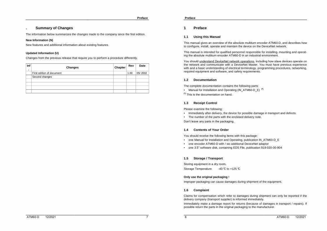
. Summary of Changes
The information below summarizes the changes made to the company since the first edition.
New Information (N)
New features and additional information about existing features.
Updated Information (U)
Changes from the previous release that require you to perform a procedure differently.
Inf.
Changes Chapter Rev Date
First edition of document 1.00 05/ 2002 Second changes
Preface
8 ATM60-D 12/2021
1 Preface
1.1 Using this Manual
This manual gives an overview of the absolute multiturn encoder ATM60-D, and describes how to configure, install, operate and maintain the device on the DeviceNet network.
This manual is intended for qualified personnel responsible for installing, mounting and operat-ing the absolute multiturn encoder ATM60-D in an industrial environment.
You should understand DeviceNet network operations, including how slave devices operate on the network and communicate with a DeviceNet Master. You must have previous experience with and a basic understanding of electrical terminology, programming procedures, networking, required equipment and software, and safety requirements.
1.2 Documentation
The complete documentation contains the following parts: • Manual for Installation and Operating (IN_ATM60-D_E) (*)
(*) This is the documentation on hand.
1.3 Receipt Control
Please examine the following: • Immediately after delivery, the device for possible damage in transport and defects.• The number of the parts with the enclosed delivery note.
Don't leave any parts in the packaging.
1.4 Contents of Your Order
You should receive the following items with this package: • one Manual for Installation and Operating, publication IN_ATM60-D_E• one encoder ATM60-D with / wo additional DeviceNet adaptor• one 3.5" software disk, containing EDS File, publication 919-020-00-904
1.5 Storage / Transport
Storing equipment in a dry room.
Storage Temperature -40 °C to +125 °C
Only use the original packaging !
Improper packaging can cause damages during shipment of the equipment.
1.6 Complaint
Claims for compensation which refer to damages during shipment can only be reported if the delivery company (transport supplier) is informed immediately.
Immediately make a damage report for returns (because of damages in transport / repairs). If possible return the parts in the original packaging to the manufacturer.

Preface
ATM60-D 12/2021 9
Enclose the following details in the return: • Name and address of the sender.• Address of receiver: -- (see Imprint).• Part number, description of the defect, contact person for possible questions.
1.7 Guarantee
Please get the guarantee conditions for the encoder ATM60-D from your sales contract. The general warranty and guarantee conditions of SICK AG are valid.
1.8 Symbol Definitions
This symbol indicates text for which you must take particular care that the proper use is ensured and dangers are excluded. Failure to observe these indications could result in physical damages and/ or damage to equipment.
This symbol indicates text which provide important information for the correct use of the encoder. A non-compliance can lead to malfunction of the encoder.
This symbol indicates text giving useful indications and explanations for under-standing the document.
Terms and Abbreviations
10 ATM60-D 12/2021
2 Terms and Abbreviations
CAN Controller Area Network
CiA CAN in Automation.
ODVA Open DeviceNet Vendor Association.
2.1 Data Specifications
BOOL Boolean 1 Bit BYTE Bit String 1 Byte (8 Bit) WORD Bit String 2 Byte (16 Bit) USINT Unsigned Short Integer Int (1 Byte) - (0...255) UINT Unsigned Integer Int (2 Byte) - (0...65.535) UDINT Unsigned Double Integer Int (4 Byte) - (0...+232.-1) SINT Signed Short Integer Int (1 Byte) - (-128...+127) INT Signed Integer Int (2 Byte) - (-32.768...+32.767) DINT Signed Double Integer Int (4 Byte) - (-231...+231 - 1)
LSB Least Significant Bit / Byte, Example: 81.938D == [00.01.40.12]hex MSB Most Significant Bit / Byte, [00.01.40.12]hex Little Endian The sequence a number of many places is ordered / transmitted. -- LSB is
placed first. -- according example above: { 12.40.01.00 } Big Endian The sequence a number of many places is ordered / transmitted. -- MSB is
placed first. -- according example above: { 00.01.40.12 }
2.2 DeviceNet specific
ID Identifier EDS An electronic data sheet is a vendor-supplied template that dictates how infor-
mation is displayed as well as what is an appropriate entry. PM-SC Predefined Master/ Slave Connection Set
NodeA node is the hardware that has a single address on the network (also referred to as device).
MAC ID Address of a DeviceNet Node. Explicit Mes-saging
This protocol commands the performance of a particular task and returns the result of the task performance to the requester.
IO (I/O) Means "Input and Output Data".
Input DataThis data is produced by a DeviceNet device (slave) and collected by the scan-ner (master) and made available for a PLC processor to read.
Output DataThis data is produced by a PLC processor that is written to the scanner's mem-ory. This data is sent by the scanner (master) to DeviceNet devices.

Terms and Abbreviations
ATM60-D 12/2021 11
2.3 Encoder specific
CPR (cpr) Counts per Revolution (steps per turn) -- Customer specified CMR Number of counts (steps) over the total Measuring Range. -- Customer specified R Ratio of CMR to CPR. -- R = [CMR] / [CPR] // (adjusted to 2**N) Scaling Pa-rameters
[CMR], [CPR]
PRS Physical Resolution Span (number of steps per span /revolution) the encoder supports -- assigned Value [8.192] is Manuf. specified
PnumRev Physical Number of Revolutions the encoder supports -- assigned Value [8.192] is Manuf. specified
PMR Physical Measuring Range = [PRS] x [PnumRev] PM_Bit correspond to the physical measuring range shown as Bit resolution with
"power of 2" (2**PM_Bit) -- The assigned value is 26 (Bit). PmaxVal Maximum physical position value correspond to [PMR] minus one (1).
ScF Scaling Factor = [CPR] / [PRS] Pos_Scal Scaled position value, after conversion by the "Scaling Parameters", Offset
and Preset-Value Pos_Phy Physical (numerical) position value before conversion
CPS Measuring unit velocity: "Counts (steps) per Sec." RPS Measuring unit velocity: "Revolutions per Sec." -- also (rps) RPM Measuring unit velocity: "Revolutions per Min." -- also (rpm)
Safety Regulations
12 ATM60-D 12/2021
3 Safety Regulations
3.1 Your Responsibilities
Because of the variety of uses for the products described in this publication, those responsible for the application and use of this control equipment must satisfy themselves that all necessary steps have been taken to assure that each application and use meets all performance and safety requirements, including any applicable laws, regulations, codes and standards.
The equipment described in these manuals are intended for use in an industrial environment. Personal injury and damage to equipment can result from not following all applicable safety codes, procedures, and requirements.
As a qualified user or installer of this device, you are responsible for determining the suitability of the product for the intended application. SICK AG is neither responsible nor liable for indirect or any consequential damage resulting from the inappropriate use of this product. The agreed use also includes to adhere the instructions of the valid documentation manuals.
A qualified person or installer is someone who is familiar with all safety requirements and es-tablished safety practices relating to the installation, operation, and maintenance of this equip-ment.
It is recommended that anyone who operates or maintains electrical or mechanical equipment should have a basic knowledge or First Aid.
3.2 Validity and Use
The absolute multiturn encoder ATM60-D is a measuring instrument produced in accordance with recognised industrial regulations and meet the quality requirements of ISO 9001.
The Encoder is a mountable device and cannot be operated independently in his function. Therefore the encoder is not equipped with direct safety facilities. Measures for the security of the plants and personal must executed by the constructor of the plant according the legal guidelines.
The ATM60-D may be used only for the purpose appropriate to its design. This equipment is designed for working at a CAN / DeviceNet network.
The DeviceNet Specification guidelines for the design of a DeviceNet network system must be adhered mandatory.
Mechanical or electrical changes at the equipment are forbidden.
The Encoder has to protected by too high vibrations, strokes, and shocks ! -- Use the appro-priate shock absorber .
Taking into account, that the following safety labelings, the in-struction notes in this document relating to installation and op-erating must be adhered mandatory.
3.3 Authorised Operators
The installation and maintenance of the encoder is to be carried out by trained and qualified personnel with knowledge of electrical engi-neering, precision engineering, and programming. They are permit-ted to install, operate, and maintain the equipment according the standard of security engineering.

Safety Regulations
ATM60-D 12/2021 13
3.4 Safety Guidelines and Personal Security
The safety guidelines have to be taken into account, by every person who install, operate, maintain the equipment: • System and safety documentation must be available and ob-
served at all times.• Only qualified personnel (familiar with the equipment) are permit-
ted to install, operate, and maintain it. • All non-qualified personnel are physically restricted from the
equipment.• Systems must be installed in accordance with all applicable
safety and regulatory codes.• Observe the professional safety codes and accident prevention
regulations applicable to your country. • Failure to observe safety procedures could result in personal in-
jury and/ or damage to equipment. • The Voltage- or Current supplies your equipment is supporting,
have been executed according to the valid technical guidelines.
3.5 Safety Labelings for Installation, Operation, Maintenance
• The encoder ATM60-D may be assembled and attached only in avoltage and current-free condition. Switch off the voltage to allthe equipment, machines and plants involved in the mounting.
• Never electrically connect or disconnect the encoder with thevoltage switched on, otherwise this may lead to damage to theencoder.
• After removing power, check for remaining voltage before makingor removing any connections.
• Wiring practices, grounding, disconnects, and over-current pro-tection are of particular importance.
• Check whether the switch-off of the equipment, machines, plantsdoesn't cause any hazards !
• If necessary, put Warning signs to prevent the unintentional in-auguration of the equipment, machines, plants !
• Carry out the assembly / repair work under retention of the cor-rect safety and accident prevention regulations specified by theprofessional Association.
• Check the correct functions of the safety facilities (e.g. emer-gency shutdown).
• For the satisfactory operation of the devices, care must be takento good grounding and to a screen connection suitable for EMC.
• Secure mounting of all moving components before powering asystem.
• Avoid striking the shaft or the collet.• Do not create a program that frequently uses explicit messages
to write parameter data to the product. The EEPROM (non-volatile Storage) will quickly exceed its life cycle and cause theproduct to malfunction.
• Ensure your device is not connected to a live DeviceNet network,while commissioning with a configuration tool.
Introduction
14 ATM60-D 12/2021
4 Introduction
4.1 Controller Area Network (CAN)
The ATM60-D is a multiturn absolute encoder using the media "CAN-Bus" for transmission.
The CAN protocol was originally developed by BOSCH for the European automatic market for replacing expensive, wire harnesses with low-cost network cable on automobiles. The CAN Bus system, is gaining more and more acceptance in automation engineering.
CAN does not specify the entire Physical Layer and /or Medium upon which it resides, or the Application Layer protocol used to move data. • A Media Access Control (MAC) methodology.• Physical Signalling.
Some specific characteristics of CAN. • Specification to ISO 11898 (High Speed) and ISO 11519-1 (Low Speed). • CAN-Specification 2.0 A (11-Bit Identifier) / 2.0 B (29-Bit Identifier).• Fast response and high transmission security (HD 6)• Broadcast oriented protocol • Message oriented protocol with assignment of Identifier (message identification)• Event-driven data transmission according to CSMA/CA• Equal-access from each node to the bus• Line-type bus topology• Expansion depends on transmission rate• Use of twisted pair wires with termination resistors at both ends • max. transmission rate 1 Mbit/s• Error-tolerant protocol with repetition of messages
4.2 DeviceNet
DeviceNet is a low-cost communication link to connect industrial devices to a network and eliminate expensive hardwiring. The Data Link Layer is completely defined by the CAN Speci-fication and by the implementation of CAN Controller chips.
DeviceNet is an Open network standard. The specification and protocol are open. Anyone may obtain the DeviceNet Specification from the ODVA.
History and main advantages: • Basic Technology developed by Allen-Bradley, (march 1994)• Foundation of the ODVA in April 1995, and transfer of the DeviceNet to the ODVA• A cost effective solution to low-level device networking and engineering• Easier configuration (only one tool for all devices) and maintenance• Reliable and secure transmission of data• Interchangeability of devices between several manufacturer • Node removal without severing the network
4.2.1 DeviceNet Specification
The DeviceNet Specification defines a network communication system for moving data be-tween elements of an industrial control system. The specification is divided into two volumes.
Volume 1 • DeviceNet Communication Protocol and Application (Layer 7 - Application Layer) • CAN and its use in DeviceNet (Layer 2 - Data Link Layer)

Introduction
ATM60-D 12/2021 15
• DeviceNet Physical Layer and Media (Layer 1 - Physical Layer)
Volume 2• Device Profiles to obtain interoperability and interchangeability among like products
4.2.2 Technology
DeviceNet uses the CAN technology but specifies more detailed the different layers of the ISO / OSI communication model. • Layer 2 (Data Link layer) as specified by CAN in ISO 11898 and ISO 11519-1.• Layer 1 (Physical layer: - Transmission Media) • Layer 7 (Application layer)
ISO Layer 7 Application Layer DeviceNet Spec.
Data Link: -- Logical Link Control - (LLC) ISO Layer 2
Data Link: -- Media Access Control - (MAC)
Physical Signalling (PLS)
CAN Protocol Spec.
Medium Attachment Unit / Transceiver (MAU) ISO Layer 1
Transmission Media DeviceNet Spec.
4.2.3 Layout and Characteristics
Shown is the layout and some specific characteristics of DeviceNet:
Node Node
NodeNodeNode
Node
Node
Node
Node
Node
Node
Daisy Chain
TerminatorTerminator
Trunk Distance
Short DropsZero DropBranching Drop
Trunk
TrunkLength
ma
x. 6m
Tap Tap
Figure 4–1: Topology of DeviceNet
• Linear Bus Layout with Trunkline and Dropline configuration. -- "Trunk" and "Drops" are to-pology terms.
• DeviceNet allows branching structures only on the drop line.• Eligible data rates of 125 kb, 250 kb, 500 kb.• Support for up to 64 nodes per Network. • Termination resistors (120 ohms) at both network Trunkline ends.• Physical media (Shielded Twisted Pair) contains signal and power lines.
Introduction
16 ATM60-D 12/2021
• Network power depends on cable (Thick: 8 amps, Thin: 3 amps).• Use of sealed and open-style connectors. • Protection from wiring errors.• Only use of the CAN Specification 2.0 A (11-Bit Identifier).• Different cable length on Trunkline and Dropline. -- see table below:
Trunk length Drop length Communication Rate
Thin cable Thick cable max. Drop Cumulative
Drop 125 Kbaud 100 m 500 m 6 m 156 m 250 Kbaud 100 m 250 m 6 m 78 m 500 Kbaud 100 m 125 m 6 m 39 m
The cable distance between any two points in the cable system must not exceed the Maximum Cable Distance allowed for the baud rate. Cable distance between two points includes both trunk line cable length and drop line cable length, that exists between the two points.
Drop line length is the longest cable distance of those measured from the tap on the trunk line to each of the transceivers of the nodes on the drop line. This value is limited to 6 m. The total amount (Cumulative Drop) of drop line allowable on the network depends upon the data rate.
4.2.4 Device Profiles
Applications using DeviceNet combine standard or application specific objects together into Device Profiles. The Device Profile fully defines the device as viewed from the network.
A library of objects and Device Profiles is contained in the DeviceNet Specifications. ODVA coordinates the work of industry experts in the development of both new Object and Device Profile Specifications. This is done through Special Interest Groups (SIGs).
There must be a core "standard" for each device type (Profile), so that they: • exhibit the same behaviour • produce and /or consume the same basic set of IO-data.• contain the same basic set of configurable attributes.
A device profile will contain the following:• Definition of an Object model for the device type.• Definitions of the IO-data format for the device type.• Definitions of configurable parameters and public interface(s) to those parameters.
The encoder SIG has the intention to established a device profile for Encoders, to ensure in-teroperability of their devices. - The following subjects shold be defined: • measuring principle of absolute and incremental systems.• mechanical specification of rotary and linear devices.• functionalities like attributes, services and behaviour to the based object.
Because of ODVA has not approved the profile, device type "Generic" [00]hex is used for the identification of the ATM60-D.
4.3 Additional informations
ODVA, DeviceNet CAN in Automation (CiA) e.V. 20423 State Road 7 Am Weichselgarten 26 Boca Raton, FL 33498, USA D-91058 ErlangenTel.: (1) 954-340-5412 (49) 9131 - 6 90 86-0

Introduction
ATM60-D 12/2021 17
email: [email protected] Web: http://www.odva.org http://www.can-cia.de
4.3.1 Related Publications:
• ODVA - Open DeviceNet Vendor Association DeviceNet Specifications Release 2.0• Device Profile for Encoders, Release 1.00• DeviceNet Manager Software, User manual 1787 - MGR (1787-6.5.3)
• RSNetWorx for DeviceNet• DeviceNet Cable System Planning and Installation Manual DN-6.7.2 - May 1999
4.3.2 EDS Web Site:
EDS files are available for downloading at: http://www.stegman.de/ xxx/ eds
Operating Modes of the Encoder
18 ATM60-D 12/2021
5 Operating Modes of the Encoder
The DeviceNet application layer defines how identifiers are assigned and how the CAN data field is used to specify services, move data, and determine its meaning.
All the devices with new data values transmit the corresponding data on the network with a proper Identifier. All devices who needed data listen for messages. When devices recognise the appropriate Identifier, they consume the data. With the Producer-Consumer Model, the message is no longer specific to a particular source or destination.
DeviceNet defines two different types of messaging: • Explicit messaging• I/O messaging
5.1 Explicit messaging
The explicit messaging is used for modifying the device configurations, reading diagnostic val-ues, program upload / download, etc.
The ATM60-D supports the fragmented as well as the non-fragmented data transmission.
Characteristics: • Very flexible• Less efficient because each device must interpret and generate response• Contents of the data field:
♦ protocol information♦ instructions for service to be performed♦ internal address to which the service is to be applied
5.2 I/O messaging
The I/O messaging is used for fast or time-critical data transfer. All of the 8 data bytes of the CAN message can be used for data transmission. The ATM60-D supports only the non-fragmented data transmission.
Characteristics: • Less flexible, “Bound” connections • Highly efficient for both bandwidth and node processing• Data field only contains data• Meaning of data is predefined
5.2.1 Input data specification of the ATM60-D
The encoder ATM60-D is an Input Device . This means, the encoder only produces data and cannot consume any data from the master.
The ATM60-D supports the following I/O connections (modes), defined within the Predefined Master/ Slave Connection Set (PM-SC). -- (see 8.2). • Bit Strobed Command/ Response• Polled Command/ Response• Change-of-State or Cyclic
Each of the 3 different I/O message connections is assigned its own attribute "Input Assy_..".
Each of these attributes can be assigned to different assemblies simultaneously (1...n).
By default each of the attribute is configured to assembly one (1) . -- "Position Value".
Operating Modes of the Encoder
ATM60-D 12/2021 19
The table below shows the characteristics of all data components implemented within the dif-ferent assemblies.
Data Component Assembly
activating COS I/O message (x1)
Update cycle time (x2)
1, 2, 3, 4 YES 0.250 ms 2 YES 0.250 ms 3 NO 50.000 ms
Position Value Flag (Alarm, Warning)
Velocity Value Cam State 4 YES 0.250 ms
(x1)
(x2)
Possibility to trigger a new message, if the value of the data component has changed.
Time needed, to calculate a new value for one of the listed data components.
For all the different I/O messages applied, the configured assembly instance de-termines the data components used as Input Data.
For more detail see section 6.7.5 (Assembly Definitions) and 7.8.6. (Using Assembly)
5.2.2 Polled mode
The standard mode in the Master-Slave communication is the polling mode. In this mode the master contacts all bus participants in a cyclic way. During one scan the output data are trans-
mitted to the slaves and the input data are read from the slaves.
Because the ATM60-D is an Input Device, any output data from the master are ignored. The Poll Command is used to trigger the transmission of return input data in the response mes-
sage.
5.2.3 COS / Cyclic mode
In Change of State mode the encoder only sends input data if the value of one of the data component, regarding the selected assembly instance, changes. In addition a Cycle Time is used to trigger the transmission of the input data. This is done after the internal Cycle Time pe-riod has elapsed, independent of whether one of the data components have changed its value.
Additionally a time delay (production inhibit time) in the range of 1 msec. to 65535 msec. can be configured, to reduce the bus load.
To get a COS message from one of the two data components "Cam State" or "Flag", you should set the parameter value "COS / Hysteresis" to "0" (zero), to
avoid a trigger from the data component "position value". -- (see also 7.4.7 ).
In Cyclic mode the encoder only transmit data, after the internal Cycle Time period has elapsed.
5.2.4 Bit Strobed mode
The Bit Strobed Command, sends one bit of output data to each Slave whose MAC ID ap-pears in the Master's scan list.
Because the ATM60-D is an Input Device, the output data bit is ignored. The Bit Strobe Com-mand is only used to trigger a transmission of return input data in the response message.
DeviceNet Object Model
20 ATM60-D 12/2021
6 DeviceNet Object Model
6.1 Terminology
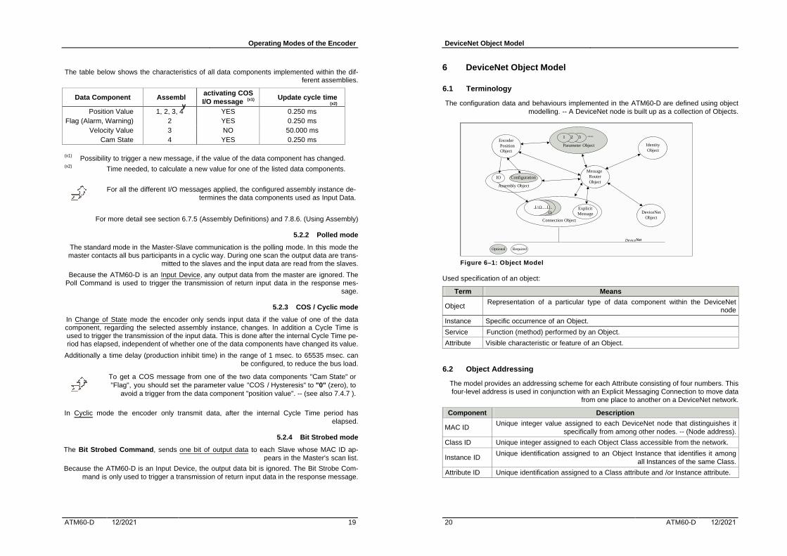
The configuration data and behaviours implemented in the ATM60-D are defined using object modelling. -- A DeviceNet node is built up as a collection of Objects.
Parameter Object
32
Assembly Object
Connection Object
ExplicitMessage
EncoderPositionObject
MessageRouterObject
IdentityObject
DeviceNetObject
DeviceNet
IO Configuration
Optional Required
1 ......
...I./..O.......I./..
O..
Figure 6–1: Object Model
Used specification of an object:
Term Means
Object Representation of a particular type of data component within the DeviceNet
node
Instance Specific occurrence of an Object.
Service Function (method) performed by an Object.
Attribute Visible characteristic or feature of an Object.
6.2 Object Addressing
The model provides an addressing scheme for each Attribute consisting of four numbers. This four-level address is used in conjunction with an Explicit Messaging Connection to move data
from one place to another on a DeviceNet network.
Component Description
MAC ID Unique integer value assigned to each DeviceNet node that distinguishes it
specifically from among other nodes. -- (Node address).
Class ID Unique integer assigned to each Object Class accessible from the network.
Instance ID Unique identification assigned to an Object Instance that identifies it among
all Instances of the same Class.
Attribute ID Unique identification assigned to a Class attribute and /or Instance attribute.

DeviceNet Object Model
ATM60-D 12/2021 21
Figure 6–2: Addressing scheme
6.3 Objects of the Encoder
The following objects are supported by the encoder:
Class ID
Object Description
01hex Identity Supports identification, information about the device, and the Reset service.
02hex Message Router
Processes all messages and routes them to the respective objects.
03hex DeviceNet Provides configuration and status attributes of a DeviceNet port. 04hex Assembly Combination of attributes from different objects into one object
05hex Connection Manages the internal resources associated with both I/O and Explicit Messaging Connections. A Connection Object within a particular module actually represents one of the end-points connection.
2Bhex Acknowledge Handler
Controls the receiving of “Acknowledge messages” for message generating objects (e.g. COS connection).
2Fhex Encoder Provides configuration and status attributes of the encoder.
6.4 Identity Object
Class Code
Class Attributes Instance Attributes Number of Instance
Services
01hex Not supported YES 1 YES
6.4.1 Instance Attributes
Attr. ID
Attribute Name Access Rule
Type Description
1 Vendor ID Get UINT 511 STEGMANN 2 Device Type Get UINT [00]hex Generic
3 Product Code Get UINT 601 AG626 x DN (Switch version)
DeviceNet Object Model
22 ATM60-D 12/2021
Attr. ID
Attribute Name Access Rule
Type Description
4 Revision Get Struct of USINT
4.01 Major / Minor Revision
5 Status Get WORD Represents status of the entire device 6 Serial Number Get UDINT Unique identifier for each device 7 Product Name Get SHORT_
STRING Unique identifier for each product. -- "AG626 Multiturn (Switch Vers)"
8 State Get USINT Not Supported 9 (F) Configur. Consi-
stency Value Get UINT Contents identify configuration of device
6.4.2 Common Services
Service Code
Service Name Description
05hex Reset Reset service for the device (Type: Value = 0) 0Ehex Get_Attribute_Single Returns the contents of the specified attribute.
6.5 Message Router Object
Class Code
Class Attributes Instance Attributes Number of Instance
Services
02hex Not supported Not supported 1 Not supported
6.6 DeviceNet Object
Class Code
Class Attributes Instance Attributes Number of Instance
Services
03hex YES YES 1 YES
6.6.1 Class Attributes
Attr. ID
Attribute Name Access Rule
Type Description
1 Revision Get UINT Revision of DeviceNet Object ( = 2)
6.6.2 Instance Attributes
Attr. ID
Attribute Name Access Rule
Type Description
1 (X) MAC-ID Get / Set USINT Node address: (Range 0 – 63) 2 (X) Baud Rate Get / Set USINT Data Rate (Range 0 – 2) 3 BOI Get BOOL Bus-OFF Interrupt (Default = 0) 4 Bus-OFF-Ctr. Get / Set USINT Number of times CAN went to the Bus-
OFF state 5 Allocation Infor-
mation Get Struct of:
USINT Allocation choice byte, and MAC-ID of Master
6 (F) MAC-ID Switch changed
Get BOOL Node address switch(es) have changed since last power-up/reset.

DeviceNet Object Model
ATM60-D 12/2021 23
Attr. ID
Attribute Name Access Rule
Type Description
7 (F) Baud Rate Switch changed
Get BOOL Baud Rate switch(es) have changed since last power-up/reset.
8 (F) MAC-ID Switch Value
Get USINT Actual Value of Node address switch(es).
9 (F) Baud Rate Switch Value
Get USINT Actual Value of Baud Rate switch(es).
(X) Set Service is only supported if "Node Commissioning" is configured to EEPROM. -- (currently not supported). -- see 7.8
(F) Future use.
6.6.3 Common Services
Service code
Service name Description
0Ehex Get_Attribute_Single Returns the contents of the specified attribute. 10hex Set_Attribute_Single Modifies the specified attribute.
6.6.4 Class specific Services
Service code
Service name Description
4Bhex Allocate_Master / Slave Connection_Set
Request the use of the specified Connection(s).
4Chex Release_Master / Slave Connection_Set
Indicates that the specified Connection(s) of the PM-SC are to be released.
6.7 Assembly Object
Class Code
Class Attributes Instance Attributes Number of Instance
Services
04hex YES YES 4 YES
6.7.1 Class attributes
Attr. ID
Attribute Name Access Rule
Type Description
1 Revision Get UINT Revision of this object ( = 2)
6.7.2 Instance Attributes
Attr. ID
Attribute Name Access Rule
Type Description
3 Data Get Array of BYTE
Depending the Instance: [1]: Position Value [2]: Position Value + Flags [3]: Position Value + Velocity Value [4] Position Value + Cam State
DeviceNet Object Model
24 ATM60-D 12/2021
6.7.3 Common Services
Service code
Service name Description
0Ehex Get_Attribute_Single Returns the contents of the specified attribute.
6.7.4 Input Assembly data components
The attributes from different objects are combined to one single assembly object. The table be-low shows the source of data with object and attribute number.
Object / Class Instance Attribute Data compo-nent name Name Number Number Name Number
Position value Encoder 0x2F 1 Position value 12 Warning flag Encoder 0x2F 1 Warning flag 88 Alarm flag Encoder 0x2F 1 Alarm flag 85 Velocity value Encoder 0x2F 1 Velocity value 22 Cam state Encoder 0x2F 1 CAM state register 40
6.7.5 Input Assembly data format
Instance Byte Bit 7 Bit 6 Bit 5 Bit 4 Bit 3 Bit 2 Bit 1 Bit 0 0 1 2
1
3
Position Value
Instance Byte Bit 7 Bit 6 Bit 5 Bit 4 Bit 3 Bit 2 Bit 1 Bit 0 0 1 2 3
Position Value
Flag
2
4 reserved Warn Alarm
Instance Byte Bit 7 Bit 6 Bit 5 Bit 4 Bit 3 Bit 2 Bit 1 Bit 0 0 1 2 3
Position Value
4 5 6
3
7
Velocity Value

DeviceNet Object Model
ATM60-D 12/2021 25
Instance Byte Bit 7 Bit 6 Bit 5 Bit 4 Bit 3 Bit 2 Bit 1 Bit 0 0 1 2 3
Position Value
Cam State
4
4 Cam 8 Cam 7 Cam 6 Cam 5 Cam 4 Cam 3 Cam 2 Cam 1
6.8 Connection Object
Class Code
Class Attributes Instance Attributes Number of Instance
Services
05hex Not supported YES 4 YES
The following Connection Objects (Inst. ID) are implemented in the device:
Inst. ID Instances 1 Group 2 Explicit Message Connection 2 Poll IO Connection 3 Bit Strobed Connection 4 Change of State / Cyclic Connection
6.8.1 Instance Attributes
Attr. ID
Attribute Name Access Rule
Type Description
1 State Get USINT State of the Connection 2 Instance_Type Get USINT I/O or Explicit Message 3 transportclass_trigger Get BYTE Behaviour of the Connection 4 produced_connection_id Get UINT CAN identifier to transmit on 5 consumed_connection_id Get UINT CAN identifier to receive on 6 initial_comm_characteristics Get BYTE Message Groups associated with
this Connection 7 produced_connection_size Get UINT Max. number of bytes transmitted
across this Connection 8 consumed_connection_size Get UINT Max. number of bytes received
across this Connection. 9 expected_packet_rate Get /
Set UINT Timing associated with this Con-
nection 12 watchdog_timeout_action Get USINT Defines how to handle Inactivity/
Watchdog time-outs 13 produced_connection_path
length Get UINT Number of bytes in attribute "pro-
duced_connection_path" 14 produced_connection_path Get /
Set (*) ARRAY of EPATH
Specifies Application Object whose data is to be produced by this Connection.
15 consumed_connection_path length
Get UINT Number of bytes in attribute "con-sumed_connection_path"
DeviceNet Object Model
26 ATM60-D 12/2021
Attr. ID
Attribute Name Access Rule
Type Description
16 consumed_connection_path Get ARRAY of EPATH
Specifies Application Object whose data is to be consumed by this Connection.
17 production_inhibit_time Get / Set
UINT Minimum time between new data production for COS connections.
(14) (*)
The path information refers to the corresponding assembly instance, which is config-ured by the specific attributes "INPUT Assy.." (section 7.8.6). This predefined value can be overwritten within the allocation sequence for this connection. -- (only alterable in the "configuring state" ).
6.8.2 Services
Service code
Service name Description
05hex Reset Reset the Inactivity Watchdog Timer associated with the Connection Object.
0Ehex Get_Attribute_Single Returns the contents of the specified attribute. 10hex Set_Attribute_Single Modifies the specified attribute.
6.9 Acknowledge Handler Object
Class Code
Class Attributes Instance Attributes Number of Instance
Services
2Bhex Not supported YES 1 YES
6.9.1 Instance Attributes
Attr. ID
Attribute Name Access Rule
Type Description
1 Acknowledge Timer
Get / Set UINT Time to wait for an acknowledge before resending (Default = 16)
2 Retry Limit Get USINT Number of Ack time-outs to wait before informing the producing application.
3 COS Producing connection In-stance
Get UINT

DeviceNet Object Model
ATM60-D 12/2021 27
6.9.2 Common Services
Service code
Service name Description
0Ehex Get_Attribute_Single Returns the contents of the specified attribute. 10hex Set_Attribute_Single Modifies the specified attribute.
6.10 Encoder Object
Class Code
Class Attributes Instance Attributes Number of Instance
Services
2Fhex YES YES 1 YES
6.10.1 Class attributes
Attr. ID
Attribute Name Access Rule
Type Description
1 Revision Get USINT Revision of this object ( = 01) 2 Max. Instance Get USINT 1
6.10.2 Instance attributes
All the following attributes are specified more detailed within section 7. The factory default val-ues are labeled in bold type
6.10.2.1 Encoder Basic attributes
Attr. ID
Attribute Name Access Rule
Type Description
1 Num. of attributes Get USINT Number of supported attributes 2 Attributes Get Array
of USINT
List of supported attributes
3 Direction counting (code sequence)
Get Set BOOL Direction control for counting. CW (0), CCW (1)
4 Diagnostic control Get Set BOOL Diagnostic Control at encoder stand still. -- Not supported
5 [SFC] Scaling function control
Get Set BOOL Physical resolution is converted into a nu-merical value. -- OFF (0), ON (1)
6 Position format Get Set USINT Format of the position attribute - Steps (0) 7 [CPR] Measuring
units per revolution Get Set UDINT Number of distinguishable steps per revolu-
tion. [20.00]hex 8 [CMR] Total meas-
uring range. Get Set UDINT Steps over the total measuring range in
measuring units. -- [04.00.00.00]hex
9 NOT supported. 10 Preset value Get Set UDINT Current position value is set to Preset Value. 11 COS/delta Get Set UDINT Hysteresis value for position change in COS
mode. -- Default value [5 ] 12 Position value Get UDINT Current position value
DeviceNet Object Model
28 ATM60-D 12/2021
Attr. ID
Attribute Name Access Rule
Type Description
13 Work state area register
Get UDINT State of software limit switch position
14 Work area low limit Get Set UDINT Switch point for lower limit - [00.00.00.00]hex 15 Work area high
limit Get Set UDINT Switch point for upper limit - [03.FF.FF.FF]hex
6.10.2.2 Encoder Extended attributes
Attr. ID
Attribute Name Access Rule
Type Description
20 Velocity format Get Set USINT Format of velocity and acceleration attributes CPS (0), RPM (1), RPS (2)
21 NOT supported. 22 Velocity value Get DINT Current speed. 23 Minimum velocity Get Set DINT Limit value for the minimum speed. 24 Maximum velocity Get Set DINT Limit value for the maximum speed. 30 NOT supported. 31 Acceleration value Get DINT Current acceleration 32 Min. acceleration Get Set DINT Limit value for the minimum acceleration. 33 Max. acceleration Get Set DINT Limit value for the maximum acceleration.
6.10.2.3 Cam specific attributes
Attr. ID
Attribute Name Access Rule
Type Description
40 CAM state register Get BYTE Current state of the 8 independent cams 41 CAM polarity reg. Get Set BYTE Determines the polarity for each cam. ---
range ( [00] hex to [FF] hex ) 42 CAM enable reg. Get Set BYTE Enable / Disable the 8 independent cams ---
range ( [00] hex to [FF] hex ) CAM_No_1
Switch point for lower limit. 43 Limit low Get UDINT Default value = [00.00.01.00] hex Switch point for higher limit. 44 Limit high Get UDINT Default value = [03.FF.FC.00] hex Delay setting of switch points. 45 Hysteresis Get UINT Default value = [00.20] hex
Cam_No_2 ID 46, 47, 48 -- (see 43, 44, 45) Cam_No_3 ID 49, 50, 51 -- (see 43, 44, 45) Cam_No_4 ID 52, 53, 54 -- (see 43, 44, 45) Cam_No_5 ID 55, 56, 57 -- (see 43, 44, 45) Cam_No_6 ID 58, 59, 60 -- (see 43, 44, 45) Cam_No_7 ID 61, 62, 63 -- (see 43, 44, 45) Cam_No_8 ID 64, 65, 66 -- (see 43, 44, 45)

DeviceNet Object Model
ATM60-D 12/2021 29
6.10.2.4 Diagnostic attributes
Attr. ID
Attribute Name Access Rule
Type Description
80 Operating status Get BYTE Encoder operating status regarding some encoder basic attributes.
81 Physical Resolu-tion Span
Get UDINT Single Turn Resolution means "Steps per Revolution" the encoder supports.
82 NumRev Get UINT Number of revolutions the encoder supports. 83 Alarms Get WORD See (7.7.4) "Alarm functionality" 84 Supported alarms Get WORD See (7.7.4) 85 Alarm flag Get BOOL See (7.7.4) 86 Warnings Get WORD See (7.7.5) "Warning functionality" 87 Supp. warnings Get WORD See (7.7.5) 88 Warning flag Get BOOL See (7.7.5) 89 Vers. (Profile, SW) Get UDINT See (7.7.6) -- Profile and Software Version 90 Operating Time Get UDINT operating time for the encoder in operating
hours (0,1 hours). -- See (7.7.7) 91 Offset Value Get UDINT calculated by PRESET function. See (7.7.8). 92 NOT supported. 93 /94
Manuf. Min./ Max. Position Value
Get UDINT Manufacturer minimum / maximum Position Value (steps) -- See (7.7.9)
95 Encoder type Get UINT Specifies the encoder type -- See (7.7.9)
6.10.3 Manufacturer specific attributes
These attributes are not specified in this object. -- See description in chapter 7.8.
6.10.4 Common Services
Service code
Service name Description
0Ehex Get_Attribute_Single Returns the contents of the specified attribute. 10hex Set_Attribute_Single Modifies the specified attribute. 05hex Reset Sets all parameters to manufacturer default values 15hex Restore Sets all parameters to the EEPROM values 16hex Save Save all parameters values to the EEPROM
Encoder Object Parameters
30 ATM60-D 12/2021
7 Encoder Object Parameters
7.1 General Conditions to use the Scaling Function
7.1.1 Specification for using encoder in "Continuous Mode"
If a absolute rotary encoder exceeds the physical measuring range [PMR] it continues counting with either its minimum value [PminVal] (0) or its maximum value [PmaxVal] depending on the direction of rotation. A successive counting regarding the position readout, is only ensured if the scaled measuring range [CMR] is an integral multiple of [PMR]. Mapping the [CMR] to [PMR] with an offset , will result in a faulty scaled position value (no steady counting). -- Possi-ble solutions: • Map the scaled measuring range completely into the physical measuring range (No result-
ing offset ). This means a possible adjustment of the configured CMR value. • Map the scaled measuring range into the physical measuring range. The resulting offset
must always be adjusted, the physical measuring range exceeds / fall below the limits. Theoffset value must be saved to a non volatile RAM (EEPROM) to ensure the correct conver-sion from physical to scaled position values after a Switch-Off.
The following view shows an example of the relationship between the two measuring ranges.
[0...N] = minimum / maximum values of the physical measuring range.
[0...M] = minimum / maximum values of the scaled measuring range.
0 phys. measuring range (PMR) -1 N 0 phys. measuring range (PMR) -2 N 0
CMR - 1 CMR - 2 CMR - 3 offset
0 M
0 M
0 M
0 0 M
0 M
0 M
0 0
Without consideration of the resulting offset, the scaled position values are no longer correct, the encoder changes from one into the next physical measuring range.
0 M 0 M 0 M 0 M 0 M 0 M 0 M 0 M
The offset is used to calculate a correct scaled position value. By changing from one into the next physical measuring range the offset value itself must be adjusted.
7.1.2 Scaling Mode without Limitation to the measuring range
The scaled measuring range is mapped into the physical measuring range. A possible result-ing offset is used to ensure the correct conversion from physical position values to scaled po-sition values. The customer specified value for CMR is not adjusted to cause a "power of two" value for the ratio of CMR to CPR. -- The following limitations are specified:
• Ratio CMR to CPR (R) must be greater or equal 1.• CMR must be less or equal the physical measuring range the encoder is supporting.
This functionality is currently Not implemented in the ATM60-D!

Encoder Object Parameters
ATM60-D 12/2021 31
7.1.3 Adjusted Scaling Mode
The scaled measuring range is completely mapped into the physical measuring range. The customer specified value for CMR is adjusted to cause a "power of two" value for the ratio of CMR to CPR (no offset is caused). -- Furthermore, the following adjustments are valid:
• 1 ≤ R ≤ 2**N, (with 1 ≤ N ≤ 13), R= CMR/ CPR • CMR ≤ PMR.
Table below shows some configurations of adjustments to meet the specified limitations.
Customer specified Adjusted values ScF R = 2N CPR CMR CPR CMR
8.192 67.108.864 8.192 67.108.864 1 213
8.192 67.108.863... 33.544.432
8.192 33.544.432 (225) 1 212
8.192 33.544.431... 16.777.216
8.192 16.777.216 (224) 1 211
8.192 16.383... 8.192 8.192 8.192 (213) 1 1 8.192 8.191... 1 8.192 8.192 (213) 1 1
4.096 67.108.864 4.096 33.544.432 (225) 1/2 213 4.096 67.108.863...
33.544.432 4.096 33.544.432 (225) 1/2 213
4.096 33.544.431... 16.777.216
4.096 16.777.216 (224) 1/2 212
2.730 (x1) 67.108.864... 33.544.432
2.730 22.364.160 1/3 (*) 213
2.730 (x1) 33.544.431... 22.364.160
2.730 22.364.160 1/3 (*) 213
2.730 (x1) 22.364.179... 11.182.080
2.730 11.182.080 1/3 (*) 212
2.048 67.108.864 2.048 16.777.216 (224) 1/4 213 2.048 67.108.863...
16.777.216 2.048 16.777.216 (224) 1/4 213
2.048 16.777.215... 8.388.608
2.048 8.388.608 (223) 1/4 212
1.000 (x1) 67.108.864 1.000 8.192.000 1/n (*) 213
1.000 (x1) 67.108.863... 8.192.000
1.000 8.192.000 1/n (*) 213
1.000 (x1) (8.192.000-1)... 4.096.000
1.000 4.096.000 1/n (*) 212
(x1) Value is no "power of two", and means the scaling factor never gives a integral result.
Encoder Object Parameters
32 ATM60-D 12/2021
Examples (a, b) for the conversion into a scaled position value:
Customer specified Adjusted values ScF R = 2N CPR CMR CPR CMR_a
a 4.096 33.544.431... 16.777.216
4.096 16.777.216 1/2 212
b 2.730 (x1) 33.544.431... 22.364.160
2.730 22.364.160 1/3 (*) 213
• physical position value (Pos_Phy): >>67.108.863<< (max. value)
Pos_Scal = (Pos_Phy x ScF) % CMR_a
a Pos_Scal = (67.108.863 x 1/2 ) % 16.777.216 = 16.777.215
b Pos_Scal = (67.108.863 x [2.730/ 8.192] ) % 22.364.160 = 22.364.159
This means the max. physical position value the encoder is supporting, also correspond to the max. value within the scaled measuring range.
7.2 Saving Encoder Parameters
Writeable attributes could be changed within the corresponding range. Generally a changed value is not automatically saved to EEPROM. If the value should be validate after a Power Off/On, you have to save the value to the EEPROM, using a special command within your configuration tool. RSNetWorx supports this command with the "Class Instance Editor", ac-cessing the service command "save" (16hex) of the encoder object. -- see 9.2.6.
During the save operation (approx. 300 ms .), the evaluation of CAN messages are blocked.
Saving encoder specific attributes to EEPROM.
The following attributes are saved immediately to the EEPROM.
Attribute Process "Offset Value" "Preset Value"
Preset Button has been pressed or number of "Preset value" has been changed via protocol to set a new position value.
Manufacturer specific attributes, to select an assembly instance for "Ass_Num_Poll" (111) Polling mode "Ass_Num_COS" (112) COS / Cyclic mode "Ass_Num_BIT" (113) BIT Strobed mode

Encoder Object Parameters
ATM60-D 12/2021 33
7.3 General Explanations to the Encoder Attributes
With the Explicit messaging the customer can configure the parameters of the encoder for his particular application. The parameters are established as attributes within the encoder object. To configure these attributes you usually use a Configuration Software Tool like "DeviceNet Manager" or "RS-NetWorx".
The numbering of the attributes in this section does not refer to the ID numbers of the parameters shown by a configuration tool (using EDS parameter number-ing), but only reflect the numbering of the encoder object.
The parameters (attributes) of the encoder object can get subdivided into different sections. For a general summary see also 6.10.2 (Encoder Profile...) • Basic Attributes (Scaling parameters, Scaling Control, Preset Value,...) • Extended Attributes (Work area, Velocity, Acceleration) • Functionality of one Channel with 8 Cams• Diagnostic Functions • Manufacturer specific Attributes.
• All the values with position details of the following parameters specifiedwithin the encoder object must be within the total working range currently configured by the CMR value.
• If several parameters will be modified online, side effects can occur. Theuser must take care of that.
7.4 Encoder - Basic Attributes
7.4.1 Direction counting / Code sequence
Direction control for counting. This attribute defines whether increasing or decreasing position values are output when the encoder shaft rotates clockwise or counter-clockwise when looking at the end of the shaft.
7.4.2 Diagnostic Control
With this function it is possible to check the encoder components responsible for position de-tection at encoder stand still. For the ATM60-D the diagnostic detection is permanently acti-vated and shows the result by the Warning / Alarm flag. -- This attribute has NO meaning for the equipment.
7.4.3 Scaling Function Control -- [SFC]
When this parameter is set to ON (1), the physical (numerical) position value of the encoder is converted by software into the scaled value. If this parameter is set to OFF (0), the scaling function is disabled.
7.4.4 Measuring units per revolution -- [CPR]
This parameter sets the number of distinguishable counts per revolution. The factory default value corresponds to the physical resolution per span.
An internal scaling factor (ScF) is generated by this value and "Physical Resolution per Span". (see 2.3 Terms..)
Encoder Object Parameters
34 ATM60-D 12/2021
7.4.5 Total measuring range in measuring units -- [CMR]
This parameter sets the number of distinguishable counts (steps) over the total measuring range, and correspond to the scaled measuring range.
Conditioned to the implementation of the adjusted scaling mode (see 7.1.3) this parameter will be adjusted by the system internally. The adjusted value is always less or equal the configured value.
7.4.6 PRESET Value
The Preset function supports adaptation of the encoder zero point to the mechanical zero point of the encoder system.
The current position value is set to this value. This and the resulting "Offset Value" (difference from current to physical position value) are both saved automatically to the EEPROM.
The Preset Value is not automatically adjusted, if the "Scaling Parameters" (CPR, CMR) have changed. Therefore this attribute must be adjusted by the user to ensure the numerical value lie inside valid limits.
7.4.7 COS/ delta
The attribute supports a hysteresis value for a position change indication in the COS mode. A new position value is only valid / transmitted, if the change in position (Pos_Scal) is greater or equal than this value.
Setting this value number to zero ("0"), means any changes of the calculated position value are ignored, and no message by a position change is transmitted. This is useful to get a COS message by another data component like "Flag" or "Cam state". -- (see also 5.2.3).
7.4.8 Position Value
Current position value. The content is based upon the "Scaling parameters", SFC, and the PRESET Value.
"Position Value" is implemented as the standard data component in all the as-sembly instances (1 - 4).
The position value is built internally by the system according the following equation. If the scal-ing function is disabled, the value for ScF is set to one (1), also the value CMR correspond to PMR. The Offset Value is determined by the configured Preset Value.
Pos_Scal = (Pos_Phy - "Offset Value") x ScF + "Preset Value"

Encoder Object Parameters
ATM60-D 12/2021 35
View of the 4 Byte position value regarding the bit assignment. Shown is the maximum meas-uring range the encoder supports, partitioned into 2 ranges.
Byte_3 (MsB) Byte_2 Byte_1 Byte_0 (LsB) 31 30 29 28 27 26 25 24 23 22 21 20 19 18 17 16 15 14 13 12 11 10 09 08 07 06 05 04 03 02 01 00
number of revolutions CPR (1...8192) - [counts p Revol.] [CMR]
View of the 4 Byte "Position Value" according a data mapping in format "Little Endian" used by the DeviceNet transmission protocol.
Byte_0 (LsB) Byte_1 Byte_2 Byte_3 (MsB) 1 2 4 0 0 1 0 0 81.938D == [00.01.40.12]hex
7.5 Encoder - Extended Attributes
7.5.1 Work area register (Attr. 13, 14, 15)
The actual work area information with work area low limit and work area high limit can be con-figured in these attributes. The "area state register" (Attr. 13) contains the actual area status of the encoder position. If the position is out of range, a bit will be set in the related position line.
Current Position Limits "area state register" fall below "work area low limit" (Attr. 14) Bit 2 flags "underflow" exceed "work area high limit" (Attr. 15) Bit 1 flags "overflow"
fall below "manufacturer Min. position value" or exceed "manufacturer Max. position value" Bit 0 flags "out of range"
7.5.2 General velocity and acceleration parameter
Attribute 20 determines the display format of the velocity and acceleration values. By changing the type of format, all the corresponding values (minimum and maximum limits, current results) are adjusted to the specified format.
Attribute Range of values Default (20): velocity format CPS (counts (steps)/ Sec) [0] || RPM [1] || RPS [2] RPM (23): Minimum velocity 0 (24): Maximum velocity
{0 - 819.200} CPS || {0 - 6000 RPM} || {0 - 100} RPS 6000
(32): Min. acceleration 0 (33): Max. acceleration
velocity values (see above) x 10 related to [sec.] 60.000
(22): velocity value current result: -- {0 - 6000 } RPM (31): acceleration value current result: -- {0 - 60.000 } RPM / sec
7.5.3 Velocity value (Attr. 22)
The calculation of the velocity value is based on the numerical position values and updated in cycles of 50 ms. To eliminate short-term fluctuations, an integration time of 1 sec. is used for the measuring.
The velocity value is signed. By changing the direction of rotation or by changing the value of code sequence (Attr. 3), the sign of the velocity value also changes (+/-).
Encoder Object Parameters
36 ATM60-D 12/2021
Table below shows the view of the value in dependence of the velocity format.
Byte 3 Byte 2 Byte 1 Byte 0 minimum limit (dec.) format
00 00 00 00 00 CPS, RPM, RPS maximum limit (dec.) format
00 0C 80 00 819.200 CPS (steps/ Sec) FF F3 80 00 - 819.200 CPS (steps/ Sec) 00 00 17 70 6000 RPM FF FF E8 90 - 6000 RPM 00 00 17 64 100 RPS FF FF FF 9C - 100 RPS
"Velocity Value" is implemented as data component in assembly instance [3].
7.5.4 Acceleration value (Attr. 31)
Acceleration is defined as a changing of velocity (speed) per time unit. The used time unit is always [sec] . -- This means the acceleration value is given in "velocity format" per [sec].
The "acceleration value" can not be read via an I/O message, but can only be accessed via an explicit message.
The current acceleration value (Attr. 31) is derived from the calculated velocity value and up-dated in the same cycle time as done for the velocity calculation. The value is also signed with the following meaning.
Value (sign) Explanation 0 Velocity is constant + Velocity is increasing - Velocity is decreasing (slow down)
7.6 Encoder - Functionality of Cam Channels
7.6.1 Usage of the Cams
The encoder device supports one channel with 8 different cams. Each cam has parameters for the minimum switch point, the maximum switch point and setting a hysteresis to the switch points.
You have to set a hysteresis value, to avoid permanent switching in case of the current posi-tion value is fluctuating round the switch point. The hysteresis value is used as an offset to shift the limits into the opposite direction. A following turning back of the current position value is now compared with the shifted limit value.
"Cam Channel State Register." is implemented as data component in assembly instance no. 4.

Encoder Object Parameters
ATM60-D 12/2021 37
The table below shows how a current position value is compared with the adjusted switch points, in dependence of the previous state of the position value.
Low Limit High Limit
Hysteresis Hysteresis
Position
Figure 7–1: Usage of the Hysteresis
previous position / state Min. switch point (LOW) Max. switch point (HIGH) within switch points / (1) Low Limit - Hysteresis High Limit + Hysteresis outside switch points / (0) Low Limit High Limit
The values of limit low, limit high, and hysteresis are checked against each other. Bit no. 13 of attribute "warnings" indicates to any of the configured cams an illegal configuration to these values.
The warning "Cam_xx limits" (high, low) out of order is set in the following cases: • hysteresis value is greater than value "low Limit".• the values "low Limit" / "high Limit" are greater than the "Total Measuring Range" (CMR).
A mutual exchange of the values "low Limit" / "high Limit" (low Limit greater high Limit) does not result in an error. Such kind of configuration can be used, if the supervising range exceeds the "Total measuring range"
7.6.2 Global registers of the Cam Channel
View of the global registers assigned to one channel of 8 cams.
Bit 7 Bit 6 Bit 5 Bit 4 Bit 3 Bit 2 Bit 1 Bit 0
Cam Ch. Reg. State / Enable / _No_8 _No_7 _No_6 _No_5 _No_4 _No_3 _No_2 _No_1 Polarity
7.6.2.1 Cam Channel State register
This attribute defines the status bit of the cam. The status bit set to "1" defines “cam active”. The status bit set to "0" defines “cam inactive”. If the CAM polarity register attribute of a cam is set (1) the actual cam state will be inverted.
State Polarity bit = 0 (default) Polarity bit = 1 (inverted)
Position within limits "cam active" / [1] "cam active" / [0] Position outside limits "cam inactive" / [0] "cam inactive" / [1]
7.6.2.2 Cam Channel Enable register
Attribute contains the calculation state for the respective cams. If the corresponding bit is set to "1", the cam state will be calculated. In the other case the cam state of the related cam will be set permanently to "0" (inactive).
Encoder Object Parameters
38 ATM60-D 12/2021
7.6.2.3 Cam Channel Polarity register
Attribute contains the actual polarity settings for a maximum of 8 cams. If the polarity bit is set to "1", the cam state of an active cam will signal by setting the related cam state bit to zero. In the other case the cam state of the related cam will not be inverted. (see above).
7.6.3 Limit of switch points and hysteresis
The encoder supports one channel with 8 different cams. Each cam has parameters for:
• the Low and High Limit setting• the delay setting (hysteresis) of the switch points
Low Limit High Limit
CAM Inactive
CAM Active
Position
Low Limit High Limit
CAM Inactive
CAM ActivePosition
Low Limit High Limitout of range
Switch Point Inactive
Switch Point Active
Position
Low Limit High Limitout of range
Switch Point Inactive
Switch Point Active
Position
Figure 7–2: Usage of the switch points regarding the polarity

Encoder Object Parameters
ATM60-D 12/2021 39
7.7 Encoder - Diagnostic Attributes
7.7.1 Operating Status
This attribute contains the operating status regarding the following encoder basic attributes:
Bit Description Value (0) Value (1)
0 Direction counting (code sequence) CW CCW 1 Diagnostics control OFF ON 2 Scaling function control OFF ON
7.7.2 Physical Resolution Span (Single Turn Resolution) -- [PRS]
Absolute physical resolution in steps per span (revolution) the encoder is supporting.
Byte 3 (MsB) Byte 2 Byte 1 Byte 0 (LsB) 00 00 20 00 8192 - (13 bit)
7.7.3 Number of distinguishable revolutions -- [PnumRev]
Absolute physical revolutions the encoder is supporting. This value and the PRS value give the physical measuring range [PMR].
Byte 1 (MsB) Byte 0 (LsB) 20 00 8192 - (13 bit)
7.7.4 Alarm functionality
The "Alarm Flag" (Attr. 85) indicates if any of the "supported alarms" (Attr. 84) occurs. If a sig-nificant error condition occurs, the according bit in the "alarm message" (Attr. 83) is set to logi-cal high, and the "Alarm Flag" is changed into "SET" (1) state.
The "Alarm Flag" is only changed into "RESET" (0) state, after the "alarm message" is cleared by a Read operation due to an Explicit message to this attribute. -- In addition the current situa-tion must be in an error-free condition.
"Alarm Flag" is implemented as data component in assembly instance no. 2.
Table below shows the supported alarms regarding the "alarm message".
Bit "Alarm Message" Value (0) Value (1) 0 Position Error NO YES 1 (x) Diagnostic Error (encoder standstill) NO YES 2...11 Reserved NO YES 12 EEPROM / IIC-Bus error NO YES 13 EEPROM Checksum (CRC) error NO YES 14...15 Not used
n (x) These functions are not supported by the ATM60-D.
Encoder Object Parameters
40 ATM60-D 12/2021
7.7.5 Warning functionality
The "Warning Flag" (Attr. 88) indicates if any of the "supported warnings" (Attr. 87) occurs. If a less significant error condition occurs, the according bit in the "warning message" (Attr. 86) is set to logical high, and the " Warning Flag" is set into "SET" (1) state.
The " Warning Flag" is always set into "RESET" (0) state, after the "warning message" indi-cates an error-free condition. This way a warning remains not stored, if the corresponding error condition occurs only one time.
"Warning Flag" is implemented as data component in assembly instance no. 2.
Table below shows the supported warnings regarding the "warning message".
Bit "Warning Message" Value (0) Value (1) 0 Frequency exceeded NO YES 1 (x) Light control reserve Not reached Error 2 CPU watchdog OK Reset 3 (x) Operating time limit warning NO YES 4 (x) Battery charge OK Too Low 5 (x) Reference Point Reached Not reached 6 Minimum Velocity Flag OK fall below 7 Maximum Velocity Flag OK exceed 8 Minimum Acceleration Flag OK fall below 9 Maximum Acceleration Flag OK exceed 10...12 Reserved 13 Cam_xx limits (high, low) out of order NO YES 14...15 Not used
n (x) These functions are not supported by the ATM60-D.
7.7.6 Profile and Software Version
The first 16 bits contains the profile version of the implemented encoder object. It is combined to a revision number and an index.
The second 16 bits contains the software version of the implemented encoder object. It is com-bined to a revision number and an index. The index indicates the internal software revision.
Byte 3 (MsB) Byte 2 Byte 1 Byte 0 (LsB) Software Version Profile Version
number Index number index 04hex 31hex 01hex 00hex
7.7.7 Operating Time
This attribute shows the number of hours the encoder has been operating since the first put-ting into operation or since the last switch-on, depending on the 'Update Functionality' config-ured to the diagnostic values. ( See 7.8.2).
The value is presented in units of [0.1 hours].

Encoder Object Parameters
ATM60-D 12/2021 41
7.7.8 Offset Value
This attribute contains the parameter offset value. The offset value is calculated by the PRESET function and shifts the position value by the calculated value. The Offset Value is saved automatically to the EEPROM, after every operation, either by PRESET Button or by setting the PRESET Value via protocol.
7.7.9 Module Identification
The Minimum / Maximum Position Value are limit values, only changeable by manufacturer. The values are given in steps according to the basic resolution of the encoder.
Byte 3 Byte 2 Byte 1 Byte 0 Maximum position value (Attr. 93) 03 FF FF FF 67.108.863 8192
Byte 3 Byte 2 Byte 1 Byte 0 Minimum position value (Attr. 94) 00 00 00 00 0
0002 multiturn absolute rotary encoder Encoder Type (Attr. 95)
7.8 Encoder - Manufacturer Functionality
Attr. ID
Attribute Name Access Rule
Type Description
100 Reserved
101 (x)
Node Commis-sioning
Get / Set BOOL Assigning node address and data rate to de-vice by Hardware (DIP-Switch) or Software.
102 Update special diagnostic data
Get BOOL Save the special diagnostic data to EEPROM (YES / NO).
103 Display special diagnostic data
Get BOOL Possibility to display the special diagnostic data (YES / NO)
104 Reserved 105 Reserved
106 Device Switches Get WORD Indicates the state of the operating devices (S1-S4) within the bus connector housing.
107 Number of "Switch-On"
Get UINT Indicates the number the device has been switched on, since putting into operation.
108 Max. velocity Get UINT Maximum velocity value occurred since first or last Switch-On.
109 Max. accelera-tion
Get UINT Maximum acceleration value occurred since first or last Switch-On.
110 Motion Time Get UDINT Complete time the encoder is in rotation. 111 Input Assy_Poll Get / Set USINT assembly instance for Polling mode 112 Input Assy_COS Get / Set USINT assembly instance for COS / Cyclic 113 Input Assy_BIT Get / Set USINT assembly instance for BIT Strobed mode
101 (x) Function is not supported in this version of the ATM 60. -- Set to DIP-Switches
Encoder Object Parameters
42 ATM60-D 12/2021
7.8.1 Node (Device) Commissioning (Attr. 101)
This parameter is to define the mode of "Node / Device Commissioning". Node commissioning, is the process of assigning a node address (MAC ID) and a data rate (Baudrate) to a device. This parameter is used to overwrite the hardware-based node commissioning which is used as the factory default value. Set this parameter to "software-based node commissioning" means the hardware settings are overwritten, and node address and data rate are set to the corresponding values located in the EEPROM. An additional indication (LED, DIP-Switch) must be used to display this mode.
0 Hardware Setting (Default) Node address / Data Rate alterable via DIP-Switches. 1 Software Setting (EEPROM) Node address / Data Rate alterable via protocol.
7.8.2 Update diagnostic data (Attr. 102)
Attribute only can be changed by manufacturer.
If attribute is set to a "YES", the special diagnostic data (Attr. 90, 108, 109, 110) are saved to EEPROM in cycles of 0.1 hours. Otherwise the diagnostic data are lost by the next switch-off, and only show the data informations sampled since the last switch-on.
7.8.3 Display diagnostic data (Attr. 103)
Attribute only can be changed by manufacturer.
If attribute is set to a "YES", the special diagnostic data (Attr. 90, 108, 109, 110) are displayed by a configuration tool. Otherwise no access is possible.
7.8.4 Device Switches (Attr. 106)
Attribute shows the settings of the two DIP Switches (S1, S2) and the state of the PRESET-Button (S4).
Byte_1 (MsB) Byte_0 (LsB) 15 14 13 12 11 10 9 8 7 6 5 4 3 2 1 0
MAC-ID (S1) [DIP ]
PRESET
Baud-Rate (S2) [DIP ]
6 5 4 3 2 1 3 2 1
7.8.5 Special diagnostic data (Attr. 108, 109, 110)
The value of these attributes depend on the configuration of attribute 102 (Update function).
The highest velocity the encoder has sampled since the first putting into operation or since the last switch-on.
The highest acceleration the encoder has sampled since the first putting into operation or since the last switch-on.
Time indication [Sec] the encoder has been operating (only in rotation ) since the first putting into operation or since the last switch-on.

Encoder Object Parameters
ATM60-D 12/2021 43
7.8.6 Configuration of the Input Assembly data
The following illustration shows how to configure an I/O connection with an appropriate "INPUT Assembly". -- (RSNetWorx).
Figure 7–3: Setting Input Assembly data
Each of the 3 different I/O message connections is assigned its own attribute "Input Assy_..".
Each of these attributes can be assigned to different assemblies simultaneously (1...n).
By default each of the attribute is configured to assembly one (1) . -- "Position Value".
DeviceNet Messaging Protocol
44 ATM60-D 12/2021
8 DeviceNet Messaging Protocol
To establish a connection, each DeviceNet product will implement either an Unconnected Mes-sage Manager (UCMM) or an Unconnected Port. Both perform their function by reserving some of the available CAN identifiers.
When either the UCMM or the Unconnected Port is used to establish an Explicit Messaging Connection, that connection is then used to move information from one node to the other, or to establish additional I/O connections. Once connections have been established, I/O data may be moved among devices on the network. At this point, all the protocol of the DeviceNet I/O message is contained within the 11-bit CAN identifier. Everything else is data.
When a connection is established, the transmissions associated with that connection are as-signed a Connection ID (CID). If the connection involves a bi-directional exchange, then two connection ID values are assigned.
8.1 Use of the CAN Identifier
The 11-bit CAN identifier is used to define the Connection ID, partitioned into Group 1 to 4.
Identifier Bits 10 9 8 7 6 5 4 3 2 1 0
Identity Usage Hex Range
0 Message ID Source MAC ID Message Group 1 000 - 3FF
1 0 MAC ID Message ID Message Group 2 400 - 5FF
1 1 Message ID Source MAC ID Message Group 3 600 - 7BF
1 1 1 1 1 Message ID Message Group 4 7C0 - 7EF
1 1 1 1 1 1 1 x x x x Invalid CAN Identifiers 7F0 - 7FF
Message ID Identifies a message within a Message Group inside a particular end point. Group 2 and Group 3 predefine uses for certain Message IDs.
Source MAC ID The MAC ID assigned to the transmitting node. Groups 1 and 3 re-quire the specification of a Source MAC ID.
Destination MAC ID The MAC ID assigned to the receiving device. Message Group2 allows the specification of either Source or Destination within the MAC ID portion.
8.2 Predefined Master / Slave Connection Set
To simplify the movement of I/O configuration-type data typically seen in a Master/ Slave archi-tecture, a set of connection identifiers know as the "Predefined Master/ Slave Connection Set" has been specified. The Predefined Set contains one explicit messaging connection and al-lows several different I/O connections including: • Bit Strobed Command/ Response• Polled Command/ Response• Change-of-State or Cyclic
The encoder ATM60-D are designed to perform some predetermined functions (provides input data / requires output data and configuration data).
The Predefined Master/ Slave Connection Set meets these needs by providing connection ob-jects, that are almost entirely configured at the time the device powers up. A master device only have to claim ownership of this predefined connection set within its slave(s) to start the flow of data.

DeviceNet Messaging Protocol
ATM60-D 12/2021 45
The 11 CAN Identifier Fields associated with the Predefined Master / Slave Connection Set are shown in the following figure:
Identifier Bits 10
9 8 7 6 5 4 3 2 1 0 Identity Usage Hex
Range
0 Message ID Source MAC ID Group 1 Messages 000-3FF 0 1 1 0 1 Slave MAC ID Slave’s IO Change of State or Cyclic Message 0 1 1 1 0 Slave MAC ID Slave's IO Bit-Strobe Response Message 0 1 1 1 1 Slave MAC ID Slave’s Poll Response or COS / Cyclic Ack 1 0 MAC ID Mess. ID Group 2 Messages 400-5FF 1 0 Master MAC ID 0 0 0 Master’s IO Bit-Strobe Command Message 1 0 0 0 1 Reserved for Master’s Use – Use is TBD 1 0 Slave MAC ID 0 1 0 Master’s COS or Cyclic Acknowledge Message 1 0 Slave MAC ID 0 1 1 Slave’s Explicit/Unconnected Response Message 1 0 Slave MAC ID 1 0 0 Master’s Explicit Request Message 1 0 Slave MAC ID 1 0 1 Master’s IO Poll Command or COS / Cyclic Mes-
sage 1 0 Slave MAC ID 1 1 0 Group 2 Only Unconnected Explicit Request Mes-
sages (reserved) 1 0 Slave MAC ID 1 1 1 Duplicate MAC ID Check Message
Mapping a data value existing of more than one Byte, to the DeviceNet protocol is performed in format "Little Endian".
The following designation applies to all examples below.
Identifier (bit 10...0) Request to slave Gr MAC ID MSG ID Head Service Class Instance Data 0 Data 1 Data 2 Data 3 10 111111 000 01
MAC ID [3F] hex: Destination (Slave ) -- Exception with MSG ID = 0 MSG ID { 0, 2, 4, 5, 6 7 } Head contains the Source MAC-ID (Master): -- [01]
Identifier (bit 10...0) Response Group-2
Gr MAC ID MSG ID Head Service Data_0 Data_1 Data_2 Data_3 Data_4 Data_6 10 111111 011
MAC ID [3F] hex: Source (Slave ) MSG ID { 3, 7 } Head contains the Destination MAC-ID (Master): -- [01]
DeviceNet Messaging Protocol
46 ATM60-D 12/2021
8.3 Connecting to a Group 2 only Server
Every connection is implemented via “Group 2 only unconnected Explicit Messaging” (Group 2 Message-ID 6). In the Predefined Master/ Slave Connection Set an instance is created via the Allocate_Master / Slave_Connection Set (4Bhex) service of the DeviceNet object. This ser-vice receives the selected connection mode information via the Allocation Choice Byte.
Allocation Choice Byte
Bit 7 Bit 6 Bit 5 Bit 4 Bit 3 Bit 2 Bit 1 Bit 0 Reserved Ack Sup-
press Cycle Change of
State Reserved Bit Strobed Polled Explicit
Message
8.3.1 Allocate_Master / Slave_Connection Set
Identifier (bit 10...0) Data ( 8 Byte) Gr MAC ID MSG ID Head Service Class Instance Data 0 Data 1 Data 2 Data 3 10 111111 110 01 4B 03 01 03 01
MAC ID [3F]: Destination (Slave ) MSG ID [06]: Group 2 Only Unconnected Explicit Request Messages Head Frag = 0, XID = 0, Source MAC-ID (Master) Service Request "Allocate_Master / Slave_Connection Set" Class Device Net Object Instance Instance ID of Class Data 0 Allocation Choice Byte Data 1 Allocater's MAC-ID
Identifier (bit 10...0) Data ( 8 Byte) Gr MAC ID MSG ID Head Service Data_0 Data_1 Data_2 Data_3 Data_4 Data_6 10 111111 011 01 CB 00
MAC ID [3F]: Source (Slave ) MSG ID [03]: Slave's Explicit/ Unconnected Response Message Head Frag = 0, XID = 0, Destination MAC-ID (Master) Service Response to requested message Data_0 Message Body Format (8 / 8)
In this example two message connections are allocated (Explicit and Polled).
The explicit message connection is automatically set to the "Established" state using the de-fault Expected_Packet_Rate [10 sec]. After this time, the connection will be released, if no fur-ther access to the connection is done. The IO message connection is now in the "Configuring“ state.

DeviceNet Messaging Protocol
ATM60-D 12/2021 47
8.3.2 Set connection into "Established State"
To transfer an allocated IO connection into the state "Established", a previous allocated explicit message connection is used to set the attribute "Expected_Packet_Rate" for the IO connec-tion. The following example is done for the Poll connection.
Identifier (bit 10...0) Data ( 8 Byte) Gr MAC ID MSG ID Head Service Class Instance Data 0 Data 1 Data 2 Data 3 10 111111 100 01 10 05 02 09 E8 03
MSG ID [04]: Master's Explicit Request Message Head Frag = 0, XID = 0, Source MAC-ID (Master) Service Request "Set_Attribute_Single" Class Connection Object Instance Instance ID of Class Data 0 Attribute ID = Expected_Packet_Rate Data 1 | 2 Time in ms (Low Byte) | (High Byte)
Identifier (bit 10...0) Data ( 8 Byte)
Gr MAC ID MSG ID Head Service Data_0 Data_1 Data_2 Data_3 Data_4 Data_6 10 111111 011 01 90 E8 03
MSG ID [03]: Slave's Explicit/ Unconnected Response Message Head Frag = 0, XID = 0, Destination MAC-ID (Master) Service Response to requested message Data 0 | 1 Actual time in ms (Low Byte) | (High Byte) -- (possible adjusted)
8.3.3 Release Connection from Group 2 only Server
To release one ore more connections the service Release_Master/ Slave_Connection Set is used. The Release Choice Byte indicates which connections are to be released.
The following command releases the same two connections allocated in the above example.
Identifier (bit 10...0) Data ( 8 Byte) Gr MAC ID MSG ID Head Service Class Instance Data 0 Data 1 Data 2 Data 3 10 111111 110 01 4C 03 01 03
MSG ID [06]: Group 2 Only Unconnected Explicit Request Messages Head Frag = 0, XID = 0, Source MAC-ID (Master) Service Release "Allocate_Master / Slave_Connection Set" Class Device Net Object Instance Instance ID of Class Data 0 Release Choice Byte
Identifier (bit 10...0) Data ( 8 Byte) Gr MAC ID MSG ID Head Service Data_0 Data_1 Data_2 Data_3 Data_4 Data_6 10 111111 011 01 CC
MSG ID [03]: Slave's Explicit/ Unconnected Response Message Head Frag = 0, XID = 0, Destination MAC-ID (Master) Service Response to requested message
DeviceNet Messaging Protocol
48 ATM60-D 12/2021
8.4 Non-Fragmented Explicit Messaging
Non-Fragmented means, the length of a message is less or equal 8 bytes and sent within one frame. A non-fragmented request message contains a header of 5 bytes (Head, Service, Class, Instance and Attribute). This means the real data length for a "Set" service is limited to 3 bytes.
8.4.1 Set attribute [Direction counting]
Identifier (bit 10...0) Data ( 8 Byte) Gr MAC ID MSG ID Head Service Class Instance Data 0 Data 1 Data 2 Data 3 10 111111 100 01 10 2F 01 03 01
MSG ID [04]: Master's Explicit Request Message Head Frag = 0, XID = 0, Source MAC-ID = 1 Service Request "Set_Attribute_Single" Class Encoder Object Instance Instance ID of Class Data 0 Attribute ID Data 1 Value for the this attribute {0, 1}
Identifier (bit 10...0) Data ( 8 Byte)
Gr MAC ID MSG ID Head Service Data_0 Data_1 Data_2 Data_3 Data_4 Data_6 10 111111 011 01 90
MSG ID [03]: Slave's Explicit/ Unconnected Response Message Head Frag = 0, XID = 0, Destination MAC-ID (Master) Service Response to requested message
8.4.2 Get attribute [Operating Status]
A response message to the request uses two bytes as header information. This means, the real data length for a "Get" service is limited to 6 bytes.
Identifier (bit 10...0) Data ( 8 Byte) Gr MAC ID MSG ID Head Service Class Instance Data 0 Data 1 Data 2 Data 3 10 111111 100 01 0E 2F 01 50
MSG ID [04]: Master's Explicit Request Message Head Frag = 0, XID = 0, Source MAC-ID (Master) Service Request "Get_Attribute_Single" Class Encoder Object Instance Instance ID of Class Data 0 Attribute ID = operating status
Identifier (bit 10...0) Data ( 8 Byte)
Gr MAC ID MSG ID Head Service Data_0 Data_1 Data_2 Data_3 Data_4 Data_6 01 111111 011 01 8E 04
MSG ID [03]: Slave's Explicit/ Unconnected Response Message Head Frag = 0, XID = 0, Destination MAC-ID (Master) Service Response to requested message Data 0 Current value of this attribute

DeviceNet Messaging Protocol
ATM60-D 12/2021 49
8.4.3 Saving encoder parameters to EEPROM
Service "Save" of the object "Encoder" saves all parameters into the EEPROM. The service "Reset" and "Restore" are used in the same way to get the factory default values or the stor-age values from EEPROM. -- (No attribute ID is used)
Identifier (bit 10...0) Data ( 8 Byte) Gr MAC ID MSG ID Head Service Class Instance Data 0 Data 1 Data 2 Data 3 10 111111 100 01 16 2F 01
MSG ID [04]: Master's Explicit Request Message Head Frag = 0, XID = 0, Source MAC-ID (Master) Service Request "Save" Class Encoder Object
Identifier (bit 10...0) Data ( 8 Byte)
Gr MAC ID MSG ID Head Service Data_0 Data_1 Data_2 Data_3 Data_4 Data_6 10 111111 011 01 96
MSG ID [03]: Slave's Explicit/ Unconnected Response Message Head Fray = 0, XID = 0, Destination MAC-ID (Master) Service Response to requested message
8.5 Fragmented Explicit Messaging
Fragmented means, the length of a message is greater 8 bytes and must sent within more frames. A fragmented request message contains within its first frame a header of 6 bytes (Head, Frag, Service, Class, Instance and Attribute). All other frames contain a header of 2 bytes (Head, Frag).
Fragmentation is used in the following cases:
Service Get attribute Real data length > 6 Bytes Set attribute Real data length > 3 Bytes
8.5.1 Set attribute [Preset Value]
This command request message set the "Preset Value" (4 Byte) to [01.02.03.04]hex.
Identifier (bit 10...0) Data ( 8 Byte) (Fragment 1)Gr MAC ID MSG ID Head Frag Service Class Instance Data 0 Data 1 Data 2 10 111111 100 81 00 10 2F 01 0A 04 03
MSG ID [04]: Master's Explicit Request Message Head Frag-Bit = 1, XID-Bit = 0, Source MAC-ID (Master) Frag [ttnn-nnnn] with tt = fragment type [First], nn-nnnn = fragment number [0] Service Request "Set_Attribute_Single" Class Encoder Object Instance Instance ID of Class Data 0 Attribute ID Data 1 | 2 | Value for the selected attribute {Bit 07...00} | {Bit 15...08}
DeviceNet Messaging Protocol
50 ATM60-D 12/2021
Identifier (bit 10...0) Data ( 8 Byte) (Ack 1)Gr MAC ID MSG ID Head Frag Rsp_0 Rsp_1 Rsp_2 Rsp_3 Rsp_4 Rsp_5 10 111111 011 81 C0 00
MSG ID [03]: Slave's Explicit/ Unconnected Response Message Head Frag-Bit = 1, XID-Bit = 0, Destination MAC-ID (Master) Frag [ttnn-nnnn] with tt = fragment type [Response], nn-nnnn = fragment number [0] Rsp_0 Status (Success)
Identifier (bit 10...0) Data ( 8 Byte) (Fragment 2)Gr MAC ID MSG ID Head Frag Data 0 Data 1 Data 2 Data 3 Data 4 Data 5 10 111111 100 81 81 02 01
Head Frag-Bit = 1, XID-Bit = 0, Source MAC-ID (Master) Frag [ttnn-nnnn] with tt = fragment type [Last], nn-nnnn = fragment number [1] Data 0 | 1 | Value for the selected attribute {Bit 23...16} | {Bit 31...24}
Identifier (bit 10...0) Data ( 8 Byte) (Ack 2)Gr MAC ID MSG ID Head Frag Rsp_0 Rsp_1 Rsp_2 Rsp_3 Rsp_4 Rsp_5 10 111111 011 81 C1 00
Head Frag-Bit = 1, XID-Bit = 0, Destination MAC-ID (Master) Frag [ttnn-nnnn] with tt = fragment type [Response], nn-nnnn = fragment number [1] Rsp_0 Status (Success)
Additionally confirmation of the complete Sequence (as non-fragmented sequence)
Identifier (bit 10...0) Data ( 8 Byte) (Ack 3)Gr MAC ID MSG ID Head Service Data_0 Data_1 Data_2 Data_3 Data_4 Data_6 10 111111 011 01 90
8.5.2 Get attribute [Array of supported attributes]
The example shows how to get a data array containing the numbers of all the supported attrib-utes of an object.
This command request message causes a fragmented response from the slave.
Identifier (bit 10...0) Data ( 8 Byte) (Request) Gr MAC ID MSG ID Head Service Class Instance Data 0 Data 1 Data 2 Data 3 10 111111 100 01 0E 2F 01 02
MSG ID [04]: Master's Explicit Request Message Head Frag = 0, XID = 0, Source MAC-ID (Master) Service Request "Get_Attribute_Single" Class Encoder Object Instance Instance ID of Class Data 0 Attribute ID

DeviceNet Messaging Protocol
ATM60-D 12/2021 51
Identifier (bit 10...0) Data ( 8 Byte) (Fragment 1)Gr MAC ID MSG ID Head Frag Ser-
vice Rsp_0 Rsp_1 Rsp_2 Rsp_3 Rsp_4
10 111111 011 81 00 8E 01 02 03 04 05
MSG ID [03]: Slave's Explicit/ Unconnected Response Message Head Frag-Bit = 1, XID-Bit = 0, Destination MAC-ID (Master) Frag [ttnn-nnnn] with tt = fragment type [First], nn-nnnn = fragment number [0] Service Response to requested message Rsp_0 ....4 Response Data (Byte 1...5)
Identifier (bit 10...0) Data ( 8 Byte) (Ack 1)Gr MAC ID MSG ID Head Frag Data 0 Data 1 Data 2 Data 3 Data 4 Data 5 10 111111 100 81 C0 00
Head Frag = 1, XID = 0, Source MAC-ID (Master) Frag [ttnn-nnnn] with tt = fragment type [Ack], nn-nnnn = fragment number [0] Data 0 Status (Success)
Identifier (bit 10...0) Data ( 8 Byte) (Fragment 2)Gr MAC ID MSG ID Head Frag Rsp_0 Rsp_1 Rsp_2 Rsp_3 Rsp_4 Rsp_5 10 111111 011 81 41 06 07 08 09 0A 0B
Head Frag-Bit = 1, XID-Bit = 0, Destination MAC-ID (Master) Frag [ttnn-nnnn] with tt = fragment type [Middle], nn-nnnn = fragment number [1] Rsp_0 ....5 Response Data (Byte 1...6)
Identifier (bit 10...0) Data ( 8 Byte) (Ack 2)Gr MAC ID MSG ID Head Frag Data 0 Data 1 Data 2 Data 3 Data 4 Data 5 10 111111 100 81 C1 00
Head Frag = 1, XID = 0, Source MAC-ID (Master) Frag [ttnn-nnnn] with tt = fragment type [Ack], nn-nnnn = fragment number [1] Data 0 Status (Success)
Identifier (bit 10...0) Data ( 8 Byte) (Fragment 3)Gr MAC ID MSG ID Head Frag Rsp_0 Rsp_1 Rsp_2 Rsp_3 Rsp_4 Rsp_5 10 111111 011 81 82 0C 0D 0E 0F 10 11
Head Frag-Bit = 1, XID-Bit = 0, Destination MAC-ID (Master) Frag [ttnn-nnnn] with tt = fragment type [Final], nn-nnnn = fragment number [2] Rsp_0 ....5 Response Data (Byte 1...6)
Identifier (bit 10...0) Data ( 8 Byte) (Ack 2)Gr MAC ID MSG ID Head Frag Data 0 Data 1 Data 2 Data 3 Data 4 Data 5 10 111111 100 81 C2 00 Head Frag = 1, XID = 0, Source MAC-ID (Master) Frag [ttnn-nnnn] with tt = fragment type [Ack], nn-nnnn = fragment number [2] Data 0 Status (Success)
DeviceNet Messaging Protocol
52 ATM60-D 12/2021
8.6 IO Messaging
For using the IO messaging you have to allocate an IO connection specified in the allocation choice Byte as done in the first example (see 8.3), and the connection set into the "Established State".
8.6.1 Poll command request/ response message
The configured assembly instance (Input Data) determines the data component(s) sent as the response to the Poll request.
Identifier (bit 10...0) Data ( 8 Byte) Gr MAC ID MSG ID Data 0 Data 1 Data2 Data 3 Data 4 Data 5 Data 6 Data 7 10 111111 101
MAC ID [3F]: Destination (Slave ) MSG ID [05]: Master's I/O Poll Command / COS Message Data None
Identifier (bit 10...0) Data ( 8 Byte)
G MSG ID MAC ID Data 0 Data 1 Data2 Data 3 Data 4 Data 5 Data 6 Data 7 0 1111 111111 01 1F 01 00
MAC ID [3F]: Source (Slave ) MSG ID [0F]: Slave's Poll Response or COS Message (Group 1) Data 0 | 1 | 2 | 3 | Position value Bit 07 -- 00 | 15 -- 08 | 23 -- 16 | 31 -- 24 |
8.6.2 Bit Strobed command request/ response message
The configured assembly instance (Input Data) determines the data component(s) sent as the response to the Bit Strobed request. -- Note : MAC ID shows the Master address.
Identifier (bit 10...0) Data ( 8 Byte) Gr MAC ID MSG ID Data 0 Data 1 Data2 Data 3 Data 4 Data 5 Data 6 Data 7 10 000001 000
MAC ID [01]: Source (Master ) MSG ID [00]: Master's I/O Bit-Strobe Command Message Data 0...7 optional (No data, or all 8 Byte used)
Identifier (bit 10...0) Data ( 8 Byte)
G MSG ID MAC ID Data 0 Data 1 Data2 Data 3 Data 4 Data 5 Data 6 Data 7 0 1110 111111 01 1F 01 00
MAC ID [3F]: Source (Slave ) MSG ID [0E]: Slave's Bit Strobed Response Message (Group 1) Data 0 | 1 | 2 | 3 | Position value Bit 07 -- 00 | 15 -- 08 | 23 -- 16 | 31 -- 24 |

Commissioning of the Encoder
ATM60-D 12/2021 53
9 Commissioning of the Encoder
9.1 Node Commissioning
Node Commissioning is required for every device prior to gaining access to a DeviceNet net-work. This means that a node address and a data rate must be programmed into the device. The factory default settings are set according the DeviceNet specification using DIP switches.
The ATM60-D only supports a hardware-based node commissioning.
Change the factory settings for node address and data rate according to your network specifi-cation, by using the corresponding DIP-Switches. -- See 10.4 (Operating devices).
9.2 Configuration of the Encoder using RSNetWorx
Configuring parameters of a device can be achieved by a configuration tool in conjunction with an Electronic Data Sheet (EDS). Parameters can be edited in point-to-point or over a network.
A configuration tool (EDS interpreter) like RSNetWorx for DeviceNet must support the follow-ing: • Reading and interpreting any standard EDS.• Presenting information and choices to the device users.• Apply the changes to device.
You can use the RSNetWorx for DeviceNet software to customize your DeviceNet configura-tion. To get access to the encoder, it must be in state On-Line. The commissioning of a De-viceNet system may be done in different ways. • Off-line mode : The parameters for the bus participants are set without an established con-
nection to the bus network. The values showed are taken from the EDS file• On-line mode : The parameters for the bus participants are configured using an estab-
lished bus connection to the bus network. Thereafter the bus connection is made and theuser data are transferred to the master as well as to the bus participants.
Commissioning of the Encoder
54 ATM60-D 12/2021
9.2.1 Installation of the EDS file
The EDS file, which is shipped with the encoder, must be installed with the RSNetWorx. Go to Tools - EDS Wizard.. and following the wizard to install the file "AG_626_x.eds".
Figure 9–1: EDS Wizard
Assign the supplied bitmap file "AG_626.ico" to the encoder.
Installation of the EDS file and the corresponding icon is now completed.
9.2.2 Offline integration into the Network
Figure 9–2: Hardware Window
After the project is started select the ATM60-D encoder under the “Vendor” category in the hardware window. Click on it, then add the encoder with drag and drop into the network.

Commissioning of the Encoder
ATM60-D 12/2021 55
To assign a name, description and node address double-click on the device in the Graph view window. Please enter the node address that has been set via the 6 pole DIP switches.
Figure 9–3: General Properties
9.2.3 Setting encoder parameters
In order to modify the parameter values of the encoder on DeviceNet, RSNetWorx offers two configuration modes: • Enhanced Device Configuration• Class Instance Editor
The Enhanced Device Configuration is a more comfortable way to read and modify encoder parameters. This mode can be used online and off-line (file access only). In the Enhanced De-vice Configuration mode the parameters can be stored to a file (*.dnt) for later transfer to the device.
Commissioning of the Encoder
56 ATM60-D 12/2021
9.2.4 Enhanced Device Configuration in off-line mode
The Enhanced Device Configuration is started by double-clicking on the encoder symbol. In off-line mode the parameters are presented with the default defined in the EDS file.
Figure 9–4: Setting Parameters
Parameters that are labeled "�“ represent status information of the encoder and only available for read access. All other data can be modified. Parameter values can be modified by double-clicking on the selected parameter. After all parameters are set they can be stored in a file us-ing the File – Save command.
9.2.5 Enhanced Device Configuration in on-line mode
The Enhanced Device Configuration is selected by double-clicking on the encoder symbol. In online mode the parameter values currently stored in the encoder are accessed.
By clicking on the "Apply or Download to Device" buttons the parameters can be saved to the encoder. The updated encoder values are stored in the encoder RAM and are valid imme-diately. Saving the new parameter values to the EEPROM is done with a separate command.
9.2.6 Using Class Instance Editor to access EEPROM data
Select the device in the graph window, click on "Class Instance Editor.." in the "Device" menu. Select the following:
• Service Code• Class ID (use number of object "Encoder" [2F]hex • Instance ID of this object
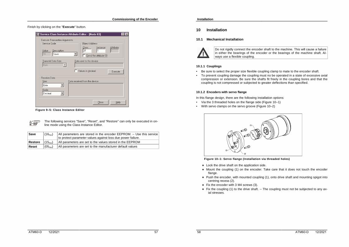
Commissioning of the Encoder
ATM60-D 12/2021 57
Finish by clicking on the "Execute" button.
Figure 9–5: Class Instance Editor
The following services "Save", "Reset", and "Restore" can only be executed in on-line mode using the Class Instance Editor.
Save (16hex) All parameters are stored in the encoder EEPROM. -- Use this service to protect parameter values against loss due power failure.
Restore (15hex) All parameters are set to the values stored in the EEPROM
Reset (05hex) All parameters are set to the manufacturer default values
Installation
58 ATM60-D 12/2021
10 Installation
10.1 Mechanical Installation
Do not rigidly connect the encoder shaft to the machine. This will cause a failure in either the bearings of the encoder or the bearings of the machine shaft. Al-ways use a flexible coupling.
10.1.1 Couplings
• Be sure to select the proper size flexible coupling clamp to mate to the encoder shaft. • To prevent coupling damage the coupling must no be operated in a state of excessive axial
compression or extension. Be sure the shafts fit freely in the coupling bores and that thecoupling is not compressed or subjected to greater deflections than specified.
10.1.2 Encoders with servo flange
In this flange design, there are the following installation options: • Via the 3 threaded holes on the flange side (Figure 10–1) • With servo clamps on the servo groove (Figure 10–2)
Figure 10–1: Servo flange (Installation via threaded holes)
♦ Lock the drive shaft on the application side.♦ Mount the coupling (1) on the encoder. Take care that it does not touch the encoder
flange.♦ Push the encoder, with mounted coupling (1), onto drive shaft and mounting spigot into
centring recess (2).♦ Fix the encoder with 3 M4 screws (3).♦ Fix the coupling (1) to the drive shaft. -- The coupling must not be subjected to any ax-
ial stresses.

Installation
ATM60-D 12/2021 59
Figure 10–2: Servo flange (Installation with servo clamps)
♦ Lock the drive shaft on the application side.♦ Mount the coupling (1) on the encoder. Take care that it does not touch the encoder
flange.♦ Mount the servo clamps (2) with M4 screws (3).♦ Do not tighten screws, rotate the servo clamps so that the encoder flange can be
pushed into the centring recess. ♦ Push the encoder, with mounted coupling (1), onto drive shaft and centring recess.♦ Push the servo clamps (2) into the groove by rotating them and tighten slightly.♦ Fix the coupling (1) to the drive shaft. -- The coupling must not be subjected to any ax-
ial stresses.♦ Tighten all 3 screws on the servo clamps.
10.1.3 Encoders with face mount (clamping) flange
In this flange design, there are the following installation options: • Via the 3 threaded holes on the flange side (Figure 10–3).• by clamping the mounting spigot (Figure 10–4).
Figure 10–3: Face mount flange (Installation via threaded holes)
♦ Lock the drive shaft on the application side.♦ Mount the coupling (1) on the encoder. Take care that it does not touch the encoder
flange.
Installation
60 ATM60-D 12/2021
♦ Push the encoder with, mounted coupling (1), onto drive shaft and centring recess (3).♦ Fix the encoder with 3 M4 screws (2).♦ Fix the coupling (1) to the drive shaft. -- The coupling must not be subjected to any ax-
ial stresses.
Figure 10–4: Face mount flange (Installation via mounting spigot)
Since the mounting spigot is also the means of centring, the clamping device must be constructed in such a way that when it is clamped firmly, no imper-missible angular or shaft offset results.
♦ Lock the drive shaft on the application side.♦ Mount the coupling (1) on the encoder. Take care that it does not touch the encoder
flange.♦ Fit the encoder with, mounted coupling (1), onto drive shaft, and the mounting spigot
into the clamping device (2).♦ Clamp the encoder firmly with the screw (3).♦ Fix the coupling (1) to the drive shaft. -- The coupling must not be subjected to any ax-
ial stresses.
10.1.4 Encoders with stator coupling for blind hollow shaft
Figure 10–5: Blind Hollow shaft
♦ Lock the drive shaft on the application side.♦ Loosen the socket-head screw (1) on the clamping ring (2).

Installation
ATM60-D 12/2021 61
♦ Push the encoder and collet onto the drive shaft. -- Take note of installation (Figure 10–6).
♦ Fix the torque support (3) with 4 M3 screws (4) and washers.♦ Firmly tighten the socket-head screw (1) on the clamping ring (2).
Figure 10–6: Note of Installation
10.2 Guidelines for Cable System
In an interference-free environment unshielded cable is permitted. The following reasons ad-vises the use of shielded cable in every case: • An interference-free space exists at most in the interior of shielded switch cabinets. How-
ever, as soon as there are also relays in the cabinet, freedom from interference is nolonger ensured.
• The use of shielded cable demands additional protective measures against over-voltages at the bus signal inputs.
You must ground your DeviceNet cable system at only one location, preferably near the physical centre of the network using a PowerTap tap.
Do not connect the grounding terminals of additional PowerTap taps, additional power supplies or additional devices to an earth ground.
For non-isolated physical layer device, make sure that additional grounding does not occur due to mounting of the device or external connections to the device.
Follow the instructions to connect the network cable system to a Bus Connector with cable termination regarding the preparation.
10.3 Electrical Connection
Make the electrical connections with the voltage switched OFF. -- After installa-tion switch ON the voltage and check the functioning of the encoder.
Only a thin cable (specified by an outside diameter of 6.9mm) can be used to connect the encoder to the network. This is due by the dimension of the cable gland or the connector.
To connect the ATM60-D to a DeviceNet network, a DeviceNet (bus terminal housing) is used with the following options: • AD-ATM60-KR1DN resp. AD-ATM60-KR2DN (cable termination) with one or two gland(s).• AD-ATM60-SR1DN resp. AD-ATM60-SR2DN (connector termination) with one or two circu-
lar plug-in connector(s).
Installation
62 ATM60-D 12/2021
Both designs are available with either one or two port(s).
10.3.1 DeviceNet adaptor with one port (AD-ATM60-?R1DN)
This type of bus connector contains only one port named IN/US (plug-in connector or cable gland). The connection to the cable system can only be done by drop line. No bus termination is used (both sliders OFF).
10.3.2 DeviceNet adaptor with two ports (AD-ATM60-?R2DN)
This type of bus connector contains two ports (plug-in connectors or cable glands). The con-nection to the cable system can be done directly to the trunk line as well as to the drop line.
A connection to the trunk line is called a "zero-length" drop or "daisy chain" configuration, and means, you have to attach the incoming bus cable to port "IN/US", and the outgoing bus cable to port "OUT/US". -- To use the bus termination see section 10.4.3.
• Take care, that the max. current flow to the terminal strip (pin 3/8 and 2/9) onthe PCB does not exceed the value of 2 A.
• The max. number of Encoders in series connection is limited to 8.
10.3.3 DeviceNet adaptor with cable termination (AD-ATM60-KR?DN)
This design has one or two screw fitting(s) / cable gland(s) in the style PG-9. Gland nuts se-cure cables to the bus connector enclosure. To attach the device to the network:
Prepare the ends of the cable section.
Jacket
shrinkage tube
8.0
Jacket
braided shield
60.0
8.0
6.5
D
Figure 10–7: Preparation of cable
♦ Strip approx. 60 mm of the outer jacket and braided shield from the end of the cable,leaving no more than 6.5mm of the braided shield exposed.
♦ Cut the foil shields surrounding the power and signal conductors.♦ Firmly twist the braided shield and the drain wire (D). Use insulating tubing on this wire.

Installation
ATM60-D 12/2021 63
♦ Use shrinkage tube (shrink wrap), covering part of the exposed conductors and part ofthe jacket.
♦ Strip approx. 8 mm of insulation from the ends of all the insulated conductors exceptthe bare drain wire. Firmly twist the bare wire ends to eliminate loose strands. Fastenwire-end sleeves to all conductors.
Attach the cable to the enclosure:
4 3
1
2
Figure 10–8: Cable termination
♦ Loosen the large gland nut (2).♦ Insert the canned cable (1) through the gland nut (2), sealing body (3) and cable gland
(4) so that about 3 mm of the cable jacket extend beyond the inside of the enclosure.♦ Firmly tighten the gland nut to provide strain relief and sealing. Do not twist or pull the
cable while tightening the gland nut.♦ Note : Hold the hex flange (4) in place during tightening.
Installation
64 ATM60-D 12/2021
Make the attachments inside the enclosure. Insert conductors into the terminal block (strip) clamping cavities according Figure 10–11, and tighten all clamping screws to secure the con-ductors to the terminal block. Figure below shows the attachment (pin-1, pin-6...9) to an enclo-sure with one port (Input). The conductors of a second port (Output) are attached to the other clamping cavities (pin-1...5)
Figure 10–9: Cable attachment using one port
Assemble the Bus Connector and encoder. -- See Figure 10–12: Assembly of Bus Connector and encoder.
10.3.4 DeviceNet adaptor with circular plug-in connectors (AD-ATM60-SR?DN )
This design has one / two circular plug-in connector(s) in the micro-style. Use cables with at-tached 5 pin QD connectors to attach the device to the network. This saves you the effort of stripping and wiring connectors to the cable ends.
OUT/ US (socket) IN/ US (pin) Function Description 1 Shield Drain / Shield 2 24V / (US ) Supply voltage (10V--32V) 3 GND (COM) 0 V (Gnd) 4 CANH CAN Bus signal high 5 CANL CAN Bus signal low
4
12
3
5
3
21
45
Figure 10–10: Plug-in connectors

Installation
ATM60-D 12/2021 65
10.3.5 Terminal strip inside DeviceNet adaptor
24VGND
CANHCANL
CANHCANL
GND24V
Shield A
B
Figure 10–11: Pin allocation
A 15-pin Sub D plug connector to put on the encoder. B Terminal strip with clamping cavity to attach network wiring.
Terminal Number
Function Description
1 Shield Shield (Drain) 2 24V / (US ) V+ (Supply voltage 10V -- 32V) / 24VDC recommend. 3 GND (COM) V- (Gnd) 4 CANH CAN Bus signal high 5 CANL CAN Bus signal low 6 CANH CAN Bus signal high 7 CANL CAN Bus signal low 8 GND (COM) V- (Gnd) 9 24V / (US ) V+ (Supply voltage 10V -- 32V) / 24VDC recommend.
10.3.6 Assembly of DeviceNet adaptor and ATM60-D encoder
Figure 10–12: Assembly of Bus Connector and encoder
♦ Put the encoder (5) onto the bus connector housing (4). Take care of the correct ad-justment and placement of the O-ring seal (6).
Installation
66 ATM60-D 12/2021
♦ Fix the bus connector housing with washers (2) and 3 M3 screws (1). -- (Socket-head /cross-recessed). Firmly tighten the screws to gain a good protection.
10.4 Operating Devices
Some characteristics of the ATM60-D may be configured by means of hardware settings. These are NODE Address, Data Rate, Electronic adjustment, and Bus termination.
In order to execute one of these functions, remove the screw cover from the back of the bus connector housing. Inside three DIP switches and a push-button become visible.
S 1 Address setting (Node ID) S 2 Baud Rate setting (Data Rate) S 3 Bus Termination S 4 Electronic adjustment (number SET)
S 3
LED
S 2S 1
1
2
1
2
3
1
2
3
4
5
6
S 4
OFF ON
Figure 10–13: Operating devices
Connecting this product to an operational DeviceNet network with improperly set DIP switches, usually will cause the entire network to stop communicating.
10.4.1 MAC ID Switch
The NODE Address (MAC-ID) can be set with DIP switch S1. The factory default setting is 63. The address must be different than the rest of the network.
DIP-6 DIP-5 DIP-4 DIP-3 DIP-2 DIP-1 25 24 23 22 21 20 Node ID
0 0 0 0 0 0 0 0 0 0 0 0 1 1 ... ... ... ... ... ... ... 1 1 1 1 1 1 63
10.4.2 Baud Rate Switch
The transmission Data Rate (Baud Rate) can be set with DIP switch S2. The factory default setting is 125 Kbaud. -- Baud rate setting must be the same as the rest of the network.
DIP-3 DIP-2 DIP-1 Data Rate X 0 0 125 Kbaud X 0 1 250 Kbaud X 1 0 500 Kbaud X 1 1 125 Kbaud

Installation
ATM60-D 12/2021 67
X = don’t care 0 = DIP switch is OFF 1 = DIP switch is ON
10.4.3 Bus Termination
The Bus termination can be set with DIP switch S3. The factory default setting is "OFF".
Each end of the CAN bus (trunk line) must be terminated with a resistor (120 Ohm) between the signals CAN_H and CAN_L !
The recommended method for connecting DeviceNet products is to run a "trunk line" with 120 ohm resistors connected at each end. DeviceNet products are connected as "drops" along the length of the trunk line. In this configuration, the internal termination resistor of the encoder should not be used, and the bus termination DIP switches should be OFF.
When the ATM60-D encoder is connected in a "daisy chain" configuration, the internal resistor may be used on the end positions only . In this configuration, the end ATM60-D should have their bus termination DIP switches turned ON.
10.4.4 Electronic adjustment (PRESET-Function)
The ATM60-D encoder supports an electronic adjustment to a predefined value (Factory PRESET value is zero [0]. -- The adjustment can be carried out in 2 ways: • Operate the push-button S4 located under the screw cover of the bus connector.• Via the DeviceNet protocol.
The PRESET function is not intended for use in dynamic parameter setting op-erations but as an electronic adjustment function during commissioning, in order to allocate a specific value to the mechanical rotary position of the encoder.
Using the PRESET function results in a change of position reading. This can cause unexpected motion which could result in damage to the product, equip-ment or personal injury.
The present physical position value is saved as the "Offset value" [Attr. 91] to the EEPROM, and the new value then applies to the position currently assumed.
10.4.4.1 Adjustment using the push button
• Switch on the voltage.• Set the drive shaft, with the encoder mounted, to the mechanical zero position.• Remove the cover from the back of the encoder and press the button with a suitable blunt
and non-conducting object for at least 100 ms. -- Refit the cover.
10.4.4.2 Adjustment using the DeviceNet protocol
Program your master device using an explicit message to the attribute "PRESET Value" of the encoder object. -- See 8.5.1 (DeviceNet Messaging...).
The PRESET value must be within the total working range currently configured as CMR.
Installation
68 ATM60-D 12/2021
10.5 Display element / Network status LED
The device includes the network status LED (NS) according to the DeviceNet specification. This built-in bi-color LED (red/green) is in the bus connector housing, and indicates the status of the communication link.
LED Status Description Off Not Powered / Device is not Online
Not On-Line - Duplicate MAC-ID check not complete- No power supply
Flashing On-Line / Device is online, but no Connection is established Green Not Connected - Duplicate MAC-ID check has passed
- Device is not allocated to a master (Group 2 Only device) Green On-Line / Device is online and has connections in the established sta-
te Connected - Device is allocated to a master (Group 2 Only device)
Flashing Connection One ore more I/O Connections are in the Timed Out state. Red Time Out - (Minor fault )
Red Critical Link Failure Failed communication device. Time Out - Device has detected an error (Duplicate MAC-ID, Bus-Off).
- (Major fault )

Putting into Operation
ATM60-D 12/2021 69
11 Putting into Operation
To continue, the following conditions are required: • The encoder is attached correctly.• The node address and data rate are set according to your network specification.• The encoder specific parameters are configured according your application.
The procedure at these settings are described in the chapter 9 ("Commissioning of the device) and 10 ("Connecting..."). .
Before putting the encoder into operation you must have read chapter "Safety Regulations".
11.1 Modes of Operation
The ATM60-D has the following operating modes: • Power-up / Reset Mode• Run Mode• Error Mode
During a power-up or reset mode, the ATM60-D: • Performs diagnostic tests including EEPROM Test, Self-Test.• Reads the MAC ID setting. Performs Duplicate MAC ID Check.
DIP switches are only read in Reset Mode
11.2 Turn-On Characteristic of the Encoder
The network Access State machine implemented in all devices describes task that must be performed prior to communicating. After Power-On a sequence according the Network Access state Transition Diagram is passed.
LED Status Description Flashing Red, Green
"Self-Test" se-quence
Reset Mode : -- (part 1) 1 sec
OFF "Duplicate MAC ID Check Request"
Reset Mode : -- (part 2) 2 sec
Flashing Green
On-Line State (*) Run Mode : -- Slave can be allocated by a master device.
Solid Red Communication Fault State (*)
Error Mode : -- Error has occurred in the previous state.
(*) only one of them se-lected
While "Self-Test" sequence (LED is flashing green and red in cycles of 250 MS), the encoder specific data are transferred from the EEPROM into the RAM part. Also the objects used by the DeviceNet Model are initialised. A failure by reading the EEPROM values is recognised, and results in setting the "Alarm Flag" (see 7.7.4, Alarms).
Putting into Operation
70 ATM60-D 12/2021
After "Self-Test" sequence has terminated, the device sends two identical consecutive "Dupli-cate MAC ID Check Request" messages within a distance of one second. These messages contain the Vendor ID (two byte) and the device identification (4 byte unique Serial Number).
The following table illustrates the message, sent by a module with a MAC ID of 3FH (63), and the Vendor ID assigned to Stegmann (511dez).
Identifier (bit 10...0) Data ( 8 Byte)
Gr MAC ID MSG ID Head Data_0 Data_1 Data_2 Data_3 Data_4 Data_5 Data_6 10 1.1111-1 111 00 FF 01 SN_Lo ... ... SN_Hi
Identifier 5.FFH MSG ID [07]: Duplicate MAC ID Check Message Head Port Number: [0xxx-xxxx]B Request Message, [1xxx-xxxx]B Response MessageData_0..._1 Vendor ID (Low Byte, High Byte): ): -- Stegmann [01.FF]H Data_2..._5 (*1) Serial Number (Low Byte...High Byte)
(*1) More detail to the encoding of the Serial Number, see Appendix A.
While Reset Mode is executed and the device receives any "DUP MAC ID Check Request/ Response" messages or a CAN Bus-Off was detected, it enters Error Mode (Communication Fault State). If no error has occurred, the encoder enters run mode and operates as a slave device to a master device.
To exit Error Mode with a Critical Error (Non-Recoverable), cycle power to the unit or disconnect the DeviceNet Cabling.
11.3 Run Mode / Connection to Master Device
The encoder ATM60-D are designed to perform some predetermined functions (provides input data / requires output data and configuration data). For this purpose, the encoder supports the "Predefined Master / Slave Connection Set". This is the easiest way to implement a predefined number of connections.
To start the interchange of data, a master device only have to claim ownership of this prede-fined connection set, as soon as the encoder changes into Run Mode (On-Line State).
The master device must establish at least one explicit connection and one I/O connection to the encoder by using the specified DeviceNet messaging protocol.
A simple configuration program to get the encoder into operation is shown in Appendix B
• A: Sequence of a "Duplicate MAC ID Check Request" initiated by the slave.• B: Allocation of the Predefined_Master / Slave_Connection Set with one explicit and one
I/O connection (Polling). -- Establish the explicit message connection. • C: The I/O connection (ID=2) is configured to assembly instance number two (2), transmit-
ting 8 bytes of I/O data (position value + velocity value).• D: Establish the I/O connection to "No terminating" (value = [00.00] ).• E: Start the Polling sequence with a cycle time of 50 MS. The receive message contains 4
byte of position value and 4 byte of velocity value.• F: Release the Predefined_Master / Slave_Connection Set.
For further details see also section 8.3 (Connecting to the DeviceNet encoder).

Problem Solving
ATM60-D 12/2021 71
12 Problem Solving
DeviceNet will not function correctly if design rules are not followed. Even a network previously thought to be functioning correctly may begin to exhibit anomalous operation due to incorrect system design.
To solve problems that can occur, you need to understand the physical DeviceNet layout, the devices on the network and how all pieces work together.
Diagnostic tools and device indicators help identify the operational state of devices and net-work communication problems.
12.1 Cable Installation and Design Problems
Cable installation and design has to do with the physical layout and connections on the net-work. Walk the network if possible to determine the actual layout.
Ensure that you have a diagram of the physical layout and a record of the following information on the layout. • Number of nodes.• Individual, branched and cumulative drop lengths.• Total trunk length, including long drop near the ends.• Power supply cable length and gauge.
• Terminator locations and size. • Break the earth ground of the V- and Shield and verify >1.0 MOhm to frame ground with
power supply off. • Check for short circuits between CAN_H and CAN_L, or CAN_(H, L) to Shield, V-, V+.• Length and gauge of the earth ground connection.• Total power load and its distribution points.
12.2 LED Status Check
The Network Status LED shows the status at power-up and during operation of the network.
LED Status Indicates Action Off • Not Pow-
ered • Not On-
Line
• No power to de-vice
• Failed DuplicateMAC ID check
• Check that one or more nodes are communicating on the network
• Check that at least one other node on the network is operational and the data rate is the same as the ATM60-D
Flashing Green
• On-Line • Not con-
nected
• Passed DuplicateMAC ID check
• And No connec-tion established
• No action is needed. The LED is flashing to signify that there are no open communication connections between the ATM60-D and any other device. Any connection (IO or explicit message) made to the encoder will cause the LED to stop flashing and re-main Steady-ON for the duration of any open con-nection.
Steady Green
• On-Line • Connected
• One or more con-nections estab-lished
• No action is needed.
Flashing Red
• On-Line • Time-Out
• At least one IOconnection has timed out
• Re-initiate IO messaging by master controller• Reduce traffic or errors on the network so that mes-
sages can get through.
Problem Solving
72 ATM60-D 12/2021
LED Status Indicates Action Steady Red
• NetworkFailure
• Failed DuplicateMAC ID check
• Bus-OFF
• Ensure that all nodes have unique addresses.• If all node addresses are unique, examine network
for correct media installation. • Ensure that all nodes have the same data rate.
If the Network Status LED goes Steady-Red at power-up, it could mean there is a Duplicate MAC ID. The user response should be to test all devices for unique addresses. If the symptom persists, it means a Bus-OFF error. • Check data rate settings.• If symptom persist, replace node address (with another address and correct data rate).• If symptom persists, check the topology. • If symptom persists, check power for noise.
12.3 Scanner Problems
If using a scanner, check the scan list, data rate and addresses of devices. Verify series and revision of the scanner.
If the scanner goes Bus-OFF after a reset the problems is some combination of: • defective node device.• incorrect node data rate.• bad network topology.• faulty wiring.• faulty scanner.• faulty power supply.• bad grounding and / or electrical noise.
12.4 Wiring Problems
Various situations in and around cables can cause problems on the network. Things to do are: • check that connectors and glands are screwed tightly.• check connectors for contamination by foreign materials. • check that nodes are not touching extremely hot or cold surfaces.• check that cables are kept a few inches away from power wiring.• check that cable are not draped on electrical motors, relays, contactors or solenoids. • check that cables are not constrained so as to place excessive tension on connectors.
12.5 Power Supply Problems
Add up the current requirements of all devices drawing power from the network. This total should be the minimum current rating in selecting the power supply used. In addition check: • length and current level in trunk and drop cables.• size and length of the cable supplying power to the trunk.• voltage measured at the middle and ends of the network (see also "Common Mode Volt-
age" -- Appendix C).
12.6 Adjusting the Physical Network Configuration
Some ways to help improve the efficiency of your physical network configuration are: • Shorten the overall length of the cable system.• Move the power supply in the direction of an overloaded cable section.• Move higher current loads closer to the power supply.
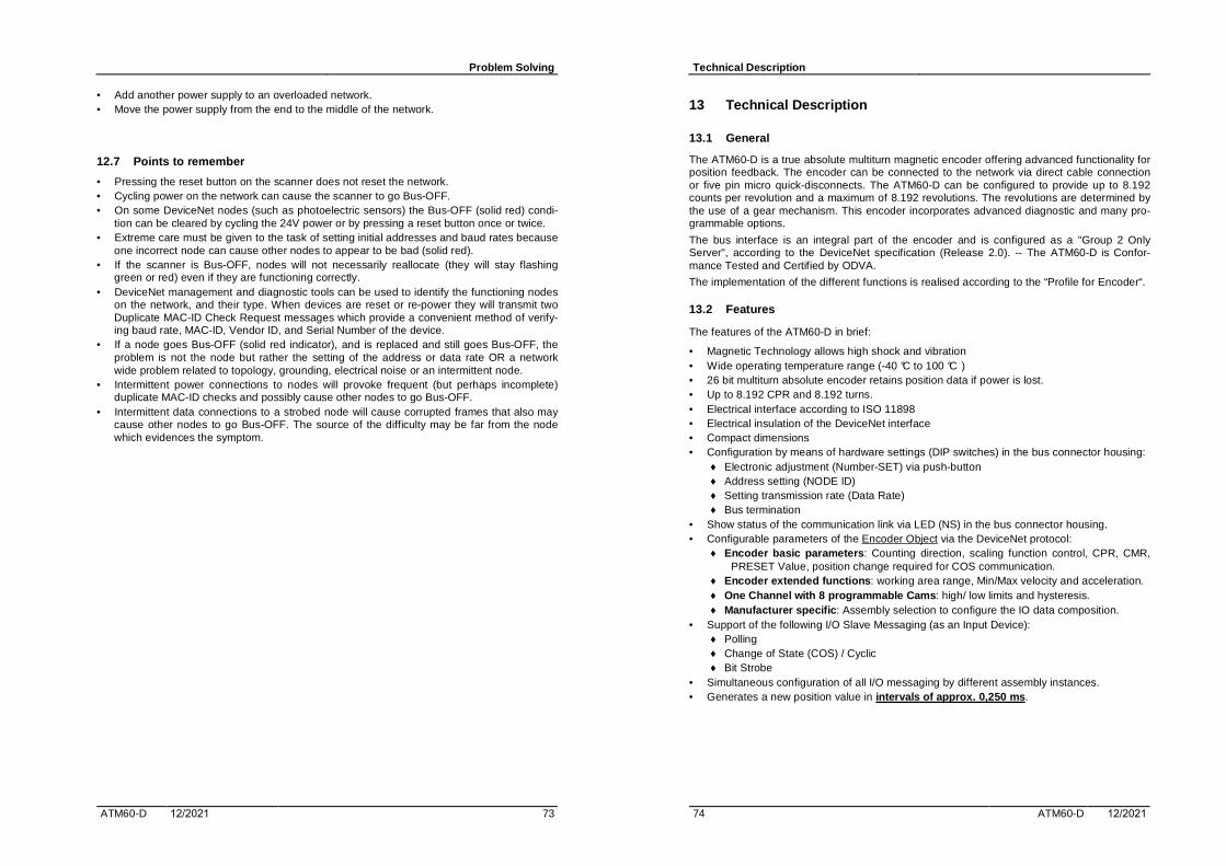
Problem Solving
ATM60-D 12/2021 73
• Add another power supply to an overloaded network. • Move the power supply from the end to the middle of the network.
12.7 Points to remember
• Pressing the reset button on the scanner does not reset the network.• Cycling power on the network can cause the scanner to go Bus-OFF. • On some DeviceNet nodes (such as photoelectric sensors) the Bus-OFF (solid red) condi-
tion can be cleared by cycling the 24V power or by pressing a reset button once or twice.• Extreme care must be given to the task of setting initial addresses and baud rates because
one incorrect node can cause other nodes to appear to be bad (solid red).• If the scanner is Bus-OFF, nodes will not necessarily reallocate (they will stay flashing
green or red) even if they are functioning correctly.• DeviceNet management and diagnostic tools can be used to identify the functioning nodes
on the network, and their type. When devices are reset or re-power they will transmit twoDuplicate MAC-ID Check Request messages which provide a convenient method of verify-ing baud rate, MAC-ID, Vendor ID, and Serial Number of the device.
• If a node goes Bus-OFF (solid red indicator), and is replaced and still goes Bus-OFF, theproblem is not the node but rather the setting of the address or data rate OR a network wide problem related to topology, grounding, electrical noise or an intermittent node.
• Intermittent power connections to nodes will provoke frequent (but perhaps incomplete) duplicate MAC-ID checks and possibly cause other nodes to go Bus-OFF.
• Intermittent data connections to a strobed node will cause corrupted frames that also may cause other nodes to go Bus-OFF. The source of the difficulty may be far from the nodewhich evidences the symptom.
Technical Description
74 ATM60-D 12/2021
13 Technical Description
13.1 General
The ATM60-D is a true absolute multiturn magnetic encoder offering advanced functionality for position feedback. The encoder can be connected to the network via direct cable connection or five pin micro quick-disconnects. The ATM60-D can be configured to provide up to 8.192 counts per revolution and a maximum of 8.192 revolutions. The revolutions are determined by the use of a gear mechanism. This encoder incorporates advanced diagnostic and many pro-grammable options.
The bus interface is an integral part of the encoder and is configured as a "Group 2 Only Server", according to the DeviceNet specification (Release 2.0). -- The ATM60-D is Confor-mance Tested and Certified by ODVA.
The implementation of the different functions is realised according to the “Profile for Encoder“.
13.2 Features
The features of the ATM60-D in brief:
• Magnetic Technology allows high shock and vibration• Wide operating temperature range (-40 °C to 100 °C ) • 26 bit multiturn absolute encoder retains position data if power is lost.• Up to 8.192 CPR and 8.192 turns. • Electrical interface according to ISO 11898• Electrical insulation of the DeviceNet interface• Compact dimensions • Configuration by means of hardware settings (DIP switches) in the bus connector housing:
♦ Electronic adjustment (Number-SET) via push-button♦ Address setting (NODE ID) ♦ Setting transmission rate (Data Rate) ♦ Bus termination
• Show status of the communication link via LED (NS) in the bus connector housing.• Configurable parameters of the Encoder Object via the DeviceNet protocol:
♦ Encoder basic parameters : Counting direction, scaling function control, CPR, CMR,PRESET Value, position change required for COS communication.
♦ Encoder extended functions : working area range, Min/Max velocity and acceleration.♦ One Channel with 8 programmable Cams : high/ low limits and hysteresis.♦ Manufacturer specific : Assembly selection to configure the IO data composition.
• Support of the following I/O Slave Messaging (as an Input Device):♦ Polling♦ Change of State (COS) / Cyclic♦ Bit Strobe
• Simultaneous configuration of all I/O messaging by different assembly instances.• Generates a new position value in intervals of approx. 0,250 ms .

Technical Description
ATM60-D 12/2021 75
13.3 Specification according DIN 32 878
Data and variables Face mount/ Servo-flange
Hollow shaft design Units
Dimensions see drawings Weight about 0,590 kg Moment of Inertia of the Rotor 35 55 gcm2 Measuring Step 0,043 Degrees Max. Number of Counts / Revolution 8192 Max. Number of Revolutions 8192 Error Limits ± 0,25 Degrees Repeatability 0,1 Degrees Working Speed 6000 3000 min-1 Position Forming Time 0,250 ms Max. Angular Acceleration 5 x 10⁵ rad/s2 Operating Torque with shaft sealing ring 1,8 0,8 Ncm Operating Torque w/o shaft sealing ring 0,3 - Ncm Starting Torque with shaft sealing ring 2,5 1,2 Ncm Starting Torque w/o shaft sealing ring 0,5 - Ncm Max. Shaft Loading Radial / Axial 300 / 50 - N Permissible Shaft Movement of the drive element
Radial Static / Dynamic - ± 0,3 / ± 0,1 mm Axial Static / Dynamic - ± 0,5 / ± 0,2 mm
Bearing Lifetime 3,6 x 10⁹ Revol. Temperature (working range) -20 ... + 85 °C Temperature (operating range) -40 ... +100 °C Temperature (storage range) -40 ... +125 °C Permissible relative air humidity 98 % EMC according to EN 50 081-2 and EN 50 082-2, CE Resistance to Shock (mounted state) -- IEC 68-2-27 100 / (6 ms) g Resistance to Vibration (mounted state) -- IEC 68-2-6 20 / (10..2000Hz) g Protection Class to EN 60 529
with shaft sealing ring IP 67 IP 67 w/o shaft sealing ring, not sealed at encoder flange IP 43 IP 43 w/o shaft sealing ring, sealed at encoder flange IP 66 -
Operating Voltage 10 - 32 V Max. Power Consumption 2,0 W Initialisation Time 1250 ms
Bus Interface DeviceNet Electrical Interface ISO 11898 (CAN High Speed) to CAN Specification
2.0 B, DC isolated DeviceNet Specification, Release 2.0 Protocol
Address Setting (NODE ID) 0...63 via DIP switches or protocol Data Transmission Rate (Data Rate) {125, 250, 500 } kb via DIP switches or protocol Electronic Adjustment (Number SET) via PRESET push button or protocol Status Information Network Status LED (NS), 2 colours Bus Termination via DIP switches (used on the end positions only) Electrical Connection Screw fitting / Cable gland with PG-9, or
M12 circular plug-in connector, (5 pin micro-style)
Drawings
76 ATM60-D 12/2021
14 Drawings
14.1 Types of Encoders
M4 (3x)7.0 Deep
Figure 14–1: Encoder ATM60-D (servo flange)
M4 (3x)7.0 Deep
Figure 14–2: Encoder ATM60-D (face mount flange)
Bearing surface fortorque support
Depth of shaft insertionmin. 15 mmmax. 30 mm
Figure 14–3: Encoder ATM60-D (blind hollow shaft)

Drawings
ATM60-D 12/2021 77
14.2 Types of DeviceNet adaptors
13
Figure 14–4: DeviceNet adaptor SR1 (circular plug-in connector)
13
Figure 14–5: DeviceNet adaptor SR2 (circular plug-in connector)
20
Figure 14–6: DeviceNet adaptor KR1 (Cable Termination, using PG-9)
20
Figure 14–7: DeviceNet adaptor KR2 (Cable Termination, using PG-9)
Drawings
78 ATM60-D 12/2021

Summary of Changes
ATM60-D 12/2021 79
Appendix A
80 ATM60-D 12/2021
. Appendix A
Encoding of the Stegmann Serial Number according DeviceNet Specification
All vendors that produce DeviceNet nodes will be assigned a Vendor Identification Code. In addition, each Vendor must assign every DeviceNet product a unique 32-bit serial number when manufacturing the product. The Serial Number need only be unique with respect to a particular vendor. This identification code is part of the "Duplicate MAC ID Check Request Message".
View of the 4 Byte Identification Code:
Byte_3 (MsB) Byte_2 Byte_1 Byte_0 (LsB)
The internal identification (serial number) used by Stegmann consist of 9 characters (ASCII-Code) with the following meaning:
U D1 D2 D3 D4 D5 D6 D7 D8
U Unused D1...D8 Internal number (Ascii-Code) "31" --> [01]
The internal Ascii-Code specifies a number range from "30...39" and "41....46" according to the number [0 ... 9] and [A ... F].
The digits D1, D2 (Byte_3) are used as a vendor specific identifier, different to each manufac-turer of this device type:
• Stegmann Donaueschingen
• Stegmann USA
• A-B
Example:
The internal serial number
U 30 31 33 34 38 39 41 46
is converted into a 4 Byte identification code (Hex format):
Byte_3 (MsB) Byte_2 Byte_1 Byte_0 (LsB) 0 1 3 4 8 9 A F
View of the 4 Byte Identification Code according a data mapping in format "Little Endian" used by the DeviceNet transmission protocol.
Byte_0 (LsB) Byte_1 Byte_2 Byte_3 (MsB) A F 8 9 3 4 0 1

Appendix B
ATM60-D 12/2021 81
. Appendix B
Configuration program to get the encoder into operation. Begin Triggerblock Tue Oct 16 14:36:40 2001 -- (base hex) // Time ID Attr Gr SM DM MId XF Serv Data
A //10.6394 1 5FF Rx 2 3F 07 Rq 'Dupl.MAC check' Serial D903039 Port 00 Vendor1FF 10.6394 1 5FF Rx d 7 00 FF 01 39 30 90 0D
//11.6399 1 5FF Rx 2 3F 07 Rq 'Dupl.MAC check' Serial D903039 Port 00 Vendor1FF 11.6399 1 5FF Rx d 7 00 FF 01 39 30 90 0D
B //13.2929 1 5FE Tx 2 01 3F 06 0 Rq 'Alloc Master/Slave' Cl3(DNet) Ins1 Choice Ex|Pl Master 1 13.2929 1 5FE Tx d 6 01 4B 03 01 03 01
//13.2933 1 5FB Rx 2 3F 01 03 0 Rsp 'Alloc Master/Slave' DN8/8 13.2933 1 5FB Rx d 3 01 CB 00
//13.8684 1 5FC Tx 2 01 3F 04 0 Rq 'Set Attr Single' Cl5(Cnxn) Ins1 Atr9(exPRate) :00 00 13.8684 1 5FC Tx d 7 01 10 05 01 09 00 00
//13.8688 1 5FB Rx 2 3F 01 03 0 Rsp 'Set Attr Single' :00 00 13.8688 1 5FB Rx d 4 01 90 00 00
C //14.4080 1 5FC Tx 2 01 3F 04 0 0 Rq 'Set Attr Single' Cl5(Cnxn) Ins2 AtrE(prdCnPath) 14.4080 1 5FC Tx d 6 81 00 10 05 02 0E
//14.4084 1 5FB Rx 2 3F 01 03 0 0 Rsp Fraq: Success 14.4084 1 5FB Rx d 3 81 C0 00
//14.9866 1 5FC Tx 2 01 3F 04 0 1 :20 04 24 03 30 03 14.9866 1 5FC Tx d 8 81 81 20 04 24 03 30 03
//14.9869 1 5FB Rx 2 3F 01 03 0 1 Rsp Fraq: Success 14.9869 1 5FB Rx d 3 81 C1 00
//14.9871 1 5FB Rx 2 3F 01 03 0 Rsp 'Set Attr Single' 14.9871 1 5FB Rx d 2 01 90
D //15.7201 1 5FC Tx 2 01 3F 04 0 Rq 'Set Attr Single' Cl5(Cnxn) Ins2 Atr9(exPRate) :00 00 15.7201 1 5FC Tx d 7 01 10 05 02 09 00 00
//15.7205 1 5FB Rx 2 3F 01 03 0 Rsp 'Set Attr Single' :00 00 15.7205 1 5FB Rx d 4 01 90 00 00
E //17.1869 1 5FD Tx 2 3F 05 Rq IO Poll 17.1869 1 5FD Tx d 0
//17.1873 1 3FF Rx 1 3F 0F Rsp IO Poll :A1 21 00 00 00 00 00 00 17.1873 1 3FF Rx d 8 A1 21 00 00 00 00 00 00
//17.2380 1 5FD Tx 2 3F 05 Rq IO Poll 17.2380 1 5FD Tx d 0
//17.2385 1 3FF Rx 1 3F 0F Rsp IO Poll :A1 21 00 00 00 00 00 00 17.2385 1 3FF Rx d 8 A1 21 00 00 00 00 00 00
//17.2891 1 5FD Tx 2 3F 05 Rq IO Poll 17.2891 1 5FD Tx d 0
//17.2895 1 3FF Rx 1 3F 0F Rsp IO Poll :A1 21 00 00 00 00 00 00 17.2895 1 3FF Rx d 8 A1 21 00 00 00 00 00 00
F //26.0870 1 5FE Tx 2 01 3F 06 0 Rq 'Release Master/Slave' Cl3(DNet) Ins1 RelChoice Ex :01 26.0870 1 5FE Tx d 6 01 4C 03 01 01 01
//26.0872 1 5FB Rx 2 3F 01 03 0 Rsp ?'Release Master/Slave'
Appendix B
82 ATM60-D 12/2021
26.0872 1 5FB Rx d 2 01 CC End Triggerblock

Appendix C
ATM60-D 12/2021 83
. Appendix C
Common Mode Voltage
When current is drawn through the power pair on the DeviceNet trunk line, the length of the cable and current draw becomes important. The thick wire, normally used for trunk line, has a resistance of 0.0045 Ohms/ foot. So as the distance from the DeviceNet power supply connec-tion becomes greater, the power pair will act as a resistor whose value will be equal to 0.0045 multiplied by the Distance from the Power Supply ( In Feet). At any particular point on the power pair the Common Mode Voltage will equal the Current being drawn on the power pair at that point times the Resistance of the Power Pair. ( V = I x 0.0045 x Distance )
The effect of the Common Mode Voltage is that the V+ line will lower gradually from the 24VDC at the power supply as you move farther down the trunk line. More importantly the V- wire will gradually raise from the 0VDC value at the power supply along the length of the trunk line. On most networks the amount of voltage the V+ lowers and V- raises are equal. So even though there may be exactly 24VDC measured at Network Power Supply, further down the ca-ble the voltage on the V+ and V- wires may only be 20VDC. This effect is due to Common Mode Voltage and should the voltage drop become too large the network will fail to operate properly. Since the CAN-H (White Wire) and the CAN-L (Blue Wire) both are referenced to the V- wire, if the V- line varies more than 4.65VDC at any two points on the network the CAN transceivers will fail to operate properly.
An easy way to measure for Common Mode Voltage problems is to go to the farthest ends of the network and measure between Red V+ and Black V- wires. This voltage should NEVER be less than 15 Volts.
Network Voltage/ OHM Readings
It needs to be understood that DeviceNet is actually a three wire Differential Voltage network. Communication is accomplished by switching the CAN-H ( White wire ) and CAN-L ( Blue wire ) signals relative to the V- line ( Black Wire ).
Important NOTE
The CAN to V- voltages given in the rest of this chapter assume NO Common Mode Voltage effect is occurring anywhere on the V- wire of the network. On a network with Common Mode Voltage influence, the voltages will be higher depending on where you take the measurement. Nodes closest to the power supply will exhibit voltages higher due to the Common Mode Volt-age, while nodes at the farthest end of the network away from the power supply will exhibit lower voltages.
The CAN-H swings between 2.5 VDC (Recessive State) and 4.0 VDC (Dominant State) while the CAN-L swings between 1.5 VDC (Dominant State) and 2.5 VDC (Recessive State)
Without a network master connected to the DeviceNet, the CAN-H and CAN-L lines should read between 2.5 VDC and 3.0 VDC relative to V- and the voltages should be identical (Re-cessive State). Measure these voltages right at the SDN scanner connection which is normally also where the power supply is connected to the network. Use a voltmeter in DC mode.
With a network master connected to the DeviceNet and polling the network, the CAN-H to V- voltage will be around +3.2 VDC. The CAN-L to V- voltage will be around 2.4 VDC. The reason these values appear a little different than the ranges shown on the scope trace, is that the sig-nals are switching, which slightly affects the DC value being read by the VOM.
With the 24VDC power supply not energised you can measure the resistance between the CAN-H and CAN-L signals. The ohm reading between the CAN-H and CAN-L lines should be 60 ohms (two 120 ohm resistors in parallel), however with a large amount of devices con-nected to the network the resistance could be as low as 50 Ohms.
Directory of Figures
84 ATM60-D 12/2021
. Directory of Figures FIGURE 4–1: TOPOLOGY OF DEVICENET--------------------------------------------------------------------------------15 FIGURE 6–1: OBJECT MODEL------------------------------------------------------------------------------------------------20 FIGURE 6–2: ADDRESSING SCHEME --------------------------------------------------------------------------------------21 FIGURE 7–1: USAGE OF THE HYSTERESIS-------------------------------------------------------------------------------37 FIGURE 7–2: USAGE OF THE SWITCH POINTS REGARDING THE POLARITY ---------------------------------38 FIGURE 7–3: SETTING INPUT ASSEMBLY DATA ----------------------------------------------------------------------43 FIGURE 9–1: EDS WIZARD----------------------------------------------------------------------------------------------------54 FIGURE 9–2: HARDWARE WINDOW ---------------------------------------------------------------------------------------54 FIGURE 9–3: GENERAL PROPERTIES--------------------------------------------------------------------------------------55 FIGURE 9–4: SETTING PARAMETERS -------------------------------------------------------------------------------------56 FIGURE 9–5: CLASS INSTANCE EDITOR----------------------------------------------------------------------------------57 FIGURE 10–1: SERVO FLANGE (INSTALLATION VIA THREADED HOLES)-------------------------------------58 FIGURE 10–2: SERVO FLANGE (INSTALLATION WITH SERVO CLAMPS) --------------------------------------59 FIGURE 10–3: FACE MOUNT FLANGE (INSTALLATION VIA THREADED HOLES) ---------------------------59 FIGURE 10–4: FACE MOUNT FLANGE (INSTALLATION VIA MOUNTING SPIGOT) --------------------------60 FIGURE 10–5: BLIND HOLLOW SHAFT------------------------------------------------------------------------------------60 FIGURE 10–6: NOTE OF INSTALLATION----------------------------------------------------------------------------------61 FIGURE 10–7: PREPARATION OF CABLE ---------------------------------------------------------------------------------62 FIGURE 10–8: CABLE TERMINATION -------------------------------------------------------------------------------------63 FIGURE 10–9: CABLE ATTACHMENT USING ONE PORT ------------------------------------------------------------64 FIGURE 10–10: PLUG-IN CONNECTORS-----------------------------------------------------------------------------------64 FIGURE 10–11: PIN ALLOCATION ------------------------------------------------------------------------------------------65 FIGURE 10–12: ASSEMBLY OF BUS CONNECTOR AND ENCODER -----------------------------------------------65 FIGURE 10–13: OPERATING DEVICES-------------------------------------------------------------------------------------64 FIGURE 14–1: ENCODER ATM60-D (SERVO FLANGE)----------------------------------------------------------------74 FIGURE 14–2: ENCODER ATM60-D (FACE MOUNT FLANGE) ------------------------------------------------------74 FIGURE 14–3: ENCODER ATM60-D (BLIND HOLLOW SHAFT) -----------------------------------------------------74 FIGURE 14–4: DEVICENET ADAPTOR SR1 (CIRCULAR PLUG-IN CONNECTOR)------------------------------75 FIGURE 14–5: DEVICENET ADAPTOR SR2 (CIRCULAR PLUG-IN CONNECTOR)------------------------------75 FIGURE 14–6: DEVICENET ADAPTOR KR1 (CABLE TERMINATION, USING PG-9) ---------------------------75 FIGURE 14–7: DEVICENET ADAPTOR KR2 (CABLE TERMINATION, USING PG-9) ---------------------------75

Notes
ATM60-D 12/2021 85
. Notes