
Vitalobe Installation/Operating Manual - Prestige Pumps
70
Hygienic Pump Vitalobe Installation/Operating Manual
-
Upload
khangminh22 -
Category
Documents
-
view
2 -
download
0
Transcript of Vitalobe Installation/Operating Manual - Prestige Pumps
Hygienic Pump
Vitalobe
Installation/OperatingManual

Legal information/Copyright Installation/Operating Manual VitalobeOriginal operating manual KSB Aktiengesellschaft All rights reserved. Contents provided herein must neither be distributed, copied, reproduced, editedor processed for any other purpose, nor otherwise transmitted, published or made available to a thirdparty without KSB´s express written consent. Subject to technical modification without prior notice. © KSB Aktiengesellschaft Frankenthal 09.03.2012

Contents
Glossary ................................................................................................ 5
1 General ................................................................................................ 6
1.1 Principles .......................................................................................................... 6
1.2 Installation of partly completed machinery .................................................. 6
1.3 Target group ................................................................................................... 6
1.4 Other applicable documents .......................................................................... 6
1.5 Symbols ............................................................................................................ 6
2 Safety ................................................................................................... 8
2.1 Key to safety symbols/markings ..................................................................... 8
2.2 General ............................................................................................................ 8
2.3 Intended use .................................................................................................... 8
2.4 Personnel qualification and training ............................................................. 9
2.5 Consequences and risks caused by non-compliance with these operatinginstructions ...................................................................................................... 9
2.6 Safety awareness ............................................................................................. 9
2.7 Safety information for the operator/user .................................................... 10
2.8 Safety information for maintenance, inspection and installation work ... 10
2.9 Unauthorised modes of operation ............................................................... 10
2.10 Explosion protection ..................................................................................... 10
3 Transport/Temporary Storage/Disposal ........................................... 12
3.1 Checking the condition upon delivery ......................................................... 12
3.2 Transport ....................................................................................................... 12
3.3 Storage/preservation ..................................................................................... 12
3.4 Return to supplier ......................................................................................... 13
3.5 Disposal .......................................................................................................... 13
4 Description of the Pump (Set) .......................................................... 15
4.1 General description ....................................................................................... 15
4.2 Designation ................................................................................................... 15
4.3 Name plate .................................................................................................... 16
4.4 Design details ................................................................................................ 16
4.5 Configuration and function ......................................................................... 18
4.6 Noise characteristics ...................................................................................... 19
4.7 Scope of supply ............................................................................................. 19
4.8 Dimensions and weights ............................................................................... 19
5 Installation at Site ............................................................................. 20
5.1 Safety regulations ......................................................................................... 20
5.2 Checks to be carried out prior to installation ............................................. 20
5.3 Installing the pump set ................................................................................. 20
Contents
Vitalobe 3 of 70
5.4 Piping ............................................................................................................. 23
5.5 Protective equipment ................................................................................... 31
5.6 Checking the coupling alignment ................................................................ 32
5.7 Electrical system ............................................................................................ 32
5.8 Electrical connection ..................................................................................... 33
5.9 Checking the direction of rotation .............................................................. 34
6 Commissioning/Start-up/Shutdown ................................................. 35
6.1 Commissioning/start-up ................................................................................ 35
6.2 Operating limits ............................................................................................ 38
6.3 Shutdown/storage/preservation ................................................................... 41
6.4 Returning to service ...................................................................................... 42
7 Servicing/Maintenance ...................................................................... 43
7.1 Safety regulations ......................................................................................... 43
7.2 Maintenance/inspection ............................................................................... 44
7.3 Drainage/cleaning ......................................................................................... 48
7.4 Dismantling the pump set ............................................................................ 49
7.5 Reassembling the pump set .......................................................................... 52
7.6 Tightening torques ....................................................................................... 57
7.7 Spare parts stock ........................................................................................... 57
8 Trouble-shooting ............................................................................... 59
9 Related Documents ........................................................................... 61
9.1 Exploded view / list of components ............................................................. 61
10 EC Declaration of Conformity .......................................................... 67
11 Certificate of Decontamination ....................................................... 68
Index .................................................................................................. 69
Contents
4 of 70 Vitalobe
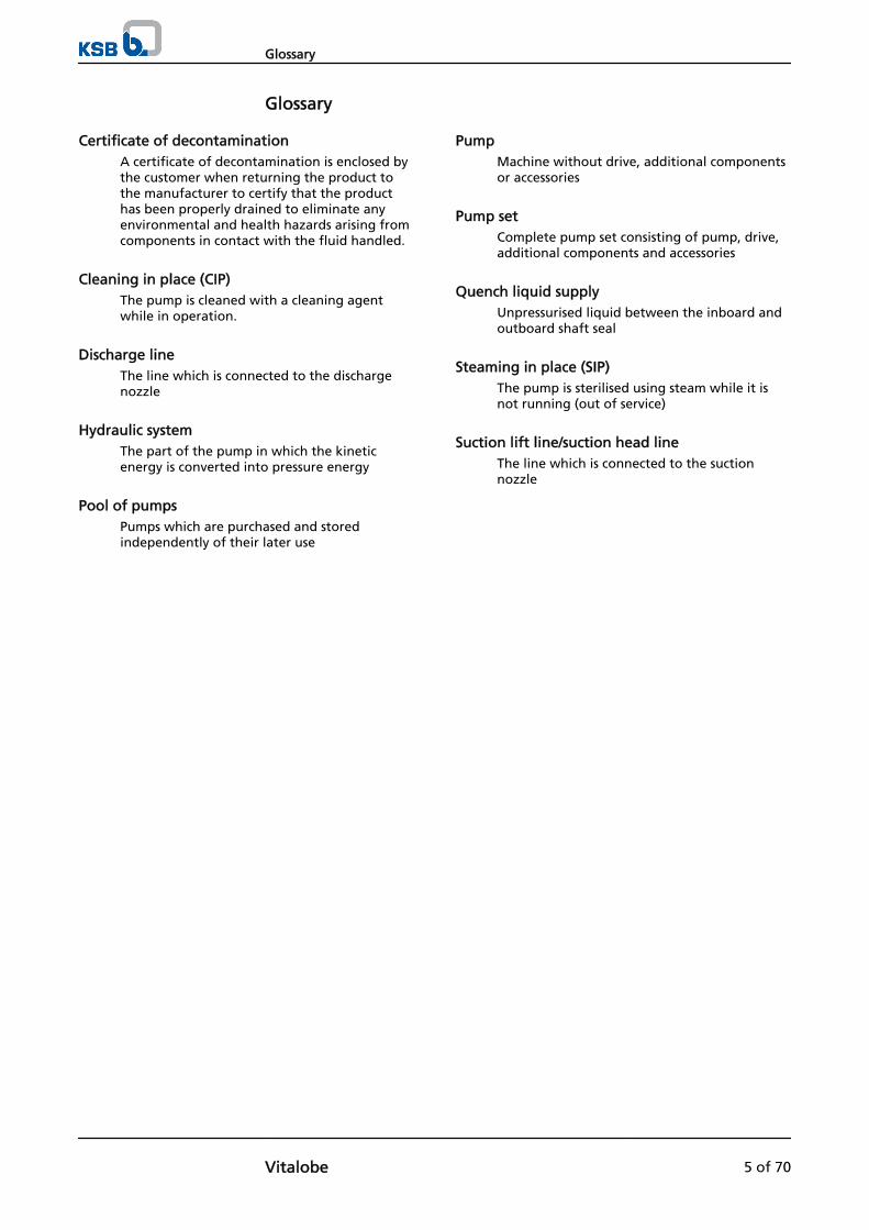
Glossary
Certificate of decontaminationA certificate of decontamination is enclosed bythe customer when returning the product tothe manufacturer to certify that the producthas been properly drained to eliminate anyenvironmental and health hazards arising fromcomponents in contact with the fluid handled.
Cleaning in place (CIP)The pump is cleaned with a cleaning agentwhile in operation.
Discharge lineThe line which is connected to the dischargenozzle
Hydraulic systemThe part of the pump in which the kineticenergy is converted into pressure energy
Pool of pumpsPumps which are purchased and storedindependently of their later use
PumpMachine without drive, additional componentsor accessories
Pump setComplete pump set consisting of pump, drive,additional components and accessories
Quench liquid supplyUnpressurised liquid between the inboard andoutboard shaft seal
Steaming in place (SIP)The pump is sterilised using steam while it isnot running (out of service)
Suction lift line/suction head lineThe line which is connected to the suctionnozzle
Glossary
Vitalobe 5 of 70
1 General
1.1 Principles
This operating manual is supplied as an integral part of the type series and variantsindicated on the front cover. The manual describes the proper and safe use of thisequipment in all phases of operation.
The name plate indicates the type series and size, the main operating data, the ordernumber and the order item number. The order number and order item number uniquely identify the pump (set) and serve as identification for all further businessprocesses.
In the event of damage, contact your nearest KSB service centre immediately tomaintain the right to claim under warranty.
Noise characteristics. (⇨ Section 4.6 Page 19)
1.2 Installation of partly completed machinery
To install partly completed machinery supplied by KSB, refer to the sub-sectionsunder Servicing/Maintenance.
1.3 Target group
This manual is aimed at the target group of trained and qualified specialist technicalpersonnel. (⇨ Section 2.4 Page 9)
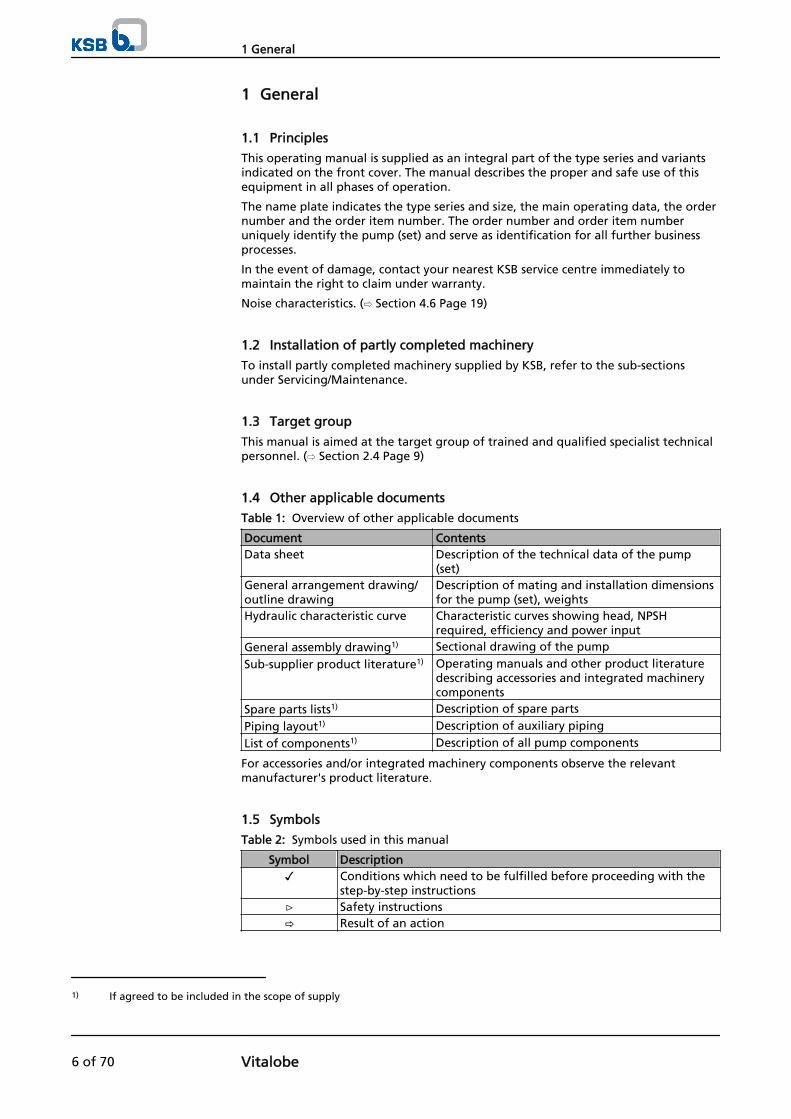
1.4 Other applicable documents
Table 1: Overview of other applicable documents
Document ContentsData sheet Description of the technical data of the pump
(set)General arrangement drawing/outline drawing
Description of mating and installation dimensionsfor the pump (set), weights
Hydraulic characteristic curve Characteristic curves showing head, NPSHrequired, efficiency and power input
General assembly drawing1) Sectional drawing of the pump
Sub-supplier product literature1) Operating manuals and other product literaturedescribing accessories and integrated machinerycomponents
Spare parts lists1) Description of spare parts
Piping layout1) Description of auxiliary piping
List of components1) Description of all pump components
For accessories and/or integrated machinery components observe the relevantmanufacturer's product literature.
1.5 Symbols
Table 2: Symbols used in this manual
Symbol Description✓ Conditions which need to be fulfilled before proceeding with the
step-by-step instructions⊳ Safety instructions⇨ Result of an action
1) If agreed to be included in the scope of supply
1 General
6 of 70 Vitalobe
Symbol Description⇨ Cross-references1.
2.
Step-by-step instructions
NoteRecommendations and important information on how to handlethe product
1 General
Vitalobe 7 of 70
2 SafetyAll the information contained in this section refers to hazardous situations.
2.1 Key to safety symbols/markings
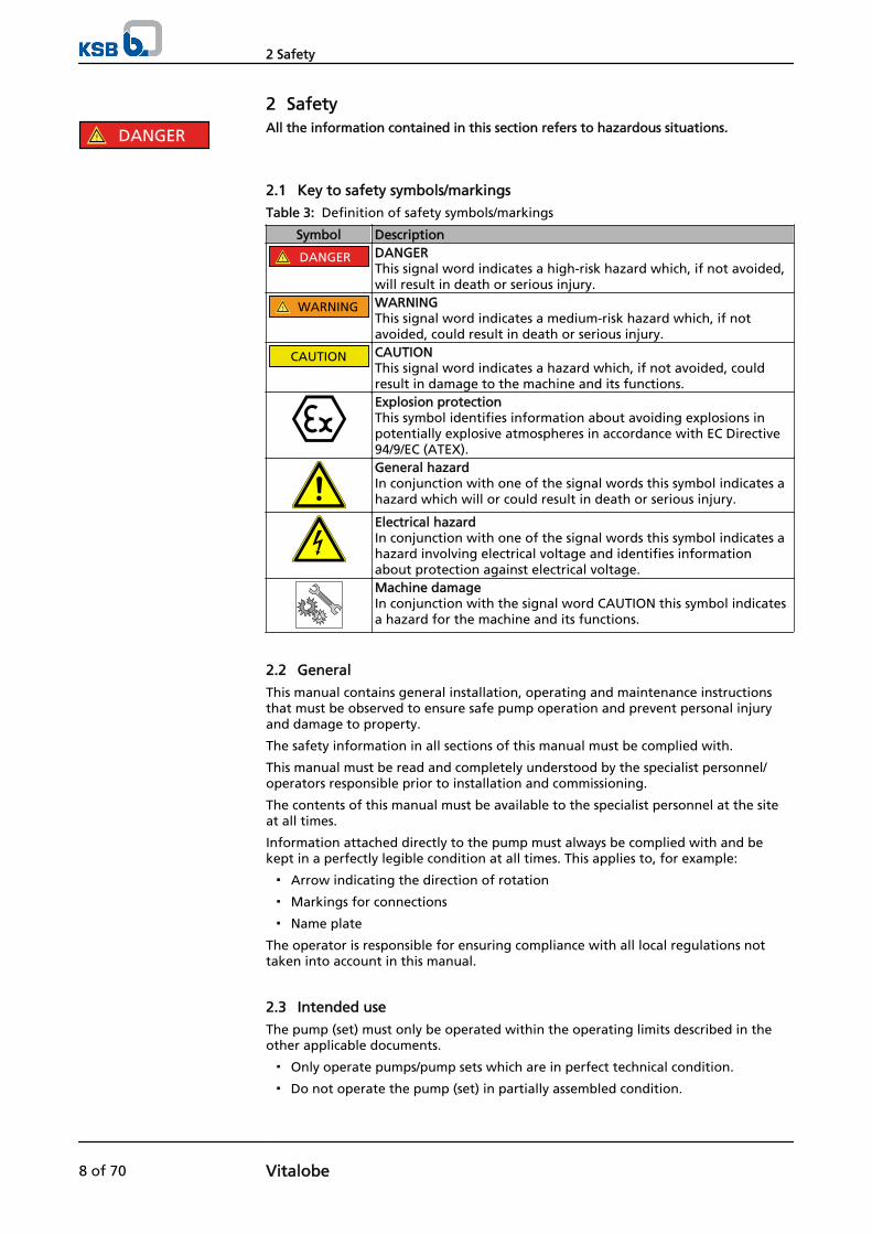
Table 3: Definition of safety symbols/markings
Symbol Description
! DANGER DANGERThis signal word indicates a high-risk hazard which, if not avoided,will result in death or serious injury.
! WARNING WARNINGThis signal word indicates a medium-risk hazard which, if notavoided, could result in death or serious injury.
CAUTION CAUTIONThis signal word indicates a hazard which, if not avoided, couldresult in damage to the machine and its functions.Explosion protectionThis symbol identifies information about avoiding explosions inpotentially explosive atmospheres in accordance with EC Directive94/9/EC (ATEX).General hazardIn conjunction with one of the signal words this symbol indicates ahazard which will or could result in death or serious injury.
Electrical hazardIn conjunction with one of the signal words this symbol indicates ahazard involving electrical voltage and identifies informationabout protection against electrical voltage.Machine damage In conjunction with the signal word CAUTION this symbol indicatesa hazard for the machine and its functions.
2.2 General
This manual contains general installation, operating and maintenance instructionsthat must be observed to ensure safe pump operation and prevent personal injuryand damage to property.
The safety information in all sections of this manual must be complied with.
This manual must be read and completely understood by the specialist personnel/operators responsible prior to installation and commissioning.
The contents of this manual must be available to the specialist personnel at the siteat all times.
Information attached directly to the pump must always be complied with and bekept in a perfectly legible condition at all times. This applies to, for example:
▪ Arrow indicating the direction of rotation
▪ Markings for connections
▪ Name plate
The operator is responsible for ensuring compliance with all local regulations nottaken into account in this manual.
2.3 Intended use
The pump (set) must only be operated within the operating limits described in theother applicable documents.
▪ Only operate pumps/pump sets which are in perfect technical condition.
▪ Do not operate the pump (set) in partially assembled condition.
! DANGER
2 Safety
8 of 70 Vitalobe

▪ Only use the pump to handle the fluids described in the data sheet or productliterature of the pump model.
▪ Never operate the pump without the fluid handled.
▪ Observe the minimum flow rates indicated in the data sheet or product literature(to prevent overheating, bearing damage, etc).
▪ Observe the maximum flow rates indicated in the data sheet or productliterature (to prevent overheating, mechanical seal damage, cavitation damage,bearing damage, etc).
▪ Do not throttle the flow rate on the suction side of the pump (to preventcavitation damage).
▪ Consult the manufacturer about any use or mode of operation not described inthe data sheet or product literature.
Prevention of foreseeable misuse
▪ Never open discharge-side shut-off elements further than permitted.
– The maximum flow rate specified in the data sheet or product literaturewould be exceeded.
– Risk of cavitation damage
▪ Never exceed the permissible operating limits specified in the data sheet orproduct literature regarding pressure, temperature, etc.
▪ Observe all safety information and instructions in this manual.
2.4 Personnel qualification and training
All personnel involved must be fully qualified to install, operate, maintain andinspect the equipment this manual refers to.
The responsibilities, competence and supervision of all personnel involved intransport, installation, operation, maintenance and inspection must be clearlydefined by the operator.
Deficits in knowledge must be rectified by means of training and instructionprovided by sufficiently trained specialist personnel. If required, the operator cancommission the manufacturer/supplier to train the personnel.
Training on the pump (set) must always be supervised by technical specialistpersonnel.
2.5 Consequences and risks caused by non-compliance with these operatinginstructions
▪ Non-compliance with these operating instructions will lead to forfeiture ofwarranty cover and of any and all rights to claims for damages.
▪ Non-compliance can, for example, have the following consequences:
– Hazards to persons due to electrical, thermal, mechanical and chemicaleffects and explosions
– Failure of important product functions
– Failure of prescribed maintenance and servicing practices
– Hazard to the environment due to leakage of hazardous substances
2.6 Safety awareness
In addition to the safety information contained in this manual and the intended use,the following safety regulations shall be complied with:
▪ Accident prevention, health and safety regulations
▪ Explosion protection regulations
▪ Safety regulations for handling hazardous substances
▪ Applicable standards and laws
2 Safety
Vitalobe 9 of 70
2.7 Safety information for the operator/user
▪ The operator shall fit contact guards for hot, cold and moving parts and checkthat the guards function properly.
▪ Do not remove any contact guards during operation.
▪ Provide the personnel with protective equipment and make sure it is used.
▪ Contain leakages (e.g. at the shaft seal) of hazardous fluids handled (e.g.explosive, toxic, hot) so as to avoid any danger to persons and the environment.Adhere to all relevant laws.
▪ Eliminate all electrical hazards. (In this respect refer to the applicable nationalsafety regulations and/or regulations issued by the local energy supplycompanies.)
▪ If shutting down the pump does not increase potential risk, fit an emergency-stop control device in the immediate vicinity of the pump (set) during pump setinstallation.
2.8 Safety information for maintenance, inspection and installation work
▪ Modifications or alterations of the pump are only permitted with themanufacturer's prior consent.
▪ Use only original spare parts or parts authorised by the manufacturer. The use ofother parts can invalidate any liability of the manufacturer for resulting damage.
▪ The operator ensures that all maintenance, inspection and installation work isperformed by authorised, qualified specialist personnel who are thoroughlyfamiliar with the manual.
▪ Only carry out work on the pump (set) during standstill of the pump.
▪ The pump casing must have cooled down to ambient temperature.
▪ Pump pressure must have been released and the pump must have been drained.
▪ When taking the pump set out of service always adhere to the proceduredescribed in the manual. (⇨ Section 6.3 Page 41)
▪ Decontaminate pumps which handle fluids posing a health hazard.
▪ As soon as the work is completed, re-install and/or re-activate any safety-relevantand protective devices. Before returning the product to service, observe allinstructions on commissioning. (⇨ Section 6.1 Page 35)
2.9 Unauthorised modes of operation
Never operate the pump (set) outside the limits stated in the data sheet and in thismanual.
The warranty relating to the operating reliability and safety of the supplied pump(set) is only valid if the equipment is used in accordance with its intended use. (⇨Section 2.3 Page 8)
2.10 Explosion protection
Always observe the information on explosion protection given in this section whenoperating the pump in potentially explosive atmospheres.
Only pumps/pump sets marked as explosion-proof and identified as such in the datasheet may be used in potentially explosive atmospheres.
Special conditions apply to the operation of explosion-proof pump sets to ECDirective 94/9/EC (ATEX). Especially adhere to the sections in this manual marked with the Ex symbol and thefollowing sections (⇨ Section 2.10.1 Page 11) to (⇨ Section 2.10.3 Page 11). The explosion-proof status of the pump set is only assured if the pump set is used inaccordance with its intended use. Never operate the pump set outside the limits stated in the data sheet and on the
! DANGER
2 Safety
10 of 70 Vitalobe

name plate.Prevent impermissible modes of operation at all times.
2.10.1 Marking
The marking on the pump refers to the pump part only. Example of such marking: II 2 G c TX Refer to the Temperature limits table for the temperatures permitted for theindividual pump variants.
An EC manufacturer's declaration is required for the shaft coupling; the shaftcoupling must be marked accordingly.
The motor must be considered separately.
2.10.2 Temperature limits
In normal pump operation, the highest temperatures are to be expected at thesurface of the pump casing, at the shaft seal and in the bearing areas. The surface temperature at the pump casing corresponds to the temperature of thefluid handled. If the pump is heated, the operator of the system is responsible forobserving the specified temperature class and fluid temperature (operatingtemperature). The table below lists the temperature classes and the resulting theoreticaltemperature limits of the fluid handled. (A possible temperature rise in the shaft sealarea has already been taken into account).
The temperature class specifies the maximum permissible temperature at the surfaceof the pump set during operation. For the permissible operating temperature of thepump in question refer to the data sheet.
Table 4: Temperature limits
Temperature class to EN 13463-1 Maximum permissible fluidtemperature
T1 Pump temperature limitT2 Pump temperature limitT3 130 °CT4 65 °C
If the pump is to be operated at a higher temperature, if there is no data sheet or ifthe pump is part of a pool of pumps, contact KSB for the maximum permissibleoperating temperature.
If a pump is supplied without motor (as part of a pool of pumps), the motor specifiedin the pump data sheet must meet the following conditions:
▪ The permissible temperature limits at the motor flange and motor shaft must behigher than the temperatures generated by the pump.
▪ Contact the manufacturer for the actual pump temperatures.
2.10.3 Monitoring equipment
The pump (set) must only be operated within the limits specified in the data sheetand on the name plate. If the system operator cannot warrant compliance with these operating limits,appropriate monitoring devices must be used. Check whether monitoring equipment is required to ensure that the pump setfunctions properly.
Contact KSB for further information on monitoring equipment.
Pump
Shaft coupling
Motor
Motor supplied by theoperator
2 Safety
Vitalobe 11 of 70
3 Transport/Temporary Storage/Disposal
3.1 Checking the condition upon delivery
1. On transfer of goods, check each packaging unit for damage.
2. In the event of in-transit damage, assess the exact damage, document it andnotify KSB or the supplying dealer (as applicable) and the insurer about thedamage in writing immediately.
3.2 Transport
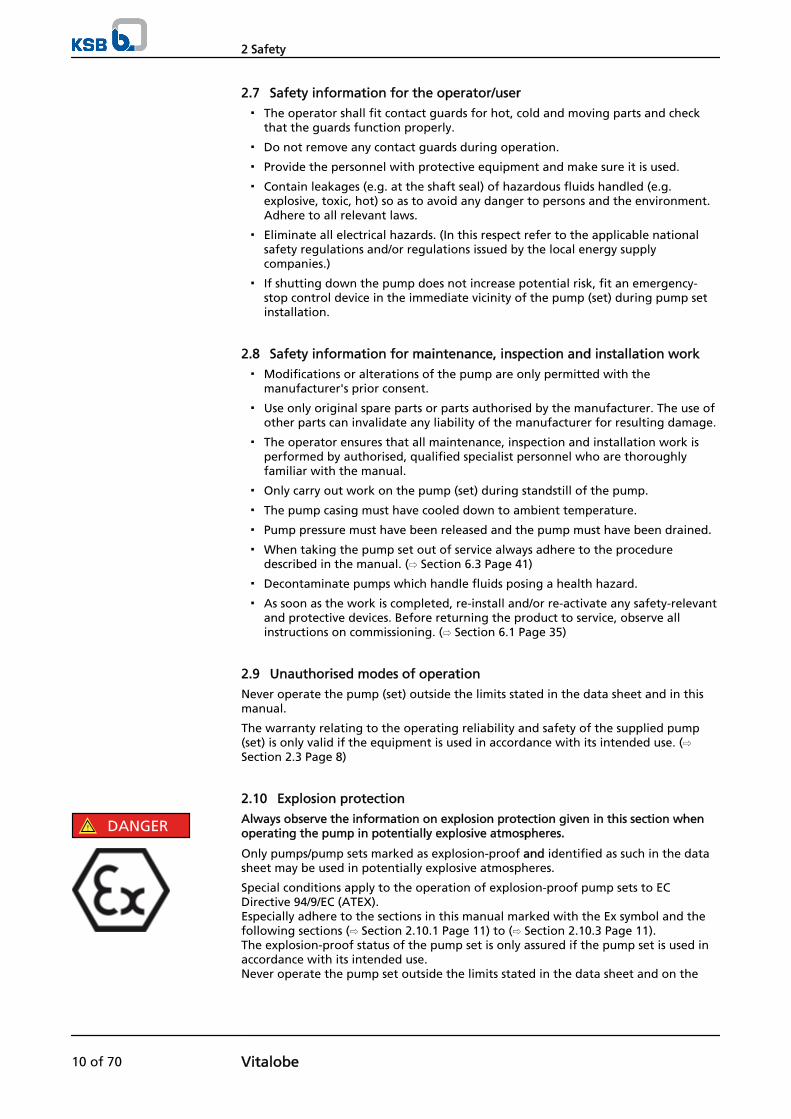
DANGERThe pump (set) could slip out of the suspension arrangementDanger to life from falling parts!
▷ Always transport the pump (set) in the specified position.
▷ Never attach the suspension arrangement to the free shaft end or the motoreyebolt.
▷ Give due attention to the weight data and the centre of gravity.
▷ Observe the applicable local health and safety regulations.
▷ Use suitable, permitted lifting accessories, e.g. self-tightening lifting tongs.
To transport the pump/pump set suspend it from the lifting equipment as shown.
The motor shroud, if fitted, must be removed before transporting the pump set.
Fig. 1: Transporting the pump
Fig. 2: Transporting the complete pump set
3.3 Storage/preservation
If commissioning is to take place some time after delivery, we recommend that thefollowing measures be taken for pump (set) storage.
3 Transport/Temporary Storage/Disposal
12 of 70 Vitalobe

CAUTIONDamage during storage by humidity, dirt, or verminCorrosion/contamination of the pump (set)!
▷ For outdoor storage cover the packed or unpacked pump (set) and accessorieswith waterproof material.
CAUTIONWet, contaminated or damaged openings and connectionsLeakage or damage to the pump set!
▷ Only remove caps/covers from the openings of the pump set at the time ofinstallation.
Store the pump (set) in a dry, protected room where the atmospheric humidity is asconstant as possible.
Rotate the shaft by hand once a month, e.g. via the motor fan.
If properly stored indoors, the pump set is protected for a maximum of 12 months.New pumps/pump sets are supplied by our factory duly prepared for storage.
For storing a pump (set) which has already been operated, observe the instructions in (⇨ Section 6.3.1 Page 41).
3.4 Return to supplier
1. Drain the pump as per operating instructions.
2. Always flush and clean the pump, particularly if it has been used for handlingnoxious, explosive, hot or other hazardous fluids.
3. If the fluids handled by the pump set leave residues which might lead tocorrosion damage when coming into contact with atmospheric humidity, orwhich might ignite when coming into contact with oxygen, the pump set mustalso be neutralised, and anhydrous inert gas must be blown through the pumpfor drying purposes.
4. Always complete and enclose a certificate of decontamination when returningthe pump (set).Always indicate any safety and decontamination measures taken. (⇨ Section 11Page 68)
NOTEIf required, a blank certificate of decontamination can be downloaded from the KSB website at: www.ksb.com/certificate_of_decontamination
3.5 Disposal
WARNINGFluids posing a health hazard and/or hot fluidsHazard to persons and the environment!
▷ Collect and properly dispose of flushing liquid and any residues of the fluidhandled.
▷ Wear safety clothing and a protective mask, if required.
▷ Observe all legal regulations on the disposal of fluids posing a health hazard.
1. Dismantle the pump (set).Collect greases and other lubricants during dismantling.
2. Separate and sort the pump materials, e.g. by:- Metals- Plastics- Electronic waste- Greases and other lubricants
3 Transport/Temporary Storage/Disposal
Vitalobe 13 of 70
3. Dispose of materials in accordance with local regulations or in another controlledmanner.
3 Transport/Temporary Storage/Disposal
14 of 70 Vitalobe
4 Description of the Pump (Set)
4.1 General description
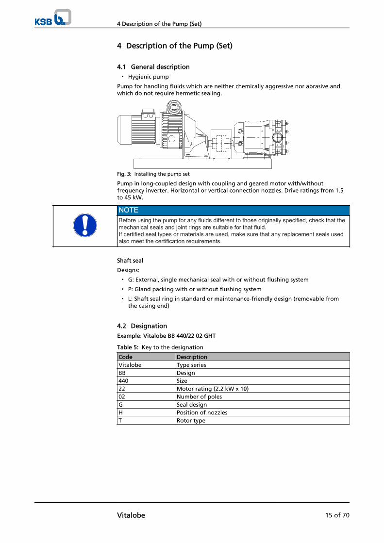
▪ Hygienic pump
Pump for handling fluids which are neither chemically aggressive nor abrasive andwhich do not require hermetic sealing.
Fig. 3: Installing the pump set
Pump in long-coupled design with coupling and geared motor with/withoutfrequency inverter. Horizontal or vertical connection nozzles. Drive ratings from 1.5to 45 kW.
NOTEBefore using the pump for any fluids different to those originally specified, check that themechanical seals and joint rings are suitable for that fluid. If certified seal types or materials are used, make sure that any replacement seals usedalso meet the certification requirements.
Shaft seal
Designs:
▪ G: External, single mechanical seal with or without flushing system
▪ P: Gland packing with or without flushing system
▪ L: Shaft seal ring in standard or maintenance-friendly design (removable fromthe casing end)
4.2 Designation
Example: Vitalobe BB 440/22 02 GHT
Table 5: Key to the designation
Code DescriptionVitalobe Type seriesBB Design440 Size22 Motor rating (2.2 kW x 10)02 Number of polesG Seal designH Position of nozzlesT Rotor type
4 Description of the Pump (Set)
Vitalobe 15 of 70
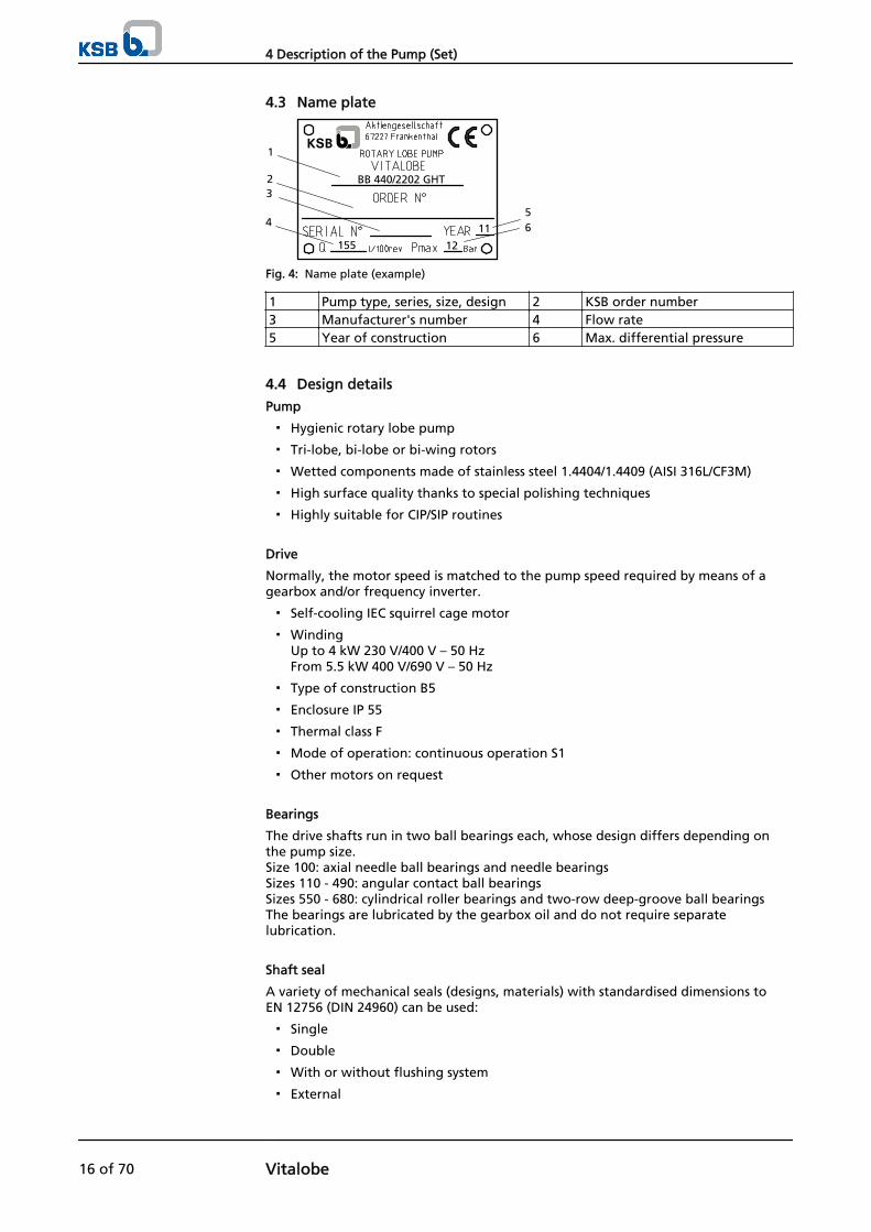
4.3 Name plate
155
11
1
23
456
12
BB 440/2202 GHT
Fig. 4: Name plate (example)
1 Pump type, series, size, design 2 KSB order number3 Manufacturer's number 4 Flow rate5 Year of construction 6 Max. differential pressure
4.4 Design details
Pump
▪ Hygienic rotary lobe pump
▪ Tri-lobe, bi-lobe or bi-wing rotors
▪ Wetted components made of stainless steel 1.4404/1.4409 (AISI 316L/CF3M)
▪ High surface quality thanks to special polishing techniques
▪ Highly suitable for CIP/SIP routines
Drive
Normally, the motor speed is matched to the pump speed required by means of agearbox and/or frequency inverter.
▪ Self-cooling IEC squirrel cage motor
▪ Winding Up to 4 kW 230 V/400 V – 50 Hz From 5.5 kW 400 V/690 V – 50 Hz
▪ Type of construction B5
▪ Enclosure IP 55
▪ Thermal class F
▪ Mode of operation: continuous operation S1
▪ Other motors on request
Bearings
The drive shafts run in two ball bearings each, whose design differs depending onthe pump size. Size 100: axial needle ball bearings and needle bearings Sizes 110 - 490: angular contact ball bearings Sizes 550 - 680: cylindrical roller bearings and two-row deep-groove ball bearings The bearings are lubricated by the gearbox oil and do not require separatelubrication.
Shaft seal
A variety of mechanical seals (designs, materials) with standardised dimensions toEN 12756 (DIN 24960) can be used:
▪ Single
▪ Double
▪ With or without flushing system
▪ External
4 Description of the Pump (Set)
16 of 70 Vitalobe

Table 6: Mechanical seal material combinations
Code Design Material combinationG Single external mechanical
seal, balanced (standarddesign)
316/CARB/EPDM; TUC/CARB/EPDM;TUC/TUC/EPDM; CER/CARB/EPDM;CER/RUL/EPDM; SIC/SIC/EPDM; SIC/CARB/EPDM
VG Single external mechanicalseal, balanced, with flushingsystem
316/CARB/EPDM; TUC/CARB/EPDM;TUC/TUC/EPDM; CER/CARB/EPDM;CER/RUL/EPDM; SIC/SIC/EPDM; SIC/CARB/EPDM
Q Double external mechanicalseal with flushing system
316/CARB/EPDM; TUC/CARB/EPDM;TUC/TUC/EPDM; CER/CARB/EPDM;CER/RUL/EPDM; SIC/SIC/EPDM; SIC/CARB/EPDM
Apart from EPDM, the elastomer seals of the mechanical seal are also available inNBR, FPM, PTFE, FFPM and FEP materials.
Table 7: Key
Code MaterialCER CeramicsCARB GraphiteEPDM Ethylene propylene diene rubberTUC Tungsten carbideSiC Silicon carbide316 Stainless steel AISI 316RUL RulonNBR Nitrile rubberFPM Fluoroelastomer (Viton)FFPM PerfluoroelastomerPTFE PolytetrafluoroethyleneFEP Fluorocarbon (PTFE-encapsulated silicone)
Gland packing
The gland packing consists of braided teflon rings sliding against a bush fitted on therotating shaft. It is used above all for handling sticky fluids or fluids which tend tosolidify, whose lack of lubricating properties would destroy a mechanical seal. Thegland packing can also be fed with a flushing or barrier liquid. This protects thegland packing against overheating and also constitutes a hydraulic barrier betweenthe fluid handled and the atmosphere.
Lip seal
The lip seal consists of a joint ring made of FKM (Viton) or thermoplasticpolyurethane (S1-Ecopur). The lip seal can either be designed to replace a mechanicalseal or to be fitted in the pump from the front end (i.e. rotor end) for greater ease ofmaintenance.
Static seals
The static (elastomer) seals can be supplied in the following materials:
▪ NBR – Nitrile butadiene rubber
▪ EPDM – Ethylene propylene diene rubber
▪ FKM – Fluoroelastomer (Viton)
▪ FEP – Perfluoroethylene propylene
▪ FFKM – Perfluoroelastomer
4 Description of the Pump (Set)
Vitalobe 17 of 70
Connections
Standard: threaded connection to DIN 11851
Other connection types:
▪ SMS thread
▪ Threaded to IDF/ISS standard
▪ Threaded to BS RJT standard
▪ Threaded to DIN 11864 standard
▪ Tri-clamp couplings
▪ BSP connections
▪ Flanges to EN 1092-1
▪ Connections to DIN 11864
▪ Other variants on request
4.5 Configuration and function
1
2
3
4
5
6
7
8
9
10
11
12
1314
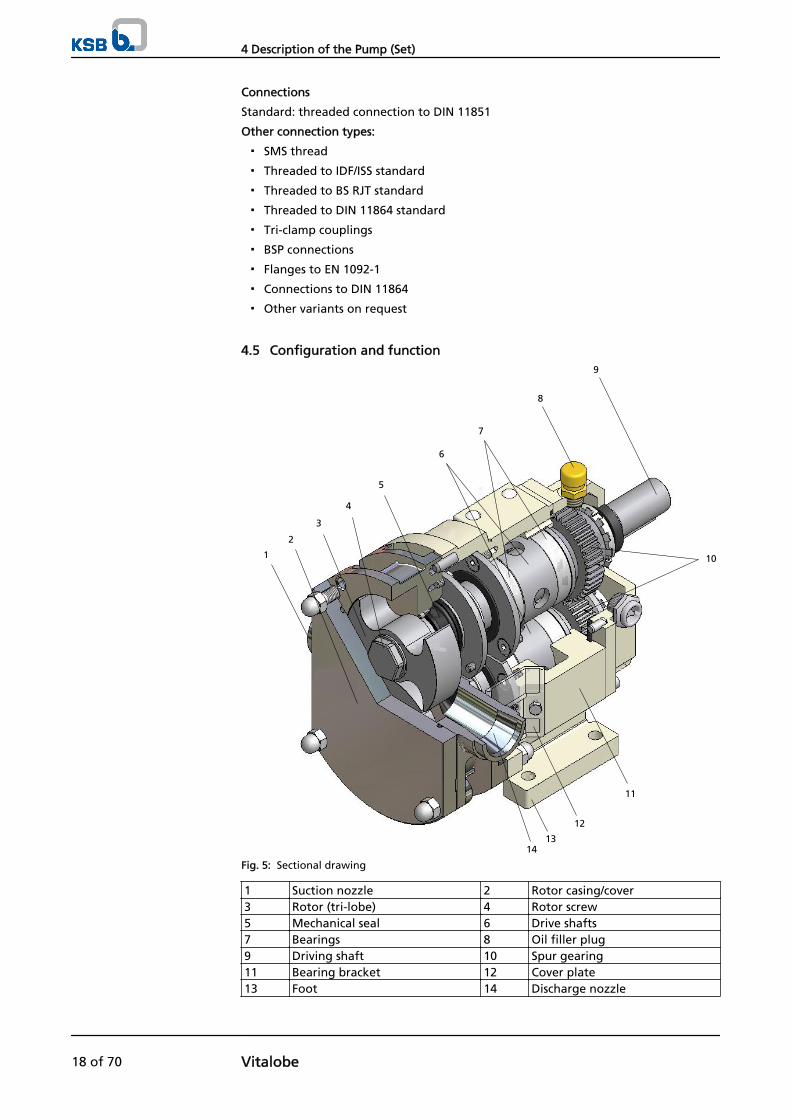
Fig. 5: Sectional drawing
1 Suction nozzle 2 Rotor casing/cover3 Rotor (tri-lobe) 4 Rotor screw5 Mechanical seal 6 Drive shafts7 Bearings 8 Oil filler plug9 Driving shaft 10 Spur gearing11 Bearing bracket 12 Cover plate13 Foot 14 Discharge nozzle
4 Description of the Pump (Set)
18 of 70 Vitalobe
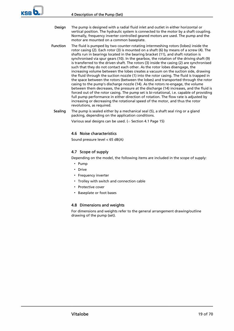
The pump is designed with a radial fluid inlet and outlet in either horizontal orvertical position. The hydraulic system is connected to the motor by a shaft coupling.Normally, frequency inverter controlled geared motors are used. The pump and themotor are mounted on a common baseplate.
The fluid is pumped by two counter-rotating intermeshing rotors (lobes) inside therotor casing (2). Each rotor (3) is mounted on a shaft (6) by means of a screw (4). Theshafts run in bearings located in the bearing bracket (11), and shaft rotation issynchronised via spur gears (10). In the gearbox, the rotation of the driving shaft (9)is transferred to the driven shaft. The rotors (3) inside the casing (2) are synchronisedsuch that they do not contact each other. As the rotor lobes disengage, theincreasing volume between the lobes creates a vacuum on the suction side, drawingthe fluid through the suction nozzle (1) into the rotor casing. The fluid is trapped inthe space between the rotors (between the lobes) and transported through the rotorcasing to the pump's discharge nozzle (14). As the rotors re-engage, the volumebetween them decreases, the pressure at the discharge (14) increases, and the fluid isforced out of the rotor casing. The pump set is bi-rotational, i.e. capable of providingfull pump performance in either direction of rotation. The flow rate is adjusted byincreasing or decreasing the rotational speed of the motor, and thus the rotorrevolutions, as required.
The pump is sealed either by a mechanical seal (5), a shaft seal ring or a glandpacking, depending on the application conditions.
Various seal designs can be used. (⇨ Section 4.1 Page 15)
4.6 Noise characteristics
Sound pressure level < 65 dB(A)
4.7 Scope of supply
Depending on the model, the following items are included in the scope of supply:
▪ Pump
▪ Drive
▪ Frequency inverter
▪ Trolley with switch and connection cable
▪ Protective cover
▪ Baseplate or foot bases
4.8 Dimensions and weights
For dimensions and weights refer to the general arrangement drawing/outlinedrawing of the pump (set).
Design
Function
Sealing
4 Description of the Pump (Set)
Vitalobe 19 of 70
5 Installation at Site
5.1 Safety regulations
DANGERImproper installation in potentially explosive atmospheresExplosion hazard!Damage to the pump set!
▷ Comply with the applicable local explosion protection regulations.
▷ Observe the information in the data sheet and on the name plates of pump andmotor.
WARNINGImproper installation of the pump setPersonal injury and damage to property!
▷ Adhere to the instructions for installing the pump set described below in orderto prevent major hazards and injuries.
5.2 Checks to be carried out prior to installation
Place of installation
WARNINGInstallation on mounting surface which is unsecured and cannot support the loadPersonal injury and damage to property!
▷ Use a concrete of compressive strength class C12/15 which meets therequirements of exposure class XC1 to EN 206-1.
▷ The mounting surface must have set and must be completely horizontal andeven.
▷ Observe the weights indicated.
1. Check the structural requirements. All structural work required must have been prepared in accordance with thedimensions stated in the outline drawing/general arrangement drawing.
CAUTIONImproper installation of the pump setDamage to property!
▷ The pump set must be installed in a closed room, i.e. it must not be exposed tothe environment.
NOTEThe pump set will operate most efficiently at temperatures between +5 °C and +40 °Cand a relative humidity below 50 %.
CAUTIONPump used in unsuitable environmental conditionsDamage to property!
▷ The pump must not be used in other environmental conditions than thosedescribed above (see note).
5.3 Installing the pump set
Always install the pump set in horizontal position.
5 Installation at Site
20 of 70 Vitalobe
DANGERExcessive temperatures due to improper installationExplosion hazard!
▷ Install the pump in horizontal position to ensure self-venting of the pump.
NOTEWhen installing the pump set, make sure that there is sufficient clearance around thepump set to allow easy servicing and maintenance.
5.3.1 Installation on a foundation
12
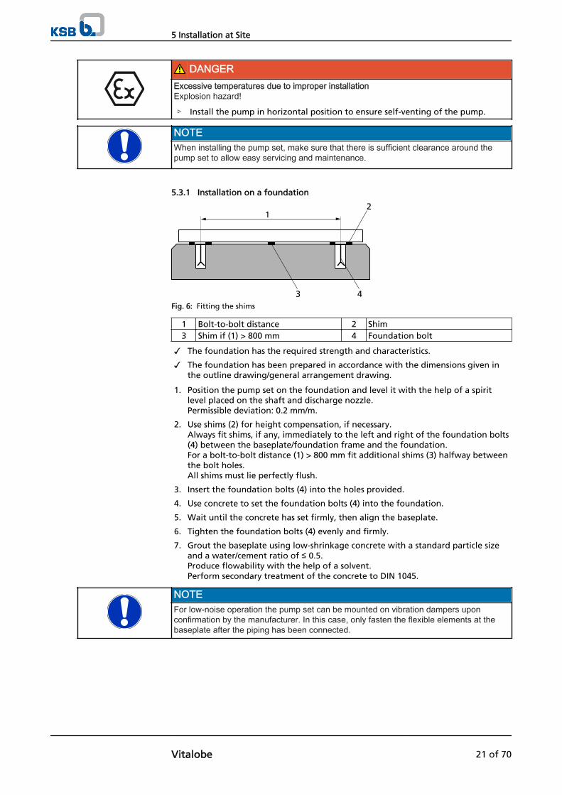
43Fig. 6: Fitting the shims
1 Bolt-to-bolt distance 2 Shim3 Shim if (1) > 800 mm 4 Foundation bolt
✓ The foundation has the required strength and characteristics.
✓ The foundation has been prepared in accordance with the dimensions given inthe outline drawing/general arrangement drawing.
1. Position the pump set on the foundation and level it with the help of a spiritlevel placed on the shaft and discharge nozzle.Permissible deviation: 0.2 mm/m.
2. Use shims (2) for height compensation, if necessary. Always fit shims, if any, immediately to the left and right of the foundation bolts(4) between the baseplate/foundation frame and the foundation. For a bolt-to-bolt distance (1) > 800 mm fit additional shims (3) halfway betweenthe bolt holes. All shims must lie perfectly flush.
3. Insert the foundation bolts (4) into the holes provided.
4. Use concrete to set the foundation bolts (4) into the foundation.
5. Wait until the concrete has set firmly, then align the baseplate.
6. Tighten the foundation bolts (4) evenly and firmly.
7. Grout the baseplate using low-shrinkage concrete with a standard particle sizeand a water/cement ratio of ≤ 0.5.Produce flowability with the help of a solvent.Perform secondary treatment of the concrete to DIN 1045.
NOTEFor low-noise operation the pump set can be mounted on vibration dampers uponconfirmation by the manufacturer. In this case, only fasten the flexible elements at thebaseplate after the piping has been connected.
5 Installation at Site
Vitalobe 21 of 70
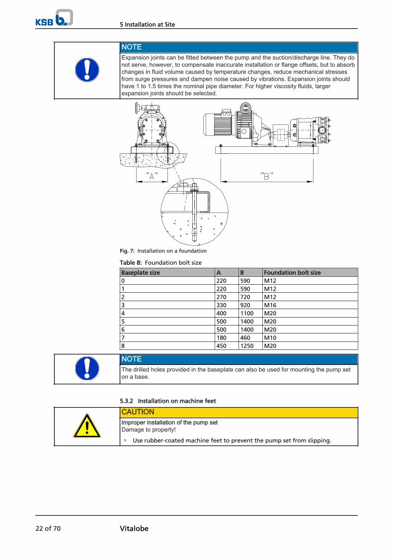
NOTEExpansion joints can be fitted between the pump and the suction/discharge line. They donot serve, however, to compensate inaccurate installation or flange offsets, but to absorbchanges in fluid volume caused by temperature changes, reduce mechanical stressesfrom surge pressures and dampen noise caused by vibrations. Expansion joints shouldhave 1 to 1.5 times the nominal pipe diameter. For higher viscosity fluids, largerexpansion joints should be selected.
Fig. 7: Installation on a foundation
Table 8: Foundation bolt size
Baseplate size A B Foundation bolt size0 220 590 M121 220 590 M122 270 720 M123 330 920 M164 400 1100 M205 500 1400 M206 500 1400 M207 180 460 M108 450 1250 M20
NOTEThe drilled holes provided in the baseplate can also be used for mounting the pump seton a base.
5.3.2 Installation on machine feet
CAUTIONImproper installation of the pump setDamage to property!
▷ Use rubber-coated machine feet to prevent the pump set from slipping.
5 Installation at Site
22 of 70 Vitalobe

Fig. 8: Installation on machine feet
✓ The installation surface is level and has the required strength and characteristics.
1. Place the pump set in position and level it with the help of spirit level placed onthe suction/discharge nozzle.The feet are vertically adjustable and must rest evenly on the installation surface.
5.4 Piping
CAUTIONContamination/dirt in the pipingDamage to the pumps!
▷ Always clean the piping and check for contamination before connecting it tothe pump.
NOTEThe piping must be cleaned whenever changes have been made to the system (e.g.after fittings have been installed), without dirt getting into the pump.
5.4.1 Connecting the piping
DANGERExcessive loads acting on the pump nozzlesDanger to life from leakage of hot, toxic, corrosive or flammable fluids!
▷ Do not use the pump as an anchorage point for the piping.
▷ Anchor the pipelines in close proximity to the pump and connect them withouttransmitting any stresses or strains.
▷ Take appropriate measures to compensate thermal expansion of the piping.
CAUTIONIncorrect earthing during welding work at the pipingDestruction of rolling element bearings (pitting effect)!
▷ Never earth the electric welding equipment on the pump or baseplate.
▷ Prevent current flowing through the rolling element bearings.
NOTEIt is recommended to install check and shut-off elements in the system, depending on thetype of plant and pump. However, such elements must not obstruct proper drainage orhinder disassembly of the pump.
✓ The suction lift line has been laid with a rising slope, the suction head line with adownward slope towards the pump.
NOTEIf site conditions do not allow the suction line to be laid with a rising slope, a ventingfacility must be provided at the highest point of the suction line.
5 Installation at Site
Vitalobe 23 of 70

✓ A flow stabilisation section having a length equivalent to at least twice thediameter of the suction flange has been provided upstream of the suction flange.
CAUTIONDry running of the mechanical seal/pump malfunctionDamage to the pump!
▷ Route the suction line such that air pockets are prevented.
▷ The suction line must not leak.
▷ Avoid sharp bends and valves fitted directly upstream of the pump which wouldaffect the approach flow to the pump and thus the NPSH available.
▷ Install a foot valve for suction lift operation to prevent drainage of the suctionline.
✓ The nominal diameters of the pipelines are at least equal to the nominaldiameters of the pump nozzles.
✓ To prevent excessive pressure losses, adapters to larger diameters have a diffuserangle of approx. 8°.
✓ The pipelines have been anchored in close proximity to the pump and connectedwithout transmitting any stresses or strains.
NOTEIt is recommended to fit gate valves immediately upstream and downstream of the pumpinto the suction and discharge line, respectively. This will prevent the fluid handled fromflowing back when the pump is stopped or removed for servicing/maintenance. Thesegate valves must always be fully open when the pump is running; they must not be usedfor control duties. Operation against a closed gate valve will inevitably result in pump/system damage.
1. Thoroughly clean, flush and blow through all vessels, pipelines and connections(especially of new installations).
2. Before installing the pump in the piping, remove the flange covers on the suctionand discharge nozzles of the pump.
CAUTIONWelding beads, scale and other impurities in the pipingDamage to the pump!
▷ Free the piping from any impurities.
▷ If necessary, install a filter.
▷ Comply with the instructions set out in (⇨ Section 7.2.2.3 Page 46) .
3. If required, install a filter in the piping (refer to figure: Filter in the piping).
1
2Fig. 9: Filter in the piping
1 Differential pressure gauge 2 Filter
5 Installation at Site
24 of 70 Vitalobe

NOTEUse a filter with laid-in wire mesh of 0.5 mm x 0.25 mm (mesh size x wire diameter)made of corrosion-resistant material.Use a filter with a filter area three times the cross-section of the piping.Conical filters have proved suitable.
4. Connect the pump nozzles to the piping.
CAUTIONAggressive flushing and pickling agentsDamage to the pump!
▷ Match the cleaning operation mode and duration for flushing and picklingservice to the casing and seal materials used.
5.4.2 Permissible forces and moments at the pump nozzles
No piping-induced forces and moments (from warped pipelines or thermalexpansion, for example) must act on the pump.If this is inevitable, the forces and moments must never exceed the values for Fmax andMmax given in the following table.
Fig. 10: Forces and moments at the pump nozzles
Table 9: Permissible forces at the pump nozzles
Size Force (N) Torque [Nm]FX FY FZ Fmax MX MY MZ Mmax
100 65 55 75 113 110 85 70 140105/110/115 105 95 120 186 125 100 90 164215 145 130 160 252 130 110 95 172220 190 180 220 342 140 115 100 183325 210 200 250 383 150 120 110 197330/390 240 230 280 435 160 130 110 206430/440 255 245 300 464 175 150 130 230470/490 260 250 305 472 180 150 130 234550 340 340 355 598 190 160 130 255660/680 405 405 440 722 200 180 170 276
5.4.3 Auxiliary connections
The following auxiliary connections are available (depending on the pump design):
5 Installation at Site
Vitalobe 25 of 70
▪ Mechanical safety pressure relief valve (safety valve)
▪ Pneumatic safety pressure relief valve (safety valve)
▪ Bypass valve (safety valve)
▪ Quench connection for mechanical seal with flushing system
▪ Heating/cooling of pump casing
NOTEThe installation of a safety valve is generally recommended to ensure pump safety evenin the event of operator errors (possibly resulting in excess pressure).
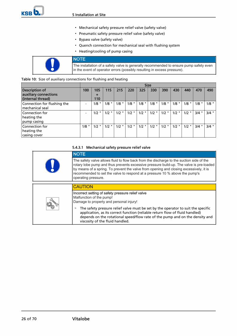
Table 10: Size of auxiliary connections for flushing and heating
SizeDescription ofauxiliary connections(internal thread)
100 105+
110
115 215 220 325 330 390 430 440 470 490
Connection for flushing themechanical seal
- 1/8 " 1/8 " 1/8 " 1/8 " 1/8 " 1/8 " 1/8 " 1/8 " 1/8 " 1/8 " 1/8 "
Connection forheating the pump casing
- 1/2 " 1/2 " 1/2 " 1/2 " 1/2 " 1/2 " 1/2 " 1/2 " 1/2 " 3/4 " 3/4 "
Connection forheating the casing cover
1/8 " 1/2 " 1/2 " 1/2 " 1/2 " 1/2 " 1/2 " 1/2 " 1/2 " 1/2 " 3/4 " 3/4 "
5.4.3.1 Mechanical safety pressure relief valve
NOTEThe safety valve allows fluid to flow back from the discharge to the suction side of therotary lobe pump and thus prevents excessive pressure build-up. The valve is pre-loadedby means of a spring. To prevent the valve from opening and closing excessively, it isrecommended to set the valve to respond at a pressure 10 % above the pump'soperating pressure.
CAUTIONIncorrect setting of safety pressure relief valveMalfunction of the pump!Damage to property and personal injury!
▷ The safety pressure relief valve must be set by the operator to suit the specificapplication, as its correct function (reliable return flow of fluid handled)depends on the rotational speed/flow rate of the pump and on the density andviscosity of the fluid handled.
5 Installation at Site
26 of 70 Vitalobe

Fig. 11: Mechanical safety pressure relief valve (sectional drawing)
904.3
100
904.3
900.1
160
932502
920.4
723
540903
159-4
161900.3
550
950
900.2
412.4
412.5
412.2
Fig. 12: Mechanical safety pressure relief valve (exploded view)
Setting the safety pressure relief valve
1. Relax the valve spring, then start up the pump.
2. Gradually tighten adjusting screw 900.1 to pre-load spring 950.
3. Determine the opening point of the valve at the required pressure by turning theadjusting screw and testing as shown.
4. Tighten the spring by a quarter turn of the adjusting screw further (beyond thecritical opening pressure), to prevent excessive opening and closing of the valve.
5. Position holder 100 and secure with grub screw 904.3.
NOTEThe safety pressure relief valve can also be used to manually adjust the flow rate. To toso, loosen adjusting screw 900.1 and retract piston 159-4 from the pump chamber toallow some of the fluid to flow back.
5 Installation at Site
Vitalobe 27 of 70
CAUTIONNo pressure gauges installed in suction and discharge lineIncorrect setting of safety pressure relief valve!Personal injury and damage to property!
▷ To set the exact differential pressure at which the safety pressure relief valve isto open, pressure gauges must be fitted in the suction line and discharge line, inorder to read off the pressure upstream and downstream of the pump.
5.4.3.2 Pneumatic safety pressure relief valve
NOTEThe safety valve allows fluid to flow back from the discharge to the suction side of therotary lobe pump and thus prevents excessive pressure build-up. The valve is controlledby air pressure. The pneumatic system controlling the valve can be selected with thehelp of the pressure curve. The pneumatic system must supply at least the air pressuredetermined from this curve. To prevent the valve from opening and closing excessively, itis recommended to set the valve to respond at a pressure 10 % above the pump'soperating pressure.
CAUTIONIncorrect setting of safety pressure relief valveMalfunction of the pump!Damage to property and personal injury!
▷ The safety pressure relief valve must be set by the operator to suit the specificapplication, as its correct function (reliable return flow of fluid handled)depends on the rotational speed/flow rate of the pump and on the density andviscosity of the fluid handled.
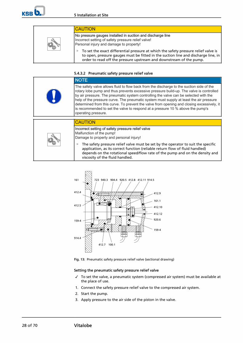
161 723 940.3 904.4 920.5 412.8 412.11 914.5
412.4
412.5
159-4
914.4
412.7 100.1
159-4
920.6
412.12
412.10
161.1
412.9
Fig. 13: Pneumatic safety pressure relief valve (sectional drawing)
Setting the pneumatic safety pressure relief valve
✓ To set the valve, a pneumatic system (compressed air system) must be available atthe place of use.
1. Connect the safety pressure relief valve to the compressed air system.
2. Start the pump.
3. Apply pressure to the air side of the piston in the valve.
5 Installation at Site
28 of 70 Vitalobe
4. Measure the pressure in the outlet line with a pressure gauge; increase/reducethe pressure supplied until the pressure in the outline line is zero (piston closed -> no return flow).
5. To prevent excessive opening and closing of the valve, increase the air pressure inthe valve to roughly 10 % above the critical opening pressure (opening of thevalve).
CAUTIONNo pressure gauges installed in suction and discharge lineIncorrect setting of safety pressure relief valve!Personal injury and damage to property!
▷ To set the exact differential pressure at which the safety pressure relief valve isto open, pressure gauges must be fitted in the suction line and discharge line, inorder to read off the pressure upstream and downstream of the pump.
5.4.3.3 Bypass valve
NOTEThe bypass line with its valve allows fluid to flow back from the discharge to the suctionside of the rotary lobe pump and thus prevents excessive pressure build-up. The valve ispre-loaded by means of a spring. To prevent the valve from opening and closingexcessively, it is recommended to set the valve to respond at a pressure 10 % above thepump's operating pressure.
CAUTIONIncorrect setting of safety pressure relief valveMalfunction of the pump!Damage to property and personal injury!
▷ The safety pressure relief valve must be set by the operator to suit the specificapplication, as its correct function (reliable return flow of fluid handled)depends on the rotational speed/flow rate of the pump and on the density andviscosity of the fluid handled.
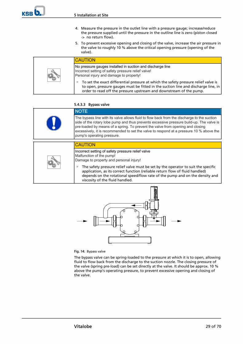
Fig. 14: Bypass valve
The bypass valve can be spring-loaded to the pressure at which it is to open, allowingfluid to flow back from the discharge to the suction nozzle. The closing pressure ofthe valve (spring pre-load) can be set directly at the valve. It should be approx. 10 %above the pump's operating pressure, to prevent excessive opening and closing ofthe valve.
5 Installation at Site
Vitalobe 29 of 70
CAUTIONIncorrect bypass arrangementDamage to property and personal injury!
▷ The valve is uni-directional. Always make sure that the bypass leads from thedischarge to the suction side and that the valve is fitted on the discharge sideonly.
5.4.3.4 Flushing connection for the mechanical seal
CAUTIONFailure to use or incorrect use of auxiliary connections (flushing liquid)Malfunction of the pump!
▷ Use and install any auxiliary connections in such a way that a proper flow isensured.
CAUTIONIncorrect flushing operationMalfunction of the pump!
▷ The flushing liquid must circulate correctly whenever the pump is running.
▷ The flushing medium used must be compatible with the fluid handled by thepump.Incorrect operation of the flushing system will result in destruction of themechanical seal and contamination of the fluid handled by the flushing medium(and vice versa).
▷ The temperature difference between the flushing liquid and the fluid handledshould not exceed 5° C.
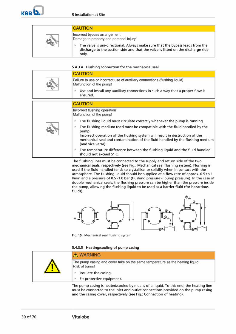
The flushing lines must be connected to the supply and return side of the twomechanical seals, respectively (see Fig.: Mechanical seal flushing system). Flushing isused if the fluid handled tends to crystallise, or solidify when in contact with theatmosphere. The flushing liquid should be supplied at a flow rate of approx. 0.5 to 1l/min and a pressure of 0.5 -1.0 bar (flushing pressure < pump pressure). In the case ofdouble mechanical seals, the flushing pressure can be higher than the pressure insidethe pump, allowing the flushing liquid to be used as a barrier fluid (for hazardousfluids).
Fig. 15: Mechanical seal flushing system
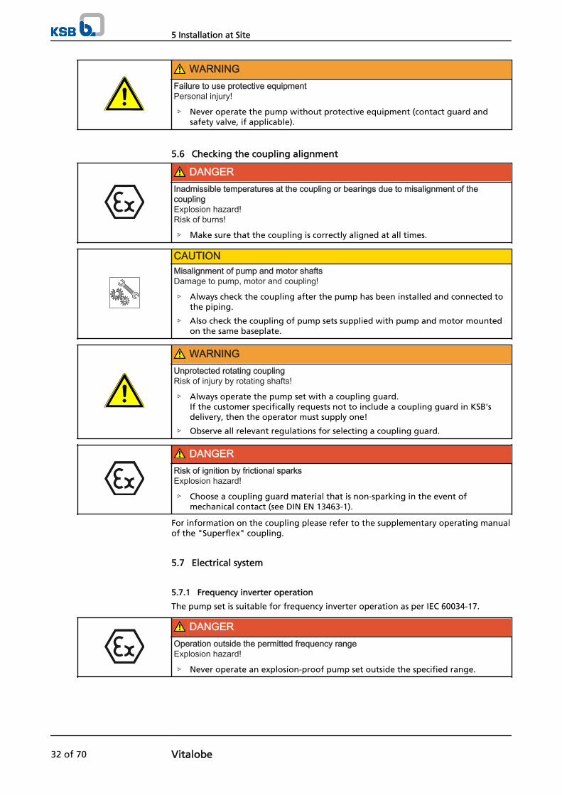
5.4.3.5 Heating/cooling of pump casing
WARNINGThe pump casing and cover take on the same temperature as the heating liquidRisk of burns!
▷ Insulate the casing.
▷ Fit protective equipment.
The pump casing is heated/cooled by means of a liquid. To this end, the heating linemust be connected to the inlet and outlet connections provided on the pump casingand the casing cover, respectively (see Fig.: Connection of heating).
5 Installation at Site
30 of 70 Vitalobe
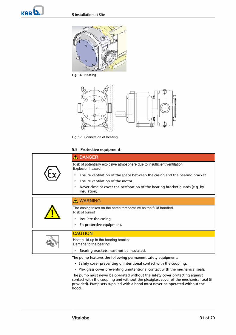
Fig. 16: Heating
Fig. 17: Connection of heating
5.5 Protective equipment
DANGERRisk of potentially explosive atmosphere due to insufficient ventilationExplosion hazard!
▷ Ensure ventilation of the space between the casing and the bearing bracket.
▷ Ensure ventilation of the motor.
▷ Never close or cover the perforation of the bearing bracket guards (e.g. byinsulation).
WARNINGThe casing takes on the same temperature as the fluid handledRisk of burns!
▷ Insulate the casing.
▷ Fit protective equipment.
CAUTIONHeat build-up in the bearing bracketDamage to the bearing!
▷ Bearing brackets must not be insulated.
The pump features the following permanent safety equipment:
▪ Safety cover preventing unintentional contact with the coupling.
▪ Plexiglass cover preventing unintentional contact with the mechanical seals.
The pump must never be operated without the safety cover protecting againstcontact with the coupling and without the plexiglass cover of the mechanical seal (ifprovided). Pump sets supplied with a hood must never be operated without thehood.
5 Installation at Site
Vitalobe 31 of 70
WARNINGFailure to use protective equipmentPersonal injury!
▷ Never operate the pump without protective equipment (contact guard andsafety valve, if applicable).
5.6 Checking the coupling alignment
DANGERInadmissible temperatures at the coupling or bearings due to misalignment of thecouplingExplosion hazard!Risk of burns!
▷ Make sure that the coupling is correctly aligned at all times.
CAUTIONMisalignment of pump and motor shaftsDamage to pump, motor and coupling!
▷ Always check the coupling after the pump has been installed and connected tothe piping.
▷ Also check the coupling of pump sets supplied with pump and motor mountedon the same baseplate.
WARNINGUnprotected rotating couplingRisk of injury by rotating shafts!
▷ Always operate the pump set with a coupling guard.If the customer specifically requests not to include a coupling guard in KSB'sdelivery, then the operator must supply one!
▷ Observe all relevant regulations for selecting a coupling guard.
DANGERRisk of ignition by frictional sparksExplosion hazard!
▷ Choose a coupling guard material that is non-sparking in the event ofmechanical contact (see DIN EN 13463-1).
For information on the coupling please refer to the supplementary operating manualof the "Superflex" coupling.
5.7 Electrical system
5.7.1 Frequency inverter operation
The pump set is suitable for frequency inverter operation as per IEC 60034-17.
DANGEROperation outside the permitted frequency rangeExplosion hazard!
▷ Never operate an explosion-proof pump set outside the specified range.
5 Installation at Site
32 of 70 Vitalobe
DANGERIncorrect setting of frequency inverter current limitExplosion hazard!
▷ Set the current limit to max. 1.2 times the rated current indicated on the nameplate.
When selecting a frequency inverter, check the following details:
▪ Data provided by the manufacturer
▪ Electrical data of the pump set, particularly the rated current
▪ Ensure short start ramps (maximum 5 seconds).
Observe the following limits when operating the pump set via frequency inverter:
▪ Only utilise up to 95 % of the motor rating indicated in the data sheet.
▪ Do not exceed the maximum speed of the pump (depending on the size).
Frequency inverter operation produces RFI emissions whose level varies depending onthe inverter used (type, interference suppression, make). To prevent the drive system,consisting of the motor and frequency inverter, from exceeding the limits stipulatedin EN 50081 always observe the EMC information provided by the invertermanufacturer. If the inverter manufacturer recommends a shielded power cable,make sure to use a pump set with a shielded power cable.
The pump set generally meets the interference immunity requirements to EN 50082.For monitoring the sensors installed the operator must ensure sufficient interferenceimmunity by appropriately selecting and laying the cables in the plant. Nomodifications are required on the power/control cable of the pump set. Suitableanalysing devices must be selected. To monitor the leakage sensor inside the motor,it is recommended to use a special relay available from KSB.
5.8 Electrical connection
DANGERIncorrect electrical installationExplosion hazard!
▷ For electrical installation, also observe the requirements of IEC 60079-14.
▷ Always connect explosion-proof motors via a motor protection switch.
DANGERWork on the pump set by unqualified personnelDanger of death from electric shock!
▷ Always have the electrical connections installed by a trained and qualifiedelectrician.
▷ Observe regulations IEC 60364 and, for explosion-proof models, EN 60079.
WARNINGIncorrect connection to the mainsDamage to the mains network, short circuit!
▷ Observe the technical specifications of the local energy supply companies.
1. Check the available mains voltage against the data in the motor data sheet.
2. Select an appropriate start-up method.
3. Connect the electric control unit, if any.
NOTEIt is recommended to fit a motor protection device.
Selection
Start-up
Operation
Electromagneticcompatibility
Interference immunity
5 Installation at Site
Vitalobe 33 of 70
5.8.1 Connecting the motor
NOTEThe pump can be operated in both directions. Select the motor's direction of rotationsuch that the fluid is pumped in the flow direction required.In compliance with DIN VDE 0530 - Part 8, three-phase motors are always wired forclockwise rotation (looking at the motor shaft stub).
1. Connect the motor in star or delta configuration in accordance with the purchaseorder data/motor data.
2. Observe the manufacturer's product literature supplied with the motor.
5.8.2 Earthing
DANGERElectrostatic chargingExplosion hazard!Fire hazard!Damage to the pump set!
▷ Connect the PE conductor to the earthing terminal provided.
5.9 Checking the direction of rotation
DANGERTemperature increase resulting from contact between rotating and stationarycomponentsExplosion hazard!Damage to the pump set!
▷ Never check the direction of rotation by starting up the unfilled pump set.
▷ Separate the pump from the motor to check the direction of rotation.
WARNINGHands or objects inside the pump casingRisk of injuries, damage to the pump!
▷ Never insert your hands or any other objects into the pump.
▷ Check that the inside of the pump is free from any foreign objects.
5 Installation at Site
34 of 70 Vitalobe

6 Commissioning/Start-up/Shutdown
6.1 Commissioning/start-up
6.1.1 Prerequisites for commissioning/start-up
Before commissioning/starting up the pump set, make sure that the followingconditions are met:
▪ The pump set has been properly connected to the electric power supply and isequipped with all protection devices. (Refer to the information provided on themotor and/or control unit.)
▪ All protective equipment (coupling guards, etc.) has been fitted.
▪ All screwed/bolted connections have been tightened properly. (⇨ Section 7.6Page 57)
▪ The pump has been primed with the fluid to be handled. (⇨ Section 6.1.3 Page35)
▪ The pipelines have been connected without warping the pump nozzles.
▪ The lubricants have been checked and topped up, if necessary. (⇨ Section 7.2.3Page 47)
▪ All auxiliary connections required are connected and operational.
▪ The direction of rotation has been checked. (⇨ Section 5.9 Page 34)
▪ The quality of the concrete foundation complies with the regulations.
▪ The pump set has been installed and aligned in accordance with the tolerancesspecified.
▪ After prolonged shutdown of the pump (set), the activities described in (⇨Section 6.3 Page 41) have been carried out.
6.1.2 Filling in the lubricant
The pump/pump set is supplied filled with lubricant. Both the synchronisation gearand the bearings of both shafts run in an oil bath. The oil level can be checked at thesight glass on the pump's bearing bracket, and oil can be topped up through theplugged opening in the bearing bracket if necessary. With the pump stopped, thesight glass must be completely filled with oil.
Fill the bearing bracket and the gearbox with lubricating oil.Oil quality see (⇨ Section 7.2.3.1.2 Page 47)Oil quantity see (⇨ Section 7.2.3.1.3 Page 47)
CAUTIONInsufficient lubricating oil in gearbox/bearing bracketDamage to gear wheels and bearings!
▷ Check the oil level at the sight glass regularly and top up if necessary
NOTEAn excessively high oil level can lead to a temperature rise and to leakage of the fluidhandled or oil.
6.1.3 Priming and venting the pump
DANGERRisk of potentially explosive atmosphere inside the pumpExplosion hazard!
▷ Before starting up the pump, vent the suction line and the pump and primethem with the fluid to be handled.
6 Commissioning/Start-up/Shutdown
Vitalobe 35 of 70
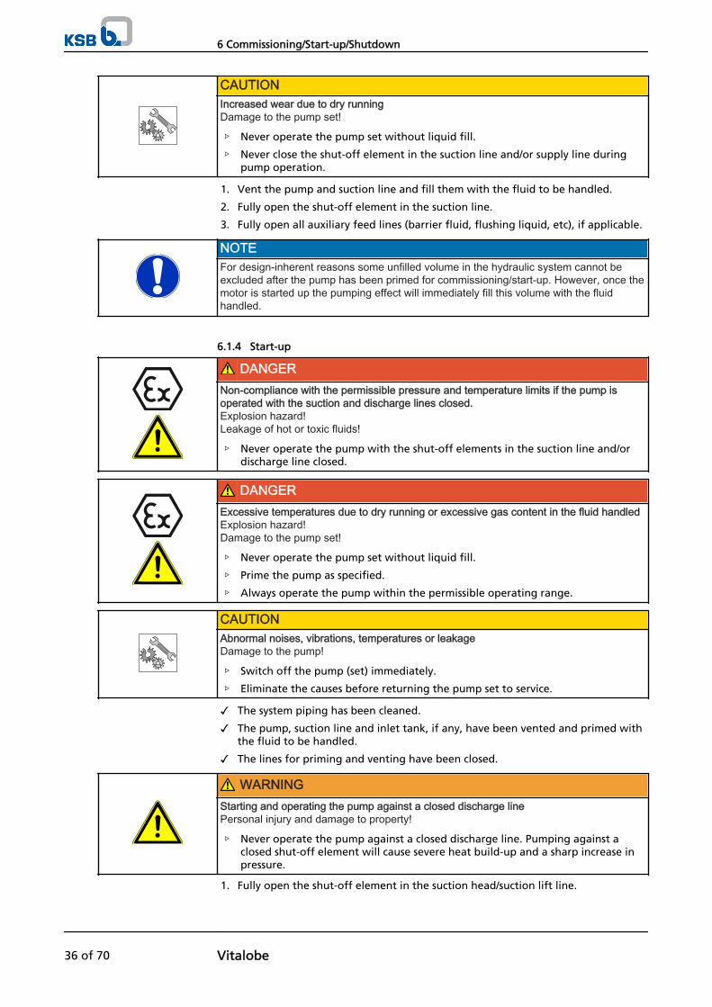
CAUTIONIncreased wear due to dry runningDamage to the pump set!
▷ Never operate the pump set without liquid fill.
▷ Never close the shut-off element in the suction line and/or supply line duringpump operation.
1. Vent the pump and suction line and fill them with the fluid to be handled.
2. Fully open the shut-off element in the suction line.
3. Fully open all auxiliary feed lines (barrier fluid, flushing liquid, etc), if applicable.
NOTEFor design-inherent reasons some unfilled volume in the hydraulic system cannot beexcluded after the pump has been primed for commissioning/start-up. However, once themotor is started up the pumping effect will immediately fill this volume with the fluidhandled.
6.1.4 Start-up
DANGERNon-compliance with the permissible pressure and temperature limits if the pump isoperated with the suction and discharge lines closed.Explosion hazard!Leakage of hot or toxic fluids!
▷ Never operate the pump with the shut-off elements in the suction line and/ordischarge line closed.
DANGERExcessive temperatures due to dry running or excessive gas content in the fluid handledExplosion hazard!Damage to the pump set!
▷ Never operate the pump set without liquid fill.
▷ Prime the pump as specified.
▷ Always operate the pump within the permissible operating range.
CAUTIONAbnormal noises, vibrations, temperatures or leakageDamage to the pump!
▷ Switch off the pump (set) immediately.
▷ Eliminate the causes before returning the pump set to service.
✓ The system piping has been cleaned.
✓ The pump, suction line and inlet tank, if any, have been vented and primed withthe fluid to be handled.
✓ The lines for priming and venting have been closed.
WARNINGStarting and operating the pump against a closed discharge linePersonal injury and damage to property!
▷ Never operate the pump against a closed discharge line. Pumping against aclosed shut-off element will cause severe heat build-up and a sharp increase inpressure.
1. Fully open the shut-off element in the suction head/suction lift line.
6 Commissioning/Start-up/Shutdown
36 of 70 Vitalobe

2. Fully open the shut-off element in the discharge line.
3. If a mechanical seal/gland packing with quench/flushing system is used, makesure that the quench/flushing liquid circulates properly.
4. Start up the motor.
NOTEIf possible, start up the pump with reduced speed, then increase speed slowly until thenominal speed is reached, and check for any disturbances (pressure overload,cavitation, vibration, etc.).
NOTEIf the discharge pressure/discharge head does not increase after pump start-up, switchoff the pump, vent it and repeat steps 1 to 4.
6.1.5 Checking the shaft seal
The mechanical seal only leaks slightly or invisibly (as vapour) during operation.Mechanical seals are maintenance-free.
Gland packings require a certain leakage rate. If leakage increases sharply, the glandmust be followed up by tightening the associated bolts, or a new gland packing mustbe fitted. Always switch off the pump before doing so; never follow up the glandwhile the pump is running!
Shaft seal rings leak only slightly or not at all during operation. Shaft seal rings aremaintenance-free.
6.1.6 Shutdown
WARNINGStarting and operating the pump against a closed discharge linePersonal injury and damage to property!
▷ Never operate the pump against a closed discharge line. Pumping against aclosed shut-off element will cause severe heat build-up and a sharp increase inpressure.
CAUTIONHeat build-up inside the pumpDamage to the shaft seal!
▷ Depending on the type of installation, the pump set requires sufficient after-runtime – with the heat source switched off – until the fluid handled has cooleddown.
1. Switch off the pump and make sure the pump set runs down smoothly to astandstill.
2. Close the shut-off element in the discharge line.
3. Close the shut-off element in the suction line.
4. Make sure that pump pressure has been released.
For prolonged shutdown periods:
1. Close all auxiliary feed lines (flushing/quench, compressed air (pneumatic safetypressure relief valve), etc.), if fitted.
CAUTIONRisk of freezing during prolonged pump shutdown periodsDamage to the pump!
▷ Drain the pump and the cooling/heating chambers (if any) or otherwise protectthem against freezing.
Mechanical seal
Gland packing
Shaft seal ring
6 Commissioning/Start-up/Shutdown
Vitalobe 37 of 70

6.1.7 Quench liquid supply
The quench liquid should preferably form a solution with the fluid handled and beenvironmentally compatible.
Typical quench liquids:
▪ Water with a conductivity of 100-800 µS/cm
▪ Water/glycol mixtures
▪ Glycerin2)
The temperatures of the quench liquid and the fluid handled must not differ by morethan 5 °C. A general minimum temperature of 0 °C applies to the quench liquid.
The quench/flushing liquid should be supplied at a flow rate of approx. 0.5 to 1 l/minand a pressure of 1.5 to 2.0 bar (flushing pressure < pump pressure).
In the case of double mechanical seals, the flushing pressure can be higher than thepressure inside the pump, allowing the flushing liquid to be used as a barrier fluid(for hazardous fluids).
6.2 Operating limits
DANGERNon-compliance with operating limits for pressure, temperature, fluid handled and speedExplosion hazard!Hot or toxic fluid could escape!
▷ Comply with the operating data indicated in the data sheet.
▷ Never operate the pump against a closed shut-off element.
▷ Never operate the pump at temperatures, pressures or rotational speedsexceeding those specified in the data sheet or on the name plate unless thewritten consent of the manufacturer has been obtained.
6.2.1 Ambient temperature
CAUTIONOperation outside the permissible ambient temperatureDamage to the pump (set)!
▷ Observe the specified limits for permissible ambient temperatures.
Observe the following parameters and values during operation:
Table 11: Permissible ambient temperatures
Permissible ambient temperature ValueMaximum 40 °CMinimum See data sheet.
6.2.2 Frequency of starts
DANGERExcessive surface temperature of the motorExplosion hazard!Damage to the motor!
▷ In case of explosion-proof motors, observe the frequency of starts specified inthe manufacturer's product literature.
The frequency of starts is usually determined by the maximum temperature increaseof the motor. This largely depends on the power reserves of the motor in steady-
Permissible quench liquids
Temperature and pressurelimits
2) Make sure the circulation line diameter is ≥ ¼".
6 Commissioning/Start-up/Shutdown
38 of 70 Vitalobe
state operation and on the starting conditions (DOL, star-delta, moments of inertia,etc). If the start-ups are evenly spaced over the period indicated, the pump set can bestarted up six times per hour (h).
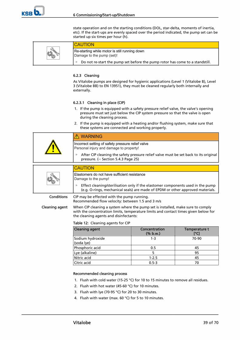
CAUTIONRe-starting while motor is still running downDamage to the pump (set)!
▷ Do not re-start the pump set before the pump rotor has come to a standstill.
6.2.3 Cleaning
As Vitalobe pumps are designed for hygienic applications (Level 1 (Vitalobe B), Level3 (Vitalobe BB) to EN 13951), they must be cleaned regularly both internally andexternally.
6.2.3.1 Cleaning in place (CIP)
1. If the pump is equipped with a safety pressure relief valve, the valve's openingpressure must set just below the CIP system pressure so that the valve is openduring the cleaning process.
2. If the pump is equipped with a heating and/or flushing system, make sure thatthese systems are connected and working properly.
WARNINGIncorrect setting of safety pressure relief valvePersonal injury and damage to property!
▷ After CIP cleaning the safety pressure relief valve must be set back to its originalpressure. (⇨ Section 5.4.3 Page 25)
CAUTIONElastomers do not have sufficient resistanceDamage to the pump!
▷ Effect cleaning/sterilisation only if the elastomer components used in the pump(e.g. O-rings, mechanical seals) are made of EPDM or other approved materials.
CIP may be effected with the pump running.Recommended flow velocity: between 1.5 and 3 m/s
When CIP cleaning a system where the pump set is installed, make sure to complywith the concentration limits, temperature limits and contact times given below forthe cleaning agents and disinfectants:
Table 12: Cleaning agents for CIP
Cleaning agent Concentration (% b.w.)
Temperature t[°C]
Sodium hydroxide (soda lye)
1-3 70-90
Phosphoric acid 0.5 45Lye (alkaline) 5 95Nitric acid 1-2.5 45Citric acid 0.5-3 70
Recommended cleaning process
1. Flush with cold water (15-25 °C) for 10 to 15 minutes to remove all residues.
2. Flush with hot water (45-60 °C) for 10 minutes.
3. Flush with lye (70-95 °C) for 20 to 30 minutes.
4. Flush with water (max. 60 °C) for 5 to 10 minutes.
Conditions
Cleaning agent
6 Commissioning/Start-up/Shutdown
Vitalobe 39 of 70

5. Flush with one of the above acids at the respective temperature for 10 to 15minutes.
6. Finally, flush with cold water for 10 to 15 minutes (until all cleaning agents havebeen removed).
6.2.3.2 Steaming in place (SIP)
1. If the pump is equipped with a safety pressure relief valve, the valve's openingpressure must set just below the SIP system pressure so that the valve is openduring the cleaning process.
2. If the pump is equipped with a heating and/or flushing system, make sure thatthese systems are connected and working properly.
WARNINGIncorrect setting of safety pressure relief valvePersonal injury and damage to property!
▷ After SIP cleaning the safety pressure relief valve must be set back to its originalpressure. (⇨ Section 5.4.3 Page 25)
WARNINGPump casing takes on the same temperature as the sterilisation fluidRisk of burns!
▷ Fit additional protective devices.
▷ Observe the general safety rules and regulations for steam applications.
CAUTIONElastomers do not have sufficient resistanceDamage to the pump!
▷ Effect cleaning/sterilisation only if the elastomer components used in the pump(e.g. O-rings, mechanical seals) are made of EPDM or other approved materials.
CAUTIONSIP with the pump runningDamage to the mechanical seals!
▷ Effect SIP (cleaning using superheated steam) only if the pump has beenswitched off.
Use SIP only with the pump set stopped.
Table 13: SIP temperature limits
Elastomer Saturated steam Chemical agentEPDM 121 °C 82 °CFPM/FKM 149 °C 82 °C
6.2.4 Fluid handled
6.2.4.1 Flow rate
The calculation formula below can be used to check if an additional heat build-upcould lead to a dangerous temperature increase at the pump surface.
Conditions
Limits
6 Commissioning/Start-up/Shutdown
40 of 70 Vitalobe
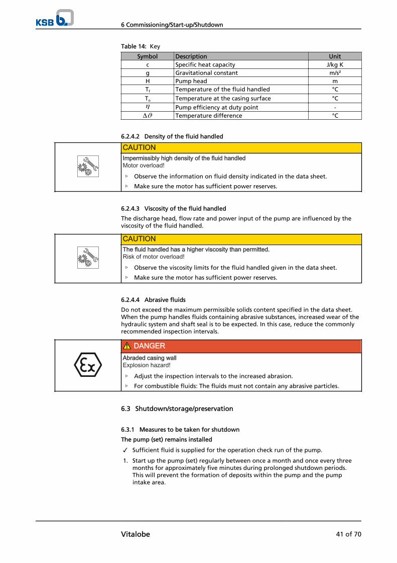
Table 14: Key
Symbol Description Unitc Specific heat capacity J/kg Kg Gravitational constant m/s²H Pump head mTf Temperature of the fluid handled °C
To Temperature at the casing surface °C
Pump efficiency at duty point -Temperature difference °C
6.2.4.2 Density of the fluid handled
CAUTIONImpermissibly high density of the fluid handledMotor overload!
▷ Observe the information on fluid density indicated in the data sheet.
▷ Make sure the motor has sufficient power reserves.
6.2.4.3 Viscosity of the fluid handled
The discharge head, flow rate and power input of the pump are influenced by theviscosity of the fluid handled.
CAUTIONThe fluid handled has a higher viscosity than permitted.Risk of motor overload!
▷ Observe the viscosity limits for the fluid handled given in the data sheet.
▷ Make sure the motor has sufficient power reserves.
6.2.4.4 Abrasive fluids
Do not exceed the maximum permissible solids content specified in the data sheet.When the pump handles fluids containing abrasive substances, increased wear of thehydraulic system and shaft seal is to be expected. In this case, reduce the commonlyrecommended inspection intervals.
DANGERAbraded casing wallExplosion hazard!
▷ Adjust the inspection intervals to the increased abrasion.
▷ For combustible fluids: The fluids must not contain any abrasive particles.
6.3 Shutdown/storage/preservation
6.3.1 Measures to be taken for shutdown
The pump (set) remains installed
✓ Sufficient fluid is supplied for the operation check run of the pump.
1. Start up the pump (set) regularly between once a month and once every threemonths for approximately five minutes during prolonged shutdown periods. This will prevent the formation of deposits within the pump and the pumpintake area.
6 Commissioning/Start-up/Shutdown
Vitalobe 41 of 70

The pump (set) is removed from the pipe and stored
✓ The pump has been properly drained (⇨ Section 7.3 Page 48) and the safetyinstructions for dismantling the pump have been observed. (⇨ Section 7.4.1 Page49)
1. Spray-coat the inside wall of the pump casing with a preservative, particularly inthe clearances around the rotors.
2. Spray the preservative through the suction and discharge nozzles.It is advisable to then close the pump nozzles (e.g. with plastic caps or similar).
3. Oil or grease all exposed machined parts and surfaces of the pump (with silicone-free oil and grease, food-approved, if required) to protect them againstcorrosion.Observe the additional instructions (⇨ Section 3.3 Page 12) ..
4. Store the pump in a dry and protected location, preferably at room temperature(approx. 20 °C).
If the pump set is to be stored temporarily, only preserve the wetted componentsmade of low-alloy materials. Commercially available preservatives (food-approved, ifrequired) can be used for this purpose. Observe the manufacturer's instructions forapplication/removal.
Observe any additional instructions and information provided. (⇨ Section 3 Page 12)
6.4 Returning to service
For returning the pump to service observe the sections on commissioning/start-up (⇨Section 6.1 Page 35) and the operating limits . (⇨ Section 6.2 Page 38).
In addition, carry out all servicing/maintenance operations before returning thepump (set) to service. (⇨ Section 7 Page 43)
WARNINGFailure to re-install or re-activate protective devicesRisk of personal injury from moving parts or escaping fluid!
▷ As soon as the work is complete, re-install and/or re-activate any safety-relevantand protective devices.
NOTEIf the pump has been out of service for more than one year, replace all elastomer seals.Make sure to use the same type of elastomer seal (material, certification) as before.
6 Commissioning/Start-up/Shutdown
42 of 70 Vitalobe

7 Servicing/Maintenance
7.1 Safety regulations
DANGERInsufficient preparation of work on the pump (set)Risk of injury!
▷ Properly shut down the pump set.
▷ Close the shut-off elements in suction and discharge line.
▷ Drain the pump and release the pump pressure.
▷ Close any auxiliary connections.
▷ Allow the pump set to cool down to ambient temperature.
DANGERImproperly serviced pump setRisk of explosion!Damage to the pump set!
▷ Service the pump set regularly.
▷ Prepare a maintenance schedule with special emphasis on the shaft seal.
The operator ensures that all maintenance, inspection and installation work isperformed by authorised, qualified specialist personnel who are thoroughly familiarwith the manual.
WARNINGLiquids escaping at high pressureRisk of injury!
▷ Depressurise the pump.
WARNINGUnintentional starting of pump setRisk of injury by moving parts!
▷ Make sure that the pump set cannot be started up unintentionally.
▷ Always make sure the electrical connections are disconnected before carryingout work on the pump set.
WARNINGFluids posing a health hazard and/or hot fluidsRisk of personal injury!
▷ Observe all relevant laws.
▷ When draining the fluid take appropriate measures to protect persons and theenvironment.
▷ Decontaminate pumps which handle fluids posing a health hazard.
WARNINGInsufficient stabilityRisk of crushing hands and feet!
▷ During assembly/dismantling, secure the pump (set)/pump parts to preventtipping or falling over.
7 Servicing/Maintenance
Vitalobe 43 of 70

A regular maintenance schedule will help avoid expensive repairs and contribute totrouble-free, reliable operation of the pump (set) with a minimum of maintenanceexpenditure and work.
NOTEAll maintenance, service and installation work can be carried out by KSB Service orauthorised workshops. Find your contact in the attached "Addresses" booklet or on theInternet at "www.ksb.com/contact".
Never use force when dismantling and reassembling the pump set.
WARNINGFailure to re-install or re-activate protective devicesRisk of injury from moving parts or escaping fluid!
▷ As soon as the work is completed, re-install and/or re-activate all safety-relevantand protective devices.
7.2 Maintenance/inspection
7.2.1 Supervision of operation
DANGERRisk of potentially explosive atmosphere inside the pumpExplosion hazard!
▷ The pump internals in contact with the fluid to be handled, including the sealchamber and auxiliary systems must be filled with the fluid to be handled at alltimes.
▷ Provide sufficient inlet pressure.
▷ Provide an appropriate monitoring system.
DANGERIncorrectly serviced shaft sealExplosion hazard!Leakage of hot, toxic fluids!Damage to the pump set!Risk of burns!Fire hazard!
▷ Regularly service the shaft seal.
DANGERExcessive temperatures as a result of bearings running hot or defective bearing sealsExplosion hazard!Fire hazard!Damage to the pump set!
▷ Regularly check the rolling element bearings for running noises.
CAUTIONIncreased wear due to dry runningDamage to the pump set!
▷ Never operate the pump set without liquid fill.
▷ Never close the shut-off element in the suction line and/or supply line duringpump operation.
7 Servicing/Maintenance
44 of 70 Vitalobe

CAUTIONImpermissibly high temperature of fluid handledDamage to the pump!
▷ Operation against a closed shut-off element is not permitted (heating up of thefluid).
▷ Observe the temperature limits in the data sheet and in the section onOperating limits.
While the pump is in operation, observe and check the following:
▪ The pump must run quietly and free from vibrations at all times.
▪ Check the shaft seal. (⇨ Section 6.1.5 Page 37)
▪ In case of oil lubrication, ensure the oil level is correct. (⇨ Section 6.1.2 Page 35)
▪ Check the static seals for leakage.
▪ Check the rolling element bearings for running noises.Vibrations, noise and an increase in current input occurring during unchangedoperating conditions indicate wear.
▪ Monitor the correct functioning of any auxiliary connections.
▪ Monitor the stand-by pump.To make sure that stand-by pumps are ready for operation, start them up once aweek.
▪ Monitor the bearing temperature.The bearing temperature must not exceed 90 °C (measured on the outside of thebearing housing).
▪ On oil-lubricated models the bearing temperature can be measured in the oilsump. The alert limit is 100 °C. Never exceed 110 °C (pump trip).
CAUTIONOperation outside the permissible bearing temperatureDamage to the pump!
▷ The bearing temperature of the pump (set) must never exceed 90 °C (measuredon the outside of the bearing housing).
NOTEAfter commissioning, increased temperatures may occur at grease-lubricated rollingelement bearings due to the running-in process. The final bearing temperature is onlyreached after a certain period of operation (up to 48 hours depending on the conditions).
7.2.2 Inspection work
Daily inspection
▪ Visually inspect all seal components for leakage. If leakage is detected, replacerelevant component as quickly as possible.
▪ Check the oil level in the bearing bracket/gearbox daily. With the pump stopped,the sight glass must be completely filled with oil. (⇨ Section 6.1.2 Page 35)
Weekly inspection
▪ Check the oil level in the bearing bracket and gearbox; top up if necessary. (⇨Section 7.2.3.1.2 Page 47) Check the bearing seal. (⇨ Section 7.2.2.5 Page 46)
▪ Check the rotor casing and clean, removing any residues of the fluid handled.
▪ Check the rotor clearances. (⇨ Section 7.2.2.2 Page 46)
▪ Check and ensure the correct function of the safety pressure relief valve.
7 Servicing/Maintenance
Vitalobe 45 of 70
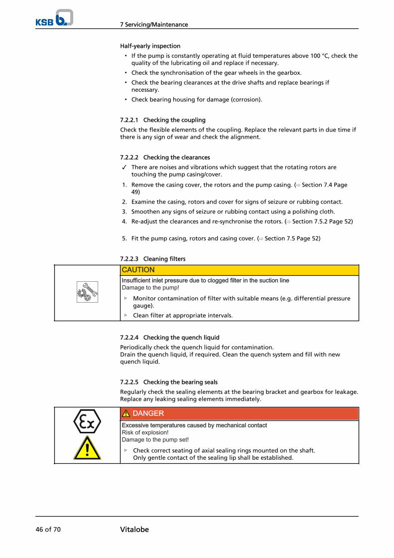
Half-yearly inspection
▪ If the pump is constantly operating at fluid temperatures above 100 °C, check thequality of the lubricating oil and replace if necessary.
▪ Check the synchronisation of the gear wheels in the gearbox.
▪ Check the bearing clearances at the drive shafts and replace bearings ifnecessary.
▪ Check bearing housing for damage (corrosion).
7.2.2.1 Checking the coupling
Check the flexible elements of the coupling. Replace the relevant parts in due time ifthere is any sign of wear and check the alignment.
7.2.2.2 Checking the clearances
✓ There are noises and vibrations which suggest that the rotating rotors aretouching the pump casing/cover.
1. Remove the casing cover, the rotors and the pump casing. (⇨ Section 7.4 Page49)
2. Examine the casing, rotors and cover for signs of seizure or rubbing contact.
3. Smoothen any signs of seizure or rubbing contact using a polishing cloth.
4. Re-adjust the clearances and re-synchronise the rotors. (⇨ Section 7.5.2 Page 52)
5. Fit the pump casing, rotors and casing cover. (⇨ Section 7.5 Page 52)
7.2.2.3 Cleaning filters
CAUTIONInsufficient inlet pressure due to clogged filter in the suction lineDamage to the pump!
▷ Monitor contamination of filter with suitable means (e.g. differential pressuregauge).
▷ Clean filter at appropriate intervals.
7.2.2.4 Checking the quench liquid
Periodically check the quench liquid for contamination.Drain the quench liquid, if required. Clean the quench system and fill with newquench liquid.
7.2.2.5 Checking the bearing seals
Regularly check the sealing elements at the bearing bracket and gearbox for leakage.Replace any leaking sealing elements immediately.
DANGERExcessive temperatures caused by mechanical contactRisk of explosion!Damage to the pump set!
▷ Check correct seating of axial sealing rings mounted on the shaft.Only gentle contact of the sealing lip shall be established.
7 Servicing/Maintenance
46 of 70 Vitalobe
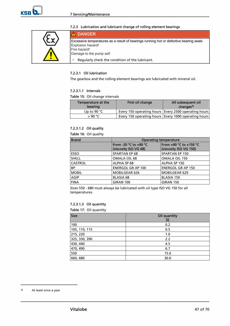
7.2.3 Lubrication and lubricant change of rolling element bearings
DANGERExcessive temperatures as a result of bearings running hot or defective bearing sealsExplosion hazard!Fire hazard!Damage to the pump set!
▷ Regularly check the condition of the lubricant.
7.2.3.1 Oil lubrication
The gearbox and the rolling element bearings are lubricated with mineral oil.
7.2.3.1.1 Intervals
Table 15: Oil change intervals
Temperature at thebearing
First oil change All subsequent oilchanges3)
Up to 90 °C Every 150 operating hours Every 2500 operating hours> 90 °C Every 150 operating hours Every 1000 operating hours
7.2.3.1.2 Oil quality
Table 16: Oil quality
Brand Operating temperature From -20 °C to +90 °C
(viscosity ISO VG 68)From +90 °C to +150 °C (viscosity ISO VG 150)
ESSO SPARTAN EP 68 SPARTAN EP 150SHELL OMALA OIL 68 OMALA OIL 150CASTROL ALPHA SP 68 ALPHA SP 150BP ENERGOL GR-XP 100 ENERGOL GR-XP 150MOBIL MOBILGEAR 626 MOBILGEAR 629AGIP BLASIA 68 BLASIA 150FINA GIRAN 100 GIRAN 150
Sizes 550 - 680 must always be lubricated with oil type ISO VG 150 for alltemperatures.
7.2.3.1.3 Oil quantity
Table 17: Oil quantity
Size Oil quantity[l]
100 0.2105, 110, 115 0.5215, 220 1.0325, 330, 390 2.2430, 440 4.5470, 490 6.7550 15.0660, 680 30.0
3) At least once a year
7 Servicing/Maintenance
Vitalobe 47 of 70
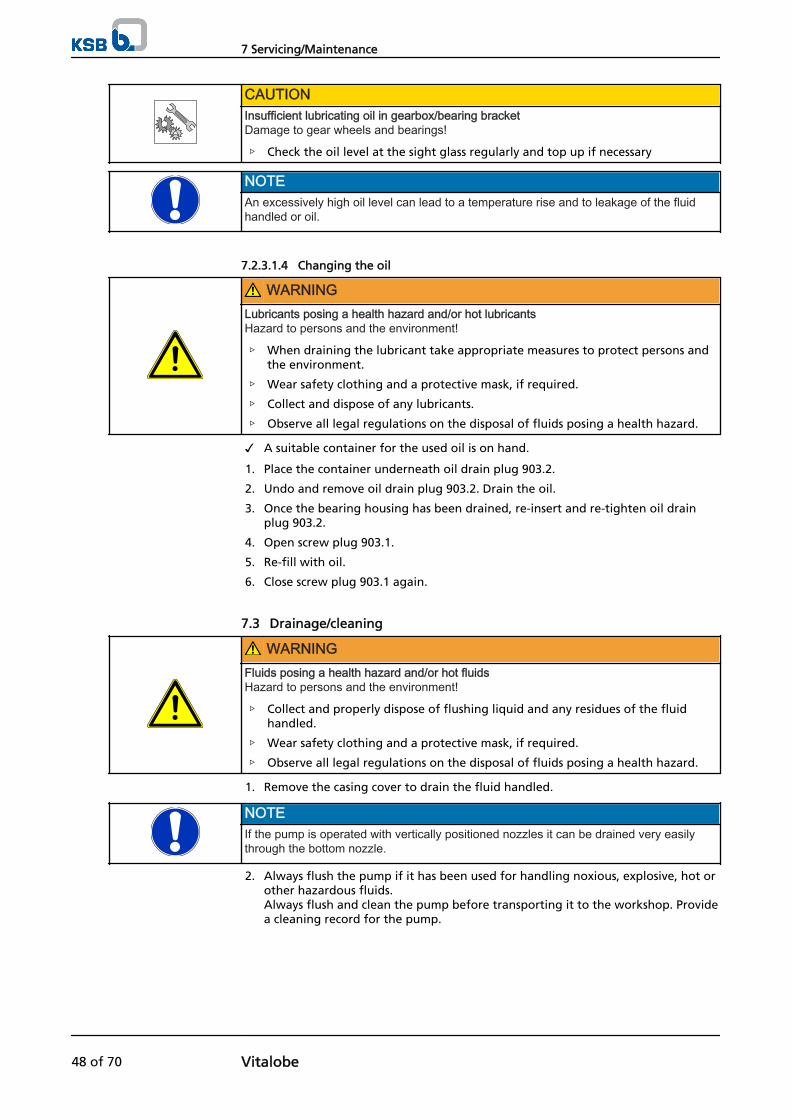
CAUTIONInsufficient lubricating oil in gearbox/bearing bracketDamage to gear wheels and bearings!
▷ Check the oil level at the sight glass regularly and top up if necessary
NOTEAn excessively high oil level can lead to a temperature rise and to leakage of the fluidhandled or oil.
7.2.3.1.4 Changing the oil
WARNINGLubricants posing a health hazard and/or hot lubricantsHazard to persons and the environment!
▷ When draining the lubricant take appropriate measures to protect persons andthe environment.
▷ Wear safety clothing and a protective mask, if required.
▷ Collect and dispose of any lubricants.
▷ Observe all legal regulations on the disposal of fluids posing a health hazard.
✓ A suitable container for the used oil is on hand.
1. Place the container underneath oil drain plug 903.2.
2. Undo and remove oil drain plug 903.2. Drain the oil.
3. Once the bearing housing has been drained, re-insert and re-tighten oil drainplug 903.2.
4. Open screw plug 903.1.
5. Re-fill with oil.
6. Close screw plug 903.1 again.
7.3 Drainage/cleaning
WARNINGFluids posing a health hazard and/or hot fluidsHazard to persons and the environment!
▷ Collect and properly dispose of flushing liquid and any residues of the fluidhandled.
▷ Wear safety clothing and a protective mask, if required.
▷ Observe all legal regulations on the disposal of fluids posing a health hazard.
1. Remove the casing cover to drain the fluid handled.
NOTEIf the pump is operated with vertically positioned nozzles it can be drained very easilythrough the bottom nozzle.
2. Always flush the pump if it has been used for handling noxious, explosive, hot orother hazardous fluids.Always flush and clean the pump before transporting it to the workshop. Providea cleaning record for the pump.
7 Servicing/Maintenance
48 of 70 Vitalobe

7.4 Dismantling the pump set
7.4.1 General information/Safety regulations
WARNINGUnqualified personnel performing work on the pump (set)Risk of injury!
▷ Always have repair and maintenance work performed by specially trained,qualified personnel.
WARNINGHot surfaceRisk of injury!
▷ Allow the pump set to cool down to ambient temperature.
WARNINGImproper lifting/moving of heavy assemblies or componentsPersonal injury and damage to property!
▷ Use suitable transport devices, lifting equipment and lifting tackle to moveheavy assemblies or components.
Always observe the safety instructions and safety information.
For any work on the motor, observe the instructions of the relevant motormanufacturer.
For dismantling and reassembly observe the exploded views and the generalassembly drawing.
NOTEAll maintenance, service and installation work can be carried out by KSB Service orauthorised workshops. Find your contact in the attached "Addresses" booklet or on theInternet at "www.ksb.com/contact".
DANGERInsufficient preparation of work on the pump (set)Risk of injury!
▷ Properly shut down the pump set.
▷ Close the shut-off elements in suction and discharge line.
▷ Drain the pump and release the pump pressure.
▷ Close any auxiliary connections.
▷ Allow the pump set to cool down to ambient temperature.
NOTEAfter a prolonged period of operation the individual components may be hard to pull offthe shaft. If this is the case, use a brand name penetrating agent and/or - if possible - anappropriate pull-off device.
7.4.2 Preparing the pump set
1. De-energise the pump set and secure it against unintentional start-up.
2. Reduce pressure in the piping by opening a consumer installation.
3. Disconnect and remove all auxiliary pipework.
7 Servicing/Maintenance
Vitalobe 49 of 70

7.4.3 Removing the complete pump set from the piping
1. Disconnect the discharge and suction nozzles from the piping.
2. Depending on the pump/motor size, unscrew the bolts that fix the support footand/or motor foot to the foundation.
3. Remove the complete pump set from the piping.
7.4.4 Dismantling the pump
1. Unbolt the pump from the baseplate.
2. Remove the coupling guard and disengage the coupling.
3. Use suitable lifting equipment to remove the pump.
7.4.5 Dismantling the rotor casing - BB design
NOTEFirst, remove any auxiliary connections (safety pressure relief valve, flushing system)from the pump.
7.4.5.1 Vitalobe size 100
1. Remove cap nuts 920.1 and take off casing cover 161 with O-ring 412.2. Undo hexagon head bolts 901.2 and remove cover plates 239, if fitted.
2. Undo rotor screws 900.1. To do so, block rotors 123-15 with a non-metallic object. Remove O-rings 412.1.
3. Mark rotors 123-15 and drive shafts 213.1, 213.2.
4. Take out rotors 123-15.
5. Pull off rotor casing 100.
6. Undo hexagon head bolt 901.1, take off seal cover 471 and remove the matingrings of mechanical seals 433 from rotor casing 100.
7. Undo the grub screws of mechanical seals 433.
8. Take the primary rings of mechanical seals 433 off shafts 213.1, 213.2.
CAUTIONDamage to seal faces and O-ringsDamage to the mechanical seal!
▷ Always handle the mechanical seal with utmost care.
7.4.5.2 Vitalobe sizes 105 to 490
1. Remove cap nuts 920.1 and take off casing cover 161 with O-ring 412.2. Undo hexagon head bolts 901.2 and remove cover plates 239, if fitted.
2. Undo rotor screws 900.1. To do so, block rotors 123-15 with a non-metallic object. Remove O-rings 412.1.
3. Mark rotors 123-15 and drive shafts 213.1, 213.2.
4. Take out rotors 123-15.
5. Undo cap nuts 902.2 and pull off rotor casing 100.
6. Undo hexagon head bolt 901.1, take off seal cover 471 and remove the matingrings of mechanical seals from rotor casing 100.
7. Undo the grub screws of mechanical seals 433.
8. Take the primary rings of mechanical seals 433 off shafts 213.1, 213.2.
7 Servicing/Maintenance
50 of 70 Vitalobe

CAUTIONDamage to seal faces and O-ringsDamage to the mechanical seal!
▷ Always handle the mechanical seal with utmost care.
7.4.6 Dismantling the bearing housing
7.4.6.1 Vitalobe size 100
1. Undo and remove screw plug 903.2. Drain the oil. (⇨ Section 7.2.3.1 Page 47) Remove key 940.2 from shaft 213.1.
2. Undo hexagon head bolts 901.3 and remove gear housing 871 with joint ring 411and shaft seal ring 420.1. Mark gear wheels 872.1, 872.2 for reference during reassembly.
3. Undo keywayed nuts 920.3. To do so, block gear wheels 872.1, 872.2 with a non-metallic object.
4. Undo hexagon head bolts 901.4, remove perforated disc 550.1 and remove gearwheels 872.1, 872.2 complete with key 940.1 and bush 540.
5. Undo countersunk head screws 900.2 and discs 550.2.
6. Pull drive shafts 213.1, 213.2 out of bearing housing 350 towards the back andtake off O-ring 412.3.
7. Remove shaft seal rings 420.2 from bearing housing 350 and take out the outerring of front rolling element bearings 320.1. Remove spacer rings 504 and circlips 932.
NOTEIf necessary, suitable pullers can be used to pull rolling element bearings 320.1, 320.2 offshafts 213.1, 213.2.
7.4.6.2 Vitalobe sizes 105 to 490
1. Undo and remove screw plug 903.2. Drain the oil. (⇨ Section 7.2.3.1 Page 47) Remove key 940.2 from shaft 213.1.
2. Undo socket head cap screws 914.2 and remove gear housing 871 complete withjoint ring 411 and shaft seal ring 420.1. Mark gear wheels 872.1, 872.2 for reference during reassembly.
3. Undo lockwashers 931.1.
4. Undo and take off keywayed nuts 920.3 after having blocked gear wheels 872.1,872.2 with a non-metallic object. Also take off lockwashers 931.1.
5. Undo hexagon head bolts 901.4, remove discs 550.1 and remove gear wheels872.1, 872.2 complete with key 940.1 and bush 540.
6. Replace gear wheels 872.1, 872.2 with spacer rings and fit keywayed nuts 920.3again.
7. Undo countersunk head screws 900.2 and remove bearing cover 471.1 and shaftseal ring 420.2.
8. Pull drive shafts 213.1, 213.2 out of bearing housing 350 towards the front (userubber mallet if necessary) and take off O-ring 412.3.
9. Remove spacer rings 504.2.
NOTEIf necessary, suitable pullers can be used to pull rolling element bearings 320.1, 320.2 offshafts 213.1, 213.2. Sizes 105, 110 and 115 are equipped with a single rolling elementbearing 320.1 only.
7 Servicing/Maintenance
Vitalobe 51 of 70

7.5 Reassembling the pump set
7.5.1 General information/Safety regulations
WARNINGImproper lifting/moving of heavy assemblies or componentsPersonal injury and damage to property!
▷ Use suitable transport devices, lifting equipment and lifting tackle to moveheavy assemblies or components.
CAUTIONImproper reassemblyDamage to the pump!
▷ Reassemble the pump (set) in accordance with the general rules of soundengineering practice.
▷ Use original spare parts only.
Always reassemble the pump in accordance with the corresponding general assemblydrawing or exploded view.
Always use new O-rings.
Never use O-rings that have been glued together from material sold by the metre.
Always use new gaskets, making sure that they have the same thickness as the oldones.
Always fit gaskets of asbestos-free materials or graphite without using lubricants(e.g. copper grease, graphite paste).
Avoid the use of assembly adhesives, if possible.
Match the lubricants to the fluid handled (e.g. water for foodstuff applications).
For reassembly, tighten all screws and bolts as specified in this manual. (⇨ Section 7.6Page 57)
7.5.2 Adjusting the clearances
Fig. 18: Pump clearances
A Behind rotor,distance between rotor and rearcasing wall
B In front of rotor,distance between rotor and casingcover
C Distance between rotors and pumpcasing
D Distance between rotor 1 and rotor2
Explanation:
All distances are factory-defined and must be strictly adhered to.
Sequence
Sealing elements
Assembly adhesives
Tightening torques
7 Servicing/Maintenance
52 of 70 Vitalobe

Table 18: Clearance dimensionsSi
zeRotary lobes 316L Rotary lobes 316L Rotary lobes
Shaf
t p
roje
ctio
n
ST version4) SM version5) Stainless steel sliding alloy A B C D A B C D A B C D S
100 0.12 0.12 0.15 0.2 0.15 0.15 0.2 0.2 0.07 0.08 0.19 0.15 0.12105 0.12 0.15 0.15 0.25 0.17 0.19 0.2 0.3 0.05 0.05 0.13 0.15 0.12110 0.14 0.14 0.15 0.3 0.19 0.19 0.23 0.3 0.08 0.07 0.15 0.2 0.14115 0.14 0.14 0.18 0.3 0.19 0.19 0.22 0.3 0.07 0.08 0.2 0.2 0.14215 0.15 0.15 0.18 0.3 0.22 0.23 0.3 0.3 0.08 0.07 0.18 0.2 0.15220 0.15 0.17 0.23 0.3 0.25 0.25 0.32 0.3 0.08 0.07 0.2 0.2 0.15325 0.17 0.17 0.2 0.35 0.25 0.25 0.32 0.35 0.08 0.08 0.2 0.2 0.17330 0.17 0.19 0.23 0.35 0.27 0.28 0.32 0.35 0.09 0.08 0.23 0.2 0.17430 0.18 0.18 0.22 0.35 0.27 0.27 0.32 0.35 0.09 0.08 0.23 0.2 0.18440 0.18 0.18 0.22 0.35 0.27 0.27 0.32 0.35 0.1 0.1 0.25 0.2 0.18470 0.2 0.2 0.27 0.35 0.32 0.32 0.35 0.35 0.09 0.09 0.25 0.2 0.2490 0.23 0.23 0.3 0.35 0.35 0.35 0.35 0.45 0.09 0.09 0.25 0.2 0.23550 0.22 0.22 0.3 0.4 0.32 0.32 0.43 0.4 0.15 0.15 0.35 0.25 0.22660 0.27 0.27 0.35 0.5 0.37 0.37 0.5 0.5 - - - - 0.27680 0.3 0.35 0.35 0.5 0.37 0.37 0.5 0.5 - - - - 0.27
The clearances must always be set in accordance with the rotor type and operatingpressure used.
7.5.2.1 Maximum discharge pressure / volume displaced
Table 19: Discharge pressure in bar, volume displaced in litres/revolution
Size
Max
. sp
eed
Stan
dar
d c
on
nec
tio
n s
ize Max. discharge pressure Possible rotor type -
volume displacedStandard clearances Increased clearances1.4404(316L)6)
Duplex(1.4462)
1.4404(316L)
Duplex(1.4462)
Tri-lobe(316L)6)
Bi-lobe(316L)
Bi-wing (special alloy)
[rpm]
100 1400 DN 25 7 10 - - 0.0357) 0.035 -105 1000 DN 40 10 13 15 18 0.0757) - 0.07
1108) 1000 DN 40 10 13 15 18 0.138 - 0.124115 1000 DN 40 7 10 12 15 0.204 0.2 0.192158) 950 DN 40 10 13 15 18 0.274 0.274 0.244220 950 DN 50 7 10 12 15 0.39 0.39 0.343258) 720 DN 65 10 13 15 18 0.62 0.62 0.55330 720 DN 80 7 10 12 15 0.79 0.79 0.7
7 Servicing/Maintenance
Vitalobe 53 of 70
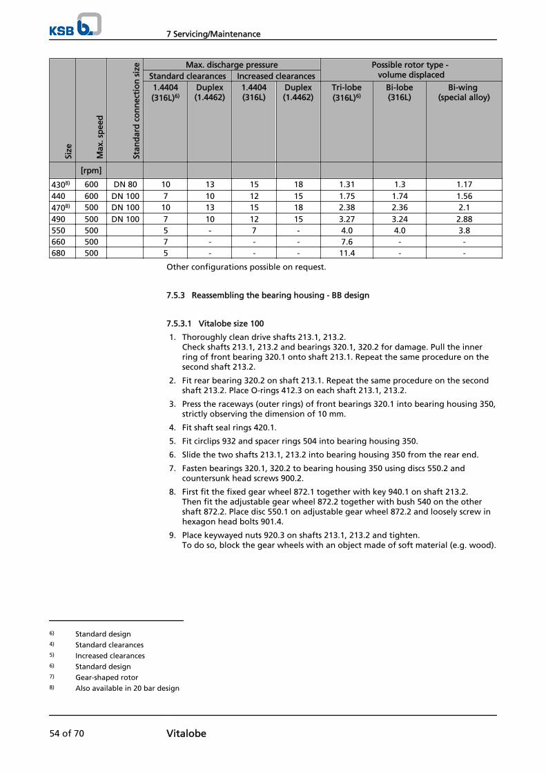
Size
Max
. sp
eed
Stan
dar
d c
on
nec
tio
n s
ize Max. discharge pressure Possible rotor type -
volume displacedStandard clearances Increased clearances1.4404(316L)6)
Duplex(1.4462)
1.4404(316L)
Duplex(1.4462)
Tri-lobe(316L)6)
Bi-lobe(316L)
Bi-wing (special alloy)
[rpm]
4308) 600 DN 80 10 13 15 18 1.31 1.3 1.17440 600 DN 100 7 10 12 15 1.75 1.74 1.564708) 500 DN 100 10 13 15 18 2.38 2.36 2.1490 500 DN 100 7 10 12 15 3.27 3.24 2.88550 500 5 - 7 - 4.0 4.0 3.8660 500 7 - - - 7.6 - -680 500 5 - - - 11.4 - -
Other configurations possible on request.
7.5.3 Reassembling the bearing housing - BB design
7.5.3.1 Vitalobe size 100
1. Thoroughly clean drive shafts 213.1, 213.2. Check shafts 213.1, 213.2 and bearings 320.1, 320.2 for damage. Pull the innerring of front bearing 320.1 onto shaft 213.1. Repeat the same procedure on thesecond shaft 213.2.
2. Fit rear bearing 320.2 on shaft 213.1. Repeat the same procedure on the secondshaft 213.2. Place O-rings 412.3 on each shaft 213.1, 213.2.
3. Press the raceways (outer rings) of front bearings 320.1 into bearing housing 350,strictly observing the dimension of 10 mm.
4. Fit shaft seal rings 420.1.
5. Fit circlips 932 and spacer rings 504 into bearing housing 350.
6. Slide the two shafts 213.1, 213.2 into bearing housing 350 from the rear end.
7. Fasten bearings 320.1, 320.2 to bearing housing 350 using discs 550.2 andcountersunk head screws 900.2.
8. First fit the fixed gear wheel 872.1 together with key 940.1 on shaft 213.2. Then fit the adjustable gear wheel 872.2 together with bush 540 on the othershaft 872.2. Place disc 550.1 on adjustable gear wheel 872.2 and loosely screw inhexagon head bolts 901.4.
9. Place keywayed nuts 920.3 on shafts 213.1, 213.2 and tighten. To do so, block the gear wheels with an object made of soft material (e.g. wood).
6) Standard design4) Standard clearances5) Increased clearances6) Standard design7) Gear-shaped rotor8) Also available in 20 bar design
7 Servicing/Maintenance
54 of 70 Vitalobe

7.5.3.2 Vitalobe sizes 105 to 490
Fitting the front bearings on both drive shafts
Table 20: Bearing dimensions
Size Dimension X105, 110, 115 63 mm215, 220 39.5 mm325, 330, 390 41.4 mm430, 440 50.9 mm470, 490 66 mm
1. Check dimension "X". Tolerance of dimension: +/- 0.02 mm.
2. Heat up the inner rings of bearings 320.1 marked # to approx. 150 °C and fit oneon each shaft 213.1, 213.2.
WARNINGHot componentsFire hazard!Risk of injury!
▷ Always wear gloves. After reassembly of the bearings allow all parts to cooldown to room temperature.
3. Assemble bearing 320.1. Grind (lap) the inner spacer ring to the correct width(dimension X). The bearings should be pre-loaded by 0.05 mm. Fit a bearing on each shaft 213.1,213.2.
4. Fasten bearings 320.1, using a keywayed nut 920.4 and lockwasher 931.2 each .
Fitting the rear bearings on both drive shafts
Sizes 105,110 and 115 feature a single (front) bearing only.
1. Determine dimensions "Y" and "Y1" of bearings 320.2. Determine dimension"Y" without the inner spacer ring. Determine dimension "Y1" without the outerspacer rings and without the outer bearing ring. "Y1" must be 0.05 mm less than"Y": Y1 = Y – 0.05 mm
2. Slide distance ring 504.3 on each shaft 213.1, 213.2. (Not applicable to sizes 105,110 and 115.)
3. Fit pre-assembled bearing 320.2 on each shaft 213.1, 213.2 and fasten withkeywayed nut 920.3 and lockwasher 931.1, fitting a spacer sleeve instead of thegear wheels.
4. Fit spacer rings 504.2 in bearing housing 350. Then fit both shafts 213.1, 213.2 inbearing housing 350 and place O-rings 412.3 on the shafts.
5. Place O-rings on bearing covers 471. Fit shaft seal rings 420.2 on shafts 213.1,213.2 and fasten bearing covers 471 on bearing housing 350 with countersunkhead screws 900.2.
7.5.4 Reassembling the rotor casing - BB design
7.5.4.1 Vitalobe size 100
1. Thoroughly clean shafts 213.1, 213.2 and slide the primary rings of mechanicalseals 433 onto shafts 213.1, 213.2. If necessary, apply lubricant to seals 433 for reassembly.
2. Make sure that the primary rings of mechanical seals 433 rest against the shaftshoulder and tighten the grub screws of mechanical seals 433 evenly.
3. Place the mating rings of mechanical seals 433 into rotor casing 100. Make surethat parallel pin 562.1, which serves as anti-rotation device, is correctly seated. Fitseal covers 471 and fasten with hexagon head bolts 901.1.
7 Servicing/Maintenance
Vitalobe 55 of 70
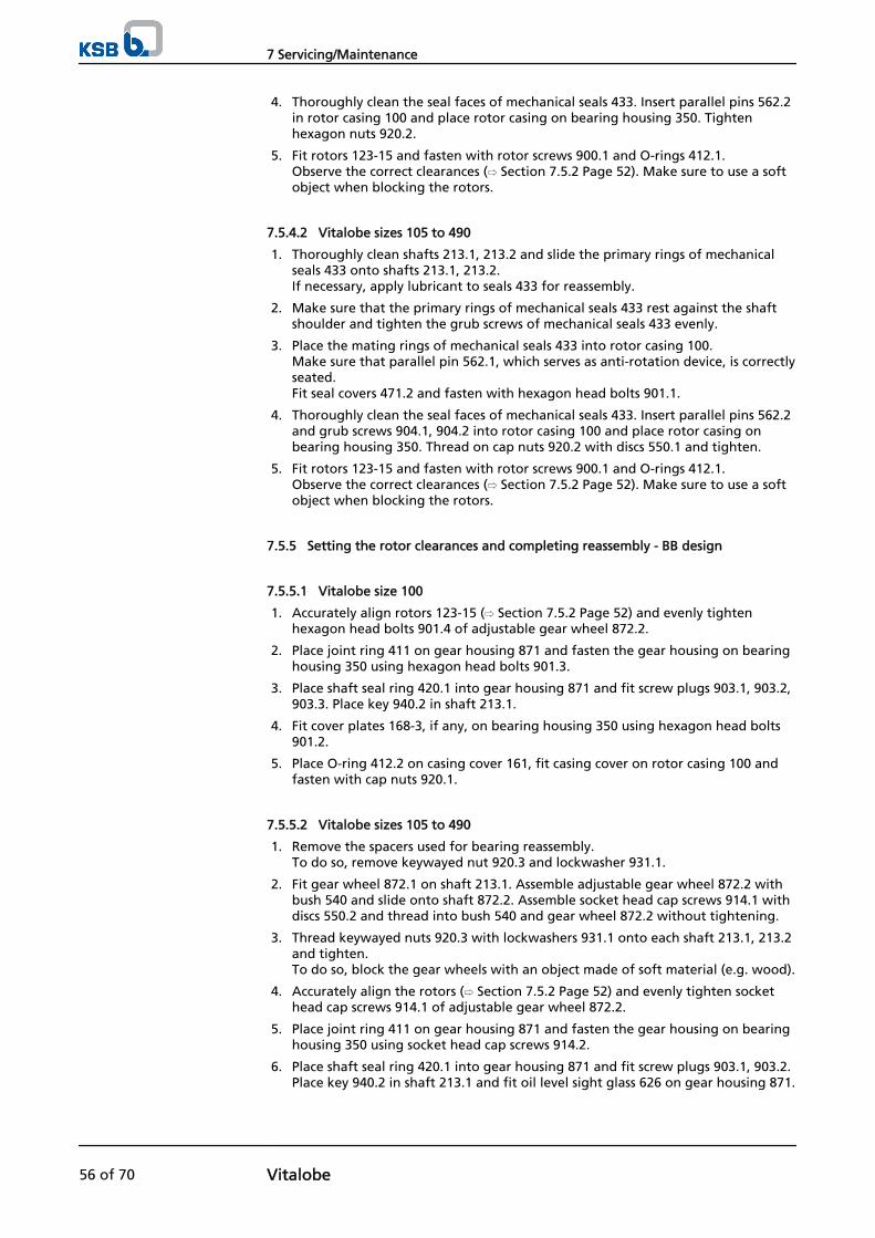
4. Thoroughly clean the seal faces of mechanical seals 433. Insert parallel pins 562.2in rotor casing 100 and place rotor casing on bearing housing 350. Tightenhexagon nuts 920.2.
5. Fit rotors 123-15 and fasten with rotor screws 900.1 and O-rings 412.1. Observe the correct clearances (⇨ Section 7.5.2 Page 52). Make sure to use a softobject when blocking the rotors.
7.5.4.2 Vitalobe sizes 105 to 490
1. Thoroughly clean shafts 213.1, 213.2 and slide the primary rings of mechanicalseals 433 onto shafts 213.1, 213.2. If necessary, apply lubricant to seals 433 for reassembly.
2. Make sure that the primary rings of mechanical seals 433 rest against the shaftshoulder and tighten the grub screws of mechanical seals 433 evenly.
3. Place the mating rings of mechanical seals 433 into rotor casing 100. Make sure that parallel pin 562.1, which serves as anti-rotation device, is correctlyseated. Fit seal covers 471.2 and fasten with hexagon head bolts 901.1.
4. Thoroughly clean the seal faces of mechanical seals 433. Insert parallel pins 562.2and grub screws 904.1, 904.2 into rotor casing 100 and place rotor casing onbearing housing 350. Thread on cap nuts 920.2 with discs 550.1 and tighten.
5. Fit rotors 123-15 and fasten with rotor screws 900.1 and O-rings 412.1. Observe the correct clearances (⇨ Section 7.5.2 Page 52). Make sure to use a softobject when blocking the rotors.
7.5.5 Setting the rotor clearances and completing reassembly - BB design
7.5.5.1 Vitalobe size 100
1. Accurately align rotors 123-15 (⇨ Section 7.5.2 Page 52) and evenly tightenhexagon head bolts 901.4 of adjustable gear wheel 872.2.
2. Place joint ring 411 on gear housing 871 and fasten the gear housing on bearinghousing 350 using hexagon head bolts 901.3.
3. Place shaft seal ring 420.1 into gear housing 871 and fit screw plugs 903.1, 903.2,903.3. Place key 940.2 in shaft 213.1.
4. Fit cover plates 168-3, if any, on bearing housing 350 using hexagon head bolts901.2.
5. Place O-ring 412.2 on casing cover 161, fit casing cover on rotor casing 100 andfasten with cap nuts 920.1.
7.5.5.2 Vitalobe sizes 105 to 490
1. Remove the spacers used for bearing reassembly. To do so, remove keywayed nut 920.3 and lockwasher 931.1.
2. Fit gear wheel 872.1 on shaft 213.1. Assemble adjustable gear wheel 872.2 withbush 540 and slide onto shaft 872.2. Assemble socket head cap screws 914.1 withdiscs 550.2 and thread into bush 540 and gear wheel 872.2 without tightening.
3. Thread keywayed nuts 920.3 with lockwashers 931.1 onto each shaft 213.1, 213.2and tighten. To do so, block the gear wheels with an object made of soft material (e.g. wood).
4. Accurately align the rotors (⇨ Section 7.5.2 Page 52) and evenly tighten sockethead cap screws 914.1 of adjustable gear wheel 872.2.
5. Place joint ring 411 on gear housing 871 and fasten the gear housing on bearinghousing 350 using socket head cap screws 914.2.
6. Place shaft seal ring 420.1 into gear housing 871 and fit screw plugs 903.1, 903.2.Place key 940.2 in shaft 213.1 and fit oil level sight glass 626 on gear housing 871.
7 Servicing/Maintenance
56 of 70 Vitalobe
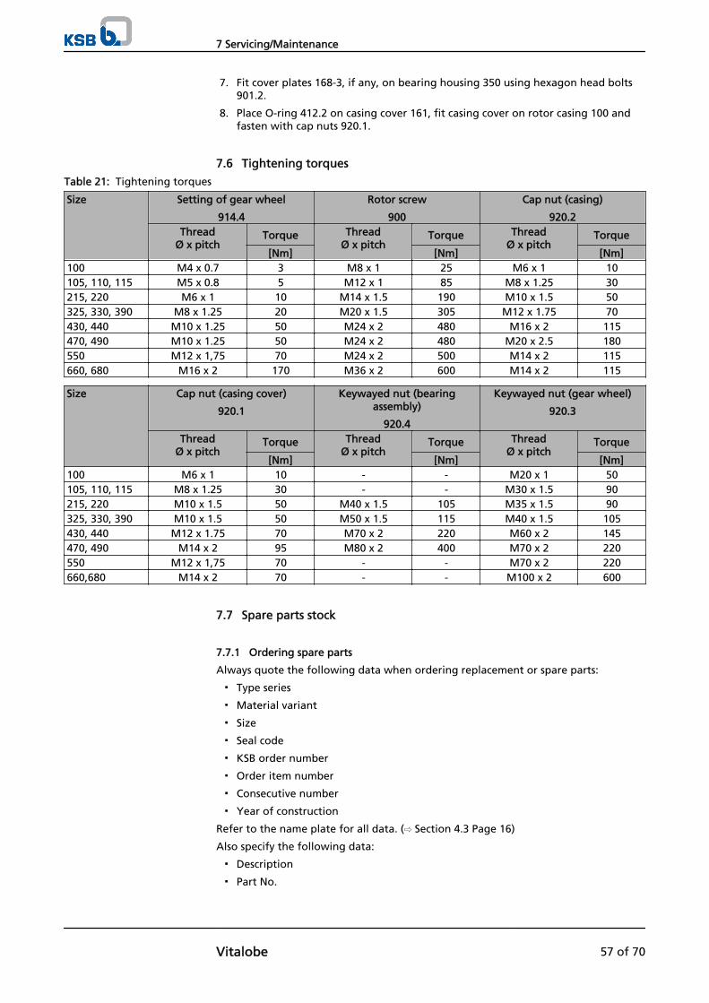
7. Fit cover plates 168-3, if any, on bearing housing 350 using hexagon head bolts901.2.
8. Place O-ring 412.2 on casing cover 161, fit casing cover on rotor casing 100 andfasten with cap nuts 920.1.
7.6 Tightening torques
Table 21: Tightening torques
Size Setting of gear wheel
914.4
Rotor screw
900
Cap nut (casing)
920.2Thread
Ø x pitchTorque Thread
Ø x pitchTorque Thread
Ø x pitchTorque
[Nm] [Nm] [Nm]100 M4 x 0.7 3 M8 x 1 25 M6 x 1 10105, 110, 115 M5 x 0.8 5 M12 x 1 85 M8 x 1.25 30215, 220 M6 x 1 10 M14 x 1.5 190 M10 x 1.5 50325, 330, 390 M8 x 1.25 20 M20 x 1.5 305 M12 x 1.75 70430, 440 M10 x 1.25 50 M24 x 2 480 M16 x 2 115470, 490 M10 x 1.25 50 M24 x 2 480 M20 x 2.5 180550 M12 x 1,75 70 M24 x 2 500 M14 x 2 115660, 680 M16 x 2 170 M36 x 2 600 M14 x 2 115
Size Cap nut (casing cover)
920.1
Keywayed nut (bearingassembly)
920.4
Keywayed nut (gear wheel)
920.3
ThreadØ x pitch
Torque ThreadØ x pitch
Torque ThreadØ x pitch
Torque
[Nm] [Nm] [Nm]100 M6 x 1 10 - - M20 x 1 50105, 110, 115 M8 x 1.25 30 - - M30 x 1.5 90215, 220 M10 x 1.5 50 M40 x 1.5 105 M35 x 1.5 90325, 330, 390 M10 x 1.5 50 M50 x 1.5 115 M40 x 1.5 105430, 440 M12 x 1.75 70 M70 x 2 220 M60 x 2 145470, 490 M14 x 2 95 M80 x 2 400 M70 x 2 220550 M12 x 1,75 70 - - M70 x 2 220660,680 M14 x 2 70 - - M100 x 2 600
7.7 Spare parts stock
7.7.1 Ordering spare parts
Always quote the following data when ordering replacement or spare parts:
▪ Type series
▪ Material variant
▪ Size
▪ Seal code
▪ KSB order number
▪ Order item number
▪ Consecutive number
▪ Year of construction
Refer to the name plate for all data. (⇨ Section 4.3 Page 16)
Also specify the following data:
▪ Description
▪ Part No.
7 Servicing/Maintenance
Vitalobe 57 of 70

▪ Quantity of spare parts
▪ Shipping address
▪ Mode of dispatch (freight, mail, express freight, air freight)
Refer to the exploded view or general assembly drawing for part numbers anddescriptions. (⇨ Section 9.1 Page 61)
7 Servicing/Maintenance
58 of 70 Vitalobe

8 Trouble-shootingPump is running but does not deliver
Flow rate insufficient
Discharge pressure not reached
Pump does not withdraw any fluid (pump takes in air)
Excessive pump power input
Leakage at mechanical seal
Mechanical seal life too short
Mechanical seal damaged
Unusual vibrations and/or noises
Bearing life too short
Table 22: Trouble-shooting
A B C D E F G H I J Possible cause Remedy 9)
X X Pump not primed sufficiently Prime pump and check suction-sideconditions. Repeat pump start-up.
X X X Pump takes in air. Check entire piping. Seal it, if required.X X X In suction lift operation, air enters via
mechanical seal.Replace mechanical seal or use seal withreinforced spring.
X X X Clogged suction line or valves in pipingclosed/not opened enough
Check suction line, remove any foreignparticles and check all valves.
X X X NPSHavailable smaller than pump'sNPSHrequired.
Improve suction and flow conditions. Reduceflow rate with discharge-side control valve.
X X Suction-side foot valve does not closeproperly and liquid column drops.
Repair or replace foot valve.
X X X Flow losses in system exceed specifieddischarge head of pump.
Reduce pipe friction losses, fit larger impeller(observe motor rating) or select differentpump which is suitable for the new dutypoint.
X X X Wrong direction of rotation or speed toolow (frequency inverter operation)
Check and correct the direction of rotationor increase speed (observe motor rating).
X X X X Impeller clogged by foreign matter (onpumps with closed impeller).
Remove foreign matter, clean impeller ifrequired.
X X X Excessive wear of mechanical seal Replace complete mechanical seal. X X X Excessive wear of impeller or clogged
impellerReplace impeller or remove foreign matter.
X X Fluid viscosity higher than expected Verify suitability of pump selected. X X Excessive gas content in fluid Use vent valve. X Fluid density higher than expected Check motor rating and use larger motor (if
possible) or reduce flow rate. X Fluid viscosity too high for centrifugal pump Check suitability of different pump. X X Flow rate too high Reduce flow rate with discharge-side control
valve, reduce impeller diameter or fit orificeplate.
X Speed too high (frequency inverteroperation)
Reduce speed.
X X X Impermissible friction. Impeller touches innerwall of casing.
Repair and re-adjust pump.
X X X X X Pump set not correctly aligned (radial orangular shaft misalignment), or shaft run-out
Re-align pump and motor or fit new pumpshaft.
X X Rolling element bearings of pump and/ormotor worn
Replace bearings.
X X X Incorrect electrical connection Adjust electrical connection as required (onlyto be performed by trained specialistpersonnel).
X X X Electrical voltage does not match motorused.
Use motor suitable for electric mains.
A
B
C
D
E
F
G
H
I
J
9) Pump pressure must be released before attempting to remedy faults on parts which are subjected to pressure.
8 Trouble-shooting
Vitalobe 59 of 70
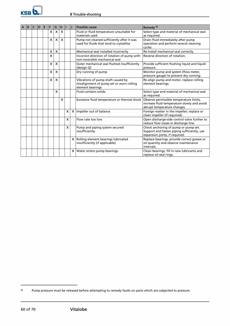
A B C D E F G H I J Possible cause Remedy 9)
X X X Fluid or fluid temperature unsuitable formaterials used
Select type and material of mechanical sealas required.
X X X Pump not cleaned sufficiently after it wasused for fluids that tend to crystallise
Drain fluid immediately after pumpoperation and perform several cleaningcycles.
X X Mechanical seal installed incorrectly Re-install mechanical seal correctly. X Incorrect direction of rotation of pump with
non-reversible mechanical sealReverse direction of rotation.
X X Outer mechanical seal flushed insufficiently(design Q)
Provide sufficient flushing liquid and liquidpressure.
X X Dry running of pump Monitor pump and system (flow meter,pressure gauge) to prevent dry running.
X X Vibrations of pump shaft caused bymisalignment of pump set or worn rollingelement bearings
Re-align pump and motor, replace rollingelement bearings.
X Fluid contains solids. Select type and material of mechanical sealas required.
X Excessive fluid temperature or thermal shock Observe permissible temperature limits,increase fluid temperature slowly and avoidabrupt temperature changes.
X X Impeller out of balance Foreign matter in the impeller; replace orclean impeller (if required).
X Flow rate too low Open discharge-side control valve further toreduce flow losses in discharge line.
X Pump and piping system securedinsufficiently
Check anchoring of pump or pump set.Support and fasten piping sufficiently, useexpansion joints, if required.
X Rolling element bearings lubricatedinsufficiently (if applicable)
Replace bearings, provide correct grease oroil quantity and observe maintenanceintervals.
X Water enters pump bearings. Clean bearings, fill in new lubricants andreplace oil seal rings.
9) Pump pressure must be released before attempting to remedy faults on parts which are subjected to pressure.
8 Trouble-shooting
60 of 70 Vitalobe
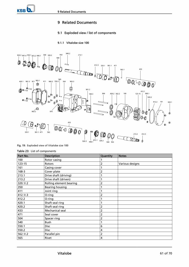
9 Related Documents
9.1 Exploded view / list of components
9.1.1 Vitalobe size 100
940.2320.2920.3 901.4 550.1 872.2 940.1 540
504
213.1932
412.3 901.1
433
320.1 471
562.1
350
901.2
903.2
550.2871901.3
970
900.2903.1 903.3
168-3
420.1565
411
904
161
420.2 562.2 123-15
920.2
412.1
920.1
900.1
412.2
100
213.2
932504320.2872.1
940.1920.3
412.3562
433
471320.1 901.1
Fig. 19: Exploded view of Vitalobe size 100
Table 23: List of components
Part No. Description Quantity Notes100 Rotor casing 1 123-15 Rotors 2 Various designs161 Casing cover 1 168-3 Cover plate 2 213.1 Drive shaft (driving) 1 213.2 Drive shaft (driven) 1 320.1/.2 Rolling element bearing 2 350 Bearing housing 1 411 Joint ring 1 412.1/.3 O-ring 2 412.2 O-ring 1 420.1 Shaft seal ring 1 420.2 Shaft seal ring 2 433 Mechanical seal 2 471 Seal cover 2 504 Spacer ring 2 540 Bush 1 550.1 Disc 6 550.2 Disc 4 562.1/.2 Parallel pin 2 565 Rivet 4
9 Related Documents
Vitalobe 61 of 70
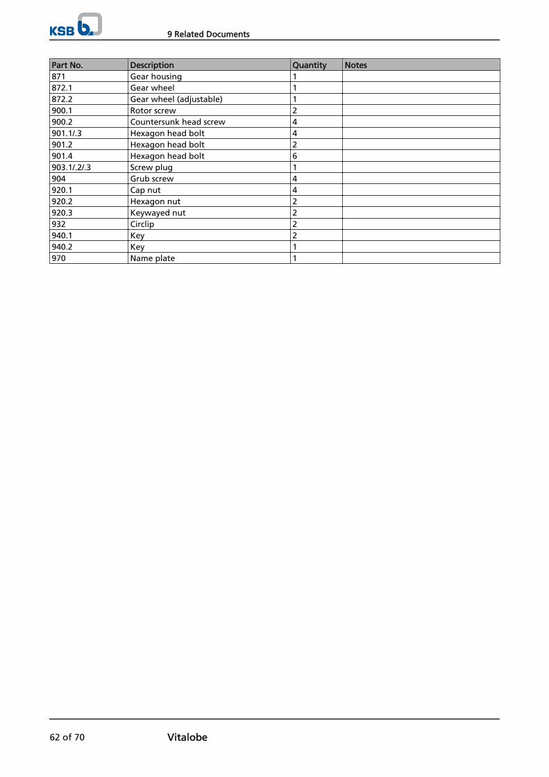
Part No. Description Quantity Notes871 Gear housing 1 872.1 Gear wheel 1 872.2 Gear wheel (adjustable) 1 900.1 Rotor screw 2 900.2 Countersunk head screw 4 901.1/.3 Hexagon head bolt 4 901.2 Hexagon head bolt 2 901.4 Hexagon head bolt 6 903.1/.2/.3 Screw plug 1 904 Grub screw 4 920.1 Cap nut 4 920.2 Hexagon nut 2 920.3 Keywayed nut 2 932 Circlip 2 940.1 Key 2 940.2 Key 1 970 Name plate 1
9 Related Documents
62 of 70 Vitalobe
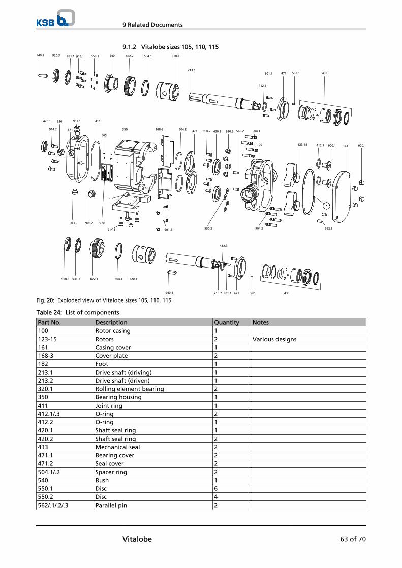
9.1.2 Vitalobe sizes 105, 110, 115940.2 920.3 540931.1 320.1872.2 504.1914.1 550.1
213.1901.1 471 562.1 433
412.3
914.2
903.1
903.2
565
350 168-3 471
903.2
914.3 901.2
411626
871
970
420.1
504.2
900.2 420.2 920.2
550.2
412.1
904.1
100
904.2
900.1123-15 920.1
562.2
161
562.3
931.1 320.1504.1872.1920.3
412.3
940.1 433562471901.1213.2
Fig. 20: Exploded view of Vitalobe sizes 105, 110, 115
Table 24: List of components
Part No. Description Quantity Notes100 Rotor casing 1 123-15 Rotors 2 Various designs161 Casing cover 1 168-3 Cover plate 2 182 Foot 1 213.1 Drive shaft (driving) 1 213.2 Drive shaft (driven) 1 320.1 Rolling element bearing 2 350 Bearing housing 1 411 Joint ring 1 412.1/.3 O-ring 2 412.2 O-ring 1 420.1 Shaft seal ring 1 420.2 Shaft seal ring 2 433 Mechanical seal 2 471.1 Bearing cover 2 471.2 Seal cover 2 504.1/.2 Spacer ring 2 540 Bush 1 550.1 Disc 6 550.2 Disc 4 562/.1/.2/.3 Parallel pin 2
9 Related Documents
Vitalobe 63 of 70
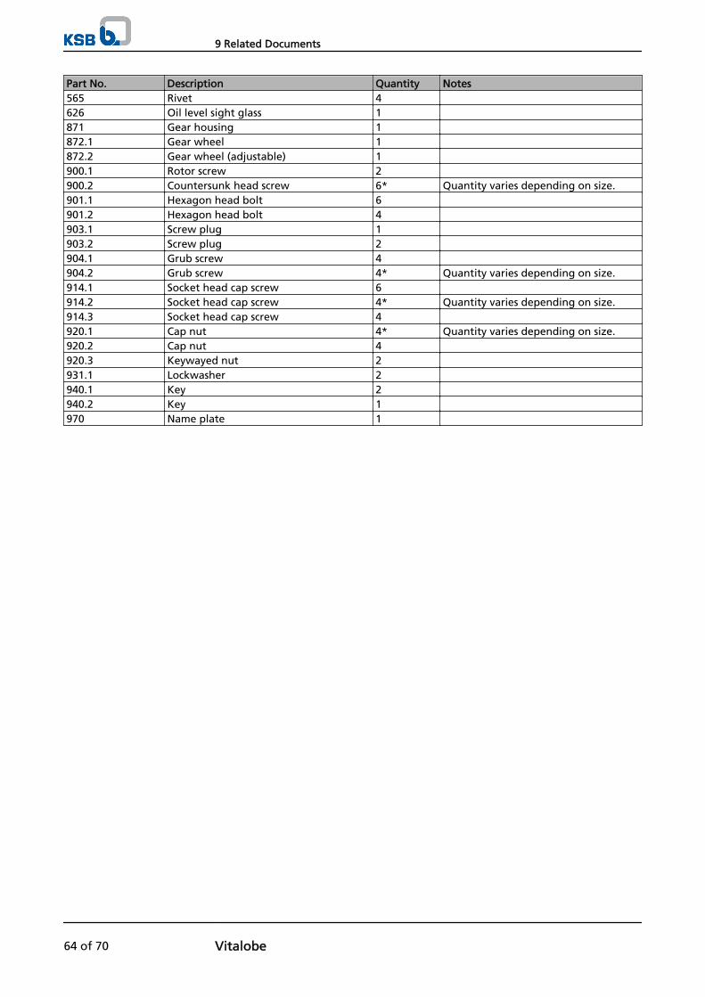
Part No. Description Quantity Notes565 Rivet 4 626 Oil level sight glass 1 871 Gear housing 1 872.1 Gear wheel 1 872.2 Gear wheel (adjustable) 1 900.1 Rotor screw 2 900.2 Countersunk head screw 6* Quantity varies depending on size.901.1 Hexagon head bolt 6 901.2 Hexagon head bolt 4 903.1 Screw plug 1 903.2 Screw plug 2 904.1 Grub screw 4 904.2 Grub screw 4* Quantity varies depending on size.914.1 Socket head cap screw 6 914.2 Socket head cap screw 4* Quantity varies depending on size.914.3 Socket head cap screw 4 920.1 Cap nut 4* Quantity varies depending on size.920.2 Cap nut 4 920.3 Keywayed nut 2 931.1 Lockwasher 2 940.1 Key 2 940.2 Key 1 970 Name plate 1
9 Related Documents
64 of 70 Vitalobe

9.1.3 Vitalobe sizes 215 to 490
940.2920.3
931.1 872.1 320.2 504.3
213.2
412.3
504.1 920.4 931.2 320.1 901.1 471 562.1 433
920.1161412.2900.1
412.1
123-15904.2562.3100562.2904.1
900.2471
420.2504.2
901.2914.3
168-3350550.2920.2
970
626871903.1914.2420.1
903.2
903.2 411 565
182
920.3931.1
914.1
550.1
540 872.2 320.2 213.1940.1
412.3
504.1 920.4 931.2 320.1 901.1 471 562 433
504.3
Fig. 21: Exploded view of Vitalobe sizes 215 to 490
Table 25: List of components
Part No. Description Quantity Notes100 Rotor casing 1 123-15 Rotors 2 Various designs161 Casing cover 1 168-3 Cover plate 2 182 Foot 1 213.1 Drive shaft (driving) 1 213.2 Drive shaft (driven) 1 320.1/.2 Rolling element bearing 2 350 Bearing housing 1 411 Joint ring 1 412.1/.3 O-ring 2 412.2 O-ring 1 420.1 Shaft seal ring 1 420.2 Shaft seal ring 2 433 Mechanical seal 2 471 Bearing cover 2 471 Seal cover 2 504.1/.2/.3 Spacer ring 2 540 Bush 1 550.1 Disc 6 550.2 Disc 4 562 Parallel pin 2 Mechanical seal type 7KFO
9 Related Documents
Vitalobe 65 of 70

Part No. Description Quantity Notes562.1/.2 Parallel pin 2 562.3 Parallel pin 3 565 Rivet 4 626 Oil level sight glass 1 871 Gear housing 1 872.1 Gear wheel 1 872.2 Gear wheel (adjustable) 1 914.1 Socket head cap screw 6 914.2 Socket head cap screw 4 900.1 Rotor screw 2 900.2 Countersunk head screw 6 901.1 Hexagon head bolt 6 901.2 Hexagon head bolt 4 903.1 Screw plug 1 903.2 Screw plug 2 904.1 Grub screw 4 904.2 Grub screw 4* Quantity varies depending on size.914.3 Socket head cap screw 4 920.1 Cap nut 4* Quantity varies depending on size.920.2 Cap nut 4 920.3/.4 Keywayed nut 2 931.1/.2 Lockwasher 2 940.1 Key 2 940.2 Key 1 970 Name plate 1
9 Related Documents
66 of 70 Vitalobe

10 EC Declaration of Conformity
Manufacturer: KSB AktiengesellschaftJohann-Klein-Straße 9
67227 Frankenthal (Germany)
The manufacturer herewith declares that the product:
Vitalobe
KSB order number: ...................................................................................................
▪ is in conformity with the provisions of the following Directives as amended from time to time:
– Pump (set): Machinery Directive 2006/42/EC
The manufacturer also declares that
▪ the following harmonised international standards have been applied:
– ISO 12100,
– EN 809/A1,
– EN 12162+A1
– EN 349+A1
– EN 953+A1
– ISO 13857+A1
– EN 13951+A1- Level 1: Vitalobe B- Level 2+3: Vitalobe BB
▪ Applied national technical standards and specifications, in particular:
– EN 14847
Person authorised to compile the technical file: Name
Function Address (company)Address (Street, No.)Address (post or ZIP code, city) (country)
The EC Declaration of Conformity was issued in/on:
Place, date
..............................10).............................
Name
FunctionCompanyAddress
Address
10) A signed, legally binding declaration of conformity is supplied with the product.
10 EC Declaration of Conformity
Vitalobe 67 of 70
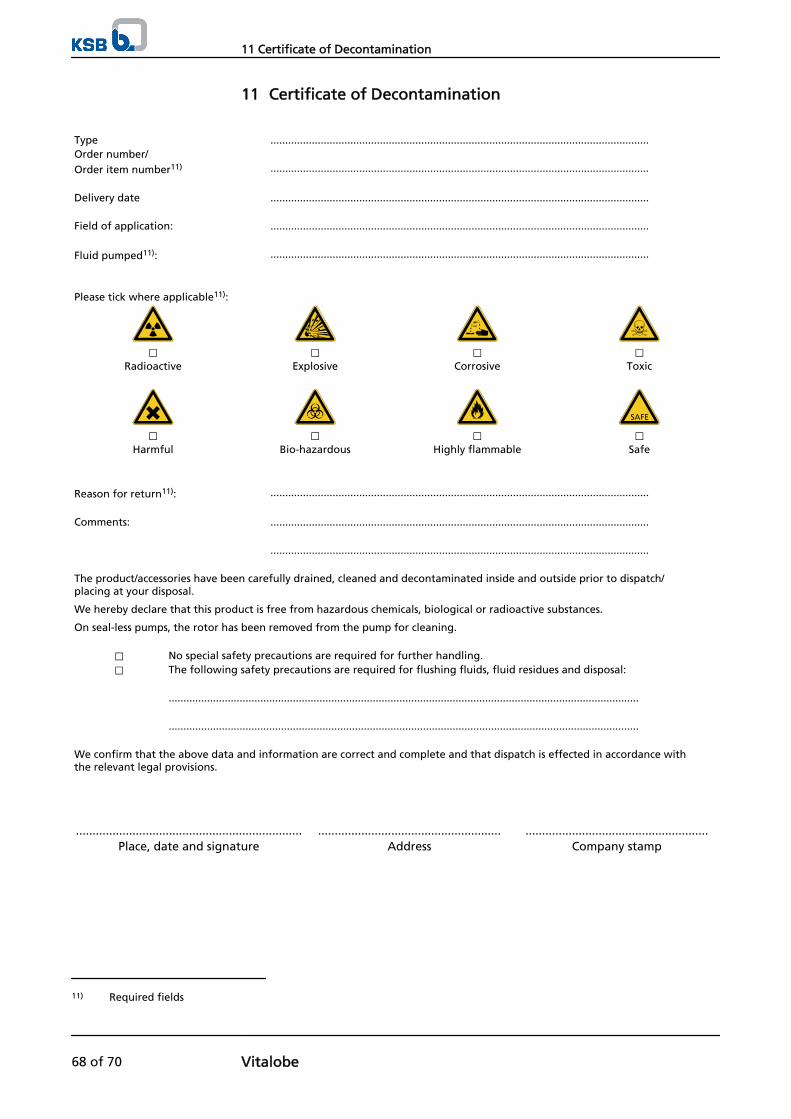
11 Certificate of Decontamination
Type ................................................................................................................................Order number/Order item number11) ................................................................................................................................ Delivery date ................................................................................................................................ Field of application: ................................................................................................................................ Fluid pumped11): ................................................................................................................................
Please tick where applicable11):
⃞ ⃞ ⃞ ⃞Radioactive Explosive Corrosive Toxic
⃞ ⃞ ⃞ ⃞Harmful Bio-hazardous Highly flammable Safe
Reason for return11): ................................................................................................................................ Comments: ................................................................................................................................ ................................................................................................................................ The product/accessories have been carefully drained, cleaned and decontaminated inside and outside prior to dispatch/placing at your disposal.
We hereby declare that this product is free from hazardous chemicals, biological or radioactive substances.
On seal-less pumps, the rotor has been removed from the pump for cleaning.
⃞ No special safety precautions are required for further handling.⃞ The following safety precautions are required for flushing fluids, fluid residues and disposal:
............................................................................................................................................................... ............................................................................................................................................................... We confirm that the above data and information are correct and complete and that dispatch is effected in accordance withthe relevant legal provisions.
.................................................................... ....................................................... .......................................................Place, date and signature Address Company stamp
11) Required fields
11 Certificate of Decontamination
68 of 70 Vitalobe

Index
AAbrasive fluids 41
BBearing temperature 45
CCertificate of decontamination 68Cleaning 39, 40Commissioning/start-up 35Coupling 46
DDesign 18Designation 15Dismantling 49Disposal 13
EElectromagnetic compatibility 33Explosion protection 10, 20, 21, 31, 32, 33, 34, 35, 36,38, 41, 43, 44, 46, 47
FFilter 24, 46Frequency inverter operation 33Frequency of starts 38Function 18
IInstallation
Installation on a foundation 21Installation on machine feet 23
Installation at site 20Intended use 8Interference immunity 33
MMechanical seal 37Misuse 9Monitoring equipment 11
OOil lubrication
Intervals 47Oil quality 47Oil quantity 47
Operating limits 8, 38Order number 6Ordering spare parts 57Other applicable documents 6
PPartly completed machinery 6Permissible forces at the pump nozzles 25Piping 23Preservation 13, 42
QQuench 46
RReassembly 49, 52Return to supplier 13Returning to service 42
SSafety 8Safety awareness 9Scope of supply 19Shutdown 42Start-up 36Storage 13, 42
TTemperature limits 11Transport 12Trouble-shooting 59
WWartung 44
Index
Vitalobe 69 of 70

KSB Aktiengesellschaft67225 Frankenthal • Johann-Klein-Str. 9 • 67227 Frankenthal (Germany)Tel. +49 6233 86-0 • Fax +49 6233 86-3401www.ksb.com
1969
.83/
01-E
N