Installation, Operating & Maintenance Manual for the Air ...
20
Installation, Operating & Maintenance Manual for the Air Blown Heat Exchanger GDM 300 to 1000 Series - 400/3/50 Boston Industrial Estate Power Station Road RUGELEY Staffordshire WS15 2HS Tel: +44 (0)1889 574880 Fax: +44 (0)1889 575074 Email: [email protected] Website: www.gdmcoolers.co.uk
-
Upload
khangminh22 -
Category
Documents
-
view
3 -
download
0
Transcript of Installation, Operating & Maintenance Manual for the Air ...
Installation, Operating & Maintenance Manual for theAir Blown Heat Exchanger
GDM 300 to 1000 Series - 400/3/50
Boston Industrial Estate Power Station Road RUGELEY StaffordshireWS15 2HS
Tel: +44 (0)1889 574880Fax: +44 (0)1889 575074 Email: [email protected]
Website: www.gdmcoolers.co.uk
Installation, Operating & Maintenance Manual for theAir Blown Heat Exchanger
GDM 300 to 1000 Series - 400/3/50
1 Product Outline
1.1 Important Advice
1.2 General Safety Advice
2 Health and Safety
3 Installation and Connection
3.1 Transport, Delivery and Off Loading
3.2 Requirements of the Installation Site, Installing the Heat Exchanger
3.3 Temperature Regulation
3.4 Electrical Connection
4 Operation
4.1 Before Starting
4.2 During Starting
4.3 Commissioning Faults
4.4 Inspection Interval
5 Maintenance of the Heat Exchanger Pack
5.1 Inspection List
5.2 Cleaning the Heat Exchanger Fins
5.3 Cleaning the Heat Exchanger Internally
5.4 Cleaning the Fan Case
6 Service and Disposal
6.1 Service Address
6.2 Disposal
Boston Industrial Estate Power Station Road RUGELEY StaffordshireWS15 2HS
Tel: +44 (0)1889 574880Fax: +44 (0)1889 575074 Email: [email protected]
Website: www.gdmcoolers.co.uk

Installation, Operating & Maintenance Manual for theAir Blown Heat Exchanger
GDM 300 to 1000 Series - 400/3/50
1 Product Outline
The GDM range of dry heat exchangers are suitable for the cooling of non-corrosive fluids.Their scope is given by their specifications and their use in other applications is not permittedwithout confirmation by GDM.This Installation, Operating & Maintenance manual has been developed to;
∙ Comply with the machinery directive 2006/42/EC, The Electromagnetic Compatibility
Directive, 2004/108/E and the Voltage Limits Directive 2006/95/EC.
∙ Satisfy health and safety requirements.
∙ Give instructions on handling, assembling and connecting.
∙ Give warning of any potential hazards or risks.
∙ Give Information regarding noise emissions
1.1 Important Advice
Please check prior to installation of the device that the technical data matches the applicationparameters and that the delivery is complete.
Operation of the device is only valid if:
∙ The product is used under the conditions described in the installation and operation
instruction.
∙ The intended application is in accordance to the type plate and the intended use.
∙ The performance limits given in the datasheets and the installation and operating
instructions are obeyed.
∙ Any monitoring devices and safety devices are installed properly.
∙ Service and repair is carried out as described in this manual.
∙ The correct spare parts are used.
In case of unauthorized modifications carried out by the user, GDM cannot be held responsiblefor any damage. This manual is part of the equipment. The manufacturer keeps the right tomodify specifications without advanced notice. Keep this manual for later use
Boston Industrial Estate Power Station Road RUGELEY StaffordshireWS15 2HS
Tel: +44 (0)1889 574880Fax: +44 (0)1889 575074 Email: [email protected]
Website: www.gdmcoolers.co.uk
1.2 General Safety Advice
Installation of the device shall be performed by competent staff only, familiar with the safetyrequirements and risks of their locality. Adhere to all relevant safety regulations and technicalindications for the specific installation Area. Prevent failures and protect persons against injuriesand the device against damage.
The person responsible for the system must ensure that:
∙ Safety and operation instructions are accessible and followed
∙ Local accident prevention regulations and standards are obeyed.
∙ Performance data and installation specifications are regarded.
∙ Safety devices are installed and the recommended maintenance is performed.
∙ National regulations for disposal of electrical equipment is obeyed.
Maintenance and repair
∙ Repairs on the device must be carried out by authorized persons only.
∙ Only perform modifications, maintenance or mounting as described in this manual.
∙ Only use original specification spare parts.
∙ During maintenance regard all safety regulations and internal operation instructions.
Boston Industrial Estate Power Station Road RUGELEY StaffordshireWS15 2HS
Tel: +44 (0)1889 574880Fax: +44 (0)1889 575074 Email: [email protected]
Website: www.gdmcoolers.co.uk
Installation, Operating & Maintenance Manual for theAir Blown Heat Exchanger
GDM 300 to 1000 Series - 400/3/50
2 Health and Safety
∙ It is the responsibility of all individuals to ensure a safe working environment for both
themselves and other people they may affect.
∙ Before installation, ensure the unit being installed is suitable for the ambient temperature
and fluid medium concerned and that fluid pressure and temperature maximum limits are
not exceeded.
∙ Ensure the fluid medium to be cooled/heated, and any additives, is as indicated on the
nameplate/order. Any medium other than that requested must be confirmed with GDM
prior to use to ensure material compatibility.
∙ The surface temperature of pipe-work may be excessively hot or cold to touch when in
use.
∙ Ensure the electrical supply voltage and frequency is as on the unit nameplate and also
matches that on the motor nameplate.
∙ If this fan/heat exchanger assembly is part of another machine, this installation,
maintenance and operating instruction must be stored or incorporated in the global
installation and maintenance instructions supplied with the larger machine.
∙ It must be ensured that the installation, maintenance and operating instruction booklet is
available for all relevant persons in the assembly and that they have read and understood
installation requirements prior to putting the unit into service.
∙ Labeled design pressure must not be exceeded.
∙ If further pressure tests are carried out, they must not exceed the test pressure stated on
the label.
∙ When installed as an assembly the combined pressure limits of each of the pieces of
equipment must be taken into account.
∙ The heat exchanger forms part of the fan guard and the motor should not be run without
the heat exchanger.
Boston Industrial Estate Power Station Road RUGELEY StaffordshireWS15 2HS
Tel: +44 (0)1889 574880Fax: +44 (0)1889 575074 Email: [email protected]
Website: www.gdmcoolers.co.uk
Protection against exceeding the allowable limits of pressure equipment:
Where, under reasonable foreseeable conditions, the allowable limits could be exceeded, it is thecustomer’s responsibility to ensure that suitable protective devices and combinations are fittedcomprising:
a. Safety accessories such as pressure relief valves, cut offs or accumulators.
b. Where appropriate, adequate monitoring devices such as indicators and/or alarms can befitted, which enable adequate action to be taken either automatically or manually to keepthe cooler matrix and motor within the allowable limits. Catastrophic failure may resultif operation is not within the allowable limits.
Before putting the unit into service, the end user must complete a Hazard Analysis andOperability Analysis (HAZOP)
Sound pressure levels for model GDM 300 to 1000 - 400/3/50 range are approximately 80 dBa@ 1 Metre with 4 pole motors.The noise values, given by the fan manufacturers in dBa, apply to ‘free field’ conditions. Inpractice different conditions lead to sound reflection reverberation and resonance, dependent oninsulation details. The resulting actual noise levels can be in excess of the nominal figure.
Boston Industrial Estate Power Station Road RUGELEY StaffordshireWS15 2HS
Tel: +44 (0)1889 574880Fax: +44 (0)1889 575074 Email: [email protected]
Website: www.gdmcoolers.co.uk
Installation, Operating & Maintenance Manual for theAir Blown Heat Exchanger
GDM 300 to 1000 Series - 400/3/50
3 Installation and Connection
3.1 Transport, Delivery and Off Loading
Secure cooler safely for all transportation to avoid shock loadings. Upon receipt, the unitsshould be visually inspected prior to off-loading. Any defects or short-falls must be marked onthe delivery advice note, notified to the transport company and GDM informed. Take care withheavy items when unloading.
Once goods have been received and signed for as being in good condition, consignee confirmsgoods are acceptable and no claim for loss or damage can be made.Care must be taken to avoid shocks and impacts during handling and transport, i.e. there shouldbe no shock lifting.
3.2 Requirements for Installing the Cooler
The overall dimensional drawings are located in Appendix 1
∙ The cooler is mounted via its feet with four bolts to an adequate rigid structure.
∙ The cooler must be located in such a way that the air flowing through the matrix has free
flow on entry and exit.
∙ The distance between air intake or air outlet to the nearest surrounding obstacle should
be at minimum the height of the matrix.
∙ If the cooler is installed in a closed space, ensure sufficient air circulation. Avoid back
flow of warmed air. If necessary, the room should be vented.
∙ If the cooler is to be sited near to working personnel, the effect of hot draught and noise
emissions must be taken into account.
∙ If the device is installed outdoors, pay regard to the protection class of the motor.
∙ In lower ambient temperatures the cooling capacity raises, but the oil viscosity also rises.
For cold start conditions consider a bypass valve and/or a heater.
∙ The connections from the cooler inlet and outlet should be stress and vibration free. The
use of flexible hoses is recommended.
Boston Industrial Estate Power Station Road RUGELEY StaffordshireWS15 2HS
Tel: +44 (0)1889 574880Fax: +44 (0)1889 575074 Email: [email protected]
Website: www.gdmcoolers.co.uk
3.3 Temperature Regulation
The fluid temperature can be controlled by the switching the fan motor on and off. The motorswitching is then governed by a thermostat (available on request).
3.4 Electrical Connection
Electrical Supply
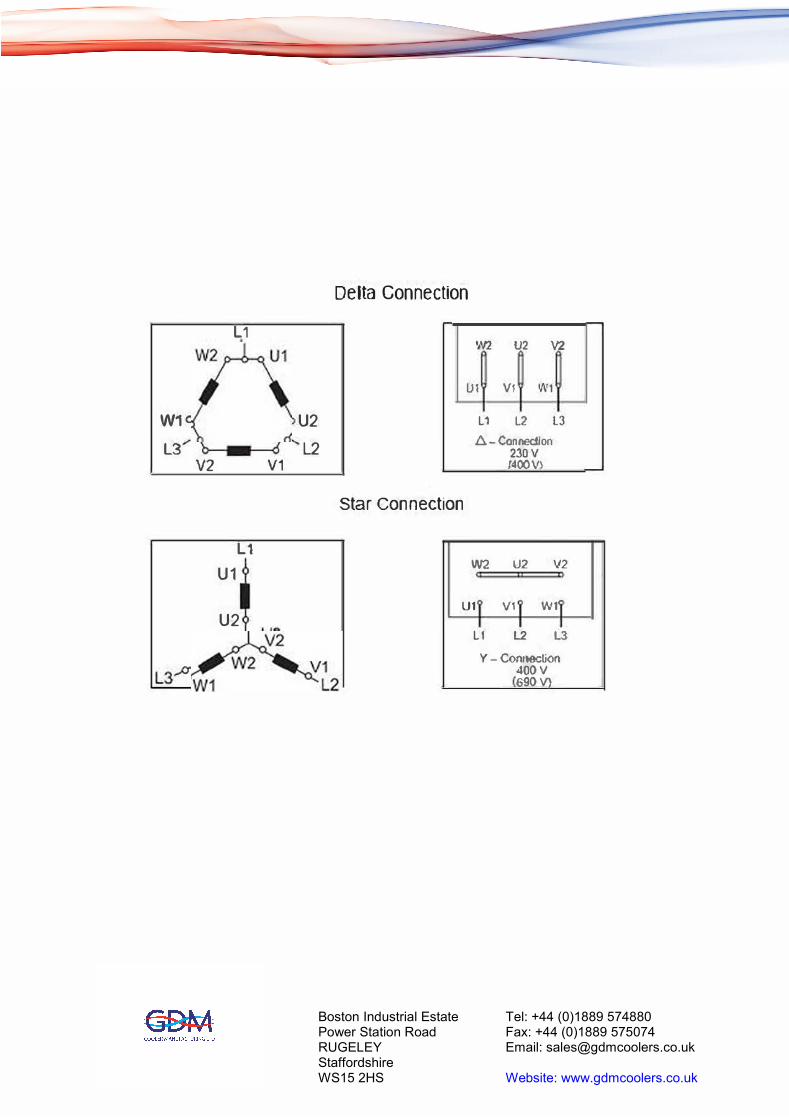
Installation of the device shall be performed by trained staff only. Attention to the prescribedvoltage and frequency is necessary to insure conformance with the technical data on the motorinformation plate.After making the electrical connection ensure the direction of the fan conforms to the directionof the rotation on the cooler installation. Direct-On-Line (D.O.L.) starting of the electric motorscan be used as standard, due to the low motor powers and small fan inertias.The motor and associated equipped must be connected to a protective earth.
Fusing
Fusing has to be fitted in compliance with local standards and the maximum motor currentrating, written on the motor information plate.For calculating the correct values of fuses and cross-section of connection wires, refer to localrules and standards.Wire type fuses protect the cables in case of a short cut, but are not sufficient to protect themotor coils from overheating due to overload. Therefore install an adequate motor circuitbreaker with a high precision to protect the motor against overload and operation with twophases.Size the motor circuit breaker according to the nominal value given on the type plate of themotor. Where applicable connect the internal thermal switch inside the motor to the circuitbreaker.Operation using out of limits mains voltage and/or frequency range is prohibited.
Boston Industrial Estate Power Station Road RUGELEY StaffordshireWS15 2HS
Tel: +44 (0)1889 574880Fax: +44 (0)1889 575074 Email: [email protected]
Website: www.gdmcoolers.co.uk
W1
L3 V2
L1
L1
U1
U2
V1
U2
L2
Delta Connection
\V2 U2 V2
U1 V1 W1
L1 L2 L3
8 -Con.nec:t!on 230V <400V\
Star Connection
W2 U2 V2
u, v, w,
L1 L2 l3
Y - Conooc�on
400V 690V
Boston Industrial Estate Power Station Road RUGELEY StaffordshireWS15 2HS
Tel: +44 (0)1889 574880Fax: +44 (0)1889 575074 Email: [email protected]
Website: www.gdmcoolers.co.uk
Installation, Operating & Maintenance Manual for theAir Blown Heat Exchanger
GDM 300 to 1000 Series - 400/3/50
4 Operation
4.1 Before Starting
Check that all parts are free of damage, especially the cooling element and fan. Do not put a damaged device into operation.Check that the directional labels and safety decals are fitted.Make sure that all valves or other parts in the cooling circuit, which have to be opened, are opened, to ensure free flowing fluid with excessive back pressure.Check that the units securing points are tight.
4.2 During Starting & Priming
Check that the fan rotates in the direction of the arrows.After filling the installation with fluid, it should be purged of air. To do this the installation should be started briefly and the fluid outlet connection (or bleed plug if fitted) opened slightly until bubble free fluid overflows.It is advisable to make the lowest connection the inlet and the highest the cooler exit to promote self-bleeding of the installation.Listen for unexpected noises that might indicate a commissioning fault.
4.3 Commissioning Faults
If the required temperature is not attained soon after starting, or the fluid temperature rises gradually above expected levels, the following should be considered:
∙ Speed of rotation and direction of the fan (correct blade orientation).
∙ Electrical connection, polarity, etc.
∙ Fluid quantity, fluid flow.
∙ Cooling air flow from the fan.
∙ Blocked or dirty radiator.
∙ Entry temperature of air and oil.
4.4 Inspection Interval
The heat exchanger pack is designed to run continuously from a mechanical perspective. But regular inspections should be carried out to check the motors bearings and to check for any damage or debris. Depending on conditions these should be weekly for difficult conditions and monthly for normal clean conditions.
Boston Industrial Estate Power Station Road RUGELEY StaffordshireWS15 2HS
Tel: +44 (0)1889 574880Fax: +44 (0)1889 575074 Email: [email protected]
Website: www.gdmcoolers.co.uk
Installation, Operating & Maintenance Manual for theAir Blown Heat Exchanger
GDM 300 to 1000 Series - 400/3/50
5 Maintenance of the Heat Exchanger Pack
The outer parts of the motor, especially the cooling fins and cooling ducts must be kept as cleanas possible to ensure sufficient heat dissipation.Keep in mind the protection class for dust and humidity. Cleaning the device with high pressurecleaners is only allowed if the motor has the respective protection class.If required, motor bearings must be replaced by trained staff only.
DANGERElectrical Voltage - Electrocution hazard.Before opening the cover or working on electrical components, isolate the device from thepower supply. Make sure that the equipment cannot be reconnected to the mains unintentionally(use lock-outs). Installation and maintenance must be carried out by trained staff only. Payregard to the correct mains supply including earth protection.
WARNINGHot Surface - Burning hazard.Let the device cool down before maintaining.
WARNINGRotating PartsAllow the fan to stop spinning before maintaining. Do not run the fan without the finger guardor heat exchanger.
CAUTIONHigh Pressure RiskBefore starting any maintenance or repair to the heat exchanger, make sure that the device isdepressurized. This applies to the bleed screws as well.Avoid environmental pollution during cleaning or maintenance of the heat exchanger. Use drippans where appropriate.
Boston Industrial Estate Power Station Road RUGELEY StaffordshireWS15 2HS
Tel: +44 (0)1889 574880Fax: +44 (0)1889 575074 Email: [email protected]
Website: www.gdmcoolers.co.uk
5.1 Inspection List
∙ Visually check the general condition of the installation.
∙ Visually check the fan for damage and blade cracking.
∙ Visually check the fan motor cover for damage and that the retaining screws are in place.
∙ Visually check the electrical input for damaged insulation and any conduit damage.
∙ Visually check the heat exchanger for dust or debris accumulating on the fins.
∙ Run the fan and listen for any unusual sounds indicating failure.
∙ Visually check the fan clearance against the fan surround tube.
5.2 Cleaning the Heat Exchanger Fins
Due to the design of the cooling fins the heat exchanger has low susceptibility to dust and dirt.But fan air flow direction means the debris/dirt will be fan-side of the heat exchanger.
∙ First let the Heat Exchanger pack cool down.
∙ Isolate the motor from the mains and secure it against reconnecting (Lock-out device).
∙ Depressurize the system and disconnect the piping. Place a drip pan below the heat
exchanger to collect any leaking fluids.
∙ Close all connections on the heat exchanger with plugs to avoid further fluid leakage.
∙ Prevent the heat exchanger from falling over.
∙ Dismantle the heat exchanger from the fan case by loosening the fastening bolts and take
it to the designated cleaning area. Be careful not to damage the fins during transport and
cleaning.
∙ While the installation is dismantled, check the fan is not catching the fan surround and
that there is no ‘lift’ or side movement in the motor shaft.
∙ Clean the heat exchanger fins with a soft brush, taking care not to damage the fins, until
light is visible through the fin passages.
∙ If light is not visible, the cleaning can be increased by blowing pressurized air through
the fin passages. This should be applied in the direction opposite to normal fan flow. The
correct safety equipment should be worn in expectation that the dust/debris will be a
concentrated version of that normally found in the vicinity.
Boston Industrial Estate Power Station Road RUGELEY StaffordshireWS15 2HS
Tel: +44 (0)1889 574880Fax: +44 (0)1889 575074 Email: [email protected]
Website: www.gdmcoolers.co.uk

∙ If neither method is sufficient to gain heat exchanger air flow, the use of a steam cleaner
and/or some washing agent is permissible. In this case, rinse the heat exchanger fins with
clean water afterward. Extreme care must be taken not to bend the delicate fins, but if
they are deformed, they must be straightened prior to re-fitting the heat exchanger.
∙ Remount the heat exchanger in reverse order, taking care to re-fit any sealing strips.
5.3 Cleaning the Heat Exchanger Internally
If the heat exchanger gets clogged from the inside, due to fluid impurities, it can be rinsed with acleaning liquid. But ideally, it should be replaced.
∙ Dismantle the heat exchanger as described in chapter 5.1
∙ Pour in a degreasing agent and plug the heat exchanger
∙ After some reaction time, empty the heat exchanger and rinse it with clean water.
Dispose of the degreasing agent and the water according to local/national regulations
∙ Remount the heat exchanger in reverse order as described in chapter 5.1
Take care that the degreasing agent does not have a corrosive effect on the heat exchangersaluminium alloy. Or react with the fluid being cooled.
5.4 Cleaning the fan case
Any debris or dirt should be removed each time the heat exchanger is cleaned.
Boston Industrial Estate Power Station Road RUGELEY StaffordshireWS15 2HS
Tel: +44 (0)1889 574880Fax: +44 (0)1889 575074 Email: [email protected]
Website: www.gdmcoolers.co.uk

Installation, Operating & Maintenance Manual for theAir Blown Heat Exchanger
GDM 300 to 1000 Series - 400/3/50
6 Service and disposal
If you have any requests, please have the heat exchanger pack model and serial number readybefore ringing. You will find this information on the type plate.Please pay regard to the local regulations for disposal of electric and electronic equipment.Please send any devices for repair or service to the address given below:
Service address:
+44 (0) 1889 574880If the device does not work correctly after elimination of failures and turning power on,the device has to be checked by the manufacturer. Please ship the device with suitablepacking to:
GDM Heat Transfer LtdPower Station RoadBoston Industrial EstateRugeleyStaffs.WS15 3HS
Boston Industrial EstatePower Station Road RUGELEY StaffordshireWS15 2HS
Tel: +44 (0)1889 574880Fax: +44 (0)1889 575074 Email: [email protected]
Website: www.gdmcoolers.co.uk
Boston Industrial EstatePower Station Road RUGELEY StaffordshireWS15 2HS
Tel: +44 (0)1889 574880Fax: +44 (0)1889 575074 Email: [email protected]
Website: www.gdmcoolers.co.uk
Boston Industrial Estate Power Station Road RUGELEY StaffordshireWS15 2HS
Tel: +44 (0)1889 574880Fax: +44 (0)1889 575074 Email: [email protected]
Website: www.gdmcoolers.co.uk
Boston Industrial Estate Power Station Road RUGELEY StaffordshireWS15 2HS
Tel: +44 (0)1889 574880Fax: +44 (0)1889 575074 Email: [email protected]
Website: www.gdmcoolers.co.uk
Installation, Operating & Maintenance Manual for theAir Blown Heat Exchanger
GDM 300 to 1000 Series - 400/3/50
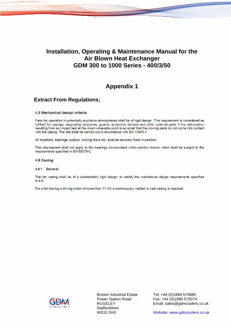
Appendix 1
Extract From Regulations;
Boston Industrial Estate Power Station Road RUGELEY StaffordshireWS15 2HS
Tel: +44 (0)1889 574880Fax: +44 (0)1889 575074 Email: [email protected]
Website: www.gdmcoolers.co.uk
Boston Industrial Estate Power Station Road RUGELEY StaffordshireWS15 2HS
Tel: +44 (0)1889 574880Fax: +44 (0)1889 575074 Email: [email protected]
Website: www.gdmcoolers.co.uk

GDM 400
i:; H -1,-
r - -
0
0
0
0
D71
4 30
- - -
D
4o0
400
200
-
H • s-,1-
--,
I �::;0· I opf
0 0 ··1
G.D.M. Manc,fo.cturlng Or"o.wlng
GOM Ver l of l
l'N..,:;ii.,..U,$•
��:i=f�l'ff
Stepht'n Krl$#,1 uo, J�y emz
F-0.n Group to o.ccep-t 0. 400MM by 400nn Cooler
Jl5
4( I� -n-
0
0 <> 0
..J
D71 Motor with 300MM r o.n for 7MM Tip Cleo.ranee
Boston Industrial Estate Power Station Road RUGELEY StaffordshireWS15 2HS
Tel: +44 (0)1889 574880Fax: +44 (0)1889 575074 Email: [email protected]
Website: www.gdmcoolers.co.uk
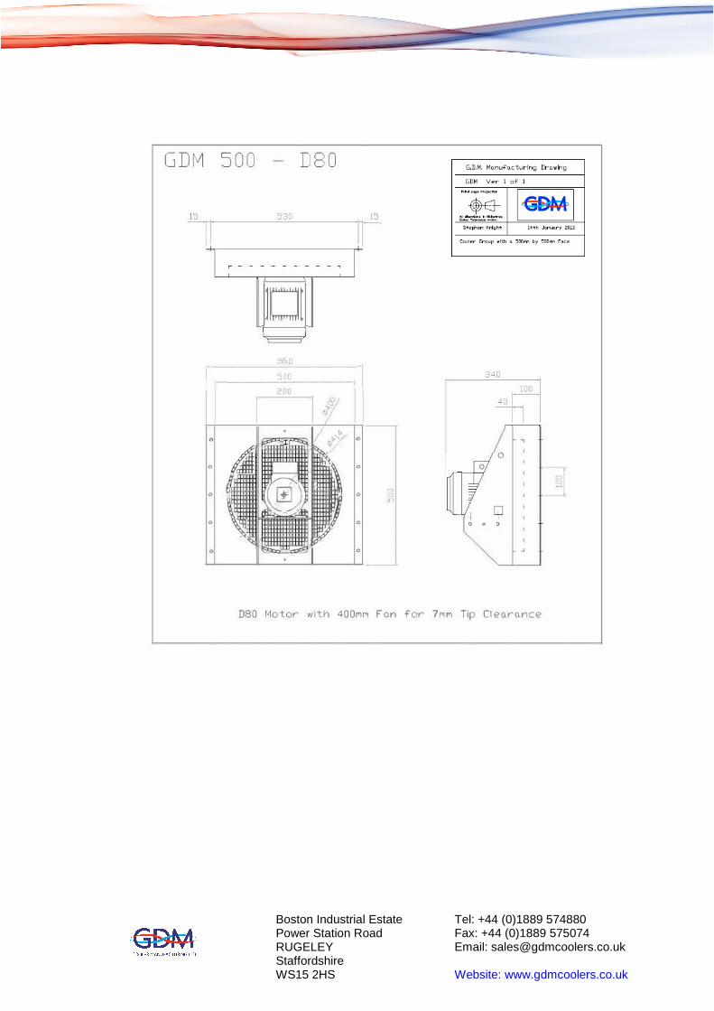
GDM 500 DSO
JIDt
,b
1- ,-------'5;...o_n _____ , -120!
'.>-
"'' ' I �\x / 0
,( I
� I
0 0
I � I
I0
Jt]/ 0
0
� 7 0
�� 0
15
0
0 o <)
D80 Motor with 400Mf"l F o.n for 7f"lf'1 Tip Cleo.ro.nce
Boston Industrial Estate Power Station Road RUGELEY StaffordshireWS15 2HS
Tel: +44 (0)1889 574880Fax: +44 (0)1889 575074 Email: [email protected]
Website: www.gdmcoolers.co.uk
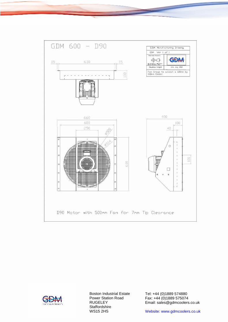
GDM 600 D90 G.D.M. l'lo.nuf'octurlng DrdW'ng
GDH Ver l of' 1
rt...--"fl.-Jo� ...
��tz �"Kri9trt llth �ly 2002
Fci.n Group to a.ccept a 600f"IM Cooler
f,00MM by
660 ,1oc
I fiOO 100
250 � 40 §S'/
1-,s/0 0
0 0 0
�,;:) 0 .-,
•.D
Q Q
0 0
"
D90 tv1o1or with 500rH''i Fon for 7rw1 Tip Cleoronce
Boston Industrial Estate Power Station Road RUGELEY StaffordshireWS15 2HS
Tel: +44 (0)1889 574880Fax: +44 (0)1889 575074 Email: [email protected]
Website: www.gdmcoolers.co.uk

GDM 800 D100
s=.o
r - - - - - - - - - - - - - - - , I' '
- 1� -
860
800
1-300
&l Q!o
'Ix �lo
/ /
(""') ('{) = (') co C'O
G.D.M. Monufo.during Drawing
GDH ve .... J of 1
'llfl'4.,.,,.,, .. J""tll,,
,�, :-�· �phff, Ktllgl'I� 1611\ Jvly 2012
r
47U
150 I
�fJI- '
'
DlOO Motor with 600r'lM F o.n f'or 7Mr'l Tip Cleo.ro.nce
Boston Industrial Estate Power Station Road RUGELEY StaffordshireWS15 2HS
Tel: +44 (0)1889 574880Fax: +44 (0)1889 575074 Email: [email protected]
Website: www.gdmcoolers.co.uk
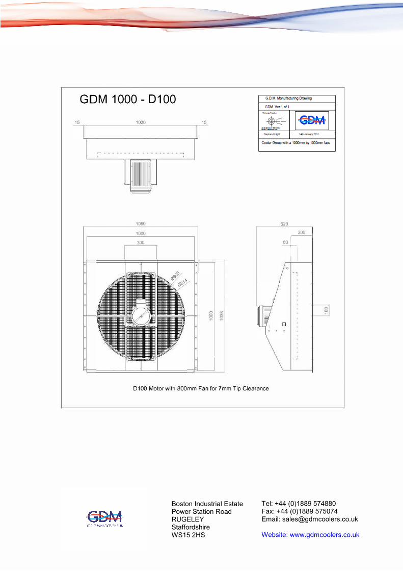
GDM 1000 - 0100
- - - - - - - - - - - - - - - - - - -,
- -
1060
1000
300
:_J
G.D.M. Manufacturing Cra•:ilng
GDM Ver1of1
... _,,., .. ......
� �··-. .,_
S�;,ll•fOh')III
1�1 \{11,,l""i�l?
FanGrouploaccepte 1000nmblj 1000mm Cooler
520
�' 0
D100 Motor with 800mm Fan for 7mm Tip Clearance
Boston Industrial Estate Power Station Road RUGELEY StaffordshireWS15 2HS
Tel: +44 (0)1889 574880Fax: +44 (0)1889 575074 Email: [email protected]
Website: www.gdmcoolers.co.uk