OPERATING MANUAL - Yaskawa
354
CNC SYSTEM FOR TURNING APPLICATIONS YASNAC J300L OPERATING MANUAL Upon receipt of the product and prior to initial operation, read these instructions thoroughly, and retain for future reference. REFERENCE YASNAC J300L PROGRAMMING MANUAL TOE-C843-13.21 YASUAVVA MANUAL NO. TOE-C843-1 3.20 —-—.——— .-.——. —. ——— ——. ———..,.,.-.—— -.. .. .—. —.——.. .-, ,—..—. —.,—. —-.
-
Upload
khangminh22 -
Category
Documents
-
view
0 -
download
0
Transcript of OPERATING MANUAL - Yaskawa

CNC SYSTEM FOR TURNING APPLICATIONS
YASNAC J300L
OPERATING MANUAL
Upon receipt of the product and prior to initial operation, read theseinstructions thoroughly, and retain for future reference.
REFERENCE
YASNAC J300L PROGRAMMING MANUAL TOE-C843-13.21
YASUAVVA MANUAL NO. TOE-C843-1 3.20
—-—.——— .-.——. —. ——— ——. ———..,.,.-.—— -.. . . .—.—.——.. .-, ,—..—. —.,—. —-.

CONTENTS
FOREWORD . . . . . . . . . . . . . . . . . . . . . . . . . . . . . . . . . . . . . . . . . . . . . . . . . ...!NOTES FOR SAFE OPERATION . . . . . . . . . . . . . . . . . . . . . . . . . . . . . . . IIIKEY TO WARNING LABELS . . . . . . . . . . . . . . . . . . . . . . . . . . . . . . . . . . . iv
1. OUTLINE OF THE PRODUCT
1.1 OUTLINE OF YASNAC SYSTEM . . . . . . . . . . . . . . . . . . . . . . ...1-2
1.1.1 System Configuration . . . . . . . . . . . . . . . . . . . . . . . . . . . . . . . . . . . . . . . . . . 1-2
1.1.2 Environmental Requirements . . . . . . . . . . . . . . . . . . . . . . . . . . . . . . . . . . . . 1-4
1.1.3 Machine Operation Panel . . . . . . . . . . . . . . . . . . . . . . . . . . . . . . . . . . . . . . . 1-6
1.1.4 General Specifications . . . . . . . . . . . . . . . . . . . . . . . . . . . . . . . . . . . . . . . . . 1-7
1.2 PROTECTIVE FIJNCTIONS . . . . . . . . . . . . . . . . . . . . . . . . . . ...1-12
1.2.1 EmergencyStop . . . . . . . . . . . . . . . . . . . . . . . . . . . . . . . . . . . . . . . . . 1-12
1.2.2 Overtravel . . . . . . . . . . . . . . . . . . . . . . . . . . . . . . . . . . . . . . . . . . . . . . . 1-12
1.2.3 Stored Stroke Limit . . . . . . . . . . . . . . . . . . . . . . . . . . . . . . . . . . . . . . . 1-13
1.2.4 Interlock inputs . . . . . . . . . . . . . . . . . . . . . . . . . . . . . . . . . . . . . . . . . . . 1-15
2. BASIC OPERATION OF YASNAC
2.1 GENERAL FLOW OF OPERATION . . . . . . . . . . . . . . . . . . . . ...2-3
2.2 INSPECTION BEFORE TURNING THE POWER ON . . . . . . . ...2-4
2.2.1 inspection ofthe NC Unit . . . . . . . . . . . . . . . . . . . . . . . . . . . . . . . . . . . . ..2-6
2.2.2 inspection oftheTape Reader.. . . . . . . . . . . . . . . . . . . . . . . . . . . . . . . . . . 2-7’
2.2.3 Preparation before Turningthe Power ON . . . . . . . . . . . . . . . . . . . . . . . . . 2-8
2.3 TURNING THE POWER ON ANDINSPECTION AFTER POWE:R ON...... . . . . . . . . . . . . . . . . ...2-9
2.3.1 ProcedureforTurningthe PowerON . . . . . . . . . . . . . . . . . . . . . . . . . . . . 2-9
2.3.2 Checking the Motors for Abnormalities . . . . . . . . . . . . . . . . . . . . . . . . . 2-10
2.3.3 ProcedureforTurningthe PowerOFF . . . . . . . . . . . . . . . . . . . . . . . . . 2-11
2.3.4 inspection ofthe Battery . . . . . . . . . . . . . . . . . . . . . . . . . . . . . . . . . . . ..2-12
2.4 MANUAL OPERATION (I) . . . . . . . . . . . . . . . . . . . . . . . . . . . . ...2-15
2.4.1 Manual Rapid Traverse (RAPID) . . . . . . . . . . . . . . . . . . . . . . . . . . . . ...2-15
2.4.2 Jog Feed (JOG) . . . . . . . . . . . . . . . . . . . . . . . . . . . . . . . . . . . . . . . . . . ...2-16
2.4.3 Step Feed (STEP) . . . . . . . . . . . . . . . . . . . . . . . . . . . . . . . . . . . . . . . . ...2-16
2.4.4 Handle Feed (HANDLE)* . . . . . . . . . . . . . . . . . . . . . . . . . . . . . . . . . ...2-17
1
——.,.— ,—. =. —. —..- ,,.. ! .-~ . ..-.. —-.. —.-. — . . .

2.5 MANUAL OPERATION (2) . . . . . . . . . . . . . . . . . . . . . . . . . . . . ...2-18
2.5.1 Simultaneous 3-axis Handle Feed . . . . . . . . . . . . . . . . . . . . . . . . . . . . . .2-18
2.5.2 Manual Reference Point Return . . . . . . . . . . . . . . . . . . . . . . . . . . . . . . ...2-19
2.5.3 Manual Reference Point Return tothe Second Reference Point* . . . . 2-22
2.5.4 I-line MDI . . . . . . . . . . . . . . . . . . . . . . . , . . . . . . . . . . . . . . . . . . . . . . . . ...2-23
2.6 AUTOMATIC OPERATION (1) . . . . . . . . . . . . . . . . . . . . . . . . . ...2-24
2.6.1 Preparation of Automatic Operation . . . . . . . . . . . . . . . . . . . . . . . . . . . . . 2-24
2.6.2 Memory Operation . . . . . . . . . . . . . . . . . . . . . . . . . . . . . . . . . . . . . , . . . ...2-26
2.6.3 MDI Operation . . . . . . . . . . . . . . . . . . . . . . . . . . . . . . . . . . . . . . . . . . . . ...2-27
2.6.4 Feed Hold . . . . . . . . . . . . . . . . . . . . . . . . . . . . . . . . . . . . . . . . . . . . . . . . . . .2-28
2.6.5 Override . . . . . . . . . . . . . . . . . . . . . . . . . . . . . . . . . . . . . . . . . . . . . . . . . . . ..2-29
2.7 AUTOMATIC OPERATION (2) . . . . . . . . . . . . . . . . . . . . . . . . . ...2-31
2.7.1 Optional Stop . . . . . . . . . . . . . . . . . . . . . . . . . . . . . . . . . . . . . . . . . . . . . . ..2-31
2.7.2 Optional Block Skip........,., . . . . . . . . . . . . . . . . . . . . . . . . . . . . . . ..2-31
2,7.3 Dry Run . . . . . . . . . . . . . . . . . . . . . . . . . . . . . . . . . . . . . . . . . . . . . . . . . . . ..2-32
2.7.4 Machine Lock......,,....,.. . . . . . . . . . . . . . . . . . . . . . . . . . . . . . . ...2-33
2.7.5 Auxiliary Function Lock . . . . . . . . . . . . . . . . . . . . . . . . . . . . . . . . . . . . . ...2-33
2.7.6 Feed Hold in Thread Cutting*. . . . . . . . . . . . . . . . . . . . . . . . . . . . ., . ...2-34
2.8 OPERATION INTERVENTIONDURING AUTOMATIC OPERATION . . . . . . . . . . . . . . . . . . . ...2-35
2.8.1 Manual Operation intervention during Automatic Operation . . . . . . . . . 2-35
2.8.2 MDIOperation intervention during Automatic Operation . . . . . . . . . . . . 2-36
2.8.3 Automatic Handle Mode Offset* . . . . . . . . . . . . . . . . . . . . . . . . . . . . . . . . 2-37
2.8.4 Manual Absolute . . . . . . . . . . . . . . . . . . . . . . . . . . . . . . . . . . . . . . . . . . . ..2-38
2.9 AUTOMATIC OPERATIONS AT ENHANCED LEVEL . . . . . ...2-40
2.9.1 Return tothe Setup Point . . . . . . . . . . . . . . . . . . . . . . . . . . . . . . . . . . . . ..2-40
2.9.2 Return tothe Operation interrupted Point* . . . . . . . . . . . . . . . . . . . . . . . 2-40
2.9.3 Saving the Present Position Data . . . . . . . . . . . . . . . . . . . . . . . . . . . . . . . . 2-42
2.9.4 Program Restart* . . . . . . . . . . . . . . . . . . . . . . . . . . . . ., ., .,, .,, , . . ...2-43
3. BASICS OF DISPLAY AND WRITING OPERATION
3.1 BASICS OF TERMS REIATED TO OPERATION ,, . .,..,.....3-2
3.1.1 Process Screens . . . . . . . . . . . . . . . . . . . . . . . . . . . . . . . . . . . . . . . . . . . . . 3-3
3.1.2 Jobs and Functions . . . . . . . . . . . . . . . . . . . . . . . . . . . . . . . . . . . . . . . . . . . . 3-3
3.1.3 YASNACJ300L Function Structure . . . . . . . . . . . . . . . . . . . . . . . . . . . . 3-4
ii

3.2 NC OPERATION PANEL . . .. . . . . . . . . . . . . . . . . . . . . . . . . . ...3-8
3.2.1 Keys and Display Screen on NC Operation Panel . . . . . . . . . . . . . . . . 3-8
3.2.2 Normal Display onCRTScreen. . . . . . . . . . . . . . . . . . . . . . . . . . . ...3-15
3.2.3 Pop-up Menu . . . . . . . . . . . . . . . . . . . . . . . . . . . . . . . . . . . . . . . . . . . . . ..3-2o
3.2.4 Key Buffer Edit Function . . . . . . . . . . . . . . . . . . . . . . . . . . . . . . . . . . . ..3-21
3.2.5 Buzzer Function . . . . . . . . . . . . . . . . . . . . . . . . . . . . . . . . . . . . . . . . . . ..3-22
4. EDIT PROCESS OPERATION
4.1 PART PROGRAM EDIT JOB . . . . . . . . . ...0................4-3
4.1.1 Calling aPart F’rogram . . . . . . . . . . . . . . . . . . . . . . . . . . . . . . . . . . . . . . . . . 4-4
4.1.2 Editing aPart F’rogram . . . . . . . . . . . . . . . . . . . . . . . . . . . . . . . . . . . . . . . . . 4-7
4.1.3 Saving aPart Program after [:diting . . . . . . . . . . . . . . . . . . . . . . . . . . . . . 4-22
4.1.4 Deleting aPart Program . . . . . . . . . . . . . . . . . . . . . . . . . . . . . . . . . . . . ...4-23
4.2 PART PROGRAM DIRECTORYJOB . . . . . . . . . . . . . . . . . . ...4-26
4.2.1 Display ofthe[lirectory ofPart Programs . . . . . . . . . . . . . . . . . . . . . . . . . 4-26
4.2.2 Calling aPartl%ogram . . . . . . . . . . . . . . . . . . . . . . . . . . . . . . . . . . . . ...4-33
4.2.3 Deleting aPart Program . . . . . . . . . . . . . . . . . . . . . . . . . . . . . . . . . . . . . ..4-35
4.2.4 Renaming aPart Program . . . . . . . . . . . . . . . . . . . . . . . . . . . . . . . . . . ...4-37
4.2.5 Copying aPart Program . . . . . . . . . . . . . . . . . . . . . . . . . . . . . . . . . . . . . ..4-39
4.3 PART PROGRAM lNPUT/OUTPUTAND VERIFY JOB . . . . ...4-40
4.3.1 inputting aPart Program . . . . . . . . . . . . . . . . . . . . . . . . . . . . . . . . . . . . . ..4-40
4.3.2 Outputting a Part Program . . . . . . . . . . . . . . . . . . . . . . . . . . . . . . . . . . . ..4-44
4.3.3 Verifying the Part Programs . . . . . . . . . . . . . . . . . . . . . . . . . . . . . . . . . ...4-51
4.3.4 Setting the Communication Conditions . . . . . . . . . . . . . . . . . . . . . . . . . . 4-55
4.3.5 Other Function . . . . . . . . . . . . . . . . . . . . . . . . . . . . . . . . . . . . . . . . . . . . . ..4-60
5. SETUP PROCESS OPERATION
5.1 SETUP JOB . . . . . . . . . . . . . . . . . . . . . . . . . . . . . . . . . . . . . . . . . ...5-2
5.1.1 Writing the Tool Offset Data..... . . . . . . . . . . . . . . . . . . . . . . . . . . . . . . . . 5-2
5.1.2 Clearing the Offset Data . . . . . . . . . . . . . . . . . . . . . . . . . . . . . . . . . . . . . . ..5-4
5.2 WORKPIECE COORDINATE SYSTEM SHIFT JOB . . . . . . . . ...5-5
5.2.1 Writing theWorkpiece Coorclinate System ShiftAmount . . . . . . . . . . . . . 5-5
5.2.2 Clearing the Workpiece Coordinate System ShiftAmount . . . . . . . . . . . . 5-6

5.3 TOOL LIFE CONTROL JOB . . . . . . . . . . . .,. ,.. s. . . . . . . . . . ...5-7
5.3.1 Writing the Tool Life Control Data... . . . . . . . . . . . . . . . . . . . . . . . . . . ...5-7
5.3.2 Displaying the Tool Lite Control Data. . . . . . . . . . . . . . . . . . . . . . . . . . ...5-7
5.3.3 Setting the Tool Life Control Data,,. . . . . . . . . . . . . . . . . . . . . . . . . . . . . . 5-8
5.3.4 Erasing the Tool Life Control Data... . . . . . . . . . . . . . . . . . . . . . . . . . ...5-10
6. RUN PROCESS
6.1 PROGRAM JOB . . . . . . . . . . . . . . . . . . . . . . . . . . . . . . . . . . . . . . ..6-3
6.1.1 Program Information [)isplayed on Screen . . . . . . . . . . . . . . . . . . . . . . . . 6-3
6.1.2 Program Number Search . . . . . . . . . . . . . . . . . . . . . . . . . . . . . . . . . . . . . . . 6-4
6.1.3 Address Search . . . . . . . . . . . . . . . . . . . . . . . . . . . . . . . . . . . . . . . . . . . . . . . 6-6
6.1.4 Editing the Part Program Stored in Memory . . . . . . . . . . . . . . . . . . . . . . . . 6-7
6.1.5 Execution ofa Part Program . . . . . . . . . . . . . . . . . . . . . . . . . . . . . . . . . . . . . 6-9
6.1.6 Display of Subprogram Nesting information . . . . . . . . . . . . . . . . . . . . . . 6-10
6.2 MDIOPERATION JOB . . . . . . . . . . . . . . . . ., .,, , . ., . . . . . . ...6-11
6.2,1
6.2.2
6.2.3
6.2.4
6.2.5
Entry ofan MDI Program ...,..... . . . . . . . . . . . . . . . . . . . . . . . . . . . . . . 6-11
Editing an MDI Program . . . . . . . . . . . . . . . . . . . . . . . . . . . . . . . . . . . . ...6 -11
Execution ofan MDI Program . . . . . . . . . . . . . . . . . . . . . . . . . . . . . . . ...6- 12
Deleting an MDI Program . . . . . . . . . . . . . . . . . . . . . . . . . . . . . . . . . . . . . . 6-13
Storing an MDI Program..,,. . . . . . . . . . . . . . . . . . . . . . . . . . . . . . . . . . . 6-13
6.3 COMMAND VALUE DISPIAY JOB....,, . . . . . . . . . . . . . . . ...6-14
6.3.1 Collective Display of Command Values . . . . . . . . . . . . . . . . . . . . . . . . . . 6-14
6.4 SEITING JOB...............,,.,,.. . . . . . . . . . . . . . . . . ...6-15
6.4.1 internal Switch Function*..,,, . . . . . . . . . . . . . . . . . . . . . . . . . . . . . . . . . 6-15
6.4.2 Software Switch Function* . . . . . . . . . . . . . . . . . . . . . . . . . . . . . . .,, ..,6-16
6.4.3 Macro Variable Function, ...,, . . . . . . . . . . . . . . . . . . . . . . . . . . . . . . . . . 6-17
6.4.4 Setting Function.,.......,.. . . . . . . . . . . . . . . . . . . . . . . . . . . . ., .,...6-19
7. COMMON PROCESS OPERATION
7,1 PRESENTPOSITION [)ATACONTROLJOB . . . . . . . . . . . . . ...7-2
7.1.1 Collective Display ofPresentPosition Data . . . . . . . . . . . . . . . . . . . . . . . . 7-2
7.1.2 Display of Present Position Datain the Workpiece Coordinate System . . . . . . . . . . . . . . . . . . . . . . . . . . . . . 7-4
7.1.3 Display of Present Position Datain the External Coordinate Values . . . . . . . . . . . . . . . . . . . . . . . . . . . . . ...7-5
7.1.4 Display of Remaining Distance. . . . . . . . . . . . . . . . . . . . . . . . . . . . . . . ...7-6
7.1.5 Setting the Coordinate Systems . . . . . . . . . . . . . . . . . . . . . . . . . . . . . . . 7-7
7.1.6 Error Pulse Display Function.. . . . . . . . . . . . . . . . . . . . . . . . . . . . . ., . ...7-9
iv
—-...—-...——..-—.—

7.2 ALARM DISPLAY JOB . . . . . . . . . . . . . . . . . . . . . . . . . . . . . ...7-10
7.2.1 Alarm Functiorl . . . . . . . . . . . . . . . . . . . . . . . . . . . . . . . . . . . . . . . . . . . . ...7-10
7.2.2 Servo Alarm Function . . . . . . . . . . . . . . . . . . . . . . . . . . . . . . . . . . . . . . . ..7-11
7.2.3 User’s Message Function . . . . . . . . . . . . . . . . . . . . . . . . . . . . . . . . . . . . ..7-12
7.3 TIME CONTROL. JOB . . . . . . . . . . . . . . . . . . . . . . . . . . . . .. . ...7-13
7.3.1 Calendar Function . . . . . . . . . . . . . . . . . . . . . . . . . . . . . . . . . . . . . . . . . ..7-14
7.3.2 Operating Time Function . . . . . . . . . . . . . . . . . . . . . . . . . . . . . . . . . . . ...7-15
8. MAINTENANCE PROCESS
8.1 PARAMETER JOB . . . . . . . . . . . . . . . . . . . . . . . . . . . . . . . . . . . ...8-3
8.1.1 Parameter Function . . . . . . . . . . . . . . . . . . . . . . . . . . . . . . . . . . . . . . . . . . . . 8-3
8.1.2 Setting Functio n. . . . . . . . . . . . . . . . . . . . . . . . . . . . . . . . . . . . . . . . . . . . . . 8-6
8.1.3 Sequence ParameterFuncti~n . . . . . . . . . . . . . . . . . . . . . . . . . . . . . . . . . . 8-7
8.1.4 Pitch Error Furlction *....... . . . . . . . . . . . . . . . . . . . . . . . . . . . . . . . . . . . 8-7
8.2 l/O MONITORING JOB . . . . . . . . . . . . . . . . . . . . . . . . . . . . . . . ...8-8
8.2.1 DisplayingtheON/OFFStatusof thel/OSignals . . . . . . . . . . . . . . . . . . . 8-8
8.2.2 DisplayingtheON/OFFStatusofthe Selectedl/OSignals . . . . . . . . . . . 8-9
8.2.3 TurningON/OFFl/OSignalsForcibly . . . . . . . . . . . . . . . . . . . . . . . . . . . . 8-11
8.3 lNPUT/OUTPUT AND VERIF’YJOB . . . . . . . . . . . . . . . . . . . ...8-12
8.3.1 input/outputandVerifyFunction . . . . . . . . . . . . . . . . . . . . . . . . . . . . . ...8-12
8.3.2 Reset Functiorl . . . . . . . . . . . . . . . . . . . . . . . . . . . . . . . . . . . . . . . . . . . . . ..8-14
8.3.3 l/ODeviceSettingFunction . . . . . . . . . . . . . . . . . . . . . . . . . . . . . . . . . . ..8-14
8.4 INTERNAL INFORMATION *JOB . . . . . . . . . . . . . . . . . . . . . . ...8-15
8.4.1 Version Number Function . . . . . . . . . . . . . . . . . . . . . . . . . . . . . . . . . . . . 8-15
8.4.2 Memory Dump Function . . . . . . . . . . . . . . . . . . . . . . . . . . . . . . . . . . . . . 8-16
8.4.3 Key Memory Function . . . . . . . . . . . . . . . . . . . . . . . . . . . . . . . . . . . ...8-16
9. MAINTENANCE
9.1 MAINTENANCE DATA . . . . . . . . . . . . . . . . . . . . . . . . . . . . . . . ...9-2
9.1.1 Checking the StatusofTroubles. . . . . . . . . . . . . . . . . . . . . . . . . . . . . . 9-2
9.1.2 Checking the lVClnformation. . . . . . . . . . . . . . . . . . . . . . . . . . . . . . . . . 9-3
9.1.3 Display ofAlarm lnformatiorl . . . . . . . . . . . . . . . . . . . . . . . . . . . . . . . . . . . 9-5
9.1.4 Cause ofAlarrn and Corrective Action . . . . . . . . . . . . . . . . . . . . . . . . . . 9-6
9.1.5 Troubleshooting (l) . . . . . . . . . . . . . . . . . . . . . . . . . . . . . . . . . . . . . . . . . . 9:7
9.1.6 Troubleshooting (2) . . . . . . . . . . . . . . . . . . . . . . . . . . . . . . . . . . . . . . . ...9 -17
9.1.7 Alarms Not indicated byAlarm Numbers . . . . . . . . . . . . . . . . . . . . . . . 9-23
v

APPENDIX 1 LIST OF NC lNPUT/OUTPUT SIGNALS
APPENDIXI.I INPUT SIGNALS (PLC--+ NC) . . . . . . . . . . . . . . . . .. A1-2
1.1.1 Operation Mode Control . . . . . . . . . . . ., . . . . . . . . . . . . . . . . . . . . . . . . .. A1-2
1.1.2 CNCPart Program Execution Control . . . . . . . . . . . . . . . . . . . . . . . . . . .. A1-4
1.1.3 ServoAxis Control . . . . . . . . . . . . . . . . . . . . . . . . . . . . . . . . . . . . . . . . . . ..A1-5
1.1.4 No. l Spindle Control.....,., . . . . . . . . . . . . . . . . . . . . . . . . . . . . . . . ..A1-7
1.1.5 No. 2SpindleControl . . . . . . . . . . . . . . . . . . . . . . . . . . . . . . . . . . . . . . . ..A1-8
1.1.6 YENET1200Compatible lnverter Control . . . . . . . . . . . . . . . . . . . . . . . . . Al-9
APPENDIX 1.2 OUTPUT SiGNALS (NC-+ PLCj . . . . . . . . . . . . . . Al -10
1.2.1 Operation Mode Control ., .,.,..... . . . . . . . . . . . . . . . . . . . . . . . . . .. A1 -10
1.2.2 NC Part Program Execution Control. . . . . . . . . . . . . . . . . . . . . . . . . . .. A1- 12
1.2.3 Servo Axis Control, . ., . .,, . . . . . . . . . . . . . . . . . . . . . . . . . . . . . . . . . .. Al- 14
1.2.4 No, l Spindle Control . . . . . . . . . . . . . . . . . . . . . . . . . . . . . . . . . . . . . . .. Al- 17
1.2.5 No.2Spindle Control . . . . . . . . . . . . . . . . . . . . . . . . . . . . . . . . . . . . . . .. A1 -18
1.2.6 YENET1200Compatible lnverter Control . . . . . . . . . . . . . . . . . . . . . . . . A1 -19
1.2.7 Axis Variable Data, . . . . . . . . . . . . . . . . . . . . . . . . . . . . . . . . . . . . . . . . .. Al- 20
APPENDIX 2 PARAMETER TABLE
APPENDIX 2.1 CLASSIFICATION OF THE PARAMETERS . . . . . . . A2 -2
APPENDIX 2.2 PARAMETER TABLE . . . . . . . . . . . . . . . . . . . . . . . . .. A2-3
APPENDIX 3 ALARM TABLE
APPENDIX 3.1 CLASSIFICATION OF ALARMS . . . . . . . . . . . . . . . . . A3 -2
APPENDIX 3.2 ALARM TA13LE . . . . . . . . . . . . . . . . . . . . . . . . . . . . . .. A3-3
APPENDIX 4 INDEX
vi

FOREWORD
This manual describes cautionary items that must be taken into consideraticm when operatingthe YASNAC J300L (with basic NC operation panel, 9-inch CRT) as well as the basic config-uration and operation procedure of it.
Some information is presented in tables in the Appendix so that readers can easily find thenecessary information. In the specification table, section numbers are given for each specifi-cation to allow quick access to a detailecl explanation if necessary.
The YASNAC J300L comes with a programming manual in addition to thi~;operating manu-
al. Use these manuals in conjunction with each other to ensure productive operation.
CAUTIONS
This manual describes all the option functions (identified by the “*” symbol) but some ofthese may not be available with your YASNAC J300M. To determine the option functionsinstalled in your NC, refer to the specification document or manuals published by the ma-
chine tool builder.
Unless otherwise specifiecl, the following conditions apply in programming explanationsand programming examples.
. Metric system for input and metric system for output/moveme.~t●
+ : Zero point in the base coordinate system
●
@ : Reference point
Yaskawa has made every effort to describe individual functions and their relationships to oth-
er functions as accurately as possible. However, there are many things ttat cannot or mustnot be performed and it is not possible to describe all of these. Accordingly, readers are re-quested to understand that unless it is specifically stated that something can be performed,
it should be assumed that it cannot be performed.
Also bear in mind that the :performance and functions of an NC machine tool are not deter-mined solely by the NC unit. The entire control system consists of the mechanicals ystem,the machine operation panel and other machine related equipment in addition to the NC.Therefore, read the manuals published by the machine tool builder for derailed informationrelating to the machine.
General Precautions
● Some drawings in this manual are shown with the protective cover or shields removed,
in order to describe the detail with more clarity. Make sure all covers and shields are
replaced before operating this product, and operate it in accordance with the directions
in the manual.
● The figures and photographs in this manual show a representative product for reference
purposes and may differ from the product actually delivered to you.
● This manual maybe modified when necessary because of improvement of the product,
modification, or changes in specifications.
Such modification is made as a revision by renewing the manual No.
● To order a copy of this manual, if your copy has been damaged or lost, contact your
Yaskawa representative listed on the last page stating the manual No. on the front
page.
● If any of the nameplates affixed to the product become damaged or illegible, please
send these nameplates to your Yaskawa representative.
● Yaskawa is not responsible for any modification of the product made by the user since
that will void our guarantee.
ii
.——— —

NOTES FOR SAFE OPEF{ATION
Read this operating manual thoroughly before installation, operation , maintenance or in-
spection of the YASNAC J300L. In this manual, the NOTES FOR SAFE OPERATION are
classified as “WARNING” or “CAUTION’.
~ WARNING
~ CAUTION
Indicates a potentially hazardous situation which, if
not avoided, could result in death or serious injury to
personnel.
Indicates a potentially hazardous situi~tion which, if
not avoided, may resuR in minor or moderate injury
to personnel and damage to equipmenk
It may also be used to alert against unsafe practice.
Even items describedinl ~ CAUTION I may result in a vital accident in some situations.
In either case, follow these important items.

KEY TO WARNING LABELS
The following warning labels are used with the YASNAC J300M.
mq~q ::;::ardDo not touch the terminals while the power ison, and for 5 minutes after switching off the
Locationoflabel
NCunit
— Warninglabel
iv

E:
O! WARNING
nQ ,fi#Y-xkfiMi%M&
Use,propergroundingtechniques.
Grounding wires must be connected to the unit’sgrounding terminals.
Locationof labelNCunit
—.Warninglabel
Il@l -JIW#UX%n%’JoF%Ji:M3ti !Maycauseelectricshock.Don?touti theinside.
—
Locationof label
NCoperationpanelwith9 inchCRT
L]—–’—Rearface
Warninglabel

1 STORAGE PRECAUTIONS
~ CAUTIONDo not store the product in locations subject to rain, water droplets,
or harmful gases or liquids.
Failure to observe this cauticm may result in product failure.
Select a storage area indoors that is clean and meets the following
temperature and humidity requirements.
Failure to observe this caution may result in product failure.
Ambient temperature : - 20’)C to 60° C
Relative humidity : 10% to 90%
2 CAUTIONS ON USE AND OF’ERATION
~ WARNINGB
●
●
●
●
—
Do not touch any unit, terminals, etc., while the power is ON.
Failure to observe this warning may lead to electric shock or device mal-
function.
Immediately after switching the power OFF, the product retains
some electric charge. Do not touch any parts which are live when
the power is ON for 5 minutes after switching the power OFF.
Failure to observe this warning may lead to electric shock or device mal-
function.
Do not damage cables, subject them to excessive stress, or pinch
them.
Excessive load on cables may cause electric shock.
When the unit is turned ON, never touch its rotating parts.
Failure to observe this warning may result in personal injury.
Never modify the product,
Failure to observe this warning may result in electric shock, fire, or prod-
uct failure.
Page
1-4
1-4
Page
2-5
2-5
2-5
2-5
2-5

~ CAUTION
I
I
)
—
Use the product in an environment with the following characteris-
tics.
Using it in an environment in which it is subject to high temperatures, high
humidity, dust, corrosive gases, vibration or impacts may cause fire, elec-
tric shock or malfunction.
.
Free from gases or vapors that create a potentially explosive atmo-
sphere.
Free from oil, organic solvents, etc.
Relative humidity in the range 10I to 90% RH, with no condensation.
Ambient temperature in the O“C to 45° C with no freezing.
(Installation site must not be exposed to direct sunlight, must be dis-
tanced from heat generating devices, and must be indoors.)
Wbration not exceeding 4.9 m/s2 (0.5 G).
Do not let foreign matter such as electric wire scrap enter the unit.
Failure to observe this caution may :result in fire, product failure or mal-
function.
Do not restart automatic operation after stopping automatic opera-
tion and then performing “tool selection” in manual operation c)r”1
line MDI” operation.
The reason for this is that the “tool selection” operation may cause the
coordinate system to be changed, leading to unexpected operation if a uto-
matic operation were restarted. This could cause tool damage due to irlter-
ference, and resulting accidents involving injuries to personnel.
Reset the NC after any manual intervention.
After stopping automatic operation and performing a manual irlter-
vention, do not restart automatic operation without resetting first.
If automatic operation is started with the “mirror image” or “manual a’l]so-
lute” function in effect, unexpected operation may be performed. “rhis
could cause tool damage due to interference, and resulting accidents in-
volving injuries to personnel.
Reset the NC after any manual intervention.
Page
-——1-4
2-6
2-37
2-37

~ CAUTIONBefore carrying out cutting operation with a new program, confirm
safety by performing single block operation and dry run operation.
If this check operation is not performed, unexpected operation maybe per-
formed due to mis-setting of the amount of offset, leading to tool damage
due to interference, and resulting accidents involving injuries to perscm-
nel.
The end user must not change parameters relating to machine ac-
curacy, travel axis control and spindle axis control.
The NC parameters are set to the optimum values for each machine, and
changing them could therefore result in unexpected operation. This could
cause tool damage due to interference, and resulting accidents involving
injuries to personnel.
Reset the NC after any manual intervention.
Strictly observe the cautions in the user’s manual when using pro-
gramming functions.
Ignoring these cautions could lead to accidents involving injuries to per-
sonnel and malfunctions.
Use the product with the “System Number Switch” of the CPU set to6’ ,,0.
Use while set to another number may lead to malfunction.
Wait at least 2 seconds after turning the power OFF before turning it
ON again.
Failure to observe this caution may lead to malfunction.
Page
2-25
8-3
2-25
2-1o
2-1o
Vlll
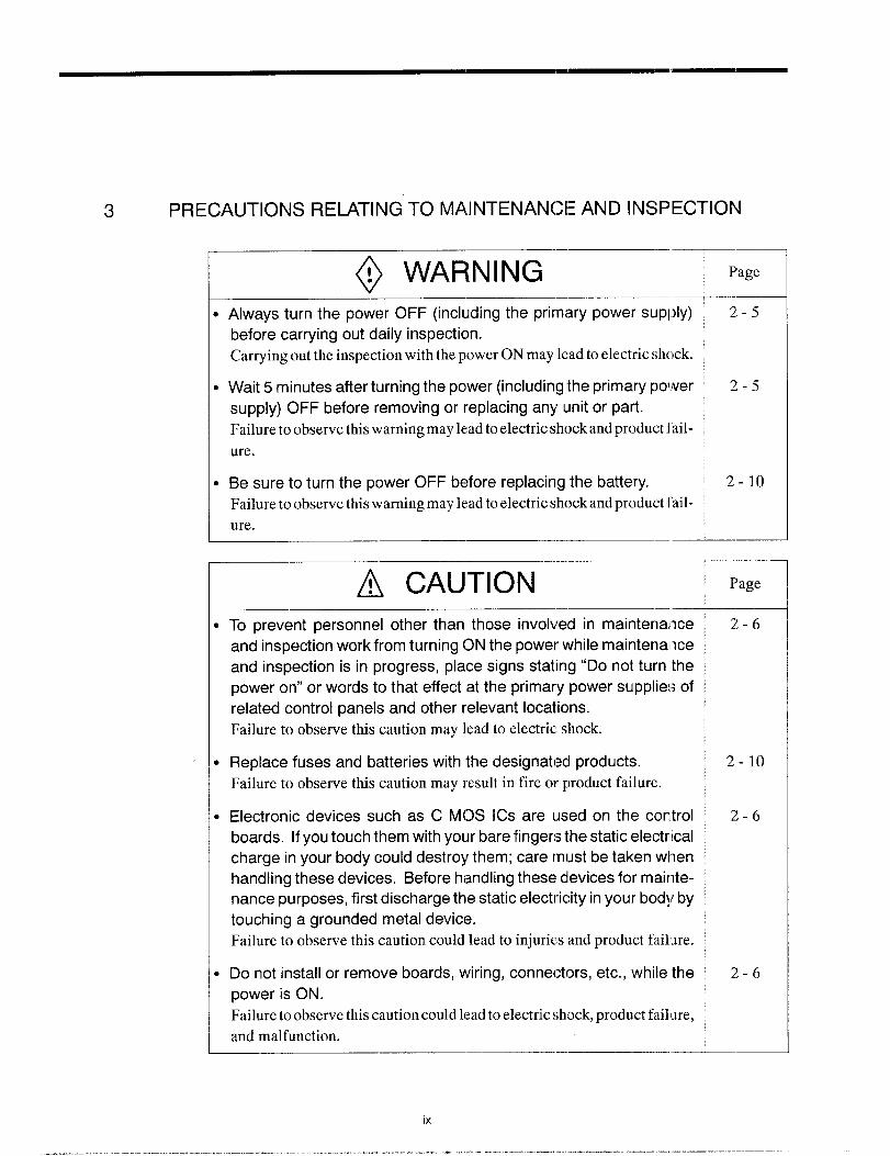
3 PRECAUTIONS RELATING TO MAINTENANCE AND INSPECTION
@ WARNING ‘- Page
● Always turn the power OFF (including the primary power supply) 2-5
before carrying out daily inspection.
Carrying out the inspection with the power ON may lead to electric shock.
● Wait 5 minutes after turning the power (including the primary power 2-5
supply) OFF before removing or replacing any unit or part.
Failure to observe this warning may lead to electric shock and product i ail-
ure.
● Be sure to turn the power OFF before replacing the battery. 2-1o
Failure to observe this warning may lead to electric shock and product ~ail-
ure.
~ CAUTION Page
—
I To prevent personnel other than those involved in maintenance ~ 2-6
and inspection work from turning ON the power while maintenance
and inspection is in progress, place signs stating “Do not turn the
power on” or words to that effect at the primary power supplies of ~
related control panels and other relevant locations.
Failure to observe this caution may lead to electric shock.
I Replace fuses and batteries with the designated products. 2-1o
Failure to observe this caution may result in fire or product failure.
I Electronic devices such as C MOS ICS are used on the control 2-6
boards. If you touch them with your bare fingers the static electrical
charge in your body could destroy them; care must be taken when
handling these devices. Before handling these devices for mair]te-nance purposes, first discharge the static electricity in your body by
touching a grounded metal device.
Failure to observe this caution could lead to injurim and product fail.me.
I Do not install or remove boards, wiring, connectors, etc., while the 2-6
power is ON.
Failure to observe this caution could leadto electric shock, product fail~re,
and malfunction..— .——

~ CAUTIONWhen an alarm occurs, eliminate its cause and confirm safety be-
fore resetting it.
Failure to observe this cautio:n could result in malfunction.
Be sure to check the following points on completing maintenance
and inspection work.
. Check that all fastening bolts are tightened.
“ Check that no tools or other objects have been left inside the control
panel.
. Check that the control panel door is closed properly.
Failure to carry out these checks may lead to electric shock, injuries, fire,
and malfunction.
For details on trouble relating to the machine-related sequence, re-
fer to the manual issued by the machine tool builder.
Never attempt to disassemble or modify units or devices inside the
NC unit.
Failure to observe this caution may lead to fire, product failure, or mal-
function.
Do not change the set values of the devices, variable resistors, etc.,
in the control panel.
Failure to observe this caution may lead to fire, product failure, and mal-
function.
Page
9-2
2-6
9-2
2-6
2-6

OUTLINE OF THE: PRODUCT
Chapter 1 describes the outline of the product and the protec-
tive functions that should be thoroughly understood for safe
and efficient operaticm of the YASINAC J300L.
1.1
1.2
OUTLINE OF YASNAC SYSTEM . . . . ...1-2
1.1.1 Systerrl Configuratiorl . . . . . . . . . . . . . . . . . 1-2
1.1.2 Environmental Requirements . . . . . . . . . . . . 1 -4
1.1.3 Machine Operation Panel . . . . . . . . . . . . . . . . 1-6
1.1.4 General Specificatiorls . . . . . . . . . . . . . . . . . 1-7
PROTECTIVE FUNCTIONS . . . . . . . ...1-12
1.2.1 Emergenc ySto p. . . . . . . . . . . . . . . . . . . . . . 1-12
1.2.2 Overtrave l . . . . . . .. o. . . . . . . . . . . . . . . . . . 1-12
1.2.3 Stored Stroke Limit . . . . . . . . . . . . . . . . . . . 1-13
1.2.4 Interlock Inputs . . . . . . . . . . . . . . . . . . . . . . . . 11-15

1.1 OUTLINE OF YASNAC SYSTEM
1.1.1 System Configuration
The configuration of the YASNAIC system and the list of components are described below.
m“”EjEI!!IylQOptionACGC
3-phase R
AC
Powers
SUPPty T
r
I
~1GeneralPurpose1/0
FE:Powersupply YASNACControlUnit Unit
‘1
1
-Fl?’”is
r t I..+’@
pmfim=--g,,:,s
,
-L--–A----J ~ !uPowerInput—Unit
Fig. 1.1
L 1 ElectricControlPanel
Configuration of YASNAC System

1.1 OUTLINEO=YASNACSYSTEM
Table 1.1 List of YASNAC System Components
~:..-n...n ““de’”’”’
NC operationpanel JZNC-JOPUIJ
ACGC JZNC-JOPCiU
SERVOPACK \ CACR-IRUU
Spindledrive CIMR-M5
Servomotor SGMG-CIEl
Manualpulsegenerator PREH-2E5T/100-M
1-3

1.1.2 Environmental Requirements
Requirements for the installation of an NC unit are indicated below. Install the NC unit only
in a location where these requirements are satisfied to avoid malfunctioning.
~, CAUTIONB
●
●
(1)
(2)
Use the product in an environment with the following characteristics.
Using it in an environment in which it is subject to high temperatures, high humidity,
dust, corrosive gases, vibration or impacts may cause fire, electric shock or malfunction.
Free from gases or vapors that create a potentially explosive atmosphere.
Free from oil, organic solvents, etc.
Relative humidity in the range 10 to 90% RH, with no condensation.
Ambient temperature in the 0° C to 45° C with no freezing.
(Installation site must not be exposed to direct sunlight, must be distanced from heat
generating devices, and must be indoors.)
Vibration not exceeding 4.9 m/s2 (0.5 G).
Do not store the product in locations subject to rain, water droplets, or harmful
gases or liquids.
Failure to observe this caution may result in product failure.
Select a storage area indocrs that is clean and meets the following temperature
and humidity requirements.
Failure to observe this caution may result in product failure.
Ambient temperature : –20° C to 60° C
Relative humidity : 10% to 90%
Ambient Temperature
For operation 0°cto450c
For storage and transportation –20°C to +60° C
Install the NC unit in locations not subject to direct sunlight, distant from heat sources,
and indoors.
Humidity
Relative humidity must be in the range of 10 to 90%RH (non-condensing).
“l-4

1.1 OUTLINEC)FYASNACSYSTEM
(3) Vibration
During operation: Max.4.9m/s2(0.5G)
(4) Atmosphere
Avoid the following locations:
. Dusty places
Q Places where concentraticm of coolant and/or Organic sok nt mist is extreme-
ly high.
(5) Power Source
Input voltage: AC (single-phase) 200/220/230 V –15 to +10%
Frequency: 50/60 Hz –2 to +2 Hz
1-5
.— - .. —.—.. #-, ,—.—.— ..———..

1.1,3
CYCLESTART
E
la
Machine Operation Panel
An example of machine operation panel is indicated below. Arrangement and names of
switches and indicator lamps vary according to the machine model. For details, refer to the
manuals published by the machine tool builder.
FEED MODE SELECT SINGIE 0P70NALHOLD
0PTION4L DRY MACHINEBLOCK STOP BLOCKSIUP RUN
TAPELCCK
~ ‘E:~!? z ~F $?F Q @RAPID
OFF OFF
HANDLE,
O+
o0
EMERGENCYSTOP
oRESET
AUTO MODEHANDLEOFFSET, PRCGFIAMFIETURN
(?(?
OFF OFF
mNDLE MANUALAXIS* PULSEMULTIPLY
’62 ~If$~””X1OO,IXX1
MANUALABSOLUTE
Q
OFF
RAPIDTRAVERSERATEOVERRIDE
50
7@
25 10w
1e
JOG
Imm
JOG FEEDRATE
@mm “.nmlmn
FEEDF!ATEOVERRIOE START
CANCEL LCCK*
FEEDRATEOVERRIDE
Au’FUNCTION
LOCK
QOFF
EOITLOCK.
6)
OFF
SPINDLE-SPEEDOVERRIDE.
90
@120
w %0
REFERENCEFUINT.
;;;
1 1 I
REFERENCEPCINTREIURN
@OFF
Fig. 1.2 Example of Machine Operation Panel
1-6

1.1 OUTLINEOFYASNACSYSTEM
1.1.4 General
(1)
Specifications
Standard Specifications
Category“emand’unc’i0n7.-um
Controlled Controlledaxes
axes --mNumberof simultaneouslycontrollableaxes
E%%E=-----+----H*~--t---t-+--w--Absolutehncrementalprogramming
~--t--+--+-t+iPositioning
Interpolation Linearinterpolation
Circularinterpolation
Rapidtraverse =lSa
Changingfeed mode – feed per minuteandfeed per revolution I
vI I
1.2.5I
Feed E=%=i----+-+---+-*I continuous threadcutting IJ=I \ 2.2.1 I
~--t-+-Y=t+wAutomaticaccelerationand deceleration
Overridecancel _----L- V 1,2.7
1-7
..——.———-. .. .—— ... ...-.—. .

Category Item and I=unctionOperation Programming Section
Manual Manual No.
Program storage capacity v 4.1
Numberof programs v 1.1.5
Storageand Programediting P 4.1.2
editingof Programnumbersearch v 6.1.2program Sequencenumbersearch 1= 6.1.2
Addresssearch v 6.1.3
MDIediting v 6.2
Operationpanel P 3.2.1
Displayfunction v 3.2.1
Displaylanguage P 3.2.1
MDI function v 6.2Operation l-line MDI Panddisplay
2.4.4
Operationtimedisplay P 7.3.2
Calendardisplay v 7.3.1
Pop-upmenu K 3.1.2
Buzzerfunction Y 3.2.3
input/outputfunction Input/outputinterface P 8.3.3
Spindle,tool Spindlefunction P 3.5.1and miscel-laneous
Toolfunction v 3.5.2
functions Miscellaneousfunction v 3.5.3
Toolpositionoffset P 3.4.3Tooloffset
Numberof tool offsetclatasets P 3.4.1
Manualreturnto referencepoint P 2.4.2
Automaticreturn to referencepoint v 2.2.1
Coordinate Automaticreturnto secondreferencepoint v 2.2.4
system Referencepoint returncheck P 2.2.2
Returnfromreferencepoint v 2.2.3
Basecoordinatesystemsetting v 3.1.1
1-8

1.1 OUTLINE OF YASNAC SYSTEM
Category Item and FunctionOperation Programming Section
Manual Manual No.
Label skip v’ 1.1.4
Singleblock P 2.5.2
Optionalstop v 2.6.1
Optionalblockskip P 1.1.6,2.6.2
Dry run P 2.6.3
3peration Machinelock v 2.6.4
;upport Miscellaneousfunctionlock v 2.6.5function Displaylock v 2.6.4
Manualabsolute v 2.7.4
Numericalvalueset-up v 7.1.5
Break-pointfunction w 4.2.5—Operationmode v 2.3,2.5
Feedhold P 2.5.4
Program- Cannedcycle P 4.1.1mingsupportfunction Subprogram ~ 4.2.1
Emergencystop input v 1.2.1.—Overtravel P 1.2.2
Safetyand Axis interlock v 1.2.4maintenance
Storedstrokelimit v 1.2.3
Self-diagnostics(alwaysdisplayed) v 3.2.2
Powersupply v 1.1.2Environment Ambienttemperature v 1.1.2requirements
Humidity F 1.1.2—
1-9
— .——. .- .,-!, ,—.—.—-..—. ——-.

(2) Option Specifications
Item and FunctionOperation
ManualCategory
I
Number of controlled axesControlledaxes
I
Rotaryaxiscontrol I 1.1.1 I
Least input/output increment ofrotary axis \
-+---+%Input
commandInch/metricswitching IMulti-activeregisters I
-++-=+Polarcoordinateinterpolation IInterpolation
Cylindrical interpolation I +-+-=-lVariableleadthreadcutting I
‘“’tip’e-threadc”tting~Simultaneousl-axis handlefeedFeed
-----H-Simultaneous3-axishandlefeed
Internaltoggleswitch -R+---lOperationand display Commentdisplayfunction I
Tapereaderwithouttake-upreelsInput/outputfunctionanddevice
Spindle,tool, andmiscella-neousfunction
Tapereaderwith take-upreels IF
+
1.2.2
8.3.3
v 3.5.3
RS-232Cinterface vI
Constantsurfacespeedcontrol IMultipleM codesin a block
+--t-=lTool radiusoffset ITooloffset Additionof tool offsetdata sets I
-+--+=+NoseR offset ISecondto fourthreferencepoint return 1P I 2.4.3 ICoordinate
system
Operationsupportfunction
Workpiececoordinatesystemsetting I v I 3.1.2 I
Optionalblockskip B 1 2.6.2 I
Automaticmodehandleoffset 1P I 2.7.3 I
Feed hold in threadcutting IReturnto operationinterruptedpoint P
1-1o

1.1 OUTLINE OF YASNACSYSTEM
Category‘t=’un’t’””-:ii:m
Circularinterpolationby R command v’
a
2.2.3
Cornerroundingby R command v’ 2.1.4
Program- Multiple-repetitivecycle P’ 4.1.2ming Hole-machiningcannedcycle v’ 4.1.5supportfunction Microprogram v’ 4.4.1
Automation I.Skipfunction I 1P / 4.3.1 1supportfunction Toollife controlfunction __l_~~
Safetyand
~1--+++--=-maintenance StoredstrokelimitC
1-11

1.2
1.2.1
1.2.2
PROTECTIVE
Emergency Stop
FUNCTIONS
Press the emergency stop button immediately if a problem occurs with the NC or sys-
tem. The execution of all commands stops instantaneously when the emergency stop
button is pressed. Servo power supply of the NC is shut OFF and dynamic broke is applied
to stop all mechanical movement. In the emergency stop state, the NC is in the alarm state
“3002”. In the state the emergency stop signal input (CN02-19 pin on JANCD-JCP03 board)
is “opened”, the NC stops the entire operation, and turns OFF SVMX (CN2-17 pin on
JANCD-JCP03 board) and BKX (CN-18 pin on JANCD-JCP03 board).
overtravel
The overtravel function stops axis feed operation when an axis reaches the travel limit; for
the detection of travel limit, a limit switch and a dog are used and if an axis reaches the travel
limit, the limit switch outputs a signal and the function stops axis feed operation in response
to this input. The axis reached and stopped at the travel limit can be moved manually
into the axis movable range.
When the overtravel input is “opened”, axis move is stopped in the manner as indicated in
Table 1.1. In response to this input, the alarm output (ALM) is “closed” and the correspond-
ing alarm message is displayed on the screen.
Table 1.2 Axis Stop Direction with Clvertravel Input “Opened”
I I Manual Operation Mode I Automatic Operation Mode I
H&alldirectiOnMovementof all axes is stoppedin
* Normally closedcontact
If the overtravel input is “opened”, select the manual mode (jog, pulse handle) and move the
axis in the direction opposite to the direction for which the overtravel input is “opened” to
“close” the input. After that press the [RESET] key on the NC operation panel, and the
alarm output and display are canceled.
1-12

1.2 PROTI:CTIVE FUNCTIONS—1
1. After the occurrence of an alarm due to the “open” of the overtraval input, the M,
S, and T code read output signals (MF, SF, and TF) are not turmd OFF.
2. If it is necessary to interrupt the operation called by M, S, and/or T code, set the
interlock by an external sequence. M
3. The alarm numbers at the occurrence of overtravel are 2001 to 2035. If the over-
travel alarm occurs, axis move is stopped. Note that the servo is Ilot turned OFF.
—. _-——
1.2.3 Stored Stroke Limit
To ensure improved safety in operation, the function prevents axes from l>ntering the preset
entry prohibited areas both in manual and automatic operation.
(1) Stored Stroke Limit A
The area either inside or outside the boundary specified by parameters or either G36 or
G38 is defined as the entry prohibited area. If an axis enters the defined entry prohibited
area, an alarm (“2011” to “2015”) occurs. By the setting of “pm500(j D6 = l“, the entry
of an axis into the entry prohibited area does not cause an alarm and only the stroke
check monitor output signal (#3640, #3641) is output.
Entry prohibited area
The area outside the boundary set by the parameters for entry prohibited area No.
1 (stored stroke limit A) is defined as the entry prohibited area. Generally, this is
used instead of overtravel limit. The parameters set the upper limit point Al and
lower limit point B1.
Stored stroke limit A
[z~AVaz@~ ~+z
B (Xb, Zb)
Fig. 1.3 Stored Stroke Limit A
1-13
—... ... ..— .—=. ——— m——... — ‘. !-,!.—. .—. —.., ———. -

(b) Setting the stored stroke limit A check
Whether or not the stored stroke limit A is made valid is set for the individual axes
using the following parameters.
Table 1.3 Valid/invalid of Stored Stroke Limit A Check
E==3=s2“’%’s‘“w’‘thMs5thhpm 6002 DO pm 6002 D1 pm 6002 D2 pm 6002 D3 pm 6002 D4
t--
0: Executesstoredstrokelimit check.Bit Setting
1: Doesnot executestoredstrokelimitcheck.
(c) Parameters for specifying the boundary of stored stroke limit A
Table 1,4 Parameters for Specifying the Boundary of Stored Stroke Limit A
Axis Name 1st Axis 2nd Axis 3rd Axis 4th AXi’ 5th AXi’
Boundary(+):PointA pm 6901 pm 6902 pm 6903 pm 6904 pm 6905
Boundary(–): Point B pm 6911 pm 6912 pm 6913 pm 6914 pm 6915
(2) Stored Stroke Limit B (G36 to G39) *
The area either outside or inside the boundary set by parameters or by the commands
in a program is established as the entry prohibited area. The boundary is set with the
coordinate values in the machine coordinate system. Whether the entry prohibited area
is established outside or inside the boundary can be determined by the setting for a pa-
rameter. The function is made valid upon completion of the reference point return after
turning ON the power.
Table 1.5 G Code Used to Turn ON/OFF the Stored Stroke Limit B Function
G Code Function Group
G36 TurningONthe storedstrokelimitB, C (entryprohibitedareasNo, 072 to No. 5)
G37 TurningOFFthe storedstrokelimitB, C (entryprohibitedareasNo. 072 to No. 5)
G38 TurningON the storedstrokelimitC (entryprohibitedareaNo. 3) 08
G39 TurningOFFthe storedstrokelimitC (entryprohibitedareaNo. 3) 08
1-14
.

1.2 PROTECTIVE FUNCTIONS
1.2.4
●
●
●
●
In addition to the stored stroke limit A, stored stroke limits B and C can be add-
ed.
With the stored stroke limits B and C, set the boundary of the area and inside
or outside the boundary by parameters.
According to the setting fc)r the parameter, either of stored stroke limits B and mlC can be made valid.
For details of the stored stroke limit B, refer to 4.2.3 “Sul~program Call Up
Function (M98, M99)” in the PROGRAMMING MANUAL.
Interlock inputs
The interlock input is the signal used to di sable axis movement, and is pro!:ided for each axis.
● When an axis is interlocked during movement, it is stopped after deceleration.
● When the interlock is released, the axis continues moving to complete the re-
maining commands. Upon completion of the command:,, the program ad-
vances to the next block.
● For simultaneous three axis interpolation commands, interpolation operation
is disabled if one of these two or three axes is interlocked.
YASNAC—-—. 1
cl---l+’
d*C z
Fig. 1.4 Interlock Inputs
Axis interlock
1-15
——.——. —.— ..—..—

BASIC OPERATION OF YASNAC
Chapter 2 describes various kinds of operations including
power ON procedure: manual operation, and automatic opera-
tion,
2.1 GENERAL FLOW OF OPERATION . ~. ..2-3
2.2 INSPECTION BEFORE TURNING
THE POWERON . . . . . . . . . . . . . . . . . ...2-4
2.2.1 inspection of the NC IJnit . . . . . . . . . . . . . . ...2-6
2.2.2 Inspection of the Tape Reader . . . . . . . . . . . . . 2-7
2.2.3 Preparation before Turning the Power CIN . . . 2-8
2.3 TURNING TI+E POWER ON AND
INSPECTION A17ER POWER ON . . ...2-9
2.3.1 Procedure for Turning the Power ON . . . . . . . 2-9
2.3.2 Checking the Motors ‘for Abnormalities . . . . . 2-10
2.3.3 Procedure for Turning the Power OFF . . . . . 2-11
2.3.4 inspection of the Battery . . . . . . . . . . . . . . . 2-12
2.4 MANUAL OF)ERATION (l) . . . . . . . . ...2-15
2.4.1 Manual Rapid Traverse (RAPID) . . . . . . . . . . 2-15
2.4.2 Jog Fef?d (JOG) . . . . . . . . . . . . . . . . . . . . . . . .2-16
2.4.3 Step Feed (STEP) . . . . . . . . . . . . . . . . . . . . .2-16
2.4.4 Handle Feed (HANDLE) . . . . . . . . . . . . . ...2-17
2-1
—-— —.. .—. ———. —.. ——. — .—. -.. .’. ..— . .. ..—. . ..— —.. .—.,.—-. —.-——..—

2.?5 MANUAL OPERATION(2) . . . . . . . . ...2-18
2.5.1 Simultaneous 3-axis Handle Feed * . . . . . . . 2- 18
2.5.2 Manual Reference Point Return . . . . . . . . . 2-19
2.5.3 Manual Reference Point Return
to the Second Reference Point* . . . . . . . . . 2-22
2.5.4 l-line MDl . . . . . . . . . . . . . . . . . . . . . . . . ... ..2-23
2.6 AUTOMATIC OPERATION (1) . . . . . ...2-24
2.6.1 Preparation of Automatic Operation . . . . . . . 2-24
2.6.2 Memory Operation . . . . . . . . . . . . . . . . . . . ...2-26
2.6.3 MDI Operation . . . . . . . . . . . . . . . . . . . . . . ...2-27
2.6.4 Feed Hold . . . . . . . . . . . . . . . . . . . . . . . . . . ...2-28
2.6.5 Override . . . . . . . . . . . . . . . . . . . . . . . . . . . . ...2-29
2.7 AUTOMATIC OPERATION (2) . . . . . . . .2-31
2.7.1 Optional Stop . . . . . . . . . . . . . . . . . . . . . . . ...2-31
2.7.2 Optional Block Skip . . . . . . . . . . . . . . . . . . ...2-31
2.7.3 Dry Run . . . . . . . . . . . . . . . . . . . . . . . . . . . . ...2-32
2.7.4 Machine Lock . . . . . . . . . . . . . . . . . . . . . . . ...2-33
2.7.5 Auxiliary Function Lock . . . . . . . . . . . . . . . . . . 2-33
2.7.6 Feed Hold in Thread Cutting*.. . . . . . . . . . . 2-34
2.8 OPERATION INTERVENTION
DURING AUTOMATIC OPERATION ., .2-35
2.8.1 Manual Operation Intervention
during Automatic Operation . . . . . . . . . . . . . . 2-35
2.8.2 MDI Operation Intervention
during Automatic Operation . . . . . . . . . . . . . . 2-36
2.8.3 Automatic Handle Mode Offset* . . . . . . . . . . 2-37
2.8.4 Manual Absolute . . . . . . . . . . . . . . . . . . . . . ...2-38
2.9 AUTOMATIC OPERATIONS
AT EN14ANCED LEVEL ., . . . 2. . . . . ...2 -402.9.1 Fleturn to Setup Point . . . . . . . . . . . . . . . . ...2-40
2.9.2 Return to the Operation Interrupted Point* . 2-40
2.9.3 Saving the Present Position Data . . . . . . . . . 2-42
2.9.4 Program Restart . . . . . . . . . . . . . . . . . . . . ...2-43
2-2
_--- ...—.

2.1 GENERAL FLOW OF OPERATION
2.1 GENERAL FLOW OF OPERATION
The operation procedure usually followed for daily operation is indicated in Fig. 2.1. This
Chapter gives explanation on these operation items.
wchecking’heNc”ni’
&- ConfirmingREADY signal ON
-__!ic= ---------”:
Zero pointManual or by G28 ,
return operationI I
Pitch error compensa- ~
Ltion,
Stored stroke limit ON/--vF _...._:
Preparation for Positioning
automatic operation at the start point
JSetting NC tape
1
LoadingNC programfromtape, 1letit.g:toredN;programand I
executingprogramnumbersearch
*rrenceI Checking tool
offset amounts II I
Fig. 2.1 Operation Procedure
Setting the switches - MODE SELECT
- SINGLE-BLOCKon the operation panel ‘tc,
RESET ON
~ CYCLE START ON
$- FEED HOLD or
SINGLE-EILOCK ON
k Manual operationintervention
$- CYCLE START ON
$- SINGLE-BLOCK ON
K MDI operation
intervention
r CYCLE S-I”ART ON
(!!!!.4-
End of mtichining
Preparation forturning OFF the power
- CYCLE START OFF
- Checking for alarm
2-3
——. ——- . . ..- .——. -.- ——, - —. —... ..— .-. —--— .———..— .-. ——-—

2.2 INSPECTION BEFORE TURNING THE POWER ON
Before turning the power ON for YASNAC J300, it is necessary to carry out inspection to
ensure safety. If the power is turned ON while the system has troubles, it could cause mal-
functioning of the system itself as well as hazards to the operators. Make sure to carry out
daily inspection before turning the power ON.
@ WARNING~Always turn the power OFF (including the primary power supply) before carrying
out daily inspection.
Carrying out the inspection with the power ON may lead to electric shock.
D Wait 5 minutes after turning the power (including the primary power supply) OFF
before removing or replacing any unit or part.
Failure to observe this warning may lead to electric shock and product failure.
o Do not touch any unit, terminals, etc., while the power is ON.
Failure to observe this warning may lead to electric shock or device malfunction.
D Immediately after switching the power OFF, the product retains some electric
charge. Do not touch any parts which are live when the power is ON for 5 min-
utes after switching the power OFF.
Failure to observe this warning may lead to electric shock or device malfunction.
● Do not damage cables, subject them to excessive stress, or pinch them.
Excessive load on cables may cause electric shock.
o When the unit is turned ON, never touch its rotating parts,
Failure to observe this warning may result in personal injury.
c Never modify the product.
Failure to observe this warning may result in electric shock, fire, or product failure.

2.2 INSPECTION BEFORE TURNING THE POWER ON
~ CAUTION
I To prevent personnel other than those involved in maintenance and inspection
work from turning ON the power while maintenance and inspection is in prog-
ress, place signs stating “Do not turn the power on” or words to ‘lhat effect at the
primary power supplies of related control panels and other relevant locations.
Failure to observe this caution may lead to electric shock.
J Electronic devices such as C MOS ICS are used on the control boards. If you
touch them with your bare fingers the static electrical charge in your body could
destroy them; care must be taken when handling these devices, Before han-dling these devices for maintenance purposes, first discharge the static electric-ity in your body by touching a grounded metal device.
Failure to observe this caution could lead to injuries and product failure.
D Do not install or remove boards, wiring, connectors, etc., while the power is ON.
Failure to observe this caution could lead to electric shock, product failure, and mal-
function.
o Do not let foreign matter such as electric wire scrap enter the unit.
Failure to observe this caution may result in fire, product failure or malfunction.
I Be sure to check the following points on completing maintenance and inspection
work.
● Check that all fastening bolts are tightened.
● Check that no tools or other objects have been left inside the conl.rol panel.
● Check that the control panel door is closed properly.
Failure to carry out these checks may lead to electric shock, injuries, fire, and malfunc-
tion.
~ Never attempt to disassemble or modify units or devices insidls the NC unit.
Failure to observe this caution may lead to fire, product failure, or malfunction.
o Do not change the set values of the devices, variable resistors, etc., in the con-
trol panel.
Failure to observe this caution may lead to fire, product failure, and malfunction.
2-5
——— ——-. — .—.. ---- - .———, . —. —.. .-,, ,—.— —-. —.—. -.

2.2.1 Inspection of the NC Unit
In this subsection, the items to be inspected before turning ON the power are indicated for
the standard NC box supplied by Yaskawa. For the control box specific to the machine tool,
refer to the manuals published by the machine tool builder.
(1) inspecting the Doors
Make sure that the doors are securely closed before turning the power ON.
The NC box is completely shielded to keep outside air out to protect the precision de-
vices in the NC box from oil mist or other airborne foreign matter. The doors of the NC
box must always be kept closed.
(2) Inspecting the Shielding Parts
Inspect the shielding parts in the NC box every month for gaps and/or damages.
@ Open the doors and check the packings which are installed around the door for
damage.
@ Inspect the inside of the NC box for abnormal contamination. If the inside is
abnormally dirty, clean it immediately after locating the cause of contamina-
tion.
@ Lock the doors securely and inspect the doors to make sure that there are no
gaps.
By carrying out the inspection indicated above at regular intervals, performance of
YASNAC J300 can be maintained for a long period.
2-6

2.2 INSPECTION BEFORE TURNING THE POWER ON——
2.2.2 Inspection of the Tape Reader
If the tape reader is dirty or does not operate smoothly, it could cause mal:~unctioning of the
NC. Inspect and clean the tape reader from time to time.
Tape hol
Reading head
Fig. 2.2 Tape Reader
Fig. 2.3
Clean the glass in the reading head by removing tape chips and dust with a soft
brush. If oily stain is found, wipe it off with clean gauze 01 soft cloth soaked
with absolute alcohol. Clean both the tape guide face and tape holder at the
same time.
If dust is found on the LED face in the upper light source, clean it with soft
brush.
For the tape reader equipped with 6-inch cm8-inch tape take-up reels, if tension
arm movement seems to be heavy, apply a small amount of machine oil to the
shaft base portion.
C)*
/
o\ Tension arm
\\
8-inch Take-up Reel
2-7
Supply oil here
----- .. — ,—.—. .. .—..—.. —.—— ..— ——-—.

DsuPP&E-klENT
.——_, ._.. __. __. _.-- . .. ._______ ——
If a problem occurs with tape winding or tape feed operation with the tape reader
equipped with 8-inch tape reels, open the front door, and clean the area around the pho-
tocoupler located near the reel drive motor.
——— —.———-——.—,——-.——— —.-—-.., --. -.—-..-.——---------
2.2.3 Preparation before Turning the Power ON
Before turning the power ON, confirm the following items.
● Make sure that both the front and rear sides of the NC unit are closed. If the
door is open or if there is a gap between the door and the box panels, securely
close the door using the door lock.
● Carry out the inspection for the machine and machine related controllers ac-
cording to the instructions given in the manuals published by the machine tool
builder.
:2.8
—.. ..-. ..-—. — - —

2.3 TURNING THE POWER ON AND INSPECTION AFTER POWER ON
2.3 TURNING THE POWER ON AND INSPECTION AFTER
POWER ON
In this section, the procedure to be used for turning the power ON is explained. Inspection
that must be conducted after turning the power ON is also described.
@ WARNING
. Be sure to turn the power OFF before replacing the battery. “7Failure to observe this warning may lead to electric shock and product failure
___l__l
~ CAUTIONml
I●
●
●
Replace fuses and batteries with the designated products.
Failure to observe this caution may result in fire or product failure.
Use the product with the “System Number Switch” of the CPU set to ‘(O”.
Use while set to another number may lead to malfunction.
Wait at least 2 seconds after turning the power OFF before turning it ON again.
Failure to observe this caution may lead to malfunction.
2.3.1 Procedure for Turning the Power ON
Turn the power ON in the following procedure.
@) Make sure that the power is supplied to the NC unit from an external power
source.
Press the POWER ON button on the NC operation panel. Control power is
turned ON and the cooling fan starts rotating.
Make sure that air is flowing out at the upper part on the side of the NC unit.
In approximately 20 seconds, the control is ready for turning ON the servo
power (alarm code 3000).
Press the POWER ON button once again.
The servo power is turned ON. When the machine is read y for operation, the
NC enters the ready state.
When the power is correctly turned ON to the NC unit, the NRD (NC ready)
signal is output.
2-9
.——-— . . . ... ——=. — ,— —,.. —.. ,.., ,—.—. —.. ——— —..

When the power is turned ON at the machine side in response to the NRD sig-
nal, the MRD (machine ready) signal will be returned to the NC. The READY
lamp goes on when the MRD signal is returned. Note that the READY lamp
is not used with some types of machines.
When the NC unit enters the ready state, the alarm message displayed on the
screen will go off.
If the NC unit fails to enter the ready state, locate the cause by referring to Sec-
tion 7.2, “ALARM DISPLAY JOB”, and take appropriate measures. For turn-
ing the power ON, there are items that must be inspected at the machine side
in addition to the NC unit related items. For such items, refer to the manuals
published by the machine tool builder. ‘
POWER ON POWER ON
44
–JAPP,OX, : Control power supply
;- ;— Control ready
—\ Servo power supply
.~. NRD (NC ready)
— Machine power supply
— MRD (machine ready)
::,,Alarm code: “3000 “21 90;’ “Blank”
Fig. 2,4 Power ON Sequence
2.3.2 Checking the Motors for Abnormalities
Check the motors for their operation. If abnormal vibration or noise is found, turn OFF the
power and contact the maintenance personnel.
2-1o

2.3 TURNING THE POWER ON AND INSPECTION AFTER POWER ON
2.3.3 Procedure for Turning the Power OF:F
Turn the power OFF in the following procedure.
Fig.
Make sure that the CYCLE START lamp on the machine operation panel is
OFF with the machine stopped.
Make sure that there is no alarm message displayed on the CRT screen. If an
alarm message is displayed, locate the cause by referring to Section 7.2,
“ALARM DISPLAY JOB” and take appropriate measures to clear it.
Carry out inspection necessary for turning the power OFF at the machine side.
For details, refer to the mimuals published by the machine tool builder.
Press the EMERGENCY STOP button on the machine operation panel to turn
OFF the servo power.
Press the POWER OFF button on the NC operation panel to shut off the power
to the control panel.
Turn the power supply to the NC OFF by turning OFF such as a circuit breaker.
EMERGENCY STOP POWER OFF
~—{Control power supply
Control ready ; ---——l___
NRD (NC ready) +-—.—
Machine powerIIL ! -
M.D(.achinerea(~Q-.–.READY lamp ----1 / —.,-
Alarm: “ENank” “3002 i
2.5 Power OFF Sequence
2-11
..-, -—..——. — .—..——. -—. ———.— ——-—

2.3.4 Inspection of the Battery
After turning the power ON, check the CRT screen if “BAT’ message is blinking at the lower
right area. If it is displayed, it indicates that the battery is weakening. The battery must be
replaced within one month. If the display of “BAT’ message is given, make sure to leave
the NC unit power ON at least olme hour every three days.
Eg:rmsmr
BAT
Battery alarm indication
Standard batteries cannot be used. For a spare battery, contact your Yaskawa representative.
Battery type: ER6VC3, Parts code: BA507
Connector
The location of battery and related indicator (LED) is shown in Fig. 2.5.
(1) Checking the Battery Which Needs Replacing
Follow the procedure indicated below to check whether or not battery must be replaced.
Press the POWER OFF button.
If a door interlock switch is installed, place the door interlock key in the OFF
position. This makes power ON possible with the door opened.
Open the door so that the front part of the NC unit is visible.
Press the POWER ON button once again.
Check the red LED on the JCPO1 board. If it is lit, the battery must be replaced.
2-12

2.3 TURNING THE POWER ON AND INSPECTION AFTER POWER ON—1
Battely Battery cover
[
Red LED—
Fig. 2.6
—
w L,
JCPO1 JOPO2 JCP04
E
!
1
111
Arrangement of Battery and Indicator Lamp (LED)
2-13

(2) Replacing the Battery
the battery quickly in the following procedure.
Turn the power OFF.
Remove the battery cover by prying it up with a screwdriver. Then, remove
the battery from the holder.
Fit the new battery in the holder and insert the connector. Although the con-
nector may be inserted in either direction, it must be securely inserted. Other-
wise, the power will not be supplied by the battery. (See Fig. 2,7.)
(Correct) (Correct) (Incorrect)
Fig. 2.7 Connecting the Battery Connector
Turn the power ON.
Make sure that “BAT” is not blinking on the CRT screen and that the red LED
in the board is OFF,
\\ I//
Q1. If the red LED remains lit after replacing the battery, the connector might be in-
POINT serted incorrectly or the battery might be faulty.
2. Power OFF operation is allowed a few seconds after turning the power ON.
3. After turning the power OFF, replace the battery quickly. If the NCunit is left with
the battery removed, the clata stored in the memory could be lost.
4. If the NC unit has two battery packs, replace both of battery packs at the same
time. Note that the date of manufacture of the battery packs to be installed newly
should be as close to each other as possible. If the battery packs manufactured
in different years are used, the service lives of them will be shortened and in the
worst case, the life will be that of a single pack.
2-14
——— ——

2.4 MANUAL OPERATION (1)
2.4 MANUAL OPERATION (1)
This section describes general explanation on manual operation. To move an axis manually,
select the operation mode of wID, JC)G, STEP or HANDLE with the MODE SELECT
switch on the machine operation panel.
TAPE
HANDLE
m
MEMSTEP
Mc)le JOG
RAPID
2.4.1 Manual Rapid Traverse (RAPID)
An axis can be moved at a rapid traverse rate. Follow the procedure indicated below.
Select the rapid mode by placing the MODE SELECT switch on the machine
operation panel in the RAPID position.
Select the feedrate to be used for axis feed operation by the RAPID TRA-
VERSE RATE OVERRIDE switch on the machine operat ion panel.
Override setting is possible in four steps of 100%, 50%, 25’%, and Fo. The fee-
drate corresponding to the ~settingat 100%, 50%, and 25% is set for parameters
pm2801 to pm2805. For the setting at F(),feedrate set for parameter pm2447
is used.
Optionally, F1 and Fz positions are selectable. Feedrate to be selected accord-
ing to the switch setting at F1 and F2 is set Ifor parameters pm2448 and pm2449.
On the machine operation panel, press the JOG button that corresponds to the
axis and the direction in which the axis should move. The ax is moves at a rapid
traverse rate while the button is held pressed.
JOG
+x +C +Z “
❑ IEIIIDmm
2-15

2.4.2 Jog Feed (JOG)
It is possible to move an axis in the jog feed mode. Follow the procedure indicated below.
@) Select the jog mode by placing the MODE SELECT switch on the machine
operation panel in the JOG position.
@ Select the feedrate with the JOG FEEDRATEswitch on the machine operation
panel.
● Feedrate can be selected from 32 steps, with actual feedrates of individual set-
ting positions set for parameters pm2400 to pm2431. The actual number of
steps and feedrates selectable by the JOG FEEDRATE switch vary depending
on the machine model. For details, refer to the manuals published by the ma-
chine tool builder.
@ Press the JOG switch corresponding to the axis to be moved and the required
axis move direction.
@ The axis moves at the selected feedrate while the JOG switch is held pressed.
2.4.3 Step Feed (STEP)
Manual step feed operation is pcs.sible. Follow the procedure indicated below.
Select the step mode by placing the MODE SELECT switch on the machine
operation panel in the STEP position.
Select the feed distance per step with the MANUAL PULSE MULTIPLY
switch on the machine operation panel.
Metric system : 0.001,0.01,0.1, 1.0,10.0, 100.0 mm (per step)
Inch system : 0.0001,0.001,0.01,0.1, 1.0, 10.0 inch (per step)
Press the JOG switch corresponding to the axis to be moved and the required
axis move direction.
Each time the JO(3 switch is pressed, the selected axis moves in the selected
direction by the set feed distance per step.
2-16

2.4 MANUAL OPERATION (1)
2.4.4 Handle Feed (HANDLE) *
When the NC is equipped with a manual pulse generator, pulse handle fetid opemtion is pos-
sible. Follow the procedure indicated below.
Select the handle mode by placing the MODE SELECT sw;tch on the machine
operation panel in the HANDLE position.
Select the axis to be movedby the HANDLEAXIS selection switch on the ma-
chine operation panel.
With the MANUAL PULSE MULTIPLY switch on the machine operation
panel, select the axis feed distance per pulse (one division of the pulse handle).
Clockwise rotation: In the positive directionCounterclockwise direction: In the negative direction
Metric system : 0.001,0 .01,0.1 mm (per division)
Inch system : 0.0001,0.001,0.01. inch (per division)
Turn the pulse handle. The axis moves in the positive or negative direction
according to the direction in which the pulse handle is turned.
2-17

2.5 MANUAL OPERATION (2)
This section describes manual operations carried out in daily production using the manual
operation functions explained in 2.4 “MANUAL OPERATION (l)”.
2.5.1 Simultaneous 3-axLs Handle Feed *
By installing the pulse handle for the individual axes, it is possible to move three axes among
the X-, Z-, and C-axis simultaneously. Follow the procedure indicated below.
1st HANDLE AXISc
Xj-w zoQ
1st HANDLE AXIS
D
— i-
00
2nd HANDLE AXIS
cXA zoe
2nd HANDLE AXIS
01+o 0
3rd HANDLE AXIS
3rd HANDLE AXIS
D—i-00
MANUAL PULSE MULTIPLY
xl 00
@
xl o xl 000
xl * Xlo,ooo
Xloo,ooo
Fig. 2.8 Simultaneous 3-axis Pulse Handle Feed
@ Select the handle mode by placing the MODE SELECT switch on the machine
operation panel in the HANDLE position.
@ Select the axis feed distance per graduation of the pulse handle with the
MANUAL PULSE MULTIPLY switch on the machine operation panel. This
switch is used in common for the three pulse handles.
@ Turn the pulse handle. The selected axis is movedin the positive or negative
direction according to the handle turning direction.
2-18

2.5 MANUAL OPERATION (2)
2.5.2 Manual Reference Point Return
Axes can be returned to the reference point in manual operation. Follow the procedure indi-
cated below.
@
@
@
@
@
Select the rapid orjogmode by placing the MODE SELECT switch on the ma-
chine operation panel in the RAPID or JOG position.
Move an axis manually (manual rapid traverse or jog feed) lo a position away
from the reference point (within the reference point return enabled area).
When an axis is located in range A in Fig. 2.9, reference point return ca be
executed correctly.
Turn ON the REFERENCE POINT RETURN switch.
Keep the JOG switch pressed corresponding to the axis to be returned to the
reference point and in the return direction. When the JOG switch is held
pressed, the corresponding axis starts moving in the same manner as ordinary
manual axis feed operation. When the axis reaches the deceleration point, fee-
drate is decelerated to a low feedrate and the axis stops automatically at the
reference point.
Upon completion of the reference point return, the REFERENCE POINT
lamp of that axis lights.
Rapid traverse rate
~<F@S2ce
Ila Dog width ~ ~
JI
~ FeedrateLS signalItI
-,
---- MnJL.l@LZero-point signalI
Area A i Area B
-1~—i
F’oint C
Fig. 2.9 Manual Reference fsoint Return
D
—.—
TERM?+ Reference Point
Aspecificpositioninthemachinecoordinatesystem. It is also called the machine zero POmt or the machinee-
preferencepoint.
2-19
—. —-- —-. ——-..—.— ——.. -.. ———. . . . .. -. .. ..—. —.——.—

\\ I//
QPOINT
-————-,.———_ .———..———— ——.—.— .—.
1. Once the reference point return is completed, point C indicatedin Fig. 2.9 is stored
to the NC. Therefore, if reference point return is attempted while an axis is in area
B, an error occurs. In this case, the axis should first be returned to area A and then
the reference point return should be executed.
2. The axis for which reference point return has been completed can be moved in the
reference point return direction manually only if the reference point return switch
is turned OFF.
3. If commands have been read to the buffer area during automatic operation, manu-
al reference point return must not be executed. If manual return operation is
executed, the data in the buffer area is cleared.
—
2-20

2.5 MANIJAL OPERATION (2)cm—l
(3SUPPLE-MENT
1.
2.
3.
4.
5.
Immediately after the power is turned ON, the axes start manual or automatic ref-
erence point return operation ind~ependent of the present axis posi tion. However,
reference point return cannot be executed correctly if the axis is located in area
B. In this case, the axis must bc returned to area A before exec~ting reference
point return.
If the MODE SELECT switch setting is changed while an axis is moving auto-
matically to the reference point, an alarm (alarm 2141 to 2145 reference point re-
turn interruption error) occurs.
Reference point return cannot be executed when the MACHINE.; LOCK switch
is ON.
With a rotary axis, it is possible to execute automatic reference point return as
with a linear axis. With a rotary axis, if it has been moved by more than
* 360.000° from the reference point established first, reference point return is
executed to the closest reference point in the preset direction of reference point
return.
The illustration below shows how the reference point return is executed from
points A and B. (The reference point return direction is determined by the setting
for pm4002 D3 and D4.)
B B’, 1
A~. ;’6 +
–720 “ –360 0 0 3600 7200
Once the reference point return is completed, second and later reference point re-
turn is executed at a high-speed mode. This is cidled “high-speed reference point
return”. However, if the setting is so made to execute the reference point return
at a low speed (pm4003 D6 = 1), second and later reference point return is
executed at a low speed.
Feed rate Rapid traverse
~z~
+Feedrate sequence
—. ._ —.- —. .—
2-21
—— . ..—. — -—. — ..—.— . .. —-—.. .

2.5.3 Manual Reference Point Return to the Second Reference Point*
\\ I/,
QPOINT
The axes are automatically positioned at the second reference point. This operation allows
positioning at the second reference point independent of the present axis position, whether
it is in the negative side or positive side from the second reference position. Follow the proce-
dure indicated below.
@ Select thejogorrapidmode byplacingthe MODE SELECT switch in the JOG
or RAPID position.
@ Turn ON the ZRN2 (second zero point return request) switch on the machine
operation panel.
@ Keep the JOG switch corresponding to the axis and direction of reference
point return. The corresponding axis is positioned at the second zero point at
the jog feedrate or rapid traverse rate according to the selected mode.
● If the ZRN2 switch is turned OFF while an axis is moving to the second refer-
ence point, the axis stops moving. To restart the second reference point return
operation, turn ON the ZRN2 switch and turn OFF the JOG switch having
been pressed once, then press it once again.
● If the JOG switch is pressed again to be turned OFF while the X-axis is moving
to the second zero :point, the axis stops moving. In this case, press the JOG
switch again to turn it ON, and the X-axis restarts moving to the second zero
point. With the Y- and Z-axis, this is also applied.
——————
1. If the JOG switches of [+] and [–] are pressed at the same time, the corresponding
axis stops moving since this operation is assumed to have turned OFF the JOG
switch.
2. It is not allowed to use the first zero point return mode and the second reference
point return mode at the same time. If both input signals are ON at the same time,
both of the modes are invalid and neither jog nor rapid feed is executed. This fea-
ture is provided to ensure safety.
3. If the NC is in either the machine lock state (including the machine lock for indi-
vidual axes) or the Z-axis command disregard state, the second zero point return
operation cannot be executed. When a JOG switch is pressed under such state,
normal jog operation is performed.
4. With the axis for which second zero point return has been completed, manual axis
move operation is allowed only after the ZRN2 (second reference point return)
switch is turned OFF.
2-22

2.5 MANUAL OPERATION (2)
(3;tJPl&LE- 1. If the second zero point return input signal is turned ON in the state that the first
zero point return has not been completed, the input is invalid and th e second refer-
ence point return mode cannot be set.
2. In the second reference point return mode, input from the JOG switch [-X] ([-Z],
[-C]) is valid. If the mode is changed, the ZRN2 switch is assumtid to have been
turned OFF.
— .- ,——.—— m2.5.4 l-line MDI
During the execution of manual operaticm, it is possible to execute one b ~ock of a part pro-
gram by directly entering it to the CRT screen. For this type of operation, a maximum of 40
characters can be written and the function codes that are allowed are M, S, T, F, and E codes.
However, MOO,MO1, M02, M30, M90 tclM99, and M190 to M199 cannot be specified. An
offset command with a T command is also disregarded. With the system that carries outset-
up by using a T command, a T command must not be specified for this I-li:ne MDI operation.
Follow the procedure indicated below.
Select the manual mode with the MODE SELECT switch on the machine op-
eration panel. l-line MD] operation is not possible in the automatic or edit
mode.
Enter the program from the operation panel and press the IEOB] (carrier re-
turn) key.
Press the CYCLE STYWT switch on the machine operation panel, and the en-
tered program is executed. When the execution of the program is completed,
the program displayed in the key entry display area is cleared.
If the mode is changed while the program is executed (waiting for FIN), the
FIN is not returned forcibly and the NC remains in the state waiting for the in-
put of FIN.
2-23

2.6 AUTOMATIC OPERATION (1)
This section describes basic information necessary for performing automatic operation.
~, CAUTION. Before carrying out cutting c)peration with anew program, confirm safety by per-
forming single block operation and dry run operation.
If this check operation is not performed, unexpected operation may be performed due to
mis-setting of the amount of cdlset, leading to tool damage due to interference, and re-
sulting accidents involving injuries to personnel.
● Strictly observe the cautions in the user’s manual when using programming
functions.
Ignoring these cautions could lead to accidents involving injuries to personnel and mal-
functions.
2.6.1 Preparation of Automatic Operation
After turning ON the power, the axes must be positioned at the start point defined in a pro-
gram before starting automatic operation. Set the coordinate system to be used for machining
either manually or by specif ying appropriate commands in a program. Several examples are
given below to explain how the the coordinate system should be set. For details, refer to the
manuals published by the machine tool builder.
(1) Setting the Coordinate System
The origin of the coordinate system to be used for executing the commands should be
set,
(a) When G50 is not specified in the program
The coordinate system for which the origin is set at other than the reference point
for the program not containing the coordinate system setting command (G50) is
called a coordinate system for machining. The procedure for setting a coordinate
system for machining is indicated below.
Return the axes to the reference point by following the manual reference point
return procedure (see 2.4.2.).
Select the MDI mode by placing the MODE SELECT switch on the machine
operation panel in the MDI position.
2-24

2.6 AUTOMATIC OPERATION (1)—m
Write the program for setting the coordinate system.
For example,G50X0. ” Z...*”;”;
+x
mlz .- Reference point
x
+_ ---.-L+z
Origin (O, O)
Fig, 2.10 Coordinate System for Machining
Execute the program by pressing the CYCLE START swirch on the machine
(b)
(c)
operation panel.
When G50 is specified in the program
Return the axes to the reference point by manual reference point return operation.
Example of Programming
EOR;
N1G50X” ”” Z””” *C”””;
When G28 (automatic reference point return) and G92 are specified in the
program
Move the axes manually to a position (in the area where refereI’lCepoint return op-
eration is allowed) away from the reference point.
Example of Programming
EOR;
N1G28. ””” Z””” *C.”.;
N2G50X” ”” Z”. .* C”””;
2-25
.—— ——— —— —.. -—. — —.— ..—..—— .—— ———

(2) Start Lock
Keep the machine in the start lock state until it is confirmed that machine operation is
permitted. Follow the procedure indicated below.
@) Before starting machine operation, turn the START LOCK switch on the ma-
chine operation panel ON.
@ After safety is confirmed, turn the START LOCK switch OFF.
2.6.2 Memory Operation
Memory mode operation is used to carry out automatic operation by using programs stored
in the NC memory. Follow the procedure indicated below.
@ Make sure that the alarm indicating lamp on the machine operation panel is
not lit. Note that with some types of machines, the alarm indicating lamp is
not provided on the machine operation panel. If the alarm indication is given,
locate the cause by referring to 9.1.4, “Cause of Alarm and Corrective Action”
and take appropriate measures to clear it.
@ Check the tool offset amounts and correct them if necessary, then position the
axes at the start point. For details of tool offset, refer to 5,3, “TOOL DATA
CONTROL JOB’.
@ Carry out necessary settings with the switches on the machine operation panel.
● Select the memory :mode by placing the MODE SELECT switch in the MEM
position.
● Set the SINGLE-BLOCK switch ON or OFF. To execute the program block-
by-block, set it ON.
c Set the rapid traverse rate with the RAPID TRAVERSE RATE OVERRIDE
switch.
● Set the MANUAL ABSOLUTE switch ON or OFF. Set the switch ON to re-
turn the tool by manual operation intervention to the previously located posi-
tion.
● Set the OPTIONAL BLOCK SKIP switch ON or OFF. Set the switch ON to
disregard the blocks that include the “/” (slash) code.
● Set the OPTIONAL STOP switch ON or OFF. To execute the optional stop
function (MO1), set the switch ON.
● Set the DRY RUN switch ON or OFF. Set the switch ON when checking the
program.
2-26

2.6 AUTOMATIC OPERATION (1)
●
✠
With the FEEDRATE OVERRIDE and JOG FEEDRATE switches, set the
feed-rate.
Press the [RESET] key on the NC operation panel. The program is rewound
to the beginning and “L-SK” (label skip:) message is displayed on the CRT
screen.
Press the CYCLE START switch on the machine operation panel to start auto-
matic operation.
To suspend operation temporarily, press the FEED HOLD switch on the ma-n
chine operation panel.
1. In case of emergency, press the EMERGENCY STOP button on th e machine op-
eration panel to stop the machine immediately.
2. It is possible to start a program halfway in the memory mode operation. Locate
the cursor at the required start block by using the address search operation, and
press the CYCLE START switch. For this operation, however, the modal G codes
must be set before starting the program.
3. In the memory mode, address search must always be executed by specifying “ad-
dress + numeral”.
2.6.3 MDI Operation
Automatic operation is possible by inputting a program in the MDI mode. Follow the proce-
dure indicated below.
Select the MDI mode with the MODE SELECT switch on tile machine opera-
tion panel.
Enter the block of commands from the keyboard. For details of program entry
operation in the MDI mode, refer to 6.2, “MDI OPERATION JOB”.
Press the CYCLE START switch on the machine operation panel and the
execution of the entered p rogram is starled.
2-27

2.6.4 Feed Hold
(3);tJPJJz-
The feed hold function suspends automatic operation temporarily. Follow the procedure in-
dicated below.
@ When the FEED HOLD switch on the machine operation panel is pressed
while an axis is moving, it stops after deceleration. The CYCLE START lamp
on the machine operation panel goes OFF and the FEED HOLD lamp lights.
@ After the completion of axis movement, the indicating lamp goes OFF.
1. If the execution of a dril”ling canned cycle is stopped halfway due to the single-
block function, the FEED HOLD lamp automatically goes ON to indicate that the
operation is suspended during the execution of a drilling canned cycle.
2. The setting of the FEED HOLD switch is disregarded while a tapping cycle is
executed in the G84 mode.
3. If the FEEL HOLD switch is turned ON while M, S, or T function not associated
‘with axis movements is executed, the function is continuously executed to be
completed although the FEED HOLD lamp lights immediately. After the
completion of the function, the FEED HOLD lamp goes OFF and operation stops.
2-28

2.6 AUTOMATIC OPERATION (1)
2.6.5 Override
The following gives a general description of the override function. For details of override,
refer to the manuals published by the machine tool builder.
(3SUPPLE-MENT
(1) Feedrate Override
In the automatic mode (TAPE, MEM, MDI), feedrate specified by an F code can be mloverridden in 21 steps in the range from Oto 200% in increments of 10%, using the FEE-
DRATE OVERRIDE switch on the machine operation panel. Duri:ng the execution of
a tapping cycle (G74, G84), the setting is disregarded and the tappir] g cycle is executed
in the feedrate specified by the program. If the OVERRIDE CANCEL switch is ON,
the setting of the FEEDRATE OVERRIDE switch is disregarded and the axes are
moved at the feedrate specified by the F (or E) codes in a program.
Table 2.1 Feedrate Override Steps
STEP % STEP 0/0
o 0 11 110
1 10 12 120
2 20 13 130
3 30 14 140
4 40 15 150
5 50 16 160
6 60 17 170.—
7 70 18 180
8 80 19 190
9 90 20 200
10 100 — —
Optionally, feedrate override range (canbe expanded to Oto 540% (32 steps). in this
case, override increments are 10% in the range from Oto 20070,2070 i:nthe range from
220 to 300%, and 40% in the range from 340 to 540%.
— .- ,—..——-—
2-29
..— —. .—..—. ——-——

(2) Rapid Traverse Override
For the GOOmode operation in automatic mode and for the rapid mode operation in
manual mode, the switch can be installed to adjust rapid traverse rate in 4 steps (1OO%,
50%, 25%, Fo) in the range from Oto 100%, using the RAPID TRA_VERSE OVERRIDE
switch on the machine operation panel. For Fo, actual override value is set for parameter
(pm2447).
CDSUWJPLE. Optionally, override setting is possible in 6 steps as 100%, 50%, 25%, Fo, Fl, and F2.
The feedrates called by the selection of FI and F2 are set for parameters (pm2448 and
pm2449). For details, refer to the manuals published by the machine tool builder.
2-30
2.7 AUTOMATIC OPERATION (2)
2.7 AUTOMATIC OPERATION (2)
This section describes the switches used for automatic operation.
2.7.1 Optional Stop
The OPTIONAL STOP iwitch is used to select whether or not the MO1 (o~tional stop) com-
mand should be executed in the automatic mode (TAPE, MEM, MDI).
(1)
(2)
OPTIONAL STOP Switch ON
When the OPTIONAL STOP switch is ON, the machine stops operating with the
CYCLE START lamp on the machine operation panel lit after the execution of the block H
that includes MO1. The CYCLE START lamp goes OFF if the FIN signal is returned.
The operation restarts when the CYCLE START switch is pressed.
OPTIONAL STOP Switch OFF
The MO1 command is disregarded. [f the OPTION.AL STOP switch :setting is changed
during the execution of an automatic operation, it is disregarded for the block presently
executed. The new setting becomes valid from the block which is read after the switch
setting has been changed.
2.7.2 Optional Block Skip
The OPTIONAL BLOCK SKIP switch is used to set whether or not the data in the block
which includes the “i” (slash) code should be disregarded in automatic operation. Note that
if the switch setting is changed during operation, the new setting is not valid for the blocks
having been read to buffer area.
(1)
(2)
OPTIONAL BLOCK SKIP Switch ON
When the OPTIONAL BLOCK SKIP switch is ON, the commands specified after the
“/” (slash) code are disregarded (up to the end of the block). For th,~blocks in which
the “/” code is specified, the commands specified preceding the “/” code are executed.
OPTIONAL BLOCK SKIP Switch OFF
The blocks which include the “/” (slash) code are executed. If the OPTIONALBLOCK
SKIP switch setting is changed during the execution of an automatic operation, it is dis-
regarded for the block presently executed and also for the blocks having been read to
the buffer area. The new setting becomes valid from the block which is read after the
switch setting has been changed.
2-31
.—..—..—. -.—.——— .— ———__—.

@iEB1. Specification of “/” is equivalent to “/1”,
2. When the optional block skip B function is selected, the switches are provided
corresponding to “/2” to “/9” individually and by using these switches, it is pos-
sible to turn ON and OFF the block skip function for the individual designation
of “/2” to “/9”.
2.7.3 Dry Run
When automatic mode operation (TAPE, MEM, MDI) is executed with the DRY RUN
switch set ON, feedrates specified in a program are disregarded and axis move commands
are executed at the feedrate set with the JOG FEEDRATE switch. Since the F code specified
in a program is displayed during the execution of a program, the program can be checked
efficiently by using this function.
Feedrate to be used in positioning (GOO) can be selected from the rapid traverse rate or jog
feedrate according to the setting for parameter pm2000 DO as indicated in Table 2.2.
Table 2.2 Rapid Traverse in Dry Run
Parameter pm2000 DO GOOin Dry Run
“w Rapid traverserate
“1?! Jog feedrateset with JOGFEEDRATEswitch
_—————
1. When the setting of the DRY RUN switch is changed during automatic operation,
the new setting becomes valid immediately. However, if it is changed while axis
movement is controlled in the “mm/rev” mode* or during the execution of a tap-
ping cycle, the new setting becomes valid after the completion of the presently
executed block.
2. In the dry run mode, the setting of the RAPID TRAVERSE RATE OVERRIDE
switch is valid for rapid traverse operation.
2-32

2.7 AUTOMATIC OPERATION (2)
2.7.4 Machine Lock
The MACHINE LOCK switch allows the program to be executed in the following manner
– to operate the machine with the present position data fixed, or to execute the program to
update the present position data withoui actually operi~ting the machine. The switch can be
operated only while the operation is stc)pped in the block stop or feed hold state.
(1) MACHINE LOCK Switch ON ml
(2)
As the program commands are executed manually or automatically, the position data
are updated according to the execution of the commands while the machine is not actu-
ally operated. With this setting, the M, S, and T functions are executed normall y. This
are used for manually presetting the display or for checking the tape. Note that the refer-
ence point return operation is not executed if the switch is placed in the MACHINE
LOCK position.
MACHINE LOCK Switch OFF
Select this position for normal manual or automiitic operation. Both the machine and
the position data are operated and updated according to the executicm of the commands
in the program.
2.7.5 Auxiliary Function Lock
The AUX FUNCTION LOCK switch cm the machine operation panel is used to check the
NC tape in combination with the MACHINE LOCK function. When the switch is ON, the
M, S, and T function commands are disregarded. When the switch is turned ON during auto-
matic operation, the function becomes valid from the block next to the presently executed
block.
(3):;t;LE- 1. The MOO, MO1, M02, and M03 codes are processed normally.
2. Both the decode signal and BCD code are output. However, BCD code is not out-
put with M90 to M99 (internally processed M codes); BCD code is not output in-
herently with these M codes.
3. The AUX FUNCTION LOCK switch setting is invalid for the S5-digit com-
mands.
—— .---- —,———
2-33
.—— —-— ..- —.. .—.—

2.7.6 Feed Hold in Thread Cutting *
When the FEED HOLD button on the machine operation panel is pressed during the execu-
tion of a thread cutting canned cycle, with this option selected, chamfering is executed imme-
diately and the thread cutting tool returns to the start point A. If parameter setting is “pm4011
D2 = l“, the cutting tool stops at the end point of chamfering (point B). In this case, the cut-
ting tool returns to the start point A when the CYCLE START button is pressed while the
cutting tool stays at point B.
Thread cutting cycle pat,?
when feed hold is not executed.
c / Ae —-i=------”
7
-——-—-,—- -.
1
Start pointI(,- Tool path
I when feed holdI is executed
Pressing of FEED HOLD button
Fig. 2.11 Feed Hold in “Thread Cutting Cycle
Without this option, pressing of the FEED HOLD button during thread cutting canned cycle
cannot interrupt the cycle, Even when the FEED HOLD button is pressed, the cycle is contin-
ued and it stops when the thread cutting tool reaches point C where the retraction movement
is finished.
2-34
2.8 OPERATION INTERVENTION DURING AUTOMATIC OPERATION
2.8
2.8.1
OPERATION INTERVENTION DIJIRING AUTOMATIC
OPERATION
This section describes the procedure used for manual and MDI operation intervention during
automatic operation.
~ C,AUTIO-kl -
~Do not restart automatic operation after stopping automatic operation and then
performing “tool selection” in manual operatiorl or”1 line MDI” operation.
Thereasonforthis is that the’’tool selection’’ operation may cause the coordinate system
to be changed, leading to unexpected operation if automatic operatiorl were restarted.
This could cause tool damage due to interference, and resulting accidents involving in-
juries to personnel.
Reset the NC after any manual intervention.
~ After stopping automatic operation and performing a manual intervention, do
not restart automatic operation without resetting first.
If automatic operation is started with the “mirror image” or “manual absolute” function
in effect, unexpected operation maybe performed. This could cause tool damage due to
interference, and resulting accidents involving injuries to personnel.
Reset the NC after any manual intervention.
Manual Operation Intervention during Automatic Operation
To carry out a manual operation during automatic operation, follow the sieps indicated be-
Interrupt the operation by using the FEED HOLD or SINGL~3-BLOCK switch
on the machine operation panel.
Record the position where the operation has been interrupted after displaying
the present position data by pressing the [EXTERN] (f3) ke y of the POS. job
at the COMN screen.
Select the manual mode (RAPID, JOG, STEP or HANDLE) with the MODE
SELECT switch on the machine operaticm panel.
Return the axes to the position where manual operation (selt 2.3 “MANUAL
OPERATION (l)”.) has been started (the position recorded in step @)).
Return the MODE SELECT switch to the operation mode (MEM or MDI)
position selected before manual operation intervention.
Press the CYCLE START switch on the machine operation panel to restart the
interrupted automatic operation.
2-35
.—.--. -———. . . ————— ..-. — .——-— ——

(2)suPPLE-ME14T
.—.——— —....————.—--.——.-.....——— .-... ————
1. If the operation mode is changed from automatic to manual without stopping the
operation, the axes are decelerated and stopped immediately. When the operation
mode is changed from one automatic mode to another automatic mode, operation
stops at the block end.
2. If automatic operation is restarted without returning the axes to the previously lo-
cated position after manual operation intervention, how the tool paths to be gener-
ated after the restart of automatic operation differs depending on the setting of the
MANUAL ABSOLUTE switch on the machine operation panel. For details of
the switch, refer to 2.8.4, “Manual Absolute”.
3. In the manual mode, l-line MDI operation is possible. For details of the opera-
tion, refer to 2.5.4, “l-line MDI”.
2.8.2 MDI
(3KWPPLE-MEffT
Operation Intervention during Automatic Operation
To carry out an MDI operation during automatic operation, follow the steps indicated below.
Interrupt the automatic operation by turning the SINGLE-13LOCK switch on
the machine operation panel ON. The machine stops after the completion of
the block being executed when the switch is turned ON. In this case, several
blocks of commands might have been read into the buffer area.
Place the MODE SELECX switch on the machine operation panel in the MDI
position.
Enter the necessary commands.
Press the CYCLE START switch to execute the entered commands.
Return the MODE SELECT switch to the mode previously selected (TAPE or
MEM).
Turn OFF the SINGLE-BLOCK switch.
Press the CYCLE START switch to restart the interrupted automatic opera-
tion.
-—.-—.—...—— -. —.- ———.-.-——.——-——..
Do not attempt MDI operation intervention in a canned cycle mode (G73, G74, G76,
G77, G81 to G89) or during reference point return. Interrupted canned cycle or refer-
ence point return could not be completed correctly.
2-36

2.8 OPERATION INTERVENTION DURING AUTOMATIC OPERATION
2.8.3 Automatic Handle Mode Offset *
During automatic operation (TAPE, MD1, MEM), distance of axis shift carried out by using
the pulse handle can be added by this function. This function allows compensation for errors
in mounting workpieces, etc. Follow the procedure indicated below.
Turn ON the AUTO MODE HANDLE OFFSET switch on the machine opera-
tion panel.
Select the axis to be moved with the HANDLE AXIS swirch on the machine
operation panel. If the simultaneous 3-axis control by using the pulse handles
is selected optionally, simultaneous 3-axis operation is allowed.
Select the axis feed distance per graduation of the pulse handle by placing the
MANUAL PULSE MULTIPLY switch on the machine operation panel at an
appropriate position. By this switch, it is possible to select 1, 10, or 100 pulses
per graduation of the manual pulse generator.
When the pulse handle is turned during the execution of a~.tomatic operation,
movement of the axis which is selected in step@ above iIs added to the axis
move distance specified in the program. When the pulse handle is turned in
the clockwise direction, the selected axis moves in the positive direction and
when it is turned in the counterclockwise direction, the axis moves in the nega-
tive direction.
Restart the automatic operation after turning the AUTO MODE HANDLE
OFFSET switch OFF. Succeeding operation is executed v,ith the axis shifted
by the pulse handle operation. When the coordinate system set-up command
(G92, etc.) is executed after that, the shift amount is not included but the coor-
dinate system is set according to the specified values.
Table 2.3 Setting Valid/invalid for AUTO MODE HANDLE OFFSET
33
.-—Parameter
Axis Valid/l nvaiidNo. Wting
lst-axis 1 ‘Valid(X-axis)
pm2002 DOo Invalid
.—2nd-axis 1 ‘Valid(Z-axis)
pm2002D1 o Invalid.—
3rd-axis 1 ‘Valid(C-axis) pm2002D2 o Invalid
.—
2-37
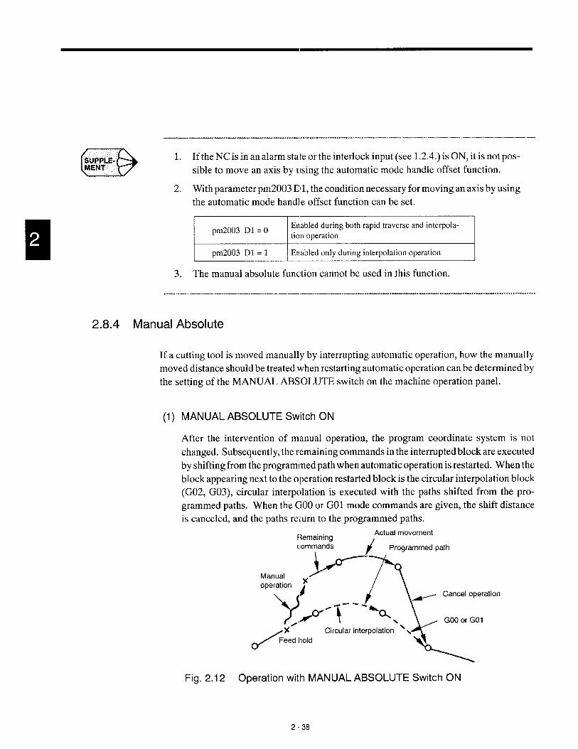
—.. —.——.....—— —.
(3SUPPLE-MENT
1. If the NC is in an alarm state or the interlock input (see 1.2.4.) is ON, it is not pos-
sible to move an axis by using the automatic mode handle offset function.
2. With parameter pm2003 Ill, the condition necessary for moving an axis by using
the automatic mode handle offset function can be set.
IEnabledduringboth rapid traverseand interpola-pm2003 D1 = Otion operation I
I pm2003 D1 = 1 \ Enabledonly duringinterpolationoperation I
3. The manual absolute function cannot be used in Ibis function.
2.8.4 Manual Absolute
If a cutting tool is moved manually by interrupting automatic operation, how the manually
moved distance should be treated when restarting automatic operation can be determined by
the setting of the MANUAL ABSOLUTE switch on the machine operation panel.
(1) MANUAL ABSOLUTE Switch ON
After the intervention of manual operation, the program coordinate system is not
changed. Subsequently, the remaining commands in the interrupted block are executed
by shifting from the programmed path when automatic operation is restarted. When the
block appearing next to the operation restarted block is the circular interpolation block
(G02, G03), circular interpolation is executed with the paths shifted from the pro-
grammed paths. When the GOOor GO1 mode commands are given, the shift distance
is canceled, and the paths return to the programmed paths.
FlemainingActual movement
commandsi
Programmed path
Manual
operation
Yx
Y’ 1
%
_ Canceloperation
./” ‘--% GOOor GO1
/
%’ Circularinterpolation‘sFeed hold
i.
Fig. 2.12 Operation with MANUAL ABSOLUTE Switch ON
2-38

2.8 OPERATION INTERVENTION DURING AUTOMATICOPERATION
(2) MANUAL ABSOLUTE Switch OF:F
If manual operation is executed by interrupting automatic operation, the program coor-
dinate system is shifted by the manually shifted distance. Accordingly, when automatic
operation is restarted, the program is executed in the shifted coordinate system.
Actual movementRemaining
commands/
Programmed path
P
Ty
\
Manual xGOO or GOl
operation
Y
+.
-,x””\- % ,d\
/
x’ Circular interpolation ‘.\
Feed hold %...+.-
Fig. 2.13 Operation with MANUAL ABSOL.UTE Switch OFF
The manually shifted amount is canceled by the fcdlowing commands or operation in
which the commands in the program are changed so that they agree wil:h the present val -
ues.
●
●
●
●
Manual or automatic reference point return
Setting the base coordinate system
Execution of skip (G31)
Reset operation
2-39
—.- .—. ,-—...—-——.—

2.9 AUTOMATIC OPERATIONS AT ENHANCED LEVEL
In this section, enhanced level functions of YASNAC J300 are described.
2.9.1 Return to the Setup Point
The function executes positioning at a jog feedrate at the position where the coordinate sys-
tem has been established (setup point). If the SRN input signal is “closed”, axis movement
at a jog feedrate stops after the completion of positioning at the setup point. Further jog feed
is not possible unless the SRN input signal is “opened”.
2.9.2 Return to the Operation Interrupted Point*
The “return to operation interrupted point” function is provided to return the axes to the pre-
viously located position where automatic operation has been interrupted to carry out manual
operation for measuring the machined dimensions or removing chips.
r-7
Fig. 2.14 Return to Operation Interrupted Point
The operation procedure is explained below.
Interrupt the automatic operation by pressing the SINGLE-BLOCK or FEED
HOLD switch on the machine operation panel.
Select a manual mode by placing the MODE SELECT switch on the machine
operation panel in the JOG, RAPID, HANDLE, or STEP position.
Move an axis in the manual mode to retract the cutting tool appropriately.
Carry out required operation such as measuring the workpiece, removal of
chips, etc.
Turn ON the INTERRUPTION POINT RETURN switch cm the machine op-
eration panel.
2-40

2.9 AUTOMA1”IC OPERATIONS AT ENHANCED LEVEL
CBSJJJF?LE- 1.
2.
3.
4.
Press the MANUAL PULSE MULTIPLY switch on the machine operation
panel corresponding to the direction to the machining interrupted point (the
point where the operation mode has been changed from automatic to manual).
The axis moves to the machining interrupted point at the selected feedrate and
it stops moving when it reaches the machining interrupte,~ point.
Turn OFF the INTERRUPTION POINT RETURN switch on the machine op-
eration panel.
Return the operation mode to an automatic mode and press the CYCLE
START switch on the machine operation panel. The automatic operation re-
starts.
If the axes are positioned on the machining interrupted point, t~lrn OFF the IN-
TERRUPTION POINT RETUllN switch. Otherwise, jog feed o~such axes is not
possible.
If the NC is reset after changing the operation mode from autonlatic to manual,
the present position is taken as the machining interrupted point. This means that
the axes are positioned on the machining intermpted point and, subsequent] y, jog
feed operation is not allowed unless the IN~ERRUPTION POINT RETURN
switch is turned OFF.
If automatic operation is interrupted by manual operation for a second time after
the automatic operation was once interrupted by manual operation and then the
automatic operation was recovered, the point where the operation mode was last
changed from automatic to manual is taken as the machining interrupted point.
If the REFERENCE POINT RETURN switch or the second reference point re-
turn switch is ON, the machining interrupted point return c!peration is not
executed but the reference point return or the second reference point return opera-
tion is executed.
—... ————-— -- ——.—,——-.—..——--
2-41
.

2.9.3 Saving the Present Position Data
The signal to save the present pc~sition data is provided. When the PST input signal is
“opened”, the NC saves the present position data to the internal memory at the timing the
signal is opened. Then, it executes the following operation using the offset data written in
the MDI operation to store the result of operation to the offset data memory.
Value to be written into the offset data memory
= (Value input in the MDI operation) - (Present position value saved in the NC memory)
The present position data is cleareci and the LED stops blinking by the reset operation (press-
ing the [RESET] key on the NC operation panel or “opening” the external reset input signal).
.—— — —— ——- —
DstlPPl&-MENT
The position at which the present position data is read to be saved, position data saving
operation, and the operation to calculate the value which is written to the offset data
memory could differ depending on the machine tool specifications.
— ——
2-42

2.9 AUTOMATIC OPERATIONS AT ENHANCED LEVEL
2.9.4 Program Restart *
By using the program restart function, it is possible to restart an interrupted operation in such
cases where execution is interrupted due to breakage of a cutting tool or to r{>startthe program
continuous] y from the block where the operation was stopped the previous day. By designat-
ing a sequence number of the block, the f unction allows the program to be restated from the
specified block. ml(1) Operation
Turn ON the PROGRAM RETURN (program restart) switch on the machine
operation panel.
After placing the MODE SELECT switch on the machine operation panel in
the MEM position.
Rewind the program to the beginning. For details of this operation, refer to
the explanation given in 6.1, “PROGRAM JOB”.
Press the [RESTART] (f3) function soft-lcey on the PROGRAM JOB screen
of the RUN process. The message requesting the input oft] le program restart
position information is displayed.
The message “ENTER SEQUENCE NUMBER” is displayed. Enter the se-
quence number and press the [WR] key.
The message “ENTER THE OCCURRENCE NUMBER’ is displayed. If the
same sequence number appears more than one time, enter Ihe position of the
objective sequence numbe:r and press the [WR] key. If designation of the posi-
tion of the objective sequence number is not necessary, press the [WR] key
only.
Press the [WR] key again. Sequence number search starts from the present
cursor position.
During the execution of the search, the message “PREI’ARING TO RE-
START” is displayed on the screen, and, at the same time, the program restart
message “PRS” blinks on and off on the screen. The “PRSI” is cleared when
the positioning of the axes at the restart position is completed.
Upon completion of these arch, the program restart information is displayed
on the screen.
If the searched sequence number is the objective block, turn OFF the PRO-
GRAM RETURN switch. If it is not the objective block, execute the program
restart request again.
2-43
—---- .——.—. ——— —

(2)
If there are M, S, and/or T codes that are necessary for restarting the program,
specify one on the program restart information screen. Select the manual
mode for this operation.
Enter the necessary M, S, and/or T code and execute it by pressing the CYCLE
START switch on the machine operation panel (execution of M, S, and/or T
code using the l-line MDI function).
Return the mode to the memory mode.
Restart the program by pressing the CYCLE START button. When the
CYCLE START switch is pressed, the axes move to the operation restart point
one by one in the order of X-axis, Z-axis, and C-axis. After that the automatic
operation restarts from the block next to the specified sequence number.
Precautions on Operation
● While the “PREPARING TO RESTART” message is displayed, no key opera-
tion is accepted except the [RESET] key on the NC operation panel. The G
and M code display in the program job of the operation process is not changed.
● After the “PREPARING TO RESTART” message is cleared, it is possible to
change the display in the lower half area of the screen to “G/M code informa-
tion”, “subprogram nesting information”, or “Program restart information”
by pressing the page keys.
● While “PRS” is displayed, it is not allowed to call and edit the program stored
in memory.
● The [RESTART] (f3) function soft-key is displayed only when the PRO-
GRAM RETURN switch on the machine operation panel is ON and the NC
is in the label skip status.
● The program restart request can be executed without using the PROGRAM
RETURN switch.
I pIn4015 DO=O \ PROGRAMRETURNswitchrwzessary I
I pxr14015DO= 1 \ PROGRAMRETIJRNswitchnot necessary I
● When the parameter setting is made so that the PROGRAM RETURN switch
is not necessary for the program restart request, the program restart mode ON/
OFF is changed by the [RESTART] (f3) soft-key. In this case, operation step
@ explained in item (1) above is not necessary.
2-44

2.9 AUTOMATICOPERATIONSK” ENHANCED LEVEL
(3) Remarks on Program Restadand Related Functions
The program restart function establishes various conditions during the execution of se-
quence number search so that the ccmditions at the restart will be the same as those when
the program was interrupted. However, some program commands require extra care.
These are indicated below.
(a) Program restart position
The position for the restart of program is generated in the NC. ‘rherefore, the axes
are regarded to move as programmed during the search for the program restart posi-
tion. If the function is executed in the mode called by the following G codes, the
point specified in a program and actual positioningpoint differ from each other and
in such modes, the point specified in the program is regarded as the end point: auto-
matic reference point return (G28), reference point return check (G27), return from
reference point (G29), second - fourth reference point return (G30), and machine
coordinate system (G53).
(b) Input signal
There are commands that perform different operations depending on the input sig-
nals. With one type of signal, the status at the start of search for the program restart
is retained, and with another type of signal, they are completely disregarded.
c The signals that retain the status at the start of search:
Mirror image (M95, M94), block delete,, machine lock, and F1-digit selection
● The signals that are disregarded:
Feed hold, single-block, auxiliary function lock, skip, program interrupt
(M91, M90), and optional stop
● The distance which the ax es were moved before cycle star! is cancelled disre-
garding of the ON/OFF status of the marwal absolute signal and the commands
are executed in the workpiece coordinate system called al the completion of
search.
2-45
.— .. ..--.. ——. . ,-., ,- —.. —. ——. ——.. .

(c) Using a macroprogralm
When a microprogram is used, care must be paid on system variables.
●
●
●
●
●
●
All interface input/output signals (#1000 - #1031, #1032, #1100 - #1131, and
#1132) are processed as “O”. Therefore, correct results cannot be expected.
Although the clock (#3001, #3002) is read and written normally, the time
count at the restart of the program is not guaranteed.
The control of single-block stop and wait for the completion of auxiliary func-
tion (#3003) is disregarded and the specification of control is made invalid.
The control for feed hold, feedrate override, and exact stop (#3004) is disre-
garded and the specification of control is made invalid.
Although the position data (#5000 - ) is read normally, the data generated in
the NC is used for the operation. For the servo error data (#5101 - #5105), “O”
is read.
Concerning the RS-232C data output 2 (BPRNT, DPRNT), if the program is
restarted at the RS-232C open command, an alarm occurs at the execution of
the RS-232C output command.
2-46

2.9 AUTOMATICOPERATIONSAT ENHANCED LEVEL
CD;IJJ;LE- 1.
2.
3.
4.
5.
6.
7.
8.
9.
10.
When moving the axes to the program restart position by pressing the CYCLE
ST~T switch, if interference occurs between the axes and the wcrkpiece or fix-
ture, move the axes to the same position manually.
If the CYCLE ST~T switch is pressed while the PROGRAM RI ITURN switch
is ON, the warning message “RESTARTING PROG!” is displayed.
After the completion of search fc)rprogram restart, operation intervention is not
allowed in other than manual mode until program restart is exacuted. If the
CYCLE START switch is pressed in the MDIl, TAPE or MEM mode, alarm
“0292” occurs and the message “IMPOSSIBLE TO START THE, COMMAND
WHEN RESTARTING PROGRAM” is displa yed.
If the PROGRAM RETURN switch is ON, it is not possible to move an axis
manually. Operation of jog switches and manual pulse generator k disregarded.
When requesting the program restart, conditions such as the input signals and tool
offset must be the same as those at the interruption of the program. Otherwise,
correct restart position and conditions cannot be established. Manual operation
that is carried out in the program restart operation is allowed only with the
MANUAL ABSOLUTE switch set ON.
During the search for program restart, the FEED HOLD switch and the SINGLE-
BLOCK switch are disregarded. If the NC is reset during the search, the search
is interrupted immediately. If this occurs, it is necessary to request the program
to restart once again.
This function executes processing on the assumption that the coordinate system
has been established correctly before the restart of operation. Therefore, if the
restart request is given without executing the reference point return after turning
the power ON, alarm “0411” to “:0415” occurs and the message “REFERENCE
POINT RETURN NOT COMPLETED” is displayed. With the incremental
command program, if the coordinate system setting command is not given at the
beginning of the program, the restart position cannot be generated correctly.
If the sequence number given with the restart request is not found, alarm “0290”
occurs and the message “PROGRAM RESTART SEQUENCE N“LJMBER NOT
FOUND” is displayed.
Upon completion of the search, if reference point return is executed by changing
the mode to manual, or if manual coordinate system setting is executed, alarm
“0291” occurs and the alarm message “COORDINATE SYSTHM SHIFTED
AFTER PROGRAM RESTART’ is displayed.
Program restart is impossible for DNC operation., tape operation, and high-speed
cutting mode operation.
2-47
.—.-.. ... . ,-—-. —- ————

3BASICS OF DISPLAY AND WRITING
OPERATION
Chapter 3 describes the basic terms related to opwation and
the NC operation panel.RI
3.1 BASICS OF TERMS REUTED TO
OPERATION . . . . . . . . . . . . . . . . . . . . . ...3-2
3.1.1 Process Screens . . . . . . . . . . . . . . . . . . . . . . . 3-3
3.1.2 Jobs and Functions . . . . . . . . . . . . . . . . . . ...3-3
3.1.3 YASNAC J300L Function Structure . . . ~. . . . . 3-4
3.2 NC OPERA1-ION PANEL . . . . . . . . . . . . . . 3-8
3.2.1 Keys and Display Screen
on NC Operation Parcel . . . . . . . . . . . . . . . . . 3-8
3.2.2 Normal Display on Cf3T Screen . . . . . . . . . . 3-15
3.2.3 Pop-up Menu . . . . . . . . . . . . . . . . . . . . . . . ...3-20
3.2.4 Key Buffer Edit Function . . . . . . . . . . . . . . ...3-21
3.2.5 Buzzer Function . . . . . . . . . . . . . . . . . . . . . ...3-22
3-1
. ——. -- —.. — —.- ..—..——. -—. ——. —, ——-.

3.1 BASICS OF TERMS RELATED TO OPERATION
This section describes the functions of the keys on the operation panel and guide messages
displayed on the screen for each of the operation steps according to the actual operation flow.
[OPERATION STEPS]
I
--LMounting Fixture
Mounting Workpiece
I I I
eSetting Coordinate
System
*
] TestCutting /
—
“m Part Program Tape
“DTool List
Tool Layout
~~-Checking Cutting Conditions
I Removing Chips I
.
.
.
I Changing Workpieces~—~nI
II
I Checking Accuracy I
Continuous Machining Checking Offset DataJ
A. I
/—
OPERATION STEPS

3.1 BASICS OF TERMS RELATED TO OPERATION
3.1.1 Process Screens
YASNAC J300 provides a variety of display screens and these display screens are largely
classified into six blocks according to the processes: edit, set-up, operaiion (run), mainte-
nance, common, and AUX1.
Processscreensdirectlyrelatedto cuttingEdit processscreen,set-upprocessscreen,runprocessscreen,AUX1screen I
IProcessscreenrelatedto NC maintenance IMaintenanceprocessscreen I
Processscreenusedin commonfor four cutting
-L---Commonprocessscreen
relatedprocesses,1 ml
At each screen, keys used to control the display are arranged on the NC operation panel (four
cutting process keys, maintenance process key, and common process key). By using these
keys, the required process screen can be quickly displayed for each machining process.
3.1.2 Jobs and Functions
Each process consists of jobs and each job has functions. One process has a maximum of
five jobs, and for each of the jobs there are no restrictions in the number clf functions. After
selecting a process, the jobs and functions are selected by using soft-kc ys. Tree structure of
the process, jobs, and functions is indicated in Fig. 3.1..
‘1MAINT
1
I
PARAM DIAGN
I
I I ‘ “J(T
lN/OUT
1]
PARAM SETING DISP“:s IN ~~ ~~}
Fig. 3.1 Example of Structure
PRO-
CESS
JOB(Max, 5)
FUNC-TIONS
3-3
.—.. .. ——.——. —

.-. ,. -.,. - .---, - .. . . .3.1.3 YASNAG J3UUL t-unction Structure
The structure of processes, jobs, and functions is indicated below.
PROG 1- -1 EDIT ‘~ fl OPEN ‘~
f2 1 SAVE
~~el--l DIR fl OPEN
f2 DELETE
f3 RENAME
f4 COPY
f5 DSP,SL-—— —.—— —— —— —I
fl I SELECT
f2 I
1--1 f3 II I I L—
f4 I I
f5 IL———-——-———— —
lN/OUT fl IN
f2 OUT
f3 VER
f4 RS232C
f5

3.1 BASICS OF TERMS RELATED TO OPERATION
I L— LO..———-———_
-1
.J
+--~ :;q?~
7- -:.SETING fl --- TGR SW* =]
f2 —- SOFTSW *—J
MACRO * ‘1
-+---t : SETING =]
~-- S-LMT =]
3-5

MAINT k 4 PARAM L--
-1 DIAGN
DATA !- fl VER NO
f2‘u”’ o
f3
3-6

3.1 BASICSOF TERMS RELATEDTO OPERATION
COMN F --l Po”~} ----- ALL =1f2 ABS =1f3 EXTERN “—]
f4 INCR =1
–-~1
J
I L— —.—-—— ———— -——— —-
L— l- J—— ——--.~—
~——__7I 1: Functions displayed by pressing the FiJNCTION SELECTION key
I—— ——-A
3-7

3.2 NC OPERATION PANEL
This section describes the configuration of the NC operation panel and the editing function.
3.2.1 Keys and Display Screen on NC Operation Panel
NC operation panel of YASNAC J300 series is shown in Fig. 3.2.
POWER ON button 9-inch graphic display Data keys AUX key RESET key
I I Process keysA \ J_ I,
‘ F’ “’’’’”=-
1!
l—————’— JI II
POWER OFF button Soft-keys Address keys Page keys and Action keys
cursor keys
Fig. 3.2 Operation Panel
(1) POWER ON/OFF Buttons
(a) POWER ON button (Turning ON the power to the NC unit)
Power is supplied in two steps of operation. In the first, pressing of the POWER
ON button, power is supplied to the control unit, and power is supplied to the servo
the second time the POWER ON button is pressed. With some models of machines,
power will be supplied to the servo in the first pressing of the POWER ON button.
For details, refer to the manuals published by the machine tool builder. To turn ON
the servo power after emergency stop or other similar operation, this button is also
used.
(b) POWER OFF button (Shutting OFF the power to the NC unit)
The power is supplied to the control unit and servo is shut OFF by pressing the
POWER OFF button.

3.2 NC OPERATION PANEL
(2) 9-inch Graphic Display (CRT)
Data are displayed indifferent sizes of characters in the range from 1 x 1 to 3 x 3 mag-
nification<
Maximumnumberof characters
Displayedcharacters
Graphicdisplay 340 characters x 20 lines(25 lines)= 800 characters(or 1000characters)[in 1 X 1 scale]
.-
Numerals(Oto 9, –, .)Alphabets(A to Z)Specialcodes[/ (slash),EOB,+, fl,SP,=, etc.]
640 x 400 dots (highresolutiontype)
I 4C1charactersf’ “-–--=
/[O line
or
25 line
Immlmmmmiml
Fig. 3.3 9-inch Graphic Display
3-9
.— — .— ..- ..-. .——.——.—.——— —- —-—

(3) Process Keys
The process keys are used tc) select the process. The following five process keys are
provided and by pressing one of these keys, the corresponding process is selected.
[PROG] Edit key : Selects the editing process.
[SET] Set-up key : Selects the set-up process.
[RUN] Operation key : Selects the operating process.
[MAINT] Maintenance key : Selects the maintenance process.
[COMN] Common key : Selects the common display or returns to eachprocess.
3-1o

3.2 NC IOPERATION PANEL
CDSUPPt.E-MENT
DTERM?
(4) Soft-keys
Thesoft-keys areselection keysrelated todisplay andwriting. Thesoft-keys aredis-
played in two rows (upper and lower) as shown in Fig. 3.4. The upper soft-keys are used
to select jobs and the lower ones to select functions. By pressing the UP/DOWN SE-
LECT key, the selection mode can be changed between the job selection mode and the
function selection mode. The presently selected mode can be found from the UP/
DOWN SELECT indicator on the CRT and also from the soft-keys.
In the job selection mode, selection of job soft-keys is possible and in [he function selec-
tion mode, selection of function soft-keys is possible. If more than five functions are
provided in the selected job, the next set of functions are displayed by pressing the
FUNCTION SELECT key. The selected job or function is highlighted. ml
FUNCTION Job soft-keysSEL,ECT indicator
~= Function soft-keys
– UP/DOWN SELECT
indicator
::::;oN ~+-up00i4hisELE13key
-—— FU NCTION soft-key
Fig. 3.4 Soft-keys
--- ——,
When there are more than five function soft-keys, the FUNCTION SELECT indicator
is displayed as shown in Fig. 3.4.
When the UP/DOWN SELECT indicator is moved, the box moves up or down.
When the box is in the upper position, it indicates the job selection mode and if it is
in the lower position, h indicates the function selection mode.
-“-- —.—
-- .—● Soft-key
The soft-keys indicate the menu frames displayed at the lower patt of the CRT. Selection of menu is accom-
plished by pressing the key located at the corresponding position
3-11
—.—————-—- .. —.--—. -——. . .. ——— —-— ——- .—— -—-——

(5) Address Keys
The address keys are used to specify the addresses when writing data.
[fl Slash key : The slash key is used to indicate the optional skipcommand.
[SHIFT] Shift key : To display special characters such as “%” and “#”,press the address keys of F to Z on which the corre-sponding special character is indicated while pressingthe [SHIFT] key.
(6) Data Keys
The data keys are used to write numerical values such as command values, tool offset
amounts, and settings for parameters.
[0] - [9] Numeric keys : Used to enter numerals.
[-1 Minus key : Used to enter a minus sign.
[.1 Decimal : Used to enter a decimal point.point key
(7) Page Keys
Display given on the screen is assumed as “page”, and these keys are used to change
the display page to the previous or next page.
[ A ] page up key : Used to display the previous page.
[ v ] page down key : Used to display the next page.
When a page key is held pressed, the display page changes continuously.
3-12

3.2 NC OPERATION PANEL
(8)
(9)
Cursor Keys
The cursor keys are used to move the cursor on the screen up/down and right/left. When
the cursor is positioned at a certain position on the screen, that position is highlighted.
In this manual, the position displayed in highlighted block is called the cursor.
(a)
(b)
Moving the cursor up/down
When a set of parameter data is displayed with parameters selected, the upldown
cursor keys are used to move the cursor to the required parameter position.
[A] cursor up key : Used to move the cursor up.
[7] cursor down key: Used to move the cursor down.
When the cursor up or down key is held pressed, the cursor mtwes continuously.
It is also possible to move the cursor to the recluired position by specifying the re-
quired number; enter the required number ancl press the cursor up or down key, and
the cursor moves to the specified position.
Moving the cursor right/left
[<] cursor left key : Used to move the cursor left.
[F] cursor right key: Used to move the tumor right.
Action Keys
The action keys are used for various applications. When an action key is pressed, dis-
play on the screen will be changed by such as entered data.
[CAN] Cancel key :
[EOB] End of block key :
[INSRT] Insert key :
[ALTER] Alter key :
[ERASE] Erase key :
[WR] Write key :
Used to cancel typing error of numerals or addressdata.
Used to indicate the end of a block. “;’’(semico-lcm)is displayed cm the screen insl:ead of EOB.
Used to insert data to the memory.
Used to correct data in the memory
Used to erase data in the memory
Used to store address data (=word) keyed in byusing the address keys and data k:ys
3-13
—...- ——.——— — .— .--—. ..— —— ..- ..—.——--—. —— .—— ——

(IO) RESET Key
The RESET key is used to reset the internal state of the NC unit. When the RESET key
is pressed, the following items are executed.
●
●
●
●
●
●
●
●
●
●
Cancels the move commands.
Clears the buffer area.
Resets the alarm (after removing the cause).
Cancels the tool offset.
Cancels the miscellaneous function.
Turns ON the label skip function.
Rewinds the memory. (Returns the program execution pointer to the begin-
ning of the program.)
Whether or not the memory rewind is executed is determined by the setting
for the parameter.
E
Memory rewind is executed.
Memory rewind is not executed. 1If “pm4008 DO = O“,memory rewind is executed by pressing the [SRCH] soft-
key.
Sends the reset signal.
Resets the G code.
Clears the key buffer area.
Note that the following items are not influenced by the reset operation.
● Present position data of the axes
● F command
● S and T commands
● Tool offset amounts, setting data, and parameter data
(ll)AUX Key
The AUX key is used for the future expansion of the functions.
[AUX1], [AUX2] keys: Used for optional functions.
3-14

3.2 NC OPERATION PANEL
3.2.2 Normal Display on CRT Screen
Independent of the selected process, job,, and function, the folIowing information is always
displayed at the top line and the lower five lines as shown in Fig. 3.5.
-—
II
II
INPUT COMPLETE 4I ~--
1234 SERVO OFF 4
MEM INPUT ERROR! MSTF~.lV~
Fig. 3.5 Normal Display on the Screen
– Nc,rmal Display@)
– Nc,rmal Display@
- Nmmal Display@
– Nc,rmal Display@)
- Normal Display@
(kc?y buffer area)
- Ncrmal Display@
(soft-keys in two rows)
3-15

Contents of normal display are indicated in Table 3.1.
Table 3.1 Contents of Normal Display
NormalDisplay
Item Message Meaning
ALMScreentitle display OFFSET
Job nameof the selectedscreenis displayedas thetitle.. . . etc.
EDT AUX1
ProcessdisplaySET AUX2MNT The selectedprocessnameis displayed.
COM
aThe nameof the selectedsystem.
Displayof selected TOOLREST 1This displayis not given for the NC unit that has only
system TOOLREST2one controlsystem.Selectionfromsevenpatternsis possibleby the set-ting for parameterpm3105.
Programnumber o“****The numberof the programoperatingin the selected
display 000001-099999 series is displayed.O*****indicatesthat programnumberis not selected.
Sequencenumber NOOOOO- N99999The presentsequencenumberof the selectedseries is
display displayed.
INPUT?( Y/N)INPUTTINGINPUTSTOPPEDINPUTCOMPLETE
OUTPUT?( Y/N)OUTPUTTINGOUTPUTSTOPPEDOUTPUTCOMPLETE
VERIFY?( Y/Ii)VERIFYINGVERIFICATIONSTOPPED
Displayof opera- VERIFICATIONCOMPLETE
@ tion resultsand CREATE? ( Y/N)Resultof key operationand the NC executionstate
guide messages CREATIONCOMPLETEare displayed.
COPY?( Y/N)COPYCOMPLETE
RENAME? ( Y/’N)RENAMINGCOMPLETE
DELETE? ( Y/N)DELETIONCOMPLETE
SELECTOTHERJOBPUSHEXECTO CONTINUE
EXECUTINGSTOP?(Y/N)
SEARCHCOMPLETE
3-16

3.2 NC OPERATION PANEL
Table 3.1 Contents of Normal Display (ccmt’d)-—
NormalDisplay
Item Message Meaning
.-
INPUTO NO.INPUTCOMMENTSAVINGCOMPLETETRANSFERPARM?
TRANSFERRINGPARMTRANSFERCOMPLT
INPUTO NO.SAVINGSEARCHINGINPUT?(PUSHY)OUTPUT?(PUSHY)
Displayof opera-VERIFY?(PUSHY)
@ tion resultsandOK?(Y/N) Resultof key operationand the NC executionstate
guide messagesMODEIS UNSUITABLE are displayed.SEARCHSTOPPED
INPUTO NO. (DELETE)DELETEALL?(Y/N)INPUTOLDO NO.INPUTORIGINALO NO.INPUTNEWO NO.INPUTO NO. (COPY)CLEARALL OFFSETS?(Y/N)
SEARCHCOMPLETEINPUTOLDSTRINGINPUTNEWSTRING( YesiNo/All) ?
--The top priorityalarmoccurringin the selectedser
::~ ‘umber ‘is- 0001-9999is displayecl.If thereis no alarmin the selectedse-ries, the top priorityalarmof the other series is dis.played.
--TH error The messageof the top priorityalarmoccurringin
@ Alarmmessage Charactercannotbe used the selectedseries. If thereis no .darmin the selecdisplay Externaldata inputerror series,the alarmmessageof the top priorityof the
. . . . . . etc. otherseriesis displayed..-
Displayof system TOOLREST 1 If an alarmmessageis displayed,this indicatestheinvolvedwith TOOLREST2 controlsyslcrninvolvedwith the alarm.alarm ---
EditMemoryMDI
@ Operationmode Communication The operaticmmodeof the select,:dseriesis dis-Step played.HandleJogRapidfeed
3-17
—.. - ..—. —. ——-— —.—

Table 3.1 Contents of ’Normal Display (cent’d)
NormalDisplay
Item Message Meaning
INPUTERROR!O NO.NOTFOUND!NOTFOUND!ALREADYIN !OVERMEMCAP !TOOMANYPROGS!VERIFYERROR!MACROLOCK!LINELOCK!RUNNINGPROGRAM!NC RUNNING!FORMATERROR!EDITLOCK !NOTFOUND!ALREADYEDIT !SELECTMODEERR !COPYMODEERROR!MOVEMODEERROR!PRMSETTINGERROR!
Warningindicateslowerpriorityerror,whichdoes
@ Warningdisplay CAN’TSET COORD! not causeoperationstop.
OVERMDIBUFFER! Resetthe errorby key input,modechange,screen
PRMSETTINGERR ! switching.
READINGPROGRAM!EDITINGPROGRAM!IMPOSSCOLLECT!EDITLOCK !OFFSETERROR!OVERMEMCAP !RUNNINGPROGRAM!TOOLARGEAREA !ALREADYIN !NC RUNNING!BREAKPOINT !SYSTEMNO.1 !CAN’TWRITE!ADDRESSINGER!AXISMOVING!RESTARTINGPROG!CAN’TSET COORD!

3.2 NC OPERATIONPANEL
Table 3.1 Contents of Normal Display (ccmt’d),..
NormalDisplay
Item Message Meaning
.-
Indicatesthe statusof the selecteeseries.M, S, TM/SITIF/R Waitingfor the completionof the specifiedcode.DWELL F: Duringcutting, R: Duringrapid traverse,
DWELL: Duringdwell.-—
OperationstatusIndicatesthe statusof the selecteeseries.
---STP Indicatesthat the NC stopped.
---RST Indicatesthat the NC is in resetslatus.
--
BUFnIndicatesthat the NC is in the n-blockbufferingsta-tus.
--
G Indicatesthe statusof the selectedseries.
ALM Indicatesthat an alarmhas occurred.-—
BAT Indicatesthat the batteryalarmh;.soccurred.-—
Alarmstatus Indicatesthat bothan alarmand a batteryalarmhaveA/B occurred.
BGA Indicatesthat a backgroundalarmhas occurred.---
B/BIndicatesthat botha backgroundalarmand a batteryalarmhave occurred.
-—Label skip LSK Displayedwhenlabelskip is ON.
.-—
B KeybufferKeyinputechoback display(up to 40 characterscan be input.’)
-—
@ Soft-keySelectionkey for displayand writing(in two rows -up and down)
3-19
——.— .—— -.. —- ——. — ——-—

3.2.3 Pop-up Menu
The pop-up menu is used to select a menu item in the selected function. Usually, there is only
a single menu item in a function. The pop-up menu is used to select the menu if there is more
than one menu item in the selected function. The soft-keys that support the pop-up menu are
distinguished by the soft-key frame with a double-line at the left side.
I
& &Pop-up menu is used to
select the menu from
these sets of menus. .-a
If the [DELETE] soft-key is pressed, the pop-up menu is displayed. Selection by the
pop-up menu is made by using the UP/DOWN SELECT key and the [WR] key. The
pop-up menu is cleared when the selection is finished.
PROG(OPR] EDT O’**** NOOOOO
F----lEACH +
ALL
INPUT O NO. (DELETE)
ImmmEmlEEl
— Pop-up Menu
Fig. 3.6 Pop-up Menu for DELETE Function
3-20

3,2 NC OPERATIONPANEL
3.2.4 Key Buffer Edit Function
For the data keyed in by key operation and displayed at the key buffer area on the CRT screen,
insertion and deletion of characters are allowed. This key buffer area edit function is helpful
to correct the entered data in the following cases.
● The user finds an error immediately after keying in the data.
● The keyed in data could not be entered with the “INPUT ERROR!” warning
message displayed even when the [WRI key was pressed.
(1)
(2)
Key Buffer Cursor
The underline cursor” “ blinks at the beg-inning of the key buffer area. This—underlined cursor is the key buffer cursor. It moves to the right as characters are keyed
in and is displayed after the last character.
Moving the Key Buffer Cursor
With characters keyed into the key buffer area, the underlined cursor moves in response
to the operation with the cursor rightfleft keys. The underlined cursor is valid in the key
buffer area but not for the contents displayed on the screen. However, if there are no
characters keyed into the key buffer, the underline cursor is valid fclr the contents dis-
played on the screen. Examples of the key buffe~ edit operation are explained below.
(a) Deletion
GOOX1 OO.Z1OO.;_
To delete “X1OO.” while the data indicated above are keyed irl to the key buffer
area.
@ Move the key buffer cursor back to “Z” by pressing the c~msor left key.
GOO X1OO. z100.;
@ Press the [CAN] key five times to delete “X1OO.”.
GOOZ1OO.;
When the [CAN] key is pressed, the last character before the kl~ybuffer cursor is
deleted. If the key buffer cursor is at the beginning of the key buffer area, pressing
the [CAN] key has no effect and no characters are deleted.
3-21
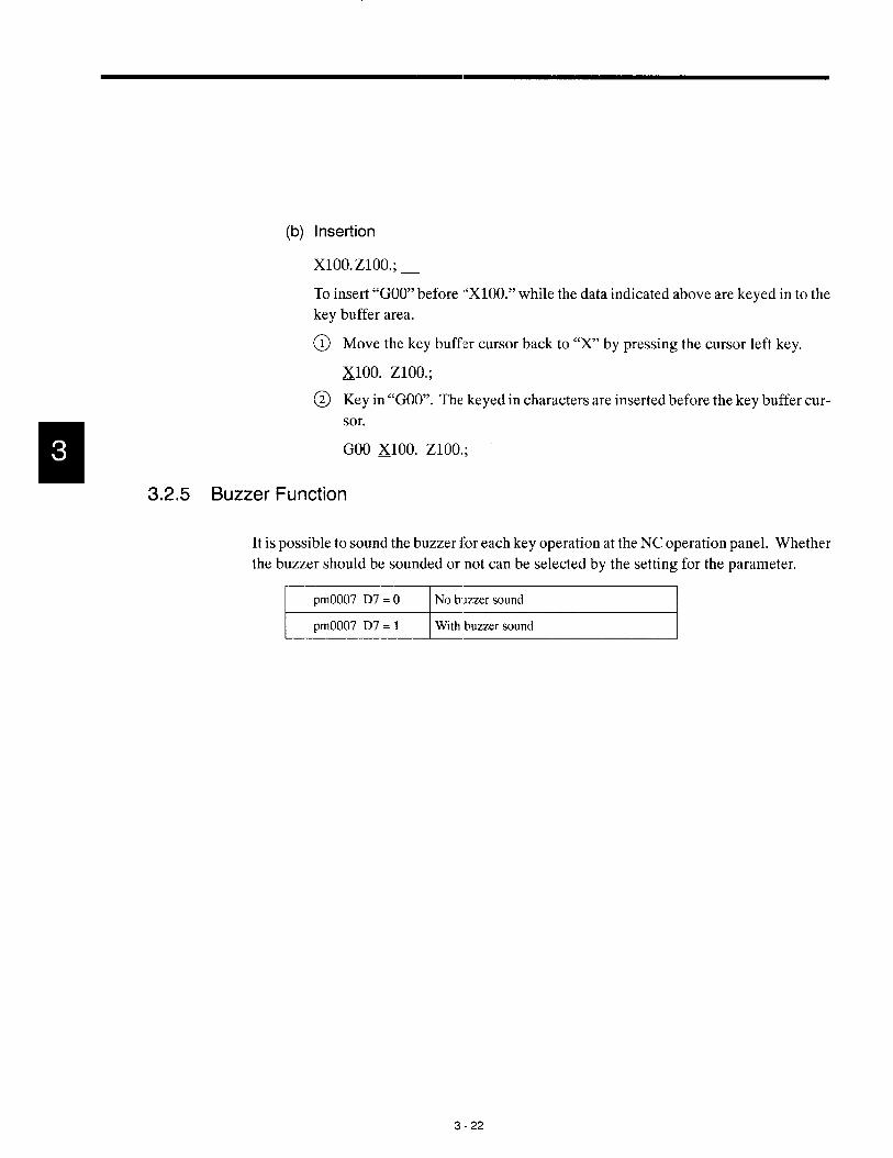
(b) Insertion
Xloo. zloo.;
To insert “GOO” before “X1OO.” while the data indicated above are keyed in to the
buffer area.
Move the key buffer cursor back to “X” by pressing the cursor left key.
~loo. Zloo.;
Key in “GOO”. The keyed in characters are inserted before the key buffer cur-
sor.
GOO ~100, Z1OO.;
3.2.5 Buzzer Function
It is possible to sound the buzzer for each key operation at the NC operation panel. Whether
the buzzer should be sounded or not can be selected by the setting for the parameter.
-~
3-22

EDIT PROCESS OPERATION
Chapter 4 describes the operation carried out by using the edit
process keys. In the edit process a part program is created us-
ing the edit job, part program directory job, part pro{gram input/
output and verify job.
Job selection is possible by using either the [EDITl job soft-key
or the [PROG] process selection key.
The operation indicated above can be executed anytime inde-
pendent of the NC operation mode even while automatic op-
eration is being executed.
4.1 PART PROGRAM EDIT JOB . . . . . . . ...4-3
4.1.1 Calling aPart Prograrrl . . . . . . . . . . . . . . . . . . . 4-4
4.1.2 Editing aPart Program . . . . . . . . . . . . . . . . . . . 4-7
4.1.3 Saving a Part Program after Editing . . . . . . . 4-22
4.1.4 Deleting a Part Program . . . . . . . . . . . . . . ...4-23
4.2 PART PROGRAM DIRECTORY JOB ..4-26
4.2.1 Display of the Directory of Part Programs . . 4-26
4.2.2 Calling a Part Program . . . . . . . . . . . . . . . ...4-33
4,2.3 Deleting a Part Program . . . . . . . . . . . . . . ...4-35
4.2.4 Renaming a Part Program . . . . . . . . . . . . . . . 4-37
4.2.5 Copying a Part Program . . . . . . . . . . . . . . ...4-39
4-1
.-- —.. —.— ..-. .—

4.3 PART PROGRAM lNPUT/OUTPUT
AND VE:RIFY JOB . . . . . . . . . . 00 . . . . ...4- 40
4.3.1 inputting a Part Program . . . . . . . . . . . . . . . . . 4-40
4.3.2 Clutputting a Part Program . . . . . . . . . . . . . . . 4-44
4.3.3 Verifying the Part Programs . . . . . . . . . . . . . . 4-51
4,3.4 Setting the Communication Conditions . . . . . 4-55
4.3.5 CMher Function . . . . . . . . . . . . . . . . . . . . . . ...4-60
4-2

4,1 PART FROGRAM EDIT JOB
4“1 PART PROGRAM EDIT JOB
To select the part program edit job, press the [EDIT] (fl) job soft-key. In the part program
edit job, the following functions are provided.
● Calling a part program
● Editing a part program
● Saving a part program
● Deleting a part program
Optionally, editing up to three part programs is simultaneously possible. The standard pro-
gram storage capacity is 16 KB (40 cm in tape length) and this capacity can be optionally
expanded to 32 KB, 64 KB, 128 KB, 256 K13, 512 ICE],1024 KB, or 2048 KB.
(3)su3u;LE- 1. If a process key other than [PROG] is pressed. while editing a part program, the
part program is temporarily saved. The interrupted editing can be continued after
pressing the [PROG] key.
2. Do not turn OFF the power during editing. Before turning OFF the power, the nApart program(s) must be saved.

A *
w
w
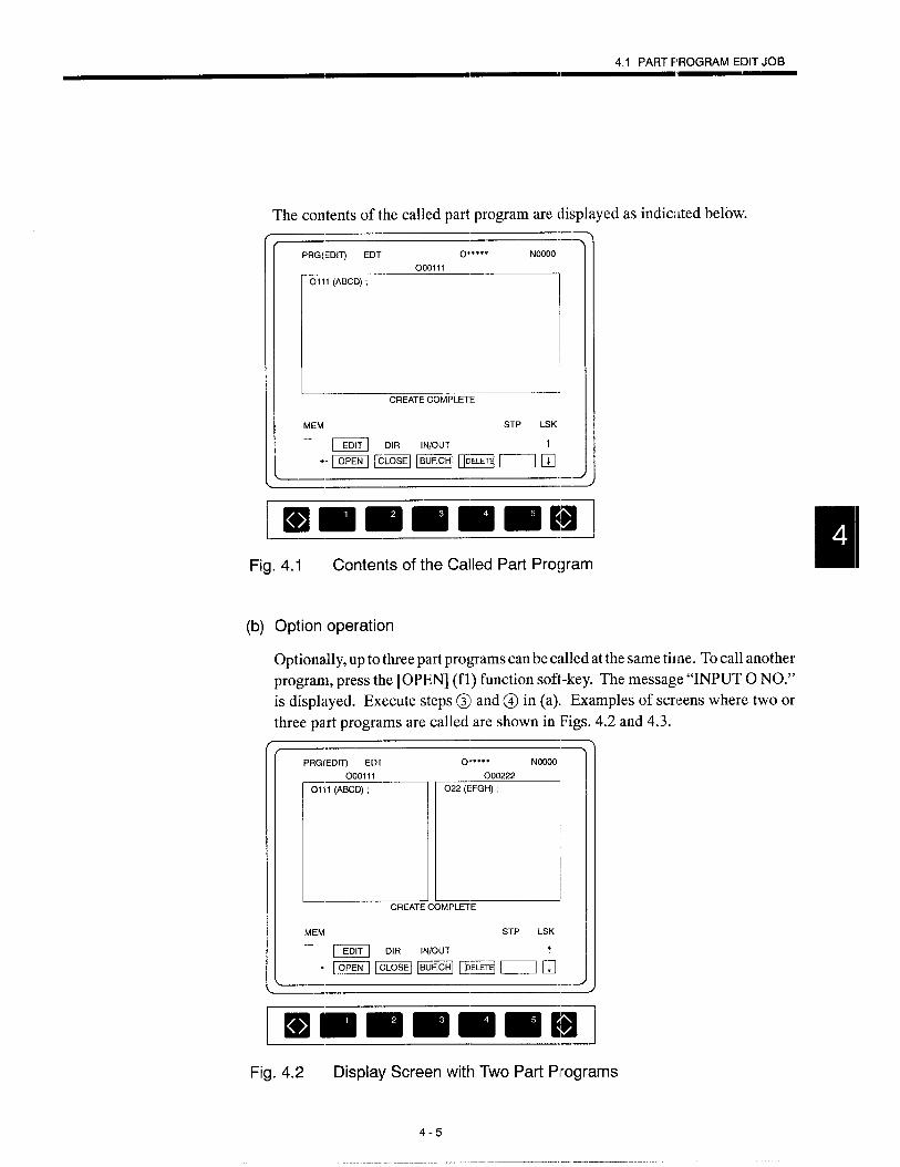
4.1 PART PROGRAM EENTJOB
The contents of the called part program are displayed as indic:lted
-—PRG(EDIT) EDT 0“”””” NCOOO
fmnil+
TO1ll (ABCD) ;
—,-.”c.l-. on,,”, m.
MEM STP LSK
-Emlmmmmmlllill
Fig. 4.1 Contents of the Ca!led Part Program
(b) Option operation
Optionally, up to three part programs can be called at the same time. To call another
program, press the [OPEN] (fl) function soft-key. The message “INPUT O NO.”
is displayed. Execute steps ~] and@ in (a). Examples of screens where two or
three part programs are called are shown in Figs. 4.2 and 4.3.
PRG(EDIT) EDT O***+* NOOOO
000111 000222
r==r= -L-L ~
CREATE COMPLETE
MEM STP LSK
– m D’R ‘“/QuT
“-H--Eqml+.-—
[Hmlmmmlmmjillljilll
Fig. 4.2 Display Screen with Two Part Pirograms
4-5

(2)
PRG(EDITI EDT O***** Noooo
000111 000222 000333
DDDCREATE COMPLETE
MEM STP LSK
– ~ Dll~ lN/ouT
-mEo@mEmA
Immlmmlmlm Bl1 J
Fig. 4.3 Display Screen with Three Part Programs
Using the [BUF. CH] (f3) Soft-key
If the part program to be called is within the allowable range of program call, the speci-
fied program can be called. However, if calling a new part program causes the allow-
able range of program call tc)be exceeded, the program selected by the [BUF. CH] (f3)
function soft-key is saved automatically before calling the specified program.
Apart program can be called without using the [OPEN] (fl) function soft-key. Follow
the procedure indicated below.
After keying in the program number of the program to be called, press the
[WR] key. When the existing program number is entered, the specified pro-
gram is called. If a program number not existing in the memory is entered, the
message “INPUT COMMENT” is displayed indicating that the specified pro-
gram number is a new program number.
Key in a comment and press the [WR] key.
4-6

4.1 PART PROGRAM EDIT JOB——
4.1.2 Editing a Part Program
The procedure for editing the part program called to the screen is explained below. Optional-
ly, the expansion editing functions (copy, move, and alter and erase with range specification)
can be used. Select the part program to “beedited in the following procedure.
@ If more than one program has been called, press the [BUF. CH] (f3) soft-key
several times until the cursor moves to the program number of the program to
be edited.
PRG(EDITI EDT 0“,””” NOOOO
Ooalll 000222 000333
DDD
MEM STP LSK
– = D’” lN/ouT
“mlmmzm maa
.
Fig. 4.4 Part Program Editing Screen
@ For editing a part program, the following keys are used: ~unction soft-keys
([SELECT] (fI), [COPY] (f2), [MOVE] (f3), [REPL] (f4), and [BT/TOP]
(f5)), function keys ([INSRT], [ALTER], and [ERASE]), cursor keys (up/
down, right/left), page keys, etc.
4-7
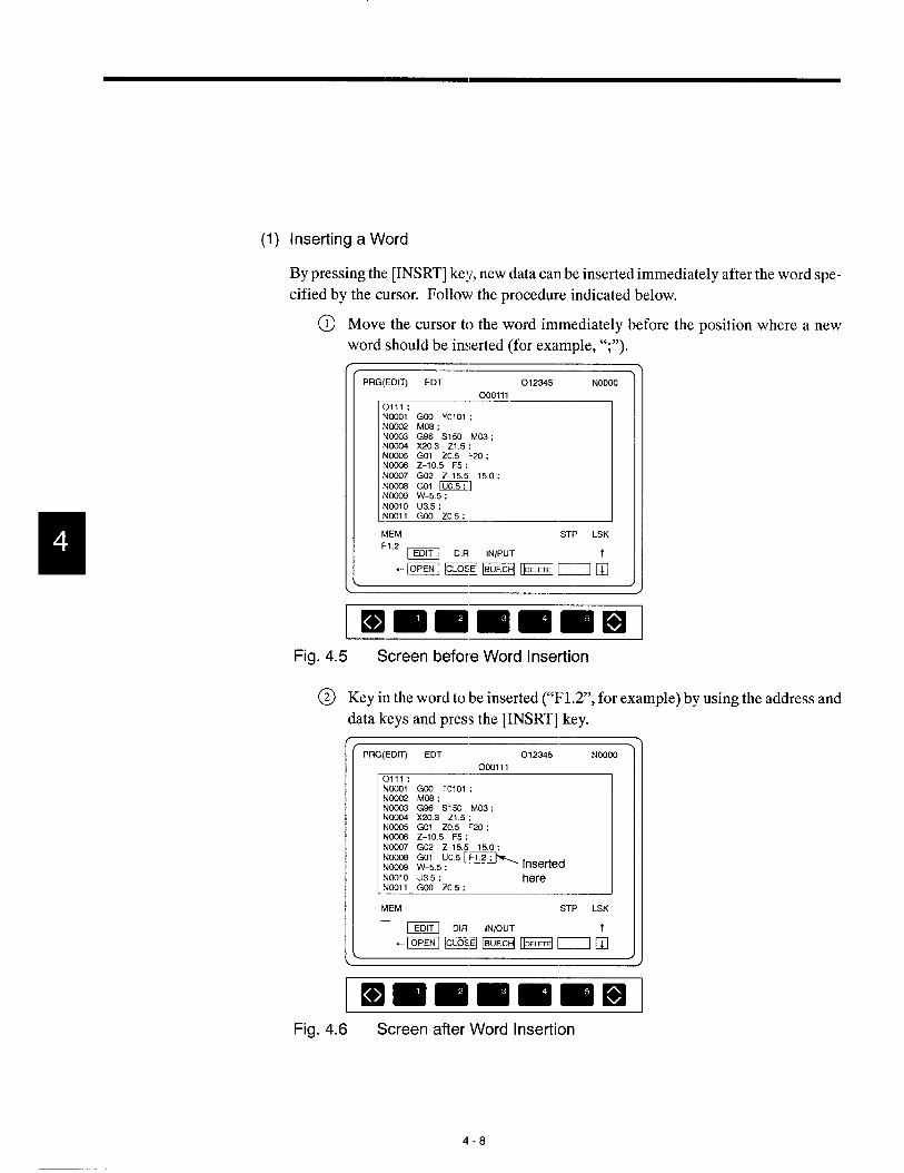
(1) Inserting a Word
By pressing the [INSRT] key, new data can be inserted immediately after the word spe-
cified by the cursor. Follow the procedure indicated below.
@ Move the cursor to the word immediately before the position where a new
word should be inserted (for example, “;”).
(( PRG(EDIT) EDT 012345 NOOOO 1
Noo05 GO1 20.5 F20 :N0006 Z-l O.5 F5 : I
MEM STP LSK
Fig. 4.5 Screen before Word Insertion
@ Key in the word to be inserted (“F1.2”, for example) by using the address and
data keys and press the [INSRT] key.
[( PFIG,EOIT EDT 012345 NOOOO )
000111
NCOO1” GCO TO1O1 ;Ncc02 M08 :NCC03 G90 S150 M03 ;Ncc04 X2O.3 21.5 ;NCCC15 GO1 20.5 F20 ;NCCCf3 Z-10.5 F5 ;NCC07 G02 Z-15.5 15.0 ;NCXX18 GO1 U0,5 [~ ,nsefledNOC09 W-5.5 ;NO31O U35 : hereNKM1(X0705:MEM STP LSK
@id DIR lN/ouT“EmmzmEaal
Iwlmmmlmnl]Fig. 4.6 Screen after Word Insertion
4-8

4.1 PARTPROGRAMEDITJOB
..—
(3SUPPLE- After inserting a word, the cursor indicates the word entered last. The insertion opera-?4E~ tion allows more than one word (within 40 characters) to be inserted at a time.
—
(2) Altering a Word
By pressing the [ALTER] key, the word specified by the cursor is erased and replaced
with a new word. Follow the procedure indicated below.
Move the cursor to the word to be altered (for example, ” X20.3”).
( PRG(EDl~ EDT 012345 N1 2345
MEMSTP LSK
x30. —
Ocnlll
0111 ;NCOO1 G03 TO1O1 :Ncc02 M08 :NCC03 G% SIW M03 :
1$% wzt55k20;NCC&3 Z-10.5 F’ :NC007 G02 Z-15.5 15.0:NcM08 Go1 UO.5 :NoD09 W-5.5 :NOOl O U3.5 :NoOl 1 GCO 20.5:
Fig. 4.7 Screen before Alter
4-9
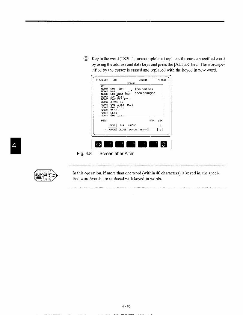
@ Key in the word (“X30.”, for example) that replaces the cursor specified word
by using the address and data keys and press the [ALTER] key. The word spe-
cified by the cursor is erased and replaced with the keyed in new word.
[\
PRG(EDITI EDT 012345 N12345
Ocolll
Rf’:””~
ElMEM STP LSK—
m OIR lN/ouT
-ml PwImEaal
ImmlmmlEm ElFig. 4.8 Screen after Alter
(3SWPLE- In this operation, if more than one word (within 40 characters) is keyed in, the speci-MEN’T fied wordlwords are replaced with keyed in words.
4-1o

4.1 PART FROGRAM EDIT JOB
(3) Erasing a Word
By pressing the [ERASE] key, the word specified by the cursor is erased. Follow the
procedure indicated below.
@ Move the cursor to the word to be erased (for example, “1220”).
---PRG(EDIT) EDT 0123=45 N1:!345
0L13111 .-0111 ;NCXII1 G03 TO1O1 :NC032 M08 :NC0)3 G90 S150 M03 ;NCCJ34 X30. Z1 .5:NC095 GO1 20.5 ~;Nc@3 Z-1 0.5 F5 :NO007 G02 Z-15.5 150:
Fig. 4.9 Screen before Erasing
@ Press the [ERASE] key. Only the specified word is erased..-—.-—
PRG(EDITI EDT 012345 N’12345
003111
E:
.—0111 ;NCCO1 GCCI TO1O1 ;NCC02 MOB :N00J3 G% S150 M03 :NOCC14 X3O. Z1 .5.N00J5 GO1 Z0.5~Z- ErasedNC036 Z-1 0.5 F5 :Ncc07 G02 Z-15.5 15.0:NCC138 GO1 UO 5:Nc0J9 W-5.5 :NO31O U3.5 :NCOl 1 GoO 20.5: .-
MEM STP LSK
– m DIR lN/oLJ-r
-mmmomm;l-——
. -—-—
Fig. 4.10 Screen after Erasing
4-11
.— .—..—

*
(4) Search and Erase Function
The search and erase function erases the characters in the specified range, from the pres-
ent cursor position to the specified character-string. Follow the procedure indicated be-
Move the cursor to the first character of the character-string to be erased (for
example, “NOO07”).[
PRG(EDIT EDT 012345 N12345
OCQ11
m.=NOX35 GOI 20.5 F20 ;
w :;:;::.: 15.0;No&38 Go1 UO.5 ;NCW9 w+.5 ;
MEM STP LSK
ImmlmmmmlmlFig. 4.11 Specifying the First Character in the Character-string to be Erased
@ Key in the last word of the range to be erased (for example, “YO’>if the part
program should be erased up to “UO.5” in the “NOO08 GO1 UO.5;” block) and
press the [ERASE] key. The specified range is highlighted. At the same time,
the message “DELETE OK? (Y/N) ?“ is also highlighted.
PRG(EDIT) EOT 012345 N12345Ocol 1
10111: 1NOCH31”GIN TO1O1 ;Noo02 M0f3 ;NC003 G% S150 M03 ;Ncc04 X30 21.5:NoG05 GO1 20.5 F20 :NC(XI6 Z–l O.5 F5 ;N0337 Gfx Z–15.5 15.0 ;
Cm8 GO1 UO.5 : IN0039 W–5.5 ; The range to beNOO1O u35 ;Nmli cm 7n6. erased
MEM STP LSK
– - DIR lN/ouT“LziFEEmmEmiEaub
Fig. 4.12 Screen for Specifying the Range to be Erased
4-12

4.1 PART F ROGRAM EDIT JOB
If the specified word is nclt found in the part program, the warning message
“NOT FOUND !“ is displayed.
While the message “DELETE OK? (Y/N)” is displayed on the screen, word
insertion, alter, and erase operation are mot allowed, If any of the soft-keys
calling such functions is pressed, the search and erase function is canceled.
To cancel the search and erase function, press the [RESEq’] key, [CAN] key,
or address ke y [N]. After the pressing of the [RESET] or [CAN] key, the cur-
sor moves to the position where it was located before the specification of the
range. In the case of the address key [Njl, the cursor is located at the position
where it was located after the specification of the range.
After confirming the range to be erased, press the [Y] key and the character-
string in the highlighted range is erased.-—
PRG(EDITI EDT 012345 N12345
00011
r
011:.—
N0301 G@l TO101 ;N@202 M08 :N0303 G98 S150 M03 :Noo04 X30. 21.5:N0335 GO1 ZO 5 F20 :NC038 Z-1 0.5 F5 ;
&09 w–5.5 ;NCK)1O U3.5 :NCKJl1 G@ ZO.5 :
MEM STP LSK
– Em DIR lN/ouT“13EmEEE@EmloEEduil
ImmmmmmmlI 1
Fig. 4.13 Screen after Erasing the Range to be Erased
.—
If the first character of the character-string specified for erasing, an O number is
erased. This is not the search and erase function. For the search of character-string,
binary search is used (leading zeros can be omitte(l).
4-13
——..———————-

(5) Moving the Cursor
Q When the cursor up/down keys are pressed, the cursor moves up or down in
units of the part program blocks. The cursor always moves to the beginning
of the next or previous block.
● When the cursor rightfleft keys are pressed, the cursor moves right or left in
units of words.
● When page keys are pressed, the part program display screen is scrolled up or
down in units of pages.
(6) Address Search Function
Follow the procedure indicated below to execute the address search function.
Key in the character-string to be searched for.
When the cursor down key is pressed, the search is made from the present cur-
sor position to the end of the program. When the cursor up key is pressed, the
search is made from the present cursor position to the beginning of the pro-
gram. During search operation, the “SEARCHING” message is displayed on
the screen.
Upon completion of the search, the message is cleared and the cursor is posi-
tioned at the found word.
If the specified word is not found, the warning message “NOT FOUND!” is
displayed.
To search the same character-string continuously, press the cursor up or down
key while holding down the [SHIFT] key. This executes the search operation
again. Once the character-string to be searched is keyed in, the same charac-
ter-string can be searched as many times as required unless another character-
string is specified
4-14

4,1 PART P30GRAM EDIT JOB—m——
(7) Copy Function
By pressing the [COPY] key, the registered character-string can be copied to the speci-
fied area.
Limit ofcharacter-string length: llD24 characters,
Follow the procedure indicated below to executedl the copy functicm.
Move the cursor to the first character of the character-string to be copied (for
example, “NOO03”).
Press the [SELECT] (fl) function soft-key.
The function name “SELECT” is highlighted indicating that the selectionmode is selected. If the [SELECT] (fl) function soft-key is pressed while itis highlighted, the selection mode is canceled.
nMove the cursor to the last character of the character-string to be copied. The ,
specified character-string are displayed highlighted.
When the [COPY] (fl) function soft-key is pressed, the selected character-
string is saved and, at the same time, “*” symbol appears at the start of the
[COPY] (f2) function soft-key. Display of the character-siring returns to the
normal mode..-——.-——
PRG(EDIT) EDT 012345 N12345
000111
r
0111 ;NOCQ1 Go) TO101 :Noc02 MOO :NCCK13 GS6 S150 M03 : –Character-strin!~Nc034 X2O.3 21.5:NCCK35 GO1 20.5 F20 : to be copied
N0306 Z-1 0.5 F5 :NCC07 G02 Z-155 150:NOOQ8 Go1 UO.5 :NOC09 W-5.5 ;NOOI O U3.5 :NWll 1 G13’I 20.5: .-
MEM STP LSK
–m DIR lN/OUT
“EEammmmmmd:l-—
13!mDmm-=mFig. 4.14 Screen for Specifying the Character-string to be Copied
Move the cursor to the position where the specified characta-string should be
copied (“;” that follows “NOO1O”, for example).
Press the [*COPY] (f2) function soft-key, and the specified character-string
is copied to the position indicated by the. cursor.
4-15
>--——-———..-..—. ..- ..—..—

While “*COPY” is displayed, the same character-string can be copied as many
times as required by simply pressing the [*COPY] (f2) function soft-key.
fPRG(EDIT) EDT 012345 N12345
Ocol11
11
0111 ;NOOOI G03 TOIO1 :NOC02 MCX3:NCO03 G% SISI M03 ;NCC04 X20.3 Z1.5 :NC035 GO1 ZO.5 F20 :NCC06 Z-1 0.5 F5 :NOW17 G02 Z-15.5 15.0 ; To beN0308 GO1 UO.5 :NCC09 W-5.5 :
copied
NCC03 G% S150 M03 : later
NCC04 X20.3 Z1 .5:
MEM STP LSK
– m OIR ~NfouT
“mmmmmmdh
Immlmm EmEl
Fig. 4.15 Copy Screen
DSJJPl;LE-1.
2.
3.
4.
When the power is turned OFF, selection of the character-sting is cancelled and
the “*” symbol is cleared.
When executing program edit by displaying more than one program, it is possible
to copy the same character-string if the edit objective program is changed.
If the move function is used after using the copy function, selection of the charac-
ter-string for the copy function is cancelled.
If the number of characters in the selected character-string exceeds 1024 charac-
ters, the warning message “MEM AREA OVER !“ is displayed.
4-16
—

4.1 PART PROGRAM EDIT JOB
(8) Move Function
By pressing the [MOVE] key, the registered character-string is mov,ad to the specified
position.
Limit of character-string length: 1024 characters
Follow the procedure indicated below to execute the move function.
@ Specify the character-string to be moved in the same manner as with the copy
function after pressing the [SELECT] (fl) function soft-key. The selected
character-string is displayed in white characters.-—
.PRG(EDIT) EDT 012345 N12345
Ocol11
r-
0111 ;0101 ;
Noo02 M06 . Character-stringNoo03 G96 S150 M03 :Noo04 X20.3 Z1.5 ;
to be moved
Nco05 GOI ZO.5 F20 :N~ Z-10.5 F5 ;Noc07 G02 Z-15.5 15.0:Noo08 Go1 UO.5 ;NOO09 W-5.5 ;NoOIO U3.5 ;NOO11 GcO 20.5 ;
MEM STP LS}<
– m DIR lN@uT
-EEm@mmm=il-–2
I I
Fig. 4.16 Specifying the Character-string 10 be Moved
When the selected character-string is saved by pressing the [MOVE] (f3) func-
tion soft-key, the “*” symbol appears at the beginning of tht. soft-kc y function
name. The character-string, displayed in white characters, is deleted from the
screen.
Move the cursor to the position where the selected character-string should be
moved.
When the [MOVE] (f3) function soft-key is pressed, the specified character-
string is moved to the position indicated by the cursor,
4-17
——— ..— —— .-. — —.. - ..— .—

(3)SUPPLE.MENT
@ While “*MOVE” is displayed, the same character-string can be moved as
many times as required by simply pressing the [*MOVE] (f2) function soft-
key.
>PRG(EDIT) EDT 012345 N12345
OCK)l11
ET
0111 ;NOCOl GIXI TO101 ;
1
NCCH33 G95 S150 IM03 ;N0394 X2O3 Z15;NOO05 GO1 ZO.5 F20 : MoveNo@6 Z-105 F5 ;NOO02 MOE@-NCO07 G02 Z-15.5 150:NW08 Go1 U0,5 ;Ncc09 W-5.5 ;NO?I1O U3.5 ;NOO1l GCO ZO.5 ;
MEM STP LSK
– ~ DIR lN/ouT
“EEaml Emmml Eh
rimimmmlmw
Fig. 4.17 Screen after Move
1. When the power is turned OFF, selection of the character-sting is cancelled and
the “*” symbol is cleared.
2. When executing program edit by displaying more than one program, it is possible
to move the same character-string if the edit objective program is changed.
3. If the copy function is used after using the move function, selection of the charac-
ter-string for the move function is cancelled.
4. If the number of characters in the selected character-string exceeds 1024 charac-/ ters, the warning message “MEM AREA OVER !“ is displayed.
5. It is not allowed to move the range including an O number given at the beginning
of a program. If move operation is attempted after specifying the range which
includes an O number, the warning message “MOVE MODE ERROR !“ is dis-
played.
418

4.1 PART PROGRAM EDIT JOB———
(9) Replace Function
By pressing the [REPL] key, this function searches the specified character-string and
replaces it with the new character-string. Follow the procedure indicated below to
execute
@
@
●
●
●
the replace function.
When the [REPL] (f4) function soft-key is pressed, the message “INPUT OLD
STRING” is displayed.
Key in the character-string to be replacedl and press the [WR] key. The mes-
sage “INPUT NEW STRING’ is displafed. See the examples below.
To change “GOO”, key in “GOO” and press the [WR] key.
To change only address Y, key in “Y [SIWFT] [X]” and press the [WR
To change only the data of “-160.0”, ke!y in “[SHIFT] [X] –160.0” and
the [WR] key.
Note 1: The [SHIFT] and [X] keys can be pressed at the same time.
key.
)ress
o
A
2: For the old character-string, only one word is allowed. If twe or more words are specified, the warning message
“INPUT ERROR !“ is displayed.
3: [t is allowed to use a wild card “*” when specifying an old character-string.
Use a wild card as a substitute for an unknown character in the address part or a numeral in the data part
.-—PRG(EDITt EDT 012345 N 12345.,
Omlll0111 :
.-
NCKJ31 GOO TO101 : INCO02 M08 :N0W3 G96 S150 M03 :NCC04 X20.3 21.5:NOO05 GO1 ZO.5 F20 :NO036 Z-1 0.5 F5 :
! Nco07 G02 Z-155 150: I
EEi!LL --INPUT OLD STFIING
MEM STP LSt(
– - DIR IN1OUT-EmmEmmd
ImmlmmlmlmilmFig. 4.18 Replace Screen
4-19
.—. ——. ——— ..-. —.——. —.—. .—-——

Oz”ti
h=.0“01–*o“ot*
6U!J~S-Ji3J%W?l./~MaN13u!JJs-JaKn2Jeq3plo
——
“pahIds~ps!a%s
-sa.u%prlt?M,,iaNflOgAON,,aql‘punoJIOUS!pa!3padsfh.qgs-law.wqoaqlJI“p

4.1 PART PROGRAM EDIT JOB
..-—.-—_PRG(EDIT) EDT 012345 N12345
Ocol11
E-
0111 ;NWO1 GOO TOI 01 ;Nw!02 M08 :Ncc03 G96 S150 M03 ;NCC04 X20.3 Z1.5 ;Noo05 GO1 ZO.5 F20 :NCCC6 Z-105 F5 ;NW07 G02 Z-15.5 15.0:NCCOE GO1 UO.5 :NIXQ9 W-55 :NII31O U35 :
1INPUT NEW STFVNG
MEM STP LSK
– m DIR lN@uT t
. -j ml [=] 1=1 m h-l.—
ImmlmmlmlmniilFig. 4.19 Keying in New Character-string
--- —,—
m
A
If a wild card is used in the old character-string, only one word can te specified for
the new character-string. If more than one word is specified in the new character-
string, the warning message “INPUT ERROR !“ is displayed.
——.. —.————.—...
The cursor moves to the character-string specified in step @, and “(Yes/No/
All)?” is displayed.
If “Y” is input, the character-string specified in step @ is replaced with the
character-string specified in step@. If there is another character-string that
is the same as the one specified in step @,, the cursor moves lo it. If thecharac-
ter-string specified in step(~ is not found., the replace processing is completed.
If “N’ is input, replace prclcessing is not executed. If there is another charac-
ter-string that is the same as the one specified in step @, the cursor moves to
it. If the character-string specified in step @ is not found, t he replace proces-
sing is completed.
If “A” is input, all character-string specified in step @ are replaced with the
character-string specified in step ~. During replace processing, “EXECUT-
ING” message is displayed.
The replace function is can.celled by pressing the [RESET] key or [REPL] (f4)
function soft-key once again.
4-21
—..——-..——.——-———— .— --- —---- .——._—.. ——— ——...— ..——.

DSUPPLE. While “(Yes/No/All)” is displayed on the screen, [SELECT], [COPY], [MOVE], andMEPJT [BTflOP], and other edit operations are not possible.
_———
(1 O)Moving the Cursor to the Top or Bottom Line of the Program
When the [BT/TOP] function soft-key is pressed, the cursor moves to first address in
the program displayed on the screen. Pressing the soft-key once again moves the cursor
to the last address of the program displayed on the screen. Bottom line and top line are
alternately selected each time the [BT/TOP] function soft-key is pressed.
4.1.3 Saving a Part Program after Editing
The called program must be saved after editing. The part program in the part program
memory is updated only after the edited program is saved. After a part program is saved,
another part program can be called.
Assume that the program numbe:rs of the programs that have been called are displayed on
the screen in the state as shown in Fig. 4.20. The following describes the procedure for saving
the part programs under this state.
PFIG(EDIT) EDT 012345 N12345
030111
~3
0111 ;NOOO1 GOO TO101 :N0C02 MOE ;Ncc03 G96 S150 M03 :No034 X20.3 ZI.5 :NCC05 GO1 20.5 F20 ;NC0C6 Z-10.5 F5 ;Ncc07 G02 Z-1 5,5 15.0 ;NCOCJ3 GO1 UO.5 :NW09 W-5,5 ;NCOIO U3.5 :NM311 G03 205:
MEM STP LSK
= DIR lN/ouT
--@GsaRDDamb
I I
Fig. 4.20 Screen before Saving Part Program
@ When the [BUF.CH] (f3) function soft-key is pressed, the cursor moves to the
other program number. Select the program to be saved by using this function
soft-key.
4-22

4.1 PART FROGRAM EDIT JOB—B—
@ Press the [CLOSE] (f2) function soft-kwy. The screen displays the contents
of the program that has been selected to be saved,
PRG(EDl~ EDT 012345 N12345
MEM STP LSK
– ~ DIR lN/ouT
“H-w[m&l. ..—
Fig. 4.21 Screen after Saving Part Program
4.1.4 Deleting a Part Program
For the deletion of a part program, the following two types of operatiorl are provided.
[EACH] : Part programs are deleted one by one.
[ALL] : All part programs are deleted simultaneously.
In the edit lock status, part program deletion is not allowed. To delete a part program, cancel
the edit lock status. During operation, the part program presently executecl cannot be deleted.
To delete the program being executed, delete it only after completing ol]eration.
(1) Deleting a Part Program One by One
To delete a part program one by one, there are tw methods: To use the [DELETE] (f4)
function soft-key and to enter the l?rogram number.
4-23
——————..—— —.—.—-.. —..-— . .... ———.. —-— .. . . —.—— —.— .—. .—--—— —

(a) To use the [DELETE] (f4) function soft-key
Follow the procedure indicated below.
@ When the [DELETE] (f4) function soft-key is pressed, the message “INPUT
DEL O NO.” is displayed.
PRG(EDIT) EDT o***** NOOOO
d
~ EACH
, ALL
INPUT DEL O NO.
MEM STP LSK
– = D’R 1“/ouT
-mmm=u&
Fig. 4.22 Delete Menu Screen
@
●
●
Key in the program number to be deleted (for example, “0123”) and press the
[WR] key. The message “DELETE OK ? (Y/N)” is displayed.
Key in “Y” to delete the program. The designated program is deleted and the
message “DELETE COMPLETE”. is displayed upon completion of program
deletion.
Key in “N’ when the program should not be deleted.
(b) To start with the entry of program number
Follow the procedure indicated below.
Enter the program number of the program to be deleted.
Press the [ERASE] key.
The message “DELETE OK? (Y/N)” is displayed.
Key in “Y” to delete the program. The “DELETE COMPLETE” message is
displayed when the designated program is deleted.
Key in “N” when the program
4-24
should not be deleted.

4.1 PART PROGRAM EDIT JOB
(3;:P$LE- If the specified program number is not found, the “NOT FOUND O NO. !“ message
is displayed.
(2) Deleting All Part Programs
All part programs punched on a single tape can be deleted by selecting the [ALL] item
in the pop-up menu.
Follow the procedure indicated below.
@
@
@
@
●
●
Press the [DELETE] (f4) function soft-lkey.
Press the [DELETE] (f4) function soft-key once again. The pop-up menu is
displayed.
Press the cursor down ke:y to select “ALL”.
u
A
Press the [WR] key. The pop-up menu for the delete menu selection is cleared.
The message “DELETE ALL? (Y/N)” is displayed.
Key in”Y” to delete all paIt programs. The “DELETE COMPLETE” message
is displayed when all programs are deleted.
Key in “N’ if the part programs should not be deleted.
(3!3JJP&LE- 1. If the program specified to be deleted is called for editing, that program is auto-
matically saved and deleted,
2. If the program specified to be deleted has been called for operation, the program
number for operation changes to “O**** *“ and the status before the selection of
a program is recovered.
4-25
——— ———— —-—. —-————.. — .-.. —. .—.-—..—

4.2
4.2.1
PART PROGRAM DIRECTORY JOB
Press the [DIR] (f2) job soft-key. In the directory job, the following functions are provided.
c Displaying the directory of part programs
● Calling part programs
● Deleting part programs
● Renaming part program
● Copying part programs
Display of the Directory of Part Programs
This function displays the directory of program numbers bf the part programs stored in the
NC memory. The display mode can be selected from the following three modes by pressing
the [DSP.SL] (f5) function soft-key: with comment and date, with comment and the actually
used number of characters, or program number only.
Display capacity of program numbers on one page is,
With comment : 10 program numbers
Without comment 50 program numbers
@ Press the [DIR] (f2) job soft-key. The directory of part program numbers is
displayed.
DIRECTRY EDT O***** NOOOO
ALL000111 A B C D
[1990.09.2815:13
000222 E F G H 1990.09.2815:14000333 (1 J K L 1990.09.2815:14012345 ( ) 1990.09.2816:06
USED PRG USED CHARREST PRG 29; REST CHAR 3;:#[ 13q
1/1MEM STP LSK
.
Immlmmmmllal
Fig. 4.23 Display of Part Program Directory with Comment and Date
4-26

4.2 PART PROGRAM DIRECTORY JOB
(3SUPPLE-MENT
Press the [DSP.SL] (f5) function soft-key.
The display mode is changed cyclically in the order from “with comment anddate” to “with comment and number of actually used characters”, then to “O-number only” as the [DSP.SL] function soft-key is pressed. From the “O-num-ber only”, the display mode is changed back to “with comment and date”.
An example of the display in “with comment and a number of actually used
characters” mode is shown below.
, .-DIRECTRY EDT O***** Noooo
ALL REAL CHAR000111 A B C D
1 1513
000222 E F G H 14000333 I J K L012345 [ 1 1YE
USED PRG LJSED CHARREST PRG 29; REST CHAR 3;:%[ Bill
1/1
MEM STP LSK
.
Fig. 4.24 Part Program Directory Display with Commentand Number of Actually Used Characters
The number of actually used characters indicates the number of characters actually
used in the individual programs. It is (different from the number of used characters and
the number of remaining characters. The number of used characters and the number
of remaining characters indicate the number of characters occupying the memory area
and they change in units of 256 or 1024, depending, on the hardware specifications.
—. ---- —,
4-27

● An example of the display in “only O numbers” mode is shown below.
h- DIRECTRY EDT O**.** NOOOO
ALL
000111000222000333012345
uSED PRG USED CHARREST PRG 29; REST CHAR
MEM—
EDIT [~ lN/OUT
Fig. 4.25 Part Program Directory Display Screen without Comment andDate
For the display of the part program directory, the following four items can be se-
lected from the menu; selection is made by pressing the [SELECT] (fl) function
soft-key.
● ALL
● O NO. RANGE
● DATE RANGE
● COLLECT
For the display of related part programs (COLLECT), the [DSP.SL] function soft-
key is invalid.

4.2 PART PROGR/\M DIRECTORY JOB
(1) Selection of All Programs
The directory of part program numbers of all stored part programs are displayed.
Move the selection symbol to “ALL” by pressing the cursor upldown keys af-
ter pressing the [SELE~] (fl) function soft-key. In the initial state, “ALL”
is selected.
Press the [RETURN] (f5) :function soft-key. The screen ret Iurnsto the directo-
ry display screen and displays the directory of all program numbers.
DIRECTRY EDT O***** h10000
*ALL
O NO. RANGE
DATE RANGEYMD-YMD
COLLECT
MEM STP LSK
Fig. 4.26 Selection of “ALL”
4-29

(2) Selection of Program Number Range
The directory of program numbers of part programs in the specified range is displayed.
Move the selection. symbol to “O NO. RANGE” by pressing the cursor upl
down keys after pressing the [SELECT] (fl) function soft-lcey. In the initial
state, “ALL” is selected.
Enter the first program number (for example, “01000”) and press the [WR]
key.
Enter the last program number (for example, “02000”) and press the [WR]
key.
Press the [RETURN] (f5) function soft-key. The screen returns to the directo-
ry screen and displays the directory of program numbers in the range from the
first program number to the last program number.
DIRECTRY EDT 0“’””” NOOOO
ALL
*O NO. RANGE001000-002000
OATE RANGEYMO-YMD
COLLECT
mmlmmllmimimlL I
Fig. 4.27 Selection of”0 NO. RANGE”
@i@
If there is an error in the input program numbers, the warning message “TOO LARGE
AREA!” is displayed.
4-30

4.2 PART PROGRAM DIRECTORY JOB
(3) Selection of Program Creation Date Range
The directory of program numbers in the specified range of progra m creation date is
displayed.
Move the selection symbol to “DATE RANGE” by pressing the cursor up/
down keys after pressing the [SELE~] (fl) function soft-key. In the initial
state, “ALL” is selected.
Enter the first date of program creation (for example, “1991. 1. l“) and press
the [WR] key. If only the year is entered, the first day of tk.e year is set. And
if only the year and month are entered, tlhe first day of that month of the year
is set.
Enter the last date of program creation (-Forexample, “1991.5.20”) and press
the [WR] key. If only the year is entere<l, the last day of the year is set. And
if only the year and month are entered, the last day of that month of the year
is set.
Press the [RETURN] (f5) function soft-key. The screen ret [urnsto the directo-
ry display screen and displa ys the directory of program numbers in the range
from the first program creation date to the last program c~eation date.
DIRECTRY EDT O***** N(IOOO
ALL
O NO. RANGE001000-002000
“DATE RANGE1991 YOIMOID -1991 Y05M20D
COLLECT
MEM STP LSK
.EOIT ~ lN/OUT
mmr3u E@L.—
Fig. 4.28 Selection of “DATE RANGE”
..-
(3;LJPJLE- If there is an error in the input program creation diiks, the warning message “TOQ
LARGE AREA!” is displayed.
4-31
———. —.-..-—.—-— ..--. —..—..—

@ii@
(4) Selection of Related Programs
By specifying the main program numbers, the directory of part programs that are called
from the specified main program is displayed.
Move the selection symbol to “COLLECT” by pressing the cursor up/down
keys after pressing the [SELE~] (fl) function soft-key. In the initial state,
“ALL” is selected.
Enter the main program number (for example, “012345”) and press the [WR]
key.
Press the [RETURIN] (f5) function soft-key. The screen returns to the directo-
ry display screen and displays the directory of program numbers of the pro-
grams called from the specified main program,
DIRECTRY EDT O“**** NOOOO
ALL
O NO. RANGE001000-002000
DATE RANGE1991 YOIMOID - 1991Y05M20D
“COLLECT012345
MEM STP LSK
EDIT [~ lN/OUT
UIInumh
Immmmlmmlml
Fig. 4.29 Selection of “COLLECT’
1. For the display of the directory of related programs, only the display mode of
“without comment and date” is selectable. The [DSP.SL] (f5) function soft-key
is valid.
2. The programs which are called from the specified main program, but not stored
in the part program memory, are displayed in blinking characters.
4-32

4.2 PART PROGR\\M DIRECTORY JOB
4.2.2 Calling aPart Program
In the directory of program numbers, part programs can be called to the program edit screen
by a simple operation. When the program number of a stored program is entered, the screen
changes to the program edit screen and the called program can be edited immediately. If a
new program number is entered, comme nt must be entered to create a new part program and
the screen changes to the program edit screen where the mewly created program can be edited.
A part program can be called in the same manner as calling a part program in the edit job.
On the program directory screen, a part program can be called by pressing function soft-keys
or by entering a program and pressing the [WR] key. Follow the procedu~e indicated below.
@ Press the [EDIT] (fl) job soft-key.
@ Press the [OPEN] (fl) function soft-ke:y. Note that this operation can be
omitted.
n
A
@ Key in the program number of the program to be called and press the [WR]
key.
@ Key in a comment and press the [WR] key.
DIRECTRY EDT o***** NOOOO
ALL000111000222 [ / ;g;~;{;012345 (
USED PRG (JSEO CHAR 768 I 2MREST PRG 29; REST CHAR 31744 ( 81 M)
INPUT O NO.
MEM STP LSK
EDIT ~ lN/OUT
-m=kam~zub\
-—
ImmlmmmlmlmlFig. 4.30 Calling a Part Program
4-33
——— —.— —————. — ,.. — .—.— _—— ——

(3s(JPPLE-MEWI’
— —--—
1. Optionally, it is possible to call a maximum of three programs at the same time
by repeating steps@ to@.
2. In the edit lock state, it is not allowed to create a new program number. Reset the
edit lock state before creating a new program number,
3. The program presently executed can also be called. However, it is not allowed
to edit such a program after calling it to the screen.
4-34

4.2 PART PROGRAM DIRECTORY JOB—1
4.2.3 Deleting a Part Program
A part program can be deleted in a simple operation on the screen displaying the directory
of part programs. The same operation as used for delet ing a part program in the edit job can
be used.
(1) Deleting a Part Program One by One
Part programs can be deleted one by one by selecting the [EACH] item in the pop-up
menu. In the operation to delete part programs one by one, the following two methods
are available: To use the [DELETE] (f2) function soft-key and to usc the [E~SE] key
after inputting a program number.
(a) To press the [DELETE] key
@ Press the [DELETE] (f2) function soft-key. The messag> “INPUT DEL O
NO.” is displayed.
@ Enter the program number of the program to be deleted. The message “DE-
LETE OK? (Y/N)” is displayed.
● Enter “Y” to delete the specified program. After the completion of deletion,
“DELETE COMPLETE” message is di~played.
c Enter “N’ when the program should not be deleted.
(b) To input a program number
Enter the program number of the program to be deleted.
Press the [ERASE] key.
The message “DELETE OK? (YiN)” is displayed.
Enter “Y” to delete the specified program. After the completion of deletion,
“DELETE COMPLETE” message is displayed.
Enter “N” when the program should not be deleted.
(3p;~LE- If the specified program number is not found, the “’INOTFOUND O NO. !“ message
is displayed.
4-3.5
.--— — ... —..———. - ...-.—-.—.—-..—-..——
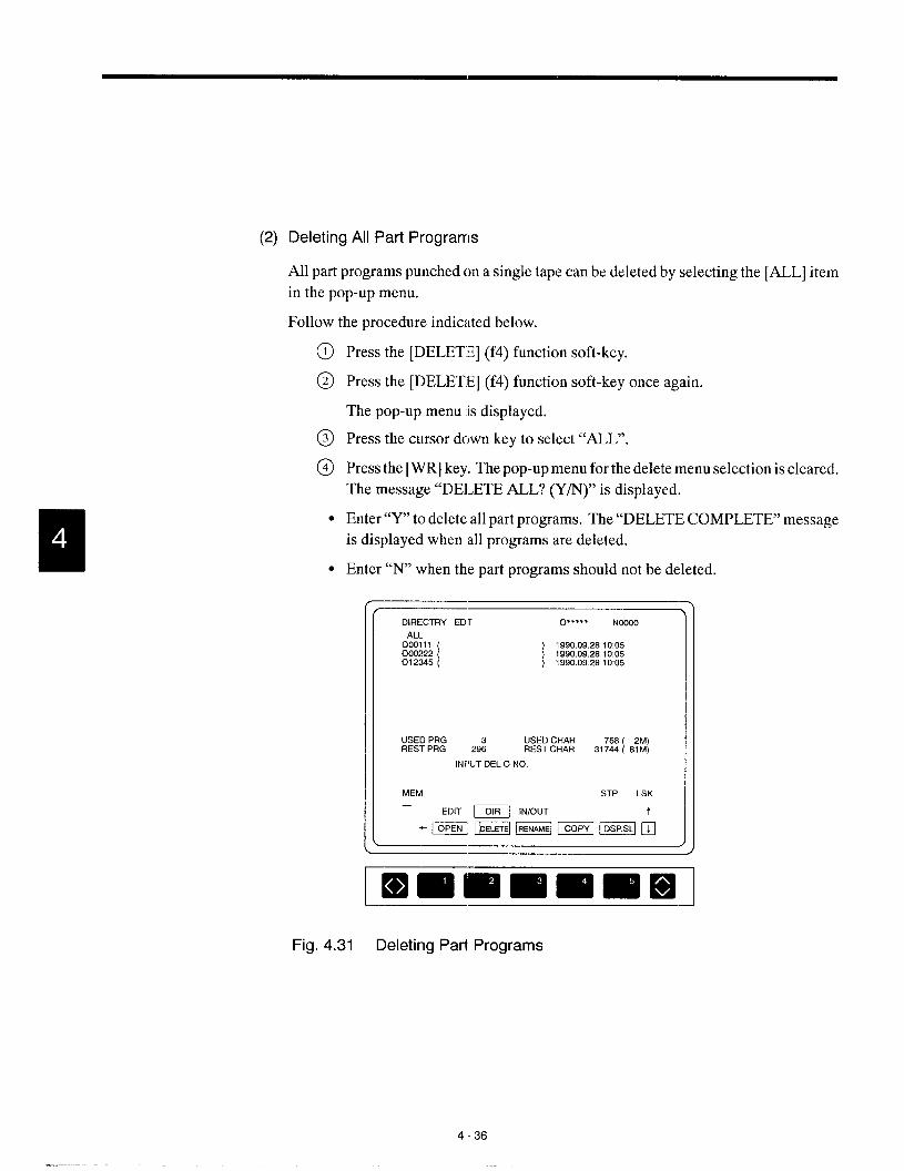
(2) Deleting All Part Programs
All part programs punched on a single tape can be deleted by selecting the [ALL] item
in the pop-up menu.
Follow the procedure indicated below.
Press the [DELETE] (f4) function soft-key.
Press the [DELETE] (f4) function soft-key once again.
The pop-up menu is displayed.
Press the cursor down key to select “ALL”.
Press the [WR] key. The pop-up menu for the delete menu selection is cleared.
The message “DELETE ALL? (Y/N)” is displayed.
Enter “Y” to delete all part programs. The “DELETE COMPLETE” message
is displayed when all programs are deleted.
Enter “N’ when the part programs should not be deleted.
DIRECTRY EDT O.**** NOOOO
ALL000111000222 [
] ;:::::’;::::
012245 ( ) 1990.09.2810:05
USEO PRG USEO CHARREST PRG 29; REST CHAR 3,;E [ ::!
INFIUT OEL O NO.
MEM STP LSK—
EOIT ~ lN/OUT
“mmBm-h
.
Iamlmml=lmw!l-”Fig. 4.31 Deleting Part Programs
4-36

4,2 PART PROGRAM DIRECTORY JOB
a)SUPPLE-MENT
1. In the edit lock state, part program deletion is not allowed. To delete a part pro-
gram, cancel the edit lock state.
2. During operation, the part program presently executed cannot bc deleted.
To delete the program being executed, delete it only after completing operation.
.- ,—
4.2.4 Renaming a Part Program
The rename function changes the program number. FOIIIOWthe procedure indicated below.
@ Press the [RENAME] (f3) function soft-key. The message “INPUT OLD O
NO.” is displayed.
DIRECTRY EDT
ALL000111000222 [012345 (
O-*** Noooo
) ;:!x!:.::;:; j::
) 1990:09:28 10IM
USED PRG USED CHARREST PRG 2~ REST CHAR 31~31 sf~l
INPUT OLD O NO.
MEM STF] LSK—
EDIT ~ lN/OUT
“Hm@@HEEah
.
Immlmmlmnml
Fig. 4.32 Renaming a Part Program
Enter the old program number (for example, “0100”) and press the [WR] key.
The message “INPUT NEW O NO.” is displayed.
Enter a new program number (for example, “0200”) and p:ress the
The message “RENAME OK? (Y/N)” is displayed.
Enter “Y” to rename the program.
Enter “N” when the program should not “berenamed.
WR] key.
4-37
.- ..— .—..—. —..— —..

\DIRECTRY EDT ~...ti. NOOOO
ALL000100002222 [ / j~{g~;[012345 (
USEO PRG :3 USED CHARREST PRG 296 REST CHAR 31%[ Efti]
RENAME OK? (Y/ N)
MEM STP LSK
EDIT T=I lN/OUT
“mBm @@m’&
/
❑ mlmmmlmm
Fig. 4.33 Part Program Rename Screen
If a program number is entered at the beginning of the part program after renaming or copying
(refer to 4.2.5.) a part program, whether or not this program number should also be changed
automatically can be selected by the setting for the parameter.
W“’’’”’’==’”’Remark
Do not edit the programnumberautomat- The programcreationdate is not updatedicallyin renaming,copyingor storing. by programrenamingoperation.
I Edit the programnumberautomaticallyinpm3005 D4 = 1renaming,copyingor storing. I
4-38

4.2 PART PROGRAMDIRECTORYJOB
4.2.5 Copying a Part Program
Apart program is copied.
creation date.
The new program created by copying is assigned a new program
Press the [COPY] (f4) function soft-key. The message “INPUT ORIGINAL
O NO.” is displayed.
Enter the original program. number (for example, “0100”) z.ndpress the [WR]
key. The message “INPUT O NO. (COPY)” is displayed.
Enter a new program number of the program to be created (for example,
“0200”) and press the [WR] key. The message “COPY OK? (Y/N)” is dis-
played.
Enter “Y” to copy the part program.
Enter “N’ when the part program should not be copied.
‘r-—
DIRECTRY EDT O“”*”’ NOOOO
ALL000100002222 [
] ;::}:;’::}%
012345 ( ) 1990.09.28 10C15
USED PRG IJSED CHARREST PRG 2$ I?EST CHAR 31~8~ { 8?~ 1
INPUT ORIG O NO.
MEM STP LSK
EOIT ~ lN/OUT
“HBEmmE:Qh
Fig. 4.34 Copying a Part Program
4-39
——— —.-. .—.. ——..
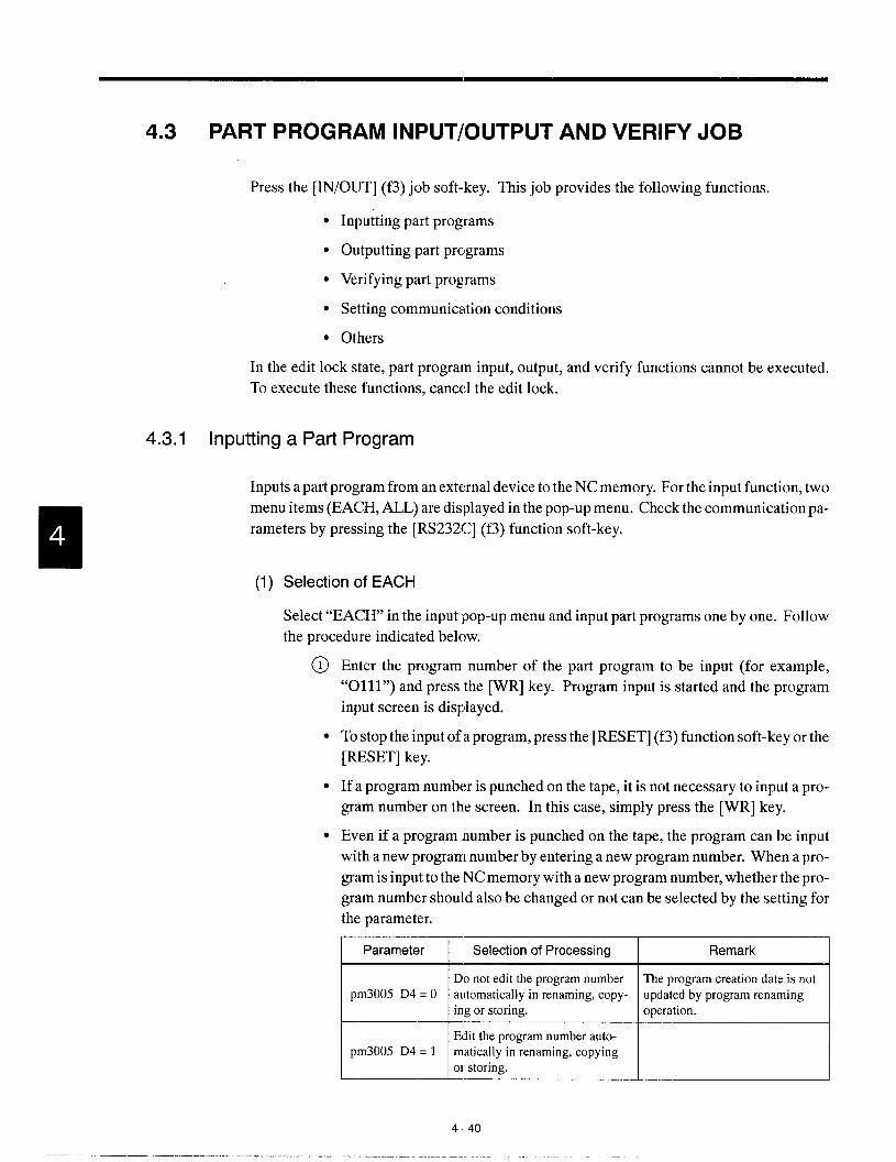
4.3 PART PROGRAM lNPUT/OUTPUT AND VERIFY JOB
Press the [IN/OUT] (f3) job soft-key. This job provides the following functions.
● Inputting part programs
● Outputting part programs
● Verifying part programs
● Setting communication conditions
● Others
In the edit lock state, part program input, output, and verify functions cannot be executed.
To execute these functions, cancel the edit lock.
4.3.1 Inputting a Part Program
Inputs apart program from an external device to the NC memory. For the input function, two
menu items (EACH, ALL) are displayed in the pop-up menu. Check the communication pa-
rameters by pressing the [RS232C] (f3) function soft-key.
(1) Selection of EACH
Select “EACH’ in the input pop-up menu and input part programs one by one. Follow
the procedure indicated below.
@ Enter the program number of the part program to be input (for example,
“0111”) and press the [WR] key. Program input is started and the program
input screen is displayed.
● To stop the input of a program, press the [RESET] (f3) function soft-key or the
[RESET] key.
● If a program number is punched on the tape, it is not necessary to input a pro-
gram number on the screen. In this case, simply press the [WR] key.
● Even if a program number is punched on the tape, the program can be input
with a new program number by entering anew program number. When a pro-
gram is input to the NC memory with a new program number, whether the pro-
gram number should also be changed or not can be selected by the setting for
the parameter., I
Parameter Selection of Processing Remark
M~aThe programcreationdate is not
automaticallyin renaming copy-
M~__Jmatically in renaming, copying
4.40
—. —... ————.-.

4.3 PART PROGRAM lNPUT/OUTPl!T AND VERIFYJOB
● If the input program number already exists, the processing to be executed can
be determined by the setting for the parameter. Selection is possible from the
generation of warning or the deletion of the existing program.
Dm3005DO= O WarningmessageIIS displayed. “~
I pm3005 DO= 1 I Programnumberis deleted. I
PROGRAM 1/0 EDT 012345 N12345
INPUT(EACH)
(0031 11)
11
0111: NoOO1G133T0101 : NC03ZMCEI ; NIIX3G96S:;50M03 : NCC04X20.3Z1 .5: NCC05G01 ZO.5F20 ; NOC06Z-10.5F5 : NCC07G02Z--1 5.515.0: NOIX16G01 UO.5 : NCC09W-5.5 ; [email protected] : NCO11GCOZO.5 ; NCO12G51 M(KI ; NUN 3: : NOO14GCOT0202 : NO015G50S31X0 : NIXI16S2COM03 : NCO17G41 M(E3 ; NCOl6G71PCO1900028U2 D6.FO.2S250R1 : NOJlSGO1Z120 : NO020X60.Z-59.FO. 1SW : N12021W-1 0.: NC022X1 10.W-10. : NCO23W-10. : NG024G02X90.W-20.115 K-20 : NIYJ25G01 W-5. : NOO26X1 20. W-5. : N0326X1 24. : NC029W3X260.Z7o,To200 : NO030T0203 ; NWJ31X124.270. : Z-1 O ._
MEMINPIJT
—EDIT DIR EIII
STP LSK
❑
pimiimmmE mlilFig. 4.35 Part Program Input Screen
● Whether or not the list of part programs being input is displayed on the screen
can be selected by the setting for the parameter setting.
m ‘e’ection:’+Li,t of programs1snotdisplayed
Listof programsis displayed.
Table 4.1 Difference between the [RESE~l (f3) Function Soft-keyand the [RESET Key
[RESET] (f3) keyStops Icmlytape input/output and verifies.Operal.ion is not influenced.
I [RESET] key I Resets all NCoperations. I
4-41

@) When an end M code (M02, M30, M99) or the “%” code is read, program input
is completed. Upon completion of program input, the message “INPUT
COMPLETE” is displayed.
. The [RETURN] (f5) function soft-key is invalid until the program input is
completed. However, the process keys are valid.
c Whether or not the end M code is regarded as the end of a program can be se-
lected by the parameter setting.
I The end M code (M02, M30, M99) is not regarded as the endpm3005 D3 = O
of a program. IThe end M code (M02-, M30, M99) is regarded as the end of
pm3005 D3 = 1a program. I
● Whether or not spaces are deleted during program input and verified can be
selected by the setting for the parameter.
I pmO020 DO= O I Spaces are deleted. I
L_2E!uE Spaces are not deleted.
4-42

4.3 PART PROGRAM lNPUT/OUTPUT AND VERIFYJOB
(2) Selection of “All”
Select “ALL” in the input pop-up :menu and input all part programs punched on tape
at a time. Follow the procedure indicated below.
When’’ALL” is selected, the message “A1.LPROG. INPU’r” is displayed and
the message “INPUT OK? (Y/N)” is displayed.
To input all programs, enter’’Y”. Program input starts and the screen changes.
As shown in Fig. 4.35, the list of programs being input is displayed.
Enter “N’ when part programs should not be input.
To stop the input of a program, press the [RESET] (f3) funcl:ion soft-key or the
[RESET] key.
PROGRAM 110 EDT 0“”””’ NOOOOO
INPUT (ALL)
ALL PROG. INPUT
INPUT CIK? (Y/N)
MEM STP LSK—
EDIT “[R mm
umlzElu!Ea!EEz+l
.
Immmmm=mFig. 4.36 All Program Input Screen
The ALL input operation is completed when the % code is input. Upon
completion of the input of the part programs, the messa~:e “INPUT COM-
PLETE” is displayed.
4-43
————. ... —. ——. - ... — .. —. —.. —. —-.

4.3.2 Outputting aPart Program
Outputs a part program from the NC memory to an external device.
The output function provides the following six menu items (EACH, PLR, RANG, ALL,
COL, and DATE) by the pop-up menu. Check the communication parameters by pressing
the [RS232C] (f3) function soft-key.
(1) Selection of EACH
Select “EACH’ in the output pop-up menu and output part programs one by one. Fol-
low the procedure indicated below.
@ Enter theprogramn.umberof theprogramtobeoutput (for example,’’O2lll”)
and press the [WR] key. Output of the specified program starts and the list of
the program being output is displayed on the screen,
● To stop program output, press the [RESET] (f3) function soft-key or the [RE-
SET] key,
,
PROGRAM 1/0 EDT 012345 N12345
OUTPUT(EACH)
(Oml11 )
F-
0111 ; NWOIGCOTO1O1 ; N0332M08 ; NCC03G96S150M03NWC-W20,3Z1 .5: NCQJ5G01 ZO.5F20 ; N0306Z-10.5F5 ; N3C07G02Z-1 5.515.0 ; NC038GOIUO.5 . NcQ39w--55 . N(I31OU3.5 . NOOI lGCOZO
.5: NOO12G51MCS ; NCW3 ; ; NOO14G03T0202 ; NO015G50S3COJ ; NG016S2COM03 : NC017G41M09 ; NCOl8G71 PCOl SQI1328U2, 06. FO.2S250R1 : NCOl9G01 Z1 20, ; NC020X&J.Z-S3 FO.1S520 ; Nc021W-1 O. ; Ncc122X110.W-l O. ; NC023W-1 O : N3024G02x90 w-20.115.K-20. : No025G01 W-5. ; NOD26X120. W-5. : N13328X124. ; Nc@x31Mx26!lz70.T0201 ; N&J30T0303 ; NoJ31X124,Z70 ; Z-1 O
OUTPUTMEM STP LSK
EOITD’R m III
mE3mmm J
Fig, 4.37 Program Output Screen (EACH)
444

4.3 PART PROGRAM lNPUT/OUTPLT AND VERIFYJOB
Whether or not the list of part programs being output is displayed”can be se-
lected by the parameter setting.
I pmOO07 D5 = O [ Pr{,gramlistisnot alisplayed. IpmOO07 D5 = 1 Program list is displayed.
.-— .-l
To cancel the feed portion at the leader and trailer part, press the [CAN] key
while feed holes are being output.
Upon completion of the program output, the message ‘GOUTPUT COM-
PLETE” is displayed. The [RETURN] (f5) function soft-key is not valid until
output of a program is completed. Note that process keys are valid.
(2) Selection of PLR., RANG, ALL, COL and DA1-E
Select the required output function from the output pop-up menu. Follow the procedure
indicated below.
n
A
@ Press the [OUT] (f2) function soft-key. The “OUTPUT (EACH)” screen is
@
displayed.
Press the [OUT] (f2) function soft-key once again. The pop-up menu appears,
displaying the selection items of EACH, PLR., RANG, ALL, COL, and
DATE.
PROGRAM 1/0 EOT
OUTPUT(EACH)
OUTPUT O NO.
MEM.
EOIT DIR
NoOO@l
B.-—
EACH.-
PLR..-—
RANG
ALL
COL
OATE.—
STP LSK
t
\ .-—
Fig. 4.38 Output Menu Selection Screen
– Pop-I.Ip menu
@ Select the menu item by moving the cursor with the cursor up/down keys’and
press the [WR] key. The output pop-up menu is cleared and the specified
screen is displayed.
4-45

(a) Selection of PLR.
Outputs the specified multiple part programs. Follow the procedure indicated be-
low.
~ Enter the program number of the part program to be output (for example,
“0111”) and press the [WR] key.
@ Move the cursor to the next line and press the [WR] key. Up to 20 program
numbers can be entered consecutively.
PROGRAM 1/0 EDT O***** NQOOOO
OUTPUT(PLURAL)
OUTPUT O NO.
*000111 “ “* 000222 * “* 000333 ‘ “* 001000 * ‘* 002000 ‘ “* 003000 ‘ “. . .
MEM STP LSK—
EDIT “’R m
mmmm+
[mmilEEEEEl
Fig. 4.39 Program Number Input Screen
@ Output of the specified program starts and the list of the program being output
is displayed on the screen. The specified programs are output on a single NC
tape.
4-46

4.3 PART PROGRAM lNPUT/OUTP(lT AND VERIFYJOBp—l
(b) Selection of RANG
Outputs the part programs in the range specified by the program numbers. Follow
@
procedure indicated below
The message is displayed :requesting the input of the start program number of
the range. Key in the first :program of the program output r:mge (for example,
“0111”) and press the [WR] key.
For the next message, input the end profirarn number of th,l~range (for exam-
ple, “0222”) and press the [WR] key.
.-—PROGRAM 1/0 EDT O’**’* NOOOOO
OUTPUT(RANG)
START O NO000111
END O NO.000222
.
pmiiimlil m EEl
Fig. 4.40 Start and End Program Number Input Screen
Output of the specified program start ancl the list of the progyams being output
is displayed on the screen. The part prog:rams in the specifi(>d range are output
on a single NC tape. If no program number is found in thes pecified range, the
warning message “O NO NOT FOUND!” is displayed.
4-47
——. — .—.— .—-. .- —. ——. —.—
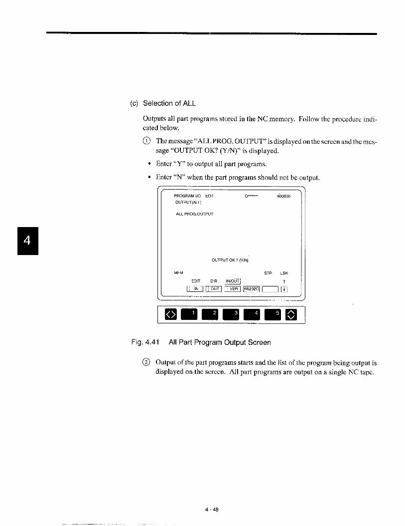
(c) Selection of ALL
Outputs all part programs stored in the NC memory. Follow the procedure indi-
cated below.
@) Themessage’’ALL PROG.OUTPUT’’is displayed on the screen and the mess-
age “OUTPUT OK? (Y/N)” is displayed.
● Enter “Y” to output all part programs.
● Enter “N’ when the part programs should not be output.
PROGRAM 1/0 EDT O***. * NOOOOO
OUTPUT(ALL)
ALL PROG,OUTPUT
OUTPUT OK? (’f/N)
MEM STP LSK—
EDIT D’” m
mummemh
Fig. 4.41 All Part Program Output Screen
@ Output of the part programs starts and the list of the program being output is
displayed on the screen. All part programs are output on a single NC tape.
4-48

4.3 PART PROGRAM lNPUT/OUTPl.JT AND VERIFY JOB
(d) Selection of COL.
By specifying the main program, the subprograms, program copi es, and micropro-
grams called from the specified main program can be output UI)to 500 programs.
Follow the procedure indicated below.
When the “COL.” item is selected, the “COLLECT O NCII.”message is dis-
played; enter the main program number [(for example, “O 12345”) and press
the [WR] key.
--— ‘
PROGRAM 1/0 EDT O’”*”= NOOOOO
OUTPUT(COLLECT)
COLLECT O NO.
JOG STP LSK012345
EOIT DIR ~~ t
Fig. 4,42 Program Number Input Screen
@ Output of the programs starts and the lisl of the programs being output is dis-
played on the screen. The main program i~~dthe programs that are called from
the specified main program are output m a single NC tapt.
4-49
-——— —.—...-——. — ,. . ———... .-#,.— -.—.—..——-

(e) Selection of DATE
The date of part program creation and registration is stored in the NC memory. It
is possible to output part programs by specifying the date. Follow the procedure
indicated below.
The message requesting the input of the date is displayed. Enter the date of
program creation of the programs to be output (for example, “1991. 05. 20”)
and press the [WR] key. If only the year is entered, all programs created in the
specified year are output, and if only the year and the month are entered, all
programs created in the specified month of the specified year are output..
PROGRAM 1/0 EOT O***** NOOOOO
OUTPUT(DATE)
DATEYMD
JOG STP LSK1991. 05 20
EDIT DIR m
=U=m=nb
Fig. 4.43 Date Input Screen
@ Output of the specified programs starts and the list of the programs being out-
put is displayed on the screen. The part programs created in the specified date
are output on a single NC tape.
4-50

4.3 PART PR(2GRAM lNPUT/OUTPl.JT AND VERIFYJOB
4.3.3 Verifying the Part Programs
Compares the part program in an external device with the part program stored in the NC
memory. For the execution of the verify function, selection is possible t’mm each and all us-
ing the pop-up menu.
Check the setting for communication parameters by pressing the [RS232C] (f5) function
soft-key.
(1) Selection of EACH
Verifies part program one by one, by selecting the [EACH] item in the pop-up menu.
FOI1OWthe procedure indicated below.
Press the [VER] (f3) function soft-key.
I
APress the [VER] (f3) function soft-key clnce again. The pop-up menu is dis-
played to allow the selection between “EACH’ and “ALL~’.
Select “EACH’ by moving the cursor with the cursor up/down keys.
PROGRAM 1/0 EDT O***** NOOOOO
VERIFY(EACH)
~..=jt
-—
EACH
VERIFY O NO.ALL
.-—
JOG STP LSK
EDIT D’R m)~
mwlcEll IEzc:lrh
Immlm EEnEml
— Pop+Jp menu
(for ~erification)
Fig, 4.44 Verification Menu Selection Screen
@ Entertheprogram number of the program tobeverified(for example,’’Olll”)
and press the [WR] key.
4-51
——.. —.. —... ”...——. -— — ———, .-—. —— ..- .—. ,—-. —-.. ——.—-.--—
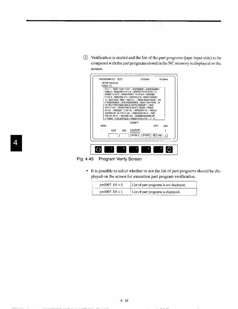
@ Verification is started and the list of the part programs (tape input side) to be
compared with the part programs stored in the NC memory is displayed on the
screen.
PROGRAM 1/0 EDT 012345 N12345
:RIFY(EACH)colll)
0111 ; NCCO1GCHJTO1O1; Ncc02M06 : NCC03G96S15JJM03 ; Nw04X20.3Z1 ,5 ; NCC05GOI205F20 ; NCOO6Z-10.5F5 ; NCC07G02Z-15,515,0 ; NOCC!8G01 UO.5 ; Noc09W--5,5 ; NcOl 0U3.5 ; NCO11G03Z0,5 ; NC012G51 Mm ; NO013 ; ; NCHJ14G03T0202 ; NOO15G5CS3fX13 ; NC016S20JM03 ; NIW17G41 M08 ; N001 8G71 POOl900028 U2.D6 FO.2S250R1 : NOO19G0121 20. ; NC020X6C.Z-50.FO.1 S500 ; NO021W-1 O ; NWL22XI 10,W-10. : NC023W-1 O ; NC024G02x90. W-20,115.K-20, ; No025G01 W-5. : N0626X1 20. W–5 ; NO026X1 24. ; NC029GOOXZ60270.T0200 ; NC030T0303 ; No031X1 24.270 ; Z-1 O
VERIFY
❑ mmmmmmFig. 4.45 Program Verify Screen
● It is possible to select whether or not the list of part programs should be dis-
played on the screen for execution part program verification.
\ pnOO07 D5 = O I List of part pmgrarns is.rmt displayed. I
pmOO07 D5 = 1 List of part programs is displayed.J
4-52

4.3 PART PROGRAM lNPUT/OUTPUT AND VERIFYJOB
. If inconsistency between the contents of the part programs stored in the NC
memory and the contents of the one input from an external device is found, the
display area in the screen is divided into two parts. The upper half area dis-
plays the list of the part programs in the ‘NCmemory and the lower half area
displays the list of the part programs input from the external device. Inconsis-
tent parts are highlighted.
PROGRAM 1/0 EDT 012345 IN12345
VERIFY(0001 11)
INPUT FROM TAPE
r ..1
01 UO.5 ; NOC09W-55 : NCO10U3.5 : NOO11GOOZO ‘-–5: NCW2G51 M09 : NCCI13 : : NCH)l4GOOT0202 : NO
015G50S30W : NOOl 6S3CK)M03 : NCXJl7G41 MOI3 : N001 8G71 FCOl 9CYX328U2.D6.FO 2S250R1 : NOOl
CONTROLLER INTERNAL DATA
c :1
OIUO.5 : Nco09W-5.5 : NOO1OU35 : NOOI lGCQZO5. NO012G51 M09 : NC013 ; : NO014GOOT0202 ; NO
015G50S3000 : NCCI16S200M03 ; NCOl 7G41 M08 : N001 8G71 PCO1SGO028U2 D6 FO 2S250R1 : NCOl
VERIFY ERROR!
MEM STP LSK—
EDIT DIR mm T
ImmlmmmmmFig. 4.46 Screen after Occurrence of Inconsistency
4-53
—.—.- .. . . . .. . ,-——— —.--— ——-. . . . .. ..- ..—..——.-. —. ——. —— —..
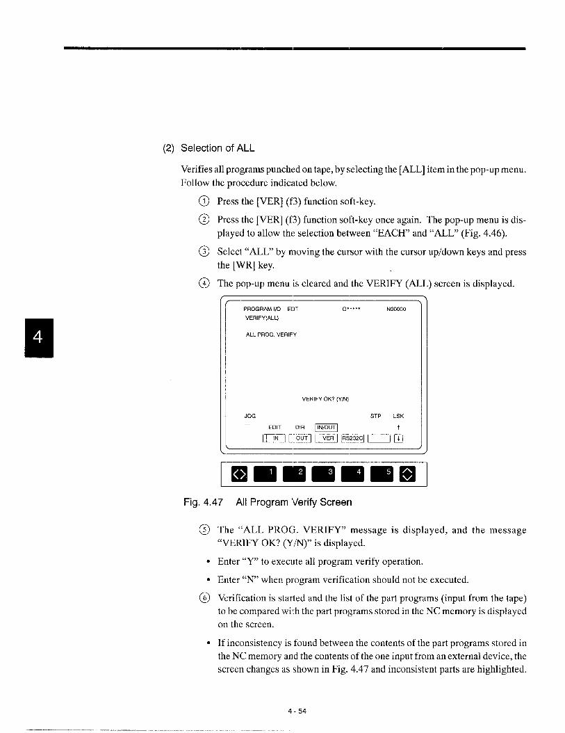
(2) Selection of ALL
Verifies all programs punched on tape, by selecting the [ALL] item in the pop-up menu.
Follow the procedure indicated below.
Press the [VER] (f3) function soft-key.
Press the [VER] (f3) function soft-key once again. The pop-up menu is dis-
played to allow the selection between “EACH’ and “ALL’ (Fig. 4.46).
Select “ALL” by moving the cursor with the cursor up/down keys and press
the [WR] key.
The pop-up menu is cleared and the VERIFY (ALL) screen is displayed.
\PROGRAM 1/0 E[)T O***** NOOOOO
VERIFY(ALL)
ALL PROG. VERIFY
VERIFY OK? (Y/N)
JOG STP LSK
EDIT “’R m
mnmm=uk
)
❑ mlmmmmmFig. 4.47 All Program Verify Screen
The “ALL PROG. VERIFY” message is displayed, and the message
“VERIFY OK? (Y/N)” is displayed.
Enter “Y” to execute all program verify operation.
Enter “N’ when program verification should not be executed.
Verification is started and the list of the part programs (input from the tape)
to be compared with the part programs stored in the NC memory is displayed
on the screen.
If inconsistency is found between the contents of the part programs stored in
the NC memory and the contents of the one input from an external device, the
screen changes as shown in Fig. 4.47 and inconsistent parts are highlighted.
4-54

4.3 PART PROGRAM lNPUT/OUTP(JT AND VERIFY JOB
4.3.4 Setting the Communication Conditicms
Sets the baud rate of the data 1/0 interface, stop bit length, the use of cclntrol codes, etc.
(1) Setting the RS-232C Communications Parameters
This screen is used to display and set the communication parameters used when an ex-
ternal device is connected by the RS-232C interface. For the connection of an external
device, two ports are provided; one is used for input and the other for output. Follow
the procedure indicated below,
@ Press the [RS232C] (f4) function soft-key, and the screen as shown below is
displayed..-—-——
PROGRAM 1/0 EOT o***** NOOOOO
1/0 UNIT SET IN OUT
UNIT RS232C RS2W(;
PORT NO.1 NO.:?BPS 4800 960()STOP BIT 2BIT IBIT
BITS 8BITS 7BlrsPARITY OFF EVENX ON/OFF ON OI=FRTS CONTROL ON 0,, F
DR CNTRL ON O,, F
NC CNTRL ON 0,, F
MEM STP LSK—
EDIT DIR @J~
m ml l==) F/ I==fi &.-—
.-
ImmmmmmqFig. 4.48 RS-232C Communication Parameters Setting
Move the cursor to the parameter for which the data should be set by using the
cursor up/down keys. When the cursor is moved to a certain parameter, the
contents of the function soft-keys change meeting the selected parameter.
Press the soft-key corresponding to the :required setting. The selected value
is set for the cursor located parameter. For example, in tht. setting of BORS,
if [9600] (f4) soft-key is pressed, “9600” is written.
--, ——
@@
For the parameters for which “*****“ is displayed, setting is not permitted.
——— ———-.--.-. ——.—-—. ---———-—-.. ..-— -—————..-—.
4-55
..-—.. —.—.—..— --.—_———.—

For the serial interface, setting is possible as indicated in Table 4.2.
Table 4.2 Serial Interface Setting
Menu Item
UNIT (device)
PORT
BORS (baud rate)
STOP BIT
BITS (bit length)
PARITY (parity scheme)
X ON/OFF (controlcode)
RTS CONTROL
PARITY 1S0
Input output
YE tape reader
General-purpose RS-232C I General-purpose RS-232C
NO. 1 NO. 1
NO. 2 NO. 2
100 or 75 I 100 or 75
110or 150 i 110 or 150
300 I 300
600 I 600
1200 I 1200
2400 2400
4800 4800
9600 9600
1 bit 1 bit
2 bits 2 bits
7 bits 7 bits
8 bits 8 bits
Even parity Even parity
Odd parity I Odd parity
None I None
Supported I Supported
None I None
Supported I Supported
None I None
Supported Supported
None None
Notel: Athoughtwo RS-232Cpoflsare provided, these twopotiscannot beusedatthe sometime. Forthesetwopods,
setting can be made independently from each other.
2: Recommended setting forthecommunication at9600bps is indicated below.
BPARITY
3
EVEN/ODD/OFFNCDAXA SPECIAL CONTROL OFF
4-56

4.3 PART PROGRAM lNPUT/OUTPLIT AND VERIFY JOB
The menu items are explained below.
(a) UNIT (external device)
Select “YE tape reader” when the tape reader special for YASNAC is used. If “YE
tape reader” is set, parameters are automatically set and “****“ is,displayed for oth-
er parameters.
BORS T==KlSTOP BIT
+
2 BITS
BIT LENGTH 8 BITS
I PARITY I OFF I
I X ON/OFF I ON I
IBy selecting “RS232C” (general-purpose R$232C), connection is possible with d
a variety of RS-232C devices by setting appropriate communication parameters.
(b) PORT
Selection is possible between No. 1 port and No, 2 port.
(c) BORS
Communication speed can be set by this parameter. Whether 100 and 110 bps or
75 and 150 bps are selected for low speed is determined by the [setting for the fol-
lowing parameters.
No. 1 port
(d) STOP BIT
It is possible to set the bit length of the stop ‘bit.
4-57

(e) BITS
It is possible to set the bit length of the data.
(9 PARITY
It is possible to specify the hardware dependent parity check status.
(g) X ON/OFF
It is possible to specify whether or not the control codes are used.
(h) RTS CONTROL
When the setting for this parameter is “ON”, communication between the YAS-
NAC and the connected device is controlled using the RS and CS signals. To use
the RTS control, the cross-cable as shown below must be used.
GE) ‘sx ‘s 6E!E9c’ c’
(i) PARITY ISO
When ISO code data is used, this parameter is used to set whether parity check is
made with the higher data bits. For this parameter, setting is possible if “YE tape
reader” is selected for lJNIT.
4-58

4.3 PART PRCIGRAM lNPUT/OUTPLITAND VERIFYJOB
(2) Other Communication Control Parameters
Set the communication parameters used for data cc~mmunications w :th an external de-
vice.
(a)
(b)
DR LINE CHECK
The DR line check executes the test at the NC side whether the DR line of the con-
nected external device is ON (that is, whethe:r the connected device is ready for
communications). For this function, the following parameters are provided. To
perform this test, use the cable that connects the DR line of the ~NCto the DR line
of the connected device. The connected device must have the DR line control func-
tion.
NC DATA SPECIAL CONTFIOL
This parameter is used to set whether or not the check specific to the NC is executed
and also whether or not special character codes are used. How this control is used
is indicated below..-
The following are as set with parameters:● pmOO04: Dl, D2, D3
Control ON for input● pm:3005: DO, D2, D3, D4, and D5The following parameters are made valid:● pm4100 -4109 and pm4144 -4146EIA/ISO automatic recognition is provided.
Several bits of the following parameters are fixed:● pmOO04: X X X X lOOX
Control OFF for input● pm:3005: X X0000 XOThe following parameters are made invalid:● pm4100 -4109 and pm4144 -4146Fixed to 1S0 code
-—
The following are as set with parameters:c pmOO04: Other than D3
Control ON for output . pm:3005: D5The t’ollowing parameters are made valid:● pm4100 -4109 and pm4144 -4146
Several bits of the fol Iclwing parameters are fixed:Control OFF for output ● pm13004: 0110 X X :X()
●pm:3005: XXOX X X X X
—
4-59
.—. ———... -. . -—- .-. —.- .—..—..— .——-. .——

4.3.5 Other Function
With the [RESET] (f3) function soft-key, resetting operation is possible. The processing
which is reset by the reset operaticm can be executed again by pressing the [START] (f4) func-
tion soft-key.
(1) Reset
The [RESET] function soft-key provides the background reset function which is differ-
ent from the function provided by the [RESET] key-on the operation panel. The reset
function executes the following processing.
● Interruption of input/output/verify operation
● Turning on the label skip function
● Resetting the background alarm (ALM 9000’s)
Even if the [RESET] (f3) function soft-key is pressed, the “RST” status indicating mes-
sage is not displayed.
(2) Execution
If the NC is reset during input, output, or verify processing, the reset processing can be
executed again by pressing the [START] (f4) function soft-key.
4-60

3SETUP PROCESS OPERATION
Chapter 5 describes Ihe operation carried out by using the set
process key. Intheset process, setting up before starting ma-
chining is carried out by using the workpiece coordinate sys-
tem job, tool data job, and tool life control job.
Job selection is possible by usin$l either the job soft-keys or
the [SET’1process selection key.
The operation indicated above can be executed any time in-
dependent of the NC operation mode even while automatic
operation is being executed.
5.1 SETUP JOB . . . . . . . . . . . . . . . . . . . . . . .. 5-2
5.1.1 Writing theToo10 ffsetD ala, . . . . . . . . . . . . . . 5-2
5.1.2 Clearin~g the Offset Data . . . . . . . . . . . . . . . . . . 5-4
5.2 WORKPIECE COORDINATE
SYSTEM MANAGEMENT . . . . . . . . . . . ..!5-5
5.2.1 Writing the Workpiece Coordinate
System Shift Amount . . . . . . . . . . . . . . . . . . . . . 5-5
5.2.2 Clearing the Workpiece Coordinate
System Shift Amount . . . . . . . . . . . . . . . . . . . . . 5-6
5.3 TOOL LIFE CONTROLJOB . . . . . . . . ..5-7
5.3.1 Writing the Tool Life Control Data ., . . . . . . . . 5-7
5.3.2 Displaying the Tool Life Control Data . . . . . . . 5-7
5.3.3 Setting the Tool Life Ccmtrol Data . . . . . . . . . . 5-8
5.3.4 Erasing the Tool Life Control Data . . . . . . . . . 5-10
5-1
—— ... .—..—. -—- —. —.——. -..

5.1 SETUP JOB
When the [SET] job key is pressed, the [OFFSET] (fl) function soft-key is displayed. The
offset function is uised to write and clear the tool offset data.
5.1.1 Writing the Tool Offset Data
The offset data include the X-axis tool offset, Z-axis tool offset, nose R offset and control
point. In the standard specification, 16 sets of tool offset data are provided. Optionally, the
number of tool offset data sets can be expanded to 99 or 299. Follow the procedure indicated
below to write the tool offset data.
@ Move the cursor to the offset number for which the offset data should be set
by using the cursor up/down keys. It is also possible to set the offset number
by pressing the [WR] key after entering the required offset number (01, for
example).
OFFSET SET 012345 N12345
T x z R c01 123020 20030 1.Cc41 102 213.020 -11 IQO 2.300 303 Omo 003CI O.000 004 -25,E67 -34.047 o.35n 405 3C4 521 -56711 3.450 7
MACHINE
x 203.552z - 12.7@9
MEM STP LSK
m T
+- -l ~oml n ~] ~] ~]
❑ mmmmmmFig. 5.1 Offset Screen (2-axis Specification)
The cursor moves to the specified offset number and five sets of the tool offset
data (tool offset data, nose R offset data, and control point) are displayed in-
cluding the tool offset data of the specified offset number.
Enter the numerical value following the address of the data to be set.
5-2

5.1 SETUP JOB
\\ I/,
QPOINT
—0 In absolute value input, press [WR] after entering the value su~
To set the X-axis offset dataas X123.000.
e In incremental value input, press [WR] after entering the valuesuch as U123.000.
—
To set the Z-axis offset data~In absolute value input, the address to be specified is “Z”.MIn incremental value input, the address to be specified is “W’.
.
To set the nose R offset data ● Press [WR] after entering “RO.S”.
To set the control point @Press [WR] after entering “C3”.—
——
1. Fcmthe entry of nose R offset data (R) and control point (C), incremental input
is not possible.
2. For the 3-axis specification, display of MACHINE POSITION is not provided.
— ———. —.—. —
5-3

5.1.2 Clearing the Offset Data
Follow the procedure indicated below to clear the offset data.
@ After pressing the [OFFSET] (fl) function soft-key, move the cursor to the
offset number of the offset data to be cleared.
@ Press the [0 CLR] (fl) function soft-key to clear the offset data of the offset
number on which the cursor is positioned to zero.
@) Press the [ALL CLR] (f2) function soft-key, and the message “CLEAR ALL
OFFSET?” is displayed.
Press “Y” to clear the entire offset memory of the offset number.
OFFSET SET 012345 N12345
T x z R c01 123.~ 20. m 1Jmo 102 213,020 -11.103 2.3oo 303 Om O.cal 0,000 004 -25,567 –34. 047 0.350 405 304521 -s.711 3.450 7
MACHINE
x 21XI.552z - 12.713S
CI.EAR ALL OFFSET? (Y/N)
ImmmmmlmllslFig. 5.2 Offset Screen (when [ALL CLR] (f2) is pressed)
5-4
.. . . .

5.2 WORKPIECE COORDINATE SYSTEM SHIFT JOB
5.2 WORKPIECE COORDINATE SYSTEM !SHIFT JOB
Workpiece coordinate system shift data can be set using the workpiece coordinate system
shift job. The workpiece coordinate system shift data are stored to offset number TOOand
t-heamount set here is valid for all cutting tools when a workpiece coordi:~ate system is set.
5.2:1 Writing the Workpiece Coordinate System Shift Amount
Follow the procedure indicated below to write the workpiece coordinate system shift amount
data.
@
@
Press the [WORK] (f2) function soft-key.
Enter a numerical value following an address. The address to be specified dif-
fers depending on which of the absolute or incremental inputs is used.
Table 5.2—- ——
Absolute input
-+=
Press [WR] after entering the shift amount such as
To set the X-axis X12.345.
shift dataIncremental input
Press [WI?.] after entering the shift amount such asU12.345.
To set the Z-axis Absolute input The address to be specified is “Z”.
shift data Incremental input The address to be specified is “W”.
To set the C-axis Absolute input The address to be specified is “(T.
shift data Incremental input The addrew to be specified is”1 I“.
f --— \
OFFSET SET 012345 N12345
T x zCKl o.OoQ O.coo
MACHINE
x O.cco
z 0.020
MEM STP LSK
m r
- e] pmq r—--l r-l (-----:1❑
Immmmmlmlfw
Fig. 5.3 Workpiece Shift Screen (2-axis Specification)
5-5

5.2.2 Clearing the Workpiece Coordinate System Shift Amount
Follow the procedure indicated below to clear the workpiece coordinate system shift data.
@ Press the [WORK] (f2) function soft-key.
@ Press the [OCLR] (fl)functionsoft-key, andtheworkpiece coordinate system
shift amount is cleared to zero.

5.3 TOOL I.IFECONTROLJOB
5.3 TOOL LIFE CONTROL JOB
When the tool life control function is used, tools are controlled in the following manner.
In a program, the tools are specified by the tool group; when tool life ha; expired, the next
tool in the same group is selected.
5.3:1 Writing the Tool Life Control Data
Classify tools into groups according to the type of tools and set the tool life for the individual
groups.
5.3.2 Displaying the Tool Life Control Data
When the [TOOL] soft-key is pressed in the [SET] process, the screen as shown in Fig. 5.4
is displayed. The TOOL LIFE screen display first is the screen for group 00. The TOOL
LIFE screen consists of multiple pages; one page for one tool group. Onc page displays the
tool data (max. 10 tools) in one group. TOdisplay the TOOL LIFE screen of the desired tool
group number, either press the page keys, or press the cursor up/down keys after entering the
desired group number.
TOOL LIFE SET 000001 NOOOO1
GROUP 05 TIME
T-NO.
TO1OIT0202T0303T0404T0505TOEG6T0707
***
LIFE \
lCO2003(!4I4005C0ml
9s99***
JSEDIlx200200123
4500
***
STS
CWEROVER
OVER
SKIP
USE
NOT
NOT***
l---t
I MEM STP LSK
– Pop-up menu display position
Immmiml’mmmlI I 1 [ / / .-i7 T rlf~
COUNT I I EACH ~— -— Pop-up menuTIME I GROUP
L&d
Fig. 5.4 Tool Life Control Data Display Screen
5-7
5.3.3 Setting the Tool Life Control Data
The tool life control data can be set in the following two methods: to set the data by directly
keying them in using the NC operation panel keys and to set them by inputting them from
tape. This sub section describes the procedure used for writing and correcting the tool life
control data by using the keys on the NC operation panel. Setting of the tool life control data
using tape is possible at the input screen of the IN/OUT job in the [MAINT] process. For
details, refer to 8.3 “INPUT/OUTPUT AND VERIFY JOB”.
(1) Writing a Tool Number
Set the tool number for which the tool life control is executed.
Move the cursor to the T-NO. column and press the [WR] key after keying in a tool num-
ber (1 to 9998).
When a tool number is written to T-NO., the corresponding data are initialized: 9999
for LIFE, O for USE, and NOT for STS.
\\ I//
Q To register tools additionally, move the cursor to the tool number immediately beforePOINT that of the tool to be added, then press the [INSRT] key after entering the tool number.
(E9 While the tool life control is executed, the tools are used in the order from the top.
If an attempt is made to enter the tool number which is already enterecl, the warning
message “REPETITION ERROR!” is displayed.
(2) Writing the Tool Life
Set the tool life.
Move the cursor to the LIFE column, key in the tool life (1 to 9999), and press the
key.
● After the tool life is changed, the cursor moves to the USED column.
[WR]
5-8

5.3 TOOL I..IFECONTROLJOB
{3)
(4)
Writing the Tool-use Data
Set the tool-use count data.
Move the cursor to the USED column, key in the use-count data (Oto 9999), and press
the [WR] key.
Enter “O” when anew tool is used. If the value in the USE12 column is greater
than the LIFE value, the STS automatically changes to “CWER’.
After the tool life is changed, the cursor :moves to the nexl T_NO. column.
Writing the Tool Life Control Type
When the [KIND] (fl) function soft-key is pressed, the po~~-upmenu as indi-
cated below is displayed and, at the same time, the message “SELECT BY
CURSOR & WR’ is displayed.
To change the life control type, move the cursor to the required life control
type by using the cursor up/down keys and press the [WR] key. When it is not
necessary to change the presently selected life control type, press the [KIND]
(fl) function soft-key again and the pop-up menu is cleared.
Table 5.3 Tool Life Control Type Menu
Menu Contents
= ‘: .5Tool life is controlled by the length of time the tool has been used.
Tool IIi-eis controlled by the number of times :he tool has been
● The selected tool life control type is valid only for the toc,l group for which
it is written.
5-9
—-.—— _— .. . ..-. —

5.3.4 Erasing the Tool Life Control Data
(1) Erasing the Tool Number
@ When the [T-ERS] (f2) function soft-key is pressed, the pop-up menu is dis-
played and, at the same time, the message “SELECT BY CURSOR & WR”
is displayed.
@ Select the requirecl erase mode by moving the cursor to the required erase
mode with the cursor up/down keys and press the [WR] key. When it is not
necessary to change the presently selected erase mode, press the [T-ERS] (f2)
function soft-key again and the pop-up menu is cleared.
Table 5.4 Tool Life Control Data Erase Menu
Menu Contents
EACH The data of the tool number indicated by the cursor are erased.
GROUP The data of the tools in the displayed group are erased.
ALL The data of all groups are erased.
● When tool data are erased for all groups or the selected group, the tool life con-
trol type of such groups is automatically set at “TIME”.
● After the execution of tool number erase operation, the data at the LIFE,
USED, and STS cc~lumns are also erased and “*” is displayed.

5.3 TOOL .IFE CONTROLJOB
(2) Erasing the Tool Life Set Data
When the [L-ERS] (f3) function soft-key is pressed, the pol)-up menu as indi-
cated below is displayed and, at the same time, the message “SELECT BY
CURSOR & WR” is displayed.
Select the required erase mode by moving the cursor to :he required erase
mode with the cursor up/clown keys and press the [WR] key. When it is not
necessary to change the presently selected erase mode, press the [L-ERS] (f3)
function soft-key again and the pop-up :menu is cleared.
Table 5.5 Tool Use Count Data Erase Menu
I Menu Contents
I EACH \ The data of the tool number indicated by the cursor are erased. I
I GROUP I Thedataof thetoolsin redisplayed group amemsed. I
I ALL \ The data of all groups arc erased. I
● After the execution of tool life set data erase operation, the data are cleared to
zero.
m(3) Erasing the Tool Used Data
When the [U-ERS] (f4) function soft-key is pressed, the poll-up menu as indi-
cated below is displayed and, at the same time, the messilge “SELECT BY
CURSOR & WR’ is displayed.
Select the required erase mode by moving the cursor to rhe required erase
mode with the cursor up/clown keys and press the [WR] key. When it is not
necessary to change the presently selectecl erase mode, press the [U-ERS] (f4)
function soft-key again and the pop-up lmenu is cleared.
Table 5.6 Tool Use Count Data Erase Menu
E :.:n’saThe data of the tool nurnher indicated by the cursor are erased.
The data of the tools m the displayed group are erased.
The data of all groups am erased.
c After the execution of tool life used data erase operation, the data are cleared
to zero.
5-11

(4) Erasing the Status Data
When the [S-ERS] (f5) function soft-key is pressed, the pop-up menu as indi-
cated below is displayed and, at the same time, the message “SELECT BY
CURSOR & WRY’is displayed.
Select the required erase mode by moving the cursor to the required erase
mode with the cursor up/down keys and press the [WR] key. When it is not
necessary to change the presently selected erase mode, press the [R-ERS] (f4)
function soft-key again and the pop-up menu is cleared.
Table 5.7 Status Data Erase Menu
I Menu I Contents I
I EACH I Thedataof the tool number indicated by thecursora,re erased. I
I GROUP I Thedataofthe tools in the displayed group are erased. I
I ALL I Thedataof all groups are erased (blank). I
● After the execution of the status data erase operation, the displayed data of the
status is cleared.
The LIFE, USE, and STS are closely related to each other.
● Generally, “OVER’ is displayed if “LIFE < USE”.
● The data can be corrected when the edit lock is OFF and the NC is in the auto-
matic operation suspended state (reset state). This also applies to the erase op-
eration.
● For the change and erase of the LIFE, USE, and STS data, data change and erase
operation are possible in the single-block stop state, with an exception of the
tool data of the tool in the tool life control mode.
● When the setting of the number of groups and the number of tools (set for pa-
rameters pmOO09 D6, 1)7) is changed, the display changes at the time the pa-
rameter is set valid (at the time the reset key is pressed.),
5.12

6RUIUPROCESS
Chapter 6 describes the operation carried out by using the run
process key.
In the run process, the part program is actual executed by the
program job (program run, MDI ruin),command value display
job, setting job, and NC path drawing job.
During the execution of the part program it is possible to dis-
play the list of the prcjgram, command values of the program
presently executed, and the necessary settings having been
made to execute the program.
Job selection is possible by using either the job soft-keys or the
[RUN] process selection key.
6.1 PROGRAM JOB . . . . . . . . . . . . . . . . . .. .. 6-3
6.1.1 Program Information Displayed on Screen ., 6-3
6.1.2 Program Number Search . . . . . . . . . . . . . . . . . 6-4
6.1.3 Address Search, . . . . . . . . . . . . . . . . . . . . . . . . 6-6
6.1.4 Editing the Part Program Stored
in Memor y. . . . . . . . . . . . . . . . . . . . . . . . . . . . . 6-7
6.1.5 Executio no f aPartProgram . . . . . . . . . . . . . . 6-9
6.1.6 Display of Subprogram Nesting
Information . . . . . . . . . . . . . . . . . . . . . . . . . ...6-10
6-1

6:2 MDI OPERATION JOB . . . . . . . . . . ,. ...6-11
6.2.1 E:ntryof an MDI Program . . . . . . . . . . . . . 6-11
6.2.2 EIditing an MDI Program.......,.. . . . . . 6-11
6.2.3 EIxecution ofan MDI Program . . . . . . . . . . . . 6-12
6.2.4 Deleting an MDI Program ...,.... . . . . . ...6-13
6.2.5 Storing an MDI Program . . . . . . . . . . . . . . ...6-13
6.3 COMMAND VALUE DISPLAY JOB . ...6-14
6.3.1 Collective Display of Command Values . . . , 6-14
6.4 SEITING JOB . . . . . . . . . . . . . . . . . . . . . . 6-15
6.4.1 Internal Switch Function . . . . . . . . . . . ... ,., 6-15
6.4.2 Software Switch Function . . . . . . . . . . . . . . . . 6-16
6.4.3 Macro Variable Function . . . . . . . . . . . . . . . . . 6-17
6.4.4 Setting Function . . . . . . . . . . . . . . . . . . . . . ...6-19
6-2
——

6.1 PROGRAMJOB
6.1 PROGRAM JOB
The program job means the job in which the operation is executed using the created part pro-
gram. This section describes how to execute the part program.
6.1.1 Program Information Displayed on Screen
To execute the part program, first call the RUNNING screen.
When the [PROG] (fl) job soft-key is pressed, the list of the programs presently executed
and the execution information are displayed. The display screen is generally classified into
four display blocks.
(1) Displaying and Editing the Execution Program
For the display of the program to be executed, the contents of the display differ depend-
ing on the selected automatic NC operation mode (memory, MDI, tape). In the manual
mode, the contents of the searched part program are displayed.
In the memory mode, it is possible to edit the program displayed on t Ihescreen by press-
ing the [EDIT] (f5) function soft-key. When the NC is in the edit en~bled state, the list
of programs is displayed with a frame.-—,
RUNNING RUN O***** NOOOOO
0123
G91 G30Z0 M91;G30 XO YO
To1 MOfZ
A8SOLUTE INCREMENTx 0.000 x 0.000z 0.000 z 0.000
TOOL : TOOO ACT : soFEED : F O MAX. : so
COM : so
MEM
– mm-
- DSP.SL
G/M COOEG G130GOO G198G97 G127G98 G125G143G131G67 G137G69G150M
STP LSK
C)PEN EDIT i
EHrnmmmmmllllll
Fig. 6.1 Program Execution Display Screen
6-3
—- ———. .-, — .- .-d, —. —. —-. —.—...

(2)
(3)
(4)
Display of G Codes and M Codes
Modal G codes, non-modal G codes, and M codes that are being executed or those im-
mediately before the execution in automatic mode operation (TAPE, MEM, or MDI)
are displayed. Concerning the modal G codes, those in the most important 14 groups
of 23 G code groups supported by the NC are displayed. With the norl-modal G codes,
if no non-modal G codes are specified, only character G is displayed. Concerning the
M codes, the specified M code numbers are displayed as a 3-digit number.
Display of Present Position Value and Remaining Distance
These display data facilitates checking of a program.
Display of Tool Number, Feedrate, and Spindle Speeds
For TOOL, FEED, ACT, MAX., and COM, the values immediately before the execu-
tion or those being executed are displayed.
(3:iJP&LE- 1. Note that the display of “ACT S“ is optional.
2. For the machine equipped with a rotary tool, the rotary tool speed is also dis-
played.
6.1.2 Program Number Search
It is possible to call the program by specifying its program number. The program can be
called by the following two methods.
(1) Using the [OPEN] (f4) Function Soft-key
Select the memory or tape mode with the MODE SELECT switch on the ma-
chine operation panel.
Press the [OPEN] (f4) function soft-key. The message “SPECIFY PRO-
GRAM NUMBER TO CALL” is displayed.
Key in the program number beginning with address “O”.
Press the [WR] key.
6-4

[; 1 PROGRAM JOB
(2) Entering the Program Number
(a)
(b)
~ Select the memory or tape mode with the .MODE SELECT switch on the ma-
chine operation panel.
@ Key in the program number.
@ Press the cursor up or down key.
In the memory mode
Program number search is executed for the stored programs and the specified pro-
gram is called. When the specified program is called, the execut ion program num-
ber displayed at the upper right area of the screen is changed tot he called program
number. If the specified program is not found, the warning message”0 NO. NOT
FOUND !“ is displayed.
Whether the program previously called should be called or not when the power is
turned ON can be selected by the setting for the parameter.
~:=~
Programnumberis clearedwhen the power is t~.rned ON.
Program number is not clear’ed when the power is turned ON.
In the tape mode
HProgram number search is executed after reading the program d;:lta(tape) from the ●
selected RS-232C input port (No. 1 port, No.’2 port). During program search, the
“SEARCHING” message is displayed on the screen. Tape reading stops after the
programs have been read. If the specified program number is nclt found in the pro-
gram data having been read, the warning message “O NO. NOT FOUND !“ is dis-
played.
After the completion of program number search, press the CYCLE START switch
on the machine operation panel, and the reading of program data (tape) restarts and
the program is executed. The list of the programs being executad is displayed on
the screen.
---
1. If an attempt is made to execute program number search in the manual mode, the
message “MODE IS UNSUITABLE” is displi~~yed.
2. When entering a program number, leading zerc)s can be omitted
6-5
.-- —.- ... ,—. ..— .-

0)
0) u)
●
l-!. m
- A

6.1 PROGRAM JOB
1. For the address search operation, leading zeros maybe omitted in the data to be
specified. Decimal point processing is also executed during search according to
the input unit (mm or inches). Therefore, it is possible to execute search for the
command having the same meaning (e.g. Xl. = X1 OOO).(Binary search function)
2. Address search is not possible in the alarm state.
3. The operation to search a sequence number which is specified ‘I)yaddress N is
called sequence number search.
---
6.1.4 Editing the Part Program Stored in lMemory
Follow the procedure indicated below to edit a part program.
Press the [EDIT] (f5) function soft-key while a part program is selected in the
memory mode. The part program presently selected can b~>edited. When the
edit function is called, a frame is displayed on the program display screen. In
the edit function called in this job, expanded edit function cim be used the same
as with editing by the edit function called in the edit process. Four lines of a
part program are displayed.
If the [DSP.SL] (fl) function soft-key is pressed in this stat e, 13 lines of a part
program are displayed.
After completing the editing, press the [EDIT] (f5) function soft-key once
again. The part program is stored and the edit mode ends. ‘While the part pro-
gram is being stored, the message of “S144VING”is displayed.
6-7

(3SUPPLE.IWENT
1.
2.
3.
4.
5.
If the [EDIT] (f5) function soft-key is pressed while a program is being executed,
it is not possible to edit the program. However, program editing is possible if the
NC is in the single-block stop state.
Cycle start is not possible while a program is being edited. To execute cycle start,
complete program editing first. In this case, the program is restarted from the
block on which the cursor is positioned after the editing. Therefore,, pay attention
to the cursor position when completing the editing.
The [EDIT] (f5) function soft-key is not displayed in the MDI and tape mode.
If the [RESET] key is pressed, the cursor moves to the beginning of the program
even during editing.
Even in the edit status, it is possible to call another program by following the op-
eration explained in 6.1.2, “Program Number Search”. However if the cursor up/
down key is pressed after inputting address “O”, character “O” is searched in the
program being edited.
6-8
5.1 PROGRAMJOB
6.1.5 Execution of a Part Program
Follow the procedure indicated below to execute a part program.
@ Select the memory mode by placing the MODE SELECT switch on the ma-
chine operation panel in the MEM position.
@ Enter theprogramnumber from the NCoperationpanel and execute program
search, The list of the part program is displayed on the scr~en and the cursor
is displayed in a highlighted block.
@ Press the CYCLE START switch on the machine operatiorl panel. Execution
of the part program starts and the cursor i.spositioned at the beginning of the
block presently executed.
If the CYCLE START switch is pressed while the cursor is positioned in the middle
of a block, how that block is executed is determined according to the setting for the
parameter.
pm4008 D3 = O “~~The block is executed from the word on which the cursor M positioned.
I pm4008 D3 = 1 I The block is executed from the beginning. I
6-9

6.1.6 Display of Subprogram Nesting Information
When the page key is pressed, the subprogram nesting information is displayed.
RUNNING RUN O’”**” NOOOOO
MAIN NEST PROG LOOP NEST PROG LOOPPROG 1 5
2 63 74 8
T NO : TOOOO ACTS :S oFEED : F O ORDER : S o
Immm EEm El1 1
Fig. 6,2 Nesting Information Display Screen
On the subprogram nesting information display screen, the main program number and
the subprogram numbers are displayed. For the subprograms, the number of loops is
displayed for up to a nesting level of eight. The program presently executed is indicated
by the symbol of “+”. Subprogram call is executed by M98.
Microprogram call is also displayed on this screen. While a program is being executed
in the memory mode, the subprogram nesting information is not displayed even if a page
key is pressed. In this case, the display page of the program being edited is changed.
6-10

6.2 M DI OPERATION JOB
6.2
6.2.1
6.2.2
MDI OPERATION JOB
The job to execute an automatic operation by manually inputting a program is called the MDI
operation job. This section describes the MDI operation procedure.
Entry of an MD I Program
An MDI program of a maximum of 1024 characters catI~be entered by the following opera-
tion. If a program exceeding 1024 characters is entered, the warning message “OVER MDI
BUFFER !“ is displayed.
@
@
Editing an MDI
Select the MDI mode by placing the MOIDE SELECT switch on the machine
operation panel in the MDI position. On the screen, “EOB” is displayed in the
execution program displa:y area. In this status, MDI program can be entered
by using the address and data keys.
Key in the required address and data, and press the [WR] key.
The entered data are stored to the MDI buffer.
Program
The MDI program entered to the MDI buffer can be edited in the same manner as with the
part program stored in the memory.
●
●
●
●
●
●
●
●
When the cursor up/down key is pressed, the cursor move!; forward or back-
ward in units of blocks of MDI program.
When the cursor rightfleft key is pressecl, the cursor move!; forward or back-
ward in units of words.
When the page key is pressed, the MDI program is moved forward or back-
ward in units of pages.
When the [INSRT] key is :pressed, the entered data are inserted following the
present cursor position.
When the [ALTER] key is pressed, the word on which the cursor is positioned
is replaced with the entered word.
When the [ERASE] key is pressed, the wclrd on which the cursor is positioned
is erased.
When [WR] key is pressed, the entered word is appended to the existing MDI
program.
Whether or not the MDI buffer should be cleared by pressin!~the [RESET] key
can be selected by the setting for the parameter.
I p-n3002 D1 = O IMDIbut%risckxiredt)y thereset signal. I
I prn3002 D1 = 1 I MDIbufferisnotcl:aredby the reset sigml. I
6-11
.—— ... . . .——.. —- —-— ———— —

CDSUPPLE.MEffT
1. The MDI program cannot be edited while it is executed. However, editing is pos-
sible in the single-block stop state.
2. After completing the MDI program editing, cycle start the edited program. In this
case, pay attention to the cursor position since the program is resti~rted from the
cursor position.
3. When the [BT/TOP] (f5) function soft-key is pressed, the cursor moves to the bot-
tom line of the MDI program. When the [BT/TOP] (f5) function soft-key is
pressed once again, the cursor moves to the top line of the MDI program.
4. When the setting is made so that the MDI buffer i{not cleared by the reset signal,
the cursor position is determined by the setting for the parameter.
pm4002 D1 = O Ttlecursoris returnedto the beginningof the program.
I pm4002 D1 = 1 I Thecursor staysat the same position. I
6.2.3 Execution of an MDI Program
With the MODE SELECT switch on the machine operation panel placed in t-heMDI position,
press the CYCLE START switch, and the entered MDI program is executed. Execution starts
from the block where the cursor is positioned.
As the MDI program is executed, the cursor moves at the beginning of the
block which is presently executed.
For the execution of the MDI program, the [RUN] process is not necessarily
selected. It is possible to execute the MDI program from any display screen
as long as the MDI program has been entered.
Whether or not the MDI program should be cleared upon completion of the
execution of the MDI program can be selected by the setting for the parameter.
IMDI buffer is cleared upon completion of MDI program execu-
pm3002 D1 .0tion. I
F~7 Single-block mode and MDI buffer are not cleared uponcompletion of MDI program execution If an end M code (M02,
(3;IJP$A In the single-block stop state, editing an MDI program and the cursor movement by
the cursor keys and the [BT/TOP] (f5) function soft-key are permitted.
—
6-12

6.2 Mill OPERATION JOB
6.2.4 Deleting an MDI Program
When the MODE SELECT switch on the machine operation panel is placed in the MDI posi-
tion, delete function is displayed ([DELETE] (f2) funclion soft-key). When the [DELETE]
(f2) function soft-key is pressed, the MD1 program is deleted.
This key is conveniently used when parameter setting is made so that the MDI buffer is not
cleared by the reset operation or when the [RESET] key cannot be pressed during MDI opera-
tion intervention.
6.2.5 Storing an MDI Program
To store the MDI program in the memory, follow the procedure indicated below.
In the MDI mode, press the [SAVE] (f4) function soft-key. Nc)te that the
[SAVE] function menu itelm is displayed only in the MDI mode. The message
“INPUT O NO.” is displayed.
Enter the program number for storing the MDI program. For example, key in
“020” and press the [WR] key. The message of “INPUT COMMENT” is dis-
played.
Enter the comment. For example, key in “DRI L“ and press the [WR] key.
HI●
6-13
——. ..- .—. . . —-.. —.—.. — _—— ——

6.3
6.3.1
COMMAND VALUE DISPLAY JOB
The job to display the command values in the program presently executed is called the com-
mand value display job. This section describes the procedure used for displaying the com-
mand values.
Collective Display of Command Values
It is possible to display all command values of the program presently executed. When the
[COMMND] (f2) job soft-key is pressed, the command value display screen is displayed as
shown in Fig. 6.3. On this screen, the data of the block being executed in the automatic mode
are displayed.
(3SUPPLE.MEW
1. During automatic operation or in the feed hold state, the contents of the execution
register are displayed.
2. In the block stop state, the contents in the buffer area are displayed. If the buffer
area is <empty>, the contents of the block executed previously are displayed.
COMMAND RUN 00001 NOOOOO
G x o Mz o
GOOG198 R oG97 G18 P oG98 G40G21 G127G143G125G37 G131G39 G137G67 G910G69 G170G123G150G80
MEM
Y o Q ow o A o
B oD o
I o L oK o T o
s oF o G50SE o
STP LSK—
PROG = SETING t
Fig. 6.3 Command Value Display Screen
6-14

6.4 SEITING JOB—l—
6.4 SEITING JOB
Various data necessary for operating the NC can be set by the setting job. When the [SET-
ING] (f3) job soft-key is pressed, any of the following functions maybe displayed.
6.4.1 Internal Switch
SWITCH (internal switchj function
SOFTSW (software switch) function
MACRO (microprogram variable) function
SETING (setting) function
Function *
By using the switches displayed on this screen, they can “beturned ON or OFF without using
the switches on the machine operation panel. Up to 15 switches are displayed on two pages.
The number of switches displayed by this function varim depending on the selected options.
@ When the [SWITCH] (fl)l function soft-key is pressed, tile internal switch
screen (Fig. 6.4) is displayed.
--—SWITCH RUN 012345 NI:~345
PROGRAM CHECK ON OFFSINGLE BLOCK ON OFFMACHINE LOCK ON OFFDRY RUN ON OFFBLOCK DELETE ON OFFMANUAL ABSOLUTE ON OFFMST. LOCK ON OFFEDIT LOCK ON OFFOPTIONAL STOP ON OFFSTART LOCK ON OFF
MEM STP LSK
PROG COMMNO ~~
mw!zmxzilewd.-—.–~
Fig. 6.4 Internal Switch Screen
@ Move the cursor to the switch to be turned ON or OFF, thm press the [WR]
key. Each time the [WR] key is pressed, the switch status to,ggles between ON
and OFF. The new setting of the switch becomes valid immediately.
6-15
.- —- . . .—_. —.-. .. ——. --— .—, . . . . ..——..- !— .—. -—-———

DSUPPLE.MEW
..— —. ——. —-—.———_______
When the PROGRAM CHECK switch is set ON, it is possible to set ON the MA-
CHINE LOCK, DRY RUN, and MST. LOCK switches at a time. This function is con-
venient for checking a new program before using it for production. In this setting, if
the PROGRAM CHECK switch is turned OFF, the three switches are turned OFF at
a time.
6.4.2 Software Switch Function *
By selecting the optional software switch function, it is possible to substitute the switches
on the operation panel with the switches provided on this screen. When the [SOFT SW] (f2)
function soft-key is pressed, the software switch selection screen is displayed. A maximum
of 64 points of software switches can be used; this uses a maximum of eight pages for display.
For details, refer to the manuals published by the machine tool builder.
SETING
LAMP
OIL
OOOR
HANOLE INTERRUPT
PROGRAM RESTARTPARTS STOCK
MEASURING ARM
012345 N12345
ON OFFON OFFON OFFON OFFON OFFON OFFON OFF
ImmmmmmlmlFig. 6.5 Software Switch Screen
6.16

6.4 SETTING JOB
6.4.3 Macro Variable Function
When the optional microprogram function is used, it is possible to display and write the local
variables (#1 to #33) and common variables (#100 to #299, #500 to #999).
When the [MACRO] (f3) function soft-key is pressed, the IIocal variables and
the nesting level are displayed.
Nesting level is indicated by the symbol in the range of L1’LO to LVL4. The
nesting level of the macroprograrn which is presently execu ted is indicated by
the symbol and a numerical value.
The values of the local variables in the present level are dis?layed by a signed
data string (integer: 8 digits, decimal fraction: 7 digits).
The values of the local variables used in a different level cannot be viewed on
this screen.
If the data area is blank, it indicates the local variable is curnpty>. After the
execution of a microprogram, local variable data are displayed in blank.
For common variables, nesting level is not displayed.
SETING (MAC) RUN 0“’””” NOOOOO
LOCAL VARIABLE
LVLO
m
LVL4LVL3
LVL2LVL1
LVLO
I I
MEM
#001# 002# 003# 004# 005# 006II 007# 006# 009#olo
STfl LSK
ImmmmmmmlFig. 6.6 Local Variable and Nesting Level Display Screer
6-17
—-. ———.. —... —,=-.... —. .-- ——-— —_. -. —... — .. ..— .—. -—-—..— —

It is possible to search the variable by directly specifying the variable number.
After entering the variable number, press the cursor up/down key, and the spe-
cified variable is displayed on the screen. The other method to search the vari-
able uses the page keys and the cursor up/down keys. Display the screen that
includes the required variable by pressing the page keys and move the cursor
to the required variable by pressing the cursor up/down keys.
After keying in the numerical value, press the [WR] key. The entered value
is stored to the variable that is specified by the cursor.
1. Common variables can be written any time.
2. Local variables can be written only while a microprogram is executed. If an at-
tempt is made to write, it will be invalid. However, since it is very risky to change
the contents of local variables while a microprogram is being executed, suspend
the execution of the microprogram once by single-block stop to change the con-
tents. When changing the contents, make sure that changing the contents does
not cause problems.
6-18
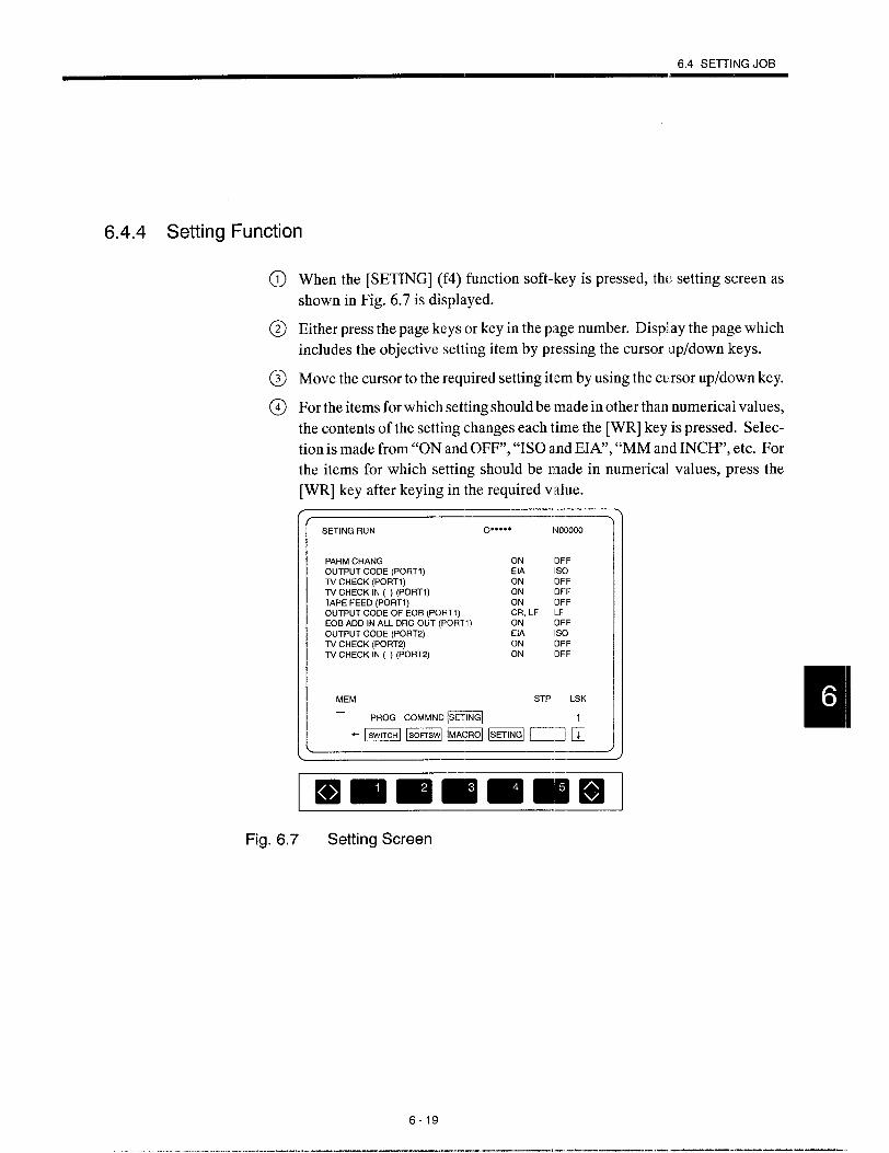
6.4 SEITING JOB
6.4.4 Setting Function
When the [SETING] (f4) function soft-key is pressed, the setting screen as
shown in Fig. 6.7 is displayed.
Either press the page keys or key in the page number. Displlay the page which
includes the objective setting item by pressing the cursor lup/down keys.
Move the cursor to the required setting item by using the cursor up/down key.
For the items for which setting should be made in other than numerical values,
the contents of the setting changes each time the [WR] key is pressed. Selec-
tion is made from “ON and OFF”, “ISO and EIA”, “MM and INCH’, etc. For
the items for which setting should be made in numerical values, press the
[WR] key after keying in the required value.
/ -——————1--—
SETING RUN O***** Nooiloo
PARM CHANG ON OFFOUTPUT CODE (PORT1 ) EIA 1s0TV CHECK (PORT1) ON OFFTV CHECK IN ( ) (PORT1) ON OFFTAPE FEED (PORT1) ON OFFOUTPUT CODE OF EOB (PORT1) CR, LF LFEOB ADD IN ALL ORG OUT (PORT1) ON OFFOUTPUT CODE (PORT2) EIA 1s0TV CHECK (PORT2) ON OFFTV CHECK IN ( ) (PORT2) ON OFF
MEM STP LSK—
PROG COMMNO ~’
“zaEEw@lmL+l-—. )
Fig. 6.7 Setting Screen
6-19
.- ——. ——. ——— ——. —

\\ I/,
o By using the PARM CHANG switch, it is possible to change the parameter data in thePOINT PARAM and SEQ PRM functions in the MAINT process. This switch is linked to set-
ting parameter pmO109.
Switch ON Parameter data can be changed.
I Switch OFF I Parameterdatacarmot be changed. \
● If the switch is set ON, cycle start is made invalid. Therefore, the switch must
always be returned to OFF after changing the parameter data.
● When the SETING function is used, parameter data can always be changed dis-
regarding of the parameter data change enabled/disabled status set by the
switch.
D:W&LE- The items to be set on this screen correspond to the setting parameters that are dis-
played by the SETING function in the PARAM job of the MAINT process.
For the correspondence between the items displayed on the SETING screen and the
setting parameter numbers, refer to Appendix 2 PARAMETER TABL,E.
6-20

COMMON PROCESS CJPERAllrlON
Chapter 7describes the operation carried out by using the
common process key.
In the common process, present position data display, coordi-
nate system setting, alarm display, calendar display, and oper-
ating time display are given by the present position data control
job, alarm display job and time control job.
Job selection is possible by using either the job soft+eysor the
[COMN] process selection key.
7.1 PRESENT POSITION
JOB .
7.1.1
7.1.2
7.1.3
7.1.4
7.1.5
7.1.6
. . . . . . . . . . . . . .
DATA CONTROL
. . . . . . . . . . . . . . . . . 7-2
Collective Display of Present Position Di~ta . . 7-2
Display of Present Position Data
in the W’orkpiece Coordinate System . . . . . . . 7-4
Display of Present Position Data
in the External Coordinate Values . . . . . . . . . . 7-5
Display of Remaining Distance ., , , , , . . . . . . 7-6
Setting the Coordinate Systems . . . . . . . . . . . ‘7 -7
Error Pulse Display Function , , . . . . . . . . . . . . 7-9
7.2 ALARM DISF’LAY JOB .. . . . . . . . . . . . .7-10
7.2.1 Alarm Function.............,,, . . . . . ...7-10
7.2.2 Servo Alarm Function . . . . . . . . . . . . ,, . . ...7-11
7.2.3 User’s MessageF unction . . . . . . . . . . . . . . . . 7-12
7.3 TIME CONTROL JOB ,,. . . . . . . . . . . ...7-13
7.3.1 Calendar Function . . . . . . . . . . . . . . . ., . ...7-14
7.3.2 Operatirlg Time Functicm . . . . . . . . . . . . . . . . . 7-15
7-1

7.1 PRESENT POSITION DATA CONTROL JOB
The present position job displays the position data and also permits the setting of the position
data.
When the [POSIT.] (fl) job soft-key is pressed, any of the following functions maybe dis-
played.
●
●
●
●
●
ALL (collective display) function
ABS (absolute position) function
EXTERN (external coordinate value) function
INCR (remaining distance) function
ERROR (error pulse) function
7.1.1 Collective Display of Present F)osition Data
When the [ALL] (fl) function soft-key is pressed, the present position data collective display
screen is displayed.
POSITION COM 012345 N12345
ASSOLUTE EXTERNAL
x 3C0.OCO x -391.728z 3m.oQ2 z -296.734
INCREMENT MACHINE
x O.m xz
-361.072Om z -298.593
MEM STP ILSK
“ m ALARM “ME
“mm EIEmE+l
ImmmmmlmlmlFig. 7.1 Present Position Data Collective Display Screen
7-2

7.1 PRESENT POSITION EIATACONTROLJOB
—. “.. . . . . . . . . . . . ,., .
‘l’he
(1)
(2)
(3)
(4)
—
Iollowlng describes ttIe lnCIIVlaual mnctlons.
ABS (Workpiece Coordinate System)
The coordinate values of a cutting tool in the set workpiece coordinate system are dis-
played. Whether or not the tool offset data are included in the coordinate values to be
displayed here can be selected by the setting for the parameter.
~areinc’”ded”: :+Tooloffsetdataare not includecl.
The workpiece coordinate system canbe preset by using [SET] of the [POSIT.] function
(see 7.1.5, “Setting the Coordinate Systems”.)
EXTERNAL (External Coordinate Values)
Accumulated travel distance of a cutting tool is displayed in reference to the position
preset by using the preset operation,
INCREMENT (Remaining Distance)
The following values are displayed,
● In the automatic operation mode, the distance from the present position of the
cutting tool to the end point of the block being executed is displayed.
● In the manual operation mode, the distarlce is measured from the present posi-
tion of the cutting tool to the manual operation start point. I’his display is reset
to “O” when the operation mode is returned to manual.
MACHINE (Machine Coordinate System)
The present position of the cutting tool is displayed in the coordinate system that has
its origin at the position where the axes are positioned by the reference point return op-
eration.
.-.. —
(3s#;PFLE- The axis names displayed on the screen are those set for parameter pm 1100. If no axis
name is set for this parameter, the default axis names are displayed.
7-3
—---- ...-. ..-— ——— .--— ———,. -.. -.. ——.. . . .—.. —. —. ——-—---

7.1.2 Display of Present Position Coordinate System
When the [ABS] (f2) function soft-key is pressed, the present position data in the workpiece
coordinate system are displayed.
POSITION colt 012245 N12345
ASSOLUTE
x 300.000
z 350.000
S1: Orpm S2: Orpm
MEM R BUF LSK
Fig. 7.2 Workpiece Coordinate System Display Screen
7-4

7.1 PlqESENT POSITION DATA CONTROL JOB
7.1.3 Display of Present Position External Coordinate Values
When the [EXTERN] (f3) function soft-key is pressed, the external coordinatevalues are dis-
played.
-- \POSITION COM 012345 N12345
EXTERNAL
x –381 .728
z –296.734
S1: Orpm S2: Orpm
MEM R BUF LSK
E!ElA~M TI”E-LzmEmEmmdl.-4
)
Fig. 7.3 External Coordinate System Display Screen
7-5

7,1.4 Display of Remaining Distance
When the [INCR] (f4) function soft-key is pressed, the remaining distance is displayed.
POSITION COM 012345 N12345
INCREMENT
xz
0.0000.000
S1. Orpm S2: Orpm
MEM R BUF LSK
– m ALARM TIME 1
Immmmmlmiml
Fig. 7.4 Remaining Distance Display Screen
7-6

7.1 F’FIESENT POSITION D.ATACONTROLJOB—— —
7.1.5 Setting the Coordinate Systems
By pressing the [ALL] (f 1), [ABS] (f2), or [EXTERN] (f3) function soft-keys, the coordinate
systems can be set.
(1) Outline of the Setting in Each Function
(a)
(b)
(c)
All function
When the [ALL] (fl) function soft-key is pressed, the external coordinate system
can be set. The external coordinate system can always be set, even while an axis
is moving in automatic operation of a part program.
Coordinate system function
When the [ABS] (f2) function soft-key is pressed, the workpiece coordinate system
can be set. This function is valid in manual operation mode (rapid traverse, jog
feed, step feed, handle feed). If an attempt is made to set a workpiece coordinate
system in a mode other than manual mode, the warning message “CAN’T SET
COORD!” is displayed.
External coordinate system function
When the [EXTERN] (f3) function soft-key is pressed, the external coordinate sys-
tem can be set. The external coordinate system can always be set, even while an
axis is moving in automatic operation of a part program.
7-7
... ..— .—. -—- ——. ——-—---

(2) Setting the Coordinate Systems
Follow the procedure indicated below to set a coordinate system.
@ When the [SET] (f5) function soft-key is pressed, the key is highlighted and,
at the same time, the name of the axis for which a coordinate value can be set
is highlighted.
POSITION COM 012345 N12L?45
ABSOLUTE
1X1 300.000
z 350.000
S1: Orpm S2: Orpm
RAPID STP LSK
Fig. 7.5 Workpiece Coordinate System Setting Screen
Move the cursor to the axis for which the coordinate value should be set by
using the cursor up/down keys.
The coordinate system is set when a coordinate value is entered and the cursor
moves to the next axis name. For example, key in “210.5” and press the [WR]
key. The coordinate system is set based on the entered value.
lf the [WR] key is pressed without keying in a coordinate value, the coordinate
system is set assuming “O”.
If the [WR] key is pressed after keying in the “/” code, one-half of the position
data value is entered and the coordinate system is set accordingly.
When the [SET] (f5) function soft-key is pressed, the cursor on the axis name
disappears.
7-8

7.1 PFIESENTPOSITION DATA CONTROLJ06
(3;lJP&LE- 1. If an attempt is made to set a coordinate system in the mode in which a coordinate
system cannot beset, the warning message “CAWT SET COORD ~“is displayed.
2. The operation to set the coordinate system in th~ present position data control job
is called the numerical setting up.
7.1.6 Error Pulse Display Function
The error pulse screen is displayed when the [ERROR] (fl) function soft-key is pressed.
POSITION COM 012?45 N12245
ERROR
x 0.000
z 0.000
S1: Orpm S2: Orpm
MEM R BUF LSK
m ALARM TIME
“=DOE306
Fig. 7.6 Error Pulse Display Screen
On the error pulse display screen, the contents of the command pulse accumulation registers
in the NC are displayed. The command pulse accumulation registers are reset to “O” when
the power is turned ON, and command pulses are all accumulated in these registers after that.
7-9
. .—. .—. -—. —--—--. —

7.2 ALARM DISPLAY JOB
The alarm display job displays the contents of the alarm if an alarm occurs with the NC unit.
When the [ALARM] (fl) job soft-key is pressed, any of the following functions maybe dis-
played: alarm function, servo alarm function, and user’s message function.
7.2.1 Alarm Function
If an alarm occurs with the NC unit, “ALM” or “BGA” (background alarm) message is dis-
played in the alarm status display area in the screen regardless of the mode or process. If
battery alarm occurs at the same time, either “A/B” or “B/B” is displayed in blinking charac-
ters. At the same time, the alarm number of the alarm having the highest priority is displayed
with the corresponding alarm message and alarm occurring program line in the alarm mes-
sage display area.
When the [ALARM] (fl) function soft-key is pressed, the screen changes to the alarm display
screen where alarm information of all alarms that have occurred is displayed. The alarm
numbers and the alarm messages are displayed in the order of priority.
ALARM COM o**’”* NOOOOO
0190 RAOIUS O IN CIRCULAR0050 POWER OFF PRM SET
0190: RAOIUS O IN CIRCU!AR
MEM STP LSK
ImmlmmmmmlFig. 7.7 Alarm Message Display Screen
7-1o

7.2 AlARM DISPLAY JOB——1
7.2.2 Servo Alarm Function
When an alarm occurs with the servo ccmtroller (SERVOPACK), the alarm information is
displayed on the screen. Follow the procedure indicated below.
@ When the [SV.ALM] (f2) function soft-key is pressed, the swvo alarm display
screen is displayed as shown in Fig. 7.8, If an alarm relatedl with the SERVO-
PACK is displayed on the alarm message display screen (I:ig. 7.7), details of
the SERVOPACK related alarm can be checked on this screen.
SERVOALM COM O“”**” NOOOOO
3301 OVER CURRENTR (xl3311 MCCB TRIP (x3321 REGEN ABNOFiMAL (x)3331 OVER VOLTAGER (x)
3341 SHORTAGE VOLTAGE (xj
MEM STP LSK
POSIT. m TIME
“--L=UE:+I
ImrnmrnrnmmlI 1
Fig. 7.8 Servo Alarm Display Screen
@ If alarms cannot be displayed on one page of the display screen, they are dis-
played on more than one page. To change the display page, use the page keys.
If alarm display is given on one page, the page keys are invalid.
7-11
———--- -,, .-, --- ... .. . ,—. -—. —-. —-—-—-

7.2.3 User’s Message Function
The function displays user’s message on the screen by the PLC system (machine sequence
controller) in the NC unit. Usually, this function is used to display the outline of the alarm
detected by the PLC. However, this function is also used to simply display the message.
When the message display instruction (macro instruction) is executed in the PLC, either
“ALM” or “A/B” blinks at the alarm status display area.
(1) When the [ALARM] (fl ) Function Soft-key is Pressed
The following display is given.
● ALM 1080
● ALM 2180
● ALM 3240
(2) When the [USERS]
SEQUENCE ERROR O
SEQUENCE ERROR 1
SEQUENCE ERROR 2
(f3) Function Soft-key is Pressed
The user’s message screen is displayed where detailed error codes output from the PLC
are displayed. For details, refer to the manuals published by the machine tool builder.
USER’S MES1 Cotd O“”*** NOOOOO
5000 SPINDLE ALARM5010 ATC ALARM
MEM STFI LSK
POSIT. = TIME
“mmm Dub
~~
Fig. 7.9 User’s Message Screen
7-12

7.3 TiME CONTROLJOB
7.3 TIME CONTROL JOB
The time control job allows the display and setting of the date and time ~lsing the calendar
function. When the operating”time data are selected, operating time data can be, displayed
gnd set.
When the [TIME] (f3) job soft-key is pressed, either the calendar screen or I.heoperating time
screen is displayed. The [CALEN] (fl) and [W.TIME] (f2) function soft-keys are used to
change the display screen.
r -—
CALENDER COM O***** NOOOOO
OAT 1991’, 01”, 0;
TIM 22 ;22”: 2;
Fig. 7.10 Calendar Display Screen
7-13
—.. - ..-. —— .-. ——_— —.———-— ———

7.3.1 Calendar Function
(1) Calendar Display
When the [CALEN] (fl) function soft-key is pressed, the calendar screen is displayed
where the NC’s calendar data (date and time) are displayed.
~~CALENDER COM O“”*** NOOOOO
Y M D
DAT 1991.01.01
H M s
TIM 22:22:22
MEM STP LSK
POSIT, AIARM r-
“mnu DDl+l
Immlnn Emlmi ElI I
Fig. 7.11 Calendar Setting Screen
(2) Calendar Setting
@ Press the FUNCTION SELECT key to display the [SET] (fl) function soft-
key.
@ When the [SET] (fl) function soft-key is pressed, the calendar setting mode
is called and the [SET] (fl) function soft-key is highlighted. At the same time,
the cursor is displayed on “DAT”.
@) Selection of date and time is possible by moving the cursor. The cursor up/
down keys are used to move the cursor.
@) Set the date. For example, key in “1991.01.01” and press the [WR] key.
@ Set the time. For example, key in “22.22.22” and press the [WR] key.
@ When the [SET] (f5) function soft-key is pressed, the cursor disappears and
the newly entered date and time are displayed.
7-14
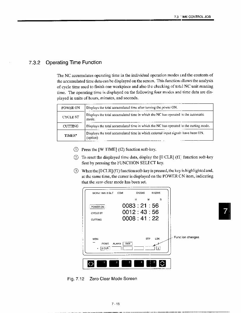
7.3 ‘I”IMECONTROLJOB
7.3.2 Operating Tme Function
The NC accumulates operating time in the individual operation modes and the contents of
the accumulated time data can be displayed on the screen. This function allows the analysis
of cycle time used to finish one workpiece and also the checking of total NC unit running
time. The operating time is displayed cm the following four modes and time data are dis-
played in units of hours, minutes, and seconds.
I CYCLE ST
Displays the total accumulated time after turning the power ON. IDisplays the total accumulated time in which the NC has operated in the automaticmode. I
I CUTTING, —4Displays the total accumulated time in which the NC has operated in the cutting mode
ITIMER*
Displays the total accumulated time in which external input signals have been ON.(option) I
Press the [W TIME] (f2) function soft-key.
To reset the displayed time data, display the [0 CLR] (fl;l function soft-key
first by pressing the FUNCTION SELECT key.
When the [0 CLR] (fl) function soft-key is pressed, the key is highlighted and,
at the same time, the cursor is displayed cm the POWER CIN item, indicating
that the zero clear mode has been set.
WORK TIME O SET COM 012345 N12345
H M s
EEml 0083:21:56CYCLE ST 0012:43:56
CUITING 0008:41:22
Funclion changes.
Immmmimlnml
Fig. 7.12 Zero Clear Mode Screen
7-15
——— ..- ,— —...-————.

@) Toclearthe time data to’’o”, move the cursor to the itemtobe cleared and press
the [WR] key. The ‘time data of the item on which the cursor is positioned are
cleared to “O” and the cursor moves to the next item.
@ When the [0 CLR] (fl) function soft-key is pressed, the cursor disappears and
the zero clear mode is canceled.
7-16

8MAINTENANCE PROCESS
Chapter 8describes the operation carried out by using the
maintenance process key.
In the maintenance process, display and setting cf the data
necessary to maintain the NC unit and input/output of the data
using an external device are executed by the parameter job,
1/0 monitoring job, input/output and verify job, and internal in-
formation job.
Job selection is possible by using either the job soft-keys or
the [MAI NTj process selection key.
8.1 PARAMETEFI JOB . . . . . . . . . . . . . . . . . . .8-3
8.1.1 Parameter Function . . . . . . . . . . . . . . . . . . . . 8-3
8.1.2 Setting Function . . . . . . . . . . . . . . . . . . . . . . . 8-6
8.1.3 Sequence Parameter Function . . . . . . . ~. . . . 8-7
8.1.4 Pitch Error Function* . . . . . . . . . . . . . . . . . . 8-7
8.2 l/O MONITORING JOB . . . . . . . . . . . . ...8-88.2.1 Displaying the ON/OFl= Status
of thel/O Signals . . . . . . . . . . . . . . . . . . . . . . . 8-8
8.2.2 Displaying the ON/OFl: Status
of the Selected l/O Sigrlals . . . . . . . . . . . . . . . . 8-9
8.2.3 Turning ON/OFF 1/0 Signals Forcibly . . . . . 8-11
8-1
.—— —. .. —,-- . —— .—.--.. —. ———. —--—

8.’3 lNPUT/OUTPUT AND VERIFY JOB . ..8-12
8.3.1 input/output and Verify Function ,,, ,. .,... 8-12
8.3.2 Reset Function . . . . . . . . . . . . . . . . . . . . . . ...8-14
8.3.3 l/ODeviceSettingFunction . . . . . . . . . . . . . . 8-14
8.4 INTERNAL INFORMATION JOB . . . ...8-15
8.4.1 Version Number Function, ,, . . . . . . . . . . . . 8-15
8.4.2 Memory Dump Function . . . . . . . . . . . . .,...8-16
8.4.3 Key Memory Function, ., .,,.,..., . . . . ...8-16
8-2

81 PARAMETERJOB
8.1
8.1.1
PARAMETER JOB
With the parameter job, the data stored in the internal memory (parameter data, setting data,
battery back-up memory data, pitch error compensaticm data) can be dis~llayed and set. Ac-
cording to the contents, specific functions are turned ON and OFF or the operatiom conditions
of the functions are determined.
When the [PARAM] (fl) job soft-key is pressed, the following functiorl soft-keys are dis-
played: [PARAM] (fl), [SETING] (fZ), [SEQI’FWl] (f3), and [p.ERR] (fA).
Before setting the parameters, set “ON” for “PARAMETER CHANG” parameter by using
the [SETING] job in the [RUN] process. With this setting, the data set for parameters, battery
back-up memory, and pitch error can be changed. After the completion of changing, make
sure to return the setting for “PARAMETER CHANC~’ to “OFF”.
~ CAUTIO~N● The end user must not change parameters relating to machine accuracy, travel
axis control and spindle axis control.
The NC parameters are set to the optimum values for each machine, and changing them
could therefore result in unexpected operation. This could cause tool damage due to
interference, and resulting accidents involving injuries to personnel.
Reset the NC after any manual intervention.
Parameter Function
With the parameter function, display and setting of parameter data storecl in the NC are pos-
sible. Usually, the parameter data are set by the machine tool builder and to change the set-
ting for the parameters, make sure to consult the machine tool builder.
(1)
Press the [PARAM] (fl) :function soft-key.
The parameters are largely classified into two types – bit type and byte/word/
double-word type.
Bit Type Parameters
Follow the procedure indicated below to write the bit type parameters.
@ Move the cursor to the parameter for which the present setting should be
changed. For this operation, use the page keys and the tumor up/down keys,
or use the cursor upldown keys after keying in the param,~ter number.
@ Press either the [INSRT] key or the cursor right key. In the case of [INSRT]
key, the cursor moves to the decimal nu:rnber display are~. and in the case of
the cursor right key, the cursor moves tc~the bit data posi :ion.
8-3
.—— —---- —,..-..’— —.. ,— .-—-... —- —-.— ———

@ Move the cursor to the bit position where the data should be changed and press
the [WR] key. Each time the [WR] key is pressed, the bit status (ON/OFF)
is changed alternately. Writing a numerical value is allowed only when the
cursor is moved to the decimal number position at the right end column.
Table 8.1 Example) Writing a decimal number for bit data
Key Operation Bit 76543210 Decimal Number
[0] [WR] 00000000 0[8] [WR] 00001000 8
[2][5][5][WR] 11111111 255
PARAMETER MNT O“*** NOOOOO
76543210pm1000 000000000pm1001 111111118pm1002 00000000255pm1003 000000000pm1004 000000000pm1005 000000000pm1006 000000000pml 007 000000000pml 006 000000000pmloo9 o 0 00 000 0 0
0. OFF l:ON
MEM STP LSK
= ‘lAGN lN/OuT DATA LADDER t
mmll==ll=dl=iiq rlm
lmmmEmmH3-Fig. 8.1 Parameter Input Screen (Bit Type Parameters)
84

8.1 PARAMETER JOB
(2) Byte/Word/Double-word Type Pi~rameters
Follow the procedure indicated below to write the ‘byte/word/double- word type param-
eters.
@ Move the cursor to the parameter for which the present setting should be
changed. For this operation, use the page keys and the cursor upldown keys,
or use the cursor up/down keys after ke ying in the paramet [jr number. When
parameter number search is executed, it is not necessary
@ Keyinarequiredparameter value andprws the [WR] key,
is entered to the specified parameter.
--—PARAMETER DIAGN O***** Nooooo
pm 8100 0pm 8101 0pm 8102 0pm 8103 0pm 81C4 opm 8105 0pm 8106 0pm8107 opm 8106 0pm8109 o
MEM STP LSK
mmm’mm=:~m
= ‘E~lNG ‘Ec~pRM pERR J
-—
--—
mmmmmmllllm
k) enter “pm”.
~’he keyed in value
Fig. 8.2 Parameter Input Screen(Byte/Word/Double-word Type Parameters)
8-5

@ After changing the setting for the parameters, press the [RESET] key. The
new settings become valid when the NC is reset.
c When the setting is made for the parameters that become valid after the power
is turned OFF, the alarm “ALM 0050: POWER OFF PRM SET” occurs. If
this alarm message is displayed, turn OFF the power once and then turn it back
ON.
● When the setting is made for the parameters that become valid when the part
program is initialized, the alarm “ALM 0051: PROGRAM GENERATION
PRM SET” occurs, If this alarm message is displayed, program clear is neces-
sary.
Contact your Yaskawa representative. Even after the occurrence of this alarm,
it is possible to run the NC without problems by turning OFF the power once
and then turning it back ON again. In this case, the new setting is invalid.
8.1.2 Setting Function
It is possible to display the setting data stored in the NC and also to set the data. Follow the
procedure indicated below.
@ Press the [SETING] (f2) function soft-key.
@ Move the cursor to the setting number for which the present setting should be
changed by pressing the page keys or cursor up/down keys. The cursor can
also be moved to the desired setting number by pressing the cursor up/down
keys after entering the parameter number.
@ Enter the required value.
(3)fwP#- 1. Operation is basically the same as with the parameter function. When changing
the setting data, it is not necessary to set “ON” for the “PARAMETER CHANG”
parameter.
2. When the setting is changed for the setting data, the new data become valid im-
mediately.
3. A part of the setting data can be set on the setting function screen in the RUN
process.
8-6

8.” PARAMETER JOB
8.1.3 Sequence Parameter Function
With the sequence parameter function, display and setting are possible for the sequence pa-
rameters. Here, the sequence parameter refers to the data. used by the PLC. Follow the proce-
dure indicated below.
Press the [SEQPRM] (f3) function soft-key.
Move the cursor to the sequence parameter number for which the present set-
ting should be changed by pressing the page keys or cursor up/down keys. The
cursor can also be moved to the desired setting number by pressing the cursor
up/down keys after entering the parameter number.
Enter the required parameter data. For the procedure for enl:ering the parame-
ter data, refer to 8.1.1, “Parameter Function”.
.— —.
a)SUPPLE- On the bit type data display screen, the numerical values given at the right end of the?4Etdl’ column are hexadecimal numbers.
8.1.4 Pitch Error Function *
The pitch error function allows the display and setting c)fthe pitch error compensation data
stored in the NC.
@ Press the [P.ERR] (f4) function soft-key.
@ Move the cursor to the pitch error number for which the prejent setting should
be changed by pressing the page keys or cursor up/down keys. The cursor can
also be moved to the desired setting number by pressing the cursor up/down
keys after entering the parameter number.
@ Enter the required pitch error compensation data. For the plocedure for enter-
ing the data, refer to 8.1.1, “Parameter Function”.
8-7
——— .—..—.— --.—-—.—.

8.2
8.2.1
(3SUPPLE-MENT
1/0 MONITORING JOB
With the 1/0 monitor job, ON/OF.F status of the 1/0 signals of the NC, PLC, and the machine
can be monitored.
Displaying the ON/OFF Status of the 1/0 Signals
When the [DIAGN.] (f2) soft-key is pressed, the ON/OFF status of the 1/0 signals of the NC,
PLC, and machine are displayed. This display can be displayed at any time.
DIAGNOSIS
# 1000# 1001# 1002# 1003# 1004# 1005# 1006# 1007# 1008# 1009
*=0
MNT
7650010000000000000000110000000000. OPEN
o“*- NOOOOO
43210000002001000000000000000000000000000000000111017D1 11101E00000000000000
1: CLOSED
STP ‘SK I IPARAM. = lN/OUT DATA L4DDER t
mmEqmum
Immmmilmlmml
Fig. 8.3 1/0 Signal Display Screen
—
On the 1/0 signal display screen, the numerical values given at the right end of the
column are hexadecimal numbers,
8-8
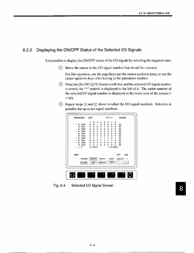
8.2 1/0 MONITORING JOB
8.2.2 Displaying the ON/OFF Status of the Selected 1/0 Signals
It is possible to display the ON/OFF status of the 1/0 signals by selecting the required ones.
Move the cursor to the 1/0 signal number that should be selected.
For this operation, use the page keys and the cursor up/down keys, or use thecursor up/down keys after keying in the parameter number.
Press the [SL/DEL] (fl) function soft-key and the selected 1/0 signal number
is stored; the “*” symbol is displayed to the left of it. The entire number of
the selected 1/0 signal number is displayed at the lower arta of the screen (“
= xx).
Repeat steps @ and@ above to select the 1/0 signal numbers: Selection is
possible for up to ten signal numbers.
* # 1000# 1001# 1002
* # 1003# 1004# 1005
* # 1006* # 1007* # 1008
# 1009* .5
MNT O“”*** NOOOOO
76543210001000002000001000000000000000000000000000000000000000000000011 111017DOOO1111O1E000000000000000000000: OPEN 1: CLOSED
MEM STP LSK
PARAM. = lN/OUT DATA LAOCE,R t
Fig. 8.4 Selected 1/0 Signal Screen
8-9

@ Press the [DISP] (f2) function soft-key. The selected 1/0 signal numbers are
displayed.
DIAGNOSIS MNT O***** NOOOOO
76 5 4 32 1 0# 1000 00 1 000 0 0 20# 1003 0000000000# 1006 0 1 1111017D# 1007 000 1 1 1 1 0 lE# 1008 000 0 00 0 0 00
0: OPEN 1: CLOSED
MEM STP LSK
PARAM. ~A~ lN/OUT DATA
ucIn m=&
/
ImmmmmlmmlFig. 8.5 Selected 1/0 Signal Display Screen
When the [RETURN] (f5) function soft-key is pressed, the screen returns to
the 1/0 signal display screen which is displayed when the [DIAGN] (f2) job
soft-key is pressed,
When the [DELETE] (f3) function soft-key is pressed, the selection of the 1/0
signal numbers is canceled.
When the [SL/DEL] (f2) function soft-key is pressed after moving the cursor
to the 1/0 signal number that has been selected, the selection of that 1/0 signal
number is cancelecl.
8-10

8.2 1/() MONITORING JOB
8.2.3 Turning ON/OFF 1/0 Signals Forcibly
The forced contact ON/OFF selection function is provided to check the machine sequence.
This function allows the contact status to be changed forcibly without changing the machine
sequence. To make this function valid, set “l” for parameter pmO109 in the [SETING] func-
tion of [PRM] job in the [MAINT] process.
Move the cursor to the 1/0 signal number that should be selected. For this op-
eration, use the page keys and the cursor up/down keys, or use the cursor up/
down keys after keying in the parameter number.
Press the [INSRT] key. The cursor moves to the bit data mea.
Move the cursor to the bit that should be selected for forced contact ON/OFF
operation and press the [(;PS] (f4) function soft-kc y. A box (0) appears at
the selected bit. The box disappears when the [CPS] (f4) f l~nction soft-key is
pressed again.
Press the [WR] key. Each time the [Wll] key is pressed, the ON/OFF status
of the selected bit is changed alternately.
After moving the cursor to the 1/0 signal number for which the “*” symbol
is displayed to the left, press the [SL/llIEL] (f 1) function soft-key and the
selection of forced contact ON/OFF operation is cancelecl.
When the [DELETE] (f3) :function soft-key is pressed, selection of forced con-
tact ON/OFF operation is canceled for all contacts.
8-11

8.3
8.3.1
lNPUT/OUTPUT AND VERIFY JOB
The input/output and verify job allows the input and output of the NC data with an external
device. It is possible to display the input/output data while the data are input from a tape
reader or output to a tape punch by setting the appropriate value for the parameter.
pmOO07D5 .0
3
Dataare displayed on the screen during data input/output using tape.
pmOO07 D5 = 1 Data are not displayed on the screen during data input/output using tape.
If data are displayed for input/output and verify operation, processing time will be extended.
Input/output and Verify Function
The input/output and verify function provides the following menu items.
● Input/output and verify of all parameters (setting, parameters, sequence pa-
rameters and battery back-up memory, pitch error, offset)
● Input/output and verify of setting data
● Input/output and verify of parameters (not possible for sequence parameters
pm7000 to pm7099)
● Input/output and verify of sequence parameters and battery back-up memory
Although data are displayed in hexadecimal number for battery back-up memory, out-
put is decimal value.
“ Input/output and verify of pitch error compensation parameters (option)
● Input/output and verify of all offset data (tool offset and work coordinate sys-
tem shift data)
● Input/output and verify of tool life control data (option)
● Input/output and verify of macro and common variables (option)
The input/output and verify of the data is possible disregarding of the NC operation mode.
However, automatic operation is not possible during input/output and verify.
8-12
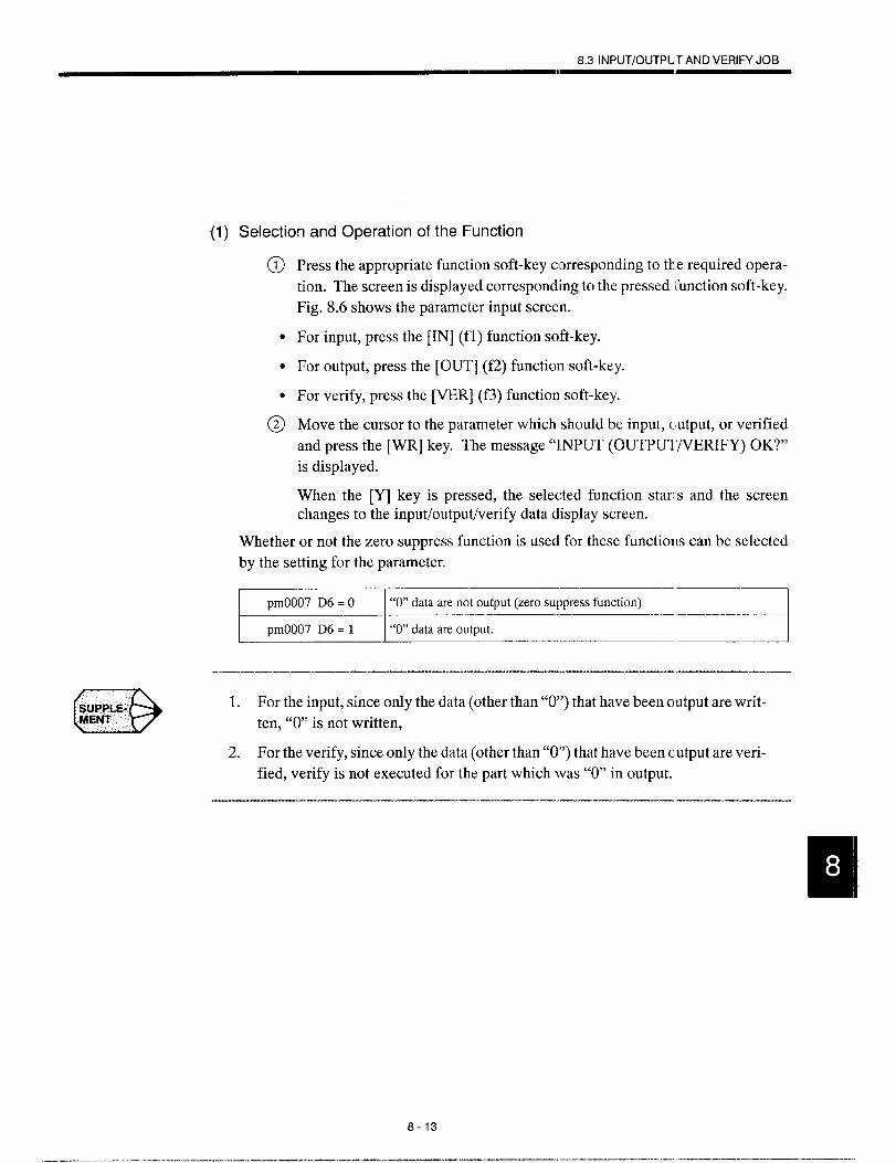
8.3 lNPUT/OUTPUIT AND VERIFYJOB
(1) Selection and Operation of the F’unction
a
●
●
(i
Press the appropriate function soft-key corresponding to the required opera-
tion. The screen is displayed corresponding to the pressed Ifunction soft-key.
Fig. 8.6 shows the parameter input screen.
For input, press the [IN] (fl) function soft-key.
For output, press the [OUT] (f2) function soft-key.
For verify, press the [VER] (f3) function soft-key.
Move the cursor to the parameter which should be input, cmtput, or verified
and press the [WR] key. The message “IINPUT (OUTPUI ‘7VERIFY) OK?”
is displayed.
When the [Y] key is pressed, the selected function starts and the screenchanges to the input/output/verify data display screen.
Whether or not the zero suppress function is usecl for these functions can be selected
by the setting for the parameter.
I pIrlooo7 D6 = o I “0)’ data are net output (zero suppress function) I
pmOO07 D6 = 1 “O” data are output..- .J
(3SUPPLE.MENT
1. For the input, since only the data (other than “O”) that have been output are writ-
ten, “0” is not written,
2. For the verify, since only the data (other than “0”) that have been clutput are veri-
fied, verify is not executed for the part which was “O” in output.
8-13
———. ---—. — —.. .-. . .. ——-. . . . .—— .--—. ——— —. ___ .,
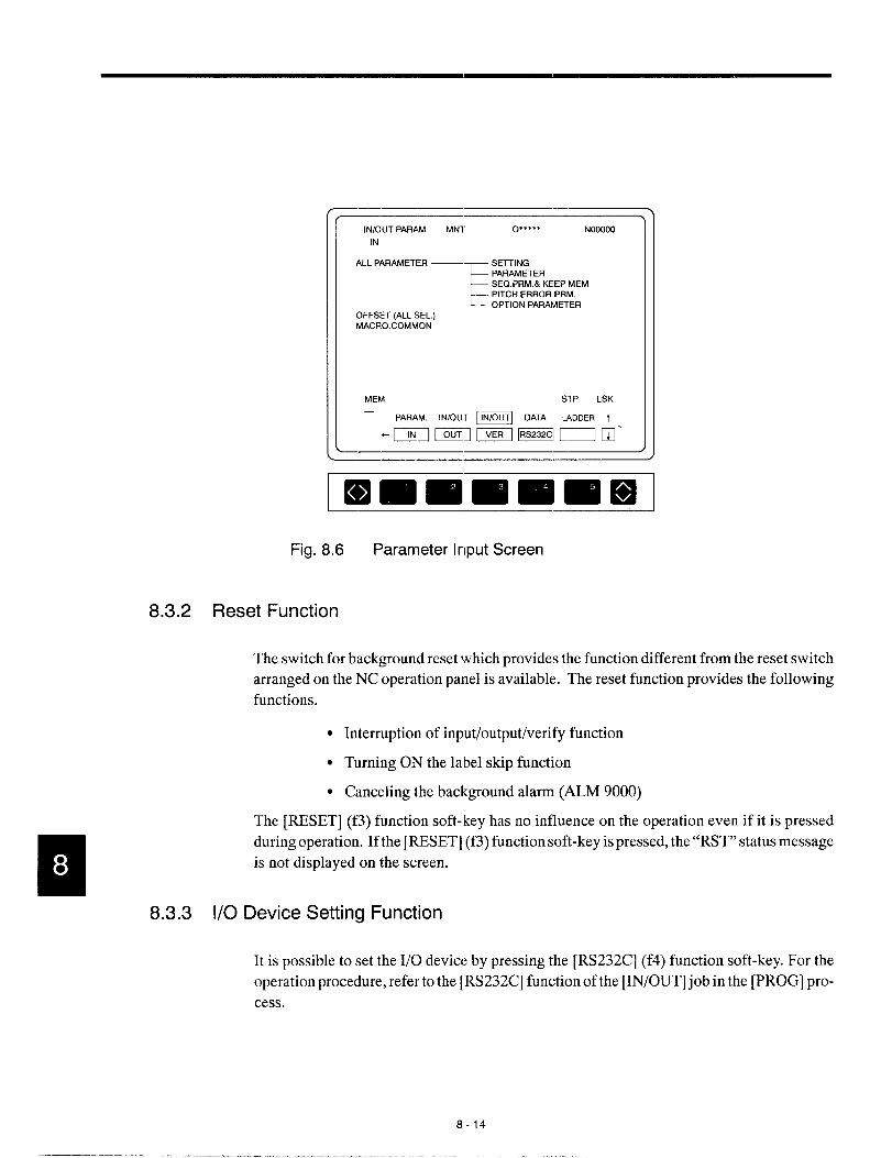
lN/OUT PARAM MN1 0“””” NOOOOO
IN
ALL PARAMETER —
E
SETTINGPARAMETERSEQ. PRM.& KEEP MEMPITCH ERROR PRM.OPTION PARAM~ER
OFFSET (ALL SEL.)MACRO. COMMON
MEM STP LSK—
PARAM, lN/OUT m DATA UDDER t
“mmm=nm’
\
ImmmmlmlmmlFig. 8.6 Parameter Input Screen
8.3.2 Reset Function
The switch for background reset which provides the function different from the reset switch
arranged on the NC operation panel is available. The reset function provides the following
functions.
●
●
●
Interruption of input/output/verify function
Turning ON the label skip function
Canceling the background alarm (ALM 9000)
8.3.3 1/0
The [RESET] (f3) function soft-key has no influence on the operation even if it is pressed
during operation. If the [RESET] (f3) function soft-key is pressed, the “RST” status message
is not displayed on the screen.
Device Setting Function
It is possible to set the 1/0 device by pressing the [RS232C] (f4) function soft-key. For the
operation procedure, refer to the [RS232C] function of the [IN/OUT] job in the [PROG] pro-
cess.
8-14

8.4 INTERNAL. INFORMATION JOB
8.4 INTERNAL INFORMATION JC)B
Selection of each job ispossiblebypressing thecorresponding job soft-keys ([PARAM] (fI),
[DIAGN] (f2), [IN/OUT] (f3)i and [DATA] (f4)), or by pressing the [MAINT] process key.
For control of the internal information, the following function soft-keys which are accessible
by pressing the [DATA] job soft-key are provided: [VER NO] (fl), [D’IJMP] (f2), [KEY-
MEM] (f3), and [SERVO] (f4).
8.4.1 Version Number Function
The version number function is provided for the purpose of maintenance and it is not used
for daily operation. When the [VER NO] (fl) function soft-key is pressed, the version num-
ber list screen is displayed. On this screen, the following information is displayed.
(1)
(2)
(3)
SYSTEM NO
Two system numbers (NC and PC ladder) are displayed.
OPTION VERSION NO
When the option boards are installed, the software version of these o ption boards is dis-
played.
BASIC VERSION NO
The software version of the basic Iboards is displayed.
-—VERSION NO MNT O’*”*” NOOOOO
SYSTEM NONC MAIN: 08330-13
IANG: 08332+5BOOT :0835600COM : 0834s43DRAW : 0833SW31C-PACK :08337434ACGC : 0836W36
ACGC COMBINATIONA-PACK : 08361+2NC MAIN: 0833W13
LANG: 08332+5NC CCIMBINATION
COIM :08348-00DRAW :0833840C-PACK :08337-04ACGC : 0836G06
USERLAD~~R : *** . . . . . .
C-APL : ..* *...
EDIT STP LSK
PARAM. _ lN/OUT DATA t
❑mmmmm BJFig. 8.7 Version Number Display Screen
8-15
—,.——.——. —

8.4.2 Memory Dump Function
The memory dump function is provided for the purpose of maintenance and it is not used
for daily operation. When the [DUMP] (f2) function soft-key is depressed, the memory
dump screen is displayed. This screen is provided for the service technician of YASNAC
NC.
8.4.3 Key Memory Function
When the [KEYMEM] (f3) functionsoft-key is pressed, the key memory screen is displayed.
On the key memory screen, the history of key entry from the NCoperationpanel is displayed.
The correspondence between the keys used and the key codes is indicated below.
List of key codes:
Alphabet, numerals, [SHIFT] + A. - Z
The characters of the pressed keys are displayed. [SP] is displayed only for space bar.
Special keys:
Soft-keys
okey . . . . . . . . .
A key . . . . . . . . .
v
1 key . . . . . . . . .
2 key . . . . . . . . .
3 key . . . . . . . . .
4 key . . . . . . . . .
5 key . . . . . . . . .
Cursor keys
➤ key . . . . . . . . .
Akey . . . . . . . . .
+key . . . . . . . . .
~key . . . . . . . . .
Page keys
A key . . . . . . . . .
V key . . . . . . . . .
MN-L
MN-R
F1
F2
F3
F4
F5
CIJ-R
CIJ-U
CIJ-L
CIJ-D
Pci-u
PCi-D
Process keys and other keys
PROG key
SET key
RUN key
MAINT key
COMN key
AUX1 key
AUX2 key
[RESET] key
CAN key
EOB key
INSRT key
ALTER key
ERASE key
WR key
. . . . . . . . .
. . . . . . . . .
. . . . . . . . ,
. . . . . . . . .
. . . . . . . . .
. . . . . . . . .
. . . . . . . . .
. . . . . . . . .
. . . . . . . . .
. . . . . . . . .
. . . . . . . . .
. . . . . . . . .
. . . . . .
. . . . . . . . .
PRG
SET
RUN
MNT
CMN
AUX1
AUX2
RES
CAN
EOB
INS
ALT
ERS
WR
8-16

MAINTENAIINCE
Chapter 9 describes the maintenance data that can be
accessed by the users.
9.1 MAINTENANICE DATA . . . . . . . . . . . . . . .. 9-2
9.1.1 Checkin~g the Status of ‘Troubles . . . . . . . . . . 9-2
9.1.2 Checking the NC Information . . . . . . . . . . . . . 9-3
9.1.3 Display of Alarm Information . . . . . . . . . . . . . 9-5
9.1.4 Cause of Alarm and Corrective Action ., . . . . 9-6
9.1.5 Troubleshooting (l) . . . . . . . . . . . . . . . . . . . ...9-7
9.1.6 Troubleshooting (2) . . . . . . . . . . . . . . . . ,, ...9-17
9.1.7 Alarms Not Indicated by Alarm Numbers . . . 9-23
9-1
..- ..-. .——--—. ——— ———

9.1
9.1.1
MAINTENANCE DATA
To locate the cause of problems or when contacting your Yaskawa representative for advice,
it is very important that users precisely understand the actual situation. To minimize the
downtime, check the following points precisely.
~ CAUTION● When an alarm occurs, eliminate its cause and confirm safety before resetting it.
Failure to observe this caution could result in malfunction.
● For details on trouble relating to the machine-related sequence, refer to the
manual issued by the machine tool builder.
Checking the Status of Troubles
(1) Understanding the Situation
To make clear the status of troubles, check the following items first.
● Type of operation that causes a trouble.
Do other types of operation not cause troubles?
“ Details of troubles.
How, frequency (always or sometimes), and when.
“ Unusual situation when the trouble occurred.
Was there an unusual external occurrence such as power failure or lightningwhen the trouble occurred?
● Timing of trouble occurrence.
Had the trouble occurred during or after the operation of the keys or in a specif-ic operation mode?
(2) Check Items
(a) Troubles related with axis feed and spindle drive
Check the following items.
● Indication of the LEDs on the drive unit
● Fuses and breakers
● Timing of trouble occurrence – when the power is turned ON, during accelera-
tion, during deceleration, or during fixed speed spindle rotation, etc.?
9-2
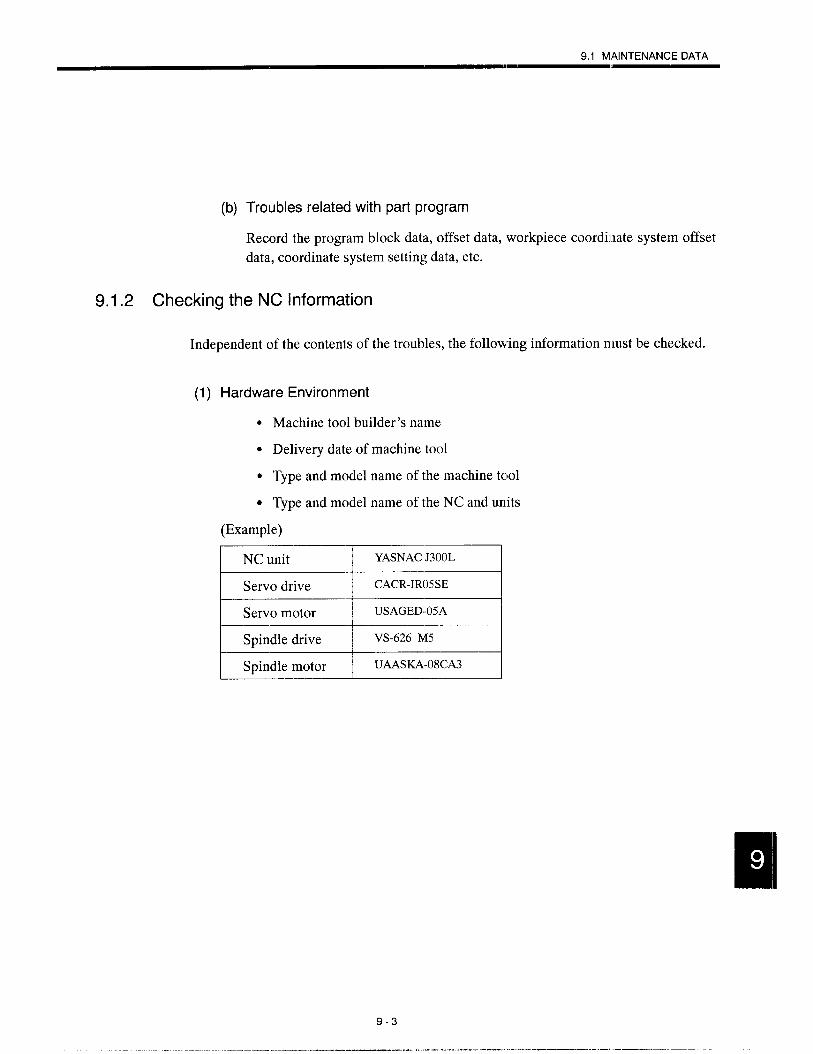
9.1 MAINTENANCE DATA
(b) Troubles related with part program
Record the program block data, offset data, workpiece coordinate system offset
data, coordinate system setting data, etc.
9.1.2 Checking the NClnformation
Independent of the contents of the
(1) Hardware Environment
troubles, the following information nmst be checked.
● Machine tool builder’s name
● Delivery date of machine tool
● Type and model name of the machine tool
● Type and model name of the NC and units
(Example)
NC unit
3
YASNACJ300L
Servo drive CACR-1R05SE
Servo motor USAGED-05A
Spindle drive VS-626 M5
Spindle motor UAASKA-08CA3
9-3
——— .. —-.. ..-. .—.-—

(2) NC System Software
YASNAC J300s software is managed by the system numbers.
(a) System number (NC: ❑0000 -[10)
The system number refers to the system software number which consists of five
integer digits and a two-digit revision number. The system number of the basic
software of the NC is displayed at the start-up screen which is displayed when the
power is turned ON.
{ f
YASNACJ 300
AA SELF TESTING !! AA
I kNC: 01271-00
/---’System No.
Fig. 9.1 Start-up Screen
Note that optional software also has individual system numbers - communication
module, PLC ladder, ACGC applications, etc.
9-4

9.1 MAINTENANCE DATA
9.1.3
(b) Calling the system number display screen
Follow the procedure indicated below to call the system numbw display screen.
Press the [MAINT] process key on the NC operation pane..
Press the FUNCTION SELECT key in the function selection mode, and the
function soft-key as shown in Fig. 9.2 is displayed.
k~:::d
Fig. 9.2
@ Press the [VER.NO] (fl) function soft-key and the system number display
screen is displayed.
/ -~-—VERSION NO MNT o***”* Nooooo
ACGC COMBINATIONSYSTEM NO A-PACK : 08361<2
NC MAIN: 0833W13 NC MAIN: 0833&l 3
IANG: 0633245 L4NG: 0833205BOOT : 0835@30 NC COMBINATIONCOM 0834843 COM : 08343-00
DRAW : 08339-01 DRAW : 0833WC0C-PACK : 0833744 C-PACK : 08337<4
ACGC : 0836N6 ACGC : 0836G06
USERLADDER *********C-APL : *“*””-”*
EDIT STP LSK
PARAM. m lN/OUT DATA
mm E3m E+l..—
. J
Fig. 9.3 System Number Display Screen
Display of Alarm Information
If an alarm occurs, the alarm number and comment of the alarm of the top priority is displayed
in the normal display area disregarding the selected mode and the screen. For the procedure
to follow to display the alarm information, refer to 7.2, “ALARM DISPI.AY JOB”.
9-5
-—— —- ——-— —.. -.--.. ——.. .—,— -—-——.—— -..

9.1.4 Cause of Alarm and Corrective Action
The following shows the classification of YASNAC J300 alarms.
Table 9.1 Alarm Numbers and Classification
No.
)000 to 0049
Contents Stop Mode output How to Reset
3rrors related to edit and operation3ccurring in the background modealso.
Zrrors related to edit and operation‘Jot occurring in the backgroundnode.
[nput erroralarm
[nput erroralarm
Block stop
Block stop
Reset
ResetPower OFF for #0050 and #0051
)050 to 0099
[nput error
alarm)100 to 0499 %gram error Block stop Reset
‘rogram error>NC, COMS total, etc.
[nput erroralarm
1000 to 1099 Block stop Reset
Reset operation after removing the cause.With the alarm caused by the machineready signal, if it occurs in the first pow-sr ON operation, it is automatically reset.
Reset after removing the cause.With the SVOFF alarm, it is automatical-ly reset by the SVON.
For maintenanceCPU haltSwitching to the special maintenancescreen
Machine related errorIT, reference pornt return, machineeady, in-position, etc.
Stop afterdeceleration, orimmediate stop
1000 to 2199 Alarm
Servo and spindle related alarmESP, CPU mutual monitoring
Immedii]te stop,or servo OFF
3000 to 3299 Alarm
Memory check errorWatchdog timer errorOffline error
Error occurring in background edit-ing (basically the same as with 0000to 0049)
Immediate stop,or servo OFF
8000 to 8049
9000 to 9049
Alarm
Backgrounderror output
Not stopped Reset or with reset soft-key
No numberindication
\AT indicationBAT. AXIS
Battery errorEncoder alarm
Not stopped No output
Warning
Changing the battery
No numberKey operation error, edit operationerror (not serious operation error)
Not stopped Next key operation
9-6
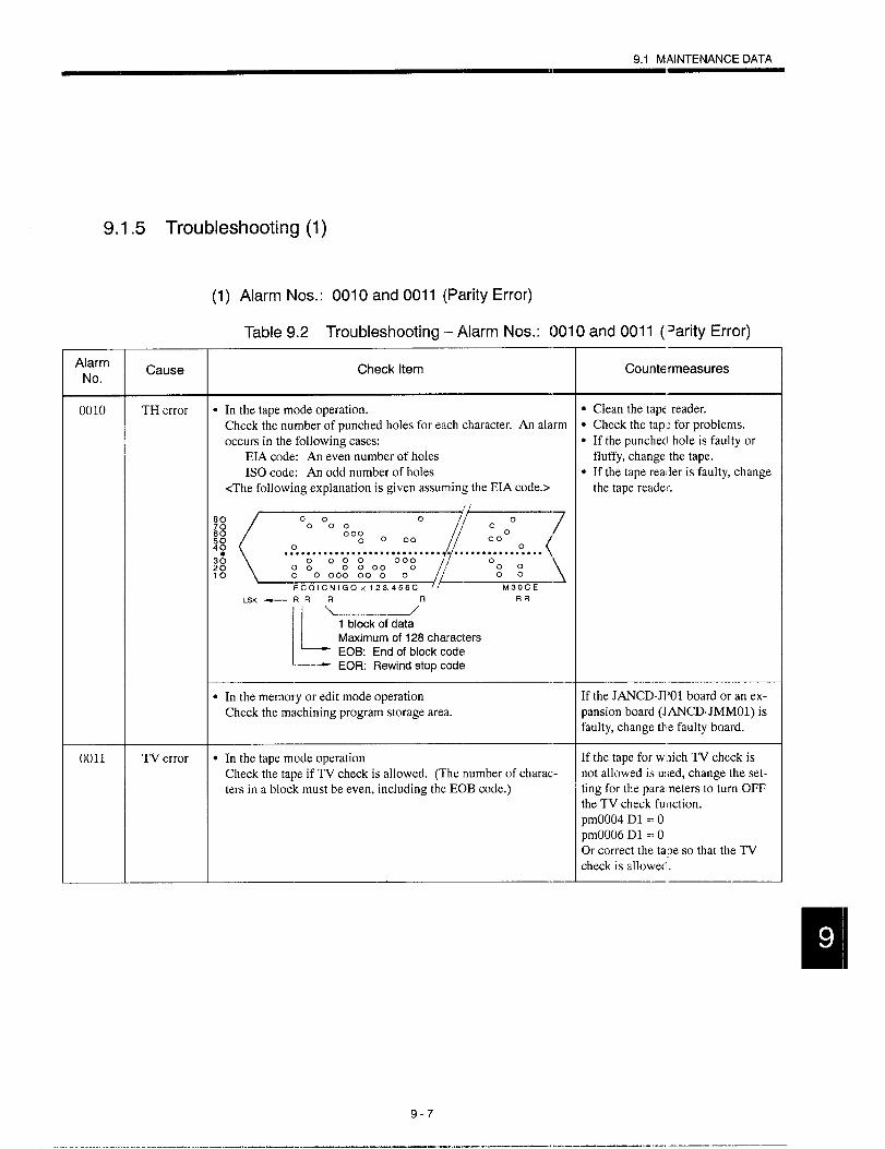
9.1 MAINTENANCEDATA
9.1.5 Troubleshooting(1)
(1) Alarm Nos.: OOIOand OOll (Parity Error)
Table 9.2 Troubleshooting – Alarm Nos.: 0010 and 0011 (Parity Error)
AlarmNo.
Cause Check item Countermeasures
0010 TH error ● In the tape mode operation. ● Clean the tape reader.
Check the number of punched holes for each character. An alarm ● Check the tapi~ for problems.
occurs in the following cases: ● If the punchecl hole is faulty orEIA code: An even number of holes fluffy, change the tape.
1S0 code: An odd number of holes ● If the tape reader is faulty, change<The following explanation is given assuming the EIA code.> the tape reader.
~(={..:$:<. . . . . . . . . . . . . . . . . . . . . . . . . . . .
LSK_ RR‘R f_____l
L
1 block of data
Maximum of 128 characters
EOB: End of blockcode— EOR: Rewindstopcode
.-
● In the memory or edit mode operation If the JANCD-JI’01 board or an ex-
Check the machining program storage area. pansion board (JANCD-JMMO1) isfaulty, change the faulty board.
0011 TV error ● In the tape mode operation If the tape for which TV check is
Check the tape if TV check is allowed. (The number of charac- not allowed is used, change the set-
ters in a block must be even, including the EOB code.) ting for the parameters to turn OFFthe TV check function.pmOO04 D1 = OpmOO06 D1 = OOr correct theta je so that the TVcheck is allowed.
.-
9-7
... .— .—— .-.—-— —.

(2) Alarm Nos.: 0016, 0017, 0018, 9016, 9017, 9018 (RS-232C Error)
Table 9.3 Countermeasures – Alarm Nos.: 0016, 0017, 00”18, 9016, 9017,9018 (RS-232C Error)
Alarm
No.
0016
9016
00179017
00189018
Cause
Transmission error
Overrun
Line selection
Check Item
Check if the RS-232C transmissionerror (high noise level) occurs.
Check if more than 10 charactershave been read after the output ofthe RS-232C interface stop code.
Check the RS-232C interface lineselection for error.
Countermeasures
Check the grcmnding of cables.
● Check the RS-232C devicespecifications.
● Check the setting for parame-ters.
Note: Nos. 0016, 0017, and 0018 are for online and Nos. 9016, 9017, and 9018 are for offline.
~=.
No output by [OUTl soft-key C+ NR] key, etc.
NO●
UNITPORTBORS
STOP BITBITS
PARITY
X ON/OFF
RTS CONTROL
DR LINE CONTROL
NC DATA SPECIAL CON-
TROL
II
I L
YES
EflFig. 9.4 RS-232C Interface Troubleshooting Flowchart
9-8

9.1 MAINTENANCEDATA
(a) Setting the interface
When the RS-232C interface is used, baud rote, stop bit length, and use of control
code must be set in the following procedure.
@ Press the [MAINT] process key on the “NCoperation panel.
@ Press the [IN/OUT] (f3) job soft-key.
@ Press the [RS232C] (f5) function soft-key to select the 1/0 device setting func-
tion.
@ Set the necessary RS-2321C communication parameters.
--~--—PROGRAM 1/0 MNT 012345 N12345
1/0 UNIT SET IN 0 UT
UNIT F?S232C RS2!32C
PORT NO.1 NO.2BPS 4800 9600STOP BIT 2BIT 1BITBITS 8BITS 7BITSPARITY OFF EVE:NX ON/OFF ON OFFRTS CONTROL ON OFFDR CNTRL ON CIFFNC CNTRL ON OFF
MEM STF) LSK
EDIT DIR ~=]
mm E112FIm Es3&
.-—)
.
Immmmmmlla
Fig. 9.!5 Setting for the Serial Interface
9-9

(b) Setting for the serial interface
For the serial interface, setting is possible for the following parameters.
Table 9.4 Serial Interface Setting
Note:
Menu Item I Input I output IYE tape reader
+
YE tape puncherUNIT (device)
General-purpose RS-232C General-purpose RS-232C
NO. 1
+
NO. 2PORT
NO. 1 ‘ NO. 2
I 75 I 75 I
I 150 I 150 I
I 300 I 300 I600
BORS (baud rate)1200 ::+
I 2400 I 2400 II 4800 I 4800 I
I 9600 I 9600 I1 bit
+
1 bitSTOP BIT
2 bits 2 bits
7 bits 7 bitsBITS (bit length)
8 bits 8 bits
I Eveu parity I Even parity I
PARITY (parity scheme) I Odd parity I Odd parity II None I None I
F--Supported SupportedX ON/OFF (control code)
None None
Supported
+
Supported
PARITY ISONone None
Although two RS-232Cpofis areprovided, these twopofiscannot beusedatthe sametirne. Forthesetwo ports,
setting can be made independently from each other,
910

91 MAINTENANCE DATA—m——
(c)Selecting the input/output port
When changing the port to be used, follow the procedure indicated below.
@ Move the cursor to the recluired port number.
@ Press the FUNCTION SELECT key.
@ Press the soft-key corresponding to the item to be set, and the data are written
to the cursor position.
Tables 9.5 and 9.6 show the R!;-232C voltage level and the interface connection
cable, respectively.
Table 9.5 RS-232C Voltage Level
~ VO.-3V ‘-1 VO<+3V ‘1I Function I OFF I ON
I Signal Status I Mark I Space ILogic 1
.-l_-__!_J
Table 9.6 RS-232C Interface Connection Cable (A)
NC Side (DB-9P)
Symbol Signal Name Pin No,
FG Frame grounding 1
SD Send data 2
RD Receive data 3
RS Request to send 4
Cs Clear to send 5
DR Data set ready 6
SG Signal grounding 7
ER Data terminal ready 9
Connection-----i
Device Side
Symbol
------i
FG
SD
RD I
---i
RS—
Cs
DR ISG I
----i
IO BUSY—
ER
9-11
.—. -—-——. ——. —-—
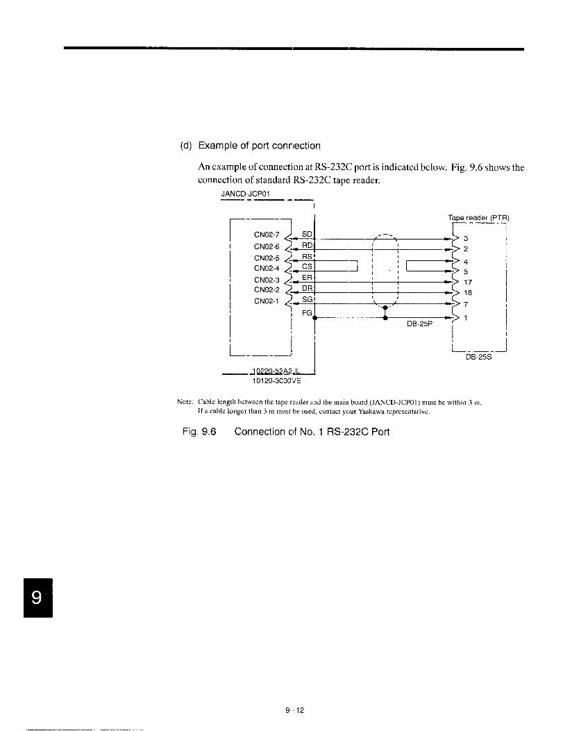
(d)
Note:
Example of port connection
An example of connection at RS-232C port is indicated below. Fig. 9.6 shows the
connection of standard RS-232C tape reader.
JANCD-JCPO1—.— .—I
_. —- _ I Twe reader (PTR)
CN02-7
CN02-6
CN02-5
CN02-4
CN02-3
CN02-2
CN02-1
L-—--- Ii i—-—--J—~ I DB-25S
—~-A2JL I
101 20-3000VE
Cable length between the tape reader and the main board (JAFJCD-JCPOI ) must be within 3 m.
If a cable longer than 3 m must be used, contact your Yrsskawarepresentative,
Fig. 9.6 Connection of No. 1 RS-232C Port
912

9.1 MAINTENANCEDATA■—l
-(3) Alarm No.: 1099 (High Temperature)
Table 9,7 Countermeasures --Alarm No.: ‘1099 (High Temperature).—
Cause Check Item Countermeasures.- .—
Ambient temperatureof the ● Open the NC unit door to check if ● If the fan is faulty, it is necessaryNC rack exceeded the speci- the cooling fan is operating cor- to change it. Contact your Yaska-fied value’ due to the failure rectl y. wa represental ive.
of cooling fan. * Make sure that air is blowing out ● If the cooling duct is blocked, re-“: 70°C t 3°Cwhen through the ventilation port of the move interfering object and start
measured above cooling duct. the cooling far].CPS-18. * Make sure tha~ the ventilation
port of the cooling duct is notblocked.
Internal temperature of the Allow the power supply unit to cd It is necessmy tc change the power
power supply unit is high. by turning OFF Ihe power with the supply unit. Contact your YaskawaNC unit door opened. If the alarm representative.
occurs even after the power supplyunit has been cooled for 30 minutts,the power supply unit will be faulty.
..—
Ambient temperature of the * Measure ambient temperature. This is not the fzlilure of the NC
NC unit is high*. ~ If the NC unit is subject to direct unit. Remove the cause.*: Allowable temperature sunlight, the NC unit temperature
range for operation is will exceed the allowable limit.oto40°c.
..—— —.—
9-13
-- —. ———=—.. .——- . . . ..— .-. -—— —... -- —-. —

(4) Alarm Nos.: 2061 to2068(Reference Point Return Area Error)
Table 9.8 Troubleshooting –Alarm Nos.: 2061 to2068(Reference Point Return Area Error)
Cause
rhe referenceJoint return start>oint is at theZero point side]f the decelera-tion limit switch.
&pproach feed-‘ate is too fast.
(5)
Check Item
Deceleration limit switch (DECLS)#3073 DO (Ist axis) Executereference
#3073 D1 (2nd axis) point returnagain
#3073 D2 (3rd axis)while observing the1/0 signal monitor
#3073 D3 (4th axis) screen.
#3073 D4 (5th axis)
If reference point return is started from a pointlocated at the reference point side of DECLS(point C) as shown below, an alarm occurs.Note: This error check is not madebefore the execution
of manual reference point return after the poweris turned ON.
Feedrate
t
D b----~A=;
Feed ratec sequence
Compare the setting for the approach feedrateparameter with the parameter list.
Countermeasures
Return the axis tc) a position on thedeceleration LS or away from itand, then, execute reference pointreturn once again.
Change the setting for parameterspm2521 to pm2525 to an appropri-ate value.
Alarm Nos.: 2071 to 2078, 2081 to 2088
(Reference Point Return Position Error)
Table 9.9 Troubleshooting – Alarm Nos.: 2071 to 2078, 2081 to 2088
(Reference Poi~t Return Position Error)
Cause
Alarm in manualreference pointreturn operation
Alarm in auto-matic referencepoint return op-eration
Check Item
Check if the error occurs every time.
G28: Check if the alarm occurs every time.
G27: Check the point specified in the programif it agrees with the zero point.
Countermeasures
Contact machine tool builder oryour Yaskawa representative.
Contact machine tool builder oryour Yaskawa representative.
Review the program.
9-14
——— —.—...-L__________ ___

9.1 MAINTENANCE DATA
(6) Alarm Nos.: 2101 to 2108 (P-SIET Error)
The P-SET alarm occurs if the error between the position specified in the program and
the actual machine position is Iargerthan the value set for parameters pm1321 (Ist axis)
to pm1325 (5th axis) in the following modes of operation.
At the completion of positioning in ‘GOO,G27, G28, G29, G30, etc., error detect ON (1/0
monitor parameter #3004 D4 = 1), and G04 (dwell).
If error pulses have been accumulated, check the number of accumulated pulses on the
error pulse display screen before contacting your Yaskawa representative.
(7) Alarm No.: 3000 (Servo Power Not Ready)
Table 9,10 Troubleshooting – Alarm No.: 3000 (Servo Power Not Ready).-
Cause Check Item Countermeasures.-
Secondary power supply is If the NC RESET switch, etc. is depressed Press tht POWER ON but-not applied. after depressing the POWER ON button ton again.
once, or after clearing the emergency stopor alarm state, the alarm message is dis-played. This does not indicate the occur-rence of alarm.
.-
W1th the secondary power Check the following on the 1/0 monitor Contact your Yaskawa rep-
ON 1/0 input specification, screen: resentative.the input is not turned ON. #3005 DO= 1 (SVON)(For the automatic servo #3503 DO= 1 (SVONS)power ON)
Emergency stop signal stays Check if alarm No. 3002 is displayed Reset ths emergency stopON. (#3503 D4 = 1) on the screen. input si~;nal.
The secondary power ON Check the alarm indication for other alarms. Take appropriate measuressignal is turned OFF due to by referring to the alarmsome other alarm. code.
9-15 .
..- ..—..——. ..—.. ———

(8)
r
Alarm No.: 3001 (Control Not Ready)
The NC executes self-diagnose after power ON. If positioning error checked during
this self-diagnosis exceeds the values set for parameters pm1321 (lst axis) to pm1325
(5th axis), this alarm occurs.
Table 9.11 Troubleshooting – Alarm No.: 3001 (Control Not Ready)
Cause Check Item
Machine (axes) have moved. Select the error pulse display screen fromthe present position display screen in thecommon process and check the error pulse
YVa’ue”
Countermeasures
The machine tool has aproblem. Contact the ma-chine tool builder.
PG or AC servo must bechanged. Contact your Yas-kawa representative.
9-16

9.1 MAINTENANCE DATA
9.1.6 Troubleshooting(2)
For the system equipped with the drive unit compatible with YENET1200, check is made
by both the drive unit itself and the NC unit. If a fault is detected, the drive unit notifies the
NC unit the alarm information in two systems.
The drive unit first gives the NC unit the information on the occurrence (If an alarm (alarm
No. 3101 to No. 3105 and No. 3201) and then the content of the alarm. The NC unit displays
alarm No. 3100 when it receives the alarm information from drive units.
Therefore, three alarms usually occur if an error is detected with the drive unit. If fuse blown
occurs with the X-axis servo unit, alarm No. 3100, No. 3101, and No. 3021 occur.
(1)
(2)
(3)
Alarm Nos.: 3021 to 3025 (Fuse Blown)
The main circuit of the servo unit will be faulty.
The servo unit detects the error.
Contact your Yaskawa representative.
Alarm Nos.: 3041 to 3045, and 3051 (Excessive Follow-up Error)
This alarm occurs if the follow-up error exceeds 120% of the error in rapid traverse
(100%) operation.
The servo unit detects the alarm.
Improper gain adjustment is one of the reasons.
Contact your Yaskawa representative.
Alarm Nos.: 3061 to 3065 (Overload)
This alarm occurs if the load exceeds the rated torque considerably.
The servo unit detects the error.
Review the cutting conditions. Contact your Yaskawa representative after checking
whether the alarm occurs simply after turning the control power ON.
9-17
———————.—- —.. .—————, .----- .—..— ,—..—.—..— —-.

I !
w al

9.1 MIAINTENANCEDATA
(9) Alarm Nos.: 3151 t03155(Phas eDetectionError)
The encoder signal cable or the encoder itself will be faulty.
The servo unit detects the error.
Contact your Yaskawa representative.
(1O)Alarm Nos.: 3161 to3165 (Absolute Error)
This alarm occurs if the absolute value data cannot be received correctly in one to two
seconds after turning ON the power to the encoder.
The servo unit detects the error.
The encoder or the servo unit will be faulty.
Contact your Yaskawa representative.
(1l) Alarm Nos.: 3181 to3185 (Absolute Position Error)
The number of feedback pulses is checked every turn of the encoder and this alarm oc-
curs if there is an error in the counted number of pulses.
The servo unit detects the alarm.
The encoder or the servo unit will be faulty, or malfunction could have occurred due
to noises,
Contact your Yaskawa representative.
(12)Alarm No.: 3201 (Inverter Alarm)
This alarm occurs when the NC unit detects the alarm signal output from the inverter.
Check the contents of the alarm by clisplayingthe servo alarm display screen (press [f2]
of the alarm job in the common process.).
(13)Alarm Nos.: 3281 to 3285, 3291 (YENET1 200 command tirme-out)
This alarm occurs when the YENET1200 communication lines fail. to get ready,
The NC units detects the alarm.
The servo unit or the inverter unit will be faulty.
Contact your Yaskawa representative.
9-19

(14)Alarm Nos.: 3301 to 3305 (Over Current)
The servo unit detects the alarm.
The servo unit will be faulty if the alarm occurs before the operation is started after turn-
ing the power ON,
If the alarm occurs during operation, ground fault of the motor will be the cause.
Contact your Yaskawa representative.
(15)Alarm Nos.: 3331 to 3335 (Over Voltage)
The servo unit detects the alarm.
If the alarm occurs when the power is turned ON to the spindle, the input voltage will
be too high.
If the alarm occurs during motor operation, it is necessary to review the operation condi-
tions; lower motor speed, for example.
If the alarm occurs when the servo control power is turned ON, the servo unit will be
faulty.
Contact your Yaskawa representative.
(16)Alarm Nos.: 3351 to 3355 (Heat Sink Overheat)
This alarm occurs when the heat sink temperature is abnormally high.
The servo unit detects the alarm.
If this alarm occurs, turn OFF the power and allow the heat sink to cool. After that turn
the power ON again.
If the alarm occurs immediately after turning the power ON, the servo unit will be faulty.
Contact your Yaskawa representative.
(17)Alarm Nos.: 3381 to 3385, 3391 (YENET1 200 Communication Error)
This is an communication error between the NC unit and the servo unit or between the
NC unit and the inverter unit; the NC unit detects the alarm when no answer is returned
for the command output by the NC unit.
The servo unit or the inverter unit will be faulty, or the cable will not be connected se-
curel y.
Contact your Yaskawa representative.
9-20

9.1 MAINTENANCE DATA
(18)Alarm Nos.: 3401 to3405 (Converter Alarm)
This alarm occurs due to the following reasons: blown fuse, regene~ation alarm, open
phase, or faulty board.
The servo unit detects the alarm.
Contact your Yaskawa representative.
(19)Alarm Nos.: 3411 to 3415 (Servo Unit Alarm)
This alarm occurs due to the following reasons: destroyed parameter setting, faulty cur-
rent detector, encoder’s battery alarm, memory e:rror, or sensor errc jr.
The servo unit detects the alarm.
The servo unit or the motor will be faulty.
Contact your Yaskawa representative.
(20) Alarm No.: 3421,3422 (Inverter Unit Alarm)
This alarm occurs when the inverter detects an alarm other than converter alarm, broken
PG cable, excessive follow-up error, and communication error.
Contact your Yaskawa representative.
(21) Alarm Nos.: 3425, 3426, 3431 to 3435 (YENETI 200 Watch cog Error)
This alarm occurs when the NC unit detects the watchdog error with the inverter unit
or the servo unit.
The inverter unit or the servo unit will be faulty.
Contact your Yaskawa representative.
(22) Alarm Nos.: 3441 to 3445 (Grolund Fault)
This alarm occurs when the servo u:nit detects the alarm when the pclwer is turned ON.
Motor insulation is faulty. ml●
Contact your Yaskawa representative.
9-21
——— .-- —-— —------- .—..—.

(23) Alarm No.: 3451 and 3452 (Follow-up Error)
This alarm occurs when the follow-up error exceeds the value set for the servo unit pa-
rameter.
The servo unit detects the alarm.
If this alarm occurs during axis feed over a long distance, it is necessary to either lower
the command speed or increase the gain.
If the motor does not rotate, the servo unit will be faulty.
Contact your Yaskawa representative.
9-22

9.1 MAINTENANCEDATA———
9.1.7 Alarms Notlndicated by Alarm Numbers
Troubles caused by abnormal functioning of the NC, but not indicated by an alarm number,
and required countermeasures are indicated below. If tlhe troubles cannot be cleared by fol-
lowing the procedure indicated below, contact the machine tool builder or your Yaskawa rep-
resentative.
(1) Power Cannot be Turned ON
(a) Power is not supplied to the NC
c Check the sOl_JRCE LED (green) of the llC power supply (CpS-l$FB) in the
CPU module if it is lit.
. Check the input AC power across CN03-1 and CN03-5 terminals of the DC
power supply (CPS-18FB).
Specification: 200/220/210 VAC -15 to +10%, 50/60 Hz * 2 HZ
R
5RS1
6 2
GND 3
7 4
CN 03
(b) Alarm LED on the DC power supply(CPS-18FB) is lit
Table 9.12 Alarm LEDs on DC power supply (CPS-18FB)
Signal Name
s
DisplayLED -
ColorFunction arid Cause
Power supplySOURCE Green
LN: Power is input.
Normal conditions Not lit: Power is not in:out.
Power ON status POWER ON Green Lit: DC power is output.
+ 5 V error *5V Red Lit: +5 V overvoltage (jr overcurrent
Error+24 V error +24 V Red Lit: +24 V overvoltage or overcurrent
indication
Overheat OHT Red Lit.: Overheat of components in the NC unit
9-23

Check the DC output voltage at CNO1 terminals of the DC power supply
(CPS-18FB).
EEl40 +5V 1
2
5 024 +24V 3
CNO1
+5 V. Across CNO1- 1 and CNO1-4
+24 V: Across CNO1-3 and CNO1-5
(2) No Display is Given on the CRT
If nothing is displayed on the CRT, the CRT itself might be faulty, or the display circuit
or connection cables might be faulty. When nothing is displayed even if the power can
be turned ON to the NC, check the cable connection to the operation panel and also the
connectors.
(3) Handle Mode Operation is Impossible
(a) Handle mode signal is not input
● Check the bit status of 1/0 monitor #3000.
D2=1Other bits (DO, Dl, D3 to D7) = O
● Check the mode display given in the normal display area on the screen.
(b) Axis selection signal is not input
● 1/0 monitor
Check whether one of the following bits is ON.
#3070
Do=l 1staxis
Dl=l 2nd axis
D2=1 3rd axis
D3=1 4th axis
D4=1 5th axis
9-24

9.1 MAINTENANCE DATA
● No. 2 handle
Check whether one of the following bits is ON.
#3080
Do=l 1st axis
Dl=l 2nd axis
D-2=1 3rd axis
D3=1 4th axis
D4=1 5th axis
● No. 3 handle
Check whether one of the following bits is ON.
#3081
aDI)=l 1st axis
Dl=l 2nd axis
D2=1 3rd axis
D3=1 4th axis
D4=1 5th axis
(c) There is no input to handle PG
c Check the input voltage (!5V) at the handle PG terminal.
● Check the handle PG signal cable connector if it is securely plugged in.
(d) Handle PG is faulty
Check the following (counter monitor) on the 1/0 screen if the values change ac-
cording to the operation of the pulse handle.
#3037 (No. 1 handle)
#3038 (No. 2 handle)
#3039 (No. 3 handle)
9-25
——. -———.————. -------- .—.—..—-— —.——. --

(e) Other related parameters
Check the setting for the following parameters.
I
I Maximum feedratefor handle operation
Acceleration/deceleration time constantfor handle operation
Pulse multiplication ratio of” X 100” isset (pm2003 D7 = 1)
(4) Jog Operation is Impossible
Parameter pm2860 (linear axis)Parameter pm2861 (rotary axis)
Parameters pm2561 to pm2565
Parameter pm2549
(a)
(b)
Jog mode signal is not input
Check the bit status of 1/0 monitor #3000.
Dl=l
Other bits (DO, D2 to D7) = O
Axis move direction signal is not input.
Check the bit status of 1/0 monitor #3071 and #3072.
#3071 #3072
DO +lst axis DO –lst axis
D1 +2nd axis D1 –2nd axis
D2 +3rd axis D2 –3rd axis
D3 +4th axis D3 ~th axis
D4 +5th axis D4 –5th axis
9-26

9.1 MAINTENANCE DATA
(c) Jog feedrate signal is not input, or job feedrate setting parameter is incor-
rect
Check th
operatior
rameters
Table 9.13
Step
E1
2
3
4
5
6
7
8
9
10
E11
12
13
14
15
16
17
18
19
20
21
E22
23
24
25
26
27
28
29
t=
30
31
lit status on the 1/0 monitor screen whether it changes according to the
lf the JOG FEEDR4TE switch, and also check if the setting for the pa-
correct.
]g Feedrate
1/0 Monitor #3002
D4 D3 D2 D1 [io Jog Feedrate
JV16 JV8 JV4 JV2 J’il
o 0 0 0 G Set for pa;-ameter pm2400
o 0 0 0 i Set for pa;-ameter pm2401
o 0 0 1 i Set for pa-ameter pm2402
o 0 0 1 i Set for pa:-ameter pm2403
o 0 1 0 6 Set for pa:-ameter pm2404
o 0 1 0 i Set for pa”ameter pm2405
o 0 1 1 i Set for pa’fameter pm2406
o 0 1 1 i Set for pa”:ameter pm2407
o 1 0 0 i Set for pa-ameter pm2408
o 1 0 0 i Set for pa”:ameter pm2409
o 1 0 1 6 Set for parameter pm2410
o 1 0 1 i Set for parameter pm2411
o 1 1 0 0 Set for parameter pm2412
o 1 1 0 i Set for parameter pm2413
o 1 1 1 i Set for parameter pm2414
o 1 1 1 1 Set for parameter pm2415
1 0 0 0 () Set for parameter pm2416
1 0 0 0 ;. Set for parameter pm2417
1 0 0 1 i Set for parameter pm2418
1 0 0 1 ;. Set for parameter pm2419
1 0 1 0 i Set for parameter pm2420
1 0 1 0 i Set for parameter pm2421
1 0 1 1 i Set for parameter pm2422
1 1 0 ]0 ] 1 Set for parameter pm2425
9-27
———.—..—— —-------- .- ,—,—.-—-——,———--

(d)
(e)
Axis interlock is input
Check the bit status on the 1/0 monitor screen. If “O”, the corresponding axis can-
not move.
#3078
I DcI=l I lstaxis I
RDI=l 2nd axis
D2=1 3rd axis
D3=1 4th axis
D4=1 5th axis
Machine lock is ON
Even when the machine lock function is ON, position display changes. Check
the input of the machine lock switch (1/0 monitor, #3006 D5 = O). If “l”, the
axes do not move.
Check the internal toggle switch (parameter pmOOOOD1 = O). If “l”, the axes
do not move.
(5) Manual Rapid Traverse is Impossible
(a)
(b)
The rapid mode is not selected
Check the bit status of 1/0 monitor #3000.
DO=l
Other bits (Dl to D7) = O
Axis move direction signal is not input.
Check the bit status of 1/0 monitor #3071 and #3072.
#3071,’302
DO +lst axis DO –lst axis
D1 +2nd axis D1 –2nd axis
D2 +3rd axis D2 –3rd axis
D’ +4th axis D3 -4th axis
D4 +5th axis D4 –5th axis
9-28

9.1 MA’\lNTENANCEDATA
(c) Rapid traverse override isnotinput
● Check the bit status on the 1/0 monitor screen whether it changes according
to the operation of the RAPID TRAVERSE RATE OVERRIDE switch, and
also check if the setting for the parameters is correct.
Table 9.14 Input Status and Rapid Traverse lRate
I Input Status of#3003 I Rapid “rraverse Rate
ROV2 ROV1 1StAxis
Zz
2nd Axis t;”d axis 4th aX.S 5th axis
1 1Set for Set for Set for Set for Set forpm2801 pm2802 pm2803 pm2804 pm2805
[Setting for [Setting for [Setting for [Setting for [Setting for1 0 pm2801] pm2802] pm2803] pm2804] pm2805]
x 1/2 x 1/2 x 1/2 x 1/2 x 1/2
[Setting for [Setting for [Setting for [Setting for [Setting foro 1 pm2801] pm2802] pm2803] pm2804] pm2805]
x 1/4 x 1/4 x :1/4 x 1/4 x 1/4
o 0 FCI(set for pm2447)
● For the 6-step specification (pm2000 D3 = 1), refer to Tab,e 9.19.
Table 9.15
InputStatus
3
RapidTraverseRate
ROV4 ROV2 ROVI 1stto 5th ,~S
1 0 1 F2 (set for pm2449)
1 0 0 F1 (set for pm2448)
Iololol F. (set for pm2447) I
(d) Parameter setting is incorrect
Refer to Tables 9.14 and 9,15.
9-29

(6)
(e)
(9
Axis interlock is input
Check the bit status on the 1/0 monitor screen. If “O”, the corresponding axis can-
not move.
#3078
Do=l 1staxis
D1=l 2nd axis
Dz=l 3rd axis
D3=1 4th axis
D4=1 5th axis
Machine lock is ON
● Even when the machine lock function is ON, position display changes. Check
the input of the machine lock switch (1/0 monitor, 3006 D5 = O). If “l”, the
axes do not move.
● Check the internal toggle switch (parameter pmOOOOD1 = O). If “l”, the axes
do not move,
Manual Reference Point Return is Incorrect
The following explanation is given assuming that jog and rapid traverse are executed
correctly.
(a)
(b)
Manual reference point return signal is not input
Check the 1/0 monitor #3007 DO. The status must be “l”.
Otherwise, the axis continues moving to OT at the same feedrate even if it reaches
point A. See Fig. 9.7.
Jog or rapid traverse mode is not selected
1/0 monitor #3000 DO or D1 must be “l”.
9-30

9.1 MAINTENANCE DATA
(c) Deceleration limit switch signal is not input.
Check 1/0 monitor #3073 DO to D4 while moving an axis at a slow feedrate such
as in jog operation. Make sure feedrate changes as shown in I~ig. 9.7.
Feedrate
~A- /
Rapid traverse (pm2t301topm2805) Ipproach feedrate (pm2521 to pm2528)
~i
tCreep feedrate (pm2531 to 2535)
IiI Travel distance (Fm4451 to pm4455)I1A
.—L
-. Feedrate S(?quence
! cl
#3073
d’
1;BI
11DECLS s]gnal
I ;D
A..& ‘ ---- Zero point sigmal
Fig. 9.7 Reference Point Return Control l/O Signals
(d)
(e)
(f)
Parameter setting is incorrect.
Check the setting for the related parameters against the parameter sheet by refer-
ring to Fig. 9.7.
Position of the dog for the cleceleration limit switch is incorrect.
If the dog position is incorrect, the zero point could be shifted by one turn of the
motor.
Others (loose coupling or dog)
If another adjustment is incorrect, zero point could be shifted at random.
9-31

(7) Cycle Start is Impossible
(a) Cycle start signal is not input, or feed hold signal is open.
Check the 1/0 monitor #3003 DO whether it goes “l” when the cycle start switch
is pressed. In this case, the feed hold signal must be open; this can be confirmed
by 1/0 monitor #3003 D1 = 1.
(b) Start interlock signal is input.
If 1/0 monitor #3004 D2 = 1, cycle start is impossible.
(c) The NC is in the reset status.
Normal status: 1/0 monitor #3500 D1 = O
Also check the external reset signal status.
Normal status: 1/0 monitor #3004 D1 = O
(8) GO1, G02, or G03 Mode Operation is Impossible
(a) The spindle is in the speed agreed status.
Check whether parameter pm1000 D7 = 1.
If it is “l”, check whether the spindle is in the speed agreed status by 1/0 monitor
#3111.
(b) FEEDRATE OVERRIDE switch setting is O%.
Check the setting for 1/0 monitor #3111 DO to D4 whether the setting is correct.
9-32

9.1 MAINTENANCE DATA
(c) lnthedry runmode, setiing forjogfeedri~te is incorrect.
Table 9.16
‘:?%4--,%--41/0 Monitor #3040
D4 D3 Feedrate Override (Automati,~Operation)
OV16 OV8
o 0
Iololololll 10% IIolololllcll 20% IIolololllll 30% IIololllolcll 40% IIololllolll 50% IIololllllcll 60% I
Iolllololll 90% I
Iolllllllll 150% IIllolololol 160% IIllolololll 170% I
1 0 0 1
13c1 180%.—
1 0 0 1 1 190%..-1 0 1 0 c1 200%.-1 0 1 0 1 220%..-1 0 1 1 , 240%.-1 0 1 1 1 260%
1 1 0 0 , 280%..-1 1 0 0 1 300%
Illllolllcll 340% I
(d) Start interlock signal is input.
If 1/0 monitor #3004 D2 = 1, start interlock is ON.
Normal: #3004 D2 = O
9-33
..-—-—. ..-.——. -—. ——.——-—.

(e)
(f)
Axis interlock is input.
Check 1/0 monitor #3087 DO to D4.
Normal: #3078 DO to 1)4 = 1
Setting of the servo system is incorrect.
Check whether the axes can be moved manually,
(9) Spindle Rotation is Impossible
(a)
(b)
(c)
(d)
(e)
Error in a program (no S command, or no spindle start M code)
Check the contents of the program on the [RUN] screen.
Start signal has not been input.
Check the output signals (#1100s) on the 1/0 monitor screen.
Spindle rotation command has not been output.
Check #3654 to #3656 on the 1/0 monitor screen.
The spindle drive is in the alarm status.
Check the alarm indication of the spindle drive,
Combination of GRS and GSC is incorrect, or “O” is input for parameter
pm14120rpm1413.
Check 1/0 monitor #3110 by referring to Table 9.21.
Table 9.17 Input of GRS and GSC and S4-digit Command Analog Voltage
I 1/0 Monitor #3110
I o I o
S4-digit Command Analog Voltage
Voltage corresponding to the spindle speed specified in the NC Iprogram.
Voltage corresponding to parameter pm1412
Voltage corresponding to parameter pm1413
Ov =+
Note: If “l” is set for parameter pm1000 D5, SSTP input is reversed.
9-34

9.1 MAINTENANCEDATA
(o Setting for the parameters related to spimdle operation is incorrect.
Check the setting for the related parameters.
#3110 DO GR1I
Spindle Motor
Rotation Command
IIov -------------
,-7::::.,-7:::::.,-~:;..7range4
,,,,.,. i I I I ~1~- Soindle SDeed
Illlt Ill II II (timin)
Fig. 9.8
(1O)FIN Wait Status after Execution of Spindle Related Commands
If sequence processing is interrupted waiting for a signal, the NC tinters the FIN wait
status.
(a) Spindle speed agree signal isnot input.
Q
If the NC enters this status after the executioo. of such as “M03 S1OO” commands, ●
check whether #3111 D6 = 1 (waiting for F]N).
Check the 1/0 signals of #1000s at the 1/0 section by referring to the ladder chart
supplied by the machine tool “builder.
9-35
.—— —. ..--.——.. ..-. — .—— -——-—— — -—

(b) Spindle zero speed signal is not input,
If the NC enters this status after the execution of “M05” command, check the 1/0
signals of #1000s at the 1/0 section by referring to the ladder chart supplied by the
machine tool builder,
(c) Others
If the NC enters this status after the execution of “M 19” or “M20” (spindle orienta-
tion command), check the 1/0 signals related with spindle orientation by referring
to the ladder chart supplied by the machine toed builder.
(11) Edit Operation is Impossible
(a) The edit lock signal is input.
Check 1/0 monitor #3007 D2.
Normal: #3007 D2 = O
If “#3007 D2 = 1“, program edit is impossible.
(b) Edit lock is set by the parameter (pmOOOOD7).
Set “pmOOOOD7 = O“ to cancel the edit lock setting.
(c) Others
● The corresponding alarm message is displayed.
OVER MEM CAP !TOO MANY PROGS !ALREADY IN !
● Delete unnecessary programs and edit the program again.
(12)Skip Function (G31) Failure
(a) The skip signal has not been input.
@ Check ON/OFF status of the skip signals by checking the 1/0 monitor #3514
DO to D2.
@ Check the operation of proximity switches, etc.
9-36

9.1 Ml\lNTENANCE DATA
(b) Pararnete rsettin gisincorrect
● Check the setting for parameter pm2001 DO. If the setting :1’orpm2440 is “O”
while “pm2001 DO = l“, an axis does not move.
I Feedrate in the skip feed mode(G31) is the feedrate set forpm2001 DO= 1
parameter pm2440. II Feedrate in the skip feed mode (G31) is the feedrate specified
pm2001 DO= Owiih an F code. I
● Check the setting for parameterspm5011 DO to D2.
Set the signal status at the start of the processing when the SKJP signal is input.
‘24”1r-A B
Fig. 9.9
. If “O”, processing starts at the point where 24 V falls to O V.
. After changing the setting, be sure to ‘turn OFF the power once and turn it
ON again.
● Check the setting for parameters pm5010 DO to D2
The setting for this parameter determines ENABLE/DISABLE of the control
circuit for the “SKIP” input.
“ Set “l” to use the skip function.
“ After changing the setting for this pa~ameter always tum OFF the power
once and then turn it ON again.
(13)Tape Mode Operation is Impossible
(a) Mode selection signal is incorrect.
Check the bit status of 1/0 monitor #3000.
D4=1
Other bits (DO to D3, D5 to D7) = O
9-37

(b) Setting at the tape reader is incorrect.
Check the setting made at taper reader model 2801 B-2. Refer to the table indicated
below.
DIP Switch (DS) Trans-
Input Read- mis- AutojInput
PTR Reading Transmission Control ing sion Self-
Speed Speed Se,ec. ~!e’jk Speed SpeedControl
check
tion (bps)
SI S2 B1 B2 C/L STS charls
oN* OFF OFF ON ON OFF 270 4800 AUTO
ON ON OFF 300 AUTO
OFF OFF OFF 200 AUTO
ON ON OFF 9600 AUTO
ON OFF OFF 2400 AUTO
OFF OFF OFF 1200 AUTO
ONSelf-
check
ONCode
control
OFFLine
control
Note: * Standard setting
Arrangement of DIP switches (standard setting)
r
0:= 0
Fig. 9.10 Setting for Tape Reader
(c) Loose contact
Make sure that the cable connectors are securely connected.
9-38

9.1 MAINTENANCEDATA
(d) Faulty tape reader
● If the tape does not move even when the FEED switch is pressed, change the
tape reader.
● If the red LED in the tape reader is not lit (power is not supplied to the taper
reader, or tape reader is faulty.), changt the tape reader.
● Check the tape holder.
(e) Power supply (EYG30/55GTL) for tape reader is faulty.
. Check if 200 V is input to the power supply.
● Check if 5 V and 24 V are correctly output.
9-39
.—.— .——. -—. ——. ——-—. .

LIST OF NC lNPUT/OUTPUT SIGNALS
Appendix 1 describes the diagnosis numbers of the input/out-
put signals between the NC and the PLC.
1.1 INPUT SIGNALS (PLC -~ NC) . . . . . . . Al -2
1.1,1 Operatio nModeContro l . . . . . . . . . . . . . . .. A1-2
1.1.2 CNC Part Program Execution Control . . . . . . Al -4
1.1.3 Servo Axis Control . . . . . . . . . . . . . . . . . . . . .. A1-5
1.1,4 No. lSi>indle Control . . . . . . . . . . . . . . . . . .. A1-7
1.1.5 No.2 Spindle Control . . . . . . . . . . . . . . . . . .. A1-8
1.1.6 YENET”I 200 Compatible Inverter Contrcl . . . Al -9
1.2 OUTPUT SIGNALS (NC - PLC) . . . . Al -10
1.2.1 Operatio nModeControl . . . . . . . . . . . . . . .. A1 -10
1.2.2 NC Part Program Execution Control . . . . . . Al -12
1.2.3 Servo Axis Control . . . . . . . . . . . . . . . . . . . .. A1 -14
1.2.4 No. l Spindle Control . . . . . . . . . . . . . . . . .. AI-17
1.2.5 No.2 Spindle Control . . . . . . . . . . . . . . . . .. AI-18
1.2.6 YENET”I 200 Compatible Inverter Contrcll . . Al -19
1.2.7 Axis Variable Data . . . . . . . . . . . . . . . . . . . .. A1 -20
Al-1
.— —

mA #3000
APPENDIX 1.1 INPUT SIGNALS (PLC + NC)
1.1.1 Operation Mode Control
#3002
#3003
#3004
#3005
#3006
#3007
#3008
#3009
#3011
#3012
#3017
Appendix Table 1.1 Operation Mode Control Signals
7 6 5 4 3 2 1 0
EDT MEM MDI TP STP H JOG RTI
\ v .
Operation Mode
MP4 Mp2 MP1 JV16 JV8 JV4‘V2 ~
L v J~~———————Manual Pulse Multiply Jog Feedrate
ROV4 ROV2 ROV1 * SP STI
~---’ stop Cycle Start
Rapid Traverse Override
CDZ SMZ STLK ERS MRD
Thread Error Detect Start Interlock External Reset MachineChamfering ON Ready
ERR2 ERR1 ERRO CJNT I “TcIEEclServo OFF Decel. Block Stop C-axis Joint Time Count External
and Stop Servo ON
External Error Detection
AFL MLK DRN PRST ABS SBK
MST Function Machine Lock Dry Run Program Manual Single-BlockLack Restart Absolute
I SRN EXT CLR EDT LK ZRN2 ZRN 1SetupPoint Ext. Position Edit Lock Second ReferenceReturn Data Clear Reference Point Return
Point Return
PST CPRN‘°Fs ~
Present Interruption Auto ModePosition Data Point Return Handle OffsetSave
~~
FSED CLR FSED CH FSED MEM FSED M ECLM EOUT EVER EIN
~’ ~ vFS Automatic Edit External 1/0 Verify
WOM WOP
L Jv
Tool Wear Offset
IDSPP3 DSPP2 DSPP1 DSPPO DSPJ3 DSPJ2 DSPJ1 DSPJO
~- ~~Ext. Screen Change (Process Designation) Ext. Screen Change (Job Designation)
Ill -2

#3018
#3020
#3023
#3024
#3025
#3028
#3030
#303 1
#3032
#3033
#3034
#3037
Appendix Table 1.1 Operation Mode Control (cent’d)
7 6 5 4 3 2 1 0
DSPCHG I 2EECEECPEIE!ZCExt. ScreenChange ~ “-~~Strobe Ext. Screen Change (Function Designation)Signal
~=:~~Se[up Request
TN07 TN06 TN05 I ‘N04lzIcEEcP!E~Tool NO.
TGN7 TGN6 TGN5 I ‘GN4I=}1.rEclTool Group No. (Tool Life Control)
Tool Life ~-v————’Control Count Tool Life Management ControlIgnore
[ED7 ED6 ED5
‘D4 I x:~~< v .- .~
Ext. Data Input
ED15 ED14 ED13‘D12 Iz!zIzEErrE~
Ext. Data Input
ED23 ED22 ED21‘D20 I x:~~
Ext. Data Input
ED31 ED30 ED29‘D28 I n:~~
Ext. Data Input
EDCL EDAS2 EDAS1 EDASO I ~--EDSC EDS~l_==l
Ext. Data Input
1HP7 1HP6 1HP51HP4 I x:~~
\ v .- .~
PG Pulse Input Monitor
Al-3

H#3038
A
#3039
Appendix Table 1‘.1 Operation Mode Control (cent’d)
7 6 5 4 3 2
2HP7 2HP6 2HP5 2HP4 2HP3 2HP2z~p’ *
\ vPG Pulse Input Monitor
I 3HP7 3HP6 3HP5 3HP4 3HP3 3HP23HP1 m
PG Pulse Input Monitor
1,.1.2CNC Part Program Execution Control
7
Tablel.2 CNCPart Program Execution Control
6 5 4 3 2 1 0
#3040
#3041
#3042
#3045
#3046
#3047
#3048
#3049
Ovc OPT BDT 0V16 OV8 OV40“2 ~
Override Optional Stop Block Delete ~Cancel
~~Feedrate Override
FIN RWDH‘“D m
MT Function High-speed Rewind End ofFin. Rewind Program
BDT9 BDT8 BDT7‘DT6= I ‘DT4 ‘DT3Imcl
\ /v
Block Delete
SSEL1~n
Rotary ToolSelectionInput
U17 U16 U15 U14 U13 U12‘“ m
Microprogram Input
U115 U114 U113 U112 U1ll UI1O“9 m
\ v/’
Microprogram Input
U123 U122 U121 U120 U119 U118“17 m
\ YMicroprogram Input
U131 U130 U129 U128 U127 U126“25 m
\ vMicroprogram Input
Al-4

1.1.3 Servo Axis Control
Appendix Table 1.3 Servo Axis Control
#3070
#3071
#3072
#3073
#3074
#3075
#3076
#3078
#3079
#3080
#3081
7 6 5 4 3 2 1 0
Pulse Handle Axis Selection
Manual Feed Ax Is/Direction Selection
Manual Feed ,4x [s/Direction Selection
*DC’ I n!lElzEr!EclReference Point Return Decel. LS
Over[ravel LS
I ““’5 I !3ZECIZ3EIZZ!ZIZEIOvertravel LS
I ‘L” I =EIzEII!EiclMachirte Lock Axis
Axis Interlock
* CISVOF * SVOF5I ‘=:~~
C-axis Servo \--~—————~
OFF Axis %rvo OFF
No, 2 Pulse Handle Axis Selection
3H5~n>~~
—--Y——————”——————’No. 3 Pulse Handle Axis Selection
Al-5

Appendix Table 1.3 Servo Axis Control (cent’d)
7 6 5 4 3 2 1 0
#3083 DTCIH5 DTCH4 DTCH3 I ‘TcH21Ecl\ vAxis Disconnection Designation
#3084 TRQI-5 TRQ1-4 TRQ1-3 I ‘RQ’-2~\ /v
Designation of Servo Axis Torque Limit Input (lst Stage) Axis
#3085[
TRQ2-5 TRQ2-4 TRQ2-3 I “Q2-2~
Designation of Servo Axis Torque Limit Input (2nd Stage) Axis
Al-6

1.1.4 No.1 Spindle Control
Appendix Table 1.4 No. 1 Spindle Control
#3110
#3111
#3112
#3113
#3114
#3115
#3116
#3117
#3118
#3119
7 6 5
GRS GSC SSTPlLd_ik_ltizk12zIaGear Shift Fixed Speed S Command S Analog ~ “-~——————~
output stop output Spindle Gear RangeReverse
SFIN SAGR‘n:~~
S Function Spindle SpeedFin. Agreed
---~Spindle Speed Override
SD17 SD16 SD15‘“14 InzcIzEIEclL
S Command Binary
SD115 SD114 SD113 SD112 I =E7prq\ .-S Command Bina~
SD123 SD122 SD121 SD120 I=>!TZEI\ .~S Command Binary
~-:~~
~“~Spindle Linkage Input
~=+~~Spindle Servo Spindle C-axis
ON copy Control Mode Switching
copy Request
~3>~1
Spindle ~ --~—~Position Spindle IndexLoop Mode
SID7 SID6 SID5“D4 I =5EcDKI-k .—~
Spindle Index
~=:~.~L “~~
Spindle Index
mlA
Al-7
—— .. ———..— ..- .—..-.— .—.—..—.—

#3120
1.1.5 No. 2
7
Spindle Control
Table 1.5 No. 2 Spindle Control
6 5 4 3 2 1 0
#3121
#3122
#3123
#3124
#3125
#3126
#3127
#3128
#3 129
GRS-2 GSC-2 SSTP-2 SINV-2 GR4-2 GR3-2 GR2-2l_!!l__
Gear Shift Fixed Speed S Command S Analog ~~~output stop output Spindle Gear Range
Reverse
SAGR-2 SPE-2 SPD-2 SPC-2 SPB-2m
S Function Spindle Speed L ~~Fin. Agreed Spindle Speed Override
SD17-2 SD16-2 SD15-2 I ‘D14-2E I SD12-’2 SD1l-2m
S Command Binary
SD115-2 SD114-2 SD113-2 SD112-2 SD1ll-2 SDI1O-2 SD19-2 SD18-2
\ /v
S Command Binary
SD123-2 SD122-2 SD121-2 I ‘D120-2E I SD118-2 SD117-2m
L
S Command Binary
~c I I ‘2c0p-2Pzzl~~
Spindle Linkage Input
~c I CSVONS-2 I‘pMODEs-2EE!EElSpindle Servo Spindle C-axisON COPY Control Mode Switching
copy Request
SLPC-2 SIDXCUT-2 SIDXI-2 I ‘lDx’Nc-21EclSpindle ~~Position Spindle IndexLoop Mode
1 SID7-2 SID6-2 SID5-2 SID4-2 S1D3-2 SID2-2 SID1-2m
\ Jv
Spindle Index
SID1l-2 S1D1O-2 SID9-2 SID8-2
Spindle Index
At-8

#3200
#3201
#3202
#3203
1,1.6 YENETI 200 Compatible
Table 1.6 YENET1 200 Compatible Inverter Control
7 6 5 4 3 2 1
SPRST-1 SPSSC-1 SPTLL-1 SPTLH-1 I ‘E!EEIIEEZP!E!EHAlarm Reset Soft-start Torque Limit Torque Limit Reverse Forward Emergency Operation
Cancel L H Rotation Rcltation stop Ready
\ .-V
.—_.————J
Signals for YENET1200 Compatible Inverter (No. 1 Spindle)
SPDAS-1 SPMGR-1 I ‘E!EcrzE~IFszzclSpeed M Gear L Gear Ori<>ntation Speed WindingCommand Selection Selection Controlled SwitchoverSelection P-PI
Switchov,x
L ~-)
Signals for YENET1200 Compatible [nverter (No. 1 Spindle)
I SPRST-2 SPSSC-2 SPTLL-2 SPTLH-2 I ‘i!!!!!IEEEclL -v .- .~
Signals for YENET1200 Compatible Inverter (No. 2 Spindle)
SPDAS-2 SPMGR-2 I ‘EI!EIE!IEEISignals for YENET1200 Compatible Inverter (No. 2 Spindle)
Al-9

mA #3500
#3501
APPENDIX 1.2 OUTPUT SIGNALS (NC + PLC)
1.2.1 Operation Mode Control
#3502
#3503
#3504
#3505
#3506
#3507
#3508
#3510
#3514
Appendix Table 1.7 Operation Mode Control
‘7 6 5 4 3 2 1 0
BGEDES I WARN S IERS * ESP S‘E~
output – output -- output - output – output – output –
BG Edit Warning State Input Error EMG. Reset State AlarmlErrorError State State Stop State State
EDTS I “’uTOzzcloutput – output – output –
Editing Auto Mode Manual ModeSelected Selected
ONPB OHT TO BALM ssw3— SSW2‘SW’ ~
~-————’~~Output – NC Control Monitor Output – System No. Switch Monitor
SVMXRST PWLOST ESP SVALM*BK~
SVMX Reset Power Lm.t Emergency Servo/Spindle output – output –output stop output Unit Alarm Brake ON Servo ON
output Monitor Monitor
ES END E’ END=- I
FSED MC I ‘SEDCEIEEC\ J
vError Detect ~~
External Data Input Function Fin. Output ON Output Output – FS Auto Edit Monitor
TLSKPF TLRSTF TLCHB TLCH I cpRNs~Tool Skip Tool Reset New Tool Output – Life output –Finish Finish Selection Control Tool Operation
Change InterruptedPoint ReturnFinish
SSWS3 SSWS2 I ‘swsl~~——————
Output – System No. Setting Monitor
EXCLFN G311S~~
External DeviationPosition Data SkipClear Finish Executing
output
TLGR7 TLGR6 TLGR5 TLGR4 TLGR3 TLGR2 I ‘LGRCE!CIL vTool Life Control Group No. Output
Setup Finish
HOUT3 HOUT2 HOUT1 HIN3 I ‘1N23ZEIOutput -- M.M Direct Processing Signal Monitor
A1 -10

#3515
#3516
#3517
Appendix Table 1.7
7.6 5
Operation Mode Control (cent’d)
4 3 2 1 0
SETS AFL SETS MLK SETS DRN I =:~crEIIElOutput – Internal Toggle Switch Monitor
~=:~~\
-Y’.~
Output – Internal Toggle Switch Monitor
L -~~Calendar Output
AI-11
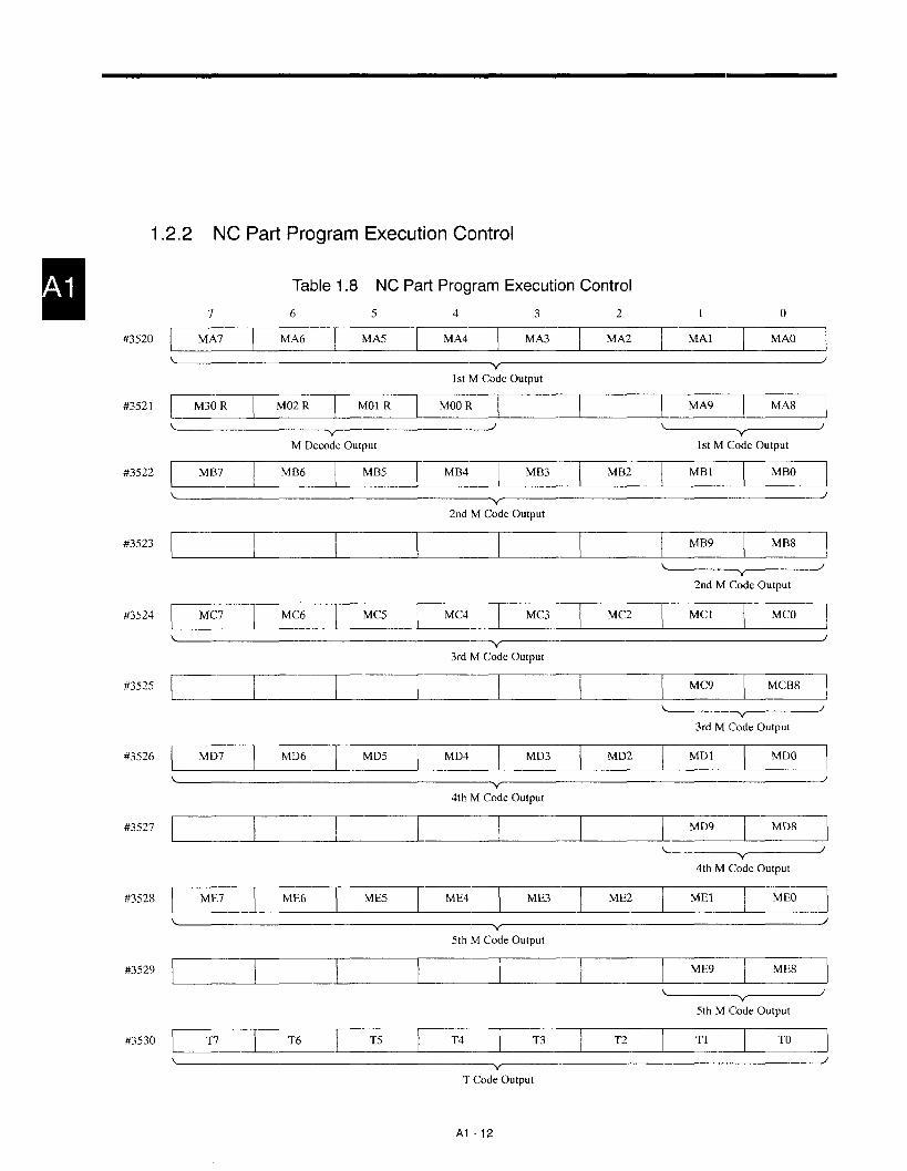
1
#3520
#352 1
#3522
#3523
#3524
#3525
#3526
#3527
#3528
#3529
— ..-—2.2 NC Part
7
Program
Table 1.8
6
Execution Control
NC Part Program Execution Control
5 4 3 2 1 0
MA7 MA6 MA5 MA4 MA3 MA2‘A’ ~
\-Y’
/
1st M Code Output
M30 R M02 R “01 R MOOR‘A9 ~
~’ ~—c————’M Decode Output 1st M Code Output
MB7 MB6 MB5 MB4 MB3 MB2‘B’ m
2nd M Code Output
~1.1 ‘B9m~—r————’
2nd M Code Output
MC7 MC6 MC5 MC4 MC3 “Cz‘c’ m
3rd M Code Output
‘C9 m
——————v————’3rd M Code Output
MD7 MD6 MD5 MD4 MD3 MD2‘D’ m
L )v
4th M Code Output
‘D’ m
—————r————’4th M Code Output
ME7 ME6 ME5 ME4 ME3 ME’2‘E1 m
5th M Code Output
5th M Code Output
L T? T6 T5 T4 T3 T2 T1 TO
v)
T Code Output
Al -12

Appendix Table 1.8 NC Part Program Execution Control (cent’d)
#353 1
#3535
#3537
#3538
#3539
#3540
#3541
#3542
#3543
~“~T Code Output
Output – Read M, B, T Code
THC RWDS OP DEN I =E~rzclDuring During During Feed R State F State Stopped DuringThread Rewinding Operation CompletedCutting
Operation
\ ~“ .~
Output – Series Operation Status M~nitor
I ‘EEEIEIZEEE12EE12E?II‘~-———’ In Solid Tap M04 Status in
Output –Internal Toggle Switch Mode Canned Cycle
Mc,nitor
During ---~——————’Thread Output – Canned Cycle Operation Status MonitorCultingCanned Cycle
U07 U06 U05 U04 I -!cIzEcmL —~Macro Program Ouiput Signal
U015 U014 U013 U012 I =!zcPc~Macro Program Output Signal
I U023 U022 U021 U020 I ~i~~]
Macro Program Output Signal
U031 U030 U029 U028I IEIIZ!EZZEE=
L
Macro Program Output Signal
Al -13
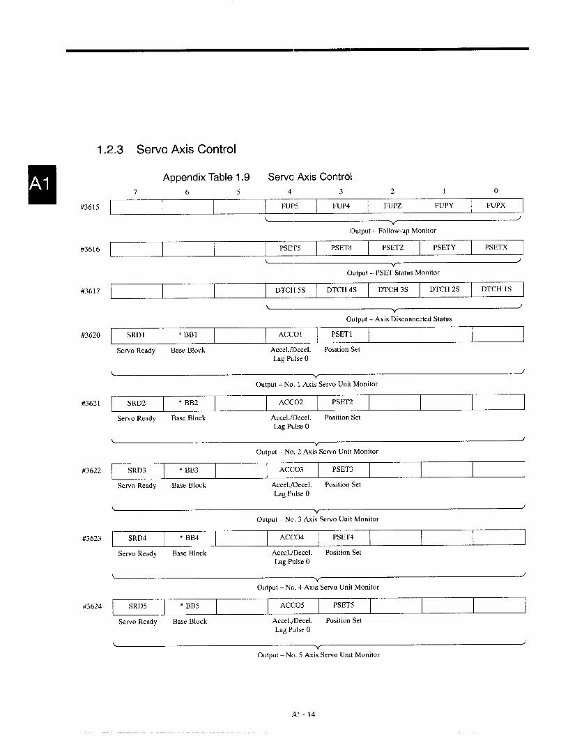
1.2.3 servoAxk Control
mA#3615
#3616
#3617
#3620
#3621
#3622
#3623
#3624
Appendix Table 1.9 Servo Axis Control
7 6 5 4 3 2 1 0
FUP5 FUP4 FUPZ FUPY FUPX
\ ~~Output – Follow-up Monitor
PsET5 PSET4 PSETZI PSEIZECI
\v
Output – PSET Status Monitor
DTCH 5S DTCH 4S DTCH 3S DTCH 2S DTCH 1S
L /v
Output – Axis Disconnected Status
SRD1 v BB1 ACCO1 PSET1
Servo Ready Base Block Accel./I>ecel. Position SetLag Pulse O
L )v
Output – No. 1 Axis Servo Unit Monitor
SRD2 * BB2 ACC02 PSET2
Servo Ready Base Block Accel./Decel. Position Set
Lag Pulse O
L Jv
Output – No. 2 Axis Servo Unit Monitor
SRD3 * BB3 ACC03 PSET3
Servo Ready Base Block Accel./Decel. Position SetLag Pulse O
L Jv
Output – No. 3 Axis Servo Unit Monitor
SRD4 * BB4 ACC04 PSET4
Servo Ready Base Block Accel./Dece1. Position SetLag Pulse O
\ Jv
Output – No. 4 Asis Servo Unit Monitor
SRD5 * BB5 ACC05 PSET5
Servo Ready Base Block Accel./Dece1. Position SetLag Pulse O
L /v
Output – Nc). 5 Axis Servo Unit Monitor
Al -14

#3629
#3630
#3631
#3632
#3633
#3640
#3641
#3642
#3643
Appendix Table 1.9 Servo Axis Control (cent’d)
7 6 5 4 3 2 1 0
ABSERR5__L_L_J3:7q
Absolute Positior[ Detection Position Errc\r
‘P5 I n:zElzcI-Output - Reference Point Position Monitm
~x;?=
Output – Reference Point Position Monitcr
Output – Refererrce Point Position Monitc r
4ZP5 I zcrzcEE3zEclOutput – Reference Point Position Monitcr
\ --v———————————’Output– St mke Check Monitor
–SOT5 I3?~zEclOutput – Stroke Check Monitor
SOT21 I=<~TzElEntry Check Axis 3 Check As is 2 Check Axis 1ProhibitedArea – Inside
\v
.~
Output – Stroke Check Monitor for No. 2 Entry Prohibited Area
SOT31 I IzE?12!Ez2EclEntry CheckAxis 3 Check As is 2 Check Axis 1ProhibitedArea – Inside
mlA
\ v .~
Output – Stroke Check Monitor for No. 3 Entry Prohibited Area
AI-15

7
Appendix Table 1.9 Servo Axis Control (cent’d)
6 5 4 3 2 1 0
#3644I
SOT41 SOT43 SOT42E
Entry Check Axis 3 Check Axis 2 Check Axis 1ProhibitedArea – Inside
Output – Stroke Check Monitor for No. 4 Entry Prohibited Area
#3645 SOT51 SOT53 SOT52 SOT51
Entry Check Axis 3 Check Axis 2 Check Axis 1ProhibitedArea – Inside
Output – Stroke Check Mc,nitorfor No. 5 Entry Prohibited Area
#3648 TRQLIM5 TRQL[M4 TRQLIM3 I ‘RQL’M212!EEIOutput – Servo Axis Torque Limit Monitor
AI-16

1.2.4 No. 1 Spindle Control
#3651
#3652
#3653
#3654
#3655
#3656
Appendix Table 1.10 No. 1 Spindle Control
7 6 5 4 3 2 1 0
I GR4S I GR3S I GR2S \ GRIS I GRSS \ GSCS I G96S I SINVA I
I S2COPE I SICOPE I SF I SLPS I SIDXO I SIDXA I
Outputdurnig SpindleLinkage Command Spindle Output – SFlindl’eIndex MonitorSampling Position Loop
Monitor
~IK~G=Spindle NC Side NC SidePosition Loop Spindle Spindle
Request Control Modeoutput Mode Switching
Output – Monitor of PG Signal, etc.
I SD07 I SD06 I SD05 I SD04 I SD03 I SD02 I SDO1 I SDOO I
L v .- .——
Output – S Command Binary
SD015 SD014 SD013 SD012 I EEIZ!!IEECIOutput – S Command Binary
SD023 SD022 SD021 SD020I =:!IEEI
\ v .~Output – S Command Binary
AI-17
..- .— .— -——_— —-——

mA #3660
1.2.5 No. 2
#3661
#3662
#3663
#3664
#3665
#3666
7
Spindle Control
6 5 4 3 2 1 0
GR4 s-2 GR3 s-2 GR2 s-2 GR1 S-2 GRS S-2 GSC S-2I “6s-2_l_R221
~--’ O“’p”’- ‘Rs0“’P”’-GSC0“’P”’-G96 :’::’;Output – Gear Range Status Control Status Control Status Control
Status ReversedStatus
S2COPE-2 SICOPE-2 SF-2 SLPS-2 SIDX O-2 SIDX A-21
~~ :::a;: :;:;;;e: —–-—----Y----JOutput during Spindle Linkgae Output – Spindle Index Monitor
Sampling Position LoopMonitor
SLRQ-2 AXMODEX-2 CAXS-2
Spindle NC Side NC SidePosition Loop Spindle SpindleRequest Control Modeoutput Mode Switching
PCS-2 PBS-2 PAS-21
Output – Monitor of PG Signal, etc.
SDO 7-2 SDO 6-2 SDO 5-2 SDO 4-2 SDO 3-2 SDO 2-2 I ‘D01-21EEclOutput -- S Co’mmand Binary
SDO 15-2 SDO 14-2 SDO 13-2 SDO 12-2 SDO 11-2 SDO 10-2 SDO 9-2 SDO 8-2
\‘/
Output - S Command Binary
SDO 23-2 SDO 22-2 SDO 21-2 SDO 20-2 SDO 19-2 SDO 18-2 I ‘D017-21zElOutput - S Co’mmand Binary
A“I -18

#3720
#3721
#3722
#3723
1.2.6 YENET1 200 Compatible Inverter Control
Appendix Table 1.11 YENETI 200 Compatible Inverter Control
7 6 5
SPCHWE-1 SPORE-1 SPORG-14 I ti!*TzElSPTLE-l
Winding Orientation Load Axis Torque Limit Torque Speed Speed Agreed Zero SpeedSwitching- Finish Zero Point Detection DetectionOver Finish
Signals for YENET1200 Compatible hrverter (No. 1 Spindle)
Alarm Fault
~“~Signals for YENEr1200Compatible Invefier (No. 1Spindle)
SPCHWE-2 SPORE-2 SPORG-2 SPTLE-2 IE!!Z!!Z!ZK12!ECIE!!EISignals for YENET1200 Compatible Inverter (No. 2 Spindle)
~-:~~
HA
~“—n————’Signals for YENET1200Compatible Inverter (No. 2Spindle)
AI-19

1.2.7 Axis Variable Data
Appendix Table 1.12 Axis Variable Data
#3740
#3741
#3742
#3743
#3744
#3745
#3746
#3747
#3748
#3749
#3756
#3757
7 6 5
ILD1-7 LD1-6 LD1-5 l’~1-+1 2 I l&LD1-2 LD1-1
Lv
1st Axis Load Data (L)
LD1-15 LD1-14 LD1-13 I “’1-E12ZE I LD1-10 LD1-9m
1st Axis Load Data (H)
LD2-7 LD~.6 LD2-5 LD2-4 LD2-3 LD~-2 LD2-1. m
2nd Axis Load Data (L)
LD2-15 LD2-14 LD2-13I ‘D2-12= I
LD2-I o LD2-9m
2nd Axis ~ad Data (H)
LD3-7 LD3-6 LD3-5 LD3-4 LD3-3 LD3-2 LD3-Im
3rd Axis Load Data (L)
LD3-15 LD3-14 LD3-13 I ‘D3-lCIEI I LD3-10 LD3-9m
3rd Axis Load Data (H)
I LD4-7 I LD4-6 I LD4-5 \ LD4-4 I LD4-3 I LD4-3 I LD4-1 \ LD4-O I
4th Axis Load Data (L)
LD4-15 LD4-14 LD4-13 LD4-12 LD4-11 LD4-10 LD4-9m
L v4th Axis Load Data (H)
I LD5-7 I LD5-6 I LD5-5 I LD5-4 ] LD5-3 I LD5-2 I LD5-1 \ LD5-O I
5th Axis Load Data (L)
LD5-15 LD5-14 LD5-13 LD5-12 LD5-11 LD5-10 LD5-9-L
LD5-8
5th Axis Load Data (H)
I LDS1-7 I LDS1-6 I LDS1-5 \ LDS1-4 I LDS1-3 / LDS1-2 I LDS1-I / LDS1-O I
\ vNo. 1 Spindle Load Data (L)
LDS1-15 LDS1-14 LDS1-13 LDS1-12 LDS1-11 LDS1-10 LDS1-9IEEl
No. 1 Spindle Load Data (H)
Al -20

Appendix Table 1.12 Servo Axis Control (cent’d)
#3758
#3759
#3764
#3765
#3764
#3765
#3772
#3773
#3774
#3775
#3780
#3781
7 6 5 4 3 2 1 0
LDS2-7 LDS2-6 LDS2-5 LDS2-4 I zEcEEc12EzIEclNo. 2 Spindle Load Data (L)
LDS2-15 LDS2-14 LDS2-13 LDS2-12 I EcPEIcEEzIEEEclNo. 2 Spindle Load Data (H)
S1RC7 S1RC6 S1RC5 S1RC4I -!~m
No. 1 Spindle S RPM Command (L)
S1RC15 S1RC14 S1RC13 S1RC12 I 9!EIETEINo. 1 Spindle S RPM Command (H)
S2RC7 S2RC6 S2RC5 S2RC4 I =!Ecb!EIz!ElNo. 2 Spindle S RPM Command (L)
S2RC15 S2RC14 S2RC13 S2RC12 I EECE3E.=No. 2 Spindle S RPM Command (H)
S1RS7 S1RS6 S1RS5 S1RS4 I TEclzEIE!EzclNo. 1 Spindle Actual Spindle Speed (L)
S1RS15 S1RS14 S1RS13 S1RS12 I -E!cPEzz!!No. 1 Spindle Actual Spindle Speed (H)
S2RS7 S2RS6 S2RS5 S2RS4 I EEcE!:~IE!ElNo. 2 Spindle Actual Spindle Speed (L)
S2RS15 S2RS14 S2RS13 S2RS12I -:~m
No. 2 Spindle Actual Spindle Speed (H)
POS1-7 POS1-6 POS1-5 POS1-4 I zzEclz!Ec12EzE!cl\ v
1st Axis Position Data (L)
POS1-15 POS1-14 POS1-13 POS1-12I ‘=:~m
L
1st Axis Position Data (H)
Al -21

#3782
#3783
#3784
#3785
#3786
#3787
#3788
#3789
#3796
#3797
#3798
#3799
Appendix Table 1.12 Servo Axis Control (cent’d)
7 6 5 4 3 2 1 0
POS2-7 POS2-6 1’0S2-5 POW-4 POS2-3 POS2-2 I ‘0s2-lzEcl2nd Axis Position Data (L)
POS2-15 POS2-14 POS2-13 POS2-12 POS2-11 POS2-10 POS2-9 POS2-81
2rtd Axis Position Data (H)
[POS3-7 POS3-6 POS3-5 POS3-4 POS3-3 POS3-2 I ‘0s3-lIEcl
3rd Axis Position Data (L)
POS3-15 POS3-14 POS3-13 POS3. 12 POS3-11 POS3-10 POS3-9 POS3-8
3rd Axis Position Data (H)
POS4-7 POS4-6 POS4-5 POS4-4 POS4-3 POS4-2 I ‘0s4-’IzE!El4th Axis Position Data (L)
POS4-15 POS4-.14 POS4-13 POS4-12 POS4-11 POS4-10 POS4-9 POS4-8
4th Axis Position Data (H)
POS5-7 POS5-6 POS5-5 POS5-4 POS5-3 POS5-2 POS5-1 POS5-O
5th Axis Position Data (L)
I POS5-15 I POS5-14 I POS5-13 I POS5-12 I POS5-11 I POS5-10 I POS5-9 I POS5-8 I
\ ,v
5th Axis Position Data (H)
I SIOR-7 I SIOR-6 I SIOR-5 I SIOR-4 I SIOR-3 I SIOR-2 I SIOR-I I SIOR-O I
\ vNo. 1 Spindle Orientation Angle Data (L)
S1OR-11 S1OR-10 I ‘10R-91Ecl\ /
vNo. 1 Spindle Orientation Angle Data (H)
I S20R-7 I S20R-6 I S20R-5 \ S20R-4 I S20R-3 I S20’-2 I S20R-1 I S20R-0 I
\ vNo. 2 Spindle Orientation Angle Data (L)
S20’-11 S2OR-10 S20R-9 S20R-8
No. 2 Spindle Orientation Angle Data (H)
Al -22
-——

AF>PEhJDD( 2PARAMETER TABLE
Appendix 2 describes the classification and function of the
parameters used for YASNAC J300.
2.1 CLASSIFICATION OF
THE PARAh/lETERS . . . . . . . . . . . . . . . . A2-2
2.2 PARAMETER TABLE . . . . . . . . . . . . . . A2-3
IQ-l
--- .-—— —.. - ..—. .— .-. _—-— —.— —-—_—

APPENDIX 2.1 CLASSIFICATION OF THE PARAMETERS
Appendix Table 2.1 Classifications of the Parameters
No. Classification Data Type Parameter No. Sign Power OFF/ON* Remarks
Bit pmOOOO- pmO099
Byte1 Related to setting
pmOIOO - pmO109
Word pm0400 - pm0429 Used
D-word pm0800 - pm0939 Used
Related to axis and spindle Bit pm1000 - pm1099 pm1020 - pm1099
control2
ByteAxis control
pm1100 - pm1393 pm1300 - pm1399
Servo Word pm1400 - pm1799 Used pm1600 - pm1799
Spindle D-word pm1800 - pm1859 Used pm1820 - pm1859
BitRelated to feed
pm2000 - pm2019
Feedrate and acceleration Byte3
pm2100 - pm2139
Thread/tap Word pm2400 - pm2649 UsedPulse handle
pm2600 - pm2649
D-word pm2800 - pm2899 Used pm2870 - pm2899
Bit pm3000 - pm3009 pm3009 ParametersRelated to interface and pm3008, pm3009,
4communications Byte pm3100 - pm3109 pm3100 - pm3109 and pm3830 to
Edit, tape input, display, Word pm3400 - pm3459 Used pm3400 - pm3429 pm3859 arecommunications, DNC validated by
D-word pm3800 - pm3859 Used generation.
Related to program and Bit pm4000 - pm4039automatic operation
Program/automatic Byte5
pm4100 - pm4199
operation, canned cycle, Word pm4400 - pm4599 Usedoffset, coordinate system,zero return, macro D-word pm4800 - pm4899 Used
Bit pm5000 - pm5019 pm5010 - pm5019
Related to 1/0 and automation Byte pm5100 - pm5109
6 assisting Word pm5400 - pm5449 Used1/0, PLC, skip, TLM
D-word pm5800 - pm5809 Used
Bit pm6000 - pm6009
Related to safety and Byte7
pm6100 - pm6149maintenance (machine)
Stroke check, pitch error Word pm6400 - pm6479 Used pm6450 - pm6479
D-word pm6800 - pm6949 Used
PLC ladder Bit8 Related to battery back-up
pm7000 - pm7099Byte and word
memory Byte pm7100 - pm7999
Bit pm8000 - pm8099
Byte9 Others
pm8100 - pm8119
Word pm8400 - pm8429 Used
D-word pm8800 - pm8829 Used
Software switch character Word10
pm9000 -pm9551
designation
A2-2

APPENDIX 2.2 PARAMETER TABLE
Appendix Table 2.2 Parameter Table..-
Description
Single-block switch O: OFF 1: ON +
Parameter No. Bit
o
Machine lock switch O: OFF 1: ON I1
Dry run switch O: OFF 1: ON I2
3 Block delete switch O: OFF 1: ON IpmOOOO
Manual absolute switch O: OFF 1: ON I4
5 Auxiliary function lock switch O: OFF 1: ON I6 Display lock switch O: OFF 1: ON I2 Edit lock switch O: OFF 1: ON Io Optional stop switch O: OFF 1: ON I
Start lock switch O: OFF 1: ON I1pmOOOl
O: Intheaux. function lock state, allspecified Mcodesareirlralid.1: Intheaux. function lock state, allspecified Mcodes are valid.
Mirror image 1 to 8 0: OFF 1: ON.-
ISO/EIA code selection for output tape codeO: 1S0 code1: EIA code
.-
Execution of TV checkO: Not executed1: Executed
.—
Counting the number of characters in ( ) for TV checkO: Not counted1: Counted
.-
TH check for 1S0 code inputO: Executed1: Not executed
Feed holes in output to tapeO: Not punched1: Punched
TH check for 1S0 code outputO: Executed1: Not executed
—,
EOB codes in 1S0 code outputO: CR and LF1: LF
7
0-7pmOO02
o
1
2
pmOO04
Data setting forNo. 1 port
3
4
5
6
0
1
2
3
7
pmOO05
Manual zero return switch O: OFF 1: ON..-
No. 2 manual zero return switch O: OFF 1: ON +
Interruption point return switch O: OFF
Automatic mode handle offset switch O: OFF :: ‘+
Program restart switch O: OFF 1: ON.- .~
A2-3
—— .—.—. —.- —. ——— —--

Appendix Table 2.2 Parameter Table (cent’d)
Parameter No. Bit Description
ISO/EIA code selection for output tape codeo 0: ISO code
1: EIA code
Execution of TV check1 0: Not executed
1: Executed
Counting the number of characters in ( ) for TV check2 0: Not counted
1: Counted
pmOO06TH check for 1S0 code input
Data setting for3 0: Executed
No. 2 port1: Not executed
Feed holes in output to tape4 0: Not punched
1: Punched
TH check for 1S0 code output5 0: Executed
1: Not executed
EOB codes in 1S0 code output6 0: CR and LF
1: LF
Selection of input unito 0: mm
1: inches
Operation instructions and control instructions in user macro1 0: Not interrupted by single-block stop.
1: Interrupted by single-block stop.
Occurrence of an alarm if skip signal is not turned ON until the completion of axis move specified in the
2skip function block
O: An alarm occurs.1: An alarm does not occur.
Tool life control tool search and life countpmOO07
4 0: Executed1: Not executed
Display of program list during input/output/verify of a program5 0: Program list is displayed.
1: Program list not displayed.
“O” data in parameter output6 0: “O” data are output.
1: “O” data are not output.
Buzzer sound for the operation of keys in the keyboard7 0: No buzzer sound
1: Buzzer sound
A2-4

Appendix Table 2.2 Parameter lable (cent’d).-
Parameter No. Bit Description
No. 2 to 5 stored stroke limito-3 0: Invalid
1: ValidpmOO08 ..-
No. 2 to 5 entry prohibited area4-7 0: Inside the boundary
1: Outside the boundary..-
Selection of input porto 0: No. lport
1: No.2port
Tool life count (use count) is made by1 0: Mcodespecified forpm4531
1: T9999.-
Selection of output port4 0: No. 1 port
1: No. 2 port
pmOO09 Alarm occurrence if the condition is not satisfied until the completion of axis mol;ement in the block ofdeviation skip function
50: Alarm occurs.1: Alarm does not occur.
Number of tool life control groups and tools (pmOO09)
Groups Took D7 D6
6.7 @64 4 0 0@) 32 0 1
@ 16 1: 1 0
@832 1 1
Input device settingD3 D2 D1 DO
o 0 0 0 Reserved
o-30 0 0 1 YE tape reader
o 0 1 0 General-purpose RS-232C device
o 0 1 1 Not used
pmOOIO1 1 1 1
No. 1 port device Output device settingdesignation D7 D6 D5 D4
o 0 0 0 Reserved 1
4-70 0 0 1 Reserved 20 0 1 0 General-purpose RS-232C device
o 0 1 1 Not usecl
1 1 1 1
A2-5

Appendix Table 2.2 Parameter Table (cent’d)
Parameter No. Bit Description
BPS settingD2 D1 DOo 0 0 100 or 750 0 1 110 or 150
0-20 1 0 3000 1 1 6001 0 0 12001 0 1 24001 1 0 4800
pmOOll 1 t 1 9600
Stop bit lengthCommunication 3 0: 1 bitparameter setting 1: 2 bitsNo. 1 port (input)‘or general-purpose Data length
RS-232C device 4 0: 7 bits(format) 1: 8 bits
Parity bitD6 D5
5.6 0 0 No parityo 1 Even parity1 () Odd parity
—
Setting of low baud rate selection7 0: 100 and 110 bps
1: 75 and 150 bps
Control by control codeo 0: Not executed
1: Executed
pmOO12RTS control
Communication 1 0: Not executed
parameter setting 1: Executed
No. 1 port (input) DR line checkfor general-purpose ~ O: Not executed
RS-232C device 1: Executed(control)
NC data special control7 0: Not executed
1: Executed
A2-6

Appendix Table 2.2 Parameter Table (cent’d)
Parameter No. Bit Description
BPS settingD2 D1 DOo 0 0 100 or 75
0 0 1 110 or 150
0 10-2
0 300
0 1 1 600
1 0 0 1200
1 0 1 2400
1 1 0 4800
1 1pmOO13
1 9600.-
Stop bit lengthCommunication 3 0: 1 bit
parameter setting 1: 2 bitsNo. 1 port (output) .- —,
‘or general-purpose Data length
RS-232C device 4 0: 7 bits(format) 1: 8 bits
..-
Parity bitD6 D5
5.6 0 0 No panty
o 1 Even parity1 0 Odd parity
.-
Setting of low baud rate selection7 0: 100 and 110 bps
1: 75 and 150 bps..-
Control by control codeo 0: Not executed
1: ExecutedpmOO14
.-
RTS control
Communication 1 0: Not executed
parameter setting 1: Executed
No. 1 port (output) DR line check!or general-purpose z O: Not executed
RS-232C device 1: Executed(control) ..-
NC data special control7 0: Not executed
1: Executed
A2-7
.-..---— — --- —.

Appendix Table 2.2 Parameter Table (cent’d)
Parameter No. Bit Description
Input device settingD3 D2 DI DOo 0 0 0 Reserved
o-30 0 0 1 YE tape readero 0 1 0 General-purpose RS-232C deviceo 0 1 1 Not used
pmOO151 1 1 1
No. 2 port devicedesignation
Output device settingD7 D6 D5 D4
o 0 0 0 Reserved 1
4-70 0 0 1 Reserved 2
0 0 1 0 General-purpose RS-232C device
o 0 1 1 Not used
1 1 1 1
BPS settingD2 D1 DOo 0 0 100 or 75‘cl o 1 110 or 150
0-20 1 0 3000 1 1 6001 0 0 12001 0 1 24001 1 0 48001 1 1 9600
pmOO16
Stop bit lengthCommunication 3 0: 1 bit
parameter setting 1: 2 bitsNo. 2 port (output)‘or general-purpose Data lengthRS-232C device 4 0: 7 bits
(format) 1: 8 bits
Parity bitD6 D5
5.6 0 0 No parityo 1 Even parity1 0 Odd parity
Setting of low baud rate selection7 0: 100 and 110 bps
1: 75 and 150 bps
/\2 -8

Appendix Table 2.2 Parameter l%ble (cent’d)
Parameter No. Bit Description
Control by control codeo 0: Notexecuted
1: Executed
pmOO17RTS control
Communication1 0: Not executed
parameter setting1: Executed
Vo. 2 port (output) DR line checkor general-purpose ‘2 O: Not executedRS-232C device
(control)1: Executed
NC data special control7 0: Not executed
1: Executed
BPS settingD2 D1 DOo 0 0 100 or 75
0 0 1 110 or 150
0-20 1 0 300
0 1 1 600
1 0 0 1200
1 0 1 2400
1 1 0 4800
1 1 1 9600pmOO18
Stop bit lengthCommunication 3 0: 1 bitparameter setting 1: 2 bits
No. 2 port (output)‘or general-purpose Data length
RS-232C device 4 0: 7 bits
(format) 1: 8 bits
Parity bitD6 D5
5.6 0 0 No parityo 1 Even parity1 0 Odd parity
Setting of low baud rate selection7 0: 100 and 110 bps
1: 75 and 150 bps
A2-9
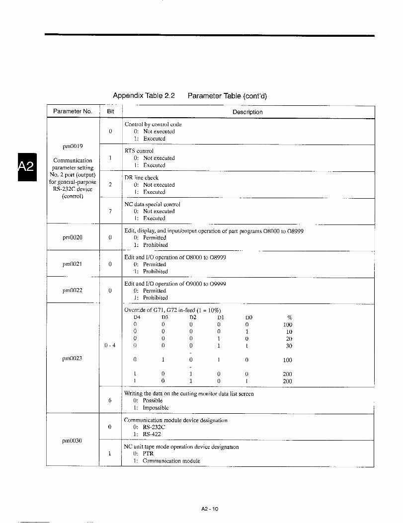
0

Appendix Table 2.2 Parameter Table (cent’d)
Parameter No. Bit Description
BPS settingD2 D1 D()o 0 0 1200
0-2 0 0 1 24000 1 0 4800
0 1 1 96001 0 0 19200
—,
pmO031 Stop bit length3 0: lbit
Communication 1: 2 bitsparameter setting
RS-232C Data length4 0: 7 bits
1: 8 bits
Parity bitD6 D5
5.6 0 0 No parityo 1 Even parity1 0 Odd parity
BPS settingD2 D1 DOo 0 0 1200
0-2 0 0 1 24000 1 0 4800
0 1 1 96001 0 0 19200
pmO032 Stop bit length3 0: 1 bit
Communication 1: 2 bitsparameter setting
RS-422 Data length4 0: 7 bits
1: 8 bits
Parity bitD6 D5
5.6 0 0 No parityo 1 Even parity1 0 Odd parity
A2-11
.—.- ..- ..—..—

Appendix Table 2,2 Parameter Table (cent’d)
‘arameterNo. Bit Description
Designation of inputso 0: Least input unit
1: 10 times the least input unit
X-axis value designation1 0: Diameter
1: Radius
SSTP setting for “O” output in response to “O” S commandpm1000 5 0: SSTP “O”
1: SSTP “l”
C-axis related servo alarm while C-axis is disconnected6 0: Alarm
1: Disregarded
Checking of SAGR when feedrate is changed from rapid traverse to cutting feedrate.7 0: Not checked
1: Checked
Y-axis value designationpm1001 1 0: Diameter
1: Radius
Magnification ratio of 1st to 4th axis speed parameterpm1002 o-3 0: xl
1: Xlo
Monitoring of spindle PG in back-machining spindle synchronization control (1)o 0: Not executed
1: Executed
Monitoring of spindle PG in back-machining spindle synchronization control (2)pm1003 1 0: Not executed
1: Executed
Loop back of D/A sequence of No. 1 to No. 4 spindles2-5 0: Provided
1: Not provided
1st - 5th axis logical axis No.D4 D3 D2() o 0 1st logical axis
o 0 1 1st logical axiso 1 0 2nd logical axis
n1004 - pm1008 2-40 1 1 3rd logical axis1 0 0 4th logical axis1 0 1 5th logical axis1 1 0 6th logical axis1 1 1 1st logical axis
A2 -12

Appendix Table 2.2 Parameter Table (cent’d)
Parameter No. Bit Description
No. 1- No. 5 spindle logical axis No.D4 D3 D2
o 0 0 No. l logical spindle
o 0 1 No. l logical spindle
o 1 0 No. 2 logical spindlepm1014 - pm1017 2-4
0 1 1 No.:3 logical spindle1 0 0 No. 4 logical spindle1 0 1 No. l logical spindle1 1 0 No. I logical spindle
1 1 1 No. l logical spindle
1st - 5th physical servo axisYENET1200 station No. setting (No. 2- Nc]. 15 stations)
D3 D2 D1 DO D3 D2 D1 DO
0000 Alarm 0001 No. 8 station
1000 Alarm 1 001 No. 9 station
2-4 0100 No. 2 station O 1 0 1 No. 10 station
1 100 No. 3 station 1101 No. 11 station
0010 No. 4 station O 0 1 1 No. 12 station
1010 No. 5 station 1 011 No. 13 stationpm1018 - pm1022 0110 No. 6 station O 1 1 1 No. 14 station
11 10 No. 7 station 1 1 1 1 No. 15 station
1st - 5th physical servo axis specification6 0: Servo axis
1: C-axis integral with spindle
1st - 5th physical servo axis7 0: Invalid
1: Valid
1st - 4th physical spindleYENET1200 station No. setting (No. 2- Nc]. 15 stations)
D3 D2 D1 DO D3 D2 D1 DO0000 Alarm 0001 No. 8 station1000 Alarm 1 001 No. 9 station
o-3 0100 No. 2 station O 1 0 1 No. 10 station1 100 No. 3 station 1101 No. 11 station0010 No, 4 station O 0 1 1 No. 12 station
1010 No. 5 station 1 0 1 1 No. 13 stationpm1026 - pm1029 0110 No. 6 station O 1 1 1 No. 14 station
1 1 1 0 No. 7 station 1 1 1 1 No. 15 station
No. 1- No. 4 physical spindle6 0: Normal spindle
1: C-axis integral with spindle
No. 1- No. 4 physical spindle7 0: Invalid
1: Valid
A2-13
.- —— ..—.. —- —— .—..—.——. .. —. ——— —. —-

Appendix Table 2.2 Parameter Table (cent’d)
Parameter No. Bit Description
Velocity loop control methodo 0: PI
1: 1P
Velocity loop control automatic setting1 0: Invalid
1: Valid
Full-closed control method2 0: Invalid
1: Valid
Axis designationpm1030 - pm1034 3 0: Normal axis designation (1 = 1 ym)
1: Linear axis designation (1 ==0.5 ~m)1st - 5th axis servo
control type Reverse connection of separately installed PG4 0: Invalid
1: Valid
50: Servo axis1: C-axis integral with spindle
Axis type6 0: Lhear axis
1: Rotary axis
Motor rotation direction7 0: Forward rotation
1: Reverse rotation
D2 D1 Use of PG
1.20 0 No PG for spindleo 1 PG used at the spindle
pm1039 - pm1042 1 0 PG used at the motor
No. 1- No. 4No. 1 spindle servo control
5 0: Executedspindle servo
1: Not executedcontrol type
No. 1 spindle configuration7 0: Normal spindle
1: C-axis integral with spindle
M-14

Appendix Table 2.2 Parameter Table (cent’d)
Parameter No. Bit Description
Servo feed amount changeo 0: Not executed
1: Executed
Absolute encoder1 0: Motor PG
1: Separately installed PG
Disregarding error pulses at the input of emergency stop2 0: Not disregarded
pm1044 - pm1048 1: Disregarded
lst-axis - 5th-axis Execution of follow-up processing for the input of servo OFF3 0: Not executed
1: Executed
Use of absolute encoder4 0: Not used
1: Used
Parameter for setting virtual C-phase interval in zero return5 0: 1 turn of motor (pm1821)
1: 1 turn of motor (pm1851)
Execution of spindle indexing in loop control2 0: Not executed
1: Executed
pm1053 - pm1056.—
Execution of C-axis indexing when switching to C-axis
No. 1- No. 43 0: Not executed
1: Executedspindle
Special spindle indexing4 0: Invalid
1: Valid
Speed agreement signal of No. 1 to No. 4 spindlepm1058 o-3 0: Not checked
1: Checked
A2-15
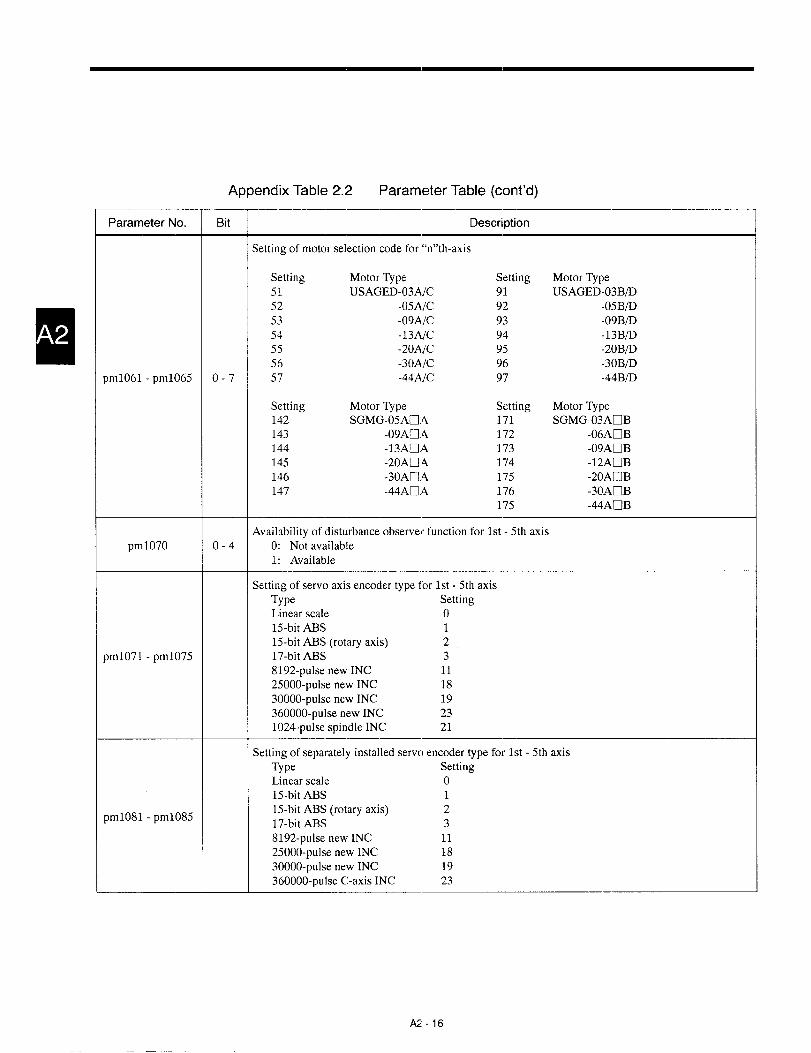
Appendix Table 2.2 Parameter Table (cent’d)
Parameter No. Bit Description
Setting of motor selection code for “n’’th-axis
Setting Motor Type Setting Motor Type51 USAGED-03A]C 91 usAGED-03B/D52 -05AIC 92 -05BI’D53 -09AJC 93 -09BID54 -13AIC 94 -13B/’D55 -20AJC 95 -20BfD56 -30AIC 96 -30BI’D
pm1061 - pm1065 o-7 57 -44AJC 97 -44 BID
Setting Motor Type Setting Motor Type142 SGMG-05ACI,A 171 SGMG-03ADB143 -09ACI.4 172 -06AnB144 -13ACi.4 173 -09AEIB145 -20ACI.A 174 -12AnB146 -30AD.A 175 -20AEIB147 -44AU.4 176 -30AnB
175 -44ACIB
Availability of disturbance observer function for 1st - 5th axispm1070 o-4 0: Not available
1: Available
Setting of servo axis encoder type for 1st - 5th axisType SettingLhear scale o15-bit ABS 115-bit ABS (rotary axis) 2
pm1071 - pm1075 17-bit A13S 38192-pulse new INC 1125000-pulse new INC 1830000-pulse new INC 19360000-pulse new INC 231024-pulse spindle INC 21
Setting of separately installed serve) encoder type for 1st - 5th axisType SettingLinear scale o15-bit ABS 115-bit ABS (rotary axis) 2
pm1081 - pm108517-bit ABS 38192-pulse new INC 1125000-pulse new INC 1830000-pulse new INC 19360000-pulse C-axis INC 23
AZ-16

Appendix Table 2.2 Parameter Table (cent’d)
Parameter No. Bit Description
Settingof encoder type for No. 1- No. 4 spindleType Setting
Linear scale o
15-bit ABS 1
pm1091 - pm1094 15-bit ABS (rotary axis) 2
17-bit ABS 3
8192-pulse new INC 11
360000-pulse C-axis INC 23
1024-pulse spindle INC 21
Command unit designationpm1096 o 0: Microns
1: Sub-microns
Torque limiter function for 1st - 5th axispm1098 o-4 0: Invalid
1: Valid
Dry run during rapid traverseo 0: Invalid
1: Valid
Dry run during thread cutting1 0: Valid
1: Invalid
Spindle override during tapping2 0: Not clamped at 100%
1: Clamped at 100% (only for lathe)
Setting of input unit for pm2447 (Fo feedrate)3 0: mm/min
pm20001: %
Validity of feedrate override signal4 0: Valid when “l” (NO contact)
1: Valid when “O” (NC contact)
Replacing rapid traverse with jog until the completion of reference point return afl.er turning ON the
6power
O: Rapid traverse is not replaced with jog.1: Rapid traverse is replaced with jog.
Setting jog feedrate of rotary axis at 1/10 of that of linear axis7 0: Not set at 1/10
1: Set at 1/10
Feedrate for skip functiono 0: As specified by F code
1: As set by parameterpm2001
Feedrate applied for the execution of deviation skip function3 0: F code
1: Parameter setting
A2-17

Appendix Table 2.2 Parameter Table (cent’d)
Parameter No, Bit Description
Validity of automatic mode handle offset (lst - 5th axis)pm2002 o-4 0: Invalid
1: Valid
Valid operation of automatic mode handle offsetpm2003 1 0: Other than rapid traverse
1: Only in the interpolation mode—
Feedrate at the detection unit of 0.001 mm or 0.0001 incho 0: F6.O mm/min or F5.2 inch/rnin
1: F6.3 mm/min or F5.4 inch/rninpm2004
Feedrate at the detection unit of 0.001 mm or 0.0001 inch1 0: F33 mm/rev or F24 inch/rev
1: F42 mm/rev or F24 inch/re\’
Presetting of the external position data display at the setting of a coordinate systemo 0: Not preset
1: Preset
Resetting of the external position data display to “O” at the completion of low-speed manual reference
1point return
O: Not cleared to “O”1: Cleared to “O”
Addition of tool position offset amc,unt in Z-axis position data for displaypm3000
2 0: Added1: Not added
Position data display change (workpiece shift coordinate system screen, correction amount screen)3 0: Machine coordinate system
1: Workpiece coordinate system
Offset data by X, Y, and Z6 0: Possible
1: Impossible
External timer displaypm3001 o 0: Invalid
1: Valid
A2-18

Appendix Table 2.2 Parameter Table (cent’d)
Parameter No. Bit Description
Clear of MDI buffer if EOP is ON with program reset (M30/M02) specified.o 0: Cleared
1: Not cleared
Clear of MDI buffer by panel reset or external reset1 0: Cleared
1: Not cleared
Start position of MDI programpm3002 2 0: Present cursor position
1: Beginning of the MDI program
EDIT process address search6 0: Character search
1: Binary search
RUN process address search7 0: Binary search
1: Character search
Initial screen at power OND1 D()
0.10 0 4POSo 1 Programcheckscreen1 0pm3003 Edit screen1 1 4POS
Clearing of the program that requires the check for alarm4 0: Cleared by reset operation
1: Cleared byreset operation after thecheck forthealarrn
Edit/display/output of part programs of 09000 to 09999pm3004 o 0: Permitted
1: Prohibited
A2- 19

Appendix Table 2’.2 Parameter Table (cent’d)
Parameter No. Bit Description
Processing if the same O number already exists in loading a program from tapeo 0: Warning
1: Existing program isoverwritten by new program
Clearing of the program numbers at power ON1 0: Cleared
1: Not cleared
Definition of program number2 0: Numerical value specified following O
1: Numerical value specified following Oor N
Interpretation of M code (M02, M30, M*99 [*: O - 3]) read at the end of program loading from tapepm3005 3 0: Regarded asprogram end
1: Notregarded asprogram end
Automatic editing of a program number in program rename/copy/storing operation4 0: Edited automatically
1: Not edited
Conversion of “:” code (1S0) at input and output5 0: Not converted
1: Converted
Conversion of “:” code (1S0) at input and output (valid if pm3005 D5 = 1)6 0: Not converted
1: Converted
Identification of tape operation deviceo 0: 1/0 input specification
1: Setting specification
Designation of processing at the occurrence of communication module error1 0: NC placed in the alarm state
1: NC not placed in the alarm state
Buffer area data storing amount at the start of DNC operationD3 D2 Bytes
2.30 0 2048
0 1 128
pm3006 1 0 256
1 1 512
Designation of the transmission of the control character4 0: Not transmitted
1: Transmitted
Communication module protocolD7 D6 D5
5-70 0 0 Protocol 1
0 0 1 Protocol 2
0 1 0 Protocol 3
0 1 1 Protocol 4
A2-20

Appendix Table 2.2 Parameter Table (cent’d)
Parameter No. Bit Description
“O” setting of external position data display at the completion of manual reference point returnO: Or-d yinlow-spee dtypemanua lreferenc epointreturn
o1: Both forlow-speed and high-speed manual reference point return
(Valid when pm3000 D1 = 1)
Program input in the edit lock status2 0: Impossible
1: Possiblepm3007
Program output and verify in the edit lock status3 0: Impossible
1: Possible
Buffering of 150-byte DAT binary data after the reception of the WAT command b:y the communication
7module.
O: Buffered1: Not buffered
Selection of G code in 01-group when the power is turned CIN or the NC is reseto 0: GOO
1: GO1
Selection of G code in 03-group when the power is turned ON1 0: G90
1: G91
Selection of G code in 04-group when the power is turned C)N2 0: G98
pm4000 1: G99
Selection of G code in 08-group when the power is turned C)ND4 D3
3.4 0 0 G49
o 1 G43
1 0 G44
G codes to be used7 0: Standard G codes
1: Special G codes
Initial M code mode when the power is turn ed ON or the NC is reset1 0: M96 (arc)
1: M97 (linear)
G code in 12 group to be set at power ON or reset
pm4001 5 0: G521: G53
Cycle interlock at system No. switch “l” or pmO109 DO = 17 0: Not available
1: Available
A2 -21
—...——. — —... .—..—--. —.———

Appendix Table 2,2 Parameter Table (cent’d)
Parameter No. Bit Description
Reference point return direction (lst - 5th axis)pm4002 o-4 0: Positiv~direction
1: Negative direction
Automatic coordinate system setting at the completion of manual zero return4 0: All axes
1: Only rotary axis—
Automatic setting of tool coordinate memory No. by external input5 0: Not executed
1: Executedpm4003
Manual reference point return type in the second and later operation after power ON6 0: High-speed type
1: Low-speed type
Automatic reference point return type in the second and later operation after power ON7 0: High-speed type
1: Low-speed type
Occurrence of alarm if movement command other than G28 is executed without carrying out manual or
pm4004 o-4automaticreference point return after power ON (lst - 5th axis)
O: Alarm does not occur.1: Alarm occurs.
Automatic coordinate system setting (lst - 5th axis)pm4006 o-4 0: Invalid
1: Valid—
Returning of the execution pointer to the start of the program when the NC is reset by the external key
ooperation
O: Returned1: Not returned
—
Rewinding of tape by M30 when YASNAC standard tape reader is connected to the No. 1 RS-232C port1 0: Not rewound
1: Rewound
Rewinding of tape by M30 when YASNAC standard tape reader is connected to the No. 2 RS-232C portpm4008
2 0: Not rewound1: Rewound
Possibility of starting of memory operation from a mid point of a block3 0: Possible
1: Not possible; always started from the beginning of a block
High-speed automatic start for high-speed rewind operation7 0: Does not start at high-speed
1: Start at high-speed
A2 -22

Appendix Table 2.2 Parameter Table (cent’d)
Parameter No. Bit Description
Present value is input to system variables #5001 and on at the execution of G31 skip.o 0: Present value
1: Command value
Microprogram common variables #100 - #2.99 become <empty> by the reset operzltion.1 0: Emptied
1: Not emptied
Output of leading zeros if the upper digit value of a variable is “O” at the execution of DPRINT function2 0: Space areoutput.
1: Nothing is output.pm4009
Automatic setting of tool coordinate memory No. by external input5 0: Not executed
1: Executed
Automatic clear of tool wear offset data by ,external input6 0: Not executed
1: Executed
MST status when operation mode is changed from automatic to manual7 0: M, S, and T are forcibly finished without SPL indicating lamp lit.
1: M, S, and T are saved with SPL indicating lamp lit.
Processing after the change of offset amounto 0: New offset amount becomes valid from the block to be buffered next.
1: New offset amount becomes valid from the T code to be buffered next.
Operation expression for the direct input of measured workpiece value2 0: Present value saved temporarily – Keyed-in value
1: Keyed-in value – Present value saved temporarily
Offset data input value check3 0: Not executed
1: Executed (alarm if input value is greater than parameter set value)pm4010
Offset movements5 0: Executed in the block in which the offset command is designated
1: Executed in the block in which axis movement command is designated
Processing of a “TO” command when the setting is “no T code output for TO” (pm5012 D6 = 1)6 0: Only offset movements are executed.
1: An alarm occurs.
Processing of T code after reset, coordinate system setting, or reference point return7 0: Lower two (three) digits: 00
1: Lower two (three) digits: Saved
A2 -23

Appendix Table 2.2 Parameter Table (cent’d)
Parameter No, Bit Description
Thread cutting in single block mode
o(): Stops after the completion of thread cutting block; feed hold is disregarded,1: Stops after the completion of the block next to the thread cutting block; the same processing for
feed hold.
Setting of stop position for feed hold during thread cutting1 0: After chamfering, the tool returns to and stops at the start point.
1: The tool stops at the position where chamfering is completed.
Validity of manual absolute function if there is no axis move command in the block where incremental
2amount is generated
0: Manual absolute function is valid.1: Manual absolute function is not valid.
Validity of manual absolute function if there is no axis move command in the block where incremental
3amount is not generated
0: Manual absolute function is valid.pm4011 1: Manual absolute function is not valid.
Constant surface speed control for rapid traverse commands4 0: Only in the block immediately before the cutting feed block
.1: All blocks containing rapid traverse commands
Coordinate values used for the calculation in the constant surface speed control mode5 0: Coordinate values specified in a program
1: Coordinate values including tool position offset data
Canceling the manually moved distance after reset, reference point return, execution of G50, and key
6setting up
O: Canceled1: Not canceled
Ignoring of the manual absolute function for the incremental commands.7 0: Manual absolute function is not ignored.
1: Manual absolute function is ignored.

Appendix Table 2.2 Parameter Table (cent’d)
Parameter No. Bit Description
Addition of workpiece shift distance at the setting of coordinate system by G50 or setting up by the
o[ORG] key.
O: Workpiece shift distance isadded.1: Workpiece shift distance isnot added.
Reversing of the input incremental value of the workpiece coordinate system shift distance1 0: Not reversed
1: Reversed
G50 coordinate system setting command specified in the G53 mode
2 0: Causes an alarm.pm4012 1: Executed
Movement direction of the coordinate system origin when a positive workpiece shi 1 distance is added
30: Inthe negative direction1: Inthe positive direction
Addition of workpiece coordinate system shift distance in automatic coordinate system setting4 0: Added
1: Not added
Canceling the G50 coordinate system by G52, G53, or T command in the G53 mode5 0: Canceled
1: Not canceled
Start-up and cancel motiono 0: Type B compensation method
1: Type A compensation method
Switching point of offset direction (G41/G42)1 0: Point of intersection
1: At the start and end points
Processing after the offset amount is changed2 0: New offset amount becomes valid from the end point.
1: New offset amount becomes valid from the start point.
pm4013 Availability of interference check function3 0: Not provided
Nose R offset 1: Provided
Processing after the detection of interference4 0: Automatic correction
1: Alarm
Corner blocks5 0: Not divided
1: Divided
Execution of tool radius offset when control point is “O”6 0: Not executed
1: Executed
A2 -25

Appendix Table 2.2 Parameter Table (cent’d)—
Parameter No. Bit Description
Allowable error range check for circular arc command1 0: Not executed
1: Executed—
Error detection at the completion dwell3 0: Error detection is OFF.
1: Error detection is ON.
In-position check when the G code mode is changed to GOO(GOO, GO1 -+ GOO)4 0: In-position check is not executed.
1: In-position check is executed.
pm4015 GOOerror detection during solid tap5 0: GOOerror detection is ON.
1: GOOerror detection is OFF.
Display of the peak value of synchronization error between the spindle and the hole machining axis dur-
6ing solid tap.
O: Not displayed1: Displayed
Approach speed for program restart7 ‘O: Jog feedrate
1: Rapid traverse—
Output of M05 for changing the spindle rotation direction (forward/reverse) at the hole bottom in theG74, G84 canned cycle
pm4016 30: M05 is not output.1: M05 is output.
Spindle override during the execution of thread cutting or tapping cycle2 0: Fixed at 100%
1: Fixed at the value read at the start of cycle
C-axis clamp/unclamp processing in a hole-machining canned cyclepm4017 4 0: Not executed
1: Executed
If the hole bottom level command cannot be designated in a hole-machining cannecl cycle6 0: Does not cause an alarm.
1: Causes an alarm.
Direction of X-coordinate axis in the polar coordinate system1 0: Forward rotation direction
1: Reverse rotation directionpm4019
C-axis command input2 0: The same as the X-axis command input
1: Fixed to radius
A2-26

Appendix Table 2.2 Parameter Table (cent’d)
Parameter No. Bit Description,—
Backing up of the macro variable data during normal operation2 0: Macro variable data is backed up.
1: Macro variable data is not backed up.pm4020
Validity of tool selection macro execution on single block switch4 0: Valid
1: Invalid
Coordinate memory No. for the setting of a new tool coordinate system2 0: Upper two digits
1: Lower two digits
Zero return function of the external position data display when the new tool coordi:late system settingfunction is valid
pm4021 50: The zero return function is invalid.1: The zero return function is valid.
—
Check of the nose R wear offset data input value6 0: Not checked
1: Checked and an alarm occurs if it is greater than the value set for pm4389
Validity of reference point return (lst - 5th axis)pm4022 o-4 0: Invalid
1: Valid
Designation of “G50 S“ in the G97 modepm4023 o 0: Invalid
1: Valid
Execution of rough turning process for G71/G72 if no I and K commands are designatedo 0: Not executed
1: Executed assuming I = U and K = W, if I = K = Opm4026
In G71/G72 operation, if X and Z coordinate values differ between the start and end points1 0: Causes alarm.
1: Imaginary point is calculated.
Address “$” in a programpm4027 1 0: Illegal character
1: The $ word (address $ and following numerical value) is skipped.
A2-27

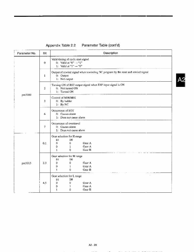
Appendix Table 2.2 Parameter Table (cent’d)
Parameter No. Bit Description,—
Valid timing of cycle start signalo 0: Valid at “O”+ “l”
1: Valid at “l”+ “O”
Output of rewind signal when rewinding NC program by the reset and rewind signal1 0: output
1: Not output
Turning ON of RST output signal when ESP input signal is ON2 0: Not turned ON
1: Turned ONpm5000
Control of MOO/MOl3 0: By ladder
1: ByNC
Occurrence of SOT6 0: Causes alarm
1: Does not cause alarm
Occurrence of overtravel7 0: Causes alarm
1: Does not cause alarm
Gear selection for H rangeD1 DO
0.1 0 0 Gear Ao 1 Gear A1 0 Gear B
Gear selection for M rangeD1 DO
pm5013 2.3 0 0 Gear A
o 1 Gear A1 0 Gear B
Gear selection for L rangeD1 DO
4.5 0 0 Gear Ao 1 Gear A1 0 Gear B
A2 -29

Appendix Table 2.2 Parameter Table (cent’d)
No. Description Setting Range Unit
pmOIOO Thread chamfering width 1-255 1 = 0.1 lead
pmOIOl Thread chamfering angle 1-2 1=45°,2=60’
Time until the occurrence of ALM9022 (API.4 error)o : 489ms
pmO104 1-254 : l-~5Jm~ 0-255
255 : Waiting infinitely
pmO109 Internal system number switch setting “O”, “ 1“ 0-255
Dwell period after C-axis unclamp in a hole-machiningpm0400 0-32767 I=lms
canned cycle
Dwell period at the completion of in-feed in multiple repeti-pm0402
tive cycle G74/G750-32767 l.lms
Spindle phase shift amount in spindle phase synchronization, ,pm0405 - pm0408
No. 1- No, 4 spindles-3600-3600 1 =0.1 deg
pm0801 Break point sequence number setting (1) 1-99999
pm0802 Break point sequence number setting (2) 1-99999
pm0811 - pm0815 Coordinate values at skip signal input (1s[ - 5th axis) 0- + 999999999 1 = Minimum input unit
pm0831 - pm0833 No. 2 stored stroke limit, 1st - 3rd axis (+) 0- * 9999999991 = Minimum detection
unit
pm0834 - pm0836 No. 2 stored stroke limit, 1st - 3rd axis (-) 0- + 9999999991 = Minimum detection
unit
pm0837 - pm0839 No. 3 stored stroke limit, 1st - 3rd axis (+) 0- * 9999999991 = Minimum detection
unit
pm0840 - pm0842 No. 3 stored stroke limit, 1st - 3rd axis (-) 0- * 9999999991 = Minimum detection
unit
pm0843 - pm0845 No, 4 stored stroke limit, 1st - 3rd axis (+) 0- * 9999999991 = Minimum detection
unit
pm0846 - pm0848 No. 4 stored stroke limit, 1st - 3rd axis (-) 0- * 9999999991 = Minimum detection
unit
pm0849 -pm0851 No. 5 stored stroke limit, 1st - 3rd axis (+) 0- * 9999999991 = Minimum detection
unit
pm0852 - pm0854 No. 5 stored stroke limit, 1st - 3rd axis (-) 0- + 9999999991 = Minimum detection
unit
Retraction amount (X-axis) after the in-feed in OD stockpm0860
removal cycle (G71)0-999999999 1 = 0.001 mm, 0.0001 inch
Retraction amount (Z-axis) after the in-feed in OD stockpm0861
removal cycle (G71)0-999999999 1 = 0.001 mm, 0.0001 inch
A2 -30

Appendix Table 2.2 Parameter Table (cent’d)
I No. I Description I Setting Range I Unit I
Ss:aRetraction amount (X-axis) after the in-feed in face rc]rrgh
pm0862cutting cycle (G72)
Retraction amount (Z-axis) after the in-feed in face roughpm0863
cutting cycle (G72)
pm0864 Return amount in face cut-off cycle (G74)
pm0865 Return amount in OD cut-off cycle (G75)
+-=
Depth of cut (X-axis) in the last cycle in automatic threadpm0866
cutting cycle (G76)
pm0867
+
Return amount in grooving canned cycle (G74) (A # O) 0-999999999
‘1
1 = 0.001 mm, ().0001 inch
pm0868 Return amount in grooving canned cycle (G75) (A * O) 0-999999999 1 = 0.001 mm, 0.0001 inch
pm1100 - pml102 Servo axis display name (Ist-axis) I Set by converting ASCIIcode into decimal I
pml103 - pml105 Servo axis display name (2nd-axis) I Set by converting ASCIIcode into decimal I
pml106 - pml108 Servo axis display name (3rd-axis) I Set by converting ASCIIcode into decimal I
Ipml109 - pmllll Servo axis display name (4th-axis)Set by converting ASCIIcode into decimal I
Ipmll12 - pmll14 Servo axis display name (5th-axis)
ISet by converting ASCIIcode into decimal I
pml127 - pml129 Spindle display name (No. 1 spindle)
12=
pml130 - pml132 Spindle display name (No. 2 spindle)
+
Set by (converting ASCIIcode into decimal
pml133 - pml135 Spindle display name (No. 3 spindle)Set by [converting ASCIIcode into decimal
pml136 - pml138 Spindle display name (No. 4 spindle)Set by (converting ASCIIcode into decimal I
pml142 - pml144 Automatic system axis display name (lst-axis)
__.1._..__l!l?ia
pml145 - pml147 Automatic system axis display name (2nd-axis)Set by converting ASCIIcode into decimal
Ipml148 - pml150 Automatic system axis display name (3rd-axis)
ISet by converting ASCIIcode into decimal I
~++apml151 - pml153 Automatic system axis display name (4th-axis)
pml154 - pml156 Automatic system axis display name (5th-axis)
A2 -31
—————— —,. ——————... .—.—.. —- —.. ——— —

Appendix Table 2.2 Parameter Table (cent’d)
No. Description Setting Range Unit
pml169 - pml171 Spindle automatic system axis display name (No. 1 spindle)Set by converting ASCIIcode into decimal
pml172 - pml174 Spindle automatic system axis display name (No. 2 spindle)Set by converting ASCIIcode into decimal
pml175 - pml177 Spindle automatic system axis display name (No. 3 spindle)Set by converting ASCIIcode into decimal
pml178 - pml180 Spindle automatic system axis display name (No. 4 spindle)Set by converting ASCIIcode into decimal
pm1200 High-speed mode operation, number of controlled axes 3-53: 3 axes, 4: 4 axes,5: 5 axes
pm1220 - pm1223 Spindle index confirmation timer (No. 1- No. 4 spindle) 1-255 1.4ms
Spindle index stopped confirmation speedpm1225 - pm1228 (No. 1- No. 4 spindle)
1-255 1 = 1 r/rein
pm1240 Axis number to execute solid tap (1) 1-4
pm1241 Servo axis number to execute solid tap (1) 1-8
pm1242 Axis number to execute solid tap (2) 1-4
pm1243 Servo axis number to execute solid tap (2) 1-8
Spindle No. A to execute rotary tool spindle synchronizationpm1244
(1)1-4
Spindle No. B to execute rotary tool spindle synchronizationpm1245
(1)1-4
Spindle No. A to execute rotary tool spindle synchronizationpm1246
(2)1-4
Spindle No. B to execute rotary tool spindle synchronizationpm1247
(2)1-4
Spindle No. A to execute back-turning spindle synchroniza-pm1248
tion (1)1-4
Spindle No. B to execute back-turning spindle synchroniza-prn1249
tion (1)1-4
Spindle No. A to execute back-turning spindle synchroniza-pm1250
tion (2)1-4
Spindle No. B to execute back-turning spindle synchroniza-pm1251
tion (2)1-4
pm1252 Solid tap (1) return feedrate multiplication ratio 1-255 1 = 0.1 times
pm1253 Solid tap (2) return feedrate multiplication ratio 1-255 1 = 0.1 times
pm1254 Error range of back-turning spindle synchronization (1) 0-2551 = 1 Minimum detectionunit

Appendix Table 2.2 Parameter Table (cent’d)
No. Description Setting Range Unit
pm1255 Offset parameter of back-turning spindle synchronization (1) 0-255 1 = 0.1
pm1256 Error range of back-turning spindle synchronization (2!) 0-2551 = 1 Minimum detectionunit
pm1257 Offset parameter of back-turning spindle synchronization (2) 0-255 1 = 0.1
pm1260 No. 1 spindle, loop control gear number (A) o-4
pm1261 No. 1 spindle, loop control gear number (B) o-4
pm1262 No. 2 spindle, loop control gear number (A) o-4
pm1263 No. 2 spindle, loop control gear number (B) o-4
pm1321 - pm1325 1st - 5th axis, error detect on area 0-255 1 = Minimum input unit
pm1331 - pm1334 No. 1- No. 4 spindle, error detection on area in loop control 0-255 1 = Minimum input unit
Multiplication ratio to rapid traverse rate in Clpm1347
(No. 1 C-axis) servo error area0-200 1=1%
Multiplication ratio to rapid traverse rate in C2pm1348
(No. 2 C-axis) servo error area0-200 1=1%
In No. 1- No. 4 spindle loop control, spindle speed multi-pm1351 - pm1354 0-200 1=1%
plication ratio in solid tapping in servo error area
pm1361 - pm1364 No. 1- No. 4 torque meter display upper limit value 0-200 1 = 1% (10% unit??)
No. 1 spindle, spindle speed clamp (minimum) for gear 1-pm1400 - pm1403 0.30000 1 = 1 r/rein, 10 r/rein
gear 4
No. 1 spindle, spindle speed clamp (maximum) for gear 1-pm1404 - pm1407
gear 40.30000 1 = 1 r/rein, 10 r/rein
pm1408 - pm1411 No. 1 spindle, maximum motor speed for gear 1- gear 4 0 ~~30000 1 = 1 r/rnin, 10 r/rein
No. 1 spindle, spindle speed in response to the input ofpm1412 O ~~32767 1 = 1 r/rein
spindle fixed speed (GSC) signal
No. 1 spindle, output voltage in response to the spindle gearpm1413
shift (GSC) signalO ~~32767 1 = 10/?2767 V
pm1414 No. 1 spindle, origin for indexing 0-4095 1 = 360,’4096 deg
No. 1 spindle, spindle speed corresponding to 10 V cclm-pm1415 0 ~~32767 1 = 1 r/tnin, 10 r/rein
mand in the gear range used for solid tap
pm1416 No. 1 spindle, maximum spindle speed during solid tap 0.32767 1 = 1 r/rein, 10 r/rein
No. 1 spindle, position loop gain in spindle indexing forpm1417
solid tap 10.32767 1 = 0,0:1 [s-1]
No. 1 spindle, maximum spindle speed corresponding to 10pm1418
V command (C-axis is used)0.32767 1 = 1 r/rein
No. 2 spindle, spindle speed clamp (minimum) for gear 1-pm1420 - pm1422
gear 40 30000 1 = 1 r/rein, 10 r/rein
A2 -33
..———.— ... .—.—- ——————

Appendix Table 2.2 Parameter Table (cent’d)
No. Description Setting Range Unit
No. 2 spindle, spindle speed clamp (maximum) for gear 1-pm1424 - pm1426
gear 40-30000 1 = 1 r/rein, 10 r/rein
pm1428 - pm1431 No. 2 spindle, maximum motor speed for gear 1- gear 4 0-30000 1 = 1 r/rein, 10 r/rein
No. 2 spindle, spindle speed in response to the input ofpm1432 0-32767
spindle fixed speed (GSC) signal1 = 1 r/lmin
No. 2 spindle, output voltage in response to the spindle gearpm1433
shift (GSC) signal0-32767 1 = 10/32767 V
pm1434 No. 2 spindle, origin for indexing 0-4095 1 = 360/4096 deg
No. 2 spindle, spindle speed corresponding to 10 V com-pm1435 0-32767
mand in the gear range used for solid tap1 = 1 r/rein, 10 r/rein
pm1436 No. 2 spindle, maximum spindle speed during solid tap 0-32767 1 = 1 r/rein, 10 r/rein
No. 2 spindle, position loop gain in spindle indexing forpm1437
solid tap 10-32767 1 = 0.01. [s-1]
No. 2 spindle, maximum spindle speed corresponding to 10pm1438
V command (C-axis is used)0-32767 1 = 1 r/rein
No. 3 spindle, spindle speed clamp (minimum) for gear 1-pm1440 - pm1443 0-30000 1 = 1 r/rein, 10 r/rein
gear 4
No. 3 spindle, spindle speed clamp (maximum) for gear 1-pm1444 - pm1447
gear 40-30000 1 = 1 r/rein, 10 r/rein
pm1448 - pm1451 No. 3 spindle, maximum motor speed for gear 1- gear 4 0-30000 1 = 1 r/rein, 10 r/rein
No. 3 spindle, spindle speed in response to the input ofpm1452 0-32767
spindle orientation (SOR) signal1 = 1 r/rein
No. 3 spindle, motor speed in response to the spindle gearpm1453
shift (SRO) signal0-32767 1 = 10/32767 V
pm1454 No. 3 spindle, origin for indexing 0-4095 1. 360/4096 deg
No. 4 spindle, spindle speed clamp (minimum) for gear 1-pm1460 - pm1463
gear 40-30000 1 = 1 r/rein, 10 r/rein
No. 4 spindle, spindle speed clamp (maximum) for gear 1-pm1464 - pm1467
gear 40-30000 1 = 1 r/rein, 10 r/rein
pm1468 - pm1471 No. 4 spindle, maximum motor speed for gear 1- gear 4 0-30000 1 = 1 r/rein, 10 r/rein
No. 4 spindle, spindle speed in response to the input ofpm1472 0-32767
spindle orientation (SOR) signal1 = 1 r/rein
No. 4 spindle, motor speed in response to the spindle gearpm1473
shift (SRO) signal0-32767 1 = 10/32767 V
A2-34

Appendix Table 2.2 Parameter Table (cent’d).—
No. Description Setting Range Unit
pm1474 No. 4 spindle, origin for indexing () -4095 1 = 360/4096 deg
1 = 1 rlmin, 10 r/reinNo. 1 spindle, spindle speed clamp (minimum) for gear 5- Note: According to the
pm1480 - pm1483 0-30000gear 8 setting for pm1002
DO
1 = 1 r;min, 10 r/rein
No. 1 spindle, spindle speed clamp (maximum) for gaar 5-pm1484 - pm1487 0-30000
Note: According to thegear 8 setting for pm1002
DO
1 = 1 r;min, 10 r/rein
pm1488 - pm1491 No. 1 spindle, maximum motor speed for gear 5- gear 8 0-30000Note: According to the
setting for pm1002DO
Spindle position loop gain in spindle synchronization controlpm1492 - pm1495 (No. 1- No. 4 spindle)
0-32767 1 = O.cll [s-1]
pm1496 Error range in rotary tool spindle synchronization control (1) 0-32767 1 = 1 plse.——
pm1497 Error range in rotary tool spindle synchronization control (2) 0-32767 1 = 1 pulse
pm1500 Solid tap (l), servo axis drawing-in in-position width 0-32767 1 = Minimum input unit
pm1501 Solid tap (2), servo axis drawing-in in-position width 0-32767 1 = Minimum input unit
pm1502 Solid tap (l), synchronization offset parameter K1 –32767 -32767
pm1503 Solid tap (l), synchronization offset parameter K2 _32;~67 -32767
pm1504 Solid tap (2), synchronization offset parameter K1 -32767-32767
pm1505 Solid tap (2), synchronization offset parameter K2 _32767 -32767
pm1506 Rotary tool spindle (l), synchronization offset parameter K1’ –32767 -32767
pm1507 Rotary tool spindle (l), synchronization offset parameter K2’ –32767 -32767
pm1508 Rotary tool spindle (2), synchronization offset parameter K1’ _32767 -32767
pm1509 Rotary tool spindle (2), synchronization offset parameter K2’ _32,767 -32767
No. 1 spindle, the number of teeth of gear A at the spindle1 = 1 tooth
pm1510 0-32767 Note:side used in loop control
“9” if intermediategear is not used.
No. 1 spindle, the number of teeth of gear A of spindle inter-mediate gear in loop control
pm1511Note: The number of teeth on the motor side if intermedi-
0-32767
ate gear is not used.
No. 1 spindle, the number of teeth of gear A of intermediatepm1512 gear in loop control 0-32767
Note: “O” if intermediate gear is not used.
A2-35

Appendix Table 2.2 Parameter Table (cent’d)
No. Description Setting Range Unit
No. 1 spindle, the number of teeth of gear A at the motor sidepm1513 used in loop control 0-32767
Note: “O” if intermediate gear is not used.
No. 1 spindle, the number of teeth of gear B at the spindlepm1514 side used in loop control 0-32767
Note: “O” if intermediate gear is not used.
No. 1 spindle, the number of teeth of gear B c)f spindle inter-pm1515 mediate gear in loop control 0-32767
Note: “O” if intermediate gear is not used.
No. 1 spindle, the number of teeth of gear B of intermediatepm1516 gear in loop control 0-32767
Note: “O” if intermediate gear is not used.
No. 1 spindle, the number of teeth of gear B a! the motor sidepm1517 used in loop control 0-32767
Note: “O” if intermediate gear is not used.
No. 2 spindle, the number of teeth of gear A at the spindle1 = 1 tooth
pm1518 0-32767 Note:side used in loop control
“9” if intermediategear is not used.
No. 2 spindle, the number of teeth of gear A c)fspindle inter-mediate gear in loop control
pm1519Note: The number of teeth on the motor side if intermedi-
0-32767
ate gear is not used.
No. 2 spindle, the number of teeth of gear A of intermediatepm1520
gear in loop control0-32767
No. 2 spindle, the number of teeth of gear A at the motor sidepm1521
used in loop control0-32767
No. 2 spindle, the number of teeth of gear B at the spindlepm1522
side used in loop control0-32767
No. 2 spindle, the number of teeth of gear B of spindle inter-pm1523 0-32767
mediate gear in loop control
No. 2 spindle, the number of teeth of gear B of intermediatepm1524
gear in loop control0-32767
No. 2 spindle, the number of teeth of gear B at the motor sidepm1525
used in loop control0-32767
pm1539 Output error range in spindle synchronization control 0-32767
No. 1- No. 4 spindle, delay time to check the spindle speedpm1540 - pm1543
arrived signal (SAGR)0-32767 l.lms
pm1544 Spindle phase synchronization offset clamp value 0-327671 = Minimum detectionunit
pm1551 - pm1555 1st - 5th axis, backlash compensation amount 0-32767 l=l@I
pm1580 1st axis, position loop gain Kp 500-20000 1 = 0.01 [1/s]

Appendix Table 2.2 Parameter Table (cent’d)
No. Description Setting Range Unit
pm1581 1staxis, velocity loop gain Kv 350-32767 1 =0.1 [1/s]
pm1582 1st axis, velocity loop integration time constant Ti 1.32767 1 = 0.01 [ins]
pm1584 1st axis, velocity feed forward gain Kvfff () -100 l=O!O1 [%] 1=1%
pm1586 1st axis, axis torsion filter time constant (for the 1st siep) Tn 1-32767 1 = 0.01 [ins]
pm1587 1st axis, axis torsion filter time constant (for the 2nd step) Tn 1-32767 1 = 0.01 [ins]
pm1588 1st axis, axis torsion filter time constant (for the 3rd step) Tn 1-32767 1 = 0.01 [ins].—
pm1589 1st axis, monitor board signal selection, multiplication ratio 1-32767
pm1590 2nd axis, position loop gain Kp 500-20000 1 = 0.01 [1/s]
pm1591 2nd axis, velocity loop gain Kv 350-32767 1 = 0.1 [1/s]
pm1592 2nd axis, velocity loop integration time constant Ti I -32767 1 = 0.01 [ins]
pm1594 2nd axis, velocity feed forward gain Kvfff 0-100 1=0.01 [%] 1=1%.—
pm1596 2nd axis, axis torsion filter time constant (for the 1st step) Tn 1-32767 1 = 0.01 [ins]
2nd axis, axis torsion filter time constant (for tbe 2nd step)pm1597
Tn I1-32767 1 = 0.01 [ins]
pm1598
*=’[ms]
2nd axis, axis torsion filter time constant (for the 3rd step) Tn
um1599 2nd axis. monitor board signal selection, multiplication ratio
pm1600 3rd axis, position loop gain Kp
pm1601 3rd axis, velocity loop gain Kv303:
pm1602 3rd axis, velocity loop integration time constant Ti 1-32767 1 = 0.01 [ins]
pm1604 3rd axis, velocity feed forward gain Kvfff 0-100 1=0.01 [%] 1=1%
pm1606 3rd axis, axis torsion filter time constant Tn 1-32767 1 = 0.01 [ins]
pm1606 3rd axis, axis torsion filter time constant (for the 1st step) Tn 1-32767 1 = 0.01 [ins]
pm1607 3rd axis, axis torsion filter time constant (for the 2nd step) Tn 1-32767 1 = 0.01 [ins]
pml 608 3rd axis, axis torsion filter time constant (for the 3rd step) Tn 1-32767 1 = 0.01 [ins]
pm1610 4th axis, position loop gain Kp 500-20000 1 = 0.01 [1/s]
pm1611 4th axis, velocity loop gain Kv 350-32767 1 = 0.1 [1/s]
pm1612 4th axis, velocity loop integration time constant Ti 1-32767 1 = 0.01 [ins]
pm1614 4th axis, velocity feed forward gain Kvfff 0-100 1=0.01 [%] 1=1%
pm1616 4th axis, axis torsion filter time constant (for the 1st step) Tn 1-32767 1 = 0.01 [ins]
pm1617 4th axis, axis torsion filter time constant (for the 2nd step) Tn 1-32767 1 = 0.01 [ins]
pm1618 4th axis, axis torsion filter time constant (for the 3rd step) Tn 1-32767 1 = 0.01 [ins]
A2 -37

Appendix Table 2.2 Parameter Table (cent’d)
No. Description Setting Range
pm1619 4th axis, monitor board signal selection, multiplication ratio 1-32767 :
pm1620 5th axis, position loop gain Kp 500-20000 1=0.01 [1/s]
pm1621 5th axis, velocity loop gain Kv 350-32767 1 = 0.1 [1/s] +
pm1622 5th axis, velocity loop integration time constant TI 1-32767 1 = 0.01 [ins]
pm1624 5th axis, velocity feed forward gain Kvfff 0-100 1 =0.01 [%] 1 = 1% i
I pm1626 I .5th axis, axis torsion filtertime constant (for the lststep)Tn I 1-32767 I 1 =0.01 [ins] Ipm1627 5th axis, axis torsion filter time constant (for the 2nd step) Tn
pm1628 5th axis, axis torsion filter time constant (for the 3rd step) Tn H:: I
pm1629 5th axis, monitor board signal selection, multiplication ratio 1-32767
pm1671 - pm1675 1st - 5th axis, torque limit (+) 1-32767 1 = 1 [%] +
pm1711 - pm1715 1s[ - 5th axis, backlash time constant
pm1720 Torque limit arrived signal output timer we
pm1721 - pm1725 I 1st - 5th axis, torque limit value 1 I 1-32767 /1=1[%] Ipm1731 - pm1735 1st - 5th axis, torque limit value 2 1-32767
pm1761 - pm1765 1st - 5th axis, disturbance limiter value for rapid traverse 1-32767 ::::L
pm1771 - pm1775 \ 1st - 5th axis, disturbance limiter value for forced input I 1-32767 11=1% INo. 1- No, 4 spindle, spindle offset amount in spindle phase
pm1811 - pm1814synchronization control
0-360000
J
1 = Minimum input unit
pm1821 - pm1825 1st - 5th axis, axis move distance per 1 turn of motor
pm1831 - pm1835 1st - 5th axis, ratio of inertia of load to motor inertia H:rO”OO1deg
pm1841 - pm1845 I 1st - 5th axis, number of’pulses per 1 turn of motor \ O-999999999 \ 1= 1 pulse
~3aTravel distance for indexing between 1st C-axis and C-axis(C-axis integral with the spindle)
Travel distance for mdexjng between 2nd C-axis and C-axis(C-axis integml with the spindle)
C-phase pulse interval of 1st - 5th virtual C-phase‘m1851 - ‘m1855 (valid when pm1044 - pm1048 D5 = 1) I 0-999999999
Feedrate corresponding to the JOG FEEDRATE setting posi-pm2400 - pm2431 Lion ~ .31
, Hsupm2432
– w+
Multiplication of jog feedrate parameter value by 10 or 100
Designation of the addition start switch position if pm2432pm2433
#f)
A:! -38

Appendix Table 2.2 Parameter Table (cent’d)—
No. Description Setting Range Unit,—
Designationof position where the jog feedrate parameterpm2434 1-31
value is multiplied by 1/10
1 = 1 rlm/min,
pm2440 - pm2442 Feedrate for the execution of skip (1) - (3) 0-32767 0.1. inch/rein,1 cefjmin
1 = 1 rlm/min,
pm2443 Feedrate in the execution of deviation skip 0-32767 0.1 inch/rein,1 cle~min
..— —
1 = 1 rlm/min,0.1 inch/rein,
pm2447 Feedrate for rapid traverse override F. 0-327671 cleg/min(pIn2000 D3 = O)
1 = Iy,
(prn2000 D3 = 1)—
pm2448 Feedrate for rapid traverse override F1 () -100 1=1?:?—
pm2449 Feedrate for rapid traverse override F~ () -100 1=1%
Multiplication value for x 100 position of manual pulsepm2459 0-32767
multiply switch1=X:1
—
1st - 5th axis, rapid traverse acceleration/deceleration timepm2461 pm2465 0-32767 l=lnls
constant (lst step)..— .—
No. 1- No. 4 spindle, linear acceleration/deceleration, timepm2471 - pm2474 constant 4-32767 l=lnls
.—
No. 1- No. 4 spindle, exponential acceleration/decelerationpm2476 - pm2479 time ~nstant 4-32767 l=lnis
1st - 5th axis, exponential acceleration/deceleration timepm2501 - pm2505
constant in normal cutting0-32767 l=lnls
—
1st - 5th axis, exponential acceleration/deceleration timepm2511 - pm2515
constant in thread cutting0-32767 1 = 1.n’s
1 = 1 nlm/min,pm2521 - pm2525 1st - 5th axis, reference point return approach speed 0-32767 0.1 inch/mirr,
1 deg/min
1 = 1 nlm/min,pm2531 - pm2535 1st - 5th axis, reference point return creep speed 15-32767 0.1 inch/rein,
1 degjmin
pm2541 - pm2544 No. 1- No. 4 spindle, index start speed 1-32767 1 = 1 rfmin——
pm2546 - pm2549 No. 1- No. 4 spindle, index creep speed 1-32767 1 = 1 rfmin
1st - 5th axis, acceleration/deceleration time constant in han-pm2561 - pm2565 d,e feed 0.32767 l=lrrs
.———
pm2584 Spindle feedback pulse sampling delay offset coefficient o-1o
A2 -39

Appendix Table 2.2 Parameter Table (cent’d)
No. Description Setting Range Unit
1st - 5th axis, S-curve factor in rapid traverse acceleration/de-pm2591 - pm2595 ~,eration 0-6
pm2800 Maximum cutting feedrate (linear axis) 0-2400001 = 1 mlm/min,
0.1 inch/rein
pm2801 - pm2805 1st - 5th axis, rapid traverse rate 0-2400001 = 1 mm/min,
0.1 inch/rein,
! 0.7,400001 = 1 mm/min,
pm2821 - pm2825 1st - 5th axis, bias in normal acceleration/decxJeration 0.1 inch/rein,1 de~min
1 = 1 mm/min,
pm2831 - pm2835 1st - 5th axis, bias in thread cutting acceIeratiorr/deceleration 0-240000 0.1 inch/rein,1 deg/min
pm2860 Maximum feedrate in handle feed (linear axis) 0-2400001 = lmm/min,
0.1 inch/rein
pm2861 Maximum feedrate in handle feed (rotary axis) 0-240000 1. ldeg/min
Number of servo lag pulses for feed clamp in handle feedpm2863
operation0-240000 1 = 1 pulse
pm2864 Shift feedrate in G86VG87 hole-machining canned cycle 0-2400001 = 1 mm/min,
0.1 inch/rein
Jm3108 - pm3108? Designation of DNC high-speed cutting data start character Example: G - 47H Hexadecimal ASCII code
pm3400 - pm3409 Title display at power on, 1st line, 1-10 columnsSet by converting ASCIIcode into decimal
pm3410 - pm3419 Title display at power on, 2nd line, 1-10 columnsSet by converting ASCIIcode inl.o decimal
1st digit:Magnification for
2-digit value is assumed tothe 1st line
be a hexadecimal number;pm3420 Title display, magnification ratio (1 -3)
2nd digit:convert it into decimal for
Magnification forsetting.
the 2nd line (1 -3)
1st and 2nd digits:1st line start posi- 2-digit value is assumed to
pm3421 Title display, display start positiontion (1 - 39) be a hexadecimal number;3rd and 4th digits: convert it into decimal for2nd line start posi- setting.
tion (1 - 39)
“RDI” command PLC battery backed-up memory numberpm3440
designation7000-7999
“SOD” command PLC battery backed-up memory numberpm3441
designation7000-7999
M -40

Appendix Table 2.2 Parameter Table (cent’d).—
No. Description Setting Range Unit
Punched hole pattern, in EIA code, of special characters usedHole piittern is regarded as
pm4100 () -255in user macro, #
a binary number; convert itinto decimal for setting.
Punched hole pattern, in EIA code, of special characters usedHole pattern is regarded as
pm4101 0-255in user macro, [
a binary number; convert itinto de simal for setting.
Punched hole pattern, in EIA code, of special characters usedHole pattern is regarded as
pm4102 0-255in user macro, ]
a binary number; convert itinto decimal for setting.
Punched hole pattern, in EIA code, of special characters usedHole p~ttern is regarded as
pm4103 0-255in user macro, *
a binary number; convert itinto decimal for setting.
Punched hole pattern, in EIA code, of special characters usedHole pattern is regarded as
pm4104 0-255in user macro, =
a binary numbeq convert itinto decimal for setting.
Punched hole pattern, in EIA code, of special characters usedHole pattern is reg~rded as
pm4105 0-255in user macro, (
a binary number; convert itinto decimal for setting.
Punched hole pattern, in EIA code, of special characters usedHole pattern is regarded as
pm4106 0-255in user macro, )
a binary number; convert itinto decimal for setting.
Punched hole pattern, in EIA code, of special characters usedHole pattern is regarded as
pm4107 0-255in user macro, .
a binary number; convert itinto decimal for setting.
Punched hole pattern, in EIA code, of special characters usedHole pattern is regarded as
pm4108 0-255in user macro, ,
a binary number; convert itinto decimal for setting.
Punched hole pattern, in EIA code, of special characters usedHole pattern is regarded as
pm4109 0-255in user macro,” “
a binary number; convert itinto dfcimal for setting.
Tool life control
pm4110 Tool life control group command T code offsetgroup (O -9)=T command
- pm4110 X 1000
Punched hole pattern, in EIA code, of special cbaractcrs usedHole pattern is regarded as
pm4144 0-255in user macro, <
a binary number; convert itinto decimal for setting.
Punched hole pattern, in EIA code, of special characters usedHole ~attern is regarded as
pm4145 0-255in user macro, >
a binary number; convert itinto dticimal for setting.
Punched hole pattern, in EIA code, of special characters usedHole pattern is regarded as
pm4146 0-255in user macro, ;
a binary number; convert itinto dticimal for setting.
A2-41
—— ..—-—. — ——. - ,—, ,—..=—.—..—— -..

Appendix Table 2.2 Parameter Table (cent’d)
No. Description Setting Range Unit
pm4400 - pm4409 Buffering stop M code (1) - (10) 0-9999
Spindle forward rotation M code used for hole-machiningpm4430 - pm4432
canned cycle0-9999
pm4439 C-axis clamp M code used for hole-machining canned cycle 0-9999
C-axis unclamp M code used for hole-machining cannedpm4440 - pm4445
cycle0-9999
pm4450 Small arc skip value in nose R and tool radius offset mode 0-32767 ------1 = Minimum input unit
1.0.001 mm,pm4451 - pm4455 1st - 5th axis, reference point return distance 0-32767 0.0001 inch,
0.001 deg
1st - 5th axis, external workpiece coordinate system shift1 = 0.001 mm,
pm4471 - pm4475 offset amount 0-32767 0.0001 inch,0.001 deg
~
pm4480 - pm4503 G code macro (1 - 24) call G code 1-999
pm4504 - pm4527 M code macro (1 - 24) call M code 1-9999
M codes valid in the auxiliary function lock modepm4532 “ pm4537 (according to the setting for setting parameter pmOOOl D7)
0-999
1 = 0.001 mm,pm4551 - pm4555 Virtual C-phase shift distance, 1st - 5th axis –32767 -32767 0.0001 inch,
0.001 deg
pm4801 - pm4805 1st - 5th axis, automatic coordinate system in “mm” input 0- * 9999999991 = Minimum input unit in
“mm” system
pm4811 - pm4815 1st - 5th axis, automatic coordinate system in “inch” input 0-* 9999999991 = Minimum input unit in
“inch” system
Allowable error range in circular arc interpolation by R com-pm4820 0-999999999
mand1 = Minimum input unit
1st - 5th axis, maximum value for inputting incremental off-pm4821 - pm4825 set amount 0-i 999999999 1 = Minimum input unit
Maximum input value of tool nose R wear amount (absolutepm4839 0-* 999999999
value)1 = Minimum input unit
pm4840 - pm4863 G code macro (1 - 24) call program number 1-99999
pm4864 - pm4887 M code macro (1 - 24) call program number 1-99999
pm4889 T code macro call designation“O” or call program
number
Duration of time from resetting of signal for turning servopm5400 0-32767 l=lms
power off to brake release at servo power ON
1st - 5th axis, duration of time from ESP signal (normallypm5401 - pm5405 0-32767 l=lms
closed) rising edge to base block ON
A2-42

Appendix Table 2.2 Parameter Table (cent’d)
No. Description Setting Range Unit
Duration of time from sending M, T code to sending of MF,pm5410
TF0-32767 l=lms
pm5411 Skip monitor timer 1-255 l=lms
Start number of battery backed-up memory used for 1/0 linkpm5412
data7000-7999
Software switch, input battery backed-up memory start num-pm5420
ber7000-7999
—
Software switch, output battery backed-up memory startpm5421
number7000-7999
pm6101 - pm6105 1st - 5th axis, pitch error compensation magnification ratio o-3
pm6111 - pm6113 No. 2 stored stroke limit check axis designation, 1-3 0-31 = X-:lxis, 2 = Y-axis,3 = Z-Lxis
pm6114 - pm6116 No. 3 stored stroke limit check axis designation, 1-3 0-3
pm6117 - pm6119 No. 4 stored stroke limit check axis designation, 1-3 0-3
pm6120 - pm6122 No. 5 stored stroke limit check axis designation, 1-3 0-3
1st - 5th axis, pitch error compensation data storing memorypm6401 - pm6405 start number
1st - 5th axis, pitch error compensation data storing memorypm6411 - pm6415 end number
—
1st - 5th axis, memory number storing the reference point forpm6421 - pm6425
pitch error compensation
1 = 0.001 mm,pm6801 - pm6805 1st - 5th axis, pitch error compensation intervals 0-999999999 0.0301 inch,
0.031 deg
1 = 0.031 mm,pm6811 - pm6815 1st - 5th axis, second reference point position 0-* 999999999 0.0301 inch,
0.031 deg
1 = 0.011 mm,pm6821 - pm6825 1st - 5th axis, third reference point position 0-* 999999999 0.0301 inch,
0.031 deg
1 = 0.0,31 mm,pm6831 - pm6835 1st - 5th axis, fourth reference point position 0-* 999999999 0.0301 inch,
(),@~l deg.—
1 = 0.001 mm,pm6901 - pm6905 1st - 5th axis, stored stroke limit (+) 0-● 999999999 (1.oijol”inch,
(1.0,11deg
1 = 0.001 mm,pm6911 - pm6915 1st - 5th axis, stored stroke limit (–) 0-* 999999999 0.0(101 inch,
().0()1 deg
A2 -43

Appendix Table 2,2 Parameter Table (cent’d)
Description Setting Range UnitNo,
X-axis workpiece shift offset amount I -999999999-999999999
1 = 0.001 mmpm6920
Offset amount of workpiece shift amount measuring toolI
–999999999-999999999
1 = 0.001 mmpm6921
~~
Parameters (1) - (4) for direct input of workpiece measure-ment valueDistance from the referenee tool nose position to the Xl -X4 I
pm6922 - pm6925
contact surface I I
X-axis barrier area setting value (in diameter) I -999999999-999999999
1 = 0.001 mmpm6926
Z-axis barrier area setting value (in diameter) I -999999999-999999999
1 = 0.001 mmpm6927
Amount to be added for Z-axis workpieee coordinate system -9999999991 = 0.001 mm
shift amount automatic determination -999999999pm6928
1st - 5th axis, reference point fine adjustment amount used I -32768-327671 = 0,001 mm,
for absolute position detection function 0.001 degpm8401 - pm8405
pm8411 - pm8415
pm8431 - pm8435
1st - 5th axis; positional deviation limit value at power ON I 0-327671.0.001 mm,
for absolute position detection function 0.001 deg
1st - 5th axis, current loop cut-off frequency offset 40- +500 1=1 HZ
1st - 5th axis, U-phase current offset value -00- +500pm8441 - pm8445
pm8451 - pm8455
pm8461 - pm8465
1st - 5th axis, V-phase current offset value I -00- +500 I
1st - 5th axis, servo pack type parameterNote: Must be “O” when analog amplifier is used. I
o-7I
1st - 5th axis, disturbance observer time constant 1-32768
1st - 5th axis, inertia fine adjustment amount for disturbanceobserver
–32768 -32767 1 = 0.01 kg-m2
pm8471 - pm8475
pm8481 - pm8485
pm8491 - pm8495 1st - 5th axis, presumed disturbance filter time constant 1-32768I I
1st - 5th axis, disturbance limiter value applied to other thanrapid traverse
1st - 5th axis, axis draw-back torque s
pm8501 - pm8505
pm8511 - pm8515
1st - 5th axis, gravity compensation torque -32768-32767 1 = 0.01 (%)
1st - 5th axis, machine position at power OFF 0- * 9999999991 = 0.001 mm,
0.001 deg
pm8521 - pm8525
pm8801 - pm8805
pm8811 - pm8815
pm8821 - pm8825
1st - 5th axis, offset amount when setting the origin of abso-lute position detection function
0- + 999999999 1 = 1 pulse
1st - 5th axis, shift amount of absolute position detection
I0- * 999999999
1 = 0.001 mm,function reference r)oint 0.001 de.g

AP’PENDIX 3ALARM TJ4BLE
Appendix 3 describes the classification and contents of
alarms.
3.1 CLASSIFICATION OF ALARMS . . . . . . A3 -2
3.2 AIARM TABLE. . . . . . . . . . . . . . . . . .,. A3-3
A3-1
.--— ,,—,— ... .—. .—. —.—. —-

z-cd
Sl,u.relv40uogt?3yssFq!-JL’Selqelx!puaddv
SIANW’IVdONOllV31dlSSW101’SXlClN3ddV

APPENDIX 3.2 ALARM TABLE
Appendix Table 3.2 Alarm Table
Description,—
In tapemode operation, TH parity error has occurred.
In tape mode operation, TV parity error has occurred. =
I Alarm No.
l==0010
0011
0012
0013
In tape mode operation, an illegal character (not conforming to EIA or 1S0) is detected. IIn tape mode operation, one block capacity (128 characters) has been exceeded.
In tape mode operation, there is no response of data set ready signal.
+In tape mode operation, overflow has occurred with the input numerical value (more than 9 characters).
I 0014
1 0015
\ 0016 RS-232C interface transfer error has occurred.
RS-232C interface overrun has occurred.(protocol setting error or transfer error)
There is an error in the RS-232C interface line.
Framing error has occurred (stop bit setting error or transmission error).
The designated line has already been opened.
The designated line has not been opened.
Double-call or combination is incorrect.
Data has not been sent within the specified length of time.
Send or receive start processing has not been execuied.
There is an error in the setting of parameters.
The parameter which is made valid after power off/on operation has been set.
The parameter which is made valid only when the program area is cleared has been set.
There is an error in the designation of category data in external data input.
There is an error in the designation of data in external data input.
The program designated by the external data number search is not fcmnd.
I 0017
I 0018
I 0019
I 0020
I 0021
I 0022
I 0023
I 0024
I 0025
>
0050
0051
0060
I 0061
I 0062
I 0065 The setting for external tool offset multiplication ra~io is “11” or greater.
The error input has been turned ON in external tool offset. +I 0066
I 0100 Overflow has occurred with one-block buffer (128 characters).
There is no data specified following an address, or the data is specified without address.
“-” or “.” is not used correctly.
Illegal character is specified in the significant information area.
Overflow has occurred with the input numerical value (more than 9 characters).
An axis not defined as an axis is designated.
The same address is designated more than one time in one block. =
I 0101
l---=--I 0104
I 0105
I 0106
A3-3

Appendix Table 3.2 Alarm Table (cent’d)
Alarm No. Description
0107 Nesting of “(”; “)” is used without “(”; “(” and “)” are not used in pairs.
0108 Addresses having the same function are designated more than one time in one block.
0110 aMore than one M code is designated in one block although multiple M code option is not selected.
I 0111 I The number of digits in the specified M code is larger than the allowable limit. I
I 0113 IThere is an error in the designation of an internal M code. I
I 0116 I M93 is designated ahhough designation isnot allowed. I
I 0125 I M orT is designated although designation of M orT is not allowed. I
I 0126 I There is no M02/M30 command in memory mode or tape mode operation, I
I0127
s In the mirror image mode, an illegal G is designated.● Mirror image is turned ON in the mirror image prohibited mode. I
I 0130 I More than one S code is designated in one block although multiple S control option is not selected. I
I 0131 I Thenumberofdigitsin thespecifiedScode islargerthan the allowable limit. I
I 0132 I An Scode is specified independently. I0140 The number of digits in the specified T code is larger than the allowable limit.
0141 In the tool selection command, tool number is “O”.
0143 The ATC command is not designated independently, or there is an error in the ATC command format.
I 0147 I A tool number other than the designated number is designated. I
I 0150 I Tool position offset number is too large. I
I 0153 I The G code of 01 group designated in the offset command block is other than GOO/GOl. I
I 0154 I Designation of address in offset designation is incorrect. I
I 0158There is an error in the designation of an offset number.(offset other than the selected system, designation in synchronized feed control, etc.) I
I 0160 I An illegal G code is designated. Or a G code for which the corresponding option is not selected is designated. I
I 0161 I Gcodes which cannot be used in combination in one block aredesignated. I
I 0162 I An address which is mandatory isnot specified. I0163 Designation of address in notch signal designation is incorrect.
I0170 An illegal G code is designated in a canned cycle.
10172 R-point level return is designated in G77 (back boring) canned cycle.
10173 The G of 01 group valid immediately before the entry to a hole-machining canned cycle is other than GO1.
1
0174 In G73/G83, Q and I are not designated. G73/G83 is designated with Q = I = O.
A3-4
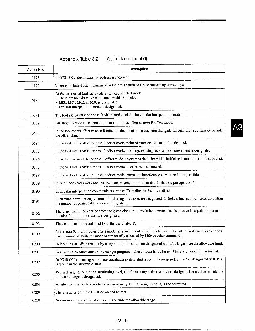
Appendix Table 3.2 Alarm Table (cent’d).—
Alarm No. Description,—
0175 In G70 - G72, designation of address is incorrect..—
0176 There is no hole-bottom command in the designation of a hole-machining canned cycle.
At the start-up of tool radius offset or nose R offset mode,
0180● There are no axis move commands within 3 blocks.● MOO, MO1, M02, or M30 is designated.● Circular interpolation mode is designated.
0181 The tool radius offset or nose R offset mode ends in the circular interpolation mode.
0182 An illegal G code is designated in the tool radius offset or nose R offset mode.
0183In the tool radius offset or nose R offset mode, offset plane has been changed. Circular arc ~sdesignated outsidethe offset plane.
0184 In the tool radius offset or nose R offset mode, point of intersection cannot be obtained.
0185 In the tool radius offset or nose R offset mode, the shape causing reversed tool movement is designated.
0186 In the tool radius offset or nose R offset mode, a system variable for which buffering is not a lowed is designated.
0187 In the tool radius offset or nose R offset mode, interference is detected.
0188 In the tool radius offset or nose R offset mode, automatic interfererree correction is not possible.
0189 Offset mode error (work area has been destroyed, or no output data in data output operation)
0190 In circular interpolation commands, a circle of “O” radius has been specified.
0191In circular interpolation, commands including three axes are designated. In helical interpolt.tion, axes exceedingthe number of controllable axes are designated.
0192The plane cannot be defined from the given circular interpolation commands. In circular interpolation, com-mands of four or more axes are designated.
0193 The center cannot be obtained from the designated .R.
0199In the nose R or tool radius offset mode, axis movement commands to cancel the offset mclde such as a cannedcycle command while the mode is temporarily canceled by MOOor other command.
0200 In inputting an offset amount by using a program, a number designated with P is larger thao the allowable limit.
0201 In inputting an offset amount by using a program, clffset amount is too large. There is an error in the format.
0202In “G1O Q2° (inputting workpiece coordinate system shift amount by program), a number designated with P islarger than the allowable limit.
0203When changing the cutting monitoring level, all of ]necessary addresses are not designated or a value outside theallowable range is designated.
0204 An attempt was made to write a command using GI O although writing is not permitted.—
0209 There is an error in tbe G301 command format.
0210 In user macro, the value of constant is outside the allowable range.
A3-5

Appendix Table 3.2 Alarm Table (cent’d)
I Alarm No. j Description I
I 0211 I llerr.rnberofcancel codes for G67is too many. II 0212 There is an error in the format.
I 0213 I A value not defined as a variable number is used. I
I 0214 I A variable used in replace statement is the variable which cannot be used forthis operation, II 0215 I The nesting level of”[ ]“ exceeds the allowable limit. I
0216 The nesting level of microprogram call exceeds the allowable limit.
0217 DO - END is not used in pairs.
0218 The numbers of brackets “[” and “]” do not agree with each other.
0219 In “DO M“, 1 S m S 3 is not satisfied. a
I 0220 I In “GOTO n“, “n” isoutside the allowable range or’<n” is not found. I
I 0221 I In a microprogram, division by ‘TY’isexecuted. I
I 0222 I Square root of anegative value I
I 0223 I Floating point data exceeds the allowable range. I
I 0224 I In modal call (G66), axis command is specified with M99 return designation. I0225 Overflow has occurred with operation stack.
0226 Execution of the following functions was impossible: ASIN, ACOS, LN, SQRT
0227 Overflow has occurred during conversion into integer.
0228 Overflow has occurred with the input data for the BCD function.
0229 \ There is an error in the format of the BIN function. I0230 Overflow has occurred as the result of execution of the EXP function.
0240 Reference point return has not been completed with the axis for which G29, G30 is designated.
0241 Reference point return is invalid for the axis for which G28 is designated.
0242 The G28 automatic coordinate system setting is invalid for a linear axis.
0250 An illegal code has been designated in a solid tap program.
0255 A C command is designated for the spindle in the spindle control mode.
0256 An S command is designated for the spindle in the C-axis control mode.
0260● There is no P or Q command in the M98 block.● There is no P command in the G65/G66 block.
0261 Nesting level of M98 subprogram call exceeds the allowable limit.
A3-6

Appendix Table 3.2 Alarm Table (cent’d)
Alarm No. Description
0262In a program that calls a microprogram by G, M, or T code (M98, M99, G65, G66), the designated programnumber or scquerree number is not found.
0263 ~ attempt was made to start a program by executing address search after buffering subprogram or macro call.
0281 There is an error in address word designation format in the Gill cotnmand block.
0282 Angle designation made by A and Bin the Gill block is outside the allowable range of –350° S A, B S 360°
The first chamfering area is
0283● Outside tbe rectangle defined by the start and encl points.● Outside the range between the 45° line from the start point toward the end point and [ha: from the end point
toward the start point.
0284 The shape defined by the Gill block is erroneous.
0285 M, S, and/or T is designated in the Gill/Gl12 block.
0286 There is an error in address word designation format in the G112 command block.
0287 The shape defined by the G112 block is erroneous.
0290 A sequence number is not found at the restart of the program.
0291The operation that changes the coordinate system is executed at the restart of the program.(G50/G92, tool setting up, or ORG operation has been executed in the MDI mode.)
0292 At the restart of the program, an axis was moved by MDI intervention.
0300 In tool registration using G112 macro, T9999 is registered.
0301 There are no tools registered in the designated tool group.
0302 All tools in the designated tool group are in the skipped status.
0305 The tool life control data is not stored in the tool file.—,
0315 The coordinate system setting command is designated in the tool setup mode.
0370 There is no FEZ command in a cutting program.
0371 An E command is designated in the mm/min mode.
0372 An F/E command value is too large.
0380 An axis command is designated in the G04, G40, G21 block.
0381 An axis command is designated in the G1O, G22, G23 block.
0382 More than one area has been selected from No. 3- No. 5 prohibited areas.
0390 An execution program does not exist.
0391 An execution program is being input.
0392 An execution program is being edited.
A3-7

Appendix Table 3,2 Alarm Table (cent’d)
I Alarm No. I Description I
0393 A sequence number that does no exist is designated in M98 Q G25 commands.I
1 0395 Cycle start is executed after changing the mode from tape to memory, or from memmy to tape.1
0397 During tape/direct operation, opemtion interruption that does not allow the re-execution has been carried out.I
0400 An O number of six or more digits is designated.I
0401 An N number of six or more digits is designated.1
I 0402 I AP number of six or more digits is designated.
I 0406 I Before the axis move, the axis is in the stored stroke limit No. 2 area. I
I 0407 I Before the axis move, the axis is in the stored stroke limit No. 3 area. I
I 0408 I Before the axis move, the axis is in the stored stroke limit No. 4 area. I
I 0409 I Before the axis move, theaxisisinthe stored stroke limitNo.5 area. II 0411 I Reference point return has not been completed (Ist-axis). I
I 0412 \ Reference point return has not been completed (2nd-axis). I0413 Reference point return has not been completed (3rd-axis).
1
0414 Reference point return has not been completed (4th-axis).
0415 Reference point return has not been completed (5th-axis).
I 0421 I After the execution of G27, theaxishas not returned tothereferencepoint (lst-axis). I
I 0422 I After the execution of G27, the axis has not returned to the reference point (2nd-axis). I
I 0423 I After the execution of G27, the axis has not returned to the reference point (3rd-axis). II 0424 I After the execution of G27, the axis has not returned to the reference point (4th-axis). I
0425 After the execution of G27, the axis has not returned to the reference point (5th-axis).
0431 Before the axis move, the axis has reached the entry prohibited area (outside) of stored stroke limit (lst-axis)
0432 Before the axis move, the axis has reached the entry prohibited area (outside) of stored stroke limit (2nd-axis)
0433 Before the axis move, the axis has reached the entry prohibited area (outside) of stored stroke limit (3rd-axis)
0434 Before the axis move, the axis has reached the entry prohibited area (outside) of stored stroke limit (4th-axis)
0435 Before the axis move, the axis has reached the entry prohibited area (outside) of stored stroke limit (5th-axis)
0440 There is a discrepancy in angle designation in the GO1 linear interpolation operation (angle designation).
0445There is an error in I, ~ and R designation in chamfering or rounding, or the value set for I, K, and R is toolarge.
0446 In chamfering or rounding, the commands in the designated block constitute a taper.
A3-8

Appendix Table 3.2 Alarm Table (cent’d),—
Alarm No. Description
0450The lead variation amount in the G34 thread cutting operation is greater than the allowable Inaximum value, or avalue that causes the lead to have a negative value is designated.
,—
0451 Chamfering or rounding is designated in a thread cutting block.—.—
0452 Thread cutting block is designated in the mm/min mode.
0453 The value set for B in multiple-thread cutting commands is outside the allowable range.
0454In thread cutting with thread chamfering, the chamfering amount in the direction of the chamfering axis is small-er than the value set for a parameter, orchamfering amount is’’O”in the G92 mode operation.
0455 Cutting time used for executing commands in one block is too short in continuous thread cutting operation.
0460 In the G90, G92, and G94 blocks, an address that must not be designated is designated.
0461 There is no P or Q command in the G70 - G73 blocks.
0462 The sequence number designated by P or Q command in the G70 - G73 blocks cannot be found.
0463The number of blocks defining the finishing shape which are designated by P or Q comma Id in the G70 - G73blocks is too many.
0464 The finishing shape commands for the G70 - G73 c:ycles include G and/or M codes that must not be designated.
0465The mode of last movement designated in the definition of finishing shape for G70 - G73 cicle is chamfering orrounding.
0466 There is an error in the finish shape for G70/G71 cycle.
0467 Thevalue set for Dinthe G73block is``O'', or``128'' or greater. Orboth Iand Kinthe G73blockare’’O”.
0468 The value set for D and Kin the G76 block is outside the allowable range.
0469In rough turning cycle of G71, G72 R1 command, four or more operation interrupted poin :s are included in thefinishing shape program.
.—
0470In the tape mode operation, the information of the Mock designated by P or Q in the G70 thock is not stored inthe internal memory.
0471In the G70 - G76 block, an address that must not be designated is used or aIl necessary adtlresses are not desig-nated.
0472 There is an error in the shape for G70/G71 cycle.
0480 There is an error in the cylindrical interpolation commands.
0481 In the cylindrical interpolation mode, a command that cannot be executed is designated.
0482 There is an error in the polar coordinate interpolation commands.
0483 In the polar coordinate interpolation, a command that cannot be executed is designated..—
0491 In the G31 block, skip signal (1) has not been input.
0494 When G31 is executed, the skip signal (1) is not ready.
A3-9
.-. ..———. .—.. ——. —

——
——
——
80C-4
-cl’
0CN
02

Appendix Table 3.2 Alarm Table (cent’d)
Alarm No. Description
2015 Axis has reached the stored stroke limit No. 1 area (5th-axis). +
I 2021 I Axis has reached the outside of the stored stroke limit No. 2 area (Ist-axis). I2022 Axis has reached the outside of the stored stroke limit No. 2 area (2nd-axis).
I 2023 I Axis hasreachedtheoutside of the stored stroke limit No. 2area (3rd-axis). I2024 Axis has reached the outside of the stored stroke limit No. 3 area (lst-axis).
1
2025 Axis has reached the outside of the stored stroke limit No. 3 area (2nd-axis).1 —---!
1- 2026 Axis has reached the outside of the stored stroke limit No. 3 area (3rcI-axis).1 —------l
2027 Axis has reached the outside of the stored stroke limit No. 4 area (lsl-axis).—--2
2028 Axis has reached the outside of the stored stroke limit No. 4 area (2nd-axis).1 —J
2029 Axis has reached the outside of the stored stroke limit No. 4 area (3rd-axis).I J
I 2031 I Axis has reached the outside of the stored stroke limit No. 5 area (lst-axis). I
I 2032 I Axis has reached the outside of the stored stroke limit No. 5 area (2nd-axis). II 2033 \ Axis has reached the outside of the stored stroke limit No. 5 area (3rd-axis). I
2040 Axis has reached the inside of the stored stroke limit No. 2 area.
I 2041 I Axis has reached the inside of the stored stroke limit No. 3 area. I
I 2042 Axis has reached the inside of the stored stroke Iimi t No. 4 area.! ----1
2043 Axis has reached the inside of the stored stroke limit No. 5 area.1 —----!
I 2061 I Reference point return area error has occurred (lst-axis). I
2062 Reference point return area error has occurred (2nd-axis).1 .—J
2063 Reference point return area error has occurred (3rd-axis).--.-1
2064 Reference point return area error has occurred (4th-axis).I ---1
2065 Reference point return area error has occurred (5th-axis).I —4
2071 Reference point return position error has occurred (Ist-axis)..__l
2072 Reference point return position error has occurred (2nd-axis).1 —----l
2073 Reference point return position error has occurred (3rd-axis).1 —------l
2074 Reference point return position error has occurred (4th-axis).I —----1
2075 Reference point return position error has occurred (5th-axis).I —-----l
I 2081In reference point return, the deceleration LS is turned OFF after it has been turned ON once and then turned ONagain (lst-axis).
A3-11
.- ——— ... .—. ..- .— ._ —-—...

Appendix Table 3.2 Alarm Table (cent’d)
I Alarm No. Description IIn reference point return, the deceleration LS is turned OFF after it has been turned ON once and then turned ONagain (2nd-axis).I 2082
In reference point return, the deceleration L,S is turned OFF after it has been turned ON once and then turned ONagain (3rd-axis).I 2083
In reference point return, the deceleration L.S is turned OFF after it has been turned ON once and then turned ONagain (4th-axis).I 2084
In reference point return, the deceleration L.S is turned OFF after it has been turned ON once and then turned ONagain (5th-axis).
According to the parameter setting, retraction operation must be made in reference point return operation (lst-axis).
I ~085
f--
2091
—
2092According to the parameter setting, retraction operation must be made in reference point return operation (2nd-axis). IAccording to the parameter setting, retraction operation must be made in reference point return operation (3rd-axis).
+
According to the parameter setting, retraction operation must be made in reference point relurn operation (4th-axis).
I 2093
I 2094
According to the parameter setting, retraction operation must be made in reference point return operation (5th-axis).
P-SET error has occurred (lst-axis). I
I 2095
I 2101
I 2102 P-SET error has occurred (2nd-axis). II 2103 P-SET error has occurred (3rd-axis). I
E---=--P-SET error has occurred (4th-axis). IP-SET error has occurred (5th-axis).
Absolute position overflow has occurred with the absolute position detection function(lst-axis). II 2111
Absolute position overflow has occurred with the absolute position detection function(2nd-axis).
Absolute position overflow has occurred with the absolute position detection function(3rd-axis). +
I 2112
F------2113
2114Absolute position overflow has occurred with the absolute position detection function
(4th-axis). IAbsolute position overflow has occurred with the absolute position detection function(5th-axis).
There is no battery mounted on the AXES board (lst-axis).
There is no battery mounted on the AXIS board (2nd-axis).
I 2115
I 2123 There is no battery mounted on the AXIS board (3rd-axis), I
A3-12

Appendix Table 3.2 Alarm Table [cent’d)
Alarm No. Description
2124 There is no battery mounted on the AXIS board (4th-axis)..—
2125 There is no battery mounted on the AXIS board (5th-axis)..—
2131Difference in axis positions between the position at the previous power off and the position at the stint-up of theabsolute position detection function is excessively large (Ist-axis).
2132Difference in axis positions between the position at the previous power off and the position at the start-up of theabsolute position detection function is excessively large (2nd-axis).
2133Difference in axis positions between the position at the previous power off and the position at the stwt-up of theabsolute position detection function is excessive y 1arge (3rd-axis).
—
2134Difference in axis positions between the position at the previous power off and the position at the start-up of theabsolute position detection function is excessive] y 1arge (4th-axis).
3000 Servo power is not turned on.
3001 The control is not ready.
3002 NC has entered the emergency stop state.
3010 The memory used to store machining programs has not been initialized..—
3011In initialization processing, expansion memory for fstoring machining programs and the memory after power ondo not match.
.—
3012Axis configuration setting parameters do not agree with the physical axis configuration, or the specified option isnot available.
3013 YENET station number parameter setting error has occurred.
3021 Fuse is blown (lst-axis).
3022 Fuse is blown (2nd-axis).
3023 Fuse is blown (3rd-axis).
3024 Fuse is blown (4th-axis)..—
3025 Fuse is blown (5th-axis).
3041 Excessively large deviation error (lst-axis).—
3042 Excessively large deviation error (2nd-axis)
3043 Excessively large deviation error (3rd-axis)
3044 Excessively large deviation error (4th-axis)
3045 Excessively large deviation error (5th-axis).—
3051 Excessively large deviation error (No. 1 spindle)
3052 Excessively large deviation error (No. 2 spindle).—
3060 Overload (other than servo axis)
A3-13
. ..—.. —. ——._—_.. ,.— ... .——. . .. .. . . . .

Appendix Table 3.2 Alarm Table (cent’ci)
I AkmnNo. I Description I
I 3061 IOverload (lst-axis) I
I 3062 Overload (2nd-axis)I
3063 Overload (3rd-axis)!
3064 Overload (4th-axis)
3065 Overload (5th-axis)
I 3071 \ Collision of the axis has been detected (Ist-axis) II 3072 I Collision of the axis has been detected (2nd-axis). I
I 3073 I Collision of the axis has been detected (3rd-axis). II 3074 I Collision of theaxis has been detected (4th-axis). I
I 3075 I Collision of theaxishas been detected (5th-axis). I
I 3081 I Disconnection in PGwiring(lst-axis) II 3082 1D“lsconnection in PG wiring (2nd-axis) II 3083 I Disconnection in PG wiring (3rd-axis] I
~~Disconnection in PG wiring (4th-axis)
–d
I 3085 \ Disconnection in PG wiring (5th-axis) I
I 3091 \ Disconnection in PG wiring (No. 1 spindle) II 3092 I Disconnection in PG wiring (No. 2 spindle’) II 3100 \ YENET1200 drive error has occurred I
3101 Servopack error has occurred (lst-axis).
I 3102 I Servopack error has occurred (2nd-axis). I3103 Servopack error has occurred (3rd-axis).
3104 Servopack error has occurred (4th-axis).
I 3105 I Servopack error has occurred (5th-axis). I
I 3111 I Servopack communication error has occurred (lst-axis). I
I 3112 I Servopack communication error has occurred (2nd-axis). I
I 3113 I Servopack corrrrnunication error trasoccurred (3rd-axis). I
I 3114 \ Servopack communication error has occurred (4th-axis). I
I 3115 I Sei-vopack communication error has occurred (5th-axis). I3121 I Over-speed has been detected (Ist-axis), I
A3-14

Appendix Table 3.2 Alarm Table (cent’d)
Alarm No. Description,—
3122 Over-speed has been detected (2nd-axis). -1
I 3123 I Over-speed has been detected (3rd-axis). II 3124 I Over-speed has been detected (4th-axis). I
3125 Over-speed has been detected (5th-axis).I
3131 Serial communication error has occurred in the communication with the inverter (No. 1 spi fldle)..—l
3132 Serial communication error has occurred in the communication with the inverter (No. 2 spi ndle).1 --l
3141 Overrun is detected with the servo controlled axis (1.st-axis).1 -4
3142 Overrun is detected with the servo controlled axis (2nd-axis).1 —--4
3143 Overrun is detected with the servo controlled axis (3rd-axis).1 —4
3144 Overrun is detected with the servo controlled axis (~ith-axis).——1 -1
3145 Overrun is detected with the servo controlled axis (5th-axis).1 —4
3151 Phase detection error has occurred (lst-axis)I
I 3152 I Phase detection error has occurred (2nd-axis) I
I 3153 I Phase detection error has occurred (3rd-axis) II 3154 I Phase detection error has occurred (4th-axis) II 3155 I Phase detection error hasoccurred (5th-axis) I
3161 Malfunctioning is detected with the absolute encoder (lst-axis).1 J
3162 Malfunctioning is detected with the absolute encodtr (2nd-axis).1 —------l
3163 Malfunctioning is detected with the absolute encoder (3rd-axis).1 —d
3164 Malfunctioning is detected with the absolute encoder (4th-axis).1 --l
3165 Malfunctioning is detected with the absolute encoder (5th-axis).I -4
3181 Malfunctioning is detected with the PG counter of the absolute encoder (lst-axis).
3182 Malfunctioning is detected with the PG counter of the absolute encoder (2nd-axis). I
I 3183 I Malfunctioning is detected with the PG counter of the absolute encoder (3rd-axis). I3184 Malfunctioning is detected with the PG counter of the absolute encoder (4th-axis).
3185 I Malfunctioning is detected with the PGcounter of theabsoluteencoder (5th-axis). I
3191 I An error has occurred in the reduction of fraction processing for gear ratio (Ist-axis). I3192 An error has occurred in the reduction of fraction processing for gear ratio (2nd-axis).
1 —d3193 An error has occurred in tbe reduction of fraction processing for gear ratio (3rd-axis).
.—–d
A3-15
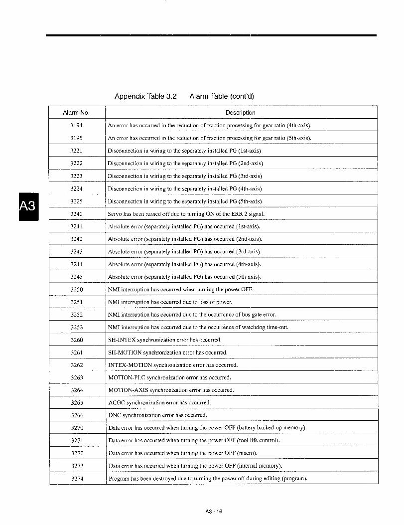
Appendix Table 3.2 Alarm Table (cent’d)
Alarm No. I Descriptioni
3194 I An error has occurred in the reduction of fraction processing for gear ratio (4th-axis).
I 3195 ~An error has oeeurred in the reduction of fraction processing for gear ratio (5th-axis). I
I 3221 ~Disconnection in wiring to the separately installed PG (Ist-axis) I
I 3222 ~Disconnection in wiring to the separately i nstalled PG (2nd-axis) II 3223 I Disconnection in wiring tothe separately installed PG@d-axis) II 3224 I Disconnection in wiring to the separately imtalled PG (4th-axis) I
I
3225 ~Disconnection in wiring to the separately installed PG (5th-axis),
3240 I Servo has been turned off due to turning ON of the ERR 2 signal.)
I 3241 I Absolute error (separately installed PG) has occurred (Ist-axis). I
I 3242 I Absolute error (separately installed PG) has occurred (2nd-axis). I
I 3243 I Absolute error (separately installed PG) has occurred (3rd-axis). II 3244 I Absolute error (separately installed PG) has occurred (4th-axis). I
I 3245 I Absolute error (separately installed PG) has occurred (5th-axis). II 3250 I NMI interruption has occurred when turning the power OFF. I
I 3251 NMI interruption has occurred due to loss of power.I
3252 1NMI interruption has occurred due to the occurrence of bus gate error.I
3253 NMI interruption has occurred due to the occurrence of watchdog time-out.I
3260 SH-INTEX synchronization error has occurred.I
3261 ~SH-MOTION synchronization error has occurred.I
3262 INTEX-MO’HON synchronization error has occurred.I
3263 MOTION-PLC synchronization error has occurred.I
3264 MOTION-AXIS synchronization error has occurred.I
3265 ACGC synchronization error has occurred.I
3266 DNC synchronization error has occurred.i
3270 Data error has occurred when turning the power OFF (battery backed-up memory).1
3271 Data error has occurred when turning the power OFF (tool life control).[
3272 Data error has occurred when turning the power OFF (macro).1
3273 Data error has occurred when turning the power OFF (internal memory).I
I 3274 I Program has been destroyed due to turning thepower off during editing (program). I
A3 -16

Appendix Table 3.2 Alarm Table (cent’d)
Alarm No. Description
Dataerror has occurred when turning the power OFFduringediting (custom variables). ‘+
The power has been turned OFF during editing. This requires the program to be checked afler turning the powerON.
.------1I 3276
Time-out of the YENET1200 command (Ist-axis)I 3281
Time-out of the YENET1200 command (2nd-axis)—4
I 3282
I 3283 Time-out of the YENET1200 command (3rd-axis)
Time-out of the YENET1200 command (4th-axis) +
=
3284
3285
3291
Time-out of the YENET1200 command (5th-axis) ITime-out of the YENET1200 command (No. 1 spindle) I
Time-out of the YENET1200 command (No. 2 spindle) I
I 3299 Communication error has occurred in YENET1200 (1/0). I
Excessively large current is supplied to the Servopack main circuit ( lst-axis). I
t---=- Excessively large current is supplied to the Servopack main circuit (2nd-axis).—---l
Excessively large current is supplied to the Servopack main circuit (3rd-axis).—----1
I 3303
Excessively large current is supplied to the Servopack main circuit (4th-axis).,—4
I 3304
Excessively large current is supplied to the Servopack main circuit (5th-axis). -4I 3305
DC voltage in the Servopack main circuit is abnormally high (lst-axis).—4
I 3331
>
3332
3333
3334
DC voltage in the Servopack main circuit is abnormally high (2nd-axis). IDC voltage in the Servopack main circuit is abnormally high (3rd-axis). I
DC voltage in the Servopack main circuit is abnormally high (4th-axis). IDC voltage in the Servopack main circuit is abnormally high (5th-axis). I
t--=--- Heat sink in the Servopack has been overheated (lst-axis). I
Heat sink in the Servopack has been overheated (2nd-axis). II 3352
I 3353 Heat sink in the Servopack has been overheated (3rd-axis).—-4
Heat sink in the Servopack has been overheated (4th-axis). —4I 3354
Heat sink in the Servopack has been overheated (5th-axis).I 3355
YENET1200 communication error (lst-axis)-4
>
3382
3383
3384
YENET1200 communication error (2nd-axis) I
YENET1200 communication error (3rd-axis) IYENET1200 communication error (4th-axis) I
A3-17

Appendix Table 3,2 Alarm ‘Table (cent’d)
Alarm No. Description
3385 YENET1200 communication error (5th-axis)
I 3391 I YENET1200 communication error (No. I spindle) II 3392 I YENET1200 communication error (No. 2 spindle) II 3395 I Converter error II 3401 I Converter error (lst-axis) II 3402 I Converter error(2nd-axis) II 3403 I Converter error(3rd-axis) II 3404 I Converter error (4th-axis) II 3405 I Converter e.rror (5th-axis) I
I 3414 \ Servo unit error (4th-axis) I
I 3415 I Servo unit error (5th-axis) II 3421 I Inverter unit error II 3425 I YENET 1200 watchdogermr (No. 1 spindle) II 3426 I YENET 1200 watchdogerror (No. 2spind!e) I
3431 YENET 1200 watchdog error (lst-axis)
~+
YENET 1200 watchdog error (2nd-axis)
YENET 1200 watchdog error (3rd-axis)
YENET 1200 watchdog error (4th-axis)
I 3435 I YENET 1200 watchdog error (5th-axis) II 3441 I Grounding fault (lst-axis) II 3442 I Grounding fault (2nd-axis) II 3443 I Grounding fault (3rd-axis) I
3444 Grounding fault (4th-axis)1
3445 Grounding fault (5th-axis)1
I 3451 I Follow-up error (lst-axis) I
I 3452 I Foliow-upe.rror (2nd-axis) I
A3 -18

Appendix Table 3.2 Alarm Table (cent’d)
I
Alarm No. Description,—
3453 Follow-up error (3rd-axis) +
I 3454 I Follow-up error (4th-axis) I
I 3455 I Follow-up error (5th-axis) I
I 3461 I There is an error in motor code setting (lst-axis) I
I 3462 I There isanerrorin rnotorcodesetting (2nd-axis) II 3463 I There is an error in motor code setting (3rd-axis) I
3464 There is an error in motor code setting (4th-axis)1 —d
3465 There is an error in motor code setting (5th-axis)I —-------l
I 8001 I RAM check error has occurred. I
I 9010 I TH parity has occurred. I
I 9011 I TV parity has occurred. I9012 In RS-232C communications, an illegal character (not conforming to EIA or 1S0) is detec[ed. I
I 9013 I In RS-232C communications, one block capacity (128 characters) hw been exceeded. I
I 9014 I In RS-232C communications, there is no response of data set ready signal. I
I 9015 I Overflow has occurred with the input numerical value (more than 9 characters). I
1 9016 In RS-232C communications, interface panty error has occurred.1 —J
90171 —d
In RS-232C communications, interface overrun has occurred. (protocol setting error or transmission error)
9018 There is an error in RS-232C interface line selection..—1 —1
9019 Framing error has occurred (stop bit setting error or transmission error).1 —----1
9020 The designated line has already been opened.
9021 The designated line has not been opened.d——
1 9022 Double-call or combination is incorrect.I —J
9023 Data has not been sent within the specified length of time.I —----1
9024 Send or receive processing is not executed,I —1
9025 I There is an error in the designated parameter. I
A3-19
——- .

INDEX
In Appendix 4, technical terms specific to NC ancl J300L are
arranged in alphabetical order.
Please use this index when looking for descriptions using the
technical term as the key code.
A4-1

A
Absolute Error.............,.,,,,,, . . . . . . . . . . . 9-19AbsolutePosition Error . . . . . . . . . . . . . 9-19ActiorrKeys....,,.,.,,...,,.,.. 3-13Address Keys...,,.,.........,,,,,, 3-12AddressSearch .,, , ., . ., .,,.,.... 6-6ALARMDISPLAYJOB . . . . . . . . . . . . . 7-10Alarm Function . . . . . . . . . . ,., ,. .,. 7-IOAlarmTable . . . . . . . . . . . . . . . . . . . . . . . . . . . A3-3Alarms Not[ndicated by Alarm Numbers 9-23Arrangementof Batteryand IndicatorLamp (LED) 2-13
Automatic Handle Mode Offset,.,,. . . . . . . . . 2-37
AUTOMATIC OPERATION ..,...... . . . . . . . . . . . . . . . . . 2-24.2-31
AUTOMATIC OPERATIONS . . . . . . . . 2-40
AUX Key . . . . . . . . . . . . . . . . . . . . . . . . . . . . . . . . . . . . . . . . . . . ...3-14
Auxiliary Function Lock . . . . . . . . . . . . . . . . . . . . . . . . . . . . . . . ...2-33
Axis Variable Data, . . . . . . . . . . . . . . . . . . . . . . . . . . . . . . . . . . . .. A202O
B
Background Reset Function . . . . . . . . 8-14
BG Reset 4-60
Broken PG Cable, ,,, . . . . . . . . . . . . 9-18
Buzzer Function . . . . . . . . . . . . . . . . . . . . 3-22
cCalendar Function, ,,, .,, . ., . ., . .,, ., . . . . . . . . . . . . . . . . ...7 .14
Calling a Part Program . . . . . . . . . . . . . . . . . . . . . . . . . . . . . . . .4-4.4-33
Cause of Alarm and Corrective Action 9-6
Checking the Motors for Abnormalities. 2-10
Checking the NChrformation .,,.,,.,. .,, .,,.............,,.9-3
Checking the Status of Troubles 9-2
CLASSIFICATION OF ALARMS . . . . . . . . . . . . . . . . . . . . . . . . . .. A3-2
CLASSIFICATION OF THE PARAMETERS A2-2
Clearing the Offset Data . . . . . . . . . . . 5-4
Clearing the Workpiece Coordinate System Shift Amount ., 5-6
CNCPart Program Execution Control.. . . . . . . . . . . . . . . . . . .. A1.41-4
Collective Display of Command Values . 6-14
Collective Display of Present Position Data . 7-2
COMMAND VALUE DISPLAY JOB.. 6-14
Control Not Ready .,, . .,, . . . . . . . . . . . . . . . . . . . . . . . . . . . . . ...9-16
Converter Alarm . . . . . . . . . . . . . . . . . . . . ,, 9-21
coordinate system for machining 2-24
Copying a Part PrOgram . . . . . . . . . . . . 4-39
CRT . . . . . . . . . . . . . . . . . . . . . . . . . . . . . . . . . . . . . . . . . . . . . . . . ...3-9
Cursor Keys .,, ., . ., .,, , ., ..,.,... . . . . . . . . . . . . . . . . . . . ...3-13
DData Keys.........,.,...,..,,,. . . . . . . . . . . . . . . . . ...3-12
Deleting a Part Program,....,.,,, . . . . . . . . . . . . . 4-23.4-35
Deleting an MDI Program 6-13
Display of Alarm Information, ,, .,. . . . . . . . . . . . . . . . . . . . . . . ...9-5
Display of Present Position Data in theExterna lCoordinat eValue s,,.,,..,.. 7.5
Display of Present Position Data in theWorkpiece Coordinate System . . . . . . 7-4
Display of Remaining Distance.,..,.. . . . . . . . . . . . 7-6
Display of Subprogram Nesting Information . ., ., ., ., 6-10
Display of the Directory of Part Programs . . . . . . . . . . . . . . 4-26
Displaying the ON/OFF Status of the 1/0 Signals 8-8
Displaying the ON/OFF Status of the Selected 1/0 Signals 8-9
Display ingthe Tool Life Control Data . . . . . . . . . . . . . 5-7
Dry Run...................,.,,.. . . . . . . . . . . . . 2-32
E
Editing a Part PrOgram . ., ..,..,.,, . . . . . . . 4-7
&fiting an MDI Program, ..,....., . . . . . . . 6-11
Editing the Part Program Stored in Memory . . . . . . 6-7
S-inch Take- up Reel, . . . . . . . . . . . . . . . . . . 2-7
Entry ofan MDI Program . . . . . . . . . . . . . . . . 6-11
Erasing the Tool Life Control Data.. 5-10
Error Pulse Display Function,,.,,., . . . . . . . . . . 7-9
Excessive Follow-up Error . . . . . . . . . 9-17
Excessive Speed . . . . . . . . . . . . . . . . . . . 9-18
Execution ofa Part Program . . . . . . . . . . 6-9
Execution ofan MDI Program . . . . . . 6-12
F
G
GENERAL FLOW OF OPERATION . . . 2-3
Ground Fault.........,,.,,,,,.. . . . . . . . . . . . . . . . . . . . . . ...9-21
HHandle Feed . . . . . . . . . . . . . . . . . . . . . . 2-17
Heat Sink Overheat . . . . . . . . . . . . . . . . . .,,.,,,...,..,.,.,,, 9.20
High Temperature . . . . . . . . . . . . . . . . 9-13
high -speed reference point return ,, . . . . . . . . . . . . . . . . . . . . 2-18.2-21
I
l/O Device Setting Function, .,..,..., 8-14
I/O MONITORING JOB . . . . . . . . . . . . . . . . . . . . . . . . . . . . . . . . ...8-8
INPUT SIGNALS (PLC+ NC) . . . . . . . . . . . . . . . . . . . . . . . . . . .. A1-2
input/output and Verify Function,,,. 8-12
INPUT/OUTPUT AND VERIFY JOB.. 8-12
A4-2

Inputting a Part Program . . . . . . . . . . ., . . . . . . . . . . . . . . . . . . . ...4-40
inspection of the Battery . . . . . . . . . . . . . . . . . . . . . . . . . . . . . . . ...2-12
Inspection of the NC Unit .,..,.... . . . . . . . . . . . . . . . . . . . . . . ...2-6
Inspection of the Tape Reader . . . . . . . . . . . . . . . . . . . . . . . . . . . . . . . 2-7
INTERNALIN FORMATIONJO B.... . . . . . . . . . . . . . . . . . . . ...8-15
Internal Switch’Function . . . . . . . . . . . . . . . . . . . . . . . . . . . . . . . ...6-15
lnverter Alarm . . . . . . . . . . . . . . . . . . . . . . . . . . . . . . . . . . . . . . . ...9-19
lnverter Unit Alarm . . . . . . . . . . . . . . . . . . . . . . . . . . . . . . . . . . . ...9-21
J
K
Key Memory Function . . . . . . . . . . . . . . . . . . . . . . . . . 8-16
M
Machine Lock . . . . . . . . . . . . . . . . . . . 2-33
Macro Variable Function . . . . . . . . . . . . . . . . . . . . . . . 6-17
MAINTENANCE DATA . . . . . . . . . . . . 9-2
Manual Absolute . . . . . . . . . . . . . . . . . . . . . . . . . . . . . . . . . . . . . ...2-38
MANUAL OPERATION . . . . . . . . . . . . . . . . . . . . . . . . . . . ..2- 15.2-1S
Manual Operation Intervention during Automatic Operation 2-35
Manual Rapid Traverse . . . . . . . . . . . . . . . . . . . . 2-15
Manual Reference Point Return . . . . . . . . . . . . . . . . . . . 2-19
Manual Reference Point Return to theSecond Reference Point . . . . . . . . . . . . . . . . . . . . . . . . . . 2-22
MDI Operation . . . . . . . . . . . . . . . . . . . . . . . . . . . . . . . . . . 2-27
MDI Operation Intervention during Automatic Operation 2-36
MD1 OPERATION JOB . . . . . . . . . . . . . 6-11
Memory Dump Function . . . . . . . . . . . . 8-16
Memory Operation . . . . . . . . . . . . . . . . . 2-26
N
NC OPERATION PANEL . . . . . . . . . . . . . . . . . . . . . . . 3-8
NC Part Program Execution Control . . . . . . . . . . . . . . . . . . . . . . .. A1 -12
NC System Software . . . . . . . . . . . . . . . . . . . . . 9-4
9-inch Graphic Display . . . . . . . . . . . . . . . . . . . . . . . . 3-9
No.2 Spindle Control ., . . . . . . . . . . . . . . . . . . . . . . . . . .. A1 -8. AI-18
Normal Display on CRT Screen . . . . . . . . . . . . . . . . . . . . 3-IS
number ofactually used characters . . . . . . . . . . . . . . . 4-27
rrumerical setting up . . . . . . . . . . . . 7-9
0I-line MDI, . . . . . . . . . . . . . . . . . . . . 2-23
Operating Time Function . . . . . . . . . . . . . . . . . . 7-15
OPER,WION INTERVENTION DURINGAUTOMATIC OPERATION . . . . . . . . . . . . . . . . . . . . . . . 2-35
Operation Mode Control Signals . . . . . . . . . . . . . . . . . . . .. A1-2. AI-10
OPERATIO NSTEP S. . . . . . . . . . . . . . . 3-2
Optional Block Skip . . . . . . . . . . . . . . 2-31
optimralblocks kipBfllnction . . . . . . . ... . . . . . 2.32OptionalStop . . . . . . . . . . . . . . . . . . . . . 2-31OUTPUTSIGNALS(N!CPLC) . . . . . . . . . . . .. A1 -10Outputtin gaPartPrOgra m. . . . . . . . 4-44OverCurrent . . . . . . . . . . . . . . . . . . . . . . 9-20Over Voltage, . . . . . . . . . . . . . . . . . . . . . 9-20Overload. . . . . . . . . . . . . . . . . . . . . . . . . . 9-17Override . . . . . . . . . . . . . . . . . . . . . . . . . . 2-29OverrunPrevention 9-18
P
P-SIZTError . . . . . . . . . . . . . . . . . . . . . . . 9-15Page Keys . . . . . . . . . . . . . . . . . . . . . . . . . . . . . . . . . . 3-12ParameterFunction 8-3PARAMETERJOB 8-3Par~.meterTable . . . . . . . . . . . . . . . . . . . . . . . . . . . . . . . .. A2-3Parity Error . . . . . . . . . . . . . . . . . . . . 9-7
PAR.TPROGRAMDIRf3~ORY JOB.. 4-26PAi7TPROGRAMEDITJOB . . . . . . . . . . 4-3PAR.TPROGRAMINPUT/OUTPUTAND VERIFYJOB 4-40
Pha:;e Detection Error . . . . . . . . . . . . . 9-19
Pitch Error Function......,...,.. 8-7
Pop-up Menu . . . . . . . . . . . . . . . . . . . . . 3-20
POWER ON/OFF Button s . . . . . . . . . . . . . . . . . 3-8
Preparation before Turning the Power ON 2-8Preparationof AutomaticOperation 2-24PRESENTPOSITIONOATACONTROLJOB 7-2Procedurefor Turningthe PowerOFF.. ,, 2-11Procedurefor Turningthe PowerON. 2-9ProcessKeys 3-10PrOcessScreens . . . . . . . . . . . . . . . . 3-3ProgramInformationDisplayedon Screen 6-3PROGRAMJOB..,............,,, ,.. ,. . 6-3ProgramNumberSearch 6-4ProgramRestart . . . . . . . . . . . . . . . . . . . 2-43
R
RAPID . . . . . . . . . . . . . . . . . . . . . . . . . . 2-15
Rapid Traverse Override 2-30
Reference Point . . . . . . . . . . . . . . . . . 2-19
Reference Point Return Area Error . 9-14
Reference Point Return Position Error ., ., 9-14
Renaming a Part Program . . . . . . . . . . . . . . . 4-37
RES,ET Key . . . . . . . . . . . . . . . . . . . . . . ,, 3.14
Return to the Operation Interrupted Point 2-40
Retarnto the Setup Point.......,.. 2-40
RS-232C Communications Parameters ., 4-55
RS-232C Error..,,.,...,..,..,.. . . . . . . . . 9-8
RS-232C Interface Troubleshooting Flowchart . 9-8
sSaving aPart Program after Editirrg . . . . . . . . . . . . . 4-22
Saving the Present Position Data . . . . . . 2-42
A4-3

sequence number search . . . . . . . . . . . . . . . . . . . . . . . . . . . . .. . . . 6-7
Sequence Parameter Function 8-7
Serial Interface Setting.,.,.,,.,,,,,. ,,, ,, ., . ., . . . . . . . 4-56.9-10
Servo Alarm . . . . . . . . . . . . . . . . . . . . . . 9-18
Servo Alarm Function ,,, ..,,,,,,,,.,,.,..,..,..,,.,,.. 7-11
Servo Axis Control . . . . . . . . . . . . . . . . . . . . . . . . . . . . . . .. A1-5. A1 -14
Servo Axis Control Signals.,,.,,., ,., ... . . . . . . . . . . . . . . . . .. A1-5
Servo Communication Alarm . . . . . . . . 9-18
Servo Power Not Ready . . . . . . . . . . . . . 9-15
Servo Unit Alarm . . . . . . . . . . . . . . . . . 9-21
Setting Function . . . . . . . . . . . . . . . . . . . . . . . . . . . . . . . . . . ...6-19.8-6
SETTING JOB . . . . . . . . . . . . . . . . . . . . 6-15
Setting the Communication Conditions . 4-55
Setting the Coordinate Systems . . . . . 7-7
Setting the Tool Life Control Data... 5-8
SETUP JOB . . . . . . . . . . . . . . . . . . . . . . . 5-2
Soft-keys . . . . . . . . . . . 3-11
Software Switch Function .,.,.,.., . . . . . . . . . . . . . . . . . . . . . ...6-16
Spindle Control . .. A1-7. A1 -17
Step Feed . . . . . . . . . . . . . . . . . . . . . . . . . . . . . . . . . . . . . . . . . . . ...2-16
Storing an MDIPrograrn . . . . . . . . . . . . . 6-13
TTape Reader . . . . . . . . . . . . . . . . . . . . . . . . . . . . . . . . . . . . . . . . . ...9-38
TIME CONTROL JOB . . . . . . . . . . . . . . . : . . . . . . . . . . . . . . . . . . . . 7-13
TOOL LIFE CONTROL JOB . . . . . . . . . . 5-7
Troubleshooting . . . . . . . . . . . . . . . . . . . . . . . . . . . . . . . . . . . . .9-7.9-17
Turning ON/OFF I/O Signals Forcibly 8-11
u
User’s Message Function . . . . . . . . . . . . . 7-12
vVerify ingthe Part Programs . . . . . . . . . . . 4-51
Version Number Function 8-15
wWORKPIECE COORDINATE SYSTEM SHIFT JOB 5-5
Writing the Tool Life Control Data.... . . . . . . . . . . . . . . . . . . . . . ...5-7
Writing the Tool Offset Data . . . . . . . . . . . . . . . . . . . . . . . . . . . . . ...5-2
Writing the Workpiece Coordinate System Shift Amount 5-5
Y
YENET1200 . . . . . . . . . . . . . . . . . . . . . . . . . . . . . . . . . . . . . . 9-17
YENET1200 command time-out . . . . 9-19
YENET1200 Communication Error.... . . . . . . . . . . . . . . . . 9-20
YENET1200 Compatible Inverter Control . . . . . . . . Al -9, Al -19
YENET1200 Watchdog Error . . . . . . . . . . . . . . 9-21
A4-4

YASNAC J300L
OPERATING MANUALTOKYO OFFICE New Pier Takes!ba SOJlh Tower 1-16-1, Ka!gan, M!naiokL, Tokyo 105 Japan
Phone 81:3-5402-4511 Fax 81-3-5402-4580YASKAWA ELECTRIC AMERICA, INC.Chicago-Corporate Headquarters 2942 MacArthur Blvd Nodhbrook, IL 60062-2028, U S APhone 1-847-291-2340 Fax 1-847-498-2430
Chicago-Technical Center 3160 MacArthur Blvd Northbrook, IL 600621917, U S A
Phone 1-847-291-0411 Fax 1-847.291.1018MOTOMAN INC.805 L!berty Lane West Carrollton, OH 45449, U S APhone 1-513-847-6200 Fax 1-513-847-6.277
YASKAWA EL<TRICO DO BRASIL COMERCIO LTDA
Avenida Brlga.de!ro Farla Lima 1664 -5’CJ 504/511, S50 Paulo, BrazilPhone 55-11-815-7723 Fax 55-11-870-3849
YASKAWA ELECTRIC EUROPE GmbH
Am Konberger Hang 2, 65824 Schwalbach, GermanyPhone 49-6196-569-300 Fax 49-6196-888-301
Motoman Robotics AB
Box 504 S38525 Torsas, Sweden
Phone 46-486-10575 Fax 46-486-41410
Motoman Robotec GmbH
KammerfeldstrajL?e 1, 85391 Allershauserl, GermanyPhone 49-8166-900 Fax 49-8166-9039
YASKAWA ELECTRIC UK LTD.
3 Drum Ma ns Park OrchardIon Woods Cumoernaulc Scotland, G68 91D U KPhone 44-1236-735000 Fax 44-1236-458182
YASKAWA ELECTRIC KOREA CORPORATION
%k Nam Bldg 901 188-3, l-Ga Eulpro Joong-Gu Seoul, Korea
phone 822-776-7844 Fax 82-2-753-2639YASKAWA ELECTRIC (SINGAPORE) PTE LTD.151 Lorong Chuan i#04-01, New Tech Pam Sirlgapcre 556741, Singapore
phone 65-282-3003 Fax 65-289-3003
YATEC ENGINEERING CORPORATION
Sher Hs!a. g Tang Sung Chlang Bulldng 10F 146 Sung Chlang Road, Tatpel, Taiwan
Phone 886-2 -563 -OOtO Fax 886.2-567.4677BEIJING OFFICE Room No 301 Of f!ce B.!lcng oi Be!)ng Imernat!onal Club, 21 Ja~guomenwa Avenue BepngPhone 86-10-532-1850 Fax 86-10-532-1851
SHANGHAI OFFICE Room No 8B Wan Zhong Buldlng 1303 Yan An Road (West} Shanghai 200050, CnnaPhone $36-21-6212-1015 Fax 86-21-6212-1326
YASKAWA JASON (HK) COMPANY LIMITEDRm 2916 Honq Kong Plaza, 186-191 Connaught Road West, Hong Koog
Phone 852-2858-3220 Fax 852-2547-5773
TAIPEI OFFICE Shen Hslang Tang Sung Chlang BJlldlng 10F 146 Sung Ch!ang Road Talpet, Tai,vanPhone 886-2.563-0010 Fax 886-2-567-4677
YYASKAWA
100020, China
YASKAWA ELECTRIC CORPORATION
MANUAL NO. TOE-C843-l 3.20
0 Printed in Japan January 1997 97-I 0.3
—.——-—..——..———— ...—