GT Simulator2 Version1 Operating Manual
82
GT Simulator2 Version1 Operating Manual MITSUBISHI Graphic Operation Terminal MELSOFT SW1D5C-GTWK2-E Integrated FA Software
-
Upload
khangminh22 -
Category
Documents
-
view
2 -
download
0
Transcript of GT Simulator2 Version1 Operating Manual

GT Simulator2 Version1
Operating ManualOperating Manual
MITSUBISHI Graphic Operation Terminal
GT Simulator2 Version1
MELSOFT SW1D5C-GTWK2-EIntegrated FA SoftwareSpecifications subject to change without notice.
SW1-GTSIM2-O-E
1D0J01
SH(NA)-080399E-A(0304)MEE
MODEL
MODELCODE
When exported from Japan, this manual does not require application to theMinistry of Economy, Trade and Industry for service transaction permission.
HEAD OFFICE : 1-8-12, OFFICE TOWER Z 14F HARUMI CHUO-KU 104-6212,JAPANNAGOYA WORKS : 1-14 , YADA-MINAMI 5 , HIGASHI-KU, NAGOYA , JAPAN
MONO


A - 1 A - 1
• SAFETY PRECAUTIONS •(Always read these instructions before using this equipment.)
Before using this product, please read this manual and the relevant manuals introduced in this manualcarefully and pay full attention to safety to handle the product correctly.The instructions given in this manual are concerned with this product. For the safety instructions of theprogrammable controller system, please read the CPU module user's manual.In this manual, the safety instructions are ranked as "DANGER" and "CAUTION".
! DANGER
CAUTION!
Indicates that incorrect handling may cause hazardous conditions,resulting in death or severe injury.
Indicates that incorrect handling may cause hazardous conditions, resulting in medium or slight personal injury or physical damage.
Note that the ! CAUTION level may lead to a serious consequence according to the circumstances.Always follow the instructions of both levels because they are important to personal safety.
Please save this manual to make it accessible when required and always forward it to the end user.
[Test Operation Precautions]! DANGER
• GT Simulator2 is designed to simulate the actual GOT to debug created screens. However, wedo not guarantee the operations of the GOT and PLC CPU after debugging.After performing debugging on GT Simulator2, connect the GOT and PLC CPU and performordinary debugging before starting actual operation.Not using the actual GOT and PLC CPU for debugging may result in accidents due to incorrectoutputs or malfunctions.

A - 2 A - 2
Precautions for using this software (important)
1. Memory of the personal computer usedProcessing may be terminated by Windows® on some personal computer models having main memory ofnot more than 32M bytes. Therefore, use them after increasing the main memory to 32M bytes or more.
2. Free space on the hard diskWhile this software is running, free space of at least 50M byte is required on the hard disk.Since free space of 50M byte is required by Windows® as the swap area, Windows® may forciblyterminate the program if that free space is used up while the drawing software is running. Produce asufficient amount of free space on the hard disk before using the drawing software.When GT Simulator2 is used with GX Developer or GX Simulator, free space is required separately.Refer to the GX Developer or GX Simulator Operating Manual (Start up Manual) for the free spacerequired for use of GX Developer or GX Simulator.
3. Instructions for displaying any line other than a continuous line (such as a dotted line) in boldface typeWhen any line other than a continuous line is drawn in boldface type, the personal computer screen maynot display the line type properly. However, it is displayed properly on the GOT and there are no problemsin data.Please understand that it may be different from the actual image during simulation.

A - 3 A - 3
REVISIONS* The manual number is given on the bottom left of the back cover.
Print Date * Manual Number RevisionApr., 2003 SH (NA)-080399E-A First editionAug., 2003 SH (NA)-080399E-B Partial additions
Section 2.2.3, Section 3.3.1, Section 3.3.3, Section 3.4 Partial corrections Section 2.1.2, Section 2.2.2, Section 3.2, Section 5.2, Section 5.2.1,Appendix 1.1
Jan., 2004 SH (NA)-080399E-C Partial additions Section 2.2.3, Section 3.2, Section 3.3.1 Partial corrections Section 2.1.2, Appendix 1.2, Appendix 3 Additions Appendix 2
Jul., 2004 SH (NA)-080399E-D Partial corrections Section 2.1.2, Section 2.2.1, Section 2.2.2, Section 2.2.3, Section 3.3.1,Section 5.2.1, Section 5.6, Section 7.4 MODEL CODE change Changed from 1D0J01 to 1DM209.
Oct., 2004 SH (NA)-080399E-E Partial additions Section 2.2.3 Partial corrections Appendix 3
Japanese Manual Version SH-080353-G
This manual confers no industrial property rights or any rights of any other kind, nor does it confer any patentlicenses. Mitsubishi Electric Corporation cannot be held responsible for any problems involving industrial propertyrights which may occur as a result of using the contents noted in this manual.
2003 MITSUBISHI ELECTRIC CORPORATION

A - 4 A - 4
INTRODUCTION
Thank you for choosing the Mitsubishi Graphic Operation Terminal.Before using the equipment, please read this manual carefully.
CONTENTS
About Manuals ................................................................................................................................................A- 6Abbreviations and generic terms in this manual ............................................................................................A- 7
1. OVERVIEW 1- 1 to 1- 2
1.1 Features .................................................................................................................................................... 1- 1
2. SYSTEM CONFIGURATION 2- 1 to 2- 7
2.1 System Configuration at Installation of GT Simulator2............................................................................ 2- 12.1.1 System configuration.......................................................................................................................... 2- 12.1.2 Operation environment....................................................................................................................... 2- 1
2.2 System Configuration for GT Simulator2 Execution ................................................................................ 2- 32.2.1 System configuration.......................................................................................................................... 2- 32.2.2 Applicable CPUs ................................................................................................................................ 2- 42.2.3 About the converter/cable .................................................................................................................. 2- 5
3. SPECIFICATIONS 3- 1 to 3-16
3.1 Specifications of the GOTs Simulated...................................................................................................... 3- 13.2 Functions that cannot be simulated.......................................................................................................... 3- 13.3 Restrictions on and Instructions for use of GT Simulator2 ...................................................................... 3- 3
3.3.1 Restrictions on and instructions for GT Simulator2........................................................................... 3- 33.3.2 Restrictions on and instructions for GX Simulator ............................................................................ 3- 63.3.3 Restrictions on and instructions for PLC CPU connection ............................................................... 3- 7
3.4 Device Ranges That Can Be Monitored................................................................................................... 3- 8
4. SCREEN CONFIGURATION OF GT SIMULATOR2 4- 1 to 4- 2
4.1 Screen Configuration and Various Tools of GT Simulator2 .................................................................... 4- 14.2 Menu Configuration................................................................................................................................... 4- 2
5. GT SIMULATOR2 OPERATING METHOD 5- 1 to 5- 9
5.1 Simulation Procedure Outline................................................................................................................... 5- 15.2 Option Setting............................................................................................................................................ 5- 3
5.2.1 Description of the option setting dialog box....................................................................................... 5- 45.3 Execution of simulation ............................................................................................................................. 5- 55.4 Opening the Project .................................................................................................................................. 5- 6
5.4.1 Description of the monitor data reading dialog box........................................................................... 5- 75.5 Simulating Operation ................................................................................................................................ 5- 85.6 Exiting from GT Simulator2....................................................................................................................... 5- 9

A - 5 A - 5
6. FUNCTIONS OF GT SIMULATOR2 6- 1 to 6- 2
6.1 Snap Shot Function .................................................................................................................................. 6- 16.1.1 Operating procedure .......................................................................................................................... 6- 1
6.2 Print Function ............................................................................................................................................ 6- 26.2.1 Operating procedure .......................................................................................................................... 6- 26.2.2 Print preview....................................................................................................................................... 6- 26.2.3 Page setup ......................................................................................................................................... 6- 2
7. DEVICE MONITOR FUNCTIONS 7- 1 to 7-17
7.1 Overview.................................................................................................................................................... 7- 17.2 Restrictions on and instructions for use of Device Monitor...................................................................... 7- 27.3 Screen Configuration of Device Monitor .................................................................................................. 7- 3
7.3.1 Screen Configuration and Various Tools of Device Monitor............................................................. 7- 37.3.2 Menu Configuration............................................................................................................................ 7- 7
7.4 How to Operate the Device Monitor Function.......................................................................................... 7- 87.5 Device Monitoring Functions ................................................................................................................... 7-10
7.5.1 Sort function ...................................................................................................................................... 7-107.5.2 Device value edit function ................................................................................................................. 7-107.5.3 Device registration function............................................................................................................... 7-127.5.4 Function to display all Device Monitor screens together ................................................................. 7-13
7.6 Various Settings ....................................................................................................................................... 7-147.6.1 How to display the setting dialog box ............................................................................................... 7-147.6.2 Settings and setting methods ........................................................................................................... 7-15
8. TROUBLESHOOTING 8- 1 to 8- 4
APPENDICES APP- 1 to APP- 8
Appendix 1 Examples of using GT Simulator2 .........................................................................................APP- 1Appendix 1.1 Simulating the sample monitor data................................................................................APP- 1Appendix 1.2 Making correction to the sample monitor data on GT Designer2 ..................................APP- 4Appendix 1.3 Simulating the sample monitor data corrected on GT Designer2 ..................................APP- 6
Appendix 2 Applicable monitor data .........................................................................................................APP- 7Appendix 3 Comparison of Functions between GT Simulator2 Version1 Edition 00A and GT Simulator
Version5 Edition 29F ...............................................................................................................APP- 8
INDEX Index- 1 to Index- 2

A - 6 A - 6
About Manuals
The following manuals related to this product are available. Obtain the manuals asrequired the according to this table.
• Related manual
Manual Name Manual Number(Model Code)
GT Works2 Version1/GT Designer2 Version1 Operating Manual (Startup • IntroductoryManual)
Describes methods of operating GT Designer2 and introductory drawing methods
(Sold separately)
SH-080250(1DM203)
GT Designer2 Version1 Operating ManualDescribes methods of operating GT Designer2 and transmitting data to GOT
(Sold separately)
SH-080278E(1DM205)
GT Designer2 Version1 Reference ManualDescribes the specifications and settings of each object function used in GT Designer2
(Sold separately)
SH-080251(1DM204)
GOT-A900 Series Operating Manual(GT Works2 Version1/GT Designer2 Version1 compatible Extended • Option FunctionsManual)
Describes the following extended functions and optional functions applicable to GOT
Utility Ladder monitorSystem monitor Special module monitorNetwork monitor List editingModule monitor Servo amplifier monitorCNC monitor Font change
(Sold separately)
SH-080253(1DM206)

A - 7 A - 7
Abbreviations and generic terms in this manualAbbreviations and generic terms used in this manual are described as follows:
Abbreviations and generic terms DescriptionA985GOT-V Generic term of A985GOT-TBA-V and A985GOT-TBD-VA985GOT Generic term of A985GOT-TBA, A985GOT-TBD and A985GOT-TBA-EU
A975GOT Generic term of A975GOT-TBA-B, A975GOT-TBD-B, A975GOT-TBA, A975GOT-TBDand A975GOT-TBA-EU
A970GOTGeneric term of A970GOT-TBA-B A970GOT-TBD-B, A970GOT-TBA, A970GOT-TBD,A970GOT-SBA, A970GOT-SBD, A970GOT-LBA, A970GOT-LBD, A970GOT-TBA-EUand A970GOT-SBA-EU
A97 GOT Generic term of A975GOT and A970GOTA960GOT Generic term of A960GOT-EBA, A960GOT-EBD and A960GOT-EBA-EUA956WGOT Abbreviation of A956WGOT-TBD
A956GOT Generic term of A956GOT-TBD, A956GOT-SBD, A956GOT-LBD, A956GOT-TBD-M3,A956GOT-SBD-M3, A956GOT-LBD-M3
A953GOT Generic term of A953GOT-TBD, A953GOT-SBD, A953GOT-LBD, A953GOT-TBD-M3,A953GOT-SBD-M3, A953GOT-LBD-M3
A951GOT Generic term of A951GOT-TBD, A951GOT-SBD, A951GOT-LBD, A951GOT-TBD-M3,A951GOT-SBD-M3, A951GOT-LBD-M3
A951GOT-Q Generic term of A951GOT-QTBD, A951GOT-QSBD, A951GOT-QLBD, A951GOT-QTBD-M3,A951GOT-QSBD-M3, A951GOT-QLBD-M3
A950GOT Generic term of A950GOT-TBD, A950GOT-SBD, A950GOT-LBD, A950GOT-TBD-M3,A950GOT-SBD-M3, A950GOT-LBD-M3
A950 handy GOT Generic term of A953GOT-SBD-M3-H and A953GOT-LBD-M3-H
A95 GOT Generic term of A956GOT, A956WGOT, A953GOT, A951GOT, A951GOT-Q, A950GOTand A950 handy GOT
F940GOT Generic term of F940GOT-SWD-E, F940GOT-LWD-E, ET-940BH(-L) and ET-940PH(-L)F930GOT Abbreviation of F930GOT-BWD-E
F940 handy GOT Generic term of F940GOT-SBD-H, F940GOT-LBD-H, F943GOT-SBD-H and F943GOT-LBD-H
F940WGOT Abbreviation of F940WGOT-TWD
F940GOT-RH Generic term of F940GOT-SBD-RH, F940GOT-LBD-RH, F943GOT-SBD-RH, F943GOT-LBD-RH
GOT-A900 series Generic term of A985GOT-V, A985GOT, A975GOT, A970GOT, A960GOT, A95*GOT andGT SoftGOT2
GOT
GOT-F900 series Generic term of F940WGOT, F940GOT-RH, F940GOT, F930GOT and F940 handy GOTGT Works2 Version1 Abbreviation of SW1D5C-GTWK2-E software packageGT Designer2 Version1 Generic term of SW1D5C-GTD2-E software packageGT Designer Abbreviation of image creation software GT Designer for GOT900GT Simulator2 Abbreviation of GT Simulator2 screen simulator GOT900GT Converter Abbreviation of data conversion software GT Converter for GOT900GT SoftGOT2 Abbreviation of GT SoftGOT2 monitoring software.GX Developer Generic term of SW D5C-GPPW-E/SW D5F-GPPW-E software packages
GX Simulator Generic term of SW D5C-LLT-E ladder logic test tool function software packages(SW5D5C-LLT-E or later)
Software
Acrobat Reader Abbreviation of Adobe Acrobat Reader
QCPU (Q Mode)Generic term of Q00JCPU, Q00CPU, Q01CPU, Q02CPU, Q02HCPU, Q06HCPU,Q12HCPU, Q25HCPU, Q12PHCPU, Q25PHCPU, Q12PRHCPU and Q25PRHCPU CPUunits
QCPU (A Mode) Generic term of Q02CPU-A, Q02HCPU-A and Q06HCPU-A CPU unitsQCPU Generic term of QCPU (Q Mode) and QCPU (A Mode)QnACPU Type Generic term of Q2ACPU, Q2ACPU-S1, Q3ACPU, Q4ACPU and Q4ARCPU CPU unitsQnASCPU Type Generic term of Q2ASCPU, Q2ASCPU-S1, Q2ASHCPU and Q2ASHCPU-S1 CPU unitsQnACPU Generic term of QnACPU Type and QnASCPU TypeAnUCPU Generic term of A2UCPU, A2UCPU-S1, A3UCPU and A4UCPU CPU unitsAnACPU Generic term of A2ACPU, A2ACPU-S1 and A3ACPU CPU unitsAnNCPU Generic term of A1NCPU, A2NCPU, A2NCPU-S1 and A3NCPU CPU unitsAnCPU Type Generic term of AnUCPU, AnACPU and AnNCPU CPU unitsA2US(H)CPU Generic term of A2USCPU, A2USCPU-S1 and A2USHCPU-S1 CPU units
AnS(H)CPU Generic term of A1SCPU, A1SCPU-S1, A1SHCPU, A1SCPUC24-R2, A2SCPU andA2SHCPU CPU units
A1SJ(H)CPU Generic term of A1SJCPU, A1SJCPU-S3 and A1SJHCPU CPU unitsAnSCPU Type Generic term of A2US(H)CPU, AnS(H)CPU and A1SJ(H)CPU CPU unitsACPU Generic term of AnCPU Type, AnSCPU Type and A1FXCPU CPU units
FXCPUGeneric term of FX0 series, FX0N series, FX0S series, FX1 series, FX1N series, FX1NC
series, FX1S series, FX2 series , FX2C series, FX2N series, FX2NC series and FX3UC seriesCPU unit
CPU
Motion controller CPU Generic term of A273UHCPU, A171SHCPU, A172SHCPU, A173UHCPU, A173UHCPU-S1 CPU unit

A - 8 A - 8
Abbreviations and generic terms DescriptionFA controller Generic term of LM610, LM7600, LM8000 CPU unitCPU MELDAS C6/C64 Generic term of FCA C6 and FCA C64
Omron PLCGeneric term of C200HS, C200H, C200HX, C200HG, C200HE, CQM1,C1000H,C2000H,CV500, CV1000, CV2000, CVM1-CPU11, CVM1-CPU21, CS1, CS1D,CJ1H, CJ1G, CJ1M, CPM1, CPM1A, CPM2A, CPM2C CPU unit
Yasukawa PLC Generic term of GL60S, GL60H, GL70H, GL120, GL130, CP-9200SH, CP-9300MS, MP-920,MP-930, MP-940, CP-9200(H) and PROGIC-8 CPU unit
SLC500 Series Generic term of SLC500-20, SLC500-30, SLC500-40, SLC5/01 SLC5/02, SLC5/03,SLC5/04 SLC5/05
MicroLogix1000 SeriesGeneric term of 1761-L10BWA, 1761-L10BWB, 1761-L16AWA, 1761-L16BWA, 1761-L16BWB, 1761-L16BBB, 1761-L32AWA, 1761-L32BWA, 1761-L32BWB, 1761-L32BBB,1761-L32AAA, 1761-L20AWA-5A, 1761-L20BWA-5A, 1761-L20BWB-5A
MicroLogix1500 Series Abbreviation of 1764-LSPAllen-Bradley PLC Generic term of SLC 500 Series, MicroLogix1000 Series, MicroLogix1500 Series
Sharp PLC Generic term of JW-21CU, JW-22CU, JW-31CUH, JW-32CUH, JW-33CUH, JW-50CUH,JW-70CUH, JW-100CU, JW-100CUH, Z-512J CPU unit
PROSEC T Series Generic term of T2(PU224 type), T2E, T2N, T3, T3H CPU unitPROSEC V Series Generic term of S2T and Model 3000 (S3) CPU unitToshiba PLC Generic term of PROSEC T Series and PROSEC V SeriesSIEMENS PLC Generic term of SIMATIC S7-300 Series and SIMATIC S7-400 Series CPU unit
Large type H seriesGeneric term of H-302(CPU2-03H), H-702(CPU2-07H), H-1002(CPU2-10H), H-2002(CPU2-20H), H-4010(CPU3-40H),.J-300(CPU-03Ha), H-700(CPU-07Ha), H-2000(CPU-20Ha)
H200 to 252 Series Generic term of H-200(CPU-02H, CPE-02H), H-250(CPU21-02H), H-252(CPU22-02H),H-252B(CPU22-02HB), H-252C(CPU22-02HC, CPE22-02HC)
H Series board type Generic term of H-20DR, H-28DR, H-40DR, H-64DR, H-20DT, H-28DT, H-40DT, H-64DT,HL-40DR, HL-64DR
EH-150 Series Generic term of EH-CPU104, EH-CPU208, EH-CPU308, EH-CPU316HITACHI PLC(HIDIC H Series)
Generic term of large type H series,H-200 to 252 Series H Series board type, EH-150Series
Other PLC
Matsushita Electric WorksPLC
Generic term of FP0-C16CT, FP0-C32CT, FP1-C24C, FP1-C40C, FP2, FP2SH, FP3, FP5,FP10(S), FP10SH, FP-M(C20TC) and FP-M(C32TC)
Memory abbreviation of mmory (flash memory) in the GOTOS Abreviation of GOT system softwareObject Setting data for dynamic image
Others
Personal Computer Personal computer where the corresponding software package is installed
In this manual, the following products are called by new names.
Old Name New Name RemarksGPPW GX Developer Generic term of SW D5C-GPPW-E/SW D5F-GPPW-E software packages
LLT GX Simulator Generic term of SW D5C-LLT-E ladder logic test tool function software packages(SW5D5C-LLT-E or later)

1 - 1 1 - 1
MELSOFT1 OVERVIEW
Chapter 1 OVERVIEW
This manual describes the system configuration, screen makeup, basic dialog boxoperation methods and others of the GT Simulator2 screen simulator for GOT(hereafter abbreviated to GT Simulator2).GT Simulator2 is designed to simulate GOT operations on a personal computer usingthe project data created on GT Designer2.
POINT For the installation method of GT Simulator2, refer to the GT Works2 Version1/GTDesigner2 Version1 Operating Manual (Start up • Introductory Manual).
Refer to the GT Designer2 Version1 Reference Manual for object functionsettings, etc. when creating monitor screens on GT Designer2.
REMARK
GT Simulator2 can use the monitor data of both GT Designer and GT Designer2.
1.1 Features(1) Simulation of GOT screen on personal computer
Simulating GOT operations on a personal computer enables you to debugmonitor data if there is no GOT.Since GT Designer2 can operate with GX Simulator to debug screens,installation of GX Simulator and GT Designer2 on the same personal computerallows operations from screen creation to screen debugging to be supported by asingle personal computer.Any correction made to a screen on GT Designer2 can be checked immediatelyon GT Simulator2, improving design efficiency greatly.
Install
Virtual GOT (GT Simulator2)
Virtual CPU (GX Simulator)
GX Developer
GT Works2 Version1(GT Designer2, GT Simulator2)
GX Simulator
GX Developer
(2) Compatibility with special modules and network-compatibleoperating environmentDirect connection of a personal computer and PLC by a CPU allows monitoringand write operation debugging of special modules and on-network PLC whichcannot be debugged by GX Simulator.
When GT Simulator2 is connected with the PLC CPU, monitoring speed islower than when it is connected with GX Simulator.
1

1 - 2 1 - 2
MELSOFT1 OVERVIEW
MEMO 1

2 - 1 2 - 1
MELSOFT2 SYSTEM CONFIGURATION
Chapter 2 SYSTEM CONFIGURATION
2.1 System Configuration at Installation of GT Simulator2
2.1.1 System configuration
GT Works2 Version1
IBM PC/AT or 100% compatible
2.1.2 Operation environment
The following table shows the GT Simulator2 operating environment.
Item Description
Personal computer Personal computer on which Windows® operates.
OS
Microsoft® Windows® 98 operating system,Microsoft® Windows® Millennium Edition operating system,Microsoft® WindowsNT® Workstation 4.0 operating system 2 3,Microsoft® Windows® 2000 Professional operating system 3,Microsoft® Windows® XP Professional operating system 3 4,Microsoft® Windows® XP Home Edition operating system 3 4
Computer main unitCPURequired memory
Refer to "Used Operating System and performance required for personal computer main unit" on the nextpage.
Hard disk space 1At the time of installation : 200M bytes or moreAt the time of operation : 100M bytes or more
Disk drive CD-ROM drive is mandatory.Display color 256 colors or moreDisplay Resolution of 800×600 dots or more
Necessary software
RequiredGT Designer or GT Designer2 5
When GX Simulator is usedFor QCPU (A mode), ACPU, Motion controller CPU simulation : SW5D5C-LLT-E Version A or laterFor QCPU (Q mode)(Except Q00J/Q00CPU/Q01CPU), QnACPU, FXCPU 6 simulation : SW5D5C-LLT-E Version E or laterFor Q00J/Q00CPU/Q01CPU simulation : SW6D5C-LLT-E Version A or laterFor Q12PHCPU, Q25PHCPU simulation : SW6D5C-LLT-E Version L or laterFor Q12PRHCPU, Q25PRHCPU simulation : SW6D5C-LLT-E Version W or later
Valid OS Japanese, English 71 When this software is used with GX Developer or GX Simulator, free space is required separately.
Refer to the GX Developer or GX Simulator Operating Manual (Start up Manual) for the free space required for use ofGX Developer or GX Simulator.
2 When using GT Simulator2, use a computer where WindowsNT® Workstation 4.0 of Service Pack 3 or later is installed.3 The authority of the administrator is required when installing GT Simulator2 into WindowsNT® Workstation4.0,
Windows® 2000 Professional, Windows® XP Professional or Windows® XP Home Edition; when using GT Simulator2on Windows® XP Professional or Windows® XP Home Edition.
4 "Compatibility mode", "user's easy switching" and "desktop theme (font) change" are not supported.5 Use GT Designer included in GT Works2 that contains GT Simulator2.6 GX Simulator2 does not support FX3UC. Use GX Simulator for simulating FX3UC within the FX2N range.7 Characters in the dialog box may not be properly displayed when OS other than the above is used.
2
2 - 2 2 - 2
MELSOFT2 SYSTEM CONFIGURATION
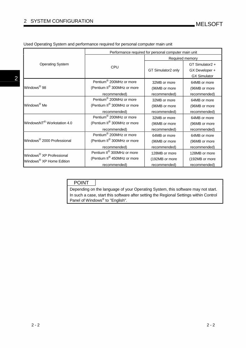
Used Operating System and performance required for personal computer main unit
Performance required for personal computer main unitRequired memory
Operating SystemCPU
GT Simulator2 onlyGT Simulator2 +GX Developer +
GX Simulator
Windows® 98Pentium® 200MHz or more
(Pentium II® 300MHz or more
recommended)
32MB or more(96MB or morerecommended)
64MB or more(96MB or morerecommended)
Windows® MePentium® 200MHz or more
(Pentium II® 300MHz or more
recommended)
32MB or more(96MB or morerecommended)
64MB or more(96MB or morerecommended)
WindowsNT® Workstation 4.0Pentium® 200MHz or more
(Pentium II® 300MHz or more
recommended)
32MB or more(96MB or morerecommended)
64MB or more(96MB or morerecommended)
Windows® 2000 ProfessionalPentium® 200MHz or more
(Pentium II® 300MHz or more
recommended)
64MB or more(96MB or morerecommended)
64MB or more(96MB or morerecommended)
Windows® XP ProfessionalWindows® XP Home Edition
Pentium II® 300MHz or more(Pentium II® 450MHz or more
recommended)
128MB or more(192MB or morerecommended)
128MB or more(192MB or morerecommended)
POINTDepending on the language of your Operating System, this software may not start.In such a case, start this software after setting the Regional Settings within ControlPanel of Windows® to "English".
2

2 - 3 2 - 3
MELSOFT2 SYSTEM CONFIGURATION
2.2 System Configuration for GT Simulator2 Execution
2.2.1 System configuration
<When using GX Simulator>
Personal computer
Commercially available
Printer
Commercially available
GX Developer 1
GX Simulator 1
GT Works2
<When using PLC CPU (Direct connection to CPU)>
Personal computer
Commercially available Printer
Commercially available
PLC CPU 2
GT Works2
GX Developer 1
Connection cable 3
1 For how to install GX Developer and GX Simulator, refer to the GX Developer and GX Simulator Operating Manuals(Start up Manual).
2 Refer to Section 2.2.2 for usable PLC CPUs.3 Refer to Section 2.2.3 for cables for connection of the personal computer and PLC CPU.

2 - 4 2 - 4
MELSOFT2 SYSTEM CONFIGURATION
2.2.2 Applicable CPUs
The following table indicates the PLC CPUs that may be connected to GT Simulator2(personal computer).
Variety TypeConnection
form
QCPU (Q Mode)Q00JCPU, Q00CPU, Q01CPU, Q02CPU, Q02HCPU,Q06HCPU, Q12HCPU, Q25HCPU, Q12PRHCPU,Q25PRHCPU
QCPU
QCPU (A Mode) Q02CPU-A, Q02HCPU-A, Q06HCPU-AQnACPU type Q2ACPU (S1), Q3ACPU, Q4ACPU, Q4ARCPU
QnACPUQnASCPU type Q2ASCPU (S1), Q2ASHCPU (S1)
ACPU (Large type)
A2UCPU (S1), A3UCPU, A4UCPU,A2ACPU (S1), A3ACPU,A1NCPU, A2NCPU (S1), A3NCPU(Version L or later for the one with link, version H or later for theone without link of AnN (S1))
ACPU
ACPU (Small type)
A2USCPU (S1), A2USHCPU-S1,A1SCPU (S1), A1SHCPU, A1SCPUC24-R2,A2SCPU (Version C or later), A2SHCPU,A1SJCPU (S3), A1SJHCPU,A0J2HCPU (Version E or later)A2CCPU (Version H or later), A2CCPUC24, A2CJCPUA1FXCPU
Motion controller CPU (A series)A171SHCPU 1, A172SHCPU 2, A173UHCPU (S1) 3,A273UHCPU 3
FXCPUFX0,FX0N, FX0S, FX1, FX1N, FX1NC, FX1S, FX2, FX2C, FX2N, FX2NC,FX3UC 4
MELDAS C6/C64 FCA C6, FCA C64
Directconnectionto CPU
1 Monitoring is allowed in the A1SHCPU range only.2 Monitoring is allowed in the A2SHCPU range only.3 Monitoring is allowed in the A3UCPU range only.4 Monitoring is allowed in the FX2N device range only.5 When the monitor destination is a multiple PLC system, the following CPU can be monitored.
For host station monitoring : Only the CPU connected to the personal computer can be monitored. For other station monitoring : Only the control PLC which controls the network module can be monitored.

2 - 5 2 - 5
MELSOFT2 SYSTEM CONFIGURATION
2.2.3 About the converter/cable
The following cables/converter have been confirmed by us that proper operation canbe performed.
(1) QCPU(a) Using the cable of Mitsubishi Electric make
RS-232 cable
QC30R2 (when peripheral device connector is D-sub, 9-pin)
The USB communication is not allowed between GT Simulator2 and QCPU.(If the USB communication is attempted, a confirmation message, "Checkcommunication.”, is displayed.)
(2) QnACPU, ACPU, Motion controller CPU, FXCPU(a) Using the product of Mitsubishi Electric make
Peripheral Device Side(RS-232C cable)
RS-232C/RS-422 ConverterPLC CPU Side(RS-422 cable)
For ACPU, Motion controller CPU, QnACPU, FX1/FX2/FX2CCPU
FX-422CAB (0.3m)FX-422CAB-150 (1.5m)F2-232CAB-1
(when peripheral deviceconnector is D-sub, 9-pin)
FX-232AW
FX-232AWC
FX-232AWC-H(FX series only)
For FX0/FX0S/FX0N/FX1S/FX1N/FX2N/FX2NC/FX3UCCPU
FX-422CABO (1.5m)
When the FX-232AWC-H is used for connection with the FX3UC, the transmissionspeed 9.6kbps, 19.2kbps, 38.4bps, 57.6kbps or 115.2kbps is available.When the FX-232AWC or FX-232AW is used for connection, select either thetransmission speed 9.6kbps or 19.2kbps.When using the F2-232CAB or F2-232CAB-1 cable, use a compatible product.You cannot use an incompatible product.Check the type label indication on the cable to see if it is compatible or not.
F2- 232CABY990C*****
F2- 232CAB- 1Y990C*****
F2- 232CAB(F/FX/A) Y990C*****
F2- 232CAB- 1(F/FX/A) Y990C*****
Incompatible products Compatible products (with indication of F/FX/A)

2 - 6 2 - 6
MELSOFT2 SYSTEM CONFIGURATION
(3) For MELDAS C6/C64When connecting GT Simulator2 and the MELDAS C6/C64, use a conversioncable with the communication terminal connector (TERMINAL) of the MELDASC6/C64.Produce the conversion cable by reference to the following connection diagram.For details, refer to the relevant MELDAS C6/C64 manual.
(a) Conversion cable connection diagramMELDAS C6/C64(TERMINAL) Side(20-pin half-pitch)
Personal Computer(GT Simulator2) Side
(9pin D-SUB)
Signal name Pin number
Cable Connection and Signal Direction
Signal name
GND 1 GND
2 RD
3 SD
5 GND
SD 6 DR (DSR)
8 CS (CTS)
GND 11
RD 16
ER (DTR) 18
(b) Applicable connector and connector cover1) MELDAS C6/C64 side
Connector 10120-3000VE(Sumitomo 3M Ltd.)Connector cover 10320-52F0-008(Sumitomo 3M Ltd.)
2) Personal computer sideUse connectors compatible with the personal computer.
(c) Precautions when producing the conversion cableThe length of the conversion cable must be 15m or shorter.
REMARK
The cables/converter used with GT Simulator2 are the same as the cables/converterused with GX Developer.

2 - 7 2 - 7
MELSOFT2 SYSTEM CONFIGURATION
MEMO

3 - 1 3 - 1
MELSOFT3 SPECIFICATIONS
Chapter 3 SPECIFICATIONS
3.1 Specifications of the GOTs SimulatedThe following table indicates the specifications of the GOTs simulated on GTSimulator2.
Name Resolution (dots) Display color Memory capacity Connection form1280×10241024×768800×600GT SoftGOT2
640×480
33M bytes
A985GOT (-V) 800×600A97 GOT 640×480A960GOT 640×400A956WGOT 480×234
9M bytes
A95 GOT 1 320×240
256 colors
3M bytes
Direct connectionto CPU
1 Incompatible with the grip and operation switches of the A950 handy GOT.2 The display section does not allow two points to be touched together.3 Any GOT other than the above cannot be simulated.
POINT Though the actual GOTs differ in display colors between models, all GOTssimulated by GT Simulator2 show 256 colors.Make check on the display colors in "Preview" of GT Designer2.
3.2 Functions that cannot be simulated
Note that the following functions cannot be used on GT Simulator2.
Function category Function name
Object functions 1 Report function 3,Barcode function,
Hard copy function 3 4,Operation Panel function 5
Test function,
Extension function 2 System monitor function 2 3
Option functions 2Ladder monitor function 5,Network monitor function 5,CNC monitor function
Special unit monitor function,Motion monitor function 5,
List editor function 5,Servo amplifier monitor function,
Other functionsTransparent function,Sound function 4,Gateway function,
Human sensor function,VIDEO/RBG display function 6,Font change function
Brightness adjustment function,Mail function,
1 For function details, refer to the GT Designer2 Version1 Reference Manual.2 For function details, refer to the GOT-A900 Series Operating Manual (GT Works2
Version1/GT Designer2 Version1 compatible Extended Option Functions Manual).3 Can be used when simulating GT SoftGOT2.
Stored as data into each folder within C:/Melsec/GSS2.(The hardcopy function can be used only when the output destination is set to the PC card.)
4 By using the GT Simulator2 snapshot and printing functions equivalent functions becomepossible.
5 By using GT Simulator2 and GX Developer together on the personal computer, equivalentfunctions become possible.
6 The video window is showed by blue color. (The video pictures are not showed)The RGB screen cannot be displayed.
3

3 - 2 3 - 2
MELSOFT3 SPECIFICATIONS
(1) About utility functions(a) About display of utility screen
GT Simulator2 does allow two points on the display section to be touchedtogether.To display the utility screen, therefore, you need to preset the touch key fordisplaying the utility screen at the time of screen creation.
(b) Usability of utility functionsWhen using the utility functions on GT Simulator2, not that some functionsare unusable.The following table indicates whether the utility functions are usable or noton GT Simulator2.
: Usable : Unusable
Item Usability
System monitorNetwork monitorList editorLadder monitorMotion/CNC monitorSpecial unit monitorServo amplifier monitorMemory informationScreen & OS copySet upClockScreen clean upPasswordSelf-testBrightness/contrast adjustment
POINT In the setup of the utility functions, some functions are inoperative if set.The following table indicates whether they are operative or not on GT Simulator2.
: Operative : Partly restricted : Inoperative
Item Operability Description
Buzzer volume
Microsoft® Windows® 98 operating system/Microsoft® Windows® Millennium Edition operatingsystem is used, "LONG" and "SHORT" of the buzzervolume are not reflected.
Outside speaker Operates.Screen save time May be set but does not function.Screen save light May be set but does not function.
Language Operates.
3

3 - 3 3 - 3
MELSOFT3 SPECIFICATIONS
3.3 Restrictions on and Instructions for use of GT Simulator2
This section gives the restrictions on and instructions for use of GT Simulator2.
3.3.1 Restrictions on and instructions for GT Simulator2
(1) Monitor data that may be simulated GT Simulator2 can simulate only the monitor data whose GOT type has beenset to the GOT-A900 series ("A985GOT", "A97 GOT", "A960GOT","A95 GOT", "GT SoftGOT2") on GT Designer2.The monitor data which has been created by setting the GOT type to the GOT-F900 series ("F940GOT", "F930GOT") on GT Designer2 can be simulated bychanging the GOT type to the GOT-A900 series.However, note that any functions the GOT-A9000 series is incompatible withcannot be converted.When changing the GOT type, always back up the data.Incompatible functions may not be converted at the time of GOT type changing,and the functions may not be converted properly when the GOT type ischanged to the GOT-F900 series again. The monitor data created on GT Designer2 with the third party PLC set as thePLC type can be simulated by setting the ACPU as the CPU type in the optionsetting of GT Simulator2 only when GX Simulator is connected.Note that the device ranges that can be monitored differ from those of the GOT.(Refer to Section 3.4 for the device ranges that can be monitored on GTSimulator2.) If you use on GT Simulator2 the monitor data of GT Designer of SW3D5C-GOTRE-PACK or earlier or the monitor data converted with GT Converter,proper operation may not be performed.The monitor data created with GT Designer of SW3D5C-GOTRE-PACK orearlier or the monitor data converted with GT Converter should be read once onGT Designer of SW4D5C-GOTR-PACKE or later or on GT Designer2 andsaved. Make sure to use the same or newer version of GT Simulator2 than that of GTDesigner2 used to create the monitor data.When the older version is used, some problems may occur such as file is notable to be opened and/or some functions/settings are invalid.For monitor data compatibility, refer to Appendix 2.
(2) Differences in display operation between GT Simulator2 and GOTIf 32-bit real number data has become unauthorized data for some reason, notethat there are differences in display operation between GT Simulator2 and GOT.
(3) About drawing imagesThe drawing images of GT Simulator2 are matched with those of GT Designer2.Hence, the display of GT Simulator2 may differ from that of the actual GOT.

3 - 4 3 - 4
MELSOFT3 SPECIFICATIONS
(4) About object functions Though the actual GOT reads and shows the clock data of the PLC CPU, GTSimulator2 displays the clock data of the personal computer, not the clock dataof the PLC CPU. If you perform a memory card save with the alarm history function or the recipefunction, data is saved on the hard disk.Also, data can not be output directly to the printer using the report function, hardcopy function, etc.A print image (TXT/CSV/BMP format file) is saved to the personal computer'shard disk, so output each file to the printer separately.The saving folder will vary according to the GOT type setting in the optionsettings, so take care.Each bit of data is stored in the folder listed below on the personal computer'shard disk.
MelsecGss2
MemCard.............
Alarmhst......Hardcopy.....Recipe.........Report..........
If SoftGOT is select with GOT type, it is saved in this folder.
If a GOT other than SoftGOT is selected with GOT type, it is saved in this folder.
Alarm history function and recipe function data is stored.
Report function data is stored.Recipe function data is stored.Hard copy function data is stored.Alarm history function data is stored.
A file saved as a printing image will not be deleted even if GT Simulator2 isexited. Because of that, files saved as printing images will accumulate on thepersonal computer's hard disk, and the GT Simulator2 may not operate due toa lack of available open space on the hard disk.If the printing trigger is frequently set to ON and monitor data is used, checkthat there is enough available open space on the personal computer's harddisk, and delete printing files if necessary. If Wordpad or Memopad were used to open saved printing image files (TXTfiles), the display of the character spacing may be slightly out of line. If thecharacter spacing is out of line, adjust the character font or font size. With the recipe function, if there is a recipe file present in the PC card, a newrecipe file will not be created as with the actual GOT.Because of that, if there is a recipe file in the MemCard or Recipe folder thatdiffers from the read monitor data's recipe function settings, reading data fromor writing data to the recipe file may not operate normally.In these cases, delete the recipe files in the MemCard or Recipe folder beforereading the monitor data.Also, if you put a check in the "Delete recipe file after reading" check box under"Option" - "Operation Settings" before reading the monitor data, the recipe filesin the MemCard or Recipe folder will automatically be deleted when the monitordata is read.However, all recipe files in the MemCard or Recipe folder will be deleted, sotake care.

3 - 5 3 - 5
MELSOFT3 SPECIFICATIONS
When using BMP image parts for the parts display function or parts movementfunction, use the BMP files saved in the hard disk of the personal computer.After the Soft GOT2 is restarted, the BMP files are stored in the Image folderthat was generated automatically in the MemCard folder.
MelsecGss2
MemCardImage......BMP file parts are stored.
For details of the BMP image parts, refer to the GT Designer2 Version 1Reference Manual. When setting the odd point of 16-bit data as the first device with the recipefunction at the time of FXCPU connection, use the device of CN199 or earlier. Note that the recipe files created on GT Simulator2 are not compatible withthose created on the GOT.

3 - 6 3 - 6
MELSOFT3 SPECIFICATIONS
3.3.2 Restrictions on and instructions for GX Simulator
When GX Simulator was started from GT Simulator2, GX Simulator cannot bestarted from GX Developer.When starting GX Simulator from GX Developer, exit from GT Simulator2 once,then restart GX Simulator from GX Developer. When GX Simulator started from GX Developer is used on GT Simulator2, exitfrom GX Developer and GX Simulator after exiting from GT Simulator2.Not that if you exit from GX Developer and GX Simulator first, GT Simulator2will result in a communication error. Monitoring the buffer memory with GT Simulator2 requires I/O assignment to bemade on GX Developer.When the default is specified in a GX Developer project at the time of GXSimulator connection, note that the buffer memory cannot be monitored sinceI/O assignment has not been made.When monitoring the buffer memory, specify the I/O-assigned project in the GXDeveloper project. When GX Simulator is used, the host station may only be monitored.Note that when another station is monitored using the station number switchingfunction, another station is handled as the host. Use GT Simulator2, GX Developer and GX Simulator of the same language. Note that the devices unsupported by GX Simulator can be used on GTSimulator2. When access was made to any file register outside the range, GX Simulatorcan read "0" even outside the range. Hence, note this when using the recipefunction for continuous read/write.

3 - 7 3 - 7
MELSOFT3 SPECIFICATIONS
3.3.3 Restrictions on and instructions for PLC CPU connection
GT Simulator2 supports only connections with the QnACPU, ACPU, motioncontroller CPU, FXCPU and MELDAS C6/C64.It cannot be connected to third-party PLCs.Refer to Section 2.2.2 for connectable CPUs on GT Simulator2. GT Simulator2 enables simulation for direct connection to CPU only.GT Simulator2 cannot be used to perform simulation for bus connection,computer link connection, MELSECNET connection, CC-Link connection andthe like.
When GT Simulator2 is connected with the PLC CPU, the monitor speed islower than on the actual GOT.
When connecting GT Simulator2 to FX0, FX0S, FX1, FX1S, FX2 or FX2C via 2PIF,use 2PIF of Ver 3.01A or later.
When connecting GT Simulator2 to the function extension board of the FXCPU,you must make the following settings on the FXCPU side.1) On GX Developer, choose "PLC parameter"-"PLC System setting (2)" and
click the checked "Communication setting" check box.2) Set "0" in device "D8120".
When GT Simulator2 is connected to the QnACPU, note that any other stationthan the QnACPU cannot be monitored.The access ranges of the other network systems that can be monitored are thesame as those of the GOT.

3 - 8 3 - 8
MELSOFT3 SPECIFICATIONS
3.4 Device Ranges That Can Be Monitored
The following device ranges can be monitored on GT Simulator2.
POINTWhen GX Simulator is connected, the devices unsupported by GX Simulator cannotbe monitored.
(1) For Q/QnA/A/FXCPU/MELDAS C6/C64The devices usable with the GOT can be monitored.For details of the device ranges that may be set, refer to GT Designer2 Version1Reference Manual.
(2) For third party PLC (can be monitored only when GX Simulator isconnected)The device ranges which can be monitored differ from those usable with theGOT.(The devices outside the ranges cannot be displayed properly by the devicemonitor function.)The following device ranges can be monitored by the GT Simulator2.
(a) OMRON SYSMAC (Omron PLC)
Device name Available range for monitoring with GOTAvailable range for monitoring with GT
Simulator2I/O relayInternal auxiliary relay
..0000 to 614315 ..0000 to 008115
Data link relay (LR) LR00000 to LR19915 LR00000 to LR08155Auxiliary memory relay (AR) AR00000 to AR95915 ——Holding relay (HR) HR00000 to HR51115 HR00000 to HR08115Internal holding relay (W) WR00000 to WR51115 WR00000 to WR08115Timer contact (TIM) TIM0000 to TIM2047 TIM0000 to TIM0255Counter contact (CNT) CNT0000 to CNT2047 CNT0000 to CNT0255Data memory (DM) DM00000 to DM9999 DM00000 to DM8191Timer (current value) (TIM) TIM0 to TIM2047 TIM0000 to TIM0255Counter (current value) (CNT) CNT0000 to CNT2047 CNT0000 to CNT0255
Bit d
evic
e
GOT bit register (GB) GB64 to GB1023 GB64 to GB1023I/O relay 0000 to 6143 0000 to 0081Data link relay (LR) LR000 to LR199 LR000 to LR031Auxiliary memory relay (AR) AR000 to AR959 ——Holding relay (HR) HR000 to HR511 HR000 to HR081Internal holding relay (W) WR000 to WR511 WR000 to WR081Data memory (DM) DM0000 to DM9999 DM0000 to DM8191Timer (current value) (TIM) TIM0000 to TIM2047 TIM0000 to TIM0255Counter (current value) (CNT) CNT0000 to CNT2047 CNT0000 to CNT0255Extended data memory(EM current bank)Extended data memory(EM banks 0 to 12)
EM0000 to EM9999 ——
GOT data register (GD) GD64 to GD1023 GD64 to GD1023
Wor
d de
vice
GOT special register (GS) GS0 to GS511 GS0 to GS511
3 - 9 3 - 9
MELSOFT3 SPECIFICATIONS
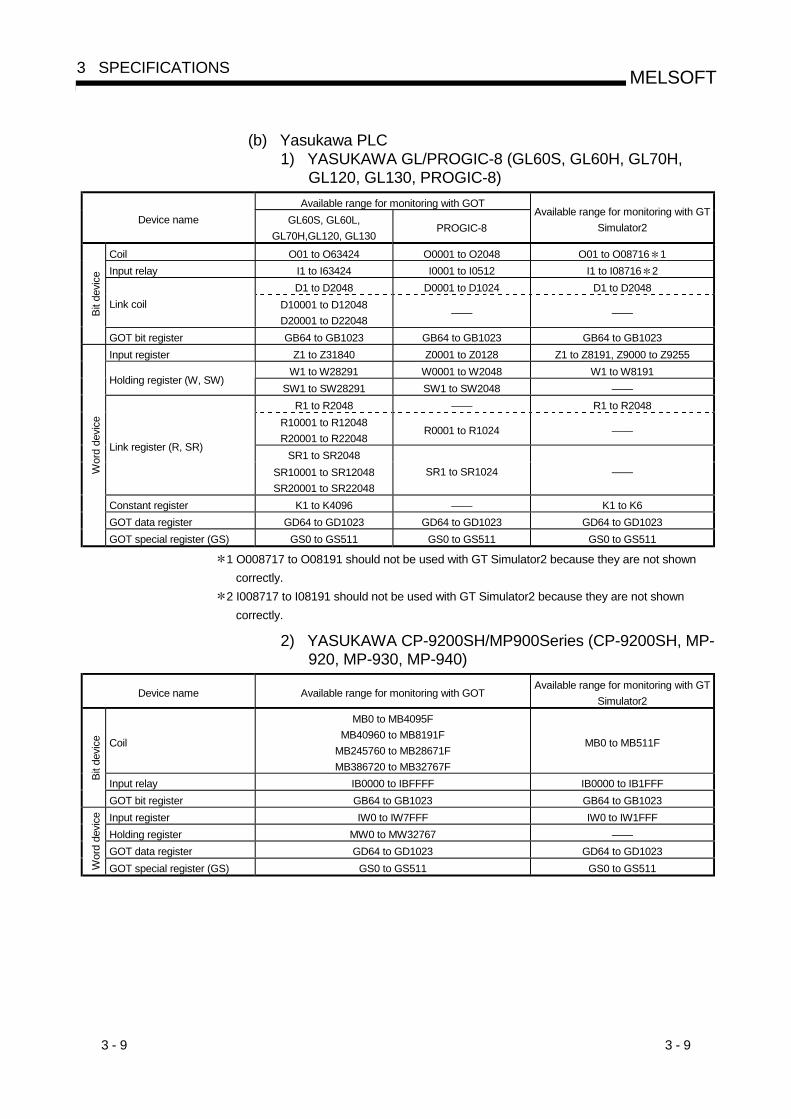
(b) Yasukawa PLC1) YASUKAWA GL/PROGIC-8 (GL60S, GL60H, GL70H,
GL120, GL130, PROGIC-8)Available range for monitoring with GOT
Device name GL60S, GL60L,GL70H,GL120, GL130
PROGIC-8Available range for monitoring with GT
Simulator2
Coil O01 to O63424 O0001 to O2048 O01 to O08716 1Input relay I1 to I63424 I0001 to I0512 I1 to I08716 2
D1 to D2048 D0001 to D1024 D1 to D2048Link coil D10001 to D12048
D20001 to D22048—— ——Bi
t dev
ice
GOT bit register GB64 to GB1023 GB64 to GB1023 GB64 to GB1023Input register Z1 to Z31840 Z0001 to Z0128 Z1 to Z8191, Z9000 to Z9255
W1 to W28291 W0001 to W2048 W1 to W8191Holding register (W, SW)
SW1 to SW28291 SW1 to SW2048 ——R1 to R2048 —— R1 to R2048
R10001 to R12048R20001 to R22048
R0001 to R1024 ——
SR1 to SR2048Link register (R, SR)
SR10001 to SR12048SR20001 to SR22048
SR1 to SR1024 ——
Constant register K1 to K4096 —— K1 to K6GOT data register GD64 to GD1023 GD64 to GD1023 GD64 to GD1023
Wor
d de
vice
GOT special register (GS) GS0 to GS511 GS0 to GS511 GS0 to GS511
1 O008717 to O08191 should not be used with GT Simulator2 because they are not showncorrectly.
2 I008717 to I08191 should not be used with GT Simulator2 because they are not showncorrectly.
2) YASUKAWA CP-9200SH/MP900Series (CP-9200SH, MP-920, MP-930, MP-940)
Device name Available range for monitoring with GOTAvailable range for monitoring with GT
Simulator2
Coil
MB0 to MB4095FMB40960 to MB8191F
MB245760 to MB28671FMB386720 to MB32767F
MB0 to MB511F
Input relay IB0000 to IBFFFF IB0000 to IB1FFFBit d
evic
e
GOT bit register GB64 to GB1023 GB64 to GB1023Input register IW0 to IW7FFF IW0 to IW1FFFHolding register MW0 to MW32767 ——GOT data register GD64 to GD1023 GD64 to GD1023
Wor
d de
vice
GOT special register (GS) GS0 to GS511 GS0 to GS511

3 - 10 3 - 10
MELSOFT3 SPECIFICATIONS
3) YASUKAWA CP-9200 (H)
Device name Available range for monitoring with GOTAvailable range for monitoring with GT
Simulator2Coil OB00000 to OB007FF OB00000 to OB007FFInput relay IB00000 to IB007FF IB00000 to IB007FF
Bit d
evic
e
GOT bit register GB64 to GB1023 GB64 to GB1023Input register IW00000 to IW007F ——Output register OW0000 to OW007F ——
DW0000 to DW02047 ——Data register
ZD0000 to ZD02047 ZD0000 to ZD00006Common register MW0000 to MW7694 ——GOT data register GD64 to GD1023 GD64 to GD1023
Wor
d de
vice
GOT special register (GS) GS0 to GS511 GS0 to GS511
4) YASKAWA CP-9300MS (CP-9300MC incompatible)
Device name Available range for monitoring with GOTAvailable range for monitoring with GT
Simulator2Coil MB0 to MB3071F MB0 to MB511FInput relay IB0000 to IB3FF IB0000 to IB1FFF
Bit d
evic
e
GOT bit register GB64 to GB1023 GB64 to GB1023Input register IW0 to IW3F IW0 to IW1FFFHolding register MW0 to MW3071 MW0 to MW8191GOT data register GD64 to GD1023 GD64 to GD1023
Wor
d de
vice
GOT special register (GS) GS0 to GS511 GS0 to GS511
5) YASKAWA CP-9300MS (CP-9300MC compatible)
Device name Available range for monitoring with GOTAvailable range for monitoring with GT
Simulator2Coil OB0 to OB1023 OB0 to OMB1023Input relay IB0000 to IB1023 IB0000 to IB1023
Bit d
evic
e
GOT bit register GB64 to GB1023 GB64 to GB1023Input register I0 to I63 ——Holding register M0 to M2047 ——GOT data register GD64 to GD1023 GD64 to GD1023
Wor
d de
vice
GOT special register (GS) GS0 to GS511 GS0 to GS511

3 - 11 3 - 11
MELSOFT3 SPECIFICATIONS
(c) Allen-Bradley PLC1) AB SLC500 (SLC500 series)
Device name Available range for monitoring with GOT Available range for monitoring with GTSimulator2
Bit (B) B3:0/0 to B3:255/15, B10:0/0 to B255:255/15 ——
Timer (timing bit) (TT) T4:0/14 to T4:255/14, T4:0/TT to T4:255/TT,T10:0/14 to T255:255/14, T10:0/TT to T255:255/TT ——
Timer (completion bit) (TN) T4:0/13 to T4:255/13, T4:0/DN to T4:255/DN,T10:0/13 to T255:255/13, T10:0/DN to T255:255/DN ——
Counter (up counter) (CU) C5:0/15 to C5:255/15, C5:0/CU to C5:255/CUC10:0/15 to C255:255/15, C10:0/CU to C255:255/CU ——
Counter (down counter) (CD) C5:0/14 to C5:255/14, C5:0/CD to C5:255/CDC10:0/14 to C255:255/14, C10:0/CD to C255:255/CD ——
Counter (completion bit) (CN) C5:0/13 to C5:255/13, C5:0/DN to C255:255/DN,C10:0/13 to C255:255/13, C10:0/DN to C255:255/DN ——
Integer (N) N7:0 to N7:255, N10:0 to N255:255 ——
Word device bit Designated bit of the following word devices Specified bit of any of the followingword devices
Bit d
evic
e
GOT internal bit register (GB) GB64 to GB1023 GB64 to GB1023Bit (B) B3:0 to B3:255 ——
Timer (set value) (TP) T4:0.1 to T4:255.1, T4:0.PRE to T4:255.PRE,T10:0.1 to T255:255.1, T10:0.PRE to T255:255.PRE ——
Timer (current value) (TA) T4:0.2 to T4:255.2, T4:0.ACC to T4:255.ACC,T10:0.2 to T255:255.2, T10:0.ACC to T255:255.ACC ——
Counter (set value) (CP) C5:0.1 to C5:255.1, C5:0.PRE to C5:255.PRE,C10:0.1 to C255:255.1, C10:0.PRE to C255:255.PRE ——
Counter (current value) (CA) C5:0.2 to C5:255.2, C5:0.ACC to C5:255.ACC,C10:0.2 to C255:255.2, C10:0.ACC to C255:255.ACC ——
Integer (N) N7:0 to N7:255, N10:0 to N255:255 ——GOT internal data register(GD) GD64 to GD1023 GD64 to GD1023
Wor
d de
vice
GOT special register (GS) GS0 to GS511 GS0 to GS511
2) AB Micrologix1000/1500 seriesAvailable range for monitoring with GOTDevice name Micrologix1000 series Micrologix1500 series
Available range for monitoring with GTSimulator2
Bit (B) B3:0/0 to B3:31/15 B3:0/0 to B255:255/15 ——
Timer (timing bit) (TT) T4:0/14 to T4:39/14T4:0/TT to T4:39/TT
T3:0/14 to T255:255/14T3:0/TT to T255:255/TT ——
Timer (completion bit) (TN) T4:0/13 to T4:39/13T4:0/DN to T4:39/DN
T3:0/13 to T255:255/13T3:0/DN to T255:255/DN ——
Counter (up counter) (CU) C5:0/15 to C5:31/15C5:0/CU to C5:31/CU
C3:0/15 to C255:255/15C3:0/CU to C255:255/CU ——
Counter (down counter) (CD) C5:0/14 to C5:31/14C5:0/CD to C5:31/CD
C3:0/14 to C255:255/14C3:0CD to C255:255/CD ——
Counter (completion bit) (CN) C5:0/13 to C5:31/13C5:0/DN to C5:31/DN
C3:0/13 to C255:255/13C3:0/DN to T255:255/DN ——
Integer (N) N7:0 to N7:104 N3:0 to N255:255 ——
Word device bit Designated bit of thefollowing word devices
Designated bit of thefollowing word devices
Designated bit of the following worddevices
Bit d
evic
e
GOT internal bit register (GB) GB64 to GB1023 GB64 to GB1023 GD64 to GD1023Bit (B) B3:0 to B3:31 B3:0 to B255:255 ——
Timer (set value) (TP) T4:0.1 to T4:39.1T4:0.PRE to T4:39.PRE
T3:0.1 to T255:255.1T3:0.PRE to T255:255.PRE ——
Timer (current value) (TA) T4:0.2 to T4:39.2T4:0.ACC to T4:39.ACC
T3:0.2 to T255:255.2T3:0.ACC to T255:255.ACC ——
Counter (set value) (CP) C5:0.1 to C5:39.1C5:0.PRE to D5:39.PRE
C3:0.1 to C255:255.1C3:0.PRE to C255:255.PRE ——
Counter (current value) (CA) C5:0.2 to C5:31.2C5:0.ACC to C5:31.ACC
C3:0.2 to C255:255.2C3:0.ACC to
C255:255.ACC——
Integer (N) N7:0 to N7:14 N3:0 to N255:255 ——GOT internal data register(GD) GD64 to GD1023 GD64 to GD1023 GD64 to GD1023
Wor
d de
vice
GOT special register (GS) GS0 to GS511 GS0 to GS511 GS0 to GS511

3 - 12 3 - 12
MELSOFT3 SPECIFICATIONS
(d) SHARP JW (Sharp PLC)
Device name Available range for monitoring with GOTAvailable range for monitoring with GT
Simulator2
I/O relay0 to 15777
20000 to 757770 to 15777
Timer counter (contact) T/C0000 to T/C1777 T/C0000 to T/C0377
Timer counter (current value)T/C0000 to T/C1777
(b0000 to b3776)T/C0000 to T/C1777
(b0000 to b3776)
Register
09000 to 0977619000 to 1977629000 to 2977639000 to 3977649000 to 4977659000 to 5977669000 to 6977679000 to 7977689000 to 8977699000 to 99776E0000 to E0776E1000 to E1776E2000 to E2776E3000 to E3776E4000 to E4776E5000 to E5776E6000 to E6776E7000 to E7776
09000 to 0977619000 to 1977629000 to 2977639000 to 3977649000 to 4977659000 to 5977669000 to 6977679000 to 7977689000 to 8977699000 to 99776E0000 to E0776E1000 to E1776E2000 to E2776E3000 to E3776E4000 to E4776E5000 to E5776
——E7000 to E7776
File register
1000000 to 11777762000000 to 21777763000000 to 31777764000000 to 41777765000000 to 51777766000000 to 61777767000000 to 7177776
——2000000 to 21777763000000 to 31777764000000 to 41777765000000 to 51777766000000 to 61777767000000 to 7177776

3 - 13 3 - 13
MELSOFT3 SPECIFICATIONS
(e) TOSHIBA PROSEC T/V (Toshiba PLC)Available range for monitoring with GOT
Device namePROSEC T Series PROSEC V Series
Available range for monitoring with GTSimulator2
External input (X) X0000 to X511F —— X0000 to X511FExternal output (Y) Y0000 to Y511F —— Y0000 to Y511FInternal relay (R) R0000 to R999F ——Data register —— R00000 to R4095F
R0000 to R4095F
Special relay (S) S0000 to S255F —— ——Special register —— S0000 to S511FLink register relay (Z) Z0000 to Z999F ——
Z0000 to Z511F
Link relay (L) L0000 to L255F —— ——Timer (contact) (T) T000 to T999 —— T000 to T255Counter (contact) (C) C000 to C511 —— C000 to C255
Word device bit
Designated bit of thefollowing word devices
(except timer (current value)and counter (current value))
Specified bit of any of thefollowing word devices
(Except data register (R))
Designated bit of the following worddevices (except timer (current value)
and counter (current value))
Bit d
evic
e
GOT bit register (GB) GB64 to GB1023 GB64 to GB1023 GB64 to GB1023External input (X) XW000 to XW511 —— XW000 to XW511External output (Y) YW000 to YW511 —— YW000 to YW511Internal relay (R) RW000 to RW999 ——Data register(R) —— RW000 to RW4095
RW000 to RW511
Special relay (S) SW000 to SW255 SW000 to SW511 ——Link register relay (Z) —— ——Link relay (L) LW000 to LW255 —— ——Timer (current value) (T) T000 to T999 —— T000 to T255Counter (current value) (C) C000 to C511 —— C000 to C255Data register (D) D0000 to D8191 D0000 to D4095 D0000 to D8191Link register (W) W0000 to W2047 —— W0000 to W2047File register (F) F0000 to F32467 —— F0 to F8191
Bit device word
Conversion of the above bitdevices to words (exceptlink register relay, timer(contact) and counter
(contact))GOT data register (GD)
Conversion of any of theabove bit devices into word
Conversion of the above bit devices towords (except link register relay, timer
(contact) and counter (contact))GOT data register (GD)
GOT data register (GD) GD64 to GD1023 GD64 to GD1023 GD64 to GD1023
Wor
d de
vice
GOT special register (GS) GS0 to GS511 GS0 to GS511 GS0 to GS511

3 - 14 3 - 14
MELSOFT3 SPECIFICATIONS
(f) SIEMENS S7-300/400 (SIEMENS PLC)Available range for monitoring with GOT
Device nameSIEMENS S7-300 series SIEMENS S7-400 Series
Available range for monitoring with GTSimulator2
Input relay I0000 to I1277 I0000 to I5117 I0000 to I1277Output relay Q0000 to Q1277 Q0000 to Q5117 Q0000 to Q1277Bit memory M0000 to M2557 M00000 to M20477 M0000 to M10237
Bit d
evic
e
GOT bit register GB64 to GB1023 GB64 to GB1023 GB64 to GB1023Input relay IW000 to IW126 IW000 to IW510 IW000 to IW126Output relay QW000 to QW126 QW000 to QW510 QW000 to QW126Bit memory MW000 to MW254 MW0000 to MW2046 MW000 to MW1022Timer (present value) T000 to T127 T000 to T511 T000 to T255Counter (present value) C00 to C63 C000 to C511 C00 to C255
Data register
D000100000 toD000108190
D000200000 toD000208190
D000300000 toD000308190
•••
D012600000 toD012608190
D012700000 toD012708190
D000100000 toD000165534
D000200000 toD000265534
D000300000 toD000365534
•••
D409400000 toD409465534
D409500000 toD409565534
——
GOT data register GD64 to GD1023 GD64 to GD1023 GD64 to GD1023
Wor
d de
vice
GOT special register (GS) GS0 to GS511 GS0 to GS511 GS0 to GS511
(g) MEWNET Series (Matsushita Electric Works PLC)
Device name Available range for monitoring with GOTAvailable range for monitoring with GT
Simulator2Input relay (X) X0000 to X511F X0000 to X511FOutput relay (Y) Y0000 to Y511F Y0000 to Y511FInternal relay (R) R0000 to R886F R0000 to R511FLink relay (L) L0000 to L639F L0000 to L511FSpecial relay (R) R9000 to R910F R9000 to R910FTimer contact (T) T0000 to T3071 T0000 to T0255Counter contact (C) C0000 to C3071 C0000 to C0255
Bit d
evic
e
GOT bit register (GB) GB64 to GB1023 GB64 to GB1023Input relay (WX)*1 WX000 to WX511 WX000 to WX511Output relay (WY)*1 WY0000 to WY511 WY0000 to WY511Internal relay (WR)*1 WR000 to WR886 WR000 to WR511Link relay (WL)*1 WL000 to WL639 WL000 to WL511Special relay (WR)*1 WR900 to WR910 WR900 to WR910Timer/counter(elapsed value)(EV)
EV0000 to EV3071 EV0000 to EV0255
Counter contact(set value)(SV)
SV0000 to SV3071 ——
Data register (DT) DT00000 to DT10239 DT00000 to DT08191Link register (LD) LD0000 to LD8447 LD0000 to LD8191File register (FL) FL00000 to FL32764 ——GOT data register (GD) GD64 to GD1023 GD64 to GD1023
Wor
d de
vice
GOT special register (GS) GS0 to GS511 GS0 to GS511*1 Set the device number as a multiple of 16.

3 - 15 3 - 15
MELSOFT3 SPECIFICATIONS
(h) HITACHI HIDIC H (Hitachi PLC)
Device name Available range for monitoring with GOTAvailable range for monitoring with GT
Simulator2External input (X) X00000 to X05A95 X00000 to X05A95External output (Y) Y00000 to Y05A95 Y00000 to Y05A95Remote external input (X) X10000 to X49995 ——Remote external output (Y) Y10000 to Y49995 ——First CPU link (L) L0000 to L3FFF L0000 to L1FFFSecond CPU link (L) L10000 to L13FFF ——Data area (M) M0000 to M3FFF M0000 to M1FFFOn-delay timer (TD) TD000 to TD255 TD000 to TD255Single-shot timer (SS) SS000 to SS255 ——Watchdog timer (WDT) WDT000 to WDT255 ——Monostable timer (MS) MS000 to MS255 ——Retentive timer (TMR) TMR000 to TMR255 ——Up counter (CU) CU000 to CU511 CU000 to CU511Ring counter (RCU) RCU000 to RCU511 ——Up/down counter (CT) CT000 to CT511 ——Bit internal output (R) R000 to R7BF ——DIF (leading edge detection) DIF000 to DIF511 ——DFN (trailing edge detection) DFN000 to DFN511 ——
Bit d
evic
e
GOT bit register GB64 to GB1023 GB64 to GB1023External input (WX) WX0000 to WX05A7 ——External output (WY) WY0000 to WY05A7 ——Remote external input (WX) WX1000 to WX4997 ——Remote external output (WY) WY1000 to WY4997 ——First CPU link (WL) WL000 to WL3FF WL0 to WL1FFSecond CPU link (WL) WL1000 to WL13FF ——Data area (WM) WM000 to WM3FF WM0 to WM1FFTimer/counter(elapsed value)(TC)
TC000 to TC511 TC000 to TC255
Word internal output (WR) WR000 to WR3FF WR000 to WR3FFGOT data register GD64 to GD1023 GD64 to GD1023
Wor
d de
vice
GOT special register (GS) GS0 toGS511 GS0 toGS511

3 - 16 3 - 16
MELSOFT3 SPECIFICATIONS
MEMO

4 - 1 4 - 1
MELSOFT4 SCREEN CONFIGURATION OF GT SIMULATOR2
Chapter 4 SCREEN CONFIGURATION OF GT SIMULATOR2
4.1 Screen Configuration and Various Tools of GT Simulator2
This section describes configuration and various tools of GT Simulator2.
Title barMenu bar
Tool bar
MonitorScreen
Dropdown menu
1 For the explanations of the title bar, menu bar and drop-down menu, refer to theGT Designer2 Version1 Operating Manual.
4

4 - 2 4 - 2
MELSOFT4 SCREEN CONFIGURATION OF GT SIMULATOR2
(1) Tool barItems allocated on the menu bar are displayed in buttons.Move the cursor to the tool button and click it. The function starts.
1) 2) 3) 4) 5)
Tool button names
Number Name Description
1) Open Opens the project data created on GT Designer2.2) Start Starts simulation.3) Stop Ends simulation.4) Device Monitor Starts the device monitor function.5) Option Sets the option functions.
4.2 Menu Configuration
This section lists and describes the commands assigned to the menu bar.Project Open Chooses the project data created on GT Designer2 and reads the
monitor data.Snap Shot Saves the monitor data being simulated into any file in BMP
format.Print Prints the monitor data being simulated.
Print Preview Shows the printing image.
Print Setup Sets the printer.
Page Setup Sets the page.
GT Simulator2 Exit Exits from GT Simulator2.
Simulate Start Starts simulation on GT Simulator2.
Option
Exits from GT Simulator2.Stop
Sets simulated GOT type, connection method, etc.
Help Contents Refers to the online manual.
About GT Simulator2 Shows the software version of GT Simulator2 installed.
Tool Start/End of Device Monitor Starts/Ends the device monitor function.
MELFANSweb Connects to MELFANSweb.
4

5 - 1 5 - 1
MELSOFT5 GT SIMULATOR2 OPERATING METHOD
Chapter 5 GT SIMULATOR2 OPERATING METHOD
5.1 Simulation Procedure Outline
This section shows a rough procedure for operating GT Simulator2.
(1) When connecting GT Simulator2 and GX SimulatorStart
Start GX Simulator from GX Developer. 1
Start GT Simulator2
Do you use GT Simulator2 for the first time?
(Is project unread?)
Make GT Simulator2 option setting.(Refer to Section 5.2)
Open the project created on GT Designer2 (refer to Section 5.4).
Perform debugging on GT Simulator2 (refer to Section 5.5).The device value of simulated monitor data should be checked and changed with the device monitor function (Refer to Chapter 7).
Exit from GT Simulator2 (refer to Section 5.6).
Do you change option setting?
Make GT Simulator2 option setting.(Refer to Section 5.2)
No
Yes
Yes
No
Do you change the project to be simulated?
No
Only when using GX Developer
YesStart simulation on GT Simulator2.
(Refer to Section 5.3)
Start GX Developer. 1
1 Refer to the GX Developer and GX Simulator Operating Manuals (Start upManual) for the way to start GX Developer and GX Simulator.
2 When GX Developer is not used, GX Simulator is automatically started at thetime of simulation execution on GT Simulator2.
5

5 - 2 5 - 2
MELSOFT5 GT SIMULATOR2 OPERATING METHOD
(2) When connecting GT Simulator2 and PLC CPU
When using GX Developer, start GX Developer. 1
Start GT Simulator2.
Do you use GT Simulator2 for the first time?
(Is project unread?)
Make GT Simulator2 option setting. 2 (Refer to Section 5.2)
Open the project created on GT Designer2 (refer to Section 5.4).
Exit from GT Simulator2 (refer to Section 5.6).
Do you change the project to be simulated?
Make GT Simulator2 option setting. 2(Refer to Section 5.2)
No
Yes
Yes
No
Start simulation on GT Simulator2.(Refer to Section 5.3)
Start
Power on the PLC CPU. Power on the PLC CPU.
Connect the personal computer and PLC CPU.
Perform debugging on GT Simulator2 (refer to Section 5.5).The device value of simulated monitor data should be checked and changed with the device monitor function (Refer to Chapter 7).
1 Refer to the GX Developer or GX Simulator Operating Manual (Start upManual) for the way to start GX Developer.
2 The connection method in Option setting returns to GX Simulator when youexit from GT Simulator2.Every time you connect GT Simulator2 to the PLC CPU, choose [CPU] in theconnection method of Option setting.
5

5 - 3 5 - 3
MELSOFT5 GT SIMULATOR2 OPERATING METHOD
5.2 Option Setting
In Option setting, set the GOT type to be simulated on GT Simulator2, GT Simulator2connection method, used sequence program and others.
POINT When changing option setting before start of simulation on GT Simulator2, youmust exit from GT Simulator2 once.Make option setting before startling simulation.
Choose any
1) When making option setting, choose any of thefollowing. "Simulate" - "Option" "Option" on toolbar "Option" by right-clicking the mouse
2) As the Option setting dialog box appears, makesettings. (Refer to Section 5.2.1.)After setting, press Apply to update theinformation.Clicking the OK button closes the dialogbox.

5 - 4 5 - 4
MELSOFT5 GT SIMULATOR2 OPERATING METHOD
5.2.1 Description of the option setting dialog box
1)2)3)4)
5)6)
7)
10) 12)11)
8)
9)
10) 12)11)
Number Item Description
1) Connection *"GX Simulator" : Simulation is performed using GX Simulator installed in the personal computer."CPU" : Simulation is performed with GT Simulator2 actually connected with the PLC.
(Defaults to "GX Simulator".)
2) ——
Choose the type of the PLC CPU connected."ACPU" : Choose when making connection with the ACPU."QnACPU, MELDAS C6*" : Choose when making connection with the QnACPU or MELDAS C6/C64."QCPU" : Choose when making connection with the QCPU (Q mode)."QCPU-A" : Choose when making connection with the QCPU (A mode)."FX" : Choose when making connection with the FXCPU.
3) Comm port
When you selected "CPU" in the connection method, choose the communication port on the personalcomputer side."COM1", "COM2", "COM3", "COM4", "COM5", "COM6"
(Defaults to "COM1".)
4) Baud rate
When you selected "CPU" in the connection method, set the transmission speed to/from the CPU.When "ACPU" or "FX" was selected : Defaults to "9.6kbps".When "QnACPU, MELDAS C6 " was selected : Defaults to "19.2kbps".When "QCPU" or "QCPU-A" was selected : Defaults to "19.2kbps".For connection with the FXCPU, select the baud rate supported by the connected FXCPU.When the set baud rate is not supported, communication is made at 9.6kbps.For connection with the MELDAS C6/C64, set the baud rate to "19.2Kbps".
5) GOT type
Choose the type of the GOT to be simulated."GOT-A950" : Simulation is performed as A950GOT (320 x 240 dots)"GOT-A956W" : Simulation is performed as A956WGOT (480 x 234 dots)"GOT-A960" : Simulation is performed as A960GOT (640 x 400 dots)"GOT-A97*" : Simulation is performed as A97*GOT (640 x 480 dots)"GOT-A985" : Simulation is performed as A985GOT (-V) (800 x 600 dots)"SoftGOT" : Simulation is performed as GT SoftGOT2.
(Defaults to "GOT-A97 ".)
6) ResolutionIf "SoftGOT" is selected for GOT type, select (Resolution: dot) for screen size.If another GOT is selected, the resolution is fixed."640 x 480", "800 x 600", "1024 x 768", "1280 x 1024" (Default is "640 x 480")
7) Print data
If "SoftGOT" is selected for GOT type, select the data format for data saved in the "Memcard" folder by thealarm history function or other functions."Text file" : Data is saved as a Text file."Resolution CSV file" : Data is saved as a CSV file (Default is "Text file")
8) Delete recipe fileafter reading data Turn on this check box to delete the recipe data in the MemCard folder after monitor data reading.
9) GX Developer project
Set the sequence program to be used.Default : Simulation is performed with the sequence program having only the END instruction.Fixed : Set any sequence program.Click the [Browse] button and choose the GX Developer project.
10) OK Used to update the settings and close the dialog box.11) Cancel Used to cancel the settings and close the dialog box.12) Apply Used to update the settings.
Connection returns to "GX Simulator" when you exit from GT Simulator2.Every time you connect GT Simulator2 to the PLC CPU, choose [CPU] in the connection method of Option setting.

5 - 5 5 - 5
MELSOFT5 GT SIMULATOR2 OPERATING METHOD
5.3 Execution of simulation
Choose any
1) To start simulation, choose any of the following. "Simulate" - "Start" "Start of Simulation" on toolbar "Start" by right-clicking the mouse
<GX Simulator> <When CPU is connected> 2) The left dialog box appears.The message displayed changes with theconnection method in Option setting.Choose Yes or OK to transfer data.
3) Simulation of the project simulated previouslystarts.
POINT When simulation is performed for the first time on GT Simulator2, choosing "Start"causes GT Simulator2 to show the utility screen.In this case, choose "Open" (refer to Section 5.4) and read the monitor data tostart simulation.For details of the utility function, refer to the GOT-A900 Series Operating Manual(GT Works2 Version1/GT Designer2 Version1 compatible Extended OptionFunctions Manual)

5 - 6 5 - 6
MELSOFT5 GT SIMULATOR2 OPERATING METHOD
5.4 Opening the Project
Choose any
1) To open a project, choose any of the following. "Project" - "Open" "Open" on toolbar "Open" by right-clicking the mouse
2) Choose the project where the monitor datacreated on GT Designer or GT Designer2 isstored.When you made correction to the project, alwayssave it on GT Designer2 before opening theproject.
<GX Simulator> <When CPU is connected> 3) The left dialog box appears.The message displayed changes with theconnection method in Option setting.Choose Yes or OK to transfer data.
4) As the "Reading data" dialog box appears, makesettings. (Refer to Section 6.4.1)Choosing [Reading] reads the monitor data ofthe selected project.

5 - 7 5 - 7
MELSOFT5 GT SIMULATOR2 OPERATING METHOD
5.4.1 Description of the monitor data reading dialog box
1)
2)
3)
5) 6) 6)5)
4)
Number Item Description
1) Object
"All data"Check when reading all monitor data of the selected project.
"Select data"Check when reading some monitor data of the selected project.
2)Delete all old monitordata
Turn on the check box when reading the monitor data of the selected project after deletion ofthe already read monitor data.
3)
Project titleProject IDGOT typeTrans size
The settings and data size of the monitor data to be read appear.
4)
"Base""Window""Others"Tab
Turn on the read data check boxes when you chose "Select data" in Object."Base"/"Window" tab
Turn on the screen number and screen title check boxes of the screen to be read."Others" tab
Turn on the read data (part data, comment, common settings, high-quality font, soundWAVE) check boxes.Common settings are always read.
5) Reading Used to read the monitor data of the selected project.6) Cancel Used to cancel reading the monitor data of the selected project.

5 - 8 5 - 8
MELSOFT5 GT SIMULATOR2 OPERATING METHOD
5.5 Simulating Operation
On GT Simulator2, touching the touch keys is performed by pressing the mousebutton.As the input validity range of the touch key is narrower than that of the actual GOT,securely touch the touch key.Touching is indicated by "beep".
POINT When the sound card is fitted, the sound set in "Default sound" after choosing"Control Panel"-"Sounds" beeps on Windows® 98, Windows® Me.
The debugging example using the sample screen data packed with GT WorksVersion 5/GT Designer Version 5 is given in the appendix.

5 - 9 5 - 9
MELSOFT5 GT SIMULATOR2 OPERATING METHOD
5.6 Exiting from GT Simulator2
Choose any
1) To exit from GT Simulator2, choose any of thefollowing. "Project" - "GT Simulator2 Exit" "Simulate" - "Stop" "Stop" on toolbar "Close" in system menu "Stop" by right-clicking the mouse
When the device monitor function is being used,exit GT Simulator2 after closing the devicemonitor function.Refer to Section 7.4 for How to Operate theDevice Monitor Function.

6 - 1 6 - 1
MELSOFT6 FUNCTIONS OF GT SIMULATOR2
Chapter 6 FUNCTIONS OF GT SIMULATOR2
6.1 Snap Shot Function
The snap shot function allows a screen image being simulated on GT Simulator2 to besaved into any folder as a BMP format file.
6.1.1 Operating procedure
1) Choose "Project" - "Snap Shot" during GTSimulator2 simulation.
2) Choose the folder which will save the data.After setting the file name, press Save tosave the screen image of GT Simulator2 in BMPformat. 6

6 - 2 6 - 2
MELSOFT6 FUNCTIONS OF GT SIMULATOR2
6.2 Print Function
The print function allows a screen image being simulated on GT Simulator2 to beoutput to a printer.
6.2.1 Operating procedure
1) Choosing "Project" - "Print" during GT Simulator2simulation starts printing.Note that printing cannot be done if the printer isnot specified.
6.2.2 Print preview
Selecting Print preview shows a printing image.
6.2.3 Page setup
Selecting Page setup shows the following dialog box.
1)
2)
Number Item Description
1) Image dataChoose "Reverse" to print the screen in reverse video.
(Defaults to "Normal".)
2) Margin
Set the margins on a page to be printed.When margins have been set, the screen to be printed is reduced according to the specifiedvalues.The reduction image of the screen can also be checked in Print preview.
6

7 - 1 7 - 1
MELSOFT7 DEVICE MONITOR FUNCTIONS
Chapter 7 DEVICE MONITOR FUNCTIONS
7.1 Overview
This section deals with the device monitor function usable on GT Simulator2.The device monitor function allows you to check and change the device values of themonitor screen data simulated on GT Simulator2.You can perform efficient debugging since you can change device values with thedevice monitor function and check indication changes on GT Simulator2.
Devicemonitorfunction
7

7 - 2 7 - 2
MELSOFT7 DEVICE MONITOR FUNCTIONS
7.2 Restrictions on and Instructions for use of Device Monitor
This section explains the restrictions on and instructions for use of the device monitorfunction.When using the device monitor function, also take into consideration the restrictions onand instructions for use of GT Simulator2.Refer to Section 3.3 for the restrictions on and instructions for use of GT Simulator2.
(1) Instructions for use of device monitor function You cannot start multiple device monitor functions.
Device monitor function shows the device list by the screen.For the device value GT Simulator2 does not show on the screen, set thedevice on “free registration screen” and refer the device value.
The device set on the called function will not be shown when screen callfunction is used.For the device value on the called function, set the device on “free registrationscreen” and refer the device value.
The monitored device cannot be switched by using station switching function,when the GT Simulator2 is directly connected with CPU. (Each device set withGT Designer2 will be monitored).For the monitored device, set the device on “free registration screen” and referthe device value.
(2) Instructions for use of GX SimulatorIn regard to the devices out of the GX Simulator’s support, the values are notshown
(3) Instructions for third party PLC monitoring (when GX Simulator isconnected)In regard to the devices out of the range, the values are not shown. (Refer to Section 3.4 for the device ranges that can be monitored.)
7

7 - 3 7 - 3
MELSOFT7 DEVICE MONITOR FUNCTIONS
7.3 Screen Configuration of Device Monitor
7.3.1 Screen Configuration and Various Tools of Device Monitor
This section describes configuration and various tools of device monitor function.
Title barMenu barTool bar
Device monitorscreen
Status bar
(1) Tool barThe toolbar buttons are described below.
1) 2) 3) 4)
Number Name Description
1) Start Starts device monitoring.2) Stop Stops device monitoring.3) Change Choose the device value display format in the list box.
4) SignMake selection when handling the device value as a signedBIN value. (You can make selection only when "Decimal" ischosen in 3)).

7 - 4 7 - 4
MELSOFT7 DEVICE MONITOR FUNCTIONS
(2) Status barThe status bar will be described below.
1) 2) 3) 4)
Number Description
1)Gives a brief description of any tool button or menu item at the mousecursor.
2) Shows the CPU type currently connected.
3)
Shows the current Monitor Mode Setting .Device Monitor <-> GT Simulator2
Changing either of the Device Monitor screen and GT Simulator2 screenalso changes the other.
Device Monitor -> GT Simulator2Changing the Device Monitor screen changes the GT Simulator2 screen.If you change the GT Simulator2 screen, the Device Monitor screen doesnot change.
GT Simulator2 -> Device MonitorChanging the GT Simulator2 screen changes the Device Monitor screen.If you change the Device Monitor screen, the GT Simulator2 screen doesnot change.
Device Monitor -><- GT Simulator2Changing either of the Device Monitor screen and GT Simulator2 screendoes not change the other.
4)Indicates the monitor status with the lamps.Lamps flickering : Indicates that devices are being monitored.Both lamps are lit green : Monitor is at a stop.
Refer to Section 7.6 for the way to make Monitor Mode Setting.
POINTYou can make selection to display or hide the toolbar and status bar.Choosing "View" - "Toolbar" or "Status bar" on the menu bar displays or hides thetoolbar or status bar.
Checked : The toolbar/status bar is displayed.Unchecked : The toolbar/status bar is hidden.

7 - 5 7 - 5
MELSOFT7 DEVICE MONITOR FUNCTIONS
(3) Device monitor screen(a) Device monitor screen types
The device monitor screen is available in four types.They are different in display data and items.1) Base Screen
Displays the object information on the base screen.
Shows the device states and others of the objects set on the base screen.
2) Window screenShows the object information in the overlap window (1, 2) orsuperimpose window.The window screens for the overlap window (1, 2) and superimposewindow are displayed separately.
Shows the device states and others of the objects set on the window screen.
3) Common screenDisplays the functions set in Common of GT Designer2.Since device values are not set to some functions, such functions arenot displayed for the device monitor function if their settings have beenmade in Common.
Shows the device states and others of the functions set in Common.
4) Free Registration screenYou can register any devices and enter or change device values.Since you can register all devices (including GOT's internal devices),you can register devices not set in the monitor screen data and enteror change their values.Refer to Section 7.5.3 for device registration.
You can register devices notset in monitor screen data

7 - 6 7 - 6
MELSOFT7 DEVICE MONITOR FUNCTIONS
(b) Items displayed on Device Monitor screenThe items displayed on the Device Monitor screen will be described below.
1) ObjectShows the preset object names. (Display example)
2) PositionDisplays the displayed object positions(coordinates).
(Display example)
3) Device KindShows the device types. (Display example)
4) DeviceShows the devices set for the objects.The devices are represented as on GT Designer2.
(Display example)
5) TypeShows the used device types.When bit device is used : BitWhen word device (16 bit) is used : Word (16)When word device (32 bit) is used : Word (32)
(Display example)

7 - 7 7 - 7
MELSOFT7 DEVICE MONITOR FUNCTIONS
6) ValueShows the device values as indicated belowaccording to their formats and display systems.
(Display example)
Device Format Display Range Device Number Representation
Bit 0, 1Binary/octal/decimal/hexadecimalindication, 1 digit
0 to 1111111111111111 Binary indication, 16 digits0 to 177777 Octal indication, 6 digits0 to 65535 Unsigned decimal indication, 5 digits-32768 to 32767 Signed decimal indication, 6 digits
Word (16)
0 to FFFF Hexadecimal indication, 4 digits0 to 111 111 Binary indication, 32 digits0 to 377777777777 Octal indication, 12 digits0 to 4294967295 Unsigned decimal indication, 10 digits-2147483648 to2147483647
Signed decimal indication, 11 digitsWord (32)
0 to FFFFFFFF Hexadecimal indication, 8 digits
7) FunctionShows the Common names set on GT Designer2. (Display example)
7.3.2 Menu Configuration
This section lists and describes the commands assigned to the menu bar.
File
Edit
View
Window
Exit Device Monitor
Regist DeviceDelete DeviceDelete All Device
Monitor
ToolbarStatusbarConfigureCascadeHorizontalVerticalBaseOverlap1Overlap2Super InposeCommonFree Regist
Terminates the device monitor function.
Registers any devices on the Free Registration screen.Deletes registered devices.Deletes all registered devices.
Starts device monitoring.Stops device monitoring.
Displays/hides the toolbar.Displays/hides the status bar.Sets the device monitor function.Shows the displayed Device Monitor screens one over another.Shows the displayed Device Monitor screens horizontally.Shows the displayed Device Monitor screens vertically.Selects the base screen or shows it at the forefront.Selects the overlap window 1 screen or shows it at the forefront.Selects the overlap window 2 screen or shows it at the forefront.Selects the superimpose window 1 screen or shows it at the forefront.Selects the Common screen or shows it at the forefront.Selects the Free Registration screen or shows it at the forefront.
..........................
...............................................................
..................................
ConnectDisconnect
..........................
...........................................................................................................................................................................
......................................................................................
.....................................................................................................................................
..................................................................................
....................................

7 - 8 7 - 8
MELSOFT7 DEVICE MONITOR FUNCTIONS
7.4 How to Operate the Device Monitor Function
The following is the operation procedure from starting the device monitor function untilterminating it.This section provides the operation procedure.Refer to Section 7.5 for the functions that can be used with the device monitor function.
Choose any
1) While GT Simulator2 is simulating, chooseeither of the following to start the devicemonitor function. "Tool" - "Start of Device Monitor" "Device Monitor" on toolbar
2) After making selection in 1), the devicemonitor function starts.
The device monitor function may be startedonly when GT Simulator2 is simulating themonitor screen data.If GT Simulator2 is not executing simulation,you cannot use the device monitor function.
(To the following page)
3) At a start, the device monitor function displaysthe base screen 1.
When you want to show another screen,choose "Window" on the toolbar of the devicemonitor screen and select the screen youwant to display.
When the selected Device Monitor screenhas already been displayed, it is shown at theforefront.
All Device Monitor screens can be displayedtogether.Refer to Section 7.5.4 for the way to displayall screens together.

7 - 9 7 - 9
MELSOFT7 DEVICE MONITOR FUNCTIONS
(From the previous page)
[Only when base or window screen is displayed] 4) When the base or window screen isdisplayed, choosing "Moni No" at top of thescreen enables you to select the base screennumber to be displayed or whether todisplay/hide the window screen.
Choose any
5) When you want to stop monitor, choose eitherof the following. "View" - "Monitor" - "Disconnect" on theDevice Monitor function menu bar Stop tool button
If monitor is stopped, the device monitorfunction is not terminated.
Choose any
6) When you want to restart monitor, chooseeither of the following. "View" - "Monitor" - "Connect" on the DeviceMonitor function menu bar Start tool button
Choose any
7) To terminate the device monitor function,choose either of the following. "File" - "Exit Device Monitor" on the DeviceMonitor function menu bar "Tool" - "End of Device Monitor" on the GTSimulator2 menu bar "Device Monitor" on the GT Simulator2toolbar "Close" in system menu
Terminate the device monitor function beforeexiting from GT Simulator2.(If you exited from GT Simulator2 beforeterminating the device monitor function, clickthe "OK" button in the dialog box displayed onthe device monitor function. If the dialog boxis hidden and invisible, perform operationafter moving away the overlapping windowscreen.)

7 - 10 7 - 10
MELSOFT7 DEVICE MONITOR FUNCTIONS
7.5 Device Monitoring Functions
This section describes the device monitoring functions.
7.5.1 Sort function
This function allows the data displayed by the device monitor function to be arranged inascending or descending order of ASCII codes or numerical value.By default, the column data on the left of the corresponding screen are displayed inascending order of ASCII codes or numerical value.In regard to the free registration screen, the devices are showed in the order in whichthey were entered.
Click this part.
1) Clicking the title section of the correspondingcolumn rearranges the column data indescending order of ASCII codes ornumerical value.Clicking the same column again rearrangesthe data in ascending order.
After that, click the column to alternatebetween the ascending order and descendingorder.
POINT You can set the display order of the "Object" column data freely. Refer to Section7.6.2 for details.
You cannot rearrange the "Chan" column data.
7.5.2 Device value edit function
With this function, you can enter or change a device value.You can check how the indication of the entered or changed device value changes onGT Simulator2.
(1) Values that may be entered or changedThe values that may be entered or changed are governed by the device typesand device value display formats.The values that may be entered or changed are indicated below.
Device Value Display FormatItem
Binary Octal Decimal Hexadecimal
Bit device 0, 1Word device (16), (32) 0, 1 0 to 7 0 to 9 0 to 9, A to F

7 - 11 7 - 11
MELSOFT7 DEVICE MONITOR FUNCTIONS
(2) Entering or changing methodHow to enter or change a device value is given below.
(a) When editing a bit device
Click this part.
When entering a value with the mouseClicking "ON" or "OFF" in the column whosevalue will be changed highlights the indication.
When entering a value from the personalcomputer keyboardChoose the "Value" item and enter a value fromthe keyboard.Pressing the Enter key determines the enteredvalue.
(b) When editing a word device
Click this part. When entering a value with the mouseClicking "Input" in the column whose value willbe changed shows the Input Device Valuedialog box. Enter or change a device value.
0 to 9, A to F : Enter a device value.+/- : Clicking here after device value
entry changes the positiveindication into negative.Clicking here again returns theindication too positive.
BK : Erases one character before thecursor.
CL : Erases all the value entered.ENT : Determines (registers) the
entered value and closes thedialog box.
Cancel : Closes the dialog box withoutthe entered value beingregistered.
When entering a value from the personalcomputer keyboardChoose the "Value" item and enter a value fromthe keyboard.Pressing the Enter key determines the enteredvalue.

7 - 12 7 - 12
MELSOFT7 DEVICE MONITOR FUNCTIONS
7.5.3 Device registration function
You can register any device on the Free Registration screen and enter or change adevice value.By entering or changing a value after registering a device not set in the monitor screendata, you can make an operation check after the change.
(1) How to register a device
Choose any
1) After displaying the Free Registration screen,choose either of the following.
Regist button on the Free Registrationscreen
"Edit" - "Regist Device" on the menu bar
2) As the Regist Device dialog box appears, setthe corresponding items and click the OKbutton.
Device type : Set the device type to beregistered.
Device : Set the device.The device setting method isthe same as on GT Designer2.
Point : Consecutive devicescorresponding to the numberset in "Point" are registered,relative to the value set in"Device".
3) The devices are registered.
POINT The devices are displayed from top to bottom in registration order. Since the registered devices are saved when GT Simulator2 is terminated, theyare also displayed at a next start.
If the CPU type connected at a next start is changed after device registration, theregistered devices are deleted.When you do not want to delete the registered devices, do not change the CPUtype.

7 - 13 7 - 13
MELSOFT7 DEVICE MONITOR FUNCTIONS
(2) How to delete the registered devices
Choose any
1) After choosing the row you want to delete,select either of the following. delete button on the Free Registrationscreen
"Edit" - "Delete Device" on the DeviceMonitor function toolbar
Choosing the delete all button or "Edit" -"Delete All Device" on the toolbar deletes alldevices registered on the Free Registrationscreen.
7.5.4 Function to display all Device Monitor screens together
You can display all device monitor screens together.You can make selection from among "Cascade", "Horizontal" and "Vertical".Cascade Horizontal Vertical
The following is how to display all screens together.
1) Choose "Window" -"Cascade/Horizontal/Vertical" on the DeviceMonitor function menu bar.
After making selection, the Device Monitorscreens appear in the chosen arrangement.

7 - 14 7 - 14
MELSOFT7 DEVICE MONITOR FUNCTIONS
7.6 Various Settings
In the device monitor function setting dialog box, you can make the following settings. Set the display order of Object column data on the Device Monitor screen. Set the display order of displayed column data on the Device Monitor screen. Choose the pattern to switch between the Device Monitor screen and GT Simulator2screen. Choose whether the internal device (GD, GB, GS) states will be saved or not attermination of GT Simulator2.
7.6.1 How to display the setting dialog box
The way to display the setting dialog box is described below.
1) Choose "View" - "Configure" on the DeviceMonitor menu bar.
2) As the setting dialog box appears, choose thetab you want to set.

7 - 15 7 - 15
MELSOFT7 DEVICE MONITOR FUNCTIONS
7.6.2 Settings and setting methods
(1) Object Sort SettingYou can set the display order of the "Object" column data shown on base orwindow screen.
1) 2)
3)
No. Item Description
1) Object item Choose the object item you want to move.2) Up, down Used to move the object selected in the object item.
3) DefaultUsed to select the standard (default) setting of the object itemdisplay order.
(2) Col SettingYou can set the displayed column data order on the base, window or commonscreen.
1)
2) 3)
4)
No. Item Description
1) Select WindowChoose the Device Monitor screen where you want to change thedisplayed column data order.
(The default is the base screen.)
2)Displayedcolumn item
Choose the displayed column item you want to move.
3) Up, down Used to move the object selected in the displayed column item.
4) DefaultUsed to select the standard (default) setting of the displayed columnitem display order.

7 - 16 7 - 16
MELSOFT7 DEVICE MONITOR FUNCTIONS
(3) Monitor ModeYou can set the pattern to switch between the Device Monitor screen and GTSimulator2 monitor screen.By setting the switching pattern, you can also disable the Device Monitor screenand GT Simulator2 monitor screen from being synchronized.
No. Item Description
1)Monitor ModeSetting
Choose the screen switching pattern.(The default is device monitor <-> GT Simulator2.)
Device Monitor <-> GT Simulator2Changing either of the Device Monitor screen and GT Simulator2screen also changes the other.
Device Monitor -> GT Simulator2Changing the Device Monitor screen changes the GT Simulator2screen.If you change the GT Simulator2 screen, the Device Monitorscreen does not change.
GT Simulator2 -> Device MonitorChanging the GT Simulator2 screen changes the Device Monitorscreen.If you change the Device Monitor screen, the GT Simulator2screen does not change.
Device Monitor -><- GT Simulator2Changing either of the Device Monitor screen and GT Simulator2screen does not change the other.
POINTMonitor Mode Setting is made to set only switching between the Device Monitorfunction and GT Simulator2 screens.Any changes, such as entry and change of device values, are reflected on theDevice Monitor function and GT Simulator2.When you do not want to reflect device value changes, stop communication andenter and/or change device values. (Refer to Section 7.4.)

7 - 17 7 - 17
MELSOFT7 DEVICE MONITOR FUNCTIONS
(4) GOT internal Device SettingWhen exiting from GT Simulator2, you can save the internal device (GD, GB,GS) states and display the saved states at the time of next monitoring.
No. Item Description
1) Keep Values
Check this check box to save the internal device values at monitorstop or end, and display the saved internal device values at the timeof next monitoring.
(Default is the checked check box.)

8 - 1 8 - 1
MELSOFT8 TROUBLESHOOTING
Chapter 8 TROUBLESHOOTINGThe following table indicates the error messages displayed during use of GTSimulator2, their definitions and causes, and corrective actions.
(1) Error messages displayed when GT Simulator2 is usedNumber Error message Definition and cause Corrective action
1 'GX Simulator' is not installed. GX Simulator was not installed. GX Simulator was not installed properly.
2The version of installed 'GX Simulator' isillegal.
Old version of GX Simulator was installed.Install GX Simulator.
Registry information on the project pathof GX Developer is corrupted. Incompatible CPU type was specified.
In Option setting, set the project of GXDeveloper again.
3Project path of 'GX Developer' cannotacquired.
GT Simulator2 was not installed properly.After uninstalling GT Simulator2, reinstallit.
4PLC type of 'GT Simulator2' setting and'GX Developer' setting is different.
CPU type setting has contradiction.Change the CPU type of the GXDeveloper project.
5Failed in the start of Shared memoryserver.
You exited from GT Simulator2, GXSimulator and/or GX Developer inunauthorized status last time. Unauthorized process is operating.
After restarting the personal computer,restart GT Simulator2. Reinstall the update versions of GTSimulator2, GX Simulator and/or GXDeveloper.
6Failed in the initialization of 'GXSimulator'.
GX Simulator may have not been installedproperly.
After uninstalling GT Simulator2, reinstallit.Reinstall the update versions of GTSimulator2, GX Simulator and/or GXDeveloper.
7Installation path of 'GT Simulator2' cannotbe acquired.
GT Simulator2 may have not beeninstalled properly.GT Simulator2 may have not beeninstalled properly.
After uninstalling GT Simulator2, reinstallit.
8 Parameter file is not found.Unauthorized GX Developer project mayhave been set.
Set the GX Developer project which hasno errors.
GT Simulator2 may have not beeninstalled properly.
After uninstalling GT Simulator2, reinstallit.
9 Program file is not found.GX Simulator may have not been installedproperly.
Set the GX Developer project which hasno errors.
10Insufficient memory to staring 'GXSimulator'.
Dynamic memory cannot be secured.Secure memory space. Close unnecessary applications. Check free hard disk space.
11
An illegal project of 'GX Developer' isselected.Project cannot be forwarded to 'GXSimulator'.
Unauthorized program exists in the GXDeveloper project folder.
Reexamine the GX Developer project.
12 Unsupport PLC type is selected.CPU type setting of GT Simulator2 is theunsupported CPU type.
Change the CPU type and restartmonitoring.
13
Failed in the initialization of 'GXSimulator'.<ES: >
error(32 different messages in all)
14
There is no response from 'GX Simulator'for terminarion request.'GX Simulator' is canceled.Please end 'GT Simulator2
You exited from GT Simulator2, GXSimulator and/or GX Developer inunauthorized status last time. Unauthorized process is operating.
Restart GT Simulator2. After restarting the personal computer,restart GT Simulator2.
8

8 - 2 8 - 2
MELSOFT8 TROUBLESHOOTING
Number Error message Definition and cause Corrective action
15An illegal project of 'GX Developer' isselected.
Project specified in "GX Developerproject" in Option setting is unauthorized.
Specify the correct GX Developer project.
16 GOT type of the project is not correct.GOT type of the read project is other thanthe GOT-A900 series (GOT-F900 series).
Change the GOT type of the projectcreated on GT Designer or GT Designer2to the GOT-A900 series.
17PLC type of the project is different fromsetting 'GT Simulator2'.
PLC type of the read project is differentfrom the setting on GT Simulator2.
Make correction so that the PLC type ofthe project created on GT Designer or GTDesigner2 is the same as the CPU type ofGT Simulator2.
18 Cannot access the project file.Access to the specified project file couldnot be made.
Check the access right of the project file(e.g. a9gotp.got).
Screen data size is too large.Check the screen data size.(Refer to Section 3.1.)
Hard disk is short of free space.Increase the free space of hard disk tomore than 100M bytes.
Since the message such as "This functioncan't be used now." is displayed on thescreen, read cannot be performed.
After choosing "OK" in the dialog box toerase the on-screen message, performread again.
Waiting for the end processing of thescript function.(Waiting for offline mode)
After the message "Off-Line processingexecution" appears on the screen,perform read again.
Access to the project file cannot be made.Check the access right of the project file(e.g. a9gotp.got).
Project setting is illegal (no script file,script grammatical error)
Check whether a script file exists in thescript setting. Check for any grammatical error in thescript.
19
Failed in reading.Please retry after checking the following. Data size and number of the data. Capacity of free disk. Please close Dialogue if it is displayed. Waiting for 'Offline mode'. Please wait atseveral seconds. File access privilege of the project file. Project file is illegal or destroyed.
The project file is not the one for the GOT.The project file is corrupted.
Use a correct project file or normal projectfile.
Hard disk is short of free space.Increase the free space of hard disk tomore than 100M bytes.
Access to the project file cannot be made.Check the access right of the project file(e.g. a9gotp.got).
Project setting is illegal (no script file,script grammatical error)
Check whether a script file exists in thescript setting. Check for any grammatical error in thescript.
20
Failed in initialize for reading.Please retry after checking the following. Capacity of free disk. File access privilege of the project file. Project file is illegal or destroyed.
The project file is not the one for the GOT.The project file is corrupted.
Use a correct project file or normal projectfile.
21Fall to delete reclpe files. Please close reclpe file if it is opened. Check the file access privilege.
After screen data reading, recipe filedeletion failed.
If there is a recipe file opened by anothersoftware, close that file. Check the file access right.
Since the message such as "This functioncan't be used now." is displayed on thescreen, you cannot exit from GTSimulator2 properly.
After choosing "OK" in the dialog box toerase the on-screen message, exit fromGT Simulator2 again.
22The simulation cannot be ended.Please retry after shutting Dialogue on thesimulation screen There is the other internal cause than the
above that does not allow you to exit fromthe software.
After choosing "OK" in the dialog box, waitfor some time and exit from GTSimulator2 again.
23Please do logoff/the termination ofWindows after ending 'GT Simulator2'.
Logoff/exit processing of Windows wasexecuted before exiting from GTSimulator2.
After exiting from GT Simulator2, executelogoff/exit processing of Windows.
8

8 - 3 8 - 3
MELSOFT8 TROUBLESHOOTING
Number Error message Definition and cause Corrective action
24 This function can’t be used now.You selected the function unusable withGT Simulator2.
Press "OK".
Cable is disconnected.Cable is open.
Check the cable.
Communication port setting mistakeCheck the communication port in Optionsetting on GT Simulator2.
Transmission speed (baudrate) isincorrect.
Check the transmission speed (baudrate)of the CPU.
25 check communication
Connection target PLC differs from thePLC type of the project.
Check the connection target PLC.
Cable is disconnected.Cable is open.
Communication port setting mistake
Transmission speed (baudrate) isincorrect.
26
Communication error occurred. Retry : Communication begins again. Cancel : Communication is interrupted.
Please reexecute 'GTSimulator2', if simulate agin.
Connection target PLC differs from thePLC type of the project.
After checking for the left causes, choosethe button in the displayed dialog box."Retry"
Restarts communication."Cancel"
After Cancel is selected, allcommunications will not be made.When performing simulation, restart GTSimulator2.
Access could not be made to the filenecessary to operate GT Simulator2.
Check whether you logged on toWindows® XP Professional orWindows® XP Home Edition as the userwho has the attributes of theadministrator (for computermanagement). Check whether "user's easy switchingfunction" of Windows® XP Professionalor Windows® XP Home Edition is beingused or not.
27This operationg enviranment isunapplicable for 'GT Simulator2'.
Last time, GT Simulator2 was exited inan illegal status. Illegal process is operating.
After restarting the personal computer,restart GT Simulator2.

8 - 4 8 - 4
MELSOFT8 TROUBLESHOOTING
(2) Error messages displayed when device monitor function is usedError message Definition and cause Corrective action
Already exist Device MonitorThe device monitor function has alreadystarted.
Check the taskbar and choose the devicemonitor function which has alreadystarted.From Task Manager or the like, terminatethe hidden device monitor function andrestart the function.
Device Monitor files not exists!The installation file for device monitorfunction has been deleted.
Fail application settingThe environment setting file for devicemonitor function has been corrupted.
After uninstalling GT Simulator2, reinstallit.
Monitoring Error Communication initialization failed.Occurrence of a communication error at amonitor start will put execution in astandby status.
Cannot read Data files Try to read data on GTSimulator2
GT Simulator2 does not read monitorscreen data.
After using GT Simulator2 to read themonitor screen data, run the devicemonitor.
Invalid string for deviceThe data input for device registration isnot correct.
Check the device representationcharacters, device number and bitposition entered and register the device.
Invalid Net Work or Station No. The network input data is not correct.Check the value which can be set for thenetwork and enter that value.
is over .. The input value is outside the range.Enter the value in accordance with themessage instruction.
is invalid valueThe input device number has an illegalformat or is outside the range.
Enter the device number in a correctformat.Enter the value within the range.
Invalid Device Number!The input device number is an oddnumber.
Enter an even number as the devicenumber.
In Multiples of 16 for Word of Bit DeviceWhen the word was specified for the bit,the device number entered is not amultiple of 16.
Enter the value as a multiple of 16.
In Multiples of 16 plus 1 for Word of Bit Device
When the word is specified for the entry ofthe bit device for Yasukawa GL, thedevice number entered is not a multiple of16 plus 1.
Enter the value as a multiple of 16 plus 1.
Over registered countThe number of freely registered items ismore than 65535.
Delete the already registered freeregistration items and reregister what youwant to register.
Value is over rangeThe input device number is outside therange.
Enter the number within the range.
memory is not enough Shared memory creation failed.Secure enough memory, start GTSimulator2, and use device monitor.

APP - 1 APP - 1
MELSOFTAPPENDICES
APPENDICES
Appendix 1 Examples of using GT Simulator2
The sample monitor data supplied by GT Designer2 is used to explain how to use GTSimulator2 specifically.As GT Simulator2, GX Developer and GT Designer2 are used in these examples,install these software programs into the personal computer.Refer to the following manuals for the ways to install and start the software.
Software Manual nameGT Simulator2GT Designer2
GT Works2 Version1/GT Designer2 Version1Operating Manual (Start up • Introductory Manual)
GX Simulator GX Simulator Operating Manual (Start up Manual)
Appendix 1.1 Simulating the sample monitor data
Use the following procedure to perform simulation on GT Simulator2 using theGOT900 series sample monitor data contained in GT Designer2.
1) Start GT Simulator2.
(To the following page)
2) Set the options of GT Simulator2. (Refer toSection 5.2.)Make the following settings in the option settingdialog box.
"Connection" : GX Simulator: ACPU
Simulate"GOT type" : GOT-A97GX Developer Project : Default
APP

APP - 2 APP - 2
MELSOFTAPPENDICES
(From the previous' page)
3) Choose Open (refer to Section 5.4) to open theGOT900 series sample monitor data.The folder which includes the sample monitordata is"C:¥Melsec¥GTD2¥Example¥a975got¥Touchswitch Lamp".
4) Make the following setting in the monitor datareading dialog box.
"Object": All data
(To the following page)
5) After completion of reading, the GOT900 seriessample monitor data appears and simulationstarts.
APP

APP - 3 APP - 3
MELSOFTAPPENDICES
(From the previous' page)
7) Press the ON delay switch of the Time Delayswitch function.For the ON delay switch, holding down themouse button for 2 seconds lights up its lamp.
8) After making sure that the lamp is lit, exit fromGT Simulator2.
POINTStarting the Device Monitor function during simulation on GT Simulator2 allows youto check or change device values in the simulated monitor screen data. Refer toChapter 7 for details of the Device Monitor function.
Devicemonitorfunction

APP - 4 APP - 4
MELSOFTAPPENDICES
Appendix 1.2 Making correction to the sample monitor data on GT Designer2
Make correction to the sample monitor data which was processed in Appendix 1.1 sothat the following operation is performed.
1) Holding down the ON delay switch for 5 seconds lights up the lamp.
Use the following procedure to make correction on GT Designer2 to the samplemonitor data simulated on GT Simulator2.When correcting the sample monitor data, copy the data beforehand or choose "Saveas" after correction to save it in the other folder.
1) Start GT Designer2.As the project selection dialog box appears, click"Open".
2) The GOT900 series sample screen opens.
(To the following page)
3) When the sample screen data appears, double-click the ON delay switch to open the MultiAction switch dialog box.

APP - 5 APP - 5
MELSOFTAPPENDICES
(From the previous' page)
4) Choose the option setting tab and change thedelay to 5 (seconds).After changing, close the touch key setting dialogbox.
5) Double-click the text figure "Press the switch for2 secs to switch ON/OFF" and change the text to" Press the switch for 5 secs to switch ON/OFF ".After changing, close the text figure settingdialog box.
6) Save the corrected monitor data in the otherfolder.
POINT When you have changed the GOT type or PLC type on GT Designer2, alwaysback up the project.Also, when you have made correction to the screen data, back up the data as faras possible.

APP - 6 APP - 6
MELSOFTAPPENDICES
Appendix 1.3 Simulating the sample monitor data corrected on GT Designer2
The sample monitor data corrected on GT Designer2 is simulated on GT Simulator2again.
1) After starting GT Simulator2, choose Open andread the corrected sample monitor data.
2) After completion of reading, press the ON delayswitch.
3) As changed on GT Designer2, the lamp is lit in 5seconds.After confirming that operation is performed aschanged, exit from GT Simulator2.

APP - 7 APP - 7
MELSOFTAPPENDICES
Appendix 2 Applicable monitor data
Make sure to use the same or newer version of GT Simulator2 than that of GTDesigner2 used to create the monitor data.When the older version is used, some problems may occur such as file is not able tobe opened and/or some functions/settings are invalid.
GT Simulator2 version GT Designer2 version
GT Simulator2 can open the monitor data created using GT Designer, irrespective ofthe software version.
<Monitor data compatibility>The following table shows the compatibility between software versions.
Software used to create monitor dataSoftware used to openmonitor data GT Designer2 GT Designer
GT Simulator2
GT Simulator
: Compatible.: When opening the monitor data by older software version, some functions/settings areinvalid.
: GT Simulator cannot open the GT Designer2 format files.Use GT Simulator2.

APP - 8 APP - 8
MELSOFTAPPENDICES
Appendix 3 Comparison of Functions between GT Simulator2 Version1 Edition 18U and GTSimulator Version5 Edition 29F
(1) GT Simulator2 is not compatible with Windows® 95.
(2) GT Simulator2 can read files of GT Designer2 format.
(3) GT Simulator2 is compatible with Windows® XP Professional and Windows® XPHome Edition.

Index - 1 Index - 1
INDEX
[A]About drawing image ..................................... 3- 3Alarm history display function ........................ 3- 4Applicable CPUs ............................................ 2- 5Applicable monitor data.............................APP- 7
[C]Cable............................................................... 2- 6Converter ........................................................ 2- 7CRT................................................................. 2- 1
[D]Description of the monitor data reading dialog box........................................................................ 5- 7Description of the option setting dialog box... 5- 4Device Monitor function
Function to display all screens together ... 7-13Screen configuration .................................. 7- 3Restrictions on and instructions ................. 7- 2Setting........................................................ 7-14How to operate ........................................... 7- 8Sort function............................................... 7-10Device value edit function ......................... 7-10Device registration function....................... 7-12Menu configuration..................................... 7- 7
Display color ................................................... 2- 1
[E]Examples of using GT Simulator2 ............APP- 1Execution of simulation .................................. 5- 5Exiting from GT Simulator2............................ 5- 9
[G]GT Simulator2 operator method .................... 5- 1
[H]Hard disk space.............................................. 2- 1
[K]Key board ....................................................... 2- 1
[L]List of functions Added to Update GT Simulator2...................................................................APP- 8
[M]Main memory ..................................................2- 1MELFANSWeb ...............................................4- 2Menu configuration .........................................4- 2Monitor data that maybe simulator.................3- 3Mouse..............................................................2- 1
[O]Opening the project ........................................5- 6Option setting..................................................5- 3
[P]Page setting ....................................................6- 2Personal computer..........................................2- 1Printer..............................................................2- 3Print function ...................................................6- 2Print preview ...................................................6- 2
[R]Resolution .......................................................2- 1Restrictions on and instructions for GX Simulator.........................................................................3- 5Restrictions on and instructions for PLC CPUconnection.......................................................3- 5Restrictions on and instructions for use of GTSimulator2 .......................................................3- 3
[S]Screen configuration
Title bar........................................................4- 1Menu bar .....................................................4- 1Dropdown menu..........................................4- 1Tool bar .......................................................4- 2
Simulating operation .......................................5- 8Simulator procedure outline............................5- 1Snap shot function ..........................................6- 1Specifications
Specifications of the GOTs simulated ........3- 1Functions that cannot be simulated............3- 1
System configurationSystem configuration at installation of GTSimulator2 ...................................................2- 1System configuration for GT Simulator2execution .....................................................2- 3
Ind

Index - 2 Index - 2
[T]Troubleshooting.............................................. 8- 1
[U]Utility function ................................................. 3- 2
Ind

Microsoft Windows, Microsoft Windows NT are registered trademarks of Microsoft Corporation in theUnited States and other countries.Pentium is a registered trademark of Intel Corporation in the United States and other countries.Other company and product names herein are either trademarks or registered trademarks of theirrespective owners.SPREADCopyright (C) 1999 Farpoint Technologies, Inc.LEADTOOLSCopyright (C) 2001 LEAD Technologies, Inc.


GT Simulator2 Version1
Operating ManualOperating Manual
MITSUBISHI Graphic Operation Terminal
GT Simulator2 Version1
MELSOFT SW1D5C-GTWK2-EIntegrated FA Software
SW1-GTSIM2-O-E
1DM209
SH(NA)-080399E-E(0410)MEE
MODEL
MODELCODE
MONO
Specifications subject to change without notice.
When exported from Japan, this manual does not require application to theMinistry of Economy, Trade and Industry for service transaction permission.
HEAD OFFICE : 1-8-12, OFFICE TOWER Z 14F HARUMI CHUO-KU 104-6212,JAPANNAGOYA WORKS : 1-14 , YADA-MINAMI 5-CHOME , HIGASHI-KU, NAGOYA , JAPAN