Operating Manual - Service Manual, Workshop and Repair Manual ...
Upload
khangminh22Category
view
1download
0
OPERATING MANUAL
for
BAUER - LINESTAR 9000
with hose feed
Version: XII / 2013 850 9898

II Operating Manual for BAUER LINESTAR 9000 with hose feed
INTRODUCTION Thank you for buying BAUER LINESTAR 9000! The present manual is a very important document that describes how to operate and service BAUER LINESTAR 9000. This manual describes the system as detailed as possible. If you need still more information, please contact your dealer or turn directly to BAUER in Voitsberg. Please note that the content of this manual neither constitutes part of nor alters in any way any previous or existing agreement, promise or legal relationship. BAUER’s commitment is based solely on the respective purchase contract which also contains the complete and only valid warranty agreement. Said contractual warranty is neither extended nor limited by the content of this manual. All information contained in the present manual is based on the latest product details available at the time of printing. BAUER reserves the right to change without notice without assuming any liability! BAUER LINESTAR 9000 is designed for highest performance safety and reliability provided it is operated in accordance with the present operating instructions. Therefore you should study this manual thoroughly before starting your BAUER LINESTAR 9000! Strictly observe all instructions pertaining to system handling, operation and service! On this condition, BAUER LINESTAR 9000 will operate to your satisfaction for many years!
Non-observance of this manual may cause personal injury or damage the equipment!
Please make this manual available to your staff. State the pump type and serial number of your BAUER LINESTAR 9000 in all inquiries, correspondence, warranty problems, or parts orders. We wish you a lot of success with your BAUER LINESTAR 9000!
This manual is to be considered an integral part of BAUER LINESTAR 9000. Suppliers of both new and used systems are advised to put down in writing that they delivered the manual together with the system.

Operating Manual for BAUER LINESTAR 9000 with hose feed III
Owner of the machine
This machine with the serial number Belongs to Name Address residence Telephone number Tutor: Bauer dealer Service – technician Telephone number

IV Operating Manual for BAUER LINESTAR 9000 with hose feed
Handing over record A duly test run has been done in the presence of the customer or a nominated agent of the customer. The customer confirms by signing that the machine has been test run before taken over. A copy of the handing over record needs to be sent back to the company BAUER Ges.m.b.H. Comments:
For the customer For the company BAUER GMBH ______________________________ ______________________________
Operating Manual for BAUER LINESTAR 9000 with hose feed V
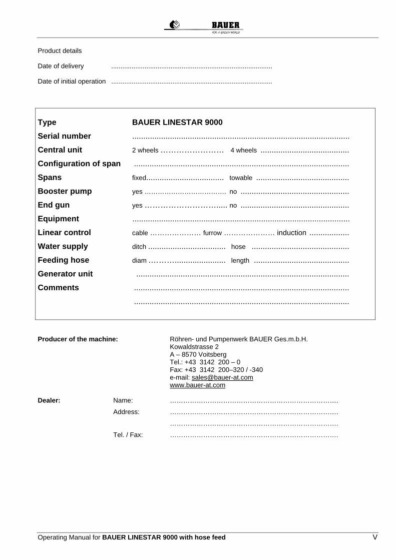
Product details Date of delivery ....................................................................................... Date of initial operation ....................................................................................... Type BAUER LINESTAR 9000
Serial number ..................................................................................................
Central unit 2 wheels …………………… 4 wheels ........................................
Configuration of span .................................................................................................
Spans fixed................................... towable ..........................................
Booster pump yes ………………………………. no .................................................
End gun yes ………………………..... no .................................................
Equipment ..................................................................................................
Linear control cable ………………… furrow ………………… induction ..................
Water supply ditch ................................... hose ............................................
Feeding hose diam .………....................... length ...........................................
Generator unit ................................................................................................
Comments .................................................................................................
.................................................................................................
Producer of the machine: Röhren- und Pumpenwerk BAUER Ges.m.b.H. Kowaldstrasse 2 A – 8570 Voitsberg Tel.: +43 3142 200 – 0 Fax: +43 3142 200–320 / -340 e-mail: [email protected] www.bauer-at.com Dealer: Name: ………………………………………………………………….
Address: ………………………………………………………………….
………………………………………………………………….
Tel. / Fax: ………………………………………………………………….

VI Operating Manual for BAUER LINESTAR 9000 with hose feed
INDEX
1 GENERAL INSTRUCTIONS .............................................................................................................................. 1
2 WARNING SYMBOLS ....................................................................................................................................... 2
3 GENERAL .......................................................................................................................................................... 3
4 GENERAL INSTRUCTIONS FOR SAFETY AND ACCIDENT PREVENTION ................................................ 3
5 SAFETY PRECAUTIONS FOR LINESTAR 9000 ............................................................................................. 4
5.1 ELECTRICAL SYSTEM .............................................................................................................................. 4 5.2 MECHANICAL SYSTEM ............................................................................................................................ 4
6 TECHNICAL DESCRIPTION ............................................................................................................................. 5
6.1 COMPONENTS OF THE LINESTAR 9000 ................................................................................................ 5 6.1.1 COMPONENTS OF THE BELOW GROUND GUIDANCE .................................................................... 6
6.2 CENTRE FEED - END FEED ..................................................................................................................... 8 6.2.1 CENTRE FEED .......................................................................................................................................... 8 6.2.2 END FEED ................................................................................................................................................. 8
7 USE OF LINESTAR ........................................................................................................................................... 9
7.1 GENERAL LIMITS ...................................................................................................................................... 9 7.1.1 INCLINATION ........................................................................................................................................... 9 7.1.2 PERMISSIBLE BENDING ANGLES ........................................................................................................ 9
7.2 LIMITS WITH BELOW GROUND GUIDANCE ......................................................................................... 10 7.2.1 LIMITS WHEN USING AN OPEN CONDUCTOR LOOP .................................................................... 10 7.2.2 LIMITS WHEN USING AN OPEN CONDUCTOR LOOP WITH ASYMMETRICAL LAYOUT ...... 11
7.3 TRACK DETERMINATION AND MAINTENANCE ................................................................................... 12 7.3.1 TRAVEL DIRECTION ............................................................................................................................ 12
8 LINESTAR CENTRAL UNIT ............................................................................................................................ 13
8.1 FOUR-WHEEL MAIN CART ..................................................................................................................... 13 8.2 TWO-WHEEL CENTRAL UNIT ................................................................................................................ 14
9 CONTROL CENTRE ........................................................................................................................................ 15
9.1 CONTROL CENTRE LINESTAR PRO ..................................................................................................... 15 9.1.1 STANDARD BUILT-IN COMPONENTS ............................................................................................... 16
9.2 CONTROL CENTRE LINESTAR PRO-G ................................................................................................. 18 9.2.1 STANDARD BUILT-IN COMPONENTS ............................................................................................... 19
10 LINEAR CONTROL SYSTEM ......................................................................................................................... 20
10.1 GENERAL ................................................................................................................................................ 20 10.2 SPECIFIED MINIMUM CURVE RADIUS ................................................................................................. 21 10.3 FURROW GUIDANCE ............................................................................................................................. 22 10.4 CABLE GUIDANCE INSTALLATION AND ADJUSTMENT ..................................................................... 22 10.5 BELOW GROUND GUIDANCE ............................................................................................................... 24
10.5.1 OSCILLATOR BOX, STEERING ANTENNAS, TRACK UNIT ........................................................... 24 10.5.2 BELOW GROUND CABLE .................................................................................................................... 27
10.6 SETTING LINEAR CONTROL ................................................................................................................. 28 10.6.1 FURROW AND CABLE GUIDANCE .................................................................................................... 28 10.6.2 BELOW GROUND GUIDANCE ............................................................................................................. 29
10.7 SETTING STOP SWITCH ........................................................................................................................ 29
11 DIESEL GENERATOR UNIT ........................................................................................................................... 31
12 ALIGNMENT OF THE LINESTAR ................................................................................................................... 31
12.1 ALIGNING THE CENTRAL UNIT PARALLEL TO THE LINEAR GUIDANCE (FURROW, CABLE) ....... 31 12.2 ALIGN SPANS 90° AT RIGHT ANGLE TO THE CENTRAL UNIT .......................................................... 32 12.3 ALIGNING THE CENTRAL UNIT TO THE LINEAR GUIDANCE (BELOW GROUND GUIDANCE) ....... 32
13 ALIGNMENT CONTROL ................................................................................................................................. 34
13.1 MICROSWITCH ADJUSTMENT .............................................................................................................. 34
14 ELECTRICAL SYSTEM ................................................................................................................................... 35
14.1 CABLES AND MARKINGS ....................................................................................................................... 35 14.2 INSTALLATION, CONNECTION OF CONTROL CENTRE ..................................................................... 36 14.3 ALIGNMENT CONTROL CONNECTION ................................................................................................. 36

Operating Manual for BAUER LINESTAR 9000 with hose feed VII
15 FIRST START-UP ........................................................................................................................................... 36
15.1 CHECKING OF CENTRAL UNIT ............................................................................................................. 36 15.2 CHECKING OF TRUSS, END TOWER AND OVERHANG ..................................................................... 37 15.3 GEARBOXES AND DRIVE MOTORS ..................................................................................................... 37
15.3.1 GEARBOXES ........................................................................................................................................... 37 15.3.2 DRIVE MOTOR ........................................................................................................................................ 38
15.4 OSCILLATOR BOX (ONLY WITH BELOW GROUND GUIDANCE) ....................................................... 38 15.5 CONTROL CENTRE ................................................................................................................................ 39
15.5.1 CHECKING VOLTAGE AND WIRING .................................................................................................. 39 15.5.2 CHECKING TOWER TRAVEL DIRECTION ......................................................................................... 39
15.6 ALIGNMENT OF THE TOWERS ............................................................................................................. 40 15.7 ALIGNMENT CONTROL ADJUSTMENT ................................................................................................ 40 15.8 CHECKING ALIGNMENT ........................................................................................................................ 41 15.9 MACHINE OFFSET FROM LINEAR GUIDANCE .................................................................................... 43
15.9.1 ALIGNMENT OF THE MACHINE WITH FURROW / CABLE GUIDANCE ...................................... 43 15.9.2 AUSRICHTEN DER MASCHINE MIT UNTERGRUNDSTEUERUNG ............................................... 44
16 TERMINOLOGY .............................................................................................................................................. 46
17 START-UP ....................................................................................................................................................... 47
17.1 START LINESTAR IN OPERATING MODE “LINEAR” ............................................................................ 47 17.1.1 START LINESTAR WITH HOSE FEED ................................................................................................. 47
17.2 STARTING AFTER INTERMEDIATE STOP............................................................................................ 47 17.3 SHUT-DOWN PROCEDURE ................................................................................................................... 48
17.3.1 SYSTEM SHUT OFF DURING IRRIGATION ....................................................................................... 48 17.3.2 AUTOMATIC SYSTEMM SHUT OFF AT FIELD END ........................................................................ 48
17.4 STARTING LINESTAR TO RUN IN OPPOSITE DIRECTION AFTER AN AUTOMATIC SHUT-DOWN 48 17.5 STARTING THE LINESTAR IN OPERATING MODE “WHEEL SWIVELLING” ...................................... 49 17.6 STARTING THE LINESTAR IN OPERATING MODE “PIVOTING” ......................................................... 49 17.7 SHUT DOWN PROCEDURE ................................................................................................................... 50
17.7.1 LINESTAR SHUT DOWN DURING IRRIGATION ............................................................................... 50 17.7.2 AUTOMATIC SHUT-OFF OF LINESTAR ............................................................................................. 50 17.7.3 STARTING INTO OPPOSITE DIRECTION AFTER AUTOMATIC SHUT-DOWN OF LINESTAR .. 51
18 MAINTENANCE INSTRUCTIONS .................................................................................................................. 51
18.1 SERVICE INTERVALS............................................................................................................................. 51 18.2 SERVICE PLAN ....................................................................................................................................... 52 18.3 POST-SEASON MAINTENANCE ............................................................................................................ 54 18.4 PRE-SEASON MAINTENANCE .............................................................................................................. 54
18.4.1 PRELOAD FORCES AND TIGHTENING TORQUES OF BOLTS ....................................................... 55
19 TROUBLESHOOTING .................................................................................................................................... 56
19.1 RESTART AFTER DOGLEGGING .......................................................................................................... 57
20 TECHNICAL DATA ......................................................................................................................................... 58
20.1 DIMENSIONS OF BAUER LINESTAR 9000 – 2 WHEEL ....................................................................... 58 20.2 DIMENSIONS OF BAUER LINESTAR 9000 - 4 WHEEL ONE SIDED .................................................. 58 20.3 DIMENSIONS OF BAUER LINESTAR 9000 - 4 WHEEL DOUBLE SIDED ............................................ 58
21 OPTIONS ......................................................................................................................................................... 59
21.1 LOW PRESSURE SHUT-OFF ................................................................................................................. 59 21.2 ELECTRIC SHUT-OFF VALVE (CENTRAL UNIT) .................................................................................. 59 21.3 END GUN ................................................................................................................................................. 59 21.4 BOOSTER PUMP FOR END GUN .......................................................................................................... 59 21.5 AUTOMATIC INTERVAL CONTROL ....................................................................................................... 60 21.6 AUTOMATIC „ON/OFF” AND INTERVAL CONTROL ............................................................................. 60 21.7 TOWER ALIGNMENT SWITCH ............................................................................................................... 60 21.8 RUNNING LIGHT ..................................................................................................................................... 60 21.9 END STOP ............................................................................................................................................... 60 21.10 STOP RAMP ............................................................................................................................................ 61
22 TOWING OF LINESTAR 2-WHEEL ................................................................................................................ 61
22.1 TOWING THE LINESTAR FROM CENTRAL UNIT ................................................................................. 61 22.1.1 SWIVELLING CENTRAL UNIT WHEELS ............................................................................................ 62 22.1.2 SWIVELLING TOWER WHEELS ........................................................................................................... 62 22.1.3 MOUNTING THE TOW CABLES ON “-WHEEL CENTRAL UNIT .................................................... 62

VIII Operating Manual for BAUER LINESTAR 9000 with hose feed
22.2 TOWING THE LINESTAR AT THE END TOWER .................................................................................. 63 22.2.1 SWIVELLING CENTRAL UNIT WHEELS (PROCEED ACCORDING TO ITEM 17.5) ...................... 63 22.2.2 SWIVELLING TOWER WHEELS .......................................................................................................... 63 22.2.3 BRACING THE END TOWER ................................................................................................................ 64
22.3 TOWING THE LINESTAR AT A FREESTANDING SPAN ..................................................................... 64 22.3.1 SWIVELLING CENTRAL TOWER WHEELS (ACCORDING TO ITEM 17.5) .................................. 64 22.3.2 SWIVELLING TOWER WHEELS .......................................................................................................... 64 22.3.3 BRACING THE END TOWER AND THE CENTRAL UNIT ................................................................ 65
23 ELECTRICAL WIRING DIAGRAMS ............................................................................................................... 66
23.1 CONTROL CENTER LINESTAR PRO ..................................................................................................... 67 23.1.1 CONTROL CENTER LINESTAR PRO - WIRING DIAGRAM 1 ......................................................... 67 23.1.2 CONTROL CENTRE LINESTAR PRO - INFEED ................................................................................. 70
23.2 CONTROL CENTRE LINESTAR PRO WITH BELOW GROUND GUIDANCE ....................................... 72 23.2.1 CONTROL CENTRE LINESTAR PRO W. BELOW GROUND GUIDANCE - WIRING DIAGRAM 173 23.2.2 CONTROL CENTRE LINESTAR PRO W. BELOW GROUND GUIDANCE - INFEED ..................... 76
23.3 CONTROL CENTRE LINESTAR PRO-G ................................................................................................. 81 23.3.1 CONTROL CENTRE LINESTAR PRO-G - WIRING DIAGRAM 1 ..................................................... 81 23.3.2 CONTROL CENTRE LINESTAR PRO-G - INFEED ............................................................................. 84
23.4 LINESTAR LINEAR CONTROL ............................................................................................................... 86 23.4.1 FURROW GUIDANCE - WIRING DIGRAM ......................................................................................... 87 23.4.2 CABLE GUIDANCE - WIRING DIGRAM ............................................................................................. 88 23.4.3 BELOW GROUND GUIDANCE OSCILLATOR BOX - WIRING DIGRAM....................................... 89 23.4.4 BELOW GROUND GUIDANCE TRACK UNIT - WIRING DIGRAM 1 .............................................. 90 23.4.5 BELOW GROUND GUIDANCE TRACK UNIT - WIRING DIGRAM 2 .............................................. 91
23.5 LINESTAR TOWER BOX ......................................................................................................................... 92 23.5.1 TOWER BOX - STANDARD .................................................................................................................. 92 23.5.2 TOWER BOX - WITH TOWER ALIGNMENT SWITCH ..................................................................... 92 23.5.3 TOWER BOX - WITH END TOWER MONITORING ........................................................................... 94 23.5.4 TOWER BOX - WITH TOWER ALIGNMENT SWITCH & END TOWER MONITORING ............... 95 23.5.5 END TOWER BOX - STANDARD ......................................................................................................... 96 23.5.6 END TOWER BOX - WITH TOWER ALIGNMENT SWITCH ............................................................ 97 23.5.7 END TOWER BOX - WITH END STOP ................................................................................................ 98 23.5.8 END TOWER BOX - WITH END STOP & TOWER ALIGNMENT SWITCH .................................... 99 23.5.9 END TOWER BOX - WITH END STOP & AUTOREVERSE ............................................................. 100 23.5.10 END TOWER BOX - WITH END STOP & AUTOREVERSE ............................................................. 101
23.6 BOOSTER PUMP FOR END GUN ........................................................................................................ 102
24 SERVICE – EVIDENCE ................................................................................................................................. 103
25 CONFORMITY CERTIFICATE ...................................................................................................................... 107

Operating Manual for BAUER LINESTAR 9000 with hose feed 1
1 GENERAL INSTRUCTIONS
CE SYMBOL
The CE symbol that has to be affixed on the machine by the manufacturer outwardly demonstrates compliance of the machine with the directives for machines and other relevant EU directives. EU conformity certificate (see Annex)
This “Warning” symbol refers to important safety instructions in this manual. Whenever you see this symbol be aware of possible injury hazards. Read the note following the symbol very carefully and inform the other operators accordingly.
Non-observance of this instruction may damage or destroy the machine or individual components.
It is very important to observe this note or instruction carefully!
Qualified operators These are persons who on behalf of their training, experience and instruction as well as their knowledge of relevant standards, rules, precautions to be taken for accident prevention, and prevailing operating conditions, have been authorised by the person in charge of plant safety to perform the respective tasks required, and in doing so are able to recognise and avoid potential hazards. Among other things, knowledge of first-aid procedures is also required.
Product liability According to the product liability law every farmer is an entrepreneur! According to §9 PHG (Product Liability Law), liability for damage to corporeal things caused by defective products is expressly excluded. This exclusion of liability also applies to parts not manufactured by BAUER itself but purchased from external suppliers.
Duty to furnish information Even if he passes on the machine to a new owner later-on, the customer is obliged to hand on the operating manual to the new owner, too. The receiver of the machine must be instructed with reference to the mentioned regulations.
Intended use BAUER LINESTAR 9000 has been constructed exclusively for use in normal irrigation (intended use). Any employment beyond this normal use is considered non-conforming. The manufacturer is not liable for
damage resulting from such non-conforming use, the sole liability for damage from non-conforming use is with the user.
Intended use also includes compliance with manufacturer’s operating, maintenance and service instructions. BAUER LINESTAR 9000 may be used and operated only by persons who are familiar with the system and
aware of the hazards involved. Al l relevant rules for accident prevention as well as any other generally accepted specifications and regulations
relating to safety, work medicine and traffic law must be strictly observed. Unauthorised modifications on the machine release the manufacturer from liability for damage resulting
therefrom.
WARNING !
CAUTION !
NOTE!

2 Operating Manual for BAUER LINESTAR 9000 with hose feed
2 WARNING SYMBOLS Danger points on the pivot system are specifically marked by safety stickers. These stickers must be affixed at the mentioned points clearly visible and serve for protection of persons working on or near the system. 1.
WARNING !
Study and observe the manual and all safety instruction carefully before you put the system
into operation.
2.
WARNING !
Before maintenance and repair work, always stop the system, disconnect all power, and read
the operating manual.
3.
WARNING ! 1. This system is powered by 400 Volts!
Danger of electrical shock / injury hazard ! 2. Do not attempt to check any components while the system is live! 3. Open the inner pivot panel door only when main switch is OFF.
4.
WARNING ! 1. The working range of the pivot must always be at a safe distance from electrical power
lines. 2. Pull towable systems only at a safe distance from electrical power lines.
Make sure that the water jet from spray nozzles and end gun does not hit electrical lines. The water jet of the nozzles and of the end gun must not touch electrical wires!
5.
WARNING ! The system can start automatically. Always keep a safe distance from the towers.
Operating Manual for BAUER LINESTAR 9000 with hose feed 3
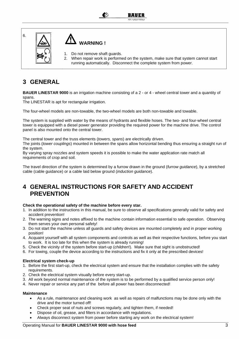
6.
WARNING ! 1. Do not remove shaft guards. 2. When repair work is performed on the system, make sure that system cannot start
running automatically. Disconnect the complete system from power.
3 GENERAL BAUER LINESTAR 9000 is an irrigation machine consisting of a 2 - or 4 - wheel central tower and a quantity of spans. The LINESTAR is apt for rectangular irrigation. The four-wheel models are non-towable, the two-wheel models are both non-towable and towable. The system is supplied with water by the means of hydrants and flexible hoses. The two- and four-wheel central tower is equipped with a diesel power generator providing the required power for the machine drive. The control panel is also mounted onto the central tower. The central tower and the truss elements (towers, spans) are electrically driven. The joints (tower couplings) mounted in between the spans allow horizontal bending thus ensuring a straight run of the system. By varying spray nozzles and system speeds it is possible to make the water application rate match all requirements of crop and soil. The travel direction of the system is determined by a furrow drawn in the ground (furrow guidance), by a stretched cable (cable guidance) or a cable laid below ground (induction guidance).
4 GENERAL INSTRUCTIONS FOR SAFETY AND ACCIDENT PREVENTION Check the operational safety of the machine before every star. 1. In addition to the instructions in this manual, be sure to observe all specifications generally valid for safety and
accident prevention! 2. The warning signs and notes affixed to the machine contain information essential to safe operation. Observing
them serves your own personal safety! 3. Do not start the machine unless all guards and safety devices are mounted completely and in proper working
position! 4. Acquaint yourself with all system components and controls as well as their respective functions, before you start
to work. It is too late for this when the system is already running! 5. Check the vicinity of the system before start-up (children!). Make sure that sight is unobstructed! 6. For towing, couple the device according to the instructions and fix it only at the prescribed devices! Electrical system check-up 1. Before the first start-up, check the electrical system and ensure that the installation complies with the safety
requirements. 2. Check the electrical system visually before every start-up. 3. All work beyond normal maintenance of the system is to be performed by a qualified service person only! 4. Never repair or service any part of the before all power has been disconnected! Maintenance
As a rule, maintenance and cleaning work as well as repairs of malfunctions may be done only with the drive and the motor turned off!
Check proper seat of nuts and screws regularly, and tighten them, if needed! Dispose of oil, grease, and filters in accordance with regulations. Always disconnect system from power before starting any work on the electrical system!

4 Operating Manual for BAUER LINESTAR 9000 with hose feed
Before electrical welding on the machine or on built-on components, cut power supply or disconnect generator!
Spare parts must meet at least the technical requirements defined by the manufacturer! This is guaranteed by the use of original spare parts!
5 SAFETY PRECAUTIONS FOR LINESTAR 9000 In addition to the GENERAL INSTRUCTIONS FOR SAFETY AND ACCIDENT PREVENTION, the following safety principles for operating the BAUER LINESTAR 9000 must be strictly observed.
5.1 ELECTRICAL SYSTEM
WARNING ! System is powered by 400V, so be sure to practice utmost caution when handling the electrical system and the electric drive!
1. All metal parts of the unit must be interconnected, all tower couplings must be bridged with a cable. 2. In addition the yellow-green earth conductor, which goes with the power supply, must be connected to the
protective conductor terminal in the control panel. 3. Before working on electrical components, make sure the system has been disconnected from all poles
and sources, and the generator has been stopped. 4. Secure the main switch with a padlock against unintentional re-closing. 5. Check electrical system for zero potential. 6. Never repair or short-circuit a fuse by means of a wire or any other item. 7. Immediately repair or replace all wires with defective isolation. 8. Do never bridge the system safety circuit except for system aligning by a qualified person.
5.2 MECHANICAL SYSTEM
WARNING !
1. Never service or repair any part or system component while the machine is operating. 2. Always disconnect the system from power before starting any maintenance work. Turn the main switch to
„0“ and padlock the switch to prevent unintentional re-closing. Stop the generating unit. Be sure to power off the machine by yourself!
3. Before you start, make sure that all persons have left the operating range of the system. 4. Make sure no objects or vehicles are in or near the system tracks when system is starting to operate or is
actually running. 5. During system run, the towers shut on and off automatically. So keep a safe distance from the towers. 6. Never climb on the system while it is running. 7. Utmost care is required by the operator when spans are aligned. 8. Always turn off the system and stop water supply before working on sprinklers or spray nozzles. 9. Use adequate means of access (ladder, elevating platform) for work on sprinklers or spray nozzles. 10.Proceed with utmost caution, when system is working near or under electric power lines, so that neither
the metal structure nor the water jets of sprinklers get in contact with live wires. 11.When towing movable systems, make sure the system does not get in contact with a power line. 12.Make sure not to wet neighbouring plots or roads with the end gun. This could cause damage or accidents. 13.If fertilisers or other chemicals are added to the irrigation water, avoid mist and do not inhale it.

Operating Manual for BAUER LINESTAR 9000 with hose feed 5
6 TECHNICAL DESCRIPTION
6.1 COMPONENTS OF THE LINESTAR 9000
CENTRAL TOWER Travelling central tower (rigid or swivable wheels depending on model) with linear control, diesel generator unit, connection for water supply, control centre. SPAN Arched truss consisting of the water-carrying pipes, the truss rods and V-Jacks. TOWER Carries the span weight and provides the electromechanical drive of the system. Components: wheel carrier, tower bracing angle, electrical drive motor, drive shafts, wheel gears and wheels. TOWER COUPLING Joint between the spans. Possible articulation: up to 30%. ALIGNMENT CONTROL Electromechanical control system, that monitors the horizontal angular deviation between the spans and switches the drive motors. OVERHANG Overhanging part from last tower to system end. END GUN Wide range sprinkler at the end of overhang for more spaying range. BOOSTER PUMP Electric pump on the last tower for increase of pressure to end gun. BELOW GROUND GUIDANCE

6 Operating Manual for BAUER LINESTAR 9000 with hose feed
The components of the below ground guidance receive signals emitted by a below ground cable, which are evaluated and are made available to the linear guidance of the CENTRELINER with BELOW GROUND GUIDANCE. BELOW GROUND CABLE Signals for linear guidance of the machine are emitted via the below ground cable.
6.1.1 COMPONENTS OF THE BELOW GROUND GUIDANCE
6.1.1.1 OSCILLATOR BOX ASSEMBLY OSCILLATOR BOX The oscillator box generates the signal required for the linear guidance which is fed to a conductor loop (below ground cable). COVER The cover serves to protect the unit against weather influences such as rain, wind, sun etc. MOUNTING LEGS The oscillator box and cover are mounted to the two mounting legs. Both mounting legs are plugged into the soil directly at the end of the field.
Frequenzgenerator komplett Oscillator Box Assembly
Tragewinkel Mounting Legs
Frequenzgenerator Oscillator Box
Abdeckung Cover

Operating Manual for BAUER LINESTAR 9000 with hose feed 7
6.1.1.2 STEERING ANTENNAS The steering antennas are mounted to the antenna mounting devices. They receive the signal emitted by the underground cable.
6.1.1.3 TRACK UNIT The signal received by the steering antenna is processed in the track unit and is transmitted to the control centre.
Auswerteeinheit Track Unit
Antennenrohr Antenna Mounting
Endstopp für LS m. UG-Strg. End Stop Device f. LS w. BG-Guidance
Lenkantenne Steering Antenna

8 Operating Manual for BAUER LINESTAR 9000 with hose feed
6.2 CENTRE FEED - END FEED
6.2.1 CENTRE FEED The central tower is located in the middle of the system and is part of the free-standing span.
6.2.2 END FEED The central tower is located at the end of the system being end tower as well Compared to the cable- and furrow-guidance the components of the Below Ground-Guidance are always located in the centre of the machine.

Operating Manual for BAUER LINESTAR 9000 with hose feed 9
7 USE OF LINESTAR
7.1 GENERAL LIMITS
7.1.1 INCLINATION
The maximum permissible inclination along the travel direction in linear mode for the central tower as well as for the drive towers is 3,0°.
7.1.2 PERMISSIBLE BENDING ANGLES
Maximum permissible inclination along the span is 3,0°. Maximum difference in elevation between central tower and the first tower is 1 m!

10 Operating Manual for BAUER LINESTAR 9000 with hose feed
7.2 LIMITS WITH BELOW GROUND GUIDANCE
7.2.1 LIMITS WHEN USING AN OPEN CONDUCTOR LOOP
OPEN CONDUCTOR LOOP symmetrical layout
OPEN CONDUCTOR LOOP symmetrical layout
7.2.1.1 PERMISSIBLE BENDING ANGLES Steering antennas in middle of span

Operating Manual for BAUER LINESTAR 9000 with hose feed 11
7.2.1.2 PERMISSIBLE INCLINATION Steering antennas in middle of span
7.2.2 LIMITS WHEN USING AN OPEN CONDUCTOR LOOP WITH ASYMMETRICAL LAYOUT
OPEN CONDUCTOR LOOP symmetrical layout
In addition to the previously indicated limits, the following deviation tolerances must be complied with.
12 Operating Manual for BAUER LINESTAR 9000 with hose feed
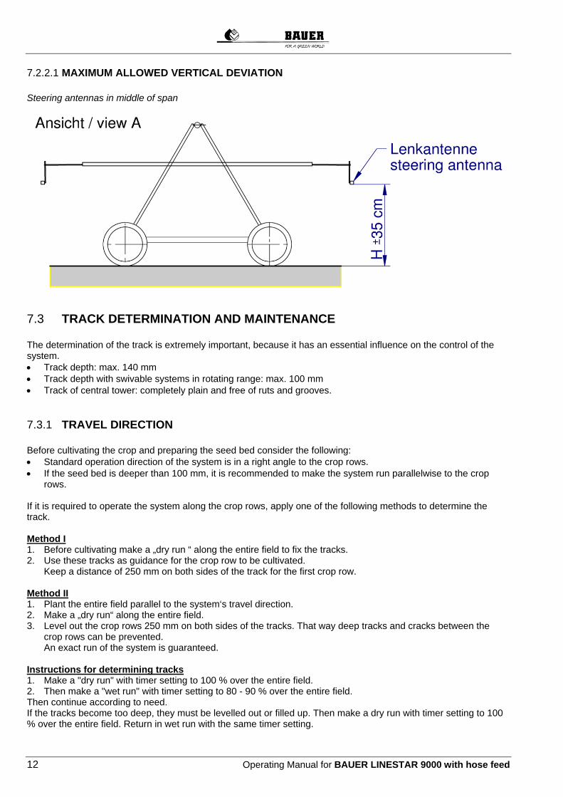
7.2.2.1 MAXIMUM ALLOWED VERTICAL DEVIATION Steering antennas in middle of span
7.3 TRACK DETERMINATION AND MAINTENANCE The determination of the track is extremely important, because it has an essential influence on the control of the system. Track depth: max. 140 mm Track depth with swivable systems in rotating range: max. 100 mm Track of central tower: completely plain and free of ruts and grooves.
7.3.1 TRAVEL DIRECTION Before cultivating the crop and preparing the seed bed consider the following: Standard operation direction of the system is in a right angle to the crop rows. If the seed bed is deeper than 100 mm, it is recommended to make the system run parallelwise to the crop
rows. If it is required to operate the system along the crop rows, apply one of the following methods to determine the track. Method I 1. Before cultivating make a „dry run “ along the entire field to fix the tracks. 2. Use these tracks as guidance for the crop row to be cultivated.
Keep a distance of 250 mm on both sides of the track for the first crop row.
Method II 1. Plant the entire field parallel to the system‘s travel direction. 2. Make a „dry run“ along the entire field. 3. Level out the crop rows 250 mm on both sides of the tracks. That way deep tracks and cracks between the
crop rows can be prevented. An exact run of the system is guaranteed.
Instructions for determining tracks 1. Make a "dry run" with timer setting to 100 % over the entire field. 2. Then make a "wet run" with timer setting to 80 - 90 % over the entire field. Then continue according to need. If the tracks become too deep, they must be levelled out or filled up. Then make a dry run with timer setting to 100 % over the entire field. Return in wet run with the same timer setting.

Operating Manual for BAUER LINESTAR 9000 with hose feed 13
8 LINESTAR CENTRAL UNIT
8.1 FOUR-WHEEL MAIN CART
The main cart (central unit) consists of the following components: Main frame with 4 rigid wheels (14.9-24) 2 drive gear motors 0.55kW, drive of 4 wheel gear via shaft drives 2 supply connections with HK coupling in front Supply riser pipe DN 150/200, electrical shut-off valve Control centre LINESTAR PRO / LINESTAR PRO-G Linear guidance (furrow guidance, cable guidance or below ground guidance) Diesel power generator according to system requirements 10kVA – 20kVA, Supply hose according to system capacity 4“ to 6“ At the field end the supply hose must be connected to the rear side of the main cart for the return run.
Generatoraggregat Generator Set
Schlauchanschluss Hose Connection Schlauchanschluss
Hose Connection
Steuerzentrale Main Control Unit
Steigleitung Riser Main

14 Operating Manual for BAUER LINESTAR 9000 with hose feed
8.2 TWO-WHEEL CENTRAL UNIT
The central unit is towable (optionally available). The central unit consists of the following components: Main frame with 2 electrically swivelling wheels 2 drive gear motors 0,55 kW, drive of 2 wheel gear via Hardy-Spicer universal joints 2 supply connections with HK coupling on the side Supply rising pipe DN 125 or DN 150, electrical shut-off valve Control centre LINESTAR PRO / LINESTAR PRO-G Linear guidance (furrow guidance, cable guidance or below ground guidance) Diesel power generator 8kVA - 20kVA Connecting hose depending on system capacity 4“ - 6” For towing the machine the wheels of the central tower can be swivelled electrically. At the end of the field it is not necessary to change the connection of the supply hose at the central unit for the return run.
Generatoraggregat Generator Set
Steuerzentrale Main Control Unit
Schlauchanschluss Hose Connection
Furchensteuerung Furrow Guidance
Schwenkeinrichtung Pivoting Arrangement
Steigleitung Riser Main

Operating Manual for BAUER LINESTAR 9000 with hose feed 15
9 CONTROL CENTRE
9.1 CONTROL CENTRE LINESTAR PRO Design and material according to ÖVE and VDE standards, built-in components according to IEC standards and VDE regulations.
Water-proof polyester box (protection IP 54) with lockable front door Swivelling operating panel, can only be opened after turning off main switch Operating voltage 400 V Control voltage: 230 V monophase Isolating transformer for control voltage Commercial contactors Wiring with lugs Protection devices
ATTENTION! To protect against soiling and splash water always close the control panel during operation.
1. Main switch 2. Control panel LINESTAR PRO 3. Voltmeter 4. Switch "LINESTAR OFF - ON“ 5. Switch "SAFETY ON – OFF“ 6. Switch "ENDGUN OFF - ON“ 7. Switch "GENSET OFF – ON” 8. Switch "EMERGENCY STOP”
1
2
3
4 5 6 7
8
16 Operating Manual for BAUER LINESTAR 9000 with hose feed
9.1.1 STANDARD BUILT-IN COMPONENTS
9.1.1.1 MAIN SWITCH With the main switch the entire power supply is shut on or off. In position "I" the electric power supply of the machine is established. The hinged operating panel in this position is locked for safety reasons. In position “0“ the power supply of the system is turned off. In this position the main switch can be locked against unintentional switching on. The hinged operating panel can only be opened in this switch position.
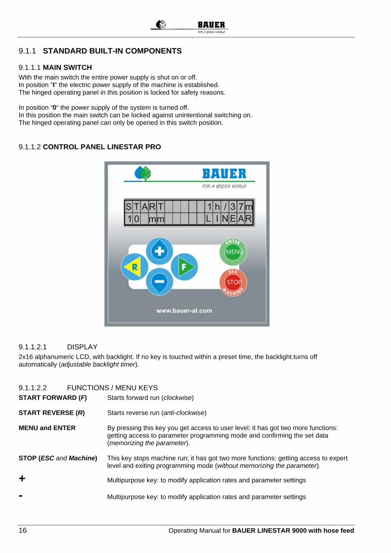
9.1.1.2 CONTROL PANEL LINESTAR PRO
9.1.1.2.1 DISPLAY 2x16 alphanumeric LCD, with backlight. If no key is touched within a preset time, the backlight.turns off automatically (adjustable backlight timer).
9.1.1.2.2 FUNCTIONS / MENU KEYS START FORWARD (F) Starts forward run (clockwise) START REVERSE (R) Starts reverse run (anti-clockwise) MENU and ENTER By pressing this key you get access to user level; it has got two more functions:
getting access to parameter programming mode and confirming the set data (memorizing the parameter).
STOP (ESC and Machine) This key stops machine run; it has got two more functions: getting access to expert
level and exiting programming mode (without memorizing the parameter).
+ Multipurpose key: to modify application rates and parameter settings
- Multipurpose key: to modify application rates and parameter settings

Operating Manual for BAUER LINESTAR 9000 with hose feed 17
9.1.1.3 VOLTMETER Indicates the voltage between phases L1 and L2.
9.1.1.4 SWITCH ”LINESTAR OFF-ON” Establishes power supply of control panel. In the “ON” position, the system can be started or stopped with an operation on the LINESTAR PRO control panel.
9.1.1.5 SWITCH SAFETY CIRCUIT ON-OFF” If this switch has been put to position “ON”, the whole system will be shut down in case of malfunction (misalignment). The position “OFF” is only to be used by an expert person for system alignment. Whenever the machine is running the switch must be in position “ON” in order to guarantee a safe unattended run!
9.1.1.6 SWITCH “END GUN OFF-ON” In position “ON” the end gun is in use, in position “OFF” it is out of use.
9.1.1.7 SWITCH “GENERATOR OFF-ON” The generator unit shuts down automatically. ON
when system runs into safety circuit. in case of pressure loss in supply line at end stop at intermediate stop, e.g. when changing the connection of the supply hose. Use this setting for regular run!
OFF In this position the generator unit does not shut down automatically for the above mentioned reasons.
This setting is used for: aligning the LINESTAR dry run of LINESTAR
9.1.1.8 SWITCH “EMERGENCY STOP” Control unit is cut off power

18 Operating Manual for BAUER LINESTAR 9000 with hose feed
9.2 CONTROL CENTRE LINESTAR PRO-G Design and material according to ÖVE and VDE standards, built-in components according to IEC standards and VDE regulations.
Water-proof polyester box (protection IP 54) with lockable front door Swivelling operating panel, can only be opened after turning off main switch Operating voltage 400 V Control voltage: 230 V monophase Isolating transformer for control voltage Commercial contactors Wiring with lugs Protection devices
ATTENTION! To protect against soiling and splash water always close the control panel during operation.
1. Main switch 2. Control panel LINESTAR PRO-G 3. Voltmeter 4. Switch "LINESTAR OFF - ON“ 5. Switch "SAFETY ON – OFF“ 6. Switch "ENDGUN OFF - ON“ 7. Switch "GENSET OFF – ON” 8. Switch "EMERGENCY STOP”
1
2
3
4 5 6 7
8
Operating Manual for BAUER LINESTAR 9000 with hose feed 19
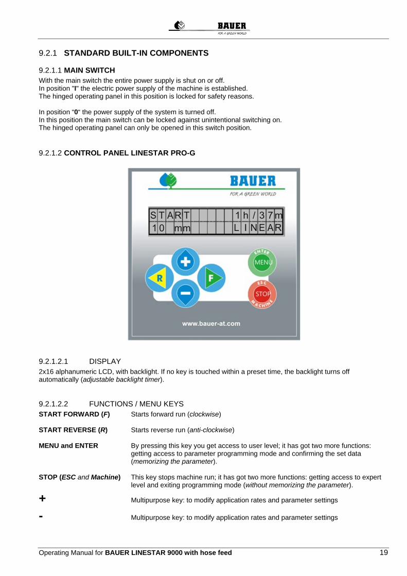
9.2.1 STANDARD BUILT-IN COMPONENTS
9.2.1.1 MAIN SWITCH With the main switch the entire power supply is shut on or off. In position "I" the electric power supply of the machine is established. The hinged operating panel in this position is locked for safety reasons. In position “0“ the power supply of the system is turned off. In this position the main switch can be locked against unintentional switching on. The hinged operating panel can only be opened in this switch position.
9.2.1.2 CONTROL PANEL LINESTAR PRO-G
9.2.1.2.1 DISPLAY 2x16 alphanumeric LCD, with backlight. If no key is touched within a preset time, the backlight turns off automatically (adjustable backlight timer).
9.2.1.2.2 FUNCTIONS / MENU KEYS START FORWARD (F) Starts forward run (clockwise) START REVERSE (R) Starts reverse run (anti-clockwise) MENU and ENTER By pressing this key you get access to user level; it has got two more functions:
getting access to parameter programming mode and confirming the set data (memorizing the parameter).
STOP (ESC and Machine) This key stops machine run; it has got two more functions: getting access to expert
level and exiting programming mode (without memorizing the parameter).
+ Multipurpose key: to modify application rates and parameter settings
- Multipurpose key: to modify application rates and parameter settings

20 Operating Manual for BAUER LINESTAR 9000 with hose feed
9.2.1.3 VOLTMETER Indicates the voltage between phases L1 and L2.
9.2.1.4 SWITCH ”LINESTAR OFF-ON” Establishes power supply of control panel. In the “ON” position, the system can be started or stopped with an operation on the LINESTAR PRO-G control panel.
9.2.1.5 SWITCH “SAFETY CIRCUIT ON-OFF” If this switch has been put to position “ON”, the whole system will be shut down in case of malfunction (misalignment). The position “OFF” is only to be used by an expert person for system alignment. Whenever the machine is running the switch must be in position “ON” in order to guarantee a safe unattended run!
9.2.1.6 SWITCH “END GUN OFF-ON” In position “ON” the end gun is in use, in position “OFF” it is out of use.
9.2.1.7 SWITCH “GENERATOR OFF-ON” The generator unit shuts down automatically. ON
when system runs into safety circuit. in case of pressure loss in supply line at end stop at intermediate stop, e.g. when changing the connection of the supply hose. Use this setting for regular run!
OFF In this position the generator unit does not shut down automatically for the above mentioned reasons.
This setting is used for: aligning the LINESTAR dry run of LINESTAR
9.2.1.8 SWITCH “EMERGENCY STOP” Control unit is cut off power
10 LINEAR CONTROL SYSTEM
10.1 GENERAL The LINESTAR is guided along a furrow in the ground (FURROW GUIDANCE), along a guiding cable (CABLE GUIDANCE) or contact-free along a below ground cable (BELOW GROUND GUIDANCE). The linear control system mounted at the side of the central tower controls both end towers. This control system allows the system to run always parallel to the control furrow / guiding cable or to the below ground cable. Two control rollers transmit the distance and the angle of the central tower to the furrow or the cable to the correction control, while in the case of inductive guidance, the guide signal of the below ground cable is received via the steering antennas and subsequently transmitted to the control centre. The linear control system consists of two control units, the one at the front (looking into travel direction) being always responsible for the control of the system and controlling the operation of the electric drive motor of the end towers. An oscillator is additionally required here for transmission of the guide signal (INDUCTION GUIDANCE) (not for furrow or cable guidance).

Operating Manual for BAUER LINESTAR 9000 with hose feed 21
10.2 SPECIFIED MINIMUM CURVE RADIUS
A end tower swivels around main cart Radius = 2 x SL Radius min. = 600 m
B main cart swivels around end tower Radius = 3 x SL Radius min. = 900 m

22 Operating Manual for BAUER LINESTAR 9000 with hose feed
10.3 FURROW GUIDANCE
Max. deviation of the straight line
10.4 CABLE GUIDANCE INSTALLATION AND ADJUSTMENT 1. The Cable Guidance system consists of an above ground cable that is supported by a line of pipe posts which are placed every 6 m. For installation be sure to observe the following two conditions: A. The posts must be located in a perfectly straight line. B. The cable must be properly tensioned.
2. Posts: The posts must be paralleled to the ditch (ditch feed) or to the track of the central tower (hose feed) respectively. They must be placed every 6 m in a straight line. The last posts at the end of the field must be solidly embedded in the soil by ground anchors to withstand the cable tension.
Steuerarm Steering Arm
Steuereinheit Control Unit
Kufe Skid

Operating Manual for BAUER LINESTAR 9000 with hose feed 23
3. Cable The Cable is attached to the posts by the means of clips welded onto the posts. Attach one end of the cable to the end post with a thimble and three clips. Five meters before the opposite end of the cable attach a second, 10 m long cable to the main cable with three clips. Fasten the end of this second cable to a vehicle or a tractor and pull until the cable is well tensioned. Recommended cable tension: approx 4000 N. After tensioning fasten the main cable to the end post and remove the auxiliary cable.
Klemme Clip
Seil Cable
Seilhalter Cable Holder
Seilklemmen Cable Clamps
2. Seil Second Cable
Weg Road
Hauptseil Main Cable
Bodenanker End Post

24 Operating Manual for BAUER LINESTAR 9000 with hose feed
10.5 BELOW GROUND GUIDANCE
10.5.1 OSCILLATOR BOX, STEERING ANTENNAS, TRACK UNIT The oscillator box assembly is supplied in a hose-proof box with a steel sheet cover and it is set up on the corresponding mounting legs directly on the field anywhere along the conductor loop. It is purposeful not to set it up on the irrigated / planted surface.
Steuereinheit Control Unit
Steuerrolle Control Roller
Steuerseil Control Cable
Seilhalter Cable Holder
Frequenzgenerator komplett Oscillator Box Assembly
Frequenzgenerator Oscillator Box
Abdeckung Cover
Tragewinkel Mounting Legs

Operating Manual for BAUER LINESTAR 9000 with hose feed 25
By means of the transformer installed, the oscillator box can either be connected to a 230V AC / 50Hz supply line or it can be supplied directly by a battery of 24V DC (2 x 12V DC). A voltage of 24V with a frequency of 1,5KHz is supplied directly to the cable laid below ground. The magnetic field generated thus is detected by the steering antennas and the voltage induced is evaluated in the so-called track unit. Important information: At first putting into operation, the below ground cable will generally be connected to the "long connection" terminal of the oscillator box. If the system works duly, the green LED will be lit. First putting into operation is exclusively carried out under the presence of a BAUER technician or of an authorized dealer and it must not be carried out by unqualified personnel.
Connection "short" is appropriate for a conductor loop of max. 1 – 15 Ohm impedance and a max. current of 600 mA.
Connection "long" is appropriate for a conductor loop of max. 3 – 75 Ohm impedance and a max. current of 300 mA.
Setting screw for amperage for adjusting the signal strength (see 15 First Start up).
setting screw for amperage

26 Operating Manual for BAUER LINESTAR 9000 with hose feed
If the loop's impedance is too high, the bottommost of the 4 check lamps will be lit red. If it is too low, the lamp above (2nd from bottom) will be lit red. The signal strength is appropriate, if the 3rd lamp from bottom will be lit green. The first check lamp indicates whether the oscillator is supplied with voltage. After the first start, the oscillator box does not require any maintenance in normal operation. In battery operation, it is necessary to change the batteries in due time. It is recommended to use batteries with a minimum capacity of 160 Ah in order to guarantee uninterrupted operation of one week. The actual operating time depends on local conditions, that is, on the loop length and/or on the current actually consumed by the oscillator box.
Magnetfeld /magnetic field
Untergrundkabel /buried cable
Lenkantenne/steering antenna
Lenkantenne/steering antenna
Lenkantenne/steering antenna
Links/left
Rechts/right0
In the steering antennas, electric coils are installed which are able to detect lines of electric flux in horizontal and vertical direction to the ground – caused by the current passing the below ground conductor. As can be seen from the above sketch, the direction of the voltage induced in a spool changes only when the antenna moves from the left to the right side and vice versa of the below ground cable. Subsequently these signals are processed in the so-called track unit and they are transmitted to the control centre of the system which on the other hand emits a control signal to the corresponding tower's motor if necessary. The steering antennas are connected by a 4-poles standard plug.
steering antenna
track unit
The steering antennas are connected to the track unit at bushes "ANT1" and "ANT2" whereby "ANT1" is provided for the front steering antenna (seen in travel direction "Forward").
The track unit is connected to the control centre via a 5-poles connector plug "BUS1".
The "PWR RS232" interface serves for communication with the PC for configuration settings. For daily operation, this connection is not used. The track unit must not and/or need not be configured subsequently because it is supplied in preset condition.

Operating Manual for BAUER LINESTAR 9000 with hose feed 27
"BUS2" is not used.
10.5.2 BELOW GROUND CABLE For transmission of the below ground signal, a below ground cable with steel reinforcement especially developed for BAUER company, is used which serves above all as anti-bite protection (against rodents etc.).
It is pointed out expressively that perfect and long-lasting function can only be guaranteed with the original BAUER below ground cable. Multi-part below ground cables must be connected exclusively with the connecting sleeves supplied along and they must be closed so that they are absolutely waterproof. Mind that the original status of the cable at the connection point must be re-established, that is, the copper wire must be insulated duly and in addition the wire must be enveloped with the steel cover. Then the connecting sleeve can be sealed and closed.
ATTENTION: Mind the correct connection of the below ground cable to the EARTH STRIP!
Laying of the cable must be done by means of appropriate machines and devices in order to ensure exact straightness of the cable. The maximum cable deviation must not exceed ±1,5 cm. Be sure that there are no abrupt "changes in direction" such as buckles etc. in the cable because they would cause increased stresses in the trusses and/or in the system and they would hence lead to malfunction. If you use an OPEN CONDUCTOR LOOP WITH ASYMMETRICAL LAYOUT for the track guide (see 7.2.2 Limits when using an open conductor loop with ASYMMETRICAL LAYOUT), you must lay the below ground cable with a slight curve “to the inside” at both ends of the field because this begins to “sense” the return conductor and would subsequently cause a deviation from the straight line. The path of the curve depends on 2 factors: the height of the antenna relative to the buried cable and the distance to the return conductor at the respective end of the field. It is recommended to initially refrain from closing the “cable trench” at the ends of the field after laying the cable. A test run with any necessary corrections must be performed in order to ensure that the system moves straight, as intended. It should also be ensured that the ground at the start and end of the field is sufficiently level since any unevenness would alter the height of the antenna, which could have an influence on the straight travel of the machine as described above.

28 Operating Manual for BAUER LINESTAR 9000 with hose feed
The conductor must be laid in a depth of 70 cm to 90 cm, depth which depends on the local conditions. Normally it is given by the customer.
For more detailed information about laying of the cable, see the CABLE LAYING INSTRUCTIONS FOR BELOW GROUND GUIDANCE under separate cover.
10.6 SETTING LINEAR CONTROL
10.6.1 FURROW AND CABLE GUIDANCE Before starting, adjust the linear control system such that the central tower will run parallel to the guiding cable or to the guiding furrow in both directions. The setting of the switch points for furrow and cable guidance is basically the same.
Position the central unit in relation to the cable or the furrow in such a way, that both control arms, when they are in their operating condition (rollers on the cable or in the furrow) form a straight line with the fixed control frame of the central unit.
Loosen the fixing screw on the control rod, which actuates the control cam of the control system. The control rod moves freely on the guide pin.
By moving the control rod hence and forth, the switching points of the micro-switches are determined. Every micro-switch has two switching points, a switch-on point and a switch-reverse point. Each of these switching points is marked on the guiding pin. Fix the switching points according to the following figure:
skid or cable roller

Operating Manual for BAUER LINESTAR 9000 with hose feed 29
If the distance between the end switching points of both micro-switches is too small or too great, readjust the
position of the micro switches and verify the distance between the switching points. If the distance between the switching points is correct, the control rod must be fixed exactly in the centre
between the switching points.
Set the second linear control system the same way.
10.6.2 BELOW GROUND GUIDANCE Before starting, ensure that the antennas of the below ground guidance are properly mounted and adjusted. In this regard, also read 12 ALIGNMENT OF THE LINESTAR and 15 FIRST START-UP.
10.7 SETTING STOP SWITCH There are switches on the central tower of the LINESTAR, which stop the system. To activate these switches, actuation pegs must be provided along the track.

30 Operating Manual for BAUER LINESTAR 9000 with hose feed
The following switches must be mounted: End stop
Safety switch at the end of the field, which shuts down all functions.
Intermediate stop Stops the system for instance between two hydrants to allow changing the hose connection. Adjust the stop
levers for the end stops in such a way to make them surely actuate the end stop switch.
CABLE GUIDANCE
ACTUATE END STOP ACTUATE INTERMEDIATE STOP
FURCHENSTEUERUNG – Schalteranordnung FURROW GUIDANCE – switch arrangement
BELOW GROUND GUIDANCE

Operating Manual for BAUER LINESTAR 9000 with hose feed 31
11 DIESEL GENERATOR UNIT For the supply of the electric drive and control system of the LINESTAR a diesel generator unit is mounted on the central unit. Depending on the power requirement of the system the electrical power of the unit is between 10kVA and 20kVA. The unit is complete and consists of the following components:
Base frame with integrated fuel tank. Diesel engine with electric start including battery Generator directly coupled to the engine. Unit cover Unit control panel with following functions and indications:
Three Ampere indicators (one per phase) One voltmeter with phase converter Frequency indicator Operating hour meter Luminous indication of malfunction Failure indicator for oil pressure, cooling water temperature, battery charging, fuel, Warning siren Fuses Start lock with key Stop switch
12 ALIGNMENT OF THE LINESTAR
12.1 ALIGNING THE CENTRAL UNIT PARALLEL TO THE LINEAR GUIDANCE (FURROW, CABLE)
Schalter f. Zwischenstopp switch f. intermediate stop
Schalter f. Endstopp switch f. end stop

32 Operating Manual for BAUER LINESTAR 9000 with hose feed
12.2 ALIGN SPANS 90° AT RIGHT ANGLE TO THE CENTRAL UNIT The imagined connection between the tower motors must be an exact straight line
12.3 ALIGNING THE CENTRAL UNIT TO THE LINEAR GUIDANCE (BELOW GROUND GUIDANCE)
Zentraleinheit Central tower

Operating Manual for BAUER LINESTAR 9000 with hose feed 33
Align the SPANS 90° towards the linear guidance / below ground cable. (The imagined connecting line of all tower engines must be an exact straight line.) The imagined connection between the two steering antennas must also be at 90° to the spans. At the same time, this straight line must overlap with the below ground cable, seen from top. Correctly mounted, the antennas should be as shown on the below figure. Factory setting of the antennas has been calibrated to a height of 3 m. Mind above all the identical height of the antennas since it influences directly the linear guidance.
Untergrundkabel/buried cable
Linearführung (Untergrundkabel) / linear guidance (Buried cable)
Antennenrohr / antenna mounting
Lenkantenne / antenna

34 Operating Manual for BAUER LINESTAR 9000 with hose feed
Seen from top, the antenna's front side must be vertical to the travelling direction.
Seen in travelling direction, the antennas must be aligned to the vertical line.
13 ALIGNMENT CONTROL An alignment control is mounted on every tower (between every span). The alignment control ensures the straight run of the LINESTAR. Every angular deviation between the different spans is transmitted by a shift linkage and a control cam to the microswitches, which turn the drive motors on and off and keep the system perfectly aligned. One microswitch is the operating switch, another one a safety switch, which shuts the system off in case of a too heavy doglegging. In addition to the microswitches an RC-link is mounted, which compensates voltage peaks to protect the
switching devices. The exact adjustment of the switching devices is absolutely necessary for the proper functioning of the machine. Each alignment control leaves the manufacturer’s in adjusted and tested condition. Operating voltage 400 V, control voltage 220 V/50 Hz.
13.1 MICROSWITCH ADJUSTMENT
If a new microswitch (control – or safety switch) has been mounted into an alignment control, it must be set into the proper operating position. For mounting works imperatively power off the entire machine. Detach the electrical connections, remove the defective switch and replace it by a new one. Reattach the electrical connections. Adjust the microswitch as follows:
1. Unwind the switch fixing screw.
+
-
Fahrtrichtung / travel direction

Operating Manual for BAUER LINESTAR 9000 with hose feed 35
2. Control switch: twist the switch cam until the switch roller touches notch „A“. Move the switch in the bolt
holes towards the switch cam until the control switch (microswitch) responds (clicks), the bracket of the switch lying next to the switch housing. Fix the switch with the screws in this position.
3. Safety switch: twist the control cam until the switch roller touches notch „B“. Move the switch toward the
cam until it responds (clicks), the bracket of the switch lying next to the switch housing. Fix the switch with the screws in this position.
4. Check the switching points, repeat adjustment if necessary.
A periodical check and re-adjustment (if necessary) of the exact switching points of the micro-switches is obligatory to guarantee a trouble-free operation of the machine.
14 ELECTRICAL SYSTEM
WARNING !
System is powered by 230 Volts and 400 Volts (460 Volts) ! All installation and service work must be performed with extreme care by an expert person - in strict compliance with the relevant safety codes !
WARNING !
All electrical installation to be carried out ONLY after powering off the complete system!
14.1 CABLES AND MARKINGS 1. The pivot cable consists of 11 phases which are marked by colours.
Phase colour Phase number
Power circuit Black 1 Blue 2 Brown 3
Control circuit Pink 4 Grey 5 Red 6 White 7 Violet 8 Green 9 Orange 10
Grounding conductor yellow/green 2. Cable lengths
The cables are already cut to length and stripped at their ends at the manufacturer’s. Cables are long enough to enter the alignment controls in a slight loop.
3. Mounting the cables On the tower side of the span, where the alignment control has been mounted on the end pipe, the cable end is
36 Operating Manual for BAUER LINESTAR 9000 with hose feed
placed along the pipe up to the end of the pipe, where it is fixed with the spring clip. Now the cable ends have got the right mounting length on both sides.
14.2 INSTALLATION, CONNECTION OF CONTROL CENTRE
Be sure to power off the supply line before connecting the control centre or performing any installation works on the electrical system!
1. Put the cable into the control centre and connect it to the terminal strip according to the wiring diagram. 2. Connect the three phase conductors of the connecting cable according to wiring diagram. (Make sure the magnetic field turns to the right, use a rotating field meter. In case of negative phase sequence, change 2 phase conductors of the connecting cable against each other at MAIN SWITCH Q1). 3. Tighten cable glands at box entry to protect of water.
14.3 ALIGNMENT CONTROL CONNECTION 1. Feed 3 cables into the alignment control:
a. incoming feeder cable, b. forwarding of feeder cable, c. cable to the tower drive motor
2. Connections according to the enclosed wiring diagrams.
4. Distinguish between different alignment control options.
NOTE !
Correct wiring of all alignment controls is essential. If phases are muddled up the towers travel into different directions!
5. Connect both coupling parts of the spans to the grounding. 6. Tighten cable threads at box entry to protect of water.
15 FIRST START-UP
15.1 CHECKING OF CENTRAL UNIT
Are all screws well tightened? Proper wiring of control centre?
Check circuit continuity according to flow sheet with a continuity tester. Are pipe clips of the connecting hoses of riser pipe fastened properly? Is the fixing ring fitting tightly the bearing pipe and is it well screwed ? Are the wheel nuts well tightened? (tightening torque 130 Nm) Tire pressure:
1,5 bar for tire size 14.9 – 24 2,1 bar for tire size 11.2 – 24 0,8 bar for tire size 16.9 R 24
Are wheel gears and drive motors filled up with oil? (see points 15.3.1 and 15.3.2)
WARNING !

Operating Manual for BAUER LINESTAR 9000 with hose feed 37
15.2 CHECKING OF TRUSS, END TOWER AND OVERHANG
Are all screw connections well tightened? (Flange screws with 100 Nm)
Are all wheel nuts well tightened? (Tightening torque 130 Nm)
Tire pressure:
1,5 bar for tire size 14.9 – 24
2.1 bar for tire size 11.2 – 24
0.8 bar for tire size 16.9 R 24
Are wheel gears and drive motors filled up with oil?
Are electric cables properly fastened?
Are cable inlets water tight?
Are sprinklers and nozzles properly installed according to delivered computer table?
Are all overhang ropes fastened properly?
15.3 GEARBOXES AND DRIVE MOTORS
15.3.1 GEARBOXES Worm gear with 50:1 reduction ratio. Model: for stationary systems for towable systems with freely rotating hub Used oil quality : SAE 85W-140, multigrade oil Oil quantity approx.: 3.8 litres up to bottom edge of filling hole oil expansion is compensated by expansion membranes
TNT Gearbox TNT wheel gears have got two grease zerk fittings to lubricate the shifting device (cf. figure hereafter). We therefore underline that the gears need to be lubricated before the first putting into operation of the machine as well as once or twice per season depending on how often the machine has to change place. Use Lithium based grease (e.g. CASTROL Grease LMX or SHELL Retinax LX2). After greasing actuate the shifting handle repeatedly to ensure uniform spreading of grease.

38 Operating Manual for BAUER LINESTAR 9000 with hose feed
Wheel gear TNT2 The wheel gear type TNT2 have not got any grease fittings for greasing the bale assembly.
15.3.2 DRIVE MOTOR Spur gear with 40:1 reduction ratio optional 30:1 Standard output 0.55 kW optional 1.1 kW Travelling speed with tires 14.9-24 ratio 40:1 = 144 m/h ratio 30:1 = 193 m/h Used oil quality: SAE 50W, or SAE 20W-50 multigrade motor oil Oil quantity approx. 3.8 litres up to bottom edge of filling hole
15.4 OSCILLATOR BOX (ONLY WITH BELOW GROUND GUIDANCE) If you have purchased a LINESTAR with Below Ground Guidance, be sure that the oscillator box is supplied with voltage. With a 230V AC supply, put the main switch of power supply to position "1". With a 24V DC battery supply (2 x 12V DC), check if the batteries are connected and sufficiently loaded. Ensure that the BELOW GROUND CABLE for linear guidance of the system is properly connected to the oscillator box, also see here 10.3.1 OSCILLATOR BOX, STEERING ANTENNAS, TRACK UNIT. Check the correct orientation of the antennas of the below ground guidance relative to the machine and to the linear guidance, see here 12.3 ALIGNING THE CENTRAL UNIT TO THE LINEAR GUIDANCE (BELOW GROUND GUIDANCE)
Schmiernippel Grease fittings
Ausrückhebel Handle

Operating Manual for BAUER LINESTAR 9000 with hose feed 39
Check whether the signal from the below ground control antennas is being received and has sufficient strength.
- Switch on the power supply to the oscillator box - Start the diesel generator - Set the main switch to "1" - Set the Linestar switch "OFF - ON" to "ON" - Set the safety circuit switch "ON - OFF" to "ON"
On the control panel of the LINESTAR PRO / PRO-G
- Page through the parameters menu to find CUMULATIVE AND DIFFERENTIAL VALUES OF THE ANTENNA The CUMULATIVE VALUES (left value, see figure below) must lie between 12,000 and 16,000 for faultless operation.
Correct the signal strength at the current strength setting screw (see figure below) if the cumulative values of the antennas do not lie between 12,000 and 16,000. The green indicator light "O.K." lights up if the signal and the loop are functioning properly.
15.5 CONTROL CENTRE
WARNING !
All work on the electrical control system is to be done by a qualified electrician ! All metal components of the system must be properly grounded with a yellow/green protective conductor ! The protective conductor must be connected to a suitable earthing (according to local legislation).
15.5.1 CHECKING VOLTAGE AND WIRING 1. Check supply voltage by measuring.
3-phase alternating current : 380 V / 400 V +/ 5% / 50 Hz +/ 2% or as alternative: 460 V +/ 5% / 60 Hz +/ 2%
2. Check the control voltage on transformer (L11, N11). 230 V +/- 5%
15.5.2 CHECKING TOWER TRAVEL DIRECTION Start generator unit Turn main switch to position “1” Turn „LINESTAR“ switch to “ON” Turn safety circuit switch to “OFF”
Einstellschraube für Stromstärke / current strength setting screw
40 Operating Manual for BAUER LINESTAR 9000 with hose feed
WARNING ! In the “OFF” position, the "SAFETY CIRCUIT" switch deactivates the safety system.
Control panel LINESTAR PRO / PRO-G The control panel displays mode “ALIGNING”. Press "FORWARD" key Press “+” and “-“ keys simultaneously and hold the keys. The LINESTAR must start to move clockwise. Press "REVERSE" key. Press “+” and “-“ keys simultaneously and hold the keys. The LINESTAR must start to move anti-clockwise. In case of faulty run of the system release the “+” and “-“ keys immediately! In case the travel direction of the wheel pairs of the central tower do not harmonize, shut off of electric power supply and change 2 phases of the feeding cable on the main switch. If none of the towers starts correctly into the set travel direction, shut off of electric power supply and change 2 phases of the feeding cable on the main switch If only individual towers travel into the wrong direction, shut off of electric power supply and reverse the poles of the motor supply cable at the concerned tower.
15.6 ALIGNMENT OF THE TOWERS If the system is not precisely aligned after mounting, i.e. the assumed connecting line of all drive motors does not form a perfect straight line, the system needs to be aligned as follows:
NOTE! In order to prevent a mechanical overload of the truss, align the Linestar step by step starting at the system end. The assumed line connecting all tower motors with the middle of the central tower must be perfectly straight.
Start generator unit Turn main switch to position “1” Turn “safety circuit” switch to “OFF” Turn „LINESTAR OFF-ON“ switch to “ON” Control panel LINESTAR PRO / PRO-G The control panel displays mode “ALIGNING”. Press "FORWARD" or "REVERSE" key to select travel direction Press “+” key. As long as the “+” key is hold the end tower is moving. Press “-“ key. As long as the “-“ key is hold the central tower is moving. Press “+” and “-“ keys simultaneously to make run both central tower and end tower. They will continue to move as long as the +- keys are hold. Align the towers by the tower alignment switches to make them form a straight line with the middle of the central tower (aiming over drive motor).
NOTE! In order to prevent a mechanical overload of the truss, align the Linestar step by step starting at the system end. The assumed line connecting all tower motors with the middle of the central tower must be perfectly straight.
15.7 ALIGNMENT CONTROL ADJUSTMENT
Operating Manual for BAUER LINESTAR 9000 with hose feed 41
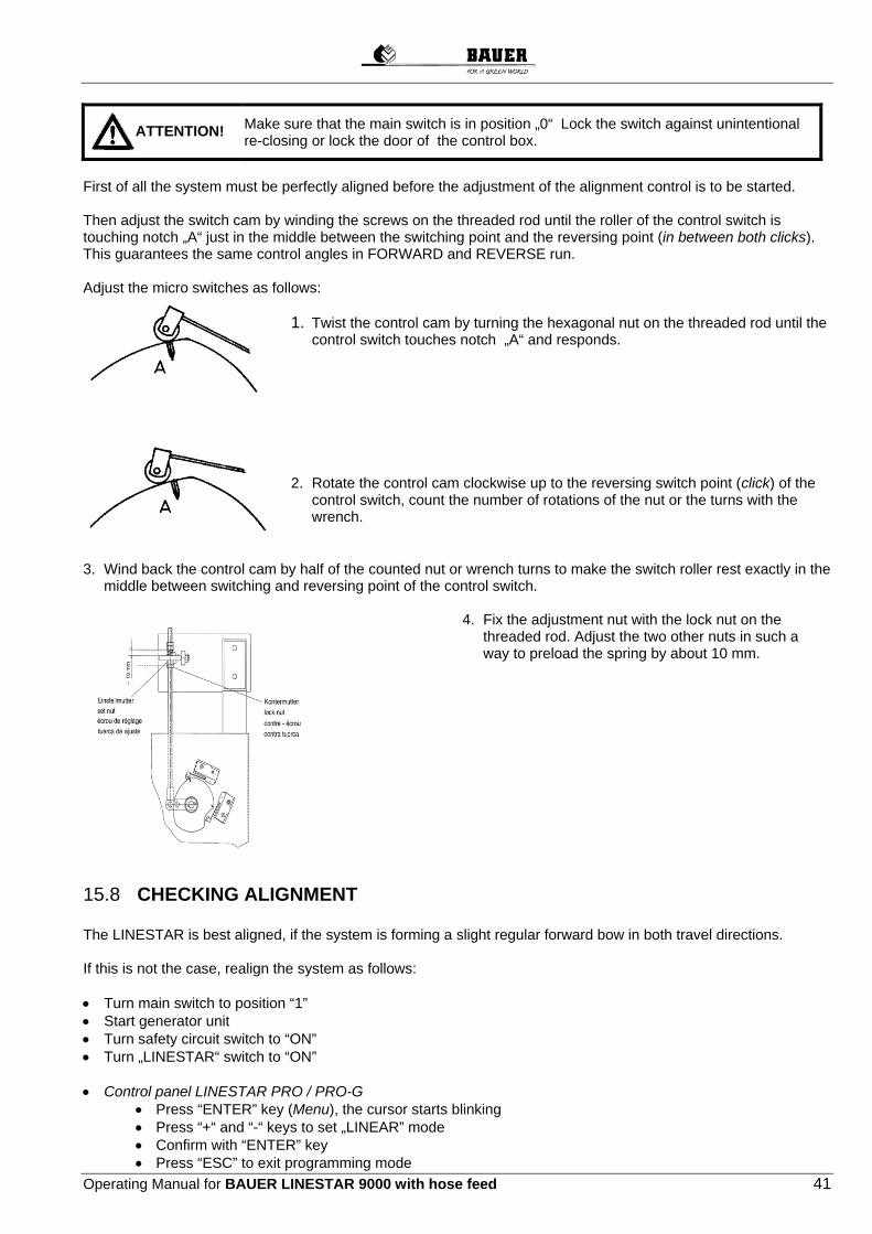
Make sure that the main switch is in position „0“ Lock the switch against unintentional re-closing or lock the door of the control box.
First of all the system must be perfectly aligned before the adjustment of the alignment control is to be started. Then adjust the switch cam by winding the screws on the threaded rod until the roller of the control switch is touching notch „A“ just in the middle between the switching point and the reversing point (in between both clicks). This guarantees the same control angles in FORWARD and REVERSE run. Adjust the micro switches as follows:
1. Twist the control cam by turning the hexagonal nut on the threaded rod until the control switch touches notch „A“ and responds.
2. Rotate the control cam clockwise up to the reversing switch point (click) of the control switch, count the number of rotations of the nut or the turns with the wrench.
3. Wind back the control cam by half of the counted nut or wrench turns to make the switch roller rest exactly in the
middle between switching and reversing point of the control switch.
4. Fix the adjustment nut with the lock nut on the threaded rod. Adjust the two other nuts in such a way to preload the spring by about 10 mm.
15.8 CHECKING ALIGNMENT The LINESTAR is best aligned, if the system is forming a slight regular forward bow in both travel directions.
If this is not the case, realign the system as follows: Turn main switch to position “1” Start generator unit Turn safety circuit switch to “ON” Turn „LINESTAR“ switch to “ON” Control panel LINESTAR PRO / PRO-G
Press “ENTER” key (Menu), the cursor starts blinking Press “+“ and “-“ keys to set „LINEAR” mode Confirm with “ENTER” key Press “ESC” to exit programming mode
ATTENTION!

42 Operating Manual for BAUER LINESTAR 9000 with hose feed
Press „FORWARD“ key. The LINESTAR must start to move clockwise Press “+” key to set a high application rate
Check if the driving motor of the first tower is located in front of an assumed line connecting the drive motor of the second tower and the middle of the central tower. If this is not the case, the alignment control on the first tower must be readjusted as follows: Unwind the hexagonal nuts and twist the threaded rod until the above requirement is fulfilled. The next step is to check if the drive motor of the second tower is positioned in front of an assumed line connecting the drive motor of the third tower and the middle of the central tower. If this is not the case, correct the alignment control on the second tower. Now check all the towers step by step as described under a) and b) Re-adjust alignment controls if necessary. Finally the LINESTAR should form a positive bow, which means that the towers in between end tower and central tower must be positioned in front of an assumed line between end tower and central tower. Press „STOP“ key Turn main switch to position „0“

Operating Manual for BAUER LINESTAR 9000 with hose feed 43
15.9 MACHINE OFFSET FROM LINEAR GUIDANCE If the linear guidance components (skid, cable roll, below ground antenna) of the LINESTAR are situated at too far a distance from the linear guidance (cable, furrow, below ground cable) after assembly, the system will not start properly because the safety circuit is broken.
15.9.1 ALIGNMENT OF THE MACHINE WITH FURROW / CABLE GUIDANCE
1. Connect the safety circuit by bringing the respective control lever of the linear guidance (skid or correction lever) back to the normal position.
2. - Start the generator unit - Move the main switch to position "1" - Move the "Safety circuit ON-OFF" switch to the position "ON" - Move the "LINESTAR OFF-ON" switch to "ON"
On the LINESTAR PRO / PRO-G control panel - Press the button "ENTER (Menu)", the cursor
begins to blink - Use the "+/-" buttons to set the "LINEAR"
mode
- Confirm with the "ENTER" button - Leave the programming mode with the "ESC"
button - Press the "FORWARD" button, the LINESTAR
must start up "clockwise" (forward) - Or press the "REVERSE" button, the LINESTAR must start up "anti-clockwise" (reverse)
3. Manually guide the LINESTAR in the direction of
the linear guidance by moving the respective control lever in the desired direction. Take care not to move the lever too far, which might interrupt the safety circuit.
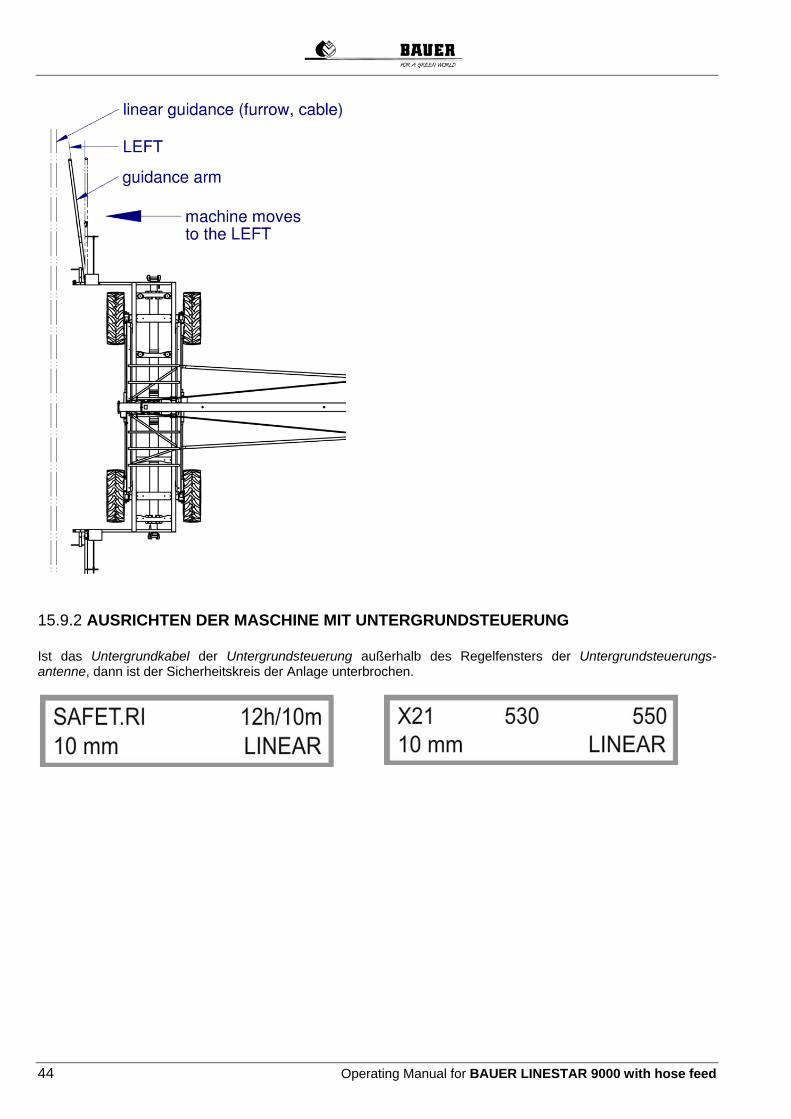
44 Operating Manual for BAUER LINESTAR 9000 with hose feed
15.9.2 AUSRICHTEN DER MASCHINE MIT UNTERGRUNDSTEUERUNG Ist das Untergrundkabel der Untergrundsteuerung außerhalb des Regelfensters der Untergrundsteuerungs-antenne, dann ist der Sicherheitskreis der Anlage unterbrochen.

Operating Manual for BAUER LINESTAR 9000 with hose feed 45
Position the antenna support such that the below ground cable is located within the regulation range (regulation window). The safety circuit of the system is closed again. You can now start up the LINESTAR as described above. If you do not want to move the antenna support and would rather move the entire system toward the linear guidance, then proceed as follows: Go to the Machine Parameters Menu on the control panel of the LINESTAR PRO / PRO-G. Increase the value in the safety circuit window under the menu item STEERING SAFETY CIRCUIT until this is large enough to cover the below ground cable.

46 Operating Manual for BAUER LINESTAR 9000 with hose feed
Bring the "SAFETY CIRCUIT ON-OFF" switch to the position "ON". On the control panel, set the operating mode "LINEAR".
Press the "FORWARD" button to start up the LINESTAR in the "clockwise" (forward) direction. Press the "REVERSE" button to start up the LINESTAR in the "anti-clockwise" (reverse) direction. When you have finished the alignment of the machine, set the value in the safety circuit window under the menu item STEERING SAFETY CIRCUIT back to the default value.
16 TERMINOLOGY Forward Looking from the central tower to the system, the LINESTAR moves to the right. Reverse Looking from the central tower to the system, the LINESTAR moves to the left. Inward Direction central tower

Operating Manual for BAUER LINESTAR 9000 with hose feed 47
Outward Direction last tower
Positive bow hurrying ahead If the middle towers are in front of an assumed straight line in travel direction between central tower and end tower.
Negative bow hurrying backward If the middle towers are behind an assumed straight line in travel direction between central tower and end tower.
Dogleg Happens, when a tower gets slower or stands still or hurries ahead of the other towers.
17 START-UP The LINESTAR is only to be released for operation to the customer after it has been completely assembled, installed and successfully started up by a qualified person! As the machine is operated with voltages from 230 V up to 460 V, the control components and the electric drive need to be handled with the utmost caution! Service and repair works must imperatively be done by a professional electrician! Before starting the system make sure, that all connected devices (like generator and pump units) are ready for operation. Have the responsible service centre repair possible damages, before you start irrigating. Be extremely cautious with live parts. The start-up as described below is valid for a BAUER LINESTAR 9000 without optional equipment. If the system has got any optional equipment (see chapter options), it has to be set properly and turned on before the start-up. If you have purchased a LINESTAR with Below Ground Guidance, be sure that the oscillator box is supplied with voltage. With a 230V AC supply, put the main switch of power supply to position "1". With a 24V DC battery supply (2 x 12V DC), check if the batteries are connected and sufficiently loaded.
17.1 START LINESTAR IN OPERATING MODE “LINEAR”
17.1.1 START LINESTAR WITH HOSE FEED Connect supply hose to hydrant and central tower, open water supply Put switch Genset „OFF – ON“ to „OFF“ Start generator unit Turn main switch to „1“ Put switch “LINESTAR OFF - ON” to „ON“ Put switch “SAFTEY CIRCUIT ON – OFF“ to „ON“ Put switch “END GUN OFF - ON“ to “ON” Control panel LINESTAR PRO / PRO-G Press key “ENTER (MENU)“, the cursor starts blinking Select mode “LINEAR” with “+/-“ keys. Press „FORWARD“ key to go to parameter travel length, set travel length with “+/-“ keys Confirm with „ENTER“ key Exit programming mode with „ESC“ key. Press „FORWARD“ or „REVERSE“ key depending on running direction Modify application rate with “+/-“ keys. Put switch “GENSET OFF – ON“ to „ON“
17.2 STARTING AFTER INTERMEDIATE STOP

48 Operating Manual for BAUER LINESTAR 9000 with hose feed
It may be necessary to stop the LINESTAR somewhere along an irrigation strip, for instance if the supply hose needs to be connected to another hydrant or if only a partial area has to be irrigated. In this case a shut-down sensor is actuated by a switching peg and the machine is turned off. The shut-off valve in the riser pipe (option) is closed and the generator unit is shut down, when the switch “GENSET OFF-ON” has been put to “ON”. Control panel LINESTAR PRO / PRO-G Press “Forward” or “Reverse” key The machine must leave the switching range within 30 seconds, otherwise it will be shut off automatically.
17.3 SHUT-DOWN PROCEDURE
17.3.1 SYSTEM SHUT OFF DURING IRRIGATION Control panel LINESTAR PRO / PRO-G Press “ESC – STOP” key If the switch GENSET “OFF-ON” has been turned to ”ON”, the generator unit shuts down automatically. If the switch has been turned to “OFF”, the generator unit must be turned off separately. Water supply will be cut automatically by the shut-off valve.
17.3.2 AUTOMATIC SYSTEMM SHUT OFF AT FIELD END The switches of the central unit shut the LINESTAR automatically down, when they are actuated by the end stoppers which have been placed at the end of the field. If the switch “GENSET OFF - ON“ has been put to „ON“, the generator unit shuts down automatically. If the switch has been turned to „OFF“ the generator unit must be shut down separately The water supply is cut automatically by the shut-off valve
17.4 STARTING LINESTAR TO RUN IN OPPOSITE DIRECTION AFTER AN AUTOMATIC SHUT-DOWN Put switch “GENSET OFF - ON” to “OFF“ Start generator unit Establish water supply Put switch “SAFETY CIRCUIT ON - OFF” to “OFF” Control panel LINESTAR PRO / PRO-G The control panel displays mode ”SETTING” Press the “FORWARD“ or „REVERSE“ key to select travel direction Press and hold the “+” and “-“ keys simultaneously until the machine has left the switching circuit Put switch “SAFETY CIRCUIT ON - OFF” to “ON”
Control panel LINESTAR PRO / PRO-G Press „FORWARD“ or „REVERSE“ key to start the machine Put switch “GENSET OFF - ON“ to “ON“
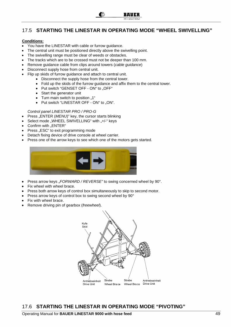
Operating Manual for BAUER LINESTAR 9000 with hose feed 49
17.5 STARTING THE LINESTAR IN OPERATING MODE “WHEEL SWIVELLING” Conditions: You have the LINESTAR with cable or furrow guidance. The central unit must be positioned directly above the swivelling point. The swivelling range must be clear of weeds or obstacles. The tracks which are to be crossed must not be deeper than 100 mm. Remove guidance cable from clips around towers (cable guidance) Disconnect supply hose from central unit. Flip up skids of furrow guidance and attach to central unit.
Disconnect the supply hose from the central tower. Fold up the skids of the furrow guidance and affix them to the central tower. Put switch “GENSET OFF - ON“ to „OFF“ Start the generator unit Turn main switch to position „1“ Put switch “LINESTAR OFF - ON“ to „ON“.
Control panel LINESTAR PRO / PRO-G Press „ENTER (MENU)” key, the cursor starts blinking Select mode „WHEEL SWIVELLING“ with „+/-“ keys Confirm with „ENTER“ Press „ESC“ to exit programming mode Detach fixing device of drive console at wheel carrier. Press one of the arrow keys to see which one of the motors gets started.
Press arrow keys „FORWARD / REVERSE” to swing concerned wheel by 90°. Fix wheel with wheel brace. Press both arrow keys of control box simultaneously to skip to second motor. Press arrow keys of control box to swing second wheel by 90° Fix with wheel brace. Remove driving pin of gearbox (freewheel).
17.6 STARTING THE LINESTAR IN OPERATING MODE “PIVOTING”

50 Operating Manual for BAUER LINESTAR 9000 with hose feed
ATTENTION: The "pivoting” operating mode is not intended for the LINESTAR with below ground guidance. Connect supply hose to hydrant and central unit. Flip up skids of furrow guidance and fasten them on the central unit Put switch “GENSET OFF - ON” to “OFF”. Start the generator unit. Put main switch to „I“. Put switch “LINESTAR OFF – ON“ to “ON“.
Swivel central unit wheels according to point 17.5 Lower pivoting device (hydraulic stand) by means of hydraulic hand pump Establish water supply Control panel Press key „Enter (Menu)“, the cursor starts blinking. Select mode “Pivoting” with + - keys. Confirm with „Enter“. Exit programming mode with „ESC“. Press “Forward“ or „Reverse“ key depending on travel direction Change application rate with + - keys. Put switch “GENSET OFF – ON“ to „ON“.
17.7 SHUT DOWN PROCEDURE
17.7.1 LINESTAR SHUT DOWN DURING IRRIGATION Control panel LINESTAR PRO / PRO-G Press “ESC - Stop“ key If switch “GENSET OFF - ON“ has been put to “ON“, the generator unit shuts down automatically. If the switch has been turned to „OFF“ the generator unit must be shut down separately. The water supply is cut automatically by the shut-off valve.
17.7.2 AUTOMATIC SHUT-OFF OF LINESTAR A switch mounted on the tower shuts down the LINESTAR automatically, when it is actuated by a shut-off bar which has been placed at the end of the field (optional equipment).
Schwenkeinrichtung Swivelling device

Operating Manual for BAUER LINESTAR 9000 with hose feed 51
If the switch “GENSET OFF – ON“ has been put to „ON“, the generator unit shuts down automatically. If the switch has been turned to „OFF“ the generator unit must be shut down separately The water supply is cut automatically by the shut-off valve
17.7.3 STARTING INTO OPPOSITE DIRECTION AFTER AUTOMATIC SHUT-DOWN OF LINESTAR As described in chapter 17.4
18 MAINTENANCE INSTRUCTIONS Note Guarantee claims can only be processed if the regulations concerning handling, maintenance (according to service plan) and care have been observed. All service works must be carried through by an authorised dealer and they must be confirmed in the service plan. The service plan is considered as evidence for warranty claims. The meaning of the service plan The service plan stipulates the time and kind of service. In the evidence spaces we confirm the carrying out of the service which can be a condition for possible warranty claims. We kindly ask you to understand that normal wear and tear as well as damages due to overstrain, improper use or unauthorized modifications are excluded from this guarantee. Always cut power before starting any maintenance work on the system. Turn the main switch to “0“ and lock the switch to prevent unauthorised or unintentional re-closing of the system. Always cut power supply by your own. Be sure to re-install all protective devices which have been dismounted during maintenance.
18.1 SERVICE INTERVALS
Monthly service Annual service

52 Operating Manual for BAUER LINESTAR 9000 with hose feed
18.2 SERVICE PLAN
Extent of Service
Inte
rmed
iate
m
ain
ten
ance
An
nu
al
mai
nte
nan
ce
Central unit
Check all screwed joints X Check tightness of electric cable entries into the control centre X Check tightness of connecting hoses in the riser pipe X X
Trussing, overhang, coupling
Check all screwing on flanges, truss rods, braces, on towers and on overhang X Check tightness of connecting hose at tower couplings. X Lubricate ball joint of tower couplings X X Empty sand trap X X Booster pump – spinning of shaft between engine and pump – check if pump rotor rotates
freely (if existing) X
Check end gun (if existing) X
Tower box, transmission device
Check switch cam and adjust if necessary X Check shifting travel of micro switches X X Check function of micro switches (operation switch and safety switch) X Check all electric connections for contact X Check tightness of all cable entries into the alignment control X Check tightness of alignment control covers X Lubricate the ball joints at transmission parts X X Exact control – Check tension of guiding cables X Visual inspection of span alignment X X Check function of switches for intermediate stop, end stop and of programme switch X
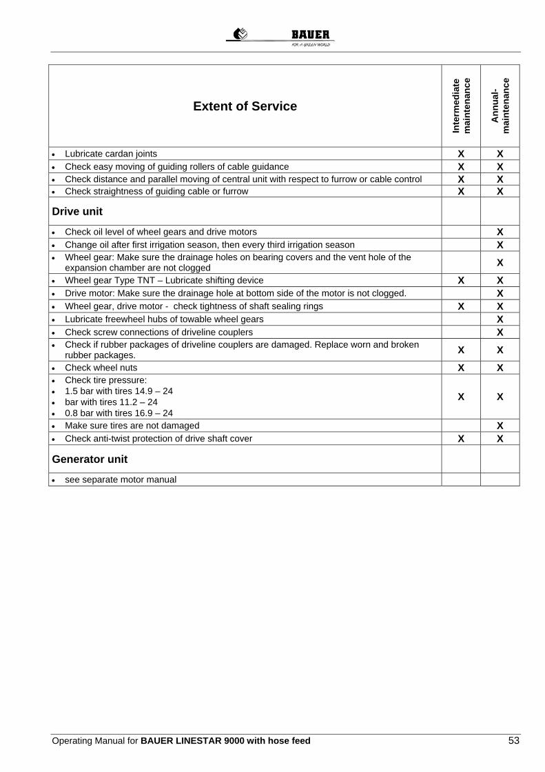
Operating Manual for BAUER LINESTAR 9000 with hose feed 53
Extent of Service
Inte
rmed
iate
m
ain
ten
ance
An
nu
al-
mai
nte
nan
ce
Lubricate cardan joints X X Check easy moving of guiding rollers of cable guidance X X Check distance and parallel moving of central unit with respect to furrow or cable control X X Check straightness of guiding cable or furrow X X
Drive unit
Check oil level of wheel gears and drive motors X Change oil after first irrigation season, then every third irrigation season X Wheel gear: Make sure the drainage holes on bearing covers and the vent hole of the
expansion chamber are not clogged X
Wheel gear Type TNT – Lubricate shifting device X X Drive motor: Make sure the drainage hole at bottom side of the motor is not clogged. X Wheel gear, drive motor - check tightness of shaft sealing rings X X Lubricate freewheel hubs of towable wheel gears X Check screw connections of driveline couplers X Check if rubber packages of driveline couplers are damaged. Replace worn and broken
rubber packages. X X
Check wheel nuts X X Check tire pressure: 1.5 bar with tires 14.9 – 24 bar with tires 11.2 – 24 0.8 bar with tires 16.9 – 24
X X
Make sure tires are not damaged X Check anti-twist protection of drive shaft cover X X
Generator unit
see separate motor manual

54 Operating Manual for BAUER LINESTAR 9000 with hose feed
18.3 POST-SEASON MAINTENANCE
1. Remove the drain valves and plugs in the pipeline.
2. Open gate valve of sand trap.
3. Flush the pipelines.
4. Remount and close drain valves, plugs and gate valves at sand trap.
5. Remove the supply hose from the irrigation field and stock it in a building.
6. Empty the coolant of the generator unit or care for sufficient anti-freeze.
18.4 PRE-SEASON MAINTENANCE
1. Check control centre and alignment controls for damages due to oxidation, rodents and insects.
2. Open sand trap gate valve and flush pipelines.
3. Check tightness of flange seals and connecting hoses.
4. Close sand trap gate valve.
5. Tension cable for cable guidance and align pegs
6. Draw a new furrow for the furrow guidance
7. Place and align the pegs correctly for intermediate stop and end stop
8. Unwind supply hose and check if it is still waterproof
9. Fill in or add coolant into the generator unit. Check motor oil.
10. Further checks => CHECKLIST
11. Optional: For below ground guidance, connect the power supply for the oscillator box or mount and connect the battery.
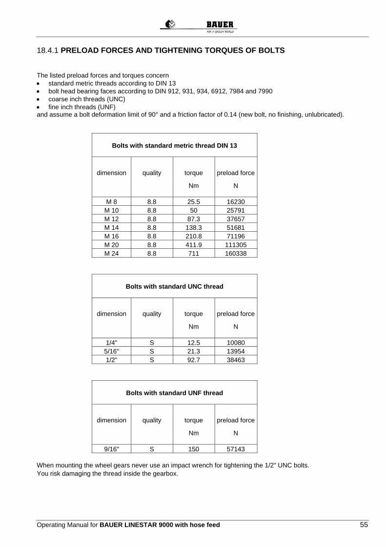
Operating Manual for BAUER LINESTAR 9000 with hose feed 55
18.4.1 PRELOAD FORCES AND TIGHTENING TORQUES OF BOLTS The listed preload forces and torques concern standard metric threads according to DIN 13 bolt head bearing faces according to DIN 912, 931, 934, 6912, 7984 and 7990 coarse inch threads (UNC) fine inch threads (UNF) and assume a bolt deformation limit of 90° and a friction factor of 0.14 (new bolt, no finishing, unlubricated). Bolts with standard metric thread DIN 13
dimension quality torque preload force
Nm N M 8 8.8 25.5 16230 M 10 8.8 50 25791 M 12 8.8 87.3 37657 M 14 8.8 138.3 51681 M 16 8.8 210.8 71196 M 20 8.8 411.9 111305 M 24 8.8 711 160338 Bolts with standard UNC thread
dimension quality torque preload force
Nm N 1/4" S 12.5 10080 5/16" S 21.3 13954 1/2" S 92.7 38463 Bolts with standard UNF thread
dimension quality torque preload force
Nm N 9/16" S 150 57143 When mounting the wheel gears never use an impact wrench for tightening the 1/2" UNC bolts. You risk damaging the thread inside the gearbox.

56 Operating Manual for BAUER LINESTAR 9000 with hose feed
19 TROUBLESHOOTING
FAILURE
POSSIBLE CAUSE
REMEDY
System shut down automatically: a) power generating unit
low fuel battery low loose terminals low coolant low oil pressure loose V-belt
refuel recharge tighten fill up soiled oil filter fill up lube oil tighten
System running in safety circuit
doglegging faulty system alignment microswitch defective obstacle in the track intermediate stop switch has been actuated leakage-current relay triggered by short circuit to system
see Restart after doglegging correction by trained service staff replace microswitch remove obstacle adjust stop bracket properly or remove obstacle reset leakage-current relay (blue reset button)
Abnormal motor or gearbox noise
low oil level oil worn defective bearing
add oil change oil replace bearing
System does not start up main switch turned off safety disconnect Q1 turned off fuses of fuse switch disconnector defective fuses F1, F2, F3, F4 defective safety circuit interrupted because system flex larger than maximum permissible bending angle no water pressure (only with low-pressure shut-off option)
turn it on turn it on replace defective fuses replace defective fuses see “Restart after doglegging” check water supply readjust pressure switch
A certain tower always runs inside the safety circuit
Wrong microswitch setting in the alignment control microswitch defective contactor defective cable loose tower slips thermal protection (inside motor) has responded because of: obstacle in the track deep soil low oil in wheel gear
readjust microswitch replace microswitch replace contactor check connections and tighten if necessary level the track remove obstacle fill up and level the track add oil
In forward and backward run the central unit is keeping a different distance to the cable/furrow guidance
The micro switches of the linear control are adjusted differently
Adjust micro switches in both s

Operating Manual for BAUER LINESTAR 9000 with hose feed 57
19.1 RESTART AFTER DOGLEGGING Before carrying through the below mentioned operations be sure to rectify the cause
of doglegging (cf. chapter Troubleshooting).
In the “OFF” position, the "SAFETY CIRCUIT" switch deactivates the safety system. Only permitted for service works.
Put switch “SAFETY CIRCUIT ON - OFF“ to „OFF“ Put switch “LINESTAR OFF - ON“ to „ON“ Control panel LINESTAR PRO / PRO-G The control panel displays mode “ALIGNING” Press “FORWARD” or “REVERSE” key to select the travel direction which is necessary to bring the outer spans back to form a straight line with the system. That is:
the outer doglegging towers hurry ahead: press the „REVERSE“ key. the outer doglegging towers lag behind: press the „FORWARD“ key.
Press and hold the „+“ key, the end tower is moving as long the „+“ key is held. Press and hold the „-“ key, the central unit is moving as long as the „-“ key is held. Hold the „+“ or „-“ keys until the misaligned spans are properly re-aligned. Check travel direction when spans start moving. In case of wrong direction release key at once. Press keys "R" or "F" to activate the tower alignment switches (for manual alignment at tower - concerns alignment control units with tower alignment switch)
Selecting the proper running direction ensures that only the outer misaligned towers start moving when the drive is turned on.
The wrong running direction will cause impermissibly high stress on the trussing.
The towers only move as long as you hold the "+” or "-" key..
The inward towers may start moving for a short time after the start-up
Continuously check tower movement after the start in order to be able to stop the system again immediately should the doglegging continue (Release “+” or " -" key).
As soon as the towers are re-aligned (forming a straight line) and the inward towers also start to move, release the “+” or the “-“ key. Put the safety circuit switch to “ON”.
Operating the BAUER LINESTAR with "SAFETY CIRCUIT SWITCH turned to “OFF" is only permitted for system alignment.
Test proper moving of the LINESTAR by a short touch of the "FORWARD“ or „REVERSE“ key.
NOTE!
CAUTION!
NOTE!
CAUTION!
NOTE!
WARNING!
NOTE!

58 Operating Manual for BAUER LINESTAR 9000 with hose feed
20 TECHNICAL DATA
20.1 DIMENSIONS OF BAUER LINESTAR 9000 – 2 WHEEL
20.2 DIMENSIONS OF BAUER LINESTAR 9000 - 4 WHEEL ONE SIDED
20.3 DIMENSIONS OF BAUER LINESTAR 9000 - 4 WHEEL DOUBLE SIDED

Operating Manual for BAUER LINESTAR 9000 with hose feed 59
21 OPTIONS
21.1 LOW PRESSURE SHUT-OFF The supply pressure on the central unit is monitored by a pressure gauge. If the supply pressure is lower than the minimum pressure set on the pressure gauge, the shut-off valve closes (option), and the Linestar shuts down. This will only happen under the condition the “WET-DRY” switch has been set to
“WET”. If it has been put to “DRY” position the pressure gauge is inoperable..
When turning the switch to “DRY” position the machine runs without irrigating (dry run). This may be necessary when moving the LINESTAR to a parking position because of natural rainfall.
21.2 ELECTRIC SHUT-OFF VALVE (CENTRAL UNIT) An electric shut-off valve in the supply line of the central tower is closed automatically, if the LINESTAR shuts down by malfunction.
21.3 END GUN To increase the irrigated strip width or the system spraying range inside the swivelling area, an end gun can be mounted at the end of the LINESTAR overhang. It may spray along the whole irrigation strip or only along parts of it. If the end gun is thought to operate in interval mode, an automatic “ON/OFF” control unit must be installed.
21.4 BOOSTER PUMP FOR END GUN In most cases the end gun needs a higher pressure than the other nozzles of the LINESTAR. An electric booster pump mounted on the end tower generates the necessary operating pressure for the end gun. The booster pump is connected to the gun on the overhang by a pressure hose..
CAUTION

60 Operating Manual for BAUER LINESTAR 9000 with hose feed
21.5 AUTOMATIC INTERVAL CONTROL If the end gun is equipped with a big nozzle for a large spray range, the application rate at the end of the system is too high. This will be compensated by an automatic interval control which opens and closes automatically a 2” valve gate and controls the operating time of the end gun. Operating and break times of the end gun can be set at the TIME/BREAK relay.
21.6 AUTOMATIC „ON/OFF” AND INTERVAL CONTROL This control unit combines the two above mentioned controls for the end gun and the booster pump..
21.7 TOWER ALIGNMENT SWITCH This switch is mounted outside on the base plate of the alignment control. It allows the forward or backward move of the tower without having to open the alignment control. This device facilitates system alignment at first start-up or after changing the operating site.
21.8 RUNNING LIGHT Mounted on the end tower or on the central unit. This light is shining as long as the LINESTAR is operating.
21.9 END STOP If it is necessary to stop the system precisely at the field end, system shut-down takes place at the end tower. A contact limit switch mounted on the end tower is actuated by a shut-off frame which is placed at the field end in the track of the last tower. The machine stops.
Abschaltstange cut-off bar tringle d’arrêt barra de desconexión
Abschaltrahmen cut-off frame cadre d’arrêt cuadro de desconexión
Grenztaster barrier sensing device interrupteur-limiteur sensor de limite

Operating Manual for BAUER LINESTAR 9000 with hose feed 61
21.10 STOP RAMP This ramp serves as an emergency stop at the end of the irrigation track. In case every switch-off system is failing, the end tower will run against the ramp fixed into the soil and the LINESTAR will be stopped mechanically. Thereafter the motor protection switch of the end tower will shut down the entire system.
22 TOWING OF LINESTAR 2-WHEEL GENERAL INSTRUCTIONS
Towing is not intended for the LINESTAR with below ground guidance. System should be towed along an even track, if possible along a cart track (width 7 m). The track must be even and clear of ruts, grooves and furrows. If there are ruts in the lane they have to be levelled Towing of the system inside the field (off road) should be avoided. If the system has to be towed inside the field, the travelling track must be levelled first and cleared of all
obstacles to avoid any increase of the rolling resistance. Max. “towing speed”: 4 km/h Min. tire pressure: 1 – 1.1 bar
22.1 TOWING THE LINESTAR FROM CENTRAL UNIT When towing the central unit a cable bracing from the central unit to the first tower is needed.

62 Operating Manual for BAUER LINESTAR 9000 with hose feed
22.1.1 SWIVELLING CENTRAL UNIT WHEELS Proceed according to item 17.5 Mounting of tow bar
22.1.2 SWIVELLING TOWER WHEELS Loosen and push back the drive shaft cover at wheel gear . Loosen driver pin on wheel hub. If wheel gear is provided with shifting lever disengage wheel gear. Detach gear carrier. Swivel gear carrier together with wheel. The coupling parts with the rubber packages have to stay at the wheel
gear. If necessary lift wheel carrier with jack or tractors hydraulics.
Put the drive shaft with the coupling parts on shaft holder which is mounted onto the tower bracing angle. Fasten wheel gear carrier with connecting brace (turned by 90°).
22.1.3 MOUNTING THE TOW CABLES ON “-WHEEL CENTRAL UNIT

Operating Manual for BAUER LINESTAR 9000 with hose feed 63
Fasten the clamp on the end pipe of the first tower. Fasten the clamp on the wheel base of the central unit. Hook up and adjust the cables (the first time). Mount drawbar (the first time).
22.2 TOWING THE LINESTAR AT THE END TOWER
22.2.1 SWIVELLING CENTRAL UNIT WHEELS (PROCEED ACCORDING TO ITEM 17.5)
22.2.2 SWIVELLING TOWER WHEELS Gehen Sie ähnlich wie in 22.1.2 SCHWENKEN DER RÄDER AM FAHRTURM vor. Loosen and push back the drive shaft cover at wheel gear Loosen driver pin on wheel hub. If wheel gear is provided with shifting lever disengage wheel gear. Detach gear carrier. Swivel gear carrier together with wheel. The coupling parts with the rubber packages have to stay at the wheel
gear. If necessary lift wheel carrier with jack or tractors hydraulics. Fasten the wheel gear carrier with steering brace “A” (turned by 90°) Mount steering device “B” on all towers except for end tower (overhang).

64 Operating Manual for BAUER LINESTAR 9000 with hose feed
22.2.3 BRACING THE END TOWER The end tower is braced to the span (on the overhang side) with 2 stabilizing cables. A drawbar is attached on the wheel carrier.
22.3 TOWING THE LINESTAR AT A FREESTANDING SPAN
22.3.1 SWIVELLING CENTRAL TOWER WHEELS (ACCORDING TO ITEM 17.5)
22.3.2 SWIVELLING TOWER WHEELS Loosen and push back the drive shaft cover at wheel gear Loosen driver pin on wheel hub. If wheel gear is provided with shifting lever disengage wheel gear. Detach gear carrier.
stabilizing cable stabilizing cable steering unit

Operating Manual for BAUER LINESTAR 9000 with hose feed 65
Swivel gear carrier together with wheel. The coupling parts with the rubber packages have to stay at the wheel gear. If necessary lift wheel carrier with jack or tractors hydraulics.
Fasten the wheel gear carrier with steering brace “A” (turned by 90°) Mount steering device “B” on all towers except for end tower (overhang).
22.3.3 BRACING THE END TOWER AND THE CENTRAL UNIT
The end tower is braced to the span (on the overhang side) with 2 stabilizing cables. A drawbar is attached to the wheel base. The central unit is braced to the span with two stabilizing cables A drawbar is attached to the central unit
stabilizing cable
stabilizing cable
steering unit
steering unit
steering unit
steering unit
66 Operating Manual for BAUER LINESTAR 9000 with hose feed
23 ELECTRICAL WIRING DIAGRAMS 23.1 CONTROL CENTRE LINEARSTAR PRO 23.1.1 CONTROL CENTRE LINESTAR PRO - WIRING DIAGRAM 1 CONTROL CENTRE LINESTAR PRO - WIRING DIAGRAM 2 CONTROL CENTRE LINESTAR PRO - WIRING DIAGRAM 3 23.1.2 CONTROL CENTRE LINESTAR PRO - INFEED CONTROL CENTRE LINESTAR PRO - CONTROL 1 CONTROL CENTRE LINESTAR PRO - CONTROL 2 23.2 CONTROL CENTRE LINEARSTAR PRO WITH BELOW GROUND GUIDANCE 23.2.1 CONTROL CENTRE LINESTAR PRO W. BELOW GROUND GUIDANCE - WIRING DIAGRAM 1 CONTROL CENTRE LINESTAR PRO W. BELOW GROUND GUIDANCE - WIRING DIAGRAM 2 CONTROL CENTRE LINESTAR PRO W. BELOW GROUND GUIDANCE - WIRING DIAGRAM 3 23.2.2 CONTROL CENTRE LINESTAR PRO W. BELOW GROUND GUIDANCE - INFEED CONTROL CENTRE LINESTAR PRO W. BELOW GROUND GUIDANCE - CONTROL 23.3 CONTROL CENTRE LINEARSTAR PRO-G 23.3.1 CONTROL CENTRE LINESTAR PRO-G - WIRING DIAGRAM 1 CONTROL CENTRE LINESTAR PRO-G - WIRING DIAGRAM 2 CONTROL CENTRE LINESTAR PRO-G - WIRING DIAGRAM 3 23.3.2 CONTROL CENTRE LINESTAR PRO-G - INFEED CONTROL CENTRE LINESTAR PRO-G - CONTROL CONTROL CENTRE LINESTAR PRO-G - GPS & GSM 23.4 LINESTAR LINEAR CONTROL 23.4.1 FURROW GUIDANCE - WIRING DIAGRAM 23.4.2 CABLE GUIDANCE - WIRING DIAGRAM 23.4.3 BELOW GROUND GUIDANCE OSCILLATOR BOX - WIRING DIAGRAM 23.4.4 BELOW GROUND GUIDANCE TRACK UNIT - WIRING DIAGRAM 23.4.5 BELOW GROUND GUIDANCE TRACK UNIT - WIRING DIAGRAM 23.5 LINESTAR TOWER BOX 23.5.1 TOWER BOX - STANDARD 23.5.2 TOWER BOX - WITH TOWER ALIGNMENT SWITCH 23.5.3 TOWER BOX - WITH END TOWER MONITORING 23.5.4 TOWER BOX - WITH TOWER ALIGNMENT SWITCH & END TOWER MONITORING 23.5.5 END TOWER BOX - STANDARD 23.5.6 END TOWER BOX - WITH TOWER ALIGNMENT SWITCH 23.5.7 END TOWER BOX - WITH END STOP 23.5.8 END TOWER BOX - WITH END STOP & TOWER ALIGNMENT SWITCH 23.5.9 END TOWER BOX - WITH END STOP & AUTOREVERSE 23.5.10 END TOWER BOX - WITH TOWER ALIGNMENT SWITCH & END STOP & AUTOREVERSE 23.6 BOOSTER PUMP FOR END GUN

Operating Manual for BAUER LINESTAR 9000 with hose feed 67
23.1 CONTROL CENTER LINESTAR PRO
23.1.1 CONTROL CENTER LINESTAR PRO - WIRING DIAGRAM 1

68 Operating Manual for BAUER LINESTAR 9000 with hose feed
CONTROL CENTER LINESTAR PRO - WIRING DIAGRAM 2
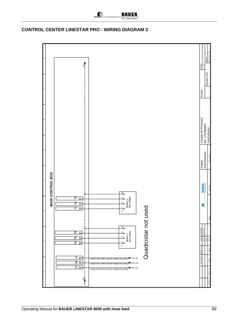
Operating Manual for BAUER LINESTAR 9000 with hose feed 69
CONTROL CENTER LINESTAR PRO - WIRING DIAGRAM 3

70 Operating Manual for BAUER LINESTAR 9000 with hose feed
23.1.2 CONTROL CENTRE LINESTAR PRO - INFEED

Operating Manual for BAUER LINESTAR 9000 with hose feed 71
CONTROL CENTER LINESTAR PRO - CONTROL 1
CONTROL CENTER LINESTAR PRO - CONTROL 2

72 Operating Manual for BAUER LINESTAR 9000 with hose feed
23.2 CONTROL CENTRE LINESTAR PRO WITH BELOW GROUND GUIDANCE

Operating Manual for BAUER LINESTAR 9000 with hose feed 73
23.2.1 CONTROL CENTRE LINESTAR PRO W. BELOW GROUND GUIDANCE - WIRING DIAGRAM 1
CONTROL CENTRE LINESTAR PRO W. BELOW GROUND GUIDANCE - WIRING DIAGRAM 2

74 Operating Manual for BAUER LINESTAR 9000 with hose feed

Operating Manual for BAUER LINESTAR 9000 with hose feed 75
CONTROL CENTRE LINESTAR PRO W. BELOW GROUND GUIDANCE - WIRING DIAGRAM 3

76 Operating Manual for BAUER LINESTAR 9000 with hose feed
23.2.2 CONTROL CENTRE LINESTAR PRO W. BELOW GROUND GUIDANCE - INFEED

Operating Manual for BAUER LINESTAR 9000 with hose feed 77
CONTROL CENTRE LINESTAR PRO W. BELOW GROUND GUIDANCE - CONTROL 1
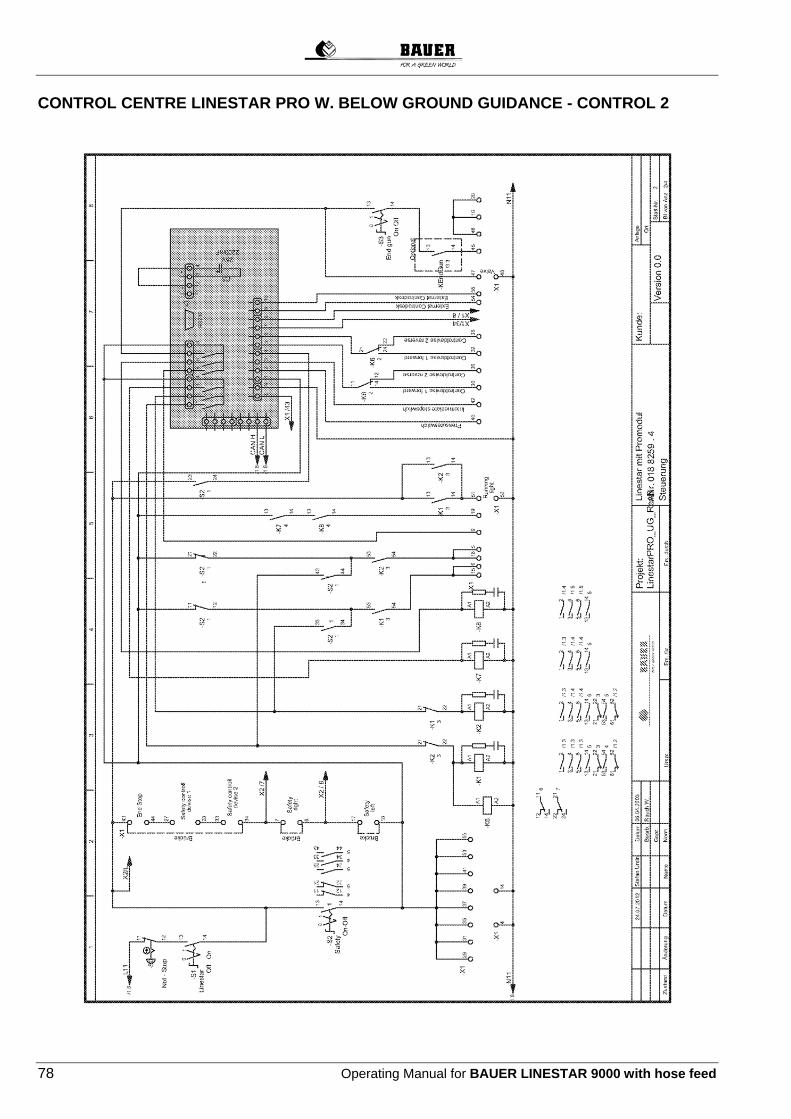
78 Operating Manual for BAUER LINESTAR 9000 with hose feed
CONTROL CENTRE LINESTAR PRO W. BELOW GROUND GUIDANCE - CONTROL 2

Operating Manual for BAUER LINESTAR 9000 with hose feed 79
CONTROL CENTRE LINESTAR PRO W. BELOW GROUND GUIDANCE - CONTROL 3

80 Operating Manual for BAUER LINESTAR 9000 with hose feed
CONTROL CENTRE LINESTAR PRO W. BELOW GROUND GUIDANCE - CONTROL 4

Operating Manual for BAUER LINESTAR 9000 with hose feed 81
23.3 CONTROL CENTRE LINESTAR PRO-G
23.3.1 CONTROL CENTRE LINESTAR PRO-G - WIRING DIAGRAM 1

82 Operating Manual for BAUER LINESTAR 9000 with hose feed
CONTROL CENTRE LINESTAR PRO-G - WIRING DIAGRAM 2

Operating Manual for BAUER LINESTAR 9000 with hose feed 83
CONTROL CENTRE LINESTAR PRO-G - WIRING DIAGRAM 3

84 Operating Manual for BAUER LINESTAR 9000 with hose feed
23.3.2 CONTROL CENTRE LINESTAR PRO-G - INFEED

Operating Manual for BAUER LINESTAR 9000 with hose feed 85
CONTROL CENTRE LINESTAR PRO-G - CONTROL
CONTROL CENTRE LINESTAR PRO-G - CONTROL

86 Operating Manual for BAUER LINESTAR 9000 with hose feed
23.4 LINESTAR LINEAR CONTROL

Operating Manual for BAUER LINESTAR 9000 with hose feed 87
23.4.1 FURROW GUIDANCE - WIRING DIGRAM
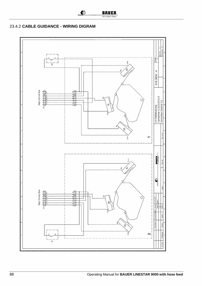
88 Operating Manual for BAUER LINESTAR 9000 with hose feed
23.4.2 CABLE GUIDANCE - WIRING DIGRAM

Operating Manual for BAUER LINESTAR 9000 with hose feed 89
23.4.3 BELOW GROUND GUIDANCE OSCILLATOR BOX - WIRING DIGRAM

90 Operating Manual for BAUER LINESTAR 9000 with hose feed
23.4.4 BELOW GROUND GUIDANCE TRACK UNIT - WIRING DIGRAM 1

Operating Manual for BAUER LINESTAR 9000 with hose feed 91
23.4.5 BELOW GROUND GUIDANCE TRACK UNIT - WIRING DIGRAM 2

92 Operating Manual for BAUER LINESTAR 9000 with hose feed
23.5 LINESTAR TOWER BOX
23.5.1 TOWER BOX - STANDARD
23.5.2 TOWER BOX - WITH TOWER ALIGNMENT SWITCH

Operating Manual for BAUER LINESTAR 9000 with hose feed 93
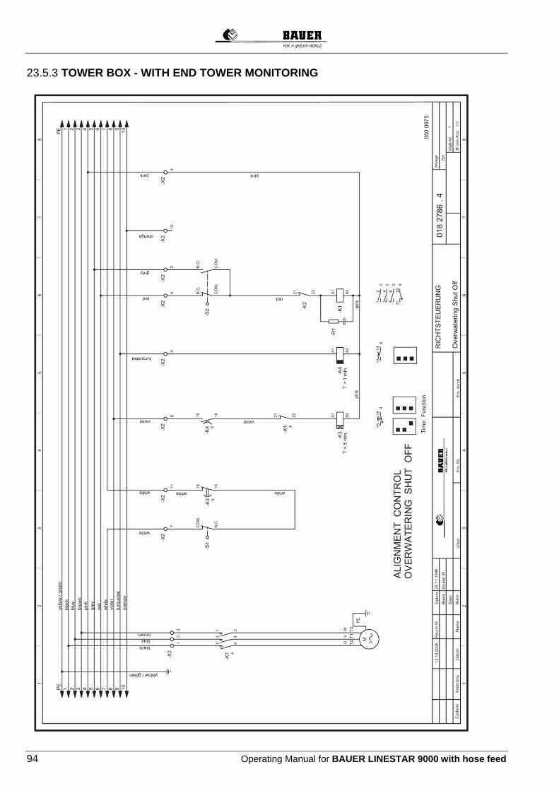
94 Operating Manual for BAUER LINESTAR 9000 with hose feed
23.5.3 TOWER BOX - WITH END TOWER MONITORING
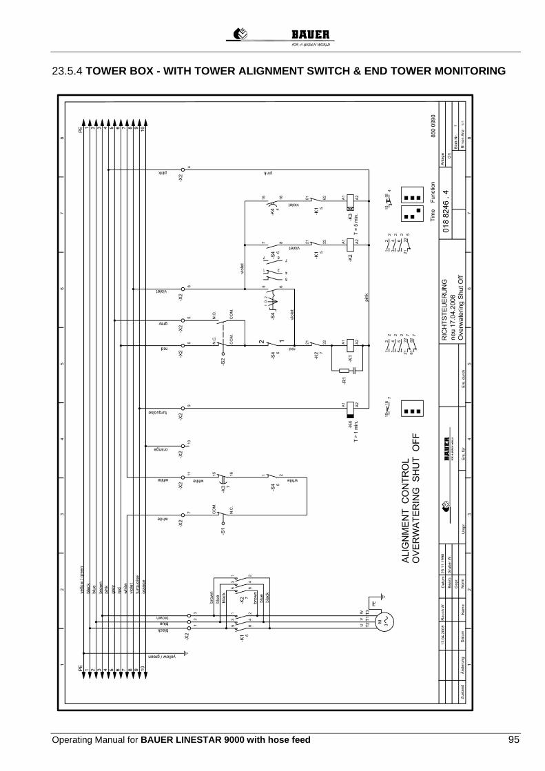
Operating Manual for BAUER LINESTAR 9000 with hose feed 95
23.5.4 TOWER BOX - WITH TOWER ALIGNMENT SWITCH & END TOWER MONITORING

96 Operating Manual for BAUER LINESTAR 9000 with hose feed
23.5.5 END TOWER BOX - STANDARD

Operating Manual for BAUER LINESTAR 9000 with hose feed 97
23.5.6 END TOWER BOX - WITH TOWER ALIGNMENT SWITCH

98 Operating Manual for BAUER LINESTAR 9000 with hose feed
23.5.7 END TOWER BOX - WITH END STOP

Operating Manual for BAUER LINESTAR 9000 with hose feed 99
23.5.8 END TOWER BOX - WITH END STOP & TOWER ALIGNMENT SWITCH

100 Operating Manual for BAUER LINESTAR 9000 with hose feed
23.5.9 END TOWER BOX - WITH END STOP & AUTOREVERSE

Operating Manual for BAUER LINESTAR 9000 with hose feed 101
23.5.10 END TOWER BOX - WITH END STOP & AUTOREVERSE

102 Operating Manual for BAUER LINESTAR 9000 with hose feed
23.6 BOOSTER PUMP FOR END GUN

Operating Manual for BAUER LINESTAR 9000 with hose feed 103
24 SERVICE – EVIDENCE
Accomplished service
Yes No Date Operating hours Confirmed by
Intermediate maintenance
Intermediate maintenance
Intermediate maintenance
Intermediate maintenance
Intermediate maintenance
Intermediate maintenance
Intermediate maintenance
Intermediate maintenance
Intermediate maintenance
Intermediate maintenance
Intermediate maintenance
Oil change
Annual maintenance

104 Operating Manual for BAUER LINESTAR 9000 with hose feed
Accomplished service
Yes No Date Operating hours Confirmed by
Intermediate maintenance
Intermediate maintenance
Intermediate maintenance
Intermediate maintenance
Intermediate maintenance
Intermediate maintenance
Intermediate maintenance
Intermediate maintenance
Intermediate maintenance
Intermediate maintenance
Intermediate maintenance
Oil change
Annual maintenance
Accomplished service
Yes No Date Operating hours Confirmed by
Intermediate maintenance
Intermediate maintenance
Intermediate maintenance
Intermediate maintenance
Intermediate maintenance
Intermediate maintenance
Intermediate maintenance
Intermediate maintenance
Intermediate maintenance
Intermediate maintenance
Intermediate maintenance
Oil change
Annual Maintenance
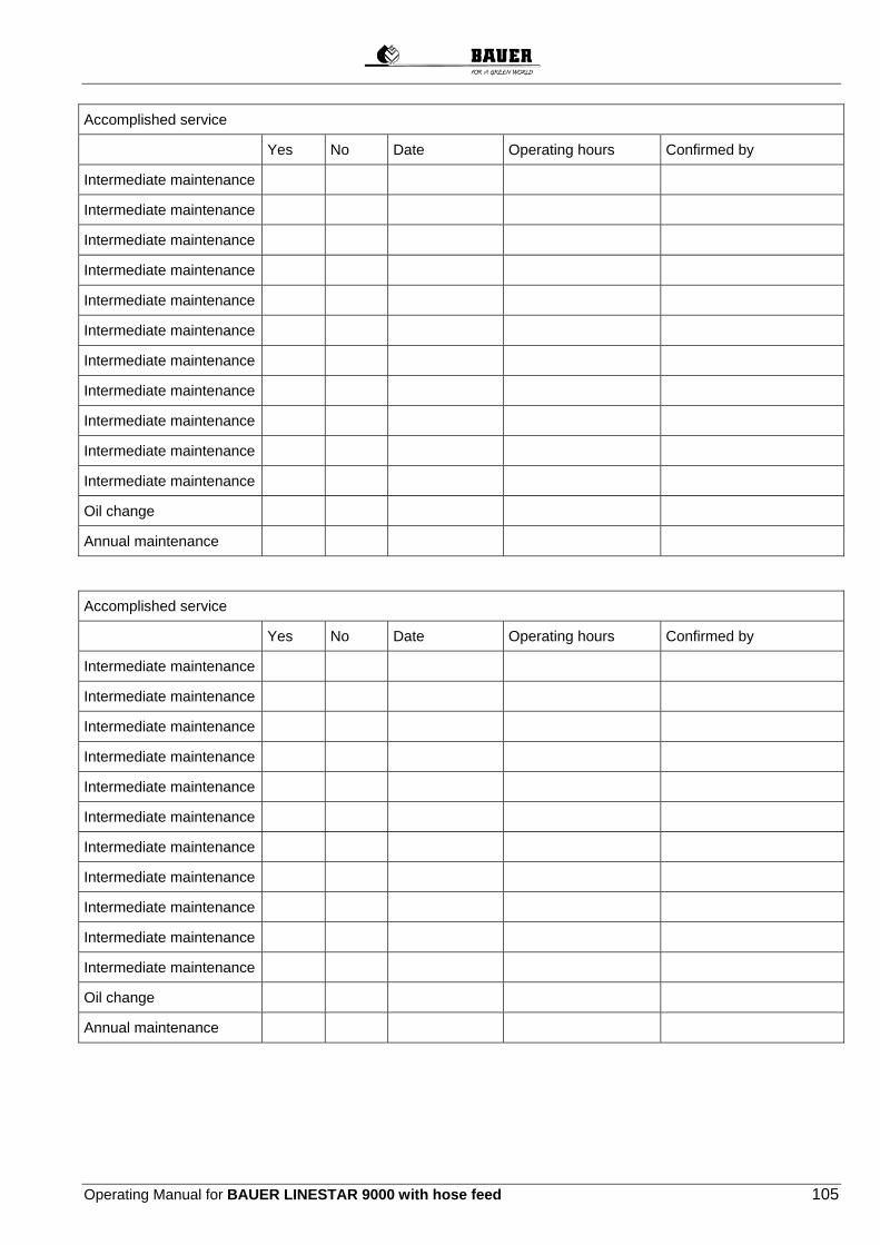
Operating Manual for BAUER LINESTAR 9000 with hose feed 105
Accomplished service
Yes No Date Operating hours Confirmed by
Intermediate maintenance
Intermediate maintenance
Intermediate maintenance
Intermediate maintenance
Intermediate maintenance
Intermediate maintenance
Intermediate maintenance
Intermediate maintenance
Intermediate maintenance
Intermediate maintenance
Intermediate maintenance
Oil change
Annual maintenance
Accomplished service
Yes No Date Operating hours Confirmed by
Intermediate maintenance
Intermediate maintenance
Intermediate maintenance
Intermediate maintenance
Intermediate maintenance
Intermediate maintenance
Intermediate maintenance
Intermediate maintenance
Intermediate maintenance
Intermediate maintenance
Intermediate maintenance
Oil change
Annual maintenance

106 Operating Manual for BAUER LINESTAR 9000 with hose feed
Accomplished service
Yes No Date Operating hours Confirmed by
Intermediate maintenance
Intermediate maintenance
Intermediate maintenance
Intermediate maintenance
Intermediate maintenance
Intermediate maintenance
Intermediate maintenance
Intermediate maintenance
Intermediate maintenance
Intermediate maintenance
Intermediate maintenance
Oil change
Annual maintenance

Operating Manual for BAUER LINESTAR 9000 with hose feed 107
25 CONFORMITY CERTIFICATE
EC Declaration of Conformity
according to EC Directive 2006/42/EG The manufacturer
Röhren- und Pumpenwerk BAUER Gesellschaft m.b.H. Kowaldstraße 2, 8570 Voitsberg, Austria Tel: +43 3142 200-0; Fax: +43 3142 200-320/-340
herewith confirms that the machine mentioned below
Designation of machine BAUER LINESTAR 9000 Machine type / basic units LINESTAR 9000 - 168 EL
corresponds analogously to the requirements of the Machinery Directive 2006/42/EG. In case of modification of the machine not accorded with BAUER GmbH, this declaration will cease to be valid. The following standards as amended have been applied analogously: DIN EN ISO 12100-1 Safety of machinery - Basic concepts, general principles for design
Part 1: Basic terminology, methodology DIN EN ISO 12100-2 Safety of machinery - Basic concepts, general principles for design
Part 2: Technical principles DIN EN 60204-1 Safety of machinery - Electrical equipment of machines
Part 1: General requirements EN ISO 14121-1 Safety of machinery - Risk assessment Part 1: Principles ÖNORM EN ISO 13857 Safety of machinery - Safety distances to prevent hazard zones being
reached by upper and lower limbs Standards related to products DIN EN 909 Agricultural and forestry machinery - Centre pivot and moving lateral
types irrigation machines - Safety Person in charge of documentation: Thomas Theissl, Kowaldstraße 2, 8570 Voitsberg, Austria,
Technical Designer in Charge Commercial Manager Voitsberg, 08.05.2012
Copyright © 2022 FDOKUMEN