YASKAWA AC Drive Z1000
394
YASKAWA AC Drive Z1000 AC Drive for HVAC Fan and Pump User Manual MANUAL NO. TOEP C710616 45G Models: 200 V Class: 2.2 to 110 kW (3 to 150 HP) 400 V Class: 2.2 to 370 kW (3 to 500 HP) To properly use the product, read this manual thoroughly and retain for easy reference, inspection, and maintenance. Ensure the end user receives this manual. Type: CIMR-ZUA Mechanical Installation 2 3 Electrical Installation 1 Receiving 4 5 A B A D E 6 Peripheral Devices & Options C BACnet Communications Quick Reference Sheet Specifications Specifications Parameter List Start-Up Programming & Operation Troubleshooting Standards Compliance
-
Upload
khangminh22 -
Category
Documents
-
view
0 -
download
0
Transcript of YASKAWA AC Drive Z1000

YASKAWA AC Drive Z1000AC Drive for HVAC Fan and Pump
User Manual
MANUAL NO. TOEP C710616 45G
Models: 200 V Class: 2.2 to 110 kW (3 to 150 HP)400 V Class: 2.2 to 370 kW (3 to 500 HP)
To properly use the product, read this manual thoroughly and retain for easy reference, inspection, and maintenance. Ensure the end user receives this manual.
Type: CIMR-ZUA
COSMOS(レター)(英文)新CI
Mechanical Installation 2
3Electrical Installation
1Receiving
4
5
A
B
A
D
E
6Peripheral Devices &Options
CBACnet Communications
Quick Reference Sheet
SpecificationsSpecifications
Parameter List
Start-Up Programming &Operation
Troubleshooting
Standards Compliance

This Page Intentionally Blank
2 YASKAWA ELECTRIC TOEP C710616 45G YASKAWA AC Drive – Z1000 User Manual
Copyright © 2011 YASKAWA ELECTRIC CORPORATION. All rights reserved.No part of this publication may be reproduced, stored in a retrieval system, or transmitted, in any form or by any means,mechanical, electronic, photocopying, recording, or otherwise, without the prior written permission of Yaskawa. No patentliability is assumed with respect to the use of the information contained herein. Moreover, because Yaskawa is constantlystriving to improve its high-quality products, the information contained in this manual is subject to change without notice.Every precaution has been taken in the preparation of this manual. Yaskawa assumes no responsibility for errors or omissions.Neither is any liability assumed for damages resulting from the use of the information contained in this publication.

Table of Contentsi. PREFACE & GENERAL SAFETY.................................................................. 11
i.1 Preface ....................................................................................................................... 12Applicable Documentation....................................................................................................... 12Symbols................................................................................................................................... 12Terms and Abbreviations ........................................................................................................ 12Trademarks ............................................................................................................................. 12
i.2 General Safety ........................................................................................................... 14Supplemental Safety Information ............................................................................................ 14Safety Messages..................................................................................................................... 15General Application Precautions ............................................................................................. 17Motor Application Precautions................................................................................................. 18Drive Label Warning Example................................................................................................. 20Warranty Information............................................................................................................... 21
1. RECEIVING .................................................................................................... 231.1 Section Safety............................................................................................................ 241.2 General Description .................................................................................................. 25
Z1000 Model Selection............................................................................................................ 25Control Mode Selection ........................................................................................................... 26
1.3 Model Number and Nameplate Check ..................................................................... 27Drive Nameplate...................................................................................................................... 27Drive Model Number Definition ............................................................................................... 28
1.4 Drive Models and Enclosure Types......................................................................... 291.5 Component Names.................................................................................................... 30
IP20/UL Type 1 Enclosure ...................................................................................................... 30IP00/Open-Type Enclosure ..................................................................................................... 33Front Views ............................................................................................................................. 37
2. MECHANICAL INSTALLATION..................................................................... 392.1 Section Safety............................................................................................................ 402.2 Mechanical Installation ............................................................................................. 42
Installation Environment .......................................................................................................... 42Transporting the Drive............................................................................................................. 42Installation Orientation and Spacing........................................................................................ 43Instructions on Installation Using the Eye Bolts ...................................................................... 43Panel Cut-Out Dimensions...................................................................................................... 45HOA Keypad Remote Usage .................................................................................................. 46Exterior and Mounting Dimensions ......................................................................................... 49
YASKAWA ELECTRIC TOEP C710616 45G YASKAWA AC Drive – Z1000 User Manual 3

3. ELECTRICAL INSTALLATION .............................................................................. 593.1 Section Safety......................................................................................................................603.2 Standard Connection Diagram...........................................................................................623.3 Main Circuit Connection Diagram......................................................................................65
Three-Phase 200 V Class (2A0011 to 2A0273) Three-Phase 400 V Class (4A0005 to 4A0302)............................................................................... 65
Three-Phase 200 V Class (2A0343 and 2A0396) Three-Phase 400 V Class (4A0361 to 4A0590)............................................................................... 65
12-Pulse/18-Pulse Rectification ........................................................................................................ 65Wiring to –/+1 Terminals (2A0343 to 2A0396 and 4A0361 to 4A0590) ............................................ 66
3.4 Terminal Block Configuration ............................................................................................683.5 Terminal Cover ....................................................................................................................70
Models 2A0143 to 2A0396 and 4A0124 to 4A0590 .......................................................................... 703.6 HOA Keypad and Front Cover............................................................................................72
Removing/Reattaching the HOA Keypad .......................................................................................... 72Removing/Reattaching the Front Cover ............................................................................................ 73
3.7 Top Protective Cover ..........................................................................................................79Removing the Top Protective Cover ................................................................................................. 79Reattaching the Top Protective Cover .............................................................................................. 80
3.8 Main Circuit Wiring..............................................................................................................81Factory Recommended Branch Circuit Protection ............................................................................ 81Main Circuit Terminal Functions........................................................................................................ 81Protecting Main Circuit Terminals ..................................................................................................... 82Wire Gauges and Tightening Torque ................................................................................................ 83Main Circuit Terminal and Motor Wiring ............................................................................................ 86
3.9 Control Circuit Wiring .........................................................................................................91Control Circuit Connection Diagram.................................................................................................. 91Control Circuit Terminal Block Functions .......................................................................................... 91Terminal Configuration ...................................................................................................................... 93Wiring the Control Circuit Terminal ................................................................................................... 95Switches and Jumpers on the Control Board .................................................................................... 99
3.10 Control I/O Connections ...................................................................................................100Sinking/Sourcing Mode Switch for Digital Inputs............................................................................. 100Input Signal Selection for Terminals A1 and A2.............................................................................. 100Terminal FM/AM Signal Selection ................................................................................................... 101MEMOBUS/Modbus Termination .................................................................................................... 101
3.11 Connect to a PC.................................................................................................................1023.12 External Interlock ..............................................................................................................103
Drive Ready..................................................................................................................................... 1033.13 Wiring Checklist ................................................................................................................104
4. START-UP PROGRAMMING & OPERATION..................................................... 1054.1 Section Safety....................................................................................................................1064.2 Using the HOA Keypad .....................................................................................................107
HOA Keypad Keys and Displays..................................................................................................... 107LCD Display .................................................................................................................................... 108ALARM (ALM) LED Displays........................................................................................................... 109AUTO LED and HAND LED Indications .......................................................................................... 109
Table of Contents
4 YASKAWA ELECTRIC TOEP C710616 45G YASKAWA AC Drive – Z1000 User Manual

Menu Structure for HOA Keypad..................................................................................................... 1114.3 The Drive, Programming, and Clock Adjustment Modes ..............................................112
Real-Time Clock (RTC) ................................................................................................................... 112Clock Adjustment ............................................................................................................................ 112Changing Parameter Settings or Values ......................................................................................... 115Verifying Parameter Changes: Verify Menu .................................................................................... 116Simplified Setup Using the Setup Group......................................................................................... 117
4.4 Start-Up Flowcharts ..........................................................................................................119Flowchart A: Basic Start-Up and Motor Tuning ............................................................................... 120Subchart A-1: Simple Motor Setup Using V/f Control...................................................................... 121Subchart A-2: Operation with Permanent Magnet Motors............................................................... 122
4.5 Powering Up the Drive ......................................................................................................123Powering Up the Drive and Operation Status Display..................................................................... 123
4.6 Application Selection........................................................................................................124HVAC Application Parameters ........................................................................................................ 124Setting 1: Fan Application ............................................................................................................... 124Setting 2: Fan with PI Control Application ....................................................................................... 125Setting 3: Return Fan with PI Control Application ........................................................................... 125Setting 4: Cooling Tower Fan Application ....................................................................................... 125Setting 5: Cooling Tower Fan with PI Control Application............................................................... 126Setting 6: Pump (Secondary) Application........................................................................................ 126Setting 7: Pump with PI Control Application.................................................................................... 126
4.7 Basic Drive Setup Adjustments .......................................................................................1274.8 Auto-Tuning .......................................................................................................................143
Types of Auto-Tuning ...................................................................................................................... 143Before Auto-Tuning the Drive.......................................................................................................... 144Auto-Tuning Interruption and Fault Codes ...................................................................................... 145Auto-Tuning Operation Example ..................................................................................................... 145T1: Parameter Settings during Induction Motor Auto-Tuning .......................................................... 147T2: Parameter Settings during PM Motor Auto-Tuning ................................................................... 148
4.9 No-Load Operation Test Run............................................................................................151No-Load Operation Test Run .......................................................................................................... 151
4.10 Test Run with Load Connected........................................................................................152Test Run with the Load Connected ................................................................................................. 152
4.11 Verifying Parameter Settings and Backing Up Changes...............................................153Backing Up Parameter Values: o2-03 ............................................................................................. 153Parameter Access Level: A1-01...................................................................................................... 153Password Settings: A1-04, A1-05 ................................................................................................... 153Copy Function ................................................................................................................................. 154
4.12 Test Run Checklist ............................................................................................................1554.13 Advanced Drive Setup Adjustments ...............................................................................156
U1: Operation Status Monitors ........................................................................................................ 194U2: Fault Trace................................................................................................................................ 194U3: Fault History.............................................................................................................................. 194U4: Maintenance Monitors .............................................................................................................. 194U5: PI Monitors................................................................................................................................ 195U6: Operation Status Monitors ........................................................................................................ 195
5. TROUBLESHOOTING.......................................................................................... 197
Table of Contents
YASKAWA ELECTRIC TOEP C710616 45G YASKAWA AC Drive – Z1000 User Manual 5

5.1 Section Safety....................................................................................................................1985.2 Motor Performance Fine-Tuning......................................................................................200
Fine-Tuning V/f Control ................................................................................................................... 200Fine-Tuning Open Loop Vector Control for PM Motors................................................................... 201Parameters to Minimize Motor Hunting and Oscillation .................................................................. 202
5.3 Drive Alarms, Faults, and Errors .....................................................................................203Types of Alarms, Faults, and Errors................................................................................................ 203Alarm and Error Displays ................................................................................................................ 204
5.4 Fault Detection ..................................................................................................................207Fault Displays, Causes, and Possible Solutions ............................................................................. 207
5.5 Alarm Detection.................................................................................................................220Alarm Codes, Causes, and Possible Solutions ............................................................................... 220
5.6 Programming Errors .........................................................................................................227Programming Error Codes, Causes, and Possible Solutions.......................................................... 227
5.7 Auto-Tuning Fault Detection ............................................................................................231Auto-Tuning Codes, Causes, and Possible Solutions..................................................................... 231
5.8 Copy Function Related Displays .....................................................................................233Tasks, Errors, and Troubleshooting ................................................................................................ 233
5.9 Diagnosing and Resetting Faults.....................................................................................235Fault Occurs Simultaneously with Power Loss ............................................................................... 235If the Drive Still has Power After a Fault Occurs ............................................................................. 235Viewing Fault Trace Data After Fault .............................................................................................. 235Fault Reset Methods ....................................................................................................................... 236
5.10 Troubleshooting without Fault Display...........................................................................237Common Problems.......................................................................................................................... 237Cannot Change Parameter Settings ............................................................................................... 237Motor Does Not Rotate Properly after Pressing AUTO Button or after Entering External RunCommand ...................................................................................................................................... 238
Motor is Too Hot.............................................................................................................................. 239oPE02 Error Occurs When Lowering the Motor Rated Current Setting .......................................... 240Motor Stalls during Acceleration or Acceleration Time is Too Long................................................ 240Drive Frequency Reference Differs from the Controller Frequency Reference Command ............. 241Excessive Motor Oscillation and Erratic Rotation............................................................................ 241Deceleration Takes Longer than Expected ..................................................................................... 241Noise From Drive or Motor Cables When the Drive is Powered On ............................................... 241Ground Fault Circuit Interrupter (GFCI) Trips During Run .............................................................. 241Connected Machinery Vibrates When Motor Rotates ..................................................................... 242PI Output Fault ................................................................................................................................ 242Motor Rotates after the Drive Output is Shut Off (Motor Rotates During DC Injection Braking) ..... 242Output Frequency is Not as High as Frequency Reference............................................................ 243Sound from Motor............................................................................................................................ 243Unstable Motor Speed when Using PM .......................................................................................... 243Motor Does Not Restart after Power Loss....................................................................................... 243
6. PERIPHERAL DEVICES & OPTIONS ................................................................. 2456.1 Section Safety....................................................................................................................2466.2 Drive Options and Peripheral Devices ............................................................................2486.3 Connecting Peripheral Devices .......................................................................................249
Table of Contents
6 YASKAWA ELECTRIC TOEP C710616 45G YASKAWA AC Drive – Z1000 User Manual

6.4 Option Installation.............................................................................................................250Prior to Installing the Option ............................................................................................................ 250Installing the Option......................................................................................................................... 250
6.5 Installing Peripheral Devices ...........................................................................................254Installing a Molded Case Circuit Breaker (MCCB) or Ground Fault Circuit Interrupter (GFCI) ....... 254Installing a Magnetic Contactor at the Power Supply Side.............................................................. 255Connecting an AC Reactor.............................................................................................................. 255Connecting a Surge Absorber ......................................................................................................... 255Attachment for External Heatsink Mounting .................................................................................... 257Installing a Motor Thermal Overload (oL) Relay on the Drive Output ............................................. 265
A. SPECIFICATIONS ................................................................................................ 267A.1 Power Ratings ...................................................................................................................268
Three-Phase 200 V Class Drive Models 2A0011 to 2A0088 .......................................................... 268Three-Phase 200 V Class Drive Models 2A0114 to 2A0396 .......................................................... 269Three-Phase 400 V Class Drive Models 4A0005 to 4A0027 .......................................................... 270Three-Phase 400 V Class Drive Models 4A0034 to 4A0096 .......................................................... 271Three-Phase 400 V Class Drive Models 4A0124 to 4A0302 .......................................................... 272Three-Phase 400 V Class Drive Models 4A0361 to 4A0590 .......................................................... 273
A.2 Drive Specifications ..........................................................................................................274A.3 Drive Watt Loss Data ........................................................................................................276A.4 Drive Derating Data ...........................................................................................................278
Carrier Frequency Derating............................................................................................................. 278Temperature Derating ..................................................................................................................... 279Altitude Derating.............................................................................................................................. 280
B. PARAMETER LIST............................................................................................... 281B.1 A: Initialization Parameters ..............................................................................................282
A1: Initialization ............................................................................................................................... 282A2: User Parameters....................................................................................................................... 283
B.2 b: Application.....................................................................................................................284b1: Operation Mode Selection......................................................................................................... 284b2: DC Injection Braking and Short Circuit Braking......................................................................... 284b3: Speed Search............................................................................................................................ 285b4: Timer Function .......................................................................................................................... 286b5: PI Control .................................................................................................................................. 287b8: Energy Saving ........................................................................................................................... 290
B.3 C: Tuning............................................................................................................................291C1: Acceleration and Deceleration Times ....................................................................................... 291C2: S-Curve Characteristics............................................................................................................ 291C4: Torque Compensation .............................................................................................................. 291C6: Carrier Frequency..................................................................................................................... 292
B.4 d: References.....................................................................................................................293d1: Frequency Reference................................................................................................................ 293d2: Frequency Upper/Lower Limits ................................................................................................. 293d3: Jump Frequency........................................................................................................................ 294d4: Frequency Reference Hold Function......................................................................................... 294d6: Field Weakening........................................................................................................................ 294d7: Offset Frequency....................................................................................................................... 295
Table of Contents
YASKAWA ELECTRIC TOEP C710616 45G YASKAWA AC Drive – Z1000 User Manual 7

B.5 E: Motor Parameters .........................................................................................................296E1: V/f Pattern for Motor 1............................................................................................................... 296E2: Motor Parameters ..................................................................................................................... 297E5: PM Motor Settings .................................................................................................................... 297
B.6 F: Communication Option Parameters............................................................................299F6, F7: Communication Option Card............................................................................................... 299
B.7 H Parameters: Multi-Function Terminals ........................................................................302H1: Multi-Function Digital Inputs ..................................................................................................... 302H2: Multi-Function Digital Outputs................................................................................................... 306H3: Multi-Function Analog Inputs .................................................................................................... 308H4: Analog Outputs ......................................................................................................................... 309H5: MEMOBUS/Modbus Serial Communication ............................................................................. 310
B.8 L: Protection Function ......................................................................................................312L1: Motor Protection ........................................................................................................................ 312L2: Momentary Power Loss Ride-Thru............................................................................................ 313L3: Stall Prevention ......................................................................................................................... 314L4: Speed Detection........................................................................................................................ 315L5: Fault Restart.............................................................................................................................. 315L6: Torque Detection....................................................................................................................... 316L8: Drive Protection......................................................................................................................... 316
B.9 n: Special Adjustment.......................................................................................................319n1: Hunting Prevention.................................................................................................................... 319n3: High Slip Braking (HSB) and Overexcitation Braking................................................................ 319n8: PM Motor Control Tuning .......................................................................................................... 320
B.10 o: Operator-Related Settings ...........................................................................................321o1: HOA Keypad Display Selection................................................................................................. 321o2: HOA Keypad Functions............................................................................................................. 322o3: Copy Function ........................................................................................................................... 323o4: Maintenance Monitor Settings................................................................................................... 323
B.11 S: Special Application.......................................................................................................324S1: Dynamic Noise Control Function .............................................................................................. 324S2: Sequence Timers...................................................................................................................... 324S3: Secondary PI (PI2) Control ....................................................................................................... 326S4: Bypass Operation ..................................................................................................................... 328S5: HOA Keypad Parameters ......................................................................................................... 328S6: Z1000 Protection....................................................................................................................... 329
B.12 T: Motor Tuning .................................................................................................................330T1: Induction Motor Auto-Tuning..................................................................................................... 330T2: PM Motor Auto-Tuning .............................................................................................................. 330
B.13 U: Monitors.........................................................................................................................332U1: Operation Status Monitors ........................................................................................................ 332U2: Fault Trace................................................................................................................................ 333U3: Fault History.............................................................................................................................. 334U4: Maintenance Monitors .............................................................................................................. 336U5: PI Monitors................................................................................................................................ 337U6: Operation Status Monitors ........................................................................................................ 338
C. BACNET COMMUNICATIONS ............................................................................ 341C.1 BACnet Configuration.......................................................................................................342
Table of Contents
8 YASKAWA ELECTRIC TOEP C710616 45G YASKAWA AC Drive – Z1000 User Manual

C.2 Communication Specifications........................................................................................343C.3 Connecting to a Network ..................................................................................................344
Network Cable Connection.............................................................................................................. 344Wiring Diagram for Multiple Connections ........................................................................................ 345Network Termination ....................................................................................................................... 345
C.4 BACnet Setup Parameters................................................................................................346BACnet Serial Communication........................................................................................................ 346
C.5 Drive Operations by BACnet ............................................................................................350Observing the Drive Operation........................................................................................................ 350Controlling the Drive........................................................................................................................ 350
C.6 Communications Timing...................................................................................................351Command Messages from Master to Drive..................................................................................... 351Response Messages from Drive to Master ..................................................................................... 351
C.7 BACnet Objects Supported ..............................................................................................352Present Value Access ..................................................................................................................... 352Supported Properties of Objects ..................................................................................................... 352Analog Input Objects ....................................................................................................................... 353Analog Output Objects .................................................................................................................... 353Analog Value Objects...................................................................................................................... 353Binary Input Objects ........................................................................................................................ 356Binary Output Objects ..................................................................................................................... 356Binary Value Objects....................................................................................................................... 356Device Object .................................................................................................................................. 357
C.8 Accessing Drive Parameters and the Enter Command .................................................358Reading Drive Parameters .............................................................................................................. 358Writing Drive Parameters ................................................................................................................ 358Enter Command .............................................................................................................................. 358
C.9 Communication Errors .....................................................................................................359C.10 Self-Diagnostics ................................................................................................................360C.11 BACnet Protocol Implementation Conformance Statement..........................................361
D. STANDARDS COMPLIANCE .............................................................................. 363D.1 Section Safety....................................................................................................................364D.2 UL/cUL Standards .............................................................................................................366
UL Standards Compliance .............................................................................................................. 366Drive Motor Overload Protection ..................................................................................................... 369Precautionary Notes on External Heatsink (IP00/Open-Type Enclosure)....................................... 370
E. QUICK REFERENCE SHEET .............................................................................. 371E.1 Drive and Motor Specifications........................................................................................372
Drive Specifications......................................................................................................................... 372Motor Specifications ........................................................................................................................ 372
E.2 Basic Parameter Settings .................................................................................................373Basic Setup ..................................................................................................................................... 373Motor Setup..................................................................................................................................... 373Multi-Function Digital Inputs ............................................................................................................ 373Analog Inputs .................................................................................................................................. 373Multi-Function Digital Outputs ......................................................................................................... 374
Table of Contents
YASKAWA ELECTRIC TOEP C710616 45G YASKAWA AC Drive – Z1000 User Manual 9

Monitor Outputs............................................................................................................................... 374E.3 User Setting Table.............................................................................................................375INDEX ................................................................................................................... 381
Table of Contents
10 YASKAWA ELECTRIC TOEP C710616 45G YASKAWA AC Drive – Z1000 User Manual

Preface & General SafetyThis section provides safety messages pertinent to this product that, if not heeded, may result in fatality,personal injury, or equipment damage. Yaskawa is not responsible for the consequences of ignoringthese instructions.
i.1 PREFACE...............................................................................................................12i.2 GENERAL SAFETY...............................................................................................14
i
YASKAWA ELECTRIC TOEP C710616 45G YASKAWA AC Drive – Z1000 User Manual 11

i.1 PrefaceYaskawa manufactures products used as components in a wide variety of industrial systems and equipment. The selection andapplication of Yaskawa products remain the responsibility of the equipment manufacturer or end user. Yaskawa accepts noresponsibility for the way its products are incorporated into the final system design. Without exception, all controls should bedesigned to detect faults dynamically and fail safely under all circumstances. All systems or equipment designed to incorporatea product manufactured by Yaskawa must be supplied to the end user with appropriate warnings and instructions as to the safeuse and operation of that part. Any warnings provided by Yaskawa must be promptly provided to the end user. Yaskawa offersan express warranty only as to the quality of its products in conforming to standards and specifications published in the Yaskawamanual. NO OTHER WARRANTY, EXPRESS OR IMPLIED, IS OFFERED. Yaskawa assumes no liability for any personalinjury, property damage, losses, or claims arising from misapplication of its products.This manual is designed to ensure correct and suitable application of Z1000-series drives. Read this manual before attemptingto install, operate, maintain, or inspect a drive and keep it in a safe, convenient location for future reference. Be sure youunderstand all precautions and safety information before attempting application.
u Applicable DocumentationThe following manuals are available for Z1000-series drives:
危 険
据え付け、運転の前には必ず取扱説明書を読むこと。通電中および電源遮断後
5分以内はフロントカバー
を外さない事。400V級インバータの場合は、電源の中性点が接地
されていることを確認すること。
( 対応)保守・点検、配線を行う場合は、出力側開閉器を
遮断後5分待って実施してください。
けが.感電のおそれがあります。
高温注意
インバータ上部、両側面は高温になります。触らないでください。
●
●
●
●
AVERTISSMENT NPJT31470-1
Lire le manuel avant l'installation.Attendre 5 minutes après la coupurede l'alimentation, pour permettrela décharge des condensateurs. Pour répondre aux exigences , sassurer que le neutre soit relié à la terre, pour la série 400V.Après avoir déconnécte la protectionentre le driver et le moteur, veuillezpatienter 5 minutes avain d’effectuerune opération de montage ou decâblage du variateur.
Risque de décharge électrique.
Surfaces ChaudesDessus et cotés du boitier Peuventdevenir chaud. Ne Pas toucher.
WARNINGRead manual before installing.Wait 5 minutes for capacitordischarge after disconnectingpower supply.To conform to requirements,make sure to ground the supplyneutral for 400V class.After opening the manual switchbetween the drive and motor,please wait 5 minutes beforeinspecting, performingmaintenance or wiring the drive.
Risk of electric shock.
Hot surfaces Top and Side surfaces maybecome hot. Do not touch.
●
●
●
●
●
●
●
●
●
●
●
●
●
●
●
F2F1
ESCM M
AUTO OFF
ENTERRESET
ALMDIGITAL OPERATOR JVOP-183
HAND
Z1000-Series AC Drive Quick Start Guide (TOEPC71061654)Read this guide first. This guide is packaged together with the product and contains basic information required to installand wire the drive. It also gives an overview of fault diagnostics, maintenance safety, and parameter settings. The mostrecent version of this manual is available for download on our documentation website, www.yaskawa.com.Z1000-Series AC Drive User Manual (TOEPC71061645)This manual contains detailed information on fault diagnostics, parameter settings, and BACnet specifications. The purposeof this manual is to prepare the drive for a trial run with an application and for basic operation. The most recent version ofthis manual is available for download on our documentation website, www.yaskawa.com.Z1000-Series AC Drive Programming Manual (SIEPC71061645)This manual provides detailed information on parameter settings, drive functions, maintenance, and MEMOBUS/ Modbusspecifications. Use this manual to expand drive functionality and to take advantage of higher performance features. Themost recent version of this manual is available for download on our documentation website, www.yaskawa.com.
u SymbolsNote: Indicates a supplement or precaution that does not cause drive damage.
TERMSTERMS Indicates a term or definition used in this manual.
u Terms and AbbreviationsTERMSTERMS • Drive: Yaskawa Z1000-Series Drive
• Digital Operator: Hand Off Auto (HOA) Keypad JVOP-183• H: Hexadecimal Number Format• IGBT: Insulated Gate Bipolar Transistor• kbps: Kilobits per Second• MAC: Media Access Control• r/min: Revolutions per Minute• V/f: V/f Control• OLV/PM: Open Loop Vector Control for PM• PM motor: Permanent Magnet Synchronous motor (an abbreviation for IPM motor or SPM motor)• IPM motor: Interior Permanent Magnet Motor (e.g., Yaskawa SSR1 Series and SST4 Series motors)• SPM motor: Surface mounted Permanent Magnet Motor (e.g., Yaskawa SMRA Series motors)
u Trademarks• APOGEE® FLN is a registered trademark of Siemens Building Technologies, Inc.• APOGEE® Anywhere™ is a trademark of Siemens Building Technologies, Inc.• BACnet is a trademark of the American Society of Heating, Refrigerating, and Air-Conditioning Engineers (ASHRAE).
i.1 Preface
12 YASKAWA ELECTRIC TOEP C710616 45G YASKAWA AC Drive – Z1000 User Manual

• GPD is a trademark of Yaskawa, Inc.• Metasys® N2 is a trademark of Johnson Controls, Inc.• MODBUS® is a registered trademark of Schneider Automation, Inc.• Other companies and product names mentioned in this manual are trademarks of those companies.
i.1 Preface
YASKAWA ELECTRIC TOEP C710616 45G YASKAWA AC Drive – Z1000 User Manual 13

i.2 General Safety
u Supplemental Safety InformationGeneral Precautions
• The diagrams in this manual may be indicated without covers or safety shields to show details. Replace the covers or shields beforeoperating the drive and run the drive according to the instructions described in this manual.
• Any illustrations, photographs, or examples used in this manual are provided as examples only and may not apply to all products towhich this manual is applicable.
• The products and specifications described in this manual or the content and presentation of the manual may be changed without noticeto improve the product and/or the manual.
• When ordering a new copy of the manual due to damage or loss, contact Yaskawa or a Yaskawa representative and provide the manualnumber shown on the front cover.
• If nameplate becomes worn or damaged, order a replacement from Yaskawa or a Yaskawa representative.
WARNINGRead and understand this manual before installing, operating or servicing this drive. The drive must be installed accordingto this manual and local codes.The following conventions are used to indicate safety messages in this manual. Failure to heed these messages could resultin serious or fatal injury or damage to the products or to related equipment and systems.
DANGERIndicates a hazardous situation, which, if not avoided, will result in death or serious injury.
WARNINGIndicates a hazardous situation, which, if not avoided, could result in death or serious injury.
WARNING! may also be indicated by a bold key word embedded in the text followed by an italicized safety message.
CAUTIONIndicates a hazardous situation, which, if not avoided, could result in minor or moderate injury.
CAUTION! may also be indicated by a bold key word embedded in the text followed by an italicized safety message.
NOTICEIndicates a property damage message.
NOTICE: may also be indicated by a bold key word embedded in the text followed by an italicized safety message.
i.2 General Safety
14 YASKAWA ELECTRIC TOEP C710616 45G YASKAWA AC Drive – Z1000 User Manual

u Safety Messages
DANGERHeed the safety messages in this manual.Failure to comply will result in death or serious injury.The operating company is responsible for any injuries or equipment damage resulting from failure to heed the warnings inthis manual.
Electrical Shock HazardDo not connect or disconnect wiring while the power is on.Failure to comply will result in death or serious injury.Before servicing, disconnect all power to the equipment. The internal capacitor remains charged even after the power supplyis turned off. After shutting off the power, wait for at least the amount of time specified on the drive before touching anycomponents.
WARNINGSudden Movement Hazard
System may start unexpectedly upon application of power, resulting in death or serious injury.Clear all personnel from the drive, motor and machine area before applying power. Secure covers, couplings, shaft keys andmachine loads before applying power to the drive.
Electrical Shock HazardDo not attempt to modify or alter the drive in any way not explained in this manual.Failure to comply could result in death or serious injury.Yaskawa is not responsible for any modification of the product made by the user. This product must not be modified.Do not allow unqualified personnel to use equipment.Failure to comply could result in death or serious injury.Maintenance, inspection, and replacement of parts must be performed only by authorized personnel familiar with installation,adjustment and maintenance of AC drives.Do not remove covers or touch circuit boards while the power is on.Failure to comply could result in death or serious injury.Always use appropriate equipment for Ground Fault Circuit Interrupters (GFCIs).The drive can cause a residual current with a DC component in the protective earthing conductor. Where a residual currentoperated protective or monitoring device is used for protection in case of direct or indirect contact, always use a type B GFCIaccording to IEC/EN 60755.
Fire HazardInstall adequate branch circuit protection according to applicable local codes and this manual.Failure to comply could result in fire and damage to the drive or injury to personnel. The device is suitable for use on a circuitcapable of delivering not more than 100,000 RMS symmetrical amperes, 240 Vac (200 V class) and 480 Vac (400 V class),when protected by branch circuit protection devices specified in this manual.Branch circuit protection shall be provided by any of the following: Non-time delay Class J, T, or CC fuses sized at 300%of the drive input rating, or Time delay Class J, T, or CC fuses sized at 175% of the drive input rating, or MCCB sized at200% maximum of the drive input rating.Do not use an improper voltage source.Failure to comply could result in death or serious injury by fire.Verify that the rated voltage of the drive matches the voltage of the incoming power supply before applying power.
i.2 General Safety
YASKAWA ELECTRIC TOEP C710616 45G YASKAWA AC Drive – Z1000 User Manual 15

CAUTIONCrush Hazard
Do not carry the drive by the front cover.Failure to comply may result in minor or moderate injury from the main body of the drive falling.
NOTICEObserve proper electrostatic discharge procedures (ESD) when handling the drive and circuit boards.Failure to comply may result in ESD damage to the drive circuitry.Do not perform a withstand voltage test on any part of the drive.Failure to comply could result in damage to the sensitive devices within the drive.Do not operate damaged equipment.Failure to comply could result in further damage to the equipment.Do not connect or operate any equipment with visible damage or missing parts.Do not expose the drive to halogen group disinfectants.Failure to comply may cause damage to the electrical components in the drive.Do not pack the drive in wooden materials that have been fumigated or sterilized.Do not sterilize the entire package after the product is packed.Do not use screws of different sizes in SW1 and SW2.Failure to comply may cause overheating and electrical damage.
i.2 General Safety
16 YASKAWA ELECTRIC TOEP C710616 45G YASKAWA AC Drive – Z1000 User Manual

u General Application Precautionsn SelectionInstalling a ReactorUse an AC reactor in the following situations:• to suppress harmonic current.• when the drive is running from a power supply system with thyristor converters.
Drive CapacityFor specialized motors, make sure that the motor rated current is less than the rated output current for the drive.When running more than one motor in parallel from a single drive, the capacity of the drive should be larger than [total motorrated current × 1.1].
Starting TorqueThe startup and acceleration characteristics of the motor are restricted to the drive overload current rating.The overload rating for the drive determines the starting and accelerating characteristics of the motor. Expect lower torquethan when running from line power. To achieve a higher starting torque, use a larger drive or a drive and motor with largercapacity.
Emergency StopDuring a drive fault condition, the output shuts off but the motor does not stop immediately. A mechanical brake may berequired when it is necessary to stop the motor faster than the ability of the Fast Stop function of the drive.
OptionsNOTICE: The -M, +M, -, +1, and +3 terminals are used to connect optional Z1000-compatible devices only. Connecting non-Yaskawa-approved devices to these terminals may damage the drive.
n InstallationEnclosure PanelsKeep the drive in a clean environment by installing the drive in an enclosure panel. Be sure to leave the required space betweendrives to provide for cooling, and take proper measures so the ambient temperature remains within allowable limits and keepflammable materials away from the drive. Yaskawa offers protective designs for drives that must be used in areas subjectedto oil mist and excessive vibration. Contact Yaskawa or your Yaskawa agent for details.
Installation DirectionNOTICE: Install the drive upright as specified in the manual. Refer to the Mechanical Installation section for more information on installation.Failure to comply may damage the drive due to improper cooling.
n SettingsUpper LimitsNOTICE: The drive is capable of running the motor up to 240 Hz. Be sure to set the upper limit for the frequency of the drive to prevent thepossible danger of accidentally operating equipment at higher than rated speed. The default setting for the maximum output frequency is60 Hz.
DC Injection BrakingNOTICE: Excessive current during DC Injection Braking and excessive duration of DC Injection Braking can cause motor overheat.
Acceleration/Deceleration TimesAcceleration and deceleration times are affected by the amount of torque generated by the motor, the load torque, and themoment of inertia. Set a longer accel/decel time when Stall Prevention is enabled. The accel/decel times are lengthened foras long as the Stall Prevention function is in operation. Install one of the available braking options or increase the capacity ofthe drive for faster acceleration and deceleration.
n General HandlingWiring CheckNOTICE: Do not connect power supply lines to output terminals U/T1, V/T2, or W/T3. Failure to comply will destroy the drive. Be sure toperform a final check of all sequence wiring and other connections before turning on the power and also check for short circuits on thecontrol terminals, which may damage the drive.
Selecting a Circuit Breaker or Circuit InterrupterYaskawa recommends installing a Ground Fault Circuit Interrupter (GFCI) to the power supply side. The GFCI should bedesigned for use with AC drives (e.g., Type B according to IEC/EN 60755).
i.2 General Safety
YASKAWA ELECTRIC TOEP C710616 45G YASKAWA AC Drive – Z1000 User Manual 17

Select a Molded Case Circuit Breaker (MCCB) or GFCI with a rated current 1.5 to 2 times higher than the drive rated currentto avoid nuisance trips caused by harmonics in the drive input current. Refer to Installing a Molded Case Circuit Breaker (MCCB) or Ground Fault Circuit Interrupter (GFCI) on page 254 for more information.Magnetic Contactor InstallationWARNING! Fire Hazard, Sudden Movement Hazard. Shut off the drive with a magnetic contactor (MC) when a fault occurs in externalequipment. Refer to Installing a Magnetic Contactor at the Power Supply Side on page 255. Failure to comply may cause seriousinjury or death due to fire or inadvertent equipment movement.
NOTICE: To get the full performance life out of the electrolytic capacitors and circuit relays, refrain from switching the drive power supplyoff and on more than once every 30 minutes. Frequent use can damage the drive. Use the drive to stop and start the motor.
Inspection and MaintenanceWARNING! Electrical Shock Hazard. Capacitors in the drive do not immediately discharge after shutting off the power. Wait for at least theamount of time specified on the drive before touching any components after shutting off the power. Failure to comply may cause injury topersonnel from electrical shock.
WARNING! Electrical Shock Hazard. When a drive is running a PM motor, voltage continues to be generated at the motor terminals afterthe drive is shut off while the motor coasts to stop. Take the precautions described below to prevent shock and injury:∙ In applications where the machine can still rotate after the drive has fully stopped a load, install a switch to the drive output side to disconnectthe motor and the drive.∙ Do not allow an external force to rotate the motor beyond the maximum allowable speed or to rotate the motor when the drive has beenshut off.∙ Wait for at least the time specified on the warning label after opening the load switch on the output side before inspecting the drive orperforming any maintenance.∙ Do not open and close the load switch while the motor is running.∙ If the motor is coasting, make sure the power to the drive is turned on and the drive output has completely stopped before closing the loadswitch.
WARNING! Burn Hazard. Because the heatsink can get very hot during operation, take proper precautions to prevent burns. When replacingthe cooling fan, shut off the power and wait at least 15 minutes to be sure that the heatsink has cooled down. Failure to comply may causeburn injury to personnel.
WiringYaskawa recommends using ring terminals on all drive models. Drive models 2A0031 to 2A0396 and 4A0034 to 4A0590require the use of ring terminals for UL/cUL compliance. Use only the tools recommended by the terminal manufacturer forcrimping.Transporting the DriveNOTICE: Never steam clean the drive. During transport, keep the drive from coming into contact with salts, fluorine, bromine, phthalateester, and other such harmful chemicals.
u Motor Application Precautionsn Standard Induction MotorsLow-Speed RangeThe cooling fan of a standard motor should sufficiently cool the motor at the rated speed. As the self-cooling capability ofsuch a motor decreases with the speed, applying full torque at low speed will possibly damage the motor. Reduce the loadtorque as the motor slows to prevent motor damage from overheat. Figure i.1 shows the allowable load characteristics for aYaskawa standard motor. Use a motor designed specifically for operation with a drive when 100% continuous torque is neededat low speeds.
50
3 6 60
60708090
100
25% ED (or 15 min)40% ED (or 20 min)
60% ED (or 40 min)
Frequency (Hz)
Continuous operation
Torque(%)
20
Figure i.1 Allowable Load Characteristics for a Yaskawa Motor
i.2 General Safety
18 YASKAWA ELECTRIC TOEP C710616 45G YASKAWA AC Drive – Z1000 User Manual

Insulation ToleranceNOTICE: Consider motor voltage tolerance levels and motor insulation in applications with an input voltage of over 440 V or particularlylong wiring distances.
High-Speed OperationNOTICE: Problems may occur with the motor bearings and dynamic balance of the machine when operating a motor beyond its rated speed.Contact the motor or machine manufacturer.
Torque CharacteristicsTorque characteristics differ compared to operating the motor directly from line power. The user should have a fullunderstanding of the load torque characteristics for the application.
Vibration and ShockThe drive allows selection of high carrier PWM control and low carrier PWM. Selecting high carrier PWM can help reducemotor oscillation.Take particular caution when adding a variable speed drive to an application running a motor from line power at a constantspeed. If resonance occurs, install shock-absorbing rubber around the base of the motor and enable the Jump frequency selectionto prevent continuous operation in the resonant frequency range.
Audible NoiseThe audible noise of the motor varies based on the carrier frequency setting. However, drive current derating may be required.When using a high carrier frequency, audible noise from the motor is comparable to the motor noise generated when runningfrom line power.
n Specialized MotorsSynchronous Motor• Contact Yaskawa or a Yaskawa agent when planning to use a synchronous motor not endorsed by Yaskawa.• Use a standard induction motor when running multiple synchronous motors simultaneously. A single drive does not have
this capability.• A synchronous motor may rotate slightly in the opposite direction of the Run command at start depending on parameter
settings and rotor position.• The amount of generated starting torque differs depending on the control mode and motor type. Set up the motor with the
drive after verifying the starting torque, allowable load characteristics, impact load tolerance, and speed control range.Contact Yaskawa or a Yaskawa agent when planning to use a motor that does not fall within these specifications:
• In Open Loop Vector Control for PM motors, braking torque is less than 125% when running between 20% and 100% speed.Braking torque drops to less than 50% when running at less than 20% speed.
• In Open Loop Vector Control for PM motors, the allowable load moment of inertia is approximately 50 times higher thanthe motor moment of inertia.Contact Yaskawa or a Yaskawa agent for questions concerning applications with a larger moment of inertia.
• To restart a coasting motor rotating below 100 Hz, use the Speed Search function if the motor cable is not too long. If themotor cable is relatively long, stop the motor using Short Circuit Braking.
Multi-Pole MotorThe rated current of a multi-pole motor differs from that of a standard motor, so be sure to check the maximum current whenselecting a drive. Always stop the motor before switching between the number of motor poles. The motor will coast to stop ifa regenerative overvoltage (ov) fault occurs or if overcurrent (oC) protection is triggered.
Submersible MotorThe rated current of a submersible motor is greater than that of a standard motor, so select the drive accordingly. Use a motorcable large enough to avoid decreasing the maximum torque level from voltage drop caused by a long motor cable.
Explosion-Proof MotorThe motor and the drive must be tested together to be certified as explosion-proof. The drive is not designed for explosion-proof areas.
Geared MotorMake sure that the gear and the lubricant are rated for the desired speed range to avoid gear damage when operating at lowspeeds or very high speeds. Consult with the manufacturer for applications that require operation outside the rated speed rangeof the motor or gear box.
i.2 General Safety
YASKAWA ELECTRIC TOEP C710616 45G YASKAWA AC Drive – Z1000 User Manual 19

Single-Phase MotorVariable speed drives are not designed to operate with single phase motors. Using capacitors to start the motor causes a high-frequency current to flow to the capacitors and can damage the capacitors. A split-phase start or a repulsion start can burn outthe starter coils because the internal centrifugal switch is not activated. The drive is for use with three-phase motors only.
Motor with BrakeTake caution when using the drive to operate a motor with a built-in holding brake. If the brake is connected to the output sideof the drive, it may not release at start due to low voltage levels, so be sure to install a separate power supply for the motorbrake. Note that motors with built-in brakes tend to generate a fair amount of noise when running at low speeds.
u Drive Label Warning ExampleAlways heed the warning information listed in Figure i.2.
危 険
据え付け、運転の前には必ず取扱説明書を読むこと。通電中および電源遮断後
5分以内はフロントカバー
を外さない事。級インバータの場合は、電源の中性点が接地
されていることを確認すること ( 対応)保守・点検、配線を行う場合は、出力側開閉器を遮断後
5分待って実施してください。
けが.感電のおそれがあります。
高温注意インバータ上部、両側面は高温になります。触らないでください。
●
●
●
●
AVERTISSMENT NPJT31470-1
Lire le manuel avant l'installation.Attendre 5 minutes après la coupurede l'alimentation, pour permettrela décharge des condensateurs. Pour répondre aux exigences , sassurer que le neutre soit relié à la terre, pour la série 400V.Après avoir déconnécte la protectionentre le driver et le moteur, veuillezpatienter 5 minutes avain d’effectuerune opération de montage ou decâblage du variateur.
Risque de décharge électrique.
Surfaces ChaudesDessus et cotés du boitier Peuventdevenir chaud. Ne Pas toucher.
WARNINGRead manual before installing.Wait 5 minutes for capacitordischarge after disconnectingpower supply.To conform to requirements,make sure to ground the supplyneutral for 400V class.After opening the manual switchbetween the drive and motor,please wait 5 minutes beforeinspecting, performingmaintenance or wiring the drive.
Risk of electric shock.
Hot surfaces Top and Side surfaces maybecome hot. Do not touch.
●
●
●
●
●
●
●
●
●
●
●
●
●
●
●
F2F1
ESCM M
AUTO OFF
ENTERRESET
ALMDIGITAL OPERATOR JVOP-183
HAND
400。
WARNINGRead manual before installing.Wait 5 minutes for capacitordischarge after disconnectingpower supply.To conform to requirements,make sure to ground the supplyneutral for 400V class.After opening the manual switchbetween the drive and motor,please wait 5 minutes beforeinspecting, performingmaintenance or wiring the drive.
Risk of electric shock.
Hot surfaces Top and Side surfaces maybecome hot. Do not touch.
●
●
●
●
●
Figure i.2 Warning Information Example and Position
i.2 General Safety
20 YASKAWA ELECTRIC TOEP C710616 45G YASKAWA AC Drive – Z1000 User Manual

u Warranty Informationn Warranty PeriodThis drive is warranted for 12 months from the date of delivery to the customer or 18 months from the date of shipment fromthe Yaskawa factory, whichever comes first.
n Scope of WarrantyInspectionsCustomers are responsible for periodic inspections of the drive. Upon request, a Yaskawa representative will inspect the drivefor a fee. If the Yaskawa representative finds the drive to be defective due to Yaskawa workmanship or materials and thedefect occurs during the warranty period, this inspection fee will be waived and the problem remedied free of charge.
RepairsIf a Yaskawa product is found to be defective due to Yaskawa workmanship or materials and the defect occurs during thewarranty period, Yaskawa will provide a replacement, repair the defective product, and provide shipping to and from the sitefree of charge.However, if the Yaskawa Authorized Service Center determines that the problem with the drive is not due to defectiveworkmanship or materials, the customer will be responsible for the cost of any necessary repairs. Some problems that areoutside the scope of this warranty are:Problems due to improper maintenance or handling, carelessness, or other reasons where the customer is determined to beresponsible.Problems due to additions or modifications made to a Yaskawa product without Yaskawa’s understanding.Problems due to the use of a Yaskawa product under conditions that do not meet the recommended specifications.Problems caused by natural disaster or fire.After the free warranty period elapses.Replenishment or replacement of consumables or expendables.Defective products due to packaging or fumigation.Other problems not due to defects in Yaskawa workmanship or materials.Warranty service is only applicable within the country where the product was purchased. However, after-sales service isavailable for customers outside of the country where the product was purchased for a reasonable fee.Contact your local Yaskawa representative for more information.
ExceptionsAny inconvenience to the customer or damage to non-Yaskawa products due to Yaskawa’s defective products whether withinor outside of the warranty period are NOT covered by warranty.
i.2 General Safety
YASKAWA ELECTRIC TOEP C710616 45G YASKAWA AC Drive – Z1000 User Manual 21

i.2 General Safety
This Page Intentionally Blank
22 YASKAWA ELECTRIC TOEP C710616 45G YASKAWA AC Drive – Z1000 User Manual

ReceivingThis chapter explains how to inspect the drive upon receipt, and gives an overview of the differentenclosure types and components.
1.1 SECTION SAFETY.................................................................................................241.2 GENERAL DESCRIPTION.....................................................................................251.3 MODEL NUMBER AND NAMEPLATE CHECK....................................................271.4 DRIVE MODELS AND ENCLOSURE TYPES........................................................291.5 COMPONENT NAMES...........................................................................................30
1
YASKAWA ELECTRIC TOEP C710616 45G YASKAWA AC Drive – Z1000 User Manual 23

1.1 Section Safety CAUTION
Do not carry the drive by the front cover or the terminal cover.Failure to comply may cause the main body of the drive to fall, resulting in minor or moderate injury.
NOTICEObserve proper electrostatic discharge procedures (ESD) when handling the drive and circuit boards.Failure to comply may result in ESD damage to the drive circuitry.A motor connected to a PWM drive may operate at a higher temperature than a utility-fed motor and the operatingspeed range may reduce motor cooling capacity.Ensure that the motor is suitable for drive duty and/or the motor service factor is adequate to accommodate the additionalheating with the intended operating conditions.
1.1 Section Safety
24 YASKAWA ELECTRIC TOEP C710616 45G YASKAWA AC Drive – Z1000 User Manual

1.2 General Description
u Z1000 Model SelectionRefer to Table 1.1 for drive selection depending on the motor power.
Note: The models and capacities in shown here are based on standard settings and operation conditions. Higher carrier frequencies and higherambient temperatures require derating.
Table 1.1 Z1000 Models
Motor Capacity kW (HP)Three-Phase 200 V Class
Model CIMR-Zo Rated Output Current (A)
2.2 (3) 2A0011 10.6 <1>
3.7 (5) 2A0017 16.7 <1>
5.5 (7.5) 2A0024 24.2 <1>
7.5 (10) 2A0031 30.8 <1>
11 (15) 2A0046 46.2 <1>
15 (20) 2A0059 59.4 <1>
18.5 (25) 2A0075 74.8 <1>
22 (30) 2A0088 88 <1>
30 (40) 2A0114 114 <1>
37 (50) 2A0143 143 <1>
45 (60) 2A0169 169 <1>
55 (75) 2A0211 211 <1>
75 (100) 2A0273 273 <1>
90 (125) 2A0343 343 <2>
110 (150) 2A0396 396 <2>
<1> Assumes the carrier frequency is set to 5 kHz.<2> Assumes the carrier frequency is set to 2 kHz.
Motor Capacity kW (HP) Three-Phase 400 V ClassInput Voltage < 460 V Input Voltage ≥ 460 V Model CIMR-Zo Rated Output Current (A)
1.5 (2) 2.2 (3) 4A0005 4.8 <1>
3.0 (4) 3.7 (5) 4A0008 7.6 <1>
4.0 (5) 5.5 (7.5) 4A0011 11 <1>
5.5 (7.5) 7.5 (10) 4A0014 14 <1>
7.5 (10) 11 (15) 4A0021 21 <1>
11 (15) 15 (20) 4A0027 27 <1>
15 (20) 18.5 (25) 4A0034 34 <1>
18.5 (25) 22 (30) 4A0040 40 <1>
22 (30) 30 (40) 4A0052 52 <1>
30 (40) 37 (50) 4A0065 65 <1>
37 (50) 45 (60) 4A0077 77 <1>
45 (60) 55 (75) 4A0096 96 <1>
55 (75) 75 (100) 4A0124 124 <1>
75 (100) 90 (125) 4A0156 156 <1>
90 (125) 110 (150) 4A0180 180 <1>
110 (150) 150 (200) 4A0240 240 <2>
160 (220) 185 (250) 4A0302 302 <2>
1.2 General Description
YASKAWA ELECTRIC TOEP C710616 45G YASKAWA AC Drive – Z1000 User Manual 25
1
Rec
eivi
ng

Motor Capacity kW (HP) Three-Phase 400 V ClassInput Voltage < 460 V Input Voltage ≥ 460 V Model CIMR-Zo Rated Output Current (A)
185 (250) 220 (300) 4A0361 361 <3>
220 (300) 260 (350) 4A0414 414 <3>
250 (340) 300 (400) 4A0480 480 <3>
300 (400) 370 (500) 4A0590 590 <3>
<1> Assumes the carrier frequency is set to 5 kHz.<2> Assumes the carrier frequency is set to 4 kHz.<3> Assumes the carrier frequency is set to 2 kHz.
Note: Current derating is required when setting the carrier frequency higher.
u Control Mode SelectionTable 1.2 gives an overview of the control modes and the various features associated with those control modes.
Table 1.2 Control Modes and FeaturesMotor Type Induction Motors Permanent Magnet Motors Comments
Control Mode V/f OLV/PM –
Parameter Setting A1-02 = 0 A1-02 = 5 Default Setting is V/f control (A1-02 = 0)
Basic Description V/f control Open Loop Vector controlfor PM motors –
Type ofApplications
Motor Type IM PM –
Multi Motor YES – –
Motor data unknown YES – –
High Speed Accuracy – YES –
ControlCharacteristics
Speed Control Range 1:40 1:20 May fluctuate with characteristics and motortemperature.
Speed Accuracy ±2 to 3% ±0.2%Speed deviation when operating at constant speedmay fluctuate with characteristics and motortemperature.
Speed Response 3 Hz (approx.) 10 HzMax. frequency of a speed reference signal that thedrive can follow may fluctuate with characteristicsand motor temperature.
Starting Torque 140% at 3 Hz 100% at5% speed
Starting torque may fluctuate with characteristics andmotor temperature.Performance may differ by capacity.
Application-Specific
Auto-Tuning• Energy Saving Tuning• Line to line resistance
• Stationary• Line to line resistance
Automatically adjusts parameter settings that concernelectrical characteristics of the motor.
Speed Search YES YES Bi-directional speed detection of a coasting motor torestart it without stopping.
Energy-Saving Control YES – Saves energy by always operating the motor at itsmaximum efficiency.
High Slip Braking YES –Increases motor loss to allow for faster deceleration.Effectiveness may vary based on motorcharacteristics.
Kinetic Energy Buffering YES YES Decelerates the drive to allow it to ride through amomentary power loss and continue operation.
Overexcitation Deceleration YES – Allows faster deceleration without overvoltage trip.
Overvoltage Suppression YES YES Prevents overvoltage by increasing speed duringregeneration.
1.2 General Description
26 YASKAWA ELECTRIC TOEP C710616 45G YASKAWA AC Drive – Z1000 User Manual

1.3 Model Number and Nameplate CheckPlease perform the following tasks after receiving the drive:• Inspect the drive for damage.
If the drive appears damaged upon receipt, contact the shipper immediately.• Verify receipt of the correct model by checking the information on the nameplate.• If you have received the wrong model or the drive does not function properly, contact Yaskawa or a Yaskawa representative.
u Drive Nameplate
H
GF
E
B
APRG:
IND.CONT.EQ.7J48
YASKAWA ELECTRIC CORPORATION Assembled in USA
: CIMR-Z
PASS
MODEL
INPUTOUTPUTMASSO / NS / N
REV :
: AC3PH 200-240V 50/60Hz 10.6A: AC3PH 0-240V 0-240Hz 10.6A: 5.6 kg: 6W3050-2-100 VAJ123456 : J0073D207410100
2-1 Kurosaki-shiroishi, Yahatanishi-Ku, Kitakyushu 806-0004 Japan
D
□□□□
FRONT = IP20 AND TYPE1 FILE NO: E131457BACKSIDE = IP20 AND TYPE12C
C/C : CIMR-Z
A – Software versionB – Address <1>
C – Enclosure typeD – Serial number
E – Lot numberF – Output specificationsG – Input specificationsH – AC drive model
Figure 1.1 Drive Nameplate Information Example
<1> The address of the head office of Yaskawa Electric Corporation (responsible for product liability) is shown on the nameplate.
1.3 Model Number and Nameplate Check
YASKAWA ELECTRIC TOEP C710616 45G YASKAWA AC Drive – Z1000 User Manual 27
1
Rec
eivi
ng

u Drive Model Number Definition
CIMR - Z U 2 A 0024 F A A
Drive Z1000 Series No. Enclosure Type Design
Revision Order
No.CustomizedSpecifications
A Standard modelNo. Region
CodeU USA
IP00/Open-Type
F IP20/UL type 1
A
No. Voltage ClassNo. Environmental
Refer to the following tables
SpecificationA Standard
3-phase, 200-240 Vac 23-phase, 380-480 Vac 4
Figure 1.2 Drive Model Number Definition
n Three-Phase 200 V ClassTable 1.3 Model Number and Specifications (200 V Class)
Drive Model Max Motor CapacitykW (HP)
Rated OutputCurrent A
2A0011 2.2 (3) 10.62A0017 3.7 (5) 16.72A0024 5.5 (7.5) 24.22A0031 7.5 (10) 30.82A0046 11 (15) 46.22A0059 15 (20) 59.42A0075 18.5 (25) 74.82A0088 22 (30) 88
Drive Model Max Motor CapacitykW (HP)
Rated OutputCurrent A
2A0114 30 (40) 1142A0143 37 (50) 1432A0169 45 (60) 1692A0211 55 (75) 2112A0273 75 (100) 2732A0343 90 (125) 3432A0396 110 (150) 396
n Three-Phase 400 V ClassTable 1.4 Model Number and Specifications (400 V Class)
Drive ModelMax Motor Capacity kW (HP)
Rated OutputCurrent AInput Voltage <
460 VInput Voltage ≥
460 V4A0005 1.5 (2) 2.2 (3) 4.84A0008 3.0 (4) 3.7 (5) 7.64A0011 4.0 (5) 5.5 (7.5) 114A0014 5.5 (7.5) 7.5 (10) 144A0021 7.5 (10) 11 (15) 214A0027 11 (15) 15 (20) 274A0034 15 (20) 18.5 (25) 344A0040 18.5 (25) 22 (30) 404A0052 22 (30) 30 (40) 524A0065 30 (40) 37 (50) 654A0077 37 (50) 45 (60) 77
Drive ModelMax Motor Capacity kW (HP)
Rated OutputCurrent AInput Voltage <
460 VInput Voltage ≥
460 V4A0096 45 (60) 55 (75) 964A0124 55 (75) 75 (100) 1244A0156 75 (100) 90 (125) 1564A0180 90 (125) 110 (150) 1804A0240 110 (150) 150 (200) 2404A0302 160 (220) 185 (250) 3024A0361 185 (250) 220 (300) 3614A0414 220 (300) 260 (350) 4144A0480 250 (340) 300 (400) 4804A0590 300 (400) 370 (500) 590
1.3 Model Number and Nameplate Check
28 YASKAWA ELECTRIC TOEP C710616 45G YASKAWA AC Drive – Z1000 User Manual

1.4 Drive Models and Enclosure TypesThe following enclosure types are offered for Z1000 drives:• IP20/UL Type 1 enclosure models mount to an indoor wall or in an enclosure panel.• IP00/Open-Type enclosure models are designed for installation in an enclosure panel that serves to protect personnel from
injury caused by accidentally touching live parts.Table 1.5 describes drive enclosures and models.
Table 1.5 Drive Models and Enclosure Types
Voltage ClassEnclosure Type
IP20/UL Type 1 Enclosure <1>Drive Model CIMR-Zo
IP00/Open-Type EnclosureDrive Model CIMR-Zo
Three-Phase200 V Class
2A0011F –
2A0017F –
2A0024F –
2A0031F –
2A0046F –
2A0059F –
2A0075F –
2A0088F –
2A0114F –
2A0143F –
2A0169F –
2A0211F –
2A0273F –
– 2A0343A
– 2A0396A
Three-Phase400 V Class
4A0005F –
4A0008F –
4A0011F –
4A0014F –
4A0021F –
4A0027F –
4A0034F –
4A0040F –
4A0052F –
4A0065F –
4A0077F –
4A0096F –
4A0124F –
4A0156F –
4A0180F –
4A0240F –
4A0302F –
– 4A0361A
– 4A0414A
– 4A0480A
– 4A0590A
<1> Removing the top protective cover from an IP20/UL Type 1 enclosure drive voids the UL Type 1 protection while maintaining IP20 conformity;removing the bottom conduit bracket voids the UL Type 1 protection and IP20 conformity.
1.4 Drive Models and Enclosure Types
YASKAWA ELECTRIC TOEP C710616 45G YASKAWA AC Drive – Z1000 User Manual 29
1
Rec
eivi
ng

1.5 Component NamesThis section gives an overview of the drive components described in this manual.
Note: 1. Refer to Using the HOA Keypad on page 107for a description of the HOA keypad.2. The drive may have multiple cooling fans depending on the model.
u IP20/UL Type 1 Enclosuren Three-Phase AC 200 V 2A0011F to 2A0059F
Three-Phase AC 400 V 4A0005F to 4A0052F
A
B
C
D
J
E
F
G
K
L
HI
A – Fan finger guardB – Cooling fanC – Top protective coverD – Front coverE – USB port (type-B)F – HOA keypad
G – ScrewH – Rubber bushingI – Conduit bracketJ – Optional 24 V DC power supply
connector coverK – HeatsinkL – Mounting hole
Figure 1.3 Exploded View of IP20/UL Type 1 Enclosure Components (2A0011F)
1.5 Component Names
30 YASKAWA ELECTRIC TOEP C710616 45G YASKAWA AC Drive – Z1000 User Manual

n Three-Phase AC 200 V 2A0075F to 2A0114FThree-Phase AC 400 V 4A0065F to 4A0096F
A
B
C
D
J
E
F
G
K
L
HI
A – Fan finger guardB – Cooling fanC – Top protective coverD – Front coverE – USB port (type-B)F – HOA keypad
G – ScrewH – Rubber bushingI – Conduit bracketJ – Optional 24 V DC power supply
connector coverK – HeatsinkL – Mounting hole
Figure 1.4 Exploded View of IP20/UL Type 1 Enclosure Components (4A0096F)
1.5 Component Names
YASKAWA ELECTRIC TOEP C710616 45G YASKAWA AC Drive – Z1000 User Manual 31
1
Rec
eivi
ng

n Three-Phase AC 200 V 2A0143F to 2A0273FThree-Phase AC 400 V 4A0124F to 4A0302F
A
B
C
D
M
FG
H
IJ
E
N
O
KL
A – Top protective coverB – Fan guardC – Cooling fanD – Fan bracketE – Front coverF – USB port (type-B)G – HOA keypadH – Drive cover
I – Terminal coverJ – ScrewK – Rubber bushingL – Conduit bracketM – Optional 24 V DC power supply
connector coverN – HeatsinkO – Mounting hole
Figure 1.5 Exploded view of IP20/UL Type 1 Enclosure Components (4A0124F)
1.5 Component Names
32 YASKAWA ELECTRIC TOEP C710616 45G YASKAWA AC Drive – Z1000 User Manual

u IP00/Open-Type Enclosuren Three-Phase AC 200 V 2A0343A, 2A0396A
A
B
C
D
K F G
H
IJ
E
L
M
A – Fan guardB – Cooling fanC – Fan bracketD – Circulation fan <1>
E – Front coverF – USB port (type-B)G – HOA keypad
H – Drive coverI – Terminal coverJ – ScrewK – Optional 24 V DC power supply
connector coverL – HeatsinkM – Mounting hole
Figure 1.6 Exploded view of IP00/Open-Type Enclosure Components (2A0343A)
<1> Drive models 2A0343 and 2A0396 have a built-in circulation fan.
1.5 Component Names
YASKAWA ELECTRIC TOEP C710616 45G YASKAWA AC Drive – Z1000 User Manual 33
1
Rec
eivi
ng

n Three-Phase AC 400 V 4A0361A
A
B
C
D EF
GH
IJ
K
L
M
N
A – Fan guardB – Cooling fanC – Fan bracketD – Circulation fanE – Front coverF – USB port (type-B)G – HOA Keypad
H – Drive coverI – Terminal coverJ – Front cover screwK – Terminal boardL – Optional 24 V DC power supply
connector coverM – HeatsinkN – Mounting hole
Figure 1.7 Exploded view of IP00/Open-Type Enclosure Components (4A0361A)
1.5 Component Names
34 YASKAWA ELECTRIC TOEP C710616 45G YASKAWA AC Drive – Z1000 User Manual

n Three-Phase AC 400 V 4A0414A
A
B
CD
E
F
G
HI
J
KLM
N
O
M
A – Fan guardB – Cooling fanC – Fan bracketD – HOA KeypadE – Drive cover 1F – Drive cover 2G – Terminal coverH – USB port (type-B)
I – Front cover screwJ – Front coverK – Circulation fanL – Terminal boardM – Mounting holeN – Optional 24 V DC power supply
connector coverO – Heatsink
Figure 1.8 Exploded view of IP00/Open Type Enclosure Components (4A0414A)
1.5 Component Names
YASKAWA ELECTRIC TOEP C710616 45G YASKAWA AC Drive – Z1000 User Manual 35
1
Rec
eivi
ng

n Three-Phase AC 400 V 4A0480A to 4A0590AA
B
C
F
D
E
G
H
IK
L
N
O
M
J
A – Fan guardB – Circuit board cooling fanC – Cooling fanD – Fan bracketE – Circulation FanF – HOA keypadG – Drive cover 1H – Drive cover 2
I – Terminal coverJ – USB port (type-B)K – ScrewL – Front coverM – Circuit board cooling fan unit caseN – HeatsinkO – Mounting hole
Figure 1.9 Exploded view of IP00/Open-Type Enclosure Components (4A0480A)
1.5 Component Names
36 YASKAWA ELECTRIC TOEP C710616 45G YASKAWA AC Drive – Z1000 User Manual

u Front Views
M
E
D
A
B
C
E
F
G
J
K
L
CIMR-Zo2A0011F
I
H
CIMR-Zo2A0075F
KL
M
A
C
EE
D
F
B
H
JI
G
A – Terminal TB2B – Terminal TB5 (FE)C – Main circuit terminalD – EMC filter switch SW2E – Ground terminalF – EMC filter switch SW1G – Terminal TB4
H – Option card connector (CN5)I – DIP switch S2J – Terminal TB1K – Terminal TB3L – Jumper switch S1M – Jumper switch S5
Figure 1.10 Front View of Drives
1.5 Component Names
YASKAWA ELECTRIC TOEP C710616 45G YASKAWA AC Drive – Z1000 User Manual 37
1
Rec
eivi
ng

1.5 Component Names
This Page Intentionally Blank
38 YASKAWA ELECTRIC TOEP C710616 45G YASKAWA AC Drive – Z1000 User Manual

Mechanical InstallationThis chapter explains how to properly mount and install the drive.
2.1 SECTION SAFETY.................................................................................................402.2 MECHANICAL INSTALLATION.............................................................................42
2
YASKAWA ELECTRIC TOEP C710616 45G YASKAWA AC Drive – Z1000 User Manual 39

2.1 Section Safety WARNING
Fire HazardProvide sufficient cooling when installing the drive inside an enclosed panel or cabinet.Failure to comply could result in overheating and fire.When multiple drives are placed inside the same enclosure panel, install proper cooling to ensure air entering the enclosuredoes not exceed 40 °C.
Crush HazardUse a dedicated lifter when transporting the drive by a lifter.Failure to comply may result in serious injury or death from falling equipment.Only use vertical suspension to temporarily lift the drive during installation to an enclosure panel. Do not use verticalsuspension to transport the drive.Failure to comply may result in serious injury or death from falling equipment.Use screws to securely affix the drive front cover, terminal blocks, and other drive components prior to verticalsuspension.Failure to comply may result in serious injury or death from falling equipment.Do not subject the drive to vibration or impact greater than 1.96 m/s2 (0.2 G) while it is suspended by the cables.Failure to comply may result in serious injury or death from falling equipment.Do not attempt to flip the drive over or leave the drive unattended while it is suspended by the wires.Failure to comply may result in serious injury or death from falling equipment.
CAUTIONCrush Hazard
Do not carry the drive by the front cover or the terminal cover.Failure to comply may result in minor or moderate injury from the main body of the drive falling.
NOTICE
Equipment HazardPrevent foreign matter such as metal shavings or wire clippings from falling into the drive during drive installationand project construction.Failure to comply could result in damage to the drive. Place a temporary cover over the top during installation. Be sure toremove the temporary cover before start-up, as the cover will reduce ventilation and cause the unit to overheat.Observe proper electrostatic discharge (ESD) procedures when handling the drive.Failure to comply could result in ESD damage to the drive circuitry.Operating the motor in the low-speed range diminishes the cooling effects, increases motor temperature, and maylead to motor damage by overheating.Reduce the motor torque in the low-speed range whenever using a standard blower cooled motor. If 100% torque is requiredcontinuously at low speed, consider using a special drive or vector-control motor. Select a motor that is compatible with therequired load torque and operating speed range.The speed range for continuous operation differs according to the lubrication method and motor manufacturer.If the motor is to be operated at a speed higher than the rated speed, consult with the manufacturer.Continuously operating an oil-lubricated motor in the low-speed range may result in burning.
2.1 Section Safety
40 YASKAWA ELECTRIC TOEP C710616 45G YASKAWA AC Drive – Z1000 User Manual

NOTICEWhen the input voltage is 440 V or higher or the wiring distance is greater than 100 meters, pay special attention tothe motor insulation voltage or use a drive-rated motor with reinforced insulation.Failure to comply could lead to motor winding failure.Motor vibration may increase when operating a machine in variable-speed mode, if that machine previously operatedat a constant speed.Install vibration-proof rubber on the motor base or use the frequency jump function to skip a frequency resonating themachine.The motor may require more acceleration torque with drive operation than with a commercial power supply.Set a proper V/f pattern by checking the load torque characteristics of the machine to be used with the motor.The rated input current of submersible motors is higher than the rated input current of standard motors.Select an appropriate drive according to its rated output current. When the distance between the motor and drive is long, usea cable thick enough to connect the motor to the drive to prevent motor torque reduction.The current rating differs for a motor with variable pole pitches differs from a standard motor.Check the maximum current of the motor before selecting the drive capacity. Only switch motor poles when the motor isstopped. Switching between motor during run will trigger overcurrent protection circuitry or result in overvoltage fromregeneration, and the motor will simply coast to stop.When using an explosion-proof motor, it must be subject to an explosion-proof test in conjunction with the drive.This is also applicable when an existing explosion-proof motor is to be operated with the drive. Since the drive itself is notexplosion-proof, always install it in a safe place.Never lift the drive up while the cover is removed.This can damage the terminal board and other components.
2.1 Section Safety
YASKAWA ELECTRIC TOEP C710616 45G YASKAWA AC Drive – Z1000 User Manual 41
2
Mec
hani
cal I
nsta
llatio
n

2.2 Mechanical InstallationThis section outlines specifications, procedures, and the environment for proper mechanical installation of the drive.
u Installation EnvironmentInstall the drive in an environment matching the conditions below to prolong the optimum performance life of the drive.
Table 2.1 Drive Installation EnvironmentEnvironment Conditions
Installation Area Indoors
AmbientTemperature
-10 °C to +40 °C (14 °F to 104 °F) IP20/UL Type 1 Enclosure, External Heatsink (2A0011 to 2A0273 and 4A0005 to 4A0302)-10 °C to +50 °C (14 °F to 122 °F) IP00/Open Type Enclosure (2A0343 and 2A0396, and 4A0361 to 4A0590)
Note: 1. To install a heatsink on the outside of a panel, design the panel to keep the air temperature inside the panelwithin 10 °C (18 °F) [5 °C (9 °F) for 2A0273 and 4A0124] of the outside air temperature.
2. Ambient temperature range for continuous operations is -10 °C to +40 °C (14 °F to 104 °F) when externalheatsink installation method is applied for models 2A0343 and 2A0396 and 4A0361 to 4A0590.
Humidity 95% RH or less and free of condensationStorageTemperature -20 °C to +70 °C (-4 °F to +158 °F)
Surrounding Area
Install the drive in an area free from:• oil mist and dust• metal shavings, oil, water, or other foreign materials• radioactive materials• combustible materials (e.g., wood)• harmful gases and liquids• excessive vibration• chlorides• direct sunlight.
Altitude Up to 1000 m (3281 ft.) without derating. Up to 3000 m (9843 ft.) with output current and voltage derating
Vibration10 to 20 Hz at 9.8 m/s2
20 to 55 Hz at 5.9 m/s2 (2A0011 to 2A0031 and 4A0005 to 4A0027) or2.0 m/s2 (2A0046 to 2A00396 and 4A0034 to 4A0590)
Orientation Install the drive vertically to maintain maximum cooling effects.
NOTICE: Avoid placing drive peripheral devices, transformers, or other electronics near the drive as the noise created can lead to erroneousoperation. If such devices must be used in close proximity to the drive, take proper steps to shield the drive from noise.
NOTICE: Prevent foreign matter such as metal shavings and wire clippings from falling into the drive during installation. Failure to complycould result in damage to the drive. Place a temporary cover over the top of the drive during installation. Remove the temporary cover beforedrive start-up, as the cover will reduce ventilation and cause the drive to overheat.
u Transporting the DriveCAUTION! Do not lift drive models 2A0011 to 2A0114 and 4A0005 to 4A0096 by the front cover. Failure to comply might result in minor ormoderate injury if the main body of the drive falls.
Figure 2.1 Incorrect Way to Transport the Drive
2.2 Mechanical Installation
42 YASKAWA ELECTRIC TOEP C710616 45G YASKAWA AC Drive – Z1000 User Manual

u Installation Orientation and SpacingInstall the drive upright as illustrated in Figure 2.2 to maintain proper cooling.
Figure 2.2 Correct Installation Orientation
n Single Drive InstallationFigure 2.3 shows the installation distance required to maintain sufficient space for airflow and wiring. Install the heatsinkagainst a closed surface to avoid diverting cooling air around the heatsink.
A
AB B
Side Clearance Top/Bottom Clearance
C
C DD
A – 50 mm minimumB – 30 mm minimum
C – 120 mm minimumD – Airflow direction
Figure 2.3 Correct Installation Spacing
Note: IP20/UL Type 1 enclosure and IP00/Open-Type enclosure models require the same amount of space above and below the drive forinstallation.
u Instructions on Installation Using the Eye BoltsEye bolts are used to install the drive or to temporarily lift the drive when replacing it. Using the eye bolts, the drive can beinstalled in an enclosure panel or on a wall. Do not leave the drive suspended by the wires in a horizontal or vertical positionfor long periods of time. Do not transport the drive over long distances. Read the following precautions and instructions beforeinstalling the drive.WARNING! Crush Hazard. Observe the following instructions and precautions. Failure to comply could result in serious injury or death fromfalling equipment.Only use vertical suspension to temporarily lift the drive during installation to an enclosure panel. Do not use vertical suspension to transportthe drive.Use screws to securely affix the drive front cover, terminal blocks, and other drive components prior to vertical suspension.Do not subject the drive to vibration or impact greater than 1.96 m/s2 (0.2 G) while it is suspended by the wires.Do not leave the drive unattended while it is suspended by the wires.Do not attempt to flip the drive over while it is suspended by the wires.
2.2 Mechanical Installation
YASKAWA ELECTRIC TOEP C710616 45G YASKAWA AC Drive – Z1000 User Manual 43
2
Mec
hani
cal I
nsta
llatio
n

n Horizontal Suspension of Drive Models 2A0343A, 2A0396A, and 4A0361A to 4A0590ATo make a wire hanger or frame for use when lifting the drive with a crane, lay the drive in a horizontal position and pass awire through the holes of the four eye bolts.NOTICE: Damage to Equipment. When lifting the drive, confirm that the spring washer is fully closed. Failure to comply may deform ordamage the drive when lifted.
Figure 2.7
BA C D
A – No space between drive andwasher
B – Spring washer fully closed
C – Space between drive and washerD – Spring washer open
Figure 2.4 Spring Washer
n Vertical Suspension of Drive Models 2A0343A, 2A0396A, and 4A0361A to 4A0590AWhen vertical suspension of the drive is required in an enclosure panel, change the orientation of the eye bolts for these modelsby turning the eye bolts counterclockwise 90 degrees.
Figure 2.5 Adjusting Angle of Eye Bolts
2.2 Mechanical Installation
44 YASKAWA ELECTRIC TOEP C710616 45G YASKAWA AC Drive – Z1000 User Manual

u Panel Cut-Out Dimensions
4-M5 Tap W1
H H1 B
W
Figure 1
A
4-M6 TapW1
A
H H1 B
W
Figure 2
4-M8 Tap W1
A
H H1
H4
H2
H3
H5
B
W
Figure 3
4-M10 Tap W1
H H1
H4
H2
H3
H5
W
Figure 4
A
B
4-M12 Tap
H2
H3
H5
H4
W1W
W3W3
W2 W2
B
A
H1H
Figure 5
6-M12 Tap
H2
H3
H5
H4
W1W
W3W3
W2 W2
B
A
H1H
Figure 6
Table 2.2 Panel Cut-Out Dimensions
Drive ModelDimensions (in)
Figure W H W1 W2 W3 H1 H2 H3 H4 H5 A B200 V Class
2A00112A0017 1 6.7 14.8 5.9 – – 14 – – – – 4.6 12.8
2A00242A0031 1 6.7 18.3 5.9 – – 17.5 – – – – 4.6 16.3
2A00462A0059 2 7.9 21.1 5.1 – – 20.5 – – – – 7.6 18.6
2A00752A00882A0114
2 12 22.5 11.2 – – 21.9 – – – – 9.4 20
2.2 Mechanical Installation
YASKAWA ELECTRIC TOEP C710616 45G YASKAWA AC Drive – Z1000 User Manual 45
2
Mec
hani
cal I
nsta
llatio
n

Drive ModelDimensions (in)
Figure W H W1 W2 W3 H1 H2 H3 H4 H5 A B2A01432A01692A02112A0273
4 13.4 31.6 9.6 – – 30.7 0.9 0.5 1.2 0.4 12.8 28.6
2A03432A0396 5 19.7 31.5 14.6 2.2 0.3 30.4 0.6 0.6 0.7 0.5 19.1 29.1
400 V Class4A00054A00084A0011
1 6.7 14.8 5.9 – – 14 – – – – 4.6 12.8
4A00144A00214A0027
1 6.7 18.3 5.9 – – 17.5 – – – – 4.6 16.3
4A00344A0040
4A0052ooB2 7.9 21.1 5.1 – – 20.5 – – – – 7.6 18.6
4A0052ooA4A00654A00774A0096
2 12 22.5 11.2 – – 21.9 – – – – 9.4 20
4A0124 3 10.9 28.4 6.7 – – 27.8 0.8 0.4 0.9 0.3 10.2 26.14A01564A01804A0240
4 13.4 31.6 9.6 – – 30.7 0.9 0.5 1.2 0.4 12.8 28.6
4A0302 5 17.9 41.9 12.8 – – 40.9 1.1 0.6 1.1 0.5 17.1 38.6
4A03614A04144A0480
519.7 31.5 14.6 2.2 0.3 30.4 0.6 0.6 0.7 0.5 19.1 29.119.7 37.4 14.6 2.2 0.3 36.3 0.6 0.6 0.7 0.5 19.1 35.026.4 44.9 17.3 4.2 0.3 43.7 0.7 0.6 0.7 0.6 25.7 42.2
4A0590 6 26.4 44.9 17.3 4.2 0.3 43.7 0.7 0.6 0.7 0.6 25.7 42.2
u HOA Keypad Remote Usagen Remote OperationThe HOA keypad mounted on the drive can be removed and connected to the drive using an extension cable up to 3 m (9.8ft.) long to facilitate operation when the drive is installed in a location where it can not be easily accessed.The HOA keypad can also be permanently mounted remote locations such as panel doors using an extension cable and aninstallation support set (depending on the installation type).
Note: Refer to Peripheral Devices & Options on page 245 for information on extension cables and installation support sets.
HOA KeypadDrive
Communication Cable Connector
Comm Port
Figure 2.6 Communication Cable Connection
2.2 Mechanical Installation
46 YASKAWA ELECTRIC TOEP C710616 45G YASKAWA AC Drive – Z1000 User Manual

n HOA Keypad Remote InstallationHOA Keypad Dimensions
Unit: mm (in)
Installation Holes (2-M3 Screws, Depth 5)
78 (3
.07)
15
(0.5
9)
44 (1.73)
Figure 2.7 HOA Keypad Dimensions
Installation Types and Required MaterialsThe HOA keypad mounts to an enclosure two different ways:• External/face-mount installs the HOA keypad outside the enclosure panel• Internal/flush-mount installs the HOA keypad inside the enclosure panel
Table 2.3 HOA Keypad Installation Methods and Required ToolsInstallation
Method Description InstallationSupport Sets Model Required Tools
External/Face-Mount
Simplified installation with theHOA keypad is mounted on theoutside of the panel with twoscrews.
– – Phillips screwdriver(#1)
Internal/Flush-Mount
Encloses the HOA keypad inthe panel. The front of the HOAkeypad is flush with the outsideof the panel.
Installation Support Set A(for mounting with screwsthrough holes in the panel)
EZZ020642A Phillips screwdriver(#1, #2)
Installation Support Set B(for use with threaded studsthat are fixed to the panel)
EZZ020642B Phillips screwdriver (#1)Wrench (7 mm)
NOTICE: Prevent foreign matter such as metal shavings or wire clippings from falling into the drive during installation and projectconstruction. Failure to comply could result in damage to the drive. Place a temporary cover over the top of the drive during installation.Remove the temporary cover before drive start-up, as the cover will reduce ventilation and cause the drive to overheat.
External/Face-Mount1. Cut an opening in the enclosure panel for the HOA keypad as shown in Figure 2.8.2. Position the HOA keypad so the display faces outwards, and mount it to the enclosure panel as shown in Figure
2.9.
2.2 Mechanical Installation
YASKAWA ELECTRIC TOEP C710616 45G YASKAWA AC Drive – Z1000 User Manual 47
2
Mec
hani
cal I
nsta
llatio
n

22 (0.87)
14 (0.56)
26 (1
.02)
78 (3
.1)
2 (0
.08)
Unit: mm (in)
22 (0.87)
22 (0
.87)
Figure 2.8 Panel Cut-Out Dimensions (External/Face-Mount Installation)
HOA Keypad M3 x 6Phillips recessedpan head machine screw x 2
Enclosure panel
Figure 2.9 External/Face-Mount Installation
Internal/Flush-MountAn internal/flush-mount requires an installation support set that must be purchased separately. Contact Yaskawa to order aninstallation support set and mounting hardware. Figure 2.10 illustrates how to attach the Installation Support Set A.
1. Cut an opening in the enclosure panel for the HOA keypad as shown in Figure 2.11.2. Mount the HOA keypad to the installation support.3. Mount the installation support set and HOA keypad to the enclosure panel.
Enclosure panel
Unit: mm (in)
HOA Keypad
Installation Support Set AM4 × 10Phillips truss head screw × 4(for panel widths between 1 (0.04) and 1.6 (0.06)) M3 × 6
Phillips recessed pan head machine screw × 2
Figure 2.10 Internal/Flush Mount Installation
Note: Use a gasket between the enclosure panel and the HOA keypad in environments with a significant amount of dust or other airborne debris.
2.2 Mechanical Installation
48 YASKAWA ELECTRIC TOEP C710616 45G YASKAWA AC Drive – Z1000 User Manual

120
(4.7
2)
45 (1.77)
59 (2.32) +0.5 (0.02) 0
89 (3
.5)+0
.5 (0
.02)
0
Unit : mm (in)
Figure 2.11 Panel Cut-Out Dimensions (Internal/Flush-Mount Installation)
u Exterior and Mounting DimensionsTable 2.4 Drive Models and Types
Protective DesignDrive Model
PageThree-Phase200 V Class
Three-Phase400 V Class
IP20/UL Type 1Enclosure
2A0011F2A0017F2A0024F2A0031F2A0046F2A0059F2A0075F2A0088F2A0114F2A0143F2A0169F2A0211F2A0273F
4A0005F4A0008F4A0011F4A0014F4A0021F4A0027F4A0034F4A0040F4A0052F4A0065F4A0077F4A0096F4A0124F4A0156F4A0180F4A0240F4A0302F
50
IP00/Open-Type Enclosure 2A0343A2A0396A
4A0361A4A0414A4A0480A4A0590A
57
2.2 Mechanical Installation
YASKAWA ELECTRIC TOEP C710616 45G YASKAWA AC Drive – Z1000 User Manual 49
2
Mec
hani
cal I
nsta
llatio
n

n IP20/UL Type 1 Enclosure DrivesNote: Removing the top protective cover or bottom conduit bracket from an IP20/UL Type 1 enclosure drive voids UL Type 1 protection while
maintaining IP20 conformity.
4-d
H2
H1 H
W1W D
D1t1
4
Figure 1
H2
H1 H
W1W
DD1
t1
44-d
Figure 2
H2
H1 H
DD1
t1
4
W1W
4-d
Figure 3
H2
H1 H
DD1
t1W1W
4-d 4
Figure 4
2.2 Mechanical Installation
50 YASKAWA ELECTRIC TOEP C710616 45G YASKAWA AC Drive – Z1000 User Manual

Figure 5Figure 6
Figure 7
H1 H
W1
W MAX.W2MAX.W2
4-d
H0
H2 t1D1
D
H1 H
W
4-d
H0
H2
t1D1
DMAX.W2
W1
MAX.W2
H1 H
MAX.W2
H0
DD1
t1
4-d
MAX.W2 W
W1 H2
2.2 Mechanical Installation
YASKAWA ELECTRIC TOEP C710616 45G YASKAWA AC Drive – Z1000 User Manual 51
2
Mec
hani
cal I
nsta
llatio
n

Table 2.5 Dimensions for IP20/UL Type 1 Enclosure: 200 V Class
Drive Model FigureDimensions mm (in) Screw
Size Wt. kg (lb)W H D W1 W2 H0 H1 H2 D1 t1 d
2A0011 <1>
1
124(4.88)
357(14.06)
218(8.58)
102(4.02) - - 345
(13.60)5
(0.20)105
(4.15)2
(0.09) M5 6(12.3)
2A0017 <1> 124(4.88)
357(14.06)
218(8.58)
102(4.02) - - 345
(13.60)5
(0.20)105
(4.15)2
(0.09) M5 6(13.0)
2A0024 <1>
2
124(4.88)
447(17.60)
233(9.17)
102(4.02) - - 436
(17.15)5
(0.20)105
(4.15)2
(0.09) M5 7(16.3)
2A0031 <1> 124(4.88)
447(17.60)
233(9.17)
102(4.02) - - 436
(17.15)5
(0.20)105
(4.15)2
(0.09) M5 8(17.2)
2A0046 <1>
3
200(7.87)
510(20.08)
237(9.35)
170(6.69) - - 496
(19.53)7
(0.28)104
(4.11)2
(0.09) M6 12(26.5)
2A0059 <1> 200(7.87)
510(20.08)
237(9.35)
170(6.69) - - 496
(19.53)7
(0.28)104
(4.11)2
(0.09) M6 13(28.7)
2A0075 <1>
4
255(10.04)
542(21.33)
263(10.37)
221(8.70) - - 527
(20.76)8
(0.30)106
(4.19)2
(0.09) M6 27(59.5)
2A0088 <1> 255(10.04)
542(21.33)
263(10.37)
221(8.70) - - 527
(20.76)8
(0.30)106
(4.19)2
(0.09) M6 28(61.7)
2A0114 <1> 255(10.04)
542(21.33)
263(10.37)
221(8.70) - - 527
(20.76)8
(0.30)106
(4.19)2
(0.09) M6 29(63.9)
2A0143 <1>
6
340(13.39)
774(30.47)
400(15.75)
244(9.61)
6(0.23)
827(32.56)
752(29.61)
10(0.41)
181(7.12)
3(0.13) M10 65
(143.3)
2A0169 <1> 340(13.39)
774(30.47)
400(15.75)
244(9.61)
6(0.23)
827(32.56)
752(29.61)
10(0.41)
181(7.12)
3(0.13) M10 68
(149.9)
2A0211 <1> 340(13.39)
774(30.47)
400(15.75)
244(9.61)
6(0.23)
827(32.56)
752(29.61)
10(0.41)
181(7.12)
3(0.13) M10 70
(154.3)
2A0273 <1> 340(13.39)
774(30.47)
400(15.75)
244(9.61)
6(0.23)
827(32.56)
752(29.61)
10(0.41)
181(7.12)
3(0.13) M10 73
(160.9)
<1> Removing the top protective cover from an IP20/UL Type 1 drive voids the UL Type 1 protection while maintaining IP20 conformity; removingthe bottom conduit bracket voids the UL Type 1 protection and IP20 conformity.
Table 2.6 Dimensions for IP20/UL Type 1 Enclosure: 400 V Class
Drive Model FigureDimensions mm (in) Screw
Size Wt. kg (lb)W H D W1 W2 H0 H1 H2 D1 t1 d
4A0005 <1>
1
124(4.88)
357(14.06)
218(8.58)
102(4.02) - - 345
(13.60)5
(0.20)105
(4.15)2
(0.09) M5 5(11.9)
4A0008 <1> 124(4.88)
357(14.06)
218(8.58)
102(4.02) - - 345
(13.60)5
(0.20)105
(4.15)2
(0.09) M5 6(12.6)
4A0011 <1> 124(4.88)
357(14.06)
218(8.58)
102(4.02) - - 345
(13.60)5
(0.20)105
(4.15)2
(0.09) M5 6(13.4)
4A0014 <1>
2
124(4.88)
447(17.60)
233(9.17)
102(4.02) - - 436
(17.15)5
(0.20)105
(4.15)2
(0.09) M5 7(16.1)
4A0021 <1> 124(4.88)
447(17.60)
233(9.17)
102(4.02) - - 436
(17.15)5
(0.20)105
(4.15)2
(0.09) M5 8(16.8)
4A0027 <1> 124(4.88)
447(17.60)
233(9.17)
102(4.02) - - 436
(17.15)5
(0.20)105
(4.15)2
(0.09) M5 8(18.5)
4A0034 <1>
3
200(7.87)
510(20.08)
237(9.35)
170(6.69) - - 497
(19.53)7
(0.28)104
(4.11)2
(0.09) M6 13(28.7)
4A0040 <1> 200(7.87)
510(20.08)
237(9.35)
170(6.69) - - 497
(19.53)7
(0.28)104
(4.11)2
(0.09) M6 13(28.7)
4A0052ooB <1> 200(7.87)
510(20.08)
237(9.35)
170(6.69) - - 497
(19.53)7
(0.28)104
(4.11)2
(0.09) M6 13(28.7)
2.2 Mechanical Installation
52 YASKAWA ELECTRIC TOEP C710616 45G YASKAWA AC Drive – Z1000 User Manual

Drive Model FigureDimensions mm (in) Screw
Size Wt. kg (lb)W H D W1 W2 H0 H1 H2 D1 t1 d
4A0052ooA <1>
4
255(10.04)
542(21.33)
263(10.37)
221(8.70) - - 527
(20.76)8
(0.30)106
(4.19)2
(0.09) M6 27(59.5)
4A0065 <1> 255(10.04)
542(21.33)
263(10.37)
221(8.70) - - 527
(20.76)8
(0.30)106
(4.19)2
(0.09) M6 29(63.9)
4A0077 <1> 255(10.04)
542(21.33)
263(10.37)
221(8.70) - - 527
(20.76)8
(0.30)106
(4.19)2
(0.09) M6 31(68.3)
4A0096 <1> 255(10.04)
542(21.33)
263(10.37)
221(8.70) - - 527
(20.76)8
(0.30)106
(4.19)2
(0.09) M6 32(70.5)
4A0124 <1> 5 276(10.87)
700(27.56)
289(11.38)
170(6.69)
6(0.23)
746(29.36)
684(26.93)
7(0.28)
157(6.22)
3(0.13) M8 46
(101.4)
4A0156 <1>
6
340(13.39)
774(30.47)
400(15.75)
244(9.61)
6(0.23)
827(32.56)
752(29.61)
10(0.41)
181(7.12)
3(0.13) M10 73
(160.9)
4A0180 <1> 340(13.39)
774(30.47)
400(15.75)
244(9.61)
6(0.23)
827(32.56)
752(29.61)
10(0.41)
181(7.12)
3(0.13) M10 76
(167.6)
4A0240 <1> 340(13.39)
774(30.47)
400(15.75)
244(9.61)
6(0.23)
827(32.56)
752(29.61)
10(0.41)
181(7.12)
3(0.13) M10 79
(174.2)
4A0302 <1> 7 455(17.91)
1045(41.14)
480(18.90)
325(12.80)
7(0.28)
1094(43.07)
1018(40.08)
13(0.51)
230(9.06)
5(0.18) M12 130
(286.6)
<1> Removing the top protective cover from an IP20/UL Type 1 drive voids the UL Type 1 protection while maintaining IP20 conformity; removingthe bottom conduit bracket voids the UL Type 1 protection and IP20 conformity.
2.2 Mechanical Installation
YASKAWA ELECTRIC TOEP C710616 45G YASKAWA AC Drive – Z1000 User Manual 53
2
Mec
hani
cal I
nsta
llatio
n

IP20/UL Type 1 Enclosure Conduit Bracket Dimensions
d5 d6
d7
D
WWW1W1
D3
D2 D
1
Figure 1
Figure 2
d5
d7
DD
3
D2 D1
d6W1W1
WW
Figure 3
d5 d6
DD
3D
2D
1
W1W1WW
Figure 4
d5 d6 W1W1
WW
DD
3D
2D
1
2.2 Mechanical Installation
54 YASKAWA ELECTRIC TOEP C710616 45G YASKAWA AC Drive – Z1000 User Manual

d5
d6 d7
d8
D
W3W2
D3
D4
D5 D
2D
1
WW
W4 W4 W5W5W4
d5 d6 d7
d8
D3
D4
D5
D6
D2 D1
W1 W1
W5
W W
W2 W2W3
D
d5 d6
d8
d7
W3W3
W1 W1
D3
D4
D5
D2 D1
W2 W2
WW
D
Figure 5Figure 6
Figure 7
Table 2.7 Conduit Bracket Dimensions for IP20/UL Type 1
Drive Model FigureDimensions (in) Diameter (in)
W D W1 W2 W3 W4 W5 D1 D2 D3 D4 D5 D6 d5 d6 d7 d8
200 V Class
2A0011F1
1.42 4.15 1.08 - - - - 3.43 3.07 1.74 - - - 0.87 1.10 1.38 -
2A0017F 1.42 4.15 1.08 - - - - 3.43 3.07 1.74 - - - 0.87 1.10 1.38 -
2A0024F2
1.42 4.15 1.06 - - - - 4.04 3.39 1.78 - - - 0.87 1.38 - -
2A0031F 1.42 4.15 1.06 - - - - 4.04 3.39 1.78 - - - 0.87 1.38 - -
2A0046F3
1.77 4.11 1.50 - - - - 3.98 3.74 1.89 - - - 0.87 1.38 1.73 -
2A0059F 1.77 4.11 1.50 - - - - 3.98 3.74 1.89 - - - 0.87 1.38 1.73 -
2A0075F
4
2.68 4.19 1.46 - - - - 4.45 4.29 2.72 - - - 1.10 1.97 - -
2A0088F 2.68 4.19 1.46 - - - - 4.45 4.29 2.72 - - - 1.10 1.97 - -
2A0114F 2.68 4.19 1.46 - - - - 4.45 4.29 2.72 - - - 1.10 1.97 - -
2A0143F
6
4.61 7.12 3.90 1.85 1.26 1.18 2.17 7.32 7.20 6.73 5.47 4.21 3.98 0.87 1.10 1.97 2.44
2A0169F 4.61 7.12 3.90 1.85 1.26 1.18 2.17 7.32 7.20 6.73 5.47 4.21 3.98 0.87 1.10 1.97 2.44
2A0211F 4.61 7.12 3.90 1.85 1.26 1.18 2.17 7.32 7.20 6.73 5.47 4.21 3.98 0.87 1.10 1.97 2.44
2A0273F 4.61 7.12 3.90 1.85 1.26 1.18 2.17 7.32 7.20 6.73 5.47 4.21 3.98 0.87 1.10 1.97 2.44
2.2 Mechanical Installation
YASKAWA ELECTRIC TOEP C710616 45G YASKAWA AC Drive – Z1000 User Manual 55
2
Mec
hani
cal I
nsta
llatio
n

Drive Model FigureDimensions (in) Diameter (in)
W D W1 W2 W3 W4 W5 D1 D2 D3 D4 D5 D6 d5 d6 d7 d8
400 V Class
4A0005F
1
1.42 4.15 1.08 - - - - 3.43 3.07 1.74 - - - 0.87 1.10 1.38 -
4A0008F 1.42 4.15 1.08 - - - - 3.43 3.07 1.74 - - - 0.87 1.10 1.38 -
4A0011F 1.42 4.15 1.08 - - - - 3.43 3.07 1.74 - - - 0.87 1.10 1.38 -
4A0014F
2
1.42 4.15 1.06 - - - - 4.04 3.39 1.78 - - - 0.87 1.38 - -
4A0021F 1.42 4.15 1.06 - - - - 4.04 3.39 1.78 - - - 0.87 1.38 - -
4A0027F 1.42 4.15 1.06 - - - - 4.04 3.39 1.78 - - - 0.87 1.38 - -
4A0034F
3
1.77 4.11 1.50 - - - - 3.98 3.74 1.89 - - - 0.87 1.38 1.73 -
4A0040F 1.77 4.11 1.50 - - - - 3.98 3.74 1.89 - - - 0.87 1.38 1.73 -
4A0052FoB 1.77 4.11 1.50 - - - - 3.98 3.74 1.89 - - - 0.87 1.38 1.73 -
4A0052FoA
4
2.68 4.19 1.46 - - - - 4.45 4.29 2.72 - - - 1.10 1.97 - -
4A0065F 2.68 4.19 1.46 - - - - 4.45 4.29 2.72 - - - 1.10 1.97 - -
4A0077F 2.68 4.19 1.46 - - - - 4.45 4.29 2.72 - - - 1.10 1.97 - -
4A0096F 2.68 4.19 1.46 - - - - 4.45 4.29 2.72 - - - 1.10 1.97 - -
4A0124F 5 3.31 6.22 3.33 1.14 1.02 0.59 0.61 3.74 3.64 3.23 2.48 2.28 - 0.87 1.10 1.38 1.97
4A0156F
6
4.61 7.12 3.90 1.85 1.26 1.18 2.17 7.32 7.20 6.73 5.47 4.21 3.98 0.87 1.10 1.97 2.44
4A0180F 4.61 7.12 3.90 1.85 1.26 1.18 2.17 7.32 7.20 6.73 5.47 4.21 3.98 0.87 1.10 1.97 2.44
4A0240F 4.61 7.12 3.90 1.85 1.26 1.18 2.17 7.32 7.20 6.73 5.47 4.21 3.98 0.87 1.10 1.97 2.44
4A0302F 7 6.10 9.06 5.71 2.95 1.50 - - 8.62 7.52 6.65 5.35 4.76 - 0.87 1.10 1.97 2.44
2.2 Mechanical Installation
56 YASKAWA ELECTRIC TOEP C710616 45G YASKAWA AC Drive – Z1000 User Manual

n IP00/Open-Type Enclosure Drives
Figure 1H
1 H
Max. W2 Max. W2 DD1
t1W
4-d
H2
W1
D1
DW
H1
H2
H
Max W2Max W2
6-d
Figure 3
t1
W1W3 W3
Figure 2
W1 4-d
H1 H
H2
Max W2 W
t2
t1D1DMax W2
D1D
t2
H1
H2
H
4-dW1
W Max W2
t1
Figure 4
Max W2
2.2 Mechanical Installation
YASKAWA ELECTRIC TOEP C710616 45G YASKAWA AC Drive – Z1000 User Manual 57
2
Mec
hani
cal I
nsta
llatio
n

Table 2.8 Dimensions for IP00/Open-Type Enclosure: 200 V Class
DriveModel Figure
Dimensions mm (in) ScrewSize Wt. kg
(lb)W H D W1 W2 W3 H1 H2 D1 t1 d
2A0343A1
500(19.69)
800(31.50)
350(13.78)
370(14.57)
8(0.30) – 773
(30.43)13
(0.51)130
(5.12)5
(0.18) M12 98(216.1)
2A0396A 500(19.69)
800(31.50)
350(13.78)
370(14.57)
8(0.30) – 773
(30.43)13
(0.51)130
(5.12)5
(0.18) M12 99(218.3)
Table 2.9 Dimensions for IP00/Open-Type Enclosure: 400 V Class
DriveModel Figure
Dimensions mm (in) ScrewSize Wt. kg
(lb)W H D W1 W2 W3 H1 H2 D1 t1 t2 d
4A0361A 2 500(19.69)
800(31.50)
350(13.78)
370(14.57)
10(0.39) – 773
(30.43)13
(0.51)130
(5.12)5
(0.18)5
(0.18) M12 107(235.9)
4A0414A 4 500(19.69)
950(37.40)
350(14.57)
370(14.57)
8(0.31) – 923
(36.34)13
(0.51)135
(5.31)5
(0.18)5
(0.18) M12 124.7(275)
4A0480A3
670(26.38)
1140(44.88)
370(14.57)
440(17.32)
6(0.24)
220(8.66)
1110(43.70)
15(0.59)
150(5.91)
5(0.18) – M12 216
(476.2)
4A0590A 670(26.38)
1140(44.88)
370(14.57)
440(17.32)
6(0.24)
220(8.66)
1110(43.70)
15(0.59)
150(5.91)
5(0.18) – M12 221
(487.2)
2.2 Mechanical Installation
58 YASKAWA ELECTRIC TOEP C710616 45G YASKAWA AC Drive – Z1000 User Manual

Electrical InstallationThis chapter explains the proper procedures for wiring the control circuit terminals, motor, and powersupply.
3.1 SECTION SAFETY.................................................................................................603.2 STANDARD CONNECTION DIAGRAM.................................................................623.3 MAIN CIRCUIT CONNECTION DIAGRAM............................................................653.4 TERMINAL BLOCK CONFIGURATION................................................................683.5 TERMINAL COVER................................................................................................703.6 HOA KEYPAD AND FRONT COVER....................................................................723.7 TOP PROTECTIVE COVER...................................................................................793.8 MAIN CIRCUIT WIRING.........................................................................................813.9 CONTROL CIRCUIT WIRING................................................................................913.10 CONTROL I/O CONNECTIONS...........................................................................1003.11 CONNECT TO A PC.............................................................................................1023.12 EXTERNAL INTERLOCK.....................................................................................1033.13 WIRING CHECKLIST...........................................................................................104
3
YASKAWA ELECTRIC TOEP C710616 45G YASKAWA AC Drive – Z1000 User Manual 59

3.1 Section Safety WARNING
Arc Flash HazardIt is possible that there is more than one source of power for equipment.Obey the requirements for Electrical Safety in the Workplace and local codes for safe work procedures and applicable personalprotective equipment (PPE). Failure to obey can cause serious injury or death.
Electrical Shock HazardDo not connect or disconnect wiring while the power is on.Failure to comply may result in death or serious injury.Before servicing, disconnect all power to the equipment. The internal capacitor remains charged even after the power supplyis turned off. The charge indicator LED will extinguish when the DC bus voltage is below 50 Vdc. To prevent electric shock,wait for at least the time specified on the warning label, once all indicators are OFF, measure for unsafe voltages to confirmthe drive is safe prior to servicing.Do not operate equipment with covers removed.Failure to comply could result in death or serious injury.The diagrams in this section may show drives without covers or safety shields to show details. Be sure to reinstall covers orshields before operating the drives and run the drives according to the instructions described in this manual.Always use appropriate equipment for Ground Fault Circuit Interrupters (GFCIs).The drive can cause a residual current with a DC component in the protective earthing conductor. Where a residual currentoperated protective or monitoring device is used for protection in case of direct or indirect contact, always use a type B GFCIaccording to IEC/EN 60755.Always ground the motor-side grounding terminal.Improper equipment grounding could result in death or serious injury by contacting the motor case.Do not perform work on the drive while wearing loose clothing, jewelry or without eye protection.Failure to comply could result in death or serious injury.Remove all metal objects such as watches and rings, secure loose clothing, and wear eye protection before beginning workon the drive.Do not remove covers or touch circuit boards while the power is on.Failure to comply could result in death or serious injury.Do not allow unqualified personnel to perform work on the drive.Failure to comply could result in death or serious injury.Installation, maintenance, inspection, and servicing must be performed only by authorized personnel familiar withinstallation, adjustment, and maintenance of AC drives.Do not touch any terminals before the capacitors have fully discharged.Failure to comply could result in death or serious injury.Before servicing, disconnect all power to the equipment. The internal capacitor remains charged even after the power supplyis turned off. The charge indicator LED will extinguish when the DC bus voltage is below 50 Vdc. To prevent electric shock,wait for at least the time specified on the warning label, once all indicators are OFF, measure for unsafe voltages to confirmthe drive is safe prior to servicing.
Fire HazardTighten all terminal screws to the specified tightening torque.Loose electrical connections could result in death or serious injury by fire due to overheating of electrical connections.Do not use improper combustible materials.Failure to comply could result in death or serious injury by fire.Do not install the drive to a combustible surface. Never place combustible materials on the drive.
3.1 Section Safety
60 YASKAWA ELECTRIC TOEP C710616 45G YASKAWA AC Drive – Z1000 User Manual

WARNINGDo not use an improper voltage source.Failure to comply could result in death or serious injury by fire.Verify that the rated voltage of the drive matches the voltage of the incoming power supply before applying power.Properly handle the HOA keypad battery.Improper use of the battery may cause fire by explosion and personal injury.Correctly install the battery, paying attention to polarity (+/-).Do not attempt to charge the battery or improperly disassemble the HOA keypad.
CAUTIONDo not carry the drive by the front cover or the terminal cover.Failure to comply may cause the main body of the drive to fall, resulting in minor or moderate injury.
NOTICEObserve proper electrostatic discharge procedures (ESD) when handling the drive and circuit boards.Failure to comply may result in ESD damage to the drive circuitry.Never connect or disconnect the motor from the drive while the drive is outputting voltage.Improper equipment sequencing could result in damage to the drive.Do not use unshielded cable for control wiring.Failure to comply may cause electrical interference resulting in poor system performance. Use shielded, twisted-pair wiresand ground the shield to the ground terminal of the drive.Do not allow unqualified personnel to use the product.Failure to comply could result in damage to the drive.Do not modify the drive circuitry.Failure to comply could result in damage to the drive and will void warranty.Yaskawa is not responsible for any modification of the product made by the user. This product must not be modified.Check all the wiring to ensure that all connections are correct after installing the drive and connecting any otherdevices.Failure to comply could result in damage to the drive.Do not heat or throw the battery into fire.The battery remains in use even when power to the drive has been shut off. Be sure to also remove the battery in the HOAkeypad when the drive will be shut off for long periods of time.A dead battery left inside the HOA keypad may leak and damage the keypad and drive. Be sure to replace the battery witha new one immediately after the expected lifespan has passed or when the “bAT” error is displayed on the HOA keypad.Be sure to observe the Perchlorate Best Management Practices (BMPs).BMPs apply to primary lithium (manganese dioxide) coin batteries sold or distributed in California. Perchlorate Material-special handling may apply, please refer to: www.dtsc.ca.gov/hazardouswaste/perchlorate.
3.1 Section Safety
YASKAWA ELECTRIC TOEP C710616 45G YASKAWA AC Drive – Z1000 User Manual 61
3
Elec
tric
al In
stal
latio
n

3.2 Standard Connection DiagramConnect the drive and peripheral devices as shown in Figure 3.1. It is possible to set and run the drive via the HOA keypadwithout connecting digital I/O wiring. This section does not discuss drive operation; Refer to Start-Up Programming & Operation on page 105 for instructions on operating the drive.WARNING! Fire Hazard. Install adequate branch circuit protection according to applicable local codes and this manual. Failure to complycould result in fire and damage to the drive or injury to personnel. The device is suitable for use on a circuit capable of delivering not morethan 100,000 RMS symmetrical amperes, 240 Vac (200 V class) and 480 Vac (400 V class), when protected by branch circuit protectiondevices specified in this manual.Branch circuit protection shall be provided by any of the following: Non-time delay Class J, T, or CC fuses sized at 300% of the drive inputrating, or Time delay Class J, T, or CC fuses sized at 175% of the drive input rating, or MCCB sized at 200% maximum of the drive inputrating.
WARNING! Sudden Movement Hazard. Do not close the wiring for the control circuit unless the multifunction input terminal parameters areproperly set. Improper sequencing of run/stop circuitry could result in death or serious injury from moving equipment.
WARNING! Sudden Movement Hazard. Ensure start/stop and safety circuits are wired properly and in the correct state before energizingthe drive. Failure to comply could result in death or serious injury from moving equipment. When programmed for 3-Wire control, a momentaryclosure on terminal S1 may cause the drive to start.
WARNING! Sudden Movement Hazard. When using a 3-Wire sequence, set the drive to 3-Wire sequence prior to wiring the control terminalsand set parameter b1-17 to 0 so the drive will not accept a Run command at power up (default). If the drive is wired for a 3-Wire sequencebut set up for a 2-Wire sequence (default), and parameter b1-17 is set to 1 so the drive accepts a Run command at power up, the motorwill rotate in reverse direction at drive power up and may cause injury.
WARNING! Sudden Movement Hazard. Confirm the drive I/O signals and external sequence before executing the application presetfunction. Executing the application preset function or setting A1-06 ≠ 0 will change the drive I/O terminal functions and may cause unexpectedequipment operation. Failure to comply may cause death or serious injury.
NOTICE: When using the automatic fault restart function with wiring designed to shut off the power supply upon drive fault, make sure thedrive does not trigger a fault output during fault restart (L5-02 = 0, default). Failure to comply will prevent the automatic fault restart functionfrom working properly.
NOTICE: When the input voltage is 440 V or higher or the wiring distance is greater than 100 meters, pay special attention to the motorinsulation voltage or use a drive duty motor. Failure to comply could lead to motor insulation breakdown.
NOTICE: Do not connect AC control circuit ground to drive enclosure. Improper drive grounding can cause control circuit malfunction.Note: The minimum load for the relay outputs M1-M2, M3-M4, M5-M6, and MA-MB-MC is 10 mA.
3.2 Standard Connection Diagram
62 YASKAWA ELECTRIC TOEP C710616 45G YASKAWA AC Drive – Z1000 User Manual

+
-+
+-
+-
SN
AMFM
V
I
<1>
MU/T1V/T2W/T
UVW3
Ground
Cooling fan
M
+
-+
+-
+-
S1
S2
S3
S4
S5
S6
S7
FE
A1
A2
0 V
AC
RRSS-
IG
Drive
2 k
FM
AM0 V
FM
AMAC
FE
<9>
<9>
<7>
<7>
<8>
<6>
<3>
<2>
+V
MA
M1M2
MBMC
CN5
Forward Run / Stop
Reverse Run / Stop
External fault
Fault reset
Multi-speed step 1
Multi-speed step 2
Jog speed
Multi-function digital inputs(default setting)
Option card connector
Shield ground terminal
Multi-function analog inputs
Power supply +10.5 Vdc, max. 20 mA
Analog Input 1 (Frequency Reference Bias)0 to +10 Vdc (20 kW)4 to 20 mA / 0 to 20 mA (250 )Analog Input 2 (Frequency Reference Bias)0 to +10 Vdc (20 kW)4 to 20 mA / 0 to 20 mA (250 )
+P
Termination resistor(120 , 1/2 W)
DIP Switch S2
Fault relay output250 Vac, max. 2 A30 Vdc, max 2 A(min. 5 Vdc, 10 mA)
Multi-function relay output (During Run)250 Vac, max. 2 A30 Vdc, max 2 A(min. 5 Vdc, 10 mA)
Multi-function analog output 1(Output frequency)0 to +10 Vdc (2 mA) 4 to 20 mA
Multi-function analog output 2(Output current)0 to +10 Vdc (2 mA) 4 to 20 mA
Main Circuit
Control Circuit
shielded line twisted-pair shielded line main circuit terminalcontrol circuit terminal
r1s1t1
FU
FVFW
R/L1S/L2T/L
+M-M
3
Three-phase power supply200 V/400 V50/60 Hz
Wiring sequence should shut off power to the drive when a fault output is triggered.
<10>
M3
M4
Multi-function relay output (Zero Speed)250 Vac, max. 2 A30 Vdc, max 2 A(min. 5 Vdc, 10 mA)
M5
M6
Multi-function relay output (Speed Agree 1)250 Vac, max. 2 A30 Vdc, max 2 A(min. 5 Vdc, 10 mA)
A2A1
V
I
Jumper S1A1/A2 Volt./Curr.Selection
R
S
T
Main Switch Fuse
12-Pulse/18-Pulse Rectification
Jumper S5AM/FM Volt./Curr.Selection
SC
<4>
+24 V
Sink / Source modeselection wire link(default: Sink) SP
<5>
ONSW1
OFF
ONSW2
OFF
APOGEE FLN Comm.RS-422/RS-48548 kbpsBACnet Comm.RS-485max. 76.8 kbpsMEMOBUS/Modbuscomm. RS-422/RS-485max. 115.2 kbpsMetasys N2 Comm.RS-422/RS-48596 kbps
3 k (8 mA)each input
Figure 3.1 Drive Standard Connection Diagram (example: 2A0011)
<1> Self-cooling motors do not require the same wiring necessary for motors with cooling fans.
3.2 Standard Connection Diagram
YASKAWA ELECTRIC TOEP C710616 45G YASKAWA AC Drive – Z1000 User Manual 63
3
Elec
tric
al In
stal
latio
n

<2> For floating, impedance grounded, or asymmetrically grounded networks, disconnect the internal EMC filter by moving the SW1and SW2 screws to the OFF position.
<3> A 24 V power supply option is required to supply power to the control circuit separately from the main circuit.<4> This figure illustrates an example of a sequence input to S1 through S7 using a non-powered relay or an NPN transistor. Install
the wire link between terminals SC-SP for Sink mode, between SC-SN for Source mode, or leave the link out for external powersupply. Never short terminals SP and SN, as it will damage the drive.
<5> This voltage source supplies a maximum current of 150 mA.<6> The maximum output current capacity for the +V terminal on the control circuit is 20 mA. Never short terminals +V and AC, as
it can cause erroneous operation or damage the drive.<7> Use jumper S1 to select between a voltage or current input signal to terminals A1 and A2. The default setting is for voltage
input.<8> Set DIP switch S2 to the ON position to enable the termination resistor in the last drive in a MEMOBUS/Modbus network.<9> Monitor outputs work with devices such as analog frequency meters, ammeters, voltmeters, and wattmeters. They are not
intended for use as a feedback-type signal.<10> Use jumper S5 to select between voltage or current output signals at terminals FM and AM. Set parameters H4-07 and H4-08
accordingly.
3.2 Standard Connection Diagram
64 YASKAWA ELECTRIC TOEP C710616 45G YASKAWA AC Drive – Z1000 User Manual

3.3 Main Circuit Connection DiagramRefer to Figure 3.2 through Figure 3.8 when wiring the main circuit of the drive. Connections may vary based on drivecapacity. The DC power supply for the main circuit also provides power to the control circuit.
u Three-Phase 200 V Class (2A0011 to 2A0273)Three-Phase 400 V Class (4A0005 to 4A0302)
Drive
Motor
+M
R/L1
S/L2T/L3
U/T1
V/T2W/T3
-M
Three-Phase power supply200 to 240 Vac, 50 to 60 Hz380 to 480 Vac, 50 to 60 Hz
12-Pulse/18-PulseRectification (Option) <1>
<1> +M and -M are for rectification options only. Do not use for dynamic braking or line-regeneration.
Figure 3.2 Connecting Main Circuit Terminals
u Three-Phase 200 V Class (2A0343 and 2A0396)Three-Phase 400 V Class (4A0361 to 4A0590)
12-Pulse/18-PulseRectification (Option) orDC power supply
+3
R/L1
S/L2T/L3
U/T1
V/T2W/T3
Drive
Motor
−
Three-Phase power supply200 to 240 Vac, 50 to 60 Hz380 to 480 Vac, 50 to 60 Hz
+ 1
Figure 3.3 Connecting Main Circuit Terminals
u 12-Pulse/18-Pulse RectificationOperation with 12-pulse/18-pulse rectification requires the user to separately prepare a 3-winding/4-winding transformer forthe power supply. Contact Yaskawa or your nearest sales representative for the transformer specifications.
n Wiring to –M/+M Terminals (2A0011 to 2A0273 and 4A0005 to 4A0302)Access the –M/+M terminals by cutting off the protection cover on models 2A0011 to 2A0114 and 4A0005 to 4A0096 or byremoving the protection sheet on –M/+M terminals on models 2A0143 to 2A0273 and 4A0124 to 4A0302.–M/+M are for rectification options only. Do not use for dynamic braking or line-regeneration.
A A
A –Protective covering over –M/+M terminalsFigure 3.4 –M/+M Terminals
3.3 Main Circuit Connection Diagram
YASKAWA ELECTRIC TOEP C710616 45G YASKAWA AC Drive – Z1000 User Manual 65
3
Elec
tric
al In
stal
latio
n

u Wiring to –/+1 Terminals (2A0343 to 2A0396 and 4A0361 to 4A0590)Wire directly to the –/+1 terminals.
n Connection Diagrams
Motor
U/T1
W/T3
V/T2
+M
-M
Figure 3.5 12-Pulse Connection Diagram (2A0011 to 2A0273 and 4A0005 to 4A0302)
Motor
U/T1
W/T3
V/T2
+M
-M
0゜
-20゜
+20゜
Figure 3.6 18-Pulse Connection Diagram (2A0011 to 2A0273 and 4A0005 to 4A0302)
3.3 Main Circuit Connection Diagram
66 YASKAWA ELECTRIC TOEP C710616 45G YASKAWA AC Drive – Z1000 User Manual

Motor
U/T1
W/T3
V/T2
+1
-
Figure 3.7 12-Pulse Connection Diagram (2A0343, 2A0396, and 4A0361 to 4A0590)
Motor
U/T1
W/T3
V/T2
+1
-
0゜
-20゜
+20゜
Figure 3.8 18-Pulse Connection Diagram (2A0343, 2A0396, and 4A0361 to 4A0590)
3.3 Main Circuit Connection Diagram
YASKAWA ELECTRIC TOEP C710616 45G YASKAWA AC Drive – Z1000 User Manual 67
3
Elec
tric
al In
stal
latio
n

3.4 Terminal Block ConfigurationFigure 3.9 and Figure 3.10 show the different main circuit terminal arrangements for the drive capacities.
CIMR-Z 2A0011, 0017, 0024, 0031, 0046, 0059
CIMR-Z 4A0005, 0008, 0011, 0014, 0021, 0027, 0034, 0040,
CIMR-Z 2A0075, 0088, 0114 CIMR-Z 4A0052 A, 0065,
0077, 0096 CIMR-Z 4A0124
CIMR-Z2A0143, 0169, 0211, 0273CIMR-Z4A0156, 0180, 0240 CIMR-Z4A0302
0052 B
Figure 3.9 Main Circuit Terminal Block Configuration
3.4 Terminal Block Configuration
68 YASKAWA ELECTRIC TOEP C710616 45G YASKAWA AC Drive – Z1000 User Manual

CIMR-Zo2A0343, 0396
R/L1 S/L2 T/L3 U/T1 V/T2 W/T3
– +3+1
CIMR-Zo4A0480, 0590
R/L1 S/L2 T/L3 U/T1 V/T2 W/T3
– +3+1
CIMR-Zo4A0361
+1 +3
R/L1 S/L2 T/L3 U/T1 V/T2 W/T3
R/L1 S/L2 T/L3 U/T1 V/T2 W/T3
– +3+1
CIMR-Zo4A0414
Figure 3.10 Main Circuit Terminal Block Configuration (continued)
3.4 Terminal Block Configuration
YASKAWA ELECTRIC TOEP C710616 45G YASKAWA AC Drive – Z1000 User Manual 69
3
Elec
tric
al In
stal
latio
n

3.5 Terminal CoverFollow the procedure below to remove the terminal cover for wiring and to reattach the terminal cover after wiring is complete.
u Models 2A0143 to 2A0396 and 4A0124 to 4A0590n Removing the Terminal Cover
1. Loosen the screws on the terminal cover, then pull down on the cover.Note: The terminal cover and the number of terminal cover screws differ depending on the drive model.
CAUTION! Do not completely remove the cover screws, just loosen them. If the cover screws are removed completely, the terminalcover may fall off causing an injury.
Figure 3.11 Removing the Terminal Cover
2. Pull forward on the terminal cover to free it from the drive.
Figure 3.12 Removing the Terminal Cover
3.5 Terminal Cover
70 YASKAWA ELECTRIC TOEP C710616 45G YASKAWA AC Drive – Z1000 User Manual

n Reattaching the Terminal CoverAfter wiring the terminal board and other devices, double-check connections and reattach the terminal cover. Refer to Wiring the Main Circuit Terminal on page 90 and Wiring the Control Circuit Terminal on page 95 for details on wiring.
Figure 3.13 Reattaching the Terminal Cover
Note: Connect the ground wiring first, then the main circuit wiring, and finally the control circuit wiring.
3.5 Terminal Cover
YASKAWA ELECTRIC TOEP C710616 45G YASKAWA AC Drive – Z1000 User Manual 71
3
Elec
tric
al In
stal
latio
n

3.6 HOA Keypad and Front CoverDetach the HOA keypad from the drive for remote operation or when opening the front cover to install an option card.NOTICE: Be sure to remove the HOA keypad prior to opening or reattaching the front cover. Leaving the HOA keypad plugged into the drivewhen removing the front cover can result in erroneous operation caused by a poor connection. Firmly fasten the front cover back into placebefore reattaching the HOA keypad.
u Removing/Reattaching the HOA Keypadn Removing the HOA KeypadWhile pressing on the tab located on the right side of the HOA keypad, pull the HOA keypad forward to remove it from thedrive.
Figure 3.14 Removing the HOA Keypad
n Reattaching the HOA KeypadInsert the HOA keypad into the opening in the top cover while aligning it with the notches on the left side of the opening.Next, press gently on the right side of the keypad until it clicks into place.
Figure 3.15 Reattaching the HOA Keypad
3.6 HOA Keypad and Front Cover
72 YASKAWA ELECTRIC TOEP C710616 45G YASKAWA AC Drive – Z1000 User Manual

u Removing/Reattaching the Front Covern Removing the Front CoverDrive Models 2A0011 to 2A0059, 4A0005 to 4A0040, and 4A0052ooB
1. Remove the HOA keypad.2. Loosen the front cover screw using a #2 Phillips screwdriver. Screw sizes vary by drive model.
Figure 3.16 Remove the Front Cover (2A0011 to 2A0059, 4A0005 to 4A0040, and 4A0052ooB)
3. Push in on the tab located on the bottom of the front cover and gently pull forward to remove the front cover.
Figure 3.17 Remove the Front Cover (2A0011 to 2A0059, 4A0005 to 4A0040, and 4A0052ooB)
3.6 HOA Keypad and Front Cover
YASKAWA ELECTRIC TOEP C710616 45G YASKAWA AC Drive – Z1000 User Manual 73
3
Elec
tric
al In
stal
latio
n

Drive Models 2A0075 to 2A0114, 4A0052ooA, and 4A0065 to 4A00961. Remove the HOA keypad.2. Loosen the front cover screws using a #2 Phillips screwdriver. Screw sizes vary by drive model.
A
A –Front cover screw locationsFigure 3.18 Remove the Front Cover (2A0075 to 2A0114, 4A0052ooA, and 4A0065 to 4A0096)
3. Pinch the tabs located on the bottom of the front cover and gently pull forward to remove the front cover.
3.6 HOA Keypad and Front Cover
74 YASKAWA ELECTRIC TOEP C710616 45G YASKAWA AC Drive – Z1000 User Manual

A
A –Location of tabs on front coverFigure 3.19 Remove the Front Cover (2A0075 to 2A0114, 4A0052ooA, and 4A0065 to 4A0096)
3.6 HOA Keypad and Front Cover
YASKAWA ELECTRIC TOEP C710616 45G YASKAWA AC Drive – Z1000 User Manual 75
3
Elec
tric
al In
stal
latio
n

Drive Models 2A0143 to 2A0396 and 4A0124 to 4A05901. Remove the terminal cover and the HOA keypad.2. Loosen the installation screw on the front cover.
Figure 3.20 Loosen the Installation Screw (2A0143 to 2A0396 and 4A0124 to 4A0590)
3. Push the hooks on each side of the cover that hold it in place.
Figure 3.21 Remove the Front Cover (2A0143 to 2A0396 and 4A0124 to 4A0590)
3.6 HOA Keypad and Front Cover
76 YASKAWA ELECTRIC TOEP C710616 45G YASKAWA AC Drive – Z1000 User Manual

n Reattaching the Front CoverDrive Models 2A0011 to 2A0114 and 4A0005 to 4A0096Reverse the instructions given in Removing the Front Cover (2A0011 to 2A0059, 4A0005 to 4A0040, and 4A0052ooB) onpage 73 and Removing the Front Cover (2A0075 to 2A0114, 4A0052ooA, and 4A0065 to 4A0096) on page 74 to reattachthe front cover. Pinch inwards on the hooks found on each side of the front cover while guiding it back into the drive. Makesure it clicks firmly into place.Power lines and signal wiring should pass through the opening provided. Refer to Wiring the Main Circuit Terminal on page 90 and Wiring the Control Circuit Terminal on page 95 for details on wiring.Reattach the front cover after completing the wiring to the drive and other devices.
Figure 3.22 Reattach the Front Cover 2A0011 to 2A0114 and 4A0005 to 4A0096)
Drive Models 2A0143 to 2A0396 and 4A0124 to 4A05901. Slide the front cover so the hooks on the top connect to the drive.
Figure 3.23 Reattach the Front Cover (2A0143 to 2A0396 and 4A0124 to 4A0590)
2. After connecting the hooks to the drive, press firmly on the cover to lock it into place.
3.6 HOA Keypad and Front Cover
YASKAWA ELECTRIC TOEP C710616 45G YASKAWA AC Drive – Z1000 User Manual 77
3
Elec
tric
al In
stal
latio
n

Figure 3.24 Lock the Cover into Place (2A0143 to 2A0396 and 4A0124 to 4A0590)
3.6 HOA Keypad and Front Cover
78 YASKAWA ELECTRIC TOEP C710616 45G YASKAWA AC Drive – Z1000 User Manual

3.7 Top Protective CoverDrive models 2A0011 to 2A0273 and 4A0011 to 4A0302 are designed to IP20/UL Type 1 specifications with a protectivecover on the top. Removing this top protective cover voids the UL Type 1 protection while maintaining IP20 conformity;removing the bottom conduit bracket voids the UL Type 1 protection and IP20 conformity.
u Removing the Top Protective Covern Removing the Top Protective Cover: 2A0011 to 2A0114 and 4A0005 to 4A0096Insert the tip of a straight-edge screwdriver into the small opening located on the front edge of the top protective cover. Gentlyapply pressure as shown in the figure below to free the cover from the drive.
Figure 3.25 Remove the Top Protective Cover (2A0011 to 2A0114 and 4A0005 to 4A0096)
n Removing the Top Protective Cover: 2A0143 to 2A0273 and 4A0124 to 4A0302Remove the bolts to remove the top protective cover from the drive.
Figure 3.26 Remove the Top Protective Cover (2A0143 to 2A0273 and 4A0124 to 4A0302)
3.7 Top Protective Cover
YASKAWA ELECTRIC TOEP C710616 45G YASKAWA AC Drive – Z1000 User Manual 79
3
Elec
tric
al In
stal
latio
n

u Reattaching the Top Protective Covern Reattaching the Top Protective Cover: 2A0011 to 2A0114 and 4A0005 to 4A0096Insert the two small protruding hooks on the rear side of the top protective cover into the provided mounting holes near theback of the drive, then press down on the front side of the top protective cover to fasten the cover into place.
Figure 3.27 Reattach the Protective Cover (2A0011 to 2A0114 and 4A0005 to 4A0096)
n Reattaching the Top Protective Cover: 2A0143 to 2A0273 and 4A0124 to 4A0302Reverse the procedure to reattach the top protective cover.
Figure 3.28 Reattach the Protective Cover (2A0143 to 2A0273 and 4A0124 to 4A0302)
3.7 Top Protective Cover
80 YASKAWA ELECTRIC TOEP C710616 45G YASKAWA AC Drive – Z1000 User Manual

3.8 Main Circuit WiringThis section describes the functions, specifications, and procedures required to safely and properly wire the main circuit inthe drive.NOTICE: Do not solder the ends of wire connections to the drive. Soldered wiring connections can loosen over time. Improper wiring practicescould result in drive malfunction due to loose terminal connections.
NOTICE: Do not switch the drive input to start or stop the motor. Frequently switching the drive on and off shortens the life of the DC buscharge circuit and the DC bus capacitors, and can cause premature drive failures. For the full performance life, refrain from switching thedrive on and off more than once every 30 minutes.
u Factory Recommended Branch Circuit ProtectionWARNING! Fire Hazard. Install adequate branch circuit protection according to applicable local codes and this manual. Failure to complycould result in fire and damage to the drive or injury to personnel. The device is suitable for use on a circuit capable of delivering not morethan 100,000 RMS symmetrical amperes, 240 Vac (200 V class) and 480 Vac (400 V class), when protected by branch circuit protectiondevices specified in this manual.Branch circuit protection shall be provided by any of the following: Non-time delay Class J, T, or CC fuses sized at 300% of the drive inputrating, or Time delay Class J, T, or CC fuses sized at 175% of the drive input rating, or MCCB sized at 200% maximum of the drive inputrating.
Yaskawa recommends installing branch circuit protection according to maintain compliance with UL508C. Semiconductorprotective type fuses are preferred. Alternate branch circuit protection devices are also listed in this manual. Refer to Factory Recommended Z1000 AC Drive Branch Circuit Protection on page 256 for details.
u Main Circuit Terminal FunctionsTable 3.1 Main Circuit Terminal Functions
Terminal Type
Function Page200 VClass Drive
Model
2A0011 to 2A0273 2A0343 and 2A0396
400 VClass 4A0005 to 4A0302 4A0361 to 4A0590
R/L1Main circuit power supply input Connects line power to the drive 63S/L2
T/L3U/T1
Drive output Connects to the motor 63V/T2W/T3
+1– DC power supply input (+1 and –) or
12/18 pulse rectification For connecting peripheral devices ––
+3 <1> – – – –+M
12/18 pulse rectification <2> – Input for 12/18 pulse rectification –-M
For 200 V class: 100 Ω or lessFor 400 V class: 10 Ω or less Grounding terminal 87
<1> Not used.<2> +M and –M are for rectification purposes only. Do not use for dynamic braking or line-regeneration.
3.8 Main Circuit Wiring
YASKAWA ELECTRIC TOEP C710616 45G YASKAWA AC Drive – Z1000 User Manual 81
3
Elec
tric
al In
stal
latio
n

u Protecting Main Circuit Terminalsn Insulation Caps or SleevesUse insulation caps or sleeves when wiring the drive with crimp terminals. Take particular care to ensure that the wiring doesnot touch nearby terminals or the surrounding case.
n Insulation BarrierInsulation barriers are packaged with drive models 4A0361 through 4A0590 to provide added protection between terminals.Yaskawa recommends using the provided insulation barriers to ensure proper wiring. Refer to Figure 3.29 for instructions onplacement of the insulation barriers.
Insulation Barrier
Figure 3.29 Installing Insulation Barriers
When wiring 4A0124, make sure the crimp terminals on the main circuit are connected so that they are facing in the correctdirection as shown in Figure 3.30.
A
A –Crimp terminals in correct positionFigure 3.30 Crimp Terminals
3.8 Main Circuit Wiring
82 YASKAWA ELECTRIC TOEP C710616 45G YASKAWA AC Drive – Z1000 User Manual

u Wire Gauges and Tightening TorqueUse the tables in this section to select the appropriate wires and crimp terminals.Gauges listed in the tables are for use in the United States.
Note: 1. Wire gauge recommendations based on drive continuous current ratings using 75 °C 600 Vac vinyl-sheathed wire assuming ambienttemperature within 40 °C and wiring distance less than 100 m.
2. Terminal +3 is not used. Do not connect devices or wiring to this terminal.
• Consider the amount of voltage drop when selecting wire gauges. Increase the wire gauge when the voltage drop is greaterthan 2% of motor rated voltage. Ensure the wire gauge is suitable for the terminal block. Use the following formula tocalculate the amount of voltage drop: Line drop voltage (V) = 3 × wire resistance (Ω/km) × wire length (m) × current (A) × 10-3
• Refer to UL Standards Compliance on page 366 for information on UL compliance.Yaskawa recommends using closed-loop crimp terminals on all drive models. To maintain UL/cUL approval, UL Listedclosed-loop crimp terminals are specifically required when wiring the drive main circuit terminals on models 2A0031 to2A0396 and 4A0034 to 4A0590. Use only the tools recommended by the terminal manufacturer for crimping.Refer to Closed-Loop Crimp Terminal Size on page 366 for closed-loop crimp terminal recommendations.The wire gauges listed in the following tables are Yaskawa recommendations. Refer to NEC table 310-16 for proper wiregauge selection for terminals -M, +M, -1, +3, and ground.
n Three-Phase 200 V ClassTable 3.2 Wire Gauge and Torque Specifications (Three-Phase 200 V Class)
Model Terminal Recomm. GaugeAWG, kcmil
Wire RangeAWG, kcmil
ScrewSize
Tightening TorqueN·m (lb. in.)
2A0011
R/L1, S/L2, T/L3 14
14 to 8M4 1.6 to 1.8
(14 to 16)U/T1, V/T2, W/T3 14
-M, +M –
– M5 2.7 to 3.0(24 to 27)
2A0017
R/L1, S/L2, T/L3 10
14 to 8M4 1.6 to 1.8
(14 to 16)U/T1, V/T2, W/T3 10
-M, +M –
– M5 2.7 to 3.0(24 to 27)
2A0024
R/L1, S/L2, T/L3 8
14 to 8M4 1.6 to 1.8
(14 to 16)U/T1, V/T2, W/T3 8
-M, +M –
– M5 2.7 to 3.0(24 to 27)
2A0031 <1>
R/L1, S/L2, T/L3 8
14 to 8M4 1.6 to 1.8
(14 to 16)U/T1, V/T2, W/T3 8
-M, +M –
– M5 2.7 to 3.0(24 to 27)
2A0046 <1>
R/L1, S/L2, T/L3 6
10 to 4 M5 2.7 to 3.0(24 to 27)
U/T1, V/T2, W/T3 6
-M, +M –
–
2A0059 <1>
R/L1, S/L2, T/L3 4
10 to 4 M5 2.7 to 3.0(24 to 27)
U/T1, V/T2, W/T3 4
-M, +M –
–
2A0075 <1>
R/L1, S/L2, T/L3 3
8 to 2/0 M8 5.4 to 6.0(48 to 53)
U/T1, V/T2, W/T3 3
-M, +M –
–
3.8 Main Circuit Wiring
YASKAWA ELECTRIC TOEP C710616 45G YASKAWA AC Drive – Z1000 User Manual 83
3
Elec
tric
al In
stal
latio
n

Model Terminal Recomm. GaugeAWG, kcmil
Wire RangeAWG, kcmil
ScrewSize
Tightening TorqueN·m (lb. in.)
2A0088 <1>
R/L1, S/L2, T/L3 2
8 to 2/0 M8 5.4 to 6.0(48 to 53)
U/T1, V/T2, W/T3 2
-M, +M –
–
2A0114 <1>
R/L1, S/L2, T/L3 1/0
8 to 2/0 M8 5.4 to 6.0(48 to 53)
U/T1, V/T2, W/T3 1/0
-M, +M –
–
2A0143 <1>
R/L1, S/L2, T/L3 3 × 2
1/0 to 3/0 M8 13.5 to 15.0(120 to 133)
U/T1, V/T2, W/T3 3 × 2
-M, +M –
–
2A0169 <1>
R/L1, S/L2, T/L3 2 × 2
1/0 to 3/0 M8 13.5 to 15.0(120 to 133)
U/T1, V/T2, W/T3 2 × 2
-M, +M –
–
2A0211 <1>
R/L1, S/L2, T/L3 1/0 × 2
1/0 to 3/0 M8 13.5 to 15.0(120 to 133)
U/T1, V/T2, W/T3 1/0 × 2
-M, +M –
–
2A0273 <1>
R/L1, S/L2, T/L3 2/0 × 2
1/0 to 4/0M10 27.0 to 30.0
(239 to 266)U/T1, V/T2, W/T3 2/0 × 2
-M, +M –
– M8 13.5 to 15.0(120 to 133)
2A0343 <1>
R/L1, S/L2, T/L3 4/0 × 2
3/0 to 350
M12 32.0 to 40.0(283 to 354)U/T1, V/T2, W/T3 4/0 × 2
–, +1 –
+3 – M10 18.0 to 23.0(159 to 204)
– M12 32.0 to 40.0(283 to 354)
2A0396 <1>
R/L1, S/L2, T/L3 250 × 2
3/0 to 350
M12 32.0 to 40.0(283 to 354)U/T1, V/T2, W/T3 250 × 2
–, +1 –
+3 – M10 18.0 to 23.0(159 to 204)
– M12 32.0 to 40.0(283 to 354)
<1> Drive models 2A0046 to 2A0396 require the use of closed-loop crimp terminals for UL/cUL compliance. Use only the tools recommended by theterminal manufacturer for crimping.
3.8 Main Circuit Wiring
84 YASKAWA ELECTRIC TOEP C710616 45G YASKAWA AC Drive – Z1000 User Manual

n Three-Phase 400 V ClassTable 3.3 Wire Gauge and Torque Specifications (Three-Phase 400 V Class)
Model Terminal Recomm. GaugeAWG, kcmil
Wire RangeAWG, kcmil
ScrewSize
Tightening TorqueN·m (lb.in.)
4A00054A00084A0011
R/L1, S/L2, T/L3 14
14 to 8M4 1.6 to 1.8
(14 to 16)U/T1, V/T2, W/T3 14
-M, +M –
– M5 2.7 to 3.0(24 to 27)
4A0014
R/L1, S/L2, T/L3 12
14 to 8M4 1.6 to 1.8
(14 to 16)U/T1, V/T2, W/T3 12
-M, +M –
– M5 2.7 to 3.0(24 to 27)
4A0021
R/L1, S/L2, T/L3 10
14 to 8M4 1.6 to 1.8
(14 to 16)U/T1, V/T2, W/T3 10
-M, +M –
– M5 2.7 to 3.0(24 to 27)
4A0027
R/L1, S/L2, T/L3 8
14 to 8M4 1.6 to 1.8
(14 to 16)U/T1, V/T2, W/T3 8
-M, +M –
– M5 2.7 to 3.0(24 to 27)
4A0034 <1>
R/L1, S/L2, T/L3 8
10 to 4 M5 2.7 to 3.0(24 to 27)
U/T1, V/T2, W/T3 8
-M, +M –
–
4A00404A0052ooB <1>
R/L1, S/L2, T/L3 8
10 to 4 M5 2.7 to 3.0(24 to 27)
U/T1, V/T2, W/T3 8
-M, +M –
–
4A0052ooA <1>
R/L1, S/L2, T/L3 6
8 to 2/0 M8 5.4 to 6.0(48 to 53)
U/T1, V/T2, W/T3 6
-M, +M –
–
4A0065 <1>
R/L1, S/L2, T/L3 4
8 to 2/0 M8 5.4 to 6.0(48 to 53)
U/T1, V/T2, W/T3 4
-M, +M –
–
4A0077 <1>
R/L1, S/L2, T/L3 3
8 to 2/0 M8 5.4 to 6.0(48 to 53)
U/T1, V/T2, W/T3 3
-M, +M –
–
4A0096 <1>
R/L1, S/L2, T/L3 1
8 to 2/0 M8 5.4 to 6.0(48 to 53)
U/T1, V/T2, W/T3 1
-M, +M –
–
4A0124 <1>
R/L1, S/L2, T/L3 2/0
8 to 2/0 M8 5.4 to 6.0(48 to 53)
U/T1, V/T2, W/T3 2/0
-M, +M –
–
3.8 Main Circuit Wiring
YASKAWA ELECTRIC TOEP C710616 45G YASKAWA AC Drive – Z1000 User Manual 85
3
Elec
tric
al In
stal
latio
n

Model Terminal Recomm. GaugeAWG, kcmil
Wire RangeAWG, kcmil
ScrewSize
Tightening TorqueN·m (lb.in.)
4A0156 <1>
R/L1, S/L2, T/L3 3 × 2
1/0 to 3/0 M8 13.5 to 15.0(120 to 133)
U/T1, V/T2, W/T3 3 × 2
-M, +M –
–
4A0180 <1>
R/L1, S/L2, T/L3 2 × 2
1/0 to 3/0 M8 13.5 to 15.0(120 to 133)
U/T1, V/T2, W/T3 2 × 2
-M, +M –
–
4A0240 <1>
R/L1, S/L2, T/L3 1/0 × 2
1/0 to 3/0 M8 13.5 to 15.0(120 to 133)
U/T1, V/T2, W/T3 1/0 × 2
-M, +M –
–
4A0302 <1>
R/L1, S/L2, T/L3 3/0 × 2
1/0 to 4/0 M10 27.0 to 30.0(239 to 266)
U/T1, V/T2, W/T3 3/0 × 2
-M, +M –
–
4A0361 <1>
R/L1, S/L2, T/L3 4/0 × 2 3/0 to 600
M12 32.0 to 40.0(283 to 354)U/T1, V/T2, W/T3 4/0 × 2 3/0 to 600
–, +1 – 4/0 to 600
+3 – 3/0 to 600 M10 18 to 23(159 to 204)
1 1 to 350 M12 32 to 40(283 to 354)
4A0414 <1>
R/L1, S/L2, T/L3 300 × 2 4/0 to 300
M12 32.0 to 40.0(283 to 354)
U/T1, V/T2, W/T3 300 × 2 4/0 to 300
–, +1 – 3/0 to 300
+3 – 3/0 to 300
1 1 to 3/0
4A0480 <1>
R/L1, S/L2, T/L3 1/0 × 4
3/0 to 300 M12 32.0 to 40.0(283 to 354)
U/T1, V/T2, W/T3 1/0 × 4
–, +1 –
+3 –
–
4A0590 <1>
R/L1, S/L2, T/L3 3/0 × 4
3/0 to 300 M12 32.0 to 40.0(283 to 354)
U/T1, V/T2, W/T3 3/0 × 4
–, +1 –
+3 –
–
<1> Drive models 4A0034 to 4A0590 require the use of closed-loop crimp terminals for UL/cUL compliance. Use only the tools recommended by theterminal manufacturer for crimping.
u Main Circuit Terminal and Motor WiringThis section outlines the various steps, precautions, and checkpoints for wiring the main circuit terminals and motor terminals.WARNING! Electrical Shock Hazard. Do not connect the AC power line to the output terminals of the drive. Failure to comply could resultin death or serious injury by fire as a result of drive damage from line voltage application to output terminals.
NOTICE: When connecting the motor to the drive output terminals U/T1, V/T2, and W/T3, the phase order for the drive and motor shouldmatch. Failure to comply with proper wiring practices may cause the motor to run in reverse if the phase order is backward.
NOTICE: Route motor leads U/T1, V/T2, and W/T3 separate from all other leads to reduce possible interference related issues. Failure tocomply may result in abnormal operation of drive and nearby equipment.
NOTICE: Do not connect phase-advancing capacitors or LC/RC noise filters to the output circuits. Failure to comply could result in damageto the drive, phase-advancing capacitors, LC/RC noise filters or ground fault circuit interrupters.
3.8 Main Circuit Wiring
86 YASKAWA ELECTRIC TOEP C710616 45G YASKAWA AC Drive – Z1000 User Manual

n Cable Length Between Drive and MotorVoltage drop along the motor cable may cause reduced motor torque when the wiring between the drive and the motor is toolong, especially at low frequency output. This can also be a problem when motors are connected in parallel with a fairly longmotor cable. Drive output current will increase as the leakage current from the cable increases. An increase in leakage currentmay trigger an overcurrent situation and weaken the accuracy of the current detection.Adjust the drive carrier frequency according to Table 3.4. If the motor wiring distance exceeds 100 m because of the systemconfiguration, reduce the ground currents. Refer to C6-02: Carrier Frequency Selection on page 133.
Table 3.4 Cable Length Between Drive and MotorCable Length 50 m or less 100 m or less Greater than 100 m
Carrier Frequency 12.5 kHz or less 5 kHz or less 2 kHz or less
Note: 1. When setting carrier frequency for drives running multiple motors, calculate cable length as the total wiring distance to all connectedmotors.
2. The maximum cable length when using OLV/PM (A1-02 = 5) is 100 m.3. Do not use a long distance shielded line if there is an overvoltage problem at start. Either lower the carrier frequency or switch on the
internal EMC filter if the power supply has a neutral ground.
n Ground WiringFollow the precautions below when wiring the ground for one drive or a series of drives.DANGER! Electrical Shock Hazard. Do not touch SW1 or SW2 screws while power is applied to the drive. Failure to comply will result indeath or serious injury.
WARNING! Electrical Shock Hazard. Always use a ground wire that complies with technical standards on electrical equipment and minimizethe length of the ground wire. Improper equipment grounding may cause dangerous electrical potentials on equipment chassis, which couldresult in death or serious injury.
WARNING! Electrical Shock Hazard. Be sure to ground the drive ground terminal (200 V class: ground to 100 Ω or less and 400 V class:ground to 10 Ω or less). Improper equipment grounding could result in death or serious injury by contacting ungrounded electrical equipment.
NOTICE: Do not share the ground wire with other devices such as welding machines or large-current electrical equipment. Improperequipment grounding could result in drive or equipment malfunction due to electrical interference.
NOTICE: When using more than one drive, ground multiple drives according to instructions. Improper equipment grounding could result inabnormal operation of drive or equipment.
Refer to Figure 3.31 when using multiple drives. Do not loop the ground wire.
Figure 3.31 Ground Wiring for Multiple Drives
3.8 Main Circuit Wiring
YASKAWA ELECTRIC TOEP C710616 45G YASKAWA AC Drive – Z1000 User Manual 87
3
Elec
tric
al In
stal
latio
n

n Enable the Internal EMC FilterDANGER! Electrical Shock Hazard. Do not touch SW1 or SW2 screws while power is applied to the drive. Failure to comply will result indeath or serious injury.
WARNING! Electrical Shock Hazard. Connect the ground cable correctly. Failure to comply may result in death or serious injury.
NOTICE: When disabling the internal EMC filter, move the screws from ON to OFF and then tighten to the specified torque. Completelyremoving the screws or tightening the screws to an incorrect torque may cause drive failure.
NOTICE: Keep SW1/SW2 screws positioned together (ON/ON or OFF/OFF). Screws at different positions may cause drive failure.Note: For floating, impedance grounded, or asymmetrically grounded networks, disconnect the internal EMC filter by moving the SW1/SW2
screws to the OFF position.
n Asymmetrical Grounded NetworkTable 3.5 shows asymmetrical grounded networks. Asymmetrical networks require screws SW1 and SW2 to be in the OFFposition. The internal ground connection for the filter is removed when the screws are in the OFF position. (Drives are shippedwith SW1 and SW2 screws installed at the OFF position.)
Table 3.5 Asymmetrical Grounded NetworkCharacteristics Diagram
Grounded at the corner of the delta
L1
L2L3
Grounded at the middle of the side
L1
L2L3
Single-phase, grounded at the end point
L1
N
Three-phase variable transformer without solidly grounded neutral
L1
L2
L3
L1
L2
L3
If EMC is a concern and the network is grounded symmetrically, install the SW1 and SW2 screws to the ON position. Installingthe SW1 and SW2 screws enables the internal EMC filter (Drives are shipped with SW1/SW2 screws installed at the OFFposition).
L1
L2L3
Figure 3.32 Symmetrical Grounded Network
3.8 Main Circuit Wiring
88 YASKAWA ELECTRIC TOEP C710616 45G YASKAWA AC Drive – Z1000 User Manual

n EMC Filter Switch Location
CB
AB
A – SW1 (ON)B – Screw (OFF)
C – SW2 (ON)
Figure 3.33 EMC Filter Switch Location (2A0011 to 2A0059, 4A0005 to 4A0040, and 4A0052ooB)
A
B
C
A – SW1 (ON)B – Screw (OFF)
C – SW2 (ON)
Figure 3.34 EMC Filter Switch Location (2A0075 to 2A0114, 4A0052ooA, and 4A0065 to 4A0096)
A
BB
C
A – SW1 (ON)B – Screw (OFF)
C – SW2 (ON)
Figure 3.35 EMC Filter Switch Location (4A0124)
A
BB
C
A – SW1 (ON)B – Screw (OFF)
C – SW2 (ON)
Figure 3.36 EMC Filter Switch Location (2A0143 to 2A0273 and 4A0156 to 4A0240)
3.8 Main Circuit Wiring
YASKAWA ELECTRIC TOEP C710616 45G YASKAWA AC Drive – Z1000 User Manual 89
3
Elec
tric
al In
stal
latio
n

A
B
B C
A – SW1 (ON)B – Screw (OFF)
C – SW2 (ON)
Figure 3.37 EMC Filter Switch Location (4A0302)
If the SW1/SW2 screws are missing, install proper size screws with the proper tightening torque as shown in Table 3.6.NOTICE: Do not use screws of different sizes in SW1 and SW2. Failure to comply may cause overheating.
Table 3.6 SW1/SW2 Screw Sizes and Tightening TorquesDrive Model SW1/SW2 Screw Size Tightening Torque
2A00112A0017
4A00054A00084A0011
M3 × 16 0.5 to 0.6 N•m
2A00242A0031
4A00144A00214A0027
M3 × 16 0.5 to 0.6 N•m
2A00462A0059
4A00344A0040
4A0052ooBM3 × 16 0.5 to 0.6 N•m
2A00752A00882A0114
4A0052ooA4A00654A00774A0096
M5 × 30 2 to 2.5 N•m
– 4A0124 M5 × 25 2 to 2.5 N•m2A01432A01692A02112A0273
4A01564A01804A0240
M5 × 25 2 to 2.5 N•m
– 4A0302 M5 × 25 2 to 2.5 N•m
n Wiring the Main Circuit TerminalWARNING! Electrical Shock Hazard. Shut off the power supply to the drive before wiring the main circuit terminals. Failure to comply mayresult in death or serious injury.
Wire the main circuit terminals after the terminal board has been properly grounded.Models 2A0011 to 2A0273 and 4A0005 to 4A0302 have a cover placed over the 12/18 rectification terminals prior to shipmentto help prevent miswiring. Use wire cutters to cut away covers as needed for terminals.Refer to Figure 3.4 on page 65 for details.
n Main Circuit Connection DiagramRefer to Main Circuit Connection Diagram on page 65 when wiring terminals on the main power circuit of the drive.
3.8 Main Circuit Wiring
90 YASKAWA ELECTRIC TOEP C710616 45G YASKAWA AC Drive – Z1000 User Manual

3.9 Control Circuit Wiring
u Control Circuit Connection DiagramRefer to Figure 3.1 on page 63 when wiring terminals on the drive control circuit.
u Control Circuit Terminal Block FunctionsDrive parameters determine which functions apply to the multi-function digital inputs (S1 to S7), multi-function digital outputs(M1 to M6), multi-function analog inputs (A1 and A2), and multi-function analog monitor output (FM, AM). The defaultsetting is listed next to each terminal in Figure 3.1 on page 63.WARNING! Sudden Movement Hazard. Always check the operation and wiring of control circuits after being wired. Operating a drive withuntested control circuits could result in death or serious injury.
WARNING! Sudden Movement Hazard. Confirm the drive I/O signals and external sequence before starting test run. Setting parameterA1-06 may change the I/O terminal function automatically from the default setting. Failure to comply may result in death or serious injury.
n Input TerminalsTable 3.7 lists the input terminals on the drive. Text in parenthesis indicates the default setting for each multi-function input.
Table 3.7 Control Circuit Input TerminalsType No. Terminal Name (Function) Function (Signal Level) Default Setting Page
Multi-FunctionDigital Inputs
S1 Multi-function input 1(Closed: Forward run, Open: Stop)
• Photocoupler• 24 Vdc, 8 mA• Set the wire jumper to select between sinking, sourcing mode, and
the power supply. Refer to Sinking/Sourcing Mode Switch for Digital Inputs on page 100.
302
S2 Multi-function input 2(Closed: Reverse run, Open: Stop)
S3 Multi-function input 3(External fault, N.O.)
S4 Multi-function input 4(Fault reset)
S5 Multi-function input 5(Multi-step speed reference 1)
S6 Multi-function input 6(Multi-step speed reference 2)
S7 Multi-function input 7(Jog reference)
SC Multi-function input common Multi-function input commonSP Digital input power supply +24 Vdc 24 Vdc power supply for digital inputs, 150 mA max
NOTICE: Do not jumper or short terminals SP and SN. Failureto comply will damage the drive.
100
SN Digital input power supply 0 V 100
FrequencyReference
Inputs
+V Power supply for analog inputs 10.5 Vdc (max allowable current 20 mA) 127
A1 Multi-function analog input 1(Frequency reference bias)
• 0 to 10 Vdc/100% (input impedance: 20 kΩ)• 4 to 20 mA/100%, 0 to 20 mA/100% (input impedance: 250 Ω)• Voltage or current input must be selected by Jumper S1 and H3-01.
127176
A2 Multi-function analog input 2(Frequency reference bias)
• 0 to 10 Vdc/100% (input impedance: 20 kΩ)• 4 to 20 mA/100%, 0 to 20 mA/100% (input impedance: 250 Ω)• Voltage or current input must be selected by Jumper S1 and H3-09.
127127177
AC Frequency reference common 0 V 127FE Ground for shielded lines and option cards – –
3.9 Control Circuit Wiring
YASKAWA ELECTRIC TOEP C710616 45G YASKAWA AC Drive – Z1000 User Manual 91
3
Elec
tric
al In
stal
latio
n

n Output TerminalsTable 3.8 lists the output terminals on the drive. Text in parenthesis indicates the default setting for each multi-function output.
Table 3.8 Control Circuit Output TerminalsType No. Terminal Name (Function) Function (Signal Level) Default Setting Page
Fault RelayOutput
MA N.O.30 Vdc, 10 mA to 2 A; 250 Vac, 10 mA to 2 AMinimum load: 5 Vdc, 10 mA –MB N.C. output
MC Fault output common
Multi-FunctionDigital Output<1>
M1Multi-function digital output (During run)
30 Vdc, 10 mA to 2 A; 250 Vac, 10 mA to 2 AMinimum load: 5 Vdc, 10 mA –
M2M3
Multi-function digital output (Zero speed)M4M5
Multi-function digital output (Speed Agree 1)M6
MonitorOutput
FM Analog monitor output 1 (Output frequency) 0 to 10 V / 0 to 100%4 to 20 mA / 0 to 100%Voltage or current output must be selected by Jumper S5 andH4-07 for FM and H4-08 for AM.
309AM Analog monitor output 2 (Output current)
AC Monitor common 0 V –External PowerSupply +P External Power Supply 24 V (Max. 150 mA) –
<1> Refrain from assigning functions to digital relay outputs that involve frequent switching, as doing so may shorten relay performance life. Switchinglife is estimated at 100,000 times (assumes 2 A, resistive load).
n Serial Communication TerminalsTable 3.9 Control Circuit Terminals: Serial Communications
Type No. Signal Name Function (Signal Level)
Serial Communication(APOGEE FLN,BACnet, MEMOBUS/Modbus, or MetasysN2) <1>
R+ Communications input (+)
APOGEE FLN, BACnet, MEMOBUS/Modbus, or Metasys N2 communication: Usean RS-422 or RS-485 cable to connect thedrive.
• APOGEE FLNComm. RS-422/RS-485, 4.8 kbps
• BACnet Comm.RS-485, max. 76.8kbps
• MEMOBUS/Modbus Comm.RS-422/RS-485,max. 115.2 kbps
• Metasys N2 Comm.RS-422/RS-485, 9.6kbps
R- Communications input (-)S+ Communications output (+)
S- Communications output (-)
IG Communications ground 0 VFE Option card ground –
<1> Enable the termination resistor in the last drive in an APOGEE FLN, BACnet, MEMOBUS/Modbus, or Metasys N2 network by setting DIP switchS2 to the ON position. Refer to Control I/O Connections on page 100 for more information on the termination resistor.
3.9 Control Circuit Wiring
92 YASKAWA ELECTRIC TOEP C710616 45G YASKAWA AC Drive – Z1000 User Manual

u Terminal ConfigurationThe control circuit terminals are arranged as shown in Figure 3.38.
TB3
TB1
TB2
TB4
+V AC A1 A2 FM AMAC
S1 S2 S3 S4 S5 S6 S7 SN SC SP +P FE
IG R+ R- S+ S-
M3 M4 M5 M6
MAMBMC M1 M2
Figure 3.38 Control Circuit Terminal Arrangement
n Wire Size and Torque SpecificationsSelect appropriate wire type and gauges from Table 3.10. For simpler and more reliable wiring, use crimp ferrules on the wireends. Refer to Table 3.11 for ferrule terminal types and sizes.
Table 3.10 Wire Gauges
TerminalBlock Terminal Screw
Size
TighteningTorque
N•m(lb. in)
Bare Wire Terminal Ferrule-Type Terminal
Wire TypeRecomm.wire size
mm2 (AWG)
Applicablewire size
mm2 (AWG)
Recomm.wire size
mm2 (AWG)
Applicablewire size
mm2 (AWG)
TB1, TB2,TB3, TB4
S1-S7, SN, SC,SP, MA, MB,MC, M1-M6, V+, AC, A1, A2,FM, AM, IG, R+, R-, S+, S-
M3 0.5 to 0.6(4.4 to 5.3)
0.75 (18)
Stranded wire:0.2 to 1.0(24 to 17)Solid wire:0.2 to 1.5(24 to 16)
0.5 (20) 0.25 to 0.5(24 to 20) Shielded wire,
etc.E(G) 1.0 (16)
TB5 E(G) M3.5 0.5 to 1.0(4.4 to 8.9) 1.25 (12) 0.5 to 2
(20 to 14) – –
3.9 Control Circuit Wiring
YASKAWA ELECTRIC TOEP C710616 45G YASKAWA AC Drive – Z1000 User Manual 93
3
Elec
tric
al In
stal
latio
n

n Ferrule-Type Wire TerminalsYaskawa recommends using CRIMPFOX 6, a crimping tool manufactured by PHOENIX CONTACT, to prepare wire endswith insulated sleeves before connecting to the drive. See Table 3.11 for dimensions.
d1
d2
8 m
m
L
(0.31
in.)
Figure 3.39 Ferrule Dimensions
Table 3.11 Ferrule Terminal Types and SizesSize mm2 (AWG) Type L mm (in) d1 mm (in) d2 mm (in) Manufacturer
0.25 (24) AI 0.25-8YE 12.5 (0.49) 0.8 (0.03) 2.0 (0.08)
PHOENIX CONTACT0.34 (22) AI 0.34-8TQ 12.5 (0.49) 0.8 (0.03) 2.0 (0.08)
0.5 (20) AI 0.5-8WHAI 0.5-8OG 14.0 (0.55) 1.1 (0.04) 2.5 (0.10)
3.9 Control Circuit Wiring
94 YASKAWA ELECTRIC TOEP C710616 45G YASKAWA AC Drive – Z1000 User Manual

u Wiring the Control Circuit TerminalThis section describes the proper procedures and preparations for wiring the control terminals.WARNING! Electrical Shock Hazard. Do not remove covers or touch the circuit boards while the power is on. Failure to comply could resultin death or serious injury.
NOTICE: Separate control circuit wiring from main circuit wiring (terminals R/L1, S/L2, T/L3, -M, +M, -, +1, +3, U/T1, V/T2, W/T3) and otherhigh-power lines. Improper wiring practices could result in drive malfunction due to electrical interference.
NOTICE: Separate wiring for digital output terminals MA, MB, MC, and M1 to M6 from wiring to other control circuit lines. Improper wiringpractices could result in drive or equipment malfunction or nuisance trips.
NOTICE: Use a class 2 power supply when connecting to the control terminals. Improper application of peripheral devices could result indrive performance degradation due to improper power supply. Refer to NEC Article 725 Class 1, Class 2, and Class 3 Remote-Control,Signaling, and Power Limited Circuits for requirements concerning class 2 power supplies.
NOTICE: Insulate shields with tape or shrink tubing to prevent contact with other signal lines and equipment. Improper wiring practices couldresult in drive or equipment malfunction due to short circuit.
NOTICE: Connect the shield of shielded cable to the appropriate ground terminal. Improper equipment grounding could result in drive orequipment malfunction or nuisance trips.
Wire the control circuit only after terminals have been properly grounded and main circuit wiring is complete. Refer to Terminal Wiring Guide on page 95 for details. Prepare the ends of the control circuit wiring as shown in Figure 3.46.Refer to Wire Gauges on page 93.NOTICE: Do not tighten screws beyond the specified tightening torque. Failure to comply may result in erroneous operation, damage to theterminal block, or cause a fire.
NOTICE: Use shielded twisted-pair cables as indicated to prevent operating faults. Improper wiring practices could result in drive orequipment malfunction due to electrical interference.
Connect control wires as shown in Figure 3.40 and Figure 3.41.Yaskawa recommends Phoenix Contact screwdriver model SZF 0-0.4 x 2.5 or equivalent to wire the terminal block.
A
B
C
DPreparing wireterminal ends
0.4 2.5
A – Loosen screw to insert wire.B – Single wire or stranded wire
C – Avoid fraying wire strands whenstripping insulation from wire. Striplength 5.5 mm.
D – Blade depth of 0.4 mm or lessBlade width of 2.5 mm or less
Figure 3.40 Terminal Wiring Guide
Use the cable tie holes and cable hooks when wiring control terminals.Note: Take proper precautions when wiring the cables so that the front covers will easily fit back onto the drive. Make sure cables are not pinched
between the front covers and the drive when replacing the covers.
3.9 Control Circuit Wiring
YASKAWA ELECTRIC TOEP C710616 45G YASKAWA AC Drive – Z1000 User Manual 95
3
Elec
tric
al In
stal
latio
n

A
B
A – Cable tie hole B – Cable hookFigure 3.41 Control Terminal Wiring (2A0011 to 2A0031 and 4A0005 to 4A0027)
A
A
B
A – Cable tie hole B – Cable hookFigure 3.42 Control Terminal Wiring (2A0046, 2A0059, 4A0034, 4A0040, and 4A0052ooB)
3.9 Control Circuit Wiring
96 YASKAWA ELECTRIC TOEP C710616 45G YASKAWA AC Drive – Z1000 User Manual

B
A
A – Cable tie hole B – Cable hookFigure 3.43 Control Terminal Wiring (2A0075 to 2A0114, 4A0052ooA, and 4A0065 to 4A0096)
A
B
C
B
A – Cable hookB – Cable tie hole
C – Cable anchor
Figure 3.44 Control Terminal Wiring (4A0124)
3.9 Control Circuit Wiring
YASKAWA ELECTRIC TOEP C710616 45G YASKAWA AC Drive – Z1000 User Manual 97
3
Elec
tric
al In
stal
latio
n

A
B
A – Cable tie hole B – Cable hookFigure 3.45 Control Terminal Wiring (2A0143 to 2A0396 and 4A0156 to 4A0590)
When setting the frequency by analog reference from an external potentiometer, use shielded twisted-pair wires (preparingwire ends as shown in Figure 3.46) and connect the shield to the ground terminal of the drive.
AE B
C
D
A – Drive sideB – InsulationC – Control device side
D – Shield sheath (insulate with tape)E – Shield
Figure 3.46 Preparing the Ends of Shielded Cables
NOTICE: The analog signal wiring between the drive and the operator station or peripheral equipment should not exceed 50 meters whenusing an analog signal from a remote source to supply the frequency reference. Failure to comply could result in poor system performance.
3.9 Control Circuit Wiring
98 YASKAWA ELECTRIC TOEP C710616 45G YASKAWA AC Drive – Z1000 User Manual

u Switches and Jumpers on the Control BoardThe control board is equipped with several switches used to adapt the drive I/Os to the external control signals. Figure 3.47shows the location of these switches. Refer to Control I/O Connections on page 100 for setting instructions.
VI
A1 A2
Jumper S1Terminal A1/A2Voltage/Current Selection
OFF ON
DIP Switch S2RS-422/RS-485Termination Resistor
VI
FM AM
Jumper S5Terminal FM/AMVoltage/Current Selection
Figure 3.47 Locations of Jumpers and Switches on the Control Board
3.9 Control Circuit Wiring
YASKAWA ELECTRIC TOEP C710616 45G YASKAWA AC Drive – Z1000 User Manual 99
3
Elec
tric
al In
stal
latio
n

3.10 Control I/O Connections
u Sinking/Sourcing Mode Switch for Digital InputsUse the wire jumper between terminals SC and SP or SC and SN to select between Sink mode, Source mode or external powersupply for the digital inputs S1 to S7 as shown in Table 3.12 (Default: Sink mode, internal power supply).NOTICE: Do not short terminals SP and SN. Failure to comply will damage the drive.
Table 3.12 Digital Input Sink/Source/External Power Supply Selection
Mode Drive Internal Power Supply(Terminals SN and SP) External 24 Vdc Power Supply
Sinking Mode (NPN)
SC
S7
S6
24 VdcSP
SN
SC
S7
S6
24 VdcSP
SN
External 24 Vdc
Sourcing Mode (PNP)
SC
S7
S6
24 VdcSP
SN
SC
S7
S6
24 VdcSP
SN
External 24 Vdc
u Input Signal Selection for Terminals A1 and A2Terminals A1 and A2 can be used to input either a voltage or a current signal. Select the signal type using jumper S1 asexplained in Table 3.13. Set parameters H3-01 and H3-09 accordingly as shown in Table 3.14.
Note: If terminals A1 and A2 are both set for frequency bias (H3-02 = 0 and H3-10 = 0), both input values will be combined to create the frequencyreference.
Table 3.13 Jumper S1 SettingsTerminal Voltage Output Current Output
Terminal A1A2A1
V
I
A2A1
V
I
Terminal A2A2A1
V
I
A2A1
V
I
3.10 Control I/O Connections
100 YASKAWA ELECTRIC TOEP C710616 45G YASKAWA AC Drive – Z1000 User Manual

Table 3.14 Parameters H3-01 and H3-09 Details
No. Parameter Name Description SettingRange
DefaultSetting
H3-01 Terminal A1 signal level selection
Selects the signal level for terminal A1.0: 0 to 10 V with Zero Limit1: 0 to 10 V without Zero Limit2: 4 to 20 mA Current Input3: 0 to 20 mA Current Input
0 to 3 0
H3-09 Terminal A2 signal level selection
Selects the signal level for terminal A2.0: 0 to 10 V with Zero Limit1: 0 to 10 V without Zero Limit2: 4 to 20 mA Current Input3: 0 to 20 mA Current Input
0 to 3 0
u Terminal FM/AM Signal SelectionThe signal type for terminals FM and AM can be set to either voltage or current output using jumper S5 on the terminal boardas explained in Table 3.15. When changing the setting of jumper S5, parameters H4-07 and H4-08 must be set accordingly.The default selection is voltage output for both terminals.
Table 3.15 Jumper S5 SettingsTerminal Voltage Output Current Output
Terminal FMAMFM
V
I
AMFM
V
I
Terminal AMAMFM
V
I
AMFM
V
I
Table 3.16 Parameter H4-07 and H4-08 Details
No. Parameter Name Description SettingRange
DefaultSetting
H4-07 Terminal FM signal level selection 0: 0 to 10 Vdc2: 4 to 20 mA 0, 2 0
H4-08 Terminal AM signal level selection
u MEMOBUS/Modbus TerminationThis drive is equipped with a built-in termination resistor for the RS-422/RS-485 communication connector. DIP switch S2enables or disabled the termination resistor as shown in Table 3.17. The OFF position is the default. The termination resistorshould be placed to the ON position when the drive is the last in a series of slave drives. Refer to Switches and Jumpers on the Control Board on page 99 to locate switch S2.
Table 3.17 MEMOBUS/Modbus Termination Switch S2 SettingsS2 Position Description
ON Internal termination resistor ONOFF Internal termination resistor OFF (default setting)
3.10 Control I/O Connections
YASKAWA ELECTRIC TOEP C710616 45G YASKAWA AC Drive – Z1000 User Manual 101
3
Elec
tric
al In
stal
latio
n

3.11 Connect to a PCThis drive is equipped with a USB port (type-B).The drive can connect to a USB port on a PC using a USB 2.0, AB-type cable (sold separately).
PC
(Type-B) (Type-A)
USB Cable(Type-AB)
Figure 3.48 Connecting to a PC (USB)
3.11 Connect to a PC
102 YASKAWA ELECTRIC TOEP C710616 45G YASKAWA AC Drive – Z1000 User Manual

3.12 External InterlockSystems that may be affected during drive fault conditions should be interlocked with the drive fault output and ready signal.
u Drive ReadyWhen the “Drive ready” signal has been set to one of the multi-function contact outputs, that output will close whenever thedrive is ready to accept a Run command or is already running.The “Drive ready” signal switches off when operation is not possible for a Run command input under the following conditionsregardless of whether a fault exists:• when the power supply is shut off• during a fault• when there is problem with the control power supply• when a parameter setting error makes the drive unable to run even if a Run command has been entered• when a fault such as overvoltage or undervoltage is triggered as soon as the Run command is entered• when the drive is in the Programming mode and will not accept a Run command even when entered
n Interlock Circuit ExampleTwo drives running a single application might interlock with the controller using the Drive Ready and Fault output signals asshown below. Figure 3.49 illustrates how the application would not be able to run if either drive experiences a fault or isunable to supply a Drive Ready signal.
Terminal Output Signal Parameter SettingMA, MB, MC Fault –
M1-M2 Drive Ready H2-01 = 06
OperationCircuit
Drive Ready
Drive ReadyStop
Ready1 Ready2 Fault1
Run
Fault2
RunS1SN
MB
MA
M2
M1
MC
Fault 1
Ready 1
SA
SA
Max250 Vac
Relay 1
Relay 2
Relay 1
Relay 2
Controller
FaultOutput
Drive Ready
Drive 1
RunS1SN
MB
MA
M2
M1
MC
Fault 2
Ready 2
SA
SA
Max250 Vac
Relay 1
Relay 2
Relay 1
Relay 2
Controller
FaultOutput
Drive Ready
Drive 2
Figure 3.49 Interlock Circuit Example
3.12 External Interlock
YASKAWA ELECTRIC TOEP C710616 45G YASKAWA AC Drive – Z1000 User Manual 103
3
Elec
tric
al In
stal
latio
n

3.13 Wiring ChecklistNo. Item Page(s)
Drive, Peripherals, Option Cards1 Check drive model number to ensure receipt of correct model. 27
2 Make sure you have the correct noise filters and other peripheral devices. –
3 Check the option card model number. –
Installation Area and Physical Setup4 Ensure that the area surrounding the drive complies with specifications. 42
Power Supply Voltage, Output Voltage5 The voltage from the power supply should be within the input voltage specification range of the drive. 134
6 The voltage rating for the motor should match the drive output specifications. 273307 Verify that the drive is properly sized to run the motor.
Main Circuit Wiring8 Confirm proper branch circuit protection as specified by national and local codes. 62
9 Properly wire the power supply to drive terminals R/L1, S/L2, and T/L3. 65
10Properly wire the drive and motor together.The motor lines and drive output terminals U/T1, V/T2, and W/T3 should match in order to produce the desired phaseorder. If the phase order is incorrect, the drive will rotate in the opposite direction.
86
11 Confirm that the crimp terminals are in the correct position. 82
12 Use 600 Vac vinyl-sheathed wire for the power supply and motor lines. 83
13
Use the correct wire gauges for the main circuit.• Consider the amount of voltage drop when selecting wire gauges. Increase the wire gauge when the voltage drop is
greater than 2% of motor rated voltage. Ensure the wire gauge is suitable for the terminal block. Use the followingformula to calculate the amount of voltage drop:Line drop voltage (V) = 3 × wire resistance (Ω/km) × wire length (m) × current (A) × 10-3
• If the cable between the drive and motor exceeds 50 m, adjust the carrier frequency set to C6-02 accordingly.
83
14 For floating, impedance grounded, or asymmetrically grounded networks, disconnect the internal EMC filter by movingthe SW screw to the OFF position. 88
15 Properly ground the drive. 87
16 Tighten control circuit and grounding terminal screws. 83
17
Set up overload protection circuits when running multiple motors from a single drive.
M1OL1
OL2
OLn
MC1
MC2
MCn
M2
Mn
Drive
MC1 - MCn OL 1 - OLn
... magnetic contactor ... thermal relay
Power supply
Note: Close MC1 – MCn before operating the drive. MC1 – MCn cannot be switched off during run.
–
18 Verify phase advancing capacitors, input noise filters, or GFCIs are NOT installed on the output side of the drive. –
Control Circuit Wiring19 Use twisted-pair line for all drive control circuit wiring. 95
20 Ground the shields of shielded wiring to the GND terminal. 95
21 For 3-Wire sequence, set parameters for multi-function contact input terminals S1 to S7, and wire control circuits. –
22 Properly wire the option card. 95
23 Check for any other wiring mistakes. Only use a multimeter to check wiring. –
24 Properly fasten drive control circuit terminal screws. 83
25 Pick up all wire clippings. –
26 Ensure that no frayed wires on the terminal block are touching other terminals or connections. –
27 Properly separate control circuit wiring and main circuit wiring. –
28 Analog signal line wiring should not exceed 50 m. –
3.13 Wiring Checklist
104 YASKAWA ELECTRIC TOEP C710616 45G YASKAWA AC Drive – Z1000 User Manual

Start-Up Programming & OperationThis chapter explains HOA keypad functions and gives instructions on programming the drive forinitial operation.
4.1 SECTION SAFETY...............................................................................................1064.2 USING THE HOA KEYPAD.................................................................................1074.3 THE DRIVE, PROGRAMMING, AND CLOCK ADJUSTMENT MODES.............1124.4 START-UP FLOWCHARTS.................................................................................1194.5 POWERING UP THE DRIVE................................................................................1234.6 APPLICATION SELECTION................................................................................1244.7 BASIC DRIVE SETUP ADJUSTMENTS..............................................................1274.8 AUTO-TUNING.....................................................................................................1434.9 NO-LOAD OPERATION TEST RUN....................................................................1514.10 TEST RUN WITH LOAD CONNECTED...............................................................1524.11 VERIFYING PARAMETER SETTINGS AND BACKING UP CHANGES............1534.12 TEST RUN CHECKLIST.......................................................................................1554.13 ADVANCED DRIVE SETUP ADJUSTMENTS.....................................................156
4
YASKAWA ELECTRIC TOEP C710616 45G YASKAWA AC Drive – Z1000 User Manual 105

4.1 Section Safety DANGER
Electrical Shock HazardDo not connect or disconnect wiring while the power is on.Failure to comply will result in death or serious injury.
WARNINGElectrical Shock Hazard
Do not operate equipment with covers removed.Failure to comply could result in death or serious injury.The diagrams in this section may include drives without covers or safety shields to illustrate details. Be sure to reinstallcovers or shields before operating the drives and run the drives according to the instructions described in this manual.Do not remove covers or touch circuit boards while the power is on.Failure to comply could result in death or serious injury.Prepare a separate holding brake.Wire the holding brake so when a fault occurs, it is activated by an external sequence and shuts the power off or triggers anemergency switch. Failure to comply could result in death or serious injury.
4.1 Section Safety
106 YASKAWA ELECTRIC TOEP C710616 45G YASKAWA AC Drive – Z1000 User Manual

4.2 Using the HOA KeypadUse the HOA keypad to enter OFF commands, switch AUTO or HAND Mode, change parameters, and display data includingfault and alarm information.
u HOA Keypad Keys and DisplaysALMDIGITAL OPERATOR JVOP-183 12
11
98
1
2
310
4 5 6 7
F2F1
ESCM M
ENTERRESET
HAND
AUTO OFF
Figure 4.1 Keys and Displays on the HOA Keypad
No. Display Name Function
1F1
F2
Function Key(F1, F2)
The functions assigned to F1 and F2 vary depending on the currently displayed menu. The name ofeach function appears in the lower half of the display window.
2 ESC ESC Key• Returns to the previous display.• Moves the cursor one space to the left.• Pressing and holding this button will return to the Frequency Reference display.
3 RESET Key• Moves the cursor to the right.• Resets the drive to clear a fault situation.
4 AUTO AUTO Key
Selects the source of Run command and frequency reference.• Set the drive to AUTO mode.• Run command input source depends on b1-02.• Frequency reference input source depends on b1-01.
5 Up Arrow Key Scrolls up to display the next item, selects parameter numbers, and increments setting values.
6 Down Arrow Key Scrolls down to display the previous item, selects parameter numbers, and decrements setting values.
7 OFF OFF KeyFollows the stopping method set in b1-03 to stop drive operation.
Note: The OFF key is DISABLED during Emergency Override.
8 ENTER Key• Enters parameter values and settings.• Selects a menu item to move between displays.
9 HAND HAND KeyThe drive runs at a selectable frequency reference source by S5-01.• Set the drive to HAND mode.• When S5-02 is set to 1, HAND and AUTO mode can be switched while the drive is running.
10 AUTO AUTO Light Lit while the drive is in AUTO mode. Refer to page 109 for details.
11 HAND HAND Light Lit while the drive is in HAND mode. Refer to page 109 for details.
12 ALM LED Light Refer to ALARM (ALM) LED Displays on page 109.
4.2 Using the HOA Keypad
YASKAWA ELECTRIC TOEP C710616 45G YASKAWA AC Drive – Z1000 User Manual 107
4St
art-U
p Pr
ogra
mm
ing
& O
pera
tion

u LCD Display
]
6
54
1 2 3
789
Figure 4.2 LCD Display
Table 4.1 Display and ContentsNo. Name Display Content
1 Operation Mode Menus
MODE Displayed when in Mode Selection.MONITR Displayed when in Monitor Mode.VERIFY Indicates the Verify Menu.PRMSET Displayed when in Parameter Setting Mode.A.TUNE Displayed during Auto-Tuning.SETUP Displayed when in Setup Mode.
2 Mode Display AreaDRV Displayed when in Drive Mode.PRG Displayed when in Programming Mode.
3 Ready Rdy Indicates the drive is ready to run.4 Data Display — Displays specific data and operation data.
5FrequencyReference
Assignment <1>
OPR Displayed when the frequency reference is assigned to the HOA keypad.
COM Displayed when the frequency reference is assigned to the MEMOBUS/Modbus CommunicationInputs of the drive.
OP Displayed when the frequency reference is assigned to option card connected to the drive.AI Displayed when the function reference is assigned to an analog input.
OFF Displayed when HAND mode is OFF.
6 LOCAL/REMOTEDisplay <2>
RSEQ Displayed when the run command is supplied from a remote source.LSEQ Displayed when the run command is supplied from the operator keypad.RREF Displayed when the run command is supplied from a remote source.LREF Displayed when the run command is supplied from the operator keypad.
7 Function Key 2(F2)
FWD/REV Pressing F2 switches between forward and reverse.
DATA Pressing F2 scrolls to the next display.
→ Pressing F2 scrolls the cursor to the right.
RESET Pressing F2 resets the existing drive fault error.
Monitor Pressing F2 switches Monitor mode.DRV/BYP The multi-function relay selected Drive/Bypass contact will be toggled.RUNBYP The multi-function relay selected to RUN Bypass will be toggled.
RLY The multi-function relay selected to Relay operator control will be toggled.
4.2 Using the HOA Keypad
108 YASKAWA ELECTRIC TOEP C710616 45G YASKAWA AC Drive – Z1000 User Manual

No. Name Display Content
8 FWD/REVFWD Indicates forward motor operation.REV Indicates reverse motor operation.
9 Function Key 1(F1)
JOG Pressing F1 executes the Jog function.
HELP Pressing F1 displays the Help menu.
← Pressing F1 scrolls the cursor to the left.
HOME Pressing F1 returns to the top menu (Frequency Reference).
ESC Pressing F1 returns to the previous display.
Monitor Pressing F1 switches Monitor mode.DRV/BYP The multi-function relay selected Drive/Bypass contact will be toggled.RUNBYP The multi-function relay selected to RUN Bypass will be toggled.
RLY The multi-function relay selected to Relay operator control will be toggled.
<1> Displayed when in Frequency Reference Mode.<2> Displayed when in Frequency Reference Mode and Monitor Mode.
u ALARM (ALM) LED DisplaysTable 4.2 ALARM (ALM) LED Status and Contents
State Content Display
Illuminated When the drive detects an alarm or error.
Flashing• When an alarm occurs.• When an oPE is detected.• When a fault or error occurs during Auto-Tuning.
Off Normal operation (no fault or alarm).
u AUTO LED and HAND LED IndicationsTable 4.3 AUTO LED and HAND LED Indications
AUTO LED HAND LED StateAUTO
OffHAND
OffOFF mode
AUTO
OffHAND
On solidHAND mode (Also during DC injection braking)
AUTO
OffHAND
Long blink (50% duty)
HAND mode when the Frequency Reference is 0 and/or decelerating in HAND mode, orduring PI Sleep or Snooze.
AUTO
On solidHAND
OffRunning in AUTO mode (Also during DC injection braking)
AUTO
OffHAND
Short blink (15% duty)
HAND mode, Ready, No Run command input.Note: Short Blink for Legacy Operation Mode (S5-04 = 0).
AUTO
OffHAND
Double blinkHAND mode, cycle the Run command.
AUTO
Long blink (50% duty)
HAND
OffRunning in AUTO mode when the Frequency Reference is 0 and/or decelerating in AUTOmode, or during PI Sleep or Snooze.
4.2 Using the HOA Keypad
YASKAWA ELECTRIC TOEP C710616 45G YASKAWA AC Drive – Z1000 User Manual 109
4St
art-U
p Pr
ogra
mm
ing
& O
pera
tion

AUTO LED HAND LED State
AUTO
Short blink (15% duty)HAND
OffAUTO mode, Ready, No run command input.
AUTO
Double blinkHAND
OffAUTO mode, stopped by a Fast- Stop from a Multi-Function Digital Input.
Long blink(50% duty)
Double blin k
Short link(15% duty)
1 s2 s
ON ON ON
ON ON ON ON ON ON
ON ON
Figure 4.3 AUTO LED and HAND LED Timing Status
OFF ON Blink OFF Blink OFF
Output Frequency
RUN Command
Frequency
AUTO LED
HAND Mode Selection
AUTO Mode Selection
OFF AUTOOperation ModeOFFHAND LED
OFF
0 Hz6 Hz
ON
Short blink
Figure 4.4 LEDs and Drive Operation in AUTO and HAND Modes
4.2 Using the HOA Keypad
110 YASKAWA ELECTRIC TOEP C710616 45G YASKAWA AC Drive – Z1000 User Manual

u Menu Structure for HOA Keypad
- MODE -
U1-01= 0.00HzU1-02= 0.00HzU1-03= 0.00A
DRVFreq Ref (OPR)
Rdy
<3>
<4>
- MODE -
U1-01= 0.00HzU1-02= 0.00HzU1-03= 0.00A
DRVMonitor Menu
Rdy
- MODE - PRGModified Consts
HELP
HELP
DATA
- MODE - PRGQuick Setting
DATA
HELP
- MODE - PRG RdyAuto-Tuning
DATA
HELP
- MODE - PRG
DATA
Programming
AUTO
-MONITR-
U1 -01= 0.00HzU1-02= 0.00HzU1-03= 0.00A
DRVMonitor
JOG
Rdy -MONITR-
U1- 01 = 0.00HzU1-02= 0.00HzU1-03= 0.00A
DRVFrequency Ref
JOG
Rdy
-MONITR-
U1- 02 = 0.00HzU1-03= 0.00AU1-04= 0
DRVOutput Freq
JOG
Rdy-MONITR-
U2 -01= oCU2-02= oPrU2-03= 0.00Hz
DRVFault Trace
JOG
Rdy
FWD
JOG
FWD
FWD
FWD
FWD
ModifiedX Parameters
LSEQLREF
LSEQLREF
LSEQLREF
LSEQLREF
LSEQLREF
LSEQLREF
YASKAWA
Z1000
XXXV, XXXHPXXXA
<XXXXXXXXX>CIMR-ZXXXXXXXXX
Initial Display <5>
<6>
Pro
gram
min
g M
ode
<2>
Driv
e M
ode
<1>
FWD FWD
FWD
FWD
FWD
Figure 4.5 HOA Keypad Menu and Screen Structure
<1>Pressing AUTO or HAND will start the motor.
<2> Drive cannot operate motor.<3> Flashing characters are shown with white letters on gray background. (Example: 0 )<4> “X” characters are used as examples in this manual. The HOA keypad will display the actual setting values.<5> The Frequency Reference appears after the initial display that shows the product name.<6> The information that appears on the display will vary depending on the drive.
4.2 Using the HOA Keypad
YASKAWA ELECTRIC TOEP C710616 45G YASKAWA AC Drive – Z1000 User Manual 111
4St
art-U
p Pr
ogra
mm
ing
& O
pera
tion

4.3 The Drive, Programming, and Clock Adjustment ModesThe drive has a Drive Mode to operate the motor, a Programming Mode to edit parameter settings, and a Clock AdjustmentMode to adjust the Real Time Clock.Drive Mode: In Drive Mode the user can operate the motor and observe U Monitor parameters. Parameter settings cannot beedited or changed when in Drive Mode.Programming Mode: In Programming Mode the user can edit and verify parameter settings and perform Auto-Tuning. Whenthe drive is in Programming Mode it will not accept a Run command unless b1-08 is set to 1.
Note: 1. If b1-08 is set to 0, the drive will only accept a Run command in Drive Mode. After editing parameters, the user must exit the ProgrammingMode and enter Drive Mode before operating the motor.
2. Set b1-08 to 1 to allow motor operation from the drive while in Programming Mode.
u Real-Time Clock (RTC)The drive has a Clock Adjustment Mode to set and adjust the Real-Time Clock.Clock Adjustment Mode: When o4-17 is set to 1, the HOA keypad will show the Clock Adjustment display. In ClockAdjustment Mode, the user can adjust the Real-Time Clock. When the drive is in Clock Adjustment Mode, it will not accepta Run command.
u Clock AdjustmentThe HOA keypad will display the Real Time Clock Adjustment Display in Figure 4.6 when the drive is powered up for thefirst time. Refer to Manual Clock Adjustment Procedure by Setting o4-17 to 1 on page 113 for the Real-Time Clock settingprocedure.
Note: Setting the Real-Time Clock will clear a “TIM” alarm.
20 10/01/01 00:00
Second per month+ 0 sec
YYYY/MM/DD HH:MM
FWD
A
B
A – Real Time Clock Setting Display B – Gain/Loss Adjustment DisplayFigure 4.6 Real Time Clock Adjustment Display
Display DescriptionYYYY Set the year with the last two digits.
MM Set the month with two digits.DD Set the day with two digits.
HH:MM Set the hours and minutes, with two digits for each.Second per month Set the gain or loss in seconds per month.
Moving the CursorPressing the F2 key or the RESET key will move the cursor to the digit on the right. Pressing the F1 key will move the cursorto the left.
Changing Settings• Changing YYYY/MM/DD HH:MM: Pressing the up arrow key will increase the number selected by the cursor from 0 to
9. Pressing the down arrow key will decrease the number selected by the cursor from 0 to 9.• Setting the Seconds per Month: Pressing the up arrow key will increase the number selected by the cursor from -504 to
+488 in increments of 8. Pressing the down arrow key will decrease the number selected by the cursor from -504 to +488in increments of 8.
4.3 The Drive, Programming, and Clock Adjustment Modes
112 YASKAWA ELECTRIC TOEP C710616 45G YASKAWA AC Drive – Z1000 User Manual

Verifying the New Time SettingAfter pressing ENTER , the display will indicate “Entry accepted” and the new time value will be saved to the Real-TimeClock (RTC).If there is a problem with the entered time, the operator will indicate “Input error” and the screen will return to the time settingdisplay.
Canceling the InputPressing the ESC key will display “Aborted” on the operator, and no value will be saved to the RTC. Pressing OFF will abortthe setting process without any display, and no setting changes will be saved to the RTC.
Exiting from the Time Setting Screen Without Making Any ChangesIf no changes are entered, the display will exit Real Time Clock Adjustment Display after a few seconds and no changes willbe saved.
n Real-Time Clock Setting at Initial Power-up of a New DriveSetting the Real-time clock is required at power-up of a new drive or after HOA keypad battery replacement.Table 4.4 illustrates how to set the Real-Time Clock at initial power-up of a new drive.
Table 4.4 Clock Adjustment Procedure at Power-up of a New DriveProcedure Display
1Turn the power on. The Real Time Clock Adjustment Display will appear. Use the right arrowkey to select the desired digit, then set the correct date and time using the up and down arrowkeys.
ALM
20 10/01/01 00:00
Second per month+ 0 sec
YYYY/MM/DD HH:MM
ALM
2After entering the Real-Time Clock data, press the ENTER key to save the changes.The display will indicate “Entry Accepted” and return to the initial display in step 3 and the alarmLED will be OFF.
ALM
Entry accepted
3 Initial display.
- MODE -
U1-01= 0.00HzU1-02= 0.00HzU1-03= 0.00 A
DRVFreq Ref (AI)
Rdy
FWD
LSEQLREF
n Manual Clock Adjustment by Setting o4-17 to 1The following actions are possible in the Clock Adjustment Mode:• Set the current time• Check the time set to the drive Real-Time ClockTable 4.5 illustrates how to set the Real-Time Clock manually.
Table 4.5 Manual Clock Adjustment Procedure by Setting o4-17 to 1Procedure Display
1The “Time Not Set” (TIM) display will appear if the Real-Time Clock data is not entered within30 seconds of power-up on a new drive. Refer to Fault Displays, Causes, and Possible Solutions on page 207 for more details on the TIM display.
- MODE -
Time Not Set
RESET
DRVALM
TIM
FWD
ALM
2 Use the up and down arrow keys to scroll through display menu until the screen displays“Programming”.
- MODE -
HOME
PRGALM
Programming
FWD
4.3 The Drive, Programming, and Clock Adjustment Modes
YASKAWA ELECTRIC TOEP C710616 45G YASKAWA AC Drive – Z1000 User Manual 113
4St
art-U
p Pr
ogra
mm
ing
& O
pera
tion

Procedure Display
3 Press the ENTER key to enter select the parameter setting mode.- PRMSET - PRG
ALM
InitializationA1-00 = 0
Select Language
FWD
ALM
HOME DATA
4 Use the up and down arrow keys to scroll through display menu until parameter o4-17 appears.- PRMSET - PRG
ALM
Maintenanceo4-17 = 0Set time
FWD
ALM
HOME DATA
5 Press the ENTER key until “0” flashes.- PRMSET - PRG
ALM
Set timeo4-17= 0 *0*
- - “0”
FWD
ALM
HOME DATA
6 Press the up arrow key so that the display changes to “1”.- PRMSET - PRG
ALM
Set timeo4-17= 1 *0*
Set“0”
FWD
ALM
HOME DATA
7 Press the ENTER key and the time setting screen will appear. Use the right arrow key to selectthe desired digit, then set the correct date and time using the up and down arrow keys.
ALM
20 10/01/01 00:00
Second per month+ 0 sec
YYYY/MM/DD HH:MM
ALM
8 After entering the correct time, press the ENTER key to save the changes.The display will return to the display shown in step 5 and the alarm LED will be OFF.
ALM
Entry accepted
n o4-17: Set/Reset Real Time ClockThe time setting screen will appear.
Z1000SoftwareVersion
No.(Addr.Hex)
LCD Display Name Description Values
PRG: 1012and earlier
o4-17(3100)
Set Time0: Disabled1: Enabled
Set/Reset Real TimeClock
Sets the current date and time for the Real Time Clock.0: Disabled1: Enabled
Default: 0Range: 0, 1
PRG: 1013and later
o4-17(3100)
Set Time0: — —1: Set2: Reset
Set/Reset Real TimeClock
Sets the current date and time for the Real Time Clock.0: — — No Setting1: Real Time Clock Set2: Real Time Clock Reset
Default: 0Range: 0 to 2
Setting 0: — —No Setting
Setting 1: SetThe HOA keypad shows the Clock Adjustment display. In Clock Adjustment Mode the user can adjust the Real Time Clock.
Setting 2: ResetThe Real-Time Clock data is cleared. A TIM fault will occur until o4-17 is set to 1 to set the Real Time Clock.
4.3 The Drive, Programming, and Clock Adjustment Modes
114 YASKAWA ELECTRIC TOEP C710616 45G YASKAWA AC Drive – Z1000 User Manual

n Drive Mode DetailsThe following actions are possible in the Drive Mode:• Run and stop the drive• Monitor the operation status of the drive (frequency reference, output frequency, output current, output voltage, etc.)• View information on an alarm• View a history of alarms that have occurred
n Programming Mode DetailsThe following actions are possible in the Programming Mode:• Parameter Setting Mode: Access and edit all parameter settings.• Verify Menu: View a list of parameters that have been changed from the default values.• Setup Group: Access a list of commonly used parameters to simplify setup (Refer to Simplified Setup Using the Setup
Group on page 117).• Auto-Tuning Mode: Automatically calculate and set motor parameters to optimize drive performance.
u Changing Parameter Settings or ValuesThis example explains changing C1-02 (Deceleration Time 1) from 30.0 seconds (default) to 20.0 seconds.
Step Display/Result
1. Turn on the power to the drive. The initial display appears.
- MODE -
U1-01= 0.00HzU1-02= 0.00HzU1-03= 0.00 A
DRVFreq Ref (AI)
Rdy
FWD
LSEQLREF
2. Press or until the Parameter Setting Mode screen appears.HELP
- MODE - PRG
DATA
Programming
FWD
3. Press to enter the parameter menu tree.
-PRMSET-Initialization
Select Language
PRG
A1-00= 0
← →FWD
4. Press or to select the C parameter group.← →
-PRMSET-Basic Setup
Accel Time 1
PRG
C1-01= 30.0 sec
← →FWD
5. Press two times.
-PRMSET-Accel/Decel
Accel Time 1
PRG
C1-01= 30.0 sec
-PRMSET-
C1-01= 30.0Sec(0.0~6000.0)
“30.0 sec”
PRGAccel Time 1
← →FWD ← →FWD
6. Press or to select parameter C1-02.
-PRMSET-
C1-02= 30.0Sec(0.0~6000.0)
“30.0 sec”
PRGDecel Time 1
← →FWD
7. Press to view the current setting value (10.0 s). The leftmost digit flashes.
-PRMSET-
C1-02= 0030.0Sec(0.0~6000.0)
“30.0 sec”
PRGDecel Time 1
← →FWD
8. Press F1 , F2 , or until the desired number is selected. “1” flashes.
-PRMSET-
C1-02=0030.0Sec(0.0~6000.0)
“30.0 sec”
PRGDecel Time 1
← →FWD
4.3 The Drive, Programming, and Clock Adjustment Modes
YASKAWA ELECTRIC TOEP C710616 45G YASKAWA AC Drive – Z1000 User Manual 115
4St
art-U
p Pr
ogra
mm
ing
& O
pera
tion

Step Display/Result
9. Press and enter 0020.0.
-PRMSET-
C1-02=0020.0Sec(0.0~6000.0)
“30.0 sec”
PRGDecel Time 1
← →FWD
10. Press to confirm the change. Entry Accepted
11. The display automatically returns to the screen shown in Step 4.
-PRMSET-
C1-02= 20.0Sec(0.0~6000.0)
“30.0 sec”
PRGDecel Time 1
← →FWD
12. Press as many times as necessary to return to the initial display.
- MODE -
U1-01= 0.00HzU1-02= 0.00HzU1-03= 0.00 A
DRVFreq Ref (AI)
Rdy
FWD
LSEQLREF
u Verifying Parameter Changes: Verify MenuThe Verify Menu lists edited parameters from the Programming Mode or as a result of Auto-Tuning. The Verify Menu helpsdetermine which settings have been changed, and is particularly useful when replacing a drive. If no settings have been changed,the Verify Menu will read “None”. The Verify Menu also allows users to quickly access and re-edit any parameter settingsthat have been changed.
Note: The Verify Menu will not display parameters from the A1 group (except for A1-02) even if those parameters have been changed from theirdefault settings.
The following example is a continuation of the steps above. Here, parameter C1-02 is accessed using the Verify Menu, andis changed again from 30.0 s to 20.0 s.To check the list of edited parameters:
Step Display/Result
1. Turn on the power to the drive. The initial display appears.
- MODE -
U1-01= 0.00HzU1-02= 0.00HzU1-03= 0.00 A
DRVFreq Ref (AI)
Rdy
FWD
LSEQLREF
2. Press or until the display shows the top of the Verify Menu.
- MODE - PRGModified Consts
HELP DATAFWD
ModifiedX Parameters
3.Press to enter the list of parameters that have been edited from their original defaultsettings.
If parameters other than C1-02 have been changed, use or to scroll until C1-02appears.
C1-02 = 20.0sec(0.0~6000.0)
“30.0sec”FWD
- VERIFY - PRGAccel Time 1
Rdy
Home DATA
4. Press to access the setting value. The most significant digit flashes.FWD
C1-01=0020.0sec(0.0~6000.0)
“30.0sec”
- VERIFY - PRGAccel Time 1
Rdy
Home DATA
4.3 The Drive, Programming, and Clock Adjustment Modes
116 YASKAWA ELECTRIC TOEP C710616 45G YASKAWA AC Drive – Z1000 User Manual

u Simplified Setup Using the Setup GroupThe Setup Group lists the basic parameters necessary to set up the drive for an application. This group expedites the startupprocess for an application by showing only the most important parameters for the application.
n Using the Setup GroupFigure 4.7 illustrates how to enter and how to change parameters in the Setup Group.The first display shown when entering the Setup Group is the Application Selection menu. Skipping this display will keep thecurrent Setup Group parameter selection. The default setting for the Setup Group is a group of parameters most commonlyuse in general-purpose applications. Pressing the ENTER key from the Application Selection menu and selecting anApplication Preset will change the Setup Group to parameters optimal for the application selected. Refer to Application Selection on page 124.In this example, the Setup Group is accessed to change b1-01 from 1 to 0. This changes the source of the frequency referencefrom the control circuit terminals to the HOA keypad.
← →
← →Control Circuit
Terminal
Parameter Display
Operator
<1>
<2>
<2>
Frequency referenceappears when powered up
- MODE -
U1-01= 0.00HzU1-02= 0.00HzU1-03= 0.00A
DRVFreq Ref (AI)
Rdy
FWD
LSEQLREF
HELP
- MODE - PRGQuick Setting
DATAFWD
Entry Accepted
- SETUP -
b1-01= 1 *1*Analog Input
PRGRef Source 1
Home FWD DATA
- SETUP -
A1-06= 0 *0*General
PRGApplication Sel
Home FWD DATA
- SETUP -
A1-02= 0 *0*V/f Control
PRGControl Method
Home FWD DATA
- SETUP -
b1-02= 1 *1*Digital Inputs
PRGRun Source 1
Home FWD DATA
- SETUP -
o2-05= 0 *0*Disabled
PRGOper Ref Method
Home FWD DATA
“1”
- SETUP -
b1-01= 1 *1*Analog Input
PRGRef Source 1
FWD
“1”
- SETUP -
b1-01= 0 *1*Operator
PRGRef Source 1
FWD
Figure 4.7 Setup Group Example
<1> Use the up and down arrow keys to scroll through the Setup Group. Press the ENTER key to view or change parameter settings.<2> To return to the previous menu without saving changes, press the ESC key.
4.3 The Drive, Programming, and Clock Adjustment Modes
YASKAWA ELECTRIC TOEP C710616 45G YASKAWA AC Drive – Z1000 User Manual 117
4St
art-U
p Pr
ogra
mm
ing
& O
pera
tion

n Setup Group ParametersTable 4.6 lists the parameters available by default in the Setup Group. Selecting an Application Preset in parameter A1-06 orfrom the Application Selection Menu of the Setup Group automatically changes the parameters selected for the Setup Group.Refer to Application Selection on page 124 for more information.Use the Programming Mode to access parameters not displayed in the Setup Group.
Table 4.6 Setup Group ParametersParameter Name
A1-02 Control Method Selectionb1-01 Frequency Reference Selection 1b1-02 Run Command Selection 1b1-03 Stopping Method SelectionC1-01 Acceleration Time 1C1-02 Deceleration Time 1C6-02 Carrier Frequency Selectiond2-01 Frequency Reference Upper Limitd2-02 Frequency Reference Lower LimitE1-01 Input Voltage SettingE1-04 Maximum Output FrequencyE1-05 Maximum VoltageE1-06 Base FrequencyE2-01 Motor Rated CurrentE2-11 Motor Rated PowerF6-01 Communications Error Operation Selection
Parameter NameH3-03 Terminal A1 Gain SettingH3-04 Terminal A1 Bias SettingH3-11 Terminal A2 Gain SettingH3-12 Terminal A2 Bias SettingL2-01 Momentary Power Loss Operation SelectionL2-02 Momentary Power Loss Ride-Thru TimeL4-05 Frequency Reference Loss Detection SelectionL4-06 Frequency Reference at Reference LossL5-01 Number of Auto Restart AttemptsL5-03 Fault Reset Interval TimeL6-01 Torque Detection Selection 1L6-02 Torque Detection Level 1L6-03 Torque Detection Time 1o2-03 User Parameter Default Valueo2-05 Frequency Reference Setting Method Selection
Note: 1. Parameter availability depends on the control mode set in A1-02; some parameters listed in Table 4.6 may not be accessible in all controlmodes.
2. Parameters listed in Table 4.6 are set in alphanumeric order as User Parameters in A2-01 to A2-32.
4.3 The Drive, Programming, and Clock Adjustment Modes
118 YASKAWA ELECTRIC TOEP C710616 45G YASKAWA AC Drive – Z1000 User Manual

4.4 Start-Up FlowchartsThese flowcharts summarize steps required to start the drive. Use the flowcharts to determine the most appropriate start-upmethod for a given application. The charts are quick references to help familiarize the user with start-up procedures.
Note: Refer to Application Selection on page 124 to set up the drive using one of the Application Presets.
Flowchart Subchart Objective PageA – Basic start-up procedure and motor tuning 120
–A-1 Simple motor setup using V/f mode 121A-2 Setting up the drive to run a permanent magnet (PM) motor 122
4.4 Start-Up Flowcharts
YASKAWA ELECTRIC TOEP C710616 45G YASKAWA AC Drive – Z1000 User Manual 119
4St
art-U
p Pr
ogra
mm
ing
& O
pera
tion

u Flowchart A: Basic Start-Up and Motor TuningFlowchart A in Figure 4.8 describes a basic start-up sequence that varies slightly depending on the application. Use the drivedefault parameter settings in simple applications that do not require high precision.
YES
NO
START
Install and wire the drive as explained in Chapters 1, 2, and 3
Apply main power on to the driveAdhere to safety messages concerning application of power
Application Presets A1-06 used ?
Set the control mode in parameter A1-02. Refer to ApplicationSelection section
To Flowchart A-1
Control ModeA1-02 =
To Flowchart A-2
Set the basic parameters
b1-01/02 for frequency reference and run command source selection H1-oo, H2-oo, H3-oo, H4-oo for I/O terminal setting d1-oo for multi-speed references if used C1-oo and C2-oo for accel./decel. and S-curve time settings
Fine tune parameters. Adjust application settings (PI, ...) if necessary.
Check the machine operation and verify parameter settings.
Drive is ready to run the application.
From Flowchart A-1 or A-2
0: V/f 5: OLV/PM
E1-01 for input voltage setting
Figure 4.8 Basic Start-Up
Note: 1. Execute Stationary Auto-Tuning for Line-to-Line Resistance if the drive has been Auto-Tuned and then moved to a different locationwhere the motor cable length exceeds 50 m.
2. Perform Auto-Tuning again after installing an AC reactor or other such components to the output side of the drive.
4.4 Start-Up Flowcharts
120 YASKAWA ELECTRIC TOEP C710616 45G YASKAWA AC Drive – Z1000 User Manual

u Subchart A-1: Simple Motor Setup Using V/f ControlFlowchart A-1 in Figure 4.9 describes simple motor setup for V/f Control. V/f Control is suited for more basic applicationssuch as fans and pumps. This procedure illustrates Energy Savings and Speed Estimation Speed Search.
Perform Stationary Auto-Tuning for Line-to-Line Resistance (T1-01 = 2)
Energy Savings (b8-01 = 1) or
Speed Estimation Speed Search (b3-24 = 1) enabled
when b3-01 = 1 or L2-01 = 1,2 ?
Is the motor cable longer than 50 meters?
Return to Flowchart
A
Perform Rotational Auto-Tuning for V/f Control (T1-01 = 3)
Set or verify the V/f pattern settings E1-oo.
NO
YES
YES
NO
Run the motor without load; check the rotation direction and operation.Verify external signal commands to the drive work as desired.
Couple the load or machine to the motor. Run the machine and check for desired operation.
From Flowchart
A
Figure 4.9 Simple Motor Setup with Energy Savings or Speed Search
4.4 Start-Up Flowcharts
YASKAWA ELECTRIC TOEP C710616 45G YASKAWA AC Drive – Z1000 User Manual 121
4St
art-U
p Pr
ogra
mm
ing
& O
pera
tion

u Subchart A-2: Operation with Permanent Magnet MotorsFlowchart A-2 in Figure 4.10 describes the setup procedure for running a PM motor in Open Loop Vector Control. PM motorscan be used for more energy-efficient operation in reduced or variable torque applications.
FromFlowchart
A
Input the motor data.(T2-01 = 0)
Run the motor without load; check the rotation direction and operation.Verify external signal commands to the drive work as desired.
Connect the load to the motor.
Run the machine and check for desired operation.
Return to Flowchart
A
Figure 4.10 Operation with Permanent Magnet Motors
4.4 Start-Up Flowcharts
122 YASKAWA ELECTRIC TOEP C710616 45G YASKAWA AC Drive – Z1000 User Manual

4.5 Powering Up the Drive
u Powering Up the Drive and Operation Status Displayn Powering Up the DriveReview the following checklist before turning the power on.
Item to Check Description
Power supply voltage
200 V class: Three-phase 200 to 240 Vac 50/60 Hz400 V class: Three-phase 380 to 480 Vac 50/60 HzProperly wire the power supply input terminals (R/L1, S/L2, T/L3).Check for proper grounding of drive and motor.
Drive output terminals andmotor terminals Properly wire drive output terminals U/T1, V/T2, and W/T3 with motor terminals U, V, and W.
Control circuit terminals Check control circuit terminal connections.Drive control terminal status Open all control circuit terminals (off).Status of the load and connectedmachinery Decouple the motor from the load.
n Status DisplayWhen the power supply to the drive is turned on, the HOA keypad lights will appear as follows:
Status Name Description
NormalOperation
LOREESC
RUN STOP
ENTERRESET
DIGITAL OPERATOR JVOP-183 ALM
- MODE -
U1-01= 0.00HzU1-02= 0.00HzU1-03= 0.00 A
DRVFreq Ref (AI)
Rdy
FWD
LSEQLREF
The data display area displays the frequency reference. is lit.
Fault
LOREESC
RUN STOP
ENTERRESET
DIGITAL OPERATOR JVOP-180 ALM
- MODE -
EF3Ext Fault S3
DRV
FWD RESET
External fault (example)
Data displayed varies by the type of fault. Refer to Fault Displays, Causes, and Possible Solutions on page 207 for more information. and are lit.
4.5 Powering Up the Drive
YASKAWA ELECTRIC TOEP C710616 45G YASKAWA AC Drive – Z1000 User Manual 123
4St
art-U
p Pr
ogra
mm
ing
& O
pera
tion

4.6 Application SelectionSeveral Application Presets are available to facilitate drive setup for commonly used applications. Selecting one of theseApplication Presets automatically assigns functions to the input and output terminals, and sets certain parameters to valuesappropriate for the application that was selected.An Application Preset can either be selected from the Application Selection display in the Setup Group (Refer to Using the Setup Group on page 117) or in parameter A1-06. The following presets can be selected:
Note: An Application Preset can only be selected if all drive parameters are on at their original default settings. It may be necessary to initializethe drive by setting A1-03 to “2220” or “3330” prior to selecting an Application Preset.
WARNING! Confirm the drive I/O signals and external sequence before performing a test run. Setting parameter A1-06 may change theI/O terminal function automatically from the default setting. Failure to comply may result in death or serious injury.
No. Parameter Name Setting Range Default
A1-06 Application Presets
0: Standard1: Fan2: Fan with PI Control3: Return Fan with PI Control4: Cooling Tower Fan5: Cooling Tower Fan with PI Control6: Pump (Secondary)7: Pump with PI Control
0
u HVAC Application ParametersIn addition, the application parameters most likely to be changed for fan and pump applications are assigned to the group ofUser Parameters, A2-01 through A2-32. User Parameters provide quicker access to by eliminating the need to scroll throughmultiple menus.
Table 4.7 User Parameters (A2-01 to A2-32)No. Parameter Name No. Parameter Name
b1-03 Stopping Method Selection C1-01 Acceleration Time 1b1-04 Reverse Operation Selection d2-03 Master Speed Reference Lower Limit
b2-09 Motor Pre-Heat Current 2 H1-07 Multi-Function Digital Input Terminal S7 FunctionSelection
b5-01 PI Function Setting H3-01 Terminal A1 Signal Level Selectionb5-03 Integral Time Setting (I) H3-02 Terminal A1 Function Selectionb5-08 PI Primary Delay Time Constant H3-10 Terminal A2 Function Selectionb5-09 PI Output Level Selection L5-01 Number of Auto Restart Attemptsb5-13 PI Feedback Low Detection Level L6-01 Stall Prevention Selection during Decelerationb5-14 PI Feedback Low Detection Time o1-06 User Monitor Selection Modeb5-15 PI Sleep Function Start Level o1-07 Second Line Monitor Selectionb5-16 PI Sleep Delay Time o1-08 Third Line Monitor Selection
u Setting 1: Fan ApplicationTable 4.8 Fan: Parameter Settings
No. Name Default Settingb1-03 Stopping Method Selection 1: Coast to Stopb1-04 Reverse Operation Selection 1: Reverse operation disabledC1-01 Acceleration Time 1 60 sL5-01 Number of Auto Restart Attempts 10L6-01 Torque Detection Selection 1 5: UL3 at speed agree (Alarm)
4.6 Application Selection
124 YASKAWA ELECTRIC TOEP C710616 45G YASKAWA AC Drive – Z1000 User Manual

u Setting 2: Fan with PI Control ApplicationTable 4.9 Fan with PI Control: Parameter Settings
No. Parameter Name Default Settingb1-03 Stopping Method Selection 1: Coast to Stopb1-04 Reverse Operation Selection 1: Reverse operation disabledb5-01 PI Function Setting 1: Output frequency = PI output 1b5-03 Integral Time Setting (I) 30 sb5-08 PI Primary Delay Time Constant 2 sb5-13 PI Feedback Low Detection Level 2%b5-14 PI Feedback Low Detection Time 25 sC1-01 Acceleration Time 1 60 sL5-01 Number of Auto Restart Attempts 10L6-01 Stall Prevention Selection during Deceleration 5: UL3 at speed agree (Alarm)
u Setting 3: Return Fan with PI Control ApplicationTable 4.10 Return Fan with PI Control: Parameter Settings
No. Parameter Name Default Settingb1-03 Stopping Method Selection 1: Coast to Stopb1-04 Reverse Operation Selection 1: Reverse operation disabledb5-01 PI Function Setting 1: Output frequency = PI output 1b5-03 Integral Time Setting (I) 30 sb5-08 PI Primary Delay Time Constant 2 sb5-13 PI Feedback Low Detection Level 2%b5-14 PI Feedback Low Detection Time 25 sC1-01 Acceleration Time 1 60 sH3-01 Terminal A1 Signal Level Selection 2: 4 to 20 mAH3-02 Terminal A1 Function Selection B: PI feedbackH3-10 Terminal A2 Function Selection 16: Differential PI feedbackL5-01 Number of Auto Restart Attempts 10L6-01 Stall Prevention Selection during Deceleration 5: UL3 at speed agree (Alarm)o1-07 Second Line Monitor Selection 505: PI Differential Feedback
u Setting 4: Cooling Tower Fan ApplicationTable 4.11 Cooling Tower Fan: Parameter Settings
No. Parameter Name Default Settingb1-03 Stopping Method Selection 1: Coast to Stopb1-04 Reverse Operation Selection 0: Reverse operation enabledb2-09 Motor Pre-Heat Current 2 10%C1-01 Acceleration Time 1 60 sd2-03 Master Speed Reference Lower Limit 30%H1-07 Multi-Function Digital Input Terminal S7 Function Selection 60: Motor Pre-Heat 1L5-01 Number of Auto Restart Attempts 10L6-01 Stall Prevention Selection during Deceleration 5: UL3 at speed agree (Alarm)
4.6 Application Selection
YASKAWA ELECTRIC TOEP C710616 45G YASKAWA AC Drive – Z1000 User Manual 125
4St
art-U
p Pr
ogra
mm
ing
& O
pera
tion

u Setting 5: Cooling Tower Fan with PI Control ApplicationTable 4.12 Cooling Tower Fan with PI Control: Parameter Settings
No. Parameter Name Default Settingb1-03 Stopping Method Selection 1: Coast to Stopb1-04 Reverse Operation Selection 0: Reverse operation enabledb2-09 Motor Pre-Heat Current 2 10%b5-01 PI Function Setting 1: Output frequency = PI output 1b5-03 Integral Time Setting (I) 30 sb5-08 PI Primary Delay Time Constant 2 sb5-09 PI Output Level Selection 1: Reverse Outputb5-13 PI Feedback Low Detection Level 2%b5-14 PI Feedback Low Detection Time 25 sb5-15 PI Sleep Function Start Level 10.8 Hzb5-16 PI Sleep Delay Time 25.5 sC1-01 Acceleration Time 1 60 sd2-03 Master Speed Reference Lower Limit 30%H1-07 Multi-Function Digital Input Terminal S7 Function Selection 60: Motor Pre-Heat 1L5-01 Number of Auto Restart Attempts 10L6-01 Stall Prevention Selection during Deceleration 5: UL3 at speed agree (Alarm)
u Setting 6: Pump (Secondary) ApplicationTable 4.13 Pump (Secondary): Parameter Settings
No. Parameter Name Default Settingb1-04 Reverse Operation Selection 1: Reverse operation disabledC1-01 Acceleration Time 1 20 sd2-03 Master Speed Reference Lower Limit 20%L5-01 Number of Auto Restart Attempts 10L6-01 Stall Prevention Selection during Deceleration 5: UL3 at speed agree (Alarm)
u Setting 7: Pump with PI Control ApplicationTable 4.14 Pump with PI Control: Parameter Settings
No. Parameter Name Default Settingb1-04 Reverse Operation Selection 1: Reverse operation disabledb5-01 PI Function Setting 1: Enabled (PI output becomes output frequency reference)b5-03 Integral Time Setting (I) 15 sb5-08 PI Primary Delay Time Constant 10.0 sb5-13 PI Feedback Low Detection Level 2%b5-14 PI Feedback Low Detection Time 25 sb5-15 PI Sleep Function Start Level 72%b5-16 PI Sleep Delay Time 25.5 sC1-01 Acceleration Time 1 20 sd2-03 Master Speed Reference Lower Limit 20%L5-01 Number of Auto Restart Attempts 10L6-01 Stall Prevention Selection during Deceleration 5: UL3 at speed agree (Alarm)
4.6 Application Selection
126 YASKAWA ELECTRIC TOEP C710616 45G YASKAWA AC Drive – Z1000 User Manual

4.7 Basic Drive Setup AdjustmentsThis section explains the basic settings required for initial drive operation. Checking these basic parameter settings will helpto ensure a successful drive start-up. Refer to Parameter List on page 281 for a complete listing of drive parameters if moreinformation is required for parameters not listed in this section or in 4.13 Advanced Drive Setup Adjustments.
n A1-02: Control Method Selection
Selects the Control Method (also referred to as the control mode) that the drive uses to operate the motor. Parameter A1-02determines the control mode for the motor.
Note: When changing control modes, all parameter settings depending upon the setting of A1-02 will be reset to the default.
No. Parameter Name Setting Range DefaultA1-02 Control Method Selection 0, 5 0
Setting 0: V/f Control for Induction MotorsUse this mode for simple speed control and for multiple motor applications with low demands to dynamic response or speedaccuracy. The speed control range is 1:40.
Setting 5: Open Loop Vector Control for PMUse this mode when running a PM motor in variable torque applications that benefit from energy efficiency. The drive cancontrol an SPM or IPM motor with a speed range of 1:20 in this control mode.
n b1-01: Frequency Reference Selection for AUTO Mode
Selects the frequency reference source 1.Note: If a Run command is input to the drive, but the frequency reference entered is 0 or below the minimum frequency, the AUTO or HAND
indicator LED on the HOA keypad will light and the OFF indicator will flash.
No. Parameter Name Setting Range Defaultb1-01 Frequency Reference Selection for AUTO Mode 0 to 3 1
Setting 0: HOA KeypadUsing this setting, the frequency reference can be input by:• switching between the multi-speed references from d1-01 to d1-04.• entering the frequency reference on the operator keypad.
Setting 1: Terminals (Analog Input Terminals)Using this setting, an analog frequency reference can be entered as a voltage or current signal from terminals A1 or A2.Voltage InputVoltage input can be used at any of the two analog input terminals. Make the settings as described in Table 4.15 for the inputused.
Table 4.15 Analog Input Settings for Frequency Reference Using Voltage Signals
Terminal Signal LevelParameter Settings
NotesSignal LevelSelection Function Selection Gain Bias
A1
0 to 10 Vwith Zero Limit H3-01 = 0
H3-02 = 0(Frequency Reference Bias) H3-03 H3-04
Set Jumper S1 on the terminalboard to “V” for voltage input.
0 to 10 Vwithout ZeroLimit
H3-01 = 1
A2
0 to 10 Vwith Zero Limit H3-09 = 0
H3-10 = 0(Frequency Reference Bias) H3-11 H3-120 to 10 V
without ZeroLimit
H3-09 = 1
4.7 Basic Drive Setup Adjustments
YASKAWA ELECTRIC TOEP C710616 45G YASKAWA AC Drive – Z1000 User Manual 127
4St
art-U
p Pr
ogra
mm
ing
& O
pera
tion

Drive
A1 Analog Input 10 to 10 V
AC Analog input common
2 k
+V 10.5 V, 20 mA power supply
A2 Analog Input 2
VI
A1 A2
Jumper S1Terminal A1/A2Voltage/Current Selection
VI
A1 A2
Figure 4.11 Setting the Frequency Reference as a Voltage Signal at Terminal A1
Use the wiring example shown in Figure 4.11 for any other analog input terminals. When using input terminals A1 and A2,make sure Jumper S1 is set for voltage input.Current InputInput terminals A1 and A2 can accept a current input signal. Refer to Table 4.16 to set terminals A1 and A2 for current input.
Table 4.16 Analog Input Settings for Frequency Reference Using a Current Signal
Terminal SignalLevel
Parameter SettingsNotesSignal Level
SelectionFunctionSelection Gain Bias
A14 to 20 mA H3-01 = 2 H3-02 = 0
(FrequencyReference Bias)
H3-03 H3-04 Make sure to set Jumper S1 on theterminal board to “I” for currentinput.
0 to 20 mA H3-01 = 3
A24 to 20 mA H3-09 = 2 H3-10 = 0
(Frequency Bias) H3-11 H3-120 to 20 mA H3-09 = 3
Drive
A1 Analog Input 1
0 or 4 to 20 mA
AC Analog input common
+V 10.5 V, 20 mA power supply
A2 Analog Input 2
VI
A1 A2
Jumper S1Terminal A1/A2Voltage/Current Selection
VI
A1 A2
Figure 4.12 Setting the Frequency Reference as a Current Signal to Terminal A2
Switching between Main/Auxiliary Frequency ReferencesThe frequency reference input can be switched between the analog terminals A1 and A2 using multi-speed inputs. Refer to Multi-Step Speed Selection on page 171 for details on using this function.
Setting 2: Serial Communication (APOGEE FLN, BACnet, MEMOBUS/Modbus, Metasys N2)This setting requires entering the frequency reference via the RS-422/RS-485 serial communications port (control terminalsR+, R-, S+, and S-).
4.7 Basic Drive Setup Adjustments
128 YASKAWA ELECTRIC TOEP C710616 45G YASKAWA AC Drive – Z1000 User Manual

Setting 3: Option CardThis setting requires entering the frequency reference via an option board plugged into connector CN5 on the drive controlboard. Consult the option card manual for instructions on integrating the drive with the communication system.
Note: If the frequency reference source is set for Option PCB (b1-01 = 3), but an option board is not installed, an oPE05 Programming Error willbe displayed on the HOA keypad and the drive will not run.
n b1-02: Run Command Selection for AUTO Mode
Determines the Run command selection for AUTO mode.
No. Parameter Name Setting Range Defaultb1-02 Run Command Selection for AUTO Mode 1 to 3 1
Setting 1: Control Circuit TerminalThis setting requires entering the Run command via the digital input terminals using one of following sequences:• 2-Wire sequence 1:
Two inputs (FWD/Stop-REV/Stop). Set A1-03 to 2220 to initialize the drive and preset terminals S1 and S2 to thesefunctions. This is the default setting of the drive.
• 2-Wire sequence 2:Two inputs (Start/Stop-FWD/REV).
• 3-Wire sequence:Three inputs (Start-Stop-FWD/REV). Set A1-03 to 3330 to initialize the drive and preset terminals S1, S2, and S5 to thesefunctions.
Setting 2: Serial Communication (APOGEE FLN, BACnet, MEMOBUS/Modbus, Metasys N2)This setting requires entering the Run command via serial communications by connecting the RS-422/RS-485 serialcommunication cable to control terminals R+, R-, S+, and S- on the terminal block.
Setting 3: Option CardThis setting requires entering the Run command via the communication option board by plugging a communication optionboard into the CN5 port on the control PCB. Refer to the option card manual for instructions on integrating the drive into thecommunication system.
Note: If b1-02 is set to 3, but an option card is not installed in CN5, an oPE05 operation error will be displayed on the HOA keypad and the drivewill not run.
n b1-03: Stopping Method Selection
Selects how the drive stops the motor when the Run command is removed or when a Stop command is entered.
No. Parameter Name Setting Range Default
b1-03 Stopping Method Selection 0 to 3 1
Setting 0: Ramp to StopWhen the Run command is removed, the drive will decelerate the motor to stop. The deceleration rate is determined by theactive deceleration time. The default deceleration time is set to parameter C1-02.When the output frequency falls below the level set in parameter b2-01, the drive will start DC injection or Zero Speed Controldepending on the selected control mode.
Setting 1: Coast to StopWhen the Run command is removed, the drive will shut off its output and the motor will coast (uncontrolled deceleration) tostop. The stopping time is determined by the inertia and the friction in the driven system.
4.7 Basic Drive Setup Adjustments
YASKAWA ELECTRIC TOEP C710616 45G YASKAWA AC Drive – Z1000 User Manual 129
4St
art-U
p Pr
ogra
mm
ing
& O
pera
tion

Drive output is shut off
Run command
Output frequency
Motor speed
ON OFF
Figure 4.13 Coast to Stop
Note: After a stop is initiated, any subsequent Run command entered will be ignored until the minimum baseblock time (L2-03) has expired. Donot enter Run command until it has come to a complete stop. Use DC Injection at Start (Refer to b2: DC Injection Braking and Short Circuit Braking on page 284) or Speed Search (Refer to b3: Speed Search on page 285) to restart the motor before it has completelystopped.
Setting 2: DC Injection Braking to StopWhen the Run command is removed, the drive will enter baseblock (turn off its output) for the minimum baseblock time(L2-03). When the minimum baseblock time has expired, the drive will inject the amount DC current set in parameter b2-02into the motor windings to brake the motor. The stopping time in DC Injection Braking to Stop is significantly faster comparedto Coast to Stop.
Note: This function is not available in OLV/PM control mode (A1-02 = 5).
Motor coasts
DC Injection Braking with the current set in
b2-02
Run command
Output frequency
ON OFF
Motor speed
Minimum Baseblock Time (L2-03)
Figure 4.14 DC Injection Braking to Stop
DC Injection Braking time is determined by the value set to b2-04 and the output frequency at the time the Run command isremoved. It can be calculated by:
DC Injection brake time (b2-04) x 10 x Output frequencyMaximum output frequency (E1-04)=
4.7 Basic Drive Setup Adjustments
130 YASKAWA ELECTRIC TOEP C710616 45G YASKAWA AC Drive – Z1000 User Manual

Output frequency when Stop command was entered
100%(Maximum output
frequency)
10%
DC Injection braking time
b2-04×10
b2-04
Figure 4.15 DC Injection Braking Time Depending on Output Frequency
Note: If an overcurrent (oC) fault occurs during DC Injection Braking to Stop, increase the momentary power loss minimum baseblock time(L2-03) until the fault no longer occurs.
Setting 3: Coast with TimerWhen the Run command is removed, the drive will turn off its output and the motor will coast to stop. The drive will not startif a Run command is input before the time t (C1-02) has expired. Cycle the Run command that was activated during time tafter t has expired to start the drive.
Drive output shut off
Run wait time t
Run command
Output frequency
ON ON ONOFF OFF
Figure 4.16 Coast with Timer
The wait time t is determined by the output frequency when the Run command is removed and by the active deceleration time.
Min output frequency
100%(Max output frequency)
Output frequency when Stop command
was entered
Run wait time t
Active deceleration time
Momentary Power LossMinimum Baseblock Time (L2-03)
Figure 4.17 Run Wait Time Depending on Output Frequency
4.7 Basic Drive Setup Adjustments
YASKAWA ELECTRIC TOEP C710616 45G YASKAWA AC Drive – Z1000 User Manual 131
4St
art-U
p Pr
ogra
mm
ing
& O
pera
tion

n C1-01 to C1-04: Accel, Decel Times 1 and 2
Four different sets of acceleration and deceleration times can be set in the drive by digital inputs, motor selection, or switchedautomatically.Acceleration time parameters always set the time to accelerate from 0 Hz to the maximum output frequency (E1-04).Deceleration time parameters always set the time to decelerate from maximum output frequency to 0 Hz. C1-01 and C1-02are the default active accel/decel settings.
No. Parameter Name Setting Range DefaultC1-01 Acceleration Time 1
0.1 to 6000.0 s 30.0 sC1-02 Deceleration Time 1C1-03 Acceleration Time 2C1-04 Deceleration Time 2
Switching Acceleration Times by Digital InputAccel/decel time 1 is active by default if no input is set.
Table 4.17 Accel/Decel Time Selection by Digital Input
Accel/Decel Time Sel. 1H1-oo = 7
Active TimesAcceleration Deceleration
0 C1-01 C1-021 C1-03 C1-04
Figure 4.18 shows an operation example for changing accel/decel. times. The example below requires that the stopping methodbe set for “Ramp to stop” (b1-03 = 0).
Outputfrequency
Accel Time 1(C1-01)
Decel Time 1 (C1-02)
Accel Time 2 (C1-03)
Decel Time 2(C1-04)
Decel Time 1(C1-02)
FWD (REV) Run command
ON OFF ON
ONAccel/Decel Time Selection 1(Terminals S1 to S7, H1-oo = “7”)
Figure 4.18 Timing Diagram of Accel/Decel Time Change
Switching Accel/Decel Times by a Frequency LevelThe drive can switch between different acceleration and deceleration times automatically. The drive will switch from accel/decel time 2 in C1-03 and C1-04 to the default accel/decel time in C1-01 and C1-02 when the output frequency exceeds thefrequency level set in parameter C1-11. When the frequency falls below this level, the accel/decel times are switched back.Figure 4.19 shows an operation example.
Note: Acceleration and deceleration times selected by digital inputs have priority over the automatic switching by the frequency level set to C1-11.For example, if accel/decel time 2 is selected, the drive will use only accel/decel time 2; it will not switch from accel/decel time 2 to theselected time.
4.7 Basic Drive Setup Adjustments
132 YASKAWA ELECTRIC TOEP C710616 45G YASKAWA AC Drive – Z1000 User Manual

Output Frequency
C1-11Accel/Decel TimeSwitch Frequency
C1-03 setting
When the output frequency C1-11, drive uses Accel/Decel Time 1 (C1-01, -02)When the output frequency < C1-11, drive uses Accel/Decel Time 2 (C1-03, -04)
C1-01 setting
C1-02 setting
C1-04 setting
C1-03 = (accel time from 0 Hz to C1-11) × (E1-04)
C1-11
C1-01 = (accel time between C1-11 and E1-04) × (E1-04)
(E1-04 - C1-11)
C1-02 = (decel time between E1-04 and C1-11) × (E1-04)
(E1-04 - C1-11)
C1-04 = (decel time from C1-11 to 0 Hz) × (E1-04)
C1-11
Figure 4.19 Accel/Decel Time Switching Frequency
n C6-02: Carrier Frequency Selection
Sets the switching frequency of the drive output transistors. Changes to the switching frequency lower audible noise and reduceleakage current.
Note: Increasing the carrier frequency above the default value automatically lowers the drive current rating.
No. Parameter Name Setting Range DefaultC6-02 Carrier Frequency Selection 1 to 5; 7 to 9; A to F Determined by A1-02 and o2-04
Settings:C6-02 Carrier Frequency
1 2.0 kHz2 5.0 kHz3 8.0 kHz4 10.0 kHz5 12.5 kHz7 Swing PWM 1
C6-02 Carrier Frequency8 Swing PWM 29 Swing PWM 3A Swing PWM 4
B to E No setting possibleF User defined
Note: Swing PWM uses a carrier frequency of 2.0 kHz as a base, then applies a special PWM pattern to reduce the audible noise.
Guidelines for Carrier Frequency Parameter SetupSymptom Remedy
Speed and torque are unstable at low speeds
Lower the carrier frequency.Noise from the drive affects peripheral devicesExcessive leakage current from the drive
Wiring between the drive and motor is too long <1>
Audible motor noise is too loud Increase the carrier frequency or use Swing PWM.
<1> The carrier frequency may need to be lowered if the motor cable is too long. Refer to the following table.
Wiring Distance Up to 50 m Up to 100 m Greater than 100 m
Recommended setting value for C6-02 1 to F (up to 12.5 kHz) 1 to 2 (up to 5 kHz),7 (Swing PWM) 1 (up to 2 kHz), 7 (Swing PWM)
Note: The maximum cable length is 100 m when using OLV/PM (A1-02 = 5).
n d2-01: Frequency Reference Upper Limit
Sets the maximum frequency reference as a percentage of the maximum output frequency. This limit applies to all frequencyreferences.Even if the frequency reference is set to a higher value, the drive internal frequency reference will not exceed this value.
No. Parameter Name Setting Range Defaultd2-01 Frequency Reference Upper Limit 0.0 to 110.0% 100.0%
n d2-02: Frequency Reference Lower Limit
Sets the minimum frequency reference as a percentage of the maximum output frequency. This limit applies to all frequencyreferences.
4.7 Basic Drive Setup Adjustments
YASKAWA ELECTRIC TOEP C710616 45G YASKAWA AC Drive – Z1000 User Manual 133
4St
art-U
p Pr
ogra
mm
ing
& O
pera
tion

If a lower reference than this value is entered, the drive will run at the limit set to d2-02. If the drive is started with a lowerreference than d2-02, it will accelerate up to d2-02.
No. Parameter Name Setting Range Defaultd2-02 Frequency Reference Lower Limit 0.0 to 110.0% 0.0%
Internal frequencyreference
d2-01
Operatingrange
Frequency Reference Upper Limit
Set frequency reference
Frequency Reference Lower Limitd2-02
Figure 4.20 Frequency Reference: Upper and Lower Limits
n E1-01: Input Voltage Setting
Adjusts the levels of some protective features of the drive (overvoltage, Stall Prevention, etc.). Set this parameter to the nominalvoltage of the AC power supply.NOTICE: Set parameter E1-01 to match the input voltage of the drive. Drive input voltage (not motor voltage) must be set in E1-01 for theprotective features to function properly. Failure to set the correct drive input voltage will result in improper drive operation.
No. Parameter Name Setting Range DefaultE1-01 Input Voltage Setting 190 to 240 V <1> 230 V <1>
<1> Values shown are specific to 200 V class drives. Double the value for 400 V class drives.
E1-01 Related ValuesThe input voltage setting determines the overvoltage and undervoltage detection levels, the KEB function, and the overvoltagesuppression function.
Voltage Setting Value of E1-01(Approximate Values)
Uv Detection Level (L2-05)200 V Class All settings 190 V
400 V ClassSetting > 460 V 440 VSetting ≥ 400 V 380 VSetting < 400 V 350 V
n V/f Pattern Settings E1-04 to E1-13
If E1-03 is set to a preset V/f pattern (i.e., a value other than F), the user can monitor the V/f pattern in parameters E1-04through E1-13. To create a new V/f pattern, set E1-03 to F. Refer to V/f Pattern on page 135 for an example custom V/fpattern.
Note: Certain E1-oo parameters might not be visible depending on the control mode. Refer to Parameter List on page 281 for details.
No. Parameter Name Setting Range DefaultE1-04 Maximum Output Frequency 40.0 to 240.0 Hz <1>
E1-05 Maximum Voltage 0.0 to 255.0 V <2> <1>
E1-06 Base Frequency 0.0 to 240.0 Hz <1>
E1-07 Middle Output Frequency 0.0 to 240.0 Hz <1>
E1-08 Middle Output Frequency Voltage 0.0 to 255.0 V <2> <1>
E1-09 Minimum Output Frequency 0.0 to 240.0 kHz <1>
E1-10 Minimum Output Frequency Voltage 0.0 to 255.0 V <2> <1>
E1-11 Middle Output Frequency 2 0.0 to 240.0 Hz 0.0 Hz <3>
E1-12 Middle Output Frequency Voltage 2 0.0 to 255.0 V <2> 0.0 V <3>
4.7 Basic Drive Setup Adjustments
134 YASKAWA ELECTRIC TOEP C710616 45G YASKAWA AC Drive – Z1000 User Manual

No. Parameter Name Setting Range DefaultE1-13 Base Voltage 0.0 to 255.0 V <2> 0.0 V
<1> Default setting is determined by the control mode.<2> Values shown are specific to 200 V class drives. Double the value for 400 V class drives.<3> Parameter ignored when E1-11 and E1-12 are set to 0.0.
Output Voltage (V)
Frequency (Hz)
E1-05E1-12
E1-13
E1-08
E1-10
E1-09 E1-07 E1-06 E1-11 E1-04
Figure 4.21 V/f Pattern
Note: 1. The following condition must be true when setting up the V/f pattern: E1-09 ≤ E1-07 < E1-06 ≤ E1-11 ≤ E1-042. To make the V/f pattern a straight line below E1-06, set E1-09 equal to E1-07. In this case the E1-08 setting is disregarded.3. E1-03 is unaffected when the drive is initialized, but E1-04 through E1-13 return to their default values.4. Only use E1-11, E1-12, and E1-13 to fine-tune the V/f pattern in the constant output range. These parameters rarely need to be changed.
n E2-01: Motor Rated Current
Provides motor control, protects the motor, and calculates torque limits. Set E2-01 to the full load amps (FLA) stamped onthe motor nameplate.
No. Parameter Name Setting Range Default
E2-01 Motor Rated Current 10% to 200% of the driverated current
Determined byo2-04
Note: 1. The number of decimal places in the parameter value depends on the drive model. This value has two decimal places (0.01 A) if thedrive is set for a maximum applicable motor capacity up to and including 11 kW, 2A0031, 4A0021 (input voltage of 460 V or higher)or 4A0027 (input voltage of lower than 460 V) and one decimal place (0.1 A) if the maximum applicable motor capacity is higher than11 kW, 2A0046, 4A0027 (input voltage 460 V or higher) or 4A0034 (input voltage lower than 460 V).
2. An oPE02 error will occur if the motor rated current in E2-01 is set lower than the motor no-load current in E2-03. Set E2-03 correctlyto prevent this error.
n E2-11: Motor Rated Power
Sets the motor rated power in kW. If Auto-Tuning completes successfully, the value entered to T1-02 will automatically besaved to E2-11.
No. Parameter Name Setting Range Default
E2-11 Motor Rated Power 0.00 to 370.00 kW Determined byo2-04
n E5-02: Motor Rated Power
Sets the rated power of the motor. Determined by the value set to T2-04 during Stationary Auto-Tuning for PM motors.
No. Parameter Name Setting Range Default
E5-02 Motor Rated Power 0.10 to 370.00 kW Determined byo2-04
4.7 Basic Drive Setup Adjustments
YASKAWA ELECTRIC TOEP C710616 45G YASKAWA AC Drive – Z1000 User Manual 135
4St
art-U
p Pr
ogra
mm
ing
& O
pera
tion

n E5-03: Motor Rated Current
Sets the motor rated current in amps. Automatically set when the value is entered to T2-06 during Auto-Tuning.
No. Parameter Name Setting Range Default
E5-03 Motor Rated Current 10 to 200% of drive ratedcurrent
Determined byo2-04
Note: The number of decimal places in the parameter value depends on the drive model. This value has two decimal places (0.01 A) if the driveis set for a maximum applicable motor capacity up to and including 11 kW, and one decimal place (0.1 A) if the maximum applicable motorcapacity is higher than 11 kW.
n E5-04: Number of Motor Poles
Sets the number of motor poles. Automatically set when the value is entered to T2-08 during Auto-Tuning.
No. Parameter Name Setting Range Default
E5-04 Number of Motor Poles 2 to 48 Determined byo2-04
n E5-05: Motor Stator Resistance (r1)
Set the resistance for one motor phase. Do not enter the line-to-line resistance into E5-05 when measuring the resistancemanually.
No. Parameter Name Setting Range Default
E5-05 Motor Stator Resistance 0.000 to 65.000 Ω Determined byo2-04
n E5-06: Motor d-Axis Inductance (Ld)
Sets the d-Axis inductance in 0.01 mH units.
No. Parameter Name Setting Range Default
E5-06 Motor d-Axis Inductance 0.00 to 300.00 mH Determined byo2-04
n E5-07: Motor q-Axis Inductance (Lq)
Sets the q-Axis inductance in 0.01 mH units.
No. Parameter Name Setting Range Default
E5-07 Motor q-Axis Inductance 0.00 to 600.00 mH Determined byo2-04
n E5-09: Motor Induction Voltage Constant 1 (Ke)
Sets the induced peak voltage per phase in units of 0.1 mV/(rad/s) [electrical angle]. Set this parameter when using an IPMmotor with variable torque.
No. Parameter Name Setting Range Default
E5-09 Motor Induction Voltage Constant 1 0.0 to 2000.0 mV/(rad/s) Determined byo2-04
Note: Set E5-24 to 0 when setting E5-09. However, setting both E5-09 and E5-24 to 0 will trigger an alarm. An alarm will also be triggered ifneither E5-09 nor E5-24 are set to 0.
n E5-24: Motor Induction Voltage Constant 2 (Ke)
Set the induced phase-to-phase rms voltage in units of 0.1 mV/(r/min) [mechanical angle]. Set this parameter when using anSPM Motor.
4.7 Basic Drive Setup Adjustments
136 YASKAWA ELECTRIC TOEP C710616 45G YASKAWA AC Drive – Z1000 User Manual

No. Parameter Name Setting Range Default
E5-24 Motor Induction Voltage Constant 2 0.0 to 6500.0 mV/(r/min) Determined byo2-04
Note: Set E5-24 to 0.0 when setting E5-09. However, setting both E5-09 and E5-24 to 0.0 will trigger an alarm. An alarm will also be triggeredif neither E5-09 nor E5-24 are set to 0.0.
n H3-03, H3-04: Terminal A1 Gain and Bias SettingsParameter H3-03 sets the level of the selected input value that is equal to 10 Vdc (20 mA) input at terminal A1 (gain).Parameter H3-04 sets the level of the selected input value that is equal to 0 V (4 mA, 0 mA) input at terminal A1 (bias).Use both parameters to adjust the characteristics of the analog input signal to terminal A1.
No. Name Setting Range DefaultH3-03 Terminal A1 Gain Setting -999.9 to 999.9% 100.0%H3-04 Terminal A1 Bias Setting -999.9 to 999.9% 0.0%
Setting Examples• Gain H3-03 = 200%, bias H3-04 = 0, terminal A1 as frequency reference input (H3-02 = 0):
A 10 Vdc input is equivalent to a 200% frequency reference and 5 Vdc is equivalent to a 100% frequency reference. Sincethe drive output is limited by the maximum frequency parameter (E1-04), the frequency reference will be equal to E1-04above 5 Vdc.
H3-01 = 0
10 V5 V0 V
Gain = 200 %
100 %
Frequency reference
Bias = 0 %
E1-04
Figure 4.22 Frequency Reference Setting by Analog Input with Increased Gain
• Gain H3-03 = 100%, bias H3-04 = -25%, terminal A1 as frequency reference input:An input of 0 Vdc will be equivalent to a -25% frequency reference.When parameter H3-01 = 0, the frequency reference is 0% between 0 and 2 Vdc input.
02.0 V 10 V
100 %
Frequency reference
-25%
H3-01 = 0
H3-01 = 1
H3-01 = 0
Analog Input Voltage
Figure 4.23 Frequency Reference Setting by Analog Input with Negative Bias
n H3-11, H3-12: Terminal A2 Gain and Bias SettingParameter H3-11 sets the level of the input value selected that is equal to 10 Vdc input or 20 mA input to terminal A2.Parameter H3-12 sets the level of the input value selected that is equal to 0 V, 4 mA or 0 mA input at terminal A2.Use both parameters to adjust the characteristics of the analog input signal to terminal A2. The setting works in the same wayas parameters H3-03 and H3-04 for analog input A1.
4.7 Basic Drive Setup Adjustments
YASKAWA ELECTRIC TOEP C710616 45G YASKAWA AC Drive – Z1000 User Manual 137
4St
art-U
p Pr
ogra
mm
ing
& O
pera
tion

No. Name Setting Range DefaultH3-11 Terminal A2 Gain Setting -999.9 to 999.9% 100.0%H3-12 Terminal A2 Bias Setting -999.9 to 999.9% 0.0%
n L2-01: Momentary Power Loss Operation SelectionWhen a momentary power loss occurs (DC bus voltage falls below the level set in L2-05), the drive can automatically returnto the operation it was performing prior to the power loss based on certain conditions.
No. Name Setting Range DefaultL2-01 Momentary Power Loss Operation Selection 0 to 2 2
Setting 0: DisabledIf power is not restored within 15 ms, a Uv1 fault will result and the motor coasts to stop.
Setting 1: Recover within L2-02When a momentary power loss occurs, the drive output will be shut off. If the power returns within the time set to parameterL2-02, the drive will perform Speed Search and attempt to resume operation. If the power does not return within this time, itwill trigger a Uv1 fault.
Setting 2: Recover as long as CPU Has PowerWhen a momentary power loss occurs, the drive output will be shut off. If the power returns and the drive control circuit haspower, the drive will attempt to perform Speed Search and resume the operation. This will not trigger a Uv1 fault.
Notes on Settings 1 and 2• “Uv” will flash on the operator while the drive is attempting to recover from a momentary power loss. A fault signal is not
output at this time.• When using a magnetic contactor between the motor and the drive, keep the magnetic contactor closed as long as the drive
attempts to restart with Speed Search.
n L2-02: Momentary Power Loss Ride-Thru TimeSets the maximum time allowed to ride through a power loss. If power loss operation exceeds this time, the drive will attemptto accelerate back to the frequency reference. This parameter is valid if L2-01 = 1.
Note: The amount of time the drive is capable of recovering after a power loss is determined by the capacity of the drive. Drive capacity determinesthe upper limit for L2-02.
No. Name Setting Range DefaultL2-02 Momentary Power Loss Ride-Thru Time 0.0 to 25.5 s Determined by o2-04
n L4-05: Frequency Reference Loss Detection SelectionThe drive can detect a loss of an analog frequency reference from input A1 or A2. Frequency reference loss is detected whenthe frequency reference drops below 10% of the reference or below 5% of the maximum output frequency within 400 ms.
100%
400 ms
Analogfrequency reference
Loss of Reference
outputtime
10%
ONOFF
Figure 4.24 Loss of Reference Function
Parameter L4-05 selects the operation when a frequency reference loss is detected.
No. Name Setting Range DefaultL4-05 Frequency Reference Loss Detection Selection 0, 1 1
Setting 0: StopDrive follows the frequency reference (which is no longer present) and stops the motor.
4.7 Basic Drive Setup Adjustments
138 YASKAWA ELECTRIC TOEP C710616 45G YASKAWA AC Drive – Z1000 User Manual

Setting 1: Continue Operation with Reduced Frequency ReferenceThe drive will continue operation at the percent of the previous frequency value set to parameter L4-06. When the externalfrequency reference value is restored, the operation is continued with the frequency reference.
n L4-06: Frequency Reference at Reference LossSets the frequency reference level at which the drive runs when L4-05 = 1 and when detecting a reference loss. The value isset as a percentage of the frequency reference before the loss was detected.
No. Name Setting Range DefaultL4-06 Frequency Reference at Reference Loss 0.0 to 100.0% 80.0%
4.7 Basic Drive Setup Adjustments
YASKAWA ELECTRIC TOEP C710616 45G YASKAWA AC Drive – Z1000 User Manual 139
4St
art-U
p Pr
ogra
mm
ing
& O
pera
tion

n L5-01: Number of Auto Restart AttemptsSets the number of times that the drive may attempt to restart itself.Parameter L5-05 determines the method of incrementing the restart counter. When the counter reaches the number set to L5-01,the operation stops and the fault must be manually cleared and reset.The restart counter is incremented at each restart attempt, regardless of whether the attempt was successful. When the counterreaches the number set to L5-01, the operation stops and the fault must be manually cleared and reset.The number of fault restarts is reset to zero when:• The drive operates normally for 10 minutes following a fault restart.• A fault is cleared manually after protective functions are triggered.• The power supply is cycled.
No. Name Setting Range DefaultL5-01 Number of Auto Restart Attempts 0 to 10 Times 0 Times
n L5-03: Time to Continue Making Fault Restarts (enabled only when L5-05 = 0)Although the drive will continue to execute fault restarts, this parameter will cause a fault if a fault restart cannot occur afterthe time set to L5-03 passes.All major faults will cause the drive to stop. For some faults it is possible to configure the drive to attempt a restart automatically.After the fault occurs, the drive baseblocks for L2-03 seconds. After the baseblock is removed, the drive checks if a faultcondition still exists. If no fault condition exists, the drive will attempt to restart the motor. If the restart is successful, the driveperforms a Speed Search (Regardless of the status of b3-01 "Speed Search Selection") from the set speed command and theAuto Restart Attempts count is increased by one. Even if the restart fails, the restart count is increased by one as long as thedrive attempted to rotate the motor. The restart count will not be incremented if the restart is not attempted due to a continuingfault condition, (i.e., an ov fault). The drive waits L5-03 seconds before attempting another restart.
No. Name Setting Range DefaultL5-03 Time to Continue Making Fault Restarts 0.00 to 600.0 s 180.0 s
Run
Fault
Attempts
Voltageremains highfor a long time,then reset (1)
Drive trips on oC,resets (2) and triesagain but motor stillshorted, trips again.
oC conditiongone, resets (3)and runs.
Time
L2-03 L2-03 L2-03
L5-01Count
ov
1 2 3
oC oC
trying eachL5-03 seconds successful successful
try, but failed
Figure 4.25 Automatic Restart Timing Diagram
The auto restart count is reset back to 0 if any of the following occur:• No further faults for 10 minutes after the last retry.• The drive power is turned off (the drive must be without power long enough to let control power dissipate).• The RESET key is pushed after the last reset attempt.The setting of parameter L5-02 determines whether the fault output (MA-MB) will be closed during an auto restart attempt.The setting of L5-02 can be important when using the drive with other equipment.The following faults will allow the Auto Restart function to initiate:• oC (Overcurrent)• LF (Output Phase Loss)
4.7 Basic Drive Setup Adjustments
140 YASKAWA ELECTRIC TOEP C710616 45G YASKAWA AC Drive – Z1000 User Manual

• PF (Input Phase Loss)• oL1 (Motor Overload)• oL3 (Overtorque Detection 1)• oL2 (Drive Overload)• ov (Overvoltage)• GF (Ground Fault)• Uv1 (Undervoltage)• oH1 (Heatsink Overheat)In order for auto restart after a Uv1 fault, Momentary Power Loss Ride-thru must be enabled (L2-01= 1: “Power Loss RidethruTime”). Setting H2-01, H2-02 or H2-03 to 1E configures a digital output as “Restart Enabled” to signal if an impending autorestart is possible.
n L6-01: Torque Detection Selection 1The torque detection function is triggered when the current or torque exceed the levels set to L6-02 for longer than the timeset to L6-03. L6-01 selects the conditions for detection and the operation that follows.
No. Name Setting Range DefaultL6-01 Torque Detection Selection 1 0 to 12 0
Setting 0: Disabled
Setting 1: oL3 at Speed Agree (Alarm)Overtorque detection is active only when the output speed is equal to the frequency reference (i.e., no detection duringacceleration and deceleration). The operation continues after detecting overtorque and triggering an oL3 alarm.
Setting 2: oL3 at Run (Alarm)Overtorque detection works as long as the Run command is active. The operation continues after detecting overtorque andtriggering an oL3 alarm.
Setting 3: oL3 at Speed Agree (Fault)Overtorque detection is active only when the output speed is equal to the frequency reference (i.e., no detection duringacceleration and deceleration). The operation stops and triggers an oL3 fault.
Setting 4: oL3 at Run (Fault)Overtorque detection works as long as a Run command is active. The operation stops and triggers an oL3 fault.
Setting 5: UL3 at Speed Agree (Alarm)Undertorque detection is active only when the output speed is equal to the frequency reference (i.e., no detection duringacceleration and deceleration). The operation continues after detecting overtorque and triggering a UL3 alarm.
Setting 6: UL3 at Run (Alarm)Undertorque detection works as long as the Run command is active. The operation continues after detecting overtorque andtriggering a UL3 alarm.
Setting 7: UL3 at Speed Agree (Fault)Undertorque detection is active only when the output speed is equal to the frequency reference (i.e., no detection duringacceleration and deceleration). The operation stops and triggers a UL3 fault.
Setting 8: UL3 at Run (Fault)Undertorque detection works as long as a Run command is active. The operation stops and triggers a UL3 fault.
Setting 9: UL6 at Speed Agree (Alarm)Motor Underload detection is active only when the output speed is equal to the frequency reference (i.e., no detection duringacceleration and deceleration). The operation continues after detection and triggers a UL6 alarm.
Setting 10: UL6 at Run (Alarm)Motor Underload detection works as long as the Run command is active. The operation continues after detection and triggersa UL6 alarm.
4.7 Basic Drive Setup Adjustments
YASKAWA ELECTRIC TOEP C710616 45G YASKAWA AC Drive – Z1000 User Manual 141
4St
art-U
p Pr
ogra
mm
ing
& O
pera
tion

Setting 11: UL6 at Speed Agree (Fault)Motor Underload detection is active only when the output speed is equal to the frequency reference (i.e., no detection duringacceleration and deceleration). The operation stops and triggers a UL6 fault.
Setting 12: UL6 at Run (Fault)Motor Underload detection works as long as a Run command is active. The operation stops and triggers a UL6 fault.
n L6-02: Torque Detection Level 1Sets the detection levels for torque detection function 1 as a percentage of the drive rated output current.
No. Name Setting Range DefaultL6-02 Torque Detection Level 1 0 to 300% 15%
Note: The torque detection level 1 (L6-02) can also be supplied by an analog input terminal set to H3-oo = 7. Here, the analog value has priorityand the setting in L6-02 is disregarded.
n L6-03: Torque Detection Time 1Determines the time required to trigger an alarm or fault after exceeding the level in L6-02.
No. Name Setting Range DefaultL6-03 Torque Detection Time 1 0.0 to 10.0 s 10.0 s
n o2-03: User Parameter Default ValueAfter completely setting up drive parameters, save the values as user-set defaults with parameter o2-03. After saving the values,parameter A1-03 (Initialize Parameters) will offer the choice of "1110: User Initialize". Selecting 1110 resets all parametersto the user-set default values. Refer to A1-03: Initialize Parameters on page 157 for details on drive initialization.
No. Name Setting Range Defaulto2-03 User Parameter Default Value 0 to 2 0
Setting 0: No Change (Awaiting Command)
Setting 1: Set User Initialize ValuesThe current parameter settings are saved as user-set default for a later User Initialization. Setting o2-03 to 1 and pressing theENTER key saves the values and returns the display to 0.
Setting 2: Clear User Initialize ValuesAll user-set defaults for “User Initialize” are cleared. Setting o2-03 to 2 and pressing the ENTER key erases the values andreturns the display to 0.
n o2-05: Frequency Reference Setting Method SelectionDetermines if the ENTER key must be pressed after changing the frequency reference using the HOA keypad while in DriveMode.
No. Name Setting Range Defaulto2-05 Frequency Reference Setting Method Selection 0, 1 0
Setting 0: ENTER Key RequiredThe ENTER key must be pressed every time the frequency reference is changed using the HOA keypad for the drive to acceptthe change.
Setting 1: ENTER Key not RequiredThe output frequency changes immediately when the reference is changed by the up or down arrow keys on the HOA keypad.The ENTER key does not need to be pressed. The frequency reference (Fref) is saved to memory after remaining unchangedfor 5 seconds.
4.7 Basic Drive Setup Adjustments
142 YASKAWA ELECTRIC TOEP C710616 45G YASKAWA AC Drive – Z1000 User Manual

4.8 Auto-Tuning
u Types of Auto-TuningThe drive offers different types of Auto-Tuning for induction motors and permanent magnet motors. The type of Auto-Tuningused differs further based on the control mode and other operating conditions. Refer to the tables below to select the type ofAuto-Tuning that bests suits the application. Refer to Start-Up Flowcharts on page 119 for directions on executing Auto-Tuning.
Note: The drive will only show Auto-Tuning parameters that are valid for the control mode that has been set in A1-02. If the control mode is foran induction motor, the Auto-Tuning parameters for PM motors will not be available.
n Auto-Tuning for Induction MotorsThis feature automatically sets the V/f pattern and motor parameters E1-oo and E2-oo for an induction motor.
Table 4.18 Types of Auto-Tuning for Induction Motors
Type Setting Application Conditions and BenefitsControlMode
V/f
Stationary Auto-Tuning for Line-to-Line Resistance T1-01 = 2
• The drive is used in V/f Control and other Auto-Tuning selections are notpossible.
• Drive and motor capacities differ.• Tunes the drive after the cable between the drive and motor has been replaced
with a cable over 50 m long. Assumes Auto-Tuning has already beenperformed.
• Should not be used for any vector control modes unless the motor cable haschanged.
YES
Rotational Auto-Tuning for V/fControl T1-01 = 3
• Recommended for applications using Speed Estimation Speed Search or usingthe Energy Saving function in V/f Control.
• Assumes motor can rotate while Auto-Tuning is executed. Increases accuracyfor certain functions like torque compensation, slip compensation, EnergySaving, and Speed Search.
YES
Table 4.19 lists the data that must be entered for Auto-Tuning. Make sure this data is available before starting Auto-Tuning.The necessary information is usually listed on the motor nameplate or in the motor test report provided by the motormanufacturer. Also refer to page 121 for details on Auto-Tuning processes and selections.
Table 4.19 Auto-Tuning Input Data
Input Value Input Parameter Unit
Tuning Type (T1-01)
2Line-to-Line Resistance
3Rotational for
V/f ControlMotor rated power T1-02 kW YES YESMotor rated voltage T1-03 Vac – YESMotor rated current T1-04 A YES YESMotor rated frequency T1-05 Hz – YESNumber of motor poles T1-06 – – YESMotor rated Speed T1-07 r/min – YESMotor iron loss T1-11 W – YES
4.8 Auto-Tuning
YASKAWA ELECTRIC TOEP C710616 45G YASKAWA AC Drive – Z1000 User Manual 143
4St
art-U
p Pr
ogra
mm
ing
& O
pera
tion

n Auto-Tuning for Permanent Magnet MotorsAutomatically sets the V/f pattern and motor parameters E1-oo and E5-oo when a PM motor is used.
Table 4.20 Types of Auto-Tuning for Permanent Magnet Motors
Type Setting Application Conditions and BenefitsControl Mode
OLV/PMPM Motor ParameterSettings T2-01 = 0
• Motor does not rotate during Auto-Tuning.• Motor test report or motor data similar to Table 4.21 are available.
YES
Table 4.21 lists the data that must be entered for Auto-Tuning. Make sure the data is available before starting Auto-Tuning.The necessary information is usually listed on the motor nameplate or in the motor test report provided by the motormanufacturer. Also refer to page 122 for details on the Auto-Tuning process and selection.
Table 4.21 Auto-Tuning Input Data
Input Value Input Parameter Unit
Tuning Type (T2-01)0
Motor ParameterSettings
Control Mode A1-02 – 5Motor Type T2-03 – –Motor Rated Power T2-04 kW YESMotor Rated Voltage T2-05 Vac YESMotor Rated Current T2-06 A YESMotor Rated Frequency T2-07 Hz YESNumber of Motor Poles T2-08 – YESStator Single-phase Resistance T2-10 Ω YESd-Axis Inductance T2-11 mH YESq-Axis Inductance T2-12 mH YES
Induced Voltage Constant Unit Selection <1> T2-13 mVs/rad (elec.) YES
Voltage Constant <1> <2> T2-14 mVmin (mech.) YESTuning Pull-in Current T2-15 A –T2 Tuning Start T2-18 – YES
<1> It is only necessary to input either T2-13 or T2-14. Select one and leave the other empty.<2> Dependent upon T2-13 setting.
u Before Auto-Tuning the DriveCheck the items below before Auto-Tuning the drive.
n Basic Auto-Tuning Preparations• Auto-Tuning requires the user to input data from the motor nameplate or motor test report. Make sure this data is available
before Auto-Tuning the drive.• For best performance, the drive input supply voltage must be at least equal to or greater than the motor rated voltage.
Note: Better performance is possible when using a motor with a base voltage that is lower than the input supply voltage (20 V for 200 V classmodels and 40 V for 400 V class models). This is particularly important when operating the motor above 90% of base speed, where hightorque precision is required.
• To cancel Auto-Tuning, press the OFF key on the HOA keypad.• When using a motor contactor, make sure it is closed throughout the Auto-Tuning process.
Table 4.22 Auto-Tuning Input DataMotor Type Auto-Tuning Type Digital Input Digital Output
InductionMotor
Stationary Auto-Tuning for Line-to-Line ResistanceDigital input functions
are disabled.
Maintains the status at the start of Auto-TuningRotational Auto-Tuning for V/f Control Functions the same as during normal operation
PM Motor PM Motor Parameter Settings Digital output functions are disabled.
4.8 Auto-Tuning
144 YASKAWA ELECTRIC TOEP C710616 45G YASKAWA AC Drive – Z1000 User Manual

n Notes on Stationary Auto-TuningStationary Auto-Tuning modes analyze motor characteristics by injecting current into the motor for approximately one minute.WARNING! Electrical Shock Hazard. When executing stationary Auto-Tuning, voltage is applied to the motor before the motor rotates. Donot touch the motor until Auto-Tuning is completed. Failure to comply may result in injury or death from electrical shock.
WARNING! Sudden Movement Hazard. If installed, do not release the mechanical brake during Stationary Auto-Tuning. Inadvertent brakerelease may cause damage to equipment or injury to personnel. Ensure that the mechanical brake release circuit is not controlled by thedrive multi-function digital outputs.
Stationary Auto-Tuning for Line-to-Line Resistance• Perform when entering motor data manually while using motor cables longer than 50 m.• If the motor cables have been replaced with cables more than 50 m long after Auto-Tuning has already been performed, use
Stationary Auto-Tuning for line-to-line resistance.
u Auto-Tuning Interruption and Fault CodesIf tuning results are abnormal or the OFF key is pressed before completion, Auto-Tuning will be interrupted and a fault codewill appear on the HOA keypad.
B
LOREESC
RUN STOP
ENTERRESET
DIGITAL OPERATOR JVOP-180
A
LOREESC
RUN STOP
ENTERRESET
DIGITAL OPERATOR JVOP-180 ALM ALM- A.TUNE -
X.XX Hz/ X.XXA
DRVTune Proceeding
Rdy
FWD<<<<<< >>> >>>
- MODE -
Er-03STOP key
DRV
FWD RESET
A – During Auto-Tuning B – Auto-Tuning AbortedFigure 4.26 Auto-Tuning Aborted Display
u Auto-Tuning Operation ExampleThe following example demonstrates Rotational Auto-Tuning for V/f.
n Selecting the Type of Auto-TuningStep Display/Result
1. Turn on the power to the drive. The initial display appears.
- MODE -
U1-01= 0.00HzU1-02= 0.00HzU1-03= 0.00 A
DRVFreq Ref (AI)
Rdy
FWD
LSEQLREF
2. Press or until the Auto-Tuning display appears.HELP
- MODE - PRG Auto-Tuning
DATA
AUTO
FWD
3. Press to display T1-01 and the current setting (0: Rotational Auto-Tuning).
- A.TUNE -
T1-01= 2 *2*
Line-to-Line
PRGTuning Mode Sel
Rdy
ESC FWD DATA
4. Press . The T1-01 setting flashes and can now be changed.
- A.TUNE -
T1-01= 2 *2*Line-to-Line
PRGTuning Mode Sel
Rdy
FWD“0”
5.The setting is already 0 (Rotational Auto-Tuning). Do not change the setting.
Press . Entry Accepted
4.8 Auto-Tuning
YASKAWA ELECTRIC TOEP C710616 45G YASKAWA AC Drive – Z1000 User Manual 145
4St
art-U
p Pr
ogra
mm
ing
& O
pera
tion

Step Display/Result
6. The display automatically returns to the display shown in Step 3.
- A.TUNE -
T1-01= 3 *3*
V/f Engy Sav Tun
PRGTuning Mode Sel
Rdy
ESC FWD DATA
n Enter Data from the Motor NameplateAfter selecting the type of Auto-Tuning, enter the data required from the motor nameplate.
Note: These instructions continue from Step 6 in “Selecting the Type of Auto-Tuning”.
Step Display/Result
1. Press to access the motor output power parameter T1-02.
- A.TUNE -
T1-02= 0.75kW(0.00 ~ 650.00)
PRGMtr Rated Power
Rdy
ESC FWD DATA“0.75kW”
2. Press to view the default setting.
- A.TUNE -
T1-02= 000.75kW(0.00 ~ 650.00)
PRGMtr Rated Power
Rdy
FWD“0.75kW”
3. Press F1
left , F2
right , , , and to enter the motor power nameplate data inkW.
- A.TUNE -
T1-02= 000.40kW(0.00 ~ 650.00)
PRGMtr Rated Power
Rdy
FWD“0.75kW”
4. Press to save the setting. Entry Accepted
5. The display automatically returns to the display in Step 1.
- A.TUNE -
T1-02= 0.40kW(0.00 ~ 650.00)
PRGMtr Rated Power
Rdy
ESC FWD DATA“0.75kW”
6.
Repeat Steps 1 through 5 to set the following parameters:• T1-03, Motor Rated Voltage• T1-04, Motor Rated Current• T1-05, Motor Base Frequency• T1-06, Number of Motor Poles• T1-07, Motor Base Frequency
- A.TUNE -
T1-10= X.XX Hz(0.00 ~ 20.00)
PRGMtr Rated Slip
ESC FWD DATA“X.XX Hz”
- A.TUNE -
T1-03= 200.0VAC(0.0 ~ 255.0)
PRGRated Voltage
ESC FWD DATA“200.0VAC”
Note: To execute Stationary Auto-Tuning for line-to-line resistance only, set parameters T1-02 and T1-04.
4.8 Auto-Tuning
146 YASKAWA ELECTRIC TOEP C710616 45G YASKAWA AC Drive – Z1000 User Manual

n Starting Auto-TuningWARNING! Sudden Movement Hazard. The drive and motor may start unexpectedly during Auto-Tuning, which could result in death orserious injury. Ensure the area surrounding the drive motor and load are clear before proceeding with Auto-Tuning.
WARNING! Electrical Shock Hazard. High voltage will be supplied to the motor when Stationary Auto-Tuning is performed even with themotor stopped, which could result in death or serious injury. Do not touch the motor until Auto-Tuning has been completed.
NOTICE: Rotational Auto-Tuning will not function properly if a holding brake is engaged on the load. Failure to comply could result in improperoperation of the drive. Ensure the motor can freely spin before beginning Auto-Tuning.
Enter the required information from the motor nameplate. Press to proceed to the Auto-Tuning start display.Note: These instructions continue from Step 6 in “Enter Data from the Motor Nameplate”.
Step Display/Result
1. After entering the data listed on the motor nameplate, press to confirm.
- A.TUNE -
0.00 Hz/ 0.00ATuning Ready ?
DRVAuto-Tuning
Rdy
ESC FWDPress HAND key
2. Press HAND to activate Auto-Tuning. flashes. The drive begins by injecting currentinto the motor for about 1 min, and then starts to rotate the motor.
- A.TUNE -
X.XX Hz/ X.XXA
DRVTune Proceeding
Rdy
FWD<<<<<< >>> >>>
3. Auto-Tuning finishes in approximately one to two minutes.
- MODE -
EndTune Successful
DRV
FWD RESET
u T1: Parameter Settings during Induction Motor Auto-TuningThe T1-oo parameters set the Auto-Tuning input data for induction motor tuning.
Note: For motors operating in the field weakening range, first perform the Auto-Tuning with the base data. After Auto-Tuning is complete, changeE1-04, Maximum Output Frequency, to the desired value.
n T1-01: Auto-Tuning Mode SelectionSets the type of Auto-Tuning to be used. Refer to Auto-Tuning for Induction Motors on page 143 for details on the differenttypes of Auto-Tuning.
No. Name Setting Range DefaultT1-01 Auto-Tuning Mode Selection 2, 3 2
Setting 2: Stationary Auto-Tuning for Line-to-Line ResistanceSetting 3: Rotational Auto-Tuning for V/f Control Energy Savingn T1-02: Motor Rated PowerSets the motor rated power according to the motor nameplate value.
Note: Use the following formula to convert HP to kW: kW = HP x 0.746.
No. Name Setting Range DefaultT1-02 Motor Rated Power 0.00 to 650.00 kW Determined by o2-04
n T1-03: Motor Rated VoltageSets the motor rated voltage according to the motor nameplate value. Enter the voltage base speed when the motor operatesabove base speed. Enter the voltage needed to operate the motor under no-load conditions at rated speed to T1-03.
No. Name Setting Range DefaultT1-03 Motor Rated Voltage 0.0 to 255.0 V <1> 200.0 V <1>
<1> Values shown are specific to 200 V class drives. Double value for 400 V class drives.
4.8 Auto-Tuning
YASKAWA ELECTRIC TOEP C710616 45G YASKAWA AC Drive – Z1000 User Manual 147
4St
art-U
p Pr
ogra
mm
ing
& O
pera
tion

n T1-04: Motor Rated CurrentSets the motor rated current according to the motor nameplate value. Enter the current at the motor base speed.
No. Name Setting Range Default
T1-04 Motor Rated Current 10.0 to 300.0% of drive ratedcurrent
Determined byo2-04
n T1-05: Motor Base FrequencySets the motor rated frequency according to the motor nameplate value. If a motor with an extended speed range is used orthe motor is used in the field weakening area, enter the maximum frequency to E1-04 after Auto-Tuning is complete.
No. Name Setting Range DefaultT1-05 Motor Base Frequency 0.0 to 240.0 Hz 60.0 Hz
n T1-06: Number of Motor PolesSets the number of motor poles according to the motor nameplate value.
No. Name Setting Range DefaultT1-06 Number of Motor Poles 2 to 48 4
n T1-07: Motor Base SpeedSets the motor rated speed according to the motor nameplate value. Enter the speed at base frequency when using a motorwith an extended speed range or if using the motor in the field weakening area.
No. Name Setting Range DefaultT1-07 Motor Base Speed 0 to 14400 r/min 1750 r/min
n T1-11: Motor Iron LossProvides iron loss information to determine the Energy Saving coefficient. T1-11 will first display the value for the motor ironloss that the drive automatically calculated when the motor capacity was entered to T1-02. Enter the motor iron loss valuelisted to T1-11 if the motor test report is available.
No. Name Setting Range DefaultT1-11 Motor Iron Loss 0 to 65535 W 14 W
n T1-12: T1 Tuning StartSet T1-12 to 0 to start IM Auto-Tuning.
No. Name Setting Range DefaultT1-12 T1 Tuning Start 0 –
u T2: Parameter Settings during PM Motor Auto-TuningThe T2-oo parameters are used to set the Auto-Tuning input data for PM motor tuning.
n T2-01: PM Motor Auto-Tuning Mode SelectionNo. Name Setting Range Default
T2-01 PM Motor Auto-Tuning Mode Selection 0 0
Setting 0: PM Motor Parameter Settings
4.8 Auto-Tuning
148 YASKAWA ELECTRIC TOEP C710616 45G YASKAWA AC Drive – Z1000 User Manual

n T2-03: PM Motor TypeSelects the type of PM motor the drive will operate.
No. Name Setting Range DefaultT2-03 PM Motor Type 0, 1 1
Setting 0: IPM motor
Setting 1: SPM motor
n T2-04: PM Motor Rated PowerSpecifies the motor rated power in kilowatts.
No. Name Setting Range Default
T2-04 PM Motor Rated Power 0.00 to 650.00 kW Determined by o2-04and C6-01
n T2-05: PM Motor Rated VoltageSets the motor rated voltage.
No. Name Setting Range DefaultT2-05 PM Motor Rated Voltage 0.0 to 255.0 V <1> 200.0 V <1>
<1> Value shown is specific to 200 V class drives. Double value for 400 V class drives.
n T2-06: PM Motor Rated CurrentEnter the motor rated current in amps.
No. Name Setting Range Default
T2-06 PM Motor Rated Current 0.0% to 300.0% of thedrive rated current. Determined by o2-04
n T2-07: PM Motor Base FrequencyEnter the motor base frequency in Hz.
Note: T2-07 will be displayed when in OLV/PM.
No. Name Setting Range DefaultT2-07 PM Motor Base Frequency 0.0 to 240.0 Hz 87.5 Hz
n T2-08: Number of PM Motor PolesEnter the number of motor poles.
No. Name Setting Range DefaultT2-08 Number of PM Motor Poles 2 to 48 6
n T2-10: PM Motor Stator ResistanceEnter the motor stator resistance per motor phase.
No. Name Setting Range DefaultT2-10 PM Motor Stator Resistance 0.000 to 65.000 Ω Determined by T2-02
n T2-11: PM Motor d-Axis InductanceEnter the d-Axis inductance per motor phase.
No. Name Setting Range DefaultT2-11 PM Motor d-Axis Inductance 0.00 to 600.00 mH Determined by T2-02
4.8 Auto-Tuning
YASKAWA ELECTRIC TOEP C710616 45G YASKAWA AC Drive – Z1000 User Manual 149
4St
art-U
p Pr
ogra
mm
ing
& O
pera
tion

n T2-12: PM Motor q-Axis InductanceEnter the q-Axis inductance per motor phase.
No. Name Setting Range DefaultT2-12 PM Motor q-Axis Inductance 0.00 to 600.00 mH Determined by T2-02
n T2-13: Induced Voltage Constant Unit SelectionSelects the units used for setting the induced voltage coefficient.
No. Name Setting Range DefaultT2-13 Induced Voltage Constant Unit Selection 0, 1 0
Setting 0: mV (r/min)
Setting 1: mV (rad/sec)Note: If T2-13 is set to 0, then the drive will use E5-24 (Motor Induction Voltage Constant 2), and will automatically set E5-09 (Motor Induction
Voltage Constant 1 (Ke)) to 0.0. If T2-13 is set to 1, then the drive will use E5-09 and will automatically set E5-25 to 0.0.
n T2-14: PM Motor Induced Voltage Constant (Ke)
Enter the motor induced voltage constant (Ke).
No. Name Setting Range DefaultT2-14 PM Motor Induced Voltage Constant (Ke) 0.0 to 2000.0 Determined by T2-02
n T2-15: Pull-In Current Level for PM Motor TuningSets the amount of pull-in current. Set as a percentage of the motor rated current.
No. Name Setting Range DefaultT2-15 Pull-In Current Level for PM Motor Tuning 0 to 120% 30%
n T2-18: T2 Tuning StartSet T2-18 to 0 to start PM motor Auto-Tuning.
No. Name Setting Range DefaultT2-18 T2 Tuning Start 0 –
4.8 Auto-Tuning
150 YASKAWA ELECTRIC TOEP C710616 45G YASKAWA AC Drive – Z1000 User Manual

4.9 No-Load Operation Test Run
u No-Load Operation Test RunThis section explains how to operate the drive with the motor decoupled from the load during a test run.
n Before Starting the MotorCheck the following items before operation:• Ensure the area around the motor is safe.• Ensure external emergency stop circuitry is working properly and other safety precautions have been taken.
n During OperationCheck the following items during operation:• The motor should rotate smoothly (i.e., no abnormal noise or oscillation).• The motor should accelerate and decelerate smoothly.
n No-Load Operation InstructionsThe following example illustrates a test run procedure using the HOA keypad.
Step Display/Result
1. Before starting the motor, set parameter d1-01, Frequency Reference, to 6 Hz.The Run command from AUTO mode must be OFF. – –
2. Turn on the power to the drive. The initial display appears.
- MODE -
U1-01= 0.00HzU1-02= 0.00HzU1-03= 0.00 A
DRVFreq Ref (AI)
Rdy
FWD
LSEQLREF
3. Press HAND to give the drive a Run command from HAND mode. The HAND light willturn on and the motor will rotate at 6 Hz.
F2F1
ESCM M
AUTO OFF
ENTERRESET
-DRIVE-
U1- 01=60.00Hz----------------U1- 02=60.00Hz
JOG FWD FWD/REV
-Rdy-
ALMDIGITAL OPERATOR JVOP-183
HAND
ENTER
Off On
- MODE -
U1-01= 0.00HzU1-02= 0.00HzU1-03= 0.00 A
DRVFreq Ref (OPR)
Rdy
JOG FWD FWD/REV
LSEQLREF
HANDHAND
4. Ensure the motor is rotating in the correct direction and that no faults or alarms occur.
Motor
Forward
5.If there is no error in step 3, press to increase the frequency reference. Increase thefrequency in increments of 10 Hz, verifying smooth operation at all speeds. For eachfrequency, check the drive output current using monitor U1-03. The current should be wellbelow the motor rated current.
– –
6. The drive should operate normally. Press OFF to stop the motor. The HAND light isOFF and the motor coasts to stop.
F2F1
ESCM M
AUTO OFF
ENTERRESET
-DRIVE-
U1- 01=60.00Hz----------------U1- 02=60.00Hz
JOG FWD FWD/REV
-Rdy-
ALMDIGITAL OPERATOR JVOP-183
HAND
On Off
- MODE -
U1-01= 0.00HzU1-02= 0.00HzU1-03= 0.00 A
DRVFREF (OPR)
Rdy
JOG FWD FWD/REV
LSEQLREF
HANDHAND
- MODE -
U1-01= 60.00HzU1-02= 0.00HzU1-03= 0.00A
DRVFreq Ref (OPR)
Rdy
JOG FWD FWD/REV
LSEQLREF
4.9 No-Load Operation Test Run
YASKAWA ELECTRIC TOEP C710616 45G YASKAWA AC Drive – Z1000 User Manual 151
4St
art-U
p Pr
ogra
mm
ing
& O
pera
tion

4.10 Test Run with Load Connected
u Test Run with the Load ConnectedAfter performing a no-load test run, connect the motor and proceed to run the motor and load together.
n Precautions for Connected MachineryWARNING! Sudden Movement Hazard. Clear all personnel from the drive, motor, and machine area before applying power. System maystart unexpectedly upon application of power, causing death or serious injury.
WARNING! Sudden Movement Hazard. Always check the operation of any fast stop circuits after they are wired. Fast stop circuits arerequired to provide safe and quick shutdown of the drive. Prepare to initiate an emergency stop during the test run. Operating a drive withuntested emergency circuits could result in death or serious injury.• The motor should come to a complete stop without problems.• Connect the load and machinery to the motor.• Fasten all installation screws properly and check that the motor and connected machinery are held in place.
n Checklist Before Operation• The motor should rotate in the proper direction.• The motor should accelerate and decelerate smoothly.
n Operating the Motor under Loaded ConditionsTest run the application similarly to the no-load test procedure when connecting the machinery to the motor.• Monitor U1-03 for overcurrent during operation.• If the application permits running the load in the reverse direction, change the motor direction and the frequency reference
while watching for abnormal motor oscillation or vibration.• Correct any problems that occur with hunting, oscillation, and other control-related issues.
4.10 Test Run with Load Connected
152 YASKAWA ELECTRIC TOEP C710616 45G YASKAWA AC Drive – Z1000 User Manual

4.11 Verifying Parameter Settings and Backing Up ChangesUse the Verify Menu to check all changes to parameter settings. Refer to Verifying Parameter Changes: Verify Menu on page 116.It is convenient to check all changes to parameters then save the verified parameters as User parameters.Change the access level or set a password to the drive to prevent accidental modification of parameter settings.
u Backing Up Parameter Values: o2-03Setting o2-03 to 1 saves all parameter settings before resetting o2-03 to 0. The drive can now recall all the saved parametersby performing a User Initialization (A1-03 = 1110).
No. ParameterName Description Setting
RangeDefaultSetting
o2-03 User ParameterDefault Values
Lets the user create a set of default settings for a User Initialization.0: Saved/Not Set1: Set Defaults - Saves current parameter settings as the default values for a UserInitialization.2: Clear All - Clears the currently saved user settings. After saving the user parameter setvalue, the items of 1110 (User Initialization) are displayed in A1-03 (User Parameter DefaultValue).
0 to 2 0
A1-03 InitializeParameters
Selects a method to initialize the parameters.0: No Initialize1110: User Initialization (The user must first program and store desired settings usingparameter o2-03)2220: 2-Wire Initialization (parameter initialized prior to shipment)3330: 3-Wire Initialization3410: HVAC Initialization3420: OEM Bypass Initialization
0 to 3420 0
u Parameter Access Level: A1-01
Setting the Access Level for “Operation only” (A1-01 = 0) allows the user to access parameters A1-oo and Uo-oo only.Other parameters are not displayed.Setting the Access Level for “User Parameters” (A1-01 = 1) allows the user to access only the parameters that have beenpreviously saved as User Parameters. This is helpful when displaying only the relevant parameters for a specific application.
No. ParameterName Description Setting Range Default
A1-01AccessLevelSelection
Selects which parameters are accessible via the HOA keypad.0: Operation only. A1-01 and A1-04 can be set and monitored, and Uo-ooparameterscan also be viewed.1: User Parameters. Only recently changed parameters from application parametersA2-01 to A2-16 and A2-17 to A2 -32 can be set and monitored.2: Advanced Access Level. All parameters can be set and monitored.
0 to 2 2
A2-01to
A2-32
UserParameters 1to 32
Parameters selected by the user are saved as User Parameters, including recently viewedparameters and parameters specifically selected for quick access.If parameter A2-33 is set to 1, recently viewed parameters will be listed between A2-17and A2-32. Parameters A2-01 through A2-16 must be manually selected by the user.If A2-33 is set to 0, recently viewed parameters will not be saved to the group of UserParameters. A2-oo parameters are now available for manual programming.
b1-01 tooo-oo –
A2-33UserParameterAutomaticSelection
0: Parameters A2-01 through A2-32 are reserved for the user to create a group of UserParameters.1: Save history of recently viewed parameters. Recently edited parameters will be savedto A2-17 through A2-32 for quick access. The most recently changed parameter is savedto A2-17. The second most recently changed parameter is saved to A2-18, etc.
0, 1 1
u Password Settings: A1-04, A1-05The user can set a password in parameter A1-05 to restrict access to the drive. The password must be entered to A1-04 tounlock parameter access (i.e., parameter setting A1-04 must match the value programmed into A1-05). The followingparameters cannot be viewed or edited until the value entered to A1-04 correctly matches the value set to A1-05: A1-01, A1-02,A1-03, A1-06, A1-07, and A2-01 through A2-32.
Note:Parameter A1-05 is hidden from view. To display A1-05, access parameter A1-04 and press OFF and simultaneously.
4.11 Verifying Parameter Settings and Backing Up Changes
YASKAWA ELECTRIC TOEP C710616 45G YASKAWA AC Drive – Z1000 User Manual 153
4St
art-U
p Pr
ogra
mm
ing
& O
pera
tion

u Copy FunctionParameter settings can be copied to another drive to simplify parameter restoration or multiple drive setup. The drive supportsthe following copy options:• HOA Keypad (standard in all models)
The HOA keypad used to operate the drive supports copying, importing, and verifying parameter settings.• USB Copy Unit and CopyUnitManager
The copy unit is an external option connected to the drive to copy parameter settings from one drive and save those settingsto another drive. Refer to the manual supplied with the USB Copy Unit for instructions.The CopyUnitManager is a PC software tool. It allows the user to load parameter settings from the Copy Unit onto a PC,or from the PC onto a Copy Unit. This is useful when managing parameters for various drives or applications. Refer to themanual supplied with the CopyUnitManager for instructions.
4.11 Verifying Parameter Settings and Backing Up Changes
154 YASKAWA ELECTRIC TOEP C710616 45G YASKAWA AC Drive – Z1000 User Manual

4.12 Test Run ChecklistReview the checklist before performing a test run. Check each item that applies.
No. Checklist Page
1 Thoroughly read the manual before performing a test run. –
2 Turn the power on. 123
3 Set the voltage for the power supply to E1-01. 134
Check the items that correspond to the control mode being used.WARNING! Sudden Movement Hazard. Ensure start/stop and safety circuits are wired properly and in the correct state before energizingthe drive. Failure to comply could result in death or serious injury from moving equipment. When programmed for 3-Wire control, a momentaryclosure on terminal S1 may cause the drive to start.
No. Checklist Page
V/f Control (A1-02 = 0)4 Select the best V/f pattern according to the application and motor characteristics. –
5 Perform Rotational Auto-Tuning for V/f Control if using Energy Saving functions. 143Open Loop Vector Control for PM (A1-02 = 5)
6 Perform Auto-Tuning as described. 143
4.12 Test Run Checklist
YASKAWA ELECTRIC TOEP C710616 45G YASKAWA AC Drive – Z1000 User Manual 155
4St
art-U
p Pr
ogra
mm
ing
& O
pera
tion

4.13 Advanced Drive Setup AdjustmentsThis section explains advanced settings and parameters that may be required for drive operation. Refer to Parameter List on page 281 for a complete listing of drive parameters if more information is required for parameters not listed in this sectionor in 4.7 Basic Drive Setup Adjustments.
n A1-00: Language Selection
Selects the display language for the HOA keypad.Note: This parameter is not reset when the drive is initialized using parameter A1-03.
No. Parameter Name Setting Range DefaultA1-00 Language Selection 0, 1, 3, 5, 6 0
Setting 0: EnglishSetting 1: JapaneseSetting 3: FrenchSetting 5: SpanishSetting 6: Portuguesen A1-01: Access Level Selection
Allows or restricts access to drive parameters.
No. Parameter Name Setting Range DefaultA1-01 Access Level Selection 0 to 2 2
Setting 0: Operation OnlyA1-01, A1-04, and Drive Mode can be accessed and set. All U monitor parameters can be accessed. Parameters that are setin A2-01 to A2-32 can be accessed in Setup Mode. Verify Mode, Setup Mode, and Auto-Tuning Mode cannot be accessed.
Setting 1: User ParametersA1-00, A1-01, A1-04, and Drive Mode can be accessed and set. All U monitor parameters can be accessed. Parameters thatare set in A2-01 through A2-32 can be accessed in Setup Mode. Verify Mode and Auto-Tuning Mode cannot be accessed.
Setting 2: Advanced Access Level (A)All parameters can be viewed and edited.
Notes on Parameter Access• If the drive parameters are password protected by A1-04 and A1-05, parameters A1-01 through A1-03, A1-07, and A2-01
through A2-32 cannot be modified.• If a digital input terminal programmed for “Program lockout” (H1-oo = 1B) is enabled, parameter values cannot be
modified, even if A1-01 is set to 1 or 2.• If parameters are changed via serial communication, it will not be possible to edit or change parameter settings with the
HOA keypad until an Enter command is issued to the drive from the serial communication.
4.13 Advanced Drive Setup Adjustments
156 YASKAWA ELECTRIC TOEP C710616 45G YASKAWA AC Drive – Z1000 User Manual

n A1-03: Initialize ParametersResets parameters to default values. After initialization, the setting for A1-03 automatically returns to 0.
No. Parameter Name Setting Range Default
A1-03 Initialize Parameters 0, 1110, 2220,3330, 3410, 3420 0
Setting 0: No InitializeSetting 1110: User InitializeResets parameters to the values selected by the user as User Settings. User Settings are stored when parameter o2-03 is set to“1: Set defaults”.
Note: User Initialization resets all parameters to a user-defined set of default values previously saved to the drive. Set parameter o2-03 to 2 toclear the user-defined default values.
Setting 2220: 2-Wire InitializationResets parameters except parameters listed in Table 4.23 to default settings with digital inputs S1 and S2 configured as Forwardrun and Reverse run, respectively.
Setting 3330: 3-Wire InitializationResets parameters to default settings with digital inputs S1, S2, and S5 configured as Run, Stop, and Forward/Reverserespectively.
Setting 3410: HVAC InitializationResets parameters to default settings. The following parameters are not reset:H1-03: b1 (Customer Safeties)H1-04: b2 (BAS Interlock)H1-05: AF (Emergency Override Forward Run)H2-03: b2 (BAS Interlock Relay Contact)
Note: After performing an HVAC Initialization, H1-03 to H1-05 and H2-03 will be displayed in the Modified Parameters list.
Setting 3420: OEM Bypass InitializationResets parameters to default settings. The following parameters are not reset:H1-03: A7 (BP Customer Safeties)H1-04: A6 (BP BAS Interlock)H1-05: A4 (Emergency Override)H1-06: AE (BP Bypass Run)H2-01: A4 (BP Drive Relay)H2-02: A5 (BP Bypass Relay)H2-03: A6 (BP BAS Interlock)o1-16: 2 (Drive/Bypass)
Note: After performing an OEM Bypass Initialization, H1-03 to H1-05, H2-01 to H2-03, and o1-16 will be displayed in the Modified Parameterslist.
Notes on Parameter InitializationThe parameters shown in Table 4.23 will not be reset when the drive is initialized by setting A1-03 = 2220 or 3330. Althoughthe control mode in A1-02 is not reset when A1-03 is set to 2220 or 3330, it may change when an application preset is selected.
Table 4.23 Parameters Not Changed by Drive InitializationNo. Parameter Name
A1-00 Language SelectionA1-02 Control Method SelectionE1-03 V/f Pattern SelectionF6-08 Communication Parameter ResetL8-35 Installation Selection
4.13 Advanced Drive Setup Adjustments
YASKAWA ELECTRIC TOEP C710616 45G YASKAWA AC Drive – Z1000 User Manual 157
4St
art-U
p Pr
ogra
mm
ing
& O
pera
tion

No. Parameter Nameo2-04 Drive Model Selection
n A1-06: Application PresetSeveral Application Presets are available to facilitate drive setup for commonly used applications. Selecting one of theseApplication Presets automatically assigns functions to the input and output terminals and sets a predefined group of parametersto values appropriate for the selected application.In addition, the parameters most likely to be changed are assigned to the group of User Parameters, A2-01 through A2-16.User Parameters are part of the Setup Group, which provides quicker access by eliminating the need to scroll through multiplemenus.
n b1-04: Reverse Operation Selection
Enables and disables Reverse operation. For some applications, reverse motor rotation is not appropriate and may causeproblems (e.g., air handling units, pumps, etc.).
No. Parameter Name Setting Range Defaultb1-04 Reverse Operation Selection 0, 1 1
Setting 0: Reverse EnabledPossible to operate the motor in both forward and reverse directions.
Setting 1: Reverse DisabledDrive disregards a Reverse run command or a negative frequency reference.
n b1-14: Phase Order Selection
Sets the phase order for drive output terminals U/T1, V/T2, and W/T3.Switching motor phases will reverse the direction of the motor.
No. Parameter Name Setting Range Defaultb1-14 Phase Order Selection 0, 1 0
Setting 0: StandardSetting 1: Switch Phase OrderThe direction of the motor is reversed.
n b1-17: Run Command at Power Up
Determines whether an external Run command that is active during power up will start the drive.
No. Parameter Name Setting Range Defaultb1-17 Run Command at Power Up 0, 1 1
Setting 0: DisregardedA new Run command must be issued after power up. Cycle the Run command to start the drive.
Setting 1: AllowedThe motor will start immediately after a power up if a Run command is already enabled.WARNING! Sudden Movement Hazard. If b1-17 is set to 1 and an external Run command is active during power up, the motor will beginrotating as soon as the power is switched on. Proper precautions must be taken to ensure that the area around the motor is safe prior topowering up the drive. Failure to comply may cause serious injury.
n b2-01: DC Injection Braking Start Frequency
Active when “Ramp to Stop” is selected as the stopping method (b1-03 = 0).
No. Name Setting Range Default
b2-01 DC Injection Braking Start Frequency 0.0 to 10.0 Hz Determined byA1-02
The function triggered by parameter b2-01 depends on the control mode that has been selected.
4.13 Advanced Drive Setup Adjustments
158 YASKAWA ELECTRIC TOEP C710616 45G YASKAWA AC Drive – Z1000 User Manual

V/f (A1-02 = 0)For these control modes, parameter b2-01 sets the starting frequency for DC Injection Braking at Stop. When the outputfrequency falls below the setting of b2-01, DC Injection Braking is enabled for the time set in parameter b2-04.
Output frequency
Time
b2-04
DC Injection BrakingE1-09 Min. Frequency
b2-01 Zero Speed Level
Figure 4.27 DC Injection Braking at Stop for V/f
Note: If b2-01 is set to a smaller value than parameter E1-09 (minimum frequency), then DC Injection Braking will begin as soon as the frequencyfalls to the value set to E1-09.
OLV/PM (A1-02 = 5)For these control modes, parameter b2-01 sets the starting frequency for Short-Circuit Braking at stop. When the outputfrequency falls below the setting of b2-01, Short-Circuit Braking is enabled for the time set in parameter b2-13. If DC InjectionBraking time is enabled at stop, then DC Injection Braking is performed for the time set in b2-04 after Short-Circuit Brakingis complete.
Output frequency Time
DC Injection Braking
b2-04b2-13
Short Circuit BrakingE1-09 Min. Frequency
b2-01 Zero Speed Level
Figure 4.28 Short-Circuit Braking at Stop in OLV/PM
Note: If b2-01 is set to a smaller value than parameter E1-09 (minimum frequency), then DC Injection Braking will begin as soon as the frequencyfalls to the value set to E1-09.
n b2-02: DC Injection Braking Current
Sets the DC Injection Braking current as a percentage of the drive rated current. The carrier frequency is automatically reducedto 1 kHz when this parameter is set to more than 50%.
No. Name Setting Range Defaultb2-02 DC Injection Braking Current 0 to 100% 50%
The level of DC Injection Braking current affects the strength of the magnetic field attempting to lock the motor shaft.Increasing the current level will increase the amount of heat generated by the motor windings. Do not set this parameter higherthan the level necessary to hold the motor shaft.
n b2-03: DC Injection Braking Time at Start
Sets the time of DC Injection Braking at start. Used to stop a coasting motor before restarting it or to apply braking torque atstart. Disabled when set to 0.00 s.
No. Name Setting Range Defaultb2-03 DC Injection Braking Time at Start 0.00 to 10.00 s 0.00 s
Note: Before starting an uncontrolled rotating motor (e.g., a fan motor driven by windmill effect), use DC Injection or Speed Search to stop themotor or detect motor speed before starting it. Otherwise, motor stalling and other faults can occur.
n b2-04: DC Injection Braking Time at Stop
Sets the time of DC Injection Braking at stop. Used to completely stop a motor with high inertia load after ramp down. Increasethe value if the motor still coasts by inertia after it should have stopped. Disabled when set to 0.00 s.
No. Name Setting Range Defaultb2-04 DC Injection Braking Time at Stop 0.00 to 10.00 s 0.00 s
4.13 Advanced Drive Setup Adjustments
YASKAWA ELECTRIC TOEP C710616 45G YASKAWA AC Drive – Z1000 User Manual 159
4St
art-U
p Pr
ogra
mm
ing
& O
pera
tion

n b3-01: Speed Search Selection at Start
Determines if Speed Search is automatically performed when a Run command is issued.
No. Parameter Name Setting Range Default
b3-01 Speed Search Selection at Start 0, 1 Determined byA1-02
Setting 0: DisabledThis setting starts operating the drive at the minimum output frequency when the Run command is entered. If external SpeedSearch 1 or 2 is already enabled by a digital input, the drive will start operating with Speed Search.
Setting 1: EnabledThis setting performs Speed Search when the Run command is entered. The drive begins running the motor after Speed Searchis complete.
n b3-02: Speed Search Deactivation Current
Sets the operating current for Speed Search as a percentage of the drive rated current. Normally there is no need to changethis setting. Lower this value if the drive has trouble restarting.
No. Name Setting Range Default
b3-02 Speed Search Deactivation Current 0 to 200% Determined byA1-02
Note: When parameter A1-02 = 0 (V/f Control) the factory default setting is 120.
n b3-03: Speed Search Deceleration Time
Sets the output frequency reduction ramp used by Current Detection Speed Search (b3-24 = 0) and by the Current InjectionMethod of Speed Estimation (b3-24 = 1). The time entered into b3-03 will be the time to decelerate from maximum frequency(E1-04) to minimum frequency (E1-09).
No. Name Setting Range Defaultb3-03 Speed Search Deceleration Time 0.1 to 10.0 s 2.0 s
n b3-04: V/f Gain during Speed Search
During Speed Search, the output voltage calculated from the V/f pattern is multiplied with this value. Changing this value canhelp reduce the output current during Speed Search.
No. Name Setting Range Default
b3-04 V/f Gain during Speed Search 10 to 100% Determined byo2-04
n b3-05: Speed Search Delay Time
In cases where an output contactor is used between the drive and the motor, the contactor must be closed before Speed Searchcan be performed. This parameter can be used to delay the Speed Search operation, giving the contactor enough time to closecompletely.
No. Name Setting Range Defaultb3-05 Speed Search Delay Time 0.0 to 100.0 s 0.2 s
n b3-06: Output Current 1 during Speed Search (Speed Estimation Type)
Sets the current injected to the motor at the beginning of Speed Estimation Speed Search as a factor of the motor rated currentset in E2-01. If the motor speed is relatively slow when the drive starts to perform Speed Search after a long period of baseblock,it may be helpful to increase the setting value. The output current during Speed Search is automatically limited by the driverated current.
4.13 Advanced Drive Setup Adjustments
160 YASKAWA ELECTRIC TOEP C710616 45G YASKAWA AC Drive – Z1000 User Manual

No. Name Setting Range Default
b3-06 Output Current 1 during Speed Search 0.0 to 2.0 Determined byo2-04
Note: Use Current Detection Speed Search if Speed Estimation is not working correctly even after adjusting b3-06.
n b3-10: Speed Search Detection Compensation Gain (Speed Estimation Type)
Sets the gain for the detected motor speed of the Speed Estimation Speed Search. Increase the setting only if an overvoltagefault occurs when the drive restarts the motor.
No. Name Setting Range Defaultb3-10 Speed Search Detection Compensation Gain 1.00 to 1.20 1.05
n b3-14: Bi-Directional Speed Search Selection (Speed Estimation Type)
Sets how the drive determines the motor rotation direction when performing Speed Estimation Speed Search.
No. Parameter Name Setting Range Defaultb3-14 Bi-Directional Speed Search Selection 0, 1 1
Setting 0: DisabledThe drive uses the frequency reference to determine the direction of motor rotation to restart the motor.
Setting 1: EnabledThe drive detects the motor rotation direction to restart the motor.
n b3-17: Speed Search Restart Current Level (Speed Estimation Type)
Sets the current level at which Speed Estimation is restarted as a percentage of drive rated current to avoid overcurrent andovervoltage problems since a large current can flow into the drive if the difference between the estimated frequency and theactual motor speed is too big when performing Speed Estimation.
No. Name Setting Range Defaultb3-17 Speed Search Restart Current Level 0 to 200% 110%
n b3-18: Speed Search Restart Detection Time (Speed Estimation Type)
Sets the time for which the current must be above the level set in b3-17 before restarting Speed Search.
No. Name Setting Range Defaultb3-18 Speed Search Restart Detection Time 0.00 to 1.00 s 0.10 s
n b3-19: Number of Speed Search Restarts (Speed Estimation Type)
Sets the number of times the drive should attempt to find the speed and restart the motor. If the number of restart attemptsexceeds the value set to b3-19, the SEr fault will occur and the drive will stop.
No. Name Setting Range Defaultb3-19 Number of Speed Search Restarts 0 to 10 3
n b3-24: Speed Search Method Selection
Sets the Speed Search method.
No. Parameter Name Setting Range Defaultb3-24 Speed Search Method Selection 0, 1 0
4.13 Advanced Drive Setup Adjustments
YASKAWA ELECTRIC TOEP C710616 45G YASKAWA AC Drive – Z1000 User Manual 161
4St
art-U
p Pr
ogra
mm
ing
& O
pera
tion

Setting 0: Current DetectionSetting 1: Speed Estimationn b3-25: Speed Search Wait Time
Sets the wait time between Speed Search restarts. Increase the wait time if problems occur with overcurrent, overvoltage, orif the SEr fault occurs.
No. Name Setting Range Defaultb3-25 Speed Search Wait Time 0.0 to 30.0 s 0.5 s
n b3-27: Start Speed Search Select
Selects a condition to activate Speed Search Selection at Start (b3-01) or External Speed Search Command 1 or 2 from themulti-function input.
No. Name Setting Range Defaultb3-27 Start Speed Search Select 0, 1 0
Setting 0: Triggered when a Run Command Is Issued (Normal)Setting 1: Triggered when an External Baseblock Is Releasedn b3-29: Speed Search Induced Voltage LevelLower this value in small increments if changes are necessary. Setting this value too low will prevent the drive from performingSpeed Search. There is normally no need to change this parameter from the default value.
No. Name Setting Range Defaultb3-29 Speed Search Induced Voltage Level 0 to 10% 10%
n b5-01: PI Function Setting
Enables or disables the PI operation and selects the PI operation mode.
No. Parameter Name Setting Range Defaultb5-01 PI Function Setting 0, 1, 3 0
Setting 0: PI DisabledSetting 1: Output Frequency = PI Output 1The PI controller is enabled and the PI output builds the frequency reference.
Setting 3: Output Frequency = Frequency Reference + PI Output 1The PI controller is enabled and the PI output is added to the frequency reference.
n b5-02: Proportional Gain Setting (P)
Sets the P gain applied to the PI input. Larger values will tend to reduce the error but may cause oscillations if set too high,while lower values may allow too much offset between the setpoint and feedback.
No. Name Setting Range Defaultb5-02 Proportional Gain Setting (P) 0.00 to 25.00 2.00
n b5-03: Integral Time Setting (I)
Sets the time constant used to calculate the integral of the PI input. The shorter the integral time set to b5-03, the faster theoffset will be eliminated. If the integral time is set too short, however, overshoot or oscillation may occur. To turn off theintegral time, set b5-03 to 0.00.
No. Name Setting Range Defaultb5-03 Integral Time Setting (I) 0.0 to 360.0 s 0.5 s
n b5-04: Integral Limit Setting
Sets the maximum output possible from the integral block as a percentage of the maximum frequency (E1-04).
4.13 Advanced Drive Setup Adjustments
162 YASKAWA ELECTRIC TOEP C710616 45G YASKAWA AC Drive – Z1000 User Manual

No. Name Setting Range Defaultb5-04 Integral Limit Setting 0.0 to 100.0% 100.0%
Note: On some applications, especially those with rapidly varying loads, the output of the PI function may show a fair amount of oscillation.Program b5-04 to apply a limit to the integral output and suppress this oscillation.
n b5-06: PI Output Limit
Sets the maximum output possible from the entire PI controller as a percentage of the maximum frequency (E1-04).
No. Name Setting Range Defaultb5-06 PI Output Limit 0.0 to 100.0% 100.0%
n b5-07: PI Offset Adjustment
Sets the offset added to the PI controller output as a percentage of the maximum frequency (E1-04).
No. Name Setting Range Defaultb5-07 PI Offset Adjustment -100.0 to 100.0% 0.0%
n b5-08: PI Primary Delay Time Constant
Sets the time constant for the filter applied to the output of the PI controller. Normally, change is not required.
No. Name Setting Range Defaultb5-08 PI Primary Delay Time Constant 0.00 to 10.00 s 0.00 s
Note: Useful when there is a fair amount of oscillation or when rigidity is low. Set to a value larger than the cycle of the resonant frequency.Increasing this time constant may reduce the responsiveness of the drive.
n b5-09: PI Output Level Selection
Reverses the sign of the PI controller output signal. Normally a positive PI input (feedback smaller than setpoint) leads topositive PI output.
No. Parameter Name Setting Range Defaultb5-09 PI Output Level Selection 0, 1 0
Setting 0: Normal OutputA positive PI input causes an increase in the PI output (direct acting).
Setting 1: Reverse OutputA positive PI input causes a decrease in the PI output (reverse acting).
n b5-10: PI Output Gain Setting
Applies a gain to the PI output and can be helpful when the PI function is used to trim the frequency reference (b5-01 = 3 or4).
No. Name Setting Range Defaultb5-10 PI Output Gain Setting 0.00 to 25.00 1.00
n b5-11: PI Output Reverse Selection
Determines whether a negative PI output reverses the direction of drive operation. This parameter has no effect when the PIfunction trims the frequency reference (b5-01 = 3) and the PI output will not be limited (same as b5-11 = 1).
No. Parameter Name Setting Range Defaultb5-11 PI Output Reverse Selection 0, 1 0
Setting 0: Reverse DisabledNegative PI output will be limited to 0 and the drive output will be stopped.
4.13 Advanced Drive Setup Adjustments
YASKAWA ELECTRIC TOEP C710616 45G YASKAWA AC Drive – Z1000 User Manual 163
4St
art-U
p Pr
ogra
mm
ing
& O
pera
tion

Setting 1: Reverse EnabledNegative PI output will cause the drive to run in the opposite direction.
n b5-12: PI Feedback Loss Detection Selection
Enables or disables the feedback loss detection and sets the operation when a feedback loss is detected.
No. Parameter Name Setting Range Defaultb5-12 PI Feedback Loss Detection Selection 0 to 5 0
Note: b5-12 setting range is 0 to 2 in drive software PRG: 1013 and earlier.
Setting 0: Digital Output Only (Remains active when PI is disabled by digital input)A digital output set for “PI feedback low” (H2-oo = 3E) will be triggered if the PI feedback value is below the detectionlevel set to b5-13 for the time set to b5-14 or longer. A digital output set for “PI feedback high” (H2-oo = 3F) will be triggeredif the PI feedback value is beyond the detection level set to b5-36 for longer than the time set to b5-37. Neither a fault nor analarm is displayed on the HOA keypad and the drive will continue operation. The output resets when the feedback value leavesthe loss detection range. Detection remains active when PI is disabled by digital input (H1-oo = 19).
Setting 1: Feedback Loss Alarm (Remains active when PI is disabled by digital input)If the PI feedback value falls below the level set to b5-13 for longer than the time set to b5-14, a “FBL - Feedback Low” alarmwill be displayed and a digital output set for “PI feedback low” (H2-oo = 3E) will be triggered. If the PI feedback valueexceeds the level set to b5-36 for longer than the time set to b5-37, a “FBH - Feedback High” alarm will be displayed and adigital output set for “PI feedback high” (H2-oo = 3F) will be triggered. Both events trigger an alarm output (H1-oo = 10).The drive will continue operation. The alarm and outputs reset when the feedback value leaves the loss detection range.Detection remains active when PI is disabled by digital input (H1-oo = 19).
Setting 2: Feedback Loss Fault (Remains active when PI is disabled by digital input)If the PI feedback value falls below the level set to b5-13 for longer than the time set to b5-14, a “FbL - Feedback Low” faultwill be displayed. If the PI feedback value exceeds the level set to b5-36 for longer than the time set to b5-37, a “FbH - FeedbackHigh” fault will be displayed. Both events trigger a fault output (H1-oo = E) and cause the drive to stop the motor. Detectionremains active when PI is disabled by digital input (H1-oo = 19).
Setting 3: Digital Output OnlyA digital output set for “PI feedback low” (H2-oo = 3E) will be triggered if the PI feedback value is below the detectionlevel set to b5-13 for the time set to b5-14 or longer. A digital output set for “PI feedback high” (H2-oo = 3F) will be triggeredif the PI feedback value is beyond the detection level set to b5-36 for longer than the time set to b5-37. Neither a fault nor analarm is displayed on the HOA keypad and the drive will continue operation. The output resets when the feedback value leavesthe loss detection range. Detection is disabled when PI is disabled by digital input (H1-oo = 19).
Setting 4: Feedback Loss AlarmIf the PI feedback value falls below the level set to b5-13 for longer than the time set to b5-14, a “FBL - Feedback Low” alarmwill be displayed and a digital output set for “PI feedback low” (H2-oo = 3E) will be triggered. If the PI feedback valueexceeds the level set to b5-36 for longer than the time set to b5-37, a “FBH - Feedback High” alarm will be displayed and adigital output set for “PI feedback high” (H2-oo = 3F) will be triggered. Both events trigger an alarm output (H1-oo = 10).The drive will continue operation. The alarm and outputs reset when the feedback value leaves the loss detection range.Detection is disabled when PI is disabled by digital input (H1-oo = 19).
Setting 5: Feedback Loss FaultIf the PI feedback value falls below the level set to b5-13 for longer than the time set to b5-14, a “FbL - Feedback Low” faultwill be displayed. If the PI feedback value exceeds the level set to b5-36 for longer than the time set to b5-37, a “FbH - FeedbackHigh” fault will be displayed. Both events trigger a fault output (H1-oo = E) and cause the drive to stop the motor. Detectionis disabled when PI is disabled by digital input (H1-oo = 19).
n b5-13: PI Feedback Low Detection Level
Sets the feedback level used for PI feedback low detection. The PI feedback must fall below this level for longer than the timeset to b5-14 before feedback loss is detected.
No. Name Setting Range Defaultb5-13 PI Feedback Low Detection Level 0 to 100% 0%
4.13 Advanced Drive Setup Adjustments
164 YASKAWA ELECTRIC TOEP C710616 45G YASKAWA AC Drive – Z1000 User Manual

n b5-14: PI Feedback Low Detection Time
Sets the time that the PI feedback has to fall below b5-13 before feedback loss is detected.
No. Name Setting Range Defaultb5-14 PI Feedback Low Detection Time 0.0 to 25.5 s 1.0 s
n b5-15: PI Sleep Function Start Level
Sets the level that triggers PI Sleep/Snooze.The drive goes into Sleep/Snooze mode if the PI output or frequency reference is smaller than b5-15 for longer than the timeset to b5-16. The drive resumes operation when the PI output or frequency reference is above b5-15 for longer than the timeset to b5-16.
No. Name Setting Range Defaultb5-15 PI Sleep Function Start Level 0.0 to 240.0 Hz 0.0 Hz
n b5-16: PI Sleep Delay Time
Sets the delay time to activate or deactivate the PI Sleep/Snooze function.
No. Name Setting Range Defaultb5-16 PI Sleep Delay Time 0.0 to 25.5 s 0.0 s
n b5-17: PI Accel/Decel Time
The PI acceleration/deceleration time is applied on the PI setpoint value.When the setpoint changes quickly, the normal C1-oo acceleration times reduce the responsiveness of the system as theyare applied after the PI output. The PI accel/decel time helps avoid the hunting and overshoot and undershoot that can resultfrom the reduced responsiveness.The PI acceleration/deceleration time can be canceled using a digital input programmed for “PI SFS cancel” (H1-oo = 34).
No. Name Setting Range Defaultb5-17 PI Accel/Decel Time 0.0 to 6000.0 s 0.0 s
n b5-18: PI Setpoint Selection
Enables or disables parameter b5-19 for PI setpoint.
No. Parameter Name Setting Range Defaultb5-18 PI Setpoint Selection 0, 1 0
Setting 0: DisabledParameter b5-19 is not used as the PI setpoint.Setting 1: EnabledParameter b5-19 is used as PI setpoint.
n b5-19: PI Setpoint Value
Used as the PI setpoint if parameter b5-18 = 1.
No. Name Setting Range Defaultb5-19 PI Setpoint Value 0.00 to 600.00% 0.00%
Note: Unit and resolution for b5-19 are determined by b5-20 and b5-39.
The following conditions apply to drives with software PRG: 1014 and later. Parameter b5-19 is internally limited to b5-38.Changing b5-20, b5-38 and b5-39 will not automatically update the value of b5-19.
n b5-20: PI Setpoint Scaling
Determines the units for the PI Setpoint Value (b5-19) and monitors U5-01 and U5-04.
4.13 Advanced Drive Setup Adjustments
YASKAWA ELECTRIC TOEP C710616 45G YASKAWA AC Drive – Z1000 User Manual 165
4St
art-U
p Pr
ogra
mm
ing
& O
pera
tion

No. Parameter Name Setting Range Defaultb5-20 PI Setpoint Scaling 0 to 3 1
Setting 0: HzThe setpoint and PI monitors are displayed in Hz with a resolution of 0.01 Hz.
Setting 1: %The setpoint and PI monitors are displayed as a percentage with a resolution of 0.01%.
Setting 2: r/minThe setpoint and PI monitors are displayed in r/min with a resolution of 1 r/min.
Setting 3: User DefinedParameters b5-38 and b5-39 determine the units and resolution used to display the values the setpoint in b5-19, and PI monitorsU5-01 and U5-04.
n b5-21: PI Sleep Input Source
Selects the Sleep Function characteristic action. When b5-21 is set to 1, the Sleep Function Start Level (b5-15) is comparedto the output of the drive (Speed Command after PI Block). Use this setting for open loop control.The Sleep Function Start Level (b5-15) can be compared to the drive input or setpoint by setting b5-21 to 0.When b5-21 is set to 2, a variation of the Sleep Function called “Snooze” is enabled. See parameters b5-22 to b5-27 for details.
No. Parameter Name Setting Range Defaultb5-21 PI Sleep Input Source 0 to 2 1
Setting 0: PI SetpointSetting 1: SFS InputSetting 2: Snoozen b5-22: PI Snooze Level
Sets the PI Snooze function start level as a percentage of maximum frequency.
No. Parameter Name Setting Range Defaultb5-22 PI Snooze Level 0 to 100% 0%
n b5-23: PI Snooze Delay Time
Sets the PI Snooze function delay time in seconds.
No. Parameter Name Setting Range Defaultb5-23 PI Snooze Delay Time 0 to 2600 s 0 s
n b5-24: PI Snooze Deactivation Level
When the PI feedback drops below this level, normal operation starts again. Sets as a percentage of maximum frequency.
No. Parameter Name Setting Range Defaultb5-24 PI Snooze Deactivation Level 0 to 100% 0%
n b5-25: PI Setpoint Boost Setting
Temporary increase of PI setpoint to create an overshoot of the intended PI setpoint.
No. Parameter Name Setting Range Defaultb5-25 PI Setpoint Boost Setting 0 to 100% 0%
4.13 Advanced Drive Setup Adjustments
166 YASKAWA ELECTRIC TOEP C710616 45G YASKAWA AC Drive – Z1000 User Manual

n b5-26: PI Maximum Boost Time
Associated with the Snooze Function. In cases where the temporary PI Setpoint (intended PI setpoint + PI Setpoint Boost)cannot be reached within the PI Maximum Boost Time (b5-26), the Setpoint Boost is interrupted and the Drive output is turnedoff.
No. Parameter Name Setting Range Defaultb5-26 PI Maximum Boost Time 0 to 2600 s 0 s
n b5-27: PI Snooze Feedback Level
The second method of initiating the Snooze Function. The drive output shuts off when the PI feedback level exceeds the PISnooze Feedback Level (b5-27).Normal drive and PI operation return after the PI feedback drops below the PI Snooze Deactivation Level (b5-24). Snoozeactivates when both b5-22 and b5-27 conditions are met. There is no time delay for deactivation.Sets as a percentage of maximum frequency.
No. Parameter Name Setting Range Defaultb5-27 PI Snooze Feedback Level 0 to 100% 60%
n b5-28: PI Feedback Function Selection
When b5-28 is set to 1, the square root of the PI feedback is compared to the PI Setpoint to determine appropriate drive outputto properly regulate the system.This is helpful in cases where the measured feedback is pressure, but the PI loop needs to regulate flow.
No. Parameter Name Setting Range Defaultb5-28 PI Feedback Function Selection 0, 1 0
0: Disabled1: Square Rootn b5-29: PI Square Root Gain
A multiplier applied to the square root of the feedback.
No. Parameter Name Setting Range Defaultb5-29 PI Square Root Gain 0.00 to 2.00 0.00
n b5-30: PI Feedback Offset
Sets PI feedback Offset as a percentage of maximum frequency.
No. Parameter Name Setting Range Defaultb5-30 PI Feedback Offset 0.00 to 100.00% 0.00%
n b5-34: PI Output Lower Limit
Sets the minimum possible PI controller output as a percentage of the maximum output frequency (E1-04). The lower limit isdisabled when set to 0.00%
No. Name Setting Range Defaultb5-34 PI Output Lower Limit -100.0 to 100.0% 0.0%
n b5-35: PI Input Limit
Sets the maximum allowed PI input as a percentage of the maximum output frequency (E1-04). Parameter b5-35 acts as abipolar limit.
No. Name Setting Range Defaultb5-35 PI Input Limit 0 to 1000.0% 1000.0%
4.13 Advanced Drive Setup Adjustments
YASKAWA ELECTRIC TOEP C710616 45G YASKAWA AC Drive – Z1000 User Manual 167
4St
art-U
p Pr
ogra
mm
ing
& O
pera
tion

n b5-36: PI Feedback High Detection Level
Sets the feedback level used for PI feedback high detection. The PI feedback must exceed this level for longer than the timeset to b5-37 before feedback loss is detected.
No. Name Setting Range Defaultb5-36 PI Feedback High Detection Level 0 to 100% 100%
n b5-37: PI Feedback High Detection Time
Sets the time that the PI feedback must exceed the value set to b5-36 before feedback loss is detected.
No. Name Setting Range Defaultb5-37 PI Feedback High Detection Time 0.0 to 25.5 s 1.0 s
n b5-38, b5-39: PI Setpoint User Display, PI Setpoint Display Digits
When parameter b5-20 is set to 3, parameters b5-38 and b5-39 set a user-defined display for the PI setpoint (b5-19) and PIfeedback monitors (U5-01, U5-04).Parameter b5-38 determines the display value when the maximum frequency is output and parameter b5-39 determines thenumber of digits. The setting value is equal to the number of decimal places.
No. Name Setting Range Default
b5-38 PI Setpoint User Display 1 to 60000 Determined byb5-20
b5-39 PI Setpoint Display Digits 0 to 3 Determined byb5-20
n b5-40: Frequency Reference Monitor Content During PI
Sets the content of the frequency reference monitor display (U1-01) when PI control is active.
No. Name Setting Range Defaultb5-40 Frequency Reference Monitor Content During PI 0, 1 0
Setting 0: Frequency Reference after PIMonitor U1-01 displays the frequency reference increased or reduced for the PI output.
Setting 1: Frequency ReferenceMonitor U1-01 displays the frequency reference value.
n b5-41: PI Unit Selection
Sets the display units in U5-14 and U5-15.
No. Name Setting Range Defaultb5-41 PI Unit Selection 0 to 14 0
4.13 Advanced Drive Setup Adjustments
168 YASKAWA ELECTRIC TOEP C710616 45G YASKAWA AC Drive – Z1000 User Manual

Setting 0: WC (Inch of Water)Setting 1: PSI (Pounds per Square Inch)Setting 2: GPM (Gallons per Minute)Setting 3: F (Degrees Fahrenheit)Setting 4: CFM (Cubic Feet per Minute)Setting 5: CMH (Cubic Meters per Hour)Setting 6: LPH (Liters per Hour)Setting 7: LPS (Liters per Second)Setting 8: Bar (Bar)Setting 9: Pa (Pascal)Setting 10: C (Degrees Celsius)Setting 11: Mtr (Meters)Setting 12: Ft (Feet)Setting 13: LPM (Liters per Minute)Setting 14: CMM (Cubic Meters per Minute)n b5-42: PI Output Monitor Calculation Method
No. Name Setting Range Defaultb5-42 PI Output Monitor Calculation Method 0 to 3 0
Setting 0: LinearThe monitor displays PI output.Setting 1: Square RootThe monitor displays square root PI output.Setting 2: QuadraticThe monitor displays 1/(PI output)2
Setting 3: CubicThe monitor displays 1/(PI output)3
n b5-43/b5-44: PI Output 2 Monitor Max Upper/Lower 4 Digits
Sets the upper or lower 4 digits of the maximum monitor value. Used with b5-43 or b5-44 to set maximum monitor value ofU5-14 and U5-15 at maximum frequency.
Note: Used for U5-14 and U5-15 only.
No. Name Setting Range Defaultb5-43 PI Output 2 Monitor Max Upper 4 Digits 0 to 9999 0b5-44 PI Output 2 Monitor Max Lower 4 Digits 0.00 to 99.99 0.00
n b5-45: PI Output 2 Monitor Minimum
U5-14 and U5-15 show Custom PI Output. b5-45 sets the minimum display value at zero speed. This function is effectivewhen b5-42 is set to 0 (Linear).
Note: Used for U5-14 and U5-15 only.
No. Name Setting Range Defaultb5-45 PI Output 2 Monitor Minimum 0.0 to 999.9 0.0
Note: Used for U5-14 and U5-15 only.
n b5-46: PI Setpoint Monitor Unit Selection
Sets the HOA keypad display units in U5-01 and U5-04 when b5-20 is set to 3.
No. Name Setting Range Defaultb5-46 PI Setpoint Monitor Unit Selection 0 to 14 0
4.13 Advanced Drive Setup Adjustments
YASKAWA ELECTRIC TOEP C710616 45G YASKAWA AC Drive – Z1000 User Manual 169
4St
art-U
p Pr
ogra
mm
ing
& O
pera
tion

Setting 0: “WC (Inch of Water)Setting 1: PSI (Pounds per Square Inch)Setting 2: GPM (Gallons per Minute)Setting 3: F (Degrees Fahrenheit)Setting 4: CFM (Cubic Feet per Minute)Setting 5: CMH (Cubic Meters per Hour)Setting 6: LPH (Liters per Hour)Setting 7: LPS (Liters per Second)Setting 8: Bar (Bar)Setting 9: Pa (Pascal)Setting 10: C (Degrees Celsius)Setting 11: Mtr (Meters)Setting 12: Ft (Feet)Setting 13: LPM (Liters per Minute)Setting 14: CMM (Cubic Meters per Minute)n b5-47: Reverse Operation Selection 2 by PI Output
Determines whether a negative PI output reverses the direction of drive operation. When the PI function is used to trim thefrequency reference (b5-01 = 3), this parameter has no effect and the PI output will not be limited(same as b5-11 = 1).
No. Name Setting Range Defaultb5-47 Reverse Operation Selection 2 by PI Output 0, 1 1
Setting 0: Reverse DisabledNegative PI output will be limited to zero and the drive output will be stopped.
Setting 1: Reverse EnabledNegative PI output will cause the drive to run in the opposite direction.
n C2-01 and C2-02: S-Curve Characteristics
C2-01 and C2-02 set separate S-curves for each section of the acceleration or deceleration.
No. Parameter Name Setting Range Default
C2-01 S-Curve Characteristic at Accel Start0.00 to 10.00 s
Determined byA1-02
C2-02 S-Curve Characteristic at Accel End 0.20 s
Figure 4.29 illustrates S-curve application.
C2-02
C2-01
0.20 s<1>
0.20 s <1>
C2-02
C2-01
0.20 s <1>
0.20 s <1>
FWD run
REV run
Outputfrequency
<1> S-Curve characteristic at Decel Start/End is fixed to 0.20 s.
Figure 4.29 S-Curve Timing Diagram - FWD/REV Operation
Setting the S-curve will increase the acceleration and deceleration times.Actual accel time = accel time setting + (C2-01 + C2-02) / 2
4.13 Advanced Drive Setup Adjustments
170 YASKAWA ELECTRIC TOEP C710616 45G YASKAWA AC Drive – Z1000 User Manual

n C6-03, C6-04, C6-05: Carrier Frequency Upper Limit, Lower Limit, Proportional GainNote: C6-04 and C6-05 are available in V/f Control mode only.
These parameters set a user-defined or a variable carrier frequency. Set C6-02 to F to set the upper and lower limits and thecarrier frequency proportional gain.
No. Parameter Name Setting Range DefaultC6-03 Carrier Frequency Upper Limit 1.0 to 12.5 kHz
Determined byC6-02C6-04 Carrier Frequency Lower Limit (V/f Control only) 1.0 to 12.5 kHz
C6-05 Carrier Frequency Proportional Gain (V/f Control only) 0 to 99
Setting a Fixed User-Defined Carrier FrequencyA carrier frequency between the fixed selectable values can be entered in parameter C6-03 when C6-02 is set to F.In V/f Control, adjust parameter C6-04 to the same value as C6-03.
Setting a Variable Carrier Frequency (V/f Control)In V/f Control, the carrier frequency can be set up to change linearly with the output frequency by setting the upper and lowerlimits for the carrier frequency and the carrier frequency proportional gain (C6-03, C6-04, C6-05) as shown in Figure 4.30.
C6-03
C6-04
E1-04
x C6-05
Output Frequency
OutputFrequency
Max Output Frequency
Carrier Frequency
Figure 4.30 Carrier Frequency Changes Relative to Output Frequency
Note: When C6-05 is set lower than 7, C6-04 is disabled and the carrier frequency will be fixed to the value set in C6-03.
n d1-01 to d1-04, d1-16, and d1-17: Frequency References 1 to 4, HAND Frequency Reference 1,and Jog Frequency Reference
The drive lets the user switch between up to 5 preset frequency references during run (including the Jog reference) throughthe digital input terminals. The drive uses the acceleration and deceleration times that have been selected when switchingbetween each frequency reference.The Jog frequency overrides all other frequency references and must be selected by a separate digital input.The multi-speed references 1 and 2 can be provided by analog inputs.
No. Parameter Name Setting Range Defaultd1-01 to d1-04 Frequency Reference 1 to 4 0.00 to 240.00 Hz <1> <2> 0.00 Hz <2>
d1-16 HAND Frequency Reference 1 0.00 to 240.00 Hz <1> <2> 0.00 Hz <2>
d1-17 Jog Frequency Reference 0.00 to 240.00 Hz <1> <2> 6.00 Hz <2>
<1> The upper limit is determined by the maximum output frequency (E1-04) and upper limit for the frequency reference (d2-01).<2> Setting units are determined by parameter o1-03. The default is “Hz” (o1-03 = 0).
Multi-Step Speed SelectionTo use several speed references for a multi-step speed sequence, set the H1-oo parameters to 3 and 4. To assign the Jogreference to a digital input, set H1-oo to 6.Notes on using analog inputs as Multi-Speed 1 and 2:• The first frequency reference (Multi-Speed 1) comes from the source specified in b1-01. When using an analog input terminal
to supply the frequency reference, assign the frequency reference source to the control terminals (b1-01 = 1).• When an analog input is set to “Auxiliary frequency 1” (H3-02 or H2-06 = 2), the value set to this input will be used as the
Multi-Step Speed 2 instead of the value set to parameter d1-02. If no analog inputs are set for “Auxiliary frequency 1”, thend1-02 becomes the reference for Multi-Step Speed 2.
Select the different speed references as shown in Table 4.24. Figure 4.31 illustrates the multi-step speed selection.
4.13 Advanced Drive Setup Adjustments
YASKAWA ELECTRIC TOEP C710616 45G YASKAWA AC Drive – Z1000 User Manual 171
4St
art-U
p Pr
ogra
mm
ing
& O
pera
tion

Table 4.24 Multi-Step Speed Reference and Terminal Switch Combinations
Reference Multi-Step SpeedH1-oo = 3
Multi-Step Speed 2H1-oo = 4
Jog ReferenceH1-oo = 6
Frequency Reference 1 (set in b1-01) OFF OFF OFFFrequency Reference 2
(d1-02 or input terminal A1, A2) ON OFF OFF
Frequency Reference 3(d1-03 or input terminal A1, A2) OFF ON OFF
Frequency Reference 4 (d1-04) ON ON OFF
Jog Frequency Reference (d1-17) <1> − − ON
<1> The Jog frequency overrides all other frequency references.
d1-04
d1-17
ON
ON
ON
ON
ON
Multi-step Speed Ref. 2
Jog Reference
Time
Multi-step Speed Ref. 1
Frequency reference
d1-01(A1)
d1-02(A2)
d1-03
FWD (REV) Run/Stop
Figure 4.31 Preset Reference Timing Diagram
n d2-03: Master Speed Reference Lower Limit
Sets a lower limit as a percentage of the maximum output frequency that will only affect a frequency reference entered fromthe analog input terminals (A1 or A2) as the master speed reference. This is unlike parameter d2-02, which affects all frequencyreferences regardless of their source.
Note: When lower limits are set to both parameters d2-02 and d2-03, the drive uses the greater of those two values as the lower limit.
No. Parameter Name Setting Range Defaultd2-03 Master Speed Reference Lower Limit 0.0 to 110.0% 0.0%
n d3-01 to d3-04: Jump Frequencies 1, 2, 3 and Jump Frequency Width
The Jump frequencies are frequency ranges at which the drive will not operate. The drive can be programmed with threeseparate Jump frequencies to avoid operating at speeds that cause resonance in driven machinery. If the speed reference fallswithin a Jump frequency dead band, the drive will clamp the frequency reference just below the dead band and only acceleratepast it when the frequency reference rises above the upper end of the dead band.Setting parameters d3-01 through d3-03 to 0.0 Hz disables the Jump frequency function.
No. Parameter Name Setting Range Defaultd3-01 Jump Frequency 1 0.0 to 240.0 Hz 0.0 Hzd3-02 Jump Frequency 2 0.0 to 240.0 Hz 0.0 Hzd3-03 Jump Frequency 3 0.0 to 240.0 Hz 0.0 Hzd3-04 Jump Frequency Width 0.0 to 20.0 Hz 1.0 Hz
Figure 4.32 shows the relationship between the Jump frequency and the output frequency.
4.13 Advanced Drive Setup Adjustments
172 YASKAWA ELECTRIC TOEP C710616 45G YASKAWA AC Drive – Z1000 User Manual

FrequencyReference
OutputFrequency
Jump Frequency
Width (d3-04)
Jump Frequency 3
d3-03
Jump Frequency 2
d3-02
Jump Frequency 1
d3-01
Frequency reference decreases Frequency
reference increases
Jump Frequency
Width (d3-04)
Jump Frequency
Width (d3-04)
Figure 4.32 Jump Frequency Operation
Note: 1. The drive will use the active accel/decel time to pass through the specified dead band range, but will not allow continuous operation inthat range.
2. When setting more than one Jump frequency, make sure that d3-01≥ d3-02 ≥ d3-03.
n E1-03: V/f Pattern Selection
Selects the V/f pattern for the drive and motor from 15 predefined patterns or creates a custom V/f pattern.
No. Parameter Name Setting Range DefaultE1-03 V/f Pattern Selection 0 to F <1> F <2>
<1> Settings 0 through E are not available in OLV/PM (A1-02 = 5).<2> Parameter is not reset to the default value when the drive is initialized using A1-03.
Setting a Predefined V/f Pattern (Setting 0 to F)Choose the V/f pattern that best meets the application demands from the table below. These settings are available only inV/f Control modes. Set the correct value to E1-03. Parameters E1-04 to E1-13 can only be monitored, not changed.
Note: 1. Setting an improper V/f pattern may result in low motor torque or increased current due to overexcitation.2. Drive initialization does not reset parameter E1-03.
Table 4.25 Predefined V/f PatternsSetting Specification Characteristic Application
0 50 Hz
Constant torque For general purpose applications. Torque remains constantregardless of changes to speed.
1 60 Hz2 60 Hz (with 50 Hz base)3 72 Hz (with 60 Hz base)4 50 Hz, Variable torque 1
Variable torque For fans, pumps, and other applications where the requiredtorque changes as a function of the speed.
5 50 Hz, Variable torque 26 50 Hz, Variable torque 37 50 Hz, Variable torque 48 50 Hz, Mid starting torque
High starting torque
Select high starting torque when:• Wiring between the drive and motor exceeds 150 m.• A large amount of starting torque is required.• An AC reactor is installed.
9 50 Hz, High starting torqueA 60 Hz, Mid starting torqueB 60 Hz, High starting torqueC 90 Hz (with 60 Hz base)
Constant output Output voltage is constant when operating at greater than60 Hz.D 120 Hz (with 60 Hz base)
E 180 Hz (with 60 Hz base)
4.13 Advanced Drive Setup Adjustments
YASKAWA ELECTRIC TOEP C710616 45G YASKAWA AC Drive – Z1000 User Manual 173
4St
art-U
p Pr
ogra
mm
ing
& O
pera
tion

Setting Specification Characteristic ApplicationF
<1> 60 Hz Variable torque Used for variable torque applications. The default setting isthe same as V/f pattern Setting 7.
<1> Setting F enables a custom V/f pattern by changing parameters E1-04 to E1-13. When the drive is shipped, the default values for parameters E1-04to E1-13 are equal to predefined V/f pattern 1.
The following tables show details on predefined V/f patterns.
Predefined V/f Patterns for Models 2A0011 and 4A0005 to 4A0008The voltage values in the following graphs are specific to 200 V class drives. Double the values for 400 V class drives.
Table 4.26 Constant Torque Characteristics, Settings 0 to 3Setting = 0 50 Hz Setting = 1 60 Hz Setting = 2 60 Hz Setting = 3 72 Hz
010.4
230
1.3 2.5 50
17.3
Volta
ge (V
)
Frequency (Hz)0
10.417.3
230
1.5 3 60
Volta
ge (V
)
Frequency (Hz)0
10.417.3
230
1.5 3 6050
Volta
ge (V
)
Frequency (Hz)0
10.417.3
230
1.5 3 7260
Volta
ge (V
)
Frequency (Hz)
Table 4.27 Variable Torque Characteristics, Settings 4 to 7Setting = 4 50 Hz Setting = 5 50 Hz Setting = 6 60 Hz Setting = 7 60 Hz
09.2
230
1.3 25 50
40.3Volta
ge (V
)
Frequency (Hz)0
10.4
230
1.3 25 50
57.5
Volta
ge (V
)
Frequency (Hz)0
9.2
230
1.5 30 60
40.3
Volta
ge (V
)
Frequency (Hz)0
10.4
230
1.5 30 60
57.5
Volta
ge (V
)
Frequency (Hz)
Table 4.28 High Starting Torque, Settings 8 to BSetting = 8 50 Hz Setting = 9 50 Hz Setting = A 60 Hz Setting = B 60 Hz
012.7
230
1.3 2.5 50
21.9Volta
ge (V
)
Frequency (Hz)0
15
230
1.3 2.5 50
27.6
Volta
ge (V
)
Frequency (Hz)0
12.7
230
1.5 3 60
21.9Volta
ge (V
)
Frequency (Hz)0
17.3
230
1.5 3 60
27.6Vo
ltage
(V)
Frequency (Hz)
Table 4.29 Rated Output Operation, Settings C to FSetting = C 90 Hz Setting = D 120 Hz Setting = E 180 Hz Setting = F 60 Hz
010.417.3
230
1.5 3 9060
Volta
ge (V
)
Frequency (Hz)0
10.417.3
230
1.5 3 12060
Volta
ge (V
)
Frequency (Hz)0
10.417.3
230
1.5 3 18060
Volta
ge (V
)
Frequency (Hz)0
10.257.5
230
1.5 30 60
Volta
ge (V
)
Frequency (Hz)
Predefined V/f Patterns for Models 2A0017 to 2A0143 and 4A0011 to 4A0077The voltage values in the following graphs are specific to 200 V class drives. Double the values for 400 V class drives.
4.13 Advanced Drive Setup Adjustments
174 YASKAWA ELECTRIC TOEP C710616 45G YASKAWA AC Drive – Z1000 User Manual

Table 4.30 Rated Torque Characteristics, Settings 0 to 3Setting = 0 50 Hz Setting = 1 60 Hz Setting = 2 60 Hz Setting = 3 72 Hz
08.1
230
1.3 2.5 50
16.1Volta
ge (V
)
Frequency (Hz)0
8.116.1
230
1.5 3 60
Volta
ge (V
)
Frequency (Hz)
Volta
ge (V
)
Frequency (Hz)0
8.116.1
230
1.5 3 6050 08.1
16.1
230
1.5 3 7260
Volta
ge (V
)
Frequency (Hz)
Table 4.31 Variable Torque Characteristics, Settings 4 to 7Setting = 4 50 Hz Setting = 5 50 Hz Setting = 6 60 Hz Setting = 7 60 Hz
Volta
ge (V
)
Frequency (Hz)0
6.9
230
1.3 25 50
40.3
0
8.1
230
1.3 25 50
57.5
Volta
ge (V
)
Frequency (Hz)
Volta
ge (V
)
Frequency (Hz)0
6.9
230
1.5 30 60
40.3
0
8.1
230
1.5 30 60
57.5
Volta
ge (V
)
Frequency (Hz)
Table 4.32 High Starting Torque, Settings 8 to BSetting = 8 50 Hz Setting = 9 50 Hz Setting = A 60 Hz Setting = B 60 Hz
010.4
230
1.3 2.5 50
20.7
Volta
ge (V
)
Frequency (Hz)
Volta
ge (V
)
Frequency (Hz)0
12.7
230
1.3 2.5 50
26.5Vo
ltage
(V)
Frequency (Hz)0
10.4
230
1.5 3 60
20.7
0
15
230
1.5 3 60
26.5
Volta
ge (V
)
Frequency (Hz)
Table 4.33 Constant Output, Settings C to FSetting = C 90 Hz Setting = D 120 Hz Setting = E 180 Hz Setting = F 60 Hz
08.1
16.1
230
1.5 3 9060
Volta
ge (V
)
Frequency (Hz)0
8.116.1
230
1.5 3 12060
Volta
ge (V
)
Frequency (Hz)0
8.116.1
230
1.5 3 18060
Volta
ge (V
)
Frequency (Hz)
Volta
ge (V
)
Frequency (Hz)0
8.157.5
230
1.5 30 60
4.13 Advanced Drive Setup Adjustments
YASKAWA ELECTRIC TOEP C710616 45G YASKAWA AC Drive – Z1000 User Manual 175
4St
art-U
p Pr
ogra
mm
ing
& O
pera
tion

Predefined V/f Patterns for Models 2A0169 to 2A0396 and 4A0096 to 4A0590The voltage values in the following graphs are specific to 200 V class drives. Double the values for 400 V class drives.
Table 4.34 Rated Torque Characteristics, Settings 0 to 3Setting = 0 50 Hz Setting = 1 60 Hz Setting = 2 60 Hz Setting = 3 72 Hz
06.9
230
1.3 2.5 50
13.8
Volta
ge (V
)
Frequency (Hz)0
6.9
230
1.5 3 60
13.8
Volta
ge (V
)Frequency (Hz)
06.9
13.8
230
1.5 3 6050
Volta
ge (V
)
Frequency (Hz)0
6.913.8
230
1.5 3 7260
Volta
ge (V
)
Frequency (Hz)
Table 4.35 Variable Torque Characteristics, Settings 4 to 7Setting = 4 50 Hz Setting = 5 50 Hz Setting = 6 60 Hz Setting = 7 60 Hz
05.8
230
1.3 25 50
40.3
Volta
ge (V
)
Frequency (Hz)0
6.9
230
1.3 25 50
57.5Volta
ge (V
)
Frequency (Hz)0
5.8
230
1.5 30 60
40.3Volta
ge (V
)
Frequency (Hz)0
6.9
230
1.5 30 60
57.5Volta
ge (V
)
Frequency (Hz)
Table 4.36 High Starting Torque, Settings 8 to BSetting = 8 50 Hz Setting = 9 50 Hz Setting = A 60 Hz Setting = B 60 Hz
08.1
230
1.3 2.5 50
17.3Volta
ge (V
)
Frequency (Hz)0
10.4
230
1.3 2.5 50
23
Volta
ge (V
)
Frequency (Hz)0
8.1
230
1.5 3 60
17.3Volta
ge (V
)
Frequency (Hz)0
12.7
230
1.5 3 60
23
Volta
ge (V
)
Frequency (Hz)
Table 4.37 Constant Output, Settings C to FSetting = C 90 Hz Setting = D 120 Hz Setting = E 180 Hz Setting = F 60 Hz
06.9
13.8
230
1.5 3 9060
Volta
ge (V
)
Frequency (Hz)0
6.913.8
230
1.5 3 12060
Volta
ge (V
)
Frequency (Hz)0
6.913.8
230
1.5 3 18060
Volta
ge (V
)
Frequency (Hz)0
6.9
230
1.5 30 60
57.5
Volta
ge (V
)
Frequency (Hz)
n H3-01: Terminal A1 Signal Level SelectionSelects the input signal level for analog input A1. Set jumper S1 on the terminal board accordingly for voltage input or currentinput.
No. Name Setting Range DefaultH3-01 Terminal A1 Signal Level Selection 0 to 3 0
Setting 0: 0 to 10 V with Zero LimitThe input level is 0 to 10 Vdc with zero limit. The minimum input level is limited to 0%, so that a negative input signal dueto gain and bias settings will be read as 0%.
Setting 1: 0 to 10 V without Zero LimitThe input level is 0 to 10 Vdc without zero limit. If the resulting voltage is negative after being adjusted by gain and biassettings, then the motor will rotate in reverse.
Setting 2: 4 to 20 mA Current InputThe input level is 4 to 20 mA. Negative input values by negative bias or gain settings are limited to 0%.
4.13 Advanced Drive Setup Adjustments
176 YASKAWA ELECTRIC TOEP C710616 45G YASKAWA AC Drive – Z1000 User Manual

Setting 3: 0 to 20 mA Current InputThe input level is 0 to 20 mA. Negative input values by negative bias or gain settings are limited to 0%.
n H3-02: Terminal A1 Function SelectionSelects the input signal level for analog input A1.
No. Name Setting Range DefaultH3-02 Terminal A1 Function Selection 0 to 41 0
n H3-09: Terminal A2 Signal Level SelectionSelects the input signal level for analog input A2. Set Jumper S1 on the terminal board accordingly for a voltage input orcurrent input.
No. Name Setting Range DefaultH3-09 Terminal A2 Signal Level Selection 0 to 3 2
Setting 0: 0 to 10 V with Zero LimitThe input level is 0 to 10 Vdc. Negative input values will be limited to 0. Refer to Setting 0: 0 to 10 V with Zero Limit on page 176.
Setting 1: 0 to 10 V without Zero LimitThe input level is 0 to 10 Vdc. Negative input values will be accepted. Refer to Setting 1: 0 to 10 V without Zero Limit on page 176.
Setting 2: 4 to 20 mA Current InputThe input level is 4 to 20 mA. Negative input values by negative bias or gain settings will be limited to 0%.
Setting 3: 0 to 20 mA Current InputThe input level is 0 to 20 mA. Negative input values by negative bias or gain settings will be limited to 0%.
n H3-10: Terminal A2 Function SelectionDetermines the function assigned to analog input terminal A2.
No. Name Setting Range DefaultH3-10 Terminal A2 Function Selection 0 to 26 0
n Multi-Function Analog Input Terminal SettingsSee Table 4.38 for information on how H3-02 and H3-10 determine functions for terminals A1 and A2.
Note: The scaling of all input functions depends on the gain and bias settings for the analog inputs. Set these to appropriate values when selectingand adjusting analog input functions.
Table 4.38 Multi-Function Analog Input Terminal SettingsSetting Function Page
0 Frequency Bias 1771 Frequency Gain 1782 Auxiliary Frequency Reference 1 1783 Auxiliary Frequency Reference 2 1784 Output Voltage Bias –5 Accel/Decel Time Gain –6 DC Injection Braking Current –7 Overtorque/Undertorque Detection Level –8 Stall Prevention Level During Run –
Setting Function Page9 Output Frequency Lower Limit Level –B PI Feedback 178C PI Setpoint 178D Frequency Bias 178E Motor Temperature (PTC Input) 178F Through Mode 17816 Differential PI Feedback 17825 Secondary PI Setpoint –26 Secondary PI Feedback –
Setting 0: Frequency BiasThe input value of an analog input set to this function will be added to the analog frequency reference value. When the frequencyreference is supplied by a different source other than the analog inputs, this function will have no effect. Use this setting alsowhen only one of the analog inputs is used to supply the frequency reference.By default, analog inputs A1 and A2 are set for this function. Simultaneously using A1 and A2 increases the frequency referenceby the total of all inputs.
4.13 Advanced Drive Setup Adjustments
YASKAWA ELECTRIC TOEP C710616 45G YASKAWA AC Drive – Z1000 User Manual 177
4St
art-U
p Pr
ogra
mm
ing
& O
pera
tion

Example: If the analog frequency reference from analog input terminal A1 is 50% and a bias of 20% is applied by analog inputterminal A2, the resulting frequency reference will be 70% of the maximum output frequency.
Setting 1: Frequency GainThe input value of an analog input set to this function will be multiplied with the analog frequency reference value.Example: If the analog frequency reference from analog input terminal A1 is 80% and a gain of 50% is applied from analoginput terminal A2, the resulting frequency reference will be 40% of the maximum output frequency.
Setting 2: Auxiliary Reference 1Sets the auxiliary frequency reference 1 when multi-step speed operation is selected. Refer to Multi-Step Speed Selection on page 171 for details.
Setting 3: Auxiliary Reference 2Sets the auxiliary frequency reference 2 when multi-step speed operation is selected. Refer to Multi-Step Speed Selection on page 171 for details.
Setting B: PI FeedbackSupplies the PI feedback value. This setting requires PI operation to be enabled in b5-01.
Setting C: PI SetpointSupplies the PI setpoint value and makes the frequency reference selected in parameter b1-01 no longer the PI setpoint. PIoperation to be enabled in b5-01 to use this setting.
Setting D: Frequency BiasThe input value of an analog input set to this function will be added to the frequency reference. This function can be used withany frequency reference source.
Setting E: Motor TemperatureIn addition to motor overload fault detection oL1, it is possible to use a PTC (Positive Temperature Coefficient) thermistorfor motor insulation protection.
Setting F: Through ModeWhen set to F, an input does not affect any drive function, but the input level can still be read out by a PLC via APOGEEFLN, BACnet, MEMOBUS/Modbus, or Metasys N2 communications.
Setting 16: Differential PI FeedbackIf an analog value is set for this function, the PI controller is set for differential feedback. The difference of the PI feedbackinput value and the differential feedback input value builds the feedback value used to calculate the PI input.
n H5-01: Drive Slave Address
Sets the drive slave address used for communications.Note: Cycle power for the setting to take effect.
No. Name Setting Range DefaultH5-01 Drive Slave Address 0 to FFH 1FH
Each slave drive must be assigned a unique slave address for serial communications to work. Slave addresses do not need tobe assigned in sequential order, but no two drives may share the same address.
n H5-02: Communication Speed SelectionSets the communications speed for APOGEE FLN, BACnet, MEMOBUS/Modbus, and Metasys N2.
Note: 1. Cycle power for the setting to take effect.2. When Metasys N2 communications are selected (H5-08 = 1), selecting a baud rate other than 9600 bps will trigger an oPE29 error.3. When APOGEE FLN (P1) communications are selected (H5-08 = 2), selecting a baud rate other than 4800 bps will trigger an oPE29
error.4. When BACnet communications are selected (H5-08 = 3), selecting 115200 bps (Setting 8) will trigger an oPE29 error.
No. Name Setting Range DefaultH5-02 Communication Speed Selection 0 to 8 <1>
4.13 Advanced Drive Setup Adjustments
178 YASKAWA ELECTRIC TOEP C710616 45G YASKAWA AC Drive – Z1000 User Manual

<1> Default depends on H5-08 setting:H5-08 = 0, MEMOBUS/Modbus; default: 3H5-08 = 1, N2 (Metasys); default: 3H5-08 = 2, P1 (APOGEE FLN); default: 2H5-08 = 3, BACnet; default: 3
H5-02 Communication Speed H5-02 Communication Speed0 <1> 1200 bps 5 <1> 38400 bps
1 <1> 2400 bps 6 <1> 57600 bps
2 4800 bps 7 <1> 76800 bps
3 <1> 9600 bps 8 <1> <2> 115200 bps
4 <1> 19200 bps
<1> Not available when H5-08 is set to 2 P1 (APOGEE FLN).<2> Not available when H5-08 is set to 0 (MEMOBUS/Modbus) or 1 (Metasys N2).
n H5-03: Communication Parity SelectionSets the parity used for communications.
Note: Cycle power for the setting to take effect.
No. Name Setting Range DefaultH5-03 Communication Parity Selection 0 to 2 0
Setting 0: No paritySetting 1: Even paritySetting 2: Odd parityn H5-04: Stopping Method after Communication ErrorSelects the stopping method after a communications error (CE) has occurred.
No. Name Setting Range DefaultH5-04 Stopping Method after CE 0 to 4 3
Setting 0: Ramp to StopUses the deceleration time currently enabled.Setting 1: Coast to StopSetting 2: Fast StopSetting 3: Alarm Only - Operation ContinuesSetting 4: Run at d1-04n H5-05: Communication Fault Detection SelectionEnables or disables the CE detection for communications.
No. Name Setting Range DefaultH5-05 Communication Fault Detection Selection 0 or 1 1
Setting 0: DisabledNo communication error detection. The drive continues operation.Setting 1: EnabledIf the drive does not receive data from the master for longer than the time set to H5-09, then a CE fault will be triggered andthe drive will operate as determined by parameter H5-04.
n H5-06: Drive Transmit Wait TimeSets the time the drive waits after receiving data from a master until responding data.
Note: Cycle power for the setting to take effect.
No. Name Setting Range DefaultH5-06 Drive Transmit Wait Time 5 to 65 ms 5 ms
4.13 Advanced Drive Setup Adjustments
YASKAWA ELECTRIC TOEP C710616 45G YASKAWA AC Drive – Z1000 User Manual 179
4St
art-U
p Pr
ogra
mm
ing
& O
pera
tion

Command message Response message Command message
PLC→Drive PLC→DriveDrive→PLC
Time
24 bit length H5-06 setting
Figure 4.33 Drive Transmit Wait Time Setting
n H5-07: RTS Control SelectionEnables or disables RTS control.
Note: Cycle power for the setting to take effect.
No. Name Setting Range DefaultH5-07 RTS Control Selection 0 or 1 1
Setting 0: Disabled. RTS is always on.Use this setting with point-to-point RS-422 communications.
Setting 1: Enabled. RTS switches while sending.Use this setting with RS-485 communications or when using multi-drop RS-422 communications.
n H5-08: Communications Protocol SelectionSelects the communications protocol.
No. Name Setting Range DefaultH5-08 Communications Protocol Selection 0 to 3 0
Setting 0: MEMOBUS/ModbusSetting 1: N2 (Metasys)Setting 2: P1 (APOGEE FLN)Setting 3: BACnetn H5-09: Communications Fault Detection TimeSets the time the communications must be lost before the drive triggers a CE fault.
No. Name Setting Range DefaultH5-09 Communications Fault Detection Time 0.0 to 10.0 s 2.0 s
n H5-10: Unit Selection for MEMOBUS/Modbus Register 0025HSets the unit for the output voltage monitor value in MEMOBUS/Modbus register 0025H.
No. Name Setting Range DefaultH5-10 Unit Selection for MEMOBUS/Modbus Register 0025H 0 or 1 0
Setting 0: 0.1 V unitsSetting 1: 1 V unitsn H5-11: Communications Enter Function SelectionSelects whether an Enter command is necessary to change parameter values via MEMOBUS/Modbus communications. Refer to Enter Command on page 358.
No. Name Setting Range DefaultH5-11 Communications Enter Function Selection 0 or 1 0
Setting 0: Enter command necessaryParameter changes become effective after an Enter command. An Enter command must only be sent after the last parameterchange, not for each single parameter.
4.13 Advanced Drive Setup Adjustments
180 YASKAWA ELECTRIC TOEP C710616 45G YASKAWA AC Drive – Z1000 User Manual

Setting 1: Enter command not necessaryParameter value changes become effective immediately without the need to send an Enter command.
n H5-12: Run Command Method SelectionSelects the type of sequence used when the Run command source is set to MEMOBUS/Modbus communications(b1-02, b1-16 = 2).
No. Name Setting Range DefaultH5-12 Run Command Method Selection 0 or 1 0
Setting 0: FWD/Stop, REV/StopSetting bit 0 of MEMOBUS/Modbus register 0001H will start and stop the drive in the forward direction. Setting bit 1 willstart and stop the drive in reverse.
Setting 1: Run/Stop, FWD/REVSetting bit 0 of MEMOBUS/Modbus register 0001H will start and stop the drive. Setting bit 1 changes the direction.
n L5-02: Auto Restart Fault Output Operation SelectionDetermines if a fault output is triggered (H2-oo = E) when the drive attempts to restart.
No. Name Setting Range DefaultL5-02 Auto Restart Fault Output Operation Selection 0, 1 0
Setting 0: No Fault OutputSetting 1: Fault Output Is Setn L5-04: Fault Reset Interval TimeDetermines the amount of time to wait between restart attempts when parameter L5-05 is set to 1.
No. Name Setting Range DefaultL5-04 Fault Reset Interval Time 0.5 to 600.0 s 10.0 s
n L5-05: Fault Reset Operation SelectionNo. Name Setting Range Default
L5-05 Fault Reset Operation Selection 0, 1 1
Setting 0: Count Successful RestartsThe drive will continuously attempt to restart. If it restarts successfully, the restart counter is increased. This operation isrepeated each time a fault occurs until the counter reaches the value set to L5-01.
Setting 1: Count Restart AttemptsThe drive will attempt to restart using the time interval set to parameter L5-04. A record is kept of the number of attempts torestart to the drive, regardless of whether those attempts were successful. When the number of attempted restarts exceeds thevalue set to L5-01, the drive stops attempting to restart.
n L6-13: Motor Underload Protection SelectionSets Motor Underload Protection (UL6) based on motor load and determines whether the level of L6-02 refers to fbase orfmax.Selects the operation of underload detection UL6. Underload is detected when the output current falls below the underloaddetection level defined by L6-14 and L2-02.
No. Name Setting Range DefaultL6-13 Motor Underload Protection Selection 0, 1 0
4.13 Advanced Drive Setup Adjustments
YASKAWA ELECTRIC TOEP C710616 45G YASKAWA AC Drive – Z1000 User Manual 181
4St
art-U
p Pr
ogra
mm
ing
& O
pera
tion

Setting 0: Enabled (Base Frequency)Setting 1: Enabled (Max Frequency)
UL Detection Level
L6-02(0 to 300%)
0 Fmin Fbase
1/f
FmaxOutput Frequency
L6-14Motor Underload
Protection at Fmin
Figure 4.34 Motor Underload Protection
n L6-14: Motor Underload Protection Level at Minimum FrequencySets the UL6 detection level at minimum frequency by percentage of drive rated current
No. Name Setting Range DefaultL6-14 Motor Underload Protection Level at Minimum Frequency 0 to 300% 15%
n L8-02: Overheat Alarm LevelSets the overheat alarm (oH) detection level.The drive outputs an alarm when the heatsink temperature exceeds the overheat alarm level. If the drive is set to continueoperation after this alarm occurs (L8-03 = 4) and the temperature reaches the overheat fault level, the drive will trigger an oH1fault and stop operation.When an output terminal is set for the oH pre-alarm (H2-oo = 20), the switch will close when the heatsink temperature risesabove L8-02.
No. Name Setting Range Default
L8-02 Overheat Alarm Level 50 to 130 °C Determined byo2-04
n L8-03: Overheat Pre-Alarm Operation SelectionSets the operation when an overheat pre-alarm is detected.
Note: Change L8-03 setting only when necessary.
No. Name Setting Range DefaultL8-03 Overheat Pre-Alarm Operation Selection 0 to 4 4
Setting 0: Ramp to StopIf an overheat alarm occurs, the drive decelerates to stop using the currently selected deceleration time. If a digital output isprogrammed for “fault” (H2-oo = E), this output will be triggered.
Setting 1: Coast to StopIf an overheat alarm occurs, the drive switches off the output and the motor coasts to stop. If a digital output is programmedfor “fault” (H2-oo = E), this output will be triggered.
4.13 Advanced Drive Setup Adjustments
182 YASKAWA ELECTRIC TOEP C710616 45G YASKAWA AC Drive – Z1000 User Manual

Setting 2: Fast StopIf an overheat alarm occurs, the drive decelerates to stop using the Fast Stop time (C1-09). If a digital output is programmedfor “fault” (H2-oo = E), this output will be triggered.
Setting 3: Alarm OnlyIf an overheat alarm occurs, an alarm is output and the drive continues operation.
Setting 4: Operation with Reduced SpeedIf an overheat alarm occurs, the operation continues with the speed reduced to the level set to parameter L8-19. If the oH alarmis still present after 10 s, the speed is reduced again. The amount of speed reduction depends on how often the alarm repeats.If the oH alarm disappears while the drive is operating at a reduced speed, the drive will switch to the previous speed in 10 sincrements until reaching base frequency. Figure 4.35 explains the operation with reduced speed during an oH alarm. A digitaloutput programmed for 4D is switched when the oH alarm is still active after ten reduction cycles.
10 s
etc.
time
10 s 10 s 10 s 10 s 10 s 10 s
fref × (L8-19)
fref × (L8-19)2
fref × (L8-19)4
fref × (L8-19)3
fref
Output frequency
Reset oH Alarm Reset oH
Alarm
Digital output (4D)
oH Alarm
oH Alarm
oH Alarm
oH Alarm
oH alarm number
Figure 4.35 Output Frequency Reduction During Overheat Alarm
n L8-05: Input Phase Loss Protection SelectionEnables or disables the input phase loss detection.
No. Name Setting Range DefaultL8-05 Input Phase Loss Protection Selection 0, 1 1
Setting 0: DisabledSetting 1: EnabledEnables input phase loss detection. Since measuring the DC bus ripple detects input phase loss, a power supply voltageimbalance or main circuit capacitor deterioration may also trigger a phase loss fault (PF).Detection is disabled if:• The drive is decelerating.• No Run command is active.• Output current is less than or equal to 30% of the drive rated current.
n L8-06: Input Phase Loss Detection LevelSets the Input Phase Loss Detection (PF) Level.Triggers PF fault when there is an imbalance larger than the value set to L8-06 in the drive input power voltage.Detection Level = 100% = Voltage Class ×
4.13 Advanced Drive Setup Adjustments
YASKAWA ELECTRIC TOEP C710616 45G YASKAWA AC Drive – Z1000 User Manual 183
4St
art-U
p Pr
ogra
mm
ing
& O
pera
tion

No. Name Setting Range Default
L8-06 Input Phase Loss Detection Level 0.0 to 50.0% Determined byo2-04
n L8-07: Output Phase Loss Protection SelectionEnables or disables the output phase loss detection.
Note: 1. Output phase loss detection can mistakenly be triggered if the motor rated current is very small compared to the drive rating. Disablethis parameter in such cases.
2. Output phase loss detection is not possible when the drive is running a PM motor with light load.
No. Name Setting Range DefaultL8-07 Output Phase Loss Protection Selection 0 to 2 1
Setting 0: DisabledSetting 1: Fault when One Phase Is LostAn output phase loss fault (LF) is triggered when the output current for any phase U, V, or W drops to 5% or less of the driverated current.When using a PM motor, this is applicable when the output current is 30% or higher of the drive rated current.When using an IM motor, this is applicable when the output current is 5% or higher of the drive rated current.
Setting 2: Fault when Two Phases Are LostAn output phase loss fault (LF) is triggered when the output current for phases U, V, and W all drop to 5% or less of the driverated current.The output shuts off and the motor coasts to stop.
n L8-09: Output Ground Fault Detection SelectionEnables or disables the output ground fault detection.
No. Name Setting Range Default
L8-09 Output Ground Fault Detection Selection 0, 1 Determined byo2-04
Setting 0: DisabledGround faults are not detected.
Setting 1: EnabledA ground fault (GF) is triggered when high leakage current or a ground short circuit occurs in one or two output phases.
n L8-10: Heatsink Cooling Fan Operation SelectionSelects the heatsink cooling fan operation.
No. Name Setting Range DefaultL8-10 Heatsink Cooling Fan Operation Selection 0, 1 0
Setting 0: Run with TimerThe fan is switched on when a Run command is active and switched off with the delay set to parameter L8-11 after releasingthe Run command. This setting extends the fan lifetime.
Setting 1: Run AlwaysThe fan runs when power is supplied to the drive.
n L8-11: Heatsink Cooling Fan Off-Delay TimeSets the cooling fan switch off-delay time if parameter L8-10 is set to 0.
No. Name Setting Range DefaultL8-11 Heatsink Cooling Fan Off-Delay Time 0 to 300 s 300 s
4.13 Advanced Drive Setup Adjustments
184 YASKAWA ELECTRIC TOEP C710616 45G YASKAWA AC Drive – Z1000 User Manual

n L8-12: Ambient Temperature SettingAutomatically adapts the drive rated current to safe values when used with parameter L8-35. This eliminates the need to reducethe drive rated current when the temperature where the drive is mounted is above the specified values.
No. Name Setting Range DefaultL8-12 Ambient Temperature Setting 40 to 60 °C 40 °C
n L8-15: oL2 Characteristics Selection at Low SpeedsSelects whether the drive overload capability (oL fault detection level) is reduced at low speeds to prevent premature outputtransistor failures. Set this parameter to 0 (Protection disabled at low speed) when protection is activated for an oL2 fault fora light load at low speed.
Note: 1. Contact Yaskawa or a Yaskawa representative before using the drive for applications for which the setting is 0 (disabled).2. Do not set this parameter to 0 (disabled) in V/f or OLV control.3. Do not set this parameter to 0 (disabled) in models 4o0302 to 4o0930.
No. Name Setting Range DefaultL8-15 oL2 Characteristics Selection at Low Speed 0, 1 1
Setting 0: oL2 (Drive Overload) Characteristics Disabled at Low SpeedThe overload protection level is not reduced. Frequently operating the drive with high output current at low speed can lead topremature drive faults.
Setting 1: oL2 (Drive Overload) Characteristics Enabled at Low SpeedThe overload protection level (oL2 fault detection level) is automatically reduced at speeds below 6 Hz. At zero speed, theoverload is derated by 50%.
n L8-18: Software Current Limit SelectionEnables and disables the Software Current Limit (CLA) protection function to prevent main circuit transistor failures causedby high current.
Note: Do not change this setting unless absolutely necessary.
No. Name Setting Range Default
L8-18 Software Current Limit Selection 0, 1 Determined byA1-02
Setting 0: Software CLA DisabledThe drive may trip on an oC fault if the load is too heavy or the acceleration is too short.
Setting 1: Software CLA EnabledWhen the Software CLA current level is reached, the drive reduces the output voltage to reduce the current. Normal operationcontinues when the current level drops below the Software CLA level.
n L8-19: Frequency Reduction Rate during Overheat Pre-AlarmSpecifies the output frequency reduction when L8-03 is set to 4 and an oH alarm is present. Set as a factor of the maximumoutput frequency.
No. Name Setting Range DefaultL8-19 Frequency Reduction Rate During Overheat Pre-Alarm 10.0 to 100.0% 20.0%
n L8-27: Overcurrent Detection GainAdjusts the overcurrent detection level in OLV/PM control mode. A setting of 100% is equal to the motor rated current. Whenthe drive rated current is considerably higher than the motor rated current, use this parameter to decrease the overcurrent leveland prevent motor demagnetization from high current.Overcurrent detection uses the lower value between the overcurrent level for the drive and the motor rated current multipliedby L8-27.
No. Name Setting Range DefaultL8-27 Overcurrent Detection Gain 0.0 to 300.0% 300.0%
4.13 Advanced Drive Setup Adjustments
YASKAWA ELECTRIC TOEP C710616 45G YASKAWA AC Drive – Z1000 User Manual 185
4St
art-U
p Pr
ogra
mm
ing
& O
pera
tion

n L8-29: Current Unbalance Detection (LF2)Enables or disables output current unbalance detection in OLV/PM control mode. Current unbalance can heat a PM motorand demagnetize the magnets. The current unbalance detection function monitors output current and triggers the LF2 fault toprevent such motor damage.
No. Name Setting Range DefaultL8-29 Current Unbalance Detection (LF2) 0, 1 1
Setting 0: DisabledNo current unbalance protection is provided to the motor.
Setting 1: EnabledThe LF2 fault is triggered if an output current unbalance is detected. Drive output shuts off and the motor coasts to stop.
n L8-32: Main Contactor and Cooling Fan Power Supply Failure SelectionDetermines drive operation when a FAn fault occurs.
No. Name Setting Range DefaultL8-32 Main Contactor and Cooling Fan Power Supply Failure Selection 0 to 4 1
Setting 0: Ramp to StopThe drive stops the motor using the deceleration time set in parameter C1-02.
Setting 1: Coast to StopThe drive output is switched off and the motor coasts to a stop.
Setting 2: Fast stopThe drive stops the motor using the Fast stop time set in parameter C1-09.
Setting 3: Alarm onlyThe operation is continued and a FAn alarm is displayed on the HOA keypad.
Setting 4: Operation with Reduced SpeedThe operation is continued, but the speed is reduced to the level set in parameter L8-19.
Note: “FAn” is detected as an error when Settings 0 or 2 are selected; it is detected as an alarm when Settings 3 or 4 are selected.
n L8-35: Installation Method SelectionSelects the type of installation for the drive and changes the drive overload (oL2) limits accordingly.
Note: 1. Initialization does not reset this parameter.2. The value is preset to the appropriate value when the drive is shipped. Change the value only when mounting a standard drive with the
heatsink outside the cabinet.
No. Name Setting Range Default
L8-35 Installation Method Selection 0, 2, 3 Determined byo2-04 <1>
<1> Default setting is determined by drive model.Setting 2: Models 2A0011 to 2A0211 and 4A0005 to 4A0096Setting 0: Models 2A0273 to 2A0396 and 4A0124 to 4A0590.
Setting 0: IP00/Open-Chassis EnclosureFor an Open Type enclosure drive installed with at a minimum of 30 mm space to the next drive or a cabinet wall.
Setting 2: IP20/UL Type 1 EnclosureFor drives compliant with IP20/UL Type 1 enclosure specifications.
Setting 3: External Heatsink InstallationFor standard drives mounted with the heatsink outside the cabinet or enclosure panel.
4.13 Advanced Drive Setup Adjustments
186 YASKAWA ELECTRIC TOEP C710616 45G YASKAWA AC Drive – Z1000 User Manual

n L8-38: Carrier Frequency Reduction SelectionSelects the operation of the carrier frequency reduction function. Reduces the carrier frequency when the output current exceedsa certain level. This temporarily increases the overload capability (oL2 detection), allowing the drive to run through transientload peaks without tripping.
No. Name Setting Range Default
L8-38 Carrier Frequency Reduction Selection 0 to 2 Determined byA1-02 and o2-04
Setting 0: DisabledNo carrier frequency reduction at high current.
Setting 1: Enabled for Output Frequencies below 6 HzThe carrier frequency is reduced at speeds below 6 Hz when the current exceeds 100% of the drive rated current. The drivereturns to the normal carrier frequency when the current falls below 88% or the output frequency exceeds 7 Hz.
Setting 2: Enabled for Entire Frequency RangeThe carrier frequency is reduced at the following speeds:• Below 6 Hz when the current exceeds 100% of the drive rated current.• Above 7 Hz when the current exceeds 112% of the drive rated current.The drive uses the delay time set in parameter L8-40 and a hysteresis of 12% when switching the carrier frequency back tothe set value.
n L8-40: Carrier Frequency Reduction Off-Delay TimeSets a hold time before returning to the original carrier frequency setting after the carrier frequency has been temporarilyderated as determined by L8-38. The carrier frequency reduction function is disabled when this value is 0.00 s.
No. Name Setting Range DefaultL8-40 Carrier Frequency Reduction Off-Delay Time 0.00 to 2.00 s 0.50 s
n L8-41: High Current Alarm SelectionTriggers a high current alarm (HCA) when the output current exceeds 150% of the drive rated current.
No. Name Setting Range DefaultL8-41 High Current Alarm Selection 0, 1 0
Setting 0: DisabledNo alarm is detected.
Setting 1: EnabledAn alarm is triggered when the output current exceeds 150% of the drive rated current. A digital output set for an alarm(H2-oo = 10) will close.
n o1-01: Drive Mode Unit Monitor SelectionThe frequency reference display appears when the drive is powered up. Pressing the up arrow key will display the followingdata: frequency reference → rotational direction → output frequency → output current → o1-01 selection.Parameter o1-01 selects the content of the last monitor in this sequence.
No. Name Setting Range Default
o1-01 Drive Mode Unit Monitor Selection104 to 699
U1-04 (Control Mode) toU6-99 (Option Monitors 20)
<1>
106 (U1-06)
<1> U2-oo and U3-oo parameters cannot be selected.
n o1-02: User Monitor Selection after Power UpSelects which monitor parameter is displayed upon power up by entering the 1- oo part of U1-oo. Certain monitors arenot available in some control modes.
4.13 Advanced Drive Setup Adjustments
YASKAWA ELECTRIC TOEP C710616 45G YASKAWA AC Drive – Z1000 User Manual 187
4St
art-U
p Pr
ogra
mm
ing
& O
pera
tion

No. Name Setting Range Defaulto1-02 User Monitor Selection after Power Up 1 to 5 1
Setting 1: Frequency Reference (U1-01)Setting 2: Motor DirectionSetting 3: Output Frequency (U1-02)Setting 4: Output Current (U1-03)Setting 5: User MonitorThe monitor value selected by o1-01 will be displayed.
n o1-03: HOA Keypad Display SelectionSets the units used to display the frequency reference and output frequency. Set o1-03 to 3 for user-set units before settingparameters o1-10 and o1-11.
No. Name Setting Range Defaulto1-03 HOA Keypad Display Selection 0 to 3 0
Setting 0: 0.01 Hz UnitsSetting 1: 0.01% Units (100% = Max Output Frequency)Setting 2: r/min Units (Calculated by the Max Output Frequency and the Number of Motor Poles)Setting 3: User-set Units (Use o1-10, o1-11)Set the value used for the maximum frequency reference to o1-10. Set the placement of the decimal point in this number too1-11.For example, to have the maximum output frequency displayed as “100.00”, set o1-10 = 1000 and o1-11 = 2 (i.e., 1000 with2 decimal points).
Note: 1. Parameter o1-03 allows the programmer to change the units used in the following parameters and monitors:U1-01: frequency referenceU1-02: output frequencyU1-16: output frequency after softstarter (accel/decel ramp generator)d1-01 to d1-17: frequency references
2. Setting o1-03 to 2 requires entering the number of motor poles to E2-04 and E5-04.
n o1-06: User Monitor Selection ModeNormally the monitors shown directly below the active monitor are the next two sequential monitors. If o1-06 (User MonitorSelection Mode) is set to 1: “3 Mon Selectable”, those two monitors are locked as specified by parameters o1-07 and o1-08and will not change as the top parameter is scrolled with the Up/Down Arrow keys.
No. Name Setting Range Defaulto1-06 User Monitor Selection Mode 0, 1 0
Setting 0: 3 Monitor Sequential (Displays the Next 2 Sequential Monitors)Setting 1: 3 Monitor Selectable (o1-07, and o1-08 Selected Monitor Is Shown)n o1-07: Second Line Monitor SelectionSelects which monitor will be displayed in the second line. The monitor parameter number is entered into the spaces provided:Uo-oo.For example, set “403” to display monitor parameter U4-03.
No. Name Setting Range Defaulto1-07 Second Line Monitor Selection 101 to 699 102
n o1-08: Third Line Monitor SelectionSelects which monitor will be displayed in the third line. The monitor parameter number is entered into the spaces provided:Uo-oo.For example, set “403” to display monitor parameter U4-03.
No. Name Setting Range Defaulto1-08 Third Line Monitor Selection 101 to 699 103
4.13 Advanced Drive Setup Adjustments
188 YASKAWA ELECTRIC TOEP C710616 45G YASKAWA AC Drive – Z1000 User Manual

n o1-09: Frequency Reference Display UnitsSets unit display for the frequency reference parameters and frequency related monitors when o1-03 = 3.
No. Name Setting Range Defaulto1-09 Frequency Reference Display Units 0 to 16 16
Setting 0: Inch of Water (“WC)Setting 1: Pounds per Square Inch (PSI)Setting 2: Gallons per Minute (GPM)Setting 3: Degrees Fahrenheit (F)Setting 4: Cubic Feet per Minute (CFM)Setting 5: Cubic Meters per Hour (CMH)Setting 6: Liters per Hour (LPH)Setting 7: Liters per Second (LPS)Setting 8: Bar (Bar)Setting 9: Pascals (Pa)Setting 10: Degrees Celsius (C)Setting 11: Meters (Mtr)Setting 12: Ft (Feet)Setting 13: Liters per Minute (LPM)Setting 14: Cubic Meters per Minute (CMM) No unitSetting 15: Custom Units (Determined by o1-12)Setting 16: Nonen o1-10: User-Set Display Units Maximum ValueDetermines the display value that is equal to the maximum output frequency.
No. Name Setting Range Default
o1-10 User-Set Display Units Maximum Value 1 to 60000 Determined byo1-03
n o1-11: User-Set Display Units Decimal DisplayDetermines how many decimal points should be used to set and display the frequency reference.
No. Name Setting Range Default
o1-11 User-Set Display Units Decimal Display 0 to 3 Determined byo1-03
Setting 0: No Decimal PointSetting 1: One Decimal PointSetting 2: Two Decimal PointsSetting 3: Three Decimal Pointsn o1-13 to o1-15: Frequency Reference and Frequency Related Monitor Custom Units 1 to 3
Sets the customer specified unit display for the frequency reference parameters and frequency related monitors when o1-03is set to 3 and o1-09 is set to 15 as custom units.The custom units consist of three characters selected from o1-13 to o1-15. Each character is selected by ASCII code from30Hex to 7AHex.
No. Name Setting Range Default
o1-13 Frequency Reference and Frequency Related Monitor Custom Units 130H to 7AH 41Ho1-14 Frequency Reference and Frequency Related Monitor Custom Units 2
o1-15 Frequency Reference and Frequency Related Monitor Custom Units 3
4.13 Advanced Drive Setup Adjustments
YASKAWA ELECTRIC TOEP C710616 45G YASKAWA AC Drive – Z1000 User Manual 189
4St
art-U
p Pr
ogra
mm
ing
& O
pera
tion

n o1-16, o1-17: F1/F2 Key Function SelectionThe HOA Keypad multi-function keys F1 and F2 can be set for different HVAC specific functions. Selects the functions ofthe F1/F2 keys and the LCD display text above the F1/F2 keys.
Note: Parameters o1-16 and o1-17 cannot be set to the same value (except for setting 0).
No. Name Setting Range Defaulto1-16 F1 Key Function Selection
0 to 40
o1-17 F2 Key Function Selection 0
Setting 0: StandardSetting 1: MonitorSetting 2: Drive/Bypass (DRV/BYP)Setting 3: Bypass Run (RUN BYP)Setting 4: Toggle Relay Output (RLY)n o1-18, o1-19: User-Defined Parameter Upper/LowerAllows the user to set values that can be used as reference information.
No. Name Setting Range Defaulto1-18 User-Defined Parameter Upper
0 to 999 0o1-19 User-Defined Parameter Lower
n o2-02: OFF Key Function SelectionDetermines if the OFF key on the HOA keypad will stop drive operation when the drive is controlled from a remote source(i.e., not from HOA keypad).
Note: The keypad OFF key is not functional when the drive is in Emergency Override.
No. Name Setting Range Defaulto2-02 OFF Key Function Selection 0, 1 1
Setting 0: DisabledSetting 1: EnabledThe OFF key will terminate drive operation even if the Run command source is not assigned to the HOA keypad. Cycle theRun command to restart the drive if the drive has been stopped by pressing the OFF key.
n o2-04: Drive Model SelectionSet this parameter when replacing the control board or the terminal board.NOTICE: Drive performance will suffer and protective functions will not operate properly if the correct drive capacity is not set to o2-04.
No. Name Setting Range Default
o2-04 Drive Model Selection - Determined bydrive capacity
Note: Change o2-04 setting only when necessary.
n o2-06: Operation Selection when HOA Keypad is DisconnectedDetermines whether the drive will stop when the HOA keypad is removed in HAND mode or when b1-02 or b1-16 is set to0. When the operator is reconnected, the display will indicate that it was disconnected.
No. Name Setting Range Defaulto2-06 Operation Selection when HOA Keypad is Disconnected 0, 1 1
Setting 0: Continue OperationThe operation continues.
Setting 1: Trigger a FaultThe operation stops and triggers an oPr fault. The motor coasts to stop.
4.13 Advanced Drive Setup Adjustments
190 YASKAWA ELECTRIC TOEP C710616 45G YASKAWA AC Drive – Z1000 User Manual

n o2-07: Motor Direction at Power Up when Using OperatorDetermines the direction the motor will rotate after the drive is powered up and the Run command is given from the HOAkeypad.
Note: This parameter is effective only when the Run command is set to be given from the HOA keypad (b1-02, b1-16 = 0).
No. Name Setting Range Defaulto2-07 Motor Direction at Power Up when Using Operator 0, 1 0
Setting 0: ForwardSetting 1: Reversen o3-01: Copy Function SelectionInstructs the drive to Read, Write, or Verify parameter settings.
No. Name Setting Range Defaulto3-01 Copy Function Selection 0 to 3 0
Setting 0: Copy Select (No Function)Setting 1: INV --> OP READCopies all parameters from the drive to the HOA keypad.
Note: The copy protection for the HOA keypad is enabled by default. Set o3-01 to 1 to unlock copy protection.
Setting 2: OP --> INV WRITECopies all parameters from the HOA keypad to the drive.
Setting 3: OP<-->INV VERIFYCompares the parameters in the drive with the parameter settings saved on the HOA keypad for matches.
n o3-02: Copy Allowed SelectionAllows and restricts the use of the Copy function.
No. Name Setting Range Defaulto3-02 Copy Allowed Selection 0, 1 0
Setting 0: DisabledSetting 1: Enabledn o4-01: Cumulative Operation Time SettingSets the cumulative operation time of the drive. The user can also manually set this parameter to begin keeping track ofoperation time from some desired value. Total operation time can be viewed in monitor U4-01.
Note: The value in o4-01 is set in 10 h units. For example, a setting of 30 will set the cumulative operation time counter to 300 h. 300 h will alsobe displayed in monitor U4-01.
No. Name Setting Range Defaulto4-01 Cumulative Operation Time Setting 0 to 9999 h 0 h
n o4-02: Cumulative Operation Time SelectionSelects the conditions for how the drive keeps track of its total operation time. This time log can be viewed in monitor U4-01.
No. Name Setting Range Defaulto4-02 Cumulative Operation Time Selection 0, 1 1
Setting 0: Power on TimeThe drive logs the time it is connected to a power supply, regardless of whether the motor is running.
Setting 1: Run TimeThe drive logs the time that the output is active including when the Run command is active (even if the motor is not rotating)and when there is voltage output.
4.13 Advanced Drive Setup Adjustments
YASKAWA ELECTRIC TOEP C710616 45G YASKAWA AC Drive – Z1000 User Manual 191
4St
art-U
p Pr
ogra
mm
ing
& O
pera
tion

n o4-03: Cooling Fan Operation Time SettingSets the value for how long the cooling fan has been operating. This value can be viewed in monitor U4-03. Parameter o4-03also sets the base value used for the cooling fan maintenance, which is displayed in U4-04. Reset this parameter to 0 afterreplacing the cooling fan.
Note: 1. The value in o4-03 increases after every 10 hours of use. A setting of 30 will set the cooling fan operation time counter to 300 h. “300”will be displayed in monitor U4-03.
2. The cooling fan may require maintenance at an earlier date in harsher environments.
No. Name Setting Range Defaulto4-03 Cooling Fan Operation Time Setting 0 to 9999 h 0 h
n o4-05: Capacitor Maintenance SettingStarts estimates for capacitor maintenance times from this setting value. This value should be reset to 0 when the capacitorshave been replaced.
Note: The actual maintenance time will depend on the environment where the drive is used.
No. Name Setting Range Defaulto4-05 Capacitor Maintenance Setting 0 to 150% 0%
n o4-07: DC Bus Pre-Charge Relay Maintenance SettingStarts estimates for soft charge bypass relay maintenance times from this setting value. This value should be reset to 0 whenthe bypass relay has been replaced.
Note: The actual maintenance time will depend on the environment where the drive is used.
No. Name Setting Range Defaulto4-07 DC Bus Pre-charge Relay Maintenance Setting 0 to 150% 0%
n o4-11: U2, U3 InitializationResets the fault trace and fault history monitors (U2-oo and U3-oo).
Note: Initializing the drive using A1-03 does not reset these monitors.
No. Name Setting Range Defaulto4-11 U2, U3 Initialization 0, 1 0
Setting 0: No ActionThe drive keeps the previously saved record concerning fault trace and fault history.Setting 1: Reset Fault DataResets the data for the U2-oo and U3-oo monitors. Setting o4-11 to 1 and pressing the ENTER key erases fault data andreturns the display to 0.
n o4-12: kWh Monitor InitializationManually resets kWh monitors U4-10 and U4-11. Initializing the drive or cycling the power will not reset these monitors.
No. Name Setting Range Defaulto4-12 kWh Monitor Initialization 0, 1 0
Setting 0: No ActionThe kWh data are maintained.Setting 1: Reset kWh DataResets the kWh counter. The monitors U4-10 and U4-11 will display “0” after they are initialized. Setting o4-12 to 1 andpressing the ENTER erases kWh data and returns the display to 0.
n o4-13: Number of Run Commands Counter InitializationResets the Run command counter displayed in U4-02. Initializing the drive or cycling the power does not reset this monitor.
No. Name Setting Range Defaulto4-13 Number of Run Commands Counter Initialization 0, 1 0
4.13 Advanced Drive Setup Adjustments
192 YASKAWA ELECTRIC TOEP C710616 45G YASKAWA AC Drive – Z1000 User Manual

Setting 0: No ActionThe Run command data are kept.
Setting 1: Number of Run Commands CounterResets the Run command counter. The monitor U4-02 will show 0. Setting o4-13 to 1 and pressing the ENTER key erases thecounter value and returns the display to 0.
n o4-17: Set/Reset Real Time ClockThe time setting screen will appear.
Z1000SoftwareVersion
No.(Addr.Hex)
LCD Display Name Description Values
PRG: 1012and earlier
o4-17(3100)
Set Time0: Disabled1: Enabled
Set/Reset Real TimeClock
Sets the current date and time for the Real Time Clock.0: Disabled1: Enabled
Default: 0Range: 0, 1
PRG: 1013and later
o4-17(3100)
Set Time0: — —1: Set2: Reset
Set/Reset Real TimeClock
Sets the current date and time for the Real Time Clock.0: — — No Setting1: Real Time Clock Set2: Real Time Clock Reset
Default: 0Range: 0 to 2
Setting 0: — —No Setting
Setting 1: SetThe HOA keypad shows the Clock Adjustment display. In Clock Adjustment Mode the user can adjust the Real Time Clock.
Setting 2: ResetThe Real-Time Clock data is cleared. A TIM fault will occur until o4-17 is set to 1 to set the Real Time Clock.
n T1-01: Auto-Tuning Mode SelectionSets the type of Auto-Tuning to be used. Refer to Auto-Tuning for Induction Motors on page 143 for details on the differenttypes of Auto-Tuning.
No. Name Setting Range DefaultT1-01 Auto-Tuning Mode Selection 2, 3 2
Setting 2: Stationary Auto-Tuning for Line-to-Line ResistanceSetting 3: Rotational Auto-Tuning for V/f Control Energy Savingn T1-02: Motor Rated PowerSets the motor rated power according to the motor nameplate value.
Note: Use the following formula to convert HP to kW: kW = HP x 0.746.
No. Name Setting Range DefaultT1-02 Motor Rated Power 0.00 to 650.00 kW Determined by o2-04
n T1-03: Motor Rated VoltageSets the motor rated voltage according to the motor nameplate value. Enter the voltage base speed when the motor operatesabove base speed. Enter the voltage needed to operate the motor under no-load conditions at rated speed to T1-03.
No. Name Setting Range DefaultT1-03 Motor Rated Voltage 0.0 to 255.0 V <1> 200.0 V <1>
<1> Values shown are specific to 200 V class drives. Double value for 400 V class drives.
n T1-04: Motor Rated CurrentSets the motor rated current according to the motor nameplate value. Enter the current at the motor base speed.
No. Name Setting Range Default
T1-04 Motor Rated Current 10.0 to 300.0% of drive ratedcurrent
Determined byo2-04
4.13 Advanced Drive Setup Adjustments
YASKAWA ELECTRIC TOEP C710616 45G YASKAWA AC Drive – Z1000 User Manual 193
4St
art-U
p Pr
ogra
mm
ing
& O
pera
tion

n T1-05: Motor Base FrequencySets the motor rated frequency according to the motor nameplate value. If a motor with an extended speed range is used orthe motor is used in the field weakening area, enter the maximum frequency to E1-04 after Auto-Tuning is complete.
No. Name Setting Range DefaultT1-05 Motor Base Frequency 0.0 to 240.0 Hz 60.0 Hz
n T1-06: Number of Motor PolesSets the number of motor poles according to the motor nameplate value.
No. Name Setting Range DefaultT1-06 Number of Motor Poles 2 to 48 4
n T1-07: Motor Base SpeedSets the motor rated speed according to the motor nameplate value. Enter the speed at base frequency when using a motorwith an extended speed range or if using the motor in the field weakening area.
No. Name Setting Range DefaultT1-07 Motor Base Speed 0 to 14400 r/min 1750 r/min
n T1-11: Motor Iron LossProvides iron loss information to determine the Energy Saving coefficient. T1-11 will first display the value for the motor ironloss that the drive automatically calculated when the motor capacity was entered to T1-02. Enter the motor iron loss valuelisted to T1-11 if the motor test report is available.
No. Name Setting Range DefaultT1-11 Motor Iron Loss 0 to 65535 W 14 W
u U1: Operation Status MonitorsStatus monitors display drive status data such as output frequency and output current. Refer to U1: Operation Status Monitors on page 332 for a complete list of U1-oo monitors and descriptions.
u U2: Fault TraceUse these monitor parameters to view the status of various drive aspects when a fault occurs.This information is helpful for determining the cause of a fault. Refer to U2: Fault Trace on page 333 for a complete list ofU2-oo monitors and descriptions.U2-oo monitors are not reset when the drive is initialized. Refer to o4-11: U2, U3 Initialization on page 192 for instructionson how to reset these monitor values.
Note: Fault histories are not kept when CPF00, CPF01, CPF06, CPF24, oFA00, oFb00, oFC00, Uv1, Uv2, or Uv3 occur.
u U3: Fault HistoryThese parameters display faults that have occurred during operation as well as the drive operation time when those faultsoccurred. Refer to U3: Fault History on page 334 for a complete list of U3-oo monitors and descriptions.U3-oo monitors are not reset when the drive is initialized. Refer to o4-11: U2, U3 Initialization on page 192 for instructionson how to reset these monitor values.
Note: Fault histories are not kept when CPF00, CPF01, CPF06, CPF24, oFA00, oFb00, oFC00, Uv1, Uv2, or Uv3 occur.
u U4: Maintenance MonitorsMaintenance monitors show:• Runtime data of the drive and cooling fans and number of Run commands issued• Maintenance data and replacement information for various drive components• kWh data• Highest peak current that has occurred and output frequency at the time the peak current occurred
4.13 Advanced Drive Setup Adjustments
194 YASKAWA ELECTRIC TOEP C710616 45G YASKAWA AC Drive – Z1000 User Manual

• Motor overload status information• Detailed information about the present Run command and frequency reference source selectionRefer to U4: Maintenance Monitors on page 336 for a complete list of U4-oo monitors and descriptions.
u U5: PI MonitorsThese monitors display various aspects of PI control. Refer to U5: PI Monitors on page 337 for a complete list of U5-oomonitors and descriptions.
u U6: Operation Status MonitorsThese monitors display reference data for the output voltage and vector control and the offset value added to the frequencyreference by the frequency offset function.Refer to U6: Operation Status Monitors on page 338 for a complete list of U6-oo monitors and descriptions.
4.13 Advanced Drive Setup Adjustments
YASKAWA ELECTRIC TOEP C710616 45G YASKAWA AC Drive – Z1000 User Manual 195
4St
art-U
p Pr
ogra
mm
ing
& O
pera
tion

4.13 Advanced Drive Setup Adjustments
This Page Intentionally Blank
196 YASKAWA ELECTRIC TOEP C710616 45G YASKAWA AC Drive – Z1000 User Manual

TroubleshootingThis chapter provides descriptions of the drive faults, alarms, errors, related displays, and guidance fortroubleshooting. This chapter can also serve as a reference guide for tuning the drive during a trial run.
5.1 SECTION SAFETY...............................................................................................1985.2 MOTOR PERFORMANCE FINE-TUNING...........................................................2005.3 DRIVE ALARMS, FAULTS, AND ERRORS........................................................2035.4 FAULT DETECTION.............................................................................................2075.5 ALARM DETECTION...........................................................................................2205.6 PROGRAMMING ERRORS..................................................................................2275.7 AUTO-TUNING FAULT DETECTION..................................................................2315.8 COPY FUNCTION RELATED DISPLAYS...........................................................2335.9 DIAGNOSING AND RESETTING FAULTS.........................................................2355.10 TROUBLESHOOTING WITHOUT FAULT DISPLAY..........................................237
5
YASKAWA ELECTRIC TOEP C710616 45G YASKAWA AC Drive – Z1000 User Manual 197

5.1 Section Safety DANGER
Electrical Shock HazardBefore servicing, disconnect all power to the equipment. The internal capacitor remains charged even after the powersupply is turned off. The charge indicator LED will extinguish when the DC bus voltage is below 50 Vdc. To prevent electricshock, wait for at least the time specified on the warning label, once all indicators are OFF, measure for unsafe voltages toconfirm the drive is safe prior to servicing.Failure to comply will result in death or serious injury.
WARNINGArc Flash Hazard
It is possible that there is more than one source of power for equipment.Obey the requirements for Electrical Safety in the Workplace and local codes for safe work procedures and applicable personalprotective equipment (PPE). Failure to obey can cause serious injury or death.
Electrical Shock HazardDo not operate equipment with covers removed.Failure to comply could result in death or serious injury.The diagrams in this section may illustrate drives without covers or safety shields to display details. Be sure to reinstall coversor shields before operating the drives and run the drives according to the instructions described in this manual.Always ground the motor-side grounding terminal.Improper equipment grounding could result in death or serious injury by contacting the motor case.Do not touch terminals before the capacitors have fully discharged.Failure to comply could result in death or serious injury.Before servicing, disconnect all power to the equipment. The internal capacitor remains charged even after the power supplyis turned off. The charge indicator LED will extinguish when the DC bus voltage is below 50 Vdc. To prevent electric shock,wait for at least the time specified on the warning label; after all indicators are OFF, measure for unsafe voltages to confirmthe drive is safe prior to servicing.After blowing a fuse or tripping a GFCI, do not attempt to restart the drive or operate peripheral devices until fiveminutes pass and CHARGE lamp is OFF.Failure to comply could result in death, serious injury, and damage to the drive.Check wiring and peripheral device ratings to identify the cause of trips.Contact your supplier if the cause cannot be identified.Do not allow unqualified personnel to perform work on the drive.Failure to comply could result in death or serious injury.Installation, maintenance, inspection and servicing must be performed only by authorized personnel familiar with installation,adjustment and maintenance of AC drives.Do not perform work on the drive while wearing loose clothing, jewelry, or without eye protection.Failure to comply could result in death or serious injury.Remove all metal objects such as watches and rings, secure loose clothing and wear eye protection before beginning workon the drive.Do not remove covers or touch circuit boards while the power is on.Failure to comply could result in death or serious injury.
5.1 Section Safety
198 YASKAWA ELECTRIC TOEP C710616 45G YASKAWA AC Drive – Z1000 User Manual

WARNINGFire Hazard
Tighten all terminal screws to the specified tightening torque.Loose electrical connections could result in death or serious injury by fire due to overheating of electrical connections.Do not use an improper voltage source.Failure to comply could result in death or serious injury by fire.Verify that the rated voltage of the drive matches the voltage of the incoming drive input power before applying power.Do not use improper combustible materials.Failure to comply could result in death or serious injury by fire.Attach the drive to metal or other noncombustible material.
NOTICEObserve proper electrostatic discharge procedures (ESD) when handling the drive and circuit boards.Failure to comply may result in ESD damage to the drive circuitry.Never connect or disconnect the motor from the drive while the drive is outputting voltage.Improper equipment sequencing could result in damage to the drive.Do not use unshielded cable for control wiring.Failure to comply may cause electrical interference resulting in poor system performance. Use shielded twisted-pair wiresand ground the shield to the ground terminal of the drive.Do not modify the drive circuitry.Failure to comply could result in damage to the drive and will void warranty.Yaskawa is not responsible for modification of the product made by the user.Check all the wiring after installing the drive and connecting other devices to ensure that all connections are correct.Failure to comply could result in damage to the drive.
5.1 Section Safety
YASKAWA ELECTRIC TOEP C710616 45G YASKAWA AC Drive – Z1000 User Manual 199
5Tr
oubl
esho
otin
g

5.2 Motor Performance Fine-TuningThis section offers helpful information for counteracting oscillation, hunting, and other problems that occur while performinga trial run. Refer to the appropriate control method in this section.
Note: This section describes commonly edited parameters that may be set incorrectly. Consult Yaskawa for more information on detailed settingsand for fine-tuning the drive.
u Fine-Tuning V/f ControlTable 5.1 Parameters for Fine-Tuning Performance in V/f
Problem Parameter No. Corrective Action Default SuggestedSetting
Motor hunting andoscillation at speedsbetween 10 and 40 Hz
Hunting Prevention Gain(n1-02)
• Reduce the setting if insufficient motor torque relative to the sizeof the load causes hunting.
• Increase the setting when motor hunting and oscillation occurwith a light load.
• Reduce the setting if hunting occurs when using a motor with arelatively low inductance, such as a high-frequency motor or amotor with a larger frame size.
1.00 0.10 to 2.00
• Motor noise• Motor hunting and
oscillation at speeds upto 40 Hz
Carrier FrequencySelection (C6-02)
• Increase the carrier frequency If the motor noise is too loud.• Lower the carrier frequency when motor hunting and oscillation
occur at speeds up to 40 Hz.• The default setting for the carrier frequency depends on the drive
capacity (o2-04).
1 (2 kHz) <1> 1 to max. setting
• Poor torque or speedresponse
• Motor hunting andoscillation
Torque CompensationPrimary Delay Time(C4-02)
• Reduce the setting if motor torque and speed response are tooslow.
• Increase the setting if motor hunting and oscillation occur.
Depends ono2-04, Drive
ModelSelection
100 to 1000 ms
• Poor motor torque atspeeds below 10 Hz
• Motor hunting andoscillation
Torque CompensationGain (C4-01)
• Increase the setting if motor torque is insufficient at speedsbelow 10 Hz.
• Reduce the setting if motor hunting and oscillation with arelatively light load.
1.00 0.50 to 1.50
• Poor motor torque atlow speeds
• Motor instability atmotor start
Mid Output Voltage A(E1-08)Minimum OutputVoltage (E1-10)
• Increase the setting if motor torque is insufficient at speedsbelow 10 Hz.
• Reduce the setting If motor instability occurs at motor start.
Depends onA1-02,
E1-03, ando2-04
Default setting±5 V
<1> Default setting value is dependent on parameter o2-04, Drive Model Selection.
5.2 Motor Performance Fine-Tuning
200 YASKAWA ELECTRIC TOEP C710616 45G YASKAWA AC Drive – Z1000 User Manual

u Fine-Tuning Open Loop Vector Control for PM MotorsTable 5.2 Parameters for Fine-Tuning Performance in OLV/PM
Problem Parameter No. Corrective Action Default SuggestedSetting
Undesirable motorperformance
Motor parameters(E1-oo, E5-oo)
• Check the settings for base and maximum frequency in theE1-oo parameters.
• Check E5-oo parameters and set motor data correctly. Donot enter line-to-line data where single-phase data is required,and vice versa.
• Perform Auto-Tuning.
- -
Poor motor torque andspeed response
Load Inertia Ratio(n8-55)
Adjust parameter n8-55 to meet the load inertia ratio of themachine. 0 Close to the actual
load inertia ratioSpeed FeedbackDetection Gain (n8-45) Increase the speed feedback detection gain (n8-45). 0.80 Increase in
increments of 0.05
Torque Compensation(C4-01)
Enable torque compensation.Note: Setting this value too high can cause
overcompensation and motor oscillation.0.00 1.00
Oscillation at start or themotor stalls
Pull-In Current duringAccel/Decel (n8-51) Increase the pull-in current in n8-51 50% Increase in steps
of 5%DC Injection BrakingCurrent (b2-02), DCInjection Time at Start(b2-03)
Use DC Injection Braking at start to align the rotor. This maycause a short reverse rotation at start.
b2-02 = 50%b2-03 = 0.00 s
b2-03 = 0.5 sIncrease b2-02 if
needed
Load Inertia Ratio(n8-55)
Increase the load inertia ratio.Note: Setting this value too high can cause
overcompensation and motor oscillation.0 Close to the actual
load inertia ratio
Stalling or oscillationoccur when load isapplied during constantspeed
Pull-In CurrentCompensation TimeConstant (n8-47)
Reduce n8-47 if hunting occurs during constant speed 5.0 sReduce inincrements
of 0.2 s
Pull-In Current (n8-48) Increase the pull-in current in n8-48. 30% Increase inincrements of 5%
Load Inertia Ratio(n8-55) Increase the load inertia ratio. 0 Close to the actual
load inertia ratioHunting or oscillationoccur
Speed feedbackDetection Gain (n8-45) Reduce the speed feedback detection gain in n8-45. 0.80 Increase in
increments 0.05
STo fault trips when theload is not excessivelyhigh
Induced VoltageConstant(E5-09 or E5-24)
• Check and adjust the induced voltage constant.• Check the motor nameplate and the data sheet or contact the
motor manufacturer.
Depends ondrive
capacity
Refer to the motordata sheet or the
nameplate.
Stalling or STo occurs athigh speed as the outputvoltage becomessaturated
Output Voltage Limit(n8-62) Set the value of the input voltage to parameter n8-62
200 Vac(200 V class)
400 Vac(400 V class)
Set equal to inputvoltage
Oscillation at constantoutput when U6-02displays -10% or more.
Output Voltage LimitProportional Gain (forPM Motors) (n8-63)
Decrease the output voltage limit proportional gain (n8-63).Note: The speed response will be slow if the setting is
too low.1.00
0.10 to 1.00Decrease in
decrements of 0.1
5.2 Motor Performance Fine-Tuning
YASKAWA ELECTRIC TOEP C710616 45G YASKAWA AC Drive – Z1000 User Manual 201
5Tr
oubl
esho
otin
g

u Parameters to Minimize Motor Hunting and OscillationIn addition to the parameters discussed on pages 200 and 201, parameters in Table 5.3 indirectly affect motor hunting andoscillation.
Table 5.3 Parameters that Affect Control Performance in ApplicationsName
(Parameter No.) Application
Accel/Decel Time(C1-01 through C1-11) Adjusting accel and decel times will affect the torque presented to the motor during acceleration or deceleration.
S-Curve Characteristics(C2-01 and C2-02) Prevents shock at the beginning and end of acceleration and deceleration.
Jump Frequency(d3-01 through d3-04) Skips over the resonant frequencies of connected machinery.
Analog Filter Time Constant(H3-13) Prevents fluctuation in the analog input signal due to noise.
Stall Prevention(L3-01 through L3-06, L3-11)
• Prevents motor speed loss and overvoltage when the load is too heavy or during sudden acceleration/deceleration.
• Adjustment is not normally necessary because Stall Prevention is enabled as a default.
5.2 Motor Performance Fine-Tuning
202 YASKAWA ELECTRIC TOEP C710616 45G YASKAWA AC Drive – Z1000 User Manual

5.3 Drive Alarms, Faults, and Errors
u Types of Alarms, Faults, and ErrorsCheck the HOA keypad for information about possible faults if the drive or motor fails to operate. Refer to Using the HOA Keypad on page 107.If problems occur that are not covered in this manual, contact the nearest Yaskawa representative with the followinginformation:• Drive model• Software version• Date of purchase• Description of the problemTable 5.4 contains descriptions of the various types of alarms, faults, and errors that may occur while operating the drive.
Table 5.4 Types of Alarms, Faults, and ErrorsType Drive Response
Faults
When the drive detects a fault:• The HOA keypad displays text indicating the specific fault and the ALM indicator LED remains lit until the fault is reset.• The fault interrupts drive output and the motor coasts to a stop.• Some faults allow the user to select the stopping method when the fault occurs.• Fault output terminals MA-MC will close, and MB-MC will open.The drive will remain inoperable until the fault is cleared. Refer to Fault Reset Methods on page 236.
Minor Faults andAlarms
When the drive detects an alarm or a minor fault:• The HOA keypad displays text indicating the specific alarm or minor fault, and the ALM indicator LED flashes.• The drive continues running the motor, although some alarms allow the user to select a stopping method when the alarm
occurs.• A multi-function contact output set to be tripped by a minor fault (H2- oo = 10) closes. If the output is set to be tripped
by an alarm, the contact will not close.• The HOA keypad displays text indicating a specific alarm and the ALM indicator LED flashes.Remove the cause of the problem to reset a minor fault or alarm.
Operation Errors
An operation error occurs when parameter settings conflict or do not match hardware settings (such as with an option card).When the drive detects an operation error:• The HOA keypad displays text indicating the specific error.• Multi-function contact outputs do not operate.The drive will not operate the motor until the error has been reset. Correct the settings that caused the operation error to clearthe error.
Tuning Errors
Tuning errors occur while performing Auto-Tuning.When the drive detects a tuning error:• The HOA keypad displays text indicating the specific error.• Multi-function contact outputs do not operate.• Motor coasts to stop.Remove the cause of the error and repeat the Auto-Tuning process.
Copy Function Errors
Copy Function Errors occur when using the HOA keypad or the USB Copy Unit to copy, read, or verify parameter settings.• The HOA keypad displays text indicating the specific error.• Multi-function contact outputs do not operate.Pressing any key on the HOA keypad will clear the fault. Investigate the cause of the problem (such as model incompatibility)and try again.
5.3 Drive Alarms, Faults, and Errors
YASKAWA ELECTRIC TOEP C710616 45G YASKAWA AC Drive – Z1000 User Manual 203
5Tr
oubl
esho
otin
g

u Alarm and Error Displaysn FaultsTable 5.5 gives an overview of possible fault codes. Conditions such as overvoltages can trip faults and alarms. It is importantto distinguish between faults and alarms to determine the proper corrective actions.When the drive detects a fault, the ALM indicator LED lights, the fault code appears on the HOA keypad, and the fault contactMA-MB-MC triggers. An alarm is present if the ALM LED blinks and the fault code on the HOA keypad flashes. Refer to Minor Faults and Alarms on page 205 for a list of alarm codes.
Table 5.5 Fault DisplaysHOA
KeypadDisplay
Name Page
bAT HOA Keypad Battery Voltage Low 207bUS Option Communication Error 207CE MEMOBUS/Modbus Communication Error 207CoF Current Offset Fault 207
CPF00,CPF01
<1>Control Circuit Error 208
CPF02 A/D Conversion Error 208CPF03 Control Board Connection Error 208CPF06 EEPROM Memory Data Error 208CPF07,CPF08 Terminal Board Connection Error 208
CPF20,CPF21
<2>Control Circuit Error 208
CPF22 Hybrid IC Error 209CPF23 Control Board Connection Error 209CPF24 Drive Unit Signal Fault 209CPF46 Terminal Board Error 209
EF0 Option Card External Fault 209EF1 to EF7 External Fault (input terminal S1 to S7) 209
Err EEPROM Write Error 210FAn Internal Fan Fault 209Fn1 External Fan Fault 210FbH Excessive PI Feedback 210FbL PI Feedback Loss 211GF Ground Fault 211LF Output Phase Loss 211LF2 Current Imbalance 211nSE Node Setup Error 211oC Overcurrent 212
oFA00 Option Card Connection Error (CN5) 213
HOAKeypadDisplay
Name Page
oFA01 Option Card Fault (CN5) 213oFA05,oFA06 Option Card Error (CN5) 213
oFA10,oFA11 Option Card Error (CN5) 213
oFA12 tooFA17 Option Card Connection Error (CN5) 213
oFA30 tooFA43 Comm Option Card Connection Error (CN5) 213
oH Heatsink Overheat 213oH1 Heatsink Overheat 213oH3 Motor Overheat Alarm (PTC input) 213oH4 Motor Overheat Fault (PTC input) 214oL1 Motor Overload 214oL2 Drive Overload 215oL3 Overtorque Detection 1 215oL7 High Slip Braking oL 215oPr Operator Connection Fault 215ov Overvoltage 216ov2 Overvoltage 2 216PF Input Phase Loss 216SEr Too Many Speed Search Restarts 217STo Pull-Out Detection 217TdE Time Data Error 217TIM Time Not Set 217UL3 Undertorque Detection 1 218UL6 Motor Underload 218Uv1 DC Bus Undervoltage 218Uv2 Control Power Supply Undervoltage 218Uv3 Soft Charge Circuit Fault 219voF Output Voltage Detection Fault 219
<1> Displayed as CPF00 when occurring at drive power up. When one of the faults occurs after successfully starting the drive, the display will showCPF01.
<2> Displayed as CPF20 when occurring at drive power up. When one of the faults occurs after successfully starting the drive, the display will showCPF21.
5.3 Drive Alarms, Faults, and Errors
204 YASKAWA ELECTRIC TOEP C710616 45G YASKAWA AC Drive – Z1000 User Manual

n Minor Faults and AlarmsRefer to Table 5.6 for an overview of possible alarm codes. Conditions such as overvoltages can trip faults and alarms. It isimportant to distinguish between faults and alarms to determine the proper corrective actions.When the drive detects an alarm, the ALM indicator LED blinks and the alarm code display flashes. Most alarms trigger adigital output programmed for alarm output (H2-oo = 10). A fault (not an alarm) is present if the ALM LED lights withoutblinking. Refer to Faults on page 204 for information on fault codes.
Table 5.6 Minor Fault and Alarm DisplaysHOA
KeypadDisplay
NameMinor Fault
Output(H2-oo = 10)
Page
bAT HOA Keypad Battery Voltage Low YES 207bb Drive Baseblock No output 220
bUS Option Card Communications Error YES 220
CALL Serial Communication TransmissionError YES 220
CE MEMOBUS/Modbus CommunicationError YES 220
CrST Cannot Reset YES 221dnE Drive Disabled YES 221EF Run Command Input Error YES 221EF0 Option Card External Fault YES 221
EF1 toEF7
External Fault(input terminal S1 to S7) YES 222
FAn Internal Fan Fault YES 209FbH Excessive PI Feedback YES 222FbL PI Feedback Loss YES 222Fn1 External Fan Fault YES 210
inTLK<1> Interlock Open No output 223
LT-1 Cooling Fan Maintenance Time No output <2> 223
HOAKeypadDisplay
NameMinor Fault
Output(H2-oo = 10)
Page
LT-2 Capacitor Maintenance Time No output <2> 223
LT-3 Soft Charge Bypass Relay MaintenanceTime No output <2> 223
oH Heatsink Overheat YES 223oH2 Drive Overheat YES 224oH3 Motor Overheat YES 224oL3 Overtorque 1 YES 224ov Overvoltage YES 224
PASS MEMOBUS/Modbus Test ModeComplete No output 225
SAFE Customer Safety No output 225SE MEMOBUS/Modbus Test Mode Fault YES 225
TdE Thermistor Disconnect YES 225TIM Time Not Set YES 217UL3 Undertorque 1 YES 225UL6 Undertorque 6 YES 225Uv Undervoltage YES 225voF Output Voltage Detection Fault YES 226
WrUn Waiting for Run YES 226
<1> ALM LED will not blink.<2> Output when H2-oo = 2F.
n Operation ErrorsTable 5.7 Operation Error Displays
HOAKeypadDisplay
Name Page
oPE01 Drive Unit Setting Error 227oPE02 Parameter Setting Range Error 227oPE03 Multi-Function Input Setting Error 227oPE05 Run Command Selection Error 228oPE07 Multi-Function Analog Input Selection Error 228oPE08 Parameter Selection Error 228oPE09 PI Control Selection Error 229
HOAKeypadDisplay
Name Page
oPE10 V/f Data Setting Error 229oPE11 Carrier Frequency Setting Error 229oPE16 Energy Saving Constants Error 229oPE27 BP Program Error 230oPE28 Sequence Timer Error 230oPE29 Baud Rate Setting Error 230
5.3 Drive Alarms, Faults, and Errors
YASKAWA ELECTRIC TOEP C710616 45G YASKAWA AC Drive – Z1000 User Manual 205
5Tr
oubl
esho
otin
g

n Auto-Tuning ErrorsTable 5.8 Auto-Tuning Error Displays
HOAKeypadDisplay
Name Page
End3 Rated Current Setting Alarm (displayed afterAuto-Tuning is complete) 231
End4 Adjusted Slip Calculation Error 231End5 Resistance Tuning Error 231End7 No-Load Current Alarm 231Er-01 Motor Data Error 231Er-02 Minor Fault 232
HOAKeypadDisplay
Name Page
Er-03 OFF Button Input 232Er-04 Line-to-Line Resistance Error 232Er-05 No-Load Current Error 232Er-08 Rated Slip Error 232Er-09 Acceleration Error 232Er-12 Current Detection Error 232
n Errors and Displays When Using the Copy FunctionTable 5.9 Copy Errors
HOAKeypadDisplay
Name Page
CoPy Writing parameter settings (flashing) 233CPEr Control mode mismatch 233CPyE Error writing data 233CSEr Copy unit error 233dFPS Drive model mismatch 233End Task complete 233iFEr Communication error 234
HOAKeypadDisplay
Name Page
ndAT Model, voltage class, capacity mismatch 234rdEr Error reading data 234rEAd Reading parameter settings (flashing) 234vAEr Voltage class, capacity mismatch 234vFyE Parameter setting mismatch 234vrFy Comparing parameter settings (flashing) 234
5.3 Drive Alarms, Faults, and Errors
206 YASKAWA ELECTRIC TOEP C710616 45G YASKAWA AC Drive – Z1000 User Manual

5.4 Fault Detection
u Fault Displays, Causes, and Possible SolutionsFaults are detected for drive protection, and cause the drive to stop while triggering the fault output terminal MA-MB-MC.Remove the cause of the fault and manually clear the fault before attempting to run the drive again.
Table 5.10 Detailed Fault Displays, Causes, and Possible SolutionsHOA Keypad Display Fault Name
bAT HOA Keypad Battery Voltage LowCause Possible Solution
The HOA keypad battery is low Replace the HOA keypad battery.
HOA Keypad Display Fault Name
bUSOption Communication Error• The connection was lost after establishing initial communication.• Only detected when the run command frequency reference is assigned to an option card.
Cause Possible SolutionNo signal was received from the PLC • Check for faulty wiring.
• Correct the wiring.• Check for disconnected cables and short circuits and repair as needed.
Faulty communications wiring or an existing shortcircuit
Communication data error occurred due to noise
• Check the various options available to minimize the effects of noise.• Counteract noise in the control circuit, main circuit, and ground wiring.• Ensure that other equipment such as switches or relays do not cause noise. Use surge absorbers if
necessary.• Use only recommended cables or other shielded line. Ground the shield on the controller side or
the drive input power side.• Separate all communication wiring from drive power lines.
The option card is damaged Replace the option card if there are no problems with the wiring and the error continues to occur.
The option card is not properly connected to thedrive
• The connector pins on the option card do not line up properly with the connector pins on the drive.• Reinstall the option card.
HOA Keypad Display Fault Name
CEMEMOBUS/Modbus Communication ErrorControl data was not received for the CE detection time set to H5-09.
Cause Possible Solution
Faulty communications wiring or an existing shortcircuit
• Check for faulty wiring.• Correct the wiring.• Check for disconnected cables and short circuits and repair as needed.
Communication data error occurred due to noise
• Check the various options available to minimize the effects of noise.• Counteract noise in the control circuit, main circuit, and ground wiring.• Use only recommended cables or other shielded line. Ground the shield on the controller side or
the drive input power side.• Ensure that other equipment such as switches or relays do not cause noise. Use surge suppressors
if required.• Separate all communication wiring from drive power lines.
HOA Keypad Display Fault NameCoF Current Offset Fault
Cause Possible SolutionThe drive tried to adjust the current offset valuebeyond the allowable range. This is due to residualinduction current in the motor (e.g., during suddendeceleration or when coasting) when the driveattempted to start the motor.
• Create a motor restart sequence that allows enough time for residual induction voltage to dissipate.• Enable Speed Search at start (b3-01 = 1). Use the multi-function terminals to execute External
Speed Search 1 and 2 (H1-oo = 61 or 62).Note: When using a PM motor, External Speed Searches 1 and 2 perform the same operation.
The current sensor in the drive is damaged If the problem continues, replace the control board or the entire drive. Contact Yaskawa or a Yaskawarepresentative for instructions on replacing the control board.
5.4 Fault Detection
YASKAWA ELECTRIC TOEP C710616 45G YASKAWA AC Drive – Z1000 User Manual 207
5Tr
oubl
esho
otin
g

HOA Keypad Display Fault NameCPF00 or CPF01 Control Circuit Error
Cause Possible Solution
There is a self-diagnostic error in the controlcircuit
• Cycle power to the drive.• If the problem continues, replace the control board or the entire drive. Contact Yaskawa or a
Yaskawa representative for instructions on replacing the control board.Connector on the operator is damaged Replace the operator.
HOA Keypad Display Fault Name
CPF02A/D Conversion ErrorAn A/D conversion error or control circuit error occurred.
Cause Possible Solution
Control circuit is damaged• Cycle power to the drive.• If the problem continues, replace the control board or the entire drive. Contact Yaskawa or a
Yaskawa representative for instructions on replacing the control board.
HOA Keypad Display Fault Name
CPF03Control Board Connection ErrorConnection error between the control board and the drive
Cause Possible Solution
There is a connection error• Turn off the power and check the connection between the control board and the drive.• If the problem continues, replace the control board or the entire drive. Contact Yaskawa or a
Yaskawa representative for instructions on replacing the control board.
Drive fails to operate properly due to noiseinterference
• Check the various options available to minimize the effects of noise.• Counteract noise in the control circuit, main circuit, and ground wiring.• Use only recommended cables or other shielded line. Ground the shield on the controller side or
the drive input power side.• Ensure that other equipment such as switches or relays do not cause noise. Use surge suppressors
if required.• Separate all communication wiring from drive power lines.
HOA Keypad Display Fault Name
CPF06EEPROM Memory Data ErrorError in the data saved to EEPROM
Cause Possible Solution
There is an error in EEPROM control circuit• Turn off the power and check the connection between the control board and the drive.• If the problem continues, replace the control board or the entire drive. Contact Yaskawa or a
Yaskawa representative for instructions on replacing the control board.The power supply was switched off whileparameters were being saved to the drive Reinitialize the drive using parameter A1-03.
HOA Keypad Display Fault NameCPF07
Terminal Board Connection ErrorCPF08Cause Possible Solution
There is a faulty connection between the terminalboard and the control board
• Turn off the power and check the connection between the control board and the drive.• If the problem continues, replace the control board or the entire drive. Contact Yaskawa or a
Yaskawa representative for instructions on replacing the control board.
HOA Keypad Display Fault NameCPF20 or CPF21 Control Circuit Error
Cause Possible Solution
Hardware is damaged• Cycle power to the drive.• If the problem continues, replace the control board or the entire drive. Contact Yaskawa or a
Yaskawa representative for instructions on replacing the control board.
5.4 Fault Detection
208 YASKAWA ELECTRIC TOEP C710616 45G YASKAWA AC Drive – Z1000 User Manual

HOA Keypad Display Fault NameCPF22 Hybrid IC FailureCause Possible Solution
Hybrid IC failure on the power board• Cycle power to the drive.• If the problem continues, replace the power board or the entire drive. Contact Yaskawa or a
Yaskawa representative for instructions on replacing the power board.
HOA Keypad Display Fault Name
CPF23Control Board Connection ErrorConnection error between the control board and the drive
Cause Possible Solution
Hardware is damaged• Turn off the power and check the connection between the control board and the drive.• If the problem continues, replace the control board or the entire drive. Contact Yaskawa or a
Yaskawa representative for instructions on replacing the control board.
HOA Keypad Display Fault Name
CPF24Drive Unit Signal FaultThe drive capacity cannot be detected correctly (drive capacity is checked when the drive is poweredup).
Cause Possible Solution
Hardware is damaged If the problem continues, replace the control board or the entire drive. Contact Yaskawa or a Yaskawarepresentative for instructions on replacing the control board.
HOA Keypad Display Fault Name
CPF46Terminal Board ErrorA terminal board that is not supported has been installed in the drive.
Cause Possible SolutionThe installed terminal board is not a Z1000terminal board. Remove the unsupported terminal board and replace with a Z1000 terminal board.
HOA Keypad Display Fault Name
EF0Option Card External FaultAn external fault condition is present.
Cause Possible Solution
An external fault was received from the PLC andF6-03 is set to a value other than 3
• Remove the cause of the external fault.• Remove the external fault input from the PLC.
Problem with the PLC program Check the PLC program and correct problems.
HOA Keypad Display Fault Name
EF1External Fault (input terminal S1)External fault at multi-function input terminal S1.
EF2External Fault (input terminal S2)External fault at multi-function input terminal S2.
EF3External Fault (input terminal S3)External fault at multi-function input terminal S3.
EF4External Fault (input terminal S4)External fault at multi-function input terminal S4.
EF5External Fault (input terminal S5)External fault at multi-function input terminal S5.
EF6External Fault (input terminal S6)External fault at multi-function input terminal S6.
EF7External Fault (input terminal S7)External fault at multi-function input terminal S7.
Cause Possible SolutionAn external device tripped an alarm function Remove the cause of the external fault and reset the fault.
5.4 Fault Detection
YASKAWA ELECTRIC TOEP C710616 45G YASKAWA AC Drive – Z1000 User Manual 209
5Tr
oubl
esho
otin
g

HOA Keypad Display Fault Name
Wiring is incorrect• Properly connect the signal lines to the terminals assigned for external fault detection
(H1-oo = 20 to 2F).• Reconnect the signal line.
Multi-function contact input setting is incorrect• Check for unused terminals set for H1-oo = 20 to 2F (External Fault).• Change the terminal settings.
HOA Keypad Display Fault Name
ErrEEPROM Write Error
Data cannot be written to the EEPROM
Cause Possible Solution
Noise has corrupted data while writing to theEEPROM
• Press “ENTER” on the HOA keypad.• Correct the parameter setting.• Cycle power to the drive.• If the problem continues, replace the control board or the entire drive. Contact Yaskawa or a
Yaskawa representative for instructions on replacing the control board.
Hardware problem If the problem continues, replace the control board or the entire drive. Contact Yaskawa or a Yaskawarepresentative for instructions on replacing the control board.
HOA Keypad Display Fault Name
FAnInternal Fan FaultFan or magnetic contactor failure
Cause Possible Solution
Internal cooling fan has malfunctioned
• Cycle power to the drive.• Check for fan operation.• Verify the cumulative operation time of the fan with monitor U4-03, and verify the cumulative
operation time of the fan maintenance timer with U4-04.• If the cooling fan has exceeded its expected performance life or is damaged in any other way, follow
the replacement instructions in the Peripheral Devices & Options chapter.
Fault detected in the internal cooling fan ormagnetic contactor to the power supply
• Cycle power to the drive.• If the fault continues to occur, replace the power board/gate drive board or the entire drive.• Contact Yaskawa or a Yaskawa representative for instructions on replacing the power board/gate
drive board.
HOA Keypad Display Fault Name
Fn1External Fan FaultExternal fan failure
Cause Possible Solution
External cooling fan has malfunctioned
• Cycle power to the drive.• Check for fan operation.• Verify the cumulative operation time of the fan with monitor U4-03, and verify the cumulative
operation time of the fan maintenance timer with U4-04.• If the cooling fan has exceeded its expected performance life or is damaged in any other way, follow
the replacement instructions in the Peripheral Devices & Options chapter.
HOA Keypad Display Fault Name
FbHExcessive PI FeedbackPI feedback input is greater than the level set to b5-36 for longer than the time set to b5-37. Set b5-12to 2 or 5 to enable fault detection.
Cause Possible SolutionParameters are set inappropriately Check b5-36 and b5-37 settings.Incorrect PI feedback wiring Correct the wiring.
There is a problem with the feedback sensor• Check the sensor on the control side.• Replace the sensor if damaged.
5.4 Fault Detection
210 YASKAWA ELECTRIC TOEP C710616 45G YASKAWA AC Drive – Z1000 User Manual

HOA Keypad Display Fault Name
FbLPI Feedback LossThis fault occurs when PI feedback loss detection is programmed to trigger a fault (b5-12 = 2) andthe PI feedback level is below the detection level set to b5-13 for longer than the time set to b5-14.
Cause Possible SolutionParameters are set inappropriately Check b5-13 and b5-14 settings.Incorrect PI feedback wiring Correct the wiring.
There is a problem with the feedback sensor• Check the sensor on the control side.• Replace the sensor if damaged.
HOA Keypad Display Fault Name
GF
Ground Fault• A current short to ground exceeded 50% of rated current on the output side of the drive.• Setting L8-09 to 1 enables ground fault detection in models 2A0075 to 2A0396, 4A0052ooA,
and 4A0065 to 4A0590.Cause Possible Solution
Motor insulation is damaged• Check the insulation resistance of the motor.• Replace the motor.
A damaged motor cable is creating a short circuit
• Check the motor cable.• Remove the short circuit and reapply power to the drive• Check the resistance between the cable and the ground terminal .• Replace the cable.
Excessive leakage current at the drive output• Reduce the carrier frequency.• Reduce the amount of stray capacitance.
The drive started to run during a current offset faultor while coasting to a stop
• The set value exceeds the allowable setting range while the drive automatically adjusts the currentoffset. This only happens when attempting to restart a PM motor that is coasting to stop.
• Set b3-01 to 1 to enable Speed Search at Start.• Perform Speed Search 1 or 2 (H1-oo = 61 or 62) via one of the external terminals.
Note: Speed Searches 1 and 2 are the same when using OLV/PM.
Hardware problem If the problem continues, replace the control board or the entire drive. Contact Yaskawa or a Yaskawarepresentative for instructions on replacing the control board.
HOA Keypad Display Fault Name
LFOutput Phase Loss• Phase loss on the output side of the drive.• Setting L8-07 to 1 or 2 enables Phase Loss Detection.
Cause Possible Solution
The output cable is disconnected• Check for wiring errors and properly connect the output cable.• Correct the wiring.
The motor winding is damaged• Check the resistance between motor lines.• Replace the motor if the winding is damaged.
The output terminal is loose • Apply the tightening torque specified in this manual to fasten the terminals. Refer to Wire Gauges and Tightening Torque on page 83 for details.
The rated current of the motor being used is lessthan 5% of the drive rated current Check the drive and motor capacities.
An output transistor is damaged If the problem continues, replace the control board or the entire drive. Contact Yaskawa or a Yaskawarepresentative for instructions on replacing the control board.
A single-phase motor is being used The drive cannot operate a single phase motor.
HOA Keypad Display Fault Name
LF2Output Current ImbalanceOne or more of the phases in the output current are lost.
Cause Possible Solution
Phase loss has occurred on the output side of thedrive
• Check for faulty wiring or poor connections on the output side of the drive.• Correct the wiring.
Terminal wires are loose on the output side of thedrive
Apply the tightening torque specified in this manual to fasten the terminals. Refer to Wire Gauges and Tightening Torque on page 83 for details.
5.4 Fault Detection
YASKAWA ELECTRIC TOEP C710616 45G YASKAWA AC Drive – Z1000 User Manual 211
5Tr
oubl
esho
otin
g

HOA Keypad Display Fault Name
The output circuit is damaged If the problem continues, replace the control board or the entire drive. Contact Yaskawa or a Yaskawarepresentative for instructions on replacing the control board.
Motor impedance or motor phases are uneven• Measure the line-to-line resistance for each motor phase. Ensure all values match.• Replace the motor.
HOA Keypad Display Fault Name
nSENode Setup ErrorA terminal assigned to the node setup function closed during run.
Cause Possible SolutionThe node setup terminal closed during run
Stop the drive when using the node setup function.A Run command was issued while the node setupfunction was active
HOA Keypad Display Fault Name
oCOvercurrentDrive sensors detected an output current greater than the specified overcurrent level.
Cause Possible Solution
The motor has been damaged due to overheatingor the motor insulation is damaged
• Check the insulation resistance.• Replace the motor.
One of the motor cables has shorted out or there isa grounding problem
• Check the motor cables.• Remove the short circuit and reapply power to the drive.• Check the resistance between the motor cables and the ground terminal .• Replace damaged cables.
The load is too heavy
• Measure the current flowing into the motor.• Replace the drive with a larger capacity drive if the current value exceeds the rated current.• Determine if there is sudden fluctuation in the current level.• Reduce the load to avoid sudden changes in the current level or switch to a larger drive.
The acceleration or deceleration times are too short
Calculate the torque needed during acceleration relative to the load inertia and the specifiedacceleration time. If it is not possible to set the proper amount of torque, make the following changes:• Increase the acceleration time (C1-01 and C1-03)• Increase the S-curve characteristics (C2-01 and C2-02)• Increase the capacity of the drive.
The drive is attempting to operate a specializedmotor or a motor larger than the maximum sizeallowed
• Check the motor capacity.• Ensure that the rated capacity of the drive is greater than or equal to the capacity rating found on
the motor nameplate.Magnetic contactor (MC) on the output side of thedrive has turned on or off Set up the operation sequence so the MC does not trip while the drive is outputting current.
V/f setting is not operating as expected• Check the ratios between the voltage and frequency.• Set parameters E1-04 through E1-10 appropriately.• Lower the voltage if it is too high relative to the frequency.
Excessive torque compensation• Check the amount of torque compensation.• Reduce the torque compensation gain (C4-01) until there is no speed loss and less current.
Drive fails to operate properly due to noiseinterference
• Review the possible solutions provided for handling noise interference.• Review the section on handling noise interference and check the control circuit lines, main circuit
lines, and ground wiring.
Overexcitation gain is set too high• Check if the fault occurs simultaneously with overexcitation function operation.• Consider motor flux saturation and reduce the value of n3-13 (Overexcitation Deceleration Gain).
Run command was applied while motor wascoasting
• Set b3-01 to 1 to enable Speed Search at Start.• Program the Speed Search command input through one of the multi-function contact input terminals
(H1-oo = 61 or 62).
The motor control method and motor do not match• Check the control mode.• For IM motors, set A1-02 to 0.• For PM motors, set A1-02 to 5.
The rated output current of the drive is too small Use a larger drive.
5.4 Fault Detection
212 YASKAWA ELECTRIC TOEP C710616 45G YASKAWA AC Drive – Z1000 User Manual

HOA Keypad Display Fault Name
oFA00Option Card Connection Error at Option Port CN5Option compatibility error
Cause Possible SolutionThe option card installed into port CN5 isincompatible with the drive Check if the drive supports the option card to be installed. Contact Yaskawa for assistance.
HOA Keypad Display Fault Name
oFA01Option Card Fault at Option Port CN5Option not properly connected
Cause Possible Solution
The option card connection to port CN5 is faulty• Turn off the power and reconnect the option card.• Check if the option card is properly plugged into the option port. Make sure the card is fixed
properly.
HOA Keypad Display Fault NameoFA05, oFA06
Option Card Error Occurred at Option Port CN5oFA10, oFA11
oFA12 to oFA17 Option Card Connection Error (CN5)oFA30 to oFA43 Communication Option Card Connection Error (CN5)
Cause Possible Solution
Option card or hardware is damaged• Cycle power to the drive.• If the problem continues, replace the control board or the entire drive. Contact Yaskawa or a
Yaskawa representative for instructions on replacing the control board.
HOA Keypad Display Fault Name
oHHeatsink OverheatThe heatsink temperature exceeded the overheat pre-alarm level set to L8-02. The default value forL8-02 is determined by drive capacity (o2-04).
Cause Possible Solution
Surrounding temperature is too high
• Check the temperature surrounding the drive. Verify temperature is within drive specifications.• Improve the air circulation within the enclosure panel.• Install a fan or air conditioner to cool the surrounding area.• Remove anything near the drive that might be producing excessive heat.
Load is too heavy• Measure the output current.• Decrease the load.• Lower the carrier frequency (C6-02).
External cooling fan is stopped• Replace the cooling fan.• After replacing the cooling fan, set parameter o4-03 to 0 to reset the cooling fan maintenance.
HOA Keypad Display Fault Name
oH1Overheat 1 (Heatsink Overheat)The heatsink temperature exceeded the drive overheat level. Overheat level is determined by drivecapacity (o2-04).
Cause Possible Solution
Surrounding temperature is too high
• Check the temperature surrounding the drive.• Improve the air circulation within the enclosure panel.• Install a fan or air conditioner to cool the surrounding area.• Remove anything near the drive that might be producing excessive heat.
Load is too heavy• Measure the output current.• Lower the carrier frequency (C6-02).• Reduce the load.
HOA Keypad Display Fault Name
oH3Motor Overheat Alarm (PTC Input)• The motor overheat signal to analog input terminals A1 or A2 exceeded the alarm detection level.• Detection requires setting multi-function analog inputs H3-02 or H3-10 to E.
5.4 Fault Detection
YASKAWA ELECTRIC TOEP C710616 45G YASKAWA AC Drive – Z1000 User Manual 213
5Tr
oubl
esho
otin
g

HOA Keypad Display Fault NameCause Possible Solution
Motor has overheated
• Check the size of the load, the accel/decel times, and the cycle times.• Decrease the load.• Increase the acceleration and deceleration times (C1-01 through C1-04).• Adjust the preset V/f pattern (E1-04 through E1-10) by reducing E1-08 and E1-10.• Do not set E1-08 and E1-10 too low. This reduces load tolerance at low speeds.• Check the motor rated current.• Enter the motor rated current to parameter E2-01 as indicated on the motor nameplate.• Ensure the motor cooling system is operating normally.• Repair or replace the motor cooling system.
HOA Keypad Display Fault Name
oH4Motor Overheat Fault (PTC Input)• The motor overheat signal to analog input terminal A1 or A2 exceeded the fault detection level.• Detection requires setting multi-function analog inputs H3-02 or H3-10 to E.
Cause Possible Solution
Motor has overheated
• Check the size of the load, the accel/decel times, and the cycle times.• Decrease the load.• Increase the acceleration and deceleration times (C1-01 through C1-04).• Adjust the preset V/f pattern (E1-04 through E1-10) by reducing E1-08 and E1-10.• Do not set E1-08 and E1-10 too low. This reduces load tolerance at low speeds.• Check the motor rated current.• Enter the motor rated current to parameter E2-01 as indicated on the motor nameplate.• Ensure the motor cooling system is operating normally.• Repair or replace the motor cooling system.
HOA Keypad Display Fault Name
oL1Motor OverloadThe electronic motor overload protection tripped
Cause Possible SolutionLoad is too heavy Reduce the load.Cycle times are too short during acceleration anddeceleration Increase the acceleration and deceleration times (C1-01 through C1-04).
A general-purpose motor is driven below the ratedspeed with a high load
• Reduce the load.• Increase the speed.• If the motor is supposed to operate at low speeds, either increase the motor capacity or use a motor
specifically designed to operate in the desired speed range.
The output voltage is too high• Adjust the user-set V/f pattern (E1-04 through E1-10) by reducing E1-08 and E1-10.• Do not set E1-08 and E1-10 too low. This reduces load tolerance at low speeds.
The wrong motor rated current is set to E2-01• Check the motor-rated current.• Enter the motor rated current to parameter E2-01 as indicated on the motor nameplate.
The maximum output frequency is set incorrectly• Check the rated frequency indicated on the motor nameplate.• Enter the rated frequency to E1-06 (Base Frequency).
Multiple motors are running off the same drive Set L1-01 to 0 to disable the motor protection function and then install a thermal relay to each motor.
The electrical thermal protection characteristicsand motor overload characteristics do not match
• Check the motor characteristics.• Correct the type of motor protection that has been selected (L1-01).• Install an external thermal relay.
The electrical thermal relay is operating at thewrong level
• Check the current rating listed on the motor nameplate.• Check the value set for the motor rated current (E2-01).
Motor overheated by overexcitation operation
• Overexcitation increases the motor loss and the motor temperature. Excessive duration ofoverexcitation may cause motor damage. Prevent excessive overexcitation operation or applyproper cooling to the motor.
• Reduce the excitation deceleration gain (n3-13).• Set L3-04 (Stall Prevention during Deceleration) to a value other than 4.
5.4 Fault Detection
214 YASKAWA ELECTRIC TOEP C710616 45G YASKAWA AC Drive – Z1000 User Manual

HOA Keypad Display Fault Name
Parameters related to Speed Search are setincorrectly
• Check values set to Speed Search related parameters.• Adjust the Speed Search current and Speed Search deceleration times (b3-02 and b3-03
respectively).Output current fluctuation due to input phase loss Check the power supply for phase loss.
HOA Keypad Display Fault Name
oL2Drive OverloadThe thermal sensor of the drive triggered overload protection.
Cause Possible SolutionLoad is too heavy Reduce the load.Acceleration or deceleration time is too short Increase the settings for the acceleration and deceleration times (C1-01 through C1-04).
The output voltage is too high• Adjust the preset V/f pattern (E1-04 through E1-10) by reducing E1-08 and E1-10.• Do not lower E1-08 and E1-10 excessively. This reduces load tolerance at low speeds.
Drive capacity is too small Replace the drive with a larger model.
Overload occurred when operating at low speeds• Reduce the load when operating at low speeds.• Replace the drive with a model that is one frame size larger.• Lower the carrier frequency (C6-02).
Excessive torque compensation Reduce the torque compensation gain in parameter C4-01 until there is no speed loss but less current.
Parameters related to Speed Search are setincorrectly
• Check the settings for all Speed Search related parameters.• Adjust the current used during Speed Search (b3-03) and the Speed Search deceleration time
(b3-02).• After Auto-Tuning, set b3-24 to 1 to enable Speed Estimation Speed Search.
Output current fluctuation due to input phase loss Check the power supply for phase loss.
HOA Keypad Display Fault Name
oL3Overtorque Detection 1The current has exceeded the value set for torque detection (L6-02) for longer than the allowable time(L6-03).
Cause Possible SolutionParameter settings are not appropriate for the load Check L6-02 and L6-03 settings.Fault on the machine side (e.g., machine is lockedup) Check the status of the load. Remove the cause of the fault.
HOA Keypad Display Fault Name
oL7High Slip Braking oLThe output frequency stayed constant for longer than the time set to n3-04 during High Slip Braking.
Cause Possible SolutionExcessive load inertia
Reduce deceleration times in parameters C1-02 and C1-04 for applications that do not use High SlipBraking.
Motor is driven by the loadSomething on the load side is restrictingdeceleration
The overload time during High Slip Braking is tooshort
• Increase parameter n3-04 (High-slip Braking Overload Time).• Install a thermal relay and increase the setting of n3-04 to maximum value.
HOA Keypad Display Fault Name
oPr
HOA Keypad Connection FaultThe HOA keypad has been disconnected from the drive.An oPr fault will occur when all of the following conditions are true:• Output is interrupted when the keypad is disconnected (o2-06 = 1).• The Run command is assigned to the keypad (b1-02 = 0 and OFF mode has been selected).• Drive software versions PRG: 1014 and later detect an oPr fault when the HOA keypad is removed
from the drive while the sequence timer is active, even when oPr error detection is disabled (o2-06= 0).
Cause Possible Solution
5.4 Fault Detection
YASKAWA ELECTRIC TOEP C710616 45G YASKAWA AC Drive – Z1000 User Manual 215
5Tr
oubl
esho
otin
g

HOA Keypad Display Fault Name
External operator is not properly connected to thedrive
• Check the connection between the operator and the drive.• Replace the cable if damaged.• Turn off the drive input power and disconnect the operator. Reconnect the operator and reapply
drive input power.
HOA Keypad Display Fault Name
ov
OvervoltageVoltage in the DC bus has exceeded the overvoltage detection level.• For 200 V class drives: approximately 410 V• For 400 V class drives: approximately 820 V (740 V when E1-01 is less than 400)
Cause Possible Solution
Deceleration time is too short and regenerativeenergy is flowing from the motor into the drive
• Increase the deceleration time (C1-02 and C1-04).• Set L3-04 to 1 to enable stall prevention during deceleration. Stall Prevention is enabled as the
default setting.
Fast acceleration time causes the motor toovershoot the speed reference
• Check if sudden drive acceleration triggers an overvoltage alarm.• Increase the acceleration time.• Use longer S-curve acceleration and deceleration times.• Enable the Overvoltage Suppression function (L3-11 = 1).• Lengthen the S-curve at acceleration end.
Ground fault in the output circuit causes the DCbus capacitor to overcharge
• Check the motor wiring for ground faults.• Correct grounding shorts and reapply power.
Improper parameters related to Speed Search(including Speed Search after a momentary powerloss and after a fault restart)
• Check the settings for Speed Search-related parameters.• Enable Speed Search restart function (b3-19 greater than or equal to 1 to 10).• Adjust the current level during Speed Search and the deceleration time (b3-02 and b3-03
respectively).• Perform Stationary Auto-Tuning for line-to-line resistance and then set b3-14 to 1 to enable Speed
Estimation Speed Search.
Drive input power voltage is too high• Check the voltage.• Lower drive input power voltage within the limits listed in the specifications.
Drive fails to operate properly due to noiseinterference
• Review the list of possible solutions provided for controlling noise.• Review the section on handling noise interference and check the control circuit lines, main circuit
lines, and ground wiring.
Load inertia is set incorrectly• Check the load inertia settings when using KEB, overvoltage suppression, or Stall Prevention
during deceleration.• Adjust the load inertia ratio in L3-25 to better match the load.
Motor hunting occurs
• Adjust the parameters that control hunting.• Set the gain for Hunting Prevention (n1-02).• Adjust the speed feedback detection suppression gain for PM motors (n8-45) and the time constant
for pull-in current (n8-47).
HOA Keypad Display Fault Name
ov2Overvoltage 2Bus voltage is boosted because the motor cable is too long.
Cause Possible Solution
The wiring is too long• Shorten the shielded motor cable• Lower the carrier frequency• Switch on the internal EMC filter if the power supply has a neutral ground
HOA Keypad Display Fault Name
PFInput Phase LossDrive input power has an open phase or has a large imbalance of voltage between phases. Detectedwhen L8-05 is set 1 (enabled).
Cause Possible Solution
There is phase loss in the drive input power• Check for wiring errors in the main circuit drive input power.• Correct the wiring.
5.4 Fault Detection
216 YASKAWA ELECTRIC TOEP C710616 45G YASKAWA AC Drive – Z1000 User Manual

HOA Keypad Display Fault Name
There is loose wiring in the drive input powerterminals
• Ensure the terminals are tightened properly.• Apply the tightening torque as specified in this manual. Refer to Wire Gauges and Tightening
Torque on page 83 for details.
There is excessive fluctuation in the drive inputpower voltage
• Check the voltage from the drive input power.• Review the possible solutions for stabilizing the drive input power.
There is poor balance between voltage phases Stabilize drive input power or disable phase loss detection.
The main circuit capacitors are worn
• Check the maintenance time for the capacitors (U4-05).• Replace the capacitor if U4-05 is greater than 90%. For instructions on replacing the capacitor,
contact Yaskawa or a Yaskawa representative.Check for problems with the drive input power. If drive input power appears normal but the alarmcontinues to occur, replace either the control board or the entire drive. For instructions on replacingthe control board, contact Yaskawa or a Yaskawa representative.
HOA Keypad Display Fault Name
SErToo Many Speed Search RestartsThe number of Speed Search restarts exceeded the value set to b3-19.
Cause Possible Solution
Parameters related to Speed Search are set to thewrong values
• Reduce the detection compensation gain during Speed Search (b3-10).• Increase the current level when attempting Speed Search (b3-17).• Increase the detection time during Speed Search (b3-18).
The motor is coasting in the opposite direction ofthe Run command Set b3-14 to 1 to enable Bi-Directional Speed Search.
HOA Keypad Display Fault Name
SToMotor Pull Out or Step Out DetectionMotor pull out or step out has occurred. Motor has exceeded its pull-out torque.
Cause Possible Solution
Load is too heavy
• Increase the load inertia for PM motor (n8-55).• Increase the pull-in current during accel/decel (n8-51).• Reduce the load.• Increase the motor or drive capacity.
Load inertia is too heavy Increase the load inertia for PM motor (n8-55).
Acceleration and deceleration times are too short• Increase the acceleration and deceleration times (C1-01 to C1-04).• Increase the S-curve acceleration and deceleration times (C2-01).
Speed response is too slow Increase the load inertia for PM motor (n8-55).
HOA Keypad Display Fault NameTdE Time Data Error
Cause Possible SolutionAn error has occurred in the Real-Clock Timefunction of the HOA keypad Replace the HOA keypad. For instructions on replacing the HOA keypad, contact Yaskawa or your
nearest sales representative.A communication error has occurred with theReal-Clock Time function of the HOA keypad
HOA Keypad Display Fault NameTIM Time Not Set
Cause Possible Solution
The Real-Time Clock for the HOA keypad is notset in parameter o4-17• The drive is a new drive, first power-up
condition• o4-17 was set to (2: Reset), by the user, manually
clearing the Real-Time Clock data.
Set the time for the HOA keypad. Parameter o4-17 = 1.• For drive software PRG: 1012 and earlier, the drive will display the "TIM" alarm (Time Not Set)
whenever the Real time Clock is not set.• For drive software PRG: 1013 and later, the drive will display the "TIM" alarm (Time Not Set)
whenever the Real time Clock is not set . Additionally, at power up, if the "TIM" condition ispresent, the drive will automatically switch to the time setting screen (o4-17 = 1) for 30 secondsto prompt the user to set the Real-Time Clock.
The user did not set the Real Time Clock whenprompted following power-up.
Cycle power to the drive and set the Real Time Clock within 30 seconds of power-up, or set the clockmanually via parameter o4-17.
5.4 Fault Detection
YASKAWA ELECTRIC TOEP C710616 45G YASKAWA AC Drive – Z1000 User Manual 217
5Tr
oubl
esho
otin
g

HOA Keypad Display Fault NameThe HOA keypad battery is low or the battery hasbeen replaced Replace the HOA keypad battery and set the Real-Time Clock.
An error has occurred in the Real-Time Clockfunction of the HOA keypad
Replace the HOA keypad. For instructions on replacing the HOA keypad, contact Yaskawa or yournearest sales representative.
HOA Keypad Display Fault Name
UL3Undertorque Detection 1The current has fallen below the minimum value set for torque detection (L6-02) for longer than theallowable time (L6-03).
Cause Possible SolutionParameter settings are not appropriate for the load Check the settings of parameters L6-02 and L6-03.There is a fault on the machine side Check the load for any problems.
HOA Keypad Display Fault Name
UL6Motor UnderloadThe weight of the load has fallen below the underload curve defined in L6-14.
Cause Possible SolutionThe output current has fallen below the motorunderload curve defined in L6-14 for longer thanthe time set to L6-03
Adjust the value set to L6-14 so that output current remains above the motor underload curve duringnormal operation.
HOA Keypad Display Fault Name
Uv1
DC Bus UndervoltageVoltage in the DC bus fell below the undervoltage detection level (L2-05).• For 200 V class drives: approximately 190 V• For 400 V class drives: approximately 440 when using input voltages 460 V or higher (350 V when
E1-01 is less than 400, and 380 V when 400V ≤ E1-01 < 460 V )The fault is output only if L2-01 is set to 0 or 1 and the DC bus voltage has fallen below the level setto L2-05 for longer than the time set to L2-02.
Cause Possible Solution
Input power phase loss• The main circuit drive input power is wired incorrectly.• Correct the wiring.
One of the drive input power wiring terminals isloose
• Ensure there are no loose terminals.• Apply the tightening torque specified in this manual to fasten the terminals. Refer to Wire Gauges
and Tightening Torque on page 83 for details.
There is a problem with the voltage from the driveinput power
• Check the voltage.• Correct the voltage to be within the range listed in drive input power specifications.• If there is no problem with the power supply to the main circuit, check for problems with the main
circuit magnetic contactor.The power has been interrupted Correct the drive input power.
The main circuit capacitors are worn• Check the maintenance time for the capacitors (U4-05).• Replace either the control board or the entire drive if U4-05 exceeds 90%. For instructions on
replacing the control board, contact Yaskawa or a Yaskawa representative.
The relay or contactor on the soft-charge bypasscircuit is damaged
• Cycle power to the drive and see if the fault reoccurs.• If the problem continues, replace either the control board or the entire drive. For instructions on
replacing the control board, contact Yaskawa or a Yaskawa representative.• Check monitor U4-06 for the performance life of the soft-charge bypass.• Replace either the control board or the entire drive if U4-06 exceeds 90%. For instructions on
replacing the control board, contact Yaskawa or a Yaskawa representative.
HOA Keypad Display Fault Name
Uv2Control Power Supply Voltage FaultVoltage is too low for the control drive input power.
Cause Possible Solution
Internal circuitry is damaged• Cycle power to the drive. Check if the fault reoccurs.• If the problem continues, replace either the control board or the entire drive. For instructions on
replacing the control board, contact Yaskawa or a Yaskawa representative.
5.4 Fault Detection
218 YASKAWA ELECTRIC TOEP C710616 45G YASKAWA AC Drive – Z1000 User Manual

HOA Keypad Display Fault Name
Uv3Undervoltage 3 (Soft-Charge Circuit Fault)The soft-charge bypass circuit failed.
Cause Possible Solution
The relay or contactor on the soft-charge bypasscircuit is damaged
• Cycle power to the drive and see if the fault reoccurs.• If the problem continues, replace either the control board or the entire drive. For instructions on
replacing the control board, contact Yaskawa or a Yaskawa representative.• Check monitor U4-06 for the performance life of the soft-charge bypass.• Replace either the control board or the entire drive if U4-06 exceeds 90%. For instructions on
replacing the control board, contact Yaskawa or a Yaskawa representative.
HOA Keypad Display Fault Name
voFOutput Voltage Detection FaultProblem detected with the voltage on the output side of the drive.
Cause Possible Solution
Hardware is damaged Replace the control board or the entire drive. For instructions on replacing the control board, contactYaskawa or a Yaskawa representative.
5.4 Fault Detection
YASKAWA ELECTRIC TOEP C710616 45G YASKAWA AC Drive – Z1000 User Manual 219
5Tr
oubl
esho
otin
g

5.5 Alarm Detection
u Alarm Codes, Causes, and Possible SolutionsAlarms are drive protection functions that do not necessarily cause the drive to stop. Once the cause of an alarm is removed,the drive will return to the same status is was before the alarm occurred.When an alarm has been triggered, the ALM light on the HOA keypad display blinks and the alarm code display flashes. If amulti-function output is set for an alarm (H2-oo = 10), that output terminal will be triggered.
Note: If a multi-function output is set to close when an alarm occurs (H2-oo = 10), it will also close when maintenance periods are reached,triggering alarms LT-1 through LT-4 (triggered only if H2-oo = 2F).
Table 5.11 Alarm Codes, Causes, and Possible SolutionsHOA Keypad Display Minor Fault Name
bbBaseblockDrive output interrupted as indicated by an external baseblock signal.
Cause Possible SolutionsExternal baseblock signal was entered via one ofthe multi-function input terminals (S1 to S7) Check external sequence and baseblock signal input timing.
HOA Keypad Display Minor Fault Name
bUSOption Communication Error• The connection was lost after initial communication was established.• Assign a Run command frequency reference to the option.
Cause Possible Solutions
Connection is broken or master controller stoppedcommunicating
• Check for faulty wiring.• Correct the wiring.• Check for disconnected cables and short circuits. Repair as needed.
Option is damaged If there are no problems with the wiring and the fault continues to occur, replace the option.
The option is not properly connected to the drive• The connector pins on the option are not properly lined up with the connector pins on the drive.• Reinstall the option.
A data error occurred due to noise
• Check options available to minimize the effects of noise.• Take steps to counteract noise in the control circuit wiring, main circuit lines and ground wiring.• Try to reduce noise on the controller side.• Use surge absorbers on magnetic contactors or other equipment causing the disturbance.• Use recommended cables or some other type of shielded line. Ground the shield to the controller
side or on the input power side.• Separate the wiring for communication devices from the drive input power lines.
HOA Keypad Display Minor Fault Name
CALLSerial Communication Transmission ErrorCommunication has not yet been established.
Cause Possible Solutions
Communications wiring is faulty, there is a shortcircuit, or something is not connected properly
• Check for wiring errors.• Correct the wiring.• Check for disconnected cables and short circuits. Repair as needed.
Programming error on the master side Check communications at start-up and correct programming errors.
Communications circuitry is damaged• Perform a self-diagnostics check.• If the problem continues, replace either the control board or the entire drive. For instructions on
replacing the control board, contact Yaskawa or your nearest sales representative.
Termination resistor setting is incorrect Install a termination resistor at both ends of a communication line. Set the internal termination resistorswitch correctly on slave drives. Place DIP switch S2 to the ON position.
HOA Keypad Display Minor Fault Name
CEMEMOBUS/Modbus Communication ErrorControl data was not received correctly for two seconds.
Cause Possible Solutions
5.5 Alarm Detection
220 YASKAWA ELECTRIC TOEP C710616 45G YASKAWA AC Drive – Z1000 User Manual

HOA Keypad Display Minor Fault Name
A data error occurred due to noise
• Check options available to minimize the effects of noise.• Take steps to counteract noise in the control circuit wiring, main circuit lines, and ground wiring.• Reduce noise on the controller side.• Use surge absorbers for the magnetic contactors or other components that may be causing the
disturbance.• Use only recommended shielded line. Ground the shield on the controller side or on the drive input
power side.• Separate all wiring for communication devices from drive input power lines.
Communication protocol is incompatible• Check the H5 parameter settings and the protocol setting in the controller.• Ensure settings are compatible.
The CE detection time (H5-09) is set shorter thanthe time required for a communication cycle to takeplace
• Check the PLC.• Change the software settings in the PLC.• Set a longer CE detection time using parameter H5-09.
Incompatible PLC software settings or there is ahardware problem
• Check the PLC.• Remove the cause of the error on the controller side.
Communications cable is disconnected ordamaged
• Check the connector to make sure the cable has a signal.• Replace the communications cable.
HOA Keypad Display Minor Fault NameCrST Cannot ResetCause Possible Solutions
Fault reset was being executed when a Runcommand was entered
• Ensure that a Run command cannot be entered from the external terminals or option during faultreset.
• Turn off the Run command.
HOA Keypad Display Minor Fault NamednE Drive Disabled
Cause Possible Solutions“Drive Enable” is set to a multi-function contactinput (H1-oo = 6A) and that signal was switchedoff
Check the operation sequence.
HOA Keypad Display Minor Fault Name
EFForward/Reverse Run Command Input ErrorBoth forward run and reverse run closed simultaneously for longer than 0.5 s.
Cause Possible Solutions
Sequence errorCheck the forward and reverse command sequence and correct the problem.
Note: When minor fault EF detected, motor ramps to stop.
HOA Keypad Display Minor Fault Name
EF0Option Card External FaultAn external fault condition is present.
Cause Possible SolutionsAn external fault was received from the PLC withF6-03 set to 3, which allows the drive to continuerunning after an external fault occurs
• Remove the cause of the external fault.• Remove the external fault input from the PLC.
There is a problem with the PLC program Check the PLC program and correct problems.
5.5 Alarm Detection
YASKAWA ELECTRIC TOEP C710616 45G YASKAWA AC Drive – Z1000 User Manual 221
5Tr
oubl
esho
otin
g

HOA Keypad Display Minor Fault Name
EF1External Fault (Input Terminal S1)External fault at multi-function input terminal S1.
EF2External fault (input terminal S2)External fault at multi-function input terminal S2.
EF3External fault (input terminal S3)External fault at multi-function input terminal S3.
EF4External fault (input terminal S4)External fault at multi-function input terminal S4.
EF5External fault (input terminal S5)External fault at multi-function input terminal S5.
EF6External fault (input terminal S6)External fault at multi-function input terminal S6.
EF7External fault (input terminal S7)External fault at multi-function input terminal S7.
Cause Possible SolutionsAn external device has tripped an alarm function Remove the cause of the external fault and reset the multi-function input value.
Wiring is incorrect• Ensure the signal lines have been connected properly to the terminals assigned for external fault
detection (H1-oo = 20 to 2F).• Reconnect the signal line.
Multi-function contact inputs are set incorrectly• Check if the unused terminals have been set for H1-oo = 20 to 2F (External Fault).• Change the terminal settings.
HOA Keypad Display Minor Fault Name
FbHExcessive PI FeedbackThe PI feedback input is higher than the level set to b5-36 for longer than the time set to b5-37, andb5-12 is set to 1 or 4.
Cause Possible SolutionsParameter settings for b5-36 and b5-37 areincorrect Check parameters b5-36 and b5-37.
PI feedback wiring is faulty Correct the wiring.Feedback sensor has malfunctioned Check the sensor and replace it if damaged.
Feedback input circuit is damaged Replace either the control board or the entire drive. For instructions on replacing the control board,contact Yaskawa or your nearest sales representative.
HOA Keypad Display Minor Fault Name
FbLPI Feedback LossThe PI feedback input is lower than the level set to b5-13 for longer than the time set to b5-14, andb5-12 is set to 1 or 4.
Cause Possible SolutionsParameter settings for b5-13 and b5-14 areincorrect Check parameters b5-13 and b5-14.
PI feedback wiring is faulty Correct the wiring.Feedback sensor has malfunctioned Check the sensor and replace it if damaged.
Feedback input circuit is damaged Replace either the control board or the entire drive. For instructions on replacing the control board,contact Yaskawa or your nearest sales representative.
HOA Keypad Display Minor Fault Name
HCACurrent AlarmDrive current exceeded overcurrent warning level (150% of the rated current).
Cause Possible SolutionsLoad is too heavy Reduce the load for applications with repetitive operations (i.e., stops and starts), or replace the drive.
5.5 Alarm Detection
222 YASKAWA ELECTRIC TOEP C710616 45G YASKAWA AC Drive – Z1000 User Manual

HOA Keypad Display Minor Fault Name
Acceleration and deceleration times are too short
• Calculate the torque required during acceleration and for the moment of inertia.• If the torque level is not right for the load, take the following steps:• Increase the acceleration and deceleration times (C1-01 to C1-04).• Increase the capacity of the drive.
A special-purpose motor is being used, or the driveis attempting to run a motor greater than themaximum allowable capacity
• Check the motor capacity.• Use a motor appropriate for the drive. Ensure the motor is within the allowable capacity range.
The current level increased due to Speed Searchafter a momentary power loss or while attemptingto perform a fault restart
The alarm will only appear briefly. There is no need to take action to prevent the alarm from occurringin such instances.
HOA Keypad Display Minor Fault Name
inTLKInterlock OpenALM LED will not blink
Cause Possible SolutionsBAS Interlock multi-function input is open Check the cause of interlock.
HOA Keypad Display Minor Fault Name
LT-1
Cooling Fan Maintenance TimeThe cooling fan has reached its expected maintenance period and may need to be replaced.
Note: An alarm output (H2-oo = 10) will only be triggered if both (H2-oo = 2F and H2-oo = 10) are set.
Cause Possible SolutionsThe cooling fan has reached 90% of its expectedperformance life Replace the cooling fan and set o4-03 to 0 to reset the Maintenance Monitor.
HOA Keypad Display Minor Fault Name
LT-2Capacitor Maintenance Time
The main circuit and control circuit capacitors are nearing the end of their expected performance life.Note: An alarm output (H2-oo = 10) will only be triggered if H2-oo = 2F.
Cause Possible SolutionsThe main circuit and control circuit capacitors havereached 90% of their expected performance lives
Replace either the control board or the entire drive. For instructions on replacing the control board,contact Yaskawa or your nearest sales representative.
HOA Keypad Display Minor Fault Name
LT-3Soft Charge Bypass Relay Maintenance TimeThe DC bus soft charge relay is nearing the end of its expected performance life.
Note: An alarm output (H2-oo = 10) will only be triggered if H2-oo = 2F.Cause Possible Solutions
The DC bus soft charge relay has reached 90% ofexpected performance life
Replace either the control board or the entire drive. For instructions on replacing the control board,contact Yaskawa or your nearest sales representative.
HOA Keypad Display Minor Fault Name
LT-4IGBT Maintenance Time (50%)IGBTs have reached 50% of their expected performance life.
Note: An alarm output (H2-oo = 10) will only be triggered if H2-oo = 2F.Cause Possible Solutions
IGBTs have reached 50% of their expectedperformance life Check the load, carrier frequency, and output frequency.
HOA Keypad Display Minor Fault Name
oHHeatsink OverheatThe temperature of the heatsink exceeded the overheat pre-alarm level set to L8-02 (90-100 °C).Default value for L8-02 is determined by drive capacity (o2-04).
Cause Possible Solutions
5.5 Alarm Detection
YASKAWA ELECTRIC TOEP C710616 45G YASKAWA AC Drive – Z1000 User Manual 223
5Tr
oubl
esho
otin
g

HOA Keypad Display Minor Fault Name
Surrounding temperature is too high
• Check the surrounding temperature.• Improve the air circulation within the enclosure panel.• Install a fan or air conditioner to cool surrounding area.• Remove anything near drive that may cause extra heat.
Internal cooling fan has stopped• Replace the cooling fan.• After replacing the drive, set parameter o4-03 to 0 to reset the cooling fan operation time.
Airflow around the drive is restricted
• Provide proper installation space around the drive as indicated in the manual. Refer to Installation Orientation and Spacing on page 43 for details.
• Allow for the proper space and ensure that there is sufficient circulation around the control panel.• Check for dust or other foreign materials clogging the cooling fan.• Clear debris caught in the fan that restricts air circulation.
HOA Keypad Display Minor Fault Name
oH2Drive Overheat Warning“Drive Overheat Warning” was input to a multi-function input terminal, S1 through S7 (H1-oo=B).
Cause Possible SolutionsAn external device triggered an overheat warningin the drive Search for the device that tripped the overheat warning. Remove the cause of the problem.
HOA Keypad Display Minor Fault Name
oH3Motor OverheatThe motor overheat signal entered to a multi-function analog input terminal exceeded the alarm level(H3-02 or H3-10 = E).
Cause Possible SolutionsMotor thermostat wiring is faulty (PTC input). Repair the PTC input wiring.
There is a fault on the machine side (e.g., themachine is locked up)
• Check the status of the machine.• Remove the cause of the fault.
Motor has overheated
• Check the load size, accel/decel times, and cycle times.• Decrease the load.• Increase accel and decel times (C1-01 to C1-08).• Adjust the preset V/f pattern (E1-04 through E1-10). This involves reducing E1-08 and E1-10.
Note: Refrain from lowering E1-08 and E1-10 excessively to prevent a reduction in loadtolerance at low speeds.
• Check the motor-rated current.• Enter motor-rated current on motor nameplate (E2-01).• Ensure the motor cooling system is operating normally.• Repair or replace the motor cooling system.
HOA Keypad Display Minor Fault Name
oL3Overtorque 1Drive output current was greater than L6-02 for longer than the time set to L6-03.
Cause Possible SolutionsInappropriate parameter settings Check parameters L6-02 and L6-03.
There is a fault on the machine side (e.g., themachine is locked up)
• Check the status of the machine.• Remove the cause of the fault.
HOA Keypad Display Minor Fault Name
ov
DC Bus OvervoltageThe DC bus voltage exceeded the trip point.• For 200 V class drives: approximately 410 V• For 400 V class drives: approximately 820 V (740 V when E1-01 is less than 400)
Cause Possible Solutions
Surge voltage present in the drive input power• Install an AC reactor.• Voltage surge can result from a thyristor convertor and a phase advancing capacitor operating on
the same drive input power system.
5.5 Alarm Detection
224 YASKAWA ELECTRIC TOEP C710616 45G YASKAWA AC Drive – Z1000 User Manual

HOA Keypad Display Minor Fault NameThe motor is short-circuited • Check the motor power cable, relay terminals and motor terminal box for short circuits.
• Correct grounding shorts and turn the power back on.Ground current has overcharged the main circuitcapacitors via the drive input power
Noise interference causes the drive to operateincorrectly
• Review possible solutions for handling noise interference.• Review section on handling noise interference and check control circuit lines, main circuit lines
and ground wiring.• If the magnetic contactor is identified as a source of noise, install a surge protector to the MC coil.Set number of fault restarts (L5-01) to a value other than 0.
HOA Keypad Display Minor Fault NamePASS MEMOBUS/Modbus Comm. Test Mode CompleteCause Possible Solutions
MEMOBUS/Modbus test has finished normally This verifies that the test was successful.
HOA Keypad Display Minor Fault Name
SAFECustomer SafetyCustomer Safeties mult-function input is open. This alarm has display priority over the Interlock Open(inTLK).
Cause Possible SolutionsExternal contact from customer wiring is open. Check the cause of the open safety.
HOA Keypad Display Minor Fault Name
SEMEMOBUS/Modbus Communication Test Mode Error
Note: This alarm will not trigger a multi-function output terminal that is set for alarm output(H2-oo = 10).
Cause Possible SolutionsA digital input set to 67H (MEMOBUS/Modbustest) was closed while the drive was running Stop the drive and run the test again.
HOA Keypad Display Minor Fault Name
TrPCIGBT Maintenance Time (90%)IGBTs have reached 90% of their expected performance life.
Cause Possible SolutionsIGBTs have reached 90% of their expectedperformance life Replace the drive.
HOA Keypad Display Minor Fault Name
UL3Undertorque Detection 1Drive output current less than L6-02 for longer than L6-03 time.
Cause Possible SolutionsInappropriate parameter settings Check parameters L6-02 and L6-03.Load has dropped or decreased significantly Check for broken parts in the transmission system.
HOA Keypad Display Minor Fault NameUL6 Undertorque Detection 6
Cause Possible SolutionsThe load has dropped or decreased under the motorunderload curve Check parameters L6-13 and L6-14.
HOA Keypad Display Minor Fault Name
Uv
UndervoltageOne of the following conditions was true when the drive was stopped and a Run command wasentered:• DC bus voltage dropped below the level specified in L2-05.• Contactor to suppress inrush current in the drive was opened.• Low voltage in the control drive input power. This alarm outputs only if L2-01 is not 0 and DC
bus voltage is under L2-05.
5.5 Alarm Detection
YASKAWA ELECTRIC TOEP C710616 45G YASKAWA AC Drive – Z1000 User Manual 225
5Tr
oubl
esho
otin
g

HOA Keypad Display Minor Fault NameCause Possible Solutions
Phase loss in the drive input power Check for wiring errors in the main circuit drive input power. Correct the wiring.
Loose wiring in the drive input power terminals• Ensure the terminals have been properly tightened.• Apply the tightening torque to the terminals as specified. Refer to Wire Gauges and Tightening
Torque on page 83.
There is a problem with the drive input powervoltage
• Check the voltage.• Lower the voltage of the drive input power so that it is within the limits listed in the specifications.
Drive internal circuitry is worn• Check the maintenance time for the capacitors (U4-05).• Replace either the control board or the entire drive if U4-05 exceeds 90%. For instructions on
replacing the control board, contact Yaskawa or your nearest sales representative.
The drive input power transformer is too small andvoltage drops when the power is switched on
• Check for an alarm when the magnetic contactor, line breaker, and leakage breaker are closed.• Check the capacity of the drive input power transformer.
Air inside the drive is too hot Check the temperature inside the drive.
The CHARGE light is broken or disconnected Replace either the control board or the entire drive. For instructions on replacing the control board,contact Yaskawa or your nearest sales representative.
HOA Keypad Display Minor Fault Name
voFOutput Voltage Detection FaultThere is a problem with the output voltage.
Cause Possible Solutions
Hardware is damaged Replace either the control board or the entire drive. For instructions on replacing the control board,contact Yaskawa or your nearest sales representative.
HOA Keypad Display Minor Fault Name
WrUnWaiting for RunA Run command has been issued and the drive is waiting to begin running the motor.
Cause Possible SolutionsAfter a Run command has been entered, the drivemust wait for the time set to b1-11 to pass beforeit can begin to operate the motor
This is not an error.
5.5 Alarm Detection
226 YASKAWA ELECTRIC TOEP C710616 45G YASKAWA AC Drive – Z1000 User Manual

5.6 Programming Errors
u Programming Error Codes, Causes, and Possible SolutionsA Programming Error (oPE) occurs when a contradictory parameter is set or an individual parameter is set to an inappropriatevalue.The drive will not operate until the parameter or parameters causing the problem are set correctly. An oPE, however, does nottrigger an alarm or fault output. If an oPE occurs, investigate the cause and refer to Table 5.12 for the appropriate action. Whenan oPE appears on the HOA keypad display, press the ENTER button to view U1-18 and see which parameter is causing theoPE.
Table 5.12 oPE Codes, Causes, and Possible SolutionsHOA Keypad Display Error Name
oPE01Drive Capacity Setting FaultDrive capacity and the value set to o2-04 do not match.
Cause Possible SolutionsThe drive model selection (o2-04) and the actualcapacity of the drive are not the same Correct the value set to o2-04.
HOA Keypad Display Error Name
oPE02Parameter Range Setting ErrorUse U1-18 to find parameters set outside the range.
Cause Possible SolutionsParameters were set outside the possible settingrange Set parameters to the proper values.
Note: When multiple errors occur simultaneously, other errors are given precedence over oPE02
HOA Keypad Display Error Name
oPE03Multi-Function Input Selection ErrorA contradictory setting is assigned to multi-function contact inputs H1-01 to H1-07.
Cause Possible Solutions• The same function is assigned to two
multi-function inputs• Excludes “Not used” and “External Fault”
• Ensure all multi-function inputs are assigned to different functions.• Re-enter the multi-function settings to ensure this does not occur.
The Up command was set but the Down commandwas not, or vice versa (settings 10 vs. 11) Properly set the functions that required for use in combination with other functions.
• Run/Stop command for a 2-wire sequence wasset (H1-oo = 42), but Forward/Reversecommand (H1-oo = 43) was not
• “Drive Enable” is set to multi-function input S1or S2 (H1-01 = 6A or H1-02 = 6A)
Properly set the functions that required for use in combination with other functions.
Two of the following functions are setsimultaneously:• Up/Down Command (10 vs. 11)• Hold Accel/Decel Stop (A)• Analog Frequency Reference Sample/Hold (1E)• Offset Frequency 1, 2, 3 Calculations (44, 45,
46)
• Check if contradictory settings have simultaneously been assigned to the multi-function inputterminals.
• Correct setting errors.
The Up/Down command (10, 11) and PI control(b5-01) are enabled simultaneously Set b5-01 to 0 to disable control PI or disable the Up/Down command.
5.6 Programming Errors
YASKAWA ELECTRIC TOEP C710616 45G YASKAWA AC Drive – Z1000 User Manual 227
5Tr
oubl
esho
otin
g

HOA Keypad Display Error NameSettings for N.C. and N.O. input for the followingfunctions were selected simultaneously:• External Search Command 1 and External
Search Command 2 (61 vs. 62)• Fast Stop N.O. and Fast Stop N.C. (15 vs. 17)• KEB for Momentary Power Loss and High Slip
Braking(65, 66, 7A, 7B vs. 68)
• KEB Command 1 and KEB Command 2 (65, 66vs. 7A, 7B)
• FWD Run Command (or REV) and FWD/REVRun Command (2-wire) (40, 41 vs. 42, 43)
• Drive Enable (60 vs. 6A)
• Check if contradictory settings have simultaneously been assigned to the multi-function inputterminals.
• Correct setting errors.
One of the following settings was entered whileH1-oo = 2 (External Reference 1/2):• b1-15 = 4 (Pulse Train Input) but the pulse train
input selection is not set for the frequencyreference (H6-01 > 0)
• b1-15 or b1-16 set to 3 but no option card isconnected
• Although b1-15 = 1 (Analog Input) and H3-02or H3-10 are set to 0 (Frequency Bias)
Correct the settings for the multi-function input terminal parameters.
H2-oo is set to 38 (Drive Enabled) and H1-oois not set to 6A (Drive Enable)
HOA Keypad Display Error NameoPE05 Run Command/Frequency Reference Source Selection ErrorCause Possible Solutions
Frequency reference is assigned to an option card(b1-01 = 3) and an input option card is notconnected to the drive
Reconnect the input option card to the drive.The Run command is assigned to an option card(b1-02 = 3) and an input option card is notconnected to the drive
HOA Keypad Display Error Name
oPE07Multi-Function Analog Input Selection ErrorA contradictory setting is assigned to multi-function analog inputs H3-02 or H3-10 and PI functionsconflict.
Cause Possible Solutions
At least two analog input terminals are set to thesame function (i.e., at least two of these parametershave the same setting: H3-02 or H3-10)
Change the settings to H3-02 and H3-10 so that functions no longer conflict.Note: Both 0 (Frequency Reference Bias) and F (Not Used) can be set to H3-02 and H3-10
simultaneously.The following simultaneous contradictorysettings:H3-02 or H3-10 = C (PI Target Value) whileb5-18 = 1 (enables b5-19 as the target PI value)
Disable one of the PI selections.
HOA Keypad Display Error Name
oPE08Parameter Selection ErrorA function has been set that cannot be used in the motor control method selected.
Cause Possible SolutionsIn OLV/PM, parameters E5-02 to E5-07 are set to0 When using a special-purpose motor, set E5-oo in accordance with the test report provided.
The following settings have occurred in OLV/PM:• E5-03 does not equal 0• E5-09 and E5-24 are both equal to 0, or neither
equals 0
• Set E5-09 or E5-24 to the correct value, and set the other to 0.• Set the motor rated current for PM to 0 (E5-03).
L6-02, Torque Detection Level 1, is set to a lowervalue than L6-14, Motor Underload ProtectionLevel at Minimum Frequency.
Adjust the parameter values so that L6-14 ≥ L6-02.
5.6 Programming Errors
228 YASKAWA ELECTRIC TOEP C710616 45G YASKAWA AC Drive – Z1000 User Manual

HOA Keypad Display Error NameNote: Use U1-18 to find parameters that are set outside the specified setting range. When multiple errors occur simultaneously, other errors are
given precedence over oPE08.
HOA Keypad Display Error Name
oPE09PI Control Selection FaultPI control function selection is incorrect. Requires that PI control is enabled (b5-01 = 1 or 3).
Cause Possible SolutionsThe following simultaneous contradictory settingshave occurred:• b5-15 is not set to 0.0 (PI Sleep Function
Operation Level)• The stopping method is set to either DC
Injection Braking or coast to stop with a timer(b1-03 = 2 or 3)
• Set b5-15 to a value other than 0.0.• Set the stopping method to coast to stop or ramp to stop (b1-03 = 0 or 1).
b5-01 is set to 1, enabling PI control, but the lowerlimit for the frequency reference (d2-02) is not setto 0 while reverse output is enabled (b5-11 = 1)
Correct the parameter settings.
b5-01 is set to 3, enabling PI control, but the lowerlimit for the frequency reference (d2-01) is not 0 Correct the parameter settings.
HOA Keypad Display Error Name
oPE10
V/f Data Setting ErrorOne of the following setting errors has occurred:E1-04 ≥ E1-06E1-06 ≥ E1-07E1-07 ≥ E1-09or E1-09 ≥ E1-11
Cause Possible SolutionsV/f pattern setting error Correct the settings for E1-04, E1-06, E1-07, E1-09, and E1-11.
HOA Keypad Display Error Name
oPE11Carrier Frequency Setting ErrorCorrect the setting for the carrier frequency.
Cause Possible SolutionsThe following simultaneous contradictory settingshave occurred: C6-05 > 6 and C6-04 > C6-03(carrier frequency lower limit is greater than theupper limit)If C6-05 ≤ 6, the drive operates at C6-03
Correct the parameter settings.
The upper and lower limits between C6-02 andC6-05 are contradictory
HOA Keypad Display Error NameoPE16 Energy Saving Constants ErrorCause Possible Solutions
The following contradictory settings are true:A1-02 = 0, S1-01 =1, and b8-01 = 1 Correct the parameter settings.
5.6 Programming Errors
YASKAWA ELECTRIC TOEP C710616 45G YASKAWA AC Drive – Z1000 User Manual 229
5Tr
oubl
esho
otin
g

HOA Keypad Display Error Name
oPE27BP Program ErrorBypass mode is not correctly configured.
Cause Possible SolutionsIf digital inputs A4, A5, or A7 or digital outputsA4 or A5 are programmed, then all must beprogrammed
Correct the parameter settings.
Digital inputs A4, A5, or A7 and digital outputs A4or A5 are programmed and one of the followingconditions is true:• H1-0o = 0 (3-Wire Sequence)• L5-01 > 0 and S4-01 = 1 (Auto Transfer of Fault)• H1-oo≤ A6 and H2-oo = A6• H1-oo = A6 and H2-oo≤ A6
HOA Keypad Display Error Name
oPE28Sequence Timer ErrorOne or more of the sequence timers is not set in the correct order.
Cause Possible SolutionsOne of the following contradictory settings is true:• S2-01 > S2-02• S2-06 > S2-07• S2-11 > S2-12• S2-16 > S2-17
Correct the parameter settings.
HOA Keypad Display Error Name
oPE29Baud Rate Setting ErrorThe baud rate setting (H5-02) is not compatible with currently selected protocol (H5-08).
Cause Possible SolutionsOne of the following contradictory settings is true:• H5-08 = 1 and H5-02 ≠ 3• H5-08 = 2 and H5-02 ≠ 2, 3• H5-08 = 3 and H5-02 ≠ 3, 4, 5, 7
Correct the parameter settings.
5.6 Programming Errors
230 YASKAWA ELECTRIC TOEP C710616 45G YASKAWA AC Drive – Z1000 User Manual

5.7 Auto-Tuning Fault DetectionAuto-Tuning faults in this section are displayed on the digital operator and will cause the motor to coast to a stop. Auto-Tuningfaults do not trigger a multi-function digital output set for fault or alarm output.An Endo error on the digital operator display indicates Auto-Tuning has successfully completed with discrepancies in thecalculations. Restart Auto-Tuning after fixing the cause of the Endo error.The drive may be used in the application if no cause can be identified despite the existence of an Endo error.An Ero error indicates that Auto-Tuning has not completed successfully. Check for the cause of the error using the tables inthis section, and perform Auto-Tuning again after fixing the cause.
u Auto-Tuning Codes, Causes, and Possible Solutions
Table 5.13 Auto-Tuning Codes, Causes, and Possible SolutionsHOA Keypad Display Error Name
End3 Rated Current Setting Alarm (displayed after Auto-Tuning is complete)Cause Possible Solutions
The correct current rating printed on the motornameplate was not entered into T1-04
• Check the setting of parameter T1-04.• Check the motor data and repeat Auto-Tuning.
HOA Keypad Display Error NameEnd4 Adjusted Slip Calculation ErrorCause Possible Solutions
The calculated slip is outside the allowable range Make sure the data entered for Auto-Tuning is correct.
HOA Keypad Display Error NameEnd5 Resistance Tuning ErrorCause Possible Solutions
The calculated resistance value is outside theallowable range
• Double-check the data entered for the Auto-Tuning process.• Check the motor and motor cable connection for faults.
HOA Keypad Display Error NameEnd7 No-Load Current AlarmCause Possible Solutions
The entered no-load current value was outside theallowable range Check and correct faulty motor wiring.
Auto-Tuning results were less than 5% of themotor rated current Double-check the data entered for the Auto-Tuning process.
HOA Keypad Display Error NameEr-01 Motor Data ErrorCause Possible Solutions
Motor data or data entered during Auto-Tuningwas incorrect
• Make sure motor data entered to T1-oo match motor nameplate information.• Restart Auto-Tuning and enter the correct information.
Motor output power and motor-rated currentsettings (T1-02 and T1-04) do not match
• Check the drive and motor capacities.• Correct the settings of parameters T1-02 and T1-04.
Motor rated current and detected no-load currentare inconsistent
• Check the motor rated current and no-load current.• Correct the settings of parameters T1-04 and E2-03.
Base frequency and motor rated speed (T1-05 andT1-07) do not match
• Correct the settings of parameters T1-05 and T1-07.• Check that the correct number of poles were entered to T1-06.
5.7 Auto-Tuning Fault Detection
YASKAWA ELECTRIC TOEP C710616 45G YASKAWA AC Drive – Z1000 User Manual 231
5Tr
oubl
esho
otin
g

HOA Keypad Display Error NameEr-02 Minor FaultCause Possible Solutions
An alarm was triggered during Auto-Tuning Exit the Auto-Tuning menu, check the alarm code, remove the alarm cause, and restart Auto-Tuning.
HOA Keypad Display Error NameEr-03 OFF Button InputCause Possible Solutions
Auto-Tuning canceled by pressing the OFF button Auto-Tuning did not complete properly. Restart Auto-Tuning.
HOA Keypad Display Error NameEr-04 Line-to-Line Resistance ErrorCause Possible Solutions
Motor data entered during Auto-Tuning wasincorrect
• Make sure motor data entered to T1-oo match motor nameplate information.• Restart Auto-Tuning and enter the correct information.
Results from Auto-Tuning are outside theparameter setting range or the tuning process tooktoo long Check and correct faulty motor wiring.
Faulty motor cable or cable connection
HOA Keypad Display Error NameEr-05 No-Load Current ErrorCause Possible Solutions
Motor data entered during Auto-Tuning wasincorrect
• Make sure motor data entered to T1-oo match motor nameplate information.• Restart Auto-Tuning and enter the correct information.
Results from Auto-Tuning are outside theparameter setting range or the tuning process tooktoo long
Check and correct faulty motor wiring.
HOA Keypad Display Error NameEr-08 Rated Slip ErrorCause Possible Solutions
Motor data entered during Auto-Tuning wasincorrect
• Make sure motor data entered to T1-oo match motor nameplate information.• Restart Auto-Tuning and enter the correct information.
Results from Auto-Tuning are outside theparameter setting range or the tuning process tooktoo long
Check and correct faulty motor wiring.
HOA Keypad Display Error NameEr-09 Acceleration ErrorCause Possible Solutions
The motor did not accelerate for the specifiedacceleration time
• Increase the acceleration time (C1-01).• Disconnect the machine from the motor if possible.
HOA Keypad Display Error NameEr-12 Current Detection ErrorCause Possible Solutions
One of the motor phases is missing:(U/T1, V/T2, W/T3) Check motor wiring and correct any problems.
The current exceeded the current rating of the drive • Check motor wiring for a short between motor lines.• Close any magnetic contactors used between motors.• Replace the control board or the entire drive. For instructions on replacing the control board, contact
Yaskawa or your nearest sales representative.The current is too low
Attempted Auto-Tuning without motor connectedto the drive Connect the motor and restart Auto-Tuning.
Current detection signal error Replace the control board or the entire drive. For instructions on replacing the control board, contactYaskawa or your nearest sales representative.
5.7 Auto-Tuning Fault Detection
232 YASKAWA ELECTRIC TOEP C710616 45G YASKAWA AC Drive – Z1000 User Manual

5.8 Copy Function Related Displays
u Tasks, Errors, and TroubleshootingThe table below lists the messages and errors that may appear when using the Copy function.When executing the tasks offered by the Copy function, the HOA keypad will indicate the task being performed. When anerror occurs, a code appears on the HOA keypad to indicate the error. Note that errors related to the Copy function do nottrigger a multi-function output terminal that has been set up to close when a fault or alarm occurs. Press any key on the HOAkeypad to clear an error; the error display will disappear.Table 5.14 lists the corrective action that can be taken when an error occurs.
Note: 1. Whenever using the copy function, the drive should be fully stopped.2. The drive will not accept a Run command while the Copy function is being executed.3. Parameters can only be saved to a drive when the voltage class, capacity, control mode, and software version match.
Table 5.14 Copy Function Task and Error DisplaysHOA Keypad Display Task
CoPy Writing Parameter Settings (flashing)Cause Possible Solutions
Parameters are being written to the drive. This is not an error.
HOA Keypad Display ErrorCPEr Control Mode MismatchCause Possible Solutions
Control mode of the parameters to be loaded onto thedrive and the control mode set to the drive do notmatch.
• Verify the control mode for the parameters to be loaded onto the drive and the control mode ondrive to which those parameters will be written.
• Set the same control mode using parameter A1-02 and retry.
HOA Keypad Display ErrorCPyE Error Writing DataCause Possible Solutions
Failed writing parameters Attempt to write parameters again.
HOA Keypad Display ErrorCSEr Copy Unit ErrorCause Possible Solutions
Hardware fault Replace the operator or the USB Copy Unit.
HOA Keypad Display ErrordFPS Drive Model MismatchCause Possible Solutions
The drives used in the copy and write process are notthe same model.• The drive from which the parameters were copied
is a different model.• The drive to be written to is a different model.
• Verify the model number of the drive from which the parameters were copied and the model ofthe drive to which those parameters will be written.
• Make sure the two drives are the same model and have the same software version.
HOA Keypad Display TaskEnd Task Complete
Cause Possible SolutionsFinished reading, writing, or verifying parameters. This is not an error.
5.8 Copy Function Related Displays
YASKAWA ELECTRIC TOEP C710616 45G YASKAWA AC Drive – Z1000 User Manual 233
5Tr
oubl
esho
otin
g

HOA Keypad Display ErroriFEr Communication Error
Cause Possible SolutionsA communication error occurred between the driveand the operator or the USB copy unit. Check the cable connection.
A non-compatible cable is being used to connect theUSB Copy Unit and the drive. Use the cable originally packaged with the USB Copy Unit.
HOA Keypad Display ErrorndAT Model, Voltage Class, Capacity MismatchCause Possible Solutions
The drive from which the parameters were copiedand the drive to which the parameters will be writtenhave different electrical specifications, capacities,are set to different control modes, or are differentmodels.
Make sure model numbers and specifications are the same for both drives.
The device being used to write the parameters isblank and does not have any parameters saved on it.
Make sure all connections are correct, and copy the parameter settings onto the USB Copy Unit orthe operator.
HOA Keypad Display ErrorrdEr Error Reading Data
Cause Possible SolutionsFailed while attempting to read parameter settingsfrom the drive.
Press and hold the READ key on the USB Copy Unit for at least one second to have the unit readparameters from the drive.
HOA Keypad Display TaskrEAd Reading Parameter Settings (flashing)Cause Possible Solutions
Displayed while the parameter settings are beingread onto the USB Copy Unit. This is not an error.
HOA Keypad Display ErrorvAEr Voltage Class, Capacity MismatchCause Possible Solutions
The drive from which the parameters were copiedand the drive on which the Verify mode is beingperformed have different electrical specifications orare a different capacity.
Make sure electrical specifications and capacities are the same for both drives.
HOA Keypad Display ErrorvFyE Parameter settings in the drive and those saved to the copy function are not the sameCause Possible Solutions
Indicates that the parameter settings that have beenRead and loaded onto the Copy Unit or HOA Keypadare different.
To synchronize parameters, either write the parameters saved on the USB Copy Unit or HOA keypadonto the drive, or Read the parameter settings on the drive onto the USB Copy Unit.
HOA Keypad Display TaskvrFy Comparing Parameter Settings (flashing)
Cause Possible SolutionsThe Verify mode has confirmed that parameterssettings on the drive and parameters read to the copydevice are identical.
This is not an error.
5.8 Copy Function Related Displays
234 YASKAWA ELECTRIC TOEP C710616 45G YASKAWA AC Drive – Z1000 User Manual

5.9 Diagnosing and Resetting FaultsWhen a fault occurs and the drive stops, follow the instructions below to remove whatever conditions triggered the fault, thenrestart the drive.
Note: An oC/SC fault will be displayed in the event of an IGBT failure. It may not be possible to reset this fault until the IGBT problem is corrected.
u Fault Occurs Simultaneously with Power LossWARNING! Electrical Shock Hazard. Ensure there are no short circuits between the main circuit terminals (R/L1, S/L2, and T/L3) or betweenthe ground and main circuit terminals before restarting the drive. Failure to comply may result in serious injury or death and will causedamage to equipment.
1. Turn on the drive input power.2. Use monitor parameters U2-oo to display data on the operating status of the drive just before the fault occurred.3. Remove the cause of the fault and reset.
Note: 1. To find out what faults were triggered, check the fault history in U2-02. Information on drive status when the fault occurredsuch as the frequency, current, and voltage can be found in U2-03 through U2-32. Refer to Viewing Fault Trace Data After Fault on page 235 for information on how to view fault data.
2. When the fault continues to be displayed after cycling power, remove the cause of the fault and reset.
u If the Drive Still has Power After a Fault Occurs1. Look at the HOA keypad for information on the fault that occurred.2. Refer to Fault Displays, Causes, and Possible Solutions on page 207.3. Reset the fault. Refer to Fault Reset Methods on page 236.
u Viewing Fault Trace Data After FaultStep Display/Result
1. Turn on the drive input power. The first screen displays.
- MODE -
U1-01= 0.00HzU1-02= 0.00HzU1-03= 0.00 A
DRVFreq Ref (AI)
Rdy
FWD
LSEQLREF
2. Press or until the monitor screen is displayed.
- MODE -
U1-01= 0.00HzU1-02= 0.00HzU1-03= 0.00A
DRVMonitor Menu
Rdy
JOG
LSEQLREF
FWD
3. Press to display the parameter setting screen.
-MONITR-
U1 -01= 0.00HzU1-02= 0.00HzU1-03= 0.00A
DRVMonitor
JOG
Rdy
LSEQLREF
FWD
4. Press and to scroll to monitor U2-02. The fault code shown in U2-02is the fault that occurred most recently.
- MONITR -
U2-02= oCU2-03= 0.00HzU2-04= 0.00Hz
DRVLast Fault
Rdy
JOG
LSEQLREF
FWD
5.Press to view drive status information when fault occurred.Parameters U2-03 through U2-32 help determine the cause of a fault.Parameters to be monitored differ depending on the control mode.
- MONITR -
U2-03= 0.00HzU2-04= 0.00HzU2-05= 0.00A
DRVFrequency Ref
Rdy
JOG
LSEQLREF
- MONITR -
U2-20= XX °CU2-01= -----U2-02= -----
DRVHeatsink Temp
Rdy
JOG
LSEQLREF
FWD
FWD
5.9 Diagnosing and Resetting Faults
YASKAWA ELECTRIC TOEP C710616 45G YASKAWA AC Drive – Z1000 User Manual 235
5Tr
oubl
esho
otin
g

u Fault Reset Methods
When a fault occurs, the cause of the fault must be removed and the drive must be restarted. The table below lists the differentways to restart the drive.
After the Fault Occurs Procedure
Fix the cause of the fault, restart the drive, andreset the fault. Press on the HOA keypad when the error code
is displayed.F2F1
ESCM M
AUTO OFF
ENTERRESET
-DRIVE-
U1- 01=60.00Hz----------------U1- 02=60.00Hz
JOG FWD FWD/REV
-Rdy-
ALMDIGITAL OPERATOR JVOP-183
HAND
Freq Ref (OPR)
Resetting via Fault Reset Digital Input S4Close then open the fault signal digital input viaterminal S4. S4 is set for “Fault Reset” as default(H1-04 = 14).
Fault Reset SwitchDrive
S4 Fault Reset Digital Input
SN Digital Input Common
SC
SP
Turn off the main power supply if the above methods do not reset the fault. Reapply power after theHOA keypad display has turned off.When an “SC” error occurs, contact Yaskawa or a Yaskawa agent before cycling the power to the drive.
ON
OFF
2
1
Note: If the Run command is present, the drive will disregard any attempts to reset the fault. Remove the Run command before attempting to cleara fault situation.
5.9 Diagnosing and Resetting Faults
236 YASKAWA ELECTRIC TOEP C710616 45G YASKAWA AC Drive – Z1000 User Manual

5.10 Troubleshooting without Fault DisplayThis section describes troubleshooting problems that do not trip an alarm or fault.The following symptoms indicate that the drive is not set correctly for proper performance with the motor. Refer to Motor Performance Fine-Tuning on page 200 for guidance on troubleshooting.• Motor hunting and oscillation• Poor motor torque• Poor speed precision• Poor motor torque and speed response• Motor noise
u Common ProblemsCommon Problems Page
Cannot Change Parameter Settings 237
Motor Does Not Rotate Properly after Pressing the AUTO Button orafter Entering External Run Command
Motor Does Not Rotate 238Motor Rotates in the Opposite Direction from the Run Command 239Motor Rotates in One Direction Only 239
Motor is Too Hot 239oPE02 Error Occurs When Lowering the Motor Rated Current Setting 240Motor Stalls During Acceleration or With Large Loads 240Drive Frequency Reference Differs from the Controller Frequency Reference Command 241Excessive Motor Oscillation and Erratic Rotation 241Deceleration Takes Longer Than Expected 241Noise From Drive or Motor Cables When the Drive is Powered On 241Ground Fault Circuit Interrupter (GFCI) Trips During Run 241
Connected Machinery Vibrates When Motor RotatesUnexpected Noise from Connected Machinery 242Oscillation or Hunting 242
PI Output Fault 242Motor Rotates After the Drive Output is Shut Off (Motor Rotates During DC Injection Braking) 242Output Frequency is not as High as Frequency Reference 243Sound from Motor 243Unstable Motor Speed when Using PM 243Motor Does Not Restart after Power Loss 243
u Cannot Change Parameter SettingsCause Possible Solutions
The drive is running the motor(i.e., the Run command is present).
• Stop the drive and switch over to the Programming Mode.• Most parameters cannot be edited during run.
The Access Level is set to restrict access to parametersettings. • Set the Access Level to allow parameters to be edited (A1-01 = 2).
The operator is not in the Parameter Setup Mode(the screen will display “PAr”).
• See what mode the operator is currently set for.• Parameters cannot be edited when in the Setup Mode (“STUP”). Switch modes so that “PAr”
appears on the screen. Refer to The Drive, Programming, and Clock Adjustment Modes on page 112.
A multi-function contact input terminal is set to allowor restrict parameter editing(H1-01 through H1-07 = 1B).
• When the terminal is open, parameters cannot be edited.• Turn on the multi-function contact input set to 1B.
5.10 Troubleshooting without Fault Display
YASKAWA ELECTRIC TOEP C710616 45G YASKAWA AC Drive – Z1000 User Manual 237
5Tr
oubl
esho
otin
g

Cause Possible Solutions
The wrong password was entered.
• If the password entered to A1-04 does not match the password saved to A1-05, then drivesettings cannot be changed.
• Reset the password.If you cannot remember the password:• Scroll to A1-04. Press the OFF and Up Arrow buttons simultaneously. Parameter A1-05 will
appear.• Set a new password to parameter A1-05.
Undervoltage was detected.• Check the drive input power voltage by looking at the DC bus voltage (U1-07).• Check all main circuit wiring.
u Motor Does Not Rotate Properly after Pressing AUTO Button or after Entering ExternalRun Command
n Motor Does Not RotateCause Possible Solutions
The drive is not in the Drive Mode.• Check if the DRV light on the HOA keypad is lit.• Enter the Drive Mode to begin operating the motor. Refer to The Drive, Programming, and
Clock Adjustment Modes on page 112.
The HAND button was pressed.
Stop the drive and check if the correct frequency reference source is selected. If the operator keypadshall be the source, the HAND button LED must be on. If the source is REMOTE, it must be off.Take the following steps to solve the problem:• Press the HAND button.
Auto-Tuning has just completed.
• When Auto-Tuning completes, the drive is switched back to the Programming Mode. The Runcommand will not be accepted unless the drive is in the Drive Mode.
• Use the HOA keypad to enter the Drive Mode. Refer to The Drive, Programming, and Clock Adjustment Modes on page 112.
A Fast Stop was executed and has not yet been reset. Reset the Fast Stop command.
Settings are incorrect for the source that provides theRun command.
Check parameter b1-02 (Run Command Selection).Set b1-02 so that it corresponds with the correct Run command source.0: HOA keypad1: Control circuit terminal (default setting)2: MEMOBUS/Modbus communications3: Option card
There is faulty wiring in the control circuit terminals.• Check the wiring for the control terminal.• Correct wiring mistakes.• Check the input terminal status monitor (U1-10).
The drive has been set to accept the frequencyreference from the incorrect source.
Check parameter b1-01 (Frequency Reference Selection 1).Set b1-01 to the correct source of the frequency reference.0: HOA keypad1: Control circuit terminal (default setting)2: MEMOBUS/Modbus communications3: Option card
The terminal set to accept the main speed reference isset to the incorrect voltage and/or current.
If the frequency reference is set at terminal A1, check parameter H3-01 for the correct signal levelselection. If terminal A2 is used, check parameter H3-09. Refer to Input Signal Selection for Terminals A1 and A2 on page 100.
Selection for the sink/source mode and the internal/external power supply is incorrect.
Check wire jumper connection between terminals SC and SP. Refer to Sinking/Sourcing Mode Switch for Digital Inputs on page 100.
Frequency reference is too low.• Check the frequency reference monitor (U1-01).• Increase the frequency by changing the maximum output frequency (E1-09).
Multi-function analog input is set up to accept gainfor the frequency reference, but no voltage (current)has been provided.
• Check the multi-function analog input settings.• Check if analog inputs A1 or A2 are set for frequency reference gain (H3-02, H3-10 = 1). If so,
check if the correct signal is applied to the terminal. The gain and the frequency reference willbe 0 if no signal is applied to the gain input.
• Check if H3-02 and H3-10 have been set to the proper values.• Check if the analog input value has been set properly. (U1-13 and U1-14)
The OFF button was pressed when the drive wasstarted from a REMOTE source.
• Pressing the OFF button will decelerate the drive to stop.• Switch off the Run command and then re-enter a new Run command.• Set o2-02 to 0 to disable the OFF button.
Motor starting torque is too low. Refer to Motor Performance Fine-Tuning on page 200.
5.10 Troubleshooting without Fault Display
238 YASKAWA ELECTRIC TOEP C710616 45G YASKAWA AC Drive – Z1000 User Manual

Cause Possible SolutionsFrequency reference value is too low or the drive doesnot accept the value entered. Enter a value that is above the minimum output frequency determined by E1-09.
The sequence Start/Stop sequence is set upincorrectly.
• If the drive is supposed to be set up for a 2-wire sequence, then ensure parameters H1-03 throughH1-07 are not set to 0.
• If the drive is supposed to be set up for a 3-wire sequence, then one of the parameters H1-03through H1-07 must be set to 0. Terminal S1 will become the Start, terminal S2 will become theStop input.
n Motor Rotates in the Opposite Direction from the Run CommandCause Possible Solutions
Phase wiring between the drive and motor is incorrect.
• Check the motor wiring.• Switch two motor cables (U, V, and W) to reverse motor direction.• Connect drive output terminals U/T1, V/T2, and W/T3 in the right order to match motor
terminals U, V, and W.• Change the setting of parameter b1-14.
The forward direction for the motor is set up incorrectly.
Typically, forward is designated as being counterclockwise when looking from the motor shaft(see figure below).
1
21. Forward Rotating Motor (looking down the motor shaft)2. Motor Shaft
The motor is running at almost 0 Hz and the SpeedSearch estimated the speed to be in the oppositedirection.
• Disable bi-directional search (b3-14 = 0) so that Speed Search is performed only in thespecified direction.
Note: Check the motor specifications for the forward and reverse directions. The motor specifications will vary depending on the manufacturerof the motor.
n Motor Rotates in One Direction OnlyCause Possible Solutions
The drive prohibits reverse rotation.• Check parameter b1-04.• Set parameter b1-04 to 0 to allow the motor to rotate in reverse.
A Reverse run signal has not been entered, although3-Wire sequence is selected.
• Make sure that one of the input terminals S3 to S7 used for the 3-Wire sequence has been setfor reverse.
u Motor is Too HotCause Possible Solutions
The load is too heavy.
If the load is too heavy for the motor, the motor will overheat as it exceeds its rated torque valuefor an extended period of time.Keep in mind that the motor also has a short-term overload rating in addition to the possiblesolutions provided below:• Reduce the load.• Increase the acceleration and deceleration times.• Check the values set for the motor protection (L1-01, L1-02) as well as the motor rated current
(E2-01).• Increase motor capacity.
The air around the motor is too hot.• Check the ambient temperature.• Cool the area until it is within the specified temperature range.
Insufficient voltage insulation between motor phases.
When the motor cable is long, high voltage surges occur between the motor coils and driveswitching.Normally, surges can reach up to three times the drive input power supply voltage.• Use a motor with a voltage tolerance higher than the max voltage surge.• Use an inverter-duty motor rated for use with AC drives when using the motor on drives rated
higher than 200 V class.• Install an AC reactor on the output side of the drive. The carrier frequency should be set to 2
kHz when installing an AC reactor.
5.10 Troubleshooting without Fault Display
YASKAWA ELECTRIC TOEP C710616 45G YASKAWA AC Drive – Z1000 User Manual 239
5Tr
oubl
esho
otin
g

Cause Possible SolutionsThe motor fan has stopped or is clogged. Check the motor fan.
The carrier frequency is too low. Increase the carrier frequency to lower the current harmonic distortion and lower the motortemperature.
u oPE02 Error Occurs When Lowering the Motor Rated Current SettingCause Possible Solutions
Motor rated current and the motor no-load currentsetting in the drive are incorrect.
• The user is trying to set the motor rated current in E2-01 to a value lower than the no-loadcurrent set in E2-03.
• Make sure that value set in E2-01 is higher than E2-03.• If it is necessary to set E2-01 lower than E2-03, first lower the value set to E2-03, then change
the setting in E2-01 as needed.
u Motor Stalls during Acceleration or Acceleration Time is Too LongCause Possible Solutions
Current suppression prevents the drive fromaccelerating.
Take the following steps to resolve the problem:• Reduce the load.• Increase motor capacity.
Note: Although the drive has a Stall Prevention function and a Torque Compensationfunction, accelerating too quickly or trying to drive an excessively large load canexceed the capabilities of the motor.
Load is too heavy.
Frequency reference is too low.
• Check the maximum output frequency (E1-04).• Increase E1-04 if it is set too low.Check U1-01 for proper frequency reference.Check if a frequency reference signal switch has been set to one of the multi-function inputterminals.Check for low gain level set to terminals A1 or A2 (H3-03 or H3-11).
Load is too heavy.Reduce the load so that the output current remains within the motor rated current.• Increase the acceleration time.• Check if the mechanical brake is fully releasing as it should.
Acceleration time has been set too long. Check if the acceleration time parameters have been set too long (C1-01, C1-03).
Motor characteristics and drive parameter settings areincompatible with one another.
• Set the correct V/f pattern so that it matches the characteristics of the motor being used.• Check the V/f pattern set to E1-03.
Incorrect frequency reference setting.
• Check the multi-function analog input settings. Multi-function analog input terminals A1 orA2 are set for frequency gain (H3-02 or H3-10 are set to 1), but there is no voltage or currentinput provided.
• Make sure H3-02 and H3-10 are set to the proper values.• See if the analog input value is set to the right value (U1-13 and U1-14).
The Stall Prevention level during acceleration anddeceleration set too low.
• Check the Stall Prevention level during acceleration (L3-02).• If L3-02 is set too low, acceleration may be taking too long.• Increase L3-02.
The Stall Prevention level during run has been set toolow.
• Check the Stall Prevention level during run (L3-06).• If L3-06 is set too low, speed will drop as the drive outputs torque.• Increase the setting value.
Drive reached the limitations of the V/f motor controlmethod.
• The motor cable may be long enough (over 50 m) to require Auto-Tuning for line-to-lineresistance.
• Be aware that V/f Control is comparatively limited when it comes to producing torque at lowspeeds.
5.10 Troubleshooting without Fault Display
240 YASKAWA ELECTRIC TOEP C710616 45G YASKAWA AC Drive – Z1000 User Manual

u Drive Frequency Reference Differs from the Controller Frequency Reference CommandCause Possible Solutions
The analog input gain and bias for the frequencyreference input are set to incorrect values.
• Check the gain and bias settings for the analog inputs that are used to set the frequency reference.Check parameters H3-03 and H3-04 for input A1 and check parameters H3-11 and H3-12 forinput A2.
• Set these parameters to the appropriate values.
A frequency bias signal is being entered via analoginput terminals A1 to A2.
• If multi-function analog inputs A1 and A2 are set for frequency reference bias (H3-02 or H3-10is set to 0), then the sum of all signals builds the frequency reference.
• Make sure that H3-02 and H3-10 are set appropriately.• Check the input level set for terminals A1 and A2 (U1-13 and U1-14).
PI control is enabled, and the drive is consequentlyadjusting the output frequency to match the PI setpoint.The drive will only accelerate to the maximum outputfrequency set in E1-04 while PI control is active.
If PI control is not necessary for the application, disable it by setting b5-01 to 0.
u Excessive Motor Oscillation and Erratic RotationCause Possible Solutions
Poor balance between motor phases. Check drive input power voltage to ensure that it provides stable power.Hunting prevention function is disabled. Set n1-01 to 1 to enable Hunting Prevention.
u Deceleration Takes Longer than ExpectedCause Possible Solutions
L3-04 is set incorrectly. Check the Stall Prevention level during deceleration (L3-04).The deceleration time is set too long. Set deceleration to more appropriate time (C1-02 and C1-04).
Insufficient motor torque.• Assuming parameter settings are normal and that no overvoltage occurs when there is
insufficient torque, it is likely that the demand on the motor has exceeded the motor capacity.• Use a larger motor.
Load exceeded the internal torque limit determined bythe drive rated current. Switch to a larger capacity drive.
u Noise From Drive or Motor Cables When the Drive is Powered OnCause Possible Solutions
Relay switching in the drive generates excessive noise.
• Lower the carrier frequency (C6-02).• Install a noise filter on the input side of drive input power.• Install a noise filter on the output side of the drive.• Place the wiring inside a metal conduit to shield it from switching noise.• Ground the drive and motor properly.• Separate the main circuit wiring and the control lines.• Make sure wires and the motor have been properly grounded.
u Ground Fault Circuit Interrupter (GFCI) Trips During RunCause Possible Solutions
Excessive leakage current trips GFCI.
• Check the wiring and rating of peripheral devices.• Increase the GFCI sensitivity or use GFCI with a higher threshold.• Lower the carrier frequency (C6-02).• Reduce the length of the cable used between the drive and the motor.• Disable the internal EMC filter.
5.10 Troubleshooting without Fault Display
YASKAWA ELECTRIC TOEP C710616 45G YASKAWA AC Drive – Z1000 User Manual 241
5Tr
oubl
esho
otin
g

u Connected Machinery Vibrates When Motor Rotatesn Unexpected Noise from Connected Machinery
Cause Possible SolutionsThe carrier frequency is at the resonant frequency ofthe connected machinery. Adjust the carrier frequency using parameters C6-02 through C6-05.
The drive output frequency is the same as the resonantfrequency of the connected machinery.
• Adjust the parameters used for the Jump frequency function (d3-01 through d3-04) to skip theproblem-causing bandwidth.
• Place the motor on a rubber pad to reduce vibration.
Note: The drive may have trouble assessing the status of the load due to white noise generated from using Swing PWM (C6-02 = 7 to A).
n Oscillation or HuntingCause Possible Solutions
Gain is too low when using PI control. Refer to b5: PI Control on page 287 for details.
The frequency reference is assigned to an externalsource and the signal is noisy.
• Ensure that noise is not affecting the signal lines.• Separate main circuit wiring and control circuit wiring.• Use twisted-pair cables or shielded wiring for the control circuit.• Increase the analog input time filter constant (H3-13).
The cable between the drive and motor is too long.• Perform Auto-Tuning for line-to-line resistance.• Reduce the length of the cable.
u PI Output FaultCause Possible Solutions
No PI feedback input.
• Check the multi-function analog input terminal settings.• Set multi-function analog input terminal A1 or, A2 for PI feedback (H3-02 or H3-10 = B).• A signal input to the terminal selection for PI feedback is needed.• Check the connection of the feedback signal.• Check the various PI-related parameter settings.• No PI feedback input to the terminal causes the value detected to be 0, causing a PI fault and
the drive to operate at max frequency.
The level of detection and the target value do notcorrespond with each other.
• PI control keeps the difference between target and detection values at 0. Set the input level forthe values relative to one another.
• Use analog input gains H3-03 and H3-11 to adjust PI target and feedback signal scaling.Reverse drive output frequency and speed detection.When output frequency rises, the sensor detects aspeed decrease.
Set PI output for reverse characteristics (b5-09 = 1).
PI parameter setting adjustments are insufficient. Refer to b5: PI Control on page 287 for details.
u Motor Rotates after the Drive Output is Shut Off (Motor Rotates During DC InjectionBraking)
Cause Possible Solutions
DC Injection Braking is set too low and the drivecannot decelerate properly.
• Adjust the DC Injection braking settings.• Increase the current level for DC Injection Braking Current (b2-02).• Increase the DC Injection Braking time at stop (b2-04).
The stopping method is set so that the drive coasts tostop. Set b1-03 (Stopping Method Selection) to 0 or 2.
5.10 Troubleshooting without Fault Display
242 YASKAWA ELECTRIC TOEP C710616 45G YASKAWA AC Drive – Z1000 User Manual

u Output Frequency is Not as High as Frequency ReferenceCause Possible Solutions
Frequency reference is set within the range of the JumpFrequency.
• Adjust the parameters used for the Jump Frequency function (d3-01, d3-02, d3-03).• Enabling the Jump Frequency prevents the drive from outputting the frequencies specified in
the Jump range.
Upper limit for the frequency reference has beenexceeded.
• Set the maximum output frequency and the upper limit for the frequency reference to moreappropriate values (E1-04, d2-01).
• The following calculation yields the upper value for the output frequency:E1-04 x d2-01 / 100
Large load triggered Stall Prevention function duringacceleration.
• Reduce the load.• Adjust the Stall Prevention level during acceleration (L3-02).
u Sound from MotorCause Possible Solutions
Exceeded 110% of the rated output current of the drivewhile operating at low speeds.
• If the output current rises too high at low speeds, the carrier frequency is automatically reducedand causes a whining or buzzing sound.
• If the sound is coming from the motor, disable carrier frequency derating (L8-38 = 0).• Disabling the automatic carrier frequency derating increases the chances of an overload fault
(oL2). Switch to a larger capacity motor if oL2 faults occur too frequently.
u Unstable Motor Speed when Using PMCause Possible Solutions
Drive is attempting to operate the motor beyond thespeed control range listed in the specifications. Check the speed control range and adjust the speed accordingly.
Drive is attempting to operate the motor at 5% or lessof the speed reference value. Use an alternative motor.
Motor hunting occurs. Refer to Motor Performance Fine-Tuning on page 200 for details.Hunting occurs at start. Increase the S-curve time at the start of acceleration (C2-01).
Too much current is flowing through the drive.
• Use alternative motor if the drive is attempting to operate the motor at 5% or less of the speedreference value.
• For special-purpose motors, enter the correct data to all E5 parameters according to the testreport provided for the motor.
u Motor Does Not Restart after Power LossCause Possible Solutions
The Run command was not issued again when powerwas restored.
• Check the sequence and wiring that has been set up to enter the Run command.• A relay should be set up to make sure the Run command remains enabled throughout any power
loss.The relay that is supposed to maintain the Runcommand has been switched off. Check wiring and circuitry for the relay intended to keep the Run command enabled.
5.10 Troubleshooting without Fault Display
YASKAWA ELECTRIC TOEP C710616 45G YASKAWA AC Drive – Z1000 User Manual 243
5Tr
oubl
esho
otin
g

5.10 Troubleshooting without Fault Display
This Page Intentionally Blank
244 YASKAWA ELECTRIC TOEP C710616 45G YASKAWA AC Drive – Z1000 User Manual

Peripheral Devices & OptionsThis chapter explains the installation of peripheral devices and options available for the drive.
6.1 SECTION SAFETY...............................................................................................2466.2 DRIVE OPTIONS AND PERIPHERAL DEVICES................................................2486.3 CONNECTING PERIPHERAL DEVICES.............................................................2496.4 OPTION INSTALLATION.....................................................................................2506.5 INSTALLING PERIPHERAL DEVICES................................................................254
6
YASKAWA ELECTRIC TOEP C710616 45G YASKAWA AC Drive – Z1000 User Manual 245

6.1 Section Safety DANGER
Electrical Shock HazardBefore servicing, disconnect all power to the equipment.The internal capacitor remains charged even after the power supply is turned off. The charge indicator LED will extinguishwhen the DC bus voltage is below 50 Vdc. To prevent electric shock, wait for at least the time specified on the warning label,once all indicators are OFF, measure for unsafe voltages to confirm the drive is safe prior to servicing.Failure to comply will result in death or serious injury.
WARNINGElectrical Shock Hazard
Do not operate equipment with covers removed.Failure to comply could result in death or serious injury.The diagrams in this section may show drives without covers or safety shields to show details. Be sure to reinstall covers orshields before operating the drives and run the drives according to the instructions described in this manual.Do not remove covers or touch circuit boards while the power is on.Failure to comply could result in death or serious injury.Do not allow unqualified personnel to perform work on the drive.Failure to comply could result in death or serious injury.Installation, maintenance, inspection, and service must be performed only by authorized personnel familiar installation,adjustment, and maintenance of drives.Do not perform work on the drive while wearing loose clothing, jewelry or without eye protection.Failure to comply could result in death or serious injury.Remove all metal objects such as watches and rings, secure loose clothing and wear eye protection before beginning workon the drive.Always ground the motor-side grounding terminal.Improper equipment grounding could result in death or serious injury by contacting the motor case.Do not remove covers or touch circuit boards while the power is on.Failure to comply could result in death or serious injury.Do not use damaged wires, place excessive stress on wiring, or damage the wire insulation.Failure to comply could result in death or serious injury.
Fire HazardTighten all terminal screws to the specified tightening torque.Loose electrical connections could result in death or serious injury by fire due to overheating of electrical connections.
6.1 Section Safety
246 YASKAWA ELECTRIC TOEP C710616 45G YASKAWA AC Drive – Z1000 User Manual

NOTICEObserve proper electrostatic discharge procedures (ESD) when handling the drive and circuit boards.Failure to comply may result in ESD damage to the drive circuitry.Never connect or disconnect the motor from the drive while the drive is outputting voltage.Improper equipment sequencing could result in damage to the drive.If a fuse is blown or a Ground Fault Circuit Interrupter (GFCI) is tripped, check the wiring and the selection of theperipheral devices.Contact your supplier if the cause cannot be identified after checking the above.Do not restart the drive or immediately operate the peripheral devices if a fuse is blown or a GFCI is tripped.Check the wiring and the selection of peripheral devices to identify the cause. Contact your supplier before restarting thedrive or the peripheral devices if the cause cannot be identified.Do not operate damaged equipment.Failure to comply could result in further damage to the equipment.Do not connect or operate any equipment with visible damage or missing parts.Do not use unshielded wire for control wiring.Failure to comply may cause electrical interference resulting in poor system performance. Use shielded twisted-pair wiresand ground the shield to the ground terminal of the drive.Properly connect all pins and connectors.Failure to comply may prevent proper operation and possibly damage equipment.Check all the wiring to ensure that all connections are correct after installing the option and connecting any otherdevices.Failure to comply could result in damage to the option.
6.1 Section Safety
YASKAWA ELECTRIC TOEP C710616 45G YASKAWA AC Drive – Z1000 User Manual 247
6
Perip
hera
l Dev
ices
&O
ptio
ns

6.2 Drive Options and Peripheral DevicesThe following table of peripheral devices lists the names of the various accessories and options available for Yaskawa drives.Contact Yaskawa or your Yaskawa agent to order these peripheral devices.• Peripheral Device Selection: Refer to the Yaskawa catalog for selection and part numbers.• Peripheral Device Installation: Refer to the corresponding option manual for installation instructions.
Table 6.1 Available Peripheral DevicesOption Model Number Description
Power Options
AC Reactor – Protects the drive when operating from a large power supply and improves the power factor bysuppressing harmonic distortion. Highly recommended for power supplies that exceed 600 kVA.
Communication Option CardsModbus TCP/IP SI-EM3 Connects to a Modbus TCP/IP network.EtherNet/IP SI-EN3 Connects to an EtherNet/IP network.LONWORKS SI-W3 Connects to a LONWORKS network.
Interface Options
Remote Operator Cable UWR000051, 1 m cableUWR000052, 2 m cable
RJ-45, 8-pin straight through, UTP CAT5e, extension cable (1 m or 2 m) to connect the HOAkeypad for remote operation
USB Copy Unit JVOP-181• Allows the user to copy and verify parameter settings between drives• Functions as an adapter to connect the drive to a USB port on a PC
Mechanical Options
Attachment for ExternalHeatsink
Installation kit for mounting the drive with the heatsink outside of the panel.IP20/UL Type 1 and UL Type 12 attachments are available. UL Type 12 attachments are available only for rev. B productsor later.
Others24 V Power Supply PS-A10LB, PS-A10HB Supplies the drive controller with 24 Vdc power during main power loss.
6.2 Drive Options and Peripheral Devices
248 YASKAWA ELECTRIC TOEP C710616 45G YASKAWA AC Drive – Z1000 User Manual

6.3 Connecting Peripheral DevicesFigure 6.1 illustrates how to configure the drive and motor to operate with various peripheral devices.Refer to the specific manual for the devices shown below for more detailed installation instructions.
PC
PowerSupply
Line Breaker(MCCB)or LeakageBreaker
SurgeAbsorber
Input SideNoise Filter
<1>
Ground
Drive
Motor
U/T1 V/T2 W/T3R/L1S/L2 T/L3
Ground
USB Copy Unit
USB Cable(Type-AB, sold separately)
HOA Keypad
USB Cable (Type-AB)
24 V PowerSupply Unit
AC Reactor
<1> An input side noise filter is built into models CIMR-ZШ2A0011 to 2A0273 and 4A0005 to 4A0302.
Fuses
Figure 6.1 Connecting Peripheral Devices
Note: If the drive is set to trigger a fault output when the fault restart function is activated (L5-02 = 1), then a sequence to interrupt power whena fault occurs will turn off the power to the drive while the drive attempts to restart. The default setting for L5-02 is 0 (fault output activeduring restart).
6.3 Connecting Peripheral Devices
YASKAWA ELECTRIC TOEP C710616 45G YASKAWA AC Drive – Z1000 User Manual 249
6
Perip
hera
l Dev
ices
&O
ptio
ns

6.4 Option InstallationThis section provides instructions on installing the options in Table 6.2.
u Prior to Installing the OptionPrior to installing the option, wire the drive, make necessary connections to the drive terminals, and verify that the drivefunctions normally without the option installed.Table 6.2 below lists the number of options that can be connected to the drive and the drive ports for connecting those options.
Table 6.2 Option InstallationOption Port/Connector
SI-W3, SI-EM3, SI-EN3 CN5
Figure 6.2 shows an exploded view of the drive with the option and related components for reference.
NSMS
F
I
H
G
AB
D
E
C
A – Drive grounding terminal (FE)B – Option cardC – Mounting screwD – Front coverE – HOA keypad
F – LED labelG – Ground wireH – Insert connector CN5 hereI – Connector CN5
Figure 6.2 Drive Components with Option
u Installing the OptionRefer to the instructions below to install the option.DANGER! Electrical Shock Hazard. Disconnect all power to the drive and wait at least the amount of time specified on the drive front coversafety label. After all indicators are off, measure the DC bus voltage to confirm safe level, and check for unsafe voltages before servicingto prevent electric shock. The internal capacitor remains charged even after the power supply is turned off.
WARNING! Electrical Shock Hazard. Do not allow unqualified personnel to perform work on the drive. Failure to comply could result in deathor serious injury. Maintenance, inspection, and replacement of parts must be performed only by authorized personnel familiar withinstallation, adjustment and maintenance of AC drives and option cards.
NOTICE: Damage to Equipment. Observe proper electrostatic discharge procedures (ESD) when handling the option card, drive, and circuitboards. Failure to comply may result in ESD damage to circuitry.
NOTICE: Damage to Equipment. Tighten all terminal screws to the specified tightening torque. Failure to comply may cause the applicationto operate incorrectly or damage the drive.
6.4 Option Installation
250 YASKAWA ELECTRIC TOEP C710616 45G YASKAWA AC Drive – Z1000 User Manual

1. Shut off power to the drive, wait the appropriate amount of time for voltage to dissipate, then remove the HOA keypad(E) and front cover (D).
D
E
Figure 6.3 Remove the Front Cover and HOA Keypad
2. With the front cover and HOA keypad removed, apply the LED label (F) in the appropriate position on the drive frontcover (D).
NSMS
F
D
Figure 6.4 Apply the LED Label
6.4 Option Installation
YASKAWA ELECTRIC TOEP C710616 45G YASKAWA AC Drive – Z1000 User Manual 251
6
Perip
hera
l Dev
ices
&O
ptio
ns

3. Insert the CN5 connector on the option card (B) into the matching CN5 connector on the drive (I), then fasten it intoplace using one of the screws (C) included with the option card.
I
BC
Figure 6.5 Insert the Option Card
4. Connect the ground wire (G) to the ground terminal (A) using one of the remaining provided screws (C). Connect theother end of the ground wire (G) to the ground terminal and installation hole on the option using the last remainingprovided screw (C).
G
C
A
Figure 6.6 Connect the Ground Wire
6.4 Option Installation
252 YASKAWA ELECTRIC TOEP C710616 45G YASKAWA AC Drive – Z1000 User Manual

5. Wire the communication cables.Note: Separate communication cables from main circuit wiring and other electrical lines.6. Replace and secure the front cover of the drive (D) and replace the HOA Keypad (F).
D
E
Figure 6.7 Replace the Front Cover and HOA Keypad
Note: Leave enough space when wiring to easily reattach the front cover. Make sure no wires get caught between the front coverand the drive.
6.4 Option Installation
YASKAWA ELECTRIC TOEP C710616 45G YASKAWA AC Drive – Z1000 User Manual 253
6
Perip
hera
l Dev
ices
&O
ptio
ns

6.5 Installing Peripheral DevicesThis section describes the proper steps and precautions to take when installing or connecting various peripheral devices to thedrive.NOTICE: Use a class 2 power supply when connecting to the control terminals. Improper application of peripheral devices could result indrive performance degradation due to improper power supply. Refer to NEC Article 725 Class 1, Class 2, and Class 3 Remote-Control,Signaling, and Power Limited Circuits for requirements concerning class 2 power supplies.
u Installing a Molded Case Circuit Breaker (MCCB) or Ground Fault Circuit Interrupter(GFCI)
Install an MCCB or GFCI for line protection between the power supply and the main circuit power supply input terminalsR/L1, S/L2, and T/L3. This protects the main circuit and devices wired to the main circuit while also providing overloadprotection.Consider the following when selecting and installing an MCCB or GFCI:• Use an MCCB or GFCI to keep the drive from faulting out instead of using overheat protection (110% for one minute at the
rated output current).• If several drives are connected to one MCCB or GFCI that is shared with other equipment, use a sequence that shuts the
power OFF when errors are output by using magnetic contactor (MC) as shown in Figure 6.8.
R/L1
MB
MCCB or GFCIA
B
MC
MC
MC
MC
S/L2T/L3
C SA
A – Power supplyB – Drive
C – Control power supply
Figure 6.8 Power Supply Interrupt Wiring (Example)
WARNING! Electrical Shock Hazard. Disconnect the MCCB (or GFCI) and MC before wiring terminals. Failure to comply may result inserious injury or death.
n Application Precautions when Installing a GFCIDrive outputs generate high-frequency leakage current as a result of high-speed switching. Install a GFCI on the input side ofthe drive to switch off potentially harmful leakage current.Factors in determining leakage current:• Size of the AC drive• AC drive carrier frequency• Motor cable type and length• EMI/RFI filterIf the GFCI trips spuriously, consider changing these items or use a GFCI with a higher trip level.
Note: Choose a GFCI designed specifically for an AC drive. The operation time should be at least 0.1 s with sensitivity amperage of at least 200mA per drive. The output waveform of the drive and built-in EMC filter may cause an increase in leakage current. This may in turn causethe leakage breaker to malfunction. Increase the sensitivity amperage or lower the carrier frequency to correct the problem.
6.5 Installing Peripheral Devices
254 YASKAWA ELECTRIC TOEP C710616 45G YASKAWA AC Drive – Z1000 User Manual

u Installing a Magnetic Contactor at the Power Supply SideInstall a magnetic contactor (MC) to the drive input for the purposes explained below.
n Disconnecting the Power SupplyShut off the drive with an MC when a fault occurs in external equipment.NOTICE: Do not connect electromagnetic switches or MCs to the output motor circuits without proper sequencing. Improper sequencing ofoutput motor circuits could result in damage to the drive.
NOTICE: Install an MC on the input side of the drive when the drive should not automatically restart after power loss. To get the fullperformance life out of the electrolytic capacitors and circuit relays, refrain from switching the drive power supply off and on more than onceevery 30 minutes. Frequent use can damage the drive. Use the drive to stop and start the motor.
NOTICE: Use a magnetic contactor (MC) to ensure that power to the drive can be completely shut off when necessary. The MC should bewired so that it opens when a fault output terminal is triggered.
Note: 1. Install an MC to the drive input side to prevent the drive from restarting automatically when power is restored after momentary powerloss.
2. Set up a delay that prevents the MC from opening prematurely to continue operating the drive through a momentary power loss.
u Connecting an AC ReactorAC reactors suppress surges in current and improve the power factor on the input side of the drive.Use an AC reactor in the following situations:• To suppress harmonic current or improve the power factor of the power supply.• When using a phase advancing capacitor switch.• With a large capacity power supply transformer (over 600 kVA).
Note: Use an AC reactor when also connecting a thyristor converter (such as a DC drive) to the same power supply system, regardless of theconditions of the power supply.
n Connecting an AC ReactorNote: Set C6-02 to 1 (Carrier Frequency Selection to 2.0 kHz) when connecting an AC reactor to the output side (secondary side) of the drive.
BA
C D
R/L1U
V
W
X
Y
Z
S/L2
T/L3
A – Power supplyB – MCCB
C – AC reactorD – Drive
Figure 6.9 Connecting an AC Reactor
u Connecting a Surge AbsorberA surge absorber suppresses surge voltage generated from switching an inductive load near the drive. Inductive loads includemagnetic contactors, relays, valves, solenoids, and brakes. Always use a surge absorber or diode when operating with aninductive load.WARNING! Fire Hazard. Due to surge absorber short circuit on drive output terminals U/T1, V/T2, and W/T3, do not connect surge absorbersto the drive output power terminals. Failure to comply may result in serious injury or death by fire or flying debris.
6.5 Installing Peripheral Devices
YASKAWA ELECTRIC TOEP C710616 45G YASKAWA AC Drive – Z1000 User Manual 255
6
Perip
hera
l Dev
ices
&O
ptio
ns

n Factory Recommended Branch Circuit ProtectionWARNING! Fire Hazard. Install adequate branch circuit protection according to applicable local codes and this manual. Failure to complycould result in fire and damage to the drive or injury to personnel. The device is suitable for use on a circuit capable of delivering not morethan 100,000 RMS symmetrical amperes, 240 Vac (200 V class) and 480 Vac (400 V class), when protected by branch circuit protectiondevices specified in this manual.Branch circuit protection shall be provided by any of the following: Non-time delay Class J, T, or CC fuses sized at 300% of the drive inputrating, or Time delay Class J, T, or CC fuses sized at 175% of the drive input rating, or MCCB sized at 200% maximum of the drive inputrating.
Yaskawa recommends installing one of the following types of branch circuit protection to maintain compliance with UL508C.Semiconductor protective type fuses are preferred. Alternate branch circuit protection devices are also listed in Table 6.3.
Table 6.3 Factory Recommended Z1000 AC Drive Branch Circuit Protection
Model Nominal OutputPower (HP)
AC Drive Input(A)
MCCB Rating (A)<1>
Time Delay FuseRating (A) <2>
Non-time DelayFuse Rating (A)
<3>
BussmannSemiconductor
Fuse Model(Fuse Ampere)
<4>
Three-Phase 200 V Class 2A0011 3 10.6 20 17.5 30 FWH-40B (40)2A0017 5 16.7 30 25 50 FWH-50B (50)2A0024 7.5 24.2 40 40 70 FWH-80B (80)2A0031 10 30.8 60 50 90 FWH-100B (100)2A0046 15 46.2 90 80 125 FWH-150B (150)2A0059 20 59.4 110 100 175 FWH-175B (175)2A0075 25 74.8 150 125 200 FWH-225A (225)2A0088 30 88 175 150 250 FWH-225A (225)2A0114 40 114 225 175 300 FWH-250A (250)2A0143 50 143 250 250 400 FWH-275A (275)2A0169 60 169 300 275 500 FWH-350A (350)2A0211 75 211 400 350 600 FWH-400A (400)2A0273 10 273 500 450
<5>
FWH-450A (450)2A0343 125 343 600 600 FWH-600A (600)2A0396 150 396 700 <5> FWH-600A (600)
Three-Phase 400 V Class 4A0005 3 4.8 15 8 12 FWH-40B (40)4A0008 5 7.6 15 12 20 FWH-40B (40)4A0011 7.5 11 20 17.5 30 FWH-45B (45)4A0014 10 14 25 20 40 FWH-45B (45)4A0021 15 21 40 35 60 FWH-60B (60)4A0027 20 27 50 45 80 FWH-60B (60)4A0034 25 34 60 50 100 FWH-125B(125)4A0040 30 40 75 70 110 FWH-150B (150)4A0052 40 52 100 90 150 FWH-200B (200)4A0065 50 65 125 110 175 FWH-225A (225)4A0077 60 77 150 125 225 FWH-225A (225)4A0096 75 96 175 150 275 FWH-225A (225)4A0124 100 124 225 200 350 FWH-250A(250)4A0156 125 156 300 250 450 FWH-300A (300)4A0180 150 180 350 300 500 FWH-350A (350)4A0240 200 240 450 400 <5> FWH-400A (400)4A0302 250 302 600 500 FWH-600A (600)4A0361 300 346 600 600 1000 <6> FWH-800A (800)
4A0414 350 410 800 700 1200 <6> FWH-800A (800)
6.5 Installing Peripheral Devices
256 YASKAWA ELECTRIC TOEP C710616 45G YASKAWA AC Drive – Z1000 User Manual

Model Nominal OutputPower (HP)
AC Drive Input(A)
MCCB Rating (A)<1>
Time Delay FuseRating (A) <2>
Non-time DelayFuse Rating (A)
<3>
BussmannSemiconductor
Fuse Model(Fuse Ampere)
<4>
4A0480 400 480 900 <5> <5> FWH-700A (700)
4A0590 500 590 1100 FWH-1000A(1000)
<1> Maximum MCCB rating is 15 A, or 200% of drive input current rating, whichever value is larger. MCCB voltage rating must be 600 Vac or greater.<2> Maximum Time delay fuse is 175% or drive input current rating. This covers any Class J, T, or CC fuse.<3> Maximum Non-time delay fuse is 300% of drive input current rating. This covers any Class J, T, or CC fuse.<4> When using semiconductor fuses, Bussmann FWH fuses are required for UL compliance.<5> Consult factory.<6> Class L fuse is also approved for this rating.
u Attachment for External Heatsink MountingAn external attachment can be used to project the heatsink outside of an enclosure to ensure that there is sufficient air circulationaround the heatsink.
n IP20/UL Type 1 Heatsink-External Mounting AttachmentTable 6.4 shows the heatsink-external mounting attachment for an IP20/UL Type 1 enclosure.Order parts according to the corresponding product codes in Table 6.4 and install them according to document EZZ021811.Refer to Table 6.6 for panel cut-out dimensions.NOTICE: Tighten the installation screws for the bracket and the attachment to the specified tightening torque. Dust can enter if the screwis loose, and may cause the drive to break down.
NOTICE: If the environment outside the diecast case is relatively harsh, then use either a sealant or a gasket to ensure that the attachmentis firmly affixed. Refer to Table 6.6 for installation details.
NOTICE: The bracket and attachment must match the direction of the installation. Water and dust can enter when the bracket and attachmentare installed incorrectly, and may cause the drive to break down.
Table 6.4 IP20/UL Type 1 Attachment Code List
Model Product Code Product Text Parts List Weightkg (lb)
Recommended Mounting Hardware(Not Provided)
Screw Size Tightening TorqueN·m (lb. in.)
Three-Phase 200 V Class2A00112A0017 100-067-550 72606 -EZZ021811A Bracket (Qty. 2)
Screw M5x14+S+W (Qty. 8) 0.4 (0.9) Screw M5x14 (Qty. 4) 2.0 to 2.5(17.7 to 22.1)
2A00242A0031 100-067-551 72606 -EZZ021811B Bracket (Qty. 2)
Screw M5x14+S+W (Qty. 8) 0.6 (1.3) Screw M5x14 (Qty. 4) 2.0 to 2.5(17.7 to 22.1)
2A00462A0059 100-067-552 72606 -EZZ021811C Bracket (Qty. 2)
Screw M5x14+S+W (Qty. 4) 0.3 (0.7) Screw M6x14 (Qty. 4) 4.0 to 4.9(35.4 to 43.3)
2A00752A00882A0114
100-067-553 72606 -EZZ021811DBracket (Qty. 2)Screw M5x14+S+W (Qty. 2)Screw M6x14+S+W (Qty. 2)
0.4 (0.9) Screw M6x14 (Qty. 4) 4.0 to 4.9(35.4 to 43.3)
2A01432A01692A02112A0273
– – – – Screw M10x20 (Qty. 4) 17.7 to 22.5(156.7 to 199.1)
Three-Phase 400 V Class4A00054A00084A0011
100-067-550 72606 -EZZ021811A Bracket (Qty. 2)Screw M5x14+S+W (Qty. 8) 0.4 (0.9) Screw M5x14 (Qty. 4) 2.0 to 2.5
(17.7 to 22.1)
4A00144A00214A0027
100-067-551 72606 -EZZ021811B Bracket (Qty. 2)Screw M5x14+S+W (Qty. 8) 0.6 (1.3) Screw M5x14 (Qty. 4) 2.0 to 2.5
(17.7 to 22.1)
4A00344A0040 100-067-552 72606 -EZZ021811C Bracket (Qty. 2)
Screw M5x14+S+W (Qty. 4) 0.3 (0.7) Screw M6x14 (Qty. 4) 4.0 to 4.9(35.4 to 43.3)
6.5 Installing Peripheral Devices
YASKAWA ELECTRIC TOEP C710616 45G YASKAWA AC Drive – Z1000 User Manual 257
6
Perip
hera
l Dev
ices
&O
ptio
ns

Model Product Code Product Text Parts List Weightkg (lb)
Recommended Mounting Hardware(Not Provided)
Screw Size Tightening TorqueN·m (lb. in.)
4A00524A00654A00774A0096
100-067-553 72606 -EZZ021811DBracket (Qty. 2)Screw M5x14+S+W (Qty. 2)Screw M6x14+S+W (Qty. 2)
0.4 (0.9) Screw M6x14 (Qty. 4) 4.0 to 4.9(35.4 to 43.3)
4A0124 – – – – Screw M8x20 (Qty. 4) 9.0 to 10.7(79.7 to 94.6)
4A01564A01804A0240
– – ––
Screw M10x20 (Qty. 4) 17.7 to 22.5(156.7 to 199.1)
4A0302 – – – – Screw M12x20 (Qty. 4) 31.4 to 39.2(277.9 to 346.9)
D1 D2
W
H
Panel
Table 6.5 IP20/UL Type 1 Drive Dimensions with Attachment Installed
ModelDimensions mm (in)
W H D1 D2Three-Phase 200 V Class
2A00112A0017 170 (6.69) 375 (14.76) 112.5 (4.43) 105.5 (4.15)
2A00242A0031 170 (6.69) 465 (18.31) 127.5 (5.02) 105.5 (4.15)
2A00462A0059 200 (7.87) 533 (20.98) 133 (5.24) 104.5 (4.11)
2A00752A00882A0114
305 (12.01) 570 (22.44) 157 (6.18) 106.5 (4.19)
2A01432A01692A02112A0273
340 (13.39) 803 (31.61) 219.2 (8.63) 180.8 (7.12)
Three-Phase 400 V Class4A00054A00084A0011
170 (6.69) 375 (14.76) 112.5 (4.43) 105.5 (4.15)
6.5 Installing Peripheral Devices
258 YASKAWA ELECTRIC TOEP C710616 45G YASKAWA AC Drive – Z1000 User Manual

ModelDimensions mm (in)
W H D1 D24A00144A00214A0027
170 (6.69) 465 (18.31) 127.5 (5.02) 105.5 (4.15)
4A00344A0040 200 (7.87) 533 (20.98) 133 (5.24) 104.5 (4.11)
4A00524A00654A00774A0096
305 (12.01) 570 (22.44) 157 (6.18) 106.5 (4.19)
4A0124 276 (10.87) 721.4 (28.40) 131 (5.16) 158 (6.22)4A01564A01804A0240
340 (13.39) 803 (31.61) 219.2 (8.63) 180.8 (7.12)
4A0302 455 (17.91) 1065 (41.93) 250.2 (9.85) 230 (9.06)
6.5 Installing Peripheral Devices
YASKAWA ELECTRIC TOEP C710616 45G YASKAWA AC Drive – Z1000 User Manual 259
6
Perip
hera
l Dev
ices
&O
ptio
ns

Figure 4
Figure 5
Figure 3
Figure 2
Figure 1
WW14-M5 Tap
H H1
B
A
4-M6 TapW
W1
H H1
B
A
WW1
H H1
B
A
4-M8 Tap
H5
H4
H2
H3
WW1
H H1 B
A
4-M10 Tap
H5
H4
H2
H3
WW1
H H1 B
A
4-M12 Tap
H5
H4
H2
H3
Table 6.6 IP20/UL Type 1 Panel Cut-Out Dimensions
ModelDimensions mm (in)
Figure W H W1 H1 H2 H3 H4 H5 A BThree-Phase 200 V Class
2A00112A0017 1 170 (6.69) 375 (14.76) 150 (5.91) 355 (13.98 ) – – – – 118 (4.65) 324 (12.76)
2A00242A0031 1 170 (6.69) 465 (18.31) 150 (5.91) 445 (17.52) – – – – 118 (4.65) 414 (16.30)
2A00462A0059 2 200 (7.87) 533 (20.98) 130 (5.12) 520 (20.47) – – – – 194 (7.64) 473 (18.62)
2A00752A00882A0114
2 305 (12.01) 570 (22.44) 285 (11.22) 555 (21.85) – – – – 239 (9.41) 508 (20.00)
2A01432A01692A02112A0273
4 340 (13.39) 803 (31.61) 244 (9.61) 781 (30.75) 24.2 (0.95) 11.5 (0.45) 30.8 (1.21) 10.5 (0.41) 326 (12.83) 726 (28.58)
Three-Phase 400 V Class4A00054A00084A0011
1 170 (6.69) 375 (14.76) 150 (5.91) 355 (13.98 ) – – – – 118 (4.65) 324 (12.76)
6.5 Installing Peripheral Devices
260 YASKAWA ELECTRIC TOEP C710616 45G YASKAWA AC Drive – Z1000 User Manual

ModelDimensions mm (in)
Figure W H W1 H1 H2 H3 H4 H5 A B4A00144A00214A0027
1 170 (6.69) 465 (18.31) 150 (5.91) 445 (17.52) – – – – 118 (4.65) 414 (16.30)
4A00344A0040 2 200 (7.87) 533 (20.98) 130 (5.12) 520 (20.47) – – – – 194 (7.64) 473 (18.62)
4A00524A00654A00774A0096
2 305 (12.01) 570 (22.44) 285 (11.22) 555 (21.85) – – – – 239 (9.41) 508 (20.00)
4A0124 3 276 (10.87) 721.4(28.40) 170 (6.69) 705.4
(27.77) 20.5 (0.81) 9 (0.35) 21.9 (0.86) 7 (0.28) 259 (10.20) 663 (26.10)
4A01564A01804A0240
4 340 (13.39) 803 (31.61) 244 (9.61) 781 (30.75) 24.2 (0.95) 11.5 (0.45) 30.8 (1.21) 10.5 (0.41) 326 (12.83) 726 (28.58)
4A0302 5 455 (17.91) 1065(41.93) 325 (12.80) 1038
(40.87) 28 (1.10) 14 (0.55) 29 (1.14) 13 (0.51) 435 (17.13) 981 (38.62)
n UL Type 12 Heatsink-External Mounting AttachmentTable 6.7 shows the heatsink-external mounting attachment for a UL Type 12 enclosure.Order parts according to the corresponding product codes in Table 6.7 and install them according to document EZZ021642.UL Type 12 attachments are available only for rev.B or later products. Contact a Yaskawa sales representative for productrevisions. Refer to Table 6.9 for panel cut-out dimensions.NOTICE: Tighten the installation screws for the bracket and the attachment to the specified tightening torque. Dust can enter if the screwis loose, and may cause the drive to break down.
NOTICE: Do not damage the gasket when installing the bracket and attachment. Water and dust can enter when the bracket and attachmentare installed incorrectly, and may cause the drive to break down.
NOTICE: The bracket and attachment must match the direction of the installation. Water and dust can enter when the bracket and attachmentare installed incorrectly, and may cause the drive to break down.
Table 6.7 UL Type 12 Attachment Code List
Model Product Code Product Text Parts List Weightkg (lb)
Recommended Mounting Hardware(Not Provided)
Screw Size Tightening TorqueN·m (lb. in.)
Three-Phase 200 V Class
2A00112A0017 100-065-941 72606 -EZZ021642A
Bracket (Qty. 2)Attachment (Qty. 1)Screw M5x14+S+W (Qty. 8)
1.1 (2.43) Screw M5x14 (Qty. 10) 2.0 to 2.5(17.7 to 22.1)
2A00242A0031 100-065-942 72606 -EZZ021642B
Bracket (Qty. 2)Attachment (Qty. 1)Screw M5x14+S+W (Qty. 8)
1.4 (3.09) Screw M5x14 (Qty. 12) 2.0 to 2.5(17.7 to 22.1)
2A00462A0059 100-065-943 72606 -EZZ021642C
Bracket 1 (Qty. 2)Bracket 2 (Qty. 2)Attachment (Qty. 1)Screw M4x10+S+W (Qty. 2)Screw M5x14+S+W (Qty. 10)
1.9 (4.19) Screw M6x14 (Qty. 12) 4.0 to 4.9(35.4 to 43.3)
2A00752A00882A0114
100-065-944 72606 -EZZ021642D
Bracket 1 (Qty. 1)Bracket 2 (Qty. 1)Bracket 3 (Qty. 1)Bracket 4 (Qty. 1)Attachment (Qty. 1)Screw M4x10+S+W (Qty. 2)Screw M5x14+S+W (Qty. 8)Screw M6x14+S+W (Qty. 2)
2.4 (5.29) Screw M6x14 (Qty. 14) 4.0 to 4.9(35.4 to 43.3)
2A01432A01692A02112A0273
100-065-946 72606 -EZZ021642F
Bracket 1 (Qty. 1)Bracket 2 (Qty. 1)Attachment (Qty. 1)Screw M4x10+S+W (Qty. 12)Screw M5x14+S+W (Qty.12)
4.8 (10.58) Screw M5x20 (Qty. 12)Screw M10x20 (Qty. 4)
M5: 2.0 to 2.5(17.7 to 22.1)
M10: 17.7 to 22.5(156.7 to 199.1)
6.5 Installing Peripheral Devices
YASKAWA ELECTRIC TOEP C710616 45G YASKAWA AC Drive – Z1000 User Manual 261
6
Perip
hera
l Dev
ices
&O
ptio
ns

Model Product Code Product Text Parts List Weightkg (lb)
Recommended Mounting Hardware(Not Provided)
Screw Size Tightening TorqueN·m (lb. in.)
Three-Phase 400 V Class4A00054A00084A0011
100-065-941 72606 -EZZ021642ABracket (Qty. 2)Attachment (Qty. 1)Screw M5x14+S+W (Qty. 8)
1.1 (2.43) Screw M5x14 (Qty. 10) 2.0 to 2.5(17.7 to 22.1)
4A00144A00214A0027
100-065-942 72606 -EZZ021642BBracket (Qty. 2)Attachment (Qty. 1)Screw M5x14+S+W (Qty. 8)
1.4 (3.09) Screw M5x14 (Qty. 12) 2.0 to 2.5(17.7 to 22.1)
4A00344A0040 100-065-943 72606 -EZZ021642C
Bracket 1 (Qty. 2)Bracket 2 (Qty. 2)Attachment (Qty. 1)Screw M4x10+S+W (Qty. 2)Screw M5x14+S+W (Qty. 10)
1.9 (4.19) Screw M6x14 (Qty. 12) 4.0 to 4.9(35.4 to 43.3)
4A00524A00654A00774A0096
100-065-944 72606 -EZZ021642D
Bracket 1 (Qty. 1)Bracket 2 (Qty. 1)Bracket 3 (Qty. 1)Bracket 4 (Qty. 1)Attachment (Qty. 1)Screw M4x10+S+W (Qty. 2)Screw M5x14+S+W (Qty. 8)Screw M6x14+S+W (Qty. 2)
2.4 (5.29) Screw M6x14 (Qty. 14) 4.0 to 4.9(35.4 to 43.3)
4A0124 100-065-945 72606 -EZZ021642E
Bracket 1 (Qty. 1)Bracket 2 (Qty. 1)Attachment (Qty. 1)Screw M4x10+S+W (Qty. 11)Screw M5x14+S+W (Qty. 10)
4.2 (9.26) Screw M5x20 (Qty. 12)Screw M8x20 (Qty. 4)
M5: 2.0 to 2.5(17.7 to 22.1)
M8: 9.0 to 10.7(79.7 to 94.6)
4A01564A01804A0240
100-065-946 72606 -EZZ021642F
Bracket 1 (Qty. 1)Bracket 2 (Qty. 1)Attachment (Qty. 1)Screw M4x10+S+W (Qty. 12)Screw M5x14+S+W (Qty.12)
4.8 (10.58) Screw M5x20 (Qty. 12)Screw M10x20 (Qty. 4)
M5: 2.0 to 2.5(17.7 to 22.1)
M10: 17.7 to 22.5(156.7 to 199.1)
4A0302 100-065-947 72606 -EZZ021642G
Bracket 1 (Qty. 1)Bracket 2 (Qty. 1)Attachment (Qty. 1)Screw M4x10+S+W (Qty. 16)Screw M5x14+S+W (Qty. 16)
6.8 (14.99) Screw M5x20 (Qty. 16)Screw M12x20 (Qty. 4)
M5: 2.0 to 2.5(17.7 to 22.1)
M12: 31.4 to 39.2(277.9 to 346.9)
6.5 Installing Peripheral Devices
262 YASKAWA ELECTRIC TOEP C710616 45G YASKAWA AC Drive – Z1000 User Manual

D1 D2
WH
PanelAttachment
Table 6.8 UL Type 12 Drive Dimensions with Attachment Installed
ModelDimensions mm (in)
W H D1 D2Three-Phase 200 V Class
2A00112A0017 182 (7.17) 383 (15.08) 113.5 (4.47) 104.5 (4.11)
2A00242A0031 182 (7.17) 473 (18.62) 128.5 (5.06) 104.5 (4.11)
2A00462A0059 260 (10.24) 550 (21.65) 134 (5.28) 103.5 (4.07)
2A00752A00882A0114
320 (12.60) 585 (23.03) 157.8 (6.21) 105.7 (4.16)
2A01432A01692A02112A0273
444 (17.48) 824 (32.44) 220.2 (8.67) 179.8 (7.08)
Three-Phase 400 V Class4A00054A00084A0011
182 (7.17) 383 (15.08) 113.5 (4.47) 104.5 (4.11)
4A00144A00214A0027
182 (7.17) 473 (18.62) 128.5 (5.06) 104.5 (4.11)
4A00344A0040 260 (10.24) 550 (21.65) 134 (5.28) 103.5 (4.07)
4A00524A00654A00774A0096
320 (12.60) 585 (23.03) 157.8 (6.21) 105.7 (4.16)
4A0124 380 (14.96) 746.4 (29.39) 132 (5.20) 157 (6.18)
4A01564A01804A0240
444 (17.48) 824 (32.44) 220.2 (8.67) 179.8 (7.08)
4A0302 556 (21.89) 1082 (42.60) 251 (9.88) 229 (9.02)
6.5 Installing Peripheral Devices
YASKAWA ELECTRIC TOEP C710616 45G YASKAWA AC Drive – Z1000 User Manual 263
6
Perip
hera
l Dev
ices
&O
ptio
ns

Figure 1
10-M5 TapWW1
A
BH
H1
H2
H3
H4
12-M5 Tap
WW1
A AA
B
B
B
H
H1
H1
H2
H3
H4
H2 H
2
H3
H3
H4
H5
H4
H5
Figure 2
12-M6 Tap
WW1
WW1
W2
H H1H
2-Ø 7 Hole 2-Ø 7 HoleFigure 3 Figure 4
14-M6 Tap
12-M5 Tap
WW1
AA
B B
H
H1
H2
H3
H4
H5
Figure 5 Figure 6 Figure 7
W2
W
W1
W2
WW1W2
2-Ø 7 Hole 2-Ø 7 Hole 2-Ø 7 Hole
H9
H8
H7
H6
H
H1 H
1
H2
H2
H3
H3
H4
H4
H5
H5
H9
H11
H8
H7
H7
H6
H6
4-M8 Tap 4-M10 Tap 4-M12 Tap
16-M5 Tap
H10
H9
H8
12-M5 Tap
A
B H
Table 6.9 UL Type 12 Panel Cut-Out Dimensions
ModelDimensions mm (in)
Fig. W H W1 W2 H1 H2 H3 H4 H5 H6 H7 H8 H9 H10 H11 A B
Three-Phase 200 V Class
2A00112A0017 1 182
(7.17)383
(15.08)150
(5.91) – 62.5(2.46)
115(4.53)
115(4.53)
62.5(2.46) – – – – – – – 118
(4.65)324
(12.76)
2A00242A0031 2 182
(7.17)473
(18.62)150
(5.91) – 57.5(2.26)
110(4.33)
110(4.33)
110(4.33)
57.5(2.26) – – – – – – 118
(4.65)414
(16.30)
2A00462A0059 3 260
(10.24)550
(21.65)230
(9.06)130
(5.12)520
(20.47)150
(5.91)150
(5.91)150
(5.91) – – – – – – – 194(7.64)
473(18.62)
2A00752A00882A0114
4 320(12.60)
585(23.03)
285(11.22) – 555
(21.85)113
(4.45)113
(4.45)113
(4.45)113
(4.45) – – – – – – 239(9.41)
508(20.00)
6.5 Installing Peripheral Devices
264 YASKAWA ELECTRIC TOEP C710616 45G YASKAWA AC Drive – Z1000 User Manual
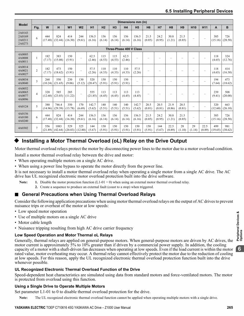
ModelDimensions mm (in)
Fig. W H W1 W2 H1 H2 H3 H4 H5 H6 H7 H8 H9 H10 H11 A B
2A01432A01692A02112A0273
6 444(17.48)
824(32.44)
414(16.30)
244(9.61)
156.5(6.16)
156(6.14)
156(6.14)
156(6.14)
156.5(6.16)
21.5(0.85)
24.2(0.95)
30.8(1.21)
21.5(0.85) – – 385
(15.16)726
(28.58)
Three-Phase 400 V Class
4A00054A00084A0011
1 182(7.17)
383(15.08)
150(5.91) – 62.5
(2.46)115
(4.53)115
(4.53)62.5
(2.46) – – – – – – – 118(4.65)
324(12.76)
4A00144A00214A0027
2 182(7.17)
473(18.62)
150(5.91) – 57.5
(2.26)110
(4.33)110
(4.33)110
(4.33)57.5
(2.26) – – – – – – 118(4.65)
414(16.30)
4A00344A0040 3 260
(10.24)550
(21.65)230
(9.06)130
(5.12)520
(20.47)150
(5.91)150
(5.91)150
(5.91) – – – – – – – 194(7.64)
473(18.62)
4A00524A00654A00774A0096
4 320(12.60)
585(23.03)
285(11.22) – 555
(21.85)113
(4.45)113
(4.45)113
(4.45)113
(4.45) – – – – – – 239(9.41)
508(20.00)
4A0124 5 380(14.96)
746.4(29.39)
350(13.78)
170(6.69)
142.7(5.62)
140(5.51)
140(5.51)
140(5.51)
142.7(5.62)
20.5(0.81)
20.5(0.81)
21.9(0.86)
20.5(0.81) – – 320
(12.60)663
(26.10)
4A01564A01804A0240
6 444(17.48)
824(32.44)
414(16.30)
244(9.61)
156.5(6.16)
156(6.14)
156(6.14)
156(6.14)
156.5(6.16)
21.5(0.85)
24.2(0.95)
30.8(1.21)
21.5(0.85) – – 385
(15.16)726
(28.58)
4A0302 7 556(21.89)
1083(42.64)
529(20.83)
325(12.80)
144(5.67)
150(5.91)
150(5.91)
150(5.91)
150(5.91)
150(5.91)
144(5.67)
22.5(0.89)
28(1.10)
29(1.14)
22.5(0.89)
499(19.65)
981(38.62)
u Installing a Motor Thermal Overload (oL) Relay on the Drive OutputMotor thermal overload relays protect the motor by disconnecting power lines to the motor due to a motor overload condition.Install a motor thermal overload relay between the drive and motor:• When operating multiple motors on a single AC drive.• When using a power line bypass to operate the motor directly from the power line.It is not necessary to install a motor thermal overload relay when operating a single motor from a single AC drive. The ACdrive has UL recognized electronic motor overload protection built into the drive software.
Note: 1. Disable the motor protection function (L1-01 = 0) when using an external motor thermal overload relay.2. Create a sequence to produce an external fault (coast to a stop) when triggered.
n General Precautions when Using Thermal Overload RelaysConsider the following application precautions when using motor thermal overload relays on the output of AC drives to preventnuisance trips or overheat of the motor at low speeds:• Low speed motor operation• Use of multiple motors on a single AC drive• Motor cable length• Nuisance tripping resulting from high AC drive carrier frequencyLow Speed Operation and Motor Thermal oL RelaysGenerally, thermal relays are applied on general-purpose motors. When general-purpose motors are driven by AC drives, themotor current is approximately 5% to 10% greater than if driven by a commercial power supply. In addition, the coolingcapacity of a motor with a shaft-driven fan decreases when operating at low speeds. Even if the load current is within the motorrated value, motor overheating may occur. A thermal relay cannot effectively protect the motor due to the reduction of coolingat low speeds. For this reason, apply the UL recognized electronic thermal overload protection function built into the drivewhenever possible.UL Recognized Electronic Thermal Overload Function of the DriveSpeed-dependent heat characteristics are simulated using data from standard motors and force-ventilated motors. The motoris protected from overload using this function.Using a Single Drive to Operate Multiple MotorsSet parameter L1-01 to 0 to disable thermal overload protection for the drive.
Note: The UL recognized electronic thermal overload function cannot be applied when operating multiple motors with a single drive.
6.5 Installing Peripheral Devices
YASKAWA ELECTRIC TOEP C710616 45G YASKAWA AC Drive – Z1000 User Manual 265
6
Perip
hera
l Dev
ices
&O
ptio
ns

Long Motor CablesWhen a high carrier frequency and long motor cables are used, nuisance tripping of the thermal relay may occur due to increasedleakage current. To avoid this, reduce the carrier frequency or increase the tripping level of the thermal overload relay.
Nuisance Tripping Due to a High AC Drive Carrier FrequencyCurrent waveforms generated by high carrier frequency PWM drives tend to increase the temperature in overload relays. Itmay be necessary to increase the trip level setting when encountering nuisance triggering of the relay.WARNING! Fire Hazard. Confirm an actual motor overload condition is not present prior to increasing the thermal oL trip setting. Checklocal electrical codes before making adjustments to motor thermal overload settings. Failure to comply could result in death or serious injury.
6.5 Installing Peripheral Devices
266 YASKAWA ELECTRIC TOEP C710616 45G YASKAWA AC Drive – Z1000 User Manual

Specifications
A.1 POWER RATINGS...............................................................................................268A.2 DRIVE SPECIFICATIONS....................................................................................274A.3 DRIVE WATT LOSS DATA..................................................................................276A.4 DRIVE DERATING DATA....................................................................................278
Appendix: A
YASKAWA ELECTRIC TOEP C710616 45G YASKAWA AC Drive – Z1000 User Manual 267

A.1 Power Ratings
u Three-Phase 200 V Class Drive Models 2A0011 to 2A0088Table A.1 Power Ratings (Three-Phase 200 V Class)
Item SpecificationCIMR-Zo2A 0011 0017 0024 0031 0046 0059 0075 0088
MaximumApplicable
MotorCapacity
<1>
HP 3 5 7.5 10 15 20 25 30
kW 2.2 3.7 5.5 7.5 11 15 18.5 22
Input
Input Current (A) <2> 10.6 16.7 24.2 30.8 46.2 59.4 74.8 88Rated Voltage
Rated Frequency Three-phase 200 to 240 Vac 50/60 Hz
Allowable Voltage Fluctuation -15 to 10%Allowable Frequency Fluctuation ±5%
Minimum Power Supply Capacity (kVA) 5 7 11 13 20 25 32 37
Output
Rated Output Capacity (kVA) <3> 4.2 6.7 10 12 18 24 30 35
Rated Output Current (A) 10.6 <4> 16.7 <4> 24.2 <4> 30.8 <4> 46.2 <4> 59.4 <4> 74.8 <4> 88 <4>
Overload Tolerance 110% of rated output current for 60 s140% of rated output current for 0.5 s
Carrier Frequency User adjustable between 1 and 12.5 kHz(Maximum Frequency varies with Rated Output Capacity)
Maximum Output Voltage (V) Three-phase 200 to 240 V (proportional to input voltage)Maximum Output Frequency (Hz) 240 Hz
HarmonicsReduction DC Link Choke Built-in
EMC Filter (IEC/EN 61800-3 Category 2) Built-in
<1> The motor capacity (HP) refers to an NEC Table 430.250 208 V motor. The rated output current of the drive output amps should be equal to orgreater than the motor current. Select the appropriate capacity drive if operating the motor continuously above motor nameplate current.
<2> Assumes operation at the rated output current. Input current rating varies depending on the power supply transformer, input reactor, wiringconnections, and power supply impedance.
<3> Rated motor capacity is calculated with a rated output voltage of 230 V.<4> Carrier frequency is set to 5 kHz. Current derating is required to raise the carrier frequency.
A.1 Power Ratings
268 YASKAWA ELECTRIC TOEP C710616 45G YASKAWA AC Drive – Z1000 User Manual

u Three-Phase 200 V Class Drive Models 2A0114 to 2A0396Table A.2 Power Ratings Continued (Three-Phase 200 V Class)
Item SpecificationCIMR-Zo2A 0114 0143 0169 0211 0273 0343 0396
MaximumApplicable
MotorCapacity <1>
HP 40 50 60 75 100 125 150
kW 30 37 45 55 75 90 110
Input
Input Current (A) <2> 114 143 169 211 273 343 396Rated Voltage
Rated Frequency Three-phase 200 to 240 Vac 50/60 Hz
Allowable Voltage Fluctuation -15 to 10%Allowable Frequency Fluctuation ±5%
Minimum Power Supply Capacity (kVA) 48 60 71 88 114 143 165
Output
Rated Output Capacity (kVA) <3> 45 57 67 84 109 137 158
Rated Output Current (A) 114 <4> 143 <4> 169 <4> 211 <4> 273 <4> 343 <5> 396 <5>
Overload Tolerance 110% of rated output current for 60 s140% of rated output current for 0.5 s
Carrier Frequency User adjustable between 1 and 12.5 kHz(Maximum Frequency varies with Rated Output Capacity)
Maximum Output Voltage (V) Three-phase 200 to 240 V (proportional to input voltage)Maximum Output Frequency (Hz) 240 Hz
HarmonicsReduction DC Link Choke Built-in
EMC Filter (IEC/EN 61800-3 Category 2) Built-in External
<1> The motor capacity (HP) refers to an NEC Table 430.250 208 V motor. The rated output current of the drive output amps should be equal to orgreater than the motor current. Select the appropriate capacity drive if operating the motor continuously above motor nameplate current.
<2> Assumes operation at the rated output current. Input current rating varies depending on the power supply transformer, input reactor, wiringconnections, and power supply impedance.
<3> Rated motor capacity is calculated with a rated output voltage of 230 V.<4> Carrier frequency is set to 5 kHz. Current derating is required to raise the carrier frequency.<5> Carrier frequency is set to 2 kHz. Current derating is required to raise the carrier frequency.
A.1 Power Ratings
YASKAWA ELECTRIC TOEP C710616 45G YASKAWA AC Drive – Z1000 User Manual 269
A
Spec
ifica
tions

u Three-Phase 400 V Class Drive Models 4A0005 to 4A0027Table A.3 Power Ratings (Three-Phase 400 V Class)
Item SpecificationCIMR-Zo4A 0005 0008 0011 0014 0021 0027
MaximumApplicable
MotorCapacity
Input Voltage460 V or higher <1>
HP 3 5 7.5 10 15 20kW 2.2 3.7 5.5 7.5 11 15
Input Voltagelower than 460 V <2>
HP 2 4 5 7.5 10 15kW 1.5 3.0 4.0 5.5 7.5 11
Input
Input Current (A) <3> 4.8 7.6 11 14 21 27Rated Voltage
Rated Frequency Three-phase 380 to 480 Vac 50/60 Hz / 510 to 680 Vdc
Allowable Voltage Fluctuation -15 to 10%Allowable Frequency Fluctuation ±5%
Minimum Power Supply Capacity (kVA) 4 7 10 12 18 23
Output
Rated Output Capacity(kVA)
Input Voltage460 V or higher <4> 3.8 6.1 8.8 11 17 22
Input Voltagelower than 460 V <5> 3.3 5.3 7.6 9.7 14.5 18.7
Rated Output Current (A) 4.8<6>
7.6<6>
11<6>
14<6>
21<6>
27<6>
Overload Tolerance 110% of rated output current for 60 s140% of rated output current for 0.5 s
Carrier Frequency User adjustable between 1 and 12.5 kHz(Maximum Frequency varies with Rated Output Capacity)
Maximum Output Voltage (V) Three-phase 380 to 480 V (proportional to input voltage)Maximum Output Frequency (Hz) 240 Hz
HarmonicsReduction DC Link Choke Built-in
EMC Filter (IEC/EN 61800-3 Category 2) Built-in
<1> The motor capacity (HP) refers to an NEC Table 430.250 208 V motor. The rated output current of the drive output amps should be equal to orgreater than the motor current. Select the appropriate capacity drive if operating the motor continuously above motor nameplate current.
<2> The motor capacity (HP) refers to a Yaskawa 4-pole motor. The rated output current of the drive output amps should be equal to or greater than themotor current. Select the appropriate capacity drive if operating the motor continuously above motor nameplate current.
<3> Assumes operation at the rated output current. Input current rating varies depending on the power supply transformer, input reactor, wiringconnections, and power supply impedance.
<4> Rated motor capacity is calculated with a rated output voltage of 460 V.<5> Rated motor capacity is calculated with a rated output voltage of 400 V.<6> Carrier frequency is set to 5 kHz. Current derating is required to raise the carrier frequency.
A.1 Power Ratings
270 YASKAWA ELECTRIC TOEP C710616 45G YASKAWA AC Drive – Z1000 User Manual

u Three-Phase 400 V Class Drive Models 4A0034 to 4A0096Table A.4 Power Ratings Continued (Three-Phase 400 V Class)
Item SpecificationCIMR-Zo4A 0034 0040 0052 0065 0077 0096
MaximumApplicable
MotorCapacity
Input Voltage460 V or higher <1>
HP 25 30 40 50 60 75kW 18.5 22 30 37 45 55
Input Voltagelower than 460 V <2>
HP 20 25 30 40 50 60kW 15 18.5 22 30 37 45
Input
Input Current (A) <3> 34 40 52 65 77 96Rated Voltage
Rated Frequency Three-phase 380 to 480 Vac 50/60 Hz / 510 to 680 Vdc
Allowable Voltage Fluctuation -15 to 10%Allowable Frequency Fluctuation ±5%
Minimum Power Supply Capacity (kVA) 29 34 44 55 65 80
Output
Rated Output Capacity(kVA)
Input Voltage460 V or higher <4> 27 32 41 52 61 76
Input Voltagelower than 460 V <5> 23.6 28 36 45 53 67
Rated Output Current (A) 34<6>
40<6>
52<6>
65<6>
77<6>
96<6>
Overload Tolerance 110% of rated output current for 60 s140% of rated output current for 0.5 s
Carrier Frequency User adjustable between 1 and 12.5 kHz(Maximum Frequency varies with Rated Output Capacity)
Maximum Output Voltage (V) Three-phase 380 to 480 V (proportional to input voltage)Maximum Output Frequency (Hz) 240 Hz
HarmonicsReduction DC Link Choke Built-in
EMC Filter (IEC/EN 61800-3 Category 2) Built-in
<1> The motor capacity (HP) refers to an NEC Table 430.250 208 V motor. The rated output current of the drive output amps should be equal to orgreater than the motor current. Select the appropriate capacity drive if operating the motor continuously above motor nameplate current.
<2> The motor capacity (HP) refers to a Yaskawa 4-pole motor. The rated output current of the drive output amps should be equal to or greater than themotor current. Select the appropriate capacity drive if operating the motor continuously above motor nameplate current.
<3> Assumes operation at the rated output current. Input current rating varies depending on the power supply transformer, input reactor, wiringconnections, and power supply impedance.
<4> Rated motor capacity is calculated with a rated output voltage of 460 V.<5> Rated motor capacity is calculated with a rated output voltage of 400 V.<6> Carrier frequency is set to 5 kHz. Current derating is required to raise the carrier frequency.
A.1 Power Ratings
YASKAWA ELECTRIC TOEP C710616 45G YASKAWA AC Drive – Z1000 User Manual 271
A
Spec
ifica
tions

u Three-Phase 400 V Class Drive Models 4A0124 to 4A0302Table A.5 Power Ratings Continued (Three-Phase 400 V Class)
Item SpecificationCIMR-Zo4A 0124 0156 0180 0240 0302
MaximumApplicable
MotorCapacity
Input Voltage460 V or higher <1>
HP 100 125 150 200 250kW 75 90 110 150 185
Input Voltagelower than 460 V <2>
HP 75 100 125 150 220kW 55 75 90 110 160
Input
Input Current (A) <3> 124 156 180 240 302Rated Voltage
Rated Frequency Three-phase 380 to 480 Vac 50/60 Hz / 510 to 680 Vdc
Allowable Voltage Fluctuation -15 to 10%Allowable Frequency Fluctuation ±5%
Minimum Power Supply Capacity (kVA) 104 130 150 200 252
Output
Rated Output Capacity(kVA)
Input Voltage460 V or higher <4> 99 124 143 191 241
Input Voltagelower than 460 V <5> 86 108 125 166 209
Rated Output Current (A) 124<6>
156<6>
180<6>
240<7>
302<7>
Overload Tolerance 110% of rated output current for 60 s140% of rated output current for 0.5 s
Carrier Frequency User adjustable between 1 and 10 kHz(Maximum Frequency varies with Rated Output Capacity)
Maximum Output Voltage (V) Three-phase 380 to 480 V (proportional to input voltage)Maximum Output Frequency (Hz) 240 Hz
HarmonicsReduction DC Link Choke Built-in
EMC Filter (IEC/EN 61800-3 Category 2) Built-in
<1> The motor capacity (HP) refers to an NEC Table 430.250 208 V motor. The rated output current of the drive output amps should be equal to orgreater than the motor current. Select the appropriate capacity drive if operating the motor continuously above motor nameplate current.
<2> The motor capacity (HP) refers to a Yaskawa 4-pole motor. The rated output current of the drive output amps should be equal to or greater than themotor current. Select the appropriate capacity drive if operating the motor continuously above motor nameplate current.
<3> Assumes operation at the rated output current. Input current rating varies depending on the power supply transformer, input reactor, wiringconnections, and power supply impedance.
<4> Rated motor capacity is calculated with a rated output voltage of 460 V.<5> Rated motor capacity is calculated with a rated output voltage of 400 V.<6> Carrier frequency is set to 5 kHz. Current derating is required to raise the carrier frequency.<7> Carrier frequency is set to 4 kHz. Current derating is required to raise the carrier frequency.
A.1 Power Ratings
272 YASKAWA ELECTRIC TOEP C710616 45G YASKAWA AC Drive – Z1000 User Manual

u Three-Phase 400 V Class Drive Models 4A0361 to 4A0590Table A.6 Power Ratings Continued (Three-Phase 400 V Class)
Item SpecificationCIMR-Zo4A 0361 0414 0480 0590
MaximumApplicable
MotorCapacity
Input Voltage460 V or higher <1>
HP 300 350 400 500kW 220 260 300 370
Input Voltagelower than 460 V <2>
HP 250 300 340 400kW 185 220 250 300
Input
Input Current (A) <3> 361 414 480 590Rated Voltage
Rated Frequency Three-phase 380 to 480 Vac 50/60 Hz / 510 to 680 Vdc
Allowable Voltage Fluctuation -15 to 10%Allowable Frequency Fluctuation ±5%
Minimum Power Supply Capacity (kVA) 316 375 400 491
Output
Rated Output Capacity (kVA)
Input Voltage460 V or higher <4> 276 316 382 470
Input Voltagelower than 460 V <5> 250 287 333 409
Rated Output Current (A) 362<6>
414<6>
480<6>
590<6>
Overload Tolerance 110% of rated output current for 60 s140% of rated output current for 0.5 s
Carrier Frequency User adjustable between 1 and 5 kHz(Maximum Frequency varies with Rated Output Capacity)
Maximum Output Voltage (V) Three-phase 380 to 480 V (proportional to input voltage)Maximum Output Frequency (Hz) 240 Hz
HarmonicsReduction DC Link Choke Built-in
EMC Filter (IEC/EN 61800-3 Category 2) External
<1> The motor capacity (HP) refers to an NEC Table 430.250 208 V motor. The rated output current of the drive output amps should be equal to orgreater than the motor current. Select the appropriate capacity drive if operating the motor continuously above motor nameplate current.
<2> The motor capacity (HP) refers to a Yaskawa 4-pole motor. The rated output current of the drive output amps should be equal to or greater than themotor current. Select the appropriate capacity drive if operating the motor continuously above motor nameplate current.
<3> Assumes operation at the rated output current. Input current rating varies depending on the power supply transformer, input reactor, wiringconnections, and power supply impedance.
<4> Rated motor capacity is calculated with a rated output voltage of 460 V.<5> Rated motor capacity is calculated with a rated output voltage of 400 V.<6> Carrier frequency is set to 2 kHz. Current derating is required to raise the carrier frequency.
A.1 Power Ratings
YASKAWA ELECTRIC TOEP C710616 45G YASKAWA AC Drive – Z1000 User Manual 273
A
Spec
ifica
tions

A.2 Drive SpecificationsNote: 1. Perform rotational Auto-Tuning to obtain the performance specifications given below.
2. For optimum performance life of the drive, install the drive in an environment that meets the required specifications.
Item Specification
ControlCharacter-
istics
Control MethodThe following control methods can be set using drive parameters:• V/f Control (V/f)• Open Loop Vector Control for PM (OLV/PM)
Frequency Control Range 0.01 to 240 HzFrequency Accuracy
(Temperature Fluctuation)Digital input: within ±0.01% of the max output frequency (-10 °C to +50 °C [14 °F to 122 °F])Analog input: within ±0.1% of the max output frequency (25 °C ±10 °C [77 °F ±50 °F])
Frequency SettingResolution
Digital inputs: 0.01 HzAnalog inputs: 1/1000 of the maximum output frequency setting (10 bit unsigned)
Output FrequencyResolution 0.001 Hz
Frequency Setting Signal 0 to 10 V, 0 to 20 mA, 4 to 20 mA
Starting Torque <1> V/f: 140% at 3 HzOLV/PM: 50% at 6 Hz
Speed Control Range <1> V/f: 1:40OLV/PM: 1:20
Speed Response <1> OLV/PM: 10 HzAccel/Decel Time 0.0 to 6000.0 s (4 selectable combinations of independent acceleration and deceleration settings)Braking Torque Approximately 20%
V/f Characteristics User-selected programs and V/f preset patterns possible
Main Control Functions
Momentary Power Loss Ride-Thru, Speed Search, Overtorque/Undertorque Detection, 4 Step Speed(max), Accel/Decel Switch, S-curve Accel/decel, 3-Wire Sequence, Auto-Tuning (Stationary for Line-to-Line Resistance, Rotational for V/f Control), Cooling Fan on/off Switch, Slip Compensation, TorqueCompensation, Frequency Jump, Upper/lower Limits for Frequency Reference, DC Injection Braking atStart and Stop, Overexcitation Braking, High Slip Braking, PI Control (with sleep function), Energy SavingControl, APOGEE FLN Comm. (RS-422/RS-485 4.8 kbps), BACnet Comm. (RS-485 max. 76.8 kbps),MEMOBUS/Modbus Comm. (RS-422/RS-485 max, 115.2 kbps), Metasys N2 Comm. (RS-422/RS-4859.6 kbps), Fault Restart, Application Presets, KEB, Overexcitation Deceleration, Overvoltage Suppression,Sequence Timer Operation, Secondary PI Control, Bypass Operation, HOA Keypad, Dynamic NoiseControl
ProtectionFunctions
Motor Protection Electronic thermal overload relayMomentary Overcurrent
Protection Drive stops when rated output current exceeds 175%
Overload Protection Drive stops after 60 s at 110% of rated output current <2>
Drive stops after 0.5 s at 140% of rated output current <2>
Overvoltage Protection 200 V class: Stops when DC bus voltage exceeds approx. 410 V400 V class: Stops when DC bus voltage exceeds approx. 820 V
A.2 Drive Specifications
274 YASKAWA ELECTRIC TOEP C710616 45G YASKAWA AC Drive – Z1000 User Manual

Item Specification
ProtectionFunctions
Undervoltage Protection
200 V class: Stops when DC bus voltage falls below approx. 190 V400 V class:Stops when DC bus voltage falls below approximately 350 V when using an input voltage lower than 400VStops when DC bus voltage falls below approximately 380 V when using an input voltage lower than 460VStops when DC bus voltage falls below approximately 440 V when using an input voltage of 460 V orhigher
Momentary Power LossRide-Thru
Immediately stop after 15 ms or longer power loss <3>
Continuous operation during power loss shorter than 2 s by speed search function <4>
Heatsink OverheatProtection Thermistor
Stall Prevention Stall Prevention is available during acceleration, deceleration, and during run.Ground Protection Electronic circuit protection <5> <6>
DC Bus Charge LED Remains lit until DC bus voltage falls below 50 V
Environment
Area of Use Indoors
Ambient Temperature
-10 °C to +40 °C (14 °F to 104 °F) IP20/UL Type 1 Enclosure, External Heatsink (2A0011 to 2A0273 and4A0005 to 4A0302)-10 °C to +50 °C (14 °F to 122 °F) IP00/Open Type Enclosure (2A0343 and 2A0396, and 4A0361 to4A0590)
Note: 1. To install a heatsink on the outside of a panel, design the panel to keep the air temperatureinside the panel within 10 °C (18 °F) [5 °C (9 °F) for 2A0273 and 4A0124] of the outsideair temperature.
2. Ambient temperature range for continuous operations is -10 °C to +40 °C (14 °F to 104°F) when external heatsink installation method is applied for models 2A0343 and2A0396 and 4A0361 to 4A0590.
Humidity 95% RH or less (no condensation)Storage Temperature -20 °C to +70 °C (-4 °F to +158 °F) (short-term temperature during transportation)
Altitude Up to 1000 meters without derating, up to 3000 m with output current and voltage derating. Refer to Altitude Derating on page 280 for details.
Vibration/Shock10 to 20 Hz at 9.8 m/s2
20 to 55 Hz at 5.9 m/s2 (2A0011 to 2A0031 and 4A0005 to 4A0027) or2.0 m/s2 (2A0046 to 2A0396 and 4A0034 to 4A0590)
Protection Design IP00/Open Type enclosure, IP20/UL Type 1 enclosure <7>
<1> The accuracy of these values depends on motor characteristics, ambient conditions, and drive settings. Specifications may vary with different motorsand with changing motor temperature. Contact Yaskawa for consultation.
<2> Overload protection may be triggered when operating with 100% of the rated output current if the output frequency is less than 6 Hz.<3> May be shorter due to load conditions and motor speed.<4> A 24 V power supply Unit (Model Nos. PS-A10LB, PS-A10HB) is required for models 2A0011 to 2A0059 and 4A0005 to 4A0052 if the application
must continue running for up to 2 seconds during a momentary power loss.<5> Ground protection cannot be provided when the impedance of the ground fault path is too low, or when the drive is powered up while a ground
fault is present at the output.<6> Setting L8-09 to 1 enables ground fault detection in models 2A0075 to 2A0396, 4A0052ooA, and 4A0065 to 4A0590.<7> Drive models 2A0011 to 2A0273 and 4A0011 to 4A0302 are designed to IP20/UL Type 1 specifications with a protective cover on the top. Removing
this top protective cover voids the UL Type 1 protection while maintaining IP20 conformity; removing the bottom conduit bracket voids the ULType 1 protection and IP20 conformity.
A.2 Drive Specifications
YASKAWA ELECTRIC TOEP C710616 45G YASKAWA AC Drive – Z1000 User Manual 275
A
Spec
ifica
tions

A.3 Drive Watt Loss DataTable A.7 Watt Loss 200 V Class Three-Phase Models
Model Rated Amps (A) Heatsink Loss (W) Interior Unit Loss (W) Total Loss (W)2A0011 10.6 <1> 121 28 148
2A0017 16.7 <1> 176 37 214
2A0024 24.2 <1> 280 55 335
2A0031 30.8 <1> 378 73 451
2A0046 46.2 <1> 396 86 482
2A0059 59.4 <1> 542 116 658
2A0075 74.8 <1> 557 132 688
2A0088 88 <1> 670 157 827
2A0114 114 <1> 864 200 1064
2A0143 143 <1> 1191 307 1499
2A0169 169 <1> 1447 365 1811
2A0211 211 <1> 1753 471 2224
2A0273 273 <1> 2378 625 3003
2A0343 343 <2> 1964 655 2620
2A0396 396 <2> 2435 829 3264
<1> Value assumes the carrier frequency is set to 5 kHz or less.<2> Value assumes the carrier frequency is set to 2 kHz.
Table A.8 Watt Loss 400 V Class Three-Phase ModelsModel Rated Amps (A) Heatsink Loss (W) Interior Unit Loss (W) Total Loss (W)4A0005 4.8 <1> 93 24 117
4A0008 7.6 <1> 146 33 178
4A0011 11 <1> 184 38 222
4A0014 14 <1> 231 52 283
4A0021 21 <1> 306 69 375
4A0027 27 <1> 390 85 475
4A0034 34 <1> 457 105 562
4A0040 40 <1> 558 118 677
4A0052ooB 52 <1> 584 151 734
4A0052ooA 52 <1> 463 130 594
4A0065 65 <1> 576 161 737
4A0077 77 <1> 891 225 1116
4A0096 96 <1> 1131 288 1419
4A0124 124 <1> 1581 398 1979
4A0156 156 <1> 1929 535 2464
4A0180 180 <1> 2342 621 2963
4A0240 240 <2> 2863 790 3653
4A0302 302 <2> 3278 929 4207
4A0361 361 <3> 3009 1157 4166
4A0414 414 <3> 3206 1633 4840
4A0480 480 <3> 3881 2011 5893
4A0590 590 <3> 4130 1964 6094
<1> Value assumes the carrier frequency is set to 5 kHz or less.<2> Value assumes the carrier frequency is set to 4 kHz or less.
A.3 Drive Watt Loss Data
276 YASKAWA ELECTRIC TOEP C710616 45G YASKAWA AC Drive – Z1000 User Manual

<3> Value assumes the carrier frequency is set to 2 kHz.
A.3 Drive Watt Loss Data
YASKAWA ELECTRIC TOEP C710616 45G YASKAWA AC Drive – Z1000 User Manual 277
A
Spec
ifica
tions
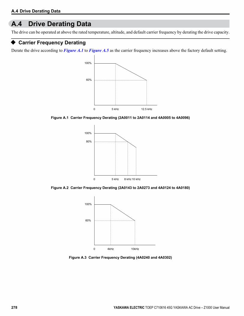
A.4 Drive Derating DataThe drive can be operated at above the rated temperature, altitude, and default carrier frequency by derating the drive capacity.
u Carrier Frequency DeratingDerate the drive according to Figure A.1 to Figure A.5 as the carrier frequency increases above the factory default setting.
12.5 kHz5 kHz
100%
60%
0
Figure A.1 Carrier Frequency Derating (2A0011 to 2A0114 and 4A0005 to 4A0096)
8 kHz5 kHz
100%
80%
10 kHz0
Figure A.2 Carrier Frequency Derating (2A0143 to 2A0273 and 4A0124 to 4A0180)
4kHz
100%
60%
10kHz0
Figure A.3 Carrier Frequency Derating (4A0240 and 4A0302)
A.4 Drive Derating Data
278 YASKAWA ELECTRIC TOEP C710616 45G YASKAWA AC Drive – Z1000 User Manual

5 kHz2 kHz
100%
80%
0
Figure A.4 Carrier Frequency Derating (2A0343 to 2A0396 and 4A0414 to 4A0590)
100%
88%
58%
2 kHz 5 kHz 10 kHz0
4A0361
Figure A.5 Carrier Frequency Derating (4A0361)
u Temperature DeratingTo ensure the maximum performance life, the drive output current must be derated as shown in Figure A.6 when the drive isinstalled in areas with high ambient temperature or if drives are mounted in a cabinet. In order to ensure reliable drive overloadprotection, set parameters L8-12 and L8-35 according to the installation conditions.
Note: To install a heatsink on the outside of a panel, design the panel to keep the air temperature inside the panel within 10 °C (18 °F)[5 °C (9 °F) for 2A0273 and 4A0124] of the outside air temperature.
n Parameter SettingsNo. Name Description Range Def.
L8-12 AmbientTemperature Setting
Adjust the drive overload (oL2) protection level when the drive is installedin an environment that exceeds its ambient temperature rating. 40 to 60 40 °C
L8-35 Installation MethodSelection
0: IP00/Open-Chassis Enclosure2: IP20/UL Type 1 Enclosure3: External Heatsink Installation
0, 2, 3 2
IP00/Open-Chassis EnclosureDrive operation between -10 °C and +50 °C (14 and 122 °F) allows 100% continuous current without derating. Models2A0343A, 2A0396A, 4A0361A, 4A0414A, 4A0480A, and 4A0590A are sold as IP00/Open-Chassis.
IP20/UL Type 1 EnclosureDrive operation between -10 °C and +40 °C (14 and 104 °F) allows 100% continuous current without derating. Operationbetween 40 °C and 50 °C (104 and 122 °F) requires output current derating.
Note: The temperature derating remains unchanged when removing the top protective cover and the bottom conduit bracket to change IP20/ULType 1 enclosure models 2A0011F through 2A0273F and 4A0005F through 4A0302F to IP00/Open-Type enclosures (derating requiredfor temperatures over 40 °C [104 °F]).
External Heatsink InstallationDrive operation between -10 °C and +40 °C (14 and 104 °F) allows 100% continuous current without derating. Operationbetween 40 °C and 50 °C (104 and 122 °F) requires output current derating.
A.4 Drive Derating Data
YASKAWA ELECTRIC TOEP C710616 45G YASKAWA AC Drive – Z1000 User Manual 279
A
Spec
ifica
tions

40°C
100%
60%
-10°C0%
50°C
80%
IP20/UL Type 1
IP00/Open-Type
External Heatsink
Figure A.6 Ambient Temperature and Installation Method Derating
u Altitude DeratingThe drive standard ratings are valid for installation altitudes up to 1000 m. For installations from 1000 m to 3000 m, the driverated output current must be derated for 0.2% per 100 m.
A.4 Drive Derating Data
280 YASKAWA ELECTRIC TOEP C710616 45G YASKAWA AC Drive – Z1000 User Manual

Parameter ListThis appendix contains a full listing of all parameters and settings available in the drive.
B.1 A: INITIALIZATION PARAMETERS....................................................................282B.2 B: APPLICATION.................................................................................................284B.3 C: TUNING............................................................................................................291B.4 D: REFERENCES.................................................................................................293B.5 E: MOTOR PARAMETERS..................................................................................296B.6 F: COMMUNICATION OPTION PARAMETERS.................................................299B.7 H PARAMETERS: MULTI-FUNCTION TERMINALS..........................................302B.8 L: PROTECTION FUNCTION...............................................................................312B.9 N: SPECIAL ADJUSTMENT................................................................................319B.10 O: OPERATOR-RELATED SETTINGS................................................................321B.11 S: SPECIAL APPLICATION.................................................................................324B.12 T: MOTOR TUNING..............................................................................................330B.13 U: MONITORS......................................................................................................332
Appendix: B
YASKAWA ELECTRIC TOEP C710616 45G YASKAWA AC Drive – Z1000 User Manual 281

B.1 A: Initialization ParametersTable B.1 Symbols and Icons Used in Parameter Descriptions
Symbol DescriptionParameter can be changed during run.
OLV/PMOLV/PM Parameter is ONLY available when operating the drive with Open Loop Vector for PM motors.
The A parameter group creates the operating environment for the drive. This includes the parameter Access Level, MotorControl Method, Password, User Parameters and more.
u A1: InitializationNo.
(Addr.Hex)
Name LCD Display Description Values Page
A1-00(100)
<1>
Language Selection
Select Language0: English1: (Japanese)3: Français5: Español6: Portuguêse
0: English1: Japanese3: French5: Spanish6: Portuguese
Default: 0Range: 0 to 6 156
A1-01(101)
<2>
Access Level SelectionAccess Level0: Operation Only1: User Parameters2: Advanced Level
0: View and set A1-01 and A1-04.Uo-oo parameters can also be viewed.1: User Parameters (access to a set of parameters selected by theuser, A2-01 to A2-32)2: Advanced Access (access to view and set all parameters)
Default: 2Range: 0 to 2 156
A1-02(102)
<1>Control MethodSelection
Control Method0: V/F Control5: PM OpenLoop Vect
0: V/f Control5: Open Loop Vector Control for PM Default: 0
Range: 0, 5 127
A1-03(103) Initialize Parameters
Init Parameters0: No Initialize1110: User Initialize2220: 2-Wire Initial3330: 3-Wire Initial3410: SELVALHVAC Initialize3420: SELVAL OEMBypass Init
0: No initialization1110: User Initialize (parameter values must be stored usingparameter o2-03)2220: 2-Wire Initialization3330: 3-Wire Initialization3410: HVAC Initialization3420: OEM Bypass Initialization
Default: 0Range: 0 to 3420 157
A1-04(104) Password Enter Password When the value set into A1-04 does not match the value set into
A1-05, parameters A1-01 through A1-03, A1-06, and A2-01through A2-32 cannot be changed.
Default: 0000Min.: 0000Max.: 9999
–
A1-05(105) Password Setting Select Password
Default: 0000Min.: 0000Max.: 9999
–
A1-06(127) Application Preset
Application Sel0: General1: Fan General2: Fan PI3: Fan ReturnAir/PI4: Cooling Tower5: CoolingTower/PI6: Pump Secondary7: Pump PI
0: Standard1: Fan2: Fan with PI Control3: Return Fan with PI Control4: Cooling Tower Fan5: Cooling Tower Fan with PI Control6: Pump (Secondary)7: Pump with PI Control
Default: 0Range: 0 to 7 158
<1> Parameter setting value is not reset to the default value when the drive is initialized.<2> Default setting value is dependent on the Application Preset selected with parameter A1-06.
B.1 A: Initialization Parameters
282 YASKAWA ELECTRIC TOEP C710616 45G YASKAWA AC Drive – Z1000 User Manual

u A2: User ParametersNo.
(Addr.Hex)
Name LCD Display Description Values Page
A2-01 toA2-32(106 to
125)
User Parameters 1 to32 User Param 1 - 32
Recently edited parameters are listed here. The user can alsoselect parameters to appear here for quicker access. Default: <1>
Range: A1-00 toS6-07
–
A2-33(126)
User ParameterAutomatic Selection
User Parms Sel0: Disabled1: Enabled
0: Parameters A2-01 to A2-32 are reserved for the user to createa list of User Parameters.1: Save history of recently viewed parameters.Recently edited parameters will be saved to A2-17 throughA2-32 for quicker access.
Default: 1 <2>
Range: 0, 1 –
<1> Default setting value is dependent on the Application Preset selected with parameter A1-06.<2> Default setting value is dependent on parameter A1-06. Default is 0 when A1-06 = 0, and 1 when A1-06 ≠ 0.
B.1 A: Initialization Parameters
YASKAWA ELECTRIC TOEP C710616 45G YASKAWA AC Drive – Z1000 User Manual 283
B
Para
met
er L
ist

B.2 b: ApplicationApplication parameters configure the source of the Run command, DC Injection Braking, Speed Search, timer functions, PIcontrol, Energy Savings, and a variety of other application-related settings.
u b1: Operation Mode SelectionNo.
(Addr.Hex)
Name LCD Display Description Values Page
b1-01(180)
Frequency ReferenceSelection for AUTOmode
Ref Source 10: Operator1: Analog Input2: Serial Com3: Option PCB
0: HOA keypad1: Terminals (Analog Input Terminals)2: Serial communications (APOGEE FLN, BACnet,MEMOBUS/Modbus, or Metasys N2)3: Option card
Default: 1Range: 0 to 3 127
b1-02(181)
Run CommandSelection for AUTOmode
Run Source 11: Digital Inputs2: Communication3: Option PCB
1: Control Circuit Terminal2: Serial communications (APOGEE FLN, BACnet,MEMOBUS/Modbus, or Metasys N2)3: Option card
Default: 1Range: 1 to 3 129
b1-03(182)
Stopping MethodSelection
Stopping Method0: Ramp to Stop1: Coast to Stop2: DCInj to Stop3: Coast w/Timer
0: Ramp to stop1: Coast to stop2: DC Injection Braking to stop3: Coast with timer
Default: 1Range: 0 to 3 129
b1-04(183)
Reverse OperationSelection
Reverse Oper0: Reverse Enabled1: Reverse Disabled
0: Reverse enabled1: Reverse disabled Default: 1
Range: 0, 1 158
b1-08(187)
Run CommandSelection inProgramming Mode
RUN dur PRG Mode0: RunDisabled@PRG1: ModeRunEnabled@PRG2: Prg only @ Stop
0: Run command is not accepted while in Programming Mode1: Run command is accepted while in Programming2: Prohibit entering Programming Mode during Run Default: 0
Range: 0 to 2 –
b1-11(1DF)
Drive Delay TimeSetting Run Delay Time
After a Run command is entered, the drive output waits untilthis delay time has passed before starting.
Default: 0 sMin.: 0Max.: 600
–
b1-14(1C3) Phase Order Selection
Rotation Sel0: Standard1: SwitchPhaseOrder
0: Standard1: Switch phase order (reverses the direction of the motor) Default: 0
Range: 0, 1 158
b1-17(1C6)
Run Command at PowerUp
Run Cmd @ Pwr On0: Cycle Ext Run1: Accept Ext Run
0: Disregarded.A new Run command must be issued after power up.1: Allowed.Motor will start immediately after power up if a Run commandis already enabled.
Default: 1Range: 0, 1 158
u b2: DC Injection Braking and Short Circuit BrakingNo.
(Addr.Hex)
Name LCD Display Description Values Page
b2-01(189)
DC Injection BrakingStart Frequency DCInj Start Freq
Sets the frequency at which DC Injection Braking starts when“Ramp to stop” (b1-03 = 0) is selected.
Default: <1>
Min.: 0.0 HzMax.: 10.0 Hz
158
b2-02(18A)
DC Injection BrakingCurrent DCInj Current
Sets the DC Injection Braking current as a percentage of thedrive rated current.
Default: 50%Min.: 0Max.: 100
159
b2-03(18B)
DC Injection BrakingTime at Start DCInj Time@Start
Sets DC Injection Braking time at start. Disabled when set to0.00 seconds.
Default: 0.00 sMin.: 0.00Max.: 10.00
159
b2-04(18C)
DC Injection BrakingTime at Stop DCInj Time@Stop
Sets DC Injection Braking time at stop. Default: 0.00 sMin.: 0.00Max.: 10.00
159
b2-09(1E1)
Motor Pre-Heat Current2 Preheat Current
Determines the percentage of motor rated output current usedfor the motor pre-heat function.
Default: 5%Min.: 0Max.: 100
–
B.2 b: Application
284 YASKAWA ELECTRIC TOEP C710616 45G YASKAWA AC Drive – Z1000 User Manual

No.(Addr.Hex)
Name LCD Display Description Values Page
b2-12(1BA)
Short Circuit BrakeTime at Start SC Brake T@Start
OLV/PMOLV/PMSets the time for Short Circuit Braking operation at start.
Default: 0.00 sMin.: 0.00Max.: 25.50
–
b2-13(1BB)
Short Circuit BrakeTime at Stop SC Brake T@Stop
OLV/PMOLV/PMSets the Short Circuit Braking operation time at stop.
Default: 0.50 sMin.: 0.00Max.: 25.50
–
b2-18(177)
Short Circuit BrakingCurrent Shrt Cir Brk
OLV/PMOLV/PMDetermines the current level for Short Circuit Braking. Set as apercentage of the motor rated current.
Default: 100.0%Min.: 0.0Max.: 200.0
–
<1> Default setting is determined by parameter A1-02, Control Method Selection.
u b3: Speed SearchNo.
(AddrHex.)
Name LCD Display Description Values Page
b3-01(191)
Speed Search Selectionat Start
SpdSrch at Start0: Disabled1: Enabled
0: Disabled1: Enabled Default: <1>
Range: 0, 1 160
b3-02(192)
Speed SearchDeactivation Current SpdSrch DeactCur
Sets the current level at which the speed is assumed to bedetected and Speed Search is ended. Set as a percentage of thedrive rated current.
Default: <1>
Min.: 0%Max.: 200%
160
b3-03(193)
Speed SearchDeceleration Time SpdSrch Dec Time
Sets output frequency reduction time during Speed Search. Default: 2.0 sMin.: 0.1Max.: 10.0
160
b3-04(194)
V/f Gain during SpeedSearch SpdSrch V/f
Determines how much to lower the V/f ratio during SpeedSearch.Output voltage during Speed Search equals the V/f settingmultiplied by b3-04.
Default: <2>
Min.: 10%Max.: 100%
160
b3-05(195)
Speed Search DelayTime Search Delay
When using an external contactor on the output side, b3-05delays executing Speed Search after a momentary power loss toallow time for the contactor to close.
Default: 0.2 sMin.: 0.0Max.: 100.0
b3-06(196)
Output Current 1 duringSpeed Search Srch Im Lvl1
Sets the current injected to the motor at the beginning of SpeedEstimation Speed Search. Set as a coefficient for the motor ratedcurrent.
Default: <2>
Min.: 0.0Max.: 2.0
160
b3-07(197)
Output Current 2 duringSpeed Search (SpeedEstimation Type)
Srch Im Lvl2
Sets the amount of output current during Speed EstimationSpeed Search as a coefficient for the no-load current (outputcurrent during Speed Search is automatically limited by thedrive rated current).Increase this setting value in increments of 0.1 if the drive failsto perform Speed Estimation.
Default: 1.0Min.: 0.0Max.: 5.0
–
b3-08(198)
Current Control Gainduring Speed Search(Speed EstimationType)
Srch ACR P GainSets the proportional gain for the current controller duringSpeed Search. Default: <1> <2>
Min.: 0.00Max.: 6.00
–
b3-09(199)
Current Control IntegralTime during SpeedSearch (SpeedEstimation Type)
Srch ACR I TimeSets the Integral Time for the current controller during SpeedSearch. Default: <1>
Min.: 0.0 msMax.: 1000.0 ms
–
b3-10(19A)
Speed Search DetectionCompensation Gain Srch Detect Comp
Sets the gain which is applied to the speed detected by SpeedEstimation Speed Search before the motor is reaccelerated.Increase this setting if ov occurs when performing Speed Searchafter a relatively long period of baseblock.
Default: 1.05Min.: 1.00Max.: 1.20
161
b3-11(19B)
Speed Search MethodSwitching Level (SpeedEstimation Type)
Srch Mthd Sw Lvl
Uses the amount of voltage remaining in the motor toautomatically switch the search method within the type of speedmeasurement.(200 V class at 100% = 200 V;400 V class at 100% = 400 V)
Default: 5.0%Min.: 0.5Max.: 100.0
–
b3-12(19C)
Minimum CurrentDetection Level duringSpeed Search
Srch I DeadbandSets the minimum current detection level during Speed Search.Increase this setting value in increments of 0.1 if the drive failsto perform Speed Estimation.
Default: <2>
Min.: 2.0Max.: 10.0
–
B.2 b: Application
YASKAWA ELECTRIC TOEP C710616 45G YASKAWA AC Drive – Z1000 User Manual 285
B
Para
met
er L
ist

No.(AddrHex.)
Name LCD Display Description Values Page
b3-14(19E)
Bi-Directional SpeedSearch Selection
Bidir Search Sel0: Disabled1: Enabled
0: Disabled (uses the direction of the frequency reference)1: Enabled (drive detects which way the motor is rotating) Default: <1>
Range: 0, 1 161
b3-17(1F0)
Speed Search RestartCurrent Level SrchRestart Lvl
Sets the Speed Search restart current level as a percentage of thedrive rated current.
Default: 110%Min.: 0Max.: 200
161
b3-18(1F1)
Speed Search RestartDetection Time SrchRestart Time
Sets the time to detect Speed Search restart. Default: 0.10 sMin.: 0.00Max.: 1.00
161
b3-19(1F2)
Number of SpeedSearch Restarts Num of SrchRestr
Sets the number of times the drive can attempt to restart whenperforming Speed Search.
Default: 3Min.: 0Max.: 10
161
b3-24(1C0)
Speed Search MethodSelection
SpdSrch Method0: CurrentDetection1: Speed Estimation
0: Current Detection1: Speed Estimation Default: 0
Range: 0, 1 161
b3-25(1C8) Speed Search Wait Time SpdSrch WaitTime
Sets the time the drive must wait between each Speed Searchrestart attempt.
Default: 0.5 sMin.: 0.0Max.: 300.0
162
b3-27(1C9)
Start Speed SearchSelect
Start srch sel0: Start from 01: Start Fref>Fmin
Selects a condition to activate Speed Search Selection at Start(b3-01) or External Speed Search Command 1 or 2 from themulti-function input.0: Triggered when a Run command is issued. (normal).1: Triggered when an external baseblock is released.
Default: 0Range: 0, 1 162
b3-29(077C)
Speed Search InducedVoltage Level SpdSrch Ind Vlvl
OLV/PMOLV/PMPerforms Speed Search when the motor induced voltageexceeds the set level.There is normally no need to change this parameter from thedefault value, but if changes are necessary, try lowering thisvalue in small increments. When set too low, the drive will notperform Speed Search.
Default: 10%Min.: 0Max.: 10
–
b3-33(0B3F)
<3>
Speed Search Selectionwhen Run Command isGiven during Uv
SpdSrch Start UV0: Disabled1: Enabled
Activates and deactivates Speed Search at start in accordancewith whether a Run command was issued during anundervoltage (Uv) condition. Function is active when amomentary power loss (L2-01 = 1 or 2), Speed Search at start(b3-01 = 1), and coasting to a stop (b1-03 = 1) are enabled.0: Disabled1: Enabled
Default: 0Range: 0, 1 –
<1> Default setting is determined by parameter A1-02, Control Method Selection.<2> Default setting is dependent on parameter o2-04, Drive Model Selection.<3> Available in drive software versions PRG: 1016 and later.
u b4: Timer FunctionNo.
(Addr.Hex)
Name Description Values Page
b4-01(1A3)
Timer Function On-DelayTime
Sets the on-delay and off-delay times for a digital timer output(H2-oo=12).The output is triggered by a digital input programmed toH1-oo=18).
Default: 0.0 sMin.: 0.0Max.: 3000.0
–
b4-02(1A4)
Timer Function Off-DelayTime
Default: 0.0 sMin.: 0.0Max.: 3000.0
–
B.2 b: Application
286 YASKAWA ELECTRIC TOEP C710616 45G YASKAWA AC Drive – Z1000 User Manual

u b5: PI ControlNo.
(Addr.Hex)
Name LCD Display Description Values Page
b5-01(1A5) PI Function Setting
PI Mode0: Disabled1: Enabled D=Fdbk3: Fref+PI D=Fdbk
0: Disabled1: Enabled (PI output becomes output frequency reference)3: Enabled (PI output added to frequency reference)
Default: 0Range: 0, 1, 3 162
b5-02(1A6) Proportional Gain
Setting (P) PI GainSets the proportional gain of the PI controller. Default: 2.00
Min.: 0.00Max.: 25.00
162
b5-03(1A7) Integral Time Setting (I) PI I Time
Sets the integral time for the PI controller. Default: 0.5 sMin.: 0.0Max.: 360.0
162
b5-04(1A8) Integral Limit Setting PI I Limit
Sets the maximum output possible from the integrator as apercentage of the maximum output frequency.
Default: 100.0%Min.: 0.0Max.: 100.0
162
b5-06(1AA) PI Output Limit PI Limit
Sets the maximum output possible from the entire PI controlleras a percentage of the maximum output frequency.
Default: 100.0%Min.: 0.0Max.: 100.0
163
b5-07(1AB) PI Offset Adjustment PI Offset
Applies an offset to the PI controller output. Set as a percentageof the maximum output frequency.
Default: 0.0%Min.: -100.0Max.: 100.0
163
b5-08(1AC) PI Primary Delay Time
Constant PI Delay TimeSets a low pass filter time constant on the output of the PIcontroller.
Default: 0.00 sMin.: 0.00Max.: 10.00
163
b5-09(1AD)
PI Output LevelSelection
Output Level Sel0: Normal Character1: Rev Character
0: Normal output (direct acting)1: Reverse output (reverse acting) Default: 0
Range: 0, 1 163
b5-10(1AE) PI Output Gain Setting Output Gain
Sets the gain applied to the PI output. Default: 1.00Min.: 0.00Max.: 25.00
163
b5-11(1AF)
PI Output ReverseSelection
Output Rev Sel0: 0 limit1: Reverse
0: Negative PI output triggers zero limit.1: Rotation direction reverses with negative PI output.
Note: When using setting 1, make sure reverseoperation is permitted by b1-04.
Default: 0Range: 0, 1 163
b5-12(1B0)
PI Feedback LossDetection Selection
Fb loss Det Sel0: DO Only - Always1: Alarm - Always2: Fault - Always3: DO Only@PI Enbl4: Alarm @ PI Enbl5: Fault @ PI Enbl
0: Digital Output Only(Remains active when PI is disabled by digital input)1: Alarm output, drive continues operation (Remains activewhen PI is disabled by digital input)2: Fault output, drive output is shut off (Remains active whenPI is disabled by digital input)3: Digital output only. No detection when PI is disabled bydigital input.4: Alarm detection. No detection when PI is disabled by digitalinput.5: Fault detection. No detection when PI is disabled by digitalinput.
Default: 0Range: 0 to 5 164
b5-13(1B1)
PI Feedback LossDetection Level Fb loss Det Lvl
Sets the PI feedback loss detection level as a percentage of themaximum output frequency.
Default: 0%Min.: 0Max.: 100
164
b5-14(1B2)
PI Feedback LossDetection Time Fb loss Det Time
Sets a delay time for PI feedback loss. Default: 1.0 sMin.: 0.0Max.: 25.5
165
b5-15(1B3)
PI Sleep Function StartLevel PI Sleep Level
Sets the frequency level that triggers the sleep/snooze function. Default: <1>
Min.: 0.0 HzMax.: 240.0 Hz
165
b5-16(1B4) PI Sleep Delay Time PI Sleep Time
Sets a delay time before the sleep/snooze function is triggered. Default: 0.0 sMin.: 0.0Max.: 25.5
165
B.2 b: Application
YASKAWA ELECTRIC TOEP C710616 45G YASKAWA AC Drive – Z1000 User Manual 287
B
Para
met
er L
ist

No.(Addr.Hex)
Name LCD Display Description Values Page
b5-17(1B5) PI Accel/Decel Time PI Acc/Dec Time
Sets the acceleration and deceleration time to PI setpoint. Default: 0.0 sMin.: 0.0Max.: 6000.0
165
b5-18(1DC) PI Setpoint Selection
PI Setpoint Sel0: Disabled1: Enabled
0: Disabled1: Enabled Default: 0
Range: 0, 1 165
b5-19(1DD) PI Setpoint Value PI Setpoint
Sets the PI target value when b5-18 = 1. Set as a percentage ofthe maximum output frequency.
Default: 0.00%Min.: 0.00Max.: 600.00 <2>
165
b5-20(1E2) PI Setpoint Scaling
PI Disp Scaling0: 0.01Hz units1: 0.01% units2: r/min3: User Units
0: 0.01 Hz units1: 0.01% units (100% = max output frequency)2: r/min (number of motor poles must entered)3: User-set (set scaling to b5-38 and b5-39)
Default: 1Range: 0 to 3 165
b5-21(1E3) PI Sleep Input Source
PI Sleep Ref0: PI Setpoint1: Frequency Ref2: Snooze Func
Input source selection for Sleep Function mode.0: PI Setpoint1: SFS Input2: Snooze
Default: 1Range: 0 to 2 166
b5-22(1E4) PI Snooze Level Snooze Level
Sets the PI Snooze Function start level as a percentage of themaximum frequency.
Default: 0%Min.: 0Max.: 100
166
b5-23(1E5) PI Snooze Delay Time Snooze DelayTime
Sets the PI Snooze Function delay time in seconds. Default: 0sMin.: 0Max.: 2600
166
b5-24(1E6)
PI Snooze DeactivationLevel SnoozeRestartLvl
When the PI feedback level drops below this level, the drivereturns to normal operation. Set as a percentage of the maximumfrequency.
Default: 0%Min.: 0Max.: 100
166
b5-25(1E7)
PI Setpoint BoostSetting SetpointBoostLvl
Temporarily increases the PI setpoint to create an overshoot ofthe intended PI setpoint.
Default: 0%Min.: 0Max.: 100
166
b5-26(1E8)
PI Maximum BoostTime SetpointBoostTim
Sets the maximum boost time when PI feedback does not reachboost level.The Snooze Function starts when the PI feedback exceeds theboost setting level or when the boost time expires.
Default: 0sMin.: 0Max.: 2600
167
b5-27(1E9)
PI Snooze FeedbackLevel Snooze Reset Lvl
Sets the PI feedback level above which Snooze mode isactivated. Set as a percentage of the maximum frequency.
Default: 60%Min.: 0Max.: 100
167
b5-28(1EA)
PI Feedback FunctionSelection
PI Fdbk Sqrt Sel0: Disabled1: Enabled
0: Disabled1: Square root Default: 0
Range: 0, 1 167
b5-29(1EB) PI Square Root Gain PI Fdbk SqrtGain
A multiplier applied to the square root of the feedback. Default: 0.00Min.: 0.00Max.: 2.00
167
b5-30(1EC) PI Feedback Offset PI Fdbk Offset
PI feedback offset set as a percentage of the maximumfrequency.
Default: 0.00Min.: 0.00Max.: 100.00
167
b5-34(19F) PI Output Lower Limit PI Out Low Lim
Sets the minimum output possible from the PI controller as apercentage of the maximum output frequency.
Default: 0.0%Min.: -100.0Max.: 100.0
167
b5-35(1A0) PI Input Limit PI Input Limit
Limits the PI control input (deviation signal) as a percentage ofthe maximum output frequency. Acts as a bipolar limit.
Default:1000.0%Min.: 0.0Max.: 1000.0
167
b5-36(1A1)
PI Feedback HighDetection Level Fb High Det Lvl
Sets the PI feedback high detection level as a percentage of themaximum output frequency.
Default: 100%Min.: 0Max.: 100
168
b5-37(1A2)
PI Feedback HighDetection Time Fb High Dly Time
Sets the PI feedback high level detection delay time. Default: 1.0 sMin.: 0.0Max.: 25.5
168
b5-38(1FE) PI Setpoint User Display PI UsrDspMaxVal
Sets the display value of U5-01 and U5-04 when the maximumfrequency is output.
Default: <3>
Min.: 1Max.: 60000
168
B.2 b: Application
288 YASKAWA ELECTRIC TOEP C710616 45G YASKAWA AC Drive – Z1000 User Manual

No.(Addr.Hex)
Name LCD Display Description Values Page
b5-39(1FF)
PI Setpoint DisplayDigits
PI UsrDspDigits0: No Dec (XXXXX)1: 1 Dec (XXXX.X)2: 2 Dec (XXX.XX)3: 3 Dec (XX.XXX)
0: No decimal places1: One decimal place2: Two decimal places3: Three decimal places
Default: <3>
Range: 0 to 3 168
b5-40(17F)
Frequency ReferenceMonitor Content duringPI
Fref Mon Sel@PI0: Fref Mon w PI1: Fref Mon w/o PI
0: Display the frequency reference (U1-01) after PIcompensation has been added.1: Display the frequency reference (U1-01) before PIcompensation has been added.
Default: 0Range: 0, 1 168
b5-41(160) PI Unit Selection
PI Mon Unit Sel0: WC1: PSI2: GPM3: °F4: CFM5: CMH6: LPH7: LPS8: Bar9: Pa10: °C11: Mtr12: Ft13: LPM14: CMM
0: WC (Inch of water)1: PSI (Pounds per square inch)2: GPM (Gallons per minute)3: F (Degrees Fahrenheit)4: CFM (Cubic feet per minute)5: CMH (Cubic meters per hour)6: LPH (Liters per hour)7: LPS (Liters per second)8: Bar (Bar)9: Pa (Pascal)10: C (Degrees Celsius)11: Mtr (Meters)12: Ft (Feet)13: LPM (Liters per minute)14: CMM (Cubic meters per minute)
Default: 0Range: 0 to 14 168
b5-42(161) PI Output Monitor
Calculation Method
PI Out Calc Mode0: Linear1: Square root2: 1/f23: 1/f3
0: Linear - the monitor displays PI output1: Square root - the monitor displays square root PI output2: Quadratic - the monitor displays 1/(PI output)3: Cubic - the monitor displays 1/(PI output)
Default: 0Range: 0 to 3 169
b5-43(162) PI Output 2 Monitor
Max Upper 4 Digits PI Out MonMax U4
Sets the upper 4 digits of the maximum monitor value.Used with b5-44 to set maximum monitor value of U5-14 andU5-15 at maximum frequency.
Note: Used for U5-14 and U5-15 only.
Default: 0Min.: 0Max.: 9999
169
b5-44(163) PI Output 2 Monitor
Max Lower 4 Digits PI Out MonMax L4
Sets the lower 4 digits of the maximum monitor value.Used with b5-43 to set maximum monitor value of U5-14 andU5-15 at maximum frequency.
Note: Used for U5-14 and U5-15 only.
Default: 0Min.: 0Max.: 99.99
169
b5-45(164) PI Output 2 Monitor
Minimum PI Out MonMin
Sets the minimum display value at zero speed.This function is effective when b5-42 is set to 0 (Linear outputmode).
Note: Used for U5-14 and U5-15 only.
Default: 0Min.: 0Max.: 999.9
169
b5-46(165)
PI Setpoint Monitor UnitSelection
PI Mon Unit Sel0: WC1: PSI2: GPM3: °F4: CFM5: CMH6: LPH7: LPS8: Bar9: Pa10: °C11: Mtr12: Ft13: LPM14: CMM
0: WC (Inch of water)1: PSI (Pounds per square inch)2: GPM (Gallons per minute)3: F (Degrees Fahrenheit)4: CFM (Cubic feet per minute)5: CMH (Cubic meters per hour)6: LPH (Liters per hour)7: LPS (Liters per second)8: Bar (Bar)9: Pa (Pascal)10: C (Degrees Celsius)11: Mtr (Meters)12: Ft (Feet)13: LPM (Liters per minute)14: CMM (Cubic meters per minute)
Default: 0Range: 0 to 14 169
b5-47(17D)
Reverse OperationSelection 2 by PI Output
Output Rev Sel20: 0 limit1: Reverse
Reverse operation selection when b5-01 = 30: Reverse Disabled1: Reverse Enabled
Default: 1Range: 0, 1 170
<1> Default setting is determined by parameter A1-02, Control Method Selection.<2> Internally limited to the value of b5-38 in drive software versions PRG: 1014 and later. Changing b5-20, b5-38, and b5-39 will not automatically
update the value of this parameter.<3> Default setting is dependent on parameter b5-20, PI Setpoint Scaling.
B.2 b: Application
YASKAWA ELECTRIC TOEP C710616 45G YASKAWA AC Drive – Z1000 User Manual 289
B
Para
met
er L
ist

u b8: Energy SavingNo.
(Addr.Hex)
Name LCD Display Description Values Page
b8-01(1CC)
Energy Saving ControlSelection
Energy Save Sel0: Disabled1: Enabled
0: Disabled1: Enabled Default: <1>
Range: 0, 1 –
b8-04(1CF)
Energy SavingCoefficient Value Energy Save COEF
Determines the level of maximum motor efficiency. Settingrange is 0.0 to 2000.0 for drives 3.7 kW and smaller.
Default: <2> <3>
Min.: 0.00Max.: 655.00
–
b8-05(1D0)
Power Detection FilterTime kW Filter Time
Sets a time constant filter for output power detection. Default: 20 msMin.: 0Max.: 2000
–
b8-06(1D1)
Search OperationVoltage Limit Search V Limit
Sets the limit for the voltage search operation as a percentageof the motor rated voltage.
Default: 0%Min.: 0Max.: 100
–
<1> Default setting is determined by parameter A1-02, Control Method Selection.<2> Default setting is determined by parameters A1-02, Control Method Selection, and o2-04, Drive Model Selection.<3> Parameter value changes automatically if E2-11 is manually changed or changed by Auto-Tuning.
B.2 b: Application
290 YASKAWA ELECTRIC TOEP C710616 45G YASKAWA AC Drive – Z1000 User Manual

B.3 C: TuningC parameters are used to adjust the acceleration and deceleration times, S-curves, torque compensation, and carrier frequencyselections.
u C1: Acceleration and Deceleration TimesNo.
(Addr.Hex)
Name LCD Display Description Values Page
C1-01(200) Acceleration Time 1 Accel Time 1
Sets the time to accelerate from 0 to maximum frequency.
Default: 30.0 sMin.: 0.1Max.: 6000.0
132
C1-02(201) Deceleration Time 1 Decel Time 1
Sets the time to decelerate from maximum frequency to 0.132
C1-03(202) Acceleration Time 2 Accel Time 2
Sets the time to accelerate from 0 to maximum frequency.
Default: 30.0 sMin.: 0.1Max.: 6000.0
132
C1-04(203) Deceleration Time 2 Decel Time 2
Sets the time to decelerate from maximum frequency to 0.132
C1-09(208) Fast Stop Time Fast Stop Time
Sets the time for the Fast Stop function. Default: 10.0 sMin.: 0.1Max.: 6000.0
–
C1-11(20A)
Accel/Decel TimeSwitching Frequency Acc/Dec SW Freq
Sets the frequency to switch between accel/decel time settings.Setting units are determined by parameter A1-02, ControlMethod Selection.
Default: 0.0 HzMin.: 0.0Max.: 240.0
–
u C2: S-Curve CharacteristicsNo.
(Addr.Hex)
Name LCD Display Description Values Page
C2-01(20B)
S-Curve Characteristicat Accel Start SCrv Acc @ Start
The S-curve can be controlled at the four points shown below.Run Command
Time
Output Frequency
C2-01 0.20 s <1>
C2-02 0.20 s <1>
ON OFFDefault: <2>
Min.: 0.00 sMax.: 10.00 s
170
C2-02(20C)
S-Curve Characteristicat Accel End SCrv Acc @ End
Default: 0.20 sMin.: 0.00Max.: 10.00
170
<1> S-curve characteristics at decel start/end are fixed to 0.20 s.<2> Default setting is determined by parameter A1-02, Control Method Selection.
u C4: Torque CompensationNo.
(Addr.Hex)
Name LCD Display Description Values Page
C4-01(215) Torque Compensation
Gain Torq Comp GainSets the gain for the automatic torque (voltage) boost functionand helps to produce better starting torque. Used for motor 1. Default: <1>
Min.: 0.00Max.: 2.50
–
C4-02(216) Torque Compensation
Primary Delay Time 1 Torq Comp TimeSets the torque compensation filter time. Default: <2>
Min.: 0 msMax.: 60000 ms
–
<1> Default setting is determined by parameter A1-02, Control Method Selection.<2> Default setting is determined by parameters A1-02, Control Method Selection, and o2-04, Drive Model Selection.
B.3 C: Tuning
YASKAWA ELECTRIC TOEP C710616 45G YASKAWA AC Drive – Z1000 User Manual 291
B
Para
met
er L
ist

u C6: Carrier FrequencyNo.
(Addr.Hex)
Name LCD Display Description Values Page
C6-02(224)
Carrier FrequencySelection
CarrierFreq Sel1: 2.0 kHz2: 5.0 kHz3: 8.0 kHz4: 10.0 kHz5: 12.5 kHz7: Swing PWM18: Swing PWM29: Swing PWM3A: Swing PWM4F: Program
1: 2.0 kHz2: 5.0 kHz3: 8.0 kHz4: 10.0 kHz5: 12.5 kHz7: Swing PWM1 (Audible sound 1)8: Swing PWM2 (Audible sound 2)9: Swing PWM3 (Audible sound 3)A: Swing PWM4 (Audible sound 4)B to E: No setting possibleF: User-defined (determined by C6-03 through C6-05)
Default: <1>
Range: 1 to 5; 7 to9; A, F
133
C6-03(225)
Carrier FrequencyUpper Limit CarrierFreq Max
Determines the upper and lower limits for the carrier frequency.
Carrier Frequency
E1-04Max Output Frequency
Output Frequency× (C6-05) × K
Output Frequency
C6-03
C6-04
Default: <2>
Min.: 1.0 kHzMax.: 12.5 kHz
171
C6-04(226)
Carrier FrequencyLower Limit CarrierFreq Min
Default: <2>
Min.: 1.0 kHzMax.: 12.5 kHz
171
C6-05(227)
Carrier FrequencyProportional Gain CarrierFreq Gain
Default: <2>
Min.: 0Max.: 99
171
<1> Default setting value is dependent on parameters A1-02, Control Method Selection and o2-04, Drive Model Selection.<2> Default setting value is dependent on parameter C6-02, Carrier Frequency Selection.
B.3 C: Tuning
292 YASKAWA ELECTRIC TOEP C710616 45G YASKAWA AC Drive – Z1000 User Manual

B.4 d: ReferencesReference parameters set the various frequency reference values during operation.
u d1: Frequency ReferenceNo.
(Addr.Hex)
Name LCD Display Description Values Page
d1-01(280) Frequency Reference 1 Reference 1
Sets the frequency reference for the drive. Setting units aredetermined by parameter o1-03.
Default: 0.00 HzMin.: 0.00Max.: 240.00<1>
171
d1-02(281) Frequency Reference 2 Reference 2
Sets the frequency reference for the drive. Setting units aredetermined by parameter o1-03.
Default: 0.00 HzMin.: 0.00Max.: 240.00<1>
171
d1-03(282) Frequency Reference 3 Reference 3
Sets the frequency reference for the drive. Setting units aredetermined by parameter o1-03.
Default: 0.00 HzMin.: 0.00Max.: 240.00<1>
171
d1-04(283) Frequency Reference 4 Reference 4
Sets the frequency reference for the drive. Setting units aredetermined by parameter o1-03.
Default: 0.00 HzMin.: 0.00Max.: 240.00<1>
171
d1-16(291) HAND Frequency
Reference 1 HAND Freq Ref 1
Sets the frequency reference for the drive. Setting units aredetermined by parameter o1-03.
Default: 0.00 HzMin.: 0.00Max.: 240.00<1>
171
d1-17(292) Jog Frequency
Reference Jog ReferenceSets the Jog frequency reference. Setting units are determinedby parameter o1-03.
Default: 6.00 HzMin.: 0.00Max.: 240.0 <1>
171
<1> Range upper limit is determined by parameters d2-01, Frequency Reference Upper Limit, and E1-04, Maximum Output Frequency.
u d2: Frequency Upper/Lower LimitsNo.
(Addr.Hex.)
Name LCD Display Description Setting Page
d2-01(289)
Frequency ReferenceUpper Limit Ref Upper Limit
Sets the frequency reference upper limit as a percentage of themaximum output frequency.
Default: 100.0%Min.: 0.0Max.: 110.0
133
d2-02(28A)
Frequency ReferenceLower Limit Ref Lower Limit
Sets the frequency reference lower limit as a percentage of themaximum output frequency.
Default: 0.0%Min.: 0.0Max.: 110.0
133
d2-03(293)
Master Speed ReferenceLower Limit Ref1 Lower Limit
Sets the lower limit for frequency references from analog inputsas a percentage of the maximum output frequency.
Default: 0.0%Min.: 0.0Max.: 110.0
172
B.4 d: References
YASKAWA ELECTRIC TOEP C710616 45G YASKAWA AC Drive – Z1000 User Manual 293
B
Para
met
er L
ist

u d3: Jump FrequencyNo.
(Addr.Hex)
Name LCD Display Description Values Page
d3-01(294) Jump Frequency 1 Jump Freq 1
Eliminates problems with resonant vibration of the motor/machine by avoiding continuous operation in predefinedfrequency ranges. The drive accelerates and decelerates themotor through the prohibited frequency ranges.Setting 0.0 disables this function.Parameters must be set so that d3-01 ≥ d3-02 ≥ d3-03.
Default: 0.0 HzMin.: 0.0Max.: 240.0
172
d3-02(295) Jump Frequency 2 Jump Freq 2
Eliminates problems with resonant vibration of the motor/machine by avoiding continuous operation in predefinedfrequency ranges. The drive accelerates and decelerates themotor through the prohibited frequency ranges.Setting 0.0 disables this function.Parameters must be set so that d3-01 ≥ d3-02 ≥ d3-03.
Default: 0.0 HzMin.: 0.0Max.: 240.0
172
d3-03(296) Jump Frequency 3 Jump Freq 3
Eliminates problems with resonant vibration of the motor/machine by avoiding continuous operation in predefinedfrequency ranges. The drive accelerates and decelerates themotor through the prohibited frequency ranges.Setting 0.0 disables this function.Parameters must be set so that d3-01 ≥ d3-02 ≥ d3-03.
Default: 0.0 HzMin.: 0.0Max.: 240.0
172
d3-04(297) Jump Frequency Width Jump Bandwidth
Sets the dead-band width around each selected prohibitedfrequency reference point.
Default: 1.0 HzMin.: 0.0Max.: 20.0
172
u d4: Frequency Reference Hold FunctionNo.
(Addr.Hex)
Name LCD Display Description Values Page
d4-01(298)
Frequency ReferenceHold Function Selection
Fref Hold Sel0: Disabled1: Enabled
0: Disabled.Drive starts from zero when the power is switched on.1: Enabled.At power up, the drive starts the motor at the Hold frequencythat was saved.
Default: 0Range: 0, 1 –
d4-10(2B6)
Up/Down FrequencyReference LimitSelection
Up/Dn LowLim Sel0: D2-02 or Analog1: D2-02 Only
0: The lower limit is determined by d2-02 or an analog input.1: The lower limit is determined by d2-02. Default: 0
Range: 0, 1 –
u d6: Field WeakeningNo.
(Addr.Hex)
Name LCD Display Description Values Page
d6-01(2A0) Field Weakening Level Field-Weak Lvl
Sets the drive output voltage for the Field Weakening functionas a percentage of the maximum output voltage. Enabled whena multi-function input is set for Field Weakening(H1-oo = 63).
Default: 80%Min.: 0Max.: 100
–
d6-02(2A1)
Field WeakeningFrequency Limit Field-Weak Freq
Sets the lower limit of the frequency range where FieldWeakening control is valid. The Field Weakening command isvalid only at frequencies above this setting and only when theoutput frequency matches the frequency reference (speedagree).
Default: 0.0 HzMin.: 0.0Max.: 240.0
–
B.4 d: References
294 YASKAWA ELECTRIC TOEP C710616 45G YASKAWA AC Drive – Z1000 User Manual

u d7: Offset FrequencyNo.
(Addr.Hex)
Name LCD Display Description Setting Page
d7-01(2B2) Offset Frequency 1 Offset Freq 1
Added to the frequency reference when the digital input“Frequency offset 1” (H1-oo = 44) is switched on.
Default: 0.0%Min.: -100.0Max.: 100.0
–
d7-02(2B3) Offset Frequency 2 Offset Freq 2
Added to the frequency reference when the digital input“Frequency offset 2” (H1-oo = 45) is switched on.
Default: 0.0%Min.: -100.0Max.: 100.0
–
d7-03(2B4) Offset Frequency 3 Offset Freq 3
Added to the frequency reference when the digital input“Frequency offset 3” (H1-oo = 46) is switched on.
Default: 0.0%Min.: -100.0Max.: 100.0
–
B.4 d: References
YASKAWA ELECTRIC TOEP C710616 45G YASKAWA AC Drive – Z1000 User Manual 295
B
Para
met
er L
ist

B.5 E: Motor Parameters
u E1: V/f Pattern for Motor 1No.
(Addr.Hex)
Name LCD Display Description Values Page
E1-01(300) Input Voltage Setting Input Voltage
This parameter must be set to the power supply voltage.
WARNING! Electrical Shock Hazard. Drive input voltage(not motor voltage) must be set in E1-01 for the protectivefeatures of the drive to function properly. Failure to do somay result in equipment damage and/or death or personalinjury.
Default: 230 V<1>
Min.: 190Max.: 240 <1>
134
E1-03(302) V/f Pattern Selection
V/F Selection0: 50 Hz1: 60 Hz Saturation2: 60 Hz Saturation3: 72 Hz4: 50 Hz VT15: 50 Hz VT26: 60 Hz VT17: 60 Hz VT28: 50 Hz HST19: 50 Hz HST2A: 60 Hz HST1B: 60 Hz HST2C: 90 HzD: 120 HzE: 180 HzF: Custom V/F
0: 50 Hz, Constant torque 11: 60 Hz, Constant torque 22: 60 Hz, Constant torque 3 (50 Hz base)3: 72 Hz, Constant torque 4 (60 Hz base)4: 50 Hz, Variable torque 15: 50 Hz, Variable torque 26: 60 Hz, Variable torque 37: 60 Hz, Variable torque 48: 50 Hz, High starting torque 19: 50 Hz, High starting torque 2A: 60 Hz, High starting torque 3B: 60 Hz, High starting torque 4C: 90 Hz (60 Hz base)D: 120 Hz (60 Hz base)E: 180 Hz (60 Hz base)F: Custom V/f E1-04 through E1-13 settings define the V/fpattern
Default: F <2>
Range: 0 to 9;A to F
173
E1-04(303)
Maximum OutputFrequency Max Frequency
These parameters are only applicable when E1-03 is set to F.To set linear V/f characteristics, set the same values for E1-07and E1-09.In this case, the setting for E1-08 will be disregarded. Ensurethat the four frequencies are set according to these rules:E1-09 ≤ E1-07 < E1-06 ≤ E1-11 ≤ E1-04
Output Voltage (V)
Frequency (Hz)
E1-05E1-12
E1-13
E1-08
E1-10
E1-09 E1-07 E1-06 E1-11 E1-04
Note: E1-07, E1-08, and E1-10 to E1-13 are notavailable in OLV/PM control mode.
Default: <3> <4>
Min.: 40.0 HzMax.: 240.0 Hz
134
E1-05(304) Maximum Voltage Max Voltage
Default: <3> <4>
Min.: 0.0 VMax.: 255.0 V<1>
134
E1-06(305) Base Frequency Base Frequency
Default: <3> <4>
Min.: 0.0 HzMax.: 240.0 Hz
134
E1-07(306)
Middle OutputFrequency Mid Frequency A
Default: <3>
Min.: 0.0 HzMax.: 240.0 Hz
134
E1-08(307)
Middle OutputFrequency Voltage Mid Voltage A
Default: <3>
Min.: 0.0 VMax.: 255.0 V<1>
134
E1-09(308)
Minimum OutputFrequency Min Frequency
Default: <3> <4>
Min.: 0.0 HzMax.: 240.0 Hz
134
E1-10(309)
Minimum OutputFrequency Voltage Min Voltage
Default: <3>
Min.: 0.0 VMax.: 255.0 V<1>
134
E1-11(30A)
<6>Middle OutputFrequency 2 Mid Frequency B
Default: 0.0 HzMin.: 0.0Max.: 240.0
134
E1-12(30B)
<6>Middle OutputFrequency Voltage 2 Mid Voltage B
Default: 0.0 VMin.: 0.0Max.: 255.0 <1>
134
E1-13(30C) Base Voltage Base Voltage
Default: 0.0 V<5>
Min.: 0.0Max.: 255.0 <1>
134
B.5 E: Motor Parameters
296 YASKAWA ELECTRIC TOEP C710616 45G YASKAWA AC Drive – Z1000 User Manual

<1> Values shown are specific to 200 V class drives. Double the value for 400 V class drives.<2> Parameter setting value is not reset to the default value when the drive is initialized.<3> Default setting is dependent on parameters A1-02, Control Model Selection and o2-04, Drive Model Selection.<4> Default setting is dependent on parameter o2-04, Drive Model Selection.<5> When Auto-Tuning is performed, E1-13 and E1-05 will be set to the same value.<6> Parameter ignored when E1-11 (Motor 1 Mid Output Frequency 2) and E1-12 (Motor 1 Mid Output Frequency Voltage 2) are set to 0.0.
u E2: Motor ParametersNo.
(Addr.Hex)
Name LCD Display Description Values Page
E2-01(30E) Motor Rated Current Motor Rated FLA
Sets the motor nameplate full load current in amps.Automatically set during Auto-Tuning.
Default: <1>
Min.: 10% ofdrive ratedcurrentMax.: 200% ofdrive ratedcurrent <2>
135
E2-02(30F) Motor Rated Slip Motor Rated Slip
Sets the motor rated slip. Automatically set duringAuto-Tuning.
Default: <1>
Min.: 0.00 HzMax.: 20.00 Hz
–
E2-03(310) Motor No-Load Current No-Load Current
Sets the no-load current for the motor. Automatically set duringAuto-Tuning.
Default: <1>
Min.: 0 AMax.: E2-01 <2>
–
E2-04(311) Number of Motor Poles Number of Poles
Sets the number of motor poles. Automatically set duringAuto-Tuning.
Default: 4Min.: 2Max.: 48
–
E2-05(312)
Motor Line-to-LineResistance Term Resistance
Sets the phase-to-phase motor resistance. Automatically setduring Auto-Tuning.
Default: <1>
Min.: 0.000 ΩMax.: 65.000 Ω
–
E2-10(317)
Motor Iron Loss forTorque Compensation Motor Iron Loss
Sets the motor iron loss. Default: <1>
Min.: 0 WMax.: 65535 W
–
E2-11(318) Motor Rated Power Mtr Rated Power
Sets the motor rated power in kilowatts (1 HP = 0.746 kW).Automatically set during Auto-Tuning.
Default: <1>
Min.: 0.00 kWMax.: 370.00 kW
135
<1> Default setting is dependent on parameter o2-04, Drive Model Selection.<2> The number of decimal places in the parameter value depends on the drive model. This value has two decimal places (0.01 A) if the drive is set for
a maximum applicable motor capacity up to and including 11 kW, 2A0031, 4A0021 (input voltage 460 V or higher) or 4A0027 (input voltage lowerthan 460 V) and one decimal place (0.1 A) if the maximum applicable motor capacity is higher than 11 kW, 2A0046, 4A0027 (input voltage 460V or higher) or 4A0034 (input voltage lower than 460 V) .
u E5: PM Motor SettingsNo.
(Addr.Hex)
Name LCD Display Description Values Page
E5-02(32A)
<1>Motor Rated Power PM Mtr Capacity
OLV/PMOLV/PMSets the rated capacity of the motor.
Default: <2>
Min.: 0.10 kWMax.: 370.00 kW
135
E5-03(32B)
<1>Motor Rated Current PM Mtr Rated FLA
OLV/PMOLV/PMSets the motor rated current.
Default: <2>
Min: 10% ofdrive ratedcurrentMax: 200% ofdrive ratedcurrent <3>
136
E5-04(32C)
<1>Number of Motor Poles PM Motor Poles
OLV/PMOLV/PMSets the number of motor poles.
Default: <2>
Min.: 2Max.: 48
136
B.5 E: Motor Parameters
YASKAWA ELECTRIC TOEP C710616 45G YASKAWA AC Drive – Z1000 User Manual 297
B
Para
met
er L
ist

No.(Addr.Hex)
Name LCD Display Description Values Page
E5-05(32D)
<1>Motor Stator Resistance PM Mtr Arm Ohms
OLV/PMOLV/PMSet the resistance for each motor phase.
Default: <2>
Min.: 0.000 ΩMax.: 65.000 Ω
136
E5-06(32E)
<1>Motor d-AxisInductance PM Mtr d Induct
OLV/PMOLV/PMSets the d-Axis inductance for the PM motor.
Default: <2>
Min.: 0.00 mHMax.: 300.00 mH
136
E5-07(32F)
<1>Motor q-AxisInductance PM Mtr q Induct
OLV/PMOLV/PMSets the q-Axis inductance for the PM motor.
Default: <2>
Min.: 0.00 mHMax.: 600.00 mH
136
E5-09(331)
<1>Motor Induction VoltageConstant 1 PM Mtr Ind V 1
OLV/PMOLV/PMSets the induced peak voltage per phase in units of0.1 mV/(rad/s) [electrical angle]. Set this parameter when usingan IPM motor with variable torque.Set E5-24 to 0 when setting this parameter.
Default: <2>
Min.: 0.0 mV/(rad/s)Max.: 2000.0mV/(rad/s)
136
E5-24(353)
<1>Motor Induction VoltageConstant 2 PM Mtr Ind V 2
OLV/PMOLV/PMSets the induced phase-to-phase rms voltage in units of0.1 mV/(r/min) [mechanical angle].
Default: <2>
Min.: 0.0 mV/(r/min)Max.: 6500.0mV/(r/min)
136
<1> Selections may vary depending on the setting entered to o2-04.<2> Default setting is dependent on parameter o2-04, Drive Model Selection.<3> The number of decimal places in the parameter value depends on the drive model. This value has two decimal places (0.01 A) if the drive is set for
a maximum applicable motor capacity up to and including 11 kW, and one decimal place (0.1 A) if the maximum applicable motor capacity ishigher than 11 kW.
B.5 E: Motor Parameters
298 YASKAWA ELECTRIC TOEP C710616 45G YASKAWA AC Drive – Z1000 User Manual

B.6 F: Communication Option Parameters
u F6, F7: Communication Option CardParameters F6-01 through F6-03 and F6-06 through F6-08 are used for EtherNet/IP, Modbus TCP/IP, and LONWORKSoptions. F7 parameters are used for the EtherNet/IP and Modbus TCP/IP options.
No.(Addr.Hex)
Name LCD Display Description Values Page
F6-01(3A2)
Communications ErrorOperation Selection
Comm Bus Flt Sel0: Ramp to Stop1: Coast to Stop2: Fast-Stop3: Alarm Only4: Alarm (d1-04)5: Alarm (C1-02)
0: Ramp to stop. Decelerate to stop using the deceleration timein C1-02.1: Coast to stop.2: Fast Stop. Decelerate to stop using the deceleration time inC1-09.3: Alarm only. <1>
4: Alarm only. Continue operation using the frequencyreference set in d1-04. <1> <2>
5: Alarm only. Decelerate to stop using the deceleration timein C1-02. <3> <4>
Default: 1Range: 0 to 5 –
F6-02(3A3)
External Fault fromComm. OptionDetection Selection
EF0 Detection0: Always Detected1: Only During Run
0: Always detected.1: Detection during run only. Default: 0
Range: 0, 1 –
F6-03(3A4)
External Fault fromComm. OptionOperation Selection
EF0 Fault Action0: Ramp to Stop1: Coast to Stop2: Fast-Stop3: Alarm Only
0: Ramp to stop. Decelerate to stop using the deceleration timein C1-02.1: Coast to stop.2: Fast Stop. Decelerate to stop using the deceleration time inC1-09.3: Alarm only. <1>
Default: 1Range: 0 to 3 –
F6-06(3A7)
Torque Reference/Torque Limit Selectionfrom Comm. Option
Torq Ref/Lmt Sel0: Disabled1: Enabled
OLV/PMOLV/PM0: Disabled. Torque reference/limit from option board disabled.1: Enabled. Torque reference/limit from option board enabled.
Default: 0Range: 0, 1 –
F6-07(3A8)
Multi-Step SpeedEnable/DisableSelection when NefRef/ComRef is Selected
Fref PrioritySel0: Net/Com REF1: MultiStep Speed
0: Multi-step reference disabled (same as F7)1: Multi-step reference enabled (same as V7) Default: 0
Range: 0, 1 –
F6-08(36A)
<5>Reset CommunicationParameters
Com Prm Init Sel0: Init Com Prms1: No Init Com Prms
0: Communication-related parameters (F6-oo) are not resetwhen the drive is initialized using A1-03.1: Reset all communication-related parameters (F6-oo) whenthe drive is initialized using A1-03.
Default: 0Range: 0, 1 –
F6-14(03BB)
CC-Link bUS ErrorAuto Reset
Bus Err Auto Rst0: Disabled1: Enabled
0: Disabled1: Enabled
Default: 0Range: 0, 1 –
F6-46(02FC) BACnet Baud Rate
BAC Baud Rate0: 1200 bps1: 2400 bps2: 4800 bps3: 9600 bps4: 19.2 kbps5: 38.4 kbps6: 57.6 kbps7: 76.8 kbps8: 115.2 kbps
0: 12001: 24002: 48003: 96004: 192005: 384006: 57600 <3>
7: 76800 <3>
8: 115200 <3>
Default: 3Range: 0 to 8 –
F7-01(3E5)
<6> <7><8>
IP Address 1 IP Address 1 Sets the most significant octet of network static IP address.Default: 192Min.: 0Max.: 255
–
F7-02(3E6)
<6> <7><8>
IP Address 2 IP Address 2 Sets the second most significant octet of network static IPaddress.
Default: 168Min.: 0Max.: 255
–
F7-03(3E7)
<6> <7><8>
IP Address 3 IP Address 3 Sets the third most significant octet of network static IP address.Default: 1Min.: 0Max.: 255
–
B.6 F: Communication Option Parameters
YASKAWA ELECTRIC TOEP C710616 45G YASKAWA AC Drive – Z1000 User Manual 299
B
Para
met
er L
ist

No.(Addr.Hex)
Name LCD Display Description Values Page
F7-04(3E8)
<6> <7><8>
IP Address 4 IP Address 4 Sets the fourth most significant octet of network static IPaddress.
Default: 20Min.: 0Max.: 255
–
F7-05(3E9)
<8>Subnet Mask 1 Subnet Mask 1 Sets the most significant octet of network static Subnet Mask.
Default: 255Min.: 0Max.: 255
–
F7-06(3EA)
<8>Subnet Mask 2 Subnet Mask 2 Sets the second most significant octet of network static Subnet
Mask.Default: 255Min.: 0Max.: 255
–
F7-07(3EB)
<8>Subnet Mask 3 Subnet Mask 3 Sets the third most significant octet of network static Subnet
Mask.Default: 255Min.: 0Max.: 255
–
F7-08(3EC)
<8>Subnet Mask 4 Subnet Mask 4 Sets the fourth most significant octet of network static Subnet
Mask.Default: 0Min.: 0Max.: 255
–
F7-09(3ED)
<8>Gateway Address 1 Gateway IP Add 1 Sets the most significant octet of network Gateway address.
Default: 192Min.: 0Max.: 255
–
F7-10(3EE)
<8>Gateway Address 2 Gateway IP Add 2 Sets the second most significant octet of network Gateway
address.Default: 168Min.: 0Max.: 255
–
F7-11(3EF)
<8>Gateway Address 3 Gateway IP Add 3 Sets the third most significant octet of network Gateway
address.Default: 1Min.: 0Max.: 255
–
F7-12(3E0)
<8>Gateway Address 4 Gateway IP Add 4 Sets the fourth most significant octet of network Gateway
address.Default: 1Min.: 0Max.: 255
–
F7-13(3F1) Address Mode at Startup
IP Add Mode Sel0: User Defined1: BOOTP2: DHCP
Select the option address setting method0: Static <7> <8>
1: BOOTP2: DHCP
Default: 2Range: 0 to 2 –
F7-14(3F2) Duplex Mode Selection
Duplex Select0: Half/Half1: Auto/Auto2: Full/Full3: Half/Auto4: Half/Full5: Auto/Half6: Auto/Full7: Full/Half8: Full/Auto
Selects duplex mode setting.0: Half Duplex forced (Both ports) <9>
1: Auto Negotiate (Both ports)2: Full Duplex forced (Both ports) <9>
3: Half (Port 1) / Auto (Port 2) <3>
4: Half (Port 1) / Full (Port 2) <3>
5: Auto (Port 1) / Half (Port 2) <3>
6: Auto (Port 1) / Full (Port 2) <3>
7: Full (Port 1) / Half (Port 2) <3>
8: Full (Port 1) / Auto (Port 2) <3>
Default: 1Range: 0 to 8 –
F7-15(3F3)
<9>Communication SpeedSelection
Baud Rate10: 10/10 Mbps100: 100/100 Mbps101: 10/100 Mbps102: 100/10 Mbps
Sets the communication speed10: 10 Mbps100: 100 Mbps101: 10 (Port 1) / 100 Mbps (Port 2) <3>
102: 100 (Port 1) / 10 Mbps (Port 2) <3>
Default: 10Range: 10, 100,101, 102
–
F7-16(3F4)
Communication LossTimeout CommLoss Tout Sets the timeout value for communication loss detection.
Setting this parameter to 0.0 disables the connection timeout.
Default: 0.0 s<10>
Min.: 0.0Max.: 30.0
–
F7-17(3F5)
EtherNet/IP SpeedScaling Factor EN Speed Scale Sets the scaling factor for the speed monitor in EtherNet/IP
Class ID 2AH Object.Default: 0Min.: -15Max.: 15
–
F7-18(3F6)
EtherNet/IP CurrentScaling Factor EN Current Scale Sets the scaling factor for the output current monitor in
EtherNet/IP Class ID 2AH Object.Default: 0Min.: -15Max.: 15
–
F7-19(3F7)
EtherNet/IP TorqueScaling Factor EN Torque Scale Sets the scaling factor for the torque monitor in EtherNet/IP
Class ID 2AH Object.Default: 0Min.: -15Max.: 15
–
B.6 F: Communication Option Parameters
300 YASKAWA ELECTRIC TOEP C710616 45G YASKAWA AC Drive – Z1000 User Manual

No.(Addr.Hex)
Name LCD Display Description Values Page
F7-20(3F8)
EtherNet/IP PowerScaling Factor EN Power Scale Sets the scaling factor for the power monitor in EtherNet/IP
Class ID 2AH Object.Default: 0Min.: -15Max.: 15
–
F7-21(3F9)
EtherNet/IP VoltageScaling Factor EN Voltage Scale Sets the scaling factor for the voltage monitor in EtherNet/IP
Class ID 2AH Object.Default: 0Min.: -15Max.: 15
–
F7-22(3FA)
EtherNet/IP TimeScaling EN Time Scale Sets the scaling factor for the time monitor in EtherNet/IP Class
ID 2AH Object.Default: 0Min.: -15Max.: 15
–
F7-23 toF7-32
(3FB to374)
Dynamic OutputAssembly Parameters –
Parameters used in Output Assembly 116. Each parametercontains a MEMOBUS/Modbus address. The value receivedfor Output Assembly 116 will be written to this correspondingMEMOBUS/Modbus address. A MEMOBUS/Modbus addressvalue of 0 means that the value received for Output Assembly116 will not be written to any MEMOBUS/Modbus register.
Default: 0 –
F7-33 toF7-42(375 to37E)
Dynamic InputAssembly Parameters –
Parameters used in Input Assembly 166. Each parametercontains a MEMOBUS/Modbus address. The value sent forInput Assembly 166 will be read from this correspondingMEMOBUS/Modbus address. A MEMOBUS/Modbus addressvalue of 0 means that the value sent for Input Assembly 166 isnot defined by the user, therefore the option default registervalue will be returned.
Default: 0 –
<1> When using this setting, be sure to take safety measures, such as installing an emergency stop switch. The drive will continue to operate when afault is detected.
<2> Available in drive software versions PRG: 1017 and later.<3> Available in drive software versions PRG: 1018 and later.<4> If the RUN command is maintained during the alarm condition, the drive will accelerate back to the frequency reference when the Communications
Error condition is resolved.<5> Parameter setting value is not reset to the default value when the drive is initialized.<6> Cycle power for setting changes to take effect.<7> When setting F7-13 to 0, all IP addresses (F7-01 to F7-04) must be unique.<8> When setting F7-13 to 0, also set parameters F7-01 to F7-12.<9> When F7-14 is set to 0 or 2, be sure to also set F7-15.<10> Default is 0 and range is 0 to 300 in drive software versions PRG: 1017 and earlier.
B.6 F: Communication Option Parameters
YASKAWA ELECTRIC TOEP C710616 45G YASKAWA AC Drive – Z1000 User Manual 301
B
Para
met
er L
ist

B.7 H Parameters: Multi-Function TerminalsH parameters assign functions to the multi-function input and output terminals.
u H1: Multi-Function Digital InputsNo.
(Addr.Hex)
Name LCD Display Description Values Page
H1-01(438)
Multi-Function DigitalInput Terminal S1Function Selection
Term S1 Func Sel
Assigns a function to the multi-function digital inputs.Refer to pages 302 to 305 for descriptions of setting values.
Note: Set unused terminals to F.
Default: 40 (F)<1>
Min.: 1Max.: B2
–
H1-02(439)
Multi-Function DigitalInput Terminal S2Function Selection
Term S2 Func Sel
Assigns a function to the multi-function digital inputs.Refer to pages 302 to 305 for descriptions of setting values.
Note: Set unused terminals to F.
Default: 41 (F)<1>
Min.: 1Max.: B2
–
H1-03(400)
Multi-Function DigitalInput Terminal S3Function Selection
Term S3 Func SelAssigns a function to the multi-function digital inputs.Refer to pages 302 to 305 for descriptions of setting values.
Note: Set unused terminals to F.
Default: 24Min.: 0Max.: B2
–
H1-04(401)
Multi-Function DigitalInput Terminal S4Function Selection
Term S4 Func SelAssigns a function to the multi-function digital inputs.Refer to pages 302 to 305 for descriptions of setting values.
Note: Set unused terminals to F.
Default: 14Min.: 0Max.: B2
–
H1-05(402)
Multi-Function DigitalInput Terminal S5Function Selection
Term S5 Func SelAssigns a function to the multi-function digital inputs.Refer to pages 302 to 305 for descriptions of setting values.
Note: Set unused terminals to F.
Default: 3 (0) <1>
Min.: 0Max.: B2
–
H1-06(403)
Multi-Function DigitalInput Terminal S6Function Selection
Term S6 Func SelAssigns a function to the multi-function digital inputs.Refer to pages 302 to 305 for descriptions of setting values.
Note: Set unused terminals to F.
Default: 4 (3) <1>
Min.: 0Max.: B2
–
H1-07(404)
Multi-Function DigitalInput Terminal S7Function Selection
Term S7 Func SelAssigns a function to the multi-function digital inputs.Refer to pages 302 to 305 for descriptions of setting values.
Note: Set unused terminals to F.
Default: 6 (4) <1>
Min.: 0Max.: B2
–
<1> Value in parenthesis is the default setting when a 3-Wire initialization is performed (A1-03 = 3330).
H1 Multi-Function Digital Input SelectionsH1-ooSetting Function LCD Display Description Page
0 3-Wire sequence 3-Wire ControlClosed: Reverse rotation (only if the drive is set up for 3-Wire sequence)Terminals S1 and S2 are automatically set up for the Run command and Stopcommand.
–
3 Multi-Step SpeedReference 1 Multi-Step Ref 1
When input terminals are set to Multi-Step Speed References 1 through 3,switching combinations of those terminals will create a multi-step speed sequenceusing the frequency references set in d1-01 through d1-04, and d1-16.
–
4 Multi-Step SpeedReference 2 Multi-Step Ref 2
When input terminals are set to Multi-Step Speed References 1 through 3,switching combinations of those terminals will create a multi-step speed sequenceusing the frequency references set in d1-01 through d1-04, and d1-16.
–
6 Jog reference selection jog Freq Ref Closed: Jog frequency reference (d1-17) selected. Jog has priority over all otherreference sources. –
7 Accel/decel timeselection 1 Multi-Acc/Dec 1 Used to switch between accel/decel time 1 (set in C1-01, C1-02) and accel/decel
time 2 (set in C1-03, C1-04). –
8 Baseblock command(N.O.) Ext BaseBlk N.O. Closed: No drive output –
9 Baseblock command(N.C.) Ext BaseBlk N.C. Open: No drive output –
A Accel/decel ramp hold Acc/Dec RampHoldOpen: Accel/decel is not heldClosed: The drive pauses during acceleration or deceleration and maintains theoutput frequency.
–
B Drive overheat alarm(oH2) OH2 Alarm Signal Closed: An external device has triggered an oH2 alarm. –
C Analog terminal inputselection Term AI Enable Open: Function assigned by H3-14 is disabled.
Closed: Function assigned by H3-14 is enabled. –
B.7 H Parameters: Multi-Function Terminals
302 YASKAWA ELECTRIC TOEP C710616 45G YASKAWA AC Drive – Z1000 User Manual

H1 Multi-Function Digital Input SelectionsH1-ooSetting Function LCD Display Description Page
F Through mode Term Not UsedSelect this setting when using the terminal in a pass-through mode. The terminaldoes not trigger a drive function, but it can be used as digital input for the controllerto which the drive is connected.
–
10 Up command Up Command 1The drive accelerates when the Up command terminal closes, and decelerates whenthe Down command closes. When both terminals are closed or both are open, thedrive holds the frequency reference. The Up and Down commands must alwaysbe used in conjunction with one another.
–
11 Down command Down Command 1The drive accelerates when the Up command terminal closes, and decelerates whenthe Down command closes. When both terminals are closed or both are open, thedrive holds the frequency reference. The Up and Down commands must alwaysbe used in conjunction with one another.
–
12 Forward Jog Forward JogClosed: Runs forward at the Jog frequency d1-17.
Note: This setting overrides sequence timer run sources S2-05/S2-10/S2-15/S2-20 in drive software versions PRG: 1018 and later.
–
13 Reverse Jog Reverse JogClosed: Runs reverse at the Jog frequency d1-17.
Note: This setting overrides sequence timer run sources S2-05/S2-10/S2-15/S2-20 in drive software versions PRG: 1018 and later.
–
14 Fault reset Fault Reset Closed: Resets faults if the cause is cleared and the Run command is removed. –15 Fast Stop (N.O.) Fast-Stop N.O. Closed: Decelerates at the Fast Stop time set to C1-09. –17 Fast Stop (N.C.) Fast-Stop N.C. Open: Decelerates to stop at the Fast Stop time set to C1-09. –
18 Timer function input Timer function Triggers the timer set up by parameters b4-01 and b4-02. Must be set in conjunctionwith the timer function output (H2-oo = 12). –
19 PI disable PI Disable Open: PI control enabledClosed: PI control disabled –
1B Program lockout Program LockoutOpen: Parameters cannot be edited (except for U1-01 if the reference source isassigned to the HOA keypad).Closed: Parameters can be edited and saved.
–
1E Reference sample hold Ref Sample Hold Closed: Samples the analog frequency reference and operates the drive at thatspeed. –
20 to 2F External fault
External fault20: NO/Always Det,Ramp to Stop21: NC/Always Det,Ramp to Stop22: NO/During RUN,Ramp to Stop23: N.C., During run,ramp to stop24: NO/ Always Det,Coast to Stop25: NC/Always Det,Coast to Stop26: NO/During RUN,Coast to Stop27: NC/During RUN,Coast to Stop28: NO/Always Det,Fast-Stop29: NC/Always Det,Fast-Stop2A: NO/During RUN,Fast-Stop2B: NC/During RUN,Fast- Stop2C: NO/Always Det,Alarm Only2D: NC/Always Det,Alarm Only2E: NO/ During RUN,Alarm Only2F: NC/During RUN,Alarm Only
20: N.O., Always detected, ramp to stop21: N.C., Always detected, ramp to stop22: N.O., During run, ramp to stop23: N.C., During run, ramp to stop24: N.O., Always detected, coast to stop25: N.C., Always detected, coast to stop26: N.O., During run, coast to stop27: N.C., During run, coast to stop28: N.O., Always detected, Fast Stop29: N.C., Always detected, Fast Stop2A: N.O., During run, Fast Stop2B: N.C., During run, Fast Stop2C: N.O., Always detected, alarm only (continue running)2D: N.C., Always detected, alarm only (continue running)2E: N.O., During run, alarm only (continue running)2F: N.C., During run, alarm only (continue running)
–
30 PI integral reset PI Intgrl Reset Closed: Resets the PI control integral value. –
B.7 H Parameters: Multi-Function Terminals
YASKAWA ELECTRIC TOEP C710616 45G YASKAWA AC Drive – Z1000 User Manual 303
B
Para
met
er L
ist

H1 Multi-Function Digital Input SelectionsH1-ooSetting Function LCD Display Description Page
31 PI integral hold PI Intgrl Hold Open: Performs integral operation.Closed: Maintains the current PI control integral value. –
34 PI soft starter cancel PI SFS Cancel Open: PI soft starter is enabled.Closed: Disables the PI soft starter b5-17. –
35 PI input level selection PI Input Invert Closed: Inverts the PI input signal. –
40 Forward run command(2-Wire sequence) FwdRun 2Wire Seq
Open: StopClosed: Forward run
Note: Cannot be set together with settings 42 or 43.–
41 Reverse run command(2-Wire sequence) RevRun 2WireSeq
Open: StopClosed: Reverse run
Note: Cannot be set together with settings 42 or 43.–
42 Run command(2-Wire sequence 2) Run/Stp 2WireSeq
Open: StopClosed: Run
Note: Cannot be set together with settings 40 or 41.–
43 FWD/REV command(2-Wire sequence 2) FWD/REV 2WireSeq
Open: ForwardClosed: Reverse
Note: Determines motor direction, but does not issue a Run command.Cannot be set together with settings 40 or 41.
–
44 Offset frequency 1 Offset Freq 1 Closed: Adds d7-01 to the frequency reference. –45 Offset frequency 2 Offset Freq 2 Closed: Adds d7-02 to the frequency reference. –46 Offset frequency 3 Offset Freq 3 Closed: Adds d7-03 to the frequency reference. –50 Motor Pre-Heat 2 Motor Preheat 2 Closed: Triggers Motor Pre-Heat 2. –51 Sequence Timer Disable SeqTimer Disable Closed: Drive ignores sequence timers and runs normally. –52 Sequence Timer Cancel SeqTimer Cancel Closed: Sequence Timer Cancel . –60 Motor pre-heat 1 Motor Preheat 1 Closed: Triggers Motor pre-heat 1. –
61 External Speed Searchcommand 1 Speed Search 1 Closed: Activates Current Detection Speed Search from the maximum output
frequency (E1-04). –
62 External Speed Searchcommand 2 Speed Search 2 Closed: Activates Current Detection Speed Search from the frequency reference. –
63 Field weakening Field Weak Closed: The drive performs Field Weakening control as set for d6-01 and d6-02. –65 KEB Ride-Thru 1 (N.C.) KEB Ridethru NC Open: KEB Ride-Thru 1 enabled. –66 KEB Ride-Thru 1 (N.O.) KEB Ridethru NO Closed: KEB Ride-Thru 1 enabled. –
67 Communications testmode Comm Test Mode Tests the MEMOBUS/Modbus RS-422/RS-485 interface. Displays “PASS” if the
test completes successfully. –
68 High slip braking HighSlipBraking Closed: Activates High Slip Braking to stop the drive during a Run command. –
69 Jog 2 Jog 2Cause the drive to ramp to the jog frequency (d1-17).
Note: This selection is only available in 3-wire control.–
6A Drive enable Drive Enable
Open: Drive disabled. If this input is opened during run, the drive will stop asspecified by b1-03.Closed: Ready for operation.
Note: H1-oo = 6A must be opened for Emergency Override (H1-oo =AF) to function.
–
6D AUTO mode select AUTO Mode Sel
Legacy Operation Mode (S5-04 = 0)• Open: HAND reference is selected (based on S5-01)• Closed: AUTO reference is selected (based on b1-01)Normal Operation Mode (S5-04 ≠ 0)• Open: Drive is in OFF or HAND mode.• Closed: Drive is in AUTO mode (when HAND mode select input is open)
–
6E HAND mode select HAND Mode Sel
Legacy Operation Mode (S5-04 = 0)• Open: AUTO reference is selected (based on b1-01)• Closed: HAND reference is selected (based on S5-01)Normal Operation Mode (S5-04 ≠ 0)• Open: Drive is in OFF or AUTO mode.• Closed: Drive is in HAND mode. (when AUTO mode select input is open)
–
B.7 H Parameters: Multi-Function Terminals
304 YASKAWA ELECTRIC TOEP C710616 45G YASKAWA AC Drive – Z1000 User Manual

H1 Multi-Function Digital Input SelectionsH1-ooSetting Function LCD Display Description Page
70 Drive Enable2 Drive Enable 2
Prevents the Drive from executing a Run command until the Drive Enable2 inputis closed.When the Drive Enable2 input is open and a Run command is closed, the driveLCD will display “dnE”.The drive will run when the Run and Drive Enable2 inputs are both closed. If theDrive Enable2 input is opened while the drive is running, the drive will stop usingthe method set by parameter b1-03.
–
7A KEB Ride-Thru 2 (N.C.) KEB Ridethru2NC Open: KEB Ride-Thru 2 enabled. Drive disregards L2-29 and performs SingleDrive KEB Ride-Thru 2. –
7B KEB Ride-Thru 2 (N.O.) KEB Ridethru2NO Closed: KEB Ride-Thru 2 enabled. Drive disregards L2-29 and performs SingleDrive KEB Ride-Thru 2. –
7C Short circuit braking(N.O.) SC Brake (NO) OLV/PMOLV/PM
Closed: Short Circuit Braking enabled–
7D Short circuit braking(N.C.) SC Brake (NC) OLV/PMOLV/PM
Open: Short Circuit Braking enabled–
A4 Emergency Override BP Emg OverrideClosed: Indicates that customer safeties are in place.
Note: The “OFF” key on the HOA keypad is DISABLED duringEmergency Override.
–
A5 BP Drive/Bypass Select BP Drv/Bypss Sel Open: Bypass mode.Closed: Drive mode. –
A6 BP BAS Interlock Input BP BAS Interlock Closed: Indicates that the dampers are open –A7 BP Customer Safeties BP Cust Safeties Closed: Indicates that customer safeties are in place. –
A8 Secondary PI Disable(N.O.) PI2 Disable N.O. Closed: Disables the secondary PI controller. Output behavior depends on the
setting of S3-12. –
A9 Secondary PI Disable(N.C.) PI2 Disable N.C. Closed: Enables the secondary PI controller. Output behavior depends on the
setting of S3-12 when open. –
AA Secondary PI InverseOperation PI2 Invert Closed: Changes the sign of the secondary PI controller input (reverse acting PI
control). –
AB Secondary PI IntegralReset PI2 Intgrl Reset Closed: Resets the secondary PI controller integral value. –
AC Secondary PI IntegralHold PI2 Intgrl Hold Closed: Locks the value of the secondary PI controller integral value. –
AD Select Secondary PIParameters Select PI2 Parms
Closed: Uses the secondary PI controller Proportional and Integral adjustments(S3-06 and S3-07) instead of the primary PI controller Proportional and Integraladjustments (b5-02 and b5-03). Only valid when S3-01 = 0 (secondary PIcontroller disabled).
Note: This multi-function input has no effect on the secondary PIcontroller. It is only used for the primary PI controller (b5-oo).
–
AE BP Bypass Run BP Bypass Run Closed: Commands a Run (via closing the BP Bypass Relay multi-function output)when in Bypass mode. –
AF Emergency OverrideForward Run EmergOverrideFWD
Closed: Emergency Override Forward RunNote: H1-oo = 6A must be opened for Emergency Override (H1-oo =
AF) to function.–
B0 Emergency OverrideReverse Run EmergOverrideREV Closed: Emergency Override Reverse Run –
B1 Customer Safeties CustomerSafeties
The functionality is identical to Drive Enable 2 (H1-oo = 70), except for thefollowing characteristics:• The stopping method is forced to Coast to Stop when the input is open• The drive will display a “SAFE” alarm if the input is open when a Run command
is present. It will not display “dnE”.Open: Customer Safeties are open. Drive will not run. Stopping method is Coastto Stop.Closed: Customer Safeties are in place.
–
B.7 H Parameters: Multi-Function Terminals
YASKAWA ELECTRIC TOEP C710616 45G YASKAWA AC Drive – Z1000 User Manual 305
B
Para
met
er L
ist

H1 Multi-Function Digital Input SelectionsH1-ooSetting Function LCD Display Description Page
B2 BAS Interlock BAS Interlock
Open: Damper interlock is not closed. Drive output is shut off (baseblocked). Thedrive displays an "inTLK" message if a Run command is present. It will not display"dnE".Closed: Damper interlock is closed. Drive operates normally.
Note: The state of the BAS Interlock multi-function input has no effect onthe Emergency Override multi-function inputs (H1-oo = AF, B0).The Emergency Override command is accepted when the BASInterlock digital input is open or closed.
–
u H2: Multi-Function Digital OutputsNo.
(Addr.Hex)
Name LCD Display Description Values Page
H2-01(40B)
Terminal M1-M2function selection(relay)
M1-M2 Func SelRefer to H2 Multi-Function Digital Output Settings on pages306 to 308 for descriptions of setting values. Default: 0
Range: 0 to 1B2 –
H2-02(40C)
Terminal M3-M4function selection(relay)
M3/M4 Func Sel Default: 1Range: 0 to 1B2 –
H2-03(40D)
Terminal M5-M6function selection(relay)
M5/M6 Func Sel Default: 2Range: 0 to 1B2 –
H2 Multi-Function Digital Output SettingsH2-ooSetting Function LCD Display Description Page
0 During run During RUN 1 Closed: A Run command is active or voltage is output. –
1 Zero speed Zero Speed Open: Output frequency is above the minimum output frequency set in E1-09.Closed: Output frequency is below the minimum output frequency set in E1-09. –
2 Speed agree 1 Fref/Fout Agree1 Closed: Output frequency equals the speed reference (plus or minus the hysteresisset to L4-02). –
3 User-set speed agree 1 Fref/Set Agree 1 Closed: Output frequency and speed reference equal L4-01 (plus or minus thehysteresis set to L4-02). –
4 Frequency detection 1 Freq Detect 1 Closed: Output frequency is less than or equal to the value in L4-01 with hysteresisdetermined by L4-02. –
5 Frequency detection 2 Freq Detect 2 Closed: Output frequency is greater than or equal to the value in L4-01 withhysteresis determined by L4-02. –
6 Drive ready Drive Ready Closed: Power up is complete and the drive is ready to accept a Run command. –7 DC bus undervoltage DC Bus Undervolt Closed: DC bus voltage is below the Uv trip level set in L2-05. –8 During baseblock (N.O.) BaseBlk 1 Closed: Drive has entered the baseblock state (no output voltage). –
9 Frequency referencesource Ref Source
Open: External Reference 1 or 2 supplies the frequency reference (set in b1-01 orb1-15).Closed: HOA keypad supplies the frequency reference.
–
A Run command source Run Cmd Source Open: External Reference 1 or 2 supplies the Run command (set in b1-02).Closed: HOA keypad supplies the Run command. –
B Torque detection 1(N.O.) Trq Det 1 N.O. Closed: An overtorque or undertorque situation has been detected. –
C Frequency reference loss Loss of Ref Closed: Analog frequency reference has been lost. –E Fault Fault Closed: Fault occurred. –F Through mode Not Used Set this value when using the terminal in the pass-through mode. –
10 Minor fault Minor Fault Closed: An alarm has been triggered, or the IGBTs have reached 90% of theirexpected life span. –
11 Fault reset commandactive Reset Cmd Active Closed: A command has been entered to clear a fault via the input terminals or
from the serial network. –
12 Timer output Timer Output Closed: Timer output. –13 Speed agree 2 Fref/Fout Agree2 Closed: When drive output frequency equals the frequency reference ±L4-04. –14 User-set speed agree 2 Fref/Set Agree 2 Closed: When the drive output frequency is equal to the value in L4-03 ±L4-04. –
B.7 H Parameters: Multi-Function Terminals
306 YASKAWA ELECTRIC TOEP C710616 45G YASKAWA AC Drive – Z1000 User Manual

H2 Multi-Function Digital Output SettingsH2-ooSetting Function LCD Display Description Page
15 Frequency detection 3 Freq Detect 3 Closed: When the drive output frequency is less than or equal to the value in L4-03±L4-04. –
16 Frequency detection 4 Freq Detect 4 Closed: When the output frequency is greater than or equal to the value in L4-03±L4-04. –
17 Torque detection 1(N.C.) Trq Det 1 N.C. Open: Overtorque or undertorque has been detected. –
1A During Reverse Reverse Dir Closed: Drive is running in the reverse direction. –1B During baseblock (N.C.) BaseBlk 2 Open: Drive has entered the baseblock state (no output voltage). –1E Restart enabled Dur Flt Restart Closed: An automatic restart is performed –
1F Motor overload alarm(oL1) Overload (OL1) Closed: oL1 is at 90% of its trip point or greater. An oH3 situation also triggers
this alarm. –
20 Drive overheat pre-alarm (oH) OH Prealarm
Closed: Heatsink temperature exceeds the L8-02 Overheat Alarm Level, or anexternal device has triggered an oH2 alarm via multi-function digital input H1-oo= B.
–
2F Maintenance period Maintenance Closed: Cooling fan, electrolytic capacitors, IGBTs, or the soft charge bypass relaymay require maintenance. –
37 During frequency output During RUN 2Open: Either the drive has stopped or baseblock, DC Injection Braking, or InitialExcitation is being performed.Closed: Drive is running the motor (not in a baseblock state and DC Injection isnot being performed).
–
38 Drive enabled Drive Enable Closed: Multi-function input set for “Drive enable” is closed (H1-oo = 6A) –
39 Watt hour pulse output Watt-hour Pulse Output units are determined by H2-06. Outputs a pulse every 200 ms to indicatethe kWh count. –
3A Drive overheat alarm OH Alarm 2 Closed: Heatsink temperature exceeds the L8-02 Overheat Alarm Level. –3D During speed search During SpdSrch Closed: Speed Search is being executed. –3E PI feedback low PI Feedback Low Closed: PI feedback level is too low. –3F PI feedback high PI FeedbackHigh Closed: The PI feedback level is too high. –4A During KEB Ride-Thru During KEB Closed: KEB Ride-Thru is being performed. –
4B During short circuitbraking During SC Brake OLV/PMOLV/PM
Closed: Short Circuit Braking is active.–
4C During fast stop During Fast Stop Closed: A Fast Stop command has been entered from the operator or inputterminals. –
4D oH Pre-alarm time limit OH Pre-Alarm Closed: oH pre-alarm time limit has passed. –50 Waiting for run Waiting for Run Closed: Delay executing any run command until the time set to b1-11 has expired. –51 Sequence timer 1 active SeqTimer Disable Closed: Sequence timer 1 is active. –52 Sequence timer 2 active SeqTimer Cancel Closed: Sequence timer 2 is active. –53 Sequence timer 3 active Sequence timer 3 Closed: Sequence timer 3 is active. –54 Sequence timer 4 active Sequence Timer 4 Closed: Sequence timer 4 is active. –58 Underload detection UL6 Closed: Underload is detected. –
60 Internal cooling fanalarm Fan Alrm Det Closed: Internal cooling fan alarm –
71 Secondary PI FeedbackLow PI2 Feedback Low Closed: PI2 feedback level is too low. –
72 Secondary PI FeedbackHigh PI2 FeedbackHigh Closed: The PI2 feedback level is too high. –
A4 BP Drive Relay Contact BP Emg Override Closed: Line voltage is being supplied to the drive, and the motor is being run viathe drive. –
A5 BP Bypass RelayContact BP Drv/Bypss Sel Closed: Line voltage is being supplied directly to the motor. –
A6 BP BAS Interlock RelayContact BP BAS Interlock Closed: Actuation signal for options dampers. –
A9 Relay Operator Control PI2 Disable N.C. Closed: F1 (F2) key toggle relay output. –
B2 BAS Interlock RelayContact BAS Interlock A Run command is active or voltage is output. Actuation signal for damper. –
B.7 H Parameters: Multi-Function Terminals
YASKAWA ELECTRIC TOEP C710616 45G YASKAWA AC Drive – Z1000 User Manual 307
B
Para
met
er L
ist

H2 Multi-Function Digital Output SettingsH2-ooSetting Function LCD Display Description Page
100 to1B2
Function 0 to b2 withinverse outputNote: A prefix of "!" isadded to representinverse functions on theLCD keypad display.Example: “!Zero speed”
–
Inverts the output switching of the multi-function output functions.Set the last two digits of 1oo to reverse the output signal of that specific function.
–
u H3: Multi-Function Analog InputsNo.
(Addr.Hex)
Name LCD Display Description Values Page
H3-01(410)
Terminal A1 SignalLevel Selection
Term A1 Level0: 0-10V,(LowLim=0)1: 0-10V, (BipolRef)2: 4-20 mA3: 0-20 mA
0: 0 to 10 V with zero limit1: 0 to 10 V without zero limit2: 4-20 mA3: 0-20 mA
Note: Use jumper switch S1 to set input terminal A1for current or voltage.
Default: 0Range: 0 to 3 176
H3-02(434)
Terminal A1 FunctionSelection Term A1 FuncSel Sets the function of terminal A1. Default: 0
Range: 0 to 26 177
H3-03(411) Terminal A1 Gain
Setting Terminal A1 GainSets the level of the input value selected in H3-02 when 10 Vis input at terminal A1.
Default: 100.0%Min.: -999.9Max.: 999.9
137
H3-04(412) Terminal A1 Bias
Setting Terminal A1 BiasSets the level of the input value selected in H3-02 when 0 V isinput at terminal A1.
Default: 0.0%Min.: -999.9Max.: 999.9
137
H3-09(417)
Terminal A2 SignalLevel Selection
Term A2 Level0: 0-10V,(LowLim=0)1: 0-10V, (BipolRef)2: 4-20 mA3: 0-20 mA
0: 0 to 10 V with zero limit1: 0 to 10 V without zero limit2: 4 to 20 mA3: 0 to 20 mA
Note: Use jumper switch S1 to set input terminal A2for current or voltage input signal.
Default: 2Range: 0 to 3 177
H3-10(418)
Terminal A2 FunctionSelection Term A2 FuncSel Sets the function of terminal A2. Default: 0
Range: 0 to 26 177
H3-11(419) Terminal A2 Gain
Setting Terminal A2 GainSets the level of the input value selected in H3-10 when 10 V(20 mA) is input at terminal A2.
Default: 100.0%Min.: -999.9Max.: 999.9
137
H3-12(41A) Terminal A2 Bias
Setting Terminal A2 BiasSets the level of the input value selected in H3-10 when 0 V (0or 4 mA) is input at terminal A2.
Default: 0.0%Min.: -999.9Max.: 999.9
137
H3-13(41B)
Analog Input Filter TimeConstant A1/A2 Filter T
Sets a primary delay filter time constant for terminals A1 andA2. Used for noise filtering.
Default: 0.03 sMin.: 0.00Max.: 2.00
–
H3-14(41C)
Analog Input TerminalEnable Selection
A1/A2 Sel1: A1 Available2: A2 Available3: A1/A2 Available
Determines which analog input terminals will be enabled whena digital input programmed for “Analog input enable”(H1-oo = C) is activated.1: Terminal A1 only2: Terminal A2 only3: Terminals A1 and A2
Default: 2Range: 1 to 3 –
H3-16(2F0) Terminal A1 Offset Term A1 Offset
Adds an offset when the analog signal to terminal A1 is at 0 V. Default: 0Min.: -500Max.: 500
–
H3-17(2F1) Terminal A2 Offset Term A2 Offset
Adds an offset when the analog signal to terminal A2 is at 0 V. Default: 0Min.: -500Max.: 500
–
B.7 H Parameters: Multi-Function Terminals
308 YASKAWA ELECTRIC TOEP C710616 45G YASKAWA AC Drive – Z1000 User Manual

H3 Multi-Function Analog Input Settings H3-ooSetting Function LCD Display Description Page
0 Frequency bias Freq Ref Bias 10 V = E1-04 (maximum output frequency) 177
1 Frequency gain Freq Ref Gain 0 to 10 V signal allows a setting of 0 to 100%. -10 to 0 V signal allows a settingof -100 to 0%. 178
2Auxiliary frequencyreference 1(used as a Multi-StepSpeed 2)
Aux Reference110 V = E1-04 (maximum output frequency)
178
3Auxiliary frequencyreference 2(3rd step analog)
Aux Reference210 V = E1-04 (maximum output frequency)
178
4 Output voltage bias Voltage Bias 10 V = E1-05 (motor rated voltage) –5 Accel/decel time gain Acc/Dec Change 10 V = 100% –
6 DC Injection Brakingcurrent DC Brake Current 10 V = Drive rated current –
7 Overtorque/undertorquedetection level Torque Det Level 10 V = Drive rated current (V/f)
10 V = Motor rated torque (OLV/PM) –
8 Stall Prevention levelduring run Stall Prev Level 10 V = Drive rated current –
9 Output frequency lowerlimit level Ref Lower Limit 10 V = E1-04 (maximum output frequency) –
B PI feedback PI Feedback1 10 V = 100% 178C PI setpoint PI Set Point 10 V = 100% 178D Frequency bias Freq Ref Bias 2 10 V = E1-04 (maximum output frequency) 178
E Motor temperature (PTCinput) Motor PTC 10 V = 100% –
F Through mode Not Used Set this value when using the terminal in the pass-through mode. –16 Differential PI feedback PI Feedback 2 10 V = 100% –25 Secondary PI Setpoint PI2 Setpoint 10 V = S3-02 (maximum output frequency) –26 Secondary PI Feedback PI2 Feedback 10 V = S3-02 (maximum output frequency) –
u H4: Analog OutputsNo.
(Addr.Hex)
Name LCD Display Description Values Page
H4-01(41D)
Multi-Function AnalogOutput Terminal FMMonitor Selection
Term FM FuncSel
Selects the data to be output through multi-function analogoutput terminal FM.Set the desired monitor parameter to the digits available inUo-oo.For example, enter “103” for U1-03.
Default: 102Range: 000 to655
–
H4-02(41E)
Multi-Function AnalogOutput Terminal FMGain
Terminal FM GainSets the signal level at terminal FM that is equal to 100% of theselected monitor value.
Default: 100.0%Min.: -999.9Max.: 999.9
–
H4-03(41F)
Multi-Function AnalogOutput Terminal FMBias
Terminal FM BiasSets the signal level at terminal FM that is equal to 0% of theselected monitor value.
Default: 0.0%Min.: -999.9Max.: 999.9
–
H4-04(420)
Multi-Function AnalogOutput Terminal AMMonitor Selection
Terminal AM Sel
Selects the data to be output through multi-function analogoutput terminal AM.Set the desired monitor parameter to the digits available inUo-oo.For example, enter “103” for U1-03.
Default: 103Range: 000 to655
–
H4-05(421)
Multi-Function AnalogOutput Terminal AMGain
Terminal AM GainSets the signal level at terminal AM that is equal to 100% ofthe selected monitor value.
Default: 50.0%Min.: -999.9Max.: 999.9
–
H4-06(422)
Multi-Function AnalogOutput Terminal AMBias
Terminal AM BiasSets the signal level at terminal AM that is equal to 0% of theselected monitor value.
Default: 0.0%Min.: -999.9Max.: 999.9
–
B.7 H Parameters: Multi-Function Terminals
YASKAWA ELECTRIC TOEP C710616 45G YASKAWA AC Drive – Z1000 User Manual 309
B
Para
met
er L
ist

No.(Addr.Hex)
Name LCD Display Description Values Page
H4-07(423)
Multi-Function AnalogOutput Terminal FMSignal Level Selection
Level Select10: 0-10 VDC2: 4-20 mA
0: 0 to 10 V2: 4 to 20 mA Default: 0
Range: 0, 2 –
H4-08(424)
Multi-Function AnalogOutput Terminal AMSignal Level Selection
AO Level Select20: 0-10 VDC2: 4-20 mA
0: 0 to 10 V2: 4 to 20 mA Default: 0
Range: 0, 2 –
u H5: MEMOBUS/Modbus Serial CommunicationNo.
(Addr.Hex)
Name LCD Display Description Values Page
H5-01(425)
<1>Drive Slave Address Serial Comm Adr
Selects drive station slave number (address) for MEMOBUS/Modbus terminals R+, R-, S+, S-. Cycle power for the settingto take effect.
Default: 1F (Hex)Min.: 0Max.: FF
178
H5-02(426)
Communication SpeedSelection
Serial Baud Rate0: 1200 bps1: 2400 bps2: 4800 bps3: 9600 bps4: 19.2 kbps5: 38.4 kbps6: 57.6 kbps7: 76.8 kbps8: 115.2 kbps
0: 1200 bps1: 2400 bps2: 4800 bps3: 9600 bps4: 19200 bps5: 38400 bps6: 57600 bps7: 76800 bps8: 115200 bpsCycle power for the setting to take effect.
Default: 3Range: 0 to 8 178
H5-03(427)
Communication ParitySelection
Serial Com Sel0: No parity1: Even parity2: Odd parity
0: No parity1: Even parity2: Odd parityCycle power for the setting to take effect.
Default: 0Range: 0 to 2 179
H5-04(428)
Stopping Method afterCommunication Error(CE)
Serial Fault Sel0: Ramp to Stop1: Coast to Stop2: Fast-Stop3: Alarm Only4: Alarm(d1-04)
0: Ramp to stop1: Coast to stop2: Fast Stop3: Alarm only4: Run at d1-04
Default: 3Range: 0 to 4 179
H5-05(429)
Communication FaultDetection Selection
Serial Flt Dtct0: Disabled1: Enabled
0: Disabled1: EnabledIf communication is lost for more than two seconds, a CE faultwill occur.
Default: 1Range: 0, 1 179
H5-06(42A)
Drive Transmit WaitTime Transmit WaitTIM
Set the wait time between receiving and sending data. Default: 5 msMin.: 5Max.: 65
179
H5-07(42B) RTS Control Selection
RTS Control Sel0: Disabled1: Enabled
0: Disabled. RTS is always on.1: Enabled. RTS turns on only when sending. Default: 1
Range: 0, 1 180
H5-08(62D)
CommunicationProtocol Selection
Protocol Select0: MEMOBUS1: N22: P13: BACnet
Selects the communication protocol.0: MEMOBUS/Modbus1: N2 (Metasys)2: P1 (APOGEE FLN)3: BACnet
Default: 0Range: 0 to 3 180
H5-09(435) CE Detection Time CE Detect Time
Sets the time required to detect a communications error.Adjustment may be needed when networking several drives.
Default: 2.0 sMin.: 0.0Max.: 10.0
180
H5-10(436)
Unit Selection forMEMOBUS/ModbusRegister 0025H
CommReg 25h Unit0: 0.1 V1: 1 V
0: 0.1 V units1: 1 V units Default: 0
Range: 0, 1 180
H5-11(43C)
CommunicationsENTER FunctionSelection
Enter CommandSel0: Enter Required1: No EnterRequired
0: Drive requires an Enter command before accepting anychanges to parameter settings.1: Parameter changes are activated immediately without theEnter command (same as V7).
Default: 0Range: 0, 1 180
H5-12(43D)
Run Command MethodSelection
Run CommandSel0: FWD Run &REVRun1: Run & FWD/REV
0: FWD/Stop, REV/Stop1: Run/Stop, FWD/REV Default: 0
Range: 0, 1 181
B.7 H Parameters: Multi-Function Terminals
310 YASKAWA ELECTRIC TOEP C710616 45G YASKAWA AC Drive – Z1000 User Manual

No.(Addr.Hex)
Name LCD Display Description Values Page
H5-14(310D) BAC Dev Obj ID 0 BAC Dev Obj Id 0 BACnet device object ID Default: 1
Range: 0 to FFFF 181
H5-15(310E) BAC Dev Obj ID 1 BAC Dev Obj Id 1 BACnet device object ID Default: 0
Range: 0 to 3F 181
<1> If this parameter is set to 0, the drive will be unable to respond to MEMOBUS/Modbus commands.
B.7 H Parameters: Multi-Function Terminals
YASKAWA ELECTRIC TOEP C710616 45G YASKAWA AC Drive – Z1000 User Manual 311
B
Para
met
er L
ist

B.8 L: Protection FunctionL parameters provide protection to the drive and motor, including control during momentary power loss, stall prevention,frequency detection, fault restarts, overtorque and undertorque detection, and other types of hardware protection.
u L1: Motor Protection
No.(Addr.Hex)
Name LCD Display Description Values Page
L1-01(480)
Motor OverloadProtection Selection
Mtr OL Charact0: OL1 Disabled1: VT Motor4: PM Motor
0: Disabled1: General purpose motor (standard fan cooled)4: PM motor with variable torque controlThe drive may not be able to provide protection when usingmultiple motors, even if overload is enabled in L1-01. Set L1-01to 0 and install separate thermal relays to each motor.
Default: <1>
Range: 0, 1, 4 –
L1-02(481)
Motor OverloadProtection Time MOL Time Const
Sets the motor thermal overload protection (oL1) time. Default: 1.0 minMin.: 1.0Max.: 5.0
–
L1-03(482)
Motor Overheat AlarmOperation Selection(PTC input)
Mtr OH Alarm Sel0 : Ramp to Stop1: Coast to Stop2: Fast-Stop3: Alarm only
Sets operation when the motor temperature analog input(H3-02 or H3-10 = E) exceeds the alarm level.0: Ramp to stop1: Coast to stop2: Fast Stop (decelerate to stop using the deceleration time inC1-09)3: Alarm only (“oH3” will flash)
Default: 3Range: 0 to 3 –
L1-04(483)
Motor Overheat FaultOperation Selection(PTC input)
Mtr OH Fault Sel0 : Ramp to Stop1: Coast to Stop2: Fast-Stop
Sets stopping method when the motor temperature analog input(H3-02, or H3-10 = E) exceeds the oH4 fault level.0: Ramp to stop1: Coast to stop2: Fast Stop (decelerate to stop using the deceleration time inC1-09)
Default: 1Range: 0 to 2 –
L1-05(484)
Motor TemperatureInput Filter Time (PTCinput)
Mtr Temp FilterAdjusts the filter for the motor temperature analog input(H3-02, or H3-10 = E).
Default: 0.20 sMin.: 0.00Max.: 10.00
–
L1-08(1103)
<2>oL1 Current Level oL1 Current Lvl Sets the reference current for motor thermal overload detection
for the motor in amperes.
Default: <3>
Min.: 10% ofdrive ratedcurrentMax.: 150% ofdrive ratedcurrent <4>
–
L1-13(46D)
ContinuousElectrothermalOperation Selection
Mtr OL Mem Sel0: Disabled1: Enabled2: Enabled(RTC)
0: Disabled1: Enabled2: Enable using Real Time Clock
Default: 1Range: 0 to 2 –
<1> Default setting is determined by parameter A1-02, Control Method Selection.<2> Available in drive software versions PRG: 1016 and later.<3> Default setting is determined by parameters o2-04, Drive Model Selection, and C6-01, Drive Duty Selection.<4> The number of decimal places in the parameter value depends on the drive model. This value has two decimal places (0.01 A) if the drive is set for
a maximum applicable motor capacity up to and including 11 kW, 2A0031, 4A0021 (input voltage 460 V or higher) or 4A0027 (input voltage lowerthan 460 V) and one decimal place (0.1 A) if the maximum applicable motor capacity is higher than 11 kW, 2A0046, 4A0027 (input voltage 460V or higher) or 4A0034 (input voltage lower than 460 V) .
B.8 L: Protection Function
312 YASKAWA ELECTRIC TOEP C710616 45G YASKAWA AC Drive – Z1000 User Manual

u L2: Momentary Power Loss Ride-ThruNo.
(Addr.Hex)
Name LCD Display Description Values Page
L2-01(485)
Momentary Power LossOperation Selection
PwrL Selection0: Disabled1: Enbl with Timer2: Enbl whl CPU act
0: Disabled.Drive trips on Uv1 fault when power is lost.1: Recover within the time set in L2-02.Uv1 will be detected if power loss is longer than L2-02.2: Recover as long as CPU has power.Uv1 is not detected.
Default: 2 <4>
Range: 0 to 2 138
L2-02(486)
Momentary Power LossRide-Thru Time PwrL Ridethru t
Sets the Power Loss Ride-Thru time. Enabled only whenL2-01 = 1 or 3.
Default: <1>
Min.: 0.0 sMax.: 25.5 s
138
L2-03(487)
Momentary Power LossMinimum BaseblockTime
PwrL Baseblock t
Sets the minimum wait time for residual motor voltage decaybefore the drive output reenergizes after performing PowerLoss Ride-Thru.Increasing the time set to L2-03 may help if overcurrent orovervoltage occur during Speed Search or during DC InjectionBraking.
Default: <1>
Min.: 0.1 sMax.: 5.0 s
–
L2-04(488)
Momentary Power LossVoltage Recovery RampTime
PwrL V/F Ramp tSets the time for the output voltage to return to the preset V/fpattern during Speed Search.
Default: <1>
Min.: 0.0 sMax.: 5.0 s
–
L2-05(489)
Undervoltage DetectionLevel (Uv1) PUV Det Level
Sets the DC bus undervoltage trip level. Default: 190 Vdc<2> <3>
Min.: 150 VdcMax.: 220 Vdc<3>
–
L2-06(48A)
KEB DecelerationTime KEB Decel Time
Sets the time required to decelerate from the speed when KEBwas activated to zero speed.
Default: 0.00 sMin.: 0.00Max.: 6000.0
–
L2-07(48B)
KEB AccelerationTime KEB Accel Time
Sets the time to accelerate to the frequency reference whenmomentary power loss is over. If set to 0.0, the activeacceleration time is used.
Default: 0.00 sMin.: 0.00Max.: 6000.0
–
L2-08(48C)
Frequency Gain at KEBStart KEB Freq Red
Sets the percentage of output frequency reduction at thebeginning of deceleration when the KEB Ride-Thru function isstarted.Reduction = (slip frequency before KEB) × L2-08 × 2
Default: 100%Min.: 0Max.: 300
–
L2-10(48E)
KEB Detection Time(Minimum KEB Time) KEB Detect Time
Sets the time to perform KEB Ride-Thru. Default: 50 msMin.: 0Max.: 2000
–
L2-11(461)
DC Bus VoltageSetpoint during KEB KEB DC Bus Level
Sets the desired value of the DC bus voltage during KEB Ride-Thru.
Default: <2>
[E1-01] × 1.22Min.: 150 VdcMax.: 400 Vdc<3>
–
L2-29(475) KEB Method Selection
KEB Mode Sel0: Single Mode KEB11: Single Mode KEB2
0: Single Drive KEB Ride-Thru 11: Single Drive KEB Ride-Thru 2 Default: 0
Range: 0, 1 –
<1> Default setting is dependent on parameter o2-04, Drive Model Selection.<2> Default setting is dependent on parameter E1-01, Input voltage Setting.<3> Values shown are specific to 200 V class drives. Double the value for 400 V class drives.<4> Default is 0 in drive software versions PRG: 1017 and earlier.
B.8 L: Protection Function
YASKAWA ELECTRIC TOEP C710616 45G YASKAWA AC Drive – Z1000 User Manual 313
B
Para
met
er L
ist

u L3: Stall PreventionNo.
(Addr.Hex)
Name LCD Display Description Values Page
L3-01(48F)
Stall PreventionSelection duringAcceleration
StallP Accel Sel0: Disabled1: General purpose2: Intelligent
0: Disabled.1: General purpose. Acceleration is paused as long as thecurrent is above the L3-02 setting.2: Intelligent. Accelerate in the shortest possible time withoutexceeding the L3-02 level.
Note: Setting 2 is not available when using OLV/PM.
Default: 1Range: 0 to 2 –
L3-02(490)
Stall Prevention Levelduring Acceleration StallP Accel Lvl
Used when L3-01 = 1 or 2. 100% is equal to the drive ratedcurrent.
Default: <1>
Min.: 0%Max.: 150% <1>
–
L3-03(491)
Stall Prevention Limitduring Acceleration StallPAcc LowLim
Sets Stall Prevention lower limit during acceleration whenoperating in the constant power range. Set as a percentage ofdrive rated current.
Default: 50%Min.: 0Max.: 100
–
L3-04(492)
Stall PreventionSelection duringDeceleration
StallP Decel Sel0: Disabled1: General purpose2: Intelligent4: High Flux Brake5: High Flux Brake2
0: Disabled. Deceleration at the active deceleration rate. An ovfault may occur.1: General purpose. Deceleration is paused when the DC busvoltage exceeds the Stall Prevention level.2: Intelligent. Decelerate as fast as possible while avoiding ovfaults.4: Overexcitation Deceleration. Decelerates while increasingthe motor flux5: Overexcitation Deceleration 2. Adjust the deceleration rateaccording to the DC bus voltage.
Default: 1Range: 0 to 2; 4,5 <2>
–
L3-05(493)
Stall PreventionSelection during Run
StallP Run Sel0: Disabled1: Decel time2: Decel time 2
0: Disabled. Drive runs at a set frequency. A heavy load maycause speed loss.1: Decel time 1. Uses the deceleration time set to C1-02 whileStall Prevention is performed.2: Decel time 2. Uses the deceleration time set to C1-04 whileStall Prevention is performed.
Default: 1Range: 0 to 2 –
L3-06(494)
Stall Prevention Levelduring Run StallP Run Level
Enabled when L3-05 is set to 1 or 2. 100% is equal to the driverated current.
Default: <1>
Min.: 30%Max.: 150% <1>
–
L3-11(4C7)
OvervoltageSuppression FunctionSelection
OV Inhibit Sel0: Disabled1: Enabled
Enables or disables the ov suppression function, which allowsthe drive to change the output frequency as the load changes toprevent an ov fault.0: Disabled1: Enabled
Default: 0Range: 0, 1 –
L3-17(462)
Target DC Bus Voltagefor OvervoltageSuppression and StallPrevention
DC Bus Reg Level
Sets the desired value for the DC bus voltage during overvoltagesuppression and Stall Prevention during deceleration.
Default: 370 Vdc<3> <4>
Min.: 150Max.: 400 <4>
–
L3-20(465)
DC Bus VoltageAdjustment Gain DC Bus P Gain
Determines the proportional gain used by overvoltagesuppression (L3-11 = 1), Single drive KEB 2 (L2-29 = 1), KEBRide-Thru 2 (H1-oo = 7A or 7B), and Intelligent StallPrevention during Deceleration (L3-04 = 2) to control the DCbus voltage in OLV/PM.
Default: <5>
Min.: 0.00Max.: 5.00
–
L3-21(466)
Accel/Decel RateCalculation Gain Acc/Dec P Gain
Sets the proportional gain used to calculate the deceleration rateduring KEB Ride-Thru, ov suppression function, and StallPrevention during deceleration (L3-04 = 2).
Default: <5>
Min.: 0.00Max.: 200.00
–
L3-22(4F9)
Deceleration Time atStall Prevention duringAcceleration
PM Acc Stall P TSets the deceleration time used for Stall Prevention duringacceleration in OLV/PM.
Default: 0.0 sMin.: 0.0Max.: 6000
–
L3-23(4FD)
Automatic ReductionSelection for StallPrevention during Run
CHP Stall P Sel0: Lv1 set in L3-061: Autom. Reduction
0: Sets the Stall Prevention level set in L3-04 that is usedthroughout the entire frequency range.1: Automatic Stall Prevention level reduction in the constantoutput range. The lower limit value is 40% of L3-06.
Default: 0Range: 0, 1 –
L3-24(46E)
Motor AccelerationTime for InertiaCalculations
Mtr Accel TimeOLV/PMOLV/PM
Sets the time needed to accelerate the uncoupled motor at ratedtorque from stop to the maximum frequency.
Default: <6> <7>
Min: 0.001 sMax: 10.000 s
–
L3-25(46F) Load Inertia Ratio Load Inertia Rat
OLV/PMOLV/PMSets the ratio between the motor and machine inertia.
Default: 1.0Min.: 1.0Max.: 1000.0
–
B.8 L: Protection Function
314 YASKAWA ELECTRIC TOEP C710616 45G YASKAWA AC Drive – Z1000 User Manual

No.(Addr.Hex)
Name LCD Display Description Values Page
L3-26(455)
Additional DC BusCapacitors ExtDC busCapSize
When DC bus capacitors have been added externally, be sureto add those values to the internal capacitor table for proper DCbus calculations.
Default: 0 μFMin: 0Max: 65000
–
L3-27(456)
Stall PreventionDetection Time Stl Prev DetTime
Sets the time the current must exceed the Stall Prevention levelto activate Stall Prevention.
Default: 50 msMin.: 0Max.: 5000
–
<1> Upper limit is dependent on parameter L8-38, Frequency Reduction Selection.<2> The setting range is 0 to 2 in OLV/PM control mode.<3> Default setting is dependent on parameter E1-01, Input voltage Setting.<4> Values shown are specific to 200 V class drives. Double the value for 400 V class drives.<5> Default setting is determined by parameter A1-02, Control Mode Setting.<6> Parameter value changes automatically if E2-11 is manually changed or changed by Auto-Tuning.<7> Default setting is dependent on parameter o2-04, Drive Model Selection.
u L4: Speed DetectionNo.
(Addr.Hex)
Name LCD Display Description Values Page
L4-01(499)
Speed AgreementDetection Level Spd Agree Level
L4-01 sets the frequency detection level for digital outputfunctions H2-oo = 2, 3, 4, 5.
Default: 0.0 HzMin.: 0.0Max.: 240.0
–
L4-02(49A)
Speed AgreementDetection Width Spd Agree Width
L4-02 sets the hysteresis or allowable margin for speeddetection.
Default: 2.0 HzMin.: 0.0Max.: 20.0
–
L4-03(49B)
Speed AgreementDetection Level (+/-) Spd Agree Lvl+-
L4-03 sets the frequency detection level for digital outputfunctions H2-oo = 13, 14, 15, 16.
Default: 0.0 HzMin.: -240.0Max.: 240.0
–
L4-04(49C)
Speed AgreementDetection Width(+/-)
Spd Agree Wdth+-L4-04 sets the hysteresis or allowable margin for speeddetection.
Default: 2.0 kHzMin.: 0.0Max.: 20.0
–
L4-05(49D)
Frequency ReferenceLoss DetectionSelection
Ref Loss Sel0: Stop1: Run@L4-06PrevRef
0: Stop. Drive stops when the frequency reference is lost.1: Run. Drive runs at a reduced speed when the frequencyreference is lost.
Default: 1Range: 0, 1 138
L4-06(4C2)
Frequency Referenceat Reference Loss Fref at Floss
Sets the percentage of the frequency reference that the driveshould run with when the frequency reference is lost.
Default: 80.0%Min.: 0.0Max.: 100.0
139
L4-07(470)
Speed AgreementDetection Selection
Freq Detect Sel0: No Detection @BB1: Always Detected
0: No detection during baseblock.1: Detection always enabled. Default: 0
Range: 0, 1 –
u L5: Fault RestartNo.
(Addr.Hex)
Name LCD Display Description Values Page
L5-01(49E)
Number of Auto RestartAttempts Num of Restarts
Sets the number of times the drive may attempt to restart afterthe following faults occur: GF, LF, oC, ov, PF, oL1, oL2, oL3,STo, Uv1.
Default: 0Min.: 0Max.: 10
140
L5-02(49F)
Auto Restart FaultOutput OperationSelection
Restart Sel0: Flt Outp Disabld1: Flt Outp Enabled
0: Fault output not active.1: Fault output active during restart attempt. Default: 0
Range: 0, 1 181
L5-03(4A0)
Time to ContinueMaking Fault Restarts Max Restart Time Enabled only when L5-05 is set to 0. Causes a fault if a fault
restart cannot occur after the set time passes.Default: 180.0 sMin.: 0.0Max.: 600.0
140
L5-04(46C)
Fault Reset IntervalTime Flt Reset Wait T
Sets the amount of time to wait between performing faultrestarts.
Default: 10.0 sMin.: 0.5Max.: 600.0
181
B.8 L: Protection Function
YASKAWA ELECTRIC TOEP C710616 45G YASKAWA AC Drive – Z1000 User Manual 315
B
Para
met
er L
ist

No.(Addr.Hex)
Name LCD Display Description Values Page
L5-05(467)
Fault Reset OperationSelection
Fault Reset Sel0: Continuous1: Use L5-04 Time
0: Continuously attempt to restart while incrementing restartcounter only at a successful restart (same as F7 and G7).1: Attempt to restart with the interval time set in L5-04 andincrement the restart counter with each attempt (same as V7).
Default: 1Range: 0, 1 181
u L6: Torque DetectionNo.
(Addr.Hex)
Name LCD Display Description Values Page
L6-01(4A1)
Torque DetectionSelection 1
Torq Det 1 Sel0: Disabled1: OL Alm at SpdAgr2: OL Alm dur RUN3: OL Flt at SpdAgr4: OL Flt dur RUN5: UL Alm at SpdAgr6: UL Alm dur RUN7: UL Flt at SpdAgr8: UL Flt dur RUN9: UL6Alm at SpdAgr10: UL6Alm dur RUN11: UL6Flt at SpdAgr12: UL6Flt dur RUN
0: Disabled1: oL3 detection only active during speed agree, operationcontinues after detection2: oL3 detection always active during run, operation continuesafter detection3: oL3 detection only active during speed agree, output shutsdown on an oL3 fault4: oL3 detection always active during run, output shuts downon an oL3 fault5: UL3 detection only active during speed agree, operationcontinues after detection6: UL3 detection always active during run, operation continuesafter detection7: UL3 detection only active during speed agree, output shutsdown on an oL3 fault8: UL3 detection always active during run, output shuts downon an oL3 fault9: UL6 at speed agree (alarm)10: UL6 at run (alarm)11: UL6 at speed agree (fault)12: UL6 at run (fault)
Default: 0Range: 0 to 12 141
L6-02(4A2)
Torque Detection Level1 Torq Det 1 Lvl
Sets the overtorque and undertorque detection level. Default: 15%Min.: 0Max.: 300
142
L6-03(4A3)
Torque Detection Time1 Torq Det 1 Time
Sets the time an overtorque or undertorque condition must existto trigger torque detection 1.
Default: 10.0 sMin.: 0.0Max.: 10.0
142
L6-13(62E)
Motor UnderloadProtection Selection
Underload Select0: Base Freq Enable1: Max Freq Enable
Sets the motor underload protection (UL6) based on motor load.0: Enabled (Base frequency)1: Enabled (Max frequency)
Default: 0Range: 0, 1 181
L6-14(62F)
Motor UnderloadProtection Level atMinimum Frequency Underload Level
Sets the UL6 detection level at minimum frequency bypercentage of drive rated current. Default: 15%
Min.: 0Max.: 300
141
u L8: Drive ProtectionNo.
(Addr.Hex)
Name LCD Display Description Values Page
L8-02(4AE) Overheat Alarm Level OH Pre-Alarm Lvl
An overheat alarm occurs when heatsink temperature exceedsthe L8-02 level.
Default: <1>
Min.: 50 °CMax.: 150 °C
182
L8-03(4AF)
Overheat Pre-AlarmOperation Selection
OH Pre-Alarm Sel0: Ramp to stop1: Coast to stop2: Fast-Stop3: Alarm only4: Run@L8-19 Rate
0: Ramp to stop. A fault is triggered.1: Coast to stop. A fault is triggered.2: Fast Stop. Decelerate to stop using the deceleration time inC1-09. A fault is triggered.3: Continue operation. An alarm is triggered.4: Continue operation at reduced speed as set in L8-19.
Default: 4Range: 0 to 4 182
L8-05(4B1)
Input Phase LossProtection Selection
Inp Ph Loss Det0: Disabled1: Enabled
Selects the detection of input current phase loss, power supplyvoltage imbalance, or main circuit electrolytic capacitordeterioration.0: Disabled1: Enabled
Default: 1Range: 0, 1 183
B.8 L: Protection Function
316 YASKAWA ELECTRIC TOEP C710616 45G YASKAWA AC Drive – Z1000 User Manual

No.(Addr.Hex)
Name LCD Display Description Values Page
L8-06(4B2)
Input Phase DetectionLevel Inp Ph Loss Lvl
When ripple is observed in the DC bus, expansion of the inputbias is calculated. This value becomes the input phase if thedifference between the maximum and minimum values of theripple is greater than the value set to L8-06.Detection Level = 100% = Voltage class x
Default: <1>
Min.: 0.0%Max.: 50.0%
183
L8-07(4B3)
Output Phase LossProtection Selection
Outp Ph Loss Det0: Disabled1: 1PH Loss Det2: 2/3PH Loss Det
0: Disabled1: Enabled (triggered by a single phase loss)2: Enabled (triggered when two phases are lost)
Default: 1Range: 0 to 2 184
L8-09(4B5)
Output Ground FaultDetection Selection
Grnd Flt Det Sel0: Disabled1: Enabled
0: Disabled1: Enabled Default: <1>
Range: 0, 1 184
L8-10(4B6)
Heatsink Cooling FanOperation Selection
Fan On/Off Sel0: Dur Run (OffDly)1: Always On
0: During run only. Fan operates only during run for L8-11seconds after stop.1: Fan always on. Cooling fan operates whenever the drive ispowered up.
Default: 0Range: 0, 1 184
L8-11(4B7)
Heatsink Cooling FanOff Delay Time Fan Delay Time
Sets a delay time to shut off the cooling fan after the Runcommand is removed when L8-10 = 0.
Default: 300 sMin.: 0Max.: 300
184
L8-12(4B8)
Ambient TemperatureSetting Ambient Temp
Enter the ambient temperature. This value adjusts the oL2detection level.
Default: 40 °CMin.: 40Max.: 60
185
L8-15(4BB)
oL2 CharacteristicsSelection at Low Speeds
OL2 Sel @ L-Spd0: Disabled1: Enabled
0: No oL2 level reduction below 6 Hz.1: oL2 level is reduced linearly below 6 Hz. It is halved at 0 Hz. Default: 1
Range: 0, 1 185
L8-18(4BE)
Software Current LimitSelection
Soft CLA Sel0: Disabled1: Enabled
0: Disabled1: Enabled Default: 0
Range: 0, 1 185
L8-19(4BF)
Frequency ReductionRate during OverheatPre-Alarm
Fc Red dur OHAlmSpecifies the frequency reference reduction gain at overheatpre-alarm when L8-03 = 4.
Default: 20.0%Min.: 10.0 <5>
Max.: 100.0185
L8-27(4DD)
Overcurrent DetectionGain OC Level
Sets the gain for overcurrent detection as a percentage of themotor rated current. Overcurrent is detected using the lowervalue between the overcurrent level of the drive or the value setto L8-27.
Default: 300.0%Min.: 0.0Max.: 300.0
185
L8-29(4DF)
Current UnbalanceDetection (LF2)
LF2 Flt Det Sel0: Disabled1: Enabled
0: Disabled1: Enabled Default: 1
Range: 0, 1 186
L8-32(4E2)
Main Contactor andCooling Fan PowerSupply Failure Selection
MC/FAN PS FltSel0: Ramp to stop1: Coast to stop2: Fast-Stop3: Alarm only4: Run@L8-19 Rate
Determines drive response when a fault occurs with the internalcooling fan.0: Ramp to stop1: Coast to stop2: Fast stop (Decelerate to stop using the deceleration time setto C1-09)3: Alarm only (“FAn” will flash)4: Continue operation at reduced speed as set to L8-19.
Default: 1Range: 0 to 4 186
L8-35(4EC)
Installation MethodSelection
Installation Sel0: IP00/OpenChassis2: IP20/Nema Type 13: ExternalHeatsink
0: IP00/Open-Chassis enclosure2: IP20/UL Type 1 enclosure3: External Heatsink Installation
Default: <1> <2><3>
Range: 0, 2, 3186
L8-38(4EF)
Carrier FrequencyReduction
Fc Reduct dur OL0: Disabled1: Active below 6Hz2: Active @ any Spd
0: Disabled1: Enabled below 6 Hz2: Enabled for the entire speed range
Default: <4>
Range: 0 to 2 187
L8-40(4F1)
Carrier FrequencyReduction Off DelayTime
Fc Reduct TimeSets the time that the drive continues running with reducedcarrier frequency after the carrier reduction condition is gone.Setting 0.00 s disables the carrier frequency reduction time.
Default: 0.50 sMin.: 0.00Max.: 2.00
187
L8-41(4F2)
High Current AlarmSelection
High Cur Alm Sel0: Disabled1: Enabled
0: Disabled1: Enabled.An alarm is triggered at output currents above 150% of driverated current.
Default: 0Range: 0, 1 187
B.8 L: Protection Function
YASKAWA ELECTRIC TOEP C710616 45G YASKAWA AC Drive – Z1000 User Manual 317
B
Para
met
er L
ist

No.(Addr.Hex)
Name LCD Display Description Values Page
L8-97(3104)
Carrier FrequencyReduction Selectionduring oH Pre-Alarm
FC Sel dur OHAlm0: Disabled1: Enabled
Carrier frequency reduction protection selection. It is reducedto the carrier frequency at oH pre-alarm.0: Disabled1: Enabled
Default: 0Range: 0, 1 –
<1> Default setting is dependent on parameter o2-04, Drive Model Selection.<2> Parameter setting value is not reset to the default value when the drive is initialized.<3> Default setting is determined by the drive model:
Setting 2: Models 2A0011 to 2A0211 and 4A0005 to 4A0096Setting 0: Models 2A0273 to 2A0396 and 4A0124 to 4A0590
<4> Default setting is dependent on parameters A1-02, Control Method Selection, and o2-04, Drive Model Selection.<5> Minimum is 0.0 in drive software versions PRG: 1017 and earlier.
B.8 L: Protection Function
318 YASKAWA ELECTRIC TOEP C710616 45G YASKAWA AC Drive – Z1000 User Manual
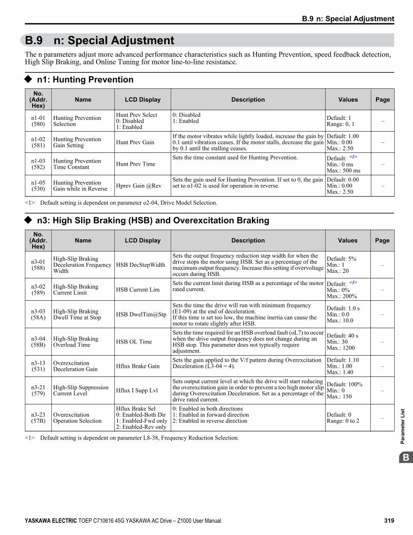
B.9 n: Special AdjustmentThe n parameters adjust more advanced performance characteristics such as Hunting Prevention, speed feedback detection,High Slip Braking, and Online Tuning for motor line-to-line resistance.
u n1: Hunting PreventionNo.
(Addr.Hex)
Name LCD Display Description Values Page
n1-01(580)
Hunting PreventionSelection
Hunt Prev Select0: Disabled1: Enabled
0: Disabled1: Enabled Default: 1
Range: 0, 1 –
n1-02(581)
Hunting PreventionGain Setting Hunt Prev Gain
If the motor vibrates while lightly loaded, increase the gain by0.1 until vibration ceases. If the motor stalls, decrease the gainby 0.1 until the stalling ceases.
Default: 1.00Min.: 0.00Max.: 2.50
–
n1-03(582)
Hunting PreventionTime Constant Hunt Prev Time
Sets the time constant used for Hunting Prevention. Default: <1>
Min.: 0 msMax.: 500 ms
–
n1-05(530)
Hunting PreventionGain while in Reverse Hprev Gain @Rev
Sets the gain used for Hunting Prevention. If set to 0, the gainset to n1-02 is used for operation in reverse.
Default: 0.00Min.: 0.00Max.: 2.50
–
<1> Default setting is dependent on parameter o2-04, Drive Model Selection.
u n3: High Slip Braking (HSB) and Overexcitation BrakingNo.
(Addr.Hex)
Name LCD Display Description Values Page
n3-01(588)
High-Slip BrakingDeceleration FrequencyWidth
HSB DecStepWidthSets the output frequency reduction step width for when thedrive stops the motor using HSB. Set as a percentage of themaximum output frequency. Increase this setting if overvoltageoccurs during HSB.
Default: 5%Min.: 1Max.: 20
–
n3-02(589)
High-Slip BrakingCurrent Limit HSB Current Lim
Sets the current limit during HSB as a percentage of the motorrated current.
Default: <1>
Min.: 0%Max.: 200%
–
n3-03(58A)
High-Slip BrakingDwell Time at Stop HSB DwelTim@Stp
Sets the time the drive will run with minimum frequency(E1-09) at the end of deceleration.If this time is set too low, the machine inertia can cause themotor to rotate slightly after HSB.
Default: 1.0 sMin.: 0.0Max.: 10.0
–
n3-04(58B)
High-Slip BrakingOverload Time HSB OL Time
Sets the time required for an HSB overload fault (oL7) to occurwhen the drive output frequency does not change during anHSB stop. This parameter does not typically requireadjustment.
Default: 40 sMin.: 30Max.: 1200
–
n3-13(531)
OverexcitationDeceleration Gain Hflux Brake Gain
Sets the gain applied to the V/f pattern during OverexcitationDeceleration (L3-04 = 4).
Default: 1.10Min.: 1.00Max.: 1.40
–
n3-21(579)
High-Slip SuppressionCurrent Level Hflux I Supp Lvl
Sets output current level at which the drive will start reducingthe overexcitation gain in order to prevent a too high motor slipduring Overexcitation Deceleration. Set as a percentage of thedrive rated current.
Default: 100%Min.: 0Max.: 150
–
n3-23(57B)
OverexcitationOperation Selection
Hflux Brake Sel0: Enabled-Both Dir1: Enabled-Fwd only2: Enabled-Rev only
0: Enabled in both directions1: Enabled in forward direction2: Enabled in reverse direction
Default: 0Range: 0 to 2 –
<1> Default setting is dependent on parameter L8-38, Frequency Reduction Selection.
B.9 n: Special Adjustment
YASKAWA ELECTRIC TOEP C710616 45G YASKAWA AC Drive – Z1000 User Manual 319
B
Para
met
er L
ist

u n8: PM Motor Control TuningNo.
(Addr.Hex)
Name LCD Display Description Values Page
n8-45(538)
Speed FeedbackDetection Control Gain PM Spd Fdbk Gain
OLV/PMOLV/PMIncrease this setting if hunting occurs. Decrease to lower theresponse.
Default: 0.80Min.: 0.00Max.: 10.00
–
n8-47(53A)
Pull-In CurrentCompensation TimeConstant
PM Pull-in I Tc
OLV/PMOLV/PMSets the time constant to make the pull-in current reference andactual current value agree. Decrease the value if the motorbegins to oscillate, and increase the value if it takes too long forthe current reference to equal the output current.
Default: 5.0 sMin.: 0.0Max.: 100.0
–
n8-48(53B) Pull-In Current PM No-load Curr
OLV/PMOLV/PMDefines the d-Axis current reference during no-load operationat a constant speed. Set as a percentage of the motor ratedcurrent. Increase this setting if hunting occurs while running atconstant speed.
Default: 30%Min.: 20Max.: 200
–
n8-49(53C)
d-Axis Current for HighEfficiency Control EnergySav ID Lvl
OLV/PMOLV/PMSets the d-Axis current reference when running a high load atconstant speed. Set as a percentage of the motor rated current.
Default: <1>
Min.: -200.0%Max.: 0.0%
–
n8-51(53E)
Acceleration/Deceleration Pull-InCurrent
PM Pull-in I@AccOLV/PMOLV/PM
Sets the d-Axis current reference during acceleration/deceleration as a percentage of the motor rated current. Set to ahigh value when more starting torque is needed.
Default: 50%Min.: 0Max.: 200
–
n8-54(56D)
Voltage ErrorCompensation TimeConstant
PM V Error CompTOLV/PMOLV/PM
Adjusts the value when hunting occurs at low speed. If huntingoccurs with sudden load changes, increase n8-54 in incrementsof 0.1. Reduce this setting if oscillation occurs at start.
Default: 1.00 sMin.: 0.00Max.: 10.00
–
n8-55(56E) Load Inertia
PMLoad wk2 Ratio0: Less than 1:101: 1:10 to 1:302: 1:30 to 1:503: More than 1:50
OLV/PMOLV/PMSets the ratio between motor and machine inertia.0: Lower than 1:101: Between 1:10 to 1:302: Between 1:30 to 1:503: Higher than 1:50
Default: 0Min.: 0Max.: 3
–
n8-62(57D) Output Voltage Limit PM Vout Limit
OLV/PMOLV/PMPrevents output voltage saturation. Should be set just below thevoltage provided by the input power supply.
Default: 200.0 V<2>
Min.: 0.0Max.: 230.0 <2>
–
n8-65(65C)
Speed FeedbackDetection Control Gainduring ov Suppression
SFdbk G @OV SuppOLV/PMOLV/PM
Sets the gain used for internal speed feedback detection duringov suppression.
Default: 1.50Min.: 0.00Max.: 10.00
–
<1> Default setting is dependent on parameter o2-04, Drive Model Selection.<2> Values shown are specific to 200 V class drives. Double the value for 400 V class drives.
B.9 n: Special Adjustment
320 YASKAWA ELECTRIC TOEP C710616 45G YASKAWA AC Drive – Z1000 User Manual

B.10 o: Operator-Related SettingsThe o parameters set up the HOA keypad displays.
u o1: HOA Keypad Display SelectionNo.
(Addr.Hex)
Name LCD Display Description Values Page
o1-01(500) Drive Mode Unit
Monitor Selection User Monitor SelSelects the content of the last monitor that is shown whenscrolling through Drive Mode display. Enter the last three digitsof the monitor parameter number to be displayed: Uo-oo.
Default: 106Range: 104 to699
187
o1-02(501) User Monitor Selection
after Power Up
Power-On Monitor1: Frequency Ref2: FWD/REV3: Output Freq4: Output Current5: User Monitor
1: Frequency reference (U1-01)2: Direction3: Output frequency (U1-02)4: Output current (U1-03)5: User Monitor
Default: 1Range: 1 to 5 187
o1-03(502)
HOA Keypad DisplaySelection
Display Unit Sel0: 0.01 Hz1: 0.01%2: r/min3: User Units
Sets the units the drive should use to display the frequencyreference and motor speed monitors.0: 0.01 Hz1: 0.01% (100% = E1-04)2: r/min (calculated using the number of motor poles setting inE2-04, E4-04, or E5-04)3: User-selected units (set by o1-10 and o1-11)
Default: 0Range: 0 to 3 188
o1-06(517)
User Monitor SelectionMode
Monitor Mode Sel0: 3 Mon Sequential1: 3 Mon Selectable
0: 3 Monitor Sequential(Displays the next two sequential monitors)1: 3 Monitor Selectable (o1-07 and o1-08 selected monitor areshown)
Default: 0Range: 0, 1 188
o1-07(518)
Second Line MonitorSelection 2nd Monitor Sel
Selects the monitor that is shown in the second line.Enter the last three digits of the monitor parameter number tobe displayed: Uo-oo. For example, set "403" to displaymonitor parameter U4-03.
Default: 102Range: 101 to699
188
o1-08(519)
Third Line MonitorSelection 3rd Monitor Sel
Selects the monitor that is shown in the third line.Enter the last three digits of the monitor parameter number tobe displayed: Uo-oo. For example, set "403" to displaymonitor parameter U4-03.
Default: 103Range: 101 to699
188
o1-09(51C)
Frequency ReferenceDisplay Units
Fref Disp Unit0: WC1: PSI2: GPM3: °F4: CFM5: CMH6: LPH7: LPS8: Bar9: Pa10: °C11: Mtr12: Ft13: LPM14: CMM15: Custom unit16: No Unit
Sets unit display for the frequency reference parameters andfrequency related monitors when o1-03 = 3.0: WC (Inch of water)1: PSI (Pounds per square inch)2: GPM (Gallons per minute)3: F (Degrees Fahrenheit)4: CFM (Cubic feet per minute)5: CMH (Cubic meters per hour)6: LPH (Liters per hour)7: LPS (Liters per second)8: Bar (Bar)9: Pa (Pascal)10: C (Degrees Celsius)11: Mtr (Meters)12: Ft (Feet)13: LPM (Liters per minute)14: CMM (Cubic meters per minute)15: Custom units (Determined by o1-12)16: None
Default: 16Range: 0 to 16 188
o1-10(520)
User-Set Display UnitsMaximum Value UserDisp Scaling
These settings define the display values when o1-03 is set to 3.o1-10 sets the display value that is equal to the maximum outputfrequency.o1-11 sets the position of the decimal position.
Default: <1>
Range: 1 to60000
189
o1-11(521)
User-Set Display UnitsDecimal Display UserDisp Dec Default: <1>
Range: 0 to 3 189
o1-13(3105)
Frequency Referenceand Frequency RelatedMonitor Custom Units 1
Fref Cust Unit 1Sets the customer-specified unit display for the frequencyreference parameters and frequency related monitors wheno1-03 = 3 and o1-09 = 15 as custom units.
Default: 41Range: 30 to 7A 189
o1-14(3106)
Frequency Referenceand Frequency RelatedMonitor Custom Units 2
Fref Cust Unit 2Sets the customer-specified unit display for the frequencyreference parameters and frequency related monitors wheno1-03 = 3 and o1-09 = 15 as custom units
Default: 41Range: 30 to 7A 189
B.10 o: Operator-Related Settings
YASKAWA ELECTRIC TOEP C710616 45G YASKAWA AC Drive – Z1000 User Manual 321
B
Para
met
er L
ist

No.(Addr.Hex)
Name LCD Display Description Values Page
o1-15(3107)
Frequency Referenceand Frequency RelatedMonitor Custom Units 3
Fref Cust Unit 3Sets the customer-specified unit display for the frequencyreference parameters and frequency related monitors wheno1-03 = 3 and o1-09 = 15 as custom units
Default: 41Range: 30 to 7A 189
o1-16(3108)
F1 Key FunctionSelection
F1 Key Func Sel0: Standard1: Mon2: DRV/BYP3: RUN BYP4: RLY
Selects the function of the F1 key and the LCD display textabove the F1 key.0: Standard1: Monitor2: Drive/Bypass (DRV/BYP)3: Bypass Run Command (RUN BYP)4: Toggle Relay Output (RLY)
Default: 0Range: 0 to 4 189
o1-17(3109)
F2 Key FunctionSelection
F2 Key Func Sel0: Standard1: Mon2: DRV/BYP3: RUN BYP4: RLY
Selects the function of the F2 key and the LCD display textabove the F2 key.0: Standard1: Monitor2: Drive/Bypass (DRV/BYP)3: Bypass Run Command (RUN BYP)4: Toggle Relay Output (RLY)
Default: 0Range: 0 to 4 189
o1-18(310A)
User Defined ParameterUpper Userdefined par1 Allows the user to set values that can be used as reference
information.Default: 0Range: 0 to 999 189
o1-19(310B)
User Defined ParameterLower Userdefined par2 Allows the user to set values that can be used as reference
information.Default: 0Range: 0 to 999 189
<1> Default setting is dependent on parameter o1-03, HOA Keypad Display Selection.
u o2: HOA Keypad FunctionsNo.
(Addr.Hex)
Name LCD Display Description Values Page
o2-02(506)
OFF Key FunctionSelection
Oper STOP Key0: Disabled1: Enabled
0: Disabled. OFF key is disabled in REMOTE operation.1: Enabled. OFF key is always enabled. Default: 1
Range: 0, 1 190
o2-03(507)
User Parameter DefaultValue
User Default Sel0: No Change1: Save User Init2: Clear User Init
0: No change.1: Set defaults. Saves parameter settings as default values for aUser Initialization.2: Clear all. Clears the default settings that have been saved fora User Initialization.
Default: 0Range: 0 to 2 142
o2-04(508) Drive Model Selection Inverter Model #
Enter the drive model. Setting required only if installing a newcontrol board.
Default:Determined bydrive capacity
190
o2-05(509)
Frequency ReferenceSetting MethodSelection
Oper Ref Method0: Disabled1: Enabled
0: ENTER key must be pressed to enter a frequency reference.1: ENTER key is not required. The frequency reference can beadjusted using the up and down arrow keys only.
Default: 0Range: 0, 1 142
o2-06(50A)
Operation Selectionwhen HOA Keypad isDisconnected
Oper Discon Det0: Disabled1: Enabled
0: The drive continues operating if the HOA keypad isdisconnected.1: An oPr fault is triggered and the motor coasts to stop.
Default: 1Range: 0, 1 190
o2-07(527)
Motor Direction atPower Up when UsingOperator
For/RevSel@PwrUp0: Forward1: Reverse
0: Forward1: ReverseThis parameter requires assigning drive operation to the HOAkeypad.
Default: 0Range: 0, 1 191
o2-19(61F)
Selection of ParameterWrite during Uv
ParameterSet Sel0: Disabled1: Enabled
Selects whether parameter settings can be changed during a DCbus undervoltage condition. Used with 24 V Power Supply (PS-A10L, PS-A10H).0: Disabled1: Enabled
Default: 0Range: 0, 1 –
B.10 o: Operator-Related Settings
322 YASKAWA ELECTRIC TOEP C710616 45G YASKAWA AC Drive – Z1000 User Manual

u o3: Copy FunctionNo.
(Addr.Hex)
Name LCD Display Description Values Page
o3-01(515) Copy Function Selection
COPY SELECT0: COPY SELECT1: INV→OP READ2: OP→INV WRITE3: OP←→INVVERIFY
0: No action1: Read parameters from the drive, saving them onto the HOAkeypad.2: Copy parameters from the digital operator, writing them to thedrive.3: Verify parameter settings on the drive to check if they matchthe data saved on the HOA keypad.
Default: 0Range: 0 to 3 191
o3-02(516) Copy Allowed Selection
Read Allowable0: Disabled1: Enabled
0: Read operation prohibited1: Read operation allowed Default: 0
Range: 0, 1 191
u o4: Maintenance Monitor SettingsNo.
(Addr.Hex)
Name LCD Display Description Values Page
o4-01(50B)
Cumulative OperationTime Setting DrvElapsTimeCnt
Sets the value for the cumulative operation time of the drive inunits of 10 h.
Default: 0 hMin.: 0Max.: 9999
191
o4-02(50C)
Cumulative OperationTime Selection
ElapsTimeCntSet0: Power-On Time1: Running Time
0: Logs power-on time1: Logs operation time when the drive output is active (outputoperation time).
Default: 1Range: 0, 1 191
o4-03(50E)
Cooling Fan OperationTime Setting FanElapsTimeCn
Sets the value of the fan operation time monitor U4-03 in unitsof 10 h.
Default: 0 hMin.: 0Max.: 9999
192
o4-05(51D)
Capacitor MaintenanceSetting BusCap Maint Set
Sets the value of the Maintenance Monitor for the capacitors. SeeU4-05 to check when the capacitors may need to be replaced.
Default: 0%Min.: 0Max.: 150
192
o4-07(523)
DC Bus Pre-ChargeRelay MaintenanceSetting
ChrgCircMaintSetSets the value of the Maintenance Monitor for the soft chargebypass relay. See U4-06 to check when the bypass relay may needto be replaced.
Default: 0%Min.: 0Max.: 150
192
o4-11(510) U2, U3 Initialization
Fault Data Init0: No Reset1: Reset
0: U2-oo and U3-oo monitor data is not reset when the driveis initialized (A1-03).1: U2-oo and U3-oo monitor data is reset when the drive isinitialized (A1-03).
Default: 0Range: 0, 1 192
o4-12(512)
kWh MonitorInitialization
kWh Monitor Init0: No Reset1: Reset
0: U4-10 and U4-11 monitor data is not reset when the drive isinitialized (A1-03).1: U4-10 and U4-11 monitor data is reset when the drive isinitialized (A1-03).
Default: 0Range: 0, 1 192
o4-13(528)
Number of RunCommands CounterInitialization
Run Counter Init0: No Reset1: Reset
0: Number of Run commands counter is not reset when the driveis initialized (A1-03).1: Number of Run commands counter is reset when the drive isinitialized (A1-03).
Default: 0Range: 0, 1 192
o4-17(3100)
<1>Set/Reset Real TimeClock
Set Time0: Disabled1: Enabled
Sets the current date and time for the Real Time Clock.0: Disabled1: Enabled
Default: 0Range: 0, 1 192
o4-17(3100)
<2>Set/Reset Real TimeClock
Set Time0: — —1: Set2: Reset
Sets the current date and time for the Real Time Clock.0: — — No Setting1: Real Time Clock Set2: Real Time Clock Reset
Default: 0Range: 0 to 2 192
<1> Available in drive software versions PRG: 1012 and earlier.<2> Available in drive software versions PRG: 1013 and later.
B.10 o: Operator-Related Settings
YASKAWA ELECTRIC TOEP C710616 45G YASKAWA AC Drive – Z1000 User Manual 323
B
Para
met
er L
ist

B.11 S: Special Application
u S1: Dynamic Noise Control FunctionNo.
(Addr.Hex)
Name LCD Display Description Values Page
S1-01(3200)
Dynamic Audible NoiseControl FunctionSelection
Dyn Noise Ctrl0: Disabled1: Enabled
Reduces audible noise by decreasing the output voltage invariable torque applications with light loads.0: Disabled1: Enabled
Default: 1Range: 0, 1 –
S1-02(3201) Voltage Reduction Rate Volt Reduce Amt
Sets the rate at which the output voltage will be reduced as apercentage of the V/f pattern when operating with no load.
Default: 50.0%Min.: 50.0Max.: 100.0
–
S1-03(3202)
Voltage RestorationLevel V Reduce On Lvl
Sets the level when the drive should start restoring the voltage asa percentage of the drive rated torque.
Default: 20.0%Min.: 0.0Max.: 90.0
–
S1-04(3203)
Voltage RestorationComplete Level V Reduce Off Lvl
Sets the level at which voltage restoration for the V/f pattern iscomplete as a percentage of the drive rated torque. If the outputtorque rises above the value of S1-04, then the voltage will becontrolled in a manner specified by the V/f pattern setting.
Default: 50.0%Min.: S1-03 +10.0Max.: 100.0
–
S1-05(3204)
Voltage RestorationSensitivity TimeConstant
Sensitivity TimeSets the level of sensitivity of the output torque and LPF timeconstant for the voltage reduction rate. The level of sensitivitycan be adjusted in accordance with the load response.
Default: 1.000 sMin.: 0.000Max.: 3.000
–
S1-06(3205)
Voltage RestorationTime Constant at Impact Impact Load Time
Sets the voltage restoration time constant if an impact load isadded.
Default: 0.050 sMin.: 0.000Max.: 1.000
–
u S2: Sequence TimersNo.
(Addr.Hex)
Name LCD Display Description Values Page
S2-01(3206)
Sequence Timer 1 StartTime Tmr 1 Start Time
Sets the start time for timer 1. The value must be set less than orequal to S2-02.
Default: 00:00Min.: 00:00Max.: 24:00
–
S2-02(3207)
Sequence Timer 1 StopTime Tmr 1 Stop Time
Sets the stop time for timer 1. The value must be set greater thanor equal to S2-01.
Default: 00:00Min.: 00:00Max.: 24:00
–
S2-03(3208)
Sequence Timer 1 DaySelection
Tmr 1 Day Sel0: Timer disabled1: Daily2: Mon - Fri3: Sat - Sun4: Monday5: Tuesday6: Wednesday7: Thursday8: Friday9: Saturday10: Sunday
Sets the days for which sequence timer 1 is active.0: Timer disabled1: Daily2: Mon - Fri3: Sat - Sun4: Monday5: Tuesday6: Wednesday7: Thursday8: Friday9: Saturday10: Sunday
Default: 0Range: 0 to 10 –
S2-04(3209)
Sequence Timer 1Selection
Tmr 1 Seq Sel0: Digital out only1: Run2: Run - PI Disable
Sets the action that occurs when sequence timers 1 is active.0: Digital output only1: Run2: Run - PI disable
Default: 0Range: 0 to 2 –
S2-05(320A)
Sequence Timer 1Reference Source
Tmr 1 Ref Source0: Operator (d1-01)1: Operator (d1-02)2: Operator (d1-03)3: Operator (d1-04)4: Terminals5: Serial com6: Option PCB
Selects the frequency reference source used for running the drivewhen sequence timer 1 is active (only applicable when S2-04 isset to 1 or 2).0: Operator (d1-01)1: Operator (d1-02)2: Operator (d1-03)3: Operator (d1-04)4: Terminals5: Serial communication6: Option card
Note: H1-oo = 12/13 overrides this sequence run timerin drive software versions PRG: 1018 and later.
Default: 0Range: 0 to 6 –
B.11 S: Special Application
324 YASKAWA ELECTRIC TOEP C710616 45G YASKAWA AC Drive – Z1000 User Manual

No.(Addr.Hex)
Name LCD Display Description Values Page
S2-06(320B)
Sequence Timer 2 StartTime Tmr 2 Start Time
Sets the start time for timer 2. The value must be set less than orequal to S2-07.
Default: 00:00Min.: 00:00Max.: 24:00
–
S2-07(320C)
Sequence Timer 2 StopTime Tmr 2 Stop Time
Sets the stop time for timer 2. The value must be set greater thanor equal to S2-06.
Default: 00:00Min.: 00:00Max.: 24:00
–
S2-08(320D)
Sequence Timer 2 DaySelection
Tmr 2 Day Sel0: Timer disabled1: Daily2: Mon - Fri3: Sat - Sun4: Monday5: Tuesday6: Wednesday7: Thursday8: Friday9: Saturday10: Sunday
Sets the days for which sequence timer 2 is active.0: Timer disabled1: Daily2: Mon - Fri3: Sat - Sun4: Monday5: Tuesday6: Wednesday7: Thursday8: Friday9: Saturday10: Sunday
Default: 0Range: 0 to 10 –
S2-09(320E)
Sequence Timer 2Selection
Tmr 2 Seq Sel0: Digital out only1: Run2: Run - PI Disable
Sets the action that occurs when sequence timers 2 is active.0: Digital output only1: Run2: Run - PI disable
Default: 0Range: 0 to 2 –
S2-10(320F)
Sequence Timer 2Reference Source
Tmr 2 Ref Source0: Operator (d1-01)1: Operator (d1-02)2: Operator (d1-03)3: Operator (d1-04)4: Terminals5: Serial com6: Option PCB
Selects the frequency reference source used for running the drivewhen sequence timer 2 is active (only applicable when S2-09 isset to 1 or 2).0: Operator (d1-01)1: Operator (d1-02)2: Operator (d1-03)3: Operator (d1-04)4: Terminals5: Serial communication6: Option card
Note: H1-oo = 12/13 overrides this sequence run timerin drive software versions PRG: 1018 and later.
Default: 0Range: 0 to 6 –
S2-11(3210)
Sequence Timer 3 StartTime Tmr 3 Start Time
Sets the start time for timer 3. The value must be set less than orequal to S2-12.
Default: 00:00Min.: 00:00Max.: 24:00
–
S2-12(3211)
Sequence Timer 3 StopTime Tmr 3 Stop Time
Sets the stop time for timer 3. The value must be set greater thanor equal to S2-11.
Default: 00:00Min.: 00:00Max.: 24:00
–
S2-13(3212)
Sequence Timer 3 DaySelection
Tmr 3 Day Sel0: Timer disabled1: Daily2: Mon - Fri3: Sat - Sun4: Monday5: Tuesday6: Wednesday7: Thursday8: Friday9: Saturday10: Sunday
Sets the days for which sequence timer 3 is active.0: Timer disabled1: Daily2: Mon - Fri3: Sat - Sun4: Monday5: Tuesday6: Wednesday7: Thursday8: Friday9: Saturday10: Sunday
Default: 0Range: 0 to 10 –
S2-14(3213)
Sequence Timer 3Selection
Tmr 3 Seq Sel0: Digital out only1: Run2: Run - PI Disable
Sets the action that occurs when sequence timer 3 is active.0: Digital output only1: Run2: Run - PI disable
Default: 0Range: 0 to 2 –
B.11 S: Special Application
YASKAWA ELECTRIC TOEP C710616 45G YASKAWA AC Drive – Z1000 User Manual 325
B
Para
met
er L
ist

No.(Addr.Hex)
Name LCD Display Description Values Page
S2-15(3214)
Sequence Timer 3Reference Source
Tmr 3 Ref Source0: Operator (d1-01)1: Operator (d1-02)2: Operator (d1-03)3: Operator (d1-04)4: Terminals5: Serial com6: Option PCB
Selects the frequency reference source used for running the drivewhen sequence timer 3 is active (only applicable when S2-14 isset to 1 or 2).0: Operator (d1-01)1: Operator (d1-02)2: Operator (d1-03)3: Operator (d1-04)4: Terminals5: Serial communication6: Option card
Note: H1-oo = 12/13 overrides this sequence run timerin drive software versions PRG: 1018 and later.
Default: 0Range: 0 to 6 –
S2-16(3215)
Sequence Timer 4 StartTime Tmr 4 Start Time
Sets the start time for timer 4. The value must be set less than orequal to S2-17.
Default: 00:00Min.: 00:00Max.: 24:00
–
S2-17(3216)
Sequence Timer 4 StopTime Tmr 4 Stop Time
Sets the stop time for timer 4. The value must be set greater thanor equal to S2-16.
Default: 00:00Min.: 00:00Max.: 24:00
–
S2-18(3217)
Sequence Timer 4 DaySelection
Tmr 4 Day Sel0: Timer disabled1: Daily2: Mon - Fri3: Sat - Sun4: Monday5: Tuesday6: Wednesday7: Thursday8: Friday9: Saturday10: Sunday
Sets the days for which sequence timer 4 is active.0: Timer disabled1: Daily2: Mon - Fri3: Sat - Sun4: Monday5: Tuesday6: Wednesday7: Thursday8: Friday9: Saturday10: Sunday
Default: 0Range: 0 to 10 –
S2-19(3218)
Sequence Timer 4Selection
Tmr 4 Seq Sel0: Digital out only1: Run2: Run - PI Disable
Sets the action that occurs when sequence timer 4 is active.0: Digital output only1: Run2: Run - PI disable
Default: 0Range: 0 to 2 –
S2-20(3219)
Sequence Timer 4Reference Source
Tmr 4 Ref Source0: Operator (d1-01)1: Operator (d1-02)2: Operator (d1-03)3: Operator (d1-04)4: Terminals5: Serial com6: Option PCB
Selects the frequency reference source used for running the drivewhen sequence timer 4 is active (only applicable when S2-19 isset to 1 or 2).0: Operator (d1-01)1: Operator (d1-02)2: Operator (d1-03)3: Operator (d1-04)4: Terminals5: Serial communication6: Option card
Note: H1-oo = 12/13 overrides this sequence run timerin drive software versions PRG: 1018 and later.
Default: 0Range: 0 to 6 –
u S3: Secondary PI (PI2) ControlNo.
(Addr.Hex)
Name LCD Display Description Values Page
S3-01(321A) Secondary PI Enable
Selection
PI2 Enable Sel0: Disabled1: Always2: Drive running3: Motor running
0: Secondary PI disabled1: Always2: Drive running3: Motor running
Default: 0Range: 0 to 3 –
S3-02(321B) Secondary PI User
Display PI2 UsrDspMaxValSets the scale value of 100% PI input. Default: 10000
Min.: 0Max.: 60000
–
S3-03(321C) Secondary PI Display
Digits
PI2 UsrDspDigits0: No Dec (XXXXX)1: 1 Dec (XXXX.X)2. 2 Dec (XXX.XX)3: 3 Dec (XX.XXX)
0: No decimal places1: One decimal place2: Two decimal places3: Three decimal places
Default: 2Range: 0 to 3 –
B.11 S: Special Application
326 YASKAWA ELECTRIC TOEP C710616 45G YASKAWA AC Drive – Z1000 User Manual

No.(Addr.Hex)
Name LCD Display Description Values Page
S3-04(321D) Secondary PI Unit
Selection
PI2 Unit Sel0: WC1: PSI2: GPM3: °F4: CFM5: CMH6: LPH7: LPS8: Bar9: Pa10: °C11: Mtr12: LPM13: CMM14: No unit15: %
0: Inch of water (WC)1: Pounds per square inch (PSI)2: Gallons per minute (GPM)3: Degrees Fahrenheit (F)4: Cubic feet per minute (CFM)5: Cubic meters per hour (CMH)6: Liters per hour (LPH)7: Liters per second (LPS)8: Bar (Bar)9: Pascals (Pa)10: Degrees Celsius (C)11: Meters (Mtr) (Ft: Feet)12: Liters per minute (LPM)13: Cubic meters per minute (CMM)14: No unit15: Percentage (%)
Default: 15Range: 0 to 15 –
S3-05(321E) Secondary PI Setpoint
Value PI2 Setpoint
Sets the secondary PI controller target value Default: 0.00<1>
Min.: 0.00Max.: 600.00<2>
–
S3-06(321F)
Secondary PIProportional GainSetting
PI2 GainSets the proportional gain of the secondary PI controller. A settingof 0.00 disables P control.
Default: 1.00Min.: 0.00Max.: 25.00
–
S3-07(3220) Secondary PI Integral
Time Setting PI2 I TimeSets the integral time for the secondary PI controller. A setting of0.0s disables integral control.
Default: 1.0 sMin.: 0.0Max.: 360.0
–
S3-08(3221) Secondary PI Integral
Limit Setting PI2 I LimitSets the maximum output possible from the integrator. Default:
100.0%Min.: 0.0Max.: 100.0
–
S3-09(3222) Secondary PI Output
Upper Limit PI2 Upper LimitSets the maximum output possible from the secondary PIcontroller.
Default:100.0%Min.: 0.0Max.: 100.0
–
S3-10(3223) Secondary PI Output
Lower Limit PI2 Lower LimSets the minimum output possible from the secondary PIcontroller.
Default: 0.00%Min.: -100.00Max.: 100.00
–
S3-11(3224) Secondary PI Output
Level SelectionPI2 Out Lvl Sel0: Normal Character1: Rev Character
0: Normal Output (direct acting)1: Reverse Output (reverse acting) Default: 0
Range: 0, 1 –
S3-12(3225) Secondary PI Disable
Mode
PI2 Disable Mode0: No output1: Lower Limit(S3-10)2: Setpoint
0: No output (0%)1: Lower Limit (S3-10)2: Setpoint Default: 0
Range: 0 to 2 –
S3-13(3226)
Secondary PI LowFeedback DetectionLevel
PI2 Low FB Lvl
Sets the secondary PI low feedback detection level. Default: 0.00<1>
Min.: 0.00Max.: 600.00<2>
–
S3-14(3227)
Secondary PI LowFeedback DetectionTime
PI2 Low FB TimeSets the secondary PI low feedback detection delay time inseconds.
Default: 1.0 sMin.: 0.0Max.: 25.5
–
S3-15(3228) Secondary PI High
Feedback Level PI2 High FB Lvl
Sets the secondary PI high feedback detection level. Default: 100.00<1>
Min.: 0.00Max.: 600.00<2>
–
B.11 S: Special Application
YASKAWA ELECTRIC TOEP C710616 45G YASKAWA AC Drive – Z1000 User Manual 327
B
Para
met
er L
ist

No.(Addr.Hex)
Name LCD Display Description Values Page
S3-16(3229)
Secondary PI HighFeedback DetectionTime
PI2 High FB TimSets the secondary PI high feedback detection delay time inseconds.
Default: 1.0 sMin.: 0.0Max.: 25.5
–
S3-17(322A) Secondary PI Feedback
Detection SelectionPI2 FB Det Sel0: PI2 Enabled1: Always
0: Secondary PI enabled1: Always Default: 0
Range: 0, 1 –
<1> Unit is determined by S3-04.<2> Upper limit is S3-02, decimal placeholder is determined by S3-03.
u S4: Bypass OperationNo.
(Addr.Hex)
Name LCD Display Description Values Page
S4-01(322B) BP Auto Transfer on
Fault EnableBP Fault Trnsfer0: Disabled1: Enabled
0: No transfer after fault1: Transfer to bypass after fault Default: 1
Range: 0, 1 –
S4-02(322C) BP Energy Save Bypass
Trigger Level BP Enrgy Sav LvlDelta used to determine when to switch into Energy Save Bypass.This allows for lower frequency output values to also triggerEnergy Save Bypass functionality.
Default: 0 HzMin.: 0Max.: 20
–
S4-03(322D) BP Energy Save Bypass
Timer BP Enrgy Sav TMRSets the time in seconds that the drive should run at the specifiedspeed before entering Energy Save Bypass mode.
Default: 60 sMin.: 10Max.: 60000
–
S4-04(322E) BP Energy Save Bypass
Speed Increase BP Enrgy Sav IncSets the value in Hz that the drive will increase the outputfrequency above E1-04 before performing an Energy Savetransfer to bypass.
Default: 6 HzMin.: 0Max.: 10
–
u S5: HOA Keypad ParametersNo.
(Addr.Hex)
Name LCD Display Description Values Page
S5-01(322F)
HAND FrequencyReference Selection
HAND Fref Source0: Operator1: Terminals2: d1-163: S5-054: Set by b1-01
0: HOA keypad1: Terminals2: d1-163: S5-054: Determined by b1-01
Default: 0Range: 0 to 4 –
S5-02(3230)
HAND/AUTO DuringRun Selection
HAND/AUTO@Run0: Disabled1: Enabled
0: Disabled1: Enabled Default: 1
Range: 0, 1 –
S5-03(3231) HAND Mode PI
SelectionHAND Mode PI Sel0: Disabled1: Enabled
0: Disabled1: Enabled Default: 1
Range: 0, 1 –
S5-04(3232)
HAND Mode BehaviorSelection
HAND BehaviorSel0: Legacy1: Normal2: Normal w/Memory
0: Legacy operation mode1: Normal operation mode2: Normal with memory
Note: 1. The drive will always be in AUTO mode atpower up with S5-04 = 1.
2. When S5-04 = 2, if the drive is powered downwith HAND from the HOA keypad, the drivewill power up in OFF mode.
Default: 1Range: 0 to 2 –
S5-05(3233) HAND Frequency
Reference 1 HAND Freq Ref 2
Sets the frequency reference used in HAND mode when S5-01 isset to 3.
Default: 0.00HzMin.: 0.00Max.: [E4-01]<1>
–
B.11 S: Special Application
328 YASKAWA ELECTRIC TOEP C710616 45G YASKAWA AC Drive – Z1000 User Manual

No.(Addr.Hex)
Name LCD Display Description Values Page
S5-07(3235)
HAND Key FunctionSelection (HOAKeypad)
Oper HAND Key0: Disabled1: Enabled
Determines whether the HAND key on the HOA keypad will beenabled for switching between HAND and AUTO.0: Disabled1: Enabled
Default: 1Range: 0, 1 –
<1> Upper limit is 240.00 in drive software versions PRG: 1017 and earlier.
u S6: Z1000 ProtectionNo.
(Addr.Hex)
Name LCD Display Description Values Page
S6-01(3236)
Emergency OverrideSpeed E Override Speed
Sets the speed command used in Emergency Override mode whenS6-02 = 0.
Default: 0.00HzMin.: 0.00Max.: [E1-04]<1>
–
S6-02(3237)
Emergency OverrideReference Selection
E OverrideRefSel0: Use S6-01 Ref1: Use AUTO Ref
Selects the frequency reference source for the EmergencyOverride function (H1-oo= AF or B0).0: Use S6-01 Reference1: Use AUTO Reference
Note: In drive software versions PRG: 1013 and earlier,if the CALL alarm is displayed, the EmergencyOverride Forward (H1-0o = AF) and EmergencyOverride Reverse (H1-0o = B0) inputs areignored. In drive software versions PRG: 1014 andlater, the Emergency Override inputs will functioneven if the CALL alarm is displayed.
Default: 0Range: 0, 1 –
S6-03(3238) ov2 Detect Time ov2 Detect Time
Sets the detection time of ov2 in 0.1 s increments. Default: 10.0 sMin.: 0.0Max.: 1200.0
–
S6-04(3239)
Main Contactor andCooling Fan PowerSupply Failure
FAN1 Fault Sel0: Ramp to Stop1: Coast to stop2: Fast-Stop
Determines the action the drive should take when a fault occurswith the external cooling fan.0: Ramp to stop1: Coast to Stop2: Fast Stop (decelerate to stop using the deceleration time inC1-09)
Default: 1Range: 0 to 2 –
S6-07(323C)
Output Phase LossDetection Level forDynamic Audible NoiseControl
Outp Ph Loss Lv1Sets the output phase loss detection level for Dynamic AudibleNoise Control. Decrease the setting in steps of 10% when outputphase loss is detected erroneously. This setting rarely needs to bechanged.
Default:100.0%Min.: 10.0Max.: 100.0
–
<1> Upper limit is 240.00 in drive software versions PRG: 1017 and earlier.
B.11 S: Special Application
YASKAWA ELECTRIC TOEP C710616 45G YASKAWA AC Drive – Z1000 User Manual 329
B
Para
met
er L
ist

B.12 T: Motor TuningEnter data into the following parameters to tune the motor and drive for optimal performance.
u T1: Induction Motor Auto-TuningNo.
(Addr.Hex)
Name LCD Display Description Values Page
T1-01(701)
<1>Auto-Tuning ModeSelection
Tuning Mode Sel2: Term Resistance3: On-DelayCompTune
2: Stationary Auto-Tuning for Line-to-Line Resistance3: Rotational Auto-Tuning for V/f Control Energy Saving Default: 2
Range: 2, 3 147
T1-02(702) Motor Rated Power Mtr Rated Power
Sets the motor rated power as specified on the motor nameplate.Note: Use the following formula to convert horsepower
into kilowatts: 1HP = 0.746 kW.
Default: <2>
Min.: 0.00 kWMax.: 650.00kW
147
T1-03(703) Motor Rated Voltage Rated Voltage
Sets the motor rated voltage as specified on the motor nameplate. Default: 200.0V <3>
Min: 0.0Max: 255.0 <3>
147
T1-04(704) Motor Rated Current Rated Current
Sets the motor rated current as specified on the motor nameplate. Default: <2>
Min.: 10% ofdrive ratedcurrentMax.: 200% ofdrive ratedcurrent
148
T1-05(705) Motor Base Frequency Rated Frequency
Sets the rated frequency of the motor as specified on the motornameplate.
Default: 60.0HzMin.: 0.0Max.: 240.0
148
T1-06(706) Number of Motor Poles Number of Poles
Sets the number of motor poles as specified on the motornameplate.
Default: 4Min.: 2Max.: 48
148
T1-07(707) Motor Base Speed Rated Speed
Sets the rated speed of the motor as specified on the motornameplate.
Default: 1750 r/minMin.: 0Max.: 14400
148
T1-11(70B) Motor Iron Loss Mtr Iron Loss(W)
Sets the iron loss for determining the Energy Saving coefficient.The value is set to E2-10 (motor iron loss) set when the power iscycled. If T1-02 is changed, a default value appropriate for themotor capacity that was entered will appear.
Default: 14 W<4>
Min.: 0Max.: 65535
148
T1-12(FFF0) T1 Tuning Start Tuning Ready The drive starts tuning. No setting
available 148
<1> The availability of certain Auto-Tuning methods depends on the control mode selected for the drive.<2> Default setting is dependent on parameter o2-04, Drive Model Selection.<3> Values shown are specific to 200 V class drives. Double the value for 400 V class drives.<4> Default setting value differs depending on the motor code value and motor parameter settings.
u T2: PM Motor Auto-TuningNo.
(Addr.Hex)
Name LCD Display Description Values Page
T2-01(750)
PM Motor Auto-TuningMode Selection
PM Tuning Mode0: Standard Tuning
OLV/PMOLV/PM0: PM Motor Parameter Settings
Default: 0Range: 0 –
T2-03(752) PM Motor Type
PM Motor Type0: IPM motor1: SPM motor
OLV/PMOLV/PM0: IPM motor1: SPM motor
Default: 1Range: 0, 1 –
B.12 T: Motor Tuning
330 YASKAWA ELECTRIC TOEP C710616 45G YASKAWA AC Drive – Z1000 User Manual

No.(Addr.Hex)
Name LCD Display Description Values Page
T2-04(730) PM Motor Rated Power Mtr Rated Power
OLV/PMOLV/PMSets the motor rated power.
Note: Use the following formula to convert horsepowerinto kilowatts: 1 HP = 0.746 kW.
Default: <1>
Min.: 0.00 kWMax.: 650.00kW
–
T2-05(732)
PM Motor RatedVoltage Rated Voltage
OLV/PMOLV/PMEnter the motor rated voltage as indicated on the motor nameplate.
Default: 200.0V <2>
Min.: 0.0Max.: 255.0 <2>
–
T2-06(733) PM Motor Rated Current Rated Current
OLV/PMOLV/PMEnter the motor rated current as indicated on the motor nameplate.
Default: <1>
Min.: 10% ofdrive ratedcurrentMax.: 200% ofdrive ratedcurrent
–
T2-07(753)
PM Motor BaseFrequency Base Frequency
OLV/PMOLV/PMEnter the motor base frequency as indicated on the motornameplate.
Default: 87.5HzMin.: 0.0Max.: 240.0
–
T2-08(734)
Number of PM MotorPoles
OLV/PMOLV/PMEnter the number of motor poles for the PM motor as indicatedon the motor nameplate.
Default: 6Min.: 2Max.: 48
–
T2-10(754)
PM Motor StatorResistance Arm Resistance
OLV/PMOLV/PMEnter the rotor resistance for the PM motor as indicated on themotor nameplate.
Default: <3>
Min.: 0.000 ΩMax.: 65.000 Ω
–
T2-11(735)
PM Motor d-AxisInductance d-Axis Induct
OLV/PMOLV/PMEnter the d-axis inductance for the PM motor as indicated on themotor nameplate.
Default: <3>
Min.: 0.00 mHMax.: 600.00mH
–
T2-12(736)
PM Motor q-AxisInductance q-Axis Induct
OLV/PMOLV/PMEnter the q-axis inductance for the PM motor as indicated on themotor nameplate.
Default: <3>
Min.: 0.00 mHMax.: 600.00mH
–
T2-13(755)
Induced VoltageConstant Unit Selection
Iduct Volt Unit0: mV/RPM1: mV/(rad/sec)
OLV/PMOLV/PM0: mV/(r/min). E5-09 will automatically be set to 0.0, and E5-24will be used.1: mV/(rad/sec). E5-24 will automatically be set to 0.0, and E5-09will be used.
Default: 0Range: 0, 1 –
T2-14(737)
PM Motor InducedVoltage Constant Induct Volt Coef
OLV/PMOLV/PMEnter the induced voltage coefficient for the PM motor asindicated on the motor nameplate. Setting units are determinedby parameter T2-13, Induced Voltage Constant Unit Selection.
Default: <3>
Min.: 0.1Max.: 2000.0
–
T2-15(756)
Pull-In Current Level forPM Motor Tuning Pull-In I Lvl
OLV/PMOLV/PMSets the amount of pull-in current to use for Auto-Tuning as apercentage of the motor rated current. Increase this setting forhigh inertia loads.
Default: 30%Min.: 0Max.: 120
–
T2-18(FFF1) T2 Tuning Start T2 Tuning Start OLV/PMOLV/PM
The drive starts tuning.No settingavailable –
<1> Default setting is dependent on parameter o2-04, Drive Model Selection.<2> Values shown are specific to 200 V class drives. Double the value for 400 V class drives.<3> Default setting is dependent on parameter T2-02, PM Motor Code Selection, and the drive capacity.
B.12 T: Motor Tuning
YASKAWA ELECTRIC TOEP C710616 45G YASKAWA AC Drive – Z1000 User Manual 331
B
Para
met
er L
ist

B.13 U: MonitorsMonitor parameters allow the user to view drive status, fault information, and other data concerning drive operation.
u U1: Operation Status MonitorsNo.
(Addr.Hex)
Name LCD Display Description AnalogOutput Level Unit
U1-01(40) Frequency Reference Frequency Ref Monitors the frequency reference. Display units are determined
by o1-03.10 V: Maxfrequency 0.01 Hz
U1-02(41) Output Frequency Output Freq Displays the output frequency. Display units are determined by
o1-03.10 V: Maxfrequency 0.01 Hz
U1-03(42) Output Current Output Current Displays the output current. 10 V: Drive
rated current<1> <2>
U1-04(43) Control Method Control Method 0: V/f Control No signal output
available –
U1-06(45)
Output VoltageReference Output Voltage Displays the output voltage. 10 V: 200 Vrms
<3> 0.1 Vac
U1-07(46) DC Bus Voltage DC Bus Voltage Displays the DC bus voltage. 10 V: 400 V
<3> 1 Vdc
U1-08(47) Output Power Output kWatts
Displays the output power (this value is calculated internally). 10 V: Driverated power(kW)
<4>
U1-10(49) Input Terminal Status Input Term Sts
Displays the input terminal status.U1 - 10=00000000
Digital input 1 (terminal S1 enabled)Digital input 2 (terminal S2 enabled)Digital input 3 (terminal S3 enabled)Digital input 4 (terminal S4 enabled)Digital input 5 (terminal S5 enabled)Digital input 6 (terminal S6 enabled)Digital input 7 (terminal S7 enabled)
1111111
No signal outputavailable –
U1-11(4A) Output Terminal Status Output Term Sts
Displays the output terminal status.U1 - 11=00000000
Multi-Function Digital Output (terminal MD-ME-MF) enabled
Digital Output (terminal M1-M2) enabled
Digital Output (terminal M3-M4) enabled
Multi-Function
Multi-Function
Not UsedFault Relay(terminal MA-MC closed,MA open) enabled
1
1
1
10
No signal outputavailable –
B.13 U: Monitors
332 YASKAWA ELECTRIC TOEP C710616 45G YASKAWA AC Drive – Z1000 User Manual

No.(Addr.Hex)
Name LCD Display Description AnalogOutput Level Unit
U1-12(4B) Drive Status Int Ctl Sts 1
Verifies the drive operation status.U1 - 12=00000000
During runDuring zero-speedDuring REVDuring fault reset signal inputDuring speed agreeDrive readyDuring alarm detectionDuring fault detection
11111111
No signal outputavailable –
U1-13(4E) Terminal A1 Input Level Term A1 Level Displays the signal level to analog input terminal A1. 10 V: 100% 0.1%
U1-14(4F) Terminal A2 Input Level Term A2 Level Displays the signal level to analog input terminal A2. 10 V: 100% 0.1%
U1-16(53)
Output Frequency afterSoft Starter SFS Output Displays output frequency with ramp time and S-curves. Units
determined by o1-03.10 V: Maxfrequency 0.01 Hz
U1-18(61) oPE Fault Parameter OPE Error Code Displays the parameter number that caused the oPEoo or Err
(EEPROM write error) error.No signal outputavailable –
U1-19(66)
MEMOBUS/ModbusError Code Transmit Err
Displays the contents of a MEMOBUS/Modbus error.
U1 - 19=00000000CRC ErrorData Length ErrorNot Used
Parity ErrorOverrun ErrorFraming Error
Timed Out
Not Used
11011110
No signal outputavailable –
U1-25(4D)
Software Number(Flash) CPU 1 SW Number FLASH ID No signal output
available –
U1-26(5B) Software No. (ROM) CPU 2 SW Number ROM ID No signal output
available –
U1-27(7A8) Message ID (OPR) MessageID (OPR) OPR ID No signal output
available –
U1-28(7A9) Message ID (INV) MessageID (INV) INV ID No signal output
available –
<1> The number of decimal places in the parameter value depends on the drive model. This value has two decimal places (0.01 A) if the drive is set fora maximum applicable motor capacity up to and including 11 kW, and one decimal place (0.1 A) if the maximum applicable motor capacity ishigher than 11 kW.
<2> When reading the value of this monitor via MEMOBUS/Modbus, a value of 8192 is equal to 100% of the drive rated output current.<3> Values shown are specific to 200 V class drives. Double the value for 400 V class drives.<4> This value has two decimal places (0.01 kW) if the drive is set for a maximum applicable motor capacity up to and including 11 kW, and one
decimal place (0.1 kW) if the maximum applicable motor capacity is higher than 11 kW.
u U2: Fault TraceNo.
(Addr.Hex)
Name LCD Display Description AnalogOutput Level Unit
U2-01(80) Current Fault Current Fault Displays the current fault. No signal output
available –
U2-02(81) Previous Fault Last Fault Displays the previous fault. No signal output
available –
B.13 U: Monitors
YASKAWA ELECTRIC TOEP C710616 45G YASKAWA AC Drive – Z1000 User Manual 333
B
Para
met
er L
ist

No.(Addr.Hex)
Name LCD Display Description AnalogOutput Level Unit
U2-03(82)
Frequency Reference atPrevious Fault Frequency Ref Displays the frequency reference at the previous fault. No signal output
available 0.01 Hz
U2-04(83)
Output Frequency atPrevious Fault Output Freq Displays the output frequency at the previous fault. No signal output
available 0.01 Hz
U2-05(84)
Output Current atPrevious Fault Output Current Displays the output current at the previous fault. No signal output
available<1> <2>
U2-07(86)
Output Voltage atPrevious Fault Output Voltage Displays the output voltage at the previous fault. No signal output
available 0.1 Vac
U2-08(87)
DC Bus Voltage atPrevious Fault DC Bus Voltage Displays the DC bus voltage at the previous fault. No signal output
available 1 Vdc
U2-09(88)
Output Power atPrevious Fault Output kWatts Displays the output power at the previous fault. No signal output
available 0.1 kW
U2-11(8A)
Input Terminal Status atPrevious Fault Input Term Sts Displays the input terminal status at the previous fault. Displayed
as in U1-10.No signal outputavailable –
U2-12(8B)
Output Terminal Statusat Previous Fault Output Term Sts Displays the output status at the previous fault. Displays the same
status displayed in U1-11.No signal outputavailable –
U2-13(8C)
Drive Operation Statusat Previous Fault Inverter Status Displays the operation status of the drive at the previous fault.
Displays the same status displayed in U1-12.No signal outputavailable –
U2-14(8D)
Cumulative OperationTime at Previous Fault Elapsed time Displays the cumulative operation time at the previous fault. No signal output
available 1 h
U2-15(7E0)
Soft Starter SpeedReference at PreviousFault
SFS OutputDisplays the speed reference for the soft starter at the previousfault. No signal output
available 0.01 Hz
U2-16(7E1)
Motor q-Axis Current atPrevious Fault Motor Iq Current Displays the q-axis current for the motor at the previous fault. No signal output
available 0.10%
U2-17(7E2)
Motor d-Axis Current atPrevious Fault Motor Id Current OLV/PMOLV/PM
Displays the d-axis current for the motor at the previous fault.No signal outputavailable 0.10%
U2-20(8E)
Heatsink Temperature atPrevious Fault Actual Fin Temp Displays the temperature of the heatsink when the most recent
fault occurred.No signal outputavailable 1 °C
U2-30(3008)
Date Year at PreviousFault Date Year YYYY Displays the year when the most recent fault occurred. No signal output
available –
U2-31(3009)
Date Month and Day atPrevious Fault Date Mo Day MMDD Displays the date and day when the most recent fault occurred. No signal output
available –
U2-32(300A)
Time Hours and Minutesat Previous Fault Time Hr Min HHMM Displays the time when the most recent fault occurred. No signal output
available –
<1> This value has two decimal places (0.01 A) if the drive is set for a maximum applicable motor capacity up to and including 11 kW, and one decimalplace (0.1 A) if the maximum applicable motor capacity is higher than 11 kW.
<2> When reading the value of this monitor via MEMOBUS/Modbus, a value of 8192 is equal to 100% of the drive rated output current.
u U3: Fault HistoryNo.
(Addr.Hex)
Name LCD Display Description AnalogOutput Level Unit
U3-01 toU3-04
(90 to 93(800 to803))
First to 4th Most RecentFault Fault Message o
Displays the first to the fourth most recent faults.No signal outputavailable –
U3-05 toU3-10(804 to
809)
5th to 10th Most RecentFault Fault Message o
Displays the fifth to the tenth most recent faults.After ten faults, data for the oldest fault is deleted. The mostrecent fault appears in U3-01, with the next most recent faultappearing in U3-02. The data is moved to the next monitorparameter each time a fault occurs.
No signal outputavailable –
U3-11 toU3-14
(94 to 97(80A to80D))
Cumulative OperationTime at 1st to 4th MostRecent Fault
Elapsed Time o
Displays the cumulative operation time when the first to thefourth most recent faults occurred. No signal output
available 1 h
B.13 U: Monitors
334 YASKAWA ELECTRIC TOEP C710616 45G YASKAWA AC Drive – Z1000 User Manual

No.(Addr.Hex)
Name LCD Display Description AnalogOutput Level Unit
U3-15 toU3-20(80E to
813)
Cumulative OperationTime at 5th to 10th MostRecent Fault
Elapsed Time oDisplays the cumulative operation time when the fifth to the tenthmost recent faults occurred. No signal output
available 1 h
U3-21(300B)
Date Year at MostRecent Fault
Fault 1 YYYY Displays the year when the most recent fault occurred. No signal outputavailable –
U3-22(300C)
Date Month and Day atMost Recent Fault
Fault 1 MMDD Displays the date and day when the most recent faults occurred. No signal outputavailable –
U3-23(300D)
Time Hours and Minutesat Most Recent Fault
Fault 1 HHMM Displays the time when the most recent fault occurred. No signal outputavailable –
U3-24(300E)
Date Year at 2nd MostRecent Fault
Fault 2 YYYY Displays the year when the second most recent fault occurred. No signal outputavailable –
U3-25(300F)
Date Month and Day at2nd Most Recent Fault
Fault 2 MMDD Displays the date and day when the second most recent faultoccurred.
No signal outputavailable –
U3-26(3010)
Time Hours and Minutesat 2nd Most Recent Fault
Fault 2 HHMM Displays the time when the second most recent fault occurred. No signal outputavailable –
U3-27(3011)
Date Year at 3rd MostRecent Fault
Fault 3 YYYY Displays the year when the most third recent fault occurred. No signal outputavailable –
U3-28(3012)
Date Month and Day at3rd Most Recent Fault
Fault 3 MMDD Displays the date and day when the third most recent faultoccurred.
No signal outputavailable –
U3-29(3013)
Time Hours and Minutesat 3rd Most Recent Fault
Fault 3 HHMM Displays the time when the third most recent fault occurred. No signal outputavailable –
U3-30(3014)
Date Year at 4th MostRecent Fault
Fault 4 YYYY Displays the year when the fourth most recent fault occurred. No signal outputavailable –
U3-31(3015)
Date Month and Day at4th Most Recent Fault
Fault 4 MMDD Displays the date and day when the fourth most recent faultoccurred.
No signal outputavailable –
U3-32(3016
Time Hours and Minutesat 4th Most Recent Fault
Fault 4 HHMM Displays the time when the fourth most recent fault occurred. No signal outputavailable –
U3-33(3017)
Date Year at 5th MostRecent Fault
Fault 5 YYYY Displays the year when the fifth most recent fault occurred. No signal outputavailable –
U3-34(3018)
Date Month and Day at5th Most Recent Fault
Fault 5 MMDD Displays the date and day when the fifth most recent faultoccurred.
No signal outputavailable –
U3-35(3019)
Time Hours and Minutesat 5th Most Recent Fault
Fault 5 HHMM Displays the time when the fifth most recent fault occurred. No signal outputavailable –
U3-36(301A)
Date Year at 6th MostRecent Fault
Fault 6 YYYY Displays the year when the sixth most recent fault occurred. No signal outputavailable –
U3-37(301B)
Date Month and Day a6th Most Recent Fault
Fault 6 MMDD Displays the date and day when the sixth most recent faultoccurred.
No signal outputavailable –
U3-38(301C)
Time Hours and Minutesat 6th Most Recent Fault Fault 6 HHMM Displays the time when the most sixth recent fault occurred. No signal output
available –
U3-39(301D)
Date Year at 7th MostRecent Fault
Fault 7 YYYY Displays the year when the most seventh recent fault occurred. No signal outputavailable –
U3-40(301E)
Date Month and Day at7th Most Recent Fault
Fault 7 MMDD Displays the date and day when the seventh most recent faultoccurred.
No signal outputavailable –
U3-41(301F)
Time Hours and Minutesat 7th Most Recent Fault
Fault 7 HHMM Displays the time when the seventh most recent fault occurred. No signal outputavailable –
U3-42(3020)
Date Year at 8th MostRecent Fault
Fault 8 YYYY Displays the year when the eighth most recent fault occurred. No signal outputavailable –
U3-43(3021)
Date Month and Day 8that Most Recent Fault
Fault 8 MMDD Displays the date and day when the eighth most recent faultoccurred.
No signal outputavailable –
U3-44(3022)
Time Hours and Minutesat 8th Most Recent Fault
Fault 8 HHMM Displays the time when the eighth most recent fault occurred. No signal outputavailable –
U3-45(3023)
Date Year at 9th MostRecent Fault
Fault 9 YYYY Displays the year when the ninth most recent fault occurred. No signal outputavailable –
U3-46(3024)
Date Month and Day at9th Most Recent Fault
Fault 9 MMDD Displays the date and day when the ninth most recent faultoccurred.
No signal outputavailable –
U3-47(3025)
Time Hours and Minutesat 9th Most Recent Fault
Fault 9 HHMM Displays the time when the ninth most recent fault occurred. No signal outputavailable –
B.13 U: Monitors
YASKAWA ELECTRIC TOEP C710616 45G YASKAWA AC Drive – Z1000 User Manual 335
B
Para
met
er L
ist

No.(Addr.Hex)
Name LCD Display Description AnalogOutput Level Unit
U3-48(3026)
Date Year at 10th MostRecent Fault
Fault 10 YYYY Displays the year when the tenth most recent fault occurred. No signal outputavailable –
U3-49(3027)
Date Month and Day at10th Most Recent Fault
Fault 10 MMDD Displays the date and day when the tenth most recent faultoccurred.
No signal outputavailable –
U3-50(3028)
Time Hours and Minutesat 10th Most Recent
Fault 10 HHMM Displays the time when the tenth most recent fault occurred. No signal outputavailable –
u U4: Maintenance MonitorsNo.
(Addr.Hex)
Name LCD Display Description AnalogOutput Level Unit
U4-01(4C)
Cumulative OperationTime Drv Elapsed Time
Displays the cumulative operation time of the drive. The valuefor the cumulative operation time counter can be reset inparameter o4-01. Use parameter o4-02 to determine if theoperation time should start as soon as the power is switched onor only while the Run command is present. The maximumnumber displayed is 99999, after which the value is reset to 0.
No signal outputavailable 1 h
U4-02(75)
Number of RunCommands RUN Cmd Counter
Displays the number of times the Run command is entered. Resetthe number of Run commands using parameter o4-13. This valuewill reset to 0 and start counting again after reaching 65535.
No signal outputavailable 1 Time
U4-03(67)
Cooling Fan OperationTime Fan Elapsed TIme
Displays the cumulative operation time of the cooling fan. Thedefault value for the fan operation time is reset in parametero4-03. This value will reset to 0 and start counting again afterreaching 99999.
No signal outputavailable 1 h
U4-04(7E)
Cooling FanMaintenance Fan Life Mon
Displays main cooling fan usage time as a percentage of itsexpected performance life. Parameter o4-03 can be used to resetthis monitor.
No signal outputavailable 1%
U4-05(7C) Capacitor Maintenance Cap Life Mon
Displays main circuit capacitor usage time as a percentage of theirexpected performance life. Parameter o4-05 can be used to resetthis monitor.
No signal outputavailable 1%
U4-06(7D6)
Soft Charge BypassRelay Maintenance ChgCirc Life Mon
Displays the soft charge bypass relay maintenance time as apercentage of its estimated performance life. Parameter o4-07 canbe used to reset this monitor.
No signal outputavailable 1%
U4-08(68) Heatsink Temperature Heatsink Temp Displays the heatsink temperature. 10 V: 100 °C 1 °C
U4-09(5E) LED Check LED Oper Check Lights all segments of the LED to verify that the display is
working properly.No signal outputavailable –
U4-10(5C) kWh, Lower 4 Digits kWh Lower 4 dig Monitors the drive output power. The value is shown as a 9-digit
number displayed across two monitor parameters, U4-10 andU4-11.Example:12345678.9 kWh is displayed as:U4-10: 678.9 kWhU4-11: 12345 MWh
No signal outputavailable 1 kWh
U4-11(5D) kWh, Upper 5 Digits kWh Upper 5 dig No signal output
available 1 MWh
U4-13(7CF) Peak Hold Current Current PeakHold Displays the highest current value that occurred during run. No signal output
available0.01 A
<1>
U4-14(7D0)
Peak Hold OutputFrequency Freq@ I PeakHold Displays the output frequency when the current value shown in
U4-13 occurred.No signal outputavailable 0.01 Hz
U4-16(7D8)
Motor OverloadEstimate (oL1) Motor OL1 Level Shows the value of the motor overload detection accumulator.
100% is equal to the oL1 detection level. 10 V: 100% 0.1%
B.13 U: Monitors
336 YASKAWA ELECTRIC TOEP C710616 45G YASKAWA AC Drive – Z1000 User Manual

No.(Addr.Hex)
Name LCD Display Description AnalogOutput Level Unit
U4-18(7DA)
Frequency ReferenceSource Selection Reference Source
Displays the source for the frequency reference as XY-nn.X: indicates which reference is used:0 = OFF1 = AUTO2 = HANDY-nn: indicates the reference source0-01 = HOA keypad1-00 = Analog (not assigned)1-01 = Analog (terminal A1)1-02 = Analog (terminal A2)2-02 to 17 = Multi-step speed (d1-02 to 17)3-01 = MEMOBUS/Modbus communications4-01 = Communication option card9-01 = Up/Down
No signal outputavailable –
U4-19(7DB)
Frequency Referencefrom MEMOBUS/Modbus Comm.
MEMOBUS Freq RefDisplays the frequency reference provided by MEMOBUS/Modbus (decimal). No signal output
available 0.01%
U4-20(7DC)
Option FrequencyReference Option Freq Ref Displays the frequency reference input by an option card
(decimal).No signal outputavailable –
U4-21(7DD)
Run Command SourceSelection Run Cmd Source
Displays the source for the Run command as XY-nn.X: Indicates which Run source is used:0 = OFF1 = AUTO2 = HANDY: Input power supply data0 = HOA keypad1 = External terminals3 = Serial communications (APOGEE FLN, BACnet,MEMOBUS/Modbus, or Metasys N2)4 = Communication option cardnn: Run command limit status data00: No limit status.01: Run command was left on when stopped in the PRG mode02: Run command was left on when switching from LOCAL toREMOTE operation03: Waiting for soft charge bypass contactor after power up (Uvor Uv1 flashes after 10 s)04: Waiting for “Run command prohibited” time period to end05: Fast Stop (digital input, HOA keypad)06: b1-17 (Run command given at power-up)07: During baseblock while coast to stop with timer08: Frequency reference is below minimal reference duringbaseblock09: Waiting for Enter command
No signal outputavailable –
U4-22(7DE)
MEMOBUS/ModbusCommunicationsReference
MEMOBUS Ref RegDisplays the drive control data set by MEMOBUS/Modbuscommunications register no. 0001H as a four-digit hexadecimalnumber.
No signal outputavailable –
U4-23(7DF)
Communication OptionCard Reference Option Ref Reg Displays drive control data set by an option card as a four-digit
hexadecimal number.No signal outputavailable –
<1> When reading the value of this monitor via MEMOBUS/Modbus, a value of 8192 is equal to 100% of the drive rated output current.
u U5: PI MonitorsNo.
(Addr.Hex)
Name LCD Display Description AnalogOutput Level Unit
U5-01(0057) PI Feedback PI Feedback 1 Displays the PI feedback value. 10 V: 100% <1>
U5-02(0063) PI Input PI Input Displays the amount of PI input (deviation between PI setpoint
and feedback). 10 V: 100% 0.01%
U5-03(0064) PI Output PI Output Displays PI control output. 10 V: 100% 0.01%
U5-04(0065) PI Setpoint PI Setpoint Displays the PI setpoint. 10 V: 100% <1>
U5-05(07D2) PI Differential Feedback PI Feedback 2 Displays the second PI feedback value if differential feedback is
used (H3-oo = 16). 10 V: 100% 0.01%
B.13 U: Monitors
YASKAWA ELECTRIC TOEP C710616 45G YASKAWA AC Drive – Z1000 User Manual 337
B
Para
met
er L
ist

No.(Addr.Hex)
Name LCD Display Description AnalogOutput Level Unit
U5-06(07D3) PI Adjusted Feedback PI Diff Fdbk
Displays the difference of both feedback values if DifferentialFeedback is used (U5-01 - U5-05).If PI Square Root Feedback or Differential Feedback are enabled,U5-01 ≠ U5-06.If PI Square Root Feedback or Differential Feedback are NOTenabled, U5-01 = U5-06.
10 V: 100% 0.01%
U5-07(0072)
AUTO Mode FrequencyReference Value AUTO mode Fref Displays the Frequency reference value at AUTO Mode. No signal output
available 0.01 Hz
U5-08(0073)
HAND Mode FrequencyReference Value HAND mode Fref Displays the Frequency reference value at HAND Mode. No signal output
available 0.01 Hz
U5-14(086B) PI Output Upper 4 Digits PI Output U4
Displays Custom PI output. U5-14 shows the upper 4 digits. 10V: (b5-43 x10000) + b5-44<2>
1
U5-15(086C) PI Output Lower 4 Digits PI Output L4 Displays Custom PI output. U5-15 shows the lower 4 digits. No signal output
available 0.01
U5-17(086E) PI2 Setpoint PI2 Set-point Displays the secondary PI setpoint. 10 V: Max
frequency 0.01%
U5-18(086F) PI2 Feedback PI2 Feedback Displays the secondary PI feedback value. 10 V: Max
frequency 0.01%
U5-19(0870) PI2 Input PI2 Input Displays the secondary PI input (deviation between PI target and
feedback).10 V: Maxfrequency 0.01%
U5-20(0871) PI2 Output PI2 Output Displays the secondary PI control output. 10 V: Max
frequency 0.01%
U5-30(3000) Time Hr Min HHMM Time Hr Min HHMM Displays the current time (Hours and Minutes). No signal output
available 1
U5-31(3001) Date Year Date Year Displays the current year. No signal output
available 1
U5-32(3002) Date Mo Day MMDD Date Mo Day MMDD Displays the current date (Month and Day). No signal output
available 1
U5-33(3003) Day of the Week
Date Week0: Sun1: Mon2: Tues3: Wed4: Thur5: Fri6: Sat
Displays the current day of the week.0: Sunday1: Monday2: Tuesday3: Wednesday4: Thursday5: Friday6: Saturday
No signal outputavailable 1
<1> Units determined by parameter b5-20, PI Setpoint Scaling.<2> Analog Output selection text is: “PI Output 2”.
u U6: Operation Status MonitorsNo.
(Addr.Hex)
Name LCD Display Description AnalogOutput Level Unit
U6-01(51)
Motor SecondaryCurrent (Iq) Mot SEC Current
Displays the value of the motor secondary current (Iq). Motorrated secondary current is 100%.
10 V: Motorsecondary ratedcurrent
0.1%
U6-02(52)
Motor ExcitationCurrent (Id) Mot EXC Current
OLV/PMOLV/PMDisplays the value calculated for the motor excitation current (Id).Motor rated secondary current is 100%.
10 V: Motorsecondary ratedcurrent
0.1%
U6-05(59)
Output VoltageReference (Vq) Voltage Ref (Vq) OLV/PMOLV/PM
Output voltage reference (Vq) for the q-Axis.10 V: 200 Vrms<1> 0.1 Vac
U6-06(5A)
Output VoltageReference (Vd) Voltage Ref (Vd) OLV/PMOLV/PM
Output voltage reference (Vd) for the d-Axis.10 V: 200 Vrms<1> 0.1 Vac
U6-21(7D5) Offset Frequency Offset Frequency Displays the frequency added to the main frequency reference. – 0.1%
B.13 U: Monitors
338 YASKAWA ELECTRIC TOEP C710616 45G YASKAWA AC Drive – Z1000 User Manual

No.(Addr.Hex)
Name LCD Display Description AnalogOutput Level Unit
U6-80 toU6-99(7B0 to
7F9)
Option Monitors 1 to20 –
Output monitor for option card.Refer to Option Instruction manual for details No signal output
available. –
<1> Values shown are specific to 200 V class drives. Double the values for 400 V class drives.
B.13 U: Monitors
YASKAWA ELECTRIC TOEP C710616 45G YASKAWA AC Drive – Z1000 User Manual 339
B
Para
met
er L
ist

B.13 U: Monitors
This Page Intentionally Blank
340 YASKAWA ELECTRIC TOEP C710616 45G YASKAWA AC Drive – Z1000 User Manual

BACnet Communications
C.1 BACNET CONFIGURATION................................................................................342C.2 COMMUNICATION SPECIFICATIONS................................................................343C.3 CONNECTING TO A NETWORK.........................................................................344C.4 BACNET SETUP PARAMETERS........................................................................346C.5 DRIVE OPERATIONS BY BACNET....................................................................350C.6 COMMUNICATIONS TIMING...............................................................................351C.7 BACNET OBJECTS SUPPORTED......................................................................352C.8 ACCESSING DRIVE PARAMETERS AND THE ENTER COMMAND................358C.9 COMMUNICATION ERRORS..............................................................................359C.10 SELF-DIAGNOSTICS...........................................................................................360C.11 BACNET PROTOCOL IMPLEMENTATION CONFORMANCE STATEMENT....361
Appendix: C
YASKAWA ELECTRIC TOEP C710616 45G YASKAWA AC Drive – Z1000 User Manual 341

C.1 BACnet ConfigurationDrives can be monitored and controlled by a controller on a Building Automation and Control network (BACnet) using RS-485technology and MS-TP (Master-Slave/Token-Passing) protocol. The drives conform to the BACnet application specificcontroller (B-ASC) device profile.Up to 127 drives can communicate on a single BACnet MS-TP network. If more drives or BACnet devices are required, thena BACnet router is required to allow another MS-TP network to be available with up to another 127 drives.The BACnet node address is configurable by a parameter in the drive. This defines the physical address of the drive on theMS-TP network. In addition, both the Device Object instance ID and the Device Object Name are configurable. These allowthe drive to have a virtual address, thus simplifying controller configuration.Once the addressing is set, a controller can initiate communication to the drive. The drive will perform the specified functionand then send a response back to the controller. The drive will usually respond immediately, but may delay its response untilit gets the token for commands that may take extra local processing time.
BACnetWorkstation
Drive Drive Drive
MS-TP
BACnet over Ethernet
Router Router
Drive Drive Drive
MS-TP
Figure C.1 Connecting Multiple Drives to a BACnet Workstation
C.1 BACnet Configuration
342 YASKAWA ELECTRIC TOEP C710616 45G YASKAWA AC Drive – Z1000 User Manual

C.2 Communication SpecificationsBACnet specifications appear in the following table:
Item Specifications
Interface MS-TP (Master-Slave/Token-Passing)RS-485
Communication ParametersCommunication Speeds: 1200, 2400, 4800, 9600, 19200, 38400, 57600, 76800 bpsData Length: 8-bit (fixed)Parity: Select Even, Odd, or NoneStop Bit: 1-bit (fixed)
Protocol BACnet MS-TPMax Number of Drives 127 per MS-TP Network Segment
C.2 Communication Specifications
YASKAWA ELECTRIC TOEP C710616 45G YASKAWA AC Drive – Z1000 User Manual 343
C
BA
Cne
tC
omm
unic
atio
ns

C.3 Connecting to a NetworkThis section explains how to connect the drive to a BACnet network and the network termination required for a connection.
u Network Cable ConnectionFollow the instructions below to connect the drive to a BACnet network.
1. With the power shut off, connect the communications cable to the drive and the master. Use terminal TB4 for BACnet.
(TB4)
S–S+R–R+IG
Send (–)Send (+)Receive (–)Receive (+)Shield Ground
IG R+ R- S+ S-
Figure C.2 Serial Communications Cable Connection Terminal (TB4)
Note: Separate the communications cables from the main circuit cables and other wiring and power cables. Use shielded cables forthe communications cables, and properly shielded clamps to prevent problems with noise. When using RS-485communications, connect S+ to R+, and S- to R- as shown in the diagram below.
2. Check or set the termination resistor selection at all slaves. Use the description in Network Termination on page345 for slaves that are Z1000 drives.
3. Switch the power on.4. Set the parameters needed for serial communications (H5-01 through H5-12) using the digital operator.5. Shut the power off and wait until the drive display goes out completely.6. Turn the power back on.7. The drive is now ready to begin communicating with the master.
C.3 Connecting to a Network
344 YASKAWA ELECTRIC TOEP C710616 45G YASKAWA AC Drive – Z1000 User Manual

u Wiring Diagram for Multiple ConnectionsThis section explains proper wiring for multiple connections using BACnet communication.
n RS-485 InterfaceNote: The isolated ground (IG) connection is optional but strongly recommended to improve network immunity to electrical interference.
Drive
Drive
Drive
S2
S2
S2
S–S+R–R+IG
S–S+R–R+IG
S–S+R–R+IG
OFF
OFF
ON
R–R+S–S+
IG
Controller
Figure C.3 RS-485 Interface
Note: 1. Set DIP switch S2 to the ON position on the drive located at the end of the network. Set DIP switch S2 to the OFF positions on all otherslave devices.
2. Set H5-07 to 1 when using the RS-485 interface.
u Network TerminationThe two ends of the BACnet network line have to be terminated. The drive has a built in termination resistor that can be enabledor disabled using DIP switch S2. If a drive is located at the end of a network line, enable the termination resistor by settingDIP switch S2 to the ON position. Disable the termination resistor on all slaves that are not located at the network line end.
C.3 Connecting to a Network
YASKAWA ELECTRIC TOEP C710616 45G YASKAWA AC Drive – Z1000 User Manual 345
C
BA
Cne
tC
omm
unic
atio
ns

C.4 BACnet Setup Parameters
u BACnet Serial CommunicationThis section describes parameters necessary to set up BACnet communications.
n H5-01: Drive Slave Address
Sets the drive slave address used for communications.Note: Cycle power for the setting to take effect.
No. Name Setting Range DefaultH5-01 Drive Slave Address 0 to FFH 1FH
Each slave drive must be assigned a unique slave address for serial communications to work. Slave addresses do not need tobe assigned in sequential order, but no two drives may share the same address.
n H5-02: Communication Speed SelectionSets the communications speed for APOGEE FLN, BACnet, MEMOBUS/Modbus, and Metasys N2.
Note: 1. Cycle power for the setting to take effect.2. When Metasys N2 communications are selected (H5-08 = 1), selecting a baud rate other than 9600 bps will trigger an oPE29 error.3. When APOGEE FLN (P1) communications are selected (H5-08 = 2), selecting a baud rate other than 4800 bps will trigger an oPE29
error.4. When BACnet communications are selected (H5-08 = 3), selecting 115200 bps (Setting 8) will trigger an oPE29 error.
No. Name Setting Range DefaultH5-02 Communication Speed Selection 0 to 8 <1>
<1> Default depends on H5-08 setting:H5-08 = 0, MEMOBUS/Modbus; default: 3H5-08 = 1, N2 (Metasys); default: 3H5-08 = 2, P1 (APOGEE FLN); default: 2H5-08 = 3, BACnet; default: 3
H5-02 Communication Speed H5-02 Communication Speed0 <1> 1200 bps 5 <1> 38400 bps
1 <1> 2400 bps 6 <1> 57600 bps
2 4800 bps 7 <1> 76800 bps
3 <1> 9600 bps 8 <1> <2> 115200 bps
4 <1> 19200 bps
<1> Not available when H5-08 is set to 2 P1 (APOGEE FLN).<2> Not available when H5-08 is set to 0 (MEMOBUS/Modbus) or 1 (Metasys N2).
n H5-03: Communication Parity SelectionSets the parity used for communications.
Note: Cycle power for the setting to take effect.
No. Name Setting Range DefaultH5-03 Communication Parity Selection 0 to 2 0
Setting 0: No paritySetting 1: Even paritySetting 2: Odd parityn H5-04: Stopping Method after Communication ErrorSelects the stopping method after a communications error (CE) has occurred.
C.4 BACnet Setup Parameters
346 YASKAWA ELECTRIC TOEP C710616 45G YASKAWA AC Drive – Z1000 User Manual

No. Name Setting Range DefaultH5-04 Stopping Method after CE 0 to 4 3
Setting 0: Ramp to StopUses the deceleration time currently enabled.
Setting 1: Coast to StopSetting 2: Fast StopSetting 3: Alarm Only - Operation ContinuesSetting 4: Run at d1-04n H5-05: Communication Fault Detection SelectionEnables or disables the CE detection for communications.
No. Name Setting Range DefaultH5-05 Communication Fault Detection Selection 0 or 1 1
Setting 0: DisabledNo communication error detection. The drive continues operation.
Setting 1: EnabledIf the drive does not receive data from the master for longer than the time set to H5-09, then a CE fault will be triggered andthe drive will operate as determined by parameter H5-04.
n H5-06: Drive Transmit Wait TimeSets the time the drive waits after receiving data from a master until responding data.
Note: Cycle power for the setting to take effect.
No. Name Setting Range DefaultH5-06 Drive Transmit Wait Time 5 to 65 ms 5 ms
Command message Response message Command message
Controller→Drive →Drive→Controller
Time
24-bit length H5-06 setting
Drive Controller
Figure C.4 Drive Transmit Wait Time Setting
n H5-07: RTS Control SelectionEnables or disables RTS control.
Note: Cycle power for the setting to take effect.
No. Name Setting Range DefaultH5-07 RTS Control Selection 0 or 1 1
Setting 0: Disabled. RTS is always on.Use this setting with point-to-point RS-422 communications.
Setting 1: Enabled. RTS switches while sending.Use this setting with RS-485 communications or when using multi-drop RS-422 communications.
C.4 BACnet Setup Parameters
YASKAWA ELECTRIC TOEP C710616 45G YASKAWA AC Drive – Z1000 User Manual 347
C
BA
Cne
tC
omm
unic
atio
ns

n H5-08: Communications Protocol SelectionSelects the communications protocol.
No. Name Setting Range DefaultH5-08 Communications Protocol Selection 0 to 3 0
Setting 0: MEMOBUS/ModbusSetting 1: N2 (Metasys)Setting 2: P1 (APOGEE FLN)Setting 3: BACnetn H5-09: Communications Fault Detection TimeSets the time the communications must be lost before the drive triggers a CE fault.
No. Name Setting Range DefaultH5-09 Communications Fault Detection Time 0.0 to 10.0 s 2.0 s
n H5-10: Unit Selection for MEMOBUS/Modbus Register 0025HSets the unit for the output voltage monitor value in MEMOBUS/Modbus register 0025H.
No. Name Setting Range DefaultH5-10 Unit Selection for MEMOBUS/Modbus Register 0025H 0 or 1 0
Setting 0: 0.1 V unitsSetting 1: 1 V unitsn H5-11: Communications Enter Function SelectionSelects whether an Enter command is necessary to change parameter values via MEMOBUS/Modbus communications. Refer to Enter Command on page 358.
No. Name Setting Range DefaultH5-11 Communications Enter Function Selection 0 or 1 0
Setting 0: Enter command necessaryParameter changes become effective after an Enter command. An Enter command must only be sent after the last parameterchange, not for each single parameter.
Setting 1: Enter command not necessaryParameter value changes become effective immediately without the need to send an Enter command.
n H5-12: Run Command Method SelectionSelects the type of sequence used when the Run command source is set to MEMOBUS/Modbus communications(b1-02, b1-16 = 2).
No. Name Setting Range DefaultH5-12 Run Command Method Selection 0 or 1 0
Setting 0: FWD/Stop, REV/StopSetting bit 0 of MEMOBUS/Modbus register 0001H will start and stop the drive in the forward direction. Setting bit 1 willstart and stop the drive in reverse.
Setting 1: Run/Stop, FWD/REVSetting bit 0 of MEMOBUS/Modbus register 0001H will start and stop the drive. Setting bit 1 changes the direction.
C.4 BACnet Setup Parameters
348 YASKAWA ELECTRIC TOEP C710616 45G YASKAWA AC Drive – Z1000 User Manual

n H5-14, H5-15: BACnet Device Object Identifiers 0 and 1These parameters set the Instance Identifier of the BACnet Device Object, where the H5-14 value is the least significant wordand the H5-15 value is the most significant word.
No. Name Setting Range DefaultH5-14 BACnet Device Object Identifier 0 0 to FFFFH 1H5-15 BACnet Device Object Identifier 1 0 to 3FH 0
Example 1: Set Device Object Instance Identifier of “1234”1234 decimal is equal to 4D2H (hexadecimal)Set H5-14 to 4D2H and set H5-15 to 0.Example 2: Set Device Object Instance Identifier of “1234567”12334567 decimal is equal to 12D687HSet H5-14 to D687H and set H5-15 to 12H.
C.4 BACnet Setup Parameters
YASKAWA ELECTRIC TOEP C710616 45G YASKAWA AC Drive – Z1000 User Manual 349
C
BA
Cne
tC
omm
unic
atio
ns

C.5 Drive Operations by BACnetThe drive operations that can be performed by BACnet communication depend on drive parameter settings. This sectionexplains the functions that can be used and related parameter settings.
u Observing the Drive OperationA controller can perform the following actions with BACnet communications at any time regardless of parameter settings(except for H5-ooparameters):• Observe drive status and drive control terminal status from a controller• Read and write parameters• Set and reset faults• Set multi-function inputs.
Note: Input settings from the input terminals So and from BACnet communications are both linked by a logical OR operation.
u Controlling the DriveSelect an external reference and adjust the parameters in Table C.1 accordingly to start and stop the drive or set the frequencyreference using BACnet communications.
Table C.1 Setting Parameters for Drive Control from BACnetReference Source Parameter Name Required Setting
External Reference 1b1-01 Frequency Reference Selection 1 2b1-02 Run Command Selection 1 2
External Reference 2b1-15 Frequency Reference Selection 2 2b1-16 Run Command Selection 2 2
Refer to b1-01: Frequency Reference Selection for AUTO Mode on page 127 and Refer to b1-02: Run Command Selection for AUTO Mode on page 129 for details on external reference parameter selections.
C.5 Drive Operations by BACnet
350 YASKAWA ELECTRIC TOEP C710616 45G YASKAWA AC Drive – Z1000 User Manual

C.6 Communications TimingTo prevent a communications overrun in the slave drive, the master should wait a certain time between sending messages tothe same drive. In the same way, the slave drive must wait before sending response messages to prevent an overrun in themaster. This section explains the message timing.
u Command Messages from Master to DriveThe master must wait for a specified time between receiving a response and resending the same type of command to the sameslave drive to prevent overrun and data loss. The minimum wait time depends on the command as shown in Table C.2.
Table C.2 Minimum Wait Time for Sending Messages
Command Type Example MinimumWait Time
1• Control command (Run, Stop)• Set inputs/outputs• Read monitors and parameter values
5 ms <1>
2 Write parameters H5-11 = 0: 50 msH5-11 = 1: 200 ms <1>
3 Save changes using an Enter command200 ms to 2 s, depending on thenumber of parameters thatwere changed <1>
4 Enter with storage to drive EEPROM after initialization 5 s<1> If the drive receives command type 1 data during the minimum wait time, it will perform the command and then respond. However, if it receives
a command type 2 or 3 during that time, either a communication error will result or the command will be ignored.
Command message Response message Command message
Controller→Drive Controller→DriveDrive →Controller
24 bit length Master Send Wait Time
Time
Figure C.5 Minimum Wait Time for Sending Messages
Set a timer in the master to check how long it takes for the slave drive(s) to respond to the master. If no response is receivedwithin a certain amount of time, the master should try resending the message.
u Response Messages from Drive to MasterIf the drive receives a command from the master, it will process the data received and wait for the time set in H5-06 until itresponds. Increase H5-06 if the drive response causes overrun in the master.
TimeCommand message Response message Command message
PLC→Drive PLC→DriveDrive→PLC
24 bit length H5-06setting
Figure C.6 Minimum Response Wait Time
C.6 Communications Timing
YASKAWA ELECTRIC TOEP C710616 45G YASKAWA AC Drive – Z1000 User Manual 351
C
BA
Cne
tC
omm
unic
atio
ns

C.7 BACnet Objects Supported
u Present Value AccessThe Present Value (PV) of BACnet objects can always be read. In addition, some PVs can be written or commanded. Acommandable PV is similar to writing the value, but the value is actually written into a priority array. The value occupyingthe highest priority in the array will be used by the drive. The convention for showing how the PV is accessed is shown inTable C.3 and will be noted for the PV of each object.
Table C.3 Present Value Access ValuesPV Access Name Description
C Commandable Value written to a priority array. The highest priority value in the array is then written to the drive.R Readable Value is read-onlyW Writable Value written to the drive
u Supported Properties of ObjectsTable C.4 Object Properties
PropertyObject Type
Device AnalogInput
AnalogOutput
AnalogValue
BinaryOutput
BinaryOutput
BinaryValue
Object_Identifier Yes Yes Yes Yes Yes Yes YesObject_Name Yes Yes Yes Yes Yes Yes YesObject_Type Yes Yes Yes Yes Yes Yes Yes
System_Status Yes – – – – – –Vendor_Name Yes – – – – – –
Vendor_Identifier Yes – – – – – –Model_Name Yes – – – – – –
Firmware_Revision Yes – – – – – –Protocol_Version Yes – – – – – –Protocol_Revision Yes – – – – – –
Protocol_Services_Supported Yes – – – – – –Protocol_Object_Types_Supported Yes – – – – – –
Object_List Yes – – – – – –Max_ADPU_Length_Accepted Yes – – – – – –
Segmentation_Supported Yes – – – – – –Local_Time Yes – – – – – –Local_Date Yes – – – – – –
ADPU_Timeout Yes – – – – – –Number_Of_ADPU_Retries Yes – – – – – –
Max_Masters Yes – – – – – –Max_Info_Frames Yes – – – – – –
Device_Address_Binding Yes – – – – – –Database_Revision Yes – – – – – –
Present_Value – Yes Yes Yes Yes Yes YesStatus_Flags – Yes Yes Yes Yes Yes YesEvent_State – Yes Yes Yes Yes Yes YesReliability – Yes Yes Yes Yes Yes Yes
Out_Of_Service – Yes Yes Yes Yes Yes YesUnits – Yes Yes Yes – – –
Priority_Array – – Yes <1> Yes <1> – Yes Yes
Relinquish_Default – – Yes <1> Yes <1> – Yes YesPolarity – – – – Yes Yes –
C.7 BACnet Objects Supported
352 YASKAWA ELECTRIC TOEP C710616 45G YASKAWA AC Drive – Z1000 User Manual

PropertyObject Type
Device AnalogInput
AnalogOutput
AnalogValue
BinaryOutput
BinaryOutput
BinaryValue
Inactive_Text – – – – Yes Yes YesActive_Text – – – – Yes Yes Yes
<1> For Commandable Object Instances only.
u Analog Input ObjectsTable C.5 Analog Input Objects
Object ID Object Name ModbusAddress Precision Range Units PV Access
AI1 Analog Input 1 Level 004EH XXXX.X – % RAI2 Analog Input 2 Level 004FH XXXX.X – % RAI3 Not used – – – – –AI4 Not used – – – – –AI5 Not used – – – – –AI6 Display Format o1-03 0502H XXXXX – – RAI7 Scale Format b5-20 01E2H XXXXX – – RAI8 Inverter Model o2-04 0508F XXXXX – – R
AI9 Rated Current n9-01 05D0H
XXXX.X (fordrives rated
above 11 kVA)XXX.X (for
drives rated 11kVA or lower)
– Amps R
u Analog Output ObjectsTable C.6 Analog Output Objects
Object ID Object Name ModbusAddress Precision Range Units PV Access
AO1 Analog Output 1 Level 0007H XXXX.X 0 to 100.0 % CAO2 Analog Output 2 Level 0008H XXXX.X 0 to 100.0 % C
u Analog Value ObjectsTable C.7 Analog Value Objects
Object ID Object Name ModbusAddress Precision Range Units PV Access
AV1
Operation Cmd (Bitmapped)Bit 0: Run FwdBit 1: Run RevBit 2: External Fault (EF0)Bit 3: Fault ResetBit 4: Multi-Function Input 1(ComRef when H1-01 = 40)Bit 5: Multi-Function Input 2(ComCtrl when H1-02 = 41)Bit 6: Multi-Function Input 3Bit 7: Multi-Function Input 4Bit 8: Multi-Function Input 5Bit 9: Multi-Function Input 6Bit A: Multi-Function Input 7Bit B to F : ReservedNote: When using AV1, do not useBV1 to BV11 or AV5.
0x0001 – 0 to 2047 Bitmapped C
AV2 Frequency Command 0002HXXX.XX
Depends ono1-03
0.00 to 600.00Hz
Depends ono1-03
C
AV3 PI Setpoint 0006H XXX.XX 0.00 to 100.00 % C
C.7 BACnet Objects Supported
YASKAWA ELECTRIC TOEP C710616 45G YASKAWA AC Drive – Z1000 User Manual 353
C
BA
Cne
tC
omm
unic
atio
ns

Object ID Object Name ModbusAddress Precision Range Units PV Access
AV4
MF Output Cmd (Bitmapped)Bit 0: Multi-Function Contact Output1 (terminal M1-M2)Bit 1: Multi-Function Contact Output2 (terminal M3-M4)Bit 2: Multi-Function Contact Output3 (terminal M5-M6)Bit 3: ReservedBit 4: ReservedBit 5: ReservedBit 6: Enables the function in Bit 7Bit 7: Fault Contact Output (terminalMA-MB-MC)Bit 8 to F: ReservedNote: When using AV4, do not useBO1 to BO3 or BV12.
0x0009 – 0 to 257 Bitmapped C
AV5
Reference Select Cmd (Bitmapped)Bit 0: ReservedBit 1: PI Setpoint InputBit 2: ReservedBit 3: ReservedBit 4: PI2 Target InputBit 5 to B: ReservedBit C: Multi-Function Input 5Bit D: Multi-Function Input 6Bit E: Multi-Function Input 7Bit F: ReservedNote: When using AV5, do not useAV1, BO4, or BV9 to BV11.
0x000F – 0 to 32767 Bitmapped C
AV6
Drive Status (Bitmapped)Bit 0: During RunBit 1: During ReverseBit 2: Drive ReadyBit 3: Drive FaultedBit 4: Data Setting ErrorBit 5: Multi-Function Contact Output1 (terminal M1-M2)Bit 6: Multi-Function Contact Output2 (terminal M3-M4)Bit 7: Multi-Function Contact Output3 (terminal M5-M6)Bit 8 to D: ReservedBit E: ComRef statusBit F: ComCtrl status
0x0020 – 0 to 65535 Bitmapped R
AV7
Fault Details (Bitmapped)Bit 0: Overcurrent (oC)(, Groundfault (GF)Bit 1: Overvoltage (ov)Bit 2: Drive Overload (oL2)Bit 3: Overheat 1 (oH1), DriveOverheat Warning (oH2)Bit 4 and 5: ReservedBit 6: PI Feedback Loss (FbL / FbH)Bit 7: EF to EF7: External FaultBit 8: CPFoo: Hardware Fault(includes oFo)Bit 9: Motor Overload (oL1),Overtorque Detection 1 (oL3),Undertorque Detection 1 (UL3)Bit A: ReservedBit B: Main Circuit Undervoltage(Uv)Bit C: Undervoltage (Uv1), ControlPower Supply Undervoltage (Uv2),Soft Charge Circuit Fault (Uv3)Bit D: Output Phase Loss (LF), InputPhase Loss (PF)Bit E: Communication Error (CE),Option Communication Error (bUS)Bit F: Operator Connection Fault(oPr)
0x0021 – 0 to 65535 Bitmapped R
C.7 BACnet Objects Supported
354 YASKAWA ELECTRIC TOEP C710616 45G YASKAWA AC Drive – Z1000 User Manual

Object ID Object Name ModbusAddress Precision Range Units PV Access
AV8
Data Link Status (Bitmapped)Bit 0: Writing DataBit 1: ReservedBit 2: ReservedBit 3: Upper or lower limit errorBit 4: Data conformity errorBit 5: Writing to EEPROMBit 6 to F: Reserved
0x0022 – 0 to 63 Bitmapped R
AV9 Frequency Reference 0040HXXX.XX
Depends ono1-03
–Hz
Depends ono1-03
R
AV10 Output Frequency 0041HXXX.XX
Depends ono1-03
–Hz
Depends ono1-03
R
AV11 Output Voltage 0045H XXXX.X – Volts R
AV12 Output Current 0026H
XXXX.X(for drives ratedabove 11 kVA)
XXX.XX(for drives rated11 kVA or lower)
– Amps R
AV13 Output Power 0047H
XXXX.X(for drives ratedabove 11 kVA)
XXX.XX(for drives rated11 kVA or lower)
– kW R
AV14 Torque Reference 0048H XXXX.X – % RAV15 MF Input Status – – – – –AV16 Drive Status 2 – – – – –AV17 MF Output Status – – – – –AV18 DC Bus Voltage 0031H XXXX.X – Volts RAV19 PI Feedback Level 0038H XXXX.X – % RAV20 PI Input Level 0039H XXXX.X – % RAV21 PI Output Level 003AH XXXX.X – % RAV22 CPU Software 005BH XXXXX – – RAV23 Flash Number 004DH XXXXX – – RAV24 Not used – – – – –AV25 kVA Setting 0508H XXXXX – – RAV26 Control Method 0043H XXXXX – – R
AV27 Accel Time 0200HXXXX.X
(when C1-10 = 1)XXX.XX
(when C1-10 = 0)
0.0 to 6000.0(when C1-10 = 1)
0.00 to 600.00(when C1-10 = 0)
Sec W
AV28 Decel Time 0201HXXXX.X
(when C1-10 = 1)XXX.XX
(when C1-10 = 0)
0.0 to 6000.0(when C1-10 = 1)
0.00 to 600.00(when C1-10 = 0)
Sec W
AV29 <1> Param Number – XXXXX 0 to FFFFH – W
AV30 <1> Param Data – XXXXX 0 to FFFFH – W
<1> Refer to Accessing Drive Parameters and the Enter Command on page 358 for an explanation of how to read and write drive parameters notlisted in the analog or binary objects.
C.7 BACnet Objects Supported
YASKAWA ELECTRIC TOEP C710616 45G YASKAWA AC Drive – Z1000 User Manual 355
C
BA
Cne
tC
omm
unic
atio
ns

u Binary Input ObjectsTable C.8 Binary Input Objects
Object ID Object Name ModbusAddress Active Text Inactive Text PV Access
BI1 Input Terminal 1 002BH:bit 0 ON OFF RBI2 Input Terminal 2 002BH:bit 1 ON OFF RBI3 Input Terminal 3 002BH:bit 2 ON OFF RBI4 Input Terminal 4 002BH:bit 3 ON OFF RBI5 Input Terminal 5 002BH:bit 4 ON OFF RBI6 Input Terminal 6 002BH:bit 5 ON OFF RBI7 Input Terminal 7 002BH:bit 6 ON OFF RBI8 Multi-Function Out 1 0020H:bit 5 ON OFF RBI9 Multi-Function Out 2 0020H:bit 6 ON OFF R
u Binary Output ObjectsTable C.9 Binary Output Objects
Object ID Object Name ModbusAddress Active Text Inactive Text PV Access
BO1 MF Output M1-M2 0009H:bit 0 ON OFF CBO2 MF Output M3-M4 0009H:bit 1 ON OFF CBO3 MF Output MA-MC 0009H:bit 2 ON OFF CBO4 Ref Sel: PI Setpoint 000FH:bit 1 ON OFF CBO5 Ref Sel: Term S5 IN 000FH:bit 8 ON OFF CBO6 Ref Sel: Term S6 IN 000FH:bit 9 ON OFF CBO7 Refl Sel: Term S7 IN 000FH:bit 10 ON OFF C
u Binary Value ObjectsTable C.10 Binary Value Objects
Object ID Object Name ModbusAddress Active Text Inactive Text PV Access
BV1 RUN FWD 0001H:bit 0 RUN OFF CBV2 RUN REV 0001H:bit 1 REV OFF CBV3 EXT FAULT 0001H:bit 2 FAULT OFF CBV4 FAULT RESET 0001H:bit 3 RESET OFF CBV5 COM NET 0001H:bit 4 COM LOCAL CBV6 COM CNTRL 0001H:bit 5 COM LOCAL CBV7 MF Input 3 Cmd 0001H:bit 6 ON OFF CBV8 MF Input 4 Cmd 0001H:bit 7 ON OFF CBV9 MF Input 5 Cmd 0001H:bit 8 ON OFF CBV10 MF Input 6 Cmd 0001H:bit 9 ON OFF CBV11 MF Input 7 Cmd 0001H:bit 10 ON OFF CBV12 Set Fault Contact Cmd 0009H:bit 6 ENABLE OFF CBV13 RUN-STOP 0020H:bit 0 RUN OFF RBV14 REV-FWD 0020H:bit 1 REV FWD RBV15 READY 0020H:bit 2 READY OFF RBV16 FAULT 0020H:bit 3 FAULTED OFF RBV17 Data Set Error 0020H:bit 4 ERROR OFF RBV18 Overcurrent – Ground Fault 0021H:bit 0 OC-GF OFF RBV19 Main Circuit Overvoltage 0021H:bit 1 OV OFF RBV20 Drive Overload 0021H:bit 2 OL2 OFF R
C.7 BACnet Objects Supported
356 YASKAWA ELECTRIC TOEP C710616 45G YASKAWA AC Drive – Z1000 User Manual

Object ID Object Name ModbusAddress Active Text Inactive Text PV Access
BV21 Drive Overheat 0021H:bit 3 OH1-OH2 OFF RBV22 Fuse Blown 0021H:bit 5 PUF OFF RBV23 PI Feedback Loss 0021H:bit 6 FBL OFF RBV24 External Fault 0021H:bit 7 EF0-EF OFF RBV25 Hardware Error 0021H:bit 8 CPF OFF RBV26 Mtr Ovrld-OvrTorque 0021H:bit 9 OL1-OL3 OFF RBV27 Overspeed 0021H:bit 10 OS-DEV OFF RBV28 Main CKT Undervoltage 0021H:bit 11 UV OFF RBV29 MCU, Cntl Pwr Sy Err 0021H:bit 12 UV1-2-3 OFF RBV30 Output Phase Loss 0021H:bit 13 LF OFF RBV31 Communication Error 0021H:bit 14 CE OFF RBV32 Operator Disconnect 0021H:bit 15 OPR OFF RBV33 Operating 002CH:bit 0 OPERATING OFF RBV34 Aero Speed 002CH:bit 1 ON OFF RBV35 Frequency Agree 002CH:bit 2 ON OFF RBV36 Desired Frequency Agree 002CH:bit 3 ON OFF RBV37 Frequency Detect 1 002CH:bit 4 ON OFF RBV38 Frequency Detect 2 002CH:bit 5 ON OFF RBV39 Drive Startup Complete 002CH:bit 6 ON OFF RBV40 Low Voltage Detect 002CH:bit 7 ON OFF RBV41 Base Block 002CH:bit 8 ON OFF RBV42 Frequency Reference Mode 002CH:bit 9 COM LOCAL RBV43 Run Command Mode 002CH:bit 10 COM LOCAL RBV44 Overtorque Detect 002CH:bit 11 ON OFF RBV45 Frequency Refer Lost 002CH:bit 12 ON OFF RBV46 Retry Error 002CH:bit 13 ON OFF RBV47 Modbus Comms Error 002CH:bit 14 ON OFF RBV48 Modbus Timeout Error 002CH:bit 15 ON OFF RBV49 CRC Error 003DH:bit 0 ON OFF RBV50 Invalid Data Length 003DH:bit 1 ON OFF RBV51 Parity Error 003DH:bit 3 ON OFF RBV52 Overrun Error 003DH:bit 4 ON OFF RBV53 Framing Error 003DH:bit 5 ON OFF RBV54 Timeout Error 003DH:bit 6 ON OFF R
BV55 <1> Parameter Accept 0910H:bit 0 ON OFF W
BV56 <1> Parameter Enter 0900H:bit 0 ON OFF WBV57 Drive Comm Error - ON OFF R
<1> Refer to Accessing Drive Parameters and the Enter Command on page 358 for an explanation of how to read and write drive parameters notlisted in the analog or binary objects.
u Device ObjectThe Device Object fully describes the BACnet device to the network. Notable is that the Device Object Instance ID and theDevice Object Name are configurable.The Device Object Instance ID is a unique internetwork-wide numerical value. It is a 22-bit value that can range from 0 to4,194,303. It is configurable by parameters H5-14 and H5-15. Any changes to these parameters will not take effect until thepower is cycled to the drive.The Device Object Name is a unique internetwork-wide character string. It is a 20-character string. It is writable from theBACnet network. Any new string written will not take effect until the power is cycled to the drive.
C.7 BACnet Objects Supported
YASKAWA ELECTRIC TOEP C710616 45G YASKAWA AC Drive – Z1000 User Manual 357
C
BA
Cne
tC
omm
unic
atio
ns

C.8 Accessing Drive Parameters and the Enter Command
u Reading Drive ParametersReading drive parameters not listed in the analog or digital objects is accomplished using AV29 and AV30 as shown below:
1. In decimal, write the desired Modbus register to AV29.2. In decimal, read the value at the given register from AV30.
For example, to read the Frequency Reference Upper Limit, read from parameter d2-01.Parameter d2-01 is located at Modbus register 0289H, which is decimal 649.Set AV29 to “649”Read AV30 to get the value.
u Writing Drive ParametersWriting drive parameters not listed in the analog or digital objects is accomplished using AV29, AV30, and BV55 or BV56as shown below:
1. In decimal, write the desired Modbus register to AV29.2. In decimal, write the value to be written into AV30.3. At this point the value is written to the drive, but the location is pending. If necessary, write in more values this way,
then the drive will accept these settings by one of two methods:Set BV55 to “ON” to move data to active memory.Set BV56 to “ON” to move data into active memory and save to non-volatile memory.
For example, to reset the KWH Monitor, write a value of “1” to parameter o1-12.Parameter o1-12 is located at Modbus register 0512H, which is decimal 1298.Set AV29 to “1298”Set AV30 to “1”Set BV55 to “ON”.
u Enter CommandEnter Commands are only required when using AV29 and AV30 to access drive parameters. An Enter command is not requiredwhen reading or writing to the other BACnet objects.When writing parameters to the drive from a controller using BACnet communications, parameter H5-11 determines if anEnter command must be issued to enable these parameters. This section describes the types and functions of the Entercommands.
n Enter Command TypesThe drive supports two types of Enter commands as shown in Table C.11.
Table C.11 Enter Command TypesBACnet Object Modbus Address Description
BV55 (Write “ON”) 0910H (Write 0) Writes data in the RAM only. Parameter changes are lost when the drive is shut off.
BV56 (Write “ON”) 0900H (Write 0) Simultaneously writes data into the EEPROM (non-volatile memory) of the drive andenables the data in RAM. Parameter changes remain after cycling power.
Note: The EEPROM can only be written to 100,000 times, so it is recommended to limit the number of times writing to the EEPROM. The Entercommand registers 0900H and 0910H are write-only and if these registers are read, the register address will be invalid. However, BACnetobjects BV55 and BV56 can be read without error.
C.8 Accessing Drive Parameters and the Enter Command
358 YASKAWA ELECTRIC TOEP C710616 45G YASKAWA AC Drive – Z1000 User Manual

C.9 Communication ErrorsErrors that may occur when accessing drive parameters using the BACnet objects are shown in Table C.12.
Table C.12 MEMOBUS to BACnet Error ConversionError Code Description
03d BN_ERR_DEVICE_IS_BUSYWriting to a parameter was attempted while the drive was saving parameters to non-volatile memory.
27d BN_ERR_READ_ACCESS_DENIEDInvalid parameter register number used when reading.
37d BN_ERR_VALUE_OUT_OF_RANGEValue written to the parameter is out of the valid range.
40d
BN_ERR_WRITE_ACCESS_DENIEDAn invalid parameter register number was used when writing.Writing to a parameter was attempted while the drive was in a mode that disables writing (i.e., writing while the drive wasAuto-Tuning).Writing to a parameter was attempted while the DC Bus had an Undervoltage (Uv) fault
C.9 Communication Errors
YASKAWA ELECTRIC TOEP C710616 45G YASKAWA AC Drive – Z1000 User Manual 359
C
BA
Cne
tC
omm
unic
atio
ns

C.10 Self-DiagnosticsThe drive has a built-in self-diagnosing function of the serial communication interface circuits. To perform the self-diagnosisfunction, use the following procedure.DANGER! Electrical Shock Hazard. Do not connect or disconnect wiring while the power is on. Failure to comply will result in death orserious injury. Before servicing, disconnect all power to the equipment. The internal capacitor remains charged even after the power supplyis turned off. The charge indicator LED will extinguish when the DC bus voltage is below 50 Vdc. To prevent electric shock, wait at leastone minute after all indicators are OFF and measure the DC bus voltage level to confirm safe level.
1. Turn on the power to the drive.2. Note the present terminal S6 function selection setting (H1-06) and set it for the communications test mode
(H1-06 = 67).3. Set parameter H5-08 to 0.4. Turn off the power to the drive.5. With the power off, wire the drive as shown in the following diagram, connecting terminals R+ and S+, R- and S-, and
S6 and SP.
+VACA1A2FMAMACS1S2S3S4S5S6S7SNSCSP+PFE
IG R+ R- S+ S-
Figure C.7 Terminal Connections for Communication Self-Diagnostics
6. Connect a wire jumper between terminals SN and SC to change to source mode.7. Turn the power to the drive back on.8. During normal operation, the drive will display “Pass” to indicate that the communications test mode is operating
normally.When a fault occurs, the drive will display “CE” on the keypad display.
9. Turn off the power supply.10.Remove the wire jumpers from terminal R+, R-, S+, S-, and S6-SP. Reset the wire jumper to its original position and
set terminal S6 to its original function.11.Return to normal operation.
C.10 Self-Diagnostics
360 YASKAWA ELECTRIC TOEP C710616 45G YASKAWA AC Drive – Z1000 User Manual

C.11 BACnet Protocol Implementation Conformance StatementDate: 1/4/2011 Vendor Name: Yaskawa America, Inc.Product Name: AC Motor Controller ProductModel Number: CIMR-ZU□A-□□□□Application Software Version: 1.3 / Firmware Revision: VSE90101X / BACnet Protocol Revision: 4Product Description:The Yaskawa Z1000 Drive and Bypass products are high performance products specifically designed for commercial buildingautomation applications. The Yaskawa BACnet feature connects the Z1000 Drive and Bypass products to a standard BACnetMS/TP network. These products may be fully controlled and monitored over BACnet. All drive parameters are available forreading and writingBACnet Standardized Device Profile (Annex L):□ BACnet Operator Workstation (B-OWS)□ BACnet Building Controller (B-BC)■ BACnet Advanced Application Controller (B-AAC)□ BACnet Application Specific Controller (B-ASC)□ BACnet Smart Sensor (B-SS)□ BACnet Smart Actuator (B-SA)List all BACnet Interoperability Building Blocks Supported (Annex K):• Data Sharing-ReadProperty-B (DS-RP-B)• Data Sharing-WriteProperty-B (DS-WP-B• Data Sharing - ReadProperty Multiple - B (DS-RPM-B)• Data Sharing - WriteProperty Multiple - B (DS-WPM-B)• Device Management-Dynamic Device Binding-B (DM-DDB-B)• Device Management-Dynamic Object Binding-B (DM-DOB-B)• Device Management-DeviceCommunicationControl-B (DM-DCC-B)• Device Management-ReinitializeDevice-B (DM-RD-B)• Device Management-TimeSyncronization-B (DM-TS-B)Segmentation Capability:□ Segmented requests supported / Window Size□ Segmented responses supported / Window SizeStandard Object Types Supported:• Device Object• Analog Input Object• Analog Output Object• Analog Value Object• Binary Input Object• Binary Output Object• Binary Value ObjectData Link Layer Options:□BACnet IP, (Annex J)□BACnet IP, (Annex J), Foreign Device□ISO 8802-3, Ethernet (Clause 7)□ ANSI/ATA 878.1, 2.5 Mb. ARCNET (Clause 8)□ANSI/ATA 878.1, RS-485 ARCNET (Clause 8), baud rate(s)■MS/TP master (Clause 9), baud rate(s): 1200, 2400, 4800, 9600, 19200, 38400, 57600, 76800, 115200□MS/TP slave (Clause 9), baud rate(s):
C.11 BACnet Protocol Implementation Conformance Statement
YASKAWA ELECTRIC TOEP C710616 45G YASKAWA AC Drive – Z1000 User Manual 361
C
BA
Cne
tC
omm
unic
atio
ns

□Point-To-Point, EIA 232 (Clause 10), baud rate(s):□Point-To-Point, modem, (Clause 10), baud rate(s):□LonTalk, (Clause 11), medium:□Other:Device Address Binding:Is static device binding supported? (This is currently necessary for two-way communication with MS/TP slaves and certainother devices.) □Yes ■ NoNetworking Options:□Router, Clause 6 - List all routing configurations, e.g., ARCNET-Ethernet, Ethernet-MS/TP, etc.□Annex H, BACnet Tunneling Router over IP□BACnet/IP Broadcast Management Device (BBMD)Does the BBMD support registrations by Foreign Devices? □Yes ■ NoCharacter Sets Supported:Indicating support for multiple character sets does not imply that they can all be supported simultaneously.■ ANSI X3.4□ IBM/Microsoft□ DBCS□ ISO 8859-1□ ISO 10646 (UCS-2)□ ISO 10646 (UCS-4)□ JIS C 6226If this product is a communication gateway, describe the types of non-BACnet equipment/networks(s) that the gatewaysupports: Not supported
C.11 BACnet Protocol Implementation Conformance Statement
362 YASKAWA ELECTRIC TOEP C710616 45G YASKAWA AC Drive – Z1000 User Manual

Standards ComplianceThis appendix explains the guidelines and criteria for maintaining CE and UL standards.
D.1 SECTION SAFETY...............................................................................................364D.2 UL/CUL STANDARDS.........................................................................................366
Appendix: D
YASKAWA ELECTRIC TOEP C710616 45G YASKAWA AC Drive – Z1000 User Manual 363

D.1 Section Safety DANGER
Electrical Shock HazardBefore servicing, disconnect all power to the equipment. The internal capacitor remains charged even after the powersupply is turned off. The charge indicator LED will extinguish when the DC bus voltage is below 50 Vdc. To prevent electricshock, wait for at least the time specified on the warning label, once all indicators are OFF, measure for unsafe voltages toconfirm the drive is safe prior to servicing.Failure to comply will result in death or serious injury.
WARNINGElectrical Shock Hazard
Do not operate equipment with covers removed.Failure to comply could result in death or serious injury.The diagrams in this section may show drives without covers or safety shields to show details. Be sure to reinstall covers orshields before operating the drives and run the drives according to the instructions described in this manual.Always ground the motor-side grounding terminal.Improper equipment grounding could result in death or serious injury by contacting the motor case.Do not touch any terminals before the capacitors have fully discharged.Failure to comply could result in death or serious injury.Before wiring terminals, disconnect all power to the equipment. The internal capacitor remains charged even after the powersupply is turned off. After shutting off the power, wait for at least the amount of time specified on the drive before touchingany components.Do not allow unqualified personnel to perform work on the drive.Failure to comply could result in death or serious injury.Installation, maintenance, inspection, and servicing must be performed only by authorized personnel familiar withinstallation, adjustment and maintenance of AC drives.Do not perform work on the drive while wearing loose clothing, jewelry or without eye protection.Failure to comply could result in death or serious injury.Remove all metal objects such as watches and rings, secure loose clothing, and wear eye protection before beginning workon the drive.Do not remove covers or touch circuit boards while the power is on.Failure to comply could result in death or serious injury.
Fire HazardTighten all terminal screws to the specified tightening torque.Loose electrical connections could result in death or serious injury by fire due to overheating of electrical connections.Do not use an improper voltage source.Failure to comply could result in death or serious injury by fire.Verify that the rated voltage of the drive matches the voltage of the incoming power supply before applying power.Do not use improper combustible materials.Failure to comply could result in death or serious injury by fire.Attach the drive to metal or other noncombustible material.
D.1 Section Safety
364 YASKAWA ELECTRIC TOEP C710616 45G YASKAWA AC Drive – Z1000 User Manual

NOTICEObserve proper electrostatic discharge procedures (ESD) when handling the drive and circuit boards.Failure to comply may result in ESD damage to the drive circuitry.Never connect or disconnect the motor from the drive while the drive is outputting voltage.Improper equipment sequencing could result in damage to the drive.Do not use unshielded wire for control wiring.Failure to comply may cause electrical interference resulting in poor system performance. Use shielded twisted-pair wiresand ground the shield to the ground terminal of the drive.Do not modify the drive circuitry.Failure to comply could result in damage to the drive and will void warranty.Yaskawa is not responsible for modification of the product made by the user. This product must not be modified.Check all the wiring to ensure that all connections are correct after installing the drive and connecting other devices.Failure to comply could result in damage to the drive.If a fuse is blown or a Ground Fault Circuit Interrupter (GFCI) is tripped, check the wiring and the selection of theperipheral devices.Contact your supplier if the cause cannot be identified after checking the above.Do not restart the drive immediately operate the peripheral devices if a fuse is blown or a GFCI is tripped.Check the wiring and the selection of peripheral devices to identify the cause. Contact your supplier before restarting thedrive or the peripheral devices if the cause cannot be identified.
D.1 Section Safety
YASKAWA ELECTRIC TOEP C710616 45G YASKAWA AC Drive – Z1000 User Manual 365
D
Stan
dard
s C
ompl
ianc
e

D.2 UL/cUL Standards
Figure D.1 UL/cUL Mark
u UL Standards Compliance
The UL/cUL mark applies to products in the United States and Canada. It indicates that UL has performed product testing andevaluation, and determined that their stringent standards for product safety have been met. For a product to receive ULcertification, all components inside that product must also receive UL certification.This drive is tested in accordance with UL standard UL508C and complies with UL requirements. The conditions describedbelow must be met to maintain compliance when using this drive in combination with other equipment:
n Installation AreaDo not install the drive to an area greater than pollution degree 2 (UL standard).
n Ambient TemperatureIP20/UL Type 1 Enclosure, External Heatsink (2A0011 to 2A0073 and 4A0005 to 4A0302): -10 to +40 °C (14 to 104 °F)IP00/Open Type Enclosure (2A0343 and 2A0396 and 4A0361 to 4A0590): -10 to +50 °C (14 to 122 °F)
n Main Circuit Terminal WiringYaskawa recommends using closed-loop crimp terminals on all drive models. To maintain UL/cUL approval, UL Listedclosed-loop crimp terminals are specifically required when wiring the drive main circuit terminals on models 2A0031 to2A0396 and 4A0034 to 4A0590. Use only the tools recommended by the terminal manufacturer for crimping. Refer to Closed-Loop Crimp Terminal Size on page 366 for closed-loop crimp terminal recommendations.The wire gauges listed in the following tables are Yaskawa recommendations. Refer to NEC table 310-16 for proper wiregauge selection for terminals -M, +M, -1, +3, and ground.
Wire Gauges and Tightening TorquesRefer to Wire Gauges and Tightening Torque on page 83 to select the appropriate wires and crimp terminals for use in theUnited States.
Closed-Loop Crimp Terminal RecommendationsYaskawa recommends using closed-loop crimp terminals on all drive models. To maintain UL/cUL approval, UL Listedclosed-loop crimp terminals are specifically required when wiring the drive main circuit terminals on models 2A0031 to2A0396 and 4A0034 to 4A0590. Use only the tools recommended by the terminal manufacturer for crimping. Yaskawarecommends crimp terminals made by JST and Tokyo DIP (or equivalent) for the insulation cap.Table D.1 matches the wire gauges and terminal screw sizes with Yaskawa-recommended crimp terminals, tools, and insulationcaps. Refer to the appropriate Wire Gauge and Torque Specifications table for the wire gauge and screw size for your drivemodel. Place orders with a Yaskawa representative or the Yaskawa sales department. Refer to local codes for proper selections.
Table D.1 Closed-Loop Crimp Terminal Size
Wire Gauge TerminalScrews
Crimp TerminalModel Number
Tool InsulationCap
Model No.Code <1>
Machine No. Die Jaw
2 mm2
14 AWG M4 R2-4 YA-4 AD-900 TP-003 100-054-028
3.5 / 5.5 mm2
12 / 10 AWG M4 5.5-4NS YA-4 AD-900 TP-005 100-064-248
8 mm2
8 AWGM4 8-4NS YA-4 AD-901 TP-008 100-064-249M5 R8-5 YA-4 AD-901 TP-008 100-054-032
D.2 UL/cUL Standards
366 YASKAWA ELECTRIC TOEP C710616 45G YASKAWA AC Drive – Z1000 User Manual

Wire Gauge TerminalScrews
Crimp TerminalModel Number
ToolInsulation
CapModel No.
Code <1>Machine No. Die Jaw
14 mm2
6 AWGM5 R14-5 YA-4 AD-902 TP-014 100-054-034M8 R14-8 YA-5 AD-952 TP-014 100-054-035
22 mm2
4 AWGM5 22-5NS YA-5 AD-953 TP-022 100-051-262M8 R22-8 YA-5 AD-953 TP-022 100-051-263
30 / 38 mm2
3 / 2 AWG M8 R38-8 YA-5 AD-954 TP-038 100-051-264
50 / 60 mm2
1 AWG1/0 AWG
1/0 AWG × 2PM8 R60-8 YA-5 AD-955 TP-060 100-051-265
70 mm2
2/0 AWG2/0 AWG × 2P
M8CB70-S8
YF-1 YET-300-1 TD-322,TD-311 TP-080100-064-417
70-8 100-064-250M10 70-10 YF-1 YET-300-1 TD-322,TD-311 TP-080 100-064-251
80 mm2
3/0 AWG × 2P3/0 AWG × 4P
M10 80-10 YF-1 YET-300-1 TD-323,TD-312 TP-080 100-051-267
M12 80-L12 YF-1 YET-300-1 TD-323,TD-312 TP-080 100-051-558
100 mm2
4/0 AWG × 2P4/0 AWG × 4P
M12 100-L12 YF-1 YET-300-1 TD-324,TD-312 TP-100 100-051-560
150 mm2
250 kcmil × 2P300 kcmil × 2P
M12 150-L12 YF-1 YET-300-1 TD-325,TD-313 TP-150 100-051-562
<1> Codes refer to a set of three crimp terminals and three insulation caps. Prepare input and output wiring using two sets for each connection.Example 1: Models with 300 kcmil for both input and output require one set for input terminals and one set for output terminals, so the user shouldorder two sets of [100-051-272].Example 2: Models with 4/0 AWG × 2P for both input and output require two sets for input terminals and two sets for output terminals, so the usershould order four sets of [100-051-560].
Note: Use crimp insulated terminals or insulated shrink tubing for wiring connections. Wires should have a continuous maximum allowabletemperature of 75 °C 600 Vac UL-approved vinyl-sheathed insulation.
n Factory Recommended Branch Circuit ProtectionWARNING! Fire Hazard. Install adequate branch circuit protection according to applicable local codes and this manual. Failure to complycould result in fire and damage to the drive or injury to personnel. The device is suitable for use on a circuit capable of delivering not morethan 100,000 RMS symmetrical amperes, 240 Vac (200 V class) and 480 Vac (400 V class), when protected by branch circuit protectiondevices specified in this manual.Branch circuit protection shall be provided by any of the following: Non-time delay Class J, T, or CC fuses sized at 300% of the drive inputrating, or Time delay Class J, T, or CC fuses sized at 175% of the drive input rating, or MCCB sized at 200% maximum of the drive inputrating.
Yaskawa recommends installing one of the following types of branch circuit protection to maintain compliance with UL508C.Semiconductor protective type fuses are preferred. Alternate branch circuit protection devices are also listed in Table 6.3.
Table D.2 Factory Recommended Z1000 AC Drive Branch Circuit Protection
Model Nominal OutputPower (HP)
AC Drive Input(A)
MCCB Rating (A)<1>
Time Delay FuseRating (A) <2>
Non-time DelayFuse Rating (A)
<3>
BussmannSemiconductor
Fuse Model(Fuse Ampere)
<4>
Three-Phase 200 V Class 2A0011 3 10.6 20 17.5 30 FWH-40B (40)2A0017 5 16.7 30 25 50 FWH-50B (50)2A0024 7.5 24.2 40 40 70 FWH-80B (80)2A0031 10 30.8 60 50 90 FWH-100B (100)2A0046 15 46.2 90 80 125 FWH-150B (150)2A0059 20 59.4 110 100 175 FWH-175B (175)2A0075 25 74.8 150 125 200 FWH-225A (225)2A0088 30 88 175 150 250 FWH-225A (225)2A0114 40 114 225 175 300 FWH-250A (250)
D.2 UL/cUL Standards
YASKAWA ELECTRIC TOEP C710616 45G YASKAWA AC Drive – Z1000 User Manual 367
D
Stan
dard
s C
ompl
ianc
e

Model Nominal OutputPower (HP)
AC Drive Input(A)
MCCB Rating (A)<1>
Time Delay FuseRating (A) <2>
Non-time DelayFuse Rating (A)
<3>
BussmannSemiconductor
Fuse Model(Fuse Ampere)
<4>
2A0143 50 143 250 250 400 FWH-275A (275)2A0169 60 169 300 275 500 FWH-350A (350)2A0211 75 211 400 350 600 FWH-400A (400)2A0273 10 273 500 450
<5>
FWH-450A (450)2A0343 125 343 600 600 FWH-600A (600)2A0396 150 396 700 <5> FWH-600A (600)
Three-Phase 400 V Class 4A0005 3 4.8 15 8 12 FWH-40B (40)4A0008 5 7.6 15 12 20 FWH-40B (40)4A0011 7.5 11 20 17.5 30 FWH-45B (45)4A0014 10 14 25 20 40 FWH-45B (45)4A0021 15 21 40 35 60 FWH-60B (60)4A0027 20 27 50 45 80 FWH-60B (60)4A0034 25 34 60 50 100 FWH-125B(125)4A0040 30 40 75 70 110 FWH-150B (150)4A0052 40 52 100 90 150 FWH-200B (200)4A0065 50 65 125 110 175 FWH-225A (225)4A0077 60 77 150 125 225 FWH-225A (225)4A0096 75 96 175 150 275 FWH-225A (225)4A0124 100 124 225 200 350 FWH-250A(250)4A0156 125 156 300 250 450 FWH-300A (300)4A0180 150 180 350 300 500 FWH-350A (350)4A0240 200 240 450 400 <5> FWH-400A (400)4A0302 250 302 600 500 FWH-600A (600)4A0361 300 346 600 600 1000 <6> FWH-800A (800)
4A0414 350 410 800 700 1200 <6> FWH-800A (800)4A0480 400 480 900 <5> <5> FWH-700A (700)
4A0590 500 590 1100 FWH-1000A(1000)
<1> Maximum MCCB rating is 15 A, or 200% of drive input current rating, whichever value is larger. MCCB voltage rating must be 600 Vac or greater.<2> Maximum Time delay fuse is 175% or drive input current rating. This covers any Class J, T, or CC fuse.<3> Maximum Non-time delay fuse is 300% of drive input current rating. This covers any Class J, T, or CC fuse.<4> When using semiconductor fuses, Bussmann FWH fuses are required for UL compliance.<5> Consult factory.<6> Class L fuse is also approved for this rating.
n Low Voltage Wiring for Control Circuit Terminals
Wire low voltage wires with NEC Class 1 circuit conductors. Refer to national state or local codes for wiring. The externalpower supply shall be a UL Listed Class 2 power supply source or equivalent only. Refer to NEC Article 725 Class 1, Class2, and Class 3 Remote-Control, Signaling, and Power Limited Circuits for requirements concerning class 1 circuit conductorsand class 2 power supplies.
Table D.3 Control Circuit Terminal Power SupplyInput / Output Terminal Signal Power Supply Specifications
Multi-function digital inputs S1, S2, S3, S4, S5, S6, S7, SC, SP, SN Use the internal control power supply of the drive or anexternal class 2 power supply.Multi-function analog inputs +V, A1, A2, AC, FM, AM
D.2 UL/cUL Standards
368 YASKAWA ELECTRIC TOEP C710616 45G YASKAWA AC Drive – Z1000 User Manual

n Drive Short Circuit RatingThe drive is suitable for use on a circuit capable of delivering not more than 100,000 RMS symmetrical Amperes, 240 Vacmaximum (200 V Class) and 480 Vac maximum (400 V Class), when protected by Bussmann Type FWH or FWP fuses asspecified in Factory Recommended Branch Circuit Protection on page 256.
u Drive Motor Overload ProtectionSet parameter E2-01 (motor rated current) to the appropriate value to enable motor overload protection. The internal motoroverload protection is UL Listed and in accordance with the NEC and CEC.
n E2-01: Motor Rated Current
Setting Range: Model-dependentDefault Setting: Model-dependentParameter E2-01 protects the motor when parameter L1-01 is not set to 0. The default for L1-01 is 1, which enables protectionfor standard induction motors.If Auto-Tuning has been performed successfully, the motor data entered to T1-04 is automatically written to parameter E2-01.If Auto-Tuning has not been performed, manually enter the correct motor rated current to parameter E2-01.
n L1-01: Motor Overload Protection SelectionThe drive has an electronic overload protection function (oL1) based on time, output current, and output frequency that protectsthe motor from overheating. The electronic thermal overload function is UL-recognized, so it does not require an externalthermal relay for single motor operation.This parameter selects the motor overload curve used according to the type of motor applied.
Table D.4 Overload Protection SettingsSetting Description
0 Disabled Disabled the internal motor overload protection of the drive.
1 Standard fan-cooled motor (default)Selects protection characteristics for a standard self-cooled motor with limited cooling capabilitieswhen running below the rated speed. The motor overload detection level (oL1) is automaticallyreduced when running below the motor rated speed.
4 Permanent Magnet motor with variabletorque control
Selects protection characteristics for a variable torque PM motor. The motor overload detectionlevel (oL1) is automatically reduced when running below the motor rated speed.
When connecting the drive to more than one motor for simultaneous operation, disable the electronic overload protection(L1-01 = 0) and wire each motor with its own motor thermal overload relay.Enable motor overload protection (L1-01 = 1, 2, or 4) when connecting the drive to a single motor, unless another motoroverload preventing device is installed. The drive electronic thermal overload function causes an oL1 fault, which shuts offthe output of the drive and prevents additional overheating of the motor. The motor temperature is continually calculated whilethe drive is powered up.
n L1-02: Motor Overload Protection Time
Setting Range: 0.1 to 5.0 minFactory Default: 1.0 minParameter L1-02 determines how long the motor is allowed to operate before the oL1 fault occurs when the drive is runninga hot motor at 60 Hz and at 150% of the full load amp rating (E2-01) of the motor. Adjusting the value of L1-02 can shift theset of oL1 curves up the y axis of the diagram below, but will not change the shape of the curves.
D.2 UL/cUL Standards
YASKAWA ELECTRIC TOEP C710616 45G YASKAWA AC Drive – Z1000 User Manual 369
D
Stan
dard
s C
ompl
ianc
e

Operation time (minutes)
Cold start(characteristics when an overload occurs at a complete stop)
Hot start(characteristics when an overload occurs during continuous operation at 100%)
Motor current (%)E2-01 = 100% motor current
107
3
1
0.4
0.1
0 100 150 200
Figure D.2 Motor Overload Protection Time
u Precautionary Notes on External Heatsink (IP00/Open-Type Enclosure)When using an external heatsink, UL compliance requires covering exposed capacitors in the main circuit to prevent injuryto surrounding personnel.The portion of the external heatsink that projects out can be protected with the enclosure or with the appropriate capacitorcover after completing drive installation. Use Table D.5 to match drive models with available capacitor covers. Order capacitorcovers from a Yaskawa representative or directly from the Yaskawa sales department.
Table D.5 Capacitor CoverModel Code Number Model Figure2A0343
100-061-278 ECAT31698-11
Figure D.3
2A03964A0361 100-061-278 ECAT31698-114A0414 100-061-279 ECAT31740-114A0480
100-061-280 ECAT31746-114A0590
A
B
C
D
E
A – Drive (outside panel)B – Drive (inside panel)C – Opening to capacitors
D – Installation screwsE – Capacitor cover
Figure D.3 Capacitor Cover
D.2 UL/cUL Standards
370 YASKAWA ELECTRIC TOEP C710616 45G YASKAWA AC Drive – Z1000 User Manual

Quick Reference SheetThis section provides tables to keep record of the drive specifications, motor specifications, and drivesettings. Fill in the table data after commissioning the application and have them ready when contactingYaskawa for technical assistance.
E.1 DRIVE AND MOTOR SPECIFICATIONS.............................................................372E.2 BASIC PARAMETER SETTINGS........................................................................373E.3 USER SETTING TABLE.......................................................................................375
Appendix: E
YASKAWA ELECTRIC TOEP C710616 45G YASKAWA AC Drive – Z1000 User Manual 371

E.1 Drive and Motor Specifications
u Drive Specifications
Items DescriptionModel CIMR-ZSerial Number Software Version (PRG) Options used Date of Usage
u Motor Specificationsn Induction Motor
Items Description Items Description
Manufacturer Motor Rated Current(T1-04) A
Model Motor BaseFrequency (T1-05) Hz
Motor Rated Power(T1-02) HP Number of Motor
Poles (T1-06)
Motor Rated Voltage(T1-03) V Motor Base Speed
(T1-07) r/min
Note: These values must be entered as part of the Auto-Tuning process.
n Permanent Magnet MotorItems Description Items Description
Manufacturer Induction VoltageConstant mVs/rad
Model Induction VoltageConstant mV/
(r/min)PM Motor RatedPower (T2-04) HP PM Motor Rated
Current (T2-06) A
PM Motor RatedVoltage (T2-05) V PM Motor Base
Frequency (T2-07) Hz
q-Axis Inductance mH Number of PM MotorPoles (T2-08)
d-Axis Inductance mH
Note: These values must be entered as part of the Auto-Tuning process.
E.1 Drive and Motor Specifications
372 YASKAWA ELECTRIC TOEP C710616 45G YASKAWA AC Drive – Z1000 User Manual

E.2 Basic Parameter SettingsUse the following tables to keep records of important parameters. Have this data available when contacting Yaskawa technicalsupport.
u Basic SetupItem Setting Value Memo
Control Mode A1-02 = Input Voltage Setting E1-01=
u Motor SetupMotor Type Item Setting Value Memo
Induction
Motor Rated Current E2-01 = Motor Rated Slip E2-02 = Motor No-Load Current E2-03 = No. of Motor Poles E2-04 = Line-to-Line Resistance E2-05 =
PermanentMagnet
Motor Rated Power E5-02 = Motor Rated Current E5-03 = No. of Motor Poles E5-04 = Motor Stator Resistance E5-05 = Motor d-Axis Inductance E5-06 = Motor q-Axis Inductance E5-07 = Induction Volt. Const. 1 E5-09 = Induction Volt. Const. 2 E5-24 =
u Multi-Function Digital Inputs
Terminal Input Used Setting Valueand Function Name Memo
S1 H1-01 = S2 H1-02 = S3 H1-03 = S4 H1-04 = S5 H1-05 = S6 H1-06 = S7 H1-07 =
u Analog Inputs
Terminal Input Used Setting Valueand Function Name Memo
A1 H3-02 = A2 H3-10 =
E.2 Basic Parameter Settings
YASKAWA ELECTRIC TOEP C710616 45G YASKAWA AC Drive – Z1000 User Manual 373E
Qui
ck R
efer
ence
She
et

u Multi-Function Digital Outputs
Terminal Output Used Setting Valueand Function Name Memo
M1-M2 H2-01 = M3-M4 H2-02 = M5-M6 H2-03 =
u Monitor Outputs
Terminal Output Used Setting Valueand Function Name Memo
FM H4-01 = AM H4-04 =
E.2 Basic Parameter Settings
374 YASKAWA ELECTRIC TOEP C710616 45G YASKAWA AC Drive – Z1000 User Manual

E.3 User Setting TableUse the Verify Menu to see which parameters have been changed from their original default settings
below the parameter number indicates that the parameter setting can be changed during run.Parameter names in bold face type are included in the Setup Group of parameters.
No. Name UserSetting
A1-00Language Selection
A1-01Access Level Selection
A1-02 Control Method Selection A1-03 Initialize Parameters A1-04 Password A1-05 Password Setting A1-06 Application Preset
A2-01 toA2-32 User Parameters, 1 to 32
A2-33 User Parameter Automatic Selection b1-01 Frequency Reference Selection 1 b1-02 Run Command Selection 1 b1-03 Stopping Method Selection b1-04 Reverse Operation Selection
b1-08 Run Command Selection while in ProgrammingMode
b1-11 Drive Delay Time Setting b1-14 Phase Order Selection b1-15 Frequency Reference Selection 2 b1-16 Run Command Selection 2 b1-17 Run Command at Power Up b1-18 HAND Frequency Reference 1 b1-19 HAND Frequency Reference 2 b2-01 DC Injection Braking Start Frequency b2-02 DC Injection Braking Current b2-03 DC Injection Braking Time at Start b2-04 DC Injection Braking Time at Stop b2-09 Motor Pre-Heat Current 2 b2-12 Short Circuit Brake Time at Start b2-13 Short Circuit Brake Time at Stop b2-18 Short Circuit Braking Current b3-01 Speed Search Selection at Start b3-02 Speed Search Deactivation Current b3-03 Speed Search Deceleration Time b3-04 V/f Gain during Speed Search b3-05 Speed Search Delay Time b3-06 Output Current 1 during Speed Search b3-10 Speed Search Detection Compensation Gain b3-14 Bi-Directional Speed Search Selection b3-17 Speed Search Restart Current Level b3-18 Speed Search Restart Detection Time b3-19 Number of Speed Search Restarts
No. Name UserSetting
b3-24 Speed Search Method Selection b3-25 Speed Search Wait Time b3-27 Start Speed Search Select b3-29 Speed Search Induced Voltage Level
b3-33 Speed Search Selection when Run Command isGiven during Uv
b4-01 Timer Function On-Delay Time b4-02 Timer Function Off-Delay Time b5-01 PI Function Setting b5-02
Proportional Gain Setting (P)
b5-03Integral Time Setting (I)
b5-04Integral Limit Setting
b5-06PI Output Limit
b5-07PI Offset Adjustment
b5-08PI Primary Delay Time Constant
b5-09 PI Output Level Selection b5-10 PI Output Gain Setting b5-11 PI Output Reverse Selection b5-12 PI Feedback Loss Detection Selection b5-13 PI Feedback Loss Detection Level b5-14 PI Feedback Loss Detection Time b5-15 PI Sleep Function Start Level b5-16 PI Sleep Delay Time b5-17 PI Accel/Decel Time b5-18 PI Setpoint Selection b5-19
PI Setpoint Value
b5-20 PI Setpoint Scaling b5-21 PI Sleep Input Source b5-22 PI Snooze Level b5-23 PI Snooze Delay Time b5-24 PI Snooze Deactivation Level b5-25 PI Setpoint Boost Setting b5-26 PI Maximum Boost Time b5-27 PI Snooze Feedback Level b5-28 PI Feedback Function Selection b5-29 PI Square Root Gain
E.3 User Setting Table
YASKAWA ELECTRIC TOEP C710616 45G YASKAWA AC Drive – Z1000 User Manual 375E
Qui
ck R
efer
ence
She
et

No. Name UserSetting
b5-30 PI Feedback Offset b5-34
PI Output Lower Limit
b5-35PI Input Limit
b5-36 PI Feedback High Detection Level b5-37 PI Feedback High Detection Time b5-38 PI Setpoint User Display b5-39 PI Setpoint Display Digits b5-40 Frequency Reference Monitor Content during PI b5-41 PI Unit Selection b5-42
PI Output Monitor Calculation Method
b5-43PI Output 2 Monitor Max Upper 4 Digits
b5-44PI Output 2 Monitor Max Lower 4 Digits
b5-45PI Output 2 Monitor Minimum
b5-46 PI Setpoint Monitor Unit Selection b5-47 Reverse Operation Selection 2 by PI Output b5-48 PI 4-20 mA Feedback Loss Detection Level b5-49 PI 4-20 mA Feedback Loss Detection Time b8-01 Energy Saving Control Selection b8-04 Energy Saving Coefficient Value b8-05 Power Detection Filter Time b8-06 Search Operation Voltage Limit C1-01
Acceleration Time 1
C1-02Deceleration Time 1
C1-03Acceleration Time 2
C1-04Deceleration Time 2
C1-09 Fast-Stop Time C1-11 Accel/Decel Time Switching Frequency C2-01 S-Curve Characteristic at Accel Start C2-02 S-Curve Characteristic at Accel End C4-01
Torque Compensation Gain
C4-02Torque Compensation Primary Delay Time
C6-02 Carrier Frequency Selection C6-03 Carrier Frequency Upper Limit C6-04 Carrier Frequency Lower Limit C6-05 Carrier Frequency Proportional Gain
No. Name UserSetting
d1-01Frequency Reference 1
d1-02Frequency Reference 2
d1-03Frequency Reference 3
d1-04Frequency Reference 4
d1-16HAND Frequency Reference 1
d1-17Jog Frequency Reference
d2-01 Frequency Reference Upper Limit d2-02 Frequency Reference Lower Limit d2-03 Master Speed Reference Lower Limit d3-01 Jump Frequency 1 d3-02 Jump Frequency 2 d3-03 Jump Frequency 3 d3-04 Jump Frequency Width d4-01 Frequency Reference Hold Function Selection d4-10 Up/Down Frequency Reference Limit Selection d6-01 Field Weakening Level d6-02 Field Weakening Frequency Limit d7-01
Offset Frequency 1
d7-02Offset Frequency 2
d7-03Offset Frequency 3
E1-01 Input Voltage Setting E1-03 V/f Pattern Selection E1-04 Maximum Output Frequency E1-05 Maximum Voltage E1-06 Base Frequency E1-07 Middle Output Frequency E1-08 Middle Output Frequency Voltage E1-09 Minimum Output Frequency E1-10 Minimum Output Frequency Voltage E1-11 Middle Output Frequency 2 E1-12 Middle Output Frequency Voltage 2 E1-13 Base Voltage E2-01 Motor Rated Current E2-02 Motor Rated Slip E2-03 Motor No-Load Current E2-04 Number of Motor Poles E2-05 Motor Line-to-Line Resistance E2-10 Motor Iron Loss for Torque Compensation E2-11 Motor Rated Power E5-02 Motor Rated Power
E.3 User Setting Table
376 YASKAWA ELECTRIC TOEP C710616 45G YASKAWA AC Drive – Z1000 User Manual

No. Name UserSetting
E5-03 Motor Rated Current E5-04 Number of Motor Poles E5-05 Motor Stator Resistance E5-06 Motor d-Axis Inductance E5-07 Motor q-Axis Inductance E5-09 Motor Induction Voltage Constant 1 E5-24 Motor Induction Voltage Constant 2
H1-01 Multi-Function Digital Input Terminal S1 FunctionSelection
H1-02 Multi-Function Digital Input Terminal S2 FunctionSelection
H1-03 Multi-Function Digital Input Terminal S3 FunctionSelection
H1-04 Multi-Function Digital Input Terminal S4 FunctionSelection
H1-05 Multi-Function Digital Input Terminal S5 FunctionSelection
H1-06 Multi-Function Digital Input Terminal S6 FunctionSelection
H1-07 Multi-Function Digital Input Terminal S7 FunctionSelection
H2-01 Multi-Function Contact Output (terminal M1-M2)
H2-02 Multi-Function Contact Output 2 (terminal M3-M4)
H2-03 Multi-Function Contact Output 3 (terminal M5-M6)
H3-01 Terminal A1 Signal Level Selection H3-02 Terminal A1 Function Selection H3-03
Terminal A1 Gain Setting
H3-04Terminal A1 Bias Setting
H3-09 Terminal A2 Signal Level Selection H3-10 Terminal A2 Function Selection H3-11
Terminal A2 Gain Setting
H3-12Terminal A2 Bias Setting
H3-13 Analog Input Filter Time Constant H3-14 Analog Input Terminal Enable Selection H3-16 Terminal A1 Offset H3-17 Terminal A2 Offset
H4-01 Multi-Function Analog Output Terminal FMMonitor Selection
H4-02Multi-Function Analog Output Terminal FM Gain
H4-03Multi-Function Analog Output Terminal FM Bias
H4-04 Multi-Function Analog Output Terminal AMMonitor Selection
H4-05Multi-Function Analog Output Terminal AM Gain
No. Name UserSetting
H4-06Multi-Function Analog Output Terminal AM Bias
H4-07 Multi-Function Analog Output Terminal FMSignal Level Selection
H4-08 Multi-Function Analog Output Terminal AMSignal Level Selection
H5-01 Drive Slave Address H5-02 Communication Speed Selection H5-03 Communication Parity Selection H5-04 Stopping Method After Communication Error (CE) H5-05 Communication Fault Detection Selection H5-06 Drive Transmit Wait Time H5-07 RTS Control Selection H5-08 Communication Protocol Selection H5-09 CE Detection Time
H5-10 Unit Selection for MEMOBUS/Modbus Register0025H
H5-11 Communications ENTER Function Selection H5-12 Run Command Method Selection H5-14 BACnet Device Object ID H5-15 BACnet Device Object ID L1-01 Motor Overload Protection Selection L1-02 Motor Overload Protection Time
L1-03 Motor Overheat Alarm Operation Selection (PTCinput)
L1-04 Motor Overheat Fault Operation Selection (PTCinput)
L1-05 Motor Temperature Input Filter Time (PTC input) L1-08 oL1 Current Level L1-13 Continuous Electrothermal Operation Selection L2-01 Momentary Power Loss Operation Selection L2-02 Momentary Power Loss Ride-Thru Time L2-03 Momentary Power Loss Minimum Baseblock Time
L2-04 Momentary Power Loss Voltage Recovery RampTime
L2-05 Undervoltage Detection Level (Uv1) L2-06 KEB Deceleration Time L2-07 KEB Acceleration Time L2-08 Frequency Gain at KEB Start L2-10 KEB Detection Time (Minimum KEB Time) L2-11 DC Bus Voltage Setpoint during KEB L2-29 KEB Method Selection L3-01 Stall Prevention Selection during Acceleration L3-02 Stall Prevention Level during Acceleration L3-03 Stall Prevention Limit during Acceleration L3-04 Stall Prevention Selection during Deceleration L3-05 Stall Prevention Selection during Run L3-06 Stall Prevention Level during Run L3-11 Overvoltage Suppression Function Selection
L3-17 Target DC Bus Voltage for OvervoltageSuppression and Stall Prevention
L3-20 DC Bus Voltage Adjustment Gain
E.3 User Setting Table
YASKAWA ELECTRIC TOEP C710616 45G YASKAWA AC Drive – Z1000 User Manual 377E
Qui
ck R
efer
ence
She
et

No. Name UserSetting
L3-21 Accel/Decel Rate Calculation Gain
L3-22 Deceleration Time at Stall Prevention duringAcceleration
L3-23 Automatic Reduction Selection for Stall Preventionduring Run
L3-24 Motor Acceleration Time for Inertia Calculations L3-25 Load Inertia Ratio L3-26 Additional DC Bus Capacitors L3-27 Stall Prevention Detection Time L4-01 Speed Agreement Detection Level L4-02 Speed Agreement Detection Width L4-03 Speed Agreement Detection Level (+/-) L4-04 Speed Agreement Detection Width (+/-) L4-05 Frequency Reference Loss Detection Selection L4-06 Frequency Reference at Reference Loss L4-07 Speed Agreement Detection Selection L5-01 Number of Auto Restart Attempts L5-02 Auto Restart Fault Output Operation Selection L5-03 Time to Continue Making Fault Restarts L5-04 Fault Reset Interval Time L5-05 Fault Reset Operation Selection L6-01 Torque Detection Selection 1 L6-02 Torque Detection Level 1 L6-03 Torque Detection Time 1 L6-13 Motor Underload Protection Selection
L6-14 Motor Underload Protection Level at MinimumFrequency
L8-02 Overheat Alarm Level L8-03 Overheat Pre-Alarm Operation Selection L8-05 Input Phase Loss Protection Selection L8-06 Input Phase Loss Detection Level L8-07 Output Phase Loss Protection L8-09 Output Ground Fault Detection Selection L8-10 Heatsink Cooling Fan Operation Selection L8-11 Heatsink Cooling Fan Off Delay Time L8-12 Ambient Temperature Setting L8-15 oL2 Characteristics Selection at Low Speeds L8-18 Software Current Limit Selection
L8-19 Frequency Reduction Rate during OverheatPre-Alarm
L8-27 Overcurrent Detection Gain L8-29 Current Unbalance Detection (LF2)
L8-32 Main Contactor and Cooling Fan Power SupplyFailure Selection
L8-35 Installation Method Selection L8-38 Carrier Frequency Reduction Selection L8-40 Carrier Frequency Reduction Off-Delay Time L8-41 High Current Alarm Selection
L8-97 Carrier Frequency Reduction Selection during oHPre-Alarm
n1-01 Hunting Prevention Selection n1-02 Hunting Prevention Gain Setting
No. Name UserSetting
n1-03 Hunting Prevention Time Constant n1-05 Hunting Prevention Gain while in Reverse n3-01 High-Slip Braking Deceleration Frequency Width n3-02 High-Slip Braking Current Limit n3-03 High-Slip Braking Dwell Time at Stop n3-04 High-Slip Braking Overload Time n3-13 Overexcitation Deceleration Gain n3-21 High-Slip Suppression Current Level n3-23 Overexcitation Operation Selection n8-45 Speed Feedback Detection Control Gain n8-47 Pull-In Current Compensation Time Constant n8-48 Pull-In Current n8-49 d-Axis Current for High Efficiency Control n8-51 Acceleration/Deceleration Pull-In Current n8-54 Voltage Error Compensation Time Constant n8-55 Load Inertia n8-62 Output Voltage Limit
n8-65 Speed Feedback Detection Control Gain during ovSuppression
o1-01Drive Mode Unit Monitor Selection
o1-02User Monitor Selection After Power Up
o1-03 Digital Operator Display Selection o1-06 User Monitor Selection Mode o1-07 Second Line Monitor Selection o1-08 Third Line Monitor Selection o1-09 Frequency Reference Display Units o1-10 User-Set Display Units Maximum Value o1-11 User-Set Display Units Decimal Display
o1-13 Frequency Reference and Frequency RelatedMonitor Custom Units 1
o1-14 Frequency Reference and Frequency RelatedMonitor Custom Units 2
o1-15 Frequency Reference and Frequency RelatedMonitor Custom Units 3
o1-16 F1 Key Function Selection o1-17 F2 Key Function Selection o1-18 User-Defined Parameter Upper o1-19 User-Defined Parameter Lower o2-02 STOP Key Function Selection o2-03 User Parameter Default Value o2-04 Drive Model Selection o2-05 Frequency Reference Setting Method Selection
o2-06 Operation Selection when Digital Operator isDisconnected
o2-07 Motor Direction at Power Up when Using Operator o2-15 HAND Key Function Selection o2-19 Selection of Parameter Write during Uv o3-01 Copy Function Selection o3-02 Copy Allowed Selection
E.3 User Setting Table
378 YASKAWA ELECTRIC TOEP C710616 45G YASKAWA AC Drive – Z1000 User Manual

No. Name UserSetting
o4-01 Cumulative Operation Time Setting o4-02 Cumulative Operation Time Selection o4-03 Cooling Fan Maintenance Operation Time Setting o4-05 Capacitor Maintenance Setting o4-07 DC Bus Pre-charge Relay Maintenance Setting o4-09 IGBT Maintenance Setting o4-11 U2, U3 Initialize Selection o4-12 kWh Monitor Initialization o4-13 Number of Run Commands Counter Initialization o4-17 Real Time Clock Setting S1-01 Stillness Control Selection S1-02 Voltage Reduction Rate S1-03 Voltage Restoration Level S1-04 Voltage Restoration Complete Level S1-05 Voltage Restoration Sensitivity Time Constant S1-06 Voltage Restoration Time Constant at Impact S2-01 Sequence Timer 1 Start Time S2-02 Sequence Timer 1 Stop Time S2-03 Sequence Timer 1 Day Selection S2-04 Sequence Timer 1 Selection S2-05 Sequence Timer 1 Reference Source S2-06 Sequence Timer 2 Start Time S2-07 Sequence Timer 2 Stop Time S2-08 Sequence Timer 2 Day Selection S2-09 Sequence Timer 2 Selection S2-10 Sequence Timer 2 Reference Source S2-11 Sequence Timer 3 Start Time S2-12 Sequence Timer 3 Stop Time S2-13 Sequence Timer 3 Day Selection S2-14 Sequence Timer 3 Selection S2-15 Sequence Timer 3 Reference Source S2-16 Sequence Timer 4 Start Time S2-17 Sequence Timer 4 Stop Time S2-18 Sequence Timer 4 Day Selection S2-19 Sequence Timer 4 Selection S2-20 Sequence Timer 4 Reference Source S3-01
Secondary PI Enable Selection
S3-02Secondary PI User Display
S3-03Secondary PI Display Digits
S3-04Secondary PI Unit Selection
S3-05Secondary PI Setpoint Value
S3-06Secondary PI Proportional Gain Setting
No. Name UserSetting
S3-07Secondary PI Integral Time Setting
S3-08Secondary PI Integral Limit Setting
S3-09Secondary PI Output Upper Limit
S3-10Secondary PI Output Lower Limit
S3-11Secondary PI Output Level Selection
S3-12Secondary PI Disable Mode
S3-13Secondary PI Low Feedback Detection Level
S3-14Secondary PI Low Feedback Detection Time
S3-15Secondary PI High Feedback Level
S3-16Secondary PI High Feedback Detection Time
S3-17Secondary PI Feedback Detection Selection
S4-01BP Auto Transfer on Fault Enable
S4-02BP Energy Save Bypass Trigger Level
S4-03BP Energy Save Bypass Timer
S4-04BP Energy Save Bypass Speed Increase
S5-01 HAND Frequency Reference Selection S5-02 HAND/AUTO During Run Selection S5-03
HAND Mode PI Selection
S5-04 HAND Mode Behavior Selection S5-05
HAND Frequency Reference 1
S5-07 HAND Key Function Selection (HOA Keypad) S6-01 Emergency Override Speed S6-02 Emergency Override Reference Selection S6-03 ov2 Detect Time
S6-04 Main Contactor and Cooling Fan Power SupplyFailure
S7-01 oH1 Detection Selection for Cooling Fan Failure
S7-02 Carrier Frequency Reduction Rate during oH Pre-Alarm
T1-01 Auto-Tuning Mode Selection T1-02 Motor Rated Power
E.3 User Setting Table
YASKAWA ELECTRIC TOEP C710616 45G YASKAWA AC Drive – Z1000 User Manual 379E
Qui
ck R
efer
ence
She
et

No. Name UserSetting
T1-03 Motor Rated Voltage T1-04 Motor Rated Current T1-05 Motor Base Frequency T1-06 Number of Motor Poles T1-07 Motor Base Speed T1-11 Motor Iron Loss T2-01 PM Motor Auto-Tuning Mode Selection T2-02 PM Motor Code Selection T2-03 PM Motor Type T2-04 PM Motor Rated Power
No. Name UserSetting
T2-05 PM Motor Rated Voltage T2-06 PM Motor Rated Current T2-07 PM Motor Base Frequency T2-08 Number of PM Motor Poles T2-10 PM Motor Stator Resistance T2-11 PM Motor d-Axis Inductance T2-12 PM Motor q-Axis Inductance T2-13 Induced Voltage Constant Unit Selection T2-14 PM Motor Induced Voltage Constant T2-15 Pull-In Current Level for PM Motor Tuning
E.3 User Setting Table
380 YASKAWA ELECTRIC TOEP C710616 45G YASKAWA AC Drive – Z1000 User Manual

Index++V... . . . . . . . . . . . . . . . . . . . . . . . . . . . . . . . . . . . . . . . . . . . . . . . . . . . . . . . . . . . . . . . . . . . . . . . . . . .91
Numerics24 V Power Supply .. . . . . . . . . . . . . . . . . . . . . . . . . . . . . . . . . . . . . . . . . . . . . . . . . . . . . . . 2482-Wire Initialization .. . . . . . . . . . . . . . . . . . . . . . . . . . . . . . . . . . . . . . . . . . . . . . . . . . . . . . 1575th Most Recent Fault. . . . . . . . . . . . . . . . . . . . . . . . . . . . . . . . . . . . . . . . . . . . . . . . . . . . . 334
AA/D Conversion Error.. . . . . . . . . . . . . . . . . . . . . . . . . . . . . . . . . . . . . . . . . . . . . . . . . . . . 208A1... . . . . . . . . . . . . . . . . . . . . . . . . . . . . . . . . . . . . . . . . . . . . . . . . . . . . . . . . . . . . . . . . . . . . . . . . . . .91A1-03 ... . . . . . . . . . . . . . . . . . . . . . . . . . . . . . . . . . . . . . . . . . . . . . . . . . . . . . . . . . . . . . . . . . . . . . 153A2... . . . . . . . . . . . . . . . . . . . . . . . . . . . . . . . . . . . . . . . . . . . . . . . . . . . . . . . . . . . . . . . . . . . . . . . . . . .91AC ... . . . . . . . . . . . . . . . . . . . . . . . . . . . . . . . . . . . . . . . . . . . . . . . . . . . . . . . . . . . . . . . . . . . . . 91, 92Accel/Decel Time... . . . . . . . . . . . . . . . . . . . . . . . . . . . . . . . . . . . . . . . . . . . . . . . . . 202, 274Acceleration Error .. . . . . . . . . . . . . . . . . . . . . . . . . . . . . . . . . . . . . . . . . . . . . . . . . . . . . . . . 232Acceleration Time ... . . . . . . . . . . . . . . . . . . . . . . . . . . . . . . . . . . . . . . . . . . . . . . . . . . . . . . 132Acceleration Time Pull-In Current .. . . . . . . . . . . . . . . . . . . . . . . . . . . . . . . . . . . . . 320Access Level Selection.. . . . . . . . . . . . . . . . . . . . . . . . . . . . . . . . . . . . . . . . . . . . . . . . . . . 156Adjusted Slip Calculation Error .. . . . . . . . . . . . . . . . . . . . . . . . . . . . . . . . . . . . . . . . 231Alarms and Errors .. . . . . . . . . . . . . . . . . . . . . . . . . . . . . . . . . . . . . . . . . . . . . . . . . . . . . . . . 203Allowable Frequency Fluctuation .. . . . . . . . 268, 269, 270, 271, 272, 273Allowable Voltage Fluctuation .. . . . . . . . . . . 268, 269, 270, 271, 272, 273ALM LED Light .. . . . . . . . . . . . . . . . . . . . . . . . . . . . . . . . . . . . . . . . . . . . . . . . . . . . . . . . . . 107Altitude.. . . . . . . . . . . . . . . . . . . . . . . . . . . . . . . . . . . . . . . . . . . . . . . . . . . . . . . . . . . . . . . . . . . . . . .42AM.... . . . . . . . . . . . . . . . . . . . . . . . . . . . . . . . . . . . . . . . . . . . . . . . . . . . . . . . . . . . . . . . . . . . . . . . . .92Ambient Temperature .. . . . . . . . . . . . . . . . . . . . . . . . . . . . . . . . . . . . . . . . . . . . . . . . . . . . . .42Ambient Temperature and Installation Method Derating .. . . . . . . . . . 0Ambient Temperature Setting.. . . . . . . . . . . . . . . . . . . . . . . . . . . . . . . 185, 279, 317Analog Filter Time Constant .. . . . . . . . . . . . . . . . . . . . . . . . . . . . . . . . . . . . . . . . . . . . 202Analog Input Objects.. . . . . . . . . . . . . . . . . . . . . . . . . . . . . . . . . . . . . . . . . . . . . . . . . . . . . 353Analog Output Objects.. . . . . . . . . . . . . . . . . . . . . . . . . . . . . . . . . . . . . . . . . . . . . . . . . . . 353Analog Value Objects .. . . . . . . . . . . . . . . . . . . . . . . . . . . . . . . . . . . . . . . . . . . . . . . . . . . . 353Application Presets .. . . . . . . . . . . . . . . . . . . . . . . . . . . . . . . . . . . . . . . . . . . . . . . . . . . . . . . 124Application Selection .. . . . . . . . . . . . . . . . . . . . . . . . . . . . . . . . . . . . . . . . . . . . . . . . . . . . 124Attachment for External Heatsink .. . . . . . . . . . . . . . . . . . . . . . . . . . . . . . . . 248, 257AUTO Key ... . . . . . . . . . . . . . . . . . . . . . . . . . . . . . . . . . . . . . . . . . . . . . . . . . . . . . . . . . . . . . . 107AUTO LED and HAND LED Indications .. . . . . . . . . . . . . . . . . . . . . . . . . . . . 109AUTO Light .. . . . . . . . . . . . . . . . . . . . . . . . . . . . . . . . . . . . . . . . . . . . . . . . . . . . . . . . . . . . . . . 107Automatic Reduction Selection for Stall Prevention during Run ... 314Auto Restart Fault Output Operation Selection.. . . . . . . . . . . . . . . . . . . . . . . 181Auto Restart Operation Selection.. . . . . . . . . . . . . . . . . . . . . . . . . . . . . . . . . . . . . . . 315Auto-Tuning ... . . . . . . . . . . . . . . . . . . . . . . . . . . . . . . . . . . . . . . . . . . . . . . . . . 143, 144, 147Auto-Tuning Codes.. . . . . . . . . . . . . . . . . . . . . . . . . . . . . . . . . . . . . . . . . . . . . . . . . . . . . . . 231Auto-Tuning Errors.. . . . . . . . . . . . . . . . . . . . . . . . . . . . . . . . . . . . . . . . . . . . . . . . . . . . . . . 206Auto-Tuning Fault Codes.. . . . . . . . . . . . . . . . . . . . . . . . . . . . . . . . . . . . . . . . . . . . . . . . 145Auto-Tuning Fault Detection.. . . . . . . . . . . . . . . . . . . . . . . . . . . . . . . . . . . . . . . . . . . . 231
Auto-Tuning Fault Solutions .. . . . . . . . . . . . . . . . . . . . . . . . . . . . . . . . . . . . . . . . . . . . 231Auto-Tuning for Induction Motors .. . . . . . . . . . . . . . . . . . . . . . . . . . . . . . . . . . . . . 143Auto-Tuning for Permanent Magnet Motors.. . . . . . . . . . . . . . . . . . . . . . . . . . 144Auto-Tuning Input Data .. . . . . . . . . . . . . . . . . . . . . . . . . . . . . . . . . . . . . . . . . . . 143, 144Auto-Tuning Interruption Codes.. . . . . . . . . . . . . . . . . . . . . . . . . . . . . . . . . . . . . . . . 145Auto-Tuning Mode Selection .. . . . . . . . . . . . . . . . . . . . . . . . . . . . . . . 147, 193, 330
BBacking Up Parameter Values .. . . . . . . . . . . . . . . . . . . . . . . . . . . . . . . . . . . . . . . . . . 153BACnet Configuration .. . . . . . . . . . . . . . . . . . . . . . . . . . . . . . . . . . . . . . . . . . . . . . . . . . . 342BACnet Objects Supported.. . . . . . . . . . . . . . . . . . . . . . . . . . . . . . . . . . . . . . . . . . . . . . 352BACnet Serial Communication .. . . . . . . . . . . . . . . . . . . . . . . . . . . . . . . . . . . . . . . . . 346BACnet Setup Parameters .. . . . . . . . . . . . . . . . . . . . . . . . . . . . . . . . . . . . . . . . . . . . . . . 346BACnet Specifications .. . . . . . . . . . . . . . . . . . . . . . . . . . . . . . . . . . . . . . . . . . . . . . . . . . . 343Baseblock .. . . . . . . . . . . . . . . . . . . . . . . . . . . . . . . . . . . . . . . . . . . . . . . . . . . . . . . . . . . . . . . . . . 220Base Frequency ... . . . . . . . . . . . . . . . . . . . . . . . . . . . . . . . . . . . . . . . . . . . . . . . . . . . . . . . . . 134Base Voltage .. . . . . . . . . . . . . . . . . . . . . . . . . . . . . . . . . . . . . . . . . . . . . . . . . . . . . . . . . . . . . . 134Basic Auto-Tuning Preparations.. . . . . . . . . . . . . . . . . . . . . . . . . . . . . . . . . . . . . . . . 144Basic Start-up and Motor Tuning.. . . . . . . . . . . . . . . . . . . . . . . . . . . . . . . . . . . . . . . 120bAT ... . . . . . . . . . . . . . . . . . . . . . . . . . . . . . . . . . . . . . . . . . . . . . . . . . . . . . . . . . . . . . . . . . . . . . . . 207bb... . . . . . . . . . . . . . . . . . . . . . . . . . . . . . . . . . . . . . . . . . . . . . . . . . . . . . . . . . . . . . . . . . . . . . . . . . . 220Bi-Directional Speed Search Selection .. . . . . . . . . . . . . . . . . . . . . . . . . . . . . . . . 161Binary Input Objects .. . . . . . . . . . . . . . . . . . . . . . . . . . . . . . . . . . . . . . . . . . . . . . . . . . . . . 356Binary Output Objects .. . . . . . . . . . . . . . . . . . . . . . . . . . . . . . . . . . . . . . . . . . . . . . . . . . . 356Binary Value Objects.. . . . . . . . . . . . . . . . . . . . . . . . . . . . . . . . . . . . . . . . . . . . . . . . . . . . . 356BP Auto Transfer on Fault Enable .. . . . . . . . . . . . . . . . . . . . . . . . . . . . . . . . . . . . . 328BP Energy Save Bypass Speed Increase.. . . . . . . . . . . . . . . . . . . . . . . . . . . . . . . 328BP Energy Save Bypass Timer .. . . . . . . . . . . . . . . . . . . . . . . . . . . . . . . . . . . . . . . . . 328BP Energy Save Bypass Trigger Level .. . . . . . . . . . . . . . . . . . . . . . . . . . . . . . . . 328BP Program Error.. . . . . . . . . . . . . . . . . . . . . . . . . . . . . . . . . . . . . . . . . . . . . . . . . . . . . . . . . 230Braking Torque .. . . . . . . . . . . . . . . . . . . . . . . . . . . . . . . . . . . . . . . . . . . . . . . . . . . . . . . . . . . 274bUS ... . . . . . . . . . . . . . . . . . . . . . . . . . . . . . . . . . . . . . . . . . . . . . . . . . . . . . . . . . . . . . . . . . 207, 220
CC2-01 and C2-02... . . . . . . . . . . . . . . . . . . . . . . . . . . . . . . . . . . . . . . . . . . . . . . . . . . . . . . . . 202C4-01 ... . . . . . . . . . . . . . . . . . . . . . . . . . . . . . . . . . . . . . . . . . . . . . . . . . . . . . . . . . . . . . . . . . . . . . 200C4-02 ... . . . . . . . . . . . . . . . . . . . . . . . . . . . . . . . . . . . . . . . . . . . . . . . . . . . . . . . . . . . . . . . . . . . . . 200C6-02 ... . . . . . . . . . . . . . . . . . . . . . . . . . . . . . . . . . . . . . . . . . . . . . . . . . . . . . . . . . . . . . . . 104, 200Cable Length Between Drive and Motor .. . . . . . . . . . . . . . . . . . . . . . . . . . . . . . . .87CALL... . . . . . . . . . . . . . . . . . . . . . . . . . . . . . . . . . . . . . . . . . . . . . . . . . . . . . . . . . . . . . . . . . . . . . 220Cannot Change Parameter Settings.. . . . . . . . . . . . . . . . . . . . . . . . . . . . . . . . . . . . . 237Cannot Reset . . . . . . . . . . . . . . . . . . . . . . . . . . . . . . . . . . . . . . . . . . . . . . . . . . . . . . . . . . . . . . . 221Capacitor Maintenance.. . . . . . . . . . . . . . . . . . . . . . . . . . . . . . . . . . . . . . . . . . . . . . . . . . . 336Capacitor Maintenance Setting .. . . . . . . . . . . . . . . . . . . . . . . . . . . . . . . . . . . 192, 323Capacitor Maintenance Time... . . . . . . . . . . . . . . . . . . . . . . . . . . . . . . . . . . . . . . . . . . 223Carrier Frequency... . . . . . . . . . . . . . . . . . . . . . . . . . 268, 269, 270, 271, 272, 273Carrier Frequency Derating .. . . . . . . . . . . . . . . . . . . . . . . . . . . . . . . . . . . . . . . . . . . . . 278Carrier Frequency Lower Limit. . . . . . . . . . . . . . . . . . . . . . . . . . . . . . . . . . . . . . . . . . 171
YASKAWA ELECTRIC TOEP C710616 45G YASKAWA AC Drive – Z1000 User Manual 381

Carrier Frequency Proportional Gain .. . . . . . . . . . . . . . . . . . . . . . . . . . . . . . . . . . . . . . . 171Carrier Frequency Reduction.. . . . . . . . . . . . . . . . . . . . . . . . . . . . . . . . . . . . . . . . . . . . . . . . . 317Carrier Frequency Reduction Off-Delay Time ... . . . . . . . . . . . . . . . . . . . . . . . . . . 187Carrier Frequency Reduction Off Delay Time... . . . . . . . . . . . . . . . . . . . . . . . . . . . 317Carrier Frequency Reduction Selection.. . . . . . . . . . . . . . . . . . . . . . . . . . . . . . . . . . . . . 187Carrier Frequency Reduction Selection during oH Pre-Alarm ... . . . . . . . . 318Carrier Frequency Selection.. . . . . . . . . . . . . . . . . . . . . . . . . . . . . . . . . . . . . . . . . . . . 133, 200Carrier Frequency Setting Error .. . . . . . . . . . . . . . . . . . . . . . . . . . . . . . . . . . . . . . . . . . . . . 229Carrier Frequency Upper Limit . . . . . . . . . . . . . . . . . . . . . . . . . . . . . . . . . . . . . . . . . . . . . . . 171CE... . . . . . . . . . . . . . . . . . . . . . . . . . . . . . . . . . . . . . . . . . . . . . . . . . . . . . . . . . . . . . . . . . . . . . . . . 207, 220CE Detection Time ... . . . . . . . . . . . . . . . . . . . . . . . . . . . . . . . . . . . . . . . . . . . . . . . . . . . . 180, 348Changing Parameter Settings or Values .. . . . . . . . . . . . . . . . . . . . . . . . . . . . . . . . . . . . 115Circulation Fan... . . . . . . . . . . . . . . . . . . . . . . . . . . . . . . . . . . . . . . . . . . . . . . . . . . . . . . . . . . . . . . . . .36Clock Adjustment Mode ... . . . . . . . . . . . . . . . . . . . . . . . . . . . . . . . . . . . . . . . . . . . . . . . . . . . . 112Closed-Loop Crimp Terminal Size.. . . . . . . . . . . . . . . . . . . . . . . . . . . . . . . . . . . . . . . . . . . .83CoF ... . . . . . . . . . . . . . . . . . . . . . . . . . . . . . . . . . . . . . . . . . . . . . . . . . . . . . . . . . . . . . . . . . . . . . . . . . . . . 207Comm. option card connection error (CN5) .. . . . . . . . . . . . . . . . . . . . . . . . . . . . . . . 213Command Messages from Master to Drive .. . . . . . . . . . . . . . . . . . . . . . . . . . . . . . . . 351Communication Error .. . . . . . . . . . . . . . . . . . . . . . . . . . . . . . . . . . . . . . . . . . . . . . . . . . . . . . . . . 234Communication Errors .. . . . . . . . . . . . . . . . . . . . . . . . . . . . . . . . . . . . . . . . . . . . . . . . . . . . . . . . 359Communication Fault Detection Selection .. . . . . . . . . . . . . . . . . . . . . . . . . . . 179, 347Communication Option Card Reference.. . . . . . . . . . . . . . . . . . . . . . . . . . . . . . . . . . . . 337Communication Parity Selection .. . . . . . . . . . . . . . . . . . . . . . . . . . . . . . . . . . . . . . 179, 346Communications Enter Function Selection .. . . . . . . . . . . . . . . . . . . . . . . . . . 180, 348Communication Speed Selection .. . . . . . . . . . . . . . . . . . . . . . . . . . . . . . . . . . . . . . 178, 346Communications Protocol Selection .. . . . . . . . . . . . . . . . . . . . . . . . . . . . . . . . . . 180, 348Communications Timing ... . . . . . . . . . . . . . . . . . . . . . . . . . . . . . . . . . . . . . . . . . . . . . . . . . . . 351Comparing Parameter Settings.. . . . . . . . . . . . . . . . . . . . . . . . . . . . . . . . . . . . . . . . . . . . . . . 234Component Names .. . . . . . . . . . . . . . . . . . . . . . . . . . . . . . . . . . . . . . . . . . . . . . . . . . . . . . . . . . . . . .30Conduit bracket .. . . . . . . . . . . . . . . . . . . . . . . . . . . . . . . . . . . . . . . . . . . . . . . . . . . . . . . . . . . . . 30, 31Conduit Bracket Dimensions for IP20/UL Type 1 .. . . . . . . . . . . . . . . . . . . . . . . . . .55Connecting an AC Reactor .. . . . . . . . . . . . . . . . . . . . . . . . . . . . . . . . . . . . . . . . . . . . . . . . . . . 255Connecting a Surge Absorber .. . . . . . . . . . . . . . . . . . . . . . . . . . . . . . . . . . . . . . . . . . . . . . . . 255Connecting Peripheral Devices .. . . . . . . . . . . . . . . . . . . . . . . . . . . . . . . . . . . . . . . . . . . . . . 249Connecting to a BACnet Network.. . . . . . . . . . . . . . . . . . . . . . . . . . . . . . . . . . . . . . . . . . . 344Connecting to a PC (USB).. . . . . . . . . . . . . . . . . . . . . . . . . . . . . . . . . . . . . . . . . . . . . . . . . . . . 102Continuous Electrothermal Operation Selection .. . . . . . . . . . . . . . . . . . . . . . . . . . 312Control Board Connection Error.. . . . . . . . . . . . . . . . . . . . . . . . . . . . . . . . . . . . . . . 208, 209Control Circuit Error .. . . . . . . . . . . . . . . . . . . . . . . . . . . . . . . . . . . . . . . . . . . . . . . . . . . . . . . . . . 208Control Circuit Input Terminals .. . . . . . . . . . . . . . . . . . . . . . . . . . . . . . . . . . . . . . . . . . . . . . .91Control Circuit Output Terminals .. . . . . . . . . . . . . . . . . . . . . . . . . . . . . . . . . . . . . . . . . . . . .92Control Circuit Terminal Block Functions .. . . . . . . . . . . . . . . . . . . . . . . . . . . . . . . . . . .91Control Method Selection .. . . . . . . . . . . . . . . . . . . . . . . . . . . . . . . . . . . . . . . . . . . . . . . . . . . . 127Control Mode... . . . . . . . . . . . . . . . . . . . . . . . . . . . . . . . . . . . . . . . . . . . . . . . . . . . . . . . . . . . . . . . . . 332Control Mode Mismatch .. . . . . . . . . . . . . . . . . . . . . . . . . . . . . . . . . . . . . . . . . . . . . . . . . . . . . . 233Control Modes and their Features .. . . . . . . . . . . . . . . . . . . . . . . . . . . . . . . . . . . . . . . . . . . . .26Control Mode Selection.. . . . . . . . . . . . . . . . . . . . . . . . . . . . . . . . . . . . . . . . . . . . . . . . . . . . . . . . .26Control Power Supply Voltage Fault. . . . . . . . . . . . . . . . . . . . . . . . . . . . . . . . . . . . . . . . . 218Cooling Fan... . . . . . . . . . . . . . . . . . . . . . . . . . . . . . . . . . . . . . . . . . . . . . . 30, 32, 33, 34, 35, 36Cooling Fan Maintenance .. . . . . . . . . . . . . . . . . . . . . . . . . . . . . . . . . . . . . . . . . . . . . . . . . . . . 336Cooling Fan Maintenance Setting (Operation Time) .. . . . . . . . . . . . . . . . . . . . . 323Cooling Fan Maintenance Time ... . . . . . . . . . . . . . . . . . . . . . . . . . . . . . . . . . . . . . . . . . . . 223Cooling Fan Operation Time... . . . . . . . . . . . . . . . . . . . . . . . . . . . . . . . . . . . . . . . . . . . . . . . 336Cooling Fan Operation Time Setting.. . . . . . . . . . . . . . . . . . . . . . . . . . . . . . . . . . . . . . . . 192Cooling Tower Fan Application .. . . . . . . . . . . . . . . . . . . . . . . . . . . . . . . . . . . . . . . . . . . . . 125Cooling Tower Fan with PI Control Application.. . . . . . . . . . . . . . . . . . . . . . . . . . 126CoPy... . . . . . . . . . . . . . . . . . . . . . . . . . . . . . . . . . . . . . . . . . . . . . . . . . . . . . . . . . . . . . . . . . . . . . . . . . . . 233Copy Allowed Selection .. . . . . . . . . . . . . . . . . . . . . . . . . . . . . . . . . . . . . . . . . . . . . . . . . . . . . . 191Copy Function.. . . . . . . . . . . . . . . . . . . . . . . . . . . . . . . . . . . . . . . . . . . . . . . . . . . . . . . . . . . . . . . . . . 154Copy Function Errors .. . . . . . . . . . . . . . . . . . . . . . . . . . . . . . . . . . . . . . . . . . . . . . . . . . . . . . . . . 203
Copy Function Selection.. . . . . . . . . . . . . . . . . . . . . . . . . . . . . . . . . . . . . . . . . . . . . . . . . . . . . . 191Copy Unit Error .. . . . . . . . . . . . . . . . . . . . . . . . . . . . . . . . . . . . . . . . . . . . . . . . . . . . . . . . . . . . . . . . 233CopyUnitManager .. . . . . . . . . . . . . . . . . . . . . . . . . . . . . . . . . . . . . . . . . . . . . . . . . . . . . . . . . . . . . 154CPEr .. . . . . . . . . . . . . . . . . . . . . . . . . . . . . . . . . . . . . . . . . . . . . . . . . . . . . . . . . . . . . . . . . . . . . . . . . . . . . 233CPF00 or CPF01... . . . . . . . . . . . . . . . . . . . . . . . . . . . . . . . . . . . . . . . . . . . . . . . . . . . . . . . . . . . . . 208CPF02 ... . . . . . . . . . . . . . . . . . . . . . . . . . . . . . . . . . . . . . . . . . . . . . . . . . . . . . . . . . . . . . . . . . . . . . . . . . 208CPF03 ... . . . . . . . . . . . . . . . . . . . . . . . . . . . . . . . . . . . . . . . . . . . . . . . . . . . . . . . . . . . . . . . . . . . . . . . . . 208CPF06 ... . . . . . . . . . . . . . . . . . . . . . . . . . . . . . . . . . . . . . . . . . . . . . . . . . . . . . . . . . . . . . . . . . . . . . . . . . 208CPF07 ... . . . . . . . . . . . . . . . . . . . . . . . . . . . . . . . . . . . . . . . . . . . . . . . . . . . . . . . . . . . . . . . . . . . . . . . . . 208CPF08 ... . . . . . . . . . . . . . . . . . . . . . . . . . . . . . . . . . . . . . . . . . . . . . . . . . . . . . . . . . . . . . . . . . . . . . . . . . 208CPF20 ... . . . . . . . . . . . . . . . . . . . . . . . . . . . . . . . . . . . . . . . . . . . . . . . . . . . . . . . . . . . . . . . . . . . . . . . . . 208CPF21 ... . . . . . . . . . . . . . . . . . . . . . . . . . . . . . . . . . . . . . . . . . . . . . . . . . . . . . . . . . . . . . . . . . . . . . . . . . 208CPF22 ... . . . . . . . . . . . . . . . . . . . . . . . . . . . . . . . . . . . . . . . . . . . . . . . . . . . . . . . . . . . . . . . . . . . . . . . . . 209CPF23 ... . . . . . . . . . . . . . . . . . . . . . . . . . . . . . . . . . . . . . . . . . . . . . . . . . . . . . . . . . . . . . . . . . . . . . . . . . 209CPF24 ... . . . . . . . . . . . . . . . . . . . . . . . . . . . . . . . . . . . . . . . . . . . . . . . . . . . . . . . . . . . . . . . . . . . . . . . . . 209CPF46 ... . . . . . . . . . . . . . . . . . . . . . . . . . . . . . . . . . . . . . . . . . . . . . . . . . . . . . . . . . . . . . . . . . . . . . . . . . 209CPyE ... . . . . . . . . . . . . . . . . . . . . . . . . . . . . . . . . . . . . . . . . . . . . . . . . . . . . . . . . . . . . . . . . . . . . . . . . . . 233CrST ... . . . . . . . . . . . . . . . . . . . . . . . . . . . . . . . . . . . . . . . . . . . . . . . . . . . . . . . . . . . . . . . . . . . . . . . . . . . 221CSEr .. . . . . . . . . . . . . . . . . . . . . . . . . . . . . . . . . . . . . . . . . . . . . . . . . . . . . . . . . . . . . . . . . . . . . . . . . . . . . 233Cumulative Operation Time... . . . . . . . . . . . . . . . . . . . . . . . . . . . . . . . . . . . . . . . . . . . . . . . . 336Cumulative Operation Time at 5th Most Recent Fault . . . . . . . . . . . . . . . . . . . . 335Cumulative Operation Time at Most Recent Fault . . . . . . . . . . . . . . . . . . . . . . . . . 334Cumulative Operation Time at Previous Fault. . . . . . . . . . . . . . . . . . . . . . . . . . . . . . 334Cumulative Operation Time Selection.. . . . . . . . . . . . . . . . . . . . . . . . . . . . . . . . 191, 323Cumulative Operation Time Setting .. . . . . . . . . . . . . . . . . . . . . . . . . . . . . . . . . . 191, 323Current Alarm ... . . . . . . . . . . . . . . . . . . . . . . . . . . . . . . . . . . . . . . . . . . . . . . . . . . . . . . . . . . . . . . . . 222Current Detection Error .. . . . . . . . . . . . . . . . . . . . . . . . . . . . . . . . . . . . . . . . . . . . . . . . . . . . . . . 232Current Fault . . . . . . . . . . . . . . . . . . . . . . . . . . . . . . . . . . . . . . . . . . . . . . . . . . . . . . . . . . . . . . . . . . . . 333Current Offset Fault . . . . . . . . . . . . . . . . . . . . . . . . . . . . . . . . . . . . . . . . . . . . . . . . . . . . . . . . . . . . 207Current Unbalance Detection (LF2).. . . . . . . . . . . . . . . . . . . . . . . . . . . . . . . . . . . 186, 317Customer Safety .. . . . . . . . . . . . . . . . . . . . . . . . . . . . . . . . . . . . . . . . . . . . . . . . . . . . . . . . . . . . . . . 225
Dd3-01 through d3-04... . . . . . . . . . . . . . . . . . . . . . . . . . . . . . . . . . . . . . . . . . . . . . . . . . . . . . . . . . 202DC Bus Overvoltage .. . . . . . . . . . . . . . . . . . . . . . . . . . . . . . . . . . . . . . . . . . . . . . . . . . . . . . . . . . 224DC Bus Pre-Charge Relay Maintenance Setting .. . . . . . . . . . . . . . . . . . . . . . . . . . 192DC Bus Undervoltage .. . . . . . . . . . . . . . . . . . . . . . . . . . . . . . . . . . . . . . . . . . . . . . . . . . . . . . . . . 218DC Bus Voltage.. . . . . . . . . . . . . . . . . . . . . . . . . . . . . . . . . . . . . . . . . . . . . . . . . . . . . . . . . . . . . . . . 332DC Bus Voltage Adjustment Gain .. . . . . . . . . . . . . . . . . . . . . . . . . . . . . . . . . . . . . . . . . . 314DC Bus Voltage at Previous Fault. . . . . . . . . . . . . . . . . . . . . . . . . . . . . . . . . . . . . . . . . . . . 334DC Injection Braking Current.. . . . . . . . . . . . . . . . . . . . . . . . . . . . . . . . . . . . . . . . . . . . . . . . 159DC Injection Braking Start Frequency... . . . . . . . . . . . . . . . . . . . . . . . . . . . . . . . . . . . . 158DC Injection Braking Time at Start . . . . . . . . . . . . . . . . . . . . . . . . . . . . . . . . . . . . . . . . . . 159DC Injection Braking Time at Stop .. . . . . . . . . . . . . . . . . . . . . . . . . . . . . . . . . . . . . . . . . 159Deceleration Rate Calculation Gain.. . . . . . . . . . . . . . . . . . . . . . . . . . . . . . . . . . . . . . . . . 314Deceleration Time ... . . . . . . . . . . . . . . . . . . . . . . . . . . . . . . . . . . . . . . . . . . . . . . . . . . . . . . . . . . . 132Deceleration Time at Stall Prevention during Acceleration.. . . . . . . . . . . . . . 314Desired DC Bus Voltage during KEB ... . . . . . . . . . . . . . . . . . . . . . . . . . . . . . . . . . . . . 313Device Object . . . . . . . . . . . . . . . . . . . . . . . . . . . . . . . . . . . . . . . . . . . . . . . . . . . . . . . . . . . . . . . . . . . 357dFPS ... . . . . . . . . . . . . . . . . . . . . . . . . . . . . . . . . . . . . . . . . . . . . . . . . . . . . . . . . . . . . . . . . . . . . . . . . . . . 233Diagnosing and Resetting Faults . . . . . . . . . . . . . . . . . . . . . . . . . . . . . . . . . . . . . . . . . . . . . 235Dimensions for IP00/Open-Type Enclosure: 200 V Class .. . . . . . . . . . . . . . . . .58Dimensions for IP00/Open-Type Enclosure: 400 V Class .. . . . . . . . . . . . . . . . .58Dimensions for IP20/UL Type 1 Enclosure: 200 V Class.. . . . . . . . . . . . . . . . . .52Dimensions for IP20/UL Type 1 Enclosure: 400 V Class.. . . . . . . . . . . . . . . . . .52DIP Switch S2... . . . . . . . . . . . . . . . . . . . . . . . . . . . . . . . . . . . . . . . . . . . . . . . . . . . . . . . . . . . . . . . . . .37dnE... . . . . . . . . . . . . . . . . . . . . . . . . . . . . . . . . . . . . . . . . . . . . . . . . . . . . . . . . . . . . . . . . . . . . . . . . . . . . . 221Down Arrow Key ... . . . . . . . . . . . . . . . . . . . . . . . . . . . . . . . . . . . . . . . . . . . . . . . . . . . . . . . . . . . . 107Drive/kVA Selection .. . . . . . . . . . . . . . . . . . . . . . . . . . . . . . . . . . . . . . . . . . . . . . . . . . . . . . . . . . 322Drive Capacity Setting Fault . . . . . . . . . . . . . . . . . . . . . . . . . . . . . . . . . . . . . . . . . . . . . . . . . . 227
Index
382 YASKAWA ELECTRIC TOEP C710616 45G YASKAWA AC Drive – Z1000 User Manual

Drive Cover.. . . . . . . . . . . . . . . . . . . . . . . . . . . . . . . . . . . . . . . . . . . . . . . . . . . . .32, 33, 34, 35, 36Drive Derating Data .. . . . . . . . . . . . . . . . . . . . . . . . . . . . . . . . . . . . . . . . . . . . . . . . . . . . . . . . . . . 278Drive Disabled .. . . . . . . . . . . . . . . . . . . . . . . . . . . . . . . . . . . . . . . . . . . . . . . . . . . . . . . . . . . . . . . . . 221Drive Mode ... . . . . . . . . . . . . . . . . . . . . . . . . . . . . . . . . . . . . . . . . . . . . . . . . . . . . . . . . . . . . . 112, 115Drive Model Mismatch .. . . . . . . . . . . . . . . . . . . . . . . . . . . . . . . . . . . . . . . . . . . . . . . . . . . . . . . 233Drive Models and Types.. . . . . . . . . . . . . . . . . . . . . . . . . . . . . . . . . . . . . . . . . . . . . . . . . . . . . . . .49Drive Model Selection .. . . . . . . . . . . . . . . . . . . . . . . . . . . . . . . . . . . . . . . . . . . . . . . . . . . . . . . . 190Drive Mode Unit Monitor Selection .. . . . . . . . . . . . . . . . . . . . . . . . . . . . . . . . . . . . . . . . 187Drive Nameplate .. . . . . . . . . . . . . . . . . . . . . . . . . . . . . . . . . . . . . . . . . . . . . . . . . . . . . . . . . . . . . . . . .27Drive Operations by BACnet .. . . . . . . . . . . . . . . . . . . . . . . . . . . . . . . . . . . . . . . . . . . . . . . . 350Drive Operation Status at Previous Fault. . . . . . . . . . . . . . . . . . . . . . . . . . . . . . . . . . . . 334Drive Overheat Warning.. . . . . . . . . . . . . . . . . . . . . . . . . . . . . . . . . . . . . . . . . . . . . . . . . . . . . . 224Drive Overload.. . . . . . . . . . . . . . . . . . . . . . . . . . . . . . . . . . . . . . . . . . . . . . . . . . . . . . . . . . . . . . . . . 215Drive Ready ... . . . . . . . . . . . . . . . . . . . . . . . . . . . . . . . . . . . . . . . . . . . . . . . . . . . . . . . . . . . . . . . . . . 103Drive Slave Address.. . . . . . . . . . . . . . . . . . . . . . . . . . . . . . . . . . . . . . . . . . . . . . . . . . . . . 178, 346Drive Specifications .. . . . . . . . . . . . . . . . . . . . . . . . . . . . . . . . . . . . . . . . . . . . . . . . . . . . . . . . . . . 274Drive Status.. . . . . . . . . . . . . . . . . . . . . . . . . . . . . . . . . . . . . . . . . . . . . . . . . . . . . . . . . . . . . . . . . . . . . 333Drive Transmit Wait Time ... . . . . . . . . . . . . . . . . . . . . . . . . . . . . . . . . . . . . . . . . . . . 179, 347Drive Unit Signal Fault . . . . . . . . . . . . . . . . . . . . . . . . . . . . . . . . . . . . . . . . . . . . . . . . . . . . . . . . 209Drive Watt Loss Data .. . . . . . . . . . . . . . . . . . . . . . . . . . . . . . . . . . . . . . . . . . . . . . . . . . . . . . . . . 276Dynamic Audible Noise Control Function Selection .. . . . . . . . . . . . . . . . . . . . . 324
EE1-08 ... . . . . . . . . . . . . . . . . . . . . . . . . . . . . . . . . . . . . . . . . . . . . . . . . . . . . . . . . . . . . . . . . . . . . . . . . . . 200E1-10 ... . . . . . . . . . . . . . . . . . . . . . . . . . . . . . . . . . . . . . . . . . . . . . . . . . . . . . . . . . . . . . . . . . . . . . . . . . . 200EEPROM Memory Data Error.. . . . . . . . . . . . . . . . . . . . . . . . . . . . . . . . . . . . . . . . . . . . . . . 208EEPROM Write Error.. . . . . . . . . . . . . . . . . . . . . . . . . . . . . . . . . . . . . . . . . . . . . . . . . . . . . . . . . 210EF ... . . . . . . . . . . . . . . . . . . . . . . . . . . . . . . . . . . . . . . . . . . . . . . . . . . . . . . . . . . . . . . . . . . . . . . . . . . . . . . 221EF0 ... . . . . . . . . . . . . . . . . . . . . . . . . . . . . . . . . . . . . . . . . . . . . . . . . . . . . . . . . . . . . . . . . . . . . . . 209, 221EF1 ... . . . . . . . . . . . . . . . . . . . . . . . . . . . . . . . . . . . . . . . . . . . . . . . . . . . . . . . . . . . . . . . . . . . . . . 209, 222EF2 ... . . . . . . . . . . . . . . . . . . . . . . . . . . . . . . . . . . . . . . . . . . . . . . . . . . . . . . . . . . . . . . . . . . . . . . 209, 222EF3 ... . . . . . . . . . . . . . . . . . . . . . . . . . . . . . . . . . . . . . . . . . . . . . . . . . . . . . . . . . . . . . . . . . . . . . . 209, 222EF4 ... . . . . . . . . . . . . . . . . . . . . . . . . . . . . . . . . . . . . . . . . . . . . . . . . . . . . . . . . . . . . . . . . . . . . . . 209, 222EF5 ... . . . . . . . . . . . . . . . . . . . . . . . . . . . . . . . . . . . . . . . . . . . . . . . . . . . . . . . . . . . . . . . . . . . . . . 209, 222EF6 ... . . . . . . . . . . . . . . . . . . . . . . . . . . . . . . . . . . . . . . . . . . . . . . . . . . . . . . . . . . . . . . . . . . . . . . 209, 222EF7 ... . . . . . . . . . . . . . . . . . . . . . . . . . . . . . . . . . . . . . . . . . . . . . . . . . . . . . . . . . . . . . . . . . . . . . . 209, 222EMC filter switch SW1 ... . . . . . . . . . . . . . . . . . . . . . . . . . . . . . . . . . . . . . . . . . . . . . . . . . . . . . . .37EMC filter switch SW2 ... . . . . . . . . . . . . . . . . . . . . . . . . . . . . . . . . . . . . . . . . . . . . . . . . . . . . . . .37Emergency Override Reference Selection.. . . . . . . . . . . . . . . . . . . . . . . . . . . . . . . . . . 329Emergency Override Speed ... . . . . . . . . . . . . . . . . . . . . . . . . . . . . . . . . . . . . . . . . . . . . . . . . 329Enclosure Types .. . . . . . . . . . . . . . . . . . . . . . . . . . . . . . . . . . . . . . . . . . . . . . . . . . . . . . . . . . . . . . . . .29End... . . . . . . . . . . . . . . . . . . . . . . . . . . . . . . . . . . . . . . . . . . . . . . . . . . . . . . . . . . . . . . . . . . . . . . . . . . . . . 233End3 ... . . . . . . . . . . . . . . . . . . . . . . . . . . . . . . . . . . . . . . . . . . . . . . . . . . . . . . . . . . . . . . . . . . . . . . . . . . . 231End4 ... . . . . . . . . . . . . . . . . . . . . . . . . . . . . . . . . . . . . . . . . . . . . . . . . . . . . . . . . . . . . . . . . . . . . . . . . . . . 231End5 ... . . . . . . . . . . . . . . . . . . . . . . . . . . . . . . . . . . . . . . . . . . . . . . . . . . . . . . . . . . . . . . . . . . . . . . . . . . . 231End7 ... . . . . . . . . . . . . . . . . . . . . . . . . . . . . . . . . . . . . . . . . . . . . . . . . . . . . . . . . . . . . . . . . . . . . . . . . . . . 231Energy Saving Constants Error .. . . . . . . . . . . . . . . . . . . . . . . . . . . . . . . . . . . . . . . . . . . . . . 229Enter Command... . . . . . . . . . . . . . . . . . . . . . . . . . . . . . . . . . . . . . . . . . . . . . . . . . . . . . . . . . . . . . . 180Enter command necessary .. . . . . . . . . . . . . . . . . . . . . . . . . . . . . . . . . . . . . . . . . . . . . . 180, 348Enter command not necessary .. . . . . . . . . . . . . . . . . . . . . . . . . . . . . . . . . . . . . . . . . 181, 348Enter Command Types.. . . . . . . . . . . . . . . . . . . . . . . . . . . . . . . . . . . . . . . . . . . . . . . . . . . . . . . . 358Enter Data from the Motor Nameplate.. . . . . . . . . . . . . . . . . . . . . . . . . . . . . . . . . . . . . . 146ENTER Key ... . . . . . . . . . . . . . . . . . . . . . . . . . . . . . . . . . . . . . . . . . . . . . . . . . . . . . . . . . . . . . . . . . . 107Er-01.. . . . . . . . . . . . . . . . . . . . . . . . . . . . . . . . . . . . . . . . . . . . . . . . . . . . . . . . . . . . . . . . . . . . . . . . . . . . . 231Er-02.. . . . . . . . . . . . . . . . . . . . . . . . . . . . . . . . . . . . . . . . . . . . . . . . . . . . . . . . . . . . . . . . . . . . . . . . . . . . . 232Er-03.. . . . . . . . . . . . . . . . . . . . . . . . . . . . . . . . . . . . . . . . . . . . . . . . . . . . . . . . . . . . . . . . . . . . . . . . . . . . . 232Er-04.. . . . . . . . . . . . . . . . . . . . . . . . . . . . . . . . . . . . . . . . . . . . . . . . . . . . . . . . . . . . . . . . . . . . . . . . . . . . . 232Er-05.. . . . . . . . . . . . . . . . . . . . . . . . . . . . . . . . . . . . . . . . . . . . . . . . . . . . . . . . . . . . . . . . . . . . . . . . . . . . . 232Er-08.. . . . . . . . . . . . . . . . . . . . . . . . . . . . . . . . . . . . . . . . . . . . . . . . . . . . . . . . . . . . . . . . . . . . . . . . . . . . . 232Er-09.. . . . . . . . . . . . . . . . . . . . . . . . . . . . . . . . . . . . . . . . . . . . . . . . . . . . . . . . . . . . . . . . . . . . . . . . . . . . . 232
Er-12.. . . . . . . . . . . . . . . . . . . . . . . . . . . . . . . . . . . . . . . . . . . . . . . . . . . . . . . . . . . . . . . . . . . . . . . . . . . . . 232Err.. . . . . . . . . . . . . . . . . . . . . . . . . . . . . . . . . . . . . . . . . . . . . . . . . . . . . . . . . . . . . . . . . . . . . . . . . . . . . . . . 210Error Reading Data .. . . . . . . . . . . . . . . . . . . . . . . . . . . . . . . . . . . . . . . . . . . . . . . . . . . . . . . . . . . . 234Errors and Displays When Using the Copy Function.. . . . . . . . . . . . . . . . . . . . . 206Error Writing Data.. . . . . . . . . . . . . . . . . . . . . . . . . . . . . . . . . . . . . . . . . . . . . . . . . . . . . . . . . . . . . 233Excessive Motor Oscillation and Erratic Rotation .. . . . . . . . . . . . . . . . . . . . . . . . 241Excessive PI Feedback ... . . . . . . . . . . . . . . . . . . . . . . . . . . . . . . . . . . . . . . . . . . . . . . . . 210, 222Exterior and Mounting Dimensions .. . . . . . . . . . . . . . . . . . . . . . . . . . . . . . . . . . . . . . . . . . .49External Fault . . . . . . . . . . . . . . . . . . . . . . . . . . . . . . . . . . . . . . . . . . . . . . . . . . . . . . . . . . . . . 209, 222External Interlock.. . . . . . . . . . . . . . . . . . . . . . . . . . . . . . . . . . . . . . . . . . . . . . . . . . . . . . . . . . . . . . 103
FF1/F2 Key Function Selection .. . . . . . . . . . . . . . . . . . . . . . . . . . . . . . . . . . . . . . . . . . . . . . . 190FAn ... . . . . . . . . . . . . . . . . . . . . . . . . . . . . . . . . . . . . . . . . . . . . . . . . . . . . . . . . . . . . . . . . . . . . . . . . . . . . 210Fan Application .. . . . . . . . . . . . . . . . . . . . . . . . . . . . . . . . . . . . . . . . . . . . . . . . . . . . . . . . . . . . . . . . 124Fan Bracket .. . . . . . . . . . . . . . . . . . . . . . . . . . . . . . . . . . . . . . . . . . . . . . . . . . . . . . . . . 32, 33, 34, 35Fan Cover .. . . . . . . . . . . . . . . . . . . . . . . . . . . . . . . . . . . . . . . . . . . . . . . . . . . . . . . . . . . . . . . . . . . . . . . . .30Fan Finger Guard .. . . . . . . . . . . . . . . . . . . . . . . . . . . . . . . . . . . . . . . . . . . . . . . . . . . . . . . . . . . . . . . .30Fan Guard.. . . . . . . . . . . . . . . . . . . . . . . . . . . . . . . . . . . . . . . . . . . . . . . . . . . . . . .32, 33, 34, 35, 36Fan with PI Control Application.. . . . . . . . . . . . . . . . . . . . . . . . . . . . . . . . . . . . . . . . . . . . . 125Fault Causes and Solutions .. . . . . . . . . . . . . . . . . . . . . . . . . . . . . . . . . . . . . . . . . . . . . . . . . . . 207Fault Detection .. . . . . . . . . . . . . . . . . . . . . . . . . . . . . . . . . . . . . . . . . . . . . . . . . . . . . . . . . . . . . . . . . 207Fault Displays .. . . . . . . . . . . . . . . . . . . . . . . . . . . . . . . . . . . . . . . . . . . . . . . . . . . . . . . . . . . . . . . . . . 207Fault History.. . . . . . . . . . . . . . . . . . . . . . . . . . . . . . . . . . . . . . . . . . . . . . . . . . . . . . . . . . . . . . . . . . . . 194Fault Relay Output.. . . . . . . . . . . . . . . . . . . . . . . . . . . . . . . . . . . . . . . . . . . . . . . . . . . . . . . . . . . . . . .92Fault Reset Interval Time... . . . . . . . . . . . . . . . . . . . . . . . . . . . . . . . . . . . . . . . . . . . . . 181, 315Fault Reset Methods.. . . . . . . . . . . . . . . . . . . . . . . . . . . . . . . . . . . . . . . . . . . . . . . . . . . . . . . . . . . 236Fault Reset Operation Selection .. . . . . . . . . . . . . . . . . . . . . . . . . . . . . . . . . . . . . . . 181, 316Faults . . . . . . . . . . . . . . . . . . . . . . . . . . . . . . . . . . . . . . . . . . . . . . . . . . . . . . . . . . . . . . . . . . . . . . . 203, 204Fault Trace.. . . . . . . . . . . . . . . . . . . . . . . . . . . . . . . . . . . . . . . . . . . . . . . . . . . . . . . . . . . . . . . . 194, 235FbH ... . . . . . . . . . . . . . . . . . . . . . . . . . . . . . . . . . . . . . . . . . . . . . . . . . . . . . . . . . . . . . . . . . . . . . . 210, 222FbL ... . . . . . . . . . . . . . . . . . . . . . . . . . . . . . . . . . . . . . . . . . . . . . . . . . . . . . . . . . . . . . . . . . . . . . . 211, 222FE ... . . . . . . . . . . . . . . . . . . . . . . . . . . . . . . . . . . . . . . . . . . . . . . . . . . . . . . . . . . . . . . . . . . . . . . . . . . . . . . . .91Ferrule Dimensions.. . . . . . . . . . . . . . . . . . . . . . . . . . . . . . . . . . . . . . . . . . . . . . . . . . . . . . . . . . . . . .94Ferrule Terminal Types and Sizes .. . . . . . . . . . . . . . . . . . . . . . . . . . . . . . . . . . . . . . . . . . . . .94Ferrule-Type Wire Terminals .. . . . . . . . . . . . . . . . . . . . . . . . . . . . . . . . . . . . . . . . . . . . . . . . . .94Fine-Tuning Open Loop Vector Control for PM Motors.. . . . . . . . . . . . . . . . . 201Fine-Tuning V/f Control . . . . . . . . . . . . . . . . . . . . . . . . . . . . . . . . . . . . . . . . . . . . . . . . . . . . . . . 200FM .... . . . . . . . . . . . . . . . . . . . . . . . . . . . . . . . . . . . . . . . . . . . . . . . . . . . . . . . . . . . . . . . . . . . . . . . . . . . . . .92Fn1... . . . . . . . . . . . . . . . . . . . . . . . . . . . . . . . . . . . . . . . . . . . . . . . . . . . . . . . . . . . . . . . . . . . . . . . . . . . . . 210Forward/Reverse Run Command Input Error.. . . . . . . . . . . . . . . . . . . . . . . . . . . . . . 221Frequency Accuracy (Temperature Fluctuation) .. . . . . . . . . . . . . . . . . . . . . . . . . . 274Frequency Control Range.. . . . . . . . . . . . . . . . . . . . . . . . . . . . . . . . . . . . . . . . . . . . . . . . . . . . . 274Frequency Reduction Rate during Overheat Pre-Alarm... . . . . . . . . . . 185, 317Frequency Reference .. . . . . . . . . . . . . . . . . . . . . . . . . . . . . . . . . . . . . . . . . . . . . . . . . . . . 171, 332Frequency Reference at Previous Fault . . . . . . . . . . . . . . . . . . . . . . . . . . . . . . . . . . . . . . 334Frequency Reference at Reference Loss.. . . . . . . . . . . . . . . . . . . . . . . . . . . . . . 139, 315Frequency Reference from MEMOBUS/Modbus Comm. ... . . . . . . . . . . . . . 337Frequency Reference Inputs.. . . . . . . . . . . . . . . . . . . . . . . . . . . . . . . . . . . . . . . . . . . . . . . . . . . .91Frequency Reference Loss Detection Selection .. . . . . . . . . . . . . . . . . . . . . 138, 315Frequency Reference Lower Limit . . . . . . . . . . . . . . . . . . . . . . . . . . . . . . . . . . . . . . . . . . . 133Frequency Reference Monitor Content During PI .. . . . . . . . . . . . . . . . . . . . . . . . 168Frequency Reference Monitor Custom Units 1 to 3 .. . . . . . . . . . . . . . . . . . . . . . 189Frequency Reference Selection 1.. . . . . . . . . . . . . . . . . . . . . . . . . . . . . . . . . . . . . . . . . . . . 238Frequency Reference Selection for AUTO Mode ... . . . . . . . . . . . . . . . . . . . . . . . 127Frequency Reference Selection for AUTO mode ... . . . . . . . . . . . . . . . . . . . . . . . 284Frequency Reference Setting Method Selection.. . . . . . . . . . . . . . . . . . . . . 142, 322Frequency Reference Source Selection .. . . . . . . . . . . . . . . . . . . . . . . . . . . . . . . . . . . . . 337Frequency Reference Upper Limit . . . . . . . . . . . . . . . . . . . . . . . . . . . . . . . . . . . . . . . . . . . 133Frequency Related Monitor Custom Units 1 to 3 .. . . . . . . . . . . . . . . . . . . . . . . . . 189
Index
YASKAWA ELECTRIC TOEP C710616 45G YASKAWA AC Drive – Z1000 User Manual 383

Frequency Setting Resolution .. . . . . . . . . . . . . . . . . . . . . . . . . . . . . . . . . . . . . . . . . . . . . . . . 274Frequency Setting Signal .. . . . . . . . . . . . . . . . . . . . . . . . . . . . . . . . . . . . . . . . . . . . . . . . . . . . . 274Front Cover .. . . . . . . . . . . . . . . . . . . . . . . . . . . . . . . . . . . . . . . . . . . .30, 31, 32, 33, 34, 35, 36Front Cover Screw... . . . . . . . . . . . . . . . . . . . . . . . . . . . . . . . . . . . . . . . . . . . . . . . . . . . . . . . . 34, 35Fuse Selection .. . . . . . . . . . . . . . . . . . . . . . . . . . . . . . . . . . . . . . . . . . . . . . . . . . . . . . . . . . . . . .81, 367
GGF... . . . . . . . . . . . . . . . . . . . . . . . . . . . . . . . . . . . . . . . . . . . . . . . . . . . . . . . . . . . . . . . . . . . . . . . . . . . . . . 211Ground Fault . . . . . . . . . . . . . . . . . . . . . . . . . . . . . . . . . . . . . . . . . . . . . . . . . . . . . . . . . . . . . . . . . . . . 211Ground Terminal.. . . . . . . . . . . . . . . . . . . . . . . . . . . . . . . . . . . . . . . . . . . . . . . . . . . . . . . . . . . . . . . . .37Ground Wiring .. . . . . . . . . . . . . . . . . . . . . . . . . . . . . . . . . . . . . . . . . . . . . . . . . . . . . . . . . . . . . . . . . . .87Ground Wiring for Multiple Drives .. . . . . . . . . . . . . . . . . . . . . . . . . . . . . . . . . . . . . . . . . . .87
HH1 Multi-Function Digital Input Selections.. . . . . . . . . . . . . . . . . . . . . . . . . . . . . . . . 302H3-01 ... . . . . . . . . . . . . . . . . . . . . . . . . . . . . . . . . . . . . . . . . . . . . . . . . . . . . . . . . . . . . . . . . . . . . . . . . . . 101H3-09 ... . . . . . . . . . . . . . . . . . . . . . . . . . . . . . . . . . . . . . . . . . . . . . . . . . . . . . . . . . . . . . . . . . . . . . . . . . . 101H3-13 ... . . . . . . . . . . . . . . . . . . . . . . . . . . . . . . . . . . . . . . . . . . . . . . . . . . . . . . . . . . . . . . . . . . . . 202, 242H3 Multi-Function Analog Input Settings.. . . . . . . . . . . . . . . . . . . . . . . . . . . . . . . . . . 309HAND/AUTO During Run Selection.. . . . . . . . . . . . . . . . . . . . . . . . . . . . . . . . . . . . . . . 328HAND Frequency Reference 1 .. . . . . . . . . . . . . . . . . . . . . . . . . . . . . . . . . . . . . . . . . . . . . . 328HAND Frequency Reference Selection.. . . . . . . . . . . . . . . . . . . . . . . . . . . . . . . . . . . . . 328HAND Key ... . . . . . . . . . . . . . . . . . . . . . . . . . . . . . . . . . . . . . . . . . . . . . . . . . . . . . . . . . . . . . . . . . . . 107HAND Key Function Selection (HOA Keypad) .. . . . . . . . . . . . . . . . . . . . . . . . . . 329HAND Light.. . . . . . . . . . . . . . . . . . . . . . . . . . . . . . . . . . . . . . . . . . . . . . . . . . . . . . . . . . . . . . . . . . . . 107HAND Mode Behavior Selection .. . . . . . . . . . . . . . . . . . . . . . . . . . . . . . . . . . . . . . . . . . . 328HAND Mode PI Selection.. . . . . . . . . . . . . . . . . . . . . . . . . . . . . . . . . . . . . . . . . . . . . . . . . . . . 328HCA ... . . . . . . . . . . . . . . . . . . . . . . . . . . . . . . . . . . . . . . . . . . . . . . . . . . . . . . . . . . . . . . . . . . . . . . . . . . . 222Heatsink .. . . . . . . . . . . . . . . . . . . . . . . . . . . . . . . . . . . . . . . . . . . . . . . .30, 31, 32, 33, 34, 35, 36Heatsink Cooling Fan Off-Delay Time ... . . . . . . . . . . . . . . . . . . . . . . . . . . . . . . . . . . . 184Heatsink Cooling Fan Operation Delay Time ... . . . . . . . . . . . . . . . . . . . . . . . . . . . 317Heatsink Cooling Fan Operation Selection.. . . . . . . . . . . . . . . . . . . . . . . . . . . 184, 317Heatsink Overheat .. . . . . . . . . . . . . . . . . . . . . . . . . . . . . . . . . . . . . . . . . . . . . . . . . . . . . . . 213, 223Heatsink Temperature.. . . . . . . . . . . . . . . . . . . . . . . . . . . . . . . . . . . . . . . . . . . . . . . . . . . . . . . . . 336High Current Alarm Selection .. . . . . . . . . . . . . . . . . . . . . . . . . . . . . . . . . . . . . . . . . 187, 317High-Slip Braking Current Limit . . . . . . . . . . . . . . . . . . . . . . . . . . . . . . . . . . . . . . . . . . . . . 319High-Slip Braking Deceleration Frequency Width.. . . . . . . . . . . . . . . . . . . . . . . . 319High-Slip Braking Dwell Time at Stop .. . . . . . . . . . . . . . . . . . . . . . . . . . . . . . . . . . . . . 319High-slip Braking oL... . . . . . . . . . . . . . . . . . . . . . . . . . . . . . . . . . . . . . . . . . . . . . . . . . . . . . . . . 215High-Slip Braking Overload Time ... . . . . . . . . . . . . . . . . . . . . . . . . . . . . . . . . . . . . . . . . 319High-Slip Suppression Current Level.. . . . . . . . . . . . . . . . . . . . . . . . . . . . . . . . . . . . . . . 319HOA Keypad ... . . . . . . . . . . . . . . . . . . . . . . . . . . . . . . . . . . . . . . . . . . . . . . . . . . . . . . . . . .34, 35, 30HOA keypad... . . . . . . . . . . . . . . . . . . . . . . . . . . . . . . . . . . . . . . . . . . . . . . . . . .30, 31, 32, 33, 36HOA Keypad Battery Voltage Low... . . . . . . . . . . . . . . . . . . . . . . . . . . . . . . . . . . . . . . . 207HOA Keypad Connection Fault . . . . . . . . . . . . . . . . . . . . . . . . . . . . . . . . . . . . . . . . . . . . . . 215HOA Keypad Dimensions .. . . . . . . . . . . . . . . . . . . . . . . . . . . . . . . . . . . . . . . . . . . . . . . . . . . . . .47HOA Keypad Display Selection .. . . . . . . . . . . . . . . . . . . . . . . . . . . . . . . . . . . . . . . . . . . . . 188HOA Keypad Installation Methods and Required Tools .. . . . . . . . . . . . . . . . . . .47HOA Keypad Menu and Screen Structure .. . . . . . . . . . . . . . . . . . . . . . . . . . . . . . . . 0HOA Keypad Remote Installation.. . . . . . . . . . . . . . . . . . . . . . . . . . . . . . . . . . . . . . . . . . . . .47HOA Keypad Remote Usage.. . . . . . . . . . . . . . . . . . . . . . . . . . . . . . . . . . . . . . . . . . . . . . . . . . .46Humidity .. . . . . . . . . . . . . . . . . . . . . . . . . . . . . . . . . . . . . . . . . . . . . . . . . . . . . . . . . . . . . . . . . . . . . . . . . .42Hunting Prevention Gain .. . . . . . . . . . . . . . . . . . . . . . . . . . . . . . . . . . . . . . . . . . . . . . . . . . . . . 200Hunting Prevention Gain Setting .. . . . . . . . . . . . . . . . . . . . . . . . . . . . . . . . . . . . . . . . . . . . 319Hunting Prevention Gain while in Reverse .. . . . . . . . . . . . . . . . . . . . . . . . . . . . . . . . 319Hunting Prevention Selection .. . . . . . . . . . . . . . . . . . . . . . . . . . . . . . . . . . . . . . . . . . . . . . . . 319Hunting Prevention Time Constant .. . . . . . . . . . . . . . . . . . . . . . . . . . . . . . . . . . . . . . . . . 319Hybrid IC Failure .. . . . . . . . . . . . . . . . . . . . . . . . . . . . . . . . . . . . . . . . . . . . . . . . . . . . . . . . . . . . . . 209
II/O Connections.. . . . . . . . . . . . . . . . . . . . . . . . . . . . . . . . . . . . . . . . . . . . . . . . . . . . . . . . . . . . . . . . . .92
iFEr .. . . . . . . . . . . . . . . . . . . . . . . . . . . . . . . . . . . . . . . . . . . . . . . . . . . . . . . . . . . . . . . . . . . . . . . . . . . . . . 234IG ... . . . . . . . . . . . . . . . . . . . . . . . . . . . . . . . . . . . . . . . . . . . . . . . . . . . . . . . . . . . . . . . . . . . . . . . . . . . . . . . .92IGBT Maintenance Time (50%) ... . . . . . . . . . . . . . . . . . . . . . . . . . . . . . . . . . . . . . . . . . . . 223IGBT Maintenance Time (90%) .. . . . . . . . . . . . . . . . . . . . . . . . . . . . . . . . . . . . . . . . . . . . 225Induced Voltage Constant Unit Selection .. . . . . . . . . . . . . . . . . . . . . . . . . . . . . . . . . . 150Initialize Parameters.. . . . . . . . . . . . . . . . . . . . . . . . . . . . . . . . . . . . . . . . . . . . . . . . . . . . . 153, 142Initial Operation.. . . . . . . . . . . . . . . . . . . . . . . . . . . . . . . . . . . . . . . . . . . . . . . . . . . . . . . . . . . . . . . . 119Input Current .. . . . . . . . . . . . . . . . . . . . . . . . . . . . . . . . . . . . . 268, 269, 270, 271, 272, 273Input Fuses.. . . . . . . . . . . . . . . . . . . . . . . . . . . . . . . . . . . . . . . . . . . . . . . . . . . . . . . . . . . . . . . . . .81, 367Input Phase Detection Level .. . . . . . . . . . . . . . . . . . . . . . . . . . . . . . . . . . . . . . . . . . . . . . . . . 317Input Phase Loss .. . . . . . . . . . . . . . . . . . . . . . . . . . . . . . . . . . . . . . . . . . . . . . . . . . . . . . . . . . . . . . . 216Input Phase Loss Detection Level .. . . . . . . . . . . . . . . . . . . . . . . . . . . . . . . . . . . . . . . . . . . 183Input Phase Loss Protection Selection .. . . . . . . . . . . . . . . . . . . . . . . . . . . . . . . . 183, 316Input Terminal Status .. . . . . . . . . . . . . . . . . . . . . . . . . . . . . . . . . . . . . . . . . . . . . . . . . . . . . . . . . 332Input Terminal Status at Previous Fault . . . . . . . . . . . . . . . . . . . . . . . . . . . . . . . . . . . . . 334Input Voltage Setting.. . . . . . . . . . . . . . . . . . . . . . . . . . . . . . . . . . . . . . . . . . . . . . . . . . . . . . . . . . 134Inrush Prevention Circuit Fault . . . . . . . . . . . . . . . . . . . . . . . . . . . . . . . . . . . . . . . . . . . . . . . 219Inrush Prevention Relay Maintenance Setting .. . . . . . . . . . . . . . . . . . . . . . . . . . . . . 323Installation Area .. . . . . . . . . . . . . . . . . . . . . . . . . . . . . . . . . . . . . . . . . . . . . . . . . . . . . . . . . . . . . . . . .42Installation Environment.. . . . . . . . . . . . . . . . . . . . . . . . . . . . . . . . . . . . . . . . . . . . . . . . . . . . . . . .42Installation Method Selection .. . . . . . . . . . . . . . . . . . . . . . . . . . . . . . . . . . . . . . . . . . 186, 317Installation Orientation.. . . . . . . . . . . . . . . . . . . . . . . . . . . . . . . . . . . . . . . . . . . . . . . . . . . . . . . . . .43Installation Orientation and Spacing .. . . . . . . . . . . . . . . . . . . . . . . . . . . . . . . . . . . . . . . . . .43Installation Spacing.. . . . . . . . . . . . . . . . . . . . . . . . . . . . . . . . . . . . . . . . . . . . . . . . . . . . . . . . . . . . . .43Installing a GFCI.. . . . . . . . . . . . . . . . . . . . . . . . . . . . . . . . . . . . . . . . . . . . . . . . . . . . . . . . . . . . . . . 254Installing a Magnetic Contactor .. . . . . . . . . . . . . . . . . . . . . . . . . . . . . . . . . . . . . . . . . . . . . . .18Installing a Molded Case Circuit Breaker (MCCB)... . . . . . . . . . . . . . . . . . . . . . . .18Installing a Motor Thermal Overload (oL) Relay on the Drive Output . 265Installing Peripheral Devices.. . . . . . . . . . . . . . . . . . . . . . . . . . . . . . . . . . . . . . . . . . . . . . . . . 254Integral Limit Setting.. . . . . . . . . . . . . . . . . . . . . . . . . . . . . . . . . . . . . . . . . . . . . . . . . . . . . . . . . . 162Integral Time Setting (I) . . . . . . . . . . . . . . . . . . . . . . . . . . . . . . . . . . . . . . . . . . . . . . . . . . . . . . . 162Interlock Circuit Example .. . . . . . . . . . . . . . . . . . . . . . . . . . . . . . . . . . . . . . . . . . . . . . . . . . . . 103Interlock Open ... . . . . . . . . . . . . . . . . . . . . . . . . . . . . . . . . . . . . . . . . . . . . . . . . . . . . . . . . . . . . . . . 223inTLK ... . . . . . . . . . . . . . . . . . . . . . . . . . . . . . . . . . . . . . . . . . . . . . . . . . . . . . . . . . . . . . . . . . . . . . . . . . 223IP00/Open-Type Enclosure.. . . . . . . . . . . . . . . . . . . . . . . . . . . . . . . . . . . . . . . . . . . . . . . . . . . . .29IP20/UL Type 1 Enclosure .. . . . . . . . . . . . . . . . . . . . . . . . . . . . . . . . . . . . . . . . . . . . . . . . . . . . .29
JJog Frequency Reference .. . . . . . . . . . . . . . . . . . . . . . . . . . . . . . . . . . . . . . . . . . . . . . . . . . . . . 171Jumper S1 Settings .. . . . . . . . . . . . . . . . . . . . . . . . . . . . . . . . . . . . . . . . . . . . . . . . . . . . . . . . . . . . 100Jumper switch S1 ... . . . . . . . . . . . . . . . . . . . . . . . . . . . . . . . . . . . . . . . . . . . . . . . . . . . . . . . . . . . . . .37Jumper switch S5 ... . . . . . . . . . . . . . . . . . . . . . . . . . . . . . . . . . . . . . . . . . . . . . . . . . . . . . . . . . . . . . .37Jump Frequency... . . . . . . . . . . . . . . . . . . . . . . . . . . . . . . . . . . . . . . . . . . . . . . . . . . . . . . . . 172, 202Jump Frequency Width .. . . . . . . . . . . . . . . . . . . . . . . . . . . . . . . . . . . . . . . . . . . . . . . . . . . . . . . 172
KKEB Acceleration Time ... . . . . . . . . . . . . . . . . . . . . . . . . . . . . . . . . . . . . . . . . . . . . . . . . . . . . 313KEB Deceleration Time ... . . . . . . . . . . . . . . . . . . . . . . . . . . . . . . . . . . . . . . . . . . . . . . . . . . . . 313KEB Start Output Frequency Reduction.. . . . . . . . . . . . . . . . . . . . . . . . . . . . . . . . . . . . 313Keys and Displays on the HOA Keypad... . . . . . . . . . . . . . . . . . . . . . . . . . . . . . . . . . . 107kWh... . . . . . . . . . . . . . . . . . . . . . . . . . . . . . . . . . . . . . . . . . . . . . . . . . . . . . . . . . . . . . . . . . . . . . . . . . . . . 336kWh, Lower 4 Digits . . . . . . . . . . . . . . . . . . . . . . . . . . . . . . . . . . . . . . . . . . . . . . . . . . . . . . . . . . . 336kWh, Upper 5 Digits . . . . . . . . . . . . . . . . . . . . . . . . . . . . . . . . . . . . . . . . . . . . . . . . . . . . . . . . . . . 336kWh Monitor Initialization .. . . . . . . . . . . . . . . . . . . . . . . . . . . . . . . . . . . . . . . . . . . . . . . . . . . 192kWh Monitor Initial Value Selection .. . . . . . . . . . . . . . . . . . . . . . . . . . . . . . . . . . . . . . . 323
L1-01 ... . . . . . . . . . . . . . . . . . . . . . . . . . . . . . . . . . . . . . . . . . . . . . . . . . . . . . . . . . . . . . . . . . . . . . . . . . 369
LL3-01 through L3-06 ... . . . . . . . . . . . . . . . . . . . . . . . . . . . . . . . . . . . . . . . . . . . . . . . . . . . . . . . . 202L3-02 ... . . . . . . . . . . . . . . . . . . . . . . . . . . . . . . . . . . . . . . . . . . . . . . . . . . . . . . . . . . . . . . . . . . . . . . . . . . 243
Index
384 YASKAWA ELECTRIC TOEP C710616 45G YASKAWA AC Drive – Z1000 User Manual

L3-04 ... . . . . . . . . . . . . . . . . . . . . . . . . . . . . . . . . . . . . . . . . . . . . . . . . . . . . . . . . . . . . . . . . . . . . . . . . . . 241L3-11 ... . . . . . . . . . . . . . . . . . . . . . . . . . . . . . . . . . . . . . . . . . . . . . . . . . . . . . . . . . . . . . . . . . . . . . . . . . . 202L8-12 ... . . . . . . . . . . . . . . . . . . . . . . . . . . . . . . . . . . . . . . . . . . . . . . . . . . . . . . . . . . . . . . . . . . . . . . . . . . 279L8-35 ... . . . . . . . . . . . . . . . . . . . . . . . . . . . . . . . . . . . . . . . . . . . . . . . . . . . . . . . . . . . . . . . . . . . . . . . . . . 279Language Selection.. . . . . . . . . . . . . . . . . . . . . . . . . . . . . . . . . . . . . . . . . . . . . . . . . . . . . . . . . . . . 156LCD Display .. . . . . . . . . . . . . . . . . . . . . . . . . . . . . . . . . . . . . . . . . . . . . . . . . . . . . . . . . . . . . . . . . . . 108LED Check ... . . . . . . . . . . . . . . . . . . . . . . . . . . . . . . . . . . . . . . . . . . . . . . . . . . . . . . . . . . . . . . . . . . . 336LF ... . . . . . . . . . . . . . . . . . . . . . . . . . . . . . . . . . . . . . . . . . . . . . . . . . . . . . . . . . . . . . . . . . . . . . . . . . . . . . . 211LF2 ... . . . . . . . . . . . . . . . . . . . . . . . . . . . . . . . . . . . . . . . . . . . . . . . . . . . . . . . . . . . . . . . . . . . . . . . . . . . . 211Line-to-Line Resistance Error.. . . . . . . . . . . . . . . . . . . . . . . . . . . . . . . . . . . . . . . . . . . . . . . . 232Load Current .. . . . . . . . . . . . . . . . . . . . . . . . . . . . . . . . . . . . . . . . . . . . . . . . . . . . . . . . . . . . . . . . . . . 320Load Inertia.. . . . . . . . . . . . . . . . . . . . . . . . . . . . . . . . . . . . . . . . . . . . . . . . . . . . . . . . . . . . . . . . . . . . . 320Load Inertia Ratio.. . . . . . . . . . . . . . . . . . . . . . . . . . . . . . . . . . . . . . . . . . . . . . . . . . . . . . . . . . . . . . 314Loss of Reference Function .. . . . . . . . . . . . . . . . . . . . . . . . . . . . . . . . . . . . . . . . . . . . . . . . . . 138Low Voltage Wiring for Control Circuit Terminals .. . . . . . . . . . . . . . . . . . . . . . 368LT-1 ... . . . . . . . . . . . . . . . . . . . . . . . . . . . . . . . . . . . . . . . . . . . . . . . . . . . . . . . . . . . . . . . . . . . . . . . . . . . 223LT-2 ... . . . . . . . . . . . . . . . . . . . . . . . . . . . . . . . . . . . . . . . . . . . . . . . . . . . . . . . . . . . . . . . . . . . . . . . . . . . 223LT-3 ... . . . . . . . . . . . . . . . . . . . . . . . . . . . . . . . . . . . . . . . . . . . . . . . . . . . . . . . . . . . . . . . . . . . . . . . . . . . 223LT-4 ... . . . . . . . . . . . . . . . . . . . . . . . . . . . . . . . . . . . . . . . . . . . . . . . . . . . . . . . . . . . . . . . . . . . . . . . . . . . 223
MM1 .... . . . . . . . . . . . . . . . . . . . . . . . . . . . . . . . . . . . . . . . . . . . . . . . . . . . . . . . . . . . . . . . . . . . . . . . . . . . . . .92M2 ... . . . . . . . . . . . . . . . . . . . . . . . . . . . . . . . . . . . . . . . . . . . . . . . . . . . . . . . . . . . . . . . . . . . . . . . . . . . . . . .92M3 ... . . . . . . . . . . . . . . . . . . . . . . . . . . . . . . . . . . . . . . . . . . . . . . . . . . . . . . . . . . . . . . . . . . . . . . . . . . . . . . .92M4 ... . . . . . . . . . . . . . . . . . . . . . . . . . . . . . . . . . . . . . . . . . . . . . . . . . . . . . . . . . . . . . . . . . . . . . . . . . . . . . . .92M5 ... . . . . . . . . . . . . . . . . . . . . . . . . . . . . . . . . . . . . . . . . . . . . . . . . . . . . . . . . . . . . . . . . . . . . . . . . . . . . . . .92M6 ... . . . . . . . . . . . . . . . . . . . . . . . . . . . . . . . . . . . . . . . . . . . . . . . . . . . . . . . . . . . . . . . . . . . . . . . . . . . . . . .92MA... . . . . . . . . . . . . . . . . . . . . . . . . . . . . . . . . . . . . . . . . . . . . . . . . . . . . . . . . . . . . . . . . . . . . . . . . . . . . . . .92Main Circuit Connection Diagram ... . . . . . . . . . . . . . . . . . . . . . . . . . . . . . . . . . . . . . 65, 90Main Circuit Terminal .. . . . . . . . . . . . . . . . . . . . . . . . . . . . . . . . . . . . . . . . . . . . . . . . . . . . . . . . . .37Main Circuit Terminal and Motor Wiring.. . . . . . . . . . . . . . . . . . . . . . . . . . . . . . . . . . . .86Main Circuit Terminal Block Configuration .. . . . . . . . . . . . . . . . . . . . . . . . . . . . . . . . .68Main Circuit Terminal Functions.. . . . . . . . . . . . . . . . . . . . . . . . . . . . . . . . . . . . . . . . . . . . . .81Main Circuit Terminal Wiring .. . . . . . . . . . . . . . . . . . . . . . . . . . . . . . . . . . . . . . . . . . . . . . . . .71Main Circuit Wiring .. . . . . . . . . . . . . . . . . . . . . . . . . . . . . . . . . . . . . . . . . . . . . . . . . . . . . . . . . . . . .81Main Contactor and Cooling Fan Power Supply Failure .. . . . . . . . . . . . . . . . . 329Main Contactor and Cooling Fan Power Supply Failure Selection .. . . . . 317Maintenance Monitors .. . . . . . . . . . . . . . . . . . . . . . . . . . . . . . . . . . . . . . . . . . . . . . . . . . . . . . . . 194Master Speed Reference Lower Limit . . . . . . . . . . . . . . . . . . . . . . . . . . . . . . . . . . . . . . . 172Maximum Applicable Motor Capacity . . . . . . . . 268, 269, 270, 271, 272, 273Maximum Output Frequency... . . . . . . . . . . . 134, 268, 269, 270, 271, 272, 273Maximum Output Voltage.. . . . . . . . . . . . . . . . . . . . . . 268, 269, 270, 271, 272, 273Maximum Voltage.. . . . . . . . . . . . . . . . . . . . . . . . . . . . . . . . . . . . . . . . . . . . . . . . . . . . . . . . . . . . . 134MB... . . . . . . . . . . . . . . . . . . . . . . . . . . . . . . . . . . . . . . . . . . . . . . . . . . . . . . . . . . . . . . . . . . . . . . . . . . . . . . .92MC... . . . . . . . . . . . . . . . . . . . . . . . . . . . . . . . . . . . . . . . . . . . . . . . . . . . . . . . . . . . . . . . . . . . . . . . . . . . . . . .92MEMOBUS/Modbus Comm. Test Mode Complete .. . . . . . . . . . . . . . . . . . . . . . 225MEMOBUS/Modbus Communication Error.. . . . . . . . . . . . . . . . . . . . . . . . . 207, 220MEMOBUS/Modbus Communications Reference.. . . . . . . . . . . . . . . . . . . . . . . . 337MEMOBUS/Modbus Error Code .. . . . . . . . . . . . . . . . . . . . . . . . . . . . . . . . . . . . . . . . . . . 333MEMOBUS/Modbus Switch Settings .. . . . . . . . . . . . . . . . . . . . . . . . . . . . . . . . . . . . . . 101MEMOBUS/Modbus Termination .. . . . . . . . . . . . . . . . . . . . . . . . . . . . . . . . . . . . . . . . . . 101Menu Structure for HOA Keypad ... . . . . . . . . . . . . . . . . . . . . . . . . . . . . . . . . . . . . . . . . . 111Message ID (INV) ... . . . . . . . . . . . . . . . . . . . . . . . . . . . . . . . . . . . . . . . . . . . . . . . . . . . . . . . . . . . 333Message ID (OPR).. . . . . . . . . . . . . . . . . . . . . . . . . . . . . . . . . . . . . . . . . . . . . . . . . . . . . . . . . . . . . 333Middle Output Frequency ... . . . . . . . . . . . . . . . . . . . . . . . . . . . . . . . . . . . . . . . . . . . . . . . . . . 134Middle Output Frequency 2 .. . . . . . . . . . . . . . . . . . . . . . . . . . . . . . . . . . . . . . . . . . . . . . . . . . 134Middle Output Frequency Voltage .. . . . . . . . . . . . . . . . . . . . . . . . . . . . . . . . . . . . . . . . . . 134Middle Output Frequency Voltage 2 .. . . . . . . . . . . . . . . . . . . . . . . . . . . . . . . . . . . . . . . . 134Mid Output Voltage A ... . . . . . . . . . . . . . . . . . . . . . . . . . . . . . . . . . . . . . . . . . . . . . . . . . . . . . . 200Minimum Output Frequency ... . . . . . . . . . . . . . . . . . . . . . . . . . . . . . . . . . . . . . . . . . . . . . . . 134
Minimum Output Frequency Voltage.. . . . . . . . . . . . . . . . . . . . . . . . . . . . . . . . . . . . . . . 134Minimum Output Voltage .. . . . . . . . . . . . . . . . . . . . . . . . . . . . . . . . . . . . . . . . . . . . . . . . . . . . 200Minimum Power Supply Capacity .. . . . . . . . . . . . 268, 269, 270, 271, 272, 273Minimum Wait Time for Sending Messages.. . . . . . . . . . . . . . . . . . . . . . . . . . . . . . . 351Minor Alarms ... . . . . . . . . . . . . . . . . . . . . . . . . . . . . . . . . . . . . . . . . . . . . . . . . . . . . . . . . . . . . . . . . 204Minor Fault . . . . . . . . . . . . . . . . . . . . . . . . . . . . . . . . . . . . . . . . . . . . . . . . . . . . . . . . . . . . . . . . . . . . . . 232Minor Fault and Alarm Displays .. . . . . . . . . . . . . . . . . . . . . . . . . . . . . . . . . . . . . . . . . . . . 205Minor Faults . . . . . . . . . . . . . . . . . . . . . . . . . . . . . . . . . . . . . . . . . . . . . . . . . . . . . . . . . . . . . . . . . . . . . 204Minor Faults and Alarms ... . . . . . . . . . . . . . . . . . . . . . . . . . . . . . . . . . . . . . . . . . . . . . 203, 204Model, Voltage Class, Capacity Mismatch.. . . . . . . . . . . . . . . . . . . . . . . . . . . . . . . . . 234Model Number and Nameplate Check ... . . . . . . . . . . . . . . . . . . . . . . . . . . . . . . . . . . . . . .27Modes .. . . . . . . . . . . . . . . . . . . . . . . . . . . . . . . . . . . . . . . . . . . . . . . . . . . . . . . . . . . . . . . . . . . . . . . . . . . 112Momentary Overcurrent Protection .. . . . . . . . . . . . . . . . . . . . . . . . . . . . . . . . . . . . . . . . . 274Momentary Power Loss Minimum Baseblock Time... . . . . . . . . . . . . . . . . . . . . 313Momentary Power Loss Operation Selection .. . . . . . . . . . . . . . . . . . . . . . . . 138, 313Momentary Power Loss Ride-Thru .. . . . . . . . . . . . . . . . . . . . . . . . . . . . . . . . . . . . . . . . . 275Momentary Power Loss Ride-Thru Time ... . . . . . . . . . . . . . . . . . . . . . . . . . . 138, 313Momentary Power Loss Voltage Recovery Ramp Time ... . . . . . . . . . . . . . . . 313Monitor Output.. . . . . . . . . . . . . . . . . . . . . . . . . . . . . . . . . . . . . . . . . . . . . . . . . . . . . . . . . . . . . . . . . . .92Monitor Parameters.. . . . . . . . . . . . . . . . . . . . . . . . . . . . . . . . . . . . . . . . . . . . . . . . . . . . . . . . . . . . 332Most Recent Fault . . . . . . . . . . . . . . . . . . . . . . . . . . . . . . . . . . . . . . . . . . . . . . . . . . . . . . . . . . . . . . 334Motor Acceleration Time for Inertia Calculations .. . . . . . . . . . . . . . . . . . . . . . . . 314Motor Base Frequency ... . . . . . . . . . . . . . . . . . . . . . . . . . . . . . . . . . . . . 146, 148, 194, 330Motor Base Speed ... . . . . . . . . . . . . . . . . . . . . . . . . . . . . . . . . . . . . . . . . . . . . . . . 148, 194, 330Motor Data Error.. . . . . . . . . . . . . . . . . . . . . . . . . . . . . . . . . . . . . . . . . . . . . . . . . . . . . . . . . . . . . . . 231Motor d-Axis Current at Previous Fault . . . . . . . . . . . . . . . . . . . . . . . . . . . . . . . . . . . . . 334Motor d-Axis Inductance .. . . . . . . . . . . . . . . . . . . . . . . . . . . . . . . . . . . . . . . . . . . . . . . . . . . . . 136Motor Direction at Power Up when Using Operator.. . . . . . . . . . . . . . . . 191, 322Motor Does Not Rotate .. . . . . . . . . . . . . . . . . . . . . . . . . . . . . . . . . . . . . . . . . . . . . . . . . . . . . . . 238Motor Excitation Current (ld) .. . . . . . . . . . . . . . . . . . . . . . . . . . . . . . . . . . . . . . . . . . . . . . . . 338Motor Hunting and Oscillation Control Parameters .. . . . . . . . . . . . . . . . . . . . . . 202Motor Induction Voltage Constant 1 .. . . . . . . . . . . . . . . . . . . . . . . . . . . . . . . . . . . . . . . . 136Motor Induction Voltage Constant 2 .. . . . . . . . . . . . . . . . . . . . . . . . . . . . . . . . . . . . . . . . 136Motor Iron Loss .. . . . . . . . . . . . . . . . . . . . . . . . . . . . . . . . . . . . . . . . . . . . . . . . . . . . 148, 194, 330Motor is Too Hot .. . . . . . . . . . . . . . . . . . . . . . . . . . . . . . . . . . . . . . . . . . . . . . . . . . . . . . . . . . . . . . 239Motor Overheat .. . . . . . . . . . . . . . . . . . . . . . . . . . . . . . . . . . . . . . . . . . . . . . . . . . . . . . . . . . . . . . . . 224Motor Overheat Alarm (PTC Input). . . . . . . . . . . . . . . . . . . . . . . . . . . . . . . . . . . . . . . . . . 213Motor Overheat Alarm Operation Selection .. . . . . . . . . . . . . . . . . . . . . . . . . . . . . . . 312Motor Overheat Fault (PTC Input) . . . . . . . . . . . . . . . . . . . . . . . . . . . . . . . . . . . . . . . . . . . 214Motor Overheat Fault Operation Selection.. . . . . . . . . . . . . . . . . . . . . . . . . . . . . . . . . 312Motor Overload .. . . . . . . . . . . . . . . . . . . . . . . . . . . . . . . . . . . . . . . . . . . . . . . . . . . . . . . . . . . . . . . . 214Motor Overload Estimate (oL1) .. . . . . . . . . . . . . . . . . . . . . . . . . . . . . . . . . . . . . . . . . . . . . 336Motor Overload Protection Selection .. . . . . . . . . . . . . . . . . . . . . . . . . . . . . . . . . 312, 369Motor Overload Protection Time ... . . . . . . . . . . . . . . . . . . . . . . . . . . . . . . . . . . . . 312, 369Motor Performance Fine-Tuning ... . . . . . . . . . . . . . . . . . . . . . . . . . . . . . . . . . . . . . . . . . . 200Motor Poles.. . . . . . . . . . . . . . . . . . . . . . . . . . . . . . . . . . . . . . . . . . . . . . . . . . . . . . . . . . . . . . . . . . . . . 146Motor Pull Out or Step Out Detection .. . . . . . . . . . . . . . . . . . . . . . . . . . . . . . . . . . . . . . 217Motor q-Axis Current at Previous Fault . . . . . . . . . . . . . . . . . . . . . . . . . . . . . . . . . . . . . 334Motor q-Axis Inductance .. . . . . . . . . . . . . . . . . . . . . . . . . . . . . . . . . . . . . . . . . . . . . . . . . . . . . 136Motor Rated Current .. . . . . . . . . . . . . . . . . . . . . . 135, 136, 146, 148, 193, 330, 369Motor Rated Power .. . . . . . . . . . . . . . . . . . . . . . . . . . . . . . . . . . . . . . . . . . 135, 147, 193, 330Motor Rated Voltage .. . . . . . . . . . . . . . . . . . . . . . . . . . . . . . . . . . . . . . . . 146, 147, 193, 330Motor Rotates Faster Than the Frequency Reference.. . . . . . . . . . . . . . . . . . . . . 241Motor Rotates in One Direction Only.. . . . . . . . . . . . . . . . . . . . . . . . . . . . . . . . . . . . . . . 239Motor Secondary Current (Iq) .. . . . . . . . . . . . . . . . . . . . . . . . . . . . . . . . . . . . . . . . . . . . . . . 338Motor Stalls During Acceleration or With Large Loads .. . . . . . . . . . . . . . . . . 240Motor Stator Resistance.. . . . . . . . . . . . . . . . . . . . . . . . . . . . . . . . . . . . . . . . . . . . . . . . . . . . . . . 136Motor Temperature Input Filter Time... . . . . . . . . . . . . . . . . . . . . . . . . . . . . . . . . . . . . . 312Motor Underload.. . . . . . . . . . . . . . . . . . . . . . . . . . . . . . . . . . . . . . . . . . . . . . . . . . . . . . . . . . . . . . . 218Motor Underload Protection Level at Minimum Frequency ... . . . . . 182, 316
Index
YASKAWA ELECTRIC TOEP C710616 45G YASKAWA AC Drive – Z1000 User Manual 385

Motor Underload Protection Selection.. . . . . . . . . . . . . . . . . . . . . . . . . . . . . . . . 181, 316Motor Wiring.. . . . . . . . . . . . . . . . . . . . . . . . . . . . . . . . . . . . . . . . . . . . . . . . . . . . . . . . . . . . . . . . . . . . .86Mounting Hole .. . . . . . . . . . . . . . . . . . . . . . . . . . . . . . . . . . . . . . . . . . . . . . . . .32, 33, 34, 35, 36Mounting hole.. . . . . . . . . . . . . . . . . . . . . . . . . . . . . . . . . . . . . . . . . . . . . . . . . . . . . . . . . . . . . . . 30, 31Multi-Function Analog Input Selection Error.. . . . . . . . . . . . . . . . . . . . . . . . . . . . . . 228Multi-Function Analog Input Terminal Settings .. . . . . . . . . . . . . . . . . . . . . . . . . . 177Multi-Function Digital Inputs .. . . . . . . . . . . . . . . . . . . . . . . . . . . . . . . . . . . . . . . . . . . . . . . . . .91Multi-Function Digital Output .. . . . . . . . . . . . . . . . . . . . . . . . . . . . . . . . . . . . . . . . . . . . . . . . .92Multi-Function Input Selection Error .. . . . . . . . . . . . . . . . . . . . . . . . . . . . . . . . . . . . . . . 227
Nn1-02... . . . . . . . . . . . . . . . . . . . . . . . . . . . . . . . . . . . . . . . . . . . . . . . . . . . . . . . . . . . . . . . . . . . . . . . . . . . 200ndAT... . . . . . . . . . . . . . . . . . . . . . . . . . . . . . . . . . . . . . . . . . . . . . . . . . . . . . . . . . . . . . . . . . . . . . . . . . . . 234Network Termination .. . . . . . . . . . . . . . . . . . . . . . . . . . . . . . . . . . . . . . . . . . . . . . . . . . . . . . . . . 344No-Load Current Alarm ... . . . . . . . . . . . . . . . . . . . . . . . . . . . . . . . . . . . . . . . . . . . . . . . . . . . . 231No-Load Current Error.. . . . . . . . . . . . . . . . . . . . . . . . . . . . . . . . . . . . . . . . . . . . . . . . . . . . . . . . 232No-Load Operation .. . . . . . . . . . . . . . . . . . . . . . . . . . . . . . . . . . . . . . . . . . . . . . . . . . . . . . . . . . . . 151No-Load Operation Test Run ... . . . . . . . . . . . . . . . . . . . . . . . . . . . . . . . . . . . . . . . . . . . . . . 151Notes on Stationary Auto-Tuning ... . . . . . . . . . . . . . . . . . . . . . . . . . . . . . . . . . . . . . . . . . 145nSE ... . . . . . . . . . . . . . . . . . . . . . . . . . . . . . . . . . . . . . . . . . . . . . . . . . . . . . . . . . . . . . . . . . . . . . . . . . . . . 212Number of Auto Restart Attempts.. . . . . . . . . . . . . . . . . . . . . . . . . . . . . . . . . . . . . 140, 315Number of Motor Poles .. . . . . . . . . . . . . . . . . . . . . . . . . . . . . . . . . . . . . 136, 148, 194, 330Number of PM Motor Poles .. . . . . . . . . . . . . . . . . . . . . . . . . . . . . . . . . . . . . . . . . . . . . . . . . . 149Number of Run Commands .. . . . . . . . . . . . . . . . . . . . . . . . . . . . . . . . . . . . . . . . . . . . . . . . . . 336Number of Run Commands Counter Initialization.. . . . . . . . . . . . . . . . . . 192, 323Number of Speed Search Restarts . . . . . . . . . . . . . . . . . . . . . . . . . . . . . . . . . . . . . . . . . . . . 161
Oo2-03... . . . . . . . . . . . . . . . . . . . . . . . . . . . . . . . . . . . . . . . . . . . . . . . . . . . . . . . . . . . . . . . . . . . . . . . . . . . 153oC ... . . . . . . . . . . . . . . . . . . . . . . . . . . . . . . . . . . . . . . . . . . . . . . . . . . . . . . . . . . . . . . . . . . . . . . . . . . . . . . 212oFA00 ... . . . . . . . . . . . . . . . . . . . . . . . . . . . . . . . . . . . . . . . . . . . . . . . . . . . . . . . . . . . . . . . . . . . . . . . . . 213oFA01 ... . . . . . . . . . . . . . . . . . . . . . . . . . . . . . . . . . . . . . . . . . . . . . . . . . . . . . . . . . . . . . . . . . . . . . . . . . 213oFA05, oFA06 ... . . . . . . . . . . . . . . . . . . . . . . . . . . . . . . . . . . . . . . . . . . . . . . . . . . . . . . . . . . . . . . . 213oFA10 ... . . . . . . . . . . . . . . . . . . . . . . . . . . . . . . . . . . . . . . . . . . . . . . . . . . . . . . . . . . . . . . . . . . . . . . . . . 213oFA11 ... . . . . . . . . . . . . . . . . . . . . . . . . . . . . . . . . . . . . . . . . . . . . . . . . . . . . . . . . . . . . . . . . . . . . . . . . . 213oFA12 to oFA17 ... . . . . . . . . . . . . . . . . . . . . . . . . . . . . . . . . . . . . . . . . . . . . . . . . . . . . . . . . . . . . . 213oFA30 to oFA43 ... . . . . . . . . . . . . . . . . . . . . . . . . . . . . . . . . . . . . . . . . . . . . . . . . . . . . . . . . . . . . . 213OFF button Input .. . . . . . . . . . . . . . . . . . . . . . . . . . . . . . . . . . . . . . . . . . . . . . . . . . . . . . . . . . . . . . 232OFF Key ... . . . . . . . . . . . . . . . . . . . . . . . . . . . . . . . . . . . . . . . . . . . . . . . . . . . . . . . . . . . . . . . . . . . . . . 107OFF Key Function Selection .. . . . . . . . . . . . . . . . . . . . . . . . . . . . . . . . . . . . . . . . . . . . . . . . . 322Offset Frequency... . . . . . . . . . . . . . . . . . . . . . . . . . . . . . . . . . . . . . . . . . . . . . . . . . . . . . . . . . . . . . 338oH... . . . . . . . . . . . . . . . . . . . . . . . . . . . . . . . . . . . . . . . . . . . . . . . . . . . . . . . . . . . . . . . . . . . . . . . . 213, 223oH1 ... . . . . . . . . . . . . . . . . . . . . . . . . . . . . . . . . . . . . . . . . . . . . . . . . . . . . . . . . . . . . . . . . . . . . . . . . . . . . 213oH2 ... . . . . . . . . . . . . . . . . . . . . . . . . . . . . . . . . . . . . . . . . . . . . . . . . . . . . . . . . . . . . . . . . . . . . . . . . . . . . 224oH3 ... . . . . . . . . . . . . . . . . . . . . . . . . . . . . . . . . . . . . . . . . . . . . . . . . . . . . . . . . . . . . . . . . . . . . . . 213, 224oH4 ... . . . . . . . . . . . . . . . . . . . . . . . . . . . . . . . . . . . . . . . . . . . . . . . . . . . . . . . . . . . . . . . . . . . . . . . . . . . . 214oL1... . . . . . . . . . . . . . . . . . . . . . . . . . . . . . . . . . . . . . . . . . . . . . . . . . . . . . . . . . . . . . . . . . . . . . . . . . . . . . 214oL1 Current Level .. . . . . . . . . . . . . . . . . . . . . . . . . . . . . . . . . . . . . . . . . . . . . . . . . . . . . . . . . . . . . 312oL2... . . . . . . . . . . . . . . . . . . . . . . . . . . . . . . . . . . . . . . . . . . . . . . . . . . . . . . . . . . . . . . . . . . . . . . . . . . . . . 215oL2 Characteristics Selection at Low Speeds.. . . . . . . . . . . . . . . . . . . . . . . . 185, 317oL3... . . . . . . . . . . . . . . . . . . . . . . . . . . . . . . . . . . . . . . . . . . . . . . . . . . . . . . . . . . . . . . . . . . . . . . . 215, 224oL7... . . . . . . . . . . . . . . . . . . . . . . . . . . . . . . . . . . . . . . . . . . . . . . . . . . . . . . . . . . . . . . . . . . . . . . . . . . . . . 215oPE ... . . . . . . . . . . . . . . . . . . . . . . . . . . . . . . . . . . . . . . . . . . . . . . . . . . . . . . . . . . . . . . . . . . . . . . . . . . . . 227oPE01 ... . . . . . . . . . . . . . . . . . . . . . . . . . . . . . . . . . . . . . . . . . . . . . . . . . . . . . . . . . . . . . . . . . . . . . . . . . 227oPE02 ... . . . . . . . . . . . . . . . . . . . . . . . . . . . . . . . . . . . . . . . . . . . . . . . . . . . . . . . . . . . . . . . . . . . . . . . . . 227oPE03 ... . . . . . . . . . . . . . . . . . . . . . . . . . . . . . . . . . . . . . . . . . . . . . . . . . . . . . . . . . . . . . . . . . . . . . . . . . 227oPE05 ... . . . . . . . . . . . . . . . . . . . . . . . . . . . . . . . . . . . . . . . . . . . . . . . . . . . . . . . . . . . . . . . . . . . . . . . . . 228oPE07 ... . . . . . . . . . . . . . . . . . . . . . . . . . . . . . . . . . . . . . . . . . . . . . . . . . . . . . . . . . . . . . . . . . . . . . . . . . 228oPE08 ... . . . . . . . . . . . . . . . . . . . . . . . . . . . . . . . . . . . . . . . . . . . . . . . . . . . . . . . . . . . . . . . . . . . . . . . . . 228oPE09 ... . . . . . . . . . . . . . . . . . . . . . . . . . . . . . . . . . . . . . . . . . . . . . . . . . . . . . . . . . . . . . . . . . . . . . . . . . 229
oPE10 ... . . . . . . . . . . . . . . . . . . . . . . . . . . . . . . . . . . . . . . . . . . . . . . . . . . . . . . . . . . . . . . . . . . . . . . . . . 229oPE11 ... . . . . . . . . . . . . . . . . . . . . . . . . . . . . . . . . . . . . . . . . . . . . . . . . . . . . . . . . . . . . . . . . . . . . . . . . . 229oPE16 ... . . . . . . . . . . . . . . . . . . . . . . . . . . . . . . . . . . . . . . . . . . . . . . . . . . . . . . . . . . . . . . . . . . . . . . . . . 229oPE27 ... . . . . . . . . . . . . . . . . . . . . . . . . . . . . . . . . . . . . . . . . . . . . . . . . . . . . . . . . . . . . . . . . . . . . . . . . . 230oPE28 ... . . . . . . . . . . . . . . . . . . . . . . . . . . . . . . . . . . . . . . . . . . . . . . . . . . . . . . . . . . . . . . . . . . . . . . . . . 230oPE29 ... . . . . . . . . . . . . . . . . . . . . . . . . . . . . . . . . . . . . . . . . . . . . . . . . . . . . . . . . . . . . . . . . . . . . . . . . . 230oPE Fault Parameter.. . . . . . . . . . . . . . . . . . . . . . . . . . . . . . . . . . . . . . . . . . . . . . . . . . . . . . . . . . . 333Open Loop Vector Control for PM Motors .. . . . . . . . . . . . . . . . . . . . . . . . . . . . . . . . . .26Open Loop Vector Control Mode Tuning Parameters .. . . . . . . . . . . . . . . . . . . . 201Operating with the Load Connected.. . . . . . . . . . . . . . . . . . . . . . . . . . . . . . . . . . . . . . . . . 152Operation Errors .. . . . . . . . . . . . . . . . . . . . . . . . . . . . . . . . . . . . . . . . . . . . . . . . . . . . . . . . . 203, 205Operation Selection when HOA Keypad is Disconnected .. . . . . . . . . 190, 322Operation Status Monitors.. . . . . . . . . . . . . . . . . . . . . . . . . . . . . . . . . . . . . . . . . . . . . . 194, 195Operation with Permanent Magnet Motors.. . . . . . . . . . . . . . . . . . . . . . . . . . . . . . . . . 122oPr .. . . . . . . . . . . . . . . . . . . . . . . . . . . . . . . . . . . . . . . . . . . . . . . . . . . . . . . . . . . . . . . . . . . . . . . . . . . . . . . 215Optional 24 V DC power supply connector cover .. . . 30, 31, 32, 33, 34, 35Option card connection error (CN5) .. . . . . . . . . . . . . . . . . . . . . . . . . . . . . . . . . . . . . . . . 213Option Card Connection Error at Option Port CN5... . . . . . . . . . . . . . . . . . . . . . 213Option card connector (CN5) .. . . . . . . . . . . . . . . . . . . . . . . . . . . . . . . . . . . . . . . . . . . . . . . . . .37Option card error occurred at option port CN5 ... . . . . . . . . . . . . . . . . . . . . . . . . . . 213Option Card External Fault. . . . . . . . . . . . . . . . . . . . . . . . . . . . . . . . . . . . . . . . . . . . . . 209, 221Option Card Fault at Option Port CN5... . . . . . . . . . . . . . . . . . . . . . . . . . . . . . . . . . . . . 213Option Communication Error .. . . . . . . . . . . . . . . . . . . . . . . . . . . . . . . . . . . . . . . . . . 207, 220Option Frequency Reference .. . . . . . . . . . . . . . . . . . . . . . . . . . . . . . . . . . . . . . . . . . . . . . . . . 337Option Installation .. . . . . . . . . . . . . . . . . . . . . . . . . . . . . . . . . . . . . . . . . . . . . . . . . . . . . . . . . . . . . 250Option Monitors 1 to 20 .. . . . . . . . . . . . . . . . . . . . . . . . . . . . . . . . . . . . . . . . . . . . . . . . . . . . . . 339Oscillation or Hunting.. . . . . . . . . . . . . . . . . . . . . . . . . . . . . . . . . . . . . . . . . . . . . . . . . . . . . . . . . 242Output Current .. . . . . . . . . . . . . . . . . . . . . . . . . . . . . . . . . . . . . . . . . . . . . . . . . . . . . . . . . . . . . . . . . 332Output Current 1 during Speed Search .. . . . . . . . . . . . . . . . . . . . . . . . . . . . . . . . . . . . . 160Output Current at Previous Fault . . . . . . . . . . . . . . . . . . . . . . . . . . . . . . . . . . . . . . . . . . . . . 334Output Current Imbalance .. . . . . . . . . . . . . . . . . . . . . . . . . . . . . . . . . . . . . . . . . . . . . . . . . . . . 211Output Frequency... . . . . . . . . . . . . . . . . . . . . . . . . . . . . . . . . . . . . . . . . . . . . . . . . . . . . . . . . . . . . 332Output Frequency after Soft Start . . . . . . . . . . . . . . . . . . . . . . . . . . . . . . . . . . . . . . . . . . . . 333Output Frequency at Previous Fault. . . . . . . . . . . . . . . . . . . . . . . . . . . . . . . . . . . . . . . . . . 334Output Frequency Reduction During Overheat Alarm ... . . . . . . . . . . . . . . . . . 183Output Frequency Resolution .. . . . . . . . . . . . . . . . . . . . . . . . . . . . . . . . . . . . . . . . . . . . . . . . 274Output Ground Fault Detection Selection .. . . . . . . . . . . . . . . . . . . . . . . . . . . . 184, 317Output Phase Loss .. . . . . . . . . . . . . . . . . . . . . . . . . . . . . . . . . . . . . . . . . . . . . . . . . . . . . . . . . . . . . 211Output Phase Loss Detection Level for Dynamic Audible Noise Control ...329Output Phase Loss Protection .. . . . . . . . . . . . . . . . . . . . . . . . . . . . . . . . . . . . . . . . . . . . . . . . 317Output Phase Loss Protection Selection .. . . . . . . . . . . . . . . . . . . . . . . . . . . . . . . . . . . . 184Output Power.. . . . . . . . . . . . . . . . . . . . . . . . . . . . . . . . . . . . . . . . . . . . . . . . . . . . . . . . . . . . . . . . . . . 332Output Power at Previous Fault. . . . . . . . . . . . . . . . . . . . . . . . . . . . . . . . . . . . . . . . . . . . . . . 334Output Terminal Status .. . . . . . . . . . . . . . . . . . . . . . . . . . . . . . . . . . . . . . . . . . . . . . . . . . . . . . . 332Output Terminal Status at Previous Fault . . . . . . . . . . . . . . . . . . . . . . . . . . . . . . . . . . . 334Output Voltage at Previous Fault . . . . . . . . . . . . . . . . . . . . . . . . . . . . . . . . . . . . . . . . . . . . . 334Output Voltage Detection Fault. . . . . . . . . . . . . . . . . . . . . . . . . . . . . . . . . . . . . . . . . 219, 226Output Voltage Reference .. . . . . . . . . . . . . . . . . . . . . . . . . . . . . . . . . . . . . . . . . . . . . . . . . . . . 332Output Voltage Reference (Vd).. . . . . . . . . . . . . . . . . . . . . . . . . . . . . . . . . . . . . . . . . . . . . . 338Output Voltage Reference (Vq).. . . . . . . . . . . . . . . . . . . . . . . . . . . . . . . . . . . . . . . . . . . . . . 338ov... . . . . . . . . . . . . . . . . . . . . . . . . . . . . . . . . . . . . . . . . . . . . . . . . . . . . . . . . . . . . . . . . . . . . . . . . . 216, 224ov2 ... . . . . . . . . . . . . . . . . . . . . . . . . . . . . . . . . . . . . . . . . . . . . . . . . . . . . . . . . . . . . . . . . . . . . . . . . . . . . . 216ov2 Detect Time ... . . . . . . . . . . . . . . . . . . . . . . . . . . . . . . . . . . . . . . . . . . . . . . . . . . . . . . . . . . . . . 329Overcurrent .. . . . . . . . . . . . . . . . . . . . . . . . . . . . . . . . . . . . . . . . . . . . . . . . . . . . . . . . . . . . . . . . . . . . . 212Overcurrent Detection Gain .. . . . . . . . . . . . . . . . . . . . . . . . . . . . . . . . . . . . . . . . . . . . 185, 317Overexcitation Deceleration Gain .. . . . . . . . . . . . . . . . . . . . . . . . . . . . . . . . . . . . . . . . . . . 319Overexcitation Operation Selection .. . . . . . . . . . . . . . . . . . . . . . . . . . . . . . . . . . . . . . . . . 319Overheat 1 (Heatsink Overheat) . . . . . . . . . . . . . . . . . . . . . . . . . . . . . . . . . . . . . . . . . . . . . . 213Overheat Alarm Level.. . . . . . . . . . . . . . . . . . . . . . . . . . . . . . . . . . . . . . . . . . . . . . . . . . . 182, 316Overheat Pre-Alarm Operation Selection .. . . . . . . . . . . . . . . . . . . . . . . . . . . . 182, 316
Index
386 YASKAWA ELECTRIC TOEP C710616 45G YASKAWA AC Drive – Z1000 User Manual

Overload Protection .. . . . . . . . . . . . . . . . . . . . . . . . . . . . . . . . . . . . . . . . . . . . . . . . . . . . . . . . . . . 274Overload Tolerance.. . . . . . . . . . . . . . . . . . . . . . . . . . . . . . 268, 269, 270, 271, 272, 273Overtorque 1.. . . . . . . . . . . . . . . . . . . . . . . . . . . . . . . . . . . . . . . . . . . . . . . . . . . . . . . . . . . . . . . . . . . . 224Overtorque Detection 1 .. . . . . . . . . . . . . . . . . . . . . . . . . . . . . . . . . . . . . . . . . . . . . . . . . . . . . . . 215Overvoltage.. . . . . . . . . . . . . . . . . . . . . . . . . . . . . . . . . . . . . . . . . . . . . . . . . . . . . . . . . . . . . . . . . . . . . 216Overvoltage 2 .. . . . . . . . . . . . . . . . . . . . . . . . . . . . . . . . . . . . . . . . . . . . . . . . . . . . . . . . . . . . . . . . . . 216Overvoltage Protection.. . . . . . . . . . . . . . . . . . . . . . . . . . . . . . . . . . . . . . . . . . . . . . . . . . . . . . . . 274ov Suppression Function Selection.. . . . . . . . . . . . . . . . . . . . . . . . . . . . . . . . . . . . . . . . . . 314
PPanel Cut-Out Dimensions .. . . . . . . . . . . . . . . . . . . . . . . . . . . . . . . . . . . . . . . . . . . . . . . . . . . . .45Parameter Access Level.. . . . . . . . . . . . . . . . . . . . . . . . . . . . . . . . . . . . . . . . . . . . . . . . . . . . . . . 153Parameter Range Setting Error.. . . . . . . . . . . . . . . . . . . . . . . . . . . . . . . . . . . . . . . . . . . . . . . 227Parameter Selection Error .. . . . . . . . . . . . . . . . . . . . . . . . . . . . . . . . . . . . . . . . . . . . . . . . . . . . 228Parameter Settings .. . . . . . . . . . . . . . . . . . . . . . . . . . . . . . . . . . . . . . . . . . . . . . . . . . . . . . . . . . . . . 115Parameters to Minimize Motor Hunting and Oscillation .. . . . . . . . . . . . . . . . . 202PASS ... . . . . . . . . . . . . . . . . . . . . . . . . . . . . . . . . . . . . . . . . . . . . . . . . . . . . . . . . . . . . . . . . . . . . . . . . . . 225Password .. . . . . . . . . . . . . . . . . . . . . . . . . . . . . . . . . . . . . . . . . . . . . . . . . . . . . . . . . . . . . . . . . . . . . . . . 153Password Settings.. . . . . . . . . . . . . . . . . . . . . . . . . . . . . . . . . . . . . . . . . . . . . . . . . . . . . . . . . . . . . . 153Peak Hold Current .. . . . . . . . . . . . . . . . . . . . . . . . . . . . . . . . . . . . . . . . . . . . . . . . . . . . . . . . . . . . . 336Peak Hold Output Frequency ... . . . . . . . . . . . . . . . . . . . . . . . . . . . . . . . . . . . . . . . . . . . . . . 336Permanent Magnet Motor Control. . . . . . . . . . . . . . . . . . . . . . . . . . . . . . . . . . . . . . . . . . . . 122PF ... . . . . . . . . . . . . . . . . . . . . . . . . . . . . . . . . . . . . . . . . . . . . . . . . . . . . . . . . . . . . . . . . . . . . . . . . . . . . . . 216Phase Order Selection .. . . . . . . . . . . . . . . . . . . . . . . . . . . . . . . . . . . . . . . . . . . . . . . . . . . . . . . . . 158PI Accel/Decel Time ... . . . . . . . . . . . . . . . . . . . . . . . . . . . . . . . . . . . . . . . . . . . . . . . . . . . . . . . . 165PI Feedback... . . . . . . . . . . . . . . . . . . . . . . . . . . . . . . . . . . . . . . . . . . . . . . . . . . . . . . . . . . . . . . . . . . . 337PI Feedback Function Selection .. . . . . . . . . . . . . . . . . . . . . . . . . . . . . . . . . . . . . . . . . . . . . 167PI Feedback High Detection Level .. . . . . . . . . . . . . . . . . . . . . . . . . . . . . . . . . . . . . . . . . . 168PI Feedback High Detection Time ... . . . . . . . . . . . . . . . . . . . . . . . . . . . . . . . . . . . . . . . . 168PI Feedback Loss .. . . . . . . . . . . . . . . . . . . . . . . . . . . . . . . . . . . . . . . . . . . . . . . . . . . . . . . . 211, 222PI Feedback Loss Detection Selection .. . . . . . . . . . . . . . . . . . . . . . . . . . . . . . . . . . . . . . 164PI Feedback Low Detection Level .. . . . . . . . . . . . . . . . . . . . . . . . . . . . . . . . . . . . . . . . . . 164PI Feedback Low Detection Time... . . . . . . . . . . . . . . . . . . . . . . . . . . . . . . . . . . . . . . . . . 165PI Feedback Offset . . . . . . . . . . . . . . . . . . . . . . . . . . . . . . . . . . . . . . . . . . . . . . . . . . . . . . . . . . . . . 167PI Function Setting .. . . . . . . . . . . . . . . . . . . . . . . . . . . . . . . . . . . . . . . . . . . . . . . . . . . . . . . . . . . . 162PI Input (feedback) .. . . . . . . . . . . . . . . . . . . . . . . . . . . . . . . . . . . . . . . . . . . . . . . . . . . . . . . . . . . . 337PI Input Limit . . . . . . . . . . . . . . . . . . . . . . . . . . . . . . . . . . . . . . . . . . . . . . . . . . . . . . . . . . . . . . . . . . . 167PI Maximum Boost Time... . . . . . . . . . . . . . . . . . . . . . . . . . . . . . . . . . . . . . . . . . . . . . . . . . . . 167PI Monitors .. . . . . . . . . . . . . . . . . . . . . . . . . . . . . . . . . . . . . . . . . . . . . . . . . . . . . . . . . . . . . . . . . . . . . 195PI Offset Adjustment .. . . . . . . . . . . . . . . . . . . . . . . . . . . . . . . . . . . . . . . . . . . . . . . . . . . . . . . . . . 163PI Output.. . . . . . . . . . . . . . . . . . . . . . . . . . . . . . . . . . . . . . . . . . . . . . . . . . . . . . . . . . . . . . . . . . . . . . . . 337PI Output 2 Monitor Max Upper/Lower 4 Digits . . . . . . . . . . . . . . . . . . . . . . . . . . 169PI Output 2 Monitor Minimum ... . . . . . . . . . . . . . . . . . . . . . . . . . . . . . . . . . . . . . . . . . . . . 169PI Output Fault . . . . . . . . . . . . . . . . . . . . . . . . . . . . . . . . . . . . . . . . . . . . . . . . . . . . . . . . . . . . . . . . . . 242PI Output Gain Setting .. . . . . . . . . . . . . . . . . . . . . . . . . . . . . . . . . . . . . . . . . . . . . . . . . . . . . . . . 163PI Output Level Selection .. . . . . . . . . . . . . . . . . . . . . . . . . . . . . . . . . . . . . . . . . . . . . . . . . . . . 163PI Output Limit . . . . . . . . . . . . . . . . . . . . . . . . . . . . . . . . . . . . . . . . . . . . . . . . . . . . . . . . . . . . . . . . . 163PI Output Lower Limit. . . . . . . . . . . . . . . . . . . . . . . . . . . . . . . . . . . . . . . . . . . . . . . . . . . . . . . . . 167PI Output Monitor Calculation Method... . . . . . . . . . . . . . . . . . . . . . . . . . . . . . . . . . . . 169PI Output Reverse Selection .. . . . . . . . . . . . . . . . . . . . . . . . . . . . . . . . . . . . . . . . . . . . . . . . . 163PI Primary Delay Time Constant .. . . . . . . . . . . . . . . . . . . . . . . . . . . . . . . . . . . . . . . . . . . . 163PI Setpoint . . . . . . . . . . . . . . . . . . . . . . . . . . . . . . . . . . . . . . . . . . . . . . . . . . . . . . . . . . . . . . . . . . . . . . . 337PI Setpoint Boost Setting .. . . . . . . . . . . . . . . . . . . . . . . . . . . . . . . . . . . . . . . . . . . . . . . . . . . . . 166PI Setpoint Display Digits . . . . . . . . . . . . . . . . . . . . . . . . . . . . . . . . . . . . . . . . . . . . . . . . . . . . . 168PI Setpoint Monitor Unit Selection.. . . . . . . . . . . . . . . . . . . . . . . . . . . . . . . . . . . . . . . . . . 169PI Setpoint Scaling .. . . . . . . . . . . . . . . . . . . . . . . . . . . . . . . . . . . . . . . . . . . . . . . . . . . . . . . . . . . . 165PI Setpoint Selection .. . . . . . . . . . . . . . . . . . . . . . . . . . . . . . . . . . . . . . . . . . . . . . . . . . . . . . . . . . 165PI Setpoint User Display.. . . . . . . . . . . . . . . . . . . . . . . . . . . . . . . . . . . . . . . . . . . . . . . . . . . . . . 168PI Setpoint Value .. . . . . . . . . . . . . . . . . . . . . . . . . . . . . . . . . . . . . . . . . . . . . . . . . . . . . . . . . . . . . . 165PI Sleep Delay Time ... . . . . . . . . . . . . . . . . . . . . . . . . . . . . . . . . . . . . . . . . . . . . . . . . . . . . . . . . 165
PI Sleep Function Start Level .. . . . . . . . . . . . . . . . . . . . . . . . . . . . . . . . . . . . . . . . . . . . . . . . 165PI Sleep Input Source .. . . . . . . . . . . . . . . . . . . . . . . . . . . . . . . . . . . . . . . . . . . . . . . . . . . . . . . . . 166PI Snooze Deactivation Level.. . . . . . . . . . . . . . . . . . . . . . . . . . . . . . . . . . . . . . . . . . . . . . . . 166PI Snooze Delay Time ... . . . . . . . . . . . . . . . . . . . . . . . . . . . . . . . . . . . . . . . . . . . . . . . . . . . . . . 166PI Snooze Feedback Level .. . . . . . . . . . . . . . . . . . . . . . . . . . . . . . . . . . . . . . . . . . . . . . . . . . . 167PI Snooze Level.. . . . . . . . . . . . . . . . . . . . . . . . . . . . . . . . . . . . . . . . . . . . . . . . . . . . . . . . . . . . . . . . 166PI Square Root Gain.. . . . . . . . . . . . . . . . . . . . . . . . . . . . . . . . . . . . . . . . . . . . . . . . . . . . . . . . . . . 167PI Unit Selection .. . . . . . . . . . . . . . . . . . . . . . . . . . . . . . . . . . . . . . . . . . . . . . . . . . . . . . . . . . . . . . . 168PM Motor Auto-Tuning Mode Selection .. . . . . . . . . . . . . . . . . . . . . . . . . . . . . . . . . . . 148PM Motor Base Frequency ... . . . . . . . . . . . . . . . . . . . . . . . . . . . . . . . . . . . . . . . . . . . . . . . . . 149PM Motor d-Axis Inductance .. . . . . . . . . . . . . . . . . . . . . . . . . . . . . . . . . . . . . . . . . . . . . . . . 149PM Motor Induced Voltage Constant .. . . . . . . . . . . . . . . . . . . . . . . . . . . . . . . . . . . . . . . 150PM Motor Parameter Settings.. . . . . . . . . . . . . . . . . . . . . . . . . . . . . . . . . . . . . . . . . . . . . . . . 144PM Motor q-Axis Inductance .. . . . . . . . . . . . . . . . . . . . . . . . . . . . . . . . . . . . . . . . . . . . . . . . 150PM Motor Rated Current .. . . . . . . . . . . . . . . . . . . . . . . . . . . . . . . . . . . . . . . . . . . . . . . . . . . . . 149PM Motor Rated Power.. . . . . . . . . . . . . . . . . . . . . . . . . . . . . . . . . . . . . . . . . . . . . . . . . . . . . . . 149PM Motor Rated Voltage .. . . . . . . . . . . . . . . . . . . . . . . . . . . . . . . . . . . . . . . . . . . . . . . . . . . . . 149PM Motor Stator Resistance .. . . . . . . . . . . . . . . . . . . . . . . . . . . . . . . . . . . . . . . . . . . . . . . . . 149PM Motor Type .. . . . . . . . . . . . . . . . . . . . . . . . . . . . . . . . . . . . . . . . . . . . . . . . . . . . . . . . . . . . . . . . 149Powering Up the Drive.. . . . . . . . . . . . . . . . . . . . . . . . . . . . . . . . . . . . . . . . . . . . . . . . . . . . . . . . 123Power Ratings (Three-Phase 200 V Class).. . . . . . . . . 268, 269, 270, 271, 272Power Ratings (Three-Phase 400 V Class).. . . . . . . . . . . . . . . . . . . . . . . . . . . . . . . . . 273Preparing the Ends of Shielded Cables .. . . . . . . . . . . . . . . . . . . . . . . . . . . . . . . . . . . . . . .98Present Value Access.. . . . . . . . . . . . . . . . . . . . . . . . . . . . . . . . . . . . . . . . . . . . . . . . . . . . . . . . . . 352Previous Fault . . . . . . . . . . . . . . . . . . . . . . . . . . . . . . . . . . . . . . . . . . . . . . . . . . . . . . . . . . . . . . . . . . . 333Programming Errors.. . . . . . . . . . . . . . . . . . . . . . . . . . . . . . . . . . . . . . . . . . . . . . . . . . . . . . . . . . . 227Programming Mode ... . . . . . . . . . . . . . . . . . . . . . . . . . . . . . . . . . . . . . . . . . . . . . . . . . . . 112, 115Proportional Gain Setting (P) .. . . . . . . . . . . . . . . . . . . . . . . . . . . . . . . . . . . . . . . . . . . . . . . . 162Protective Cover .. . . . . . . . . . . . . . . . . . . . . . . . . . . . . . . . . . . . . . . . . . . . . . . . . . . . . . . . . . . . . . . . .79Protective Covers, Reattaching .. . . . . . . . . . . . . . . . . . . . . . . . . . . . . . . . . . . . . . . . . . . . . . . .71Protective Covers, Removing ... . . . . . . . . . . . . . . . . . . . . . . . . . . . . . . . . . . . . . . . . . . . . . . . .70Pull-In Current .. . . . . . . . . . . . . . . . . . . . . . . . . . . . . . . . . . . . . . . . . . . . . . . . . . . . . . . . . . . . . . . . . 320Pull-In Current Compensation Time Constant.. . . . . . . . . . . . . . . . . . . . . . . . . . . . . 320Pull-In Current during Accel/Decel for PM... . . . . . . . . . . . . . . . . . . . . . . . . . . . . . . 217Pull-In Current Level for PM Motor Tuning.. . . . . . . . . . . . . . . . . . . . . . . . . . . . . . . 150Pump (Secondary) Application .. . . . . . . . . . . . . . . . . . . . . . . . . . . . . . . . . . . . . . . . . . . . . . 126Pump with PI Control Application . . . . . . . . . . . . . . . . . . . . . . . . . . . . . . . . . . . . . . . . . . 126
RR-... . . . . . . . . . . . . . . . . . . . . . . . . . . . . . . . . . . . . . . . . . . . . . . . . . . . . . . . . . . . . . . . . . . . . . . . . . . . . . . . . .92R/L1 ... . . . . . . . . . . . . . . . . . . . . . . . . . . . . . . . . . . . . . . . . . . . . . . . . . . . . . . . . . . . . . . . . . . . . . . . . . . . . .81R+... . . . . . . . . . . . . . . . . . . . . . . . . . . . . . . . . . . . . . . . . . . . . . . . . . . . . . . . . . . . . . . . . . . . . . . . . . . . . . . . .92Rated Current Setting Alarm ... . . . . . . . . . . . . . . . . . . . . . . . . . . . . . . . . . . . . . . . . . . . . . . . 231Rated Output Capacity .. . . . . . . . . . . . . . . . . . . . . . . . . . 268, 269, 270, 271, 272, 273Rated Output Current.. . . . . . . . . . . . . . . . . . . . . . . . . . . . 268, 269, 270, 271, 272, 273Rated Slip Error .. . . . . . . . . . . . . . . . . . . . . . . . . . . . . . . . . . . . . . . . . . . . . . . . . . . . . . . . . . . . . . . . 232Rated Voltage, Rated Frequency ... . . . . . . . . . . . . 268, 269, 270, 271, 272, 273rdEr .. . . . . . . . . . . . . . . . . . . . . . . . . . . . . . . . . . . . . . . . . . . . . . . . . . . . . . . . . . . . . . . . . . . . . . . . . . . . . . 234READ ... . . . . . . . . . . . . . . . . . . . . . . . . . . . . . . . . . . . . . . . . . . . . . . . . . . . . . . . . . . . . . . . . . . . . . . . . . 191rEAd ... . . . . . . . . . . . . . . . . . . . . . . . . . . . . . . . . . . . . . . . . . . . . . . . . . . . . . . . . . . . . . . . . . . . . . . . . . . . 234Reading BACnet Drive Parameters .. . . . . . . . . . . . . . . . . . . . . . . . . . . . . . . . . . . . . . . . . 358Reading Parameter Settings .. . . . . . . . . . . . . . . . . . . . . . . . . . . . . . . . . . . . . . . . . . . . . . . . . . 234Real Time Clock Setting.. . . . . . . . . . . . . . . . . . . . . . . . . . . . . . . . . . . . . . . . . . . . . . . . 114, 193Reattaching the Front Cover .. . . . . . . . . . . . . . . . . . . . . . . . . . . . . . . . . . . . . . . . . . . . . . . . . . .77Reattaching the HOA Keypad ... . . . . . . . . . . . . . . . . . . . . . . . . . . . . . . . . . . . . . . . . . . . . . . .72Reattaching the Protective Cover.. . . . . . . . . . . . . . . . . . . . . . . . . . . . . . . . . . . . . . . . . . . . . .80Reattaching the Terminal Cover .. . . . . . . . . . . . . . . . . . . . . . . . . . . . . . . . . . . . . . . . . . . . . . .71Removing the Front Cover .. . . . . . . . . . . . . . . . . . . . . . . . . . . . . . . . . . . . . . . . . . . . . . . . . . . . .73Removing the HOA Keypad ... . . . . . . . . . . . . . . . . . . . . . . . . . . . . . . . . . . . . . . . . . . . . . . . . .72Removing the Protective Cover.. . . . . . . . . . . . . . . . . . . . . . . . . . . . . . . . . . . . . . . . . . . . . . . .79
Index
YASKAWA ELECTRIC TOEP C710616 45G YASKAWA AC Drive – Z1000 User Manual 387

Removing the Terminal Cover.. . . . . . . . . . . . . . . . . . . . . . . . . . . . . . . . . . . . . . . . . . . . . . . . .70RESET Key... . . . . . . . . . . . . . . . . . . . . . . . . . . . . . . . . . . . . . . . . . . . . . . . . . . . . . . . . . . . . . . . . . . . 107Resistance Tuning Error .. . . . . . . . . . . . . . . . . . . . . . . . . . . . . . . . . . . . . . . . . . . . . . . . . . . . . . 231Response Messages from Drive to Master .. . . . . . . . . . . . . . . . . . . . . . . . . . . . . . . . . 351Return Fan with PI Control Application.. . . . . . . . . . . . . . . . . . . . . . . . . . . . . . . . . . . . 125Reverse Operation Selection .. . . . . . . . . . . . . . . . . . . . . . . . . . . . . . . . . . . . . . . . . . . . . . . . . 158Reverse Operation Selection 2 by PI Output.. . . . . . . . . . . . . . . . . . . . . . . . . . . . . . . 170Rotational Auto-Tuning for V/f Control. . . . . . . . . . . . . . . . . . . . . . . . . . . . . . . . . . . . . 143RS-485 Interface .. . . . . . . . . . . . . . . . . . . . . . . . . . . . . . . . . . . . . . . . . . . . . . . . . . . . . . . . . . . . . . . 345RTS Control Selection .. . . . . . . . . . . . . . . . . . . . . . . . . . . . . . . . . . . . . . . . . . . . . . . . . . 180, 347Rubber Bushing .. . . . . . . . . . . . . . . . . . . . . . . . . . . . . . . . . . . . . . . . . . . . . . . . . . . . . . . . . . . . . . . . . .30Run Command/Frequency Reference Source Selection Error.. . . . . . . . . . . 228Run Command at Power Up... . . . . . . . . . . . . . . . . . . . . . . . . . . . . . . . . . . . . . . . . . . . . . . . . 158Run Command Method Selection .. . . . . . . . . . . . . . . . . . . . . . . . . . . . . . . . . . . . . 181, 348Run Command Selection .. . . . . . . . . . . . . . . . . . . . . . . . . . . . . . . . . . . . . . . . . . . . . . . . . . . . . 238RUN Command Selection for AUTO mode ... . . . . . . . . . . . . . . . . . . . . . . . . . . . . . 284Run Command Selection for AUTO Mode ... . . . . . . . . . . . . . . . . . . . . . . . . . . . . . . 129Run Command Source Selection .. . . . . . . . . . . . . . . . . . . . . . . . . . . . . . . . . . . . . . . . . . . . 337
SS- .. . . . . . . . . . . . . . . . . . . . . . . . . . . . . . . . . . . . . . . . . . . . . . . . . . . . . . . . . . . . . . . . . . . . . . . . . . . . . . . . . . .92S: Special Parameters .. . . . . . . . . . . . . . . . . . . . . . . . . . . . . . . . . . . . . . . . . . . . . . . . . . . . . . . . . 324S/L2... . . . . . . . . . . . . . . . . . . . . . . . . . . . . . . . . . . . . . . . . . . . . . . . . . . . . . . . . . . . . . . . . . . . . . . . . . . . . . .81S+ ... . . . . . . . . . . . . . . . . . . . . . . . . . . . . . . . . . . . . . . . . . . . . . . . . . . . . . . . . . . . . . . . . . . . . . . . . . . . . . . . .92S1 ... . . . . . . . . . . . . . . . . . . . . . . . . . . . . . . . . . . . . . . . . . . . . . . . . . . . . . . . . . . . . . . . . . . . . . . . . . . . . . . . .91S1: Dynamic Noise Control Function.. . . . . . . . . . . . . . . . . . . . . . . . . . . . . . . . . . . . . . . 324S2 ... . . . . . . . . . . . . . . . . . . . . . . . . . . . . . . . . . . . . . . . . . . . . . . . . . . . . . . . . . . . . . . . . . . . . . . . . . . . . . . . .91S2: Sequence Timers .. . . . . . . . . . . . . . . . . . . . . . . . . . . . . . . . . . . . . . . . . . . . . . . . . . . . . . . . . . 324S3 ... . . . . . . . . . . . . . . . . . . . . . . . . . . . . . . . . . . . . . . . . . . . . . . . . . . . . . . . . . . . . . . . . . . . . . . . . . . . . . . . .91S4 ... . . . . . . . . . . . . . . . . . . . . . . . . . . . . . . . . . . . . . . . . . . . . . . . . . . . . . . . . . . . . . . . . . . . . . . . . . . . . . . . .91S5 ... . . . . . . . . . . . . . . . . . . . . . . . . . . . . . . . . . . . . . . . . . . . . . . . . . . . . . . . . . . . . . . . . . . . . . . . . . . . . . . . .91S6 ... . . . . . . . . . . . . . . . . . . . . . . . . . . . . . . . . . . . . . . . . . . . . . . . . . . . . . . . . . . . . . . . . . . . . . . . . . . . . . . . .91S7 ... . . . . . . . . . . . . . . . . . . . . . . . . . . . . . . . . . . . . . . . . . . . . . . . . . . . . . . . . . . . . . . . . . . . . . . . . . . . . . . . .91SAFE ... . . . . . . . . . . . . . . . . . . . . . . . . . . . . . . . . . . . . . . . . . . . . . . . . . . . . . . . . . . . . . . . . . . . . . . . . . . 225SC... . . . . . . . . . . . . . . . . . . . . . . . . . . . . . . . . . . . . . . . . . . . . . . . . . . . . . . . . . . . . . . . . . . . . . . . . . . . . . . . .91Screw ... . . . . . . . . . . . . . . . . . . . . . . . . . . . . . . . . . . . . . . . . . . . . . . . . . . . . . . . . . . . . . . 30, 32, 33, 36S-Curve Characteristics .. . . . . . . . . . . . . . . . . . . . . . . . . . . . . . . . . . . . . . . . . . . . . . . . . 170, 202SE ... . . . . . . . . . . . . . . . . . . . . . . . . . . . . . . . . . . . . . . . . . . . . . . . . . . . . . . . . . . . . . . . . . . . . . . . . . . . . . . 225Secondary PI Disable Mode... . . . . . . . . . . . . . . . . . . . . . . . . . . . . . . . . . . . . . . . . . . . . . . . . 327Secondary PI Display Digits . . . . . . . . . . . . . . . . . . . . . . . . . . . . . . . . . . . . . . . . . . . . . . . . . . 326Secondary PI Enable Selection .. . . . . . . . . . . . . . . . . . . . . . . . . . . . . . . . . . . . . . . . . . . . . . 326Secondary PI Feedback Detection Selection .. . . . . . . . . . . . . . . . . . . . . . . . . . . . . . . 328Secondary PI High Feedback Detection Time ... . . . . . . . . . . . . . . . . . . . . . . . . . . . 328Secondary PI High Feedback Level .. . . . . . . . . . . . . . . . . . . . . . . . . . . . . . . . . . . . . . . . . 327Secondary PI Integral Limit Setting.. . . . . . . . . . . . . . . . . . . . . . . . . . . . . . . . . . . . . . . . . 327Secondary PI Integral Time Setting .. . . . . . . . . . . . . . . . . . . . . . . . . . . . . . . . . . . . . . . . . 327Secondary PI Low Feedback Detection Level .. . . . . . . . . . . . . . . . . . . . . . . . . . . . . 327Secondary PI Low Feedback Detection Time ... . . . . . . . . . . . . . . . . . . . . . . . . . . . 327Secondary PI Output Level Selection .. . . . . . . . . . . . . . . . . . . . . . . . . . . . . . . . . . . . . . . 327Secondary PI Output Lower Limit . . . . . . . . . . . . . . . . . . . . . . . . . . . . . . . . . . . . . . . . . . . 327Secondary PI Output Upper Limit. . . . . . . . . . . . . . . . . . . . . . . . . . . . . . . . . . . . . . . . . . . . 327Secondary PI Proportional Gain Setting .. . . . . . . . . . . . . . . . . . . . . . . . . . . . . . . . . . . . 327Secondary PI Setpoint Value.. . . . . . . . . . . . . . . . . . . . . . . . . . . . . . . . . . . . . . . . . . . . . . . . . 327Secondary PI Unit Selection .. . . . . . . . . . . . . . . . . . . . . . . . . . . . . . . . . . . . . . . . . . . . . . . . . 327Secondary PI User Display .. . . . . . . . . . . . . . . . . . . . . . . . . . . . . . . . . . . . . . . . . . . . . . . . . . . 326Second Line Monitor Selection .. . . . . . . . . . . . . . . . . . . . . . . . . . . . . . . . . . . . . . . . . . . . . . 188Selecting the Type of Auto-Tuning ... . . . . . . . . . . . . . . . . . . . . . . . . . . . . . . . . . . . . . . . 145Selection of Parameter Write during Uv... . . . . . . . . . . . . . . . . . . . . . . . . . . . . . . . . . . 322Self-Diagnostics.. . . . . . . . . . . . . . . . . . . . . . . . . . . . . . . . . . . . . . . . . . . . . . . . . . . . . . . . . . . . . . . . 360Sequence Timer 1 Day Selection .. . . . . . . . . . . . . . . . . . . . . . . . . . . . . . . . . . . . . . . . . . . . 324
Sequence Timer 1 Reference Source.. . . . . . . . . . . . . . . . . . . . . . . . . . . . . . . . . . . . . . . . 324Sequence Timer 1 Selection.. . . . . . . . . . . . . . . . . . . . . . . . . . . . . . . . . . . . . . . . . . . . . . . . . . 324Sequence Timer 1 Start Time ... . . . . . . . . . . . . . . . . . . . . . . . . . . . . . . . . . . . . . . . . . . . . . . 324Sequence Timer 1 Stop Time ... . . . . . . . . . . . . . . . . . . . . . . . . . . . . . . . . . . . . . . . . . . . . . . 324Sequence Timer 2 Day Selection .. . . . . . . . . . . . . . . . . . . . . . . . . . . . . . . . . . . . . . . . . . . . 325Sequence Timer 2 Reference Source.. . . . . . . . . . . . . . . . . . . . . . . . . . . . . . . . . . . . . . . . 325Sequence Timer 2 Selection.. . . . . . . . . . . . . . . . . . . . . . . . . . . . . . . . . . . . . . . . . . . . . . . . . . 325Sequence Timer 2 Start Time ... . . . . . . . . . . . . . . . . . . . . . . . . . . . . . . . . . . . . . . . . . . . . . . 325Sequence Timer 2 Stop Time ... . . . . . . . . . . . . . . . . . . . . . . . . . . . . . . . . . . . . . . . . . . . . . . 325Sequence Timer 3 Day Selection .. . . . . . . . . . . . . . . . . . . . . . . . . . . . . . . . . . . . . . . . . . . . 325Sequence Timer 3 Reference Source.. . . . . . . . . . . . . . . . . . . . . . . . . . . . . . . . . . . . . . . . 326Sequence Timer 3 Selection.. . . . . . . . . . . . . . . . . . . . . . . . . . . . . . . . . . . . . . . . . . . . . . . . . . 325Sequence Timer 3 Start Time ... . . . . . . . . . . . . . . . . . . . . . . . . . . . . . . . . . . . . . . . . . . . . . . 325Sequence Timer 3 Stop Time ... . . . . . . . . . . . . . . . . . . . . . . . . . . . . . . . . . . . . . . . . . . . . . . 325Sequence Timer 4 Day Selection .. . . . . . . . . . . . . . . . . . . . . . . . . . . . . . . . . . . . . . . . . . . . 326Sequence Timer 4 Reference Source.. . . . . . . . . . . . . . . . . . . . . . . . . . . . . . . . . . . . . . . . 326Sequence Timer 4 Selection.. . . . . . . . . . . . . . . . . . . . . . . . . . . . . . . . . . . . . . . . . . . . . . . . . . 326Sequence Timer 4 Start Time ... . . . . . . . . . . . . . . . . . . . . . . . . . . . . . . . . . . . . . . . . . . . . . . 326Sequence Timer 4 Stop Time ... . . . . . . . . . . . . . . . . . . . . . . . . . . . . . . . . . . . . . . . . . . . . . . 326Sequence Timer Error .. . . . . . . . . . . . . . . . . . . . . . . . . . . . . . . . . . . . . . . . . . . . . . . . . . . . . . . . . 230SEr .. . . . . . . . . . . . . . . . . . . . . . . . . . . . . . . . . . . . . . . . . . . . . . . . . . . . . . . . . . . . . . . . . . . . . . . . . . . . . . . 217Serial Comms Cable Connection Terminal .. . . . . . . . . . . . . . . . . . . . . . . . . . . . . . . . 344Serial Communication Terminals.. . . . . . . . . . . . . . . . . . . . . . . . . . . . . . . . . . . . . . . . . . . . . .92Serial Communication Transmission Error .. . . . . . . . . . . . . . . . . . . . . . . . . . . . . . . . 220Set Time... . . . . . . . . . . . . . . . . . . . . . . . . . . . . . . . . . . . . . . . . . . . . . . . . . . . . . . . . . . . 114, 193, 323Setup Group ... . . . . . . . . . . . . . . . . . . . . . . . . . . . . . . . . . . . . . . . . . . . . . . . . . . . . . . . . . . . . . . . . . . 117Setup Group Parameters .. . . . . . . . . . . . . . . . . . . . . . . . . . . . . . . . . . . . . . . . . . . . . . . . . . . . . . 118Setup Mode ... . . . . . . . . . . . . . . . . . . . . . . . . . . . . . . . . . . . . . . . . . . . . . . . . . . . . . . . . . . . . . . . . . . . 115Shielded Twisted-Pair Cables .. . . . . . . . . . . . . . . . . . . . . . . . . . . . . . . . . . . . . . . . . . . . . . . . . .98Simple Motor Setup Using V/f Control. . . . . . . . . . . . . . . . . . . . . . . . . . . . . . . . . . . . . . 121Simplified Setup Using the Setup Group ... . . . . . . . . . . . . . . . . . . . . . . . . . . . . . . . . . 115Sinking/Sourcing Mode Switch for Digital Inputs .. . . . . . . . . . . . . . . . . . . . . . . . . .91SN... . . . . . . . . . . . . . . . . . . . . . . . . . . . . . . . . . . . . . . . . . . . . . . . . . . . . . . . . . . . . . . . . . . . . . . . . . . . . . . . .91Soft Charge Bypass Relay Maintenance.. . . . . . . . . . . . . . . . . . . . . . . . . . . . . . . . . . . . 336Soft Charge Bypass Relay Maintenance Time... . . . . . . . . . . . . . . . . . . . . . . . . . . . 223Soft CLA Selection .. . . . . . . . . . . . . . . . . . . . . . . . . . . . . . . . . . . . . . . . . . . . . . . . . . . . . . . . . . . . 317Soft Starter Speed Reference at Previous Fault. . . . . . . . . . . . . . . . . . . . . . . . . . . . . 334Software Current Limit Selection .. . . . . . . . . . . . . . . . . . . . . . . . . . . . . . . . . . . . . . . . . . . 185Software No. (Flash) .. . . . . . . . . . . . . . . . . . . . . . . . . . . . . . . . . . . . . . . . . . . . . . . . . . . . . . . . . . 333Software No. (ROM) ... . . . . . . . . . . . . . . . . . . . . . . . . . . . . . . . . . . . . . . . . . . . . . . . . . . . . . . . . 333Software version .. . . . . . . . . . . . . . . . . . . . . . . . . . . . . . . . . . . . . . . . . . . . . . . . . . . . . . . . . . . . . . . . .27Speed Agreement Detection Level .. . . . . . . . . . . . . . . . . . . . . . . . . . . . . . . . . . . . . . . . . . 315Speed Agreement Detection Level (+/-) . . . . . . . . . . . . . . . . . . . . . . . . . . . . . . . . . . . . . 315Speed Agreement Detection Width .. . . . . . . . . . . . . . . . . . . . . . . . . . . . . . . . . . . . . . . . . 315Speed Agreement Detection Width (+/-) . . . . . . . . . . . . . . . . . . . . . . . . . . . . . . . . . . . . 315Speed Control Range .. . . . . . . . . . . . . . . . . . . . . . . . . . . . . . . . . . . . . . . . . . . . . . . . . . . . . . . . . . 274Speed Feedback Detection Control Gain .. . . . . . . . . . . . . . . . . . . . . . . . . . . . . . . . . . . 320Speed Response .. . . . . . . . . . . . . . . . . . . . . . . . . . . . . . . . . . . . . . . . . . . . . . . . . . . . . . . . . . . . . . . . 274Speed Search Deactivation Current .. . . . . . . . . . . . . . . . . . . . . . . . . . . . . . . . . . . . . . . . . 160Speed Search Deceleration Time ... . . . . . . . . . . . . . . . . . . . . . . . . . . . . . . . . . . . . . . . . . . 160Speed Search Delay Time ... . . . . . . . . . . . . . . . . . . . . . . . . . . . . . . . . . . . . . . . . . . . . . . . . . . 160Speed Search Detection Compensation Gain .. . . . . . . . . . . . . . . . . . . . . . . . . . . . . . 161Speed Search Induced Voltage Level .. . . . . . . . . . . . . . . . . . . . . . . . . . . . . . . . . . . . . . . 162Speed Search Method Selection .. . . . . . . . . . . . . . . . . . . . . . . . . . . . . . . . . . . . . . . . . . . . . 161Speed Search Restart Current Level.. . . . . . . . . . . . . . . . . . . . . . . . . . . . . . . . . . . . . . . . . 161Speed Search Restart Detection Time... . . . . . . . . . . . . . . . . . . . . . . . . . . . . . . . . . . . . . 161Speed Search Selection at Start . . . . . . . . . . . . . . . . . . . . . . . . . . . . . . . . . . . . . . . . . . . . . . . 160Speed Search Wait Time... . . . . . . . . . . . . . . . . . . . . . . . . . . . . . . . . . . . . . . . . . . . . . . . . . . . . 162Stall Prevention .. . . . . . . . . . . . . . . . . . . . . . . . . . . . . . . . . . . . . . . . . . . . . . . . . . . . . . . . . . . . . . . . 202Stall Prevention Level during Acceleration .. . . . . . . . . . . . . . . . . . . . . . . . . . . . . . . . 314
Index
388 YASKAWA ELECTRIC TOEP C710616 45G YASKAWA AC Drive – Z1000 User Manual

Stall Prevention Level during Run ... . . . . . . . . . . . . . . . . . . . . . . . . . . . . . . . . . . . . . . . . 314Stall Prevention Limit during Acceleration .. . . . . . . . . . . . . . . . . . . . . . . . . . . . . . . . 314Stall Prevention Selection during Acceleration.. . . . . . . . . . . . . . . . . . . . . . . . . . . . 314Stall Prevention Selection during Deceleration.. . . . . . . . . . . . . . . . . . . . . . . . . . . . 314Stall Prevention Selection during Run ... . . . . . . . . . . . . . . . . . . . . . . . . . . . . . . . . . . . . 314Standard Connection Diagram ... . . . . . . . . . . . . . . . . . . . . . . . . . . . . . . . . . . . . . . . . . . . . . . .62Starting Torque.. . . . . . . . . . . . . . . . . . . . . . . . . . . . . . . . . . . . . . . . . . . . . . . . . . . . . . . . . . . . . . . . . 274Start Speed Search Select. . . . . . . . . . . . . . . . . . . . . . . . . . . . . . . . . . . . . . . . . . . . . . . . . . . . . . 162Start-Up Flowcharts .. . . . . . . . . . . . . . . . . . . . . . . . . . . . . . . . . . . . . . . . . . . . . . . . . . . . . . . . . . . 119Stationary Auto-Tuning... . . . . . . . . . . . . . . . . . . . . . . . . . . . . . . . . . . . . . . . . . . . . . . . . . . . . . 145Stationary Auto-Tuning for Line-to-Line Resistance .. . . . . . . . . . . . . . . . . . . . . 143Status Display .. . . . . . . . . . . . . . . . . . . . . . . . . . . . . . . . . . . . . . . . . . . . . . . . . . . . . . . . . . . . . . . . . . 123STo ... . . . . . . . . . . . . . . . . . . . . . . . . . . . . . . . . . . . . . . . . . . . . . . . . . . . . . . . . . . . . . . . . . . . . . . . . . . . . 217STOP Key Function Selection .. . . . . . . . . . . . . . . . . . . . . . . . . . . . . . . . . . . . . . . . . . . . . . . 190Stopping Method after Communication Error .. . . . . . . . . . . . . . . . . . . . . . . 179, 346Stopping Method Selection.. . . . . . . . . . . . . . . . . . . . . . . . . . . . . . . . . . . . . . . . . . . . . . . . . . . 129Storage Temperature .. . . . . . . . . . . . . . . . . . . . . . . . . . . . . . . . . . . . . . . . . . . . . . . . . . . . . . . . . . . .42Supported Properties of Objects .. . . . . . . . . . . . . . . . . . . . . . . . . . . . . . . . . . . . . . . . . . . . . 352Surrounding Area .. . . . . . . . . . . . . . . . . . . . . . . . . . . . . . . . . . . . . . . . . . . . . . . . . . . . . . . . . . . . . . . .42
TT/L3... . . . . . . . . . . . . . . . . . . . . . . . . . . . . . . . . . . . . . . . . . . . . . . . . . . . . . . . . . . . . . . . . . . . . . . . . . . . . . .81T1-03 ... . . . . . . . . . . . . . . . . . . . . . . . . . . . . . . . . . . . . . . . . . . . . . . . . . . . . . . . . . . . . . . . . . . . . . . . . . . 146T1-04 ... . . . . . . . . . . . . . . . . . . . . . . . . . . . . . . . . . . . . . . . . . . . . . . . . . . . . . . . . . . . . . . . . . . . . . . . . . . 146T1-05 ... . . . . . . . . . . . . . . . . . . . . . . . . . . . . . . . . . . . . . . . . . . . . . . . . . . . . . . . . . . . . . . . . . . . . . . . . . . 146T1-06 ... . . . . . . . . . . . . . . . . . . . . . . . . . . . . . . . . . . . . . . . . . . . . . . . . . . . . . . . . . . . . . . . . . . . . . . . . . . 146T1-07 ... . . . . . . . . . . . . . . . . . . . . . . . . . . . . . . . . . . . . . . . . . . . . . . . . . . . . . . . . . . . . . . . . . . . . 146, 147T1 Tuning Start . . . . . . . . . . . . . . . . . . . . . . . . . . . . . . . . . . . . . . . . . . . . . . . . . . . . . . . . . . . . . . . . . 330T2 Tuning Start . . . . . . . . . . . . . . . . . . . . . . . . . . . . . . . . . . . . . . . . . . . . . . . . . . . . . . . . . . . . . . . . . 150Task Complete .. . . . . . . . . . . . . . . . . . . . . . . . . . . . . . . . . . . . . . . . . . . . . . . . . . . . . . . . . . . . . . . . . 233TdE ... . . . . . . . . . . . . . . . . . . . . . . . . . . . . . . . . . . . . . . . . . . . . . . . . . . . . . . . . . . . . . . . . . . . . . . . . . . . . 217Temperature Derating .. . . . . . . . . . . . . . . . . . . . . . . . . . . . . . . . . . . . . . . . . . . . . . . . . . . . . . . . . 279Terminal A1 Bias Setting.. . . . . . . . . . . . . . . . . . . . . . . . . . . . . . . . . . . . . . . . . . . . . . . . . . . . . 137Terminal A1 Function Selection.. . . . . . . . . . . . . . . . . . . . . . . . . . . . . . . . . . . . . . . . . . . . . 177Terminal A1 Gain Setting .. . . . . . . . . . . . . . . . . . . . . . . . . . . . . . . . . . . . . . . . . . . . . . . . . . . . 137Terminal A1 Signal Level Selection .. . . . . . . . . . . . . . . . . . . . . . . . . . . . . . . . . . . . . . . . 176Terminal A2 Bias Setting.. . . . . . . . . . . . . . . . . . . . . . . . . . . . . . . . . . . . . . . . . . . . . . . . . . . . . 138Terminal A2 Function Selection.. . . . . . . . . . . . . . . . . . . . . . . . . . . . . . . . . . . . . . . . . . . . . 177Terminal A2 Gain Setting .. . . . . . . . . . . . . . . . . . . . . . . . . . . . . . . . . . . . . . . . . . . . . . . . . . . . 138Terminal A2 Signal Level Selection .. . . . . . . . . . . . . . . . . . . . . . . . . . . . . . . . . . . . . . . . 177Terminal Block Configuration .. . . . . . . . . . . . . . . . . . . . . . . . . . . . . . . . . . . . . . . . . . . . . . . . .68Terminal Board . . . . . . . . . . . . . . . . . . . . . . . . . . . . . . . . . . . . . . . . . . . . . . . . . . . . . . . . . . . . . . 34, 35Terminal Board Connection Error.. . . . . . . . . . . . . . . . . . . . . . . . . . . . . . . . . . . . . . . . . . . 208Terminal Board Error .. . . . . . . . . . . . . . . . . . . . . . . . . . . . . . . . . . . . . . . . . . . . . . . . . . . . . . . . . 209Terminal Connections for Communication Self-Diagnostics.. . . . . . . . . . . . 360Terminal Cover .. . . . . . . . . . . . . . . . . . . . . . . . . . . . . . . . . . . . . . . . . . . 32, 33, 34, 35, 36, 70Terminal TB1 ... . . . . . . . . . . . . . . . . . . . . . . . . . . . . . . . . . . . . . . . . . . . . . . . . . . . . . . . . . . . . . . . . . .37Terminal TB2 ... . . . . . . . . . . . . . . . . . . . . . . . . . . . . . . . . . . . . . . . . . . . . . . . . . . . . . . . . . . . . . . . . . .37Terminal TB3 ... . . . . . . . . . . . . . . . . . . . . . . . . . . . . . . . . . . . . . . . . . . . . . . . . . . . . . . . . . . . . . . . . . .37Terminal TB4 ... . . . . . . . . . . . . . . . . . . . . . . . . . . . . . . . . . . . . . . . . . . . . . . . . . . . . . . . . . . . . . . . . . .37Terminal TB5 ... . . . . . . . . . . . . . . . . . . . . . . . . . . . . . . . . . . . . . . . . . . . . . . . . . . . . . . . . . . . . . . . . . .37Test Run... . . . . . . . . . . . . . . . . . . . . . . . . . . . . . . . . . . . . . . . . . . . . . . . . . . . . . . . . . . . . . . . . . 144, 147Test Run Checklist. . . . . . . . . . . . . . . . . . . . . . . . . . . . . . . . . . . . . . . . . . . . . . . . . . . . . . . . . . . . . . 155Test Run with Load Connected .. . . . . . . . . . . . . . . . . . . . . . . . . . . . . . . . . . . . . . . . . . . . . . 152Third Line Monitor Selection .. . . . . . . . . . . . . . . . . . . . . . . . . . . . . . . . . . . . . . . . . . . . . . . . 188Tightening Torque .. . . . . . . . . . . . . . . . . . . . . . . . . . . . . . . . . . . . . . . . . . . . . . . . . . . . . . . . . . . . . . .83TIM ... . . . . . . . . . . . . . . . . . . . . . . . . . . . . . . . . . . . . . . . . . . . . . . . . . . . . . . . . . . . . . . . . . . . . . . . . . . . . 217Time Data Error.. . . . . . . . . . . . . . . . . . . . . . . . . . . . . . . . . . . . . . . . . . . . . . . . . . . . . . . . . . . . . . . . 217Time Not Set . . . . . . . . . . . . . . . . . . . . . . . . . . . . . . . . . . . . . . . . . . . . . . . . . . . . . . . . . . . . . . . . . . . . 217Time to Continue Making Fault Restarts . . . . . . . . . . . . . . . . . . . . . . . . . . . . . . . . . . . . 315
Too Many Speed Search Restarts. . . . . . . . . . . . . . . . . . . . . . . . . . . . . . . . . . . . . . . . . . . . . 217Torque Compensation Gain .. . . . . . . . . . . . . . . . . . . . . . . . . . . . . . . . . . . . . . . . . . . . . . . . . . 200Torque Compensation Primary Delay Time ... . . . . . . . . . . . . . . . . . . . . . . . . . . . . . 200Torque Detection Level 1.. . . . . . . . . . . . . . . . . . . . . . . . . . . . . . . . . . . . . . . . . . . . . . . 142, 316Torque Detection Selection 1 .. . . . . . . . . . . . . . . . . . . . . . . . . . . . . . . . . . . . . . . . . . 141, 316Torque Detection Time 1 .. . . . . . . . . . . . . . . . . . . . . . . . . . . . . . . . . . . . . . . . . . . . . . . 142, 316Torque Specifications, Three Phase 200 V Class .. . . . . . . . . . . . . . . . . . . . . . . . . . .83Torque Specifications, Three Phase 400 V Class .. . . . . . . . . . . . . . . . . . . . . . . . . . .85Troubleshooting without Fault Display.. . . . . . . . . . . . . . . . . . . . . . . . . . . . . . . . . . . . . 237TrPC ... . . . . . . . . . . . . . . . . . . . . . . . . . . . . . . . . . . . . . . . . . . . . . . . . . . . . . . . . . . . . . . . . . . . . . . . . . . . 225Tuning Errors.. . . . . . . . . . . . . . . . . . . . . . . . . . . . . . . . . . . . . . . . . . . . . . . . . . . . . . . . . . . . . . . . . . . 203Types of Alarms, Faults, and Errors .. . . . . . . . . . . . . . . . . . . . . . . . . . . . . . . . . . . . . . . . 203Types of Auto-Tuning for Induction Motors.. . . . . . . . . . . . . . . . . . . . . . . . . . . . . . . 143Types of Auto-Tuning for Permanent Magnet Motors .. . . . . . . . . . . . . . . . . . . 144
UU/T1 ... . . . . . . . . . . . . . . . . . . . . . . . . . . . . . . . . . . . . . . . . . . . . . . . . . . . . . . . . . . . . . . . . . . . . . . . . . . . . .81U1-01 ... . . . . . . . . . . . . . . . . . . . . . . . . . . . . . . . . . . . . . . . . . . . . . . . . . . . . . . . . . . . . . . . . . . . . . . . . . . 240U1-07 ... . . . . . . . . . . . . . . . . . . . . . . . . . . . . . . . . . . . . . . . . . . . . . . . . . . . . . . . . . . . . . . . . . . . . . . . . . . 238U2, U3 Initialization.. . . . . . . . . . . . . . . . . . . . . . . . . . . . . . . . . . . . . . . . . . . . . . . . . . . . . . . . . . . 192U2, U3 Initial Value Selection .. . . . . . . . . . . . . . . . . . . . . . . . . . . . . . . . . . . . . . . . . . . . . . . 323UL3 ... . . . . . . . . . . . . . . . . . . . . . . . . . . . . . . . . . . . . . . . . . . . . . . . . . . . . . . . . . . . . . . . . . . . . . . 218, 225UL6 ... . . . . . . . . . . . . . . . . . . . . . . . . . . . . . . . . . . . . . . . . . . . . . . . . . . . . . . . . . . . . . . . . . . . . . . 218, 225UL Standards .. . . . . . . . . . . . . . . . . . . . . . . . . . . . . . . . . . . . . . . . . . . . . . . . . . . . . . . . . . . . . . . . . . . 366UL Standards Compliance.. . . . . . . . . . . . . . . . . . . . . . . . . . . . . . . . . . . . . . . . . . . . . . . . . . . . 366Undertorque Detection 1.. . . . . . . . . . . . . . . . . . . . . . . . . . . . . . . . . . . . . . . . . . . . . . . . 218, 225Undertorque Detection 6.. . . . . . . . . . . . . . . . . . . . . . . . . . . . . . . . . . . . . . . . . . . . . . . . . . . . . . 225Undervoltage .. . . . . . . . . . . . . . . . . . . . . . . . . . . . . . . . . . . . . . . . . . . . . . . . . . . . . . . . . . . . . . . . . . . 225Undervoltage 3 .. . . . . . . . . . . . . . . . . . . . . . . . . . . . . . . . . . . . . . . . . . . . . . . . . . . . . . . . . . . . . . . . . 219Undervoltage 3 (Soft-Charge Circuit Fault). . . . . . . . . . . . . . . . . . . . . . . . . . . . . . . . . 219Undervoltage Detection Level (Uv1) .. . . . . . . . . . . . . . . . . . . . . . . . . . . . . . . . . . . . . . . 313Undervoltage Protection .. . . . . . . . . . . . . . . . . . . . . . . . . . . . . . . . . . . . . . . . . . . . . . . . . . . . . . 275Unexpected Noise from Connected Machinery.. . . . . . . . . . . . . . . . . . . . . . . . . . . . 242Unit Code .. . . . . . . . . . . . . . . . . . . . . . . . . . . . . . . . . . . . . . . . . . . . . . . . . . . . . . . . . . . . . . . . . . . . . . . 190Unit Selection for MEMOBUS/Modbus Register 0025H... . . . . . . . . 180, 348Unstable Motor Speed when Using PM ... . . . . . . . . . . . . . . . . . . . . . . . . . . . . . . . . . . 243Up Arrow Key... . . . . . . . . . . . . . . . . . . . . . . . . . . . . . . . . . . . . . . . . . . . . . . . . . . . . . . . . . . . . . . . . 107USB Copy Unit . . . . . . . . . . . . . . . . . . . . . . . . . . . . . . . . . . . . . . . . . . . . . . . . . . . . . . . . . . . 154, 248USB port (type-B) .. . . . . . . . . . . . . . . . . . . . . . . . . . . . . .30, 31, 32, 33, 34, 35, 36, 102User-Defined Parameter Upper/Lower .. . . . . . . . . . . . . . . . . . . . . . . . . . . . . . . . . . . . . 190User Monitor Selection after Power Up ... . . . . . . . . . . . . . . . . . . . . . . . . . . . . . . . . . . 187User Monitor Selection Mode... . . . . . . . . . . . . . . . . . . . . . . . . . . . . . . . . . . . . . . . . . . . . . . 188User Parameter Automatic Selection.. . . . . . . . . . . . . . . . . . . . . . . . . . . . . . . . . . 153, 283User Parameter Default Value .. . . . . . . . . . . . . . . . . . . . . . . . . . . . . . . . . . . . . . . . . 142, 322User Parameter Default Values .. . . . . . . . . . . . . . . . . . . . . . . . . . . . . . . . . . . . . . . . . . . . . . 153User Parameters 1 to 32.. . . . . . . . . . . . . . . . . . . . . . . . . . . . . . . . . . . . . . . . . . . . . . . . . 153, 283User-Set Display Units Decimal Display.. . . . . . . . . . . . . . . . . . . . . . . . . . . . . . . . . . . 189User-Set Display Units Maximum Value.. . . . . . . . . . . . . . . . . . . . . . . . . . . . . . . . . . . 189Uv... . . . . . . . . . . . . . . . . . . . . . . . . . . . . . . . . . . . . . . . . . . . . . . . . . . . . . . . . . . . . . . . . . . . . . . . . . . . . . . 225Uv1 ... . . . . . . . . . . . . . . . . . . . . . . . . . . . . . . . . . . . . . . . . . . . . . . . . . . . . . . . . . . . . . . . . . . . . . . . . . . . . 218Uv2 ... . . . . . . . . . . . . . . . . . . . . . . . . . . . . . . . . . . . . . . . . . . . . . . . . . . . . . . . . . . . . . . . . . . . . . . . . . . . . 218Uv3 ... . . . . . . . . . . . . . . . . . . . . . . . . . . . . . . . . . . . . . . . . . . . . . . . . . . . . . . . . . . . . . . . . . . . . . . . . . . . . 219
VV/f Characteristics .. . . . . . . . . . . . . . . . . . . . . . . . . . . . . . . . . . . . . . . . . . . . . . . . . . . . . . . . . . . . . 274V/f Control. . . . . . . . . . . . . . . . . . . . . . . . . . . . . . . . . . . . . . . . . . . . . . . . . . . . . . . . . . . . . . . . . . . . . . . . .26V/f Control Mode Tuning .. . . . . . . . . . . . . . . . . . . . . . . . . . . . . . . . . . . . . . . . . . . . . . . . . . . . 200V/f Control Mode Tuning Parameters .. . . . . . . . . . . . . . . . . . . . . . . . . . . . . . . . . . . . . . 200V/f Data Setting Error.. . . . . . . . . . . . . . . . . . . . . . . . . . . . . . . . . . . . . . . . . . . . . . . . . . . . . . . . . 229V/f Gain During Speed Search.. . . . . . . . . . . . . . . . . . . . . . . . . . . . . . . . . . . . . . . . . . . . . . . 160
Index
YASKAWA ELECTRIC TOEP C710616 45G YASKAWA AC Drive – Z1000 User Manual 389

V/f Pattern Selection .. . . . . . . . . . . . . . . . . . . . . . . . . . . . . . . . . . . . . . . . . . . . . . . . . . . . 173, 240V/T2 ... . . . . . . . . . . . . . . . . . . . . . . . . . . . . . . . . . . . . . . . . . . . . . . . . . . . . . . . . . . . . . . . . . . . . . . . . . . . . .81vAEr .. . . . . . . . . . . . . . . . . . . . . . . . . . . . . . . . . . . . . . . . . . . . . . . . . . . . . . . . . . . . . . . . . . . . . . . . . . . . . 234VERIFY... . . . . . . . . . . . . . . . . . . . . . . . . . . . . . . . . . . . . . . . . . . . . . . . . . . . . . . . . . . . . . . . . . . . . . . . 191Verifying Parameter Changes .. . . . . . . . . . . . . . . . . . . . . . . . . . . . . . . . . . . . . . . . . . . . . . . . 116Verify Menu ... . . . . . . . . . . . . . . . . . . . . . . . . . . . . . . . . . . . . . . . . . . . . . . . . . . . . . . . . . . . . . . . . . . 116vFyE ... . . . . . . . . . . . . . . . . . . . . . . . . . . . . . . . . . . . . . . . . . . . . . . . . . . . . . . . . . . . . . . . . . . . . . . . . . . . 234voF... . . . . . . . . . . . . . . . . . . . . . . . . . . . . . . . . . . . . . . . . . . . . . . . . . . . . . . . . . . . . . . . . . . . . . . . 219, 226Voltage Class, Capacity Mismatch . . . . . . . . . . . . . . . . . . . . . . . . . . . . . . . . . . . . . . . . . . 234Voltage drop calculation formula.. . . . . . . . . . . . . . . . . . . . . . . . . . . . . . . . . . . . . . . . . . . . . .83Voltage Reduction Rate.. . . . . . . . . . . . . . . . . . . . . . . . . . . . . . . . . . . . . . . . . . . . . . . . . . . . . . . 324Voltage Restoration Complete Level .. . . . . . . . . . . . . . . . . . . . . . . . . . . . . . . . . . . . . . . 324Voltage Restoration Level .. . . . . . . . . . . . . . . . . . . . . . . . . . . . . . . . . . . . . . . . . . . . . . . . . . . . 324Voltage Restoration Sensitivity Time Constant .. . . . . . . . . . . . . . . . . . . . . . . . . . . 324Voltage Restoration Time Constant at Impact .. . . . . . . . . . . . . . . . . . . . . . . . . . . . . 324vrFy... . . . . . . . . . . . . . . . . . . . . . . . . . . . . . . . . . . . . . . . . . . . . . . . . . . . . . . . . . . . . . . . . . . . . . . . . . . . . 234
WW/T3... . . . . . . . . . . . . . . . . . . . . . . . . . . . . . . . . . . . . . . . . . . . . . . . . . . . . . . . . . . . . . . . . . . . . . . . . . . . . .81Waiting for Run... . . . . . . . . . . . . . . . . . . . . . . . . . . . . . . . . . . . . . . . . . . . . . . . . . . . . . . . . . . . . . . 226Warranty Information .. . . . . . . . . . . . . . . . . . . . . . . . . . . . . . . . . . . . . . . . . . . . . . . . . . . . . . . . . . .21Watt Loss 200 V Class Three Phase Models.. . . . . . . . . . . . . . . . . . . . . . . . . . . . . . . 276Watt Loss 400 V Class Three Phase Models.. . . . . . . . . . . . . . . . . . . . . . . . . . . . . . . 276Wire Gauge, Three Phase 200 V Class .. . . . . . . . . . . . . . . . . . . . . . . . . . . . . . . . . . . . . . .83Wire Gauge, Three Phase 400 V Class .. . . . . . . . . . . . . . . . . . . . . . . . . . . . . . . . . . . . . . .85Wire Gauges.. . . . . . . . . . . . . . . . . . . . . . . . . . . . . . . . . . . . . . . . . . . . . . . . . . . . . . . . . . . . . . . . . . . . . .83Wiring Checklist . . . . . . . . . . . . . . . . . . . . . . . . . . . . . . . . . . . . . . . . . . . . . . . . . . . . . . . . . . . . . . . . 104Wiring the Control Circuit Terminal .. . . . . . . . . . . . . . . . . . . . . . . . . . . . . . . . . . . . . . . . . .71WRITE ... . . . . . . . . . . . . . . . . . . . . . . . . . . . . . . . . . . . . . . . . . . . . . . . . . . . . . . . . . . . . . . . . . . . . . . . . 191Writing BACnet Drive Parameters .. . . . . . . . . . . . . . . . . . . . . . . . . . . . . . . . . . . . . . . . . . 358Writing Parameter Settings .. . . . . . . . . . . . . . . . . . . . . . . . . . . . . . . . . . . . . . . . . . . . . . . . . . . 233WrUn ... . . . . . . . . . . . . . . . . . . . . . . . . . . . . . . . . . . . . . . . . . . . . . . . . . . . . . . . . . . . . . . . . . . . . . . . . . . 226
ZZ1000 Models .. . . . . . . . . . . . . . . . . . . . . . . . . . . . . . . . . . . . . . . . . . . . . . . . . . . . . . . . . . . . . . . . . . . .25
Index
390 YASKAWA ELECTRIC TOEP C710616 45G YASKAWA AC Drive – Z1000 User Manual

Index
This Page Intentionally Blank
YASKAWA ELECTRIC TOEP C710616 45G YASKAWA AC Drive – Z1000 User Manual 391

Revision HistoryThe revision dates and the numbers of the revised manuals appear on the bottom of the back cover.
MANUAL NO. TOEP C710616 45F <5> -1
Published in Japan May 2017
MANUAL NO. SIEP C710616 41B <2>MANUAL NO. SIEP C710616 41B <2>
Date of publication
Revision number
Date of publicationDate of publication
Web revision number
Date of Publication RevisionNumber
WebRevisionNumber
Section Revised Content
June 2021 <6> 0
All Revision: Reviewed and corrected entire documentation.Preface,
Chapter 3 Deletion: Safety messages about EMC Guidelines Compliance
Chapter 1,Appendix E Revision: Drive Nameplate
Appendix D Deletion: European StandardsBack Cover Revision: Address
May 2017 <5> 1 Preface Revision: Removed restrictions
April 2016 <5> 0Front Cover Revision: Format
All Updated documentation for software version PRG: 1018Back Cover Revision: Format and address
October 2013 <4> 0
AllUpdated documentation for software versions PRG: 1016 and PRG:1017Addition: Model 4A0052ooB
Chapter 2 Addition: Instructions on installation using the eye bolts
Chapter 6 Addition: NEMA Type 1 and NEMA Type 12 External HeatsinkMounting data
November 2012 <3> 0
All Revision: Reviewed and corrected entire documentation
Chapter 4Addition: Parameter settings according to software version PRG:1015H5-08: Settings 1 (Metasys N2) and 2 (APOGEE FLN P1)
Appendix BAddition: Parameter settings according to software version PRG:1015H5-08: Settings 1 (Metasys N2) and 2 (APOGEE FLN P1)
September 2012 <2> 0–
Removed references to model 4A0515 throughout bookUpdated documentation for software versions PRG: 1013 and 1014Updated technical specifications for 4A0361 and 4A0414 modelsthroughout book
Chapter 4 Addition: Technical data for Real Time Clock function
May 2011 <1> 0
Chapter 1 Addition: Component namesChapter 2 Addition: Panel cut-out dimensions
Chapter 4Addition: Parameter settings according to software version PRG:1012A1-03: Settings 3410 (HVAC Initialization) and 3420 (OEM BypassInitialization)
Chapter 5Addition: Alarm codes according to software version PRG: 1012Interlock Open (inTLK)Customer Safety (SAFE)
Appendix B
Addition: Parameter settings according to software version PRG:1012A1-03: Settings 3410 (HVAC Initialization) and 3420 (OEM BypassInitialization)H1-oo: Settings b1 (Customer Safeties) and b2 (BAS Interlock)H2–oo: Setting b2 (BAS Interlock)
392 YASKAWA ELECTRIC TOEP C710616 45G YASKAWA AC Drive – Z1000 User Manual

Date of Publication RevisionNumber
WebRevisionNumber
Section Revised Content
March 2011 – – – First Edition. This manual supports drive software version PRG:1011
YASKAWA ELECTRIC TOEP C710616 45G YASKAWA AC Drive – Z1000 User Manual 393

YASKAWA AMERICA, INC.2121, Norman Drive South, Waukegan, IL 60085, U.S.A.Phone: +1-800-YASKAWA (927-5292) or +1-847-887-7000 Fax: +1-847-887-7310www.yaskawa.com
DRIVE CENTER (INVERTER PLANT)2-13-1, Nishimiyaichi, Yukuhashi, Fukuoka, 824-8511, JapanPhone: +81-930-25-2548 Fax: +81-930-25-3431www.yaskawa.co.jp
YASKAWA ELECTRIC CORPORATIONNew Pier Takeshiba South Tower, 1-16-1, Kaigan, Minatoku, Tokyo, 105-6891, JapanPhone: +81-3-5402-4502 Fax: +81-3-5402-4580www.yaskawa.co.jp
YASKAWA ELÉTRICO DO BRASIL LTDA.777, Avenida Piraporinha, Diadema, São Paulo, 09950-000, BrasilPhone: +55-11-3585-1100 Fax: +55-11-3585-1187www.yaskawa.com.br
YASKAWA EUROPE GmbHHauptstra�e 185, 65760 Eschborn, GermanyPhone: +49-6196-569-300 Fax: +49-6196-569-398www.yaskawa.eu.com E-mail: [email protected]
YASKAWA ELECTRIC KOREA CORPORATION35F, Three IFC, 10 Gukjegeumyung-ro, Yeongdeungpo-gu, Seoul, 07326, KoreaPhone: +82-2-784-7844 Fax: +82-2-784-8495www.yaskawa.co.kr YASKAWA ASIA PACIFIC PTE. LTD.30A, Kallang Place, #06-01, 339213, SingaporePhone: +65-6282-3003 Fax: +65-6289-3003www.yaskawa.com.sg
YASKAWA ELECTRIC (THAILAND) CO., LTD.59, 1F-5F, Flourish Building, Soi Ratchadapisek 18, Ratchadapisek Road, Huaykwang, Bangkok, 10310, ThailandPhone: +66-2-017-0099 Fax: +66-2-017-0799www.yaskawa.co.th
YASKAWA ELECTRIC (CHINA) CO., LTD.22F, Link Square 1, No.222, Hubin Road, Shanghai, 200021, ChinaPhone: +86-21-5385-2200 Fax: +86-21-5385-3299www.yaskawa.com.cn
YASKAWA ELECTRIC (CHINA) CO., LTD. BEIJING OFFICERoom 1011, Tower W3 Oriental Plaza, No. 1, East Chang An Avenue, Dong Cheng District, Beijing, 100738, ChinaPhone: +86-10-8518-4086 Fax: +86-10-8518-4082
YASKAWA ELECTRIC TAIWAN CORPORATION12F, No. 207, Section 3, Beishin Road, Shindian District, New Taipei City 23143, TaiwanPhone: +886-2-8913-1333 Fax: +886-2-8913-1513 or +886-2-8913-1519www.yaskawa.com.tw
YASKAWA INDIA PRIVATE LIMITED#17/A, Electronics City, Hosur Road, Bengaluru, 560 100 (Karnataka), IndiaPhone: +91-80-4244-1900 Fax: +91-80-4244-1901www.yaskawaindia.in
英文 No.5-5 (レター) YAI向けインバータ製品用 新ロゴ
20-2-22_YAI
In the event that the end user of this product is to be the military and said product is to be employed in any weapons systems or the manufacture thereof, the export will fall under the relevant regulations as stipulated in the Foreign Exchange and Foreign Trade Regulations. Therefore, be sure to follow all procedures and submit all relevant documentation according to any and all rules, regulations and laws that may apply.
Specifications are subject to change without notice for ongoing product modifications and improvements.
© 2011 YASKAWA ELECTRIC CORPORATION
Published in Japan June 2021
MANUAL NO. TOEP C710616 45G <6>-0
YASKAWA AC Drive Z1000AC Drive for HVAC Fan and Pump
User Manual