AC MOTOR DRIVE Operation Manual RM6F5 series
204
AC MOTOR DRIVE Operation Manual RM6F5 series
-
Upload
khangminh22 -
Category
Documents
-
view
3 -
download
0
Transcript of AC MOTOR DRIVE Operation Manual RM6F5 series

AC MOTOR DRIVE
Operation Manual
RM6F5 series

Quality․Satisfaction․Improvement․Innovation
http://www.rhymebus.com.tw 2014.06.05 Revised

Thank you for using RHYMEBUS RM6F5 series drive. For proper operations and
safety purposes, please do read and follow specific instructions contained in this
manual before using the product. The manual shall be placed on the top of the
machine, and all the setup parameters and reference numbers must be properly
recorded in Attachment 3 to facilitate future maintenance and repairs.
PREFACE

Please read this manual thoroughly and pay attention to the safety precautions marked with “ DANGER ” or “ CAUTION ” before the installation, wiring, maintenance, or troubleshooting.
Only the qualified personnel may proceed with the installation, wiring, testing, troubleshooting, or other tasks.
※Qualified Personnel: Must be familiar with the fundamentals, structures,
characteristics, operating procedures, and installation, and this personnel must read the manual in details and follow the steps of security measures to prevent possible dangers.
DANGER
User may cause the casualty or serious damages if user does not abide by the instructions of the manual to execute the tasks.
CAUTION
User may cause injuries to the people or damage the equipment if user does not abide by the instructions of the manual to execute the tasks.
※Although the “ ” mark may indicate minor damages, serious damages or
injuries may be possibly incurred if the caution is not under user’s attention.
Installation
CAUTION
a. The installation shall take place only on top of the metal surface or any material with the fire resistant. Any place or location of high temperature, moist, oil and gas, cotton fiber, metal powder and erosive gas shall be avoided.
b. If the product specification indicates IP00 (the protective level of the equipment structure), any human contact is forbidden at the installation location to avoid the electric shock. The option of installing AC reactor(ACL) or DC reactor(DCL) shall be very cautious, too.
c. Please note the surrounding temperature shall not exceed 40°C when the installation needs to be placed inside the control panel.
d. For the environment of storage and installation, please follow the instructions of the environmental conditions illustrated in the sections of the common specification of RM6F5 series.
SAFETY PRECAUTION

Wiring
DANGER
a. Do Not conduct any wiring during the system power ON to avoid the electric shock. b. R/L1,S/L2,T/L3 are power inputs (electric source terminals) and U/T1,V/T2,W/T3
are drive’s outputs connecting to a motor. Please Do Not connect these input and output terminals to P, PA○+E
A, N, NA○-EA, P1 and PR terminals.
c. Once the wiring is completed, the cover of the drive must be put back and must seal the drive to avoid other’s accidental contact.
d. Do Not connect 200V series drives to the electric source of 346/380/415/440/ 460/480V.
e. The main circuit and multi-function terminals cannot connect to ground (PE).
f. PE terminal must be exactly grounded. The grounding method must
compliance with the NEC standard or local electrical code. g. Please refer to the “section 2-3-4 Description of Terminals” for the screwing
torque of the wiring terminal. h. Please refer to the national or local electric code for the appropriate specification
of the cords and wires.
i. Please install an appropriate Molded Case Circuit Breaker (MCCB) or Fuse at each path of power lines to a drive.
j. Please install the thermal relay between the individual motor and the drive when using one drive to propel several motors.
k. Do Not connect phase advance capacitor, surge absorber, or non-three-phase motor to drive’s U/T1,V/T2,W/T3 side.
l. AC reactor(ACL) installation is required when the power capacity exceeds 500kVA or 10 times or more than the drive rated capacity.
m. After power off (30HP below models must wait at least 5 minutes; 40HP~75HP models must wait at least 10 minutes; 100HP above models must wait at least 20 minutes). Do Not touch the drive or perform any unwiring actions before drive indicator light (CHARGE) turns off. Use a multimeter with the DC voltage stage to measure the cross voltage between P(+) and N(-) ports (DC bus voltage must be less than 25V).
n. When the motor do the voltage-proof, insulation testing, unwiring the U/T1,V/T2,W/T3 terminal of drive at first.
CAUTION
a. The RM6F5 series are designed to drive a three-phase induction motor. Do Not use for single-phase motor or other purposes.
b. The main circuit and control circuit must be wired separately; control circuit must use a shielded or twisted-pair shielded wires to avoid possible interferences.
c. The control circuit must use a shielded or twisted-pair shielded wires to avoid possible interferences and confirm the grounding.

Operation
DANGER
a. Do Not open or remove the cover while power is on or during the operation. Do close up the cover before powering on the drive. Do Not remove the cover except for wiring or periodic inspection when power off.
b. At the function F_051=0, F_078=1, the drive will automatically restart when the power is restored. Stay away from the motor and machine.
c. At the function F_003=0 and F_001=0 or 1, the OFF
RESET key on keypad is ineffective.
Please use an emergency stop switch separately for safe operations.
d. The drive can produce high frequency outputs. Before adjusting the frequency, please check the specifications of motor carefully to prevent the motor from unexpected damages.
e. If any of the protective functions have been activated, and the start command is set to terminal control (F_001=0 or 1). First remove the case and check if the all
running commands set to OFF. Then press the OFF
RESET key to release the alarm.
CAUTION
a. Do Not touch the heat sink or brake resistors due to the high heat.
b. Some models attach nylon rope when shipping. Do Not proceed the movement or hanging the drive by this nylon rope to avoid unexpecting accident. Please select a suitable rope to proceed the movement or hanging the drive.

No Text on This Page

a. Simple and easy control framework, stable system. Easy installing, single spare parts, only need to set parameter to expand number of machines in parallel connection.(maximum number of machines in parallel connection: four machines.)
b. Smart manual/automatic parallel connection constant pressure separation function.
c. Smart period constant pressure adjustment in Water Supply.
d. Pipeline damage automatic compensation function. Calculates pipeline damage according to the flow, and automatically adjusts the pressure set value for the water supply in constant pressure.
e. Dry-run protection.
f. Out of curve operation and excessive outlet pressure alarm.
g. Pipe Leakage differential pressure automatic adjustment start and stop.
h. User-friendly advanced control mode.
i. System control mode parameterization set. Various constant pressure control modes are set within, and you only need to set simple parameters to switch into a different control mode.
j. Process cooling water system. Specially designed for process cooling water, you can set a minmum number of operating pumps in order to avoid a pump fails during operation.
k. Operation control and management for temperature and cooling fan.
l. Re-start automatically after abnormal tripping.
m. Setting value (SV) and practical value (PV) are shown simultaneously.
Features

Chapter 1 Cautions Before Installation ---------------------------------- 1
1-1 Product Verification ---------------------------------------------------------------------------- 1 1-1-1 Confirmation of Appearance -------------------------------------------------------- 1 1-1-2 The description of nomenclature: ------------------------------------------------- 1 1-1-3 Confirmation of Accessories -------------------------------------------------------- 2
1-2 Standard Specifications ---------------------------------------------------------------------- 2 1-2-1 Three-Phase 200V Series ----------------------------------------------------------- 2 1-2-2 Three-Phase 400V Series ----------------------------------------------------------- 4
1-3 Common Specifications ---------------------------------------------------------------------- 6 1-3-1 The Features of Control and Operation------------------------------------------ 6
Chapter 2 Installation and Confirmation ------------------------------ 10 2-1 Basic Equipment ----------------------------------------------------------------------------- 10 2-2 Installing the Drive --------------------------------------------------------------------------- 10 2-3 Descriptions of Terminal and Wiring Diagram ---------------------------------------- 14 2-4 Wiring Diagram and Setting for Single-pump and Multi-pump Applications -- 31
2-4-1 Single Pump Control ---------------------------------------------------------------- 31 2-4-2 Dual & Multi-pump Control (E-mode、F-mode、M-mode) --------------- 32 2-4-3 Multi-pump Use of ACE-S12 Signal Distributor Control ------------------- 35 2-4-4 Multi-pump Control (S-mode Application) ------------------------------------- 36
Chapter 3 The Setting of Keypad ----------------------------------------- 38 3-1 Functions of Keypad (KP-605) ----------------------------------------------------------- 38 3-2 The Operation of Keypad(KP-605) and Monitor Mode ----------------------------- 40
Chapter 4 Parameter List ----------------------------------------------------- 48 Chapter 5 Parameter Setting Description ---------------------------- 64
5-1 The Keypad Setup --------------------------------------------------------------------------- 64 5-2 Preset Speed Setup ------------------------------------------------------------------------- 71 5-3 Multi-Speed Accel./Decel. Time Setup ------------------------------------------------- 73 5-4 V/F Pattern Setup ---------------------------------------------------------------------------- 75 5-5 Analog Input Command Setup ------------------------------------------------------------ 77 5-6 Analog Output Setup ------------------------------------------------------------------------ 80 5-7 Motor Protecti Primary Frequency on Setup ------------------------------------------ 82 5-8 Multi-Function Input Setup ----------------------------------------------------------------- 83 5-9 Multi-Function Output Setup -------------------------------------------------------------- 87 5-10 Automatic Torque Compensation ------------------------------------------------------- 90 5-11 System Overload Detection SetUp ---------------------------------------------------- 91 5-12 Stall Prevention SetUp -------------------------------------------------------------------- 92 5-13 DC Braking Set Up ------------------------------------------------------------------------- 93 5-14 Operation Selection at Instantaneous Power Failure ----------------------------- 93 5-15 Speed Tracing ------------------------------------------------------------------------------- 94 5-16 Current Limitation -------------------------------------------------------------------------- 94 5-17 Others Function ----------------------------------------------------------------------------- 95
Table of Contents

6. Parameter Description of Pump ----------------------------------------- 97 6-1 Related Settings of Feedback Signal (pressure transmitter) and Pump (default: Iin analog input terminal) ------------------------------------------------------------------------ 97 6-2 Sequential Operation and Parallel Control of Multi-pump ----------------------- 100 6-3 Constant Pressure Control Mode and ON / OFF Mode-------------------------- 105 6-4 PID Control Functions -------------------------------------------------------------------- 107 6-5 Pump Protection ---------------------------------------------------------------------------- 110 6-6 Noise Prevention --------------------------------------------------------------------------- 112 6-7 Water Pipe and System Protection – Over Pressure ----------------------------- 113 6-8 Error Trip Disposals ----------------------------------------------------------------------- 114 6-9 Overheating Disposals ------------------------------------------------------------------- 115 6-10 Flow Sensor ------------------------------------------------------------------------------- 116 6-11 Compensation for Pipe Friction Loss ------------------------------------------------ 117 6-12 Sequential Operation Control --------------------------------------------------------- 118
Chapter 7 Communication Description -------------------------------- 122 7-1 Communication wiring -------------------------------------------------------------------- 122 7-2 Communication Setting ------------------------------------------------------------------- 122 7-3 Communication Protocol ----------------------------------------------------------------- 122 7-4 Message Format --------------------------------------------------------------------------- 123 7-5 CRC Checksum Algorithm --------------------------------------------------------------- 126 7-6 Processing Time of Communication Transmission -------------------------------- 127 7-7 Communication Troubleshooting------------------------------------------------------- 128 7-8 Drive Registers and Command Code ------------------------------------------------ 129 7-9 Programming Examples – Register and Command ------------------------------ 133
Chapter 8 Operation Procedures and Fault Protection ------ 137 8-1 Operation Procedures -------------------------------------------------------------------- 137 8-2 Fault Protection Display and Troubleshooting -------------------------------------- 139
Appendix A Peripheral Equipment of Drive ----------------------- 146 Appendix B Selection of AC Reactor(ACL) ------------------------ 147 Appendix C Selection of EMC Filter ----------------------------------- 152 Appendix D Zero-Phase Radio Frequency Filter Selection 154 Appendix E Selection of Motor ------------------------------------------ 159 Appendix F Instruction of Drive Charging ------------------------- 161 Appendix G Dynamic Brake Unit and Braking Resistor ----- 162 Appendix H Instruction of Remote Controller and External
Display ------------------------------------------------------------ 170 Appendix I Outline Dimension Drawing of Drives -------------- 172 Attachment 1 Dimension of Keypad (KP-605) -------------------- 177 Attachment 2 Default Value List ----------------------------------------- 178 Attachment 3 Setting Memo----------------------------------------------- 186 Attachment 4 Fault Display ------------------------------------------------ 190

No Text on This Page

Chapter 1 Cautions Before Installation
1 1
Chapter 1 Cautions Before Installation
1-1 Product Verification
The product has passed the strictest quality test before shipped out from the factory. However, the product might possibly sustain minor damages due to the impact, shaking, vibration, and other factors during the transportation. Please make sure to verify the following items after receiving this product. If the product verification finds anything abnormal, please contact the agent immediately for the further assistance. 1-1-1 Confirmation of Appearance
1. Check up the specifications at shipping label on the carton is identical with the nameplate of drive.
2. Check up the appearance of drive for any paint chipped off, smearing, deformation of shape, etc.
3. Check up the nameplate (as below example by RM6F5-2001) of the drive to verify the product descriptions with the order specification.
Rhymebus Corporation, TAIWAN
BXXXXXXXX
0041-d(AZXXXXXX)
3PH 200-240V 0.1-120Hz 4.2A
3PH 200-240V 5A 50/60Hz
RM6F5-2001B3
SERIAL NO.
PGM NO.
OUTPUT
INPUT
TYPEModel Number
Input Power Specs
Output Current & Capacity
Software Number
Product Serial Number
ISO 9001 IP20
BX
XX
XX
XX
X
1-1-2 The description of nomenclature:
RM6F5 – 2 001
Model code
Input voltage2:AC 200~240V
4:AC 380~480VProduct series
Please refer to maximum
applicable motor
Maximum applicable motor
Model code
HP/kW Model code
HP/kW Model code
HP/kW Model code
HP/kW
001 1 0.75 020 20 15 100 100 75 350 350 250
002 2 1.5 025 25 18.5 125 125 90 420 420 315
003 3 2.2 030 30 22 150 150 110 500 500 375
005 5 3.7 040 40 30 175 175 132 600 600 450
007 7.5 5.5 050 50 37 200 200 160 700 700 500
010 10 7.5 060 60 45 250 250 200 - - -
015 15 11 075 75 55 300 300 220 - - -

Chapter 1 Cautions Before Installation
2 1
1-1-3 Confirmation of Accessories One operation manual is inclusive. Please verify other accessories inclusively such as braking resistor, AC reactor, etc.
※Please refer to the standard specifications to verify the product
specifications with your requirements.
1-2 Standard Specifications
1-2-1 Three-Phase 200V Series
Model name (RM6F5-□□□□)
2001 2002 2003 2005 2007 2010 2015
Maximum applicable motor (HP / kW)
1/0.75 2/1.5 3/2.2 5/3.7 7.5/5.5 10/7.5 15/11
Rated output capability (kVA)
1.6 2.6 3.8 5.8 9.5 12 16
Rated output current (A) 4.2 6.8 10 15.2 25 31 42
Rated output voltage (V) Three-phase 200~240V
Range of output frequency (Hz)
0.1~120.00Hz
Power source (ψ, V, Hz) Three-phase 200~240V 50/60Hz
Input current (A) 5 8 12 18 30 41 55
Permissible AC power source fluctuation
176~264V 50/60Hz / ±5%
Overload protection 120% of drive rated output current for 1 min.
Cooling method Nature cooling
Fan cooling
Applicable safety standards
-
Protective structure IP20
Weight / Mass(kg) 1.8 1.8 1.9 2 5.3 5.3 5.4

Chapter 1 Cautions Before Installation
3 1
Model name (RM6F5-□□□□)
2020 2025 2030 2040 2050 2060 2075 2100
Maximum applicable motor (HP / kW)
20/15 25/18.5 30/22 40/30 50/37 60/45 75/55 100/75
Rated output capability (kVA)
22 28 34 43 55 67 83 105
Rated output current (A) 58 74 90 112 144 175 218 275
Rated output voltage (V) Three-phase 200~240V
Range of output frequency (Hz)
0.1~120.00Hz
Power source (ψ, V, Hz) Three-phase 200~240V 50/60Hz
Input current (A) 66 85 103 128 176 200 240 280
Permissible AC power source fluctuation
176~264V 50/60Hz / ±5%
Overload protection 120% of drive rated output current for 1 min.
Cooling method Fan cooling
Applicable safety standards
-
Protective structure IP20 IP00 (IP20 OPTION)
Weight / Mass(kg) 5.7 16 16 16 17 40 41 44
Model name
(RM6F5-□□□□) 2125 2150 2200 2250 - - - -
Maximum applicable motor (HP / kW)
125/90 150/110 200/160 250/200 - - - -
Rated output capability (kVA)
132 154 223 267 - - - -
Rated output current (A) 346 405 585 700 - - - -
Rated output voltage (V) Three-phase 200~240V
Range of output frequency (Hz)
0.1~120.00Hz
Power source (ψ, V, Hz) Three-phase 200~240V 50/60Hz
Input current (A) 330 380 550 660 - - - -
Permissible AC power source fluctuation
176~264V 50/60Hz / ±5%
Overload protection 120% of drive rated output current for 1 min.
Cooling method Fan cooling
Applicable safety standards
-
Protective structure IP00 (IP20 OPTION)
Weight / Mass(kg) 61 89 164 164 - - - -

Chapter 1 Cautions Before Installation
4 1
1-2-2 Three-Phase 400V Series
Model name (RM6F5-□□□□)
4001 4002 4003 4005 4007 4010 4015 4020
Maximum applicable motor (HP / kW)
1/0.75 2/1.5 3/2.2 5/3.7 7.5/5.5 10/7.5 15/11 20/15
Rated output capability (kVA)
1.9 2.7 3.7 6.1 8.4 13 17 23
Rated output current (A) 2.5 3.5 4.8 8 11 17 22 30
Rated output voltage (V) Three-phase 380~480V
Range of output frequency (Hz)
0.1~120.00Hz
Power source (ψ, V, Hz) Three-phase 380~480V 50/60Hz
Input current (A) 3 4.2 5.8 9.6 13 20 25 38
Permissible AC power source fluctuation
332~528V 50/60Hz / ±5%
Overload protection 120% of drive rated output current for 1 min.
Cooling method Nature cooling Fan cooling
Applicable safety standards
-
Protective structure IP20, UL open type IP20
Weight / Mass(kg) 1.8 1.8 1.9 2 2 5.3 5.4 5.6
Model name
(RM6F5-□□□□) 4025 4030 4040 4050 4060 4075 4100 4125
Maximum applicable motor (HP / kW)
25/18.5 30/22 40/30 50/37 60/45 75/55 100/75 125/90
Rated output capability (kVA)
28 34 46 56 66 82 105 134
Rated output current (A) 37 45 56 73 87 108 138 176
Rated output voltage (V) Three-phase 380~480V
Range of output frequency (Hz)
0.1~400.00Hz
Power source (ψ, V, Hz) Three-phase 380~480V 50/60Hz
Input current (A) 42 52 64 84 100 130 155 177
Permissible AC power source fluctuation
332~528V 50/60Hz / ±5%
Overload protection 120% of drive rated output current for 1 min.
Cooling method Fan cooling
Applicable safety standards
-
Protective structure IP20 IP00 (IP20 OPTION)
Weight / Mass(kg) 5.7 5.8 16 16 17 18 44 45

Chapter 1 Cautions Before Installation
5 1
Model name (RM6F5-□□□□)
4150 4175 4200 4250 4300 4350 4420 4500 4600 4700
Maximum applicable motor (HP / kW)
150/ 110
175/ 132
200/ 160
250/ 200
300/ 220
350/ 250
420/ 315
500/ 375
600/ 450
700/ 500
Rated output capability (kVA)
160 193 232 287 316 366 446 533 655 732
Rated output current (A)
210 253 304 377 415 480 585 700 860 960
Rated output voltage (V)
Three-phase 380~480V
Range of output frequency (Hz)
0.1~120.00Hz
Power source (ψ, V,
Hz) Three-phase 380~480V 50/60Hz
Input current (A) 196 217 282 355 385 440 540 650 800 900
Permissible AC power source fluctuation
332~528V 50/60Hz / ±5%
Overload protection 120% of drive rated output current for 1 min.
Cooling method Fan cooling
Applicable safety standards
-
Protective structure IP00 (IP20 OPTION) IP00
Weight / Mass(kg) 47 65 91 95 97 159 163 217 217 272
※The weight illustrated in the standard specifications of RM6F5 series does not include the
weights of AC reactor(ACL) and DC reactor(DCL).

Chapter 1 Cautions Before Installation
6 1
1-3 Common Specifications
1-3-1 The Features of Control and Operation
Contr
ol C
hara
cte
ristics
Control method ․Voltage vector sinusoidal PWM control (V/F control).
․Switching frequency: 800Hz~16kHz.
Range of frequency setting
0.1~120.00Hz
Resolution
of frequency setting
․Digital Keypad: 0.01Hz
․Analog signal: 0.06Hz / 60Hz
Resolution
of output frequency
0.01Hz
Frequency setting signal
DC 0~10V, 4~20mA.
Overload protection
120% of drive rated output current for 1 minute.
DC braking
․Time of DC braking after start / before stop: 0~20.0sec
․DC braking frequency at stop: 0.1~60Hz
․DC baking level: 0~150% of rated current
Braking torque Approximately 20%(with the external braking resistor
connected, braking torque is approximately 100%).
Acceleration/ deceleration time
․0sec(coast to stop), 0.0~3200.0sec(independent setting of
the acceleration / deceleration).
․The setting of accel/decel time from 0 to 60Hz is 0.015sec ~
19,200,000sec(222 days).
V/F pattern
․Linear, Square curve, 1.7th power curve, 1.5
th power curve.
․V/F pattern (2 V/F points).
․V/F pattern can be adjusted by analog input (Variable
voltage (V) adjustment of V/F pattern for acceleration /
deceleration).
Other functions
slip compensation, auto-torque compensation, auto-adjustment for output voltage stability, auto-operation for energy-saving, auto-adjustment of switching frequency, restart after instantaneous power failure, speed tracing, overload detection, PID control, acceleration/deceleration switch, fan control, parameters copy, sequential control, communication control, over pressure protection, pump protection, ON/OFF mode.

Chapter 1 Cautions Before Installation
7 1
Opera
tio
n C
hara
cte
ristics
Operation method
(FWD)/(REV) rotation control, 9 sets preset speed control, 3
wire start/stop FWD&REV rotation control, Communication
control
Input
Multi-function inputs
4 sets programmable input terminals: X1~X4
Refer to the function setting description of F_052~F_055
Analog inputs
․Vin – GND: DC 0~10V
․Iin – GND: DC 4~20mA / 2~10V or DC 0~20mA / 0~10V
Refer to the function setting description of F_040, F_041, and
F_126~F_128
Outp
ut
Multi-function outputs
4 sets programmable output detection: Ta2–Tc2, Ta1–Tb1–
Tc1, Y1–CME, Y2–CME
Refer to the function setting description of F_058~F_061
Analog outputs
․“FM+” – “M-“:DC 0~10V
․“AM+” – “M-“:DC 0~10V
Refer to the function setting description of F_044, F_045,
F_129, F_130
Dis
pla
y
Keypad (KP-605)
output frequency, frequency command, output voltage, DC
bus voltage, output current, terminal status and heat sink
temperature, actual / setting pressure.
External indicator (DM-501)
Independent external display can be added for up to three
sets(96mm * 48mm, 5 digits) to show output frequency,
frequency command, output voltage, DC bus voltage, output
current, terminal status and heat sink temperature.
Pro
tectio
ns
Fa
ult p
rote
ctio
n
Error trip messages of
drive
EEPROM error(EEr), A/D converter error(AdEr), Fuse
open(SC), Under voltage during operation(LE1), Drive over
current(OC), Grounding fault (GF), Over voltage(OE), Drive
overheating(OH), Motor overload(OL), Drive overload(OL1),
System overload(OLO), External fault(thr), NTC thermistor
sensor fault(ntCF), Keypad interruption during copy(PAdF)
Error trip messages of
drive for pressure control
PID feedback signal error(no Fb), Over pressure(OP), Water
shortage(Fb Lo)
Warning messages of
drive
Power source under voltage(LE), Drive output interruption
(bb), Coast to stop(Fr), Dynamic brake transistor over
voltage(db), Software fault(PrEr), Drive overheating(Ht),
Keypad cable trip before connecting(Err_00), Keypad cable
trip during operation(Err_01), Over pressure(OP), FWD/REV
command input simultaneously(dtF)、Different software
version inter-copy(wrF)

Chapter 1 Cautions Before Installation
8 1
Cooling method
․Nature cooling: 2001, 4001, 4002 models.
․Fan cooling: Three fan control methods for cooling(forced
air, operation air, temperature level setting) for other models.
Environm
ent
Atmosphere Non-corrosive or non-conductive, or non-explosive gas or liquid, and non-dusty
Surrounding
temperature
-10°C (14°F) ~ +40°C (104°F) (Non-freezing and non-condensing)
Storage temperature
-20°C (-4°F) ~ +60°C (149°F)
Relative humidity 90% RH or less (No-condensing atmosphere)
Vibration Less than 5.9m/sec² (0.6G)
Altitude Less than 1000m (3280 ft.)

Chapter 1 Cautions Before Installation
9 1
No Text on This Page

Chapter 2 Installation and Confirmation
10 2
Chapter 2 Installation and Confirmation
2-1 Basic Equipment
The drive needs the several components for the conjunctive operation. These components are called “basic equipment”, listed in the following:
2-1-1 Power Source: The voltage with three-phase of the power source must meet the drive specifications.
2-1-2 MCCB or NFB: MCCB (Molded Case Circuit Breaker) or NFB (No Fuse Breaker) can withstand the inrush current at instant power ON and provide the overload and over-current protection to the drive.
2-1-3 Drive: The main device of motor control must be chosen in accordance with the rated voltage and current specifications of motor (please refer to 1-2 RM6F5 standard specifications of drives).
2-1-4 Motor: The specifications of motor are determined from the requirement. Please be cautious to the motor rated current that must not exceed the drive current.
2-2 Installing the Drive
For the safe operation of the drive, please be cautious to the environmental conditions where the drive is going to be installed.
2-2-1 AC Power: AC power input must be complied with the AC power input specification of the drive.(see RM6F5 series standard specifications)
2-2-2 Location: Due to the heat dissipating requirement during the drive operation, please install the drive with clearance space (shown as below figure) around the drive. Therefore, the location of installation shall be arranged as follows:
gRunnin
10cm 以上
5cm 以上
10cm 以上
5cm 以上
10 cm above
10 cm above
5 cm above 5 cm above

Chapter 2 Installation and Confirmation
11 2
2-2-3 Arrangement: Due to the heat generated at the machine operation, the drive must be installed in the ventilate space. The installations of drive are shown as below figure 1 and figure 2:
a. Internal cooling
Outlet
Fan
Outlet
Fan
Intlet
RM5G/P
Driver
RM5G/P
Driver
Outlet
Fan
Outlet
Fan
Intlet
Drive Drive
Correct Incorrect
Inlet Inlet
Outlet
Intlet
Outlet
FanFan
Guide
RM5G/P
Driver
RM5G/P
Driver
Outlet
Intlet
Outlet
FanFan
RM5G/P
Driver
RM5G/P
Driver
Drive
Drive
Drive
Drive
Correct Incorrect
InletInlet
Figure 1: Drive mounting inside the cabinet/control panel

Chapter 2 Installation and Confirmation
12 2
b. External cooling
Outlet
Outlet
Fan
Fan
Intlet Intlet
Guide
RM5G/P
Drive
RM5G/P
Drive
Outlet
Outlet
Fan
Fan
Intlet Intlet
RM5G/P
Drive
RM5G/P
Drive
Drive
Drive Drive
Drive
Correct Incorrect
Inlet InletInlet Inlet
Outlet
Outlet
Intlet Intlet
RM5G/P
Drive
FanFan
Outlet
Intlet Intlet
RM5G/P
Drive
Fan
Outlet
Correct Correct
Drive Drive
Inlet Inlet Inlet Inlet
Figure 2: Drive mounting inside the cabinet/control panel
Note: The external cooling is suitable for 2007,4010 above. Please ensure all air
vents to be ventilated using the external cooling.

Chapter 2 Installation and Confirmation
13 2
2-2-4 Specifications of Associated Accessories: The specifications of the accessories must be according to the specifications of the drive. Otherwise, the drive will be damaged and the life span of the drive will be shorten.
Do Not add any phase-advanced capacitor (RC, LC or other capacitance
component) between the drive and motor to avoid any accidents.
2-2-5 Cleaning of Environment: The installed location of drive must consider
the ventilation, cleanliness and moisture. 2-2-6 Operator: Only the qualified personnel can perform the operation and
troubleshooting. 2-2-7 Drive Supporting Frame (option): (Please refer to opage 172
a. Applicable mode: RM6F5-2007 ~ RM6F5-2020;
RM6F5-4010 ~ RM6F5-4030 b. Instruction:
Screw
Screw

Chapter 2 Installation and Confirmation
14 2
2-3 Descriptions of Terminal and Wiring Diagram
2-3-1 Wiring Diagram
Model: RM6F5-2001 ~ RM6F5-2005; RM6F5-4001~RM6F5-4007
RM6F5
IM
SINK
SOURCE
I
V
FWD
REV
X1
X2
X3
X4
12V
Vin
Iin
GND
CME
Y2
Y1
Tc1
Tb1
Ta1
Tc2
Ta2
FM+
AM+
R/L1
S/L2
W/T3
V/T2
G
U/T1
PR P N
Shielded
WireTwisted-Pair
Shielded WireP
P P P
VR 1KΩ,1/4W
Forward
Reverse
Multi-function Input Terminal 1
Three-Phase, 50/60Hz
AC Power Input
Induction Motor
(-)
(+)
(+)
Multi-function Output Terminal(Relay Type)(AC 250V/0.5A COSθ=0.3)
Multi-function Output Terminal(Open collector)(DC 48V/50mA)
Main Circuit Terminals
Control Terminals
※2
T/L3
Braking Resistor(option)
GND
Analog Output Terminal (DC 0~10V)
※1
COM
R/L1
S/L2
Current Input for Frequency Setting(Default: DC 4~20mA)
Voltage Input for Frequency Setting
(Default: DC 0~10V)
JP4
Multi-pump Control TerminalPDX+
DX-
FG
P24
JP5
ON
1
DSW3
Multi-function Input Terminal 2
Multi-function Input Terminal 3
Multi-function Input Terminal 4
G
T/L3
※3
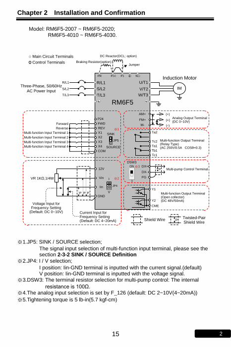
※1.JP5: SINK / SOURCE selection;
The signal input selection of multi-function input terminal, please see the section 2-3-2 SINK / SOURCE Definition
※2.JP4: I / V selection;
I position: Iin-GND terminal is inputted with the current signal.(default) V position: Iin-GND terminal is inputted with the voltage signal.
※3.DSW3: The terminal resistor selection for multi-pump control: The internal
resistance is 100Ω. ※4.The analog input selection is set by F_126 (default: DC 2~10V(4~20mA))
※5.Tightening torque is 5 lb-in(5.7 kgf-cm)
Chapter 2 Installation and Confirmation
15 2
Model: RM6F5-2007 ~ RM6F5-2020; RM6F5-4010 ~ RM6F5-4030.
RM6F5
IM
SINK
SOURCE
I
V
FWD
REV
X1
X2
X3
X4
12V
Vin
Iin
GND
CME
Y2
Y1
Tc1
Tb1
Ta1
Tc2
Ta2
FM+
AM+
R/L1
S/L2
W/T3
V/T2
U/T1
Shield Wire Twisted-Pair Shield Wire
P
P P P
VR 1KΩ,1/4W
Forward
Reverse
Multi-function Input Terminal 1
Three-Phase, 50/60Hz
AC Power Input
Induction Motor
(-)
(+)
(+)
Multi-function Output Terminal(Relay Type)(AC 250V/0.5A COSθ=0.3)
Multi-function Output Terminal(Open collector)(DC 48V/50mA)
Main Circuit Terminals
Control Terminals
※2
T/L3
M-
Analog Output Terminal (DC 0~10V)
※1
COM
R/L1
S/L2
Current Input for Frequency Setting(Default: DC 4~20mA)
Voltage Input for Frequency Setting
(Default: DC 0~10V)
JP4
Multi-pump Control TerminalPDX+
DX-
FG
P24
JP5
ON
1
DSW3
Multi-function Input Terminal 2
Multi-function Input Terminal 3
Multi-function Input Terminal 4
T/L3
※3
N
Braking Resistor(option)Jumper
P( )+PR P1
DC Reactor(DCL; option)
※1.JP5: SINK / SOURCE selection;
The signal input selection of multi-function input terminal, please see the section 2-3-2 SINK / SOURCE Definition
※2.JP4: I / V selection;
I position: Iin-GND terminal is inputted with the current signal.(default) V position: Iin-GND terminal is inputted with the voltage signal.
※3.DSW3: The terminal resistor selection for multi-pump control: The internal
resistance is 100Ω. ※4.The analog input selection is set by F_126 (default: DC 2~10V(4~20mA))
※5.Tightening torque is 5 lb-in(5.7 kgf-cm)

Chapter 2 Installation and Confirmation
16 2
Model: RM6F5-2025 ~ RM6F5-2100; RM6F5-4040 ~ RM6F5-4150
RM6F5
IM
SINK
SOURCE
I
V
FWD
REV
X1
X2
X3
X4
12V
Vin
Iin
GND
CME
Y2
Y1
Tc1
Tb1
Ta1
Tc2
Ta2
FM+
AM+
R/L1
S/L2
W/T3
V/T2
PE
U/T1
P P1 NӨ
Shielded
WireTwisted-Pair
Shielded WireP
P P P
VR 1KΩ,1/4W
Forward
Reverse
Multi-function Input Terminal 1
Three-Phase,
50/60Hz AC
Power Input
Induction Motor
(-)
(+)
(+)
Multi-function Output Terminal(Relay Type)(AC 250V/0.5A COSθ=0.3)
Multi-function Output Terminal(Open collector)(DC 48V/50mA)
Main Circuit Terminals
Control Terminals
※2
T/L3
M-
Analog Output Terminal (DC 0~10V)
※1
COM
R/L1
S/L2
Current Input for Frequency Setting(Default: DC 4~20mA)
Voltage Input for Frequency Setting
(Default: DC 0~10V)
JP4
Multi-pump Control TerminalPDX+
DX-
FG
P24
JP5
ON
1
DSW3
Multi-function Input Terminal 2
Multi-function Input Terminal 3
Multi-function Input Terminal 4
PE
T/L3
※3
Jumper
+
※1.JP5: SINK / SOURCE selection;
The signal input selection of multi-function input terminal, please see the section 2-3-2 SINK / SOURCE Definition
※2.JP4: I / V selection;
I position: Iin-GND terminal is inputted with the current signal. (default) V position: Iin-GND terminal is inputted with the voltage signal.
※3.DSW3: The terminal resistor selection for multi-pump control: The internal
resistance is 100Ω.
※4.The analog input selection is set by F_126 (default: DC 2~10V(4~20mA))
※5.Tightening torque is 5 lb-in(5.7 kgf-cm)

Chapter 2 Installation and Confirmation
17 2
Model: RM6F5-2125 ~ RM6F5-2250; RM6F5-4175 ~ RM6F5-4700
RM6F5
IM
SINK
SOURCE
I
V
FWD
REV
X1
X2
X3
X4
12V
Vin
Iin
GND
CME
Y2
Y1
Tc1
Tb1
Ta1
Tc2
Ta2
FM+
AM+
R/L1
S/L2
W/T3
V/T2
PE
U/T1
P1 P1 NӨ
Shielded
WireTwisted-Pair
Shielded WireP
P P P
VR 1KΩ,1/4W
Forward
Reverse
Multi-function Input Terminal 1
Three-Phase,
50/60Hz AC
Power Input
Induction Motor
(-)
(+)
(+)
Multi-function Output Terminal(Relay Type)(AC 250V/0.5A COSθ=0.3)
Multi-function Output Terminal(Open collector)(DC 48V/50mA)
Main Circuit Terminals
Control Terminals
※2
T/L3
M-
Analog Output Terminal (DC 0~10V)
※1
COM
Current Input for Frequency Setting(Default: DC 4~20mA)
Voltage Input for Frequency Setting
(Default: DC 0~10V)
JP4
Multi-pump Control TerminalPDX+
DX-
FG
P24
JP5
ON
1
DSW3
Multi-function Input Terminal 2
Multi-function Input Terminal 3
Multi-function Input Terminal 4
PE
R/L1
S/L2
T/L3
DCL
※4
ACL
Jumper
※4
※3
+
※1.JP5: SINK / SOURCE selection;
The signal input selection of multi-function input terminal, please see the section 2-3-2 SINK / SOURCE Definition
※2.JP4: I / V selection;
I position: Iin-GND terminal is inputted with the current signal.(default) V position: Iin-GND terminal is inputted with the voltage signal.
※3.DSW3: The terminal resistor selection for multi-pump control: The internal
resistance is 100Ω.
※4.125HP above drives: AC reactor (ACL) is the standard accessory;
200HP above drives: DC reactor (DCL) is the standard accessory. Please remove the jumper between P1 and P terminal, when connecting the external DC reactor (DCL). Do Not remove the jumper, when DC reactor (DCL) does not be connected.
※5.The analog input selection is set by F_126 (default: DC 2~10V(4~20mA))
※6.Tightening torque is 6.9 lb-in(8 kgf-cm)

Chapter 2 Installation and Confirmation
18 2
2-3-2 SINK / SOURCE Definition There are two ways of connection for multi-function input terminals:
SINK
SOURCE
SINK (NPN) logic
X1~X4
COM
FWD
REV
Drive
+24V
0V
SINK
SOURCE
SOURCE (PNP) logic
COM
Drive
+24V
(a) Jumper at 1,2 position; SINK mode (b) Jumper at 2,3 position; SOURCE mode
X1~X4
FWD
REV
0V 0V
12
3
12
3
Figure(a) and (b) show two examples by using a switch to control X1 to X4, FWD, or REV terminals with sink or source mode.
2-3-3 Using a PLC Circuit
There are two ways of connection for multi-function input terminals by PLC circuit:
SINK (NPN) logic
X1~X4
COM
FWD
REV
Drive
+24V
0V
SOURCE (PNP) logic
X1~X4
COM
FWD
REV
Drive
+24V
Jumper at 1,2 position; SINK mode (b) Jumper at 2,3 position; SOURCE mode
PLC(NPN) PLC(PNP)
0V 0V
SINK
SOURCE
SINK
SOURCE
12
3
12
3
Figure(a) and (b) show two examples by using PLC to control X1 to X4, FWD, or REV terminals with sink or source mode.

Chapter 2 Installation and Confirmation
19 2
2-3-4 Description of Terminals
a. Main Circuit Terminals
Type Symbol Function Description
Power Source
R,S,T (L1,L2,L3)
AC power source input
terminals
Three-phase; sinusoidal power source input terminal.
A○+EA, NA○-E
DC power source input
terminals
External DC power source terminal. ※Only 2007~2020,4010~4030 models
have the terminal.
Motor U,V,W
(T1,T2,T3)
Drive outputs to motor terminals
Output three-phase variable frequency and voltage to motor.
Power and
Braking
P(+), NA○-E
Dynamic brake unit terminal
The terminals can connect to dynamic braking unit (option).
PA○+EA, NA○-E
P, N
P, PR
External braking resistor
terminal
The terminals can connect to external brake resistor (option).
P(+), PR
PA○+EA, PR
P(+), P1 External reactor terminal
The terminal can connect to DC reactor (DCL) for improving power factor. The default setting is connected by a jumper. PA○+E
A, P1
Grounding PE Grounding
terminal
The grounding method must compliance with the NEC standard or local electrical code.

Chapter 2 Installation and Confirmation
20 2
b. Main Circuit Connection
(1)
NSG
R T P VRP U WGrounding
MCCB
Resistor
Motor
Grounding
G
Model number Terminal
screw size
Tightening torque
lb-in (kgf-cm)
Grounding terminal
size
Tightening torque
lb-in (kgf-cm)
RM6F5-______: 2001, 2002, 2003, 2005; 4001, 4002, 4003, 4005, 4007
M4 13.8 (15) M4 13.8 (15)
(2)
Grounding
MCCB
Grounding
Resistor
+
-
Motor
Jumper
Model number Terminal
screw size
Tightening torque
lb-in (kgf-cm)
Grounding terminal
size
Tightening torque
lb-in (kgf-cm)
RM6F5-______: 2007, 2010, 2015, 2020; 4010, 4015, 4020, 4025, 4030
M5 20.8 (24) M4 13.8 (15)

Chapter 2 Installation and Confirmation
21 2
(3)
EPP1
MCCBMotor
Grounding
Jumper
EP
Grounding/L1R
/L2 /L3S T V
/T2/T1U
/T3WN
+P
-
Model number Terminal
screw size
Tightening torque
lb-in (kgf-cm)
Grounding terminal
size
Tightening torque
lb-in (kgf-cm)
RM6F5-______: 2025, 2030, 2040, 2050 4040, 4050, 4060, 4075
M6 69.4 (80) M5 20.8 (24)
(4)
PE EP
Grounding
MCCB
Motor
Grounding
TS/L3/L2
R/L1
W/T3
U/T1 /T2
V-N P
+P1
Model number Terminal
screw size
Tightening torque
lb-in (kgf-cm)
Grounding terminal
size
Tightening torque
lb-in (kgf-cm)
RM6F5-______: 2060, 2075, 2100 4100, 4125, 4150
M8 104 (120) M8 104 (120)

Chapter 2 Installation and Confirmation
22 2
(5)
PEEP
Grounding
Motor
Grounding
Resistor
ACL
DBU
DCL
/L1R TS
/L2 /L3P1
/T3VU
/T1 /T2W N
-P+
MCCB
Model number Terminal
screw size
Tightening torque
lb-in (kgf-cm)
Grounding terminal
size
Tightening torque
lb-in (kgf-cm)
RM6F5-______: 2125, 2150, 2200, 2250; 4175, 4200, 4250, 4300, 4350, 4420, 4500, 4600, 4700
M12 347 (400) M8 104 (120)
※Be cautious of the electrodes of DBU when connecting to PA○+EA, NA○-E
A terminals of drive to
avoid any possible damages to drive.

Chapter 2 Installation and Confirmation
23 2
c. Voltage Selection Board of Cooling Fan
※RM6F5-4100 above models have the voltage selection board shown in above
figure when removing the main circuit terminal cover of the drive. Please carefully select the jumper position according to the power source (actual power voltage level) to avoid the burnout of the fan or the overheating of the drive. (EX: When the power source is 460V, to select the position from 380V to 460V)
d. Control Terminals
Type Symbol Function Description
Contr
ol circuit t
erm
inal
Contr
ol pow
er P24
Power terminal; Control device usage
Output DC+24V; Maximum supplied current is 50mA.
P12/12V Output DC+12V; Maximum supplied current is 20mA.
GND Common terminal for analog input control
Grounding terminal for control power (P12/12V,P24) and analog input terminal (Vin, Iin).
Input te
rmin
als
FWD Forward command
terminal Connect the FWD and COM terminals for forward operation. (F_001=0,1,2)
REV Reverse command
terminal Connect the REV and COM terminals for reverse operation. (F_001=0,1,2)
X1 Multi-function input
terminal 1 ․Connect the X1 and COM terminals and
set the function F_052.
X2 Multi-function input
terminal 2 ․Connect the X2 and COM terminals and
set the function F_053.
X3 Multi-function input
terminal 3 ․Connect the X3 and COM terminals and
set the function F_054.
X4 Multi-function input
terminal 4 ․Connect the X4 and COM terminals and
set the function F_055.
COM Input common
terminal The common of input control signal terminals. (FWD, REV and X1 ~ X4)
Vin Analog input terminal Input range: DC 0~10V。

Chapter 2 Installation and Confirmation
24 2
Type Symbol Function Description
Iin Analog input terminal
․Input signal selection
JP4: I position (current signal) JP4: V position (voltage signal)
․Input range: DC 4~20mA (2~10V) or
DC 0~20mA (0~10V)
․The function is set by F_126.
Contr
ol circuit t
erm
inal
Outp
ut te
rmin
als
FM+ AM+
Analog output terminal
․Voltage meter with 10V full scale spec.
(meter impedance: 10KΩ above)
․Maximum output current: 1mA
M- (GND)
Common of analog output terminals
Common of analog output terminals.
Ta1
Multi-function output terminals
(relay type)
․N.O (form a contact); The function is set by F_060
․Capacity: AC250V, 0.5AMax, cosθ=0.3
Tb1 ․N.C (form b contact); The function is set
by F_060 ․Capacity: AC250V, 0.5AMax, cosθ=0.3
Tc1 Common terminal for Ta1,Tb1.
Ta2
․N.O (form a contact); The function is set by F_061.
․Capacity: AC250V, 0.5AMax, cosθ=0.3
Tc2 Common terminal for Ta2.
Y1
Multi-function output terminals
(open collector type)
․The function is set by F_058, F_059.
․Capacity: DC48V, 50mAMax Y2
CME Common terminal of Y1, Y2.
FG(A8) Connect the shielded net to FG(A8) and avoid the reflective signal to interfere the signal.
FM_P Reserved
e. Control Terminals and Switch for Communication Application Type Symbol Function Description
Com
munic
atio
n
term
inals
DX+ Multiple pump/ Modbus
communication terminal
․Connect the RM6F5 series drives by
transmission cable, when the drives control multiple pumps.
․Maximum parallel units:2 units DX-
FG Grounding terminal
of signal transmission
Grounding terminal of shielding wire.
Term
inal
resis
tor
DSW3 Terminal resistor
switch
․Switch the DSW3 to “ON” position for first
and last drives, when parallel control the multi-pump system.
․Terminal resistance: 100Ω
Note: The total length of connecting cable can not exceed 500 meters.

Chapter 2 Installation and Confirmation
25 2
f. CN2 / CN3: KP-605 (RJ-45) / Modbus RS-485 Modbus Port
8 1
Type Pin Function Description
Modbus(RS-485)/ KP-605 communication
1 Communication transmission terminal (DX+)
Differential input of RS-485 *Note 1 Modbus (RS-485) communication only uses pin1, 2. 2
Communication transmission terminal (DX-)
3 Power terminal of KP-605(+16V)
Only for KP-605 linking
4 Auto-detect terminal of KP-605
Only for KP-605 linking
5
Reserved Reserved
6
7 Common ports of KP-605 power(0V)
Only for KP-605 linking
8
Note 1: The terminal resistor(100Ω) selection is set by DSW1(Default setting: ON)
Note 2: When using multiple sets of drive, connect all the DX+, DX- terminals of each drive by
series, and connect the shielded net of the connection wire to FG terminal.
Note 3: The function of terminal resistor is to terminate the electric signal and avoid the reflective signal to interfere the signal. Switch DSW1 to “ON” position of the first and last device and switch to “1” position for other drives. The default value is “ON” position.
Note 4: The cable length from the controllers(PC, PLC) to the last drive cannot exceed 500m.
Note 5: Max. controller number are 31 sets.

Chapter 2 Installation and Confirmation
26 2
2-3-5 Control Board
(1) RM6F5-2001 ~ RM6F5-2005;
RM6F5-4001 ~ RM6F5-4007
Tb1
Y2
CME
FWD Y1COMREV24VX4
SOURCE
3
2
1
COMX3 X2 X1 FM_P
JP5
SINK
SINK
SOURCE
JP5
SOURCE
TB1
SOURCE
SINK
SINK
TB312V AM+FM+
CN1
5
M-GNDVin IinV
I
DX+ DX- FG Tc1 Ta1
1
JP4
JP1
JP4
I mode V mode
DSW31
ON
CN3
GFD
TB2
Ta2Tc2
CN1: External indicator (DM-501) socket.
CN3: Digital keypad (KP-605) RJ-45 socket / RS-485 communication interface (choose one of the two options)
TB1: Input/Output terminals.
TB2: Multi-function output terminals (relay type).
TB3: Connection terminals for multi-pump control/RS-485 communication interface. (choose one of the two options)
JP1: Input impedance selection of Iin (close: 250Ω ; open: 500Ω); Default: close.
JP4: Input signal type selection of Iin (voltage/current). Default: current
JP5: SINK/SOURCE mode selection of X1 to X4, FWD or REV (refer to page 18).
Default: SINK
DSW3: Terminal resistor switch (ON: enable; 1: disable).

Chapter 2 Installation and Confirmation
27 2
(2)RM6F5-2007 ~ RM6F5-2250;
RM6F5-4007 ~ RM6F5-4700
CME
JP4
V mode
JP4
FM+
M-
AM+
FG
Vin12V
Y1
TB1
DX
-T
B3
DS
W3
FG
1
ON
DX
+
V
I
JP5
3
SINK
2
1
SOURCE
I mode
JP4 JP1
CN
1
51
CN2
X3X1
IinGND
Y2
FWD
FM_P
REVCOM
COM
P24
X2
SINK
SOURCE
SOURCE
SOURCE
JP5
Tb1
Ta2X4
Ta1
Tc2
Tc1
SINK
SINK
JP5
GFD
CN1: External indicator (DM-501) socket.
CN2: Digital keypad (KP-605) RJ-45 socket / RS-485 communication interface (choose one of the two options)
TB1: Input/Output terminals.
TB3: Connection terminals for multi-pump control / RS-485 communication interface (choose one of the two options)
JP1: Input impedance selection of Iin (close: 250Ω ; open: 500Ω); Default: close.
JP4: Input signal type selection of Iin (voltage/current). Default: current
JP5: SINK/SOURCE mode selection of X1 to X4, FWD or REV (refer to page 19).
Default: SINK
DSW3: Terminal resistor switch (ON: enable; 1: disable).

Chapter 2 Installation and Confirmation
28 2
2-3-6 Wiring Cautions and Specifications a. Wiring connection between drive and motor due to the variance of the
rated power causes the variance of current leakage. The setting of the switching frequency, rated power, and cable length is listed in the below table.
Cable length Rated power
10m 20m 30m 50m 100m 100m above
1/2~5HP 10KHz 7.5KHz 5KHz 2.5KHz 800Hz 800Hz
7.5~10HP 10KHz 7.5KHz 5KHz 2.5KHz 800Hz 800Hz
15~30HP 7.5KHz 5KHz 2.5KHz 2.5KHz 800Hz 800Hz
40~75HP 5KHz 5KHz 2.5KHz 2.5KHz 800Hz 800Hz
100~700HP 2.5KHz 2.5KHz 2.5KHz 800Hz 800Hz 800Hz
The setting of switching frequency is determined by F_081
b.The wiring length between drive and motor must keep as short as possible. The parasitic capacitance effect is minor within 10 meters. The drive should install an AC reactor (ACL) on the side of drive output terminals U/T1,V/T2,W/T3 and decrease the switching frequency if the wiring length is over 30m.
c. If the altitude over than 1000m , The relationship between drive’s rated current and altitude are shown as below figure.
Altitude (m)60%
0 1000 2000 3000 4000
Percentage
of the rated
current of
drive70%
90%
80%
100%
d.Recommend wire size and Molded Case Circuit Breaker(MCCB)
F_081
=0
Switching frequency
800Hz 1. Do Not adjust the setting value of switching frequency (F_081) of 75HP above drives while the drive is running.
2. Do Not adjust the setting value of switching frequency (F_081) of 75HP above drives while the drive is running.
=1 2.5KHz
=2 5KHz
=3 7.5KHz
=4 10KHz
=5 12.5KHz
=6 15KHz

Chapter 2 Installation and Confirmation
29 2
Three-Phase 200V Series
Model number
RM6F5-____
Input
Current
(A)
MCCB
(A)
Input wire size
(R/L1,S/L2,T/L3)
(mm²)
Control circuit wire
size
(mm²)
Grounding wire size
(mm²)
2001 5 10 2.0
0.75~1.25
2.0
2002 8 15 2.0 2.0
2003 12 20 2.0 2.0
2005 18 30 3.5 3.5
2007 30 50 5.5 5.5
2010 41 75 8 8
2015 55 100 14 14
2020 66 125 22 22
2025 85 150 22 22
2030 103 175 38 38
2040 128 200 60 60
2050 176 300 80 80
2060 200 350 100 100
2075 240 400 60*2 60*2
2100 280 500 100*2 100*2
2125 330 500 150*2 150*2
2150 380 600 200*2 200*2
2200 550 800 200*2 200*2
2250 660 1000 250*2 250*2

Chapter 2 Installation and Confirmation
30 2
Three-Phase 400V Series
Model number
RM6F5-____
Input Current
(A)
MCCB
(A)
Input wire size
(R/L1,S/L2,T/L3)
(mm²)
Control circuit wire size
(mm²)
Grounding wire size
(mm²)
4001 3 5 2.0
0.75~1.25
2.0
4002 4.2 10 2.0 2.0
4003 5.8 15 2.0 2.0
4005 9.6 20 3.5 3.5
4007 13 30 3.5 3.5
4010 20 30 5.5 5.5
4015 25 40 8.0 8.0
4020 38 75 8.0 8.0
4025 42 75 14 14
4030 52 100 22 22
4040 64 125 22 22
4050 84 150 22 22
4060 100 175 38 38
4075 130 200 60 60
4100 155 250 80 80
4125 177 300 100 100
4150 196 300 60*2 60*2
4175 217 350 100*2 100*2
4200 282 400 100*2 100*2
4250 355 600 150*2 150*2
4300 385 600 200*2 200*2
4350 440 700 250*2 250*2
4420 540 800 250*2 250*2
4500 650 1000 325*2 325*2
4600 800 1200 325*2 325*2
4700 900 1200 325*2 325*2
Cautions: i. Please refer to the local electrical code with respect to the wiring(the loading
and continuity, the wire capability for the current and temperature, the length of wiring, and the surrounding temperature must be all considered in order to add or reduce the size of the wire).
ii. Please use the cable that is suitable for 600V, 75℃ above. iii. This table is only for reference.

Chapter 2 Installation and Confirmation
31 2
2-4 Wiring Diagram and Setting for Single-pump and Multi-pump Applications
2-4-1 Single Pump Control
Drive #0
I
V
Pressure
transducer
JP4
ON
DSW3
1
P24 Iin DX+ DX- FG
JP1
– +
Drive #0
Setting Description Content
Func.
F_015 (Selection of Parallel Control Mode)
=1(Single pump)
F_016 (Set Drive’s No. in Parallel Control)
=0(Drive#0)
JP1/JP4
Selection
JP1 Impedance selection of Iin
(Open﹕500Ω;Close﹕250Ω) Open
JP4 Input signal type selection of Iin
(Voltage/Current) I position
Terminal Resistor Switch
DSW3 ON position

Chapter 2 Installation and Confirmation
32 2
2-4-2 Dual & Multi-pump Control (E-mode、F-mode、M-mode)
Wiring 1 (standard wiring)
Drive #0
- +
Drive #1
- +
Drive#2
- +
ON
I
V
I
V
I
V
Pressure
transducer
Drive#3
- +
I
V
DSW3JP4 JP4 JP4 JP4
1
ON
DSW3
1
ON
DSW3
1
ON
DSW3
1
P24 Iin DX+ DX- FG P24 Iin DX+ DX- FG P24 Iin DX+ DX- FGP24 Iin DX+ DX- FG
JP1 JP1 JP1 JP1
Pressure
transducer
Pressure
transducer
Pressure
transducer
※( Dotted line: more than three pumps according customer requirement to set up )
Drive #0
Setting Description Content
Func.
F_015 (Selection of Parallel Control Mode)
=2 (E-mode) or
=3 (F-mode) or
=4 (M-mode)
F_016 (Set Drive’s No. in Parallel Control)
=0(Drive#0)
JP1/JP4
Selection
JP1 Impedence selection of Iin
(Open﹕500Ω;Close﹕250Ω) Open
JP4 Input signal type selection of Iin
(Voltage/Current) I position
Terminal Resistor Switch
DSW3 ON position
Auxiliary Drive #1(#2,#3)
Setting Description Content
Func.
F_015 (Selection of Parallel Control
Mode)
=2 (E-mode) or
=3 (F-mode) or
=4 (M-mode)
F_016 (Set Drive’s No. in Parallel Control)
=1
JP1/JP4
Selection
JP1 Impedence selection of Iin
(Open﹕500Ω;Close﹕250Ω) Open
JP4 Input signal type selection of Iin
(Voltage/Current) I position
Terminal Resistor Switch
DSW3 #1, #2: 1 position
#3: ON position
※Note: Dual drive (or multi-drive) uses a set of pressure sensor independently.(Suggest
that using this wiring standard)
Chapter 2 Installation and Confirmation
33 2
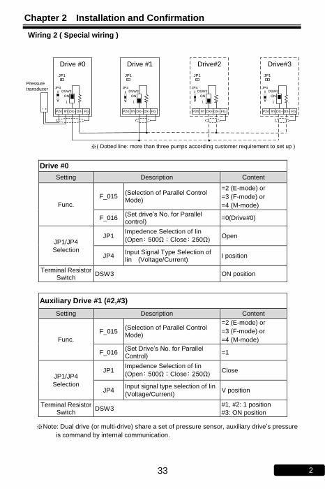
Wiring 2 ( Special wiring )
Drive #0
- +
Drive #1 Drive#2
ON
I
V
I
V
I
V
Pressure
transducer
Drive#3
I
V
DSW3JP4 JP4 JP4 JP4
1
ON
DSW3
1
ON
DSW3
1
ON
DSW3
1
P24 Iin DX+ DX- FG P24 Iin DX+ DX- FG P24 Iin DX+ DX- FGP24 Iin DX+ DX- FG
JP1 JP1 JP1 JP1
※( Dotted line: more than three pumps according customer requirement to set up )
Drive #0
Setting Description Content
Func.
F_015 (Selection of Parallel Control Mode)
=2 (E-mode) or
=3 (F-mode) or
=4 (M-mode)
F_016 (Set drive’s No. for Parallel control)
=0(Drive#0)
JP1/JP4
Selection
JP1 Impedence Selection of Iin
(Open﹕500Ω;Close﹕250Ω) Open
JP4 Input Signal Type Selection of Iin (Voltage/Current)
I position
Terminal Resistor Switch
DSW3 ON position
Auxiliary Drive #1 (#2,#3)
Setting Description Content
Func.
F_015 (Selection of Parallel Control Mode)
=2 (E-mode) or
=3 (F-mode) or
=4 (M-mode)
F_016 (Set Drive’s No. for Parallel Control)
=1
JP1/JP4
Selection
JP1 Impedence Selection of Iin
(Open﹕500Ω;Close﹕250Ω) Close
JP4 Input signal type selection of Iin
(Voltage/Current) V position
Terminal Resistor Switch
DSW3 #1, #2: 1 position
#3: ON position
※Note: Dual drive (or multi-drive) share a set of pressure sensor, auxiliary drive’s pressure
is command by internal communication.

Chapter 2 Installation and Confirmation
34 2
Wiring 3 ( Special wiring )
Drive #0
- +
Drive #1 Drive #2
ON
I
V
I
V
I
V
Pressure
transducer
Drive#3
I
V
DSW3JP4 JP4 JP4 JP4
1
ON
DSW3
1
ON
DSW3
1
ON
DSW3
1
P24 Iin DX+ DX- FG P24 Iin DX+ DX- FG P24 Iin DX+ DX- FGP24 Iin DX+ DX- FG
JP1 JP1 JP1 JP1
※( Dotted line: more than three pumps according customer requirement to set up )
Drive #0
Setting Description Content
Func.
F_015 (Selection of Parallel Control Mode)
=2 (E-mode) or
=3 (F-mode) or
=4 (M-mode)
F_016 (Set Drive’s No. for Parallel Control)
=0(Drive#0)
JP1/JP4
Selection
JP1 Impedence selection of Iin
(Open﹕500Ω;Close﹕250Ω) Open
JP4 Input signal type selection of Iin
(Voltage/Current) I position
Terminal Resistor Switch
DSW3 ON position
Auxiliary Drive #1 (#2,#3)
Setting Description Content
Func.
F_015 (Selection of Parallel Control Mode)
=2 (E-mode) or
=3 (F-mode) or
=4 (M-mode)
F_016 (Set Drive’s No. for Parallel Cntrol)
=1
JP1/JP4
Selection
JP1 Impedence selection of Iin
(Open﹕500Ω;Close﹕250Ω) Close
JP4 Input signal type selection of Iin
(Voltage/Current) V position
Terminal Resistor Switch
DSW3 #1, #2: 1 position
#3: ON position
※Note: Dual drive (or multi-drive) independently use a set of pressure sensor and parallel
pressure signal. If the drive(#0) error occurs, auxiliary drive (#1,#2,#3) will control pressure signal.

Chapter 2 Installation and Confirmation
35 2
2-4-3 Multi-pump Use of ACE-S12 Signal Distributor Control
Iin GND R S T
U V W
Drive#1
R S T
U V W
R S T
U V W
R S T
U V W
NFB NFB NFB NFB
Meter
PEPE PE PE
I
V
I
V
I
V
I
V
L N
ACE - S12
DX+
DX-
DX+
DX-
DX+
DX-
DX+
DX-
PT2 PT1
泵浦馬達泵浦馬達泵浦馬達泵浦馬達
P P P
隔離線 雙絞隔離線P
Iin GND Iin GND Iin GND
AO1+ AO1- FG AO2+ AO2- FG AO3+ AO3- FG AO4+ AO4- FG
AO5+ AO5- FG 24V Iin G24 FG 24V Iin G24 FG
NFB
Drive#2Drive#0 Drive#3
Note: 1. ACE-S12 signal distributor can be made input current signal covert into DC voltage, meanwhile, distributing five set of output (output can switch current DC:4~20mA or DC: 0~10V signal). To reach constant pressure, output signal will distribute the signal to drives(maximum: 4 drives). 2. Wiring: First, pressure sensor connect PT1 , and alternative pressure sensor connect PT2.
Pressure sensor
Isolated Line Twisted Isolated Lines
Pump motor
Pump motor
Pump motor
Pump motor
Three phase AC power
Single 110/220 Vac

Chapter 2 Installation and Confirmation
36 2
2-4-4 Multi-pump Control (S-mode Application)
Wiring (standard wiring)
Tc2
Ta2
Tc1
Ta1
Auxiliary
Pump 1
U/T1 W/T3V/T2
X4
X3
X2
X1
R/L1 T/L3S/L2
MC1 MC2
OL1 OL2
COM
SW1
SW2
Lead
pump
NLR/L1 T/L3S/L2
Auxiliary
Pump 2
Drive
(S-mode)
Iin
P24
- +
Drive (S-mode)
Setting Description Setting Content
Func.
F_015 Selection of Control Mode for Parallel Control
=5 (S-mode)
F_016 Set Drive’s No. for Parallel Control =0(lead drive)
F_052 Multi-input terminal setting (X1) =17(multi-pump start
command 1)
F_053 Multi-input terminal setting (X2) =18(multi-pump start
command 2)
F_054 Multi-input terminal setting (X3) =19(multi-pump error
command 1)
F_055 Multi-input terminal setting X4) =20(multi-pump error
command 2)
F_060 Multi-output terminal setting (Ta1,Tb1) =15(multi-pump start
1detection)
F_061 Multi-output terminal setting (Ta2/Tc2) =16(multi-pump start
2 detection)
JP1/JP4
Selection
JP1 Input impedence selection of Iin
(Open﹕500Ω;Close﹕250Ω) open
JP4 Input signal type selection of Iin
(Voltage/Current) I position
Termination Resistors
DSW3 ON position
Pressure
transducer

Chapter 2 Installation and Confirmation
37
2
2
No Text on This Page

Chapter 3 The Setting of Keypad
38 3
Chapter 3 The Setting of Keypad
3-1 Functions of Keypad (KP-605)
3-1-1 Indicators of Keypad
Symbol Name Description
KEYPAD
Lead drive/
communication indicator
1.Indicate the lead drive.
2.In multi-pump control modes, the indicator
will be off, when pressing OFF
RESET .
3. Parallel connection error(flashing)
SV Setting pressure
indicator Indicate the setting pressure
PV Actual pressure
indicator Indicate the actual pressure
Running Operation indicator
Blinking: Under acceleration or deceleration
ON: Constant speed
OFF: Stop
HAND
ON
Manual mode/
standby indicator
ON: Manual mode/Drive is standing by.
OFF: Auto mode/ Stop
AUTO
ON
Auto constant pressure/ standby indicator
ON: Auto constant pressure mode/Drive is standing by.
OFF: Manual mode/Drive stops.

Chapter 3 The Setting of Keypad
39 3
Running
3-1-2 Keys of Keypad
Symbol Name Description
PROG
Function key
1.Enter the function setting mode
2.Back to the monitor mode
FUN
DATA
Function/
Parameter key
1.Enter the parameter setting mode
2.Back to the function setting mode
3.Switch the monitor mode
HAND
ON
Manual control key
Starting inverter to enter manual control mode.( Auto constant pressure control)
UP key
Change functions and parameters
DOWN key
AUTO
ON
Auto constant pressure control
Starting the inverter to auto constant pressure mode.
OFF
RESET
Off/Reset key
1.Drive stops (Cut off the output signal of U/T1,V/T2,W/T3 terminals)
2.Error reset.
Note:
KP-605 cables: Only used with 8-pin telephone cable (flat) or Cat.5e cable (AMP)
8-pin telephone cable: The cable length must be within 5 meters. Compared Cat. 5e cable (AMP): The cable length can be over 5 meters (the longest length is
100 meters)
PROG key
FUN/DATA key
HAND ON key
Operation key
UP/Down key
AUTO ON key
OFF/RESET key
POT knob

Chapter 3 The Setting of Keypad
40 3
3-2 The Operation of Keypad(KP-605) and Monitor Mode
3-2-1 Operation of Keypad The operation of the digital keypad includes fault messages and three modes. The switching methods are shown as below figure:
Monitor mode Function setting mode Parameter setting mode
Fault message
FUN
DATA
PROGFUN
DATA
OFF
RESET
PROG
PROG
PVRunning
SV
KEYPAD
PVRunning
SV
KEYPAD
PVRunning
SV
KEYPAD
PVRunning
SV
KEYPAD
The operation steps are shown as below table (by default setting)
Operation Steps Display
1.Start the drive and enter the monitor mode. SV
KEYPAD
PVRunning
2.Press PROG key and enter the function setting mode. SV
KEYPAD
PVRunning
3.Press FUN
DATA key and enter the parameter setting mode. SV
KEYPAD
PVRunning
4.Press FUN
DATA key and return to the function setting mode. SV
KEYPAD
PVRunning
5.Press PROG key and return to the monitor mode. SV
KEYPAD
PVRunning
Error message display:
Operation Steps Display
The fault message displayed during the drive operation SV
KEYPAD
PVRunning
1.After the error is troubleshooted, press OFF
RESET key to
clear the fault and return to the monitor mode. SV
KEYPAD
PVRunning

Chapter 3 The Setting of Keypad
41 3
3-2-2 Description of Monitor Mode
There are seven displays can be selected in the monitor mode. Press FUN
DATA to
switch the display in accordance with below sequence under monitor mode. User can determine one of seven displays as the main display from function F_006 (Selection of Main Display). Please refer to the following illustrations:
Display 1
(Output Frequency)
Display 2
(Frequency Command)
Display 3
(Output Voltage)
Display 5
(Output Current)
Display 6(Terminal Status and
Heat Sink Temperature)
Monitor
Mode
FUN
DATA
FUN
DATA
PVRunningSV
KEYPAD
PVRunningSV
KEYPAD
PVRunningSV
KEYPAD
PVRunningSV
KEYPAD
PVRunningSV
KEYPAD
PVRunningSV
KEYPAD
FUN
DATA
FUN
DATA
Display 4
(DC Bus
Voltage)
PVRunningSV
KEYPAD
PVRunningSV
KEYPAD
FUN
DATA
FUN
DATA
FUN
DATA
Display 8( Actual Pressure)
Display 7
Main Display
(SV & PV)
FUN
DATA
The descriptions of monitor modes are shown as below table (by default setting)
Name Description Display
Display 1 Output frequency SV
KEYPAD
PVRunning
Display 2 Frequency command SV
KEYPAD
PVRunning
Display 3 Output voltage SV
KEYPAD
PVRunning
Display 4 DC bus voltage SV
KEYPAD
PVRunning
Display 5 Output current SV
KEYPAD
PVRunning
Display 6 Terminal status and heat sink temperature SV
KEYPAD
PVRunning

Chapter 3 The Setting of Keypad
42 3
Display 7 Setting pressure and actual pressure SV
KEYPAD
PVRunning
Display 8 Actual flow SV
KEYPAD
PVRunning
a. Select one of eight displays as the main display in accordance with the table of
from F_006 (Selection of Main Display).
b. Determine one of eight displays as the main display according to the application.
When the parameter of function is completed without pressing PROG
key, the drive
will automatically switch back to the main display after 3 minute.
c. The significance of seven-segment displays of Display 6 (Terminal status and heat sink temperature) is shown as below figure.
X4X3
REVX1
Y2Y1
Ta2Ta1/Tb1
X2FWD
Heat sink temperature
Left Display Right Display
*grey-color digit in above figure means blinking
Right display: The temperature of heat sink. Left display:
1.Blinking number “6”: Indicate the Display 6 2.Horizontal line of seven-segment displays: X1~X4, FWD, REV terminals
Vertical line of seven-segment displays: Y1, Y2, Ta1, Tb1, Ta2 terminals
The significance of seven-segment displays
Display Terminal Description Display Terminal Description
FWD
FWD terminal is
active X4
X4 terminal is active
REV
REV terminal is
active Ta1,Tb1
Ta1,Tb1 terminal is
active
X1
X1 terminal is active
Ta2 Ta2 terminal is
active
X2
X2 terminal is active
Y1 Y1 terminal is
active
X3
X3 terminal is active
Y2 Y2 terminal is
active

Chapter 3 The Setting of Keypad
43 3
3-2-3 Description of Function Setting Mode
In function setting mode, there are 194 functions (F_000 ~ F_194) can be selected for RM6F5 series drive, (F_116=1) and the setting steps are as below:
Operation Steps Display
1.In the monitor mode, press PROG key to enter
function setting mode. SV
KEYPAD
PVRunning
2.Press key to increase the function number. SV
KEYPAD
PVRunning
3.Press key to decrease the function number. SV
KEYPAD
PVRunning
3-2-4 Description of Parameter Setting Mode
In parameter setting mode, the setting range for every function is shown in Chapter 4 - Parameter List.
Operation Steps Display
1.Select F_001 (Start Command Selection) as the example.
SV
KEYPAD
PVRunning
2.Press FUN
DATA key to enter parameter setting mode. SV
KEYPAD
PVRunning
3.Press key to decrease the value of F_001
from 3 (default value) to 2. SV
KEYPAD
PVRunning
4.Press FUN
DATA key and return to function setting mode. SV
KEYPAD
PVRunning
3-2-5 Operation at Monitor Mode In monitor mode, user can change the value of setting pressure (SV). The operation steps are shown as below. (by default display)
Operation Steps Display
1.In monitor mode, the display of setting pressure(SV) and practical pressure(PV) as right figure.
SV
KEYPAD
PVRunning
2.Press key for several times or keep pressing
the to increase the setting value of pressure to
2.5. SV
KEYPAD
PVRunning
3.After completing the setting, press FUN
DATA key within 5 seconds (the setting
value is under blinking status) to save the setting value or waiting the drive automatically save the setting value.

Chapter 3 The Setting of Keypad
44 3
3-2-6 Parameter Copy; Restore Default Value; Save/Restore Setting Value
a. Parameter Copy: Including writing and readout functions. Parameter settings of two drives can
be copied by “ ” and “ ” functions.
a-1 (Parameter Read Out: Drive parameter Keypad)
Operation steps Display
1.In the monitor mode, press PROG key to enter function
setting mode. SV
KEYPAD
PVRunning
2.Press or key to select the function to
F_194 (Default Setting) and then press FUN
DATA key to
enter parameter setting mode. SV
KEYPAD
PVRunning
3.Press key and then select
parameter and then press FUN
DATA key to execute the
parameter readout. SV
KEYPAD
PVRunning
4.Drive will start to copy the parameters to keypad, and then display the copy process on keypad.
SV
KEYPAD
PVRunning
5.After completing the copy, the keypad will display
message and automatically back to
function setting mode. SV
KEYPAD
PVRunning
a-2 (Parameter Write In: Keypad parameter Drive)
Operation steps Display
1.In the monitor mode, press PROG key to enter function
setting mode. SV
KEYPAD
PVRunning
2.Press or key to select the function to
F_194 (Default Setting) and then press FUN
DATA key to
enter parameter setting mode. SV
KEYPAD
PVRunning
3.Press key and then select
parameter and then press FUN
DATA key to execute the
writing. SV
KEYPAD
PVRunning
4.Keypad will start to copy the parameters to drive, and then display the copy process on keypad.
SV
KEYPAD
PVRunning
5.After completing the copy, the keypad will display
message and automatically back to
function setting mode. SV
KEYPAD
PVRunning

Chapter 3 The Setting of Keypad
45 3
※Do Not execute the copy for different software version, otherwise the
parameters will occur error and the keypad will display
message.
a-3: ( Parameter Copy: Master Slaves)
Except for two methods described above a1 and a2,
It also can use the operation panel of lead drive, through the control wire copy parameter to other auxiliary drive. It allows parameter settings to be easily copied from the drive
Operation steps Display
1. Through the indicator of lead drive (KEAYPAD) to distinguish location of lead drive. When the indicator becomes brighter ,and the inverter represent for the lead drive.
SV
KEYPAD
PVRunning
2. Press PROG key to enter function setting mode. SV
KEYPAD
PVRunning
3. Press or key to select the function to
F_194 (Default Setting) and then press FUN
DATA key to
enter parameter setting mode. SV
KEYPAD
PVRunning
4. Press key to select and then
press FUN
DATA key to copy the parameters.
SV
KEYPAD
PVRunning
5. After completing the copy, the keypad will display
message and automatically back to
function setting mode. SV
KEYPAD
PVRunning
※ When using copy parameter function, please note F_015、F_016、
F_091 parameter content can’t copy to the slave.
b. Restore Default Value:
RM6F5 series drive provide 5 default values for using. User can according to the demand to restore default values.
(Restore the default value of drive for 60Hz)
(Restore the default value of single pump constant pressure control
application with 60Hz power source)
(Restore the default value of multi-pump constant pressure control
application with 60Hz power source)
(Restore the default value of single pump constant pressure control
application with 50Hz power source)
(Restore the default value of multi-pump constant pressure control
(S-mode)application with 60Hz power source)

Chapter 3 The Setting of Keypad
46 3
※Be cautious of the usage of this parameter! This parameter will clear
the saved setting value via parameter.
Select the parameter as an example, and the operation steps as
below:
Operation Steps Display
1.Press or key selecting the function to
F_194 (Default Setting) and then press FUN
DATA key to
enter parameter setting mode.
SV
KEYPAD
PVRunning
2.Press key to select parameter,
and then press FUN
DATA key to execute the restoring. SV
KEYPAD
PVRunning
3.After completing the restoring, the keypad will
display message and back to the
function setting mode. SV
KEYPAD
PVRunning
c . Save / Restore Setting Value:
(Save the setting value)
Operation Steps Display
1.Press or key to select the function to
F_194 (Default Setting) and then press FUN
DATA key to
enter parameter setting mode.
SV
KEYPAD
PVRunning
2.Press key to select parameter,
and then press FUN
DATA key to execute the saving. SV
KEYPAD
PVRunning
3.After completing the saving, the keypad will display
message and back to the function
setting mode. SV
KEYPAD
PVRunning
(Restore the setting value)
Operation Steps Display
1.Press or key to select the function to
F_194 (Default Setting) and then press FUN
DATA key to
enter parameter setting mode.
SV
KEYPAD
PVRunning
2.Press key to select parameter,
and then press FUN
DATA key to execute the restoring. SV
KEYPAD
PVRunning
3.After completing the restoring, the keypad will
display message and back to function
setting mode. SV
KEYPAD
PVRunning
Note: “Restore” parameter is activation when the setting value is saved by “Save” parameter.

Chapter 3 The Setting of Keypad
47 3
No Text on This Page

Chapter 4 Parameter List
48 4
Chapter 4 Parameter List
Func. Name Description Range of Setting
Unit Def50 Page
F_000 Drive
Information
0: Software version (0041-d) 1: Drive model number 2: Drive running hours 3: Drive power supplying time 4: Software checksum code 5: Reserved
─ ─ ─ 64
F_001 Start
Command Selection
Start command Rotation direction
command
0~11 ─ 3 64
0 FWD or REV
terminal FWD or REV
terminal
1 FWD terminal REV terminal
2 Keypad
“AUTO RUN” key
FWD, REV terminal
3 Forward direction
4 Reverse direction
5~7 Reserved Reserved
8 RS-485
Communication interface
RS-485 Communication
interface
9 RS-485
Communication interface
REV terminal
10 FWD termial RS-485
Communication interface
11 Keypad “RUN” key RS-485
Communication interface
F_002 Frequency Command Selection
0: Frequency command by analog signal via terminal.
1: Frequency command by keypad. 2: Pressure command by keypad. 3: Frequency command by RS-485. 4: Pressure command by RS-485.
0~4 ─ 2 68
F_003 Selection of “STOP” key
Validity
0: Start command by terminal, “STOP” key disabled.
1: Start command by terminal, “STOP” key enabled.
0,1 ─ 1 69
F_004
Setting Value (SV)
Selection
0: In the monitor mode, setting value cannot be changed.
1: In the monitor mode, setting value can be changed.
0,1 ─ 1 69
F_005
Auto-Storing of Setting
Value Selection
0: In the monitor mode, setting value auto-storing disable.
1: In the monitor mode, setting value auto-storing after 3 minutes.
0,1 ─ 1 69
F_006 Selection of
Main Display
Select 1 of 8 “monitor modes” as the main display. *Refer to section 3-2-2.
1~8 ─ 7 70

Chapter 4 Parameter List
49 4
Func. Name Description Range of Setting
Unit Def50 Page
F_007 Pressure
Transducer Setting
Set upper limit value of pressure in accordance with pressure transducer specification.(pressure setting value is corresponding to maximum voltage or current.
0.0~160.0 0.1bar 10.0 97
F_008
Maximum Allowabel Operating Pressure
Set the maximum operating pressure value (F_007*F_008) in accordance with the specification of pump.
0~100 1﹪ 100 97
F_009 Starting
Frequency The starting frequency of drive. 0.1~10.0 0.1Hz 0.5 75
F_010 Starting
Voltage
The voltage correspond to the starting
frequency.
0.1~50.0
0.1V
8.0 (Note1)
75 0.1~100.0
12.0 (Note2)
F_011 Base
Frequency The frequency correspond to the base voltage in V/F pattern.
0.1~400.0 0.1Hz 60.0 75
F_012 Base
Voltage The voltage correspond to the base frequency in V/F pattern.
0.1~255.0 0.1V
220.0 (Note1)
75 0.1~510.0
380.0 (Note2)
F_013
Selection of Pump Shift Operation
(Parallel control)
0: Disable.
1: Shift the pump operation arriving the operating time (F_024).
2: Shift the pump operation after a drive stops.
3: Both 1 and 2 enabled.
0~3 ─ 3 100
F_014 Reserved ─
F_015
Control Mode
Selection (Parallel control)
0: Disable the functions related to pump. 1: Single pump application. 2: Multi-pump applications; (E-mode) 3: Multi-pump applications; (F-mode) 4: Multi-pump applications; (M-mode) 5. Multi-pump applications; (S-mode)
0~5 ─ 1 101
F_016
Set Drive’s No. for Parallel Control
Set the individual number for every drive. #0 as the lead drive to command others.
0~3 ─ 0 102
The color as means the function can be set during the operation.
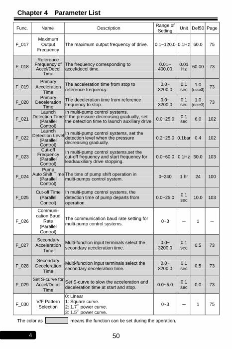
Chapter 4 Parameter List
50 4
Func. Name Description Range of Setting
Unit Def50 Page
F_017 Maximum
Output Frequency
The maximum output frequency of drive. 0.1~120.0 0.1Hz 60.0 75
F_018
Reference Frequency of Accel/Decel
Time
The frequency corresponding to accel/decel time.
0.01~ 400.00
0.01 Hz
60.00 73
F_019 Primary
Acceleration Time
The acceleration time from stop to reference frequency.
0.0~ 3200.0
0.1 sec
1.0 (note3)
73
F_020 Primary
Deceleration Time
The deceleration time from reference frequency to stop.
0.0~ 3200.0
0.1 sec
1.0 (note3)
73
F_021
Launch Detection Time
(Parallel Control)
In multi-pump control systems, If the pressure decreasing gradually, set the detection time to launch auxiliary drive.
0.0~25.0 0.1 sec
6.0 102
F_022
Launch Detection Level
(Parallel Control)
In multi-pump control systems, set the detection level when the pressure decreasing gradually.
0.2~25.0 0.1bar 0.4 102
F_023
Cut-off Frequency (Parallel Control)
In multi-pump control systems,set the cut-off frequency and start frequency for lead/auxiliary drive stopping.
0.0~60.0 0.1Hz 50.0 103
F_024
Pump Auto Shift Time
(Parallel Control)
The time of pump shift operation in multi-pumps control system.
0~240 1 hr 24 100
F_025 Cut-off Time
(Parallel Control)
In multi-pump control systems, the detection time of pump departs from operation.
0.0~25.0 0.1 sec
10.0 103
F_026
Communi- cation Baud
Rate (Parallel Control)
The communication baud rate setting for multi-pump control systems.
0~3 ─ 1 ─
F_027 Secondary
Acceleration Time
Multi-function input terminals select the secondary acceleration time.
0.0~ 3200.0
0.1 sec
0.5 73
F_028 Secondary
Deceleration Time
Multi-function input terminals select the secondary deceleration time.
0.0~ 3200.0
0.1 sec
0.5 73
F_029 Set S-curve for
Accel/Decel Time
Set S-curve to slow the acceleration and deceleration time at start and stop.
0.0~5.0 0.1 sec
0.0 73
F_030 V/F Pattern Selection
0: Linear 1: Square curve. 2: 1.7
th power curve.
3: 1.5th
power curve.
0~3 ─ 1 75
The color as means the function can be set during the operation.

Chapter 4 Parameter List
51 4
Func. Name Description Range of Setting
Unit Def50 Page
F_031 Primary Speed
Jog command
Multi-speed level 3
command
Multi-speed level 2
command
Multi-speed level 1
command
0.00~ 120.00
0.01 Hz
0.00 71
OFF OFF OFF OFF
F_032 Preset Speed
1 OFF OFF OFF ON 20.00 71
F_033 Preset Speed
2 OFF OFF ON OFF 25.00 71
F_034 Preset Speed
3 OFF OFF ON ON 30.00 71
F_035 Preset Speed
4 OFF ON OFF OFF 45.00 71
F_036 Preset Speed
5 OFF ON OFF ON 50.00 71
F_037 Preset Speed
6 OFF ON ON OFF 55.00 71
F_038 Preset Speed
7 OFF ON ON ON 60.00 71
F_039 Jog Speed ON X X X 7.00 71
F_040 Vin Gain Analog input “Vin” gain ratio adjustment. 0.00~ 2.00
0.01 1.00 77
F_041 Vin Bias Analog input “Vin” bias ratio adjustment. -1.00~ 1.00
0.01 0.00 78
F_042 Frequency Upper Limit
The upper limit of output frequency= F_017*F_042 0.00~ 1.00
0.01 1.00 76
F_043 Frequency Lower Limit
The lower limit of output frequency= F_017*F_043 0.00~ 1.00
0.01 0.00 76
F_044 FM+ Analog
Output Signal Selection
0: Output frequency 1: Frequency command 2: Output current 3: “Vin” frequency command 4: “Iin” frequency command
0~4 ─ 0 80
F_045 FM+ Analog Output Gain
Analog output gain ratio adjustment. 0.00~ 2.00
0.01 1.00 81
F_046
Motor Overload Protection
(OL)
0: Motor overload protection: Disabled 1: Motor overload protection: Enabled(OL) 2: Motor overload protection of independent
cooling fans: Enabled(OL)
0~2 ─ 1 82
F_047 Filter Setting
of Analog Frequency
Filter the noise based on analog input signal (F_002=0).
0~255 ─ 20 79
F_048 Motor Rated
Current Set the value according to the motor rated current.
10%~150% of drive rated
current
0.1A
According to the rated
current of motor
82
F_049 Motor
No-Load Current
Current setting according to the motor’s no-load condition.
0~motor rated
current 0.1A
1/3 motor rated
current
82
F_050 Motor Slip
Compensa- tion
According to the load condition, set the motor slip compensation for motor running at the constant speed. (0.0: Off)
-9.9~10.0 0.1H
z 0.0 82
The color as means the function can be set during the operation.

Chapter 4 Parameter List
52 4
Func. Name Description Range of Setting
Unit Def50 Page
F_051 Operation Condition Memory
Record the last status of drive before power off. 0: Enable (F_001=2,3,4) 1: Disable
0,1 ─ 0 94
F_052 Multi-function
Input Terminal X1
=0: Manual control command 1 of M-mode (F_015=4)
±1: Jog command. ±2: Switch of secondary
accel/decel time. ±3: Multi-speed level 1
command ±4: Multi-speed level 2
command ±5: Multi-speed level 3
command ±6: Reset command ±7: External fault command (thr) ±8: Interruption of output
command (bb) ±9: Coast to stop command (Fr) ±10: Speed tracing from the
maximum frequency ±11: Speed tracing from the
setting frequency ±12: Holding command ±13: Under close-loop control
condition (F_103≠0), open-loop selection.
±14: Reset the integrator at close-loop control condition. (F_103≠0)
±15: Stop command. ±16: Analog input source
selection. ±17:Auxiliary Pump start
command 1. ±18: Auxiliary Pump start
command 2. ±19: Auxiliary Pump error
command 1.(P1_OL) ±20: Auxiliary Pump error
command 2.(P2_OL) ±21:Flow sensor input. ±22: Sequential operation
control.
-22 ~ +22
(Note 5) ─
9
83
F_053 Multi-function
Input Terminal X2
=0: Manual control command 2 of M-mode (F_015=4)
13
F_054 Multi-function
Input Terminal X3
=0: Manual control command 3 of M-mode (F_015=4)
1
F_055 Multi-function
Input Terminal X4
=0: Reserved
2
F_056 Reserved ─
F_057 Reserved ─
The color as means the function can be set during the operation.

Chapter 4 Parameter List
53 4
Func. Name Description Range
of Setting
Unit Def50 Page
F_058 Multi-function
Output Terminal (Y1)
0: Disable ±1: Standby detection ±2: Constant speed detection. ±3: Zero speed detection. ±4: Frequency detection. ±5: System overload detection. (OLO) ±6: Stall prevention detection. ±7: Low voltage detection. (LE) ±8: Braking detection. ±9: Restart after instantaneous power
failure detection. ±10: Restart after error condition detection ±11: Error detection. ±12: Overheating warning detection. (Ht) ±13: Over pressure detection. (OP) ±15: Auxiliary pump 1 detection. ±16: Auxiliary pump 2 detection. ±17: Fan detection during operation.
-17~ +17 (Note 5)
─
1
87
F_059 Multi-function
Output Terminal (Y2)
2
F_060
Multi-function Output
Terminal (Ta1,Tb1)
-11
F_061
Multi-function Output
Terminal (Ta2/Tc2)
-3
F_062 Frequency Detection
Range
Set the bandwidth of frequency detection range.
0.0~ 10.0
0.1Hz 2.0 87
F_063 Frequency Detection
Level
Set the frequency detection level of multi-function output terminal.
0.0~ 400.0
0.1Hz 0.0 87
F_064 Automatic
Boost Voltage Range
According to the load condition, adjust the output voltage of the V/F Pattern. (0.0: Off)
0.0~ 25.5
0.1 1.0 90
F_065
System Overload Detection
(OLO)
0: Disable 1: Enable(OLO)
0,1 ─ 0 91
F_066
System Overload Detecting Selection
0: Detection during constant speed only 1: Detection during operation only
0,1 ─ 0 91
F_067 Output Setting after System
Overload
0: Drive keeps operation when the overload is detected 1: Drive trips to protection when the
overload is detected
0,1 ─ 0 91
F_068
System Overload Detection
Level
The output current is larger than the level and exceeds the time interval(F_069) of the overload detection.
30%~ 200%
of drive rated
current
1% 160 91
F_069 System
Overload Detection Time
The output current is larger than the level (F_068) and exceeds the time interval of the overload detection.
0.1~ 25.0
0.1 sec
2.0 91
F_070
Stall Prevention
Level at Acceleration
If stall is occurred during acceleration, the motor keeps running at the constant speed.
30%~ 200%
of drive rated
current
1% 140 92

Chapter 4 Parameter List
54 4
Func. Name Description Range of Setting
Unit Def50 Page
F_071
Stall Prevention
Level at Constant Speed
While the stall is occurred during constant speed running condition, the prevention of stall is to decrease the speed of motor.
30%~200% of drive rated
current
1% 130 92
F_072
Acceleration Time for
Stall Prevention
during Constant Speed
Set the acceleration time to recover to the constant speed from stall prevention.
0.1~ 3200.0
0.1 sec
3.0 (note3)
92
F_073
Deceleration Time for
Stall Prevention
during Constant Speed
Set the deceleration time to recover to the constant speed from stall prevention
0.1~ 3200.0
0.1 sec
3.0 (note3)
92
F_074
Stall Prevention Setting at
Deceleration
0: Disable 1: Enable
0, 1 ─ 1 92
F_075 DC Braking
Level Set the current level of DC braking.
0~150% of drive rated
current
1% 50 93
F_076
Time Interval of
DC Braking at Stop
Set the time for DC braking after drive stopped.
0.0~20.0 0.1 sec
0.2 93
F_077
Time Interval of
DC Braking at Start
Set the time for DC braking before drive starts.
0.0~20.0 0.1 sec
0.0 93
F_078
Operation Selection at Instantane- ous Power
Failure
0: Drive cannot be restarted 1: Drive can be restarted 0~1 ─ 0 93
F_079
Auto- Restarting
Selection for Error Trip Condition
0: Short time interval to auto-restart according to the setting of F_080 (OC,OE,GF only).
1: Long time interval to auto-restart according to the setting value of F_080, F_083 (all errors except Fb Lo).
0~1 ─ 1 114
F_080
Maximum Reset Time
of Auto-Restart
at Drive’s Error Trip
Set the counting number for drive auto-restart when errors occur.
0~16 1 10 114
F_081 Switching Frequency
The setting value is higher and the motor noise is lower.
0~6 ─ 6
(note4) 95
F_082 Stop Mode 0: Ramp to stop 1: Coast to stop 2: Coast to stop + DC braking
0~2 ─ 0 95
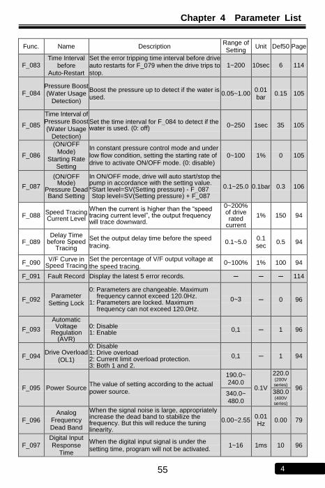
Chapter 4 Parameter List
55 4
Func. Name Description Range of Setting
Unit Def50 Page
F_083 Time Interval
before Auto-Restart
Set the error tripping time interval before drive auto restarts for F_079 when the drive trips to stop.
1~200 10sec 6 114
F_084 Pressure Boost (Water Usage
Detection)
Boost the pressure up to detect if the water is used.
0.05~1.00 0.01 bar
0.15 105
F_085
Time Interval of Pressure Boost (Water Usage
Detection)
Set the time interval for F_084 to detect if the water is used. (0: off) 0~250 1sec 35 105
F_086
(ON/OFF Mode)
Starting Rate Setting
In constant pressure control mode and under low flow condition, setting the starting rate of drive to activate ON/OFF mode. (0: disable)
0~100 1% 0 105
F_087
(ON/OFF Mode)
Pressure Dead Band Setting
In ON/OFF mode, drive will auto start/stop the pump in accordance with the setting value. *Start level=SV(Setting pressure) - F_087 Stop level=SV(Setting pressure) + F_087
0.1~25.0 0.1bar 0.3 106
F_088 Speed Tracing Current Level
When the current is higher than the “speed tracing current level”, the output frequency will trace downward.
0~200% of drive rated
current
1% 150 94
F_089 Delay Time
before Speed Tracing
Set the output delay time before the speed tracing.
0.1~5.0 0.1 sec
0.5 94
F_090 V/F Curve in
Speed Tracing Set the percentage of V/F output voltage at the speed tracing.
0~100% 1% 100 94
F_091 Fault Record Display the latest 5 error records. ─ ─ ─ 114
F_092 Parameter
Setting Lock
0: Parameters are changeable. Maximum frequency cannot exceed 120.0Hz.
1: Parameters are locked. Maximum frequency can not exceed 120.0Hz.
0~3 ─ 0 96
F_093
Automatic Voltage
Regulation (AVR)
0: Disable 1: Enable 0,1 ─ 1 96
F_094 Drive Overload
(OL1)
0: Disable 1: Drive overload 2: Current limit overload protection. 3: Both 1 and 2.
0,1 ─ 1 94
F_095 Power Source The value of setting according to the actual power source.
190.0~ 240.0
0.1V
220.0 (200V series)
96 340.0~ 480.0
380.0 (400V series)
F_096 Analog
Frequency Dead Band
When the signal noise is large, appropriately increase the dead band to stabilize the frequency. But this will reduce the tuning linearity.
0.00~2.55 0.01 Hz
0.00 79
F_097 Digital Input Response
Time
When the digital input signal is under the setting time, program will not be activated.
1~16 1ms 10 96

Chapter 4 Parameter List
56 4
Func. Name Description Range of Setting
Unit Def50 Page
F_098 Grounding
Fault Protection (GF)
0: Disable 1: Enable(GF)
0, 1 ─ 1 96
F_099 External
Indicator 1 Select the monitor mode of external indicator 1 0: Disable
0~8 ─ 1 70
F_100 External
Indicator 2 Select the monitor mode of external indicator 2 0: Disable
0~8 ─ 5 70
F_101 External
Indicator 3 Select the monitor mode of external indicator 3 0: Disable
0~8 ─ 2 70
F_102 PID
Compensa- tion Gain
Compensate the gain for pressure command control under constant pressure control.
0.1~8.0 ─ 1.0 107
F_103 PID Control
Mode Selection
0: Open-loop operation 1: Forward control; D postposition 2: Forward control; D preposition 3: Reverse control; D postposition 4: Reverse control; D preposition
0~4 ─ 1 107
F_104 P Selection 0: P postposition 1: P preposition
0,1 ─ 1 107
F_105 Proportional
Gain(P) Set the gain value for deviation adjustment. (0.0: P control disabled)
0.0~25.0 0.1 3.0 107
F_106 Integration
Time(I) Set the integration time for deviation adjustment. (0.0: I control disabled)
0.0~25.0 0.1 sec
1.2 107
F_107 Derivative Time(D)
Set the derivative time for deviation adjustment. (0.00: D control disabled)
0.00~2.50 0.01 sec
0.00 107
F_108
Derivative
Time of Feedback
Set the derivative time for feedback signal. 0.00~2.50 0.01 sec
0.00 107
F_109 Integration
Upper Limitation
Set the upper limitation value of integrator. 0~200%
of maximum frequency
1% 100 ─
F_110 Integration
Lower Limitation
Set the lower limitation value of integrator. -100~100% of maximum frequency
1% 0 ─
F_111
Offset Adjustment for
Integration Time
Adjust the integration time offset. -100~100% of maximum frequency
1% 65 107
F_112 PID Buffer
Space Set the buffer space of PID output value. 0~255 ─ 2 ─
F_113 Feedback
Signal Filter Filter the feedback signal. 0~255 ─ 10 ─
F_114 Feedback Signal Trip Detection
0: Disable 1: Enable (at F_126=0)
0,1 ─ 1 97
F_115 (Water Usage) Pressure Boost
Time
Set the time of F_084 (Pressure Boost for Water Usage Detection) to detect if the water is used.
0.1~25.0 ─ 0.6 105
F_116 Parameter Selection
0: F_000 ~ F_134
1: F_000 ~ F_194 0,1 ─ 0 ─
The color as means the function can be set during the operation.

Chapter 4 Parameter List
57 4
Func. Name Description Range of Setting
Unit Def50 Page
F_117 PID Start Range
In constant pressure control mode (F_103≠0), drive will activate PID control when the feedback signal exceeds the dead band.
0.0~10.0 0.1bar 0.3 105
F_118
(Water Shortage Detection)
Auto-restart Selection
0: Disable 1: Trip (Fb Lo): Press “RESET” key to reset. 2: Trip (Fb Lo): Power ON again to reset. 3: Trip (Fb Lo): Drive will auto-restarts
according to the setting of F_122 (Drive Shutdown Time for Water Shortage)
0~3 ─ 1 110
F_119
(Water Shortage Detection) Pressure
Level
Set the pressure level to detect if pump suffers from water shortage conditions. (0: Disable)
0~100% of
pressure command
1% 40 110
F_120
(Water Shortage Detection)
Current Level
Set the current level to detect if pump suffers from water shortage conditions. (0: Disable)
0~100% of motor
rated current
1% 0 110
F_121
(Water Shortage Detection)
TimeDetection
Set the detection time for F_119 and F_120 to detect if a pump suffers from water shortage.
0~250 1sec 60 110
F_122
(Water Shortage)
Drive Shutdown
Time
Drive will auto-restart after the time setting, when a pump suffers from water shortage. F_118 =3. (0:off)
0~200 1min 5 110
F_123 Analog Input
Selection
F_103=0 F_103≠0
0~3 ─ 0 79
0 Vin+Iin
Vin: Frequency command
Iin: Feedback signal
1 Vin-Iin
2 Iin-Vin
3 Vin or Iin(switch by multi-function input Terminal X1~X4)
F_124
Proportion Type of
Pressure Transducer
0: Direct proportion signal. 1: Inverse proportion signal.
0,1 ─ 0 97
F_125
Speed Command
Source Selection
under Open- Loop
Condition
In the closed-loop control, select the speed command source when PID is disabled by multi-function input terminal.[ multi-function
input terminal= ±13 (F_103≠0)or press HAND
ON]
0: Analog input terminal(Vin).
1: Keypad or key setting
2: Keypad setting knob 3: RS-485 Communication interface
0~3 ─ 1 99
F_126 Iin Range Selection
0: 4~20mA (2~10V) 1: 0~20mA (0~10V)
0,1 ─ 0 98
F_127 Iin Gain
(Analog Input) The gain ratio of analog input terminal Iin. 0.00~2.00 0.01 1.00 77
F_128 Iin Bias
(Analog Input) The bias ratio of analog input terminal Iin.
-1.00~ 1.00
0.01 0.00 78

Chapter 4 Parameter List
58 4
Func. Name Description Range of Setting
Unit Def50 Page
F_129 AM+ Analog
Output Signal Selection
0: Output frequency. 1: Frequency command. 2: Output current. 3: Vin frequency command. 4: Iin frequency command.
0~4 ─ 2 80
F_130 AM+ Analog Output Gain
AM+ analog output adjustment ratio. 0.00~2.00 0.01 1.00 81
F_131
Multi-function Output
Terminal Ta2/Tc2
The way of settings are same as multi-function output terminals setting. (F_058 ~ F_060)
0.0~10.0 0.1Hz 2.0 87
F_132 DC Braking Frequency
at Stop Active frequency level of DC braking at stop. 0.1~60.0 0.1Hz 0.5 93
F_133
(Water Usage Detection)
Drive Standby level
When the frequency during the operation is lower than the setting value, drive will decelerate to 0Hz and entering stand by status.
0~120 1Hz 10 105
F_134 Default Setting
0: Disable
0 ─
CLF: Clear fault records
dEF60: Restore the default value of drive for
60Hz.
dEF50: Restore the default value of drive for
50Hz. Distributor A setting value for
constant pressure setting (single
pump)
dEF52: Restore the default value of drive for
60Hz.Distributor A setting value for
constant pressure
setting(multi-pump)
dEF53: Restore the default value of drive for
50Hz.
SAv: Save the setting value.
rES: Restore the setting value.
rd_EE: Read the parameters from drive to
digital keypad
Wr_EE: Write the parameters from digital
keypad to drive
Cpy: In multi-pump control system, copy lead drive’s parameter.
F_135 Set Standby
Drives In multi-pump control systems, setting the drives standby numbers.
0~3 ─ 0 104
F_136 Noise
Prevention 0: Disable. 1: Enable.
0,1 ─ 0 112
F_137 Delay Time at
Pump Shift Operation
The delay time setting is to remain the stable pressure of the system at the interchanging of the pump operation.
0~250 1sec 10 100
F_138 200%
Current Limit 0: Disable. 1: Enable.
0,1 ─ 0 94

Chapter 4 Parameter List
59 4
Func. Name Description Range of Setting
Unit Def50 Page
F_140 NTC
Thermistor Setting
0: Disable. 1: Enable.
0,1 ─ 1 115
F_141
Drive Overheat Pre-alarm Selection
0: Disable 1: Warning (Ht): Continue operation. 2: Warning (Ht): Drive de-rates the switching
frequency automatically every 5 minutes. 3: Warning (Ht): Stop operation.
0~3 ─ 0 115
F_142
Drive Overheat Pre-alarm
Level
Set the warning level to prevent drive overheating.
45~85 1℃ 70 115
F_143 Drive
Overheating Dead Band
Set the temperature dead band of F_142 and F_145.
2.0~10.0 0.1℃ 3.0 115
F_144 Fan Control Selection
0: Forced air: Start the fan at power ON. 1: Operation air: Start the fan at running. 2: Temperature level setting: Start the fan
according to F_145.
0~2 ─ 1 115
F_145 Temperature Level of Fan
Activation Set the temperature level of fan activation. 25~60 1℃ 50 115
F_146 Minimum Operation
Time of Fan
Set the minimum operation time of fan when the fan stops.
0.1~25.0 0.1 min
0.5 115
F_147 Over Pressure
Disposal
0: Disable 1: Alarm: Drive keeps operation. 2: Alarm: Drive stops output. 3: Error trip: Drive trips to stop.
0~3 ─ 0 113
F_148 Over Pressure
Level
According to the setting value of F_007 (Pressure Transmitter Setting) to set the over pressure level.
0~100 1% 100 113
F_149 Over Pressure
of Detection Time
When the actual pressure exceeds over pressure level (F_007*F_148) with duration (F_149), the detection is activation.
0.0~25.5 0.1 sec
2.0 113
F_150 Continuous
Water Supply Control
0:Disable 1:Enable
0,1 ─ 0 104
F_151
Set the Minimum
Pumps during Operation
In parallel control system, set the minimum quantity of pumps during operation.
1~4 1 104
F_155 Communica-
tion Address
The host uses the address to send and receive messages from the drive (0: Disable)
0~254 ─ 0 122
F_156 Baud Rate 0: 4800bps 1: 9600bps 2: 19200bps 3: 38400bps
0~3 1 122

Chapter 4 Parameter List
60 4
Func. Name Description Range of Setting
Unit Def50 Page
F_157 Communica-
tion Protocol
0: 8,N,2 1: 8,E,1 2: 8,O,1
0~2 ─ 1 122
F_158 Communica- tion Overtime
(Cot)
When the data transmission during communication transmission is interrupted, has no data transmitting, or delays, drive displays “Cot” message (0.0: Communication overtime disable)
0~1000 1sec 0.0 122
F_159
Communica-
tion
Overtime
Disposal
0: Warning (Cot): Continue operation. 1: Warning (Cot): Ramp to stop 2: Warning (Cot): Coast to stop
0~2 ─ 0 122
F_160 Multi-Function
Input Selection
0: Multi-function inputs from multi-function terminals 1: Multi-function inputs from communication control
0,1 ─ 0 122
F_162
Frequency Upper
Limitation by Manual Mode
Setting manual mode for upper limit of frequency command
0~100% maximum of output frequency
1% 100 99
F_163
Frequency Lower
Limitation by Manual Mode
Setting manual mode for lower limit of frequency command
0~100% maximum of output frequency
1% 0 99
F_166 K Value of
Flow Sensor Setting value accord with specification of flow sensor
0.1~100.0 1L
/Pulse 10.0 116
F_167 Rate of Flow
Sensor Setting rate of flow sensor 0.00~2.00 0.01 1.00 116
F_168 Unit of Flow
Sensor 0: LPS
1: CMH 0,1 ─ 0 116
F_171 Shutoff
Head(H) Setting shutoff head of pump 0~160 0.1bar 12.0 117
F_172 Maximum Flow (Q) Setting maximum flow of pump
0.0~ 6000.0
0.1L/min
300.0 117
F_173 Compensa- tion for Pipe Friction Loss
0:Disable 1:Enable
0,1 ─ 0 117
F_174
The Current in
Maximum Flow (IQmax)
Setting current in maximum flow(IQmax) 1~200% of
drive rated current
1% 100 117
F_175 The Current in
Minimum Flow (IQmin)
Setting current in minimum flow(IQmin) 0~200% of drive rated
current 1% 30 117
The color as means the function can be set during the operation.

Chapter 4 Parameter List
61 4
Func. Name Description Range of Setting
Unit Def50 Page
F_176
Pump Flow Rate
Compensation for Pipe
Friction Loss (HCOMP max)
Setting maximum flow for pipe friction loss 0.1~160 0.1bar 0.0 117
F_177
Response Time
Compensation of Pipe Friction
Loss
Setting pump for response time compensation of friction loss
1~255 ─ 40 117
F_180 Sequetial
Operation for Start Control
0: Disable 1: Enable
0~1 ─ 0 119
F_181 Date/ Time
Setting
Y: Year 2000~ 2099
118
M: Month 1~12
d :Day 1~31
W: Week Sun.7~ SAt.6
H: Hour 0~23
MM: Minute 0~59
F_182 Date/ Time
Setting
Y: Year M: Month d: Day W: Week H: Hour MM: Minute ____: Reserved
─ ─ ─ 118
F_183 Sequential Operation
Mode
0: Every week 1: Every day
0,1 ─ 0 119
F_184 Sector 1
Sequential Operation
S: Level selection OFF,ON ─ OFF
119
W: Week Sun.7: Sunday Mon.1: Monday TUE.2:Tuesday Wed.3:Wednesday THU.4:Thursday
Fri.5:Friday SAt.6:Saturday
Sun.7~ SAt.6
─ Sun.7
H: Hour 0~23 hour 0
MM: Minute 0~59 min 0
C: Pressure command 0.1~160 0.1 bar
0.0
SL: Inclined time 0.1~600.0 0.1 sec
0.0
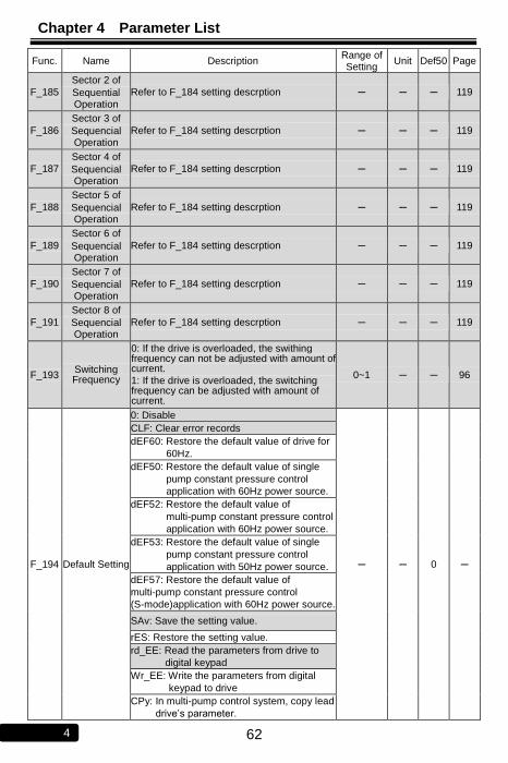
Chapter 4 Parameter List
62 4
Func. Name Description Range of Setting
Unit Def50 Page
F_185
Sector 2 of
Sequential Operation
Refer to F_184 setting descrption ─ ─ ─ 119
F_186
Sector 3 of
Sequencial Operation
Refer to F_184 setting descrption ─ ─ ─ 119
F_187
Sector 4 of
Sequencial Operation
Refer to F_184 setting descrption ─ ─ ─ 119
F_188
Sector 5 of
Sequencial Operation
Refer to F_184 setting descrption ─ ─ ─ 119
F_189
Sector 6 of
Sequencial Operation
Refer to F_184 setting descrption ─ ─ ─ 119
F_190
Sector 7 of
Sequencial Operation
Refer to F_184 setting descrption ─ ─ ─ 119
F_191
Sector 8 of
Sequencial Operation
Refer to F_184 setting descrption ─ ─ ─ 119
F_193 Switching Frequency
0: If the drive is overloaded, the swithing frequency can not be adjusted with amount of current.
1: If the drive is overloaded, the switching frequency can be adjusted with amount of current.
0~1 ─ ─ 96
F_194 Default Setting
0: Disable
─ ─ 0 ─
CLF: Clear error records
dEF60: Restore the default value of drive for
60Hz.
dEF50: Restore the default value of single
pump constant pressure control
application with 60Hz power source.
dEF52: Restore the default value of
multi-pump constant pressure control
application with 60Hz power source.
dEF53: Restore the default value of single
pump constant pressure control
application with 50Hz power source.
dEF57: Restore the default value of
multi-pump constant pressure control
(S-mode)application with 60Hz power source.
SAv: Save the setting value.
rES: Restore the setting value.
rd_EE: Read the parameters from drive to
digital keypad
Wr_EE: Write the parameters from digital
keypad to drive
CPy: In multi-pump control system, copy lead
drive’s parameter.

Chapter 4 Parameter List
63 4
The color as means the function can be set during the operation.
Note: 1. 200V Series. 2. 400V Series. 3. 0.5 ~ 5HP: 5.0sec;
7.5 ~ 30HP: 15.0sec; g 40HP above: 30.0sec
4. When the setting value of switching frequency(F0.81) exceeds “4”, the drive must be de-rating for usage or selecting the higher capacity of drive. 5. + : Represents a contact (N.O)
─ : Represents b contact (N.C) 6. Setting function F_014、F_056、F_057、F_139、F_152~F_154、F_161、F_164、F_165、F_169、
F_170、F_178、F_179、F_192、F_193: Reserved

Chapter 5 Parameter Setting Description
64 5
Chapter 5 Parameter Setting Description
5-1 The Keypad Setup
F_000 Drive Information
0: Software version (0041-d)
a. The drives with different software versions cannot execute readout or writing, otherwise, the parameters will occur error and the keypad ( KP-605) will display
message.
b. Please refer to 1-1-2 “The description of nomenclature”.
1: Drive model number.
2: Drive running hours.
3: Drive power supplying time.
4: Software checksum code.
5: Reserved
F_001 Start Command Selection
a. F_001=0
(I). FWD and REV terminals both control the start command and rotation
direction.
(II). Drive stops operation when FWD and REV terminals are simultaneously
open-circuit or short-circuit.
SINK (NPN) mode:
FWD (OFF: stop ON: forward running)
COM
REV (OFF: stop ON: reverse running)
FWD RUN / STOP
REV RUN / STOP
SOURCE (PNP) mode:
FWD (OFF: stop ON: forward running)
COM
REV (OFF: stop ON: reverse running)
FWD RUN / STOP
REV RUN / STOP
-+
DC 24V

Chapter 5 Parameter Setting Description
65 5
b. F_001=1
Start command by FWD terminal.
Rotation direction command by REV terminal.
SINK (NPN) mode:
FWD (OFF: stop ON: running)
COM
REV (OFF: forward ON: reverse)
RUN / STOP
REV / FWD
SOURCE (PNP) mode:
FWD (OFF: stop ON: running)
COM
REV (OFF: forward ON: reverse)
RUN / STOP
REV / FWD
-+
DC 24V
c. F_001=2
(I). Start command by keypad “ ON ” key.
Rotation direction command by FWD or REV terminal.
(II). Drive stops operation when FWD and REV terminals are simultaneously
open-circuit or short-circuit.
SINK (NPN) mode:
FWD (OFF: stop ON: forward)
COM
REV (OFF: stop ON: reverse)
FWD
REV

Chapter 5 Parameter Setting Description
66 5
SOURCE (PNP) mode:
FWD (OFF: stop ON: forward)
COM
REV (OFF: stop ON: reverse)
FWD
REV
-+
DC 24V
d. F_001=3 (default value)
Start command by the keypad “ ON ” key.
Motor rotates at the forward direction (clockwise).
e. F_001=4
(I). Start command by keypad “ ON ” key.
Motor rotates at the reverse direction (counterclockwise).
(II). The most left digit of output frequency will show “-“.
f. F_001=8
Start command and rotate direction by the RS-485 communication interface.
Related control command refer to “7-8 Drive Registors and Command Code”.
g. F_001=9
Start command by RS-485 communication interface.
Rotation direction command by REV terminal.
Related control command refer to “7-8 Drive Registors and Command Code”.
h. F_001=10
Start command by FWD terminal.
Rotation direction command by RS-485 communication interface.
Related control command refer to “6-6 Drive Registors and Command Code”.
i. F_001=11
Start command by Keypad
Rotation direction command by RS-485 communication interface.
Related control command refer to “7-8 Drive Registors and Command Code”

Chapter 5 Parameter Setting Description
67 5
Note:
1.When F_001 set to 0 or 2 and FWD-COM and REV-COM are simultaneously open-circuit,
the monitor mode will display blanking “ “ (except “Display 8-terminal
status”). If FWD-COM and REV-COM are simultaneously short-circuit, the monitor mode
will display blanking “ ” (except “Display 8-terminal status”).
2.The definition of rotation direction is according to IEC (International Electrotechnical Commission) standard. Observing the motor from axle center side, not the fan side. The standard rotation direction (Forward) is clockwise
U/T1 V/T2 W/T3
DRIVE
FWD
REV
COM
DRIVE
FWD
REV
COM
U/T1 V/T2 W/T3
U/T1 V/T2 W/T3
U/T1 V/T2 W/T3
Figure A Figure B
EX: F_001=0, Forward (FWD) rotation is clockwise (Figure A). Reverse (REV) rotation is counter-clockwise (Figure B).

Chapter 5 Parameter Setting Description
68 5
F_002 Frequency Command Selection
a. F_002=0
Frequency command by “Vin” or “Iin” analog input terminal (select Vin or Iin analog input sources by F_123).
(I). Vin-GND: Input range DC 0~10V。
※ The gain or bias of frequency command can be set by function F_040 and F_041.
(II). Iin-GND: Select the input signal mode via “JP4” switch.
JP4I position (current signal); Range: 4~20mA or 0~20mA (set by F_126).
JP4V position (voltage signal); Range: 2~10V or 0~10V (set by F_126).
※ The gain or bias of frequency command can be set by function F_127 and F_128.
b. F_002=1
Frequency command by keypad.
(I). In keypad KP-605, the primary speed, jog speed and preset speeds (F_009 ~
F_017) can be set during operation and the frequency command can be set
under monitor mode.
(II). In keypad KP-605, the pot knob can be defined by speed control.
c. F_002=2
Pressure command by keypad (KP-605).
d. F_002=3
Frequency command by RS-485.
Related control command refer to “6-6 Drive Registors and Command Code”
e. F_002=4
Pressure command by RS-485.
Related control command refer to “6-6 Drive Registors and Command Code”
※ Note: In monitor mode, when F_002 sets 1, 2 or 3, pressing ▲
or ▼
key one time
and the frequency command will be blink but not changing. Press the ▲
or ▼
key
again to change the frequency command.

Chapter 5 Parameter Setting Description
69 5
F_003 Selection of “STOP” Key Validity
a. F_003=0
When the start command by terminal, the “STOP
RESET ” key of keypad disabled.
b. F_003=1
When the start command by terminal, the “STOP
RESET ” key of keypad enabled.
c. The applications of “STOP” key.
(I). Emergency stop:
When the start and frequency command are both controlled by multi-function input
terminal (F_001=0 or 1), the output frequency will be decreased to 0Hz and
displaying on keypad by pressing “STOP
RESET ” key during operation.
If the drive needs to be restarted, cut off the wire between the terminals of the start
command (FWD or REV) and COM and restart the drive again.
(II). Normal stop:
F_001=2 or 3, the start command by “ ON ” key of keypad KP-201C and the stop is
controlled by “ STOP
RESET ” key.
F_004 Setting Value (SV) Change Selection
a. F_004=0
In the monitor mode, the setting value cannot be changed by KP-605 keypad to avoid possible mistakes and errors.
b. F_004=1
In the monitor mode, the setting value can be changed by KP-605 keypad.
F_005 Setting Value (SV) Auto-Storing
a. F_005=0
In the monitor mode, the setting value will not be saved automatically.
b. F_005=1
In the monitor mode, the setting value will be saved automatically after 3 minutes.

Chapter 5 Parameter Setting Description
70 5
F_006 KP-605 Selection of Main Display
In the monitor mode, there are 8 monitor modes can be selected. The corresponding
value and monitor modes are shown as below table:
1. Output Frequency
2. Frequency Command
3. Output Voltage
4. DC bus Voltage
5. Output Current
6. Terminals Status & Temperature
7. Setting Value & Practical Value (default value)
F_099 External Indicator 1
F_100 External Indicator 2
F_101 External Indicator 3
1. External indicator (DM-501) is used for expanding the display of “monitor mode”. DM-501 can be directly connected to the drive without connecting other power source.
2. The setting range of F_099 ~ F_101 is 0 ~ 6, and the significance is shown as below:
0: Disable the indicator
1: Output frequency
2: Frequency command
3: Output voltage
4: DC bus voltage
5: Output current
6: Terminal status and heat sink temperature
※DM-501 cannot monitor the pressure setting and actual pressure
3. Please select twisted-pair shield wiring and shielding connected to the GND terminal of drive’s control board.
4. The wiring diagram of external indicators is as follows:
5
CN1
1
Indicator 1 (DM-501)
RM6F5 control
board
Indicator 2 (DM-501) Indicator 3 (DM-501)
GND
1234567 1234567 1234567
5.The position of connector (CN1), please refer to “2-3-5 Control Board” on page 26,27.

Chapter 5 Parameter Setting Description
71 5
5-2 Preset Speed Setup
F_031 Primary Speed
F_032 Preset Speed 1
F_033 Preset Speed 2
F_034 Preset Speed 3
F_035 Preset Speed 4
F_036 Preset Speed 5
F_037 Preset Speed 6
F_038 Preset Speed 7
F_039 Jog Speed
a. Related functions:
(I) The setting of acceleration and deceleration time (F_018 ~ F_20、F_027、
F_029).
(II) The setting of multi-function input terminals (F_052 ~ F_055).
b. Switch of jog speed, primary speed and preset speeds.
※ The ON/OFF conditions as below table are “contact a (N.O)” setting of
functions.
Jog speed
command
Multi-speed level 3 command
Multi-speed level 2 command
Multi-speed level 1 command
Command Description
ON X X X Jog speed
OFF OFF OFF OFF Primary speed
OFF OFF OFF ON Preset speed 1
OFF OFF ON OFF Preset speed 2
OFF OFF ON ON Preset speed 3
OFF ON OFF OFF Preset speed 4
OFF ON OFF ON Preset speed 5
OFF ON ON OFF Preset speed 6
OFF ON ON ON Preset speed 7
Note: 1. “ X “ : Don’t care
2. The following chart shows jog speed having highest precedence, and jog speed command is ON, the motor is running at jog speed
3. Jog speed command and the multi-speed commands are programmed by the multi-function input terminals (X1 ~ X4) by functions (F_052 ~ F055). ON / OFF the terminal in accordance with above table to switch the speed.
4. “ ON “ : The terminal is short-circuit at contact a (N.O) setting. The terminal is open-circuit at contact b (N.C) setting.
“ OFF ” : The terminal is open-circuit at contact a (N.O) setting The terminal is short-circuit at contact b (N.C) setting.
5. The priority of speed command: Jog speed>Multi-sped>primary speed

Chapter 5 Parameter Setting Description
72 5
c. Multi-speed and acceleration/deceleration time
Primary acceleration
time
Time
Frequency
Primary
speed
Multi-speed level 2
Multi-speed level 1
Multi-speed level 3
Acceleration time of preset speed 1
Preset speed 1
Jog speed command
Deceleration time of preset speed 2
Preset speed 2
Acceleration time of preset speed 3
Preset speed 3
Preset speed 4
Primary acceleration
time
Preset speed 5
Preset speed 6
Primary acceleration
time
Preset speed 7
Primary deceleration
time
Jog speed
Primary acceleration
timePrimary
acceleration time
※ The acceleration / deceleration time of jog speed and preset speed 4~7 are according to the setting of primary acceleration / deceleration time (F_019, F_020).
※ Jog speed control include start command. When drive stop, activating the jog speed command can start the drive without start command.
※ Analog input terminals (Vin, Iin) are disabilities under jog speed, preset speed 1~7 and primary speed control.
※ Please refer to F_019 ~ F_020 for acceleration / deceleration time setting.

Chapter 5 Parameter Setting Description
73 5
5-3 Multi-Speed Accel./Decel. Time Setup
F_018 Reference Frequency of Accel/Decel Time
F_019 Primary Acceleration Time
F_020 Primary Deceleration Time
F_027 Secondary Acceleration Time
F_028 Secondary Deceleration Time
F_029 Set S-curve for Accel/Decel Time
a. The multi-speeds acceleration / deceleration time is the time interval from 0Hz to the
setting of F_018 (Reference Frequency of Accel/Decel Time). Multi-speed level
commands can simultaneously control preset speeds and the preset speed
acceleration / deceleration time.
b. The acceleration / deceleration time of primary speed, preset speed 4 ~ 7 and jog
speed are controlled by the setting of primary acceleration / deceleration time.
c. The switch between primary accel / decel and secondary accel / decel can be
selected by multi-function input terminals.
Illustration is as follows:
Max. output frequency
(F_017)
Time
Secondary
acceleration time
Secondary accel/decel time
command
(Multi-function input terminal)
F_019 F_027 F_028 F_020
Secondary Accel/Decel Time
Switching and Prohibited Command
Curve
Primary
acceleration time
Secondary
deceleration time
Primary
deceleration time
Output
Frequency
Holding command
(Multi-function input terminal)

Chapter 5 Parameter Setting Description
74 5
d. The “holding command” is disabled when STOP command is activated.
※STOP command:
(I) When F_001 set 0 or 2, “FWD” and “REV” terminals are simultaneously
short-circuit or open-circuit.
(II) When F_001 set 1, “FWD” terminal is open-circuit.
(III) When F_003 set 1, pressing the “OFF
RESET ” key.
(IV) Press the “OFF
RESET ” key when start command by keypad.
e. Set the S-curve function depend on the application to buffer the impact during start,
stop, acceleration and deceleration.
EX: To buffer the impact when the object fall on the conveyor line or the running of
elevator.
Frequency
command
Time
Output
frequency
S-curve time
S-curve timeS-curve time
S-curve time

Chapter 5 Parameter Setting Description
75 5
5-4 V/F Pattern Setup
F_009 Starting Frequency Range: 0.1~10.0Hz
F_010 Starting Voltage
The range of 200V series is 0.1 ~ 50.0V.
The range of 400V series is 0.1 ~ 100.0V.
F_011 Base Frequency
Motor base frequency;
The setting must be according to the nameplate of motor.
F_012 Base Voltage
Motor base voltage;
The setting must be according to the nameplate of motor.
(200V series: 0.1~255.0V; 400V series: 0.1~510.0V)
F_017 Maximum Output Frequency
RM5P series: The setting range of max output frequency is 0.1 ~ 120.0.
F_030 V/F Pattern Selection
a. The settings are listed as below:
0: Linear
1: Energy saving mode (Auto-adjust V/F according to the loads)
2: Square curve
3: 1.7th power curve
Base freq.
Output voltage
Output freq.
70%
100%
Below 50% of drive rated current
Linear
Energy saving
Square of 2 curve
Square of 1.7 curve
Square of 1.5 curve

Chapter 5 Parameter Setting Description
76 5
F_042 Frequency Upper Limit
Set the ratio of the frequency upper limit (1.00=maximum output frequency), and the
setting range is 0.00~1.00
Output frequency upper limit = Frequency upper limit (F_042) × Maximum output
frequency (F_017)
F_043 Frequency Lower Limit
Set the ratio of the frequency lower limit (1.00=maximum output frequency), and the setting range is 0.00~1.00
Output frequency lower limit = Frequency lower limit (F_043) × Maximum output
frequency (F0_17)
Output
frequency
Frequency
command
60.0Hz
60.0Hz
54.0Hz
54.0Hz
6.0Hz
6.0Hz
Max. output freq.60.0Hz
Freq. upper limit=0.90
Freq. lower limit=0.10

Chapter 5 Parameter Setting Description
77 5
5-5 Analog Input Command Setup
The analog input terminals:
“Vin” – “GND”: 0~10V;
“Iin” – “GND”: 4~20mA (2~10V) or 0~20mA (0~10V)
F_040 Vin Gain Rate 0~2.00
F_127 Analog Input Gain (Iin)
a. (General Mode)
The corresponding frequency command value of analog command =
Maximum output frequency (F_017) x Analog input gain (F_040 or F_127)
EX: If analog input bias (F_041 or F_128) = 0.00
Maximum output frequency = 60.0Hz Maximum output frequency = 60.0Hz
Analog input gain = 1.20 Analog input gain = 0.80
Output
Frequency
Analog
Command
60.0Hz
48.0Hz
0Hz 0Hz
0V(4mA) 0V(4mA) 10V(20mA)
Analog
Command
Output
Frequency
10V(20mA)8.3V(17.3mA)
Gain=1
Gain=1.2
Gain=1
Gain=0.8
60.0Hz
b. (F_103≠0)
Iin- PV value = Maximum transmitter(F_007) x Analog input gain(F_40 or F_127)
EX: If analog input bias (F_041 or F_128) = 0.00
Maximum transmitter=10bar Maximum transmitter=10bar
Analog input gain = 1.20 Analog input gain = 0.80
PV
Analog
signal
10bar
8bar
0bar 0bar
0V(4mA) 0V(4mA) 10V(20mA)
Analog
signal
PV
10V(20mA)8.3V(17.3mA)
Gain=1
Gain=1.2
Gain=1
Gain=0.8
10bar

Chapter 5 Parameter Setting Description
78 5
F_041 Vin Bias Bias -1.00~1.00
F_128 Iin Bias
a.( General Mode)
The corresponding frequency command value of analog command (C.V) =
Maximum output freq. (F_017) x Analog input bias (F_041 or F_128)
EX: If analog input gain (F_040 or F_127) = 1.00
Maximum output frequency =60.0Hz Maximum output frequency =60.0Hz
Analog input bias=0.05 Analog input bias=-0.05
Example of reverse control application:
Analog
Command
60.0Hz 60.0Hz
3.0Hz
-3.0Hz0V(4mA)
0V(4mA)0.5V(4.8mA)
10V(20mA)
Output
Frequency
Analog
Command
Output
Frequency
Bias=1
Bias=0.05
Bias=-0.05
Bias=1
10V(20mA)
Max. output freq.=60.0Hz
Analog input gain=0.00
Analog input bias=1.00
Analog command
0V(4mA) 10V(20mA)
60.0Hz
0Hz
Frequencycommand
b. (F_103≠0)
The corresponding PV value of Iin analog input bais =
Maximum transducer (F_007) x Analog input bias (F_128)
command analog of v alue commandf requency ingcorrespond The C.V*
C.Vcommand) (Analog20mA) (or10V
C.V) - command f req. (Max. command Freq.

Chapter 5 Parameter Setting Description
79 5
F_123 Analog Input Selection
F_103=0 F_103≠0
0: Vin+Iin Vin: Frequency command
Iin: Feedback signal
1: Vin-Iin
2: Iin-Vin
3: Vin or Iin (X1 ~ X4)
F_047 Filter Setting of Analog Input Signal
a. Filter the analog input signal when the frequency command by analog input terminals.
(F_002=0).
b. The larger setting value will cause the slower response.
c. 0: Disable the filtering.
F_096 Analog Input Dead Band
a. When the noise of analog input signal is large, appropriately increase the dead band to
stabilize the frequency command. But adjusting this function will reduce the tuning
linearity of input signal.
b. This setting must be applied along with the F_047.

Chapter 5 Parameter Setting Description
80 5
5-6 Analog Output Setup
The analog output terminals:
“FM+” – “M-”: DC 0 ~ 10V;
“AM+” – “M-”: DC 0 ~ 10V
(1/2 HP ~ 5HP models are marked by “FM+” – “GND” and “AM+” – “GND”)
F_044 Analog Output Signal Selection(FM+)
F_129 Analog Output Signal Selection(AM+)
0: Output frequency The analong output terminal(FM+ or AM+) outputs DC 0~10V to correspond the output frequency. (the terminal will output signal when drive operation)
1: Frequency command
The analong output terminal(FM+ or AM+) outputs DC 0~10V to correspond the frequency command. (the terminal will output when drive is operation or stop)
2: Output current
The analong output terminal(FM+ or AM+) outputs DC 0~10V to correspond the output current. (max. corresponding value is rated output current of drive)
3: “Vin” analog input signal The analong output terminal(FM+ or AM+) outputs DC 0~10V to correspond the signal of “Vin” analong input terminal. (the setting is activation when F_124=1)
4: “Iin” analog input signal The analong output terminal(FM+ or AM+) outputs DC 0~10V to correspond the signal of “Iin” analong input terminal. (the setting is activation when F_125=1)

Chapter 5 Parameter Setting Description
81 5
F_045 Analog Output Gain(FM+)
F_130 Analog Output Gain(AM+)
a. Analog output gain =Maximum output freq.
Output freq. (freq. command)or
Drive rated current
Output current
b. Analog output curve
Maximum output freq. = 60.0Hz
Analog output signal selection = 0, 1
Analog output gain = 1.20
10V
0V
21.25A
17AOutput current
8V
10V
0V
0.0Hz 60.0Hz
50.0Hz
Output freq.
or
Freq. command
Analog output
10V
0V 50.0HzVin freq. setting
0V
8V
60.0Hz
Driver rated current = 17A
Analog output signal selection = 2
Analog output gain = 0.80
Analog output
Maximum output freq. = 60.0Hz
Analog output signal selection = 3
Analog output gain = 1.20
Analog output Analog output
Maximum output freq. = 60.0Hz
Analog output signal selection = 4
Analog output gain = 0.08
Iin freq. setting
60.0Hz

Chapter 5 Parameter Setting Description
82 5
5-7 Motor Protecti Primary Frequency on Setup
F_046 Motor Overload Protection (OL)
Enable the function can preventing the motor from damage by operating in the overload condition for a long time. 0: Disable 1: Overload protection for dependent cooling fan type motor: Enabled (OL) 2: Overload protection for independent cooling fan type motor: Enabled (OL)
F_048 Motor Rated Current
F_049 Motor No-Load Current
F_050 Motor Slip Compensation
a. The slip of motor is variable depending on the load. When the load current is over the level of slip compensation, the drive will compensate the output frequency to output constant speed. The setting range is -9.9~10.0Hz. b. Compensation frequency =
on(F_050)compensati Slip(F_049)) current load-No(048)current(F_ Rated
(F_049)) current loadNo(current Loading

Chapter 5 Parameter Setting Description
83 5
5-8 Multi-Function Input Setup
F_052 Multi-function Input Terminal (X1)
F_053 Multi-function Input Terminal (X2)
F_054 Multi-function Input Terminal (X3)
F_055 Multi-function Input Terminal (X4)
a. “+” represents positive logic (N.O; contact a)
b. “-” represents negative logic (N.C; contact b)
c. Multi-function terminals X1 ~ X4 can be set to perform following functions:
0: As F_015 = 4 (Under draining multi-pump control mode ), F_052、F_053、F_054=0.
Pump start/stop control by multi-input terminal (X1,X2,X3). This funtion is suggested to be used, drive will start/stop in sequence when any terminal is activated.
±1: Jog command (refer to F_039)
±2: Secondary accel/decel time command (refer to F_027, F_028)
±3: Multi-speed level 1 command (refer to F_032 ~ F_038)
±4: Multi-speed level 2 command (refer to F_032 ~ F_038)
±5: Multi-speed level 3 command (refer to F_032 ~ F_038)
±6: Reset command
When the drive trips to stop, executing reset command can clear the fault
±7: External fault command (thr)
a. When the terminal received the fault command during operation, drive trips to stop.
b. This function is disabled when the drive at stop condition
±8: Interruption of output command (bb)
The parameter can interrupt the output voltage of drive.
Interruption of output command (F_054=8)
Output voltage
Output frequency
Interruption of output command
(X3)
Start command
0.3 sec

Chapter 5 Parameter Setting Description
84 5
±9: Coast to stop command (Fr)
Cut off the control of motor from drive immediately.
Coast to stop command (F_055=9)
Output voltage
Acceleration time
Output frequency
Coast to stop command (X3)
Start command
±10: Speed tracing from the maximum frequency
Speed tracing from the maximum frequency
(F_053=10)
Terminal start command (FWD)
Decel. time is 2 sec
Delay Time before Speed
Tracing(F_089)
The current level of speed tracing (F_088)
Normal accel. time
> 0.1secSpeed tracing
command (X1)
Max. output frequency
Output frequency
Output voltage
Output current
The V/F Pattern of Speed Tracing(F_090)
Return to normal V/F
The current level of speed tracing

Chapter 5 Parameter Setting Description
85 5
±11: Speed tracing from the setting frequency
Speed tracing from the setting frequency
(F_053=11)
Terminal start command (FWD)
Decel. time is 2 sec
Delay Time before Speed
Tracing(F_089)
The current level of speed tracing (F_088)
Normal accel. time
> 0.1secSpeed tracing
command (X1)
Setting frequency
Output frequency
Output voltage
Output current
The V/F Pattern of Speed Tracing(F_090)
Return to normal V/F
The current level of speed tracing
±12: Accel/Decel disable (Please refer to page 74)
±13: In closed-loop control (F_103 ≠ 0), opened-loop selection.
* In closed-loop control, temporarily run bypass signa ,controlled by analog input
signal (Vin or Iin) or frequency command of preset speed.
±14: In closed-loop control (F_103 ≠ 0), integrator reset.
±15: Stop command
*After the terminal is acted, the drive will decelerate and stop.
±16: Analog input source selection
Select Vin or Iin to as the analog input signal.
F_123 = 3 (Vin or Iin)
+16 Terminals short circuited: Vin Analog Input Source
Terminals open circuited: Iin Analog Input Source
-16 Terminals short circuited: Iin Analog Input Source
Terminals open circuited: Vin Analog Input Source
±17: Auxiliary pump start command 1
±18: Auxiliary pump start command 2
*Auxiliary pump 1, 2 start command, only suitable for S-mode.
*Please refer to “2-4-4 multi-pump control (S-mode)”。
±19: Auxiliary pump error command ( P1_OL)
±20: Auxiliary pump error command ( P2_OL)
*In S-mode control, auxiliary pump 1, 2 error signal command.
If the error state was removed, the drive will return to normal status.
*Please refer to “2-4-4 multi-pump control (S-mode)” on page36.

Chapter 5 Parameter Setting Description
86 5
±21: Flow sensor input
*Flow sensor input signal, please refer to “6-11 Flow sensor” description”。
±22: Sequential operation start command,
*please refer to “6-13-2 Sequential operation control ” description on page 122.

Chapter 5 Parameter Setting Description
87 5
5-9 Multi-Function Output Setup
F_058 Multi-function Output Terminal (Y1)
F_059 Multi-function Output Terminal (Y2)
F_060 Multi-function Output Terminal (Ta1,Tb1/Tc1)
F_061 Multi-function Output Terminal (Ta2/Tc2)
0: Disable
±1: Running detection
PressAUTO
ON , the drive will detect at start
Running detection (F_060=1)
Output
terminal
(Ta1,Tb1)
(SV)
Start command
Freq.
(PV)
Time
±2: Constant speed detection Detection at constant speed
±3: Zero speed detection
F_131 Constant speed detection range 0.0~10.0Hz
±4: Frequency detection
F_062 Frequency detection range 0~10Hz
F_063 Frequency detection level 0~120Hz
Output terminal
Time
Output freq.
Freq. detection
range F_062
Freq. detection level F_063
Freq. detection
range F_062
Freq. detection range(F_059=4)

Chapter 5 Parameter Setting Description
88 5
±5: Overload detection(OLO)
Overload detection
level F_068(OLO)
Overload detection time
F_069(OLO)
Output
terminal
Time
Output
currentOverload detection
(F_060=5)
±6: Stall prevention detection
Stall Prevention Level
at the Constant Speed
F_071
Outupt
terminal
Time
Time
Output
current
Output
freq.
Stall Prevention Detection
(F_058=6)
±7: Low voltage detection(LE)
DC bus voltage
Output terminal
(Y1)
“LE”abnormal status level
Low voltage detection (F_058=7)
±8: Braking transistor is active detection.
Detection when the DC bus voltage of drive is higher than the dynamic brake voltage.

Chapter 5 Parameter Setting Description
89 5
±9: Restart after instantaneous power failure detection Enable when F_078 is set to 1.
Restart after instantaneous power failure detection (F_058=9)
Power source
Low voltage
detection signal
Output freq.
Output voltage
Speed searching
current level
F_088
Output current
Output terminal
Delay time
for speed
searching
F_089
normal
V/F
The V/F pattern of speed
searching F_090
±10: Restart after fault condition detection
Restart after fault condition detection (F_058=10)
Fault condition
Output freq.
Output current
Output voltage
Output terminal
normal V/F
The V/F pattern of speed
searching F_090
Delay time for speed
searching F_089
Speed searching current level F_088

Chapter 5 Parameter Setting Description
90 5
±11: Fault detection
Fault
condition
Output
terminal
±12: Overheating detection (Ht)
Detection level is set by F_142(Ht) ±13: Over pressure detection (OP)
Detection level is set by F_148(OP) ±14: Reserved
±15: Auxiliary pump 1detection ±16: Auxiliary pump 2 detection
*Control mode when F_015 is set to 5. * Please refer to “2-4-4 multi-pump control (S-mode)” on page36.
±17: Fan detection during operation *Please refer to F_144 “Fan control selection”
5-10 Automatic Torque Compensation
F_064 Automatic Boost Voltage Range 0~25.5V
Dynamic compensation by voltage to avoid any insufficient voltage at heavy-duty load.
The adjustment method is to minimize the output current by adjusting the parameter.
(maximum power factor).
Higher compensation setting will result higher current.
Fault detection (F_059=11)

Chapter 5 Parameter Setting Description
91 5
5-11 System Overload Detection SetUp
F_065 System Overload Detection(OLO)
a. The settings are listed as below:
0: Disable 1: Enable (OLO)
F_066 System Overload Detection Status
0: Detection at constant speed only.
1: Detection at operation: Including the system overload at acceleration, deceleration or constant speed.
F_067 Output Setting of System Overload
0: Drive continues running after the system overload is detected
1: Drive trips after the system overload is detected.
F_068 System Overload Detection Level
Setting the level of current for system overload detection, and the setting range is 30~200% of drive rated current.
F_069 System Overload Detection Time
a. The detection of system overload is shown in the below chart:
Overload
detection
Overload
detection level
F_068Current
Time
Time
Overload detection time
F_069
Time interval<overload detection time
b. The operation panel displays “OLO”, when the system overload time is over the setting value of system overload detection time (F_069).
c. Setting range: 0.1~25.

Chapter 5 Parameter Setting Description
92 5
5-12 Stall Prevention SetUp
F_070 Stall Prevention Level at the
Acceleration Setting range is 30%~200% of drive’s rated current F_071 Stall Prevention Level at the Constant
Speed
If stall is occurred during acceleration or constant speed, the motor keeps running at the
constant speed (200%: Off), and the setting range is 30%~200% of drive’s rated current
F_072 Acceleration Time for Stall Prevention during the Constant Speed
F_073 Deceleration Time for Stall Prevention during the Constant Speed
Setting range is 0.1~3200.0 sec.
F_074 Deceleration Stall Prevention
0: Deceleration stall prevention: Disabled
1: Deceleration stall prevention: Enabled
Stall prevention
level at the
acceleration
Stall prevention
level at the
constant speed
Stall prevention
level at the
accelerationF_070
TimeTime
Time Time
CurrentCurrent
Output
frequencyOutput
frequency
Deceleration time for
stall prevention
(F_073)
Acceleration time
for stall prevention
(F_072)
Multi-output
terminal(Y1)
(F_058=6)
Stall prevention
level at the
constant speed(F_071)
Multi-output
terminal(Y1)
(F_058=6)
a. The function of the stall prevention during the deceleration is to maintain a constant speed when the deceleration is stalling.
b. When connecting a dynamic brake unit, F074 function can be disabled according to the operation requirement
c. If the DC bus voltage of the drive is higher than the dynamic brake voltage level when drive stops, the operation panel or external keypad will display “Hv”. “RUN” key of the operation panel and digital keypad can’t start the drive. If the DC bus voltage is less than the dynamic brake voltage level, the drive will be automatically recovered and the display will be back to the main display.

Chapter 5 Parameter Setting Description
93 5
5-13 DC Braking Set Up
F_075 DC Braking Level
a. Set the current level of DC braking. b. The setting range is 0~150% of drive rated current.
F_076 Time Interval of DC Braking at Start
Set the DC braking for motor random running at start. The setting range is 0.0~20.0.
F_077 Time Interval of DC Braking at Stop
Set the DC braking of ramp to stop. The setting range is 0.0~20.0 sec.
F_132 DC Braking Frequency at Stop
a. Set the DC braking frequency at stop. The setting range is 0.1~60.0. b. If changing the setting value of frequency below the starting frequency(F2.33), the drive will stop by DC braking, and the DC Braking Frequency at Stop(F3.25) will be not active.
Start
command
Time interval of
DC braking at
start F_077Time interval of DC
braking at start F_076
Output
frequency
DC braking
frequency at stop
F_132
Time
Time
5-14 Operation Selection at Instantaneous Power Failure
F_078 Operation Selection at Instantaneous Power Failure
a. The settings are listed as below:
0: Drive cannot be restarted at instantaneous power failure.
1: Drive can be restarted at instantaneous power failure.
(see the function description of the restart after instantaneous power failure detection of
multi-function output setting )
2: Ramp to stop
3: When the power is restored during the ramp to stop interval, the drive is restarted and re-accelerated again.

Chapter 5 Parameter Setting Description
94 5
Power source
Time
Output Freq.
Power failurere-accelerated
Power
restart
F_051 Start Command Memory 0: Enable (F_001=2,3,4 enable)
1: Disable
5-15 Speed Tracing
F_088 Speed Tracing Current Level The setting range is 0~200% of drive rated current.
F_089 Delay Time for Speed Tracing Set the output delay time before the speed
tracing. The setting range is 0.1~60.0 sec.
F_090 The V/F Pattern of Speed Tracing
The setting range is 0~100%
a. When the drive current is greater than the current level of speed tracing (F_088), the output
frequency is tracing downwardly to reach the current level of speed tracing.
b. The speed tracing function is mainly used for tracing the speed for the drive restart after instantaneous power failure/flying start, the drive fault restart, or the speed tracing command is given by the input terminal.
c. See the function description of multi-function input terminals for speed tracing on page 85.
5-16 Current Limitation
F_138 Current Limitation 0:Disable 1:Enable
F_094 Drive Overload(OL1)
0: Disable 1: Thermal protection 2: Current limit overload protection 3: Both 1 and 2 enable

Chapter 5 Parameter Setting Description
95 5
5-17 Others Function
F_081 Switching Frequency
When the value of F_081 is set to “0”, the switching frequency of PWM voltage will be 800Hz and others switching frequency = F_081×2.5kHz. The higher switching frequency has less noise. But using higher switching frequency must consider the cable length between drive and motor and must be adjusted according the connection distance between drive and motor. (Refer to the 2-3-6)
※Upper limit of switching frequency
RM6E(9916): 1/2HP~75HP 15kHz Above 100HP 10kHz
※ Switching frequency will be modulated with load automatically.
1min
Load current
80%
90%
100%
Switching
frequency
15K
12.5K
10K
7.5K
Time
5%
1min 1min 1min 1min 1min
Switching
frequency
Load current
F_082 Stop Mode 0: Ramp to stop 1: Coast to stop 2: Coast to stop + DC braking
When the value of F_082 is set to “2”, the operation characteristic is shown as below figure:
DC voltageTime
Output voltage N
Fout / F_031 ratio0.1 1
F_075 (DC
Braking Level)
Delay Time before
Speed Tracing (F_089)10
1
F_076 (Time
of DC Braking
after Stop) * N
Stop
AC voltage
*F_031 (Maximum Output Frequency)
When the output current of drive is abnormal at DC braking, appropriately increase the setting value of F_089 (Delay Time before Speed Tracing).

Chapter 5 Parameter Setting Description
96 5
F_092 Parameter Setting Lock
0: Parameters are changeable. 1: Parameters are locked. 2&3: Reversed ※ According F_004 setting to change selection of setting value (SV)
F_093 Automatic Voltage Regulation (AVR) 0: Disable 1: Enable
F_095 Power Source
The setting value according to the actual power source voltage. 200V series setting range: 190.0 ~ 240.0V; 400V series setting range: 340.0 ~ 480.0V.
When the drive is power ON for first time and the power source voltage is lower than the 90% of F_095 setting value, the drive will display “LE” warning message. After the power ON for drive, the drive displays “LE” message when the power source is lower than the 70% of F_095 setting value.
F_098 Grounding Fault Protection (GF) 0: Disable 1: Enable
F_097 Digital Input Response Time Range: 1~16ms (default: 10ms)
If the signal length of digital inputs is smaller than the digital input response time, drive software will reject the input signal and do no process to input signal.
F_193 Decrease the Switching Frequency
0: If the drive is overloaded, the swithing frequency can not be adjusted with amount of current.
1: If the drive is overloaded, the switching frequency can be adjusted with amount of current.

Chapter 5 Parameter Setting Description
97 5
6. Parameter Description of Pump
6-1 Related Settings of Feedback Signal (pressure transmitter) and Pump (default: Iin analog input terminal)
․6-1-1 Feedback Signal (pressure transmitter)
Func. Name Description
F_007 Pressure Transmitter Setting
․Set the upper limit value of pressure in accordance with
pressure transmitter specification.
*The upper limit value of pressure is corresponding to the maximum input signal of Vin or Iin.
*Recommend to select a high precision type (<+0.5%) pressure transmitter to provide the drive better feedback signal.
F_008
Maximum Allowable Operational Pressure
․Set the percentage to F_007 in accordance with the specification
of pump. *The setting can adjust the maximum operational pressure in accordance with the specification of the pump or can prevent the water pipe from harm by setting too high pressure.
*According to the specification of the pump to set the operational pressure value: F_007 * F_008.
*Example: Maximum pressure value of the pressure transmitter = 10.0bar; F_008 = 50%
Maximum operational pressure of the drive = F_007(10.0bar) * F_008(50%) = 5.0bar.
F_114 Feedback Signal Trip Detection
=0: Disable *Disable the trip detection.
=1: Enable. *Enable the trip detection. *F_126 must be set to “0”. *When the feedback signal (default: Iin input) is below 4mA, the
keypad will display message.
F_124
Proportion Type of Pressure Transducer
=0: Direct proportion type signal. *P/I or P/V curve of pressure transducer
Output signal
Input pressure
10V(20mA)
10bar
2V(4mA)
Pressure transmitter 1
Pressure transmitter 2
0
=1: Inverse proportion signal. *P/I or P/V curve of pressure transducer
Output signal
Input pressure
10V(20mA)
10bar
2V(4mA)
Pressure transmitter 1
Pressure transmitter 2

Chapter 6 Parameter Description of Pump
98 5
Func. Name Description
F_125
Selection of Frequency Command by Manaul Mode under Close- Loop Condition
=0: Analog input terminal (Vin)
=1: Keypad “ ” or “ ” key setting
=2: Keypad setting knob
=3: RS-485 Communication interface
*In close-loop control, select the speed command source when feedback signal is bypassed in temporary.
*When the multi-function input terminal is set to +13 (Under close-loop control condition (F_103≠0), open-loop selection.)
F_126 Iin Range Selection
=0: 4~20mA (2~10V).
=1: 0~20mA (0~10V).
*According to the specification of pressure transmitter to select the Iin range.
F_127 Iin Gain (Analog Input)
․The gain ratio of analog input terminal Iin.
*Set the gain ratio for the feedback signal from pressure transmitter.
F_128 Iin Bias (Analog Input)
․The bias ratio of analog input terminal Iin.
*Set the bias ratio for the feedback signal from pressure transmitter.

Chapter 5 Parameter Setting Description
99 5
․6-1-2 Manual Mode
1. When the multi-function input terminal is set to +13 (Under close-loop control condition (F_103≠0), open-loop selection.)
2. Press HAND
ON key to control.
Example:
․Automatic Mode Manual Mode, press HAND
ON key (HAND ON LED light)
․Manual Mode Automatic Mode, press HAND
ON key (HAND ON LED light)
*The drive will resume to the previous frequency setting when the manual mode turns off.
Func. Name Description
F_125
Selection of Frequency Command by Manaul Mode under Close- Loop Condition
=0: Analog input terminal (Vin)
=1: Keypad “ ” or “ ” key setting
=2: Keypad setting knob
=3: RS-485 Communication interface
*In close-loop control, select the speed command source when feedback signal is bypassed in temporary.
F_162
Frequency Upper Limitation by Manual Mode
* Setting Frequency Upper Limitation:
The drive only follow F_162 setting value.
* Upper Limitation(Manual Mode) =
Maximum output frequency (F_017)*F_162
* Setting range: 0~100%(default value:100)
F_163
Frequency Lower Limitation by Manual Mode
* Setting Frequency Lower Limitation:
The drive only follow F_163 setting value.
* Upper Limitation(Manual Mode) =
Maximum output frequency (F_017)*F_163
* Setting range: 0~100%(default value:100)

Chapter 6 Parameter Description of Pump
100 5
6-2 Sequential Operation and Parallel Control of Multi-pump
․6-2-1 Sequential Control for Multi-Pump(Only used for F-mode、E-mode)
Func. Name Description
F_013 Pump Shift Operation (Parallel control)
=0: Disable.
=1: Shift the pump operation after the operating time (F_024).
*The function is to shift the operation from one pump to another when the operating time (F_024) reaches.
=2: Shift the pump operation after a drive stops. *The function is to shift the operation from one pump to another after an operating pump drive comes to stop.
=3: Both 1 and 2 enable.
F_024 Pump Auto Shift Time (Parallel control)
․Set the pump operating time of the sequential control
in multi-pump control.
*Setting range:0~240hr. *0: Disable. (drive will not execute sequential operation.)
F_137 Delay Time at Pump Shifting
․The delay time setting is to remain the stable pressure
of the system at the interchanging of the pump operation.
*Default: 10sec. *During the pump shifting, the system pressure becomes unstable when one pump drive disengages and another pump drive engages. The delay time is to increase the disengaging time of the current pump drive to stabilize the system pressure.
1. The sequence of pump shifting for multi-pump control as below diagram.
Drive #0
Time
Drive #1
Drive #2
Drive #3
2. Below figure is the process of function F_024 and F_137.
Drive #1
Output frequency
Actual pressure
(PV) Setting
pressure
(SV)
Drive #1
F_024
F_137 F_137
Drive #0
Drive #1
Drive #0Drive #0
Time
Time

Chapter 5 Parameter Setting Description
101 5
Func. Name Description
F_015 Control Mode
Selection (Pump Parallel)
=0: Disable the functions related to pump.
=1: Single pump application. *Constant pressure is controlled by single pump.
=2: Multi-pump applications; E-mode (Equal-mode).
*Pumps run at identical speed to maintain the pressure in constant.
*Recommend to select this mode for 2 pump applications to increase the efficiency and save the energy.
=3: Multi-pump applications; F-mode (Full-mode).
*Only one pump auto-adjusts the speed, and other pumps run at full speed when the multi-pump system outputs the constant pressure.
*Recommend to select this mode for more than 2-pump operations to increase the efficiency and save the energy.
=4: Multi-pump applications; M-mode (Manual-mode).
*Pump ON/OFF is controlled by multi-function input terminals (X1, X2, X3).
*F_052, F_053, F_054 must set to “0”.
*Drive will start/stop in sequence when any terminal is activated.
*Recommend to select this mode when installing or trial running the pump.
=5: Multi-pump applications; S-modet
*Lead pump which have an automatic speed control, auxiliary pump1 or pump 2 will follow setting condition to run.
AC power start operating to maintain constant pressure.
*Start condition of sequential operation:
Lead Pump Auxiliary Pump1 Auxiliary Pump2
(1) When lead pump run at full speed, but PV value < F_022 (Start detection level), the multi- output terminal will detect immediately and start the auxiliary pump 1 (AC power); And so on, auxiliary pump 2 will start in sequence.
(2) When lead pump run at full speed, and operating time > F_021(Start detection time), the muti-output terminal may detect immediately and start auxiliary pump 1 (AC power); And so on, auxiliary pump2 will start in sequence.
*Stop sequential operation:
Auxiliary Pump2 Auxiliary Pump1 Lead Pump
*Auxiliary pump stop condition:
(1) When PV value > F_022(Start detection level), the muti-output terminal may detect immediately and stop auxiliary pump 2(AC power stop), and so on, auxiliary pump 1 will stop in sequence; When operating frequency of lead pump < F_133( Drive standby level), lead pump will decelerate and stop.

Chapter 6 Parameter Description of Pump
102 5
(2) When the operating frequency value < F_023 (Departing frequency of pump), and operating time > F_025(Departing time), the multi- output terminal may detect immediately and stop auxiliary pump 2. And so on, auxiliary pump 1 will stop in sequence; When the operating frequency of lead drive < F_133(Drive standby level), lead pump will decelerate and stop.
F_016 Set Drive’s No. for
Parallel Control
․Set the individual number to each drive.
*In multi-pump control systems, assign the activating number to each drive for parallel control. Lead drive (the smallest number) will order command to other drives.
*The smallest number stand for lead drive. When the lead
drive occurs fault or pressed the OFF
RESET key, the drive with
following number will become lead drive to order the command to other drives.
Func. Name Description
F_021 Launch Detection
Time (Parallel Control)
․In multi-pump control systems, set the detection time
of pump for parallel start up.
*In multi-pump control systems, the standby pumps will parallel control in sequence when the operating drive runs at full speed for a time by setting value of F_021.
*Setting range: 0.0~25.0sec.
Drive #1
Output frequency
Actual pressure
(PV) Setting pressure
(SV)
Drive #0
F_021 Full speed
Drive #0
Drive #1
Time
Time
F_015=2(E-mode)
F_022 Launch Detection
Level (Parallel Control)
․In multi-pump control systems, set the detection level
of pump for parallel start up.
*In multi-pump control systems, the standby pumps will parallel control in sequence when the operating drive runs at full speed and the actual pressure is still below the setting value.

Chapter 5 Parameter Setting Description
103 5
Drive #1
Output frequency
Actual pressure
(PV) Setting pressure
(SV)
Drive #0
Full speed
F_022
Drive #0
Drive #1
Time
Time
F_015=2(E-mode)
F_023 Cut-off Frequency of Parallel Control
․In multi-pump control systems, set the cut-off
frequency to cut off the pump operation.
F_025 Cut-off Time of Parallel Control
․In multi-pump control systems, set the cut-off time to
cut off the pump operation.
1.In multi-pump control systems (E-mode or S-mode), when the output frequency is below the F_023 and maintaining the time interval (F_025), the drive will depart from the parallel control system in sequence (Last in - First out).
*Example: Two pumps for parallel control; F_015 = 2 (E-mode).
Output frequency
Actual pressure
(PV) Setting pressure
(SV)
Drive #0
Drive #1
F_025F_023
Time
Time
F_015=2(E-mode)
Drive #0
Drive #1

Chapter 6 Parameter Description of Pump
104 5
2.In multi-pump control systems, drives will start / cut off the operation in accordance with below diagram.
Time
#0 #0 #0
#1
Drive #1
Drive #0
F_135
Drives Standby Numbers of Multi-pumps Control system
․In multi-pump control systems, setting the number
of drives standing by. *According to the condition of applications, users can set the standing by number of drives to protect the system.
*Setting range: 0~3 units.(0: disable) *The default parallel number of drives are 2 sets. *Valid setting of standing by drives as below.
F_150 Continuous Water Supply Control
0:Disable
1: Enable(default)
F_151 Less Pumps set during Operation
In multi-pump control systems, deploying the number of operating pumps and maintaining the system pressure within certain acceptable limits.
Setting range: 0~1 pump (0: Disable ; Default value: 1 pump)
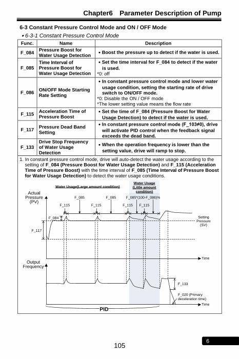
Chapter6 Parameter Description of Pump
105 6
6-3 Constant Pressure Control Mode and ON / OFF Mode
․6-3-1 Constant Pressure Control Mode
Func. Name Description
F_084 Pressure Boost for Water Usage Detection
․Boost the pressure up to detect if the water is used.
F_085 Time Interval of Pressure Boost for Water Usage Detection
․Set the time interval for F_084 to detect if the water
is used. *0: off
F_086 ON/OFF Mode Starting Rate Setting
․In constant pressure control mode and lower water
usage condition, setting the starting rate of drive switch to ON/OFF mode.
*0: Disable the ON / OFF mode *The lower setting value means the flow rate
F_115 Acceleration Time of Pressure Boost
․Set the time of F_084 (Pressure Boost for Water
Usage Detection) to detect if the water is used.
F_117 Pressure Dead Band Setting
․In constant pressure control mode (F_103≠0), drive
will activate PID control when the feedback signal exceeds the dead band.
F_133 Drive Stop Frequency of Water Usage Detection
․When the operation frequency is lower than the
setting value, drive will ramp to stop.
1. In constant pressure control mode, drive will auto-detect the water usage according to the setting of F_084 (Pressure Boost for Water Usage Detection) and F_115 (Acceleration Time of Pressure Boost) with the time interval of F_085 (Time Interval of Pressure Boost for Water Usage Detection) to detect the water usage conditions.
Output Frequency
Actual Pressure
(PV)
F_084
F_115
F_085 F_085*(100-F_086)%
F_115F_115
Setting Pressure
(SV)
F_085
F_115
Water Usage(Large amount condition)Water Usage
(Little amount
condition)
PID
F_133
F_020 (Primary
deceleration time)
Time
Time
F_117

Chapter 6 Parameter Description of Pump
106 6
․6-3-2 ON / OFF Control Mode
Func. Name Description
F_087 ON / OFF Mode Pressure Dead Band Setting
․In ON/OFF mode, drive will auto start/stop the pump
in accordance with the setting of setting value. *Start level=SV(Setting pressure) - F_087 Stop level=SV(Setting pressure) + F_087
*Example: SV=2.0bar, F_087 = 0.3bar When PV(actual pressure) = 1.7bar Drive starts When PV(actual pressure) = 2.3bar Drive stops
1. In ON / OFF control mode, drive will start / stop in accordance with the setting of F_087.
2. When the drive is operating under ON / OFF control mode, There are two dots will be shown on display of keypad at SV and PV indicators.
3. The positions of dots:
SV
KEYPAD
PVRunning
2 sec
ON
2 sec 2 sec
F_087
F_087
OFF ON OFF ONOFF
Output Frequency
Actual Pressure
(PV)
Setting Pressure
(SV)
Stop level
Start level
Time
Time

Chapter6 Parameter Description of Pump
107 6
6-4 PID Control Functions
․6-4-1 PID Control Functions
Func. Name Description
F_102 PID Compensation Gain ․Compensate the gain for pressure command
control under constant pressure control.
F_103 PID Control Mode Selection
=0: Open-loop operation *Disable the feedback signal from the pressure transmitter.
=1: Forward control; D postposition *When the actual pressure (PV) is lower than the setting pressure (SV), the drive will start to accelerate.
*Forward control: When the system actual value is less than the setting value, the drive will start to accelerate.
=2: Forward control; D preposition *Forward control: When the system actual value is less than the setting value, the drive will start to accelerate.
=3: Reverse control; D postposition *Reverse control: When the system actual value is less than the setting value, the drive will start to decelerate.
=4: Reverse control; D preposition *Reverse control: When the system actual value is less than the setting value, the drive will start to decelerate.
F_104 P Selection =0: P postposition
=1: P preposition
F_105 Proportional Gain(P)
․Set the gain value for deviation adjustment.
(0.0: “P” control disabled) *To adjust the stable time. *Increase the value: Increase the response speed of constant pressure control system.
*Decrease the value: Reduce the oscillation and response speed.
F_106 Integration Time(I)
․Set the integration time for deviation adjustment.
(0.0: “I” control disabled) *To adjust the error value at stable state. *Increase the value: Reduce the error value. The response speed of constant pressure control system will be decreased.
*Decrease the value: The response speed of constant pressure control will be increased, but the error amount will be increased.
F_107 Derivative Time(D)
․Set the derivative time for deviation adjustment. (0.00: “D” control disabled) *To adjust the amount of overshooting. *Increase the value: Reduce the overshooting of pressure, but motor is easier vibration.
*Decrease the unstable vibration factor of motor, but the pressure is easier overshooting.
F_108 Derivative Time of Feedback
․Set the derivative time for feedback signal.
F_111 Offset Adjustment for Integration Time
․Adjust the PID control offset.

Chapter 6 Parameter Description of Pump
108 6
․6-4-1 The block diagram of setting value and feedback value.
F_127(Iin Gain)
F_128(Iin Bias)
F_124(Proportion
Type of Pressure
Transmitter)
1
0
D
F_108Derivative
Time of
Feedback)
F_103(PID
Control Mode
Selection)
2,4 1,3
F_113(Feedback
Signal Filter)
+
+
-
-
F_103(PID
Control Mode
Selection
1,2
3,4
F_002(Selection
of Command)
0
1
2
Vin
terminal
Setting value
Feedback
value
Pressure command
F_032~F_038
Multi-speed 1~7
Error
Keypad
(KP-207)
Iin
terminal
Multi-speed
level 3,2,1
0 0 0
001~111
F_047(Filter Setting of Analog
Frequency)
F_040(Vin Gain), F_041(Vin Bias)
․6-4-2 The block diagram of PID control.
+
++
0
10
Analog frequency command
F_031
Primary speed
1
0 0
+
PID_HALT
F_042(Frequency Upper Limit)
F_043(Frequency Lower Limit)
PID_HALT
Error
F_102(PID
Compensation
Gain)
Gain
F_002( Selection
of Command)
0,1
2
F_105
(Proportional
Gain(P))
P
F_104
(P Selection)
0
1
F_111(PID Offset Adjustment)
Bias
F_109(Integration Upper Limitation)
F_110(Integration Lower Limitation)
F_107
(Derivative Time(D))
D
P
I
F_103(PID
Control Mode
Selection)
1,3
2,4
0
1
F_112(PID
Buffer Space)
F_125(Signal Source
Selection under Close-
Loop Condition)
0
1
Open loop command from multi-function input terminal
1
0
PID
command
F_105
(Proportional
Gain(P))F_104
(P Selection)
․6-4-3 PID adjustment The system reaction condition can be adjusted by P, I, D to improve the system efficiency. Improper setting may cause system oscillated, please follow below adjustment steps to keep system stable. 1. Gradually increase the value of proportional gain(P). 2. Gradually decrease the value of integration time(I). 3. Gradually increase the value of derivative time(D).

Chapter6 Parameter Description of Pump
109 6
(1) Over-tuning suppression Increasing the integration time (I) and decrease the derivative time(D).
Time
Before adjustment
After adjustment
Response
(2) Advance stabilizing Decreasing the integration time (I) and increase the derivative time (D).
Time
After adjustment
Before adjustment
Response
(3)Reducing the oscillation in the short period When the oscillation happens in the cycle that longer than the setting time of integration, the integration setting is too strong causing the system oscillation. Set longer time of integration to stabilize the system and reduce the oscillation.
Time
After adjustment
Before adjustmentResponse
(4) Reducing the oscillation of continuous period If the system appears the continuous oscillation caused by higher derivative value, shortening the derivative time can reduce the system oscillation.
Time
After adjustment
Before adjustmentResponse

Chapter 6 Parameter Description of Pump
110 6
6-5 Pump Protection
Func. Name Description
F_118 Water Shortage Trip Recovery
=0: Disable *When the pump suffers from water shortage or conditions, the pump keeps running.
*Warning: Pump will be easily damaged.
=1: Trip (Fb Lo);Press “RESET” key to reset *When the pump suffers from water shortage conditions,
the drive will trip to stop and display .
*Must press OFF
RESET key to clear the error.
*When the OFF
RESET key of the lead drive is pressed, the drive
with following number after the lead drive now becomes the new lead drive.
=2: Trip (Fb Lo);Power ON again to reset
*When the pump suffers from water shortage conditions,
the drive will trip to stop and display .
*Drive must Power ON again to reset.
=3: Trip (Fb Lo);Drive will auto-restarting according to the setting of F_122 (Drive Shutdown Time for Water Shortage)
*When the drive suffers from water shortage conditions,
the drive will trip to stop and display The drive
will auto restart after the setting time of F_122.
F_119 Water Shortage Detection by Pressure Level
․Set the pressure level to detect if pump suffers from
water shortage conditions. *Detection engages when the drive runs at full speed. *0: Disable
F_120 Water Shortage Detection by Current Level
․Set the current level to detect if pump suffers from
water shortage conditions. *Detection engages when the drive runs at full speed. *0: Disable
F_121 Time of Water Shortage Detection
․Set the detection time for F_119 and F_120 to detect
if pump suffers from water shortage. *0: Disable
F_122 Drive Shutdown Time for Water Shortage
․Drive will auto-restart after the time setting, when
pump suffers from water shortage and F_118 is set to 3.
*Shutdown time interval = F_122 *0: off
Output
frequency
Setting pressure(SV)
or
Output current
F_119 or
F_120
F_121
F_122 F_122 F_122
F_121 F_121 F_121
Fb LoFb Lo Fb Lo Fb Lo

Chapter6 Parameter Description of Pump
111 6
․6-5-1 Cavitation Phenomenon
When the drive runs at full speed and actual pressure (PV) is lower than the setting value of F_119 (Water Shortage Detection by Pressure Level) with a time interval (F_121 Time of Water Shortage Detection), the drive will trip to avoid the cavitation phenomenon appearing in pump systems.
Output frequency
Actual pressure
(PV) Setting pressure
(SV)
F_119
F_121
Fb Lo
․6-5-2 Dry Running
When the drive runs at full speed and the output current of the drive is lower than F_048 (Motor Rated Current) * F_120 (Water Shortage Detection by Current Level) with a time interval (F_121 Time of Water Shortage Detection), the drive will trip to avoid dry running conditions appearing in pump systems.
Output
frequency
F_120
F_121
Output
current
Fb Lo
Water shortage
condition

Chapter 6 Parameter Description of Pump
112 6
6-6 Noise Prevention
Func. Name Description
F_028 Secondary Deceleration Time
․Default value: 0.5sec
F_133 Drive Stop Frequency for Water Usage Detection
․When the operation frequency is lower than the
setting value, drive will ramp to stop.
F_136 Noise Prevention
=0: Disable *When the output frequency decreases to the setting of F_133, the drive will ramp to stop in accordance with the setting of F_020 (Primary Deceleration Time).
=1: Enable *When the output frequency decreases to the setting of F_133, the drive will ramp to stop in accordance with the setting of F_028 (Secondary Deceleration Time).
1.The pump might produce noise when stopping due to the friction of the pump shaft seal. Enable F_136 and adjust the suitable setting value of F_028 to reduce the noise.
Frequency
Time
F_133 Drive
Stop Frequency
of Water Used
Detection
F_136=0; The deceleration time is controlled by F_020
Output frequency
PID
control
F_136=1; The deceleration time is controlled by F_028

Chapter6 Parameter Description of Pump
113 6
6-7 Water Pipe and System Protection – Over Pressure
Func. Name Description
F_147 Over Pressure Disposal
=0: Disable
=1: Alarm: Drive keeps operation.
*The SV indicator of keypad will display blinking
character and the pump keeps running till the actual pressure reaches the setting pressure.
=2: Alarm: Drive stops output.
*The SV indicator of keypad will display blinking
character and the drive ramps to stop.
=3: Error trip: Drive trips to stop. *When the actual pressure is over the setting value of F_007 (Pressure Transmitter Setting) * F_148, the drive
will trip to stop and display blinking character.
*Press the OFF
RESET key to restart the drive again, when drive
trips to stop.
F_148 Over Pressure Level
․According to the setting value of F_007 (Pressure
Transmitter Setting) to set the over pressure level. *Set the over pressure level in accordance with maximum pressure of water pipe or system.
F_149 Over Pressure Detection Time
․When the actual pressure exceeds over pressure
level (F_007*F_148) with duration (F_149), the detection is activation.
1.The over pressure detection is activated when the over pressure condition > F_007 (Pressure Transmitter Setting) x F_148 (Over Pressure Level) during F_149 (Over Pressure Detection Time)
Actual pressure
F_007*F_148
The duration of over pressure < F_149
Multi-function output terminal(over pressure
detection)
Time
The duration of over pressure > F_149
Fault displayDisplay“OP”

Chapter 6 Parameter Description of Pump
114 6
6-8 Error Trip Disposals
Func. Name Description
F_079 Auto-Restart Selection for Error Trip Condition
=0: Short time interval to auto-restart according to the setting of F_080 (OC,OE,GF only).
*Drive will trip to stop, when the numbers of drive errors (only OC,OE,GF) occurs over the setting of F_080 (Numbers of Auto-Restart at Drive’s Error Trip).
*OC(Drive over current), OE(Over voltage), GF(Grounding fault).
=1: Long time interval to auto-restart according to the setting value of F_080, F_083 (all errors except “Fb Lo”).
*Drive will auto-restart by the time interval setting of F_083 (Error Tripping Time Interval before Auto-Restart).
F_080 Maximum Reset Times of Error Trip Conditions
․Set the counting number for drive auto-restart when
errors occur.
Note: When the numbers of drive’s auto-restart reach the setting value of F_080, the drive must be restarted manually.
*The drive will auto-restart according to the setting value after tripping to stop.
*When the setting value sets to “0”, the drive will not restart after an error occurs.
*If a drive is operating over 24hrs without any error trip, the drive will automatically reset the counting number.
F_083 Time Interval of Drive Auto-Restart
․Set the error tripping time interval before drive auto
restarts for F_079 (Auto-Restart Selection of Error Trip) when the drive trips to stop.
*Unit: 10sec; Default value = 6: F_083= 6x10sec = 60sec
※Error tripping time interval (counting number is
defined by the drive internal counter.
*1st time interval = 1 x F_083; 2
nd time interval = 2 x F_083
3rd
time interval = 3 x F_083 and so on.
F_091 Fault Record
․Display the latest 5 error records.
*The first one record is the latest error message, and represented by the number of “1”.
*Selecting “CLF” parameter of F_154 can clear error records.
1.When the drive trips to stop, the drive will auto-restart with the time interval (the number of error trip * F_083). If the auto-restart times are over the setting of F_080 (Number of Auto-Restart at Drive’s Error Trip), the drive must be restarted manually.
Drive operation
1*F_083
Error detection
(except Fb Lo) 2*F_083 3*F_083
Time
Time
1st Error trip 2
nd Error trip 3
rd Error trip
. . . . .
. . . . .

Chapter6 Parameter Description of Pump
115 6
6-9 Overheating Disposals
Func. Name Description
F_140 NTC Thermistor Setting
=0: Disable. *Disable the NTC thermistor. *The “Ht” fault detection is disabled. *The display 6 (terminal status and heat sink temperature) of drive monitor mode will not display heat sink’s temperature.
=1: Enable. *Enable the NTC thermistor.
F_141
Drive Overheat
Pre-alarm Selection
=0: Disable. =1: Warning (Ht): *Continue operation. =2: Warning (Ht): *Drive automatically de-rates the switching frequency every 5
minutes. =3: Warning (Ht): *Drive trips to “Ht” protection and stop the drive operation, when the temperature of heat sink is over F_142.
*The cooling fan will restart, when the temperature is lower than the drive overheating dead band (F_143).
F_142 Drive Overheat Pre-alarm Level
․Set the warning level for overheating detection.
F_143 Drive Overheating Dead Band
․Set the temperature dead band of F_142 and F_145.
F_144 Fan Control Selection
=0: Forced air. *Fan will start running at drive power ON.
=1: Operation air.
*Fan will start running when the drive is running.
=2: Temperature level setting *Fan will start running when the temperature is over the setting level of F_145.
F_145 Temperature Level of Fan Activation
․Set the temperature level of fan activation.
F_146 Minimum Operation Time of Fan
․Set the minimum operation time for fan when the fan
stops.
Display ”Ht”
Minimum operation
time F_146
Drive overheating
pre-alarm level F_142
Temperature level of fan
activation F_145
Fan operation
Overheating
pre-alarm level
※F_144 = 2 (Temperature Level setting)Temperature
Time
105℃
Display
”OH”
Overheating
dead band
F_143
Overheating
dead band
F_143
Overheating
dead band
F_143
Overheating
pre-alarm level
Time
Time
Time

Chapter 6 Parameter Description of Pump
116 6
6-10 Flow Sensor
Func. Name Description
F_166 Flow Sensor
K Value
A default flow sensor K value, based on the flow sensor specification.
F_167 Flow Sensor
Rate
Set up the rate of flow sensor.
Range: 0.00~2.00 (default: 1.00)
F_168 Flow Sensor
Display Unit
0 : LPS(l/sec) (default value)
1: CMH(m3/hr)
1. Flow sensor specification: Pulse input type.
2. Flow sensor formula:
Flow rate(I/sec)= Input pulses(pulse/sec)* Flow sensor K value( I/ pulse)* Flow sensor rate
3. Flow sensor input signal can connect multi-input terminal(X1~X4), F_52~F_055 set 21.

Chapter6 Parameter Description of Pump
117 6
6-11 Compensation for Pipe Friction Loss
Func. Name Content
F_171 Shutoff Head(H)
Setting "shut-off" head of a pump.
Range: 0.1~160.0 bar (default value:12.0)
F_172 Maximum Flow (Q)
Setting maximum flow of pump.
Range: 0.0~6000.0 L/min (default value:300.0)
F_173 Pipe friction loss compensation
0: Disable
1: Enable
F_174 Current in Maximum Flow (IQmax)
Setting current in maximum flow. (IQmax)
Range: 1~200% (default value:100)
F_175
Current in
Minimum Flow
(IQmin)
Setting current in minimum flow. (IQmax)
Range: 1~200% (default value:30)
F_176
Pump Flow Rate Compensation for Pipe Friction Loss
(HCOMP max)
Setting Pipe Friction Loss in maximum flow.
Range:0.1~160.0 bar (default value:0.0)
F_177
Response Time Compensation of Pipe Friction Loss
Setting Response Time Compensation for Pipe Friction Loss.
Range:0.1~255 (default value:40)
1. Maximum flow of pump curve (Q) and shutoff head (H)
Head(bar)
流量(GPM)
Maximum flow
Shutoff
head
2. According compensation of pipe friction loss which makes end pressure reach a constant pressure.
3. Compensation of Pipe Friction Loss:
HCOMP = (Output current - IQmin) / (IQmax- IQmin)* HCOMP max

Chapter 6 Parameter Description of Pump
118 6
6-12 Sequential Operation Control
․6-12-1 Time setting display
Func. Name Description
Content Range
F_181 Time Setting
Y: Year 2000~2099
: Month 1~12
d: Day 1~31
u: Week
SUn.7 (Sunday)
On.1 (Monday)
tUE.2 (Tuesday)
uEd.3 (Wednesday)
tHU.4 (Thursday)
F r i . 5 (Friday)
S a t . 6 (Saturday)
H: Hour 0~23
: Minute 0~59
Reserved –
When entering F_181function, key to adjust the time,
FUN
DATA key to switch the setting
display.
Func. Name Description
Content Setting Range
F_182 Time Display
Y: Year 2000~2099
: Month 1~12
d: Day 1~31
u: Week SUn.7 (Sunday)
H: Hour 0~23
: Minute 0~59
Reserved –
When entering F_182 function, key to switch the setting display.

Chapter6 Parameter Description of Pump
119 6
6-12-2 Operation sequential control
Func. Name Description
F_180 Sequece Operation for Start Control
0: Close 1: Open
F_183
Operation Mode for Sequential Operation Contro
0: Every week
1: Every day
F_184
Setting Sector 1 of Sequential Operation
S: Level selection (ON / OFF)
u: Week setting
H: Hour setting
: Minute setting
C: Pressure command setting
SL: Incline time
F_185
Setting Sector 2 of
Sequencial Operation
F_186
Setting Sector 3 of Sequencial Operation
F_187
Setting Sector 4 of Sequencial Operation
F_188
Setting Sector 5 of Sequencial Operation
F_189
Setting Sector 6 of Sequencial Operation
F_190
Setting Sector 7 of Sequencial Operation
F_191
Setting Sector 8 of Sequencial Operation
1. Sequential control offer 8 periods can be set. 2. Sequential control offer 2 operating modes: daily, weekly.
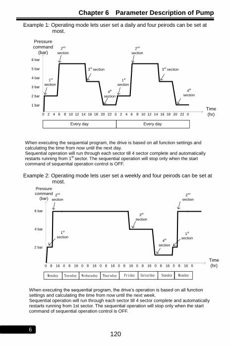
Chapter 6 Parameter Description of Pump
120 6
Example 1: Operating mode lets user set a daily and four peirods can be set at most.
0 2 4 6 8 10 12 14 16 18 20 22 0 2 4 6 8 10 12 14 16 18 20 22 0
Time
(hr)
Pressure
command
(bar)
1 bar
2 bar
3 bar
4 bar
5 bar
6 bar
Every day Every day
1st
section
2nd
section
3rd
section
4th
section
1st
section
2nd
section
3rd
section
4th
section
When executing the sequential program, the drive is based on all function settings and calculating the time from now until the next day. Sequential operation will run through each sector till 4 sector complete and automatically restarts running from 1
st sector. The sequential operation will stop only when the start
command of sequential operation control is OFF.
Example 2: Operating mode lets user set a weekly and four peirods can be set at most.
0 8 16
Time
(hr)
Pressure
command
(bar)
2 bar
4 bar
6 bar
Monday
1st
section
2nd
section
3rd
section
4th
section
0
Tuesday ThursdayWednesday Friday Saturday Monday Sunday
8 16 0 8 16 0 8 16 0 8 16 0 8 16 0 8 16 0 8 16 0
1st
section
2nd
section
When executing the sequential program, the drive’s operation is based on all function settings and calculating the time from now until the next week. Sequential operation will run through each sector till 4 sector complete and automatically restarts running from 1st sector. The sequential operation will stop only when the start command of sequential operation control is OFF.

Chapter6 Parameter Description of Pump
121 6
No Text on This Page
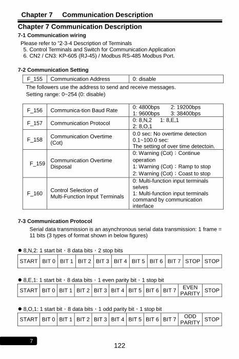
Chapter 7 Communication Description
122 7
Chapter 7 Communication Description
7-1 Communication wiring
Please refer to “2-3-4 Description of Terminals 5. Control Terminals and Switch for Communication Application 6. CN2 / CN3: KP-605 (RJ-45) / Modbus RS-485 Modbus Port.
7-2 Communication Setting
F_155 Communication Address 0: disable
The followers use the address to send and receive messages.
Setting range: 0~254 (0: disable)
F_156 Communica-tion Baud Rate 0: 4800bps 2: 19200bps 1: 9600bps 3: 38400bps
F_157 Communication Protocol 0: 8,N,2 1: 8,E,1 2: 8,O,1
F_158 Communication Overtime (Cot)
0.0 sec: No overtime detection 0.1~100.0 sec: The setting of over time detectoin.
F_159 Communication Overtime Disposal
0: Warning (Cot);Continue
operation
1: Warning (Cot);Ramp to stop
2: Warning (Cot);Coast to stop
F_160 Control Selection of Multi-Function Input Terminals
0: Multi-function input terminals selves 1: Multi-function input terminals command by communication interface
7-3 Communication Protocol
Serial data transmission is an asynchronous serial data transmission: 1 frame = 11 bits (3 types of format shown in below figures)
8,N,2: 1 start bit,8 data bits,2 stop bits
START BIT 0 BIT 1 BIT 2 BIT 3 BIT 4 BIT 5 BIT 6 BIT 7 STOP STOP
8,E,1: 1 start bit,8 data bits,1 even parity bit,1 stop bit
START BIT 0 BIT 1 BIT 2 BIT 3 BIT 4 BIT 5 BIT 6 BIT 7 EVEN
PARITY STOP
8,O,1: 1 start bit,8 data bits,1 odd parity bit,1 stop bit
START BIT 0 BIT 1 BIT 2 BIT 3 BIT 4 BIT 5 BIT 6 BIT 7 ODD
PARITY STOP

Chapter 7 Communication Description
123 7
7-4 Message Format
Address (Drive)
OP Code Data n … Data 1 Data 0 CRC 0 CRC1 END
Drive Address
No. (1 Byte)
Operation Message (1 Byte)
Data Message (Data length “n”: depending on
OP Code)
CRC Checksum
No Transmitting
≧10ms
●Address: Drive address number for host to control 00H: The host broadcasts messages to all receivers (drives). All
receivers only receive the message but has no messages returned to the host.
01H~FEH: The host designates the receiver (drive) by defining the drive address number.
●OP Code(Operation Code): The operation of the host to the drive 03H- Read multi-registers 06H- Write to single register 08H- Receiver detection 10H- Write to multi-registers
●Data: Including start register, several registers, data length (maximum 8 data), data content (maximum 16 bits) Note: Data length – 1 byte, others – 1 word(2 bytes)
●CRC Checksum: Cyclical Redundancy Check performs XOR and bit shifting operations for all hexadecimal values in the message to generate the checksum code to verify the communication validity. Checksum is to sum all message bits for 16-bit CRC calculations. (See CRC Checksum)
●Message Length: Message length is listed in between maximum and minimum values. Message lengths of OP code 03H and 10H are dependent on the number of registers required in one message. (See Operation Code(OP Code) Description)
OP Code
Description Instruction Code Return Code
Min(bytes) Max(bytes) Min(bytes) Max(bytes)
03H Read multi-registers 8 8 7 21
06H Write to single register 8 8 8 8
08H Drive Detection 8 8 8 8
10H Write to multi-registers 11 25 8 8

Chapter 7 Communication Description
124 7
●Operation Code(OP Code) Description:
※03H (Read multi-registers):
Example: Read data from registers 2101H and 2102H of the drive 1
Message Code (Host to Drive)
Address OP
Code
Starting Register Register
Numbers to Readout
CRC Checksum
MSB LSB MSB LSB LSB MSB
02H 03H 21H 01H 00H 02H 9FH C4H
This example shows the host to read the drive data from 2 registers of the drive. The host identifies drive 1 by calling the drive address (02H) with the “read” operation command (03H) to read the drive data from the registers (2101H – starting register) to the register (2102H – Register Numbers to Readout defines the numbers of register for data readouts).
Return Code (Drive to Host)
Address OP
Code Data Bytes
2101H(Register) Data
2102H(Register) Data
CRC Checksum
MSB LSB MSB LSB LSB MSB
02H 03H 04H 55H 00H 17H 70H D6H EBH
The host reads registers 2101H and 2102H of drive (02H) (drive status and speed command). After the drive receives the host’s command, the drive returns 4 bytes data (2101H=5500H and 2102H=1770H) to the host.
Caution: The host cannot simultaneously broadcast 03H OP code to drives when multiple drives connected or all drives reject host’s OP code.
※06H (Write to single register)
Example: Write a data (1770H) into the drive register (2001H)
Message Code (Host to Drive)
Address OP
Code
Drive Register Register Data CRC Checksum
MSB LSB MSB LSB LSB MSB
02H 06H 20H 01H 17H 70H DDH EDH
This example shows the host to write the data (1770H) to the register (2001H) of the drive. The host identifies drive 1 by calling the drive address (02H) with the “write” operation command (06H) to write the data (1770H) into the register (2001H).
Return Code (Drive to Host)
Address OP
Code
Drive Register Register Data CRC Checksum
MSB LSB MSB LSB LSB MSB
02H 06H 20H 01H 17H 70H DDH EDH
The host writes data 1770H into the drive register 2001H. After receiving data from the host and writing data into drive’s registers, the drive returns the original receiving message to the host. OP code-06H of the host can synchronously broadcast to all drives but has no return code to the host.
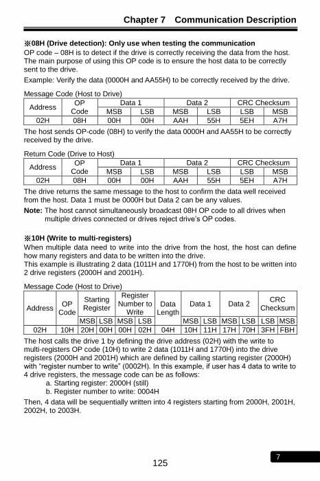
Chapter 7 Communication Description
125 7
※08H (Drive detection): Only use when testing the communication
OP code – 08H is to detect if the drive is correctly receiving the data from the host. The main purpose of using this OP code is to ensure the host data to be correctly sent to the drive.
Example: Verify the data (0000H and AA55H) to be correctly received by the drive.
Message Code (Host to Drive)
Address OP
Code
Data 1 Data 2 CRC Checksum
MSB LSB MSB LSB LSB MSB
02H 08H 00H 00H AAH 55H 5EH A7H
The host sends OP-code (08H) to verify the data 0000H and AA55H to be correctly received by the drive.
Return Code (Drive to Host)
Address OP
Code
Data 1 Data 2 CRC Checksum
MSB LSB MSB LSB LSB MSB
02H 08H 00H 00H AAH 55H 5EH A7H
The drive returns the same message to the host to confirm the data well received from the host. Data 1 must be 0000H but Data 2 can be any values.
Note: The host cannot simultaneously broadcast 08H OP code to all drives when multiple drives connected or drives reject drive’s OP codes.
※10H (Write to multi-registers)
When multiple data need to write into the drive from the host, the host can define how many registers and data to be written into the drive. This example is illustrating 2 data (1011H and 1770H) from the host to be written into 2 drive registers (2000H and 2001H).
Message Code (Host to Drive)
Address OP
Code
Starting Register
Register Number to
Write Data
Length Data 1 Data 2
CRC Checksum
MSB LSB MSB LSB MSB LSB MSB LSB LSB MSB
02H 10H 20H 00H 00H 02H 04H 10H 11H 17H 70H 3FH FBH
The host calls the drive 1 by defining the drive address (02H) with the write to multi-registers OP code (10H) to write 2 data (1011H and 1770H) into the drive registers (2000H and 2001H) which are defined by calling starting register (2000H) with “register number to write” (0002H). In this example, if user has 4 data to write to 4 drive registers, the message code can be as follows: a. Starting register: 2000H (still) b. Register number to write: 0004H
Then, 4 data will be sequentially written into 4 registers starting from 2000H, 2001H, 2002H, to 2003H.

Chapter 7 Communication Description
126 7
Return Code (Drive to Host)
Address OP
Code
Starting Register Register
Numbers to Write CRC Checksum
MSB LSB MSB LSB LSB MSB
02H 10H 20H 00H 00H 02H 4AH 3BH
The host writes 2 data (1011H and 1770H) with total data length 4 byte to 2000H and 2001H registers of drive. The drive receives and writes the data to the registers, and then returns the message to the host. The host can synchronously broadcast all drives to write multi-data to multi-registers in order to change the data synchronously.
7-5 CRC Checksum Algorithm
CRC checksum code is to verify the message validity during the communication and its algorithm is to apply each code in the message to perform XOR and bit shifting operations to generate the CRC code. Here is the checksum algorithm diagram to generate CRC code.
FFFFH1
st Code
Address
Bit Shifting &
XOR(A001H)
2nd
Code
OP Code
Bit Shifting &
XOR(A001H)
3rd
Code
…CRC
Code
XOR XOR
The following example of showing how CRC code is generated.
Example: To generate CRC code D140 from Address Code: 02H and OP Code: 03H 1 1 1 1 1 1 1 1 1 1 1 1 1 1 1 1
0 0 0 0 0 0 1 0
1 1 1 1 1 1 0 11 1 1 11 1 1 10 1 1 1 1 1 1 01 1 1 11 1 1 1
1 0 1 0 0 0 0 0 0 0 0 0 0 0 0 1
1 0 1 0 0 0 0 0 0 0 0 0 0 0 0 1
1 1 0 1 1 1 1 1 1 1 1 1 1 1 1 10 1 1 0 1 1 1 1 1 1 1 1 1 1 1 11 0 1 0 0 0 0 0 0 0 0 0 0 0 0 1
1 1 0 0 1 1 1 1 1 1 1 1 1 1 1 00 1 1 0 0 1 1 1 1 1 1 1 1 1 1 10 0 1 1 0 0 1 1 1 1 1 1 1 1 1 11 0 1 0 0 0 0 0 0 0 0 0 0 0 0 1
1 0 0 1 0 0 1 1 1 1 1 1 1 1 1 00 1 0 0 1 0 0 1 1 1 1 1 1 1 1 10 0 1 0 0 1 0 0 1 1 1 1 1 1 1 11 0 1 0 0 0 0 0 0 0 0 0 0 0 0 1
1 0 0 0 0 1 0 0 1 1 1 1 1 1 1 00 1 0 0 0 0 1 0 0 1 1 1 1 1 1 10 0 1 0 0 0 0 1 0 0 1 1 1 1 1 1
1 0 0 0 0 0 0 1 0 0 1 1 1 1 1 00 0 0 0 0 0 1 1
1 0 0 0 0 0 0 1 0 0 1 1 1 1 0 1
MOVE 1
MOVE 3
MOVE 2
MOVE 5
MOVE 4
MOVE 6
MOVE 8MOVE 7
0 1 0 0 0 0 0 0 1 0 0 1 1 1 1 01 0 1 0 0 0 0 0 0 0 0 0 0 0 0 1
1 1 1 0 0 0 0 0 1 0 0 1 1 1 1 10 1 1 1 0 0 0 0 0 1 0 0 1 1 1 11 0 1 0 0 0 0 0 0 0 0 0 0 0 0 1
1 1 0 1 0 0 0 0 0 1 0 0 1 1 1 00 1 1 0 1 0 0 0 0 0 1 0 0 1 1 10 0 1 1 0 1 0 0 0 0 0 1 0 0 1 11 0 1 0 0 0 0 0 0 0 0 0 0 0 0 1
1 0 0 1 0 1 0 0 0 0 0 1 0 0 1 00 1 0 0 1 0 1 0 0 0 0 0 1 0 0 10 0 1 0 0 1 0 1 0 0 0 0 0 1 0 01 0 1 0 0 0 0 0 0 0 0 0 0 0 0 1
1 0 0 0 0 1 0 1 0 0 0 0 0 1 0 10 1 0 0 0 0 1 0 1 0 0 0 0 0 1 0
1 1 1 0 0 0 1 0 1 0 0 0 0 0 1 1
MOVE 1
MOVE 3
MOVE 2
MOVE 5
MOVE 4
MOVE 6
MOVE 8
MOVE 7
First Code 02H
Second Code 03H
XOR
D 4 01CRC :
1 0 1 0 0 0 0 0 0 0 0 0 0 0 0 1
0 1 1 1 0 0 0 1 0 1 0 0 0 0 0 11 0 1 0 0 0 0 0 0 0 0 0 0 0 0 1
1 1 0 1 0 0 0 1 0 1 0 0 0 0 0 0
1
1
1
1
1
1
01
01
01
01
01

Chapter 7 Communication Description
127 7
The following example of using C language to create a sample program for CRC checksum algorithm
Example: C language sample program
unsigned char *data; // Message pointer
unsigned char length; // Message length
unsigned int crc_chk(unsigned char *data,unsigned char length)
{
int i;
unsigned int reg_crc=0xffff;
while(length--)
{
reg_crc^=*data++;
for(i=0;i<8;i++)
if(reg_crc&0x01)
reg_crc=(reg_crc>>1)^0xa001;
else
reg_crc=reg_crc>>1;
}
}
7-6 Processing Time of Communication Transmission
Host
Drive
Communication Starts/Resets
10ms 10ms 5ms
(Note) Time
The communication waits for 10ms to start the communication transmission after the drive powers on or the communication function of the drive changes. The drive needs 5ms processing time to return the message to the host after the message are received from the host. If the host only broadcasts to the drive, the host can start sending the message code after 5ms.
Note: if the message code is to “Read” or “Write” the parameter, the drive needs 100ms processing time to return the message to the host.

Chapter 7 Communication Description
128 7
7-7 Communication Troubleshooting
1. When error occurs at the communication network, the drive provides the self-testing function to identify where error occurs. Please check communication function settings to verify the validity of functions.
2. When the host receives returned error messages from a drive, the host sends the invalid operation command to drive. The following table is the error message format.
Address OP Code Error Code CRC Checksum
LSB MSB
02H 1xxxxxxxB xxH xxH xxH
OP code sets MSB (bit7) as 1 for the original command message, but error code gives different values according to different types of errors. The below table is describing types of error code:
Error Code
Error Type Descriptions
0 0 Serial communication
format error
Parity error of serial communication
0 1 Data frame error of serial communication
0 2 Over-bit error of serial communication
0 3 Modbus OP code error OP code is not in either 03H,06H,08H, or 10H
0 4 Modbus CRC error CRC checksum error
0 5 Modbus data range
error
1. Data length in transmission not matched with the protocol
2. Data range over the register length at “write”
0 6 Modbus register
characteristics error Registers writes into read-only registers
0 7 Modbus register error No-defined registers

Chapter 7 Communication Description
129 7
7-8 Drive Registers and Command Code
●Registers – Write Operation Reg. No. Name Description
10nnH
(Note4) Function setting
Drive function setting/monitoring; nn=F_000 ~ F_194 Example: F0_19=1013H
2000H Operation command 1
b0~b1
00: No use
01: Stop
10: Start
11: JOG command
b2~b3 Reserved
b4~b5
00: No use
01: Forward command
10: Reverse command
11: Rotation direction change command
b6~b7
00: Primary accel/decel time
01: Second accel/decel time
10: Third accel/decel time
11: Fourth accel/decel time
b8~bA
000: Primary speed (communication)
001: Preset speed 1
010: Preset speed 2
011: Preset speed 3
100: Preset speed 4
101: Preset speed 5
110: Preset speed 6
111: Preset speed 7
bB Reserved
bC~bD
00: No use
01: b6~bA functions *Note 1
10: Enable operation command 2 resister.
11: Disable 01 and 10
bE~bF Reserved
2001H Frequency command Primary frequency is set by communication (unit: 0.01Hz)
2002H Operation command 2
b0 1: External fault command
b1 1: Reset command
b2 1: Jog command
b3 1: Output interruption command
b4 1: Coast to stop command
b5 1: Secondary accel/decel command
b6 1: Accel/decel prohibition command
b7 1: Select analog input source
bA~bF Reserved
2003H Constant pressure
setting Setting value (SV) is controlled by communication. (Unit: 0.1 bar)

Chapter 7 Communication Description
130 7
●Registers – Read Operation Reg. No. Name Description
2100H Drive error code
00H No error
01H Drive over current (OC)
02H Over voltage (OE)
03H Drive overheat (OH)
04H Drive overload (OL1)(OL2)
05H Motor overload (OL)
06H External fault (EF)
07H Short protection (SC)
08H A/D converter error (AdEr)
09H- 12H
Reserved
13H Grounding fault (GF)
14H Under voltage during operation (LE1)
15H EEPROM error (EEr)
16H Reserved
17H Drive output interruption (bb)
18H System overload (OLO)
19~20 Reserved
21 Coast to stop (Fr)
22H- 30H
Reserved
31H PID feedback signal error.
32H Water shortage protection(noFB)
33H Over pressure protection(OP)
2101H Drive status 1
b0~b7 Reserved
b8 1: Frequency control by communication
b9 1: Frequency control by analog inputs
bA 1: Operation command by communication
bB 1: Parameter locking
bC 1: Drive running status
bD 1: Jog running status
bE 1: Forward indication
bF 1: Reverse indication
2102H Frequency command Monitor drive’s frequency command (unit: 0.01Hz)
2103H Output frequency Monitor drive’s output frequency(unit: 0.01Hz)
2104H Output current Monitor drive’s output current(unit: 0.1A)
2105H DC bus voltage Monitor drive’s DC bus voltage(unit: 0.1V)
2106H Output voltage Monitor drive’s AC output voltage(unit: 0.1V)
2107H Frequency of multi-speed
Monitor drive’s frequency of multi-speed *Note 2
2108H PV value Monitor drive’s PV value (unit: 0.1 bar)
2109H Reserved
210AH Reserved
210BH Reserved
210CH Reserved

Chapter 7 Communication Description
131 7
210DH Reserved
210EH Reserved
210FH Reserved
2300H I/O terminal status
b0 Reserved
b1 Reserved
b2 1: X1 terminal operation
b3 1: X2 terminal operation
b4 1: X3 terminal operation
b5 1: X4 terminal operation
b6 Reserved
b7 Reserved
b8 1: Y1 terminal detection
b9 Reserved bA Reserved bB Reserved bC 1: Primary speed by analog input
bD 1: Primary speed by operation panel
bE 1: Primary speed by UP/DOWN command
bF 1: Primary speed by communication
2301H Drive status 2
b0 Reserved
b1 1: Constant speed
b2 1: Zero speed
b3 1: Frequency detection
b4 1: System overload
b5 1: Stall prevention
b6 Reserved
b7 1: Braking action
b8 Reserved
b9 Reserved
bA 1: Error signal
bB~bF Reserved
2302H Reserved
2303H Fault record 1 Fault record 1 *Note 3
2304H Fault record 2 Fault record 2 *Note 3
2305H Fault record 3 Fault record 3 *Note 3
2306H Fault record 4 Fault record 4 *Note 3
2307H Fault record 5 Fault record 5 *Note 3

Chapter 7 Communication Description
132 7
Note: 1. When b6 ~ bA function is enabled, multi-function command –Multi-speed 1, 2, 3, will be
inactive.
2. 0: Analog
1: Primary speed
2~8: Multi-speed 1~7
9: Jog speed
11: Communication
3. Fault record table
Error code Drive display Description
01H (AdEr)
A/D converter error
02H (Fot)
IGBT module error
03H (EEr1)
Internal memory error
08H (OC)
Drive over current
0CH (OE)
Over voltage
0DH (LE1)
Under voltage during operation
0EH (GF)
Grounding fault
0FH (OH)
Drive overheat
10H (OL)
Motor overload
11H (OL1)
Drive overload
12H (OLO)
System overload
13H (EF)
External fault
14H (PAdF)
Keypad interruption during copy
16H (ntcF)
Thermal sensor fault
17H (OH2)
Motor overheat
18H (noFb)
PID feedback signal error
19H (OL2)
Drive current limit
4.AGnnH—Write and read allowed 2000H~2002H—Write only, read prohibited
2100H~210FH—Read only, write prohibited

Chapter 7 Communication Description
133 7
7-9 Programming Examples – Register and Command
7-9-1 Access Drive Function Setting – Write Operation Write a single register to access drive function setting: Ex: Set function F_031 (primary speed) = 30 Hz a. Register address: 001FH ( 31 (decimal) = 001FH (hex) )
b. Speed =:0BB8H ( 30Hz 30.00Hz(resolution: 0.01Hz) 30.00 ÷
0.01 = 3000 (decimal) = 0BB8H (hex) Code to write to drive register from the host (CRC exclusive)
Address OP Code Drive Register Register Data
MSB LSB MSB LSB
01H 06H 00H 1FH 0BH B8H
7-9-2 Host Control to Drive – Write Operation
When the host control by Modbus communication, user can simply create an icon or active key/button to activate the drive. The following examples shows how to program the communication control.
1. Start the drive: a. Create an icon or active button/key on the host for “Drive Start” b. Program the host with the following code for “Drive Start” c. The drive register to be written for start operation: 2000H d. The register data for start operation: 0002H
Address OP Code Drive Register Register Data
MSB LSB MSB LSB
01H 06H 20H 00H 00H 02H
2. Forward rotation command: a. Create an icon or active button/key on the host for “Forward” b. Program the host with following code for “Forward” rotation control c. The drive register to be written for forward command: 2000H d. The register data for forward command: 0010H
Address OP Code Drive Register Register Data
MSB LSB MSB LSB
01H 06H 20H 00H 00H 10H
3. Speed Setting (frequency command) – without using drive function setting: Set the speed to be 30.05Hz (resolution: 0.01Hz) a. The drive register to be written for Speed setting(frequency
command): 2001H b. Convert 30.05Hz to hexadecimal value:
30.05 x 100 (by the resolution) = 3005 (decimal) = 0BBDH
Address OP Code Drive Register Register Data
MSB LSB MSB LSB
01H 06H 20H 01H 0BH BDH

Chapter 7 Communication Description
134 7
4.Primary Acceleration/Deceleration Time Setting: Set the acceleration/deceleration time = 1.5 seconds (resolution: 0.1 seconds) a. Set F_019 (Primary accel time) = 1.5 seconds
Convert F_019 to hexadecimal value for generating register number: 18 (decimal) = 12H Convert 1.5 seconds to hex value: 1.5 x 10 (by resolution) = 15 (decimal) = 000FH
b. Set F_020 (Primary decel time) = 1.5 seconds Convert F_020 to hex value: 19 (decimal) = 13H
c. Select primary accel/decel time command: register: 2000H, register data = 00 (b6,b7)
Set the acceleration time F_019 = 1.5 seconds
Address OP Code Drive Register Register Data
MSB LSB MSB LSB
01H 06H A2H 12H 00H 0FH
Set the deceleration time F_020 = 1.5 seconds
Address OP Code Drive Register Register Data
MSB LSB MSB LSB
01H 06H A2H 13H 00H 0FH
Select primary acceleration/deceleration time
Address OP Code Drive Register Register Data
MSB LSB MSB LSB
01H 06H 20H 00H 00H 00H
7-9-3 Host Control to Drive – Read Operation 1. Drive Error Trips (Fault Code):
Example: Drive error trips due to “GF” (grounding fault) and the fault message displayed at the host. 1) The host sends the below codes to access the drive register
to monitor drive faults (read only one register data) a.-Drive register: 2100H b.-Number of register to read: 1 0001H
Message Code (Host to Drive)
Address OP Code Drive Register
Register Numbers to Readout
MSB LSB MSB LSB
01H 03H 21H 00H 00H 01H
2) The drive returns the fault code to the host when “GF” occurs: -GF code: 0DH
Return Code (Drive to Host)
Address OP Code Data Byte 2100H(Register) Data
MSB LSB
01H 03H 04H 00H 0DH
c. Program the host to convert register data 000DH to “GF” message

Chapter 7 Communication Description
135 7
2. Drive Frequency Output Readout:
Example: If the drive frequency outputs = 40.65Hz, read the data output from the drive and display 40.05Hz in the host.
a. The host sends the below codes to access the drive register to read out the frequency output data (read only one register data) -Drive register: 2103H -Number of register to read: 1 0001H
Message Code (Host to Drive)
Address OP Code Drive Register
Register Numbers to Readout
MSB LSB MSB LSB
01H 03H 21H 03H 00H 01H
b. The drive returns the frequency output readouts to the host -Output frequency readouts from the drive (2103H register data):
Return Code (Drive to Host)
Address OP Code Data Byte 2103H(Register) Data
MSB LSB
01H 03H 04H 0FH E1H
c. Program the host to convert register data 0FE1H (Hex value) = 4065 (Decimal value)
d. Display the output frequency (resolution = 0.01): 4065/100 = 40.65 (unit in Hz)
Chapter 7 Communication Description
136 7
No Text on This Page

Chapter 8 Operation Procedures and Fault Protection
137 8
Chapter 8 Operation Procedures and Fault Protection
8-1 Operation Procedures
DANGER
1. Do Not remove wires when the internal indicator of the drive remains ON.
2. After power off (30HP below models must wait at least 5 minutes; 40HP~75HP models must wait at least 10 minutes; 100HP above models must wait at least 20 minutes), Do Not perform any unwiring actions before drive indicator light (CHARGE) turns off. Use a multimeter with the DC voltage stage to measure the cross voltage between P(+) and N(-) ports (DC bus voltage must be less than 25V).
CAUTION
1. Check if the shield of wire is broken after wiring is completed to avoid electric leakage or short circuit.
2. Screws on the terminal must be fastened.
A. Verify and check the compatibility between power source, voltage, motor, and drive.
B. Connect the power to drive R/L1, S/L2, T/L3 (three-phases) or R/L1, S/L2 terminals (single-phase).
C. Set all required parameters and functions after power is ON and measure the output voltage of the drive at U/T1, V/T2, W/T3 terminals to verify if the output
voltage and current are valid. Press OFF
RESET when completing all verifications.
D. Switch off the power and wait for drive’s power indicators off, and then connect drive’s U/T1, V/T2, W/T3 terminals to the motor.
E. Operate the motor with the drive by low speed after power ON to verify the validity of the motor rotation direction and then to slowly increase the motor speed.
F. Motor start or stop must be controlled by drive control signal instead of switching the power ON / OFF. The lifetime of the drive will be significantly reduced if the invalid operation using the switch control of the power is applied to motor control.
G. Because the starting current of motor is 6~8 times of rated current, Do NOT install the magnetic contactor between the drive and motor for the motor operation.
H. When using the single-phase power source to drive the three-phase drive (not the standard type of single-phase power input), first confirm the horsepower of motor, and then calculate the motor rated current by multiplying the motor rated current by 2 times to the base value of drive rated current. The drive selection for this single-phase power must have the rated current equal to the calculated drive rated value.
Formula: Motor rated current × 2 = Drive rated output current

Chapter 8 Communication Description
138 8
Example:
a. Drive selection:
Motor specification: 220VAC, 1HP ; rated current: 3.1A
Base value of drive rated current=3.1 (A) × 2 = 6.2 (A)
Drive specifications: 220VAC, 1HP drive = 5A (rated output current) 2HP drive = 8A (rated output current)
Select 2HP drive for 1HP AC motor. b. Wiring of power: Connect the single-phase power line to R, S terminals. c. Parameter settings:
Please reset below functions. If the parameters are not modified, the motor and drive could be possibly damaged.
F_048 Motor Rated Current = 3.1A (the setting must be based on the motor rated current)
F_068 System Overload Detection Level = 80 (the half of the default setting value 160%)
F_071 Stall Prevention Level at Constant Speed = 80 (the half of the default setting value 160%)

Chapter 8 Operation Procedures and Fault Protection
139 8
8-2 Fault Protection Display and Troubleshooting
a: Description: The drive has well protection functions to protect drive and motor when faults occur. When the fault occurs, the drive trips by the protection functions and display fault message on keypad. After the fault is troubleshooted, reset the
drive by pressing OFF
RESET of keypad or command the drive to reset through
multi-function input terminals by an external reset signal
b: Protection and Troubleshooting List:
Error Trip Messages of Drive
Display Description Cause Troubleshooting
(EEr)
SV
KEYPAD
PVRunning
EEPROM error
●EEPROM data write fault.
●EEPROM component defected.
●Please reset all parameters to default value and restart the drive.
●Return the drive to repair, when the fault cannot be eliminated.
(AdEr)
SV
KEYPAD
PVRunning
A/D converter error
--- Please call customer service for drive repair.
(SC)
SV
KEYPAD
PVRunning
Fuse open
●Drive internal fuse open.
●IGBT power module damage.
Please call customer service for drive repair.
(SC1)
SV
KEYPAD
PVRunning
Short circuit protection
The output terminals of drive are short.
Check wires of U/T1,V/T2,W/T3 terminals to verify if there is short between terminals.
(LE1)
SV
KEYPAD
PVRunning
Under voltage during operation
The internal DC bus voltage level is below 70%.
●Phase failure of input power.
●Instantaneous power off.
●Voltage variation of power source is too high.
●Motor with instant overload causing the high voltage drop.
Increase the power capacity by selecting higher capacity drive to avoid the voltage drop of the power cord.

Chapter 8 Communication Description
140 8
Error Trip Messages of Drive
Display Description Cause Troubleshooting
(OC)
SV
KEYPAD
PVRunning
Drive over current
The output current of drive during operation exceeds 220% of drive’s rated current.
●The output terminals of drive are short.
●The load is too heavy.
●The acceleration time is too short.
●Drive starts at zero speed while the motor is still running in rotation condition.
●Wrong wiring or
bad insulation.
●Starting voltage is
too high.
●The motor terminal installs an advance-phase or filter capacitor.
●Check wires of U/T1,V/T2,W/T3 terminals to verify if there is short between terminals.
●Check the motor and drive compatibility.
●Check if the motor operated in over-rated condition.
●Check if the the acceleration time is too short.
(GF)
SV
KEYPAD
PVRunning
Grounding fault ●The three-phase
output current is unbalance and exceeding the detection level of grounding fault.
●Grounding fault protection: F_098
The output terminal of the drive is short or grounding.
Check the insulation value of motor and the shield of motor’s wire.
(OE)
SV
KEYPAD
PVRunning
Over voltage ●The internal DC
bus voltage of drive is over the protection level.
●100V / 200V series: About DC410V.
●400V series: About DC820V.
●The deceleration time of motor is too short causing the regeneration voltage on DC bus too high.
●Power voltage is too high.
●Increase the “deceleration time” or use high torque braking and dynamic brake unit to reduce input voltage.
●Check if the power input is within drive’s rated input range.
●Add AC reactor at power input terminal.

Chapter 8 Operation Procedures and Fault Protection
141 8
Error Trip Messages of Drive
Display Description Cause Troubleshooting
(OH)
SV
KEYPAD
PVRunning
Drive overheating
The temperature of drive’s heat sink reaches the 105℃.
●The surrounding temperature is too high.
●The heat sink has foreign body.
●The cooling fan of drive is fault.
●Improve the system ventilation.
●Clean the foreign body on the heat sink.
●Return the drive to replace the cooling fan.
(OL)
SV
KEYPAD
PVRunning
Motor overload
Operation current exceeds 150% of motor’s rated current and reaches the motor overload protection time.
●Motor is overloaded.
●The voltage setting of V/F pattern is too high or too low.
●The current setting of motor’s rated current is invalid.
●Check the load of motor.
●Check if the acceleration or deceleration time is too short.
●Check if V/F setting is proper.
●Check if the rated current setting is valid.
(OL1)
SV
KEYPAD
設定值
PV
實際值Running
Drive overload
Operation current exceeds 150% of drive’s rated current for 1 minute.
●Motor overload.
●The voltage setting of V/F pattern is too high or too low.
●Drive capacity is too small.
●Check whether the motor is overloaded.
●Check the load of motor if overload.
●Check whether the acceleration or deceleration time is too short.
●Check if V/F setting is proper.
●Select the higher capacity of drive.
(OLO)
SV
KEYPAD
PVRunning
Syste9m overload
●Load system is overload and the operation current reaches the active level.
●Detection level: F_068.
●Detection time: F_069.
--- Check the usage of mechanical equipment.

Chapter 8 Communication Description
142 8
Error Trip Messages of Drive
Display Description Cause Troubleshooting
(thr)
SV
KEYPAD
PVRunning
External fault
The multi-function terminal receives the external fault signal.
Clear the external fault and then press
OFF
RESET key.
(ntCF)
SV
KEYPAD
PVRunning
NTC thermistor sensor fault
●NTC thermistor sensor broke down. ●The wiring connection of the NTC thermistor sensor is loose.
●Check whether the NTC thermistor sensor is normal. ●Check whether the wire of NTC thermistor sensor is normal.
(PAdF)
SV
KEYPAD
PVRunning
Keypad interruption during copy
●The connecting wire of the keypad is loosen.
●The keypad jack of the drive is oxidized.
Check the connecting wire of keypad.
(no Fb)
SV
KEYPAD
PVRunning
PID feedback signal error
The feedback signal wire is loosen/ tripped.
Check the feedback signal wire.
(OP)
SV
KEYPAD
PVRunning
Over pressure
●The setting value of F148 is not appropriate. ●Pump oulet pressure is too high. ●The water valve shut down immediately. ●The pressure sensor is abnormal.
●Check whether the setting value of F148 is appropriate.
●Check whether the pressure of water pipe is normal.
●Check whether the pressure sensor is normal.
(Fb Lo)
SV
KEYPAD
PVRunning
Water shortage protection
●Pressure level of water shortage F_119
●Current level of water shortage
F_120 ●Detection time of
water shortage F_121
●Outflow is greater than inflow.
●Pump cannot suck up any water.
●The inlet of pump is blocked.
●Check whether the water usage is under the normal condition.
●Check whether the water storage tank is lack of water.
●Check whether the inlet is blocked .

Chapter 8 Operation Procedures and Fault Protection
143 8
Warning Messages of Drive *When the drive displays below messages, drive stops output. If the abnormal condition is removed, the drive auto recovers the normal operation.
Display Description Cause Troubleshooting
(LE)
SV
KEYPAD
PVRunning
Power source under voltage The internal DC bus voltage level is below 70%.
The voltage of power source is too low.
Check if the voltage of power source is valid.
(bb)
SV
KEYPAD
PVRunning
Drive output interruption
Drive stops the output when the output interruption command is activated.
Clear drive output interruption command.
(Fr)
SV
KEYPAD
PVRunning
Coast to stop
Drive stops the output when the coast to stop command is activated.
Clear “coast to stop” command.
(db)
SV
KEYPAD
PVRunning
Dynamic brake over voltage
The internal DC bus voltage of drive is over the protection level.
DC bus voltage is too high .
Increase the “deceleration time” or use high torque braking method and add dynamic brake unit.
(PrEr)
SV
KEYPAD
PVRunning
Program fault --- Check the software version of drive.
(Ht)
SV
KEYPAD
PVRunning
Drive overheating
●The temperature of drive’s heat sink reaches the warning level.
●Warning level: F_142.
●The surrounding temperature is too high.
●The heat sink has foreign body.
●The cooling fan of drive is fault.
●Improve the system ventilation.
●Clean the dust on the heat sink.
●Return the drive to replace the cooling fan.
(Err_00)
SV
KEYPAD
PVRunning
(Err_01)
SV
KEYPAD
PVRunning
Err_00: Keypad cable trip before connecting Err_01: Keypad cable trip during operation
●The connecting wire of the keypad is loose.
●The keypad jack of the drive is oxidized.
Check the wire between the keypad and drive.

Chapter 8 Communication Description
144 8
Display Description Cause Troubleshooting
(dtF)
SV
MAIN
PVRUNNING
Direction command error
Forward and reverse commands are inputted to the drive simultaneously
Check the direction command.
(Wr_F)
SV
MAIN
PVRUNNING
Different software version inter-copy
The software version of drive is different.
Check up the software version.
(OP)
SV
KEYPAD
PVRunning
Over pressure ●Over pressure level: F_148 ●Detect time of over pressure: F_149
●The setting value of F148 is not appropriate.
●Pump oulet pressure is too high.
●The water valve shut down immediately.
●The pressure sensor is abnormal.
●Check the settings of function
(F_148~F149)
●Check the pressure of pump system and water pipes.
(CPyF)
SV
KEYPAD
PVRunning
Parameter copy fault
● In the parallel control, the software version of auxiliary drive do not correspond with the host drive.
● The software version of auxiliary drives must be correspond with the host drive.

Chapter 8 Operation Procedures and Fault Protection
145 8
No Text on This Page

Appendix A Peripheral Equipment of Drive
146 App.A
Appendix A Peripheral Equipment of Drive
Molded Case
Circuit Breaker
(MCCB)or Fuse
Magnetic
Contactor
(MC)
AC reactor
(ACL)
EMC filter
Zero-phase
radio frequency
filter (RFI)
Power
source
Please use within the permissible
power supply for the drive.
When the power is ON, a large in-
rush current flow will be inputted into
the drive. The breaker must be
selected carefully.
Option. When it is used for external
control or the DBU is used, it should be
installed at the primary side. Do not use
MC to start/stop the drive, otherwise the
life of drive will be reduced.
Reduce the harmonic
interference for low frequency
of power.
Reduce conduction
interference.
Reduce radiation interference.
The range of limited frequency
is 1MHz - 10MHz.
R S TL1 L2 L3
U V WT1 T2 T3
P(+) P1
DC reactor
(DCL)
Improve
power factor
of driver
The ACL can
reduce the leakage
current of motor
effectively; It is
used as the motor
is far away from the
drive.
Reduce radiation interference.
The range of limited
frequency is
1MHz - 10MHz.
Motor
(RFI Filter)
CAUTION
1. When the drive requires the following equipment, please select the proper external equipment. The incorrect system setup will result the failure of drive, reduce the of drive’s service life time, and even damage the drive.
2. The surrounding temperature will influence drive’s service life time. Please monitor the temperature to avoid of exceeding the temperature specifications, especially as drive installed at a closed place. In addition, the control signal should be far away from main loop to avoid of the signal interference.
3. The motor and drive should be grounded well to avoid of electric shocks. Motor’s grounding must connect to drive’s grounding terminal.

Appendix B Selection of AC Reactor(ACL)
147 App.C
Appendix B Selection of AC Reactor(ACL)
CAUTION
Due to the AC reactor(ACL) or DC reactor(DCL) possibly produce the heat (about 100℃) in use, please Do NOT touch the reactor and caution the environment
conditions.
a. Suppress the harmonic current of power and improve the power faction is the main function of the ACL and DCL. Connect the ACL at the power source input terminal of the drive also can suppress the surge voltage to protect the drive.
b. When the power capacity is over 500kVA or more than ten times of the rated capacity of the drive, adding the ACL (as below figure) is necessary. The input terminal (R/L1,S/L2,T/L3) of the drive must connect ACL.
Drive capacity (kVA)
ACL is necessary
7000
500
Po
we
r ca
pa
city (
kV
A)
0 50 700
ACL is not necessary
c. When the heater (with the SCR), air compressor, high-frequency equipment, or
welding machine is installed at the same power source site, the harmonic current will interfere the drive. Thus, add the ACL at the input terminal (R/L1,S/L2,T/L3) of the drive is required.
d. When multiple drives of high horse power are used, due to harmonic wave exerted, adding ACL at the input terminal (R/L1,S/L2,T/L3) of the drives is required to prevent the drives from the possible interference and power quality deterioration.
e. When the cable length between the drive and motor is over 30 meters or multiple motors are used in parallel, please add ACL at the output terminal of the drive.
f. Add the ACL at the input terminal(R/L1,S/L2,T/L3), the power factor is above 75%; Add ACL and DCL, the power factor is above 90%.(the specifications of ACL and DCL, please refer to page 149 ~150)
g. When horse power of drive is 100HP(included) or above, ACL is the standard equipment. When the drive is 175HP(included) or above, DCL is the standard equipment.
h. The connecting cable between the drive and DCL must be the same specifications with the cable of input terminal(R/L1,S/L2,T/L3).
i. For installation, in accordance with the motor capacity to select the suitable ACL to use and the specifications list are as below:

Appendix B Selection of AC Reactor(ACL)
148 App.C
AC Reactor (ACL) Specifications
Drive model number
Input
(R/L1,S/L2,
T/L3)
Output
(U/T1,V/T2,
W/T3) Drive model number
Input
(R/L1,S/L2,
T/L3)
Output
(U/T1,V/T2,
W/T3)
(mH) (A) (mH) (A) (mH) (A) (mH) (A)
RM6F5-2001 0.45 15 0.45 15 RM6F5-4001 0.45 15 0.45 15
RM6F5-2002 0.45 15 0.45 15 RM6F5-4002 0.45 15 0.45 15
RM6F5-2003 0.45 15 0.45 15 RM6F5-4003 0.45 15 0.45 15
RM6F5-2005 0.45 15 0.45 15 RM6F5-4005 0.45 15 0.45 15
RM6F5-2007 0.2 30 0.2 30 RM6F5-4007 0.45 15 0.45 15
RM6F5-2010 0.2 30 0.13 50 RM6F5-4010 0.2 30 0.2 30
RM6F5-2015 0.13 50 0.13 50 RM6F5-4015 0.2 30 0.2 30
RM6F5-2020 0.13 50 0.07 75 RM6F5-4020 0.2 30 0 .13 50
RM6F5-2025 0.07 75 0.05 100 RM6F5-4025 0.13 50 0.13 50
RM6F5-2030 0.05 100 0.05 100 RM6F5-4030 0.13 50 0.13 50
RM6F5-2040 0.05 100 0.035 150 RM6F5-4040 0.13 50 0.07 75
RM6F5-2050 0.035 150 0.025 200 RM6F5-4050 0.07 75 0.05 100
RM6F5-2060 0.025 200 0.025 200 RM6F5-4060 0.05 100 0.05 100
RM6F5-2075 0.025 200 0.015 300 RM6F5-4075 0.05 100 0.035 150
RM6F5-2100 0.015 300 0.013 400 RM6F5-4100 0.025 200 0.025 200
RM6F5-2125 0.013 400 0.013 400 RM6F5-4125 0.015 300 0.015 300
RM6F5-2150 0.01 600 0.01 600 RM6F5-4150 0.015 300 0.015 300
RM6F5-2200 0.006 800 0.006 800 RM6F5-4175 0.015 300 0.015 300
RM6F5-2250 0.006 800 0.005 1000 RM6F5-4200 0.015 300 0.013 400
- - - - - RM6F5-4250 0.013 400 0.03 400
- - - - - RM6F5-4300 0.013 400 0.01 600
- - - - - RM6F5-4350 0.01 600 0.01 600
- - - - - RM6F5-4420 0.01 600 0.006 800
- - - - - RM6F5-4500 0.006 800 0.006 800
- - - - - RM6F5-4600 0.006 800 0.005 1000
RM6F5-4700 0.005 1000 0.005 1000

Appendix B Selection of AC Reactor(ACL)
149 App.C
DC Reactor (DCL) Specifications
Drive model
number
200V Series Drive model
number
400V Series
(mH) (A) (mH) (A)
RM6F5-2007 1.2 30 RM6F5-4007 1.5 20
RM6F5-2010 1.2 30 RM6F5-4010 1.5 20
RM6F5-2015 0.9 50 RM6F5-4015 1.2 30
RM6F5-2020 0.5 75 RM6F5-4020 1.2 30
RM6F5-2025 0.5 75 RM6F5-4025 0.9 50
RM6F5-2030 0.4 100 RM6F5-4030 0.9 50
RM6F5-2040 0.4 100 RM6F5-4040 0.9 50
RM6F5-2050 0.25 150 RM6F5-4050 0.5 75
RM6F5-2060 0.2 200 RM6F5-4060 0.4 100
RM6F5-2075 0.2 200 RM6F5-4075 0.4 100
RM6F5-2100 0.15 300 RM6F5-4100 0.25 150
RM6F5-2125 0.177 400 RM6F5-4125 0.2 200
RM6F5-2150 0.126 600 RM6F5-4150 0.2 200
RM6F5-2200 0.126 600 RM6F5-4175 0.15 300
RM6F5-2250 0.09 800 RM6F5-4200 0.15 300
- - - RM6F5-4250 0.177 400
- - - RM6F5-4300 0.177 400
- - - RM6F5-4350 0.126 600
- - - RM6F5-4420 0.126 600
- - - RM6F5-4500 0.09 800
- - - RM6F5-4600 0.09 800
RM6F5-4700 0.07 1000

Appendix B Selection of AC Reactor(ACL)
150 App.C
Outline dimensions of AC reactor (ACL)
Specifications of AC reactor (ACL)
Capacity Figure A B C D W
(MAX)
L
(MAX)
H
(MAX) G I
Weight
(kg)
0.4mH/15A A 150 80 66 85 152 97 146 16×8 M4 4.0
0.2mH/30A B 150 80 66 85 152 127 130 16×8 6 4.2
0.13mH/50A B 150 80 68 85 152 134 131 16×8 6 4.6
0.07mH/75A B 150 80 68 85 151 134 131 16×8 6 4.8
0.05mH/100A B 180 100 77 97 182 145 149 16×8 8 8.0
0.035mH/150A B 180 100 77 97 182 148 149 16×8 8 8.6
0.025mH/200A B 180 100 90 107 182 165 153 16×8 8 9.8
0.015mH//300A C 190 120 104 130 225 220 210 25×14 12 19
0.013mH//400A C 230 120 104 130 230 240 200 22×10 12 20.2
0.01mH//600A C 280 140 120 135 280 270 235 22×10 16 29.3
0.006mH/800A D 300 150 140 174 300 300 305 25×13 15 65
0.005mH/1000A D 350 160 145 184 350 290 320 25×13 14 84.6
(unit: mm)
H(MAX)
H(MAX)
A
A
W(MAX)
W(MAX)
H(MAX)
A
D
C
W(MAX)
A
圖C
D
圖D
L(MAX)
D
圖A 圖B
6-ψI
CB
H(MAX)
C
L(MAX)
6-ψI
B
固定孔4-G
6-ψI
L(MAX)
B CD
L(MAX)
B
W(MAX)
6-I
固定孔4-G
4-G固定孔固定孔4-G
Figure A Figure B
Figure C Figure D
HoleHole
HoleHole

Appendix B Selection of AC Reactor(ACL)
151 App.C
Outline dimensions of DC reactor (DCL)
圖A
A D
圖BW(MAX)
A D
圖C
C
D
B
L(MAX)
H(M
AX)
W(MAX)
A
2-ψI
固定孔4-G
B C
2-ψI
H(M
AX)
H(MA
X)
W(MAX)
固定孔4-G
B C
L(MAX)
L(MAX)
2-ψI
圖A 圖B
圖C
Figure A Figure B
Figure C
Hole Hole
Specifications of DC reactor (DCL)
Capacity Figure A B C D W
(MAX)
L
(MAX)
H
(MAX) G I
Weight
(kg)
1.5mH/20A A 96 80 81 98 96 120 85 11×5 5 3.0
1.2mH/30A A 114 95 89 110 114 150 100 13×6 6 4.4
0.9mH/50A A 134 111 87 107 134 160 115 14×6 6 6.5
0.5mH/75A A 134 111 87 107 134 160 115 14×6 6 6.8
0.4mH/100A A 162 135 102 133 162 180 140 17×8 8 12.5
0.25mH/150A A 162 135 114 145 162 188 140 17×8 8 13.8
0.2mH/200A A 162 135 122 153 162 200 139 17×8 8 15.5
0.15mH/300A B 160 120 123 140 190 225 230 21×10 12 19
0.177mH/400A B 200 150 160 170 200 280 270 22×13 12 34.7
0.126mH/600A C 240 182 175 194 240 320 315 20×13 14 60.5
0.09mH/800A C 250 150 150 190 250 290 385 25×13 15 72
0.07mH/1000A C 270 160 155 200 270 310 400 25×13 15 86
(unit: mm)

Appendix C Selection of EMC Filter
152 App.D
Appendix C Selection of EMC Filter
ElectroMagnetic Interference(EMI) is a major bother of drive. Drive will generate high-frequency / low-frequency noise to interfere the peripheral equipment by radiation or conduction during running. In many countries especially in Europe have the strict limit for the AC motor drive generated the electromagnetic interference. By installing the EMC filter can reduce much electromagnetic(conduction) interference from drive.
CAUTION (1) Keep all grounding connections as short as physically possible. (2) Use the largest area as grounding conductor, for example the cabinet wall. (3) The filter must be mounted on the same panel as the drive.
Recommending specification of EMC filter
Select an EMC filter in accordance with the model number of drive to suppress drive’s electromagnetic(conduction) interference.
200V Series
Drive model number EMC filter model number EMC filter rated current / phase
RM6F5-2001 FN3270H-10-44 10A / 3ψ
RM6F5-2002 FN3270H-10-44 10A / 3ψ
RM6F5-2003 FN3270H-20-44 20A / 3ψ
RM6F5-2005 FN3270H-20-44 20A / 3ψ
RM6F5-2007 FN3270H-35-33 35A / 3ψ
RM6F5-2010 FN3270H-35-33 35A / 3ψ
RM6F5-2015 FN3270H-50-34 50A / 3ψ
RM6F5-2020 FN3270H-65-34 65A / 3ψ
RM6F5-2025 FN3270H-80-35 80A / 3ψ
RM6F5-2030 FN3270H-100-35 100A / 3ψ
RM6F5-2040 FN3270H-150-99 150A / 3ψ
RM6F5-2050 FN3270H-200-99 200A / 3ψ
RM6F5-2060 FN3270H-200-99 200A / 3ψ
RM6F5-2075 FN3270H-250-99 250A / 3ψ
RM6F5-2100 FN3270H-320-99 320A / 3ψ
RM6F5-2125 FN3270H-400-99 400A / 3ψ
RM6F5-2150 FN3270H-600-99 600A / 3ψ
RM6F5-2200 FN3270H-800-99 800A / 3ψ
RM6F5-2250 FN3270H-800-99 800A / 3ψ

Appendix C Selection of EMC Filter
153 App.D
400V Series
Drive model number EMC filter model number EMC filter rated current / phase
RM6F5-4001 FN3270H-10-44 10A / 3ψ
RM6F5-4002 FN3270H-10-44 10A / 3ψ
RM6F5-4003 FN3270H-10-44 10A / 3ψ
RM6F5-4005 FN3270H-10-44 10A / 3ψ
RM6F5-4007 FN3270H-20-44 20A / 3ψ
RM6F5-4010 FN3270H-20-44 20A / 3ψ
RM6F5-4015 FN3270H-35-33 35A / 3ψ
RM6F5-4020 FN3270H-35-33 35A / 3ψ
RM6F5-4025 FN3270H-50-34 50A / 3ψ
RM6F5-4030 FN3270H-50-34 50A / 3ψ
RM6F5-4040 FN3270H-65-34 65A / 3ψ
RM6F5-4050 FN3270H-80-35 80A / 3ψ
RM6F5-4060 FN3270H-100-35 100A / 3ψ
RM6F5-4075 FN3270H-150-99 150A / 3ψ
RM6F5-4100 FN3270H-200-99 200A / 3ψ
RM6F5-4125 FN3270H-200-99 200A / 3ψ
RM6F5-4150 FN3270H-250-99 250A / 3ψ
RM6F5-4175 FN3270H-320-99 320A / 3ψ
RM6F5-4200 FN3270H-320-99 320A / 3ψ
RM6F5-4250 FN3270H-400-99 400A / 3ψ
RM6F5-4300 FN3270H-600-99 600A / 3ψ
RM6F5-4350 FN3270H-600-99 600A / 3ψ
RM6F5-4420 FN3270H-800-99 800A / 3ψ
RM6F5-4500 FN3270H-800-99 800A / 3ψ
RM6F5-4600 FN3270H-1000-99 1000A / 3ψ
RM6F5-4700 FN3270H-1000-99 1000A / 3ψ
Note: 1. The leakage current of FN2090 series approximately 0.5mA ~ 1.02mA 2. The leakage current of FN3270 series approximately 26.4mA ~ 59.5mA

Appendix D Zero-Phase Radio Frequency Filter Selection
154 App.E
Pass all 3-phase power cords through RFI filter in same direction with same coil number, and then connect to the power input terminal of the drive. Caution: Do Not exceed 4 coils to prevent overheat of RFI filter. (Note) Either the ground wire or the four-core cable with ground wire cannot pass through RFI filter; otherwise the filtration effect will be reduced.
Appendix D Zero-Phase Radio Frequency Filter Selection
Please read this manual carefully to understand the correct and safety operations before using the product to prevent possible personnel injuries caused by false operations.
CAUTION (1) Do Not touch zero-phase radio frequency filter to prevent the scald burn from
the extreme high temperature when power is on, just off, or during the operation.
(2) While lift up product, please note the weight of product and move it with proper method to avoid possible injuries.(Please be more cautions to the sharp parts).
(3) Wiring or inspection must be done by qualified professional technicians.
By installing the RFI filter(s), it can reduce the radio frequency interference generated by drive. Because the RFI filter is constructed by ferrite core, it is not related to the capacity and voltage of drive. 1. Specification of product:
Applied Model RM6E1
Environm
enta
l C
onditio
n
Use Place
(1) Clean place without high temperature, high humidity, and flammable gases.
(2) If the zero-phase radio frequency filter is installed inside the power distribution panel, the around temperature
should not exceed the range(-10~ +50℃).
(3) The heat will be generated in the zero-phase radio frequency filter, so the space should be reserved for heat dissipation.
Ambient Temperature
-10 ~ +40℃(no condensation)
Ambient Humidity 90%RH(no dew)
Ambient Gas No corrosive gas, and no flammable gas
Vibration 5.9m/ sec2(0.6G) below
2. Wiring for RFI: Connect the RFI filter in accordance with the following wiring diagram. (1) Install the RFI filter at the power source site of the drive
RST
RFI
RST
RFI
Power
Power
Ex. 2
Ex. 1

Appendix E Selection of Motor
155 App.E
Pass all 3-phase power cords through RFI filter in same direction with same coil number, and then connect to motor terminals of the drive. Caution: Do Not exceed 4 coils to prevent overheat of RFI filter. (Note) Either the ground wire or the four-core cable with ground wire cannot pass through RFI filter; otherwise the filtration will be reduced.
Pass all 3-phase power cords through RFI filter in same direction with same coil number, and then connect to motor terminals of the drive.
(Note) Either the ground wire or the four-core cable with ground wire cannot pass through RFI filter; otherwise the filtration will be reduced.
(2) Install the RFI filter at the output site of the drive
RFI
U
VW
RFI
Motor
U
VW Motor
Ex. 1
Ex. 2
(3) If the power cords are too thick to be winded, pass the power cords through RFI filter directly, and connect two or more RFI in series.
RFI Filter
U/T1
V/T2
W/T3
Motor
EX. 1
3. Recommend to use power cords as many as possible of coil number. If the RFI filter is overheated, please reduce the coil number to reduce temperature.
Wire Size (mm²) Coil Number of 3-Phase
Wire Selected Model
2 / 3.5 4
RFI-01 5.5 3
8 / 14 2
22 1
22 / 38 4
RFI-02 50/60 2
80 / 100 / 125 / 150 1
50/60 3
RFI-03 80 / 100 / 125 / 150 2
200 1
50 / 60 4
RFI-04
80 / 100 3
125 / 150 2
200 2
250 1

Appendix D Zero-Phase Radio Frequency Filter Selection
156 App.E
4. Outline dimensions of RFI-01: (unit: mm)
5. Outline dimensions of RFI-02
ψ7
160
7
130
86
37
1.4
180
8532
(unit: mm)

Appendix E Selection of Motor
157 App.E
6. Outline dimensions of RFI-03
211
130
R55
44
37
12
22.3ψ9
42.3
230
2
4713
0
54176
(unit: mm)
7. Outline dimensions of RFI-04
276
175
7 R5
54
63
46
12
22.3
ψ9
295
42.3
2
47
241
154
(unit: mm)

Appendix D Zero-Phase Radio Frequency Filter Selection
158 App.E
No Text on This Page

Appendix E Selection of Motor
159 App.E
Appendix E Selection of Motor
a. Standard Motor a. Must be used the 3-phase induction motor as load.
b. Motor cannot run at the low-speed operation for a long time because the cooling fan speed can be decreased as well as the motor temperature can be increased. For the long-time and low-speed operation, use the variable-frequency motor with the independent cooling fan.
c. Standard 3-phase induction motor (NEMA B) characteristics as follows:
d. When the motor speed exceeds the rated speed(50/60HZ), the torque will be decreased while the motor speed increasing.
e. Check the motor insulation. The standard requirement is 500V (or 1000V) / 100MΩ above.

Appendix E Selection of Motor
160 App.F
b.Insulation Measurement of Drive and Motor 1. Measure the drive insulation impedance
a. Please extremely cautious the following steps to test the main circuit insulation of drive. Any incaution operations while testing the drive insulation may possibly harm operating personnel and cause serious damages to drive.
b. Remove all wiring at power terminal (main circuit) and control circuit terminal before the testing is performed. Please follow the below diagram to wire all power terminals in parallel with an insulation tester for drive insulation test.
c. Using an insulation tester with DC500V to test the insulation value of drive. The drive insulation impedance must be greater than 20MΩ. If drive insulation impedance is below 20MΩ, replace a drive and contact the customer support for repair service of drive.
Insulation
tester
Drive
Drive Insulation Impedance Measurement
2. Measure the motor insulation impedance
a. Remove the U/T1, V/T2, W/T3 cables of motor from the drive before measuring the motor insulation impedance, and then measure the motor insulation impedance (including motor cables) using the insulation tester with DC500V. The motor insulation impedance (including motor cables) must be greater than 20MΩ.
b. If motor insulation impedance is less than 20MΩ, Do Not connect motor with a drive or the drive lifetime may be shorten or the drive may be possibly damaged due to insufficient motor insulation.
c. Please follow the below connection diagram for motor insulation test. Motor cables must be connected in parallel to the insulation tester with DC500V to test the insulation, and the motor insulation impedance must be greater than 20MΩ to connect the drive.
Insulation
tester Motor
Motor
cable
Motor Insulation Impedance Measurement (Including Motor Cables)

Appendix F Instruction of Drive Charging
161 App.G
Appendix F Instruction of Drive Charging
Caution: If the drive is unused or stored in the storage over 1 year, the surface of aluminum foil of electrolytic capacitor within the drive will be oxidized and cracked causing the L and C value up. This is the common characteristics of capacitor. Therefore, with directly applying the voltage and high current to drive after the drive is placed for a long time, the drive may be damaged due to the oxide film cracked.
A. If the drive is stored or non-used (no power ON) over 1 year, it is necessary to charge the drive by autotransformer for 30 minutes from 0 volt to the half of drive’s rated voltage and then to apply drive rated voltage to charge the drive for another 30 minutes.
B. When charging the internal capacitor of drive, the wiring between autotransformer and terminals (R/L1, S/L2) of drive is shown as below:
Autotransformer
AC Power
0
375125Drive
500
Output terminal
Input terminal
250
Connection diagram between autotransformer and drive
(single-phase series drive)
Autotransformer
AC Power
0
375125Drive
500
Output terminal
Input terminal
250
Connection diagram between autotransformer and drive
(Three-phase series drive) Note: If the drive is already applied with drive rated voltage and doesn’t display
SV
KEYPAD
設定值
PV
實際值Running
, on the display of the keypad, please contact the customer service
for repair service.

Appendix G Dynamic Brake Unit and Braking Resistor
162 App.H
Appendix G Dynamic Brake Unit and Braking Resistor
a. Braking transistor is installed in the following models
RM6-2001B3 ~ RM6-2040B3; RM6-4001B3 ~ RM6-4060B3
b. Outline of braking resistor (option)
Aluminum Case Resistor
c. Rated specification of braking resistor
Model number Specification Dimensions (mm) Max. weight
(g) L1 L2 W H D
MHL100-100 100W/100Ω 165 150 40 20 5.3 200
MHL100-400 100W/400Ω 165 150 40 20 5.3 200
MHL500-40 500W/40Ω 335 320 60 30 5.3 1100
※Notes:
1. When the braking is frequently applied, please increase the resistor wattage and add the cooling fan to prevent the resistor from overheating.
2. Aluminum case resistors have the better thermal performance. Please select 1.2 times rated power resistor by using general wirewound type resistor.
3. Please use the heat-resistant wire for the brake resistor wiring.
DANGER
When the dynamic brake unit is fault, the braking transistor maybe turn on for full cycle. Add the thermal protection device to cut off the power at high temperature to avoid the drive burnout (refer to the section f of Appendix D for wiring of braking resistor).

Appendix G Dynamic Brake Unit and Braking Resistor
163 App.H
d. Recommending specification of braking resistor
AC 200V Series
Model number of drive
Braking resistor specification Approximate
braking torque
(10%ED)
Minimum specification
Recommending combination
RM6F5-2001 100Ω/100W MHL100-100*1
170
RM6F5-2002 105
RM6F5-2003 100Ω/500W MHL500-40*1
75
RM6F5-2005 40Ω/500W 120
RM6F5-2007
20Ω/1000W MHL500-40*2
(2pcs in parallel)
145
RM6F5-2010 115
RM6F5-2015 85
RM6F5-2020 13.3Ω/1500W MHL500-40*3
(3pcs in parallel) 95
RM6F5-2025 10Ω/2000W MHL500-40*4
(4pcs in parallel) 100
RM6F5-2030 8Ω/2500W MHL500-40*5
(5pcs in parallel) 100
RM6F5-2040 6.6Ω/3000W MHL500-40*6
(6pcs in parallel) 100

Appendix G Dynamic Brake Unit and Braking Resistor
164 App.H
AC 400V Series
Model number of drive
Braking resistor specification Approximate
braking torque
(10%ED)
Minimum specification
Recommending combination
RM6F5-4001 400Ω/100W MHL100-400*1 145
RM6F5-4002 400Ω/200W MHL100-400*2
(2pcs in parallel) 105
RM6F5-4003 200Ω/300W MHL100-400*2
(2pcs in parallel) 150
RM6F5-4005 133.3Ω/300W MHL100-400*3
(3pcs in parallel) 135
RM6F5-4007 100Ω/400W MHL100-400*4
(4pcs in parallel) 130
RM6F5-4010 80Ω/1000W
MHL500-40*2
(2 sets in series)
105
RM6F5-4015 80
RM6F5-4020 40Ω/2000W
MHL500-40*4
(2pcs in parallel, 2 sets in series)
120
RM6F5-4025 100
RM6F5-4030 27Ω/3000W
MHL500-40*6
(3pcs in parallel, 2 sets in series)
120
RM6F5-4040 20Ω/4000W
MHL500-40*8
(4pcs in parallel, 2 sets in series)
130
RM6F5-4050 100
RM6F5-4060 13.3Ω/6000W
MHL500-40*12
(6pcs in parallel, 2 sets in series)
125

Appendix G Dynamic Brake Unit and Braking Resistor
165 App.H
e. Recommending specification of dynamic brake unit (DBU) and braking resistor
AC 200V Series
Drive DBU
specification Braking resistor specification
Approximate braking torque
(10%ED) Model number Model
(DBU6-) Unit (set)
Recommending combination Unit (set)
RM6F5-2125 L400 1 MHL500-40*18 (9000W / 2.2; 18pcs in parallel)
1 95
RM6F5-2150 L400 1 MHL500-40*22 (11000W / 1.82; 22pcs in parallel)
1 100
RM6F5-2200 L400 2 MHL500-40*26 (9000W / 2.2Ω; 18pcs in parallel)
2 110
RM6F5-2250 L400 2 MHL500-40*22 (11000W / 1.82; 22pcs in parallel)
2 115
AC 400V Series
Drive DBU
specification Braking resistor specification
Approximate braking torque
(10%ED) Model number Model
(DBU6-) Unit (set)
Recommending combination Unit (set)
RM6F5-4125 H200 1
MHL500-40*24 (12000W / 6.6; 12pcs in parallel, 2 sets in series)
1 125
RM6F5-4150 105
RM6F5-4175 H300 1
MHL500-40*36 (18000W / 4.4; 18pcs in parallel, 2 sets in series)
1 130
RM6F5-4200 105
RM6F5-4250 H400 1
MHL500-40*48 (24000W / 3.3; 24pcs in parallel, 2 sets in series)
1 115
RM6F5-4300 105
RM6F5-4350 H300 2 MHL500-40*36 (18000W / 4.4; 18pcs in parallel, 2 sets in series)
2 135
RM6F5-4420 H300 2 MHL500-40*40 (20000W / 4Ω; 20pcs in parallel, 2 sets in series)
2 140
RM6F5-4500 H400 2 MHL500-40*44 (22000W / 3.63Ω; 22pcs in parallel, 2 sets in series)
2 115
RM6F5-4600 H400 2 MHL500-40*52 (26000W / 3.08Ω; 26pcs in parallel, 2 sets in series)
2 110
RM6F5-4700 H400 3 MHL500-40*44 (22000W / 3.63Ω; 22pcs in parallel, 2 sets in series)
3 125

Appendix G Dynamic Brake Unit and Braking Resistor
166 App.H
Time
Output frequency
Tb
Ta f. Wiring Diagram of External Braking Resistor and Thermal Switch
CAUTION
Strongly recommend to Install the thermal switch for the brake protection to prevent the brake from any possible damages caused by the overheating on the braking resistor. Please refer to the figure 1 and 2 as following for the wiring diagram.
1.) Wiring diagram a
RM6F5
IM
Tc2
Ta2
R/L1
S/L2
T/L3 W/T3
V/T2
PE
U/T1
PR P N
Main Circuit TerminalControl Terminal
PE
R/L1
S/L2
T/L3
MCX4 (External Fault)
COM
MC
Braking Resistor (option)
Three-phase AC
power source
(single-phase terminal
are R/L1,S/L2)
Thermal Switch
(OHD3-100B)
AC Motor
(Figure 1)
(1) Use the thermal switch to protect the temperature of braking resistor and generate an external fault signal to the multi-function terminal (X4) to stop the drive when the braking resistor is overheating and interrupt the connection of magnet contactor (MC) by output terminals Ta2 / Tc2.
(2) Set the multi-function terminal (X4) to “-7” (External fault).
(3) Set the multi-function terminal (Ta2 / Tc2) to “-11” (Error detection).
Note:
1. %ED (Effective Duty Cycle) = Tb/Ta*100% (continuous operation time Tb<15 sec).The definition is shown as above figure.
2. Above wattages of table is defined at 10%ED.
3. 200V series drive or DBU braking activation voltage is DC 395V
4. 400V series drive or DBU braking activation voltage is DC 790V

Appendix G Dynamic Brake Unit and Braking Resistor
167 App.H
2.) Wiring diagram b
RM6F5
IM
R/L1
S/L2
T/L3 W/T3
V/T2
PE
U/T1
PR P N
AC Motor
PE
Braking Resistor (option)
R/L1
S/L2
T/L3
MC
RELAY
OFF
ON
MC
MC
AC220V
AC220V
RELAY
DC24V
DC0V
Thermal Switch
(OHD3-100B)
OHD3-100B
(Figure 2)
When the drive power is controlled by the magnet contactor (MC), use the thermal switch to control magnet contactor (MC). When the braking resistor is overheating, the contactor (MC) is disconnected.

Appendix G Dynamic Brake Unit and Braking Resistor
168 App.H
g. Wiring Diagram of External Dynamic Brake Unit(DBU6) and Thermal Switch
CAUTION
Strongly recommend to Install the thermal switch for the brake protection to prevent the brake from any possible damages caused by the overheating on the braking resistor. Please refer to the figure 1 and 2 as following for the wiring diagram.
1.) Wiring diagram a
RM6F5
IM
Tc2
Ta2
R/L1
S/L2
T/L3 W/T3
V/T2
PE
U/T1
PR P N
Main Circuit TerminalControl Terminal
PE
R/L1
S/L2
T/L3
MCX4 (External Fault)
COM
Braking Resistor (option)
Three-phase AC
power source
(single-phase terminal
are R/L1,S/L2)
AC Motor
P N
RB1 RB2
MC
DBU6
Thermal guard
(OHD3-100B)
(Figure 1)
(1) Use the thermal switch to protect the temperature of braking resistor and generate an external fault signal to the multi-function terminal (X4) to stop the drive when the braking resistor is overheating and interrupt the connection of magnet contactor (MC) by output terminals Ta2 / Tc2.
(2) Set the multi-function terminals (X4) to “-7” (External fault).
(3) Set the multi-function terminals (Ta2 / Tc2) to “-11” (Error detection).
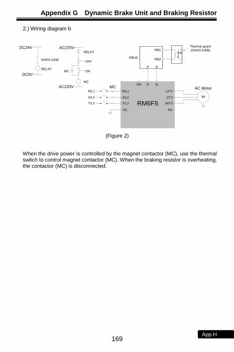
Appendix G Dynamic Brake Unit and Braking Resistor
169 App.H
2.) Wiring diagram b
P N
RB1
RB2DBU6
Thermal guard
(OHD3-100B)
RM6F5
IM
R/L1
S/L2
T/L3 W/T3
V/T2
PE
U/T1
PR P N
AC Motor
PE
R/L1
S/L2
T/L3
MC
RELAY
OFF
ON
MC
MC
AC220V
AC220V
RELAY
DC24V
DC0V
OHD3-100B
(Figure 2)
When the drive power is controlled by the magnet contactor (MC), use the thermal switch to control magnet contactor (MC). When the braking resistor is overheating, the contactor (MC) is disconnected.

Appendix H Instruction of Remote Controller and External Display
170 App.I
Appendix H Instruction of Remote Controller and External Display
a. Remote controller: KP-605 Two types of the remote controller: Internal panel type and external panel type:
1. Dimension of internal panel type (consist of A-01, KP-605
(unit: mm)
2. Dimension of external panel type (consist of A-01, A-02, KP-605)
R2.5 M4-4攻牙
ψ532.5
65
14 37 63.2
2
48.2
124
112
6
(Unit: mm)

Appendix H Instruction of Remote Controller and External Display
171 App.I
b. External display: DM-501
1. Outline dimensions
2.7 90.6
96
98
75
44
7
1.5
2
Unit:mm
Panel cutting
dimension
93
45
48
2. Appearance of display panel
3. The standard length of 2.54/5P wires is 1.5 m and 3 m respectively. Do not exceed
this length.

Appendix I Outline Dimension Drawing of Drives
172 App.J
Appendix I Outline Dimension Drawing of Drives
Model Number: RM6F5-2001 ~ RM6F5-2005; RM6F5-4001 ~ RM6F5-4007
螺絲M4-4128
13
8
128
142
5.51
38
15
1.5
6.5
2-Ø 6
5.5
46
149
85
.5 10
7
11
0
(unit: mm)
Model Number: RM6F5-2007 ~ RM6F5-2020;
RM6F5-4010 ~ RM6F5-4030
Internal cooling type External cooling type
2-ψ6.6
hole
2-ψ35
3-ψ23 3-ψ23
2-ψ35
2-ψ6
Supporting frame accessory
(Model: A0006804 V1.1)
8 hole
(unit: mm)

Appendix I Outline Dimension Drawing of Drives
173 App.J
Model Number: RM6F5-2025 ~ RM6F5-2050; RM6F5-4040 ~ RM6F5-4075
Internal cooling type External cooling type
235
44
5
257
43
26
.5ScrewM8-4
235
253 2-Ø 10
42
7
10
44
5
46
09
270
43
133
252
25
3
235
44
5
ScrewM8-4
235
253 2-Ø 10
42
7
10
44
5
46
0
9
16
3
25
3
130
254
Panel cutting
dimension
(unit: mm)
Model Number: RM6F5-2060 ~ RM6F5-2250; RM6F5-4100 ~ RM6F5-4700
Internal cooling type External cooling type
H2
H1
H
D2
d
H1
W3
W
W3
W1
h1
D0
D1 h2
H3
H4
D2
W4
W3
HH1
H2
d
W1
W
W3 h1
D0
D1 h2
2-ψ d hole 2-ψ d hole
4 screw 4 screw
Panel
cutting
dimension
Internal cooling type External cooling type
ψ 15 ψ 15
Screw*4 Screw*4
*Refer to below table for outline dimension (unit: mm)

Appendix I Outline Dimension Drawing of Drives
174 App.J
RM
6F
5 s
eri
es 2
00V
Se
ries
Mou
nting
hole
(mm
)
M8
M10
M12
Dim
ensio
n (
mm
)
Ref.
Refe
r
to
P.1
1
0
figure
d1
3
3
3
3
d
10
12
15
15
D2
242
246
257
294
D1
170
172
183
224
D0
325
334
366
405
h3
10
12
12
18
h2
25
30
35
39
h1
11
14
19
15
H4
545
634
758
936
H3
564
662
788
978
H2
539
630
751
929
H1
562
660
785
974
H
584
685
818
100
0
W4
365
427
487
657
W3
275
275
275
580
W1
361
418
479
654
W
386
446
508
696
Mod
el
num
be
r
RM
6F
5-2
060B
3
RM
6F
5-2
075B
3
RM
6F
5-2
100B
3
RM
6F
5-2
125B
3
RM
6F
5-2
150B
3
RM
6F
5-2
200B
3
RM
6F
5-2
250B
3
RM
6
serie
s
400V
Series
Mou
nting
hole
(mm
)
M8
M10
M12

Appendix I Outline Dimension Drawing of Drives
175 App.J
Dim
ensio
n (
mm
)
Ref.
Refe
r
to
P.1
1
0
figure
d1
3
3
3
3
3
d
10
12
15
15
15
D2
242
246
257
294
308
D1
170
172
183
224
235
D0
325
334
366
405
419
h3
10
12
12
18
19
h2
25
30
35
39
39
h1
11
14
19
15
15
H4
545
634
758
936
968
H3
564
662
788
978
100
7
H2
539
630
751
929
963
H1
562
660
785
974
100
3
H
584
685
818
100
0
103
0
W4
365
427
487
657
958
W3
275
275
275
580
710
W1
361
418
479
654
954
W
386
446
508
696
992
Mod
el
num
be
r
RM
6F
5-4
100B
3
RM
6F
5-4
125B
3
RM
6F
5-4
150B
3
RM
6F
5-4
175B
3
RM
6F
5-4
200B
3
RM
6F
5-4
250B
3
RM
6F
5-4
300B
3
RM
6F
5-4
350B
3
RM
6F
5-4
420B
3
RM
6F
5-4
500B
3
RM
6F
5-4
600B
3
RM
6F
5-4
700B
3

Appendix I Outline Dimension Drawing of Drives
176 App.J
No Text on This Page
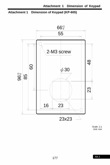
Attachment 1 Dimension of Keypad
177 Att.1
Attachment 1 Dimension of Keypad (KP-605)
60
16 23
55
85
23
48
23x23
ψ30
2-M3 screw
96
+1
0
66+1 0
Scale: 1:1 Unit: mm

Attachment 2 Default Value List
178 Att.2
Attachment 2 Default Value List
Func. Name dEF 60 dEF 50 dEF 52 dEF 53 dEF 57
F_000 Drive Information - - - - -
F_001 Start Command Selection 3 3 3 3 3
F_002 Frequency
Command Selection 1 2 2 2 2
F_003 Selection of “STOP” Key
Validity 1 1 1 1 1
F_004
Setting Value (SV)
Selection 1 1 1 1 1
F_005 Auto-Storing of Setting Value
Selection 1 1 1 1 1
F_006 Selection of Main Display 1 7 7 7 7
F_007 Pressure Transducer Setting 10.0 10.0 10.0 10.0 10.0
F_008 Maximum Allowabel Operating Pressure
100 100 100 100 100
F_009 Starting Frequency 0.5 0.5 0.5 0.5 0.5
F_010 Starting Voltage 8.0 8.0 8.0 8.0 8.0
F_011 Base Frequency 60.0 60.0 60.0 50.0 60.0
F_012 Base Voltage 220.0 220.0 220.0 220.0 220.0
F_013 Selection of Pump Shift
Operation (Parallel control)
3 3 3 3 3
F_015 Control Mode Selection
(Parallel control) 0 1 2 1 5
F_016 Set Drive’s No. for
Parallel Control 0 0 0 0 0
F_017 Maximum Output Frequency 60.0 60.0 60.0 50.0 60.0
F_018 Reference Frequency of
Accel/Decel Time 60.00 60.00 60.0 50.00 60.00
F_019 Primary Acceleration Time 5.0 3.0 3.0 3.0 1.0
F_020 Primary Deceleration Time 5.0 3.0 3.0 3.0 1.0
F_021 Launch Detection Time
(Parallel Control) 6.0 6.0 6.0 6.0 6.0
F_022 Launch Detection Level
(Parallel Control) 0.4 0.4 0.4 0.4 0.4
F_023 Cut-off Frequency (Parallel Control) 50.0 50.0 50.0 42.0 50.0

Attachment 2 Default Value List
179 Att.2
Func. Name dEF 60 dEF 50 dEF 52 dEF 53 dEF 57
F_024 Pump
Auto Shift Time (Parallel Control)
24 24 24 24 24
F_025 Cut-off Time
(Parallel Control) 10.0 10.0 10.0 10.0 10.0
F_026 Communi-
cation Baud Rate (Parallel Control)
1 1 1 1 1
F_027 Secondary Acceleration Time 0.5 0.5 0.5 0.5 0.5
F_028 Secondary Deceleration Time 0.5 0.5 0.5 0.5 0.5
F_029 Set S-curve for Accel/Decel
Time 0.0 0.0 0.0 0.0 0.0
F_030 V/F Pattern Selection 0 1 1 1 1
F_031 Primary Speed 60.00 0.00 0.00 0.00 0.00
F_032 Preset Speed 1 20.00 20.00 20.00 20.00 20.00
F_033 Preset Speed 2 25.00 25.00 25.00 25.00 25.00
F_034 Preset Speed 3 30.00 30.00 30.00 30.00 30.00
F_035 Preset Speed 4 45.00 45.00 45.00 45.00 45.00
F_036 Preset Speed 5 50.00 50.00 50.00 50.00 50.00
F_037 Preset Speed 6 55.00 55.00 55.00 55.00 55.00
F_038 Preset Speed 7 60.00 60.00 60.00 50.00 60.00
F_039 Jog Speed 7.00 7.00 7.00 7.00 7.00
F_040 Vin Gain 1.00 1.00 1.00 1.00 1.00
F_041 Vin Bias 0.00 0.00 0.00 0.00 0.00
F_042 Frequency Upper Limit 1.00 1.00 1.00 1.00 1.00
F_043 Frequency Lower Limit 0.00 0.00 0.00 0.00 0.00
F_044 FM+ Analog Output Signal
Selection 0 0 0 0 0
F_045 FM+ Analog Output Gain 1.00 1.00 1.00 1.00 1.00
F_046 Motor Overload Protection
(OL) 1 1 1 1 1
F_047 Filter Setting of Analog
Frequency 20 20 20 20 20
F_048 Motor Rated Current - - - - -
F_049 Motor No-Load Current - - - - -
F_050 Motor Slip Compensation 0.0 0.0 0.0 0.0 0.0
F_051 Operation Condition Memory 1 0 0 0 0
F_052 Multi-function Input Terminal
X1 3 3 3 3 17

Attachment 2 Default Value List
180 Att.2
Func. Name dEF 60 dEF 50 dEF 52 dEF 53 dEF 57
F_053 Multi-function Input Terminal
X2 4 4 4 4 18
F_054 Multi-function Input Terminal
X3 1 1 1 1 19
F_055 Multi-function Input Terminal
X4 2 2 5 2 20
F_058 Multi-function Output
Terminal Y1 1 1 1 1 1
F_059 Multi-function Output
Terminal Y2 2 2 2 2 2
F_060 Multi-function Output
Terminal Ta1,Tb1 11 11 11 11 11
F_061 Multi-function Input Terminal 2 2.0 2.0 2.0 2.0
F_062 Frequency Detection Range 2.0 2.0 2.0 2.0 2.0
F_063 Frequency Detection Level 0.0 0.0 0.0 0.0 0.0
F_064 Automatic Boost Voltage
Range 1.0 1.0 1.0 1.0 1.0
F_065 System Overload Detection
(OLO) 0 0 0 0 0
F_066 System Overload Detecting
Selection 0 0 0 0 0
F_067 Output Setting after System Overload
0 0 0 0 0
F_068 System Overload Detection Level
160 160 160 160 160
F_069 System Overload Detection Time
2.0 2.0 2.0 2.0 2.0
F_070 Stall Prevention Level at
Acceleration 170 170 170 170 170
F_071 Stall Prevention Level at
Constant Speed 160 160 160 160 160
F_072 Acceleration Time Setting
after Stall Prevention under Constant Speed
5.0 3.0 3.0 3.0 3.0
F_073 Deceleration Time for Stall Prevention under
Constant Speed 5.0 3.0 3.0 3.0 3.0
F_074 Stall Prevention Setting at
Deceleration 1 1 1 1 1
F_075 DC Braking Level 50 50 50 50 50

Attachment 2 Default Value List
181 Att.2
Func. Name dEF 60 dEF 50 dEF 52 dEF 53 dEF 57
F_076 Time of DC Braking
after Stop 0.5 0.2 0.0 0.2 0.2
F_077 Time of DC Braking
before Start 0.0 0.0 0.0 0.0 0.0
F_078 Operation Selection at
Instantaneous Power Failure 0 0 0 0 0
F_079 Auto-Restart Selection for
Error Trip Condition 0 1 1 1 1
F_080 Maximum Reset Time of
Auto-Restart at Drive’s Error Trip
0 10 10 10 10
F_081 Switching Frequency 1 6 6 6 6
F_082 Stop Mode 0 0 0 0 0
F_083 Time Interval before
Auto-Restart 6 6 6 6 6
F_084 Pressure Boost for Water
Usage Detection 0.15 0.15 0.15 0.15 0.15
F_085 Time Interval of Pressure Boost for Water Usage
Detection 0 35 35 35 35
F_086 ON/OFF Mode
Starting Rate Setting 0 0 0 0 0
F_087 ON/OFF Mode Pressure
Dead Band Setting 0.3 0.3 0.3 0.3 0.3
F_088 The Current Level of Speed
Tracing 150 150 150 150 150
F_089 Delay Time for Speed Tracing
0.5 0.5 0.5 0.5 0.5
F_090 The V/F Pattern of
Speed Tracing 100 100 100 100 100
F_091 Error Record - - - - -
F_092 Parameter Setting Lock 0 0 0 0 0
F_093 Automatic Voltage Regulation
(AVR) 1 1 1 1 1
F_094 Drive Overload (OL1) 1 1 1 1 1
F_095 Power Source 220.0 220.0 220.0 220.0 220.0
F_096 Analog Frequency
Dead Band 0.00 0.00 0.00 0.00 0.00
F_097 Digital Input Response Time 10 10 10 10 10

Attachment 2 Default Value List
182 Att.2
Func. Name dEF 60 dEF 50 dEF 52 dEF 53 dEF 57
F_098 Grounding Fault Protection
(GF) 1 1 1 1 1
F_099 External Indicator 1 1 1 1 1 1
F_100 External Indicator 2 5 5 5 5 5
F_101 External Indicator 3 2 2 2 2 2
F_102 PID Compensation Gain 1.0 1.0 1.0 1.0 1.0
F_103 PID Control Mode Selection 0 1 0 1 1
F_104 P Selection 1 1 1 1 1
F_105 Proportional Gain(P) 3.0 3.0 3.0 3.0 3.0
F_106 Integration Time(I) 1.2 1.2 1.2 1.2 1.2
F_107 Derivative Time(D) 0.00 0.00 0.00 0.00 0.00
F_108 Derivative Time of Feedback 0.00 0.00 0.00 0.00 0.00
F_109 Integration Upper Limitation 100 100 100 100 100
F_110 Integration Lower Limitation 0 0 0 0 0
F_111 PID Offset Adjustment 0 65 65 65 65
F_112 PID Buffer Space 2 2 2 2 2
F_113 Feedback Signal Filter 10 10 10 10 10
F_114 Feedback Signal Trip
Detection 0 1 0 1 1
F_115 Acceleration Time of
Pressure Boost 0.6 0.6 0.6 0.6 0.6
F_116 Parameter Selection 0 0 0 0 0
F_117 PID Start Range 0.3 0.3 0.3 0.3 0.3
F_118 Auto-restart Selection of
Water Shortag 0 3 0 3 3
F_119 Pressre Level of Water
Shortag 0 40 0 40 40
F_120 Current Leve Detectionl of
Water Shortage 0 0 0 0 0
F_121 Time Detection of Water
Shortage 60 60 60 60 60
F_122 Drive Shutdown Time for
Water Shortage 5 5 5 5 5
F_123 Analog Input Selection 0 0 0 0 0
F_124 Proportion Type of Pressure
Transmitter 0 0 0 0 0

Attachment 2 Default Value List
183 Att.2
Func. Name dEF 60 dEF 50 dEF 52 dEF 53 dEF 57
F_125 Speed Command Source
Selection under Close-Loop Condition
1 1 1 1 1
F_126 Iin Range Selection 0 0 0 0 0
F_127 Iin Gain (Analog Input) 1.00 1.00 1.00 1.00 1.00
F_128 Iin Bias (Analog Input) 0.00 0.00 0.00 0.00 0.00
F_129 AM+ Analog Output Signal
Selection 2 2 2 2 2
F_130 AM+ Analog Output Gain 1.00 1.00 1.00 1.00 1.00
F_131 Multi-function Output
Terminal Ta2/Tc2 1 1 1 1 1
F_132 DC Braking Frequency
at Stop 0.5 0.5 0.5 0.5 0.5
F_133 Drive Standby level (Water Detection)
0 10 0 10 10
F_134 Default Setting 10 10 10 10 10
F_135 Number of Drives
Standing By 0 0 0 0 0
F_136 Noise Prevention 0 0 0 0 0
F_137 Delay Time at Pump Exchange Operation
0 0 0 0 0
F_138 200% Current Limit 0 0 0 0 0
F_139 Reserved 0 0 0 0 0
F_140 NTC Thermistor Setting 1 1 1 1 1
F_141 Drive Overheat Pre-alarm
Selection 0 0 0 0 0
F_142 Drive Overheat Pre-alarm
Level 70 70 70 70 70
F_143 Drive Overheating
Dead Band 3.0 3.0 3.0 3.0 3.0
F_144 Fan Control Selection 1 1 1 1 1
F_145 Temperature Level of Fan
Activation 50 50 50 50 50
F_146 Minimum Operation Time of
Fan 0.5 0.5 0.5 0.5 0.5
F_147 Over Pressure Disposal 0 0 0 0 0
F_148 Over Pressure Level 100 100 100 100 100
F_149 Over Pressure Detection Time
2.0 2.0 2.0 2.0 2.0

Attachment 2 Default Value List
184 Att.2
Func. Name dEF 60 dEF 50 dEF 52 dEF 53 dEF 57
F_150 Continuous Water Supply
Control 0 0 0 0 0
F_151 Set the
Minimum Pumps during Operation
1 1 1 1 1
F_155 Communica- tion Address
0 0 0 0 0
F_156 Baud Rate 1 1 1 1 1
F_157 Communica- tion Protocol
1 1 1 1 1
F_158 Communica-
tion Overtime (Cot) 0.0 0.0 0.0 0.0 0.0
F_159 Communica-
tion Overtime Disposal
0 0 0 0 0
F_160 Multi-Function
Input Selection 0 0 0 0 0
F_162 Frequency Upper Limitation
by Manual Mode 100 100 100 100 100
F_163 Frequency Lower Limitation
by Manual Mode 0 0 0 0 0
F_166 K Value of Flow Sensor 10.0 10.0 10.0 10.0 10.0
F_167 Rate of Flow Sensor 1.00 1.00 1.00 1.00 1.00
F_168 Unit of Flow Sensor 0 0 0 0 0
F_171 Shutoff Head(H) 12.0 12.0 12.0 12.0 12.0
F_172 Maximum Flow (Q) 300.0 300.0 300.0 300.0 300.0
F_173 Compensation for Pipe Friction Loss 0 0 0 0 0
F_174 The Current in Maximum Flow
(IQmax) 100 100 100 100 100
F_175 The Current in Minimum Flow
(IQmin) 30 30 30 30 30
F_176
Pump Flow Rate Compensation for Pipe
Friction Loss (HCOMP max)
0.0 0.0 0.0 0.0 0.0
F_177 Response Time
Compensation of Pipe Friction Loss
40 40 40 40 40
F_180 Sequetial Operation for
Start Control 0 0 0 0 0
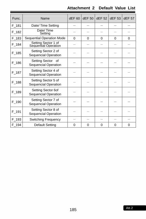
Attachment 2 Default Value List
185 Att.2
Func. Name dEF 60 dEF 50 dEF 52 dEF 53 dEF 57
F_181 Date/ Time Setting - - - - -
F_182 Date/ Time
Setting - - - - -
F_183 Sequential Operation Mode 0 0 0 0 0
F_184 Setting Sector 1 of
Sequential Operation - - - - -
F_185 Setting Sector 2 of
Sequencial Operation - - - - -
F_186 Setting Sector of
Sequencial Operation - - - - -
F_187 Setting Sector 4 of
Sequencial Operation - - - - -
F_188 Setting Sector 5 of
Sequencial Operation - - - - -
F_189 Setting Sector 6of
Sequencial Operation - - - - -
F_190 Setting Sector 7 of
Sequencial Operation - - - - -
F_191 Setting Sector 8 of
Sequencial Operation - - - - -
F_193 Switching Frequency - - - - -
F_194 Default Setting 0 0 0 0 0

Attachment 3 Setting Memo
186 Att.3
Attachment 3 Setting Memo
Func. Description dEF50 Setting Value
Func. Description dEF50 Setting Value
F_000 - F_025 10.0
F_001 3 F_026 1
F_002 2 F_027 0.5
F_003 1 F_028 0.5
F_004 1 F_029 0.0
F_005 1 F_030 1
F_006 7 F_031 0.00
F_007 10.0 F_032 20.00
F_008 100 F_033 25.00
F_009 0.5 F_034 30.00
F_010 8.0
F_035 45.00 12.0
F_011 60.0 F_036 50.00
F_012 220.0
F_037 55.00 380.0
F_013 3 F_038 60.00
F_014 - F_039 7.00
F_015 1 F_040 1.00
F_016 0 F_041 0.00
F_017 60.0 F_042 1.00
F_018 60.00 F_043 0.00
F_019 1.0 F_044 0
F_020 1.0 F_045 1.00
F_021 6.0 F_046 1
F_022 0.4 F_047 20
F_023 50.0 F_048 -
F_024 24

Attachment 3 Setting Memo
187 Att.3
Func. Description dEF50 Setting Value
Func. Description dEF50 Setting Value
F_049 - F_074 1
F_050 0.0 F_075 50
F_051 0 F_076 0.2
F_052 9 F_077 0.0
F_053 13 F_078 0
F_054 1 F_079 1
F_055 2 F_080 10
F_056 - F_081 6
F_057 - F_082 0
F_058 1 F_083 6
F_059 2 F_084 0.15
F_060 -11 F_085 35
F_061 -3 F_086 0
F_062 2.0 F_087 0.3
F_063 0.0 F_088 150
F_064 1.0 F_089 0.5
F_065 0 F_090 100
F_066 0 F_091 -
F_067 0 F_092 0
F_068 160 F_093 1
F_069 2.0 F_094 1
F_070 140
F_095
220.0 (200Vseries)
F_071 130 380.0
(400Vseries)
F_072 3.0 F_096 0.00
F_073 3.0 F_097 10
F_098 1 F_098 1

Attachment 3 Setting Memo
188 Att.3
Func. Description dEF50 Setting Value
Func. Description dEF50 Setting Value
F_099 1 F_128 0.00
F_100 5 F_129 2
F_101 2 F_130 1.00
F_102 1.0 F_131 2.0
F_103 1 F_132 0.5
F_104 1 F_133 10
F_105 3.0 F_134 0
F_106 1.2 F_135 0
F_107 0.00 F_136 0
F_108 0.00 F_137 10
F_109 100 F_138 0
F_110 0 F_139 -
F_111 65 F_140 0
F_112 2 F_141 0
F_113 10 F_142 70
F_114 1 F_143 3.0
F_115 0.6 F_144 1
F_116 0 F_145 50
F_117 0.3 F_146 0.5
F_118 1 F_147 0
F_119 40 F_148 100
F_120 0 F_149 2.0
F_121 60 F_150 0
F_122 5 F_155 0
F_123 0 F_156 1
F_124 0 F_157 1
F_125 1 F_158 0.0
F_126 0 F_159 0
F_127 1.00 F_173 0
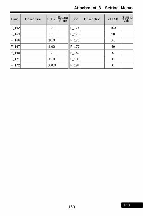
Attachment 3 Setting Memo
189 Att.3
Func. Description dEF50 Setting Value
Func. Description dEF50 Setting Value
F_162 100 F_174 100
F_163 0 F_175 30
F_166 10.0 F_176 0.0
F_167 1.00 F_177 40
F_168 0 F_180 0
F_171 12.0 F_183 0
F_172 300.0 F_194 0

Attachment 4 Fault Display
190 Att.4
Attachment 4 Fault Display
Error Trip Messages of Drive
Display Description Display Description
(EEr)
SV
KEYPAD
PVRunning
EEPROM error
(OH)
SV
KEYPAD
PVRunning
Drive overheating
(AdEr)
SV
KEYPAD
PVRunning
A/D converter error
(Cot)
SV
KEYPAD
PVRunning
Modbus communication
overtime
(SC)
SV
KEYPAD
PVRunning
Fuse open
(OL)
SV
KEYPAD
PVRunning
Motor overload
(LE1)
SV
KEYPAD
PVRunning
Under voltage during operation
(OL1)
SV
KEYPAD
PVRunning
Drive overload
(OC)
SV
KEYPAD
PVRunning
Drive over current
(OLO)
SV
KEYPAD
PVRunning
System overload
(GF)
SV
KEYPAD
PVRunning
Grounding fault
(thr)
SV
KEYPAD
PVRunning
External fault
(OP)
SV
KEYPAD
PVRunning
Over pressure
(ntCF)
SV
KEYPAD
PVRunning
NTC Thermistor sensor fault
(OE)
SV
KEYPAD
設定值
PV
實際值Running
Over voltage
(PAdF)
SV
KEYPAD
PVRunning
Keypad interruption during copy
(no Fb)
SV
KEYPAD
設定值
PV
實際值Running
PID feedback signal error
(Fb Lo)
SV
KEYPAD
PVRunning
Water shortage
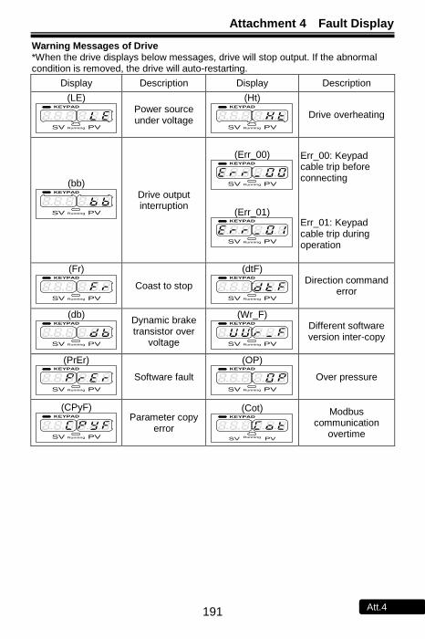
Attachment 4 Fault Display
191 Att.4
Warning Messages of Drive *When the drive displays below messages, drive will stop output. If the abnormal condition is removed, the drive will auto-restarting.
Display Description Display Description
(LE)
SV
KEYPAD
PVRunning
Power source under voltage
(Ht)
SV
KEYPAD
PVRunning
Drive overheating
(bb)
SV
KEYPAD
PVRunning
Drive output interruption
(Err_00)
SV
KEYPAD
PVRunning
(Err_01)
SV
KEYPAD
PVRunning
Err_00: Keypad cable trip before connecting
Err_01: Keypad cable trip during operation
(Fr)
SV
KEYPAD
PVRunning
Coast to stop
(dtF)
SV
KEYPAD
PVRunning
Direction command error
(db)
SV
KEYPAD
PVRunning
Dynamic brake transistor over
voltage
(Wr_F)
SV
KEYPAD
PVRunning
Different software version inter-copy
(PrEr)
SV
KEYPAD
PVRunning
Software fault
(OP)
SV
KEYPAD
PVRunning
Over pressure
(CPyF)
SV
KEYPAD
PVRunning
Parameter copy error
(Cot)
SV
KEYPAD
PVRunning
Modbus communication
overtime

Notes
192 Notes

Notes
193 Notes