HSD2000 Series Servo Drive Operation Manual - HNC Electric
181
HSD2000 Series Servo Drive Operation Manual V1.2 HNC Electric Limited
-
Upload
khangminh22 -
Category
Documents
-
view
2 -
download
0
Transcript of HSD2000 Series Servo Drive Operation Manual - HNC Electric
HSD2000 Series Servo Drive
Operation Manual
V1.2
HNC Electric Limited

1
Forward
Welcome to purchase HSD2000 high performance vector control servo drive produced by HNC Automation limited.
HSD2000 adopts advanced strategy to achieve real high precise flux vector torque control. Either PG operation or no PG operation
has reached advanced industrial level. Since the synchronous motor drive and induction motor drive will be integration; the torque
control, speed control and position control shall be integration. The HSD2000 has become rare parts of high control performance
integrated drive. The integrated will meet high performance demands of customers. At the same time, HSD2000 has advanced
anti-tripping performance and abilities to fit bad power, temperature, humidity and dust. It will improve reliability of products
greatly.
HSD2000 is designed by module. In addition to meet common demand of customers, the expand design will meet individual and
industrial needs of customers. It meets applicable trend of drive industry. The following internal configuration will meet complex
high-precision drive requirements: PG interface; strong speed control, torque control, servo function; practical process closed-loop
control; simple PLC; flexible input and output terminals; given pulse frequency; power fault and downtime parameter selection;
binding of both given frequency channel and operation command channel; zero frequency hysteresis control; main and auxiliary
given control; swing frequency control. It will meet various complicated high precise drive requirements. The high integrated
solution will be provided to equipments manufacture customers. The equipments are applicable for reducing system cost and
improving system reliability.
According to optimize PWM control technology and electromagnetic compatibility overall design, HSD2000 will meet low noise,
low electromagnetic interference requirements of site.
The manual may provide user installation wiring, parameter setting, fault diagnosis and troubleshooting, daily maintenance. For
installation and operation of HSD2000 serial servo drive, read the manual carefully before installed to develop excellent performance.
The manual shall be saved carefully and delivered to operators.
OBA (open box audit) Precautions
After open the box, the following items shall be audited:
1. Check package box for fitting the packing list;
2. Inspect for the damage of servo drive in transportation (damage or gap on machine);
3. Check servo drive nameplate for purchased products;
4. Ensure the optional accessories for purchased;
If damage of servo drive or optional accessories, contact dealer as soon as possible.
2
Content
Chapter I Safety Information ................................................................................................................................................... 5
1.1 Safety Precaution ...................................................................................................................................................................... 5
1.2 Precautions ............................................................................................................................................................................... 6
Chapter II Product Introduction ............................................................................................................................................... 8
2.1. General Specification .............................................................................................................................................................. 8
2.2. Product Serial Introduction ...................................................................................................................................................... 9
2.2.1. HSD2000 Servo Drive Model ..................................................................................................................................... 9
2.2.2. HSD2000 Servo Drive Serial Model and Nameplate ............................................................................................. 10
2.3. Dimension and Gross Weight ................................................................................................................................................ 11
2.3.1. Dimension and Net Weight of Servo Drive ............................................................................................................... 11
2.3.2. Operation Panel and Installation Box Dimension...................................................................................................... 13
2.4. Optional Accessories ........................................................................................................................................................... 13
2.4.1. Braking Resistor and Brake Unit Option Recommendation ...................................................................................... 14
2.4.2. Expanded PG Card Introduction ............................................................................................................................... 16
Chapter III Installation Environment and Part Disassembly ...................................................................................................... 18
3.1 Servo Drive Installation Environment .................................................................................................................................... 18
Chapter IV Servo Drive Connection and EMC Installation Instructions ..................................................................................... 20
4.1Main Circuit Terminal Connection and Configuration ............................................................................................................ 20
4.1.1 Main Circuit Input and Output Terminal Type ........................................................................................................... 20
4.1.2Connect servo drive and optional accessories ............................................................................................................. 21
4.1.3Basic Operation Connection Connection .................................................................................................................... 22
4.2Control Circuit Connection and Configuration........................................................................................................................ 22
4.2.1Relative position and function introduction of jumper ................................................................................................ 22
4.2.2Control circuit terminal wiring .................................................................................................................................... 23
4.3Optional Accessories Installation ............................................................................................................................................ 29
4.2Installation Instructions Met EMC Requirement ..................................................................................................................... 29
4.4.1Noise Suppression ....................................................................................................................................................... 29
4.4.2Site Connection Requirement ...................................................................................................................................... 31
4.4.3Ground ........................................................................................................................................................................ 31
4.4.4 Installation Requirements of Relay, Contactor and Electromagnetic Brake ............................................................... 32
4.4.5Leakage Current and Strategies ................................................................................................................................... 32
4.4.6Correct EMC Installation of Servo Drive .................................................................................................................... 32
4.4.7Power Supply Wave Filter User Guide ........................................................................................................................ 33
4.4.8Servo Drive Radiation Emission ................................................................................................................................. 33
Chapter V Servo Drive Rapid Operation Guide ....................................................................................................................... 35
5.1Servo Drive Operation Panel ................................................................................................................................................... 35
5.1.1Operation Panel Appearance and Key Function Description....................................................................................... 35
5.1.2LED Digital and Indicator Description ....................................................................................................................... 36
5.1.3Operation Mode of Operation Panel ............................................................................................................................ 36
5.2Servo Drive Operation Mode .................................................................................................................................................. 38

3
5.2.1Servo Drive Operation Command Channel ................................................................................................................. 38
5.2.2Servo Drive Run Status ............................................................................................................................................... 38
5.2.3Servo Drive Control and Operation Mode .................................................................................................................. 38
5.2.4Servo Drive Frequency, Torque, Position Given Channel ........................................................................................... 39
5.3The First Power up .................................................................................................................................................................. 40
5.3.1Checking before Power up .......................................................................................................................................... 40
5.3.2The First Power Up Operation .................................................................................................................................... 40
5.4Pilot running ............................................................................................................................................................................ 41
5.4.1 Sensorless Vector Pilot Running ................................................................................................................................ 41
5.4.2Closed-loop Vector Pilot Running ............................................................................................................................... 41
5.4.3Torque Control Pilot Running ..................................................................................................................................... 41
5.4.4Servo Control Pilot Running(X7 and X8 terminal pulse serial control as example) ................................................... 41
5.4.5Spindle Positioning Pilot Running .............................................................................................................................. 42
5.4.6Synchronous Motor Pilot Running(Increment ABZUVW Encoder as Example) ..................................................... 42
Chapter VI Function Code Details ......................................................................................................................................... 43
6.1 Function Code Description ..................................................................................................................................................... 43
6.1.1System management (P00 group) ................................................................................................................................ 43
6.1.2Status Display Parameter (P01 group) ......................................................................................................................... 45
6.1.3Basic Operation Parameter (P02 group) ................................................................................................................... 47
6.1.4 Motor 1 parameter (P03 group) .................................................................................................................................. 50
6.1.5 Motor 2 parameter (P04 group) ............................................................................................................................... 53
6.1.6Start and Stop Parameter (P05 group) ...................................................................................................................... 55
6.1.7V/F Control Parameter (P06 group) ......................................................................................................................... 57
6.1.8Speed Control Parameter (P07 group) ......................................................................................................................... 58
6.1.9Torque Control Parameter (P08 group) .................................................................................................................... 60
6.1.10 Servo control parameters (P09 group) ...................................................................................................................... 63
6.1.11 Switch I/O terminal parameters (P10 group) ............................................................................................................ 65
6.1.12 Analog I/O terminal parameters (P11 group)............................................................................................................ 77
6.1.13 Encoder parameters (P12 group) .............................................................................................................................. 83
6.1.14 Process closed loop parameters (P13 group) ............................................................................................................ 84
6.1.15 Extended function code parameters (P14 group) ...................................................................................................... 88
6.1.16 Simple PLC parameters (P15 group) ........................................................................................................................ 93
6.1.17 Multi-speed parameters (P16 group) ........................................................................................................................ 96
6.1.18 LED display parameters (P17 group) ....................................................................................................................... 97
6.1.19 Communication parameters (P18 group) .................................................................................................................. 98
6.1.20 Bus communication parameters (P19 group) ........................................................................................................... 99
6.1.21 Protection parameter and fault record (P20 group) .................................................................................................. 99
6.1.22 Traverse operation parameter (P30 group) ............................................................................................................. 103
6.1.23 Driver parameters (P97 group) ............................................................................................................................... 107
6.1.24 Custom parameter group (P98 group) .................................................................................................................... 107
Chapter VII Measures relative Fault Alarm, Handling of Abnormality ..................................................................................... 108
Chapter VIII Servicing and Maintenance ...............................................................................................................................114
8.1 Daily servicing and maintenance .......................................................................................................................................... 114
8.2 Regular maintenance ............................................................................................................................................................ 114

4
8.3 Replacement of quick-wear parts of servo driver ................................................................................................................. 115
8.4 Storage of servo driver ......................................................................................................................................................... 115
8.5 Maintenance of servo driver ................................................................................................................................................. 115
Chapter IX Functional Code List ..........................................................................................................................................116
Appendix I: Communication Protocol .................................................................................................................................. 162
1. Networking mode ................................................................................................................................................................... 162
2. Interface.................................................................................................................................................................................. 162
3. Communication ...................................................................................................................................................................... 162
4. Protocol format ....................................................................................................................................................................... 162
5. Protocol function .................................................................................................................................................................... 163
6. Servo driver’s control parameters and status parameters ........................................................................................................ 167
7. Expansion access .................................................................................................................................................................... 171
8. Precautions ............................................................................................................................................................................. 173
9. CRC Check ............................................................................................................................................................................. 175
10. Application Samples ............................................................................................................................................................. 176
11. Servo driver’s calibration relation ........................................................................................................................................ 177

HSD2000 Series Servo Drive Operation Manual Chapter I Safety Information
5
Chapter I Safety Information
Safety Definitions
Safety precaution in the manual is divided into the
following two parts:
Danger
No required operation will cause serious injuries or
even death.
Attention
No required operation will cause moderate, minor
injury or equipments damage.
1.1 Safety Precaution
Before installation:
Danger
Damage and servo drive lacking parts servo drive will cause
injury!
Above B degree insulated motor shall be used to prevent electric
shock!
In installation:
Danger
Please install to flame retardant objects to get away from
combustibles.
Otherwise, the fire alarm will be occurred.
Attention
When two or more servo drives are placed in the same cabinet, the
installation position (refer to chapter III in installation) shall be
noted to ensure cooling effects.
Conductor head or screw shall not fall into servo drive to prevent
servo drive damage!
In connection:
Danger
Electrical personnel construction may prevent electric shock!
Breaker shall be used for separation between servo drive and
power to prevent fire!
Before wiring, power shall be ensured shutdown to prevent
electric shock!
Ground terminal shall be grounded to prevent electric shock!
Attention
The power line shall be not connected to output terminal U, V, W
to prevent servo drive damage!
The connection path shall be ensured to meet EMC requirements
and related safety standard. The used conductor diameter shall
refer to manual recommendation to prevent accident!
The braking resistor shall be not connected between + and
–terminal of DC bus, otherwise it may cause fire!
Before power up:
Danger
The power voltage degree shall be ensured to be consisted with
servo drive rated voltage. The input and output wiring position
shall be correct. Inspect for short circuit of peripheral circuits and
circuit fastening to prevent servo drive damage!
Servo drive shall not power up before cover the plate. Otherwise
the electric shock will be occurred!
Attention
Servo drive does not need to implement withstand test. The test
has been implemented before factory. Otherwise the accident
would be occurred.
All the peripheral accessories shall be wired as circuit provided by
the manual. Otherwise the accident would be occurred!
After power up:
Danger
Cover plate shall be not opened after power up. Otherwise the
electric shock will be occurred!
Don’t touch servo or surround circuit by wet hands. Otherwise
electric shock will be occurred!
Don’t touch servo drive terminals (including control terminal).
Otherwise electric shock will be occurred!
At the beginning of power up, servo drive would inspect external
strong electrical circuit automatically. At this time, U, V, W
wiring terminals shall be not touched to prevent electric shock!
HSD2000 Series Servo Drive Operation Manual Chapter I Safety Information
6
Attention
During parameter identification (if necessary), be careful to the
rotary motor for hurt someone. Otherwise it will cause accidents!
Don’t changing servo drive factory parameter freely. Otherwise
the equipments will be damaged!
In operation:
Danger
When select restart function, we shall not close to mechanical
equipments to prevent personal injury!
Don’t touch cooling fan and discharge resistor. Otherwise burn
injury will be occurred.
The signal in operation shall be inspected by professionals.
Otherwise personal injury or equipment damage would be
occurred.
Attention
During servo drive operation, the dust shall be avoided to fall into
equipments. Otherwise equipments damage will be occurred!
Start and stop of servo drive shall be not controlled by contactor
on and off. Otherwise equipments damage will be occurred!
In maintenance:
Danger
The equipments shall be not maintained or repaired by electric.
Otherwise electric shock will be occurred!
After ten minutes of power cut, servo drive may be maintained
and repaired when positive or negative bus terminal voltage is less
than 36V. Otherwise the residual charge will hurt people!
Maintenance shall be implemented by professionals. Otherwise
personal injury or equipment damage would be occurred!
1.2 Precautions
Motor insulation inspection
Motor insulation inspection shall be implemented in: before reuse
of primary placing at long time; regular inspection. The insulation
inspection will prevent servo drive from damage caused by motor
winding insulation fault. During insulation inspection, the motor
wire will be separated from servo drive. The 200V voltage mega
meter is suggested to use. The measured insulation resistor shall
be not less than 5TΩ.
Motor thermal protection
When rated capacity of selected motor is different from servo
drive, especially when the servo drive rated power is greater than
motor rated power. The servo drive inside motor related
parameters shall be adjusted; or the thermal relay shall be
assembly in front of motor to protect motor.
Operation above power frequency
The servo drive may provide 0Hz~1000Hz output frequency.
When operate in greater than 50Hz condition, tolerance of
mechanical device shall be considered.
Machinery vibration
Servo drive may meet mechanical resonance points of loading
device in certain output frequency. The mechanical resonance
points may be avoided by setting servo drive inside jump
frequency parameters.
Motor heat and noise
Since the servo drive output voltage (PWM wave) contains certain
harmonic wave; the motor temperature, noise and vibration are
greater than power frequency.
Output end contains voltage dependent devices or electric
capacity (improve power factor)
Servo drive output is PWM wave. When electric capacity of
improving power factor or lightning voltage dependent resistors is
installed, servo drive instantaneous over current or servo drive
damage will be caused.
When the servo drive installs contactor, the contactor shall be not
used to control start and stop of servo drive. If necessary, the
interval of contactor controlling servo drive starting and stop shall
be not less than one hour. Charging or discharging frequently will
reduce electric capacity service life in servo drive. When the
contactors install between output end and motor, on-off operation
of servo drive shall be implemented in no output. Otherwise
module in servo drive will be damaged.
Using other than rated voltage
The servo drive shall be not used in other than manual allowance
working voltage range. Otherwise parts of servo drive will be
damaged. If necessary, related pressure lifting or relief device
shall be used in pressure treatment.
Three-phase input changes into two-phase input
Three-phase servo drive of the serial shall be not changed into
two-phase. Otherwise servo drive fault or damage will be caused.
Lightning surge protection
The serial servo drive is equipped with over current protective
device. The device is equipped with certain ability for
self-protection in lighting. For lightning occurs frequently,
customers shall install protection in front of servo drive.
Altitude height and derating using
In area of higher than 1000M of thin air, the cooling effects will
be worse. The derating using will be implemented. If applicable,
consult our company.
Special using
During using, if customers need to use methods other than wiring
diagram of the manual (such as common DC bus), please consult
to our company.
Servo drive scrapped precautions

HSD2000 Series Servo Drive Operation Manual Chapter I Safety Information
7
1) Electrolysis electric capacity in servo drive will be exposed in
burning.
2) Plastics, Rubber on servo drive will generate hazardous, toxic
gas in burning. Be careful in burning.
3) Treat servo drive as industrial waste
Adaptive motor
1) The standard adaptive motor shall be four-grade squirrel-cage
asynchronous induction motor. If not the motor above, the motor
rated current shall be applied to select servo drive. When drive the
PMSM, please consult to our company.
2) Cooling fan and rotor shaft of non-inverter motor are connected
in the same shaft. The fan cooling effects will reduce when
rotational speed reduces. Thus the motor overheating may install
fan or change into inviter motor.
3) Servo drive has set adaptive motor standard parameters inside.
According to specified, the parameter identification or
personalized defaults shall be implemented to conform actual
value as much as possible. Otherwise operation effects and
protective performance will be influenced.
4) Since short circuit of cable or motor will cause servo drive
alarms or explosion, the insulation short circuit testing will be
implemented to primary installation motor and cable. The testing
may be implemented in daily maintenance. During the testing,
servo drive and tested part shall be broken.
Before operating the servo drive, please read the
manual carefully. The contents shall be learned to
operate correctly.
The manual is attachment configured with machine.
After using, it shall be saved carefully for view at any
time.

HSD2000 Series Servo Drive Operation Manual Chapter II Product Introduction
8
Chapter II Product Introduction
The chapter shows basic products information of HSD2000 serial products specification, model and structure.
2.1. General Specification
Table 2-1Common Specification
Item Item description
Input Rated voltage;
frequency Three-phase, 380V~480V; 50Hz/60Hz; voltage unbalance rate: <3%; frequency: ±5%
Output
Rated frequency 380V, 400V, 415V, 440V, 460V, 480V
Frequency 0Hz~1000Hz
Overload G: 150% rated current in 2 minutes,200% rated current 0.5 seconds
Main control
performance
Control mode magnetic flux vector control without PG(SVC), magnetic flux vector control with PG(VC), servo control, V/F
control, V/F control with PG
Modulation mode Space vector PWM modulation
Speed range 1: 200 (magnetic flux vector control without PG), 1: 5000 (magnetic flux vector control with PG, servo control)
Start torque 150% rated torque@0Hz (magnetic flux vector control without PG), 200% rated torque@0Hz (magnetic flux
vector control with PG)
Operational
rotational speed
steady-status
accuracy
≤±0.2% rated synchronous speed (magnetic flux vector control without PG),
≤±0.02% rated synchronous speed (magnetic flux vector control with PG, servo control)
Speed fluctuations ≤±0.3% rated synchronous speed (magnetic flux vector control without PG)
≤±0.1% rated synchronous speed (magnetic flux vector control with PG、servo control)
Positioning
accuracy ±1 pulse
Torque response ≤10ms (magnetic flux vector control with PG, servo control);
≤20ms (magnetic flux vector control without PG)
Torque control Support magnetic flux vector control without PG, magnetic flux vector control with PG, servo control
Frequency accuracy Digital setting: maximum frequency×±0.01%; analog setting: maximum frequency×±0.2%
Frequency
resolution Digital setting: 0.01Hz; analog setting: maximum frequency×0.05%
Torque boost Automatic torque boost, manual torque boost 0.1%~30.0%
V/F curve Four types: one user setting V/F curve and 3 reduced torque curves (2.0 order, 1.7 order, 1.2 order)
Acceleration and
deceleration curves
Two types: linear acceleration and deceleration, S curve acceleration and deceleration; Four Acc/Dec time, Time
units (minutes / seconds) optional, maximum to 60 hours
DC braking Initial frequency of DC injection braking process: 0.00 Hz~60.00Hz; Braking time: 0.0s~30.0s; Braking
current: 0.0%~100.0%
Automatic Voltage
Regulation (AVR) When grid voltage changes, the output voltage keeps constant automatically.
Automatic current
limiting Limit current in operation automatically to prevent overcurrent fault tripping frequently.
Automatic carrier
wave adjustment According to loading characteristics, the carrier wave frequency may be adjusted automatically; optional
Customization
capabilities
Textile traverse
frequency Textile traverse frequency control, achieve adjustable traverse frequency function of center frequency
Bundling function Free bundling and synchronous switching may be implemented between command channel and given frequency
channel.
Jog Jog frequency range: 0.00Hz~50.00Hz;Jog acceleration and deceleration time 0.1s~60.0s may best; jog
interval can be set
Multi-speed
operation Multi-speed operation will be achieved by inside PLC or control terminals.
built-in process
closed loop control Form closed loop control system
Operation
function
Operation
command channel Operation panel control , terminal control, Sci control, and may be switched by variety of methods.
HSD2000 Series Servo Drive Operation Manual Chapter II Product Introduction
9
Item Item description
Given frequency
channel Digital given, analog voltage, analog current, pulse, serial port may be switched by variety of methods.
Given auxiliary
frequency Achieve flexible auxiliary frequency fine tuning, frequency synthesis
Pulse output
termianl 0~100kHz pulse signal output, achieve output of setting frequency, output frequency.
Analog output
terminal
2analog signals output, 0/4~20mA or 0/2~10V may be selected separately. Achieve output of setting
frequency, output frequency.
operation
panel
LED display Display 20 types of parameters such as setting frequency, output frequency, output voltage and output current .
LCD dislay Optional, Chinese / English prompts content
Parameter copy Operation panel may be used to achieve rapid copy of parameters
Key lock and
function selection Achieve parts or all locking functions pf keys. Define function range of part key to prevent error operation.
Protective function lack-phase protection (optional) , over current protection, over voltage protection, under-voltage protection,
over-thermal protection, overload protection, off-load protection
Environme
nt
Condition Indoor, without sunlight, dust, corrosive gases, flammable gas, mist, water vapor, dripping or salt.
Altitude height Derating above 1000 meters, derating 10% in each 1000 meters lifting
Ambient temperature -10℃~+40℃ (ambient temperature between 40℃~50℃, derating )
Environme
nt
Humidity 5%~95%RH, without condensing
Vibration Less than 5.9m/s2 (0.6g)
Storage temperature -40℃~+70℃
Structure Protective degree IP20
Cooling method Air-cooled with fan control
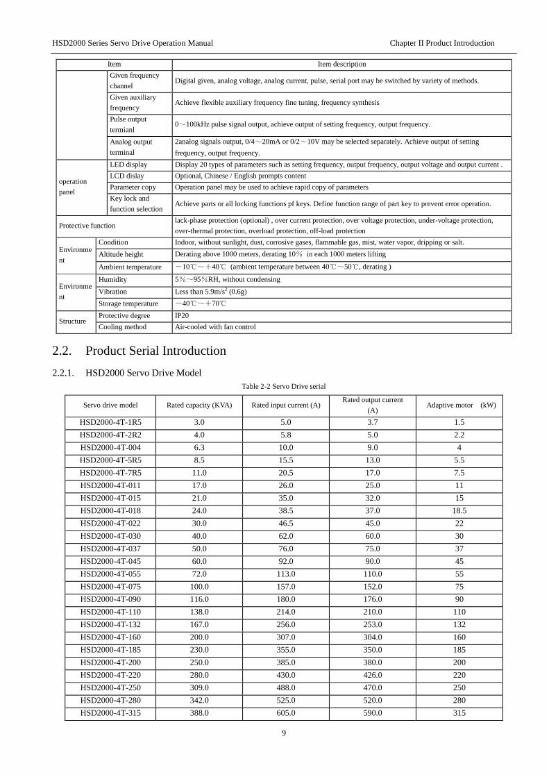
2.2. Product Serial Introduction
2.2.1. HSD2000 Servo Drive Model
Table 2-2 Servo Drive serial
Servo drive model Rated capacity (KVA) Rated input current (A) Rated output current
(A) Adaptive motor (kW)
HSD2000-4T-1R5 3.0 5.0 3.7 1.5
HSD2000-4T-2R2 4.0 5.8 5.0 2.2
HSD2000-4T-004 6.3 10.0 9.0 4
HSD2000-4T-5R5 8.5 15.5 13.0 5.5
HSD2000-4T-7R5 11.0 20.5 17.0 7.5
HSD2000-4T-011 17.0 26.0 25.0 11
HSD2000-4T-015 21.0 35.0 32.0 15
HSD2000-4T-018 24.0 38.5 37.0 18.5
HSD2000-4T-022 30.0 46.5 45.0 22
HSD2000-4T-030 40.0 62.0 60.0 30
HSD2000-4T-037 50.0 76.0 75.0 37
HSD2000-4T-045 60.0 92.0 90.0 45
HSD2000-4T-055 72.0 113.0 110.0 55
HSD2000-4T-075 100.0 157.0 152.0 75
HSD2000-4T-090 116.0 180.0 176.0 90
HSD2000-4T-110 138.0 214.0 210.0 110
HSD2000-4T-132 167.0 256.0 253.0 132
HSD2000-4T-160 200.0 307.0 304.0 160
HSD2000-4T-185 230.0 355.0 350.0 185
HSD2000-4T-200 250.0 385.0 380.0 200
HSD2000-4T-220 280.0 430.0 426.0 220
HSD2000-4T-250 309.0 488.0 470.0 250
HSD2000-4T-280 342.0 525.0 520.0 280
HSD2000-4T-315 388.0 605.0 590.0 315

HSD2000 Series Servo Drive Operation Manual Chapter II Product Introduction
10
HSD2000-4T-355 427.0 667.0 650.0 355
HSD2000-4T-400 454.0 701.0 690.0 400
HSD2000-4T-450 510.0 789.0 775.0 450
HSD2000-4T-500 566.0 877.0 860.0 500
HSD2000-4T-560 625.0 982.0 950.0 560
HSD2000-4T-630 724.0 1184.0 1100.0 630
HSD2000-4T-800 921.0 1500.0 1400.0 800
2.2.2. HSD2000 Servo Drive Serial Model and Nameplate
HSD2000 servo drive models description is shown in figure 2-1. The nameplate description is shown in figure 2-2.
Figure 2-1 HSD2000 Servo Drive Nameplate
HSD 2000 -4T -5R5 G- TE - 02
5.5 kW
3 PH AC 380-440 V 15.5A 50/60 HZ
3 PH AC0- 440 V 13A 0~1000HZ
MODEL :
POWER :
INPUT:
OUTPUT:
S/ N :
Inverter Model
Adaptation motor capacity
Rated input voltage curent
and frenquency
Rated current and
frequency range
Barcode information
WARNING
* Risk of electric shock
* Wait 10 mins power down before removing cover
* Read the manual and follow the safety instructiongs
before use
Figure 2-2 HSD2000 Servo Drive Model

HSD2000 Series Servo Drive Operation Manual Chapter II Product Introduction
11
2.3. Dimension and Gross Weight
2.3.1. Dimension and Net Weight of Servo Drive
Dimension of servo drive is shown as figure below:
Figure 2-3 HSD2000-4T-1R5~HSD2000-4T-7R5
Figure 2-4 HSD2000-4T-011~HSD2000-4T-015
Figure 2-5 HSD2000-4T-018~HSD2000-4T-055
Figure 2-6 HSD2000-4T-075~HSD2000-4T-280

HSD2000 Series Servo Drive Operation Manual Chapter II Product Introduction
12
Figure 2-7 HSD2000-4T-315~HSD2000-4T-560
Figure 2-8 HSD2000-4T-630~4T-800
Table 2-3 HSD2000 Serial Servo Drive Dimension table 1 (mm)
Servo drive model D W1 H1 H W
Outline
Drawing
No.
Installatio
n hole
diameter
Gross
weight
(kg)
Installation
method
HSD2000-4T-1R5
175 127 200 215 140 Figure2-3 5 3.5 Hanging HSD2000-4T-2R2
HSD2000-4T-004
HSD2000-4T-5R5 181 146 251 262 157 Figure2-3 5.5 5 Hanging
HSD2000-4T-7R5
HSD2000-4T-011 181 180 288 305 198 Figure2-4 5.5 8 Hanging
HSD2000-4T-015
HSD2000-4T-018
220 230 424.5 438 276 Figure2-5 7.0 18 Hanging HSD2000-4T-022
HSD2000-4T-030
HSD2000-4T-037
231.5 320 571 589 395 Figure2-5 10.0 45 Hanging HSD2000-4T-045
HSD2000-4T-055
HSD2000-4T-075 298 320 733 759 489 Figure2-6 12.0 75 Hanging
HSD2000-4T-090

HSD2000 Series Servo Drive Operation Manual Chapter II Product Introduction
13
HSD2000-4T-110
HSD2000-4T-132
370
320 898 927 539 Figure2-6
12.0
125 Hanging
and
cabinet
HSD2000-4T-160
HSD2000-4T-185 507 898 1377 539 Figure2-6 142
HSD2000-4T-200
HSD2000-4T-220
373
280 1022 1054 704 Figure2-6
12.0
160 Hanging
and
cabinet
HSD2000-4T-250 672 1022 1500 704 Figure2-6 181
HSD2000-4T-280
Table 2-4 HSD2000 Serial Servo Drive Dimension table 2 (mm)
Servo Drive Model
(G: constant torque loading; P: fan pump
loading)
D W1 D1 H W Shape
Figure No.
Hole
diameter
Estimated
weight (kg)
Installatio
n means
HSD2000-4T-315
400 924 240 1684 960 Figure2-7 14.0 365 Cabinet
HSD2000-4T-355
HSD2000-4T-400
HSD2000-4T-450
HSD2000-4T-500
HSD2000-4T-560
HSD2000-4T-630 460 1386 240 1808 1464 Figure2-8 18.0 * Cabinet
HSD2000-4T-800
2.3.2. Operation Panel and Installation Box Dimension
Front Side Keyboard hole size
Figure2.9 Keyboard Appearance and Installation Dimension
2.4. Optional Accessories
The following optional accessories may be ordered to our company (if necessary)
Accessories
name
Option range Specification
Remark
Brake unit See table 2-4 See table 2-4
Keyboard
tray Option 74.7×141 Hole size
Keyboard
extension
cable
Option 2m、3m Network cable
Cabinet base 132KW~200KW option 539*370*485 132KW~280KW installation may be compatible
hanging with cabinet 220KW~280KW option 704*366*480

HSD2000 Series Servo Drive Operation Manual Chapter II Product Introduction
14
Accessories
name
Option range Specification
Remark
DC reactor 132KW~800KW option - -
2.4.1. Braking Resistor and Brake Unit Option Recommendation
Energy consumption braking requirements, braking resistor or braking unit may refer to table 2-4. Braking resistor wiring specification,
wiring specification between brake unit and servo drive may refer to table 3-2.
Table 2-4 Braking Resistor and Brake Unit Option Recommendation Table
Servo Drive Model
Braking Resistor
Recommended
Resistor Value
Braking Resistor
Recommended Power
Brake Unit
Recommended
Model
Remark
HSD2000-4T-1R5 200-300Ω 200W
Built-in
Standard
Configuration
HSD2000-4T-2R2 100-250Ω 250W
HSD2000-4T-004 100-150Ω 300W
HSD2000-4T-5R5 80-100Ω 500W
HSD2000-4T-7R5 60-80Ω 700W
HSD2000-4T-011 40-50Ω 1.0KW
HSD2000-4T-015 30-40Ω 1.5KW
HSD2000-4T-018 25-30Ω 2.0KW
HSD2000-4T-022 20-25Ω 2.5KW Built-in
Standard
Configuration
HSD2000-4T-030 15-20Ω 3.0KW
HSD2000-4T-037 15-20Ω 3.5KW
HSD2000-4T-045 10-15Ω 4.5KW
HSD2000-4T-055 10-15Ω 5.5KW
HSD2000-4T-075 8~10Ω 7.5 KW
BU4R150
External
option
HSD2000-4T-090 8~10Ω 9 .0KW
HSD2000-4T-110 6~8Ω 11 .0KW
HSD2000-4T-132 6~8Ω 13.5KW
BU4R250 HSD2000-4T-160 4~6Ω 16 .0KW
HSD2000-4T-185 4~6Ω 18.5 KW
HSD2000-4T-200 4~6Ω 20.0 KW
HSD2000-4T-220 6~8*2Ω 11.0*2 KW
BU4R250*2 HSD2000-4T-250 6~8*2Ω 12.5*2 KW
HSD2000-4T-280 4~6*2Ω 14*2 KW
HSD2000-4T-315 4~6*2Ω 16*2 KW
HSD2000-4T-355 4~6*3Ω 11*3 KW
BU4R250*3
HSD2000-4T-400 4~6*3Ω 14*3 KW
HSD2000-4T-450 4~6*3Ω 17*3 KW
HSD2000-4T-500 4~6*3Ω 21*3 KW
HSD2000-4T-560 4~6*3Ω 25*3 KW
HSD2000-4T-630 * *
HSD2000-4T-800 * *
Note: Resistance value and power of braking resistor shall be not less than recommended minimum resistance and power of table
above. Otherwise the brake unit will damage.
Attached: braking resistor calculation method
In braking, almost all renewable energy of motor consumes on the braking resistor. Where:
U×U/R=Pb
U-Brake voltage of system table brake (U value is different in different systems, 380Vac system takes 700V);
Pb - Brake power
Braking resistor power selection
HSD2000 Series Servo Drive Operation Manual Chapter II Product Introduction
15
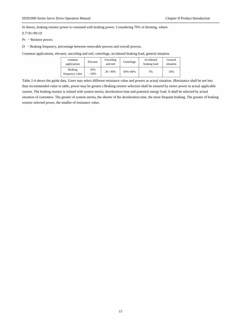
In theory, braking resistor power is consisted with braking power. Considering 70% of derating, where:
0.7×Pr=Pb×D
Pr -Resistor power;
D -Braking frequency, percentage between renewable process and overall process.
Common applications, elevator, uncoiling and reel, centrifuge, accidental braking load, general situation
common
applications Elevator
Uncoiling
and reel Centrifuge
Accidental
braking load
General
situation
Braking
frequency value
20%
~30% 20 ~30% 50%~60% 5% 10%
Table 2-4 shows the guide data. Users may select different resistance value and powers as actual situation. (Resistance shall be not less
than recommended value in table, power may be greater.) Braking resistor selection shall be ensured by motor power in actual applicable
system. The braking resistor is related with system inertia, deceleration time and potential energy load. It shall be selected by actual
situation of customers. The greater of system inertia, the shorter of the deceleration time, the more frequent braking. The greater of braking
resistor selected power, the smaller of resistance value.
HSD2000 Series Servo Drive Operation Manual Chapter II
Product Introduction
16
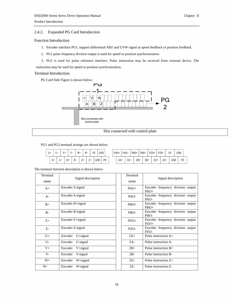
2.4.2. Expanded PG Card Introduction
Function Introduction
1.Encoder interface PG1, support differential ABZ and UVW signal as speed feedback or position feedback.
2.PG1 pulse frequency division output is used for speed or position synchronization.
3.PG2 is used for pulse reference interface. Pulse instruction may be received from external device. The
instruction may be used for speed or position synchronization.
Terminal Introduction
PG Card Side Figure is shown below:
A
PG
1
PG
2
Slot connected with
control plate
B Z
U V W
Slot connected with control plate
PG1 and PG2 terminal arrange are shown below:
U+ U- V+ V- W+ W- 5V GND
A+ A- B+ B- Z+ Z- GND PE
PAO+ PAO- PBO+ PBO- PZO+ PZO- 5V GND
2A+ 2A- 2B+ 2B- 2Z+ 2Z- GND PE
The terminal function description is shown below:
Terminal
name Signal description
Terminal
name Signal description
A+ Encoder A signal PAO+ Encoder frequency division output
PAO+
A- Encoder A-signal PAO- Encoder frequency division output
PAO-
B+ Encoder B+signal PBO+ Encoder frequency division output
PBO+
B- Encoder B-signal PBO- Encoder frequency division output
PBO-
Z+ Encoder Z+signal PZO+ Encoder frequency division output
PZO+
Z- Encoder Z-signal PZO- Encoder frequency division output
PZO-
U+ Encoder U+signal 2A+ Pulse instruction A+
U- Encoder U-signal 2A- Pulse instruction A-
V+ Encoder V+signal 2B+ Pulse instruction B+
V- Encoder V-signal 2B- Pulse instruction B-
W+ Encoder W+signal 2Z+ Pulse instruction Z+
W- Encoder W-signal 2Z- Pulse instruction Z-

HSD2000 Series Servo Drive Operation Manual Chapter II
Product Introduction
17
5V 5V output 5V 5V output
GND Ground GND Ground
PE Shielding layer PE Shielding layer
Resolver PG card function introduced
If the user selects the rotating transformer as feedback speed, should choose Resolver PG card . Resolver PG card
profile drawing is shown below :
For the detail of terminal blocks, please see the table below:
Signal screen printing Signal definitions
T1 Motor temperature detection 1
GND Ground
T2 Motor temperature detection 2
EXC+ Rotary Transformer REF+ Signal l
EXC- Rotary Transformer REF - Signal
SIN+ Rotary Transformer SIN + Signal
SIN- Rotary Transformer SIN - Signal
COS+ Rotary Transformer COS + Signal
COS- Rotary Transformer C0S - Signal
Dial switch description:
Signal screen printing Functional Description Factory
value
HX1
HX2
( Move it up is 1 Move
it down is 0 )
Pole number selection:
00:×1
01:×2
10:×3
11:×4
11
HF1
HF2
( Move it up is 1
Move it down is 0 )
Rotary transformer excitation
signal frequency selection:
00:10KHz
01:2.5KHz
10:5KHz
11:5KHz
00
Fault indicating lamp and Failure reset instruction:
When the rotating transformer signal abnormalities, PG card fault indicator will light up, at this time can use SW6 fault
reset button.
HSD2000 Series Servo Drive Operation Manual Chapter III Installation Environment and Part Disassembly
18
Chapter III Installation Environment and Part Disassembly
The chapter shows installation environment requirements and parts disassembly methods of servo drive.
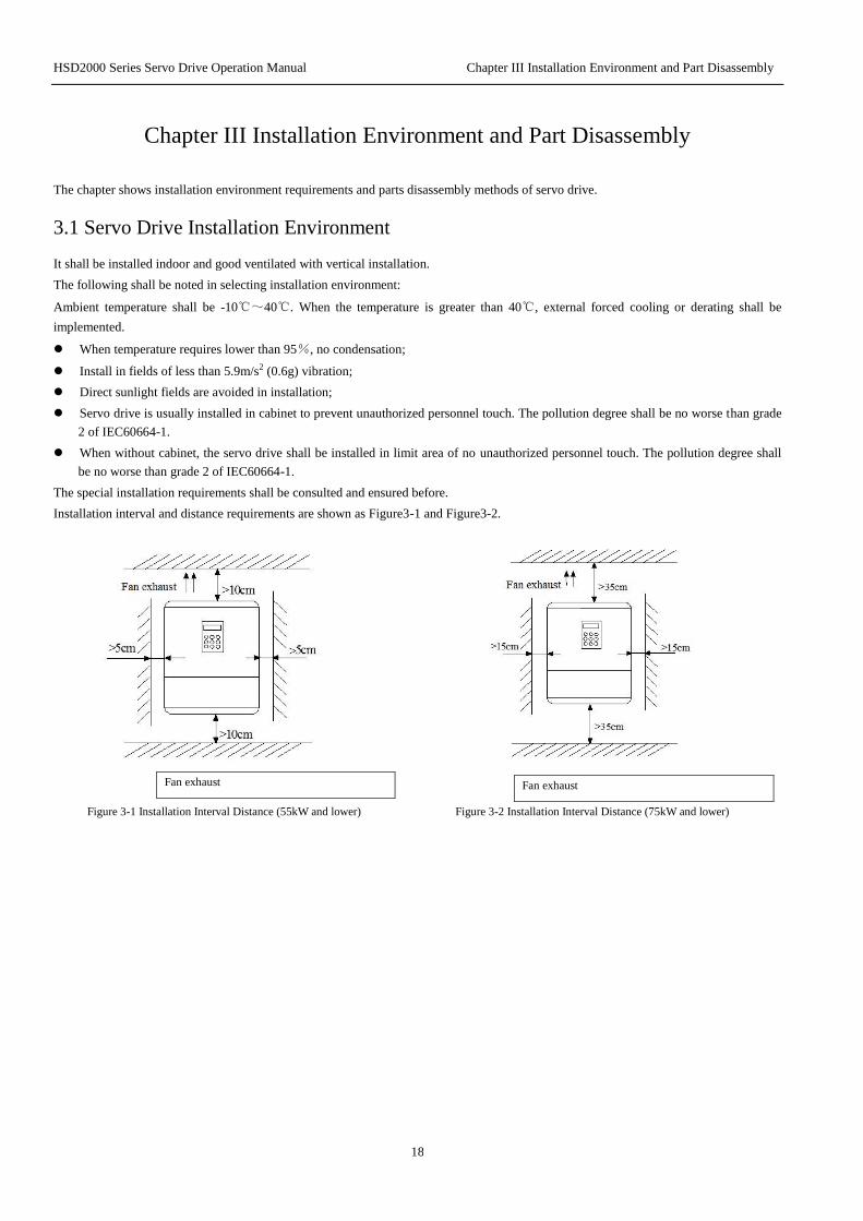
3.1 Servo Drive Installation Environment
It shall be installed indoor and good ventilated with vertical installation.
The following shall be noted in selecting installation environment:
Ambient temperature shall be -10℃~40℃. When the temperature is greater than 40℃, external forced cooling or derating shall be
implemented.
When temperature requires lower than 95%, no condensation;
Install in fields of less than 5.9m/s2 (0.6g) vibration;
Direct sunlight fields are avoided in installation;
Servo drive is usually installed in cabinet to prevent unauthorized personnel touch. The pollution degree shall be no worse than grade
2 of IEC60664-1.
When without cabinet, the servo drive shall be installed in limit area of no unauthorized personnel touch. The pollution degree shall
be no worse than grade 2 of IEC60664-1.
The special installation requirements shall be consulted and ensured before.
Installation interval and distance requirements are shown as Figure3-1 and Figure3-2.
Fan exhaust
Fan exhaust
Figure 3-1 Installation Interval Distance (55kW and lower) Figure 3-2 Installation Interval Distance (75kW and lower)

HSD2000 Series Servo Drive Operation Manual Chapter III Installation Environment and Part Disassembly
19
When install two servo drives, baffle plate shall be used in the middle. It is shown in Figure3-3.
Servo
motor
Servo
motor
Servo drive
Servo drive
Figure 3-3 Installation of two servo drives
HSD2000 Series Servo Drive Operation Manual Chapter IV Servo Drive Wire Distribution and EMC Installation Instructions
20
Chapter IV Servo Drive Connection and EMC Installation Instructions
The chapter shows connection and wiring of servo drive, the question of meeting EMC requirements.
Danger
·Servo drive cover plate shall be not opened until cutting servo drive power supply and waiting for at least 10 minutes.
·Servo drive internal wiring work shall be implemented by trained and authorized qualified professionals.
·When connect emergency stop or safety circuit, wiring shall be inspected carefully before and after operation.
· Before energize, the servo drive voltage degree shall be inspected carefully. Otherwise the casualties and equipments damage will be occurred.
! Attention ·Before using, the servo drive rated input voltage shall be checked to consist with AC power supply voltage.
·Before factory, servo drive has passed the puncture test. Puncture test shall be not implemented on servo drive.
·External braking resistor or braking unit shall refer to chapter II.
·Don’t connect the power supply lines with U, V, W.
·The ground wires are usually copper wire above 3.5mm diameters. The ground resistance shall be less than 10Ω.
·Current leakage is happened in servo drive. The specified value shall be determined by using condition. Servo drive and motor shall be grounded
for safety. RCD is required to install with B type. The current leakage current setting value shall be 300mA.
·For input over current protection and power out maintenance, the servo drive shall connect to power by air switch or fuse switch.
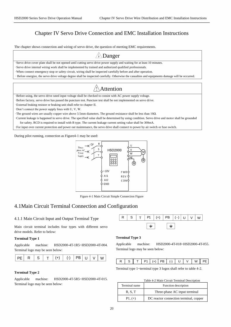
During pilot running, connection as Figure4-1 may be used:
Figure 4-1 Main Circuit Simple Connection Figure
4.1Main Circuit Terminal Connection and Configuration
4.1.1 Main Circuit Input and Output Terminal Type
Main circuit terminal includes four types with different servo
drive models. Refer to below:
Terminal Type 1
Applicable machine: HSD2000-4T-1R5~HSD2000-4T-004.
Terminal logo may be seen below:
PBS VRPE (+)T U W(-)
Terminal Type 2
Applicable machine: HSD2000-4T-5R5~HSD2000-4T-015.
Terminal logo may be seen below:
( - )S VR P1 (+)T U WPB
Terminal Type 3
Applicable machine: HSD2000-4T-018~HSD2000-4T-055.
Terminal logo may be seen below:
R S T P1 (+) PB (-) U V W PE
Terminal type 1~terminal type 3 logos shall refer to table 4-2.
Table 4-2 Main Circuit Terminal Description
Terminal name Function description
R, S, T Three-phase AC input terminal
P1, (+) DC reactor connection terminal, copper

HSD2000 Series Servo Drive Operation Manual Chapter IV Servo Drive Wire Distribution and EMC Installation Instructions
21
Terminal name Function description
short circuit when factory
(+), PB Braking resistor connection terminal
(+) (-) DC power supply input terminal
U, V, W Three-phase AC output terminal
, PE Grounded terminal
Terminal type 4
Applicable machine: Terminal logo above HSD2000-4T-075 may
be seen below:
PE T
Input terminal
(Machine top)
output terminal
(Machine bottom )
S
V P1W (+)
R
PE U (-)
Input terminal (top of the machine)
Output terminal (bottom of machine)
Table 4-3 Main Circuit Terminal Description
Terminal name Function description
R, S, T three-phase ACinput terminal
P1, (+) DC reactor connects to terminal,copper short circuit when factory
(+), (-) DC power supplu input terminal;
external brake unit DC output terminal
U, V, W Three-phase AC output terminal
PE Grounded terminal
4.1.2Connect servo drive and optional accessories
Figure 4-2 Servo Drive and Optional Accessories
Connection
1.Obvious breaking device (such as disconnect switch) shall be
installed between grid and servo drive to ensure personal safety in equipment maintenance.
2.When contactor is used for power supply control, it shall be not
used for control power up and down of servo drive.
3.DC Reactor
For prevent servo drive influence from power supply, protect
servo drive and higher harmonic wave; the DC reactor may be configured in the following conditions.
When the same power node supplied to servo drive is
equipped with switching electric capacity reactive power
compensation device screen or controlled silicon phased load,
the electric capacity device screen wsitch shifting may cause
reactive transients causing mutations net pressure. The
phased load will cause harmonic wave and grid waveform gap. Above will damage input rectifier circuit of servo drive.
When imbalance in the servo drive power of three-phase
power supply is not greater than 3%;
When power factor of servo drive input end is required to be improved to greater than 0.93;
When servo drive accesses large-capacity transformer, input
power circuit current may damage rectifier circuit. In general,
when servo drive power supply capacity is greater than
550kVA; or the power supply capacity is 10 times greater
than servo drive capacity; DC reactor will be configured in servo drive.
4.AC Input Reactor
The AC input reactor may be equipped in the following conditions:
when grid waveform distorts seriously; when higher harmonic
wave influences between servo drive and power supply can’t meet
requirements (DC reactor is equipped on servo drive). AC input reactor may improve power factor of servo drive input.
5.AC Output Tractor
When wiring between servo and motor exceeds 80 meters, it is
suggested to use bunch wire and install AC output reactor
restricted high frequency oscillation. Motor insulation, too large
leakage current and servo drive frequently protection are avoided.
6.Input EMI
EMI wave filter may be used to restrict high-frequency noise from servo drive power line.
7.Output EMI wave filter
EMI wave filter may be used to restrict interference noise and leakage current conductors from servo drive output.
8.Safety ground wire
Leakage current exists in servo drive. Servo drive and motor shall
be grounded for safety. The ground resistance shall be less than
10Ω. The ground wire shall be as short as possible. The wire diameter shall meet standard of table 4-4.
Note: Value in the table will be correct when the same metal uses
in both conductors. If not, section area of conductor protection
shall be ensured by equivalent conductivity coefficient in table 4-4.
Table 4-4 Section area of conductor protection
Phase conductor section area in installation S (mm2)
The minimum section area of
related protection conductor Sp
(mm2)
S≤16 S
16<S≤35 16
35<S S/2
Note
1.Input (output) EMI wave filter shall be installed to close to
servo drive as much as possible. The installation method
shall refer to Optional Accessories Installation of 4.3.
HSD2000 Series Servo Drive Operation Manual Chapter IV Servo Drive Wire Distribution and EMC Installation Instructions
22
2.Technical parameters of optional accessories may refer to
Optional Accessories of 2.4.
3.Servo drive output: it is suggested to use #6 cable, wiring
terminal (RNBS14-6), heat shrink tubing (φ18.0, black,
125 ℃, 600V). The specific process may refer to table 4-4.
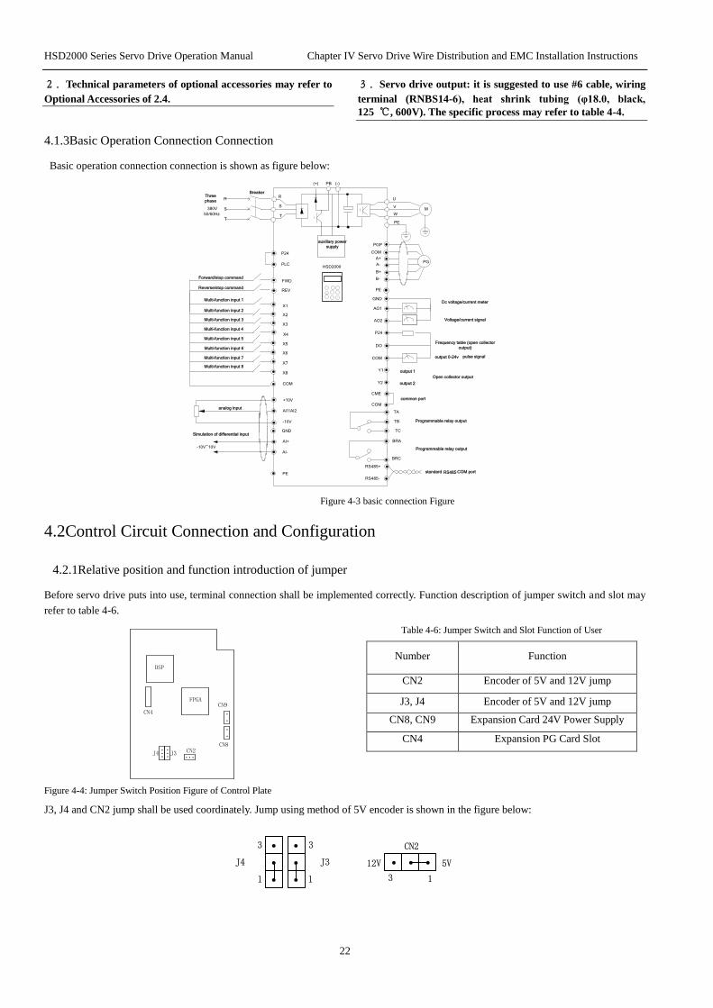
4.1.3Basic Operation Connection Connection
Basic operation connection connection is shown as figure below:
(+) PB
R
S
T
R
S
T
Three
phase
380V
50/60Hz
M
U
V
W
PE
Breaker
PG
PGP
COM
A-
A+
PE
HSD2000
Dc voltage/current meter
Voltage/current signal
AO1
AO2
GND
Frequency table (open collector
output)
DO
COM
TB
TC
TA
Programmable relay output
RS485-
RS485+
standard RS485
X1
X2
X3
X4
X5
X6
X7
X8
FWD
REV
Forward/stop command
PLC
COM
analog inputAI1/AI2
GND
+10V
PE
CME
Y1
Y2
output 1
output 2
common port
P24
COM
P24
Reverse/stop command
BRA
BRC
Programmable relay output
AI+
-10V~10V
-10V
B+
B-
AI-
Simulation of differential input
(-)
auxiliary power
supply
pulse signal
Multi-function input 1
Multi-function input 2
Multi-function input 3
Multi-function input 4
Multi-function input 5
Multi-function input 6
Multi-function input 7
Multi-function input 8
COM port
output 0-24v
Open collector output
Figure 4-3 basic connection Figure
4.2Control Circuit Connection and Configuration
4.2.1Relative position and function introduction of jumper
Before servo drive puts into use, terminal connection shall be implemented correctly. Function description of jumper switch and slot may
refer to table 4-6.
DSP
FPGA
J4 J3 CN2
CN4
...... ...
.
.
.
.
CN9
CN8
Table 4-6: Jumper Switch and Slot Function of User
Number Function
CN2 Encoder of 5V and 12V jump
J3, J4 Encoder of 5V and 12V jump
CN8, CN9 Expansion Card 24V Power Supply
CN4 Expansion PG Card Slot
Figure 4-4: Jumper Switch Position Figure of Control Plate
J3, J4 and CN2 jump shall be used coordinately. Jump using method of 5V encoder is shown in the figure below:
.
.
....
J3J4
1
3
1
3
. . .
CN2
13
5V12V
HSD2000 Series Servo Drive Operation Manual Chapter IV Servo Drive Wire Distribution and EMC Installation Instructions
23
Jump using method of 12V encoder is shown in the figure below:
.
.
....
J3J4
1
3
1
3
. . .
CN2
13
5V12V
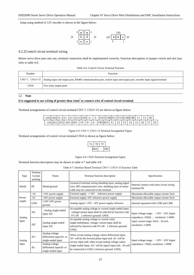
4.2.2Control circuit terminal wiring
Before servo drive puts into use, terminal connection shall be implemented correctly. Function description of jumper switch and slot may
refer to table 4-6.
Table 4-6: Control Circuit Terminal Function
Number Function
CN5~7,CN13~15 Analog input and output port, RS485 communication port, switch input and output port, encoder input signal terminal
CN16 Two relay output ports
Note
It is suggested to use wiring of greater than 1mm2 as connect wire of control circuit terminal.
Terminal arrangements of control circuit terminal CN5~7, CN13~15 are shown as figure below:
-10V AO1 AO2 485+ 485- PE B+ B- FWD REV X1 X2 X3 X4 X5 X6 X7 X8
+10V GND AI+ AI- AI1 AI2 GND A+ A- PGP COM PLC P24 COM CME Y1 Y2 DO
Figure 4-5: CN5~7, CN13~15 Terminal Arrangement Figure
Terminal arrangements of control circuit terminal CN16 is shown as figure below:
BRA BRC
TA TB TC
Figure 4-6: CN16 Terminal Arrangement Figure
Terminal function description may be shown in table 4-7 and table 4-8.
Table 4-7: Interface Board Terminal CN5~7, CN13~15 Function Table
Type
Termina
l screen
printing
Name Terminal function description Specification
Shield PE Shield ground
Ground of terminal wiring shielding layer; analog signal
wire, 485 communication wire; shielding layer of motor
cable may be connected to the terminal.
Internal connect with main circuit wiring
terminal PE
Power
supply
+10 +10V power supply External supply +10V reference power supply Maximum allowable output current 5mA
-10 -10V power supply External supply-10V reference power supply Maximum allowable output current 5mA
GND +10V-10V power
ground Analog signal+10V, -10V power supply reference Internal separated with COM and CME
Analog
input
AI1 Analog single-ended
input AI1
Acceptable analog voltage or current single-ended input,
voltage/current input shall be selected by function code
P11.00 ( reference ground: GND) Input voltage range: -10V~10V (input
impedance: 45kΩ) ,resolution: 1/4000
input current range: 0mA~20 mA,
resolution: 1/2000 AI2 Analog single-ended
input AI2
Acceptable analog voltage or current value
single-endedinput, voltage/ current input shall be
selected by function code P11.00 ( reference ground:
GND)
Analog
input
AI+
Analog voltage
differential inputAI+ or
single-ended input
When accept analog voltage values differential input,
AI+ will be the forward phase input end. AI- will be
reverse input end; when accept analog voltage values
single-ended input, AI+ will be signal input end,AI-will
be connected to GND ( reference ground: GND).
Input voltage range: -10V~10V (input
impedance: 15kΩ), resolution: 1/4000
AI-
Analog voltage
differential inputAI- or
single-ended input

HSD2000 Series Servo Drive Operation Manual Chapter IV Servo Drive Wire Distribution and EMC Installation Instructions
24
Type
Termina
l screen
printing
Name Terminal function description Specification
Analog
output
AO1 Analog output1
When provide analog voltage/ current values output, 25
types of values may be represented; output voltage,
current may be selected by function code P11.16. The
factory default shall be output voltage. See the function
code P11.17 description ( reference ground: GND)
Voltage output range: 0/2~10V
current output range: 0/4~20mA
AO2 Analog output2
When provide analog voltage/ current values output, 25
types of values may be represented; output voltage,
current may be selected by function code P11.1. 6. The
factory default shall be output voltage. See the function
code P11.21 description. ( reference ground: GND)
Voltage output range: 0/2~10V
current output range: 0/4~20mA
Commun
ication
RS485+ RS485 communication
port
485 difference signal positive end Standard RS485 communication port may
use twisted-pair wire or shield wire RS485- 485 difference signal negative end
Encoder
A+,A- Encoder A phase signal encoder A Phase difference inputsignal Input maximum frequency≤100kHz
B+,B- Encoder B phase signal Encoder B phase difference inputsignal
PGP Encoder power supply Provide power supply to external encoder ( reference
ground : COM)
Output voltage : 12V
Maximum output current: 250mA
Operatio
n
control
terminal
FWD Forward operation
command terminal The forward and reverse switch command may refer to
P10.08 two-wire three-wire control function description
Optocoupler isolation input
input impedance: R=3.3kΩ; maximum
input frequency: 200Hz
input voltage range: 20V~30V
+ 2 4 V
X i、F W D 、R E V
P L C + 3 .3 V
C O M
P 2 4
R
REV Reverse operation
command terminal
Multi-fun
ction
input
terminal
X1 Multi-function input
terminal 1
The programmable may be defined as multifunction
switch values input terminal. See the 6.1.11 switch value
input and output terminal parameters (P10 group) of
P10.00~P10.07 input terminal function introduction
X2 Multi-function input
terminal 2
X3 Multi-function input
terminal 3
X4 Multi-function input
terminal 4
X5 Multi-function input
terminal 5
X6 Multi-function input
terminal 6
X7 Multi-function input
terminal7
X8 Multi-function input
terminal 8
In addition to be X8 ordinary multi-function terminal (as
X1~X7), the program may be implemented as high
speed pulse input end. See the 6.1.11 switch value input
and output terminal parameters (P10 group) of
P10.00~P10.07 input terminal function introduction.
Optocoupler isolation input equivalent
figure is shown above
input impedance: R=2kΩ
Maximum input frequency: 100kHz
input voltage range: 20~30V
Multi-fun
ction
output
terminal
Y1
Bidirectional
open-collector output
terminal 1
The programmable may be defined as multifunction
switch values output terminal. See the 6.1.11 switch
value input and output terminal parameters (P10 group)
of P10.18 and P10.19 output terminal function
introduction (common terminal: CME)
Optocoupler isolation output
maximum working voltage: 30V
maximum output current: 50mA
the method may refer to P10.18~P10.19
description Y2
Bidirectional
open-collector output
terminal 2
DO Open-collector pulse
output terminal
The programmable may be defined as multifunction
pulse signal output terminal. See the 6.1.11 switch value
input and output terminal parameters (P10 group) of
P10.32 output terminal function introduction (common
terminal: CME)
Output frequency range: determined by
P10.33. the maximum of 100kHz
Power
supply P24 +24V power supply External supply+24V power supply Maximum output current: 200mA
Common
terminal
PLC Multi-function input
common terminal
Multi-function input terminal common terminal
(short circuit with P24 when factory)
X1~X8, FWD, REV common terminal,
PLC will be isolated with P24 internal
COM +24V power supply
common terminal
Three public terminals. Using together with other
terminals. COM and CME、GND internal isolation
CME Y1, Y2output common
terminal
Multi-functionoutput terminal Y1, Y2 common terminal
(short circuit with COM by manufacturer) COM is isolated with CME and GND
Shield PE Shield ground Shielding layer ground terminal Internal connects with main circuit terminal
PE

HSD2000 Series Servo Drive Operation Manual Chapter IV Servo Drive Wire Distribution and EMC Installation Instructions
25
Table 4-8: Interface Board Terminal CN16 Function Table
Type
Terminal
screen
printing
Name Terminal function description Specification
Relay
output
terminal1
TA
Relay output
The programmable may be defined as multifunction
pulse signal output terminal. See the 6.1.11 switch value
input and output terminal parameters (P10 group) of
P10.21 output terminal function introduction.
TA-TB: normally close,TA-TC: normally
open
Contact capacity :
250Vac/2A (COSФ=1)
250Vac/1A (COSФ=0.4)
30Vdc/1A
The method may refer to P10 description.
Relay output terminal input over voltage is
class II.
TB
TC
Relay
output
terminal2
BRA
Relay output
The programmable may be defined as multifunction
pulse signal output terminal. See the 6.1.11 switch value
input and output terminal parameters (P10 group) of
P10.20 output terminal function introduction.
BRA-BRC: normally open
Contact capacity:
250Vac/2A (COSФ=1)
250Vac/1A (COSФ=0.4)
30Vdc/1A
The operation method may refer to P10
instruction. Relay output terminal input over
voltage is class II.
BRC
Note
“AI+, AI-”is function code AI3 in P11.
Analog input terminalconnection
1) AI1,AI2 terminal acceptable analog voltage or current value single-ended input,voltage/current input will be selected by function code
P11.00. The connection method is shown below:
Shielded wire
-10
AI1,AI2
GND
+10
-10~+10V
Or 0~20mA
PE
HSD200
0
P11.00 unit digital:
AI1 0 :
1 :
P11.00 tens
digital :
AI2 0 :
1 :
Voltage input
Voltage input
Current input
Current input
Figure 4-7: AI1,AI2 Terminal connection Figure
2) AI+, AI-terminal accepts analog voltage differential input or analog voltage single-ended input. The connection method is shown below:
AI+
AI-PE
HSD2000
-10V : +10V Analog voltage
difference input
Shielding wire
Analog voltage
differential input
Shielding wire
PE
-10V : +10V
Shielding wire GND
AI+/AI -
AI - /AI+
HSD2000
Shielding wire
Figure 4-8: AI+, AI-terminal Differential Voltage Input connection Figure Figure 4-9: AI+,AI-terminal Single-ended Voltage Input connection Figure

HSD2000 Series Servo Drive Operation Manual Chapter IV Servo Drive Wire Distribution and EMC Installation Instructions
26
Analog Output Terminal Connection Method
Analog output terminal AO1 and AO2 external analog gauge may show variety of physical values. The function code P11.16 will select
output current (0/4~20mA) and voltage (0/2~10V). Terminal connection method is shown below:
P11.16 unit digital: AO1 option
P11.16 tens digital: AO2 option
Figure 4-10: Analog Output Terminal Connection
Note:
1.When using analog input, wave filter electric capacity or common mode choke may be installed between input signal and GND.
2.Voltage of analog input signal is not suggested to exceed 15V.
3. Analog input and output signal is easy to be disturbed by external. Shield cable with good ground shall be used in connection.
Length of connection shall be as short as possible.
4. The maximum voltage of analog output terminal is 15V.
Communication Port Connection
HSD2000 servo drive provides RS485 serial communication port to users. The following connection method may composite single
master/multi-slave system or single slave/multi master system. The host(PC computer or PLC controller) software may be used to achieve
real time monitor of network. Remote control, automatic control may be finished and achieve complicated motion control (such as
unlimited multi segment PLC operation).
1. Servo drive connects with host with RS485 interface:
Terminal
instructions Terminal name
Signal -Terminal RS485-Signal +Terminal RS485+
HSD2000
Signal ground GND
Terminal
instructions
Terminal
name
Signal - Terminal RS485-Signal+Terminal RS485+
Signal ground GND
Shield cable
Host
Figure 4-11: RS485-RS485 Communication connection
2. Servo drive connects with upper computer with RS232 interface:
Terminal
instructions Terminal name
Signal - Terminal RS485-
Signal + Terminal RS485+
Terminal
instructions
Terminal
name Signal -Terminal RS485-
Signal +Terminal RS485+
Terminal
instructions Terminal name
5VPower
supply
terminal +5V
Transmit data
line TXD
Receive data
line RXD
5V Power GND
Pin No. Signal
CasePE
2RXD
3TXD
5GND
4DTR
6DSR
9RI
1CD
7RTS
8CTS
Shield
cable HSD2000
RS485/232 Transverter Host
RS232(DB9)
Signal ground GND Signal ground GND
Shield
cable
Figure 4-12: RS485- (RS485/232) -RS232 Communication connection
HSD2000 Series Servo Drive Operation Manual Chapter IV Servo Drive Wire Distribution and EMC Installation Instructions
27
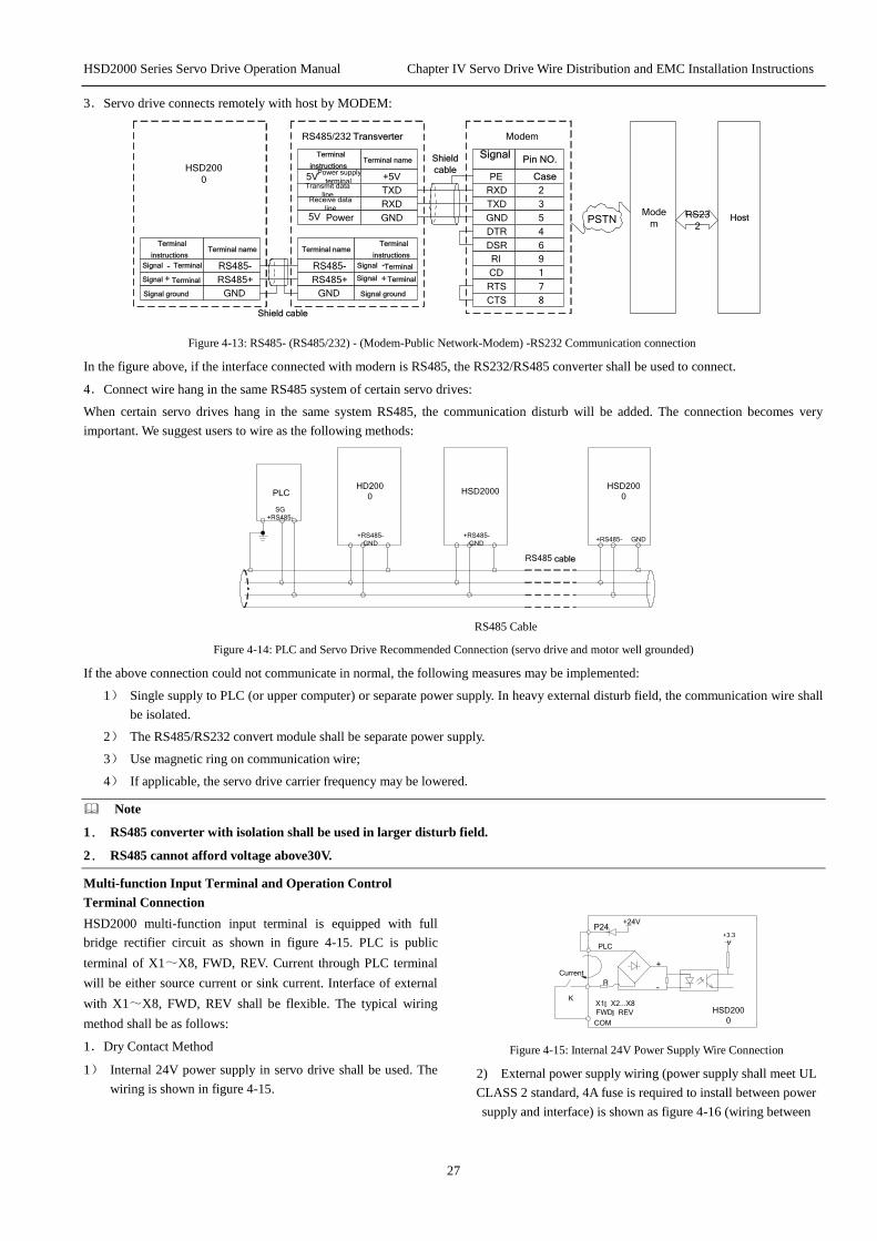
3.Servo drive connects remotely with host by MODEM:
Terminal
instructions Terminal name
Signal - Terminal RS485-
Signal + Terminal RS485+
Terminal
instructions Terminal name
Signal - Terminal RS485-
Signal +Terminal RS485+
Terminal
instructions Terminal name
5V Power supply
terminal+5V
Transmit data
line TXD
Receive data
line RXD
5V Power GND
Pin NO. Signal
CasePE
2RXD
3TXD
5GND
4DTR
6DSR
9RI
1CD
7RTS
8CTS
Shield
cable HSD200
0
RS485/232 Transverter Modem
Signal ground GND Signal ground GND
Mode
mHostPSTN
RS23
2
Shield cable
Figure 4-13: RS485- (RS485/232) - (Modem-Public Network-Modem) -RS232 Communication connection
In the figure above, if the interface connected with modern is RS485, the RS232/RS485 converter shall be used to connect.
4.Connect wire hang in the same RS485 system of certain servo drives:
When certain servo drives hang in the same system RS485, the communication disturb will be added. The connection becomes very
important. We suggest users to wire as the following methods:
PLCHD200
0
+RS485-
GND
HSD2000
+RS485-
GND
HSD200
0
+RS485- GND
SG
+RS485-
RS485 cable
RS485 Cable
Figure 4-14: PLC and Servo Drive Recommended Connection (servo drive and motor well grounded)
If the above connection could not communicate in normal, the following measures may be implemented:
1) Single supply to PLC (or upper computer) or separate power supply. In heavy external disturb field, the communication wire shall
be isolated.
2) The RS485/RS232 convert module shall be separate power supply.
3) Use magnetic ring on communication wire;
4) If applicable, the servo drive carrier frequency may be lowered.
Note
1. RS485 converter with isolation shall be used in larger disturb field.
2. RS485 cannot afford voltage above30V.
Multi-function Input Terminal and Operation Control
Terminal Connection
HSD2000 multi-function input terminal is equipped with full
bridge rectifier circuit as shown in figure 4-15. PLC is public
terminal of X1~X8, FWD, REV. Current through PLC terminal
will be either source current or sink current. Interface of external
with X1~X8, FWD, REV shall be flexible. The typical wiring
method shall be as follows:
1.Dry Contact Method
1) Internal 24V power supply in servo drive shall be used. The
wiring is shown in figure 4-15.
+24V
X1: X2...X8
FWD: REV
PLC
HSD200
0
+3.3
V
COM
P24
R
+
-
K
Current
Figure 4-15: Internal 24V Power Supply Wire Connection
2) External power supply wiring (power supply shall meet UL
CLASS 2 standard, 4A fuse is required to install between power
supply and interface) is shown as figure 4-16 (wiring between

HSD2000 Series Servo Drive Operation Manual Chapter IV Servo Drive Wire Distribution and EMC Installation Instructions
28
PLC and P24 terminal shall be removed).
R
+
- Current
Fuse
X1: X2...X8
FWD: REV
COM HSD2000
+3.3
V
+24VP24
PLC
+
-K
DC
Figure 4-16: External 24V Power Supply Wire Connection
2. Source (Drain) Mode
1) The servo drive internal + 24V power supply shall be used. The
external controller connection mode is NPN common emitter
output. It is shown in figure 4-17:
Shielding Wire
Proximal Ground COM
●
HSD2000
PE●
1●
PLC
FWD
●
●
P24
COM●
●24Vdc
D2+
-+3.3V
10●
X8●
+3.3V
External controller
Figure 4-17: Internal +24V Power Supply Servo Drive Source Connection
2) The servo drive internal + 24V power supply shall be used.
The external controller connection mode is NPN common
emitter output. It is shown in figure 4-18: (wiring between
PLC and P24 terminal shall be removed).
●
●
●
●
●
●
●
● ●
24V+-
Shielding Wire
Proximal Ground
HSD200
0
PE
1
PLC
FWD
P24
COM 24Vdc
D2+-
+3.3V
10 X8
External Controller
+3.3V
Figure 4-18: Internal +24V Power Supply Servo Drive Drain Connection
3) External power supply source connection shall be used: (wiring
between PLC and P24 terminal shall be removed)
●
●
●
●
●
●
●
●
+-
24V
Shielding Wire
Proximal Ground
HSD2000
PE
1
PLC
FWD
P24
COM24V
DC
D2+
-+3.3V
10 X8
External Controller
+3.3
V
Figure 4-19: External Power Supply Source Connection
4) External power supply drain connection shall be used: (wiring between
PLC and P24 terminal shall be removed).
●
●
●
●
●
●
●
● ●
●
Shielding Wire
Proximal Ground
COM
HSD200
0
PE
1
PLC
FWD
P24
COM
D2+-
+3.3
V
10 X8
External controller
+3.3
V
24Vdc
Figure 4-20: External Power Supply Drain Connection
Multi-function output terminalconnection
1.Multi-function output terminalY1, Y2 may use servo drive
internal 24V power supply. The wiring may refer to 0.
HSD2000 COM
P24
+5V
+24V
CME
Y1 : Y2Relay
Figure 4-21: Multi-function Output Terminal Connection 1
2.Multi-function output terminalY1, Y2 may use external power
supply. The wiring may refer to 0.
DC
HSD2000 COM
CME
Y1 : Y2
P24+5V
+24V
+ -
Relay
Figure 4-22: Multi-function Output Terminal Connection 2
3.Digital pulse frequency output DO may use servo drive internal
24V power supply. The wiring may refer to Figure 4-23.
+24VHSD2000
P24
4.7k
DO
COM
+5V +24V
Digital frequency
meter
Figure 4-23: Output Terminal DO Connection 1
4.Digital pulse frequency output DO may use external power
supply. Wiring may refer to Figure 4-24.
DC
+24V
HSD200
0 P24
4.7kDO
COM
+5V +24V
+-
Digital frequency
meter
Figure 4-24: Output Terminal DO Connection 2
Relay Output Terminal TA, TB, TC Connection
The surge voltage absorbing circuit may be installed on driving
inductive load (electromagnetic relay, contactor). When the RC
absorbs circuit (the current leakage shall be less than keep current
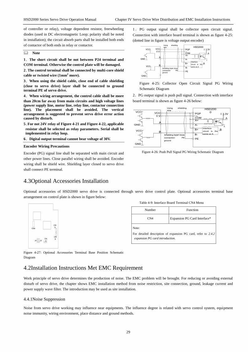
HSD2000 Series Servo Drive Operation Manual Chapter IV Servo Drive Wire Distribution and EMC Installation Instructions
29
of controller or relay), voltage dependent resistor, freewheeling
diodes (used in DC electromagnetic Loop; polarity shall be noted
in installation); the circuit absorb parts shall be installed both ends
of contactor of both ends in relay or contactor.
Note
1.The short circuit shall be not between P24 terminal and
COM terminal. Otherwise the control plate will be damaged.
2.The control terminal shall be connected by multi-core shield
cable or twisted wire (1mm2 more).
3.When using the shield cable, close end of cable shielding
(close to servo drive) layer shall be connected to ground
terminal PE of servo drive.
4.When wiring arrangement, the control cable shall be more
than 20cm far away from main circuits and high voltage lines
(power supply line, motor line, relay line, contactor connection
line). The placement shall be avoided. The vertical
arrangement is suggested to prevent servo drive error action
caused by disturb.
5.For not 24V relay of Figure 4-21 and Figure 4-22, applicable
resistor shall be selected as relay parameters. Serial shall be
implemented in relay loop.
6.Digital output terminal cannot bear voltage of 30V.
Encoder Wiring Precautions
Encoder (PG) signal line shall be separated with main circuit and
other power lines. Close parallel wiring shall be avoided. Encoder
wiring shall be shield wire. Shielding layer closed to servo drive
shall connect PE terminal.
1.PG output signal shall be collector open circuit signal.
Connection with interface board terminal is shown as figure 4-25:
(dotted line in figure is voltage output encoder)
GND
HSD2000
A
VCC
0 V
A
B
PGP
PE
COMA+
A-
B-
B+ B
Using shielding
wire
GND
VCC
VCC
: 3.3V
Shielding layer close
connection PE
ground
Interface
circuit is the
same as A
Figure 4-25: Collector Open Circuit Signal PG Wiring
Schematic Diagram
2.PG output signal is push pull signal. Connection with interface
board terminal is shown as figure 4-26 below:
GND
HSD200
0
A
VCC
0 V
A
B
: 3.3VPGP
PE
COMA+
A-
B-
B+ B
VCC
VCC
Using shielding
wire
GND
Shielding layer close
connection PE
ground
Interface
circuit is the
same as A
Figure 4-26: Push Pull Signal PG Wiring Schematic Diagram
4.3Optional Accessories Installation
Optional accessories of HSD2000 servo drive is connected through servo drive control plate. Optional accessories terminal base
arrangement on control plate is shown in figure below:
J4 J3CN
2
CN4
...... ...
.
.
.
.
CN
9
CN
8
Figure 4-27: Optional Accessories Terminal Base Position Schematic
Diagram
Table 4-9: Interface Board Terminal CN4 Menu
Number Function
CN4 Expansion PG Card Interface*
Note:
For detailed description of expansion PG card, refer to 2.4.2
expansion PG card introduction.
4.2Installation Instructions Met EMC Requirement
Work principle of servo drive determines the production of noise. The EMC problem will be brought. For reducing or avoiding external
disturb of servo drive, the chapter shows EMC installation method from noise restriction, site connection, ground, leakage current and
power supply wave filter. The introduction may be used as site installation.
4.4.1Noise Suppression
Noise from servo drive working may influence near equipments. The influence degree is related with servo control system, equipment
noise immunity, wiring environment, place distance and ground methods.

HSD2000 Series Servo Drive Operation Manual Chapter IV Servo Drive Wire Distribution and EMC Installation Instructions
30
Noise type
...
...
...
Electrostatic
induction noise
Path:
...
Electromagnetic
induction noise
Path: :
...
Current
grounding
wire noise
Circuit
transmission noise
Path : ..
.
Path:
...
Noise
category
Space
transmission noise
Path: Path: Path:
Servo drive
radiated
noise
Power cord
radiated
noise
Motor line
radiation
noise
Power line
transmission
noise
Figure 4-28: Noise Classification
Noise Spread Path
Instrument
Servo drive
Wireless
installation
:
:
:
:
: :
:
:
:
:
:
Sensor Motor
Sensor power
supply
Phon
e
instrument
Figure 4-29: Noise Spread Path Schematic Diagram
Noise Suppression Basic Strategies
Table 4-10: Noise Suppression Strategies
Noise
spread
path
Strategies of reducing influence
②
When peripheral equipments form closed loop by servo drive
wiring, the error action will be produced when current
leakage of servo drive. Error action will be reduced when
the equipment is not grounded.
Noise
spread
path
Strategies of reducing influence
③
When power supply of peripheral equipments and servo
drives us the same system, the noise inverse power supply
wire spread of servo drive will produce error action to
equipments of the same system. The following measures may
be used to prevent: install noise wave filter on input end pf
servo drive; isolation transformer or power supply wave filter
is used to isolate noise.
④⑤⑥
Process measuring instrument, radio device, sensor and
signal wires. If the devices are in the same cabinet with servo
drive and closing wiring, it may be influenced by space
noise. The following strategies will be used:
(1) For equipments and signal wires easy to be influenced,
its installation shall be far away from servo drive. The
signal wire shall be shielding. The shielding layer shall be
grounded. The signal wire cable shall be in metal tube and
far away from servo drive, input and output wire. When the
signal cable passes through power cable, the two device
shall be orthogonal.
(2) Radio noise wave filter and a linear noise wave filter
(Ferrite Common Mode Chokes) shall be installed on input
and output of servo drive to restrain radiated noise of power
wire.
(3) The motor cable wire shall be placed in barrier of
larger thickness. It may be placed in larger thickness (2mm
more) tubes or buried in cement tanks. The power wire shall
be set into metal tube with shield ground (4 core cable is
used in motor cable; the one is grounded on servo drive side;
another is connected to motor shell).
① ⑧
When the signal wire wiring parallel or binding with power
wire: since the electromagnetic induction noise and
electrostatic induction noise, the noise may be spread in
signal wire. The error action may be occurred sometimes.
The wiring above shall be avoided. The related equipments
shall be far away from input and output wire of servo drive.
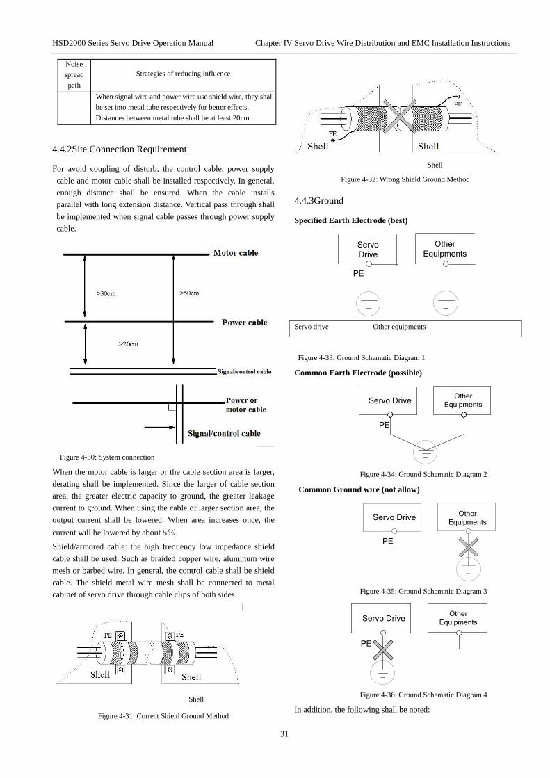
HSD2000 Series Servo Drive Operation Manual Chapter IV Servo Drive Wire Distribution and EMC Installation Instructions
31
Noise
spread
path
Strategies of reducing influence
When signal wire and power wire use shield wire, they shall
be set into metal tube respectively for better effects.
Distances between metal tube shall be at least 20cm.
4.4.2Site Connection Requirement
For avoid coupling of disturb, the control cable, power supply
cable and motor cable shall be installed respectively. In general,
enough distance shall be ensured. When the cable installs
parallel with long extension distance. Vertical pass through shall
be implemented when signal cable passes through power supply
cable.
Figure 4-30: System connection
When the motor cable is larger or the cable section area is larger,
derating shall be implemented. Since the larger of cable section
area, the greater electric capacity to ground, the greater leakage
current to ground. When using the cable of larger section area, the
output current shall be lowered. When area increases once, the
current will be lowered by about 5%.
Shield/armored cable: the high frequency low impedance shield
cable shall be used. Such as braided copper wire, aluminum wire
mesh or barbed wire. In general, the control cable shall be shield
cable. The shield metal wire mesh shall be connected to metal
cabinet of servo drive through cable clips of both sides.
Shell
Figure 4-31: Correct Shield Ground Method
Shell
Figure 4-32: Wrong Shield Ground Method
4.4.3Ground
Specified Earth Electrode (best)
Other
Equipments
PE
Servo
Drive
Servo drive Other equipments
Figure 4-33: Ground Schematic Diagram 1
Common Earth Electrode (possible)
Other
Equipments
PE
Servo Drive
Figure 4-34: Ground Schematic Diagram 2
Common Ground wire (not allow)
PE
Other
EquipmentsServo Drive
Figure 4-35: Ground Schematic Diagram 3
PE
Other
EquipmentsServo Drive
Figure 4-36: Ground Schematic Diagram 4
In addition, the following shall be noted:

HSD2000 Series Servo Drive Operation Manual Chapter IV Servo Drive Wire Distribution and EMC Installation Instructions
32
For possible low of different ground system impedances, the
maximum ground cable standard size shall be used. The flat
cable is used well. For cable of the same section area, high
frequency impedance of flat conductor is smaller than round
conductor.
One wire of 4 core motor cables shall be grounded on servo
drive side. The other side shall be connected to motor ground.
If motor and servo drive have specific earth electrode with
good effects.
When all the ground ends of system connects together, the
leakage current will be noise source to influence equipments.
The ground ends of servo drive, other audio devices, sensor
and computer shall be isolated.
For lower high frequency impedance, fixed screw of
equipments may be as high frequency terminal connected to
rear cabinet. The insulation paint of fixed point shall be
removed.
The ground cable shall be as short as possible. The ground
point shall close to servo drive.
The ground cable shall be far away from connection of I/O in
noise-sensitive devices. The ground wire shall be as short as
possible.
4.4.4 Installation Requirements of Relay, Contactor and
Electromagnetic Brake
Relay, contactor and electromagnetic brake shall be equipped
with surge suppressors including installation outside servo drive
cabinet.
220V AC
Piezoresistor
Servo
Drive
220V
AC
RC- Filter
Diode
24V DC
Figure 4-37: relay, contactor and electromagnetic brake
4.4.5Leakage Current and Strategies
Leakage current passes through servo drive input and output
electric capacity and motor electric capacity. Its capacity is
determined by wiring electric capacity and carrier wave frequency.
The leakage current includes earth leakage current and wiring
leakage current.
Power
supply
Servo Drive
Distributed
capacitance between
lines
Motor
Cable to
ground
capacitance
distributed
capacitance
of motor
R
S
T
QF
Figure 4-38: Leakage way
Earth Leakage Current
The leakage will flow into either servo drive system or other
equipments (by earth wire). The leakage current may cause error
action of leakage breaker, relay or other equipments. The higher
of servo drive carrier wave frequency, the greater leakage current.
The larger the motor cable, the greater of leakage current.
Restrain Measures:
Reduce carrier wave frequency. The motor noise will be
increased.
The motor cable shall be as short as possible.
The leakage breaker designed for leakage of high harmonic
wave/surge shall be used for servo drive system and other
systems.
Wiring Leakage Current
Leakage current of electric capacity flowed to servo drive output
cable. The higher harmonic wave may cause error action of
thermal relay, especially for small capacity (7.5kW less) servo
drive. When the connection is larger (50m more), the leakage
current will be relative increased. The error action of external
thermal relay may be caused.
Restrain measures:
Reduce carrier wave frequency. The motor noise will be
increased.
Install reactor in output side.
For motor protection, the temperature sensor is recommended to
use for monitoring motor temperature. The overload protection
function (electric thermal relay) of servo drive may replace
external thermal relay.
4.4.6Correct EMC Installation of Servo Drive
Partition Principle
In the driving system made up by servo and motor, the servo drive,
control device and sensor shall be in the same cabinet. The noise
emitted outside shall be restricted on main connection point. The
radio noise wave filter and line reactor shall be installed in cabinet.
The cabinet internal shall meet electromagnetic compatibility
requirements.
During mechanical/system design phase, the isolate noise source
in space and noise receiver shall be considered. The measure is the
most effective and the most expensive measure. In the driving
system made up by servo and motor, the servo drive, control
device and sensor shall be the noise source. The noise receiver
shall be automatic device, encoder and sensor.
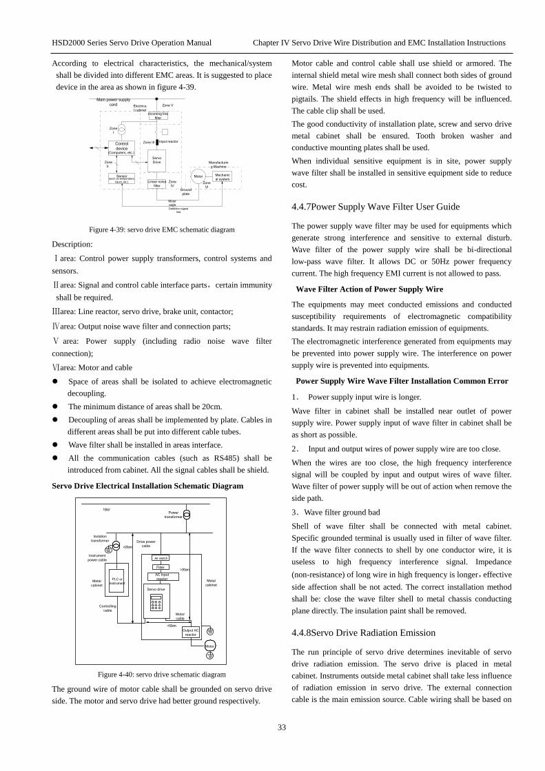
HSD2000 Series Servo Drive Operation Manual Chapter IV Servo Drive Wire Distribution and EMC Installation Instructions
33
According to electrical characteristics, the mechanical/system
shall be divided into different EMC areas. It is suggested to place
device in the area as shown in figure 4-39.
Incoming line
filter
Servo
Drive
Sensor (such as temperature,
liquid, etc.)
Control
device (Computers, etc.)
Electrica
l cabinet Zone V
Zone Ⅲ
Zone
I
Mechanic
al system
Manufacturin
g Machine
Zone
Ⅵ
Motor
Input reactor
Zone
Ⅱ
Linear noise
filter Ground
plate
Zone
Ⅳ
Main power supply
cord
Detection signal
line
Motor
cable
Figure 4-39: servo drive EMC schematic diagram
Description:
Ⅰarea: Control power supply transformers, control systems and
sensors.
Ⅱarea: Signal and control cable interface parts,certain immunity
shall be required.
Ⅲarea: Line reactor, servo drive, brake unit, contactor;
Ⅳarea: Output noise wave filter and connection parts;
Ⅴ area: Power supply (including radio noise wave filter
connection);
Ⅵarea: Motor and cable
Space of areas shall be isolated to achieve electromagnetic
decoupling.
The minimum distance of areas shall be 20cm.
Decoupling of areas shall be implemented by plate. Cables in
different areas shall be put into different cable tubes.
Wave filter shall be installed in areas interface.
All the communication cables (such as RS485) shall be
introduced from cabinet. All the signal cables shall be shield.
Servo Drive Electrical Installation Schematic Diagram
10kV
Power
transformer
Motor
Metal
cabinet
AC input
reactorMetal
cabinet
PLC or
instrument
Air switch
Output AC
reactor
>30cm
>50cm
Servo drive
Motor
cable
Controlling
cable
>20cm
Drive power
cable
Isolation
transformer
Instrument
power cable
Filter
Figure 4-40: servo drive schematic diagram
The ground wire of motor cable shall be grounded on servo drive
side. The motor and servo drive had better ground respectively.
Motor cable and control cable shall use shield or armored. The
internal shield metal wire mesh shall connect both sides of ground
wire. Metal wire mesh ends shall be avoided to be twisted to
pigtails. The shield effects in high frequency will be influenced.
The cable clip shall be used.
The good conductivity of installation plate, screw and servo drive
metal cabinet shall be ensured. Tooth broken washer and
conductive mounting plates shall be used.
When individual sensitive equipment is in site, power supply
wave filter shall be installed in sensitive equipment side to reduce
cost.
4.4.7Power Supply Wave Filter User Guide
The power supply wave filter may be used for equipments which
generate strong interference and sensitive to external disturb.
Wave filter of the power supply wire shall be bi-directional
low-pass wave filter. It allows DC or 50Hz power frequency
current. The high frequency EMI current is not allowed to pass.
Wave Filter Action of Power Supply Wire
The equipments may meet conducted emissions and conducted
susceptibility requirements of electromagnetic compatibility
standards. It may restrain radiation emission of equipments.
The electromagnetic interference generated from equipments may
be prevented into power supply wire. The interference on power
supply wire is prevented into equipments.
Power Supply Wire Wave Filter Installation Common Error
1. Power supply input wire is longer.
Wave filter in cabinet shall be installed near outlet of power
supply wire. Power supply input of wave filter in cabinet shall be
as short as possible.
2. Input and output wires of power supply wire are too close.
When the wires are too close, the high frequency interference
signal will be coupled by input and output wires of wave filter.
Wave filter of power supply will be out of action when remove the
side path.
3.Wave filter ground bad
Shell of wave filter shall be connected with metal cabinet.
Specific grounded terminal is usually used in filter of wave filter.
If the wave filter connects to shell by one conductor wire, it is
useless to high frequency interference signal. Impedance
(non-resistance) of long wire in high frequency is longer,effective
side affection shall be not acted. The correct installation method
shall be: close the wave filter shell to metal chassis conducting
plane directly. The insulation paint shall be removed.
4.4.8Servo Drive Radiation Emission
The run principle of servo drive determines inevitable of servo
drive radiation emission. The servo drive is placed in metal
cabinet. Instruments outside metal cabinet shall take less influence
of radiation emission in servo drive. The external connection
cable is the main emission source. Cable wiring shall be based on

HSD2000 Series Servo Drive Operation Manual Chapter IV Servo Drive Wire Distribution and EMC Installation Instructions
34
requirements of the chapter. It may restrain radiation emission of
cable.
When the servo drive is in the same metal cabinet with other
control device, the partition principle above shall be considered in
cabinet designing. Isolation, cable wiring, shield and lap shall be
considered.
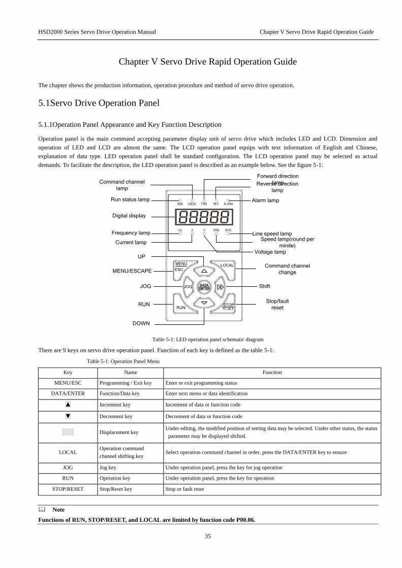
HSD2000 Series Servo Drive Operation Manual Chapter V Servo Drive Rapid Operation Guide
35
Chapter V Servo Drive Rapid Operation Guide
The chapter shows the production information, operation procedure and method of servo drive operation.
5.1Servo Drive Operation Panel
5.1.1Operation Panel Appearance and Key Function Description
Operation panel is the main command accepting parameter display unit of servo drive which includes LED and LCD. Dimension and
operation of LED and LCD are almost the same. The LCD operation panel equips with text information of English and Chinese,
explanation of data type. LED operation panel shall be standard configuration. The LCD operation panel may be selected as actual
demands. To facilitate the description, the LED operation panel is described as an example below. See the figure 5-1:
Run status lamp
Command channel
lamp
Forward direction
lampReverse direction
lamp
Alarm lamp
Digital display
Frequency lamp
Current lamp
Line speed lampSpeed lamp(round per
minite)Voltage lamp
MENU
ESC
RUN
JOG
LOCAL
MENU/ESCAPE
JOG
RUN
UP
DOWN
STOP
Command channel
change
Shift
Stop/fault
reset
Table 5-1: LED operation panel schematic diagram
There are 9 keys on servo drive operation panel. Function of each key is defined as the table 5-1:
Table 5-1: Operation Panel Menu
Key Name Function
MENU/ESC Programming / Exit key Enter or exit programming status
DATA/ENTER Function/Data key Enter next menu or data identification
▲ Increment key Increment of data or function code
▼ Decrement key Decrement of data or function code
Displacement key Under editing, the modified position of setting data may be selected. Under other status, the status
parameter may be displayed shifted.
LOCAL Operation command
channel shifting key Select operation command channel in order, press the DATA/ENTER key to ensure
JOG Jog key Under operation panel, press the key for jog operation
RUN Operation key Under operation panel, press the key for operation
STOP/RESET Stop/Reset key Stop or fault reset
Note
Functions of RUN, STOP/RESET, and LOCAL are limited by function code P00.06.
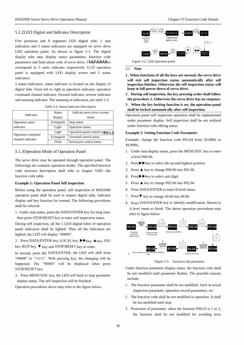
HSD2000 Series Servo Drive Operation Manual Chapter VI Function Code Details
36
5.1.2LED Digital and Indicator Description
Five positions and 8 segments LED digital tube, 5 unit
indicators and 5 status indicators are equipped on servo drive
LED operation panel. As shown in figure 5-1. The digital
display tube may display status parameters, function code
parameters and fault alarm code of servo drive. 5 unit indicators
correspond to 5 units indicates respectively. LCD operation
panel is equipped with LED display screen and 5 status
indicators.
5 status indicators: status indicator is located on the display of
digital tube. From left to right as operation indicator, operation
command channel indicator, forward indicator, reverse indicator
and warning indicator. The meaning of indication, see table 5-2.
Table 5-2: Status Indicator Description
Indicator Status
display
Indicate servo drive current
status
Operation status
indicator
Extinguish Stop status
Light Operation status
Operation command
channel indicator
Light Operation panel control status
Extinguish Terminal control status
Flash Serial port control status
5.1.3Operation Mode of Operation Panel
The servo drive may be operated through operation panel. The
followings are common operation modes. The specified function
code structure description shall refer to chapter VIIII—the
function code table.
Example 1: Operation Panel Self Inspection
Before using the operation panel, self inspection of HSD2000
operation panel shall be used to inspect digital tube, indicator
display and key function for normal. The following procedures
shall be referred:
1.Under stop status, press the DATA/ENTER key for long time,
then press STOP/RESET key to enter self inspection status.
During self inspection, all the 5 LED digital tubes of operation
panel indicators shall be lighted. Then all the indicators are
lighted, the LED will display “00000”.
2.Press DATA/ENTER key, LOCAL key, key, ▲key, JOG
key, RUN key, ▼ key and STOP/RESET key in order.
In normal, press the DATA/ENTER, the LED will shift from
“00000” to “11111”. With pressing key, the changing will be
happened. The “88888” will be displayed when press
STOP/RESET key.
3.Press MENU/ESC key, the LED will back to stop parameter
display status. The self inspection will be finished.
Operation procedures above may refer to the figure below:
Stop
parameter
display
state
Digital tube
lights in turn
2.1.1.1.1.1.1. Figure 5-2: LED operation panel
Note
1.When functions of all the keys are normal, the servo drive
will exit self inspection status automatically after self
inspection finishes. Otherwise the self inspection status will
keep to full power-down of servo drive.
2.During self inspection, the key pressing order shall follow
the procedure 2. Otherwise the servo drive has no response.
3.When the key locking function is set, the operation panel
shall be locked automatically after self inspection.
Operation panel self inspection operation shall be implemented
under parameter display. Self inspection shall be not realized
under function code editing status.
2.1.1.2. Example 2: Setting Function Code Parameter
Example: change the function code P02.04 from 50.00Hz to
49.99Hz.
1.Under data display status, press the MENU/ESC key to enter
a level P00.00.
2.Presskey to select the second highest position.
3.Press ▲ key to change P00.00 into P02.00.
4.Presskey to select unit digit.
5.Press ▲ key to change P02.00 into P02.04.
6.Press DATA/ENTER to enter B level menu.
7.Press▼ key to change 50.00 into 49.99.
8.Press DATA/ENTER key to identify modification. Return to
A level menu to finish. The above operation procedures may
refer to figure below:
Shutdown
parameter
Display status
First level menu
Flickering bits
Time high scintillation
Second level menu
50.00 P00.00 P00.00 P02.00 P02.00
P02.0450.049.9P02.04
:Bold numbers in figure indicate the flashing
digit
1
68
MENUESC
ENTERDATA
ENTERDATA
09
2 3 4
5
7
Figure 5-3: function code parameter
Under function parameter display status, the function code shall
be not modified until parameter flashes. The possible reasons
include:
1.The function parameter shall be not modified. Such as actual
inspection parameter, operation record parameters, etc.
2.The function code shall be not modified in operation. It shall
be not modified until stop.
3.Protection of parameter: when the function P00.03 is 1 or 2,
the function shall be not modified for avoiding error
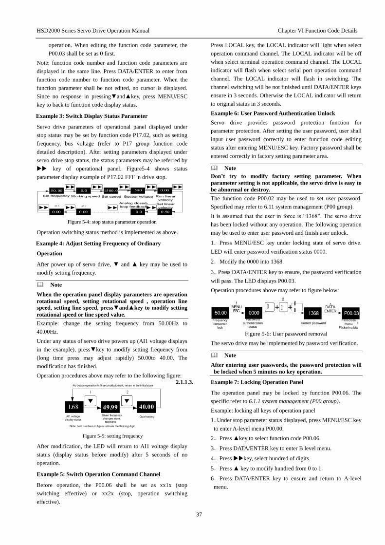
HSD2000 Series Servo Drive Operation Manual Chapter VI Function Code Details
37
operation. When editing the function code parameter, the
P00.03 shall be set as 0 first.
Note: function code number and function code parameters are
displayed in the same line. Press DATA/ENTER to enter from
function code number to function code parameter. When the
function parameter shall be not edited, no cursor is displayed.
Since no response in pressing▼and▲key, press MENU/ESC
key to back to function code display status.
Example 3: Switch Display Status Parameter
Servo drive parameters of operational panel displayed under
stop status may be set by function code P17.02, such as setting
frequency, bus voltage (refer to P17 group function code
detailed description). After setting parameters displayed under
servo drive stop status, the status parameters may be referred by
key of operational panel. Figure5-4 shows status
parameter display example of P17.02 FFF in drive stop.
Set frequency Working speed Set speed Busbar voltage Run linear
velocity
Set linear
velocity
Analog closed-
loop feedback
Figure 5-4: stop status parameter operation
Operation switching status method is implemented as above.
Example 4: Adjust Setting Frequency of Ordinary
Operation
After power up of servo drive, ▼ and ▲ key may be used to
modify setting frequency.
Note
When the operation panel display parameters are operation
rotational speed, setting rotational speed , operation line
speed, setting line speed, press▼and▲key to modify setting
rotational speed or line speed value.
Example: change the setting frequency from 50.00Hz to
40.00Hz.
Under any status of servo drive powers up (AI1 voltage displays
in the example), press▼key to modify setting frequency from
(long time press may adjust rapidly) 50.00to 40.00. The
modification has finished.
Operation procedures above may refer to the following figure:
No button operation in 5 seconds,Automatic return to the initial state
AI1 voltage
display status
Given frequency
changes state.
fast blink
Goal setting
Note: bold numbers in figure indicate the flashing digit
Figure 5-5: setting frequency
After modification, the LED will return to AI1 voltage display
status (display status before modify) after 5 seconds of no
operation.
Example 5: Switch Operation Command Channel
Before operation, the P00.06 shall be set as xx1x (stop
switching effective) or xx2x (stop, operation switching
effective).
Press LOCAL key, the LOCAL indicator will light when select
operation command channel. The LOCAL indicator will be off
when select terminal operation command channel. The LOCAL
indicator will flash when select serial port operation command
channel. The LOCAL indicator will flash in switching. The
channel switching will be not finished until DATA/ENTER keys
ensure in 3 seconds. Otherwise the LOCAL indicator will return
to original status in 3 seconds.
Example 6: User Password Authentication Unlock
Servo drive provides password protection function for
parameter protection. After setting the user password, user shall
input user password correctly to enter function code editing
status after entering MENU/ESC key. Factory password shall be
entered correctly in factory setting parameter area.
Note
Don’t try to modify factory setting parameter. When
parameter setting is not applicable, the servo drive is easy to
be abnormal or destroy.
The function code P00.02 may be used to set user password.
Specified may refer to 6.11 system management (P00 group).
It is assumed that the user in force is “1368”. The servo drive
has been locked without any operation. The following operation
may be used to enter user password and finish user unlock.
1.Press MENU/ESC key under locking state of servo drive.
LED will enter password verification status 0000.
2.Modify the 0000 into 1368.
3.Press DATA/ENTER key to ensure, the password verification
will pass. The LED displays P00.03.
Operation procedures above may refer to figure below:
P00.03+ +
:
MENUESC
1368000050.00
312
: :ENTERDATA
First class
menu
Flickering bits
Correct password
Password
authentication
status
Frequency
converter
lock
Figure 5-6: User password removal
The servo drive may be implemented by password verification.
Note
After entering user passwords, the password protection will
be locked when 5 minutes no key operation.
2.1.1.3. Example 7: Locking Operation Panel
The operation panel may be locked by function P00.06. The
specific refer to 6.1.1 system management (P00 group).
Example: locking all keys of operation panel
1.Under stop parameter status displayed, press MENU/ESC key
to enter A-level menu P00.00.
2.Press ▲key to select function code P00.06.
3.Press DATA/ENTER key to enter B level menu.
4.Press key, select hundred of digits.
5.Press ▲ key to modify hundred from 0 to 1.
6.Press DATA/ENTER key to ensure and return to A-level
menu.

HSD2000 Series Servo Drive Operation Manual Chapter VI Function Code Details
38
7.Press MENU/ESC key to return to stop parameter display
state.
8.Press DATA/ENTER key and keep, then press MENU/ESC
key to lock operation panel.
The procedures above may refer to figure below:
Stop parameter
display state
Stop parameter
display state
First class
menu
Flickering bits
First class
menu
Flickering bits
Second class
menu
Flickering bits
Operation
panel button
lock
Figure 5-7: operation panel key lock
Example 8: Unlock Operation Panel Key
When all the operation panel keys are locked, the following
operation may be implemented to unlock: press DATA/ENTER
key and keep, then click▼key for three times.
Note
However setting of P00.06, the operation panel shall be
unlock status after servo drive powers up.
5.2Servo Drive Operation Mode In the following chapters, terminologies of servo control,
operation and status will be referred. Please read the chapter
carefully to understand and use the following functions.
5.2.1Servo Drive Operation Command Channel
Servo drive operation command channel specifies servo drive to
accept operation command: physical channels in start and stop,
jog. The operation command channels include three types:
1.Operation panel: control by RUN, STOP and JOG keys of
operation panel.
2.Control terminal: control by control terminal FWD, REV,
COM (Two-wire), Xi (Three-wire).
3.Serial port: control start and stop by upper computer.
The command channel shall be selected by function code
P02.02, LOCAL key and DATA/ENTER key of operation panel,
multi-function input terminal (P10.00~P10.07 selects number
27-29 functions).
Note
Before switch command channel, the switch debugging
shall be implemented. Otherwise equipments damage and
personal injury will be occurred!
5.2.2Servo Drive Run Status
HSD2000 run status include stop status, operation status, motor
parameter auto-tuning status.
1.Stop status: after initialization of servo drive powers up, the
servo drive will enter stop status when: no operation
command input; implement stop command in operation.
2.Operation status: after receive operation command. The servo
drive will enter operation status.
3.Motor parameter auto-tuning status: operation command
sends after function parameter P03.11 (or P04.11) sets as 1 or 2,
the motor parameter identification status will be entered. After
identification, the stop status will be entered.
5.2.3Servo Drive Control and Operation Mode
Control Mode
HSD2000 servo drive has 4 control types which determined by
function code P02.00.
1.No PG vector control: zero speed sensors without installation
of PG. At the same time, the high control performance is
equipped to control speed and torque of motor accurately. The
low frequency high torque and high speed accuracy may
achieve high accuracy torque control and speed control. It may
be used in fields of no meeting V/F control mode and high
robustness requirements.
2.PG vector control: the PG shall be installed to ensure the
control performance is installed on controlled motor shaft. It is
applicable for fields of faster torque response and higher torque
and speed control accuracy. As feedback, the PG may finish
high accuracy position control—servo control function.
3.No PG V/Control: it is used for fields: lower requirements for
normal performance requirements; single servo drive controls
multi motors.
4.PG V/F control: PG shall be installed to improve V/F speed
control accuracy.
2.1.1.4. Operation Mode
Operation modes of HSD2000 servo drive vector control
include the following three types:
1.Speed control: Control motor speed accuracy. Related
function code of P07 and P08 groups shall be configured.
2.Torque control: Control torque speed accuracy. Related
function code of P07 and P08 groups shall be configured.
3.Position control: it is only effective in PG vector controls.
Motor position shall be controlled accuracy to achieve motor
position synchronous function. The P09 group function code
shall be set.
HSD2000 servo drive supports online switch of the operation
modes.
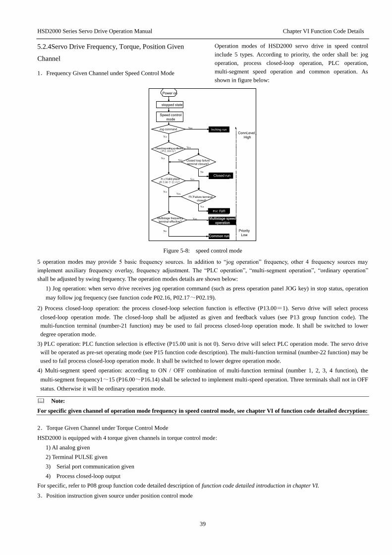
HSD2000 Series Servo Drive Operation Manual Chapter VI Function Code Details
39
5.2.4Servo Drive Frequency, Torque, Position Given
Channel
1.Frequency Given Channel under Speed Control Mode
Operation modes of HSD2000 servo drive in speed control
include 5 types. According to priority, the order shall be: jog
operation, process closed-loop operation, PLC operation,
multi-segment speed operation and common operation. As
shown in figure below:
Power on
stopped state
Speed control
mode
ConnLevel_
High
Priority
Low
Inching run
Closed run
Closed loop setting up effective
run
Multistage speed
operation
Common run
Multistage frequency
terminal effective?
Failure terminal
closed:
Valid place
Closed loop failure
terminal closure?
Jog command
Figure 5-8: speed control mode
5 operation modes may provide 5 basic frequency sources. In addition to “jog operation” frequency, other 4 frequency sources may
implement auxiliary frequency overlay, frequency adjustment. The “PLC operation”, “multi-segment operation”, “ordinary operation”
shall be adjusted by swing frequency. The operation modes details are shown below:
1) Jog operation: when servo drive receives jog operation command (such as press operation panel JOG key) in stop status, operation
may follow jog frequency (see function code P02.16, P02.17~P02.19).
2) Process closed-loop operation: the process closed-loop selection function is effective (P13.00=1). Servo drive will select process
closed-loop operation mode. The closed-loop shall be adjusted as given and feedback values (see P13 group function code). The
multi-function terminal (number-21 function) may be used to fail process closed-loop operation mode. It shall be switched to lower
degree operation mode.
3) PLC operation: PLC function selection is effective (P15.00 unit is not 0). Servo drive will select PLC operation mode. The servo drive
will be operated as pre-set operating mode (see P15 function code description). The multi-function terminal (number-22 function) may be
used to fail process closed-loop operation mode. It shall be switched to lower degree operation mode.
4) Multi-segment speed operation: according to ON / OFF combination of multi-function terminal (number 1, 2, 3, 4 function), the
multi-segment frequency1~15 (P16.00~P16.14) shall be selected to implement multi-speed operation. Three terminals shall not in OFF
status. Otherwise it will be ordinary operation mode.
Note:
For specific given channel of operation mode frequency in speed control mode, see chapter VI of function code detailed decryption:
2.Torque Given Channel under Torque Control Mode
HSD2000 is equipped with 4 torque given channels in torque control mode:
1) AI analog given
2) Terminal PULSE given
3) Serial port communication given
4) Process closed-loop output
For specific, refer to P08 group function code detailed description of function code detailed introduction in chapter VI.
3.Position instruction given source under position control mode

HSD2000 Series Servo Drive Operation Manual Chapter VI Function Code Details
40
For position instruction given channel of HSD2000 position control mode, refer to refer to P09 group function code detailed description of
function code detailed introduction in chapter VI.
5.3The First Power up
5.3.1Checking before Power up
The connection connection shall be implemented as technical requirements in Chapter IV Servo Drive Connection and EMC
Installation Instructions of chapter IV.
5.3.2The First Power Up Operation
When wiring and power supply is correct, close air switch of AC power supply in servo drive input side; charge to servo drive; “8.8.8.8.8.”
will be displayed on servo drive operation panel; the contactor will be picked closely. When digital tube display symbol is setting
frequency, the initialization of servo drive will be finished.
When LED indicator on digital tube of operation panel is ON state, the operation panel is in control state.
The first power up process is shown as figure below:
Start
Connection according to the
requirements
Check the connections
Check the input voltage
Power up
Display 8.8.8.8.8?
Hear the contactor
closed?
Display set frequency?
Power up ok Power up failed
Disconnect the
input air switch
Check the circuit
Y
N
Y
Y
N
N
Figure 5-9: servo drive power up

HSD2000 Series Servo Drive Operation Manual Chapter VI Function Code Details
41
5.4Pilot running
5.4.1 Sensorless Vector Pilot Running
1.Inspect drive input and output connections. Power up shall be implemented after without error.
2.Enter P03 group to input motor parameter correctly. Set P03.11=2 (remove load) to tune the motor parameters.
3.Set P02.00 as no PG vector control.
4.Running
5.4.2Closed-loop Vector Pilot Running
1. Inspect drive input and output connections. Power up after without error.
2. Enter P03 group to input motor parameter correctly. Set P03.11=2 (remove load) to tune the motor parameters.
3.Set encoder signal feedback source correctly, when expansion PG card is selected as signal feedback, then set P07.00=1. When
select local terminal as signal feedback, then set P07.00=0. The P12 group parameter shall be set as selected signal feedback.
4.The control mode set as V/F control mode of P02.00=2. The operation frequency set as P02.04=10.00Hz.
5.Run the motor and observe P01.13 values. When the value closes to 10Hz, it shows that encoder parameter is correct. When the
value is negative, it shows direction error of encoder. Exchange any two of the three phase motor wires. When the frequency is 0, it
represents that encoder is not connected correctly. Encoder shall use shielding layer and connect to control terminal PE of servo drive.
When the frequency is not correct, it represents that the encoder wires or motor rated speed setting error. The related function code shall be
changed.
6.The control mode set as closed-loop vector of P02.00=1(induction motor close loop vector control).
7.Set the frequency from 0 to rated frequency. The motor stable and vibration shall be noted, especially around 0. When vibration
occurs around 0 frequencies, the encoder low speed wave filter parameter P12.03/P12.14 and speed loop PI parameter P07 group shall
be adjusted. It shall be finished until stable operation without vibration in the entire frequency range.
5.4.3Torque Control Pilot Running
1.Do the step 5.4.1(open-loop mode) or 5.4.2(closed-loop mode) to ensure drive normal.
2.The control mode set as torque control P08.00=1.
3.Set torque instruction given of P11.01=8. AI1 is channel of torque instruction.
4.Set speed limit mode, P07.08=1.
5.Set speed limit channel, P07.09=1。
6.Set speed limit instruction, P11.06=4, AI2 is speed limit channel.
7.Applicable set speed/torque switching point P08.04.
5.4.4Servo Control Pilot Running(X7 and X8 terminal pulse serial control as example)
1.The 5.4.2 methods may be used to ensure drive PG closed-loop vector control for normal operation.
2.Set servo function P09.00=3.
3.Set position given source P09.03=0; set X7 and X8 terminal function as P10.06=71, P10.07=72; The position given is entered
by terminalX7 and X8input. The X7 represents direction, X8 represents pulse serial. X7 shall be forward when no conducting. X7 shall be
reverse when conducting. The reverse may be taken reverse of X7 by P10.16.
4.Set P10.11 (each pulse number of X8). The follow rotational speed shall be obtained by X8 pulse frequency. The rotational speed
value is not related with electronic gear function (P09.10, P09.11).
5.Set P09.10 and P09.11 (electronic gear numerator, denominator). When motor follows pulse serial, relationship between encoder
feedback number and pulse serial number shall be electronic gear ratio relationship.

HSD2000 Series Servo Drive Operation Manual Chapter VI Function Code Details
42
6.Example: the motor shall be 4 degree motor. The encoder shall be 1024-coil. When pulse serial is 100k, the rotational speed of
Corresponding motor is required to be 1500rpm. P10.11=100k*60/1500=4000 shall be set; electronic gear ratio= (1024*1500/60)
/100K=256/1000, P09.10=256 may be set; P09.11=1000.
7.Adjust speed loop PI parameter and position loop P parameter P09.26 (position loop Kp1), P09.27 (position loop Kp2), P09.28
(position loop increment switch mode). The pulse serial track process shall be fast without overload. The P09.08 may be set as
requirements (pulse instruction wave filter time). The pulse tracking error shall be monitored by function code P01.47 at real time.
8.Before debugging, the P09.34=0 ( position loop output range) may be set. It is speed tracing mode at this time. The speed shall be
observed for normal. Then the position loop shall be added to monitor position. The P09.33 (Velocity feed forward gain) shall be set as
100.00%. The parameter value shall be not changed.
5.4.5Spindle Positioning Pilot Running
1.According to 5.4.2 method, the drive PG closed-loop vector control shall be ensured for normal.
2.The servo operation mode shall be spindle operation, P09.01=2.
3. Set the X1~X5 terminal function as 84, 77, 78, 79, 37. X1 shall be zero origin. X2 shall be spindle position start. X3 and X4
shall be position selection terminal. X5 shall be prohibited running terminal of servo drive.
4.Set unit digital value of positioning mode P09.02. The electric spindle shall equip encoder Z pulse as reference point. The
non-electric spindle shall equip close switch. The closing switch shall be used to refer zero point. During operation, the spindle will
search reference point automatically. The function code setting is not necessary.
5.When using the X1or X3, X4, the motor will stop after an angle of rotation. The zero position shall be observed for consist. The
degree shall be correct.
6.Adjust speed loop PI parameter and position loop P parameter P09.26 (zero servo locking position loop KP), P09.27 (position
process position loop KP). The position process shall be fast without overshoot.
5.4.6Synchronous Motor Pilot Running(Increment ABZUVW Encoder as Example)
1.Inspect drive input and output wiring; inspect PG card wiring. Power shall be implemented after no error.
2. The control mode shall be set as PG closed-loop vector; P02.00=11.
3.Set PG parameter correctly; PG feedback resource P07.00;
4.The motor parameter P03 group shall be set correctly. The tuning P03.23 of motor shall be implemented.
5.When tuning the motor, send the DC first, turn the motor to certain position and low speed rotation. When current is smaller with
stable operation, it represents that encoder setting correct with success tuning. When report E025 in tuning process, it represents
encoder wiring problem. The encoder shall be connected again. After tuning, the function code P03.25, P03.26 will save initial angular
of synchronous machine obtained by tuning. When the initial angle difference is smaller than 5°(65536 represents 360°), it represents
the tuning in normal.
6. When the tuning is abnormal without E025 fault, P12.16,P12.19,P12.21 shall be observed to determine for encoder signal
problems. Encoder shall be checked to solve problem. When rotate the motor shaft, when P12.19 count value increases, the P12.16
displays the magnetic signal status order of 5, 1, 3, 2, 6, 4. When the count value reduces, the order of magnetic signal shall be reverse.
When 0 or 7 be happened in P12.16, magnetic signal UVW wiring of encoder shall be not correct. After one round rotation, Z pulse
count value of P12.21 shall be not 0. Otherwise the Z signal has problems.
7. Set the frequency from 0 to rated frequency. The motor stable and vibration shall be noted, especially around 0. When vibration
occurs around 0, the encoder low speed wave filter parameter P12.03/P12.14 and speed loop PI parameter P07 group shall be set.
8. During operation, the encoder Z pulse count value P12.21 shall be observed. When the value jumps higher, it shows disturb of
encoder. The encoder wiring shall be checked.
Note
When P12.08 value is 1, when rotate the motor shaft, if the P12.19 count value reduces, the P12.16 display magnetic signal status
order shall be 5, 1, 3, 2, 6, 4. When the count increases, the magnetic signal order shall be reverse.
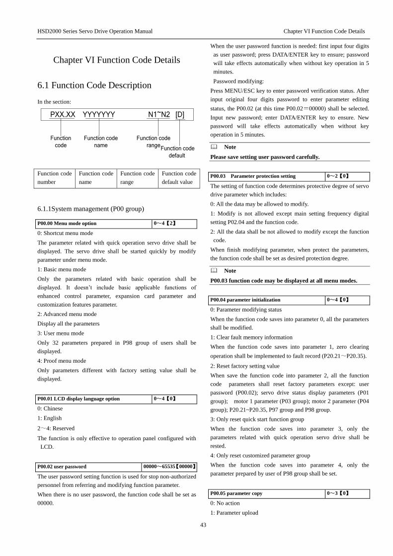
HSD2000 Series Servo Drive Operation Manual Chapter VI Function Code Details
43
Chapter VI Function Code Details
6.1 Function Code Description
In the section:
PXX.XX YYYYYYY N1~N2 [D]
Function
code
Function code
name
Function code
range Function code
default
Function code
number
Function code
name
Function code
range
Function code
default value
6.1.1System management (P00 group)
P00.00 Menu mode option 0~4【2】
0: Shortcut menu mode
The parameter related with quick operation servo drive shall be
displayed. The servo drive shall be started quickly by modify
parameter under menu mode.
1: Basic menu mode
Only the parameters related with basic operation shall be
displayed. It doesn’t include basic applicable functions of
enhanced control parameter, expansion card parameter and
customization features parameter.
2: Advanced menu mode
Display all the parameters
3: User menu mode
Only 32 parameters prepared in P98 group of users shall be
displayed.
4: Proof menu mode
Only parameters different with factory setting value shall be
displayed.
P00.01 LCD display language option 0~4【0】
0: Chinese
1: English
2~4: Reserved
The function is only effective to operation panel configured with
LCD.
P00.02 user password 00000~65535【00000】
The user password setting function is used for stop non-authorized
personnel from referring and modifying function parameter.
When there is no user password, the function code shall be set as
00000.
When the user password function is needed: first input four digits
as user password; press DATA/ENTER key to ensure; password
will take effects automatically when without key operation in 5
minutes.
Password modifying:
Press MENU/ESC key to enter password verification status. After
input original four digits password to enter parameter editing
status, the P00.02 (at this time P00.02=00000) shall be selected.
Input new password; enter DATA/ENTER key to ensure. New
password will take effects automatically when without key
operation in 5 minutes.
Note
Please save setting user password carefully.
P00.03 Parameter protection setting 0~2【0】
The setting of function code determines protective degree of servo
drive parameter which includes:
0: All the data may be allowed to modify.
1: Modify is not allowed except main setting frequency digital
setting P02.04 and the function code.
2: All the data shall be not allowed to modify except the function
code.
When finish modifying parameter, when protect the parameters,
the function code shall be set as desired protection degree.
Note
P00.03 function code may be displayed at all menu modes.
P00.04 parameter initialization 0~4【0】
0: Parameter modifying status
When the function code saves into parameter 0, all the parameters
shall be modified.
1: Clear fault memory information
When the function code saves into parameter 1, zero clearing
operation shall be implemented to fault record (P20.21~P20.35).
2: Reset factory setting value
When save the function code into parameter 2, all the function
code parameters shall reset factory parameters except: user
password (P00.02); servo drive status display parameters (P01
group); motor 1 parameter (P03 group); motor 2 parameter (P04
group); P20.21~P20.35, P97 group and P98 group.
3: Only reset quick start function group
When the function code saves into parameter 3, only the
parameters related with quick operation servo drive shall be
rested.
4: Only reset customized parameter group
When the function code saves into parameter 4, only the
parameter prepared by user of P98 group shall be set.
P00.05 parameter copy 0~3【0】
0: No action
1: Parameter upload

HSD2000 Series Servo Drive Operation Manual Chapter VI Function Code Details
44
After setting as 1 and ensure, the servo drive will upload all
function codes between control panel P00.00 ~ P98.31 to
EPPROM of operation panel for storage.
2: Parameter downloading
After setting as 2 and ensure, the servo drive will download all
function codes between operation panel P00.00 ~P98.31 to
internal control panel for storage.
3: Parameter downloading (except parameter)
After setting as 3 and ensure, the servo drive will download all
function codes between operation panel P00.00 ~P98.31 to
internal control panel for storage (P03 and P04 group motors
parameters shall be not downloaded).
Note
1.For operation panel, the parameter uploading shall be
implemented first. Otherwise the operation panel memory will
be empty. When finish one time parameter loading operation,
operation panel parameter shall be kept in operation panel
memory.
2.Before the parameters download to servo drive, servo
drive will inspect integrity and version information of function
code parameter in operation panel. In the following conditions,
the parameter shall be not modified and the error information
will be mentioned to copy: when the memory is empty;
parameter is not full; parameter version is not the same as
current servo drive software version (different quantities of
function codes).
3.After download the parameter, parameter in operation
panel memory is still existed. Multi servo drives shall be
copied repeatedly.
P00.06 key function option 0000~1422H【0000】
Thousands
placs
Hundred
placs
Tens
placs
Ones
placs
0 :Panel control method is invalid1 :Panel control mode in down way down
2 :Panel control mode free parking
LOCAL Key feature selection
0 :Nullify 1 :Effective stop condition
STOPKey feature
selection
Operation panel locking
options 0: no lock 1: all lock 2: in addition to the STOP key lock3: in addition to the SHIFT key lock
STOPKey double-click the abrupt stop function 0
:Double click the STOP key free
parking
1: No function
2 :Stop and run effectively
4: all locked except the RUN, the STOP
button
Figure 6-1: operation panel
Unit digit: STOP/RESET key function option
The item is used for setting operation panel STOP/RESET key as
working range and run mode in STOP of stop key.
Unit
digit Function Description
0 Invalid It is effective for operation panel to run
command channel
non-panel
control
1
Stop of
non-panel as
stop mode
It is effective in operation panel, terminal,
serial port operation command channel.
Press the key, the servo drive will stop as
P05.05 setting.
2
Non-panel
control
freewheel
When running command channel on
operation panel, press the key, servo drive
will stop as mode of P05.05. When the
command channel is operated by terminal
or serial port, press the key, the servo drive
will be freewheel and report E015 fault.
Note
STOP/RESET key will be effective in any command channel
operation of fault reset key RESET.
Tens digits: LOCAL key function option
The item is used for setting working and range of LOCAL key on
operational panel.
Tens
digits Function Description
0 Invalid LOCAL key is invalid. The key shall be not
used for switch operation command channel.
1
Stop
status
effective
LOCAL key is only effective in stop status.
The key shall be not used for switch operation
command channel.
2
Stop
operation
effective
LOCAL key may switch running command
channel under stop status and operation
status.
Operation Command Channel Switch Order:
Operation panel running command channel (LOCAL lights)
→terminal running command channel (LOCAL off) →serial
port running command channel (LOCAL flash) →operation panel
running command channel (LOCAL lights)
Note
After switch to necessary running command channel by
LOCAL key, the DATA/ENTER shall be pressed in 3 seconds
for effective.
Hundred digits: operation panel locking function
The item is used for setting locking range option of operation
panel keys.
Hundr
ed
digits
Function Description
0 No locking No locking function, any key shall be not
locked.
1 Full locking
Operation panel key shall be locked fully.
After the locking function takes effect, any
key on operation panel will be invalid.
2
All locking
except
STOP/RESE
T key
In addition to STOP/RESET key, other keys
are all locked. After the locking function
takes effects, only the STOP/RESET key
may be used.
3
All locking
except SHIFT
key
All locking except key. After the
locking function takes effect, only
key may be used.

HSD2000 Series Servo Drive Operation Manual Chapter VI Function Code Details
45
4
All locking
except RUN,
STOP/RESE
T keys.
In addition to STOP, RUN keys, other keys
are all locked. After the locking function
takes effects, only the STOP, RUN keys
may be used.
After setting the items as demands, the specified operation
methods shall be implemented to make locking effective. Refer to
05.1.3Operation Mode of Operation Panel operation method.
The locking method may refer to 05.1.3Operation Mode of
Operation Panel.
Thousand digits: double click STOP key for emergency stop
function
Thousand
digits Function Description
0
Double click
STOP key for
freewheel
Double click STOP key for freewheel.
During operation, double click STOP key
for freewheel and report E015 fault.
1 No function
Double click STOP key for freewheel.
During operation, double click STOP key
may stop as normal stop.
6.1.2Status Display Parameter (P01 group)
P01 group function code parameters are used for monitoring servo
drive and motor status parameters. At the same time, the
frequency given channel, the setting frequency, PID given, PID
feedback and PID error shall be checked.
P01.00 Main setting
frequency channel 0~6【0】
Monitor the main frequency channel under ordinary operation
mode. Non-ordinary operation mode will be displayed as 0.
P01.01 Main given setting
frequency -1000.0~1000.0Hz【0.00】
Monitor the main setting frequency under ordinary operation
mode. Non-ordinary operation mode will be displayed as 0.
P01.02 Auxiliary given set
frequency -1000.0~1000.0Hz【0.00】
Monitor auxiliary setting frequency under ordinary operation
mode. Non-ordinary operation mode will be displayed as 0.
P01.03 Setting frequency -1000.0~1000.0Hz【0.00】
Monitor the final frequency through primary and secondary
synthesis. The positive value indicates forward; the negative
indicates reverse.
P01.04 Acceleration and
deceleration frequency instruction -1000.0~1000.0Hz【0.00】
Monitor servo drive output frequency through acceleration and
deceleration process including frequency direction.
P01.05 Output frequency -1000.0~1000.0Hz【0.00】
Monitor servo drive output frequency including frequency
direction.
P01.06 output voltage 0~480V【0】
Monitor servo drive output voltage.
P01.07 output current 0.0~3Ie【0】
Monitor servo drive output current.
P01.08 torque current -300.0%~300.0%【0.0%】
Monitor servo drive percentage of torque current to motor rated
current.
P01.09 Flux current 0.0%~100.0%【0.0】
Monitor percentage of flux current to motor rated current.
P01.10 output torque -300.0%~300.0%【0.0】
Monitor percentage of servo drive output torque to motor rated
torque.
P01.11 motor power 0.0%~200.0%【0.0】
Monitor percentage of servo drive output power to power rated
power.
P01.12 Motor estimate frequency -600.00~600.00Hz【0.00】
Motor rotor frequency estimated under open-loop vector condition
P01.13 motor measured frequency -600.00~600.00Hz【0.00】
Actual motor rotor frequency of closed-loop vector condition by
encoder
P01.14 Energy consumption in high
position 0~65535*10000kwh【0】
P01.15 Energy consumption in low
position 0~9999kwh【0】
Monitor energy consumption output of servo drive.
P01.16 bus voltage 0~800V【0】
Monitor servo drive bus voltage.
P01.17 servo drive operation status 0000~FFFFH【0000】
Hundreds
place
Tens
placs
Oncs
placs
BIT0: Run/stop BIT1: Inverse/forwardBIT2:Zero speed operation
BIT3 : Speed
BIT0: Reduce speed
BIT1: Constant speed operation
BIT2: Pre-excitation
BIT3 : Tuning
BIT0: Flow limit
BIT1: Dc overvoltage limitBIT2: Torque limitation
BIT3: Speed limiter
Thousands
place
BIT0: Drive malfunction
BIT1: Speed controlBIT2: Torque Control
Figure 6-2: servo drive run
LED unit digit BIT0: operation/stop;
When servo drive is in stop status, the BIT0 position shall be 0.
Otherwise it will be 1.
LED unit digits BIT1: reverse/forward;
When servo drive forwards, BIT1 position is 0. Otherwise it will
be 1.

HSD2000 Series Servo Drive Operation Manual Chapter VI Function Code Details
46
When meeting condition, other positions may be set as 1.
P01.18 switch input status 000~3FFH【000】
Hundred
s place
Tens
place
Ones
place
BIT0: X1 Terminal state of on and off
BIT1: X2 Terminal state of on and off
BIT2: X3 Terminal state of on and off
BIT3: X4 Terminal state of on and off
BIT0: X5
BIT1: X6 BIT2: X7
BIT3: X8
BIT0: FWD
BIT1: REV BIT2
:Reserv
eBIT3
:Reserv
e
Terminal state of on and off Terminal state of on and off
Terminal state of on and off
Terminal state of on and off
Terminal state of on and off Terminal state of on and off
Figure 6-3: Switch input status
The figure shows on-off status of 10 terminals, including X1~X8,
FWD, REV. “0” represent the terminal in off status; 1 represents
the terminal in close status.
P01.19 Switch output status 0~FH【0】
Ones placs
BIT0:Y1 State of terminal signal
BIT1: Y2 State of terminal signal
BIT2: BR Relay ttracts gathers state
BIT3: T Relay ttracts gathers state
Figure 6-4: Switch output status
Function code P01.19 may display output status of switch
terminal Y1, Y2 and relay BR, T. When output signal is
implemented, the related position of P01.19 will be set as 1.
For example, when signal output only exists in Y1 terminal, the
BIT0 position will be set as 1, the P01.19 display value will be 1.
When signal output only exists in relay T, the P01.19 display
value will be 8.
P01.20 AI1 input -10.00~10.00V【0.00】
P01.21 AI2 input -10.00~10.00V【0.00】
P01.22 AI3 input -10.00~10.00V【0.00】
P01.20~P01.22 shows analog input signal before adjustment.
P01.23 adjusted AI1 input -10.00~10.00V【0.00】
P01.24 adjusted AI2 input -10.00~10.00V【0.00】
P01.25 adjusted AI3 input -10.00~10.00V【0.00】
P01.23~P01.25 shows the adjusted analog input signal through
increment, deviation.
Note
When analog input is current input, the adjusted AI input
range shall be 4~20mA. The corresponding display range
shall be 2~10.
P01.26 AO1 output 0.0%~100.0%【0.0】
P01.27 AO2 output 0.0%~100.0%【0.0】
P01.26 and P01.27 show percentage of analog output value to full
scale capacity.
For example: when AO1function setting is: output frequency; the
maximum frequency is 100Hz; actual operation frequency is
50Hz; then P01.26 shall display 50%.
P01.28 process closed-loop given -100.0%~100.0%【0.0】
P01.29 process closed-loop feedback -100.0%~100.0%【0.0】
P01.30 process closed-loop error -100.0%~100.0%【0.0】
P01.31 process closed-loop output -100.0%~100.0%【0.0】
P01.28 ~ P01.31 show percentage of P13 group process
closed-loop given value, feedback value, error value, output value
to full scale capacity.
P01.32 rediator 1 temperature 0.0~150.0℃【0.0】
P01.33 rediator 2 temperature 0.0~150.0℃【0.0】
Radiator 1 temperature shows temperature of inverter module.
Different types of inverter modules have different
over-temperature protection values.
Radiator 2 temperature shows temperature of rectifier module.
Rectifier bridge temperature below 37kW type shall be not
inspected.
Temperature display range: 0~150℃; accuracy: 5%
P01.34~P01.35 Reserved
Reserved function
P01.36 charge cumulative time 0~65535 hours【0】
P01.37 operation cumulative time 0~65535 hours【0】
P01.38 fan operation cumulative time 0~65535hours【0】
P01.36~P01.38 shows respectively charge cumulative time,
operation cumulative time and fan operation cumulative time of
servo drive from factory.
P01.39 Reserved
Reserved function.
P01.40 ASR controller output -300.0%~300.0%【0.0】
Percentage to motor rated torque, it shows ASR controller output.
P01.41 torque given -300.0%~300.0%【0.0】
Percentage to motor rated torque, it shows torque given.
P01.42 Reserved
Reserved function.
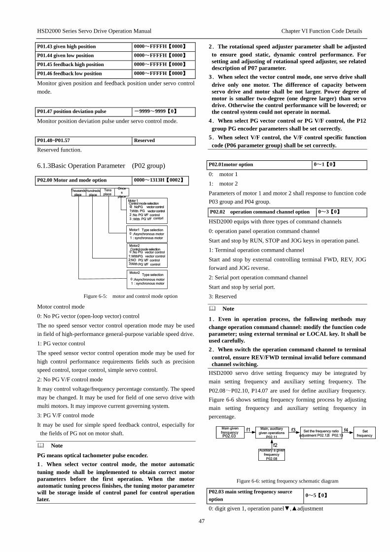
HSD2000 Series Servo Drive Operation Manual Chapter VI Function Code Details
47
P01.43 given high position 0000~FFFFH【0000】
P01.44 given low position 0000~FFFFH【0000】
P01.45 feedback high position 0000~FFFFH【0000】
P01.46 feedback low position 0000~FFFFH【0000】
Monitor given position and feedback position under servo control
mode.
P01.47 position deviation pulse -9999~9999【0】
Monitor position deviation pulse under servo control mode.
P01.48~P01.57 Reserved
Reserved function.
6.1.3Basic Operation Parameter (P02 group)
P02.00 Motor and mode option 0000~1313H【0002】
Thousands
place Hundreds
place
Tens
place
Once
s
place
0: NoPG vector control 1 :With PG vector control 2 :No PG V/F control 3 :With PG V/F contorl
Motor1 Type selection 0 :Asynchronous motor
1 : synchronous motor
Motor 1 Control mode selection
Motor2Control mode selection 0 :No PG vector control
1:WithPG vector control 2 :NO PG V/F control 3 :With PG V/F control
Motor2 Type selection
0 :Asynchronous motor1 : synchronous motor
Figure 6-5: motor and control mode option
Motor control mode
0: No PG vector (open-loop vector) control
The no speed sensor vector control operation mode may be used
in field of high-performance general-purpose variable speed drive.
1: PG vector control
The speed sensor vector control operation mode may be used for
high control performance requirements fields such as precision
speed control, torque control, simple servo control.
2: No PG V/F control mode
It may control voltage/frequency percentage constantly. The speed
may be changed. It may be used for field of one servo drive with
multi motors. It may improve current governing system.
3: PG V/F control mode
It may be used for simple speed feedback control, especially for
the fields of PG not on motor shaft.
Note
PG means optical tachometer pulse encoder.
1.When select vector control mode, the motor automatic
tuning mode shall be implemented to obtain correct motor
parameters before the first operation. When the motor
automatic tuning process finishes, the tuning motor parameter
will be storage inside of control panel for control operation
later.
2.The rotational speed adjuster parameter shall be adjusted
to ensure good static, dynamic control performance. For
setting and adjusting of rotational speed adjuster, see related
description of P07 parameter.
3.When select the vector control mode, one servo drive shall
drive only one motor. The difference of capacity between
servo drive and motor shall be not larger. Power degree of
motor is smaller two-degree (one degree larger) than servo
drive. Otherwise the control performance will be lowered; or
the control system could not operate in normal.
4.When select PG vector control or PG V/F control, the P12
group PG encoder parameters shall be set correctly.
5.When select V/F control, the V/F control specific function
code (P06 parameter group) shall be set correctly.
P02.01motor option 0~1【0】
0: motor 1
1: motor 2
Parameters of motor 1 and motor 2 shall response to function code
P03 group and P04 group.
P02.02 operation command channel option 0~3【0】
HSD2000 equips with three types of command channels
0: operation panel operation command channel
Start and stop by RUN, STOP and JOG keys in operation panel.
1: Terminal operation command channel
Start and stop by external controlling terminal FWD, REV, JOG
forward and JOG reverse.
2: Serial port operation command channel
Start and stop by serial port.
3: Reserved
Note
1.Even in operation process, the following methods may
change operation command channel: modify the function code
parameter; using external terminal or LOCAL key. It shall be
used carefully.
2.When switch the operation command channel to terminal
control, ensure REV/FWD terminal invalid before command
channel switching.
HSD2000 servo drive setting frequency may be integrated by
main setting frequency and auxiliary setting frequency. The
P02.08~P02.10, P14.07 are used for define auxiliary frequency.
Figure 6-6 shows setting frequency forming process by adjusting
main setting frequency and auxiliary setting frequency in
percentage.
Main, auxiliary
given operations
P02.11
Set the frequency ratio
adjustment P02.12: P02.13
Main given
frenquencyP02.03
f1 f3 Set
frequency
f4
Auxiliary a given
frequency
P02.08
f2
Figure 6-6: setting frequency schematic diagram
P02.03 main setting frequency source
option 0~5【0】
0: digit given 1, operation panel▼,▲adjustment

HSD2000 Series Servo Drive Operation Manual Chapter VI Function Code Details
48
When servo drive powers up, the function code P02.04 value shall
be as current setting frequency.
When servo drive is in operation or stop status, the▼and▲ key of
operation panel shall be used to change current setting frequency
of servo drive.
1: Digit given 2, terminal UP/DOWN adjustment
Under the mode, function code P02.04 value in servo drive
powers up shall be set as current setting frequency of servo drive.
By setting external control terminal function, the current setting
frequency shall be implemented in operation or stop status of
servo drive.
When select the sting mode, the following parameters setting shall
be implemented:
1) In parameter P10.00~P10.07, functions of both external
control terminals shall be 13, 14.
2) According to function code P10.09, P10.10, the value change
rate of UP/DN terminal in frequency setting.
Select to
define both
terminals in
X1~X8
13 Frequency increment
instruction UP
Short as UP terminal
below
14 Frequency decrement
instruction DOWN
Short as DOWN
terminal below
When select digit given-2 mode, the wiring schematic diagram is
shown below:
UP
terminal
DOW
N
termina
l
CO
Mtermina
l
UPswitch
DOW
Nswitch
HSD200
0
Figure 6-7: Digital setting 2 connection schematic diagram
Under terminal closes, relationship of two external switch statue
setting and servo drive current setting frequency is as follows:
External switch status and servo drive current setting frequency
UP terminal switch status Break Close
DOWN terminal switch status Break Close Break Close
servo drive current setting
frequency Keep
Decreas
e
Increas
e Keep
2: Digit given 3, serial port communication given
The setting frequency shall be changed by serial port frequency
setting order.
3: AI analog given
Analog given has three separate physical channels: AI1, AI2 and
AI3.
AI is analog signal input channel. When AI inputs as voltage
signal, the voltage input range shall be: -10V~0V~+10V. For
adjusted analog input signal (-10V~0V~+10V), the following
regulations:
0V~+10V segments, forward, response to frequency defined in
P11 group function code.
0V~-10V segments, forward, response to frequency defined in
P11 group function code.
4: Terminal pulse (PULSE) given
Frequency setting shall be defined by terminal pulse frequency.
The input shall be X8. Specified refer to P10 group definition.
5: Reserved
Note
Frequency main given mode of 3 and 4 frequency calculation
shall be determined by function code P11.25~P11.41 of
relationship curve. When the main frequency given is analog
or pulse given, positive and negative polarity of output main
setting frequency shall be determined by analog and pulse
value. The value is not related with P02.20 function code. In
reverse, setting frequency positive and negative polarity of
other frequency given modes shall be determined by P02.20.
P02.04 main setting frequency
digital setting
Lower limit frequency~upper
limit frequency【50.00Hz】
When main setting frequency cannel is defined as digit given
(P02.03=0, 1, 2), the function parameter shall be initial setting
frequency of servo drive main setting frequency.
P02.05 maximum
output frequency Max (50.00,P02.06) ~1000.0Hz【50.00Hz】
P02.06 upper limit
frequency
Lower limit frequency~ maximum
outputfrequency【50.00Hz】
P02.07 lower limit
frequency 0~ upper limit frequency【0.00Hz】
Maximum output frequency is the highest frequency allowed by
servo drive. As Fax of 0:
Upper limit frequency is the highest frequency allowed by user
setting. As FH of 0:
Lower limit frequency is the lowest frequency allowed by user
setting. As FL in figure 6-8:
Fb in 0 represents the basic operation frequency. It is the response
output frequency minimum value of servo drive in V/F output
mode.
Figure 6-8: Limit frequency parameter schematic diagram
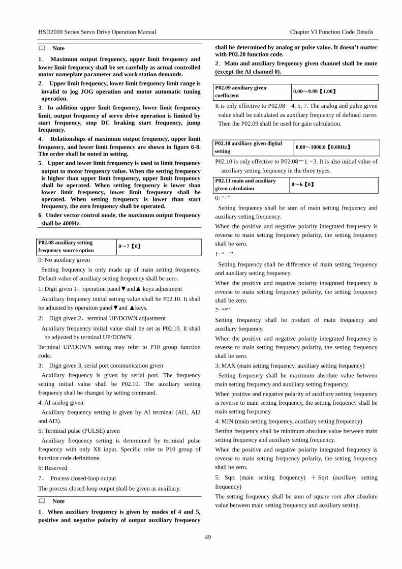
HSD2000 Series Servo Drive Operation Manual Chapter VI Function Code Details
49
Note
1. Maximum output frequency, upper limit frequency and
lower limit frequency shall be set carefully as actual controlled
motor nameplate parameter and work station demands.
2. Upper limit frequency, lower limit frequency limit range is
invalid to jog JOG operation and motor automatic tuning
operation.
3.In addition upper limit frequency, lower limit frequency
limit, output frequency of servo drive operation is limited by
start frequency, stop DC braking start frequency, jump
frequency.
4. Relationships of maximum output frequency, upper limit
frequency, and lower limit frequency are shown in figure 6-8.
The order shall be noted in setting.
5.Upper and lower limit frequency is used to limit frequency
output to motor frequency value. When the setting frequency
is higher than upper limit frequency, upper limit frequency
shall be operated. When setting frequency is lower than
lower limit frequency, lower limit frequency shall be
operated. When setting frequency is lower than start
frequency, the zero frequency shall be operated.
6.Under vector control mode, the maximum output frequency
shall be 400Hz.
P02.08 auxiliary setting
frequency source option 0~7【0】
0: No auxiliary given
Setting frequency is only made up of main setting frequency.
Default value of auxiliary setting frequency shall be zero.
1: Digit given 1,operation panel▼and▲ keys adjustment
Auxiliary frequency initial setting value shall be P02.10. It shall
be adjusted by operation panel▼and ▲keys.
2: Digit given 2,terminal UP/DOWN adjustment
Auxiliary frequency initial value shall be set as P02.10. It shall
be adjusted by terminal UP/DOWN.
Terminal UP/DOWN setting may refer to P10 group function
code.
3: Digit given 3, serial port communication given
Auxiliary frequency is given by serial port. The frequency
setting initial value shall be P02.10. The auxiliary setting
frequency shall be changed by setting command.
4: AI analog given
Auxiliary frequency setting is given by AI terminal (AI1, AI2
and AI3).
5: Terminal pulse (PULSE) given
Auxiliary frequency setting is determined by terminal pulse
frequency with only X8 input. Specific refer to P10 group of
function code definitions.
6: Reserved
7、 Process closed-loop output
The process closed-loop output shall be given as auxiliary.
Note
1.When auxiliary frequency is given by modes of 4 and 5,
positive and negative polarity of output auxiliary frequency
shall be determined by analog or pulse value. It doesn’t matter
with P02.20 function code.
2.Main and auxiliary frequency given channel shall be mute
(except the AI channel 0).
P02.09 auxiliary given
coefficient 0.00~9.99【1.00】
It is only effective to P02.08=4, 5, 7. The analog and pulse given
value shall be calculated as auxiliary frequency of defined curve.
Then the P02.09 shall be used for gain calculation.
P02.10 auxiliary given digital
setting 0.00~1000.0【0.00Hz】
P02.10 is only effective to P02.08=1~3. It is also initial value of
auxiliary setting frequency in the three types.
P02.11 main and auxiliary
given calculation 0~6【0】
0: “+”
Setting frequency shall be sum of main setting frequency and
auxiliary setting frequency.
When the positive and negative polarity integrated frequency is
reverse to main setting frequency polarity, the setting frequency
shall be zero.
1: “-”
Setting frequency shall be difference of main setting frequency
and auxiliary setting frequency.
When the positive and negative polarity integrated frequency is
reverse to main setting frequency polarity, the setting frequency
shall be zero.
2: “*”
Setting frequency shall be product of main frequency and
auxiliary frequency.
When the positive and negative polarity integrated frequency is
reverse to main setting frequency polarity, the setting frequency
shall be zero.
3: MAX (main setting frequency, auxiliary setting frequency)
Setting frequency shall be maximum absolute value between
main setting frequency and auxiliary setting frequency.
When positive and negative polarity of auxiliary setting frequency
is reverse to main setting frequency, the setting frequency shall be
main setting frequency.
4: MIN (main setting frequency, auxiliary setting frequency)
Setting frequency shall be minimum absolute value between main
setting frequency and auxiliary setting frequency.
When the positive and negative polarity integrated frequency is
reverse to main setting frequency polarity, the setting frequency
shall be zero.
5: Sqrt (main setting frequency) + Sqrt (auxiliary setting
frequency)
The setting frequency shall be sum of square root after absolute
value between main setting frequency and auxiliary setting.
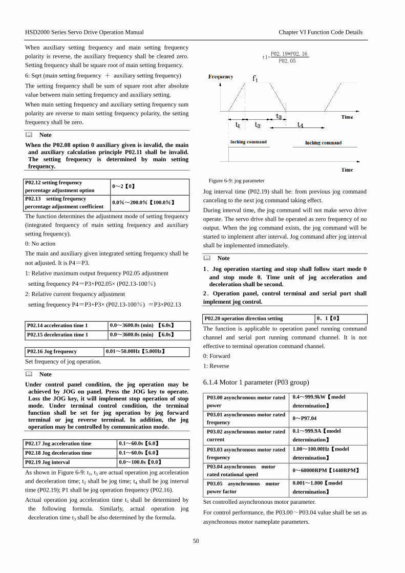
HSD2000 Series Servo Drive Operation Manual Chapter VI Function Code Details
50
When auxiliary setting frequency and main setting frequency
polarity is reverse, the auxiliary frequency shall be cleared zero.
Setting frequency shall be square root of main setting frequency.
6: Sqrt (main setting frequency + auxiliary setting frequency)
The setting frequency shall be sum of square root after absolute
value between main setting frequency and auxiliary setting.
When main setting frequency and auxiliary setting frequency sum
polarity are reverse to main setting frequency polarity, the setting
frequency shall be zero.
Note
When the P02.08 option 0 auxiliary given is invalid, the main
and auxiliary calculation principle P02.11 shall be invalid.
The setting frequency is determined by main setting
frequency.
P02.12 setting frequency
percentage adjustment option 0~2【0】
P02.13 setting frequency
percentage adjustment coefficient 0.0%~200.0%【100.0%】
The function determines the adjustment mode of setting frequency
(integrated frequency of main setting frequency and auxiliary
setting frequency).
0: No action
The main and auxiliary given integrated setting frequency shall be
not adjusted. It is P4=P3.
1: Relative maximum output frequency P02.05 adjustment
setting frequency P4=P3+P02.05× (P02.13-100%)
2: Relative current frequency adjustment
setting frequency P4=P3+P3× (P02.13-100%) =P3×P02.13
P02.14 acceleration time 1 0.0~3600.0s (min) 【6.0s】
P02.15 deceleration time 1 0.0~3600.0s (min) 【6.0s】
P02.16 Jog frequency 0.01~50.00Hz【5.00Hz】
Set frequency of jog operation.
Note
Under control panel condition, the jog operation may be
achieved by JOG on panel. Press the JOG key to operate.
Loss the JOG key, it will implement stop operation of stop
mode. Under terminal control condition, the terminal
function shall be set for jog operation by jog forward
terminal or jog reverse terminal. In addition, the jog
operation may be controlled by communication mode.
P02.17 Jog acceleration time 0.1~60.0s【6.0】
P02.18 Jog deceleration time 0.1~60.0s【6.0】
P02.19 Jog interval 0.0~100.0s【0.0】
As shown in Figure 6-9: t1, t3 are actual operation jog acceleration
and deceleration time; t2 shall be jog time; t4 shall be jog interval
time (P02.19); P1 shall be jog operation frequency (P02.16).
Actual operation jog acceleration time t1 shall be determined by
the following formula. Similarly, actual operation jog
deceleration time t3 shall be also determined by the formula.
P02.19*P02.16P02.05
t1=
Figure 6-9: jog parameter
Jog interval time (P02.19) shall be: from previous jog command
canceling to the next jog command taking effect.
During interval time, the jog command will not make servo drive
operate. The servo drive shall be operated as zero frequency of no
output. When the jog command exists, the jog command will be
started to implement after interval. Jog command after jog interval
shall be implemented immediately.
Note
1.Jog operation starting and stop shall follow start mode 0
and stop mode 0. Time unit of jog acceleration and
deceleration shall be second.
2.Operation panel, control terminal and serial port shall
implement jog control.
P02.20 operation direction setting 0、1【0】
The function is applicable to operation panel running command
channel and serial port running command channel. It is not
effective to terminal operation command channel.
0: Forward
1: Reverse
6.1.4 Motor 1 parameter (P03 group)
P03.00 asynchronous motor rated
power
0.4~999.9kW【model
determination】
P03.01 asynchronous motor rated
frequency 0~P97.04
P03.02 asynchronous motor rated
current
0.1~999.9A【model
determination】
P03.03 asynchronous motor rated
frequency
1.00~100.00Hz【model
determination】
P03.04 asynchronous motor
rated rotational speed 0~60000RPM【1440RPM】
P03.05 asynchronous motor
power factor
0.001~1.000【model
determination】
Set controlled asynchronous motor parameter.
For control performance, the P03.00~P03.04 value shall be set as
asynchronous motor nameplate parameters.

HSD2000 Series Servo Drive Operation Manual Chapter VI Function Code Details
51
P03.05 is asynchronous motor power factor. The value will be
updated automatically after normal operation tuning. User may
select to modify P03.05 automatically. The following two
conditions may be modified manually: after all tuning finishes; no
tuning.
Note
Asynchronous motor and servo drive power class shall meet等
the configuration. In general, two-class smaller or one class
larger of servo drive is allowed. Control performance shall
not be ensured when exceeding the range.
P03.06 asynchronous motor
stator resistance %R1
0.00~50.00%【model
determination】
P03.07 asynchronous motor
leakage inductance %X
0.00~50.00%【model
determination】
P03.08 asynchronous motor
rotor resistance %R2
0.00~50.00%【model
determination】
P03.09 asynchronous motor
mutual inductance %Xm
0.0~2000.0%【model
determination】
P03.10 asynchronous motor
load current
0.1~999.9A【model
determination】
Specific meanings of motor parameter above may refer to figure
6-10.
R 1
j X 1
1
R 2
1 I 2
I 0 X m
U 1 1 - S
S R 2
j X 2 1
I
Figure 6-10: Asynchronous Motor Static Equivalent Circuit Figure
In the 0, the R1, X11, R2, X21, Xm, Io represents respectively: stator
resistance, the stator leakage inductance, rotor resistance, rotor
leakage inductance, mutual inductance, no-load current. The
function code P03.07 shall be sum of stator and rotor leakage
inductance.
Above P03.06~P03.09 are percentages of asynchronous motor
parameters. The formula shall be:
1) Resistor (stator resistance or rotor resistance) formula:
%% 100)3/(
IV
RR
R: rotor resistance actual value of stator resistance converted to
the stator side;
V: rated frequency;
I: asynchronous motor rated current
2) Inductive reactance (leakage inductance or mutual inductance)
formula:
%% 100)3/(
IV
XX
(2)
X: sum (inverted to the stator side) or mutual inductance of basic
frequency stator and rotor
V: rated frequency;
I: asynchronous motor rated current
When the asynchronous motor parameters have been known, the
calculation value shall be written as formula above P03.06~
P03.09. P03.10 is asynchronous motor empty load current. User
may input empty load value directly.
When implement self tuning of motor parameter, the P03.06~
P03.10 setting values will be changed after the tuning finishes.
After modify the asynchronous motor power P03.00, servo drive
will set P03.02 ~ P03.10 parameter as related power
asynchronous motor default parameter (P03.01 is asynchronous
motor rated frequency value. It is not in asynchronous motor
default parameter. It shall be set by users as nameplate).
P03.11 asynchronous motor
parameter self tuning 0~3【0】
0: No action
1: Action (asynchronous motor static)
Before self tuning, the nameplate parameters (P03.00~P03.04) of
controlled asynchronous motor shall be entered.
When in static tuning, the motor is in state of static. The
asynchronous motor tutor resistance ( % R1), related rated
frequency leakage inductance (%X), rotor resistance (%R2) shall
be measured automatically. The measured parameters shall be
written into P03.06, P03.07 and P03.08 automatically.
2: Action (asynchronous motor rotates)
Before self tuning, the nameplate parameters (P03.00~P03.04) of
controlled asynchronous motor shall be entered.
When in static tuning, the motor is in state of static. The
asynchronous motor tutor resistance ( % R1), related rated
frequency leakage inductance (%X), rotor resistance (%R2) shall
be measured automatically. Then the asynchronous motor is in
rotation status, the motor mutual inductance (%Xm) and empty
load current (Io) shall be measured automatically. The measured
parameters will be written into P03.06, P03.07, P03.08, P03.09
and P03.10 automatically. The P03.05 will be updated after rotate
tuning.
After self tuning, the P03.11 setting value shall be set as 0
automatically.
Self tuning procedures:
1) It is suggested for users to set P06.07 (motor 1torque lifting) as
0.
2) Set function code parameter “P03.00 rated power”, “P03.01
rated frequency”, “P03.02 rated current”, “P03.03 rated
frequency” and “P03.04 rated rotational speed”.
3) Set P02.06 (upper limit frequency). P02.06 setting value shall
be not lower than rated frequency。
4) When select P03.11 as 2, remove the motor shaft from loading
and ensure its safety. The motor shall not rotate tuning with
loading.
5) Set P03.11 as 1 or 2. First press DATA/ENTER key, then press
the RUN key for self tuning.
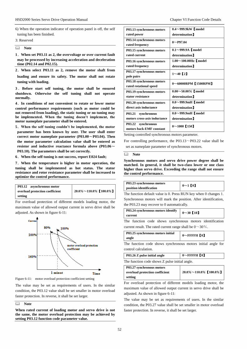
HSD2000 Series Servo Drive Operation Manual Chapter VI Function Code Details
52
6) When the operation indicator of operation panel is off, the self
tuning has been finished.
3: Reserved
Note
1.When set P03.11 as 2, the overvoltage or over current fault
may be processed by increasing acceleration and deceleration
time (P02.14 and P02.15).
2.When select P03.11 as 2, remove the motor shaft from
loading and ensure its safety. The motor shall not rotate
tuning with loading.
3.Before start self tuning, the motor shall be ensured
shutdown. Otherwise the self tuning shall not operate
normally.
4.In conditions of not convenient to rotate or lower motor
control performance requirements (such as motor could be
not removed from loading), the static tuning or no tuning may
be implemented. When the tuning doesn’t implement, the
motor nameplate parameter shall be entered.
5.When the self tuning couldn’t be implemented, the motor
parameter has been known by user. The user shall enter
correct motor nameplate parameter (P03.00~P03.04). Then
the motor parameter calculation value shall be entered as
resistor and inductive reactance formula above (P03.06~
P03.10). The parameters shall be set correctly.
6.When the self tuning is not success, report E024 fault;
7.When the temperature is higher in motor operation, the
tuning shall be implemented as hot status. The stator
resistance and rotor resistance parameter shall be increased to
optimize the control performance.
P03.12 asynchronous motor
overload protection coefficient
setting
20.0%~110.0%【100.0%】
For overload protection of different models loading motor, the
maximum value of allowed output current in servo drive shall be
adjusted. As shown in figure 6-11:
Figure 6-11: motor overload protection coefficient setting
The value may be set as requirements of users. In the similar
condition, the P03.12 value shall be set smaller in motor overload
faster protection. In reverse, it shall be set larger.
Note
When rated current of loading motor and servo drive is not
the same, the motor overload protection may be achieved by
setting P03.12 function code parameter value.
P03.13 synchronous motors
rated power
0.4~999.9kW【model
determination】
P03.14 synchronous motors
rated frequency 0~P97.04
P03.15 synchronous motors
rated current
0.1~999.9A【model
determination】
P03.16 synchronous motors
rated frequency
1.00~100.00Hz【model
determination】
P03.17 synchronous motors
pole pairs 1~40【2】
P03.18 synchronous motors
rated rotational speed 0~60000RPM【1500RPM】
P03.19 synchronous motors
stator resistance
0.00~50.00%【model
determination】
P03.20 synchronous motors
direct axis inductance
0.0~999.9mH【model
determination】
P03.21 synchronous
motors cross-axis inductance
0.0~999.9mH【model
determination】
P03.22 synchronous
motors back-EMF constant 0~1000【150】
Setting controlled synchronous motors parameter.
For controlling performance, the P03.13~P03.22 value shall be
set as nameplate parameter of synchronous motors.
Note
Synchronous motors and servo drive power degree shall be
matched. In general, it shall be two-class lower or one class
higher than servo drive. Exceeding the range shall not ensure
the control performance.
P03.23 synchronous motors
position identification 0~1【0】
The function default value is 0. Press RUN key when 0 changes 1.
Synchronous motors will mark the position. After identification,
the P03.23 may recover to 0 automatically.
P03.24 synchronous motors identify
current 0~30【10】
The function code shows synchronous motors identification
current result. The rated current range shall be 0~30%.
P03.25 synchronous motors initial
angle 0~FFFFH【0】
The function code shows synchronous motors initial angle for
control calculation.
P03.26 Z pulse initial angle 0~FFFFH【0】
The function code shows Z pulse initial angle.
P03.27 synchronous motors
overload protection coefficient
setting
20.0%~110.0%【100.0%】
For overload protection of different models loading motor, the
maximum value of allowed output current in servo drive shall be
adjusted. As shown in figure 6-11:
The value may be set as requirements of users. In the similar
condition, the P03.27 value shall be set smaller in motor overload
faster protection. In reverse, it shall be set larger.

HSD2000 Series Servo Drive Operation Manual Chapter VI Function Code Details
53
6.1.5 Motor 2 parameter (P04 group)
P04.00 asynchronous
motor rated power
0.4~999.9kW【model
determination】
P04.01 asynchronous
motor rated frequency
0~servo drive rated frequency
(P97.04)
P04.02 asynchronous
motor rated current 0.1~999.9A【model determination】
P04.03 asynchronous
motor rated frequency
1.00~100.00Hz【model
determination】
P04.04 asynchronous motor
rated rotational speed 0~60000RPM【1440RPM】
P04.05 asynchronous motor
power factor 0.001~1.000【model determination】
Set the controlled asynchronous motor parameter.
For controlling performance, the P04.00~P04.04 value shall be
set as nameplate parameter of synchronous motors.
P04.05 is asynchronous motor power factor. The value will be
updated automatically after normal operation tuning. User may
select to modify P04.05 automatically. The following two
conditions may be modified manually: after all tuning finishes; no
tuning.
Note
Synchronous motors and servo drive power degree shall be
matched. In general, it shall be two-class lower or one class
higher than servo drive. Exceeding the range shall not ensure
the control performance.
P04.06 asynchronous motor
stator resistance %R1
0.00~50.00%【model
determination】
P04.07 asynchronous motor
leakage inductance %X
0.00~50.00%【model
determination】
P04.08 asynchronous motor
rotor resistance %R2
0.00~50.00%【model
determination】
P04.09 asynchronous motor
mutual inductance %Xm
0.0~2000.0%【model
determination】
P04.10 asynchronous motor
empty load current
0.1~999.9A【model
determination】
Specific meaning of above motor parameter may refer to figure
6-11.
Function code P04.07 is sum of stator, stator leakage inductance.
Above P04.06~P04.09 are percentage of asynchronous motor
parameter. The calculation formula is shown in formula (1) and
(2).
When the asynchronous motor parameter has been given, the
P04.06~P04.09 shall be written into by formula above. The
P04.10 is asynchronous motor empty load current. The user may
enter empty load current value directly.
When implement the motor parameter self tuning, the P04.06~
P04.10 setting values will be updated after tuning.
After changing asynchronous motor power P04.00, servo drive
will set P04.02~P04.10 parameter as related power asynchronous
motor default parameter (P04.01 is asynchronous motor rated
frequency value. It is not in synchronous motor default
parameter range. It shall be set as nameplate by user. ).
P04.11 asynchronous motor
parameter self tuning 0~3【0】
0: No action
1: action (asynchronous motor static)
Before implement the self tuning, the nameplate parameter of
controllers asynchronous motor shall be entered (P04.00 ~
P04.04).
When in static tuning, the motor is in state of static. The
asynchronous motor tutor resistance ( % R1), related rated
frequency leakage inductance (%X), rotor resistance (%R2) shall
be measured automatically. The measured parameters shall be
written into P04.06, P04.07 and P04.08 automatically.
2: Action (asynchronous motor rotates)
Before self tuning, the nameplate parameters (P04.00~P04.04) of
controlled asynchronous motor shall be entered.
When in static tuning, the motor is in state of static. The
asynchronous motor tutor resistance ( % R1), related rated
frequency leakage inductance (%X), rotor resistance (%R2) shall
be measured automatically. Then the asynchronous motor is in
rotation status, the motor mutual inductance (%Xm) and empty
load current (Io) shall be measured automatically. The measured
parameters will be written into P04.06, P04.07, P04.08, P04.09
and P04.10 automatically. The P04.05 will be updated after rotate
tuning.
After self tuning, the P04.11 setting value shall be set as 0
automatically.
3: Reserved
Self tuning procedure:
1) Set the P06.19 torque as 00.0 (if user could not enter P06 group,
the function code parameter value of P00.06 shall be modified
to0200. Press the DATA/ENTER key, then implement function
code operation. The P06 function code group may be entered.)
2) Set function code parameter “P04.00 rated power”,
“P04.01rated frequency”, “P04.02rated current” and “P04.03
rated frequency”.
3) Set P02.06 (upper limit frequency),P02.06 setting value shall
be not lower than rated frequency.
4) When select P04.11 as 2, set acceleration time (P02.14) and
deceleration time (P02.15). Remove the motor shaft from
loading and ensure its safety.
5) When set P04.11 as 1 or 2, press the DATA/ENTER. The self
tuning will be started when press RUN key. 。
6) When indicator on operation panel is off, the self tuning is
finished.
Note
1.When select P04.11 as 2, when overvoltage or over current
fault happens in self tuning, the acceleration and deceleration
shall be increased.

HSD2000 Series Servo Drive Operation Manual Chapter VI Function Code Details
54
2.When set the P04.11 as 2 in rotate tuning. The motor shall
remove the loading. The motor shall not rotate tuning with
loading.
3.Before start self tuning, the motor shall be ensured
shutdown. Otherwise the self tuning shall not operate
normally.
4.N conditions of not convenient to rotate or lower motor
control performance requirements (such as motor could be
not removed from loading), the static tuning or no tuning may
be implemented. When the tuning does not implement, the
motor nameplate parameter shall be entered (P04.00~
P04.04).
5.When the self tuning couldn’t be implemented, the motor
parameter has been known by user. The user shall enter
correct motor nameplate parameter (P04.00~P04.04). Then
the motor parameter calculation value shall be entered as
resistor and inductive reactance formula above (P04.06~
P04.10). The parameters shall be set correctly.
6.When the self tuning is not success, report E024 fault;
7. When the temperature is higher in motor operation, the
tuning shall be implemented as hot status. The stator
resistance and rotor resistance parameter shall be increased to
optimize the control performance.
P04.12 asynchronous motor
overload protection coefficient
setting
20.0%~110.0%【100.0%】
For effective overload protection to loading motors in different
types, the servo allowed output current maximum value shall be
adjusted. As shown in figure 6-11.
The value may be set as requirements of users. In the similar
condition, the P04.12 value shall be set smaller in motor overload
faster protection. In reverse, it shall be set larger.
Note
When rated current of loading motor and servo drive is not
the same, the motor overload protection may be achieved by
setting P04.12 function code parameter value.
P04.13 synchronous motors
rated power
0.4~999.9kW【model
determination】
P04.14 synchronous motors
rated frequency 0~P97.04
P04.15 synchronous motors
rated current
0.1~999.9A【model
determination】
P04.16 synchronous motors
rated frequency
1.00~100.00Hz【model
determination】
P04.17 synchronous motors
pole pairs 1~40【2】
P04.18 synchronous motors
rated rotational speed 0~60000RPM【1500RPM】
P04.19 synchronous motors
stator resistance
0.00~50.00%【model
determination】
P04.20 synchronous motors
direct axis inductance
0.0~999.9mH【model
determination】
P04.21 synchronous motors
cross-axis inductance
0.0~999.9mH【model
determination】
P04.22 synchronous motors
back-EMF constant 0~1000【150】
Set controlled synchronous motors parameter.
For control performance, the P04.13~P04.22 values shall be set
as nameplate parameter of synchronous motors.
Note
Synchronous motors and servo drive power degree shall be
matched. In general, it shall be two-class lower or one class
higher than servo drive. Exceeding the range shall not ensure
the control performance.
P04.23 synchronous motors
position identification 0~1【0】
The function default value is 0. Press RUN key when 0 changes 1.
Synchronous motors will mark the position. After identification,
the P04.23 may recover to 0 automatically.
P04.24 synchronous motors
identification current 0~30【10】
The function code shows synchronous motors identification
current result. The rated current range shall be 0~30%.
P04.25 synchronous motors
initial angle 0~FFFFH【0】
The function code shows synchronous motors initial angle for
control calculation.
P04.26 Z pulse initial angle 0~FFFFH【0】
The function code shows Z pulse initial angle.
P04.27 synchronous motors
overload protection coefficient
setting
20.0%~110.0%【100.0%】
For overload protection of different models loading motor, the
maximum value of allowed output current in servo drive shall be
adjusted. As shown in figure 6-11:
The value may be set as requirements of users. In the similar
condition, the P04.27 value shall be set smaller in motor overload
faster protection. In reverse, it shall be set larger.
P04.28 motor 2 PI parameter
option 0~1【0】
The function code shows parameter option function code of PI
adjuster in motor 2.
0: it is the same option with PI adjuster of motor 1.
1: it takes P04.29~P04.32 function code value.
P04.29 motor 2 ASR-P 0.1~200.0【20.0】
P04.30 motor 2 ASR-I 0.010~1.000s【0.200s】
P04.29 and P04.30 function codes shall be P and I coefficient of
motor 2 ASR.
P04.31 motor 2 ACR-P 1~5000【1000】
P04.32 motor 2 ACR-I 0.5~100.0ms【8.0ms】
P04.30 and P04.31 function codes shall be P and I coefficient of
motor 2 ACR.
P04.33 motor 2 encoder option 0~1【1】
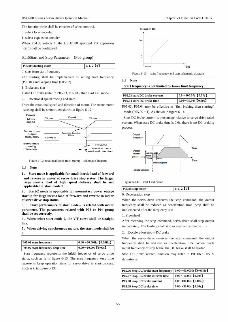
HSD2000 Series Servo Drive Operation Manual Chapter VI Function Code Details
55
The function code shall be encoder of select motor 2.
0: select local encoder
1: select expansion encoder
When P04.33 selects 1, the HSD2000 specified PG expansion
card shall be configured.
6.1.6Start and Stop Parameter (P05 group)
P05.00 Starting mode 0, 1, 2【0】
0: start from start frequency
The starting shall be implemented as setting start frequency
(P05.01) and keeping time (P05.02).
1: Brake and star
Fisted DC brake (refer to P05.03, P05.04), then start as 0 mode.
2. Rotational speed tracing and start
Trace the rotational speed and direction of motor. The rotate motor
starting shall be smooth. As shown in figure 6-12:
Power
Motor
speed
Close
0
Opposite direction
idling
Forward
Reverse Detection motor
Speed and direction
Break Close
Servo drive
running
direction
Servo driver
output
frequency
Figure 6-12: rotational speed track startup schematic diagram
Note
1. Start mode is applicable for small inertia load of forward
and reverse in motor of servo drive stop status. The larger
large inertia load of high speed delivery shall be not
applicable for start mode 1.
2. Start-2 mode is applicable for momentary power outage
startup for large inertia load of forward and reverse in motor
of servo drive stop status.
3. Start performance of start mode-2 is related with motor
parameter. The parameters related with P03 or P04 group
shall be set correctly.
4.When select start mode 2, the V/F curve shall be straight
line.
5.When driving synchronous motors, the start mode shall be
0.
P05.01 start frequency 0.00~60.00Hz【0.00Hz】
P05.02 start frequency keep time 0.00~10.00s【0.00s】
Start frequency represents the initial frequency of servo drive
starts, such as fS in figure 6-13. The start frequency keep time
represents keep operation time for servo drive in start process.
Such as t1 in figure 6-13:
Figure 6-13: start frequency and start schematic diagram
Note
Start frequency is not limited by lower limit frequency.
P05.03 start DC brake current 0.0~100.0%【0.0%】
P05.04 start DC brake time 0.00~30.00s【0.00s】
P05.03, P05.04 may be effective in “first braking then starting”
mode (P05.00=1). As shown in figure 6-14:
Start DC brake current is percentage relative to servo drive rated
current. When start DC brake time is 0.0s, there is no DC braking
process.
Figure 6-14: start 1 indication
P05.05 stop mode 0, 1, 2【0】
0: Deceleration stop
When the servo drive receives the stop command, the output
frequency shall be reduced as deceleration time. Stop shall be
implemented after the frequency is 0.
1: Freewheel
After receiving the stop command, servo drive shall stop output
immediately. The loading shall stop as mechanical inertia. 。
2: Deceleration stop+DC brake
When the servo drive receives the stop command, the output
frequency shall be reduced as deceleration time. When reach
initial frequency of stop brake, the DC brake shall be started.
Stop DC brake related function may refer to P05.06~P05.09
definitions:
P05.06 Stop DC brake start frequency 0.00~60.00Hz【0.00Hz】
P05.07 Stop DC brake interval time 0.00~10.00s【0.00s】
P05.08 Stop DC brake current 0.0~100.0%【0.0%】
P05.09 Stop DC brake time 0.00~30.00s【0.00s】
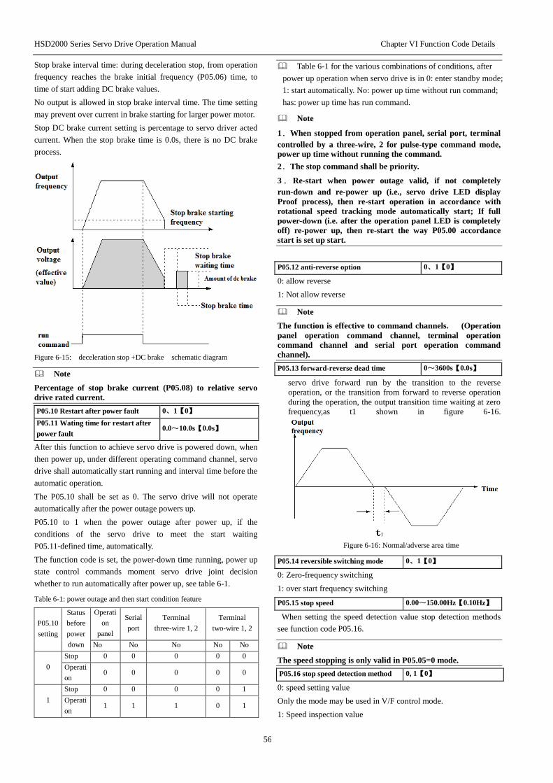
HSD2000 Series Servo Drive Operation Manual Chapter VI Function Code Details
56
Stop brake interval time: during deceleration stop, from operation
frequency reaches the brake initial frequency (P05.06) time, to
time of start adding DC brake values.
No output is allowed in stop brake interval time. The time setting
may prevent over current in brake starting for larger power motor.
Stop DC brake current setting is percentage to servo driver acted
current. When the stop brake time is 0.0s, there is no DC brake
process.
Figure 6-15: deceleration stop +DC brake schematic diagram
Note
Percentage of stop brake current (P05.08) to relative servo
drive rated current.
P05.10 Restart after power fault 0、1【0】
P05.11 Wating time for restart after
power fault 0.0~10.0s【0.0s】
After this function to achieve servo drive is powered down, when
then power up, under different operating command channel, servo
drive shall automatically start running and interval time before the
automatic operation.
The P05.10 shall be set as 0. The servo drive will not operate
automatically after the power outage powers up.
P05.10 to 1 when the power outage after power up, if the
conditions of the servo drive to meet the start waiting
P05.11-defined time, automatically.
The function code is set, the power-down time running, power up
state control commands moment servo drive joint decision
whether to run automatically after power up, see table 6-1.
Table 6-1: power outage and then start condition feature
P05.10
setting
Status
before
power
down
Operati
on
panel
Serial
port
Terminal
three-wire 1, 2
Terminal
two-wire 1, 2
No No No No No
0
Stop 0 0 0 0 0
Operati
on 0 0 0 0 0
1
Stop 0 0 0 0 1
Operati
on 1 1 1 0 1
Table 6-1 for the various combinations of conditions, after
power up operation when servo drive is in 0: enter standby mode;
1: start automatically. No: power up time without run command;
has: power up time has run command.
Note
1.When stopped from operation panel, serial port, terminal
controlled by a three-wire, 2 for pulse-type command mode,
power up time without running the command.
2.The stop command shall be priority.
3.Re-start when power outage valid, if not completely
run-down and re-power up (i.e., servo drive LED display
Proof process), then re-start operation in accordance with
rotational speed tracking mode automatically start; If full
power-down (i.e. after the operation panel LED is completely
off) re-power up, then re-start the way P05.00 accordance
start is set up start.
P05.12 anti-reverse option 0、1【0】
0: allow reverse
1: Not allow reverse
Note
The function is effective to command channels. (Operation
panel operation command channel, terminal operation
command channel and serial port operation command
channel).
P05.13 forward-reverse dead time 0~3600s【0.0s】
servo drive forward run by the transition to the reverse
operation, or the transition from forward to reverse operation
during the operation, the output transition time waiting at zero
frequency,as t1 shown in figure 6-16.
Figure 6-16: Normal/adverse area time
P05.14 reversible switching mode 0、1【0】
0: Zero-frequency switching
1: over start frequency switching
P05.15 stop speed 0.00~150.00Hz【0.10Hz】
When setting the speed detection value stop detection methods
see function code P05.16.
Note
The speed stopping is only valid in P05.05=0 mode.
P05.16 stop speed detection method 0, 1【0】
0: speed setting value
Only the mode may be used in V/F control mode.
1: Speed inspection value
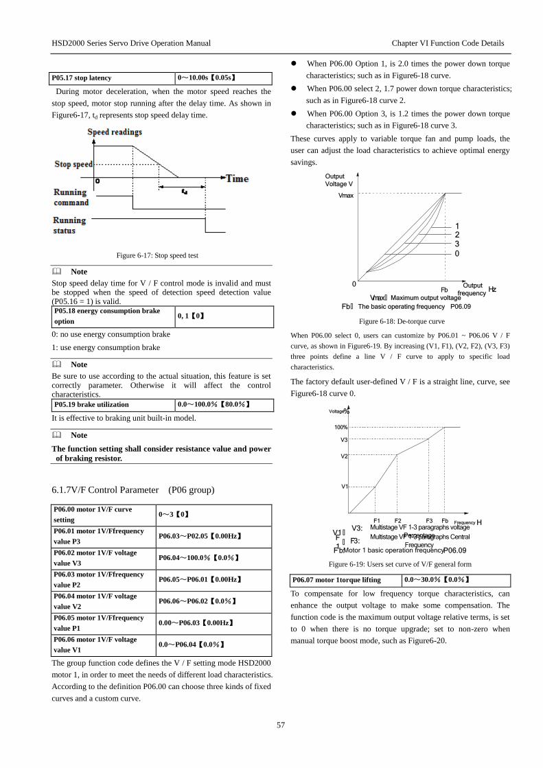
HSD2000 Series Servo Drive Operation Manual Chapter VI Function Code Details
57
P05.17 stop latency 0~10.00s【0.05s】
During motor deceleration, when the motor speed reaches the
stop speed, motor stop running after the delay time. As shown in
Figure6-17, td represents stop speed delay time.
Figure 6-17: Stop speed test
Note
Stop speed delay time for V / F control mode is invalid and must be stopped when the speed of detection speed detection value (P05.16 = 1) is valid. P05.18 energy consumption brake
option 0, 1【0】
0: no use energy consumption brake
1: use energy consumption brake
Note
Be sure to use according to the actual situation, this feature is set correctly parameter. Otherwise it will affect the control characteristics.
P05.19 brake utilization 0.0~100.0%【80.0%】
It is effective to braking unit built-in model.
Note
The function setting shall consider resistance value and power
of braking resistor.
6.1.7V/F Control Parameter (P06 group)
P06.00 motor 1V/F curve
setting 0~3【0】
P06.01 motor 1V/Ffrequency
value P3 P06.03~P02.05【0.00Hz】
P06.02 motor 1V/F voltage
value V3 P06.04~100.0%【0.0%】
P06.03 motor 1V/Ffrequency
value P2 P06.05~P06.01【0.00Hz】
P06.04 motor 1V/F voltage
value V2 P06.06~P06.02【0.0%】
P06.05 motor 1V/Ffrequency
value P1 0.00~P06.03【0.00Hz】
P06.06 motor 1V/F voltage
value V1 0.0~P06.04【0.0%】
The group function code defines the V / F setting mode HSD2000
motor 1, in order to meet the needs of different load characteristics.
According to the definition P06.00 can choose three kinds of fixed
curves and a custom curve.
When P06.00 Option 1, is 2.0 times the power down torque
characteristics; such as in Figure6-18 curve.
When P06.00 select 2, 1.7 power down torque characteristics;
such as in Figure6-18 curve 2.
When P06.00 Option 3, is 1.2 times the power down torque
characteristics; such as in Figure6-18 curve 3.
These curves apply to variable torque fan and pump loads, the
user can adjust the load characteristics to achieve optimal energy
savings.
0
1
Output
Voltage V
Output
frequency Hz
23
Vmax
Fb
Vmax: Maximum output voltage
Fb: The basic operating frequency P06.09
0
Figure 6-18: De-torque curve
When P06.00 select 0, users can customize by P06.01 ~ P06.06 V / F
curve, as shown in Figure6-19. By increasing (V1, F1), (V2, F2), (V3, F3)
three points define a line V / F curve to apply to specific load
characteristics.
The factory default user-defined V / F is a straight line, curve, see
Figure6-18 curve 0.
Voltage %
Frequency HFb
100%
V1
V2
F1 F2
V3
F3
V1 : V3:
F
1 : F3:
Fb: P06.09
Multistage VF 1-3 paragraphs voltage
Percentage Multistage VF 1-3 paragraphs Central
Frequency Motor 1 basic operation frequency
Figure 6-19: Users set curve of V/F general form
P06.07 motor 1torque lifting 0.0~30.0%【0.0%】
To compensate for low frequency torque characteristics, can
enhance the output voltage to make some compensation. The
function code is the maximum output voltage relative terms, is set
to 0 when there is no torque upgrade; set to non-zero when
manual torque boost mode, such as Figure6-20.

HSD2000 Series Servo Drive Operation Manual Chapter VI Function Code Details
58
Figure 6-20: torque rise (rise: shadow)
Note
1.This parameter setting can lead to improper motor heat or
over current protection.
2.See the definition of fz function code P06.08.
3.When driving synchronous motors, torque recommended to
be used to enhance and adjust V / F curve according to motor
parameter and use the occasion.
4.The maximum output voltage Vmax corresponds to the
motor rated frequency, and thus need to set P03 or P04 group
set motor rated frequency correctly according to the selected
motor.
P06.08 motor 1 torque lifting
cut-off point 0.0%~50.0%【10.0%】
This function defines the percentage of manual torque cutoff
frequency relative to enhance the basic operation frequencyP06.09,
see Figure6-20 in fz. The cutoff frequency determined by any
applicable P06.00 V / F curve.
P06.09 motor 1 base frequency 1.00~1000.0Hz【50.00Hz】
The basic operation is the minimum frequency when the servo
drive output highest frequency voltage corresponding to the motor
is generally rated frequency. As in Figure6-18 fb:
P06.10 Reserved Reserved
Reserved function.
P06.11 motor 1 stability factor 0~255【10】
This function is used to suppress the natural oscillation with servo
drive and motor generated. If the output current constant load
changes repeatedly, on the basis of the factory parameter adjusting
the function code size can eliminate oscillation motor running
smoothly.
P06.12 motor 2V/F curve setting 0~3【0】
P06.13 motor 2V/Ffrequency
value P3 P06.15~P02.05【0.00Hz】
P06.14 motor 2V/F voltage value
V3 P06.16~100.0%【0.0%】
P0615 motor 2V/Ffrequency
value P2 P06.17~P06.13【0.00Hz】
P0616 motor 2V/F voltage value
V2 P06.18~P06.14【0.0%】
P06.17 motor 2V/Ffrequency
value P1 0.00~P06.15【0.00Hz】
P06.18 motor 2V/F voltage value
V1 0.0~P06.16【0.0%】
The group function code defines the HSD2000 motor 2 for V / F
set way to meet the needs of different load characteristics. See
detailed description of function code, in P06.00 ~ P06.06:
P06.19 motor 2 torque lifting 0.0~30.0%【0.0%】
P06.20 motor 2torque lifting
cut-off point 0.0%~50.0%【10.0%】
P06.21 motor 2 base frequency 1.00~1000.0Hz【50.00Hz】
P06.22 motor 2 maximum
output voltage 0~480V
P06.23 motor 2 stability factor 0~255【10】
Refer to P06.07~P06.11 description.
P06.24 AVR function 0~2【1】
0: no action
1: action
2: only no action in deceleration
AVR is automatic voltage adjusting.
When the input voltage deviates from rated value, the function can
be maintained by constant output voltage, so under normal
circumstances should AVR action, especially in the input voltage
is higher than the rated value when.
When the deceleration stop, select AVR does not operate,
deceleration time is short, but running current is slightly larger;
choose AVR always action, smooth motor deceleration, running
current is small, but the deceleration time longer.
6.1.8Speed Control Parameter (P07 group)
P07.00 Speed Feedback Option 0, 1【0】
HSD2000 has two speed feedback channel options.
0: local PG feedback channel
It is applicable for PG feedback of asynchronous motor.
1: Expansion PG feedback channel
It is suitable for both synchronous and asynchronous motor PG
feedback in setting P07.00 = 1, the need to use PG expansion
card.
In with PG vector control, with PG V / F control mode, you need
to set the correct speed feedback channels, otherwise motor
cannot operate normally.
Note
P07.00 function code parameter only for the default choice of
motor 1, if you select the motor 2 (P02.01 to 1), it should be
selected by function code P04.33 encoder.
P07.01 ASR1-P 0.1~200.0【20.0】
P07.02 ASR1-I 0.000~10.000s【0.200s】
P07.03 ASR1output wave filter 0~8【0】
P07.04 ASR2-P 0.1~200.0【20】
P07.05 ASR2-I 0.000~10.000s【0.200s】
P07.06 ASR2output wave filter 0~8【0】
P07.07 ASR1/2 switching
frequency 0~100.0%【10.0%】
Function code P07.00~P07.07 may be effective in control
modes of vector control and PG V/F control modes.

HSD2000 Series Servo Drive Operation Manual Chapter VI Function Code Details
59
In vector control mode by setting the speed regulator, proportional
gain P and integral time I may change the vector control speed
response characteristics.
1.Speed regulator (ASR) constituted as Figure6-21 shows. Figure
in KP is the proportional gain P; TI is the integral time I.
频率指令
实际速度
转矩电流给定++ 速度误差
转矩限定
P08.10 P08.11
--
转矩偏置给定
输出滤波
Kp
(1+T
iS
1)
Figure 6-21: Speed adjustor Figure
The integration time is set 0 (P07.02 = 0, P07.05 = 0) when no
integral action, speed loop is a simple proportional regulator.
3. Speed regulator (ASR) P proportional gain and integral time
I is tuning.
Figure 6-22 speed (ASR) step response and PI parameter
Increase the proportional gain P, can speed up the dynamic
response of the system; But P is too large, the system tends to
oscillate.
Reducing the integral time I, can accelerate the dynamic response
of the system; But I too small, the overshoot is large and easy to
produce oscillations.
Usually first adjust the proportional gain P, to ensure the system
does not oscillate maximize the premise P; then adjust the
integration time I make the system both fast response without
overshoot. Figure6-23 is P, I select a good speed step response
time curve (velocity response curve can be analog output
terminalAO1, AO2 observation, see P11 parameter group).
Figure 6-23: Step response with fine dynamic performance
Note
PI parameter was not selected, the system quickly start to the
high-speed, over-voltage fault may occur (if no external
braking resistor or brake unit), which is due to overshoot in
the rate of decline over the medium-range regenerative brake
system of the state energy feedback cause. It can be avoided
by adjusting PI parameter.
3.Speed regulator (ASR) adjustment PI parameter in high / low
speed situations.
If the system is on high and low load operation has a rapid
response requirements, you can set ASR switching frequency
(P07.07). Usually the system is running at low frequencies, to
improve the dynamic response characteristics, can increase
proportional gain P and reduce integration time I. Generally in the
following order to adjust the speed regulator parameter:
1) Select the appropriate switch frequency P07.07.
2) Scaling at high speed and integration time gain P07.01
P07.02, ensure that the system does not occur and the
oscillation characteristics of a good dynamic response.
3) P07.04 proportional gain and integration time adjustment at
low speeds P07.05, to ensure that no low-frequency
oscillation and good dynamic response characteristics.
4.Speed regulator (ASR) of output after a delay wave filter to
obtain a given torque current. P07.03, P07.06, respectively, is the
time constant of ASR1 and ASR2outputwave filter.
P07.08 speed limit mode 0~2【0】
P07.09 speed limit channel 1 0~1【0】
P07.10 speed limit channel 2 0~1【0】
P07.11 speed limit value 1 0.0%~100.0%【100.0%】
P07.12 speed limit value 2 0.0%~100.0%【100.0%】
Function code P07.08 ~ P07.12 only valid in torque control
mode, the rest of the control is invalid.
By setting function code P07.08 ~ P07.12 under torque control
motor's speed limit value. In torque control mode if the motor
rotational speed limit value. Internal torque instruction to switch
to the speed regulator (ASR) output, control motor speed is not
out of control.
Speed limit mode:
0: Forward limit value by the speed limit channel 1 (P07.09)
setting, reverse limit value by the speed limit channel 2 (P07.10)
setting.
1: Reversible limit value is limited by the speed channel 1 (P07.09)
setting.
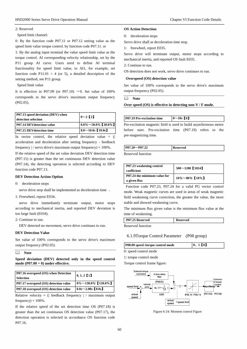
HSD2000 Series Servo Drive Operation Manual Chapter VI Function Code Details
60
2: Reserved
Speed limit channel:
0: By the function code P07.11 or P07.12 setting value as the
speed limit value torque control. by function code P07.11. or
1: By the analog input terminal the value speed limit value as the
torque control. AI corresponding velocity relationship, set by the
P11 group AI curve. Users need to define AI terminal
functionality for speed limit value, to AI1, for example, set
function code P11.01 = 4 (or 5), a detailed description of the
setting method, see P11 group.
Speed limit value
It is effective in P07.09 (or P07.10) =0. Set value of 100%
corresponds to the servo drive's maximum output frequency
(P02.05).
P07.13 speed deviation (DEV) when
detection selection 0~2【2】
P07.14 DEVdetection value 0.0%~50.0%【20.0%】
P07.15 DEVdetection time 0.0~10.0s【10.0s】
In vector control, the relative speed deviation value = (|
acceleration and deceleration after setting frequency - feedback
frequency | / servo drive's maximum output frequency) × 100%.
If the relative speed of the set value deviation DEV detection time
(P07.15) is greater than the set continuous DEV detection value
(P07.14), the detecting operation is selected according to DEV
function code P07.13.
DEV Detection Action Option
0: deceleration stops
servo drive stop shall be implemented as deceleration time 。
1: Freewheel, repost E034。
servo drive immediately terminate output, motor stops
according to mechanical inertia, and reported DEV deviation is
too large fault (E034).
2: Continue to run.
DEV detected no movement, servo drive continues to run.
DEV Detection Value
Set value of 100% corresponds to the servo drive's maximum
output frequency (P02.05).
Note
Speed deviation (DEV) detected only in the speed control
mode (P07.00 = 0) under effective.
P07.16 overspeed (OS) when Detection
Selection 0, 1, 2【1】
P07.17 overspeed (OS) detection value 0%~130.0%【120.0%】
P07.18 overspeed (OS) detection value 0.0s~2.00s【0.0s】
Relative velocity = (| feedback frequency | / maximum output
frequency) × 100%.
If the relative speed of the set detection time OS (P07.18) is
greater than the set continuous OS detection value (P07.17), the
detection operation is selected in accordance OS function code
P07.16.
OS Action Detection
0: deceleration stops
Servo drive shall as deceleration time stop.
1: freewheel, report E035.
Servo drive will terminate output, motor stops according to
mechanical inertia, and reported OS fault E035.
2: Continue to run.
OS detection does not work, servo drive continues to run.
Overspeed (OS) detection value
Set value of 100% corresponds to the servo drive's maximum
output frequency (P02.05).
Note
Over speed (OS) is effective in detecting non-V / F mode.
P07.19 Pre-excitation time 0~10s【0】
Pre-excitation magnetic field is used to build asynchronous motor
before start. Pre-excitation time (P07.19) refers to the
pre-magnetizing time.
P07.20~P07.22 Reserved
Reserved function
P07.23 weakening control
coefficient 500~1200【1024】
P07.24 the minimum value for
a given flux 10%~80%【10%】
Function code P07.23, P07.24 for a valid PG vector control
mode. Weak magnetic curves are used in areas of weak magnetic
field weakening curve correction, the greater the value, the more
stable and showed weakening curve.
The minimum flux given value is the minimum flux value at the
time of weakening.
P07.25 Reserved Reserved
Reserved function
6.1.9Torque Control Parameter (P08 group)
P08.00 speed /torque control mode 0、1【0】
0: speed control mode
1: torque control mode
Torque control frame figure:
-
)T
iS
1(1KP +
ASR
(P08.03)
External torque
command
(P07.03: P07.06)
speed limit +
actual
speed
velocity
error
A time delay
filter
output filtering
Common
d torque
current
(P08.10 P08.11. )
<speed limit actual
speed
Figure 6-24: Moment control Figure
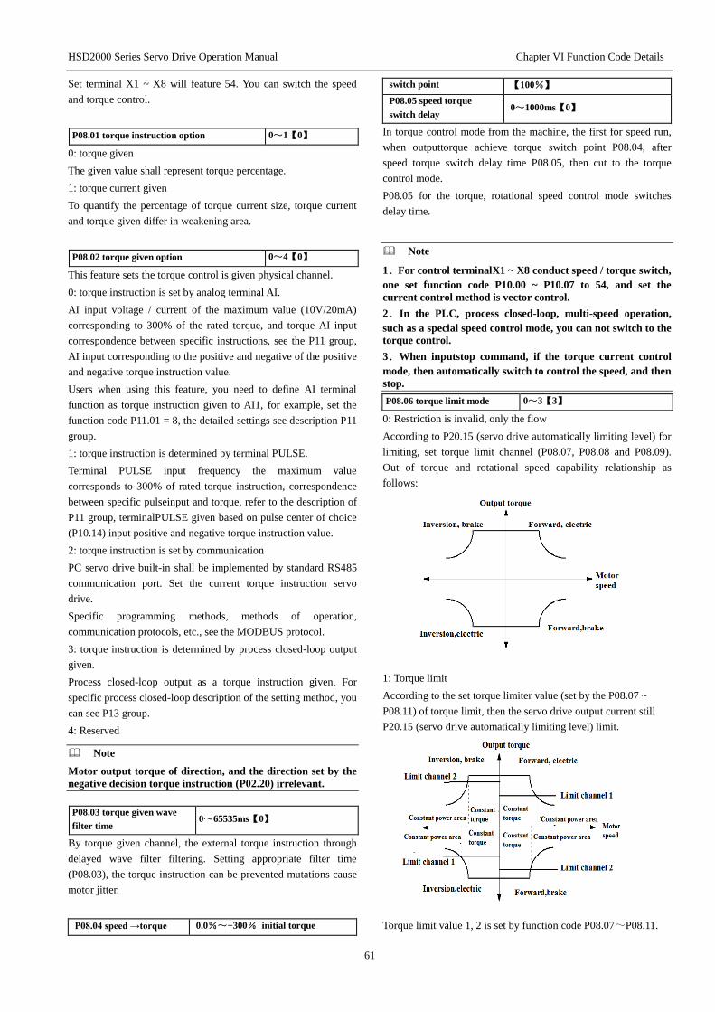
HSD2000 Series Servo Drive Operation Manual Chapter VI Function Code Details
61
Set terminal X1 ~ X8 will feature 54. You can switch the speed
and torque control.
P08.01 torque instruction option 0~1【0】
0: torque given
The given value shall represent torque percentage.
1: torque current given
To quantify the percentage of torque current size, torque current
and torque given differ in weakening area.
P08.02 torque given option 0~4【0】
This feature sets the torque control is given physical channel.
0: torque instruction is set by analog terminal AI.
AI input voltage / current of the maximum value (10V/20mA)
corresponding to 300% of the rated torque, and torque AI input
correspondence between specific instructions, see the P11 group,
AI input corresponding to the positive and negative of the positive
and negative torque instruction value.
Users when using this feature, you need to define AI terminal
function as torque instruction given to AI1, for example, set the
function code P11.01 = 8, the detailed settings see description P11
group.
1: torque instruction is determined by terminal PULSE.
Terminal PULSE input frequency the maximum value
corresponds to 300% of rated torque instruction, correspondence
between specific pulseinput and torque, refer to the description of
P11 group, terminalPULSE given based on pulse center of choice
(P10.14) input positive and negative torque instruction value.
2: torque instruction is set by communication
PC servo drive built-in shall be implemented by standard RS485
communication port. Set the current torque instruction servo
drive.
Specific programming methods, methods of operation,
communication protocols, etc., see the MODBUS protocol.
3: torque instruction is determined by process closed-loop output
given.
Process closed-loop output as a torque instruction given. For
specific process closed-loop description of the setting method, you
can see P13 group.
4: Reserved
Note
Motor output torque of direction, and the direction set by the
negative decision torque instruction (P02.20) irrelevant.
P08.03 torque given wave
filter time 0~65535ms【0】
By torque given channel, the external torque instruction through
delayed wave filter filtering. Setting appropriate filter time
(P08.03), the torque instruction can be prevented mutations cause
motor jitter.
P08.04 speed →torque 0.0%~+300% initial torque
switch point 【100%】
P08.05 speed torque
switch delay 0~1000ms【0】
In torque control mode from the machine, the first for speed run,
when outputtorque achieve torque switch point P08.04, after
speed torque switch delay time P08.05, then cut to the torque
control mode.
P08.05 for the torque, rotational speed control mode switches
delay time.
Note
1.For control terminalX1 ~ X8 conduct speed / torque switch,
one set function code P10.00 ~ P10.07 to 54, and set the
current control method is vector control.
2.In the PLC, process closed-loop, multi-speed operation,
such as a special speed control mode, you can not switch to the
torque control.
3.When inputstop command, if the torque current control
mode, then automatically switch to control the speed, and then
stop.
P08.06 torque limit mode 0~3【3】
0: Restriction is invalid, only the flow
According to P20.15 (servo drive automatically limiting level) for
limiting, set torque limit channel (P08.07, P08.08 and P08.09).
Out of torque and rotational speed capability relationship as
follows:
1: Torque limit
According to the set torque limiter value (set by the P08.07 ~
P08.11) of torque limit, then the servo drive output current still
P20.15 (servo drive automatically limiting level) limit.
Torque limit value 1, 2 is set by function code P08.07~P08.11.

HSD2000 Series Servo Drive Operation Manual Chapter VI Function Code Details
62
2: Detailed instruction Reserved
3: Torque current limit
According to the set torque current limiter value (set by the
P08.07 ~ P08.11) of torque limit, and a torque limit mode is
basically the same, but differ in the field weakening. At this point,
servo drive output current still P20.15 (servo drive automatically
limiting level) limit.
P08.07 torque limit channel
option 0~3【1】
Channel option of torque limit value.
0: Limit value is taken from the same channel 1 and 4 quadrants
1: Electric (1 and 3 quadrant) taken from Channel 1, power (2 and
4 quadrant) taken from Channel 2
2: Upper limit (1, 2 quadrant) taken from channel 1, lower limit
(3, 4) taken from Channel 2 upper limit.
3: The same four quadrants, limiting the choice of channel 1 and 2
by the terminal switch. Terminal function shall select 56.
P08.08 torque limit
channel 1 0~3【0】
P08.09 torque limit
channel 2 0~3【0】
Set torque limit physical channel.
0: torque limit value by the digital setting
P08.10, P08.11 as the torque limit value 1 and 2
1: Torque limit value given by the AI
AI input voltage / current of the maximum value (10V/20mA) can
correspond to 300% of rated torque instruction, correspondence
between specific Input and output volume, see instructions P11
group.
Users when using this feature, you need to define A terminal
function as torque limit value, to AI1, for example, set function
code P11.01 = 6 (or 7), detailed settings, see instructions P11
group.
2: torque limit value is given by terminal PULSE
Terminal PULSE input frequency of the maximum value (100k)
may correspond to 300% of rated torque instruction,
correspondence between the amount of specific pulse input and
output instructions, please refer to P11 parameter group.
Torque limit value pulse input terminal X8 only valid, should be
defined as the torque limit function X8terminal pulse, users need
to set function code P10.07 = 61 or 62.
3: Process closed-loop output
Process closed-loop output shall be as a torque limit given. Set
the relevant process closed-loop function code may be seen in
section 6.1.14 P13 group function code instructions.
Note
Torque limit value can only be a positive value, if the setting
value is negative value, automatically limit is 0.
P08.10 torque limit
value 1 0.0%~300.0% initial torque 【180.0%】
P08.11 torque limit
value 2 0.0%~300.0% initial torque 【180.0%】
Torque limit value only P08.08 (or P08.09) = 0 is valid. Set the
value of 100% corresponds to the servo drive's rated torque.
P08.12 mechanical loss
compensation value -20.0%~+20.0%【0.0%】
Set the mechanical loss compensation value, under speed control
and torque control for torque compensated according to the setting
value.
Usually when a large torque loss caused by the mechanical loss of
motor mechanical losses should be adjusted, generally do not need
to set the value.
Set value of 100% corresponds to the servo drive's rated torque
current. Set value of 100% corresponds to the servo drive's rated
torque current.
P08.13 torque deviation
T1 -300%~+300.0%【0.0%】
P08.14 torque deviation
T2 -300%~+300.0%【0.0%】
P08.15 torque deviation
T3 -300%~+300.0%【0.0%】
To startup torque deviation, choose two control terminal, defined
its function as a torque deviation options to control terminalX6,
X7, for example, set P10.05 = 58, P10.06 = 59. By combining X6
and X7terminal can only choose one torque deviation effective,
specific parameters see table 6-2.
Torque Deviation Option Table
X7 X6 Torque Deviation Option
OFF OFF No startup
OFF ON T1
ON OFF T2
ON ON T3
Set value of 100% corresponds to the servo drive's rated torque
current.
Note
Torque deviation may be effective in speed or torque control
mode.
P08.16 torque deviation
startup delay 0.0~1.0s【0.0s】
After the torque deviation effective, if P08.16 is not zero, then
torque deviation is not immediately given the added torque, but
after a certain delay time (P08.16) coupled to a torque current
given on.
Note
Torque deviation startup delay P08.16 only AI given time to be
effective in torque deviation.
P08.17 over torque / less torque
Detection selection 0~8【0】
P08.18 over torque / less torque
detection value 1 0%~300%【0】
P08.19 over torque / torque detection 0~10s【0】

HSD2000 Series Servo Drive Operation Manual Chapter VI Function Code Details
63
time of less than 1
P08.20 over torque / less torque
Detection selection 2 0~8【0】
P08.21 over torque / less torque
detection value 2 0%~300%【0】
P08.22 over torque / torque detection
time of less than 2 0~10s【0】
Over Torque Determination
If within the detection time (P08.19 or P08.22), continuous greater
torque detection value (P08.18 or P08.21), considered detected
over torque signal.
Insufficient torque judge:
If the detection time (P08.19 or P08.22), continuous torque is less
than the detection value (P08.18 or P08.21), considered
insufficient detected torque signal.
Over torque / less torque detection mode selection:
0: over torque / less torque detected invalid
Not conducted torque / insufficient torque detection
1: The only consistent speed, over torque detection continues to
run after.
Only detect whether excessive torque during constant speed
operation, and checked out the torque servo drive continues to
run.
2: After running over torque detection continues to run after
3: The only consistent speed, over torque detection off after only
detect whether excessive torque output during constant speed
operation, and checked out the torque servo drive stops output,
motor coasts to stop.
4: After running through the cut output torque detection
Detected in the course of the entire operation over torque after,
servo drive stops output, motor coasts to stop.
5: Only consistent in speed, the less continue to run after the
torque detection during constant speed operation only detect
whether the lack of torque, and the lack of detectable torque, servo
drive continues to run.
6: Continue to run after run less torque detection
After the detection of insufficient torque on the entire operation
process, servo drive continues to run
7: After only a consistent speed, the lack of torque detection cut
output
Detected only during constant speed operation is insufficient
torque, and detection of the lack of torque servo drive stops output,
motor coasts to stop.
8: Cut output after running less torque detection
After the detection of insufficient torque on the entire operation
process, servo drive stops output, motor coasts to stop.
Over torque / less torque detection value:
In the V / F control mode, set the value for the corresponding
servo drive rated current at 100%; in vector control mode, set the
value for the corresponding motor when 100% rated torque.
By switching terminalY1 or Y2 can be monitored through the
torque / less torque signal output.
Note
Over torque / less torque detection are valid in any control
mode.
6.1.10 Servo control parameters (P09 group)
P09.00 Servo control switching
option 0~3【0】
0: non-servo control
Under non-servo control, position control is not available.
1: speed/ torque←→ servo control
Current status is speed or torque control, and when switching
terminal (function 81) of servo control is valid, it switches to
servo control.
2: servo ←→ speed/torque control
Current status is servo control, and when switching terminal
(function 81) of servo control is valid, it switches to speed or
torque control.
3:Servo control
Under servo control, position control is available and the position
given source is selected by P09.03. Control mode must be set as
closed loop vector control so as to select servo control.
P09.01Servo run mode option 0~2【0】
0: normal run
It is basic position control mode and special switching of position
run mode is not available.
1: Reserved
2: spindle run
The spindle runs first in P09.00 mode, and when the positioning
terminal (function 77) of spindle or return-to-zero terminal
(function 84) of origin is valid, the spindle is stopped in the
specified position.
P09.02 Orientation mode of
spindle 0~1131H【0010H】
Ones place: positioning zero option
0: Z-pulse positioning
When Z-pulse is used as spindle zero, the accuracy of position
control is high, but the encoder must be installed on the spindle.
1: photoelectric switch positioning
The photoelectric feedback signal of a position on the spindle is
used as spindle zero.
Tens place: acceleration/deceleration time option
0~3: acceleration/deceleration time option
Select acceleration/deceleration 1 ~ 4 as the
acceleration/deceleration time of the process that spindle slows
down to its directional speed.
HSD2000 Series Servo Drive Operation Manual Chapter VI Function Code Details
64
Hundreds place: motion option after the spindle is stopped in the
specified position.
0: hold at the positioning point
Continue position control and hold at the specified stop point.
1: hold within the positioning range
When the position deviation from the specified stop point is
within the range set in P09.12, position control is not available;
when the deviation is beyond the range, a position loop is
available.
Thousands place: calculation mode of position
0: direct position loop control
1: position loop + feedfoward control
P09.03 Position given source 0~4【0】
0: X8 terminal pulse given
The number of X8 pulses is given as motor position. Users are
requested to define X7 terminal function as position pulse
direction and define X8 terminal function as position pulse input,
and respectively set the function codes: P10.06=71, P10.07=72.
1: Reserved
2: expansion PG given
Pulse input on the expansion PG card is set as motor position.
3: setting of position number
The position target of motor is set by the function codes P09.05
and P09.06.
4: Reserved
P09.04 Pulse instruction input
mode option 0~1【0】
The function code defines the expansion PG card as the pulse
input mode when the position is given.
0: A/B phase pulse
It is two-phase orthogonal pulse; when A phase is in advance of B
phase, motor rotates forward.
1: PLUS+SIGN pulse
It is pulse + direction input mode; A phase represents pulse train
and B phase represents direction; when it is high level, motor
rotates forward and when it is low level, motor rotates backward.
P09.05 Position given- high
position 0~150【0】
P09.06 Position given- low
position 0~65535【0】
When the position given source is digitally set (P09.03=3), the
function codes P09.05 and P09.06 are valid.
P09.07 Reserved
Reserved function
P09.08 Filtering time constant of
position instruction 0~3000.0ms【10ms】
A position instruction needs to be filtered by a one-delay filter.
Filtering time constant of the filter is set by the function code
P09.08
P09.09 Reserved
Reserved function
P09.10 Numerator of position
instruction ratio 1~65535【1024】
P09.11 Denominator of position
instruction ratio 1~65535【1024】
A pulse instruction is converted into amount of movement of
motor by setting the function codes P09.10 and P09.11, e.g. a
pulse represents 10um. It may be controlled without regard to the
speed reducing ratio of machinery and pulse number of encoder.
An example is given below:
On the supposition that the encoder is of 2500 lines and absolute
position of travel of motor completing one revolution is 5mm, it
can be known that 5mm distance corresponds to 10000 (2500×4)
pulses.
Now there is a workpiece that needs moving 8mm, so the number
of pulses that need moving is 5
8×10000; supposing that
instruction unit is 1um, position pulse is directly set as 8000 and
electronic gear ratio is set as 5
8×
8000
10000=
1
2.
Therefore, set the function codes: P09.10=2, P09.11=1.
P09.12 Range of positioning
completion 1~10000【10】
In the process of servo running, if position deviation is within the
set range (P09.12), servo positioning is completed. If any switch
output terminal function is defined as positioning completion
output, take Y1 as an example, set the function code P10.18=25,
and simultaneously output a positioning completion indication
signal.
P09.13 Width of position
approach signal 1~32767【100】
In the process of servo running, if position deviation is within the
set range (P09.13), the position approaches. If any switch output
terminal function is defined as position approach output, take Y1
as an example, set the function code P10.18 = 26, and
simultaneously output a position approach indication signal.
P09.14 Position out-of-tolerance
detection range 0~32767【1000】
P09.15 Position out-of-tolerance
alarm option 0~1【0】
0: valid
1: invalid
In the process of servo running, if position deviation is beyond the
set range (P09.14) and position out-of-tolerance alarm option is
valid (P09.15=0), when any switch output terminal function is
defined as position out-of-tolerance alarm output, take Y1 as an
example, set the function code P10.18=28, and simultaneously
output a position out-of-tolerance alarm indication signal.
P09.16 Spindle transmission ratio 0~30.000【1.000】
On many occasions, the spindle of spindle motor needs to be
controlled by a transmission mechanism. The transmission ratio of
the transmission mechanism is set by P09.16.

HSD2000 Series Servo Drive Operation Manual Chapter VI Function Code Details
65
P09.17~P09.18 Reserved
Reserved function
P09.19 Directional speed of spindle 0~200.00【5.00】
When motor spindle is revolving at a high speed, after spindle
orientation is started, the spindle should be first switched to a
relatively low speed (P09.19) from the high speed and then
positioned. The acceleration/deceleration time from current speed
to directional speed is set by P09.02.
P09.20 Starting position of spindle
orientation 0~30000【0】
P09.21 Directional deceleration
time of spindle 0~3000.0【10.0】
P09.22 Spindle position 1 0~30000【0】
P09.23 Spindle position 2 0~30000【0】
P09.24 Spindle position 3 0~30000【0】
P09.25 Spindle position 4 0~30000【0】
After the spindle is switched to directional speed (P09.19), it runs
at the speed and waits for orientation starting position (P09.20);
after arriving at the position, orientation starts and the spindle is
decelerated to the specified stop point according to the
deceleration time set by P09.21, to make it just stop in the set
position (one of P09.22~P09.25). P09.21 refers to the time for
decelerating to zero from maximum speed.
The positions 1~4 can be selected by means of terminals; for
details, see the description of functions “78” and “79” in the P10
group.
P09.26 Position loop gain 1 1~8000【50】
P09.27 Position loop gain 2 1~8000【200】
Proportional gain of position loop regulator is set by P09.26 and
P09.27. The greater the gain is, the quicker the position tracking is,
but too great gain may easily cause oscillation; the smaller the
gain is, the slower the position tracking is. Position gain should be
increased properly while it does not cause oscillation.
P09.28 Switching mode of position gain 1
and gain 2 0~4【0】
P09.29~P09.30 Reserved
P09.31 Level of position gain switching
deviation 0~10000
P09.32 Smoothing time of gain switching 0~100ms
0: non-switching
Position loop gain 1 (P09.26) is valid.
1: Reserved
2: Reserved
3: Position deviation
When position deviation is smaller than the level of position gain
switching deviation (P09.31), after smoothing time of gain
switching (P09.32) passes, position gain will be automatically
switched to position loop gain 1 (P09.26) from position loop gain
2 (P09.27).
4: external terminal switching
Position gain can be manually switched by means of a terminal.
Any one of terminals X1~X8 may be selected and it is defined as
function “80”; take X3 as an example, set P10.02=80 and enable
X3, and after switching time of position gain passes, position gain
will be switched to 1 from 2.
P09.33 Speed feedforward gain 0~120.00%【100.00%】
P09.34 Output amplitude limit
of position controller
0~100.0%maximum frequency
【0.0%】
Position
filtering
Speed
feedforward
gain
(P09.08) (P09.33)
(P09.34)
(P09.26)Pulse
feedback
Pulse given
Speed given
+
-
Calculated pulse
frequency f
Proportional gain KP
Fig. 6-25 Simplified Diagram of Servo Control with Pulse Given
脉冲给定 Pulse given
脉冲反馈 Pulse feedback
计算脉冲频率 f Calculated pulse frequency f
位置滤波 Position filtering
速度前馈增益 Speed feedforward gain
比例增益 KP Proportional gain KP
速度给定 Speed given
In the servo control mode, when the position given source is pulse
given at a certain frequency, position feedforward control is
required to ensure feedback can quickly track the given pulse.
Output amplitude limit of position controller:
When set value is 100%, it corresponds to maximum output
frequency of servo driver (P02.05).
P09.35 Servo stop mode 0~1【0】
In the process of servo control, a stop mode may be selected by
P09.35.
0: Emergency stop by torque limit
The frequency of servo driver immediately reduces to 0 according
to the instruction and servo driver stops in an emergency.
1: Stop by switching to speed control
Servo driver stops according to the set deceleration curve from
current speed after switched to speed control mode from servo
control mode.
6.1.11 Switch I/O terminal parameters (P10 group)
P10.00 Function option of multi-function
input terminal X1 0~88【0】
P10.01 Function option of multi-function
input terminal X2 0~88【0】
P10.02 Function option of multi-function
input terminal X3 0~88【0】
P10.03 Function option of multi-function
input terminal X4 0~88【0】
P10.04 Function option of multi-function 0~88【0】

HSD2000 Series Servo Drive Operation Manual Chapter VI Function Code Details
66
input terminal X5
P10.05 Function option of multi-function
input terminal X6 0~88【0】
P10.06 Function option of multi-function
input terminal X7 0~88【0】
P10.07 Function option of multi-function
input terminal X8 0~88【0】
Multi-function input terminals X1~X8 are functionally rich and a
function can be selected easily according to the need, i.e. the
functions of X1~X8 can be defined respectively by setting
P10.00~P10.07 and set values and functions are as shown in
table 6-3 below.
Table 6-3 Multi-Function Input Option Functions
Content Corresponding function Cont
ent Corresponding function
0 Non-function 1 Multi-phase frequency
terminal 1
2 Multi-phase frequency
terminal 2 3
Multi-phase frequency
terminal 3
4 Multi-phase frequency
terminal 4 5
Acceleration/deceleration
time terminal 1
6 Acceleration/deceleration time
terminal 2 7
Normally open input of
external fault
8 Normally closed input of
external fault 9 External reset input
10 Control input of external jog
forward-rotation 11
Control input of external
jog reverse-rotation
12 Free stop (FRS) input 13 Frequency increase
instruction (UP)
14 Frequency decrease
instruction (DOWN) 15
Simple PLC pause
instruction
16 Acceleration/deceleration
disable instruction 17 Three-wire run control
18 Normally open contact input
of external interrupt 19
Normally closed contact
input of external interrupt
20 Stop DC braking input
instruction 21 Closed loop disable
22 PLC disable 23 Main set frequency
source option 1
24 Main set frequency source
option 2 25
Main set frequency
source option 3
26 Main set frequency switching
to AI 27
Command switching to
terminal
28 Command source option 1 29 Command source option
2
30 Multi-phase closed loop given
terminal 1 31
Multi-phase closed loop
given terminal 2
32 Multi-phase closed loop given
terminal 3 33
Multi-phase closed loop
given terminal 4
34 Traverse frequency input 35 Traverse frequency state
reset
36 External stop instruction 37 Servo driver run disable
38 Forward rotation disable 39 Reverse rotation disable
40 Reset of auxiliary set
frequency 41
Clearing of PLC stop
memory
42 Reserved 43 Reserved
44 Reserved 45
Pulse input of main set
frequency (set for X8
only)
46 Pulse input of auxiliary set
frequency (set for X8 only) 47
PG tach input (set for
X8 only)
Content Corresponding function Cont
ent Corresponding function
48 Reserved 49 Reserved
50 Reserved 51 Pre-exciting command
terminal
52 Reserved 53 Reserved
54 Switching terminal of speed
control and torque control 55 Reserved
56 Selection of torque limitation
channels 1 and 2 57 Reserved
58 Torque-bias option terminal 1 59 Torque-bias option
terminal 2
60 Torque-bias retention 61
Pulse input terminal of
torque limitation 1 (set
for X8 only)
62 Pulse input terminal of torque
limitation 2 (set for X8 only) 63
Pulse input terminal of
torque given (set for X8
only)
64 Reserved 65 Reserved
66 Reserved 67 Reserved
68 Reserved 69 Reserved
70 Reserved 71 Position pulse direction
(only X7 is valid)
72 Position pulse input (only X8
is valid) 73
Reset of position
deviation counter
74 Instruction pulse disable 75 Reserved
76 Reserved 77 Spindle orientation start
78 Position option terminal 1 79 Position option terminal 2
80 Reserved 81 Servo control switching
terminal
82 Reserved 83
Position reference point
input terminal (only
X6,X7 and X8 are valid)
84 Origin return-to-zero 85 Reserved
86 Reserved 87 Reserved
88 Switching terminal of motors
1 and 2
The functions listed in the above table are described as follows:
1~4: multi-phase frequency option terminals
15-phase speed running curves at most can be defined by selecting
the ON/OFF combination of these function terminals.
Table 6-4 Selection of Multi-Speed Run

HSD2000 Series Servo Drive Operation Manual Chapter VI Function Code Details
67
These frequencies will be used in the multi-speed run and simple
PLC run. Take multi-speed run as an example to give a description
as below:
Control terminals X1, X2, X3 and X4 are respectively defined as
below: P10.00=1, P10.01=2, P10.02=3, and P10.03=4, and
then terminals X1~X4 are used to realize multi-speed run, as
shown in Fig.6-26 below:
Fig.6-26 Multi-Speed Run Diagram
输出频率 Output frequency
普通运行频率 Normal run frequency
运行命令 Run command
1 速 1st speed
15 速 15th speed
时间 Time
5~6: acceleration/deceleration time terminal option
Table 6-5 Expression of Acceleration/Deceleration Time Option
Terminal 2 Terminal 1 Acceleration/deceleration time option
OFF OFF Acceleration time 1/ deceleration
time 1
OFF ON Acceleration time 2/ deceleration
time 2
ON OFF Acceleration time 3/ deceleration
time 3
ON ON Acceleration time 4/ deceleration
time 4
Selection of acceleration/deceleration time 1~4 can be realized
by the ON/OFF combination of acceleration/deceleration time
terminals 1 and 2.
7~8: normally open/normally closed input of external device
fault
A fault signal of an external device can be inputted by the terminal,
convenient for servo driver to monitor faults of external devices.
After servo driver receives a fault signal of an external device, it
displays “E015”, namely fault alarm of the external device. The
fault signal can be inputted in a normally open or normally closed
way.
Xi
Xj
COM
HSD2000
KM
Fig.6-27 Normally Open/Normally Closed Input Diagram of External
Device Fault
9: external reset input
When servo driver gives a fault alarm, the fault can be reset by the
terminal. The function of the terminal is identical with the
function of RESET key on the operating panel.
10~11: control input of external jog run: JOG forward /JOG
reverse
K4 K3 K2 K1 Frequency setting
OFF OFF OFF OFF Normal running
frequency
OFF OFF OFF ON Multi-phase
frequency 1
OFF OFF ON OFF Multi-phase
frequency 2
OFF OFF ON ON Multi-phase
frequency 3
OFF ON OFF OFF Multi-phase
frequency 4
OFF ON OFF ON Multi-phase
frequency 5
OFF ON ON OFF Multi-phase
frequency 6
OFF ON ON ON Multi-phase
frequency 7
ON OFF OFF OFF Multi-phase
frequency 8
ON OFF OFF ON Multi-phase
frequency 9
ON OFF ON OFF Multi-phase
frequency 10
ON OFF ON ON Multi-phase
frequency 11
ON ON OFF OFF Multi-phase
frequency 12
ON ON OFF ON Multi-phase
frequency 13
ON ON ON OFF Multi-phase
frequency 14
ON ON ON ON Multi-phase
frequency 15
HSD2000 Series Servo Drive Operation Manual Chapter VI Function Code Details
68
It is used for jog run control in the control terminal mode. Jog run
frequency, jog interval time and jog acceleration/deceleration time
are defined in the P02.16~P02.19.
12: free stop input
The function is the same as the meaning of free running stop
defined in the P05.05, but here is realized by a control terminal, to
facilitate remote control.
13~14: frequency increase instruction (UP)/decrease instruction
(DOWN)
Progressive increase or progressive decrease of frequency is
realized by a control terminal, to perform remote control instead
of operating panel. It is valid when normal run P02.03=1, or
P02.08=2 as auxiliary frequency. Increase/decrease rate is set in
the P10.09 and P10.10.
15: simple PLC pause instruction:
It is used for pause control of running PLC process. When the
terminal is valid, it runs at zero frequency and PLC run is not
timed; when the terminal is invalid, automatic speed tracking
starts and PLC run continues. For the use method, refer to the
functional description of P15.00~P15.30.
16: acceleration/deceleration disable instruction
It is used to keep motor away from any external signal influence
(except stop command), to maintain running at current speed.
17: three-wire run control
Refer to the functional description of P10.08 run modes 2 and 3
(three-wire run modes 1 and 2).
18~19: normally open/normally closed contact input of external
interrupt
In the running process, when servo driver receives an external
interrupt signal, it locks out output and runs at zero frequency.
Once the external interrupt signal is cleared, automatic speed
tracking of servo driver starts and servo driver resumes running.
External interrupt input has two modes: normally open contact
and normally closed contact. As shown in Fig. 6-27, Xi is
normally open contact input and Xj is normally closed contact
input.
Attention
The difference from functions 7~8 is that external interrupt
will not cause alarm output of servo driver, and after interrupt
signal is cleared, servo driver resumes running.
20: stop DC braking input instruction
DC braking is applied to the motor in the stop process by a control
terminal, to realize its emergency stop and accurate positioning.
Braking start frequency, braking waiting time and braking current
are defined in the P05.06~P05.08; braking time may be the
greater value between the time defined in the P05.09 and the
effective duration of the control terminal.
21: closed loop fault
It is used for flexible switching between closed loop run mode and
low-level run mode. Run mode of HSD2000 by priority level is
successively: setting run > jog run > closed loop run > PLC run >
multi-speed run > normal run.
It can be switched between closed loop run mode and low-level
run mode only in the closed loop run mode (P13.00=1).
When switched to the low-level run mode, start/stop control,
direction and acceleration/deceleration time should comply with
setting of the corresponding run mode.
22: PLC disable
It is used for flexible switching between PLC run mode and
low-level run mode.
It can be switched between PLC run mode and low-level run
mode only in the PLC run mode (P15.00 Ones place ≠0).
When switched to the low-level run mode, start/stop control,
direction and acceleration/deceleration time should comply with
setting of the corresponding run mode.
23~25: main set frequency source option 1~3
Switching of frequency given channels in table 6-6 can be realized
by the ON/OFF combination of frequency given channel option
terminals 1, 2 and 3. The relation between terminal switching and
setting of function code P02.03 is after-valid.
Table 6-6 Expression of Frequency Given Channel Selection
Option
terminal 3 of
frequency
given channel
Option
terminal 2 of
frequency
given channel
Option
terminal 1 of
frequency
given channel
Selection of frequency
given channel
OFF OFF OFF P02.03 setting
OFF OFF ON Operating panel ▲ ▼
given
OFF ON OFF Terminal UP/DOWN
given
OFF ON ON Serial port
communication given
ON OFF OFF AI analog given
ON OFF ON Terminal PULSE given
ON ON OFF Extended card given
ON ON ON Frequency setting
holding
26: AI main set frequency switching to AI
When the function terminal is valid, main set frequency channel is
forced to switch to AI given and which AI needs to be set in the AI
function in the P11 group. When the function terminal is invalid,
the frequency given channel will be restored to the original state.
27: command switching to terminal
When the function terminal is valid, run command channel is
forced to switch to terminal run command channel. When the
function terminal is invalid, run command channel will be
restored to the original state.
28~29: Command source option 1~2
Table 6-7 Selection of Run Command Channels
HSD2000 Series Servo Drive Operation Manual Chapter VI Function Code Details
69
Option terminal 2 of
command source
Option terminal 1
of command
source
Run command channel
OFF OFF Run command channel
holding
OFF ON Operating panel run command
channel
ON OFF Terminal run command
channel
ON ON Serial port run command
channel
Selection of run command channels can be realized by the
ON/OFF combination of command source option terminals 1 and
2.
30~33: multi-phase closed loop terminals 1~4
Table 6-8 Selection Expression of Multi-Phase Closed Loop
Given
Multi-pha
se closed
loop
terminal 4
Multi-pha
se closed
loop
terminal 3
Multi-pha
se closed
loop
terminal 2
Multi-pha
se closed
loop
terminal 1
Selection of multi-phase
closed loop given
OFF OFF OFF OFF Closed loop given
depends on P13.01
OFF OFF OFF ON Multi-phase closed loop
given 1
OFF OFF ON OFF Multi-phase closed loop
given 2
OFF OFF ON ON Multi-phase closed loop
given 3
OFF ON OFF OFF Multi-phase closed loop
given 4
OFF ON OFF ON Multi-phase closed loop
given 5
OFF ON ON OFF Multi-phase closed loop
given 6
OFF ON ON ON Multi-phase closed loop
given 7
ON OFF OFF OFF Multi-phase closed loop
given 8
ON OFF OFF ON Multi-phase closed loop
given 9
ON OFF ON OFF Multi-phase closed loop
given 10
ON OFF ON ON Multi-phase closed loop
given 11
ON ON OFF OFF Multi-phase closed loop
given 12
ON ON OFF ON Multi-phase closed loop
given 13
ON ON ON OFF Multi-phase closed loop
given 14
ON ON ON ON Multi-phase closed loop
given 15
Selection of multi-phase closed loop given can be realized by the
ON/OFF combination of multi-phase closed loop terminals 1~4.
34: traverse frequency input
When traverse frequency start mode is manually put into service,
the terminal is valid and traverse frequency function is valid, see
the description of traverse frequency function parameter in the
P16 group.
35: traverse frequency state reset
When selecting the traverse frequency function no matter whether
it is automatic or manual mode, once the terminal is closed,
traverse frequency state information memorized inside servo
driver will be cleared. After the terminal is disconnected, traverse
frequency restarts. See the function description in the P16 group.
36: external stop instruction
The command is valid to all run command channels. When the
function terminal is valid, servo driver will stop according to the
mode set in P05.05.
37: servo driver run disable
When the terminal is valid, running servo driver will stop freely
and its start-up is disabled in the standby mode. It is mainly used
on the occasion when security interaction is required.
38: forward rotation disable
If the terminal is enabled in the process of forward rotation, servo
driver will stop freely. First enable the terminal and then run
forward, and it will be in zero-frequency running state. Reverse
rotation is not affected by this.
39: reverse rotation disable
Contrary to function 38, see the description of function 38.
40: reset of auxiliary set frequency
It is valid only to the digital auxiliary frequency (P02.08=1, 2, 3).
When the function terminal is valid, given value of auxiliary
frequency is reset and set frequency completely depends on main
given value.
41: clearing of PLC stop memory
In the stop state in PLC run mode, when the function terminal is
valid, PLC run phase, run time, run frequency and other
information of PLC stop memory will be cleared, see the function
description in the P15 group.
42~44: Reserved
45: pulse input of main set frequency (set for X8 only)
It is valid only to input terminal X8, as a mode of main frequency
setting together with P02.03=4. The relation between input signal
pulse frequency and set frequency can be adjusted by curve
setting in the P11 group.
46: pulse input of auxiliary set frequency (set for X8 only)
It is valid only to input terminal X8, as a mode of auxiliary
frequency setting together with P02.08=5. The relation between
input signal pulse frequency and set frequency can be adjusted by
curve setting in the P03 group.
47: PG tach input (set for X8 only)
It is valid only to input terminal X8 and the accuracy of speed
control is 0.1%. The input port in combination with pulse encoder
(PG) can realize feedback control of single-phase pulse speed.
48~50: Reserved

HSD2000 Series Servo Drive Operation Manual Chapter VI Function Code Details
70
51: pre-exciting command terminal
When the terminal is valid, motor pre-excitation will be started
until the terminal becomes invalid.
52~53: Reserved
54: Switching of speed control and torque control
In the vector control mode, the terminal can realize switching of
speed control and torque control modes. If P10.16 is set as
positive logic, after the terminal is closed, if output torque
(observable by P01.10) of servo driver is continuously more than
switching torque point P08.04 within the set speed torque
switching delay (P08.05), control mode will automatically switch
to torque control mode; after the terminal is disconnected, it is
speed control mode. The relation between terminal switching and
setting of function code P08.00 is after-valid.
55: Reserved
56: selection of torque limitation channels 1 and 2
Selection of torque limitation channels can be realized by the
terminal.
57: Reserved
58~59: torque-bias option terminals 1~2
Three torque bias values can be selected by the state combination
of the two terminals. Torque bias values can be set by P08.13~
P08.15. Combination mode is as shown in table 6-9 below.
Table 6-9 Torque-Bias Selection
Torque-bias option
terminal 2
Torque-bias option
terminal 1 Torque bias value
OFF OFF No torque bias
OFF ON Torque bias value1
ON OFF Torque bias value 2
ON ON Torque bias value 3
60: AI torque-bias retention
When the terminal is valid, AI input at this moment is converted
into corresponding torque bias value. It is requested to set the
corresponding function as torque bias in the analog input function
selection in the P11 group; the torque bias value does not vary
with AI input voltage.
Attention
After given AI is changed, if AI torque bias needs to vary with
it, the terminal should be enabled again.
61: pulse input terminal of torque limitation 1
The function is set only for terminal X8. Torque limit 1 is
determined by external input pulse frequency. When external
input pulse frequency reaches maximum input frequency P10.13,
the corresponding torque limit 1 is 300%.
62: pulse input terminal of torque limitation 2
The function is set only for terminal X8, similar to function 61.
63: pulse input terminal of torque given
The function is set only for terminal X8. Given value of torque is
determined by external input pulse frequency. Pulse input of
functions 61~63 should undergo curve adjustment in the P11
group.
64: Reserved
65~70: Reserved
71: position pulse direction (set for X7 only)
The function is valid only to terminal X7. The direction of
position pulse input depends on ON/OFF level of the terminal.
72: position pulse input (set for X8 only)
The function is valid only to terminal X8. When the terminal
pulse given in P09.03 is selected, the position instruction given
can be determined by inputting the pulse of the terminal.
73: reset of position deviation counter
When the terminal is valid, the error count value of position given
and position feedback will be cleared.
74: Instruction pulse disable
When P09.03=0, 2, if instruction pulse disable terminal is valid
pulse input is disabled and position given remains unchanged;
when the terminal is invalid, the pulse is inputted normally as
position given.
75~76: Reserved
77: spindle orientation start
When spindle directional run is selected in the P09.01 and the
terminal is valid, spindle directional run starts.
78~79: position option terminals 1~2
Spindle directional position of P09.22~P09.25 can be selected by
the combination of the two terminals.
Select two control terminals from X1~X8 and respectively define
its function as position option 1 and 2. Take control terminals X6
and X7 as an example, set P10.05=78 and P10.06=79. By the
combination of terminals X6 and X7, it is valid to select a set
position.
Specific combination is as follows:
Table 6-10 Selection of Spindle Position
Position option
terminal 2
Position option
terminal 1 Spindle position
OFF OFF Spindle position 1
OFF ON Spindle position 2
ON OFF Spindle position 3
ON ON Spindle position 4
80: Reserved
81: servo control switching terminal
When current control mode is speed/torque control (P09.00=1),
the switching terminal can be enabled to switch it to servo control
mode.
When current control mode is servo control (P09.00=2), the
switching terminal can be enabled to switch it to speed/torque
control mode.
See the description of function codes in the P09 group.

HSD2000 Series Servo Drive Operation Manual Chapter VI Function Code Details
71
82: Reserved
83: position reference point input terminal
When ones place of P09.02 is equal to 1 and position reference
point input terminal is valid, photoelectric switch signal is
inputted through the position reference point.
84: origin return-to-zero
In the spindle orientation control mode, when origin return-to-zero
terminal is valid, spindle position is 0, or else one of spindle
positions 1~4 (P09.22~P09.25) should be selected.
85~87: Reserved
88: switching terminal of motors 1 and 2
When the terminal is valid, switching control of the two motors
can be realized.
Attention
Only the following function numbers are displayed in the
shortcut menu.
0, 7, 8, 9, 10, 11, 12, 13, 14, 17, 18, 19, 20, 26, 27, 35, 37, 45, 46,
47, 48。
P10.08 FWD/REV run mode setting 0~3【0】
The parameter defines four different modes of controlling running
of servo driver by an external terminal.
0: 1 two-wire run mode 1
FWD
COM
REV
HSD
2000PLC
P24k2
k1
Run
instruction 0 0 Stop
1 0Revers
e 0 1 Forward
1 1 Stop
K1
K2
Fig. 6-28 Two-Wire Run Mode 1
运行指令 Run instruction
停止 Stop
反转 Reverse
正转 Forward
1: two-wire run mode 2
FWD
COM
REV
HSD
2000PLC
P24
K1
k2
k1
0 0 Stop
1 0 Stop
0 1
Forwar
d 1 1
Revers
e
K2
Run instruction
Fig. 6-29 Two-Wire Run Mode 2
运行指令 Run instruction
停止 Stop
反转 Reverse
正转 Forward
2: three-wire run mode 1
FWD
Xi
REVSB3
COM
SB1
SB2 HSD2000PLC
P24
Fig. 6-30 Three-Wire Run Mode 1
In which,
SB1: stop button
SB2: forward button
SB3: reverse button
Xi stands for multi-function input terminals X1~X8 and here the
corresponding terminal function should be defined as 17# function
“three-wire run control”.
3: three-wire run mode 2
K
COM
SB1
SB2
HSD2000
.
.
.
PLC
P24.
.
FWD
Xi
REV
k
0
1
Run direction option
Reverse
Forward
Fig. 6-31 Three-Wire Run Mode 2
运行方向选择 Run direction option
反转 Reverse
正转 Forward
In which,
SB1: stop button
SB2: run button
Xi stands for multi-function input terminals X1~X8 and here the
corresponding terminal function should be defined as 17# function
“three-wire run control”.
P10.09 Terminal UP rate 0.01~99.99Hz/s【1.00Hz/s】
P10.10 Terminal DOWN rate 0.01~99.99Hz/s【1.00Hz/s】
The function code defines the change rate of set frequency
modified by the terminal UP/DOWN
P10.11 X8 pulses per
revolution 1~9999【1024】
When the terminal X8 selects 47# function “PG tach input”, actual
speed of PG can be measured by setting the value of P10.11 to be
consistent with pulses per revolution of local PG.
P10.12 Terminal filtering time 0~500ms【10ms】
The function code sets filtering time of input terminal detection.
When input terminal state changes, if it remains unchanged after
the set filtering time has passed, the change of terminal state is

HSD2000 Series Servo Drive Operation Manual Chapter VI Function Code Details
72
valid, or else it still keeps previous state, to effectively reduce
misoperations arising from interference.
P10.13 Maximum input pulse
frequency 0.1~100.0kHz【10kHz】
The function code sets maximum input pulse frequency when the
terminal X8 is used for pulse input.
P10.14 Pulse given center point
option 0~2【0】
The function code defines three different midpoint modes when
the terminal X8 is used for pulse input.
0: centerless midpoint, as shown in the figure below:
0 P10.13Pulse frequency f
Correspondi
ng value
Fig. 6-32 Centerless Midpoint Mode
对应量 Corresponding value
脉冲频率 Pulse frequency
Values corresponding to pulse input frequencies are all positive.
1: center point mode 1
0 P10.13
Pulse frequency f
P10.132
Corresponding
value
Fig. 6-33 Center Point Mode 1
对应量 Corresponding value
脉冲频率 Pulse frequency
Pulse input has a center point and the center point is half of
maximum pulse input frequency P10.13. When input pulse
frequency is less than midpoint frequency, corresponding values
are positive.
2: center point mode 2
Pulse input has a center point and the center point is half of
maximum pulse input frequency P10.13. When input pulse
frequency is greater than midpoint frequency, corresponding
values are positive.
0 P10.13 f
P10.132
Correspondin
g value
Pulse frequency
Fig. 6-34 Center Point Mode 2
对应量 Corresponding value
脉冲频率 Pulse frequency
P10.15 Pulse given filtering time 0.00~10.00s【0.05s】
The function code defines filtering time of input pulse. The longer
the filtering time is, the lower the change rate of given pulse
frequency is.
P10.16 Valid state setting of input
terminal 000~3FFH【000H】
BIT0: Positive and negative logic definition of X1
Hundreds
place
One
s
plac
e
Tens
plac
e
BIT1: Positive and negative logic definition of X2
BIT2: Positive and negative logic definition of X3
BIT3: Positive and negative logic definition of X4
BIT4: Positive and negative logic definition of X5
BIT5: Positive and negative logic definition of X6
BIT6: Positive and negative logic definition of X7
BIT7: Positive and negative logic definition of X8
BIT0: Positive and negative logic definition of FWD
BIT1: Positive and negative logic definition of REV
Fig. 6-35 Positive and Negative Logic Setting of Terminals
个位 Ones place
十位 Tens place
百位 Hundreds place
X1 的正反逻辑定
义
Positive and negative logic definition of
X1
X2 的正反逻辑定
义
Positive and negative logic definition of
X2
X3 的正反逻辑定
义
Positive and negative logic definition of
X3
X4 的正反逻辑定
义
Positive and negative logic definition of
X4
X5 的正反逻辑定
义
Positive and negative logic definition of
X5
X6 的正反逻辑定
义
Positive and negative logic definition of
X6
X7 的正反逻辑定
义
Positive and negative logic definition of
X7
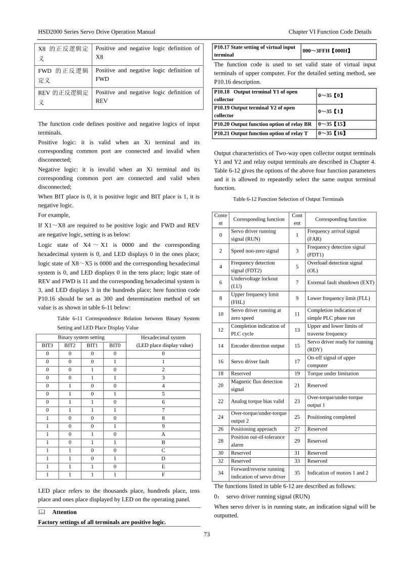
HSD2000 Series Servo Drive Operation Manual Chapter VI Function Code Details
73
X8 的正反逻辑定
义
Positive and negative logic definition of
X8
FWD 的正反逻辑
定义
Positive and negative logic definition of
FWD
REV 的正反逻辑定
义
Positive and negative logic definition of
REV
The function code defines positive and negative logics of input
terminals.
Positive logic: it is valid when an Xi terminal and its
corresponding common port are connected and invalid when
disconnected;
Negative logic: it is invalid when an Xi terminal and its
corresponding common port are connected and valid when
disconnected;
When BIT place is 0, it is positive logic and BIT place is 1, it is
negative logic.
For example,
If X1~X8 are required to be positive logic and FWD and REV
are negative logic, setting is as below:
Logic state of X4 ~ X1 is 0000 and the corresponding
hexadecimal system is 0, and LED displays 0 in the ones place;
logic state of X8~X5 is 0000 and the corresponding hexadecimal
system is 0, and LED displays 0 in the tens place; logic state of
REV and FWD is 11 and the corresponding hexadecimal system is
3, and LED displays 3 in the hundreds place; here function code
P10.16 should be set as 300 and determination method of set
value is as shown in table 6-11 below:
Table 6-11 Correspondence Relation between Binary System
Setting and LED Place Display Value
Binary system setting Hexadecimal system
(LED place display value) BIT3 BIT2 BIT1 BIT0
0 0 0 0 0
0 0 0 1 1
0 0 1 0 2
0 0 1 1 3
0 1 0 0 4
0 1 0 1 5
0 1 1 0 6
0 1 1 1 7
1 0 0 0 8
1 0 0 1 9
1 0 1 0 A
1 0 1 1 B
1 1 0 0 C
1 1 0 1 D
1 1 1 0 E
1 1 1 1 F
LED place refers to the thousands place, hundreds place, tens
place and ones place displayed by LED on the operating panel.
Attention
Factory settings of all terminals are positive logic.
P10.17 State setting of virtual input
terminal 000~3FFH【000H】
The function code is used to set valid state of virtual input
terminals of upper computer. For the detailed setting method, see
P10.16 description.
P10.18 Output terminal Y1 of open
collector 0~35【0】
P10.19 Output terminal Y2 of open
collector 0~35【1】
P10.20 Output function option of relay BR 0~35【15】
P10.21 Output function option of relay T 0~35【16】
Output characteristics of Two-way open collector output terminals
Y1 and Y2 and relay output terminals are described in Chapter 4.
Table 6-12 gives the options of the above four function parameters
and it is allowed to repeatedly select the same output terminal
function.
Table 6-12 Function Selection of Output Terminals
Conte
nt Corresponding function
Cont
ent Corresponding function
0 Servo driver running
signal (RUN) 1
Frequency arrival signal
(FAR)
2 Speed non-zero signal 3 Frequency detection signal
(FDT1)
4 Frequency detection
signal (FDT2) 5
Overload detection signal
(OL)
6 Undervoltage lockout
(LU) 7 External fault shutdown (EXT)
8 Upper frequency limit
(FHL) 9 Lower frequency limit (FLL)
10 Servo driver running at
zero speed 11
Completion indication of
simple PLC phase run
12 Completion indication of
PLC cycle 13
Upper and lower limits of
traverse frequency
14 Encoder direction output 15 Servo driver ready for running
(RDY)
16 Servo driver fault 17 On-off signal of upper
computer
18 Reserved 19 Torque under limitation
20 Magnetic flux detection
signal 21 Reserved
22 Analog torque bias valid 23 Over-torque/under-torque
output 1
24 Over-torque/under-torque
output 2 25 Positioning completed
26 Positioning approach 27 Reserved
28 Position out-of-tolerance
alarm 29 Reserved
30 Reserved 31 Reserved
32 Reserved 33 Reserved
34 Forward/reverse running
indication of servo driver 35 Indication of motors 1 and 2
The functions listed in table 6-12 are described as follows:
0: servo driver running signal (RUN)
When servo driver is in running state, an indication signal will be
outputted.

HSD2000 Series Servo Drive Operation Manual Chapter VI Function Code Details
74
1: frequency arrival signal (FAR)
Refer to the function description of P10.26.
2: speed non-zero signal
When servo driver is in running state and the speed is greater than
P05.15 “stop speed”, an indication signal will be outputted.
Detection mode of speed non-zero is set by P05.16 “detection
mode of stop speed”.
Attention
Zero-speed detection is valid in all control modes.
3: frequency detection signal (FDT1)
Refer to the function description of P10.28~P10.29.
4: frequency detection signal (FDT2)
Refer to the function description of P10.30~P10.31.
5: overload detection signal (OL)
When output current of servo driver exceeds P20.10 overload
pre-alarm detection level and time is greater than P20.11 overload
pre-alarm detection time, an indication signal will be outputted. It
is often used for overload pre-alarm.
6: undervoltage lockout (LU)
When DC bus voltage is lower than undervoltage limit level, an
indication signal will be outputted and LED will display “P.oFF”.
7: External fault shutdown (EXT)
When servo driver gives an external fault trip alarm (E015), an
indication signal will be outputted.
8: Upper frequency limit (FHL)
When set frequency is greater than or equal to the upper frequency
limit and running frequency reaches the upper frequency limit, an
indication signal will be outputted.
9: Lower frequency limit (FLL)
When set frequency is less than or equal to the lower frequency
limit and running frequency reaches the lower frequency limit, an
indication signal will be outputted.
10: Servo driver running at zero speed
When servo driver is in zero-speed running state, an indication
signal will be outputted. Specifically speaking, in V/F mode,
when output frequency is 0, an indication signal will be outputted;
in non-V/F mode, when feedback frequency is less than P10.37
corresponding frequency, an indication signal will be outputted.
11: completion indication of simple PLC phase run
After simple PLC run in current phase is completed, an indication
signal (single pulse signal, width: 500ms) will be outputted.
12: completion indication of PLC cycle
After simple PLC completes a run cycle, an indication signal
(single pulse signal, width: 500ms) will be outputted.
13: upper and lower limits of traverse frequency
After the traverse frequency function is selected, if the fluctuation
range of traverse frequency calculated based on center frequency
exceeds the upper frequency limit P02.06 or is below the lower
frequency limit P02.07, an indication signal will be outputted, as
shown in Fig.6-36.
Fig. 6-36 Amplitude Limit of Traverse Frequency
上限频率 Upper frequency limit
摆频中心频率 Center frequency
下限频率 Lower frequency limit
摆频超出上下
限阀值
Traverse frequency is beyond the upper and
lower thresholds
14: output of encoder frequency division direction
It is indicate the direction signal of frequency division output of
current encoder.
15: servo driver ready for running (RDY)
When the signal output is valid, it shows servo driver is fault-free,
bus voltage is normal, run disable terminal of servo driver is
invalid, and servo driver can receive a start command.
16: servo driver fault
When servo driver breaks down, an indication signal will be
outputted.
17: on-off signal of upper computer
Output signals of Y1 and Y2 or BR and T are directly controlled
by serial ports. Output is also affected by P10.17.
18: Reserved
19: torque under limitation
When a torque instruction is restricted by torque limit 1 or 2, an
indication signal will be outputted.
20: magnetic flux detection signal
When magnetic flux detection value exceeds P10.37, an indication
signal will be outputted.
21: Reserved
22: analog torque bias valid
When input terminal function is set as 60 “torque-bias retention”
and it is valid, an indication signal will be outputted.
23: over-torque/under-torque output 1
According to setting of P08.17~P08.19, the corresponding
indication signal will be outputted.
24: over-torque/under-torque output2
According to setting of P08.20~P08.22, the corresponding
indication signal will be outputted.
25: positioning completed
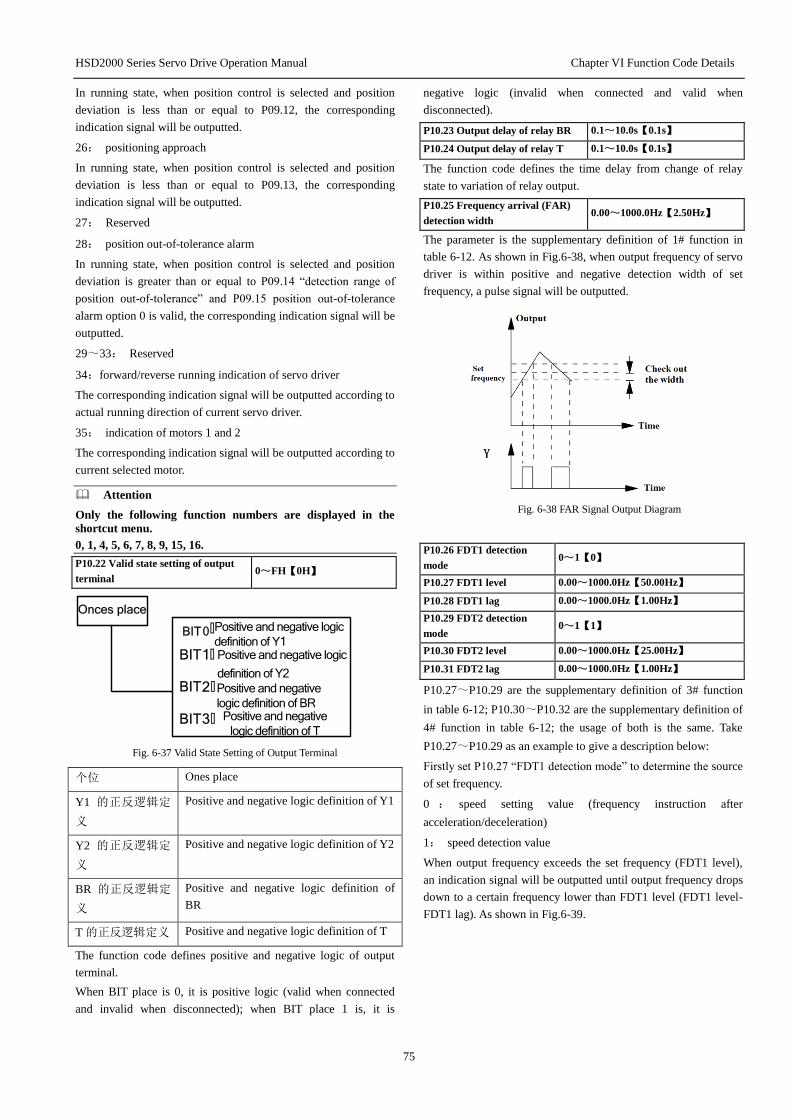
HSD2000 Series Servo Drive Operation Manual Chapter VI Function Code Details
75
In running state, when position control is selected and position
deviation is less than or equal to P09.12, the corresponding
indication signal will be outputted.
26: positioning approach
In running state, when position control is selected and position
deviation is less than or equal to P09.13, the corresponding
indication signal will be outputted.
27: Reserved
28: position out-of-tolerance alarm
In running state, when position control is selected and position
deviation is greater than or equal to P09.14 “detection range of
position out-of-tolerance” and P09.15 position out-of-tolerance
alarm option 0 is valid, the corresponding indication signal will be
outputted.
29~33: Reserved
34:forward/reverse running indication of servo driver
The corresponding indication signal will be outputted according to
actual running direction of current servo driver.
35: indication of motors 1 and 2
The corresponding indication signal will be outputted according to
current selected motor.
Attention
Only the following function numbers are displayed in the
shortcut menu.
0, 1, 4, 5, 6, 7, 8, 9, 15, 16.
P10.22 Valid state setting of output
terminal 0~FH【0H】
Onces place
BIT0:Positive and negative logic
definition of Y1 BIT1:
BIT2:Positive and negative
logic definition of BR
BIT3: Positive and negative
logic definition of T
Positive and negative logic
definition of Y2
Fig. 6-37 Valid State Setting of Output Terminal
个位 Ones place
Y1 的正反逻辑定
义
Positive and negative logic definition of Y1
Y2 的正反逻辑定
义
Positive and negative logic definition of Y2
BR 的正反逻辑定
义
Positive and negative logic definition of
BR
T 的正反逻辑定义 Positive and negative logic definition of T
The function code defines positive and negative logic of output
terminal.
When BIT place is 0, it is positive logic (valid when connected
and invalid when disconnected); when BIT place 1 is, it is
negative logic (invalid when connected and valid when
disconnected).
P10.23 Output delay of relay BR 0.1~10.0s【0.1s】
P10.24 Output delay of relay T 0.1~10.0s【0.1s】
The function code defines the time delay from change of relay
state to variation of relay output.
P10.25 Frequency arrival (FAR)
detection width 0.00~1000.0Hz【2.50Hz】
The parameter is the supplementary definition of 1# function in
table 6-12. As shown in Fig.6-38, when output frequency of servo
driver is within positive and negative detection width of set
frequency, a pulse signal will be outputted.
Fig. 6-38 FAR Signal Output Diagram
P10.26 FDT1 detection
mode 0~1【0】
P10.27 FDT1 level 0.00~1000.0Hz【50.00Hz】
P10.28 FDT1 lag 0.00~1000.0Hz【1.00Hz】
P10.29 FDT2 detection
mode 0~1【1】
P10.30 FDT2 level 0.00~1000.0Hz【25.00Hz】
P10.31 FDT2 lag 0.00~1000.0Hz【1.00Hz】
P10.27~P10.29 are the supplementary definition of 3# function
in table 6-12; P10.30~P10.32 are the supplementary definition of
4# function in table 6-12; the usage of both is the same. Take
P10.27~P10.29 as an example to give a description below:
Firstly set P10.27 “FDT1 detection mode” to determine the source
of set frequency.
0 : speed setting value (frequency instruction after
acceleration/deceleration)
1: speed detection value
When output frequency exceeds the set frequency (FDT1 level),
an indication signal will be outputted until output frequency drops
down to a certain frequency lower than FDT1 level (FDT1 level-
FDT1 lag). As shown in Fig.6-39.

HSD2000 Series Servo Drive Operation Manual Chapter VI Function Code Details
76
Fig. 6-39 Frequency Detection Diagram
输出频率 Output frequency
FDT1 电平 FDT1 level
FDT1 滞后 FDT1 lag
时间 Time
P10.32 DO terminal output 0~19【0】
Output of DO pulse frequency: 0~ maximum output pulse
frequency (defined by P10.33).
The linear correspondence relation between DO output and
indication range is as shown in table 6-13.
Table 6-13 Indication of Output Terminal
Conte
nt Corresponding function Indication range
0 Non-function No
1 Output frequency 0~maximum output frequency
2 Set frequency 0~maximum output frequency
3 Output current Iei 0~2×rated current of servo
driver
4 Output current Iem 0~3×rated current of motor
5 Output torque 0~3×rated motor torque
6 Output torque current 0~3×torque current
7 Motor speed 0~ maximum speed
8 Output voltage 0~1.5× rated voltage of servo
driver
9 Adjusted AI1 voltage -10V~10V/4~20mA
10 Adjusted AI2 voltage -10V~10V/4~20mA
11 Adjusted AI3 voltage -10V~10V
12 Output power 0~3×rated power
13 Torque limit 1 0~3×rated motor torque
14 Torque limit 2 0~3×rated motor torque
15 Torque bias 0~3×rated motor torque
16 Torque given 0~3×rated motor torque
17 Extended function 1 of
upper computer 0~65535
18 Frequency division
output of encoder
19 Reserved
For extended function 1 of upper computer, DO output is directly
controlled by serial port. 65535 corresponds to maximum output
frequency of DO, refer to HSD2000 communication protocol.
Attention
Only the following function numbers are displayed in the
shortcut menu.
0, 1, 2, 3, 4, 5, 6, 7, 8.
P10.33 Maximum output pulse
frequency 0.1~100kHz【10.0】
The function code defines maximum output frequency of DO
pulse.
P10.34 Pulse output center point
option 0~2【0】
The function code defines three different center point modes of
DO terminal pulse output.
0 P10.33Pulse
frequency f
Corresponding
value
Fig. 6-40 Centerless Midpoint Mode
Values corresponding to pulse output frequencies are all positive.
1: center point mode 1, as shown in the figure below:
0 P10.33
Pulse
frequency f
Correspondin
g value
P10.332
Fig. 6-41 Center Point Mode 1
对应量 Corresponding value
脉冲频率 Pulse frequency
Pulse output has a center point and the center point is half of
maximum pulse output frequency P10.13. When output pulse
frequency is less than midpoint frequency, corresponding values
are positive.
2: center point mode 2
Pulse output has a center point and the center point is half of
maximum pulse output frequency P10.13. When output pulse
frequency is greater than midpoint frequency, corresponding
values are positive.

HSD2000 Series Servo Drive Operation Manual Chapter VI Function Code Details
77
0 P10.33Pulse frequency f
Correspondin
g value
P10.332
Fig. 6-42 Center Point Mode 2
对应量 Corresponding value
脉冲频率 Pulse frequency
P10.35 Filtering time of pulse
output 0.00~10.00s【0.05s】
The function code defines the filtering time of output pulse. The
longer the filtering time is, the lower the change rate of output
pulse frequency is.
P10.36 Magnetic flux
detection value 10.0%~100.0%【100.0%】
It is used in conjunction with 20# function of switch output
terminal.
P10.37 Zero-speed threshold 0.0%~100.0%【1.0%】
The function code is relative to maximum output frequency
P02.05 and it is used in conjunction with 10# function of switch
output terminal.
P10.38 Reserved
Reserved function
6.1.12 Analog I/O terminal parameters (P11 group)
P11.00 Analog input type option 00~11【00】
AI2
Tens
place
1 : 4 : 20mA
0 : -10: 10V
AI1input type option
1 : 4 : 20mA
0 : -10: 10V
Ones place
input type option
Fig. 6-43 Analog Input Type Option
十位 Tens place
个位 Ones place
AI1 输入类型选择 AI1 input type option
AI2 输入类型选择 AI2 input type option
The function code is used to select analog input type and range of
AI1 and AI2.
P11.01 AI1 terminal input function
option 0~13【00】
0: non-function
1: main set frequency given
When the function is selected, it is used in conjunction with
P02.03 function code. When serving as voltage input, the polarity
of analog input affects running direction of servo driver: when
analog input is positive, servo driver rotates forward; on the
contrary, servo driver rotates reversely. Maximum value
(10V/20mA) of analog input corresponds to maximum output
frequency of servo driver.
2: auxiliary set frequency given
When the function is selected, it is used in conjunction with
P02.08 function code. When serving as voltage input, the polarity
of analog input affects the polarity of auxiliary frequency: when
analog input is positive, auxiliary frequency is positive; on the
contrary, auxiliary frequency is negative. Maximum value
(10V/20mA) of analog input corresponds to maximum output
frequency of servo driver.
3: torque bias
When the function is selected, AI torque bias retention function
should be selected for switch input terminal. When serving as
voltage input, -10~10V corresponds to -100%~100%
rated motor torque; when serving as current input, 4~20mA
corresponds to 0~100%rated motor torque.
When analog input serves as torque bias, an application example
is given as below:
AI1 analog input 4~20mA corresponds to 0~100% rated motor
torque of indication analog given torque bias
Setting is as below:
1)P11.01=3, input torque bias;
2)P11.00=01, AI1 input type is 4~20mA;
3)P11.03=1.0, input gain is 1;
4)P11.02=0, zero-bias correction is 0.
5)Select the function 60 of switch input terminal Xi and make
the terminal Xi have a switch-off~ switch-on jump (only
this way can make analog input torque bias valid, or else
analog input given torque bias always remains to be
previous analog given value).
Attention
AI torque bias is just a part of torque bias and final torque
bias also includes setting of P08.12~P08.15.
4: speed limit 1
When the function is selected, it is used in conjunction with
P07.09 function code setting. When serving as voltage input, 0~
±10V corresponds to maximum output frequency of 0~100%
servo driver; when serving as current input, 20mA corresponds to
maximum output frequency of 0~100% servo driver
5: speed limit 2
When the function is selected, it is used in conjunction with
P07.09 function code setting. The meaning of analog input is the
same as speed limit 1.
6: torque limit 1
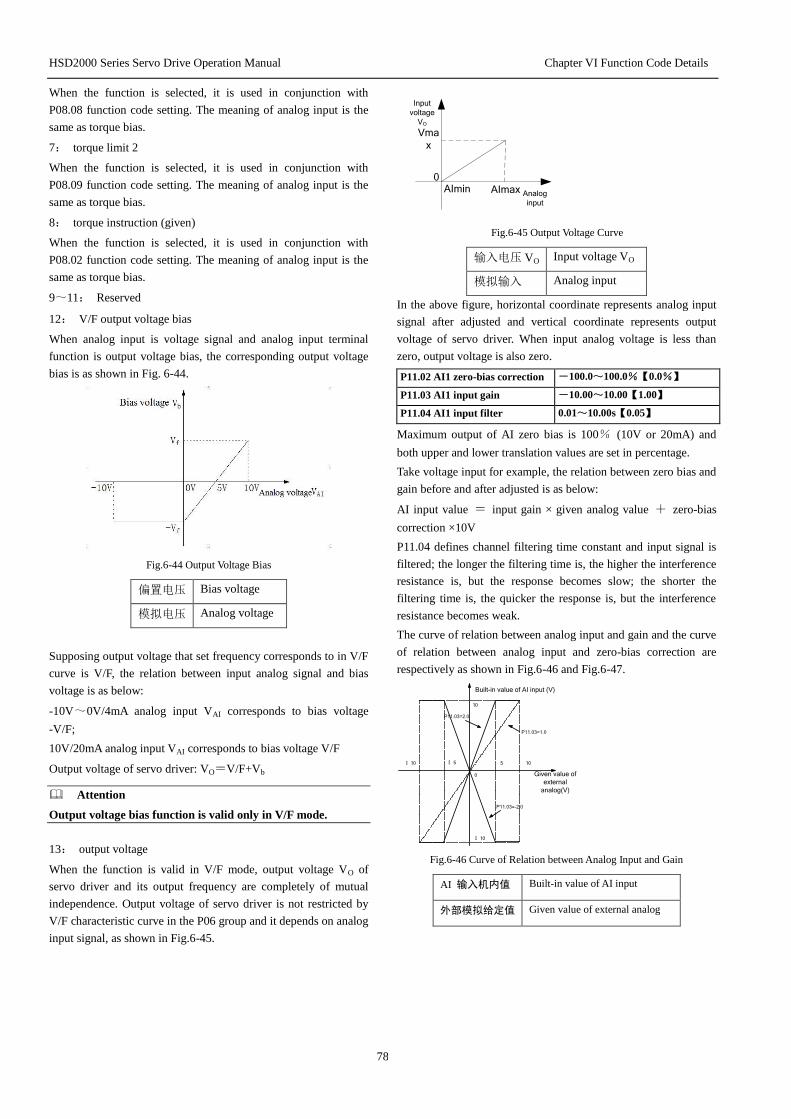
HSD2000 Series Servo Drive Operation Manual Chapter VI Function Code Details
78
When the function is selected, it is used in conjunction with
P08.08 function code setting. The meaning of analog input is the
same as torque bias.
7: torque limit 2
When the function is selected, it is used in conjunction with
P08.09 function code setting. The meaning of analog input is the
same as torque bias.
8: torque instruction (given)
When the function is selected, it is used in conjunction with
P08.02 function code setting. The meaning of analog input is the
same as torque bias.
9~11: Reserved
12: V/F output voltage bias
When analog input is voltage signal and analog input terminal
function is output voltage bias, the corresponding output voltage
bias is as shown in Fig. 6-44.
Fig.6-44 Output Voltage Bias
偏置电压 Bias voltage
模拟电压 Analog voltage
Supposing output voltage that set frequency corresponds to in V/F
curve is V/F, the relation between input analog signal and bias
voltage is as below:
-10V~0V/4mA analog input VAI corresponds to bias voltage
-V/F;
10V/20mA analog input VAI corresponds to bias voltage V/F
Output voltage of servo driver: VO=V/F+Vb
Attention
Output voltage bias function is valid only in V/F mode.
13: output voltage
When the function is valid in V/F mode, output voltage VO of
servo driver and its output frequency are completely of mutual
independence. Output voltage of servo driver is not restricted by
V/F characteristic curve in the P06 group and it depends on analog
input signal, as shown in Fig.6-45.
0
Vma
x
AImax Analog
input
AImin
Input
voltage
VO
Fig.6-45 Output Voltage Curve
输入电压 VO Input voltage VO
模拟输入 Analog input
In the above figure, horizontal coordinate represents analog input
signal after adjusted and vertical coordinate represents output
voltage of servo driver. When input analog voltage is less than
zero, output voltage is also zero.
P11.02 AI1 zero-bias correction -100.0~100.0%【0.0%】
P11.03 AI1 input gain -10.00~10.00【1.00】
P11.04 AI1 input filter 0.01~10.00s【0.05】
Maximum output of AI zero bias is 100% (10V or 20mA) and
both upper and lower translation values are set in percentage.
Take voltage input for example, the relation between zero bias and
gain before and after adjusted is as below:
AI input value = input gain × given analog value + zero-bias
correction ×10V
P11.04 defines channel filtering time constant and input signal is
filtered; the longer the filtering time is, the higher the interference
resistance is, but the response becomes slow; the shorter the
filtering time is, the quicker the response is, but the interference
resistance becomes weak.
The curve of relation between analog input and gain and the curve
of relation between analog input and zero-bias correction are
respectively as shown in Fig.6-46 and Fig.6-47.
P11.03=1.0
P11.03=2.0
Given value of
external
analog(V)
Built-in value of AI input (V)
10: 10
10
: 10
5: 5
0
P11.03=-2.0
Fig.6-46 Curve of Relation between Analog Input and Gain
AI 输入机内值 Built-in value of AI input
外部模拟给定值 Given value of external analog

HSD2000 Series Servo Drive Operation Manual Chapter VI Function Code Details
79
P11.02=50.0
%
Given value of
external analog(V)
Built-in value of AI input (V)
10: 10
10
: 10
5: 5
0
P11.02=-
50.0%
P11.02=0
Fig.6-47 Curve of Relation between Analog Input and Zero Bias
AI 输入机内值 Built-in value of AI input
外部模拟给定值 Given value of external analog
P11.05 AI1 zero-bias correction
mode 0~3【0】
0: zero bias-centered
1: below zero bias is equal to zero bias
2: above zero bias is equal to zero bias
3: zero bias-centered absolute value
The meanings of the four values are respectively shown as Fig.
6-48, Fig. 6-49, Fig.6-50 and Fig.6-51.
Given value of
external
analog(V)
10: 10
10
: 10
0
P11.02=: 50.0:
Built-in value of AI input (V)
Fig.6-48 Zero Bias-Centered Correction Mode
AI 输入机内值 Built-in value of AI input
外部模拟给定值 Given value of external analog
Given value of
external
analog(V)
10: 10
10
: 10
0
P11.02=: 50.0:
Built-in value of AI input (V)
Fig.6-49 Below Zero Bias Is Equal To Zero Bias Correction Mode
AI 输入机内值 Built-in value of AI input
外部模拟给定值 Given value of external analog
Given value of
external analog : V:
Built-in value of AI input : V:
10: 10
10
: 10
0
P11.02=50.0:
Fig.6-50 Above Zero Bias Is Equal To Zero Bias Correction Mode
AI 输入机内值 Built-in value of AI input
外部模拟给定值 Given value of external analog
Given value of
external analog : V:
Built-in value of AI input : V:
10: 10
10
: 10
0
P11.02=: 50.0:
Fig.6-51 Zero Bias-Centered Absolute Value Correction Mode
AI 输入机内值 Built-in value of AI input
外部模拟给定值 Given value of external analog
Attention
Input gain and zero-bias correction function codes have a
real-time influence on analog input in the modification
process.
P11.06 AI2 terminal input
function option 0~11【00】
P11.07 AI2 zero-bias
correction -100.0~100.0%【0.0%】
P11.08 AI2 input gain -10.00~10.00【1.00】
P11.09 AI2 input filter 0.01~10.00s【0.05】
P11.10 AI2 zero-bias
correction mode 0~3【0】
P11.11 AI3 terminal input
function option 0~11【00】
P11.12 AI3 zero-bias
correction -100.0~100.0%【0.0%】
P11.13 AI3 input gain -10.00~10.00【1.00】
P11.14 AI3 input filter 0.01~10.00s【0.05】
P11.15 AI3 zero-bias
correction mode 0~3【0】
Function setting of analog input of AI2 terminal and its meaning
are identical with AI1. Function setting and meaning of AI3
terminal as differential voltage input are identical with AI1 as
voltage input.
P11.16 Analog output type option 00~33【00】

HSD2000 Series Servo Drive Operation Manual Chapter VI Function Code Details
80
AO1output type option
1 : 0 : 20mA
0 : 0 : 10V
3 : 4 : 20mA
2 : 2 : 10V
AO2output type option
1 : 0 : 20mA
0 : 0 : 10V
3 : 4 : 20mA
2 : 2 : 10V
Tens
place
Ones
place
Fig.6-52 Analog Output Type Option
十位 Tens place
个位 Ones place
AO1 输出类型选择 AO1 output type option
AO2 输出类型选择 AO2 output type option
The function code is used to select the analog output range of
AO1 and AO2.
P11.17 Output function option of
AO1 terminal 0~25【0】
For output characteristics of AO1 and AO2, see 4.2 control circuit
wiring and configuration; analog output range is determined by
the function code P11.16.
The linear correspondence relation between AO1 output and
indication range is as shown in table 6-14.
Table 6-14 Indication of Analog Output Terminal
Cont
ent Corresponding function Indication range
0 Output frequency 0~maximum output frequency
1 Set frequency 0~maximum output frequency
2 Set frequency (after
acceleration/deceleration) 0~maximum output frequency
3 Motor speed 0~maximum speed
4 Output current 0~2×rated current of servo driver
5 Output current 0~2×rated current of motor
6 Output torque 0~3×rated torque of motor
7 Output torque current 0~3×rated torque of motor
8 Output voltage 0~1.2×rated voltage of servo
driver
9 Bus voltage 0~800V
10 AI1 0~maximum analog input
11 AI2 0~maximum analog input
12 AI3 0~10V
13 Output power 0~2×rated power of motor
14 Extended function 2 of upper
computer 0~4095
15 Torque limit 1 0~300%rated torque of motor
16 Torque limit 2 0~300%rated torque of motor
17 Torque bias 0~300%rated torque of motor
18 Torque instruction 0~300%rated torque of motor
19 Magnetic flux instruction 0~100%rated magnetic flux of
motor
20 Position deviation 0~2048
21 Output torque (bipolarity) -300~300%rated torque of
Cont
ent Corresponding function Indication range
motor
22 Output torque current
(bipolarity)
-300~300%rated torque of
motor
23 Torque bias (bipolarity) -300~300%rated torque of
motor
24 Motor speed (bipolarity)
Negative maximum output
frequency ~maximum output
frequency
25 Reserved Reserved
For extended function 2 of upper computer, output of AO1 and
AO2 is directly controlled by serial port. 4095 corresponds to
maximum output 10V (20mA), refer to HSD2000 communication
protocol.
For example,
AO1 output 4~20mA corresponds to indicating bus voltage 0~
800V.
Setting is as below:
①P11.17=8, output bus voltage;
②P11.16=03, AO1 output type is 4~20mA;
③P11.19=100%, output gain is 100%
④P11.20=0, zero-bias correction is 0.
Attention
1. When the corresponding function of AO output is
unipolarity (P11.17 = 0 ~ 20), absolute value of the
corresponding indication of minimum output is minimal and
absolute value of the corresponding indication of maximum
output is maximal; when the corresponding function is
bipolarity (P11.17=21~24), the corresponding indication of
minimum output is minimal and the corresponding indication
of maximum output is maximal.
2. When AO output is current, it is suggested that external
equivalent resistance should not exceed 400Ω.
P11.18 AO1 output filter 0.0~20.0s【0.1】
P11.19 AO1 output gain 0.0~200.0%【100.0%】
P11.20 AO1 zero-bias correction -100.0~100.0%【0.0%】
AO1 output filter is used to set the time constant of AO1 analog
output filter. The longer the filtering time is, the slower the analog
output response is; on the contrary, the response is quicker
For AO1 and AO2 analog outputs, if users need to change the
indication range or correct the error of gauge outfit, it can be
realized by adjusting output gain.
Maximum output of AO zero bias is 100% (10V or 20mA) and
both upper and lower translation values are set in percentage. Take
output voltage for example, the relation before and after adjusted
is as below:
AO output value = output gain × the value before adjusted +
zero-bias correction ×10V

HSD2000 Series Servo Drive Operation Manual Chapter VI Function Code Details
81
The curve of relation between analog output and gain and the
curve of relation between analog output and zero-bias correction
are respectively as shown in Fig.6-53 and Fig.6-54.
P11.19=200
%
The values
before
adjusted
: V:
The values after
adjusted : V:
10: 10
10
: 10
5: 5
0
P11.19=100
%
Fig.6-53 Curve of Relation between Analog Output and Gain
调整后的值 The values after adjusted
调整前的值 The values before adjusted
The values
before adjusted : V:
: V:
10: 10
10
: 10
5
5
P11.20=0
0
P11.20=50
%
The values after adjusted
Fig.6-54 Curve of Relation between Analog Output and Zero Bias
调整后的值 The values after adjusted
调整前的值 The values before adjusted
Attention
Output gain and zero-bias correction function codes have a
real-time influence on analog output in the modification
process.
P11.21 AO2 terminal output
function option 0~25【0】
P11.22 AO2 output filter 0.0~20.0s【0.1】
P11.23 AO2 output gain 0.0~200.0%【100.0%】
P11.24 AO2 zero-bias correction -100.0~100.0%【0.0%】
Function setting of analog output of AO2 terminal and its meaning
are identical with AO1.
P11.25 Curve option 0000~1111【0000】
P11.26 Maximum given on curve 1 P11.26~100.0%【100.0%】
P11.27 Actual value corresponding to
maximum given on curve 1 0.0%~300.0%【100.0%】
P11.28 Inflection point 2 given on curve
1 P11.32~P11.28【100.0%】
P11.29 Actual value corresponding to
inflection point 2 given on curve 1 0.0%~300.0%【100.0%】
P11.30 Inflection point 1 given on curve
1 P11.26~P11.30【0.0%】
P11.31 Actual value corresponding to 0.0%~300.0%【0.0%】
inflection point 1 given on curve 1
P11.32 Minimum given on curve 1 0.0%~P11.28【0.0%】
P11.33 Actual value corresponding to
minimum given on curve 1 0.0%~300.0%【0.0%】
P11.34 Maximum given on curve 2 P11.34~100.0%【100.0%】
P11.35 Actual value corresponding to
maximum given on curve 2 0.0%~300.0%【100.0%】
P11.36 Inflection point 2 given on curve
2 P11.40~P11.36【100.0%】
P11.37 Actual value corresponding to
inflection point 2 given on curve 2 0.0%~300.0%【100.0%】
P11.38 Inflection point 1 given on curve
2 P11.34~P11.38【0.0%】
P11.39 Actual value corresponding to
inflection point 1 given on curve 2 0.0%~300.0%【0.0%】
P11.40 Minimum given on curve 2 0.0%~P03. 11【0.0%】
P11.41 Actual value corresponding to
minimum given on curve 2 0.0%~300.0%【0.0%】
Analog input AI1~AI3 and pulse input can be given as different
channels; for function selection of analog input channel, see the
setting of function codes in the P11 group; for function selection
of pulse input, see the setting of input function of terminal X8. for
example, when AI1, AI2, AI3 or pulse frequency (PULSE) input is
selected as frequency given channel, the relation between given
frequency and set frequency is as shown in Fig.6-55 (AI1 is
selected as main frequency given channel).
Channel filter
P11.04
Channel gain and zero
bias
P11.03: P11.02
Selection of
curve 1 or 2
P11.25
P02.03
Selection of analog
input channel
P11.01
Set
frequenc
y
Selection of frequency
given channel
Fig.6-55 Relation between Given Channel Input and Set Frequency
通道滤波 Channel filter
通道增益和零偏 Channel gain and zero bias
曲线 1 或 2 选择 Selection of curve 1 or 2
设定频率 Set frequency
频率给定通道选择 Selection of frequency given channel
模拟输入通道选择 Selection of analog input channel
The relation between set frequency and given analog signal after
filter, gain and zero bias processing is determined by curve 1 or
curve 2. Curve 1 is defined by P11.26~P11.33 and curve 2 is
defined by P11.34~P11.41. Take set frequency for example, both
can independently realize positive action characteristic and
reverse action characteristic, as shown in Fig. 6-56.
Fig. 6-56 shows the correspondence relation of inflection point
setting on the curve determined by maximum and minimum given
points. If an inflection point is set additionally, the flexible
correspondence relation can be realized; for details, see the
example analysis hereinafter.
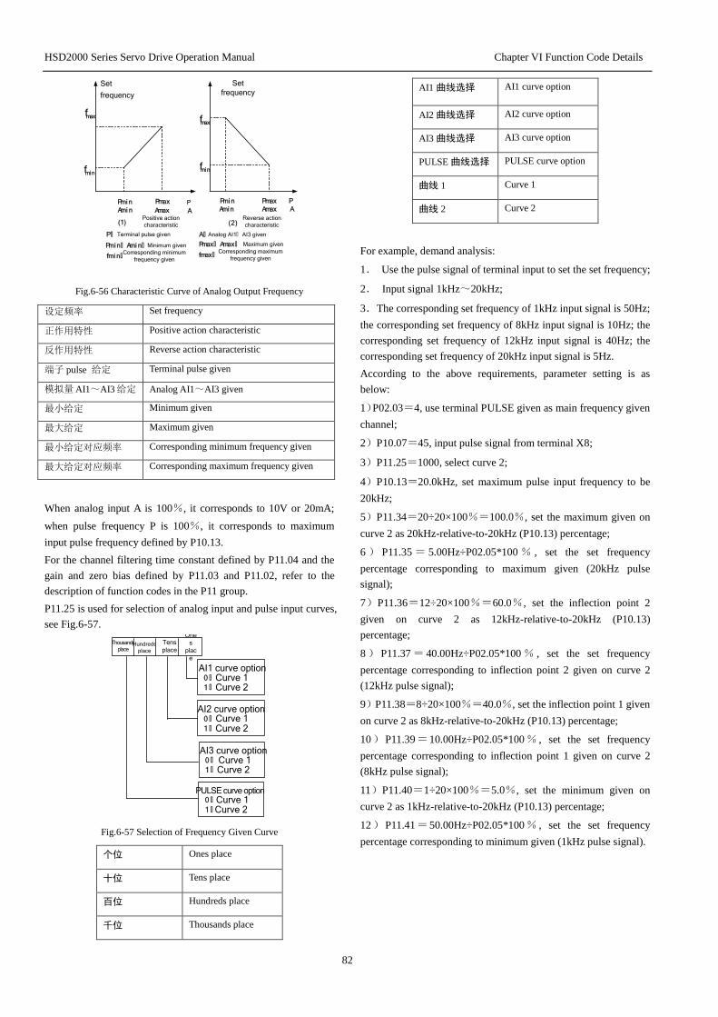
HSD2000 Series Servo Drive Operation Manual Chapter VI Function Code Details
82
P
f m a x
f m i n
P m i n A m i n A m a x ( 1 ) ( 2 )
P m a x P m i n A m i n
P m a x A m a x
P A A
f m i n
f m a x
P : Terminal pulse given P m i n : A m i n : Minimum given P m a x : A m a x : Maximum given f m i n : Corresponding minimum
frequency given f m a x : Corresponding maximum
frequency given
A : Analog AI1: AI3 given
Set
frequency
Positive action
characteristic Reverse action
characteristic
Set
frequency
Fig.6-56 Characteristic Curve of Analog Output Frequency
设定频率 Set frequency
正作用特性 Positive action characteristic
反作用特性 Reverse action characteristic
端子 pulse 给定 Terminal pulse given
模拟量 AI1~AI3 给定 Analog AI1~AI3 given
最小给定 Minimum given
最大给定 Maximum given
最小给定对应频率 Corresponding minimum frequency given
最大给定对应频率 Corresponding maximum frequency given
When analog input A is 100%, it corresponds to 10V or 20mA;
when pulse frequency P is 100%, it corresponds to maximum
input pulse frequency defined by P10.13.
For the channel filtering time constant defined by P11.04 and the
gain and zero bias defined by P11.03 and P11.02, refer to the
description of function codes in the P11 group.
P11.25 is used for selection of analog input and pulse input curves,
see Fig.6-57.
AI1 curve option
0 : Curve 1
1 : Curve 2
AI2 curve option
0 : Curve 1
1 : Curve 2
AI3 curve option
0 : Curve 1
1 : Curve 2
PULSE curve option
0 : Curve 1
1 : Curve 2
Thousands
place Hundreds
place
Tens
place
One
s
plac
e
Fig.6-57 Selection of Frequency Given Curve
个位 Ones place
十位 Tens place
百位 Hundreds place
千位 Thousands place
AI1 曲线选择 AI1 curve option
AI2 曲线选择 AI2 curve option
AI3 曲线选择 AI3 curve option
PULSE 曲线选择 PULSE curve option
曲线 1 Curve 1
曲线 2 Curve 2
For example, demand analysis:
1. Use the pulse signal of terminal input to set the set frequency;
2. Input signal 1kHz~20kHz;
3. The corresponding set frequency of 1kHz input signal is 50Hz;
the corresponding set frequency of 8kHz input signal is 10Hz; the
corresponding set frequency of 12kHz input signal is 40Hz; the
corresponding set frequency of 20kHz input signal is 5Hz.
According to the above requirements, parameter setting is as
below:
1)P02.03=4, use terminal PULSE given as main frequency given
channel;
2)P10.07=45, input pulse signal from terminal X8;
3)P11.25=1000, select curve 2;
4)P10.13=20.0kHz, set maximum pulse input frequency to be
20kHz;
5)P11.34=20÷20×100%=100.0%, set the maximum given on
curve 2 as 20kHz-relative-to-20kHz (P10.13) percentage;
6 ) P11.35 = 5.00Hz÷P02.05*100 % , set the set frequency
percentage corresponding to maximum given (20kHz pulse
signal);
7)P11.36=12÷20×100%=60.0%, set the inflection point 2
given on curve 2 as 12kHz-relative-to-20kHz (P10.13)
percentage;
8 ) P11.37 = 40.00Hz÷P02.05*100 % , set the set frequency
percentage corresponding to inflection point 2 given on curve 2
(12kHz pulse signal);
9)P11.38=8÷20×100%=40.0%, set the inflection point 1 given
on curve 2 as 8kHz-relative-to-20kHz (P10.13) percentage;
10)P11.39=10.00Hz÷P02.05*100% , set the set frequency
percentage corresponding to inflection point 1 given on curve 2
(8kHz pulse signal);
11)P11.40=1÷20×100%=5.0%, set the minimum given on
curve 2 as 1kHz-relative-to-20kHz (P10.13) percentage;
12)P11.41=50.00Hz÷P02.05*100% , set the set frequency
percentage corresponding to minimum given (1kHz pulse signal).
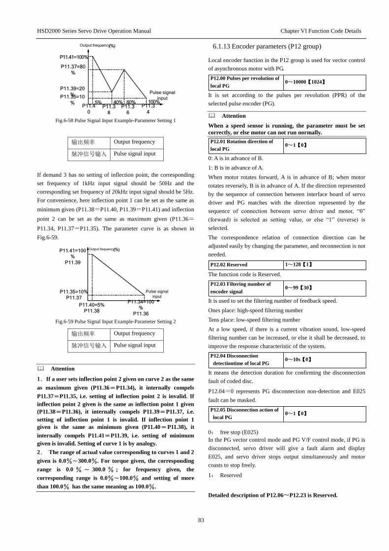
HSD2000 Series Servo Drive Operation Manual Chapter VI Function Code Details
83
Pulse signal
input
Output frequency (%)
P11.41=100%
5% 40% 60% 100%
P11.37=80
%
P11.39=20
%P11.35=10
%P11.4
0P11.3
8
P11.3
6
P11.3
4
Fig.6-58 Pulse Signal Input Example-Parameter Setting 1
输出频率 Output frequency
脉冲信号输入 Pulse signal input
If demand 3 has no setting of inflection point, the corresponding
set frequency of 1kHz input signal should be 50Hz and the
corresponding set frequency of 20kHz input signal should be 5Hz.
For convenience, here inflection point 1 can be set as the same as
minimum given (P11.38=P11.40, P11.39=P11.41) and inflection
point 2 can be set as the same as maximum given (P11.36=
P11.34, P11.37=P11.35). The parameter curve is as shown in
Fig.6-59.
Pulse signal
input
Output frequency (%)P11.41=100
%
P11.39
P11.35=10%
P11.37
P11.40=5%
P11.38
P11.34=100
%
P11.36
Fig.6-59 Pulse Signal Input Example-Parameter Setting 2
输出频率 Output frequency
脉冲信号输入 Pulse signal input
Attention
1. If a user sets inflection point 2 given on curve 2 as the same
as maximum given (P11.36=P11.34), it internally compels
P11.37=P11.35, i.e. setting of inflection point 2 is invalid. If
inflection point 2 given is the same as inflection point 1 given
(P11.38=P11.36), it internally compels P11.39=P11.37, i.e.
setting of inflection point 1 is invalid. If inflection point 1
given is the same as minimum given (P11.40=P11.38), it
internally compels P11.41=P11.39, i.e. setting of minimum
given is invalid. Setting of curve 1 is by analogy.
2. The range of actual value corresponding to curves 1 and 2
given is 0.0%~300.0%. For torque given, the corresponding
range is 0.0 % ~ 300.0 % ; for frequency given, the
corresponding range is 0.0%~100.0% and setting of more
than 100.0% has the same meaning as 100.0%.
6.1.13 Encoder parameters (P12 group)
Local encoder function in the P12 group is used for vector control
of asynchronous motor with PG.
P12.00 Pulses per revolution of
local PG 0~10000【1024】
It is set according to the pulses per revolution (PPR) of the
selected pulse encoder (PG).
Attention
When a speed sensor is running, the parameter must be set
correctly, or else motor can not run normally.
P12.01 Rotation direction of
local PG 0~1【0】
0: A is in advance of B.
1: B is in advance of A.
When motor rotates forward, A is in advance of B; when motor
rotates reversely, B is in advance of A. If the direction represented
by the sequence of connection between interface board of servo
driver and PG matches with the direction represented by the
sequence of connection between servo driver and motor, “0”
(forward) is selected as setting value, or else “1” (reverse) is
selected.
The correspondence relation of connection direction can be
adjusted easily by changing the parameter, and reconnection is not
needed.
P12.02 Reserved 1~128【1】
The function code is Reserved.
P12.03 Filtering number of
encoder signal 0~99【30】
It is used to set the filtering number of feedback speed.
Ones place: high-speed filtering number
Tens place: low-speed filtering number
At a low speed, if there is a current vibration sound, low-speed
filtering number can be increased, or else it shall be decreased, to
improve the response characteristic of the system.
P12.04 Disconnection
detectiontime of local PG 0~10s【0】
It means the detection duration for confirming the disconnection
fault of coded disc.
P12.04=0 represents PG disconnection non-detection and E025
fault can be masked.
P12.05 Disconnection action of
local PG 0~1【0】
0: free stop (E025)
In the PG vector control mode and PG V/F control mode, if PG is
disconnected, servo driver will give a fault alarm and display
E025, and servo driver stops output simultaneously and motor
coasts to stop freely.
1: Reserved
Detailed description of P12.06~P12.23 is Reserved.
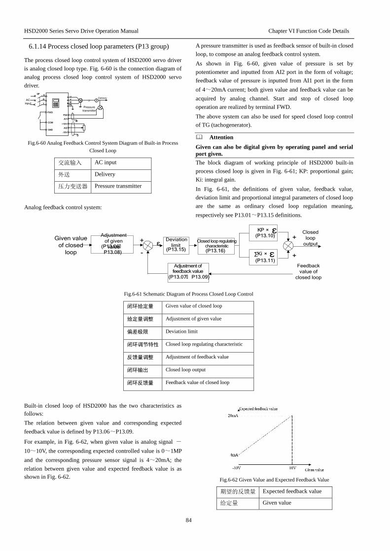
HSD2000 Series Servo Drive Operation Manual Chapter VI Function Code Details
84
6.1.14 Process closed loop parameters (P13 group)
The process closed loop control system of HSD2000 servo driver
is analog closed loop type. Fig. 6-60 is the connection diagram of
analog process closed loop control system of HSD2000 servo
driver.
U
V
W
PE
M AC
input
QF
GND
P24
+10V
..
.
AI1 .
R
S
T
FWD
COM
AI2
-10V ..
.
.
p
Pressure
transmitter
Delivery
Fig.6-60 Analog Feedback Control System Diagram of Built-in Process
Closed Loop
交流输入 AC input
外送 Delivery
压力变送器 Pressure transmitter
Analog feedback control system:
A pressure transmitter is used as feedback sensor of built-in closed
loop, to compose an analog feedback control system.
As shown in Fig. 6-60, given value of pressure is set by
potentiometer and inputted from AI2 port in the form of voltage;
feedback value of pressure is inputted from AI1 port in the form
of 4~20mA current; both given value and feedback value can be
acquired by analog channel. Start and stop of closed loop
operation are realized by terminal FWD.
The above system can also be used for speed closed loop control
of TG (tachogenerator).
Attention
Given can also be digital given by operating panel and serial
port given.
The block diagram of working principle of HSD2000 built-in
process closed loop is given in Fig. 6-61; KP: proportional gain;
Ki: integral gain.
In Fig. 6-61, the definitions of given value, feedback value,
deviation limit and proportional integral parameters of closed loop
are the same as ordinary closed loop regulation meaning,
respectively see P13.01~P13.15 definitions.
Given value
of closed
loop
Adjustment
of given
value ε
Deviation
limit +
-
Feedback
value of
closed loop
KP ×
Ki ×
Closed loop regulating characteristic
ε
ε∑
+
+
Closed
loop
output
Adjustment of feedback value
(P13.06:
P13.08)(P13.15) (P13.16)
(P13.10)
(P13.11)
(P13.07: P13.09)
Fig.6-61 Schematic Diagram of Process Closed Loop Control
闭环给定量 Given value of closed loop
给定量调整 Adjustment of given value
偏差极限 Deviation limit
闭环调节特性 Closed loop regulating characteristic
反馈量调整 Adjustment of feedback value
闭环输出 Closed loop output
闭环反馈量 Feedback value of closed loop
Built-in closed loop of HSD2000 has the two characteristics as
follows:
The relation between given value and corresponding expected
feedback value is defined by P13.06~P13.09.
For example, in Fig. 6-62, when given value is analog signal -
10~10V, the corresponding expected controlled value is 0~1MP
and the corresponding pressure sensor signal is 4~20mA; the
relation between given value and expected feedback value is as
shown in Fig. 6-62.
Fig.6-62 Given Value and Expected Feedback Value
期望的反馈量 Expected feedback value
给定量 Given value

HSD2000 Series Servo Drive Operation Manual Chapter VI Function Code Details
85
Determination of given value is based on 10V; determination of
feedback value is based on 20mA
That is to say,
The meaning of adjustment of given value and feedback value in
Fig. 6-61 is that given value and feedback value adopt internal
unified value.
The closed loop characteristics are selected by P13.16, to satisfy
different applications.
In order to meet the control requirement in the actual control
system, when given value increases, motor speed needs to be
increased, and such closed loop characteristic is positive action
characteristic; on the contrary, when given value increases, motor
speed needs to be decreased, and such closed loop characteristic is
reverse position characteristic.
As shown in Fig. 6-63, definition of P13.16 is for meeting the
requirements of two closed loop characteristics.
Fig. 6-63 Closed Loop Regulating Characteristic Diagram
转速 Speed
正作用 Positive action
反作用 Reverse action
闭环给定 Closed loop given
After determination of the system, basic steps of closed loop
parameter setting are as below:
1)Determine the closed loop given and feedback channel
(P13.01、P13.02);
2)For analog closed loop, set the relation between closed loop
given and feedback (P13.06~P13.09);
3)Determine the closed loop regulating characteristic; if the
relation between given and required motor speed is reverse, set the
closed loop characteristic regulation as reverse action (P13.16=
1);
4)Set the integral regulation option and closed loop preset
frequency function (P13.17~P13.19);
5)Adjust the closed loop filtering time, sampling period, deviation
limit and gain coefficient (P13.10~P13.15).
P13.00 Closed loop run control
option 0, 1【0】
0: closed loop run control is invalid.
1: closed loop run control is valid.
P13.01Given channel option 0, 1, 2, 3【1】
0: digital given
Based on the value in P13.05
1: AI1 analog given
2: AI2 analog given
3: AI3 analog voltage given
Analog given input -10~10V (P11.00 digit option 0), 4~20mA
(P11.00 digit option 1).
Attention
Input of analog given AI1 and AI2 can be current or voltage
input by the function code P11.00 (digit option); AI3 as
differential input can only be voltage input.
P13.02 Feedback channel option 0~5【1】
0: AI1 analog given
1: AI2 analog given
2:AI1+ AI2
3:AI1-AI2
4:Min{ AI1,AI2}
5:Max{ AI1,AI2}
AI input type option is the same as above.
P13.03 Given channel filtering 0.01~50.00s【0.50s】
P13.04 Feedback channel
filtering 0.01~50.00s【0.50s】
External given signals and feedback signals often have a certain
interference superposition and channels are filtered by setting the
filtering time constant in P13.03 and P13.04; the longer the
filtering time is, the higher the interference resistance, but the
response becomes slow; the shorter the filtering time is, the
quicker the response is, but the interference resistance becomes
weak.
P13.05 Digital setting of given
value -10.00~10.00V【0.00】
The function is used for digital setting of given value by operating
panel or serial port.
P13.06 Minimum given value 0.0%~P13.08【0.0%】
P13.07 Feedback value
corresponding to minimum given
value
0.0~100.0%【0.0%】
P13.08 Maximum given value P13.06~100.0%【100.0%】
P13.09 Feedback value
corresponding to maximum given
value
0.0~100.0%【100.0%】
The relation of given value adjustment in P13.06 and P13.08 in
Fig. 6-61 is as shown in Fig. 6-64. When analog input is 6V, if
P13.06=0% and P13.08=100%, the converted value after
adjustment is 60%; if P13.06=25% and P13.08=100%, the
converted value after adjustment is 46.6%.

HSD2000 Series Servo Drive Operation Manual Chapter VI Function Code Details
86
-100%
100%
Analog
input value
The values after
adjusted
0% 100%
50%25%
P13.06=25%
P13.08=100%
P13.06=0%
P13.08=100%
80%
(6V)
60%
46.6%
Fig.6-64 Given Value Adjustment Curve Diagram
调整后的量 The values after adjusted
模拟输入量 Analog input value
Attention
1. As shown in Fig. 6-64, scaling analog input of horizontal
axis 0%~ 100% is - 10V~ 10V; analog input 10V
corresponds to 100% and -10V corresponds to 0%, and 6V
corresponds to 80%.
2. If it is analog current input, the range of current input is
4~20mA, so the range of scaling on the horizontal axis is
50%~100%.
3. The values after adjusted can be observed by the function
code P01.28.
As shown in Fig. 6-61, the relation curve of feedback value
adjustment in P13.07 and P13.09 is relative to the adjustment of
given value. The values after adjusted can be observed by the
function code P01.29.
P13.10 Proportional gain KP 0.000~10.000【2.000】
P13.11 Integral gain Ki 0.000~10.000【0.100】
P13.12 Reserved
P13.13 Sampling period T 0.01~50.00s【0.50s】
The greater the proportional gain KP is, the quicker the response
is, but if KP is excessively great, it may cause oscillation easily.
The deviation can not be eliminated completely only by
proportional gain KP adjustment. In order to eliminate residual
deviation, integral gain Ki can be adopted to compose the closed
loop control. The greater the Ki is, the quicker the response to
varying deviation is, but if Ki is excessively great, it may cause
oscillation easily.
Sampling period T is the sampling period of feedback value and
the closed loop regulator operates once within a sampling period.
The greater the sampling period is, the slower the response is.
P13.14 Output filtering time 0.01~10.00【0.05】
Output filtering time is the filtering time of closed loop output
(frequency or torque). The greater the output filtering time is, the
slower the output response is.
P13.15 Deviation limit 0.0~20%【2.0%】
System output value is relative to maximum deviation permitted
by given value of closed loop; as shown in Fig. 6-65, when
feedback value is within the range, closed loop regulator will stop
regulation. Appropriate setting of the function is helpful to give
consideration to both accuracy and stability of system output.
Fig.6-65 Deviation Limit Diagram
P13.16 Closed loop regulating
characteristic 0, 1【0】
0: positive action
When given value increases, it is used if requiring increasing
motor speed.
1: reverse action
When given value increases, it is used if requiring decreasing
motor speed.
P13.17 Integral regulation
option 0, 1【0】
0: when the frequency reaches the upper and lower limits, stop
integral regulation;
1: when the frequency reaches the upper and lower limits,
continue integral regulation.
For the system that requires quick response, it is suggested that
continuing integral regulation should be cancelled.
P13.18 Closed loop preset
frequency 0.00~1000.0Hz【0.00Hz】
P13.19 Holding time of closed
loop preset frequency 0.0~3600.0s【0.0s】
The function code can make closed loop regulation quickly enter
into steady stage.
After closed loop run starts, the frequency first increases to the
closed loop preset frequency P13.18 according to the acceleration
time, then it runs for a period of time P13.19 on the frequency
point, and finally runs according to the closed loop characteristic.

HSD2000 Series Servo Drive Operation Manual Chapter VI Function Code Details
87
Fig.6-66 Run Diagram of Closed Loop Preset Frequency
输出频率 Output frequency
预置频率 Preset frequency
预置频率保持时间 Holding time of preset frequency
时间 Time
Attention
If the closed loop preset frequency function is not needed,
preset frequency and holding time should be set as 0.
P13.20 Multi-phase closed
loop given 1 -10.00~10.00V【0.00V】
P13.21 Multi-phase closed
loop given 2 -10.00~10.00V【0.00V】
P13.22 Multi-phase closed
loop given 3 -10.00~10.00V【0.00V】
P13.23 Multi-phase closed
loop given 4 -10.00~10.00V【0.00V】
P13.24 Multi-phase closed
loop given 5 -10.00~10.00V【0.00V】
P13.25 Multi-phase closed
loop given 6 -10.00~10.00V【0.00V】
P13.26 Multi-phase closed
loop given 7 -10.00~10.00V【0.00V】
P13.27 Multi-phase closed
loop given 8 -10.00~10.00V【0.00V】
P13.28 Multi-phase closed
loop given 9 -10.00~10.00V【0.00V】
P13.29 Multi-phase closed
loop given 10 -10.00~10.00V【0.00V】
P13.30 Multi-phase closed
loop given 11 -10.00~10.00V【0.00V】
P13.31 Multi-phase closed
loop given 12 -10.00~10.00V【0.00V】
P13.32 Multi-phase closed
loop given 13 -10.00~10.00V【0.00V】
P13.33 Multi-phase closed
loop given 14 -10.00~10.00V【0.00V】
P13.34 Multi-phase closed
loop given 15 -10.00~10.00V【0.00V】
Among the closed loop given channels except the three kinds of
channels defined by P13.01, the voltage value of multi-phase
closed loop given defined by P13.20~P13.34 can also be used as
closed loop given.
Voltage options of multi-phase closed loop given 1~15 can be
switched flexibly by external terminals, see P10.00~P10.07
terminal functions 30~33. it can also be used in conjunction with
simple PLC closed loop section, see the description of function
codes in the P11 group.
The priority level of multi-phase closed loop given control is
higher than the given channel defined in P13.01.
P13.35 Closed loop output
reversion option 0, 1【0】
0: closed loop output is negative and servo driver runs at zero
frequency.
1: closed loop output is negative and servo driver runs reversely,
but if anti-reversion option disables reverse running, servo driver
runs at zero frequency, see the description of P05.12 function code.

HSD2000 Series Servo Drive Operation Manual Chapter VI Function Code Details
88
P13.36 Closed loop feedback loss
action option 0, 1, 2【0】
0: closed loop feedback loss detection is not available;
1: closed loop feedback loss detection is available; when
detected, continue running and display the alarm A021;
2: closed loop feedback loss detection is available; when
detected, stop freely and display the fault E021;
When displaying an alarm to continue running, running frequency
is described as P20.04 function code.
P13.37 Detection value of closed
loop feedback loss 0.0~100.0%【50.0%】
P13.38 Detection time of closed
loop feedback loss 0.0~20.0s【1.0s】
Detection value of closed loop feedback loss is 100 % as
reference value; within the detection time, if closed loop feedback
value is lower than detection value, servo driver will operate
according to setting of P13.36 function code. The time sequence
diagram of closed loop feedback loss detection is as shown in Fig.
6-67.
Fig.6-67 Time Sequence Diagram of Closed Loop Feedback Loss
Detection
闭环反馈值 Closed loop feedback value
检出值 Detection value
丢失不检出 Loss non-detection
丢失检出 Loss detection
时间 Time
6.1.15 Extended function code parameters (P14 group)
P14.00 Carrier frequency 2.0~15.0kHz【8kHz】
Table 6-15 Carrier Frequency of PWM Wave Outputted by Servo
Driver
Carrier frequency
Model
Maximum
carrier
frequency
(kHz)
Minimum
carrier
frequency
(kHz)
Factory
setting
(kHz)
1.5kW~15kW 15.0 2.0 8.0
18.5kW~45kW 10.0 2.0 4.0
55kW~75kW 6.0 2.0 3.0
Above 90kW 3.0 2.0 2.0
Attention
1. Carrier frequency will affect the running noise of motor
and it is usually set at 3~5kHz. In the place requiring silent
running, carrier frequency is usually set at 6~8kHz.
2. When running at above factory set carrier frequencies,
servo driver should be derated by 5% for use with an increase
of 1kHz.
3. In the vector control mode, P14.00 minimum carrier
frequency is 3kHz.
P14.01 PWM mode
optimization 000~111【001】
One
s
plac
e
PWM overmodulation
enable
0: Invalid
1: Valid
Automatic adjustment option of
PWM carrier frequency
0 :Non- automatic
adjustment
1 :Automatic
adjustment
PWM adjustment mode
0: Two-phase/three-phase switching
1 :Three-phase
modulation
Tens
place
Hundreds
place
Fig.6-68 PWM Mode Optimization Option
百位 Hundreds place
十位 Tens place
个位 Ones place
PWM 过调制使能 PWM overmodulation enable
无效 Invalid
有效 Valid
PWM 载波频率自动
调整选择
Automatic adjustment option of PWM carrier
frequency
不自动调整 Non- automatic adjustment
自动调整 Automatic adjustment
PWM 调整方式 PWM adjustment mode
两相/三相切换 Two-phase/three-phase switching
三相调制 Three-phase modulation
Ones place: overmodulation enable

HSD2000 Series Servo Drive Operation Manual Chapter VI Function Code Details
89
The function decides whether to enable V/F control
overmodulation function. Vector control overmodulation is
enabled all the time.
0: invalid
V/F control overmodulation function is disabled.
1: valid
V/F control overmodulation function is enabled.
Tens pace: automatic adjustment option of carrier frequency
0: non-operating
1: operating
When automatic adjustment option of carrier frequency is
“operating”, servo driver can automatically adjust the carrier
frequency according to internal temperature. Here actual
maximum run frequency of servo driver is restricted by the carrier
frequency set by function code (P14.00).
Hundreds place: modulation mode
0: two-phase/three-phase switching
1: three-phase modulation
P14.02 cooling fan control 0~1【1】
0: automatic run
Servo driver automatically starts internal temperature detection
program when it is running, to determine running and stop of fan
according to the module temperature. Before servo driver stops, if
the fan is running, the fan will continue running 3min when servo
driver stops, and then internal temperature detection program is
started.
1: power-on fan is always running
After servo driver is electrified, the fan is always running.
P14.03 ACR-P 1~5000【1000】
P14.04 ACR-I 0.5~100.0ms【8.0ms】
P14.03 and P14.04 are PI regulator parameters of electric current
loop. Increasing electric current loop KP or reducing I can
accelerate dynamic response of system torque; reducing KP or
increasing I can strengthen the stability of the system.
Attention
For most purposes, it is needless to adjust PI parameters of
electric current loop, so it is suggested that users should not
change this group of parameters at will.
P14.05 Reserved 0~65535【0】
P14.06 Main set frequency
control 00~11【00】
It is valid only in case of P02.00=0, 1, 2.
0 :Set frequency storage in
case of power down 1 :Set frequency non-storage
in case of power down
0:Frequency holding in case of
stop
1 :Frequency recovery P02.04 in
case of stop
Ones placeTens place
Fig.6-69 LED Setting of Digital Frequency Control
个位 Ones place
十位 Tens place
设定频率掉电存储 Set frequency storage in case of power down
设定频率掉电不存
储
Set frequency non-storage in case of power down
停机频率保持 Frequency holding in case of stop
停 机 频 率 恢 复
P02.04
Frequency recovery P02.04 in case of stop
Ones place:
0: set frequency storage in case of power down
When servo driver is power-down or under-voltage, P02.04 is
refreshed automatically according to the set value of current actual
frequency.
1: set frequency non-storage in case of power down
When servo driver is power-down or under-voltage, P02.04
remains unchanged.
Tens place:
0: set frequency holding in case of stop
When servo driver stops, set value of frequency is final modified
value.
1: set frequency recovery P02.04 in case of stop
When servo driver stops, set value of frequency is automatically
restored to P02.04.
P14.07 Auxiliary set frequency
control 00~11【00】
P14.07: digital auxiliary frequency control is valid only when
P02.08=1~3, as shown in Fig. 6-70.
Tens place Ones place
0:Auxiliary frequency storage in case of power down
1:Auxiliary frequency non-
storage in case of power down
0:Auxiliary frequency holding
after stop 1:Auxiliary frequency clearing
after stop
Fig.6-70 Setting of Digital Auxiliary Frequency Control
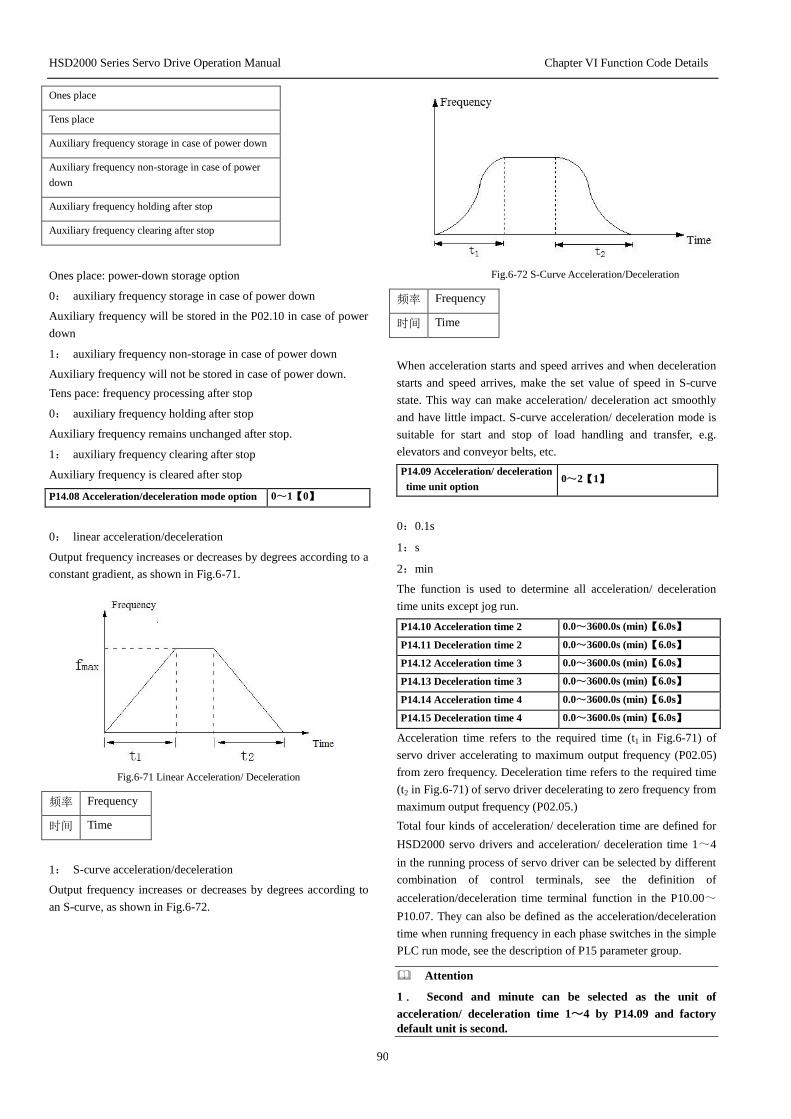
HSD2000 Series Servo Drive Operation Manual Chapter VI Function Code Details
90
Ones place
Tens place
Auxiliary frequency storage in case of power down
Auxiliary frequency non-storage in case of power
down
Auxiliary frequency holding after stop
Auxiliary frequency clearing after stop
Ones place: power-down storage option
0: auxiliary frequency storage in case of power down
Auxiliary frequency will be stored in the P02.10 in case of power
down
1: auxiliary frequency non-storage in case of power down
Auxiliary frequency will not be stored in case of power down.
Tens pace: frequency processing after stop
0: auxiliary frequency holding after stop
Auxiliary frequency remains unchanged after stop.
1: auxiliary frequency clearing after stop
Auxiliary frequency is cleared after stop
P14.08 Acceleration/deceleration mode option 0~1【0】
0: linear acceleration/deceleration
Output frequency increases or decreases by degrees according to a
constant gradient, as shown in Fig.6-71.
Fig.6-71 Linear Acceleration/ Deceleration
频率 Frequency
时间 Time
1: S-curve acceleration/deceleration
Output frequency increases or decreases by degrees according to
an S-curve, as shown in Fig.6-72.
Fig.6-72 S-Curve Acceleration/Deceleration
频率 Frequency
时间 Time
When acceleration starts and speed arrives and when deceleration
starts and speed arrives, make the set value of speed in S-curve
state. This way can make acceleration/ deceleration act smoothly
and have little impact. S-curve acceleration/ deceleration mode is
suitable for start and stop of load handling and transfer, e.g.
elevators and conveyor belts, etc.
P14.09 Acceleration/ deceleration
time unit option 0~2【1】
0:0.1s
1:s
2:min
The function is used to determine all acceleration/ deceleration
time units except jog run.
P14.10 Acceleration time 2 0.0~3600.0s (min)【6.0s】
P14.11 Deceleration time 2 0.0~3600.0s (min)【6.0s】
P14.12 Acceleration time 3 0.0~3600.0s (min)【6.0s】
P14.13 Deceleration time 3 0.0~3600.0s (min)【6.0s】
P14.14 Acceleration time 4 0.0~3600.0s (min)【6.0s】
P14.15 Deceleration time 4 0.0~3600.0s (min)【6.0s】
Acceleration time refers to the required time (t1 in Fig.6-71) of
servo driver accelerating to maximum output frequency (P02.05)
from zero frequency. Deceleration time refers to the required time
(t2 in Fig.6-71) of servo driver decelerating to zero frequency from
maximum output frequency (P02.05.)
Total four kinds of acceleration/ deceleration time are defined for
HSD2000 servo drivers and acceleration/ deceleration time 1~4
in the running process of servo driver can be selected by different
combination of control terminals, see the definition of
acceleration/deceleration time terminal function in the P10.00~
P10.07. They can also be defined as the acceleration/deceleration
time when running frequency in each phase switches in the simple
PLC run mode, see the description of P15 parameter group.
Attention
1. Second and minute can be selected as the unit of
acceleration/ deceleration time 1~4 by P14.09 and factory
default unit is second.
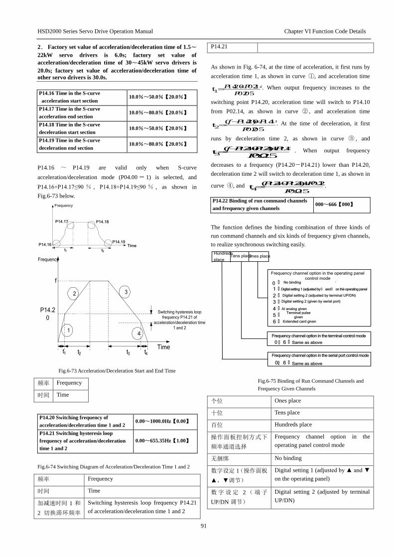
HSD2000 Series Servo Drive Operation Manual Chapter VI Function Code Details
91
2. Factory set value of acceleration/deceleration time of 1.5~
22kW servo drivers is 6.0s; factory set value of
acceleration/deceleration time of 30~45kW servo drivers is
20.0s; factory set value of acceleration/deceleration time of
other servo drivers is 30.0s.
P14.16 Time in the S-curve
acceleration start section 10.0%~50.0%【20.0%】
P14.17 Time in the S-curve
acceleration end section 10.0%~80.0%【20.0%】
P14.18 Time in the S-curve
deceleration start section 10.0%~50.0%【20.0%】
P14.19 Time in the S-curve
deceleration end section 10.0%~80.0%【20.0%】
P14.16 ~ P14.19 are valid only when S-curve
acceleration/deceleration mode (P04.00 = 1) is selected, and
P14.16+P14.17≤90 % , P14.18+P14.19≤90 % , as shown in
Fig.6-73 below.
P14.16 Time
Frequency
t1 t2
P14.17 P14.18
P14.19
Frequency
Time
P14.2
0Switching hysteresis loop
frequency P14.21 of
acceleration/deceleration time
1 and 2
1
2 3
4
t1 t2 t3 t4
f
Fig.6-73 Acceleration/Deceleration Start and End Time
频率 Frequency
时间 Time
P14.20 Switching frequency of
acceleration/deceleration time 1 and 2 0.00~1000.0Hz【0.00】
P14.21 Switching hysteresis loop
frequency of acceleration/deceleration
time 1 and 2
0.00~655.35Hz【1.00】
Fig.6-74 Switching Diagram of Acceleration/Deceleration Time 1 and 2
频率 Frequency
时间 Time
加减速时间 1 和
2 切换滞环频率
Switching hysteresis loop frequency P14.21
of acceleration/deceleration time 1 and 2
P14.21
As shown in Fig. 6-74, at the time of acceleration, it first runs by
acceleration time 1, as shown in curve ①, and acceleration time
05.02
14.0220.141t
P
PP . When output frequency increases to the
switching point P14.20, acceleration time will switch to P14.10
from P02.14, as shown in curve ② , and acceleration time
05.02
10.14)20.14(2t
P
PPf . At the time of deceleration, it first
runs by deceleration time 2, as shown in curve ③ , and
05.02t
11.14)21.1420.14(3 P
PPPf . When output frequency
decreases to a frequency (P14.20-P14.21) lower than P14.20,
deceleration time 2 will switch to deceleration time 1, as shown in
curve ④, and 05.02
15.02)21.1420.14(4t P
PPP .
P14.22 Binding of run command channels
and frequency given channels 000~666【000】
The function defines the binding combination of three kinds of
run command channels and six kinds of frequency given channels,
to realize synchronous switching easily.
Frequency channel option in the operating panel
control mode 0 : No binding 1 : Digital setting 1 (adjusted by : and : on the operating panel 2 : Digital setting 2 (adjusted by terminal UP/DN) 3 : Digital setting 2 (given by serial port) 4 : AI analog given 5 : Terminal pulse
given 6 : Extended card given
Frequency channel option in the terminal control mode 0 : 6 : Same as above
Frequency channel option in the serial port control mode 0 6 :
Ones place
:
Tens placeHundreds
place
Same as above
Fig.6-75 Binding of Run Command Channels and
Frequency Given Channels
个位 Ones place
十位 Tens place
百位 Hundreds place
操作面板控制方式下
频率通道选择
Frequency channel option in the
operating panel control mode
无捆绑 No binding
数字设定 1(操作面板
▲、▼调节)
Digital setting 1 (adjusted by ▲ and ▼
on the operating panel)
数字设定 2 (端子
UP/DN 调节)
Digital setting 2 (adjusted by terminal
UP/DN)
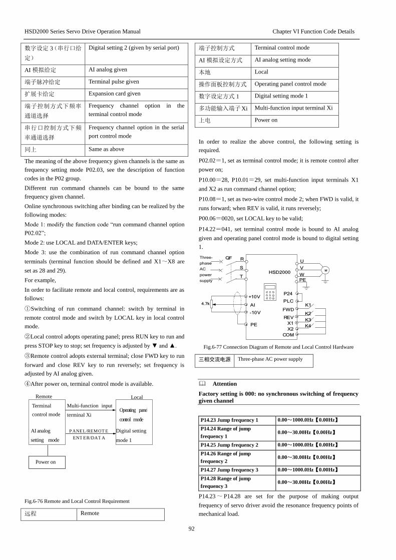
HSD2000 Series Servo Drive Operation Manual Chapter VI Function Code Details
92
数字设定 3(串行口给
定)
Digital setting 2 (given by serial port)
AI 模拟给定 AI analog given
端子脉冲给定 Terminal pulse given
扩展卡给定 Expansion card given
端子控制方式下频率
通道选择
Frequency channel option in the
terminal control mode
串行口控制方式下频
率通道选择
Frequency channel option in the serial
port control mode
同上 Same as above
The meaning of the above frequency given channels is the same as
frequency setting mode P02.03, see the description of function
codes in the P02 group.
Different run command channels can be bound to the same
frequency given channel.
Online synchronous switching after binding can be realized by the
following modes:
Mode 1: modify the function code “run command channel option
P02.02”;
Mode 2: use LOCAL and DATA/ENTER keys;
Mode 3: use the combination of run command channel option
terminals (terminal function should be defined and X1~X8 are
set as 28 and 29).
For example,
In order to facilitate remote and local control, requirements are as
follows:
①Switching of run command channel: switch by terminal in
remote control mode and switch by LOCAL key in local control
mode.
②Local control adopts operating panel; press RUN key to run and
press STOP key to stop; set frequency is adjusted by ▼ and ▲.
③Remote control adopts external terminal; close FWD key to run
forward and close REV key to run reversely; set frequency is
adjusted by AI analog given.
④After power on, terminal control mode is available.
Fig.6-76 Remote and Local Control Requirement
远程 Remote
端子控制方式 Terminal control mode
AI 模拟设定方式 AI analog setting mode
本地 Local
操作面板控制方式 Operating panel control mode
数字设定方式 1 Digital setting mode 1
多功能输入端子Xi Multi-function input terminal Xi
上电 Power on
In order to realize the above control, the following setting is
required.
P02.02=1, set as terminal control mode; it is remote control after
power on;
P10.00=28, P10.01=29, set multi-function input terminals X1
and X2 as run command channel option;
P10.08=1, set as two-wire control mode 2; when FWD is valid, it
runs forward; when REV is valid, it runs reversely;
P00.06=0020, set LOCAL key to be valid;
P14.22=041, set terminal control mode is bound to AI analog
given and operating panel control mode is bound to digital setting
1.
MHSD2000
R
S
T
QF
PLC
COM
.
.
.
.
.
REV
.
.
.
P24
FWD
4.7k
.
PE
K1
K2
.X1
.X2
K3
K4
+10V
AI
-10V
U
V
W
PE
Three-
phase
AC
power
supply
Fig.6-77 Connection Diagram of Remote and Local Control Hardware
三相交流电源 Three-phase AC power supply
Attention
Factory setting is 000: no synchronous switching of frequency
given channel
P14.23 Jump frequency 1 0.00~1000.0Hz【0.00Hz】
P14.24 Range of jump
frequency 1 0.00~30.00Hz【0.00Hz】
P14.25 Jump frequency 2 0.00~1000.0Hz【0.00Hz】
P14.26 Range of jump
frequency 2 0.00~30.00Hz【0.00Hz】
P14.27 Jump frequency 3 0.00~1000.0Hz【0.00Hz】
P14.28 Range of jump
frequency 3 0.00~30.00Hz【0.00Hz】
P14.23 ~ P14.28 are set for the purpose of making output
frequency of servo driver avoid the resonance frequency points of
mechanical load.
Local Remote
Operating panel
control mode
Terminal
control mode
AI analog
setting mode
Multi-function input
terminal Xi
P A N E L / R E M O T E E N T E R / D A T A
Power on
Digital setting
mode 1
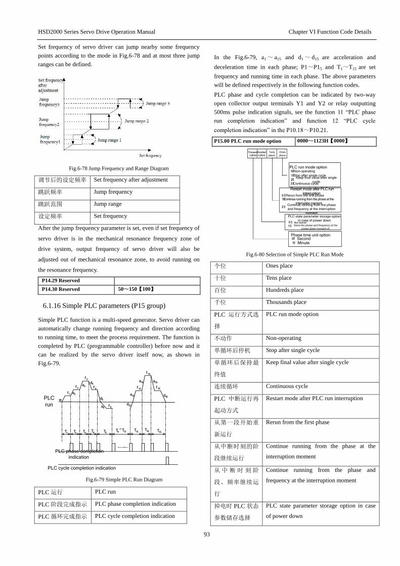
HSD2000 Series Servo Drive Operation Manual Chapter VI Function Code Details
93
Set frequency of servo driver can jump nearby some frequency
points according to the mode in Fig.6-78 and at most three jump
ranges can be defined.
Fig.6-78 Jump Frequency and Range Diagram
调节后的设定频率 Set frequency after adjustment
跳跃频率 Jump frequency
跳跃范围 Jump range
设定频率 Set frequency
After the jump frequency parameter is set, even if set frequency of
servo driver is in the mechanical resonance frequency zone of
drive system, output frequency of servo driver will also be
adjusted out of mechanical resonance zone, to avoid running on
the resonance frequency.
P14.29 Reserved
P14.30 Reserved 50~150【100】
6.1.16 Simple PLC parameters (P15 group)
Simple PLC function is a multi-speed generator. Servo driver can
automatically change running frequency and direction according
to running time, to meet the process requirement. The function is
completed by PLC (programmable controller) before now and it
can be realized by the servo driver itself now, as shown in
Fig.6-79.
a 1
f 1
a 2
f 2
a 3
f 3 d
4
f 4
d 5 a 5
f 5
a
1
3
f 1 3
a 1 4
f 1 4
d 1
5
a
1
5
f 1 5
T 1 T 2
T 3 T 4
T 5
T 6
~
T
1
2
d 1
3
T 1
4
T
1 5
T 1
3
PLC
run
PLC phase completion
indication
PLC cycle completion indication
Fig.6-79 Simple PLC Run Diagram
PLC 运行 PLC run
PLC 阶段完成指示 PLC phase completion indication
PLC 循环完成指示 PLC cycle completion indication
In the Fig.6-79, a1 ~ a15 and d1 ~ d15 are acceleration and
deceleration time in each phase; P1~P15 and T1~T15 are set
frequency and running time in each phase. The above parameters
will be defined respectively in the following function codes.
PLC phase and cycle completion can be indicated by two-way
open collector output terminals Y1 and Y2 or relay outputting
500ms pulse indication signals, see the function 11 “PLC phase
run completion indication” and function 12 “PLC cycle
completion indication” in the P10.18~P10.21.
P15.00 PLC run mode option 0000~1123H【0000】
Thousands place
Hundreds place
Tens
place
Ones
place
PLC run mode option 0: Non-operating
1:Stop after single cycle
2:Keep final value after single
cycle
3 : Continuous cycle
Phase time unit option 0: Second
1: Minute
Restart mode after PLC run interruption
0 : Rerun from the first phase
1:Continue running from the phase at the
interruption moment
2 :Continue running from the phase
and frequency at the interruption
moment
PLC state parameter storage option
in case of power down
0 : Not stored 1 : Store the phase and frequency at the
power-down moment of
Fig.6-80 Selection of Simple PLC Run Mode
个位 Ones place
十位 Tens place
百位 Hundreds place
千位 Thousands place
PLC 运行方式选
择
PLC run mode option
不动作 Non-operating
单循环后停机 Stop after single cycle
单循环后保持最
终值
Keep final value after single cycle
连续循环 Continuous cycle
PLC 中断运行再
起动方式
Restart mode after PLC run interruption
从第一段开始重
新运行
Rerun from the first phase
从中断时刻的阶
段继续运行
Continue running from the phase at the
interruption moment
从 中 断 时 刻 阶
段、频率继续运
行
Continue running from the phase and
frequency at the interruption moment
掉电时 PLC 状态
参数储存选择
PLC state parameter storage option in case
of power down

HSD2000 Series Servo Drive Operation Manual Chapter VI Function Code Details
94
不储存 Not stored
储存掉电时刻的
阶段、频率
Store the phase and frequency at the
power-down moment of
阶段时间单位选
择
Phase time unit option
秒 Second
分 Minute
Ones place: PLC run mode option
0: non-operating
PLC run mode is invalid.
1: stop after single cycle
As shown in Fig.6-81, servo driver will automatically stop after
completing a cycle and it can start only after a run command is
given again.
a 1
f 1
a 2
f 2
a 3
f 3 d
4
f 4
d 5 a 5
f 5
a
1
3
f 1 3
a 1 4
f 1 4
d 1
5
a
1
5
f 1 5
T 1 T 2
T 3 T 4
T 5
T 6
~
T
1
2
d 1
3
T 1
4
T
1 5
T 1
3
PLC run
RUN
comman
d
Fig.6-81 Stop Mode after PLC Single Cycle
PLC 运行 PLC run
RUN 命令 RUN command
2: Keep final value after single cycle
As shown in Fig.6-82, servo driver will automatically keep the
running frequency and direction in the final phase after
completing a cycle.
a 1
f 1
a 2
f 2
a 3
f 3 d
4
f 4
d 5 a 5
f 5
a
1
3
f 1 3
a 1 4
f 1 4
a
1
5
f 1 5
T 1 T 2
T 3 T 4
T 5
T 6
~
T
1
2
d 1
3
T 1
4
T
1 5
T 1
3
PLC run
RUN
comman
d
Fig.6-82 Keeping Mode of PLC Single Cycle
PLC 运行 PLC run
RUN 命令 RUN command
3 (continuous cycle):as shown in Fig.6-83, servo driver will
automatically proceed to the next cycle after completing a cycle,
till a stop command is given.
a
1
f 1
f 2
f 1 5
f 1 4 f
1
f 2
f 3 f 3
f 1 4
f 1 5
f 1
R U N command
The first
cycle The second cycle
Fig.6-83 PLC Continuous Cycle Mode
第一次循环 The first cycle
第二次循环 The second cycle
RUN 命令 RUN command
Tens place: restart mode option after PLC run interruption
0: rerun from the first phase
If servo driver stops (arising from stop command, fault or power
down) when running, it will rerun from the first phase after restart.
1: continue running at the phase frequency at the stop (or fault)
moment
If servo driver stops (arising from stop command or fault) when
running, it will automatically record the already-running time in
current phase and automatically enter the phase after restart, and
moreover, continue running of remaining time at the frequency
defined in the phase, as shown in the figure below:
Fig.6-84 PLC Start Mode 1
输出频率 Output frequency
中断信号 Interrupt signal
阶段 1 Phase 1
阶段 2 已运行时间 Already-running time in the phase 2
阶段 2 剩余时间 Remaining time in the phase 2
时间 Time
阶段 1 加速时间 Acceleration time in the phase 1
Interrupt signal Interrupt
signal Interrupt signal
...
Phase 1 1
f 1
a 1
Already-running time in the phase 2
Remaining time in
the phase 2
Output
frequency Hz
Time t
f 2
d 2
a 2
a 1 :Acceleration time in the phase 1 a 2: :Acceleration time in the phase 2
a 3 :Acceleration time in the phase 3
d2 :Frequency in the phase 2
f 1 : Frequency in the phase 1
f2 :Frequency in the phase 2
f 3 :Frequency in the phase 3
... f 3 a 3

HSD2000 Series Servo Drive Operation Manual Chapter VI Function Code Details
95
阶段 2 加速时间 Acceleration time in the phase 2
阶段 3 加速时间 Acceleration time in the phase 3
阶段 2 减速时间 Deceleration time in the phase 2
阶段 1 频率 Frequency in the phase 1
阶段 2 频率 Frequency in the phase 2
阶段 3 频率 Frequency in the phase 3
2: continue running at the running frequency at the stop (or fault)
moment
If servo driver stops (arising from stop command or fault) when
running, it not only will automatically record the already-running
time in current phase but also will record the running frequency at
the stop moment; after restart, servo driver will first return to the
running frequency at the stop moment and then continue running
in remaining phases, as shown in Fig. 6-85.
Attention
The difference between mode 1 and mode 2 is that mode 2
memorizes a running frequency at the stop moment more than
mode 1 and servo driver continues running at the frequency
after restart.
Fig.6-85 PLC Start Mode 2
输出频率 Output frequency
中断信号 Interrupt signal
阶段 1 Phase 1
阶段 2 已运行时间 Already-running time in the phase 2
阶段 2 剩余时间 Remaining time in the phase 2
时间 Time
阶段 1 加速时间 Acceleration time in the phase 1
阶段 2 加速时间 Acceleration time in the phase 2
阶段 3 加速时间 Acceleration time in the phase 3
阶段 2 减速时间 Deceleration time in the phase 2
阶段 1 频率 Frequency in the phase 1
阶段 2 频率 Frequency in the phase 2
阶段 3 频率 Frequency in the phase 3
Hundreds place: PLC state parameter storage option in case of
power down
0: not stored
Not memorize PLC running state in case of power down; rerun
from the first phase after restart upon power on.
1: store the phase and frequency at the power-down moment
Memorize PLC running state in case of power down, including the
phase, running frequency and already-running time at the
power-down moment. After power on, it runs according to the
restart mode after PLC run interruption defined in the tens place.
Thousands place: phase time unit option
0:s
Running time in each phase is in seconds.
1:min
Running time in each phase is in minutes.
The unit is valid only to the definition of PLC run phase time T1~
T15. Selection of acceleration and deceleration time unit during
PLC run is determined by P14.09.
Attention
1. When PLC running time in a phase is set as zero, the
phase is invalid.
2. The pause, fault and memory state clearing of PLC
process can be realized by terminals, see the definition of
terminal function in the P10 group.
P15.01 Setting in the phase 1 000~323H【000】
P15.02 Running time in the
phase 1 0~6500s (min)【20.0s】
P15.03 Setting in the phase 2 000~323H【000】
P15.04 Running time in the
phase 2 0~6500s (min)【20.0s】
P15.05 Setting in the phase 3 000~323H【000】
P15.06 Running time in the
phase 3 0~6500s (min)【20.0s】
P15.07 Setting in the phase 4 000~323H【000】
P15.08 Running time in the
phase 4 0~6500s (min)【20.0s】
P15.09 Setting in the phase 5 000~323H【000】
P15.10 Running time in the
phase 5 0~6500s (min)【20.0s】
P15.11 Setting in the phase 6 000~323H【000】
P15.12 Running time in the
phase 6 0~6500s (min)【20.0s】
P15.13 Setting in the phase 7 000~323H【000】
P15.14 Running time in the
phase 7 0~6500s (min)【20.0s】
P15.15 Setting in the phase 8 000~323H【000】
P15.16 Running time in the
phase 8 0~6500s (min)【20.0s】
P15.17 Setting in the phase 9 000~323H【000】
P15.18 Running time in the
phase 9 0~6500s (min)【20.0s】
P15.19 Setting in the phase 10 000~323H【000】
P15.20 Running time in the
phase 10 0~6500s (min)【20.0s】
P15.21 Setting in the phase 11 000~323H【000】
P15.22 Running time in the
phase 11 0~6500s (min)【20.0s】

HSD2000 Series Servo Drive Operation Manual Chapter VI Function Code Details
96
P15.23 Setting in the phase 12 000~323H【000】
P15.24 Running time in the
phase 12 0~6500s (min)【20.0s】
P15.25 Setting in the phase 13 000~323H【000】
P15.26 Running time in the
phase 13 0~6500s (min)【20.0s】
P15.27 Setting in the phase 14 000~323H【000】
P15.28 Running time in the
phase 14 0~6500s (min)【20.0s】
P15.29 Setting in the phase 15 000~323H【000】
P15.30 Running time in the
phase 15 0~6500s (min)【20.0s】
P15.01, P15.03, P15.05, P15.07, P15.09, P15.11, P15.13, P15.15,
P15.17, P15.19, P15.21, P15.23, P15.25, P15.27 and P15.29 are
used to set running frequency, direction and
acceleration/deceleration time in each PLC phase, selected by
places. As shown in Fig. 6-86.
Hundred
s place
Tens
place
Ones
place
Frequency setting
0:
1: Determined by P02.03 function code
2 : Multi-phase closed loop given i
3:Determined by P13.01 function code
Running direction option
0 : Forward 1 : Reverse
2 :Determined by run command
Acceleration/deceleration time
option
0 :
1 :
2 :
3 :
Multi-phase frequency i
Acceleration/deceleration time 1
Acceleration/deceleration time 2
Acceleration/deceleration time 3
Acceleration/deceleration time 4
Fig.6-86 Setting in the PLC Phase i (i=1~15)
个位 Ones place
十位 Tens place
百位 Hundreds place
频率设置 Frequency setting
多段频率 i Multi-phase frequency i
由 P02.03 功能码决定 Determined by P02.03 function code
多段闭环给定 i Multi-phase closed loop given i
由 P13.01 功能码决定 Determined by P13.01 function code
运转方向选择 Running direction option
正转 Forward
反转 Reverse
由运行命令确定 Determined by run command
加减速时间选择 Acceleration/deceleration time option
加减速时间 1 Acceleration/deceleration time 1
加减速时间 2 Acceleration/deceleration time 2
加减速时间 3 Acceleration/deceleration time 3
加减速时间 4 Acceleration/deceleration time 4
Setting of LED ones place in the PLC phase i:
0: select multi-phase frequency i
For example, when i is equal to 3, the frequency of phase 3 is
multi-phase frequency 3; for definition of multi-phase frequency,
see the P16.00~P16.14.
1: the frequency is determined by main set frequency source
function code P02.03.
2: I multi-phase closed loop given
For example, when i is equal to 2, the frequency of phase 2 is
multi-phase closed loop given 2; for definition of multi-phase
closed loop given, see the P13.20~P13.34.
3: determined by closed loop given channel function code P13.01
PLC can realize closed loop running in a phase; closed loop given
channel can be multi-phase closed loop given i or determined by
P13.01 function code; feedback channel is determined by P13.0.
When given channel is determined by P13.01 function code, the
closed loop given channel can be switched to multi-phase closed
loop given value by the option terminal of multi-phase closed loop
given. See the terminal functions 30, 31 and 32 of function codes
P10.00~P10.07 and detailed description of P13.20~P13.34.
Attention
When PLC phase running direction is determined by run
command, running direction of motor can be changed in a
real-time way by external direction command. For example,
realize forward running by FWD-COM and realize reverse
running by REV-COM. Running direction is determined by
run command; if the direction can not be determined, it
follows the running direction in the previous phase.
6.1.17 Multi-speed parameters (P16 group)
P16.00 Multi-phase
frequency 1
Lower frequency limit ~Upper frequency
limit 【5.00Hz】
P16.01 Multi-phase
frequency 2
Lower frequency limit ~Upper frequency
limit 【10.00Hz】
P16.02 Multi-phase
frequency 3
Lower frequency limit ~Upper frequency
limit 【20.00Hz】
P16.03 Multi-phase
frequency 4
Lower frequency limit ~Upper frequency
limit 【30.00Hz】
P16.04 Multi-phase
frequency 5
Lower frequency limit ~Upper frequency
limit 【40.00Hz】
P16.05 Multi-phase
frequency 6
Lower frequency limit ~Upper frequency
limit 【45.00Hz】
P16.06 Multi-phase
frequency 7
Lower frequency limit ~Upper frequency
limit 【50.00Hz】
P16.07 Multi-phase
frequency 8
Lower frequency limit ~Upper frequency
limit 【5.00Hz】
P16.08 Multi-phase
frequency 9
Lower frequency limit ~Upper frequency
limit 【10.00Hz】
P16.09 Multi-phase
frequency 10
Lower frequency limit ~Upper frequency
limit 【20.00Hz】
P16.10 Multi-phase
frequency 11 Lower frequency limit ~Upper frequency

HSD2000 Series Servo Drive Operation Manual Chapter VI Function Code Details
97
limit 【30.00Hz】
P16.11 Multi-phase
frequency 12
Lower frequency limit ~Upper frequency
limit 【40.00Hz】
P16.12 Multi-phase
frequency 13
Lower frequency limit ~Upper frequency
limit 【45.00Hz】
P16.13 Multi-phase
frequency 14
Lower frequency limit ~Upper frequency
limit 【50.00Hz】
P16.14 Multi-phase Lower frequency limit ~Upper frequency
frequency 15 limit 【50.00Hz】
These frequencies will be used in the multi-speed run mode and
simple PLC run mode, see the detailed description of multi-speed
run terminal functions “1”, “2”, “3” and “4” in 6.1.11 switching
input terminal P10.00~P10.07 and P15-group function codes in
6.1.16 simple PLC.
6.1.18 LED display parameters (P17 group)
P17.00 LED run display parameter
option 1 000~3F7H【007H】
Tens
place Ones
place Hundred
s place
BIT0 Output power
BIT0 : Output
frequency : Hz :
BIT1 BIT2 : A :
BIT0 Running speed : RPM : BIT1 Set speed (RPM flicker) BIT2 Running linear speed (M/S) BIT3 Set linear speed (m/s
flicker)
Set frequency (Hz flicker):Output current :
:
:
:
:
:
:
Fig.6-87 Setting of LED Run Display Parameter Option 1
个位 Ones place
十位 Tens place
百位 Hundreds place
输出频率 Output frequency
设定频率(Hz 闪烁) Set frequency (Hz flicker)
输出电流 Output current
运行转速 Running speed
设定转速(RPM 闪烁) Set speed (RPM flicker)
运行线速度 Running line speed
设定线速度(m/s 闪烁) Set line speed (m/s flicker)
输出功率 Output power
P17.00 and P17.01 define the state parameter displayed by LED
when servo driver is in running state.
When BIT place is 0, the parameter is not displayed.
When BIT place is 1, the parameter is displayed.
For example, LED ones place-BIT0 is the display switch code of
“output frequency”; when BIT0 is equal to 0, the parameter is not
displayed; when BIT0 is equal to 1, the parameter is displayed.
P17.01 LED run display parameter
option 2 00~FFH【00H】
BIT0 :Output voltage : V : BIT1 : AI1 : V : BIT2 : AI2 : V : BIT3 : AI3 : V :
BIT0 :Analog closed loop feedback BIT1 :Analog closed loop setting BIT2 :Terminal state
Ones place Tens place
Fig.6-88 Setting of LED Run Display Parameter Option 2
个位 Ones place
十位 Tens place
输出电压 Output voltage
模拟闭环反馈 Analog closed loop feedback
模拟闭环设定 Analog closed loop setting
端子状态 Terminal state
Displayed terminal state includes multi-function terminals X1~
X8 and FWD and REV terminals; LED digital tube specified
value is used to indicate the state of each function terminal. For
example, when X1, X2 and FWD terminals are closed and other
terminals are disconnected, displayed terminal state value is 103H.
For terminal sequence, see the description of P10.16.
Attention
When running speed and line speed are displayed, they can be
modified in a real-time way by ▼ and ▲ keys (it is
unnecessary to switch to frequency state).
When both P17.00 and P17.01 are 0, default display is output
frequency.
In the display state of run parameter, display parameters can
be switched successively by shift key .
Tens
place Ones
place Hundred
s place
BIT0 Set frequency : Hz : BIT1 :Running speed : RPM : BIT2 :Set speed : RPM: BIT3 :Bus voltage : V :
BIT0 : AI1 : V : BIT1 : AI2 : V : BIT2 : AI3 : V :
BIT0 BIT1 Set linear speed(m/s) BIT2 Analog closed loop feedback BIT3 Analog closed loop setting
Running linear speed(R/S)
Fig.6-89 Setting of LED Stop Display Parameter Option
P17.02 LED stop display
parameter option 000~FFFH【009H】
个位
Ones place
十位 Tens place
百位 Hundreds place
设定频率 Set frequency
运行转速 Running speed
设定转速 Set speed
母线电压 Bus voltage
运行线速度 Running line speed
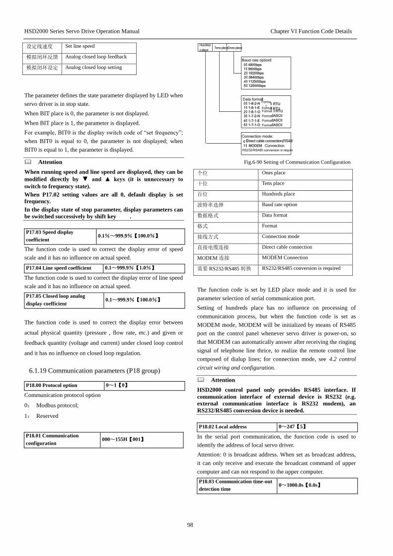
HSD2000 Series Servo Drive Operation Manual Chapter VI Function Code Details
98
设定线速度 Set line speed
模拟闭环反馈 Analog closed loop feedback
模拟闭环设定 Analog closed loop setting
The parameter defines the state parameter displayed by LED when
servo driver is in stop state.
When BIT place is 0, the parameter is not displayed.
When BIT place is 1, the parameter is displayed.
For example, BIT0 is the display switch code of “set frequency”;
when BIT0 is equal to 0, the parameter is not displayed; when
BIT0 is equal to 1, the parameter is displayed.
Attention
When running speed and line speed are displayed, they can be
modified directly by ▼ and ▲ keys (it is unnecessary to
switch to frequency state).
When P17.02 setting values are all 0, default display is set
frequency.
In the display state of stop parameter, display parameters can
be switched successively by shift key .
P17.03 Speed display
coefficient 0.1%~999.9%【100.0%】
The function code is used to correct the display error of speed
scale and it has no influence on actual speed.
P17.04 Line speed coefficient 0.1~999.9%【1.0%】
The function code is used to correct the display error of line speed
scale and it has no influence on actual speed.
P17.05 Closed loop analog
display coefficient 0.1~999.9%【100.0%】
The function code is used to correct the display error between
actual physical quantity (pressure , flow rate, etc.) and given or
feedback quantity (voltage and current) under closed loop control
and it has no influence on closed loop regulation.
6.1.19 Communication parameters (P18 group)
P18.00 Protocol option 0~1【0】
Communication protocol option
0: Modbus protocol;
1: Reserved
P18.01 Communication
configuration 000~155H【001】
Connection mode:
0 Direct cable connection(RS485)
1 : MODEM Connection RS232/RS485 conversion is required
Baud rate option :
1 : 9600bps
0 : 4800bps
3 : 38400bps
2 : 19200bps
5 : 125000bps
4 : 112500bps
Data format :0 : 1-8-2-N Forma
t : RTU
1 : 1-8-1-E : RTU2 : 1-8-1-O : RTU
3 : 1-7-2-N :ASCII
4 : 1-7-1-E :ASCII
5 : 1-7-1-O :ASCII
Ones placeTens placeHundred
s place
FormatFormat
Format
Format
Format
:
Fig.6-90 Setting of Communication Configuration
个位 Ones place
十位 Tens place
百位 Hundreds place
波特率选择 Baud rate option
数据格式 Data format
格式 Format
接线方式 Connection mode
直接电缆连接 Direct cable connection
MODEM 连接 MODEM Connection
需要 RS232/RS485 转换 RS232/RS485 conversion is required
The function code is set by LED place mode and it is used for
parameter selection of serial communication port.
Setting of hundreds place has no influence on processing of
communication process, but when the function code is set as
MODEM mode, MODEM will be initialized by means of RS485
port on the control panel whenever servo driver is power-on, so
that MODEM can automatically answer after receiving the ringing
signal of telephone line thrice, to realize the remote control line
composed of dialup lines; for connection mode, see 4.2 control
circuit wiring and configuration.
Attention
HSD2000 control panel only provides RS485 interface. If
communication interface of external device is RS232 (e.g.
external communication interface is RS232 modem), an
RS232/RS485 conversion device is needed.
P18.02 Local address 0~247【5】
In the serial port communication, the function code is used to
identify the address of local servo driver.
Attention: 0 is broadcast address. When set as broadcast address,
it can only receive and execute the broadcast command of upper
computer and can not respond to the upper computer.
P18.03 Communication time-out
detection time 0~1000.0s【0.0s】
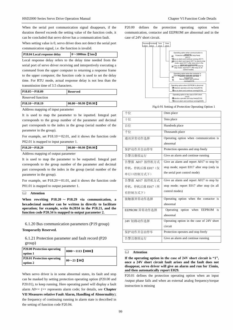
HSD2000 Series Servo Drive Operation Manual Chapter VI Function Code Details
99
When the serial port communication signal disappears, if the
duration thereof exceeds the setting value of the function code, it
can be concluded that servo driver has a communication fault.
When setting value is 0, servo driver does not detect the serial port
communication signal, i.e. the function is invalid.
P18.04 Local response delay 0~1000ms【5ms】
Local response delay refers to the delay time needed from the
serial port of servo driver receiving and interpretively executing a
command from the upper computer to returning a response frame
to the upper computer; the function code is used to set the delay
time. For RTU mode, actual response delay is not less than the
transmission time of 3.5 characters.
P18.05~P18.09 Reserved
Reserved function
P18.10~P18.19 00.00~99.99【99.99】
Address mapping of input parameter
It is used to map the parameter to be inputted. Integral part
corresponds to the group number of the parameter and decimal
part corresponds to the index in the group (serial number of the
parameter in the group).
For example, set P18.10=02.01, and it shows the function code
P02.01 is mapped to input parameter 1.
P18.20~P18.29 00.00~99.99【99.99】
Address mapping of output parameter
It is used to map the parameter to be outputted. Integral part
corresponds to the group number of the parameter and decimal
part corresponds to the index in the group (serial number of the
parameter in the group).
For example, set P18.20=01.01, and it shows the function code
P01.01 is mapped to output parameter 1.
Attention
When rewriting P18.20 ~ P18.29 via communication, a
hexadecimal number can be written in directly to facilitate
operation; for example, write 0x2034 in the P18.21, and the
function code P20.34 is mapped to output parameter 2.
6.1.20 Bus communication parameters (P19 group)
Temporarily Reserved.
6.1.21 Protection parameter and fault record (P20
group)
P20.00 Protection operating
option 1 0000~1113【0000】
P20.01 Protection operating
option 2 00~23【00】
When servo driver is in some abnormal states, its fault and stop
can be masked by setting protection operating option (P20.00 and
P20.01), to keep running. Here operating panel will display a fault
alarm A0×× (×× represents alarm code; for details, see Chapter
VII Measures relative Fault Alarm, Handling of Abnormality);
the frequency of continuing running in alarm state is described in
the setting of function code P20.04.
P20.00 defines the protection operating option when
communication, contactor and EEPROM are abnormal and in the
case of 24V short circuit.
Operating option when the contactor is
Operating option when the contactor is
0:Protection operates and stop
freely(E018)
1:Give an alarm and continue
running(A018)
Operating option when EEPROM is abnormal
0:Protection operates and stop freely(E016)
1: Give an alarm and continue running(A016)
Operating option in the case of 24V short
circuit
0: Protection operates and stop freely(E016)
1: Give an alarm and continue running(A029)
Operating option when communication is
abnormal
0:Protection operates and stop freely
(E017)
1: Give an alarm and continue running (A017)
2: Give an alarm and report A017 to stop by stop
mode; report E017 after stop (only in the
serial port control mode)
3: Give an alarm and report A017 to stop by
stop mode; report E017 after stop (in all
control modes)
Ones
place
Tens
place
Hundreds
place
Thousand
s place
Fig.6-91 Setting of Protection Operating Option 1
个位 Ones place
十位 Tens place
百位 Hundreds place
千位 Thousands place
通讯异常动作选择 Operating option when communication is
abnormal
保护动作并自由停车 Protection operates and stop freely
告警且继续运行 Give an alarm and continue running
告警报 A017 按停机方式
停机,停机后报 E017(仅
串行口控制方式下)
Give an alarm and report A017 to stop by
stop mode; report E017 after stop (only in
the serial port control mode)
告警报 A017 按停机方式
停机,停机后报 E017(所
有控制方式下)
Give an alarm and report A017 to stop by
stop mode; report E017 after stop (in all
control modes)
接触器异常动作选择 Operating option when the contactor is
abnormal
EEPROM 异常动作选择 Operating option when EEPROM is
abnormal
24V 短路动作选择 Operating option in the case of 24V short
circuit
保护动作并自由停车 Protection operates and stop freely
告警且继续运行 Give an alarm and continue running
Attention
If the operating option in the case of 24V short circuit is “1”,
once a 24V short circuit fault arises and the fault does not
disappear, servo driver will give an alarm and run for 15min,
and then automatically report E029.
P20.01 defines the protection operating option when an input
/output phase fails and when an external analog frequency/torque
instruction is missing

HSD2000 Series Servo Drive Operation Manual Chapter VI Function Code Details
100
Tens
place
Ones
place
Operating option when a phase fails 0 : Protection operates when an input phase and an output
phase fail (E008/E009)
1 : Protection does not operate when an input phase
fails2 :
Protection does not operate when an output phase
fails3 : Protection does not operate when an input phase
and an output phase fail
Operating option when an external analog frequency/
torque instruction is missing
0 : Non-operating
1 : Protection operates and stop freely(E022)
2 : Give an alarm and continue
running(A022)
Fig.6-92 Setting of Protection Operating Option 2
个位 Ones place
十位 Tens place
缺相动作选择 Operating option when a phase fails
输入输出缺相将被
保护
Protection operates when an input phase and an
output phase fail
输入缺相不动作 Protection does not operate when an input phase
fails
输出缺相不动作 Protection does not operate when an output phase
fails
输入输出均不动作 Protection does not operate when an input phase
and an output phase fail
外部模拟频率 /转
矩指令丧失动作选
择
Operating option when an external analog
frequency/torque instruction is missing
不动作 Non-operating
保护动作并自由停
车
Protection operates and stop freely
告警且继续运行 Give an alarm and continue running
P20.02 Fault indication option 1 000~211【000】
P20.02 defines the protection operating option in the case of
undervoltage, automatic reset interval and fault locking.
Undervoltage fault indication operating option
0 : Non-operating
1 : Operating (undervoltage is regarded as a
fault)
Automatic reset interval fault indication
operating option 0 : Non-operating
1 : Operating
Fault locking function option
0 : Disabled
1 :
2 : Enabled (fault indication operates)
Ones placeTens
place
Hundred
s place
Enabled (fault indication does not operate)
Fig.6-93 Fault Indication Option 1
个位 Ones place
十位 Tens place
百位 Hundreds place
欠压故障指示动作选择 Undervoltage fault indication operating option
不动作 Non-operating
动作(欠压视为故障) Operating (undervoltage is regarded as a
fault)
自动复位间隔故障指示
动作选择
Automatic reset interval fault indication
operating option
不动作 Non-operating
动作 Operating
故障锁定功能选择 Fault locking function option
禁止 Disabled
开放(故障指示不动作) Enabled (fault indication does not operate)
开放(故障指示动作) Enabled (fault indication operates)
! Attention
The protection operating option function should be selected with
care and it must be correctly selected after the cause of the fault
is determined, or else it may cause an extension of accident
scope, personal injury and property damage.
P20.03 Reserved
Reserved function
P20.04 Continuing running
frequency option at fault 0~4【0】
0: run at current set frequency
1: run at the set frequency in P02.04 function code
2: run at the upper frequency limit
3: run at the lower frequency limit
4: run at a standby frequency in case of an abnormity
When function 4 is selected, it should be in combination with
setting of function code P20.05
P20.05 Setting of standby
frequency in case of an abnormity 0.0~100.0%【100.0%】
The setting adopts the running frequency before an abnormity as
maximum value 100%.
P20.06 Motor overload protection
mode option 0、1、2【1】
0: non-operating
There is no motor overload protection characteristic (it should be
selected with care), and here servo driver has no overload
protection of load motor;
1: normal motor (with low-speed compensation)
Because the heat dissipation effect of a normal motor is poor at a
low speed, the corresponding electronic thermal protection value
is also adjusted properly. The low-speed compensation
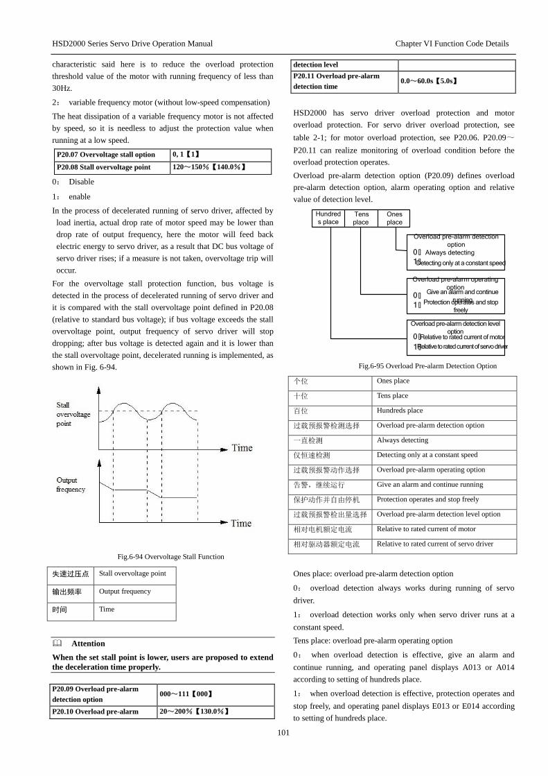
HSD2000 Series Servo Drive Operation Manual Chapter VI Function Code Details
101
characteristic said here is to reduce the overload protection
threshold value of the motor with running frequency of less than
30Hz.
2: variable frequency motor (without low-speed compensation)
The heat dissipation of a variable frequency motor is not affected
by speed, so it is needless to adjust the protection value when
running at a low speed.
P20.07 Overvoltage stall option 0, 1【1】
P20.08 Stall overvoltage point 120~150%【140.0%】
0: Disable
1: enable
In the process of decelerated running of servo driver, affected by
load inertia, actual drop rate of motor speed may be lower than
drop rate of output frequency, here the motor will feed back
electric energy to servo driver, as a result that DC bus voltage of
servo driver rises; if a measure is not taken, overvoltage trip will
occur.
For the overvoltage stall protection function, bus voltage is
detected in the process of decelerated running of servo driver and
it is compared with the stall overvoltage point defined in P20.08
(relative to standard bus voltage); if bus voltage exceeds the stall
overvoltage point, output frequency of servo driver will stop
dropping; after bus voltage is detected again and it is lower than
the stall overvoltage point, decelerated running is implemented, as
shown in Fig. 6-94.
Fig.6-94 Overvoltage Stall Function
失速过压点 Stall overvoltage point
输出频率 Output frequency
时间 Time
Attention
When the set stall point is lower, users are proposed to extend
the deceleration time properly.
P20.09 Overload pre-alarm
detection option 000~111【000】
P20.10 Overload pre-alarm 20~200%【130.0%】
detection level
P20.11 Overload pre-alarm
detection time 0.0~60.0s【5.0s】
HSD2000 has servo driver overload protection and motor
overload protection. For servo driver overload protection, see
table 2-1; for motor overload protection, see P20.06. P20.09~
P20.11 can realize monitoring of overload condition before the
overload protection operates.
Overload pre-alarm detection option (P20.09) defines overload
pre-alarm detection option, alarm operating option and relative
value of detection level.
Overload pre-alarm detection
option 0 : Always detecting 1 : Detecting only at a constant speed
Overload pre-alarm operating
option 0 : Give an alarm and continue
running
1 : Protection operates and stop
freely
Overload pre-alarm detection level
option
0 : Relative to rated current of motor Relative to rated current of servo driver
Tens
place Ones
place
Hundred
s place
1 :
Fig.6-95 Overload Pre-alarm Detection Option
个位 Ones place
十位 Tens place
百位 Hundreds place
过载预报警检测选择 Overload pre-alarm detection option
一直检测 Always detecting
仅恒速检测 Detecting only at a constant speed
过载预报警动作选择 Overload pre-alarm operating option
告警,继续运行 Give an alarm and continue running
保护动作并自由停机 Protection operates and stop freely
过载预报警检出量选择 Overload pre-alarm detection level option
相对电机额定电流 Relative to rated current of motor
相对驱动器额定电流 Relative to rated current of servo driver
Ones place: overload pre-alarm detection option
0: overload detection always works during running of servo
driver.
1: overload detection works only when servo driver runs at a
constant speed.
Tens place: overload pre-alarm operating option
0: when overload detection is effective, give an alarm and
continue running, and operating panel displays A013 or A014
according to setting of hundreds place.
1: when overload detection is effective, protection operates and
stop freely, and operating panel displays E013 or E014 according
to setting of hundreds place.

HSD2000 Series Servo Drive Operation Manual Chapter VI Function Code Details
102
Hundreds place: overload pre-alarm detection level option
0: detection level is relative to rated current of motor (fault code
E014).
1: detection level is relative to rated current of servo driver (fault
code E013).
Fig.6-96 Overload Pre-alarm Detection Function Diagram
输出电流 Output
过载预报警检出水平 Overload pre-alarm detection level
过载检出计时 Overload detection timing
过载检出动作 Overload detection operates
过载预报警检出时间 Overload pre-alarm detection time
有效 Valid
时间 Time
Overload pre-alarm detection level (P20.10) defines the current
threshold of overload pre-alarm operation and its setting value is
the percentage relative to rated current (see P20.09).
Overload pre-alarm detection time (P20.11) defines that an
overload pre-alarm signal is outputted after output current of servo
driver is greater than overload detection level (P20.10) for more
than a certain time.
When output current of servo driver is greater than pre-alarm
detection level, pre-alarm detection timing increases by degrees;
when output current of servo driver is less than detection level,
pre-alarm detection timing decreases by degrees. When overload
pre-alarm state is valid, it shows the time kept by pre-alarm
detection timer exceeds the overload pre-alarm detection time.
Attention
1. Generally, setting of overload pre-alarm detection level
should be less than overload protection level.
2. When output current of servo driver is greater than
detection level, pre-alarm detection timing will increase
gradually up to built-in amplitude limit. On the contrary, if
run current is less than overload pre-alarm detection level,
built-in overload pre-alarm detection time will reduce
gradually up to zero.
P20.12 Off-load protection
option 0~2【0】
P20.13 Off-load detection level 0.0~100%【30.0%】
P20.14 Off-load detection time 0.0~60.0s【1.0s】
Off-load protection option defines the protection operation of
servo driver in case of off-load in the torque control mode.
0: off-load protection of servo driver is disabled.
1: off-load protection of servo driver is enabled.
2: Reserved.
Off-load detection level (P20.13) defines the current threshold of
off-load operation and its setting value is the percentage relative to
rated current of servo driver.
Off-load detection time (P20.14) defines that an off-load signal is
outputted after output current of servo driver is continuously less
than off-load detection level (P20.13) for more than a certain time.
When off-load state is valid, it shows run current of servo driver is
less than off-load detection level and holding time exceeds the
off-load detection time.
Fig.6-97 Off-Load Protection Detection Function Diagram
输出电流 Output current
掉载检出时间 Off-load detection time
掉载检出水平 Off-load detection level
掉载检出动作 Off-load detection operation
有效 Valid
时间 Time
Attention
After run current is greater than off-load detection level
within the off-load detection time, built-in off-load detection
time will be reset.
P20.15 Automatic current
limiting level 20.0~200.0%【150.0%】
P20.16 Drop rate of frequency
during current limiting 0.00~99.99Hz/s【10.00Hz/s】
P20.17 Automatic current 0~1【1】
Off-load detection operation
Off-load detection time
Off-load detection time
Output current
Valid
Time
Time
Off-load detection time
Overload detection operates
Overload pre-alarm
detection level
Overload pre-alarm
detection level
Output
Valid
Time
Time
Overload detection timing
Time

HSD2000 Series Servo Drive Operation Manual Chapter VI Function Code Details
103
limiting operation option
Automatic current limiting function is to automatically restrict
current and make it not exceed the set automatic current limiting
level (P20.15) through real-time control of load current, so as to
prevent the fault tripping arising from current overshoot. The
function is especially applicable on the occasions that load inertia
is greater or load change is violent.
Automatic current limiting level (P20.15) defines the current
threshold of automatic current limiting operation and its setting
range is the percentage relative to rated current of servo driver.
Drop rate of frequency during current limiting (P20.16) defines
the adjustment rate of output frequency when automatic current
limiting operates.
When automatic current limiting operates, if the drop rate of
frequency (P20.16) is much lower, it does not get rid of automatic
current limiting state easily and an overload fault may be caused
finally; if the drop rate (P20.16) is much higher, the degree of
frequency adjustment increases and servo driver may be in the
power generation state for a long time, causing overvoltage
protection.
Automatic current limiting function is always valid in the
acceleration/deceleration state. Whether automatic current limiting
function is valid when running at a constant speed depends on
automatic current limiting operation option (P20.17).
P20.17=0, it shows automatic current limiting function is invalid
when running at a constant speed;
P20.17=1, it shows automatic current limiting function is valid
when running at a constant speed.
When automatic current limiting function operates, output
frequency may change, so the function should not be used on the
occasions that output frequency must be relatively stable during
constant-speed running.
When automatic current limiting function is valid, lower setting of
current limiting level may affect the overload capacity of servo
driver.
P20.18 Automatic reset
number 0~100【0】
P20.19 Automatic reset
interval time 2.0~20.0s【5.0s】
Automatic fault reset function can automatically reset the running
fault according to the set number and interval time. When
automatic reset number is set as 0, it shows automatic reset is
disabled and fault protection is executed immediately.
Attention
1. Inversion module protection (E010), external device fault
(E015) and analog input overcurrent fault (E041) have no
automatic reset function.
2. During reset interval, output is locked out to run at zero
frequency; after completion of automatic reset, it starts
automatically by speed tracking to run.
3. The automatic fault reset function should be used with
care, or else it may cause personal injury and property loss.
P20.20 Reserved
Reserved function
P20.21 Type of the first abnormity 0~50【0】
P20.22 Bus voltage at the moment of the
first fault 0~999V【0】
P20.23 Actual current at the moment of
the first fault 0.0~999.9A【0】
P20.24 Running frequency at the
moment of the first fault 0.00~1000.0Hz【0.00】
P20.25 Running state of servo driver at
the moment of the first fault 0~FFFFH【0000】
P20.26 Type of the second abnormity 0~50【0】
P20.27 Bus voltage at the moment of the
second fault 0~999V【0】
P20.28 Actual current at the moment of
the second fault 0.0~999.9A【0】
P20.29 Running frequency at the
moment of the second fault 0.00~1000.0Hz【0.00】
P20.30 Running state of servo driver at
the moment of the second fault 0~FFFFH【0000】
P20.31 Type of the third abnormity 0~50【0】
P20.32 Bus voltage at the moment of the
third fault 0~999V【0】
P20.33 Actual current at the moment of
the third fault 0.0~999.9A【0】
P20.34 Running frequency at the
moment of the third fault 0.00~1000.0Hz【0.00】
P20.35 Running state of servo driver at
the moment of the third fault 0~FFFFH【0000】
HSD2000 series have 50 kinds of abnormity protection alarms;
the type of the latest three abnormal faults (P20.21, P20.26 and
P20.31), bus voltage of servo driver at the moment of the latest
three faults (P20.22, P20.27 and P20.32), current at the moment of
the latest three faults (P20.23, P20.28 and P20.33), frequency at
the moment of the latest three faults (P20.24, P20.29 and P20.34)
and running state of servo driver at the moment of the latest three
faults (P20.25, P20.30 and P20.35) are memorized for users to
inquire.
The latest fault record is the record for the third time.
For running state of servo driver, see the function code P01.17.
For detailed description of protection alarms and fault handling
methods, see Chapter VII Measures relative Fault Alarm,
Handling of Abnormality .
6.1.22 Traverse operation parameter (P30 group)
Traverse frequency is applicable to textile and chemical fiber
industries and on the occasion of needing traversing and winding
functions. Typical work of traverse frequency is as shown in Fig.
6-98.
Generally, traverse frequency process is as below: first accelerate
to the preset traverse frequency (P30.02) according to acceleration
time and wait for a period of time (P30.03), next transit to center
frequency according to acceleration/deceleration time, and then
run cyclically according to the set traverse frequency amplitude
(P30.04), jump frequency (P30.05), traverse frequency period
(P30.06) and traverse frequency rise time (P30.07), till a stop
command is given to slow down and stop according to
deceleration time.

HSD2000 Series Servo Drive Operation Manual Chapter VI Function Code Details
104
Running frequency
Lower wobble
frequency limit FL
Upper wobble
frequency limit H
Textile jump
frequency
=AW*P30 . 0 5
Accelerat
e
according to
acceleration
time
Textile start
waiting time
Triangular wave rise
time
Wobble
frequency
period
Wobble frequency
amplitude
Aw=Fset *P30 .04
-Aw
+Aw
Run
command
Stop command
Time tDecelerat
e
according
to
deceleratio
n time
a1
a1
Preset wobble
frequency
Center frequency Fast
P30.03
P30.06*30.0
7
Fig.6-98 Traverse Frequency Diagram
运行频率 Running frequency
摆频上限频率 Upper traverse frequency limit
中心频率 Center frequency
摆频下限频率 Lower traverse frequency limit
摆频预置频率 Preset traverse frequency
运行命令 Run command
停机命令 Stop command
摆频幅度 Traverse frequency amplitude
纺织突跳频率 Textile jump frequency
按加速时间加速 Accelerate according to acceleration time
纺织启动等待时间 Textile start waiting time
三角波上升时间 Triangular wave rise time
摆频周期 Traverse frequency period
按减速时间减速 Decelerate according to deceleration time
时间 Time

HSD2000 Series Servo Drive Operation Manual Chapter VII Measures against Fault Alarm, Handling of Abnormality
105
Center frequency roots in the set frequency of normal run, multi-speed run or PLC run;
Traverse frequency is automatically cancelled in the jog and closed loop run modes.
PLC and traverse frequency run simultaneously; when switching between PLC phases, traverse frequency becomes invalid; after transition
to PLC set frequency according to acceleration/deceleration setting in PLC phase, traverse frequency starts; decelerate according to the
deceleration time in PLC phase when stopping.
P30.00 Textile function option 0~1【0】
The function decides whether to use the textile function.
0: textile function is not selected;
1: textile function is selected.
P30.01 Traverse frequency
run mode 0000~1111【0000】
The function code is used to the operating mode of traverse frequency function. Users can design programs at will according to own needs.
The meaning of each display place of LED is as shown in Fig.6-99.
Thousand
s place
Hundred
s place
Tens
place
Ones
place
Operating mode
0 : Automatic operating mode 1 : Terminal manual operating
mode
Wobble amplitude control0 :
Variable wobble
amplitude1 : Fixed wobble amplitude
Wobble frequency start mode
option 0: Run in the state memorized
before stop
1: Restart Wobble frequency state storage in case of power
down0 : Store the wobble frequency state
in case of power down1 : Not the store
Fig.6-99 Meaning of Traverse Frequency Run Mode Parameter
个位 Ones place
十位 Tens place
百位 Hundreds place
千位 Thousands place
投入方式 Operating mode
自动投入方式 Automatic operating mode
端子手动投入方式 Terminal manual operating mode
摆幅控制 Traverse amplitude control
变摆幅 Variable traverse amplitude
固定摆幅 Fixed traverse amplitude
摆频停机起动方式选择 Traverse frequency start mode option
按停机前记忆的状态运动 Run in the state memorized before stop
重新开始起动 Restart
摆频状态掉电存储 Traverse frequency state storage in case of power down
掉电存储摆频状态 Store the traverse frequency state in case of power down
不存储 Not store the traverse frequency state in case of power down
Ones place: operating mode
0: automatic operating mode
After starting, first run for a period of time (P30.03) at the preset traverse frequency (P30.02) and then run automatically at traverse
frequency.
1: terminal manual operating mode

HSD2000 Series Servo Drive Operation Manual Chapter VII Measures against Fault Alarm, Handling of Abnormality
106
When multi-function terminal (Xi is defined as function 34) is set to be valid, it enters traverse frequency state; when invalid, it goes out of
traverse frequency state and running frequency remains at the preset traverse frequency (P30.02).
Tens place: traverse amplitude control
0: variable traverse amplitude
Traverse amplitude AW varies with center frequency and its variation rate is defined in P30.04.
1: fixed traverse amplitude
Traverse amplitude AW depends on maximum frequency and P30.04.
Hundreds place: traverse frequency start mode option
0: start in the state memorized before stop
1: restart
Thousands place: traverse frequency state storage in case of power down
Traverse frequency state parameter is stored in case of power down. The function is valid only the start mode in the state memorized
before stop is selected.
0: store the traverse frequency state in case of power down;
1: not store the traverse frequency state in case of power down.
Attention
The terminal (Xi defined as function 34) can be used to reset traverse frequency state.
P30.02 Preset traverse frequency 0.00Hz~P02.06【0.00Hz】
P30.03 Waiting time of preset
traverse frequency 0.0~3600.0s【0.0s】
P30.02 is used to define the running frequency of frequency converter before entering traverse frequency running state.
When automatic start mode is selected, P30.03 is used to set the duration of running at the preset traverse frequency before entering
traverse frequency state; when manual start mode is selected, P30.03 setting is invalid.
P30.04 Traverse
frequency amplitude 0.0%~50.0%【0.0%】
Variable traverse amplitude: AW= center frequency ×P30.04
Fixed traverse amplitude: AW= maximum running frequency P02.05×P30.04
Attention
Running frequency at traverse frequency is restricted by the upper and lower frequency limits; if it is set improperly, traverse
frequency will not work properly.
P30.05 Jump
frequency
0.0~50.0% (relative traverse amplitude)
【0.0%】
As described in Fig.6-98, when set as 0, there will be no jump frequency.
P30.06 Traverse
frequency period
0.1~999.9s【10.0s】
It defines the time of a complete period of traverse frequency rise and drop process.
Attention
It is not allowed to select automatic acceleration/deceleration run mode in the traverse frequency run mode, or else the traverse
frequency period is abnormal.
P30.07 Triangular wave rise
time 0~100.0%【50.0%】
It defines the running time (=P30.06×P30.07 (s)) of traverse frequency at the ascent stage and the running time (=P30.06×9(1-P30.07)
(s)) at the descent stage. See the description in Fig.6-98.
Attention
Users select S-curve acceleration/deceleration mode while selecting traverse frequency and traverse frequency running is
smoother.

HSD2000 Series Servo Drive Operation Manual Chapter VII Measures against Fault Alarm, Handling of Abnormality
107
6.1.23 Driver parameters (P97 group)
P97.00 Serial number 0~FFFF【6000】
P97.01 Software version number 0.00~99.99【1.00】
P97.02 Custom version number 0~9999【0】
P97.03 Rated capacity 0~999.9kVA
P97.04 Rated voltage 0~999V
P97.05 Rated current 0~999.9A
The above are the parameters of servo driver and factory defaults are set by the manufacturer.
6.1.24 Custom parameter group (P98 group)
Users can customize parameters by P98 group.
Customization details: first set the first function code parameter that a user wants to display by P98.00, next set the second function code
parameter that the user wants to display by P98.01, and so on. At most 32 custom parameters can be set.
After completion of setting, set P00.00 as 3 (user menu mode) and then press DATA/ENTER key.
If not changing P00.00 function code parameter value (set as 3), enter the function code display state; press ▲ or ▼ key, and operating
panel will only display P00.00 and custom parameters.
If a user wants to quit from custom parameter display mode, the user can enter P00.00 and change the P00.00 parameter value to a value
(not 3), and then press DATA/ENTER key.
For example, a user wants to set three custom parameters: P02.01, P03.02 and P03.00, the user can set them according to the steps as
below:
1) Use P98.00 to set the first function code parameter 02.01 and then press DATA/ENTER key;
2) Use P98.01 to set the second function code parameter 03.02 and then press DATA/ENTER key;
3) Use P98.02 to set the third function code parameter 03.00 and then press DATA/ENTER key.
4) Set P00.00 as 3 (user menu mode) and then press DATA/ENTER key.
After completion of setting, if not changing the P00.00 function code parameter value, operating panel will only display the four function
code parameters: P00.00, P02.01, P03.02 and P03.00, when entering the function code display state.
Attention
1. When a user sets a custom parameter by P98 group, if the set function code parameter is not available in the user manual of
HSD2000, setting of parameter customization will not achieve the goal.
For example, a user sets P98.01 parameter value as 02.82 and then press DATA/ENTER key, here P98.01 parameter value
displayed is 99.99.
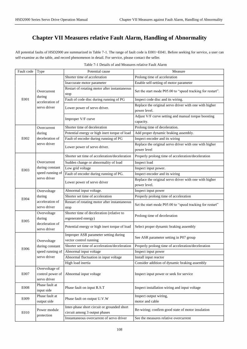
HSD2000 Series Servo Drive Operation Manual Chapter VII Measures against Fault Alarm, Handling of Abnormality
108
Chapter VII Measures relative Fault Alarm, Handling of Abnormality
All potential faults of HSD2000 are summarized in Table 7-1. The range of fault code is E001~E041. Before seeking for service, a user can
self-examine as the table, and record phenomenon in detail. For service, please contact the seller.
Table 7-1 Details of and Measures relative Fault Alarm
Fault code Type Potential cause Measure
E001
Overcurrent
during
acceleration of
servo driver
Shorter time of acceleration Prolong time of acceleration
Inaccurate motor parameter Enable self-setting of motor parameter
Restart of rotating motor after instantaneous
stop Set the start mode P05.00 to “speed tracking for restart”.
Fault of code disc during running of PG Inspect code disc and its wiring.
Lower power of servo driver. Replace the original servo driver with one with higher
power level.
Improper V/F curve Adjust V/F curve setting and manual torque boosting
capacity.
E002
Overcurrent
during
deceleration of
servo driver
Shorter time of deceleration Prolong time of deceleration.
Potential energy or high inert torque of load Add proper dynamic braking assembly.
Fault of encoder during running of PG Inspect encoder and its wiring
Lower power of servo driver. Replace the original servo driver with one with higher
power level
E003
Overcurrent
during constant
speed running of
servo driver
Shorter set time of acceleration/deceleration Properly prolong time of acceleration/deceleration
Sudden change or abnormality of load Inspect load
Low grid voltage Inspect input power.
Fault of encoder during running of PG. Inspect encoder and its wiring
Lower power of servo driver Replace the original servo driver with one with higher
power level.
E004
Overvoltage
during
acceleration of
servo driver
Abnormal input voltage. Inspect input power
Shorter set time of acceleration Properly prolong time of acceleration
Restart of rotating motor after instantaneous
stop Set the start mode P05.00 to “speed tracking for restart”
E005
Overvoltage
during
deceleration of
servo driver
Shorter time of deceleration (relative to
regenerated energy) Prolong time of deceleration
Potential energy or high inert torque of load Select proper dynamic braking assembly
E006
Overvoltage
during constant
speed running of
servo driver
Improper ASR parameter setting during
vector control running See ASR parameter setting in P07 group
Shorter set time of acceleration/deceleration Properly prolong time of acceleration/deceleration
Abnormal input voltage Inspect input power
Abnormal fluctuation in input voltage Install input reactor
High load inertia Consider addition of dynamic braking assembly
E007
Overvoltage of
control power of
servo driver
Abnormal input voltage Inspect input power or seek for service
E008 Phase fault at
input side Phase fault on input R.S.T Inspect installation wiring and input voltage
E009 Phase fault at
output side Phase fault on output U.V.W
Inspect output wiring,
motor and cable
E010 Power module
protection
Inter-phase short circuit or grounded short
circuit among 3 output phases Re-wiring; confirm good state of motor insulation
Instantaneous overcurrent of servo driver See the measures relative overcurrent

HSD2000 Series Servo Drive Operation Manual Chapter VII Measures against Fault Alarm, Handling of Abnormality
109
Fault code Type Potential cause Measure
Blocking of air duct, damage of fan Unblock air duct or replace fan
Higher ambient temperature Lower ambient temperature
Looseness of wiring or plug-in of control
panel Inspect whether re-wiring is needed
Abnormal current waveform due to output
phase fault Inspect wiring
Damage of auxiliary power and
undervoltage of driver Seek for service
Shoot-through of bridge arm of inverter
module Seek for service
Abnormality of control panel Seek for service
E011
Overheat of heat
radiator of
inverter module
Higher ambient temperature Lower ambient temperature
Blocking of air duct Clean air duct
Damage of fan Replace fan
Abnormality of inverter module Seek for service
E012
Overheat of heat
radiator of
rectifier module
Higher ambient temperature Lower ambient temperature
Blocking of air duct Clean air duct
Damage of fan Replace fan
E013 Overload of
servo driver
Inaccurate motor parameter Enable self-setting of motor parameter
Higher load Replace the original servo driver with one with higher
power
DC over-braking Reduce DC brake current and prolong time of braking
Restart of rotating motor after instantaneous
stop Set the start mode P05.00 to “speed tracking for restart”
Shorter time of acceleration Prolong time of acceleration
Lower grid voltage Inspect grid voltage
Improper V/F curve Adjust V/F curve and torque boosting capacity
E014 Overload of
motor
Incorrect setting of motor overload
protection factor Correctly set motor overload protection factor
Blocking of motor or excess of sudden
change in load Inspect load.
Long-time low-speed running of universal
motor under heavy load Select special motor for long-time low-speed running
Lower grid voltage Inspect grid voltage
Improper V/F curve Correctly set V/F curve and torque boosting capacity
E015
Emergency stop
or fault of
external
equipment
The key “STOP” pressed; See the functional definition of the key “STOP” in
P00.06.
Effectiveness of external emergency stop
terminal
After cancellation of external fault, release external
emergency stop terminal
E016 Read-write fault
of EEPROM Error in read-write of control parameter Press STOP/RESET for reset or seek for service
E017
Abnormal
communication
at serial port
Improper setting of Baud rate Set Baud rate as appropriate
Communication error at serial port Press STOP/RESET for reset or seek for service
Improper setting of fault alarm parameter Modify settings in P18.03 and P20.00
Inactiveness of upper computer Inspect whether upper computer is active and its wiring is
correct
E018 Abnormality of
contactor
Lower grid voltage Inspect grid voltage
Damage of contactor Replace contactor of main circuit or seek for service
Damage of power-on buffer resistor Replace buffer resistor or seek for service
Damage of control circuit Seek for service
Phase fault of input Inspect input R.S.T wiring
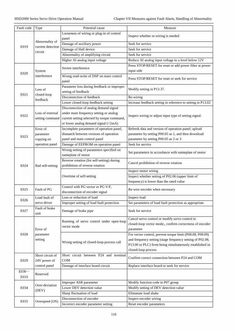
HSD2000 Series Servo Drive Operation Manual Chapter VII Measures against Fault Alarm, Handling of Abnormality
110
Fault code Type Potential cause Measure
E019
Abnormality of
current detection
circuit
Looseness of wiring or plug-in of control
panel Inspect whether re-wiring is needed
Damage of auxiliary power Seek for service
Damage of Hall device Seek for service
Abnormality of amplifying circuit Seek for service
Higher AI analog input voltage Reduce AI analog input voltage to a level below 12V
E020 System
interference
Severe interference Press STOP/RESET for reset or add power filter at power
input side
Wrong read-write of DSP on main control
panel Press STOP/RESET for reset or seek for service
E021
Loss of
closed-loop
feedback
Parameter loss during feedback or improper
setting of feedback Modify setting in P13.37.
Disconnection of feedback Re-wiring
Lower closed-loop feedback setting Increase feedback setting in reference to setting in P13.02
E022 Loss of external
setting command
Disconnection of analog demand signal
under main frequency setting or analog
current setting selected by torque command,
or lower analog demand signal (<2mA)
Inspect wiring or adjust input type of setting signal.
E023
Error of
parameter
copying on
operation panel
Incomplete parameters of operation panel,
dismatch between versions of operation
panel and main control panel
Refresh data and version of operation panel; upload
parameter by setting P00.05 as 1, and then download
parameter by setting P00.05 as 2 or 3
Damage of EEPROM on operation panel Seek for service
E024 Bad self-setting
Wrong setting of parameters specified on
nameplate of motor Set parameters in accordance with nameplate of motor
Reverse rotation (for self-setting) during
prohibition of reverse rotation Cancel prohibition of reverse rotation
Overtime of self-setting
Inspect motor wiring
Inspect whether setting of P02.06 (upper limit of
frequency) is lower than the rated value
E025 Fault of PG Control with PG vector or PG V/F,
disconnection of encoder signal Re-wire encoder when necessary
E026 Load fault of
servo driver
Loss or reduction of load Inspect load
Improper setting of load fault protection Set parameters of load fault protection as appropriate
E027 Fault of brake
unit Damage of brake pipe Seek for service
E028
Error of
parameter
setting
Running of servo control under open-loop
vector mode
Cancel servo control or modify servo control to
closed-loop vector mode;, confirm correctness of encoder
parameter
Wrong setting of closed-loop process call
For vector control, prevent torque limit (P08.08, P08.09)
and frequency setting (stage frequency setting of P02.08,
P13.00 or PLC) from being simultaneously established in
closed-loop process
E029
Short circuit of
24V power of
control panel
Short circuit between P24 and terminal
COM Confirm correct connection between P24 and COM
Damage of interface board circuit Replace interface board or seek for service
E030~
E033 Reserved
E034 Over-deviation
(DEV)
Improper ASR parameter Modify function code in P07 group
Lower DEV detection value Modify setting of DEV detection value
Sharp fluctuation of load Elimanate load shake
E035 Overspeed (OS) Disconnection of encoder Inspect encoder wiring
Incorrect encoder parameter setting Reset encoder parameters

HSD2000 Series Servo Drive Operation Manual Chapter VII Measures against Fault Alarm, Handling of Abnormality
111
Fault code Type Potential cause Measure
Lower overspeed detection value Modify setting of overspeed detection value
E036~
E040 Reserved
E041
Input
overcurrent of
CCI
Abnormality of control circuit Seek for servicfe
Higher input current Inspect analog current input
E042~
E045 Reserved
Attention
Short circuit of brake resistor on the servo driver can cause damage to brake unit of the servo driver.
All potential alarms of HSD2000 are shown in Table 7-2 (for detail, see the settings of function codes in P20 group). If fault automatically
disappears during running, the servo driver will automatically recover to the pre-alarm state, except A017 (for detail, see the note on
function codes in P20 group).
Table 7-2 Details of and Measures relative Alarm
Alarm code Type Potential cause Measure
A013 Overload of
servo driver
Inaccurate motor parameter Enable self-setting of motor parameter
Higher load Replace the original servo driver with one with higher
power
DC over-braking Reduce DC brake current and prolong time of braking
Restart of rotating motor after instantaneous
stop Set the start mode P05.00 to “speed tracking for restart”
Shorter time of acceleration Prolong time of acceleration
Lower grid voltage Inspect grid voltage
Improper V/F curve Adjust V/F curve and torque boosting capacity
A014 Overload of
motor
Incorrect setting of motor overload
protection factor Correctly set motor overload protection factor
Blocking of motor or excess of sudden
change in load Inspect load
Long-time low-speed running of universal
motor under heavy load Select special motor for long-time low-speed running
Lower grid voltage Inspect grid voltage
Improper V/F curve Correctly set V/F curve and torque boosting capacity
A016 Read-write fault
of EEPROM Error in read-write of control parameter Press STOP/RESET for reset or seek for service
A017
Abnormal
communication
at serial port
Improper setting of Baud rate Set Baud rate as appropriate
Communication error at serial port Press STOP/RESET for reset or seek for service
Improper setting of fault alarm parameter Modify settings in P18.03 and P20.00
Inactiveness of upper computer Inspect whether upper computer is active and its wiring is
correct
A018 Abnormality of
contactor
Lower grid voltage Inspect grid voltage
Damage of contactor Replace contactor of main circuit or seek for service
Damage of power-on buffer resistor Replace buffer resistor or seek for service
Damage of control circuit Seek for service
Phase fault of input Inspect input R.S.T wiring
A021
Loss of
closed-loop
feedback
Parameter loss during feedback or improper
setting of feedback Modify setting in P13.37.
Disconnection of feedback Re-wiring
Lower closed-loop feedback setting Increase feedback setting in reference to setting in P13.02

HSD2000 Series Servo Drive Operation Manual Chapter VII Measures against Fault Alarm, Handling of Abnormality
112
Alarm code Type Potential cause Measure
A022 Loss of external
setting command
Disconnection of analog demand signal
under main frequency setting or analog
current setting selected by torque command,
or lower analog demand signal (<2mA)
Inspect wiring or adjust input type of setting signal
A029
Short circuit of
24V power of
control panel
Short circuit between P24 and terminal
COM Confirm correct connection between P24 and COM.
Damage of interface board circuit Replace interface board or seek for service
! Attention
The function of fault alarm shall be enabled with caution, otherwise accident can spread and cause personal injury and property
damage.
Table 7-3 Abnormality in Operation and Measure
Phenomenon Detail Potential cause Measure
No response
on operation
panel
Individual or all keys fail to
respond.
The function of operation panel locking is
enabled.
In out-of-service state or state of running
parameter, keep down the key
“DATA/ENTER”, and then press the key
“▼” for 3 continuous times for unlocking
Re-connect power supply of servo driver
after full power-down
Poor contact of connecting wire of operation
panel Inspect connecting wire by re-hot-plug
Damage of key of operation panel Replace operation panel or seek for
service
Function code
modification
fault
Modification fault in
running state
The function code is non-modifiable in
running state.
Modify the function code in out-of-service
state
Part of function codes are
non-modifiable.
The function code P00.03 is set as “1” or “2”. Modify P00.03 to 0
The function code is measured value. User is not allowed to modify measured
value of function code.
No response is given by
pressing MENU/ESC.
The function of operation panel locking is
enabled; other cause
See the solution for “no response on
operation panel”
Modification can’t be
entered by pressing
MENU/ESC, and function
code is displayed as “0000”.
User password required
Input correct user password
Seek for service
Accidental
stop of servo
driver during
running
Without stop command,
servo driver automatically
stops and running indicator
lamp goes out.
Fault alarm Find cause of and clear fault
Simple PLC single cycle completed Inspect parameter setting of PLC
Interruption of power supply Inspect power supply
Switching of running command channel Inspect setting of function code related to
operation and running command channel
Speed over-deviation (DEV) Modify setting of DEV detection value
OS Modify setting of OS detection value
Change in positive and negative logic of
control terminal Inspect conformity of setting in P10.16
Without stop command,
motor automatically stops
and servo driver runs at zero
frequency with brightness
of running indicator.
Automatic fault recovery Inspect setting of automatic fault recovery
and cause of fault
Simple PLC pause Inspect PLC pause terminal
External interruption Inspect setting of external interruption and
fault source
Frequency setting of 0 Inspect frequency setting
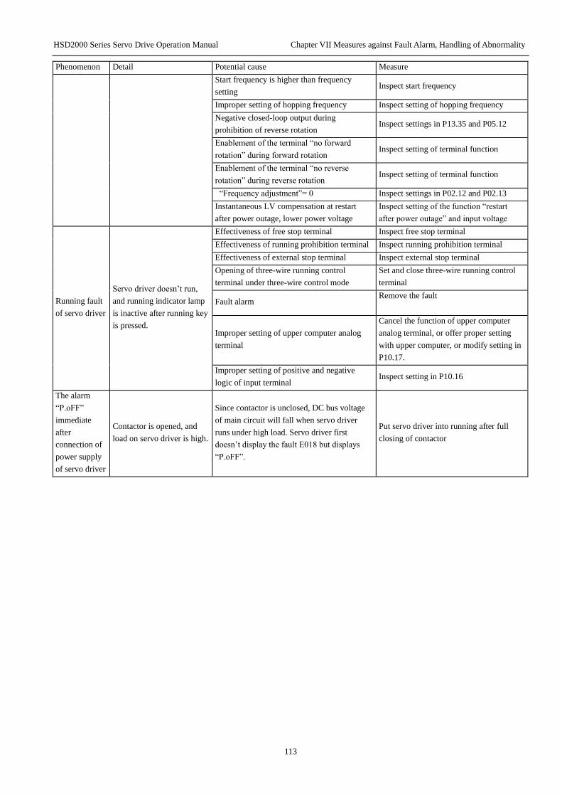
HSD2000 Series Servo Drive Operation Manual Chapter VII Measures against Fault Alarm, Handling of Abnormality
113
Phenomenon Detail Potential cause Measure
Start frequency is higher than frequency
setting Inspect start frequency
Improper setting of hopping frequency Inspect setting of hopping frequency
Negative closed-loop output during
prohibition of reverse rotation Inspect settings in P13.35 and P05.12
Enablement of the terminal “no forward
rotation” during forward rotation Inspect setting of terminal function
Enablement of the terminal “no reverse
rotation” during reverse rotation Inspect setting of terminal function
“Frequency adjustment”= 0 Inspect settings in P02.12 and P02.13
Instantaneous LV compensation at restart
after power outage, lower power voltage
Inspect setting of the function “restart
after power outage” and input voltage
Running fault
of servo driver
Servo driver doesn’t run,
and running indicator lamp
is inactive after running key
is pressed.
Effectiveness of free stop terminal Inspect free stop terminal
Effectiveness of running prohibition terminal Inspect running prohibition terminal
Effectiveness of external stop terminal Inspect external stop terminal
Opening of three-wire running control
terminal under three-wire control mode
Set and close three-wire running control
terminal
Fault alarm Remove the fault
Improper setting of upper computer analog
terminal
Cancel the function of upper computer
analog terminal, or offer proper setting
with upper computer, or modify setting in
P10.17.
Improper setting of positive and negative
logic of input terminal Inspect setting in P10.16
The alarm
“P.oFF”
immediate
after
connection of
power supply
of servo driver
Contactor is opened, and
load on servo driver is high.
Since contactor is unclosed, DC bus voltage
of main circuit will fall when servo driver
runs under high load. Servo driver first
doesn’t display the fault E018 but displays
“P.oFF”.
Put servo driver into running after full
closing of contactor

HSD2000 Series Servo Drive Operation Manual Chapter IX Functional Code List
114
Chapter VIII Servicing and Maintenance
Potential fault of the servo driver can occur due to any of ambient temperature, humidity, dust, vibration and ageing or wear of internal
components of servo driver. Given this, it is necessary to maintain the servo driver daily and regularly.
Attention
1. Before inspection or maintenance, the items below shall be confirmed, otherwise electric shock can occur.
2. Power supply of the servo driver has been disconnected.
3. The charge indicator lamp will go out when cover plate is opened.
4. The voltage measured with DC HV voltmeter between (+) and (-) is lower than 36V.
8.1 Daily servicing and maintenance
The servo driver must run in the service environment specified in 2.1. Accidents can occur during running. Daily maintenance shall be
carried out as the table below. Keeping good running environment, recording data about daily running and finding cause of abnormality as
soon as possible are favorable to prolonging service life of the servo driver.
Table 8-1 Prompt on Daily Inspection
Object Essentials
Standard Content Interval Method
Service
environment
Temperature and
humidity
Anytime
Thermometer and
hydrometer
Derating under the temperature range -10℃
~+40℃ or 40℃~50℃,
Dust, water and
leak Visual inspection No sign of water leak
Gas Olfactory inspection No odor
Servo driver Shake and heat
Anytime Touch on shell Stable vibration and reasonable air temperature
Noise Audible inspection No abnormal sound
Motor Heat
Anytime Touch No abnormal heat
Noise Audible inspection Even noise
Running state
parameter
Output current
Anytime
Ammeter Current within the range of rated value
Output voltage Voltmeter Voltage within the range of rated value
Internal
temperature Thermometer Temperature lower than 35℃
8.2 Regular maintenance
With a view to service environment, the servo driver can be inspected once 3 or 6 months.
Attention
1.Only one that has passed professional training can undertake removal of component, maintenance and replacement of device.
2.Metals such as screw and washer shall not be left in the servo driver, otherwise damage can be caused to the servo driver.
Common contents of inspection
1. Whether screw of the control terminal is loose (if the screw is loose, tighten it with screwdriver)
2. Whether there’s poor contact on terminal of the main circuit or sign of overheat at connection of the copper bar.
3. Whether there’s damage of power cable or control cable especially sign of cut on sheath in contact with metal surface
4. Whether insulating binding tape of power cable nose has fallen off.
5. Fully clear dust on circuit board and air duct with dust collector
6. A servo driver stored for long term must be energized once within 2 years, for 5h at least. In this process, voltage shall be slowly
increased to the rated value with voltage regulator. During the increase, the servo driver can be unloaded.

HSD2000 Series Servo Drive Operation Manual Chapter IX Functional Code List
115
7. For insulation test of the servo driver, all input and output terminals (R, S, T, U, V, W, PE, P1, +, -) of the main circuit must be
short-circuited and grounded for test. A terminal mustn’t be individually grounded for test, otherwise damage can be caused to the
servo driver. For the test, 500V megameter shall be used.
8. For insulation test of the motor, input terminals (U, V, W) of the motor must be removed from the servo driver, and the motor shall be
independently tested, otherwise damage can be caused to the servo driver.
Attention
1. Before delivery, withstand voltage test has been carried out. It is unnecessary for user to newly carry out withstand voltage test.
Improper test can damage the device.
2. The element for replacing an original element must be the same model with the same electrical parameters, otherwise damage
can be caused to the servo driver.
8.3 Replacement of quick-wear parts of servo driver
Quick-wear parts of the servo driver are cooling fan and filter electrolytic capacitor. Their lives are tightly associated with service
environment and situation of maintenance. Their common lives are shown in the table below.
Table 8-2 Life of Component
Name of device Life
Fan 30000~40000h
Electrolytic
capacitor 40000~50000h
Relay 100000 times
A user can establish replacement interval according to running time.
1. Cooling fan
Potential cause of damage: wear of bearing, ageing of blade
Standard: whether there’s crack on blade or sound of abnormal vibration at start
2. Filter electrolytic capacitor
Potential cause of damage: high ambient temperature, increase in pulsating current due to frequent load hopping, ageing of electrolyte
Standard: whether there’s leakage of liquid or protrusion of safety valve, measurement of electrostatic capacity, measurement of
insulation resistance
3. Relay
Potential cause of damage: corrosion, frequent action
Standard: opening/closing fault
8.4 Storage of servo driver
For temporary or long-term storage of the servo driver, attention must be paid to those below.
1. The servo driver shall not be stored where there’s high temperature, humidity, dust or metal dust. The place for storing the servo driver
shall be well ventilated.
2. Long-term storage can worsen electrolytic capacitor. Given this, for long-term storage, the servo driver must be energized once within 2
years, for 5h at least. In this process, voltage must be slowly increased to the rated value with voltage regulator.
8.5 Maintenance of servo driver
In any of the circumstances below, we will undertake repair.
1. The scope of warranty only refers to body of the servo driver.
2. For fault or damage occurring during normal service of the servo driver, the manufacturer will undertake repair within 18 months as of
the date of delivery. Anytime out of the 18 months, proper maintenance cost will be collected.
3. In any of the circumstances below, proper maintenance cost will be collected even within the 18 months.
1)Damage due to operation in violation of the user manual
2)Damage due to fire disaster, flood or abnormal voltage
3)Damage due to application of the servo driver for abnormal purpose.
4. Related service fee will be collected as actually incurred. If there’s an agreement concerned, the agreement shall prevail.

HSD2000 Series Servo Drive Operation Manual Chapter IX Functional Code List
116
Chapter IX Functional Code List
Parameters of HSD2000 series servo driver is grouped by function including 25 units as P00-P19, P20,P30 and P97-P99, each group
contain some functional codes which adopt “functional group number +function code” for grouping, samples as P XX.YZ given in the
manual mean: the YZ functional code in the XX group, for example, P10.26 means that 26th functional code in the 10th group.
Introduction to the structure of functional code list:
Table 9-1 Introduction to the structure of functional code list
Line Name Description
1 Functional code Number of functional parameter group and parameters
2 Name Full name of functional parameters
3 LCD display Functional parameter name is simply shown through LCD on the panel
4 Setting scope Valid setting scope for functional parameters, shown through LCD on the panel
5 Min unit Min unit for setting functional parameters
6 Factory default Original value of functional parameters set in factory
7 Change
Change of functional parameters (allow to change or not and conditions for any change)
“○”: means the parameter can be changed when the servo drive is kept in stop and running;
“×”: means the parameter cannot be changed when the servo drive is kept in running;
“*”: means the parameter cannot be changed when it is the actual test value;
“--”: means the parameter is “factory default” to be set by the factory only, and the user is forbidden to
change.
(The servo drive has make automatic check limit to the change of parameters so as to prevent from
improper change by the user)
Note:
1. Parameter systems adopt decimal system (DEC) and hexadecimal system (HEX), if the HEX is used, each data in editing shall be
kept independent and some values can adopt HEX (0-F).
2. LCD display in the table is available for LCD Chinese/English operation panel only.
3. “Factory default” means when the user selects the factory default, the functional code parameters will brush the value, but actually
tested parameters or record values will not be brushed.
Table 9-2 Functional Code List
Group P00: System Management
Functio
nal
Code
Name LCD Display Setting Scope Min
Unit Default
Chang
e
P00.00 Menu mode option Menu mode
option
0: Shortcut menu: display only parameters related
to the shortcut operation of servo driver;
1: Basic menu: display only basic functional
parameters
2: Advanced menu: display all parameters;
3: User menu: display only 32 parameters that the
user set in P98;
4: Proof menu: display only parameter groups
differing from the default.
1 2 ○
P00.01 LCD language
option
Language
option
0: Chinese
1: English
2~4: Reserved
1 0 ○
P00.02 Password Password 0: No password
Other: Password needed 1 0 ○
P00.03 Parameter
protection setting
Parameter
protection
setting
0: Able to change all data;
1: Not allow to change except this functional code
and main frequency setting P02.04.
2: Not allow to change except this functional code
1 0 ○
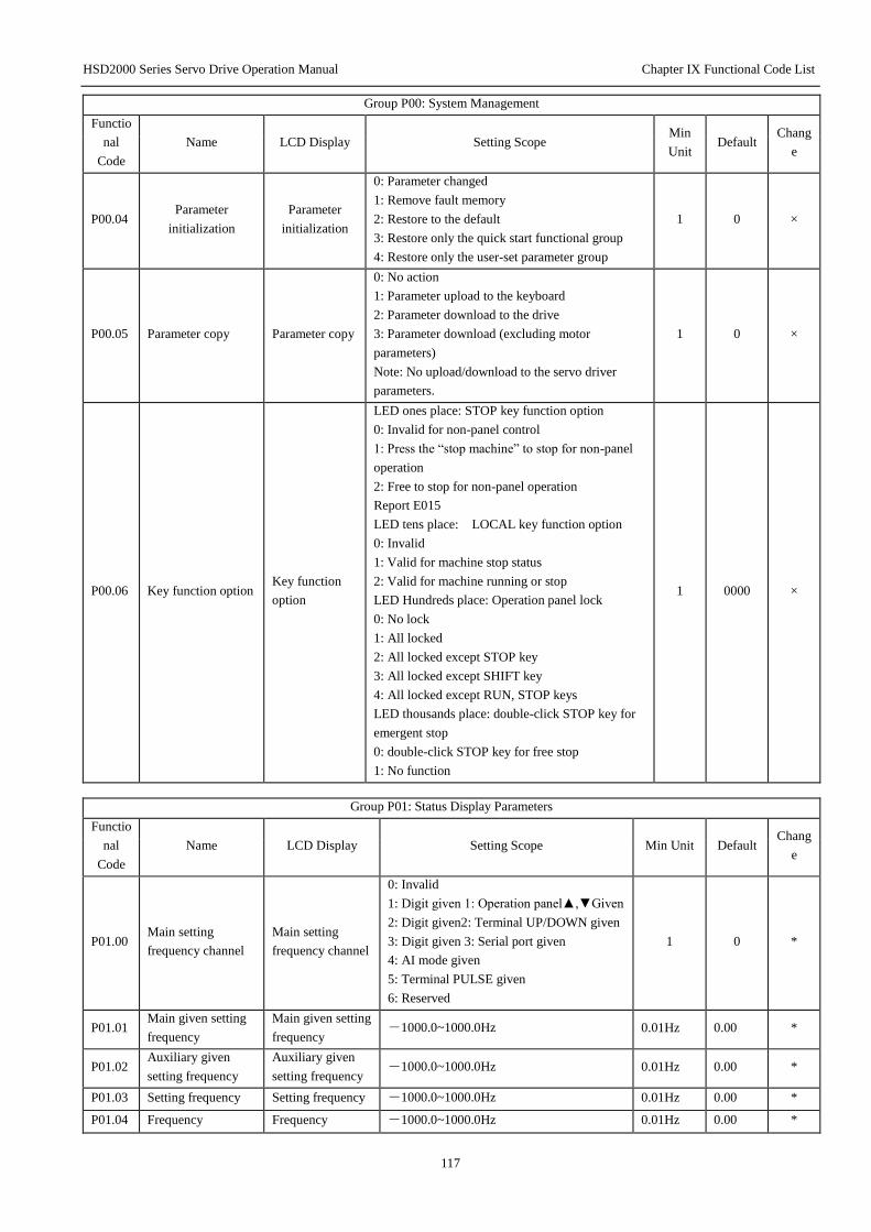
HSD2000 Series Servo Drive Operation Manual Chapter IX Functional Code List
117
Group P00: System Management
Functio
nal
Code
Name LCD Display Setting Scope Min
Unit Default
Chang
e
P00.04 Parameter
initialization
Parameter
initialization
0: Parameter changed
1: Remove fault memory
2: Restore to the default
3: Restore only the quick start functional group
4: Restore only the user-set parameter group
1 0 ×
P00.05 Parameter copy Parameter copy
0: No action
1: Parameter upload to the keyboard
2: Parameter download to the drive
3: Parameter download (excluding motor
parameters)
Note: No upload/download to the servo driver
parameters.
1 0 ×
P00.06 Key function option Key function
option
LED ones place: STOP key function option
0: Invalid for non-panel control
1: Press the “stop machine” to stop for non-panel
operation
2: Free to stop for non-panel operation
Report E015
LED tens place: LOCAL key function option
0: Invalid
1: Valid for machine stop status
2: Valid for machine running or stop
LED Hundreds place: Operation panel lock
0: No lock
1: All locked
2: All locked except STOP key
3: All locked except SHIFT key
4: All locked except RUN, STOP keys
LED thousands place: double-click STOP key for
emergent stop
0: double-click STOP key for free stop
1: No function
1 0000 ×
Group P01: Status Display Parameters
Functio
nal
Code
Name LCD Display Setting Scope Min Unit Default Chang
e
P01.00 Main setting
frequency channel
Main setting
frequency channel
0: Invalid
1: Digit given 1: Operation panel▲,▼Given
2: Digit given2: Terminal UP/DOWN given
3: Digit given 3: Serial port given
4: AI mode given
5: Terminal PULSE given
6: Reserved
1 0 *
P01.01 Main given setting
frequency
Main given setting
frequency -1000.0~1000.0Hz 0.01Hz 0.00 *
P01.02 Auxiliary given
setting frequency
Auxiliary given
setting frequency -1000.0~1000.0Hz 0.01Hz 0.00 *
P01.03 Setting frequency Setting frequency -1000.0~1000.0Hz 0.01Hz 0.00 *
P01.04 Frequency Frequency -1000.0~1000.0Hz 0.01Hz 0.00 *

HSD2000 Series Servo Drive Operation Manual Chapter IX Functional Code List
118
Group P01: Status Display Parameters
Functio
nal
Code
Name LCD Display Setting Scope Min Unit Default Chang
e
instruction(after
Acc or Dec)
instruction
P01.05 Output frequency Output frequency -1000.0~1000.0Hz 0.01Hz 0.00 *
P01.06 Output voltage Output voltage 0~480V 1V 0 *
P01.07 Output current Output current 0.0~3Ie 0.1A 0.0 *
P01.08 Torque current Torque current -300.0%~+300.0% 0.1% 0.0% *
P01.09 Flux current Flux current 0.0%~+100.0% 0.1% 0.0% *
P01.10 Output torque Output torque -300.0%~+300.0% 0.1% 0.0% *
P01.11 Motor power Motor power 0.0%~200.0%(relative rated power of the
motor) 0.1% 0.0% *
P01.12 Motor estimate
frequency
Estimated motor
frequency -600.00~600.00Hz 0.01 0.00 *
P01.13 Motor measured
frequency
Motor measured
frequency -600.00~600.00Hz 0.01 0.00 *
P01.14
Energy
consumption high
bit(kWh)
Energy
consumption high
bit (kWh)
0~65535*10000kWh 10000kW
h 0 *
P01.15
Energy
consumption low bit
(kWh)
Energy
consumption low
bit (kWh)
0~9999kWh 1kWh 0 *
P01.16 Bus voltage Bus voltage 0~800V 1V 0 *
P01.17 Servo driver
running status
Servo driver
running status
0~7FFFH
BIT0: Run/Stop
BIT1: Reverse/Forward
BIT2: Zero speed run
BIT3: Accelerate
BIT4: Decelerate
BIT5: Constant speed run
BIT6: Pre-excitation
BIT7: Setting
BIT8: Over current limit
BIT9: DC over voltage limit
BIT10: Torque limit
BIT11: Speed limit
BIT12: Servo driver fails
BIT13: Speed control
BIT14: Torque control
BIT15: Place control
1 0 *
P01.18 Digital input
terminal status DI terminal status 0~3FFH, 0: off; 1: on 1 000 *
P01.19 Digital output
terminal status DO terminal status 0~FH, 0: off; 1: on 1 0 *
P01.20 AI1 input voltage AI1 input voltage -10.00~10.00V 0.01V 0.00 *
P01.21 AI2 input voltage AI2 input voltage -10.00~10.00V 0.01V 0.00 *
P01.22 AI3 input voltage AI3 input voltage -10.00~10.00V 0.01V 0.00 *
P01.23 Adjusted AI1 input Adjusted AI1
input -10.00~10.00V 0.01V 0.00 *
P01.24 Adjusted AI2 input Adjusted AI2
input -10.00~10.0V 0.01V 0.00 *

HSD2000 Series Servo Drive Operation Manual Chapter IX Functional Code List
119
Group P01: Status Display Parameters
Functio
nal
Code
Name LCD Display Setting Scope Min Unit Default Chang
e
P01.25 Adjusted AI3 input Adjusted AI3
input -10.00~10.00V 0.01V 0.00 *
P01.26 AO1 output AO1 output 0.0~100.0%( percent relative full range) 0.1% 0.0% *
P01.27 AO2 output AO2 output 0.0~100.0%( percent relative full range) 0.1% 0.0% *
P01.28 Process close-loop
given
Process close-loop
given
-100.0~100.0%( percent relative full
range) 0.1% 0.0% *
P01.29 Process close-loop
feedback
Process close-loop
feedback
-100.0~100.0%( percent relative full
range) 0.1% 0.0% *
P01.30 Process close-loop
error
Process close-loop
error
-100.0~100.0%( percent relative full
range) 0.1% 0.0% *
P01.31 Process close-loop
output
Process close-loop
output
-100.0~100.0%( percent relative full
range) 0.1% 0.0% *
P01.32 Radiator1
temperature
Radiator1
temperature 0.0~150.0℃ 0.1℃ 0.0 *
P01.33 Radiator2
temperature
Radiator2
temperature 0.0~150.0℃ 0.1℃ 0.0 *
P01.34 Reserved Reserved *
P01.35 Reserved Reserved *
P01.36 Power on hours
accumulated
Power on hours
accumulated 0~max65535 hours 1 hour 0 *
P01.37 Run hour
accumulated
Run house
accumulated 0~max65535 hours 1 hour 0 *
P01.38 Fan run hour
accumulated
Fan run hour
accumulated 0~max65535 hours 1 hour 0 *
P01.39 Reserved Reserved *
P01.40 ASR controller
output
ASR controller
output
-300.0~300.0%(Rated torque relative
motor) 0.1% 0.0% *
P01.41 Torque given Torque given -300.0~300.0%(Rated torque relative
motor) 0.1% 0.0% *
P01.42 Reserved Reserved *
P01.43 Position loop given
high bit Given high bit 0~FFFFH 1 0 *
P01.44 Position loop given
low bit Given low bit 0~FFFFH 1 0 *
P01.45
Position loop
feedback high
position
Feedback high
position 0~FFFFH 1 0 *
P01.46
Position loop
feedback low
position
Feedback low
position 0~FFFFH 1 0 *
P01.47 Position error pulse Position error -9999~9999 1 0 *
P01.48 Reserved Reserved Reserved - - *
P01.49
~P01.5
7
Reserved Reserved Reserved - - *

HSD2000 Series Servo Drive Operation Manual Chapter IX Functional Code List
120
Group P02: Basic Operation Parameters
Functio
nal
Code
Name LCD Display Setting Scope Min
Unit Default
Chang
e
P02.00 Motor and mode
option
Motor and mode
option
Ones place: Motor 1 control mode
option
0: Vector control without PG
1: Vector control with PG
2: V/F control without PG
3: V/F control with PG
Tens place: Motor 1 type option
0: Asynchronous motor
1: Synchronous motor
Hundreds place: Motor 2 control
mode option
0: Vector control without PG
1: Vector control with PG
2: V/F control without PG
3: V/F control with PG
Thousands place: Motor 2 type option
0: Asynchronous motor
1: Synchronous motor
1 0002 ×
P02.01 Motor option Motor option 0: Motor 1
1: Motor 2 1 0 ×
P02.02 Operation command
channel option
Command channel
option
0: Operation panel control
1: Terminal control
2: Comm. control
3: Reserved
1 0 ○
P02.03
Main setting
frequency source
option
Main given source
option
0: Digit given1: operation panel▲,▼
given
1: Digit given2: Terminal UP/DOWN
given
2: Digit given3: Serial port comm.
given
3: AI analog given
4: Terminal PULSE given
5: Reserved
1 0 ○
P02.04
Main setting
frequency digital
setting
Main setting
frequency set P02.07~P02.06 0.01Hz 50.00 ○
P02.05 Max output
frequency
Max output
frequency
MAX{50.00, Upper frequency
limitP02.06}~1000.0Hz 0.01Hz 50.00 ×
P02.06 Upper limit
frequency
Upper limit
frequency P02.07~P02.05 0.01Hz 50.00 ○
P02.07 Lower limit
frequency
Lower limit
frequency 0.00~P02.06 0.01Hz 0.00 ○
P02.08
Auxiliary setting
frequency source
option
Auxiliary frequency
source option
0: no assistance given
1: Digit given1: operation panel▲,▼
given
2: Digit given2: Terminal UP/DOWN
given
3: Digit given3: Serial port comm.
given
4: AI analog given
5: Terminal PULSE given
6: Reserved
7: Process closed-loop output
1 0 ○
P02.09 Auxiliary given Auxiliary given 0.00~9.99 0.01 1.00 ○
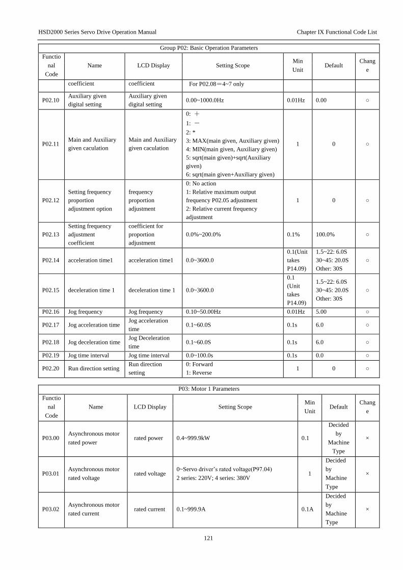
HSD2000 Series Servo Drive Operation Manual Chapter IX Functional Code List
121
Group P02: Basic Operation Parameters
Functio
nal
Code
Name LCD Display Setting Scope Min
Unit Default
Chang
e
coefficient coefficient For P02.08=4~7 only
P02.10 Auxiliary given
digital setting
Auxiliary given
digital setting 0.00~1000.0Hz 0.01Hz 0.00 ○
P02.11 Main and Auxiliary
given caculation
Main and Auxiliary
given caculation
0: +
1: -
2: *
3: MAX(main given, Auxiliary given)
4: MIN(main given, Auxiliary given)
5: sqrt(main given)+sqrt(Auxiliary
given)
6: sqrt(main given+Auxiliary given)
1 0 ○
P02.12
Setting frequency
proportion
adjustment option
frequency
proportion
adjustment
0: No action
1: Relative maximum output
frequency P02.05 adjustment
2: Relative current frequency
adjustment
1 0 ○
P02.13
Setting frequency
adjustment
coefficient
coefficient for
proportion
adjustment
0.0%~200.0% 0.1% 100.0% ○
P02.14 acceleration time1 acceleration time1 0.0~3600.0
0.1(Unit
takes
P14.09)
1.5~22: 6.0S
30~45: 20.0S
Other: 30S
○
P02.15 deceleration time 1 deceleration time 1 0.0~3600.0
0.1
(Unit
takes
P14.09)
1.5~22: 6.0S
30~45: 20.0S
Other: 30S
○
P02.16 Jog frequency Jog frequency 0.10~50.00Hz 0.01Hz 5.00 ○
P02.17 Jog acceleration time Jog acceleration
time 0.1~60.0S 0.1s 6.0 ○
P02.18 Jog deceleration time Jog Deceleration
time 0.1~60.0S 0.1s 6.0 ○
P02.19 Jog time interval Jog time interval 0.0~100.0s 0.1s 0.0 ○
P02.20 Run direction setting Run direction
setting
0: Forward
1: Reverse 1 0 ○
P03: Motor 1 Parameters
Functio
nal
Code
Name LCD Display Setting Scope Min
Unit Default
Chang
e
P03.00 Asynchronous motor
rated power rated power 0.4~999.9kW 0.1
Decided
by
Machine
Type
×
P03.01 Asynchronous motor
rated voltage rated voltage
0~Servo driver’s rated voltage(P97.04)
2 series: 220V; 4 series: 380V 1
Decided
by
Machine
Type
×
P03.02 Asynchronous motor
rated current rated current 0.1~999.9A 0.1A
Decided
by
Machine
Type
×
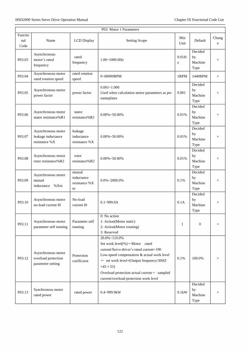
HSD2000 Series Servo Drive Operation Manual Chapter IX Functional Code List
122
P03: Motor 1 Parameters
Functio
nal
Code
Name LCD Display Setting Scope Min
Unit Default
Chang
e
P03.03
Asynchronous
motor’s rated
frequency
rated
frequency 1.00~1000.0Hz
0.01H
z
Decided
by
Machine
Type
×
P03.04 Asynchronous motor
rated rotation speed
rated rotation
speed 0~60000RPM 1RPM 1440RPM ×
P03.05 Asynchronous motor
power factor power factor
0.001~1.000
Used when calculation motor parameters as per
nameplates
0.001
Decided
by
Machine
Type
×
P03.06 Asynchronous motor
stator resistance%R1
stator
resistance%R1 0.00%~50.00% 0.01%
Decided
by
Machine
Type
×
P03.07
Asynchronous motor
leakage inductance
resistance %X
leakage
inductance
resistance %X
0.00%~50.00% 0.01%
Decided
by
Machine
Type
×
P03.08 Asynchronous motor
rotor resistance%R2
rotor
resistance%R2 0.00%~50.00% 0.01%
Decided
by
Machine
Type
×
P03.09
Asynchronous motor
mutual
inductance %Xm
mutual
inductance
resistance %X
m
0.0%~2000.0% 0.1%
Decided
by
Machine
Type
×
P03.10 Asynchronous motor
no-load current I0
No-load
current I0 0.1~999.9A 0.1A
Decided
by
Machine
Type
×
P03.11 Asynchronous motor
parameter self tunning
Parameter self
tunning
0: No action
1: Action(Motor static)
2: Action(Motor rotating)
3: Reserved
1 0 ×
P03.12
Asynchronous motor
overload protection
parameter setting
Protection
coefficient
20.0%~110.0%
Set work level(%)=Motor rated
current/Servo driver’s rated current×100
Low-speed compensation & actual work level
= set work level×(Output frequency/30HZ
×45+55)
Overload protection actual current= sampled
current/overload protection work level
0.1% 100.0% ×
P03.13 Synchronous motor
rated power rated power 0.4~999.9kW 0.1kW
Decided
by
Machine
Type
×

HSD2000 Series Servo Drive Operation Manual Chapter IX Functional Code List
123
P03: Motor 1 Parameters
Functio
nal
Code
Name LCD Display Setting Scope Min
Unit Default
Chang
e
P03.14 Synchronous motor
rated voltage rated voltage 0~Servo driver’s rated voltage(P97.04) 1V
Decided
by
Machine
Type
×
P03.15 Synchronous motor
rated current rated current 0.1~999.9A 0.1A
Decided
by
Machine
Type
×
P03.16 Synchronous motor’s
rated frequency
Motor rated
frequency 1.00~1000.0Hz
0.01H
z
Decided
by
Machine
Type
×
P03.17 Synchronous motor
pole pairs
Motor pole
pairs 1~40 1 2 ×
P03.18 Synchronous motor
rated speed
rated rotation
speed 0~60000RPM 1RPM 1500RPM ×
P03.19 Synchronous motor
stator resistance
stator
resistance%R1 0.00%~50.00% 0.01%
Decided
by
Machine
Type
×
P03.20 Synchronous motor
d-axis inductance
d-axis
inductance 0.0~999.9mH
0.1m
H
Decided
by
Machine
Type
×
P03.21 Synchronous motor
q-axis inductance
q-axis
inductance 0.0~999.9mH
0.1m
H
Decided
by
Machine
Type
×
P03.22 Synchronous motor
back-EMF constant
Back-EMF
constant 1000V/1000rpm 1 150 ×
P03.23 Synchronous motor
position identification
position
identification
Identify from 0→1, and change to 0 after
ending 1 0 ×
P03.24 Synchronous motor
identify current
Identify
current 0~30%Motor rated current 1 10 ×
P03.25 Synchronous motor
initial angle initial angle 0~FFFFH 1 0 ×
P03.26 Z pulse initial angle Z pulse angle 0~FFFFH 1 0 ×
P03.27
synchronous motor
overload protection
coefficient setting
protective
coefficient
20.0%~110.0%
Setting work level(%)=Motor rated
current/Servo driver’s rated current×100
Low-speed compensation & actual work level
=Setting work level×(Output
frequency/30HZ×45+55)
Overload protection and actual current=
sampled current/overload protection work level
0.1% 100.0% ×
P04: Motor 2 Parameters
Functio
nal
Code
Name LCD Display Setting Scope Min
Unit Default
Chang
e

HSD2000 Series Servo Drive Operation Manual Chapter IX Functional Code List
124
P04: Motor 2 Parameters
Functio
nal
Code
Name LCD Display Setting Scope Min
Unit Default
Chang
e
P04.00 Asynchronous motor
rated power rated power 0.4~999.9kW 0.1kW
Decided
by
Machine
Type
×
P04.01 Asynchronous motor
rated voltage rated voltage
0~Servo driver’s rated voltage(P97.04)
2 series: 220V
4 series: 380V
1V
Decided
by
Machine
Type
×
P04.02 Asynchronous motor
rated current rated current 0.1~999.9A 0.1A
Decided
by
Machine
Type
×
P04.03
Asynchronous
motor’s rated
frequency
rated
frequency 1.00~1000.0Hz
0.01H
z
Decided
by
Machine
Type
×
P04.04 Asynchronous motor
rated speed
rated rotation
speed 0~60000RPM 1RPM 1440RPM ×
P04.05 Asynchronous motor
power factor power factor
0.001~1.000
Used when calculating motor parameters as per
nameplates
0.001
Decided
by
Machine
Type
×
P04.06 Asynchronous motor
stator resistance%R1
Stator
resistance%R1 0.00%~50.00% 0.01%
Decided
by
Machine
Type
×
P04.07
Asynchronous motor
leakage inductance
resistance %X
Leakage
inductance
resistance %X
0.00%~50.00% 0.01%
Decided
by
Machine
Type
×
P04.08 Asynchronous motor
rotor resistance%R2
Rotor
resistance%R2 0.00%~50.00% 0.01%
Decided
by
Machine
Type
×
P04.09
Asynchronous motor
mutual inductance
resistance %Xm
mutual
inductance
resistance %Xm
0.0%~2000.0% 0.1%
Decided
by
Machine
Type
×
P04.10 Asynchronous motor
no-load current I0
no-load current
I0 0.1~999.9A 0.1A
Decided
by
Machine
Type
×
P04.11
Asynchronous motor
parameters self
tunning
Parameters self
tunning
0: No action
1: Action(Motor static)
2: Action(Motor rotation)
3: Reserved
1 0 ×
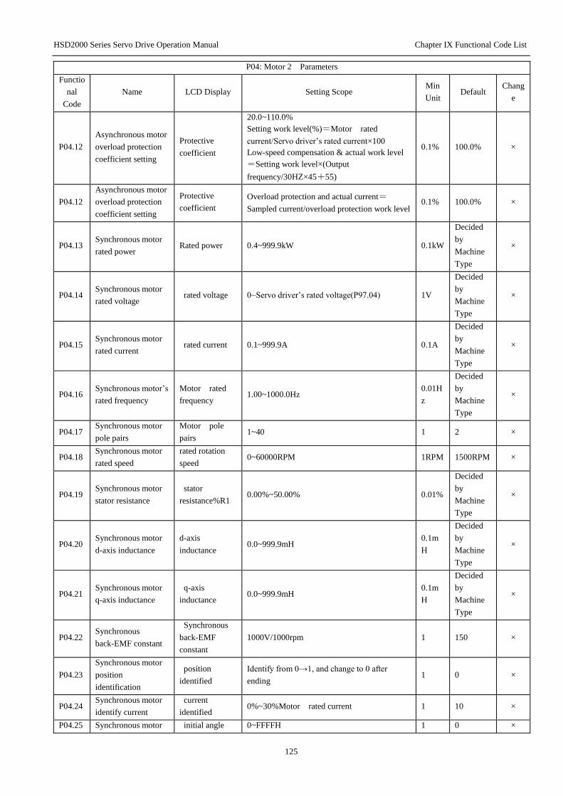
HSD2000 Series Servo Drive Operation Manual Chapter IX Functional Code List
125
P04: Motor 2 Parameters
Functio
nal
Code
Name LCD Display Setting Scope Min
Unit Default
Chang
e
P04.12
Asynchronous motor
overload protection
coefficient setting
Protective
coefficient
20.0~110.0%
Setting work level(%)=Motor rated
current/Servo driver’s rated current×100
Low-speed compensation & actual work level
=Setting work level×(Output
frequency/30HZ×45+55)
0.1% 100.0% ×
P04.12
Asynchronous motor
overload protection
coefficient setting
Protective
coefficient
Overload protection and actual current=
Sampled current/overload protection work level 0.1% 100.0% ×
P04.13 Synchronous motor
rated power Rated power 0.4~999.9kW 0.1kW
Decided
by
Machine
Type
×
P04.14 Synchronous motor
rated voltage rated voltage 0~Servo driver’s rated voltage(P97.04) 1V
Decided
by
Machine
Type
×
P04.15 Synchronous motor
rated current rated current 0.1~999.9A 0.1A
Decided
by
Machine
Type
×
P04.16 Synchronous motor’s
rated frequency
Motor rated
frequency 1.00~1000.0Hz
0.01H
z
Decided
by
Machine
Type
×
P04.17 Synchronous motor
pole pairs
Motor pole
pairs 1~40 1 2 ×
P04.18 Synchronous motor
rated speed
rated rotation
speed 0~60000RPM 1RPM 1500RPM ×
P04.19 Synchronous motor
stator resistance
stator
resistance%R1 0.00%~50.00% 0.01%
Decided
by
Machine
Type
×
P04.20 Synchronous motor
d-axis inductance
d-axis
inductance 0.0~999.9mH
0.1m
H
Decided
by
Machine
Type
×
P04.21 Synchronous motor
q-axis inductance
q-axis
inductance 0.0~999.9mH
0.1m
H
Decided
by
Machine
Type
×
P04.22 Synchronous
back-EMF constant
Synchronous
back-EMF
constant
1000V/1000rpm 1 150 ×
P04.23
Synchronous motor
position
identification
position
identified
Identify from 0→1, and change to 0 after
ending 1 0 ×
P04.24 Synchronous motor
identify current
current
identified 0%~30%Motor rated current 1 10 ×
P04.25 Synchronous motor initial angle 0~FFFFH 1 0 ×

HSD2000 Series Servo Drive Operation Manual Chapter IX Functional Code List
126
P04: Motor 2 Parameters
Functio
nal
Code
Name LCD Display Setting Scope Min
Unit Default
Chang
e
initial angle
P04.26 Synchronous motor
Z pulse initial angle Z pulse angle 0~FFFFH 1 0 ×
P04.27
Synchronous motor
overload protection
coefficient setting
protective
coefficient
20.0%~110.0%
Setting work level(%)=Motor rated
current/Servo driver’s rated current×100
Low-speed compensation & actual work level
=Setting work level×(Output
frequency/30HZ×45+55)
Overload protection and actual current=
Sampled current/overload protection work level
0.1% 100.0% ×
P04.28 Motor 2 PI
Parameters option
PI Parameters
option
0: The same as motor 1 PI Parameters
1: Taken from P04.29~P04.32 1 0 ×
P04.29 Motor 2 ASR-P ASR1-P 0.1~200.0 0.1 20.0 ○
P04.30 Motor 2 ASR-I ASR1-I 0.010~1.000S 0.001s 0.200s ○
P04.31 Motor 2 ACR-P ACR-P 1~5000 1 1000 ○
P04.32 Motor 2 ACR-I ACR-I 0.5~100.0ms 0.1 8.0 ○
P04.33 Motor 2 encoder
option
Motor 2 encoder
option
0: Local encoder
1: Expansion encoder 1 1 ×
P05: Start/close Control Parameters
Functio
nal
Code
Name LCD Display Setting Scope Min
Unit
Defaul
t
Chang
e
P05.00 Start mode Start mode
0 Starting from starting frequency
1 First brake, then start from starting
frequency
2 Rotation speed track, including direction
judgment before start
1 0 ×
P05.01 Start frequency Start frequency 0.00~60.00Hz 0.01Hz 0.00H
z ○
P05.02 Start frequency holding
time
Start frequency
holding time 0.00~10.00s 0.01s 0.00s ○
P05.03 Start DC brake current Start DC brake
current 0.0%~100.0%Servo driver’s rated current 0.1% 0.0% ○
P05.04 Start DC brake time Start DC brake
time
0.00(No action)
0.01~30.00s 0.01s 0.00s ○
P05.05 Stop Mode Stop Mode
0: deceleration stop
1: Free to stop
2: deceleration stop+DC brake
1 0 ×
P05.06 Stop DC brake initial
frequency
Stop brake initial
frequency 0.00~60.00Hz 0.01Hz
0.00H
z ○
P05.07 Stop DC brake waiting
time
Stop brake
waiting time 0.00~10.00s 0.01s 0.00s ○
P05.08 Stop DC brake current Stop DC brake
current 0.0%~100.0%Servo driver’s rated current 0.1% 0.0% ○
P05.09 Stop DC brake time Stop DC brake
time
0.0(No action)
0.01~30.00s 0.01s 0.00s ○
P05.10 Restart after power Restart after 0: No action 1 0 ×

HSD2000 Series Servo Drive Operation Manual Chapter IX Functional Code List
127
P05: Start/close Control Parameters
Functio
nal
Code
Name LCD Display Setting Scope Min
Unit
Defaul
t
Chang
e
fault power fault 1: Action
P05.11 Waiting time for restart
after power fault
Waiting time for
restart after power
fault
0.0~10.0s 0.1s 0.0s ○
P05.12 Anti-reverse option Anti-reverse
option
0: Allow reverse
1: Forbid reverse(apply reverse run command
for 0-frequency run)
1 0 ×
P05.13 Forward-Reverse dead
zone time
Forward-Reverse
dead zone time 0.00~360.00s 0.01s 0.00s ○
P05.14 Forward -Reverse
switch mode
Forward -Reverse
switch mode
0: 0 frequency switch
1: Over starting frequency switch 1 0 ×
P05.15 Stop speed Stop speed 0.00~150.00Hz 0.01Hz 0.10H
z ×
P05.16 Stop speed test Stop speed test
0: Speed value set(only the method for V/F
mode)
1: Speed measure value
1 0 ×
P05.17 Stop speed delay time Stop speed delay
time 0.00~10.00S 0.01s 0.05s ×
P05.18 Energy consumption
brake option
Energy
consumption
brake option
0: No action
1: Action 1 0 ×
P05.19 Energy consumption
brake service rating
Brake service
rating 0.0~100.0% 0.1% 80.0% ○
P06: V/F control Parameters
Functio
nal
Code
Name LCD Display Setting Scope Min Unit Default Chang
e
P06.00 Motor 1V/F curve
setting
Motor 1V/F curve
setting
0: User defines V/F curve
1: Square curve
2: One point seven power curve
3: One point two power curve
1 0 ×
P06.01 Motor 1V/F frequency
3
Motor 1V/F frequency
3 P06.03~P02.05 0.01Hz 0.00Hz ×
P06.02 Motor 1V/F voltage 3 Motor 1V/F voltage 3 P06.04~100.0% 0.1% 0.0% ×
P06.03 Motor 1V/F frequency
2
Motor 1V/F frequency
2 P06.05 ~P06.01 0.01Hz 0.00Hz ×
P06.04 Motor 1V/F voltage 2 Motor 1V/F voltage 2 P06.06~P06.02 0.1% 0.0% ×
P06.05 Motor 1V/F frequency
1
Motor 1V/F frequency
1 0.00~P06.03 0.01Hz 0.00Hz ×
P06.06 Motor 1V/F voltage 1 Motor 1V/F voltage 1 0~P06.04 0.1% 0.0% ×
P06.07 Motor 1 torque lift Motor 1 torque lift 0.0%~30.0% 0.1% 0.0% ○
P06.08 Motor 1 torque lift
cut-off point
Torque lift cut-off
point 0.0%~50.0%(relative to P06.09) 0.1% 10.0% ○
P06.09 Motor 1 base
frequency Base frequency 1.00~1000.0Hz 0.01Hz 50.00 ×
P06.10 Motor 1Max Output
voltage Max Output voltage 0~480V 1V
Rated
value of
servo
driver
×
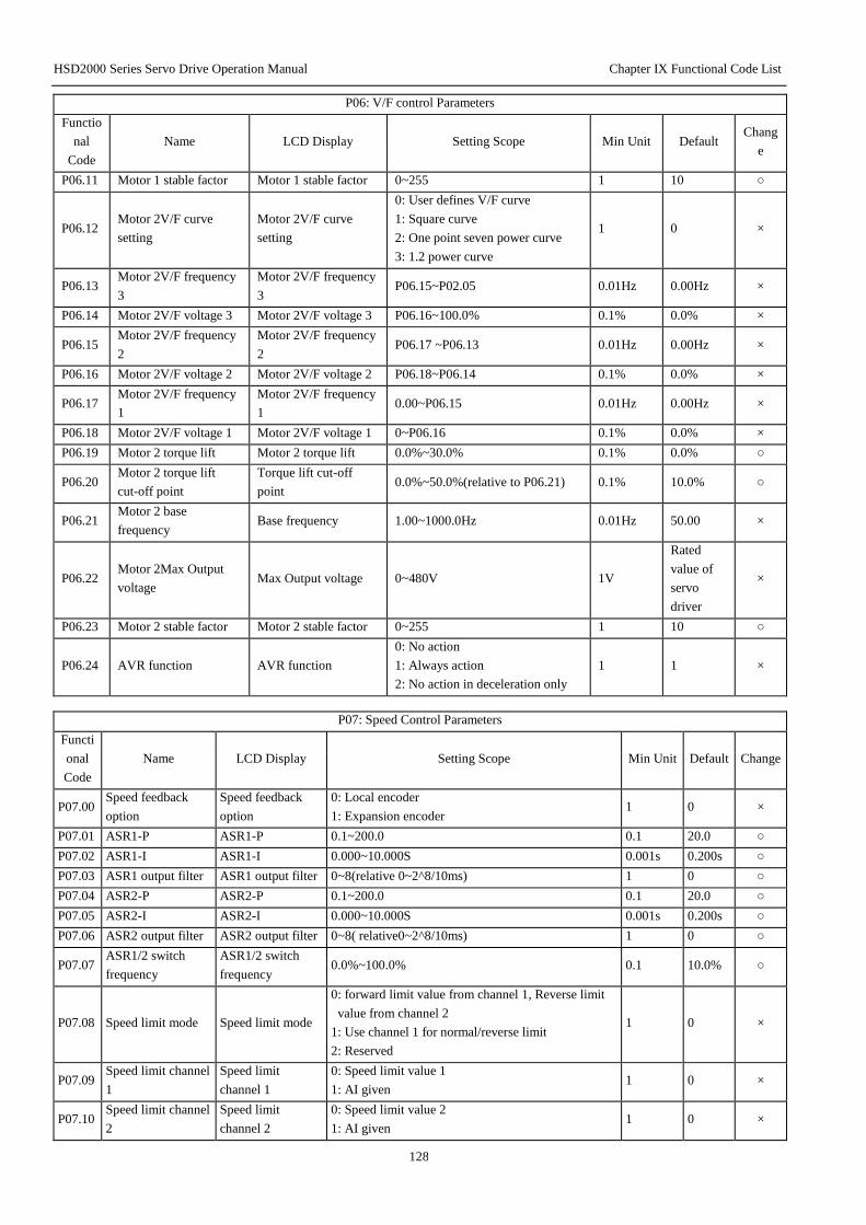
HSD2000 Series Servo Drive Operation Manual Chapter IX Functional Code List
128
P06: V/F control Parameters
Functio
nal
Code
Name LCD Display Setting Scope Min Unit Default Chang
e
P06.11 Motor 1 stable factor Motor 1 stable factor 0~255 1 10 ○
P06.12 Motor 2V/F curve
setting
Motor 2V/F curve
setting
0: User defines V/F curve
1: Square curve
2: One point seven power curve
3: 1.2 power curve
1 0 ×
P06.13 Motor 2V/F frequency
3
Motor 2V/F frequency
3 P06.15~P02.05 0.01Hz 0.00Hz ×
P06.14 Motor 2V/F voltage 3 Motor 2V/F voltage 3 P06.16~100.0% 0.1% 0.0% ×
P06.15 Motor 2V/F frequency
2
Motor 2V/F frequency
2 P06.17 ~P06.13 0.01Hz 0.00Hz ×
P06.16 Motor 2V/F voltage 2 Motor 2V/F voltage 2 P06.18~P06.14 0.1% 0.0% ×
P06.17 Motor 2V/F frequency
1
Motor 2V/F frequency
1 0.00~P06.15 0.01Hz 0.00Hz ×
P06.18 Motor 2V/F voltage 1 Motor 2V/F voltage 1 0~P06.16 0.1% 0.0% ×
P06.19 Motor 2 torque lift Motor 2 torque lift 0.0%~30.0% 0.1% 0.0% ○
P06.20 Motor 2 torque lift
cut-off point
Torque lift cut-off
point 0.0%~50.0%(relative to P06.21) 0.1% 10.0% ○
P06.21 Motor 2 base
frequency Base frequency 1.00~1000.0Hz 0.01Hz 50.00 ×
P06.22 Motor 2Max Output
voltage Max Output voltage 0~480V 1V
Rated
value of
servo
driver
×
P06.23 Motor 2 stable factor Motor 2 stable factor 0~255 1 10 ○
P06.24 AVR function AVR function
0: No action
1: Always action
2: No action in deceleration only
1 1 ×
P07: Speed Control Parameters
Functi
onal
Code
Name LCD Display Setting Scope Min Unit Default Change
P07.00 Speed feedback
option
Speed feedback
option
0: Local encoder
1: Expansion encoder 1 0 ×
P07.01 ASR1-P ASR1-P 0.1~200.0 0.1 20.0 ○
P07.02 ASR1-I ASR1-I 0.000~10.000S 0.001s 0.200s ○
P07.03 ASR1 output filter ASR1 output filter 0~8(relative 0~2^8/10ms) 1 0 ○
P07.04 ASR2-P ASR2-P 0.1~200.0 0.1 20.0 ○
P07.05 ASR2-I ASR2-I 0.000~10.000S 0.001s 0.200s ○
P07.06 ASR2 output filter ASR2 output filter 0~8( relative0~2^8/10ms) 1 0 ○
P07.07 ASR1/2 switch
frequency
ASR1/2 switch
frequency 0.0%~100.0% 0.1 10.0% ○
P07.08 Speed limit mode Speed limit mode
0: forward limit value from channel 1, Reverse limit
value from channel 2
1: Use channel 1 for normal/reverse limit
2: Reserved
1 0 ×
P07.09 Speed limit channel
1
Speed limit
channel 1
0: Speed limit value 1
1: AI given 1 0 ×
P07.10 Speed limit channel
2
Speed limit
channel 2
0: Speed limit value 2
1: AI given 1 0 ×

HSD2000 Series Servo Drive Operation Manual Chapter IX Functional Code List
129
P07: Speed Control Parameters
Functi
onal
Code
Name LCD Display Setting Scope Min Unit Default Change
P07.11 Speed limit value 1 Speed limit value 1 0.0%~100.0% 0.1% 100.0% ○
P07.12 Speed limit value 2 Speed limit value 2 0.0%~100.0% 0.1% 100.0% ○
P07.13 Speed deviation
(DEV) action select DEV action select
0: Deceleration stop
1: Free to stop, report E034
2: Continue to action
1 2 ×
P07.14 DEV test value DEV test value 0%~50.0% 0.1% 20.0% ×
P07.15 DEV test time DEV test time 0.0~10.0S 0.1S 10.0 ×
P07.16 Overspeed action
select
Overspeed action
select
0: Deceleration stop
1: Free to stop, report E035 2: Continue to run 1 1 ×
P07.17 Over speed(OS)
test value
Over speed test
value 0.0%~130.0% 0.1% 120.0% ×
P07.18 Over speed(OS)
test time
Over speed test
time 0.0~2.00 0.01s 0.10 ×
P07.19 Pre-excitation time Pre-excitation time 0.0~10.0s 0.1 0.0 ×
P07.20 Reserved Reserved 10~400 1 100 ×
P07.21 Reserved Reserved 0~2 1 0 ×
P07.22 Reserved Reserved 10~100 1 10 ×
P07.23 Field weaken
control coefficient
Low magnetic
control coefficient 500~1200 1 1024 ○
P07.24 Min flux given
value
Min flux given
value 10%~80% 1% 10% ×
P07.25 Reserved Reserved 10~100 1 50 ×
P08: Torque Control
Functio
nal
Code
Name LCD Display Setting Scope Min
Unit Default
C
ha
ng
e
P08.00 Speed/torque
control mode
Speed/torque
option
0: Speed control mode
1: Torque control mode 1 0 ×
P08.01 Torque instruction
option
Torque
instruction option
0: Torque given
1: Torque current given 1 0 ×
P08.02 Torque given option Torque given
option
0: AI given
1: Terminal PULSE given
2: Serial port comm. given
3: Process close-loop output
4: Reserved
1 0 ×
P08.03 Given torque filter
time
Given torque
filter time 0~65535ms 1 0 ×
P08.04 Speed→torque
switch point
Speed/torque
switch point 0~300.0% initial torque 0.1% 100.0% ×
P08.05 Speed torque switch
delay
Speed torque
switch delay 0~1000ms 1 0 ×
P08.06 Torque limit mode Torque limit
mode
0: Limit invalid: current limit only, limit to the max
overload current allowed of drive;
1: Torque limit: Torque limit for constant torque area,
current limit for constant power area;
2: Power limit: Current limit for constant torque area,
output capacity limit for constant power area;
1 3 ×

HSD2000 Series Servo Drive Operation Manual Chapter IX Functional Code List
130
3: Torque current limit: Torque limit for constant
torque area, output capacity limit for constant power
area;
P08.07 Torque limit
channel option
Torque limit
channel option
0: Limit channel 1, same limit for 4 quadrants
1: Motor mode use channel 1,regen mode use channel
2
2: Upper limit use limit channel 1, lower limit use
channel 2
3: Same limit for 4 quadrants, torque limit channels 1
and2 are switched by terminal
1 1 ×
P08.08 Torque limit
channel 1
Torque limit
channel 1
0: Torque limit value 1
1: AI given
2: Terminal PULSE given
3: Process close-loop output
1 0 ×
P08.09 Torque limit
channel 2
Torque limit
channel 2
0: Torque limit value 2
1: AI given
2: Terminal PULSE given
3: Process close-loop output
1 0 ×
P08.10 Torque limit value 1 Torque limit value
1 0.0%~+300.0% 0.1% 180.0% ○
P08.11 Torque limit value 2 Torque limit value
2 0.0%~+300.0% 0.1% 180.0% ○
P08.12 Mechanical loss
compensation value
Mechanical loss
compensation -20.0%~+20.0% 0.1% 0.0% ×
P08.13 Torque bias T1 Torque bias T1 -300.0%~+300.0% 0.1% 0.0% ×
P08.14 Torque bias T2 Torque bias T2 -300.0%~+300.0% 0.1% 0.0% ×
P08.15 Torque bias T3 Torque bias T3 -300.0%~+300.0% 0.1% 0.0% ×
P08.16 Torque bias start
time delay
Torque bias
start time delay 0.00~1.00S 0.01S 0.00 ×
P08.17
Over torque/less
torque detection
action option1
Torque detection
action 1
0: Over torque/less torque: invalid test
1: With consistent speed, after over torque detection,
continue to action;
2: During the run after torque detection, continue to
run;
3: With consistent speed, after over torque detection,
cut off the output;
4: During the run, after over torque detection, cut off
the output;
5: With consistent speed, after over torque detection,
continue to run;
6: During the run, after less torque detection,
continue to run;
7: With consistent speed, after less torque detection,
cut off the output;
8: During the run, after less torque detection,
continue to run;
1 0 ×
P08.18 Over torque/Less
torque test value1
Torque test
value1
0.0%~300.0%
0.0%~300.0%
SVC: Relative to motor rated torque
V/F: Relative driver rated current
0.1 0 ×
P08: Torque control
Functio
nal
Code
Name LCD Display Setting Scope Min
Unit Default
C
ha
ng
e

HSD2000 Series Servo Drive Operation Manual Chapter IX Functional Code List
131
P08.19 Over torque/Less
torque test time 1 Torque test time1 0.0~10.0s 0.1 0.0s ×
P08.20
Over torque/Less
torque detection
option 2
Torque detection
option 2
0: Over torque/Less torque detection: invalid
1: With consistent speed, after over torque detection,
continue to work;
2: During the work, after less torque detection,
continue to work;
3: With consistent speed, after less torque detection,
cut off the output;
4: During the work, after less torque detection,
continue to work;
5: With consistent speed, after less torque detection,
cut off the output;
6: During the run, after less torque detection,
continue to run;
7: With consistent speed, after less torque detection,
cut off the output;
8: During the run, after less torque detection,
continue to run;
1 0 ×
P08.21 Over torque/Less
torque test value2
Torque test
value2
0.0~300.0%
SVC: Relative motor rated torque
V/F: Relative driver rated current
0.1% 0.0% ×
P08.22 Over torque/Less
torque test time2 Torque test time2 0.0~10.0s 0.1 0.0s ×
P09: Servo Control
Functio
nal
Code
Name LCD Display Setting Scope Min Unit Default Chang
e
P09.00 Servo control switch
option Servo control option
0: Non-Servo control
1: Speed/Torque←→Servo control
2: Servo←→Speed/Torque control
3: Servo control
1 0 ×
P09.01 Servo run mode option Servo run mode option
0: Normal run
1: Reserved
2: Spindle run
1 0 ×
P09.02 Orientation mode of
spindle
Orientation mode of
spindle
Ones place: Position zero point
option
0: Z pulse position
1: Photoswitch position
Tens place:
Accelerating/Deceleration time
option
0~3: Accelerating /Deceleration
time 1~4
Hundreds place: Run after position
completion
0: Keep at the position point
1: Keep within the position scope
Thousands place: position
calculation mode
0: Position loop
1: Position loop+ feedforward
1 0010H ×
P09.03 Position given source Position given source
0: Terminal pulse given
1: Reserved
2: Expansion PG given
3: Position digital given
1 0 ×

HSD2000 Series Servo Drive Operation Manual Chapter IX Functional Code List
132
4: Reserved
P09.04 Pulse given input mode
option
Pulse given input mode
option
0: A/B phase pulse
1: PLUS+SIGN pulse 1 0 ×
P09.05 Position digital given
high position High position given 0~150 1 0 ○
P09.06 Position digital given
low position Low position given 0~65535 1 0 ○
P09.07 Reserved Reserved Reserved 1 0 ○
P09.08 Position given filtering
time constant
Position command
filtering time 0.0~3000.0ms 0.1ms 10.0ms ○
P09.09 Reserved Reserved Reserved ○
P09.10 Numerator of position
instruction ratio Numerator of position 1~65535 1 1024 ×
P09.11
Denominator of
position instruction
ratio
Denominator of position 1~65535 1 1024 ×
P09.12 Position completed
range Position completed range 0~10000
Command
unit 10 ○
P09.13 Width of position
approach
Width of position
approach 1~32767
Command
unit 100 ○
P09.14
Position
out-of-tolerance
detection range
Position out-of-tolerance
detection range 0~32767
Command
unit 1000 ○
P09.15
Position
out-of-tolerance alarm
option
Position out-of-tolerance
alarm option 0: Valid; 1: Invalid 1 0 ○
P09.16 Spindle transmission
ratio
Spindle transmission
ratio 0.000~30.000 0.001 1.000 ×
P09.17 Reserved Reserved Reserved 0.01 5.00 ○
P09.18 Reserved Reserved Reserved 1 0 *
P09.19 Orientation speed Orientation speed 0.00~200.00Hz 0.01 5.00 ×
P09.20 Starting position of
spindle orientation
Starting position of
spindle orientation 0~30000 1 0 *
P09.21 Orientation
Deceleration time
Orientation Deceleration
time 0~3000.0 0.1s 10.0 ×
P09.22 Orientation positioning
1
Orientation positioning
1 0~30000 1 0 ×
P09.23 Orientation positioning
2
Orientation positioning
2 0~30000 1 0 ×
P09.24 Orientation positioning
3
Orientation positioning
3 0~30000 1 0 ×
P09.25 Orientation positioning
4
Orientation positioning
4 0~30000 1 0 ×
P09.26 Position loop gain 1 Position loop gain 1 1~8000 1Hz 50 ○
P09.27 Position loop gain 2 Position loop gain 2 1~8000 1Hz 200 ○
P09.28 Position gain 1 and
gain 2 switch mode Gain 1/2 switch mode
0: No switch ;
1~2: Reserved
3: Position DEV
4: External terminal switch
1 0 ○
P09.29 Reserved Reserved Reserved ○
P09.30 Reserved Reserved Reserved ○

HSD2000 Series Servo Drive Operation Manual Chapter IX Functional Code List
133
P09.31 Position gain switch
Position DEV level
Gain switch Position
DEV 0~10000
1 command
unit 100 ○
P09.32 Gain switch smoothing
time
Gain switch smoothing
time 0~100ms 1ms 1 ○
P09.33 Speed feedforward
gain Speed feedforward gain 0.00~120.00% 1.00%
100.00
% ○
P09.34 Position controller
output limit Position loop limit 0~100.0%Max frequency 0.1% 0.0% ○
P09.35 Servo stop mode Servo stop mode
0: Emergency stop by torque limit
1: Stop by switching to speed
control
1 0 ○
P10: Switch Input /Output Terminal
Functio
nal
Code
Name LCD Display Setting Scope Min Unit Default Chang
e
P10.00
~P10.0
7
Input Terminal X1~X8
function option
X1 Terminal
function
X2 Terminal
function
X3 Terminal
function
X4 Terminal
function
X5 Terminal
function
X6 Terminal
function
X7 Terminal
function
X8 Terminal
function
0: No function
1: Multiplex frequency Terminal 1
2: Multiplex frequency Terminal 2
3: Multiplex frequency Terminal 3
4: Multiplex frequency Terminal 4
5: Accelerating/Deceleration time
Terminal 1
6: Accelerating /Deceleration time
Terminal 2
7: External fault normally open Input
8: External fault normally closed Input
9: External reset(RESET) Input
10: External Jog Forward Run control
Input
11: External Jog Reverse Run control
Input
12: Free stop Input (FRS)
13: Frequency increase instruction(UP)
14: Frequency decrease instruction
(DOWN)
15: Simple PLC pause instruction
16: Accelerating/Deceleration disable
instruction
17: Three-line operation control
18: External break normally open
contact input
19: External break normally closed
contact input
20: Stop DC break Input instruction
21: Process close-loop disable
22: PLC disable
23: Main setting frequency source
option1
24: Main setting frequency source

HSD2000 Series Servo Drive Operation Manual Chapter IX Functional Code List
134
option2
25: Main setting frequency source
option3
26: Main setting frequency switch to
AI
27: Command switch to terminal
28: Command source option1
29: Command source option2
30: Multiplex Process close-loop given
Terminal 1
31: Multiplex Process close-loop given
Terminal 2
32: Multiplex Process close-loop given
Terminal 3
33: Multiplex Process close-loop given
Terminal 4
34: Traverse frequency input
35: Traverse frequency reset
36: External Stop command(valid for
all control modes, stop under current
stop mode)
37: Servo driver run disable
38: Forward disable
39: Reverse disable
40: Auxiliary setting frequency clear
41: PLC stop memory remove
42~44: Reserved
45: Main setting frequency pulse input
(for X8 setting only)
46: Auxiliary setting frequency pulse
input )(for X8 setting only)
47: PG speed measuring input (for X8
setting only)
48: Reserved
49: Reserved
50: Reserved
51: Pre-excitation command terminal
52: Reserved
53: Reserved
54: Speed control and torque control
switch terminal
55: Reserved
56: Torque limit channel1, 2 option
57: Reserved
58: Torque bias option Terminal 1
59: Torque bias option Terminal 2
Combination of status switch’s three
torque bias values
60: AI torque bias hold
Hold torque bias AI input value
61: Torque limit 1 pulse input
Terminal (for X8 setting only)
62: Torque limit 2 pulse input
Terminal (for X8 setting only)
63: Torque given pulse input Terminal
(for X8 setting only)
1 00 ×

HSD2000 Series Servo Drive Operation Manual Chapter IX Functional Code List
135
P10: Switch Input/Output Terminal
Functi
onal
Code
Name LCD Display Setting Scope Min Unit Default Change
P10.00
~P10.
07
Input Terminal
X1~X8 function
option
X1 Terminal
function
X2 Terminal
function
X3 Terminal
function
X4 Terminal
function
X5 Terminal
function
X6 Terminal
function
X7 Terminal
function
X8 Terminal
function
64~70: Reserved
71: Position pulse direction( for X7 only)
72: Position pulse Input (for X8 only)
73: Position DEV counter clear
74: Given pulse disable
75: Reserved
76: Reserved
77: Spindle orientation start
78: Position option Terminal 1
79: Position option Terminal 2
80: Reserved
81: Servo control switch Terminal
82: Reserved
83: Position reference point input terminal
(for X6,X7 X8 only)
84: Spindle orientation return to zero
85~87: Reserved
88: Motor 1 and 2 switch terminal
Display only under shortcut menu function
numbers:
0,7,8,9,10,11,12,13,14,17,18,19,20,26,27,3
5,37,45,46,47,48
1 00 ×
P10.08
FWD/REV
operation mode
setting
Run control mode
0: Two-line control mode 1
1: Two-line control mode 2
2: Three-line operation control 1-self
holding function(Add any terminal from
X1~X8 )
3: Three-line operation control 2-self
holding function(Add any terminal from
X1~X8 )
1 0 ×
P10.09 Terminal UP
accelerated speed
Terminal UP
accelerated speed 0.01~99.99Hz/s 0.01 1.00 ○
P10.10
Terminal DOWN
Deceleration
speed
Terminal DOWN
Deceleration
speed
0.01~99.99Hz/s 0.01 1.00 ○
P10.11 X8 pulses per
revolution
X8 pulses per
revolution 1~9999 1 1024 ×
P10.12 Terminal filtering
time
Terminal filtering
time 0~500ms 1 10 ○
P10.13 Max Input pulse
frequency Max Input pulse
0.1~100.0(Max 100k)
Valid only for X8 option high-speed pulse
input
0.1kHz 10.0 ○
P10.14 Pulse given center
option Pulse given center
0: No center
1: With center, center: (P10.13)/2,
frequency if less than center, shall be
positive
2: With center, center: (P10.13)/2,
frequency, if more than center, shall be
positive.
1 0 ○
P10.15 Pulse given
filtering time
Pulse given
filtering time 0.00~10.00s 0.01s 0.05 ○
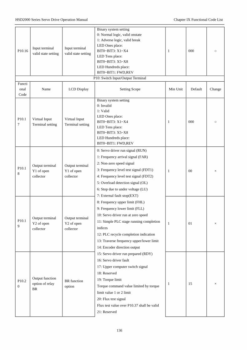
HSD2000 Series Servo Drive Operation Manual Chapter IX Functional Code List
136
P10.16 Input terminal
valid state setting
Input terminal
valid state setting
Binary system setting
0: Normal logic, valid onstate
1: Adverse logic, valid break
LED Ones place:
BIT0~BIT3: X1~X4
LED Tens place:
BIT0~BIT3: X5~X8
LED Hundreds place:
BIT0~BIT1: FWD,REV
1 000 ○
P10: Switch Input/Output Terminal
Functi
onal
Code
Name LCD Display Setting Scope Min Unit Default Change
P10.1
7
Virtual Input
Terminal setting
Virtual Input
Terminal setting
Binary system setting
0: Invalid
1: Valid
LED Ones place:
BIT0~BIT3: X1~X4
LED Tens place:
BIT0~BIT3: X5~X8
LED Hundreds place:
BIT0~BIT1: FWD,REV
1 000 ○
P10.1
8
Output terminal
Y1 of open
collector
Output terminal
Y1 of open
collector
0: Servo driver run signal (RUN)
1: Frequency arrival signal (FAR)
2: Non-zero speed signal
3: Frequency level test signal (FDT1)
4: Frequency level test signal (FDT2)
5: Overload detection signal (OL)
6: Stop due to under voltage (LU)
7: External fault stop(EXT)
8: Frequency upper limit (FHL)
9: Frequency lower limit (FLL)
10: Servo driver run at zero speed
11: Simple PLC stage running completion
indices
12: PLC recycle completion indication
13: Traverse frequency upper/lower limit
14: Encoder direction output
15: Servo driver run prepared (RDY)
16: Servo driver fault
17: Upper computer switch signal
18: Reserved
19: Torque limit
Torque command value limited by torque
limit value 1 or 2 limit
20: Flux test signal
Flux test value over P10.37 shall be valid
21: Reserved
1 00 ×
P10.1
9
Output terminal
Y2 of open
collector
Output terminal
Y2 of open
collector
1 01 ×
P10.2
0
Output function
option of relay
BR
BR function
option 1 15 ×

HSD2000 Series Servo Drive Operation Manual Chapter IX Functional Code List
137
P10.2
1
Output function
option of relay T T function option
22: Valid analog torque bias
23: Over torque/Less torque output1
24: Over torque/Less torque output2
25: Position completed
26: Position accessed
27: Reserved
28: Position out of tolerance warning
29: Reserved
30: Reserved
31: Reserved
32: Reserved
33: Reserved
34: Servo driver normal/reverse indication
terminal
35: Motors 1 and 2 indication terminal
Display only under shortcut menu function
numbers: 0,1,4,5,6,7,8,9,15,16
1 16 ×
1 16 ×
P10.2
2
Output terminal
valid state setting
Output terminal
valid state setting
Binary system setting
0: Valid onstate
1: Valid break
LED Ones place:
BIT0~BIT3: Y1,Y2,BR,T
1 0 ○
P10.2
3
Relay BR output
time delay
BR output time
delay 0.1~10.0s 0.1s 0.1 ○
P10.2
4
Relay T output
time delay
T output time
delay 0.1~10.0s 0.1s 0.1 ○
P10.2
5
Frequency
arrive(FAR)detect
ion width
Frequency arrive
detection width 0.00~1000.0Hz 0.01Hz 2.50Hz ○
P10.2
6
FDT1 detection
mode
FDT1 detection
mode
0: Speed setting
value(accelerated/decelerated frequency
command)
1: Speed test value
1 0 ○
P10.2
7 FDT1 level FDT1 level 0.00~1000.0Hz 0.01Hz 50.00Hz ○
P10.2
8 FDT1 lag FDT1 lag 0.00~1000.0Hz 0.01Hz 1.00Hz ○
P10.2
9
FDT2 detection
mode
FDT2 detection
mode
0: Speed setting
value(Accelerated/decelerated frequency
command)
1: Speed test value
1 1 ○
P10.3
0 FDT2 level FDT2 level 0.00~1000.0Hz 0.01Hz 25.00Hz ○
P10.3
1 FDT2 lag FDT2 lag 0.00~1000.0Hz 0.01Hz 1.00Hz ○
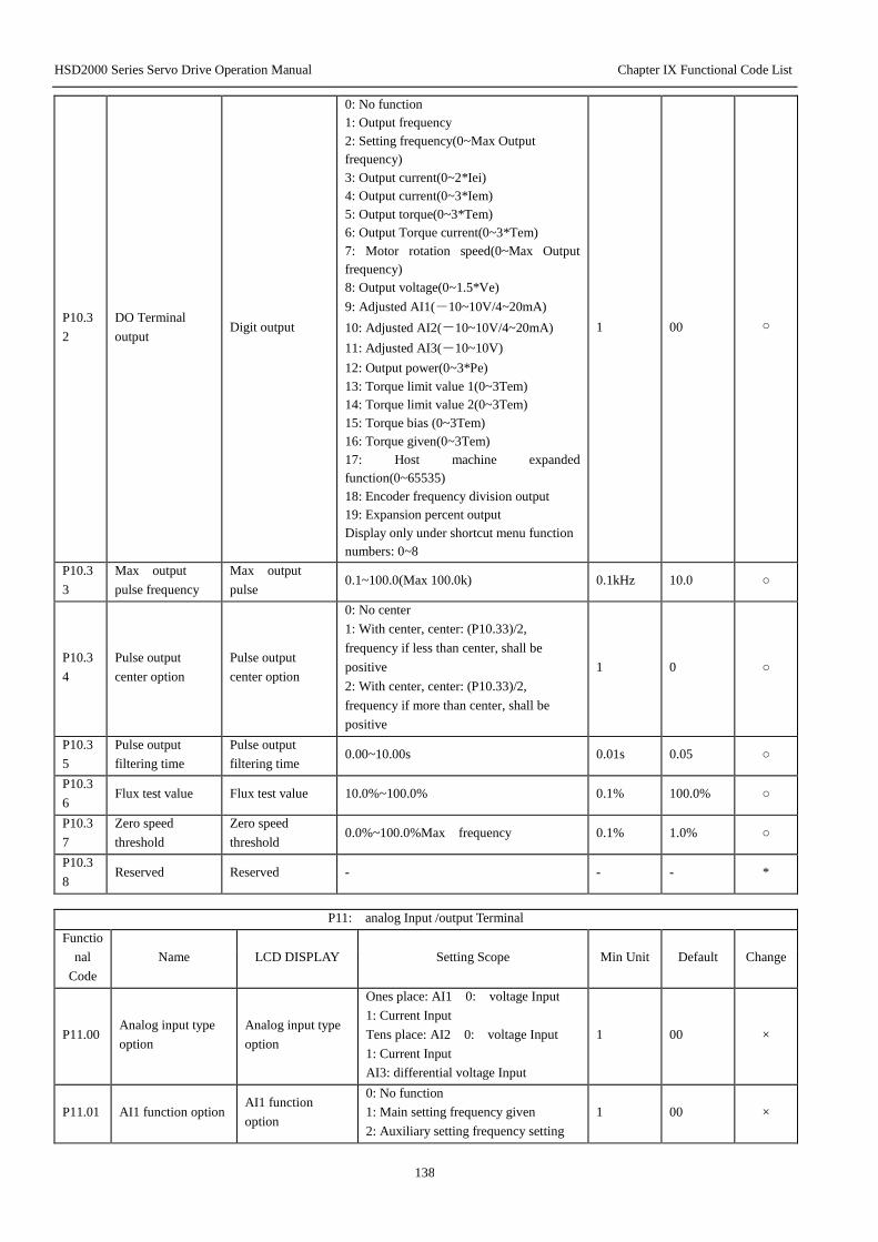
HSD2000 Series Servo Drive Operation Manual Chapter IX Functional Code List
138
P10.3
2
DO Terminal
output Digit output
0: No function
1: Output frequency
2: Setting frequency(0~Max Output
frequency)
3: Output current(0~2*Iei)
4: Output current(0~3*Iem)
5: Output torque(0~3*Tem)
6: Output Torque current(0~3*Tem)
7: Motor rotation speed(0~Max Output
frequency)
8: Output voltage(0~1.5*Ve)
9: Adjusted AI1(-10~10V/4~20mA)
10: Adjusted AI2(-10~10V/4~20mA)
11: Adjusted AI3(-10~10V)
12: Output power(0~3*Pe)
13: Torque limit value 1(0~3Tem)
14: Torque limit value 2(0~3Tem)
15: Torque bias (0~3Tem)
16: Torque given(0~3Tem)
17: Host machine expanded
function(0~65535)
18: Encoder frequency division output
19: Expansion percent output
Display only under shortcut menu function
numbers: 0~8
1 00 ○
P10.3
3
Max output
pulse frequency
Max output
pulse 0.1~100.0(Max 100.0k) 0.1kHz 10.0 ○
P10.3
4
Pulse output
center option
Pulse output
center option
0: No center
1: With center, center: (P10.33)/2,
frequency if less than center, shall be
positive
2: With center, center: (P10.33)/2,
frequency if more than center, shall be
positive
1 0 ○
P10.3
5
Pulse output
filtering time
Pulse output
filtering time 0.00~10.00s 0.01s 0.05 ○
P10.3
6 Flux test value Flux test value 10.0%~100.0% 0.1% 100.0% ○
P10.3
7
Zero speed
threshold
Zero speed
threshold 0.0%~100.0%Max frequency 0.1% 1.0% ○
P10.3
8 Reserved Reserved - - - *
P11: analog Input /output Terminal
Functio
nal
Code
Name LCD DISPLAY Setting Scope Min Unit Default Change
P11.00 Analog input type
option
Analog input type
option
Ones place: AI1 0: voltage Input
1: Current Input
Tens place: AI2 0: voltage Input
1: Current Input
AI3: differential voltage Input
1 00 ×
P11.01 AI1 function option AI1 function
option
0: No function
1: Main setting frequency given
2: Auxiliary setting frequency setting
1 00 ×
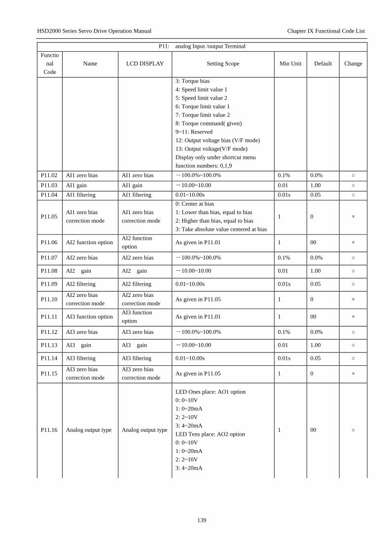
HSD2000 Series Servo Drive Operation Manual Chapter IX Functional Code List
139
P11: analog Input /output Terminal
Functio
nal
Code
Name LCD DISPLAY Setting Scope Min Unit Default Change
3: Torque bias
4: Speed limit value 1
5: Speed limit value 2
6: Torque limit value 1
7: Torque limit value 2
8: Torque command( given)
9~11: Reserved
12: Output voltage bias (V/F mode)
13: Output voltage(V/F mode)
Display only under shortcut menu
function numbers: 0,1,9
P11.02 AI1 zero bias AI1 zero bias -100.0%~100.0% 0.1% 0.0% ○
P11.03 AI1 gain AI1 gain -10.00~10.00 0.01 1.00 ○
P11.04 AI1 filtering AI1 filtering 0.01~10.00s 0.01s 0.05 ○
P11.05 AI1 zero bias
correction mode
AI1 zero bias
correction mode
0: Center at bias
1: Lower than bias, equal to bias
2: Higher than bias, equal to bias
3: Take absolute value centered at bias
1 0 ×
P11.06 AI2 function option AI2 function
option As given in P11.01 1 00 ×
P11.07 AI2 zero bias AI2 zero bias -100.0%~100.0% 0.1% 0.0% ○
P11.08 AI2 gain AI2 gain -10.00~10.00 0.01 1.00 ○
P11.09 AI2 filtering AI2 filtering 0.01~10.00s 0.01s 0.05 ○
P11.10 AI2 zero bias
correction mode
AI2 zero bias
correction mode As given in P11.05 1 0 ×
P11.11 AI3 function option AI3 function
option As given in P11.01 1 00 ×
P11.12 AI3 zero bias AI3 zero bias -100.0%~100.0% 0.1% 0.0% ○
P11.13 AI3 gain AI3 gain -10.00~10.00 0.01 1.00 ○
P11.14 AI3 filtering AI3 filtering 0.01~10.00s 0.01s 0.05 ○
P11.15 AI3 zero bias
correction mode
AI3 zero bias
correction mode As given in P11.05 1 0 ×
P11.16 Analog output type Analog output type
LED Ones place: AO1 option
0: 0~10V
1: 0~20mA
2: 2~10V
3: 4~20mA
LED Tens place: AO2 option
0: 0~10V
1: 0~20mA
2: 2~10V
3: 4~20mA
1 00 ○

HSD2000 Series Servo Drive Operation Manual Chapter IX Functional Code List
140
P11: analog Input /output Terminal
Functio
nal
Code
Name LCD DISPLAY Setting Scope Min Unit Default Change
P11.17
Analog output
terminal AO1
function
AO1 function
0: Output frequency(0~Max
frequency )
1: Setting frequency(0~Max
frequency )
2: Setting frequency(after
Accelerating/Deceleration)(0~Max
frequency )
3: Motor rotation speed(0~Max rotation
speed)
4: Output current(0~2*Iei)
5: Output current(0~2*Iem)
6: Output torque(0~3*Tem)
7: Output Torque current(0~3*Tem)
8: Output voltage(0~1.2*Ve)
9: Bus voltage (0~800V)
10: Adjusted AI1
11: Adjusted AI2
12: Adjusted AI3
13: Output power(0~2*Pe)
14: Host machine expansion
function(0~4095)
15: Torque limit value 1(+10V/+
300%)
16: Torque limit value 2(+10V/+
300%)
17: Torque bias (+10V/+300%)
18: Torque command(+10V/+300%)
19: Flux command(+10V/+100%)
20: Position DEV(+10V/2048
command pulse)
21: Output torque(-300.0~+300.0%)
22: Output Torque current(-300.0~+
300.0%)
23: Torque bias (-300~+300%)
24: Motor rotation speed(Double
polarity, at V/F output frequency-slip
compensation)
25: Reserved
Display only under shortcut menu
function numbers: 0~9
1 00 ○
P11.18 AO1 filtering AO1 filtering 0.0~20.0s 0.1 0.1 ○
P11.19 AO1 gain AO1 gain 0.0%~200.0% 0.1% 100.0% ○
P11.20 AO1 zero bias
correction
AO1 zero bias
correction -100.0%~100.0% 0.1% 0.0% ○
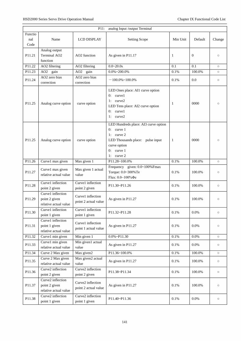
HSD2000 Series Servo Drive Operation Manual Chapter IX Functional Code List
141
P11: analog Input /output Terminal
Functio
nal
Code
Name LCD DISPLAY Setting Scope Min Unit Default Change
P11.21
Analog output
Terminal AO2
function
AO2 function As given in P11.17 1 0 ○
P11.22 AO2 filtering AO2 filtering 0.0~20.0s 0.1 0.1 ○
P11.23 AO2 gain AO2 gain 0.0%~200.0% 0.1% 100.0% ○
P11.24 AO2 zero bias
correction
AO2 zero bias
correction -100.0%~100.0% 0.1% 0.0 ○
P11.25 Analog curve option curve option
LED Ones place: AI1 curve option
0: curve1
1: curve2
LED Tens place: AI2 curve option
0: curve1
1: curve2
1 0000 ○
P11.25 Analog curve option curve option
LED Hundreds place: AI3 curve option
0: curve 1
1: curve 2
LED Thousands place: pulse input
curve option
0: curve 1
1: curve 2
1 0000 ○
P11.26 Curve1 max given Max given 1 P11.28~100.0% 0.1% 100.0% ○
P11.27 Curve1 max given
relative actual value
Max given 1 actual
value
Frequency given: 0.0~100%Fmax
Torque: 0.0~300%Te
Flux: 0.0~100%Φe
0.1% 100.0% ○
P11.28 Curve1 inflection
point 2 given
Curve1 inflection
point 2 given P11.30~P11.26 0.1% 100.0% ○
P11.29
Curve1 inflection
point 2 given
relative actual value
Curve1 inflection
point 2 actual value As given in P11.27 0.1% 100.0% ○
P11.30 Curve1 inflection
point 1 given
Curve1 inflection
point 1 given P11.32~P11.28 0.1% 0.0% ○
P11.31
Curve1 inflection
point 1 given
relative actual value
Curve1 inflection
point 1 actual value As given in P11.27 0.1% 0.0% ○
P11.32 Curve1 min given Min given 1 0.0%~P11.30 0.1% 0.0% ○
P11.33 Curve1 min given
relative actual value
Min given1 actual
value As given in P11.27 0.1% 0.0% ○
P11.34 Curve 2 Max given Max given2 P11.36~100.0% 0.1% 100.0% ○
P11.35 Curve 2 Max given
relative actual value
Max given2 actual
value As given in P11.27 0.1% 100.0% ○
P11.36 Curve2 inflection
point 2 given
Curve2 inflection
point 2 given P11.38~P11.34 0.1% 100.0% ○
P11.37
Curve2 inflection
point 2 given
relative actual value
Curve2 inflection
point 2 actual value As given in P11.27 0.1% 100.0% ○
P11.38 Curve2 inflection
point 1 given
Curve2 inflection
point 1 given P11.40~P11.36 0.1% 0.0% ○

HSD2000 Series Servo Drive Operation Manual Chapter IX Functional Code List
142
P11: analog Input /output Terminal
Functio
nal
Code
Name LCD DISPLAY Setting Scope Min Unit Default Change
P11.39
Curve2 inflection
point 1 given
relative actual value
Curve2 inflection
point 1 actual value As given in P11.27 0.1% 0.0% ○
P11.40 Curve2 min given Min given2 0.0%~P11.38 0.1% 0.0% ○
P11.41 Curve2 min given
relative actual value
Min given2 actual
value As given in P11.27 0.1% 0.0% ○
P12: Encoder Parameters
Functio
nal
Code
Name LCD DISPLAY Setting Scope Min Unit Default Change
P12.00 Pulses per revolution of
local PG
Pulses per revolution
of local PG 1~10000 1 1024 ○
P12.01 Rotation direction of
local PG
Rotation direction of
local PG
0: A is in advance of B.
1: B is in advance of A. 1 0 ×
P12.02 Reserved Reserved 1~128 1 1 ×
P12.03 Local encoder signal
filtering time
Local encoder
filtering time 0~99 1 30 ○
P12.04 Disconnection detection
time of local PG
Disconnection
detection time of local
PG
0.0: No action
0.1~10.0 0.1s 0.0 ○
P12.05 Disconnection action of
local PG
Disconnection action
of local PG
0: Free stop(E025)
1: Reserved 1 0 ○
P12.06 Expansion PG interface
card type(R)
Expansion PG
interface card type(R)
0: Incremental interface card
1~3: Reserved 1 0 *
P12.07 Pulses per revolution of
expansion PG1
Pulses per revolution
of expansion PG1 1~10000 1 2048 ○
P12.08 Rotation direction of
expansion PG1
Rotation direction of
expansion PG1
0: A is in advance of B.
1: B is in advance of A. 1 0 ×
P12.09 Frequency division
coefficient
Frequency division
coefficient 0~4096 1 1 ×
P12.10 Disconnection detection
time of expansion PG1
Disconnection
detection time of
expansion PG1
0.0: No action
0.1~10.0 s 0.1 0.0 ×
P12.11 Disconnection action of
local PG1
Disconnection action
of local PG1
0: Free stop(E025)
1: Switch to SVC
Run(Reserved)
1 0 ○
P12.12 Pulses per revolution of
expansion PG2
Pulses per revolution
of expansion PG2 1~10000 1 2048 ○
P12.13 Rotation direction of
expansion PG2
Rotation direction of
expansion PG1
0: A beyond B
1: B beyond A 1 0 ○
P12.14 Expansion PG signal
filtering
Expansion PG signal
filtering
Ones place: PG1 filtering: 0~9
Tens place: PG2 filtering: 0~9 1 30 ○
P12.15 Expansion PG
signal-enable
Expansion PG
signal-enable
BIT0: Z pulse enabled
BIT1: UVW signal enabled 1 10 ×
P12.16 Expansion PG1 UVW
Input status UVW Input status 0~7 1 0 *
P12.17 Expansion PG1Speed Expansion PG1Speed 0.00~600.00Hz 0.01 0.00 *
P12.18 Expansion PG2Speed Expansion PG2Speed 0.00~600.00Hz 0.01 0.00 *

HSD2000 Series Servo Drive Operation Manual Chapter IX Functional Code List
143
P12: Encoder Parameters
Functio
nal
Code
Name LCD DISPLAY Setting Scope Min Unit Default Change
P12.19 Expansion PG1 counter
value
Expansion PG1
counter value 0~65535 1 0 *
P12.20 Expansion PG1 U pulse
relative Position
Expansion PG1 U
pulse position 0~65535 1 0 *
P12.21 Expansion PG1 Z pulse
relative Position
Expansion PG1 Z
pulse position 0~65535 1 0 *
P12.22 Expansion PG2 counter
value
Expansion PG2
counter value 0~65535 1 0 *
P12.23 Expansion PG2 Z pulse
relative Position
Expansion PG2 Z
pulse position 0~65535 1 0 *
P13: Process close-loop control
Functi
onal
Code
Name LCD DISPLAY Setting Scope Min
Unit Default Change
P13.00 Process close-loop
function option
Process close-loop
function option
0: No action
1: Action 1 0 ×
P13.01 Given channel option Given channel
option
0: Digit given;
1: AI1;
2: AI2;
3: AI3;
Note: for speed close loop, analog
given 10V relative max frequency
P02.05 is synchronous rotation speed,
-10v relative neg-max
1 1 ○
P13.02 Feedback channel option Feedback channel
option
0: AI1;
1: AI2;
2: AI1+AI2;
3: AI1-AI2;
4: MIN(AI1, AI2);
5: MAX(AI1, AI2)
1 1 ○
P13.03 Given channel filtering Given filtering
constant 0.01~50.00s 0.01s 0.50s ○
P13.04 Feedback channel
filtering
Feedback filtering
constant 0.01~50.00s 0.01s 0.50s ○
P13.05 Digital given setting Digital given setting -10.00V~10.00V 0.01 0.00 ○
P13.06 Min given Min given
0.0%~(P13.08)(Min given and
reference value 10V; 20mA’s
percent)
0.1% 0.0% ○
P13.07 Min given relative
feedback Min feedback
0.0~100.0%(Min given relative
feedback and reference value 10V;
20mA’s percent)
0.1% 0.0% ○
P13.08 Max given Max given (P13.06)~100.0%(Max given and
reference value 10V;20mA’s percent) 0.1% 100.0% ○
P13.09 Max given relative
feedback Max feedback
0.0~100%(Max given relative
feedback and reference value
10V;20mA’s percent)
0.1% 100.0% ○
P13.10 Proportional gain KP Proportional gain
KP 0.000~10.000 0.001 2.000 ○
P13.11 Integral gain Ki Integral gain 0.000~10.000 0.001 0.100 ○

HSD2000 Series Servo Drive Operation Manual Chapter IX Functional Code List
144
P13: Process close-loop control
Functi
onal
Code
Name LCD DISPLAY Setting Scope Min
Unit Default Change
P13.12 Reserved Reserved ○
P13.13 Sampling period Sampling period 0.01~50.00s 0.01s 0.50s ○
P13.14 Output filtering time Output filtering
time 0.01~10.00s 0.01s 0.05 ○
P13.15 Deviation limit Deviation limit
0.0~20.0%
(Relative process close-loop given
value)
0.1% 2.0% ○
P13.16 Process close-loop
adjustment
Process close-loop
adjustment
0: Positive effect 1: Negative
effect
Note: Relation between the given and
rotation speed
1 0 ×
P13.17 Integral adjustment
option
Integral adjustment
option
0: Frequency upper/lower limit, stop
integral adjustment
1: Frequency upper/lower limit,
continue integral adjustment
1 0 ×
P13.18 Process close-loop preset
frequency
Process close-loop
preset frequency 0.00~1000.0Hz
0.01H
z 0.00Hz ○
P13.19 Preset holding time Preset holding time 0.0~3600.0S 0.1S 0.0S ×
P13.20 Multiplex Process
close-loop given1
Multiplex Process
close-loop given1 -10.00V~10.00V 0.01V 0.00V ○
P13.21 Multiplex Process
close-loop given2
Multiplex Process
close-loop given2 -10.00V~10.00V 0.01V 0.00V ○
P13.22 Multiplex Process
close-loop given3
Multiplex Process
close-loop given3 -10.00V~10.00V 0.01V 0.00V ○
P13.23 Multiplex Process
close-loop given4
Multiplex Process
close-loop given4 -10.00V~10.00V 0.01V 0.00V ○
P13.24 Multiplex Process
close-loop given5
Multiplex Process
close-loop given5 -10.00V~10.00V 0.01V 0.00V ○
P13.25 Multiplex Process
close-loop given6
Multiplex Process
close-loop given6 -10.00V~10.00V 0.01V 0.00V ○
P13.26 Multiplex Process
close-loop given7
Multiplex Process
close-loop given7 -10.00V~10.00V 0.01V 0.00V ○
P13.27 Multiplex Process
close-loop given8
Multiplex Process
close-loop given8 -10.00V~10.00V 0.01V 0.00V ○
P13.28 Multiplex Process
close-loop given9
Multiplex Process
close-loop given9 -10.00V~10.00V 0.01V 0.00V ○
P13.29 Multiplex Process
close-loop given10
Multiplex Process
close-loop given10 -10.00V~10.00V 0.01V 0.00V ○
P13.30 Multiplex Process
close-loop given11
Multiplex Process
close-loop given11 -10.00V~10.00V 0.01V 0.00V ○
P13.31 Multiplex Process
close-loop given12
Multiplex Process
close-loop given12 -10.00V~10.00V 0.01V 0.00V ○
P13.32 Multiplex Process
close-loop given13
Multiplex Process
close-loop given13 -10.00V~10.00V 0.01V 0.00V ○
P13.33 Multiplex Process
close-loop given14
Multiplex Process
close-loop given14 -10.00V~10.00V 0.01V 0.00V ○
P13.34 Multiplex Process
close-loop given15
Multiplex Process
close-loop given15 -10.00V~10.00V 0.01V 0.00V ○
P13.35 Process close-loop output
reverse option
Process close-loop
output reverse
0: Process close-loop output is
negative, 0 frequency actions 1 0 ○

HSD2000 Series Servo Drive Operation Manual Chapter IX Functional Code List
145
P13: Process close-loop control
Functi
onal
Code
Name LCD DISPLAY Setting Scope Min
Unit Default Change
option 1: Process close-loop output is
negative, reverse, if P05.12 setting
forbid reverse, 0 frequency actions
P13.36
Process close-loop
feedback missing action
option
Feedback missing
option
0: Process close-loop missing, no
action
1: Run as per P20.04 setting, no fault
signal output, display A021
2: Run freely to stop, without fault
signal output
1 0 ○
P13.37
Process close-loop
feedback missing test
value
Feedback missing
test value
0.0~100.0% Max Output frequency:
100% 0.1% 50.0% ○
P13.38
Process close-loop
feedback missing test
time
Feedback missing
test time 0.0s~20.0s 0.1s 1.0s ○
P14: Expansion function Parameters
Functio
nal
Code
Name LCD DISPLAY Setting Scope Min Unit Default Change
P14.00 Carrier frequency Carrier
frequency 2.0~15.0kHz 0.1
Decided
by
Machine
Type
○
P14.01 PWM mode
optimized
PWM mode
optimized
Ones place: Over-modulation enabled
0: Invalid 1: Valid
Tens place: Carrier frequency
automatic adjustment option
0: Non-automatic adjustment
1: Automatic adjustment
Hundreds place: Modulation mode
0: 2phase/3phase switch
1: 3 phase modulation
1 001 ×
P14.02 Cooling fan control Fan control
0: Automatic run
1: Always run
Note: Last 3 minutes after stop
1 1 ×
P14.03 ACR-P ACR-P 1~5000 1 1000 ○
P14.04 ACR-I ACR-I 0.5~100.0ms 0.1 8.0 ○
P14.05 Reserved Reserved ○
P14.06 Main digital setting
frequency control
Main digital
given frequency
control
LED Ones place:
0: Frequency power down saved
1: frequency power down not
saved
LED Tens place:
0: Stop frequency held
1: Stop frequency store P02.04
Note: Only for P02.03=0, 1, 2
1 00 ○
P14.07
Auxiliary digital
setting frequency
control
Auxiliary digital
setting
frequency
LED Ones place: Memory control
0: power down saved
1: power down not saved
1 00 ○
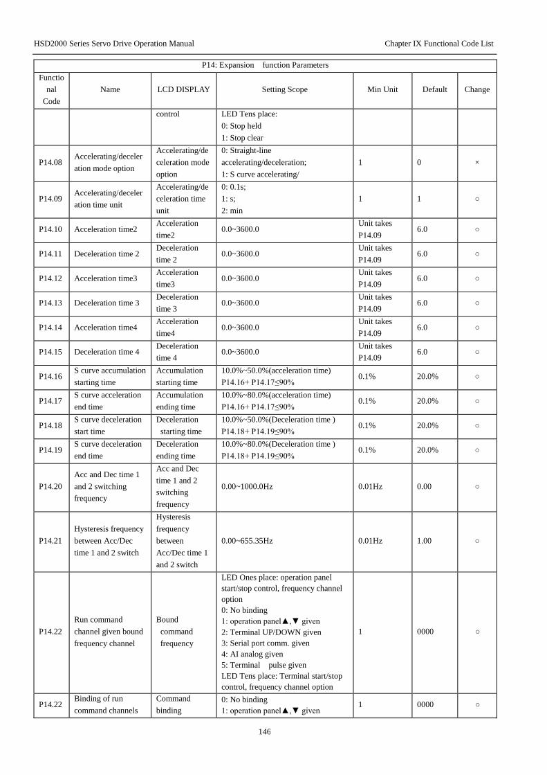
HSD2000 Series Servo Drive Operation Manual Chapter IX Functional Code List
146
P14: Expansion function Parameters
Functio
nal
Code
Name LCD DISPLAY Setting Scope Min Unit Default Change
control LED Tens place:
0: Stop held
1: Stop clear
P14.08 Accelerating/deceler
ation mode option
Accelerating/de
celeration mode
option
0: Straight-line
accelerating/deceleration;
1: S curve accelerating/
1 0 ×
P14.09 Accelerating/deceler
ation time unit
Accelerating/de
celeration time
unit
0: 0.1s;
1: s;
2: min
1 1 ○
P14.10 Acceleration time2 Acceleration
time2 0.0~3600.0
Unit takes
P14.09 6.0 ○
P14.11 Deceleration time 2 Deceleration
time 2 0.0~3600.0
Unit takes
P14.09 6.0 ○
P14.12 Acceleration time3 Acceleration
time3 0.0~3600.0
Unit takes
P14.09 6.0 ○
P14.13 Deceleration time 3 Deceleration
time 3 0.0~3600.0
Unit takes
P14.09 6.0 ○
P14.14 Acceleration time4 Acceleration
time4 0.0~3600.0
Unit takes
P14.09 6.0 ○
P14.15 Deceleration time 4 Deceleration
time 4 0.0~3600.0
Unit takes
P14.09 6.0 ○
P14.16 S curve accumulation
starting time
Accumulation
starting time
10.0%~50.0%(acceleration time)
P14.16+ P14.17≤90% 0.1% 20.0% ○
P14.17 S curve acceleration
end time
Accumulation
ending time
10.0%~80.0%(acceleration time)
P14.16+ P14.17≤90% 0.1% 20.0% ○
P14.18 S curve deceleration
start time
Deceleration
starting time
10.0%~50.0%(Deceleration time )
P14.18+ P14.19≤90% 0.1% 20.0% ○
P14.19 S curve deceleration
end time
Deceleration
ending time
10.0%~80.0%(Deceleration time )
P14.18+ P14.19≤90% 0.1% 20.0% ○
P14.20
Acc and Dec time 1
and 2 switching
frequency
Acc and Dec
time 1 and 2
switching
frequency
0.00~1000.0Hz 0.01Hz 0.00 ○
P14.21
Hysteresis frequency
between Acc/Dec
time 1 and 2 switch
Hysteresis
frequency
between
Acc/Dec time 1
and 2 switch
0.00~655.35Hz 0.01Hz 1.00 ○
P14.22
Run command
channel given bound
frequency channel
Bound
command
frequency
LED Ones place: operation panel
start/stop control, frequency channel
option
0: No binding
1: operation panel▲,▼ given
2: Terminal UP/DOWN given
3: Serial port comm. given
4: AI analog given
5: Terminal pulse given
LED Tens place: Terminal start/stop
control, frequency channel option
1 0000 ○
P14.22 Binding of run
command channels
Command
binding
0: No binding
1: operation panel▲,▼ given 1 0000 ○
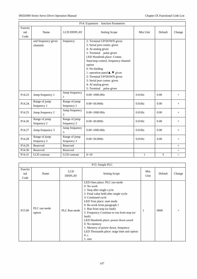
HSD2000 Series Servo Drive Operation Manual Chapter IX Functional Code List
147
P14: Expansion function Parameters
Functio
nal
Code
Name LCD DISPLAY Setting Scope Min Unit Default Change
and frequency given
channels
frequency 2: Terminal UP/DOWN given
3: Serial port comm. given
4: AI analog given
5: Terminal pulse given
LED Hundreds place: Comm.
Start/stop control, frequency channel
option
0: No binding
1: operation panel▲,▼ given
2: Terminal UP/DOWN given
3: Serial port comm. given
4: AI analog given
5: Terminal pulse given
P14.23 Jump frequency 1 Jump frequency
1 0.00~1000.0Hz 0.01Hz 0.00 ×
P14.24. Range of jump
frequency 1
Range of jump
frequency 1 0.00~30.00Hz 0.01Hz 0.00 ×
P14.25 Jump frequency 2 Jump frequency
2 0.00~1000.0Hz 0.01Hz 0.00 ×
P14.26 Range of jump
frequency 2
Range of jump
frequency 2 0.00~30.00Hz 0.01Hz 0.00 ×
P14.27 Jump frequency 3 Jump frequency
3 0.00~1000.0Hz 0.01Hz 0.00 ×
P14.28 Range of jump
frequency 3
Range of jump
frequency 3 0.00~30.00Hz 0.01Hz 0.00 ×
P14.29 Reserved Reserved ×
P14.30 Reserved Reserved ○
P14.31 LCD contrast LCD contrast 0~10 1 5 ○
P15: Simple PLC
Functio
nal
Code
Name LCD
DISPLAY Setting Scope
Min
Unit Default Change
P15.00 PLC run mode
option PLC Run mode
LED Ones place: PLC run mode
0: No work
1: Stop after single cycle
2: Final value held after single cycle
3: Continued cycle
LED Tens place: start mode
0: Re-work from paragraph 1
1: Run from stop (or fault)
2: Frequency Continue to run from stop (or
fault)
LED Hundreds place: power down saved
0: No memory
1: Memory of power down, frequency
LED Thousands place: stage time unit option
0: s
1: min
1 0000 ×
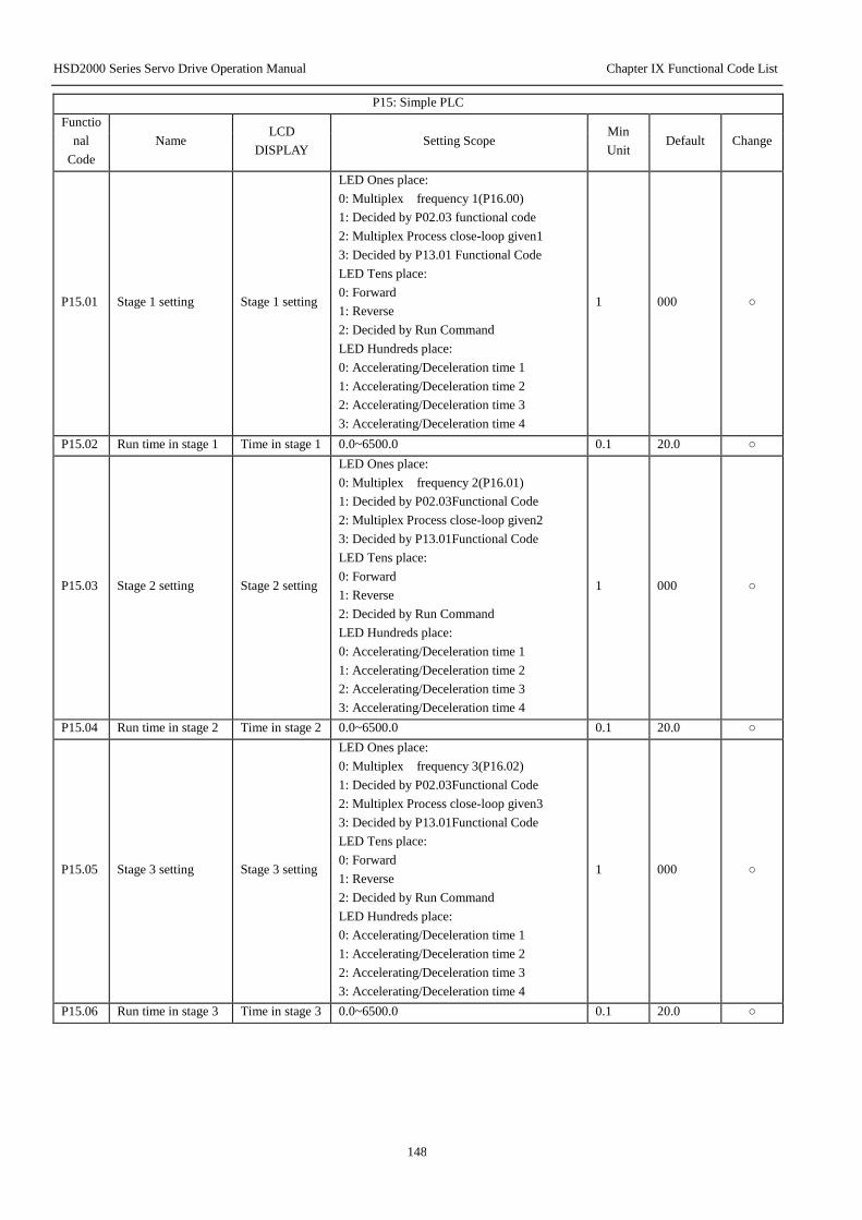
HSD2000 Series Servo Drive Operation Manual Chapter IX Functional Code List
148
P15: Simple PLC
Functio
nal
Code
Name LCD
DISPLAY Setting Scope
Min
Unit Default Change
P15.01 Stage 1 setting Stage 1 setting
LED Ones place:
0: Multiplex frequency 1(P16.00)
1: Decided by P02.03 functional code
2: Multiplex Process close-loop given1
3: Decided by P13.01 Functional Code
LED Tens place:
0: Forward
1: Reverse
2: Decided by Run Command
LED Hundreds place:
0: Accelerating/Deceleration time 1
1: Accelerating/Deceleration time 2
2: Accelerating/Deceleration time 3
3: Accelerating/Deceleration time 4
1 000 ○
P15.02 Run time in stage 1 Time in stage 1 0.0~6500.0 0.1 20.0 ○
P15.03 Stage 2 setting Stage 2 setting
LED Ones place:
0: Multiplex frequency 2(P16.01)
1: Decided by P02.03Functional Code
2: Multiplex Process close-loop given2
3: Decided by P13.01Functional Code
LED Tens place:
0: Forward
1: Reverse
2: Decided by Run Command
LED Hundreds place:
0: Accelerating/Deceleration time 1
1: Accelerating/Deceleration time 2
2: Accelerating/Deceleration time 3
3: Accelerating/Deceleration time 4
1 000 ○
P15.04 Run time in stage 2 Time in stage 2 0.0~6500.0 0.1 20.0 ○
P15.05 Stage 3 setting Stage 3 setting
LED Ones place:
0: Multiplex frequency 3(P16.02)
1: Decided by P02.03Functional Code
2: Multiplex Process close-loop given3
3: Decided by P13.01Functional Code
LED Tens place:
0: Forward
1: Reverse
2: Decided by Run Command
LED Hundreds place:
0: Accelerating/Deceleration time 1
1: Accelerating/Deceleration time 2
2: Accelerating/Deceleration time 3
3: Accelerating/Deceleration time 4
1 000 ○
P15.06 Run time in stage 3 Time in stage 3 0.0~6500.0 0.1 20.0 ○

HSD2000 Series Servo Drive Operation Manual Chapter IX Functional Code List
149
P15: Simple PLC
Functio
nal
Code
Name LCD
DISPLAY Setting Scope
Min
Unit Default Change
P15.07 Stage 4 setting Stage 4 setting
LED Ones place:
0: Multiplex frequency 4(P16.03)
1: Decided by P02.03Functional Code
2: Multiplex Process close-loop given4
3: Decided by P13.01Functional Code
LED Tens place:
0: Forward
1: Reverse
2: Decided by Run Command
LED Hundreds place:
0: Accelerating/Deceleration time 1
1: Accelerating/Deceleration time 2
2: Accelerating/Deceleration time 3
3: Accelerating/Deceleration time 4
1 000 ○
P15.08 Run time in stage 4 Time in stage 4 0.0~6500.0 0.1 20.0 ○
P15.09 Stage 5 setting Stage 5 setting
LED Ones place:
0: Multiplex frequency 5(P16.04)
1: Decided by P02.03Functional Code
2: Multiplex Process close-loop given5
3: Decided by P13.01Functional Code
LED Tens place:
0: Forward
1: Reverse
2: Decided by Run Command
LED Hundreds place:
0: Accelerating/Deceleration time 1
1: Accelerating/Deceleration time 2
2: Accelerating/Deceleration time 3
3: Accelerating/Deceleration time 4
1 000 ○
P15.10 Run time in stage 5 Time in stage 5 0.0~6500.0 0.1 20.0 ○
P15.11 Stage 6 setting Stage 6 setting
LED Ones place:
0: Multiplex frequency 6(P16.05)
1: Decided by P02.03Functional Code
2: Multiplex Process close-loop given6
3: Decided by P13.01Functional Code
LED Tens place:
0: Forward
1: Reverse
2: Decided by Run Command
LED Hundreds place:
0: Accelerating/Deceleration time 1
1: Accelerating/Deceleration time 2
2: Accelerating/Deceleration time 3
3: Accelerating/Deceleration time 4
1 000 ○
P15.12 Run time in stage 6 Time in stage 6 0.0~6500.0 0.1 20.0 ○
P15.13 Stage 7 setting Stage 7 setting
LED Ones place:
0: Multiplex frequency 7(P16.06)
1: Decided by P02.03Functional Code
2: Multiplex Process close-loop given7
3: Decided by P13.01Functional Code
1 000 ○
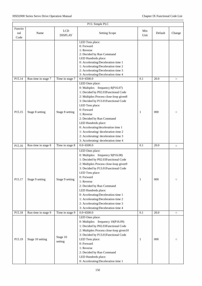
HSD2000 Series Servo Drive Operation Manual Chapter IX Functional Code List
150
P15: Simple PLC
Functio
nal
Code
Name LCD
DISPLAY Setting Scope
Min
Unit Default Change
LED Tens place:
0: Forward
1: Reverse
2: Decided by Run Command
LED Hundreds place:
0: Accelerating/Deceleration time 1
1: Accelerating/Deceleration time 2
2: Accelerating/Deceleration time 3
3: Accelerating/Deceleration time 4
P15.14 Run time in stage 7 Time in stage 7 0.0~6500.0 0.1 20.0 ○
P15.15 Stage 8 setting Stage 8 setting
LED Ones place:
0: Multiplex frequency 8(P16.07)
1: Decided by P02.03Functional Code
2: Multiplex Process close-loop given8
3: Decided by P13.01Functional Code
LED Tens place:
0: Forward
1: Reverse
2: Decided by Run Command
LED Hundreds place:
0: Accelerating/deceleration time 1
1: Accelerating/ deceleration time 2
2: Accelerating/ deceleration time 3
3: Accelerating/ deceleration time 4
1 000 ○
P15.16 Run time in stage 8 Time in stage 8 0.0~6500.0 0.1 20.0 ○
P15.17 Stage 9 setting Stage 9 setting
LED Ones place:
0: Multiplex frequency 9(P16.08)
1: Decided by P02.03Functional Code
2: Multiplex Process close-loop given9
3: Decided by P13.01Functional Code
LED Tens place:
0: Forward
1: Reverse
2: Decided by Run Command
LED Hundreds place:
0: Accelerating/Deceleration time 1
1: Accelerating/Deceleration time 2
2: Accelerating/Deceleration time 3
3: Accelerating/Deceleration time 4
1 000 ○
P15.18 Run time in stage 9 Time in stage 9 0.0~6500.0 0.1 20.0 ○
P15.19 Stage 10 setting Stage 10
setting
LED Ones place:
0: Multiplex frequency 10(P16.09)
1: Decided by P02.03Functional Code
2: Multiplex Process close-loop given10
3: Decided by P13.01Functional Code
LED Tens place:
0: Forward
1: Reverse
2: Decided by Run Command
LED Hundreds place:
0: Accelerating/Deceleration time 1
1 000 ○
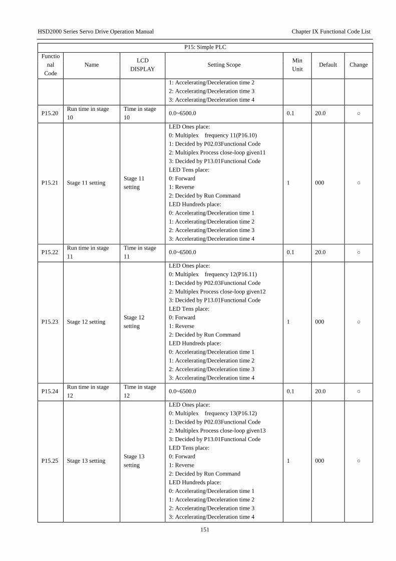
HSD2000 Series Servo Drive Operation Manual Chapter IX Functional Code List
151
P15: Simple PLC
Functio
nal
Code
Name LCD
DISPLAY Setting Scope
Min
Unit Default Change
1: Accelerating/Deceleration time 2
2: Accelerating/Deceleration time 3
3: Accelerating/Deceleration time 4
P15.20 Run time in stage
10
Time in stage
10 0.0~6500.0 0.1 20.0 ○
P15.21 Stage 11 setting Stage 11
setting
LED Ones place:
0: Multiplex frequency 11(P16.10)
1: Decided by P02.03Functional Code
2: Multiplex Process close-loop given11
3: Decided by P13.01Functional Code
LED Tens place:
0: Forward
1: Reverse
2: Decided by Run Command
LED Hundreds place:
0: Accelerating/Deceleration time 1
1: Accelerating/Deceleration time 2
2: Accelerating/Deceleration time 3
3: Accelerating/Deceleration time 4
1 000 ○
P15.22 Run time in stage
11
Time in stage
11 0.0~6500.0 0.1 20.0 ○
P15.23 Stage 12 setting Stage 12
setting
LED Ones place:
0: Multiplex frequency 12(P16.11)
1: Decided by P02.03Functional Code
2: Multiplex Process close-loop given12
3: Decided by P13.01Functional Code
LED Tens place:
0: Forward
1: Reverse
2: Decided by Run Command
LED Hundreds place:
0: Accelerating/Deceleration time 1
1: Accelerating/Deceleration time 2
2: Accelerating/Deceleration time 3
3: Accelerating/Deceleration time 4
1 000 ○
P15.24 Run time in stage
12
Time in stage
12 0.0~6500.0 0.1 20.0 ○
P15.25 Stage 13 setting Stage 13
setting
LED Ones place:
0: Multiplex frequency 13(P16.12)
1: Decided by P02.03Functional Code
2: Multiplex Process close-loop given13
3: Decided by P13.01Functional Code
LED Tens place:
0: Forward
1: Reverse
2: Decided by Run Command
LED Hundreds place:
0: Accelerating/Deceleration time 1
1: Accelerating/Deceleration time 2
2: Accelerating/Deceleration time 3
3: Accelerating/Deceleration time 4
1 000 ○
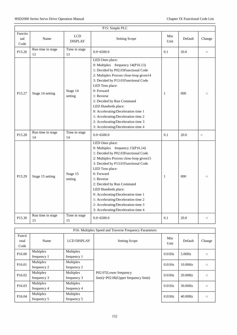
HSD2000 Series Servo Drive Operation Manual Chapter IX Functional Code List
152
P15: Simple PLC
Functio
nal
Code
Name LCD
DISPLAY Setting Scope
Min
Unit Default Change
P15.26 Run time in stage
13
Time in stage
13 0.0~6500.0 0.1 20.0 ○
P15.27 Stage 14 setting Stage 14
setting
LED Ones place:
0: Multiplex frequency 14(P16.13)
1: Decided by P02.03Functional Code
2: Multiplex Process close-loop given14
3: Decided by P13.01Functional Code
LED Tens place:
0: Forward
1: Reverse
2: Decided by Run Command
LED Hundreds place:
0: Accelerating/Deceleration time 1
1: Accelerating/Deceleration time 2
2: Accelerating/Deceleration time 3
3: Accelerating/Deceleration time 4
1 000 ○
P15.28 Run time in stage
14
Time in stage
14 0.0~6500.0 0.1 20.0 ○
P15.29 Stage 15 setting Stage 15
setting
LED Ones place:
0: Multiplex frequency 15(P16.14)
1: Decided by P02.03Functional Code
2: Multiplex Process close-loop given15
3: Decided by P13.01Functional Code
LED Tens place:
0: Forward
1: Reverse
2: Decided by Run Command
LED Hundreds place:
0: Accelerating/Deceleration time 1
1: Accelerating/Deceleration time 2
2: Accelerating/Deceleration time 3
3: Accelerating/Deceleration time 4
1 000 ○
P15.30 Run time in stage
15
Time in stage
15 0.0~6500.0 0.1 20.0 ○
P16: Multiplex Speed and Traverse Frequency Parameters
Functi
onal
Code
Name LCD DISPLAY Setting Scope Min
Unit Default Change
P16.00 Multiplex
frequency 1
Multiplex
frequency 1
P02.07(Lower frequency
limit)~P02.06(Upper frequency limit)
0.01Hz 5.00Hz ○
P16.01 Multiplex
frequency 2
Multiplex
frequency 2 0.01Hz 10.00Hz ○
P16.02 Multiplex
frequency 3
Multiplex
frequency 3 0.01Hz 20.00Hz ○
P16.03 Multiplex
frequency 4
Multiplex
frequency 4 0.01Hz 30.00Hz ○
P16.04 Multiplex
frequency 5
Multiplex
frequency 5 0.01Hz 40.00Hz ○

HSD2000 Series Servo Drive Operation Manual Chapter IX Functional Code List
153
P16.05 Multiplex
frequency 6
Multiplex
frequency 6 0.01Hz 45.00Hz ○
P16.06 Multiplex
frequency 7
Multiplex
frequency 7 0.01Hz 50.00Hz ○
P16.07 Multiplex
frequency 8
Multiplex
frequency 8 0.01Hz 5.00Hz ○
P16.08 Multiplex
frequency 9
Multiplex
frequency 9 0.01Hz 10.00Hz ○
P16.09 Multiplex
frequency 10
Multiplex
frequency 10 0.01Hz 20.00Hz ○
P16.10 Multiplex
frequency 11
Multiplex
frequency 11 0.01Hz 30.00Hz ○
P16.11 Multiplex
frequency 12
Multiplex
frequency 12 0.01Hz 40.00Hz ○
P16.12 Multiplex
frequency 13
Multiplex
frequency 13 0.01Hz 45.00Hz ○
P16.13 Multiplex
frequency 14
Multiplex
frequency 14 0.01Hz 50.00Hz ○
P16.14 Multiplex
frequency 15
Multiplex
frequency 15 0.01Hz 50.00Hz ○
P17: LED Parameters Display
Functio
nal
Code
Name LCD
DISPLAY Setting Scope
Min
Unit Default Change
P17.00 LED Run parameters
display option1 Run display 1
Binary system setting:
0: No display; 1: Display
LED Ones place:
BIT0: Output frequency(Hz))
BIT1: Setting frequency(Hz flash)
BIT2: Output current(A)
LED Tens place:
BIT0: Run rotation speed(RPM)
BIT1: Setting rotation speed(RPM flash)
BIT2: Run line speed(m/s)
BIT3: Setting line speed(m/s flash)
LED Hundreds place:
BIT0: Output power
BIT1: Output torque(%)
Note: All are zeros, display default:
Output frequency
1 007H ○
P17.01 LED Run parameters
display option2 Run display 2
Binary system setting:
0: No display; 1: Display
LEDOnes place:
BIT0: Output voltage(V)
BIT1: AI1(V)
BIT2: AI2(V)
BIT3: AI3(V)
LED Tens place:
BIT0: Analog Process close-loop
feedback
BIT1: Analog Process close-loop setting
1 00 ○

HSD2000 Series Servo Drive Operation Manual Chapter IX Functional Code List
154
P17: LED Parameters Display
Functio
nal
Code
Name LCD
DISPLAY Setting Scope
Min
Unit Default Change
BIT2: Terminal status
BIT3: Bus voltage (V)
P17.02 LED Stop parameters
display option Stop display
Binary system setting:
0: No display; 1: Display
LEDOnes place:
BIT0: Setting frequency(Hz)
BIT1: Run rotation speed(RPM)
BIT2: Setting rotation speed(RPM)
BIT3: Bus voltage
LED Tens place:
BIT0: Run line speed(m/s)
BIT1: Setting line speed(m/s)
BIT2: Analog process close-loop
feedback
BIT3: Analog process close-loop setting
LED Hundreds place:
BIT0: AI1(V)
BIT1: AI2(V)
BIT2: AI3(V)
BIT3: terminal status
Note: All are zeros, display default:
Setting frequency
1 009H ○
P17.03 Rotation speed display
coefficient
Rotation
speed display
coefficient
0.1%~999.9%
V/F control mode with PG :
Run rotation speed=Mechanical rotation
speed* P17.03
Setting rotation speed= setting rotation
speed* P17.03
V/F control mode without PG :
Run rotation speed= run
frequency*Motor rated rotation
speed/Motor rated frequency* P17.03
Setting rotation speed=Setting
frequency*Motor rated rotation
speed/Motor rated frequency* P17.03
Non V/F mode:
Run rotation speed=Actual /estimated
rotation speed* P17.03
Setting rotation speed=Setting
frequency*Motor rated rotation
speed/Motor rated frequency* P17.03
0.1% 100.0% ○
P17.04 Line speed coefficient Line speed
coefficient
0.1%~999.9%
V/F control mode with PG:
Line speed=Mechanical rotation speed*
P17.04
Setting line speed= setting rotation
speed* P17.04
0.1% 1.0% ○
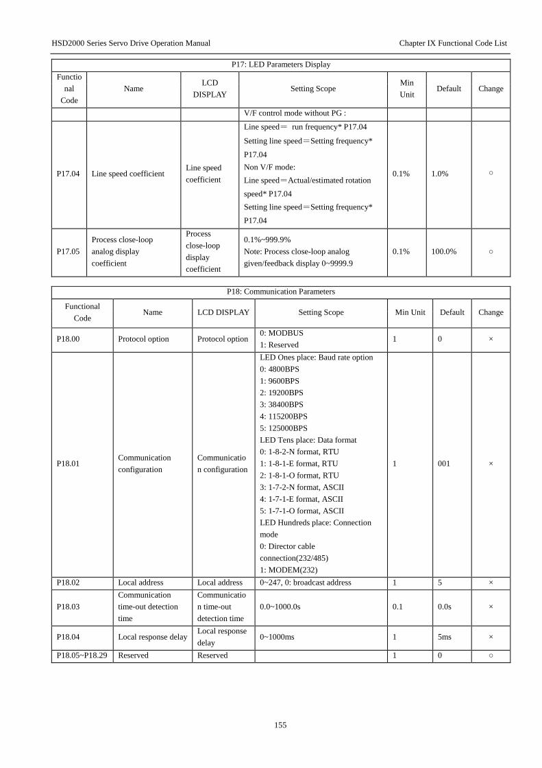
HSD2000 Series Servo Drive Operation Manual Chapter IX Functional Code List
155
P17: LED Parameters Display
Functio
nal
Code
Name LCD
DISPLAY Setting Scope
Min
Unit Default Change
V/F control mode without PG :
P17.04 Line speed coefficient Line speed
coefficient
Line speed= run frequency* P17.04
Setting line speed=Setting frequency*
P17.04
Non V/F mode:
Line speed=Actual/estimated rotation
speed* P17.04
Setting line speed=Setting frequency*
P17.04
0.1% 1.0% ○
P17.05
Process close-loop
analog display
coefficient
Process
close-loop
display
coefficient
0.1%~999.9%
Note: Process close-loop analog
given/feedback display 0~9999.9
0.1% 100.0% ○
P18: Communication Parameters
Functional
Code Name LCD DISPLAY Setting Scope Min Unit Default Change
P18.00 Protocol option Protocol option 0: MODBUS
1: Reserved 1 0 ×
P18.01 Communication
configuration
Communicatio
n configuration
LED Ones place: Baud rate option
0: 4800BPS
1: 9600BPS
2: 19200BPS
3: 38400BPS
4: 115200BPS
5: 125000BPS
LED Tens place: Data format
0: 1-8-2-N format, RTU
1: 1-8-1-E format, RTU
2: 1-8-1-O format, RTU
3: 1-7-2-N format, ASCII
4: 1-7-1-E format, ASCII
5: 1-7-1-O format, ASCII
LED Hundreds place: Connection
mode
0: Director cable
connection(232/485)
1: MODEM(232)
1 001 ×
P18.02 Local address Local address 0~247, 0: broadcast address 1 5 ×
P18.03
Communication
time-out detection
time
Communicatio
n time-out
detection time
0.0~1000.0s 0.1 0.0s ×
P18.04 Local response delay Local response
delay 0~1000ms 1 5ms ×
P18.05~P18.29 Reserved Reserved 1 0 ○
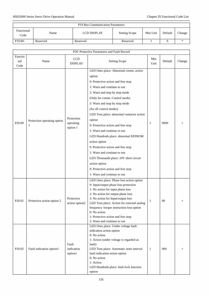
HSD2000 Series Servo Drive Operation Manual Chapter IX Functional Code List
156
P19 Bus Communication Parameters
Functional
Code Name LCD DISPLAY Setting Scope Min Unit Default Change
P19.00- Reserved Reserved Reserved 1 0 *
P20: Protective Parameters and Fault Record
Functio
nal
Code
Name LCD
DISPLAY Setting Scope
Min
Unit Default Change
P20.00 Protection operating option
1
Protection
operating
option 1
LED Ones place: Abnormal comm. action
option
0: Protective action and free stop
1: Warn and continue to run
2: Warn and stop by stop mode
(Only for comm. Control mode)
3: Warn and stop by stop mode
(for all control modes)
LED Tens place: abnormal contactor action
option
0: Protective action and free stop
1: Warn and continue to run
LED Hundreds place: abnormal EEPROM
action option
0: Protective action and free stop
1: Warn and continue to run
LED Thousands place: 24V short circuit
action option
0: Protective action and free stop
1: Warn and continue to run
1 0000 ×
P20.01 Protective action option 2 Protective
action option2
LED Ones place: Phase loss action option
0: Input/output phase loss protection
1: No action for input phase loss
2: No action for output phase loss
3: No action for Input/output loss
LED Tens place: Action for external analog
frequency /torque instruction loss option
0: No action
1: Protective action and free stop
2: Warn and continue to run
1 00 ×
P20.02 Fault indication option1
Fault
indication
option1
LED Ones place: Under voltage fault
indication action option
0: No action
1: Action (under voltage is regarded as
fault)
LED Tens place: Automatic reset interval
fault indication action option
0: No action
1: Action
LED Hundreds place: fault lock function
option
1 000 ×

HSD2000 Series Servo Drive Operation Manual Chapter IX Functional Code List
157
P20: Protective Parameters and Fault Record
Functio
nal
Code
Name LCD
DISPLAY Setting Scope
Min
Unit Default Change
0: Disable
1: Enable (fault indication don’t operate)
2: Enable (Fault indication operates)
P20.03
~P20.0
5
Reserved Reserved ×
P20.06 Motor overload protection
mode option
Overload
protection
0: No action
1: Common motor (with low-speed
compensation)
2: variable frequency motor (without
low-speed compensation)
1 1 ×
P20.07 Overvoltage stall option Overvoltage
stall option
0: Disable (when installing brake
resistance)
1: Enable
1 1 ×
P20.08 Overvoltage stall point Overvoltage
stall point 120.0%~150.0%Udce 0.1% 140.0% ×
P20.09 Overload pre-alarm
detection option
Overload
pre-alarm
detection
option
LED Ones place: Detection option
0: Always detect
1: Only detect at constant speed
LED Tens place: Alarm option
0: Alarm, continue to run
1: Protective action and free stop
LED Hundreds place: Detection level
option
0: Relative to motor rated current(E014)
1: Relative to Servo driver’s rated
current(E013)
1 000 ×
P20.10 Overload pre-alarm
detection level
Overload
detection level 20.0%~200.0% 0.1% 130.0% ○
P20.11 Overload pre-alarm
detection time
Overload
pre-alarm
detection time
0.0~60.0s 0.1S 5.0S ○
P20.12 Off load protection option
Off load
protection
option
0: Servo driver Off load protection
forbidden
1: Servo driver off load protective action
2: Reserved
1 0 ○
P20.13 Off load detection level Off load
detection level 0.0~100.0%Ie 0.1% 30.0% ○
P20.14 Off load detection time Off load
detection time 0.0~60.0s 0.1s 1.0s ○
P20.15 Automatic current limit
level
Current limit
level 20.0%~200.0%Ie 0.1% 150.0% ×
P20.16 Drop rate of frequency
during current limiting
Drop rate of
frequency
during current
limiting
0.00~99.99Hz/s 0.01
Hz/s
10.00
Hz/s ○
P20.17 Automatic current limit
action option
Automatic
current limit
action
0: Invalid for constant speed
1: Valid for constant speed
Note: in accelerating/deceleration always
valid
1 1 ×

HSD2000 Series Servo Drive Operation Manual Chapter IX Functional Code List
158
P20: Protective Parameters and Fault Record
Functio
nal
Code
Name LCD
DISPLAY Setting Scope
Min
Unit Default Change
P20.18 Automatic reset time Automatic
reset time
0: No action
1~100: Automatic reset time
Note: Module protection, External
equipment fault, AI overcurrent fault
without automatic reset function
1 0 ×
P20.19 Automatic reset time
interval
Reset time
interval 2.0~20.0s/ time 0.1s 5.0s ×
P20.20 Reserved Reserved ○
P20.21 First abnormality type First
abnormality
0: No records of abnormality
1: Overcurrent when accelerate(E001)
2: Overcurrent when decelerates (E002)
3: Overcurrent when constant speed(E003)
4: Overvoltage when accelerates(E004)
5: Overvoltage when decelerates(E005)
6: Overvoltage when constant speed (E006)
7: Control voltage overvoltage (E007)
8: Input side phase loss (E008)
9: Output side phase loss (E009)
10: Power module protection (E010)
11: Radiator 1 overheat(E011)
12: Radiator 2 overheat(E012)
13: Servo driver overload (E013)
14: Motor overload (E014)
15: External fault(E015)
16: EEPROM read/write error (E016)
17: Serial port abnormal comm. (E017)
18: Contactor abnormal (E018)
19: Current measure circuit abnormal
(E019 )
20: System disturbance(E020)
21: Process close-loop feedback
missing(E021)
22: External given command
missing(E022)
23: Operation panel parameters copy
error(E023)
24: Motor parameter identification error
(E024)
25: PG fault(E025)
26: Servo driver Off load (E026)
27: Braking unit fault (E027)
28: Parameters setting error (E028)
29: Control board 24V short circuit(E029)
30~33: Reserved
34: DEV error (E034)
35: Overspeed (OS) fault(E035)
36~40: Reserved
41: CCI Input overcurrent fault
42: Reserved
43: Reserved
44~50: Reserved
Note:
1.E007 at 18.5G/22G or below will not be
detected, others will be tested after stop;
1 0 *
1 0 *
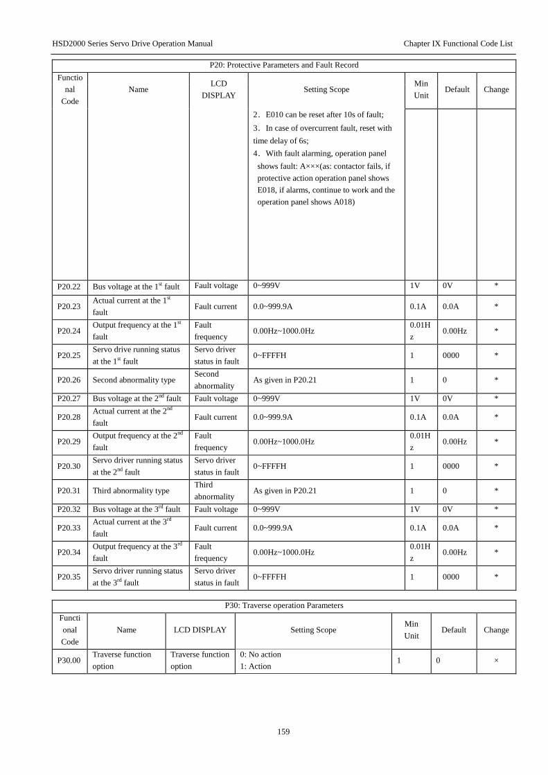
HSD2000 Series Servo Drive Operation Manual Chapter IX Functional Code List
159
P20: Protective Parameters and Fault Record
Functio
nal
Code
Name LCD
DISPLAY Setting Scope
Min
Unit Default Change
2.E010 can be reset after 10s of fault;
3.In case of overcurrent fault, reset with
time delay of 6s;
4.With fault alarming, operation panel
shows fault: A×××(as: contactor fails, if
protective action operation panel shows
E018, if alarms, continue to work and the
operation panel shows A018)
P20.22 Bus voltage at the 1st fault Fault voltage 0~999V 1V 0V *
P20.23 Actual current at the 1st
fault Fault current 0.0~999.9A 0.1A 0.0A *
P20.24 Output frequency at the 1st
fault
Fault
frequency 0.00Hz~1000.0Hz
0.01H
z 0.00Hz *
P20.25 Servo drive running status
at the 1st fault
Servo driver
status in fault 0~FFFFH 1 0000 *
P20.26 Second abnormality type Second
abnormality As given in P20.21 1 0 *
P20.27 Bus voltage at the 2nd fault Fault voltage 0~999V 1V 0V *
P20.28 Actual current at the 2nd
fault Fault current 0.0~999.9A 0.1A 0.0A *
P20.29 Output frequency at the 2nd
fault
Fault
frequency 0.00Hz~1000.0Hz
0.01H
z 0.00Hz *
P20.30 Servo driver running status
at the 2nd fault
Servo driver
status in fault 0~FFFFH 1 0000 *
P20.31 Third abnormality type Third
abnormality As given in P20.21 1 0 *
P20.32 Bus voltage at the 3rd fault Fault voltage 0~999V 1V 0V *
P20.33 Actual current at the 3rd
fault Fault current 0.0~999.9A 0.1A 0.0A *
P20.34 Output frequency at the 3rd
fault
Fault
frequency 0.00Hz~1000.0Hz
0.01H
z 0.00Hz *
P20.35 Servo driver running status
at the 3rd fault
Servo driver
status in fault 0~FFFFH 1 0000 *
P30: Traverse operation Parameters
Functi
onal
Code
Name LCD DISPLAY Setting Scope Min
Unit Default Change
P30.00 Traverse function
option
Traverse function
option
0: No action
1: Action 1 0 ×
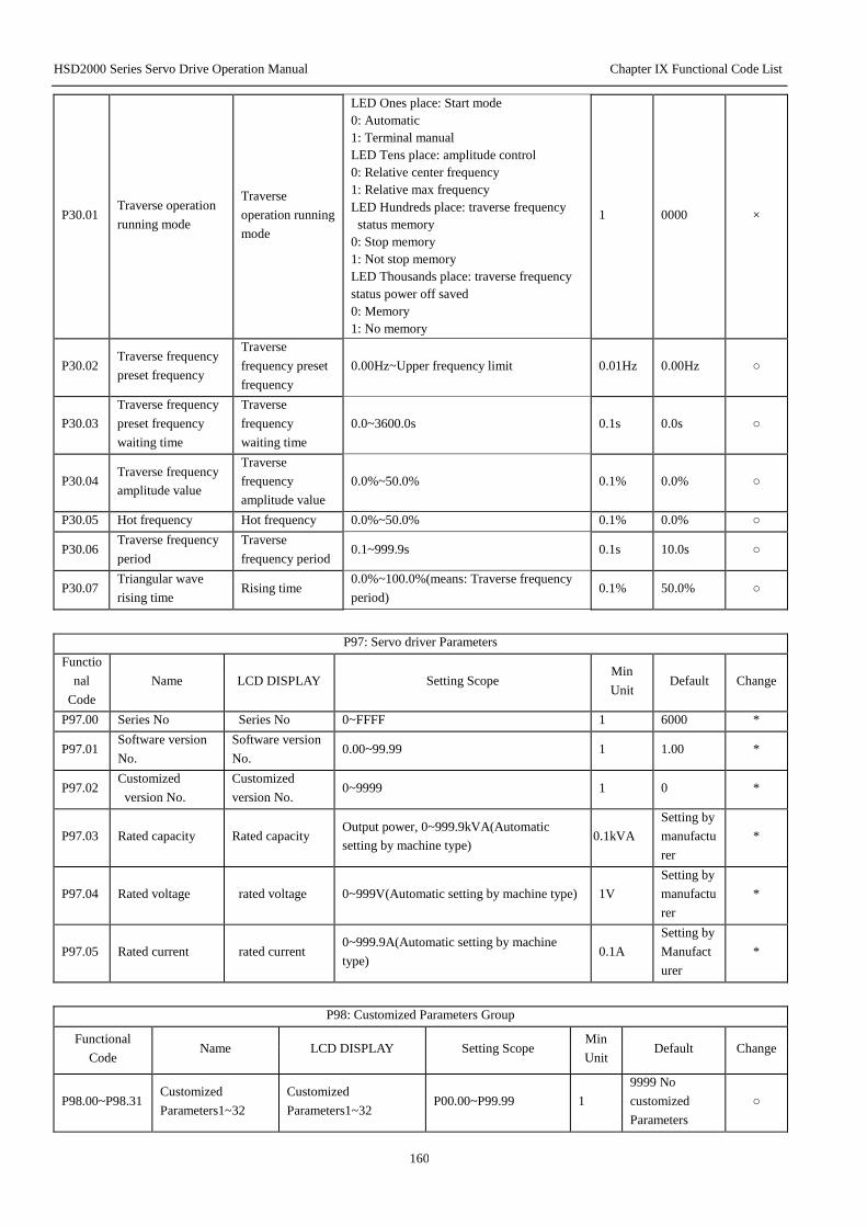
HSD2000 Series Servo Drive Operation Manual Chapter IX Functional Code List
160
P30.01 Traverse operation
running mode
Traverse
operation running
mode
LED Ones place: Start mode
0: Automatic
1: Terminal manual
LED Tens place: amplitude control
0: Relative center frequency
1: Relative max frequency
LED Hundreds place: traverse frequency
status memory
0: Stop memory
1: Not stop memory
LED Thousands place: traverse frequency
status power off saved
0: Memory
1: No memory
1 0000 ×
P30.02 Traverse frequency
preset frequency
Traverse
frequency preset
frequency
0.00Hz~Upper frequency limit 0.01Hz 0.00Hz ○
P30.03
Traverse frequency
preset frequency
waiting time
Traverse
frequency
waiting time
0.0~3600.0s 0.1s 0.0s ○
P30.04 Traverse frequency
amplitude value
Traverse
frequency
amplitude value
0.0%~50.0% 0.1% 0.0% ○
P30.05 Hot frequency Hot frequency 0.0%~50.0% 0.1% 0.0% ○
P30.06 Traverse frequency
period
Traverse
frequency period 0.1~999.9s 0.1s 10.0s ○
P30.07 Triangular wave
rising time Rising time
0.0%~100.0%(means: Traverse frequency
period) 0.1% 50.0% ○
P97: Servo driver Parameters
Functio
nal
Code
Name LCD DISPLAY Setting Scope Min
Unit Default Change
P97.00 Series No Series No 0~FFFF 1 6000 *
P97.01 Software version
No.
Software version
No. 0.00~99.99 1 1.00 *
P97.02 Customized
version No.
Customized
version No. 0~9999 1 0 *
P97.03 Rated capacity Rated capacity Output power, 0~999.9kVA(Automatic
setting by machine type) 0.1kVA
Setting by
manufactu
rer
*
P97.04 Rated voltage rated voltage 0~999V(Automatic setting by machine type) 1V
Setting by
manufactu
rer
*
P97.05 Rated current rated current 0~999.9A(Automatic setting by machine
type) 0.1A
Setting by
Manufact
urer
*
P98: Customized Parameters Group
Functional
Code Name LCD DISPLAY Setting Scope
Min
Unit Default Change
P98.00~P98.31 Customized
Parameters1~32
Customized
Parameters1~32 P00.00~P99.99 1
9999 No
customized
Parameters
○

HSD2000 Series Servo Drive Operation Manual Chapter IX Functional Code List
161
P99: Manufacturer Parameters
Functio
nal
Code
Name LCD
DISPLAY Setting Scope
Min
Unit Default Change
P99.00
Password Input
by
manufacturer
Manufacturer’s
password
****
Note: After correct password input, the
parameters left in the group will be shown.
1 Setting by
manufacturer -
Note:
○: Change in working; ×: No change in working; *: Actual parameters, unable to change; -Manufacturer setting, unable to change by
users.
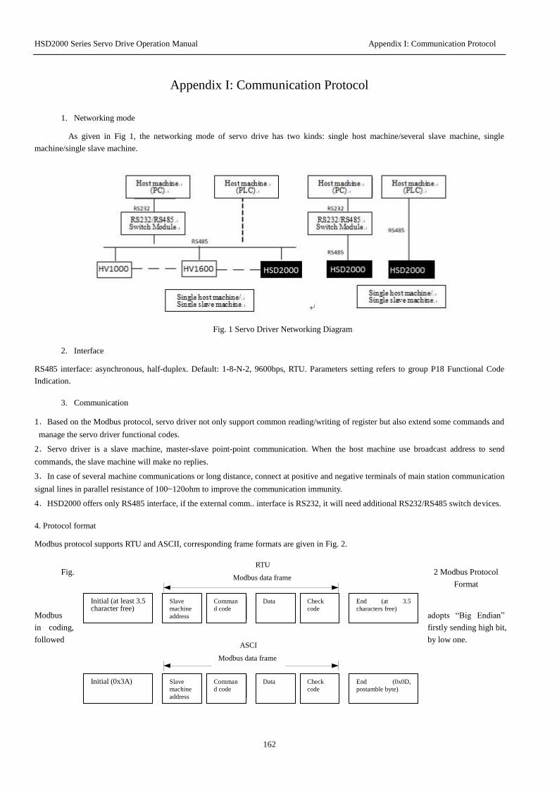
HSD2000 Series Servo Drive Operation Manual Appendix I: Communication Protocol
162
Appendix I: Communication Protocol
1. Networking mode
As given in Fig 1, the networking mode of servo drive has two kinds: single host machine/several slave machine, single
machine/single slave machine.
Fig. 1 Servo Driver Networking Diagram
2. Interface
RS485 interface: asynchronous, half-duplex. Default: 1-8-N-2, 9600bps, RTU. Parameters setting refers to group P18 Functional Code
Indication.
3. Communication
1.Based on the Modbus protocol, servo driver not only support common reading/writing of register but also extend some commands and
manage the servo driver functional codes.
2.Servo driver is a slave machine, master-slave point-point communication. When the host machine use broadcast address to send
commands, the slave machine will make no replies.
3.In case of several machine communications or long distance, connect at positive and negative terminals of main station communication
signal lines in parallel resistance of 100~120ohm to improve the communication immunity.
4.HSD2000 offers only RS485 interface, if the external comm.. interface is RS232, it will need additional RS232/RS485 switch devices.
4. Protocol format
Modbus protocol supports RTU and ASCII, corresponding frame formats are given in Fig. 2.
Fig. 2 Modbus Protocol
Format
Modbus adopts “Big Endian”
in coding, firstly sending high bit,
followed by low one.
起始(至少3.5个字符空闲)
从机地址 命令码 数据 校验码结束(至少3.5个
字符空闲)
Modbus数据帧
RTU方式
起始(0x3A)
从机地址 命令码 数据 校验码结束
(0x0D,帧尾字节)
Modbus数据帧
ASCII方式
Initial (at least 3.5 character free)
Slave
machine
address
Comman
d code
Data Check
code
End (at 3.5
characters free)
Initial (0x3A)
Slave
machine
address
Comman
d code
Data Check
code
End (0x0D,
postamble byte)
RTU
Modbus data frame
ASCI
Modbus data frame

HSD2000 Series Servo Drive Operation Manual Appendix I: Communication Protocol
163
1.RTU
Under RTU, free time between frames shall take the bigger value
between function code setting and Modbus value agreed internally.
The min frame agreed in Modbus shall be: the bus-through time
from frame head to frame end shall have at least 3.5 characters to
define frames. Data check adopts CRC-16, all information will be
checked, check and high/low bit shall be exchanged for sending.
Specific CRC check refers to samples attached hereto. Note: there
shall be 3.5 characters at least for bus free between frames, and
the bus free between frames shall not need to accumulate initial
and final idle.
The following is applicable for: under RTU, read the register
0101(P01.01) parameters from No. 5 slave machine.
Request frame:
Slave
machine
address
Comman
d code
Data
Check code Register
address
Read
characters
0x05 0x03 0x0
1
0x0
1
0x0
0
0x0
1
0xD
5
0xB
2
Response frame:
Slave
machine
address
Comman
d code
Data
Check code Respons
e bit
Register
content
0x05 0x03 0x02 0x1
3
0x8
8
0x4
4
0xD
2
Where, check code is CRC check value, CRC check calculations
refer to the following instruction.
2.ASCII
Under ASCII, the frame head is “0x3A”, the frame end default:
“0x0D,0x0A”, which can be also set by users, under the mode,
except the frame head and the frame end, other data bytes all
adopt ASCII codes for sending, first sending high 4 byte, followed
by low one. Under ASCII, the data have 7 digits, for “A”~“F”,
adopt uppercase ASCII codes. At the time, the data adopt LRC for
check, which cover from slave machine address to data
information. Total check equals to all characters for check and
complement codes (no carry available).
The following is applicable for: under ASCII, write the register
0201(P02.01) parameters from No. 5 slave machine.
Request frame:
Frame
Head
Slave
machine
address
Command
Code
Data Check
code
Frame
End Register
address
Written
Content
Character : 0 5 0 6 0 2 0 1 0 F A 0 4 3 CR LF
ASCII 3A 30 31 30 36 30 32 30 31 30 46 41 30 34 33 0D 0A
Where, Check code is total LRC check, equal to complement codes of (05+06+02+01+0x0F+0xA0).
Response frame:
Frame
Head
Slave
machine
address
Command
Code
Data Check
code
Frame
End Register
address
Written
Content
Character : 0 5 0 6 0 2 0 1 0 F A 0 4 3 CR LF
ASCII 3A 30 31 30 36 30 32 30 31 30 46 41 30 34 33 0D 0A
Through functional code, servo driver can set different response
time delay to meet different main stations, for RTU mode, the
response time delay shall keep at least 3.5 characters interval; for
ASCII mode, the response time delay shall be not less than 1ms.
5. Protocol function
Modbus’ most function is to read/write parameters, different
command codes decide different operation requests. HSD2000
servo driver Modbus protocol support the operation in the table.
Command
code Description
0x03
Read servo driver parameters, including functional
code parameters, control parameters and status
parameters
0x06
Modify single 16-bit servo driver functional code
parameter or control parameters, after power off,
servo driver keeps no parameters.
0x08 Line diagnosis
0x10
Modify several servo driver functional code or
control parameters, after power off, servo driver
keeps no parameters.
0x41
Modify single 16-bit servo driver functional code
parameter or control parameters, after power off,
servo driver keeps parameters.
0x42 Servo driver functional code management
0x43
Modify several servo driver functional code or
control parameters, after power off, servo driver
keeps parameters.
Servo driver’s functional code parameters, control parameters and
status parameters all image to be Modbus’s read/write register.
Reading/writing characteristics and scope of functional code
parameters follow servo driver user manual. Group number of
servo driver functional code images to be high bit of register
address, index in groups (namely parameters’ number in the group)
images to be low bit of register address. Servo driver’s control
parameters and status parameters are taken as servo driver
functional code group. Functional code group number and its
imaged high bit of register address have coincidence relations as
follows:
Servo
driver
Group
Parameters
High Bit of
Image
Address
Servo driver
Group
Parameters
High Bit of
Image Address
Group P00 0x00 Group P19 0x13
Group P01 0x01 Group P20 0x14
Group P02 0x02 Group P30 0x1E
Group P03 0x03 Group P31 0x1F
Group P04 0x04 Group P32 0x20
Group P05 0x05 Group P33 0x21
Group P06 0x06 Group P34 0x22
Group P07 0x07 Group P35 0x23
Group P08 0x08 Group P36 0x24
Group P09 0x09 Group P40 0x28
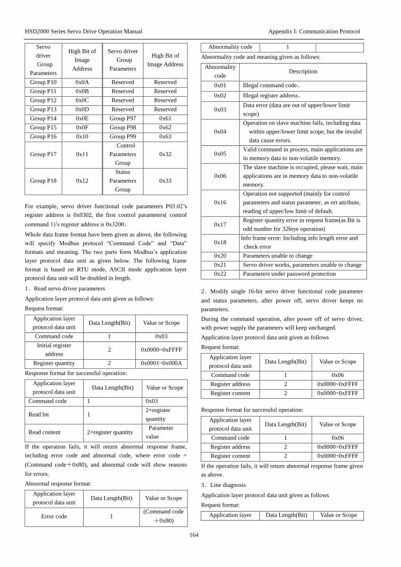
HSD2000 Series Servo Drive Operation Manual Appendix I: Communication Protocol
164
Servo
driver
Group
Parameters
High Bit of
Image
Address
Servo driver
Group
Parameters
High Bit of
Image Address
Group P10 0x0A Reserved Reserved
Group P11 0x0B Reserved Reserved
Group P12 0x0C Reserved Reserved
Group P13 0x0D Reserved Reserved
Group P14 0x0E Group P97 0x61
Group P15 0x0F Group P98 0x62
Group P16 0x10 Group P99 0x63
Group P17 0x11
Control
Parameters
Group
0x32
Group P18 0x12
Status
Parameters
Group
0x33
For example, servo driver functional code parameters P03.02’s
register address is 0x0302, the first control parameters( control
command 1)’s register address is 0x3200。
Whole data frame format have been given as above, the following
will specify Modbus protocol “Command Code” and “Data”
formats and meaning. The two parts form Modbus’s application
layer protocol data unit as given below. The following frame
format is based on RTU mode, ASCII mode application layer
protocol data unit will be doubled in length.
1.Read servo driver parameters
Application layer protocol data unit given as follows:
Request format:
Application layer
protocol data unit Data Length(Bit) Value or Scope
Command code 1 0x03
Initial register
address 2 0x0000~0xFFFF
Register quantity 2 0x0001~0x000A
Response format for successful operation:
Application layer
protocol data unit Data Length(Bit) Value or Scope
Command code 1 0x03
Read bit 1 2×register
quantity
Read content 2×register quantity Parameter
value
If the operation fails, it will return abnormal response frame,
including error code and abnormal code, where error code =
(Command code+0x80), and abnormal code will show reasons
for errors.
Abnormal response format:
Application layer
protocol data unit Data Length(Bit) Value or Scope
Error code 1 (Command code
+0x80)
Abnormality code 1
Abnormality code and meaning given as follows:
Abnormality
code Description
0x01 Illegal command code。
0x02 Illegal register address。
0x03 Data error (data are out of upper/lower limit
scope)
0x04
Operation on slave machine fails, including data
within upper/lower limit scope, but the invalid
data cause errors.
0x05 Valid command in process, main applications are
in memory data to non-volatile memory.
0x06
The slave machine is occupied, please wait, main
applications are in memory data to non-volatile
memory.
0x16
Operation not supported (mainly for control
parameters and status parameter, as ort attribute,
reading of upper/low limit of default.
0x17 Register quantity error in request frame(as Bit is
odd number for 32btye operation)
0x18 Info frame error: Including info length error and
check error
0x20 Parameters unable to change
0x21 Servo driver works, parameters unable to change
0x22 Parameters under password protection
2.Modify single 16-bit servo driver functional code parameter
and status parameters, after power off, servo driver keeps no
parameters.
During the command operation, after power off of servo driver,
with power supply the parameters will keep unchanged.
Application layer protocol data unit given as follows
Request format:
Application layer
protocol data unit Data Length(Bit) Value or Scope
Command code 1 0x06
Register address 2 0x0000~0xFFFF
Register content 2 0x0000~0xFFFF
Response format for successful operation:
Application layer
protocol data unit Data Length(Bit) Value or Scope
Command code 1 0x06
Register address 2 0x0000~0xFFFF
Register content 2 0x0000~0xFFFF
If the operation fails, it will return abnormal response frame given
as above.
3.Line diagnosis
Application layer protocol data unit given as follows
Request format:
Application layer Data Length(Bit) Value or Scope

HSD2000 Series Servo Drive Operation Manual Appendix I: Communication Protocol
165
protocol data unit
Command code 1 0x08
Sub-command code 2 0x0000~0x0030
Data 2 0x0000~0xFFFF
Response format for successful operation:
Application layer
protocol data unit Data Length(Bit) Value or Scope
Command code 1 0x08
Sub-command code 2 0x0000~0x0030
Data 2 0x0000~0xFFFF
If the operation fails, it will return abnormal response frame given
as above.
Command code supported by line diagnosis and meaning are
given as follows:
Sub-Command
code Data(Request) Data(Response) Meaning
0x0001
0x0000 0x0000
Re-initializing
communication:
make “No
response mode”
invalid
0xFF00 0xFF00
Re-initializing
communication:
make “No
response mode”
invalid
0x0003
High bit
is“new frame
end”, low bit
is “00”
High bit is“new
frame end”,
low bit is “00”
Set the frame end
of ASCII mode to
replace the
original line break
symbol, in case of
power off, the
new frame end
will keep no
change. (Note:
the new frame
end shall not
exceed 0x7F and
not equal to
0x3A).
Sub-Command
code Data(Request) Data(Response) Meaning
0x0004 0x0000 No response
Set “No response
mode”, under
which, the slave
machine only
responds
“Re-initializing
communication
request” (request
of sub-function
code 0x0001) and
nothing to other
requests. The
function is mainly
used for slave
machines failing
and separated.
0x0030
0x0000 0x0000
Set “Slave
machine makes
no responses”
invalid command
and error
command。
0x0001 0x0001
Set “Slave
machine response
invalid”
command and
error command。
4. During the command operation, after power off of servo driver,
with power supply the parameters will keep unchanged.
Application layer protocol data unit given as follows:
Request format:
Application layer
protocol data unit Data Length(Bit) Value or Scope
Command code 1 0x10
Initial register
address 2 0x0000~0xFFFF
Operating register
quantity 2 0x0001~0x000A
Register content
Byte 1
2×Operating
register quantity
Register content 2×Operating register
quantity
Response format for successful operation:
Application layer
protocol data unit Data Length(Bit) Value or Scope
Command code 1 0x10
Initial register
address 2 0x0000~0xFFFF
Operating register
quantity 2 0x0001~0x000A

HSD2000 Series Servo Drive Operation Manual Appendix I: Communication Protocol
166
The command is used to modify contents of continuous data unit
starting from the register address.
If the operation fails, it will return abnormal response frame given
as above.
5.Modify single 16-bit servo driver functional code parameter
and status parameters, after power off, servo driver keeps
parameters.
Command code 0x41 is used to modify single 16-bit servo driver
functional code parameters or control parameters, and save in
non-volatile memory unit.
The command format is the same as that of 0x06, and the sole
difference is: 0x06 Command operation parameters, after power
off, keeps no parameters, and 0x41 operation parameters, after
power off, keeps parameters.
6.Servo driver functional code management
Servo driver functional code management include reading
upper/lower limit of parameters, parameters characteristics,
functional code menu max index in group, read the next functional
code group number and previous functional code group number,
read current parameter display index, display the next status
parameters, read the default of functional code parameters.
Parameters characteristics include parameters’ readability and
writability, parameter unit and calibration relation. The commands
are used for remote modification. Servo driver Functional Code
Parameters。
Application layer protocol data unit given as follows
Request format:
Application layer
protocol data unit Data Length(Bit) Value or Scope
Command code 1 0x42
Sub-Command code 2 0x0000~0x0008
Data 2 Decided by servo
driver type
Response format for successful operation:
Application layer
protocol data unit Data Length(Bit) Value or Scope
Command code 1 0x42
Sub-Command code 2 0x0000~0x0008
Data 2 or 4 0x00000000~
0xFFFFFFFF
If the operation request fails, the response shall be error code and
abnormality code, and the abnormality response codes can refer to
the description mentioned above.
Functional code manages and supports sub-command code as
follows:
Sub-command
code Data(Request) Data(Response) Meaning
0x0000
Parameter
group number
and group
index occupy
high and low
Parameters’
upper
limit(4-bit
length)
Read
parameters’
upper limit
(Not supported
by status
Sub-command
code Data(Request) Data(Response) Meaning
bits
respectively
parameters)
0x0001
Parameter
group number
and group
index occupy
high and low
bits
respectively
Parameters’
lower
limit(4-bit
length)
Read
parameters’
lower limit
(Not supported
by status
parameters)
0x0002
Parameter
group number
and group
index occupy
high and low
bits
respectively
Parameter
characteristics
(refer to
character table
for details)
Read
functional code
parameters’
characteristics
(Not supported
by control
parameters and
status
parameters)
0x0003
Parameter
group number
occupies high
bit, the low
bit is “00”
Quantity of
parameters in
the group
Read the
quantity of
parameters in
the group
0x0004
Parameter
group number
occupies high
bit, the low
bit is “00”
High bit is the
next group
number of
parameters, low
bit is “00”
Read the
number of next
parameter
group
0x0005
Parameter
group number
occupies high
bit, the low
bit is “00”
High bit is the
next group
number of
parameters, low
bit is “00”
Read the
number of
previous
parameter
group
0x0006 0x3300
Current display
of status
parameters
index
Read current
display of
status
parameter
index (Status
parameters’
meaning is
defined in the
status
parameter
group)
0x0007 0x3300
Next status
parameters
index
Display the
next status
parameters
(Status
parameters’
meaning is
defined in the
status
parameter
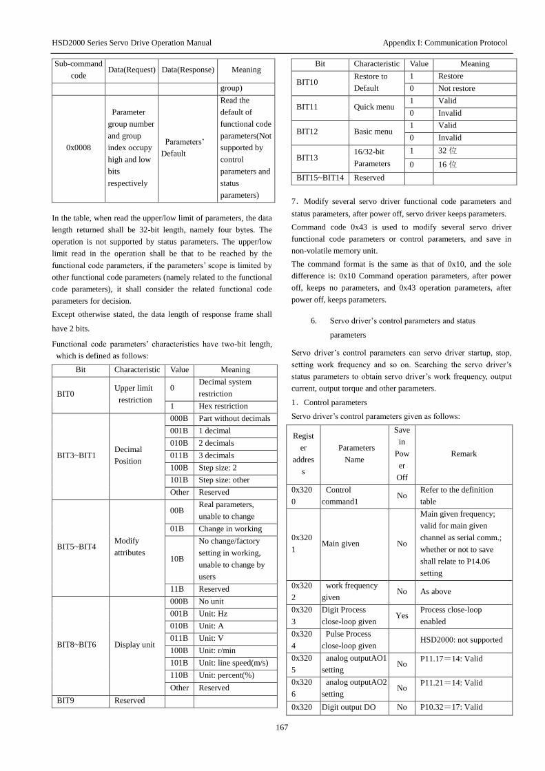
HSD2000 Series Servo Drive Operation Manual Appendix I: Communication Protocol
167
Sub-command
code Data(Request) Data(Response) Meaning
group)
0x0008
Parameter
group number
and group
index occupy
high and low
bits
respectively
Parameters’
Default
Read the
default of
functional code
parameters(Not
supported by
control
parameters and
status
parameters)
In the table, when read the upper/low limit of parameters, the data
length returned shall be 32-bit length, namely four bytes. The
operation is not supported by status parameters. The upper/low
limit read in the operation shall be that to be reached by the
functional code parameters, if the parameters’ scope is limited by
other functional code parameters (namely related to the functional
code parameters), it shall consider the related functional code
parameters for decision.
Except otherwise stated, the data length of response frame shall
have 2 bits.
Functional code parameters’ characteristics have two-bit length,
which is defined as follows:
Bit Characteristic Value Meaning
BIT0 Upper limit
restriction
0 Decimal system
restriction
1 Hex restriction
BIT3~BIT1 Decimal
Position
000B Part without decimals
001B 1 decimal
010B 2 decimals
011B 3 decimals
100B Step size: 2
101B Step size: other
Other Reserved
BIT5~BIT4 Modify
attributes
00B Real parameters,
unable to change
01B Change in working
10B
No change/factory
setting in working,
unable to change by
users
11B Reserved
BIT8~BIT6 Display unit
000B No unit
001B Unit: Hz
010B Unit: A
011B Unit: V
100B Unit: r/min
101B Unit: line speed(m/s)
110B Unit: percent(%)
Other Reserved
BIT9 Reserved
Bit Characteristic Value Meaning
BIT10 Restore to
Default
1 Restore
0 Not restore
BIT11 Quick menu 1 Valid
0 Invalid
BIT12 Basic menu 1 Valid
0 Invalid
BIT13 16/32-bit
Parameters
1 32 位
0 16 位
BIT15~BIT14 Reserved
7.Modify several servo driver functional code parameters and
status parameters, after power off, servo driver keeps parameters.
Command code 0x43 is used to modify several servo driver
functional code parameters or control parameters, and save in
non-volatile memory unit.
The command format is the same as that of 0x10, and the sole
difference is: 0x10 Command operation parameters, after power
off, keeps no parameters, and 0x43 operation parameters, after
power off, keeps parameters.
6. Servo driver’s control parameters and status
parameters
Servo driver’s control parameters can servo driver startup, stop,
setting work frequency and so on. Searching the servo driver’s
status parameters to obtain servo driver’s work frequency, output
current, output torque and other parameters.
1.Control parameters
Servo driver’s control parameters given as follows:
Regist
er
addres
s
Parameters
Name
Save
in
Pow
er
Off
Remark
0x320
0
Control
command1 No
Refer to the definition
table
0x320
1 Main given No
Main given frequency;
valid for main given
channel as serial comm.;
whether or not to save
shall relate to P14.06
setting
0x320
2
work frequency
given No As above
0x320
3
Digit Process
close-loop given Yes
Process close-loop
enabled
0x320
4
Pulse Process
close-loop given HSD2000: not supported
0x320
5
analog outputAO1
setting No
P11.17=14: Valid
0x320
6
analog outputAO2
setting No
P11.21=14: Valid
0x320 Digit output DO No P10.32=17: Valid

HSD2000 Series Servo Drive Operation Manual Appendix I: Communication Protocol
168
Regist
er
addres
s
Parameters
Name
Save
in
Pow
er
Off
Remark
7 setting
0x320
8
frequency ratio
setting HSD2000: not supported
0x320
9
Virtual Terminal
control setting No
BIT0~BIT9:
X1~X8/FWD/REV, valid
for bits in P10.17;
BIT10~BIT13:
Y1/Y2/RO1/RO2,
P10.18~P10.21=17
Terminal: Valid
0x320
A
Setting acceleration
time1 Yes
0x320
B
Setting
Deceleration time 1 Yes
0x320
C
Auxiliary
frequency given No
Auxiliary given channel:
serial comm, Auxiliary
given bits( Control 2’s
BIT2): valid
0x320
D Torque given No
Torque control mode,
torque given channel:
serial and under torque
control mode: valid
0x320
E
Torque current
given No
Torque control mode:
Torque given channel:
serial and under torque
current control mode:
valid
0x321
2
Control command
2 No
Refer to the definition
table
Attentions
1.When reading control parameters, the return value will be the
one written in previous communication;
2 . Within control parameters, max length of “Main
setting”,“ work frequency setting” and “Auxiliary frequency setting” shall be 32 bits, and others shall be 16 bits in length;
3. Within control parameters, all units given, input/output setting
scope, decimal calibration and so on can be seen in related
functional code parameters。
Control command 1 is defined as follows:
Bit Valu
e Function Remark
BIT2~
BIT0
111
B Work Command
Start servo driver
(Valid when JOG is
invalid)
110
B Mode 0: stop
Stop as per the set
deceleration
time(Valid when
JOG is invalid)
Bit Valu
e Function Remark
101
B Mode 1: stop Free to stop
100
B
Stop due to external
fault
Free to stop, servo
driver displays
external fault
011
B Mode 2: stop
HSD2000: not
support
Othe
r No command
BIT3 1 Reverse Set work direction with
work command valid 0 Forward
BIT4 1 Jog Forward Jog does not act with
normal and reverse
valid, and stops with
normal and reverse
invalid
0 Jog Forward invalid
BIT5
1 Jog Reverse
0 Jog Reverse invalid
BIT6
1
Allow
accelerating/Decele
ration
When the bit is valid,
the control 1’s
BIT5~BIT0 will be
valid 0
Disable
accelerating/Decele
ration
BIT7
1 Upper computer
control 1 valid Valid option bit of
control 1 of upper
computer 0 Upper computer
control 1 invalid
BIT8 1 Reserved
Reserved 0 Reserved
BIT9
1 Fault reset valid Valid option bit for
upper computer fault
reset 0 Fault reset invalid
BIT15
~BIT1
0
0000
00B Reserved
Attentions
1.Upper computer’s control command(control command 1 and
control command 2) shall be valid with “Work command channel
option” value equal to “Communication Command” ; When the
control 1’s BIT7 bit is valid, the whole control 1 will be valid;
When control 1’s BIT6 bit is valid, BIT5~BIT0 will be valid.
2.Upper computer’s treatment on fault and alarm: When servo
driver fails, as for control 1 and 2 command, except the fault reset
command, the upper computer will be invalid if sending other
commands. Namely the upper computer shall firstly reset the fault
before sending command. When alarms exist, the control will be
valid.
Control Command 2 is defined as follows:
Bit Value Function Remark
BIT0
1 Servo driver work
disable Servo driver
allow/disable
work option bit 0 Servo driver work
allowed

HSD2000 Series Servo Drive Operation Manual Appendix I: Communication Protocol
169
Bit Value Function Remark
BIT1
1
Work( direction
taken from
functional code) Work direction
0
Other work
status(refer to
control 1)
BIT2
1 Auxiliary given
valid
Valid option
bit for
Auxiliary
given
frequency of
upper
computer
0 Auxiliary given
invalid
BIT3
1 Upper computer
control 2 valid
Valid option
bit for control
2 of upper
computer 0
Upper computer
control 2 invalid
BIT15~BIT4 Reserved
Note: When control command’s BIT3 bit is valid, the whole
control 2 will be valid.
2.Status parameters
Register
address Parameters Name Remark
0x3300 Servo driver operating
status 1
0x3301 Current main given actual
work value
Current work
frequency
0x3302 Slave machine type
0x3303 Servo driver type
0x3304 Software version
0x3305 Current work frequency
0x3306 Output current
0x3307 Output voltage
0x3308 Output power
0x3309 Work rotation speed
0x330A Work line speed
0x330B Analog Process close-loop
feedback
0x330C Bus voltage
0x330D External counter HSD2000: not
support
0x330E Output torque
0x330F Switch Input output
terminal status
BIT0~BIT9:
X1~X8/FWD/REV
;
BIT10~BIT13:
Y1/Y2/RO1/RO2
0x3310 Actual length HSD2000: not
support
0x3311 Work frequency after
compensation
HSD2000: not
support
0x3312 The 1st work fault
0x3313 The 2nd work fault
Register
address Parameters Name Remark
0x3314 The 3rd (latest) work fault
0x3315 work frequency setting
0x3316 Setting rotation speed
0x3317 Analog Process close-loop
setting
0x3318 setting 线 Speed
0x3319 AI1
0x331A AI2
0x331B Setting length HSD2000: not
support
0x331C Setting acceleration time1
0x331D Setting Deceleration time
1
0x331E
Command given channel:
0: Panel control;
1: Terminal control;
2: Serial port control
0x331F Servo driver operating
status 2
0x3320
frequency given
channel:
0: Digit given1(operation
panel▲▼ given);
1: Digit given2(Terminal
UP/DOWN given);
2: Digit given3(Serial
port);
3: AI analog given;
4: Terminal PULSE given;
0x3321 Accumulated length HSD2000: not
support
0x3322
Motor and mode option:
Ones place: Motor 1
control mode option
0: Vector control without
PG
1: Vector control with PG
2: V/F control without PG
3: V/F control with PG
Tens place: Motor 1 type
option
0: Asynchronous motor
1: Synchronous motor
Hundreds place: Motor 2
control mode option
0: Vector control without
PG
1: Vector control with PG
2: V/F control without PG
3: V/F control with PG
Thousands place: Motor 2
type option

HSD2000 Series Servo Drive Operation Manual Appendix I: Communication Protocol
170
Register
address Parameters Name Remark
0: Asynchronous motor
1: Synchronous motor
0x3323 Bus voltage at the 3rd fault
0x3324 Actual current at the 3rd
fault
0x3325 Work frequency at the 3rd
fault
0x3326 Servo driver operating
status at the 3rd fault
Bit is defined as
work status 1
0x3327 AI3
0x3328 Servo driver operating
status 3
Attentions
1.Status parameters do not support writing operation.
2.Within status parameters, max length of “Actual work value of
main setting”,“ work frequency setting” and “work frequency at
the 3rd fault” shall be 32 bits, and others shall be 16 bits in length.
Servo driver operating status 1 is defined as follows:
Bit Value Function Remark
BIT0
1 Servo driver
Work
0 Servo driver
Stop
BIT1
1 Servo driver
Reverse
0 Servo driver
Forward
BIT2
1 Reach main
setting
0 Fail to reach
main setting
BIT3
1 Allow serial
port control
0 Disable serial
port control
BIT4
1 Allow serial
port given
0 Disable serial
port given
BIT5~BI
T6 Reserved
BIT7
1 Alarm When the bit is 0, it
shall consider control
1’s BIT15~8 to judge
whether it is normal or
fault. BIT15~8 equal to
0 means normal,
otherwise, it will be
fault.
0 Fault or
normal
Bit Value Function Remark
BIT15~B
IT8
0x00~
0xFF
Fault/alarm
code
0: Servo driver is
normal;
Non 0: fault/alarm,
specific fault/alarm
codes can be seen in
user manual.
Fault/alarm can be
seen in status 1 defined
in BIT7.
Servo driver operating status 2 is defined as follows:
Bit Value Function Remark
BIT0 1 Jog Work
0 Non-Jog Work
BIT1
1 Process close-loop
Work
0 Non Process
close-loop Work
BIT2 1 PLCWork
0 Non-PLC Work
BIT3
1 Multiplex
frequency Work
0 Non-Multiplex
frequency Work
BIT4 1 Common Work
0 Uncommon Work
BIT5
1 Traverse
frequency
0 Non-Traverse
frequency
BIT6 1 Under voltage
0 Normal voltage
BIT7 Reserved
BIT8 Servo Work
BIT9 Customized Work
BIT10 Synchronous
speed work
Other Reserved
Servo driver operating status 3 is defined as follows:
Bit Value Function Remark
BIT0~BIT1 Reserved
BIT2 Zero-speed Work
BIT3 Accelerating
BIT4 Decelerating
BIT5 Constant-speed
Work
BIT6 Pre-excitation
BIT7 Setting
BIT8 Over current
limit
BIT9 DC over voltage
limit
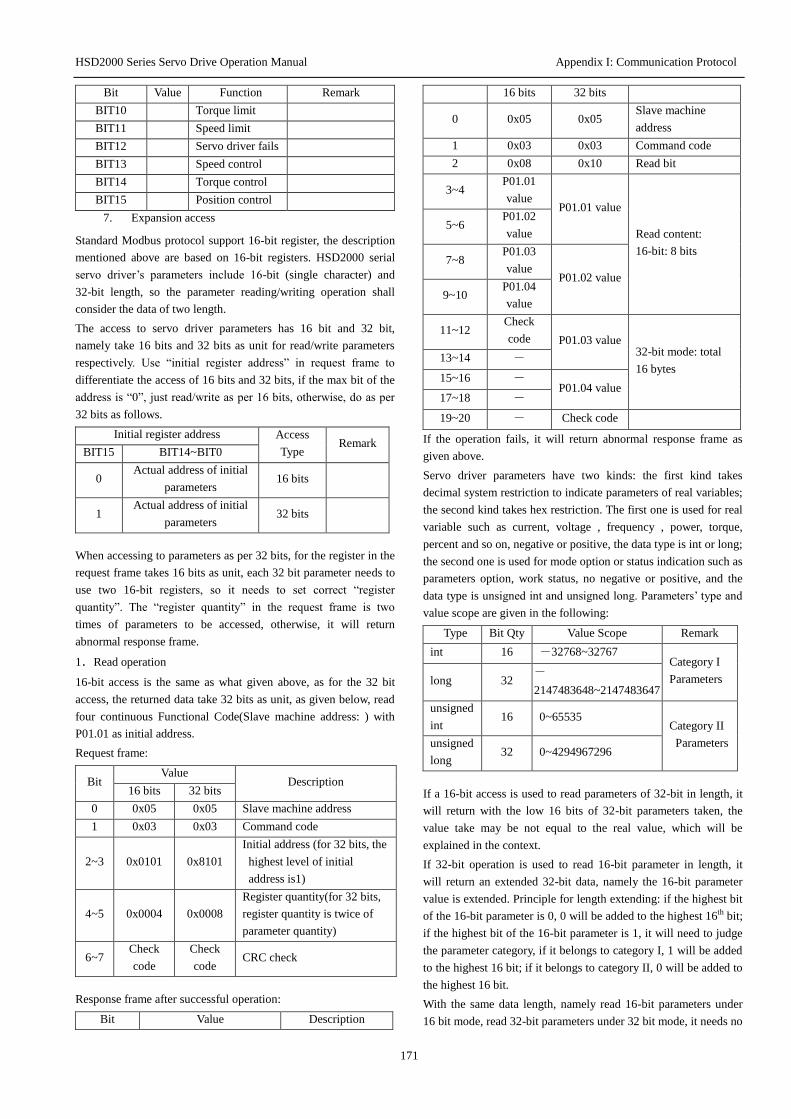
HSD2000 Series Servo Drive Operation Manual Appendix I: Communication Protocol
171
Bit Value Function Remark
BIT10 Torque limit
BIT11 Speed limit
BIT12 Servo driver fails
BIT13 Speed control
BIT14 Torque control
BIT15 Position control
7. Expansion access
Standard Modbus protocol support 16-bit register, the description
mentioned above are based on 16-bit registers. HSD2000 serial
servo driver’s parameters include 16-bit (single character) and
32-bit length, so the parameter reading/writing operation shall
consider the data of two length.
The access to servo driver parameters has 16 bit and 32 bit,
namely take 16 bits and 32 bits as unit for read/write parameters
respectively. Use “initial register address” in request frame to
differentiate the access of 16 bits and 32 bits, if the max bit of the
address is “0”, just read/write as per 16 bits, otherwise, do as per
32 bits as follows.
Initial register address Access
Type Remark
BIT15 BIT14~BIT0
0 Actual address of initial
parameters 16 bits
1 Actual address of initial
parameters 32 bits
When accessing to parameters as per 32 bits, for the register in the
request frame takes 16 bits as unit, each 32 bit parameter needs to
use two 16-bit registers, so it needs to set correct “register
quantity”. The “register quantity” in the request frame is two
times of parameters to be accessed, otherwise, it will return
abnormal response frame.
1.Read operation
16-bit access is the same as what given above, as for the 32 bit
access, the returned data take 32 bits as unit, as given below, read
four continuous Functional Code(Slave machine address: ) with
P01.01 as initial address.
Request frame:
Bit Value
Description 16 bits 32 bits
0 0x05 0x05 Slave machine address
1 0x03 0x03 Command code
2~3 0x0101 0x8101
Initial address (for 32 bits, the
highest level of initial
address is1)
4~5 0x0004 0x0008
Register quantity(for 32 bits,
register quantity is twice of
parameter quantity)
6~7 Check
code
Check
code CRC check
Response frame after successful operation:
Bit Value Description
16 bits 32 bits
0 0x05 0x05 Slave machine
address
1 0x03 0x03 Command code
2 0x08 0x10 Read bit
3~4 P01.01
value P01.01 value
Read content:
16-bit: 8 bits
5~6 P01.02
value
7~8 P01.03
value P01.02 value
9~10 P01.04
value
11~12 Check
code P01.03 value 32-bit mode: total
16 bytes 13~14 -
15~16 - P01.04 value
17~18 -
19~20 - Check code
If the operation fails, it will return abnormal response frame as
given above.
Servo driver parameters have two kinds: the first kind takes
decimal system restriction to indicate parameters of real variables;
the second kind takes hex restriction. The first one is used for real
variable such as current, voltage , frequency , power, torque,
percent and so on, negative or positive, the data type is int or long;
the second one is used for mode option or status indication such as
parameters option, work status, no negative or positive, and the
data type is unsigned int and unsigned long. Parameters’ type and
value scope are given in the following:
Type Bit Qty Value Scope Remark
int 16 -32768~32767 Category I
Parameters long 32 -
2147483648~2147483647
unsigned
int 16 0~65535
Category II
Parameters unsigned
long 32 0~4294967296
If a 16-bit access is used to read parameters of 32-bit in length, it
will return with the low 16 bits of 32-bit parameters taken, the
value take may be not equal to the real value, which will be
explained in the context.
If 32-bit operation is used to read 16-bit parameter in length, it
will return an extended 32-bit data, namely the 16-bit parameter
value is extended. Principle for length extending: if the highest bit
of the 16-bit parameter is 0, 0 will be added to the highest 16th bit;
if the highest bit of the 16-bit parameter is 1, it will need to judge
the parameter category, if it belongs to category I, 1 will be added
to the highest 16 bit; if it belongs to category II, 0 will be added to
the highest 16 bit.
With the same data length, namely read 16-bit parameters under
16 bit mode, read 32-bit parameters under 32 bit mode, it needs no
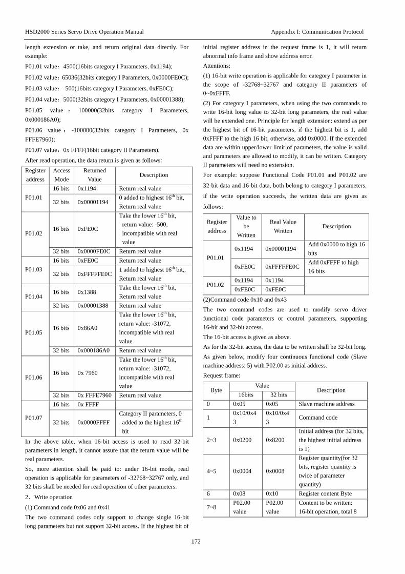
HSD2000 Series Servo Drive Operation Manual Appendix I: Communication Protocol
172
length extension or take, and return original data directly. For
example:
P01.01 value:4500(16bits category I Parameters, 0x1194);
P01.02 value:65036(32bits category I Parameters, 0x0000FE0C);
P01.03 value:-500(16bits category I Parameters, 0xFE0C);
P01.04 value:5000(32bits category I Parameters, 0x00001388);
P01.05 value : 100000(32bits category I Parameters,
0x000186A0);
P01.06 value : -100000(32bits category I Parameters, 0x
FFFE7960);
P01.07 value:0x FFFF(16bit category II Parameters).
After read operation, the data return is given as follows:
Register
address
Access
Mode
Returned
Value Description
P01.01
16 bits 0x1194 Return real value
32 bits 0x00001194 0 added to highest 16th bit,
Return real value
P01.02 16 bits 0xFE0C
Take the lower 16th bit,
return value: -500,
incompatible with real
value
32 bits 0x0000FE0C Return real value
P01.03
16 bits 0xFE0C Return real value
32 bits 0xFFFFFE0C 1 added to highest 16th bit,,
Return real value
P01.04 16 bits 0x1388
Take the lower 16th bit,
Return real value
32 bits 0x00001388 Return real value
P01.05 16 bits 0x86A0
Take the lower 16th bit,
return value: -31072,
incompatible with real
value
32 bits 0x000186A0 Return real value
P01.06 16 bits 0x 7960
Take the lower 16th bit,
return value: -31072,
incompatible with real
value
32 bits 0x FFFE7960 Return real value
P01.07
16 bits 0x FFFF
32 bits 0x0000FFFF
Category II parameters, 0
added to the highest 16th
bit
In the above table, when 16-bit access is used to read 32-bit
parameters in length, it cannot assure that the return value will be
real parameters.
So, more attention shall be paid to: under 16-bit mode, read
operation is applicable for parameters of -32768~32767 only, and
32 bits shall be needed for read operation of other parameters.
2.Write operation
(1) Command code 0x06 and 0x41
The two command codes only support to change single 16-bit
long parameters but not support 32-bit access. If the highest bit of
initial register address in the request frame is 1, it will return
abnormal info frame and show address error.
Attentions:
(1) 16-bit write operation is applicable for category I parameter in
the scope of -32768~32767 and category II parameters of
0~0xFFFF.
(2) For category I parameters, when using the two commands to
write 16-bit long value to 32-bit long parameters, the real value
will be extended one. Principle for length extension: extend as per
the highest bit of 16-bit parameters, if the highest bit is 1, add
0xFFFF to the high 16 bit, otherwise, add 0x0000. If the extended
data are within upper/lower limit of parameters, the value is valid
and parameters are allowed to modify, it can be written. Category
II parameters will need no extension.
For example: suppose Functional Code P01.01 and P01.02 are
32-bit data and 16-bit data, both belong to category I parameters,
if the write operation succeeds, the written data are given as
follows:
Register
address
Value to
be
Written
Real Value
Written Description
P01.01
0x1194 0x00001194 Add 0x0000 to high 16
bits
0xFE0C 0xFFFFFE0C Add 0xFFFF to high
16 bits
P01.02 0x1194 0x1194
0xFE0C 0xFE0C
(2)Command code 0x10 and 0x43
The two command codes are used to modify servo driver
functional code parameters or control parameters, supporting
16-bit and 32-bit access.
The 16-bit access is given as above.
As for the 32-bit access, the data to be written shall be 32-bit long.
As given below, modify four continuous functional code (Slave
machine address: 5) with P02.00 as initial address.
Request frame:
Byte Value
Description 16bits 32 bits
0 0x05 0x05 Slave machine address
1 0x10/0x4
3
0x10/0x4
3 Command code
2~3 0x0200 0x8200
Initial address (for 32 bits,
the highest initial address
is 1)
4~5 0x0004 0x0008
Register quantity(for 32
bits, register quantity is
twice of parameter
quantity)
6 0x08 0x10 Register content Byte
7~8 P02.00
value
P02.00
value
Content to be written:
16-bit operation, total 8
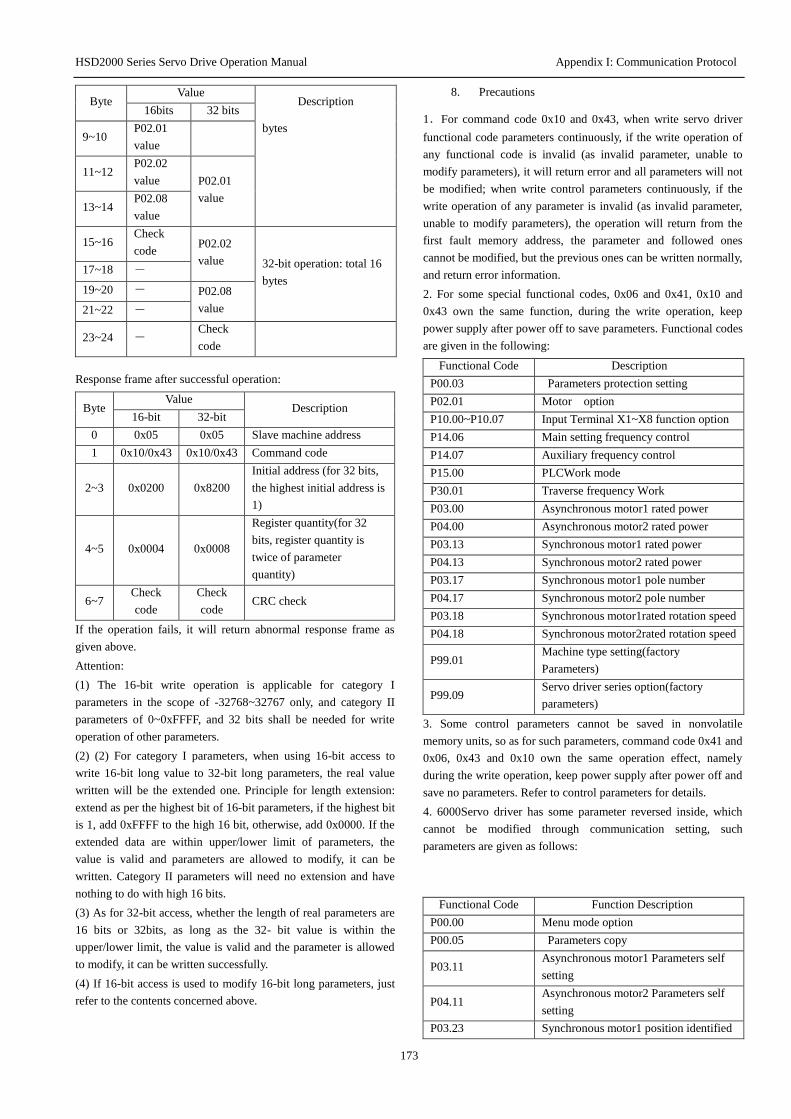
HSD2000 Series Servo Drive Operation Manual Appendix I: Communication Protocol
173
Byte Value
Description 16bits 32 bits
9~10 P02.01
value
bytes
11~12 P02.02
value P02.01
value 13~14
P02.08
value
15~16 Check
code P02.02
value 32-bit operation: total 16
bytes 17~18 -
19~20 - P02.08
value 21~22 -
23~24 - Check
code
Response frame after successful operation:
Byte Value
Description 16-bit 32-bit
0 0x05 0x05 Slave machine address
1 0x10/0x43 0x10/0x43 Command code
2~3 0x0200 0x8200
Initial address (for 32 bits,
the highest initial address is
1)
4~5 0x0004 0x0008
Register quantity(for 32
bits, register quantity is
twice of parameter
quantity)
6~7 Check
code
Check
code CRC check
If the operation fails, it will return abnormal response frame as
given above.
Attention:
(1) The 16-bit write operation is applicable for category I
parameters in the scope of -32768~32767 only, and category II
parameters of 0~0xFFFF, and 32 bits shall be needed for write
operation of other parameters.
(2) (2) For category I parameters, when using 16-bit access to
write 16-bit long value to 32-bit long parameters, the real value
written will be the extended one. Principle for length extension:
extend as per the highest bit of 16-bit parameters, if the highest bit
is 1, add 0xFFFF to the high 16 bit, otherwise, add 0x0000. If the
extended data are within upper/lower limit of parameters, the
value is valid and parameters are allowed to modify, it can be
written. Category II parameters will need no extension and have
nothing to do with high 16 bits.
(3) As for 32-bit access, whether the length of real parameters are
16 bits or 32bits, as long as the 32- bit value is within the
upper/lower limit, the value is valid and the parameter is allowed
to modify, it can be written successfully.
(4) If 16-bit access is used to modify 16-bit long parameters, just
refer to the contents concerned above.
8. Precautions
1.For command code 0x10 and 0x43, when write servo driver
functional code parameters continuously, if the write operation of
any functional code is invalid (as invalid parameter, unable to
modify parameters), it will return error and all parameters will not
be modified; when write control parameters continuously, if the
write operation of any parameter is invalid (as invalid parameter,
unable to modify parameters), the operation will return from the
first fault memory address, the parameter and followed ones
cannot be modified, but the previous ones can be written normally,
and return error information.
2. For some special functional codes, 0x06 and 0x41, 0x10 and
0x43 own the same function, during the write operation, keep
power supply after power off to save parameters. Functional codes
are given in the following:
Functional Code Description
P00.03 Parameters protection setting
P02.01 Motor option
P10.00~P10.07 Input Terminal X1~X8 function option
P14.06 Main setting frequency control
P14.07 Auxiliary frequency control
P15.00 PLCWork mode
P30.01 Traverse frequency Work
P03.00 Asynchronous motor1 rated power
P04.00 Asynchronous motor2 rated power
P03.13 Synchronous motor1 rated power
P04.13 Synchronous motor2 rated power
P03.17 Synchronous motor1 pole number
P04.17 Synchronous motor2 pole number
P03.18 Synchronous motor1rated rotation speed
P04.18 Synchronous motor2rated rotation speed
P99.01 Machine type setting(factory
Parameters)
P99.09 Servo driver series option(factory
parameters)
3. Some control parameters cannot be saved in nonvolatile
memory units, so as for such parameters, command code 0x41 and
0x06, 0x43 and 0x10 own the same operation effect, namely
during the write operation, keep power supply after power off and
save no parameters. Refer to control parameters for details.
4. 6000Servo driver has some parameter reversed inside, which
cannot be modified through communication setting, such
parameters are given as follows:
Functional Code Function Description
P00.00 Menu mode option
P00.05 Parameters copy
P03.11 Asynchronous motor1 Parameters self
setting
P04.11 Asynchronous motor2 Parameters self
setting
P03.23 Synchronous motor1 position identified
HSD2000 Series Servo Drive Operation Manual Appendix I: Communication Protocol
174
P04.23 Synchronous motor2 position identified
5.Upper computer’s operation on user password and factory
password
(1) User password
1) Reading/writing of functional code parameters protected by
user password, functional code management (“read and display
data address”, except data switch display).
2) If user password is set (P00.02!=0), only after passport
removal, can the upper computer access to functional code
parameters, yet the access to control parameters and status
parameters will not be limited by password.
3) Upper computer cannot set, modify or cancel user password,
which can be done only through operation panel. As for P00.02
write operation, it is valid under two conditions only: I, remove
password if any; II, write 0 if there is no password, and invalid
operation return for other conditions.
4)Upper computer and operation panel have independent
operation on password, even the password is removed through the
operation panel, but the upper computer must have password
removed so as to access to functional code parameters through the
upper computer, vice versa.
5)After the upper computer obtains the right to access to
parameters, it will read the user password and return “0000” but
not the real user password.
6) After removal password, the upper computer will obtain the
right to access to functional code, if there is no communication
within 5 minutes, the access will be invalid. If it needs to access to
the functional code, just input password again.
7) After the upper computer obtains the right to access (no user
password or password removal), through the operation panel, set
the user password or new password, and the upper computer still
has the right to current access, needing no password removal
again. If failing to access, just remove the password (write new
password) to obtain the right to access.
(2) Factory password
1) Reading/writing of group P99 parameter for factory password
protection, functional code management of parameters in group
P99.
2) Only after password removal (write correct factory password to
P99.00), can the upper computer access to functional code of the
group P99; if there is no communication within 5 minutes with the
right to access, the right will be invalid automatically, and correct
password shall be input again to access to the group 99.
3)With the right to access to group P99, the upper computer will
read P99.00 and return “0000” but not real factory password.
4)Upper computer and operation panel have independent
password operation, namely correct password shall be input
respectively to access;
5)Upper computer has no right to modify the factory password,
when the upper computer write P99.00, the password must be
correct, otherwise, it will return invalid operation with prompt
“unable to modify”.

HSD2000 Series Servo Drive Operation Manual Appendix I: Communication Protocol
175
9. CRC Check
In order to increase the speed, CRC-16 is expressed generally by form, the following are language C source code to realize
CRC-16, attention: the final result has exchanged high and low bytes and the result is the CRC total of CRC.
unsigned short CRC16 (unsigned char *msg, unsigned char length) /* The function returns the CRC as a unsigned
short type */
{
unsigned char uchCRCHi = 0xFF ; /* high byte of CRC initialized */
unsigned char uchCRCLo = 0xFF ; /* low byte of CRC initialized */
unsigned uIndex ; /* index into CRC lookup table */
while (length--) /* pass through message buffer */
{
uIndex = uchCRCLo ^ *msg++ ; /* calculate the CRC */
uchCRCLo = uchCRCHi ^ (crcvalue[uIndex] >>8);
uchCRCHi =crcvalue[uIndex]&0xff;
}
return (uchCRCHi | uchCRCLo<<8) ;
}
/* Table of CRC values */
const unsigned int crcvalue[ ] = {
0x0000,0xC1C0,0x81C1,0x4001,0x01C3,0xC003,0x8002,0x41C2,0x01C6,0xC006,0x8007,0x41C7,
0x0005,0xC1C5,0x81C4,0x4004,0x01CC,0xC00C,0x800D,0x41CD,0x000F,0xC1CF,0x81CE,0x400E,
0x000A,0xC1CA,0x81CB,0x400B,0x01C9,0xC009,0x8008,0x41C8,0x01D8,0xC018,0x8019,0x41D9,
0x001B,0xC1DB,0x81DA,0x401A,0x001E,0xC1DE,0x81DF,0x401F,0x01DD,0xC01D,0x801C,0x41DC,
0x0014,0xC1D4,0x81D5,0x4015,0x01D7,0xC017,0x8016,0x41D6,0x01D2,0xC012,0x8013,0x41D3,
0x0011,0xC1D1,0x81D0,0x4010,0x01P0,0xC030,0x8031,0x41P1,0x0033,0xC1P3,0x81P2,0x4032,
0x0036,0xC1P6,0x81F7,0x4037,0x01F5,0xC035,0x8034,0x41P4,0x003C,0xC1FC,0x81FD,0x403D,
0x01FF,0xC03F,0x803E,0x41FE,0x01FA,0xC03A,0x803B,0x41FB,0x0039,0xC1P9,0x81P8,0x4038,
0x0028,0xC1E8,0x81E9,0x4029,0x01EB,0xC02B,0x802A,0x41EA,0x01EE,0xC02E,0x802F,0x41EF,
0x002D,0xC1ED,0x81EC,0x402C,0x01E4,0xC024,0x8025,0x41E5,0x0027,0xC1E7,0x81E6,0x4026,
0x0022,0xC1E2,0x81E3,0x4023,0x01E1,0xC021,0x8020,0x41E0,0x01A0,0xC060,0x8061,0x41A1,
0x0063,0xC1A3,0x81A2,0x4062,0x0066,0xC1A6,0x81A7,0x4067,0x01A5,0xC065,0x8064,0x41A4,
0x006C,0xC1AC,0x81AD,0x406D,0x01AF,0xC06F,0x806E,0x41AE,0x01AA,0xC06A,0x806B,0x41AB,
0x0069,0xC1A9,0x81A8,0x4068,0x0078,0xC1B8,0x81B9,0x4079,0x01BB,0xC07B,0x807A,0x41BA,
0x01BE,0xC07E,0x807F,0x41BF,0x007D,0xC1BD,0x81BC,0x407C,0x01B4,0xC074,0x8075,0x41B5,
0x0077,0xC1B7,0x81B6,0x4076,0x0072,0xC1B2,0x81B3,0x4073,0x01B1,0xC071,0x8070,0x41B0,
0x0050,0xC190,0x8191,0x4051,0x0193,0xC053,0x8052,0x4192,0x0196,0xC056,0x8057,0x4197,
0x0055,0xC195,0x8194,0x4054,0x019C,0xC05C,0x805D,0x419D,0x005F,0xC19F,0x819E,0x405E,
0x005A,0xC19A,0x819B,0x405B,0x0199,0xC059,0x8058,0x4198,0x0188,0xC048,0x8049,0x4189,
0x004B,0xC18B,0x818A,0x404A,0x004E,0xC18E,0x818F,0x404F,0x018D,0xC04D,0x804C,0x418C,
0x0044,0xC184,0x8185,0x4045,0x0187,0xC047,0x8046,0x4186,0x0182,0xC042,0x8043,0x4183,
0x0041,0xC181,0x8180,0x4040}
To calculate the total CRC check of online sending will take a long time, yet it will save the program space occupied by forms. CRC
codes for online calculation are given as follows:
unsigned int crc_check(unsigned char *data,unsigned char length)
{
int i;
unsigned crc_result=0xffff;
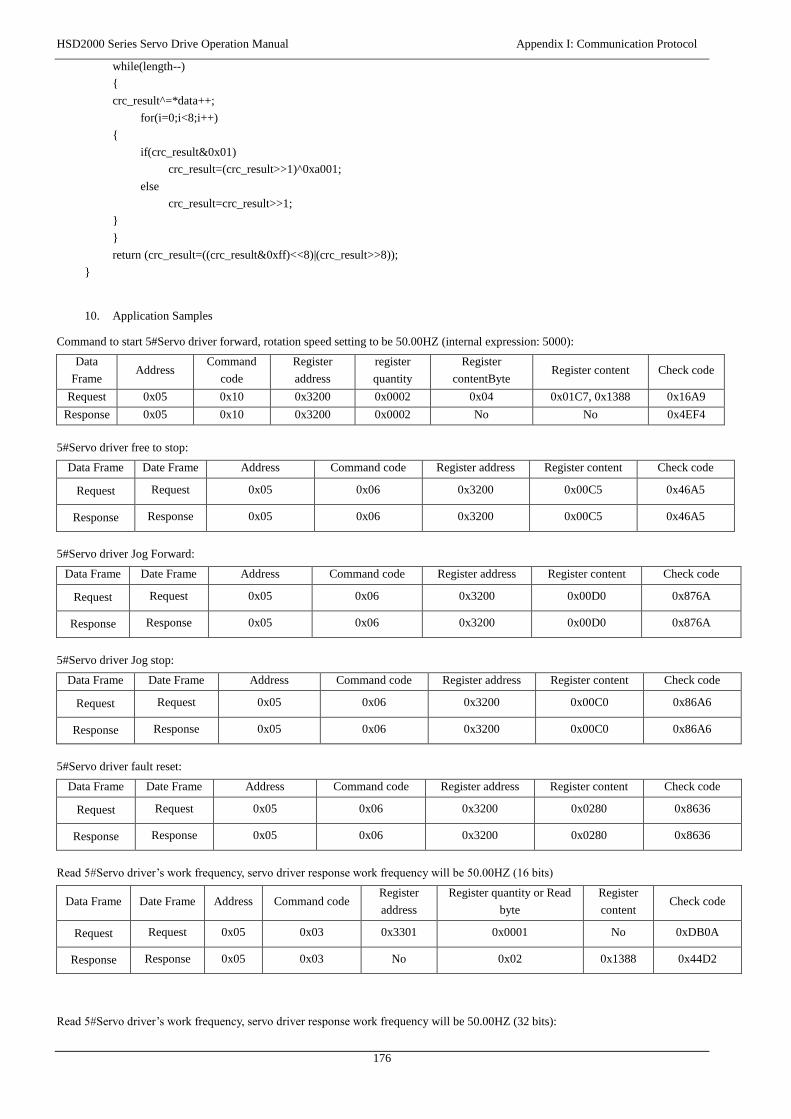
HSD2000 Series Servo Drive Operation Manual Appendix I: Communication Protocol
176
while(length--)
{
crc_result^=*data++;
for(i=0;i<8;i++)
{
if(crc_result&0x01)
crc_result=(crc_result>>1)^0xa001;
else
crc_result=crc_result>>1;
}
}
return (crc_result=((crc_result&0xff)<<8)|(crc_result>>8));
}
10. Application Samples
Command to start 5#Servo driver forward, rotation speed setting to be 50.00HZ (internal expression: 5000):
Data
Frame Address
Command
code
Register
address
register
quantity
Register
contentByte Register content Check code
Request 0x05 0x10 0x3200 0x0002 0x04 0x01C7, 0x1388 0x16A9
Response 0x05 0x10 0x3200 0x0002 No No 0x4EF4
5#Servo driver free to stop:
Data Frame Date Frame Address Command code Register address Register content Check code
Request Request 0x05 0x06 0x3200 0x00C5 0x46A5
Response Response 0x05 0x06 0x3200 0x00C5 0x46A5
5#Servo driver Jog Forward:
Data Frame Date Frame Address Command code Register address Register content Check code
Request Request 0x05 0x06 0x3200 0x00D0 0x876A
Response Response 0x05 0x06 0x3200 0x00D0 0x876A
5#Servo driver Jog stop:
Data Frame Date Frame Address Command code Register address Register content Check code
Request Request 0x05 0x06 0x3200 0x00C0 0x86A6
Response Response 0x05 0x06 0x3200 0x00C0 0x86A6
5#Servo driver fault reset:
Data Frame Date Frame Address Command code Register address Register content Check code
Request Request 0x05 0x06 0x3200 0x0280 0x8636
Response Response 0x05 0x06 0x3200 0x0280 0x8636
Read 5#Servo driver’s work frequency, servo driver response work frequency will be 50.00HZ (16 bits)
Data Frame Date Frame Address Command code Register
address
Register quantity or Read
byte
Register
content Check code
Request Request 0x05 0x03 0x3301 0x0001 No 0xDB0A
Response Response 0x05 0x03 No 0x02 0x1388 0x44D2
Read 5#Servo driver’s work frequency, servo driver response work frequency will be 50.00HZ (32 bits):
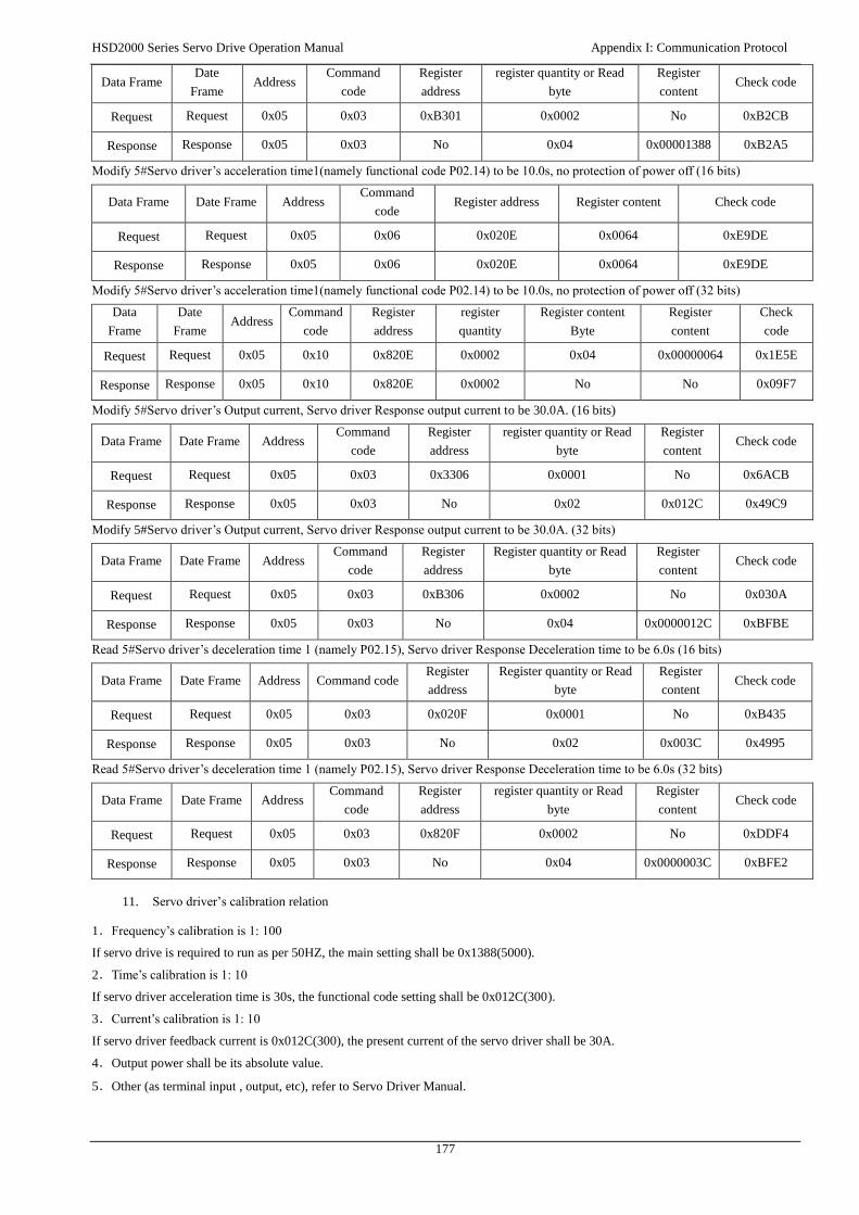
HSD2000 Series Servo Drive Operation Manual Appendix I: Communication Protocol
177
Data Frame Date
Frame Address
Command
code
Register
address
register quantity or Read
byte
Register
content Check code
Request Request 0x05 0x03 0xB301 0x0002 No 0xB2CB
Response Response 0x05 0x03 No 0x04 0x00001388 0xB2A5
Modify 5#Servo driver’s acceleration time1(namely functional code P02.14) to be 10.0s, no protection of power off (16 bits)
Data Frame Date Frame Address Command
code Register address Register content Check code
Request Request 0x05 0x06 0x020E 0x0064 0xE9DE
Response Response 0x05 0x06 0x020E 0x0064 0xE9DE
Modify 5#Servo driver’s acceleration time1(namely functional code P02.14) to be 10.0s, no protection of power off (32 bits)
Data
Frame
Date
Frame Address
Command
code
Register
address
register
quantity
Register content
Byte
Register
content
Check
code
Request Request 0x05 0x10 0x820E 0x0002 0x04 0x00000064 0x1E5E
Response Response 0x05 0x10 0x820E 0x0002 No No 0x09F7
Modify 5#Servo driver’s Output current, Servo driver Response output current to be 30.0A. (16 bits)
Data Frame Date Frame Address Command
code
Register
address
register quantity or Read
byte
Register
content Check code
Request Request 0x05 0x03 0x3306 0x0001 No 0x6ACB
Response Response 0x05 0x03 No 0x02 0x012C 0x49C9
Modify 5#Servo driver’s Output current, Servo driver Response output current to be 30.0A. (32 bits)
Data Frame Date Frame Address Command
code
Register
address
Register quantity or Read
byte
Register
content Check code
Request Request 0x05 0x03 0xB306 0x0002 No 0x030A
Response Response 0x05 0x03 No 0x04 0x0000012C 0xBFBE
Read 5#Servo driver’s deceleration time 1 (namely P02.15), Servo driver Response Deceleration time to be 6.0s (16 bits)
Data Frame Date Frame Address Command code Register
address
Register quantity or Read
byte
Register
content Check code
Request Request 0x05 0x03 0x020F 0x0001 No 0xB435
Response Response 0x05 0x03 No 0x02 0x003C 0x4995
Read 5#Servo driver’s deceleration time 1 (namely P02.15), Servo driver Response Deceleration time to be 6.0s (32 bits)
Data Frame Date Frame Address Command
code
Register
address
register quantity or Read
byte
Register
content Check code
Request Request 0x05 0x03 0x820F 0x0002 No 0xDDF4
Response Response 0x05 0x03 No 0x04 0x0000003C 0xBFE2
11. Servo driver’s calibration relation
1.Frequency’s calibration is 1: 100
If servo drive is required to run as per 50HZ, the main setting shall be 0x1388(5000).
2.Time’s calibration is 1: 10
If servo driver acceleration time is 30s, the functional code setting shall be 0x012C(300).
3.Current’s calibration is 1: 10
If servo driver feedback current is 0x012C(300), the present current of the servo driver shall be 30A.
4.Output power shall be its absolute value.
5.Other (as terminal input , output, etc), refer to Servo Driver Manual.

HSD2000 Series Servo Drive Operation Manual Appendix I: Communication Protocol
178
HSD2000 Series Servo Drive Operation Manual Appendix I: Communication Protocol
Version: 1.2
Thanks for choosing HNC product.
Any technique support, PLS feel free to contact our support team
Tel: 86(20)84898493 Fax: 86(20)61082610
URL: www.hncelectric.com
Email: [email protected]