Românii din Transilvania între provocările Reformei protestante și necesitatea reformării Ortodoxiei
Upload
khangminh22Category
view
5download
0
www.lsmecapion.com 3
Feature
Servo Motor and Drive designations
Partnames
System Configuration
Characteristics of Servo Motor
Servo Motor Dimension
Feature of Servo drive
VS Drive Connection Diagrams
VP Drive Connection Diagrams
VN Dirve Connection Diagrams
Servo Drive Dimension
Options (Cable)
Options (Cable·connector)
Options (Braking Resistor)
Options (Noise Filter)
Options (Setting machine / Indicator)
4101214162530323842485462636465
C o n t e n t s
Widerange ofMotor
Precisecontrol
Highperformance
Easy &Convenience
30W(Flange : 40) ~ 37KW(Flange : 280) VS series
Hollow shaft Motor(ø40 ~ ø130mm Flange)available
Built-in communication(RS-422)
Parameter download/upload and monitor through PC Loader
Auto tuning
Overshoot suppression(P<->PI control)
Fast Positioning time through Feed-forward compensation function
Anti-vibration at stop
17Bit serial encoder adopted(VN series)
Full Closed control through Dual Encoder Port(VN series)
High performance motor by Neodymium magnet and Split Core
Application
All FA Machine
Semiconductor Machine
Injection Molding Machine
Servo Press Machine
Machine Tools
Textile Machine
Steel Processing Machine
AC Servo System

4
Comprehensive ranges of the products30W(Flange: 40) ~ 37kW(Flange: 280) Hollow shaft type(Ø40 ~ Ø130mm Flange)
Feature >>
AC Servo Motor
30W~37kW Servo Motor & Drive released
•Provide a wide range of selection withvarious series•40 Flange 30W ~ 280 Flange 37kW•Adopted core-dividing type by using themost advanced tooling technology•Realized high efficiency & compact size byadopting high precision winding•Motor’s life extended by the use of F-classinsulation against B-class temperature rise •Suitable for high precision control thanks tothe high-precision fabricating technology &quality control•High torque output is possible at a smallersize by adopting neodymium permanentmagnet of highest-performance in its class•Provide exclusive models with variousstructures & characteristics
Spinner Motor
•Spinner Motor for semi-conductor equipment 8”&12”developed•Used at Coater, Developer & Scrubber•Realized high instantaneous accelerationcharacteristic-higher than 100,000 rps•Manufactured custom made-spinner motor inresponse to customer’s demands•Secured various diameters of hollow shaft as percustomer’s requirement•Environment-resistance strengthened by adoptingmagnetic fluid seal•Anti-corrosion strengthened by the special coatingprocess on the surface
Hollow Shaft Motor
•Provide various diameters of hollow shaft(Max.Ø40-Ø130mm Flange)•Realized a compact size by the use ofhigh-performance permanent magnet•Compact design by adopting an exclusive encoder•Motor’s life extended by the use of F-class insulation against B-class temperature rise•Designing various shapes of ExclusiveMotor(customized type) is provided for customer’srequirement
>>>

AC Servo Drive
The Rated Specifications of Standard Servo Drive
•High-efficiency power transformation technologies realized by developingdedicated ASIC featuring latest control theory.•Diversified functions added and convenience of use stregthened by the useof large-capacity flash memory.•Precision control realized by the application of high-performance controlalgorithm.•Additional services provided through various kinds of communication options.(PC Communication, Touch Screen, High-order Network Communication)•Loader(6digits) is basically mounted for the convenience of use •Various menu function that is applied instantly after changing.
Advanced Servo Drive 「APD - VN Series」
•Quick : Hi-Performance, Hi-Response, Hi-Efficiency.•Simple : Position Control, Digital Speed Control.•Easy Operation.
>>> PC Loader>>>
PC communication software also provides the graphic function in whichthe operation by using a computer. Reading/writing the menu data anddisplaying speed & torque information are all possible
Characteristics
•Display the current status information(Motor Speed, Load Rate, I/O contacts status, etc.)•Saving the menu data & download function.•Display the motor speed & torque with a graph.•Display function of Alarm status •Easy changing of mode & menu data.•Operation handling function by using communication protocol•Data editing function by using communication-code•PC Specifications : Window 98,WindowXP •Auto Jog operation test function
AC Servo System
www.lsmecapion.com 5

6
High-performance control function
Auto tuning, Over-shoot protection,
Feed-forward compensation function,
Anti-vibration function, etc.
Feature >>
Optimum operating environment by various functions and precise control>>>
Loader indicating 7 segments of 6 digits isinstalled for user’s convenience.
Built-In Loader Installation
At motor’s stop, it prevents the noisecaused produced by vibration and thedamage of machine.
Anti-vibtation at Stop
Load inertia, speed gain and integral timeconstant are set up automatically by autotuning operation.
Auto Tuning Operation
With a unit, individual control andswitching operation for torque, speed andposition are possible.
Position, Speed, Torque are All in One.
When noise is occurred by the vibration ofshaft during operation, the noise can bereduced by setting the filter of speed controlpart.
Anti-vibration during Operation
By Servo only, test operation is possiblewithout upper controller.
Test Operation
Auto Tuning Operation
(Test operation is possible without connecting to Upper controller)
+
Load
Motor
Load
Motor
Load
Motor
Load
Motor
TorqueControl
SpeedControl
PositionControl
upper controller

Enhanced System stability and responsibility through the reinforced high performance>>>
By switching PI control and P control in orderto improve the transitional characteristic atacceleration/deceleration, it is possible tocontrol the overshoot and undershoot.
Anti-Overshoot
At a sudden electricity failure or emergencystop, sudden braking operation is possible byconsuming the generating energy of motor toprevent the machine from damaging.
Built-in Dynamic Brake
If the moving part of motor outruns themovable area, it prevents the machine fromdamaging by stopping the rotation of motor.
Preventing Over-Trouble
Display the current load ratio, instantaneousmaximum load ratio and the average loadratio for 5 seconds during servo operation.
Various Load Ratio Display Function
Stable decelerating operation is possible byconsuming the regenerative energy that isproduced during motor deceleration throughthe regenerative circuit.
Bulit-in Regenerative Brake Function
Using an absolute encoder, the currentposition is always recognized even at anelectricity failure, and the returning operationto the starting point is not necessary. And atpower ON, the immediate operation is possible.
Applying an Absolute Encoder
P Control switching
Dynamic Brake
CCW CW
Limit SwitchLimit Switch
STOP STOP
Regenerative Energy
RegenerativeBrake Circuit
installed
Load ratio display window
Possible to detect theabsolute position all the time
AC Servo System
www.lsmecapion.com 7

8
Convenient User oriented design>>>
The interface of the convenient and
user oriented function
Enhanced user friendly function though Serial communication(RS-422),
Parameter transmissioning PC loader, etc.
Feature >>
Motor might be rotated by the minute noisevoltage even at 0[V] of analog commandvoltage.This function prevents it and stops the motor.
Zero Clamp Function
The speed by analog voltage commandcould be piled up on the basic setting speed
Speed Override Operation
Selecting Various Speed
Switching Function of the Rotating Direction
Can select Linear acceleration/deceleration and S-shape acceleration/deceleration operation with0~100[second].
Smooth Acceleration/Deceleration Operation
Restrict excessive torque by controlmaximum electric current of motor.It prevents mechanical damage of motor.
Torque Limit Function
Stop
Minute Rotation
AnalogSpeed Internal Speed 1Internal Speed 2Internal Speed 3Internal Speed 4Internal Speed 5Internal Speed 6Internal Speed 7
SPD3offoffoffoffonononon
SPD2offoffononoffoffonon
SPD1offonoffonoffonoffon
DIR Contact off
CCW
CW
CW command
CCW command
DIR Contact on
CW
CCW
CW
Analog command and 7 internal speed commandscould be selected by external contact.
Speed Commend
Driving speed
Basic speed
Time
Override
Switching the rotating direction by externalcontact could be possible without anychanging of wiring of motor or encoder
CCW
Over Torque
Over current
Restrict electriccurrent
LoadMotor
LoadMotor
Compensate the repeatedly swerved positionthat is caused by backlash of mechanical partat forward/reverse operation.
Backlash Compensation
By selecting the feed-forward compensation,the position decision time can be reduced.
Feed-Forward Compensation
Various command pulse could be applicable
Various Positon Command Pulse
It is possible to stop at origin(Z phase)withina rotation of motor. It is used at combiningshaft of motor with machine.
The Origin Point Searching Function
Can select 4 of electronic gear ratios with theinput contact. And Minute Offset can also becontrolled.
Selecting Electronic Gear Ratio & Offset Function
4 of speed limit setting is possible at torquecontrol operation.
Speed Limit Function at Torque’s Operation
negative logic positive logic
CW CCW CW CCW
A+B phase
Pulse
PF
PR
PF
PR
PF
PR
Forward/Reverse
Pulse+Dir
EGEAR2
off
off
on
on
Electronic gear ratio1
Electronic gear ratio2
Electronic gear ratio3
Electronic gear ratio4
EGEAR1
off
on
off
on
SPD2
off
off
on
on
Analog Speed
Internal Speed 1
Internal Speed 2
Internal Speed 3
SPD1
off
on
off
on
Compensation Compensation
No compensation
Compensation
Speed command Reduced time
AC Servo System
www.lsmecapion.com 9

10
Servo Motor and Drivedesignations
Servo Motor
Note1)Standard. Encoder type for Motor Inc. 3,000P/R(15 Lines)40 Flange : Inc. 2048 P/R(15Lines)60, 80 Flange : Inc. 2,500P/R(15Lines)130, 180, 220, 250, 280 Flange : Inc. 3,000P/R(15Lines)
Note2) Brake Power Supply40,60,80,130,180 Flange : DC 24[V]220 Flange : DC 90[V]
Note3) SA,SB,SC,SE Models : Approved by ULNote4) Gearheaded Motor : Contact to LS Mecapion
Servo Drive
Encoder and Servo Motor
Provide the Optimized
Servo System for Customer
needs with various Design
and Characteristics
Provide The Optimized
Control System with 32bit
High-Performance DSP
and Various Interface
Communication for Multi-
Function control parts and
High Credibility and Self-
Protective Function for IPM
Power Module
Motor ShaftS : Solid Shaft
H : Hollow Shaft
Type ClassificationVS : Standand
VP : Controller
- embedded
VN : Advanced
generation
Encoder TypeN : Incremental
A : Absolute
Exclusive CodeVS
VP
Reduction ratio3 : 1/3
10 : 1/10
.
.
Flange Size
A : 40 Flange
B : 60 Flange
C : 80 Flange
E : 130 Flange
F : 180 Flange
G : 220 Flange
H : 250 Flange
J : 280 Flange
Shape of Shaft
N : Straight
K : One Side Round Key (Standard)
L : L Cut
D : D Cut
T : Taper Shape
R : Both Sides Round Key
H : Hollow Shaft
Exclusive Option Code
AS per the operating software
1. Linear coordinates position drive
2. Rotary coordinates position drive
3. Feeder and sensor-input position type
5. Program operation drive
Existence of Oil Seal,Brake (Note2)
None : None
1 : Oil Seal Attached
2 : Brake Attached(DC 24[V])
3 : Oil Seal,
Brake Attached(DC 24[V])
Encoder Type (Note1)A : Inc. 1,024 P/R(15 Lines)
B : Inc. 2,000 P/R(15 Lines)
C : Inc. 2,048 P/R(15 Lines)
D : Inc. 2,500 P/R(15 Lines)
E : Inc. 3,000 P/R(15 Lines)
F : Inc. 5,000 P/R(15 Lines)
G : Inc. 6,000 P/R(15 Lines)
K : Abs.2,048 P/R
S : Inc. 2,000 P/R(9 Lines)
T : Inc. 2,048 P/R(9 Lines)
U : Inc. 2,500 P/R(9 Lines)
V : Inc. 3,000 P/R(9 Lines)
Speed Reducer (Gearbox)None : No Reducer
G2 : For General Industry
(Flange Mount)
G3 : Precision Gearbox
(Flange Mount)
Rated Rotation Speed
A : 3000 rpm
D : 2000 rpm
G : 1500 rpm
M : 1000 rpm
Flange Size
R3 : 30W
R5 : 50W
01 : 100W
02 : 200W
04 : 400W
05 : 450W
06 : 550W/600W
07 : 650W
08 : 750W/800W
09 : 850W/900W
10 : 1,000W
.
.
.
110 : 11,000W
150 : 15,000W
220 : 22,000W
300 : 30,000W
370 : 37,000W
Drive Capacity
Note1) VS Drive : 50W~37KWVP Drive : 50W~15KWVN Drive : 100W~1.5KW
APM-
APD-R5 :
01 :
02 :
04 :
05 :
10 :
15 :
20 :
35 :
50 :
75 :
110 :
150 :
220 :
300 :
370 :
50W
100W
200W
400W
500W
1KW
1.5KW
2KW
3.5KW
5KW
7.5KW
11KW
15KW
22KW
30KW
37KW

Note1) IP grade of Servo Motor excludes the shaft section.
0.03
0.05
0.1
0.15
0.1
0.2
0.4
0.4
0.6
0.8
1.0
0.9
1.5
2.2
3.0
3.0
5.0
0.3
0.45
0.55
0.65
0.6
1.1
1.6
2.2
2.2
3.5
5.5
7.5
2.2
3.5
5.5
7.5
11.0
0.45
0.85
1.3
1.7
1.8
2.9
4.4
6.0
7.5
2.0
3.0
4.4
6.0
8.5
11.0
15.0
22.0
30.0
37.0
0.3
0.6
0.9
1.2
1.2
2.0
3.0
4.4
1.2
2.0
3.0
4.4
6.0
0.1
0.2
0.4
0.9
1.5
SAR3A
SAR5A
SA01A
SA015A
SB01A
SB02A
SB04A
SC04A
SC06A
SC08A
SC10A
SE09A
SE15A
SE22A
SE30A
SF30A
SF50A
SC03D
SC05D
SC06D
SC07D
SE06D
SE11D
SE16D
SE22D
SF22D
SF35D
SF55D
SF75D
SG22D
SG35D
SG55D
SG75D
SG110D
SE05G
SE09G
SE13G
SE17G
SF20G
SF30G
SF44G
SF60G
SF75G
SG20G
SG30G
SG44G
SG60G
SG85G
SG110G
SG150G
SH220G
SH300G
SJ370G
SE03M
SE06M
SE09M
SE12M
SF12M
SF20M
SF30M
SF44M
SG12M
SG20M
SG30M
SG44M
SG60M
HB01A
HB02A
HB04A
HE09A
HE15A
VSR5/VN01
VSR5/VN01
VS/VN01N
VS02/VN02N
VS/VN01N
VS/VN02N
VS/VN04N
VS/VN04N
VS/VN04N
VS/VN07N
VS/VN10N
VS/VN10N
VS/VN15N
VS20
VS35
VS35
VS50
VS/VN04N
VS/VN04N
VS/VN07N
VS/VN07N
VS/VN07N
VS/VN10N
VS/VN15N
VS20
VS20
VS35
VS50
VS75
VS20
VS35
VS50
VS75
VS110
VS/VN07N
VS/VN10N
VS/VN15N
VS20
VS20
VS35
VS50
VS75
VS110
VS20
VS35
VS50
VS75
VS110
VS150
VS150
VS220
VS300
VS370
VS/VN04N
VS/VN07N
VS/VN10N
VS/VN15N
VS/VN15N
VS20
VS35
VS50
VS15
VS20
VS35
VS50
VS75
VS01/VN01
VS02/VN02
VS04/VN04
VS10/VN10
VS15/VN15
3,000
2,000
1,500
1,000 2,000
3,000
3,000
3,000
2,500
2,500
2,500
3,000
2,500
2,000
3,000 5,000
5,000
₩15pin type
₩2048 P/R
₩15pin type
₩2,500 P/R
₩15pin type
₩3,000 P/R
₩15pin type
₩2,500 P/R
₩15pin type
₩3,000 P/R
₩15pin type
₩3,000 P/R
₩15pin type
₩3,000 P/R
₩15pin type
₩1,024 P/R
₩N/A IP 55
IP 55
IP 55
IP 55
IP 65
IP 65
IP 65
IP 65
IP 65
IP 65
₩15pin type
₩2,048 P/R
₩11/13bit
₩15pin type
₩2,048 P/R
₩11/13bit
₩15pin type
₩2,048 P/R
₩11/13bit
₩15pin type
₩2,048 P/R
₩11/13bit
₩N/A
₩15pin type
₩2,048 P/R
₩11/13bit
₩15pin type
₩2,048 P/R
₩11/13bit
₩N/A
40
Servo Motor Applicable driveIP
gradeRated Speed(r/min)
Maximum Speed(r/min)
FlangeCapacity(kW)
Model(APM- )
Model(APD- )
Incremental Absolute
Encoder
60
80
80
180
180
220
130
180
220
250
280
130
180
220
60
130
130
130
AC Servo System
www.lsmecapion.com 11
Servo Motor and Drive combination

12
Part names
Motor
Drive
Power Connector
Encoder Connector
Bearing Cap
Shaft
Flange
Frame
Encoder Cover
Housing
Handling Key(Left, Right, Up, Enter)
CN1 Control Signal Connector
Front Cover
CN3 Communication Connector
CN2 Encoder Signal Connector
Loader(Display window)
L1, L2, L3 : Main power
L1C, L2C : Control power
B1, B2 : Regenerating Resistance
U, V, W : Servo Motor
Grounding
Terminal Block
Heat Sink

PC Loader, Handy Loader
Built-in LoaderDesignationand Handlingkey function
PC LoaderHandy Loader
Left
Right
Up
Enter
PC software provides the graphic function to read, write and display the data such as Menu,
Speed and Torque information
① Menu display window : decreases menu number
② Data display window : shifts the row to the left
① Menu display window : increses menu number
② Data display window : shifts the row to the right
① Menu display window : increases menu group number
② Data display window : increases the current low number
① Menu display window : converts to the data display window
② Data display window : saves the current data
RS232/485
Communication
CN3 connection
Left Right Up Enter
AC Servo System
www.lsmecapion.com 13

14
System Configuration
CN3
CN2
CN1
No Fuse Braker(NFB)
Noise Filter(NF)
Magnet Contactor(MC)
Upper controller
RS232/485Communication
PC Communication
Handy Loader Touch Screen
CNC / PLC / Motion ControllerOP Unit / Exclusive Controller
Magnet Contactor(MC)
Braking Resistor
Encoder Cable
Absoute Battery
AC Servo MotorPower Cable
Brake Power Supplier(DC24V)
FG
L1
L2
L3L1C
L2C
B1
B2
U
W
V
U
R
CO
bsoute Battery
a
b
actor
CO
bsoute Battery
L1
L2
L3L1C
L2C
B1
B2
U
W
V
CN3CN3CN3CCCNCN3CN3CNCN3CNCN3CN3CN3CN3N33CNCN3NCNCNNNCNCN3CCN3NN3CNCCC
CN2CN2N2CN22222222222222222222222222222222222222222222222222CN2222222222222222222222222222
CCCCN1CNC
C
d L
L1L2L3
CN3
CN2
CN1
B1B2UVW
No Fuse Braker(NFB)
Noise Filter(NF)
Magnet Contactor(MC)
Upper controller
RS232/485Communication
PC Communication
Handy Loader Touch Screen
CNC / PLC / Motion ControllerOP Unit / Exclusive Controller
Magnet Contactor(MC)
Braking Resistor
Encoder Cable
Absoute Battery
AC Servo MotorPower Cable
Brake Power Supplier(DC24V)
FG
3Phase AC 200-230[V] +10%, -15% (50/60Hz)
SERVO DRIVE APD--
SERVO DRIVE APD--
Note1) In single phase AC 200 ~230V Power supply, connect L1, L2 andRemain L3 with Open. (The output may be lower than the rating)
Note2) Std. Braking Resistance(50[W], 50[Ω]) is embedded on APD-VS02~04 Type and Between B2and B3 is short. (There is no Braking Resistance for APD-VSR5 ~01) When the capacity ofregenerative capacity is big from frequent Accel/Decel speed operation, Please use externalBraking resistance with connecting B1, B2 after opening B2, B3
Note3) RS-485 Communication is optionalNote4) Remote Display type is optionalNote5) Opening power supply for Brake attached type motor is DC 24[V]Note6) Read our operating manual before installation.Note7) PC communication software can be downloaded from our web site.
Note1) When the capacity of regenerative capacity is big from frequent Accel/Decel speedoperation, Please use external Braking resistance which has same Resistance value withbigger capacity
Note2) RS-485 Communication is optionalNote3) Remote Display type is optionalNote4) Opening power supply for Brake attached type motor is DC 24V
(We can also supply DC90V of Break release power supply as optional for APM-SG Series)Note5) Read our operating manual before installation.Note6) PC communication software can be downloaded from our web site.
3 Phase AC 200-230[V] +10%, -15% (50/60Hz)Below 400W
1.5kW`~`7.5kW

www.lsmecapion.com 15
L1
B1
L1C L2C
B2
L2 L3 U V W FG
CN3
CN2
CN1
No Fuse Braker(NFB)
Noise Filter(NF)
Magnet Contactor(MC)
RS232/485Communication
PC Communication
Handy Loader Touch Screen
Upper Controller
CNC / PLC / Motion ControllerOP Unit / Exclusive Controller
Braking Resistor
Encoder Cable Absoute BatteryAC Servo Motor Power Cable
Cooling Fan Power
FG
L1 L2 L3L1C
L2C
CN3
CN1
B1 B2 U V
No Fuse Braker(NFB)
Noise Filter(NF)
Magnet Contactor(MC)
Upper Controller
RS232/485Communication
PC Communication
Handy Loader Touch Screen
CNC / PLC / Motion ControllerOP Unit / Exclusive Controller
Magnet Contactor(MC)
Braking Resistor
Encoder Cable Absoute Battery
AC Servo MotorPower Cable
BrakePower Supplier(DC24V)
FG
CN2
SERVO DRIVE APD--
SERVO DRIVEAPD--
Note1) When the capacity of regenerative capacity is big from frequent Accel/Decel speed operation,Please use external Braking resistance which has same Resistance value with bigger capacity
Note2)RS-485 Communication is optionalNote3) Remote Display type is optionalNote4) Opening power supply for Brake attached type motor is DC 24V
(We can also supply DC90V of Break release power supply as optional for APM-SG Series)Note5) Read our operating manual before installation.Note6) PC communication software can be downloaded from our web site.
Note1) When the capacity of regenerative capacity is big from frequent Accel/Decel speed operation,Please use external Braking resistance which has same Resistance value with bigger capacity
Note2) RS-485 Communication is optionalNote3) Remote Display type is optionalNote4) Opening power supply for Brake attached type motor is DC 24V
We can also supply DC90V of Break release power supply as optional for APM-SG Series)Note5) Read our operating manual before installation.Note6) PC communication software can be downloaded from our web site.
3Phase AC 200-230[V] +10%, -15% (50/60Hz)
3Phase AC 200-230[V] +10%, -15% (50/60Hz)11kW`~`15kW
22kW, 30kW37kW
AC Servo System

16
Servo Motor Model (APM-)
Servo Drive Model (APD-)
Flange Size ( )
Rated Power
Weight
Rated rpm
Max. rpm
SAR3A SC04A SC06A
VSR5/VN01 VS04/VN04
SAR5A SA01A
VS/VN01
SB01A
VS/VN01
SB02A
VS/VN02
SB04A
VS/VN04
SC08A
VS05/VN07
SC10A
VS/VN10
AS015A
VS/VN02
Allowable Load Inertia Ratio
Rated Power Rate
Rated Torque
Speed, PotionTransducer
Max.Instantaneoustorque
Monent ofinertia
Specification &
Features
[kW]
[N·m]
[kgf·cm]
[N·m]
[kgf·cm]
[r/min]
[r/min]
[kg·m2×10-4]
[gf·cm·s2]
[kW/S]
Standard(Note1)
Option
Protective Method
Insulation rate
Ambient Temp.
Ambient Humidity
Atmosphere
E/V
[kg]
Note) Standard Encoder specification is 5[V] Line Driver.
Servo Motor'sCharacteristics(Rated Speed
3000r/min)
RotationSpeed-Torque'sCharacteristics
0.03
0.095
0.97
0.286
2.92
0.0164
0.0167
5.57
0.32
0.05
0.159
1.62
0.477
4.87
0.024
0.0245
10.55
0.38
0.1
0.318
3.25
0.955
9.74
0.045
0.0459
22.52
0.5
0.1
0.318
3.25
0.955
9.74
0.114
0.116
8.92
0.82
0.15
0.477
4.872
1.432
14.62
0.066
0.065
35.34
0.7
0.2
0.637
6.50
1.912
19.5
0.182
0.186
22.26
1.05
0.4
1.274
13.0
3.822
39.0
0.321
0.327
50.65
1.58
0.4
1.27
13.0
3.82
39.0
0.674
0.687
24.07
1.88
0.6
1.91
19.5
5.73
58.46
1.092
1.114
33.45
2.52
0.8
2.55
26.0
7.64
77.94
1.509
1.539
43.02
3.15
1.0
3.19
32.5
9.56
97.5
1.927
1.966
52.65
3.80
RRoottaattiinngg ssppeeeedd((rr//mmiinn))
7.64
6.0
4.5
3.0
1.5
01000 2000 3000 4000 5000
AAPPMM--SSCC0088AA
RRoottaattiinngg ssppeeeedd((rr//mmiinn))
10.0
8.0
6.0
4.0
2.0
01000 2000 3000 4000 5000
AAPPMM--SSCC1100AA
RRoottaattiinngg ssppeeeedd((rr//mmiinn))
6.0
4.8
3.6
2.4
1.2
01000 2000 3000 4000 5000
AAPPMM--SSCC0066AATorque(N·m)
Torque(N·m)
RRoottaattiinngg ssppeeeedd((rr//mmiinn))
0.35
0.28
0.21
0.14
0.07
01000 2000 3000 4000 5000
AAPPMM--SSAARR33AATorque(N·m)
RRoottaattiinngg ssppeeeedd((rr//mmiinn))
1.0
0.8
0.6
0.4
0.2
01000 2000 3000 4000 5000
AAPPMM--SSBB0011AA
Peak operating range
Continuous operating range
RRoottaattiinngg ssppeeeedd((rr//mmiinn))
2.0
1.6
1.2
0.8
0.4
01000 2000 3000 4000 5000
AAPPMM--SSBB0022AA
RRoottaattiinngg ssppeeeedd((rr//mmiinn))
0.5
0.4
0.3
0.2
0.1
01000 2000 3000 4000 5000
AAPPMM--SSAARR55AA
Peak operating range
Torque(N·m)
RRoottaattiinngg ssppeeeedd((rr//mmiinn))
1.0
0.8
0.6
0.4
0.2
01000 2000 3000 4000 5000
AAPPMM--SSAA0011AA
RRoottaattiinngg ssppeeeedd((rr//mmiinn))
4.0
3.2
2.4
1.6
0.8
01000 2000 3000 4000 5000
AAPPMM--SSBB0044AATorque(N·m)
Torque(N·m)
Torque(N·m)
Torque(N·m)
Torque(N·m)
RRoottaattiinngg ssppeeeedd((rr//mmiinn))
4.0
3.2
2.4
1.6
0.8
01000 2000 3000 4000 5000
AAPPMM--SSCC0044AATorque(N·m)
Peak operating range
Continuous operating rangeContinuous operating range
Peak operating range
Continuous operating range
Peak operating range Peak operating range
Continuous operating range
Peak operating range
Peak operating range
Continuous operating rangeContinuous operating range Continuous operating range
Peak operating range
Continuous operating range
Continuous operating range
Peak operating range
B
Operating Temp. : 0~40[°C] ₩Storage Temp. : -20~60[°C]
Lower than 90[%] (Avoid condensation)
Avoid direct sunlight, no corrosive gas, inflammable gas, oil mist, or dust
Elevation/Vibration 49[m/s2](5G)
40
30times of motor inertia
Totally enclosed, Non ventilated IP55(Excluding the shaft-through section and connectors) Totally enclosed, Non ventilated IP65(Excluding the shaft-through section and connectors)
15times of motor inertia20times of motor inertia
60
3,000
5,000
Incremental 2048 [P/R]
-
Incremental 2500 [P/R]
Absolute, 11/13bit Manchester communication
80
Characteristics of Servo Motor
RRoottaattiinngg ssppeeeedd((rr//mmiinn))
1.5
1.3
1.0
0.5
0.3
01000 2000 3000 4000 5000
AAPPMM--SSAA001155AATorque(N·m)
Continuous operating range
Peak operating range

www.lsmecapion.com 17
RotationSpeed-Torque'sCharacteristics
Flange Size ( )
SE09A
VS/VN10
HB02A
VS/VN02
HB04A
VS/VN04
SE15A
VS/VN15
SE22A
VS20
SF30A
VS35
SF50A
VS50
HB01A
VS/VN01
HE09A
VS/VN10
HE15A
VS/VN15
SE30A
VS35
[kW]
[N·m]
[kgf·cm]
[N·m]
[kgf·cm]
[r/min]
[r/min]
[kg·m2×10-4]
[gf·cm·s2]
[kW/S]
Standard(Note1)
Option
Protective Method
Insulation rate
Ambient
Temp.
Ambient Humidity
Atmosphere
E/V[kg]
Note) Standard Encoder specification is 5[V] Line Driver.
Servo Motor'sCharacteristics(Rated Speed
3000r/min) 0.9
2.86
29.2
8.59
87.7
6.659
6.792
12.31
5.5
1.5
4.77
48.7
14.32
146.1
11.999
12.238
18.98
7.54
2.2
7.0
71.4
21.01
214.3
17.339
17.685
28.25
9.68
3.0
9.55
97.4
28.64
292.2
30.74
31.35
29.66
12.11
3.0
9.55
97.4
28.65
292.2
22.679
23.132
40.17
11.78
5.0
15.91
162.3
47.74
487.0
52.13
53.16
48.56
17.7
0.1
0.318
3.25
0.955
9.74
0.269
0.274
3.77
0.89
0.2
0.637
6.50
1.912
19.5
0.333
0.339
12.17
1.16
0.4
1.274
13.0
3.822
39.0
0.461
0.470
35.17
1.69
0.9
2.86
29.2
8.59
87.7
19.558
19.943
4.20
5.82
1.5
4.77
48.7
14.32
146.1
22.268
22.707
10.24
7.43
130
30times of motor inertia 15times of motor inertia20times of motor inertia
180 60
3,000
5,000
Incremental 2048 [P/R]
-
130
RRoottaattiinngg ssppeeeedd((rr//mmiinn))
50.0
40.0
30.0
20.0
10.0
01000 2000 3000 4000 5000
AAPPMM--SSFF5500AA
Continuous operating range
Torque(N·m)
Peak operating range
RRoottaattiinngg ssppeeeedd((rr//mmiinn))
15.0
12.0
9.0
6.0
3.0
01000 2000 3000 4000 5000
AAPPMM--SSEE1155AATorque(N·m)
RRoottaattiinngg ssppeeeedd((rr//mmiinn))
10.0
8.0
6.0
4.0
2.0
01000 2000 3000 4000 5000
AAPPMM--SSEE0099AATorque(N·m)
RRoottaattiinngg ssppeeeedd((rr//mmiinn))
25.0
20.0
15.0
10.0
5.0
01000 2000 3000 4000 5000
AAPPMM--SSEE2222AATorque(N·m)
Peak operating range
Continuous operating range
Peak operating range
Continuous operating range
Peak operating range
Continuous operating range
RRoottaattiinngg ssppeeeedd((rr//mmiinn))
30.0
24.0
18.0
12.0
6.0
01000 2000 3000 4000 5000
AAPPMM--SSFF3300AATorque(N·m)
Continuous operating range
Peak operating range
RRoottaattiinngg ssppeeeedd((rr//mmiinn))
4.0
3.2
2.4
1.2
0.8
01000 2000 3000 4000 5000
AAPPMM--HHBB0044AA
Peak operating range
Continuous operating range
Torque(N·m)
RRoottaattiinngg ssppeeeedd((rr//mmiinn))
10.0
8.0
6.0
4.0
2.0
01000 2000 3000 4000 5000
AAPPMM--HHEE0099AA
Peak operating range
Continuous operating range
Torque(N·m)
RRoottaattiinngg ssppeeeedd((rr//mmiinn))
15.0
12.0
9.0
6.0
3.0
01000 2000 3000 4000 5000
AAPPMM--HHEE1155AA
Peak operating range
Continuous operating range
Torque(N·m)
RRoottaattiinngg ssppeeeedd((rr//mmiinn))
1.0
0.8
0.6
0.4
0.2
01000 2000 3000 4000 5000
AAPPMM--HHBB0011AA
Peak operating range
Continuous operating range
Torque(N·m)
RRoottaattiinngg ssppeeeedd((rr//mmiinn))
2.0
1.6
1.2
0.8
0.4
01000 2000 3000 4000 5000
AAPPMM--HHBB0022AA
Peak operating range
Continuous operating range
Torque(N·m)
RRoottaattiinngg ssppeeeedd((rr//mmiinn))
30.0
24.0
18.0
12.0
6.0
01000 2000 3000 4000 5000
AAPPMM--SSEE3300AATorque(N·m)
Peak operating range
Continuous operating range
Rated Power
Weight
Rated rpm
Max. rpm
Allowable Load Inertia Ratio
Rated Power Rate
Rated Torque
Speed, PotionTransducer
Max.Instantaneoustorque
Monent ofinertia
Specification &
Features
Servo Motor Model (APM-)
Servo Drive Model (APD-)
B
Lower than 90[%] (Avoid condensation)
Avoid direct sunlight, no corrosive gas, inflammable gas, oil mist, or dust
Elevation/Vibration 49[m/s2](5G)
Totally enclosed, Non ventilated IP55(Excluding the shaft-through section and connectors) Totally enclosed, Non ventilated IP65(Excluding the shaft-through section and connectors)
Incremental 2500 [P/R]
Absolute, 11/13bit Manchester communication
AC Servo System
Operating Temp. : 0~40[°C] ₩Storage Temp. : -20~60[°C] Stor : -10~60[°C]

18
Servo Motor Model (APM-)
Servo Drive Model (APD-)
Flange Size ( )
SC03D
VS04/VN04
SC05D SC06D
VS05/VN07
SC07D SE16D
VS15/VN15
SE11D
VS10/VN10
SE06D
VS05/VN05
SE22D
VS20
[kW]
[N·m]
[kgf·cm]
[N·m]
[kgf·cm]
[r/min]
[r/min]
[kg·m2×10-4]
[gf·cm·s2]
[kW/S]
Standard(Note1)
Option
Protective Method
Insulation rate
Ambient Temp.
Ambient Humidity
Atmosphere
E/V
[kg]
Note) Standard Encoder specification is 5[V] Line Driver.
Servo Motor'sCharacteristics(Rated Speed2000r/min)
RotationSpeed-Torque'sCharacteristics
Characteristics of Servo Motor
Totally enclosed, Non ventilated IP65(Excluding the shaft-through section and connectors)
B
Operating Temp. : 0~40[°C] ₩Storage Temp. : -20~60[°C]
Lower than 90[%] (Avoid condensation)
Avoid direct sunlight, no corrosive gas, inflammable gas, oil mist, or dust
Elevation/Vibration 49[m/s2](5G)
80
15 times of motor inertia
3,000
5,000
Incremental 2500 [P/R]
Absolute, 11/13bit Manchester communication
Incremental 3000 [P/R]
Absolute, 11/13bit Manchester communication
130
RRoottaattiinngg ssppeeeedd((rr//mmiinn))
5.0
4.0
3.0
2.0
1.0
0
AAPPMM--SSCC0033DD
RRoottaattiinngg ssppeeeedd((rr//mmiinn))
7.0
5.6
4.2
2.8
1.4
01000 2000 30001000 2000 3000
AAPPMM--SSCC0055DD
RRoottaattiinngg ssppeeeedd((rr//mmiinn))
8.5
6.8
5.1
3.4
1.7
01000 2000 3000
AAPPMM--SSCC0066DD
RRoottaattiinngg ssppeeeedd((rr//mmiinn))
10.0
8.0
6.0
4.0
2.0
01000 2000 3000
AAPPMM--SSCC0077DD
Peak operating range
Continuous operating range
Torque(N·m)
Torque(N·m)
Torque(N·m)
Torque(N·m)
Peak operating range
Continuous operating range Continuous operating range
Peak operating range
Continuous operating range
Peak operating range
RRoottaattiinngg ssppeeeedd((rr//mmiinn))
35.0
28.0
21.0
14.0
7.0
01000 2000 3000
AAPPMM--SSEE2222DDTorque(N·m)
RRoottaattiinngg ssppeeeedd((rr//mmiinn))
25.0
20.0
15.0
10.0
5.0
01000 2000 3000
AAPPMM--SSEE1166DDTorque(N·m)
RRoottaattiinngg ssppeeeedd((rr//mmiinn))
17.5
14.0
10.5
7.0
3.5
01000 2000 3000
AAPPMM--SSEE1111DDTorque(N·m)
RRoottaattiinngg ssppeeeedd((rr//mmiinn))
10.0
8.0
6.0
4.0
2.0
01000 2000 3000
AAPPMM--SSEE0066DDTorque(N·m)
Peak operating range Peak operating range
Continuous operating range
Peak operating range
Continuous operating range
Peak operating range
Continuous operating rangeContinuous operating range
0.3
1.43
14.6
4.29
43.8
0.674
0.687
30.44
1.85
0.3
1.43
14.6
4.29
43.8
0.674
0.687
30.44
1.85
0.55
2.63
26.8
7.88
80.4
1.509
1.539
45.7
3.18
0.65
3.10
31.6
9.31
94.8
1.927
1.966
49.98
3.90
0.6
2.86
29.2
8.59
87.7
6.569
6.792
12.31
5.5
1.1
5.25
53.6
15.75
160.7
11.999
12.238
22.97
7.54
1.6
7.63
77.9
22.92
233.8
17.339
17.685
33.63
9.68
2.2
10.5
107.1
31.51
321.4
22.67
23.132
48.61
11.78
10 times of motor inertia
Rated Power
Weight
Rated rpm
Max. rpm
Allowable Load Inertia Ratio
Rated Power Rate
Rated Torque
Speed, PotionTransducer
Max.Instantaneoustorque
Monent ofinertia
Specification &
Features

RotationSpeed-Torque'sCharacteristics
Servo Motor Model (APM-)
Servo Drive Model (APD-)
Flange Size ( )
SF22D
VS20
SF35D
VS35
SF55D
VS50
SF75D
VS75
SG22D
VS20
SG35D
VS35
SG55D
VS50
SG75D
VS75
SG110D
VS110
[kW]
[N·m]
[kgf·cm]
[N·m]
[kgf·cm]
[r/min]
[r/min]
[kg·m2×10-4]
[gf·cm·s2]
[kW/S]
Standard(Note1)
Option
Protective Method
Insulation rate
Ambient Temp.
Ambient Humidity
Atmosphere
E/V
[kg]
Note) Standard Encoder specification is 5[V] Line Driver.
Servo Motor'sCharacteristics(Rated Speed
2000r/min) 2.2
10.5
107.1
31.5
321.3
30.74
31.35
35.88
12.4
3.5
16.7
170.4
50.12
511.3
52.13
53.16
53.56
17.7
5.5
26.25
267.8
78.76
803.4
83.60
85.24
82.56
26.3
7.5
35.81
365.41
89.53
913.53
121.35
123.74
105.75
35.6
2.2
10.5
107.2
31.5
321.3
51.42
52.47
21.45
16.95
3.5
16.7
170.5
50.1
511.5
80.35
81.99
34.75
21.95
5.5
26.3
267.9
78.8
803.8
132.41
135.11
52.07
30.8
7.5
35.8
365.4
89.5
913.4
172.91
176.44
74.15
37.52
11.0
52.5
535.9
131.3
1339.7
291.36
297.31
94.65
66.2
Incremental 3000[P/R]
Absolute, Manchester communication
Totally enclosed, Non ventilated IP65(Excluding the shaft-through section and connectors.)
B
Operating Temp. : 0~40[°C] ₩Storage Temp. : -20~60[°C]
Lower than 90[%] (Avoid condensation)
Avoid direct sunlight, no corrosive gas, inflammable gas, oil mist, or dust
Elevation/Vibration 49[m/s2](5G)
180 220
30 times of motor inertia
2,000
3,000 3,0002,500 2,500
RRoottaattiinngg ssppeeeedd((rr//mmiinn))
80.0
64.0
48.0
32.0
16.0
01000 2000 3000
AAPPMM--SSGG5555DDTorque(N·m)
RRoottaattiinngg ssppeeeedd((rr//mmiinn))
100.0
80.0
60.0
40.0
20.0
01000 2000 2500
AAPPMM--SSGG7755DDTorque(N·m)
RRoottaattiinngg ssppeeeedd((rr//mmiinn))
140.0
112.0
84.0
56.0
28.0
01000 2000 2500
AAPPMM--SSGG111100DDTorque(N·m)
Continuous operating range
Peak operating rangePeak operating range
Continuous operating range
Peak operating range
Continuous operating range
RRoottaattiinngg ssppeeeedd((rr//mmiinn))
35.0
28.0
21.0
14.0
7.0
01000 2000 3000
AAPPMM--SSFF2222DDTorque(N·m)
RRoottaattiinngg ssppeeeedd((rr//mmiinn))
52.5
42.0
31.5
21.0
10.5
01000 2000 3000
AAPPMM--SSFF3355DDTorque(N·m)
RRoottaattiinngg ssppeeeedd((rr//mmiinn))
80.0
64.0
48.0
32.0
16.0
01000 2000 3000
AAPPMM--SSFF5555DDTorque(N·m)
RRoottaattiinngg ssppeeeedd((rr//mmiinn))
100.0
80.0
60.0
40.0
20.0
01000 2000 2500
AAPPMM--SSFF7755DDTorque(N·m)
Continuous operating range
Peak operating range
Continuous operating range
Peak operating rangePeak operating range
Continuous operating range
Peak operating range
Continuous operating range
RRoottaattiinngg ssppeeeedd((rr//mmiinn))
35.0
28.0
21.0
14.0
7.0
01000 2000 3000
AAPPMM--SSGG2222DDTorque(N·m)
RRoottaattiinngg ssppeeeedd((rr//mmiinn))
52.5
42.0
31.5
21.0
10.5
01000 2000 3000
AAPPMM--SSGG3355DDTorque(N·m)
Continuous operating range
Peak operating rangePeak operating range
Continuous operating range
Rated Power
Weight
Rated rpm
Max. rpm
Allowable Load Inertia Ratio
Rated Power Rate
Rated Torque
Speed, PotionTransducer
Max.Instantaneoustorque
Monent ofinertia
Specification &
Features
AC Servo System
www.lsmecapion.com 19

20
Characteristics of Servo Motor
RotationSpeed-Torque'sCharacteristics
SF05G
VS05/VN07
SF09G
VS10/VN10
SF13G
VS15/VN15
SF17G
VS20
SF20G
VS20
SF30G
VS35
SF44G
VS50
SF60G
VS75
SF75G
VS110
Note) Standard Encoder specification is 5[V] Line Driver.
Servo Motor'sCharacteristics(Rated Speed1500r/min) 0.45
2.86
29.22
8.59
87.66
6.659
6.792
12.28
5.5
0.85
5.41
55.19
16.23
165.57
11.999
12.238
24.39
7.54
1.3
8.27
84.41
24.82
253.23
17.339
17.685
39.54
9.68
1.7
10.82
110.38
32.46
331.14
22.679
23.132
51.61
11.78
1.8
11.45
116.88
34.35
350.64
30.74
31.35
42.70
12.4
2.9
18.46
188.3
55.38
564.9
52.13
53.16
65.36
17.7
4.4
28.0
285.7
84.03
857.1
83.60
85.24
93.84
26.3
6.0
38.2
389.8
95.5
974.9
121.35
123.74
120.32
35.6
7.5
47.7
487.2
128.8
1315.4
143.82
146.76
158.48
39.4
Incremental 3000[P/R]
Absolute, 11/13bit Manchester communication
Totally enclosed, Non ventilated IP65(Excluding the shaft-through section and connectors.)
B
Operating Temp. : 0~40[°C] ₩Storage Temp. : -20~60[°C]
Lower than 90[%] (Avoid condensation)
Avoid direct sunlight, no corrosive gas, inflammable gas, oil mist, or dust
Elevation/Vibration 49[m/s2](5G)
130 180
5 times of motor inertia
1,500
3,000 2,500
RRoottaattiinngg ssppeeeedd((rr//mmiinn))
10.0
8.0
6.0
4.0
2.0
01000 2000 3000
AAPPMM--SSEE0055GGTorque(N·m)
RRoottaattiinngg ssppeeeedd((rr//mmiinn))
20.0
16.0
12.0
8.0
4.0
01000 2000 3000
AAPPMM--SSEE0099GGTorque(N·m)
RRoottaattiinngg ssppeeeedd((rr//mmiinn))
25.0
20.0
15.0
10.0
5.0
01000 2000 3000
AAPPMM--SSEE1133GGTorque(N·m)
RRoottaattiinngg ssppeeeedd((rr//mmiinn))
35.0
30.0
25.0
20.0
10.0
01000 2000 3000
AAPPMM--SSEE1177GG
Peak operating range
Continuous operating range
Torque(N·m)
Peak operating range
Peak operating range
Peak operating range
Continuous operating rangeContinuous operating rangeContinuous operating range
130.0
104.0
78.0
52.0
26.0
01000 2000 3000
AAPPMM--SSFF7755GGTorque(N·m)
RRoottaattiinngg ssppeeeedd((rr//mmiinn))
Peak operating range
Continuous operating range
RRoottaattiinngg ssppeeeedd((rr//mmiinn))
85.0
68.0
51.0
34.0
17.0
01000 2000 3000
AAPPMM--SSFF4444GG
Peak operating range
Continuous operating range
Torque(N·m)
RRoottaattiinngg ssppeeeedd((rr//mmiinn))
100.0
80.0
60.0
40.0
20.0
01000 2000 3000
AAPPMM--SSFF6600GG
Peak operating range
Continuous operating range
Torque(N·m)
RRoottaattiinngg ssppeeeedd((rr//mmiinn))
35.0
28.0
21.0
14.0
7.0
01000 2000 3000
AAPPMM--SSFF2200GGTorque(N·m)
Peak operating range
Continuous operating range
RRoottaattiinngg ssppeeeedd((rr//mmiinn))
60.0
48.0
36.0
24.0
12.0
01000 2000 3000
AAPPMM--SSFF3300GGTorque(N·m)
Peak operating range
Continuous operating range
Servo Motor Model (APM-)
Servo Drive Model (APD-)
Flange Size ( )
[kW]
[N·m]
[kgf·cm]
[N·m]
[kgf·cm]
[r/min]
[r/min]
[kg·m2×10-4]
[gf·cm·s2]
[kW/S]
Standard(Note1)
Option
Protective Method
Insulation rate
Ambient Temp.
Ambient Humidity
Atmosphere
E/V
[kg]
Rated Power
Weight
Rated rpm
Max. rpm
Allowable Load Inertia Ratio
Rated Power Rate
Rated Torque
Speed, PotionTransducer
Max.Instantaneoustorque
Monent ofinertia
Specification &
Features
10 times of motor inertia

RotationSpeed-Torque'sCharacteristics
Servo Motor Model (APM-)
Servo Drive Model (APD-)
Flange Size ( )
SG20G
VS20
SG30G
VS35
SG44G
VS50
SG60G
VS75
SG85G
VS110
SG110G
VS150
SG150G
VS150
Note) Standard Encoder specification is 5[V] Line Driver.
Servo Motor'sCharacteristics(Rated Speed
1500r/min) 1.8
11.5
116.9
34.4
350.8
51.42
52.47
25.53
16.95
2.9
18.5
188.4
55.4
565.1
80.35
81.99
42.41
21.95
4.4
28.0
285.8
84.0
857.4
132.41
135.11
59.25
30.8
6.0
38.2
389.7
95.5
974.3
172.91
176.44
84.36
37.52
8.5
54.1
552.1
135.3
1380.3
291.36
297.31
78.23
66.2
11.0
70.0
714.5
175.1
1786.4
291.36
297.31
168.27
66.3
15.0
95.5
974.3
224.4
2289.6
424.5
433.2
236.47
92.2
Incremental 3000[P/R]
Absolute, Manchester communication
Totally enclosed, Non ventilated IP65(Excluding the shaft-through section and connectors.)
B
Operating Temp. : 0~40[°C] ₩Storage Temp. : -20~60[°C]
Lower than 90[%] (Avoid condensation)
Avoid direct sunlight, no corrosive gas, inflammable gas, oil mist, or dust
Elevation/Vibration 49[m/s2](5G)
220
5 times of motor inertia
1,500
3,000 2,500 2,000
RRoottaattiinngg ssppeeeedd((rr//mmiinn))
35.0
28.0
21.0
14.0
7.0
01000 2000 3000
AAPPMM--SSGG2200GGTorque(N·m)
RRoottaattiinngg ssppeeeedd((rr//mmiinn))
60.0
48.0
36.0
24.0
12.0
01000 2000 3000
AAPPMM--SSGG3300GGTorque(N·m)
Peak operating range
Continuous operating range
Peak operating range
Continuous operating range
RRoottaattiinngg ssppeeeedd((rr//mmiinn)) RRoottaattiinngg ssppeeeedd((rr//mmiinn))
Peak operating range Peak operating range
Continuous operating rangeContinuous operating range
180.0
150.0
120.0
90.0
60.0
0500 1000 1500 2000
AAPPMM--SSGG111100GG
225.0
180.0
135.0
90.0
45.0
0500 1000 1500 2000
AAPPMM--SSGG115500GGTorque(N·m)
Torque(N·m)
RRoottaattiinngg ssppeeeedd((rr//mmiinn))
150.0
120.0
90.0
60.0
30.0
01000 2000 2500
AAPPMM--SSGG8855GG
Peak operating range
Continuous operating range
RRoottaattiinngg ssppeeeedd((rr//mmiinn))
85.0
68.0
51.0
34.0
17.0
0
1000 2000 3000
AAPPMM--SSGG4444GG
Peak operating range
Continuous operating range
Torque(N·m)
RRoottaattiinngg ssppeeeedd((rr//mmiinn))
100.0
80.0
60.0
40.0
20.0
01000 2000 3000
AAPPMM--SSGG6600GG
Peak operating range
Continuous operating range
Torque(N·m)
Torque(N·m)
[kW]
[N·m]
[kgf·cm]
[N·m]
[kgf·cm]
[r/min]
[r/min]
[kg·m2×10-4]
[gf·cm·s2]
[kW/S]
Standard(Note1)
Option
Protective Method
Insulation rate
Ambient Temp.
Ambient Humidity
Atmosphere
E/V
[kg]
Rated Power
Weight
Rated rpm
Max. rpm
Allowable Load Inertia Ratio
Rated Power Rate
Rated Torque
Speed, PotionTransducer
Max.Instantaneoustorque
Monent ofinertia
Specification &
Features
AC Servo System
www.lsmecapion.com 21

22
Characteristics of Servo Motor
RotationSpeed-Torque'sCharacteristics
Servo Motor Model (APM-)
Servo Drive Model (APD-)
Flange Size ( )
SH220G
VS220
SH300G
VS300
SJ370G
VS370
[kW]
[N·m]
[kgf·cm]
[N·m]
[kgf·cm]
[r/min]
[r/min]
[kg·m2×10-4]
[gf·cm·s2]
[kW/S]
Standard(Note1)
Option
Protective Method
Insulation rate
Ambient Temp.
Ambient Humidity
Atmosphere
E/V
[kg]
Note) Standard Encoder specification is 5[V] Line Driver.
Servo Motor'sCharacteristics(Rated Speed
1500r/min) 22
140.04
1,429.0
280.08
2,858.0
628.51
641.34
312.03
117
30
190.96
1,948.6
381.93
3,897.2
800.81
817.15
455.38
138
37
235.52
2,403.3
471.04
4,806.6
1,314.31
1,341.13
422.05
232
Incremental 3000[P/R]
Absolute, Manchester communication
Totally enclosed, Non ventilated IP55(Excluding the shaft-through section and connectors.)
B
Operating Temp. : 0~50[°C] ₩Storage Temp. : -20~60[°C]
Lower than 90[%] (Avoid condensation)
Avoid direct sunlight, no corrosive gas, inflammable gas, oil mist, or dust
Elevation/Vibration 49[m/s2](5G)
250 280
Incremental 3000[P/R]
1,500
2,000
400.0
320.0
240.0
160.0
80.0
0
AAPPMM--SSHH330000GG
Peak operating range
Continuous operating range
RRoottaattiinngg ssppeeeedd((rr//mmiinn))
500.0
400.0
300.0
200.0
100.0
0500 1000 1500 2000
AAPPMM--SSJJ337700GG
RRoottaattiinngg ssppeeeedd((rr//mmiinn))
300.0
240.0
180.0
120.0
60.0
0500 1000 1500 2000
AAPPMM--SSHH222200GG
Peak operating range
Continuous operating range
Torque(N·m)
RRoottaattiinngg ssppeeeedd((rr//mmiinn))
500 1000 1500 2000
Torque(N·m)
Torque(N·m)
Peak operating range
Continuous operating range
Rated Power
Weight
Rated rpm
Max. rpm
Allowable Load Inertia Ratio
Rated Power Rate
Rated Torque
Speed, PotionTransducer
Max.Instantaneoustorque
Monent ofinertia
Specification &
Features

RotationSpeed-Torque'sCharacteristics
SE03M
VS04/VN04
SE06M
VS05/VN07
SE09M
VS10/VN10
SE12M
VS15/VN15
SF12M
VS15/VN15
SF20M
VS20
SF30M
VS35
SF40M
VS50
Note) Standard Encoder specification is 5[V] Line Driver.
Servo Motor'sCharacteristics(Rated Speed
1000r/min) 0.3
2.86
29.2
8.59
87.7
6.659
6.792
12.31
5.5
0.6
5.72
58.4
17.18
175.3
11.999
12.238
27.34
7.54
0.9
8.59
87.7
25.77
262.9
17.339
17.685
42.56
9.68
1.2
11.46
116.9
34.22
349.1
22.679
23.132
57.85
11.78
1.2
11.46
116.9
34.38
350.7
30.74
31.35
42.70
12.4
2.0
19.09
194.8
57.29
584.4
52.13
53.16
69.96
17.7
3.0
28.64
292.2
85.94
876.6
83.60
85.24
98.16
26.3
4.4
42.02
428.7
126.05
1286.2
121.35
123.74
145.55
35.6
Incremental 3000 [P/R]
Absolute, Manchester communication
Totally enclosed, Non ventilated IP65(Excluding the shaft-through section and connectors.)
B
Operating Temp. : 0~40[°C] ₩Storage Temp. : -20~60[°C]
Lower than 90[%] (Avoid condensation)
Avoid direct sunlight, no corrosive gas, inflammable gas, oil mist, or dust
Elevation/Vibration 49[m/s2](5G)
130 180
10 times of motor inertia 5 times of motor inertia
1,000
2,000
17.5
14.0
10.5
7.0
3.5
0
AAPPMM--SSEE0066MM
Peak operating range
Continuous operating range
RRoottaattiinngg ssppeeeedd((rr//mmiinn))
30.0
24.0
18.0
12.0
6.0
0500 1000 1500 2000
AAPPMM--SSEE0099MM
RRoottaattiinngg ssppeeeedd((rr//mmiinn))
35.0
28.0
21.0
14.0
7.0
0500 1000 1500 2000
AAPPMM--SSEE1122MM
RRoottaattiinngg ssppeeeedd((rr//mmiinn))
10.0
8.0
6.0
4.0
2.0
0500 1000 1500 2000
AAPPMM--SSEE0033MM
Peak operating range
Continuous operating range
Torque(N·m)
RRoottaattiinngg ssppeeeedd((rr//mmiinn))
500 1000 1500 2000
토크(N·m) Torque(N·m)
Torque(N·m)
Continuous operating range
Peak operating rangePeak operating range
Continuous operating range
RRoottaattiinngg ssppeeeedd((rr//mmiinn))
35.0
28.0
21.0
14.0
7.0
0500 1000 1500 2000
AAPPMM--SSFF1122MMTorque(N·m)
RRoottaattiinngg ssppeeeedd((rr//mmiinn))
60.0
48.0
36.0
24.0
12.0
0500 1000 1500 2000
AAPPMM--SSFF2200MMTorque(N·m)
RRoottaattiinngg ssppeeeedd((rr//mmiinn))
90.0
72.0
54.0
36.0
18.0
0500 1000 1500 2000
AAPPMM--SSFF3300MMTorque(N·m)
RRoottaattiinngg ssppeeeedd((rr//mmiinn))
126.0
100.0
75.0
50.0
25.0
0500 1000 1500 2000
AAPPMM--SSFF4444MMTorque(N·m)
Peak operating range
Continuous operating rangeContinuous operating range
Peak operating rangePeak operating range
Continuous operating range
Peak operating range
Continuous operating range
Servo Motor Model (APM-)
Servo Drive Model (APD-)
Flange Size ( )
[kW]
[N·m]
[kgf·cm]
[N·m]
[kgf·cm]
[r/min]
[r/min]
[kg·m2×10-4]
[gf·cm·s2]
[kW/S]
Standard(Note1)
Option
Protective Method
Insulation rate
Ambient Temp.
Ambient Humidity
Atmosphere
E/V
[kg]
Rated Power
Weight
Rated rpm
Max. rpm
Allowable Load Inertia Ratio
Rated Power Rate
Rated Torque
Speed, PotionTransducer
Max.Instantaneoustorque
Monent ofinertia
Specification &
Features
AC Servo System
www.lsmecapion.com 23

24
Characteristics of Servo Motor
RotationSpeed-Torque'sCharacteristics
BrakeSpecification
SG12M
VS15/VN15
SG20M
VS20
SG30M
VS35
SG44M
VS50
SG60M
VS75
Note) Standard Encoder specification is 5[V] Line Driver.
Servo Motor'sCharacteristics(Rated Speed
1000r/min) 1.2
11.5
116.9
34.4
350.8
51.42
52.47
25.53
16.95
2.0
19.1
194.9
57.3
584.6
80.35
81.99
45.39
21.95
3.0
28.6
292.3
85.9
876.9
132.41
135.11
61.97
30.8
4.4
42.0
428.7
126.0
1286.1
172.91
176.44
102.08
37.52
6.0
57.3
584.6
171.9
1753.8
291.36
297.31
112.64
66.2
Incremental 3000[P/R]
Absolute, Manchester communication
Totally enclosed, Non ventilated IP65(Excluding the shaft-through section and connectors.)
B
Operating Temp. : 0~40[°C] ₩Storage Temp. : -20~60[°C]
Lower than 90[%] (Avoid condensation)
Avoid direct sunlight, no corrosive gas, inflammable gas, oil mist, or dust
Elevation/Vibration 49[m/s2](5G)
220
30 times of motor inertia
1,000
2,000
Applicable Motor Series
Use
Power supply [V]
Rated Friction Torque [N•m]
Capacity [W]
Coil Resistance [Ω]
Rated Current [A]
Braking Type
Insulation Class
APM-SA APM-SB APM-SC APM-SE APM-SF APM-SG
Maintenance
DC 24V
0.32
6
96
0.25
Spring brake
F- class
Maintenance
DC 24V
1.47
6.5
89
0.27
Spring brake
F- class
Maintenance
DC 24V
3.23
9
64
0.38
Spring brake
F- class
Maintenance
DC 24V
10.4
19.4
29.6
0.81
Spring brake
F- class
Maintenance
DC 24V
40
25
23
1.04
Spring brake
F- class
Maintenance
DC 90V
74
25
327
0.28
Spring brake
F- class
RRoottaattiinngg ssppeeeedd((rr//mmiinn))
35.0
28.0
21.0
14.0
7.0
0500 1000 1500 2000
AAPPMM--SSGG1122MM
Peak operating range
Continuous operating range
Torque(N·m)
RRoottaattiinngg ssppeeeedd((rr//mmiinn))
60.0
48.0
36.0
24.0
12.0
0500 1000 1500 2000
AAPPMM--SSGG2200MM
Peak operating range
Continuous operating range
RRoottaattiinngg ssppeeeedd((rr//mmiinn))
90.0
72.0
54.0
36.0
18.0
0500 1000 1500 2000
AAPPMM--SSGG3300MM
Peak operating range
Continuous operating range
RRoottaattiinngg ssppeeeedd((rr//mmiinn))
130.0
104.0
72.0
48.0
24.0
0500 1000 1500 2000
AAPPMM--SSGG4444MM
Peak operating range
Continuous operating range
RRoottaattiinngg ssppeeeedd((rr//mmiinn))
180.0
150.0
120.0
90.0
60.0
0500 1000 1500 2000
AAPPMM--SSGG6600MM
Peak operating range
Continuous operating range
Torque(N·m)
Torque(N·m)
Torque(N·m)
Torque(N·m)
Note 1) For the electronic Brake that is attached to our Servo Motor, the same specifications are to be applied as per the series
2) use it for braking purpose because the electronic brake is only formaintenance of stopped condition
3) The characteristic of electronic brake is measured at 20 C4) APM-SA.SB.SC.SE.SF Series-DC24[V]. APM-SG Series-DC90[V]
Servo Motor Model (APM-)
Servo Drive Model (APD-)
Flange Size ( )
[kW]
[N·m]
[kgf·cm]
[N·m]
[kgf·cm]
[r/min]
[r/min]
[kg·m2×10-4]
[gf·cm·s2]
[kW/S]
Standard(Note1)
Option
Protective Method
Insulation rate
Ambient Temp.
Ambient Humidity
Atmosphere
E/V
[kg]
Rated Power
Weight
Rated rpm
Max. rpm
Allowable Load Inertia Ratio
Rated Power Rate
Rated Torque
Speed, PotionTransducer
Max.Instantaneoustorque
Monent ofinertia
Specification &
Features

Servo Motor Dimension
SA Series | APM-SAR3A, APM-SAR5A, APM-SA01A, APM-SA015A
Plug Specification
Note1) 40Flange standard shaft : Straight2) Use DC24V for brake input supply depending onBrake specification
3) The dimension in ( ) is for Brake attached motor
(Encoder Connector Pin)
(Brake Connector Pin)
(Power Connector Pin)
SAR3A
SAR5A
SA01A
SA015A
`Pin No
1
2
3
4
5
6
7
8
Phase
A
A
B
B
Z
Z
U
U
Phase
V
V
W
W
+5V
0V
SHIELD
`Pin No
9
10
11
12
13
14
15
ModelExternal Dimension
L LM LC CB
Weight(kg)
100(137.5)
108(144.5)
125(161.5)
145
76(112.5)
83(119.5)
100(136.5)
120
42.5
49.5
66.5
86.5
66(102.5)
73(109.5)
90(126.5)
110
0.32(0.67)
0.38(0.73)
0.5(0.85)
0.7
`Pin No.
1
2
3
4
Color
Red
White
Black
Green
Phase
U
V
W
Ground
`Pin No
1
2
Color
Red
White
Phase
BK+
BK-
SB Series | APM-SB01A, APM-SB02A, APM-SB04A
Plug Specification
Note1) Use DC24V for brake input supply depending onBrake specification
2) The dimension in ( ) is for Brake attached motor
(Encoder Connector Pin)
(Brake Connector Pin)
(Brake Connector Pin)
SB01A
SB02A
SB04A
`Pin No
1
2
3
4
5
6
7
8
Phase
A
A
B
B
Z
Z
U
U
Phase
V
V
W
W
+5V
0V
SHIELD
`Pin No
9
10
11
12
13
14
15
ModelExternal Dimension
L LM LC CB
Weight(kg)
121.5(161.5)
135.5(175.5)
163.5(203.5)
91.5(131.5)
105.5(145.5)
133.5(173.5)
52.5
66.5
94.5
61(101)
73(115)
103(143)
0.82(1.4)
1.08(1.66)
1.58(2.16)
`Pin No
1
2
3
4
Color
Red
White
Black
Green
Phase
U
V
W
Ground
`Pin No
1
2
Color
Red
White
Phase
BK+
BK-
Plug Specification: 172167-1
(Made by APM)
Plug Specification: 172165-1
(Made by APM)
Plug Specification: 172171-1
(Made by APM)
Plug Specification: 172167-1
(Made by APM)
Plug Specification: 172165-1
(Made by APM)
Plug Specification: 172171-1
(Made by APM)
AC Servo System
www.lsmecapion.com 25

26
Servo Motor Dimension
SC Series | APM-SC04A, SC03D, APM-SC06A, SC05D, APM-SC08A, SC06D, APM-SC10A, SC07D
Plug Specification
Note1) Use DC24V for brake input supply depending onBrake specification
2) The dimension in ( ) is for Brake attached motor
(Encoder Connector Pin)
(Brake Connector Pin)
(Power Connector Pin)
SC04A, SC03D
SC06A, SC05D
SC08A, SC06D
SC10A, SC07D
`Pin No.
1
2
3
4
5
6
7
8
Phase
A
A
B
B
Z
Z
U
U
Phase
V
V
W
W
+5V
0V
SHIELD
`Pin No.
9
10
11
12
13
14
15
ModelExternal Dimension
L LM LC CB S
Weight(kg)
158(198.5)
178(218.5)
198(238.5)
218(258.5)
118(158.5)
138(178.5)
158(198.5)
178(218.5)
79
99
119
139
14
16
16
16
87(127.5)
107(147.5)
127(167.5)
147(187.5)
1.88(2.92)
2.52(3.56)
3.15(4.22)
3.80(4.94)
`Pin No.
1
2
3
4
Color
Red
White
Black
Green
Phase
U
V
W
Ground
`Pin No.
1
2
Color
Red
White
Phase
BK+
BK-
SE Series | APM-SE09A, SE06D, SE05G, SE03M, APM-SE15A, SE11D, SE09G, SE06M,APM-SE22A, SE16D, SE13G, SE09M, APM-SE30A, SE22D, SE17G, SE12M
Plug Specification
Note1) Use DC24V for brake input supply depending onBrake specification
2) The dimension in ( ) is for Brake attached motor
`Pin No
A
B
C
D
E
F
K
L
Phase
A
A
B
B
Z
Z
U
U
Phase
V
V
W
W
+5V
0V
SHIELD
`Pin No
M
N
P
R
H
G
J
`Pin No
A
B
C
D
Color
U
V
W
Ground
`Pin No
A
B
C
`Pin No
D
E
F
Color
U
V
W
Phase
Ground
BK+
BK-
SE09A, SE06D, SE05G, SE03M
SE15A, SE11D, SE09G, SE06M
SE22A, SE16D, SE13G, SE09M
SE30A, SE22D, SE17G, SE12M
ModelExternal Dimension
L LM LC S T W U
Weight(kg)
201(240)
225(264)
249(288)
273(312)
143(182)
167(206)
191(230)
215(254)
94
118
142
166
19
19
22
22
5
5
6
6
5
5
6
6
3
3
3.5
3.5
5.5(7.04)
7.54(9.08)
9.68(11.22)
11.78(13.32)
Plug Specification: 172167-1
(Made by APM)
Plug Specification: 172165-1
(Made by APM)
Plug Specification: 172171-1
(Made by APM)
Plug Specification: MS3102A20-4P(Standard)
Plug Specification: MS3102A20-15P(Brake attachedtype)
Specification: MS3102A20-29P
(Note1)

SG Series | APM-SG22D, SG20G, SG12M, APM-SG35D, SG30G, SG20M,APM-SG55D, SG44G, SG30M, APM-SG75D, SG60G, SG44M
Plug Specification
Note1) Use DC90V for brake input supply depending onBrake specification
2) The dimension in ( ) is for Brake attached motor
`Pin No.
A
B
C
D
E
F
K
L
Phase
A
A
B
B
Z
Z
U
U
Phase
V
V
W
W
+5V
0V
SHIELD
`Pin No.
M
N
P
R
H
G
J
`Pin No.
A
B
C
D
Phase
U
V
W
Ground
`Pin No.
A
B
C
Phase
Ground
BK+
BK-
SG22D, SG20G, SG12M
SG35D, SG30G, SG20M
SG55D, SG44G, SG30M
SG75D, SG60G, SG44M
ModelExternal Dimension
L LM LC LR
Weight(kg)
237(303)
257(323)
293(359)
321(387)
172(238)
192(258)
228(294)
256(322)
122
142
178
206
65
LF S Q QK T W U
22 60 55 8 10 535
16.95(30.76)
21.95(35.7)
30.8(44.94)
37.52(50.94)
SF Series | APM-SF30A, SF22D, SF20G, SF12M, APM-SF50A, SF35D, SF30G, SF20M,APM-SF55D, SF44G, SF30M, APM-SF75D, SF60G, SF44M, APM-SF75G
Plug Specification
Note1) 아이볼트는 SF55D, SF44G, SF30M 이상의모델에적용됩니다.2) Use DC24V for brake input supply depending onBrake specification
3) The dimension in ( ) is for Brake attached motor
`Pin No.
A
B
C
D
E
F
K
L
Phase
A
A
B
B
Z
Z
U
U
Phase
V
V
W
W
+5V
0V
SHIELD
`Pin No.
M
N
P
R
H
G
J
`Pin No.
A
B
C
D
Phase
U
V
W
Ground
`Pin No.
A
B
C
`Pin No.
D
E
F
Color
U
V
W
Phase
Ground
BK+
BK-
SF30A, SF22D, SF20G, SF12M
SF50A, SF35D, SF30G, SF20M
SF55D, SF44G, SF30M
SF75D, SF60G, SF44M
SF75G
ModelExternal Dimension Shaft, Key
Shaft, Key
L LM LC LR QKS T W U
262(315)
296(348)
346(398)
406(458)
458
183(235)
217(268)
267(318)
327(378)
345
133
167
217
277
295
12.4(19.2)
17.7(24.9)
26.3(33.4)
35.6(42.8)
39.4
35
35
35
35
42
79
79
79
79
113
60
60
60
60
96
8
8
8
8
8
5
5
5
5
5
10
10
10
10
12
Weight(kg)
+0.01
+0.01
+0.01
-0.016
+0.01
-0.016
Specification: MS3102A32-17P(Standard)
Specification: MS3102A14S-7P(Brake attachedtype)
Specification: MS3102A20-29P
Note
Specification: MS3102A22-22P(Standard)
Specification: MS3102A14S-7P(Brake attachedtype)
Specification: MS3102A20-29P
AC Servo System
www.lsmecapion.com 27

28
Servo Motor Dimension
SG Series | APM-SG110D, SG85G, SG60M, APM-SG110G, APM-SG150G
Plug Specification
Note1) Use DC90V for brake input supply depending onBrake specification
NotePower Cable-Customer have to buy it in their market
SG110D, SG85G,
SG60M
SG110G
SG150G
ModelExternal Dimension Shaft, Key
L LM LC LR LF Q QK T W US
Weight(kg)
421
(486)
469
(536)
575
356
(421)
354
(421)
459
304
304
409
65
115
116
22
22
35
60
(110)
110
110
55
(96)
96
96
8
10
10
10
12
16
5
5
6
45
42
55
66.2(82.6)
66.3(82.7)
92.2
SH, SJ Series | APM-SH220G, SHP220G, SH300G, SHP300G
Plug Specification
`Pin No.
A
B
C
D
E
F
K
L
Phase
A
A
B
B
Z
Z
U
U
Phase
V
V
W
W
+5V
0V
SHIELD
`Pin No.
M
N
P
R
H
G
J
`Pin No.
A
B
C
D
Phase
U
V
W
Ground
`Pin No.
A
B
C
D
E
F
K
L
Phase
A
A
B
B
Z
Z
U
U
Phase
V
V
W
W
+5V
0V
SHIELD
`Pin No.
M
N
P
R
H
G
J
`Pin No.
A
B
C
D
Phase
U
V
W
Ground
`Pin No.
A
B
C
Phase
BK+
BK-
NC
-0.016
-0.016
+0.030+0.016
SH220G, SHP220G
SH300G, SHP300G
ModelExternal Dimension
L1 L2 L3
Weight(kg)
326
394
533
685
758
826
117
138
Specification: MS3102A32-17P(Standard)
Specification: MS3102A14S-7P(Brake attachedtype)
Specification: MS3102A20-29P
Specification: MS3102A20-4P(Standard)
Specification: MS3102A20-29P(Standard)

HE Series(Hollow Shaft Type) | APM-HE09A, APM-HE15A
Plug Specification
`Pin No.
A
B
C
D
E
F
K
L
Phase
A
A
B
B
Z
Z
U
U
Phase
V
V
W
W
+5V
0V
SHIELD
`Pin No.
M
N
P
R
H
G
J
`Pin No.
A
B
C
D
Phase
U
V
W
Ground
HB Series(Hollow Shaft Type) | APM-HB01A, APM-HB02A, APM-HB04A
Plug Specification
`Pin No.
1
2
3
4
5
6
7
8
Phase
A
A
B
B
Z
Z
U
U
Phase
V
V
W
W
+5V
0V
SHIELD
`Pin No.
9
10
11
12
13
14
15
`Pin No.
1
2
3
4
신호명
U
V
W
Ground
Color
Red
White
Black
Green
(Encoder Connector Pin)
(Power Connector Pin)
HB01A
HB02A
HB04A
ModelExternal Dimension
L LM LC CB Hollow Shaft TypeWeight(kg)
140.5
154.5
182.5
98.5
112.5
140.5
63.5
77.5
105.5
25
39
67
0.89
1.16
1.69
15
15
15
HE09A
HE15A
ModelExternal Dimension
L LM LC Hollow shaft Dia
Weight(kg)
207
231
150
174
111.5
135.5
40
40
5.82
7.43
Plug Specification: 172167-1
(Made by APM)
Plug Specification: 172171-1
(Made by APM)
Specification: MS3102A20-4P(Standard)
Specification: MS3102A20-29P
10
AC Servo System
www.lsmecapion.com 29

30
Feature of Servo Drive
Standard Servo Drive APD-VS Series
APD-VP Series Ratings and Characteristics
Model (APD-VP) 01R5 0402 1005 2015 5035 11075 220150 370300
Bracking System
Ambient Environment
Detector Type
ApplicableMotor
ExternalInput /Output
Position Pulse Input
Input Power supply (Note)
Setting Up Position Coordinates
Voltage Type
Rated Current[A]
MAx. Current[A]
Input / Output Contacts
Analog Input
Analog Output
Encoder Output
1.2
3.6
1.65
4.95
1.65
4.95
3.2
9.6
4.3
12.9
6.4
19.2
11
33
16
48
21
63
32
96
38
102
50
125
76
190
125
250
165
370
210
420
Set up Max. 64 point by input contacts, set up 6-digits of position, 2-digits of speed by digital switch
Input : 20 points, Output : 9 points
Maximum input frequency : 500[kpps]
Input system : A+B Phass, Forward+Reverse Pulse, Direction+Pulse(Line Drive, Open collection)
Maximum 4 Channels, DC-10~+10[V]
Maximum 2 Channels, DC0~5[V]
A, B and Z Phase, 5V Line Driver, 1/1~1/16 frequency deviding possible.
Power Generated Braking, Regenerated Braking
Operating Temp : 0~50[], Storage Temp : -20~+80[], Humidity : less than 90[%]
3 phase AC200~230[V]+10%-15%, 50/60[Hz]
3 phase sine wave PWM driven AC Servo Motor
Regenerated Braking
Standard : Incremental 5V Line Drive 2000~10000P/revOption : Absolute 11/13bit
400[kpps]
High efficiency power transformation technology realized by ASIC.
Veriety of communication options
Convenient loader installation
Model (APD-VS) 01R5 0402 1005 2015 5035 11075 220150 370300
Torque Control mode
Braking Type
Ambient Environment
Detector Type
ApplicableMotor
SpeedControlMode
PositionControlMode
Input Power supply (Note)
Voltage Type
Rated Current[A]
MAx. Current[A]
Control function
Speed command
Acceleration/Deceleration time
Speed variation ratio
Input frequency
Pulse
Electronic gear ratio
Note 1) Single-phase AC220 -230V may be used : However, the output may be lower than the rating.
(the use of single-phase AC 220-230V for 500W and lower drive is acceptable)
Note 1) Single-phase AC200 -230[V] may be used : However, the output may be lower than the rating.
Specification
1.2
3.6
1.65
4.95
1.65
4.95
3.2
9.6
4.3
12.9
6.4
19.2
11
33
16
48
21
63
32
96
38
102
50
125
76
190
125
250
165
370
210
420
Speed control range(1:10000), frequency Response(400Hz)
DC-10[V]~+10[V] (-Voltage: Reverse Rotation), Digital Command 7 Speeds.
Linear, S Type Acceleration/Deceleration (0~100000[msec])
± 0.01% or less(Load Variation 0-100%), ± 0.1% or less (Temperature 25 + - 10C)
500[kpps]
A+B Phase, Forward+Reverse Pulse, Direction + Pulse(Line driver, Open collector)
Digital 4 speed, Available detail adjust
Torque Command : DC -10 ~ +10V( - Voltage : Reverse), Linearity is less than 4%
Generative Brake, regenerative Brake
Operating Temp. : 0~50[], Storage Temp. : -20~+80[], Humidity : Less than 90C(Avoid condensation)
3 phase AC200~230[V]+10%-15%, 50/60[Hz]
3 phase sine wave PWM driven Ac Servo Motor
Linearity is less than 2%
Regenerative Brake
Standard : Incremental 5V Line Drive 2000~10000P/revOption : Absolute 11/13bit
Response(200Hz)
400[kpps]

MODEL VN01
Power
Applicablemotor
SpeedControl
Mode
PositionControlMode
TorqueControlMode
EmbededFunction
AmbientEnvironment
Detector Type
Supply
Control
Voltage type
Rated Currnet[A]
Max Current[A]
Speed control range
Frequency response
Speed command
Acceleration/Deceration time
Speed Variation ratio
Input pulse
Electronic gear ratio
Torque command
Torque linearity
Speed limit
Generative Brake
Regenerative Brake
Loader
Monitor output
Protective function
Temperature
Humidity
Environment
Input
frequency
VN02 VN04 VN07 VN10 VN15
High performance drive APD-VN Series
Specification
3 phase AC 200~230V +10[%] - - 15[%], 50/60[Hz]
AC 200~230V +10[%] - - 15[%], 50/60[Hz]
3 phase sine wave PWM driven AC Servo Motor
Standard : Incremental line drive 2000 ~ 10000P/R
Option : Serial 17(bit)
Max 1:5000
600[Hz] (For using Serial Encoder)
DC -10[V] ~ +10[V](-voltage : Reverse Rotation), 3 digital speed commands
Linear 0~10,000[ms], S type acceleration/deceleration
± 0.01[%] or less [load variation 0~100%], ±0.1[%] or less [Temperature 25 ±10]
Line drive : 500[kbps]Open collector : 400[kbps]
A+B phase, forward + reverse pulse, direction + pulse[Line driver, Open Collector)
Digital 4 speed, Available detail adjust
DC -10[V] ~ +10[V] (- voltage : reverse)
Less than 2[%]
DC 0[V] ~ +10[V], 3 digital speed commands
Standard embedded [Operating on Servo ON or Servo OFF]
Embedded 7 segments [6 digits], CHARGE & ALARM Lamp
DC -5[V] ~ +5[V], 2Channels [Speed, Torque, Position etc]
For the error and mistake of Input/UVW wiring, Encoder pulse setting,Overheat of power module, Over current, Over load and Over speed etc
0 ~ 50[]
Less than 90[%] (Avoid condensation)
Indoor, No corrosive gas, inflammable gas and Oil mist etc
Option Embedded
Compact•Reduced 40% of size comparing with VS series (400W)
•Improved space flexibility of control panel with minature design
Serial Encoder Support•17 ~ 19 Bit serial encoder available
Excellent Speed Response•Fast response speed comparing with VS series
(for the serial encoder)
Various Alarm Function•Input/UVW wiring, Encoder pulse setting,Overheat of power module,
Over current, Over load and Over speed, etc
Firmware download and PC communication via USB
RS-422 Communication
1.4
4.2
1.65
4.95
3
9
4.3
12.9
6.0
18.0
11
30
AC Servo System
www.lsmecapion.com 31

32
Note1) 400W and lower size of Drive don't have control power terminals(L1C, L2C)2) Connect L1 and L2 for Single phase AC 200-230 but the output may be lower than the rating. (Single-phase AC 220-230V is available only for less 500W)
3) Reverse installation of diode cause abnormal operation of the drive output 4) Normally closed contact should be applied to Emergency Stop, CWLIM, and CCWLIM terminals for safety 5) To prevent Electric shock and Noise, FG terminal of servo drive should be connected to FG terminal of Control panel 6) Shield cable should be connected to plate in the connector 7) Refer to APD-VS manual for detail information.
APD-VS Series : Position operating mode
VS Drive Connection Diagrams

Note1) 400W and lower size of Drive don't have control power terminals(L1C, L2C)2) Connect L1 and L2 for Single phase AC 200-230 but the output may be lower than the rating. (Single-phase AC 220-230V is available only for less 500W)
3) Reverse installation of diode cause abnormal operation of the drive output 4) Normally closed contact should be applied to Emergency Stop, CWLIM, and CCWLIM terminals for safety 5) To prevent Electric shock and Noise, FG terminal of servo drive should be connected to FG terminal of Control panel 6) Shield cable should be connected to plate in the connector 7) Refer to APD-VS manual for detail information.
APD-VS Series : Speed operating mode
AC Servo System
www.lsmecapion.com 33

34
Note1) 400W and lower size of Drive don't have control power terminals(L1C, L2C)2) Connect L1 and L2 for Single phase AC 200-230 but the output may be lower than the rating. (Single-phase AC 220-230V is available only for less 500W)
3) Reverse installation of diode cause abnormal operation of the drive output 4) Normally closed contact should be applied to Emergency Stop, CWLIM, and CCWLIM terminals for safety 5) To prevent Electric shock and Noise, FG terminal of servo drive should be connected to FG terminal of Control panel 6) Shield cable should be connected to plate in the connector 7) Refer to APD-VS manual for detail information.
APD-VS Series : Torque operating mode
VS Drive Connection Diagrams

Note1) 400W and lower size of Drive don't have control power terminals(L1C, L2C)2) Connect L1 and L2 for Single phase AC 200-230 but the output may be lower than the rating. (Single-phase AC 220-230V is available only for less 500W)
3) Reverse installation of diode cause abnormal operation of the drive output 4) Normally closed contact should be applied to Emergency Stop, CWLIM, and CCWLIM terminals for safety 5) To prevent Electric shock and Noise, FG terminal of servo drive should be connected to FG terminal of Control panel 6) Shield cable should be connected to plate in the connector 7) Refer to APD-VS manual for detail information.
APD-VS Series : Speed/Position operating mode
AC Servo System
www.lsmecapion.com 35

36
Note1) 400W and lower size of Drive don't have control power terminals(L1C, L2C)2) Connect L1 and L2 for Single phase AC 200-230 but the output may be lower than the rating. (Single-phase AC 220-230V is available only for less 500W)
3) Reverse installation of diode cause abnormal operation of the drive output 4) Normally closed contact should be applied to Emergency Stop, CWLIM, and CCWLIM terminals for safety 5) To prevent Electric shock and Noise, FG terminal of servo drive should be connected to FG terminal of Control panel 6) Shield cable should be connected to plate in the connector 7) Refer to APD-VS manual for detail information.
APD-VS Series : Speed/Torque operating mode
VS Drive Connection Diagrams

Note1) 400W and lower size of Drive don't have control power terminals(L1C, L2C)2) Connect L1 and L2 for Single phase AC 200-230 but the output may be lower than the rating. (Single-phase AC 220-230V is available only for less 500W)
3) Reverse installation of diode cause abnormal operation of the drive output 4) Normally closed contact should be applied to Emergency Stop, CWLIM, and CCWLIM terminals for safety 5) To prevent Electric shock and Noise, FG terminal of servo drive should be connected to FG terminal of Control panel 6) Shield cable should be connected to plate in the connector 7) Refer to APD-VS manual for detail information.
APD-VS Series : Position/Torque operating mode
AC Servo System
www.lsmecapion.com 37
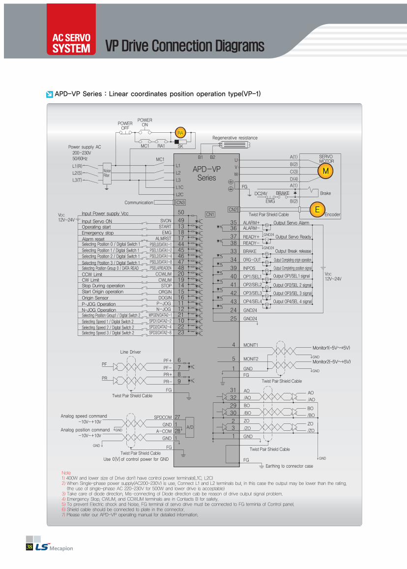
38
Note1) 400W and lower size of Drive don't have control power terminals(L1C, L2C)2) When Single-phase power supply(AC200-230V) is use, Connect L1 and L2 terminals but, in this case the output may be lower than the rating.(the use of single-phase AC 220-230V for 500W and lower drive is acceptable)
3) Take care of diode direction, Mis-connecting of Diode direction cab be reason of drive output signal problem.4) Emergency Stop, CWLIM, and CCWLIM terminals are in Contacts B for safety.5) To prevent Electric shock and Noise, FG terminal of servo drive must be connected to FG terminla of Control panel.6) Shield cable should be connected to plate in the connector.7) Please refer our APD-VP operating manual for detailed information.
APD-VP Series : Linear coordinates position operation type(VP-1)
VP Drive Connection Diagrams

AC Servo System
www.lsmecapion.com 39
Note1) 400W and lower size of Drive don't have control power terminals(L1C, L2C)2) When Single-phase power supply(AC200-230V) is use, Connect L1 and L2 terminals but, in this case the output may be lower than the rating.(the use of single-phase AC 220-230V for 500W and lower drive is acceptable)
3) Take care of diode direction, Mis-connecting of Diode direction cab be reason of drive output signal problem.4) Emergency Stop, CWLIM, and CCWLIM terminals are in Contacts B for safety.5) To prevent Electric shock and Noise, FG terminal of servo drive must be connected to FG terminla of Control panel.6) Shield cable should be connected to plate in the connector.7) Please refer our APD-VP operating manual for detailed information.
APD-VP Series : Rotary coordinates position operation type(VP-2)
AC Servo System

40
Note1) 400W and lower size of Drive don't have control power terminals(L1C, L2C)2) When Single-phase power supply(AC200-230V) is use, Connect L1 and L2 terminals but, in this case the output may be lower than the rating.(the use of single-phase AC 220-230V for 500W and lower drive is acceptable)
3) Take care of diode direction, Mis-connecting of Diode direction cab be reason of drive output signal problem.4) Emergency Stop, CWLIM, and CCWLIM terminals are in Contacts B for safety.5) To prevent Electric shock and Noise, FG terminal of servo drive must be connected to FG terminla of Control panel.6) Shield cable should be connected to plate in the connector.7) Please refer our APD-VP operating manual for detailed information.
APD-VP Series : Position operation type after feeder and Sensor(VP-3)
VP Drive Connection Diagrams

AC Servo System
www.lsmecapion.com 41
Note1) 400W and lower size of Drive don't have control power terminals(L1C, L2C)2) When Single-phase power supply(AC200-230V) is use, Connect L1 and L2 terminals but, in this case the output may be lower than the rating.(the use of single-phase AC 220-230V for 500W and lower drive is acceptable)
3) Take care of diode direction, Mis-connecting of Diode direction cab be reason of drive output signal problem.4) Emergency Stop, CWLIM, and CCWLIM terminals are in Contacts B for safety.5) To prevent Electric shock and Noise, FG terminal of servo drive must be connected to FG terminla of Control panel.6) Shield cable should be connected to plate in the connector.7) Please refer our APD-VP operating manual for detailed information.
APD-VP Series : Program operation type(VP-5)
AC Servo System

42
VN Drive Connection Diagrams
Note1) RDY BRAKE Output contact signal : Select in [PE-508].Note2) Twisted pair shield cable should be used for Pulse command signal (PF+, PF- , PR+, PR-) and Torque limit signal(TRQLIM)
APD-VN Series : Position operating mode

www.lsmecapion.com 43
Note1) RDY BRAKE Output contact signal : Select in [PE-508].Note2) Twisted pair shield cable should be used for SPDLIM, TRQCOM, GND
APD-VN Series : Speed operating mode
AC Servo System
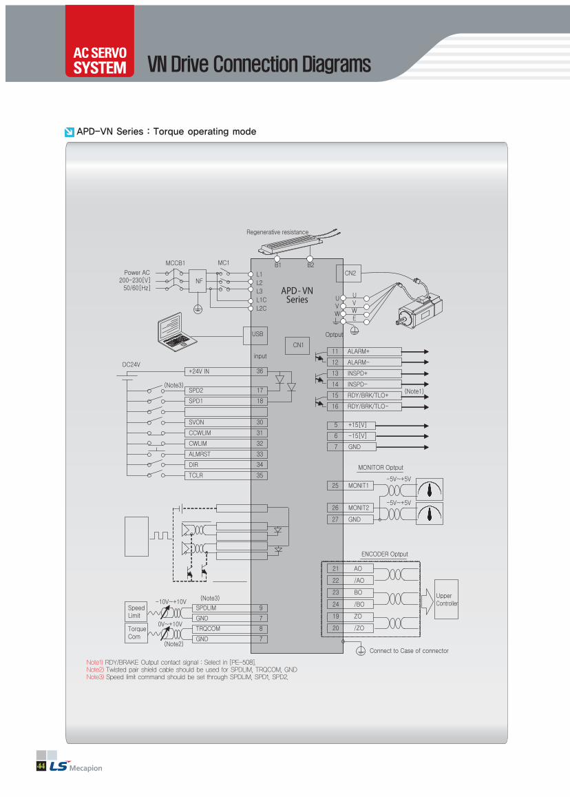
44
VN Drive Connection Diagrams
Note1) RDY/BRAKE Output contact signal : Select in [PE-508].Note2) Twisted pair shield cable should be used for SPDLIM, TRQCOM, GND Note3) Speed limit command should be set through SPDLIM, SPD1, SPD2.
APD-VN Series : Torque operating mode

www.lsmecapion.com 45
Note1) RDY BRAKE Output contact signal : Select in [PE-508].
Note2) MODE=ON: Speed control mode, MODE=OFF: Position control mode
APD-VN Series : Speed / Position operating mode
AC Servo System

46
VN Drive Connection Diagrams
Note1) RDY BRAKE Output contact signal : Select in [PE-508].
Note2) MODE=ON: Speed control mode, MODE=OFF: torgue control mode
APD-VN Series : Speed / Torgue operating mode

www.lsmecapion.com 47
Note1) RDY BRAKE Output contact signal : Select in [PE-508].
Note2) MODE=ON: Position control mode, MODE=OFF: Torgue control mode
APD-VN Series : Position / Torque operating mode
AC Servo System

48
Servo Drive Dimension
Weight : 1.2[kg]
Weight : 1.5[kg]
APD VS04N
APD VSR5N, VS01N, VS02N200W and Below
400W
Note) Indicate the dimension which connector is attached.
Note) Indicate the dimension which connector is attached.
66(Note) 132
(70)
(Note) 132
(70)
59
80
667 7
16
6 6
32 32
7
6
322
56
56
176
187
176
32
Ø6
Ø6

www.lsmecapion.com 49
APD VS15N, VS20N, VS35N, VS50N
Note) Indicate the dimension which connector is attached.
(VS/VP35N, VS/VP50N : Fan냉각) Weight : 7.2[kg]
1.5kW~5kW
137
5018
2-R3 2-R5
18
5866
50 50
18 18
275
(Note)
(70) 14
256
291
225
Note) Indicate the dimension which connector is attached.
APD VS05N, VS10N
Weight : 2.5[kg]
500W~1kW
88
747 7
6 6
(Note)
(70)
195
5724 7 99
192
210
Ø6
FG
AC Servo System

50
Servo Drive Dimension
(Cooling Fan type) Weight : 8[kg]
(Cooling Fan type)Weight : 12[kg]
APD VS110N
APD VS75N7.5kW
11kW
Note) Indicate the dimension which connector is attached.
Note) Indicate the dimension which connector is attached.
137
2-R3 2-R5
5018
6
5050
18 18
6
18
5
300
281
225
316
(Note)
(70)
259
7
25
381±1.5
396
2-R3.52-R6
227±1.0
227±1.07
178M4 M6
220
206
14(Note)
(70)
14

www.lsmecapion.com 51
APD VS220N, 300N, 370N
Note) Indicate the dimension which connector is attached.
Note) Indicate the dimension which connector is attached.
APD VS150N15kW
22kW, 30kW37kW
(Cooling Fan type) Weight :22,30[kw] 58[kg] / 37[kw] 62[kg]
(Cooling Fan type) Weight : 15[kg]259
25
452
468
2-R3.52-R6
227±1.0
246.4
590 321.5
165
151
510
470
10 10
451
493
393.5
470
9
21 8M4 M6
237
223
14(Note)
(70)
AC Servo System

52
Servo Drive Dimension
APD VN01~02N
Note) Indicate the dimension which connector is attached.
Note) Indicate the dimension which connector is attached.
VN Series
APD VN04N
Weight : 1.0[kg]
Weight : 0.8[kg]
4,3
48,5
3,6
3,6
52,1
5,4
139,1
150

www.lsmecapion.com 53
APD VN07N~VN10N
Note) Indicate the dimension which connector is attached.
Note) Indicate the dimension which connector is attached.
VN Series
APD VN15N
Weight : 2.7[kg]
Weight : 1.9~2.0[kg]
AC Servo System

54
Options (Cable)
Incremental Encoder Cable
1
2
3
4
5
6
7
8
9
10
W
W
V
V
U
U
-
-
0V
-
Model (Note1) : APC - EAS
Applicable Motor : APM-SA Series, APM-SB Series, APM-SC Series, APM-HB Series
Applicable Drive : APD-VS/VN Series
1. Motor Side Connector •CAP (15 Position) : 172163-1(Made by APM) •SOCKET : 170361-1(Made by APM)
2. Drive Side Connector(CN2) •CASE : 10320-52A0-008(Made by APM) •CONNECTOR : 10120-3000VE(Made by APM)
3. Cable•7Px0.2SQ(AWG24)
Motor Side Connector
APM 172163-1 CAP(15Circuits)
Drive Side Connector(CN2)
PINNO.
EncoderSignal Color
11
12
13
14
15
16
17
18
19
20
Z
SHIELD
B
Z
A
B
-
A
+5V
-
PINNO.
EncoderSignal Color
1
2
3
4
5
6
7
8
A
A
B
B
Z
Z
U
U
PINNO.
EncoderSignal Color
9
10
11
12
13
14
15
V
V
W
W
+5V
0V
SHIELD
PINNO.
EncoderSignal Color
1
2
3
4
5
6
7
8
9
10
W
W
V
V
U
U
-
-
0V
-
Model (Note1) : APC-EBS
Applicable Motor : APM-SE Series, APM-SF Series, APM-SG Series, APM-SH Series,
APM-SJ Series, APM-HE Series
Applicable Drive : APD-VS/VN Series
1 .Motor side connector (MS:Military standard)•PLUG : MS3108A20-29S
2. Drive Side Connector (CN2) •CASE : 10320-52A0-008(Made by APM) •CONNECTOR : 10120-3000VE(Made by APM)
3. Cable•7Px0.2SQ(AWG24)
PINNO.
EncoderSignal Color
11
12
13
14
15
16
17
18
19
20
Z
SHIELD
B
Z
A
B
-
A
+5V
-
PINNO.
EncoderSignal Color
1
2
3
4
5
6
7
8
A
A
B
B
Z
Z
U
U
PINNO.
EncoderSignal Color
9
10
11
12
13
14
15
V
V
W
W
+5V
0V
SHIELD
PINNO.
EncoderSignal Color
Motor Side Connector
Drive Side Connector(CN2)
Robotic Cable
General Cable
3 5 10 20Standard Cable Length (m)
F03
N03
F05
N05
F10
N10
F20
N20
Note1) of model indicates the cable type and length
APM 172163-1 CAP(15Circuits)

www.lsmecapion.com 55
Absolute Encoder Cable
1
2
3
4
5
6
7
8
9
10
RX
RX
-
-
-
-
-
-
0V
-
Model (Note1) : APC-EAA
Applicable Motor : APM-SB Series, APM-SC Series
Applicable Drive : APD-VS Series
1. Motor Side Connector•CAP 사양(15 Position) : 172163-1(Made by APM) •SOCKET : 170361-1(Made by APM)
2. Drive Side Connector(CN2)•CASE : 10320-52A0-008(Made by 3M) •CONNECTOR : 10120-3000VE(Made by 3M)
3. Cable•7Px0.2SQ(AWG24)
4. BATTERY CONNECTOR •5267-02A(Made by MOLEX)
PINNO.
EncoderSignal
11
12
13
14
15
16
17
18
19
20
Z
SHIELD, FG
B
Z
A
B
-
A
+5V
CLR
PINNO.
EncoderSignal
1
2
3
4
5
6
7
8
A
A
B
B
Z
Z
CLR
FG
PINNO.
EncoderSignal
9
10
11
12
13
14
15
BATTERY
BATTERY 0V
RX
RX
+5V
0V
SHIELD
PINNO.
EncoderSignal
1
2
3
4
5
6
7
8
9
10
RX
RX
-
-
-
-
-
-
0V
-
PINNO.
EncoderSignal
11
12
13
14
15
16
17
18
19
20
Z
SHIELD, FG
B
Z
A
B
-
A
+5V
CLR
PINNO.
EncoderSignal
A
B
C
D
E
F
K
L
A
A
B
B
Z
Z
BATTERY
BATTERY 0V
PINNO.
EncoderSignal
M
N
P
R
H
G
J
CLR
FG
RX
RX
+5V
0V
SHIELD
PINNO.
EncoderSignal
Model (Note1) : APC-EBA
Applicable Motor : APM-SE Series, APM-SF Series, APM-SG Series
Applicable Drive : APD-VS Series
1. Motor Side Connector (MS : Military Standard)•PLUG : MS3108A20-29S
2. Drive Side Connector(CN2)•CASE : 10320-52A0-008(Made by 3M) •CONNECTOR : 10120-3000VE(Made by 3M)
3. Cable•7Px0.2SQ(AWG24)
4. BATTERY CONNECTOR •5267-02A(Made by MOLEX)
Robotic Cable
General Cable
3 5 10 20Standard Cable Length (m)
F03
N03
F05
N05
F10
N10
F20
N20
Note1) of model indicates the cable type and length
Motor Side Connector Drive Side Connector (CN2)
Motor Side Connector
Drive Side Connector (CN2)
APM 172163-1 CAP(15Circuits)
AC Servo System

56
Options (Cable)
Power cableModel (Note1) : APC - PCS
Applicable Motor : APM-SA Series, APM-SB Series, APM-HB Series, APM-SC04A, SC06A, SC03D, SC05D
Applicable Drive : APD-VS/VN Series
1. Motor Side Connector•CAP(4 Position) : 172159-1(Made by APM) •SOCKET : 170362-1(Made by APM)
2. Drive Side Connector (U,V,W,FG)• PIN : UA-F1512(Made by Suh-il Electronic) •Compressor : UA-510A
(Made by Suh-il Electronic)3. Cable•4Cx0.75SQ(AWG18)
1
2
3
4
U
V
W
Ground
PINNO. Phase
Robotic Cable
General Cable
3 5 10 20Standard Cable Length (m)
F03
N03
F05
N05
F10
N10
F20
N20
Note1) of model indicates the cable type and length
Motor Side Connector
Drive Side Connector (CN2)
APM 172159-1 CAP(4Circuits)
Model (Note1) : APC - PDS
Applicable Motor : APM-SC08A, SC10A, SC06D, SC07D
Applicable Drive : APD-VS Series
1. Motor Side Connector•CAP (4 Position) : 172159-1(Made by APM) •SOCKET : 170362-1(Made by AMP)
2. Drive Side Connector (U,V,W,FG)•Connection terminals : 1.25×3(KET GP110012)
3. Cable•4Cx0.75SQ(AWG18)
1
2
3
4
U
V
W
Ground
PINNO. Phase
APM 172159-1 CAP(4Circuits)
Motor Side Connector
Drive Side Connector (CN2)
Model (Note1) : APC - PES
Applicable Motor : APM-SE Series, APM-HE Series
Applicable Drive : APD-VS/VN Series (VN : PESV)
1. Motor Side Connecto (MS:Military Standard)•PLUG : MS3108A20-4S
2. Drive Side Connector (U,V,W,FG)•Connection terminals : 2.5x4(KET GP110721)
3. Cable•4Cx2.0SQ(AWG14)
Note) For drive side connector of APM-SE03M Series cable, UA-F1512 pin is to be applied
A
B
C
D
U
V
W
Ground
PINNO. Phase
MS3108B20-4S(4Circuits)
Motor Side Connector
Drive Side Connector (CN2)

www.lsmecapion.com 57
Power cableModel (Note1) : APC-PFS Applicable Drive : APD-VS/VN Series (VN : PFSV)
Applicable Motor : APM-SF30A, SF22D, SF35D, SF20G, SF30G, SF12M, SF20M, SF30M
SG22D, SG35D, SG20G, SG30G, SG12M, SG20M, SG30M
1. Motor Side Connector (MS:Military Standard)•PLUG : MS3108A22-22S
2. Drive Side Connector (U,V,W,FG)•Connection terminals : 3.5x5(KET GP110028)
3. Cable•4Cx3.5SQ(AWG12)
A
B
C
D
U
V
W
Ground
PINNO. Phase
Robotic Cable
General Cable
3 5 10 20Standard Cable Length (m)
F03
N03
F05
N05
F10
N10
F20
N20
Note1) of model indicates the cable type and length
MS3108B22-22S(4Circuits)
Model (Note1) : APC-PGS
Applicable Drive : APD-VS Series
Applicable Motor : APM-SF50A, SF55D, SF75D, SF44G, SF60G, SF44M, SG55D, SG75D, SG44G, SG60G, SG44M
1. Motor Side Connector(MS:Military Standard)•PLUG : MS3108A22-22S
2. Drive Side Connector (U,V,W,FG)•Connection terminals : 5.5x5(KET GP110028)
3. Cable•4Cx5.0SQ(AWG10)
A
B
C
D
U
V
W
Ground
PINNO. Phase
MS3108B22-22S(4Circuits)
Model (Note1,2) : APC-PRS
Applicable Drive : APD-VS Series
Applicable Motor : APM-SG110D, SG85G, SG60M, SF75G
Model (Note1,3) : APC-PTS
Applicable Drive : APD-VS Series
Applicable Motor : APM-SG110G
Model (Note1,4) APC-PSS
Applicable Drive : APD-VS Series
Applicable Motor : SG150G
Note21. Motor Side Connector(MS:Military Standard) •PLUG : MS3108A(MS3106B)32-17S2. Drive Side Connector(U,V,W,FG) •Connection terminals : 8.0x8(KET GP140841)
3. Cable •4Cx8.0SQ(AWG8)
Note31. Motor Side Connector (MS:Military Standard) •PLUG : MS3108A(MS3106B)32-17S
2. Drive Side Connector(U,V,W,FG) •Connection terminals : 14x8(KET GP140841)
3. Cable •4Cx16.0SQ
Note4
1. Motor Side Connector (MS:Military Standard) •PLUG :MS3108A(MS3106B)32-17S
2. Drive Side Connector(U,V,W,FG) •Connection terminals : 22x8(KET GP140841)
3. Cable •4Cx25.0SQ
A
B
C
D
U
V
W
Phase
PINNO. Phase
MS3108B32-17S(4Circuits)
Motor Side Connector
Drive Side Connector
Motor Side Connector
Drive Side Connector
Motor Side Connector
Drive Side Connector
AC Servo System

58
Options (Cable)
Fan Power Cable (Using AP 25,28in common)
Power Cable (22,30kW)
Model (Note1) : General APC-PNHS / Robotic APC-PFHS
Applicable Drive : APD-VS Series
1. Motor Side Connector (MS : military standard)•PLUE MS3108B 18-10S
2. Cable•3CX2.0SQ
Red
Yellow
Black
U
V
W
Color Phase
MS3108B18-10S
(4Circuits)
Motor Side Connector
Brake Power Side
Drive Side
Model : General APC-PNQS
1. Motor Side Connector •Ring Terminal : 50x10s
2. Cable•50SQ 600V KIV
Red
Yellow
Black
U
V
W
Color Phase
Power Cable (37kW) Model : General APC-PNUS
1. Motor Side Connector •Ring Terminal : 80x10s
2. Cable•75SQ 600V KIV
Red
Yellow
Black
U
V
W
Color Phase
Ground CableModel : General APC-PNJS
1. Motor Side Connector•Ring Terminal : 16x10s
2. Cable•16SQ FR-GV

www.lsmecapion.com 59
Brake cableModel (Note1) : APC-PKB
Applicable Motor : APM-SA Series, APM-SB Series, APM-SC Series
Applicable Drive : APD-VS/VN Series
1. Motor Side Connector (MS:Military Standard)•CAP (2 Position) : 172157-1(Made by APM)•SOCKET : 170362-1(Made by APM)
2. Brake Power Side•Connection terminals : 1.25×3(KET GP110012)•Cable : 2C×0.75SQ(AWG18)
A
B
C
D
U
V
W
Ground
PINNO. Phase
Robotic Cable
General Cable
3 5 10 20Standard Cable Length (m)
F03
N03
F05
N05
F10
N10
F20
N20
Note1) of model indicates the cable type and length
APM 172157-1 CAP(2Circuits)
Model (Note1) : APC-PMB
Applicable Motor : APM-SE Series
Applicable Drive : APD-VS/VN Series (VN : PMBV)
1. Motor Side Connector (MS:Military Standard)•PLUG : MS3108A20-15S
2. Drive Side (U,V,W,FG)•Connection terminals : 2.5x4(KET GP110721)•Cable : 4Cx2.0SQ(AWG14)
3. Brake Power Side (+,-)•Connection terminals : 1.25x3(KET GP110012)•Cable : 2Cx0.75SQ(AWG18)
Note) For drive side connector of APM-SE03M
Series cable, UA-F1512 pin is to be applied
A
B
C
D
E
F
U
V
W
Ground
BK+
BK-
PINNO. Phase
MS3108B20-15S(6Circuits)
Motor Side Connector
Brake Power Side
Drive Side
AC Servo System
Motor Side ConnectorBrake Power Side

60
Options (Cable)
Brake cableModel (Note1) : APC-PNB
Applicable Motor : APM-SF30A, SF22D, SF35D, SF20G, SF30G, SF12M, SF20M, SF30M
Applicable Drive : APD-VS/VN Series
1. Motor Side Connector (MS:Military Standard)•PLUG : MS3108A24-10S
2. Drive Side (U,V,W,FG)•Connection terminals : 3.5x5(KET GP110028)•Cable : 4Cx3.5SQ(AWG12)
3. Brake Power Side (+,-)•Connection terminals : 1.25x3(KET GP110012)•Cable : 2Cx0.75SQ(AWG18)
A
B
BK+
BK-
PINNO. Phase
Robotic Cable
General Cable
3 5 10 20Standard Cable Length (m)
F03
N03
F05
N05
F10
N10
F20
N20
Note1) of model indicates the cable type and length
MS3108B24-10S(6Circuits)
A
B
C
D
E
F
U
V
W
Ground
BK+
BK-
Red
White
Black
Green
-
-
PINNO. Phase color
Motor Side Connector
Brake Power Side
Drive Side
Model (Note1) : APC-PSB
Applicable Motor : APM-SG Series
Applicable Drive : APD-VS/VN Series (VN : PSBV)
1. Motor Side Connector (MS:Military Standard)•PLUG : MS3108A24-10S
2. Power Side (+, -)•Connection terminals : 1.25×3(KET GP110012)
3. Cable•2C×0.75SQ(AWG18)
MS3108B14S-7S(2Circuits)
Model (Note1) : APC-PPB
Applicable Motor : APM-SF50A, SF55D, SF75D, SF44G, SF60G, SF75G, SF44M
Applicable Drive : APD-VS Series
MS3108B24-10S(6Circuits)
Motor Side Connector
Brake Power Side
Drive Side
Motor Side Connector
Brake Power Side
1. Motor Side Connector (MS:Military Standard)•PLUG : MS3108A24-10S
2. Drive Side (U,V,W,FG)•Connection terminals : 3.5x5(KET GP110028)•Cable : 4Cx3.5SQ(AWG10)
3. Brake Power Side (+,-)•Connection terminals : 1.25x3(KET GP110012)•Cable : 2Cx0.75SQ(AWG18)

www.lsmecapion.com 61
Marking
1Standard Cable Length (m)
01
2
02
3
03
5
05
Note1) of model indicates the cable type and length
For CN1 CableModel (Note1) : APC-CN1A
Applicable Drive : APD-VS/VN Series (VN : CN1VNA)
1. Drive Side (CN1)•Case : 10350-52A0-008(3M사)•Connector : 10150-3000VE(3M사)•Cable : UL20276 25Pair(AWG 28)
2. Cable can be changed without any notice.
1
2
3
4
5
6
7
8
9
10
Orange/Black 1P
Orange/Red 1P
Yellow/Black 1P
Yellow/Red 1P
White/Black 1P
White/Red 1P
White/Black 1P
White/Red 1P
Pink/Black 1P
Pink/Red 1P
CN1
11
12
13
14
15
16
17
18
19
20
CN1
21
22
23
24
25
26
27
28
29
30
CN1
31
32
33
34
35
36
37
38
39
40
CN1
41
42
43
44
45
46
47
48
49
50
CN1Color
Orange/Black 2P
Orange/Red 2P
Yellow/Black 2P
Yellow/Red 2P
White/Black 2P
White/Red 2P
White/Black 2P
White/Red 2P
Pink/Black 2P
Pink/Red 2P
Color
Orange/Black 3P
Orange/Red 3P
Yellow/Black 3P
Yellow/Red 3P
White/Black 3P
White/Red 3P
White/Black 3P
White/Red 3P
Pink/Black 3P
Pink/Red 3P
Color
Orange/Black 4P
Orange/Red 4P
Yellow/Black 4P
Yellow/Red 4P
White/Black 4P
White/Red 4P
White/Black 4P
White/Red 4P
Pink/Black 4P
Pink/Red 4P
Color
Orange/Black 5P
Orange/Red 5P
Yellow/Black 5P
Yellow/Red 5P
White/Black 5P
White/Red 5P
White/Black 5P
White/Red 5P
Pink/Black 5P
Pink/Red 5P
Color
Servo Drive CN1
Indicate pin number
Terminal Blockfor CN1 Model (Note1) : APC-VSCN1T-
Applicable Drive : APD-VS/VN Series
1. For APD-VS/VP
2. Standard cable Length : 0.5m
3. 1m, 2m also available
Servo Drive CN1
Servo Drive O/S Download Cable
Model (Note1) : APC-CN3S
Applicable Drive : APD-VS/VN Series
Standard Cable length : 2[m]
PC Parallel Port
Servo DriveCN3
15
8
7
9
16
18~25
6
18~25
Error
Data6
Data5
Data7
init
GND
Data4
GND
PINNO. Phase
1
2
3
4
8
9
10
11
Case
DX0
RSRX
CLKRX
CLK
RESET
INT2/3
DR0
GND
Shield
PINNO. Phase
AC Servo System

62
Options (Connector)
Marking
1Standard Cable Length (m)
01
2
02
3
03
5
05
Note1) of model indicates the cable type and length
CN1 ConnectorModel : APC-CN1NNA
Applicable Drive : APD-VS/VP Series
1. Case : 10350-52A0-008(Made by 3M)
2. Connector : 10150-3000VE(Made by 3M)
RS232CommunicationCable
Model (Note1) : APC-CN3R
Applicable Drive : APD-VS/VN/VP Series
Standard Cable length : 2[m]
PC-SerialPort
Servo Drive CN3
2
3
5
RXD
TXD
GND
PINNO. Phase
6
5
11or12
Case
TXD
RXD
GND
Shield
PINNO. Phase
CN2 ConnectorModel : APC-CN2NNA
Applicable Drive : APD-VS/VP Series
1. Case : 10320-52A0-008(Made by 3M)
2. Connector : 10120-3000VE(Made by 3M)
CN3 ConnectorModel : APC-CN3NNA
Applicable Drive : APD-VS/VP Series
1. Case : 10314-52A0-008(Made by 3M)
2. Connector : 10114-3000VE(Made by 3M)
Length
Options (Cable·Connector)
VS/VP VN

www.lsmecapion.com 63
Braking Resistor
Model (Note1) : APC-140R40, VN : 140R40VN(140W, 40Ω)
Applicable Drive : APD-VS/VP02, VS04
Braking Resistance(Basically provided)
R5 01 02 04 05 10 15 20 35 50 75 110 150 220 300 370Applicable DriveAPD-VS/VPN
VS Series40[Ω](140[W])
23[Ω](300[W])
11.5[Ω](300[W]×2P)
Option
Note) Standard Braking Resistance for drive capacity is as below table.
Part Name : IRH 140W 40ohm)
Model (Note1) : APC-300R23, VN : 300R23VN(300W, 23Ω)
Applicable Drive : APD-VS/VP05, VS10
Part Name : IRV 300W 23ohm)
Model (Note1) : APC-600R30(600W, 30Ω)
Applicable Drive : APD-VS15(2P), VS20(2P), VS35(3P),
VS50(3P), VS75(3P), VS110(4P),
APD-VN Series
Model (Note1) : APC-1000R6R5(1,000W, 65Ω)
Applicable Drive : APD-VS150(2P)
Part Name : IRV 1,000S 6.5ohm)
Part Name : IRV 600S 30ohm)
Model (Note1) : APC-2400R2R4(2,400W, 2.4Ω)
Applicable Drive : APD-VS220(1P), VS Series
Part Name : IRV 2,400P 2.4ohm)
Model (Note1) : APC-2400R3R2(2,400W, 3.2Ω)
Applicable Drive : APD-VS300(2P), VS370(2P)
Part Name : IRV 2,400P 3.2ohm)
AC Servo SystemOptions (Braking Resistor)

64
Options (Noise Filter)
Noise Filter
Model : APC-RFY4010M/4015M/4020M/4030M
Applicable Drive (Note1)
Noise FilterAPC-RFYM
R5 01 02 04 05 10 15 20 35 50 75 110 150 220 300 370Applicable Drive APD-VS
4010 4015 4020 4030 4040 4050 4080 4150 4200 4250
Note) Standard Noise filter for drive capacity is as below table.
Part Name : (RFY4010M/4015M/4020M/4030M)
Model : APC-RFY4040M/4050M/4080M
Applicable Drive (Note1)
Part Name : (RFY-4040M/4050M/4080M)
Model : APC-RFY4150M/4200M
Applicable Drive (Note1)
Part Name : (RFY-4150M/4200M)
Model : APC-RFY4250M
Applicable Drive (Note1)
Part Name : (RFY-4250M)

AC Servo System
www.lsmecapion.com 65
Handy Loader
Model (Note1) : Handy Loader : APC-HD1
Applicable Drive (Note1) : APD-VS Series
Marking
1Standard Cable Length (m)
01
2
02
3
03
5
05
Note1) of model indicates the length of cable, and the notation is as below
Marking
2Standard Cable Length (m)
20
3
30
4
40
5
50
Note1) of model indicates the cable type and length
A
B
C
D
E
F
U
V
W
Ground
BK+
BK-
Red
White
Black
Green
-
-
PINNO. Color Phase
1. Handy Loader Input Voltage : DC 5[V]
2. The Length of standard Cable : 2[m]
Servo Drive CN3
Remote Display Model (Note1) : APC-DPUB
Applicable Drive : APD-VS Series
1. Cable length can be adjusted upon request
2. Place an order with Servo Drive (Remote Type)
Dept when cable is connected
MPLength
Options(Setting machine / Indicator)

LS Industrial Systems creates core automation
solutions that cover everything from production
facilities to information systems.
As a leader in automation solutions that introduced products like PLCs, Inverter, DCSs, and HMIs for the first time in
Korea, LS Industrial Systems is developing and producing top Products that meet the most exacting standards in
Korea and around the world.
Ever since producing and supplying Korea’first programmable logic controller (PLC), LS Industrial Systems has
played a pivotal role in the history of automation equipment in Korea. From the most diverse machines to large-
sized process control, the company has created an optimum automation environment based on the country’highest
levels of reliability and technology. While leading industrial automation and supplying optimum solutions for
automobile companies, international airports, subways, power plants, and LCD production complexes,
LS Industrial Systems has had its industry-leading technology recognized by international certification
organizations like CE and UL. As the first company to introduce a general-purpose AC Drives in Korea and the
undisputed leader in the field of AC Drives, LS Industrial Systems developed iS7 AC Drives, which provide advanced
embedded functions and PLC (K120S), and recently released next generation products such as Medium Voltage
AC Drives through continuous technology development.
66

Inverter, AC Drive
Low Voltage AC Drive Panel
3 phase 220V/380V/440V 0.75 - 450KW
•For HVAC/Plant, Vector system, Medium-Large size Specialized function for capacity
and energy saving FAN/PUMP
•Human Interface Design for user convenice
•Circuit design considerd electric noise consider provide various option and solution
•Built-in optimal sequence for satisfied Operating Conditions
•IEC standard safety design
SolarvertOutdoor : 1 phase 3kW (IP54 Enclosure)
•Max power point tracking (MPPT)
•Low distortion •High efficiency
•Compact & slim size •Remote monitoring with RS485 communication
•User frendly HMI
Medium Voltage AC Drive
Low Voltage AC Drive
Starvert - iG5A
MV Drive
3kV 200kVA ~ 3,700kVA, 4kV 250kVA ~ 4,700kVA,
6kV 400kVA ~ 7,500kVA, 10kV 600kVA ~ 11,100kVA,
•Auto Cell Bypass Method allows an Easy Maintenance
•FAN Speed Control by Inverter Internal Heat Value
•New Algorithm for an Anti-Current Hunt
•Built-in RS485(or Modbus-RTU) Communication
Optional : DeviceNet, Lonworks, CANopen, Profibus-DP,
EtherNet-IP
•Optinized Monitoring System for Users
Powerful & compact sensorless vector control
AC Drives
1 phase 0.4 ~ 1.5kW (0.5 ~ 2HP), 200 ~ 230V
3 phase 0.4 ~ 22kW (0.5 ~ 30HP), 200 ~ 230V
3 phase 0.4 ~ 22kW (0.5 ~ 30HP), 380 ~ 480V
•Selectable V/F, sensorless vector control•Motor parameter auto-tuning•Powerful torque at overall apeed range•IP20 enclosure, UL type 1 (option)•Built-in RS 485 (LS Bus/Modbus RTU) communication
Starvert - iS5Precise vector control standard AC Drives
3 phase 0.75 ~ 55kW (1 ~ 75HP), 200 ~ 230V
3 phase 0.75 ~ 75kW (1 ~ 100HP), 380 ~ 480V
•Selectable V/F, sensorless, sensored vector control
(optional)
•Optimum acceleration & deceleration for a maximum
torque
•Muilt-function I/O terminal :
input : 27 functions/output: 21 functions
•Communication options: Modbus RTU, Profibus-DP,
Devicenet, RS485 (LS Bus), Fnet
Low Voltage AC Drive Panel Photovoltaic Inverter
Starvert - iS7High torque perfomance and precise AC Drives
3 phase 0.75 ~ 22kW (1 ~ 30HP), 200 ~ 230V
3 phase 0.75 ~ 160kW (1 ~ 250HP), 380 ~ 480V
•Constant torque/variable torque dual rating
•Selectable V/F, sensorless, sensored vector control
•Available IP54 enclosure (0.75 ~ 22kW[1 ~ 30HP])
as built-in option
•Built-in RS485 (LS Bus/Modbus RTU) Communication
•Available EMC filter & DC reactor as built-in option
EMC filter (0.75 ~ 22kW)/DC reactor (0.75 ~ 160kW)
Starvert - iP5AFan & pump specialized AC Drives
3 phase 5.5 ~ 30kW (7.5 ~ 40HP), 200 ~ 230V
3 phase 5.5 ~ 450kW (7.5 ~ 600HP), 380 ~ 480V
•Specialized functions for fan & pump :
Advanced PID control (Pre-PID, Dual PID)
Multi motor control funtion (Up to 4 motors: 5.5~90kW)
•Selectable V/F, sensorless vector control
•Built-in RS485 (LS Bus) communication
•Communication boards (optional) :
Modbus RTU, Devicenet, Profibus-DP, Lonworks,
Bacnet
Asla Paclflc : +82-2-2034-4901 / [email protected] Europe & CIS : +82-2-2034-4376 / [email protected] Meddle East & Afrlca : +82-2-2034-4645 [email protected]
AC Servo System
www.lsmecapion.com 67

PLCs(Programmable Logic Controllers)
XGR
•Base, power, CPU, network redundancy
•Processing speed : 42ns/step
•I/O points : max. 131,072
•Total memory : 32MB (program 7MB, data 2MB, reserved 7MB, flash 16MB)
•Max. 31 expansion base
•Switching over time : 4.3 ~ 22ms
•IEC 61131-3 standard language
•Enhanced maintenance via system history and network ring configuration
XGI•Processing speed : 28ns/step
•I/O device point : 131,072 (remote I/O)
•Program capacity : 128K ~ 1Mbyte
•IEC61131-3 standard programming
- LD (ladder), SFC (sequential function chart), ST (structured text),
User defined FB (function block)
•Powerful built-in PID and process control
- Max. 256 loops and variety of process functions
XGT Series
XGK
•Processing speed : 28ns/step
•High speed backplane (base) transfer
•Compact size (Module size 27x98x90)
•The system solution based on open network
•Setup and operation of each special modules without additional complicated
user program
XGB(XBM)•Processing speed : 160ns/step
•The smallest size among the same class (Basic unit: 30x90x60)
•Extension to as many as 7 layers, controlling as many as 256 points
•Best suited for medium and small system
•Maximum 5 channel communication available using built-in and extension
communication modules
XGB(XBC)
•Processing speed : 83ns/step
•Extension to as many as 10 layers, controlling as many as 384 points
•Supporting floating-point arithmetic
•Built-in Cnet, HSC, PID, Positioning, Pulse Catch, Input Filter, External Interrupt
•Download port: serial, USB
68

HMIs(Human Machine Interfaces)
SMART I/O Series
Block Type SMART I/O
•Compatible with Modbus, Profibus DP, DeviceNet, Rnet
•Suited for medium and small scale network system
•Small size
Extension Type SMART I/O
•Open protocol Profibus-DP, DeviceNet, EtherNet/IP, Modbus/TCP, Rnet
•Suited for medium and large scale system
•Wide extension of input/output
•Maximum 256 points
•100% compatible with XGB I/O module
XGT Panel Series
XP70-TTA
•Screen size: 26cm (10.4”)
•TFT color: VGA (640 x 480)
•Display color: 65,536 color
•8-wire system, analog
•10/100 BASE-T Ethernet, USB
•RS232C, RS422/485
•CF memory card
XP50-TTA•Screen size: 21cm (8.4”)
•TFT color: VGA (640 x 480)
•Display color: 65,536 color
•8-wire system, analog
•10/100 BASE-T Ethernet, USB
•RS232C, RS422/485
•CF memory card
XGT InfoU XGT Panel Series
XGT InfoU (Powerful & Trendy HMI Software)
•Integrated development environment for interactive user interface
•Direct import tag database for LS PLC software
•Open architecture meets industrial standards (OPC, OLE DB, etc.)
•Easy to use
•Program development environment
•for simple application
XP80-TTA•Screen size : 31cm (12.1”)
•TFT color : SVGA (800 x 600)
•Display color : 65,536 color
•8-wire system, analog
•10/100 BASE-T Ethernet, USB
•RS232C, RS422/485
•CF memory card
Asla Paclflc : +82-2-2034-4901 / [email protected] Europe & CIS : +82-2-2034-4376 / [email protected] Meddle East & Afrlca : +82-2-2034-4645 [email protected]
AC Servo System
www.lsmecapion.com 69

70
MEMO
Copyright © 2022 FDOKUMEN