Preface - HNC Electric
337
i Preface The manual may help you to quickly get familiar with the HNC-818 system (hereafter referred to as "system"), providing detailed information about the features, components, commands, usage, operation procedure, programming and beyond. Any updates or modification of the manual is not allowed without the authorization of Wuhan Huazhong Numerical Control Co., LTD (hereafter referred to as "Huazhong NC") under any circumstances. Huazhong NC will not be responsible for any loss caused by pirated copies. The documentation focuses on the main operations of the system. Limited by space as well as product conceptualization and development, it’s impossible for us to explain anything unnecessapory or impossible.Hence, what are not described in the manual can be regarded as “IMPOSSIBLE” or “NOT ALLOWED”. The documentation is protected by copyright and contains proprietary and confidential information. No part of the contents of the documentation may be disclosed, used or reproduced in any form, or by any means, without the prior written consent of the copyright holder.
-
Upload
khangminh22 -
Category
Documents
-
view
0 -
download
0
Transcript of Preface - HNC Electric

i
Preface
The manual may help you to quickly get familiar with the HNC-818 system (hereafter referred to as "system"), providing detailed information about the features, components, commands, usage, operation procedure, programming and beyond. Any updates or modification of the manual is not allowed without the authorization of Wuhan Huazhong Numerical Control Co., LTD (hereafter referred to as "Huazhong NC") under any circumstances. Huazhong NC will not be responsible for any loss caused by pirated copies. The documentation focuses on the main operations of the system. Limited by space as well as product conceptualization and development, it’s impossible for us to explain anything unnecessapory or impossible.Hence, what are not described in the manual can be regarded as “IMPOSSIBLE” or “NOT ALLOWED”. The documentation is protected by copyright and contains proprietary and confidential information. No part of the contents of the documentation may be disclosed, used or reproduced in any form, or by any means, without the prior written consent of the copyright holder.

Contents HNC-818 User Manual
ii
Contents
Preface ......................................................................................................................................................................... i
Contents ...................................................................................................................................................................... ii
I Product Overview ..................................................................................................................................................... 1
1 Overview ........................................................................................................................................................... 2 2 Symbol Description ........................................................................................................................................... 3
II NC Functions .......................................................................................................................................................... 4
1 Overview ........................................................................................................................................................... 5 1.1 CNC Machine Programming .................................................................................................................. 6 1.2 Machine Coordinate System ................................................................................................................... 7 1.3 Machine Origin ....................................................................................................................................... 9 1.4 Reference Point of Machine ................................................................................................................. 10 1.5 Workpiece Coordinate System and Workpiece Origin .......................................................................... 11 1.6 Programming Origin ............................................................................................................................. 12 1.7 Absolute and Relative Coordinate Systems .......................................................................................... 13
2 Preparation (G-Code) ....................................................................................................................................... 14 2.1 G-Codes (T) .......................................................................................................................................... 15 2.2 G-Codes (M) ......................................................................................................................................... 17
3 Program Structure ............................................................................................................................................ 20 3.1 Command Format ................................................................................................................................. 21 3.2 Program Block Format.......................................................................................................................... 22 3.3 General Program Structure ................................................................................................................... 23 3.4 Program File Name ............................................................................................................................... 24 3.5 Program File Properties ........................................................................................................................ 25 3.6 Sub-Programs ....................................................................................................................................... 26
4 Auxiliary Functions ......................................................................................................................................... 27 4.1 M Commands ........................................................................................................................................ 28 4.2 S Commands ......................................................................................................................................... 34 4.3 T Commands ......................................................................................................................................... 35
5 Interpolation Functions .................................................................................................................................... 38 5.1 Linear Feed (G01) ................................................................................................................................. 39 5.2 Arc Feed (G02, G03) ............................................................................................................................ 42 5.3 Cylindrical Helical Interpolation (G02, G03) ....................................................................................... 47 5.4 Specify Imaginary Axis and Sine Interpolation (G07) .......................................................................... 50 5.5 NURBS Spline Interpolation (NURBS) ............................................................................................... 51 5.6 Thread Cutting (G32) ............................................................................................................................ 54 5.7 HSPLINE Spline Interpolation (HSPLINE) ......................................................................................... 58

HNC-818 User Manual Contents
5.8 GOTO Function (G31) .......................................................................................................................... 60 6 Feed Functions ................................................................................................................................................. 63
6.1 Rapid Feed (G00) ................................................................................................................................. 64 6.2 Unidirectional Positioning (G60) .......................................................................................................... 65 6.3 Define Feed Speed Unit (G93, G94, G95) ............................................................................................ 67 6.4 Exact Stop Verification (G09) ............................................................................................................... 69 6.5 Cutting Mode (G61/G64) ...................................................................................................................... 70 6.6 Feed Hold (G04) ................................................................................................................................... 72 6.7 High-Speed High-Precision Mode Selection (M) (G05.1) ................................................................... 73
7 Reference Point ................................................................................................................................................ 74 7.1 Return to Reference (G28, G29, G30) .................................................................................................. 75
8 Coordinate System ........................................................................................................................................... 78 8.1 Machine Coordinate System Programming (G53) ................................................................................ 80 8.2 Workpiece Coordinate System .............................................................................................................. 82 8.3 Define Local Coordinate System (G52) ............................................................................................... 87 8.4 Select Coordinate Planes (G17, G18, G19) .......................................................................................... 89
9 Coordinate Values and Dimension Unit ........................................................................................................... 90 9.1 Absolute Commands and Incremental Commands (G90, G91) ............................................................ 91 9.2 Dimension Unit Selection (G20, G21) .................................................................................................. 93 9.3 Polar Coordinate Programming (M) (G16, G15) .................................................................................. 94 9.4 Diameter and Radius Programming (T) (G36, G37) ............................................................................ 98
10 Tool Compensation Functions ..................................................................................................................... 100 10.1 Tool Offset (T) .................................................................................................................................. 101 10.2 Tool Nose Radius Compensation (T) (G40, G41, G42) .................................................................... 104 10.3 Introduction to Tool Radius Compensation (M) (G40, G41, G42) ................................................... 113 10.4 Description of Tool Radius Compensation (M) (G40, G41, G42) .................................................... 117 10.5 Tool Length Compensation (M) (G43, G44, G49) ........................................................................... 126
11 Programming Simplification Functions ....................................................................................................... 131 11.1 Mirroring Function (M) (G24, G25) ................................................................................................. 132 11.2 Scaling Function (M) (G50, G51) ..................................................................................................... 136 11.3 Rotation Function (M) (G68, G69) ................................................................................................... 139 11.4 Direct Programming based on Blueprint Dimensions (T) ................................................................ 142
12 Fixed Cycle .................................................................................................................................................. 146 12.1 Drilling Fixed Cycle for Milling Machines (M) ............................................................................... 147 12.2 Simple Cycle for Turning Machines (T) ........................................................................................... 239 12.3 Fixed Cycle for Drilling of Turning Machines (T) ........................................................................... 255 12.4 Compound Cycle for Turning Machines (T) .................................................................................... 261 12.5 Special Cases in Fixed Cycle .......................................................................................................... 281
13 User Macro Program .................................................................................................................................... 282 13.1 Variables ........................................................................................................................................... 283 13.2 Operation Instructions....................................................................................................................... 290 13.3 Macro Statement ............................................................................................................................... 292 13.4 Calling Macro Programs ................................................................................................................... 297
14 Spindle Functions ........................................................................................................................................ 308

Contents HNC-818 User Manual
iv
14.1 Constant Linear Speed Cutting Control (T) (G96, G97) .................................................................. 309 14.2 C/S Axis Switching Function (CTOS/STOC) ................................................................................... 312 14.3 Spindle Synchronization (G116, G117) ............................................................................................ 313
15 Programmable Data Input ............................................................................................................................ 315 15.1 Programmable Data Input (G10, G11) .............................................................................................. 316
16 Axis Control Functions ................................................................................................................................ 320 16.1 Cycle Function of the Rotation Axis ................................................................................................. 321 16.2 Reference of Grating Ruler with Distance-Code .............................................................................. 322
17 Other Functions ........................................................................................................................................... 324 17.1 Stop Read -ahead (G08) .................................................................................................................... 325 17.2 Redefine Rotary Axis Angle Resolution (G115) ............................................................................... 326 17.3 Axis Release (G101) and Axis Obtaining (G102) ............................................................................. 327 17.4 Command Channel Loader (G1030) and Running (G103.1) ............................................................ 329 17.5 Channel Synchronization (G104) ..................................................................................................... 330 17.6 Alarms (G110) .................................................................................................................................. 332

1
I Product Overview

1. Overview HNC-818 User Manual
2
1 Overview
This documentation describes the following CNC systems:
CNC System Abbreviation
HNC-818
HNC-818A Turning Unit (with handheld unit)
HNC-818A-TU-H
HNC-818A Turning Unit (without handheld unit)
HNC-818A-TU-X
HNC-818B Turning Unit HNC-818B-TU HNC-818A Milling Unit HNC-818A-MU HNC-818B Milling Unit HNC-818B-MU

HNC-818 User Manual 2. Symbol Description
3
2 Symbol Description
The symbols used in this documentation:
M: description valid only in the Milling Unit
T: description valid only in the Turning Unit
IP_: combination of any axis, e.g. X_ Y_ Z_ …. Coordinate axis values are in the position of "_" in actual programming.

4
II NC Functions

HNC-818 User Manual 1. Overview
5
1 Overview
This chapter includes the following sections:
1.1 CNC Machine Programming
1.2 Machine Coordinate System
1.3 Machine Origin
1.4 Reference Point of Machine
1.5 Workpiece Coordinate System and Workpiece Origin
1.6 Programming Origin
1.7 Absolute and Relative Coordinate Systems

1. Overview HNC-818 User Manual
6
1.1 CNC Machine Programming
CNC machines conduct workpiece machining based on programming. The programming has a direct impact on the quality of machining, productivity, and lifecycle of cutting tools. A good programmer should have the abilities to master and flexibly use the CNC machine programming.
Programming means that a programmer, by referring to the workpiece machining blueprint and craft, creates program codes and instructions for the workpiece cutting process, machining path, auxiliary operations during the machining such as tool change, cooling, clamp, and clockwise (CW) and counter clockwise (CCW) rotation of spindle, etc. Then the programmer inputs all the programs into the CNC system to run the CNC machine for the workpiece machining. The CNC programming indicates the process to create CNC codes and instructions based on the blueprint and craft, and input them to the CNC system.
The figure below shows the general programming methods and procedure:
Blueprint
Craft
Tool Path Calculation
Program input
Manual or autom
atic program
ming
Program Verification
TestCutting
Machining
Edit

HNC-818 User Manual 1. Overview
7
1.2 Machine Coordinate System
Machine coordinate system is a geometric coordinate system and a fixed coordinate on the machine, which is established to determine the position of the workpiece on the machine, the special position and motion scope of the motion parts. In the machine coordinate system, the workpiece is believed stationary and the tool is in motion. This allows programmers to determine the machining process based on the blueprint without considering the movement of the workpiece and the tool.
Standard machine coordinate system adopts the right hand Cartesian coordinate system. The coordinate is named X, Y, Z which is often referred to as the basic coordinate system shown in the figure below. It follows the right-hand rule: stretching out the right hand thumb, forefinger and middle finger, and keeping them mutually perpendicular; then the thumb points in the positive direction of the X axis (+X), the index finger points in the positive direction of the Y axis (+Y), and the middle finger points in the positive direction of the Z axis (+Z).
The letters A, B, and C are used to define the circumferential feed coordinate which rotates around X, Y, and Z or the axis parallel to the X, Y, and Z. According to the right-hand screw rule, if the thumb points in the direction of +X, +Y, or +Z, the rotation direction of the remaining four fingers point in the direction of +A, +B and +C.
• Define the Z axis
The axis parallel to the spindle is the Z axis. For the machine without a spindle, Z axis is perpendicular to the workpiece clamping surface. The positive direction of Z (+Z) is the direction where the tool moves away from the workpiece.
+Y
+Z
+X
+X, +Y, +Z
+A, +B, +C
+X
+Z
+Y
+A +C
+Y
+Z
+X
+X, +Y, +Z
+A, +B, +C
+X
+Z
+Y
+A +C
+B

1. Overview HNC-818 User Manual
8
•
•
• Define the X axis
On the machine where the tool rotates, such as milling machine, drilling machine, or boring machine, if the Z axis is horizontal, the X axis is positive in the right direction when looking from the tool (spindle) to the workpiece; If the Z axis is vertical, X axis is positive in the right direction when looking from the spindle to the column. The above are based on the motion of tool relative to workpiece.These directions are relative directions of the tool to the motion workpiece.
On the machine where the tool rotates, such as turning machine or grinding machine, the X axis motion is in the radial direction of the workpiece and parallel to the cross carriage. The direction where the tool moves away from the workpiece rotation center is the positive direction of the X axis.
• Define the Y axis
After defining the positive directions of X and Z axis, you may define the positive direction of the Y axis based on the right-handed rectangular Cartesian coordinate system. That is, within the ZX plane, rotate from + Z to + X, and the right hand-screw should advance along the + Y direction.
This may differ based on the machine types. The figure below shows the coordinate system of a six-axis machining center:

HNC-818 User Manual 1. Overview
9
1.3 Machine Origin
The origin of the machine is called Machine Origin (X=0, Y=0, Z=0).
The Machine Origin is a fixed point on the machine, which is defined by the machine manufacturer. It is a benchmark of workpiece coordinate system, programming coordinate system and reference point. The Milling Machine Origin may differ for different machine manufacturers. Some are defined at the center of the machine work table, and some are defined at the end of the feed travel.
M:machine origin; R: reference point

1. Overview HNC-818 User Manual
10
1.4 Reference Point of Machine
The machine reference point is exactly defined by the machine manufacturer in each feed axis with limit switch. The coordinate values are input into the numerical control system, which are fixed by the mechanical block along each axis. You may return the tool or the work table to the reference point by pressing the Reference key on the control panel. Usually in the CNC milling machines and machining centers, the machine reference point is coincident with the machine origin. See the figure below:
R: Reference Point
Y
X
Z
M: Machine Origin
W: Workpiece Origin

HNC-818 User Manual 1. Overview
11
1.5 Workpiece Coordinate System and Workpiece Origin
The workpiece coordinate system is used to define the position of the workpiece geometry elements (points, straight lines and arcs). The origin of the workpiece coordinate system is the workpiece zero. When you select the workpiece zero, it is recommended to define it in the position where the dimension of the blueprint can be easily converted into coordinate values. For the workpiece zero of milling machines, it is generally defined on one corner of the outer contour of the workpiece; the zero point in the cutting depth direction is mostly defined on the surface of the workpiece.
During processing, after the workpiece is installed on the machine with the clamper, measure the distance between the workpiece origin and the machine origin (defined by measuring the distance between certain base level/lines). This distance is called the workpiece origin offset (the absolute coordinate value of the machine origin in the workpiece coordinate system). See the figure below. Before machining, pre-input the offset value in the CNC system, then during machining, the workpiece origin offset value is automatically attached to the workpiece coordinate system, to ensure accurate axis movement on the CNC machine; therefore, programmers can directly create programs based on blueprint dimensions, without considering the installation position of the workpiece on the machine.
Y Y
Ow Workpiece coordinate system X
Y
Workpiece origin offset
Machine coordinate system

1. Overview HNC-818 User Manual
12
1.6 Programming Origin
Generally, for simple workpiece, the workpiece origin is the programming origin. For the workpiece with complex shapes, you need to create several programs or subprograms. To facilitate programming and reduce coordinate value calculation, the programming origin will not be necessarily the workpiece origin, but be defined in a position for easy programming.
The figure below shows the coordinate systems and relative points.
M: Machine origin
R: Machine reference point
W: Workpiece origin
P: Programming origin

HNC-818 User Manual 1. Overview
13
1.7 Absolute and Relative Coordinate Systems
There are two modes to describe the amount of movement in the CNC system: the absolute coordinate system and the relative coordinate system.
- The absolute coordinate system refers to the coordinate system where all coordinate points are measured based on a fixed origin.
- The relative coordinate system refers to the coordinate system where the end point coordinates of the motion path are measured based on the starting point.
As shown in the figure below, A, B are two coordinate points. In the absolute coordinate system, the coordinate value of the two points (A, B)
are ( ) ( )40,40, =AA yx and ( ) ( )20,15, =BB yx respectively; but in
the relative coordinate system with the origin of point A, the coordinate
value of the point B is ( ) ( )20,25, −−=BB yx .
Y
40
O 15
X
X
Y
A
B
4025
20
20

2. Preparation HNC-818 User Manual
14
2 Preparation (G-Code)
Modal
There are two kinds of G-codes based on their validity:
- Non-Modal G-code: valid only when the G-code is specified, invalid when not specified.
- Modal G-code: saved in the CNC system when it is executed once, and valid until other codes of the same group is executed
Group
G-codes are divided into several groups according to their functions. 00 group is non-modal G-code and other groups are modal G-code. Multiple G-codes from different groups can be specified in the same program block. If multiple G-codes from the same group are specified in the same block, only the last specified code is valid.

HNC-818 User Manual 2. Preparation
15
2.1 G-Codes (T)
Attention
After the system is powered on, the G-code marked with the "[ ]" symbol indicates the initial modal of the same group, while the "『 』" symbol indicates the equivalent macro name of the G-code.
G Code
Group No.
Function
G00
01
Quick location [G01] Linear interpolation
G02 Clockwise (CW) circular interpolation/CW cylindrical helical interpolation
G03 Counter clockwise (CCW) circular interpolation/ CCW cylindrical helical interpolation
G04 00 Pause G07
00 Specify the imaginary axis
G08 Close look-ahead function G09 Exact stop verification G10
07 Programmable data input
[G11] Cancel programmable data input G17
02 XY plane selection
G18 ZX plane selection [G19] YZ plane selection G20
08 Inch input
[G21] Metric input G28
00 Return to the reference point
G29 Return from the reference point G30 Return to the reference point 2, 3, 4, and 5 G32 01 Thread cutting
[G36]17
Diameter programming G37 Radius programming
[G40]09
Cancel tool radius compensation G41 Left cutter compensation G42 Right cutter compensation G52
00 Local coordinate system settings
G53 Direct machine coordinate system programming G54.x
11
Extended workpiece coordinate system selection [G54] Select workpiece coordinate system 1 G55 Select workpiece coordinate system 2 G56 Select workpiece coordinate system 3 G57 Select workpiece coordinate system 4 G58 Select workpiece coordinate system 5

2. Preparation HNC-818 User Manual
16
G59 11 Select workpiece coordinate system 6 G60 00 Single-orientation
[G61] 12
Precise stop mode G64 Cutting mode G65 00 Macro non-modal calling
G71
06
Inner (outer) diameter roughing compound cycle
G72 End-face roughing compound cycle G73 Closed contour compound cycle G76 Thread cutting compound cycle G80 Inner (outer) diameter cutting cycle G81 End-face cutting cycle G82 Thread cutting cycle G74 End-face deep-hole drilling cycle G75 Outer diameter grooving cycle G83 Axial drilling cycle G87 Radial drilling cycle G84 Axially rigid tapping cycle G88 Radial rigid tapping cycle
[G90] 13
Absolute programming mode G91 Incremental programming mode G92 00 Workpiece coordinate system settings G93
14 Inverse-time feed
[G94] Feed per minute G95 Feed per revolution
[G97] 19
Disable constant linear velocity control G96 Enable constant linear velocity control
G101
00
Axis release G102 Axis acquisition G103 Command channel loader
G103.1 Run the command channel loader G104 Channel synchronization G108
『STOC』Change the spindle to the C-axis
G109 『CTOS』
Change the C-axis to spindle
G110 Alarm G115 Redefine the rotary axis angular resolution

HNC-818 User Manual 2. Preparation
17
2.2 G-Codes (M)
Attention
After the system is powered on, the G-code marked with the "[ ]" symbol indicates the initial modal of the same group, while the "『 』" symbol indicates the macro name of the G-code.
G Code
Group No.
Function
G00
01
Quick location [G01] Linear interpolation
G02 CW circular interpolation/ CW cylindrical helical interpolation
G03 CCW circular interpolation/ CCW cylindrical helical interpolation
G04 00 Pause G05.1 27 High-speed high-precision mode G07
00
Specifies the imaginary axis G07.1 Cylindrical surface interpolation G08 Close look-ahead function G09 Exact stop verification G10
07 Programmable data input
[G11] Cancel programmable data input G12
18 Enable polar coordinate interpolation
[G13] Disable polar coordinate interpolation [G15]
16 Disable polar coordinate programming
G16 Enable polar coordinate programming [G17]
02 XY plane selection
G18 ZX plane selection G19 YZ plane selection G20
08 Inch input
[G21] Metric input G24
03 Enable Mirror function
[G25] Disable Mirror function G28
00 Return to the reference point
G29 Return from the reference point G30 Return to the reference points 2, 3, 4, and 5
[G40]09
Cancel tool radius compensation G41 Left cutter compensation G42 Right cutter compensation G43
10 Positive tool length compensation
G44 Negative tool length compensation [G49] Cancel tool length compensation

2. Preparation HNC-818 User Manual
18
[G50] 04
Disable the Zoom function G51 Enable the Zoom function G52
00 Local coordinate system setting
G53 Direct machine coordinate system programming
G54.x
11
Extended workpiece coordinate system selection
[G54] Select workpiece coordinate system 1 G55 Select workpiece coordinate system 2 G56 Select workpiece coordinate system 3 G57 Select workpiece coordinate system 4 G58 Select workpiece coordinate system 5 G59 Select workpiece coordinate system 6 G60 00 Single-orientation
[G61] 12 Precise stop mode G64 Cutting mode G65 00 Macro non-modal calling G68
05 Start rotation transformation
[G69] Cancel rotation transformation G73
06
Deep-hole drilling cycle G74 Reverse-tapping cycle G76 Fine-boring cycle
[G80] Cancel fixed cycle G81 Centre-drilling cycle G82 Drilling cycle with pause G83 Deep-hole drilling cycle G84 Tapping cycle G85 Boring cycle G86 Boring cycle G87 Anti-boring cycle G88 Boring cycle (hand boring) G89 Boring cycle
G181 Arc groove cycle (Type 1) G182 Arc groove cycle (Type 2) G183 Circumference groove milling cycle G184 Rectangular groove cycle G185 Circular groove cycle G186 End-face milling cycle G188 Rectangular boss cycle G189 Circular boss cycle [G90]
13 Absolute programming mode
G91 Incremental programming mode G92 00 Define workpiece coordinate system

HNC-818 User Manual 2. Preparation
19
G93 14
Inverse-time feed [G94] Feed per minute G95 Feed per revolution
[G98] 15
Fixed cycle returning to the starting point
G99 Fixed cycle returning to the reference point
G101
00
Axis release G102 Axis acquisition G103 Command channel loader
G103.1 Run the command channel loader G104 Channel synchronization G108
『STOC』Change the spindle to the C-axis
G109 『CTOS』
Change the C-axis to spindle
G115 Redefine the rotary axis angular resolutionNURBS NURBS spline interpolation
HSPLINE HSPLINE spline interpolation

3. Program Structure HNC-818 User Manual
20
3 Program Structure
A program is a set of commands and data transferred to the CNC system.
A program consists of a number of program blocks which follow a certain structure, syntax and format rules. Each block consists of a number of commands. See the figure below:
Program
%1000
N01 G91 G00 X50 Y60
N10 G01 X100 Y500 F150 S300 M03
N......N200 M02
Block
Command

HNC-818 User Manual 3. Program Structure
21
3.1 Command Format
A command consists of address characters (command word) and digital numbers with characters (e.g. dimension word) or without characters (e.g. preparatory function character command: G-code). Example: G01 X100 Z-90
Different commands in the program block may have different meaning in different environments. For details, see relevant sections in this documentation.

3. Program Structure HNC-818 User Manual
22
3.2 Program Block Format
A program block specifies the commands executed by a numerical control device.
The block format specifies the syntax of the functional words of each program block. See the figure below:
N.. G.. X.. F.. M.. S..
Block
Auxiliary Function
Spindle Function
Feed Function
Dimension wordPreparatory function
Block number

HNC-818 User Manual 3. Program Structure
23
3.3 General Program Structure
A program must include the start symbol and end symbol.
A program is executed based on the input order of the blocks, rather than the order of block numbers. However, when you write a program, it is recommended to write block numbers in the ascending order.
Start symbol
The symbol "%" (or "O") must be followed by a number (e.g. % 3256). The program start symbol should be in a separate line, starting at the first line and first character of the program.
Program end
M02: End the program
M30: End the program and return to the program head
Comment symbol
The content inside "( )" or behind a semicolon symbol (;) is the comment text. Identify ;and ; .
Single-line command
During G-code programs writing, please be noted that some commands must be in a separate line. Examples: M30, M02, M99, M6T, CTOS, STOC, G16, G15, G05.1, G04

3. Program Structure HNC-818 User Manual
24
3.4 Program File Name
Many program files can be saved in the CNC device, and can be written and read in the disk.
File Name
Oxxxxx; "xxxxx" indicates the file name.
The CNC system calls programs by calling the file name, for machining or editing.
Naming Rules
Use the following characters to name
the file:
- 26 letters, uppercase or lowercase
- Numbers
The created program file name can contain up to seven characters.
The CNC system may read program files, of which name contains more than seven characters (created externally).
The CNC system reserves the following file names, which cannot be specified for naming the program file.
• USERDEF.CYC
• MILLING.CYC
• TURNING.CYC

HNC-818 User Manual 3. Program Structure
25
3.5 Program File Properties
Access properties of program files can be set.
Editing forbidden
The currently loaded program can be set to Read-only through interface operation. The file cannot be edited until its property is set to Write through interface operation.
In addition, you may also control the program accessibility through the key switch on the project panel. However, the key switch is valid for all programs in the Program Manager. When the key switch is turned off, all programs will become read-only until the switch is turned on.
For detailed description of the program file property control, see section 错误!未找到引用源。 in III Operation.

3. Program Structure HNC-818 User Manual
26
3.6 Sub-Programs
When a fixed machining operation is repeated in a program, you may set it as a sub-program and input it into the program to simplify the programming.
Execution Process
Call Sub-program
You may call a sub-program with M98 or G65. For the method of calling a sub-program with M98, see the description of M98 in section 4. For the method of calling a sub-program with G65, see section 13.
%1001;
……
M98P1002;
……
M99;
Main program Sub-program 1001
……
M98P1001;
……
M98P2001;
……
M98P1001;
……
M30;
%2001;
……
……
M99;
Sub-program 2001
%1002;
……
……
M99;
Sub-program 1002

HNC-818 User Manual 4. Auxiliary Functions
27
4 Auxiliary Functions
This chapter includes the following sections:
4.1 M Commands
4.2 S Commands
4.3 T Commands

4. Auxiliary Functions HNC-818 User Manual
28
4.1 M Commands
Auxiliary function commands consist of the address character "M" and digital numbers. It is used to control the motion of the programs, various auxiliary switch of the machine, the start and stop of the spindle, end of the program, etc.
Generally, one program block has only one valid M command. In this system, up to four M commands can be specified in one block (M commands in the same group cannot be specified in the same line).
The M commands (M00, M01, M02, M30, and M99) must be in a separate line. In other words, the program line which contains any of the M commands mentioned above can contain only one M command, and cannot have other commands such as G commands or T commands.
The relationship between the M commands and their functions depends on the specific settings of the machine manufacturer.
Modal
The M functions include non-modal and modal functions:
- Non-modal M function (valid only in the current block)
- Modal M function (continuously valid)
Modal Group
Modal M commands are grouped according to different functions. Once the defined modal M command has been executed, it remains valid until it is canceled by other modal M commands in the same group.
The Modal M function group contains a default function which is the initial function when the system is powered on.
Pre- and Post- M functions
The M function can also be divided into pre-M function and post-M function:
- Pre-M function
Executed before the axis motion specified by the program block.
- Post-M function
Executed after the axis motion specified by the program block.

HNC-818 User Manual 4. Auxiliary Functions
29
4.1.1 Default CNC Auxiliary Functions
M00
Pause Program
When the CNC system executes the M00 command, it will pause the execution of the current program. That facilitates the operator to carry out dimensional measurements of the tool and the workpiece, turn around the workpiece, manually change speed, etc.
When the system pauses the program, the feeding on the machine is stopped, and all existing modal information remains unchanged. If you want to continue the follow-up procedures, press the Start button on the control panel.
M00 indicates the non-modal post-M function.
M01
Optional Pause Program
If you activate the Optional Pause key on the control panel, the CNC system will pause the current program when it executes the M01 command, to facilitate the operator to carry out dimensional measurements of the tool and the workpiece, turn around the workpiece, manually change speed, etc. When the system pauses the program, the feeding on the machine is stopped, and all existing modal information remains unchanged. If you want to continue the follow-up procedures, press the Start button on the control panel.
If you do not activate the Optional Pause key on the control panel, the CNC system will not pause the current program when it executes the M01 command.
M01 indicates the non-modal post-M function.
M02
End program
M02 is created in the last program block of the main program.
When the CNC system executes the M02 command, all the spindle, feed, and coolant functions are stopped and the machining is ended.
After the program is ended by M02, you need to recall the program or press the Restart key under the auto machining sub menu, and press the Start button on the control panel if you want to re-execute the program.
M02 indicates the non-modal post-M function.

4. Auxiliary Functions HNC-818 User Manual
30
M30
End program and return (valid only when it is in a separate line)
The functions of M30 are similar to those of M02, with an additional control function of returning to the program header (%).
After the program is ended by M30, you need to repress the Start button on the control panel if you want to re-execute the program.
M98/M99
Call sub-programs
If the program contains a fixed sequence or frequently repeated pattern, the sequence or pattern can be stored as a sub-program in the memory to simplify the programming.
A sub-program can be called for a maximum of 10,000 times (L).
A sub-program can be called from a main program.
In addition, a called sub-program can call another sub-program.
Call nested sub-programs
A main program can call up to six levels of sub-programs. See the figure below:
Sub-program structure: %xxxx; Sub-program number
……; Sub-program content M99; Sub-program returns Call sub-program (M98) M98 P□□□□ LΔΔΔ
□□□□: The number of the called sub-program (Arabic numerals)
ΔΔΔ: The times that the sub-program is called
%1000
…
M98P1001
…
M30
%1001
…
M98P1002
…
M99
%1002
…
M98P1003
…
M99
%1008
…
…
M99 ……

HNC-818 User Manual 4. Auxiliary Functions
31
Execute M99 in a main program
If M99 is executed in a main program, then the system returns to the header of the main program and re-execute the program.
Use M commands to call sub-programs
Using the M commands to call sub-programs may cause program errors. You may add G80before M99 to ensure a proper program running. For details, see section 12.5.

4. Auxiliary Functions HNC-818 User Manual
32
4.1.2 Auxiliary Functions Defined by PLC
M3/4/5
Spindle Control
The M03 command starts and rotates the spindle in a clockwise direction (from the positive direction toward the negative direction of the Z axis) at the speed specified in the program.
The M04 command starts and rotates the spindle in a counter clockwise direction at the speed specified in the program.
The M05 command stops the spindle rotation.
The M03 and M04 are modal pre-M functions. M05 is a modal post-M function, which is the default function.
M03, M04, M05 can be canceled by each other.
M06 Tool Change
M06 is used to call a tool that will be installed on the spindle from the machining center. The tool will be automatically installed on the spindle when executing this command. Example: M06 T01 can be used to install the 01 tool on the spindle.
M06 indicates a non-modal post-M function.
For the machines with armless type ATC, the tool change process is as follows (e.g. to change the tool 15 on the spindle to tool 01, execute M06 T01.):
1. Move the spindle quickly to the fixed tool change position which has been defined by the commissioning personnel.
2. Directionally rotate the spindle.
3. Rotate the tool magazine to the position (the position of the tool 15 in Group 0).
4. The cylinder drives the tool magazine, and chucks the tool on the spindle.
5. The cylinder releases the tool on the spindle, and blows to clean the spindle.
6. The spindle moves upward, and moves away completely from the tool.
7. The tool magazine rotates to the tool position of tool 01(the tool number of Group 0 in the tool magazine changes to 01).

HNC-818 User Manual 4. Auxiliary Functions
33
8. The spindle moves downward, and catches the tool.
9. The cylinder on the spindle clamps the tool.
10. The tool magazine returns to the original position.
11. Release the orientation of the spindle.
Attention
M06 must be defined in a separate line.
M7/8/9
Coolant Control
M07 and M08 are used to enable the coolant control.
M09 is used to disable the coolant control.
M07 and M08 are modal pre-M functions; M09 is a modal post-M function, which is the default function.
M64
Workpiece Count
M64 is used to calculate the cumulative count of completed workpiece.
M19/M20
Spindle Orientation
M19 is used for spindle orientation.
M20 is used to cancel the spindle orientation.
M03/M04
The spindle can be switched directly from the position mode to speed mode by executing the M03/M04 command, without executing G109.

4. Auxiliary Functions HNC-818 User Manual
34
4.2 S Commands
Directly Define Spindle Speed
The S command is used to control the spindle rotation speed. The number that follows S indicates the spindle speed in revolution per minute (r/min).
The S command is a modal command, and the S function is valid only when the spindle speed is adjustable.
Define Spindle Speed with Code
In the lathe with mechanical shifting, you may specify a value behind S to input a code signal to the machine, thereby controlling the spindle speed of the machine.
This approach needs to be processed in the ladder graph.

HNC-818 User Manual 4. Auxiliary Functions
35
4.3 T Commands
T commands are used for tool selection. The value that follows T indicates the selected tool number. The relationship between T commands and the tool is defined by the machine manufacturer.
Milling System
Execute a T command on the
machining center to input a code signal or a strobe signal into the machine, thereby controlling the rotation of the tool magazine to the selected tool, and then wait until the completion of the tool change with the M06 command. For armless type ATC, the M06 and T commands must be written in the same block. During tool change, the tool number (e.g. 15) of Group 0 must be the position of the tool clamped on the spindle in the tool magazine. When you change the tool to another, you need to firstly return the tool to the corresponding tool position in the tool magazine (that is No. 15). Then there should be no tool in the position of No.15, otherwise a collision may occur. The tools in the tool magazine are automatically managed by the system, and cannot be modified. After the machine starts, tool position(e.g. No. 15) facing to the spindle must be the same as tool number of Group 0 in the tool magazine, and there should be no tool in the corresponding tool position (e.g. No. 15).
Therefore, when installing tools to the tool magazine, it is recommended to firstly install the tool on the spindle, then in the MDI mode, run the M and T commands (e.g. M06 T01) to install the tool through the spindle.
Turning System
T commands are used for tool selection and tool change. The four/six/eight digits that follow T indicates the selected tool number and tool compensation number.
For TXX XX (4 digits), the first two digits indicate the tool number, and the last two digits indicate the tool compensation number.
For TXXX XXX (6 digits), the first three digits indicate the tool number, and the last three digits indicate the tool compensation number.
4. Auxiliary Functions HNC-818 User Manual
36
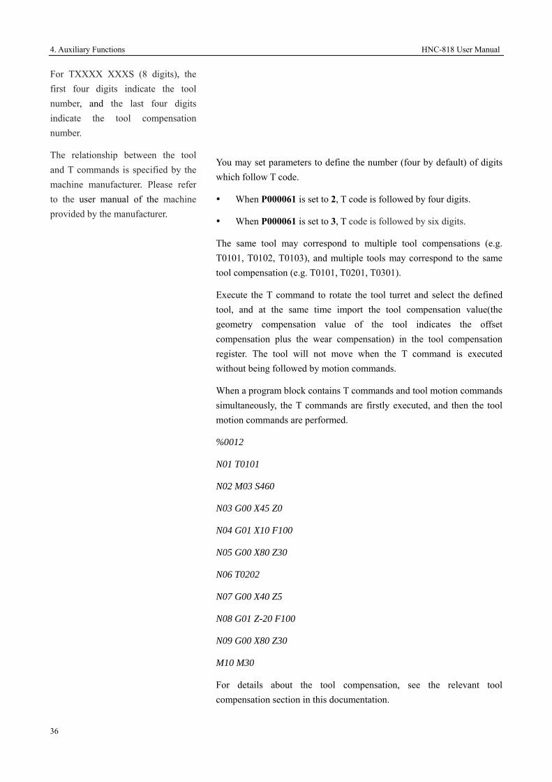
For TXXXX XXXS (8 digits), the first four digits indicate the tool number, and the last four digits indicate the tool compensation number.
The relationship between the tool and T commands is specified by the machine manufacturer. Please refer to the user manual of the machine provided by the manufacturer.
You may set parameters to define the number (four by default) of digits which follow T code.
When P000061 is set to 2, T code is followed by four digits.
When P000061 is set to 3, T code is followed by six digits.
The same tool may correspond to multiple tool compensations (e.g. T0101, T0102, T0103), and multiple tools may correspond to the same tool compensation (e.g. T0101, T0201, T0301).
Execute the T command to rotate the tool turret and select the defined tool, and at the same time import the tool compensation value(the geometry compensation value of the tool indicates the offset compensation plus the wear compensation) in the tool compensation register. The tool will not move when the T command is executed without being followed by motion commands.
When a program block contains T commands and tool motion commands simultaneously, the T commands are firstly executed, and then the tool motion commands are performed.
%0012
N01 T0101
N02 M03 S460
N03 G00 X45 Z0
N04 G01 X10 F100
N05 G00 X80 Z30
N06 T0202
N07 G00 X40 Z5
N08 G01 Z-20 F100
N09 G00 X80 Z30
M10 M30
For details about the tool compensation, see the relevant tool compensation section in this documentation.

HNC-818 User Manual 4. Auxiliary Functions
37

5. Interpolation Functions HNC-818 User Manual
38
5 Interpolation Functions
This chapter includes the following sections:
5.1 Linear Feed
5.2 Arc Feed
5.3 Cylindrical Helical Interpolation
5.4 Specify Imaginary Axis
5.5 NURBS Spline Interpolation
5.6 Thread Cutting
5.7 HSPLINE Spline Interpolation
5.8 Jump Function

HNC-818 User Manual 5. Interpolation Functions
39
5.1 Linear Feed (G01)
G01 enables a linear feed of the tool from the starting point to the end.
Format
G01 IP_ F_
Description
G01 enables a linear feed of the tool from the current position to the end point defined by the program block at the speed specified by F and in linkage approach.
G01 is a modal code, which can be canceled by G00, G02, G03 or G34.
The feed speed specified by F is constantly valid and does not need to be specified in every program block.
The speed along each axis is as follows:
G91 G01 Xα Yβ Zγ Ff;
X axis: Fα = α x f/L;
Y axis: Fβ = β x f/L;
Z axis: Fγ = γ x f/L;
222 γβα ++=L
Speed of Rotation Axis
For rotation axis, its feed speed is defined by the linear speed.
During linear interpolation, when the linear axis is α (e.g. X, unit: mm) and the rotation axis is β (e.g. C, unit: deg), the tangential speed in the α/β Cartesian coordinate system is defined by F (mm/min). The speed on the β axis is obtained based on the time calculated from the formula above and then converted to deg/min.
Parameter Description IP Under G90command, it indicates the coordinate value of
the end point in the workpiece coordinate system. UnderG91command, it indicates the relative displacement of the end point to the starting point.
F Feed speed

5. Interpolation Functions HNC-818 User Manual
40
Example: G91 G01 X20.0 C40.0 F300.0;
Assuming the metric input of the C axis 40.0deg is 40 mm
Then the time required should be:
3004020 22 +
0.14907 min
The speed on the C axis is:
min14907.0deg40
268.3 deg/min
Linear Interpolation
Rotation Interpolation
Start point
End point
90 Feed speed 300 degree/min
G91 G01 C-90 F300
Y Feed speed 300mm/min
0 (Start point) 300.0 X
End point 200.0
G91 G01 X300.0 Y200.0 F300

HNC-818 User Manual 5. Interpolation Functions
41
Attention
Example
After the five-axis RTCP function is enabled, F specifies the movement speed of the tool center point in the workpiece coordinate system. During the five-axis machining, due to the join of the rotation axis, the movement speed of the tool center point may not match the actual machine movement speed; therefore, the split-axis speed may exceed the specified maximum speed limit. In this case, the CNC system will reduce the machining speed to ensure the split-axis speed within the defined range.
Use G01 for programming: Linear feed from the point A to B (a straight line from A to B)
OX
Y
B
A
20 90
15
45
Programming path
Actual path
Linear feed from A to B
Absolute programming:
G90 G01 X90 Y45 F800
Incremental programming:
G91 G01 X70 Y30 F800

5. Interpolation Functions HNC-818 User Manual
42
5.2 Arc Feed (G02, G03)
Run the tool to the end along the specified arc direction at a specified plane (G17, G18, G19).
Format
Parameter Description
Parameter Description G17 Specify arc interpolation at the XY plane G18 Specify arc interpolation at the ZX plane G19 Specify arc interpolation at the YZ plane G02 CW arc interpolation G03 CCW arc interpolation X The amount of movement along the X-axis with arc
interpolation or the X-axis coordinate value of the arc end Y The amount of movement along the Y-axis with arc
interpolation or the Y-axis coordinate value of the arc end Z The amount of movement along the Z-axis with arc
interpolation or the Z-axis coordinate value of the arc end R Arc radius (with signal, "+": inferior arc; "-": excellent arc) I The distance from the arc start point along the X-axis to the
center of the arc (with signal) J The distance from the arc start point along the Y-axis to the
center of the arc (with signal) K The distance from the arc start point along the Z-axis to the
center of the arc (with signal) F Feed speed, valid in the modal mode
__
___
G03G02
17 FR
JIYXG
⎭⎬⎫
⎩⎨⎧
⎭⎬⎫
⎩⎨⎧
Arc interpolation in the XY
plane
__
___
0302
18 FR
KIZX
GG
G⎭⎬⎫
⎩⎨⎧
⎭⎬⎫
⎩⎨⎧
Arc interpolation in the ZX plane
__
___
0302
19 FR
KJZY
GG
G⎭⎬⎫
⎩⎨⎧
⎭⎬⎫
⎩⎨⎧
Arc interpolation in the YZ plane

HNC-818 User Manual 5. Interpolation Functions
43
Arc Interpolation Direction
Definition of clockwise (CW) and counter clockwise (CCW) direction in each plane: in the Cartesian coordinate system, looking to the XY plane from the positive direction of Z-axis to the negative direction to define the CW and CCW direction of the XY plane; similarly, looking to the ZX plane from the positive direction of the Y-axis to the negative direction to define the CW and CCW direction of the ZX plane; looking to the YZ plane from the positive direction of the X-axis to the negative direction to define the CW and CCW direction of the YZ plane. See the figure below:
Arc End
Use the position command (X, Y, Z) to specify the arc end.
In the absolute value (G90) mode, the position command (X, Y, Z) specifies the absolute position of the arc end point; in the incremental value (G91) mode, the position command (X, Y, Z) specified the distance from the arc start point to the end point. See the figure below:
Start point (X1, Y1)
End point (X2, Y2)
End point of Arc:
G90: X_=X2
Y_=Y2
G91: X_=X2-X1
Y_=Y2-Y1
G03
G02
G03
G02
X
G03
G02
G17 G18 G19
Y
Z
X
Y
Z

5. Interpolation Functions HNC-818 User Manual
44
UVW Programming
Distance from the Start Point to the Arc Center
In addition to the position command (X, Y, Z), you may use the UVW command to specify the arc end.
For the turning CNC system (T Series), when the channel parameter Enable Programming with UVW (040033) is set to 1, you may use UVW instead of XYZ to represent the movement amount (increment) of G02/G03 along the XYZ axis, or use XYZ and UVW for one programming.
Note: Only when the UVW axes are not specified as the motion axis, can UVW be used to specify the arc end.
Use the command (I, J, K) to specify the position of the arc center.
The parameters (I, J, K) indicate the vector components from the start point to the arc center, and it is always incremental value for both G90 and G91.
You need to specify the positive ("+") or negative symbol ("-") for the parameters (I, J, K) based on the direction.
See the figure below:
Center (X0, Y0)
End point (X2, Y2)
Start point
(X1, Y1)J
I
G17I_=X0-X1
J_=Y0-Y1
Center (Z0, X0)
End point (Z2, X2)
Start point
(Z1, X1)I
K
G18 K_=Z0-Z1
I _=X0-X1
Center (Y0, Z0)
End point (Y2, Z2)
Start point
(Y1, Z1) K
J
G19J_=Y0-Y1
K_=Z0-Z1

HNC-818 User Manual 5. Interpolation Functions
45
Circular Programming
If the position commands (X, Y, Z) are all left blank during programming, the start point overlaps the end point. In this case, the command (I, J, K) specifies a full circle. If R is used to specify the arc, it becomes an arc of zero degree. A system alarm will be reported.
Arc radius
In addition to the command (I, J, K) mentioned above, you may specify the arc center by using the arc radius. The arc is divided into two types:
1. Central angle less than 180 degrees
2. Central angle larger than 180 degrees
Therefore, you need know which arc to be programmed. The two types can be defined by the positive or negative symbols ("+" or "-") of the arc radius (R). See the figure below:
Attention
Parameters related to arc interpolation
If the radius difference between the arc start point and end point is greater than the value specified by CIR INTERPOLATION C-TOL(mm) (000010), or (radius difference between the arc start point and end point) /actual radius is greater than the value specified by Arc ARC PROG POINT RADIUS TOL(mm) (000011), the system will alarm.
I/J/K and R are specified simultaneously
If "I, J, K" and "R" are simultaneously specified in a non-full circular arc interpolation command, the arc defined by R is valid.
Specify axis outside the defined plane
If the axis is specified outside the defined plane, an alarm will be reported.
2
1
Start point Central angle < 180
degrees
End point
Arc1 (Central angle < 180 degrees)
G91 G02 X70 Y80 R50 F500;
Arc2 (Central angle > 180 degrees)
G91 G02 X70 Y80 R-50 F500;
Central angle > 180 degrees

5. Interpolation Functions HNC-818 User Manual
46
Semicircle Programming
When the arc is a semicircle or the central angle is close to 180 degrees, you must use I, J, K to specify the arc center, because a calculation error may be generated due to the rounding errors if you use R to specify the arc center.
Example
As shown in the figure above, the tool path programming is as follows:
1. Absolute programming
G92 X200.0 Y40.0 Z0;
G90 G03 X140.0 Y100.0 R60.0 F300.;
G02 X120.0 Y60.0 R50.0;
Or
G92 X200.0 Y40.0Z0;
G90 G03 X140.0 Y100.0 I-60.0 F300.;
G02 X120.0 Y60.0 I-50.0;
2. Incremental programming
G91 G03 X-60.0 Y60.0 R60.0 F3000.;
G02 X-20.0 Y-40.0 R50.0;
Or
G91 G03 X-60.0 Y60.0 I-60.0 F300.;
G02 X-20.0 Y-40.0 I-50.0
100
Y
60
40
0 90 120 140 200 X
Start point
End point
R50
R60

HNC-818 User Manual 5. Interpolation Functions
47
5.3 Cylindrical Helical Interpolation (G02, G03)
In addition to arc interpolation, the G02 and G03 commands can also be used to define helical interpolation by specifying the movement distance of the third axis.
Format
Parameter Description
Parameter Description
G17 Specify arc interpolation at the XY plane G18 Specify arc interpolation at the ZX plane G19 Specify arc interpolation at the YZ plane G02 CW arc interpolation G03 CCW arc interpolation X The amount of movement along the X-axis with arc
interpolation or the X-axis coordinate value of the arc end
Y The amount of movement along the Y-axis with arc interpolation or the Y-axis coordinate value of the arc end
Z The Z-axis coordinate value in absolute programming, or the the Z-axis increment of the end point relative the start point(even if L command is programmed)
R Arc radius (with signal: "+": inferior arc; "-": excellent arc)
I The distance from the arc start point along the X-axis to the center of the arc (with signal). The value of height variation for a spiral circle at YZ plane in conic interpolation.
J The distance from the arc start point along the Y-axis to the center of the arc (with signal)
__
____
G03G02
17 FL
JIZYXG
⎭⎬⎫
⎩⎨⎧
⎭⎬⎫
⎩⎨⎧
XY Plane Helical Interpolation
__
____
0302
18 FL
KIYZX
GG
G⎭⎬⎫
⎩⎨⎧
⎭⎬⎫
⎩⎨⎧ ZX Plane Helical Interpolation
__
____
0302
19 FL
KJXZY
GG
G⎭⎬⎫
⎩⎨⎧
⎭⎬⎫
⎩⎨⎧ YZ Plane Helical Interpolation

5. Interpolation Functions HNC-818 User Manual
48
Rotation Direction
K The distance from the arc start point along the Z-axis to the center of the arc (with signal).
F Feed speed, valid in the modal mode L Helical rotation number (positive number without a
decimal point)
For the rotation direction of helical interpolation, refer to the arc direction projected on a two-dimensional plane.
Circular Programming
If the position commands (X, Y, Z) are all left blank during programming, the start point overlaps the end point. In this case, the command (I, J, K) specifies a full circle. If R is used to specify the arc, it becomes an arc of zero degree. A system alarm will be reported.
Example
The figure below shows the helical machining:
1. Absolute programming
X30 Y0 Z0
G90 G03 X0 Y0 Z50 I-15 J0 K0 L10 F3500
50
O
Y
X
Z
15
K=5

HNC-818 User Manual 5. Interpolation Functions
49
M30
2. Incremental programming
X30 Y0 Z0
G91 G03 X-30 Y0 Z50 I-15 J0 K0 L10 F3500
M30

5. Interpolation Functions HNC-818 User Manual
50
5.4 Specify Imaginary Axis and Sine Interpolation (G07)
Format
G07 IP_
Parameter Description IP Specify axis:
0: imaginary axis 1: real axis
Description
If an axis is specified as an imaginary axis, this axis is only used for interpolation calculation without any motion. For example, if the G07 X0 command specifies the X axis as the imaginary axis, then the X axis will not move until the G07 X1 command is executed.
Sine Interpolation
G07 can be used for a sine interpolation. For example, before the helical interpolation, if an axis used for arc interpolation is specified as the imaginary axis, then the helical interpolation becomes the sine interpolation.
Attention If you want to cancel the imaginary axis specification, you only specify the imaginary axis as a real axis, e.g. executing G07 X1.
Example
Use G03 for programming the sine curve as below:
…
M3S1000
G90 G00 X-50 Y0 Z0
G07 X0 G91
G03 X0 Y0 I0 J50 Z60 F800
…
100
60
50
O
Y
Z

HNC-818 User Manual 5. Interpolation Functions
51
5.5 NURBS Spline Interpolation (NURBS)
You may conduct NURBS spline interpolation by specifying three parameters (IP, W, K) of the NURBS curve.
Single Spline NURBS Format
NURBS P_ K_ IP_ W_ F_;
Parameter Description P Order of NURBS curve; Only cubic spline
interpolation is supported, where the value of P is 4. K Node IP Control point coordinate W Weight F Feed speed
Cancel Interpolation
NURBS indicates modal of Group 01. You may cancel the NURBS interpolation modal by specifying G01 or G00.
Curve order
P is used to specify the order of the NURRBS curve:
P=4, indicates cubic NURBS curve;
P is modal address word, which will be valid until it is changed or other modal commands in group 01 are specified.
Node
During NURBS interpolation, you must specify the first control point as the start point and the last control point as the end point.
In addition, use the following format to specify the node of the first program block:
Single-spline:
NURBS P4 K:0,0,0,0,1: X1 Y0 Z0
Dual-spline:
NURBSB P4 K:0,0,0,0,0.5: Q:10,0,0,38.28,0,28.28: W1F60

5. Interpolation Functions HNC-818 User Manual
52
Weight
Weight indicates the weight value of the control point specified in the same program block. If it is not specified, the default value is 1.0.
Compensation
In the NURBS curve interpolation mode, you cannot use tool radius compensation.
Description
Single-spline NURBS interpolation is generally used for three-axis small line interpolation.
Dual- spline NURBS interpolation is generally used for five-axis small line interpolation.
Example of Single-spline interpolation
The figure below shows the single-spline NURBS interpolation for a full-circle (R=50mm):
%0001
G54
G90G17F500G64
G01x0y0z0
NURBS P4 K:0.0,0.0,0.0,0.0,0.5: X0.0Y0.0Z0.0 W1.0
K0.5 X0.0000 Y100.0 W0.3333
K0.5 X100.0 Y100.0 W0.3333
Y
100 (100, 100)
X
(100, -100) -100

HNC-818 User Manual 5. Interpolation Functions
53
K1.0 X100.0 Y0.0 W1.0
K1.0 X100 Y-100.0 W0.3333
K1.0 X0.0 Y-100 W0.3333
K1.0 X0.0 Y0.0 W1.0
M30

5. Interpolation Functions HNC-818 User Manual
54
5.6 Thread Cutting (G32)
The feed operation coincides with the spindle rotation, which different kinds of threads can be processed, such as variable pitch screw, multi-thread, etc.
Format
G32 X_ Z_ F_ P_ R_ E_
Parameter Description X Z Thread end point coordinate (G90).
Relative distance of the thread end point away from the start point (G91).
F Metric thread pitch (along the long axis). P Angle of the thread start point R Specify the retreat of tailstock along the Z axis in the
incremental mode. If the tool withdrawal groove is not required, the parameter signal cannot be specified.
E Specify the retreat of tailstock along the X axis in the incremental mode. If the tool withdrawal groove is not required, the parameter signal cannot be specified.
Constant Pitch
Multi-Thread
You may process multi-threads by specifying the thread start angle P. For example, you may set P to 180 degrees to process double threads.
See the figure below:

HNC-818 User Manual 5. Interpolation Functions
55
Retreat of tailstock
You may define the retreat of
tailstock by specifying the R (retreat along the Z axis) and E (retreat along the X axis) parameters, of which values are specified in the incremental mode for both absolute and incremental programming. The positive value indicates the retreat along the positive direction of the Z/X axis, while the negative value indicates the retreat in the negative direction of the Z/X axis. If no R or E value is specified, there will be no retreat function.
According to the thread standard, R is generally specified as double pitch, while E is specified as the height of the thread.
Note: If the retreat of tailstock is specified, the thread cutting direction must be coordinated with the R/E direction to avoid damage to the thread. For example, if the thread cutting is towards the negative direction of the Z axis, then the value of R must be negative; otherwise, there may be damage to the processed thread.
Attention
1. Do not change the feed rate or spindle override during thread cutting.
2. It is dangerous to stop the feed of the thread cutting tool without stopping the spindle as it may suddenly increase the cutting depth; therefore, the function of feed hold is invalid during thread cutting. The feed hold is valid only during the non-thread machining.
3. When thread cutting is conducted in the single block mode, the tool will stop at the beginning of the first block where no threading cutting is specified.
4. During thread cutting, the work mode cannot be changed from the auto mode into manual, incremental or reference mode.

5. Interpolation Functions HNC-818 User Manual
56
Example
The figure below shows the cylindrical thread programming. Thread lead: 1.5 mm; each cut depth (diameter value): 0.8 mm, 0.6 mm, 0.4 mm, 0.16 mm.
%3316
N1 T0101 (Set coordinate system, and select No. 1 tool)
N2 G00 X50 Z120 (Move to the start point position)
N3 M03 S300 (Rotate the spindle at 300 r/min)
N4 G00 X29.2 Z101.5 (Move to the start point, acceleration stage: 1.5 mm, cut depth: 0.8 mm)
N5 G32 Z19 F1.5 (Thread cutting to the end point, deceleration stage: 1 mm)
N6 G00 X40 (Quick retreat along the X axis)
N7 Z101.5 (Quick retreat to the start point along the Z axis)
N8 X28.6 (Fast forward to the start point along the X axis, cut depth: 0.6 mm)
N9 G32 Z19 F1.5 (Cut thread to the end point)
N10 G00 X40 (Quick retreat along the X axis)
N11 Z101.5 (Quick retreat to the start point along the Z axis)
N12 X28.2 (Fast forward to the start point along the X axis, cut depth: 0.4 mm)
N13 G32 Z19 F1.5 (Cut thread to the end point)
80
100
M30
×1.5

HNC-818 User Manual 5. Interpolation Functions
57
N14 G00 X40 (Quick retreat along the X axis)
N15 Z101.5 (Quick retreat to the start point along the Z axis)
N16 U-11.96 (Fast forward to the start point along the X axis, cut depth: 0.16 mm)
N17 G32 W-82.5 F1.5 (Cut thread to the end point)
N18 G00 X40 (Quick retreat along the X axis)
N19 X50 Z120 (Back to the tool setting position)
N20 M05 (Stop the spindle)
N21 M30 (End the main program and reset)

5. Interpolation Functions HNC-818 User Manual
58
5.7 HSPLINE Spline Interpolation (HSPLINE)
HSPLINE is the abbreviation of Hermite SPLINE. The Hermite interpolation function can also improve the machining results of small lines, making the surface fairing. Different from the NURBS curves, the Hermite curve passes through the control point. The CNC system may conduct spline interpolation by specifying the control point and vectors of the Hermite curve.
Format
HSPLINE P_ X_ Y_ Z_ I_ J_ K_ F_
Parameter Description X Y Z Control point coordinates.
Note: The coordinate position must be the same as the end point position of the previous line.
I J K Vector of the control point F Hermite curve order
Cancel Interpolation
HSPLINE indicates modal of Group 01. You may cancel the HSPLINE interpolation modal by specifying G01 or G00.
Curve order
P is used to specify the order of the HSPLINE curve: P must be set to 3.
Compensation
Example
Tool radius compensation cannot be used for HSPLINE interpolation.
Use cubic Hermite spline interpolation for the curve as below:
Q1
Q2
Q3Q4
V1 V2
V3
V4

HNC-818 User Manual 5. Interpolation Functions
59
%0001
G54G0X0Y0Z0
G90G17 F1000G64
X0.005y-0.987z0.04
HSPLINE P3 X0.005 Y-0.987 Z0.040 I1.000 J-0.026 K-0.002; Q1
X0.748 Y-0.727 Z0.027 I0.756 J0.655 K-0.016; Q2
X1.049 Y-1.097 Z0.023 I0.967 J0.256 K-0.011; Q3
X1.249 Y-0.727 Z0.053 I0.497 J0.866 K0.050; Q4
M30

5. Interpolation Functions HNC-818 User Manual
60
5.8 GOTO Function (G31)
G31 is followed by axes, the motion path of which is similar to the G01 linear interpolation. When G31 command is executed, if an external GOTO signal is input, the execution will be interrupted and the system proceeds to execute the next block instead.
You may use the GOTO function if the processing end point is not specified in the program, but specified with the signal from the machine, e.g. grinding. The GOTO function can also be used to measure the dimension of the workpiece.
Format
G31 L_IP_; The number behind L indicates the trigger point number, which must be the same as that in PLC.
G31: non-modal G-code
Description
The coordinate values when the GOTO signal is connected can be used in user macro-program because they are stored in the axis macro variables of user macro programs. The axis macro variables start from 60000, and each axis uses 100 macro variables. For example, if the X axis number is 0, the X-axis variables start from 60000 to 60099; if the Y axis number is 1, the Y-axis macro variables starts from 60100 to 60199; similarly, the Z axis macro variables start from 60200 to 60299. Macro variables related to measurement are defined as follows:
#60010-60011: The command position of the axis 0 on the machine when receiving measurement signals
#60012-60013: The real position of the axis 0 on the machine when receiving measurement signals
#60014-60015: The position of the No.2 encoder on the axis 0 when receiving measurement signals
#60016: The speed on the axis 0 when receiving measurement signals
#60017: The current of the axis 0 when receiving measurement signals
Example
If there is a X7.6 signal, then go to the next block.

HNC-818 User Manual 5. Interpolation Functions
61
1. The program block after G31 is incremental command.
G31L1G91X100.0F100;
Y50.0;
2. The program block after G31 is absolute command to one axis.
G31L1G90X200.0F100;
Y100.0;
3. The program block after G31 is absolute command to two axes,
ESC
BLK
0
1
X7.6
Actual motion
Y100.0
Input GOTO signal here
X200.0
Without GOTO signal
X
YActual motion
50.0 Input GOTO signal here
Without GOTO signal
100.0

5. Interpolation Functions HNC-818 User Manual
62
G31L1G90X200.0F100;
X300.0Y100.0;
Y
Actual motion
100
Input GOTO signal here
(300,100)
X100 200 300
Without GOTO signal

HNC-818 User Manual 6. Feed Functions
63
6 Feed Functions
This chapter includes the following sections:
6.1 Rapid Feed
6.2 Unidirectional Positioning
6.3 Define Feed Speed Unit
6.4 Exact stop verification
6.5 Cutting Mode
6.6 Feed Hold
6.7 High-Speed High-Precision Mode Selection

6. Feed Functions HNC-818 User Manual
64
6.1 Rapid Feed (G00)
In the G00 mode, the tool moves at the rapid feed speed to the specified position.
Format
G00 IP_
Description
The rapid motion speed of each axis in the G00 command is defined by the axis parameter Rapid Traverse Feed Rate (100034 axis 0). You cannot specify it with the F command.
G00 is generally used for quick positioning before processing or fast tool retreat after machining. In the positioning mode initiated by G00, the tool speeds up to the specified speed from the start point of the block and slows down when close to the target position. After reaching the end point, the CNC system will execute the next block.
The rapid traverse speed can be adjusted with the override ratio button on the control plane.
G00 is modal code, of which functions can be canceled by G01, G02, or G03.
Parameter Description IP In the absolute value mode (G90): the coordinate value
of the end point in the workpiece coordinate system. In the incremental value mode (G91): the relative movement amount of the end point away from the start point.

HNC-818 User Manual 6. Feed Functions
65
6.2 Unidirectional Positioning (G60)
Format
G60 IP_
Description
In order to eliminate the influence of backlash, you may control the axis to conduct positioning in one direction.
As shown in the figure, conduct positioning in a common mode when the motion direction is the same as the positioning direction; when the motion direction is different from the positioning direction, move the tool in the motion direction, then move one offset in the positioning direction. Then the tool reaches the end point.
Offset Value
When running G60, you also need to specify the offset value and the offset direction. The positive and negative values of the following parameters indicate the offset directions of G60.
Axis Parameter Index Description 1st axis Parm100030 G60 offset vector of the first axis.
2nd axis Parm101030 G60 offset vector of the second axis.
3rd axis Parm102030 G60 offset vector of the third axis.
Parameter Description IP In the absolute value mode (G90): the end point position
in unidirectional positioning. In the incremental value mode (G90): the distance from the current position to the end point.
Positioning direction
Offset
Start point
Start point
End point

6. Feed Functions HNC-818 User Manual
66
Attention
1. Conduct unidirectional positioning even if the tool movement is zero.
2. The specified overshoot in unidirectional orientation must be greater than the backlash of the corresponding shaft; otherwise you cannot completely eliminate the backlash during unidirectional orientation.
Example
(Set 100030 to 10, G60 end point - parameter value of 10X030 = G60 center point)
%0008
G54
G00X20
G60X0; move to X-10, and then move to 0
M30

HNC-818 User Manual 6. Feed Functions
67
6.3 Define Feed Speed Unit (G93, G94, G95)
During workpiece machining, the feed speed of linear interpolation (G01) and circular interpolation (G02, G03) are defined by the value after F. The feed speed unit is defined by G93, G94, and G95.
1. M: three commands
Feed per minute (G94)
After F, specify the tool feed per minute.
Feed per revolution (G95)
After F, specify the tool feed per revolution around the spindle.
Inverse-time feed (G93)
After F, specify FRN
2. T: two commands
Feed per minute (G94)
After F, specify the tool feed per minute.
Feed per revolution (G95)
After F, specify the tool feed per revolution around the spindle.
Format
G93; Specify FRN feed
G94; Specify feed per minute
G95; Specify feed per revolution
G94
Feed per minute
In the G94 mode (feed per minute), F specifies the tool movement amount per minute. Unit: mm/min (G21) or in/min (G20)
G95

6. Feed Functions HNC-818 User Manual
68
Feed per revolution
G95 specifies the tool movement amount per revolution around the spindle as the feed rate F. Unit: mm/r (G21) or in/r (G20)
Only when the spindle is configured with an encoder, can G95 be specified.
G93
FRN feed
FRN feed is achieved by specifying the time which is taken to execute the current program block.
Attention
1. G93, G94, and G95 are modal functions, which can be canceled by each other. G94 is the default modal.
2. In the FRN feed mode, if the calculated speed exceeds the maximum cutting speed, the actual speed is limited to the maximum cutting feed speed.
3. G93 must be programmed in a separate line.
Example
%0008
G54X0Y0Z0; the F value in each mode below is 1000.
G94
G01X50F1000
M3S500
G95
G01Y50F2
G93
G01Z50F20; movement distance x F = final feed speed
M30
HNC-818 User Manual 6. Feed Functions
69
6.4 Exact Stop Verification (G09)
Control the tool stop exactly at the end point of the program block.
Format G09; specified in a separate line
Description
Stop exactly at the end point of the program block including G09 before proceeding to execute another program block. The function is used for machining sharp corners.
G09 is non-modal command, which is valid only in the defined program block.
The difference between G09 and G61 is that G09 is valid in program blocks but G61 is valid in the modal mode.

6. Feed Functions HNC-818 User Manual
70
6.5 Cutting Mode (G61/G64)
The cutting mode is used to control feed speed.
Description
1. G61: exact stop mode
In each block after G61, the programmed axis must exactly stop at the end point of the block, and then proceed to the next block.
2. G64: continuous cutting mode
In each block after G64, the programmed axis executes the next block right after it begins to slow down (not reaching the programmed end point). However, in the block including position commands (G00, G60) or exact stop verification command (G09), or in the block excluding motion command, the position verification will be executed only when the feed speed slows down to zero.
Attention
1. The programming contour of G61 is consistent with the actual contour.
2. The difference between G61 and G09 is that G61 is modal command.
3. The programming contour of G64 is inconsistent with the actual contour. Its difference depends on the value of F and the angle between the two paths. The greater the value of F is, the greater the difference is.
4. G61 and G64 are modal commands, which can be canceled by each
Y
O
2
X
1
Position verification
Tool path in the exact stop mode
Tool path in the cutting or tapping
mode

HNC-818 User Manual 6. Feed Functions
71
other.
5. After running small line programs and changing from the automatic mode to the single block mode, the G64 command will execute the splines in the look-ahead buffer, and then execute program blocks in single block mode; therefore, a number of program blocks may be continuously executed in a single block. Small lines program includes programs generated by CAM and programs generated by macro operation.
Example
1: Create a program for the machining as shown in the figure below: The programming contour must be consistent with the actual contour.
2: Create a program for the machining as shown in the figure below: no stops between program blocks.
%0061
G92 X0 Y0 Z0
G91 G00 G43 Z-10 H01
G41 X50 Y20 D01
G01 G61 Y80 F300
X100
…
100
3020
50 150
X
Y
%0061
G92 X0 Y0 Z0
G91 G00 G43 Z-10 H01
G41 X50 Y20 D01
G01 G64 Y80 F300
X100
…
100
3020
50 150
X
Y
Actual path

6. Feed Functions HNC-818 User Manual
72
6.6 Feed Hold (G04)
During automatic running, you may use G04 to pause the tool feed. The system will automatically execute the ongoing program blocks after the specified time is expired.
Format
G04 P_; Feed hold
G04 X_;
X: Unit: second
P: Unit: millisecond
Attention
1. The minimum feed hold time is specified as an interpolation cycle (Parm000001). If the specified time is less than an interpolation cycle, it will be executed as an interpolation cycle.
2. The value after X cannot be greater than 2000; otherwise, the system will not execute the program.

HNC-818 User Manual 6. Feed Functions
73
6.7 High-Speed High-Precision Mode Selection (M) (G05.1)
The command is used to switch among different machining modes to meet different requirements.
Format
G05.1 Q_; Specify machining mode
……
G05.1 Q0; Default mode
Description
Command Description G05.1Q0 Default mode; focuses on the balance between efficiency
and precision G05.1Q1 High-precision mode; focuses on the machined surface
and dimensional accuracy. G05.1Q2 High-speed and high-precision mode; focuses on
processing smoothness and the balance between the efficiency and precision.
G05.1Q3 High-speed mode; focuses on the processing efficiency, improves the processing speed for free curve.
Attention
G05.1Q_ must be specified in a separate line.
Parameter Description Q_ Select a machining mode 0, 1, 2 and 3, which can be
switched by G05.1Q_.

7. Reference Point HNC-818 User Manual
74
7 Reference Point
Reference point is a fixed position on the CNC machine, based on which, the workpiece coordinate system can be established, or the tool change and other fixed operations can be conducted.
The chapter includes the section below:
7.1 Return to Reference Point

HNC-818 User Manual 7. Reference Point
75
7.1 Return to Reference (G28, G29, G30)
Reference point is a fixed point on the machine. There are a total of five reference points: the first, the second, the third, the fourth and the fifth reference points. You may use the reference command to easily move the tool to the reference points. The referent points can be used as the tool change position.
Take the axis 0 as an example. You may set five reference points in the machine coordinate system by setting the reference point position parameters (100017, 100021, 100022, 100023, and 100024).
Execution procedure
When you execute the command of returning to the reference point, the tool automatically passes through the intermediate point to reach the reference point rapidly. At the same time, the specified intermediate point is saved in the CNC system, and the tool automatically passes through the intermediate point and moves along the specified axis to the end point.
The figure below shows the process that a tool returns to the reference point:
Automatically home to reference point
G28 IP_; Return to the first reference point
G30 P2 IP_; Return to the second reference point (P2 can be omitted )
G30 P3 IP_; Return to the third reference point
G30 P4 IP_; Return to the fourth reference point
G30 P5 IP_; Return to the fifth reference point
Start point
end point Intermediate point
Reference point

7. Reference Point HNC-818 User Manual
76
The coordinate value specified by IP is the value in the workpiece coordinate system. Only the axis specified with the
intermediate point can move when the command of automatic returning to reference is executed.
Return from reference point
G29 IP_;
The coordinate value specified by IP is the value in the workpiece coordinate system.
The intermediate point is that of G28, G30 specified previously.
The table below describes the running mode for the relative value (G91):
Execute program Workpiece coordinate system x, y, zG54X0Y0Z0 G91G28X10Y10Z10 X100 Y100 Z100 G29X10Y10Z10
0,0,0 10,10,10--------->0,0,0 100,0,0 100,100,0 100,100,100 10,10,10--------->20,20,20 Move to the intermediate point of G28, and then execute G91
Parameter Description IP In the absolute value mode (G90), specify the absolute
position of the intermediate point; in the relative value mode (G91), specify the distance from the intermediate point to the start point. You do not need to calculate the specific movement amount from the intermediate point to the reference point.
Parameter Description IP In the absolute value mode (G90), specify the end point;
in the relative value mode (G91), the intermediate point of G29 must be that of G28 specified previously. To execute G29, you may execute G91 based on the intermediate point of G28.
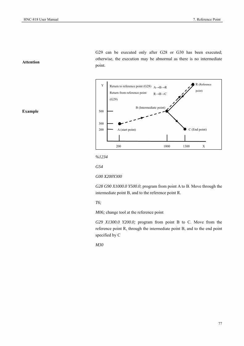
HNC-818 User Manual 7. Reference Point
77
Attention
G29 can be executed only after G28 or G30 has been executed; otherwise, the execution may be abnormal as there is no intermediate point.
Example
%1234
G54
G00 X200Y300
G28 G90 X1000.0 Y500.0; program from point A to B. Move through the intermediate point B, and to the reference point R.
T6;
M06; change tool at the reference point
G29 X1300.0 Y200.0; program from point B to C. Move from the reference point R, through the intermediate point B, and to the end point specified by C
M30
200 1000 1300 X
R (Reference
point)
C (End point)
B (Intermediate point) 500
300
200
Y
A (start point)
Return to reference point (G28)
Return from reference point
(G29)
A→B→R
R→B→C

8. Coordinate System HNC-818 User Manual
78
8 Coordinate System
During the machining, the tool may
reach a predefined position, which is defined based on the coordinate values within a coordinate system. The coordinate value is specified by program axis value, so as to process workpiece according to the specific program.
• Milling machine (use X40.0 Y50.0 Z25.0 to define the tool position)
• Turning machine (use X50.0 Z40.0 to define the tool position)
This CNC system provides the following coordinate systems:
• Machine coordinate system
• Workpiece coordinate system
• Local coordinate system
•
50.0 Y
Z
25.0
40.0
X
X
Z
40.0
50.0
Origin

HNC-818 User Manual 8. Coordinate System
79
This chapter includes the following sections:
8.1 Machine Coordinate System Programming
8.2 Define Workpiece Coordinate System
8.3 Define Local Coordinate System
8.4 Select Coordinate System Plane
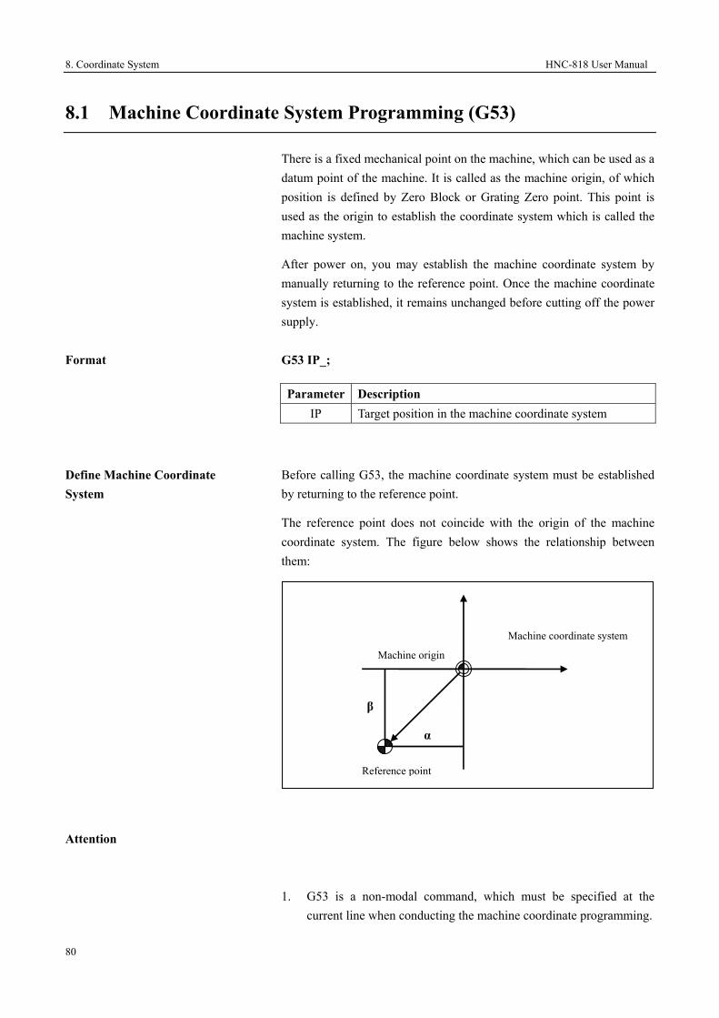
8. Coordinate System HNC-818 User Manual
80
8.1 Machine Coordinate System Programming (G53)
There is a fixed mechanical point on the machine, which can be used as a datum point of the machine. It is called as the machine origin, of which position is defined by Zero Block or Grating Zero point. This point is used as the origin to establish the coordinate system which is called the machine system.
After power on, you may establish the machine coordinate system by manually returning to the reference point. Once the machine coordinate system is established, it remains unchanged before cutting off the power supply.
Format
G53 IP_;
Define Machine Coordinate System
Before calling G53, the machine coordinate system must be established by returning to the reference point.
The reference point does not coincide with the origin of the machine coordinate system. The figure below shows the relationship between them:
Attention
1. G53 is a non-modal command, which must be specified at the current line when conducting the machine coordinate programming.
Parameter Description IP Target position in the machine coordinate system
Machine coordinate system Machine origin
Reference point
α
β

HNC-818 User Manual 8. Coordinate System
81
2. The target position specified by G53 cannot be relative programming. You must use absolute command for
programming.
3. The compensation functions such as tool radius compensation, tool length compensation, and cutter radius compensation are cleared when the G53 command is specified.
4. Before specifying the G53 command, you must set the machine coordinate system; therefore it is necessary to manually return to the reference point or return to the reference point with the G28 command after power on. You may skip this operation when using the absolute position encoder.

8. Coordinate System HNC-818 User Manual
82
8.2 Workpiece Coordinate System
The coordinate system used for workpiece machining is called as a workpiece coordinate system.
The workpiece coordinate system is predefined in the CNC system (Define workpiece coordinate system).
You may create programs in the defined workpiece coordinate system and machine the workpiece (Select workpiece coordinate system).
You may move the origin of the defined workpiece coordinate system to change the workpiece coordinate system (Change workpiece coordinate system).
8.2.1 Define Workpiece Coordinate System (G92)
There are three methods to define a
workpiece coordinate system:
1. Use G92 to define the workpiece coordinate system.
2. Define the workpiece coordinate system through the selecton of G code.
Use the workpiece coordinate system on the HMI interface to define six standard workpiece coordinate systems (G54-59) and 60 extended workpiece coordinate systems (G54.X) (for milling machining center), and then use the corresponding program commands to define the workpiece coordinate.
3. For turning machines, in the absolute tool offset compensation mode, you may define the origin of the workpiece coordinate system via T commands (see section 10.1)
Under the absolute commands, the workpiece coordinate system must be established by using any of the methods above.
Format
G92 IP_;
Parameter Description IP The orientation distance from the origin of the
coordinate system to the tool start point.
HNC-818 User Manual 8. Coordinate System
83
Set Workpiece Coordinate System
Attention
Example
The G92 command can be used to set the relative position of the tool start point to the coordinate origin. Thereby defining the workpiece coordinate system. Once the workpiece coordinate system is defined, the command value in absolute programming is the coordinate value in the workpiece coordinate system.
1. The execution of this program block is only to set the workpiece coordinate system, but the tool will not move.
2. G92 is a non-modal command.
3. In the tool length compensation mode of milling machines, the coordinate system set G92 command is the specified coordinate system before conducting the compensation. However, the G code cannot be executed in the program blocks where the tool length compensation vector changes. For example, it is cannot be executed in the following blocks:
• Program blocks where the G43/G44 is specified.
• Program blocks where H code is specified in G43/G44 modes
• Program blocks where G49 is specified in G43/G44 modes
• Program blocks where the compensation vector is canceled by G28/G53 in G43/G44 modes and the vector is restored
In addition, when setting the workpiece coordinate system with G92, the programs before it will be stopped and the tool length compensation defined by MDI cannot be changed.
Use G92 to set the workpiece coordinate system as shown below:
G92 X30.0 Y30.0 Z20.0

8. Coordinate System HNC-818 User Manual
84
20.0
30.0
30.0
X
Y
Z
Program origin
Tool start point

HNC-818 User Manual 8. Coordinate System
85
8.2.2 Select Workpiece Coordinate System (G54-G59)
You may select the following workpiece coordinate systems that have been defined:
1. In the workpiece coordinate system defined by G92, the absolute command defined is a position in this coordinate system.
2. Select among 6 standard workpiece coordinate systems of G54 to G59.
3. For milling machines and machining centers, select among 60 extended workpiece coordinate systems of G54.X.
4. For turning machines, in the absolute tool offset mode, select a workpiece coordinate system with T commands. For details, see section 10.1.
Example
%1234
G54
G90 G00 X100 Y100 Z50; Locate X=100 Y=100 Z=50 in the G54 coordinate system
M30
8.2.3 Change Workpiece Coordinate System (G10)
You may change the workpiece coordinate system defined in the following modes by changing an external workpiece origin offset or workpiece origin offset:
1. Workpiece coordinate systems defined by G54-G59
• Set the Coordinate system on the HMI interface.(see relevant section of Operation manual)
• Select the G code to define the workpiece coordinate systems
• Change the coordinate system origin with G10 command(for details, see section 15)
2. Workpiece coordinate systems defined by G54.X for milling machines

8. Coordinate System HNC-818 User Manual
86
•
• Set the Coordinate system on the HMI interface.(see relevant section of Operation manual)
• Select the G code to define the workpiece coordinate systems
• Change the coordinate system origin with G10 command(for details, see section 15)
•
3. Workpiece coordinate systems defined with absolute tool offset for turning machines
• Set the Coordinate system on the HMI interface.(see relevant section of Operation manual)
• Select the G code to define the workpiece coordinate systems
8.2.4 Select Extended Workpiece Coordinate System (G54.x)
In addition to the six standard workpiece coordinate systems, you may select extended workpiece coordinate systems for milling machines as required.
A total of 60 extended workpiece coordinate systems for milling machines are available.
Format
G54.n, G54.1Pn, G54Pn: Select No. n workpiece coordinate system
Example
%1234
G54.18; or G54.1P18, G54P18
G90 G00 X100 Y100 Z50; locate the position where X=100 Y=100 Z=50 in the 18th coordinate system
M30
Parameter Description n Number of Extended workpiece coordinate system,
ranging from 1 to 60.

HNC-818 User Manual 8. Coordinate System
87
8.3 Define Local Coordinate System (G52)
During workpiece coordinate system programming, you may create a sub workpiece coordinate system, which is called local coordinate system.
Format
G52 IP_; Define the local coordinate system
......
G52 IP 0; Cancel the local coordinate system
Description
The G52 IP_; command can be used to create the local coordinate systems in all workpiece coordinate systems. The origin of the local coordinate system becomes the position defined by IP_ in the corresponding workpiece coordinate system.
Once the local coordinate system is defined, the axial movement command to be specified will be the coordinate value in the local coordinate system.
If you want to cancel the local coordinate system or specify coordinate value in the workpiece coordinate system, you may make the origin of the local coordinate system coincide with the origin of the workpiece coordinate system.
Example
%1234
G55; select G55, assuming that the value of G55 in the machine coordinate system is (10, 20)
G1 X10Y10F1000; move to the point (20, 30) in the machine coordinate system
G52 X30Y30; set local coordinate system based on G55 in the workpiece coordinate system, with the origin of (30, 30)
G1 X0Y0; move to the origin of the local coordinate system (the current position in the machine coordinate system is (40, 50))
G52 X0Y0; cancel the local coordinate system, and restore the G55
Parameter Description IP Define the origin of the local coordinate system
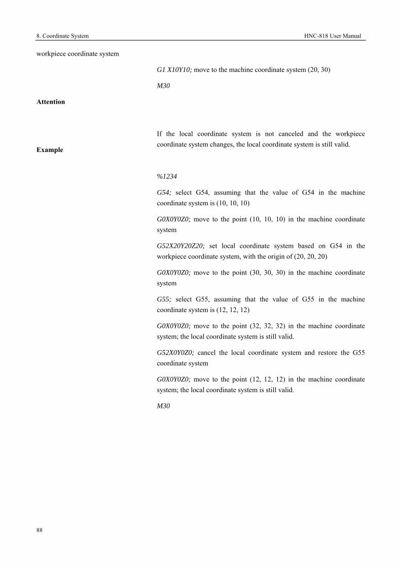
8. Coordinate System HNC-818 User Manual
88
workpiece coordinate system
G1 X10Y10; move to the machine coordinate system (20, 30)
M30
Attention
Example
If the local coordinate system is not canceled and the workpiece coordinate system changes, the local coordinate system is still valid.
%1234
G54; select G54, assuming that the value of G54 in the machine coordinate system is (10, 10, 10)
G0X0Y0Z0; move to the point (10, 10, 10) in the machine coordinate system
G52X20Y20Z20; set local coordinate system based on G54 in the workpiece coordinate system, with the origin of (20, 20, 20)
G0X0Y0Z0; move to the point (30, 30, 30) in the machine coordinate system
G55; select G55, assuming that the value of G55 in the machine coordinate system is (12, 12, 12)
G0X0Y0Z0; move to the point (32, 32, 32) in the machine coordinate system; the local coordinate system is still valid.
G52X0Y0Z0; cancel the local coordinate system and restore the G55 coordinate system
G0X0Y0Z0; move to the point (12, 12, 12) in the machine coordinate system; the local coordinate system is still valid.
M30

HNC-818 User Manual 8. Coordinate System
89
8.4 Select Coordinate Planes (G17, G18, G19)
The coordinate plane selection command G17/G18/G19 is used to select machining planes during circular interpolation, cutter radius compensation (M), rotation transformation (M), etc.
Description
Attention
G17, G18, and G19 are modal functions, which can be canceled by each other.
The motion command has nothing to do with the plane selection. For example, the Z axis moves even the command G17 G01 Z10 is executed.
G code Plane
G17 XY plane G18 ZX plane G19 YZ plane

9. Coordinate Values and Dimension Unit HNC-818 User Manual
90
9 Coordinate Values and Dimension Unit
This chapter includes the following sections:
9.1 Absolute Commands and Incremental Commands
9.2 Dimension Unit Selection
9.3 Polar Coordinate Programming (M)
9.4 Diameter and Radius Programming (T)

HNC-818 User Manual 9. Coordinate Values and Dimension Unit
91
9.1 Absolute Commands and Incremental Commands (G90, G91)
There are two methods to specify tool movement: absolute commands and incremental commands:
Absolute commands are used to create programs for the tool movement end point coordinates.
Incremental command is used to create programs for the amount of tool movement.
Format
Milling Machines
- Absolute command G90 IP_;
- Incremental command G91 IP_;
Turning Machines (two formats):
- First: Absolute command G90 IP_;
Incremental command G91 IP_;
- Second: UVW incremental programming
When UVW is not defined as a coordinate axis and the channel parameter Enable Programming with UVW (040033) is set to 1, you may use UVW to present the incremental value of XYZ.
Description
It can simplify programming by selecting a proper programming mode. When the blueprint dimension is based on a fixed point, it is recommended to use the absolute programming. When the blueprint dimension is based on the distance between contour vertexes, it is recommended to use the incremental programming.

9. Coordinate Values and Dimension Unit HNC-818 User Manual
92
Example
1. Milling machines
2. Turning machines
The tool moves from P to Q (X axis indicates the diameter value commands).
Absolute command: G90X400Z50
Incremental command: G91X200Z-400 or U200W-400
Z
Φ200
P (200, 450)
Q (400, 50) X
Φ400
Φ450 50
End point
Start point
70.0
30.0
40.0 100.0
Y
X
G90 X40.0 Y70.0; Absolute command
G91 X-60.0 Y40.0; Incremental command

HNC-818 User Manual 9. Coordinate Values and Dimension Unit
93
9.2 Dimension Unit Selection (G20, G21)
You may select dimension unit with G20/G21.
Format
Description
Attention
1. G20 and G21 are modal functions, which can be canceled by each other. G21 is the default value after power on.
2. The unit of the data input for G codes has nothing to do with the unit of the data displayed on the HMI interface. G20/21 is used to select the unit of the data input for G codes, but cannot change the data unit displayed on the HMI interface. The NC parameter SIZE METRIC/INCH (000025) is used to set the coordinate data unit displayed on the interface.
Example
%0007
G54
G01 x10y10z10
G20
x2y2z2
M30
G20 Inch input mode
G21 Metric input mode
G Code Linear Axis Rotation Axis
Inch input (G20) inch Degree (deg) Metric input (G21) Millimeter (mm) Degree (deg)

9. Coordinate Values and Dimension Unit HNC-818 User Manual
94
9.3 Polar Coordinate Programming (M) (G16, G15)
For G code programming, it is more convenient and faster to create programs by entering the coordinate values of the end point at the polar coordinate system of the radius and angle.
From the positive direction of the first axis in the specified polar coordinate plane, the angle in the CCW direction is positive, and the angle in the CW direction is negative.
The absolute command and incremental command (G90, G91) can be used to specify radius and angle.
Format
Define the plane of the polar coordinate system
G17 XY plane: The X axis specifies the polar radius while the Y axis specifies the polar angle.
G18 ZX plane: The Z axis specifies the polar radius while the X axis specifies the polar angle.
G19 YZ plane: The Y axis specifies the polar radius while the Z axis specifies the polar angle
Define the origin of the polar coordinate system
G90 Specify the workpiece coordinate system origin as the origin of the polar coordinate system, and measure radius from this point.
G91 Specify the current point as the origin of the polar coordinate system, and measure radius from this point.
G16 Start of the polar coordinate programming command
G15 End of the polar coordinate programming command
Set origin of polar coordinate system
There are two methods to set the origin of the polar coordinate system:
1. Specify the workpiece coordinate system zero point as the origin of the polar coordinate system
Specify the radius with absolute value.
Specify the workpiece coordinate system origin as the origin of the polar coordinate system.
When using the local coordinate system (G52), the origin of the
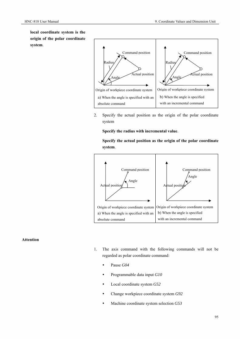
HNC-818 User Manual 9. Coordinate Values and Dimension Unit
95
local coordinate system is the origin of the polar coordinate system.
2. Specify the actual position as the origin of the polar coordinate system
Specify the radius with incremental value.
Specify the actual position as the origin of the polar coordinate system.
Attention
1. The axis command with the following commands will not be regarded as polar coordinate command:
Pause G04
Programmable data input G10
Local coordinate system G52
Change workpiece coordinate system G92
Machine coordinate system selection G53
Angle Actual position
Command position
Origin of workpiece coordinate system
Angle
Actual position
Command position
Origin of workpiece coordinate system
Angle Actual position
Command position
Radius
Angle Actual position
Command position
Radius
Origin of workpiece coordinate system
b) When the angle is specified
with an incremental command
Origin of workpiece coordinate system
b) When the angle is specified
with an incremental command a) When the angle is specified with an
absolute command
a) When the angle is specified with an
absolute command

9. Coordinate Values and Dimension Unit HNC-818 User Manual
96
Coordinate rotation G68
Scaling G51
Examples
2. In the polar coordinate system, any degrees of angle/convex corner R cannot be specified.
3. In the polar coordinate system, you cannot use fixed cycle G commands.
4. For polar coordinate programming, when specifying the radius with absolute values, set the workpiece coordinate system origin as the polar coordinate system origin; when specifying the radius with incremental values, set the actual position as the polar coordinate system origin. However, if only angle is specified in the command, set the workpiece coordinate system origin as the polar coordinate system origin both in absolute mode and incremental mode.
1. Use absolute commands to specify the radius and angle
%1000;
G54
G00 X0Y0Z0
G17 G90 G16;
G01 X100.0 Y30.0F1500
Y150.0;
Y270.0;
G15
M30
2. Use absolute command to specify the radius and incremental command to specify the angle
%1000
G54
G00 X0Y0Z0
G17 G90 G16;
G01 X100.0 Y30.0F1500
G91Y120.0;
Y120.0;

HNC-818 User Manual 9. Coordinate Values and Dimension Unit
97
G15
M30

9. Coordinate Values and Dimension Unit HNC-818 User Manual
98
9.4 Diameter and Radius Programming (T) (G36, G37)
Format
G36; Diameter programming
G37; Radius programming
Description
The shape of the workpiece to be processed in a turning machine is usually a rotating piece, and its X axis dimension can be specified in two ways: diameter and radius modes. G36, the default value, indicates the diameter programming.
Attention
1. The Z-axis command input has nothing to do with the diameter or radius programming.
2. When G02 or G03 is specified, the parameter values of R, I, K are radius values.
3. In single fixed rotation, the parameter R used as the tool feed along the X axis indicates the radius value.
4. For turning machines or machining center, the default mode is the diameter programming (G36).
5. Specify the axial feed rate based on the change of radius.
Example
Φ18
0
160+X
44
254
Φ20
Φ50

HNC-818 User Manual 9. Coordinate Values and Dimension Unit
99
Diameter programming Radius programming %3341 N1 G92 X180 Z254 N2 G36 G01 X20 W-44 N3 U30 Z50 N4 G00 X180 Z254 N5 M30
%3342 N1 G92 X90 Z254 N2 G37 G01 X10 W-44 N3 U15 Z50 N4 G00 X90 Z254 N5 M30

10. Tool Compensation Function HNC-818 User Manual
100
10 Tool Compensation Functions
This chapter includes the following sections:
10.1 Tool Offset (T)
10.2 Tool Nose Radius Compensation (T)
10.3 Introduction to Tool Radius Compensation (M)
10.4 Detailed Description of Tool Radius Compensation (M)
10.5 Tool Length Compensation (M)

HNC-818 User Manual 10. Tool Compensation Functions
101
10.1 Tool Offset (T)
The programming path is the motion path of the tool nose. However, in real machining, the geometry dimensions and installation positions of different tools are different; therefore, the relative position of the tool nose to the center of the turret is different. You need to measure and set the tool nose position, so that the system may conduct tool offset compensation during the machining. When programming, you do not need to take into account the tool nose position difference caused by tool shape and installation position.
Tool dimension error may be caused by tool wear after a period of usage; therefore the compensation is required. The compensation and tool offset compensation are stored in the same register address number. The tool wear compensation of a tool is only valid for the tool (including the standard tool).
10.1.1 T Command for Tool Offset
The tool compensation is specified by T commands, and the four digits after T express selected tool number and tool offset compensation (for details, see section 4.3).
The description of T command is as follows:
The tool offset number is the address number of the tool offset compensation register which stores the tool offset compensation values and tool wear compensation value of X axis and Z axis.
T plus compensation number starts the offset compensation feature. The offset number 00 expresses the offset is 0. In this case, the offset feature
T Tool geometry offset number
Tool number

10. Tool Compensation Functions HNC-818 User Manual
102
is canceled.
The tool geometry offset number and tool number may be the same or different. In other words, multiple tool offset numbers (value) may correspond to one tool.
Example
N1 G00X100Z140
N2 T0313 (select No. 3 tool and the tool offset of No. 13 tool)
N3 X200Z150
As shown in the figure below, if there is compensation value for the tool path (relative to the programming path) in the X, Z axis (the vector of the compensation in the X, Z direction is referred to as compensation vector), the position of the end point in the program segment plus or minus compensation amount (compensation vector) is the end position specified by the T command.
10.1.2 Tool Offset Compensation and Tool Wear Compensation
The programming path of the turning machine is actually the movement path of the tool nose. But in the actual situation, the geometry dimension and installation position of different tools are different, and the relative position of the tool nose to the center of the turret is different. Hence, you need to measure and define the tool nose position of each tool, so that the system may conduct tool offset compensation during the processing. This way, you do not need to take account of the tool nose position difference caused by the difference of tool shape and installation position in programming.
Compensation path
Programming path
Compensation vector
(components in X and Z
axis directions)
Program block containing T
commands

HNC-818 User Manual 10. Tool Compensation Functions
103
Absolute Compensation Mode
The absolute tool offset indicates the orientation distance from the tool nose of each tool on the turret to the workpiece zero when the machine returns to the machine zero. When executing tool offset compensation, the processing coordinate system of each tool is defined based on the distance. This way, when the turret is at the machine zero, even the tool dimension and the distance from the tool position to the workpiece zero are different, the defined coordinate system of each tool is coincide with the workpiece coordinate system (programmed).
Example
As shown in the figure below, set tool offset wear compensation, and then cancel the tool offset wear compensation:
Programming path
Tool compensation path
Z
X
50
100
100 200 250
T0202
G01 X50 Z100
Z200
X100 Z250 T0200
M30
Workpiece origin
Machine origin No. 1 tool Z
axis offset
No. 2 tool X
axis offset
No. 2 tool Z
axis offset
Z1
Z2
X1/2 X2/2

10. Tool Compensation Functions HNC-818 User Manual
104
10.2 Tool Nose Radius Compensation (T) (G40, G41, G42)
The CNC program is generally created based on the dimension of the workpiece for a point that is on the cutting tools (cutter location point), which is generally the imaginary tool nose (point A) under ideal conditions or the center point of the tool nose circle (O). But in the actual processing, the tool nose may not be a point but an arc because of the processing craft or other requirements. During cutting, the cutting point changes on the arc. This way, there may be deviation between the actual cutting position and the cutter location point, and thereby causing excessive or less cutting. The processing error, caused because that the tool nose is not an ideal point but one arc, can be eliminated by the nose radius compensation function.
Attention
Radius compensation does not support interruption command such as G31.
10.2.1 Imaginary Tool Nose
As shown in the figure below, the imaginary tool nose point (A) does not exist. It is more difficult to set the radius center of actual tool nose at the start point than to set the imaginary tool nose at the start point. Hence, the imaginary is necessary.
When using the imaginary tool nose, you do not need to consider the radius of tool nose during programming.
When the tool is set at the start point, the position is as below:
Tool path without compensation
Tool path with compensation
Cutting depth without tool nose radius compensation
Workpiece
Tool nose
R

HNC-818 User Manual 10. Tool Compensation Functions
105
Description
The tool nose arc radius compensation function can be used to add or cancel radius compensation, which is specified with the G41/G42/G40 and too nose radius compensation number specified by T.
Format
G Code Workpiece Position Tool Path
G40 Canceling tool nose radius compensation
Move along the tool path
G41 Left tool compensation Compensation at the left side of the tool movement direction
G42 Right tool compensation
Compensation at the right side of the tool movement direction
See the figure below:
G41:too on the left of its movement direction
G42: tool on the right of its movement direction
Z
X
Start point Start point Programming based on the
imaginary tool nose
Programming based on the
tool nose center

10. Tool Compensation Functions HNC-818 User Manual
106
10.2.2 Define Tool Nose Direction
The direction number of cutting tool nose defines the relationship between the cutter location point and tool nose center. There are ten directions ranging from 0 to 9. See the figure below:
Back tool turret
Front tool turret
"●": Cutter location point A, "+": Tool nose circle center O
7 0
Z
4 8 3
59X
1 6 2
"●": Cutter location point A, "+": Tool nose circle center O
7
X
0
Z
8 3 4
1 6 2
59

HNC-818 User Manual 10. Tool Compensation Functions
107
Attention
Tool Offset Transition
Cancel Offset
1. G40, G41, and G42 are modal codes, which can be canceled by each other.
2. G41/G42 is not followed by any parameters, and its compensation number (indicating the tool nose radius compensation corresponding to the tool) is specified by T commands. The tool nose arc compensation number corresponds to the tool offset compensation number.
3. The command used to establish or cancel the tool radius compensation can be only G00 or G01, but cannot be G02 or G03.
The program block changing from G40 to G41 or G42 is called the program of tool offset transition.
G40_;
G41_; (starting cutting)
The tool offset transition movement is performed in this program block. In the start point of the next program block after it, the tool nose center is located in the vertical line of the programming path.
The program block changing from G41 or G42 to G40 is called the offset cancelation program.
G41_;
G40_; (offset cancelation program)
In the program block prior to the offset cancelation program, the tool nose center moves to the position vertical to the programming path. The tool is located at the end point of the offset cancelation program. See the figure below:
Workpiece
G42
G42 (Start)
G40

10. Tool Compensation Functions HNC-818 User Manual
108
Example
Create a program for the workpiece machining as shown in the figure below (considering the tool radius compensation):
%3323
N1 T0101 (change to the No. 1 tool and set the coordinate system)
N2 M03 S400 (CW rotate spindle at 400r/min)
N3 G00 X40 Z5 (move to the program start point)
N4 G00 X0 (the tool moves to the workpiece center)
N5 G01 G42 Z0 F60 (add tool radius compensation, and move to the workpiece position)
N6 G03 U24 W-24 R15 (process the R15 arc segment)
N7 G02 X26 Z-31 R5 (process the R5 arc segment)
N8 G01 Z-40 (process the Φ26 external circle)
N9 G00 X30 (exit the processed surface)
N10 G40 X40 Z5 (cancel the radius compensation, and return to
27
R15
4031
R5
Φ26
Φ22
End point
G40
G42
Workpiece

HNC-818 User Manual 10. Tool Compensation Functions
109
the program start point)
N11 M30 (stop spindle, end the main program and reset)

10. Tool Compensation Functions HNC-818 User Manual
110
10.2.3 Usage of Tool Radius Compensation
Tool nose radius compensation of inner/outer diameter cutting cycle (G80) or end-face cutting cycle (G81)
1. Movement path in the direction of the imaginary tool
The tool movement path direction is generally parallel to the programming path. The figure below shows the paths with tool nose radius compensation in nine tool nose directions:
2. Offset direction
G80
G81 tool path center
Start point
4
5
6 1 2
7
8 3 0
Programming path
G80 tool path center
Start point
Programming path
4
5
6 1 2
7
8 3 0
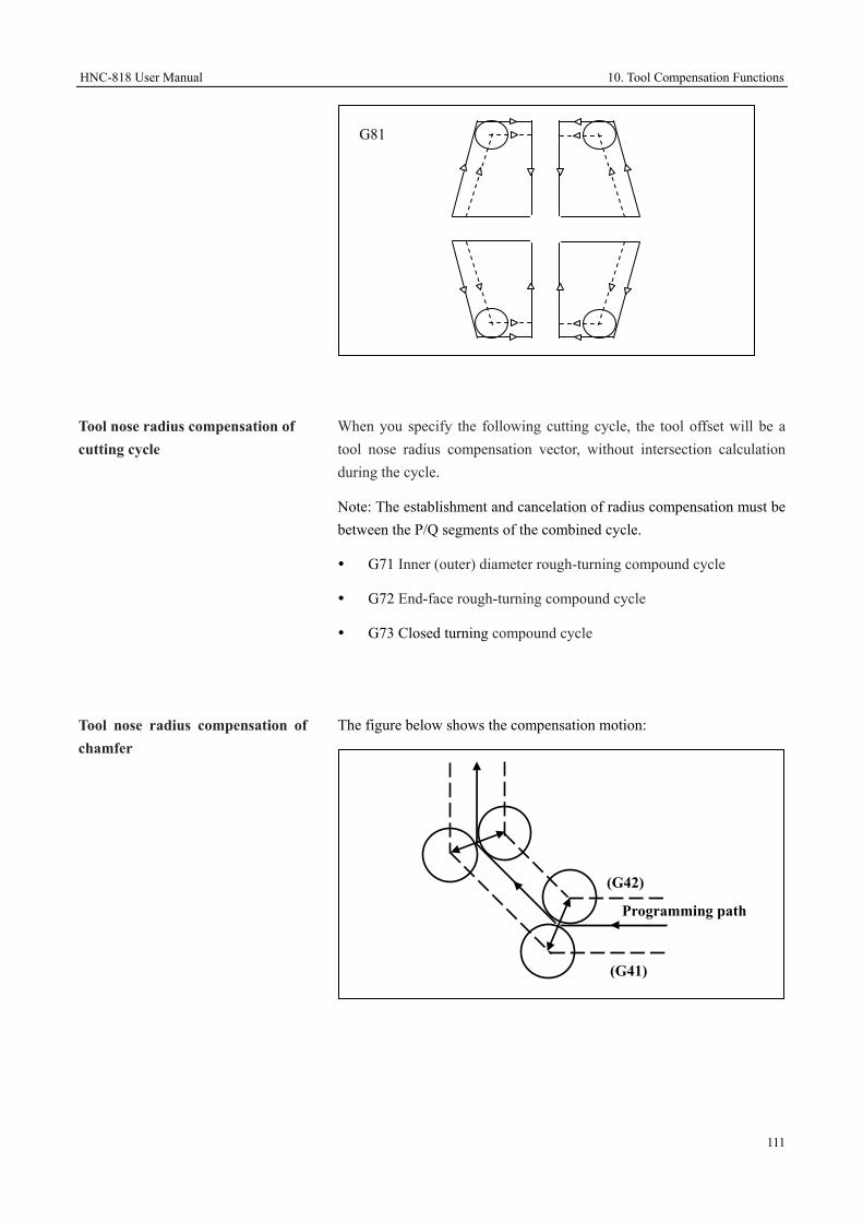
HNC-818 User Manual 10. Tool Compensation Functions
111
Tool nose radius compensation of cutting cycle
When you specify the following cutting cycle, the tool offset will be a tool nose radius compensation vector, without intersection calculation during the cycle.
Note: The establishment and cancelation of radius compensation must be between the P/Q segments of the combined cycle.
G71 Inner (outer) diameter rough-turning compound cycle
G72 End-face rough-turning compound cycle
G73 Closed turning compound cycle
Tool nose radius compensation of chamfer
The figure below shows the compensation motion:
(G42)
(G41)
Programming path
G81

10. Tool Compensation Functions HNC-818 User Manual
112
Tool nose radius compensation of corner arc
(G42)
(G41)
Programming path

HNC-818 User Manual 10. Tool Compensation Functions
113
10.3 Introduction to Tool Radius Compensation (M) (G40, G41, G42)
Attention
Radius compensation does not support interruption command such as G31.
In the program block between G41/G42 and G40, G0 automatically changes to G01.
10.3.1 Tool Radius Compensation for Milling Machines
During programming, only the tool center path is generally programmed (the tool radius is assumed as 0). However, in the actual machining, you need to conduct offset for the tool center path because the tool radius is not zero (The offset distance equals to the tool radius and the offset direction may be left or right based on the actual programming). In this case, tool radius compensation function is required.
Format G17 (or G18/G19) G41 (or G42) G00 (or G01) IP_ D_;
Attention
1. Tool radius compensation does not support radius change.
2. Tool radius compensation does not support the status change of G41/G42.
Establish Tool Compensation
G17/G18/G19: Define the compensation plane, XY, YZ, ZX plane respectively
G41/G42: Tool radius compensation is valid. G41: left compensation. G42: Right compensation.
D: Define the tool radius compensation number.
Cancel Tool Radius Compensation
G40 IP_;
G40: Cancel tool radius compensation (G40, G41, G42 are modal codes, which can be canceled by each other.)
IP_: The command value of axis movement

10. Tool Compensation Functions HNC-818 User Manual
114
Offset Direction
The tool radius compensation function is defined by G41or G42.
G41: Conduct left offset along the tool movement (see a)
G42: Conduct right offset along the tool movement (see b)
10.3.2 Establish or Cancel Tool Compensation
Establish or cancel radius compensation through G00 or G01.
If the arc interpolation commands (G02, G03) are used to establish or cancel the tool compensation, an alarm will be reported.
10.3.3 Define Tool Radius Compensation Amount
You may use the D codes to set the tool radius compensation amount by defining the number of tool radius compensation amount.
The D code is valid until another D code is defined.
Attention
The change of tool radius compensation amount is generally conducted during tool change when the tool compensation is canceled.
10.3.4 Plane Selection and Vector
Tool compensation path
Programming
path
a: left tool
compensation
Programming
path
b: right tool
compensation
Tool compensation path
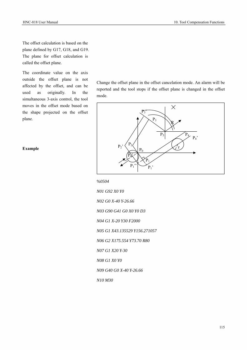
HNC-818 User Manual 10. Tool Compensation Functions
115
The offset calculation is based on the plane defined by G17, G18, and G19. The plane for offset calculation is called the offset plane.
The coordinate value on the axis outside the offset plane is not affected by the offset, and can be used as originally. In the simultaneous 3-axis control, the tool moves in the offset mode based on the shape projected on the offset plane.
Example
Change the offset plane in the offset cancelation mode. An alarm will be reported and the tool stops if the offset plane is changed in the offset mode.
%0504
N01 G92 X0 Y0
N02 G0 X-40 Y-26.66
N03 G90 G41 G0 X0 Y0 D3
N04 G1 X-20 Y30 F2000
N05 G1 X43.135529 Y156.271057
N06 G2 X175.554 Y73.70 R80
N07 G1 X20 Y-30
N08 G1 X0 Y0
N09 G40 G0 X-40 Y-26.66
N10 M30
P3’
P3 R
P5 P4 P4’ P2 P2’ P0
r
P1’ P1
P0’
P1’’

10. Tool Compensation Functions HNC-818 User Manual
116

HNC-818 User Manual 10. Tool Compensation Functions
117
10.4 Description of Tool Radius Compensation (M) (G40, G41, G42)
10.4.1 Tool Movement during Tool Start
The figure below shows the tool movement when the mode is changed from the offset cancelation into the offset mode:
Tool movement around the inner corner
(α≥180 degrees)
Linear → Circular
G42 Workpiece
α
r
Programming path Tool center path Start point L
S C
Linear→ Linear
Workpiece
G42
α
r Programming path
Start point Tool center pathL
LS

10. Tool Compensation Functions HNC-818 User Manual
118
Tool movement around the outer corner
(90 degrees ≤α<180 degrees)
Tool movement around the outer corner
(α<90 degrees)
Linear → Linear
L
Workpiece G42 α
rProgramming path
Start point
Tool center path
LS
L
L
L
r
Linear → Circular
Workpiece
α
r
Programming pathTool center path
Start pointG42
L
r
LL CIntersection point
S
Linear → Linear
Workpiece
G42
α
rProgramming path
Start point
Tool center path
Lr
S LLIntersection point

HNC-818 User Manual 10. Tool Compensation Functions
119
10.4.2 Tool Movement in Offset
Tool movement around the inner corner
(α≥180 degrees)
Linear → Circular Start point
α
Workpiece
Tool center path Programming path
Intersection point
L SC
Linear → Circular
Workpiece
α
r
Programming path Tool center path
G42
Start point
L
L
L
L
C
S
r
Linear → Linear α Workpiece
Intersection point
Programming path
Tool center path
L
L S

10. Tool Compensation Functions HNC-818 User Manual
120
Tool movement around the outer corner
(90 degrees ≤α<180 degrees)
Linear → Linear
α Workpiece
Tool center pathIntersection point
Programming path
LS
L
Circular → Circular
Workpiece
α
Programming path
Intersection point
Tool center path
SC C
Circular → Linear
α Workpiece
Programming path
Tool center path Intersection point
L SC

HNC-818 User Manual 10. Tool Compensation Functions
121
Circular → Circular
Workpiec
αProgramming path
Tool center path
r
Intersection point
C S
CL L
r
Tool center path
α Workpiece
Programming path
Intersection point L L
SC
r
Linear → Circular
α
Workpiece r
Intersection point
Tool center path
Programming path
L C S
L
Circular → Linear

10. Tool Compensation Functions HNC-818 User Manual
122
Tool movement around the outer corner
(α<90 degrees)
Workpiec
Tool center path
Programming path
r
L
r
L α
L
S
C
Linear → Circular
L
Tool center path Programming path
r
L
rWorkpiec
L
α
CL
S
α Workpiece
Tool center path
Programming path
Linear → Linear
r
L
L
r
L
L
S
L
Circular → Linear

HNC-818 User Manual 10. Tool Compensation Functions
123
10.4.3 Tool Movement during Offset Cancelation
In the program block including offset cancelation, tool movement around the inner corner
(α≥180 degrees)
Workpiece
Linear → Circular
Tool center path Programming path
r
α
G42G40
SL C
Workpiece
Linear → Linear
Tool center path
Programming path r
α G40
LL
S
Circular → Circular
Tool center path
Program
Workpiece
r
L
r
Lα
S
C
L
C

10. Tool Compensation Functions HNC-818 User Manual
124
In the program block including offset cancelation, tool movement around the outer obtuse angle
(90 degrees ≤α<180 degrees)
Workpiece
Tool center path Programming path
r
αG40
Circular → Linear
SC
L
Intersection point L
L
Workpiec
Tool center path
Programming path r
α
G42
G40
Linear → Linear
L
L S Intersection point

HNC-818 User Manual 10. Tool Compensation Functions
125
In the program block including offset cancelation, tool movement around the outer acute angle
(α<90 degrees)
Linear → Circular
Workpiece
Tool center path Programming path
α
r L
S
L
L
L
r
C
Linear → Linear
Workpiece
Tool center path
Programming path
α G4
r L
S
L
L L
L
r

10. Tool Compensation Functions HNC-818 User Manual
126
10.5 Tool Length Compensation (M) (G43, G44, G49)
Generally, there may be a difference
between the tool length specified in programming and the actual tool length. You may save this difference in the CNC's tool offset register, and then use the tool length compensation codes to conduct the compensation for the difference, in order to simplify the operation and programming. This way, even tools with different length are used for machining, you may conduct normal machining without modifying the program if you know the difference between the programmed tool length and the actual length.
Attention
The length compensation does not support interruption codes such as G31.
Abstract
There are three kinds of tool length compensation based on the type of the axis allowed tool length compensation.
1. Tool length compensation A
Tool length compensation along Z axis direction
2. Tool length compensation B
Tool length compensation vertical to the selected plane
3. Tool length compensation C
Tool length compensation along specified axis direction
Programmed tool length Actual tool length
Tool length compensation

HNC-818 User Manual 10. Tool Compensation Functions
127
Format
Type Format Tool length compensation A G43/G44 Z_H_ Tool length compensation B G17 G43/G44 Z_H_
G18 G43/G44 Y_H_ G19 G43/G44 X_H_
Tool length compensation C G43/G44 X_H_ G43/G44 Y_H_ G43/G44 Z_H_ ……
Cancel tool length compensation G49 IP_
Description
Tool length compensation is defined by G43 and G44.
G43: Tool length compensation in the positive direction (plus the tool length compensation value to the theoretical position in the tool axis direction)
G44: Tool length compensation in the negative direction (minus the tool length compensation value to the theoretical position in the tool axis direction)
G17: Select XY plane
G18: Select ZX plane
G19: Select YZ plane
H: The number of tool length compensation amount in the tool compensation table
Attention
1. The direction of tool length compensation is always vertical to the plane defined by G17/G18/G19.
2. When the offset number is changed, the new offset value will not be added to the old offset value. Example:
H1: Tool length compensation amount 20.0; H2: Tool length compensation amount 30.0
G90 G43 Z100 H01; Z reaches 120
G90 G43 Z100 H02; Z reaches 130
3. G43, G44, G49 are modal codes which can be canceled by each other.
4. The axis movement is invalid if no tool length compensation after G49.

10. Tool Compensation Functions HNC-818 User Manual
128

HNC-818 User Manual 10. Tool Compensation Functions
129
Example 1
Take into account the tool length compensation, and create a program for the workpiece as shown in the figure below.
Requirements: establish a workpiece coordinate system and conduct machining in the direction shown by the arrow in the figure below:
H1 = -4.0 (tool length compensation value)
%3325
G92 X0 Y0 Z0
G91 G00 X120 Y80 M03 S600 ○1
G43 Z-32 H01 ○2
G01 Z-21 F300 ○3
G04 P2000 ○4
G00 Z21 ○5
X30 Y-50 ○6
20
#2
#3○6
○9 30
30
13
X
120 30 50
Offset value = 4mmActual position
35 ○2
12
30 18 ○3 ○5
○4
○10
11
22
Programming position
○1Y
○8 ○7
#1

10. Tool Compensation Functions HNC-818 User Manual
130
G01 Z-41 ○7
G00 Z41 ○8
X50 Y30 ○9
G01 Z-25 ○10
G04 P2000 ○11
G00 G49 Z57 ○12
X-200Y-60 ○13
M05
M30

HNC-818 User Manual 11. Programming Simplification Functions
131
11 Programming Simplification Functions
This chapter includes the following sections:
11.1 Mirroring Function (M) (G24/G25)
11.2 Scaling Function (M) (G50/G51)
11.3 Rotation Function (M) (G68/G69)
11.4 Direct Programming Based on Blueprint Dimension (T)

11. Programming Simplification Functions HNC-818 User Manual
132
11.1 Mirroring Function (M) (G24, G25)
When the workpiece is symmetric around an axis, you may use the mirroring functions and subprograms to create a program only for one part of the workpiece, and other symmetrical parts can be produced. This is called mirroring.
Format
G24 IP_; Create mirror
……
G25 IP0; Cancel mirror
Attention
1. you may establish the symmetrical mirror of the β axis by specifying G24 α_.
After establishing the mirror of the β axis, you may cancel the mirror of the β axis by specifying G25 α0. If you establish a point-symmetrical mirror by specifying G24 X0Y0, the symmetrical mirror of the Y axis can be canceled by specifying G25 X0, and then only the X axis mirror is specified.
The character "α" represents the first axis in the selected plane while "β" represents the second axis in the selected plane.
2. G24 and G25 program blocks are specified in separate lines.
3. G24 is a modal function. You may use G25 to cancel the mirroring function after it is ended.
4. When no axis is after G25, all mirroring functions are canceled.
Parameter Description IP The position of the mirror axis.

HNC-818 User Manual 11. Programming Simplification Functions
133
Description
1. The mirroring path 1 and the programming path is axisymmetric, with the symmetry axis α=50.
2. The mirroring path 2 and the programming path is point-symmetric, with the symmetry point (50, 60).
3. The mirroring path 3 and the programming path is axisymmetric, with the symmetry axis β=60.
Axisymmetric mirror
(G17/G18/G19) G24 α_/β_;
…… ;
G25;
G17/G18/G19: Selects the mirror plane which should contain the programming tool path.
G24 α_/β_: Specifies the symmetry axis of the mirror. You can only and must specify either α_ or β_. The character "α" represents the first axis in the selected plane, and "β" represents the second axis in the selected plane. If an axis that is not in the selected plane is specified, an alarm will be reported.
……: Programming command of tool path.
G25α0/β0: Cancels the mirroring function. Only the command G25 or the command with G25 followed by the random value of "a" and "b" can cancel the mirroring function.
Point-symmetric mirror
(G17/G18/G19) G24 α_ β_;
…… ;
G25;
Mirroring
path 1 Programming path
Mirroring
path 2 Mirroring path 3
50
60
α
β

11. Programming Simplification Functions HNC-818 User Manual
134
Example
G17/G18/G19: Selects the mirror plane which should contain the programming tool path.
G24 α_ β_: Specifies the symmetry point of the mirror. When α_ or β_ is blank, the point is the actual tool position by default. If an axis that is not in the selected plane is specified, an alarm will be reported.
……: Programming command of tool path.
G25α0β0: Cancels the mirroring function. Only the command G25 or the command with G25 followed by the random value of "a" and "b" can cancel the mirroring function.
Use the mirroring function to create a program for the machining of the contour as shown in the figure below: The distance from the start point of the tool to the workpiece surface is 100 mm, and the cutting depth is 5 mm.
%3331 Main program
G92 X0 Y0 Z100
G91 G17 M03 S600
M98 P100; Conduct machining for ○1
G24 X0; Y axis mirroring, with mirroring position X=0
M98 P100; Conduct machining for ○2
G24 Y0; X&Y axis mirroring, with mirroring position (0, 0)
M98 P100; Conduct machining for ○3
G25 X0; X axis mirroring remains valid, and cancel the Y axis mirroring
M98 P100; Conduct machining for ○4
Y
○1
30
10
10 30 X -30 -10
-10
-30
○2
○3 ○4

HNC-818 User Manual 11. Programming Simplification Functions
135
G25 x0 Y0; Cancel mirroring
M30
%100; sub program (program for ○1 ):
N100 G41 G00 X10 Y4 D01
N120 G43 Z10 H01
N130 G01 G90 Z-3 F300
N140 G91 Y26
N150 X10
N160 G03 X10 Y-10 I10 J0
N170 G01 Y-10
N180 X-25
N185 G00 Z10
N190 G90 G49 G00 Z100
N200 G40 X0 Y0
N210 M99

11. Programming Simplification Functions HNC-818 User Manual
136
11.2 Scaling Function (M) (G50, G51)
The scaling function can be used to zoom in or zoom out the programming path by a given scaling factor.
Uniform scaling
G51 IP_ P_; Start scaling
……
G50; Cancel scaling
Tool Compensation
In the case of tool compensation, scaling is conducted before the tool radius compensation or tool length compensation. The scaling will not change the tool radius compensation value or tool length compensation value.
Attention
1. Specify G51 block in a separate line.
2. Use G50 to cancel the scaling after the scaling is completed.
3. In the G51 block, either in the incremental (G91) or absolute mode (G90), the center coordinates of the scaling IP_ refers to the absolute position in the workpiece coordinate system.
Parameter Description IP Specify the center point coordinates for the scaling. If
the center point is not specified, the current point will be specified by default. The command always specifies the absolute position of the scaling center in the workpiece coordinate system.
P Specifies the scaling factor for each axis. All axes are scaled according to the scaling factor.

HNC-818 User Manual 11. Programming Simplification Functions
137
Example
Use the scaling function to create a program for the machining of the contour as shown in the figure below: The apexes of the triangle ABC are A (10, 30), B (90, 30), C (50, 110); the triangle A'B'C 'is the shape after scaling, with the scaling center D (50, 50)and the scaling factor 0.5; the distance from the start point of the tool to the surface of the workpiece is 50 mm.
%3332; Main program
G92 X0 Y0 Z60
G17 M03 S600 F300
G43 G00 Z14 H01
X110 Y0
#51=0
M98 P100; Machining for the triangle ABC
#51=6
G51 X50 Y50 P0.5; Scaling center (50, 50), scaling factor 0.5
M98 P100; Machining for the triangle A'B'C'
G50; Cancel the scaling
G49 Z60
G00 X0 Y0
M05 M30
Y
O A (10, 30) B (90, 30)
C (50, 110)
C’
A’ BD
106
ZX
X

11. Programming Simplification Functions HNC-818 User Manual
138
%100; Sub program (program for the triangle ABC)
N100 G41 G00 Y30 D01
N120 Z[#51]
N150 G01 X10
N160 X50 Y110
N170 G91 X40 Y-80
N180 G90 Z[#51]
N200 G40 G00 X110 Y0
N210 M99

HNC-818 User Manual 11. Programming Simplification Functions
139
11.3 Rotation Function (M) (G68, G69)
The rotation function can be used to rotate the programming path around the rotation center with the specified angle. If the workpiece consists of multiple parts with the same shape, you may create sub programs and then use the rotation command to call the subprograms.
It can simplify the programming and save storage space.
Format
G17/G18/G19; Select a rotation plane
G68 IP_ P_; Establish rotation
……
G69; Cancel rotation
Rotation angle
The rotation angle P ranges from -360 to 360 degrees, positive in the counterclockwise direction and negative in the clockwise direction. Either specified by G90 or G91, P is always the absolute value of the angle which is based on the positive direction of the first axis in the specified plane.
Tool compensation
Conduct tool radius compensation, tool length compensation, tool offset, and other compensation after the coordinate system rotation. If rotation and scaling are both required, rotation should be programmed prior to the scaling function; otherwise a message prompting you "SWITCHING NESTING ORDER ERROR." will be displayed.
Attention
1. The G code (G28, G29, G30, etc.) related to reference or the command used for changing the coordinate system (G52, G54-G59, G54.X, G92, etc.) cannot be specified in the rotation mode. To specify such commands, please firstly cancel the coordinate rotation command.
Parameter Description IP Specifies the rotation center coordinate. If nothing is
specified as the rotation center, the current point of the tool will be specified by default. Either in the incremental or absolute mode, the specified value refers to the absolute position in the workpiece coordinate system.
P Rotation angle (unit: degree)

11. Programming Simplification Functions HNC-818 User Manual
140
Example
2. If you Specify G68 and G69 in the tool radius compensation mode, the rotation plane must be consistent with the tool radius compensation plane.
3. Use G69 to cancel the rotation function after it is completed.
4. Specify the G68 program block in a separate line.
Use the rotation function to create a program for the machining of the contour as shown in the figure below: the distance from the tool start point to the workpiece surface is 50 mm, and the cutting depth is 5 mm.
%3333; Main program
N10 G92 X0 Y0 Z50
N15 G90 G17 M03 S600
N20 G43 Z-5 H02
N25 M98 P200; Machining for ○1
N30 G68 X0 Y0 P45; Rotate 45 degrees
N40 M98 P200; Machining for ○2
N60 G68 X0 Y0 P90; Rotate 90 degrees
N70 M98 P200; Machining for ○3
N20 G49 Z50
N80 G69 M05 M30 ; Cancel rotation
%200; Programming for subprogram ○1
G41 G01 X20 Y-5 D02 F300
N105 Y0
错误
错误
错误
X’
X
Y’
Y
20
20
2010
10
45°

HNC-818 User Manual 11. Programming Simplification Functions
141
N110 G02 X40 I10
N120 X30 I-5
N130 G03 X20 I-5
N140 G00 Y-6
N145 G40 X0 Y0
N150 M99

11. Programming Simplification Functions HNC-818 User Manual
142
11.4 Direct Programming based on Blueprint Dimensions (T)
Straight angles, chamfering values, corner arc transition values and other dimensional values on machining blueprint can be directly entered for programming. In addition, chamfer or transition arc can be inserted between the straight lines of any dip angle. This program mode is called direct programming based on blueprint dimensions.
This programming mode is used only for G01 command of turning series G01.
Command format
The programming mode consists of eight command modes. The meaning of each character is as below:
X_/Z_: Linear destination address word
A_: The angle between the direction of linear movement and the positive direction of Z-axis, negative in the clockwise direction and positive in the counterclockwise direction. Unit: degree.
C_: Chamfer side length.
R_: Rounding radius.
1. Specify a straight line
Note: You can only specify the amount of displacement in one direction for the target position. For example: Z50a45 or X100a45.
X
A
Z (X1, Z1)
(X2, Z2)
X1_Z1_
X2_(Z2_)A_;

HNC-818 User Manual 11. Programming Simplification Functions
143
2. Specify straight lines continuously
3. Rounding
4. Chamfer
X
A1
Z (X1, Z1)
(X3, Z3) X2_Z2_C1_;
X3_Z3
or
A1_C1_;
X3_Z3_A2_; (X2, Z2)
A2
C1
X
A1
Z (X1, Z1)
(X3, Z3)
X2_Z2_R1_;
X3_Z3_
or
A1_R1_;
X3 Z3 A2 ;
(X2, Z2)
A2 R1
X
A1
Z (X1, Z1)
(X3, Z3) X1_Z1_
A1_;
X3_Z3_A2_;
(X2, Z2)
A2

11. Programming Simplification Functions HNC-818 User Manual
144
5. Continuous rounding
6. Continuous chamfer
7. Rounding and then chamfer
X
(X3, Z3)X2_Z2_C1_;
X3_Z3_C2_;
X4_Z4_
or
A1_C1_;
X3_Z3_A2_C2;
X4_Z4_;
A2
Z
A1 (X2, Z2)
(X4, Z4)
C2
C1
X
(X3, Z3)X2_Z2_R1_;
X3_Z3_R2_;
X4_Z4_
or
A1_R1_;
X3_Z3_A2_R2;
X4_Z4_;
A2
R2
Z
A1 (X2, Z2)
R1 (X4, Z4)

HNC-818 User Manual 11. Programming Simplification Functions
145
8. Chamfer and then rounding
Attention
To avoid the conflicts between the address word in this function and the axis name, make sure to set the channel parameter Parm040035 [ANGLE PROGRAMMING ENABLED] (channel 0) when using this function.
X
(X3, Z3)
X2_Z2_R1_;
X3_Z3_C2_;
X4_Z4_
or
A1_R1_;
X3_Z3_A2_C2;
X4_Z4_;
A2
Z
A1 (X2, Z2)
(X4, Z4)
C2
R1
X
(X3, Z3)
X2_Z2_C1_;
X3_Z3_R2_;
X4_Z4_
or
A1_C1_;
X3_Z3_A2_R2;
X4_Z4_;
A2
Z
A1 (X2, Z2)
(X4, Z4)
C1
R2

12. Fixed Cycle HNC-818 User Manual
146
12 Fixed Cycle
During CNC machining, some machining cycle has been stylized. Some typical machining operations such as drilling, boring, milling, turning, etc., are pre-created via the macro program and are saved in the system. Call the programs through G codes to simplify the programming. This chapter includes the following sections:
12.1 Drilling Fixed Cycle for Milling Machines
12.2 Simple Cycle for Turning Machines
12.3 Drilling Fixed Cycle for Turning Machines
12.4 Combined Cycle for Turning Machines
12.5 Exceptions in Fixed Cycle
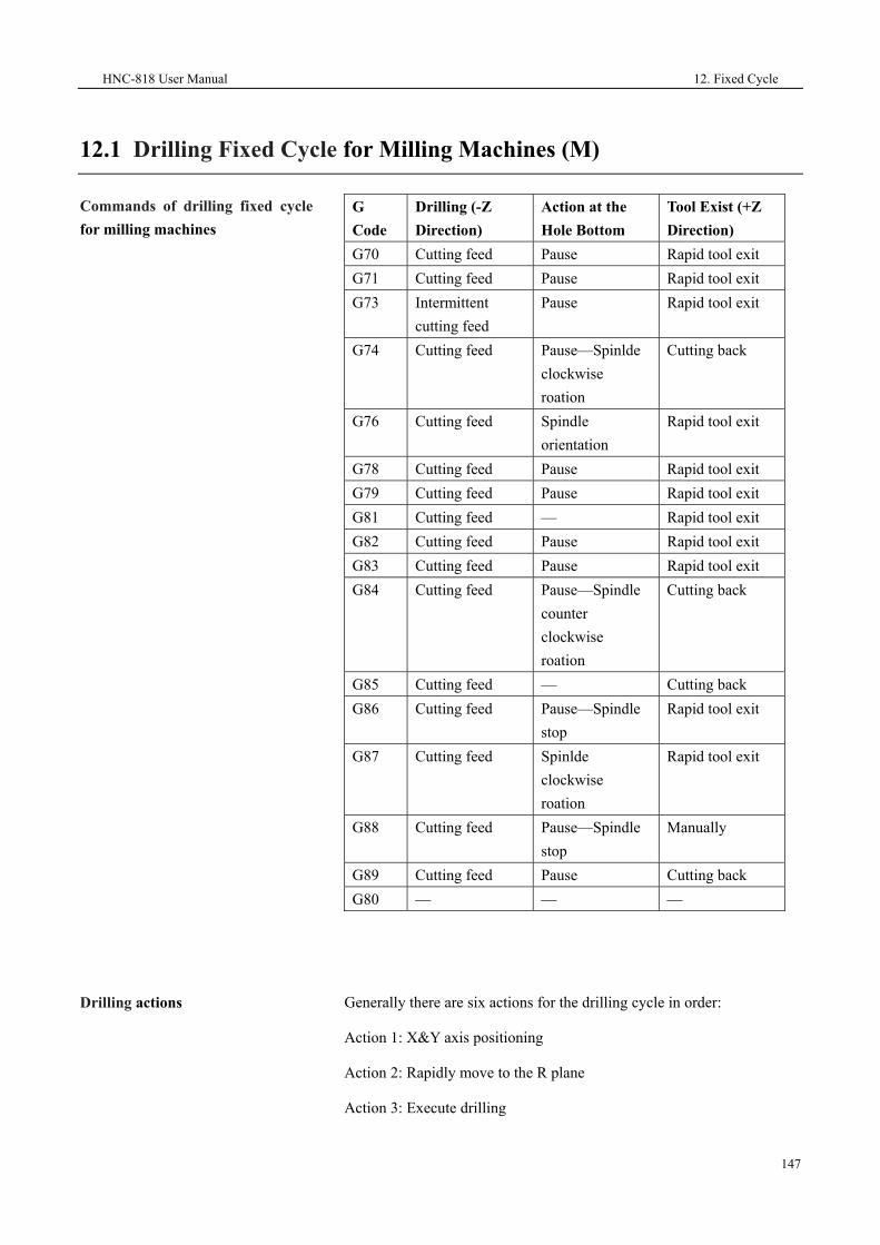
HNC-818 User Manual 12. Fixed Cycle
147
12.1 Drilling Fixed Cycle for Milling Machines (M)
Commands of drilling fixed cycle for milling machines
G Code
Drilling (-Z Direction)
Action at the Hole Bottom
Tool Exist (+Z Direction)
G70 Cutting feed Pause Rapid tool exit G71 Cutting feed Pause Rapid tool exit G73 Intermittent
cutting feed Pause Rapid tool exit
G74 Cutting feed Pause—Spinlde clockwise roation
Cutting back
G76 Cutting feed Spindle orientation
Rapid tool exit
G78 Cutting feed Pause Rapid tool exit G79 Cutting feed Pause Rapid tool exit G81 Cutting feed — Rapid tool exit G82 Cutting feed Pause Rapid tool exit G83 Cutting feed Pause Rapid tool exit G84 Cutting feed Pause—Spindle
counter clockwise roation
Cutting back
G85 Cutting feed — Cutting back G86 Cutting feed Pause—Spindle
stop Rapid tool exit
G87 Cutting feed Spinlde clockwise roation
Rapid tool exit
G88 Cutting feed Pause—Spindle stop
Manually
G89 Cutting feed Pause Cutting back G80 — — —
Drilling actions
Generally there are six actions for the drilling cycle in order:
Action 1: X&Y axis positioning
Action 2: Rapidly move to the R plane
Action 3: Execute drilling

12. Fixed Cycle HNC-818 User Manual
148
Action 4: Operations at the hole bottom
Action 5: Exit the tool to the R plane
Action 6: Rapidly exit the tool to the initial Z plane
Locate plane G17 plane (X, Y axis)
Drilling axis Z axis
Drilling data
G73, G74, G76 and the codes from G81 to G89 are modal G codes, which are valid before they are canceled. The parameters defined in these drilling cycle commands are modal data, which indicates that the parameters are valid before they are canceled.
Return to the reference plane G99
The G99 command can be used to return to the reference point plane specified by the R parameter after the fixed cycle is ended.
Operation 1 Intital level
R Level
Operation 6
Operation 4 Rapid traverse Feed
Operation 5
Operation 2
Operation 3
Initial plane
R level

HNC-818 User Manual 12. Fixed Cycle
149
Return to the start plane G98
The G98 command can be used to return to the start plane where the fixed cycle is commanded after the fixed cycle is ended. G98 is the initial modal G code of Group 15.
Cancle the fixed cycle G80 or the G codes of Group 01 can be used to cancle the fixed cycel.
Symbol description
Attention
1. When the fixed cycle program lines without X, Y, Z axis movement command are executed, the tool will not move, but the cycle parameter modal value of the current lines will be saved.
2. Specifying the G code of Group 1 or G80 will cancel the current fixed cycle G code modal, and also clear the cycle parameter modal value.
3. If you need to execute the fixed cycle repeatedly by specifying L, an alarm will be reported when L is set to 0.
Positioning (rapid traverse G00)
Cutting feed (linear interpolation G01)
Manual feed
P Dwell
Initial plane
R level

12. Fixed Cycle HNC-818 User Manual
150
4. When the G53 command is specified in a fixed cycle block, its positioning data (X, Y) is still the original workpiece coordinate system data, but not the coordinate system data specified by G53.
Example: Use Φ10 drilling bit to drill the holes shown in the figure below:
Program example
%5647
G54
G90 X0 Y0 Z80
M3 S1000;
G90 G99 G81 X300 Y-250 Z-150 R-120 F120; Position, drill hole 1, return to the point of R
Y-550; Position, drill hole 2, return to the point of R
Y-750; Position, drill hole 3, return to the point of R
X1000; Position, drill hole 4, return to the point of R
Y-550; Position, drill hole 5, return to the point of R
G98 Y-750; Position, drill hole 6, return the initial plane
G80 G28 G91 X0 Y0 Z0; Cancel the fixed cycle and return to the reference point
M5;
M30
—150Z—
X+
X+
Y—
—250
1000
—550
—750
300

HNC-818 User Manual 12. Fixed Cycle
151
12.1.1 Circumference Drilling Cycle (G70)
Description
In the circumference with the radius I and the center being the coordinate (X, Y). Divide the circle into N equal parts based on the angle J and the X axis. Conduct drilling for N holes. Execute fixed cycle of G81 and G83 based on the value of Q, K for each hole. The movement between holes is performed through G00. G70 is a modal code, and the command word following it is non-modal.
Format
(G98 / G99) G70 X_ Y_ Z_ R_ I_ J_ N_[Q_K_P]_ F_ L_
G98
Initial point B
Reference point R
Q
Q
Q
k
k
Hole bottom point Z
G99
Delay at the hole bottom for P seconds
Hole bottom point Z
Initial point B
Reference point R
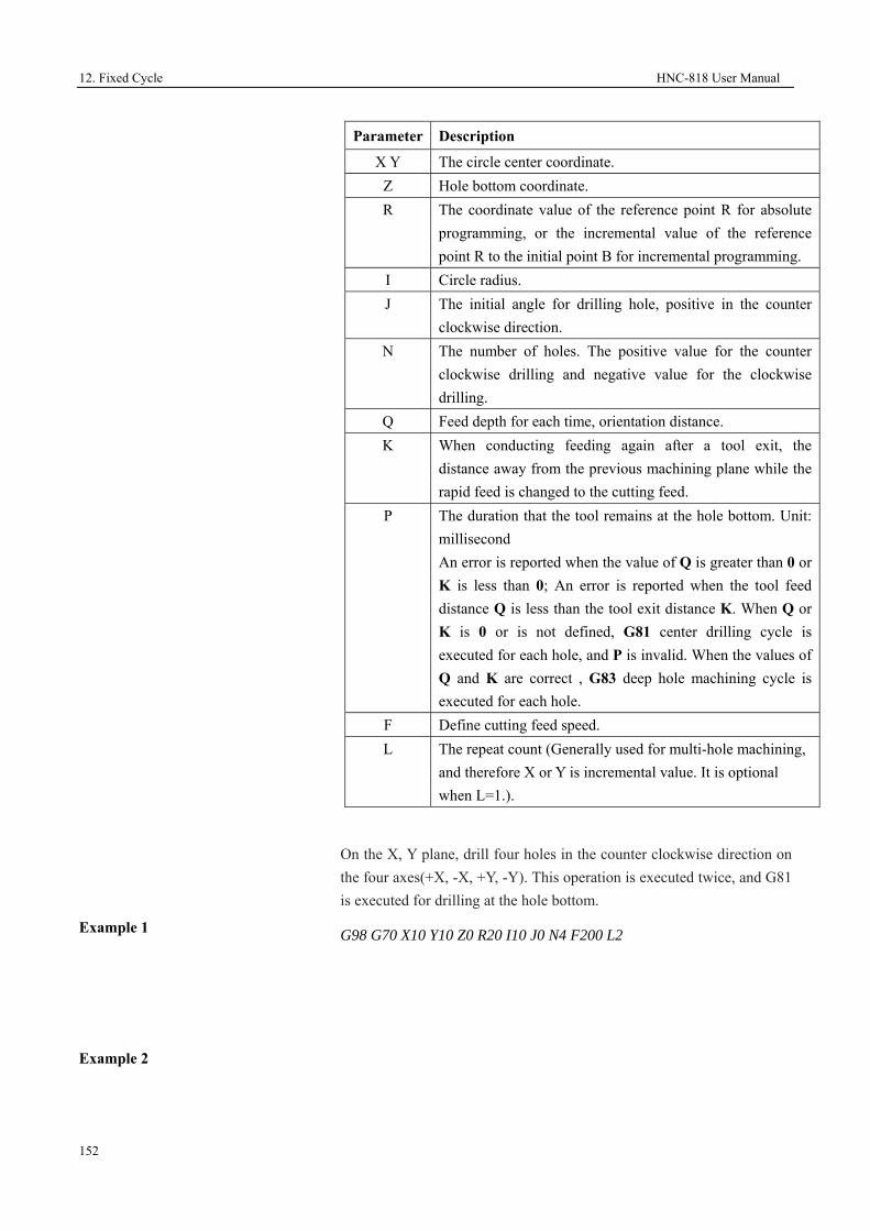
12. Fixed Cycle HNC-818 User Manual
152
Example 1
On the X, Y plane, drill four holes in the counter clockwise direction on the four axes(+X, -X, +Y, -Y). This operation is executed twice, and G81 is executed for drilling at the hole bottom.
G98 G70 X10 Y10 Z0 R20 I10 J0 N4 F200 L2
Example 2
Parameter Description
X Y The circle center coordinate. Z Hole bottom coordinate. R The coordinate value of the reference point R for absolute
programming, or the incremental value of the reference point R to the initial point B for incremental programming.
I Circle radius. J The initial angle for drilling hole, positive in the counter
clockwise direction. N The number of holes. The positive value for the counter
clockwise drilling and negative value for the clockwise drilling.
Q Feed depth for each time, orientation distance. K When conducting feeding again after a tool exit, the
distance away from the previous machining plane while the rapid feed is changed to the cutting feed.
P The duration that the tool remains at the hole bottom. Unit: millisecond An error is reported when the value of Q is greater than 0 or K is less than 0; An error is reported when the tool feed distance Q is less than the tool exit distance K. When Q or K is 0 or is not defined, G81 center drilling cycle is executed for each hole, and P is invalid. When the values of Q and K are correct , G83 deep hole machining cycle is executed for each hole.
F Define cutting feed speed. L The repeat count (Generally used for multi-hole machining,
and therefore X or Y is incremental value. It is optional when L=1.).

HNC-818 User Manual 12. Fixed Cycle
153
On the X, Y plane, drill four holes in the clockwise direction with thangle of 45 degrees. This operation is
executed once, and G81 is executed for drilling at the hole bottom.
G99 G70 X10 Y10 Z10 R50 I10 J45 N-4 F200
Example 3
On the X, Y plane, drill four holes in the clockwise direction, with the angle of -45 degrees. This operation is executed once, and G81 is executed for drilling at the hole bottom.
G99 G70 X10 Y10 Z10 R50 I10 J-45 N-4 F200
Example 4
On the X, Y plane, drill four holes in the clockwise direction with the angle of -45 degrees. This operation is executed once. The value of Q is invalid, and G81 is executed for drilling at the hole bottom.
G99 G70 X10 Y10 Z10 R50 I10 J-45 N-4 Q-10 F200
Example 5
Example 6
On the X, Y plane, drill four holes in the clockwise direction with the angle of -45 degrees. This operation is executed once, and G81 is executed for drilling at the hole bottom.
G99 G70 X10Y10Z10R50 I10J-45N-4 Q0 F200
G99 G70 X10Y10Z10R50 I10J-45N-4 K0 F200
G99 G70 X10Y10Z10R50 I10J-45N-4 Q0K0 F200
On the X, Y plane, drill four holes in the clockwise direction with the angle of -45 degrees. This operation is executed once, and G83 is executed for deep hole cycle.
G99 G70 X10Y10Z10R50 I10J-45N-4 Q-10 K5 F200
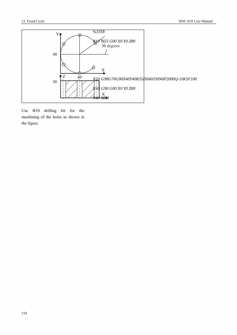
12. Fixed Cycle HNC-818 User Manual
154
Use Φ10 drilling bit for the machining of the holes as shown in the figure.
%3358
N10 G55 G00 X0 Y0 Z80
N20 G98G70G90X40Y40R35Z0I40J30N6P2000Q-10K5F100
N30 G90 G00 X0 Y0 Z80
N40 M30
30 Z
X
X
Y
40
40
30 degrees

HNC-818 User Manual 12. Fixed Cycle
155
12.1.2 Arc Drilling Cycle (G71)
Decription
In the circumference with the radius
I and the center being the coordinate (X, Y). Divide the circle into N equal parts based on the angle J and the X axis. Conduct drilling for N holes per O degrees, starting from the point where the angle from the A axis is J. Execute fixed cycle of G81 or G83 based on the value of Q, K for each hole. The movement between holes is performed through G00. G71 is a modal code, and the command following it is non-modal.
Foramt
(G98/G99) G71 X_ Y_ Z_ R_ I_ J_ O_ N[Q_K_P] _ F_ L_
Parameter Description
X Y The center coordinate for the arc. Z Hole bottom coordinate. R The coordinate value of the reference point R for
absolute programming, or the incremental value of the reference point R to the initial point B for incremental programming.
I Arc radius. J The initial drilling hole angle, positive in the counter
clockwise direction O The angle between each hole. The positive value for the
counter clockwise drilling and negative value for the clockwise drilling.
N The number of holes, including the start hole. Q Feed depth for each time, orientation distance. K When conducting feeding again after a tool exit, the
distance away from the previous machining plane while the rapid feed is changed to the cutting feed.
P The duration that the tool remains at the hole bottom. Unit: millisecond An error is reported when Q is greater than 0 or K is less than 0; An error is reported when the tool feed distance Q is less than the tool exit distance K. When Q or K is 0 or is not defined, execute G81 center drilling cycle for each hole, and P is invalid. When the values of Q and K are correct, G83 deep hole machining cycle is executed for each hole and P is valid.
F Define cutting feed speed.
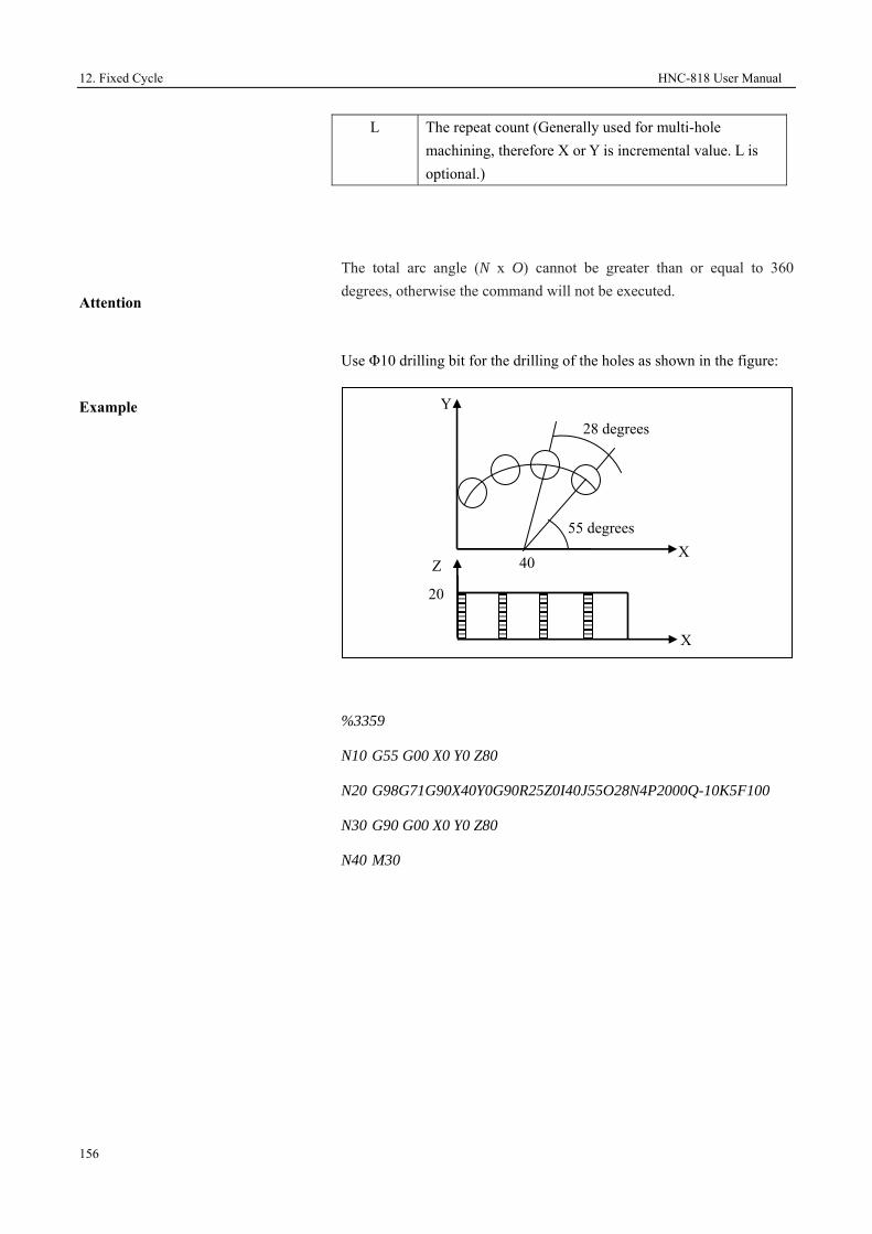
12. Fixed Cycle HNC-818 User Manual
156
Attention
Example
The total arc angle (N x O) cannot be greater than or equal to 360 degrees, otherwise the command will not be executed.
Use Φ10 drilling bit for the drilling of the holes as shown in the figure:
%3359
N10 G55 G00 X0 Y0 Z80
N20 G98G71G90X40Y0G90R25Z0I40J55O28N4P2000Q-10K5F100
N30 G90 G00 X0 Y0 Z80
N40 M30
L The repeat count (Generally used for multi-hole machining, therefore X or Y is incremental value. L is optional.)
20
Z
X
X
Y
40
28 degrees
55 degrees

HNC-818 User Manual 12. Fixed Cycle
157
12.1.3 High-Speed Deep-Hole Drilling Cycle (G73)
Example
The fixed cycle is used for the intermittent feed along Z axis, which is prone to chip-breaking, chip-removal, coolant adding, and small amount of tool exit. It is applicable for high-speed deep-hole drilling.
The figure below shows the operation action sequence of G73. The dotted line represents rapid positioning, q represents each feed depth, and k represents each tool exit value.
Format
(G98/G99) G73 X_ Y_ Z_ R_ Q_ P_ K_ F_ L_;
Parameter Description
X Y The coordinate value of the hole center in the XY plane for absolute programming (G90), or the incremental value of the hole center to the start point in the XY plane for incremental programming (G91).
Z The coordinate value of the hole bottom point Z for absolute programming (G90), or the incremental value of the hole bottom point Z to the reference point R for incremental programming (G91).
R The coordinate value of the reference point R for absolute programming (G90), or the incremental value of the reference point R to the initial point B for incremental programming (G91).
Q Drilling depth for each time (incremental value, negative).
P The duration that the tool remains at the hole bottom. Unit: millisecond.
G9
Initial plane
Point R
q
q
q
k
k
Point Z
Plane of point R Point R
q
q
q
k
k G99
Point Z
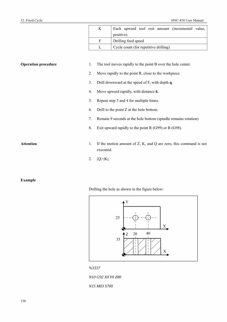
12. Fixed Cycle HNC-818 User Manual
158
Operation procedure
1. The tool moves rapidly to the point B over the hole center.
2. Move rapidly to the point R, close to the workpiece.
3. Drill downward at the speed of F, with depth q.
4. Move upward rapidly, with distance k.
5. Repeat step 3 and 4 for multiple times.
6. Drill to the point Z at the hole bottom.
7. Remain 9 seconds at the hole bottom (spindle remains rotation)
8. Exit upward rapidly to the point R (G99) or B (G98).
Attention
1. If the motion amount of Z, K, and Q are zero, this command is not executed.
2. |Q|>|K|;
Example
Drilling the hole as shown in the figure below:
%3337
N10 G92 X0 Y0 Z80
N15 M03 S700
K Each upward tool exit amount (incremental value, positive).
F Drilling feed speed L Cycle count (for repetitive drilling)
25
40 20 35
Y
X
Z
X

HNC-818 User Manual 12. Fixed Cycle
159
N20 G00 Y25
N30 G98 G73 G91 X20 G90 R40 P2000 Q-10 K2 Z-3 L2 F80
N40 G00 X0 Y0 Z80
N45 M30
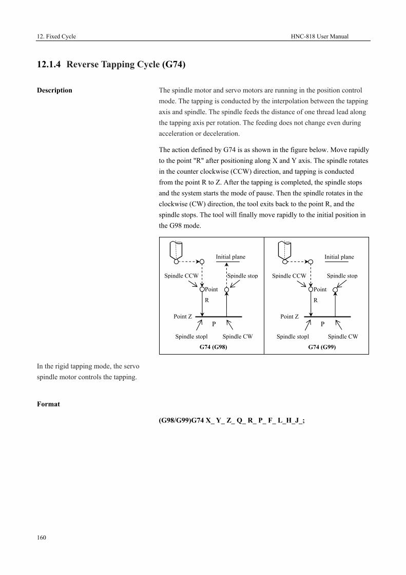
12. Fixed Cycle HNC-818 User Manual
160
12.1.4 Reverse Tapping Cycle (G74)
Description
In the rigid tapping mode, the servo spindle motor controls the tapping.
The spindle motor and servo motors are running in the position control mode. The tapping is conducted by the interpolation between the tapping axis and spindle. The spindle feeds the distance of one thread lead along the tapping axis per rotation. The feeding does not change even during acceleration or deceleration.
The action defined by G74 is as shown in the figure below. Move rapidly to the point "R" after positioning along X and Y axis. The spindle rotates in the counter clockwise (CCW) direction, and tapping is conducted from the point R to Z. After the tapping is completed, the spindle stops and the system starts the mode of pause. Then the spindle rotates in the clockwise (CW) direction, the tool exits back to the point R, and the spindle stops. The tool will finally move rapidly to the initial position in the G98 mode.
Format
(G98/G99)G74 X_ Y_ Z_ Q_ R_ P_ F_ L_H_J_;
G74 (G98)
Spindle CCW
Point
R
Point ZP
Spindle stopl Spindle CW
Initial plane
G74 (G99)
Spindle CCW
Point
R
Point Z P
Spindle stopl Spindle CW
Initial plane
Spindle stop Spindle stop

HNC-818 User Manual 12. Fixed Cycle
161
F (feed speed) during tapping
During rigid tapping, the feed speed
(F) specified in the programming is invalid. The feed speed along the tapping axis is derived from: speed feed = spindle speed x thread lead
Tapping mode
C axis tapping: take the servo spindle as the C axis, and conduct tapping by interpolation, to achieve high-speed high-precision tapping.
Attention
1. The tapping axis must be the Z axis.
2. The point Z must be lower than the plane of point R; otherwise, an alarm will be reported.
Parameter Description X Y The absolute position of the hole for absolute
programming (G90), or the distance from the current tool position to the hole for incremental programming (G91).
Z The absolute position of the hole bottom for absolute programming (G90), or the distance from the hole bottom to the point R for incremental programming (G91).
Q The amount of each feed during segment tapping. Leave it blank in the H2 mode.
Parameter Description R The absolute position of the point R for absolute
programming (G90), or the distance from the point R to the initial plane for incremental programming (G91).
P The duration that the tool remains at the hole bottom. Unit: millisecond.
F Define thread lead. H H1: segment tapping, exits to the R plane each time.
H2: directly drills to the hole bottom. L Repeat count (It is optional when L=1.) J J1: A axis tapping; J2: B axis tapping; J3 C: axis
tapping

12. Fixed Cycle HNC-818 User Manual
162
3. The G74 command data is saved as modal data.
4. When the motion amount of Z is zero, the cycle is not executed.
5. During reverse tapping, the operations on feed rate adjustment, spindle rate adjustment, and feed hold is invalid.
6. Before specifying reverse tapping with G74, change the control mode of the spindle servo motor from speed control to the position control by using the STOC command. After tapping, you may use the CTOS command to change back to the speed control mode and take the servo spindle as a common spindle.
7. Before specifying reverse tapping with G74, use the corresponding M command to rotate the spindle in the counter
Example
clockwise direction.
8. After executing the rigid tapping with G74, the programmer must restore the original feed speed; otherwise, the feed speed will be the rigid tapping speed (s*pitch).
Use M10 x 1 for anti-tapping
%3339
G92 X0 Y0 Z80 F200
M04 S300
STOC
G98G74X50Y40R40P10000G90Z-5F1
CTOS
50 35
Y
X
Z
X

HNC-818 User Manual 12. Fixed Cycle
163
G0 X0 Y0 Z80
M30

12. Fixed Cycle HNC-818 User Manual
164
12.1.5 Fine-Boring Cycle (G76)
Description
During finish boring, after the spindle stops orientation at the hole bottom, it moves away from the tool nose, then the tool quickly exits. The value of movement away from the tool nose is specified by (I, J), which can only be positive. The value of (I, J) is modal, and the movement direction is determined during tool installation.
Format
(G98/G99) G76 X_ Y_ Z_ R_ I_ J_ P_ F_ L_;
Parameter Description X Y The absolute position of the hole for absolute
programming (G90), or the distance from the current tool position to the hole for incremental programming (G91). UW programming is not supported.
Z The absolute position of the hole bottom along Z axis for absolute programming (G90), or the distance from the hole bottom to the point R for incremental programming (G91).
R The absolute position of the point R along Z axis for absolute programming (G90), or the distance from the point R to the initial plane for incremental programming (G91).
I Offset value along X axis, positive only. J Offset value along Y axis, positive only.
P The duration that the tool remains at the hole bottom. Unit: millisecond.
F Cutting feed speed. L Repeat count (It is optional when L=1.)
Offset value (I, J)
Point Z
Point RG98
Initial plane
Offset value (I, J)
Point Z
Point R
G99
Plane of point R

HNC-818 User Manual 12. Fixed Cycle
165
Operation procedure
1. The tool moves rapidly to the point B over the hole center.
2. Move rapidly to the point R, close to the workpiece.
3. Conduct boring downward at the speed of F, to the point Z at the hole bottom.
4. Remain at the hole bottom for P seconds (The spindle remains rotation).
5. The spindle conducts orientation and stops rotation.
6. The boring tool rapidly moves away form the tool nose with the distance specified by I or J.
7. Exit upward rapidly to the point R (G99) or B G98).
8. Move rapidly in the positive direction of the tool nose with the distance specified by I or J, and the tool moves back to the point R or B over the hole center.
9. The spindle restores the clockwise rotation.
Attention
1. The boring axis must be the Z axis.
2. The point Z must be lower than the plane of point R; otherwise, an alarm will be reported.
3. The G76 command data is saved as modal data.
4. Before using the command of G76, use the corresponding M command to rotate the spindle.
Example

12. Fixed Cycle HNC-818 User Manual
166
Use the single-margin boring tool.
%3341
N10 G54
N12 M03 S600
N15 G00 X0 Y0 Z80
N20 G98G76X20Y15R40P2000I5Z-4F100
N25 X40Y30
N30 G00 G90 X0 Y0 Z80
N40 M30
15
40 20 35
Y
X
Z
X
30

HNC-818 User Manual 12. Fixed Cycle
167
12.1.6 Angular Linear Drilling Cycle (G78)
Description
Divide the oblique line which rotates J degrees around axis X into N holes with the interval distance of I. Starting from the point defined by X, Y, conduct the drilling cycle for each hole. Execute G81 and G83 fixed cycle based on the value of Q, K for each hole. The movement between holes is conducted through G00. G78 is a modal code, and the command following it is non-modal.
Format
(G98/G99) G78 X_ Y_ Z_ R_ I_ J_ N_[Q_K_P]_ F_ L_
Parameter Description
X Y The coordinate of the first hole. Z The coordinate of the hole bottom. R The absolute position of the reference point R for
absolute programming (G90), or the distance from the reference point R to the initial point B for incremental programming (G91).
I The distance between two successive hole centers. J The start angle formed by the oblique line and the
positive X axis, which is positive in the counter clockwise direction.
N The number of holes including the start hole. Q Feed depth for each time, orientation distance. K When conducting feeding again after a tool exit, the
distance away from the previous machining plane while the rapid feed is changed to the cutting feed.
P The duration that the tool remains at the hole bottom. Unit: millisecond An error is reported when Q is greater than 0 or K is less than 0; An error is reported when the tool feed distance Q is less than the tool exit distance K. When Q or K is 0 or is not defined, execute G81 center drilling cycle for each hole, and P is invalid. When the values of Q and K are corrective, execute G83 deep hole machining cycle for each hole, and P is valid.
F Define cutting feed speed. L The repeat count (Generally used for multi-hole
machining,and therefore X or Y is incremental value. (It is optional when L=1.)

12. Fixed Cycle HNC-818 User Manual
168
Example
Use Φ10 drilling bit to drill the holes as shown in the figure:
%3360
N10 G55 G00 X0 Y0 Z80
N20 G98G78G90X20Y10G90R15Z0I20J30N3P2000Q-10K5F100
N30 G90 G00 X0 Y0 Z80
N40 M30
10
Z
X
X
Y
20
20
30 degrees 10

HNC-818 User Manual 12. Fixed Cycle
169
12.1.7 Chessboard Drilling Cyle (Drilling along X Axis First) (G79)
Description
Starting from the point defined by X, Y, conduct drilling for N holes in the direction parallel to the X-axis with the interval distance of I. Then conduct drilling in the direction of the X axis with an interval specified by J along the Y axis. This operation is repeated for O times. Execute G81 and G83 fixed cycle based on the value of Q, K for each hole. The movement between holes is performed through G00. G79 is a modal code, and the command following it is non-modal.
Format
(G98/G99) G79 X_ Y_ Z_ R_ I_ N_ J_ O_[Q_K_P]_ F_ L_
Parameter Description
X Y The coordinate of the first hole. Z The coordinate of the hole bottom. R The coordinate value of the reference point R for absolute
programming (G90), or the incremental value of the reference point R to the initial point B for incremental programming (G91).
I The distance between two successive hole centers in the X axis direction. The positive value indicates the drilling along the positive X axis direction while the negative value indicates the drilling along the negative X axis direction.
N The number of holes including the start hole in the X axis direction.
J The distance between two successive hole centers in the Y axis direction. The positive value indicates the drilling along the positive Y axis direction while the negative value indicates the drilling along the negative Y axis direction.
O The number of holes including the start hole in the Y axis direction.
Q Feed depth for each time, orientation distance. K When conducting feeding again after a tool exit, the
distance away from the previous machining plane while the rapid feed is changed to the cutting feed.

12. Fixed Cycle HNC-818 User Manual
170
Example
Use Φ10 drilling bit for the drilling of the holes as shown in the figure:
%3361
N10 G55 G00 X0 Y0 Z80
N20 G98G79G90X20Y20G90R25Z0I15N3J15O3P2000Q-10K5F100
N30 G90 G00 X0 Y0 Z80
N40 M30
P The duration that the tool remains at the hole bottom. Unit: millisecond An error is reported when Q is greater than 0 or K is less than 0; An error is reported when the tool feed distance Q is less than the tool exit distance K. When Q or K is 0 or is not defined, execute G81 center drilling cycle for each hole, and P is invalid. When the values of Q and K are correct, execute G83 deep hole machining cycle for each hole, and P is valid.
F Define cutting feed speed. L The repeat count (Generally used for multi-hole machining,
therefore X or Y is incremental value. It is optional when L=1.)
20
Z
X
X
Y
20
15
20
15
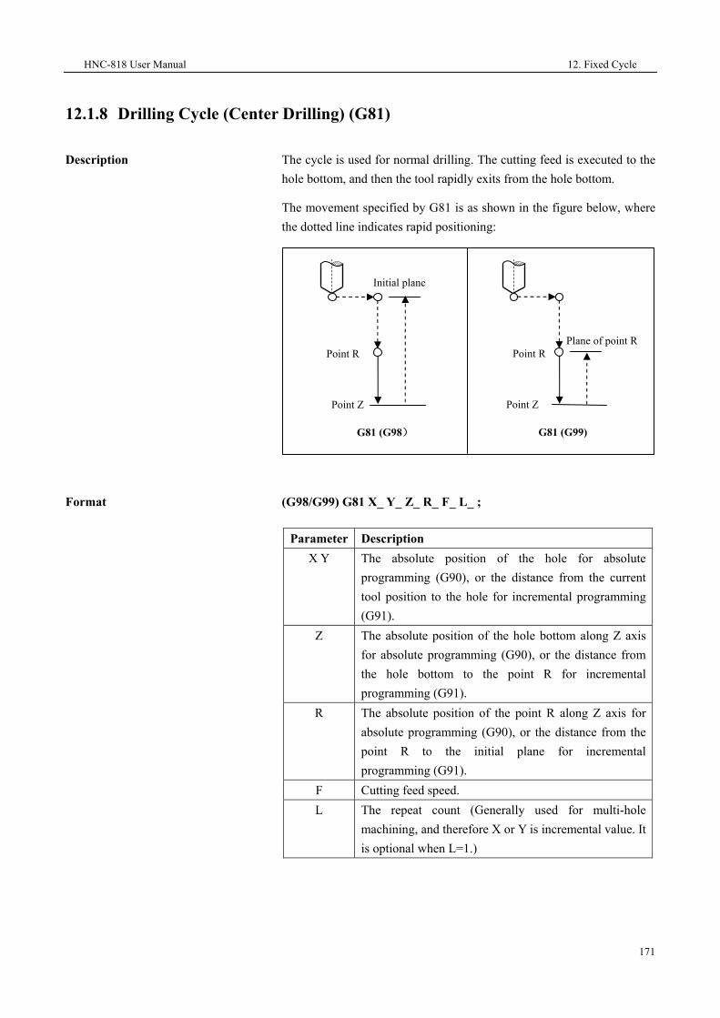
HNC-818 User Manual 12. Fixed Cycle
171
12.1.8 Drilling Cycle (Center Drilling) (G81)
Description
The cycle is used for normal drilling. The cutting feed is executed to the hole bottom, and then the tool rapidly exits from the hole bottom.
The movement specified by G81 is as shown in the figure below, where the dotted line indicates rapid positioning:
Format
(G98/G99) G81 X_ Y_ Z_ R_ F_ L_ ;
Parameter Description X Y The absolute position of the hole for absolute
programming (G90), or the distance from the current tool position to the hole for incremental programming (G91).
Z The absolute position of the hole bottom along Z axis for absolute programming (G90), or the distance from the hole bottom to the point R for incremental programming (G91).
R The absolute position of the point R along Z axis for absolute programming (G90), or the distance from the point R to the initial plane for incremental programming (G91).
F Cutting feed speed. L The repeat count (Generally used for multi-hole
machining, and therefore X or Y is incremental value. It is optional when L=1.)
Initial plane
Point R
Point Z
G81 (G98)
Plane of point RPoint R
Point Z
G81 (G99)

12. Fixed Cycle HNC-818 User Manual
172
Operation procedure
1. The tool moves rapidly to the point B over the hole center.
2. Move rapidly to the point R, close to the workpiece.
3. Conduct drilling downward at the speed of F, to the point Z at the hole bottom.
4. The spindle remains the rotation and moves upward rapidly to the point R (G99) or B (G98).
Attention
1. If the movement amount of Z is zero, the command is not executed.
2. The drilling axis must be the Z axis.
3. The G81 command data is saved as modal data.
4. Before using the command of G81, use the corresponding M command to rotate the spindle.
Example
Conduct drilling of the holes as shown in the figure below:
%3343
N10 G92 X0 Y0 Z80
N15 M03 S600
N20 G98 G81 G91 X20 Y15 G90 R20 Z-3 L2 F200
N30 G00 X0 Y0 Z80
N40 M30
15
2015
Y
X
Z
X
30

HNC-818 User Manual 12. Fixed Cycle
173
12.1.9 Drilling Cycle with Pause (G82)
Description
This instruction is mainly used for processing sink holes, blind holes, to improve the hole depth precision. Except for the pause at the hole bottom, other operations are similar as that of G81. The figure below shows the operation of G82:
Format
(G98/G99) G82 X_ Y_ Z_ R_ P_ F_ L_;
Parameter Description X Y The absolute position of the hole for absolute
programming (G90), or the distance from the current tool position to the hole for incremental programming (G91).
Z The absolute position of the hole bottom along Z axis for absolute programming (G90), or the distance from the hole bottom to the point R for incremental programming (G91).
R The absolute position of the point R for absolute programming (G90), or the distance from the point R to the initial plane for incremental programming (G91).
P The duration that the tool remains at the hole bottom. Unit: millisecond
F Cutting feed speed. L The repeat count (Generally used for multi-hole
machining to simplify programming. It is optional when L=1.)
Initial plane
Point R
Point Z
G82 (G98)
Plane of point R Point R
Point Z
G82 (G99)
Pause Pause

12. Fixed Cycle HNC-818 User Manual
174
Operation procedure
1. The tool moves rapidly to the point B over the hole center.
2. Move rapidly to the point R, close to the workpiece.
3. Conduct drilling downward at the speed of F, to the point Z at the hole bottom.
4. Delay P milliseconds with the rotation of the spindle.
5. Move upward rapidly to the point R (G99) or B (G98).
Attention
1. The drilling axis must be the Z axis.
2. If the movement amount of Z is zero, the command is not executed.
3. The G82 command data is saved as modal data.
4. Before using the command of G82, use the corresponding M command to rotate the spindle.
Example
Conduct drilling of the hole as shown in the figure below:
%3345
N10 G92 X0 Y0 Z80
N15 M03 S600
N20 G98 G82 G90 X25 Y30 R40 P2000 Z25 F200
N30 G00 X0 Y0 Z80
4
35
X
Z
Φ12
90 degrees

HNC-818 User Manual 12. Fixed Cycle
175
N40 M30

12. Fixed Cycle HNC-818 User Manual
176
12.1.10 Deep-Hole Drilling Cycle (G83)
Description
The fixed cycle is used for the intermittent feed along Z axis, which enables a rapid tool exit to the reference point R with larger retract amount after each drilling,.It facilitates the chip-removal and coolant adding. The figure below shows the operation specified by G83:
Format
(G98/G99) G83 X_ Y_ Z_ R_ Q_ K_ F_ L_ P_;
Parameter Description
X Y The absolute position of the hole for absolute programming (G90), or the distance from the current tool position to the hole for incremental programming (G91).
Z The absolute position of the hole bottom for absolute programming (G90), or the distance from the hole bottom to the point R for incremental programming (G91).
R The absolute position of the point R for absolute programming (G90), or the distance from the point R to the initial plane for incremental programming (G91).
Q The each downward drilling depth (incremental value, negative).
K The distance away from the upper surface of drilled hole (incremental value, positive). K cannot be greater than Q.
F Cutting feed speed.
L The repeat count (Generally used for multi-hole machining to simplify programming. It is optional when L=1.)
P The duration that the tool remains at the hole bottom. Unit: millisecond
Initial plane
Point Z
Point R
q
q
q
k
kG98
Plane of point R
Point Z
Point R
q
q
q
k
kG99

HNC-818 User Manual 12. Fixed Cycle
177
Operation procedure
1. The tool moves rapidly to the point B over the hole center.
2. Move rapidly to the point R, close to the workpiece.
3. Drill downward at the speed of F, with depth q.
4. Move upward rapidly to the point R.
5. Move downward rapidly to the upper surface of the drilled hole, the distance is specified with K.
6. Drill downward at the speed of F, with depth (q + k).
7. Repeat the step 4, 5, and 6, and then drills to the hole bottom Z point.
8. Delay P milliseconds at the hole bottom (spindle remains rotation).
9. Exit upward rapidly to the point R (G99) or B (G98).
Attention
1. The drilling axis must be the Z axis.
2. If the movement amount of Z, Q, and K are zero, the command is not executed.
3. The G83 command data is saved as modal data.
4. Before using the command of G83, use the corresponding M command to rotate the spindle.
Example
Conduct drilling of the hole as shown in the figure below:

12. Fixed Cycle HNC-818 User Manual
178
%3347
N10 G55 G00 X0 Y0 Z80
N15 Y25
N20 G98G83G91X20G90R40P2Q-10K5G91Z-43F100L2
N30 G90 G00 X0 Y0 Z80
N40 M30
25
40 20 35
Y
X
Z
X

HNC-818 User Manual 12. Fixed Cycle
179
12.1.11 Tapping Cycle (G84)
Description
The command G84 and G74 works
on the same principle. In the G84 mode, the tool taps to the hole bottom with the spindle rotation in the clockwise direction and then goes back with the spindle rotation in the counter clockwise direction. See the figure below:
Format
G84 X_ Y_ Z_ R_ Q_ P_ F_ L_H_J_;
Parameter Description X Y The absolute position of the hole for absolute
programming (G90), or the distance from the current tool position to the hole for incremental programming (G91).
Z The absolute position of the hole bottom for absolute programming (G90), or the distance from the hole bottom to the point R for incremental programming (G91).
R The absolute position of the point R for absolute programming (G90), or the distance from the point R to the initial plane for incremental programming (G91).
Q The amount of each feed during segment tapping. Leave it blank in the H2 mode.
P The duration that the tool remains at the hole bottom. Unit: millisecond.
F Define thread lead.
G84 (G98)
Spindle CW
Point
R
Point ZP
Spindle stop Spindle CCW
Initial plane
G84 (G99)
Spindle CW
Point
R
Point Z P
Spindle stop Spindle CCW
Initial plane
Spindle stop Spindle stop
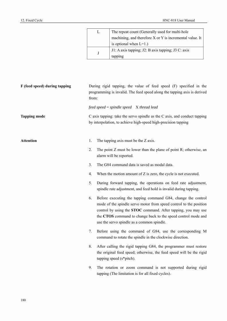
12. Fixed Cycle HNC-818 User Manual
180
F (feed speed) during tapping
During rigid tapping, the value of feed speed (F) specified in the programming is invalid. The feed speed along the tapping axis is derived from:
feed speed = spindle speed X thread lead
Tapping mode
C axis tapping: take the servo spindle as the C axis, and conduct tapping by interpolation, to achieve high-speed high-precision tapping
Attention
1. The tapping axis must be the Z axis.
2. The point Z must be lower than the plane of point R; otherwise, an alarm will be reported.
3. The G84 command data is saved as modal data.
4. When the motion amount of Z is zero, the cycle is not executed.
5. During forward tapping, the operations on feed rate adjustment, spindle rate adjustment, and feed hold is invalid during tapping.
6. Before executing the tapping command G84, change the control mode of the spindle servo motor from speed control to the position control by using the STOC command. After tapping, you may use the CTOS command to change back to the speed control mode and use the servo spindle as a common spindle.
7. Before using the command of G84, use the corresponding M command to rotate the spindle in the clockwise direction.
8. After calling the rigid tapping G84, the programmer must restore the original feed speed; otherwise, the feed speed will be the rigid tapping speed (s*pitch).
9. The rotation or zoom command is not supported during rigid tapping (The limitation is for all fixed cycles).
L The repeat count (Generally used for multi-hole machining, and therefore X or Y is incremental value. It is optional when L=1.)
J J1: A axis tapping; J2: B axis tapping; J3 C: axis tapping

HNC-818 User Manual 12. Fixed Cycle
181
Example
%3349
N10 G92 X0 Y0 Z80
N15 M03 S300
G108
N20 G98G84X0Y0Z-15R10P2000F1
G109
N30 G90 G0 X0 Y0 Z80
N40 M30

12. Fixed Cycle HNC-818 User Manual
182
12.1.12 Boring Cycle (G85)
Description
The command is used to bore the holes which have low requirement for precision. The operation specified by G85 is as shown below:
Format
(G98/G99) G85 X_ Y_ Z_ R_ F_ L_;
Parameter Description X Y The absolute position of the hole for absolute
programming (G90), or the distance from the current tool position to the hole for incremental programming (G91). UW programming is not supported.
Z The absolute position of the hole bottom for absolute programming (G90), or the distance from the hole bottom to the point R for incremental programming (G91).
R The absolute position of the point R for absolute programming (G90), or the distance from the point R to the initial plane for incremental programming (G91).
F Cutting feed speed. L The repeat count (Generally used for multi-hole
machining to simplify programming. It is optional when L=1.)
Operation procedure
1. The tool moves rapidly to the point B over the hole center.
2. Move rapidly to the point R, close to the workpiece.
Initial plane
Point R
Point Z
G85 (G98)
Plane of point RPoint R
Point Z
G85 (G99)

HNC-818 User Manual 12. Fixed Cycle
183
3. Conduct boring downward at the speed of F.
4. Move to the point Z at the hole bottom.
5. Exit upward rapidly to the point R (the spindle remains rotation).
6. Exit upward rapidly to the point B in the G98 mode.
Attention
1. The boring axis must be the Z axis.
2. The point Z must be lower than the plane of point R; otherwise, an alarm will be reported.
3. If the motion amount of Z, Q, and K are zero, the cycle is not executed.
4. The G85 command data is saved as modal data.
5. Before using the command of G85, use the corresponding M command to rotate the spindle.
Example
Conduct boring of the holes as shown in the figure below:
%3351
N10 G92 X0 Y0 Z80
N15 M03 S600
N20 G98 G85 G91 X20 Y15 G90 R20 Z-3 L2 F100
15
402015
Y
X
Z
X
30

12. Fixed Cycle HNC-818 User Manual
184
N30 G90 G00 X0 Y0 Z80
N40 M30

HNC-818 User Manual 12. Fixed Cycle
185
12.1.13 Boring Cycle (G86)
Description
The operation specified by G86 is similar as G81. In the G86 mode, the spindle stops at the hole bottom and the tool exits rapidly. The command is used to bore the holes which have low requirement for precision.
Format
(G98/G99) G86 X_ Y_ Z_ R_ F_ L_;
Parameter Description X Y The absolute position of the hole for absolute
programming (G90), or the distance from the current tool position to the hole for incremental programming (G91).
Z The absolute position of the hole bottom for absolute programming (G90), or the distance from the hole bottom to the point R for incremental programming (G91)
R The absolute position of the point R for absolute programming (G90), or the distance from the point R to the initial plane for incremental programming (G91).
F Cutting feed speed. L The repeat count (Generally used for multi-hole
machining to simplify programming. It is optional when L=1.)
Operation procedure
1. The tool moves rapidly to the point B over the hole center.
2. Move rapidly to the point R, close to the workpiece.
3. Conduct boring downward at the speed of F.
4. Reach the hole bottom of point Z.
5. The spindle stops rotation.
6. Exit upward rapidly to the point R (G99) or B (G98).
7. The spindle restores clockwise rotation.
Attention
1. If the movement amount of Z is zero, the command is not executed.
2. The G86 command data is saved as modal data.

12. Fixed Cycle HNC-818 User Manual
186
3. The boring axis must be the Z axis.
4. The point Z must be lower than the plane of point R; otherwise, an alarm will be reported.
Example
Conduct boring of the hole as shown in the figure below:
%3353; Reaming with a reamer
N10 G92 X0 Y0 Z80
N15 G98 G86 G90 X20 Y15 R20 Z-2 F200
N20 X40 Y30
N30 G90 G00 X0 Y0 Z80
N40 M30
15
402015
Y
X
Z
X
30

HNC-818 User Manual 12. Fixed Cycle
187
12.1.14 Anti-Boring Cycle(G87)
Description
The instruction is generally used to bore holes which are smaller at the upper part and larger at the lower part. The hole bottom point Z is generally above the reference point R, which is different from other instructions.
Format
(G98/G99) G87X_ Y_ Z_ R_ I_ J_ P_ F_ L_;
Parameter Description X Y The absolute position the hole for absolute
programming (G90), or the distance from the current tool position to the hole for incremental programming (G91).
Z The absolute position of the hole bottom along Z axis for absolute programming (G90), or the distance from the hole bottom to the point R for incremental programming (G91)
R The absolute position of the point R along Z axis for absolute programming (G90), or the distance from the point R to the initial plane for incremental programming (G91).
I Offset value along X axis. J Offset value along Y axis. P The duration that the tool remains at the hole bottom.
Unit: millisecond. F Cutting feed speed. L The repeat count (Generally used for multi-hole
Reverse offset (I, J)
Offset (I, J)
Point Z
Point R
Positioning point R
Initial point

12. Fixed Cycle HNC-818 User Manual
188
machining, and therefore X or Y is incremental value. It is optional when L=1.)

HNC-818 User Manual 12. Fixed Cycle
189
Operation procedure
1. The tool moves rapidly to the point B over the hole center.
2. The spindle conducts orientation and stops rotation.
3. The boring tool rapidly moves away from the tool nose with the distance specified by I or J.
4. Move rapidly to the point R.
5. Move rapidly in the positive direction of the tool nose with the distance specified by I or J, and the tool moves back to the hole center specified by X, Y.
6. The spindle rotates in the clockwise direction.
7. Conduct boring upward at the speed of F, to the point Z at the hole bottom.
8. Remain at the hole bottom for P milliseconds (The spindle remains rotation).
9. The spindle conducts orientation and stops rotation.
10. The boring tool rapidly moves away from the tool nose with the distance specified by I or J.
11. Exit upward rapidly to the point B (G98).
12. Move rapidly in the positive direction of the tool nose with the distance specified by I or J, and the tool moves back to the hole center point B.
13. The spindle restores the clockwise rotation.
Attention
1. The boring axis must be the Z axis.
2. If the movement amount of Z is zero, the command is not executed.
3. The point Z must be higher than the plane of point R; otherwise, an alarm will be reported.
4. The G87 command data is saved as modal data.
5. Only G98 can be used for G87.
6. Before using the command of G87, use the corresponding M command to rotate the spindle.

12. Fixed Cycle HNC-818 User Manual
190
Example
%3355
N10 G92 X0 Y0 Z80
N15 M03 S600
N20 G00 Y15 F200
N25 G98
G87 G91
X20 I5 R-83 P2000 Z23 L2
N30 G90 G00 X0 Y0 Z80 M05
N40 M30
X
Z
35 20
2×Φ28
2×Φ20 20 40
X
Y
15

HNC-818 User Manual 12. Fixed Cycle
191
12.1.15 Boring Cycle (Manual Boring) (G88)
Description
Before boring, this instruction memories the initial point B or reference point R. When the boring tool automatically processes to the hole bottom, the machine stops. You may manually change the operation mode to "Manual", and move the tool upward to the point B or R, and avoid the workpiece. Then the operation mode is changed back to the automatic operation mode. Start the program again, and the tool returns back to the point B or R. This instruction is generally used for precise boring with milling machines, without calling the spindle exact stop function.
Format
G98 (G99) G88 X_ Y_ Z_ R_ P_ F_ L_
Parameter Description X Y The absolute position of the hole for absolute
programming (G90), or the distance from the current tool position to the hole for incremental programming (G91).
Z The absolute position of the hole bottom along axis Z for absolute programming (G90), or the distance from the hole bottom to the point R for incremental programming (G91).
R The absolute position of the point R along Z axis for absolute programming (G90), or the distance from the point R to the initial plane for incremental programming (G91).
P The duration that the tool remains at the hole bottom. Unit: millisecond.
F Boring feed speed. L The repeat count (Generally used for multi-hole
machining, and therefore X or Y is incremental value.)
Initial point B
Reference point R
Reference point R
Hole bottom point
Z
Return to point
B; spindle CW
Return to point
R; spindle CW
G98G99
Hole bottom
point Z Remains at the hole bottom
and the spindle stops

12. Fixed Cycle HNC-818 User Manual
192
Operation procedure
1. The tool moves rapidly to the point B over the hole center.
2. Move rapidly to the point R, close to the workpiece surface.
3. Conduct boring downward at the speed of F, to the point Z at the hole bottom.
4. Remain at the hole bottom for P seconds (The spindle remains rotation).
5. The spindle stops rotation.
6. Manually move the tool until it is over the point R (G99) or B (G98).
7. Press Start in the auto operation mode, the tool rapidly moves to the point R (G99) or B (G98).
8. The spindle restores the clockwise rotation.
Attention
1. The boring axis must be the Z axis.
2. If the movement amount of Z is zero, the command is not executed.
3. The point Z must be lower than the plane of point R; otherwise, an alarm will be reported.
4. The G88 command data is saved as modal data.
5. If G99 is used, manually move the tool to the place over the point of R.
6. If G98 is used, manually move the tool to the place over the point of B.
7. Before using the command of G88, use the corresponding M command to rotate the spindle.

HNC-818 User Manual 12. Fixed Cycle
193
Example
%3357; Drilling with a single-margin boring tool
N10 G54
N12 M03 S600
N15 G00 X0 Y0 Z80
N20 G98G88G91X20Y15R-42P2000Z-40L2F100
N30 G00 G90 X0 Y0 Z80
N40 M30
15
402035
Y
X
Z
X
30

12. Fixed Cycle HNC-818 User Manual
194
12.1.16 Boring Cycle (G89)
Description
This cycle is used for boring.
This operation specified by the command G89 is almost the same as that of G86. In the G89 mode, the spindle pauses at the hole bottom. Before specifying G89, use auxiliary function the M command to rotate the spindle. When the G89 command and M command are specified in the same block, the system executes the M command while the first positioning movement is performing , and then conducts the next boring. If the repeat count L is specified, the system executes the M command only for the first boring hole.
The operation specified by G89 is as shown below:
Format
(G98/G99) G89 X_ Y_ Z_ R_ P_ F_ L;
Parameter Description X Y The absolute position of the hole for absolute
programming (G90), or the distance from the current tool position to the hole for incremental programming (G91).
Z The absolute position of the hole bottom for absolute programming (G90), or the distance from the hole bottom to the point R for incremental programming (G91).
R The absolute position of the point R for absolute programming (G90), or the distance from the point R to the initial plane for incremental programming (G91).
P The duration that the tool remains at the hole bottom. Unit: millisecond.
F Cutting feed speed.
Initial plane
Point R
Point Z
G89 (G98)
Plane of point RPoint R
Point Z
G89 (G99)
Pause Pause
Plane of point R

HNC-818 User Manual 12. Fixed Cycle
195
L The repeat count (Generally used for multi-hole machining, and therefore X or Y is an incremental value.)

12. Fixed Cycle HNC-818 User Manual
196
Attention
1. The boring axis must be the Z axis.
2. The point Z must be lower than the plane of point R; otherwise, an alarm will be reported.
3. The G89 command data is saved as modal data.
4. G89 is similar as G86, but with a pause at the hole bottom.
5. If the movement amount of Z is zero, this command is not executed.
6. Before using the command of G89, use the corresponding M command to rotate the spindle.
Example
M3 S1000; The spindle starts rotation.
G90 G99 G89 X300 Y-250 Z-150 R-120 P1000 F120; Conduct positioning, and conduct boring for hole 1, return to the point R and then pauses at the hole bottom for one second
Y-550; Conduct positioning, and conduct boring for hole 2; return to the point R
Y-750; Conduct positioning, and conduct boring for hole 3; return to the point R
X1000; Conduct positioning, and conduct boring for hole 4; return to the point R
Y-550; Conduct positioning, and conduct boring for hole 5; return to the point R
G98 Y-750; Conduct positioning, and conduct boring for hole 5; return to the initial plane
G80 G28 G91 X0 Y0 Z0; Cancel boring and return to the reference point
M5; The spindle stops rotation.

HNC-818 User Manual 12. Fixed Cycle
197
12.1.17 Cancel Fixed Cycle (G80)
Description This command is used to cancel the fixed cycle for drilling.
Format G80
Attention
1. Cancel all fixed cycles for the drilling and then restore the normal operation.
2. Cancel the R and Z planes.
3. Other drilling parameters are also canceled.

12. Fixed Cycle HNC-818 User Manual
198
12.1.18 Arc Groove Cycle (Type 1) (G181)
Description
This command is used to process the grooves arranged according to an arc. The groove width is defined by the tool diameter.
Format
(G98/G99) G181 R_ Z_ N_ K_ X_ Y_ I_ A_ B_ F_ Q_ V_
Parameter Description
R
The coordinate value of the reference point R for absolute programming, or the distance from reference point R to the initial plane for incremental programming.
Z
The coordinate value of the groove bottom for absolute programming, or the incremental value from the groove bottom to the reference point R for incremental programming.
N The number of grooves (It is optional when N=1) K The length of the groove.
X
The center of the arc formed by the grooves. The first axis coordinate of the current plane for absolute programming, and the incremental value relative to the start point for incremental programming.
Y
The center of the arc formed by the grooves. The second axis coordinate of the current plane for absolute programming, and the incremental value relative to the start point for incremental programming.
I The radius of the arc formed by the grooves.
A Start angle (-180 to 180 degrees, positive in the CCW direction and negative in the CW direction. It is optional when A=0)
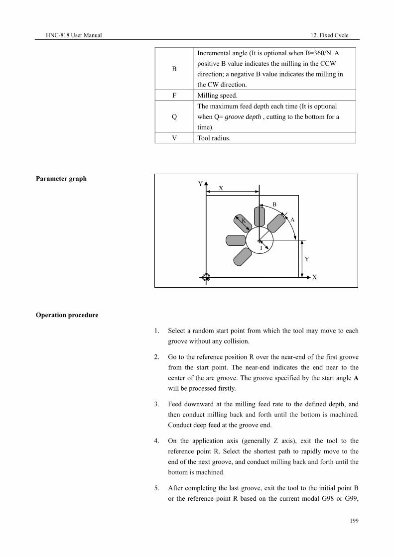
HNC-818 User Manual 12. Fixed Cycle
199
B
Incremental angle (It is optional when B=360/N. A positive B value indicates the milling in the CCW direction; a negative B value indicates the milling in the CW direction.
F Milling speed.
Q The maximum feed depth each time (It is optional when Q= groove depth , cutting to the bottom for a time).
V Tool radius.
Parameter graph
Operation procedure
1. Select a random start point from which the tool may move to each groove without any collision.
2. Go to the reference position R over the near-end of the first groove from the start point. The near-end indicates the end near to the center of the arc groove. The groove specified by the start angle A will be processed firstly.
3. Feed downward at the milling feed rate to the defined depth, and then conduct milling back and forth until the bottom is machined. Conduct deep feed at the groove end.
4. On the application axis (generally Z axis), exit the tool to the reference point R. Select the shortest path to rapidly move to the end of the next groove, and conduct milling back and forth until the bottom is machined.
5. After completing the last groove, exit the tool to the initial point B or the reference point R based on the current modal G98 or G99,
XY
K
B
A
I
Y
X

12. Fixed Cycle HNC-818 User Manual
200
and then the cycle ends.
Attention
1. The groove number N must be a non-negative integer. If not, the negative symbol (-) will be ignored, and the number will be rounded.
2. The maximum feed depth is specified by the value of Q. If the groove depth is not divisible by Q, the final cut depth will be less than Q.
3. The milling direction for each groove is related to the symbol of B. If the value of B is positive, the system starts the milling from the first groove to the last in the CCW direction; if the value of B is negative, the system starts the milling in the CW direction. If B is not specified, the system will automatically derive B from B=360/N, and conduct milling in the CCW direction.
4. The value of K, I, and Q should be non-negative values. If not, the system will ignore the negative symbol.
5. Rotate the spindle before executing the cycle. For alarm information, see section 12.1.26.
Milling in the CCW direction
N=3 A=180 B=-90

HNC-818 User Manual 12. Fixed Cycle
201
Example
Conduct milling for four rectangle
grooves as shown in the figure below: Groove length 30 mm; groove depth 23 mm; feed depth 6 mm
%0526
N10 G54 X0 Y0 Z5
N20 G17 G90
N30 T10
N40 M06
N50 M03 S600
N60 G181 R0 Z-23 N4 K30 X40 Y45 I20 A45 B90 F100 Q6 V5
N70 M30
Y
X
A
B40
45
20
30
23
45
degrees
90 degreesY
Z
A-B

12. Fixed Cycle HNC-818 User Manual
202
12.1.19 Arc Groove Cycle (Type 2) (G182)
Description
The instruction is used to process grooves which are arranged in an annular array. The longitudinal shaft of these grooves turn up radially. The instruction is different from G181, as the groove width can be specified by a parameter, but not be defined by the tool diameter.
This cycle can be specified for rough and finish machining.
Format
(G98/G99)G182 R_Z_N_K_W_X_Y_I_A_B_F_ Q_ E_O_H_U_P_C_D_V_
Parameter
Description
R The coordinate value of the reference point R for absolute programming, or the distance from reference point R to the initial plane for incremental programming.
Z
The coordinate value of the groove bottom for absolute programming, or the incremental value from the groove bottom to the reference point R for incremental programming.
N The number of grooves (It is optional when N=1) K The length of the groove. W The groove width (It is optional when W= tool diameter).
X
The center of the arc formed by the grooves. The first axis coordinate of the current plane for absolute programming, and the incremental value relative to the start point for incremental programming.
G0 G0
G0 G0

HNC-818 User Manual 12. Fixed Cycle
203
Parameter graph
Y
The center of the arc formed by the grooves. The second axis coordinate of the current plane for absolute programming, and the incremental value relative to the start point for incremental programming.
I The radius of the arc formed by the grooves.
A Start angle (-180 to 180 degrees, positive in the CCW direction and negative in the CW direction. It is optional when A=0)
B Incremental angle (It is optional when B=360/N. A positive B value indicates the milling in the CCW direction; a negative B value indicates the milling in the CW direction.
F Milling speed for rough machining.
Q The maximum feed depth for rough machining each time(It is optical when Q=groove depth -the depth of groove bottom left for finish machining).
E The finish allowance at the edge of the groove(It is optional when E=0).
O The finish allowance in the groove bottom(It is optional when O=0).
H The maximum feed depth for finish machining(It is optional when H=Q).
U Feed speed for finish machining(It is optional when U=F).
P Spindle speed for finish machining(It is optional when P=spindle speed before the cycle or default spindle speed).
C
The direction for milling each groove (It is optional when C=3) 0:milling in the same direction with the spindle rotation;1:milling in the reversed direction with the spindle rotation; 2:milling in G02 direction; 3:milling in G03 direction
D 1:rough machining 2:finish machining (It is optional when D=1).
V Tool radius.

12. Fixed Cycle HNC-818 User Manual
204
Milling direction
Operation procedure
Before entering the cycle mode, you need to use the command to enable spindle rotation. The system will calculate the reasonable milling direction based on the spindle rotation direction (M03/M04) and the command . See the table below:
Milling direction (Parameter C)
Execute M03/M04 before the cycle M03 spindle CW M04 spindle CCW
0: same direction G03 G02 1: reversed direction G02 G03 2: in G02 direction G02 G02 3: in G03 direction G03 G03 Left blank G03 G03
1. Select the start point , a random start point from which the tool may move to each groove without any collision.
2. Go to the reference point R over the first groove. The groove specified by the start angle A will be processed firstly.
3. Rough machining (D=1):
Starting at the groove end, the tool conducts milling from the middle part to the margin and from the groove surface to the finish allowance in the milling direction specified by C. Each time the tool feeds at the same point of the groove end until it reaches finish allowance in the groove bottom.
Finish machining (D=2):
Conduct finish machining for the groove wall and then the groove bottom. Conduct milling from the middle part to the defined groove margin in the milling direction specified by the parameter C, and then back to the the same start position, conduct milling downward to the groove bottom
XY
k
B
A
IY
X
w

HNC-818 User Manual 12. Fixed Cycle
205
Attention
4. After completing a groove, exits the tool to the reference point R. Rapidly move to the near-end of the next groove, and repeat step 3 until completing the last groove.
5. Exits the tool to the initial point B or the reference point R with G98 or G99, and then the cycle ends.
1. The tool radius cannot exceed the specified groove width W; otherwise, an alarm will be reported.
2. The groove number N must be a non-negative integer. If not, the system will ignore the negative symbol, and conduct rounding for the non-integer.
3. Q and H both specify the maximum feed depth . If the groove depth is not divisible by Q or H, the final cut depth will be less than Q or H.
4. The milling direction for each groove is specified by the parameter C. The milling direction between grooves is specified by the parameter B. If the value of B is positive, the system starts the milling from the first groove to the last in the CCW direction; if the value of B is negative, the system starts the milling in the CW direction. If B is not specified, the system will automatically derives B from B=360/N, and conduct milling in the CCW direction.
5. The values of parameter K, W, I, E, O, H and Q should be non-negative values. If the value is negative, the system will ignore the negative symbol.
6. Rotate the spindle Before executing the cycle. The finish allowance (E) specified for the groove margin cannot exceed half of the groove width (W/2), and the finish allowance (O) specified for the groove bottom cannot exceed the groove depth; otherwise, an alarm will be reported. For more alarm information, see section 12.1.26.

12. Fixed Cycle HNC-818 User Manual
206
Example
Conduct milling for four grooves as shown in the figure below:
Groove length 30 mm; groove width 15 mm; groove depth 23 mm; finish allowance 0.5 mm; milling direction G02; feed depth for rough machining 6 mm; tool radius: 5 mm
%0527
N10 G54 G17 G90
N20 T10
N30 M06
N40 M03 S600
N50 G182R5Z-23N4K30X40Y45W15I20A45B90F100Q6E0.5O0.5C2 V5
N60 M30
Y
X
A
B40
45
20
30
23
45°
90 degreesX
Z
A-B
15

HNC-818 User Manual 12. Fixed Cycle
207
12.1.20 Circumference Groove Milling Cycle (G183)
Description
This cycle is used to process circumference grooves distributed in a circle shape. You may specify roughing, finishing or comprehensive machining.
Format
(G98/G99)G183R_Z_N_K_W_X_Y_I_A_B_F_ Q_E_O_H_U_P_C_D_V_
Parameter Description
R
The coordinate value of the reference point R for absolute programming, or the distance from reference point R to the initial plane for incremental programming.
Z
The coordinate value of the groove bottom for absolute programming, or the incremental value from the groove bottom to the reference point R for incremental programming.
N The number of grooves (It is optional when N=1 ).
K The angle of groove length (0 to 360 degrees. Unit: degree).
W The width of the groove (It is optional when W= tool diameter ).
X
The center of the circle rounded by the grooves. The first axis coordinate of the current plane for absolute programming, and the incremental value to the start point for incremental programming.

12. Fixed Cycle HNC-818 User Manual
208
Y
The center of the circle rounded by the grooves. The second axis coordinate of the current plane for absolute programming, and the incremental value to the start point for incremental programming.
I The radius of the circle rounded by the grooves.
A Start angle (-180 to 180 degrees, positive in the CCW direction and negative in the CW direction. It is optional when A=0.)
B
Incremental angle (It is optional when B=360/N ; a positive B value indicates the milling in the CCW direction while a negative B value indicates the milling in the CW direction.
F Milling speed during rough machining.
Q The maximum feed depth for each time during rough machining (It is optional when Q= groove depth- finish ing allowance of the groove bottom).
E The finishing allowance of the groove margin (It is optional when E=0).
O The finishing allowance in the groove bottom (It is optional when O=0).
U The feed rate for finish machining (It is optional when U=F).
P The spindle speed for finish machining (It is optional when P= the spindle speed before cycle ).
C
The direction for milling each groove (It is optional when C=3) 0:milling in the same direction with the spindle rotation; 1:milling in the reversed direction with the spindle rotation; 2:milling in G02 direction; 3:milling in G03 direction
D Machining type (It is optional when D=1) 1: rough machining; 2: finish machining
V Tool radius.

HNC-818 User Manual 12. Fixed Cycle
209
Parameter graph
Milling direction
Before entering the cycle mode, you need to use the command to enable spindle rotation. The system will calculate the reasonable milling direction (M03/M04) based on the spindle rotation and the command . See the table below:
Operation procedure
1. During the cycle, use G00 to move to the reference plane R.
2. Conduct milling for the current groove from middle part to the edge. The operation procedure is similar as that of G182.
3. After completing a groove, exit the tool to the reference plane and move to the next groove.
4. After completing all grooves, exit the tool with the G98 or G99 command, and then the cycle ends.
Milling Direction (Parameter C)
Execute M03/M04 before the cycle
M03 spindle CW M04 spindle CCW 0: same direction G03 G02 1: reversed direction G02 G03 2: in G02 direction G02 G02 3: in G03 direction G03 G03 Left blank G03 G03
X
kB
A
Y
X
w
Y

12. Fixed Cycle HNC-818 User Manual
210
Example
Conduct milling for three grooves shown in the figure below:
Circle center: (X60, Y60); radius on the XY plane: 42 mm; groove width: 15 mm; groove length angle: 70 degrees; groove depth: 23 mm; start angle: 0 degree; incremental angle: 120 degrees; finishing allowance on the groove contour: 0.5 mm; feed depth: 6 mm; tool radius 5 mm
The spindle speed and feed rate for rough and finish machining are the same. The finish machining is completed with one cut.
See the figure below:
%0528
N10 G54 G17 G90
N20 T10
N30 M06
N40 M03 S600
23
A-B
Y
Z
60 42
B60
15
Y
120°
X
70°A
G0
G0
G0

HNC-818 User Manual 12. Fixed Cycle
211
N50 G00 X60 Y60 Z5
N60 G183R2Z-23N3K70W15X60Y60I42A70B120F100Q6E0.5O0.5V5
N70 M30

12. Fixed Cycle HNC-818 User Manual
212
12.1.21 Rectangular Groove Cycle (G184)
Description
This cycle is used for the rough and finish machining of rectangular grooves with rounded corners.
Format
(G98/G99)G184R_Z_K_W_X_Y_I_A_F_ Q_E_O_H_U_P_C_D_V_
Parameter Description
R
The coordinate value of the reference point R for absolute programming, or the distance from reference point R to the initial plane for incremental programming.
Z
The coordinate value of the groove bottom for absolute programming, or the incremental value from the groove bottom to the reference point R for incremental programming.
K The length of the groove. W The width of the groove.
X
The center of the groove. The first axis coordinate of the current plane for absolute programming, and the incremental value to the start point for incremental programming.
Y
The center of the groove. The second axis coordinate of the current plane for absolute programming, and the incremental value to the start point for incremental programming.
I The arc radius of the rounded corner (It can be left blank or specified to 0 when I=W/2 ).

HNC-818 User Manual 12. Fixed Cycle
213
A The angle formed by the long side of the rectangle groove and the first positive axis (It is optional when A=0.).
F Milling speed during rough machining.
Q The maximum feed depth for each time during rough machining (It is optional when Q= groove depth- finishing allowance of the groove bottom).
E The finishing allowance of the groove margin (It is optional when E=0).
O The finishing allowance of the groove bottom (It is optional when O=0).
H The maximum feed rate for finish machining (It is optional when U=Q ).
U The feed rate for finish machining (It is optional when U=F ).
P The spindle speed for finish machining (It is optional when P= the spindle speed before cycle or the default spindle speed).
C
The direction for milling each groove (It is optional when C=3) 0:milling in the same direction with the spindle rotation; 1:milling in the reversed direction with the spindle rotation; 2:milling in G02 direction; 3:milling in G03 direction
D Machining type (It is optional when D=1) 1: rough machining 2: finish machining
V The tool radius.

12. Fixed Cycle HNC-818 User Manual
214
Parameter graph
Milling direction
Operation Procedure
Before entering the cycle mode, you need to use the command to enable spindle rotation. The system will calculate the reasonable milling direction based on the spindle rotation direction (M03/M04) and the command. See the table below:
Milling Direction (Parameter C)
Execute M03/M04 before the cycle M03 spindle CW M04 spindle CCW
0: same direction G03 G02 1: reversed direction G02 G03 2: in G02 direction G02 G02 3: in G03 direction G03 G03 Left blank G03 G03
1. Select a random start point from which the tool may move to each groove without any collision.
2. Rough machining (D=1):
Go to the center of the long side of the groove with G00(reserve the finishing allowance for the groove margin). The tool feeds downward with the depth specified by Q, and then conducts milling from the margin to the center for the upper part of the groove in the milling direction specified by C. Then backing to the same start position, the tool conducts milling from the groove surface to the groove bottom (reserve the finishing allowance).
Finish machining (D=2):
Go to the center of the long side of the groove with G00
G
X
Y
Y
G3
X
A
k
I
w

HNC-818 User Manual 12. Fixed Cycle
215
Attention
Example
(reserve the finishing allowance for the groove margin). The tool feeds downward with the depth specified by H, and then conducts milling from the center to the defined margin for the groove surface in the milling direction specified by C. After that, the tool goes back to the same point, moves to the surface for milling the finishing allowance, from the surface to the bottom in the direction specified by C.
3. After machining, exit the tool to the initial plane or the reference plane based on the current modal G98 or G99, and then the cycle ends.
1. This cycle requires milling tool with face tooth.
2. The maximum feed depth for rough and finish machining is specified by the parameter Q or H respectively. If the groove depth is not divisible by Q or H, the final cut depth will be less than Q or H.
3. The values of N, K, W, I, E, O, Q and H should be non-negatives. If the specified value is a negative value, the system will ignore the negative symbol.
4. For the information about alarms, see section 12.1.26.
5. If the specified groove width is greater than the groove length, the system will automatically exchange them and rotate to the expected position.
6. The parameter C specifies the milling direction, like G182.
7. You need to use the command to enable spindle rotation before entering the cycle mode.
Conduct milling for the groove as shown in the figure below. Dimension of the groove:
Length: 60 mm; width: 40 mm; radius of the rounded arc: 8 mm; depth: 17.5 mm; angle between the groove and the X axis: 0 degree; finishing allowance on the groove margin: 0.75 mm; finishing allowance on the groove bottom: 0.2 mm; groove center: X60Y40; feed depth: 4 mm; tool radius 5 mm
Only rough machining is required.

12. Fixed Cycle HNC-818 User Manual
216
%0526
N10 G54 G90 G17
N20 T20
N30 M06
N40 M04 S600
N50 G00 X60 Y40 Z5
N60 G98G184R5Z-17.5K60W40X60Y40I8F120Q4E0.75O0.2D1V5
N70 M30
A - B
Z
40 R8
B
60 X
A
17.5
Y Y

HNC-818 User Manual 12. Fixed Cycle
217
12.1.22 Circular Groove Cycle (G185)
Description
This cycle is used for rough or finish machining for circular grooves.
Format
(G98/G99)G185R_Z_X_Y_I_ F_ Q_E_O_H_U_P_C_D_V_
Parameter Description
R
The coordinate value of the reference point R for absolute programming, or the distance from reference point R to the initial plane for incremental programming.
Z
The coordinate value of the groove bottom for absolute programming, or the incremental value from the groove bottom to the reference point R for incremental programming.
X
The center of the groove. The first axis coordinate of the current plane for absolute programming, and the incremental value to the start point for incremental programming.
Y
The center of the groove. The second axis coordinate of the current plane for absolute programming, and the incremental value to the start point for incremental programming.
I The radius of the circular groove. F Milling speed during rough machining.
Q The maximum feed depth for each time during rough machining (It is optional when Q= groove depth- finishing allowance of the groove bottom).

12. Fixed Cycle HNC-818 User Manual
218
E The finishing allowance of the groove margin (It is optional when E=0).
O The finishing allowance of the groove bottom (It is optional when O=0 ).
H The maximum feed rate for finish machining (It is optional when H=Q).
U The feed rate for finish machining (It is optional when U=F ).
P The spindle speed for finish machining (It is optional when P= the spindle speed before cycle or the default spindle speed).
C
The direction for milling each groove (It is optional when C=3) 0:milling in the same direction with the spindle rotation;1:milling in the reversed direction with the spindle rotation; 2:milling in G02 direction; 3:milling in G03 direction
D Machining type (It is optional when D=1 ). 1: rough machining; 2: finish machining
V Tool radius.
Parameter graph
Milling direction
Before entering the cycle mode, you need to use the command to enable spindle rotation. The system will calculate the reasonable milling direction based on the spindle rotation direction (M03/M04) and the command. See the table below:
Milling Direction (Parameter C)
Execute M03/M04 before the cycle M03 spindle CW M03 spindle CW
0: same direction G03 G02 1: reversed direction G02 G03
G3
Y
I
X
X
Y
G2

HNC-818 User Manual 12. Fixed Cycle
219
Operation procedure
Attention
2: in G02 direction G02 G02 3: in G03 direction G03 G03 Left blank G03 G03
1. Select a random start point from which the tool may move to each groove without any collision.
2. Rough machining (D=1):
Go to the center of the long side of the groove with G00(reserve the finishing allowance for the groove margin). The tool feeds downward with the depth specified by Q, and then conducts milling from the margin to the center for the upper part of the groove in the milling direction specified by C. Then backing to the same start position, the tool conducts milling from the groove surface to the groove bottom (reserve the finishing allowance).
Finish machining (D=2):
Go to the center of the long side of the groove with G00. (reserve the finishing allowance for the groove margin). The tool feeds downward with the depth specified by H, and then conducts milling from the center to the defined margin for the groove surface in the milling direction specified by C. After that, the tool goes back to the same point, moves to the surface for milling the finishing allowance, from the surface to the bottom in the direction specified by C
3. After machining, exit the tool to the initial plane or the reference plane with the command G98 or G99, and then the cycle ends.
1. For the information about alarms, see section 12.1.26.
2. The maximum feed depth for rough and finish machining is specified by the parameter Q or H respectively. If the groove depth is not divisible by Q or H, the final cut depth will be less than Q or H.
3. The values of I, E, O, Q, and H should be non-negatives. If the specified value is a negative value, the system will ignore the negative symbol.
4. The parameter C specifies the milling direction, like G182.

12. Fixed Cycle HNC-818 User Manual
220
Example
5. You need to use the command
to enable spindle rotation before entering the cycle mode.
Conduct milling for the groove with the following specifications:
Circle center: X50 Y50; radius: 100 mm; depth: 50 mm; finishing allowance on the groove bottom and margin: 2 mm and 1.5 mm respectively; feed depth for rough machining: 4 mm; tool radius: 5 mm
G54 X0 Y0 Z40
G17 G90
T10
M06
M03 S650
G99 G185 R0 Z-50 X50 Y50 I100 F300 Q4 E1.5 O2 V5D1; rough machining
X50 Y50 I100 P800 H1.5 D2; finish machining
M30

HNC-818 User Manual 12. Fixed Cycle
221
12.1.23 Face Milling Cycle (G186)
Description
This cycle can be used to conduct milling for any rectangular end face. The cycle for rough machining (perform multi-step reaming from surface to finishing allowance) and finish machining (finish the end face) is different.
Foramt
(G98/G99)G186R_Z_N_W_X_Y_ I_ A_F_Q_J_O_H_K_U_P_C_D_V_
Parameter Description
R
The coordinate value of the reference point R for absolute programming, or the distance from reference point R to the initial plane for incremental programming.
Z
The coordinate value of the groove bottom for absolute programming, or the incremental value from the groove bottom to the reference point R for incremental programming.
N The first axis length of the workpiece. W The second axis length of the workpiece.
X, Y
The start position. The first axis coordinate of the current plane for absolute programming, or the incremental value to the current point during incremental programming.
I The safety margin in the milling direction (It is optional when I= tool radius).
A The angle formed by the long side of the end face and the first positive axis (It is optional when A=0 ).
F Milling speed during rough machining.
Q The maximum feed depth for each time during rough machining (It is optional when Q= groove depth- finishing allowance of the groove bottom).
J The milling width during rough machining (It is optional when J= tool radius x 80%).
O The finishing allowance of the workpiece bottom (It is optional when O=0).
H The maximum feed depth during finish machining (It is optional when H=Q).
K The cutting width during rough machining (It is optional when K= tool radius x 80%).

12. Fixed Cycle HNC-818 User Manual
222
Basic description
U The milling speed for finish machining (It is optional when U=F).
P The spindle speed for finish machining (It is optional when P= the spindle speed before cycle or the default spindle speed).
C
The direction for milling each groove (It is optional when C=3) 0:milling in the same direction with the spindle rotation;1:milling in the reversed direction with the spindle rotation; 2:milling in G02 direction; 3:milling in G03 direction
D Machining type (It is optional and D=1 by default) 1: rough machining 2: finish machining
V The tool radius.
• C=0, D=1, bidirectional machining along the X axis
W
I
N
J
I (X,
J
+X
+Y +Z
+Y
Z-O Q Q Q

HNC-818 User Manual 12. Fixed Cycle
223
•
•
• C=1, D=1, bidirectional machining along the Y axis
• C=2, D=1, unidirectional machining along the X axis
• C=3, D=1, unidirectional machining along the Y axis
Note: The figures above show the milling cycle (rough machining) only for the end face of the G17 plane. The cycle for G18/G19 is similar, and
W
I
N
J(X, Y)
J
+X
+Y+Z
+Y
Z-O Q Q Q
I
W
I
N
J
I (X, Y)
J
+X
+Y +Z
+Y
Z-O Q Q Q
J
W
I
N
J
J(X, Y)
J
+X
+Y +Z
+X
Z-O Q Q Q
I

12. Fixed Cycle HNC-818 User Manual
224
that for the finish and comprehensive machining (D=2) is also similar.
Attention
1. The values of N, W, I, O, Q, J, H and K should be non-negatives. If the specified value is a negative value, the system will ignore the negative symbol.
2. For the feed width (specified by J/K) or the feed depth (specified by Q/H), the final cut will be less than the feed width or the feed depth if the feed rate is not divisible by them.
3. Before executing the cycle, use the command to enable the spindle rotation.
4. For the information about alarms, see section 12.1.26.
Example
Conduct milling for a rectangular
end face, with the following end dimension and relative parameters:
Start plane: 10 mm; reference plane: 2 mm, only rough machining, each milling width: 10 mm; each feed depth: 6 mm; total milling depth: 11 mm; milling start point (100, 100); end face dimension: 60 mm x 40 mm; safety margin in the milling direction: 5 mm; bidirectional milling along the X axis; feed rate on the surface: 500 mm/min; tool radius: 5 mm.
%1018
N10 G54 X0 Y0 Z20
N20 G17 G90
N30 T10
N40 M06
N50 M03 S650
N60 G00 X0 Y0 Z20
N70 G99G186 Z-11 R0 N60 W40 X100 Y100 I5 F500 Q6 J10 V5
N80 M30

HNC-818 User Manual 12. Fixed Cycle
225
12.1.24 Rectangular Boss Cycle (G188)
Description
This cycle is used to conduct machining for rectangular boss of arbitrary size on a plane. The rectangular boss may have rounded corners. You may select roughing, finishing or comprehensive machining as required.
Format
(G98/G99)G188R_Z_N_W_X_Y_J_K_I_ A_F_ Q_E_O_H_U_P_C_D_V_
Parameter Description
R
The coordinate value of the reference point R for absolute programming, or the distance from reference point R to the initial plane for incremental programming.
Z
The coordinate value of the boss bottom for absolute programming, or the incremental value from the boss bottom to the reference point R for incremental programming.
N The length of the rectangular boss. W The width of the rectangular boss.
X
The center of the rectangular boss. The first axis coordinate of the current plane for absolute programming, and the incremental value to the start point for incremental programming.
Y
The center of the rectangular boss. The second axis coordinate of the current plane for absolute programming, and the incremental value to the start point for incremental programming.
J The length of the rough rectangular boss.

12. Fixed Cycle HNC-818 User Manual
226
K The width of the rough rectangular boss.
I The radius of the rounded corner in the rectangular boss (It is optional when I=W/2 ).
A The angle formed by the long side of the rectangular boss and the first positive axis (It is optional when A=0).
F The milling speed for rough machining.
Q The maximum feed depth for each rough machining (It is optional when Q = groove depth - finishing allowance at the groove bottom).
E The finishing allowance at the boss margin (It is optional when E=0).
O The finishing allowance at the boss bottom (It is optional when O=0).
H The maximum feed depth for finish machining (It is optional when H=Q).
U The feed speed for finish machining (It is optional when U=F).
P The spindle speed for finish machining (It is optional when P= the spindle speed before cycle or the default spindle speed).
C
The milling direction for the boss (It is optional when C=3 ). 0:milling in the same direction with the spindle rotation;1:milling in the reversed direction with the spindle rotation; 2:milling in G02 direction; 3:milling in G03 direction
D Machining type (It is optional and D=1 by default). 1: rough machining; 2: finish machining
V Tool radius.
Parameter graph
X
Y
Y
X
A
N
I
W

HNC-818 User Manual 12. Fixed Cycle
227
Semicircle path for entering and existing
To ensure the tool smoothly moves into the workpiece, the cycle automatically adds a semicircle path when entering and exiting the workpiece. The semicircle radius is determined by the cycle parameters, and the semicircle direction is opposite to the milling direction. For example, if the milling direction is specified by G2, then the added semicircle is in the direction of G3.
Dimension of rough boss
For the machining of workpiece with prior casting, the rough size of rectangular boss, which is symmetrical to the size of the boss with the center(X,Y), may be taken into account.
Milling direction
Before entering the cycle mode, you need to use the command to enable spindle rotation. The system will calculate the reasonable milling direction based on the spindle rotation direction (M03/M04) and the commands. See the table below:
Milling Direction Execute M03/M04 before the cycle
Y
X
J
K
X
Y
Path for entering
Path for existing

12. Fixed Cycle HNC-818 User Manual
228
(Parameter C) M03 spindle CW M03 spindle CW 0: same direction G03 G02
1: reversed direction G02 G03 2: in G02 direction G02 G02 3: in G03 direction G03 G03 Left blank G03 G03
Operation procedure
1. Selecting a start point, which must be to the right of the boss in the first postive axis direction of the plane. You need to consider the automatically added semicircle during the cycle.
2. Rough machining (D=1):
Go to the reference plane over the long side of the boss with G00, feed downward with the specified depth, and then in the milling direction, enter the workpiece contour through a semicircle path to conduct milling from the surface to the finishing allowance of the margin, and exit the workpiece contour through a semicircle path in the opposite direction. Use G00 to rapidly move to the start point, and then conduct milling from the groove surface to the finishing allowance of the bottom.
Finish machining (D=2):
Go to the reference plane over the long side of the boss with G00, feed downward with the specified depth, and then in the milling direction, enter the workpiece contour through a semicircle path to machine the finishing allowance of margin. After that, exit the workpiece contour through a semicircle path in the opposite direction. Use G00 to rapidly move to the start point, feed downward again to machine the finishing allowance of the bottom.
3. After completing the machining, exit the tool to the initial point or the reference point based on the current modal G98 or G99, and then the cycle ends.
Attention
1. For the information about alarms, see section 12.1.26.
2. The values of W, J, K, I, O, Q and H should be non-negatives. If the specified value is a negative value, the system will ignore the negative symbol.

HNC-818 User Manual 12. Fixed Cycle
229
3. For the maximum feed depth for rough and finish machining (specified by Q and H respectively), if the feed rate is not divisible , the final cut will be less than Q or H.
4. Before executing the cycle, use the command to enable the spindle rotation.
5. If the specified width is greater than the length, the system will automatically exchange them and rotate to the expected position.
Example
Conduct milling for the boss as shown in the figure below:
Dimension: 60 mm x 40 mm; rough dimension: 80 mm x 50 mm; tool radius: 3 mm
%1019
G17 G54 G90
T10
M06
M03 S650
G98 G188 R2Z-17.5N60W40X80Y60J80K50I15A10F200Q11E2O1V3
M30
80
Y
X
A A - B
R1
B
60
17.5 Z
10°
Y

12. Fixed Cycle HNC-818 User Manual
230
12.1.25 Circular Boss Cycle (G189)
Description
The cycle is used to conduct machining for circular boss with arbitrary size.
Format
(G98/G99)G189R_Z_X_Y_ I_ J_F_ Q_E_O_H_U_P_C_D_V_
Parameter Description
R
The coordinate value of the reference point R for absolute programming, or the distance from reference point R to the initial plane for incremental programming.
Z
The coordinate value of the boss bottom for absolute programming, or the incremental value from the boss bottom to the reference point R for incremental programming.
X
The center of the rectangular boss. The first axis coordinate of the current plane for absolute programming, and the incremental value to the start point for incremental programming.
Y
The center of the rectangular boss. The second axis coordinate of the current plane for absolute programming, and the incremental value to the start point for incremental programming.
I The radius of the circular boss. J The radius of the rough circular boss. F The milling speed for rough machining.

HNC-818 User Manual 12. Fixed Cycle
231
Q The maximum feed depth for each rough machining (It is optional when Q = groove depth - finishing allowance at the groove bottom).
E The finishing allowance at the boss margin (It is optional when E=0).
O The finishing allowance of the boss bottom (It is optional when O=0 ).
H The maximum feed depth for finish machining (It is optional when H=Q).
U The feed speed for finish machining (It is optional when U=F ).
P The spindle speed for finish machining (It is optional when P= the spindle speed before cycle or the default spindle speed).
C
The milling direction for the grooves (It is optional when C=3 ). 0:milling in the same direction with the spindle rotation;1:milling in the reversed direction with the spindle rotation; 2:milling in G02 direction; 3:milling in G03 direction
D Machining type (It is optional when D=1) 1: rough machining; 2: finish machining
V Tool radius.
Semicircle path for entering and existing
Similar as G188, to ensure the tool smoothly moves into the workpiece, the cycle automatically adds a semicircle path when entering and exiting the workpiece. The semicircle radius is automatically determined by the cycle. The direction of the semicircle is opposite to that of milling.
X
Y
Return to the running contour
Exit the running contour

12. Fixed Cycle HNC-818 User Manual
232
Dimension of rough boss
Milling direction
Operation procedure
Similar as G188, you may set the dimension of the rough boss, with the center (X, Y).
Before entering the cycle mode, you need to use the command to enable spindle rotation. The system will calculate the reasonable milling direction based on the spindle rotation direction (M03/M04) and the commands. See the table below:
Milling Direction (Parameter C)
Execute M03/M04 before the cycle M03 spindle CW M04 Spindle CCW
0: same direction G03 G02 1: reversed direction G02 G03 2: in G02 direction G02 G02 3: in G03 direction G03 G03 Left blank G03 G03
1. Select a start point, which must be to the right of the boss in the first postive axis direction of the plane. You need to consider the automatically added semicircle during the cycle.
2. Rough machining (D=1):
Go to the reference plane over the long side of the boss with G00, feed downward with the specified depth, and then in the milling direction, enter the workpiece contour through a semicircle path to conduct milling from the surface to the finishing allowance of the margin, and exit the workpiece contour through a semicircle path in the opposite direction. Use G00 to rapidly move to the start point, and then conduct milling from the groove surface to the finishing allowance of the bottom.
Finish machining (D=2):
Go to the reference plane over the long side of the boss with G00, feed downward with the specified depth, and then in the milling direction, enter the workpiece contour through a semicircle path to machine the finishing allowance of margin. After that, exit the workpiece contour through a semicircle path in the opposite direction. Use G00 to rapidly move to the start point, feed downward again to machine the finishing allowance of the bottom.

HNC-818 User Manual 12. Fixed Cycle
233
Attention
Example
3. After completing the machining, exits the tool to the initial point or the reference point based on the current modal G98 or G99, and then the cycle ends.
1. For the information about alarms, see section 12.1.26.
2. The values of J, K, I, E, O, Q and H should be non-negatives. If the specified value is a negative value, the system will ignore the negative symbol.
3. For the maximum feed depth for rough and finish machining (specified by Q and H respectively), if the feed rate is not divisible by them, the final cut will be less than Q or H.
4. Before executing the cycle, use the command to enable the spindle rotation.
5. If the specified width is greater than the length, the system will automatically exchange them and rotate to the expected position.
Conduct milling for the boss as shown in the figure below:
Rough boss radius: 55 mm; each feed depth: 10 mm; tool radius: 5 mm
%1020
G17 G54 G90
T10
M06
M03 S650
G98G189 R2Z-20X60Y70I25J27.5F200Q10E1O1V5
M30
60
Y
X
A A - B
B20
Z
70 Φ50
Φ55
Y

12. Fixed Cycle HNC-818 User Manual
234
12.1.26 Alarm Information for Milling Cycle
During fixed cycle, if the system detects an error, an alarm will be reported, and the current cycle execution will be stopped. After you modify the program, the system will proceed to run the ongoing cycle.
This section describes the alarms that may be reported during the milling cycle, and provides alarm analysis and suggestions, based on which you may modify the program.
Alarm
No. Alarm Text Source Reasons and Suggestions
800
"MILLING
CYCLE: TOOL
OFFSET
NUMBER NOT
DEFINED."
G181
G182
G183
G184
G185
G186
G188
G189
The tool radius V is not specified
before executing the cycle.
801
"MILLING
CYCLE:
REFERENCE
PLANE NOT
DEFINED."
G181
G182
G183
G184
G185
G186
G188
G189
This alarm is reported if R is not
specified in the program and the cycle
cannot detect the modal R value. This
parameter should be specified as it is
required when the groove depth is
defined in the incremental value or the
tool exits to the R plane after the cycle
is completed.
802
"MILLING
CYCLE:
POSITION OF
BOTTOM OF
GROOVE NOT
DEFINED."
G181
G182
G183
G184
G185
G186
G188
G189
The groove bottom position must be
specified; otherwise, the groove depth
cannot be defined.
803
"MILLING
CYCLE:
NUMBER OF
GROOVE IS
SET TO ZERO."
G181
G182
G183
This alarm is reported when the
groove number is set to 0. The number
of grooves should be an integer
greater than 0.

HNC-818 User Manual 12. Fixed Cycle
235
804
"MILLING
CYCLE: GROOVE
LENGTH
DEFINED TOO
SMALL."
G182
For the groove with user-defined width,
the length should be greater than the
width; otherwise, this alarm is reported.
805
"M-CYC: TOOL
RADIUS TOO
MUCH."
G181
G182
G183
G184
G185
G186
G188
G189
This alarm is reported when the tool
radius is greater than the defined groove
length. You may select a milling tool with
relative smaller radius for the milling.
806
"MILLING
CYCLE: CENTER
POSITION OF
ARC MADE OF
GROOVES."
G181
G182
G183
This alarm is reported if the arc center is
not specified in the program and no
related modal position is detected by the
cycle.
807
"M-CYC: AR
MADE OF GV
NOT DEFINED."
G181
G182
G183
If there is no modal arc radius value, the
radius should be specified in this line;
otherwise, this alarm is reported.
808
"M-CYC:
INTERFER
BTWN
GROOVE"
G181
G182
G183
Because of the angle formed by the tool
radius and the groove, there may be
interference among the machined
grooves, which may affect the groove
contour shape. The system conducts the
interference detection before the cycle
and provides prompts for you.
809
"M-CYC: GV
NO.&DEF OF AI
CONFLICTS"
G181
G182
G183
This alarm is reported when the groove
number or the angle between grooves is
defined improperly, e.g. groove number x
the angle between grooves > 360 degrees.
810
"The maximum feed
depth for each time
is over large."
G181
G182
G183
G184
G185
G186
G188
G189
This alarm is reported when the
maximum feed depth for each time (Q) is
greater than the groove depth. You may
decrease the value of Q.

12. Fixed Cycle HNC-818 User Manual
236
811
"M-CYC:
ROTATE SPDL
BEF CYC RUN."
G181
G182
G183
G184
G185
G186
G188
G189
This alarm is reported when the spindle
does not rotate before the cycle. The
spindle status is detected before the
cycle is executed.
812
"CG OR BOSS
CP NOT
DEFINED."
G184
G185
G188
G189
This alarm is reported when the center
of the circular groove or boss is not
specified.
813
"M-CYC: CG OR
BOSS R NOT
DEFINED."
G185
G189
This alarm is reported when the radius
of the circular groove or boss is not
specified.
814
"M-CYC:
F.ALOW OF
MARGIN
MUCH."
G182
G183
G184
G185
G188
G189
The reserved finishing allowance for
the margin is too large to complete. You
may decrease the finishing allowance.
815
"M-CYC:
F.ALOW OF
BOTTOM
MUCH."
G182
G183
G184
G185
G186
G188
G189
The reserved finishing allowance for
the bottom is too large to complete. You
may decrease the finishing allowance.
816
"M-CYC: MAX
F.DEP OF
FINISH MUCH."
G182
G183
G184
G185
G186
G188
G189
For finish machining, this alarm is
reported if the maximum feed depth for
each time (H) is greater than the groove
depth. You may decrease the value of
H.

HNC-818 User Manual 12. Fixed Cycle
237
817
"M-CYC: DIR
MILLING
ERROR."
G182
G183
G184
G185
G186
G188
G189
This alarm is reported if the defined
milling direction is not supported by
the system, that is the value specified
for C is not within the allowed range
(0, 1, 2, 3).
818
"M-CYC: DEF
OF MACHING
TYPE ERROR."
G182
G183
G184
G185
G186
G188
G189
This alarm is reported if a milling
type not supported by the system is
defined, that is the value specified for
D is not within the allowed range (1,
2).
819 "M-CYC: W.SIZE
NOT DEFINED."G186
For G186, the dimension of the end
face should be specified for the
workpiece to be machined, e.g.
length and width; otherwise, this
alarm is reported.
820
"M-CYC: ST PT
OF MIL NOT
DEFINED."
G186
For G186, the start point for the
milling should be specified, generally
the lower left corner of the workpiece
on the machining plane; otherwise,
this alarm is reported.
821
"M-CYC:
SAFETY LMT
TOO SMALL."
G186
For G186, the safety margin should
be specified for a good milling effect.
Its value cannot be lower than the
radius of the milling tool.
822
"M-CYC: WID
OF RM TOO
MUCH."
G186
For G186, the milling width for
rough machining cannot be greater
than the tool diameter.
823
"M-CYC: WID
OF RM TOO
MUCH."
G186
For G186, the milling width for finish
machining cannot be greater than the
tool diameter.
824
"M-CYC: WP
SIZE ON BOSS
NOT DEF."
G188
G189
For G189 and G188, the workpiece
dimension should be defined;
otherwise, this alarm is reported.

12. Fixed Cycle HNC-818 User Manual
238
826
"M-CYC: GV/BOSS LEN/WID NOT DEF."
G181 G182 G183 G184 G188
This alarm is reported if the groove length or width is not specified in this line or the related modal value of the groove length cannot be detected.
829
"M-CYC: CR OF REC.GV/BOSS MUCH."
G184 G188
For 184 or 188, the rounded corner can be defined, but the arc radius cannot be greater than long side / 2; otherwise, this alarm is reported.
830
"M-CYC: WP SIZE ON BOSS<MAC SIZE."
G188 G189
For G189 and G188, the rough boss dimension should be greater than the contour dimension; otherwise, this alarm is reported.
873
"M-CYC: TOOL RAD CANNOT BE 0."
G181 G182 G183 G184 G185 G186 G188 G189
The parameter V indicates the compensation number in the tool compensation table. The value entered in the compensation number is the tool radius. This value cannot be zero; otherwise, this alarm is reported.
874
"The finishing allowances is not defined for the finishing."
G182 G183 G184 G185 G186 G188 G189
This alarm is reported when the finishing allowances of groove wall and groove bottom are not defined simultaneously or both are specified as 0 during finish machining.

HNC-818 User Manual 12. Fixed Cycle
239
12.2 Simple Cycle for Turning Machines (T)
For turning machines, there are five simple cycles. See the table below:
G Code Functions
G80 Inner (outer) diameter cutting cycle
G81 End-face cutting cycle
G82 Thread cutting cycle
G74 End-face deep-hole drilling cycle
G75 Outer diameter grooving cycle
The cycle is to use a G code program block to complete the machining of multiple blocks, to simplify the programs.
Attention
1. The cycle described in this section can only be used for turning machines.
2. The commands G83, G87, G84and G88 have no positioning function. To conduct positioning, you need to execute G01 or G00 outside the fixed cycle.

12. Fixed Cycle HNC-818 User Manual
240
12.2.1 Inner (Outer) Diameter Cutting Cycle (G80)
This cycle can be used for inner (outer) diameter cutting of cylindrical and conical surfaces.
Cylindrical surface cutting
G80 X_/U_ Z_/W_ F_
Parameter Description X/U Z/W The cutting end point C at the workpiece coordinate
system for absolute value programming; The relative distance from the cutting end point C to the cycle start point A for the incremental value programming. Use U and W to express them in the blueprint and the direction of path 1 and 2 determine whether it is a positive or a negative value.
F Feed speed (indicates to move at the speed specified by F) (mm/min)
The tool moves along the path A→B→C→D→A. See the figure below:
+X
+Z
z w
u/23F 1R 2F
4R A D
B Cx/2
Cutting end point
Tool exit point
Cutting start
point
Cycle start point

HNC-818 User Manual 12. Fixed Cycle
241
Conical surface cutting
G80 X_/U_ Z_/W_ I_ F_
Parameter Description
X/U Z/W The cutting end point C at the workpiece coordinate system for absolute value programming; The relative distance from the cutting end point C to the cycle start point A for the incremental value programming. Use U and W to express them in the blueprint and the direction of path 1 and 2 determine whether it is a positive or a negative value.
I The radius difference between the cutting start point B and the end point C. Either in the absolute value programming or in the incremental value programming, the sign (+ or -) of the difference value determines whether the value of I is positive or negative.
F Feed speed (indicates to move at the speed specified by F) (mm/min)
The tool moves along the path A→B→C→D→A. See the figure below:
+X
+Z
z w
u/23F 1R
2F
4R A D
B
C
x/2
i

12. Fixed Cycle HNC-818 User Manual
242
Example 1
Conduct machining for the workpiece as shown in the figure below: use G80 to conduct rough and finish machining for simple cylindrical parts.
%3320
N1 T0101
N2 M03 S460
N3 G00 X90Z20
N4 X40 Z3
N5 G80 X31 Z-50 F100
N6 G80 X30 Z-50 F80
N7 G00X90 Z20
N8 M30
Example 2:
Conduct machining for the workpiece as shown in the figure below: use G80 to conduct rough or finish machining for simple conical parts.
50
Φ35 Φ30

HNC-818 User Manual 12. Fixed Cycle
243
%3321
N1 T0101
N2 G00 X100Z40 M03 S460
N3 G00 X40 Z5
N4 G80 X31 Z-50 I-2.2 F100
N5 G00 X100 Z40
N6 T0202
N7 G00 X40 Z5
N8 G80 X30 Z-50 I-2.2 F80
N9 G00 X100 Z40
N10 M05
N11 M30
50
Φ35 Φ26Φ30

12. Fixed Cycle HNC-818 User Manual
244
12.2.2 End-face cutting cycle (G81)
This cycle can be used for end face cutting and conical face cutting.
End face cutting
G81 X_/U_ Z_/W_ F_
Parameter Description X/U Z/W The cutting end point C at the workpiece coordinate
system for the absolute value programming; The relative distance from the cutting end point C to the cycle start point A for the incremental value programming. Use U and W to express them in the blueprint and the direction of path 1 and 2 determines whether it is a positive or a negative value.
F Feed speed (inidicates to move at the speed specified by F) (mm/min)
The tool moves along the path A→B→C→D→A. See the figure below:
Conical face cutting
G81 X_/U_ Z_/W_ K_ F_
Parameter Description X /U Z/W The cutting end point C at the workpiece coordinate
system for absolute value programming; The relative distance from the cutting end point C to the cycle start point A for the incremental value programming. Use U and W to express them in the blueprint and the direction of path 1 and 2 determines whether it is a positive or a negative
+X
z
w
u/2
3F
1R
2F 4R
A
D
B
Cx/2
+Z
Cutting
end point Tool exit
point
Cutting
start pointCycle start point
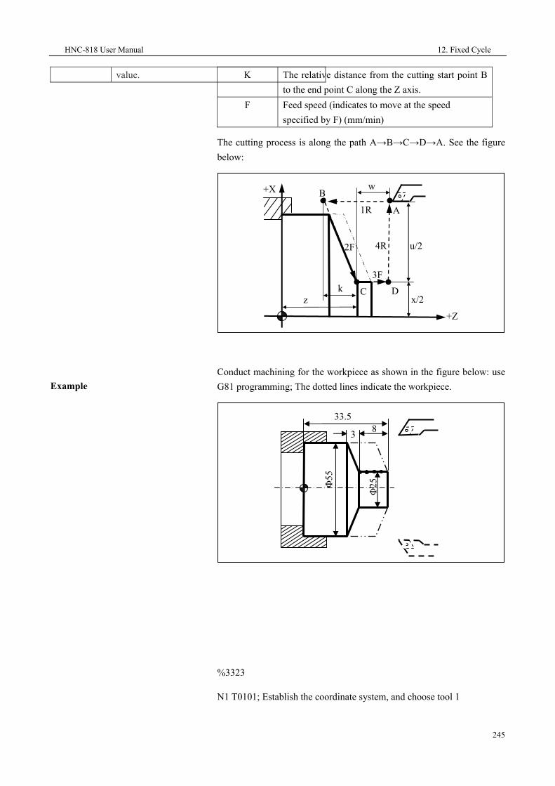
HNC-818 User Manual 12. Fixed Cycle
245
value.
Example
K The relative distance from the cutting start point B to the end point C along the Z axis.
F Feed speed (indicates to move at the speed specified by F) (mm/min)
The cutting process is along the path A→B→C→D→A. See the figure below:
Conduct machining for the workpiece as shown in the figure below: use G81 programming; The dotted lines indicate the workpiece.
%3323
N1 T0101; Establish the coordinate system, and choose tool 1
3 8
Φ25Φ
55
33.5
+X
zk
u/2
3F
1R
2F 4R
A
D
B
Cx/2
+Z
w

12. Fixed Cycle HNC-818 User Manual
246
N2 G00 X60 Z45; Move to the cycle
start point
N3 M03 S460; Rotate the spindle in
the clockwise direction
N4 G81 X25 Z31.5 K-3.5 F100;
Conduct the first cycle with tool
depth 2 mm
N5 X25 Z29.5 K-3.5; Each tool depth is 2 mm.
N6 X25 Z27.5 K-3.5; Conduct each cutting at the start point; 5 mm away
from the outer circle of workpiece; the value of K is -3.5.
N7 X25 Z25.5 K-3.5; Conduct the fourth cycle with tool depth 2 mm
N8 M05; Stop the spindle
N9 M30; End the main program and reset.
HNC-818 User Manual 12. Fixed Cycle
247
12.2.3 Thread Cutting Cycle (G82)
This cycle can be used for machining straight thread or conical thread.
Straight thread cutting cycle
G82 X_/U_ Z_/W_ R_ E_ C_ P_ F_
Parameter Description X /U Z/W The thread end point C at the workpiece coordinate
system for absolute value programming; The relative distance from the thread end point C to the cycle start point A for the incremental value programming. Use U and W to express them in the blueprint and the direction of path 1 and 2 determines whether it is a positive or a negative value.
R E The retreat of tailstock for thread cutting. R and E are vectors. R indicates the retreat along the Z axis direction, and E indicates the retreat along the X axis direction. A positive value indicates the retreat towards the positive X/Z direction, while a negative value indicates the retreat towards the negative X/Z direction. R and E can be left blank, which indicates that there is no tailstock retreat function.
C The number of threads. The value 0 or 1 indicates single thread cutting.
P During the single thread cutting, it inidcates the spindle rotation angle between the spindle reference pulse and the starting point of the cutting (default value 0); During multi-thread cutting, it indicates the spindle rotation angle between the cutting start points of the adjacent thread.
F Metric thread lead (mm/r)

12. Fixed Cycle HNC-818 User Manual
248
Conical thread cutting cycle
The tool moves along the path A→B→C→D→A. See the figure below:
G82 X_/U_ Z_/W_ I_ R_ E_ C_ P_ F_
Parameter Description X /U Z/W The thread end point C at the workpiece coordinate
system for absolute value programming; The relative distance from the thread end point C to the cycle start point A for the incremental value programming. Use U, W to express them in the blueprint and the direction of path 1 and 2 determines whether it is a positive or a negative value.
I The difference of radius between thread starting point B and the thread end C. Either in the absolute value programming or in the incremental value programming, the sign (+ or -) of the difference value determines whether the value of I is positive or negative.
R E The retreat of tailstock for thread cutting. R and E are vectors. R indicates the retreat along the Z axis direction, and E indicates the retreat along the X axis direction. R and E can be left blank, which indicates that there is no tailstock retreat function.
C The number of threads. The value 0 or 1 indicates single thread cutting.
X
+Z
z w
u/23R 1R 2F
L
4R A
B C
D
r
e
x/2

HNC-818 User Manual 12. Fixed Cycle
249
P During the single thread cutting, it inidcates the spindle rotation angle between the spindle reference pulse and the starting point of the cutting (default value 0); During multi-thread cutting, it indicates the spindle rotation angle between the cutting start points of the adjacent thread.
F Metric thread lead (mm/r)
The tool moves along the path A→B→C→D→A.
Attention
1. If the retreat function is required, the symbol of the R or E value ("+"/"-") should be coordinated with the thread cutting direction. Otherwise, it may damage the threads. In addition, you can specify only the R value without specifying E, but if E is specified, R must be specified.
2. Similar as G32 thread cutting, in the feed hold state, this cycle can stop the movment only after all operations specified by this cycle are completed.
+X
+Z
z w
u/23R 1R
2F
L
4RA
D
r
e
B Cx/2
i

12. Fixed Cycle HNC-818 User Manual
250
Example
Conduct machining for the workpiece shown in the figure below with G82 programming. The blank shape has been worded.
%3324
N1 G54 G00 X35 Z104; Select coordinate system G54, to the cycle start point
N2 M03 S300; Rotate spindle in the CW direction at 300 r/min
N3 G82 X29.2 Z18.5 C2 P180 F3; The first cycle thread cutting with depth 0.8 mm
N4 X28.6 Z18.5 C2 P180 F3; The second cycle thread cutting, with depth 0.4 mm
N5 X28.2 Z18.5 C2 P180 F3; The third cycle thread cutting with depth 0.4 mm
N6 X28.04 Z18.5 C2 P180 F3; The forth cycle thread cutting with depth 0.16 mm
N7 M30; Stop spindle, end the main program, and reset
80
100
M30
×1.5
(dua
l-hea
d)

HNC-818 User Manual 12. Fixed Cycle
251
12.2.4 End-Face Deep-Hole Drilling Cycle (G74)
This cycle is used to conduct end-face deep-hole drilling. See the figure below:
Format
G74 X_/U_Z_/W_ Q(ΔK)_R(e)_ I(i)_P(p)_
Parameter Description X/U For the absolute value programming, this value is the
coordinates of the end point at the hole bottom along the X axis in the workpiece coordinate system; for the incremental value programming this value is the relative distance from the end point at the hole bottom to the start point of the cycle. Use U to express it in the blueprint. This value is optional.
Z/W For the absolute value programming, this value is the coordinates of the end point at the hole bottom along the Z axis in the workpiece coordinate system; for the incremental value programming this value is the relative distance from the end point at the hole bottom to the start point of the cycle. Use W to express it in the blueprint.
R The retract amount along the Z axis. This value must be a positive value, and is optional.
Q The feed depth which must be positive.
ΔK e
X
Z W
U i
p

12. Fixed Cycle HNC-818 User Manual
252
Example
I The feed width for wide-hole drilling. This value must be a positive value, and is optional.
P The retract amount along the X axis. When I is specified, P must be a positive value. When I is not specified, P may be a positive or a negative value. This parameter is optional.
Conduct end-face deep hole drilling cycle with G74.
%1234
T0101
M03S500
G01 X0 Z10F2000
G74 X-10Z-60R1Q5I3P1
M30
X
Z
10 60

HNC-818 User Manual 12. Fixed Cycle
253
12.2.5 Outer Diameter Grooving Cycle (G75)
This cycle is used to conduct grooving for the outer diameter of the workpiece. See the figure below:
Format
G75X_/U_Z_/W_ Q(ΔK)_R(e)_ I(i)_P(p)_
Parameter Description X/U For the absolute value programming, this value is
the coordinates of the end point at the hole bottom along the X axis in the workpiece coordinate system; for the incremental value programming this value is the relative distance from the end point at the hole bottom to the start point of the cycle. Use U to express it in the blueprint.
Z/W For the absolute value programming, this value is the coordinates of the end point at the hole bottom along the Z axis in the workpiece coordinate system; for the incremental value programming this value is the relative distance from the end point at the hole bottom to the start point of the cycle. Use W to express it in the blueprint. This value is optional.
R The retract amount along the X axis. This value must be a positive value, and is optional.
Q The feed depth which must be positive.
U/2 ΔK
Z
X
e
Wi
p

12. Fixed Cycle HNC-818 User Manual
254
Example
I The groove width. This value must be a positive value, and is optional.
P The retract amount along the Z axis. When I is specified, P must be a positive value. When I is not specified, P may be a positive or negative value. It is optional.
Conduct outer diameter grooving cycle with G75.
%1234
T0101
M03S500
G01 X50 Z50F2000
G75 X10Z60R1Q5I3P2
M30
X
Z
Φ80
50

HNC-818 User Manual 12. Fixed Cycle
255
12.3 Fixed Cycle for Drilling of Turning Machines (T)
Commands of fixed cycle for drilling of turning machines
G Code Description
G83 Axial drilling cycle
G87 Radial drilling cycle
G84 Axial rigid tapping cycle
G88 Radial rigid tapping cycle
Attention The commands in this section have no positioning function. To conduct positioning, you need to specify G01 or G00 outside the fixed cycle.

12. Fixed Cycle HNC-818 User Manual
256
12.3.1 Axial Drilling Cycle (G83)/Radial Drilling Cycle (G87)
This cycle is used for the high-speed deep-hole drilling, with the cutting feed speed for drilling, specified distance for tool exit, and periodically repeat until the hole bottom. The chips is discharged out of the hole during tool exit.
Format
G87X(U)_R_Q_K_P_F_H_
Parameter Description X/Z Hole bottom coordinates. R The distance from the initial plane to the R plane. Q The cutting depth for each time. P The duration when the tool remains at the hole
bottom. F Feed speed. K Tool exit distance.
H1 Exit with the specified distance K. H2 Exit to the R point. H3 Directly drilling to the hole bottom.
• H1 Mode
G83 or G87 (G98)
Point R
Point ZP1
Initial plane
G83 or G87 (G99)
Mα
M (α+1)
P2
q
q
q
d
d
Point R
P1
Mα
M (α+1), P2
q
q
q
d
d
Point Z
Point R

HNC-818 User Manual 12. Fixed Cycle
257
• G83Z(W)_R_Q_K_P_F_H_
• H2 mode
• H3 mode
G83 or G87 (G98)
Point R
Point Z
P1
Initial plane
G83 or G87 (G99)
Mα
M (α+1) P2
q
q
q
d
d
Point R
Point Z
P1
Mα
M (α+1), P2
q
q
q
d
d
G83 or G87 (G98)
R plane
Point Z
P1
Initial plane
G83 or G87 (G99)
Mα
M (α+1), P2 R plane
Point Z
Mα
M (α+1), P2
P1
12. Fixed Cycle HNC-818 User Manual
258
Example
%1111
g54x0z50
g98g83z-10r10q5k2p1000f200h1
g99g83z-10r10q5k2p1000f200h1
g0x0z50
g98g83z-10r10q5k2p1000f200h2
g99g83z-10r10q5k2p1000f200h2
g0x0z50
g98g83z-10r10q5k2p1000f200h3
g99g83z-10r10q5k2p1000f200h3
m30
%1111
g54z0x50
g98g87x-10r10q5k2p1000f200h1
g99g87x-10r10q5k2p1000f200h1
g0z0x50
g98g87x-10r10q5k2p1000f200h2
g99g87x-10r10q5k2p1000f200h2
g0z0x50
g98g87x-10r10q5k2p1000f200h3
g99g87x-10r10q5k2p1000f200h3
m30
Attention
When H=1, the tool exits with the distance specified by K. When the tapping is in the H1 and H2 mode, the cutting depth Q and retract amount K must be specified.

HNC-818 User Manual 12. Fixed Cycle
259
12.3.2 Axial Rigid Tapping Cycle (G84)/Radial Rigid Tapping Cycle (G88)
This cycle is used for tapping. In this cycle, the spindle rotates in the counter clockwise direction when it reaches the hole bottom.
Format 1
G84 Z(W)_R_P_Q_E_J_K_F_H_
Parameter Description Z Hole bottom coordinates. R The distance from the initial plane to the R plane. P The duration when the tool remains at the hole
bottom. F Feed speed. Q Cutting depth. K Retract amount E1 Clockwise tapping. E2 Counter clockwise tapping J1 Tapping with the first spindle C. J2 Tapping with the second spindle A. H1 Exit with the distance specified by K. H2 Back to the point R. H3 Directly back to the hole bottom.
Format 2
G88X(U)_R_E_Q_K_H_P_F_(Tapping with the second spindle A only)
Parameter Description E1 Clockwise tapping. E2 Counter clockwise tapping Q Cutting depth. K Retract amount
H1 Exit with the distance specified by K. H2 Back to the point R. H3 Directly back to the hole bottom.

12. Fixed Cycle HNC-818 User Manual
260
Example
M3 S1=1000; Rotate No. 1 spindle
G0X50Z50
M5
G84Z-10R20P1000F1000H1
M33 S2=1000; Rotate No. 2 spindle
G4P1000
M55
G84Z-10R20P1000F1H2
G88X-10R20P1000F1
M30
G84 or G88 (G98)
Point R
Point ZP1
Initial plane
G84 or G88 (G99)
Mα
Point R
Point Z
Mα
P1
Spindle CW
rotation
Spindle CCW rotation
Spindle CW
rotation
Plane of point
R
Spindle CCW rotation

HNC-818 User Manual 12. Fixed Cycle
261
12.4 Compound Cycle for Turning Machines (T)
This fixed cycle simplifies programming by using the finishing shape data to describe the roughing tool path. This system provides four combined cycle:
G71: Inner (outer) diameter roughing compound cycle
G72: End-face roughing compound cycle
G73: Closed cutting compound cycle
G76: Thread cutting compound cycle
Through this instruction, you need to specify only the finishing path and roughing cutting depth, the system will automatically calculate the roughing path and the cutting count.
Attention
This cycle is used only for turning machines.
For G71, G72, and G73 compound cycle, pay attention to the following items:
1. The program block specified by P should have the commands of G00 or G01in group 01; otherwise, an alarm will be reported.
2. In the MDI mode, the compound cycle command cannot be executed.
3. In the compound cycle G71, G72 and G73, the blocks of which sequence number is specified by P or Q should not have M98 subprogram calling or M99 subprogram returning command.
4. In the compound cycle G71, G72 and G73, tool compensation cannot be executed for the blocks of which which sequence number is specified by P or Q.

12. Fixed Cycle HNC-818 User Manual
262
12.4.1 Inner (Outer) Diameter Roughing Compound Cycle (G71)
This cycle can be divided into inner (outer) diameter roughing compound cycle with groove and without groove.
Inner (outer) diameter roughing compound cycle without groove
G71 U(Δd) R(r) P(ns) Q(nf) X(Δx) Z(Δz) F(f) S(s) T(t);
Parameter Description U Cutting depth (each cutting amount). The symbol
("+/"-") is not specified with the value. The direction is determined by the vector AA'.
R Each retract amount. P The first program block sequence number for finish
machining (AA' in the figure below). Q The last program block sequence number for finish
machining (B'B in the figure below). X Finishing allowance in the X axis direction. Z Finishing allowance in the Z axis direction.
F S T During roughing, the F, Sand T in G71 are valid, while in finishing, the F, S and T between the ns program block and nf program block are valid.
Description
This cycle is used for the roughing as shown in the figure below, and the
tool returns to the cycle start point. The finishing path A→A'→B'→B is
executed based on the command order.
45 degrees
Δx/2
Δz
B
A’
A Δd
r
B’

HNC-818 User Manual 12. Fixed Cycle
263
XZ symbol ("+"/"-")
In the cutting cycle G71, the cutting feed direction is parallel to the Z
axis. The symbol of X (ΔU) and Z (ΔW) is as shown below, where "+"
indicates a positive direction along the axis, "-" indicates the negative
direction along the axis.
Attention
1. In the last program block of the finishing path with Q, there must be
X axial movements.
2. In outer diameter roughing compound cycle G71, the cycle start
point must be the highest point, and in the inner diameter of the
roughing compound cycle , it must be the lowest point.
Example 1
Use outer diameter roughing compound cycle to create a machining
program for the workpiece shown as below: cycle start point: A (46, 3);
cutting depth 1.5 mm (radius); retract amount: 1 mm; finishing
allowance along the X axis: 0.4 mm; finishing allowance along the Z
axis: 0.1 mm. The dotted lines indicate the workpiece.
A′
X(+) Z(-)
X(-) Z(-)
X(+)B
AX(-)Z(+)
A
B
A
A
B
A
A′
B
A
A′
X(+) Z(-)
X(-) Z(-)
X(+) Z(+)
B
A
X(-)Z(+)
A′
B
A
A′
B
A
A′
B
A

12. Fixed Cycle HNC-818 User Manual
264
%3325
T0101; Define coordinate system, and select No. 1 tool.
N1 G00 X80 Z80; Go to the program start point
N2 M03 S400; Spindle rotates at 400r/min
N3 G01 X46 Z3 F100; The tool goes to the cycle start point.
N4 G71U1.5R1P5Q14X0.4 Z0.1; Roughing amount: 1.5 mm; finishing amount: X0.4 mm, Z0.1 mm
N5 G00 X0; Start finishing contour , go to the extended line of chamfer
N6 G01 X10 Z-2; Conduct finishing for chamfer of 2×45 degrees
N7 Z-20; Conduct finishing for Φ10 outer circle
N8 G02 U10 W-5 R5; Conduct finishing for R5 arc
N9 G01 W-10; Conduct finishing for Φ20 outer circle
N10 G03 U14 W-7 R7; Conduct finishing for R7 arc
N11 G01 Z-52; Conduct finishing for Φ34 outer circle
N12 U10 W-10; Conduct finishing for outer cone
N13 W-20; Conduct finishing for Φ44 outer circle
N14 U1; End finishing
N15 X50; Exit the machined face
N16G00 X80 Z80; Back to the tool exchange position
N17 M05; Stop spindle
Φ10
Φ20
Φ34
Φ44
R7 R5
25
62
35 52
82
2×45°

HNC-818 User Manual 12. Fixed Cycle
265
N18 M30 ; End the main program and reset
Example 2
Use inner diameter roughing compound cycle to create a machining program for the workpiece shown as below: cycle start point: A (6, 5); cutting depth: 1.5 mm (radius); retract amount: 1 mm; finishing allowance along the X axis: 0.4 mm; finishing allowance along the Z axis: 0.1mm. The dotted lines indicate the workpiece.
%3326
N1 T0101; Select No.1 tool, and define the coordinate system
N2 G00 X80 Z80; Go to the program start point or tool exchange position.
N3 M03 S400; Rotate Spindle in the clockwise direction at 400r/min
N4 X6 Z5; Go to the cycle start point
G71U1R1P8Q16X-0.4Z0.1 F100; Start roughing
N5 G00 X80 Z80; After roughing, go to the tool exchange position
N6 T0202; Change to No.2 tool, and define the coordinate system
N7 G00 G41X6 Z5; Add tool nose arc radius compensation to No.2 tool
N8 G00 X44; Start finishing , go to the outer circle of Φ44
N9 G01 Z-20 F80; Conduct finishing for the outer circle of Φ44
N10 U-10 W-10; Conduct finishing for the outer cone
Φ10
Φ20
Φ34
Φ44
R7R5
25
62
35
82
2×45°
Φ8
52

12. Fixed Cycle HNC-818 User Manual
266
N11 W-10; Conduct finishing for the outer circle of Φ34
N12 G03 U-14 W-7 R7; Conduct finishing for the arc of R7
N13 G01 W-10; Conduct finishing for the outer circle of Φ20
N14 G02 U-10 W-5 R5; Conduct finishing for the arc of R5
N15 G01 Z-80 ; Conduct finishing for the outer circle of Φ10
N16 U-4 W-2; Conduct finishing for 2×45° chamfer, and end the finishing
N17 G40 X4; Exit the machined face, and cancel the tool arc radius compensation
N18 G00 Z80; Exit the inner hole of the workpiece
N19 X80; Return to the program start point or the tool exchange position
N20 M30; Stop spindle, end the main program, and reset
Inner (outer) diameter roughing compound cycle with groove
Format
G71 U(Δd) R(r) P(ns) Q(nf) E(e) F(f) S(s) T(t);
Parameter Description U Cutting depth (each cutting amount). The symbol
("+"/"-") is not specified with the value. The direction is determined by the vector AA'.
R Each retract amount. P The first program block sequence number for
finishing path (AA' in the figure below). Q The last program block sequence number for finishing
path (B'B in the figure below). E The finishing allowance, which indicates the distance
along the X axis; It is positive for outer diameter cutting and negative for inner diameter cutting.
F S T During roughing, the F, S, and T in G71 are valid, while in finishing, the F, S, and T between the ns program block and nf program block are valid.
Description
This cycle is used for the roughing as shown in the figure below. The finishing path is A→A'→B'→B.

HNC-818 User Manual 12. Fixed Cycle
267
Attention
1. G71 must have ns and nf of P/Q, which should correspond to the start and end number of the finishing path; otherwise, the cycle cannot be executed.
2. The program block of ns must be G00/G01. In other words, the action from A to A' must be a straight line or point positioning movement.
3. In the program blocks from ns to nf, no subprogram (4.03) should be included.
r
B'
B A
A' e
Δd45°

12. Fixed Cycle HNC-818 User Manual
268
Example
Use outer diameter roughing compound cycle with groove to create a machining program for the workpiece shown as below: the dotted lines indicate the workpiece.
%3327
N1 T0101; Select No. 1 tool and define coordinate system
N2 G00 X80 Z100; Go to the program start point or tool exchange position
M03 S400; Rotate spindle in the clockwise direction at 400 r/min
N3 G00 X42 Z3; The tool goes to the cycle start point.
N4G71U1R1P8Q19E0.3F100; Conduct rough cutting cycle with groove.
N5 G00 X80 Z100; After roughing, go to the tool exchange position
N6 T0202; Select No.2 tool, and define the coordinate system
N7 G00 G42 X42 Z3; Add tool nose arc radius compensation to No.2 tool
N8 G00 X10; Conduct finishing, go to the extended line of chamfer
N9 G01 X20 Z-2 F80; Conduct finishing for 2×45° chamfer
N10 Z-8; Conduct finishing for Φ20 outer circle
N11 G02 X28 Z-12 R4; Conduct finishing for R4 arc
N12 G01 Z-17; Conduct finishing for Φ28 outer circle
N13 U-10 W-5; Conduct finishing for under-cut cone
Φ40
Φ22
.66
45 degrees Φ
30.6
6
(8)
10 5
Φ18
Φ20
Φ28
Φ26
.66
R10R4
32.5
61.5
17
12
30 degrees
2×45 degrees

HNC-818 User Manual 12. Fixed Cycle
269
N14 W-8; Conduct finishing for Φ18 outer circular groove
N15 U8.66 W-2.5; Conduct finishing for upper-cut cone
N16 Z-37.5; Conduct finishing for Φ26.66 outer circle
N17 G02 X30.66 W-14 R10; Conduct finishing for R10 under-cut arc
N18 G01 W-10; Conduct finishing for Φ30.66 outer circle
N19 X40; Exit the machined face, and end the finishing
N20 G00 G40 X80 Z100 ; Cancel the radius compensation, and back to the tool exchange position
N21 M30; Stop spindle, end the main program, and reset

12. Fixed Cycle HNC-818 User Manual
270
12.4.2 End-Face Roughing Compound Cycle (G72)
This cycle is similar as G71. The difference is that the cutting of G72 is parallel to the X axis.
Foramt
G72 W(Δd) R(r) P(ns) Q(nf) X(Δx) Z(Δz) F(f) S(s) T(t);
Parameter Description W Cutting depth (each cutting amount). The sign
(positive or negative) is not specified with the value. The direction is determined by the vector AA'.
R Each retract amount. P The first program block sequence number for
finishing path (AA' in the figure below). Q The last program block sequence number for
finishing path (BB' in the figure below). X Finishing allowance in the X axis direction. Z Finishing allowance in the Z axis direction.
F S T During roughing, the F, S, and T in G72 are valid, while in finishing, the F, S, and T between the ns program block and nf program block are valid.
Description
This cycle is used for the roughing and finishing as shown in the figure below. The finishing path is A→A'→B'→B.
B'
A A'
B'
Δz
Δd
Δd
O
+X
+Z
r r
Δx/2
Δd

HNC-818 User Manual 12. Fixed Cycle
271
Symbol of XZ value ("+"/"-")
In the cutting cycle of G72, the cutting feed direction is parallel to the X axis, and the sign of X(ΔU) and Z(ΔW) is shown in the figure below. The sign "+" indicates the movement along the positive direction of the axis while "-" indicates the movement along the negative direction of the axis.
Attention
1. The G72 command should have the address specified by P or Q; otherwise, this cycle cannot be executed.
2. The ns program should include G00/G01 coammnds, to execute the action from A to A'. In addition, this program block should not have the commands for the movement along the X axis.
3. The program blocks from ns to nf may include G02/G03 commands, but cannot include subprograms.
Example 1
Create a machining program for the workpiece shown as below: cycle start point: A (80, 1); cutting depth 1.2 mm; tool exit quantity: 1 mm; finishing allowance along the X axis: 0.2 mm; finishing allowance along the Z axis: 0.5 mm. The dotted lines indicate the workpiece.
Z
X
X(-) Z(+)X(-) Z(-)
X(+) Z(+)X(+) Z(-)
Z
X
X(-) Z(+)X(-) Z(-)
A'A
B
X(+) Z(+)X(+) Z(-)A'
A
B
A'A
B
A' A
B
A' A
B
A' A
B
A'A
B
A' A
B

12. Fixed Cycle HNC-818 User Manual
272
%3328
N1 T0101; Select No. 1 tool and define coordinate system
N2 G00 X80 Z80; Go to the program start point
N3 M03 S400; Rotate spindle in the clockwise direction at 400r/min.
N4 X80 Z1; Go to the cycle start point
N5 G72W1.2R1P8Q17X0.2Z0.5F100; Conduct roughing for the external end face
N6 G00 X100 Z80; Go to the tool exchange position after roughing.
N7 G42 X80 Z1; Add tool nose arc radius compensation
N8 G00 Z-53; Start finishing , go to the extended line of the cone
N9 G01 X54 Z-40 F80; Conduct finishing for the cone.
N10 Z-30; Conduct finishing for Φ54 outer circle
N11 G02 U-8 W4 R4; Conduct finishing for R4 arc
N12 G01 X30; Conduct finishing for Z26 end face
N13 Z-15; Conduct finishing for Φ30 outer circle
N14 U-16; Conduct finishing for Z15 end face
N15 G03 U-4 W2 R2; Conduct finishing for R2 arc
N16 G01 Z-2; Conduct finishing for Φ10 outer circle
N17 U-6 W3; Conduct finishing for 2×45° chamfer, complete finishing
N18 G00 X50; Exit the machined face
N19 G40 X100 Z80; Cancel the radius compensation and back to the program start point
N20 M30; Stop spindle, end the main program, and reset
Φ10
Φ30
Φ54
Φ74
R4 R2
15
50
2640
60
2×45 degrees

HNC-818 User Manual 12. Fixed Cycle
273
Example 2
Create a machining program for the workpiece shown as below: cycle start point: A (6, 3); cutting depth: 1.2 mm; tool exit quantity: 1 mm; finishing allowance along the X axis: 0.2 mm; finishing allowance along the Z axis: 0.5 mm. The dotted lines indicate the workpiece.
%3329
N1 T0101; Define coordinate system
N2 G00 X100 Z80; Go to the start point
N3 M03 S400; Rotate spindle in the clockwise direction at 400r/min
N4 G00 X6 Z3; Go to the cycle start point
N5 G72W1.2R1P6Q16X-0.2Z0.5F100; Inner end face roughing process
N6 G00 Z-61; Conduct finishing , go to the extended line of chamfer
N7 G01 U6 W3 F80; Conduct finishing for the chamfer 2×45°
N8 W10; Conduct finishing for the outer circle of Φ10
34 10
11
2×45 degrees R4R2
Φ10
Φ30
Φ54
Φ74
10
Φ8
60

12. Fixed Cycle HNC-818 User Manual
274
N9 G03 U4 W2 R2; Conduct finishing for the arc of R2
N10 G01 X30; Conduct finishing for Z45 end face
N11 Z-34 ; Conduct finishing for the outer circle of Φ30
N12 X46; Conduct finishing for Z34 end face
N13 G02 U8 W4 R4; Conduct finishing for the arc of R4
N14 G01 Z-20 ; Conduct finishing
for the outer circle of Φ54
N15 U20 W10 ; Conduct finishing for the cone
N16 Z3; Conduct finishing for the outer circle of Φ74, complete finishing
N17 G00 X100 Z80; Back to the tool exchange position
N18 M30 ; Stop spindle, end the main program, and reset

HNC-818 User Manual 12. Fixed Cycle
275
12.4.3 Closed Cutting Compound Cycle (G73)
This cycle can be used to cut workpiece with fixed graphics. It can be used to effectively cut cast molding, forging molding or rough workpieces.
Without groove
G73 U(ΔI) W(ΔK) R(r) P(ns) Q(nf) X(Δx) Z(Δz) F(f) S(s) T(t)
Parameter Description U Total finishing allowance in the X axis direction. W Total finishing allowance in the Z axis direction. R Rough cutting count. P The first program block sequence number for
finishing path (AA' in the figure below). Q The last program block sequence number for finishing
path (BB' in the figure below). X Finishing allowance in the X axis direction. Z Finishing allowance in the Z axis direction.
F S T During roughing, the F, S, and T in G73 are valid, while during finishing, the F, S, and T between the ns program block and nf program block are valid.
Description
The tool path specified by the
instruction is a closed loop shown in the figure below. The tool feeds gradually and cuts the workpiece to the final shape step by step. The finishing path is A→A'→B'→B. See the figure below:
A
A’●
A
Δz Δx/2
Δz
ΔI+Δx/2
Δx/2
A’
+X
Δk+Δz

12. Fixed Cycle HNC-818 User Manual
276
Attention
1. ΔI and ΔK indicates the total cutting amount during roughing. If the roughing number is r, then each cutting amount in the X and Z direction is ΔI/r and ΔK/r respectively.
2. When executing this cycle based on the P and Q commands in G73, pay attention to the symbols ("+" or "-") of Δx, Δz, ΔI and ΔK.
Example
Create a machining program for the workpiece shown as below: cutting start point: A (60, 5); roughing allowance along the X and Z axis: 3 mm and 0.9 mm respectively; roughing count: 3. The finishing allowance along the X and Z axis: 0.6 mm and 0.1 mm respectively. The dotted lines indicate the workpiece.
%3330
N1 T010; Select No. 1 tool and define coordinate system
N2 G00 X80 Z80; Go to the program start point
N3 M03 S400; Rotate spindle in the clockwise direction at 400r/min
N4 G00 X60 Z5; Go to the cycle start point
N5 G73U3W0.9R3P6Q13X0.6Z0.1F120; Conduct machining with closed rough cutting cycle
N6 G00 X0 Z3; Start finishing, go to the extended line of chamfer
N7 G01 U10 Z-2 F80; Conduct finishing for 2×45° chamfer
N8 Z-20; Conduct finishing for the outer circle of Φ10
N9 G02 U10 W-5 R5; Conduct finishing for the arc of R5
N10 G01 Z-35; Conduct finishing for the outer circle of Φ20
Φ10
Φ20
Φ34
Φ44
R7R5
25
62
35 52
2×45 degrees

HNC-818 User Manual 12. Fixed Cycle
277
N11 G03 U14 W-7 R7; Conduct finishing for the arc of R7
N12 G01 Z-52; Conduct finishing for the outer circle of Φ34
N13 U10 W-10; Conduct finishing for the cone
N14 U10; Exit the machined face, complete finishing contour
N15 G00 X80 Z80; Back to the program start point
N16 M30; Stop spindle, end the main program, and reset

12. Fixed Cycle HNC-818 User Manual
278
12.4.4 Thread Cutting Compound Cycle (G76)
Format
G76 C(c) R(r) E(e) A(a) X(x) Z(z) I(i)
K(k) U(d) V(Δdmin) Q(Δd) P(p) F
Parameter Description C Exact cutting count (1-99), modal value. R The retreat of tailstock along the Z axis during
threading, modal value. E The retreat of tailstock along the X axis during
threading; modal value. A The tool nose angle (two digits), modal value.
The value must be greater than 10 degrees and less than 80 degrees.
X Z The coodinates of the valid thread end point C for absolute value programming; The relative distance from the valid thread end point C to the cycle start point A for the incremental value programming. ( the G91 command for incremental programming, and the G90 command for absolute value programming).
I The radius difference between the ends of the thread. If i = 0, it indicates a straight thread (cylindrical thread) cutting mode.
K Thread height. This value is specified by the radius value in the X axis direction.
U The finishing allowance (radius value). V The minimum cutting depth (radius value); when the
nth cutting depth Δ Δd n d n− −1 is less than Δdmin, the cutting depth is set to Δdmin.
Q The first cutting depth (radius value) P The spindle rotation angle between the the spindle
reference pulse and the cutting start point. F Thread lead (same as G32); F indicates Metric.
Description
The thread cutting fixed cycle G76 can be used for the machining path shown as below:

HNC-818 User Manual 12. Fixed Cycle
279
The unilateral cutting and related parameters are shown as below:
Attention
1. When executing the cycle with the X(x) and Z(z) commands in G76, pay attention to the sign ("+" or "-") of u and w (determined by the direction of the tool path AC and CD) during incremental programming.
2. G76 can be used for unilateral cutting, reducing the force of the tool nose. The first cutting depth is Δd; the total nth cutting depth is
Δd n ; The depth of cut for each cycle is )( 1−−Δ nnd .
3. In the unilateral cutting figure, the cutting speed from B to C is specified by the thread cutting speed, while other paths are all defined by the feed speed.
Example
Use the thread cutting compound cycle command G76 to create a program for the thread machining of ZM60×2. The dimension of the
α
d
k
Δd
n
12 ndΔ
Δd
BC
(R )
i
e
u/2
AD
K
(R)
(F)
(R)
+Z
wr
+X
z x/2
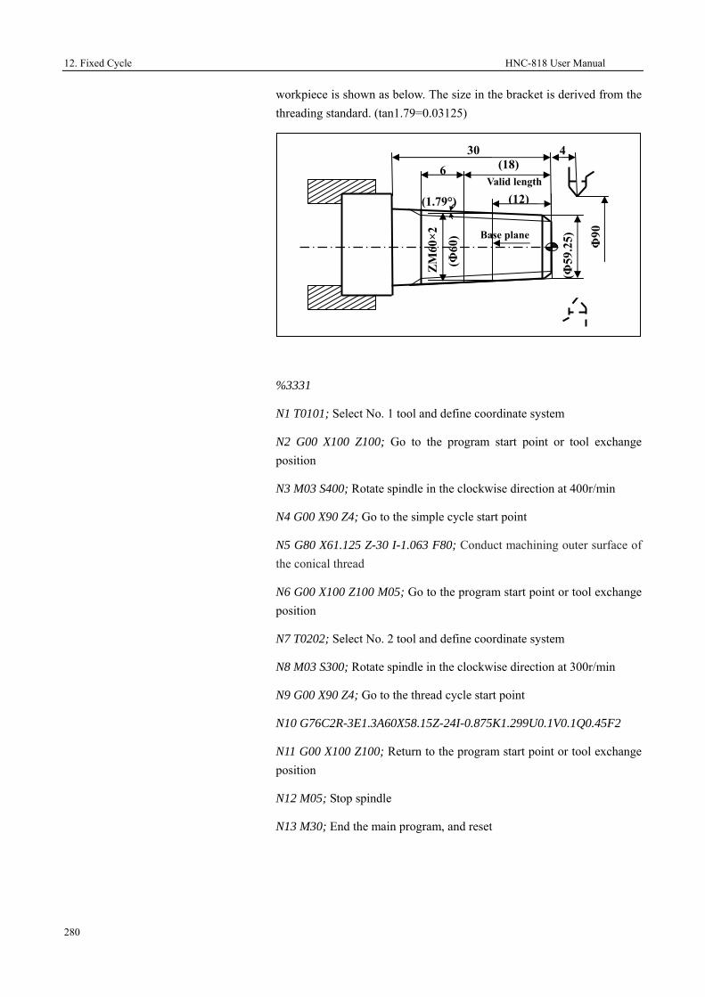
12. Fixed Cycle HNC-818 User Manual
280
workpiece is shown as below. The size in the bracket is derived from the threading standard. (tan1.79=0.03125)
%3331
N1 T0101; Select No. 1 tool and define coordinate system
N2 G00 X100 Z100; Go to the program start point or tool exchange position
N3 M03 S400; Rotate spindle in the clockwise direction at 400r/min
N4 G00 X90 Z4; Go to the simple cycle start point
N5 G80 X61.125 Z-30 I-1.063 F80; Conduct machining outer surface of the conical thread
N6 G00 X100 Z100 M05; Go to the program start point or tool exchange position
N7 T0202; Select No. 2 tool and define coordinate system
N8 M03 S300; Rotate spindle in the clockwise direction at 300r/min
N9 G00 X90 Z4; Go to the thread cycle start point
N10 G76C2R-3E1.3A60X58.15Z-24I-0.875K1.299U0.1V0.1Q0.45F2
N11 G00 X100 Z100; Return to the program start point or tool exchange position
N12 M05; Stop spindle
N13 M30; End the main program, and reset
Valid length
Base plane
4
(1.79°)
(Φ60
)
(Φ59
.25)
(12)
(18)
ZM
60×2
30
Φ90
6

HNC-818 User Manual 12. Fixed Cycle
281
12.5 Special Cases in Fixed Cycle
For milling machines, use G80 to cancel the fixed cycle. For turning machines, use G00/G01/G02 to cancel the fixed cycle. After the fixed cycle statement, all statements are identified by the system as a fixed cycle before the fixed cycle is canceled.
Wrong programming Correct programming
%1111
T0101
G0X50Z20
X32Z0
G80X30Z-30
M98P12; Call %12 in the fixed cycle
M30
%12
G0X10Z10
X30Z30
M99
%1111
T0101
G0X50Z20
X32Z0
G80X30Z-30
G01
M98P12; call %12 of the current program
M30
%12
G0X10Z10
X30Z30
M99
Currently, the fixed cycle cannot be used with rotation, mirroring, scaling, and G91 simultaneously.

13. User Macro Program HNC-818 User Manual
282
13 User Macro Program
User macro program is similar to a high-level language programming method, which allows users to use variables, arithmetic, logical operations and conditional transfer. This function makes it simpler to create the same machining program than the traditional ones. Users may create general macro program for the same machining operation, e.g. the machining of the bolt hole circle shown as below:
Create a macro program for the bolt hole circle machining shown in the figure above, and store it in the CNC. This way, you can call this program to machine the bolt hole circle at any time by simply entering the bolt hole properties such as the number of holes and deviation angle. It is like a bolt hole circle function is added to the CNC.
13.1 Variables
13.2 Operation Instructions
13.3 Macro Statement
13.4 Macro Program Calling
13.5 User Sub-Programs
r b
a

HNC-818 User Manual 13. User Macro Program
283
13.1 Variables
In a macro program, you may use variables for parameters of preparation function commands and axial movement distance, e.g. G00 X[#43], where #43 is a variable. You can assign to it before calling it.
Attention
In macro program, you cannot directly use the variable name. Variables is specified with the variable symbol (#) and the variable number following the symbol.
Variables
According to the variable numbers, variables can be divided into local variables, global variables, and system variables. Different variables have different usages. In addition, the access properties of different variables are different; some variables are read-only.
Constant
A number of constants have been defined for users in the system, which are read-only.
PI: circular constant Π
TRUE: indicates the condition is true.
FALSE: indicates the condition is false.
Attention
When using the constant PI, users need to specially handle the end condition of the program because of its calculation error; otherwise, exceptions may occur.
Local variables
Local variables are variables used within the macro program. That means a local variable (e.g. #i) called from a macro program A at one time is different from that at another time. Therefore, during multi-layer calling, the system may improperly use in macro B the local variables being used in macro A when calling macro B from A, resulting in damage to the value.
Variables from #0 to #49 are local variables, of which properties are read and write.

13. User Macro Program HNC-818 User Manual
284
The system provides six layers of nested local variables, of which properties are read-only.
• #200-#249: local variables of layer 0
• #250-#299: local variables of layer 1
• #300-#349: local variables of layer 2
• #350-#399: local variables of layer 3
• #400-#449: local variables of layer 4
• #450-#499: local variables of layer 5
Global variables
Different from local variables, global
variables can be generally used for the main program calling subprograms, or used among subprograms and macro programs, while the values remain unchanged. That means a global variable (e.g. #i) used in one macro program and others is the same. In addition, the public variable #i out of a macro can be used in other macros.
Variables from #50 to #199 are global variables, of which properties are read and write.
System variables
System variables are fixed variables in the system. Its properties are read-only, write-only and read &write, depending on the properties of each system.
Undefined variables
The default value for the variables undefined in the system is 0.
Example:
%1234
G54
G01 X10Y10
X[#1]Y30; Coordinate value of the workpiece coordinate system (0, 30)
M30
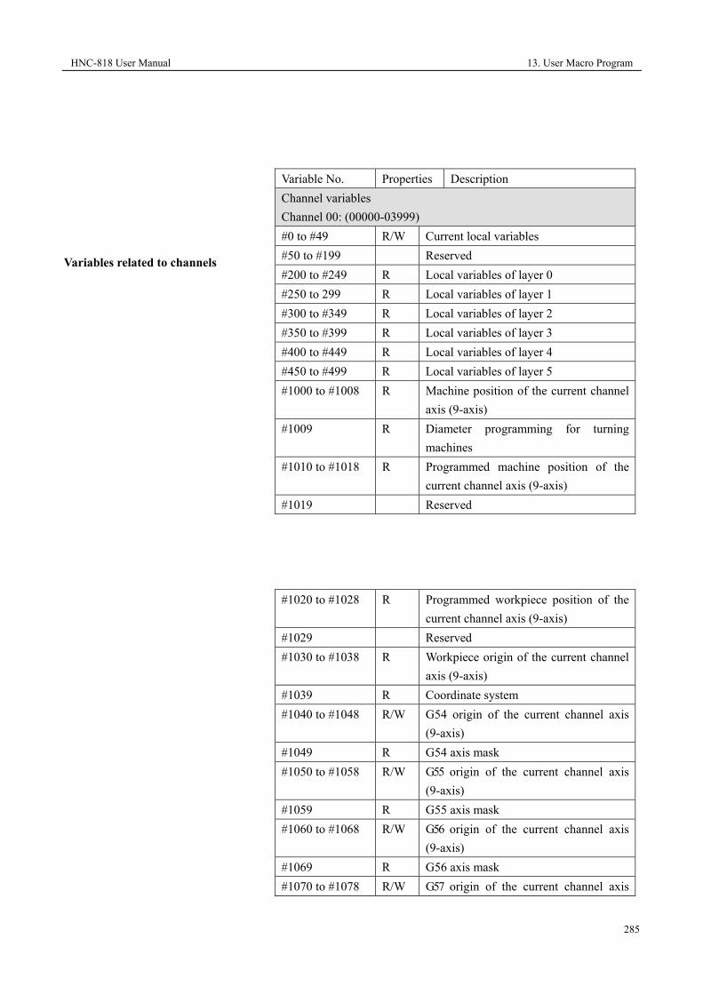
HNC-818 User Manual 13. User Macro Program
285
Variables related to channels
Variable No. Properties Description Channel variables Channel 00: (00000-03999) #0 to #49 R/W Current local variables #50 to #199 Reserved #200 to #249 R Local variables of layer 0 #250 to 299 R Local variables of layer 1 #300 to #349 R Local variables of layer 2 #350 to #399 R Local variables of layer 3 #400 to #449 R Local variables of layer 4 #450 to #499 R Local variables of layer 5 #1000 to #1008 R Machine position of the current channel
axis (9-axis) #1009 R Diameter programming for turning
machines #1010 to #1018 R Programmed machine position of the
current channel axis (9-axis) #1019 Reserved
#1020 to #1028 R Programmed workpiece position of the current channel axis (9-axis)
#1029 Reserved #1030 to #1038 R Workpiece origin of the current channel
axis (9-axis) #1039 R Coordinate system #1040 to #1048 R/W G54 origin of the current channel axis
(9-axis) #1049 R G54 axis mask #1050 to #1058 R/W G55 origin of the current channel axis
(9-axis) #1059 R G55 axis mask #1060 to #1068 R/W G56 origin of the current channel axis
(9-axis) #1069 R G56 axis mask #1070 to #1078 R/W G57 origin of the current channel axis

13. User Macro Program HNC-818 User Manual
286
(9-axis) #1079 R G57 axis mask #1080 to #1088 R/W G58 origin of the current channel axis
(9-axis) #1089 R G58 axis mask #1090 to #1098 R/W G59 origin of the current channel axis
(9-axis) #1099 R G59 axis mask

HNC-818 User Manual 13. User Macro Program
287
#1100 to #1108 R G92 origin of the current channel axis (9-axis)
#1109 R G92 axis mask #1110 to #1118 R Breakpoint of the current channel axis
(9-axis) #1119 R Breakpoint axis labels #1120 to #1149 R/W Fixed cycle modal variables #1150 to #1189 R G code 0-39 modal #1190 R User-defined input #1191 R User-defined output #1192 to #1199 Reserved #1200 to #1209 R AD input #1210 to #1219 R DA output #1220 R M3/4/5 #1221 R G94 F value #1222 R Tapping F value #1223 to #1226 R Tapping spindle rotation speed #1227 R Valid radius compensation No. D #1228 R Valid length compensation No.H #1229 R cmd_feed #1300 to #1308 R Relative origin of the current channel
axis (9-axis) #1309 Reserved #1310 to 1318 R Programmed machine position of the
current channel axis (9-axis) #1319 Reserved #1320 to #1328 R G28 midpoint #1329 R G28 axis mask #1330 to #1338 R G52 origin #1339 Reserved #1340 to #1349 R G31 measure machine command
position #1350 to #1359 Reserved #1360 to #1369 R G31 measure actual machine position #1370 to #1399 Reserved #1400 to #1408 R/W G54 offset #1409 Reserved #1410 to #1418 R/W G55 offset #1419 Reserved #1420 to #1428 R/W G56 offset #1429 Reserved #1430 to #1438 R/W G57 offset

13. User Macro Program HNC-818 User Manual
288
Attention User-defined variables Attention Variables related to tool
#1439 Reserved #1440~#1448 R/W G58 offset #1449 Reserved #1450~#1458 R/W G59 offset #1459~#3999 Reserved
The variables corresponding to the origins and offsets of the current channel workpiece coordinate system G54~G59 are read and write, and can be saved after power off.
User-defined variables: 500 to 999 50000 to 54999
#500 to #999 R/W Global variables #50000 to #54999 R/W Global variables
When the machine user parameter 010091"#500~#999USER MACRO ENABLED" is 1, the user-defined variables #500 to #999 are valid. User-defined variables are saved after power off.
Tool data: #70000 to #89999 Each tool uses 200 numbers. There is a total of 100 tools, with a total of 20000 numbers. Coding range corresponding to No. 0 tool: 000 to 199 Coding range corresponding to No. 1 tool: 200 to 399 Coding range corresponding to No. 99 tool:18000-19999 #70005 R The direction of the turning tool nose. #70006 R/W The length of the milling tool or the X
offset of the turning tool. #70007 R The Y offset of the turning tool. #70008 R The Z offset of the turning tool. #70009 Reserved #70010 Reserved #70011 R/W The radius of the milling tool or the
radius of the turning tool nose. #70012-#70028 Reserved #70029 R/W The length wear of the milling tool or
the Z offset wear of the turning tool. #70030 The Y offset wear of the turning tool.

HNC-818 User Manual 13. User Macro Program
289
Attention
The properties of the variables corresponding to the tool radius compensation value, length offset, and wear values are read and write, which can be save after power off.
#70034 R/W The radius wear of the milling tool or the X offset wear of the turning tool.
#70035- #70100 Reserved #70101 R Tool life monitoring types #70104 R Maximum cutting time #70105 R Alarm cutting time #70106 R Acutal cutting time #70107 R Maximum cutting count #70108 R Alarm cutting count #70109 R Actual cutting count

13. User Macro Program HNC-818 User Manual
290
13.2 Operation Instructions
In the macro statement, you may flexibly use arithmetic operators and functions to meet complex programming requirements. See the figure below:
Operation Type
Operation Instructions
Description
Arithmetic operation
#i = #i + #j Addition, #i plus #j #i = #i - #j Subtraction, #i minus #j #i = #i * #j Multiplication, #i times #j #i = #i / #j Division, #i divided by #j
Condition operation
#i EQ #j Equal to (=) #i NE #j Not equal to (≠) #i GT #j Greater than (>) #i GE #j Greater than and equal to (≥) #i LT #j Less than (<) #i LE #j Less than and equal to (≤)
Logical operation
#i = #i & #j Logical operation "And" #i = #i | #j Logical operation "Or" #i = ~#i Logical operation "Not"
Functions
#i= SIN[#i] Sine (unit: radian) #i=ASIN[#i] Anti-sine #i=COS[#i] Cos (unit: radian) #i=ACOS[#i] Anti-cos #i=TAN[#i] Tangent (unit: radian) #i=ATAN[#i] Anti-tangent #i=ABS[#i] Absolute value #i=INT[#i] Integer (round down) #i=SIGN[#i] Obtain sign #i=SQRT[#i] Square root #i=POW[#i] Power #i=LOG[#i] logarithm #i=PTM[#i] Pulse time modulation (mm) #i=PTD[#i] Pulse time degree #i=RECIP[#i] Reciprocal #i=EXP[#i] Index based on e (2.718) #i=ROUND[#i] Round #i=FIX[#i] Round down #i=FUP[#i] Round up

HNC-818 User Manual 13. User Macro Program
291
Example
The program below is used to obtain the sum of 1 to 10:
O9500
#1=0; The initial value of the subtrahend
#2=1; The initial value of the addend
N1 IF[#2 LE 10]; The addend cannot exceed 10; otherwise, it goes to the N2 after ENDIF.
#1 =#1 + #2; Subtraction operation
#2 =#2 +1; The next addend
ENDIF; Move to N1
N2 M30; End program

13. User Macro Program HNC-818 User Manual
292
13.3 Macro Statement
Expression
Those calculation formulas with symbols like "+", "-", "*", "/", "[", "]", and SIN are known as expression. See the examples as below:
1. -#1
2. SIN[#1+#2]*COS[[#1+#2]/#3]
Attention:
1. The symbol "[ ]" indicates a higher priority than "+", "-", "*", and "/". E.g. when conducting operation for [[#1+#2]/#3], firstly calculate the [#1+#2], then calculate /#3.
2. For the expression, to ensure the calculation accuracy, it is recommended to use the symbol "[ ]", e.g. [-#2]. It is not recommended to write like -[#2].
Assignment statement
Assignment means to transfer the value of a constant or an expression to a macro variable. This statement is called an assignment statement. See the example below:
#2 = 175 / SQRT[2] * COS[55*PI/180]
#3 = 124.0
Condition statements
Two types of condition statement are supported in this system:
IF [condition expression]; Type 1
……
ENDIF
IF [condition expression]; Type 2
……

HNC-818 User Manual 13. User Macro Program
293
ELSE
……
ENDIF
For the condition expression of the IF statement, you may use a simple or complex expression. See the examples below:
When #1 is equal to #2, 0 is assigned to #3.
IF [#1 EQ #2]
#3 = 0
ENDIF
When #1 is equal to #2, and #3 is equal to #4, 0 is assigned to #3.
IF [#1 EQ #2] AND [#3 EQ #4]
#3 = 0
ENDIF
When #1 is equal to #2, or #3 is equal to #4, 0 is assigned to #3. Otherwise, 1 is assigned to #3.
IF [#1 EQ #2] OR [#3 EQ #4]
#3 = 0
ELSE
#3 = 1
ENDIF
Cycle statement
Specify a condition expression after WHILE. When the specified condition expression is satisfied, execute the programs between WHILE to ENDW. When the specified condition expression is not satisfied, exit the WHILE cycle, and execute the program line after ENDW.
Calling format:
WHILE [condition expression]
……
ENDW
Infinite cycle

13. User Macro Program HNC-818 User Manual
294
When the WHILE condition expression is defined as always true, an infinite cycle can be realized:
WHILE [TRUE]; or WHILE [1]
……
ENDW
GOTO statement
GOTO _
Use GOTO to move to the specified label.
GOTO must be followed by numbers. E.g. GOTO 4 indicates to move to the N4 program block (N4 must be defined at the header of the program block).
Nest
For the IF and WHILE statement, the system allows nested statements that follow a certain of restrictive rules.
For IF statement, only up to six layers of nested statements are allowed; if over six, an error will be reported.
For WHILE statement, only up to six layers of nested statements are allowed; if over six, an error will be reported.
The system supports combined IF and WHILE statements, but the matching relationship of IF-ENDIF and WHILE-ENDW must be satisfied. For the usage as described below, the system will report an error.
IF [condition expression 1]
WHILE [condition expression 2]
ENDIF
ENDW
Example

HNC-818 User Manual 13. User Macro Program
295
Edit ellipse machining program (elliptic expression: X=a×COSα; Y =b×SINα).
%0001
#0=5; Define tool radius R
#1=20; Define a
#2=10; Define b
#3=0; Define the initial value of the stepping angle. unit: degree
N1 G92 X0 Y0 Z10
N2 G00 X[2*#0+#1] Y[2*#0+#2]
N3 G01 Z0
N4 G41 X[#1] D01
N5 WHILE #3 GE [-360]
N6 G01 X[#1*COS[#3*PI/180]] Y[#2*SIN[#3*PI/180]]
N7 #3=#3-5
ENDW
G01 G91 Y[-2*#0]
G90 G00 Z10
α

13. User Macro Program HNC-818 User Manual
296
G40 X0 Y0
M30

HNC-818 User Manual 13. User Macro Program
297
13.4 Calling Macro Programs
There are three modes to call macro programs:
1. Non-modal call: G65
2. G-code call: fixed cycle
3. Call subprograms with M codes
13.4.1 Rules for Defining Arguments
Rules for defining arguments
When users call the macro, the system will automatically copy the argument (A - Z) in the current program to the local variables (#0 to #25) of the current layer in the corresponding user macro, and copy the workpiece coordinate system absolute position of the current channel axis (XYZABCUVW) to the local variables (#30 to #38) of the current channels.
Macro Variables
Argument Name
Macro Variables
Argument Name
Macro Variables
Argument Name
#0 A #1 B #2 C #3 D #4 E #5 F #6 G #7 H #8 I #9 J #10 K #11 L
#12 M #13 N #14 O #15 P #16 Q #17 R #18 S #19 Blank #20 U #21 V #22 W #23 X #24 Y #25 Z #26 Reserved#27 Reserved #28 Reserved #29 Reserved#30 X position #31 Y position #32 Z position#33 A position #34 B position #35 C position
#36 U position #37 V position #38 W
position
Example
%1234; Main program
G92 X0 Y0 Z50
G91 G01 Z10 F400

13. User Macro Program HNC-818 User Manual
298
M98 P111
G4X1
%111
G01x10y10z10
…
M99
Verification of macro definition
Format: AR[# variable number]
Returned value:
0: The variable is not defined.
90: The variable is defined as the absolute mode G90.
91: The variable is defined as the incremental mode G91.
Note: Use the system macro AR[] to determine whether the macro variable is defined, and whether it is defined as the incremental or absolute mode.
Example
%1234
G92X0Y0Z0
M98P9990X20Y30Z40
M30
%9990
IF [AR[#23] EQ 0] OR [AR[#24] EQ 0] OR [AR[#25] EQ 0]; if X or Y or Z is not defined, then return
M99
ENDIF
G91; create macro program with the incremental mode
IF AR[#23] EQ 90; if the X value is the absolute mode G90
#23=#23-#30; change the X value to the incremental mode; #30 is the absolute coordinate of X
ENDIF
……..
M99

HNC-818 User Manual 13. User Macro Program
299
13.4.2 Non-Modal Call (G65)
When G65 is specified, the defined user macro program following the parameter P is called. At the same time, the arguments and variables required by the user macro program are transferred to the user macro program.
Format
G65 P_ L_ [argument address word]
Parameter Description P The number of the program to be called. L Call repeats.
Argument address word
The data that users need to transfer to the macro program.
Attention
1. G65 is a non-modal command. You need to specify G65 in the current line when calling macro programs.
2. Subprograms must be in the same file.
Example
%0032
G54G0X100Z100
G65P100L5X50Z-30F1000
G00X50Z10
M30
%100
G01X[#23]Z[#25]F[#5]
G81X[#23]Z[#25]
G0X100Z50
M30
13.4.3 Call Macro Program with G Codes

13. User Macro Program HNC-818 User Manual
300
In addition to use non-modal (G65)
to call macro programs, you may call macro programs with G codes. Currently, only the G codes in the
fixed cycle can be used to call macro programs. For details, see relevant sections related to turning and milling operations.
Function
Use G codes to call the user-defined subprograms in the fixed cycle.
Format
G_
Parameter Description G The subprogram number called in the
USERDEF.CYC (Arabic numerals).
Example
Add a fixed cycle 1001 in USERDEF.CYC
%1001;
G01 X10 Y10 Z10
G80
M99
Main program
%1244
G92X0Y0Z50
G91G01X10F400
G1001 (call user-defined fixed cycle)
G4X1
M30
13.4.4 Call Macro Program with M Commands
Format
M98 P_

HNC-818 User Manual 13. User Macro Program
301
Parameter Description P The subprogram number to be called in the current
program
Description
For the macro program calling with M commands, refer to the relevant
information (M98) in the auxiliary function section. When executing M98, the system will find the subprogram number to be called. If the subprogram is not found, an error will be reported.
Format
M_
Parameter Description M The input value of the user-defined parameter.
Description
Use a M command to call a user-defined subprogram.
The table below describes the M parameter settings corresponding to the subprograms. The user-defined parameters (010360-010373) correspond to the subprograms (%1007-%1020) in USERDEF.CYC.

13. User Macro Program HNC-818 User Manual
302
Example
Set the M command parameter (010360) corresponding to the fixed cycle G1007 to 13, then you may use M13 to call the %1007 program in USERDEF.CYC.
%1007; add user-defined subprogram 1007 to USERDEF.CYC
G0Z5
Z-50
G80
M99
%1234; main program
G54
G1X0Y0Z0
M13; use M13 to call the 1007 subprogram
Parameter List
Parameter No.
Parameter Name Parameter Value
Effective Mode
Machine user param
eters
010360 M command corresponding to the fixed cycle G1007
13 Save
010361 M command corresponding to the fixed cycle G1008
0 Save
010362 M command corresponding to the fixed cycle G1009
0 Save
010363 M command corresponding to the fixed cycle G1010
0 Save
010364 M command corresponding to the fixed cycle G1011
0 Save
010365 M command corresponding to the fixed cycle G1012
0 Save
010366 M command corresponding to the fixed cycle G1013
0 Save
010367 M command corresponding to the fixed cycle G1014
0 Save
010368 M command corresponding to the fixed cycle G1015
0 Save
010369 M command corresponding to the fixed cycle G1016
0 Save
010370 M command corresponding to the fixed cycle G1017
0 Save
010371 M command corresponding to the fixed cycle G1018
0 Save
010372 M command corresponding to the fixed cycle G1019
0 Save
010373 M command corresponding to the fixed cycle G1020
0 Save

HNC-818 User Manual 13. User Macro Program
303
X10Y10
X20Y30
Y0
X0
M30
Attention
1. Currently, the fixed cycle cannot be used with rotation/mirroring/scaling/G91 simultaneously.
2. When using M commands to call subprograms, you need to add G80 before M99 when the program ends.
13.4.5 Macro Program Cases
Case 1 (milling)
Use spher mill to machine the R5 fillet surface shown in the figure below:
%0001 (The cutter location is the ball center) G92 X-30 Y-30 Z25 #0=5 (Fillet radius) #1=4 (Spher mill radius) #2=180 (The initial value of the stepping angle γ. Unit: degree) WHILE #2 GT 90 G01 Z[25+[#0+#1]*SIN[#2*PI/180]] (Calculate Z axis height) #101=ABS[[#0+#1]*COS[#2*PI/180]]-#0 (Calculate radius offset) G01 G41 X-20 D01 Y14 G02 X-14 Y20 R6
R5
R6
Z
X
1530
X
Y
3040

13. User Macro Program HNC-818 User Manual
304
G01 X14 Case 1 (turning)
G02 X20 Y14 R6 G01 Y-14 G02 X14 Y-20 R6 G01 X-14 G02 X-20 Y-14 R6 G01 X-30 G40 Y-30 #2=#2-10 ENDW M30 Use macro program to create a program for the parabola within interval A[0, 8]. See the figure below:
%3401
N1 T0101
N2 G37
N3 #10=0; A coordinate
N4 M03 S600
N5 WHILE #10 LE 8
N6 #11=#10*#10/2
8
32
A
B
Parabola B=-A2/2 within interval A [0, 8]
Ф16
32

HNC-818 User Manual 13. User Macro Program
305
N7 G90 G01 X[#10] Z[-#11] F500
N8 #10=#10+0.08
N9 ENDW
N10 G00 Z0 M05
N11 G00 X0
N12 M30

13. User Macro Program HNC-818 User Manual
306
13.4.6 Subprogram Classification
Internal subprogram
If the called program and the main program are in the same file, then the called program is an internal subprogram.
Example
G code file name: O_test; %111: an internal subprogram, which is in the same file with the main program %1001, and is called by G98 in the main program.
%1001; main program
G92 X0 Y0 Z50
G91 G01 Z10 F400
M98 P111; call subprogram 111
G4X1
M30
%111; subprogram
G01x10y10z10
…
G80
M99
External subprogram
If the called program is in another file, it is an external subprogram.
The external subprogram file name must start with letter "O".
Example
G code file name: O_test; subprogram file name: O123
Main program
%1001
G92 X0 Y0 Z50

HNC-818 User Manual 13. User Macro Program
307
G91 G01 Z10 F400
M98 P123; call subprogram O123
G4X1
M30
Subprogram O123
%1234;
G01x10y10z10
…
G80
M99
Fixed cycle
There are two kinds of fixed cycles. One is the general fixed cycle, mainly used for turning, milling and drilling; the other is the user fixed cycle, which is created by yourself according to your requirements.
For detailed information about general fixed cycle, see section 12.
For user-defined fixed cycle (USERDEF.CYC), you may add subprograms to this file as required, and may directly call them in the main program.
Open the user-defined fixed cycle file "USERDEF.CYC", find the content as below, and add subprograms after it, e.g. add 1010:
The fixed cycle below is a user-defined fixed cycle:
User-defined fixed cycle ranging from G1000 to Gxxxx by tp 2010.12.27
User-defined fixed cycle G1090
%1010
G01X10Y10
M99

14. Spindle Functions HNC-818 User Manual
308
14 Spindle Functions
This chapter includes the following sections:
14.1 Constant Linear Speed Cutting Control
14.2 C/S Axis Change Function

HNC-818 User Manual 14. Spindle Functions
309
14.1 Constant Linear Speed Cutting Control (T) (G96, G97)
Specifies the circumferential speed (relative speed between the tool and the workpiece) after S. With respect to the tool position change, rotate the spindle at specified circumferential speed all the time.
Format
G96 P_ S_ ; enable the spindle
constant linear speed control
G46 X_ P_; limit spindle speed
G97 S_ ; cancel the spindle constant linear speed control
Parameter Description P In G96 command: It specifies the axis for the constant
linear speed control. The axis specified by 0 is determined by the system axis parameter. The values 1, 2, and 3 indicate the X, Y and Z axis respectively. In G46 command: It specifies the maximum spindle speed (r/min) limitation when the constant linear speed is defined by G46.
S Define the constant linear speed in G96 (mm/min or inch/min). The defined spindle speed (r/min) after the constant linear speed is canceled in G97.
X The minimum spindle speed (r/min) limitation when the constant linear speed is defined.
Description
1. G96/G97 are modal commands
which can be canceled by each other.
2. G46 is valid only when the constant linear speed function is valid.
3. Only when the spindle can automatically change speed (e.g.: servo spindle, frequency spindle), can the constant linear speed function be used.
4. During the constant linear speed control, when the spindle speed exceeds the maximum spindle speed, it will be limited at the maximum speed.
Attention

14. Spindle Functions HNC-818 User Manual
310
G96 must be followed by G46, to limit the maximum and minimum spindle speed.

HNC-818 User Manual 14. Spindle Functions
311
Example
%3318
N1 T0101; Select No. 1 tool and define coordinate system
N2 G00 X40 Z5; Go to the start point
N3 M03 S460; Rotates spindle at 460r/min
N4 G96 P0 S80; The constant linear speed is valid, with the speed of 80m/min).
N5 G46 X400 P900; Limit the spindle speed range: 400-900 r/min
N6 G00 X0; The tool goes to the center, and the spindle speed increases until the maximum speed 900r/min.
N7 G01 Z0 F60; Close to the workpiece
N8 G03 U24 W-24 R15; Conduct machining for the arc of R15
N9 G02 X26 Z-31 R5; Conduct machining for the arc of R5
N10 G01 Z-40; Conduct machining for the outer circle of Φ26
N11 X40 Z5; Back to the tool setting location
N12 G97 S300; Cancel the constant linear speed function, and rotate the spindle at the speed of 300r/min
N13 M30; Stop spindle, end the main program, and reset
27
R15
4031
R5
Φ26
Φ22

18. Spindle Functions HNC-818 User Manual
312
14.2 C/S Axis Switching Function (CTOS/STOC)
In complex applications, such as rigid tapping function, the spindle need to be used as a rotation axis in addition to a spindle. In this case, the C/S axis switching function is available.
Format
STOC/G108 IP;
CTOS/G109 IP;
Parameter Description IP IP can be defined as A/B/C. The number following it
indicates the channel spindle number, which ranges from 0 to 3. When IP is not specified after STOC, No. 0 spindle will be switched to the C axis by default. When IP is not specified after CTOS, the C axis will be switched to No.0 spindle by default.
Attention
1. In the same G code, it is not recommended to frequently use the STOC/CTOS macro commands
2. When the spindle is switched to the C axis, the unit of the C axis is deg/min.
3. It is not allowed to use the random line function to jump among lines between STOC and CTOS, or jump from other line to a line between STOC and CTOS.
4. The random line function does not support the C axis of STOC.
Example
%900 Program name
G54
M03S600
STOC; Switch the spindle to the C axis
G28 C0; The C axis returns to the origin.
G1 C45 F2000

HNC-818 User Manual 14. Spindle Functions
313
…
CTOS; Switch the C axis to the spindle
M03S600
M30
Attention
M30 cannot restore the status of the C/S axis.
14.3 Spindle Synchronization (G116, G117)
During dual spindle synchronization, one spindle is the master axis, and the other is the slave axis. The reference spindle for synchronization is called the master axis, while the axis moves with the master axis is called the slave axis. During polygon machining, the tool axis is the master axis, and the workpiece axis is the slave axis.
Format
G116 J_/K_ P_/Q_ R_; establish synchronization
G117; cancel synchronization
Parameter Description J The logical axis number of the master axis. K The logical axis number of the slave axis. P The rotation speed ration of the master axis, ranging
from 1 to 1000. Q The rotation speed ration of the slave axis, ranging
from -1000 to 1000 and cannot be 0. When Q is a positive value, the rotation direction of the slave axis is the same as that of the master axis. When Q is a negative value, the rotation direction of the slave axis is opposite to that of the master axis.
R Phase angle (0 to 360)
Example
T0101
G0 X100 Z20
M3 S1000

18. Spindle Functions HNC-818 User Manual
314
G116 J5 K1 P1 Q2 R0; Establish synchronization. No.5 logical axis is the master axis and No.1 logical axis is the slave axis.
G01 X20 F100; Conduct tool feed for cutting
G04 X2
G0 X100; Exit the tool
G117; Cancel synchronization
M5
M30
Attention
1. The spindle synchronization commands (G116/G117) cannot be
used with other commands simultaneously in one line.
2. During synchronization, you can not specify the metric conversion
commands (G20, G21).
3. The Emergency Stop and Reset command can automatically cancel
the synchronization.
4. During synchronization, you cannot control the slave axis with
commands. Only the rotational speed and direction of the master
axis can be specified. But you may specify movement commands
for other axis through the programming.

HNC-818 User Manual 15. Programmable Data Input
315
15 Programmable Data Input
You can dynamically modify system data in the program via programmable data input.
1. Change the origin of the workpiece coordinate system
2. Change the origin of the extended workpiece coordinate system

15. Programmable Data Input HNC-818 User Manual
316
15.1 Programmable Data Input (G10, G11)
You can dynamically modify system data in the program with G10/G11.The modified system data takes effect immediately.
Format
Function G Code G54-G59: the origin of the workpiece coordinate system
G10 L2 Pp IP_
G54.X: the origin of the extended workpiece coordinate system
G10 L20 Pp IP_
System parameter output G10 L53 PpRr Cancel user-defined input G11 Milling tool geometry compensation value H input
G10 L10 PpRr
Milling tool geometry compensation value D input
G10 L12 PpRr
Turning tool compensation value input
G10 L14 Pp X_ Z_ R_ Q_ Y_ J_ K_
Description
G10 is a modal command, which enables the programmable data input mode until it is canceled by G11.
G54-G59 origin of the workpiece coordinate system
G10 L2 Pp IP_
Parameter Description Pp Specify the workpiece origin offset in the relative
workpiece coordinate systems from 1 to 6: 1 indicates the G54 workpiece coordinate system 2 indicates the G55 workpiece coordinate system 3 indicates the G56 workpiece coordinate system 4 indicates the G57 workpiece coordinate system 5 indicates the G58 workpiece coordinate system 6 indicates the G59 workpiece coordinate system
IP The workpiece origin offset of each axis for absolute commands. Added to the workpiece origin offset of each axis for incremental commands.
Example 1
%0002

HNC-818 User Manual 15. Programmable Data Input
317
G54; Initial value of G54
G01X100Y100Z100
G10L2P1X100Y100Z50; Change the origin of the G54 workpiece coordinate system to (100, 100, 50)
G11
G01X20Y20Z20; The command value of the machine coordinate system is (120, 120, 70).
M30
G54.X origin of the extended workpiece coordinate system
G10 L20 Pp IP_
Parameter Description Pp Set the code p for the workpiece coordinate system of
the workpiece origin offset: 1-60, corresponding to the X value in the G54.X coordinate system.
IP The workpiece origin offset of each axis for absolute commands. Added to the workpiece origin offset of each axis for incremental commands.
Example 2
%0002
G54.1
G01X100Y100Z100
G10L20P1X100Y100Z50; Change the origin of the G54.1 workpiece coordinate system to (100, 100, 50)
G11
G01X20Y20Z20
M30
Attention
In the turning system and in the diameter programming mode, the X value specified by G10 is the radius value.
System parameter output
Output the system parameter to the current channel variables specified

15. Programmable Data Input HNC-818 User Manual
318
by Rr: #0 to #49
G10 L53 Pp Rr
Parameter Description Pp Index of parameter ID Rr Variable address (0 to 49)
Cancel user-defined input
Example 3
G11
Use machine user parameters from P40 to P48
Parameter number 010340 to 010348
As the parameter P ranges from 500000 to -500000, you may use it if the error range is wide.
G54
G01X0Y0Z0
G10L53P010340R1
G10L53P010341R2
G10L53P010342R3
G10L53P010343R4
G10L53P010344R5
G10L53P010345R6
G10L53P010346R7
G10L53P010347R8
G10L53P010348R9
G11
G01X[#1/1000]Y[#2/1000]Z[#3/1000]
G01X[#4/1000]Y[#5/1000]Z[#6/1000]
G01X[#7/1000]Y[#8/1000]Z[#9/1000]
M30

HNC-818 User Manual 15. Programmable Data Input
319
Milling tool geometry compensation value H input
G10 L10 Pp Rr;
Parameter Description Pp Tool offset number Rr Tool compensation data
Milling tool geometry compensation value D input
G10 L12 Pp Rr;
Parameter Description Pp Tool offset number Rr Tool compensation data
Turning tool compensation input
G10 L14 Pp X_ Z_ R_ Q_ Y_ J_ K_;
Parameter Description Pp Tool offset number X Tool compensation data X Z Tool compensation data Z R Tool nose compensation R Q Imaginary too nose direction Y Tool compensation data Y J Tool radial wear J K Tool axial wear K

16. Axis Control Functions HNC-818 User Manual
320
16 Axis Control Functions
This chapter includes the following sections:
16.1 Cycle Function of the Rotation Axis
16.2 Reference of the Grating Ruler with Distance-Code
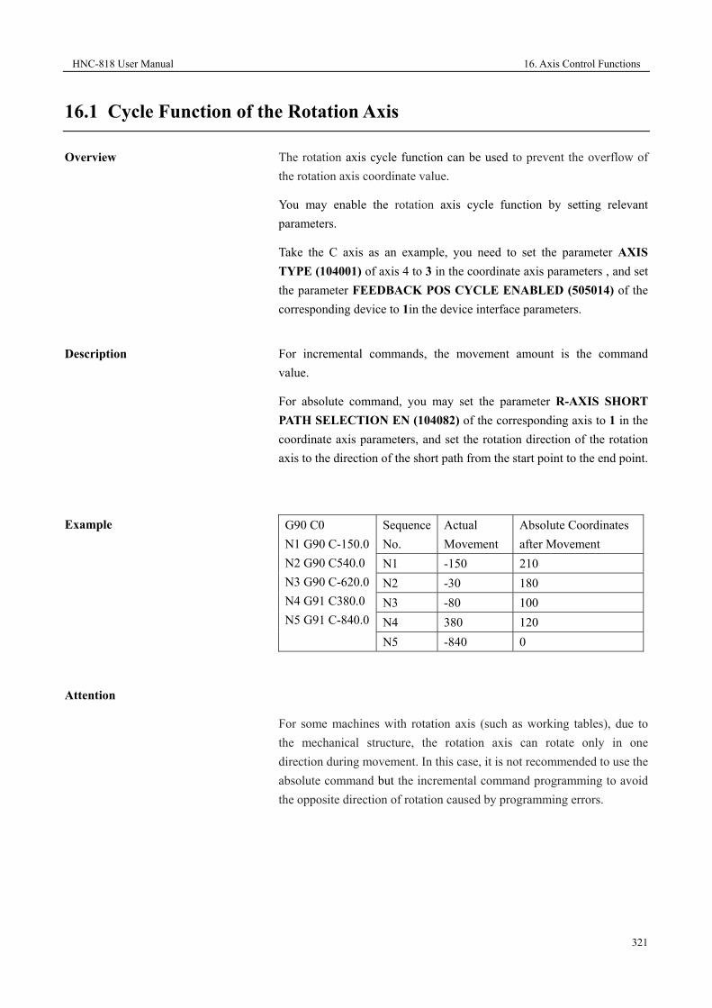
HNC-818 User Manual 16. Axis Control Functions
321
16.1 Cycle Function of the Rotation Axis
Overview
The rotation axis cycle function can be used to prevent the overflow of the rotation axis coordinate value.
You may enable the rotation axis cycle function by setting relevant parameters.
Take the C axis as an example, you need to set the parameter AXIS TYPE (104001) of axis 4 to 3 in the coordinate axis parameters , and set the parameter FEEDBACK POS CYCLE ENABLED (505014) of the corresponding device to 1in the device interface parameters.
Description
For incremental commands, the movement amount is the command value.
For absolute command, you may set the parameter R-AXIS SHORT PATH SELECTION EN (104082) of the corresponding axis to 1 in the coordinate axis parameters, and set the rotation direction of the rotation axis to the direction of the short path from the start point to the end point.
Example
G90 C0 N1 G90 C-150.0N2 G90 C540.0 N3 G90 C-620.0N4 G91 C380.0 N5 G91 C-840.0
Sequence No.
Actual Movement
Absolute Coordinates after Movement
N1 -150 210 N2 -30 180 N3 -80 100 N4 380 120 N5 -840 0
Attention
For some machines with rotation axis (such as working tables), due to the mechanical structure, the rotation axis can rotate only in one direction during movement. In this case, it is not recommended to use the absolute command but the incremental command programming to avoid the opposite direction of rotation caused by programming errors.

16. Axis Control Functions HNC-818 User Manual
322
16.2 Reference of Grating Ruler with Distance-Code
Overview
Using a linear measuring system with distance-coded reference point symbols, you do not need to install a deceleration switch on the machine for returning to the reference point, and the machine can return to a fixed machine reference point. It makes the operation much faster and easier in the actual use.
Principle
The principle for the linear measuring system with distance-coded reference point symbols is to adopt a standard linear grid line and a channel with distance-coded reference point symbols which is parallel to the linear grid line. The distance between two reference point symbols in the same group is the same, but the distance between the adjacent reference point symbols of two different groups is variable. Each segment distance plus a fixed value, then the CNC axis can determine the absolute position according to the distance. See the figure below (example: LS486C):
For example, the machine moves from point A to point C through the middle point B. If the system detects 10.02 , it will know which reference point the axis is at. Similarly, when the machine moves from point B to point D through the middle point C and the distance from the point C to point D is 10.04, the system will know which reference point the axis is at. Therefore, if the axis moves more than two reference points (20 mm), the system will be able to get the absolute position of the machine.
A B C D E
10.02 10.04 10.06 10.08 10.10
20.02
20
Reference point
symbol
20.02 20.02 20.02
20 20 20 20
10.02
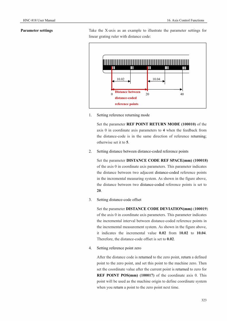
HNC-818 User Manual 16. Axis Control Functions
323
Parameter settings
Take the X-axis as an example to illustrate the parameter settings for linear grating ruler with distance code:
1. Setting reference returning mode
Set the parameter REF POINT RETURN MODE (100010) of the axis 0 in coordinate axis parameters to 4 when the feedback from the distance-code is in the same direction of reference returning; otherwise set it to 5.
2. Setting distance between distance-coded reference points
Set the parameter DISTANCE CODE REF SPACE(mm) (100018) of the axis 0 in coordinate axis parameters. This parameter indicates the distance between two adjacent distance-coded reference points in the incremental measuring system. As shown in the figure above, the distance between two distance-coded reference points is set to 20.
3. Setting distance-code offset
Set the parameter DISTANCE CODE DEVIATION(mm) (100019) of the axis 0 in coordinate axis parameters. This parameter indicates the incremental interval between distance-coded reference points in the incremental measurement system. As shown in the figure above, it indicates the incremental value 0.02 from 10.02 to 10.04. Therefore, the distance-code offset is set to 0.02.
4. Setting reference point zero
After the distance code is returned to the zero point, return a defined point to the zero point, and set this point to the machine zero. Then set the coordinate value after the current point is returned to zero for REF POINT POS(mm) (100017) of the coordinate axis 0. This point will be used as the machine origin to define coordinate system when you return a point to the zero point next time.
10.02 10.04
Distance between
distance-coded
reference points
20 40 0
17. Other Functions HNC-818 User Manual
324
17 Other Functions
This chapter includes the following sections:
17.1 Stop Read-ahead (G08)
17.2 Redefine Rotation Axis Angle Resolution (G115)
17.3 Axis Release (G101)
17.4 Command Channel Loader (G103) and Running (G103.1)
17.5 Channel Synchronization (G104)
17.6 Alarms (G110)
HNC-818 User Manual 17. Other Functions
325
17.1 Stop Read -ahead (G08)
During program execution, the system stops interpreting the subsequent lines after encountering this command. Only after the previously interpreted commands are completed, the system proceeds to interpret. This command is also used for real-time coordinate reading and state judgment.
Format
G08 ; specify this command in a separate program line.
Example
%0003
G54
G01 X10 Y10 Z10
G08; stop interpretation
G01 X100Y100Z100
G01 X30
M30

17. Other Functions HNC-818 User Manual
326
17.2 Redefine Rotary Axis Angle Resolution (G115)
Format
G115 IP_
Paramter Description IP Set the reciprocal value for the rotary axis resolution.
When it is set to 0, the system restores the default angle resolution. It must be greater than 0.
Description
Modify the rotary axis resolution. The default value is 1/100000 degree. There should be greater angle increments in one instruction during rigid tapping. Therefore, you need to decrease the angle resolution to an appropriate degree, to make sure that the equivalent length will not exceed the limit.
Attention
1. This command must be specified in a separate row.
2. One command can be used to modify only one rotary axis instruction.
3. The specified axis must be a rotary axis.
4. The newly defined angle resolution must be divisible by the standard one.
Example
%1234
STOC
G54
G90 C0
G115 C 1000; change the C axis resolution to 1/1000 degree.
G01 C3000
G115 C0; restore the C axis resolution to the default 1/100000 degree.
CTOS
HNC-818 User Manual 17. Other Functions
327
17.3 Axis Release (G101) and Axis Obtaining (G102)
Format
G101 IP_
Parameter Description IP Set the axis to be released. Options:
X/Y/Z/A/B/C/U/V/W/S0/S1/S2/S3
G102 IP_
Parameter Description IP Set the axis to be obtained. Options:
X/Y/Z/A/B/C/U/V/W/S0/S1/S2/S3
Description
G101 is used to release the axis by the channel. The address word following G101 can be any numbers, but it is recommended to specify it as 0.
G102 is used to obtain the axis by the channel. The address word following G102 must be a logical axis number.
Attention
1. Generally, the same logical axis can belong to only one channel at the same time.
2. After a channel obtains an axis, you need to set the G5X origin of the axis. If it cannot be specified on the settings interface, you may use G10 to specify it.
3. Axis release or obtaining cannot be executed during axis movement.

17. Other Functions HNC-818 User Manual
328
Example
How is drilling executed in the X/Y axis direction on the milling machines? In the example as below, assuming that in the channel configuration, the logical axis number of the X axis is 0, the logical axis number of the Y axis is 1, and the logical axis number of the Z axis is 2:
%1111
G54
G101 Y0 Z0; Release the Y axis and Z axis
G102 Y2 Z1; Exchange the logical axis numbers of the Y axis and Z axis
Start drilling:
G0X0Y0Z60
M3S700
G99G73X20Y25R5P2Q-3K2Z-32F80
G0X0Y0Z60
M30

HNC-818 User Manual 17. Other Functions
329
17.4 Command Channel Loader (G1030) and Running (G103.1)
Format
G103 P="program name" Q={channel number,...}
Parameter Description P The name of the program to be loaded. Q The number of the channel where the program will be
loaded. Separate multiple channels with a comma symbol (,).
G103.1 Q={channel number,...}
Parameter Description Q The number of the channel where the program will
run. Separate multiple channels with a comma symbol (,).
Description
When G103.1 is executed, the channel where the program will be loaded must be in the auto mode.
When G103 is executed, the channel where the program will be loaded should not have selection programs.
These two commands are generally used for multi-channels.
Example
Assuming that there is a dual-channel machine, channel 1 makes channel 2 load and run program O01.
%1
N1 G54
N2 G103 P="O01" Q={2}
N3 G103.1 Q={2}
.......;
M30
When channel 1 completes the line N3, channel 2 starts to run O01.

17. Other Functions HNC-818 User Manual
330
17.5 Channel Synchronization (G104)
Format
G104 P_ Q={channel number,}
Parameter Description Q The number of the channel to be synchronized.
Separate multiple channels with a comma symbol (,). P Signal value, ranging from 0 to 40.
Description
G104 is generally used for the process synchronization of multiple channels.
Example
Assuming there is a dual-channel milling machine, and the X axis is the public axis, with the following configuration:
Logical Axis No. of Channel 0
Logical Axis No. of Channel 1
X axis 0 --- Y axis 1 3 Z axis 2 4
Programs of Channel 1 Programs of Channel 2 %1 N1G54X0Y0Z0 N2G02X10Y10R20 N3G1X0Y0Z0 N4G101 X0; release X axis N5G104 P1 Q={1,2}; synchronization statement 1 N6G104 P2 Q={1,2}; synchronization statement 2 N7G102 X0 N8G0X100 N9M30
%2 N1G104 P1 Q={1,2}; synchronization statement 1 N2G102 X0; obtain X axis N3G54X0Y0Z0 N4G02X10Y10R20 N5G0X0Y0Z0 N6G101 X0; release X axis N7G104 P2 Q={1,2}; synchronization statement 2 N8M30
As listed in the table above, channel 1 and 2 load their own programs

HNC-818 User Manual 17. Other Functions
331
and start the cycle.
1. Channel 1 executes N1 to N4, and channel 2 waits at N1.
2. Channel 1 executes N5, and channel 2 can execute downward.
3. Channel 1 waits at N6, and channel 2 executes N2 to N6.
4. Channel 2 executes N7, and channel 1 cam execute downward.
5. Channel 2 executes N8, and channel 1 proceeds to execute N7 to N9.

17. Other Functions HNC-818 User Manual
332
17.6 Alarms (G110)
Format
G110 P_
Parameter Description P Alarm code, which must be a negative value.
Attention
User-defined alarm codes: -8000 to -9999
You may write alarm information as required, which will be saved in USR_SYTAX.TXT (all uppercase). The format is as below:
-8000 milling cycle: The tool is not defined.
-8001 milling cycle: The reference plane is not defined.
……
……
Write the following statement in the G codes:
G110 P-8000; when the system executes this line, an alarm indicating the tool is not defined will be reported.

HNC-818 User Manual 9. User Operation and Maintenance Information
333