Σ-7-Series AC Servo Drive - Linear Servomotor - Yaskawa
187
Model: SGLG/SGLF/SGLT Linear Servomotor -7-Series AC Servo Drive Product Manual MANUAL NO. SIEP S800001 37D Basic Information on Servomotors Capacity Selection Equipment Design Precautions Servomotor Installation Connecting Linear Encoders Maintenance and Inspection Specifications, Ratings, and External Dimensions of SGLG Servomotors Connections between Servomotors and SERVOPACKs 1 2 3 4 5 6 7 8 9 10 Specifications, Ratings, and External Dimensions of SGLF Servomotors Specifications, Ratings, and External Dimensions of SGLT Servomotors
-
Upload
khangminh22 -
Category
Documents
-
view
0 -
download
0
Transcript of Σ-7-Series AC Servo Drive - Linear Servomotor - Yaskawa

Model: SGLG/SGLF/SGLT
Linear Servomotor-7-Series AC Servo Drive
Product Manual
MANUAL NO. SIEP S800001 37D
Basic Information on Servomotors
Capacity Selection
Equipment Design Precautions
Servomotor Installation
Connecting Linear Encoders
Maintenance and Inspection
Specifications, Ratings, andExternal Dimensions of SGLG Servomotors
Connections between Servomotors and SERVOPACKs
1
2
3
4
5
6
7
8
9
10
Specifications, Ratings, andExternal Dimensions of SGLF Servomotors
Specifications, Ratings, andExternal Dimensions of SGLT Servomotors

Copyright © 2014 YASKAWA ELECTRIC CORPORATION
All rights reserved. No part of this publication may be reproduced, stored in a retrieval system, or transmitted, in any form, or by any means, mechanical, elec-tronic, photocopying, recording, or otherwise, without the prior written permission of Yaskawa. No patent liability is assumed with respect to the use of the informa-tion contained herein. Moreover, because Yaskawa is constantly striving to improve its high-quality products, the information contained in this manual is sub-ject to change without notice. Every precaution has been taken in the preparation of this manual. Nevertheless, Yaskawa assumes no responsibility for errors or omissions. Neither is any liability assumed for damages resulting from the use of the information contained in this publication.

iii
About this Manual
This manual provides information required to select, install, connect, and maintain Linear Servomo-tors for Σ-7-Series AC Servo Drives.Read and understand this manual to ensure correct usage of the Σ-7-Series AC Servo Drives.
Keep this manual in a safe place so that it can be referred to whenever necessary.
Outline of Manual
The contents of the chapters of this manual are described in the following table.Refer to these chapters as required.
Chapter Chapter Title Contents
1 Basic Information on Servomotors Provides basic information on Linear Servomotors, including Servomo-tor part names and combinations with SERVOPACKs.
2 Capacity Selection Describes calculation methods to use when selecting Servomotor capacities.
3Specifications, Ratings, and External Dimensions of SGLG Servomotors
Describes how to interpret the model numbers of SGLG Servomotors and gives their specifications, ratings, and external dimensions.
4Specifications, Ratings, and External Dimensions of SGLF Servomotors
Describes how to interpret the model numbers of SGLF Servomotors and gives their specifications, ratings, and external dimensions.
5Specifications, Ratings, and External Dimensions of SGLT Servomotors
Describes how to interpret the model numbers of SGLT Servomotors and gives their specifications, ratings, and external dimensions.
6 Equipment Design Precautions Provides precautions for equipment design.
7 Servomotor Installation Describes the installation conditions, procedures, and precautions for Servomotors.
8 Connecting Linear Encoders Describes the conditions and procedures for mounting linear encoders.
9 Connections between Servomotors and SERVOPACKs
Describes the cables that are used to connect the Servomotors and SERVOPACKs. It also provides information on peripheral devices and provides related precautions.
10 Maintenance and Inspection Describes the maintenance, inspection, and disposal of a Servomotor.

iv
Related Documents
The relationships between the documents that are related to the Servo Drives are shown in the following figure. The numbers in the figure correspond to the numbers in the table on the following pages. Refer to these documents as required.
Man
uals
Cat
alog
s
Σ-7-Series Operation Interface
Operating Manuals
System Components
� Machine Controller and Servo Drive
General Catalog
� MP3300
Catalog
Machine Controllers
� Σ-7-Series
Catalog
Servo Drives
Machine Controllers
SERVOPACKs: Σ-7S and Σ-7W
SERVOPACKs with Built-in Controllers: Σ-7C
Servomotors
Other Documents
� Built-in Function
Manuals
�Σ-7-SeriesΣ-7S/Σ-7W SERVOPACK Product Manuals
�Σ-7-SeriesΣ-7S/Σ-7W SERVOPACK Hardware Option
Product Manuals
�Option Module User’s Manuals
Σ-7-SeriesΣ-7S/Σ-7W SERVOPACK FT/EX
Product Manuals
Option Module
User’s Manual
Σ-7-Series Servomotor Product Manuals(such as this manual)
Σ-7-Series Σ-7CSERVOPACK
Product Manual
Σ-7-Series Σ-7CSERVOPACK
Troubleshooting Manual
Enclosed Documents
�Enclosed Documents
� Built-in Function
Manuals
�Enclosed Documents
Σ-7-Series Peripheral Device
Selection Manual
Σ-7-Series MECHATROLINK Communications
Command Manuals
Programming Manuals
Distributed I/O Module
User’s Manual

v
Classification Document Name Document No. Description
Machine Controller and Servo DriveGeneral Catalog
Machine Controller and AC Servo Drive Solutions Catalog
KAEP S800001 22
Describes the features and applica-tion examples for combinations of MP3000-Series Machine Control-lers and Σ-7-Series AC Servo Drives.
MP3300 Catalog
Machine ControllerMP3300 KAEP C880725 03
Provides detailed information on MP3300 Machine Controllers, including features and specifica-tions.
Σ-7-Series Catalog
AC Servo DrivesΣ-7 Series KAEP S800001 23
Provides detailed information on Σ-7-Series AC Servo Drives, including features and specifications.
Built-in Function Manuals
Σ-7-Series AC Servo Drive Σ-7C SERVOPACK Motion Control User’s Manual
SIEP S800002 03
Provides detailed information on the specifications, system configu-ration, and application methods of the Motion Control Function Mod-ules (SVD, SVC4, and SVR4) for Σ-7-Series Σ-7C SERVOPACKs.
Machine Controller MP3000 Series Communications User’s Manual
SIEP C880725 12
Provides detailed information on the specifications, system configu-ration, and communications con-nection methods for the Ethernet communications that are used with MP3000-Series Machine Control-lers and Σ-7-Series Σ-7C SERVO-PACKs.
Option Module User’s Manuals
Machine Controller MP2000 Series Communication Module User’s Manual
SIEP C880700 04
Provide detailed information on the specifications and communica-tions methods for the Communica-tions Modules that can be mounted to MP3000-Series Machine Con-trollers and Σ-7-Series Σ-7C SERVOPACKs.
Machine Controller MP2000 Series 262IF-01 FL-net Communication Module User’s Manual
SIEP C880700 36
Machine Controller MP2000 Series 263IF-01 EtherNet/IP Communication Module User’s Manual
SIEP C880700 39
Machine Controller MP2000 Series I/O Module User’s Manual
SIEP C880700 34
Provide detailed information on the specifications and communica-tions methods for the I/O Modules that can be mounted to MP3000-Series Machine Controllers and Σ-7-Series Σ-7C SERVOPACKs.
Machine Controller MP2000 Series Analog Input/Analog Output Module AI-01/AO-01User’s Manual
SIEP C880700 26
Machine Controller MP2000 Series Counter Module CNTR-01User’s Manual
SIEP C880700 27
Continued on next page.

vi
Enclosed Documents
Σ-7-Series AC Servo Drive Σ-7S and Σ-7W SERVOPACK Safety Precautions
TOMP C710828 00Provides detailed information for the safe usage of Σ-7-Series SERVOPACKs.
Σ-V-Series/Σ-V-Series for Large-Capacity Models/Σ-7-SeriesSafety PrecautionsOption Module
TOBP C720829 00 Provides detailed information for the safe usage of Option Modules.
Σ-V-Series/Σ-V-Series for Large-Capacity Models/Σ-7-SeriesInstallation GuideCommand Option Module
TOBP C720829 01Provides detailed procedures for installing the Command Option Module in a SERVOPACK.
Σ-V-Series/Σ-V-Series for Large-Capacity Models/Σ-7-SeriesInstallation GuideFully-closed Module
TOBP C720829 03Provides detailed procedures for installing the Fully-closed Module in a SERVOPACK.
Σ-V-Series/Σ-V-Series for Large-Capacity Models/Σ-7-SeriesInstallation GuideSafety Module
TOBP C720829 06Provides detailed procedures for installing the Safety Module in a SERVOPACK.
Σ-V-Series/Σ-V-Series for Large-Capacity Models/Σ-7-SeriesInstallation GuideINDEXER Module
TOBP C720829 02Provides detailed procedures for installing the INDEXER Module in a SERVOPACK.
Σ-V-Series/Σ-V-Series for Large-Capacity Models/Σ-7-SeriesInstallation GuideDeviceNet Module
TOBP C720829 07Provides detailed procedures for installing the DeviceNet Module in a SERVOPACK.
Σ-7-Series Σ-7C SERVOPACK Product Manual
Σ-7-Series AC Servo Drive Σ-7C SERVOPACK Product Manual
SIEP S800002 04
Provides detailed information on selecting Σ-7-Series Σ-7C SERVO-PACKs; installing, connecting, set-ting, testing in trial operation, and tuning Servo Drives; writing, moni-toring, and maintaining programs; and other information.
Σ-7-Series Σ-7C SERVOPACK Troubleshooting Manual
Σ-7-Series AC Servo Drive Σ-7C SERVOPACK Troubleshooting Manual
SIEP S800002 07Provides detailed troubleshooting information for Σ-7-Series Σ-7C SERVOPACKs.
Continued on next page.
Continued from previous page.
Classification Document Name Document No. Description

vii
Σ-7-Series Σ-7S/Σ-7W SERVOPACK Product Manuals
Σ-7-Series AC Servo Drive Σ-7S SERVOPACK with MECHATROLINK-III Communications References Product Manual
SIEP S800001 28
Provide detailed information on selecting Σ-7-Series SERVO-PACKs and information on install-ing, connecting, setting, performing trial operation for, tuning, monitor-ing, and maintaining the Servo Drives.
Σ-7-Series AC Servo Drive Σ-7S SERVOPACK with MECHATROLINK-II Communications References Product Manual
SIEP S800001 27
Σ-7-Series AC Servo Drive Σ-7S SERVOPACK with Analog Voltage/Pulse Train References Product Manual
SIEP S800001 26
Σ-7-Series AC Servo DriveΣ-7S SERVOPACK Command Option Attachable Type with INDEXER ModuleProduct Manual
SIEP S800001 64
Σ-7-Series AC Servo Drive Σ-7S SERVOPACK Command Option Attachable Type with DeviceNet ModuleProduct Manual
SIEP S800001 70
Σ-7-Series AC Servo Drive Σ-7W SERVOPACK with MECHATROLINK-III Communications References Product Manual
SIEP S800001 29
Σ-7-Series Σ-7S/Σ-7W SERVOPACK with Hardware Option Specifications Product Manuals
Σ-7-Series AC Servo Drive Σ-7S/Σ-7W SERVOPACK withHardware Option Specifica-tionsDynamic Brake Product Manual
SIEP S800001 73
Provide detailed information on Hardware Options for Σ-7-Series SERVOPACKs.Σ-7-Series AC Servo Drive
Σ-7W/Σ-7C SERVOPACK withHardware Option Specifica-tions HWBB FunctionProduct Manual
SIEP S800001 72
Continued on next page.
Continued from previous page.
Classification Document Name Document No. Description

viii
Σ-7-Series Σ-7S/Σ-7W SERVOPACK FT/EX Product Manuals
Σ-7-Series AC Servo Drive Σ-7S SERVOPACK with FT/EX Specification for Index-ing Application Product Manual
SIEP S800001 84
Provide detailed information on the FT/EX Option for Σ-7-Series SERVOPACKs.
Σ-7-Series AC Servo Drive Σ-7S SERVOPACK with FT/EX Specification for Track-ing Application Product Manual
SIEP S800001 89
Σ-7-Series AC Servo Drive Σ-7S SERVOPACK with FT/EX Specification for Application with Special Motor, SGM7D Motor Product Manual
SIEP S800001 91
Σ-7-Series AC Servo Drive Σ-7S SERVOPACK with FT/EX Specification for Press and Injection Molding Application Product Manual
SIEP S800001 94
Σ-7-Series AC Servo DriveΣ-7S SERVOPACK withFT/EX Specificationfor Transfer and AlignmentApplicationProduct Manual
SIEP S800001 95
Σ-7-Series AC Servo DriveΣ-7S SERVOPACK withFT/EX Specificationfor Torque/Force Assistancefor Conveyance ApplicationProduct Manual
SIEP S800002 09
Σ-7-Series AC Servo DriveΣ-7S SERVOPACK withFT/EX Specificationfor Cutting ApplicationFeed Shaft MotorProduct Manual
SIEP S800002 10
Σ-7-Series AC Servo DriveΣ-7S SERVOPACK withFT/EX Specificationfor Three-Point Latchingfor Conveyance ApplicationProduct Manual
SIEP S800002 17
Σ-7-Series AC Servo DriveΣ-7S SERVOPACK withFT/EX Specificationfor Semi-/Fully-Closed LoopControl Online Switchingfor Conveyance ApplicationProduct Manual
SIEP S800002 27
Σ-7-Series AC Servo DriveΣ-7W SERVOPACK withFT/EX Specificationfor Gantry ApplicationsProduct Manual
SIEP S800002 29
Continued on next page.
Continued from previous page.
Classification Document Name Document No. Description

ix
Option Module User’s Manual
AC Servo Drives Σ-V Series/Σ-V Series for Large-Capacity Models/Σ-7 SeriesUser’s ManualSafety Module
SIEP C720829 06Provides details information required for the design and mainte-nance of a Safety Module.
Enclosed Documents
AC Servo Drive Rotary Servomotor Safety Precautions
TOBP C230260 00Provides detailed information for the safe usage of Rotary Servomo-tors and Direct Drive Servomotors.
AC Servomotor Linear Σ SeriesSafety Precautions
TOBP C230800 00Provides detailed information for the safe usage of Linear Servomo-tors.
Σ-7-Series Servomotor Product Manuals
Σ-7-Series AC Servo Drive Rotary Servomotor Product Manual
SIEP S800001 36
Provide detailed information on selecting, installing, and connecting the Σ-7-Series Servomotors.
Σ-7-Series AC Servo Drive Linear Servomotor Product Manual
This manual(SIEP S800001 37)
Σ-7-Series AC Servo Drive Direct Drive Servomotor Product Manual
SIEP S800001 38
Σ-7-Series Peripheral Device Selection Manual
Σ-7-Series AC Servo Drive Peripheral Device Selection Manual
SIEP S800001 32
Provides the following information in detail for Σ-7-Series Servo Sys-tems.• Cables: Models, dimensions, wir-
ing materials, connector models, and connection specifications
• Peripheral devices: Models, specifications, diagrams, and selection (calculation) methods
Σ-7-Series MECHATROLINK Communications Command Manuals
Σ-7-Series AC Servo Drive MECHATROLINK-II Communications Command Manual
SIEP S800001 30
Provides detailed information on the MECHATROLINK-II communi-cations commands that are used for a Σ-7-Series Servo System.
Σ-7-Series AC Servo Drive MECHATROLINK-III Communications Standard Servo Profile Command Manual
SIEP S800001 31
Provides detailed information on the MECHATROLINK-III communi-cations standard servo profile com-mands that are used for a Σ-7-Series Servo System.
Continued on next page.
Continued from previous page.
Classification Document Name Document No. Description

x
Programming Manuals
Machine Controller MP3000 Series Ladder Programming Manual
SIEP C880725 13
Provides detailed information on the ladder programming specifica-tions and instructions for MP3000-Series Machine Controllers and Σ-7-Series Σ-7C SERVOPACKs.
Machine Controller MP3000 Series Motion Programming Manual
SIEP C880725 14
Provides detailed information on the motion programming and sequence programming specifica-tions and instructions for MP3000-Series Machine Controllers and Σ-7-Series Σ-7C SERVOPACKs.
Σ-7-Series Operation Interface Operating Manuals
Machine Controller MP2000/MP3000 Series Engineering Tool MPE720 Version 7 User’s Manual
SIEP C880761 03 Describes in detail how to operate MPE720 version 7.
Σ-7-Series AC Servo Drive Digital Operator Operating Manual
SIEP S800001 33Describes the operating proce-dures for a Digital Operator for a Σ-7-Series Servo System.
AC Servo Drive Engineering Tool SigmaWin+ Operation Manual
SIET S800001 34
Provides detailed operating proce-dures for the SigmaWin+ Engineer-ing Tool for a Σ-7-Series Servo System.
Distributed I/O Module User’s Manual
MECHATROLINK-III Compatible I/O Module User’s Manual
SIEP C880781 04
Describes the functions, specifica-tions, operating methods, and MECHATROLINK-III communica-tions for the Remote I/O Modules for MP2000/MP3000-Series Machine Controllers.
Continued from previous page.
Classification Document Name Document No. Description

xi
Using This Manual
Technical Terms Used in This ManualThe following terms are used in this manual.
Trademarks• MECHATROLINK is a trademark of the MECHATROLINK Members Association.• QR code is a trademark of Denso Wave Inc.• Other product names and company names are the trademarks or registered trademarks of the
respective company. “TM” and the ® mark do not appear with product or company names in this manual.
Visual AidsThe following aids are used to indicate certain types of information for easier reference.
Term Meaning
Servomotor A Σ-7-Series Linear Servomotor.
SERVOPACK A Σ-7-Series Servo Amplifier.
Servo Drive The combination of a Servomotor and SERVOPACK.
Main Circuit Cable One of the cables that connect to the main circuit terminals, including the Main Circuit Power Supply Cable, Control Power Supply Cable, and Servomotor Main Circuit Cable.
Indicates precautions or restrictions that must be observed.Also indicates alarm displays and other precautions that will not result in machine damage.
Indicates definitions of difficult terms or terms that have not been previously explained in this manual.
Indicates operating or setting examples.
Indicates supplemental information to deepen understanding or useful information.
Important
Term
Example
Information

xii
Safety Precautions
Safety InformationTo prevent personal injury and equipment damage in advance, the following signal words are used to indicate safety precautions in this document. The signal words are used to classify the hazards and the degree of damage or injury that may occur if a product is used incorrectly. Information marked as shown below is important for safety. Always read this information and heed the precau-tions that are provided.
DANGER Indicates precautions that, if not heeded, are likely to result in loss of life, serious injury, or fire.
WARNING Indicates precautions that, if not heeded, could result in loss of life, serious injury, or fire.
CAUTION
Indicates precautions that, if not heeded, could result in relatively serious or minor injury, or in fire.
NOTICE Indicates precautions that, if not heeded, could result in property damage.

xiii
Safety Precautions That Must Always Be Observed
General Precautions
Storage Precautions
DANGER Read and understand this manual to ensure the safe usage of the product. Keep this manual in a safe, convenient place so that it can be referred to whenever necessary.
Make sure that it is delivered to the final user of the product. Do not remove covers, cables, connectors, or optional devices while power is being supplied to
the SERVOPACK.There is a risk of electric shock, operational failure of the product, or burning.
WARNING Connect the ground terminals on the SERVOPACK and Servomotor to ground poles according
to local electrical codes (100 Ω or less for a SERVOPACK with a 100-VAC or 200-VAC power supply, and 10 Ω or less for a SERVOPACK with a 400-VAC power supply).There is a risk of electric shock or fire.
Do not attempt to disassemble, repair, or modify the product.There is a risk of fire or failure.The warranty is void for the product if you disassemble, repair, or modify it.
CAUTION The SERVOPACK heat sinks, regenerative resistors, External Dynamic Brake Resistors, Servo-
motors, and other components can be very hot while power is ON or soon after the power is turned OFF. Implement safety measures, such as installing covers, so that hands and parts such as cables do not come into contact with hot components.There is a risk of burn injury.
Do not damage, pull on, apply excessive force to, place heavy objects on, or pinch cables.There is a risk of failure, damage, or electric shock.
Do not use the product in an environment that is subject to water, corrosive gases, or flamma-ble gases, or near flammable materials.There is a risk of electric shock or fire.
NOTICE Do not attempt to use a SERVOPACK or Servomotor that is damaged or that has missing parts. Install external emergency stop circuits that shut OFF the power supply and stops operation
immediately when an error occurs. Always use a Servomotor and SERVOPACK in one of the specified combinations. Do not touch a SERVOPACK or Servomotor with wet hands.
There is a risk of product failure.
CAUTION Store the Magnetic Way of a Linear Servomotor in the package that was used for delivery. Do not place an excessive load on the product during storage. (Follow all instructions on the
packages.)There is a risk of injury or damage.

xiv
Transportation Precautions
NOTICE Do not install or store the product in any of the following locations.
• Locations that are subject to direct sunlight• Locations that are subject to ambient temperatures that exceed product specifications• Locations that are subject to relative humidities that exceed product specifications• Locations that are subject to condensation as the result of extreme changes in temperature• Locations that are subject to corrosive or flammable gases• Locations that are near flammable materials• Locations that are subject to dust, salts, or iron powder• Locations that are subject to water, oil, or chemicals• Locations that are subject to vibration or shock that exceeds product specifications• Locations that are subject to radiationIf you store or install the product in any of the above locations, the product may fail or be damaged.
Although machined surfaces are covered with an anticorrosive coating, rust can develop due to storage conditions or the length of storage. If you store the product for more than six months, reapply an anticorrosive coating to machined surfaces, particularly the core.
Consult with your Yaskawa representative if you have stored products for an extended period of time.
CAUTION Transport the product in a way that is suitable to the mass of the product. Do not hold onto the cables attached to the Moving Coil when you move a Linear Servomotor.
There is a risk of disconnection, damage, or injury. Make sure that the eyebolts are securely attached to the Linear Servomotor with no looseness
before you use them to move the Linear Servomotor.There is a risk of injury or damage.
Do not use the eyebolts on a SERVOPACK or Servomotor to move the machine.There is a risk of damage or injury.
When you handle a SERVOPACK or Servomotor, be careful of sharp parts, such as the corners.There is a risk of injury.
Do not hold onto the magnet protective cover when you move a Magnetic Way.There is a risk of injury from the edges of the cover. There is also a risk of deforming the cover.
Do not place an excessive load on the product during transportation. (Follow all instructions on the packages.)There is a risk of injury or damage.
NOTICE A SERVOPACK or Servomotor is a precision device. Do not drop it or subject it to strong shock.
There is a risk of failure or damage. Do not subject connectors to shock.
There is a risk of faulty connections or damage. If disinfectants or insecticides must be used to treat packing materials such as wooden frames,
plywood, or pallets, the packing materials must be treated before the product is packaged, and methods other than fumigation must be used.Example: Heat treatment, where materials are kiln-dried to a core temperature of 56°C for 30
minutes or more.If the electronic products, which include stand-alone products and products installed in machines, are packed with fumigated wooden materials, the electrical components may be greatly damaged by the gases or fumes resulting from the fumigation process. In particular, disinfectants containing halogen, which includes chlorine, fluorine, bromine, or iodine can contribute to the erosion of the capacitors.
Do not overtighten the eyebolts on a SERVOPACK or Servomotor.If you use a tool to overtighten the eyebolts, the tapped holes may be damaged.

xv
Installation Precautions
DANGER The Magnetic Way of a Linear Servomotor uses a strong permanent magnet. To ensure safety
and prevent accidents, observe the following precautions when you install the Linear Servomo-tor.If you have a heart pacemaker or any other electronic medical device, do not go near the location of or near a machine where the Magnetic Way of a Linear Servomotor is being used. The influence of the magnetism may cause the medical device to malfunction or fail.
CAUTION Make sure that there are no magnetic substances, such pieces of iron, near the worksite before
you unpack or install the Magnetic Way.There is a risk of injury or damage to the magnets in the Magnetic Way due to the magnetic attrac-tion of the Magnetic Way.
Securely mount the Servomotor to the machine.If the Servomotor is not mounted securely, it may come off the machine during operation.
Use all of the mounting screw holes on the Linear Servomotor to mount the Servomotor to the machine.There is a risk of damage or injury if the Servomotor is not mounted correctly.
Do not use the mounting screw holes on a Linear Servomotor for any other purpose.There is a risk of damage or injury if the Servomotor is not mounted correctly.
The Magnetic Way of a Linear Servomotor uses a strong permanent magnet. To ensure safety and prevent accidents, observe the following precautions when you install the Linear Servomo-tor.• Do not bring magnetic substances (including Moving Coils and tools) near the Magnetic Way. There
is a risk of serious injury (such as pinching your hand) due to the large magnetic attraction exerted by the magnetic side of the Magnetic Way. Pay sufficient attention to the worksite and surrounding area to prevent magnetic substances from approaching the Magnetic Way.
• Use only nonmagnetic tools for all work. Install the Servomotor or SERVOPACK in a way that will support the mass given in technical
documents. Install SERVOPACKs, Servomotors, regenerative resistors, and External Dynamic Brake Resis-
tors on nonflammable materials.Installation directly onto or near flammable materials may result in fire.
Do not step on or place a heavy object on the product.There is a risk of failure, damage, or injury.
Do not allow any foreign matter to enter the SERVOPACK or Servomotor.There is a risk of failure or fire.
When you remove the dummy plates for reducing magnetic force from the Magnetic Way of an SGLF Linear Motor, be careful of the magnetic attraction of the Magnetic Way. Do not place the dummy plates close to the Magnetic Way after you remove them.There is a risk of injury, damage to the magnets in the Magnetic Way, or damage to the magnet pro-tective cover.
Implement safety measures, such as installing a cover so that the Linear Servomotor cannot be touched accidentally during operation.

xvi
Wiring Precautions
NOTICE Do not install or store the product in any of the following locations.
• Locations that are subject to direct sunlight• Locations that are subject to ambient temperatures that exceed product specifications• Locations that are subject to relative humidities that exceed product specifications• Locations that are subject to condensation as the result of extreme changes in temperature• Locations that are subject to corrosive or flammable gases• Locations that are near flammable materials• Locations that are subject to dust, salts, or iron powder• Locations that are subject to water, oil, or chemicals• Locations that are subject to vibration or shock that exceeds product specifications• Locations that are subject to radiationIf you store or install the product in any of the above locations, the product may fail or be damaged.
The Magnetic Way of a Linear Servomotor uses a strong permanent magnet. To ensure safety and prevent accidents, observe the following precautions when you install the Linear Servomo-tor.Do not work on a Magnetic Way with electronic devices (such as clocks, calculators, or computers) or magnetic storage media (such as IC cards or magnetic cards) on your person or bring such devices or media near a Magnetic Way.The influence of the magnetism may cause the device or media to malfunction or fail.
Use the product in an environment that is appropriate for the product specifications.If you use the product in an environment that exceeds product specifications, the product may fail or be damaged.
A SERVOPACK or Servomotor is a precision device. Do not drop it or subject it to strong shock.There is a risk of failure or damage.
In an application where the Servomotor would be subjected to large quantities of water or oil, implement measures to protect the Servomotor from large quantities of liquid, such as installing covers to protect against water and oil.
In an environment that contains magnetic substances, such iron cuttings or powder, implement measures to prevent the magnetic substances from adhering to or entering the product. Be par-ticularly careful not to let foreign matter, such as metals, enter the gaps between a Magnetic Way and Moving Coil.If foreign material adheres in the gaps between a Moving Coil and Magnetic Way, operation may stop or burning may occur.
DANGER Do not change any wiring while power is being supplied.
There is a risk of electric shock or injury.
WARNING Wiring and inspections must be performed only by qualified engineers.
There is a risk of electric shock or product failure.

xvii
CAUTION Observe the precautions and instructions for wiring and trial operation precisely as described in
this document.Failures caused by incorrect wiring or incorrect voltage application in the brake circuit may cause the SERVOPACK to fail, damage the equipment, or cause an accident resulting in death or injury.
Check the wiring to be sure it has been performed correctly.Connectors and pin layouts are sometimes different for different models. Always confirm the pin layouts in technical documents for your model before operation.There is a risk of failure or malfunction.
Connect wires to power supply terminals and motor connection terminals securely with the specified methods and tightening torque.Insufficient tightening may cause wires and terminal blocks to generate heat due to faulty contact, possibly resulting in fire.
Use shielded twisted-pair cables or screened unshielded multi-twisted-pair cables for I/O Sig-nal Cables and Encoder Cables.
The maximum wiring length is 3 m for I/O Signal Cables, and 50 m for Encoder Cables or Servo-motor Main Circuit Cables.
Observe the following precautions when wiring the SERVOPACK’s main circuit terminals.• Turn ON the power supply to the SERVOPACK only after all wiring, including the main circuit termi-
nals, has been completed.• If a connector is used for the main circuit terminals, remove the main circuit connector from the SER-
VOPACK before you wire it.• Insert only one wire per insertion hole in the main circuit terminals.• When you insert a wire, make sure that the conductor wire (e.g., whiskers) does not come into con-
tact with adjacent wires.
NOTICE Whenever possible, use the Cables specified by Yaskawa.
If you use any other cables, confirm the rated current and application environment of your model and use the wiring materials specified by Yaskawa or equivalent materials.
Securely tighten cable connector screws and lock mechanisms.Insufficient tightening may result in cable connectors falling off during operation.
Do not bundle power lines (e.g., the Main Circuit Cable) and low-current lines (e.g., the I/O Sig-nal Cables or Encoder Cables) together or run them through the same duct. If you do not place power lines and low-current lines in separate ducts, separate them by at least 30 cm.If the cables are too close to each other, malfunctions may occur due to noise affecting the low-cur-rent lines.
For a motor with a built-in temperature sensor, use the temperature sensor to protect the motor from overheating.
Secure the cable from the Moving Coil of the Linear Servomotor so that it moves together with the Moving Coil.There is a risk of cable disconnection.

xviii
Operation Precautions
WARNING Before starting operation with a machine connected, change the settings of the switches and
parameters to match the machine.Unexpected machine operation, failure, or personal injury may occur if operation is started before appropriate settings are made.
Do not radically change the settings of the parameters.There is a risk of unstable operation, machine damage, or injury.
Install limit switches or stoppers at the ends of the moving parts of the machine to prevent unexpected accidents.There is a risk of machine damage or injury.
Forcing the motor to stop for overtravel is disabled when the Jog, Origin Search, or Easy FFT utility function is executed. Take necessary precautions.There is a risk of machine damage or injury.
When an alarm occurs, the Servomotor will coast to a stop or stop with the dynamic brake according to the SERVOPACK Option specifications and settings. The coasting distance will change with the moment of inertia of the load and the resistance of the External Dynamic Brake Resistor. Check the coasting distance during trial operation and implement suitable safety mea-sures on the machine.
Do not enter the machine’s range of motion during operation.There is a risk of injury.
Do not touch the moving parts of the Servomotor or machine during operation.There is a risk of injury.
CAUTION Always turn OFF the servo before you turn OFF the power supply. If you turn OFF the main cir-
cuit power supply or control power supply during operation before you turn OFF the servo, the Servomotor will stop as follows:• If you turn OFF the main circuit power supply during operation without turning OFF the servo, the
Servomotor will stop abruptly with the dynamic brake.• If you turn OFF the control power supply without turning OFF the servo, the stopping method that is
used by the Servomotor depends on the model of the SERVOPACK. For details, refer to the manual for the SERVOPACK.
Linear Servomotors do not have holding brakes. If the load mass is large or the speed is high, the coasting distance will increase even if you perform a rapid stop with a dynamic brake. Install safety devices (external brakes or stoppers) so that the ends of the moving parts of the machine will not strike anything.
NOTICE Always measure the vibration of the Servomotor with the Servomotor mounted to the machine
and confirm that the vibration is within the allowable value.If the vibration is too large, the Servomotor will be damage quickly and bolts may become loose.
When you adjust the gain during system commissioning, use a measuring instrument to monitor the torque waveform and speed waveform and confirm that there is no vibration.If a high gain causes vibration, the Servomotor will be damaged quickly.
If a high gain causes vibration, the Servomotor will be damaged quickly. An alarm or warning may occur if communications are performed with the host controller while the SigmaWin+ or Digital Operator is operating.If an alarm or warning occurs, it may interrupt the current process and stop the system.

xix
Maintenance and Inspection Precautions
Troubleshooting Precautions
DANGER Do not change any wiring while power is being supplied.
There is a risk of electric shock or injury.
WARNING Wiring and inspections must be performed only by qualified engineers.
There is a risk of electric shock or product failure. If you replace a Linear Servomotor, secure the machine before you replace the Servomotor.
There is a risk of injury or equipment damage if the equipment falls.
CAUTION Wait for at least six minutes after turning OFF the power supply (with a SERVOPACK for a 100-
VAC power supply input, wait for at least nine minutes) and then make sure that the CHARGE indicator is not lit before starting wiring or inspection work. Do not touch the power supply ter-minals while the CHARGE lamp is lit because high voltage may still remain in the SERVOPACK even after turning OFF the power supply.There is a risk of electric shock.
WARNING The product may suddenly start to operate when the power supply is recovered after a momen-
tary power interruption. Design the machine to ensure human safety when operation restarts.There is a risk of injury.
CAUTION When an alarm occurs, remove the cause of the alarm and ensure safety. Then reset the alarm
or turn the power supply OFF and ON again to restart operation.There is a risk of injury or machine damage.
If the Servo ON signal is input to the SERVOPACK and an alarm is reset, the Servomotor may suddenly restart operation. Confirm that the servo is OFF and ensure safety before you reset an alarm.There is a risk of injury or machine damage.
If there is the possibility that an external force (including gravity) may move the current position and create a hazardous situation when power is interrupted or an error occurs, install an exter-nal braking mechanism that ensures safety.

xx
Disposal Precautions
General Precautions
CAUTION When you dispose of a Linear Servomotor, heat the Magnetic Way to 300°C or higher for one
hour to demagnetize it.There is a risk of injury from the strong magnetic attraction.
Correctly discard the product as stipulated by regional, local, and municipal laws and regulations. Be sure to include these contents in all labelling and warning notifications on the final product as necessary.
Figures provided in this document are typical examples or conceptual representations. There may be differences between them and actual wiring, circuits, and products.
The products shown in illustrations in this document are sometimes shown without covers or protective guards. Always replace all covers and protective guards before you use the product.
If you need a new copy of this document because it has been lost or damaged, contact your nearest Yaskawa representative or one of the offices listed on the back of this document.
This document is subject to change without notice for product improvements, specifications changes, and improvements to the manual itself.We will update the document number of the document and issue revisions when changes are made.
Any and all quality guarantees provided by Yaskawa are null and void if the customer modifies the product in any way. Yaskawa disavows any responsibility for damages or losses that are caused by modified products.

xxi
Warranty
Details of Warranty
Warranty Period
The warranty period for a product that was purchased (hereinafter called the “delivered product”) is one year from the time of delivery to the location specified by the customer or 18 months from the time of shipment from the Yaskawa factory, whichever is sooner.
Warranty Scope
Yaskawa shall replace or repair a defective product free of charge if a defect attributable to Yaskawa occurs during the above warranty period.This warranty does not cover defects caused by the delivered product reaching the end of its ser-vice life and replacement of parts that require replacement or that have a limited service life.This warranty does not cover failures that result from any of the following causes.• Improper handling, abuse, or use in unsuitable conditions or in environments not described in
product catalogs or manuals, or in any separately agreed-upon specifications • Causes not attributable to the delivered product itself • Modifications or repairs not performed by Yaskawa• Use of the delivered product in a manner in which it was not originally intended• Causes that were not foreseeable with the scientific and technological understanding at the time
of shipment from Yaskawa• Events for which Yaskawa is not responsible, such as natural or human-made disasters
Limitations of Liability• Yaskawa shall in no event be responsible for any damage or loss of opportunity to the customer
that arises due to failure of the delivered product.• Yaskawa shall not be responsible for any programs (including parameter settings) or the results of
program execution of the programs provided by the user or by a third party for use with program-mable Yaskawa products.
• The information described in product catalogs or manuals is provided for the purpose of the cus-tomer purchasing the appropriate product for the intended application. The use thereof does not guarantee that there are no infringements of intellectual property rights or other proprietary rights of Yaskawa or third parties, nor does it construe a license.
• Yaskawa shall not be responsible for any damage arising from infringements of intellectual prop-erty rights or other proprietary rights of third parties as a result of using the information described in catalogs or manuals.

xxii
Suitability for Use• It is the customer’s responsibility to confirm conformity with any standards, codes, or regulations
that apply if the Yaskawa product is used in combination with any other products.• The customer must confirm that the Yaskawa product is suitable for the systems, machines, and
equipment used by the customer.• Consult with Yaskawa to determine whether use in the following applications is acceptable. If use
in the application is acceptable, use the product with extra allowance in ratings and specifica-tions, and provide safety measures to minimize hazards in the event of failure.
• Outdoor use, use involving potential chemical contamination or electrical interference, or use in conditions or environments not described in product catalogs or manuals
• Nuclear energy control systems, combustion systems, railroad systems, aviation systems, vehicle systems, medical equipment, amusement machines, and installations subject to sep-arate industry or government regulations
• Systems, machines, and equipment that may present a risk to life or property• Systems that require a high degree of reliability, such as systems that supply gas, water, or
electricity, or systems that operate continuously 24 hours a day• Other systems that require a similar high degree of safety
• Never use the product for an application involving serious risk to life or property without first ensuring that the system is designed to secure the required level of safety with risk warnings and redundancy, and that the Yaskawa product is properly rated and installed.
• The circuit examples and other application examples described in product catalogs and manuals are for reference. Check the functionality and safety of the actual devices and equipment to be used before using the product.
• Read and understand all use prohibitions and precautions, and operate the Yaskawa product correctly to prevent accidental harm to third parties.
Specifications ChangeThe names, specifications, appearance, and accessories of products in product catalogs and manuals may be changed at any time based on improvements and other reasons. The next edi-tions of the revised catalogs or manuals will be published with updated code numbers. Consult with your Yaskawa representative to confirm the actual specifications before purchasing a product.

xxiii
Compliance with UL Standards, EU Directives, and Other Safety Standards
Certification marks for the standards for which the product has been certified by certification bodies are shown on nameplate. Products that do not have the marks are not certified for the standards.
North American Safety Standards (UL)
* Only products with derating specifications are in compliance with the UL Standards. Estimates are available for those prod-ucts. Contact your Yaskawa representative for details.
Product Model UL Standards (UL File No.)
SERVOPACKs • SGD7S• SGD7W
UL 61800-5-1 (E147823)CSA C22.2 No.274
Rotary Servomotors
• SGM7M• SGM7A• SGM7J• SGM7P• SGM7G• SGMMV
UL 1004-1UL 1004-6(E165827)
Direct Drive Servomotors
• SGM7E• SGM7F-A,
-B, -C, and -D (Small-Capacity Servomotors with Cores)
• SGMCV• SGMCS-B,
-C, -D, and -E (Small-Capacity, Coreless Servomotors)
UL 1004-1UL 1004-6(E165827)
Linear Servomotors
• SGLGW*• SGLFW*• SGLFW2• SGLTW*
UL 1004-1UL 1004-6(E165827)

xxiv
EU Directives
*1. Only models with “-E” at the end of model numbers are in compliance with the standards. Estimates are available for those models. Contact your Yaskawa representative for details.
*2. For Moving Coils, only models with “-E” at the end of model numbers are in compliance with the standards.
Note: 1. We declared the CE Marking based on the harmonized standards in the above table.2. These products are for industrial use. In home environments, these products may cause electromagnetic interfer-
ence and additional noise reduction measures may be necessary.
Product Model EU Directives Harmonized Standards
SERVOPACKs
SGD7S Machinery Directive2006/42/EC EN ISO13849-1: 2015
• SGD7S• SGD7W
EMC Directive2014/30/EU
EN 55011 group 1, class AEN 61000-6-2EN 61000-6-4EN 61800-3 (Category C2, Second environment)
Low Voltage Directive2014/35/EU
EN 50178EN 61800-5-1
RoHS Directive2011/65/EU EN 50581
Rotary Servomotors
SGMMV
EMC Directive2004/108/EC
EN 55011 group 1, class AEN 61000-6-2EN 61800-3 (Category C2, Second environment)
Low Voltage Directive2006/95/EC
EN 60034-1EN 60034-5
RoHS Directive2011/65/EU EN 50581
• SGM7M• SGM7J• SGM7A• SGM7P• SGM7G
EMC Directive2014/30/EU
EN 55011 group 1, class AEN 61000-6-2EN 61000-6-4EN 61800-3 (Category C2, Second environment)
Low Voltage Directive2014/35/EU
EN 60034-1EN 60034-5
RoHS Directive2011/65/EU EN 50581
Direct Drive Servomotors
• SGM7E• SGM7F• SGMCV• SGMCS-B,
-C, -D, and -E (Small-Capacity, Coreless Servomotors)*1
EMC Directive2014/30/EU
EN 55011 group 1, class AEN 61000-6-2EN 61000-6-4EN 61800-3 (Category C2, Second environment)
Low Voltage Directive2014/35/EU
EN 60034-1EN 60034-5
RoHS Directive2011/65/EU EN 50581
Linear Servomotors
• SGLG*2
• SGLF*2
• SGLF2• SGLT*2
EMC Directive2014/30/EU
EN 55011 group 1, class AEN 61000-6-2EN 61000-6-4EN 61800-3 (Category C2, Second environment)
Low Voltage Directive2014/35/EU EN 60034-1
RoHS Directive2011/65/EU EN 50581

xxv
Safety Standards
Safety Parameters
Product Model Safety Standards Standards
SERVOPACKs SGD7S
Safety of Machinery EN ISO13849-1: 2015IEC 60204-1
Functional SafetyIEC 61508 seriesIEC 62061IEC 61800-5-2
EMC IEC 61326-3-1
Item Standards Performance Level
Safety Integrity LevelIEC 61508 SIL3
IEC 62061 SILCL3
Mission Time IEC 61508 10 years 20 years
Probability of Dangerous Failure per Hour IEC 61508IEC 62061
PFH = 4.04 × 10⁻⁹ [1/h] (4.04% of SIL3)
PFH = 4.05 × 10⁻⁹ [1/h] (4.05% of SIL3)
Performance Level EN ISO 13849-1 PLe (Category 3)
Mean Time to Dangerous Failure of Each Channel EN ISO 13849-1 MTTFd: High
Average Diagnostic Coverage EN ISO 13849-1 DCavg: Medium
Stop Category IEC 60204-1 Stop category 0
Safety Function IEC 61800-5-2 STO
Hardware Fault Tolerance IEC 61508 HFT = 1
Subsystem IEC 61508 B

xxvi
ContentsAbout this Manual . . . . . . . . . . . . . . . . . . . . . . . . . . . . . . . . . . . . . . . . . . . . . . . . iiiOutline of Manual . . . . . . . . . . . . . . . . . . . . . . . . . . . . . . . . . . . . . . . . . . . . . . . . iiiRelated Documents . . . . . . . . . . . . . . . . . . . . . . . . . . . . . . . . . . . . . . . . . . . . . . . ivUsing This Manual . . . . . . . . . . . . . . . . . . . . . . . . . . . . . . . . . . . . . . . . . . . . . . . . xiSafety Precautions . . . . . . . . . . . . . . . . . . . . . . . . . . . . . . . . . . . . . . . . . . . . . . . xiiWarranty . . . . . . . . . . . . . . . . . . . . . . . . . . . . . . . . . . . . . . . . . . . . . . . . . . . . . . xxiCompliance with UL Standards, EU Directives, and Other Safety Standards. . .xxiii
Basic Information on Servomotors1
1.1 Servomotor Part Names . . . . . . . . . . . . . . . . . . . . . . . . . . . . . . . 1-21.1.1 SGLG Servomotors . . . . . . . . . . . . . . . . . . . . . . . . . . . . . . . . . . . . . . . . . . .1-21.1.2 SGLF Servomotors . . . . . . . . . . . . . . . . . . . . . . . . . . . . . . . . . . . . . . . . . . . .1-21.1.3 SGLT Servomotors . . . . . . . . . . . . . . . . . . . . . . . . . . . . . . . . . . . . . . . . . . . .1-2
1.2 Interpreting the Nameplates. . . . . . . . . . . . . . . . . . . . . . . . . . . . 1-31.2.1 Moving Coils . . . . . . . . . . . . . . . . . . . . . . . . . . . . . . . . . . . . . . . . . . . . . . . .1-31.2.2 Magnetic Ways . . . . . . . . . . . . . . . . . . . . . . . . . . . . . . . . . . . . . . . . . . . . . . .1-3
1.3 Outline of Model Designations . . . . . . . . . . . . . . . . . . . . . . . . . . 1-41.3.1 Servomotors . . . . . . . . . . . . . . . . . . . . . . . . . . . . . . . . . . . . . . . . . . . . . . . . .1-41.3.2 SERVOPACKs. . . . . . . . . . . . . . . . . . . . . . . . . . . . . . . . . . . . . . . . . . . . . . . .1-4
1.4 Combinations of Servomotors and SERVOPACKs. . . . . . . . . . . 1-5
Capacity Selection2
2.1 Selecting the Servomotor Capacity . . . . . . . . . . . . . . . . . . . . . . 2-2
Specifications, Ratings, and External Dimensions of SGLG Servomotors3
3.1 Model Designations . . . . . . . . . . . . . . . . . . . . . . . . . . . . . . . . . . 3-23.1.1 Moving Coil . . . . . . . . . . . . . . . . . . . . . . . . . . . . . . . . . . . . . . . . . . . . . . . . .3-23.1.2 Magnetic Way. . . . . . . . . . . . . . . . . . . . . . . . . . . . . . . . . . . . . . . . . . . . . . . .3-33.1.3 Precautions on Moving Coils with Polarity Sensors (Hall Sensors) . . . . . . . .3-4
3.2 Ratings and Specifications . . . . . . . . . . . . . . . . . . . . . . . . . . . . 3-53.2.1 Specifications: With Standard-Force Magnetic Way . . . . . . . . . . . . . . . . . . .3-53.2.2 Ratings: With Standard-Force Magnetic Way . . . . . . . . . . . . . . . . . . . . . . . .3-63.2.3 Force-Motor Speed Characteristics . . . . . . . . . . . . . . . . . . . . . . . . . . . . . . .3-73.2.4 Servomotor Overload Protection Characteristics . . . . . . . . . . . . . . . . . . . . .3-83.2.5 Specifications: With High-Force Magnetic Way . . . . . . . . . . . . . . . . . . . . . .3-93.2.6 Ratings: With High-Force Magnetic Way . . . . . . . . . . . . . . . . . . . . . . . . . . .3-93.2.7 Force-Motor Speed Characteristics . . . . . . . . . . . . . . . . . . . . . . . . . . . . . .3-103.2.8 Servomotor Overload Protection Characteristics . . . . . . . . . . . . . . . . . . . .3-11

xxvii
3.3 External Dimensions. . . . . . . . . . . . . . . . . . . . . . . . . . . . . . . . . 3-123.3.1 SGLGW-30 . . . . . . . . . . . . . . . . . . . . . . . . . . . . . . . . . . . . . . . . . . . . . . . . 3-123.3.2 SGLGW-40 . . . . . . . . . . . . . . . . . . . . . . . . . . . . . . . . . . . . . . . . . . . . . . . . 3-153.3.3 SGLGW-60 . . . . . . . . . . . . . . . . . . . . . . . . . . . . . . . . . . . . . . . . . . . . . . . . 3-193.3.4 SGLGW-90 . . . . . . . . . . . . . . . . . . . . . . . . . . . . . . . . . . . . . . . . . . . . . . . . 3-23
3.4 Selecting Cables . . . . . . . . . . . . . . . . . . . . . . . . . . . . . . . . . . . 3-253.4.1 Cable Configurations . . . . . . . . . . . . . . . . . . . . . . . . . . . . . . . . . . . . . . . . . 3-25
Specifications, Ratings, and External Dimensions of SGLF Servomotors4
4.1 Model Designations . . . . . . . . . . . . . . . . . . . . . . . . . . . . . . . . . . 4-34.1.1 SGLFW2 Models . . . . . . . . . . . . . . . . . . . . . . . . . . . . . . . . . . . . . . . . . . . . . 4-34.1.2 SGLFW Models . . . . . . . . . . . . . . . . . . . . . . . . . . . . . . . . . . . . . . . . . . . . . . 4-44.1.3 Precautions on Moving Coils with Polarity Sensors (Hall Sensors) . . . . . . . 4-5
4.2 Ratings and Specifications: SGLFW2 Models . . . . . . . . . . . . . . 4-64.2.1 Specifications . . . . . . . . . . . . . . . . . . . . . . . . . . . . . . . . . . . . . . . . . . . . . . . 4-64.2.2 Ratings: Self-Cooled Models . . . . . . . . . . . . . . . . . . . . . . . . . . . . . . . . . . . . 4-74.2.3 Force-Motor Speed Characteristics: Self-Cooled Models . . . . . . . . . . . . . . 4-94.2.4 Ratings: Water-Cooled Models . . . . . . . . . . . . . . . . . . . . . . . . . . . . . . . . . 4-104.2.5 Force-Motor Speed Characteristics: Water-Cooled Models . . . . . . . . . . . . 4-114.2.6 Servomotor Overload Protection Characteristics . . . . . . . . . . . . . . . . . . . . 4-12
4.3 Ratings and Specifications: SGLFW Models . . . . . . . . . . . . . . 4-134.3.1 Specifications . . . . . . . . . . . . . . . . . . . . . . . . . . . . . . . . . . . . . . . . . . . . . . 4-134.3.2 Ratings . . . . . . . . . . . . . . . . . . . . . . . . . . . . . . . . . . . . . . . . . . . . . . . . . . . 4-144.3.3 Force-Motor Speed Characteristics. . . . . . . . . . . . . . . . . . . . . . . . . . . . . . 4-154.3.4 Servomotor Overload Protection Characteristics . . . . . . . . . . . . . . . . . . . . 4-16
4.4 External Dimensions. . . . . . . . . . . . . . . . . . . . . . . . . . . . . . . . . 4-174.4.1 SGLFW2-30. . . . . . . . . . . . . . . . . . . . . . . . . . . . . . . . . . . . . . . . . . . . . . . . 4-174.4.2 SGLFW2-45. . . . . . . . . . . . . . . . . . . . . . . . . . . . . . . . . . . . . . . . . . . . . . . . 4-224.4.3 SGLFW2-90: Self-Cooled Models . . . . . . . . . . . . . . . . . . . . . . . . . . . . . . . 4-254.4.4 SGLFW2-90: Water-Cooled Models. . . . . . . . . . . . . . . . . . . . . . . . . . . . . . 4-284.4.5 SGLFW2-90: Self-Cooled and Water-Cooled Models . . . . . . . . . . . . . . . . 4-304.4.6 SGLFW2-1D . . . . . . . . . . . . . . . . . . . . . . . . . . . . . . . . . . . . . . . . . . . . . . . 4-314.4.7 SGLFW-20. . . . . . . . . . . . . . . . . . . . . . . . . . . . . . . . . . . . . . . . . . . . . . . . . 4-344.4.8 SGLFW-35. . . . . . . . . . . . . . . . . . . . . . . . . . . . . . . . . . . . . . . . . . . . . . . . . 4-364.4.9 SGLFW-50. . . . . . . . . . . . . . . . . . . . . . . . . . . . . . . . . . . . . . . . . . . . . . . . . 4-394.4.10 SGLFW-1Z . . . . . . . . . . . . . . . . . . . . . . . . . . . . . . . . . . . . . . . . . . . . . . . . 4-42
4.5 Selecting Cables . . . . . . . . . . . . . . . . . . . . . . . . . . . . . . . . . . . 4-454.5.1 Cable Configurations . . . . . . . . . . . . . . . . . . . . . . . . . . . . . . . . . . . . . . . . . 4-454.5.2 Linear Servomotor Main Circuit Cables . . . . . . . . . . . . . . . . . . . . . . . . . . . 4-46
.
Specifications, Ratings, and External Dimensions of SGLT Servomotors5
5.1 Model Designations . . . . . . . . . . . . . . . . . . . . . . . . . . . . . . . . . . 5-25.1.1 Moving Coil . . . . . . . . . . . . . . . . . . . . . . . . . . . . . . . . . . . . . . . . . . . . . . . . . 5-25.1.2 Magnetic Way . . . . . . . . . . . . . . . . . . . . . . . . . . . . . . . . . . . . . . . . . . . . . . . 5-35.1.3 Precautions on Moving Coils with Polarity Sensors (Hall Sensor) . . . . . . . . 5-4

xxviii
5.2 Ratings and Specifications . . . . . . . . . . . . . . . . . . . . . . . . . . . . 5-55.2.1 Specifications. . . . . . . . . . . . . . . . . . . . . . . . . . . . . . . . . . . . . . . . . . . . . . . .5-55.2.2 Ratings . . . . . . . . . . . . . . . . . . . . . . . . . . . . . . . . . . . . . . . . . . . . . . . . . . . . .5-65.2.3 Force-Motor Speed Characteristics . . . . . . . . . . . . . . . . . . . . . . . . . . . . . . .5-75.2.4 Servomotor Overload Protection Characteristics . . . . . . . . . . . . . . . . . . . . .5-9
5.3 External Dimensions . . . . . . . . . . . . . . . . . . . . . . . . . . . . . . . . 5-105.3.1 SGLTW-20: Standard Models . . . . . . . . . . . . . . . . . . . . . . . . . . . . . . . . . . .5-105.3.2 SGLTW-35: Standard Models . . . . . . . . . . . . . . . . . . . . . . . . . . . . . . . . . . .5-135.3.3 SGLTW-35H: High-efficiency Models . . . . . . . . . . . . . . . . . . . . .5-165.3.4 SGLTW-40: Standard Models . . . . . . . . . . . . . . . . . . . . . . . . . . . . . . . . . . .5-185.3.5 SGLTW-50: High-efficiency Models . . . . . . . . . . . . . . . . . . . . . . . . . . . . . .5-215.3.6 SGLTW-80: Standard Models . . . . . . . . . . . . . . . . . . . . . . . . . . . . . . . . . . .5-23
5.4 Selecting Cables . . . . . . . . . . . . . . . . . . . . . . . . . . . . . . . . . . . 5-265.4.1 Cable Configurations . . . . . . . . . . . . . . . . . . . . . . . . . . . . . . . . . . . . . . . . .5-265.4.2 Linear Servomotor Main Circuit Cables . . . . . . . . . . . . . . . . . . . . . . . . . . .5-27
Equipment Design Precautions6
6.1 Influence of Magnetic Attraction . . . . . . . . . . . . . . . . . . . . . . . . 6-26.1.1 SGLF Servomotors . . . . . . . . . . . . . . . . . . . . . . . . . . . . . . . . . . . . . . . . . . . .6-26.1.2 SGLT Servomotors . . . . . . . . . . . . . . . . . . . . . . . . . . . . . . . . . . . . . . . . . . . .6-3
6.2 Influence of Magnetic Way Leakage Flux . . . . . . . . . . . . . . . . . 6-46.2.1 SGLG Servomotors . . . . . . . . . . . . . . . . . . . . . . . . . . . . . . . . . . . . . . . . . . .6-46.2.2 SGLF Servomotors . . . . . . . . . . . . . . . . . . . . . . . . . . . . . . . . . . . . . . . . . . . .6-46.2.3 SGLT Servomotors . . . . . . . . . . . . . . . . . . . . . . . . . . . . . . . . . . . . . . . . . . . .6-5
6.3 Special Precautions for SGLT Servomotors . . . . . . . . . . . . . . . . 6-6
6.4 Precautions for Water-Cooled Models . . . . . . . . . . . . . . . . . . . . 6-7
Servomotor Installation7
7.1 Installation Conditions . . . . . . . . . . . . . . . . . . . . . . . . . . . . . . . . 7-27.1.1 Installation Environment . . . . . . . . . . . . . . . . . . . . . . . . . . . . . . . . . . . . . . . .7-27.1.2 Installation Orientation . . . . . . . . . . . . . . . . . . . . . . . . . . . . . . . . . . . . . . . . .7-2
7.2 Installation Procedure . . . . . . . . . . . . . . . . . . . . . . . . . . . . . . . . 7-37.2.1 SGLG Servomotors (Coreless Models) . . . . . . . . . . . . . . . . . . . . . . . . . . . . .7-37.2.2 SGLF Servomotors (Models with F-type Iron Cores) . . . . . . . . . . . . . . . . . . .7-57.2.3 SGLT Servomotors (Models with T-type Iron Cores) . . . . . . . . . . . . . . . . . .7-10
7.3 Servomotor Temperature Increase . . . . . . . . . . . . . . . . . . . . . . 7-16

xxix
Connecting Linear Encoders8
8.1 Installation Conditions for Linear Encoders . . . . . . . . . . . . . . . . 8-28.1.1 SGLG Servomotors . . . . . . . . . . . . . . . . . . . . . . . . . . . . . . . . . . . . . . . . . . . 8-28.1.2 SGLF Servomotors . . . . . . . . . . . . . . . . . . . . . . . . . . . . . . . . . . . . . . . . . . . 8-38.1.3 SGLT Servomotors . . . . . . . . . . . . . . . . . . . . . . . . . . . . . . . . . . . . . . . . . . . 8-3
8.2 Mounting Linear Encoders . . . . . . . . . . . . . . . . . . . . . . . . . . . . . 8-48.2.1 Linear Encoders from Heidenhain Corporation . . . . . . . . . . . . . . . . . . . . . . 8-48.2.2 Linear Encoders from RSF Elektronik GmbH . . . . . . . . . . . . . . . . . . . . . . . . 8-48.2.3 Linear Encoders from Renishaw PLC. . . . . . . . . . . . . . . . . . . . . . . . . . . . . . 8-48.2.4 Linear Encoders from RLS d.o.o. . . . . . . . . . . . . . . . . . . . . . . . . . . . . . . . . . 8-48.2.5 Absolute Linear Encoders from Mitutoyo Corporation . . . . . . . . . . . . . . . . . 8-58.2.6 Linear Encoders from Magnescale Co., Ltd. . . . . . . . . . . . . . . . . . . . . . . . . 8-5
8.3 Adjusting Linear Encoders . . . . . . . . . . . . . . . . . . . . . . . . . . . . . 8-6
Connections between Servomotors and SERVOPACKs9
9.1 Selecting Cables . . . . . . . . . . . . . . . . . . . . . . . . . . . . . . . . . . . . 9-29.1.1 Linear Encoder Cables . . . . . . . . . . . . . . . . . . . . . . . . . . . . . . . . . . . . . . . . 9-29.1.2 Serial Converter Unit Cables . . . . . . . . . . . . . . . . . . . . . . . . . . . . . . . . . . . . 9-29.1.3 Sensor Cables . . . . . . . . . . . . . . . . . . . . . . . . . . . . . . . . . . . . . . . . . . . . . . . 9-39.1.4 Serial Converter Units . . . . . . . . . . . . . . . . . . . . . . . . . . . . . . . . . . . . . . . . . 9-4
9.2 Wiring Servomotors and SERVOPACKs . . . . . . . . . . . . . . . . . . . 9-79.2.1 Wiring Precautions . . . . . . . . . . . . . . . . . . . . . . . . . . . . . . . . . . . . . . . . . . . 9-79.2.2 Wiring Procedure . . . . . . . . . . . . . . . . . . . . . . . . . . . . . . . . . . . . . . . . . . . . 9-10
Maintenance and Inspection10
10.1 Periodic Inspections. . . . . . . . . . . . . . . . . . . . . . . . . . . . . . . . . 10-210.1.1 Linear Servomotor Inspections . . . . . . . . . . . . . . . . . . . . . . . . . . . . . . . . . 10-210.1.2 Linear Encoder Inspections . . . . . . . . . . . . . . . . . . . . . . . . . . . . . . . . . . . . 10-3
10.2 Disposing of Servomotors . . . . . . . . . . . . . . . . . . . . . . . . . . . . 10-4
Revision History

This chapter provides basic information on Linear Servo-motors, including Servomotor part names and combina-tions with SERVOPACKs.
1.1 Servomotor Part Names . . . . . . . . . . . . . . . 1-21.1.1 SGLG Servomotors . . . . . . . . . . . . . . . . . . . . . . . 1-21.1.2 SGLF Servomotors . . . . . . . . . . . . . . . . . . . . . . . 1-21.1.3 SGLT Servomotors . . . . . . . . . . . . . . . . . . . . . . . 1-2
1.2 Interpreting the Nameplates . . . . . . . . . . . . 1-31.2.1 Moving Coils . . . . . . . . . . . . . . . . . . . . . . . . . . . . 1-31.2.2 Magnetic Ways . . . . . . . . . . . . . . . . . . . . . . . . . . 1-3
1.3 Outline of Model Designations . . . . . . . . . . 1-41.3.1 Servomotors . . . . . . . . . . . . . . . . . . . . . . . . . . . . 1-41.3.2 SERVOPACKs . . . . . . . . . . . . . . . . . . . . . . . . . . . 1-4
1.4 Combinations of Servomotors and SERVOPACKs . . 1-5
Basic Information on Servomotors 1

1.1 Servomotor Part Names
1.1.1 SGLG Servomotors
1-2
1.1 Servomotor Part Names
1.1.1 SGLG Servomotors
1.1.2 SGLF Servomotors
1.1.3 SGLT Servomotors
Winding sectionNameplate
Base
Magnetic Way
Moving Coil
Polarity Sensor(Hall Sensor)
Enclosed cable (Servomotor Main Circuit Cable)
Enclosed cable (Sensor Cable)
Nameplate
Magnetic Way
Moving Coil
Polarity Sensor(Hall Sensor)
Enclosed cable (Servomotor Main Circuit Cable)Note: The Moving Coil nameplate is attached here.
Enclosed cable (Sensor Cable)
Dummy plate to reduce magnetic force Magnet Cover
Magnetic Way yoke
Cardboard
Condition with Cardboard Removed
Magnetic Way Details
Nameplate
Magnet
Magnetic Way
Moving Coil
Enclosed cable (Servomotor Main Circuit Cable)Note: The Moving Coil nameplate is attached here.
Mounting spacer
Enclosed cable (Sensor Cable)
Polarity Sensor(Hall Sensor)
Dummy plate to reduce magnetic force Magnet Cover
Magnetic Way yoke
Cardboard
Condition with Cardboard Removed
Magnetic Way Details
MagnetNameplate

1.2 Interpreting the Nameplates
1.2.1 Moving Coils
1-3
1
Bas
ic In
form
atio
n on
Ser
vom
otors
1.2 Interpreting the Nameplates
The following basic information is provided on the nameplate.
1.2.1 Moving Coils
1.2.2 Magnetic Ways
SGLG Servomotors
SGLF, SGLT, and SGLF2 Servomotors
WN
400V A
MADE IN JAPAN
Rated/Max.m/s /O/NS/N DD0123456789012
SGLFW2−45A200ASUL/TUVIns. B/B
LINEAR SERVO MOTOR
112078Hz3Ph.
4 4.52.2
R0B205−101−001 1W840
SUD Order number
Rated force, rated motor speed, number of phases, and rated current frequency
Rated output, power supply voltage, rated current, and thermal class
Serial number
Moving Coil model
QR code
Magnetic Way Model
Order number
QR code
Serial number
DATEMade IN JAPAN
SGLGM-30108A390021-11-1D0136A517410001
13.06
O/N
S/N
TYPE:LINEAR SERVO MOTOR
DATE
TYPE:
O/N
S/N
Made IN JAPAN
SGLFM2-45714A
390021-11-1D0136A517410001
1306
Magnetic Way Model
Order number
QR code
Serial number

1.3 Outline of Model Designations
1.3.1 Servomotors
1-4
1.3 Outline of Model Designations
1.3.1 ServomotorsThis section outlines the model numbers of Σ-7-Series Servomotors. For details, refer to the chapter for your type of Servomotor.
1.3.2 SERVOPACKsThis section outlines the model numbers of Σ-7-Series SERVOPACKs. For details, refer to the manual for your SERVOPACK.
Σ-7-Series Σ-7S SERVOPACK with Analog Voltage/Pulse Train References Product Manual (Manual No.: SIEP S800001 26)
Σ-7-Series Σ-7S SERVOPACK with MECHATROLINK-II Communications References Product Manual (Manual No.: SIEP S800001 27)
Σ-7-Series Σ-7S SERVOPACK with MECHATROLINK-III Communications References Product Manual (Manual No.: SIEP S800001 28)
Σ-7-Series Σ-7W SERVOPACK with MECHATROLINK-III Communications References Product Manual (Manual No.: SIEP S800001 29)
Code Specifications Reference
Servomotor Type1st digit
3rd digit on
3rd digit on
G
F
T
Chapter 3
Chapter 4
Chapter 5
Coreless models
Models with F-type iron core
Models with T-type iron core
Code Specification
W
W2
M
M2
Moving Coil
Magnetic Way
The specifications for the 3rd digit on depend on the Servomotor type.
SGL � � - 30 A 050 C P �1st digit
2nd digitSeries
Σ-7-Series ServomotorsSeries 2nd digit Moving Coil/Magnetic Way
Code Specification
SGD7S
SGD7W
Single-Axis SERVOPACKs
Two-Axis SERVOPACKs
0.05 kW to 15 kW
200 VAC
Analog voltage/pulse train reference MECHATROLINK-II communications reference MECHATROLINK-III communications reference Command Option attachable type
Two-Axis SERVOPACKs with Built-in Controllers
SGD7C
Σ-7-Series SERVOPACKsSeriesMaximum Applicable Motor Capacity1st+2nd+3rd digits
Power Supply Voltage4th digit8th+9th+10th digits
Interface5th+6th digits
Design Revision Order7th digit
SGD7� - R70 000 A A004th digit
1st+2nd+3rd digits
5th+6th digits
8th+9th+10th digits
7th digitSeries
000 B11th+12th+13th
digits14th digit
Hardware Options Specification
FT/EX Specification
BTO Specification
11th+12th+13th digits
14th digit

1.4 Combinations of Servomotors and SERVOPACKs
1-5
1
Bas
ic In
form
atio
n on
Ser
vom
otors
1.4 Combinations of Servomotors and SERVOPACKs
Linear Servomotor ModelRated Force
N
Instanta-neous Maxi-mum Force
N
SERVOPACK Model
SGD7S-SGD7W-SGD7C-
SGLG (Coreless Models),
Used with Standard-Force Magnetic Way
SGLGW-30A050C 12.5 40 R70A or R70F
1R6ASGLGW-30A080C 25 80
R90A or R90FSGLGW-40A140C 47 140
SGLGW-40A253C 93 280 1R6A or 2R1F
SGLGW-40A365C 140 420 2R8A or 2R8F 2R8A
SGLGW-60A140C 70 220 1R6A or 2R1F 1R6A
SGLGW-60A253C 140 440 2R8A or 2R8F 2R8A
SGLGW-60A365C 210 660 5R5A
SGLGW-90A200C 325 1300 120A
−SGLGW-90A370C 550 2200 180A
SGLGW-90A535C 750 3000 200A
SGLG (Coreless Models),
Used with High-Force
Magnetic Way
SGLGW-40A140C 57 230 1R6A or 2R1F 1R6A
SGLGW-40A253C 114 460 2R8A or 2R8F 2R8A
SGLGW-40A365C 171 690 3R8A 5R5A
SGLGW-60A140C 85 360 1R6A or 2R1F 1R6A
SGLGW-60A253C 170 720 3R8A 5R5A
SGLGW-60A365C 255 1080 7R6A
SGLF (Models with
F-type Iron Cores)
SGLFW-20A090A 25 86
1R6A or 2R1F 1R6ASGLFW-20A120A 40 125
SGLFW-35A120A 80 220
SGLFW-35A230A 160 440 3R8A 5R5A
SGLFW-50A200B 280 600 5R5A
SGLFW-50A380B560 1200 120A
−SGLFW-1ZA200B
SGLFW-1ZA380B 1120 2400 200A
SGLFW2-30A070A 45 1351R6A or 2R1F 1R6A
SGLFW2-30A120A 90 270
SGLFW2-30A230A180 540 3R8A −170 500 2R8A or 2R8F 2R8A
SGLFW2-45A200A 280 840 5R5A
SGLFW2-45A380A 5601680 180A
−
1500
120ASGLFW2-90A200A1 5601680
SGLFW2-90A200AL 896
SGLFW2-90A380A 1120 3360 200A
SGLFW2-90A560A 1680 5040 330A
SGLFW2-1DA380A 1680 5040 200A
SGLFW2-1DA560A 2520 7560 330A
Continued on next page.

1.4 Combinations of Servomotors and SERVOPACKs
1-6
SGLT (Models with
T-type Iron Cores)
SGLTW-20A170A 130 380 3R8A 5R5A
SGLTW-20A320A 250 760 7R6A
SGLTW-20A460A 380 1140 120A −SGLTW-35A170A 220 660
5R5ASGLTW-35A170H 300 600
SGLTW-35A320A 440 1320120A
−SGLTW-35A320H 600 1200
SGLTW-35A460A 670 2000180A
SGLTW-40A400B 670 2600
SGLTW-40A600B 1000 4000 330A −
SGLTW-50A170H 450 900 5R5A
SGLTW-50A320H 900 1800 120A
−SGLTW-80A400B 1300 5000 330A
SGLTW-80A600B 2000 7500 550A
Continued from previous page.
Linear Servomotor ModelRated Force
N
Instanta-neous Maxi-mum Force
N
SERVOPACK Model
SGD7S-SGD7W-SGD7C-

This chapter describes calculation methods to use when selecting Servomotor capacities.
2.1 Selecting the Servomotor Capacity . . . . . . 2-2
Capacity Selection 2

2.1 Selecting the Servomotor Capacity
2-2
2.1 Selecting the Servomotor Capacity
Contact your Yaskawa representative for information on the Servomotor capacity selection soft-ware.
Refer to the following selection examples to select Servomotor capacities with manual calculations.
1. Mechanical Specifications
2. Operation Pattern
3. Steady-State Force (Excluding Servomotor Moving Coil)FL = {9.8 × μ × (mW + mT)} + F = 9.8 × 0.2 × (1 + 2) + 0 = 5.88 (N)
4. Acceleration Force (Excluding Servomotor Moving Coil)
5. Provisional Selection of Linear Servomotor
Selection Conditions• FP ≤ Maximum force × 0.9• Fs ≤ Maximum force × 0.9• Frms ≤ Rated force × 0.9
The following Servomotor Moving Coil and Magnetic Way meet the selection conditions.• SGLGW-60A253CP Linear Servomotor Moving Coil• SGLGM-60C Linear Servomotor Magnetic Way
Item Code Value Item Code Value
Load Mass mW 1 kg Acceleration Time ta 0.02 s
Table Mass mT 2 kg Constant-speed Time tc 0.36 s
Motor Speed v 2 m/s Deceleration Time td 0.02 s
Feeding Distance l 0.76 m Cycle Time t 0.5 s
Friction Coefficient μ 0.2 External Force on Linear Motion Section F 0 N
Load
TableMoving Coil
Magnetic Way
v
t
Motor speed (m/s)Force (N)
Time (s)
ta
FP
FL
FS
tc td
vta
20.02
FP = (mW + mT) × + FL = (1 + 2) × + 5.88 = 305.88 (N)

2.1 Selecting the Servomotor Capacity
2C
apac
ity S
elec
tion
2-3
Specifications of the Provisionally Selected Servomotor
6. Verification of the Provisionally Selected Servomotor • Steady-State Force
FL = μ {9.8 × (mW + mT + mM) + Fatt} = 0.2 {9.8 × (1 + 2 + 0.82) + 0} = 7.5 (N)• Verification of Acceleration Force
• Verification of Deceleration Force
• Verification of Effective Force
7. ResultIt has been verified that the provisionally selected Servomotor is applicable.
Item Value
Maximum Force 440 (N)
Rated Force 140 (N)
Moving Coil Mass (mM) 0.82 (kg)
Servomotor Magnetic Attraction (Fatt) 0 (N)
taFP = (mW + mT + mM) × + FL = (1 + 2 + 0.82) × + 7.5
= 389.5 (N) ≤ × 0.9 (= 396 N)…
20.02
Maximum force Satisfactory
taFS = (mW + mT + mM) × − FL = (1 + 2 + 0.82) × − 7.5
= 374.5 (N) ≤ × 0.9 (= 396 N)…Maximum force Satisfactory
20.02
Frms = =t
FP2 ∙ ta + FL
2 ∙ tc + Fs2 ∙ td
0.5389.52 × 0.02 + 7.52 × 0.36 + 374.52 × 0.02
= 108.3 (N) ≤ × 0.9 (= 132.3 N)…Rated force Satisfactory

This chapter describes how to interpret the model numbers of SGLG Servomotors and gives their specifications, rat-ings, and external dimensions.
3.1 Model Designations . . . . . . . . . . . . . . . . . . 3-23.1.1 Moving Coil . . . . . . . . . . . . . . . . . . . . . . . . . . . . . 3-23.1.2 Magnetic Way . . . . . . . . . . . . . . . . . . . . . . . . . . . 3-33.1.3 Precautions on Moving Coils with
Polarity Sensors (Hall Sensors) . . . . . . . . . . . . . . 3-4
3.2 Ratings and Specifications . . . . . . . . . . . . . 3-53.2.1 Specifications: With Standard-Force Magnetic
Way . . . . . . . . . . . . . . . . . . . . . . . . . . . . . . . . . . . 3-53.2.2 Ratings: With Standard-Force Magnetic Way . . . 3-63.2.3 Force-Motor Speed Characteristics . . . . . . . . . . 3-73.2.4 Servomotor Overload Protection
Characteristics . . . . . . . . . . . . . . . . . . . . . . . . . . 3-83.2.5 Specifications: With High-Force Magnetic Way . . 3-93.2.6 Ratings: With High-Force Magnetic Way . . . . . . . 3-93.2.7 Force-Motor Speed Characteristics . . . . . . . . . 3-103.2.8 Servomotor Overload Protection
Characteristics . . . . . . . . . . . . . . . . . . . . . . . . . 3-11
3.3 External Dimensions . . . . . . . . . . . . . . . . . 3-123.3.1 SGLGW-30 . . . . . . . . . . . . . . . . . . . . . . . . . . . . 3-123.3.2 SGLGW-40 . . . . . . . . . . . . . . . . . . . . . . . . . . . . 3-153.3.3 SGLGW-60 . . . . . . . . . . . . . . . . . . . . . . . . . . . . 3-193.3.4 SGLGW-90 . . . . . . . . . . . . . . . . . . . . . . . . . . . . 3-23
3.4 Selecting Cables . . . . . . . . . . . . . . . . . . . . 3-253.4.1 Cable Configurations . . . . . . . . . . . . . . . . . . . . 3-25
Specifications, Ratings, and External Dimensions of SGLG Servomotors 3

3.1 Model Designations
3.1.1 Moving Coil
3-2
3.1 Model Designations
3.1.1 Moving Coil
Note: This information is provided to explain model numbers. It is not meant to imply that models are available for all combinations of codes.
050
080
140
200
253
365
370
535
S G L G W - 30 A 050 C P - E
30 30 mm
40 40 mm
60 60 mm
90 86 mm
A 200 VAC
SGLGW-40A, -60A, -90A
SGLGW-30A, -40A, -60A
G
W 50 mm
80 mm
140 mm
199 mm
252.5 mm
365 mm
367 mm
535 mmD
C
H
P
Servomotor Type Power Supply Voltage Sensor Specification and Cooling Method
Connector for Servomotor Main Circuit Cable
NoneConnector from Tyco Electronics Japan G.K. All models
Connector from Interconnectron GmbH
None None Self-cooled All models
All models
Air-cooled
Air-cooled
Self-cooled
None
Yes
Yes
Polarity Sensor
(Hall Sensor)
Cooling Method
Length of Moving Coil
Design Revision Order
Coreless model
Magnet Height
Moving Coil
Moving Coil/Magnetic Way
1st digit
3rd+4th digits
2nd digit
11th digit
9th digit
6th+7th+8th digits
5th digit 10th digit
3rd+4th digits
SpecificationCode
1st digitLinear Series
Linear Servomotors
2nd digit
5th digit
6th+7th+8th digits
9th digit
10th digit
11th digit
Code
Code
Code
Code
Code
Code
Specification Specifications
Specification
SpecificationSpecification
Specification
Applicable Models
Applicable Models
A, B...
12th digit
Certified
Not certifiedNone
E
EU Directive Certification12th digit
Code Specification

3.1 Model Designations
3.1.2 Magnetic Way
3S
pec
ifica
tions
, Rat
ings
, and
Ext
erna
l Dim
ensi
ons
of SG
LG S
ervo
mot
ors
3-3
3.1.2 Magnetic Way
* The SGLGM-40 and SGLGM-60 also have a CT code. • C = Without mounting holes on the bottom • CT = With mounting holes on the bottom
Note: This information is provided to explain model numbers. It is not meant to imply that models are available for all combinations of codes.
090
108
216
225
252
360
405
432
450
504
S G L G M - 30 108 A
(Same as for the Moving Coil.)
Magnetic Way
(Same as for the Moving Coil.)
Length of Magnetic Way Options
Standard-force All models
High-force
9th digit
M
90 mm
108 mm
216 mm
225 mm
252 mm
360 mm
405 mm
432 mm
450 mm
504 mm
Servomotor Type
None
Design Revision Order
Magnet Height
Moving Coil/Magnetic Way
1st digit
3rd+4th digits
2nd digit
8th digit
3rd+4th digits
SpecificationCode
1st digitLinear Σ Series
Linear Servomotors
2nd digit
9th digit
8th digit
Code CodeSpecification Specification Applicable Models
A, B, C*...
5th+6th+7th digits
-M
5th+6th+7th digits
SGLGM-40, -60

3.1 Model Designations
3.1.3 Precautions on Moving Coils with Polarity Sensors (Hall Sensors)
3-4
3.1.3 Precautions on Moving Coils with Polarity Sensors (Hall Sensors)
When you use a Moving Coil with a Polarity Sensor (Hall Sensor), the Magnetic Way must cover the bottom of the polarity sensor (hall sensor). Refer to the example that shows the correct instal-lation. When determining the length of the Moving Coil’s stroke or the length of the Magnetic Way, con-sider the total length (L) of the Moving Coil and the polarity sensor (hall sensor). Refer to the fol-lowing table.
Correct Installation Incorrect Installation
Total Length of Moving Coil with Polarity Sensor (Hall Sensor)
Note
Polarity sensor(hall sensor)
Edge of Magnetic Way
Magnetic WayMoving Coil
Moving Coil movement direction Polarity sensor (hall sensor)
Edge of Magnetic Way
L1AL
Polarity sensor(hall sensor)
Magnetic Way
Moving Coil
Moving Coil Model
SGLGW-
Length of Moving
Coil, L1 [mm]
Length of Polarity Sensor
(Hall Sensor), A [mm]
Total Length, L [mm]
30A050P 50 0(Included in the
length of Moving Coil.)
50
30A080P 80 80
40A140H40A140P 140
16
156
40A253H40A253P 252.5 268.5
40A365H40A365P 365 381
60A140H60A140P 140
16
156
60A253H60A253P 252.5 268.5
60A365H60A365P 365 381
90A200H90A200P 199
0(Included in the
length of Moving Coil.)
199
90A370H90A370P 367 367
90A535H90A535P 535 535

3.2 Ratings and Specifications
3.2.1 Specifications: With Standard-Force Magnetic Way
3-5
3S
pec
ifica
tions
, Rat
ings
, and
Ext
erna
l Dim
ensi
ons
of SG
LG S
ervo
mot
ors
3.2 Ratings and Specifications
3.2.1 Specifications: With Standard-Force Magnetic Way
Linear Servomotor Moving Coil Model
SGLGW-
30A 40A 60A 90A
050C 080C 140C 253C 365C 140C 253C 365C 200C 370C 535C
Time Rating Continuous
Thermal Class B
Insulation Resistance 500 VDC, 10 MΩ min.
Withstand Voltage 1,500 VAC for 1 minute
Excitation Permanent magnet
Cooling Method Self-cooled or air-cooled (Only self-cooled models are available for the SGLGW-30A.)
Protective Structure IP00
Environ-mental Condi-tions
Surrounding Air Tempera-ture
0°C to 40°C (with no freezing)
Surrounding Air Humidity 20% to 80% relative humidity (with no condensation)
Installation Site
• Must be indoors and free of corrosive and explosive gases.• Must be well-ventilated and free of dust and moisture. • Must facilitate inspection and cleaning. • Must have an altitude of 1,000 m or less.• Must be free of strong magnetic fields.
Shock Resis-tance
Impact Accelera-tion Rate
196 m/s2
Number of Impacts 2 times
Vibra-tion Resis-tance
Vibration Accelera-tion Rate
49 m/s2 (the vibration resistance in three directions, vertical, side-to-side, and front-to-back)

3.2 Ratings and Specifications
3.2.2 Ratings: With Standard-Force Magnetic Way
3-6
3.2.2 Ratings: With Standard-Force Magnetic Way
*1. These values are for operation in combination with a SERVOPACK when the temperature of the armature wind-ing is 100°C. The values for other items are at 20°C. These are typical values.
*2. The rated forces are the continuous allowable force values at a surrounding air temperature of 40°C with an alu-minum heat sink of the dimensions given in the following table.• Heat Sink Dimensions
• 200 mm × 300 mm × 12 mm: SGLGW-30A050C, -30A080C, -40A140C, and -60A140C• 300 mm × 400 mm × 12 mm: SGLGW-40A253C and -60A253C• 400 mm × 500 mm × 12 mm: SGLGW-40A365C and -60A365C• 800 mm × 900 mm × 12 mm: SGLGW-90A200C, -90A370C, and -90A535C
*3. To externally connect dynamic brake resistor, select hardware option specification 020 for the SERVOPACK. However, you cannot externally connect dynamic brake resistor if you use the following SERVOPACKs (maxi-mum applicable motor capacity: 400 W).• SGD7S-R70A020 to -2R8A020• SGD7W-1R6A20A020 to -2R8A20A020• SGD7C-1R6AMAA020 to -2R8AMAA020
Linear Servomotor Moving Coil Model SGLGW-
30A 40A 60A 90A
050C 080C 140C 253C 365C 140C 253C 365C 200C 370C 535C
Rated Motor Speed (Refer-ence Speed during Speed Control)*1
m/s 1.5 1.5 2.0 2.0 2.0 2.3 2.3 2.3 1.8 1.5 1.5
Maximum Speed*1 m/s 5.0 5.0 5.0 5.0 5.0 4.8 4.8 4.8 4.0 4.0 4.0
Rated Force*1, *2 N 12.5 25 47 93 140 70 140 210 325 550 750
Maximum Force*1 N 40 80 140 280 420 220 440 660 1300 2200 3000
Rated Current*1 Arms 0.51 0.79 0.80 1.6 2.4 1.2 2.2 3.3 4.4 7.5 10.2
Maximum Current*1 Arms 1.6 2.5 2.4 4.9 7.3 3.5 7.0 10.5 17.6 30.0 40.8
Moving Coil Mass kg 0.10 0.15 0.34 0.60 0.87 0.42 0.76 1.1 2.2 3.6 4.9
Force Constant N/Arms 26.4 33.9 61.5 61.5 61.5 66.6 66.6 66.6 78.0 78.0 78.0
BEMF ConstantVrms/(m/s)/phase
8.80 11.3 20.5 20.5 20.5 22.2 22.2 22.2 26.0 26.0 26.0
Motor Constant N/ 3.66 5.63 7.79 11.0 13.5 11.1 15.7 19.2 26.0 36.8 45.0
Electrical Time Constant ms 0.19 0.41 0.43 0.43 0.43 0.45 0.45 0.45 1.4 1.4 1.4
Mechanical Time Constant ms 7.5 4.7 5.6 5.0 4.8 3.4 3.1 3.0 3.3 2.7 2.4
Thermal Resis-tance (with Heat Sink)
K/W 5.19 3.11 1.67 0.87 0.58 1.56 0.77 0.51 0.39 0.26 0.22
Thermal Resis-tance (without Heat Sink)
K/W 8.13 6.32 3.02 1.80 1.23 2.59 1.48 1.15 1.09 0.63 0.47
Magnetic Attraction N 0 0 0 0 0 0 0 0 0 0 0
Maximum Allow-able Payload kg 1.7 3.4 5.9 12 18 9.9 19 48 110 190 260
Maximum Allow-able Payload(With External Regenerative Resistor and External Dynamic Brake Resistor*3)
kg 1.7 3.4 5.9 12 18 9.9 19 48 110 190 260
Combined Magnetic Way, SGLGM- 30A 40C 60C 90A
Combined Serial Converter Unit, JZDP-- 250 251 252 253 254 258 259 260 264 265 266
Applicable SERVOPACKs
SGD7S- R70A,R70F R90A, R90F 1R6A,
2R1F2R8A,2R8F
1R6A,2R1F
2R8A,2R8F 5R5A 120A 180A 200A
SGD7W-SGD7C- 1R6A 2R8A 1R6A 2R8A 5R5A −
W

3.2 Ratings and Specifications
3.2.3 Force-Motor Speed Characteristics
3S
pec
ifica
tions
, Rat
ings
, and
Ext
erna
l Dim
ensi
ons
of SG
LG S
ervo
mot
ors
3-7
3.2.3 Force-Motor Speed Characteristics
* The characteristics are the same for three-phase 200 V and single-phase 200 V.
Note: 1. These values (typical values) are for operation in combination with a SERVOPACK when the temperature of the armature winding is 100°C.
2. The characteristics in the intermittent duty zone depend on the power supply voltage. 3. If the effective force is within the allowable range for the rated force, the Servomotor can be used within the
intermittent duty zone. 4. If you use a Servomotor Main Circuit Cable that exceeds 20 m, the intermittent duty zone in the torque-
motor speed characteristics will become smaller because the voltage drop increases.
SGLGW-40A365C
A B
SGLGW-40A140C
A B
SGLGW-40A253C
A B
SGLGW-30A050C*
6
5
4
3
2
1
0
6
5
4
3
2
1
0
6
5
4
3
2
1
0
6
5
4
3
2
1
0
6
5
4
3
2
1
0
6
5
4
3
2
1
0
6
5
4
3
2
1
0
6
5
4
3
2
1
0
6
5
4
3
2
1
0
6
5
4
3
2
1
0
6
5
4
3
2
1
0
A B
SGLGW-30A080C*
A B
SGLGW-60A365CSGLGW-60A140C SGLGW-60A253C
SGLGW-90A200C
A B
SGLGW-90A370C
A B
SGLGW-90A535C
A B BA BA
BA
0 10 20 30 40 50 20 40 60 80 1000
0 100 200 300 400 5000 15050 100 0 300200100
750600450150 3000250150 20050 1000 0 100 200 300 400 500
0 015001200900600300 2500200015001000500 0 3500280021001400700
(dashed-dotted lines): With single-phase 100-V input
Continuous duty zone
Intermittent duty zone
(solid lines): With three-phase 200-V input
(dotted lines): With single-phase 200-V input
A :
B :
Force (N)
Mot
or s
peed
(m/s
)
Force (N)
Mot
or s
peed
(m/s
)
Force (N)
Mot
or s
peed
(m/s
)
Force (N)
Mot
or s
peed
(m/s
)
Force (N)
Mot
or s
peed
(m/s
)
Force (N)
Mot
or s
peed
(m/s
)
Force (N)
Mot
or s
peed
(m/s
)
Force (N)
Mot
or s
peed
(m/s
)
Force (N)
Mot
or s
peed
(m/s
)
Force (N)
Mot
or s
peed
(m/s
)
Force (N)
Mot
or s
peed
(m/s
)

3.2 Ratings and Specifications
3.2.4 Servomotor Overload Protection Characteristics
3-8
3.2.4 Servomotor Overload Protection CharacteristicsThe overload detection level is set for hot start conditions with a Servomotor surrounding air tem-perature of 40°C.
Note: The above overload protection characteristics do not mean that you can perform continuous duty operation with an output of 100% or higher. Use the Servomotor so that the effective force remains within the continu-ous duty zone given in 3.2.3 Force-Motor Speed Characteristics on page 3-7.
SGLGW-30A
10000
1000
100
10
135050 100 150 200 250 300
SGLGW-40A
35050 100 150 200 250 300
10000
1000
100
10
1
35050 100 150 200 250 300 450350 40050 100 150 200 250 300
SGLGW-90A
10000
1000
100
10
1
SGLGW-60A
10000
1000
100
10
1
Det
ectio
n tim
e (s
)
Force reference (percent of rated force) (%)
Det
ectio
n tim
e (s
)
Force reference (percent of rated force) (%)
Det
ectio
n tim
e (s
)
Force reference (percent of rated force) (%)
Det
ectio
n tim
e (s
)
Force reference (percent of rated force) (%)

3.2 Ratings and Specifications
3.2.5 Specifications: With High-Force Magnetic Way
3S
pec
ifica
tions
, Rat
ings
, and
Ext
erna
l Dim
ensi
ons
of SG
LG S
ervo
mot
ors
3-9
3.2.5 Specifications: With High-Force Magnetic Way
3.2.6 Ratings: With High-Force Magnetic Way
Linear Servomotor Moving Coil Model SGLGW-
40A 60A
140C 253C 365C 140C 253C 365C
Time Rating Continuous
Thermal Class B
Insulation Resistance 500 VDC, 10 MΩ min.
Withstand Voltage 1,500 VAC for 1 minute
Excitation Permanent magnet
Cooling Method Self-cooled or air-cooled
Protective Structure IP00
Environmental Conditions
Surrounding Air Temperature 0°C to 40°C (with no freezing)
Surrounding Air Humidity 20% to 80% relative humidity (with no condensation)
Installation Site
• Must be indoors and free of corrosive and explosive gases. • Must be well-ventilated and free of dust and moisture. • Must facilitate inspection and cleaning. • Must have an altitude of 1,000 m or less.• Must be free of strong magnetic fields.
Shock Resistance
Impact Acceleration Rate 196 m/s2
Number of Impacts 2 times
Vibration Resistance Vibration Acceleration Rate 49 m/s2 (the vibration resistance in three directions, vertical,
side-to-side, and front-to-back)
Linear Servomotor Moving Coil Model SGLGW-
40A 60A
140C 253C 365C 140C 253C 365C
Rated Motor Speed (Reference Speed during Speed Control)*1 m/s 1.0 1.0 1.0 1.0 1.0 1.0
Maximum Speed*1 m/s 4.2 4.2 4.2 4.2 4.2 4.2
Rated Force*1, *2 N 57 114 171 85 170 255
Maximum Force*1 N 230 460 690 360 720 1080
Rated Current*1 Arms 0.80 1.6 2.4 1.2 2.2 3.3
Maximum Current*1 Arms 3.2 6.5 9.7 5.0 10.0 14.9
Moving Coil Mass kg 0.34 0.60 0.87 0.42 0.76 1.1
Force Constant N/Arms 76.0 76.0 76.0 77.4 77.4 77.4
BEMF Constant Vrms/(m/s)/phase 25.3 25.3 25.3 25.8 25.8 25.8
Motor Constant N/ 9.62 13.6 16.7 12.9 18.2 22.3
Electrical Time Constant ms 0.43 0.43 0.43 0.45 0.45 0.45
Mechanical Time Constant ms 3.7 3.2 3.1 2.5 2.3 2.2
Thermal Resistance (with Heat Sink) K/W 1.67 0.87 0.58 1.56 0.77 0.51
Thermal Resistance (without Heat Sink) K/W 3.02 1.80 1.23 2.59 1.48 1.15
Magnetic Attraction N 0 0 0 0 0 0
Maximum Allowable Payload kg 12 24 58 18 61 91
Maximum Allowable Payload(With External Regenerative Resistor and External Dynamic Brake Resistor*3)
kg 12 24 58 18 61 91
Continued on next page.
W

3.2 Ratings and Specifications
3.2.7 Force-Motor Speed Characteristics
3-10
*1. These values are for operation in combination with a SERVOPACK when the temperature of the armature wind-ing is 100°C. The values for other items are at 20°C. These are typical values.
*2. The rated forces are the continuous allowable force values at a surrounding air temperature of 40°C with an alu-minum heat sink of the dimensions given in the following table.• Heat Sink Dimensions
• 200 mm × 300 mm × 12 mm: SGLGW-40A140C and -60A140C• 300 mm × 400 mm × 12 mm: SGLGW-40A253C and -60A253C• 400 mm × 500 mm × 12 mm: SGLGW-40A365C and -60A365C
*3. To externally connect dynamic brake resistor, select hardware option specification 020 for the SERVOPACK. However, you cannot externally connect dynamic brake resistor if you use the following SERVOPACKs (maxi-mum applicable motor capacity: 400 W).• SGD7S-R70A020 to -2R8A020• SGD7W-1R6A20A020 to -2R8A20A020• SGD7C-1R6AMAA020 to -2R8AMAA020
3.2.7 Force-Motor Speed Characteristics
Note: 1. These values (typical values) are for operation in combination with a SERVOPACK when the temperature of the armature winding is 100°C.
2. The characteristics in the intermittent duty zone depend on the power supply voltage. 3. If the effective force is within the allowable range for the rated force, the Servomotor can be used within the
intermittent duty zone. 4. If you use a Servomotor Main Circuit Cable that exceeds 20 m, the intermittent duty zone in the torque-
motor speed characteristics will become smaller because the voltage drop increases.
Combined Magnetic Way, SGLGM- 40C-M 60C-M
Combined Serial Converter Unit, JZDP-- 255 256 257 261 262 263
Applicable SERVOPACKs SGD7S- 1R6A,
2R1F2R8A,2R8F 3R8A 1R6A,
2R1F 3R8A 7R6A
SGD7W-SGD7C- 1R6A 2R8A 5R5A 1R6A 5R5A 7R6A
Continued from previous page.
Linear Servomotor Moving Coil Model SGLGW-
40A 60A
140C 253C 365C 140C 253C 365C
SGLGW-40A140C
0
1
2
3
4
5
A B A BA B
SGLGW-40A253C
0
1
2
3
4
5SGLGW-40A365C
0
1
2
3
4
5
A B A B A B
SGLGW-60A253CSGLGW-60A140C
5
4
3
2
1
0
SGLGW-60A365C
5
4
3
2
1
0
5
4
3
2
1
0
0 200 400 600 8000 100 200 300 400 5000 250150 20050 100
200 400 600 8000 00400240 32080 160 240 480 720 960 1200
Force (N)
Mot
or s
peed
(m/s
)
Force (N)
Mot
or s
peed
(m/s
)
Force (N)
Mot
or s
peed
(m/s
)
Force (N)
Mot
or s
peed
(m/s
)
Force (N)
Mot
or s
peed
(m/s
)
Force (N)
Mot
or s
peed
(m/s
)(dashed-dotted lines): With single-phase 100-V input
(dotted lines): With single-phase 200-V input
(solid lines): With three-phase 200-V input
Intermittent duty zone
Continuous duty zoneA :
B :

3.2 Ratings and Specifications
3.2.8 Servomotor Overload Protection Characteristics
3S
pec
ifica
tions
, Rat
ings
, and
Ext
erna
l Dim
ensi
ons
of SG
LG S
ervo
mot
ors
3-11
3.2.8 Servomotor Overload Protection Characteristics The overload detection level is set for hot start conditions with a Servomotor surrounding air tem-perature of 40°C.
Note: The above overload protection characteristics do not mean that you can perform continuous duty operation with an output of 100% or higher. Use the Servomotor so that the effective force remains within the continu-ous duty zone given in 3.2.7 Force-Motor Speed Characteristics on page 3-10.
450350 40050 100 150 200 250 300
10000
1000
100
10
1450350 40050 100 150 200 250 300
10000
1000
100
10
1
SGLGW-40A with High-Force Magnetic Way SGLGW-60A with High-Force Magnetic Way
Det
ectio
n tim
e (s
)
Force reference (percent of rated force) (%)
Force reference (percent of rated force) (%)
Det
ectio
n tim
e (s
)

3.3 External Dimensions
3.3.1 SGLGW-30
3-12
3.3 External Dimensions
3.3.1 SGLGW-30
Moving Coils: SGLGW-30AC
* The mass is for a Moving Coil with a Polarity Sensor (Hall Sensor).
Moving Coil Model SGLGW-
L1 L2 L3 L4 L5 WG
(Gap)Approx.
Mass* [kg]
30A050C 50 48 30 20 20 5.9 0.85 0.14
30A080C 80 72 50 30 25 5.7 0.95 0.19
Connector Specifications Polarity Sensor (Hall Sensor) Output Signal
• Servomotor Connector The figure on the right shows the relationship between the Su, Sv, and Sw polarity sen-sor (hall sensor) output sig-nals and the inverse power of each motor phase Vu, Vv, and Vw when the Moving Coil moves in the direction indi-cated by the arrow in the dimensional drawings of the Moving Coil.
Plug: 350779-1 Pins: 350924-1 or 770672-1 From Tyco Electronics Japan G.K. Mating Connector Cap: 350780-1 Socket: 350925-1 or 770673-1
• Polarity Sensor (Hall Sensor) Connector
Pin connector: 17JE-23090-02 (D8C)-CGFrom DDK Ltd. Mating Connector Socket connector: 17JE-13090-02 (D8C)A-CGStuds: 17L-002C or 17L-002C1
UL20276,AWG26
2 × #4-40 UNC screws
Cable
(5.3 dia.)
Cable UL2517, AWG25
The Moving Coil moves in the direction indicated by the arrow when current flows in the following phase sequence: U, V, W.
2 × 2 × M4 × 5 (both sides)
Unit: mm
(5 dia.)3 1
17
4 × M4 × 5
L5 L4
500±
50
500±
50
22
57
2444
48.5
15L1L3
L2
G (Gap) G (Gap)
W
12
Vu
Vv
Vw
Su
Sv
Sw
0 180 360 540
Electrical angle (°)
Inve
rse
pow
er (V
)1 2 3 41 Phase U Red
2 Phase V White
3 Phase W Blue
4 FG Green
9 6
5 1
1 +5 V (power supply) 6
Not used2 Phase U 7
3 Phase V 8
4 Phase W 9
5 0 V (power supply) − −

3.3 External Dimensions
3.3.1 SGLGW-30
3S
pec
ifica
tions
, Rat
ings
, and
Ext
erna
l Dim
ensi
ons
of SG
LG S
ervo
mot
ors
3-13
Moving Coils: SGLGW-30ACD
* The mass is for a Moving Coil with a Polarity Sensor (Hall Sensor).
Moving Coil Model SGLGW-
L1 L2 L3 L4 L5 W G (Gap)Approx.
Mass* [kg]
30A050CD 50 48 30 20 20 5.9 0.85 0.14
30A080CD 80 72 50 30 25 5.7 0.95 0.19
Connector Specifications Polarity Sensor (Hall Sensor) Output Signal
• Servomotor Connector The figure on the right shows the relationship between the Su, Sv, and Sw polarity sen-sor (hall sensor) output sig-nals and the inverse power of each motor phase Vu, Vv, and Vw when the Moving Coil moves in the direction indi-cated by the arrow in the dimensional drawings of the Moving Coil.
Extension: SROC06JMSCN169 Pins: 021.423.1020 From Interconnectron GmbH Mating Connector Plug: SPUC06KFSDN236 Socket: 020.030.1020
• Polarity Sensor (Hall Sensor) Connector
Pin connector: 17JE-23090-02 (D8C)-CGFrom DDK Ltd. Mating Connector Socket connector: 17JE-13090-02 (D8C)A-CGStuds: 17L-002C or 17L-002C1
2 × #4-40 UNC screws
CableUL20276, AWG26
(5.3 dia.)
(5 dia.)
The Moving Coil moves in the direction indicated by the arrow when current flows in the following phase sequence: U, V, W.
Cable UL2517, AWG25 2 × 2 × M4 × 5 (both sides)
Unit: mm
3
22
24
48.5
15
500±
50
500±
50
L1L3
L2
G (Gap)G (Gap)
17
4 × M4 × 5
L5 L4
15744
W
12
Vu
Vv
Vw
Su
Sv
Sw
0 180 360 540
Electrical angle (°)
Inve
rse
pow
er (V
)3
2
4
6
1
5
1 Phase U Red
2 Phase V White
3 Phase W Blue
4 Not used −5 Not used −6 FG Green
9 6
5 1
1 +5 V (power supply) 6
Not used2 Phase U 7
3 Phase V 8
4 Phase W 9
5 0 V (power supply) − −

3.3 External Dimensions
3.3.1 SGLGW-30
3-14
Standard-Force Magnetic Ways: SGLGM-30A
Magnetic Way Model SGLGM-
L1 L2 N Approx. Mass [kg]
30108A 108 54 2 0.6
30216A 216 162 4 1.1
30432A 432 378 8 2.3
Pitch: 54
L1 (1 unit)
Pitch: 54
Unit: mm
8 dia. 5N × 4.5 dia.
27 (27)
44
7.6 8.2
N × M4 × 6
24
L2
4.5
36 (18)L2
-0.1-0.3
-0.1-0.3
-0.1-0.3

3.3 External Dimensions
3.3.2 SGLGW-40
3S
pec
ifica
tions
, Rat
ings
, and
Ext
erna
l Dim
ensi
ons
of SG
LG S
ervo
mot
ors
3-15
3.3.2 SGLGW-40
Moving Coils: SGLGW-40AC
* The mass is for a Moving Coil with a Polarity Sensor (Hall Sensor).
Moving Coil Model
SGLGW-L1 L2 L3 L4 L5 L6 N1 N2
Approx. Mass* [kg]
40A140C 140 125 90 30 52.5 45 3 4 0.40
40A253C 252.5 237.5 180 37.5 60 135 5 8 0.66
40A365C 365 350 315 30 52.5 270 8 14 0.93
Connector Specifications Polarity Sensor (Hall Sensor) Output Signal
• Servomotor Connector The figure on the right shows the relationship between the Su, Sv, and Sw polarity sen-sor (hall sensor) output sig-nals and the inverse power of each motor phase Vu, Vv, and Vw when the Moving Coil moves in the direction indicated by the arrow in the dimensional drawings of the Moving Coil.
Plug: 350779-1 Pins: 350561-3 or 350690-3 (No.1 to 3) 350654-1 or 350669-1 (No. 4) From Tyco Electronics Japan G.K. Mating Connector Cap: 350780-1 Socket: 350570-3 or 350689-3
• Polarity Sensor (Hall Sensor) Connector
Pin connector: 17JE-23090-02 (D8C)-CGFrom DDK Ltd. Mating Connector Socket connector: 17JE-13090-02 (D8C)A-CGStuds: 17L-002C or 17L-002C1
2 × #4-40 UNC screws
(5.3 dia.)(7 dia.)
Polarity sensor(hall sensor)
The Moving Coil moves in the direction indicated by the arrow when current flows in the following phase sequence: U, V, W.
N1 × M4 × 6 (both sides)
Unit: mm
N2 × M4 × 6
15
63
30
4
(7.5)
17
L5 L645
L1L316 L4
45
L2
500±
50 500±
50
15 1
25.4
Gap 0.8Gap 0.8
25.4
78
62
5.8
Vu
Vv
Vw
Su
Sv
Sw
0 180 360 540
Electrical angle (°)
Inve
rse
pow
er (V
)
1 2 3 4 1 Phase U Red
2 Phase V White
3 Phase W Blue
4 FG Green
9 6
5 1
1 +5 V (power supply) 6
Not used2 Phase U 7
3 Phase V 8
4 Phase W 9
5 0 V (power supply) − −

3.3 External Dimensions
3.3.2 SGLGW-40
3-16
Moving Coils: SGLGW-40ACD
* The mass is for a Moving Coil with a Polarity Sensor (Hall Sensor).
Moving Coil Model
SGLGW-L1 L2 L3 L4 L5 L6 N1 N2
Approx. Mass* [kg]
40A140CD 140 125 90 30 52.5 45 3 4 0.40
40A253CD 252.5 237.5 180 37.5 60 135 5 8 0.66
40A365CD 365 350 315 30 52.5 270 8 14 0.93
Connector Specifications Polarity Sensor (Hall Sensor) Output Signal
• Servomotor Connector The figure on the right shows the relationship between the Su, Sv, and Sw polarity sen-sor (hall sensor) output sig-nals and the inverse power of each motor phase Vu, Vv, and Vw when the Moving Coil moves in the direction indi-cated by the arrow in the dimensional drawings of the Moving Coil.
Extension: SROC06JMSCN169 Pins: 021.423.1020 From Interconnectron GmbH Mating Connector Plug: SPUC06KFSDN236 Socket: 020.030.1020
• Polarity Sensor (Hall Sensor) Connector
Pin connector: 17JE-23090-02 (D8C)-CGFrom DDK Ltd. Mating Connector Socket connector: 17JE-13090-02 (D8C)A-CGStuds: 17L-002C or 17L-002C1
2 × #4-40 UNC screws
Polarity sensor(hall sensor)
The Moving Coil moves in the direction indicated by the arrow when current flows in the following phase sequence: U, V, W.
N1 × M4 × 6 (both sides)
Unit: mm
(7 dia.)(5.3 dia.)
N2 × M4 × 6
15
63
30
4
(7.5)
17
L5 L645
L1L3
L2
16 L445
500±
50 500±
50
15 1
25.4
Gap 0.8Gap 0.8
25.4
78
62
5.8
Vu
Vv
Vw
Su
Sv
Sw
0 180 360 540
Electrical angle (°)
Inve
rse
pow
er (V
)3
2
4
6
1
5
1 Phase U Red
2 Phase V White
3 Phase W Blue
4 Not used −5 Not used −6 FG Green
9 6
5 1
1 +5 V (power supply) 6
Not used2 Phase U 7
3 Phase V 8
4 Phase W 9
5 0 V (power supply) − −

3.3 External Dimensions
3.3.2 SGLGW-40
3S
pec
ifica
tions
, Rat
ings
, and
Ext
erna
l Dim
ensi
ons
of SG
LG S
ervo
mot
ors
3-17
Standard-Force Magnetic Ways: SGLGM-40C (without Mounting Holes on the Bottom) SGLGM-40CT (with Mounting Holes on the Bottom)
Type Magnetic Way Model SGLGM- L1 L2 N Approx. Mass [kg]
Standard-Force
40090C or 40090CT 90 45 2 0.8
40225C or 40225CT 225 180 5 2.0
40360C or 40360CT 360 315 8 3.1
40405C or 40405CT 405 360 9 3.5
40450C or 40450CT 450 405 10 3.9
10 dia. 5.4
L1 (1 unit)
( SGLGM- CT only)Unit: mm
5.5
dia.
10 d
ia.
5.5
dia.
10 d
ia.
Pitch: 45
N × 5.5 dia.
Pitch: 45
7
L222.5
L222.5
N × M5 × 13
X
X
(22.5)
(22.5)
5.4
9
62
7.4
25.4
X-X
9
12.7
62
5.4
(13)
7.4
25.4
X-X
X
XSGLGM-40C
SGLGM-40CT
-0.1-0.3
-0.1-0.3
-0.1-0.3
-0.1-0.3
-0.1-0.3

3.3 External Dimensions
3.3.2 SGLGW-40
3-18
High-Force Magnetic Ways: SGLGM-40C-M (without Mounting Holes on the Bottom) SGLGM-40CT-M (with Mounting Holes on the Bottom)
Type Magnetic Way Model SGLGM- L1 L2 N Approx. Mass [kg]
High-Force
40090C-M or 40090CT-M 90 45 2 1.0
40225C-M or 40225CT-M 225 180 5 2.6
40360C-M or 40360CT-M 360 315 8 4.1
40405C-M or 40405CT-M 405 360 9 4.6
40450C-M or 40450CT-M 450 405 10 5.1
Pitch: 45
L1 (1 unit)
( SGLGM- CT-M only)Unit: mm
5.5
dia.
10 d
ia.
5.5
dia.
10 d
ia.
10 dia. 5.4
N × 5.5 dia.
Pitch: 45L222.5
22.5 (22.5)
(22.5)
L2
7
62 62
12.27.4
31.815.9
12.2
31.8
7.4
X
X
X
X
5.4
(13)5.4
X-X X-X
N × M5 × 13SGLGM-40C-M
SGLGM-40CT-M
-0.1-0.3
-0.1-0.3
-0.1-0.3
-0.1-0.3
-0.1-0.3

3.3 External Dimensions
3.3.3 SGLGW-60
3S
pec
ifica
tions
, Rat
ings
, and
Ext
erna
l Dim
ensi
ons
of SG
LG S
ervo
mot
ors
3-19
3.3.3 SGLGW-60
Moving Coils: SGLGW-60AC
* The mass is for a Moving Coil with a Polarity Sensor (Hall Sensor).
Moving Coil ModelSGLGW-
L1 L2 L3 L4 L5 L6 N1 N2Approx.
Mass* [kg]
60A140C 140 125 90 30 52.5 45 3 4 0.48
60A253C 252.5 237.5 180 37.5 60 135 5 8 0.82
60A365C 365 350 315 30 52.5 270 8 14 1.16
Connector Specifications Polarity Sensor (Hall Sensor) Output Signal
• Servomotor Connector The figure on the right shows the relationship between the Su, Sv, and Sw polarity sen-sor (hall sensor) output sig-nals and the inverse power of each motor phase Vu, Vv, and Vw when the Moving Coil moves in the direction indi-cated by the arrow in the dimensional drawings of the Moving Coil.
Plug: 350779-1 Pins: 350561-3 or 350690-3 (No.1 to 3) 350654-1 or 350669-1 (No. 4) From Tyco Electronics Japan G.K. Mating Connector Cap: 350780-1 Socket: 350570-3 or 350689-3
• Polarity Sensor (Hall Sensor) Connector
Pin connector: 17JE-23090-02 (D8C)-CGFrom DDK Ltd. Mating Connector Socket connector: 17JE-13090-02 (D8C)A-CGStuds: 17L-002C or 17L-002C1
2 × #4-40 UNC screws
(5.3 dia.)(7 dia.)
Polarity sensor(hall sensor)
The Moving Coil moves in the direction indicated by the arrow when current flows in the following phase sequence: U, V, W.
N1 × M4 × 6 (both sides)
Unit: mm
N2 × M4 × 6
15
83
L645
L5
30
500±
50
16 L445
L1
L3
(7.5)L2
500±
50
4
17
15 1
25.4
Gap 0.8Gap 0.8
25.4
98
82
5.8
Vu
Vv
Vw
Su
Sv
Sw
0 180 360 540
Electrical angle (°)
Inve
rse
pow
er (V
)1 2 3 4 1 Phase U Red
2 Phase V White
3 Phase W Blue
4 FG Green
9 6
5 1
1 +5 V (power supply) 6
Not used2 Phase U 7
3 Phase V 8
4 Phase W 9
5 0 V (power supply) − −

3.3 External Dimensions
3.3.3 SGLGW-60
3-20
Moving Coils: SGLGW-60ACD
* The mass is for a Moving Coil with a Polarity Sensor (Hall Sensor).
Moving Coil ModelSGLGW-
L1 L2 L3 L4 L5 L6 N1 N2Approx.
Mass* [kg]
60A140CD 140 125 90 30 52.5 45 3 4 0.48
60A253CD 252.5 237.5 180 37.5 60 135 5 8 0.82
60A365CD 365 350 315 30 52.5 270 8 14 1.16
Connector Specifications Polarity Sensor (Hall Sensor) Output Signal
• Servomotor Connector The figure on the right shows the relationship between the Su, Sv, and Sw polarity sen-sor (hall sensor) output sig-nals and the inverse power of each motor phase Vu, Vv, and Vw when the Moving Coil moves in the direction indi-cated by the arrow in the dimensional drawings of the Moving Coil.
Extension: SROC06JMSCN169 Pins: 021.423.1020 From Interconnectron GmbH Mating Connector Plug: SPUC06KFSDN236 Socket: 020.030.1020
• Polarity Sensor (Hall Sensor) Connector
Pin connector: 17JE-23090-02 (D8C)-CGFrom DDK Ltd. Mating Connector Socket connector: 17JE-13090-02 (D8C)A-CGStuds: 17L-002C or 17L-002C1
The Moving Coil moves in the direction indicated by the arrow when current flows in the following phase sequence: U, V, W.
Polarity sensor(hall sensor)
Unit: mm
N1 × M4 × 6 (both sides)(7 dia.)
(5.3 dia.)
2 × #4-40 UNC screws
N2 × M4 × 6
1583
L645
L5
3050
0±50
16 L445
L1L3
(7.5)L2
500±
50
4
17
15 1
25.4
Gap 0.8Gap 0.8
25.4
98
82
5.8
Vu
Vv
Vw
Su
Sv
Sw
0 180 360 540
Electrical angle (°)
Inve
rse
pow
er (V
)3
2
4
6
1
5
1 Phase U Red
2 Phase V White
3 Phase W Blue
4 Not used −5 Not used −6 FG Green
9 6
5 1
1 +5 V (power supply) 6
Not used2 Phase U 7
3 Phase V 8
4 Phase W 9
5 0 V (power supply) − −

3.3 External Dimensions
3.3.3 SGLGW-60
3S
pec
ifica
tions
, Rat
ings
, and
Ext
erna
l Dim
ensi
ons
of SG
LG S
ervo
mot
ors
3-21
Standard-Force Magnetic Ways: SGLGM-60C (without Mounting Holes on the Bottom) SGLGM-60CT (with Mounting Holes on the Bottom)
Type Magnetic Way Model SGLGM- L1 L2 N Approx. Mass [kg]
Standard-Force
60090C or 60090CT 90 45 2 1.1
60225C or 60225CT 225 180 5 2.6
60360C or 60360CT 360 315 8 4.1
60405C or 60405CT 405 360 9 4.6
60450C or 60450CT 450 405 10 5.1
22.5
7
L2
L2
N × M5 × 13
22.5
X
(22.5)
(22.5)X
X
X
5.4
9
82
7.4
25.4
X-X
12.7
82
5.4
(13)
7.4
25.4
9
X-X
SGLGM-60���C
SGLGM-60���CT
� �
5.5
dia.
10 dia. 5.4N × 5.5 dia.
L1 (1 unit)
Unit: mm
10 d
ia.
5.5
dia.
10 d
ia.
Pitch: 45
(� SGLGM- CT only)
Pitch: 45
-0.1-0.3
-0.1-0.3
-0.1-0.3
-0.1-0.3
-0.1-0.3

3.3 External Dimensions
3.3.3 SGLGW-60
3-22
High-Force Magnetic Ways: SGLGM-60C-M (without Mounting Holes on the Bottom) SGLGM-60CT-M (with Mounting Holes on the Bottom)
Type Magnetic Way Model SGLGM- L1 L2 N Approx. Mass [kg]
High-Force
60090C-M or 60090CT-M 90 45 2 1.3
60225C-M or 60225CT-M 225 180 5 3.3
60360C-M or 60360CT-M 360 315 8 5.2
60405C-M or 60405CT-M 405 360 9 5.9
60450C-M or 60450CT-M 450 405 10 6.6
10 dia. 5.4
( SGLGM- CT-M only)Unit: mm
Pitch: 45
N × 5.5 dia.
10 d
ia.
5.5
dia.
10 d
ia.
5.5
dia.
Pitch: 45
L1 (1 unit)
L222.5 (22.5)
(22.5)22.5 L2
N × M5 × 13
7
82 82
12.27.4
31.815.9
12.2
31.8
7.4
SGLGM-60C-M
SGLGM-60CT-M
X
X
X
X
5.4
(13)5.4
X-X X-X
-0.1-0.3
-0.1-0.3
-0.1-0.3
-0.1-0.3
-0.1-0.3

3.3 External Dimensions
3.3.4 SGLGW-90
3S
pec
ifica
tions
, Rat
ings
, and
Ext
erna
l Dim
ensi
ons
of SG
LG S
ervo
mot
ors
3-23
3.3.4 SGLGW-90
Moving Coils: SGLGW-90AC
* The mass is for a Moving Coil with a Polarity Sensor (Hall Sensor).
Moving Coil ModelSGLGW-
L1 L2 L3 L4 L5 L6 N1 N2Approx. Mass*
[kg]
90A200C 199 189 130 40 60 95 3 4 2.2
90A370C 367 357 260 40 55 285 5 8 3.65
90A535C 535 525 455 40 60 380 8 10 4.95
Connector Specifications Polarity Sensor (Hall Sensor) Output Signal
• Servomotor Connector The figure on the right shows the relationship between the Su, Sv, and Sw polarity sen-sor (hall sensor) output sig-nals and the inverse power of each motor phase Vu, Vv, and Vw when the Moving Coil moves in the direction indi-cated by the arrow in the dimensional drawings of the Moving Coil.
Plug: 350779-1 Pins: 350218-3 or 350547-3 (No.1 to 3) 350654-1 or 350669-1 (No. 4) From Tyco Electronics Japan G.K. Mating Connector Cap: 350780-1 Socket: 350537-3 or 350550-3
• Polarity Sensor (Hall Sensor) Connector
Pin connector: 17JE-23090-02 (D8C)-CGFrom DDK Ltd. Mating Connector Socket connector: 17JE-13090-02 (D8C)A-CGStuds: 17L-002C or 17L-002C1
UL20276, AWG26
2 × #4-40 UNC screws
The Moving Coil moves in the direction indicated by the arrow when current flows in the following phase sequence: U, V, W.
2 × N1 × M6 × 9 (both sides)
Unit: mm
Cable
(5.3 dia.)(1
0.5
dia.
)
Cable UL2517, AWG15
2
50.8
Gap1Gap1
11.8
26
49
138
110
32
500±
50
L2
95
8
121
500±
50
65
L3L4
L1
L6L5
N2 × M6 × 9
Vu
Vv
Vw
Su
Sv
Sw
0 180 360 540
Electrical angle (°)
Inve
rse
pow
er (V
)1 2 3 4 1 Phase U Red
2 Phase V White
3 Phase W Blue
4 FG Green
9 6
5 1
1 +5 V (power supply) 6
Not used2 Phase U 7
3 Phase V 8
4 Phase W 9
5 0 V (power supply) − −

3.3 External Dimensions
3.3.4 SGLGW-90
3-24
Standard-Force Magnetic Ways: SGLGM-90A
Magnetic Way ModelSGLGM-
L1 L2 N Approx. Mass [kg]
90252A 252 189 4 7.3
90504A 504 441 8 14.7
L1 (1 unit)
Pitch: 63
N × 6.6 dia.
Pitch: 63 12 d
ia.
6.6
dia.
Unit: mm
12 dia. 6.5
X-X
6.5
50.8
110
13.8 18.5
X
X
L2
L231.5 (31.5)
N × M6 × 14.5
8.5
19 (44)
-0.1-0.3
-0.1-0.3

3.4 Selecting Cables
3.4.1 Cable Configurations
3-25
3S
pec
ifica
tions
, Rat
ings
, and
Ext
erna
l Dim
ensi
ons
of SG
LG S
ervo
mot
ors
3.4 Selecting Cables
3.4.1 Cable ConfigurationsPrepare the cable required for the encoder.
Refer to the following manual to select a Linear Encoder.Σ-7-Series AC Servo Drive Peripheral Device Selection Manual (Manual No.: SIEP S800001 32)
* You can connect directly to an absolute linear encoder.
Note: Refer to the following manual for the following information.• Cable dimensional drawings and cable connection specifications• Order numbers and specifications of individual connectors for cables• Order numbers and specifications for wiring materials
Σ-7-Series AC Servo Drive Peripheral Device Selection Manual (Manual No.: SIEP S800001 32)
SERVOPACK
Serial Converter Unit Cable* (between SERVOPACK connector CN2 and Serial Converter Unit)
Linear Servomotor Main Circuit Cable
Sensor Cable (between Serial Converter Unit and polarity sensor (hall sensor))
Polarity sensor (hall sensor)
Serial Converter Unit
Linear Encoder Cable
Linear encoder (Not provided by Yaskawa.)
Linear Servomotor

3.4 Selecting Cables
3.4.1 Cable Configurations
3-26
Linear Servomotor Main Circuit Cables
*1. Connector from Tyco Electronics Japan G.K.*2. Connector from Interconnectron GmbH
Linear Servomotor ModelLength
(L)Order Number Appearance
SGLGW-30A, -40A, -60A
1 m JZSP-CLN11-01-E
3 m JZSP-CLN11-03-E
5 m JZSP-CLN11-05-E
10 m JZSP-CLN11-10-E
15 m JZSP-CLN11-15-E
20 m JZSP-CLN11-20-E
SGLGW-90A
1 m JZSP-CLN21-01-E
3 m JZSP-CLN21-03-E
5 m JZSP-CLN21-05-E
10 m JZSP-CLN21-10-E
15 m JZSP-CLN21-15-E
20 m JZSP-CLN21-20-E
SGLGW-30AD-40AD-60AD
1 m JZSP-CLN14-01-E
3 m JZSP-CLN14-03-E
5 m JZSP-CLN14-05-E
10 m JZSP-CLN14-10-E
15 m JZSP-CLN14-15-E
20 m JZSP-CLN14-20-E
L
*1
SERVOPACK end Linear Servomotor end
L
*1
SERVOPACK end Linear Servomotor end
L
*2
SERVOPACK end Linear Servomotor end

This chapter describes how to interpret the model numbers of SGLF Servomotors and gives their specifications, rat-ings, and external dimensions.
4.1 Model Designations . . . . . . . . . . . . . . . . . . 4-34.1.1 SGLFW2 Models . . . . . . . . . . . . . . . . . . . . . . . . . 4-34.1.2 SGLFW Models . . . . . . . . . . . . . . . . . . . . . . . . . . 4-44.1.3 Precautions on Moving Coils with
Polarity Sensors (Hall Sensors) . . . . . . . . . . . . . . 4-5
4.2 Ratings and Specifications: SGLFW2 Models . . 4-64.2.1 Specifications . . . . . . . . . . . . . . . . . . . . . . . . . . . 4-64.2.2 Ratings: Self-Cooled Models . . . . . . . . . . . . . . . 4-74.2.3 Force-Motor Speed Characteristics:
Self-Cooled Models . . . . . . . . . . . . . . . . . . . . . . 4-94.2.4 Ratings: Water-Cooled Models . . . . . . . . . . . . . 4-104.2.5 Force-Motor Speed Characteristics:
Water-Cooled Models . . . . . . . . . . . . . . . . . . . . 4-114.2.6 Servomotor Overload Protection
Characteristics . . . . . . . . . . . . . . . . . . . . . . . . . 4-12
4.3 Ratings and Specifications: SGLFW Models . . 4-134.3.1 Specifications . . . . . . . . . . . . . . . . . . . . . . . . . . 4-134.3.2 Ratings . . . . . . . . . . . . . . . . . . . . . . . . . . . . . . . 4-144.3.3 Force-Motor Speed Characteristics . . . . . . . . . 4-154.3.4 Servomotor Overload Protection
Characteristics . . . . . . . . . . . . . . . . . . . . . . . . . 4-16
Specifications, Ratings, and External Dimensions of SGLF Servomotors 4

4.4 External Dimensions . . . . . . . . . . . . . . . . . 4-174.4.1 SGLFW2-30 . . . . . . . . . . . . . . . . . . . . . . . . . . . .4-174.4.2 SGLFW2-45 . . . . . . . . . . . . . . . . . . . . . . . . . . . .4-224.4.3 SGLFW2-90: Self-Cooled Models . . . . . . . . . . .4-254.4.4 SGLFW2-90: Water-Cooled Models . . . . . . . . . .4-284.4.5 SGLFW2-90: Self-Cooled and
Water-Cooled Models . . . . . . . . . . . . . . . . . . . .4-304.4.6 SGLFW2-1D . . . . . . . . . . . . . . . . . . . . . . . . . . . .4-314.4.7 SGLFW-20 . . . . . . . . . . . . . . . . . . . . . . . . . . . . .4-344.4.8 SGLFW-35 . . . . . . . . . . . . . . . . . . . . . . . . . . . . .4-364.4.9 SGLFW-50 . . . . . . . . . . . . . . . . . . . . . . . . . . . . .4-394.4.10 SGLFW-1Z . . . . . . . . . . . . . . . . . . . . . . . . . . . . .4-42
4.5 Selecting Cables . . . . . . . . . . . . . . . . . . . . . . . . 4-454.5.1 Cable Configurations . . . . . . . . . . . . . . . . . . . . .4-454.5.2 Linear Servomotor Main Circuit Cables . . . . . . .4-46

4.1 Model Designations
4.1.1 SGLFW2 Models
4-3
4
Sp
ecifi
catio
ns, R
atin
gs, a
nd E
xter
nal D
imen
sion
s of
SG
LF S
ervo
mot
ors
4.1 Model Designations
4.1.1 SGLFW2 Models
Moving Coil
Note: This information is provided to explain model numbers. It is not meant to imply that models are available for all combinations of codes.
Magnetic Way
F A
30
45
90
1D
30 mm
45 mm
90 mm
135 mm
070
120
200
230
380
560
70 mm
125 mm
205 mm
230 mm
384 mm
563 mm
T
S
L
S G L F W 2 - 30 A 070 A T 1 H
None
F
G
H
Connector from Tyco Electronics Japan G.K., 300 mm
Loose lead wires with no connector, 300 m
Loose lead wires with no connector, 500 m
Connector from Tyco Electronics Japan G.K., 500 mm
Sensor Specification
With F-type iron core
Without polarity sensor(hall sensor), with Thermal Protector
With polarity sensor(hall sensor) and Thermal Protector
Cooling MethodMoving Coil
1 Self-cooled
Water-cooled
200 VAC
Servomotor Type Power Supply Voltage
Length of Moving Coil
Design Revision Order
Magnet Height
Moving Coil/Magnetic Way
1st digit
3rd+4th digits
2nd digit
11th digit
9th digit
6th+7th+8th digits
5th digit 10th digit
3rd+4th digits
1st digitLinear Series
Linear Servomotors
5th digit
6th+7th+8th digits
9th digit
10th digit
11th digit
Code Specification
A
Code Specification
Code Specification
Code Specification
Code Specification
Code Specification
Code Specification
12th digit
2nd digits
W2
Code Specification
12th digit Connector for Servomotor Main Circuit Cable and Cable Length
270
306
450
510
630
714
M
S G L F M 2 - 30 270 A
(Same as for the Moving Coil.)
(Same as for the Moving Coil.)
Magnetic Way
270 mm
306 mm
450 mm
510 mm
630 mm
714 mm
Servomotor TypeLength of Magnetic Way
Design Revision Order
Magnet Height
Moving Coil/Magnetic Way
1st digit
3rd+4th digits
2nd digit
8th digit
5th+6th+7th digits
3rd+4th digits
1st digitLinear S Series
Linear Servomotors
5th+6th+7th digits
8th digit
Code Specification
A
Code Specification
2nd digits

4.1 Model Designations
4.1.2 SGLFW Models
4-4
4.1.2 SGLFW Models
Moving Coil
Note: This information is provided to explain model numbers. It is not meant to imply that models are available for all combinations of codes.
Magnetic Way
S G L F W - 20 A 090 A P - E
F A
W
20
35
50
1Z
20 mm
36 mm
47.5 mm
95 mm
090
120
200
230
380
91 mm
127 mm
215 mm
235 mm
395 mm
SGLFW-35, -50, -1Z200B
Connector for Servomotor Main Circuit Cable
Connector from Tyco Electronics Japan G.K.
All models
Connector from Interconnectron GmbH
Applicable Models
None
Moving Coil
With polarity sensor (hall sensor)
Without polarity sensor (hall sensor)None
With F-type iron core
Voltage
P
D
Sensor Specification
200 VAC
Servomotor Type
Length of Moving Coil
Design Revision Order
Magnet Height
Moving Coil/Magnetic Way
1st digit
3rd+4th digits
2nd digit
11th digit
9th digit
6th+7th+8th digits
5th digit 10th digit
3rd+4th digits
1st digitLinear Series
Linear Servomotors
2nd digit
5th digit
6th+7th+8th digits
9th digit
10th digit
11th digit
Code Specification
A, B ...
Code Specification
Code SpecificationCode Specification
Code Specification Code Specification Code Specification
12th digit
Certified
Not certifiedNone
E
EU Directive Certification12th digit
Code Specification
324
405
540
675
756
945
M
S G L F M - 20 324 A
Without options
With magnet cover
Options
(Same as for the Moving Coil.)
Magnetic Way
(Same as for the Moving Coil.)
324 mm
405 mm
540 mm
675 mm
756 mm
945 mm
None
C
Servomotor TypeLength of Magnetic Way
Design Revision Order
Magnet Height
Moving Coil/Magnetic Way
1st digit
3rd+4th digits
2nd digit
8th digit
5th+6th+7th digits 9th digit
3rd+4th digits
1st digitLinear Σ Series
Linear Servomotors
2nd digit
8th digit
5th+6th+7th digits
9th digit
A, B ...
Code Specification
Code Specification
Code Specification

4.1 Model Designations
4.1.3 Precautions on Moving Coils with Polarity Sensors (Hall Sensors)
4
Sp
ecifi
catio
ns, R
atin
gs, a
nd E
xter
nal D
imen
sion
s of
SG
LF S
ervo
mot
ors
4-5
4.1.3 Precautions on Moving Coils with Polarity Sensors (Hall Sensors)
When you use a Moving Coil with a Polarity Sensor (Hall Sensor), the Magnetic Way must cover the bottom of the polarity sensor (hall sensor). Refer to the example that shows the correct instal-lation. When determining the length of the Moving Coil’s stroke or the length of the Magnetic Way, con-sider the total length (L) of the Moving Coil and the polarity sensor (hall sensor). Refer to the fol-lowing table.
Correct Installation Incorrect Installation
Total Length of Moving Coil with Polarity Sensor (Hall Sensor)
Note
Polarity sensor(hall sensor)
Moving Coilmovement direction
Magnetic Way
Moving Coil
Edge of Magnetic Way
Polarity sensor(hall sensor)
Edge of Magnetic Way
LL1A Moving Coil
Magnetic WayPolarity sensor (hall sensor)
Moving Coil Model
SGLFW2-
Length of Moving
Coil, L1 [mm]
Length of Polarity Sensor
(Hall Sensor), A [mm]
Total Length, L [mm]
30A070AS 70
27
97
30A120AS 125 152
30A230AS 230 257
45A200AS 20532
237
45A380AS 384 416
90A200AS 205
32
237
90A380AS 384 416
90A560AS 563 595
1DA380AS 38432
416
1DA560AS 563 595
Moving Coil Model
SGLFW-
Length of Moving
Coil, L1 [mm]
Length of Polarity Sensor
(Hall Sensor), A [mm]
Total Length, L [mm]
20A090AP 9122
113
20A120AP 127 149
35A120AP 12722
149
35A230AP 235 257
50A200BP 21522
237
50A380BP 395 417
1ZA200BP 21522
237
1ZA380BP 395 417

4.2 Ratings and Specifications: SGLFW2 Models
4.2.1 Specifications
4-6
4.2 Ratings and Specifications: SGLFW2 Models
4.2.1 Specifications
Linear Servomotor Moving Coil Model SGLFW2-
30A 45A 90A 1DA
070A 120A 230A 200A 380A 200A 380A 560A 380A 560A
Time Rating Continuous
Thermal Class B
Insulation Resistance 500 VDC, 10 MΩ min.
Withstand Voltage 1,500 VAC for 1 minute
Excitation Permanent magnet
Cooling Method Self-cooled and water-cooled
Protective Structure IP00
Environ-mental Condi-tions
Surrounding Air Temperature 0°C to 40°C (with no freezing)
Surrounding Air Humidity 20% to 80% relative humidity (with no condensation)
Installation Site
• Must be indoors and free of corrosive and explosive gases.• Must be well-ventilated and free of dust and moisture.• Must facilitate inspection and cleaning.• Must have an altitude of 1,000 m or less. • Must be free of strong magnetic fields.
Shock Resis-tance
Impact Accelera-tion Rate 196 m/s2
Number of Impacts 2 times
Vibra-tion Resis-tance
Vibration Accel-eration Rate 49 m/s2 (the vibration resistance in three directions, vertical, side-to-side, and front-to-back)

4.2 Ratings and Specifications: SGLFW2 Models
4.2.2 Ratings: Self-Cooled Models
4
Sp
ecifi
catio
ns, R
atin
gs, a
nd E
xter
nal D
imen
sion
s of
SG
LF S
ervo
mot
ors
4-7
4.2.2 Ratings: Self-Cooled Models
*1. These values are for operation in combination with a SERVOPACK when the temperature of the armature wind-ing is 100°C. The values for other items are at 20°C. These are typical values.
*2. The rated forces are the continuous allowable force values at a surrounding air temperature of 40°C with an alu-minum heat sink of the dimensions given in the following table.• Heat Sink Dimensions
• 150 mm × 100 mm × 10 mm: SGLFW2-30A070A• 254 mm × 254 mm × 25 mm: SGLFW2-30A120A and -30A230A• 400 mm × 500 mm × 25 mm: SGLFW2-45A200A and -45A380A
*3. To externally connect dynamic brake resistor, select hardware option specification 020 for the SERVOPACK. However, you cannot externally connect dynamic brake resistor if you use the following SERVOPACKs (maxi-mum applicable motor capacity: 400 W).• SGD7S-R70A020 to -2R8A020• SGD7W-1R6A20A020 to -2R8A20A020• SGD7C-1R6AMAA020 to -2R8AMAA020
Linear Servomotor Moving Coil Model SGLFW2-
30A 45A070A1 120A1 230A1 200A1 380A1
Rated Motor Speed (Reference Speed during Speed Control)*1
m/s 4.0 4.0 4.0 4.0 4.0
Maximum Speed*1 m/s 5.0 5.0 5.0 4.5 4.5
Rated Force*1, *2 N 45 90 180 170 280 560
Maximum Force*1 N 135 270 540 500 840 1680 1500
Rated Current*1 Arms 1.4 1.5 2.9 2.8 4.4 8.7
Maximum Current*1 Arms 5.3 5.2 10.5 9.3 16.4 32.7 27.5
Moving Coil Mass kg 0.50 0.90 1.7 2.9 5.5 Force Constant N/Arms 33.3 64.5 64.5 67.5 67.5
BEMF Constant Vrms/(m/s)/phase
11.1 21.5 21.5 22.5 22.5
Motor Constant N/ 11.3 17.3 24.4 36.9 52.2
Electrical Time Constant ms 7.6 7.3 7.3 19 19 Mechanical TimeConstant ms 3.9 3.0 2.9 2.1 2.0
Thermal Resistance(with Heat Sink) K/W 2.62 1.17 0.79 0.60 0.44
Thermal Resistance (without Heat Sink) K/W 11.3 4.43 2.55 2.64 1.49
Magnetic Attraction N 200 630 1260 2120 4240 Maximum AllowablePayload kg 5.6 9.4 34 10 58 110 95
Maximum AllowablePayload(With External Regenera-tive Resistor and External Dynamic Brake Resis-tor*3)
kg 5.6 11 34 20 64 110 110
Combined Magnetic Way, SGLFM2- 30A 45ACombined Serial Converter Unit, JZDP-- 628 629 630 631 632
Applicable SERVOPACKs
SGD7S- 1R6A, 2R1F 3R8A 2R8A,2R8F 5R5A 180A 120A
SGD7W-SGD7C- 1R6A − 2R8A 5R5A −
W

4.2 Ratings and Specifications: SGLFW2 Models
4.2.2 Ratings: Self-Cooled Models
4-8
*1. These values are for operation in combination with a SERVOPACK when the temperature of the armature wind-ing is 100°C. The values for other items are at 20°C. These are typical values.
*2. The rated forces are the continuous allowable force values at a surrounding air temperature of 40°C with an alu-minum heat sink of the dimensions given in the following table.• Heat Sink Dimensions
• 400 mm × 500 mm × 25 mm: SGLFW2-90A200A• 609 mm × 762 mm × 40 mm: SGLFW2-90A380A• 900 mm × 762 mm × 40 mm: SGLFW2-90A560A and -1DA380A• 1,400 mm × 900 mm × 40 mm: SGLFW2-1DA560A
*3. To externally connect dynamic brake resistor, select hardware option specification 020 for the SERVOPACK. However, you cannot externally connect dynamic brake resistor if you use the following SERVOPACKs (maxi-mum applicable motor capacity: 400 W).• SGD7S-R70A020 to -2R8A020• SGD7W-1R6A20A020 to -2R8A20A020• SGD7C-1R6AMAA020 to -2R8AMAA020
Linear Servomotor Moving Coil Model SGLFW2-
90A 1DA
200A1 380A1 560A1 380A1 560A1
Rated Motor Speed (Reference Speed during Speed Control)*1
m/s 4.0 4.0 4.0 2.0 2.0
Maximum Speed*1 m/s 4.0 4.0 4.0 2.5 2.5
Rated Force*1, *2 N 560 1120 1680 1680 2520
Maximum Force*1 N 1680 3360 5040 5040 7560
Rated Current*1 Arms 7.2 14.4 21.6 14.4 21.6
Maximum Current*1 Arms 26.9 53.9 80.8 53.9 80.8
Moving Coil Mass kg 5.3 10.1 14.9 14.6 21.5
Force Constant N/Arms 82.0 82.0 82.0 123 123
BEMF ConstantVrms/(m/s)/phase
27.3 27.3 27.3 41.0 41.0
Motor Constant N/ 58.1 82.2 101 105 129
Electrical Time Constant ms 24 23 24 25 25
Mechanical Time Constant ms 1.6 1.5 1.5 1.3 1.3
Thermal Resistance(with Heat Sink) K/W 0.45 0.21 0.18 0.18 0.12
Thermal Resistance(without Heat Sink) K/W 1.81 1.03 0.72 0.79 0.55
Magnetic Attraction N 4240 8480 12700 12700 19100
Maximum AllowablePayload kg 130 160 360 690 1000
Maximum AllowablePayload(With External Regenera-tive Resistor and External Dynamic Brake Resistor)
kg 140 290 440 710 1000
Combined Magnetic Way, SGLFM2- 90A 1DA
Combined Serial Converter Unit, JZDP-- 633 634 648 649 650
Applicable SERVOPACKs
SGD7S- 120A 200A 330A 200A 330A
SGD7W-SGD7C- −
W

4.2 Ratings and Specifications: SGLFW2 Models
4.2.3 Force-Motor Speed Characteristics: Self-Cooled Models
4
Sp
ecifi
catio
ns, R
atin
gs, a
nd E
xter
nal D
imen
sion
s of
SG
LF S
ervo
mot
ors
4-9
4.2.3 Force-Motor Speed Characteristics: Self-Cooled Models
Note: 1.These values are for operation in combination with a SERVOPACK when the temperature of the armature winding is 100°C. These are typical values.
2. The characteristics in the intermittent duty zone depend on the power supply voltage.3. If the effective force is within the allowable range for the rated force, the Servomotor can be used within the
intermittent duty zone.4. If you use a Servomotor Main Circuit Cable that exceeds 20 m, the intermittent duty zone in the torque-motor
speed characteristics will become smaller because the voltage drop increases.
SGLFW2-30A070A�1
SGLFW2-45A200A�1
SGLFW2-45A380A�1(Combined with SGD7S-120A)
SGLFW2-45A380A�1(Combined with SGD7S-180A)
SGLFW2-30A230A�1(Combined with SGD7�-2R8A)
SGLFW2-30A230A�1(Combined with SGD7S-3R8A)
SGLFW2-30A120A�16
5
4
3
2
1
00 50 100 150
A B
6
5
4
3
2
1
00 100 200 300
A B
A B
6
5
4
3
2
1
0
A B
6
5
4
3
2
1
0
A B
5
4
3
2
1
0
5
4
3
2
1
00 200015001000500
A B
5
4
3
2
1
00 200015001000500
A B
0 10008006004002000 200 400 600 0 200 400 600
Force (N)
Mot
or s
peed
(m/s
)
Force (N)
Mot
or s
peed
(m/s
)
Force (N)
Mot
or s
peed
(m/s
)
Force (N)
Mot
or s
peed
(m/s
)
Force (N)
Mot
or s
peed
(m/s
)
Force (N)
Mot
or s
peed
(m/s
)
Force (N)
Mot
or s
peed
(m/s
)
(dashed-dotted lines): With single-phase 100-V input
Continuous duty zone
Intermittent duty zone
(solid lines): With three-phase 200-V input
(dotted lines): With single-phase 200-V input
A :
B :
SGLFW2-90A200A1
Force (N)
Mot
or s
peed
(m/s
)
5
4
3
2
1
00 200015001000500
A B
SGLFW2-90A380A1
SGLFW2-1DA380A1 SGLFW2-1DA560A1
SGLFW2-90A560A15
4
3
2
1
00 4000300020001000
A B
Mot
or s
peed
(m/s
)
Force (N)
A B
0 2000 4000 6000
5
4
3
2
1
0
Mot
or s
peed
(m/s
)
Force (N)
A B
3
2.5
2
1.5
1
0.5
00 2000 4000 6000
Mot
or s
peed
(m/s
)
Force (N)
3
2.5
2
1.5
1
0.5
00 8000600040002000
A BMot
or s
peed
(m/s
)
Force (N)

4.2 Ratings and Specifications: SGLFW2 Models
4.2.4 Ratings: Water-Cooled Models
4-10
4.2.4 Ratings: Water-Cooled Models
*1. These values are for operation in combination with a SERVOPACK when the temperature of the armature wind-ing is 100°C. The values for other items are at 20°C. These are typical values.
*2. Do not allow the effective load ratio to exceed 80% when the servo is locked or during very small round-trip operation.
Linear Servomotor Moving Coil Model SGLFW2-90A
200AL
Rated Motor Speed (Reference Speed during Speed Control)*1 m/s 4.0
Maximum Speed*1 m/s 4.0
Rated Force*1, *2 N 896
Maximum Force*1 N 1680
Rated Current*1 Arms 11.5
Maximum Current*1 Arms 26.9
Moving Coil Mass kg 6.1
Force Constant N/Arms 82.0
BEMF Constant Vrms/(m/s)/phase 27.3
Motor Constant N/ 58.1
Electrical Time Constant ms 24
Mechanical Time Constant ms 1.8
Thermal Resistance with Water Cooling K/W 0.22
Thermal Resistance without Water Cooling K/W 1.81
Magnetic Attraction N 4240
Maximum Allowable Load Mass kg 120
Maximum Allowable Payload(With External Regenerative Resistor and External Dynamic Brake Resistor)
kg 130
Cooling Water Flow Rate L/min 4.0
Combined Magnetic Way, SGLFM2- 90A
Combined Serial Converter Unit, JZDP-- 699
Applicable SERVOPACKsSGD7S- 120A
SGD7W- −
W

4.2 Ratings and Specifications: SGLFW2 Models
4.2.5 Force-Motor Speed Characteristics: Water-Cooled Models
4
Sp
ecifi
catio
ns, R
atin
gs, a
nd E
xter
nal D
imen
sion
s of
SG
LF S
ervo
mot
ors
4-11
4.2.5 Force-Motor Speed Characteristics: Water-Cooled Models
Note: 1.These values are for operation in combination with a SERVOPACK when the temperature of the armature winding is 100°C. These are typical values.
2. The characteristics in the intermittent duty zone depend on the power supply voltage. 3. If the effective force is within the allowable range for the rated force, the Servomotor can be used within the
intermittent duty zone. 4. If you use a Servomotor Main Circuit Cable that exceeds 20 m, the intermittent duty zone in the torque-motor
speed characteristics will become smaller because the voltage drop increases.
Mot
or s
peed
(m/s
)Continuous duty zone
Intermittent duty zone
(solid lines): With three-phase 200-V input
(dotted lines): With single-phase 200-V input
A :
B :
Force (N)
SGLFW2-90A200AL5
4
3
2
1
00 200015001000500
A B

4.2 Ratings and Specifications: SGLFW2 Models
4.2.6 Servomotor Overload Protection Characteristics
4-12
4.2.6 Servomotor Overload Protection CharacteristicsThe overload detection level is set for hot start conditions with a Servomotor surrounding air tem-perature of 40°C.
Note: The above overload protection characteristics do not mean that you can perform continuous duty operation with an output of 100% or higher. Use the Servomotor so that the effective force remains within the continu-ous duty zone given in 4.2.3 Force-Motor Speed Characteristics: Self-Cooled Models on page 4-9 and on page 4-11.
40035050 100 150 200 250 300
SGLFW2-30A070A
10000
1000
100
10
1
40035050 100 150 200 250 300
10000
1000
100
10
1
40035050 100 150 200 250 300
SGLFW2-30A120A and -230A
10000
1000
100
10
1
SGLFW2-45A, -90A1, and -1DA1 SGLFW2-90AL
1
10
100
1000
50 100 150 200 250
Det
ectio
n tim
e (s
)
Force reference (percent of rated force) (%)
Force reference (percent of rated force) (%)
Force reference (percent of rated force) (%)
Det
ectio
n tim
e (s
)D
etec
tion
time
(s)
Det
ectio
n tim
e (s
)
Force reference (percent of rated force) (%)

4.3 Ratings and Specifications: SGLFW Models
4.3.1 Specifications
4-13
4
Sp
ecifi
catio
ns, R
atin
gs, a
nd E
xter
nal D
imen
sion
s of
SG
LF S
ervo
mot
ors
4.3 Ratings and Specifications: SGLFW Models
4.3.1 Specifications
Linear Servomotor Moving Coil Model SGLFW-
20A 35A 50A 1ZA
090A 120A 120A 230A 200B 380B 200B 380B
Time Rating Continuous
Thermal Class B
Insulation Resistance 500 VDC, 10 MΩ min.
Withstand Voltage 1,500 VAC for 1 minute
Excitation Permanent magnet
Cooling Method Self-cooled
Protective Structure IP00
Environmen-tal Conditions
Surrounding Air Temperature 0°C to 40°C (with no freezing)
Surrounding Air Humidity 20% to 80% relative humidity (with no condensation)
Installation Site
• Must be indoors and free of corrosive and explosive gases.• Must be well-ventilated and free of dust and moisture.• Must facilitate inspection and cleaning.• Must have an altitude of 1,000 m or less. • Must be free of strong magnetic fields.
Shock Resistance
Impact Acceleration Rate 196 m/s2
Number of Impacts 2 times
Vibration Resistance Vibration Acceleration Rate 49 m/s2 (the vibration resistance in three directions, vertical,
side-to-side, and front-to-back)

4.3 Ratings and Specifications: SGLFW Models
4.3.2 Ratings
4-14
4.3.2 Ratings
*1. These values are for operation in combination with a SERVOPACK when the temperature of the armature wind-ing is 100°C. The values for other items are at 20°C. These are typical values.
*2. The rated forces are the continuous allowable force values at a surrounding air temperature of 40°C with an alu-minum heat sink of the dimensions given in the following table.• Heat Sink Dimensions
• 125 mm × 125 mm × 13 mm: SGLFW-20A090A and -20A120A• 254 mm × 254 mm × 25 mm: SGLFW-35A120A and -35A230A• 400 mm × 500 mm × 40 mm: SGLFW-50A200B, 50A380B, and -1ZA200B• 600 mm × 762 mm × 50 mm: SGLFW-1ZA380B
*3. To externally connect dynamic brake resistor, select hardware option specification 020 for the SERVOPACK. However, you cannot externally connect dynamic brake resistor if you use the following SERVOPACKs (maxi-mum applicable motor capacity: 400 W).• SGD7S-R70A020 to -2R8A020• SGD7W-1R6A20A020 to -2R8A20A020• SGD7C-1R6AMAA020 to -2R8AMAA020
Linear Servomotor Moving Coil Model SGLFW-
20A 35A 50A 1ZA
090A 120A 120A 230A 200B 380B 200B 380B
Rated Motor Speed (Reference Speed during Speed Control)*1
m/s 5.0 3.5 2.5 3.0 1.5 1.5 1.5 1.5
Maximum Speed*1 m/s 5.0 5.0 5.0 5.0 5.0 5.0 4.9 4.9
Rated Force*1, *2 N 25 40 80 160 280 560 560 1120
Maximum Force*1 N 86 125 220 440 600 1200 1200 2400
Rated Current*1 Arms 0.70 0.80 1.4 2.8 5.0 10.0 8.7 17.5
Maximum Current*1 Arms 3.0 2.9 4.4 8.8 12.4 25.0 21.6 43.6
Moving Coil Mass kg 0.70 0.90 1.3 2.3 3.5 6.9 6.4 12
Force Constant N/Arms 36.0 54.0 62.4 62.4 60.2 60.2 69.0 69.0
BEMF Constant Vrms/(m/s)/phase 12.0 18.0 20.8 20.8 20.1 20.1 23.0 23.0
Motor Constant N/ 7.95 9.81 14.4 20.4 34.3 48.5 52.4 74.0
Electrical Time Constant ms 3.2 3.3 3.6 3.6 16 16 18 18
Mechanical Time Constant ms 11 9.4 6.3 5.5 3.0 2.9 2.3 2.1
Thermal Resistance (with Heat Sink) K/W 4.35 3.19 1.57 0.96 0.56 0.38 0.47 0.20
Thermal Resistance (without Heat Sink) K/W 7.69 5.02 4.10 1.94 1.65 0.95 1.30 0.73
Magnetic Attraction N 310 460 810 1590 1650 3260 3300 6520
Maximum Allowable Payload kg 3.2 4.8 8.7 29 33 67 66 78
Maximum Allowable Payload(With External Regenerative Resistor and External Dynamic Brake Resistor*3)
kg 3.2 4.8 8.7 29 40 80 82 160
Combined Magnetic Way, SGLFM- 20A 35A 50A 1ZA
Combined Serial Converter Unit, JZDP-- 017 018 019 020 181 182 183 184
Applicable SERVOPACKs
SGD7S- 1R6A, 2R1F 3R8A 5R5A 120A 200A
SGD7W-SGD7C- 1R6A 5R5A −
W

4.3 Ratings and Specifications: SGLFW Models
4.3.3 Force-Motor Speed Characteristics
4
Sp
ecifi
catio
ns, R
atin
gs, a
nd E
xter
nal D
imen
sion
s of
SG
LF S
ervo
mot
ors
4-15
4.3.3 Force-Motor Speed Characteristics
Note: 1.These values are for operation in combination with a SERVOPACK when the temperature of the armature winding is 100°C. These are typical values.
2. The characteristics in the intermittent duty zone depend on the power supply voltage.
3. If the effective force is within the allowable range for the rated force, the Servomotor can be used within the intermittent duty zone.
4. If you use a Servomotor Main Circuit Cable that exceeds 20 m, the intermittent duty zone in the torque-motor speed characteristics will become smaller because the voltage drop increases.
SGLFW-20A090A6
5
4
3
2
1
0
6
5
4
3
2
1
0
6
5
4
3
2
1
0
6
5
4
3
2
1
0
6
5
4
3
2
1
0
6
5
4
3
2
1
0
6
5
4
3
2
1
0
6
5
4
3
2
1
0
0 10080604020
A B
SGLFW-50A200B SGLFW-50A380B
0 200 400 600 800 0 500 1000 1500
SGLFW-1ZA200B SGLFW-1ZA380B
0 500 1000 1500 0 1000 2000 3000
A AB B
A B A B
SGLFW-35A120A
0 25020015010050
A B
SGLFW-35A230A
0 500400300200100
A B
SGLFW-20A120A
0 20 40 60 80 100 120 140
A B
Force (N)
Mot
or s
peed
(m/s
)
Force (N)
Mot
or s
peed
(m/s
)
Force (N)
Mot
or s
peed
(m/s
)
Force (N)
Mot
or s
peed
(m/s
)
Force (N)
Mot
or s
peed
(m/s
)
Force (N)
Mot
or s
peed
(m/s
)
Force (N)
Mot
or s
peed
(m/s
)
Force (N)
Mot
or s
peed
(m/s
)
Continuous duty zone
Intermittent duty zone
(solid lines): With three-phase 200-V input
(dashed-dotted lines): With single-phase 100-V input
(dotted lines): With single-phase 200-V input
A :
B :

4.3 Ratings and Specifications: SGLFW Models
4.3.4 Servomotor Overload Protection Characteristics
4-16
4.3.4 Servomotor Overload Protection CharacteristicsThe overload detection level is set for hot start conditions with a Servomotor surrounding air tem-perature of 40°C.
Note: The above overload protection characteristics do not mean that you can perform continuous duty operation with an output of 100% or higher. Use the Servomotor so that the effective force remains within the continu-ous duty zone given in 4.3.3 Force-Motor Speed Characteristics on page 4-15.
SGLFW-50A and -1ZA
50 100 150 200 250 300
10000
1000
100
10
1
SGLFW-35A
35050 100 150 200 250 300
10000
1000
100
10
1450350 40050 100 150 200 250 300
SGLFW-20A
10000
1000
100
10
1
Force reference (percent of rated force) (%)
Force reference (percent of rated force) (%)
Force reference (percent of rated force) (%)
Det
ectio
n tim
e (s
)
Det
ectio
n tim
e (s
)D
etec
tion
time
(s)

4.4 External Dimensions
4.4.1 SGLFW2-30
4-17
4
Sp
ecifi
catio
ns, R
atin
gs, a
nd E
xter
nal D
imen
sion
s of
SG
LF S
ervo
mot
ors
4.4 External Dimensions
4.4.1 SGLFW2-30
Moving Coil with Polarity Sensor (Hall Sensor): SGLFW2-30A070AS
Moving Coil Model SGLFW2- L Approx. Mass [kg]
30A070AS1 300 ±30 0.5
30A070AS1H 500 ±50 0.5
Connector Specifications Polarity Sensor (Hall Sensor) Output Signal• Servomotor Connector The figure on the right shows
the relationship between the Su, Sv, and Sw polarity sen-sor (hall sensor) output sig-nals and the inverse power of each motor phase Vu, Vv, and Vw when the Moving Coil moves in the direction indicated by the arrow in the dimensional drawings of the Moving Coil.
Plug: 350779-1Pins: 350218-3 or 350547-3 (No.1 to 3)
350654-1 or 350669-1 (No. 4)From Tyco Electronics Japan G.K. Mating ConnectorCap: 350780-1Socket: 350536-3 or 350550-3
• Polarity Sensor (Hall Sensor) and Thermal Protector Connector
Pin connector: 17JE-23090-02 (D8C) -CGFrom DDK Ltd. Mating ConnectorSocket connector: 17JE-13090-02 (D8C) A-CGStuds: 17L-002C or 17L-002C1
SGLFW2-30A070AS
50 min.
3115
14
29
40
18 20
3 × M4 × 8
Polarity sensor(hall sensor)
Magnetic WayThermal protector relay connector (Molex Japan LLC)Receptacle housing: 5557-02RPlug housing: 5559-02P
Polarity sensor (hall sensor) and thermal protector cable UL20276, AWG28
2 × #4-40 UNC screws
Polarity sensor (hall sensor) and thermal protector connector
Servomotor connector
(7 dia.)Refer to the following figure .
Servomotor Main Circuit CableUL2586, AWG19
The Moving Coil moves in the direction indicated by the arrow when current flows in the following phase sequence: U, V, W.Thermal protector cable
UL1333, AWG20
Thermal protector relay cableUL1333, AWG22
Unit: mm
50 min.
Gap: 0.8
(27.
5)(2
7.5)
(27.5) 1.5
(55)
15
(6)
40 0.1
29 0.1
12.5
0.
1
(10.2)
54
14
2020
70
(1.5
)
27
31(9
)
(12)
0.2
5.812.2
L
L
Vu
Vv
Vw
Su
Sv
Sw
0 180 360 540
Inve
rse
pow
er (V
)
Electrical angle (°)
1 2 3 41 Phase U Red2 Phase V White3 Phase W Black4 FG Green
9 6
5 1
1 +5 V (thermal protector), +5 V (power supply)2 Su 6
Not used3 Sv 74 Sw 85 0 V (power supply) 9 Thermal protector

4.4 External Dimensions
4.4.1 SGLFW2-30
4-18
Moving Coils with Polarity Sensors (Hall Sensors): SGLFW2-30AAS
Moving Coil Model SGLFW2-
L1 L2 L3 L4Approx. Mass
[kg]
30A120AS1125 52.5 105.9
300 ±300.9
30A120AS1H 500 ±50
30A230AS1230 157.5 210.9
300 ±301.7
30A230AS1H 500 ±50
Connector Specifications Polarity Sensor (Hall Sensor) Output Signal• Servomotor Connector The figure on the right shows
the relationship between the Su, Sv, and Sw polarity sen-sor (hall sensor) output sig-nals and the inverse power of each motor phase Vu, Vv, and Vw when the Moving Coil moves in the direction indicated by the arrow in the dimensional drawings of the Moving Coil.
Plug: 350779-1Pins: 350218-3 or 350547-3 (No.1 to 3)
350654-1 or 350669-1 (No. 4)From Tyco Electronics Japan G.K. Mating ConnectorCap: 350780-1Socket: 350536-3 or 350550-3
• Polarity Sensor (Hall Sensor) and Thermal Protector Connector
Pin connector: 17JE-23090-02 (D8C) -CGFrom DDK Ltd. Mating ConnectorSocket connector: 17JE-13090-02 (D8C) A-CGStuds: 17L-002C or 17L-002C1
Gap 0.8
Thermal protector relay connector (Molex Japan LLC)
Polarity sensor(hall sensor)
Polarity sensor (hall sensor) and thermal protector cableUL20276, AWG28
2 × #4-40 UNC screws
Thermal protector relay cableUL1333, AWG22
Thermal protector cableUL1333, AWG20
(7 dia.)
50 min.Servomotor Main Circuit Cable UL2586, AWG19
Refer to the following figures and .
The Moving Coil moves in the direction indicated by the arrow when current flows in the following phase sequence: U, V, W.
Unit: mm
Polarity sensor (hall sensor) and thermal protector connector
Servomotor connector
Magnetic Way
50 min.
Receptacle housing: 5557-02RPlug housing: 5559-02P
(27.
5)(2
7.5)
(27.5) 1.5
(55)
(0.5
)15
50
12
(6)
290.1
15
26.7 L2
L3
(33.2)
L1
12.50
.1(10.2)
27400.1
31(7
)
7.5
12.6
0.2 L4
L4
SGLFW2-30A120AS SGLFW2-30A230AS
153112 7.
5 39.3 52.5
27
153112 7.5 39.3 52.5
27
4 × M4 × 8 8 × M4 × 8
157.5 (52.5 × 3)
Vu
Vv
Vw
Su
Sv
Sw
0 180 360 540
Electrical angle (°)
Inve
rse
pow
er (V
)
1 2 3 4 1 Phase U Red2 Phase V White3 Phase W Black4 FG Green
9 6
5 1
1 +5 V (thermal protector), +5 V (power supply)2 Su 6
Not used3 Sv 74 Sw 85 0 V (power supply) 9 Thermal protector

4.4 External Dimensions
4.4.1 SGLFW2-30
4
Sp
ecifi
catio
ns, R
atin
gs, a
nd E
xter
nal D
imen
sion
s of
SG
LF S
ervo
mot
ors
4-19
Moving Coil without Polarity Sensor (Hall Sensor): SGLFW2-30A070AT
Moving Coil Model SGLFW2- LApprox. Mass
[kg]
30A070AT1 300 ±30 0.5
30A070AT1H 500 ±50 0.5
Connector Specifications• Servomotor Connector
Plug: 350779-1Pins: 350218-3 or 350547-3 (No.1 to 3)
350654-1 or 350669-1 (No. 4)From Tyco Electronics Japan G.K. Mating ConnectorCap: 350780-1Socket: 350536-3 or 350550-3
• Thermal Protector Connector
Receptacle housing: 5557-02RTerminals: 5556T or 5556TLFrom Molex Japan LLCMating ConnectorPlug housing: 5559-02PTerminals: 5558T or 5558TL
Magnetic Way
50 min.
Servomotor Main Circuit Cable UL2586, AWG19
Refer to the following figure .
Thermal protector cableUL1333, AWG20
Thermal protector connector
The Moving Coil moves in the direction indicated by the arrow when current flows in the following phase sequence: U, V, W.
Unit: mm
Servomotor connector
(7 dia.)
(27.
5)(2
7.5)
(27.5) 1.5
(55)
15
(6)
40±0.1
29±0.1
12.5
±0.1
(10.2)54
14
20
70(1
.5)
31(9
)
20 (12)
0.2
100±20Gap 0.8L
5.812.2
SGLFW2-30A070AT
3115
14
29
40
18 20
3 × M4 × 8
1 2 3 4 1 Phase U Red2 Phase V White3 Phase W Black4 FG Green
1
2
1 Thermal protector2 Thermal protector

4.4 External Dimensions
4.4.1 SGLFW2-30
4-20
Moving Coils without Polarity Sensors (Hall Sensors): SGLFW2-30AAT
Moving Coil Model SGLFW2-
L1 L2 L3 L4Approx. Mass
[kg]
30A120AT1125 52.5 105.9
300 ±300.9
30A120AT1H 500 ±50
30A230AT1230 157.5 210.9
300 ±301.7
30A230AT1H 500 ±50
Connector Specifications• Servomotor Connector
Plug: 350779-1Pins: 350218-3 or 350547-3 (No.1 to 3)
350654-1 or 350669-1 (No. 4)From Tyco Electronics Japan G.K. Mating ConnectorCap: 350780-1Socket: 350536-3 or 350550-3
• Thermal Protector Connector
Receptacle housing: 5557-02RTerminals: 5556T or 5556TLFrom Molex Japan LLC Mating ConnectorPlug housing: 5559-02PTerminals: 5558T or 5558TL
50 min.
Magnetic Way
Servomotor Main Circuit CableUL2586, AWG19
Thermal protector cableUL1333, AWG20
Thermal protector connector
Servomotor connector
The Moving Coil moves in the direction indicated by the arrow when current flows in the following phase sequence: U, V, W.
Refer to the following figures and .
(7 dia.)
(27.
5)(2
7.5)
(27.5) 1.5
(55)
(0.5
)15
50
12
(6)
29±0.1
157.
5
26.7 L2
L3
(33.2)
L1
12.5
±0.1
(10.2)
40±0.1
31(7
)
12.6
0.2
Gap 0.8
100±20L4
Unit: mm
SGLFW2-30A120AT SGLFW2-30A230AT
153112 7.
5 39.3 52.5
27
153112 7.5 39.3 52.5
27
4 × M4 × 8 8 × M4 × 8
157.5 (52.5 × 3)
1 2 3 4 1 Phase U Red2 Phase V White3 Phase W Black4 FG Green
1
2
1 Thermal protector2 Thermal protector

4.4 External Dimensions
4.4.1 SGLFW2-30
4
Sp
ecifi
catio
ns, R
atin
gs, a
nd E
xter
nal D
imen
sion
s of
SG
LF S
ervo
mot
ors
4-21
Magnetic Ways: SGLFM2-30A
Note: More than one Magnetic Way can be connected. Connect the Magnetic Ways so that the reference marks on them are aligned in the same direction as shown in the figure.
Magnetic Way Model SGLFM2-
L1 ± 0.1 L2 N Approx. Mass [kg]
30270A 270 225 (45 × 5) 6 0.9
30450A 450 405 (45 × 9) 10 1.5
30630A 630 585 (45 × 13) 14 2.0
N S N SN S55
45
22.5±0.1 (22.5)
(45)
L2
(27.
5)27
.5
45(5
)5
6
L1±0.1
4.2
10.2±0.1
0.2
2 × N, 4.8-dia. mounting holes
Reference mark
Height of screw head: 4.2 max.
Mounting Section Details
(There are two, approx. 4-dia. indentations.)
(Reference mark)
Unit: mm
8.5 dia. 0.4

4.4 External Dimensions
4.4.2 SGLFW2-45
4-22
4.4.2 SGLFW2-45
Moving Coils with Polarity Sensors (Hall Sensors): SGLFW2-45AAS
Moving Coil Model SGLFW2-
L1 L2 L3 L4 FlatnessApprox. Mass
[kg]
45A200AS1205 89.5 187
300 ±300.2 2.9
45A200AS1H 500 ±50
45A380AS1384 268.5 365.5
300 ±300.3 5.5
45A380AS1H 500 ±50
Connector Specifications Polarity Sensor (Hall Sensor) Output Signal• Servomotor Connector The figure on the right shows
the relationship between the Su, Sv, and Sw polarity sen-sor (hall sensor) output sig-nals and the inverse power of each motor phase Vu, Vv, and Vw when the Moving Coil moves in the direction indicated by the arrow in the dimensional drawings of the Moving Coil.
Plug: 350779-1Pins: 350218-3 or 350547-3 (No.1 to 3)
350654-1 or 350669-1 (No. 4)From Tyco Electronics Japan G.K. Mating ConnectorCap: 350780-1Socket: 350536-3 or 350550-3
• Polarity Sensor (Hall Sensor) and Thermal Protector Connector
Pin connector: 17JE-23090-02 (D8C) -CGFrom DDK Ltd. Mating ConnectorSocket connector: 17JE-13090-02 (D8C) A-CGStuds: 17L-002C or 17L-002C1
Thermal protector relay connector (Molex Japan LLC)
50 min.Polarity sensor (hall sensor)
Polarity sensor(hall sensor) and thermal protector cableUL20276, AWG28
Magnetic Way
Refer to the following table. 50 min.
Servomotor Main Circuit CableUL2586, AWG15
Thermal protector cableUL1333, AWG20
Thermal protector relay cableUL1333, AWG22
Refer to the following figures and .
The Moving Coil moves in the direction indicated by the arrow when current flows in the following phase sequence: U, V, W.
Unit: mm
2 × #4-40 UNC screws
Polarity sensor (hall sensor) and thermal protector connector
Servomotor connector
(9.1 dia.)
Receptacle housing: 5557-02RPlug housing: 5559-02P
Gap: 0.8
11
(36) 2
(6)
(37.
5)(3
7.5)
48.5 (55)
L1
L3
L2500.1
(75)
380.1(11.2)
32(9
)46
150
.1
(0.5
)
69.5
14.5
22.5
12
L4
L4
23
46 2311
14.5 60.5 89.5
37
268.5 (89.5 × 3)
46 2314
.5 11 60.5 89.5
37
8 × M6 × 11.54 × M6 × 11.5
SGLFW2-45A200AS SGLFW2-45A380AS
Vu
Vv
Vw
Su
Sv
Sw
0 180 360 540Electrical angle (°)
Inve
rse
pow
er (V
)1 2 3 4 1 Phase U Red2 Phase V White3 Phase W Black4 FG Green
9 6
5 1
1 +5 V (thermal protector), +5 V (power supply)2 Su 6
Not used3 Sv 74 Sw 85 0 V (power supply) 9 Thermal protector

4.4 External Dimensions
4.4.2 SGLFW2-45
4
Sp
ecifi
catio
ns, R
atin
gs, a
nd E
xter
nal D
imen
sion
s of
SG
LF S
ervo
mot
ors
4-23
Moving Coils without Polarity Sensors (Hall Sensors): SGLFW2-45AAT
Moving Coil Model SGLFW2-
L1 L2 L3 L4 FlatnessApprox.
Mass[kg]
45A200AT1205 89.5 187
300 ±300.2 2.9
45A200AT1H 500 ±50
45A380AT1384 268.5 365.5
300 ±300.3 5.5
45A380AT1H 500 ±50
Connector Specifications• Servomotor Connector
Plug: 350779-1Pins: 350218-3 or 350547-3 (No.1 to 3)
350654-1 or 350669-1 (No. 4)From Tyco Electronics Japan G.K. Mating ConnectorCap: 350780-1Socket: 350536-3 or 350550-3
• Thermal Protector Connector
Receptacle housing: 5557-02RTerminals: 5556T or 5556TLFrom Molex Japan LLC Mating ConnectorPlug housing: 5559-02PTerminals: 5558T or 5558TL
Gap: 0.8
11
(36) 2
22.5 23
(6)
(37.
5)(3
7.5)
46(9
)
69.5
48.5 (55)
L1
L2
L3
500.1(7
5)
14.5
380.1
(0.5
)
150
.1
(11.2)
12
10020
L4
Magnetic Way 50 min.
Servomotor Main Circuit CableUL2586, AWG15
Refer to the following table.
Servomotor connector
Thermal protector connector
Thermal protector cableUL1333, AWG20
The Moving Coil moves in the direction indicated by the arrow when current flows in the following phase sequence: U, V, W.
Unit: mm
(9.1 dia.)
Refer to the following figures and .
46 2311
14.5 60.5 89.5
37
268.5 (89.5×3)
46 2314
.5 11 60.5 89.5
37
8 × M6 × 11.54 × M6 × 11.5
SGLFW2-45A200AT SGLFW2-45A380AT
1 2 3 4 1 Phase U Red2 Phase V White3 Phase W Black4 FG Green
1
2
1 Thermal protector2 Thermal protector

4.4 External Dimensions
4.4.2 SGLFW2-45
4-24
Magnetic Ways: SGLFM2-45A
Note: More than one Magnetic Way can be connected. Connect the Magnetic Ways so that the reference marks on them are aligned in the same direction as shown in the figure.
Magnetic Way Model SGLFM2-
L1 ± 0.1 L2 N Approx. Mass [kg]
45306A 306 204 (102 × 2) 3 1.5
45510A 510 408 (102 × 4) 5 2.5
45714A 714 612 (102 × 6) 7 3.4
N S N S N S
6102
(37.
5)
63(6
)6
75
L2 (51)
L1±0.1
(102)5.2
11.2±0.151±0.1
0.237
.5
2 × N, 5.8-dia. mounting holes
10 dia. 0.5
(Reference mark)
Unit: mm
Reference mark(There are two, approx. 4-dia. indentations.)
Height of screw head: 5.2 max.
Mounting Section Details

4.4 External Dimensions
4.4.3 SGLFW2-90: Self-Cooled Models
4
Sp
ecifi
catio
ns, R
atin
gs, a
nd E
xter
nal D
imen
sion
s of
SG
LF S
ervo
mot
ors
4-25
4.4.3 SGLFW2-90: Self-Cooled Models
Moving Coils with Polarity Sensors (Hall Sensors): SGLFW2-90AAS1
Moving Coil Model SGLFW2-
L1 L2 L3 L4 FlatnessApprox. Mass
[kg]
90A200AS1205 89.5 187
300 ±300.2 5.3
90A200AS1H 500 ±50
90A380AS1384 268.5 365.5
300 ±300.3 10.1
90A380AS1H 500 ±50
90A560AS1563 447.5 544
300 ±300.3 14.9
90A560AS1H 500 ±50
Thermal protector relay connector (Molex Japan LLC)Receptacle housing: 5557-02RPlug housing: 5559-02P
Polarity sensor (hall sensor) and thermal protector cableUL20276, AWG28
Refer to the following table.
50 min.
Polarity sensor(hall sensor)
Magnetic Way
2 #4-40 UNC screws
60 min. Refer to the following figures , , and .
The Moving Coil moves in the direction indicated by the arrow when current flows in the following phase sequence: U, V, W.
Thermal protector cableUL1333, AWG20
Thermal protector relay cableUL1333, AWG22
Polarity sensor (hall sensor) and thermal protector connector
Servomotor connector
Servomotor Main Circuit CableUL2586, AWG12
Unit: mm
(10.5 dia.)
SGLFW2-90A560AS
60.5 89.5447.5 (89.5 × 5)
59.5
9114
.5
3030
15
18 × M6 × 11.5
SGLFW2-90A200AS SGLFW2-90A380AS
9115
14.5 60.5 89.5
59.530
30
6 × M6 × 11.5
9114
.5
59.5
60.5 89.5268.5 (89. 5 × 3)
3030
15
12 × M6 × 11.5
(60)
(60)
120
(11.2)
4515
±0.1
9111
4.5
14.5
50±0.1
2(36)
38±0.1
(6)
15
(0.5
)
3030
(9)
L4
Gap 0.8
L4
48.5 (55)
L1
32
12
L2
L3

4.4 External Dimensions
4.4.3 SGLFW2-90: Self-Cooled Models
4-26
Moving Coils without Polarity Sensors (Hall Sensors): SGLFW2-90AAT1
Connector Specifications Polarity Sensor (Hall Sensor) Output Signal• Servomotor Connector The figure on the right shows
the relationship between the Su, Sv, and Sw polarity sen-sor (hall sensor) output sig-nals and the inverse power of each motor phase Vu, Vv, and Vw when the Moving Coil moves in the direction indicated by the arrow in the dimensional drawings of the Moving Coil.
Tab housing: 1-917808-2Contacts: 917803-2 (A1, A2, and B1)
84695-1 (B2)From Tyco Electronics Japan G.K.Mating ConnectorReceptacle housing: 1-917807-2Contacts: 179956-2
• Polarity Sensor (Hall Sensor) and Thermal Protector Connector
Pin connector: 17JE-23090-02 (D8C) -CGFrom DDK Ltd. Mating ConnectorSocket connector: 17JE-13090-02 (D8C) A-CGStuds: 17L-002C or 17L-002C1
Vu
Vv
Vw
Su
Sv
Sw
0 180 360 540Electrical angle (°)
Inve
rse
pow
er (V
)
A1
B1 B2
A2
A1 Phase U RedA2 Phase V WhiteB1 Phase W BlackB2 FG Green
9 6
5 1
1 +5 V (thermal protector), +5 V (power supply)2 Su 6
Not used3 Sv 74 Sw 85 0 V (power supply) 9 Thermal protector
60 min.
Magnetic Way
Servomotor Main Circuit CableUL2586, AWG12
Thermal protector cableUL1333, AWG20
(10.5 dia.)
The Moving Coil moves in the direction indicated by the arrow when current flows in the following phase sequence: U, V, W.
Unit: mm
Thermal protector connector
Servomotor connector
SGLFW2-90A560AT
60.5 89.5447.5 (89.5 × 5)
59.5
9114
.5
3030
15
18 × M6 × 11.5
9115
14.5
60.5 89.5
59.530
30
6 × M6 × 11.5
9114
.5
59.5
60.5 89.5268.5 (89. 5 × 3)
3030
15
12 × M6 × 11.5SGLFW2-90A200AT SGLFW2-90A380AT
(60)
(60)
120
(11.2)
4515
±0.1
9111
4.5
14.5
50±0.1
2(36)
38±0.1
(6)
15
(0.5
)
3030
(9)
L4Gap 0.8
48.5 (55)
L1L212
100±20
L3
Refer to the following figures , , and .
Refer to the following table.

4.4 External Dimensions
4.4.3 SGLFW2-90: Self-Cooled Models
4
Sp
ecifi
catio
ns, R
atin
gs, a
nd E
xter
nal D
imen
sion
s of
SG
LF S
ervo
mot
ors
4-27
Moving Coil Model SGLFW2-
L1 L2 L3 L4 FlatnessApprox. Mass
[kg]
90A200AT1205 89.5 187
300 ±300.2 5.3
90A200AT1H 500 ±50
90A380AT1384 268.5 365.5
300 ±300.3 10.1
90A380AT1H 500 ±50
90A560AT1563 447.5 544
300 ±300.3 14.9
90A560AT1H 500 ±50
Connector Specifications• Servomotor Connector
Tab housing: 1-917808-2Contacts: 917803-2 (A1, A2, and B1)
84695-1 (B2)From Tyco Electronics Japan G.K.Mating ConnectorReceptacle housing: 1-917807-2Contacts: 179956-2
• Thermal Protector Connector
Receptacle housing: 5557-02RTerminals: 5556T or 5556TLFrom Molex Japan LLC Mating ConnectorPlug housing: 5559-02PTerminals: 5558T or 5558TL
A1
B1 B2
A2
A1 Phase U RedA2 Phase V WhiteB1 Phase W BlackB2 FG Green
1
2
1 Thermal protector2 Thermal protector
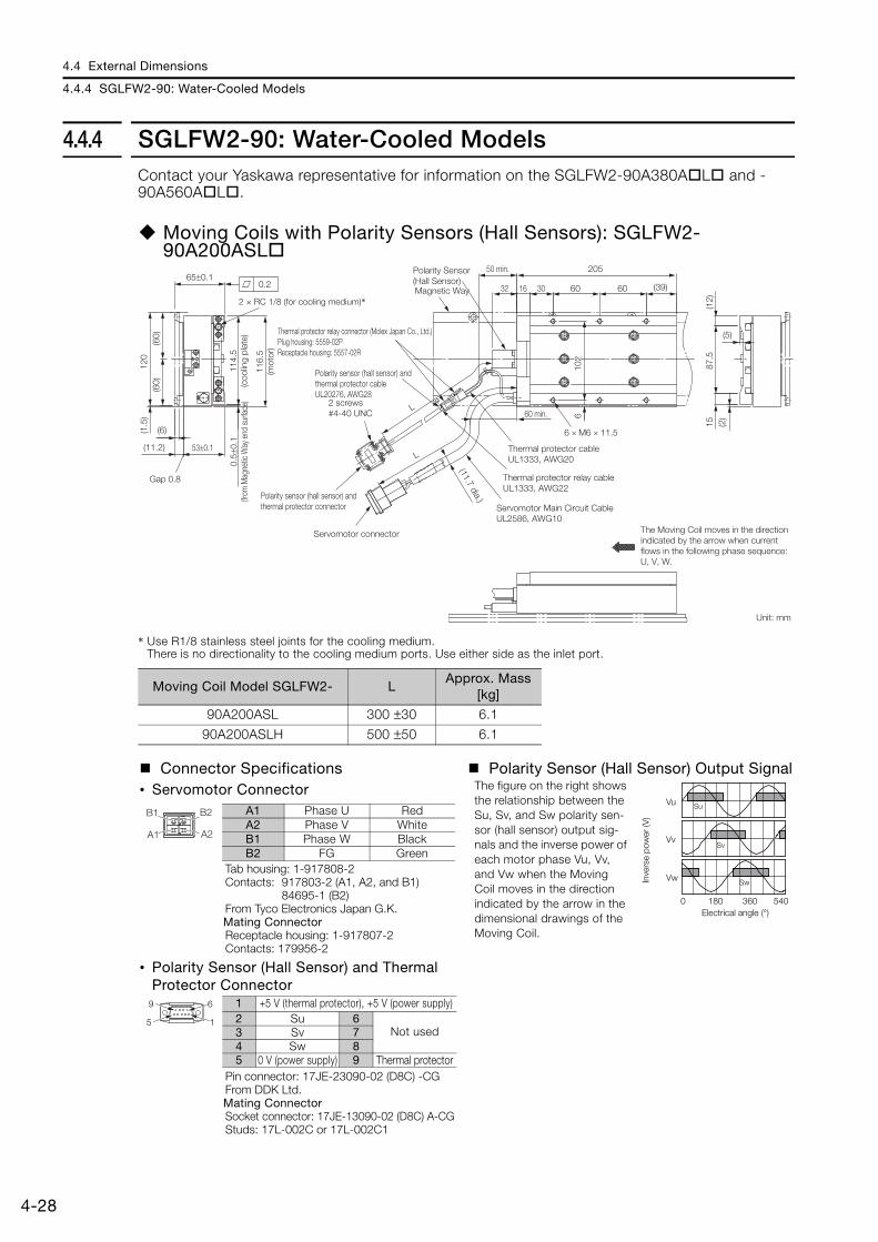
4.4 External Dimensions
4.4.4 SGLFW2-90: Water-Cooled Models
4-28
4.4.4 SGLFW2-90: Water-Cooled ModelsContact your Yaskawa representative for information on the SGLFW2-90A380AL and -90A560AL.
Moving Coils with Polarity Sensors (Hall Sensors): SGLFW2-90A200ASL
* Use R1/8 stainless steel joints for the cooling medium.There is no directionality to the cooling medium ports. Use either side as the inlet port.
Moving Coil Model SGLFW2- LApprox. Mass
[kg]
90A200ASL 300 ±30 6.1
90A200ASLH 500 ±50 6.1
Connector Specifications Polarity Sensor (Hall Sensor) Output Signal• Servomotor Connector The figure on the right shows
the relationship between the Su, Sv, and Sw polarity sen-sor (hall sensor) output sig-nals and the inverse power of each motor phase Vu, Vv, and Vw when the Moving Coil moves in the direction indicated by the arrow in the dimensional drawings of the Moving Coil.
Tab housing: 1-917808-2Contacts: 917803-2 (A1, A2, and B1)
84695-1 (B2)From Tyco Electronics Japan G.K.Mating ConnectorReceptacle housing: 1-917807-2Contacts: 179956-2
• Polarity Sensor (Hall Sensor) and Thermal Protector Connector
Pin connector: 17JE-23090-02 (D8C) -CGFrom DDK Ltd. Mating ConnectorSocket connector: 17JE-13090-02 (D8C) A-CGStuds: 17L-002C or 17L-002C1
(60)
(60)
(1.5
)12
0
(11.2)
(6)
102
102
65±0.10.2
0.5±
0.1
(from
Mag
netic
Way
end
sur
face
)
53±0.1
Gap 0.8
114.
5(c
oolin
g pl
ate)
116.
5(m
otor
)
Servomotor connector
Polarity sensor (hall sensor) and thermal protector connector
L
L
60 min.(11.7 dia.)
50 min. 205
32 30 (39)16 60
Polarity Sensor(Hall Sensor)
Thermal protector relay connector (Molex Japan Co., Ltd.)Plug housing: 5559-02PReceptacle housing: 5557-02R
Magnetic Way
Servomotor Main Circuit CableUL2586, AWG10
6 × M6 × 11.5
Thermal protector cableUL1333, AWG20
Thermal protector relay cableUL1333, AWG22
2 screws#4-40 UNC
2 × RC 1/8 (for cooling medium)*60
6
Polarity sensor (hall sensor) and thermal protector cableUL20276, AWG28
87.5
15(1
2)(2
)
(5)
Unit: mm
The Moving Coil moves in the direction indicated by the arrow when current flows in the following phase sequence: U, V, W.
Vu
Vv
Vw
Su
Sv
Sw
0 180 360 540Electrical angle (°)
Inve
rse
pow
er (V
)
A1
B1 B2
A2
A1 Phase U RedA2 Phase V WhiteB1 Phase W BlackB2 FG Green
9 6
5 1
1 +5 V (thermal protector), +5 V (power supply)2 Su 6
Not used3 Sv 74 Sw 85 0 V (power supply) 9 Thermal protector

4.4 External Dimensions
4.4.4 SGLFW2-90: Water-Cooled Models
4
Sp
ecifi
catio
ns, R
atin
gs, a
nd E
xter
nal D
imen
sion
s of
SG
LF S
ervo
mot
ors
4-29
Moving Coils without Polarity Sensors (Hall Sensors): SGLFW2-90A200ATL
* Use R1/8 stainless steel joints for the cooling medium.There is no directionality to the cooling medium ports. Use either side as the inlet port.
Moving Coil Model SGLFW2- LApprox. Mass
[kg]
90A200ATL 300 ±30 6.1
90A200ATLH 500 ±50 6.1
Connector Specifications• Servomotor Connector
Tab housing: 1-917808-2Contacts: 917803-2 (A1, A2, and B1)
84695-1 (B2)From Tyco Electronics Japan G.K.Mating ConnectorReceptacle housing: 1-917807-2Contacts: 179956-2
• Thermal Protector Connector
Receptacle housing: 5557-02RTerminals: 5556T or 5556TLFrom Molex Japan LLC Mating ConnectorPlug housing: 5559-02PTerminals: 5558T or 5558TL
(60)
(60)
(1.5
)12
0
(11.2)
(6)
102
102
65±0.10.2
0.5±
0.1
(from
Mag
netic
Way
en
d su
rface
)
53±0.1
Gap 0.8
114.
5(c
oolin
g pl
ate)
116.
5(m
otor
)
Servomotor connector
L
(11.7 dia.)
205
30 (39)60Magnetic Way
6 × M6 × 11.5
Thermal protector cableUL1333, AWG20
Thermal protector connector
2 × RC 1/8 (for cooling medium)*60
6
The Moving Coil moves in the direction indicated by the arrow when current flows in the following phase sequence: U, V, W.
87.5
15(1
2)
(2)
(5)
100±
20
60 min.
Servomotor Main Circuit CableUL2586, AWG10
Unit: mm
16
A1
B1 B2
A2
A1 Phase U RedA2 Phase V WhiteB1 Phase W BlackB2 FG Green
1
2
1 Thermal protector2 Thermal protector

4.4 External Dimensions
4.4.5 SGLFW2-90: Self-Cooled and Water-Cooled Models
4-30
4.4.5 SGLFW2-90: Self-Cooled and Water-Cooled Models
Magnetic Ways: SGLFM2-90A
Note: More than one Magnetic Way can be connected. Connect the Magnetic Ways so that the reference marks on them are aligned in the same direction as shown in the figure.
Magnetic Way Model SGLFM2-
L1±0.1 L2 N Approx. Mass [kg]
90306A 306 204 (102 × 2) 3 2.6
90510A 510 408 (102 × 4) 5 4.2
90714A 714 612 (102 × 6) 7 5.9
L2
2 × N, 7-dia. mounting holes
11.5 dia. 2
Reference mark(There are two, approx. 4-dia. indentations.)
Height of screw head: 6.7 max.
Mounting Section Details
(Reference mark)
Unit: mm
(51)
(102)
N N SSN S
10251±0.1
L1±0.1
11.2±0.1
0.3
6 5.2
6.5
(6.5
)(6
0)(6
0)10
712
0

4.4 External Dimensions
4.4.6 SGLFW2-1D
4
Sp
ecifi
catio
ns, R
atin
gs, a
nd E
xter
nal D
imen
sion
s of
SG
LF S
ervo
mot
ors
4-31
4.4.6 SGLFW2-1D
Moving Coil with Polarity Sensor (Hall Sensor): SGLFW2-1DAAS1
Moving Coil Model SGLFW2-
L1 L2 L3 L4 FlatnessApprox. Mass
[kg]
1DA380AS1384 268.5 365.5
300 ±300.3 14.6
1DA380AS1H 500 ±50
1DA560AS1563 447.5 544
300 ±300.3 21.5
1DA560AS1H 500 ±50
Connector Specifications Polarity Sensor (Hall Sensor) Output Signal• Servomotor Connector The figure on the right shows
the relationship between the Su, Sv, and Sw polarity sen-sor (hall sensor) output sig-nals and the inverse power of each motor phase Vu, Vv, and Vw when the Moving Coil moves in the direction indicated by the arrow in the dimensional drawings of the Moving Coil.
Tab housing: 1-917808-2Contacts: 917803-2 (A1, A2, and B1)
84695-1 (B2)From Tyco Electronics Japan G.K.Mating ConnectorReceptacle housing: 1-917807-2Contacts: 179956-2
• Polarity Sensor (Hall Sensor) and Thermal Protector Connector
Pin connector: 17JE-23090-02 (D8C) -CGFrom DDK Ltd. Mating ConnectorSocket connector: 17JE-13090-02 (D8C) A-CGStuds: 17L-002C or 17L-002C1
UL20276, AWG28
Thermal protector relay connector (Molex Japan LLC)Receptacle housing: 5557-02RPlug housing: 5559-02P 50 min.
Polarity sensor(hall sensor)
Magnetic Way
Polarity sensor (hall sensor) and thermal protector cable
2 × #4-40 UNC screws
Polarity sensor (hall sensor) and thermal protector connector
Servomotor connector
60 min.
Thermal protector cableUL1333, AWG20
Thermal protector relay cableUL1333, AWG22
Servomotor Main Circuit CableUL2586, AWG12
The Moving Coil moves in the direction indicated by the arrow when current flows in the following phase sequence: U, V, W.
Unit: mm
(10.5 dia.)
SGLFW2-1DA560AS
60.5 89.5447.5 (89.5 × 5)
82.5
18 × M8 × 16
136
15
4545
22.5
SGLFW2-1DA380AS
(87.
5)(8
7.5)
175
(11.2)
67.5
20±0
.113
616
0
15
50±0.1
2(36)
38±0.1
(6)
48.5
L3
L2 (55)L1
22.5
32(5
)
4545
(9) 12
Gap 0.8
L4
L4
60.5 89.5268.5 (89.5 × 3)
82.513
615
4545
22.5
12 × M8 × 16
Refer to the following table.
Refer to the following figures and .
Vu
Vv
Vw
Su
Sv
Sw
0 180 360 540Electrical angle (°)
Inve
rse
pow
er (V
)
A1
B1 B2
A2
A1 Phase U RedA2 Phase V WhiteB1 Phase W BlackB2 FG Green
9 6
5 1
1 +5 V (thermal protector), +5 V (power supply)2 Su 6
Not used3 Sv 74 Sw 85 0 V (power supply) 9 Thermal protector

4.4 External Dimensions
4.4.6 SGLFW2-1D
4-32
Moving Coil without Polarity Sensor (Hall Sensor): SGLFW2-1DAAT1
Moving Coil Model SGLFW2-
L1 L2 L3 L4 FlatnessApprox. Mass
[kg]
1DA380AT1384 268.5 365.5
300 ±300.3 14.6
1DA380AT1H 500 ±50
1DA560AT1563 447.5 544
300 ±300.3 21.5
1DA560AT1H 500 ±50
Connector Specifications• Servomotor Connector
Tab housing: 1-917808-2Contacts: 917803-2 (A1, A2, and B1)
84695-1 (B2)From Tyco Electronics Japan G.K.Mating ConnectorReceptacle housing: 1-917807-2Contacts: 179956-2
• Polarity Sensor (Hall Sensor) and Thermal Protector Connector
Pin connector: 17JE-23090-02 (D8C) -CGFrom DDK Ltd. Mating ConnectorSocket connector: 17JE-13090-02 (D8C) A-CGStuds: 17L-002C or 17L-002C1
Magnetic Way
Servomotor Main Circuit CableUL2586, AWG12
Servomotor connector
60 min.
Thermal protector cableUL1333, AWG20
Thermal protector connector
(10.5 dia.)
The Moving Coil moves in the direction indicated by the arrow when current flows in the following phase sequence: U, V, W.
Unit: mm
Refer to the following table.
Refer to the following figures and .
(87.
5)(8
7.5)
175
(11.2)
67.5
20±
0.1
136
160
15
50±0.1
2(36)
38±0.1
(6)
22.5
(5)
4545
(9)
L4
Gap 0.8
48.5 (55)L1L212
L3
100±20
SGLFW2-1DA560AT
60.5 89.5447.5 (89.5 × 5)
82.5
18 × M8 × 16
136
15
4545
22.5
SGLFW2-1DA380AT
60.5 89.5268.5 (89.5 × 3)
82.513
615
4545
22.5
12 × M8 × 16
A1
B1 B2
A2
A1 Phase U RedA2 Phase V WhiteB1 Phase W BlackB2 FG Green
9 6
5 1
1 +5 V (thermal protector), +5 V (power supply)2 Su 6
Not used3 Sv 74 Sw 85 0 V (power supply) 9 Thermal protector

4.4 External Dimensions
4.4.6 SGLFW2-1D
4
Sp
ecifi
catio
ns, R
atin
gs, a
nd E
xter
nal D
imen
sion
s of
SG
LF S
ervo
mot
ors
4-33
Magnetic Ways: SGLFM2-1DA
Note: More than one Magnetic Way can be connected. Connect the Magnetic Ways so that the reference marks on them are aligned in the same direction as shown in the figure.
Magnetic Way Model SGLFM2-
L1 ±0.1 L2 N Approx. Mass [kg]
1D306A 306 204 (102 × 2) 3 3.7
1D510A 510 408 (102 × 4) 5 6.2
1D714A 714 612 (102 × 6) 7 8.6
L2
175
(87.
5)9.
515
6(9
.5)
(87.
5)
N S N SN S
10251±0.1 (51)
(102)6
L1±0.1
5.211.2±0.1
0.3
2 × N, 10-dia. mounting holes
15 dia. 3
(Reference mark)
Unit: mm
Reference mark
(There are two, approx. 4-dia. indentations.)
Height of screw head: 8.2 max.Mounting Section Details

4.4 External Dimensions
4.4.7 SGLFW-20
4-34
4.4.7 SGLFW-20
Moving Coils: SGLFW-20AA
Note: The above dimensional drawing gives the dimensions for both models with polarity sensors (hall senors) and models without polarity sensors (hall sensors).
Moving Coil Model SGLFW- L1 L2 L3 Approx. Mass [kg]
20A090A 91 36 72 0.7
20A120A 127 72 108 0.9
Connector Specifications Polarity Sensor (Hall Sensor) Output Signal• Servomotor Connector The figure on the right shows
the relationship between the Su, Sv, and Sw polarity sen-sor (hall sensor) output sig-nals and the inverse power of each motor phase Vu, Vv, and Vw when the Moving Coil moves in the direction indicated by the arrow in the dimensional drawings of the Moving Coil.
Plug: 350779-1Pins: 350218-3 or 350547-3 (No.1 to 3)
350654-1 or 350669-1 (No. 4)From Tyco Electronics Japan G.K. Mating ConnectorCap: 350780-1Socket: 350536-3 or 350550-3
• Polarity Sensor (Hall Sensor) Connector
Pin connector: 17JE-23090-02 (D8C) -CGFrom DDK Ltd. Mating ConnectorSocket connector: 17JE-13090-02 (D8C) A-CGStuds: 17L-002C or 17L-002C1
Unit: mm
2 × M4 × 8
(20)
(12.
5)
(22.
5)
30 36
�SGLFW-20A090A�3 × M4 × 8
(20)
(12.
5)
(22.
5)
30 36
72
�SGLFW-20A120A�
(Gap: 0.8 with magnet cover)(Gap: 1 without magnet cover)
(10.2 with magnet cover)(10 without magnet cover)
(4.2 with magnet cover)(4 without magnet cover)0.1
28
7.7
2
5.5
(22.
5)
40
(17.
5)
12.5
45±0.1
34
(32)
0.5(6)
(44)
(22)
(22)
Refer to the following figures � and �.
9.7
dia. 5
(20)
36
(25)L1L23030
(12) (7.5
)
(10)
(12.
5)
50 min.
Polarity sensor(hall sensor)
Magnetic Way
12
500±50
500±50 730 min.
L3
(6.1 dia.)
(4.2 dia.)
2 × #4-40 UNCscrews
The Moving Coil moves in the direction indicated by the arrow when current flows in the following phase sequence: U, V, W.
(20) 22
Vu
Vv
Vw
Su
Sv
Sw
0 180 360 540
Electrical angle (°)
Inve
rse
pow
er (V
)
1 2 3 41 Phase U Red2 Phase V White3 Phase W Black4 FG Green
9 6
5 1
1 +5 V (thermal protector), +5 V (power supply)2 Su 6
Not used3 Sv 74 Sw 85 0 V (power supply) 9 Thermal protector

4.4 External Dimensions
4.4.7 SGLFW-20
4
Sp
ecifi
catio
ns, R
atin
gs, a
nd E
xter
nal D
imen
sion
s of
SG
LF S
ervo
mot
ors
4-35
Magnetic Ways: SGLFM-20A
Note: More than one Magnetic Way can be connected. Connect the Magnetic Ways so that the reference marks on them are aligned in the same direction as shown in the figure.
Magnetic Way Model SGLFM-
L1 L2 (L3) LA NApprox. Mass
[kg]
20324A 324 270 (54 × 5) (331.6) 30.8 6 0.9
20540A 540 486 (54 × 9) (547.6) 30.8 10 1.4
20756A 756 702 (54 × 13) (763.6) 30.8 14 2
(Gap: 1)
SNSN
6
9.9°
10
4
(40)
(22.
5)(1
7.5)
(34)
4.5
3544
(4.5
)
(22)
22
54
LA
L1
L2
(L3)
(54)
(30.8)
SNSN
45±0.1
Moving Coil2 × N × 4.8 dia.
Reference mark(There are two, approx. 4-dia. indentations.)
Height of screw head: 4.2 max.
Mounting Section Details
Reference mark (Reference mark)
Unit: mm
-0.1-0.3
0-0.2
-0.1-0.3
0-0.2
-0.1-0.3
0-0.2

4.4 External Dimensions
4.4.8 SGLFW-35
4-36
4.4.8 SGLFW-35
Moving Coils: SGLFW-35AA
Note: The above dimensional drawing gives the dimensions for both models with polarity sensors (hall sensors) and models without polarity sensors (hall sensors).
Moving Coil Model SGLFW- L1 L2 L3 Flatness Approx. Mass [kg]
35A120A 127 72 108 0.1 1.3
35A230A 235 180 216 0.2 2.3
Connector Specifications Polarity Sensor (Hall Sensor) Output Signal• Servomotor Connector The figure on the right shows
the relationship between the Su, Sv, and Sw polarity sen-sor (hall sensor) output sig-nals and the inverse power of each motor phase Vu, Vv, and Vw when the Moving Coil moves in the direction indicated by the arrow in the dimensional drawings of the Moving Coil.
Plug: 350779-1Pins: 350218-3 or 350547-3 (No.1 to 3)
350654-1 or 350669-1 (No. 4)From Tyco Electronics Japan G.K. Mating ConnectorCap: 350780-1Socket: 350536-3 or 350550-3
• Polarity Sensor (Hall Sensor) Connector
Pin connector: 17JE-23090-02 (D8C) -CGFrom DDK Ltd. Mating ConnectorSocket connector: 17JE-13090-02 (D8C) A-CGStuds: 17L-002C or 17L-002C1
SGLFW-35A120A
Unit: mm
SGLFW-35A230A
Refer to the following table.
5.5
2
450.1
34
(32)
0.57.7(6)
5543
(30)
(25)
12.5
(30)
(30)
(60)
(Gap: 0.8 with magnet cover)(Gap: 1 without magnet cover)
(10.2 with magnet cover)(10 without magnet cover)
(4.2 with magnet cover)(4 without magnet cover)
12
5
50050
50050
7
L1
30
(6.1 dia.)
(4.2 dia.)
(10.
5)
(12.
5)(7
.5)
L3
30 min.
L230 25
36
(8.5
)
50 min.
Polarity sensor(hall sensor)
Magnetic Way
2 #4-40 UNCscrews
The Moving Coil moves in the direction indicated by the arrow when current flows in the following phase sequence: U, V, W.
Refer to the following figures and .
(35)18(35) 37
9.7
dia.
6 M4 8
(35)
18
(30)
(8.5
)
(12.
5) 30 36
72
12 M4 8
(35)
18(8
.5)
(12.
5) 30 36
180 (365)
(30)
Vu
Vv
Vw
Su
Sv
Sw
0 180 360 540
Electrical angle (°)
Inve
rse
pow
er (V
)
1 2 3 41 Phase U Red2 Phase V White3 Phase W Black4 FG Green
9 6
5 1
1 +5 V (power supply) 6
Not used2 Phase U 73 Phase V 84 Phase W 95 0 V (power supply) − −

4.4 External Dimensions
4.4.8 SGLFW-35
4
Sp
ecifi
catio
ns, R
atin
gs, a
nd E
xter
nal D
imen
sion
s of
SG
LF S
ervo
mot
ors
4-37
Moving Coils: SGLFW-35AAD
Note: The above dimensional drawing gives the dimensions for both models with polarity sensors (hall sensors) and models without polarity sensors (hall sensors).
Moving Coil Model SGLFW- L1 L2 L3 Flatness Approx. Mass [kg]
35A120AD 127 72 108 0.1 1.3
35A230AD 235 180 216 0.2 2.3
Connector Specifications Polarity Sensor (Hall Sensor) Output Signal• Servomotor Connector The figure on the right shows
the relationship between the Su, Sv, and Sw polarity sen-sor (hall sensor) output sig-nals and the inverse power of each motor phase Vu, Vv, and Vw when the Moving Coil moves in the direction indicated by the arrow in the dimensional drawings of the Moving Coil.
Extension: ARRA06AMRPN182Pins: 021.279.1020From Interconnectron GmbH Mating Connector Plug: APRA06BFRDN170Socket: 020.105.1020
• Polarity Sensor (Hall Sensor) Connector
Pin connector: 17JE-23090-02 (D8C)-CGFrom DDK Ltd.Mating ConnectorSocket connector: 17JE-13090-02 (D8C)A-CGStuds: 17L-002C or 17L-002C1
SGLFW-35A120AD SGLFW-35A230AD
30 36
6 M4 8
(35) 18
(30)
(8.5
)
(12.
5)
72
12 M4 8
(35) 18
(8.5
)
(12.
5) 30 36
180 (365)
(30)
12
50050
50050
7
L130
(10.
5)
(12.
5)(7
.5)
(35)
L3
L230 25
36
(8.5
)
9.7
dia.
18
50 min.
Polarity sensor (Hall sensor)
Magnetic Way
2 × #4-40 UNC screws
Refer to the following figures and .
(4.2 dia.) (6.1 dia.)
30 min.
The Moving Coil moves in the direction indicated by the arrow when current flows in the following phase sequence: U, V, W.
Unit: mm
5.5
2
450.1
34
(32)
0.57.7(6)
5543
(30)
(25)
12.5
(30)
(30)
(60)
(35) 37
(10.2 with magnet cover)(10 without magnet cover)
(4.2 with magnet cover)(4 without magnet cover)
(Gap: 0.8 with magnet cover)(Gap: 1 without magnet cover)
Refer to the following table.
Vu
Vv
Vw
Su
Sv
Sw
0 180 360 540
Electrical angle (°)
Inve
rse
pow
er (V
)
65
4
1
2
1 Phase U 5 Not used2 Phase V 6 Not used
4 Phase W Ground
9 6
5 1
1 +5 V (power supply) 6
Not used2 Phase U 73 Phase V 84 Phase W 95 0 V (power supply) − −

4.4 External Dimensions
4.4.8 SGLFW-35
4-38
Magnetic Ways: SGLFM-35A
Note: More than one Magnetic Way can be connected. Connect the Magnetic Ways so that the reference marks on them are aligned in the same direction as shown in the figure.
Magnetic Way Model SGLFM-
L1 L2 (L3) LA NApprox. Mass
[kg]
35324A 324 270 (54 × 5) (334.4) 32.2 6 1.2
35540A 540 486 (54 × 9) (550.4) 32.2 10 2
35756A 756 702 (54 × 13) (766.4) 32.2 14 2.9
L1
L2(Gap: 1)
(34)
S SNS SNNN
(L3)
6
10
4
45±0.1
60 51
30(3
0)
(4.5
)4.
5
(55)
(30)
(25)
9.9°
LA
54 (54)
(32.2)
2 × N × 4.8 dia.
Reference mark
Reference mark(There are two, approx. 4-dia. indentations.)
Height of screw head: 4.2 max.Mounting Section Details
(Reference mark)
Unit: mm
Moving Coil
-0.1-0.3
0-0.2
-0.1-0.3
0-0.2
-0.1-0.3
0-0.2

4.4 External Dimensions
4.4.9 SGLFW-50
4
Sp
ecifi
catio
ns, R
atin
gs, a
nd E
xter
nal D
imen
sion
s of
SG
LF S
ervo
mot
ors
4-39
4.4.9 SGLFW-50
Moving Coils: SGLFW-50AB
Note: The above dimensional drawing gives the dimensions for both models with polarity sensors (hall sensors) and models without polarity sensors (hall sensors).
Moving Coil ModelSGLFW-
L1 L2 L3 Flatness Approx. Mass [kg]
50A200B 215 120 180 0.2 3.5
50A380B 395 300 360 0.3 6.9
Connector Specifications Polarity Sensor (Hall Sensor) Output Signal• Servomotor Connector The figure on the right shows
the relationship between the Su, Sv, and Sw polarity sen-sor (hall sensor) output sig-nals and the inverse power of each motor phase Vu, Vv, and Vw when the Moving Coil moves in the direction indicated by the arrow in the dimensional drawings of the Moving Coil.
Plug: 350779-1Pins: 350218-3 or 350547-3 (No.1 to 3)
350654-1 or 350669-1 (No. 4)From Tyco Electronics Japan G.K. Mating ConnectorCap: 350780-1Socket: 350536-3 or 350550-3
• Polarity Sensor (Hall Sensor) Connector
Pin connector: 17JE-23090-02 (D8C) -CGFrom DDK Ltd. Mating ConnectorSocket connector: 17JE-13090-02 (D8C) A-CGStuds: 17L-002C or 17L-002C1
SGLFW-50A200B SGLFW-50A380B
Unit: mm
6 M5 9.5
(48)
23.5
(12)
(14)
55 60
120
12 M5 9.5
(48)
23.5
(12)
(14) 55 60
300 (60 5)
(7.4 dia.)
25
5
L3
L2 40
6055
L130
(4.2 dia.)
23.5
12 d
ia.
10
(15)
50050
50050
Polarity sensor(hall sensor)Magnetic Way
50 min.
50 min.
2 #4-40 UNCscrews
The Moving Coil moves in the direction indicated by the arrow when current flows in the following phase sequence: U, V, W.
Refer to the following figures and .
7
(40)
(37.
5)
3
(33.
75)
(37.
75)
71.5
(37.
5)(75)
0.5(9)
43
580.1
(48)
(64.
5)
(10.2 with magnet cover)(10 without magnet cover)
(Gap: 0.8 with magnet cover)(Gap: 1 without magnet cover)
(4.2 with magnet cover)(4 without magnet cover)
Refer to the following table.
Vu
Vv
Vw
Su
Sv
Sw
0 180 360 540
Electrical angle (°)
Inve
rse
pow
er (V
)
1 2 3 41 Phase U Red2 Phase V White3 Phase W Black4 FG Green
9 6
5 1
1 +5 V (thermal protector), +5 V (power supply)2 Su 6
Not used3 Sv 74 Sw 85 0 V (power supply) 9 Thermal protector

4.4 External Dimensions
4.4.9 SGLFW-50
4-40
Moving Coils: SGLFW-50ABD
Note: The above dimensional drawing gives the dimensions for both models with polarity sensors (hall sensors) and models without polarity sensors (hall sensors).
Moving Coil ModelSGLFW-
L1 L2 L3 Flatness Approx. Mass [kg]
50A200BD 215 120 180 0.2 3.5
50A380BD 395 300 360 0.3 6.9
Connector Specifications Polarity Sensor (Hall Sensor) Output Signal• Servomotor Connector The figure on the right shows
the relationship between the Su, Sv, and Sw polarity sen-sor (hall sensor) output sig-nals and the inverse power of each motor phase Vu, Vv, and Vw when the Moving Coil moves in the direction indicated by the arrow in the dimensional drawings of the Moving Coil.
Extension: ARRA06AMRPN182Pins: 021.279.1020From Interconnectron GmbH Mating Connector Plug: APRA06BFRDN170Socket: 020.105.1020
• Polarity Sensor (Hall Sensor) Connector
Pin connector: 17JE-23090-02 (D8C)-CGFrom DDK Ltd.Mating ConnectorSocket connector: 17JE-13090-02 (D8C)A-CGStuds: 17L-002C or 17L-002C1
SGLFW-50A200BD SGLFW-50A380BD 6 M5 9.5
(48)
23.5
(12)
(14)
55 60
120
12 M5 9.5
(48)
23.5
(12)
(14) 55 60
300 (60 5)
Unit: mm
2 #4-40 UNCscrews
50050
50050
10
30
(7.4 dia.)
(4.2 dia.)
(15)
L3
L2
L1
25
55
5
55 40
60
23.5
12 d
ia.
50 min.
50 min.
Polarity sensor(hall sensor)Magnetic Way
The Moving Coil moves in the direction indicated by the arrow when current flows in the following phase sequence: U, V, W.
Refer to the following figures and .
(64.
5) (33.
75)
(37.
75)
7
71.5
3
(37.
5)(75) (3
7.5)
(40)
43
580.1
0.5(9)
(Gap: 0.8 with magnet cover)(Gap: 1 without magnet cover)
(10.2 with magnet cover)(10 without magnet cover)
(4.2 with magnet cover)(4 without magnet cover)
(48)
Refer to the following table.
Vu
Vv
Vw
Su
Sv
Sw
0 180 360 540
Electrical angle (°)
Inve
rse
pow
er (V
)
65
4
1
2
1 Phase U 5 Not used2 Phase V 6 Not used
4 Phase W Ground
9 6
5 1
1 +5 V (power supply) 6
Not used2 Phase U 73 Phase V 84 Phase W 95 0 V (power supply) − −

4.4 External Dimensions
4.4.9 SGLFW-50
4
Sp
ecifi
catio
ns, R
atin
gs, a
nd E
xter
nal D
imen
sion
s of
SG
LF S
ervo
mot
ors
4-41
Magnetic Ways: SGLFM-50A
Note: More than one Magnetic Way can be connected. Connect the Magnetic Ways so that the reference marks on them are aligned in the same direction as shown in the figure.
Magnetic Way Model SGLFM-
L1 L2 (L3) LA NApprox. Mass
[kg]
50405A 405 337.5 (67.5 × 5) (416.3) 39.4 6 2.8
50675A 675 607.5 (67.5 × 9) (686.3) 39.4 10 4.6
50945A 945 877.5 (67.5 × 13) (956.3) 39.4 14 6.5
(Gap: 1)
2 × N × 5.8 dia.
S SSNS NNN
67.5
9 5
58±0.1
14 (43)
(5)
5
75 65
37.5
(37.
5)
(37.
75)
(71.
5)(33.
75)
8.6°
LA
L1
L2
(L3)
(67.5)
(39.4)
Moving Coil
Reference mark
Height of screw head: 5.2 max.Mounting Section Details
(There are two, approx. 4-dia. indentations.)
Reference mark (Reference mark)
Unit: mm
-0.1-0.3
0-0.2
-0.1-0.3
0-0.2
-0.1-0.3
0-0.2

4.4 External Dimensions
4.4.10 SGLFW-1Z
4-42
4.4.10 SGLFW-1Z
Moving Coils: SGLFW-1ZAB
Note: The above dimensional drawing gives the dimensions for both models with polarity sensors (hall sensors) and models without polarity sensors (hall sensors).
Moving Coil Model SGLFW- L1 L2 L3 Approx. Mass [kg]
1ZA200B 215 120 180 6.4
1ZA380B 395 300 360 11.5
Connector Specifications Polarity Sensor (Hall Sensor) Output Sig-nal
• Servomotor Connector The figure on the right shows the relationship between the Su, Sv, and Sw polarity sen-sor (hall sensor) output sig-nals and the inverse power of each motor phase Vu, Vv, and Vw when the Moving Coil moves in the direction indicated by the arrow in the dimensional drawings of the Moving Coil.
Plug: 350779-1Pins: 350218-3 or 350547-3 (No.1 to 3)
350654-1 or 350669-1 (No. 4)From Tyco Electronics Japan G.K. Mating ConnectorCap: 350780-1Socket: 350536-3 or 350550-3
• Polarity Sensor (Hall Sensor) Connector
Pin connector: 17JE-23090-02 (D8C)-CGFrom DDK Ltd.Mating ConnectorSocket connector: 17JE-13090-02 (D8C)A-CGStuds: 17L-002C or 17L-002C1
9 × M5 × 9.5
(96) 35
.535
.5(1
2)
(14)
55 60
120
SGLFW-1ZA200B
500±50
500±50
60
(15)
10L325
(96)
(12)
L1L25530
(96) 35.5
35.5
4098
119
(57.
5)(6
1.5)
(62.
5)(6
2.5)
(125
)
3(40)7
14
43
58±0.1
0.5(9)
18 × M5 × 9.5
(96) 35
.535
.5(1
2)
(14)
55 60
300 (60 × 5)
SGLFW-1ZA380B
Magnetic WayPolarity sensor(hall sensor)
2 × #4-40 UNC screws
(5.2 with magnet cover)(5 without magnet cover)(Gap: 0.8 with magnet cover)(Gap: 1 without magnet cover)
(14.2 with magnet cover)(14 without magnet cover)
50 min.
The Moving Coil moves in the direction indicated by the arrow when current flows in the following phase sequence: U, V, W.
Unit: mm
Refer to the following figures and .
50 min.
(8.4 dia.)
(4.2 dia.)
Vu
Vv
Vw
Su
Sv
Sw
0 180 360 540
Electrical angle (°)
Inve
rse
pow
er (V
)
1 2 3 41 Phase U Red2 Phase V White3 Phase W Black4 FG Green
9 6
5 1
1 +5 V (power supply) 6
Not used2 Phase U 73 Phase V 84 Phase W 95 0 V (power supply) − −

4.4 External Dimensions
4.4.10 SGLFW-1Z
4
Sp
ecifi
catio
ns, R
atin
gs, a
nd E
xter
nal D
imen
sion
s of
SG
LF S
ervo
mot
ors
4-43
Moving Coils: SGLFW-1ZA200BD
Note: The above dimensional drawing gives the dimensions for both models with polarity sensors (hall sensors) and models without polarity sensors (hall sensors).
Connector Specifications Polarity Sensor (Hall Sensor) Output Signal• Servomotor Connector The figure on the right shows
the relationship between the Su, Sv, and Sw polarity sen-sor (hall sensor) output sig-nals and the inverse power of each motor phase Vu, Vv, and Vw when the Moving Coil moves in the direction indicated by the arrow in the dimensional drawings of the Moving Coil.
Extension: SROC06JMSCN169Pins: 021.423.1020From Interconnectron GmbH Mating ConnectorPlug: SPUC06KFSDN236Socket: 020.030.1020
• Polarity Sensor (Hall Sensor) Connector
Pin connector: 17JE-23090-02 (D8C)-CGFrom DDK Ltd.Mating ConnectorSocket connector: 17JE-13090-02 (D8C)A-CGStuds: 17L-002C or 17L-002C1
43
(9)0.5
(62.
5)(6
2.5)
(125
)
3(40)
119
(61.
5)(5
7.5)
7
60
(96)
(112
)
4030
(15)
215120 (60 × 2)55
25 10180
35.5
35.5
60
120
(96) 35
.535
.5
(14)
(12) 55
58±0.1 500±50
500±50
0.2
9 × M5 × 9.5L
SGLFW-1ZA200BD
Magnetic Way
Proximity sensor (Hall sensor) cable UL20276, AWG28
Servomotor Main Circuit CableUL2517, AWG15
Refer to the following figure .
The Moving Coil moves in the direction indicated by the arrow when current flows in the following phase sequence: U, V, W.
2 × #4-40 UNC screws
50 min.
(5.2 with magnet cover)
(Gap: 0.8 with magnet cover)
(14.2 with magnet cover)(14 without magnet cover)
(Gap: 1 without magnet cover)
Polarity sensor (hall sensor) connector
(4.2 dia.)
(8.4 dia.)
Servomotor connector
Approx. mass: 6.4 kg
Unit: mm
(5 without magnet cover)
Polarity sensor(hall sensor)
50 min.
Vu
Vv
Vw
Su
Sv
Sw
0 180 360 540
Electrical angle (°)
Inve
rse
pow
er (V
)
6
5
4
3
2
1 1 Phase U 4 Not used2 Phase V 5 Not used3 Phase W 6 Ground
9 6
5 1
1 +5 V (power supply) 6
Not used2 Phase U 73 Phase V 84 Phase W 95 0 V (power supply) − −

4.4 External Dimensions
4.4.10 SGLFW-1Z
4-44
Magnetic Ways: SGLFM-1ZA
Note: More than one Magnetic Way can be connected. Connect the Magnetic Ways so that the reference marks on them are aligned in the same direction as shown in the figure.
Magnetic Way Model SGLFM-
L1 L2 (L3) LA NApprox. Mass
[kg]
1Z405A 405 337.5 (67.5 × 5) (423.9) 43.2 6 5
1Z675A 675 607.5 (67.5 × 9) (693.9) 43.2 10 8.3
1Z945A 945 877.5 (67.5 × 13) (963.9) 43.2 14 12
125
112
6.5
(6.5
)
(62.
5)62
.5
(61.
5)(5
7.5)
(119
)
(43.2)67.514
9 5
58±0.1
(43)
(Gap1)
S
(There are two, approx. 4-dia. indentations.)
S SS NNNN
8.6°
LAL1L2
(L3)
1.5
11.5
dia.
(67.5)
Moving Coil2 × N, 7-dia. mounting holes
11.5 dia. 1.5
Reference mark(Reference mark)
Height of screw head: 6.7 max.
Mounting Section DetailsUnit: mm
Reference mark
-0.1-0.3
0-0.2
-0.1-0.3
0-0.2
-0.1-0.3
0-0.2

4.5 Selecting Cables
4.5.1 Cable Configurations
4-45
4
Sp
ecifi
catio
ns, R
atin
gs, a
nd E
xter
nal D
imen
sion
s of
SG
LF S
ervo
mot
ors
4.5 Selecting Cables
4.5.1 Cable ConfigurationsPrepare the cable required for the encoder.
Refer to the following catalog to select a Linear Encoder.AC Servo Drives Σ-7 Series (Manual No.: KAEP S800001 23)
* You can connect directly to an absolute linear encoder.
Note: Refer to the following manual for the following information.• Cable dimensional drawings and cable connection specifications• Order numbers and specifications of individual connectors for cables• Order numbers and specifications for wiring materials
Σ-7-Series AC Servo Drive Peripheral Device Selection Manual (Manual No.: SIEP S800001 32)
SERVOPACK
Serial Converter Unit Cable* (between SERVOPACK connector CN2 and Serial Converter Unit)
Linear Servomotor Main Circuit Cable
Sensor Cable (between Serial Converter Unit and polarity sensor (hall sensor))
Serial Converter Unit
Linear Encoder Cable
Linear Encoder (Not provided by Yaskawa.)
Polarity sensor (hall sensor)
Linear Servomotor

4.5 Selecting Cables
4.5.2 Linear Servomotor Main Circuit Cables
4-46
4.5.2 Linear Servomotor Main Circuit Cables
Linear Servomotor ModelLength
(L)Order Number Appearance
SGLFW-20A, -35A
1 m JZSP-CLN11-01-E
3 m JZSP-CLN11-03-E
5 m JZSP-CLN11-05-E
10 m JZSP-CLN11-10-E
15 m JZSP-CLN11-15-E
20 m JZSP-CLN11-20-E
SGLFW-50A, -1ZA
1 m JZSP-CLN21-01-E
3 m JZSP-CLN21-03-E
5 m JZSP-CLN21-05-E
10 m JZSP-CLN21-10-E
15 m JZSP-CLN21-15-E
20 m JZSP-CLN21-20-E
SGLFW-AD
1 m JZSP-CLN14-01-E
3 m JZSP-CLN14-03-E
5 m JZSP-CLN14-05-E
10 m JZSP-CLN14-10-E
15 m JZSP-CLN14-15-E
20 m JZSP-CLN14-20-E
SGLFW2-30A070ASGLFW2-30A120ASGLFW2-30A230A
1 m JZSP-CL2N703-01-E
3 m JZSP-CL2N703-03-E
5 m JZSP-CL2N703-05-E
10 m JZSP-CL2N703-10-E
15 m JZSP-CL2N703-15-E
20 m JZSP-CL2N703-20-E
SGLFW2-45A200ASGLFW2-45A380A
1 m JZSP-CL2N603-01-E
3 m JZSP-CL2N603-03-E
5 m JZSP-CL2N603-05-E
10 m JZSP-CL2N603-10-E
15 m JZSP-CL2N603-15-E
20 m JZSP-CL2N603-20-E
SGLFW2-90A200ASGLFW2-90A380A
1 m JZSP-CL2N803-01-E
3 m JZSP-CL2N803-03-E
5 m JZSP-CL2N803-05-E
10 m JZSP-CL2N803-10-E
15 m JZSP-CL2N803-15-E
20 m JZSP-CL2N803-20-E
SGLFW2-90A560ASGLFW2-1DA380ASGLFW2-1DA560A
1 m JZSP-CL2N503-01-E
3 m JZSP-CL2N503-03-E
5 m JZSP-CL2N503-05-E
10 m JZSP-CL2N503-10-E
15 m JZSP-CL2N503-15-E
20 m JZSP-CL2N503-20-E
Continued on next page.
L
*1
SERVOPACK end Linear Servomotorend
L
*1
SERVOPACK end Linear Servomotor end
L
*2
SERVOPACK end Linear Servomotor end
L
*1
SERVOPACK end Motor end
L
*1
SERVOPACK end Motor end
LSERVOPACK end Motor end
LSERVOPACK end Motor end

4.5 Selecting Cables
4.5.2 Linear Servomotor Main Circuit Cables
4
Sp
ecifi
catio
ns, R
atin
gs, a
nd E
xter
nal D
imen
sion
s of
SG
LF S
ervo
mot
ors
4-47
Note: Estimates are available for models other than those listed above (SGLFW2-90AAL and SGLFW2-1DAL).
*1. Connector from Tyco Electronics Japan G.K.
*2. Connector from Interconnectron GmbH
SGLFW2-90A200AL
1 m JZSP-CLN423-01-E
3 m JZSP-CLN423-03-E
5 m JZSP-CLN423-05-E
10 m JZSP-CLN423-10-E
15 m JZSP-CLN423-15-E
20 m JZSP-CLN423-20-E
Continued from previous page.
Linear Servomotor ModelLength
(L)Order Number Appearance
LSERVOPACK end Linear Servomotor end

This chapter describes how to interpret the model numbers of SGLT Servomotors and gives their specifications, rat-ings, and external dimensions.
5.1 Model Designations . . . . . . . . . . . . . . . . . . 5-25.1.1 Moving Coil . . . . . . . . . . . . . . . . . . . . . . . . . . . . . 5-25.1.2 Magnetic Way . . . . . . . . . . . . . . . . . . . . . . . . . . . 5-35.1.3 Precautions on Moving Coils with Polarity
Sensors (Hall Sensor) . . . . . . . . . . . . . . . . . . . . . 5-4
5.2 Ratings and Specifications . . . . . . . . . . . . . 5-55.2.1 Specifications . . . . . . . . . . . . . . . . . . . . . . . . . . . 5-55.2.2 Ratings . . . . . . . . . . . . . . . . . . . . . . . . . . . . . . . . 5-65.2.3 Force-Motor Speed Characteristics . . . . . . . . . . 5-75.2.4 Servomotor Overload Protection
Characteristics . . . . . . . . . . . . . . . . . . . . . . . . . . 5-9
5.3 External Dimensions . . . . . . . . . . . . . . . . . 5-105.3.1 SGLTW-20: Standard Models . . . . . . . . . . . . . . 5-105.3.2 SGLTW-35: Standard Models . . . . . . . . . . . . . . 5-135.3.3 SGLTW-35H: High-efficiency
Models . . . . . . . . . . . . . . . . . . . . . . . . . . . . . . . 5-165.3.4 SGLTW-40: Standard Models . . . . . . . . . . . . . . 5-185.3.5 SGLTW-50: High-efficiency Models . . . . . . . . . . 5-215.3.6 SGLTW-80: Standard Models . . . . . . . . . . . . . . 5-23
5.4 Selecting Cables . . . . . . . . . . . . . . . . . . . . 5-265.4.1 Cable Configurations . . . . . . . . . . . . . . . . . . . . 5-265.4.2 Linear Servomotor Main Circuit Cables . . . . . . . 5-27
Specifications, Ratings, and External Dimensions of SGLT Servomotors 5

5.1 Model Designations
5.1.1 Moving Coil
5-2
5.1 Model Designations
5.1.1 Moving Coil
* Contact your Yaskawa representative for the characteristics, dimensions, and other details on Servomotors with these specifications.
Note: This information is provided to explain model numbers. It is not meant to imply that models are available for all combinations of codes.
10th digit Sensor Specification and Cooling Method
Code Specification
5th digit Power Supply Voltage1st digit Servomotor Type
6th+7th+8th digitsLength of Moving Coil2nd digit Moving Coil/Magnetic Way
S G L T W - 20 A 170 A P - E
11th digit Connector for Servomotor Main Circuit Cable
Code
T With T-type iron core A 200 VAC
Specification
Code
W Moving Coil
Specification
3rd+4th digits Magnet Height
Code
20
35
40
50
80
20 mm
36 mm
40 mm
51 mm
76.5 mm
Specification
Code
170
320
400
460
600
170 mm
315 mm
394.2 mm
460 mm
574.2 mm
Specification
A, B …H: High-efficiency model
9th digit Design Revision Order
Code
None Self-cooledNone
Specifications
Polarity Sensor
(Hall Sensor)Cooling Method
Applicable Models
All models
Code
Connector from Tyco Electronics Japan G.K.
MS connector
Loose lead wires with no connector
Specification Applicable Models
SGLTW-20A-35A
SGLTW-40AB-80AB
SGLTW-35AH-50AH
3rd+4th digits
1st digit
2nd digit
5th digit
6th+7th+8th digits
9th digit
10th digit
11th digit
C*H*P
None
Yes
Yes
Water-cooled
Water-cooled
Self-cooled
SGLTW-40, -80
All models
None
Linear Series Linear Servomotors
12th digit
Certified
Not certifiedNone
E
EU Directive Certification12th digit
Code Specification

5.1 Model Designations
5.1.2 Magnetic Way
5
Sp
ecifi
catio
ns, R
atin
gs, a
nd E
xter
nal D
imen
sion
s of
SG
LT S
ervo
mot
ors
5-3
5.1.2 Magnetic Way
* The SGLTM-35H (high-efficiency models) do not support this specification.
Note: This information is provided to explain model numbers. It is not meant to imply that models are available for all combinations of codes.
9th digit
Code
324
405
540
675
756
945
1st digit Length of Magnetic WayServomotor Type
8th digit Design Revision Order
S G L T M - 20 324 A
3rd+4th digits
5th+6th+7th digits
Specification
2nd digit Moving Coil/Magnetic Way
Magnet Height
Code
M Magnetic Way
Specification
A, B …H: High-efficiency model
Code
Without options
With magnet cover
With base and magnet cover
Specification Applicable Models
3rd+4th digits
1st digit
2nd digit
5th+6th+7th digits
8th digit
9th digit
(Same as for the Moving Coil.)
(Same as for the Moving Coil.)
324 mm
405 mm
540 mm
675 mm
756 mm
945 mm
Options
None
C
Y
All models
SGLTM-20, -35*, -40,
-80
Linear Series Linear Servomotors

5.1 Model Designations
5.1.3 Precautions on Moving Coils with Polarity Sensors (Hall Sensor)
5-4
5.1.3 Precautions on Moving Coils with Polarity Sensors (Hall Sensor)
When you use a Moving Coil with a Polarity Sensor (Hall Sensor), the Magnetic Way must cover the bottom of the polarity sensor (hall sensor). Refer to the example that shows the correct instal-lation.When determining the length of the Moving Coil’s stroke or the length of the Magnetic Way, con-sider the total length of the Moving Coil and the polarity sensor (hall sensor). Refer to the follow-ing table.
Correct Installation Incorrect Installation
Total Length of Moving Coil with Polarity Sensor (Hall Sensor)
Note
Moving CoilPolarity sensor(hall sensor)
Magnetic Way
Moving Coil movement direction
Edge of Magnetic Way
Polarity sensor(hall sensor)
Edge of Magnetic Way
Magnetic Way
Polarity sensor(hall sensor)
Moving Coil
L
L1A
Moving Coil Model
SGLTW-
Length of Moving
Coil, L1 [mm]
Length of Polarity Sensor
(Hall Sensor), A [mm]
Total Length, L [mm]
20A170AP 170
34
204
20A320AP 315 349
20A460AP 460 494
35A170AP 170
34
204
35A320AP 315 349
35A460AP 460 494
35A170HP 17034
204
35A320HP 315 349
50A170HP 17034
204
50A320HP 315 349
40A400BH40A400BP 394.2 26 420.2
40A600BH40A600BP 574.2 26 600.2
80A400BH80A400BP 394.2 26 420.2
80A600BH80A600BP 574.2 26 600.2

5.2 Ratings and Specifications
5.2.1 Specifications
5-5
5
Sp
ecifi
catio
ns, R
atin
gs, a
nd E
xter
nal D
imen
sion
s of
SG
LT S
ervo
mot
ors
5.2 Ratings and Specifications
5.2.1 Specifications
Linear Servomotor Moving Coil Model
SGLTW-
Standard Models High-efficiency Models
20A 35A 40A 80A 35A 50A
170A 320A 460A 170A 320A 460A 400B 600B 400B 600B 170H 320H 170H 320H
Time Rating Continuous
Thermal Class B
Insulation Resistance 500 VDC, 10 MΩ min.
Withstand Voltage 1,500 VAC for 1 minute
Excitation Permanent magnet
Cooling Method Self-cooled
Protective Structure IP00
Environ-mental Condi-tions
Surround-ing Air Tempera-ture
0°C to 40°C (with no freezing)
Surround-ing Air Humidity
20% to 80% relative humidity (with no condensation)
Installation Site
• Must be indoors and free of corrosive and explosive gases.• Must be well-ventilated and free of dust and moisture.• Must facilitate inspection and cleaning.• Must have an altitude of 1,000 m or less. • Must be free of strong magnetic fields.
Shock Resis-tance
Impact Accelera-tion Rate
196 m/s2
Number of Impacts 2 times
Vibra-tion Resis-tance
Vibration Accelera-tion Rate
49 m/s2 (the vibration resistance in three directions, vertical, side-to-side, and front-to-back)

5.2 Ratings and Specifications
5.2.2 Ratings
5-6
5.2.2 Ratings
*1. These values are for operation in combination with a SERVOPACK when the temperature of the armature winding is 100°C. The values for other items are at 20°C. These are typical values.
*2. The rated forces are the continuous allowable force values at a surrounding air temperature of 40°C with an aluminum heat sink of the dimensions given in the following table.• Heat Sink Dimensions
• 254 mm × 254 mm × 25 mm: SGLTW-20A170A and -35A170A• 400 mm × 500 mm × 40 mm: SGLTW-20A320A, -20A460A, -35A170H, -35A320A, -35A320H, -35A460A,
and -50A170H• 609 mm × 762 mm × 50 mm: SGLTW-40A400B, -40A600B, -50A320H, -80A400B, and -80A600B
*3. The unbalanced magnetic gap that results from the Moving Coil installation condition causes a magnetic attraction on the Moving Coil.*4. The value that is given is the magnetic attraction that is generated on one side of the Magnetic Way.
Linear Servomotor Moving Coil Model SGLTW-
Standard Models High-efficiency Models
20A 35A 40A 80A 35A 50A
170A 320A 460A 170A 320A 460A 400B 600B 400B 600B 170H 320H 170H 320H
Rated Motor Speed (Reference Speed during Speed Control)*1
3.0 3.0 3.0 2.5 2.5 2.5 1.5 2.0 2.0 2.0 2.5 2.0 2.0 2.0
Maximum Speed*1 m/s 5.0 5.0 5.0 5.0 5.0 5.0 3.1 3.1 2.5 2.5 4.8 4.8 3.2 3.1
Rated Force*1, *2 N 130 250 380 220 440 670 670 1000 1300 2000 300 600 450 900
Maximum Force*1 N 380 760 1140 660 1320 2000 2600 4000 5000 7500 600 1200 900 1800
Rated Current*1 Arms 2.3 4.4 6.7 3.5 7.0 10.7 7.3 10.9 11.1 17.1 5.1 10.1 5.1 10.2
Maximum Current*1 Arms 7.7 15.4 23.2 12.1 24.2 36.7 39.4 60.6 57.9 86.9 11.9 23.9 11.8 23.6
Moving Coil Mass kg 2.5 4.6 6.7 3.7 6.8 10 15 23 24 35 4.9 8.8 6.0 11
Force Constant N/Arms 61.0 61.0 61.0 67.5 67.5 67.5 99.1 99.1 126 126 64.0 64.0 95.2 95.2
BEMF ConstantVrms/(m/s)/phase
20.3 20.3 20.3 22.5 22.5 22.5 33.0 33.0 42.0 42.0 21.3 21.3 31.7 31.7
Motor Constant N/ 18.7 26.5 32.3 26.7 37.5 46.4 61.4 75.2 94.7 116 37.4 52.9 48.6 68.7
Electrical Time Constant ms 5.9 5.9 5.9 6.9 6.8 6.9 15 15 17 17 15 16 16 17
Mechanical Time Constant ms 7.1 6.6 6.4 5.2 4.8 4.6 4.0 4.1 2.7 2.6 3.5 3.1 2.5 2.4
Thermal Resistance (with Heat Sink)
K/W 1.01 0.49 0.38 0.76 0.44 0.32 0.24 0.20 0.22 0.18 0.76 0.40 0.61 0.30
Thermal Resistance (without Heat Sink)
K/W 1.82 1.11 0.74 1.26 0.95 0.61 0.57 0.40 0.47 0.33 1.26 0.83 0.97 0.80
Magnetic Attrac-tion*3 N 0 0 0 0 0 0 0 0 0 0 0 0 0 0
Magnetic Attraction on One Side*4
N 800 1590 2380 1400 2780 4170 3950 5890 7650 11400 1400 2780 2000 3980
Maximum Allow-able Payload kg 25 50 76 44 88 130 280 440 690 1000 33 67 92 190
Maximum Allow-able Payload (With External Regenerative Resistor and External Dynamic Brake Resistor)
kg 25 50 76 44 88 130 280 440 690 1000 40 82 95 190
Combined Magnetic Way, SGLTM- 20A 35A 40A 80A 35H 50H
Combined Serial Converter Unit, JZDP-- 011 012 013 014 015 016 185 186 187 188 105 106 108 109
Applicable SERVOPACKs
SGD7S- 3R8A 7R6A 120A 5R5A 120A 180A 330A 550A 5R5A 120A 5R5A 120A
SGD7W-SGD7C- 5R5A 7R6A − 5R5A − 5R5A − 5R5A −
W

5.2 Ratings and Specifications
5.2.3 Force-Motor Speed Characteristics
5
Sp
ecifi
catio
ns, R
atin
gs, a
nd E
xter
nal D
imen
sion
s of
SG
LT S
ervo
mot
ors
5-7
5.2.3 Force-Motor Speed Characteristics
Standard Models
Note: 1.These values are for operation in combination with a SERVOPACK when the temperature of the armature winding is 100°C. These are typical values.
2. The characteristics in the intermittent duty zone depend on the power supply voltage.
3. If the effective force is within the allowable range for the rated force, the Servomotor can be used within the intermittent duty zone.
4. If you use a Servomotor Main Circuit Cable that exceeds 20 m, the intermittent duty zone in the torque-motor speed characteristics will become smaller because the voltage drop increases.
Continuous duty zone
Intermittent duty zone
(solid lines): With three-phase 200-V input
(dotted lines): With single-phase 200-V input
A :
B :
A B
0 400 800 1200 1400
SGLTW-35A320A
A B
0 500 1000 1500 2000 2500
SGLTW-35A460A
A B
0 1000 2000 3000
SGLTW-40A400B
A B
0 200 400 600 800
SGLTW-20A320A
A B
0 200 400 600 800 1000 1200
SGLTW-20A460A
0 100 200 300 400
0 200 400 600 700
A B
A B
SGLTW-20A170A
SGLTW-35A170A
0 2000 4000 6000
SGLTW-80A400B4
3
2
1
0
0 2000 4000
SGLTW-40A600B
A B
A B
4
3
2
1
00 2000 4000 80006000
SGLTW-80A600B
A B
6
5
4
3
2
1
0
6
5
4
3
2
1
0
6
5
4
3
2
1
0
6
5
4
3
2
1
0
4
3
2
1
0
4
3
2
1
0
6
5
4
3
2
1
0
6
5
4
3
2
1
0
Force (N)
Mot
or s
peed
(m/s
)
Force (N)
Mot
or s
peed
(m/s
)
Force (N)
Mot
or s
peed
(m/s
)
Force (N)
Mot
or s
peed
(m/s
)
Force (N)
Mot
or s
peed
(m/s
)
Force (N)
Mot
or s
peed
(m/s
)Force (N)
Mot
or s
peed
(m/s
)
Force (N)
Mot
or s
peed
(m/s
)
Force (N)
Mot
or s
peed
(m/s
)
Force (N)
Mot
or s
peed
(m/s
)

5.2 Ratings and Specifications
5.2.3 Force-Motor Speed Characteristics
5-8
High-efficiency Models
Note: 1.These values are for operation in combination with a SERVOPACK when the temperature of the armature winding is 100°C. These are typical values.
2. The characteristics in the intermittent duty zone depend on the power supply voltage.
3. If the effective force is within the allowable range for the rated force, the Servomotor can be used within the intermittent duty zone.
4. If you use a Servomotor Main Circuit Cable that exceeds 20 m, the intermittent duty zone in the torque-motor speed characteristics will become smaller because the voltage drop increases.
6
5
4
3
2
1
0
4
3
2
1
00 400200 600 0 600300 900
BA BA
4
3
2
1
00 1200600 1800
BA
SGLTW-35A170H SGLTW-50A170H
Mot
or s
peed
(m/s
)
Force (N) Force (N) Force (N) Force (N)
Mot
or s
peed
(m/s
)
Mot
or s
peed
(m/s
)
Mot
or s
peed
(m/s
)
A B
6
5
4
3
2
1
00 400 800 1200
SGLTW-35A320H SGLTW-50A320H

5.2 Ratings and Specifications
5.2.4 Servomotor Overload Protection Characteristics
5
Sp
ecifi
catio
ns, R
atin
gs, a
nd E
xter
nal D
imen
sion
s of
SG
LT S
ervo
mot
ors
5-9
5.2.4 Servomotor Overload Protection CharacteristicsThe overload detection level is set for hot start conditions with a Servomotor surrounding air tem-perature of 40°C.
Note: The above overload protection characteristics do not mean that you can perform continuous duty operation with an output of 100% or higher. Use the Servomotor so that the effective force remains within the continu-ous duty zone given in 5.2.3 Force-Motor Speed Characteristics on page 5-7.
SGLTW-40AB and -80AB
50 100 150 200 250 300 350 400 450 550500
10000
1000
100
10
1
SGLTW-35AH and -50AH
25050 100 150 200
10000
1000
100
10
1
40035050 100 150 200 250 300
SGLTW-20AA and -35AA
10000
1000
100
10
1
Det
ectio
n tim
e (s
)
Force reference (percent of rated force) (%)
Det
ectio
n tim
e (s
)
Force reference (percent of rated force) (%)
Det
ectio
n tim
e (s
)
Force reference (percent of rated force) (%)

5.3 External Dimensions
5.3.1 SGLTW-20: Standard Models
5-10
5.3 External Dimensions
5.3.1 SGLTW-20: Standard Models
Moving Coils: SGLTW-20AA
Moving Coil Model SGLTW-
L1 L2 (L3) NApprox. Mass
[kg]
20A170A 170 144 (48 × 3) (16) 8 2.5
20A320A 315 288 (48 × 6) (17) 14 4.6
20A460A 460 432 (48 × 9) (18) 20 6.7
Connector Specifications Polarity Sensor (Hall Sensor) Output Signal• Servomotor Connector The figure on the right shows
the relationship between the Su, Sv, and Sw polarity sen-sor (hall sensor) output sig-nals and the inverse power of each motor phase Vu, Vv, and Vw when the Moving Coil moves in the direction indi-cated by the arrow in the dimensional drawings of the Moving Coil.
Plug: 350779-1 Pins: 350218-3 or 350547-3 (No.1 to 3)
350654-1 or 350669-1 (No. 4) From Tyco Electronics Japan G.K. Mating Connector Cap: 350780-1 Socket: 350537-3 or 350550-3
• Polarity Sensor (Hall Sensor) Connector
Pin connector: 17JE-23090-02 (D8C)-CGFrom DDK Ltd.Mating ConnectorSocket connector: 17JE-13090-02 (D8C)A-CGStuds: 17L-002C or 17L-002C1
Magnetic Way
2 × #4-40 UNC screws
(Gap
: 1 w
ithou
t mag
net c
over
)(G
ap: 0
.8 w
ith m
agne
t cov
er)
(19
with
out m
agne
t cov
er)
(19.
2 w
ith m
agne
t cov
er)
Polarity sensor(hall sensor)
The Moving Coil moves in the direction indicated by the arrow when current flows in the following phase sequence: U, V, W.
(4.2 dia.)
63 min.(7.4 dia.)
90 min.
Unit: mm
47.510
0
60 80
2820
(15)
(15)
(70)
(55)
500±50
500±50
12
51
(L3)
L1
1
L210
48
50
60
N × M6 × 12
Vu
Vv
Vw
Su
Sv
Sw
0 180 360 540
Inve
rse
pow
er (V
)
Electrical angle (°)
1 2 3 41 Phase U Red2 Phase V White3 Phase W Blue4 FG Green
9 6
5 1
1 +5 V (DC) 6
Not used2 Phase U 73 Phase V 84 Phase W 95 0 V − −

5.3 External Dimensions
5.3.1 SGLTW-20: Standard Models
5
Sp
ecifi
catio
ns, R
atin
gs, a
nd E
xter
nal D
imen
sion
s of
SG
LT S
ervo
mot
ors
5-11
Magnetic Ways: SGLTM-20A
Note: 1. Two Magnetic Way tracks are used together as a set. For safety, when they are shipped, the two tracks are secured to a mounting spacer made from aluminum.
2. More than one Magnetic Way can be connected.
3. Dimensions with asterisks are the distances between the Magnetic Way tracks. Install the tracks according to the specified dimensions. Observe the dimensions given in Mounting Section Details after installation. Dimensions when the Magnetic Way is shipped from the factory are indicated by .
4. Use socket head screws of strength class 10.9 or higher for the Magnetic Way mounting screws. (Do not use stainless steel screws.)
Magnetic Way Model SGLTM-
L1 L2 LA LB LC LD NApprox.
Mass [kg]
20324A 324 270 (54 × 5) 31.7 13.7 40.3 62 6 3.4
20540A 540 486 (54 × 9) 31.7 13.7 40.3 62 10 5.7
20756A 756 702 (54 × 13) 31.7 13.7 40.3 62 14 7.9
2 × N × M6 × 8
C1
C1
(54)
L2
54
9.9°
L2
54
(29.3)
(54)
R6
(54)
8
LC L254
(29.3)
L1
L1
LA
LB
(9.4)
9.9°
*2.4±0.3
*2.4±0.3
32 (8)
(55)
40
27
8727
(1)
(100
)
19
Gap
1±0.
3
1515
*70±
0.3
*70±0.3
LD
3
Moving Coil
2 N 7 dia. (Refer to Side-to-Side Cross Section for the depth.)
Spacers: Do not remove them until the Moving Coil is mounted on the machine.
Unit: mm
Mount the Magnetic Way so that its edge surfaces are flush with the inner step.
Mount the Magnetic Way so that its edge surfaces are flush with the inner step.
R: 0.5 max.R: 1
max.
71.5
1
(at th
e fac
tory)
103
max
.(at t
he fa
ctor
y)
Mounting Section Details
Side-to-Side Cross Section
-0.1-0.3
0-0.2
0-0.2
0-0.2
+0.6 0
-0.1-0.3
0-0.2
0-0.2
0-0.2
+0.6 0
-0.1-0.3
0-0.2
0-0.2
0-0.2
+0.6 0

5.3 External Dimensions
5.3.1 SGLTW-20: Standard Models
5-12
Magnetic Ways with Bases: SGLTM-20AY
Note: Two Magnetic Way tracks are used together as a set. More than one Magnetic Way can be connected.
Magnetic Way Model SGLTM-
L1 L2 L3 L4 L5 N1 N2Approx.
Mass [kg]
20324AY 324 270 310 162 162 6 2 5.1
20540AY 540 486 526 378 189 10 3 8.5
20756AY 756 702 742 594 198 14 4 12
Base
Moving Coil
2 N2 10 dia.(Refer to Side-to-Side Cross Section for the depth.)
Unit: mm
Includes a 0.2-mm-thick magnet cover.
Side-to-Side Cross Section
Gap
2715
(2.4±0.3)
132
116
87
2.4±0.3
L3
L4
L5
(0.8
)0.
8±0.
3
19.2
70±
0.3
L1(11.7)
(54)
2.3
2054
L2
9.9°
74 (14)
(162)74
(54)11.7 L254
20
27
9.9°
160
1515
(100
)
(70)
(55)
40
15
DATE
2 × N1 × M6 × 8
2×N1×M6×16
-0.1-0.3
-0.1-0.3
-0.1-0.3

5.3 External Dimensions
5.3.2 SGLTW-35: Standard Models
5
Sp
ecifi
catio
ns, R
atin
gs, a
nd E
xter
nal D
imen
sion
s of
SG
LT S
ervo
mot
ors
5-13
5.3.2 SGLTW-35: Standard Models
Moving Coils: SGLTW-35AA
Moving Coil Model SGLTW-
L1 L2 (L3) NApprox. Mass
[kg]
35A170A 170 144 (48 × 3) (16) 8 3.7
35A320A 315 288 (48 × 6) (17) 14 6.8
35A460A 460 432 (48 × 9) (18) 20 10
Connector Specifications Polarity Sensor (Hall Sensor) Output Signal• Servomotor Connector The figure on the right shows
the relationship between the Su, Sv, and Sw polarity sen-sor (hall sensor) output sig-nals and the inverse power of each motor phase Vu, Vv, and Vw when the Moving Coil moves in the direction indi-cated by the arrow in the dimensional drawings of the Moving Coil.
Plug: 350779-1 Pins: 350218-3 or 350547-3 (No.1 to 3)
350654-1 or 350669-1 (No. 4) From Tyco Electronics Japan G.K. Mating Connector Cap: 350780-1 Socket: 350537-3 or 350550-3
• Polarity Sensor (Hall Sensor) Connector
Pin connector: 17JE-23090-02 (D8C)-CGFrom DDK Ltd.Mating ConnectorSocket connector: 17JE-13090-02 (D8C)A-CGStuds: 17L-002C or 17L-002C1
55
100
60
2820
(70)
66
12
500±50
500±50
50
60(70)
(15)
(L3)
L1
80
1
10
48L2
(15)
N × M6 × 12
Magnetic Way
2 #4-40 UNC screws
(8.4 dia.)(4.2 dia.)
Polarity sensor(hall sensor)
63 min.
Unit: mm100 min.
The Moving Coil moves in the direction indicated by the arrow when current flows in the following phase sequence: U, V, W.
(Gap
: 1 w
ithou
t mag
net c
over
)(G
ap: 0
.8 w
ith m
agne
t cov
er)
(19
with
out m
agne
t cov
er)
(19.
2 w
ith m
agne
t cov
er)
Vu
Vv
Vw
Su
Sv
Sw
0 180 360 540
Inve
rse
pow
er (V
)
Electrical angle (°)
1 2 3 41 Phase U Red2 Phase V White3 Phase W Blue4 FG Green
9 6
5 1
1 +5 V (DC) 6
Not used2 Phase U 73 Phase V 84 Phase W 95 0 V − −

5.3 External Dimensions
5.3.2 SGLTW-35: Standard Models
5-14
Magnetic Ways: SGLTM-35A
Note: 1. Two Magnetic Way tracks are used together as a set. For safety, when they are shipped, the two tracks are secured to a mounting spacer made from aluminum.
2. More than one Magnetic Way can be connected.
3. Dimensions with asterisks are the distances between the Magnetic Way tracks. Install the tracks according to the specified dimensions. Observe the dimensions given in Mounting Section Details after installation. Dimensions when the Magnetic Way is shipped from the factory are indicated by .
4. Use socket head screws of strength class 10.9 or higher for the Magnetic Way mounting screws. (Do not use stainless steel screws.)
Magnetic Way Model SGLTM-
L1 L2 LA LB LC LD NApprox.
Mass [kg]
35324A 324 270 (54 × 5) 33 15 39 62 6 4.8
35540A 540 486 (54 × 9) 33 15 39 62 10 8
35756A 756 702 (54 × 13) 33 15 39 62 14 11
Moving Coil
2 N 7 dia. (Refer to Side-to-Side Cross Section for the depth.)
Mount the Magnetic Way so that its edge surfaces are flush with the inner step.
Mount the Magnetic Way so that its edge surfaces are flush with the inner step.
Spacers: Do not remove them until the Moving Coil is mounted on the machine.
R: 0.5 max.
Unit: mm
103
max
.(at t
he fa
ctor
y)
71.5
1
(at th
e fac
tory)
Side-to-Side Cross Section
Mounting Section Details
(54)
L2
54
L1
LB
2 × N × M6 × 8
C1
C1
47 (8)
(70)55
(1)
(100
)
19
Gap
1±0.
3
1515
*70±
0.3
*70±0.3
LD (54)LC L254
L1(12)
9.9°9.9°
*2.4±0.3
34.5
L2
54
(30.6)
(54)
R6
(30.6)
LA
87
34.5
*2.4±0.3
3
4
R: 1 m
ax.
-0.1-0.3
0-0.2
0-0.2
0-0.2
+0.6 0
-0.1-0.3
0-0.2
0-0.2
0-0.2
+0.6 0
-0.1-0.3
0-0.2
0-0.2
0-0.2
+0.6 0

5.3 External Dimensions
5.3.2 SGLTW-35: Standard Models
5
Sp
ecifi
catio
ns, R
atin
gs, a
nd E
xter
nal D
imen
sion
s of
SG
LT S
ervo
mot
ors
5-15
Magnetic Ways with Bases: SGLTM-35AY
Note: Two Magnetic Way tracks are used together as a set. More than one Magnetic Way can be connected.
Magnetic Way Model SGLTM-
L1 L2 L3 L4 L5 N1 N2Approx. Mass
[kg]
35324AY 324 270 310 162 162 6 2 6.4
35540AY 540 486 526 378 189 10 3 11
35756AY 756 702 742 594 198 14 4 15
Base
Moving Coil
2 N2 10 dia.(Refer to Side-to-Side Cross Section for the depth.)
Unit: mm
Includes a 0.2-mm-thick magnet cover.
Side-to-Side Cross Section
Gap34
.515
(2.4±0.3)
(54)
9.9°
2.4±0.3
L5L4
L3
132
116
87
0.8±
0.3
19.2
70±
0.3
(54)
9.9°34.5
13 L2
54
(162)7474
1
54
L2
L1
60
(100
)
15
55
(85)
(70)
1
1515
2 × N1 × M6 × 8
2 × N1 × M6 × 16
(13)
20
(14)
20
(0.8
)
-0.1-0.3
-0.1-0.3
-0.1-0.3

5.3 External Dimensions
5.3.3 SGLTW-35H: High-efficiency Models
5-16
5.3.3 SGLTW-35H: High-efficiency Models
SGLTW-35H: High-efficiency Models
Moving Coil Model SGLTW-
L1 L2 L3 NApprox. Mass
[kg]
35A170H 170 144 (48 × 3) (16) 8 4.7
35A320H 315 288 (48 × 6) (17) 14 8.8
Connector Specifications Polarity Sensor (Hall Sensor) Output Signal• Moving Coil Lead The figure on the right
shows the relationship between the Su, Sv, and Sw polarity sensor (hall sensor) output signals and the inverse power of each motor phase Vu, Vv, and Vw when the Moving Coil moves in the direction indicated by the arrow in the dimensional drawings of the Moving Coil.
Secure the lead from the Moving Coil of the Linear Servomotor so that it moves together with the Moving Coil.
• Polarity Sensor (Hall Sensor) Connector
Pin connector: 17JE-23090-02 (D8C)-CGFrom DDK Ltd.Mating ConnectorSocket connector: 17JE-13090-02 (D8C)A-CGStuds: 17L-002C or 17L-002C1
Magnetic Way
2 #4-40 UNC screws
Polarity sensor (hall sensor) Protective tube The Moving Coil moves in the
direction indicated by the arrow when current flows in the following phase sequence: U, V, W.
CableUL20276, AWG28
Unit: mm
(4.2
dia
.)
(Gap
: 1.0
with
out m
agne
t cov
er)
(Gap
: 0.8
with
mag
net c
over
)
(19
with
out m
agne
t cov
er)
(19.
2 w
ith m
agne
t cov
er)
12
1
60
2830
62.566
(70)
(L3)
(90)
(15)
(15)
3080±
0.05
120±
0.1
500±50
35
43
63 min.
500±
50
20±
0.1
100±
0.15
48±0.1520
1030 L1
N × M6 × 12
L2
Vu
Vv
Vw
Su
Sv
Sw
0 180 360 540
Inve
rse
pow
er (V
)
Electrical angle (°)
Phase V Phase U
GroundPhase W
(Viewed from the top surface of the Moving Coil.)
Phase U Red U
2 mm2Phase V White VPhase W Black WGround Green −
9 6
5 1
1 +5 V (DC) 6
Not used2 Phase U 73 Phase V 84 Phase W 95 0 V − −
5.3 External Dimensions
5.3.3 SGLTW-35H: High-efficiency Models
5
Sp
ecifi
catio
ns, R
atin
gs, a
nd E
xter
nal D
imen
sion
s of
SG
LT S
ervo
mot
ors
5-17
Magnetic Ways: SGLTM-35H
Note: 1. Two Magnetic Way tracks are used together as a set. For safety, when they are shipped, the two tracks are secured to a mounting spacer made from aluminum.
2. More than one Magnetic Way can be connected.
3. Dimensions with asterisks are the distances between the Magnetic Way tracks. Install the tracks according to the specified dimensions. Observe the dimensions given in Mounting Section Details after installation. Dimensions when the Magnetic Way is shipped from the factory are indicated by .
4. Use socket head screws of strength class 10.9 or higher for the Magnetic Way mounting screws. (Do not use stainless steel screws.)
Magnetic Way Model SGLTM-
L1 L2 LA LB LC LD NApprox.
Mass [kg]
35324H 324 270 (54 × 5) 33 15 39 82 6 4.8
35540H 540 486 (54 × 9) 33 15 39 82 10 8
35756H 756 702 (54 × 13) 33 15 39 82 14 11
Moving Coil
Includes a 0.2-mm-thick magnet cover.
2 N 7 dia. (Refer to Side-to-Side Cross Section for the depth.)
Spacers: Do not remove them until the Moving Coil is mounted on the machine.
Unit: mm
Mount the Magnetic Way so that its edge surfaces are flush with the inner step.
Mount the Magnetic Way so that its edge surfaces are flush with the inner step.
R: 0.5 max. R: 1 m
ax.
91.5
1
(at th
e fac
tory)
123
max
.(at t
he fa
ctor
y)
Side-to-Side Cross Section
Mounting Section Details
3
LD
*90±0.3
(120
)
(70)
(0.8
)
47
0.8±
0.3
4.2 ±
0.1
15±
0.1
*90±
0.3
15±
0.1
(8)
55
C1
C1
Gap
9.9°9.9°
*2.4±0.3
*2.4±0.3
34.5
107
2 × N × M6 × 834
.5
(12)
L2LC
L1
(54)
(4)
54
O/N
S/N
MADE IN JAPANDATE
YASKAWATYPE:
(30.6)
R6
(54)
(54)54
54
L2
L2LBL1
(30.6)LA
-0.1-0.3
0-0.2
0-0.2
0-0.2
+0.6 0
-0.1-0.3
0-0.2
0-0.2
0-0.2
+0.6 0
-0.1-0.3
0-0.2
0-0.2
0-0.2
+0.6 0

5.3 External Dimensions
5.3.4 SGLTW-40: Standard Models
5-18
5.3.4 SGLTW-40: Standard Models
Moving Coils: SGLTW-40AB
Moving Coil Model SGLTW-
L1 L2 (L3) NApprox. Mass
[kg]
40A400B 394.2 360 (60 × 6) (15) 14 15
40A600B 574.2 540 (60 × 9) (15) 20 22
Connector Specifications Polarity Sensor (Hall Sensor) Output Signal• Servomotor Connector The figure on the right
shows the relationship between the Su, Sv, and Sw polarity sensor (hall sensor) output signals and the inverse power of each motor phase Vu, Vv, and Vw when the Moving Coil moves in the direction indicated by the arrow in the dimensional drawings of the Moving Coil.
Receptacle: MS3102A-22-22PFrom DDK Ltd.Mating ConnectorRight-angle plug: MS3108B22-22SStraight plug: MS3106B22-22SCable clamp: MS3057-12A
• Polarity Sensor (Hall Sensor) Connector
Pin connector: 17JE-23090-02 (D8C)-CGFrom DDK Ltd.Mating ConnectorSocket connector: 17JE-13090-02 (D8C)A-CGStuds: 17L-002C or 17L-002C1
Polarity sensor (hall sensor)
Receptacle
Magnetic Way
2 #4-40 UNC screws
64 min.The Moving Coil moves in the direction indicated by the arrow when current flows in the following phase sequence: U, V, W.
Unit: mm
(4.2
dia.
)
(Gap
: 1.4
with
out m
agne
t cov
er)
(Gap
: 1.2
with
mag
net c
over
)(2
5.1
with
out m
agne
t cov
er)
(25.
3 w
ith m
agne
t cov
er)
500±50
75
(83)
78
16(L3)20
63 L1L2
40 60(19.
1)(1
11.8
)
97
130
38
98 124
149.
8
(19.
1)
N × M8 × 16
Vu
Vv
Vw
Su
Sv
Sw
0 180 360 540
Inve
rse
pow
er (V
)
Electrical angle (°)
A
B
D
C
A Phase UB Phase VC Phase WD Ground
9 6
5 1
1 +5 V (power supply) 6
Not used2 Phase U 73 Phase V 84 Phase W 95 0 V (power supply) − −

5.3 External Dimensions
5.3.4 SGLTW-40: Standard Models
5
Sp
ecifi
catio
ns, R
atin
gs, a
nd E
xter
nal D
imen
sion
s of
SG
LT S
ervo
mot
ors
5-19
Magnetic Ways: SGLTM-40A
Note: 1. Two Magnetic Way tracks are used together as a set. For safety, when they are shipped, the two tracks are secured to a mounting spacer made from aluminum.
2. More than one Magnetic Way can be connected.
3. Dimensions with asterisks are the distances between the Magnetic Way tracks. Install the tracks according to the specified dimensions. Observe the dimensions given in Mounting Section Details after installation. Dimensions when the Magnetic Way is shipped from the factory are indicated by .
4. Use socket head screws of strength class 10.9 or higher for the Magnetic Way mounting screws. (Do not use stainless steel screws.)
Magnetic Way Model SGLTM-
L1 L2 LA LB LC LD NApprox.
Mass [kg]
40405A 405 337.5 (67.5 × 5) 37.5 15 52.5 100 6 9
40675A 675 607.5 (67.5 × 9) 37.5 15 52.5 100 10 15
40945A 945 877.5 (67.5 × 13) 37.5 15 52.5 100 14 21
Moving Coil
Mount the Magnetic Way so that its edge surfaces are flush with the inner step.
Mount the Magnetic Way so that its edge surfaces are flush with the inner step.
Unit: mm
R: 0.5 max.R: 1 max.
2 N 9 dia. (Refer to Side-to-Side Cross Section for the depth.)
Spacers: Do not remove them until the Moving Coil is mounted on the machine.
113 1
(at t
he fa
ctor
y)
153
max
.(at t
he fa
ctor
y)
Side-to-Side Cross Section
Mounting Section Details
MADE IS/NO/N
TYPE:YASKAWA
2 × N × M8 × 10
C1
(67.5)LC L2
67.5
L1(7.6)
*1.4±0.3
39
*111.8±0.3LD
48 (15)
(83)
63
(1.4
)
(150
)
131
25.1 C1
Gap
1.4
±0.
3
19.1
19.1
*111
.8±
0.3
L267.5
(36.1)
(67.5)
(36.1)
LA
R7*1.4±0.3
(67.5)L267.5
5.6°
L1
LB
39
4
5.6°
6
-0.1-0.3
0-0.2
0-0.2
0-0.2
+0.6 0
-0.1-0.3
0-0.2
0-0.2
0-0.2
+0.6 0
-0.1-0.3
0-0.2
0-0.2
0-0.2
+0.6 0

5.3 External Dimensions
5.3.4 SGLTW-40: Standard Models
5-20
Magnetic Ways with Bases: SGLTM-40AY
Note: Two Magnetic Way tracks are used together as a set. More than one Magnetic Way can be connected.
Magnetic Way Model SGLTM-
L1 L2 L3 L4 L5 N1 N2Approx. Mass
[kg]
40405AY 405 337.5 387.5 202.5 202.5 6 2 13
40675AY 675 607.5 657.5 472.5 236.25 10 3 21
40945AY 945 877.5 927.5 742.5 247.5 14 4 30
Gap
Base
(1.4±0.3)
L1(12.5)L35
25 L2 (67.5)
67.5
5.6°
(202.5)92.5 L4
L5 92.5 (17.5)
170
190
131
2039
1.4±0.3
(83)
(103)
1
(1.2
)
90
19.1
25.3
±0.3
111.
8
±0.3
1.2
5.6°39
12.5 25 (67.5)
67.5
L2
63
20
19.1
(150
)
2 × N1 × M8 × 10
2 × N1 × M8 × 25
Moving Coil
2 × N2 × 12 dia.(Refer to the side cross-sectional view for the depth.)
Unit: mm
Includes a 0.2-mm-thick magnet cover.
Side-to-Side Cross Section
-0.1-0.3
-0.1-0.3
-0.1-0.3

5.3 External Dimensions
5.3.5 SGLTW-50: High-efficiency Models
5
Sp
ecifi
catio
ns, R
atin
gs, a
nd E
xter
nal D
imen
sion
s of
SG
LT S
ervo
mot
ors
5-21
5.3.5 SGLTW-50: High-efficiency Models
Moving Coils: SGLTW-50AH
Moving Coil Model SGLTW-
L1 L2 (L3) NApprox. Mass
[kg]
50A170H 170 144 (48 × 3) (16) 8 6
50A320H 315 288 (48 × 6) (17) 14 11
Connector Specifications Polarity Sensor (Hall Sensor) Output Signal• Moving Coil Lead The figure on the right
shows the relationship between the Su, Sv, and Sw polarity sensor (hall sensor) output signals and the inverse power of each motor phase Vu, Vv, and Vw when the Moving Coil moves in the direction indicated by the arrow in the dimensional drawings of the Moving Coil.
Secure the lead from the Moving Coil of the Linear Servomotor so that it moves together with the Moving Coil.
• Polarity Sensor (Hall Sensor) Connector
Pin connector: 17JE-23090-02 (D8C)-CGFrom DDK Ltd.Mating ConnectorSocket connector: 17JE-13090-02 (D8C)A-CGStuds: 17L-002C or 17L-002C1
Magnetic Way
2 #4-40 UNC screws
Polarity sensor (hall sensor) connector
CableUL20276, AWG28
(4.2
dia
.)
Polarity sensor(hall sensor) Protective tube
Unit: mm
The Moving Coil moves in the direction indicated by the arrow when current flows in the following phase sequence: U, V, W.
(Gap
: 1.0
with
out m
agne
t cov
er)
(Gap
: 0.8
with
mag
net c
over
)
(23.
1 w
ithou
t mag
net c
over
)(2
3.3
with
mag
net c
over
)
2830
1
(4.1
)
(90)
(85)
(19.
1)
80±
0.05
120 ±
0.1
500±50
35
43
63 min.
20±
0.1
500±
5010
0±0.
15
(L3)
48±0.1520
1030 L1
N × M6 × 12
L2
(19.
1)
12
60
8162.5
Vu
Vv
Vw
Su
Sv
Sw
0 180 360 540
Inve
rse
pow
er (V
)
Electrical angle (°)
Phase V Phase U
GroundPhase W
(Viewed from the top surface of the Moving Coil.)
Phase U Red U
2 mm2Phase V White VPhase W Black WGround Green −
9 6
5 1
1 +5 V (DC) 6
Not used2 Phase U 73 Phase V 84 Phase W 95 0 V − −

5.3 External Dimensions
5.3.5 SGLTW-50: High-efficiency Models
5-22
Magnetic Ways: SGLTM-50H
Note: 1. Two Magnetic Way tracks are used together as a set. For safety, when they are shipped, the two tracks are secured to a mounting spacer made from aluminum.
2. More than one Magnetic Way can be connected.
3. Dimensions with asterisks are the distances between the Magnetic Way tracks. Install the tracks according to the specified dimensions. Observe the dimensions given in Mounting Section Details after installation. Dimensions when the Magnetic Way is shipped from the factory are indicated by .
4. Use socket head screws of strength class 10.9 or higher for the Magnetic Way mounting screws. (Do not use stainless steel screws.)
Magnetic Way Model SGLTM-
L1 L2 LA LB LC LD NApprox.
Mass [kg]
50324H 324 270 (54 × 5) 27 9 45 82 6 8
50540H 540 486 (54 × 9) 27 9 45 82 10 13
50756H 756 702 (54 × 13) 27 9 45 82 14 18
91.5
1
(at th
e fac
tory)
Moving Coil
R: 0.5 max.R: 1
max
.
2 N 7 dia. (Refer to Side-to-Side Cross Section for the depth.)
Spacers: Do not remove them until the Moving Coil is mounted on the machine.
Unit: mm
12 d
ia.
Includes a 0.2-mm-thick magnet cover.
Mount the Magnetic Way so that its edge surfaces are flush with the inner step.
Mount the Magnetic Way so that its edge surfaces are flush with the inner step.
131
max
.(at t
he fa
ctor
y)
Side-to-Side Cross Section
Mounting Section Details
3
LD
*90±0.3
(120
)(4
.1)
(85)
(0.8
)
62
0.8±
0.3
4.2 ±
0.1
19.1
±0.
1*9
0±0.
319
.1±
0.1
(8)
70
C1
C1
Gap
2 × N × M6 × 8
(4)
(54)LC L2L1
L1
54
112
4242
(54)
(54)54
L2LB
(27)
54
LA L2
-0.1-0.3
0-0.2
0-0.2
0-0.2
+0.6 0
-0.1-0.3
0-0.2
0-0.2
0-0.2
+0.6 0
-0.1-0.3
0-0.2
0-0.2
0-0.2
+0.6 0

5.3 External Dimensions
5.3.6 SGLTW-80: Standard Models
5
Sp
ecifi
catio
ns, R
atin
gs, a
nd E
xter
nal D
imen
sion
s of
SG
LT S
ervo
mot
ors
5-23
5.3.6 SGLTW-80: Standard Models
Moving Coils: SGLTW-80B
Moving Coil Model SGLTW-
L1 L2 (L3) NApprox. Mass
[kg]
80A400B 394.2 360 (60 × 6) (15) 14 24
80A600B 574.2 540 (60 × 9) (15) 20 35
Connector Specifications Polarity Sensor (Hall Sensor) Output Signal• Servomotor Connector The figure on the right
shows the relationship between the Su, Sv, and Sw polarity sensor (hall sensor) output signals and the inverse power of each motor phase Vu, Vv, and Vw when the Moving Coil moves in the direction indicated by the arrow in the dimensional drawings of the Moving Coil.
Receptacle: MS3102A-22-22PFrom DDK Ltd.Mating ConnectorRight-angle plug: MS3108B22-22SStraight plug: MS3106B22-22SCable clamp: MS3057-12A
• Polarity Sensor (Hall Sensor) Connector
Pin connector: 17JE-23090-02 (D8C)-CGFrom DDK Ltd.Mating ConnectorSocket connector: 17JE-13090-02 (D8C)A-CGStuds: 17L-002C or 17L-002C1
(25.
3 w
ith m
agne
t cov
er)
(25.
1 w
ithou
t mag
net c
over
)
(Gap
: 1.2
with
mag
net c
over
)
(Gap
: 1.4
with
out m
agne
t cov
er)
Magnetic WayReceptacle
Polarity sensor (hall sensor)
500±50
75
(4.2
dia
.)
(L3)L1
L2
6320
6040
(120)
115
16
64 min.
3038
98 124
149.
8
97
(19.
1)(1
11.8
)(1
9.1)
N × M8 × 16
The Moving Coil moves in the direction indicated by the arrow when current flows in the following phase sequence: U, V, W.
1
2 × #4-40 UNC screws
Unit: mm
Vu
Vv
Vw
Su
Sv
Sw
0 180 360 540
Inve
rse
pow
er (V
)
Electrical angle (°)
A
B
D
C
A Phase UB Phase VC Phase WD Ground
9 6
5 1
1 +5 V (power supply) 6
Not used2 Phase U 73 Phase V 84 Phase W 95 0 V (power supply) − −

5.3 External Dimensions
5.3.6 SGLTW-80: Standard Models
5-24
Magnetic Ways: SGLTM-80A
Note: 1. Two Magnetic Way tracks are used together as a set. For safety, when they are shipped, the two tracks are secured to a mounting spacer made from aluminum.
2. More than one Magnetic Way can be connected.
3. Dimensions with asterisks are the distances between the Magnetic Way tracks. Install the tracks according to the specified dimensions. Observe the dimensions given in Mounting Section Details after installation. Dimensions when the Magnetic Way is shipped from the factory are indicated by .
4. Use socket head screws of strength class 10.9 or higher for the Magnetic Way mounting screws. (Do not use stainless steel screws.)
Magnetic Way
Model SGLTM-
L1 L2 L3 LA LB LC LD N1 N2Approx.
Mass [kg]
80405A 405337.5
(67.5 × 5)337.5
(33.75 × 10) 39.4 16.9 50.6 100 6 11 14
80675A 675607.5
(67.5 × 9)607.5
(33.75 × 18) 39.4 16.9 50.6 100 10 19 24
80945A 945877.5
(67.5 × 13)887.5
(33.75 × 26) 39.4 16.9 50.6 100 14 27 34
2 × N1 × M8 × 10
2 × N2 × 9 dia. (Refer to Side-to-Side Cross Section for the depth.)
Mounting Section DetailsUnit: mm
C1
C1
Moving Coil
85 (15)
(120)100
(1.4
)
(150
)
25.1
Gap
1.4
±0.
3
19.1
19.1
♣153
max
. (at
the
fact
ory)
*111
.8±
0.3
♣113
±1
(at t
he fa
ctor
y)
R0.5 max. R: 1 m
ax.
*111.8±0.3LD (67.5)LC L2
67.5
L1(11.3)
*1.5±0.357
L333.75
(37.9)
(37.9)
(67.5)
R7
LA
131
*1.5±0.3
(67.5)
L267.5
5.6°
L1LB
57
4
5.6°
6
Spacers: Do not remove them until the Moving Coil is mounted on the machine.
Side-to-Side Cross Section
Mount the Magnetic Way so that its edge surfaces are flush with the inner step.
Mount the Magnetic Way so that its edge surfaces are flush with the inner step.
-0.1-0.3
0-0.2
0-0.2
0-0.2
+0.6 0
-0.1-0.3
0-0.2
0-0.2
0-0.2
+0.6 0
-0.1-0.3
0-0.2
0-0.2
0-0.2
+0.6
0

5.3 External Dimensions
5.3.6 SGLTW-80: Standard Models
5
Sp
ecifi
catio
ns, R
atin
gs, a
nd E
xter
nal D
imen
sion
s of
SG
LT S
ervo
mot
ors
5-25
Magnetic Ways with Bases: SGLTM-80AY
Note: Two Magnetic Way tracks are used together as a set. More than one Magnetic Way can be connected.
Magnetic Way Model SGLTM-
L1 L2 L3 L4 L5 N1 N2 N3Approx.
Mass [kg]
80405AY 405 337.5 387.5 202.5 202.5 6 2 11 18
80675AY 675 607.5 657.5 472.5 236.25 10 3 19 31
80945AY 945 877.5 927.5 742.5 247.5 14 4 27 43
Moving Coil
Gap
Base
67.533.75
(67.5)L22514.4
(17.5)(202.5)L492.5
92.5L5
33.75
(67.5)(14.4)
Unit: mmL13.1 L3
25 L267.5
2057
(1.5±0.3)
5.6°
190
170
131
1.5±0.3
(120)
(140)
1.2±
0.3
(1.2
)25
.3
111.
8±0.
3
57
90
1
5.6°
100
20
19.1
19.1
(150
)
Includes a 0.2-mm-thick magnet cover.
2 × N2 × 12 dia.(Refer to Side-to-Side Cross Section for the depth.)
2 × N1 × M8 × 10
2 × N3 × M8 × 25
Side-to-Side Cross Section
-0.1-0.3
-0.1-0.3
-0.1-0.3

5.4 Selecting Cables
5.4.1 Cable Configurations
5-26
5.4 Selecting Cables
5.4.1 Cable ConfigurationsPrepare the cable required for the encoder.
Refer to the following catalog to select a Linear Encoder.AC Servo Drives Σ-7 Series (Manual No.: KAEP S800001 23)
* You can connect directly to an absolute linear encoder.
Note: Refer to the following manual for the following information.• Cable dimensional drawings and cable connection specifications• Order numbers and specifications of individual connectors for cables• Order numbers and specifications for wiring materials
Σ-7-Series AC Servo Drive Peripheral Device Selection Manual (Manual No.: SIEP S800001 32)
SERVOPACK
Serial Converter Unit Cable* (between SERVOPACK connector CN2 and Serial Converter Unit)
Linear Servomotor Main Circuit Cable
Sensor Cable (between Serial Converter Unit and polarity sensor (hall sensor))
Linear Servomotor
Serial Converter Unit
Linear Encoder Cable
Linear encoder (Not provided by Yaskawa.)
Polarity sensor (hall sensor)

5.4 Selecting Cables
5.4.2 Linear Servomotor Main Circuit Cables
5
Sp
ecifi
catio
ns, R
atin
gs, a
nd E
xter
nal D
imen
sion
s of
SG
LT S
ervo
mot
ors
5-27
5.4.2 Linear Servomotor Main Circuit Cables
*1. Connector from Tyco Electronics Japan G.K.
*2. Connector from Interconnectron GmbH
*3. A connector is not provided on the Linear Servomotor end. Obtain a connector according to your specifications. Refer to the next page for information on connectors.
JZSP-CLN39--E Cables
Wiring Specifications
JZSP-CLN39 Cable Connectors
Linear Servomotor ModelLength
(L)Order Number Appearance
SGLTW-20A, -35A
1 m JZSP-CLN21-01-E
3 m JZSP-CLN21-03-E
5 m JZSP-CLN21-05-E
10 m JZSP-CLN21-10-E
15 m JZSP-CLN21-15-E
20 m JZSP-CLN21-20-E
SGLTW-AD
1 m JZSP-CLN14-01-E
3 m JZSP-CLN14-03-E
5 m JZSP-CLN14-05-E
10 m JZSP-CLN14-10-E
15 m JZSP-CLN14-15-E
20 m JZSP-CLN14-20-E
SGLTW-40B-80B
1 m JZSP-CLN39-01-E
3 m JZSP-CLN39-03-E
5 m JZSP-CLN39-05-E
10 m JZSP-CLN39-10-E
15 m JZSP-CLN39-15-E
20 m JZSP-CLN39-20-E
Applicable Servomotor
Connector Provided with Servomotor
PlugCable Clamp
Straight Right-angle
SGLTW-40 and -80 MS3102A22-22PMS3106B22-22S
orMS3106A22-22S
MS3108B22-22S MS3057-12A
L
*1
SERVOPACK end Linear Servomotor end
L
*2
SERVOPACK end Linear Servomotor end
L
*3
SERVOPACK end Motor end
L 35 mm 2 mm
8.5 mm
U
V
W
G
50 mm
M4 crimp terminal
Wire markers
Heat-shrinkable tube
Finished diameter: 15.8
Cable (UL2570) AWG11/4C
A
B
C
DFGFG
SERVOPACK Leads
Wire Color
Red
White
Blue
Green/yellow
Signal Signal
Phase U
Phase V
Phase W
Pin
Phase U
Phase V
Phase W
Servomotor Connector

5.4 Selecting Cables
5.4.2 Linear Servomotor Main Circuit Cables
5-28
MS3106B22-2S: Straight Plug with Two-piece Shell
MS3106A22-2S: Straight Plug with Solid Shell
MS3108B22-2S: Right-angle Plug with Two-piece Shell
Dimensional Drawings: MS3057-12A Cable Clamp with Rubber Bush-ing
Unit: mm
Unit: mm
Unit: mm
Unit: mm
J W
A
Q
55.57 max.
Cable Clamp mounting thread: 1-3/16-18UNEF
50 m
ax. Shell Size
Joint ThreadA
Length of Joint
J ±0.12
Joint NutOuter
DiameterQ
Effective Thread Length
W min.
22 1-3/8-18UNEF 18.26 40.48 9.53
+0-0.38
A
54±0.5
J
Q
W
Cable Clamp mounting thread: 1-3/16-18UNEF
34.9
9 ±0
.5 d
ia.
Shell SizeJoint Thread
A
Length of Joint
J ±0.12
Joint Nut Outer
DiameterQ
Effective Thread Length W min.
22 1-3/8-18UNEF 18.26 40.48 9.53
+0-0.38
24.1±0
.5W
J
A
Q
33.3±0
.5
76.98 max.
Cable Clamp mounting thread: 1-3/16-18UNEF
Shell SizeJoint Thread
ALength of Joint
J ± 0.12
Joint Nut Outer
DiameterQ
Effective Thread LengthW min.
22 1-3/8-18UNEF 18.26 40.48 9.53
+0-0.38
37.3
±0.7
23.8±0.7
V
1.6 C
35 ±
0.7
dia.
15.9 dia. (bushing inner diameter)
19.0 dia. (Cable Clamp inner diameter)
4.0 (slide range)
Applicable Connector Shell Size
Effective Thread Length
C
Mounting Thread
V
Attached Bushing
20.22 10.3 1-3/16-18UNEF AN3420-12

This chapter provides precautions for equipment design.
6.1 Influence of Magnetic Attraction . . . . . . . . . 6-26.1.1 SGLF Servomotors . . . . . . . . . . . . . . . . . . . . . . . 6-26.1.2 SGLT Servomotors . . . . . . . . . . . . . . . . . . . . . . . 6-3
6.2 Influence of Magnetic Way Leakage Flux . . 6-46.2.1 SGLG Servomotors . . . . . . . . . . . . . . . . . . . . . . . 6-46.2.2 SGLF Servomotors . . . . . . . . . . . . . . . . . . . . . . . 6-46.2.3 SGLT Servomotors . . . . . . . . . . . . . . . . . . . . . . . 6-5
6.3 Special Precautions for SGLT Servomotors . .6-6
6.4 Precautions for Water-Cooled Models . . . . . .6-7
Equipment Design Precautions 6

6.1 Influence of Magnetic Attraction
6.1.1 SGLF Servomotors
6-2
6.1 Influence of Magnetic Attraction
6.1.1 SGLF ServomotorsThe Moving Coil and Magnetic Way face each other, so magnetic attraction will occur. Consider the following magnetic attractions when you design the equipment.
*1. Gap values are given for the design value minus 0.3 mm.*2. The maximum force is given for the magnetic attraction.*3. Dimensions in parentheses are for when the magnet cover is attached.
Moving Coil Model Gap, G*1 (mm)Magnetic Attrac-
tion, F*2 (N)
SGLFW-
20A090
0.7(0.5)*3
410
20A120 600
35A120 1100
35A230 2100
50A200 2100
50A380 4100
1ZA200 4200
1ZA380 6520
SGLFW2-
30A070
0.5
240
30A120 750
30A230 1490
45A200 2390
45A380 4770
90A200 4770
90A380 9550
90A560 14300
1DA380 14300
1DA560 21500
Gap
, G
Magnetic attraction,
F

6.1 Influence of Magnetic Attraction
6.1.2 SGLT Servomotors
6
Eq
uip
men
t D
esig
n P
reca
utio
ns
6-3
6.1.2 SGLT ServomotorsThe Magnetic Way tracks are located on both sides of the Moving Coil. If the gaps on both sides of the Moving Coil are the same, the magnetic attraction is canceled. However, it is diffi-cult to obtain the same gaps due to Servomotor precision, the precision of the user’s equip-ment, error when assembling the Servomotor, and other factors. Consider the following magnetic attractions when you design the equipment.
*1. Gap values are given for the design value plus 0.3 mm on one side and minus 0.3 mm on the other side.*2. The maximum force is given for the magnetic attraction.*3. Dimensions in parentheses are for when the magnet cover is attached.
Moving Coil Model
SGLTW-
Magnetic Gap, G1*1
(mm)
Magnetic Gap, G2*1
(mm)
Magnetic Attraction, F1*2
(N)
Magnetic Attraction, F2*2
(N)
Difference in Magnetic
Attraction, ΔF(N)
20A1701.3
(1.1)*30.7
(0.5)*3
760 1030 27020A320 1510 2040 53020A460 2260 3050 79035A170
1.3(1.1)*3
0.7(0.5)*3
1330 1800 47035A320 2650 3570 92035A460 4000 5400 1400
40A400 1.7 (1.5)*3 1.1 (0.9)*3 4700 5900 1200
40A600 1.7 (1.5)*3 1.1 (0.9)*3 7000 8700 1700
50A170 1.3(1.1)*3
0.7(0.5)*3
1900 2600 700
50A320 3750 5100 1350
80A400 1.7(1.5)*3
1.1(0.9)*3
9200 11400 2200
80A600 13600 16900 3300
Gap,G1
Magnetic attraction,
F1
Moving Coil
Mag
netic
Way
trac
k Magnetic attraction,
F2
Gap,G2
Mag
netic
Way
trac
k

6.2 Influence of Magnetic Way Leakage Flux
6.2.1 SGLG Servomotors
6-4
6.2 Influence of Magnetic Way Leakage Flux
The Magnetic Way has leakage flux. Particularly in locations where the leakage flux is 10 gauss or higher, the influence of the leakage flux will be strongly felt. Consider this in the equipment design. The following tables give the locations where the leakage flux will be 10 gauss for each Servomotor model.
6.2.1 SGLG Servomotors
6.2.2 SGLF Servomotors
Magnetic Way Model
SGLGM-
Location of 10-Gauss Leakage Flux
X (mm) +Y (mm) -Y (mm) Z (mm)
30 25 25 5 35
40C 30 30 5 40
40C-M 50 50 5 60
60C 45 40 5 55
60C-M 65 60 5 75
90 100 85 5 115
ZZ
X+Y-Y
Magnetic Way Model
Location of 10-Gauss Leakage Flux
X (mm) Y (mm) +Z (mm) -Z (mm)
SGLFM-20 60 35 65 5
SGLFM-35 70 45 85 5
SGLFM-50 90 50 105 5
SGLFM-1Z 120 60 135 5
SGLFM2-30 60 30 70 5
SGLFM2-45 90 50 105 5
SGLFM2-90 120 60 135 5
SGLFM2-1D 130 70 150 5
+Z
-Z
+Z
-Z
Y X

6.2 Influence of Magnetic Way Leakage Flux
6.2.3 SGLT Servomotors
6
Eq
uip
men
t D
esig
n P
reca
utio
ns
6-5
6.2.3 SGLT Servomotors
Magnetic Way Model
SGLTM-
Location of 10-Gauss Leakage Flux
X (mm) Y (mm) Z (mm)
20 55 40 10
35A 60 40 10
35H 65 45 15
40 80 60 15
50 70 50 15
80 90 60 20
ZZ
XY

6.3 Special Precautions for SGLT Servomotors
6-6
6.3 Special Precautions for SGLT Servomotors
To mount the Magnetic Way, space is required between the Magnetic Way yoke and the posi-tioning ridges on the equipment. Design the equipment with the following recommended values (W2) for the positioning ridges on the equipment.
Magnetic Way Model
SGLTM-
Dimensions (mm)
W1(Factory Distance between
Magnetic Way Yokes)
W2(Recommended Positioning Ridge
Dimensions for Equipment)
2071.5 ± 1 70 ± 0.15
35
40113 ± 1 111.8 ± 0.15
80
35H91.5 ± 1 90 ± 0.15
50
W2
Positioning ridges
Mounting spacer
Magnet
W1
Magnetic Way yoke
Magnetic Way yoke
Equipment

6.4 Precautions for Water-Cooled Models
6-7
6
Eq
uip
men
t D
esig
n P
reca
utio
ns
6.4 Precautions for Water-Cooled Models
SGLFW2 Servomotors (SGLFW2-AL) use forced cooling with a cooling medium. Observe the following precautions if you use one of these Servomotors.
Cooling System Design and Installation• You must design, purchase, and install the portion of the cooling system that is external to
the Servomotor, such as the cooling medium, piping, and chiller or other cooling device.• The joints on the Servomotor are made of stainless steel. Use parts that will not corrode for
the connecting joints, piping, and other connecting parts. (We recommend that you use stainless steel parts.)
• The joints on the Servomotor are Rc1/8 (taper pipe thread). Wrap joints with sealing tape or take other measures to prevent the cooling water from leaking.
• Use flexible piping tubes to prevent leaking.
Cooling Medium• Use cooling water for the cooling medium.• Use cooling water that meets the water quality standards given in the following table (con-
forming to JRA GL-02 1994 of the Japan Refrigeration and Air Conditioning Industry Associ-ation).If the water quality standards are not met, cooling performance will suffer and corrosion may cause problems.
• The temperature range for the cooling medium supplied to the Servomotor is 5°C to 25°C.Using a colder cooling medium will increase cooling performance, but make sure that freezing or condensation does not occur.
• The rated cooling medium flow rate is 4 L/min. This is the minimum flow rate required to pre-vent burning in the Servomotor for the current flow that corresponds to the rated force.If the flow rate is less than 4 L/min, install a protective circuit to cut off the current to the Ser-vomotor.
• The maximum cooling medium flow rate is 6 L/min.• Do not allow cooling water to be contaminated with oils, chemicals, or other impurities.
Preventing Contamination by Foreign MatterAny foreign matter that is 0.5 mm or larger must not be allowed to enter the cooling piping to the Servomotor. Install a strainer, filter, or similar device to remove such foreign matter from the cooling water in the piping upstream from the cooling medium inlet port on the Servomotor.
ItemWater Quality Standard (Makeup Water Requirements for Cooling
Water)
pH (25°C) 6.8 to 8.0
Conductivity (mS/m) (25°C) 30 max.
Chloride ions (mgCl-/l) 50 max.
Sulfate ions (mgSO42-/l) 50 max.
Alkalinity (pH4.8) (mgCaCO3/l) 50 max.
Total hardness (mgCaCo3/l) 70 max.
Calcium hardness (mgCaCO3/l) 50 max.
Ionic silica (mgSiO2/l) 30 max.
Iron (mgFe/l) 0.3 max.
Copper (mgCu/l) 0.1 max.
Sulfide ions (mgS2-/l) Must not be detected.
Ammonium ions (mgNH4+/l) 0.1 max.
Residual chlorine (mgCl/l) 0.3 max.
Free carbon dioxide (mgCO2/l) 4.0 max.

6.4 Precautions for Water-Cooled Models
6-8
Pressure• Install a safety valve or other mechanism to keep the pressure in the Servomotor cooling pip-
ing below 1.0 MPa.• The normal withstand pressure of the Servomotor is 0.5 MPa.
Do not allow the pressure to increase even momentarily to greater than 1.0 MPa, e.g., for cooling medium surges.Do not allow the pressure to exceed 0.5 MPa more than 99 times.
Checking the Flow RateUse a flow rate meter or other device to confirm that the required flow rate is achieved.
If the flow rate is too low, burning may occur in the Servomotor and cooling performance may suffer.
Storage and Periods of Nonuse• If you store the Servomotor or do not use it for a period of time, remove all of the cooling
medium from the cooling piping.• Observe the following conditions when you store the Servomotor or do not use it for a period
of time.Temperature: −20°C to +60°C (with no freezing)Humidity: 20% to 80% relative humidity (with no condensation)
Other Precautions• If cooling medium leaks from the Servomotor, stop using the Servomotor immediately.
Then, inspect the Servomotor and take suitable countermeasures.• After you install the Servomotor, make sure that there is no cooling medium or other liquid on
the Servomotor.If you find any liquid, wipe it off immediately and dry the Servomotor sufficiently.A Servomotor may be damaged if it is used with liquid on it.
• If you disconnect the piping during maintenance or at any other time, do not allow the cooling water to get on the Servomotor.

This chapter describes the installation conditions, proce-dures, and precautions for Servomotors.
7.1 Installation Conditions . . . . . . . . . . . . . . . . 7-27.1.1 Installation Environment . . . . . . . . . . . . . . . . . . . 7-27.1.2 Installation Orientation . . . . . . . . . . . . . . . . . . . . 7-2
7.2 Installation Procedure . . . . . . . . . . . . . . . . . 7-37.2.1 SGLG Servomotors (Coreless Models) . . . . . . . . 7-37.2.2 SGLF Servomotors
(Models with F-type Iron Cores) . . . . . . . . . . . . . 7-57.2.3 SGLT Servomotors
(Models with T-type Iron Cores) . . . . . . . . . . . . 7-10
7.3 Servomotor Temperature Increase . . . . . . 7-16
Servomotor Installation 7

7.1 Installation Conditions
7.1.1 Installation Environment
7-2
7.1 Installation Conditions
The service life of a Servomotor will be shortened or unexpected problems will occur if the Ser-vomotor is installed incorrectly or in an inappropriate location. Always observe the following installation instructions.
7.1.1 Installation EnvironmentRefer to the specifications for each type of Servomotor for the mechanical specifications, pro-tective structure, and environmental conditions related to Servomotor installation.
7.1.2 Installation OrientationYou can install the Servomotor in any orientation.
Installation Orientation Figure Precautions
Horizontal Direction −
HungInstall a mechanism on the equipment to pro-vide protection in case the Servomotor falls off.
Vertical Direction (Stroke in Vertical Direc-tion)
• Implement safety measures, such as attach-ing a counterbalance, so that the workpiece will not fall, e.g., when an alarm occurs, when overtravel occurs, or when the power supply is interrupted.
• Set the parameters so that the Servomotor will stop in the zero clamping state when overtravel occurs.

7.2 Installation Procedure
7.2.1 SGLG Servomotors (Coreless Models)
7-3
7
Ser
vom
otor
Inst
alla
tion
7.2 Installation Procedure
7.2.1 SGLG Servomotors (Coreless Models)
Mounting the Magnetic Way
Use the following procedure.
1. Confirm the mounting reference surfaces of the Magnetic Way and place the Magnetic Way on one of the reference surfaces. There are two mounting references surfaces, as shown in the following figure. Select the appropriate reference surface for your system.Note: Be careful not to pinch your hands between the equipment and the Magnetic Way.
2. Press the Magnetic Way tightly against the equipment and secure it with screws.
Note:Use socket head screws with a strength class of 10.9.
3. Place the second Magnetic Way in line with and at least 30 mm away from the first Mag-netic Way.
4. Align the corners of the connecting surfaces of the Magnetic Ways and then rotate the second Magnetic Way so that it connects to the first Magnetic Way.Note: The magnetic attraction will pull the Magnetic Ways together. Be careful not to pinch your fingers.
5. Secure the second Magnetic Way with screws.
The SGLG Magnetic Ways consist of C-shaped steel plates with magnets facing each other attached between them. Be careful not to let foreign matter (magnetic material) enter between the magnets.
Magnetic Way Model SGLGM-
Screw Nominal Size Tightening Torque (Ncm)
30 M4 360 to 500
40M5 720 to 1,010
60
90 M6 1,220 to 1,710
Note
Magnet
NameplateMounting reference surface
Mounting reference surface
First Magnetic Way
Second Magnetic Way
Align the corners.
Rotate the Magnetic Way.

7.2 Installation Procedure
7.2.1 SGLG Servomotors (Coreless Models)
7-4
6. Mount the third and any other Magnetic Ways in the same way.
This concludes the procedure.
Mounting the Moving Coil
Use the following procedure.
1. Insert the winding section between the magnets of the Magnetic Ways that you previ-ously installed.
2. Attach the Moving Coil to the moving table that is supported by the linear motion guides.
An SGLGW Moving Coil consists of an aluminum base and a winding section that is protected by plastic. Do not subject them to shock. Doing so may result in injury or equipment damage.
Note
Moving Coil
Magnetic Ways
Winding section
Base
Linear motion guidesLinear motion guides
Moving table
Magnetic Way
Secure the table with screws.
Moving Coil

7.2 Installation Procedure
7.2.2 SGLF Servomotors (Models with F-type Iron Cores)
7
Ser
vom
otor
Inst
alla
tion
7-5
3. Confirm that the gap, G, between the winding section of the Moving Coil and the mag-nets of the Magnetic Way are as given in the following table.
4. Move the Moving Coil back and forth to the ends of the Magnetic Ways several times and confirm the following items.• That the Moving Coil does not come into contact with the Magnetic Ways• That there is no foreign matter (magnetic material) between the magnets
This concludes the procedure.
7.2.2 SGLF Servomotors (Models with F-type Iron Cores)
Outline1. Mount one Magnetic Way.
2. Separate the moving table that is supported by the linear motion guides from the Mag-netic Way and attach the Moving Coil to it.
Moving Coil
Magnetic Way
G G
H
P Moving Coil Model
SGLGW-
Dimensions (mm)
H P G
30A050 1 ± 0.3 1 ± 0.1 0.85 ± 0.3
30A080 1 ± 0.3 1 ± 0.1 0.95 ± 0.3
40 1 ± 0.3 0 ± 0.1 0.8 ± 0.3
60 1 ± 0.3 0 ± 0.1 0.8 ± 0.3
90 2 ± 0.3 0.9 ± 0.1 1 ± 0.3
To install the Moving Coil, you need a Magnetic Way that is longer than the Moving Coil. If one Magnetic Way is shorter than the Moving Coil, install two Magnetic Ways first and then install the Moving Coil.
Important
Linear motion guide
Magnetic Way
Moving table
Moving Coil

7.2 Installation Procedure
7.2.2 SGLF Servomotors (Models with F-type Iron Cores)
7-6
3. Place the Moving Coil on top of the Magnetic Way.
4. Attach the second and any other Magnetic Ways.
This concludes the procedure.
Mounting the First Magnetic Way
Use the following procedure.
If you will use only one Magnetic Way, the linear motion guide may not be sufficiently long enough to install the Moving Coil at a location separated from the Magnetic Way. Install a dummy linear motion guide and use it to mount the Moving Coil.
When a Magnetic Way is shipped, the side with the magnets is covered with cardboard onto which thin rectangular steel plates are placed.The steel plates are dummy plates that are used to reduce the influence of the magnetism on the surroundings. When you remove the plates, be careful not to pinch your fingers and to not dam-age the magnets or magnet cover.
The magnets in the Magnetic Way exert a very strong magnetic attraction. Be very careful when you use steel screws, wrenches, or other metal objects.
Important
Magnetic Way
Proper linear motion guide Dummy linear motion guide
Moving table
Blocks
Moving Coil
Second and any other Magnetic Ways
Note
Dummy plate to reduce magnetic force
Magnetic Way yoke
Cardboard
Magnet
Magnet Cover
Condition with Cardboard Removed
Nameplate
Note

7.2 Installation Procedure
7.2.2 SGLF Servomotors (Models with F-type Iron Cores)
7
Ser
vom
otor
Inst
alla
tion
7-7
1. Remove the dummy plates to reduce magnetic force and the cardboard from the surface of the Magnetic Way.
2. Face the reference marks on the Magnetic Way (depressions of approx. 4 mm in diame-ter) toward the equipment and set down the Magnetic Way.Note: Be careful not to pinch your hands between the equipment and the Magnetic Way.
3. Press the Magnetic Way tightly against the equipment and secure it with screws.
Note:Use socket head screws with a strength class of 10.9.
This concludes the procedure.
Mounting the Moving Coil
Use the following procedure.
1. On a line extending from the Magnetic Way that you previously mounted, attach the Moving Coil to the moving table supported by the linear motion guides.
2. Confirm that the gap, G, between the Moving Coil and the Magnetic Way are as given in the following table.
Magnetic Way Model
Screw Nominal Size
Tightening Torque(Ncm)
Screw Head Height, K
(mm)Reference
SGLFM-20M4 360 to 500 4.2 max.
Figure 1SGLFM-35
SGLFM-50 M5 720 to 1,010 5.2 max.
SGLFM-1Z M6 1,220 to 1,710 6.7 max.
Figure 2
SGLFM2-30 M4 360 to 500 4.2 max.
SGLFM2-45 M5 720 to 1,010 5.2 max.
SGLFM2-90 M6 1,220 to 1,710 6.7 max.
SGLFM2-1D M8 2,970 to 4,150 8.2 max.
An SGLF Moving Coil consists of an iron core and a winding section that is protected by plastic. Do not subject them to shock. Doing so may result in injury or equipment damage.
Magnetic Way connecting section
Mounting surface
Reference mark Reference mark
Magnet
Magnetic Way yoke
K
Figure 1
Figure 2
Magnet
Magnetic Way yoke
K
Note

7.2 Installation Procedure
7.2.2 SGLF Servomotors (Models with F-type Iron Cores)
7-8
*Dimensions in parentheses are for when the magnet cover is attached.
3. Place a thin nonmagnetic sheet in the gap between the Moving Coil and Magnetic Way. The sheet must be approximately 0.5 mm thick, and we recommend using a plastic sheet.
4. Slowly move the Moving Coil toward the Magnetic Way and confirm that there are no noises, such as noise from contact between the Moving Coil and Magnetic Way.
5. Move the Moving Coil back and forth to the ends of the Magnetic Ways several times and confirm the following items.• That the Moving Coil does not come into contact with the Magnetic Ways• That there is no foreign matter (magnetic material) between the magnets
Moving Coil ModelDimensions (mm)
H P G (Gap)
SGLFW-
2045 ± 0.1
22 ± 0.2
1(0.8)*
35 21 ± 0.2
5058 ± 0.1
25.8 ± 0.2
1Z 27 ± 0.2
SGLFW2-
30A070
40 ± 0.1
27.5 ± 0.2
0.8
30A12020 ± 0.2
30A230
45
50 ± 0.1
26 ± 0.2
90 30 ± 0.2
1D 42.5 ± 0.2
As the Moving Coil approaches the Magnetic Way, magnetic attraction will pull on the Moving Coil. Be careful not to pinch your fingers or tools.
Gap
, G
H
P
Moving Coil
Magnetic Way
Mounting hole
Side of Linear Servomotor (viewed from side of Moving Coil cable)
Cable
Reference mark
Important
Nonmagnetic sheet
Move the Moving Coil slowly.
Moving Coil

7.2 Installation Procedure
7.2.2 SGLF Servomotors (Models with F-type Iron Cores)
7
Ser
vom
otor
Inst
alla
tion
7-9
6. Remove the thin nonmagnetic sheet.
7. Use a nonmagnetic gap gauge to confirm that the gap between the Moving Coil and Magnetic Way is 1 ±0.3 mm* at all locations. (We recommend a brass or stainless steel gauge.)*If the magnet cover is in place, the gaps should be 0.8 ±0.3 mm
This concludes the procedure.
Mounting the Second and Any Other Magnetic WaysUse the following procedure.
1. Place the second Magnetic Way in line with and at least 30 mm away from the first Mag-netic Way.Note: Face the Magnetic Ways in same orientation using the locations of the reference marks as a guide
(depressions of approx. 4 mm in diameter).
2. Hold down the Magnetic Way tightly, press the second Magnetic Way against the first Magnetic Way, and then secure the second Magnetic Way with screws.Note: The magnetic attraction will pull the Magnetic Ways together. Be careful not to pinch your fingers.
3. Mount the third and any other Magnetic Ways using steps 1 and 2, above.
This concludes the procedure.
30 mm
Reference mark
First Magnetic Way
Second Magnetic Way
Magnetic attraction

7.2 Installation Procedure
7.2.3 SGLT Servomotors (Models with T-type Iron Cores)
7-10
7.2.3 SGLT Servomotors (Models with T-type Iron Cores)
Outline1. Mount one Magnetic Way.
2. Separate the moving table that is supported by the linear motion guides from the Mag-netic Way and attach the Moving Coil to it.
3. Place the Moving Coil on top of the Magnetic Way.
4. Attach the second and any other Magnetic Ways.
To install the Moving Coil, you need a Magnetic Way that is longer than the Moving Coil. If one Magnetic Way is shorter than the Moving Coil, install two Magnetic Ways first and then install the Moving Coil.
If you will use only one Magnetic Way, the linear motion guide may not be sufficiently long enough to install the Moving Coil at a location separated from the Magnetic Way. Install a dummy linear motion guide and use it to mount the Moving Coil.
Important
Linear motion guideMagnetic WayMoving table
Moving Coil
Important
Magnetic Way
Proper linear motion guide Dummy linear motion guide
Moving table
Blocks
Moving Coil
Moving Coil
Second and any other Magnetic Ways

7.2 Installation Procedure
7.2.3 SGLT Servomotors (Models with T-type Iron Cores)
7
Ser
vom
otor
Inst
alla
tion
7-11
Mounting the First Magnetic WayThere are two types of Magnetic Ways: Magnetic Ways with mounting spacers, and Magnetic Ways with Magnetic Way yokes secured to bases.• Magnetic Ways with mounting spacers: SGLTM-A and SGLTM-AC• Magnetic Ways with Magnetic Way yokes secured to bases: SGLTM-AYThe installation procedure depends on the type of Magnetic Way.
SGLTM-A and SGLTM-AC
Use the following procedure.
1. Without removing the mounting spacers, place the Magnetic Way on the positioning ridges on the equipment. There should be a gap between the positioning ridges on the equipment and the Magnetic Way yokes.Note: Be careful not to damage the equipment and the Magnetic Way.
2. Place a mounting screw in one of the Magnetic Way yokes and secure it provisionally
When the Magnetic Way is shipped, the two Magnetic Way yokes are secured to mounting spac-ers made from aluminum.Never remove these mounting spacers until the Magnetic Way is provisionally installed on the equipment.Important
Mounting spacer
Magnetic Way yoke Magnetic Way yoke
Be careful of the magnetic
force.
Positioning ridges
Mounting spacer
MagnetMagnetic Way yoke
Magnetic Way yoke
Equipment
Gap Gap

7.2 Installation Procedure
7.2.3 SGLT Servomotors (Models with T-type Iron Cores)
7-12
3. Hold the provisionally mounted Magnetic Way yoke tightly against the positioning ridges and secure it completely with screws.
Note:These values are for the following conditions.•Equipment materials: Iron•Use of socket head screws with a strength class of 10.9
4. Remove the bolts from mounting spacers on the side of the Magnetic Way yoke that you mounted.
5. Hold the other Magnetic Way yoke tightly against the positioning ridges and secure it completely with screws.Note: Be careful not to let the Magnetic Way yoke slip in the direction of Moving Coil forward movement.
6. Remove the mounting spacers. If there are Magnetic Way mounting holes in the posi-tions where the mounting spacers were attached, secure the yokes with screws in those mounting holes as well.
This concludes the procedure.
SGLTM-AYUse the following procedure.
1. Place the base to which the Magnetic Way yokes are attached in the specific location in the equipment.
2. Firmly secure the base to the equipment with bolts using the base mounting bolt holes.
This concludes the procedure.
Magnetic Way Model SGLTM-
Screw Nominal SizeTightening Torque
(Ncm)
20
M6 1,220 to 1,71035
50
40M8 2,970 to 4,150
80
Hold the Magnetic Way yoke.
Positioning ridge

7.2 Installation Procedure
7.2.3 SGLT Servomotors (Models with T-type Iron Cores)
7
Ser
vom
otor
Inst
alla
tion
7-13
Mounting the Moving Coil
Use the following procedure.
1. On a line extending from the Magnetic Way that you previously mounted, attach the Moving Coil to the moving table supported by the linear motion guides.
2. Confirm that the gaps, G1 and G2, between the Moving Coil and the Magnetic Way are as given in the following table.
*Dimensions in parentheses are for when the magnet cover is attached.
3. Place a thin nonmagnetic sheet in the gap between the Moving Coil and Magnetic Way. The sheet must be approximately 0.5 mm thick, and we recommend using a plastic sheet.
An SGLT Moving Coil consists of an aluminum or steel base, iron core, and a winding section that is protected by plastic. Do not subject them to shock. Doing so may result in injury or equipment damage.
Moving Coil Model
SGLTW-
Dimensions (mm)
H A G1 , G2
20 55 ± 0.315 ± 0.1 1 ± 0.3
(0.8 ± 0.3)*35 70 ± 0.3
50 85 ± 0.3 19.1 ± 0.1
40 83 ± 0.319.1 ± 0.1
1.4 ± 0.3(1.2)*80 120 ± 0.3
Note
Linear motion guide
Magnetic Way
Moving table
Moving Coil
A
Magnetic WayMagnetic Way
Gap, G1 Gap, G2
Moving Coil
Viewed from Moving Coil Cable Side
H

7.2 Installation Procedure
7.2.3 SGLT Servomotors (Models with T-type Iron Cores)
7-14
4. Slowly move the Moving Coil attached to the moving table toward the Magnetic Way and confirm that there are no noises, such as noise from contact between the Moving Coil and Magnetic Way.
5. Move the Moving Coil back and forth to the ends of the Magnetic Ways several times and confirm the following items.• That the Moving Coil does not come into contact with the Magnetic Ways• That there is no foreign matter (magnetic material) between the magnets
6. Remove the thin nonmagnetic sheet.
7. Use a nonmagnetic gap gauge to confirm that the gap between the Moving Coil and Magnetic Way is 1 ±0.3 mm* at all locations. (We recommend a brass or stainless steel gauge.)*If the magnet cover is in place, the gaps should be 0.8 ±0.3 mm
This concludes the procedure.
As the Moving Coil approaches the Magnetic Way, magnetic attraction will pull on the Moving Coil. Be careful not to pinch your fingers or tools.
Important
Move the Moving Coil slowly.
Moving table
Nonmagnetic sheet

7.2 Installation Procedure
7.2.3 SGLT Servomotors (Models with T-type Iron Cores)
7
Ser
vom
otor
Inst
alla
tion
7-15
Mounting the Second and Any Other Magnetic WaysUse the following procedure.
1. Place the second Magnetic Way in line with and at least 30 mm away from the first Mag-netic Way.
2. Press the second Magnetic Way against the first Magnetic Way and secure it with screws.Note: The magnetic attraction will pull the Magnetic Ways together. Be careful not to pinch your fingers.
3. Mount the third and any other of the Magnetic Ways using steps 1 and 2, above.
This concludes the procedure.
Magnetic attraction

7.3 Servomotor Temperature Increase
7-16
7.3 Servomotor Temperature Increase
This section describes measures to suppress temperature increases in the Servomotor.• When you install the Servomotor, observe the cooling conditions (heat sink sizes) that are
given in the specifications for each type of Servomotor.The Servomotor generates heat when it operates. The heat generated by the Servomotor radiates to the heat sink through the motor mounting surface. Therefore, if the surface area of the heat sink is too small, the temperature of the Servomotor may increase abnormally.
• If the operating environment makes it difficult to use a large heat sink, or if the ambient oper-ating temperature or altitude given in the specifications is exceeded, implement the following measures.
• Derate the Servomotor.Contact your Yaskawa representative for information on derating.
• Use external forced-air cooling for the Servomotor with a cooling fan or other means.
Do not place packing or any other insulating material between the Servomotor and heat sink. Doing so will cause the motor temperature to increase, affect resistance to noise, and may cause motor failure.
Important

This chapter describes the conditions and procedures for mounting linear encoders.
8.1 Installation Conditions for Linear Encoders . . 8-28.1.1 SGLG Servomotors . . . . . . . . . . . . . . . . . . . . . . . 8-28.1.2 SGLF Servomotors . . . . . . . . . . . . . . . . . . . . . . . 8-38.1.3 SGLT Servomotors . . . . . . . . . . . . . . . . . . . . . . . 8-3
8.2 Mounting Linear Encoders . . . . . . . . . . . . . 8-48.2.1 Linear Encoders from Heidenhain Corporation . . 8-48.2.2 Linear Encoders from RSF Elektronik GmbH . . . . 8-48.2.3 Linear Encoders from Renishaw PLC . . . . . . . . . 8-48.2.4 Linear Encoders from RLS d.o.o. . . . . . . . . . . . . 8-48.2.5 Absolute Linear Encoders from Mitutoyo
Corporation . . . . . . . . . . . . . . . . . . . . . . . . . . . . . 8-58.2.6 Linear Encoders from Magnescale Co., Ltd. . . . . 8-5
8.3 Adjusting Linear Encoders . . . . . . . . . . . . . 8-6
Connecting Linear Encoders 8

8.1 Installation Conditions for Linear Encoders
8.1.1 SGLG Servomotors
8-2
8.1 Installation Conditions for Linear Encoders
Observe the following installation conditions so that leakage flux from the Servomotor does not cause the linear encoder to malfunction.Refer to the specifications for each type of linear encoder for the installation conditions outside a magnetic field.
Mounting location guidelines for the linear encoders are given below.
8.1.1 SGLG Servomotors
Manufacturer ModelExternal Magnetic
Field Strength
Magnescale Co., Ltd.
SR75/775 mT max.
SR85/87
SL710/PL101 0.5 mT max.
SQ10 0.5 mT max.
SQ47/SQ57 5 mT max.
Mitutoyo Corporation ST78A 3 mT max.
If the linear encoder mounting materials or the Magnetic Way mounting materials are magnetic materials, the magnetic field strength may exceed the specified values even for the following installation conditions. Implement the following measures.• Use a nonmagnetic material for the structure (SUS, aluminum, etc.).• Install a magnetic material between the Magnetic Way and the linear encoder.If implementing the above measures is not possible, install the linear encoder in a location where the magnetic field strength is less than the specified value.
Note
Magnetic Way Model
SGLGM-
Distance from Magnetic Way
X (mm) +Y (mm) -Y (mm) Z (mm)
30 35 35 10 5040 45 40 10 5540-M 65 60 10 7560 65 55 10 7560-M 85 75 10 10090 130 110 10 155
ZZ
X+Y-Y

8.1 Installation Conditions for Linear Encoders
8.1.2 SGLF Servomotors
8
Con
nect
ing
Line
ar E
ncod
ers
8-3
8.1.2 SGLF Servomotors
8.1.3 SGLT Servomotors
Magnetic Way Model
Distance from Magnetic WayX (mm) Y (mm) +Z (mm) -Z (mm)
SGLFM-
20 85 55 85 1035 100 65 110 1050 125 80 135 101Z 165 95 170 10
SGLFM2-
30 85 50 95 1045 120 75 140 1090 160 90 175 101D 175 90 200 10
+Z
-Z
+Z
-Z
Y X
Magnetic Way Model
SGLTM-
Distance from Magnetic Way
X (mm) Y (mm) Z (mm)
20 70 50 20
35A 80 55 25
35H 85 60 25
50 85 65 30
40 110 80 35
80 120 80 40
ZZ
XY

8.2 Mounting Linear Encoders
8.2.1 Linear Encoders from Heidenhain Corporation
8-4
8.2 Mounting Linear Encoders
Attach the linear encoder so that the forward direction of the Servomotor is the count-up direc-tion of the linear encoder.If wiring or other restrictions prevent using the same directions for the forward direction and count-up direction, set parameter Pn080 to n.1 (phase-B lead and phase sequence of U, V, W).
The forward direction for the motor is toward the side where the cable is connected. (The for-ward direction is the direction in which the Moving Coil moves when current flows in a phase sequence of U, V, W.)
8.2.1 Linear Encoders from Heidenhain Corporation
8.2.2 Linear Encoders from RSF Elektronik GmbH
8.2.3 Linear Encoders from Renishaw PLC
8.2.4 Linear Encoders from RLS d.o.o.
If the forward direction of the Servomotor and the count-up direction of the linear motor do not agree, the Servomotor may not operate or it may run out of control.
Important
Motor forward direction (U, V, W)
Moving Coil cable
If the linear encoder is installed as shown in the diagram on the left, the count is incremented when the scanning head moves to the right.
Reverse
Scanning head Signal cable
Forward
LIDA 48
HEIDENHAIN
If the linear encoder is installed as shown in the diagram on the left, the count is incremented when the scanning head moves to the right.
RSF Elektronik
Reverse Forward
Scanning head Signal cable
If the linear encoder is installed as shown in the diagram on the left, the count is incremented when the scanning head moves to the left.
Signal cable
Forward Reverse
Scanning head
RENISHAWRGH22
If the linear encoder is installed as shown in the diagram on the left, the count is incremented when the scanning head moves to the right.
RLS
Forward Reverse
Signal cable Scanning head

8.2 Mounting Linear Encoders
8.2.5 Absolute Linear Encoders from Mitutoyo Corporation
8
Con
nect
ing
Line
ar E
ncod
ers
8-5
8.2.5 Absolute Linear Encoders from Mitutoyo Corporation
ST781A, ST783A, ST788A, and ST789A
ST782A and ST784A
8.2.6 Linear Encoders from Magnescale Co., Ltd.
SR75-R, SR85-R, SR77-R, and SR87-R
SR75-L, SR85-L, SR77-L, and SR87-L
SL700, SL710, SL720, and SL730
If the linear encoder is installed as shown in the diagram on the left, the count is incremented when the scanning head moves to the right.
If the linear encoder is installed as shown in the diagram on the left, the count is incremented when the scanning head moves to the right.
Reverse
Scanning head Signal cable
Forward
Mitutoyo
Reverse
Scanning head
Signal cableForward
Mitutoyo
If the linear encoder is installed as shown in the diagram on the left, the count is incre-mented when the scanning head moves to the right.
If the linear encoder is installed as shown in the diagram on the left, the count is incre-mented when the scanning head moves to the right.
If the linear encoder is installed as shown in the diagram on the left, the count is incre-mented when the scanning head moves to the left.
Reverse Forward
Scanning head Signal cable
Reverse Forward
Scanning headSignal cable
ReverseForward
Scanning headSignal cable

8.3 Adjusting Linear Encoders
8-6
8.3 Adjusting Linear Encoders
• Exposed Linear EncodersAlways adjust the mounting of the scanning head. Consult the manufacturer of the linear encoder for the adjustment method.
• Sealed Linear EncodersNo adjustment is necessary. However, you must observe the dimensional tolerances for mounting. Consult the manufacturer of the linear encoder for details.

This chapter describes the cables that are used to connect the Servomotors and SERVOPACKs. It also provides infor-mation on peripheral devices and provides related precau-tions.
9.1 Selecting Cables . . . . . . . . . . . . . . . . . . . . . 9-29.1.1 Linear Encoder Cables . . . . . . . . . . . . . . . . . . . . 9-29.1.2 Serial Converter Unit Cables . . . . . . . . . . . . . . . . 9-29.1.3 Sensor Cables . . . . . . . . . . . . . . . . . . . . . . . . . . . 9-39.1.4 Serial Converter Units . . . . . . . . . . . . . . . . . . . . . 9-4
9.2 Wiring Servomotors and SERVOPACKs . . . 9-79.2.1 Wiring Precautions . . . . . . . . . . . . . . . . . . . . . . . 9-79.2.2 Wiring Procedure . . . . . . . . . . . . . . . . . . . . . . . 9-10
Connections between Servomotors and SERVOPACKs 9

9.1 Selecting Cables
9.1.1 Linear Encoder Cables
9-2
9.1 Selecting Cables
9.1.1 Linear Encoder Cables
* When using a JZDP-J00--E Serial Converter Unit, do not exceed a cable length of 3 m.
9.1.2 Serial Converter Unit Cables
NameServomotor
ModelLength
(L)*Order Number Appearance
For linear encoder from Renishaw PLC
All Models
1 m JZSP-CLL00-01-E
3 m JZSP-CLL00-03-E
5 m JZSP-CLL00-05-E
10 m JZSP-CLL00-10-E
15 m JZSP-CLL00-15-E
For linear encoder from Heidenhain Corporation
1 m JZSP-CLL30-01-E
3 m JZSP-CLL30-03-E
5 m JZSP-CLL30-05-E
10 m JZSP-CLL30-10-E
15 m JZSP-CLL30-15-E
LSerial Converter Unit end
Linear encoder end
Servomotor ModelLength
(L)Order Number Appearance
All Models
1 m JZSP-CLP70-01-E
3 m JZSP-CLP70-03-E
5 m JZSP-CLP70-05-E
10 m JZSP-CLP70-10-E
15 m JZSP-CLP70-15-E
20 m JZSP-CLP70-20-E
L
SERVOPACK end
Serial Converter Unit end

9.1 Selecting Cables
9.1.3 Sensor Cables
9
Con
nect
ions
bet
wee
n S
ervo
mot
ors
and
SE
RV
OPA
CKs
9-3
9.1.3 Sensor Cables
Servomotor ModelLength
(L)Order Number Appearance
SGLGW-ASGLFW-ASGLTW-A
1 m JZSP-CLL10-01-E
3 m JZSP-CLL10-03-E
5 m JZSP-CLL10-05-E
10 m JZSP-CLL10-10-E
15 m JZSP-CLL10-15-E
SGLFW2-AAS(With Polarity Sensor (Hall Sensor))
1 m JZSP-CL2L100-01-E
3 m JZSP-CL2L100-03-E
5 m JZSP-CL2L100-05-E
10 m JZSP-CL2L100-10-E
15 m JZSP-CL2L100-15-E
SGLFW2-AAT(Without Polarity Sensor (Hall Sensor))
1 m JZSP-CL2TH00-01-E
3 m JZSP-CL2TH00-03-E
5 m JZSP-CL2TH00-05-E
10 m JZSP-CL2TH00-10-E
15 m JZSP-CL2TH00-15-E
Polarity sensor (hall sensor) endL
Serial Converter Unit end
Polarity sensor (hall sensor) endL
Serial Converter Unit end
Serial Converter Unit end
Thermal Protector endL

9.1 Selecting Cables
9.1.4 Serial Converter Units
9-4
9.1.4 Serial Converter Units
Order NumberUse the following tables to select the Serial Converter Unit.
Note: Refer to the following manual for detailed specifications of the Serial Converter Units.Σ-7-Series AC Servo Drive Peripheral Device Selection Manual (Manual No.: SIEP S800001 32)
JZDP - �00� - ���
Serial Converter Unit Model
Code AppearanceApplicable
Linear Encoder P
olar
ity
Sen
sor
(Hal
l Sen
sor)
Ther
mal
P
rote
ctor
H003J003
From Heid-enhain Corp.
None None
H005J005
From Renishaw
PLCNone None
H006J006
From Heid-enhain Corp.
Yes Yes
H008J008
From Renishaw
PLCYes Yes
Applicable Linear Servomotor
Servomotor Model Code Servomotor Model Code
SGLGW -(coreless models)
For Stan-dard-force Magnetic
Way
30A050C 250
SGLFW- (models
with F-type iron cores)
20A090A 017
30A080C 251 20A120A 018
40A140C 252 35A120A 019
40A253C 253 35A230A 020
40A365C 254 50A200B 181
60A140C 258 50A380B 182
60A253C 259 1ZA200B 183
60A365C 260 1ZA380B 184
90A200C 264
SGLTW- (models with T-
type iron cores)
20A170A 011
90A370C 265 20A320A 012
90A535C 266 20A460A 013
SGLGW -+
SGLGM --M
(coreless models)
For High-force Mag-netic Way
40A140C 255 35A170A 014
40A253C 256 35A320A 015
40A365C 257 35A460A 016
60A140C 261 35A170H 105
60A253C 262 35A320H 106
60A365C 263 50A170H 108
SGLFW2- (models
with F-type iron cores)
30A070A 628 50A320H 109
30A120A 629 40A400B 185
30A230A 630 40A600B 186
45A200A 631 80A400B 187
45A380A 632 80A600B 188
90A200A1 633
90A380A1 634
90A560A1 648
1DA380A1 649
1DA560A1 650
90A200AL 699
90A380AL 700
90A560AL 701
1DA380AL 702
1DA560AL 703

9.1 Selecting Cables
9.1.4 Serial Converter Units
9
Con
nect
ions
bet
wee
n S
ervo
mot
ors
and
SE
RV
OPA
CKs
9-5
Characteristics and Specifications
*1. The current consumptions of the Linear Encoder and the polarity sensor (hall sensor) are not included in this value.The current consumption of the polarity sensor (hall sensor) is approximately 40 mA. Confirm the current con-sumption of the Linear Encoder that you will use and make sure that the current capacity of the SERVOPACK is not exceeded.
*2. If you input an out-of-range value, the correct position information will not be output. Also, the device may be damaged.
*3. Only SGLFW2 Servomotors come equipped with thermal protectors.
Item JZDP-H00- JZDP-J00-
Electri-cal Charac-teristics
Power Supply Voltage +5.0 V ±5%, ripple content: 5% max.
Current Consumption*1 120 mA Typ, 160 mA max.
Signal Resolution 1/256 pitch of input two-phase sine wave
1/4,096 pitch of input two-phase sine wave
Maximum Response Frequency 250 kHz 100 kHz
Analog Input Signals*2 (cos, sin, and Ref)
Differential input amplitude: 0.4 V to 1.2 V Input signal level: 1.5 V to 3.5 V
Polarity Sensor (Hall Sensor) Input Signal CMOS level
Thermal Protector Input Signal Connect the thermal protector built into the Linear Servomotor *3
Output Signals Position data, polarity sensor (hall sensor) information, and alarms
Output Method Serial data transmission
Output Circuit Balanced transceiver (SN75LBC176 or the equivalent), internal terminating resistance: 120 Ω
Mechanical Charac-teristics
Approximate Mass 150 g
Vibration Resistance 98 m/s2 max. (10 Hz to 2,500 Hz) in three directions
Shock Resistance 980 m/s2, (11 ms) two times in three directions
Environ-ment
Operating Temperature Range 0°C to 55°C
Storage Temperature Range -20°C to 80°C
Humidity Range 20% to 90% relative humidity (with no condensation)

9.1 Selecting Cables
9.1.4 Serial Converter Units
9-6
Analog Signal Input Timing Input the analog signals with the timing shown in the following figure. The /cos and /sin signals are the differential signals when the cos and sin signals are shifted 180°. The specifications of the cos, /cos, sin, and /sin signals are identical except for the phases. The Ref and /Ref signals are input to the comparator. Input a signal that will exceed the hyster-esis of the comparator (i.e., the broken lines in the following figure).When they are crossed, the output data will be counted up.
*1. If the analog signal amplitude declines to approximately 0.35 V because of the differential amplitude, the Serial Converter Unit will output an alarm.
*2. This is the hysteresis width.
Application Precautions 1. Never perform insulation resistance or withstand voltage tests. 2. When analog signals are input to the Serial Converter Unit, they are very weak signals, and
therefore noise influence on the analog signals affects the Unit’s ability to output correct posi-tion information. Keep the analog signal cable as short as possible and implement proper shielding.
3. Use the Serial Converter Unit in a location without gases such as H2S. 4. Do not replace the Unit while power is being supplied. There is a risk of device damage. 5. If you use more than one axis, use a shielded cable for each axis.
Do not use one shielded cable for multiple axes.6. If you use any Linear Encoder other than a recommended Linear Encoder, evaluate the system
in advance before you use it.
100%
12.5%
0.05
V
cos(A+)
/cos(A-)
sin(B+)
/sin(B-)
/Ref(R-)Ref(R+)
*2
*1
Count-Up Direction
1.5 V to 3.5 V
Ref and /Ref input voltage range:
cos, /cos, sin, and /sin input voltage range: 1.5 V to 3.5 V
12.5% min. 12.5% min.
Origin position, SERVOPACK origin pulse output position
75% max. 75% max.
0.2
V to
0.6
V
Important

9.2 Wiring Servomotors and SERVOPACKs
9.2.1 Wiring Precautions
9-7
9
Con
nect
ions
bet
wee
n S
ervo
mot
ors
and
SE
RV
OPA
CKs
9.2 Wiring Servomotors and SERVOPACKs
9.2.1 Wiring Precautions
General Precautions• Never perform any wiring work while the power supply is ON. • Always connect the Servomotor Main Circuit Cable before you connect the Encoder Cable. If
you connect the Encoder Cable first, the encoder may be damaged due to the difference in electrical potential from the FG.
• Never touch the connector pins on the Servomotor directly with your hands. Particularly the encoder may be damaged by static electricity.
• Separate the Servomotor Main Circuit Cable from the I/O Signal Cables and Encoder Cable by at least 30 cm.
• Do not connect magnetic contactors, reactors, or other devices on the cables that connect the SERVOPACK and Servomotor. Failure to observe this caution may result in malfunction or damage.
• Do not subject the cables to excessive bending stress or tension. The conductors in the Encoder Cable and Servomotor Main Circuit Cable are as thin as 0.2 mm2 or 0.3 mm2. Wire them so that they are not subjected to excessive stress.
• If you secure the cables with cable ties, protect the cables with cushioning material.• If the cable will be bent repeatedly, e.g., if the Servomotor will move in the equipment, use
Flexible Cables. If you do not use Flexible Cables, the cables may break.• Before you connect the wires, make sure that there are no mistakes in the wiring.• Always use the connectors specified by Yaskawa and insert them correctly.• When you connect a connector, check it to make sure there is no foreign matter, such as
metal clippings, inside.• The connectors are made of resin. To prevent damage, do not apply any strong impact.• Perform all wiring so that stress is not applied to the connectors. The connectors may break
if they are subjected to stress.• If you move the Servomotor while the cables are connected, always hold onto the main body
of the Servomotor. If you lift the Servomotor by the cables when you move it, the connectors may be damaged or the cables may be broken.
CAUTION Do not connect the Servomotor directly to an industrial power supply. Doing so will destroy
the Servomotor. You cannot operate a Servomotor without a SERVOPACK that is designed for it.

9.2 Wiring Servomotors and SERVOPACKs
9.2.1 Wiring Precautions
9-8
Grounding PrecautionsThe ground terminal on the SERVOPACK is used to ground the Servomotor.
Precautions for Standard CablesDo not use standard cables in applications that required a high degree of flexibility, such as twisting and turning, or in which the cables themselves must move. When you use Standard Cables, observe the recommended bending radius given in the following table and perform all wiring so that stress is not applied to the cables. Use the cables so that they are not repeatedly bent.
Cable Diameter Recommended Bending Radius [R]
Less than 8 mm 15 mm min.
8 mm 20 mm min.
Over 8 mm Cable diameter × 3 mm min.
SERVOPACK
Ground terminal

9.2 Wiring Servomotors and SERVOPACKs
9.2.1 Wiring Precautions
9
Con
nect
ions
bet
wee
n S
ervo
mot
ors
and
SE
RV
OPA
CKs
9-9
Precautions for Flexible Cables• The Flexible Cables have a service life of 10,000,000 operations minimum when used at the
recommended bending radius of 90 mm or larger under the following test conditions. The service life of a Flexible Cable is reference data under special test conditions. The service life of a Flexible Cable greatly depends on the amount of mechanical shock, how the cable is attached, and how the cable is secured.Test Conditions
• One end of the cable is repeatedly moved forward and backward for 320 mm using the test equip-ment shown in the following figure.
• The lead wires are connected in series, and the number of cable return operations until a lead wire breaks are counted. One round trip is counted as one bend.
Note: The service life of a Flexible Cable indicates the number of bends while the lead wires are electrically charged for which no cracks or damage that affects the performance of the cable sheathing occur. Breaking of the shield wire is not considered.
• Straighten out the Flexible Cable when you connect it. If the cable is connected while it is twisted, it will break faster. Check the indication on the cable surface to make sure that the cable is not twisted.
• Do not secure the portions of the Flexible Cable that move. Stress will accumulate at the point that is secured, and the cable will break faster. Secure the cable in as few locations as possible.
• If a Flexible Cable is too long, looseness will cause it to break faster. It the Flexible Cable is too short, stress at the points where it is secured will cause it to break faster. Adjust the cable length to the optimum value.
• Do not allow Flexible Cables to interfere with each other. Interference will restrict the motion of the cables, causing them to break faster. Separate the cables sufficiently, or provide parti-tions between them when wiring.
Bending radius= 90 mm
Travel distance: 320 mm
Fixed end
End of travel

9.2 Wiring Servomotors and SERVOPACKs
9.2.2 Wiring Procedure
9-10
9.2.2 Wiring Procedure
SGLG ServomotorsRefer to the following figures for wiring.
* You can connect directly to an absolute linear encoder.
Serial Converter Unit Cable* (between SERVOPACK connector CN2 and Serial Converter Unit)
SERVOPACK
Linear encoder (Not provided by Yaskawa.)
Linear Servomotor
Polarity sensor (hall sensor)
Sensor Cable (between Serial Converter Unit and polarity sensor (hall sensor))
Serial Converter Unit
Servomotor Main Circuit Cable
Linear Encoder Cable

9.2 Wiring Servomotors and SERVOPACKs
9.2.2 Wiring Procedure
9
Con
nect
ions
bet
wee
n S
ervo
mot
ors
and
SE
RV
OPA
CKs
9-11
SGLF ServomotorsRefer to the following figures for wiring.
* You can connect directly to an absolute linear encoder.
SERVOPACK
Linear encoder (Not provided by Yaskawa.)
Polarity sensor (hall sensor)
Sensor Cable (between Serial Converter Unit and polarity sensor (hall sensor))
Serial Converter UnitServomotor Main Circuit Cable
Linear Encoder Cable
Serial Converter Unit Cable* (between SERVOPACK connector CN2 and Serial Converter Unit)
Linear Servomotor

9.2 Wiring Servomotors and SERVOPACKs
9.2.2 Wiring Procedure
9-12
SGLT ServomotorsRefer to the following figures for wiring.
* You can connect directly to an absolute linear encoder.
SERVOPACK
Linear encoder (Not provided by Yaskawa.)
Polarity sensor (hall sensor)
Sensor Cable (between Serial Converter Unit and polarity sensor (hall sensor))
Serial Converter UnitServomotor Main Circuit Cable
Linear Encoder Cable
Serial Converter Unit Cable* (between SERVOPACK connector CN2 and Serial Converter Unit)
Linear Servomotor

This chapter describes the maintenance, inspection, and disposal of a Servomotor.
10.1 Periodic Inspections . . . . . . . . . . . . . . . . . 10-210.1.1 Linear Servomotor Inspections . . . . . . . . . . . . . 10-210.1.2 Linear Encoder Inspections . . . . . . . . . . . . . . . . 10-3
10.2 Disposing of Servomotors . . . . . . . . . . . . . 10-4
Maintenance and Inspection 10

10.1 Periodic Inspections
10.1.1 Linear Servomotor Inspections
10-2
10.1 Periodic Inspections
10.1.1 Linear Servomotor InspectionsThe following table gives the periodic inspection items for a Servomotor. The inspection periods given in the table are guidelines. Determine the optimum inspection periods based on the appli-cation conditions and environment.
CAUTION Before you perform any maintenance or inspection work, turn OFF the power supply, con-
firm that the CHARGE indicator on the front of the SERVOPACK has gone out, and then use a tester to check the voltage between the positive and negative terminals on the SERVO-PACK. Start inspection work only after you have confirmed that the main circuit voltage has dropped.If there is any main circuit voltage left, the risk of electric shock still exists. Do not touch the Ser-vomotor or any wiring.
All inspection and maintenance work must be performed by a trained technician.Failure to observe this caution may result in electric shock or injury.
Contact your Yaskawa representative for help with failures, repairs, or part replacement.
ItemInspection
PeriodBasic Inspection and Main-
tenance ProcedureRemarks
Dai
ly In
spec
tions
Check for vibration and noise. Daily Inspect by touching and by listening in a safe location.
There should be no more vibration or noise than normal.
Exterior
Moving Coil molded plastic
Daily
Confirm that there are no cracks, splitting, or chipping, and that there is no rubbing with the Magnetic Way. If any abnormality is
found, repair it or replace the part. Con-tact your Yaskawa rep-resentative.
Cables Make sure that there are no scratches or splitting.
Magnets Make sure that there is no splitting or chipping.
Magnetic Way protective cover
Make sure that there is no deformation or rubbing with the Moving Coil.
Screws Make sure that there are no loose screws.
Tighten any loose screws.
Dirt and foreign matter
As required by conditions
Clean off any dirt or foreign matter with a cloth or pres-surized air.
Use alcohol as a sol-vent.
Continued on next page.

10.1 Periodic Inspections
10.1.2 Linear Encoder Inspections
10
Mai
nten
ance
and
Insp
ectio
n
10-3
10.1.2 Linear Encoder InspectionsConsult the manufacturer of the linear encoder for maintenance and inspection information.
Per
iod
ic In
spec
tions
Gaps between Moving Coil and Magnetic Way
At least once a year
Disconnect the Servomotor from the SERVOPACK and confirm that there is no for-eign matter caught inside the Servomotor and that none of the gaps has increased in size since the Servomotor was first used.
−
Measure the insulation resis-tance.
At least once a year
Disconnect the Servomotor from the SERVOPACK and measure the insulation resis-tance at 500 V with an insula-tion resistance meter. (Measurement method: Mea-sure the resistance between phase U, V, or W on the Ser-vomotor’s power line and FG.)The insulation is normal if the resistance is 10 MΩ or higher.
• If the resistance is less than 10 MΩ, contact your Yaskawa representative.
• Do not perform insu-lation resistance mea-surements or withstand voltage tests on the sensor.
Overhaul At least once every 5 years
Contact your Yaskawa repre-sentative.
Never attempt to disas-semble or clean a Ser-vomotor yourself.
Continued from previous page.
ItemInspection
PeriodBasic Inspection and Main-
tenance ProcedureRemarks

10.2 Disposing of Servomotors
10-4
10.2 Disposing of Servomotors
When disposing of a Servomotor, treat it as ordinary industrial waste.However, local ordinances and national laws must be observed. Implement all labeling and warnings as a final product as required.
CAUTION When you dispose of a Linear Servomotor, heat the Magnetic Way to 300°C or higher for one
hour to demagnetize it.There is a risk of injury from the strong magnetic attraction.

Revision History-1
Revision History
The revision dates and numbers of the revised manuals are given at the bottom of the back cover.
Date of Publication
Rev. No.
Web Rev. No. Section Revised Content
December 2019 <4> 0 All chapters Partly revised.
Back cover Revision: Address
July 2017 <3> 0 Preface Revision: Information on certification for standards
Back cover Revision: Address
April 2017 <2> 0 All chapters Deleted the SGLC, corrected mistakes, and made changes to some parts.
Chapter 4 Addition: SGLFW2-90A200AL
6.4 Addition: Precautions for water-cooled models
8.1 Addition: SG10 and SQ47/SQ57
September 2014 <1> All chapters Corrected mistakes and made changes to some parts.
Preface Addition: Troubleshooting precautionsRevision: Compliance with UL Standards, EU Directives, and Other Safety Standards
Chapters 1, 4, and 10
Addition: Information on SGLFW2-90A560AS and -1DA560AS
Chapters 1, 5, and 7
Addition: Information on SGLTW-40A600B, -80A400B, and -80A600B
May 2014 − − − First edition
MANUAL NO. SIEP S800001 37B <1>-0
Published in Japan September 2014
Date of publication
Revision numberWEB revision number

IRUMA BUSINESS CENTER (SOLUTION CENTER)480, Kamifujisawa, Iruma, Saitama, 358-8555, JapanPhone: +81-4-2962-5151 Fax: +81-4-2962-6138www.yaskawa.co.jp
YASKAWA AMERICA, INC.2121, Norman Drive South, Waukegan, IL 60085, U.S.A.Phone: +1-800-YASKAWA (927-5292) or +1-847-887-7000 Fax: +1-847-887-7310www.yaskawa.com
YASKAWA ELÉTRICO DO BRASIL LTDA.777, Avenida Piraporinha, Diadema, São Paulo, 09950-000, Brasil Phone: +55-11-3585-1100 Fax: +55-11-3585-1187www.yaskawa.com.br
YASKAWA EUROPE GmbHHauptstraβe 185, 65760 Eschborn, GermanyPhone: +49-6196-569-300 Fax: +49-6196-569-398www.yaskawa.eu.com E-mail: [email protected]
YASKAWA ELECTRIC KOREA CORPORATION35F, Three IFC, 10 Gukjegeumyung-ro, Yeongdeungpo-gu, Seoul, 07326, KoreaPhone: +82-2-784-7844 Fax: +82-2-784-8495www.yaskawa.co.kr
YASKAWA ASIA PACIFIC PTE. LTD.30A, Kallang Place, #06-01, 339213, SingaporePhone: +65-6282-3003 Fax: +65-6289-3003www.yaskawa.com.sg
YASKAWA ELECTRIC (THAILAND) CO., LTD.59, 1F-5F, Flourish Building, Soi Ratchadapisek 18, Ratchadapisek Road, Huaykwang, Bangkok, 10310, ThailandPhone: +66-2-017-0099 Fax: +66-2-017-0799www.yaskawa.co.th
YASKAWA ELECTRIC (CHINA) CO., LTD.22F, Link Square 1, No.222, Hubin Road, Shanghai, 200021, ChinaPhone: +86-21-5385-2200 Fax: +86-21-5385-3299www.yaskawa.com.cn
YASKAWA ELECTRIC (CHINA) CO., LTD. BEIJING OFFICERoom 1011, Tower W3 Oriental Plaza, No.1, East Chang An Avenue,Dong Cheng District, Beijing, 100738, ChinaPhone: +86-10-8518-4086 Fax: +86-10-8518-4082
YASKAWA ELECTRIC TAIWAN CORPORATION12F, No. 207, Section 3, Beishin Road, Shindian District, New Taipei City 23143, TaiwanPhone: +886-2-8913-1333 Fax: +886-2-8913-1513 or +886-2-8913-1519www.yaskawa.com.tw
In the event that the end user of this product is to be the military and said product is to be employed in any weapons systems or the manufacture thereof, the export will fall under the relevant regulations as stipulated in the Foreign Exchange and Foreign Trade Regulations. Therefore, be sure to follow all procedures and submit all relevant documentation according to any and all rules, regulations and laws that may apply.
Specifications are subject to change without notice for ongoing product modifications and improvements.
© 2014 YASKAWA ELECTRIC CORPORATION
Published in Japan December 2019
MANUAL NO. SIEP S800001 37D <4>-0
19-10-16Original instructions
Linear Servomotor-7-Series AC Servo Drive
Product Manual