
Σ (SIGMA) CONFIGURATION GUIDE Chapter 34 IC3xx ...
72
DOCUMENT RELEASE REFERENCE DATE 31•MAR•2006 1 ST_CJA_CGUIDE34.DOC PAGE 1 of 72 Σ (SIGMA) CONFIGURATION GUIDE Chapter 34 IC3xx (INTEGRATION CONTROLLERS) This document is supplied for and on behalf of the Company on the express terms that it is to be treated as confidential and it may not be copied, used or disclosed to others except as authorised in writing by the Company. This document is for internal use only.
-
Upload
khangminh22 -
Category
Documents
-
view
1 -
download
0
Transcript of Σ (SIGMA) CONFIGURATION GUIDE Chapter 34 IC3xx ...
DOCUMENT RELEASE REFERENCE DATE 31•MAR•2006 1 ST_CJA_CGUIDE34.DOC PAGE 1 of 72
Σ (SIGMA) CONFIGURATION GUIDE
Chapter 34
IC3xx (INTEGRATION CONTROLLERS)
This document is supplied for and on behalf of the Company on the express terms that it is to be treated as confidential and it may not be copied, used or disclosed to others except as authorised in writing by the Company. This document is for internal use only.

T. A. C. Satchwell CHAPTER 34 RWI 1014 COMPANY CONFIDENTIAL ICxx (Integration Controller) Σ (SIGMA) CONFIGURATION GUIDE
DOCUMENT RELEASE REFERENCE DATE 31•MAR•2006 1 ST_CJA_CGUIDE34.DOC PAGE 2 of 72
IC3xx (Integration Controllers) (DS 13.305/13.6xx)
CONTENTS 1 INTRODUCTION 4 2 HARDWARE CONFIGURATION 5
2.1 IC3xx Controller Characteristics...............................................................................5 2.2 Sockets, Plugs, Switches, Links ...............................................................................6 2.3 Data Backup.........................................................................................................8 2.4 Reserved Objects ..................................................................................................8 2.5 Fuses ..................................................................................................................8 2.6 Mains Selection.....................................................................................................8 2.7 Mains Connector ...................................................................................................8 2.8 External Battery Connection....................................................................................9 2.9 External UPS Connection ........................................................................................9
3 NETWORK CONFIGURATION 10 3.1 On First Power On .................................................................................................10 3.2 Setup with SDCU (Sigma Device Configuration Utility) ................................................11
3.2.1 SDCU Diagnostics ....................................................................................13 3.3 Setup with Pocket Terminal Programme....................................................................15
3.3.1 Pocket/Hand Held Terminal Diagnostics ......................................................16 3.4 Setup with a Hand Held Terminal.............................................................................17 3.5 Node Configuration and Communications Check.........................................................18
3.5.1 Ping Check Sigma Ping .............................................................................18 3.5.2 Ping Check Windows DOS .........................................................................22
3.6 Setup with Σ(SIGMA) Client ....................................................................................23 3.6.1 Setup the NODE ......................................................................................23 3.6.2 Setup the Controller.................................................................................27 3.6.3 Transfer NODE Configuration from Σ(SIGMA) Local Client to Node ..................30 3.6.4 Transfer of Controller Files ........................................................................31 3.6.5 ATT.set and Lookup.rec Creation and Download ...........................................32 3.6.6 Image Download .....................................................................................32 3.6.7 Cold Start/Operlist.txt Mechanisms ............................................................33
3.7 Resetting the Controller .........................................................................................34 3.7.1 Local Warm Start Reset ............................................................................34 3.7.2 Local Cold Start Reset ..............................................................................34 3.7.3 Remote Reset .........................................................................................34 3.7.4 Controller Start-up Sequence ....................................................................35
3.8 Diagnostics...........................................................................................................36 3.8.1 LED Operation.........................................................................................36 3.8.2 Node Comms Stats ..................................................................................38 3.8.3 Controller Comms Stats............................................................................40 3.8.4 Controller Contents ..................................................................................41 3.8.5 Fault Reports ..........................................................................................42
4 NETWORK WIRING ARRANGEMENTS 43 4.1 IC3xx ETHERNET LAN ............................................................................................44
4.1.1 Ethernet LAN Wiring.................................................................................44 4.1.2 Making a CAT5 Cable ...............................................................................45 4.1.3 Ethernet Connection to a Hub, Switch, Router or Bridge ................................45 4.1.4 Ethernet Connection from Controller to a PC ................................................46 4.1.5 10base-T/100base-T Specification..............................................................46 4.1.6 Cable Separation .....................................................................................46 4.1.7 Potential Problems ...................................................................................47
4.2 IC3xx ARCNET® LAN .............................................................................................48 4.2.1 ARCNET® LAN Wiring...............................................................................48 4.2.2 ARCNET® Network Control .......................................................................49 4.2.3 Potential Problems ...................................................................................50
4.3 IC3xx Σ (SIGMA) LAN ............................................................................................51 4.4 LAN Termination, ARCNET® & Σ(Sigma)...................................................................52 4.5 LAN Bias Requirements ..........................................................................................53
4.5.1 LAN Bias Jumper Settings .........................................................................53 4.6 Terminal Connection to IC3xx .................................................................................54
4.6.1 Local PC/Laptop Connection ......................................................................54 4.6.2 Local WinCE Connection............................................................................55
4.7 IC3xx to AutoDial Modem ......................................................................................56 4.7.1 Autodial Modem Connections.....................................................................56

T. A. C. Satchwell CHAPTER 34 RWI 1014 COMPANY CONFIDENTIAL ICxx (Integration Controller) Σ (SIGMA) CONFIGURATION GUIDE
DOCUMENT RELEASE REFERENCE DATE 31•MAR•2006 1 ST_CJA_CGUIDE34.DOC PAGE 3 of 72
4.7.2 Autodial Modem Setup, SDCU ................................................................... 56 4.7.3 Autodial Modem Setup, Server.................................................................. 57
4.8 Autodial Modem Types .......................................................................................... 62 4.9 Connection Lead Detail .......................................................................................... 62
4.9.1 SDCU/Pocket Terminal Connection............................................................. 62 4.9.2 Hand Held Terminal Adapter ..................................................................... 62
5. APPLICATIONS CONFIGURATION 63 5.1 Object Summary/Memory Usage............................................................................. 65 5.3 Third Party Connection Detail ................................................................................. 66 5.4 Front Panel Layouts .............................................................................................. 67
5.4.1 IC3-Unifact ............................................................................................ 67 5.4.2 IC3-SNP ................................................................................................ 68 5.4.3 IC3-MODBUS.......................................................................................... 69 5.4.4 IC3-LON ................................................................................................ 70 5.4.5 IC3 Integration Controller Typical .............................................................. 71
6 OBJECT FILE CONSIDERATIONS (REPLACEMENTS/UPGRADES) 72 7 DOCUMENT CONTROL 72

T. A. C. Satchwell CHAPTER 34 RWI 1014 COMPANY CONFIDENTIAL ICxx (Integration Controller) Σ (SIGMA) CONFIGURATION GUIDE
DOCUMENT RELEASE REFERENCE DATE 31•MAR•2006 1 ST_CJA_CGUIDE34.DOC PAGE 4 of 72
1 INTRODUCTION The IC3 (S-IC3-*-A/ IC3-*-E/ IC3-*-DT) is a development of the Σ(Sigma) IC. It is based on the platform of the DNN3 as described in Configuration Guide Chapter 33. No reference to components used in the DNN3 is mentioned in this chapter. The existing 20 MHz NEC V53 processor card has been superseded by a new design based on the Cirrus logic - 32 bit ARM-720T processor, running at 74 MHz utilising surface mount, dual image (active and dormant) flash EPROM technology. Unlike the V53 hardware both pairs of flash EPROM’s are soldered on to the PCB and there are NO sockets or removable components, firmware upgrades can only be carried out via an image download and switchover. The new PCB has ARCNET®, Ethernet high-speed communications protocols as standard and, optionally, Σ(Sigma) LAN, built into the board and separate communications modules are no longer required. Dual trunking on a backbone LAN is possible with an IC3xx-DT using Ethernet and Arcnet or Ethernet and Ethernet protocols. Dual trunking on the subLAN (controller LAN) is possible with any IC3xx-DT controller using either Ethernet or Arcnet protocols and Σ(Sigma) LAN. All twisted pair communications, ARCNET® and Σ(Sigma) LAN, are Opto-Isolated as standard, a Non-Isolated option is not available. When upgrading ensure the LAN is correctly wired. (See section 4.) Additional communications LED’s are close to the edges of the board for easy visibility and diagnosis purposes (See section 3.8.1) The new ARM-720T processor has more RAM capacity than the V53 processor it replaces and enables more communications buffers, which provides greater system resilience. The Cirrus logic - 32 bit ARM-720T processor can operate with existing Σ(Sigma) controllers but it does not support backward compatibility with BAS 2000/2800/2800+ systems. Up to 31 IC3xx/UNC 632/696/796/496/596/532/ICx controllers using ARCNET® communications are supported under a DNN3 (DNN3 + 31 ARM-720T/V53 processors) The General Configuration & Diagnostics of the IC3xx is dealt with in section 3, of this Chapter and the Configuration of the Communications is covered in section 4. When configured for ARCNET® the controller can take up to 10 minutes to join the LAN (see section 3.8.3) The IC3xx now supports data backup, archive to local flash memory, and reserved object functions in common with other controllers (see sections 2.3 and 2.4)
T. A. C. Satchwell CHAPTER 34 RWI 1014 COMPANY CONFIDENTIAL ICxx (Integration Controller) Σ (SIGMA) CONFIGURATION GUIDE
DOCUMENT RELEASE REFERENCE DATE 31•MAR•2006 1 ST_CJA_CGUIDE34.DOC PAGE 5 of 72
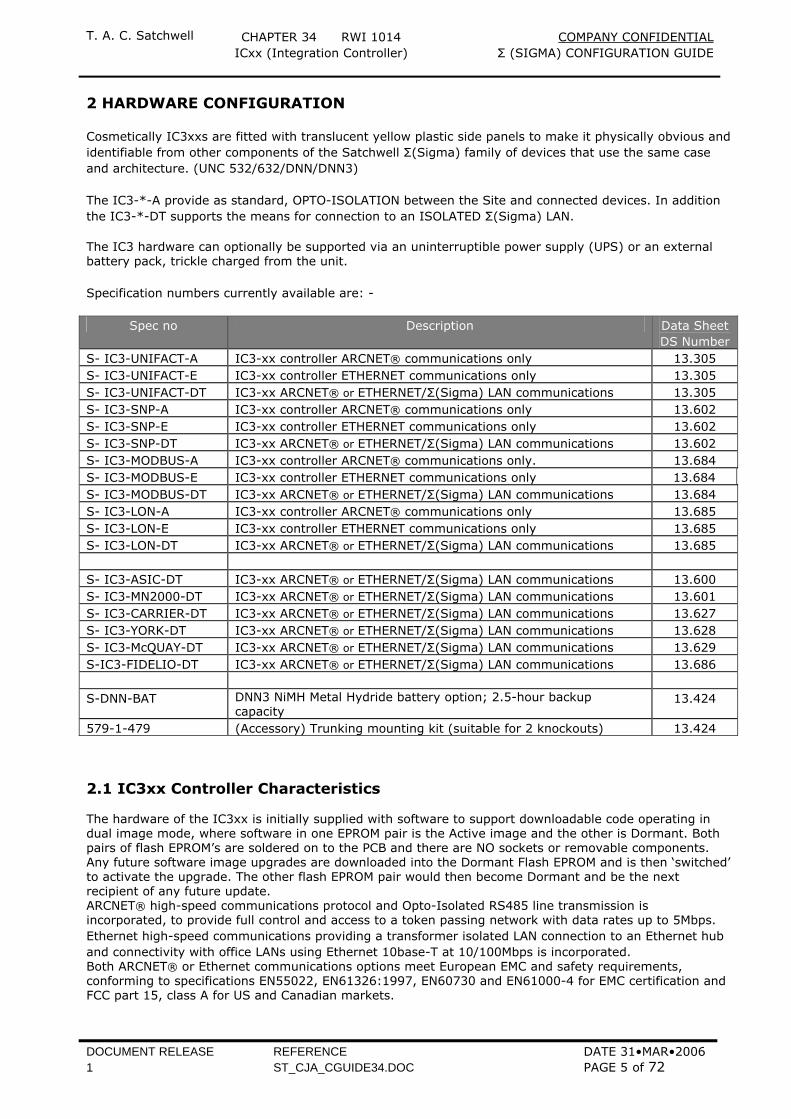
2 HARDWARE CONFIGURATION Cosmetically IC3xxs are fitted with translucent yellow plastic side panels to make it physically obvious and identifiable from other components of the Satchwell Σ(Sigma) family of devices that use the same case and architecture. (UNC 532/632/DNN/DNN3) The IC3-*-A provide as standard, OPTO-ISOLATION between the Site and connected devices. In addition the IC3-*-DT supports the means for connection to an ISOLATED Σ(Sigma) LAN. The IC3 hardware can optionally be supported via an uninterruptible power supply (UPS) or an external battery pack, trickle charged from the unit. Specification numbers currently available are: -
Spec no Description Data Sheet DS Number
S- IC3-UNIFACT-A IC3-xx controller ARCNET® communications only 13.305 S- IC3-UNIFACT-E IC3-xx controller ETHERNET communications only 13.305 S- IC3-UNIFACT-DT IC3-xx ARCNET® or ETHERNET/Σ(Sigma) LAN communications 13.305 S- IC3-SNP-A IC3-xx controller ARCNET® communications only 13.602 S- IC3-SNP-E IC3-xx controller ETHERNET communications only 13.602 S- IC3-SNP-DT IC3-xx ARCNET® or ETHERNET/Σ(Sigma) LAN communications 13.602 S- IC3-MODBUS-A IC3-xx controller ARCNET® communications only. 13.684 S- IC3-MODBUS-E IC3-xx controller ETHERNET communications only 13.684 S- IC3-MODBUS-DT IC3-xx ARCNET® or ETHERNET/Σ(Sigma) LAN communications 13.684 S- IC3-LON-A IC3-xx controller ARCNET® communications only 13.685 S- IC3-LON-E IC3-xx controller ETHERNET communications only 13.685 S- IC3-LON-DT IC3-xx ARCNET® or ETHERNET/Σ(Sigma) LAN communications 13.685 S- IC3-ASIC-DT IC3-xx ARCNET® or ETHERNET/Σ(Sigma) LAN communications 13.600 S- IC3-MN2000-DT IC3-xx ARCNET® or ETHERNET/Σ(Sigma) LAN communications 13.601 S- IC3-CARRIER-DT IC3-xx ARCNET® or ETHERNET/Σ(Sigma) LAN communications 13.627 S- IC3-YORK-DT IC3-xx ARCNET® or ETHERNET/Σ(Sigma) LAN communications 13.628 S- IC3-McQUAY-DT IC3-xx ARCNET® or ETHERNET/Σ(Sigma) LAN communications 13.629 S-IC3-FIDELIO-DT IC3-xx ARCNET® or ETHERNET/Σ(Sigma) LAN communications 13.686 S-DNN-BAT DNN3 NiMH Metal Hydride battery option; 2.5-hour backup
capacity 13.424
579-1-479 (Accessory) Trunking mounting kit (suitable for 2 knockouts) 13.424 2.1 IC3xx Controller Characteristics The hardware of the IC3xx is initially supplied with software to support downloadable code operating in dual image mode, where software in one EPROM pair is the Active image and the other is Dormant. Both pairs of flash EPROM’s are soldered on to the PCB and there are NO sockets or removable components. Any future software image upgrades are downloaded into the Dormant Flash EPROM and is then ‘switched’ to activate the upgrade. The other flash EPROM pair would then become Dormant and be the next recipient of any future update. ARCNET® high-speed communications protocol and Opto-Isolated RS485 line transmission is incorporated, to provide full control and access to a token passing network with data rates up to 5Mbps. Ethernet high-speed communications providing a transformer isolated LAN connection to an Ethernet hub and connectivity with office LANs using Ethernet 10base-T at 10/100Mbps is incorporated. Both ARCNET® or Ethernet communications options meet European EMC and safety requirements, conforming to specifications EN55022, EN61326:1997, EN60730 and EN61000-4 for EMC certification and FCC part 15, class A for US and Canadian markets.
T. A. C. Satchwell CHAPTER 34 RWI 1014 COMPANY CONFIDENTIAL ICxx (Integration Controller) Σ (SIGMA) CONFIGURATION GUIDE
DOCUMENT RELEASE REFERENCE DATE 31•MAR•2006 1 ST_CJA_CGUIDE34.DOC PAGE 6 of 72
The three specification variants have different communications options as below and the selection should be made according to site requirements. It is not possible to add components to upgrade to a different specification.
Specification Ethernet ARCNET® Σ(SIGMA) LAN RS485 RS232 S-IC3-xx-DT 2 1 1 1 1 S-IC3-xx-A 0 1 0 1 1 S-IC3-xx-E 1 0 0 1 1
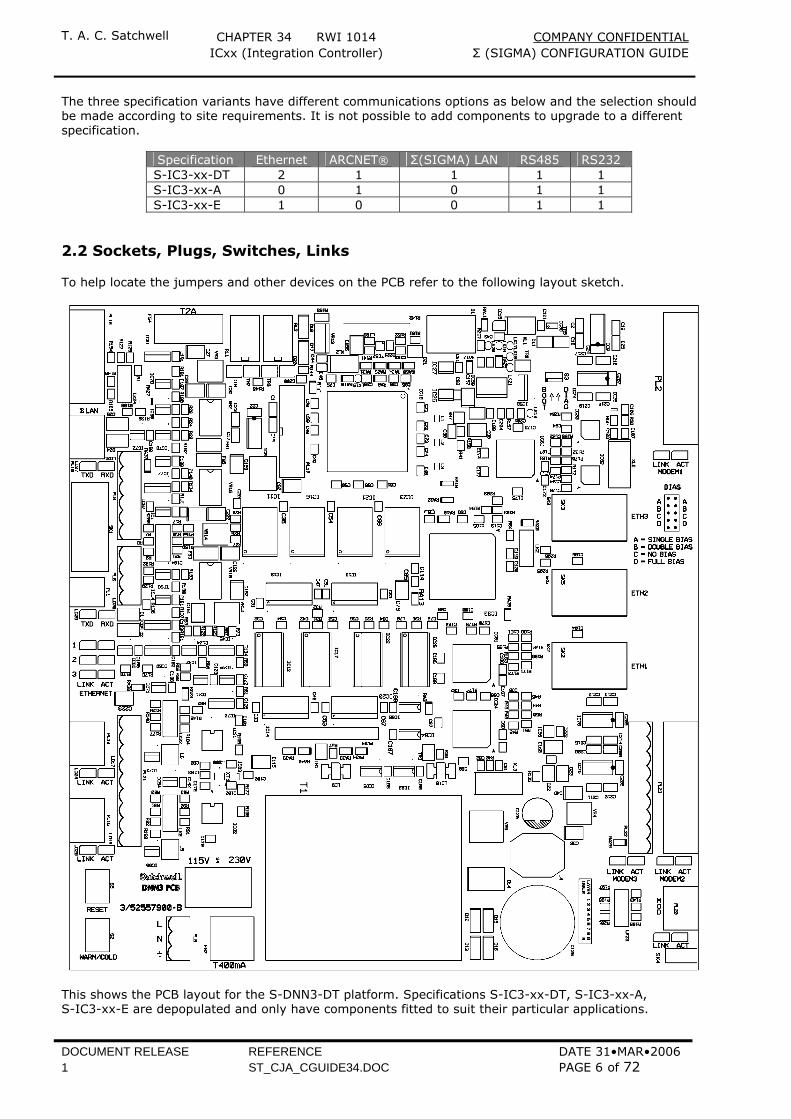
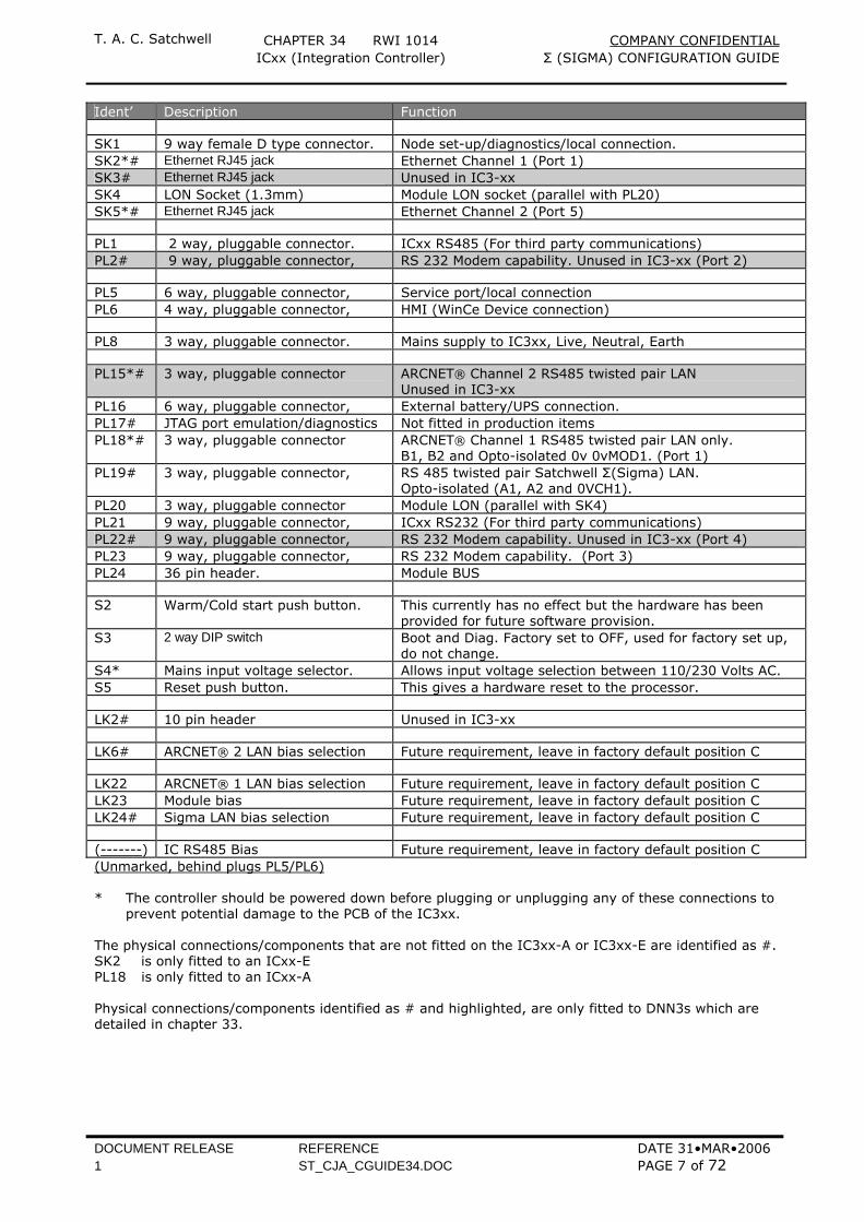
2.2 Sockets, Plugs, Switches, Links To help locate the jumpers and other devices on the PCB refer to the following layout sketch.
This shows the PCB layout for the S-DNN3-DT platform. Specifications S-IC3-xx-DT, S-IC3-xx-A, S-IC3-xx-E are depopulated and only have components fitted to suit their particular applications.
T. A. C. Satchwell CHAPTER 34 RWI 1014 COMPANY CONFIDENTIAL ICxx (Integration Controller) Σ (SIGMA) CONFIGURATION GUIDE
DOCUMENT RELEASE REFERENCE DATE 31•MAR•2006 1 ST_CJA_CGUIDE34.DOC PAGE 7 of 72
Ident’ Description Function SK1 9 way female D type connector. Node set-up/diagnostics/local connection. SK2*# Ethernet RJ45 jack Ethernet Channel 1 (Port 1) SK3# Ethernet RJ45 jack Unused in IC3-xx SK4 LON Socket (1.3mm) Module LON socket (parallel with PL20) SK5*# Ethernet RJ45 jack Ethernet Channel 2 (Port 5) PL1 2 way, pluggable connector. ICxx RS485 (For third party communications) PL2# 9 way, pluggable connector, RS 232 Modem capability. Unused in IC3-xx (Port 2) PL5 6 way, pluggable connector, Service port/local connection PL6 4 way, pluggable connector, HMI (WinCe Device connection) PL8 3 way, pluggable connector. Mains supply to IC3xx, Live, Neutral, Earth PL15*# 3 way, pluggable connector ARCNET® Channel 2 RS485 twisted pair LAN
Unused in IC3-xx PL16 6 way, pluggable connector, External battery/UPS connection. PL17# JTAG port emulation/diagnostics Not fitted in production items PL18*# 3 way, pluggable connector ARCNET® Channel 1 RS485 twisted pair LAN only.
B1, B2 and Opto-isolated 0v 0vMOD1. (Port 1) PL19# 3 way, pluggable connector, RS 485 twisted pair Satchwell Σ(Sigma) LAN.
Opto-isolated (A1, A2 and 0VCH1). PL20 3 way, pluggable connector Module LON (parallel with SK4) PL21 9 way, pluggable connector, ICxx RS232 (For third party communications) PL22# 9 way, pluggable connector, RS 232 Modem capability. Unused in IC3-xx (Port 4) PL23 9 way, pluggable connector, RS 232 Modem capability. (Port 3) PL24 36 pin header. Module BUS S2 Warm/Cold start push button. This currently has no effect but the hardware has been
provided for future software provision. S3 2 way DIP switch Boot and Diag. Factory set to OFF, used for factory set up,
do not change. S4* Mains input voltage selector. Allows input voltage selection between 110/230 Volts AC. S5 Reset push button. This gives a hardware reset to the processor. LK2# 10 pin header Unused in IC3-xx LK6# ARCNET® 2 LAN bias selection Future requirement, leave in factory default position C LK22 ARCNET® 1 LAN bias selection Future requirement, leave in factory default position C LK23 Module bias Future requirement, leave in factory default position C LK24# Sigma LAN bias selection Future requirement, leave in factory default position C (-------) IC RS485 Bias Future requirement, leave in factory default position C (Unmarked, behind plugs PL5/PL6) * The controller should be powered down before plugging or unplugging any of these connections to
prevent potential damage to the PCB of the IC3xx. The physical connections/components that are not fitted on the IC3xx-A or IC3xx-E are identified as #. SK2 is only fitted to an ICxx-E PL18 is only fitted to an ICxx-A Physical connections/components identified as # and highlighted, are only fitted to DNN3s which are detailed in chapter 33.
T. A. C. Satchwell CHAPTER 34 RWI 1014 COMPANY CONFIDENTIAL ICxx (Integration Controller) Σ (SIGMA) CONFIGURATION GUIDE
DOCUMENT RELEASE REFERENCE DATE 31•MAR•2006 1 ST_CJA_CGUIDE34.DOC PAGE 8 of 72
2.3 Data Backup Controller data backup to Flash EPROM and restoration from this area in the event of cold start is supported by the configuration of a time schedule object number 1001. Backup occurs to the dormant flash Eprom when the time schedule object switches from Off to On. Note that a backup may exist in active and dormant images and the operating system uses the most recent valid copy from either location. Note that all files are backed up including logging detail but not logged data.
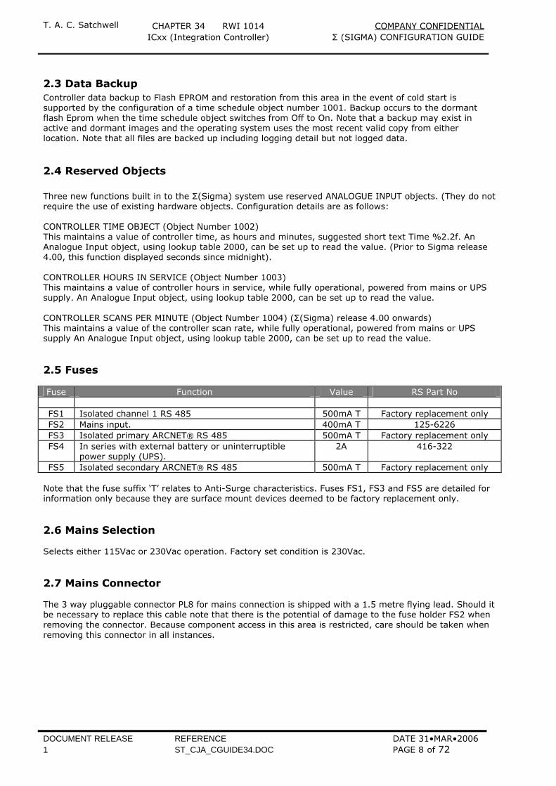
2.4 Reserved Objects Three new functions built in to the Σ(Sigma) system use reserved ANALOGUE INPUT objects. (They do not require the use of existing hardware objects. Configuration details are as follows: CONTROLLER TIME OBJECT (Object Number 1002) This maintains a value of controller time, as hours and minutes, suggested short text Time %2.2f. An Analogue Input object, using lookup table 2000, can be set up to read the value. (Prior to Sigma release 4.00, this function displayed seconds since midnight). CONTROLLER HOURS IN SERVICE (Object Number 1003) This maintains a value of controller hours in service, while fully operational, powered from mains or UPS supply. An Analogue Input object, using lookup table 2000, can be set up to read the value. CONTROLLER SCANS PER MINUTE (Object Number 1004) (Σ(Sigma) release 4.00 onwards) This maintains a value of the controller scan rate, while fully operational, powered from mains or UPS supply An Analogue Input object, using lookup table 2000, can be set up to read the value. 2.5 Fuses Fuse Function Value RS Part No
FS1 Isolated channel 1 RS 485 500mA T Factory replacement only FS2 Mains input. 400mA T 125-6226 FS3 Isolated primary ARCNET® RS 485 500mA T Factory replacement only FS4 In series with external battery or uninterruptible
power supply (UPS). 2A 416-322
FS5 Isolated secondary ARCNET® RS 485 500mA T Factory replacement only Note that the fuse suffix ‘T’ relates to Anti-Surge characteristics. Fuses FS1, FS3 and FS5 are detailed for information only because they are surface mount devices deemed to be factory replacement only. 2.6 Mains Selection Selects either 115Vac or 230Vac operation. Factory set condition is 230Vac. 2.7 Mains Connector The 3 way pluggable connector PL8 for mains connection is shipped with a 1.5 metre flying lead. Should it be necessary to replace this cable note that there is the potential of damage to the fuse holder FS2 when removing the connector. Because component access in this area is restricted, care should be taken when removing this connector in all instances.
T. A. C. Satchwell CHAPTER 34 RWI 1014 COMPANY CONFIDENTIAL ICxx (Integration Controller) Σ (SIGMA) CONFIGURATION GUIDE
DOCUMENT RELEASE REFERENCE DATE 31•MAR•2006 1 ST_CJA_CGUIDE34.DOC PAGE 9 of 72
BAT BC1 BC2 0V BCON 0V
PL16
+
_
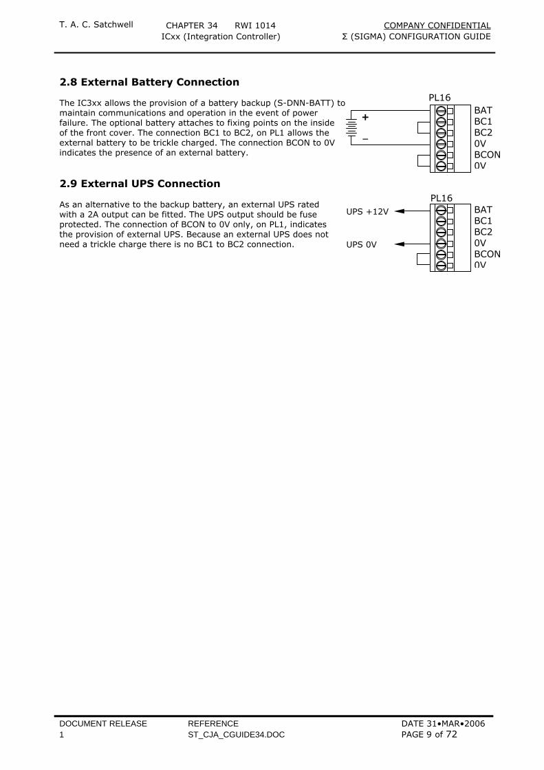
2.8 External Battery Connection The IC3xx allows the provision of a battery backup (S-DNN-BATT) to maintain communications and operation in the event of power failure. The optional battery attaches to fixing points on the inside of the front cover. The connection BC1 to BC2, on PL1 allows the external battery to be trickle charged. The connection BCON to 0V indicates the presence of an external battery. 2.9 External UPS Connection As an alternative to the backup battery, an external UPS rated with a 2A output can be fitted. The UPS output should be fuse protected. The connection of BCON to 0V only, on PL1, indicates the provision of external UPS. Because an external UPS does not need a trickle charge there is no BC1 to BC2 connection.
BAT BC1 BC2 0V BCON 0V
PL16UPS +12V
UPS 0V

T. A. C. Satchwell CHAPTER 34 RWI 1014 COMPANY CONFIDENTIAL ICxx (Integration Controller) Σ (SIGMA) CONFIGURATION GUIDE
DOCUMENT RELEASE REFERENCE DATE 31•MAR•2006 1 ST_CJA_CGUIDE34.DOC PAGE 10 of 72
3 NETWORK CONFIGURATION The NODE inside a IC3xx is a complete communications system and connects to the Satchwell Σ(Sigma) Network. ARCNET® or ETHERNET communications must be selected in every case, as this is the only way to communicate with the IC3xx and route to secondary networks. The IC3xx gives the following Network facilities.
Port 1 LAN Σ(Sigma) LAN, 19200 baud, Opto-isolated (dual LAN installation only) Port 1 LAN Communications ARCNET® or 10/100base-T ETHERNET Port 3 RS232 Modem connection Port 5 LAN Communications 10/100base-T ETHERNET Port 7 RS232 Service port/local connection Port 8 RS232 Human Machine Interface (HMI) SK1 Diagnostic port 3rd Party LAN IC RS485 LAN (common with 3rd party RS232 alternative) LON Module
Network configuration is carried out in two parts. At the device using a locally connected CONFIGURATION device, using any form of Hand Held Terminal (HHT) device to set-up the node and IP (Internet Protocol) address. And finally by sending network configuration data from a Satchwell Σ(Sigma) client/server connected either locally to SK1, the diagnostic port or remotely over the Network. It is important that the device is configured first using a local device as this enables the operational (second) set of configuration data to be sent. While it is possible to use the existing Oyster hand held terminal, it becomes a cumbersome exercise because of the use of spaces and stops. For this reason it is recommended that the SDCU (Sigma Device Configuration Utility) or the Pocket Terminal programme be used for ease of entering the characters. Updated copies of these programmes can be found on the Satchwell area of Exchange On Line (EOL) which is the T. A. C. Global Extranet. Note that when setting up a network, the IP address is part of the node and must be unique. IP addresses may be dictated by an external network administrator and may be restricted in range, or they may be part of a standalone network and be freely available. However it is suggested/recommended, where possible, that the device node number is related to the last part of the IP address, such that device 114 is equivalent to network address 10.44.100.114 and is more easily remembered. Because IP addresses are essential parts of nodes, it is also necessary that the network design and layout is predetermined before node configuration is begun. All devices, including servers, are now nodes and this has to be taken into account when determining network design. IT IS VITALLY IMPORTANT THAT CARE IS TAKEN WHEN SETTING UP IP ADDRESSES AS ANY MISTAKE IN THIS AREA COULD HAVE DRAMATIC CONSEQUENCES UPON THE REST OF THE NETWORK. FOR THIS REASON THE PREFERRED METHOD OF INITIAL INPUT IS VIA THE SDCU OR POCKET TERMINAL PROGRAMME, WITH THE OYSTER HAND HELD TERMINAL BEING THE LEAST FAVOURED METHOD
3.1 On First Power On • When the IC3xx is powered up for the first time and before any form of setup has been carried out,
the activity on the card will be as follows:- • It starts to run the boot image, which switches the Run LED (green), and activity LED (yellow) ON for
approximately one second. • The Green LED flashes three times as the image is selected and it validates the Low image checksum. • The Green LED then flashes once, if a valid image is found. • The controller starts to run the image. • Both Green and Yellow LED’s will flash indefinitely if no valid image is found. If this happens, please
contact Product Support. • As no node configuration is found, the Green LED goes off and the Yellow LED stays on with a steady
illumination. • As soon as a node configuration device is connected the Yellow LED will start to flash at 1Hz. The node can now be configured with one of the devices as below: -
T. A. C. Satchwell CHAPTER 34 RWI 1014 COMPANY CONFIDENTIAL ICxx (Integration Controller) Σ (SIGMA) CONFIGURATION GUIDE
DOCUMENT RELEASE REFERENCE DATE 31•MAR•2006 1 ST_CJA_CGUIDE34.DOC PAGE 11 of 72
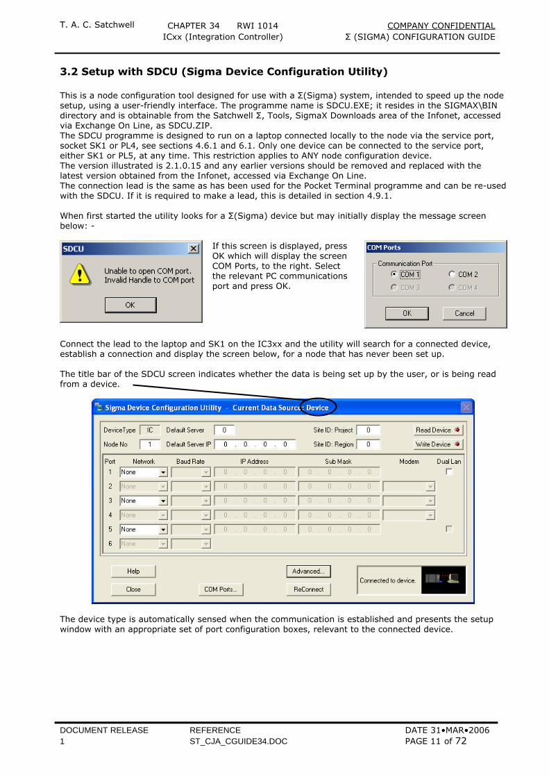
3.2 Setup with SDCU (Sigma Device Configuration Utility) This is a node configuration tool designed for use with a Σ(Sigma) system, intended to speed up the node setup, using a user-friendly interface. The programme name is SDCU.EXE; it resides in the SIGMAX\BIN directory and is obtainable from the Satchwell Σ, Tools, SigmaX Downloads area of the Infonet, accessed via Exchange On Line, as SDCU.ZIP. The SDCU programme is designed to run on a laptop connected locally to the node via the service port, socket SK1 or PL4, see sections 4.6.1 and 6.1. Only one device can be connected to the service port, either SK1 or PL5, at any time. This restriction applies to ANY node configuration device. The version illustrated is 2.1.0.15 and any earlier versions should be removed and replaced with the latest version obtained from the Infonet, accessed via Exchange On Line. The connection lead is the same as has been used for the Pocket Terminal programme and can be re-used with the SDCU. If it is required to make a lead, this is detailed in section 4.9.1. When first started the utility looks for a Σ(Sigma) device but may initially display the message screen below: -
If this screen is displayed, press OK which will display the screen COM Ports, to the right. Select the relevant PC communications port and press OK.
Connect the lead to the laptop and SK1 on the IC3xx and the utility will search for a connected device, establish a connection and display the screen below, for a node that has never been set up. The title bar of the SDCU screen indicates whether the data is being set up by the user, or is being read from a device.
The device type is automatically sensed when the communication is established and presents the setup window with an appropriate set of port configuration boxes, relevant to the connected device.
T. A. C. Satchwell CHAPTER 34 RWI 1014 COMPANY CONFIDENTIAL ICxx (Integration Controller) Σ (SIGMA) CONFIGURATION GUIDE
DOCUMENT RELEASE REFERENCE DATE 31•MAR•2006 1 ST_CJA_CGUIDE34.DOC PAGE 12 of 72
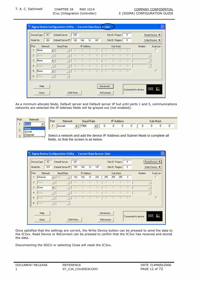
As a minmum allocate Node, Default server and Default server IP but until ports 1 and 5, communications networks are selected the IP Address fields will be greyed out (not enabled).
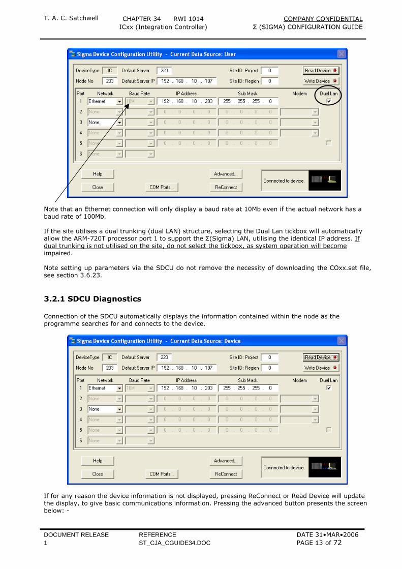
Select a network and add the device IP Address and Subnet Mask to complete all fields, so that the screen is as below.
Once satisfied that the settings are correct, the Write Device button can be pressed to send the data to the IC3xx. Read Device or ReConnect can be pressed to confim that the IC3xx has received and stored the data. Disconnecting the SDCU or selecting Close will reset the IC3xx.
T. A. C. Satchwell CHAPTER 34 RWI 1014 COMPANY CONFIDENTIAL ICxx (Integration Controller) Σ (SIGMA) CONFIGURATION GUIDE
DOCUMENT RELEASE REFERENCE DATE 31•MAR•2006 1 ST_CJA_CGUIDE34.DOC PAGE 13 of 72
Note that an Ethernet connection will only display a baud rate at 10Mb even if the actual network has a baud rate of 100Mb. If the site utilises a dual trunking (dual LAN) structure, selecting the Dual Lan tickbox will automatically allow the ARM-720T processor port 1 to support the Σ(Sigma) LAN, utilising the identical IP address. If dual trunking is not utilised on the site, do not select the tickbox, as system operation will become impaired. Note setting up parameters via the SDCU do not remove the necessity of downloading the COxx.set file, see section 3.6.23.
3.2.1 SDCU Diagnostics Connection of the SDCU automatically displays the information contained within the node as the programme searches for and connects to the device.
If for any reason the device information is not displayed, pressing ReConnect or Read Device will update the display, to give basic communications information. Pressing the advanced button presents the screen below: -
T. A. C. Satchwell CHAPTER 34 RWI 1014 COMPANY CONFIDENTIAL ICxx (Integration Controller) Σ (SIGMA) CONFIGURATION GUIDE
DOCUMENT RELEASE REFERENCE DATE 31•MAR•2006 1 ST_CJA_CGUIDE34.DOC PAGE 14 of 72
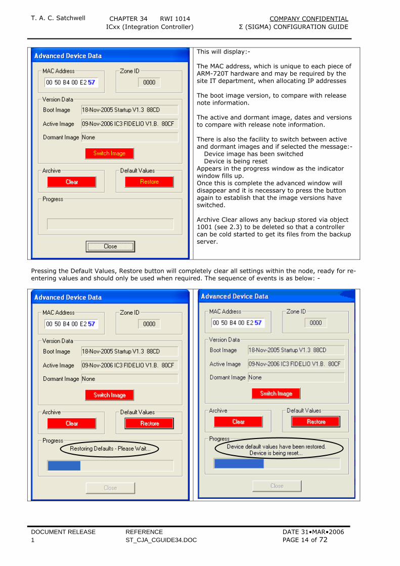
This will display:- The MAC address, which is unique to each piece of ARM-720T hardware and may be required by the site IT department, when allocating IP addresses The boot image version, to compare with release note information. The active and dormant image, dates and versions to compare with release note information. There is also the facility to switch between active and dormant images and if selected the message:- Device image has been switched Device is being reset Appears in the progress window as the indicator window fills up. Once this is complete the advanced window will disappear and it is necessary to press the button again to establish that the image versions have switched. Archive Clear allows any backup stored via object 1001 (see 2.3) to be deleted so that a controller can be cold started to get its files from the backup server.
Pressing the Default Values, Restore button will completely clear all settings within the node, ready for re-entering values and should only be used when required. The sequence of events is as below: -
T. A. C. Satchwell CHAPTER 34 RWI 1014 COMPANY CONFIDENTIAL ICxx (Integration Controller) Σ (SIGMA) CONFIGURATION GUIDE
DOCUMENT RELEASE REFERENCE DATE 31•MAR•2006 1 ST_CJA_CGUIDE34.DOC PAGE 15 of 72
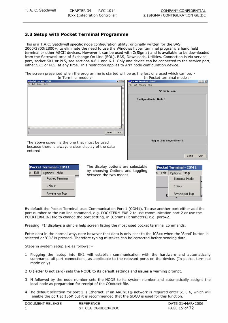
3.3 Setup with Pocket Terminal Programme This is a T.A.C. Satchwell specific node configuration utility, originally written for the BAS 2000/2800/2800+, to eliminate the need to use the Windows hyper terminal program; a hand held terminal or other ASCII devices. However it can be used with Σ(Sigma) and is available to be downloaded from the Satchwell area of Exchange On Line (EOL), BAS, Downloads, Utilities. Connection is via service port, socket SK1 or PL5, see sections 4.6.1 and 6.1. Only one device can be connected to the service port, either SK1 or PL5, at any time. This restriction applies to ANY node configuration device. The screen presented when the programme is started will be as the last one used which can be: -
In Terminal mode :- In Pocket terminal mode :-
The above screen is the one that must be used because there is always a clear display of the data entered.
The display options are selectable by choosing Options and toggling between the two modes
By default the Pocket Terminal uses Communication Port 1 (COM1). To use another port either add the port number to the run line command, e.g. POCKTERM.EXE 2 to use communication port 2 or use the POCKTERM.INI file to change the port setting, in [Comms Parameters] e.g. port=2. Pressing 'F1' displays a simple help screen listing the most used pocket terminal commands. Enter data in the normal way, note however that data is only sent to the IC3xx when the ‘Send’ button is selected or 'CR.' is pressed. Therefore typing mistakes can be corrected before sending data. Steps in system setup are as follows: - 1 Plugging the laptop into SK1 will establish communication with the hardware and automatically
summarise all port connections, as applicable to the relevant ports on the device. (In pocket terminal mode only)
2 O (letter O not zero) sets the NODE to its default settings and issues a warning prompt. 3 N followed by the node number sets the NODE to its system number and automatically assigns the
local node as preparation for receipt of the COxx.set file. 4 The default selection for port 1 is Ethernet. If an ARCNET® network is required enter S1 0 6, which will
enable the port at 156K but it is recommended that the SDCU is used for this function.
T. A. C. Satchwell CHAPTER 34 RWI 1014 COMPANY CONFIDENTIAL ICxx (Integration Controller) Σ (SIGMA) CONFIGURATION GUIDE
DOCUMENT RELEASE REFERENCE DATE 31•MAR•2006 1 ST_CJA_CGUIDE34.DOC PAGE 16 of 72
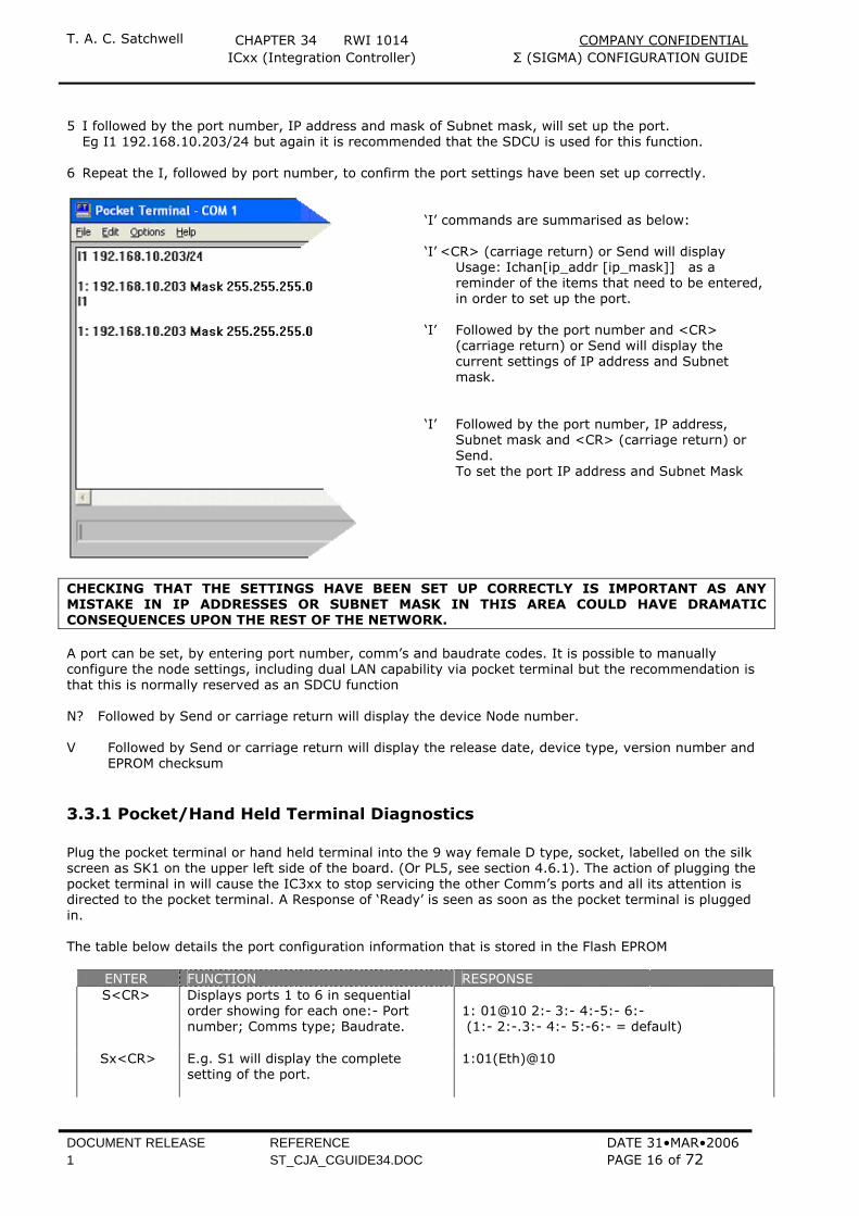
5 I followed by the port number, IP address and mask of Subnet mask, will set up the port. Eg I1 192.168.10.203/24 but again it is recommended that the SDCU is used for this function. 6 Repeat the I, followed by port number, to confirm the port settings have been set up correctly.
‘I’ commands are summarised as below: ‘I’ <CR> (carriage return) or Send will display Usage: Ichan[ip_addr [ip_mask]] as a
reminder of the items that need to be entered, in order to set up the port.
‘I’ Followed by the port number and <CR>
(carriage return) or Send will display the current settings of IP address and Subnet mask.
‘I’ Followed by the port number, IP address,
Subnet mask and <CR> (carriage return) or Send.
To set the port IP address and Subnet Mask
CHECKING THAT THE SETTINGS HAVE BEEN SET UP CORRECTLY IS IMPORTANT AS ANY MISTAKE IN IP ADDRESSES OR SUBNET MASK IN THIS AREA COULD HAVE DRAMATIC CONSEQUENCES UPON THE REST OF THE NETWORK. A port can be set, by entering port number, comm’s and baudrate codes. It is possible to manually configure the node settings, including dual LAN capability via pocket terminal but the recommendation is that this is normally reserved as an SDCU function N? Followed by Send or carriage return will display the device Node number. V Followed by Send or carriage return will display the release date, device type, version number and
EPROM checksum
3.3.1 Pocket/Hand Held Terminal Diagnostics Plug the pocket terminal or hand held terminal into the 9 way female D type, socket, labelled on the silk screen as SK1 on the upper left side of the board. (Or PL5, see section 4.6.1). The action of plugging the pocket terminal in will cause the IC3xx to stop servicing the other Comm’s ports and all its attention is directed to the pocket terminal. A Response of ‘Ready’ is seen as soon as the pocket terminal is plugged in. The table below details the port configuration information that is stored in the Flash EPROM
ENTER FUNCTION RESPONSE S<CR> Displays ports 1 to 6 in sequential
order showing for each one:- Port number; Comms type; Baudrate.
1: 01@10 2:- 3:- 4:-5:- 6:- (1:- 2:-.3:- 4:- 5:-6:- = default)
Sx<CR> E.g. S1 will display the complete setting of the port.
1:01(Eth)@10
T. A. C. Satchwell CHAPTER 34 RWI 1014 COMPANY CONFIDENTIAL ICxx (Integration Controller) Σ (SIGMA) CONFIGURATION GUIDE
DOCUMENT RELEASE REFERENCE DATE 31•MAR•2006 1 ST_CJA_CGUIDE34.DOC PAGE 17 of 72
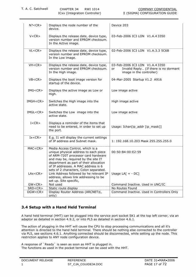
N?<CR> Displays the node number of the device.
Device 203
V<CR> Displays the release date, device type, version number and EPROM checksum. In the Active image.
03-Feb-2006 IC3 LON V1.A.4 3350
VL<CR> Displays the release date, device type, version number and EPROM checksum. In the Low image.
02-Feb-2006 IC3 LON V1.A.3.3 5C6B
VH<CR> Displays the release date, device type, version number and EPROM checksum. In the High image.
03-Feb-2006 IC3 LON V1.A.4 3350 or Invalid Reply… (If there is no dormant image in the controller)
VB<CR> Displays the boot image version for startup of the device.
04-Mar-2005 Startup V1.2 A916
IMG<CR> Displays the active image as Low or High.
Low image active
IMGH<CR> Switches the High image into the active state.
High image active
IMGL<CR> Switches the Low image into the active state.
Low image active
I<CR> Displays a reminder of the items that need to be entered, in order to set up the port.
Usage: Ichan[ip_addr [ip_mask]]
Ix<CR> E.g. I1 will display the current settings of IP address and Subnet mask.
1: 192.168.10.203 Mask 255.255.255.0
MAC<CR> Media Access Control, which is a unique physical address to each piece of ARM-720T processor card hardware and may be, required by the site IT department as part of their allocation of IP addresses. A MAC address is 6 sets of 2 characters, Colon separated.
00:50:B4:00:E2:59
LAx<CR> Link Address followed by he relevant IP address, allows link addressing to be set up. Site specific,
Usage LA[ + - DC]
GW<CR> Not used Command Inactive. Used in UNC/IC SRD<CR> Static route display No Routes Found DGW<CR> Display Router Address (ARCNET®,
only) Command Inactive. Used in Controllers Only
3.4 Setup with a Hand Held Terminal A hand held terminal (HHT) can be plugged into the service port socket SK1 at the top left corner, via an adaptor as detailed in section 4.9.2, or into PL5 as detailed in section 4.6.1. The action of plugging in the HHT will cause the CPU to stop processing communications and all it's attention is directed to the hand held terminal. There should be nothing else connected to the controller via PL5, see sections 4.6.1. Anything connected should be disconnected, while setting up the node. This restriction applies to ANY node configuration device. A response of `Ready` is seen as soon as HHT is plugged in. The functions as used in the pocket terminal can be used with the HHT.
T. A. C. Satchwell CHAPTER 34 RWI 1014 COMPANY CONFIDENTIAL ICxx (Integration Controller) Σ (SIGMA) CONFIGURATION GUIDE
DOCUMENT RELEASE REFERENCE DATE 31•MAR•2006 1 ST_CJA_CGUIDE34.DOC PAGE 18 of 72
IT IS VITALLY IMPORTANT THAT CARE IS TAKEN WHEN SETTING UP IP ADDRESSES AS ANY MISTAKE IN THIS AREA COULD HAVE DRAMATIC CONSEQUENCES UPON THE REST OF THE NETWORK. FOR THIS REASON AND THE FACT THAT THE NUMBERS OF CHARACTERS ENTERED TO SET UP THE IP ADDRESS MEANS THAT AS THE DISPLAY SCREEN SCROLLS ALONG, IS DIFFICULT TO FOLLOW AND IS PRONE TO MISTAKES IN DATA ENTRY. THE OYSTER HAND HELD TERMINAL IS THE LEAST FAVOURED METHOD OF NODE SETUP/CONFIGURATION.
3.5 Node Configuration and Communications Check To check that the node has been set up correctly it is advisable to check that it responds to its IP address, from a Σ(Sigma) server, by pinging it first to make sure that communications is possible before attempting to download the node configuration (COxx.set) file. If it is not possible to ping the node it could be a network problem, or default gateway issue. If there is a failure double check that the IP address being used is valid and has not been duplicated elsewhere on the system. There are two ways to ping a device, either from the diagnostic Sigma ping programme or a standard Windows tool. Both methods are detailed below.
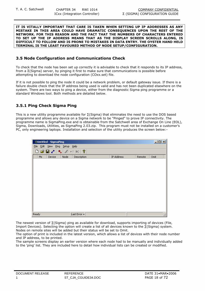
3.5.1 Ping Check Sigma Ping This is a new utility programme available for ∑(Sigma) that eliminates the need to use the DOS based programme and allows any device on a Sigma network to be "Pinged" to prove IP connectivity. The programme name is SigmaPing.exe and is obtainable from the Satchwell area of Exchange On Line (EOL), Sigma, Downloads, Utilities, as SigmaPing 2.03.zip. This program must not be installed on a customer’s PC, only engineering laptops. Installation and selection of the utility produces the screen below:-
The newest version of ∑(Sigma) ping as available for download, supports importing of devices (File, Import Devices). Selecting the option will create a list of all devices known to the ∑(Sigma) system. Nodes on remote sites will be added but their status will be set to Omit. The option of print is included in the latest version, which allows a list of devices with their node number and IP address, to be printed. The sample screens display an earlier version where each node had to be manually and individually added to the 'ping' list. They are included here to detail how individual lists can be created or modified.
T. A. C. Satchwell CHAPTER 34 RWI 1014 COMPANY CONFIDENTIAL ICxx (Integration Controller) Σ (SIGMA) CONFIGURATION GUIDE
DOCUMENT RELEASE REFERENCE DATE 31•MAR•2006 1 ST_CJA_CGUIDE34.DOC PAGE 19 of 72
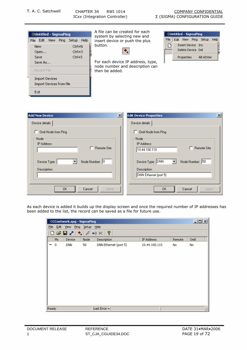
A file can be created for each system by selecting new and insert device or push the plus button.
For each device IP address, type, node number and description can then be added.
As each device is added it builds up the display screen and once the required number of IP addresses has been added to the list, the record can be saved as a file for future use.
T. A. C. Satchwell CHAPTER 34 RWI 1014 COMPANY CONFIDENTIAL ICxx (Integration Controller) Σ (SIGMA) CONFIGURATION GUIDE
DOCUMENT RELEASE REFERENCE DATE 31•MAR•2006 1 ST_CJA_CGUIDE34.DOC PAGE 20 of 72
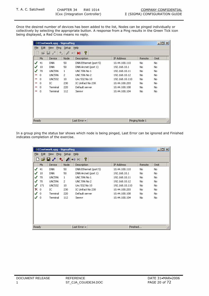
Once the desired number of devices has been added to the list, Nodes can be pinged individually or collectively by selecting the appropriate button. A response from a Ping results in the Green Tick icon being displayed, a Red Cross means no reply.
In a group ping the status bar shows which node is being pinged, Last Error can be ignored and Finished indicates completion of the exercise.
T. A. C. Satchwell CHAPTER 34 RWI 1014 COMPANY CONFIDENTIAL ICxx (Integration Controller) Σ (SIGMA) CONFIGURATION GUIDE
DOCUMENT RELEASE REFERENCE DATE 31•MAR•2006 1 ST_CJA_CGUIDE34.DOC PAGE 21 of 72
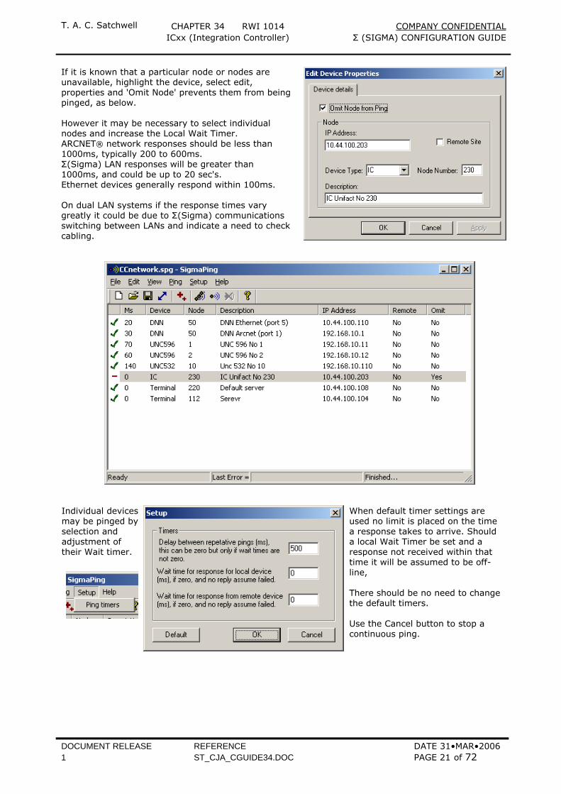
If it is known that a particular node or nodes are unavailable, highlight the device, select edit, properties and 'Omit Node' prevents them from being pinged, as below. However it may be necessary to select individual nodes and increase the Local Wait Timer. ARCNET® network responses should be less than 1000ms, typically 200 to 600ms. Σ(Sigma) LAN responses will be greater than 1000ms, and could be up to 20 sec's. Ethernet devices generally respond within 100ms. On dual LAN systems if the response times vary greatly it could be due to Σ(Sigma) communications switching between LANs and indicate a need to check cabling.
Individual devices may be pinged by selection and adjustment of their Wait timer.
When default timer settings are used no limit is placed on the time a response takes to arrive. Should a local Wait Timer be set and a response not received within that time it will be assumed to be off-line, There should be no need to change the default timers. Use the Cancel button to stop a continuous ping.
T. A. C. Satchwell CHAPTER 34 RWI 1014 COMPANY CONFIDENTIAL ICxx (Integration Controller) Σ (SIGMA) CONFIGURATION GUIDE
DOCUMENT RELEASE REFERENCE DATE 31•MAR•2006 1 ST_CJA_CGUIDE34.DOC PAGE 22 of 72
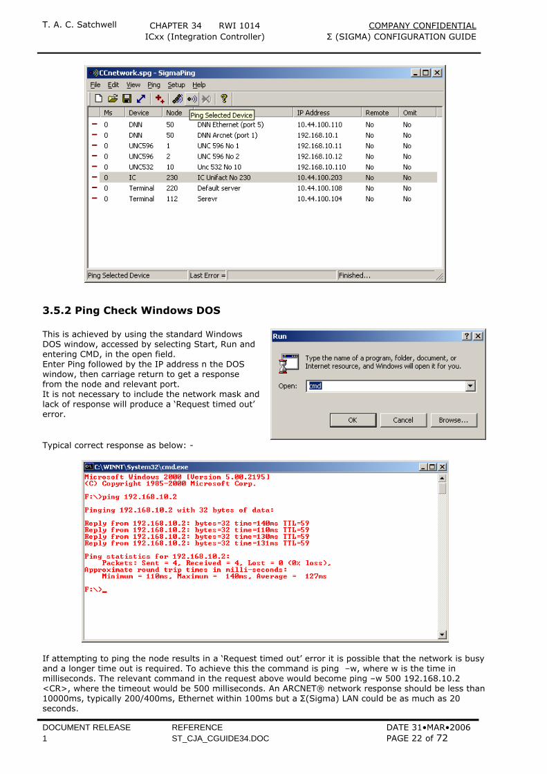
3.5.2 Ping Check Windows DOS This is achieved by using the standard Windows DOS window, accessed by selecting Start, Run and entering CMD, in the open field. Enter Ping followed by the IP address n the DOS window, then carriage return to get a response from the node and relevant port. It is not necessary to include the network mask and lack of response will produce a ‘Request timed out’ error.
Typical correct response as below: -
If attempting to ping the node results in a ‘Request timed out’ error it is possible that the network is busy and a longer time out is required. To achieve this the command is ping –w, where w is the time in milliseconds. The relevant command in the request above would become ping –w 500 192.168.10.2 <CR>, where the timeout would be 500 milliseconds. An ARCNET® network response should be less than 10000ms, typically 200/400ms, Ethernet within 100ms but a Σ(Sigma) LAN could be as much as 20 seconds.
T. A. C. Satchwell CHAPTER 34 RWI 1014 COMPANY CONFIDENTIAL ICxx (Integration Controller) Σ (SIGMA) CONFIGURATION GUIDE
DOCUMENT RELEASE REFERENCE DATE 31•MAR•2006 1 ST_CJA_CGUIDE34.DOC PAGE 23 of 72
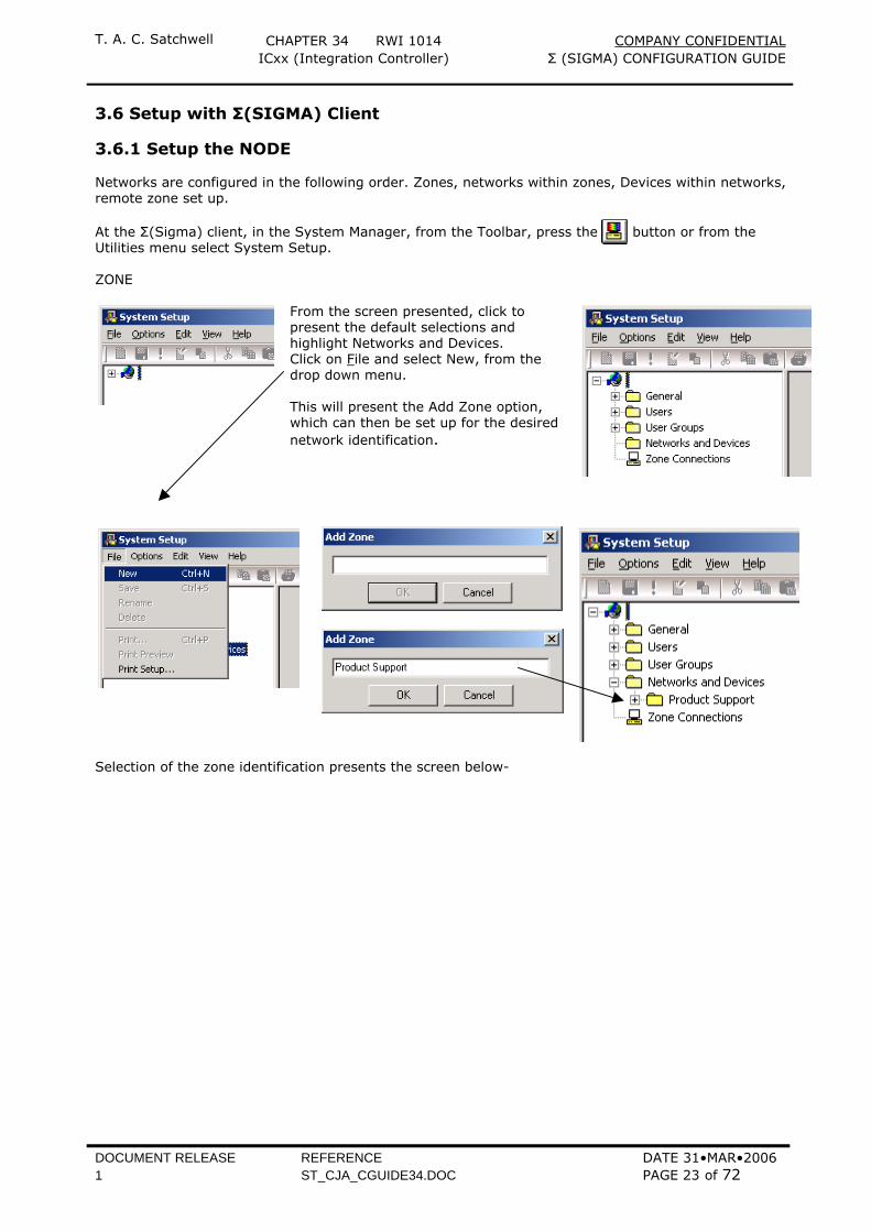
3.6 Setup with Σ(SIGMA) Client 3.6.1 Setup the NODE Networks are configured in the following order. Zones, networks within zones, Devices within networks, remote zone set up. At the Σ(Sigma) client, in the System Manager, from the Toolbar, press the button or from the Utilities menu select System Setup.
ZONE
From the screen presented, click to present the default selections and highlight Networks and Devices. Click on File and select New, from the drop down menu. This will present the Add Zone option, which can then be set up for the desired network identification.
Selection of the zone identification presents the screen below-
T. A. C. Satchwell CHAPTER 34 RWI 1014 COMPANY CONFIDENTIAL ICxx (Integration Controller) Σ (SIGMA) CONFIGURATION GUIDE
DOCUMENT RELEASE REFERENCE DATE 31•MAR•2006 1 ST_CJA_CGUIDE34.DOC PAGE 24 of 72
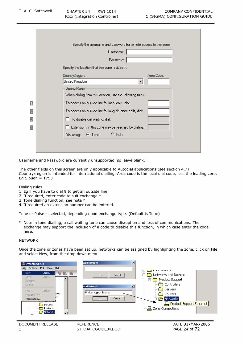
Username and Password are currently unsupported, so leave blank. The other fields on this screen are only applicable to Autodial applications (see section 4.7) Country/region is intended for international dialling. Area code is the local dial code, less the leading zero. Eg Slough = 1753 Dialing rules 1 Eg if you have to dial 9 to get an outside line. 2 If required, enter code to suit exchange * 3 Tone dialling function, see note * 4 If required an extension number can be entered. Tone or Pulse is selected, depending upon exchange type. (Default is Tone) * Note in tone dialling, a call waiting tone can cause disruption and loss of communications. The
exchange may support the inclusion of a code to disable this function, in which case enter the code here.
NETWORK Once the zone or zones have been set up, networks can be assigned by highlighting the zone, click on File and select New, from the drop down menu.
1
2
3
4
T. A. C. Satchwell CHAPTER 34 RWI 1014 COMPANY CONFIDENTIAL ICxx (Integration Controller) Σ (SIGMA) CONFIGURATION GUIDE
DOCUMENT RELEASE REFERENCE DATE 31•MAR•2006 1 ST_CJA_CGUIDE34.DOC PAGE 25 of 72
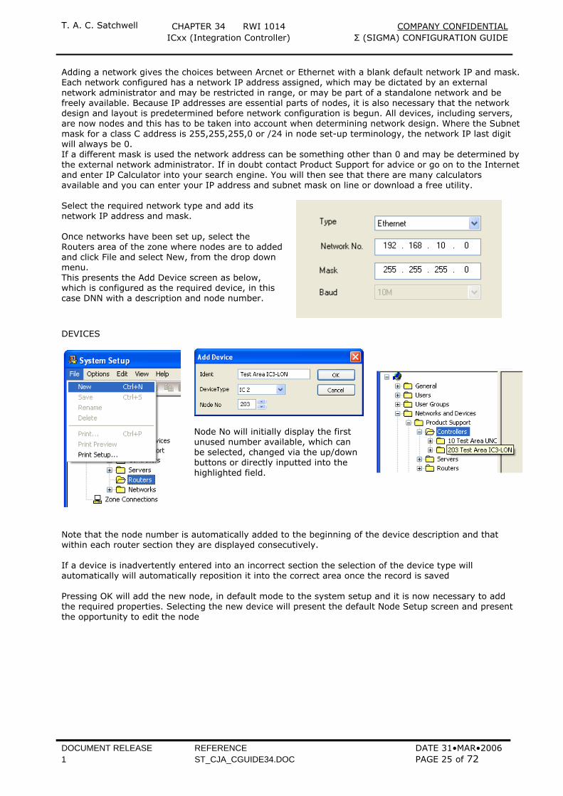
Adding a network gives the choices between Arcnet or Ethernet with a blank default network IP and mask. Each network configured has a network IP address assigned, which may be dictated by an external network administrator and may be restricted in range, or may be part of a standalone network and be freely available. Because IP addresses are essential parts of nodes, it is also necessary that the network design and layout is predetermined before network configuration is begun. All devices, including servers, are now nodes and this has to be taken into account when determining network design. Where the Subnet mask for a class C address is 255,255,255,0 or /24 in node set-up terminology, the network IP last digit will always be 0. If a different mask is used the network address can be something other than 0 and may be determined by the external network administrator. If in doubt contact Product Support for advice or go on to the Internet and enter IP Calculator into your search engine. You will then see that there are many calculators available and you can enter your IP address and subnet mask on line or download a free utility. Select the required network type and add its network IP address and mask. Once networks have been set up, select the Routers area of the zone where nodes are to added and click File and select New, from the drop down menu. This presents the Add Device screen as below, which is configured as the required device, in this case DNN with a description and node number.
DEVICES
Node No will initially display the first unused number available, which can be selected, changed via the up/down buttons or directly inputted into the highlighted field.
Note that the node number is automatically added to the beginning of the device description and that within each router section they are displayed consecutively. If a device is inadvertently entered into an incorrect section the selection of the device type will automatically will automatically reposition it into the correct area once the record is saved Pressing OK will add the new node, in default mode to the system setup and it is now necessary to add the required properties. Selecting the new device will present the default Node Setup screen and present the opportunity to edit the node

T. A. C. Satchwell CHAPTER 34 RWI 1014 COMPANY CONFIDENTIAL ICxx (Integration Controller) Σ (SIGMA) CONFIGURATION GUIDE
DOCUMENT RELEASE REFERENCE DATE 31•MAR•2006 1 ST_CJA_CGUIDE34.DOC PAGE 26 of 72
Enter the configuration details of the NODE. It is necessary to edit the screen fields, as to the IP address, default server and dual LAN as a minimum requirement. A completed Node setup screen, with no modems will be as below:-
If the site utilises a dual trunking (dual LAN) structure, selecting the Dual Lan tickbox will automatically allow the ARM-720T processor port 1 to support the Satchwell Σ(Sigma) LAN, utilising the identical IP address. If dual trunking is not utilised on the site, do not select the tickbox, as system operation will become impaired.
T. A. C. Satchwell CHAPTER 34 RWI 1014 COMPANY CONFIDENTIAL ICxx (Integration Controller) Σ (SIGMA) CONFIGURATION GUIDE
DOCUMENT RELEASE REFERENCE DATE 31•MAR•2006 1 ST_CJA_CGUIDE34.DOC PAGE 27 of 72
The Node record is held in Flash EPROM and contains the number of the default server, as entered in the above screen. The default server receives Fault and Error messages and is the source of the time and date. It will also receive Alarms and Reports normally destined for other servers if they fail to get through to their assigned original destination. It is advisable on single server sites, that the Default and Backup servers are the same and it is recommended it is numbered 254, with subsequent devices as 253, 252 etc. The IC3xx router can also be used with autodial modems to connect one zone to another and must be used when there are multiple devices within a zone. Only one router is allowed within a network but the IC3xx can support up to three telephone lines using PSTN, (Public Switched Telephone Network) or PABX (Private Automatic Branch eXchangees). Set up and configuration of this feature is detailed in section 4.5.
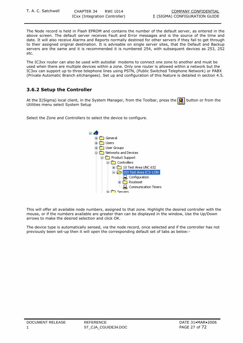
3.6.2 Setup the Controller At the Σ(Sigma) local client, in the System Manager, from the Toolbar, press the button or from the Utilities menu select System Setup Select the Zone and Controllers to select the device to configure.
This will offer all available node numbers, assigned to that zone. Highlight the desired controller with the mouse, or if the numbers available are greater than can be displayed in the window, Use the Up/Down arrows to make the desired selection and click OK.
The device type is automatically sensed, via the node record, once selected and if the controller has not previously been set-up then it will open the corresponding default set of tabs as below:-
T. A. C. Satchwell CHAPTER 34 RWI 1014 COMPANY CONFIDENTIAL ICxx (Integration Controller) Σ (SIGMA) CONFIGURATION GUIDE
DOCUMENT RELEASE REFERENCE DATE 31•MAR•2006 1 ST_CJA_CGUIDE34.DOC PAGE 28 of 72
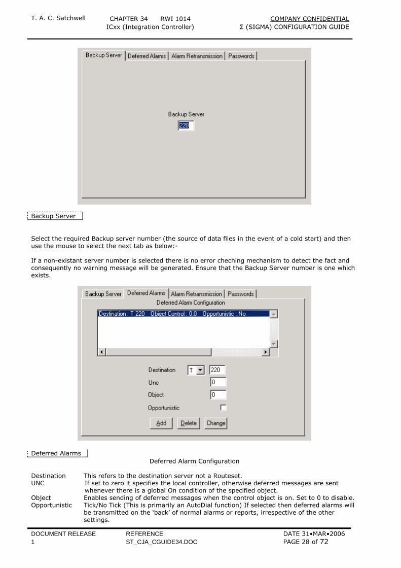
Backup Server Select the required Backup server number (the source of data files in the event of a cold start) and then use the mouse to select the next tab as below:- If a non-existant server number is selected there is no error cheching mechanism to detect the fact and consequently no warning message will be generated. Ensure that the Backup Server number is one which exists.
Deferred Alarms Deferred Alarm Configuration
Destination This refers to the destination server not a Routeset. UNC If set to zero it specifies the local controller, otherwise deferred messages are sent
whenever there is a global On condition of the specified object. Object Enables sending of deferred messages when the control object is on. Set to 0 to disable. Opportunistic Tick/No Tick (This is primarily an AutoDial function) If selected then deferred alarms will
be transmitted on the ‘back’ of normal alarms or reports, irrespective of the other settings.
T. A. C. Satchwell CHAPTER 34 RWI 1014 COMPANY CONFIDENTIAL ICxx (Integration Controller) Σ (SIGMA) CONFIGURATION GUIDE
DOCUMENT RELEASE REFERENCE DATE 31•MAR•2006 1 ST_CJA_CGUIDE34.DOC PAGE 29 of 72
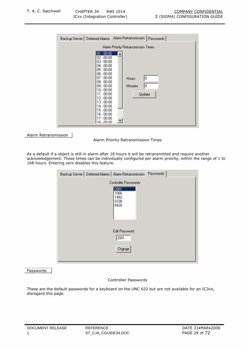
Alarm Retransmission
Alarm Priority Retransmission Times
As a default if a object is still in alarm after 18 hours it will be retransmitted and require another acknowledgement. These times can be individually configured per alarm priority, within the range of 1 to 168 hours. Entering zero disables this feature.
Passwords
Controller Passwords
These are the default passwords for a keyboard on the UNC 632 but are not available for an IC3xx, disregard this page.
T. A. C. Satchwell CHAPTER 34 RWI 1014 COMPANY CONFIDENTIAL ICxx (Integration Controller) Σ (SIGMA) CONFIGURATION GUIDE
DOCUMENT RELEASE REFERENCE DATE 31•MAR•2006 1 ST_CJA_CGUIDE34.DOC PAGE 30 of 72
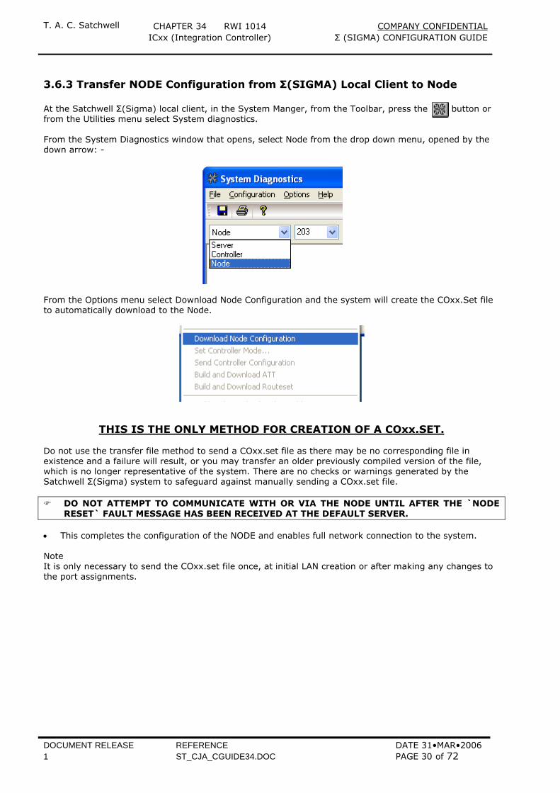
3.6.3 Transfer NODE Configuration from Σ(SIGMA) Local Client to Node At the Satchwell Σ(Sigma) local client, in the System Manger, from the Toolbar, press the button or from the Utilities menu select System diagnostics. From the System Diagnostics window that opens, select Node from the drop down menu, opened by the down arrow: -
From the Options menu select Download Node Configuration and the system will create the COxx.Set file to automatically download to the Node.
THIS IS THE ONLY METHOD FOR CREATION OF A COxx.SET.
Do not use the transfer file method to send a COxx.set file as there may be no corresponding file in existence and a failure will result, or you may transfer an older previously compiled version of the file, which is no longer representative of the system. There are no checks or warnings generated by the Satchwell Σ(Sigma) system to safeguard against manually sending a COxx.set file.
DO NOT ATTEMPT TO COMMUNICATE WITH OR VIA THE NODE UNTIL AFTER THE `NODE
RESET` FAULT MESSAGE HAS BEEN RECEIVED AT THE DEFAULT SERVER. • This completes the configuration of the NODE and enables full network connection to the system. Note It is only necessary to send the COxx.set file once, at initial LAN creation or after making any changes to the port assignments.
T. A. C. Satchwell CHAPTER 34 RWI 1014 COMPANY CONFIDENTIAL ICxx (Integration Controller) Σ (SIGMA) CONFIGURATION GUIDE
DOCUMENT RELEASE REFERENCE DATE 31•MAR•2006 1 ST_CJA_CGUIDE34.DOC PAGE 31 of 72
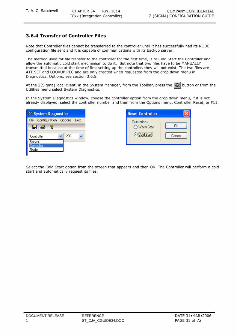
3.6.4 Transfer of Controller Files Note that Controller files cannot be transferred to the controller until it has successfully had its NODE configuration file sent and it is capable of communications with its backup server. The method used for file transfer to the controller for the first time, is to Cold Start the Controller and allow the automatic cold start mechanism to do it. But note that two files have to be MANUALLY transmitted because at the time of first setting up the controller, they will not exist. The two files are ATT.SET and LOOKUP.REC and are only created when requested from the drop down menu in, Diagnostics, Options, see section 3.6.5. At the Σ(Sigma) local client, in the System Manager, from the Toolbar, press the button or from the Utilities menu select System Diagnostics. In the System Diagnostics window, choose the controller option from the drop down menu, if it is not already displayed, select the controller number and then from the Options menu, Controller Reset, or F11.
Select the Cold Start option from the screen that appears and then OK. The Controller will perform a cold start and automatically request its files.
T. A. C. Satchwell CHAPTER 34 RWI 1014 COMPANY CONFIDENTIAL ICxx (Integration Controller) Σ (SIGMA) CONFIGURATION GUIDE
DOCUMENT RELEASE REFERENCE DATE 31•MAR•2006 1 ST_CJA_CGUIDE34.DOC PAGE 32 of 72
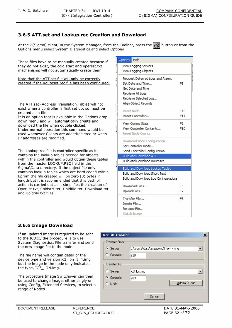
3.6.5 ATT.set and Lookup.rec Creation and Download At the Σ(Sigma) client, in the System Manager, from the Toolbar, press the button or from the Options menu select System Diagnostics and select Options These files have to be manually created because if they do not exist, the cold start and operlist.txt mechanisms will not automatically create them. Note that the ATT.set file will only be correctly created if the Routeset.rec file has been configured. The ATT.set (Address Translation Table) will not exist when a controller is first set up, so must be created as a file. It is an option that is available in the Options drop down menu and will automatically create and download the file when double clicked. Under normal operation this command would be used whenever Clients are added/deleted or when IP addresses are modified. The Lookup.rec file is controller specific as it contains the lookup tables needed for objects within the controller and would obtain these tables from the master LOOKUP.REC held in the Sigma\Data directory. If the object file only contains lookup tables which are hard coded within Eprom the file created will be zero (0) bytes in length but it is recommended that this path of action is carried out as it simplifies the creation of Operlist.txt, Coldstrt.txt, Dnldfile.txt, Download.txt and Upldfile.txt files.
3.6.6 Image Download
If an updated image is required to be sent to the IC3xx, the procedure is to use System Diagnostics, File transfer and send the new image file to the node. The file name will contain detail of the device type and version ic3_lon_1_4.img but the image in the node only indicates the type, IC3_LON.img. The procedure Image Switchover can then be used to change image, either singly or using Config, Extended Services, to select a range of Nodes

T. A. C. Satchwell CHAPTER 34 RWI 1014 COMPANY CONFIDENTIAL ICxx (Integration Controller) Σ (SIGMA) CONFIGURATION GUIDE
DOCUMENT RELEASE REFERENCE DATE 31•MAR•2006 1 ST_CJA_CGUIDE34.DOC PAGE 33 of 72
3.6.7 Cold Start/Operlist.txt Mechanisms The initial cold start request from the controller asks the default server for time, configuration and backup server number, contained in the CONFIG.REC. The next stage of the cold start places a request to the backup server, invoking the transfer of files listed in COLDSTART.TXT. One of the first files sent would be OPERLIST.TXT, which contains a list of files that should be in the controller. Operlist.txt is processed every 5 minutes, comparing its list with the controller contents, placing a request for any missing file/files to the relevant server. It will attempt to retrieve one file every five minutes from the server specified at the start of line containing the missing file, 0 is the backup any other number is a specific server. If the file is not received, the controller will make two further attempts before sending a failure message and will then wait 60 minutes before trying to obtain the missing file again. In the meantime it will attempt to get the next missing file in the list. If for any reason the Operlist.txt is missing from the controller but it knows its backup server, it will request the OPERLIST.TXT file and then compare and progress through any missing files as above. If for any reason the Operlist.txt file is missing from the controller but it doesn’t know its backup server it will send a cold start request to the default server for time, configuration and backup information, and begin processing files as above. A controller will also automatically force its own cold start retrieval, if the ARM-7 CPU fails to detect an object file. The timing of this is calculated from the low nibble of the hexadecimal (Hex) part of the controller number, multiplied by a factor of two and added to a constant. See the table below: - Operlist.txt and the cold start mechanism work in conjunction with each other, with the Operlist function acting as a backup to any file transfer failures within a cold start.
UNC No Hex Low nibble × 2 (mins)
Σ(Sigma) Constant
Time before COLDSTART
Σ(Sigma)
1 1 1 2 + 2 min. = 4 minutes 2 2 2 4 + 2 min. = 6 minutes 3 3 3 6 + 2 min. = 8 minutes 4 4 4 8 + 2 min. = 10 minutes 5 5 5 10 + 2 min. = 12 minutes 6 6 6 12 + 2 min. = 14 minutes 7 7 7 14 + 2 min. = 16 minutes 8 8 8 16 + 2 min. = 18 minutes 9 9 9 18 + 2 min. = 20 minutes 10 A A = 10 20 + 2 min. = 22 minutes 11 B B = 11 22 + 2 min. = 24 minutes 12 C C = 12 24 + 2 min. = 26 minutes 13 D D = 13 26 + 2 min. = 28 minutes 14 E E = 14 28 + 2 min. = 30 minutes 15 F F = 15 30 + 2 min. = 32 minutes 16 10 0 0 + 2 min. = 2 minutes 17 11 1 2 + 2 min. = 4 minutes
31 1F F = 15 30 + 2 min. = 32 minutes 32 20 0 0 + 2 min. = 2 minutes
50 32 2 4 + 2 min. = 6 minutes
63 3F F = 15 30 + 2 min. = 32 minutes 64 40 0 0 + 2 min. = 2 minutes
T. A. C. Satchwell CHAPTER 34 RWI 1014 COMPANY CONFIDENTIAL ICxx (Integration Controller) Σ (SIGMA) CONFIGURATION GUIDE
DOCUMENT RELEASE REFERENCE DATE 31•MAR•2006 1 ST_CJA_CGUIDE34.DOC PAGE 34 of 72
3.7 Resetting the Controller The Controller may be reset locally or remotely, using one of the options from the Σ(Sigma) local client. During the reset process in warm or cold start the yellow LED flashes once for low image active or twice for high image active.
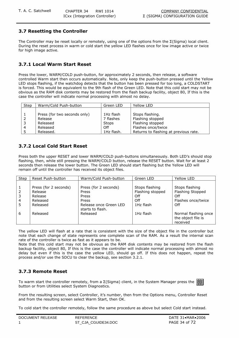
3.7.1 Local Warm Start Reset Press the lower, WARM/COLD push-button, for approximately 2 seconds, then release, a software controlled Warm start then occurs automatically. Note, only keep the push-button pressed until the Yellow LED stops flashing, if the watchdog detects that the button has been pressed for too long, a COLDSTART is forced. This would be equivalent to the 9th flash of the Green LED. Note that this cold start may not be obvious as the RAM disk contents may be restored from the flash backup facility, object 80, If this is the case the controller will indicate normal processing with almost no delay.
Step Warm/Cold Push-button Green LED Yellow LED 1 2 3 4 5
Press (for two seconds only) Release Released Released Released.
1Hz flash 7 flashes Stops Off 1Hz flash.
Stops flashing. Flashing stopped Flashing stopped Flashes once/twice Returns to flashing at previous rate.
3.7.2 Local Cold Start Reset Press both the upper RESET and lower WARM/COLD push-buttons simultaneously. Both LED’s should stop flashing, then, while still pressing the WARM/COLD button, release the RESET button. Wait for at least 2 seconds then release the lower button. The Green LED should start flashing but the Yellow LED will remain off until the controller has received its object files. Step Reset Push-button Warm/Cold Push-button Green LED Yellow LED 1 2 3 4 5 6
Press (for 2 seconds) Release Release Released Released Released
Press (for 2 seconds) Press Press Press Release once Green LED starts to flash. Released
Stops flashing Flashing stopped Off Off 1Hz flash 1Hz flash
Stops flashing Flashing Stopped Off Flashes once/twice Off Normal flashing once the object file is received
The yellow LED will flash at a rate that is consistent with the size of the object file in the controller but note that each change of state represents one complete scan of the RAM. As a result the internal scan rate of the controller is twice as fast as it appears to be. Note that this cold start may not be obvious as the RAM disk contents may be restored from the flash backup facility, object 80, If this is the case the controller will indicate normal processing with almost no delay but even if this is the case the yellow LED, should go off. If this does not happen, repeat the process and/or use the SDCU to clear the backup, see section 3.2.1.
3.7.3 Remote Reset To warm start the controller remotely, from a Σ(Sigma) client, in the System Manager press the button or from Utilities select System Diagnostics. From the resulting screen, select Controller, it’s number, then from the Options menu, Controller Reset and from the resulting screen select Warm Start, then OK. To cold start the controller remotely, follow the same procedure as above but select Cold start instead.
T. A. C. Satchwell CHAPTER 34 RWI 1014 COMPANY CONFIDENTIAL ICxx (Integration Controller) Σ (SIGMA) CONFIGURATION GUIDE
DOCUMENT RELEASE REFERENCE DATE 31•MAR•2006 1 ST_CJA_CGUIDE34.DOC PAGE 35 of 72
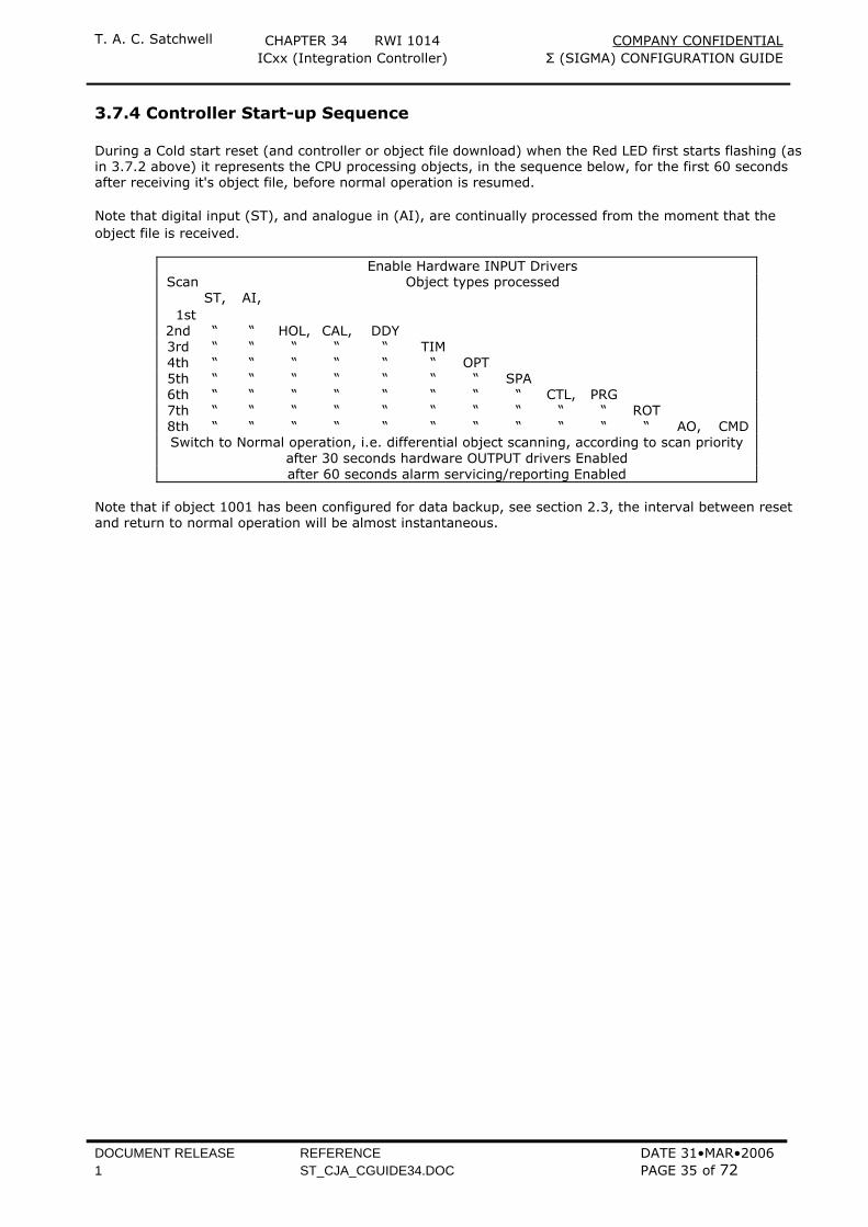
3.7.4 Controller Start-up Sequence During a Cold start reset (and controller or object file download) when the Red LED first starts flashing (as in 3.7.2 above) it represents the CPU processing objects, in the sequence below, for the first 60 seconds after receiving it's object file, before normal operation is resumed. Note that digital input (ST), and analogue in (AI), are continually processed from the moment that the object file is received.
Enable Hardware INPUT Drivers Scan Object types processed
1st ST, AI,
2nd “ “ HOL, CAL, DDY 3rd “ “ “ “ “ TIM 4th “ “ “ “ “ “ OPT 5th “ “ “ “ “ “ “ SPA 6th “ “ “ “ “ “ “ “ CTL, PRG 7th “ “ “ “ “ “ “ “ “ “ ROT 8th “ “ “ “ “ “ “ “ “ “ “ AO, CMD Switch to Normal operation, i.e. differential object scanning, according to scan priority
after 30 seconds hardware OUTPUT drivers Enabled after 60 seconds alarm servicing/reporting Enabled
Note that if object 1001 has been configured for data backup, see section 2.3, the interval between reset and return to normal operation will be almost instantaneous.
T. A. C. Satchwell CHAPTER 34 RWI 1014 COMPANY CONFIDENTIAL ICxx (Integration Controller) Σ (SIGMA) CONFIGURATION GUIDE
DOCUMENT RELEASE REFERENCE DATE 31•MAR•2006 1 ST_CJA_CGUIDE34.DOC PAGE 36 of 72
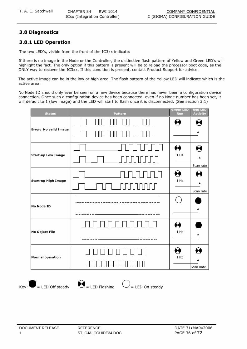
3.8 Diagnostics 3.8.1 LED Operation The two LED’s, visible from the front of the IC3xx indicate: If there is no image in the Node or the Controller, the distinctive flash pattern of Yellow and Green LED’s will highlight the fact. The only option if this pattern is present will be to reload the processor boot code, as the ONLY way to recover the IC3xx. If this condition is present, contact Product Support for advice. The active image can be in the low or high area. The flash pattern of the Yellow LED will indicate which is the active area. No Node ID should only ever be seen on a new device because there has never been a configuration device connection. Once such a configuration device has been connected, even if no Node number has been set, it will default to 1 (low image) and the LED will start to flash once it is disconnected. (See section 3.1)
Status PatternGreen LED
RunRed LEDActivity
Error: No valid Image
Start-up Low Image 1 Hz
Scan rate
Start-up High Image 1 Hz
Scan rate
No Node ID
No Object File 1 Hz
Normal operation I Hz
Scan Rate
Key: = LED Off steady = LED Flashing = LED On steady
T. A. C. Satchwell CHAPTER 34 RWI 1014 COMPANY CONFIDENTIAL ICxx (Integration Controller) Σ (SIGMA) CONFIGURATION GUIDE
DOCUMENT RELEASE REFERENCE DATE 31•MAR•2006 1 ST_CJA_CGUIDE34.DOC PAGE 37 of 72
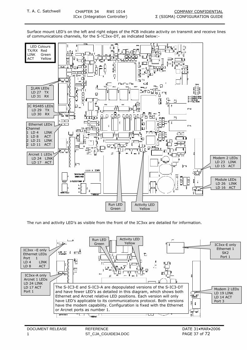
Surface mount LED’s on the left and right edges of the PCB indicate activity on transmit and receive lines of communications channels, for the S-!C3xx-DT, as indicated below:-
The run and activity LED’s as visible from the front of the IC3xx are detailed for information.
∑LAN LEDs LD 27 TX LD 31 RX
Arcnet 1 LEDs LD 24 LINK LD 17 ACT
Modem 2 LEDs LD 23 LINK LD 15 ACT
Ethernet LEDs Channel 1 LD 4 LINK 1 LD 8 ACT 2 LD 21 LINK 2 LD 11 ACT
IC RS485 LEDs LD 29 TX LD 30 RX
Module LEDs LD 26 LINK LD 16 ACT
Activity LED Yellow
Run LED Green
LED Colours TX/RX Red LINK Green ACT Yellow
IC3xx-E only Ethernet 1
SK2 Port 1
Run LED Green
Activity LED Yellow
IC3xx-A only Arcnet 1 LEDs LD 24 LINK LD 17 ACT Port 1
The S-IC3-E and S-IC3-A are depopulated versions of the S-IC3-DT and have fewer LED’s as detailed in this diagram, which shows both Ethernet and Arcnet relative LED positions. Each version will only have LED’s applicable to its communications protocol. Both versions have the modem capability. Configuration is fixed with the Ethernet or Arcnet ports as number 1.
IC3xx –E only Ethernet LEDs Port 1 LD 4 LINK LD 8 ACT
Modem 2 LEDs LD 19 LINK LD 14 ACT Port 3
T. A. C. Satchwell CHAPTER 34 RWI 1014 COMPANY CONFIDENTIAL ICxx (Integration Controller) Σ (SIGMA) CONFIGURATION GUIDE
DOCUMENT RELEASE REFERENCE DATE 31•MAR•2006 1 ST_CJA_CGUIDE34.DOC PAGE 38 of 72
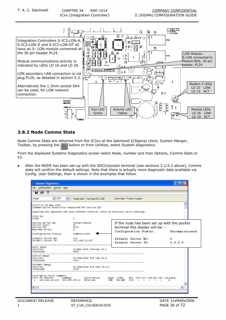
3.8.2 Node Comms Stats Node Comms Stats are obtained from the IC3xx at the Satchwell Σ(Sigma) client, System Manger, Toolbar, by pressing the button or from Utilities, select System diagnostics. From the displayed Systems Diagnostics screen select Node, number and then Options, Comms Stats or F3. After the NODE has been set-up with the SDCU/pocket terminal (see sections 3.1/3.2 above), Comms
stats will confirm the default settings. Note that there is actually more diagnostic data available via Config, User Settings, than is shown in the examples that follow.
If the node has been set up with the pocket terminal this display will be: -
Module LEDs LD 26 LINK LD 16 ACT
Activity LED Yellow
Run LED Green
Modem 2 LEDs LD 23 LINK LD 15 ACT
LON Module:- S-LON connected to Module BUS, 36 pin header, PL24
Integration Controllers S-IC3-LON-A, S-IC3-LON–E and S-IC3-LON-DT all have an S- LON module connected atthe 36 pin header PL24. Module communications activity is indicated by LEDs LD 16 and LD 26. LON secondary LAN connection is via plug PL20, as detailed in section 5.3. Alternatively the 1.3mm socket SK4 can be used, for LON network connection.
T. A. C. Satchwell CHAPTER 34 RWI 1014 COMPANY CONFIDENTIAL ICxx (Integration Controller) Σ (SIGMA) CONFIGURATION GUIDE
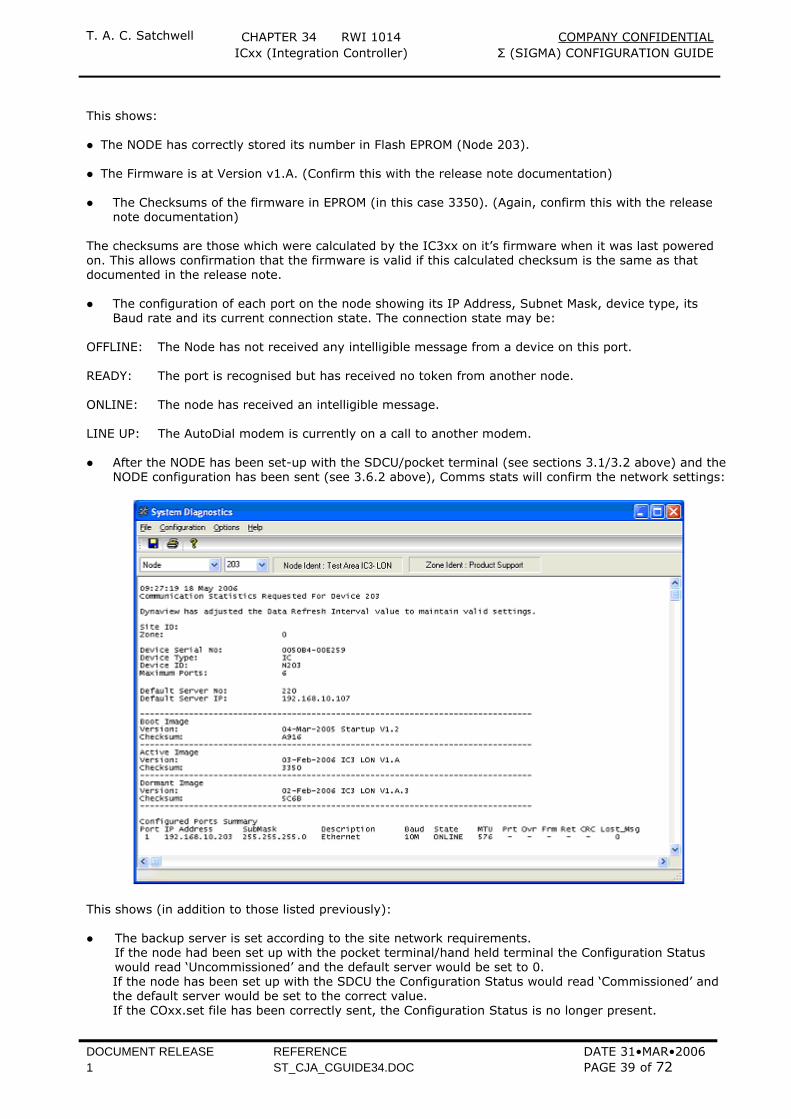
DOCUMENT RELEASE REFERENCE DATE 31•MAR•2006 1 ST_CJA_CGUIDE34.DOC PAGE 39 of 72
This shows: The NODE has correctly stored its number in Flash EPROM (Node 203).
The Firmware is at Version v1.A. (Confirm this with the release note documentation)
The Checksums of the firmware in EPROM (in this case 3350). (Again, confirm this with the release
note documentation) The checksums are those which were calculated by the IC3xx on it’s firmware when it was last powered on. This allows confirmation that the firmware is valid if this calculated checksum is the same as that documented in the release note. The configuration of each port on the node showing its IP Address, Subnet Mask, device type, its
Baud rate and its current connection state. The connection state may be: OFFLINE: The Node has not received any intelligible message from a device on this port. READY: The port is recognised but has received no token from another node. ONLINE: The node has received an intelligible message. LINE UP: The AutoDial modem is currently on a call to another modem.
After the NODE has been set-up with the SDCU/pocket terminal (see sections 3.1/3.2 above) and the
NODE configuration has been sent (see 3.6.2 above), Comms stats will confirm the network settings:
This shows (in addition to those listed previously): The backup server is set according to the site network requirements.
If the node had been set up with the pocket terminal/hand held terminal the Configuration Status would read ‘Uncommissioned’ and the default server would be set to 0.
If the node has been set up with the SDCU the Configuration Status would read ‘Commissioned’ and the default server would be set to the correct value.
If the COxx.set file has been correctly sent, the Configuration Status is no longer present.
T. A. C. Satchwell CHAPTER 34 RWI 1014 COMPANY CONFIDENTIAL ICxx (Integration Controller) Σ (SIGMA) CONFIGURATION GUIDE
DOCUMENT RELEASE REFERENCE DATE 31•MAR•2006 1 ST_CJA_CGUIDE34.DOC PAGE 40 of 72
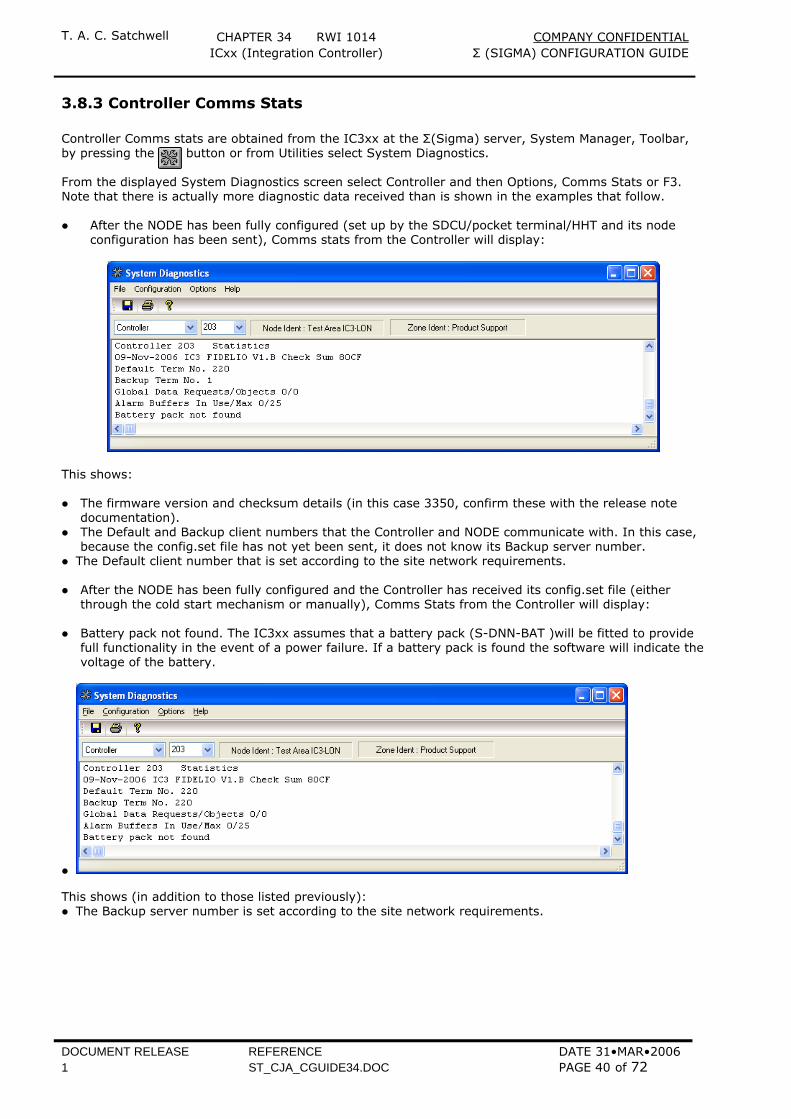
3.8.3 Controller Comms Stats Controller Comms stats are obtained from the IC3xx at the Σ(Sigma) server, System Manager, Toolbar, by pressing the button or from Utilities select System Diagnostics. From the displayed System Diagnostics screen select Controller and then Options, Comms Stats or F3. Note that there is actually more diagnostic data received than is shown in the examples that follow. After the NODE has been fully configured (set up by the SDCU/pocket terminal/HHT and its node
configuration has been sent), Comms stats from the Controller will display:
This shows: The firmware version and checksum details (in this case 3350, confirm these with the release note
documentation). The Default and Backup client numbers that the Controller and NODE communicate with. In this case,
because the config.set file has not yet been sent, it does not know its Backup server number. The Default client number that is set according to the site network requirements.
After the NODE has been fully configured and the Controller has received its config.set file (either
through the cold start mechanism or manually), Comms Stats from the Controller will display: Battery pack not found. The IC3xx assumes that a battery pack (S-DNN-BAT )will be fitted to provide
full functionality in the event of a power failure. If a battery pack is found the software will indicate the voltage of the battery.
This shows (in addition to those listed previously): The Backup server number is set according to the site network requirements.

T. A. C. Satchwell CHAPTER 34 RWI 1014 COMPANY CONFIDENTIAL ICxx (Integration Controller) Σ (SIGMA) CONFIGURATION GUIDE
DOCUMENT RELEASE REFERENCE DATE 31•MAR•2006 1 ST_CJA_CGUIDE34.DOC PAGE 41 of 72
3.8.4 Controller Contents Controller RAMDisk contents are obtained from the IC3xx at the Σ(Sigma) client, System Manager, Toolbar, by pressing the button or from Utilities select System Diagnostics. From the displayed System Diagnostics screen select Controller and then Options, Controller Contents or F10. When the Controller has been cold started, before it gets its application files, the contents of the
RAMDisk are:
This shows:
The controller RAMDisk contains no files. The controller is currently in Commission mode following a manually instigated Cold start
request. (From either the client or locally with the push-buttons) It does not know its backup server.
After the controller has had its application files sent, the RAMDisk could look like this:
This shows: The controller RAMDisk now contains a list of data files, what they are, their sizes and the space still
available.
T. A. C. Satchwell CHAPTER 34 RWI 1014 COMPANY CONFIDENTIAL ICxx (Integration Controller) Σ (SIGMA) CONFIGURATION GUIDE
DOCUMENT RELEASE REFERENCE DATE 31•MAR•2006 1 ST_CJA_CGUIDE34.DOC PAGE 42 of 72
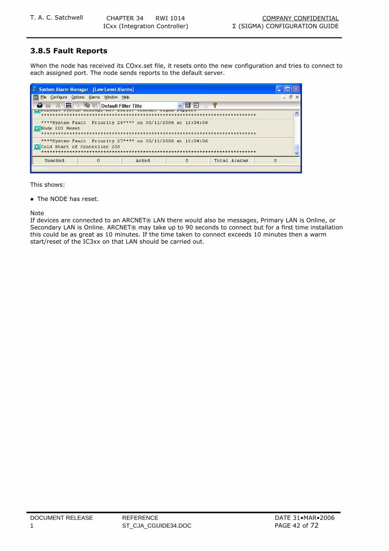
3.8.5 Fault Reports When the node has received its COxx.set file, it resets onto the new configuration and tries to connect to each assigned port. The node sends reports to the default server.
This shows: The NODE has reset.
Note If devices are connected to an ARCNET® LAN there would also be messages, Primary LAN is Online, or Secondary LAN is Online. ARCNET® may take up to 90 seconds to connect but for a first time installation this could be as great as 10 minutes. If the time taken to connect exceeds 10 minutes then a warm start/reset of the IC3xx on that LAN should be carried out.
T. A. C. Satchwell CHAPTER 34 RWI 1014 COMPANY CONFIDENTIAL ICxx (Integration Controller) Σ (SIGMA) CONFIGURATION GUIDE
DOCUMENT RELEASE REFERENCE DATE 31•MAR•2006 1 ST_CJA_CGUIDE34.DOC PAGE 43 of 72
4 NETWORK WIRING ARRANGEMENTS Ethernet or ARCNET® Communications protocols can be selected with the provision to use a Σ(Sigma) LAN, for dual trunking. Possible permutations are as below but refer to Product Information Bulletin 02.09.12-3 Σ Architecture Guidelines regarding network design to cover the full application of ARCNET®, Ethernet and dual LAN installation. The Σ(Sigma) LAN is always the secondary route and is not supported in a primary LAN. It is limited to use as a backup to the primary LAN (Ethernet or ARCNET®) in dual LAN mode following loss of the primary LAN. The Σ(Sigma) LAN is a fixed configuration of 19200 baud and is enabled when failure of the primary LAN is detected. In fallback mode the Σ(Sigma) LAN will provide standby/backup communications at reduced performance and with reduced functionality.
For detail of which port to use for each IC3-xx-A/-E/-DT type see the Front Panel Layout diagrams in section 5 of this document
DNN3
UNC
IC
Σ L
AN
ARCN
ET®
HUB
DNN3
UNC
UNC
DNN3
UNC
IC
ARCN
ET®
Σ L
AN
ETHERNET
ETH
ERN
ET
ETHERNET
HUB
DNN3
IC
IC
ETH
ERN
ET
HUB
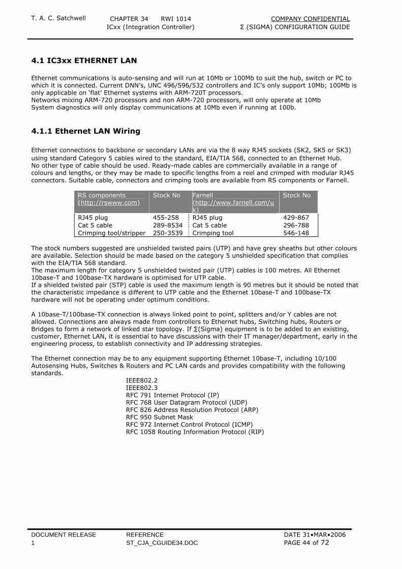
T. A. C. Satchwell CHAPTER 34 RWI 1014 COMPANY CONFIDENTIAL ICxx (Integration Controller) Σ (SIGMA) CONFIGURATION GUIDE
DOCUMENT RELEASE REFERENCE DATE 31•MAR•2006 1 ST_CJA_CGUIDE34.DOC PAGE 44 of 72
4.1 IC3xx ETHERNET LAN Ethernet communications is auto-sensing and will run at 10Mb or 100Mb to suit the hub, switch or PC to which it is connected. Current DNN’s, UNC 496/596/532 controllers and IC’s only support 10Mb; 100Mb is only applicable on ‘flat’ Ethernet systems with ARM-720T processors. Networks mixing ARM-720 processors and non ARM-720 processors, will only operate at 10Mb System diagnostics will only display communications at 10Mb even if running at 100b.
4.1.1 Ethernet LAN Wiring Ethernet connections to backbone or secondary LANs are via the 8 way RJ45 sockets (SK2, SK5 or SK3) using standard Category 5 cables wired to the standard, EIA/TIA 568, connected to an Ethernet Hub. No other type of cable should be used. Ready-made cables are commercially available in a range of colours and lengths, or they may be made to specific lengths from a reel and crimped with modular RJ45 connectors. Suitable cable, connectors and crimping tools are available from RS components or Farnell.
RS components (http://rswww.com)
Stock No Farnell (http://www.farnell.com/uk)
Stock No
RJ45 plug 455-258 RJ45 plug 429-867 Cat 5 cable 289-8534 Cat 5 cable 296-788 Crimping tool/stripper 250-3539 Crimping tool 546-148
The stock numbers suggested are unshielded twisted pairs (UTP) and have grey sheaths but other colours are available. Selection should be made based on the category 5 unshielded specification that complies with the EIA/TIA 568 standard. The maximum length for category 5 unshielded twisted pair (UTP) cables is 100 metres. All Ethernet 10base-T and 100base-TX hardware is optimised for UTP cable. If a shielded twisted pair (STP) cable is used the maximum length is 90 metres but it should be noted that the characteristic impedance is different to UTP cable and the Ethernet 10base-T and 100base-TX hardware will not be operating under optimum conditions. A 10base-T/100base-TX connection is always linked point to point, splitters and/or Y cables are not allowed. Connections are always made from controllers to Ethernet hubs, Switching hubs, Routers or Bridges to form a network of linked star topology. If ∑(Sigma) equipment is to be added to an existing, customer, Ethernet LAN, it is essential to have discussions with their IT manager/department, early in the engineering process, to establish connectivity and IP addressing strategies. The Ethernet connection may be to any equipment supporting Ethernet 10base-T, including 10/100 Autosensing Hubs, Switches & Routers and PC LAN cards and provides compatibility with the following standards.
IEEE802.2 IEEE802.3 RFC 791 Internet Protocol (IP) RFC 768 User Datagram Protocol (UDP) RFC 826 Address Resolution Protocol (ARP) RFC 950 Subnet Mask RFC 972 Internet Control Protocol (ICMP) RFC 1058 Routing Information Protocol (RIP)

T. A. C. Satchwell CHAPTER 34 RWI 1014 COMPANY CONFIDENTIAL ICxx (Integration Controller) Σ (SIGMA) CONFIGURATION GUIDE
DOCUMENT RELEASE REFERENCE DATE 31•MAR•2006 1 ST_CJA_CGUIDE34.DOC PAGE 45 of 72
4.1.2 Making a CAT5 Cable When it is necessary to fabricate cables on site, the correct cables, components and tools should be selected but it is also important that a proper wire crimp and strain relief is achieved. The following procedure should be adopted to ensure that these requirements are met. 1 Strip the cable jacket back one inch. 2 Untwist the wires to within 1/8th of an inch (3.2mm) of the jacket. 3 Arrange the wires in the order in which they are to be crimped, as below. 4 Grasp the wires firmly and flatten and wriggle them to remove any curl, concentrating on the last 1/2
inch, (12.7mm) so that the wires lay flat and are aligned as close together as is possible. 5 Hold the wire firmly and cut off the wires 1/2 inch (12.7mm) from the cable jacket. Avoid wire cutters
that flatten the ends of the insulation as this makes it difficult to stuff the wires into the connector. 6 Stuff the wires into the connector making sure that they stay lined up and reach the ends of their
tubes. 7 Ensure that the jacket reaches the end of the first indent as this acts as a strain relief for the cable. 8 Insert into the crimping tool and crimp. Note that the pin to colour code MUST be followed as below.
4.1.3 Ethernet Connection to a Hub, Switch, Router or Bridge When connecting with Ethernet to a Hub, Switch, Router or Bridge a ‘straight’ cable must be used. This is the same type of cable that is used when connecting a computer interface card to a hub. Each RJ45 end is wired 1-1, 2-2, 3-3 etc as detailed below, for information and to assist in the construction of specific cable lengths. 10/100base-T straight cable wiring.
Ethernet Socket
CAT5 Cable HUB
Name Pin Colour Pin Name Tx+ 1 White/Orange 1 Tx+ Tx- 2 Orange 2 Tx- Rx+ 3 White/Green 3 Rx+
4 Blue 4 5 White/Blue 5
Rx- 6 Green 6 Rx- 7 White/Brown 7 8 Brown 8
In a ‘straight’ cable it is important that transmit and receive pairs are in the same twisted pair, i.e. TX+/- and RX+/- are together as below.
Pair Pins Common colour 1 4 & 5 Blue 2 1 & 2 Orange 3 3 & 6 Green 4 7 & 8 Brown
Note that the colours detailed above are the industry standards for Cat 5 cabling and any cable bought in bulk will comply with this. It is essential that this guide is followed as this dictates the pairing of the cables and the pin numbers they must connect to.
View from front of connector with clip on top.
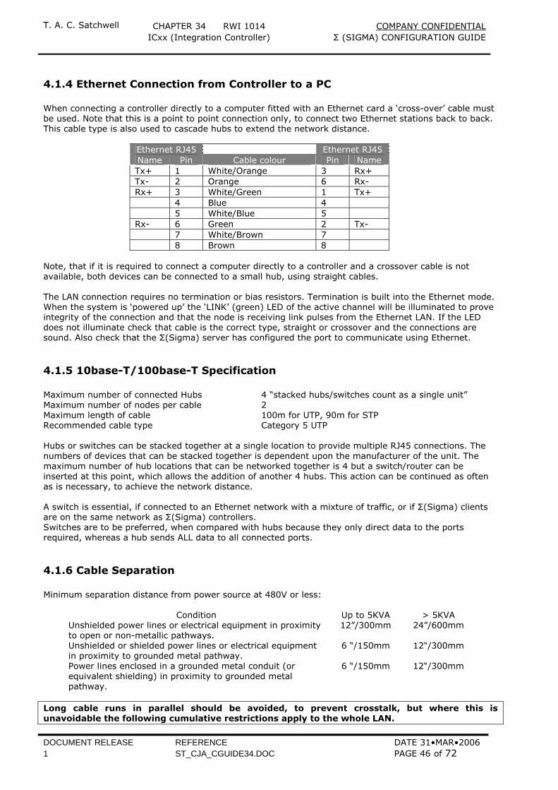
T. A. C. Satchwell CHAPTER 34 RWI 1014 COMPANY CONFIDENTIAL ICxx (Integration Controller) Σ (SIGMA) CONFIGURATION GUIDE
DOCUMENT RELEASE REFERENCE DATE 31•MAR•2006 1 ST_CJA_CGUIDE34.DOC PAGE 46 of 72
4.1.4 Ethernet Connection from Controller to a PC When connecting a controller directly to a computer fitted with an Ethernet card a ‘cross-over’ cable must be used. Note that this is a point to point connection only, to connect two Ethernet stations back to back. This cable type is also used to cascade hubs to extend the network distance.
Ethernet RJ45 Ethernet RJ45 Name Pin Cable colour Pin Name Tx+ 1 White/Orange 3 Rx+ Tx- 2 Orange 6 Rx- Rx+ 3 White/Green 1 Tx+ 4 Blue 4 5 White/Blue 5 Rx- 6 Green 2 Tx- 7 White/Brown 7 8 Brown 8
Note, that if it is required to connect a computer directly to a controller and a crossover cable is not available, both devices can be connected to a small hub, using straight cables. The LAN connection requires no termination or bias resistors. Termination is built into the Ethernet mode. When the system is ‘powered up’ the ‘LINK’ (green) LED of the active channel will be illuminated to prove integrity of the connection and that the node is receiving link pulses from the Ethernet LAN. If the LED does not illuminate check that cable is the correct type, straight or crossover and the connections are sound. Also check that the Σ(Sigma) server has configured the port to communicate using Ethernet.
4.1.5 10base-T/100base-T Specification Maximum number of connected Hubs 4 “stacked hubs/switches count as a single unit” Maximum number of nodes per cable 2 Maximum length of cable 100m for UTP, 90m for STP Recommended cable type Category 5 UTP Hubs or switches can be stacked together at a single location to provide multiple RJ45 connections. The numbers of devices that can be stacked together is dependent upon the manufacturer of the unit. The maximum number of hub locations that can be networked together is 4 but a switch/router can be inserted at this point, which allows the addition of another 4 hubs. This action can be continued as often as is necessary, to achieve the network distance. A switch is essential, if connected to an Ethernet network with a mixture of traffic, or if Σ(Sigma) clients are on the same network as Σ(Sigma) controllers. Switches are to be preferred, when compared with hubs because they only direct data to the ports required, whereas a hub sends ALL data to all connected ports.
4.1.6 Cable Separation Minimum separation distance from power source at 480V or less:
Condition Up to 5KVA > 5KVA Unshielded power lines or electrical equipment in proximity to open or non-metallic pathways.
12”/300mm 24”/600mm
Unshielded or shielded power lines or electrical equipment in proximity to grounded metal pathway.
6 “/150mm 12“/300mm
Power lines enclosed in a grounded metal conduit (or equivalent shielding) in proximity to grounded metal pathway.
6 “/150mm 12“/300mm
Long cable runs in parallel should be avoided, to prevent crosstalk, but where this is unavoidable the following cumulative restrictions apply to the whole LAN.

T. A. C. Satchwell CHAPTER 34 RWI 1014 COMPANY CONFIDENTIAL ICxx (Integration Controller) Σ (SIGMA) CONFIGURATION GUIDE
DOCUMENT RELEASE REFERENCE DATE 31•MAR•2006 1 ST_CJA_CGUIDE34.DOC PAGE 47 of 72
The purpose of dual trunking is to preserve system communications integrity so the practice of two data cables running along the same route should not occur, or where it does, parallel running should be minimal. Where parallel running cannot be avoided the maximum allowable, cumulative distances are as below. Dual backbone Ethernet and ARCNET® 100m Dual backbone Ethernet and Σ(Sigma) cables. Dual Ethernet and Σ(Sigma) cables. 100m
4.1.7 Potential Problems 1 If upgrading do not use existing cables. Ethernet does not work over telephone or audio cable or the
type of twisted pair often used on conventional BAS installations. 2 When attaching ∑(Sigma) equipment using Ethernet communications, to an existing client LAN it is
important to contact the IT people on that site. They will have a range of static IP addresses for the Σ(Sigma) system to use or will assign them. They may require to make a record all IP addresses that the ∑(Sigma) system is using as part of the system documentation. If they are using 100base-TX they may need to ensure that 10/100Mbps Autosensing Switching hubs are used. A normal hub will detect the data rate but slow all connections to the lowest speed ∑(Sigma) at 10Mbps. An autosensing hub allows different data rates to work simultaneously. A mix of ∑(Sigma) V53 and ARM-720T processors on the same network will only work at 10Mbps. ∑(Sigma) does NOT support DHCP (Dynamic Host Configuration Protocol) fixed IP addresses HAVE to be used.
3 Ensure that Ethernet cables are isolated from sources of electromagnetic interference. Do not allow
them to be run in the same trunking as main’s cable, motor wiring etc.
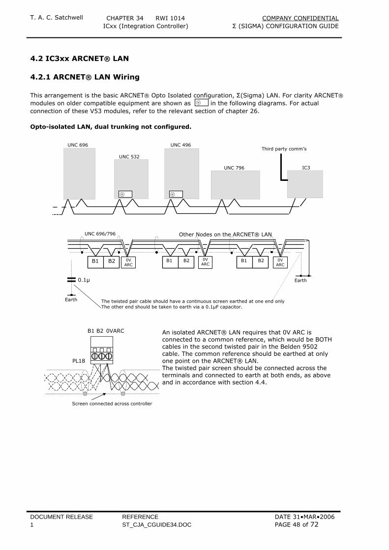
T. A. C. Satchwell CHAPTER 34 RWI 1014 COMPANY CONFIDENTIAL ICxx (Integration Controller) Σ (SIGMA) CONFIGURATION GUIDE
DOCUMENT RELEASE REFERENCE DATE 31•MAR•2006 1 ST_CJA_CGUIDE34.DOC PAGE 48 of 72
4.2 IC3xx ARCNET® LAN
4.2.1 ARCNET® LAN Wiring This arrangement is the basic ARCNET® Opto Isolated configuration, Σ(Sigma) LAN. For clarity ARCNET® modules on older compatible equipment are shown as in the following diagrams. For actual connection of these V53 modules, refer to the relevant section of chapter 26. Opto-isolated LAN, dual trunking not configured.
B1 B2 B1 B2B1 B2
UNC 696/796
The twisted pair cable should have a continuous screen earthed at one end onlyThe other end should be taken to earth via a 0.1µF capacitor.
Earth
Other Nodes on the ARCNET® LAN
0VARC
0VARC
0VARC
0.1µ
Earth
An isolated ARCNET® LAN requires that 0V ARC isconnected to a common reference, which would be BOTHcables in the second twisted pair in the Belden 9502cable. The common reference should be earthed at onlyone point on the ARCNET® LAN.The twisted pair screen should be connected across theterminals and connected to earth at both ends, as aboveand in accordance with section 4.4.
PL18
B1 B2 0VARC
Screen connected across controller
UNC 696 UNC 496
IC3
UNC 532
UNC 796
Third party comm’s
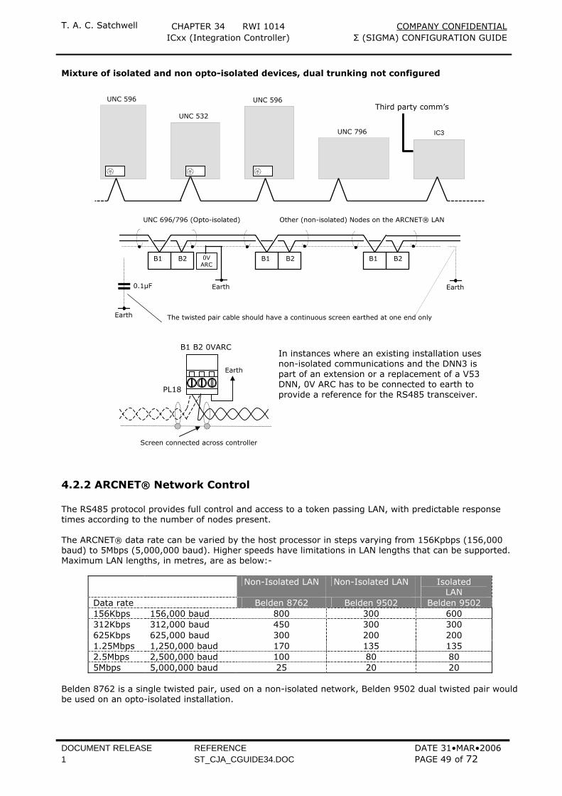
T. A. C. Satchwell CHAPTER 34 RWI 1014 COMPANY CONFIDENTIAL ICxx (Integration Controller) Σ (SIGMA) CONFIGURATION GUIDE
DOCUMENT RELEASE REFERENCE DATE 31•MAR•2006 1 ST_CJA_CGUIDE34.DOC PAGE 49 of 72
Mixture of isolated and non opto-isolated devices, dual trunking not configured
B1 B2 B1 B2B1 B2
UNC 696/796 (Opto-isolated)
The twisted pair cable should have a continuous screen earthed at one end only
Earth
Other (non-isolated) Nodes on the ARCNET® LAN
0VARC
0.1µF
Earth
Earth
4.2.2 ARCNET® Network Control The RS485 protocol provides full control and access to a token passing LAN, with predictable response times according to the number of nodes present. The ARCNET® data rate can be varied by the host processor in steps varying from 156Kpbps (156,000 baud) to 5Mbps (5,000,000 baud). Higher speeds have limitations in LAN lengths that can be supported. Maximum LAN lengths, in metres, are as below:-
Non-Isolated LAN Non-Isolated LAN Isolated LAN
Data rate Belden 8762 Belden 9502 Belden 9502 156Kbps 156,000 baud 800 300 600 312Kbps 312,000 baud 450 300 300 625Kbps 625,000 baud 300 200 200 1.25Mbps 1,250,000 baud 170 135 135 2.5Mbps 2,500,000 baud 100 80 80 5Mbps 5,000,000 baud 25 20 20
Belden 8762 is a single twisted pair, used on a non-isolated network, Belden 9502 dual twisted pair would be used on an opto-isolated installation.
IC3
UNC 532
UNC 796
UNC 596 UNC 596
PL18
B1 B2 0VARC
Earth
Screen connected across controller
In instances where an existing installation uses non-isolated communications and the DNN3 is part of an extension or a replacement of a V53 DNN, 0V ARC has to be connected to earth to provide a reference for the RS485 transceiver.
Third party comm’s

T. A. C. Satchwell CHAPTER 34 RWI 1014 COMPANY CONFIDENTIAL ICxx (Integration Controller) Σ (SIGMA) CONFIGURATION GUIDE
DOCUMENT RELEASE REFERENCE DATE 31•MAR•2006 1 ST_CJA_CGUIDE34.DOC PAGE 50 of 72
From software release 4 onwards, ∑(Sigma) will support up to 32 devices on each ARCNET® RS485 LAN, including any additional ARCNET® routers on that sub-LAN (DNN’s), or 128 ARCNET® routers on a backbone LAN. Earlier releases would only support 15 devices. To avoid interference on the high speed ARCNET® RS485, from power cables, it is recommended that a minimum distance of 150mm separates them. Ideally the high-speed ARCNET® RS485 and power cables should be routed along separate trays, conduit or trunking and where they cross, they should do so at right angles. Long cable runs in parallel should be avoided, to prevent crosstalk, but where this is unavoidable the following cumulative restrictions apply to the whole LAN. The purpose of dual trunking is to preserve system communications integrity so the practice of two data cables running along the same route should not occur, or where it does, parallel running should be minimal. Where parallel running cannot be avoided the maximum allowable, cumulative distance is as below. Dual backbone ARCNET® LAN and Σ(Sigma) cables. 300m Dual ARCNET® LAN and Σ(Sigma) cables. 300m Dual ARCNET® LAN and ARCNET® LAN cables (because of cable routing constraints) 300m
4.2.3 Potential Problems 1 Do not use existing BAS LAN cables, in opto-isolated or non-isolated form unless they have been
installed using Belden 8762 or 9502 twisted pair cable. Even if the correct cables have been used, particular attention should be paid to the quality of the installation and screening. If in doubt, install a new twisted pair for the ARCNET® RS485 LAN and reuse the existing cable as a backup Σ(Sigma) LAN.
2 When attaching ∑(Sigma) equipment using ARCNET®, it uses a private network and has no
connection except via IC3xx’s to a clients network. In exceptional cases the IT people on that site may need to record every IP addresses that the ∑(Sigma) system is using, for their documentation, or may wish to assign a range of networks for the Σ(Sigma) system to use. ∑(Sigma) does NOT support DHCP (Dynamic Host Configuration Protocol) fixed IP addresses HAVE to be used.
3 Ensure that ARCNET® cables are isolated from sources of electromagnetic interference. Do not allow
them to be run in the same trunking as main’s cable, motor wiring etc.
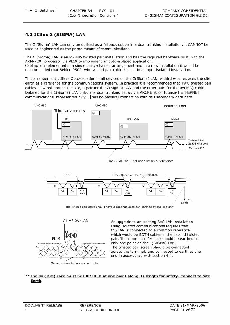
T. A. C. Satchwell CHAPTER 34 RWI 1014 COMPANY CONFIDENTIAL ICxx (Integration Controller) Σ (SIGMA) CONFIGURATION GUIDE
DOCUMENT RELEASE REFERENCE DATE 31•MAR•2006 1 ST_CJA_CGUIDE34.DOC PAGE 51 of 72
4.3 IC3xx Σ (SIGMA) LAN The Σ (Sigma) LAN can only be utilised as a fallback option in a dual trunking installation; it CANNOT be used or engineered as the prime means of communications. The Σ (Sigma) LAN is an RS 485 twisted pair installation and has the required hardware built in to the ARM-720T processor via PL19 to implement an opto-isolated application. Cabling is implemented in a single daisy-chained arrangement and in a new installation it would be recommended that Belden 9502 twin twisted pair cable is used in an opto-isolated installation. This arrangement utilises Opto-isolation in all devices on the Σ(Sigma) LAN. A third wire replaces the site earth as a reference for the communications system. In practice it is recommended that TWO twisted pair cables be wired around the site, a pair for the Σ(Sigma) LAN and the other pair, for the 0v(ISO) cable. Detailed for the Σ(Sigma) LAN only, any dual trunking set up via ARCNET® or 10base-T ETHERNET communications, represented by has no physical connection with this secondary data path.
0vΣLANΣLAN
UNC 696
Twisted PairΣ(SIGMA) LAN
UNC 696
ΣLAN ΣLAN
DNN3
Σ LAN
IC3
0vCH1
The Σ(SIGMA) LAN uses 0v as a reference.
UNC 796
ΣLAN
0v (ISO)**
0v ΣLAN0vΣLAN 0vCH
Isolated LANThird party comm’s
A1 A2 A1 A2A1 A2
DNN3
The twisted pair cable should have a continuous screen earthed at one end only
Earth
Other Nodes on the Σ(SIGMA)LAN
0VΣLAN
0VCH1
0VCH1
An upgrade to an existing BAS LAN installationusing isolated communications requires that0VΣLAN is connected to a common reference,which would be BOTH cables in the second twistedpair. The common reference should be earthed atonly one point on the Σ(SIGMA) LAN.The twisted pair screen should be connectedacross the terminals and connected to earth at oneend in accordance with section 4.4.
PL19
A1 A2 0VΣLAN
Screen connected across controller
**The 0v (ISO) core must be EARTHED at one point along its length for safety. Connect to Site
Earth.
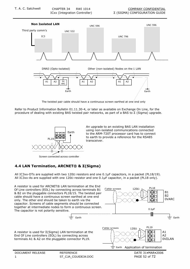
T. A. C. Satchwell CHAPTER 34 RWI 1014 COMPANY CONFIDENTIAL ICxx (Integration Controller) Σ (SIGMA) CONFIGURATION GUIDE
DOCUMENT RELEASE REFERENCE DATE 31•MAR•2006 1 ST_CJA_CGUIDE34.DOC PAGE 52 of 72
IC3
UNC 532
UNC 796
UNC 596 UNC 596 Non Isolated LAN
Third party comm’s
A1 A2 A1 A2A1 A2
DNN3 (Opto-isolated)
The twisted pair cable should have a continuous screen earthed at one end only
Earth
Other (non-isolated) Nodes on the Σ LAN
0VARC
Earth
Refer to Product Information Bulletin 01.11.30-4, or later as available on Exchange On Line, for the procedure of dealing with existing BAS twisted pair networks, as part of a BAS to Σ (Sigma) upgrade.
4.4 LAN Termination, ARCNET® & Σ(Sigma) All IC3xx-DTs are supplied with two 120Ω resistors and one 0.1µF capacitors, in a packet (PL18/19). All IC3xx-As are supplied with one 120Ω resistor and one 0.1µF capacitor, in a packet (PL18 only).
Application of termination
PL19
Earth
Screen connected across controller
An upgrade to an existing BAS LAN installation using non-isolated communications connected to the ARM-720T processor card has to connectto earth to provide a reference for the RS485 transceiver.
PL19
A1 A2 0VΣLAN
120Ω Cable screen
Earth
A resistor is used for Σ(Sigma) LAN termination at the End Of Line controllers (EOL) by connecting across terminals A1 & A2 on the pluggable connector PL19.
Cable screen PL18 B1 B2 0VARC
120Ω
0.1µF
A resistor is used for ARCNET® LAN termination at the End Of Line controllers (EOL) by connecting across terminals B1 & B2 on the pluggable connectors PL18/15. The twisted pair cable should have a continuous screen earthed at one end only. The other end should be taken to earth via the capacitor. Screens of cable segments should be connected together at intermediate nodes to form a continuous screen.The capacitor is not polarity sensitive.
Earth Earth
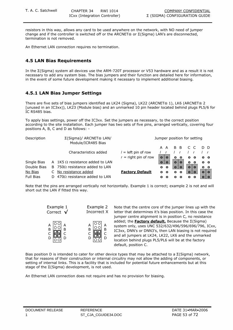
T. A. C. Satchwell CHAPTER 34 RWI 1014 COMPANY CONFIDENTIAL ICxx (Integration Controller) Σ (SIGMA) CONFIGURATION GUIDE
DOCUMENT RELEASE REFERENCE DATE 31•MAR•2006 1 ST_CJA_CGUIDE34.DOC PAGE 53 of 72
resistors in this way, allows any card to be used anywhere on the network, with NO need of jumper change and if the controller is switched off or the ARCNET® or Σ(Sigma) LAN’s are disconnected, termination is not removed. An Ethernet LAN connection requires no termination.
4.5 LAN Bias Requirements In the Σ(Sigma) system all devices use the ARM-720T processor or V53 hardware and as a result it is not necessary to add any system bias. The bias jumpers and their function are detailed here for information, in the event of some future development making it necessary to implement additional biasing.
4.5.1 LAN Bias Jumper Settings There are five sets of bias jumpers identified as LK24 (Sigma), LK22 (ARCNET® 1), LK6 (ARCNET® 2 [unused in an IC3xx]), LK23 (Module bias) and an unmarked 10 pin header located behind plugs PL5/6 for IC RS485 bias. To apply bias settings, power off the IC3xx. Set the jumpers as necessary, to the correct position according to the site installation. Each jumper has two sets of five pins, arranged vertically, covering four positions A, B, C and D as follows: - Description Σ(Sigma)/ ARCNET® LAN/
Module/ICR485 Bias Jumper position for setting
Characteristics added
l = left pin of row
A l
A r
B l
B r
C l
C r
D l
D r
r = right pin of row o o o o o o o o Single Bias A 1K5 Ω resistance added to LAN o o o o o o o o Double Bias B 750Ω resistance added to LAN o o o o o o o o No Bias C No resistance added Factory Default o o o o o o o o Full Bias D 470Ω resistance added to LAN o o o o o o o o Note that the pins are arranged vertically not horizontally. Example 1 is correct; example 2 is not and will short out the LAN if fitted this way.
Bias position D is intended to cater for other device types that may be attached to a Σ(Sigma) network, that for reasons of their construction or internal circuitry may not allow the adding of components, or setting of internal links. This is a facility that is included for potential future enhancements but at this stage of the Σ(Sigma) development, is not used. An Ethernet LAN connection does not require and has no provision for biasing.
ABCD
ABCD
Example 1 Correct √
ABCD
ABCD
Example 2 Incorrect X
Note that the centre core of the jumper lines up with the letter that determines it’s bias position. In this case the jumper centre alignment is in position C, no resistance added; the Factory default. Because the Σ(Sigma) system only, uses UNC 532/632/496/596/696/796, ICxx,IC3xx, DNN’s or DNN3’s, then LAN biasing is not requiredand all jumpers at LK24, LK22, LK6 and the unmarked location behind plugs PL5/PL6 will be at the factory default, position C.
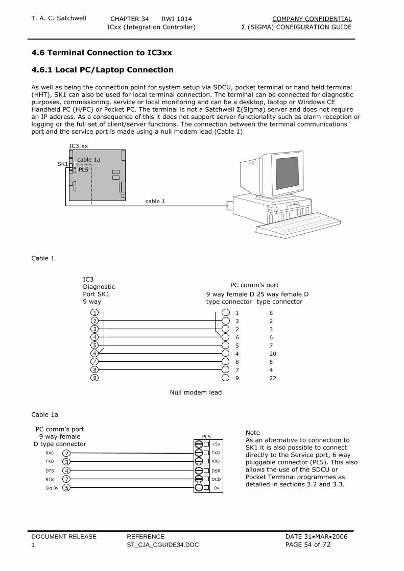
T. A. C. Satchwell CHAPTER 34 RWI 1014 COMPANY CONFIDENTIAL ICxx (Integration Controller) Σ (SIGMA) CONFIGURATION GUIDE
DOCUMENT RELEASE REFERENCE DATE 31•MAR•2006 1 ST_CJA_CGUIDE34.DOC PAGE 54 of 72
4.6 Terminal Connection to IC3xx
4.6.1 Local PC/Laptop Connection As well as being the connection point for system setup via SDCU, pocket terminal or hand held terminal (HHT), SK1 can also be used for local terminal connection. The terminal can be connected for diagnostic purposes, commissioning, service or local monitoring and can be a desktop, laptop or Windows CE Handheld PC (H/PC) or Pocket PC. The terminal is not a Satchwell Σ(Sigma) server and does not require an IP address. As a consequence of this it does not support server functionality such as alarm reception or logging or the full set of client/server functions. The connection between the terminal communications port and the service port is made using a null modem lead (Cable 1).
IC3-xx
SK1cable 1a
cable 1
PL5
Cable 1
Null modem lead
Cable 1a
1 3 2 6 5 4 8 7 9
8 2 3 6 7 205 4 22
IC3 Diagnostic Port SK1 9 way
l
PC comm’s port
9 way female Dtype connector
25 way female D type connector
1 2 3 4 5 6 7 8 9
PL5
DCD
DSR RXD TXD +5v
0v
4
7
2
3
5
RTS DTS
TXD RXD
Sig 0v
PC comm’s port 9 way female
D type connector
Note As an alternative to connection to SK1 it is also possible to connect directly to the Service port, 6 way pluggable connector (PL5). This alsoallows the use of the SDCU or Pocket Terminal programmes as detailed in sections 3.2 and 3.3.
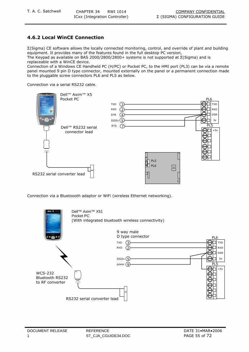
T. A. C. Satchwell CHAPTER 34 RWI 1014 COMPANY CONFIDENTIAL ICxx (Integration Controller) Σ (SIGMA) CONFIGURATION GUIDE
DOCUMENT RELEASE REFERENCE DATE 31•MAR•2006 1 ST_CJA_CGUIDE34.DOC PAGE 55 of 72
4.6.2 Local WinCE Connection Σ(Sigma) CE software allows the locally connected monitoring, control, and override of plant and building equipment. It provides many of the features found in the full desktop PC version, The Keypad as available on BAS 2000/2800/2800+ systems is not supported at Σ(Sigma) and is replaceable with a WinCE device. Connection of a Windows CE Handheld PC (H/PC) or Pocket PC, to the HMI port (PL3) can be via a remote panel mounted 9 pin D type connector, mounted externally on the panel or a permanent connection made to the pluggable screw connectors PL6 and PL5 as below. Connection via a serial RS232 cable.
Connection via a Bluetoooth adaptor or WiFi (wireless Ethernet networking).
RS232 serial converter lead
PL5
PL6
Dell™ RS232 serial connector lead
Dell™ Axim™ X5 Pocket PC
PL5 +5v
PL6
DSR RXD TXD
0v
3
2
4
5
7
SIG0v
DTR RXD TXD
RTS
WCS-232 Bluetooth RS232 to RF converter
RS232 serial converter lead
PL5 +5v
PL6
DSR RXD TXD
0v
3
2
5
9
SIG0v
RXD TXD
power
9 way male D type connector
Dell™ Axim™ X51 Pocket PC (With integrated bluetooth wireless connectivity)
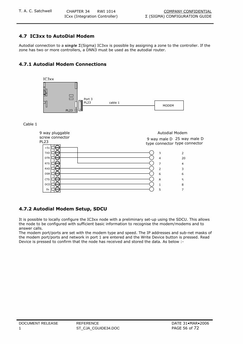
T. A. C. Satchwell CHAPTER 34 RWI 1014 COMPANY CONFIDENTIAL ICxx (Integration Controller) Σ (SIGMA) CONFIGURATION GUIDE
DOCUMENT RELEASE REFERENCE DATE 31•MAR•2006 1 ST_CJA_CGUIDE34.DOC PAGE 56 of 72
4.7 IC3xx to AutoDial Modem Autodial connection to a single Σ(Sigma) IC3xx is possible by assigning a zone to the controller. If the zone has two or more controllers, a DNN3 must be used as the autodial router.
4.7.1 Autodial Modem Connections
Cable 1
4.7.2 Autodial Modem Setup, SDCU It is possible to locally configure the IC3xx node with a preliminary set-up using the SDCU. This allows the node to be configured with sufficient basic information to recognise the modem/modems and to answer calls. The modem port/ports are set with the modem type and speed. The IP addresses and sub-net masks of the modem port/ports and network in port 1 are entered and the Write Device button is pressed. Read Device is pressed to confirm that the node has received and stored the data. As below :-
9 way pluggablescrew connectorPL23
DCD
CTS DSR RXD RTS DTR TXD +5v
0v 1
8
6
2
7
4
3
5
8
5
6
3
4
20
2
7
Autodial Modem
25 way male Dtype connector
9 way male D type connector
MODEMcable 1
Port 3 PL23
PL23
IC3xx

T. A. C. Satchwell CHAPTER 34 RWI 1014 COMPANY CONFIDENTIAL ICxx (Integration Controller) Σ (SIGMA) CONFIGURATION GUIDE
DOCUMENT RELEASE REFERENCE DATE 31•MAR•2006 1 ST_CJA_CGUIDE34.DOC PAGE 57 of 72
The above procedure only enables the node to set-up the modem and to receive calls. The final stage would be to set up networks, nodes and telephone numbers the node configuration at the default server. Once this has been done, the normal commissioning sequence of node configuration and COxx.set download can be followed.
4.7.3 Autodial Modem Setup, Server Autodial connections are set up in the order, Zones, Networks within zones, Devices within networks and Remote Zone set up. The main system has to have a PSTN network established before any connections to remote sites can be set up. Each modem port is assigned a unique telephone number, which can be accessed using standard PSTN dialling methods, both nationally and locally but must also include unique network and IP addresses. At the Satchwell Σ(Sigma) client, in the System Manager, from the Toolbar, press the button or from the Utilities menu select System Setup.
ZONE Setup Select Networks and Devices, new and create the local master zone
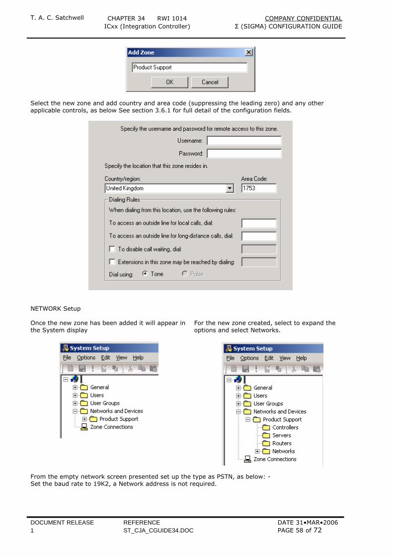
T. A. C. Satchwell CHAPTER 34 RWI 1014 COMPANY CONFIDENTIAL ICxx (Integration Controller) Σ (SIGMA) CONFIGURATION GUIDE
DOCUMENT RELEASE REFERENCE DATE 31•MAR•2006 1 ST_CJA_CGUIDE34.DOC PAGE 58 of 72
Select the new zone and add country and area code (suppressing the leading zero) and any other applicable controls, as below See section 3.6.1 for full detail of the configuration fields.
NETWORK Setup Once the new zone has been added it will appear in the System display
For the new zone created, select to expand the options and select Networks.
From the empty network screen presented set up the type as PSTN, as below: - Set the baud rate to 19K2, a Network address is not required.
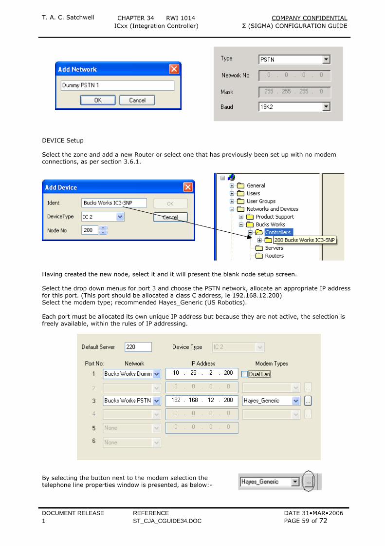
T. A. C. Satchwell CHAPTER 34 RWI 1014 COMPANY CONFIDENTIAL ICxx (Integration Controller) Σ (SIGMA) CONFIGURATION GUIDE
DOCUMENT RELEASE REFERENCE DATE 31•MAR•2006 1 ST_CJA_CGUIDE34.DOC PAGE 59 of 72
DEVICE Setup Select the zone and add a new Router or select one that has previously been set up with no modem connections, as per section 3.6.1.
Having created the new node, select it and it will present the blank node setup screen. Select the drop down menus for port 3 and choose the PSTN network, allocate an appropriate IP address for this port. (This port should be allocated a class C address, ie 192.168.12.200) Select the modem type; recommended Hayes_Generic (US Robotics). Each port must be allocated its own unique IP address but because they are not active, the selection is freely available, within the rules of IP addressing.
By selecting the button next to the modem selection the telephone line properties window is presented, as below:-
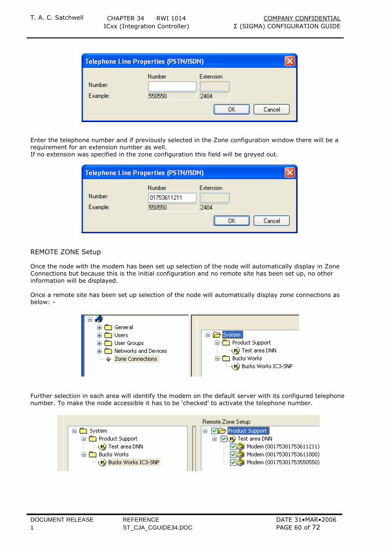
T. A. C. Satchwell CHAPTER 34 RWI 1014 COMPANY CONFIDENTIAL ICxx (Integration Controller) Σ (SIGMA) CONFIGURATION GUIDE
DOCUMENT RELEASE REFERENCE DATE 31•MAR•2006 1 ST_CJA_CGUIDE34.DOC PAGE 60 of 72
Enter the telephone number and if previously selected in the Zone configuration window there will be a requirement for an extension number as well. If no extension was specified in the zone configuration this field will be greyed out.
REMOTE ZONE Setup Once the node with the modem has been set up selection of the node will automatically display in Zone Connections but because this is the initial configuration and no remote site has been set up, no other information will be displayed. Once a remote site has been set up selection of the node will automatically display zone connections as below: -
Further selection in each area will identify the modem on the default server with its configured telephone number. To make the node accessible it has to be ‘checked’ to activate the telephone number.
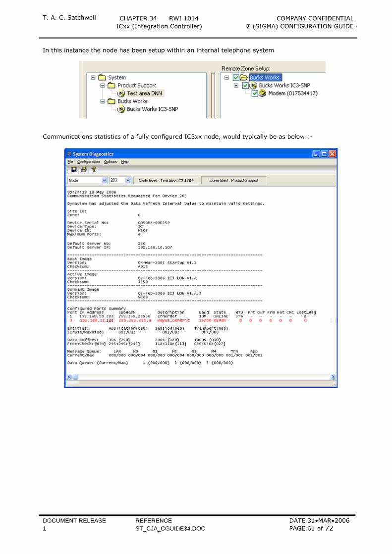
T. A. C. Satchwell CHAPTER 34 RWI 1014 COMPANY CONFIDENTIAL ICxx (Integration Controller) Σ (SIGMA) CONFIGURATION GUIDE
DOCUMENT RELEASE REFERENCE DATE 31•MAR•2006 1 ST_CJA_CGUIDE34.DOC PAGE 61 of 72
In this instance the node has been setup within an internal telephone system
Communications statistics of a fully configured IC3xx node, would typically be as below :-
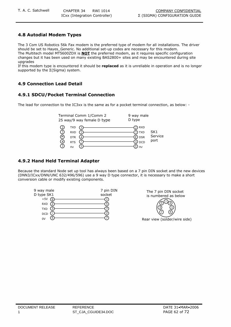
T. A. C. Satchwell CHAPTER 34 RWI 1014 COMPANY CONFIDENTIAL ICxx (Integration Controller) Σ (SIGMA) CONFIGURATION GUIDE
DOCUMENT RELEASE REFERENCE DATE 31•MAR•2006 1 ST_CJA_CGUIDE34.DOC PAGE 62 of 72
4.8 Autodial Modem Types The 3 Com US Robotics 56k Fax modem is the preferred type of modem for all installations. The driver should be set to Hayes_Generic. No additional set-up codes are necessary for this modem. The Multitech model MT5600ZDX is NOT the preferred modem, as it requires specific configuration changes but it has been used on many existing BAS2800+ sites and may be encountered during site upgrades If this modem type is encountered it should be replaced as it is unreliable in operation and is no longer supported by the Σ(Sigma) system.
4.9 Connection Lead Detail
4.9.1 SDCU/Pocket Terminal Connection The lead for connection to the IC3xx is the same as for a pocket terminal connection, as below: -
4.9.2 Hand Held Terminal Adapter Because the standard Node set up tool has always been based on a 7 pin DIN socket and the new devices (DNN3/ICxx/DNN/UNC 632/496/596) use a 9 way D type connector, it is necessary to make a short conversion cable or modify existing components.
7 pin DIN socket
9 way male D type SK1
92
3
1
5
1
5
7
2
7
2 4
1
6
3
5
7
The 7 pin DIN socket is numbered as below
Rear view (solder/wire side)
+5V
RXD
TXD
DCD
0V
2320
47
TXD
RXD
DTR
RTS
0V
32475
23615
RXD
TXD
DSR
DCD
0V
Terminal Comm 1/Comm 2 25 way/9 way female D type
9 way male D type
SK1 Service port

T. A. C. Satchwell CHAPTER 34 RWI 1014 COMPANY CONFIDENTIAL ICxx (Integration Controller) Σ (SIGMA) CONFIGURATION GUIDE
DOCUMENT RELEASE REFERENCE DATE 31•MAR•2006 1 ST_CJA_CGUIDE34.DOC PAGE 63 of 72
5. APPLICATIONS CONFIGURATION The IC3 (Integration Controller) RAM disk size for a DNN3 platform is between xxx and yyy kBytes, depending upon model and image version. The RAM disk contains all operating data files (pntfle.rec, gateway.txt etc.). The maximum number of objects that can be operated in an IC3 (Integration Controller) is determined by, object count maximum of 1000 objects and the total amount of space required by the various files within the RAM disk. Both of these constraints can limit the number of objects, within the IC3 (Integration Controller). Memory usage should be calculated at the time of engineering as there may be a trade off between numbers of objects monitored, quantity of third party devices attached, client requirements of the IC3 (Integration Controller) and graphics performance. Any IC3 (Integration Controller) with the exception of the S-IC3-LON-x, polls each third party device for read and output values via the gateway.txt file. Due to the nature of the polling mechanism and because of the potentially larger object file capacity of 1000 and the inherent slower scan rate, the updating of graphics may appear to be slower than expected. This may be contrary to client’s expectations and act as a limit to the number objects set up in the controller and third part devices connected. If contingency logging is assigned to objects in the IC3 (Integration Controller) the data space required for the log records is added to each object record and is allocated during creation or when the log is configured. It is possible to assign more contingency logging than can be accommodated in the RAM disk. For guidance: - Analogue objects with 100 samples assigned (the default number) will require, an additional 415 bytes for contingency logging. Digital objects with 32 event samples assigned (the default number) will require, an additional 175 bytes for contingency logging. Any objects that have a requirement for Data Logging should also be calculated to make allowance for RAM requirements. Each object to be logged will generate a dedicated track to hold its data. Each track can be considered to be 132 bytes in length. Typically one track will hold 25 data entries for an analogue reading. It is possible to request a higher log demand than is available at the IC3 (integration Controller). Logging capacity/availability is 75% of the RAM left after all files have been sent to the controller and can be divided by 132 to determine the number of objects, that can be logged. At Sigma release 4.00 the maximum number of tracks that can be assigned is 1499, even if this represents less than 75% of the available memory. For guidance the records available per track for different log types are:-
Analogue interval logs 25 Digital interval logs 800 Text (PRG) interval log 9 Analogue event logs 14 Digital event log 32 Text (PRG) event log 7 Alarm event log 28
The use of user-configured lookup tables, lookup.rec, will slow down IC3 (Integration Controller) operation and use additional RAM. For this reason it is recommended that the hard-coded tables in firmware (1991 to 2000) are used wherever possible. Standard tables are as below:- Table Title Table Title Table Title Table Title 1991 Multiply by 10. 1994 m/sec - ft/min 1996 ‘F to ‘C -1.5 1998 ‘F to ‘C 1992 Divide by 10. 1995 ft/min - m/sec 1997 ‘F to ‘C +1.5 1999 ‘C to ‘F 1993 Feet2- metre2 2000 No conversion All IC3 (Integration Controllers) map object number to third party I/O via the file gateway.txt, which is created individually for each application. Some also require the addition of the file Protocol.txt which is specific for each IC3 (Integration Controller). Current IC3 (Integration Controller) models that also require the file protocol.txt are: - S-IC3-SNP-x, S-IC3-ASIC-DT and S-IC3-YORK-DT. Note that the S-IC3-YORK-DT connects to different versions of York equipment and there are specific protocol.txt files for each model and the correct one has to be selected. Refer to the appropriate release note for full detail.

T. A. C. Satchwell CHAPTER 34 RWI 1014 COMPANY CONFIDENTIAL ICxx (Integration Controller) Σ (SIGMA) CONFIGURATION GUIDE
DOCUMENT RELEASE REFERENCE DATE 31•MAR•2006 1 ST_CJA_CGUIDE34.DOC PAGE 64 of 72
This page left blank intentionally
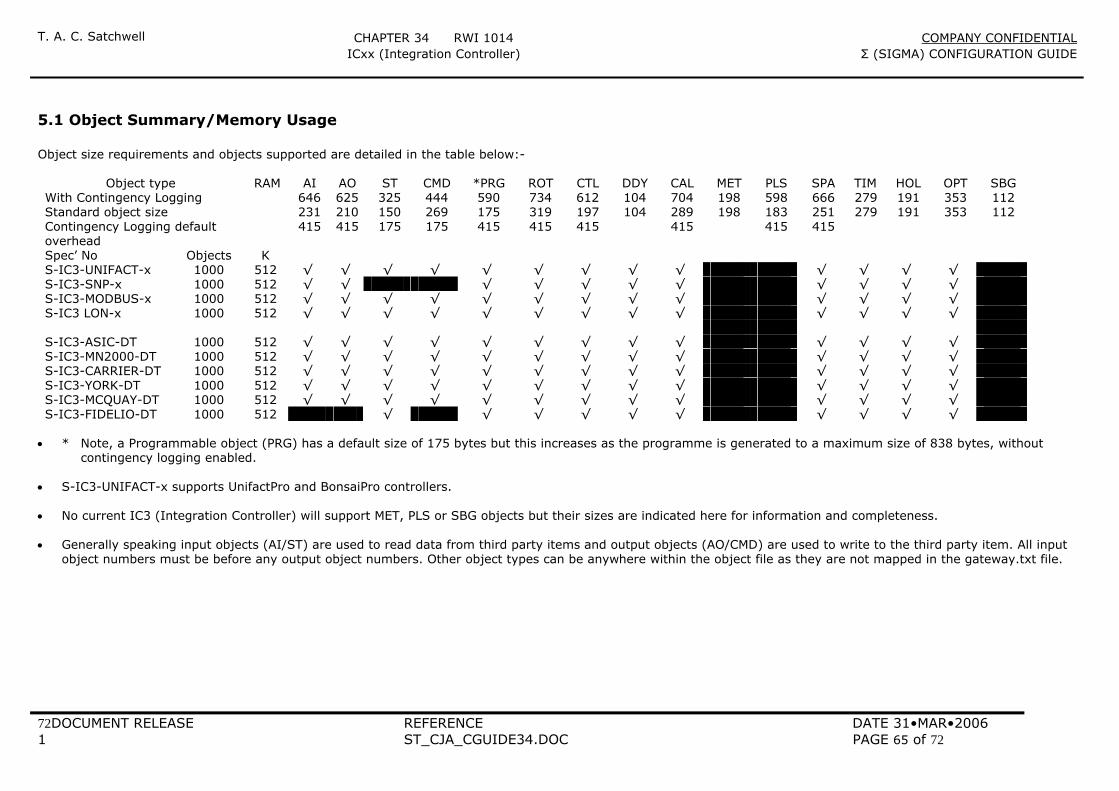
T. A. C. Satchwell CHAPTER 34 RWI 1014 COMPANY CONFIDENTIAL ICxx (Integration Controller) Σ (SIGMA) CONFIGURATION GUIDE
72DOCUMENT RELEASE REFERENCE DATE 31•MAR•2006 1 ST_CJA_CGUIDE34.DOC PAGE 65 of 72
5.1 Object Summary/Memory Usage Object size requirements and objects supported are detailed in the table below:-
Object type RAM AI AO ST CMD *PRG ROT CTL DDY CAL MET PLS SPA TIM HOL OPT SBG With Contingency Logging 646 625 325 444 590 734 612 104 704 198 598 666 279 191 353 112 Standard object size 231 210 150 269 175 319 197 104 289 198 183 251 279 191 353 112 Contingency Logging default overhead
415 415 175 175 415 415 415 415 415 415
Spec’ No Objects K S-IC3-UNIFACT-x 1000 512 √ √ √ √ √ √ √ √ √ √ √ √ √ S-IC3-SNP-x 1000 512 √ √ √ √ √ √ √ √ √ √ √ S-IC3-MODBUS-x 1000 512 √ √ √ √ √ √ √ √ √ √ √ √ √ S-IC3 LON-x 1000 512 √ √ √ √ √ √ √ √ √ √ √ √ √ S-IC3-ASIC-DT 1000 512 √ √ √ √ √ √ √ √ √ √ √ √ √ S-IC3-MN2000-DT 1000 512 √ √ √ √ √ √ √ √ √ √ √ √ √ S-IC3-CARRIER-DT 1000 512 √ √ √ √ √ √ √ √ √ √ √ √ √ S-IC3-YORK-DT 1000 512 √ √ √ √ √ √ √ √ √ √ √ √ √ S-IC3-MCQUAY-DT 1000 512 √ √ √ √ √ √ √ √ √ √ √ √ √ S-IC3-FIDELIO-DT 1000 512 √ √ √ √ √ √ √ √ √ √
• * Note, a Programmable object (PRG) has a default size of 175 bytes but this increases as the programme is generated to a maximum size of 838 bytes, without
contingency logging enabled. • S-IC3-UNIFACT-x supports UnifactPro and BonsaiPro controllers. • No current IC3 (Integration Controller) will support MET, PLS or SBG objects but their sizes are indicated here for information and completeness. • Generally speaking input objects (AI/ST) are used to read data from third party items and output objects (AO/CMD) are used to write to the third party item. All input
object numbers must be before any output object numbers. Other object types can be anywhere within the object file as they are not mapped in the gateway.txt file.
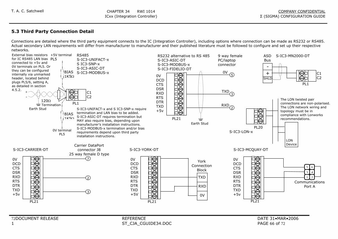
T. A. C. Satchwell CHAPTER 34 RWI 1014 COMPANY CONFIDENTIAL ICxx (Integration Controller) Σ (SIGMA) CONFIGURATION GUIDE
72DOCUMENT RELEASE REFERENCE DATE 31•MAR•2006 1 ST_CJA_CGUIDE34.DOC PAGE 66 of 72
5.3 Third Party Connection Detail Connections are detailed where the third party equipment connects to the IC (Integration Controller), including options where connection can be made as RS232 or RS485. Actual secondary LAN requirements will differ from manufacturer to manufacturer and their published literature must be followed to configure and set up their respective networks.
0V
TXD
RXD
PL21 Earth Stud
5
3
2
0V DCD CTS DSR RXD RTS DTR TXD +5v
RS232 alternative to RS 485S-IC3-ASIC-DT S-IC3-MODBUS-x S-IC3-FIDELIO-DT
9 way female PC/laptop connector
1 23 45 6
S-IC3-MCQUAY-DT
0V DCD CTS DSR RXD RTS DTR TXD +5v
CommunicationsPort A
PL21
0V DCD CTS DSR RXD RTS DTR TXD +5v
2
7
3
Carrier DataPort connector J8
25 way female D typeS-IC3-CARRIER-DT
PL21
0V DCD CTS
DSR RXD RTS DTR TXD +5V
TXD
RXD
0V
York Connection
Block
S-IC3-YORK-DT
PL21
PL1
C1 C2 SHLD
- +
ASD Bus
S-IC3-MN2000-DT
LON Device
PL20 S-IC3-LON-x
The LON twisted pair connections are non-polarised. The LON network wiring and topology must be in compliance with Lonworks recommendations.
BIAS 1K5Ω
C1 C2
120Ω Termination
+ -
PL1 Earth Stud
BIAS 1K5Ω
0V terminal PL5
+5V terminal PL5
RS485 S-IC3-UNIFACT-x S IC3-SNP-x S-IC3-ASIC-DT S-IC3-MODBUS-x
S-IC3-UNIFACT-x and S IC3-SNP-x require termination and LAN bias to be added. S-IC3-ASIC-DT requires termination but MAY also require bias, depending upon manufacturer’s installation instructions. S-IC3-MODBUS-x termination and/or bias requirements depend upon third party installation instructions.
External bias resistors for IC RS485 LAN bias connected to +5v and 0V terminals on PL5. Orthey can be configured internally via unmarked header, located behind plugs PL5/6, setting A, as detailed in section 4.5.2.
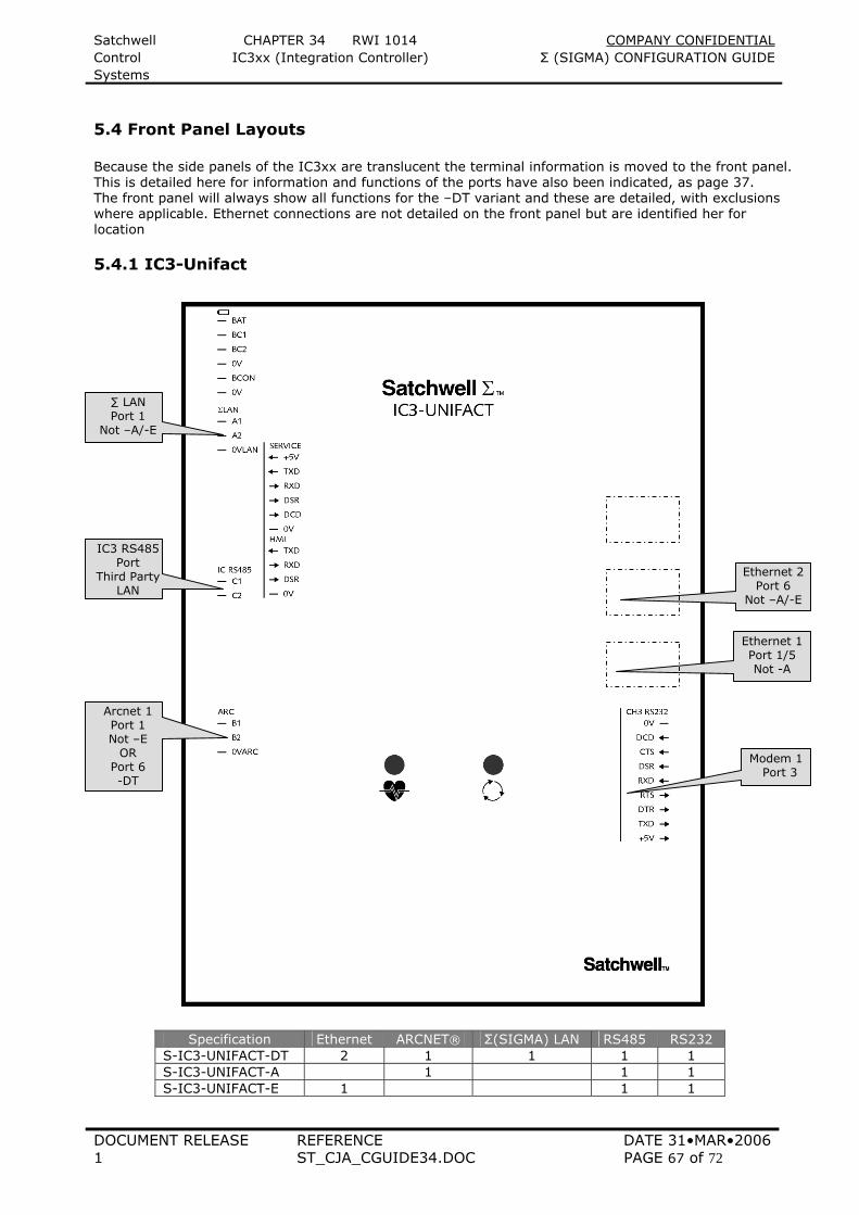
Satchwell CHAPTER 34 RWI 1014 COMPANY CONFIDENTIAL Control IC3xx (Integration Controller) Σ (SIGMA) CONFIGURATION GUIDE Systems
DOCUMENT RELEASE REFERENCE DATE 31•MAR•2006 1 ST_CJA_CGUIDE34.DOC PAGE 67 of 72
5.4 Front Panel Layouts Because the side panels of the IC3xx are translucent the terminal information is moved to the front panel. This is detailed here for information and functions of the ports have also been indicated, as page 37. The front panel will always show all functions for the –DT variant and these are detailed, with exclusions where applicable. Ethernet connections are not detailed on the front panel but are identified her for location
5.4.1 IC3-Unifact
Specification Ethernet ARCNET® Σ(SIGMA) LAN RS485 RS232 S-IC3-UNIFACT-DT 2 1 1 1 1 S-IC3-UNIFACT-A 1 1 1 S-IC3-UNIFACT-E 1 1 1
Arcnet 1 Port 1 Not –E
OR Port 6 -DT
Modem 1 Port 3
Ethernet 2 Port 6
Not –A/-E
Ethernet 1 Port 1/5 Not -A
IC3 RS485 Port
Third Party LAN
∑ LAN Port 1
Not –A/-E
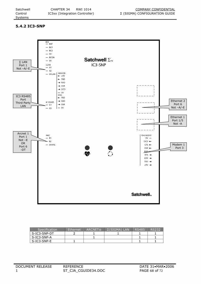
Satchwell CHAPTER 34 RWI 1014 COMPANY CONFIDENTIAL Control IC3xx (Integration Controller) Σ (SIGMA) CONFIGURATION GUIDE Systems
DOCUMENT RELEASE REFERENCE DATE 31•MAR•2006 1 ST_CJA_CGUIDE34.DOC PAGE 68 of 72
5.4.2 IC3-SNP
Specification Ethernet ARCNET® Σ(SIGMA) LAN RS485 RS232 S-IC3-SNP-DT 2 1 1 1 1 S-IC3-SNP-A 1 1 1 S-IC3-SNP-E 1 1 1
IC3 RS485 Port
Third Party LAN
∑ LAN Port 1
Not –A/-E
Modem 1 Port 3
Ethernet 2 Port 6
Not –A/-E
Ethernet 1 Port 1/5 Not -A
Arcnet 1 Port 1 Not –E
OR Port 6 -DT
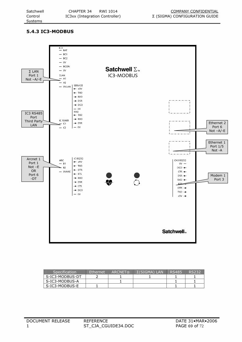
Satchwell CHAPTER 34 RWI 1014 COMPANY CONFIDENTIAL Control IC3xx (Integration Controller) Σ (SIGMA) CONFIGURATION GUIDE Systems
DOCUMENT RELEASE REFERENCE DATE 31•MAR•2006 1 ST_CJA_CGUIDE34.DOC PAGE 69 of 72
5.4.3 IC3-MODBUS
Specification Ethernet ARCNET® Σ(SIGMA) LAN RS485 RS232 S-IC3-MODBUS-DT 2 1 1 1 1 S-IC3-MODBUS-A 1 1 1 S-IC3-MODBUS-E 1 1 1
Arcnet 1 Port 1 Not –E
OR Port 6 -DT
IC3 RS485 Port
Third Party LAN
Modem 1 Port 3
Ethernet 2 Port 6
Not –A/-E
Ethernet 1 Port 1/5 Not -A
∑ LAN Port 1
Not –A/-E
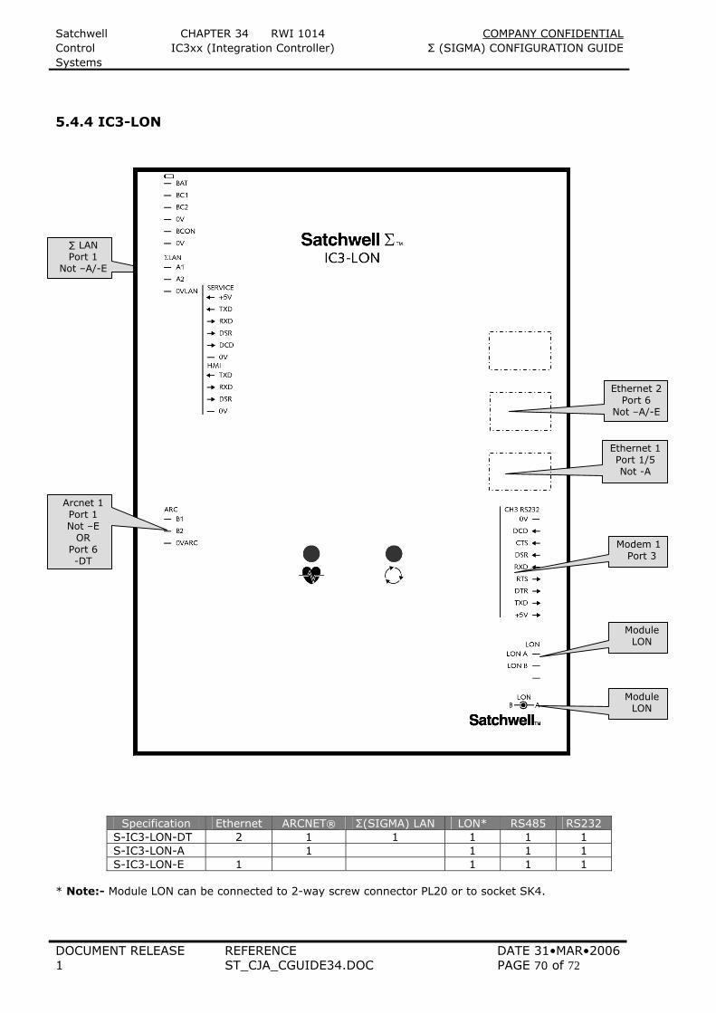
Satchwell CHAPTER 34 RWI 1014 COMPANY CONFIDENTIAL Control IC3xx (Integration Controller) Σ (SIGMA) CONFIGURATION GUIDE Systems
DOCUMENT RELEASE REFERENCE DATE 31•MAR•2006 1 ST_CJA_CGUIDE34.DOC PAGE 70 of 72
5.4.4 IC3-LON
Specification Ethernet ARCNET® Σ(SIGMA) LAN LON* RS485 RS232 S-IC3-LON-DT 2 1 1 1 1 1 S-IC3-LON-A 1 1 1 1 S-IC3-LON-E 1 1 1 1
* Note:- Module LON can be connected to 2-way screw connector PL20 or to socket SK4.
∑ LAN Port 1
Not –A/-E
Arcnet 1 Port 1 Not –E
OR Port 6 -DT
Modem 1 Port 3
Ethernet 2 Port 6
Not –A/-E
Ethernet 1 Port 1/5 Not -A
Module LON
Module LON
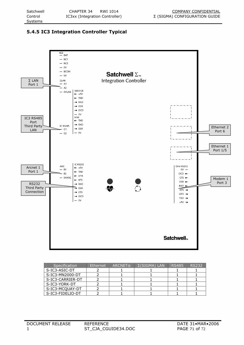
Satchwell CHAPTER 34 RWI 1014 COMPANY CONFIDENTIAL Control IC3xx (Integration Controller) Σ (SIGMA) CONFIGURATION GUIDE Systems
DOCUMENT RELEASE REFERENCE DATE 31•MAR•2006 1 ST_CJA_CGUIDE34.DOC PAGE 71 of 72
5.4.5 IC3 Integration Controller Typical
Specification Ethernet ARCNET® Σ(SIGMA) LAN RS485 RS232 S-IC3-ASIC-DT 2 1 1 1 1 S-IC3-MN2000-DT 2 1 1 1 1 S-IC3-CARRIER-DT 2 1 1 1 1 S-IC3-YORK-DT 2 1 1 1 1 S-IC3-MCQUAY-DT 2 1 1 1 1 S-IC3-FIDELIO-DT 2 1 1 1 1
Arcnet 1 Port 1
IC3 RS485 Port
Third Party LAN
∑ LAN Port 1
RS232 Third Party Connection
Ethernet 2 Port 6
Modem 1 Port 3
Ethernet 1 Port 1/5
Satchwell CHAPTER 34 RWI 1014 COMPANY CONFIDENTIAL Control IC3xx (Integration Controller) Σ (SIGMA) CONFIGURATION GUIDE Systems
DOCUMENT RELEASE REFERENCE DATE 31•MAR•2006 1 ST_CJA_CGUIDE34.DOC PAGE 72 of 72
6 OBJECT FILE CONSIDERATIONS (REPLACEMENTS/UPGRADES) When replacing or upgrading an existing IC, the ARM 720T processor is considerably faster than the V53 that is being replaced (20mHz v 74mHz). This may not cause any problems but if programmable objects have been used to perform real time actions i.e. valve slugging or sequence delay loops that count the number of scans rather than real time these loops will need adjusting. Individual object files will need to be checked to see if there are any objects that match this profile so that adjustments can be made. In order to determine the additional rate of object scanning the actual speed of scan needs to be known for the original IC and its new IC3 Σ(Sigma) environment. Reserved object 1004 will provide this information (see section 2.4) but prior to Sigma release 4.00, a programmable object was required. A typical programmable object to determine scan speed would be: - 10 Xflo = Xflo + 1.0 20 If not minute changed then goto 50 30 Yflo = Xflo 40 Xflo = 0.0 50 Return via text nnn Value Yflo (text nnn = %2.0f / min) Note In Σ(Sigma), ALL objects transmit on change of state (CoS), therefore programmable (PRG) objects should be introduced to reduce transmission frequency, or the scan priority of the object should be changed, to prevent frequent updates on the network. Scan priority 1 2 3 4 5 6 7 8 0 Object Processes on every nth scan
Every
2nd
4th
8th
16th
32nd
64th
128th
Disabled
From Sigma release 4.00 PRG, AI, AO, CAL, SPA, and CTL objects, incorporate a minimum send delay time of 10 seconds, all other objects are transmitted on CoS with no delay. Note If replacing an IC controller previously using ARCNET® communications, note that the twisted pair connectors are now on the right hand side of the PCB and wiring may have to be modified. See section 2.2. The latest release of this document is available as a .PDF file for download, from Exchange On Line, accessed via http://delphi.tac.com/ 7 DOCUMENT CONTROL Document release Date Comments 1 31/03/2006 First introduction of Satchwell Σ(Sigma) system Decentralised
Network Node (IC3xx) Prepared by C Allen Authorised by