


AC BAlAnCe ChArger
76
-
Upload
khangminh22 -
Category
Documents
-
view
0 -
download
0
Transcript of AC BAlAnCe ChArger

Hitec RCD USA, Inc. | 9320 Hazard Way, Suite D, San Diego, CA 92123 | (858) 748-6948 | www.hitecrcd.com
CONTINUES...
Hot on the heels of our wildly popular RDX1 Mini, Hitec is expanding your charging game with the new RDX2. This Mighty Mini features dual independent circuits to charge two batteries simultaneously, regardless of chemistry or capacity. The sleek, compact design allows easy front-loading convenience, while its powerful output and readily accessible balancing and XT60 ports make your battery management moreefficient and effortless.
• Dual Independent Charge Ports
• 5-Amp Charging Output
• 100-Watt Maximum Output
• Charges All Battery Chemistries
• Convenient Front-Loading Design
AC BAlAnCe ChArger
Features
efficient and effortless.efficient and effortless.efficient and effortless.efficient and effortless.efficient and effortless.efficient and effortless.efficient and effortless.efficient and effortless.efficient and effortless.efficient and effortless.efficient and effortless.efficient and effortless.efficient and effortless.efficient and effortless.efficient and effortless.efficient and effortless.
• Dual Independent Char• Dual Independent Char• Dual Independent Char• Dual Independent Char• Dual Independent Char• Dual Independent Char• Dual Independent Char• Dual Independent Char• Dual Independent Char• Dual Independent Char• Dual Independent Char• Dual Independent Char• Dual Independent Char• Dual Independent Char• Dual Independent Char• Dual Independent Char• Dual Independent Char• Dual Independent Char• Dual Independent Char• Dual Independent Char• Dual Independent Char• Dual Independent Char• Dual Independent Char• Dual Independent Char• Dual Independent Char• Dual Independent Char• Dual Independent Char• Dual Independent Char• Dual Independent Char• Dual Independent Char• Dual Independent Char• Dual Independent Char• Dual Independent Char• Dual Independent Char• Dual Independent Char• Dual Independent Char• Dual Independent Char• Dual Independent Char• Dual Independent Char• Dual Independent Char• Dual Independent Char• Dual Independent Char• Dual Independent Char• Dual Independent Char• Dual Independent Char• Dual Independent Char• Dual Independent Char• Dual Independent Char• Dual Independent Char• Dual Independent Char• Dual Independent Char• Dual Independent Char• Dual Independent Char• Dual Independent Char• Dual Independent Char• Dual Independent Char• Dual Independent Char• Dual Independent Char• Dual Independent Char• Dual Independent Char• Dual Independent Char• Dual Independent Char• Dual Independent Char• Dual Independent Char• Dual Independent Char• Dual Independent Char• Dual Independent Char
• 5-Amp Char• 5-Amp Charging Output • 5-Amp Char• 5-Amp Char• 5-Amp Charging Output • 5-Amp Charging Output • 5-Amp Char• 5-Amp Char• 5-Amp Char• 5-Amp Char• 5-Amp Char• 5-Amp Char• 5-Amp Char• 5-Amp Char• 5-Amp Char• 5-Amp Char• 5-Amp Char• 5-Amp Char• 5-Amp Char• 5-Amp Char• 5-Amp Char• 5-Amp Char• 5-Amp Char• 5-Amp Char• 5-Amp Char• 5-Amp Char• 5-Amp Charging Output • 5-Amp Char• 5-Amp Char• 5-Amp Char• 5-Amp Char• 5-Amp Char• 5-Amp Char• 5-Amp Char• 5-Amp Char• 5-Amp Char• 5-Amp Charging Output • 5-Amp Char• 5-Amp Char• 5-Amp Char• 5-Amp Char• 5-Amp Charging Output • 5-Amp Char• 5-Amp Char• 5-Amp Char• 5-Amp Char• 5-Amp Char• 5-Amp Char• 5-Amp Char• 5-Amp Char• 5-Amp Char• 5-Amp Char• 5-Amp Char• 5-Amp Char• 5-Amp Char• 5-Amp Char• 5-Amp Char• 5-Amp Char• 5-Amp Char• 5-Amp Char• 5-Amp Char• 5-Amp Charging Output • 5-Amp Char• 5-Amp Char• 5-Amp Char
• 100-Watt Maximum Output• 100-Watt Maximum Outputatt Maximum Outputatt Maximum Outputatt Maximum Outputatt Maximum Outputatt Maximum Outputatt Maximum Output• 100-W• 100-W• 100-Watt Maximum Output• 100-Watt Maximum Outputatt Maximum Output• 100-W• 100-W• 100-Watt Maximum Output• 100-Watt Maximum Outputatt Maximum Outputatt Maximum Outputatt Maximum Output• 100-Watt Maximum Output• 100-W• 100-Watt Maximum Output• 100-Watt Maximum Output• 100-Watt Maximum Output• 100-W• 100-W• 100-W• 100-W• 100-W• 100-W• 100-W
eatureseatureseatureseatureseatureseatureseatureseatureseatureseatureseatureseatureseatureseatureseatureseatureseatureseatureseatureseatureseatureseatureseatureseatureseatureseatureseatureseatureseatureseatureseatures
RDX1 Mini, Hitec is expanding your charRDX1 Mini, Hitec is expanding your charRDX1 Mini, Hitec is expanding your charRDX1 Mini, Hitec is expanding your charRDX1 Mini, Hitec is expanding your charRDX1 Mini, Hitec is expanding your charRDX1 Mini, Hitec is expanding your charRDX1 Mini, Hitec is expanding your charRDX1 Mini, Hitec is expanding your charRDX1 Mini, Hitec is expanding your charRDX1 Mini, Hitec is expanding your charRDX1 Mini, Hitec is expanding your charRDX1 Mini, Hitec is expanding your charRDX1 Mini, Hitec is expanding your charRDX1 Mini, Hitec is expanding your charRDX1 Mini, Hitec is expanding your charRDX1 Mini, Hitec is expanding your charRDX1 Mini, Hitec is expanding your charRDX1 Mini, Hitec is expanding your charRDX1 Mini, Hitec is expanding your charRDX1 Mini, Hitec is expanding your charRDX1 Mini, Hitec is expanding your charRDX1 Mini, Hitec is expanding your charRDX1 Mini, Hitec is expanding your charRDX1 Mini, Hitec is expanding your charRDX1 Mini, Hitec is expanding your charRDX1 Mini, Hitec is expanding your charRDX1 Mini, Hitec is expanding your chargame with the new game with the new game with the new game with the new game with the new game with the new game with the new game with the new game with the new game with the new game with the new game with the new game with the new game with the new game with the new game with the new game with the new game with the new game with the new game with the new game with the new game with the new game with the new game with the new game with the new game with the new game with the new game with the new game with the new game with the new game with the new game with the new game with the new game with the new game with the new game with the new game with the new game with the new game with the new game with the new game with the new RDX2RDX2RDX2RDX2RDX2RDX2RDX2RDX2RDX2RDX2RDX2RDX2RDX2
features dual independent cires dual independent cires dual independent cires dual independent cires dual independent cires dual independent cires dual independent cires dual independent cires dual independent cires dual independent cires dual independent cires dual independent cires dual independent cirfeatures dual independent cires dual independent cires dual independent cires dual independent cires dual independent cires dual independent cires dual independent cires dual independent cires dual independent cires dual independent cires dual independent cires dual independent cirfeatures dual independent cires dual independent cires dual independent cires dual independent cires dual independent cires dual independent cirfeatures dual independent cirfeatures dual independent cirfeatures dual independent cires dual independent cires dual independent cires dual independent cires dual independent cires dual independent cires dual independent cires dual independent cires dual independent cires dual independent cires dual independent cires dual independent cires dual independent cires dual independent cires dual independent cirfeatures dual independent cirfeatures dual independent cirfeatures dual independent cirfeatures dual independent cirfeatures dual independent cires dual independent cires dual independent cires dual independent cires dual independent cires dual independent cires dual independent cirfeatures dual independent cires dual independent cires dual independent cires dual independent cires dual independent cires dual independent cires dual independent cires dual independent cires dual independent cires dual independent cires dual independent cires dual independent cires dual independent cires dual independent cires dual independent cires dual independent cires dual independent cires dual independent cires dual independent cires dual independent cires dual independent cires dual independent cires dual independent cires dual independent cires dual independent cirtwo batteries simultaneouslytwo batteries simultaneouslytwo batteries simultaneouslytwo batteries simultaneouslytwo batteries simultaneouslytwo batteries simultaneouslytwo batteries simultaneouslytwo batteries simultaneouslytwo batteries simultaneouslytwo batteries simultaneouslytwo batteries simultaneouslytwo batteries simultaneouslytwo batteries simultaneouslytwo batteries simultaneouslytwo batteries simultaneouslytwo batteries simultaneouslytwo batteries simultaneouslytwo batteries simultaneouslytwo batteries simultaneouslytwo batteries simultaneouslytwo batteries simultaneouslytwo batteries simultaneouslytwo batteries simultaneouslytwo batteries simultaneouslytwo batteries simultaneouslytwo batteries simultaneouslytwo batteries simultaneouslytwo batteries simultaneouslytwo batteries simultaneouslytwo batteries simultaneouslytwo batteries simultaneouslytwo batteries simultaneouslytwo batteries simultaneouslytwo batteries simultaneouslytwo batteries simultaneouslytwo batteries simultaneouslytwo batteries simultaneouslytwo batteries simultaneouslytwo batteries simultaneouslytwo batteries simultaneouslytwo batteries simultaneouslytwo batteries simultaneouslytwo batteries simultaneouslytwo batteries simultaneouslytwo batteries simultaneouslytwo batteries simultaneouslytwo batteries simultaneouslytwo batteries simultaneouslytwo batteries simultaneouslytwo batteries simultaneouslytwo batteries simultaneouslytwo batteries simultaneouslytwo batteries simultaneouslytwo batteries simultaneouslytwo batteries simultaneouslytwo batteries simultaneouslytwo batteries simultaneouslytwo batteries simultaneouslytwo batteries simultaneouslytwo batteries simultaneouslytwo batteries simultaneouslytwo batteries simultaneouslytwo batteries simultaneouslytwo batteries simultaneouslytwo batteries simultaneouslytwo batteries simultaneouslytwo batteries simultaneouslytwo batteries simultaneouslytwo batteries simultaneouslytwo batteries simultaneouslytwo batteries simultaneouslytwo batteries simultaneouslytwo batteries simultaneouslytwo batteries simultaneouslytwo batteries simultaneouslytwo batteries simultaneouslytwo batteries simultaneouslytwo batteries simultaneouslytwo batteries simultaneouslytwo batteries simultaneouslytwo batteries simultaneouslytwo batteries simultaneouslytwo batteries simultaneouslytwo batteries simultaneouslytwo batteries simultaneouslytwo batteries simultaneouslytwo batteries simultaneouslytwo batteries simultaneouslytwo batteries simultaneouslytwo batteries simultaneouslytwo batteries simultaneouslytwo batteries simultaneouslytwo batteries simultaneouslytwo batteries simultaneouslytwo batteries simultaneouslytwo batteries simultaneouslytwo batteries simultaneouslytwo batteries simultaneouslytwo batteries simultaneouslytwo batteries simultaneouslytwo batteries simultaneouslytwo batteries simultaneouslytwo batteries simultaneouslytwo batteries simultaneouslytwo batteries simultaneouslytwo batteries simultaneouslytwo batteries simultaneouslytwo batteries simultaneouslytwo batteries simultaneouslyof chemistry or capacityof chemistry or capacityof chemistry or capacityof chemistry or capacityof chemistry or capacityof chemistry or capacityof chemistry or capacityof chemistry or capacityof chemistry or capacityof chemistry or capacityof chemistry or capacityof chemistry or capacityof chemistry or capacityof chemistry or capacityof chemistry or capacityof chemistry or capacityof chemistry or capacityof chemistry or capacityof chemistry or capacityof chemistry or capacityof chemistry or capacityof chemistry or capacityof chemistry or capacityof chemistry or capacityof chemistry or capacityof chemistry or capacityof chemistry or capacityof chemistry or capacityof chemistry or capacityof chemistry or capacityof chemistry or capacityof chemistry or capacityof chemistry or capacityof chemistry or capacityof chemistry or capacityof chemistry or capacityof chemistry or capacityof chemistry or capacityof chemistry or capacityof chemistry or capacityof chemistry or capacityof chemistry or capacityof chemistry or capacityof chemistry or capacityof chemistry or capacityof chemistry or capacityof chemistry or capacityof chemistry or capacityof chemistry or capacityof chemistry or capacityof chemistry or capacityof chemistry or capacityof chemistry or capacityof chemistry or capacityof chemistry or capacityof chemistry or capacityof chemistry or capacityof chemistry or capacityof chemistry or capacityof chemistry or capacityof chemistry or capacityof chemistry or capacityof chemistry or capacityof chemistry or capacityof chemistry or capacityof chemistry or capacityof chemistry or capacityof chemistry or capacityof chemistry or capacityof chemistry or capacityof chemistry or capacityof chemistry or capacityof chemistry or capacityof chemistry or capacityof chemistry or capacityof chemistry or capacityof chemistry or capacityof chemistry or capacityof chemistry or capacityof chemistry or capacityof chemistry or capacityof chemistry or capacityof chemistry or capacityof chemistry or capacityof chemistry or capacityof chemistry or capacityof chemistry or capacityof chemistry or capacityof chemistry or capacityof chemistry or capacityof chemistry or capacityof chemistry or capacityof chemistry or capacityof chemistry or capacityof chemistry or capacityof chemistry or capacityof chemistry or capacityof chemistry or capacityof chemistry or capacityof chemistry or capacityof chemistry or capacityof chemistry or capacityof chemistry or capacityof chemistry or capacityof chemistry or capacityof chemistry or capacityof chemistry or capacityof chemistry or capacityof chemistry or capacitycompact design allows easy frcompact design allows easy frcompact design allows easy frcompact design allows easy frcompact design allows easy frcompact design allows easy frcompact design allows easy frcompact design allows easy frcompact design allows easy frcompact design allows easy frcompact design allows easy frcompact design allows easy frcompact design allows easy frcompact design allows easy frcompact design allows easy frcompact design allows easy frcompact design allows easy frcompact design allows easy frcompact design allows easy frcompact design allows easy frcompact design allows easy frcompact design allows easy frcompact design allows easy frcompact design allows easy frcompact design allows easy frcompact design allows easy frcompact design allows easy frcompact design allows easy frcompact design allows easy frcompact design allows easy frcompact design allows easy frcompact design allows easy frcompact design allows easy frcompact design allows easy frcompact design allows easy frcompact design allows easy frcompact design allows easy frcompact design allows easy frcompact design allows easy frcompact design allows easy frcompact design allows easy frcompact design allows easy frcompact design allows easy frcompact design allows easy frcompact design allows easy frcompact design allows easy frcompact design allows easy frcompact design allows easy frcompact design allows easy frcompact design allows easy frcompact design allows easy frcompact design allows easy frcompact design allows easy frcompact design allows easy frcompact design allows easy frcompact design allows easy frcompact design allows easy frcompact design allows easy frcompact design allows easy frcompact design allows easy frcompact design allows easy frcompact design allows easy frcompact design allows easy frcompact design allows easy frcompact design allows easy frcompact design allows easy frcompact design allows easy frcompact design allows easy frcompact design allows easy frcompact design allows easy frcompact design allows easy frcompact design allows easy frcompact design allows easy frcompact design allows easy frcompact design allows easy frcompact design allows easy frcompact design allows easy frcompact design allows easy frcompact design allows easy frcompact design allows easy frcompact design allows easy frcompact design allows easy frcompact design allows easy frcompact design allows easy frcompact design allows easy frcompact design allows easy frcompact design allows easy frcompact design allows easy frcompact design allows easy frconvenience, while its powerful output and convenience, while its powerful output and convenience, while its powerful output and convenience, while its powerful output and convenience, while its powerful output and convenience, while its powerful output and convenience, while its powerful output and convenience, while its powerful output and convenience, while its powerful output and convenience, while its powerful output and convenience, while its powerful output and convenience, while its powerful output and convenience, while its powerful output and convenience, while its powerful output and convenience, while its powerful output and convenience, while its powerful output and convenience, while its powerful output and convenience, while its powerful output and convenience, while its powerful output and convenience, while its powerful output and convenience, while its powerful output and convenience, while its powerful output and convenience, while its powerful output and convenience, while its powerful output and convenience, while its powerful output and convenience, while its powerful output and convenience, while its powerful output and convenience, while its powerful output and convenience, while its powerful output and convenience, while its powerful output and convenience, while its powerful output and convenience, while its powerful output and convenience, while its powerful output and convenience, while its powerful output and convenience, while its powerful output and convenience, while its powerful output and convenience, while its powerful output and convenience, while its powerful output and convenience, while its powerful output and convenience, while its powerful output and convenience, while its powerful output and convenience, while its powerful output and convenience, while its powerful output and convenience, while its powerful output and convenience, while its powerful output and convenience, while its powerful output and convenience, while its powerful output and convenience, while its powerful output and convenience, while its powerful output and convenience, while its powerful output and convenience, while its powerful output and eadily accessible balancing and XT60 ports eadily accessible balancing and XT60 ports eadily accessible balancing and XT60 ports eadily accessible balancing and XT60 ports eadily accessible balancing and XT60 ports eadily accessible balancing and XT60 ports
convenience, while its powerful output and eadily accessible balancing and XT60 ports eadily accessible balancing and XT60 ports eadily accessible balancing and XT60 ports eadily accessible balancing and XT60 ports eadily accessible balancing and XT60 ports eadily accessible balancing and XT60 ports eadily accessible balancing and XT60 ports eadily accessible balancing and XT60 ports eadily accessible balancing and XT60 ports eadily accessible balancing and XT60 ports eadily accessible balancing and XT60 ports eadily accessible balancing and XT60 ports eadily accessible balancing and XT60 ports eadily accessible balancing and XT60 ports eadily accessible balancing and XT60 ports eadily accessible balancing and XT60 ports eadily accessible balancing and XT60 ports eadily accessible balancing and XT60 ports eadily accessible balancing and XT60 ports eadily accessible balancing and XT60 ports eadily accessible balancing and XT60 ports eadily accessible balancing and XT60 ports eadily accessible balancing and XT60 ports eadily accessible balancing and XT60 ports eadily accessible balancing and XT60 ports eadily accessible balancing and XT60 ports eadily accessible balancing and XT60 ports eadily accessible balancing and XT60 ports eadily accessible balancing and XT60 ports eadily accessible balancing and XT60 ports eadily accessible balancing and XT60 ports eadily accessible balancing and XT60 ports eadily accessible balancing and XT60 ports eadily accessible balancing and XT60 ports eadily accessible balancing and XT60 ports eadily accessible balancing and XT60 ports eadily accessible balancing and XT60 ports eadily accessible balancing and XT60 ports eadily accessible balancing and XT60 ports eadily accessible balancing and XT60 ports eadily accessible balancing and XT60 ports eadily accessible balancing and XT60 ports eadily accessible balancing and XT60 ports eadily accessible balancing and XT60 ports eadily accessible balancing and XT60 ports eadily accessible balancing and XT60 ports eadily accessible balancing and XT60 ports eadily accessible balancing and XT60 ports eadily accessible balancing and XT60 ports eadily accessible balancing and XT60 ports eadily accessible balancing and XT60 ports eadily accessible balancing and XT60 ports eadily accessible balancing and XT60 ports eadily accessible balancing and XT60 ports eadily accessible balancing and XT60 ports eadily accessible balancing and XT60 ports eadily accessible balancing and XT60 ports eadily accessible balancing and XT60 ports eadily accessible balancing and XT60 ports eadily accessible balancing and XT60 ports eadily accessible balancing and XT60 ports eadily accessible balancing and XT60 ports eadily accessible balancing and XT60 ports eadily accessible balancing and XT60 ports eadily accessible balancing and XT60 ports eadily accessible balancing and XT60 ports eadily accessible balancing and XT60 ports eadily accessible balancing and XT60 ports eadily accessible balancing and XT60 ports eadily accessible balancing and XT60 ports eadily accessible balancing and XT60 ports eadily accessible balancing and XT60 ports eadily accessible balancing and XT60 ports eadily accessible balancing and XT60 ports eadily accessible balancing and XT60 ports eadily accessible balancing and XT60 ports eadily accessible balancing and XT60 ports eadily accessible balancing and XT60 ports eadily accessible balancing and XT60 ports eadily accessible balancing and XT60 ports eadily accessible balancing and XT60 ports
make your battery management moremake your battery management mormake your battery management mormake your battery management mormake your battery management mormake your battery management mormake your battery management mormake your battery management mormake your battery management mormake your battery management mormake your battery management mormake your battery management mormake your battery management mormake your battery management mormake your battery management mormake your battery management mormake your battery management mormake your battery management moremake your battery management mormake your battery management mormake your battery management mormake your battery management moremake your battery management mormake your battery management mormake your battery management mormake your battery management mormake your battery management mormake your battery management mormake your battery management mormake your battery management moremake your battery management mormake your battery management mormake your battery management mormake your battery management mormake your battery management mormake your battery management mormake your battery management moremake your battery management mormake your battery management mormake your battery management mormake your battery management moremake your battery management moremake your battery management mormake your battery management moremake your battery management mormake your battery management mormake your battery management mormake your battery management mormake your battery management moremake your battery management mormake your battery management moremake your battery management mormake your battery management mormake your battery management mormake your battery management mormake your battery management mormake your battery management mormake your battery management mormake your battery management mormake your battery management mormake your battery management mormake your battery management mormake your battery management mormake your battery management mormake your battery management mormake your battery management mormake your battery management mormake your battery management mormake your battery management mormake your battery management mormake your battery management mor
• Dual Independent Charge Portsge Ports• Dual Independent Charge Portsge Portsge Portsge Portsge Portsge Portsge Portsge Portsge Portsge Portsge Portsge Portsge Portsge Portsge Ports• Dual Independent Charge Ports• Dual Independent Char• Dual Independent Char• Dual Independent Char• Dual Independent Char• Dual Independent Char• Dual Independent Char• Dual Independent Char• Dual Independent Char• Dual Independent Char• Dual Independent Char• Dual Independent Char• Dual Independent Char• Dual Independent Char• Dual Independent Charge Portsge Portsge Portsge Portsge Portsge Portsge Portsge Ports• Dual Independent Charge Ports• Dual Independent Charge Ports• Dual Independent Charge Portsge Portsge Portsge Ports• Dual Independent Charge Portsge Ports• Dual Independent Char• Dual Independent Char• Dual Independent Char• Dual Independent Charge Ports• Dual Independent Charge Ports• Dual Independent Char• Dual Independent Char• Dual Independent Char• Dual Independent Char• Dual Independent Char• Dual Independent Char• Dual Independent Charge Ports• Dual Independent Char• Dual Independent Char• Dual Independent Charge Portsge Portsge Portsge Portsge Portsge Portsge Portsge Portsge Portsge Portsge Portsge Portsge Portsge Portsge Ports• Dual Independent Charge Portsge Portsge Ports• Dual Independent Charge Portsge Portsge Portsge Portsge Portsge Portsge Ports• Dual Independent Charge Portsge Portsge Ports• Dual Independent Charge Ports• Dual Independent Char• Dual Independent Charge Ports• Dual Independent Charge Ports• Dual Independent Char• Dual Independent Char• Dual Independent Charge Ports• Dual Independent Charge Ports• Dual Independent Charge Portsge Portsge Portsge Ports• Dual Independent Char• Dual Independent Char• Dual Independent Char• Dual Independent Char• Dual Independent Char• Dual Independent Charge Ports• Dual Independent Charge Ports• Dual Independent Charge Ports• Dual Independent Charge Ports• Dual Independent Charge Ports• Dual Independent Charge Ports• Dual Independent Charge Ports• Dual Independent Charge Ports• Dual Independent Charge Ports• Dual Independent Charge Ports• Dual Independent Char• Dual Independent Char• Dual Independent Char• Dual Independent Charge Ports• Dual Independent Char• Dual Independent Char• Dual Independent Char• Dual Independent Char• Dual Independent Char• Dual Independent Charge Ports• Dual Independent Char• Dual Independent Char• Dual Independent Char• Dual Independent Charge Ports• Dual Independent Charge Ports• Dual Independent Char• Dual Independent Charge Ports• Dual Independent Charge Ports• Dual Independent Charge Ports• Dual Independent Char• Dual Independent Charge Portsge Portsge Ports• Dual Independent Charge Ports• Dual Independent Charge Ports• Dual Independent Charge Ports• Dual Independent Charge Ports• Dual Independent Char• Dual Independent Char• Dual Independent Char• Dual Independent Char
ging Output ging Output ging Output ging Output ging Output ging Output ging Output ging Output ging Output ging Output ging Output ging Output ging Output ging Output ging Output ging Output ging Output ging Output ging Output ging Output ging Output ging Output ging Output ging Output ging Output ging Output ging Output ging Output ging Output ging Output ging Output ging Output ging Output ging Output ging Output ging Output ging Output ging Output ging Output ging Output ging Output ging Output ging Output ging Output ging Output ging Output ging Output ging Output ging Output ging Output ging Output ging Output ging Output ging Output ging Output ging Output ging Output ging Output ging Output ging Output ging Output ging Output ging Output ging Output ging Output ging Output ging Output ging Output ging Output ging Output ging Output ging Output
Hot on the heels of our wildly popular Hot on the heels of our wildly popular Hot on the heels of our wildly popular Hot on the heels of our wildly popular Hot on the heels of our wildly popular Hot on the heels of our wildly popular Hot on the heels of our wildly popular Hot on the heels of our wildly popular Hot on the heels of our wildly popular Hot on the heels of our wildly popular Hot on the heels of our wildly popular Hot on the heels of our wildly popular Hot on the heels of our wildly popular Hot on the heels of our wildly popular Hot on the heels of our wildly popular Hot on the heels of our wildly popular RDX1 Mini, Hitec is expanding your charging RDX1 Mini, Hitec is expanding your charging RDX1 Mini, Hitec is expanding your charging RDX1 Mini, Hitec is expanding your charging RDX1 Mini, Hitec is expanding your charging RDX1 Mini, Hitec is expanding your charRDX1 Mini, Hitec is expanding your charRDX1 Mini, Hitec is expanding your charRDX1 Mini, Hitec is expanding your charRDX1 Mini, Hitec is expanding your charRDX1 Mini, Hitec is expanding your charRDX1 Mini, Hitec is expanding your charRDX1 Mini, Hitec is expanding your charRDX1 Mini, Hitec is expanding your charRDX1 Mini, Hitec is expanding your charRDX1 Mini, Hitec is expanding your charRDX1 Mini, Hitec is expanding your charging RDX1 Mini, Hitec is expanding your charRDX1 Mini, Hitec is expanding your charRDX1 Mini, Hitec is expanding your charRDX1 Mini, Hitec is expanding your charRDX1 Mini, Hitec is expanding your charRDX1 Mini, Hitec is expanding your charRDX1 Mini, Hitec is expanding your charRDX1 Mini, Hitec is expanding your charRDX1 Mini, Hitec is expanding your charRDX1 Mini, Hitec is expanding your charRDX1 Mini, Hitec is expanding your charRDX1 Mini, Hitec is expanding your charRDX1 Mini, Hitec is expanding your charging RDX1 Mini, Hitec is expanding your charging RDX1 Mini, Hitec is expanding your charging RDX1 Mini, Hitec is expanding your charging RDX1 Mini, Hitec is expanding your charRDX1 Mini, Hitec is expanding your charRDX1 Mini, Hitec is expanding your charRDX1 Mini, Hitec is expanding your charRDX1 Mini, Hitec is expanding your charRDX1 Mini, Hitec is expanding your charRDX1 Mini, Hitec is expanding your charRDX1 Mini, Hitec is expanding your charRDX1 Mini, Hitec is expanding your charRDX1 Mini, Hitec is expanding your charRDX1 Mini, Hitec is expanding your charRDX1 Mini, Hitec is expanding your charRDX1 Mini, Hitec is expanding your charRDX1 Mini, Hitec is expanding your charRDX1 Mini, Hitec is expanding your charRDX1 Mini, Hitec is expanding your charging RDX1 Mini, Hitec is expanding your charRDX1 Mini, Hitec is expanding your charging
. This Mighty Mini . This Mighty Mini . This Mighty Mini . This Mighty Mini . This Mighty Mini . This Mighty Mini . This Mighty Mini . This Mighty Mini . This Mighty Mini . This Mighty Mini . This Mighty Mini . This Mighty Mini . This Mighty Mini . This Mighty Mini . This Mighty Mini . This Mighty Mini . This Mighty Mini . This Mighty Mini . This Mighty Mini . This Mighty Mini . This Mighty Mini . This Mighty Mini . This Mighty Mini . This Mighty Mini . This Mighty Mini . This Mighty Mini . This Mighty Mini . This Mighty Mini . This Mighty Mini . This Mighty Mini . This Mighty Mini . This Mighty Mini . This Mighty Mini . This Mighty Mini . This Mighty Mini . This Mighty Mini . This Mighty Mini . This Mighty Mini . This Mighty Mini . This Mighty Mini . This Mighty Mini . This Mighty Mini . This Mighty Mini . This Mighty Mini . This Mighty Mini . This Mighty Mini . This Mighty Mini . This Mighty Mini . This Mighty Mini . This Mighty Mini . This Mighty Mini . This Mighty Mini es dual independent circuits to charge cuits to charcuits to charcuits to chares dual independent circuits to chares dual independent circuits to charcuits to charcuits to chares dual independent circuits to charcuits to charcuits to charcuits to charcuits to charcuits to charcuits to chares dual independent circuits to charcuits to charcuits to charcuits to charcuits to charcuits to charcuits to charcuits to charcuits to charcuits to charcuits to charcuits to charcuits to charcuits to charcuits to charcuits to charcuits to charcuits to charcuits to charcuits to chares dual independent circuits to charcuits to charge cuits to charge cuits to charge cuits to charcuits to charcuits to charcuits to charcuits to charge cuits to charge cuits to charge cuits to chares dual independent circuits to charcuits to charcuits to charcuits to charcuits to charcuits to charcuits to chares dual independent circuits to char
egardless dless egardless dless dless dless dless dless dless , regardless egardless egardless egaregardless egardless egaregaregardless egardless egardless egaregaregaregartwo batteries simultaneously, regartwo batteries simultaneously, regartwo batteries simultaneously, rtwo batteries simultaneously, rtwo batteries simultaneously, rtwo batteries simultaneously, regar, regar, regartwo batteries simultaneously, rtwo batteries simultaneously, rtwo batteries simultaneously, r dless egardless egardless egardless egardless egardless egardless dless two batteries simultaneously, regaregartwo batteries simultaneously, regaregar, regaregar, regar, regartwo batteries simultaneously, rtwo batteries simultaneously, rtwo batteries simultaneously, rtwo batteries simultaneously, regardless egaregartwo batteries simultaneously, rtwo batteries simultaneously, rtwo batteries simultaneously, rtwo batteries simultaneously, r, regar, regartwo batteries simultaneously, regardless two batteries simultaneously, regartwo batteries simultaneously, rtwo batteries simultaneously, regardless egardless dless dless dless dless dless egardless . The sleek, . The sleek, . The sleek, . The sleek, . The sleek, . The sleek, . The sleek, . The sleek, . The sleek, . The sleek, . The sleek, . The sleek, . The sleek, . The sleek, . The sleek, . The sleek, . The sleek, . The sleek, . The sleek, . The sleek, . The sleek, . The sleek, . The sleek, . The sleek, . The sleek, . The sleek, . The sleek, . The sleek, . The sleek, . The sleek, . The sleek, . The sleek, . The sleek, . The sleek, . The sleek, . The sleek, . The sleek, . The sleek, . The sleek, . The sleek, . The sleek, . The sleek, . The sleek, . The sleek, . The sleek, . The sleek, . The sleek, . The sleek, . The sleek, . The sleek, . The sleek, . The sleek, . The sleek, . The sleek, . The sleek, . The sleek, . The sleek, . The sleek, . The sleek, . The sleek, . The sleek, . The sleek, . The sleek, . The sleek, . The sleek, . The sleek, . The sleek, . The sleek, . The sleek, . The sleek, . The sleek, . The sleek, . The sleek, . The sleek, . The sleek, . The sleek, . The sleek, . The sleek, . The sleek, . The sleek, . The sleek, . The sleek, . The sleek, . The sleek, . The sleek, . The sleek, . The sleek, . The sleek, . The sleek, . The sleek, . The sleek, . The sleek, . The sleek, . The sleek, . The sleek, . The sleek, . The sleek, . The sleek, . The sleek, . The sleek, . The sleek, . The sleek, . The sleek, . The sleek, . The sleek, . The sleek, . The sleek, . The sleek, . The sleek,
ont-loading ont-loading ont-loading ont-loading ont-loading ont-loading ont-loading ont-loading ont-loading compact design allows easy front-loading compact design allows easy front-loading compact design allows easy front-loading compact design allows easy front-loading compact design allows easy front-loading ont-loading ont-loading compact design allows easy frcompact design allows easy frcompact design allows easy frcompact design allows easy frcompact design allows easy frcompact design allows easy frcompact design allows easy frcompact design allows easy front-loading ont-loading compact design allows easy frcompact design allows easy front-loading compact design allows easy frcompact design allows easy frcompact design allows easy frcompact design allows easy frcompact design allows easy front-loading ont-loading ont-loading ont-loading ont-loading ont-loading ont-loading ont-loading ont-loading ont-loading ont-loading compact design allows easy front-loading compact design allows easy front-loading ont-loading compact design allows easy front-loading compact design allows easy frcompact design allows easy front-loading compact design allows easy frcompact design allows easy frcompact design allows easy front-loading compact design allows easy front-loading ont-loading compact design allows easy front-loading compact design allows easy front-loading compact design allows easy front-loading compact design allows easy frcompact design allows easy frcompact design allows easy frcompact design allows easy frcompact design allows easy frcompact design allows easy front-loading compact design allows easy front-loading compact design allows easy frcompact design allows easy front-loading compact design allows easy front-loading ont-loading compact design allows easy frcompact design allows easy frcompact design allows easy front-loading ont-loading ont-loading ont-loading ont-loading compact design allows easy front-loading compact design allows easy front-loading compact design allows easy frcompact design allows easy frcompact design allows easy frcompact design allows easy frcompact design allows easy frcompact design allows easy frcompact design allows easy frcompact design allows easy frcompact design allows easy frcompact design allows easy frcompact design allows easy front-loading ont-loading ont-loading compact design allows easy frcompact design allows easy frcompact design allows easy frcompact design allows easy frcompact design allows easy frcompact design allows easy frcompact design allows easy frcompact design allows easy front-loading compact design allows easy front-loading compact design allows easy front-loading compact design allows easy front-loading compact design allows easy front-loading compact design allows easy front-loading compact design allows easy front-loading compact design allows easy frcompact design allows easy frcompact design allows easy frcompact design allows easy frcompact design allows easy front-loading compact design allows easy front-loading compact design allows easy front-loading compact design allows easy front-loading compact design allows easy front-loading compact design allows easy frcompact design allows easy frcompact design allows easy frcompact design allows easy frcompact design allows easy frcompact design allows easy frcompact design allows easy frcompact design allows easy frcompact design allows easy frcompact design allows easy frcompact design allows easy frcompact design allows easy frcompact design allows easy frcompact design allows easy frcompact design allows easy frcompact design allows easy frcompact design allows easy front-loading ont-loading ont-loading ont-loading ont-loading compact design allows easy frcompact design allows easy frcompact design allows easy frcompact design allows easy frcompact design allows easy frcompact design allows easy frcompact design allows easy frcompact design allows easy front-loading ont-loading ont-loading ont-loading ont-loading ont-loading ont-loading ont-loading ont-loading ont-loading ont-loading ont-loading ont-loading ont-loading ont-loading ont-loading ont-loading ont-loading ont-loading compact design allows easy front-loading ont-loading compact design allows easy front-loading compact design allows easy front-loading compact design allows easy front-loading compact design allows easy front-loading ont-loading compact design allows easy frcompact design allows easy front-loading compact design allows easy front-loading compact design allows easy front-loading compact design allows easy front-loading compact design allows easy front-loading ont-loading ont-loading ont-loading ont-loading ont-loading compact design allows easy front-loading compact design allows easy frcompact design allows easy frcompact design allows easy front-loading compact design allows easy frcompact design allows easy frcompact design allows easy frcompact design allows easy frcompact design allows easy frcompact design allows easy frcompact design allows easy frcompact design allows easy frcompact design allows easy frcompact design allows easy frcompact design allows easy frcompact design allows easy frcompact design allows easy frcompact design allows easy frcompact design allows easy frcompact design allows easy frcompact design allows easy frcompact design allows easy front-loading ont-loading ont-loading compact design allows easy front-loading compact design allows easy frcompact design allows easy frcompact design allows easy frcompact design allows easy frcompact design allows easy frcompact design allows easy frcompact design allows easy frcompact design allows easy frcompact design allows easy frcompact design allows easy frcompact design allows easy frcompact design allows easy frcompact design allows easy frcompact design allows easy frcompact design allows easy frcompact design allows easy frcompact design allows easy frcompact design allows easy frcompact design allows easy frcompact design allows easy frcompact design allows easy frcompact design allows easy frcompact design allows easy frcompact design allows easy frcompact design allows easy frcompact design allows easy frcompact design allows easy frcompact design allows easy front-loading compact design allows easy frcompact design allows easy front-loading ont-loading ont-loading ont-loading ont-loading ont-loading ont-loading ont-loading ont-loading ont-loading ont-loading ont-loading ont-loading ont-loading ont-loading compact design allows easy front-loading compact design allows easy front-loading compact design allows easy front-loading ont-loading compact design allows easy front-loading compact design allows easy front-loading compact design allows easy front-loading ont-loading ont-loading ont-loading compact design allows easy front-loading compact design allows easy frcompact design allows easy front-loading ont-loading ont-loading ont-loading ont-loading ont-loading ont-loading ont-loading ont-loading compact design allows easy frconvenience, while its powerful output and convenience, while its powerful output and convenience, while its powerful output and convenience, while its powerful output and convenience, while its powerful output and convenience, while its powerful output and convenience, while its powerful output and convenience, while its powerful output and convenience, while its powerful output and convenience, while its powerful output and convenience, while its powerful output and convenience, while its powerful output and convenience, while its powerful output and convenience, while its powerful output and convenience, while its powerful output and convenience, while its powerful output and convenience, while its powerful output and convenience, while its powerful output and convenience, while its powerful output and convenience, while its powerful output and convenience, while its powerful output and convenience, while its powerful output and convenience, while its powerful output and convenience, while its powerful output and convenience, while its powerful output and convenience, while its powerful output and convenience, while its powerful output and convenience, while its powerful output and convenience, while its powerful output and convenience, while its powerful output and convenience, while its powerful output and convenience, while its powerful output and convenience, while its powerful output and convenience, while its powerful output and convenience, while its powerful output and convenience, while its powerful output and convenience, while its powerful output and convenience, while its powerful output and convenience, while its powerful output and convenience, while its powerful output and convenience, while its powerful output and convenience, while its powerful output and convenience, while its powerful output and convenience, while its powerful output and convenience, while its powerful output and convenience, while its powerful output and convenience, while its powerful output and convenience, while its powerful output and convenience, while its powerful output and convenience, while its powerful output and convenience, while its powerful output and convenience, while its powerful output and convenience, while its powerful output and convenience, while its powerful output and convenience, while its powerful output and convenience, while its powerful output and convenience, while its powerful output and convenience, while its powerful output and convenience, while its powerful output and convenience, while its powerful output and convenience, while its powerful output and convenience, while its powerful output and convenience, while its powerful output and convenience, while its powerful output and convenience, while its powerful output and convenience, while its powerful output and convenience, while its powerful output and convenience, while its powerful output and convenience, while its powerful output and convenience, while its powerful output and convenience, while its powerful output and convenience, while its powerful output and convenience, while its powerful output and convenience, while its powerful output and convenience, while its powerful output and convenience, while its powerful output and convenience, while its powerful output and convenience, while its powerful output and convenience, while its powerful output and convenience, while its powerful output and convenience, while its powerful output and convenience, while its powerful output and convenience, while its powerful output and convenience, while its powerful output and convenience, while its powerful output and convenience, while its powerful output and convenience, while its powerful output and convenience, while its powerful output and convenience, while its powerful output and convenience, while its powerful output and convenience, while its powerful output and convenience, while its powerful output and convenience, while its powerful output and convenience, while its powerful output and convenience, while its powerful output and convenience, while its powerful output and convenience, while its powerful output and convenience, while its powerful output and convenience, while its powerful output and convenience, while its powerful output and convenience, while its powerful output and convenience, while its powerful output and convenience, while its powerful output and convenience, while its powerful output and convenience, while its powerful output and convenience, while its powerful output and convenience, while its powerful output and convenience, while its powerful output and convenience, while its powerful output and convenience, while its powerful output and convenience, while its powerful output and convenience, while its powerful output and convenience, while its powerful output and convenience, while its powerful output and convenience, while its powerful output and convenience, while its powerful output and convenience, while its powerful output and convenience, while its powerful output and convenience, while its powerful output and convenience, while its powerful output and convenience, while its powerful output and convenience, while its powerful output and convenience, while its powerful output and convenience, while its powerful output and convenience, while its powerful output and convenience, while its powerful output and convenience, while its powerful output and convenience, while its powerful output and convenience, while its powerful output and convenience, while its powerful output and convenience, while its powerful output and convenience, while its powerful output and convenience, while its powerful output and convenience, while its powerful output and convenience, while its powerful output and convenience, while its powerful output and convenience, while its powerful output and convenience, while its powerful output and convenience, while its powerful output and convenience, while its powerful output and convenience, while its powerful output and convenience, while its powerful output and convenience, while its powerful output and convenience, while its powerful output and convenience, while its powerful output and convenience, while its powerful output and convenience, while its powerful output and convenience, while its powerful output and convenience, while its powerful output and convenience, while its powerful output and convenience, while its powerful output and convenience, while its powerful output and convenience, while its powerful output and convenience, while its powerful output and convenience, while its powerful output and convenience, while its powerful output and convenience, while its powerful output and convenience, while its powerful output and convenience, while its powerful output and convenience, while its powerful output and convenience, while its powerful output and convenience, while its powerful output and convenience, while its powerful output and convenience, while its powerful output and convenience, while its powerful output and convenience, while its powerful output and convenience, while its powerful output and convenience, while its powerful output and convenience, while its powerful output and convenience, while its powerful output and convenience, while its powerful output and convenience, while its powerful output and convenience, while its powerful output and convenience, while its powerful output and convenience, while its powerful output and convenience, while its powerful output and convenience, while its powerful output and convenience, while its powerful output and convenience, while its powerful output and convenience, while its powerful output and convenience, while its powerful output and convenience, while its powerful output and convenience, while its powerful output and convenience, while its powerful output and convenience, while its powerful output and convenience, while its powerful output and convenience, while its powerful output and convenience, while its powerful output and convenience, while its powerful output and convenience, while its powerful output and convenience, while its powerful output and convenience, while its powerful output and convenience, while its powerful output and convenience, while its powerful output and convenience, while its powerful output and convenience, while its powerful output and convenience, while its powerful output and convenience, while its powerful output and convenience, while its powerful output and convenience, while its powerful output and convenience, while its powerful output and convenience, while its powerful output and convenience, while its powerful output and convenience, while its powerful output and convenience, while its powerful output and convenience, while its powerful output and convenience, while its powerful output and convenience, while its powerful output and convenience, while its powerful output and convenience, while its powerful output and convenience, while its powerful output and convenience, while its powerful output and convenience, while its powerful output and convenience, while its powerful output and convenience, while its powerful output and convenience, while its powerful output and convenience, while its powerful output and convenience, while its powerful output and convenience, while its powerful output and convenience, while its powerful output and convenience, while its powerful output and convenience, while its powerful output and convenience, while its powerful output and convenience, while its powerful output and convenience, while its powerful output and convenience, while its powerful output and convenience, while its powerful output and convenience, while its powerful output and convenience, while its powerful output and convenience, while its powerful output and convenience, while its powerful output and convenience, while its powerful output and convenience, while its powerful output and convenience, while its powerful output and convenience, while its powerful output and convenience, while its powerful output and convenience, while its powerful output and convenience, while its powerful output and convenience, while its powerful output and convenience, while its powerful output and convenience, while its powerful output and convenience, while its powerful output and convenience, while its powerful output and convenience, while its powerful output and convenience, while its powerful output and convenience, while its powerful output and convenience, while its powerful output and convenience, while its powerful output and convenience, while its powerful output and convenience, while its powerful output and convenience, while its powerful output and convenience, while its powerful output and convenience, while its powerful output and convenience, while its powerful output and convenience, while its powerful output and convenience, while its powerful output and convenience, while its powerful output and convenience, while its powerful output and convenience, while its powerful output and convenience, while its powerful output and convenience, while its powerful output and convenience, while its powerful output and convenience, while its powerful output and convenience, while its powerful output and convenience, while its powerful output and convenience, while its powerful output and convenience, while its powerful output and convenience, while its powerful output and convenience, while its powerful output and convenience, while its powerful output and convenience, while its powerful output and convenience, while its powerful output and convenience, while its powerful output and eadily accessible balancing and XT60 ports eadily accessible balancing and XT60 ports eadily accessible balancing and XT60 ports eadily accessible balancing and XT60 ports eadily accessible balancing and XT60 ports eadily accessible balancing and XT60 ports eadily accessible balancing and XT60 ports eadily accessible balancing and XT60 ports eadily accessible balancing and XT60 ports eadily accessible balancing and XT60 ports eadily accessible balancing and XT60 ports eadily accessible balancing and XT60 ports eadily accessible balancing and XT60 ports eadily accessible balancing and XT60 ports eadily accessible balancing and XT60 ports eadily accessible balancing and XT60 ports eadily accessible balancing and XT60 ports eadily accessible balancing and XT60 ports eadily accessible balancing and XT60 ports eadily accessible balancing and XT60 ports eadily accessible balancing and XT60 ports eadily accessible balancing and XT60 ports eadily accessible balancing and XT60 ports eadily accessible balancing and XT60 ports eadily accessible balancing and XT60 ports eadily accessible balancing and XT60 ports eadily accessible balancing and XT60 ports eadily accessible balancing and XT60 ports eadily accessible balancing and XT60 ports eadily accessible balancing and XT60 ports eadily accessible balancing and XT60 ports eadily accessible balancing and XT60 ports eadily accessible balancing and XT60 ports eadily accessible balancing and XT60 ports eadily accessible balancing and XT60 ports eadily accessible balancing and XT60 ports eadily accessible balancing and XT60 ports eadily accessible balancing and XT60 ports eadily accessible balancing and XT60 ports eadily accessible balancing and XT60 ports eadily accessible balancing and XT60 ports eadily accessible balancing and XT60 ports eadily accessible balancing and XT60 ports eadily accessible balancing and XT60 ports eadily accessible balancing and XT60 ports eadily accessible balancing and XT60 ports eadily accessible balancing and XT60 ports eadily accessible balancing and XT60 ports eadily accessible balancing and XT60 ports eadily accessible balancing and XT60 ports eadily accessible balancing and XT60 ports eadily accessible balancing and XT60 ports eadily accessible balancing and XT60 ports eadily accessible balancing and XT60 ports eadily accessible balancing and XT60 ports eadily accessible balancing and XT60 ports eadily accessible balancing and XT60 ports eadily accessible balancing and XT60 ports eadily accessible balancing and XT60 ports eadily accessible balancing and XT60 ports eadily accessible balancing and XT60 ports eadily accessible balancing and XT60 ports eadily accessible balancing and XT60 ports eadily accessible balancing and XT60 ports eadily accessible balancing and XT60 ports eadily accessible balancing and XT60 ports eadily accessible balancing and XT60 ports eadily accessible balancing and XT60 ports eadily accessible balancing and XT60 ports eadily accessible balancing and XT60 ports eadily accessible balancing and XT60 ports eadily accessible balancing and XT60 ports eadily accessible balancing and XT60 ports eadily accessible balancing and XT60 ports eadily accessible balancing and XT60 ports eadily accessible balancing and XT60 ports eadily accessible balancing and XT60 ports eadily accessible balancing and XT60 ports eadily accessible balancing and XT60 ports eadily accessible balancing and XT60 ports eadily accessible balancing and XT60 ports eadily accessible balancing and XT60 ports eadily accessible balancing and XT60 ports eadily accessible balancing and XT60 ports eadily accessible balancing and XT60 ports eadily accessible balancing and XT60 ports eadily accessible balancing and XT60 ports eadily accessible balancing and XT60 ports eadily accessible balancing and XT60 ports eadily accessible balancing and XT60 ports eadily accessible balancing and XT60 ports eadily accessible balancing and XT60 ports eadily accessible balancing and XT60 ports eadily accessible balancing and XT60 ports eadily accessible balancing and XT60 ports eadily accessible balancing and XT60 ports eadily accessible balancing and XT60 ports eadily accessible balancing and XT60 ports eadily accessible balancing and XT60 ports eadily accessible balancing and XT60 ports
make your battery management mormake your battery management mormake your battery management mormake your battery management mormake your battery management mormake your battery management mormake your battery management mormake your battery management mormake your battery management mormake your battery management mormake your battery management mormake your battery management mormake your battery management mormake your battery management mormake your battery management mormake your battery management mormake your battery management mormake your battery management mormake your battery management mormake your battery management mormake your battery management mormake your battery management mormake your battery management mormake your battery management mormake your battery management mormake your battery management mormake your battery management mormake your battery management mormake your battery management mormake your battery management mormake your battery management mormake your battery management mormake your battery management mormake your battery management mormake your battery management mormake your battery management mormake your battery management mormake your battery management mormake your battery management mormake your battery management mormake your battery management mormake your battery management mormake your battery management mormake your battery management mormake your battery management mormake your battery management mormake your battery management mormake your battery management mormake your battery management mormake your battery management mormake your battery management mormake your battery management mormake your battery management mormake your battery management mormake your battery management mormake your battery management mormake your battery management mormake your battery management mormake your battery management mormake your battery management mormake your battery management mormake your battery management mormake your battery management mormake your battery management mormake your battery management mormake your battery management mormake your battery management mormake your battery management mormake your battery management mormake your battery management mormake your battery management mormake your battery management mormake your battery management mormake your battery management mormake your battery management mormake your battery management mormake your battery management mormake your battery management mormake your battery management mormake your battery management mormake your battery management mormake your battery management mormake your battery management mormake your battery management mormake your battery management mormake your battery management mormake your battery management mormake your battery management mormake your battery management mormake your battery management mormake your battery management mormake your battery management mormake your battery management mormake your battery management mormake your battery management mormake your battery management mormake your battery management mormake your battery management mormake your battery management mormake your battery management mormake your battery management mormake your battery management mormake your battery management mormake your battery management mormake your battery management mormake your battery management mormake your battery management mormake your battery management mormake your battery management mormake your battery management mormake your battery management mormake your battery management mormake your battery management mormake your battery management mormake your battery management mormake your battery management mormake your battery management mormake your battery management mormake your battery management mormake your battery management mormake your battery management mormake your battery management mormake your battery management mormake your battery management mormake your battery management morefficient and effortless.efficient and effortless.efficient and effortless.efficient and effortless.efficient and effortless.efficient and effortless.efficient and effortless.efficient and effortless.efficient and effortless.efficient and effortless.efficient and effortless.efficient and effortless.efficient and effortless.efficient and effortless.efficient and effortless.efficient and effortless.efficient and effortless.efficient and effortless.efficient and effortless.efficient and effortless.efficient and effortless.efficient and effortless.efficient and effortless.efficient and effortless.efficient and effortless.efficient and effortless.efficient and effortless.efficient and effortless.efficient and effortless.efficient and effortless.efficient and effortless.efficient and effortless.efficient and effortless.efficient and effortless.efficient and effortless.efficient and effortless.efficient and effortless.efficient and effortless.efficient and effortless.efficient and effortless.efficient and effortless.efficient and effortless.efficient and effortless.efficient and effortless.efficient and effortless.efficient and effortless.efficient and effortless.efficient and effortless.efficient and effortless.efficient and effortless.efficient and effortless.efficient and effortless.efficient and effortless.efficient and effortless.efficient and effortless.efficient and effortless.efficient and effortless.efficient and effortless.efficient and effortless.efficient and effortless.efficient and effortless.efficient and effortless.efficient and effortless.efficient and effortless.efficient and effortless.efficient and effortless.efficient and effortless.efficient and effortless.efficient and effortless.efficient and effortless.efficient and effortless.efficient and effortless.efficient and effortless.efficient and effortless.efficient and effortless.efficient and effortless.efficient and effortless.efficient and effortless.efficient and effortless.efficient and effortless.efficient and effortless.efficient and effortless.efficient and effortless.efficient and effortless.
FFFFFFFFFFFFFFFFFFeatureseatureseatureseatureseatureseatureseatureseatureseatureseatures
THE MIGHT

Subscription InformationSERVO Magazine — 2279 Eagle Glen Parkway #112-481
Corona, CA 92883 • (951) 371-8497Call (800) 783-4624 or go to www.servomagazine.com
Subscribe • Gift • Renewal • Change of Info
Issue-1.2020VOLUME 18
06 Mind/Iron An Analog Artifact Worthy of Your Robotics Toolkit
26 New Products
37 The GearBox
72 Advertiser’s Index
73 SERVO Webstore
Departments
For more details on subscribing, see our ad on Page 74.
Combat Zone28 Building a Better Box
30 Stepping Stones —
The Story of Thunder
Child
33 Bringing About the
ApocalypsePage 30
SERVO Magazine (ISSN 1546-0592/CDN Pub Agree#40702530) Issue-1 (Jan-Feb) is published 6X a year for $26.95 per year by T & L Publications, Inc., 2279 Eagle Glen Parkway, #112-481, Corona, CA 92883. Periodicals postage PAID at Corona, CA and at additional entry mailing offices. POST MASTER: Send address changes to SERVO Magazine, 2279 Eagle Glen Parkway #112-481, Corona, CA 92883 or Station A, P.O. Box 54, Windsor ON N9A 6J5; [email protected].
• Armed and Dangerous?
• HAMR-Jr Time
• Slow as a SlothBot
• Healthcare Gone to the Dogs
• Cheetahs Never Prosper
• Bot or Not?
• Do the Worm
• Draganfly Drones Do Monitoring
• Follow the Bouncing Ball
• Gonna Burst Your Bubble
20 Bots in Brief
4 SERVO Issue-1.2020
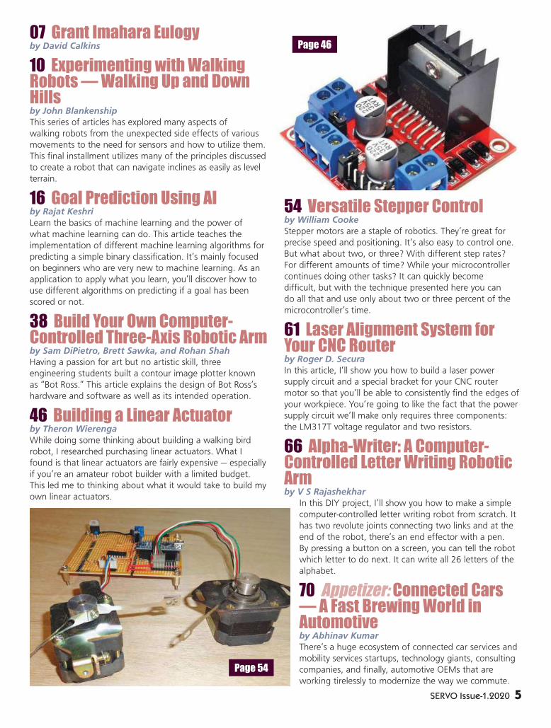
07 Grant Imahara Eulogyby David Calkins
10 Experimenting with Walking Robots — Walking Up and Down Hillsby John Blankenship
This series of articles has explored many aspects of
walking robots from the unexpected side effects of various
movements to the need for sensors and how to utilize them.
This final installment utilizes many of the principles discussed
to create a robot that can navigate inclines as easily as level
terrain.
16 Goal Prediction Using AIby Rajat Keshri
Learn the basics of machine learning and the power of
what machine learning can do. This article teaches the
implementation of different machine learning algorithms for
predicting a simple binary classification. It’s mainly focused
on beginners who are very new to machine learning. As an
application to apply what you learn, you’ll discover how to
use different algorithms on predicting if a goal has been
scored or not.
38 Build Your Own Computer-Controlled Three-Axis Robotic Armby Sam DiPietro, Brett Sawka, and Rohan Shah
Having a passion for art but no artistic skill, three
engineering students built a contour image plotter known
as “Bot Ross.” This article explains the design of Bot Ross’s
hardware and software as well as its intended operation.
46 Building a Linear Actuatorby Theron Wierenga
While doing some thinking about building a walking bird
robot, I researched purchasing linear actuators. What I
found is that linear actuators are fairly expensive — especially
if you’re an amateur robot builder with a limited budget.
This led me to thinking about what it would take to build my
own linear actuators.
54 Versatile Stepper Controlby William Cooke
Stepper motors are a staple of robotics. They’re great for
precise speed and positioning. It’s also easy to control one.
But what about two, or three? With different step rates?
For different amounts of time? While your microcontroller
continues doing other tasks? It can quickly become
difficult, but with the technique presented here you can
do all that and use only about two or three percent of the
microcontroller’s time.
61 Laser Alignment System for Your CNC Routerby Roger D. Secura
In this article, I’ll show you how to build a laser power
supply circuit and a special bracket for your CNC router
motor so that you’ll be able to consistently find the edges of
your workpiece. You’re going to like the fact that the power
supply circuit we’ll make only requires three components:
the LM317T voltage regulator and two resistors.
66 Alpha-Writer: A Computer-Controlled Letter Writing Robotic Armby V S Rajashekhar
In this DIY project, I’ll show you how to make a simple
computer-controlled letter writing robot from scratch. It
has two revolute joints connecting two links and at the
end of the robot, there’s an end effector with a pen.
By pressing a button on a screen, you can tell the robot
which letter to do next. It can write all 26 letters of the
alphabet.
70 Appetizer: Connected Cars — A Fast Brewing World in Automotiveby Abhinav Kumar
There’s a huge ecosystem of connected car services and
mobility services startups, technology giants, consulting
companies, and finally, automotive OEMs that are
working tirelessly to modernize the way we commute.
Page 46
Page 54
SERVO Issue-1.2020 5

At my first real job with a communications company, every technician was equipped
with a piece of state-of-the-art test gear designed to function in the harshest environments and with literally constant abuse. Of course, I’m talking about the Simpson 260, easily the most popular analog VOM (volt-ohm meter) of all time.
The best technicians and engineers wouldn’t consider anything else to assist them in diagnosing and maintaining microwave communications gear. I remember the best of the engineers could read a dozen values in only a few seconds. They could accurately estimate values long before the Simpson’s needle moved into final position, simply based on the initial velocity of the needle.
I, on the other hand, lusted after one of the new digital meters on the market. After all, why settle for a reading of only 2-3% full scale accuracy, when a DMM could theoretically take a reading with double the accuracy and to several digits and with a much higher input impedance?
Putting aside the issues of settling time, need for frequent calibration, and the need to be near a 110V outlet, when digital meters first hit the market, they were cool. They were like having one of the first iPhones to hit the street.
Over the years, I worked through several generations of DMMs, ranging from $10 to over $800. I even considered the digital Simpson — a short-lived abomination. My current toolkit includes a portable Fluke 87
PUBLISHED BY
T & L Publications, Inc.
CONTACT
2279 Eagle Glen Pkwy #112-481
Corona, CA 92883
OFFICE: (951) 371-8497
FAX: (951) 371-3052
www.servomagazine.com
SUBSCRIPTION INQUIRIES/
WEBSTORE ORDERS
TOLL FREE: (800) 783-4624
store.nutsvolts.com
PUBLISHER
Larry Lemieux
ASSOCIATE PUBLISHER/
ADVERTISING SALES
Robin Lemieux
EXECUTIVE DIRECTOR/
PRODUCTION
Sean Lemieux
EDITOR
Bryan Bergeron
CONTRIBUTING EDITORS
Kevin Berry John Blankenship
William Cook V S Rajashekhar
Roger Secura Rohan Shah
Sam DiPietro Brett Sawka
Rajat Keshri Abhinav Kumar
Theron Wierenga Ryan Clingman
Nate Franklin David Calkins
WEBSTORE MARKETING/
COVER GRAPHICS
Brian Kirkpatrick
Copyright © 2020 by T & L Publications, Inc.
All Rights ReservedAll advertising is subject to publisher’s approval.
We are not responsible for mistakes, misprints,
or typographical errors. SERVO Magazine
assumes no responsibility for the availability
or condition of advertised items or for the
honesty of the advertiser. The publisher makes
no claims for the legality of any item advertised
in SERVO. This is the sole responsibility of the
advertiser. Advertisers and their agencies agree
to indemnify and protect the publisher from
any and all claims, action, or expense arising
from advertising placed in SERVO. Please send all
editorial correspondence, UPS, overnight mail,
and artwork to: 2279 Eagle Glen Pkwy #112-
481, Corona, CA 92883.
An Analog Artifact Worthy of Your Robotics Toolkit
Mind / Ironby Bryan Bergeron, Editor
6 SERVO Issue-1.2020

DMM and a benchtop Fluke 45 DMM.Other than changing batteries and
leads, these DMMs have been trouble-free and a cornerstone of my repair work. So, why did I add a Simpson 260 to my arsenal, especially when — on specifi cations alone — a DMM with similar capabilities can be had for 5% of the price of a used Simpson 260?
I have to admit the reason is partly nostalgia. After all, handling the 3 lb over-sized Bakelite case and the solid “click-click” rotary switch is pure pleasure. Instead of a series of cold LED or LCD numbers, my measurements are based on a crisp black needle defl ected across a colorful mirrored background.
My reason for acquiring the Simpson 260 (Simpson 260 8p, used, with leather case, $175, eBay) is also partly practical. Measuring the voltage across and current through motors and other actuators is simply easier with an analog meter. The analog meter movement is relatively immune to higher frequency noise and spurious signals, making measurements a lot easier.
In fact, I’ve found the Simpson performs well in just about every task previously covered by my Fluke DMMs. If I could talk with the Simpson designers, the only change I’d suggest is to supplement the current DCV full scale ranges of 2.5V, 10V, 25V, 50V, 250V, 500V, and 1000V with 3.5V and 5.0V or 6.0V. Even so, the 10V full scale range is suffi cient for both 5V and 3.3V circuits.
If you’re convinced that an analog artifact is in your future, the cost of entry is between $50 and $200 used, depending on model and condition, and $350 new (Simpson 260-8p, Amazon).
A point to consider is that, unlike your digital meters and lesser analog VOMs, even an older Simpson is likely to outlast you. SV
Whenever we talk about the famous, we call them “stars.”
The dots of light in an otherwise black sky. However, stars
aren’t the only things in the night sky. About once in our
lifetime, we get to see something even bigger and more
memorable — we are graced with a comet.
A comet isn’t just one point of light in the sky. It fl ies across the
stars leaving a giant trail of lights. That was Grant. It wasn’t enough
that he should be a dot in the sky. Everywhere he went, he made
sure that there was a streak of countless glowing points following in
his wake. Comets are rare and bring with them wonder and magic.
You know they’re special the second you see them.
I fi rst met Grant in 2000, and I knew he was special. We were
just chatting about the nascent fi eld of robots, and he listened to
everything I had to say. He was one of the few people I’ve ever met
that really cared about your opinions. He wasn’t just waiting for his
turn to talk. He wanted to learn from you, about you, and what you
could share with him.
When he did talk, it was invariably about ideas or other people.
Never himself. We bonded over a similar upbringing by single moms
without a strong male infl uence. Which is an all too common thing.
But Grant didn’t just discuss it casually. He was immensely grateful
to his mother for her hard work in raising him, and he was forever
talking her up. How many people actually talk about their moms and
how important they are?
He was already living the dream, working at ILM and in the
incredibly unique position to play both R2-D2 and C-3PO. When The
Phantom Menace went into production, he not only got to build and
Grant Masaru ImaharaOctober 23, 1970 – July 13, 2020
by David Calkins
SERVO Issue-1.2020 7

drive R2, but he frequently put the C-3PO suit on for
public appearances.
He taught me a lot about transparency in those
days. When he drove R2, he’d keep the R/C behind his
hip and drove blind. Not to show off his crazy driving
skills (man, could he drive). No. Just the opposite:
to hide them. He’d subtly cling to a back wall so
that people (especially kids) would only see R2. He
completed the illusion with wonder and amazement.
He didn’t want the accolades. He wanted to make
people happy. To help them believe the magic. To
make them shine. And so, a few more points of light
were born, and trailed him in the sky.
A few years later, he joined Mythbusters. Rather
than shirking the “geek” label, he reveled in it, giving
all of us other geeks a path to follow — unashamed
of any labels that people might put on us. He helped
drive the societal shift to embracing the inner geek in
us all.
While most people might be happy to shine as
a popular TV star, Grant didn’t grow distant. He
continued to help every chance he could with anyone
and everyone in the community. For several years, he
mentored a high school robotics team, long after most
others who had achieved fame would have pulled
away. No matter how tired he was from TV shoots
or how many times he had to cross the Bay Bridge
in a day, he made time for those kids, even donating
considerable money to ensure that they could glow in
the night sky as brightly as he did. And so, even more
points of light appeared in the sky behind him.
As his fame grew, so did his generosity. When old
friends from ILM needed his help on small independent
projects, he was there for them. Not for the money,
but because he could help them. His kindness and
cheerfulness were ever present. Working alongside
him late at night at FonCo on various projects, he was
always the one who was the most sparkling of us, no
matter how late at night (or early in the morning). We
all shone a bit brighter when we were around him ...
and more lights followed him in the sky.
No matter what time it was, Grant the comet just
glowed. His smile and optimism were contagious, and
he stood out in a crowd even if you had no idea who
8 SERVO Issue-1.2020

he was. He cracked jokes, slapped you on the back, and
saw the good in everyone and everything. He wasn’t
good to others to keep up his image. He was kind and
generous to everyone because that was the only way
he knew how to be. When he helped you, you always
knew everything was going to be just fi ne when you
saw him nod and arch his brow.
I had the great fortune of being a close enough
friend to go out socially with Grant. One night at
dinner, as we discussed solemn non-roboty things, a
little girl approached the table. Grant never hesitated
and went from being dulled by the discussion’s clouds
to glowing and listening to everything she had to say. I
don’t think it ever occurred to him to shoo her away ...
and one more light in the sky was born.
On several occasions, when we geeks would
go out “marauding” (as he called it), he was often
approached by fans for photos. He never turned
anyone down and didn’t just take the photo. Grant
made sure to thank them for their fandom. To ask
them about their lives. And to truly listen to them as
they shared their hopes and dreams with him (on more
than one occasion, the fans got more of him than we
did).
At the height of Mythbusters, he called me out of
the blue to go to dinner. It wasn’t just a casual dinner
between old friends, but he looked gravely at me and
said, “You know, now that I’ve made it, I want to help
everyone. What can I do to help RoboGames?”
This was typical Grant. He could have bought a
bunch of fancy cars and hidden away in a condo on a
beach somewhere, but he never forgot where he came
from. So, he MC’d a bunch of events to help everyone.
(You can watch one of them at https://youtu.be/
a45qx2bV6JQ. The fi rst 1:26 of him and Kiki is great.
You can see his passion and honest excitement. Grant
doesn’t appear for the remainder of the clip.)
He didn’t just help host. He roamed the pits and
made contestants from around the world feel special.
He wasn’t basking in his fame. He was a kid in a toy
shop. He just knew that he could make things better
(even helping teams fi x their robots). And, while
helping everyone else, he always made sure that he
took care of his mom (which is far more than most of
us can say ...).
While a lot of stars might turn to product
endorsement, Grant only ever used his name to help
others (other than the McDonalds thingy ... but most
people have forgotten that). He was always teaching
and sharing to help people. If you saw his comet
streaking across the sky, it was telling you how to
make cool stuff and always focused on education.
Time is always more precious than money, and
Grant was most generous with his time. Even with all
the demands of work and travel, he always found time
for others. When a close friend was having a Sailor
Moon themed wedding, he spent months making a
movie-worthy perfect giant Cutie Moon Rod which lit
up for the bride.
Even his personal robotics projects weren’t to be
kept in his living room. He made a replica BB-8 and
a Baby Yoda not so much for himself, but for kids in
hospitals who needed something to cheer them up.
How many people who could do that, would?
The trail he left — as all comets do — can be seen
more for the countless points of light trailing it, rather
than the single star at the front. There are hundreds
of stories of Grant’s generosity, just like the sparkling
dots of light left in a comet’s wake. He was rare and
unique, fi tting seamlessly into whatever group of
people he encountered. But like a comet, his presence
in the sky was all too short, but never to be forgotten.
He stood apart in a fi eld of endless stars, and it’s his
light that will be remembered.
You’re lucky if you get to see a comet once in your
lifetime. Grant was that comet.
When you look up to the sky and you see a comet
streaking across it followed by an uncountable number
of twinkling lights, look to see if it has that sly smile
and an arched brow.
Thanks Buddy.
SERVO Issue-1.2020 9

10 SERVO Issue-1.2020
Most walking robots built by hobbyists walk by
transitioning between various static poses; an
approach that — while relatively easy — has many
limitations. In addition, affordable walking robots are
typically powered by inexpensive servo motors which have
limited torque for small movements, imprecise repeatability,
and signifi cant play in their gear trains. A major goal of my
experimentation with walking robots was to determine ways
of dealing with these limitations.
The experimentation also revealed that two walking
robots can be far different from each other when compared
with two wheel based robots. This simply means that
techniques that work for one walker might be more or less
successful with another, due to differences in the two robots
such as the center of gravity, the number of joints, and the
quality of the motors and sensors used.
Perhaps the most important revelation is that building
a walking robot with hobby-level hardware is extremely
diffi cult; certainly far more diffi cult than I expected. On the
positive side, walkers provide a very different experience for
hobbyists and when something fi nally works, the process
can be very rewarding.
This fi nal article of the series demonstrates how
applying some of the principles discovered during
experimentation gave my robot the capability to walk on a
sloped terrain as well as a fl at surface.
A Basic Principle
A basic principle of my walking process is to always
know where the major joints are currently located, so that
it’s easy to move to the next position. To that end, my
software always moves major joints in fi xed increments. Let’s
look at an example.
Suppose we want the robot to take a step of size “D.”
It might start by lifting the leg, then extending it. Lifting
This series of articles has explored many aspects of walking robots from the unexpected side effects of various movements to the need for sensors and how to utilize them. This final installment utilizes many of the principles discussed to create a robot that can navigate inclines as easily as level terrain.
Experimenting with Walking
Robots ♦ Part 5
Walking Up and Down Hills
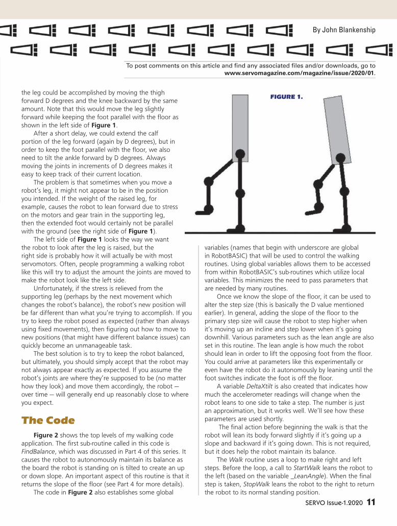
SERVO Issue-1.2020 11
the leg could be accomplished by moving the thigh
forward D degrees and the knee backward by the same
amount. Note that this would move the leg slightly
forward while keeping the foot parallel with the fl oor as
shown in the left side of Figure 1.
After a short delay, we could extend the calf
portion of the leg forward (again by D degrees), but in
order to keep the foot parallel with the fl oor, we also
need to tilt the ankle forward by D degrees. Always
moving the joints in increments of D degrees makes it
easy to keep track of their current location.
The problem is that sometimes when you move a
robot’s leg, it might not appear to be in the position
you intended. If the weight of the raised leg, for
example, causes the robot to lean forward due to stress
on the motors and gear train in the supporting leg,
then the extended foot would certainly not be parallel
with the ground (see the right side of Figure 1).
The left side of Figure 1 looks the way we want
the robot to look after the leg is raised, but the
right side is probably how it will actually be with most
servomotors. Often, people programming a walking robot
like this will try to adjust the amount the joints are moved to
make the robot look like the left side.
Unfortunately, if the stress is relieved from the
supporting leg (perhaps by the next movement which
changes the robot’s balance), the robot’s new position will
be far different than what you’re trying to accomplish. If you
try to keep the robot posed as expected (rather than always
using fi xed movements), then fi guring out how to move to
new positions (that might have different balance issues) can
quickly become an unmanageable task.
The best solution is to try to keep the robot balanced,
but ultimately, you should simply accept that the robot may
not always appear exactly as expected. If you assume the
robot’s joints are where they’re supposed to be (no matter
how they look) and move them accordingly, the robot —
over time — will generally end up reasonably close to where
you expect.
The Code
Figure 2 shows the top levels of my walking code
application. The fi rst sub-routine called in this code is
FindBalance, which was discussed in Part 4 of this series. It
causes the robot to autonomously maintain its balance as
the board the robot is standing on is tilted to create an up
or down slope. An important aspect of this routine is that it
returns the slope of the fl oor (see Part 4 for more details).
The code in Figure 2 also establishes some global
variables (names that begin with underscore are global
in RobotBASIC) that will be used to control the walking
routines. Using global variables allows them to be accessed
from within RobotBASIC’s sub-routines which utilize local
variables. This minimizes the need to pass parameters that
are needed by many routines.
Once we know the slope of the fl oor, it can be used to
alter the step size (this is basically the D value mentioned
earlier). In general, adding the slope of the fl oor to the
primary step size will cause the robot to step higher when
it’s moving up an incline and step lower when it’s going
downhill. Various parameters such as the lean angle are also
set in this routine. The lean angle is how much the robot
should lean in order to lift the opposing foot from the fl oor.
You could arrive at parameters like this experimentally or
even have the robot do it autonomously by leaning until the
foot switches indicate the foot is off the fl oor.
A variable DeltaXtilt is also created that indicates how
much the accelerometer readings will change when the
robot leans to one side to take a step. The number is just
an approximation, but it works well. We’ll see how these
parameters are used shortly.
The fi nal action before beginning the walk is that the
robot will lean its body forward slightly if it’s going up a
slope and backward if it’s going down. This is not required,
but it does help the robot maintain its balance.
The Walk routine uses a loop to make right and left
steps. Before the loop, a call to StartWalk leans the robot to
the left (based on the variable _LeanAngle). When the fi nal
step is taken, StopWalk leans the robot to the right to return
the robot to its normal standing position.
By John Blankenship
Experimenting with Walking
Part 5
FIGURE 1.
To post comments on this article and fi nd any associated fi les and/or downloads, go to
www.servomagazine.com/magazine/issue/2020/01.

12 SERVO Issue-1.2020
Taking Steps
The difficult work is performed by the routine TakeStep
which can perform either a right or left step. In either
case, TakeStep assumes that the robot is already leaning
appropriately, so that the stepping foot is off the ground.
The routine ends with the robot leaning in the opposite
direction, so it’s
prepared for the
next step. The actual
step is accomplished
by calling four
routines as shown
in Figure 3. These
four routines will
move the stepping
leg forward, bring
the body forward
over the stepping
foot, lean the robot
back to the center
to regain a good
balance, and finally
sub LegForward(leg)
amount = _StepSize
gosub InitServoNames
call FromCurServoPos(leg+1,amount)
delay 300
call FromCurServoPos(leg+3,5) // raise toe slightly to prevent stubbing
call FromCurServoPos(leg+2,-amount)
if leg = RGT
call BalanceWithArms(100-_DeltaXtilt,_DesiredYtilt)
else
call BalanceWithArms(100+_DeltaXtilt,_DesiredYtilt)
endif
delay 500
call FromCurServoPos(leg+2,amount)
call FromCurServoPos(leg+3,-amount-5) // lowers toe
call BalanceWithArms(100,_DesiredYtilt)
return
Application:
gosub InitApplication
delay 500
// local variables to control walking
_DesiredXtilt = 100 // used for balance with arms
_DesiredYtilt = 100
_LeanAngle = 12
_PrimaryStepSize = 25
call FindBalance(CurSlope)
_CurrentSlope=CurSlope
_StepSize = _PrimaryStepSize+_CurrentSlope // Step higher going up hills (lower/down)
_DesiredYtilt+=_CurrentSlope
_DeltaXtilt = _LeanAngle/5
// adjust body for hill walking
call FromCurServoPos(Rthigh,_CurrentSlope) // lean back going down slope
call FromCurServoPos(Lthigh,_CurrentSlope) // and forward going up
delay 500
call Walk(4) // 4 steps
return
sub Walk(Num)
gosub InitServoNames
gosub StartWalk
delay 1000
stepping _MODE
for i=1 to Num
call TakeStep(RGT)
call TakeStep(LFT)
next
gosub StopWalk
return
FIGURE 4.
sub TakeStep(leg)
call LegForward(leg)
call BodyForwardOverFoot(leg)
call LeanToCenter(leg)
call StartOpStepPosition(leg)
return
FIGURE 3.
FIGURE 2.

SERVO Issue-1.2020 13
lean further so the robot is ready to step
with the opposite leg.
Moving the Leg Forward
The routine LegForward is shown in
Figure 4. It uses the leg value passed to
it to access the different joints (+1 is the
thigh, +2 is the knee, and +3 is the F/R
ankle). In keeping with the philosophy
discussed earlier, all joints are moved
based on the current step size.
Notice also that the toe is raised
slightly at one point to help prevent
it from stubbing (in case the robot is
leaning forward as depicted by Figure
1), and then lowered again at the end
of the routine. Notice also that the final
line in this routine moves the arms to
improve the robot’s balance.
Executing this routine puts the
robot in the position shown in Figure
5. Notice the knee and ankle joints are
now in a straight line, extending the
foot forward.
Moving the Body Forward
The routine in Figure 6 moves the
robot’s body over the stepping leg.
Because the robot is balanced on one
foot while this is happening, the step-
sized movements are divided into smaller
actions and performed within a loop.
The use of RobotBASIC’s modulo
operator (#) and integer divide ensures
that each movement is fully completed.
Notice that the arms are used to help
maintain balance as the movement
progresses.
Figure 7 shows how the robot will
appear after this routine is executed. This
pose looks very much like Figure 5, but
the body is definitely forward. Compare
the knee and ankle joints in Figures 5
and 7. The camera angle makes these
differences very easy to see.
Leaning Back to Center
At this point in the sequence, the
sub BodyForwardOverFoot(leg)
gosub InitServoNames
SS = _StepSize
if leg=RGT
call FromCurServoPos(Rknee,-SS#4)
call FromCurServoPos(Rankle,SS#4)
call FromCurServoPos(Lthigh,-SS#4)
call FromCurServoPos(Lknee,SS#4)
for i=1 to 4
call FromCurServoPos(Rknee,-SS/4)
call FromCurServoPos(Rankle,SS/4)
call FromCurServoPos(Lthigh,-SS/4)
call FromCurServoPos(Lknee,SS/4)
call BalanceWithArms(100-_DeltaXtilt,_DesiredYtilt)
next
elseif leg=LFT
call FromCurServoPos(Lknee,-SS#4)
call FromCurServoPos(Lankle,SS#4)
call FromCurServoPos(Rthigh,-SS#4)
call FromCurServoPos(Rknee,SS#4)
for i=1 to 4
call FromCurServoPos(Lknee,-SS/4)
call FromCurServoPos(Lankle,SS/4)
call FromCurServoPos(Rthigh,-SS/4)
call FromCurServoPos(Rknee,SS/4)
call BalanceWithArms(100+_DeltaXtilt,_DesiredYtilt)
next
call
endif
return
FIGURE 5.
FIGURE 6.
FIGURE 7.

14 SERVO Issue-1.2020
robot is still leaning to one side, so it needs to move its
weight back toward the stepping foot. Figure 8 shows how
this is accomplished.
Basically, it shortens the leg the robot is currently
standing on in order to lower the stepping foot to the
ground. You might think the amount of this lowering would
change if the robot is moving on an incline. The reason it
doesn’t is because we have the robot taking a bigger (thus
higher) step when it’s walking up an incline and a smaller
(lower) step when it’s going downward.
This adjustment to the step size means the stepping
foot will be approximately the same distance from the floor
regardless of the terrain’s slope. This means we can always
lower the robot a proper amount by moving the joints in
the supporting leg by the _PrimaryStepSize initialized earlier
(this is the step size for level terrain). Figure 9 shows how
the robot will be positioned after this routine is executed.
Notice the robot is
well balanced, but
the stepping foot
is forward in the
stance.
The action
of lowering the
stepping leg to the
ground is much
different than
letting the robot’s
weight pull the
body forward onto
that leg.
This action
helps the robot
maintain its
balance and is a
vital move when
walking up and
down inclines.
sub StartOpStepPosition(leg)
gosub InitServoNames
if leg=RGT
OpLeg = LFT
else
OpLeg = RGT
endif
call Lean(leg,_LeanAngle/2)
call FromCtrServoPos(leg+2,0) // 0 forces startup angles
call FromCtrServoPos(leg+1,-_CurrentSlope) // maintains body tilt for
call FromCtrServoPos(OpLeg+1,-_CurrentSlope) // navigating a slope
call FromCtrServoPos(OpLeg+2,0)
call FromCtrServoPos(OpLeg+3,0)
call Lean(leg,_LeanAngle/2)
// balance based on current lean direction
if leg = LFT
call BalanceWithArms(100-_DeltaXtilt,_DesiredYtilt)
else
call BalanceWithArms(100+_DeltaXtilt,_DesiredYtilt)
endif
delay 500
return
sub LeanToCenter(leg)
gosub InitServoNames
if leg=RGT
OpLeg = LFT
else
OpLeg = RGT
endif
call ShortenLegForStep(OpLeg,_PrimaryStepSize#4)
delay 100
call Lean(leg,_LeanAngle#4)
call BalanceWithArms(_DesiredXtilt,_DesiredYtilt)
for i=1 to 4
call ShortenLegForStep(OpLeg,_PrimaryStepSize/4)
delay 100
call Lean(leg,_LeanAngle/4)
call BalanceWithArms(_DesiredXtilt,_DesiredYtilt)
next
delay 300
return
FIGURE 10.
FIGURE 8.
FIGURE 9.

SERVO Issue-1.2020 15
Preparing to Step with the Opposite Leg
With the robot balanced on
two feet again, the next action is
for the robot to lean away from
the leg that will make the next
step. Figure 10 shows how this is
accomplished.
In this routine, all the joints
are reset to their original balanced
position (as was established by
StartWalk, except that the robot
may be leaning either left or
right depending on which foot
is stepping). This always leaves
the robot ready to proceed with
the next step or to return to the
normal standing position.
Figure 11 shows how the
robot is positioned after this
routine is executed.
Conclusion
Programming hobby-
oriented walking robots can be
both frustrating and rewarding.
Experimenting with a variety of
movements can greatly improve
your understanding of the
problems and ultimately help you
find innovative solutions. Here’s a
YouTube video demonstrating my
robot in action: https://youtu.
be/LB_uBJh5bQ8.
Watching it actively balance
as it walks on different slopes
should be exciting for anyone who
understands how difficult this
project is. I’m sure that fine-tuning
properties such as delays, motor
speeds, and balancing algorithms
could greatly improve the robot’s
performance, but at least for now,
such modifications will be left for
the motivated reader. SV
FIGURE 11.

16 SERVO Issue-1.202016
Goal Prediction Using AI
From this article, you’ll discover the basics of machine learning and the
power of what machine learning can do. I’ll discuss the implementation
of different machine learning algorithms for predicting a simple binary
classifi cation. This article is mainly focused on beginners who are very
new to machine learning. I’ll show you how to use different algorithms
on predicting if a goal has been scored or not by Cristiano Ronaldo — the
famous Portuguese professional footballer who plays as a forward for
Serie A club Juventus and captains the Portugal national team. He is often
considered the best player in the world and widely regarded as one of the
greatest players of all time.
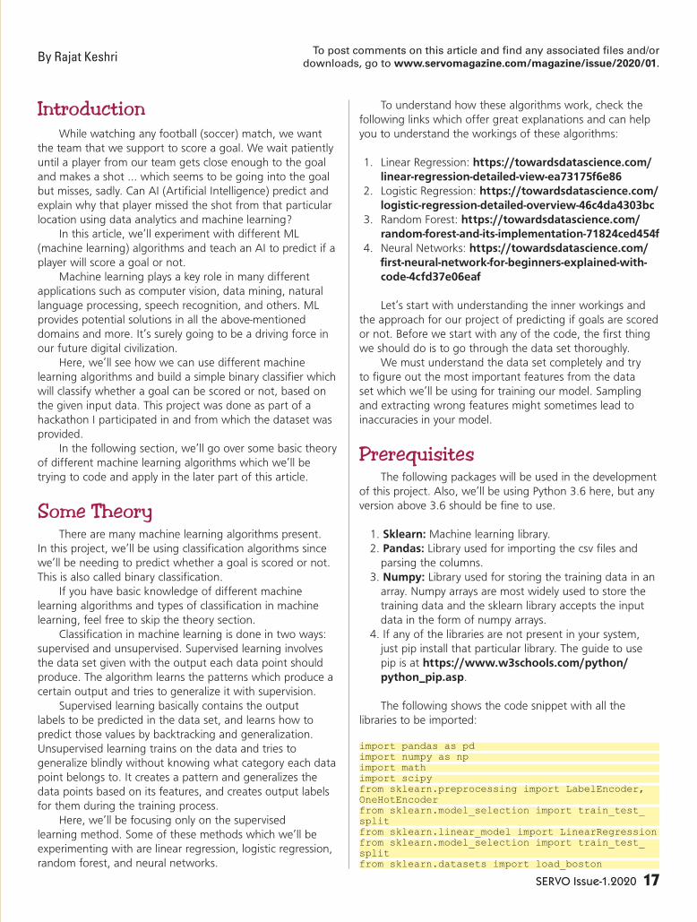
SERVO Issue-1.2020 17
IntroductionWhile watching any football (soccer) match, we want
the team that we support to score a goal. We wait patiently
until a player from our team gets close enough to the goal
and makes a shot ... which seems to be going into the goal
but misses, sadly. Can AI (Artificial Intelligence) predict and
explain why that player missed the shot from that particular
location using data analytics and machine learning?
In this article, we’ll experiment with different ML
(machine learning) algorithms and teach an AI to predict if a
player will score a goal or not.
Machine learning plays a key role in many different
applications such as computer vision, data mining, natural
language processing, speech recognition, and others. ML
provides potential solutions in all the above-mentioned
domains and more. It’s surely going to be a driving force in
our future digital civilization.
Here, we’ll see how we can use different machine
learning algorithms and build a simple binary classifier which
will classify whether a goal can be scored or not, based on
the given input data. This project was done as part of a
hackathon I participated in and from which the dataset was
provided.
In the following section, we’ll go over some basic theory
of different machine learning algorithms which we’ll be
trying to code and apply in the later part of this article.
Some TheoryThere are many machine learning algorithms present.
In this project, we’ll be using classification algorithms since
we’ll be needing to predict whether a goal is scored or not.
This is also called binary classification.
If you have basic knowledge of different machine
learning algorithms and types of classification in machine
learning, feel free to skip the theory section.
Classification in machine learning is done in two ways:
supervised and unsupervised. Supervised learning involves
the data set given with the output each data point should
produce. The algorithm learns the patterns which produce a
certain output and tries to generalize it with supervision.
Supervised learning basically contains the output
labels to be predicted in the data set, and learns how to
predict those values by backtracking and generalization.
Unsupervised learning trains on the data and tries to
generalize blindly without knowing what category each data
point belongs to. It creates a pattern and generalizes the
data points based on its features, and creates output labels
for them during the training process.
Here, we’ll be focusing only on the supervised
learning method. Some of these methods which we’ll be
experimenting with are linear regression, logistic regression,
random forest, and neural networks.
To understand how these algorithms work, check the
following links which offer great explanations and can help
you to understand the workings of these algorithms:
1. Linear Regression: https://towardsdatascience.com/
linear-regression-detailed-view-ea73175f6e86
2. Logistic Regression: https://towardsdatascience.com/
logistic-regression-detailed-overview-46c4da4303bc
3. Random Forest: https://towardsdatascience.com/
random-forest-and-its-implementation-71824ced454f
4. Neural Networks: https://towardsdatascience.com/
first-neural-network-for-beginners-explained-with-
code-4cfd37e06eaf
Let’s start with understanding the inner workings and
the approach for our project of predicting if goals are scored
or not. Before we start with any of the code, the first thing
we should do is to go through the data set thoroughly.
We must understand the data set completely and try
to figure out the most important features from the data
set which we’ll be using for training our model. Sampling
and extracting wrong features might sometimes lead to
inaccuracies in your model.
PrerequisitesThe following packages will be used in the development
of this project. Also, we’ll be using Python 3.6 here, but any
version above 3.6 should be fine to use.
1. Sklearn: Machine learning library.
2. Pandas: Library used for importing the csv files and
parsing the columns.
3. Numpy: Library used for storing the training data in an
array. Numpy arrays are most widely used to store the
training data and the sklearn library accepts the input
data in the form of numpy arrays.
4. If any of the libraries are not present in your system,
just pip install that particular library. The guide to use
pip is at https://www.w3schools.com/python/
python_pip.asp.
The following shows the code snippet with all the
libraries to be imported:
import pandas as pdimport numpy as npimport mathimport scipyfrom sklearn.preprocessing import LabelEncoder, OneHotEncoderfrom sklearn.model_selection import train_test_splitfrom sklearn.linear_model import LinearRegressionfrom sklearn.model_selection import train_test_splitfrom sklearn.datasets import load_boston
To post comments on this article and find any associated files and/or
downloads, go to www.servomagazine.com/magazine/issue/2020/01.By Rajat Keshri

18 SERVO Issue-1.2020
from sklearn.metrics import mean_squared_errorfrom scipy.stats import spearmanrfrom sklearn.ensemble import RandomForestClassifierfrom sklearn.preprocessing import scalefrom sklearn.linear_model import LogisticRegressionfrom sklearn.model_selection import train_test_splitfrom sklearn import preprocessingfrom sklearn import svmfrom sklearn.ensemble import RandomForestClassifierfrom sklearn.neural_network import MLPClassifier
Dataset PreprocessingThe data set used here is a csv file with information
about different matches played by Real Madrid against
different teams. The data set contains different fields
describing the goal scored by Ronaldo at different situations
and scenarios, like what time was the goal scored, how
much distance from the goal, what was the shot power,
what angle did he score at, etc. As mentioned before, this
data set was given to me during a hackathon, so I’m not
sure if it’s publicly available on Kaggle or any other website.
Either way, the data set is included in the article downloads
or you can get it from https://github.com/rajatkeshri/ZS-
HACK-predict-ronaldo-goal.
Figure 1 shows some of the columns for the data set.
From the data set, we’ll be using the following columns as
input data: location_x, location_y, power_of_shot, distance_
of_shot, remaining_sec, and is_goal column as the output
label. You can use the other fields for training the model and
experimenting with it, but in this article, I’ll just explain the
use of the input field data columns listed above.
You’ll notice there are many fields which are empty and
there’s a lot of noise in this data set. Our first step is to go
through the data set and fix the noisy data and remove all
the empty fields.
Let’s jump to the code now. First, we open the data set
csv file using pandas and define the columns which act as
the input data and the columns which are the output labels
for training.
Here, column 10 is the “is_goal” column which acts like
the output label and 2,3,4,5,9 columns are the input labels
location_x, location_y, remaining_sec, power_of_shot, and
distance_of_shot, respectively. If you want to try training
your model with other feature columns from the data.csv,
then just add those column numbers in the array.
datasets = pd.read_csv(‘data.csv’)output=pd.DataFrame(datasets)cols = [10]output = output[output.columns[cols]]df = pd.DataFrame(datasets)cols = [2,3,4,5,9]df = df[df.columns[cols]]
Once we have read the features from the csv files,
we must go through and remove all the noise from these
columns. We loop through the features and check if a
particular value for that column if NAN or not. If it’s NAN,
we drop the entire row, removing the entire noisy data.
Once the noisy data is removed, we store the entire 2D
array of multiple column features in variables X and Y:
#Removing rows with Output label not definedk=0x=[]for i in df[“is_goal”]: if math.isnan(i): x.append(k) #print(i) k+=1df=(df.drop(x))#Removing rows with distance of shot not definedk=0x=[]for i in df[“distance_of_shot”]: if math.isnan(i): x.append(df.index[k]) #print(i) k+=1df=(df.drop(x))#Removing rows with power of shot not definedk=0
Figure 1. Dataset in csv format.
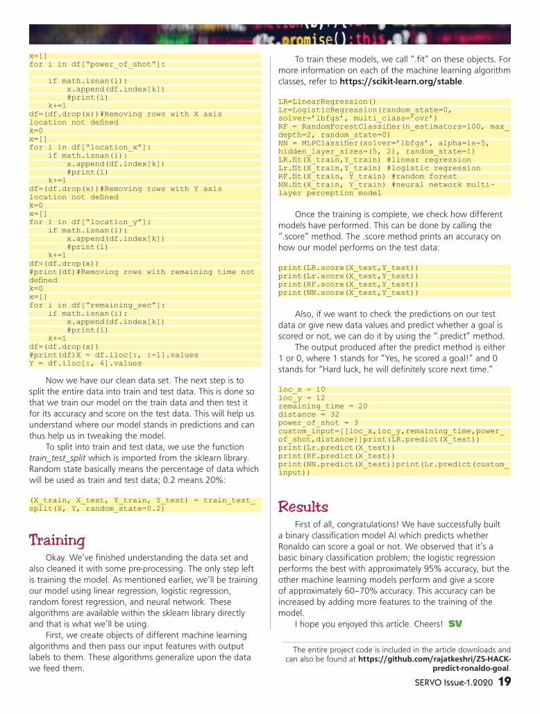
SERVO Issue-1.2020 19
x=[]for i in df[“power_of_shot”]: if math.isnan(i): x.append(df.index[k]) #print(i) k+=1df=(df.drop(x))#Removing rows with X axis location not definedk=0x=[]for i in df[“location_x”]: if math.isnan(i): x.append(df.index[k]) #print(i) k+=1df=(df.drop(x))#Removing rows with Y axis location not definedk=0x=[]for i in df[“location_y”]: if math.isnan(i): x.append(df.index[k]) #print(i) k+=1df=(df.drop(x))#print(df)#Removing rows with remaining time not definedk=0x=[]for i in df[“remaining_sec”]: if math.isnan(i): x.append(df.index[k]) #print(i) k+=1df=(df.drop(x))#print(df)X = df.iloc[:, :-1].valuesY = df.iloc[:, 4].values
Now we have our clean data set. The next step is to
split the entire data into train and test data. This is done so
that we train our model on the train data and then test it
for its accuracy and score on the test data. This will help us
understand where our model stands in predictions and can
thus help us in tweaking the model.
To split into train and test data, we use the function
train_test_split which is imported from the sklearn library.
Random state basically means the percentage of data which
will be used as train and test data; 0.2 means 20%:
(X_train, X_test, Y_train, Y_test) = train_test_split(X, Y, random_state=0.2)
TrainingOkay. We’ve finished understanding the data set and
also cleaned it with some pre-processing. The only step left
is training the model. As mentioned earlier, we’ll be training
our model using linear regression, logistic regression,
random forest regression, and neural network. These
algorithms are available within the sklearn library directly
and that is what we’ll be using.
First, we create objects of different machine learning
algorithms and then pass our input features with output
labels to them. These algorithms generalize upon the data
we feed them.
To train these models, we call “.fit” on these objects. For
more information on each of the machine learning algorithm
classes, refer to https://scikit-learn.org/stable.
LR=LinearRegression()Lr=LogisticRegression(random_state=0, solver=’lbfgs’, multi_class=’ovr’)RF = RandomForestClassifier(n_estimators=100, max_depth=2, random_state=0)NN = MLPClassifier(solver=’lbfgs’, alpha=1e-5, hidden_layer_sizes=(5, 2), random_state=1)LR.fit(X_train,Y_train) #linear regressionLr.fit(X_train,Y_train) #logistic regressionRF.fit(X_train, Y_train) #random forestNN.fit(X_train, Y_train) #neural network multi-layer perception model
Once the training is complete, we check how different
models have performed. This can be done by calling the
“.score” method. The .score method prints an accuracy on
how our model performs on the test data:
print(LR.score(X_test,Y_test))print(Lr.score(X_test,Y_test))print(RF.score(X_test,Y_test))print(NN.score(X_test,Y_test))
Also, if we want to check the predictions on our test
data or give new data values and predict whether a goal is
scored or not, we can do it by using the “.predict” method.
The output produced after the predict method is either
1 or 0, where 1 stands for “Yes, he scored a goal!” and 0
stands for “Hard luck, he will definitely score next time.”
loc_x = 10loc_y = 12remaining_time = 20distance = 32power_of_shot = 3custom_input=[[loc_x,loc_y,remaining_time,power_of_shot,distance]]print(LR.predict(X_test))print(Lr.predict(X_test))print(RF.predict(X_test))print(NN.predict(X_test))print(Lr.predict(custom_input))
ResultsFirst of all, congratulations! We have successfully built
a binary classification model AI which predicts whether
Ronaldo can score a goal or not. We observed that it’s a
basic binary classification problem; the logistic regression
performs the best with approximately 95% accuracy, but the
other machine learning models perform and give a score
of approximately 60–70% accuracy. This accuracy can be
increased by adding more features to the training of the
model.
I hope you enjoyed this article. Cheers! SV
The entire project code is included in the article downloads and can also be found at https://github.com/rajatkeshri/ZS-HACK-
predict-ronaldo-goal.

botsIN BRIEF
Researchers at the
Université de Sherbrooke in
Canada developed a waist-
mounted hydraulic arm that
can help you with all kinds
of tasks.
Photos courtesy of
Université de Sherbrooke.
The researchers envision a number of
applications for their supernumerary arm,
including: vegetable picking (a, b); painting a wall
(c); washing a window (d); handing tools to a
worker (e, f); and playing badminton (g).
Armed and Dangerous?
Researchers from Université de Sherbrooke
in Canada have designed a waist-mounted,
remote controlled hydraulic arm that can help
you with all kinds of tasks. Oh, and you can
smash through walls with it too.
This type of wearable robotic arm is
known as “supernumerary.” The system
created by the Canadian researchers (in
partnership with Exonetik) has three
degrees of freedom and is actuated by
magnetorheological clutches and hydrostatic
transmissions with the goal of “mimicking the
performance of a human arm in a multitude
of industrial and domestic applications.” (Like
wall punching.)
The hydraulic system provides
comparatively high power, but the power
system itself is connected to the user through
a tether, minimizing how much mass the user
has to actually wear (and keeping the inertia of the arm low) while also limiting mobility somewhat.
Off-board power does put a bit of a dampener on the superhero potential, but in practical
terms, users aren’t likely to be moving around all that much. If they are, mobile options could include
being tethered to an autonomous vehicle that follows you around or perhaps a more portable
backpack power unit.
The robotic arm itself weighs just over four kilograms — about the same as a real human arm.
It can lift 5 kg and has a maximum end effector speed of 3.4 meters per second, with a workspace
that’s restricted to keep it from smashing you into a wall.
At the moment, there isn’t much in the way of autonomy since the arm is being controlled by a
second human via a miniature handheld arm in a master-slave configuration. The researchers suggest
that adding some sensors could allow the arm to do things like pick vegetables next to the user, as
well as do more collaborative tasks like providing tool assistance.
You can think of it as being able to act as a co-worker, either directly increasing productivity by
performing the same task as the user in parallel, or doing some different tasks in order to free up
the user to do
stuff that requires
creativity or
judgement.
20 SERVO Issue-1.2020

bots IN BRIEF
About the size of a penny, HAMR-Jr is one of the smallest and
fastest insect-scale robots, capable of running at nearly 14 body
lengths (30 centimeters) per second. Photo courtesy of Kaushik
Jayaram/University of Colorado Boulder/Harvard SEAS.
Georgia Tech roboticists
are exploring the idea
of “slowness as a design
paradigm” through an
arboreal robot called
SlothBot.
Photo courtesy of
Georgia Tech.
HAMR-Jr Time
The Harvard Ambulatory MicroRobot
(HAMR) was a bit chunky back in 2018,
measuring about five centimeters long and
weighing around three grams. However, a new
version of HAMR has been introduced. Called
HAMR-Jr, it’s significantly smaller at just a
tenth of the weight and it comes up to about
knee-high on a cockroach.
HAMR-Jr may be tiny, but it’s no slouch.
Piezoelectric actuators can drive it at nearly
14 body lengths (30 cm) per second, at a gait
frequency of 200 Hz. The actuators can be
cranked up even more approaching 300 Hz,
but the robot actually slows down past 200
Hz because it turns out that 200 Hz hits a
sort of resonant sweet spot that gives the
robot as much leg lift and stride length as
possible.
Slow as a SlothBot
We tend to focus on motion a lot with robots,
and the most dynamic robots get the most
attention. This isn’t to say that highly dynamic
robots don’t deserve our attention, but there are
other robotic philosophies that, while perhaps less
visually exciting, are equally valuable under the right
circumstances.
Magnus Egerstedt, a robotics professor at
Georgia Tech, was inspired by some sloths he met
in Costa Rica to explore the idea of “slowness as a
design paradigm” through an arboreal robot called
SlothBot.
Since the robot moves so slowly, why use a
robot at all you ask. It may be very energy-efficient,
but it’s definitely not more energy efficient than a
static sensing system that’s just bolted to a tree for example. The robot moves but it’s also going to be
much more expensive (and likely much less reliable) than a handful of static sensors that could cover
a similar area. The problem with static sensors, though, is that they’re constrained by power availability,
and in environments like under a dense tree canopy, you’re not going to be able to augment their
lifetime with solar panels.
If your goal is a long duration study of a small area (over weeks or months or more), SlothBot
is uniquely useful in this context because it can crawl out from beneath a tree to find some sun to
recharge itself, then crawl right back again to resume collecting data.
SERVO Issue-1.2020 21
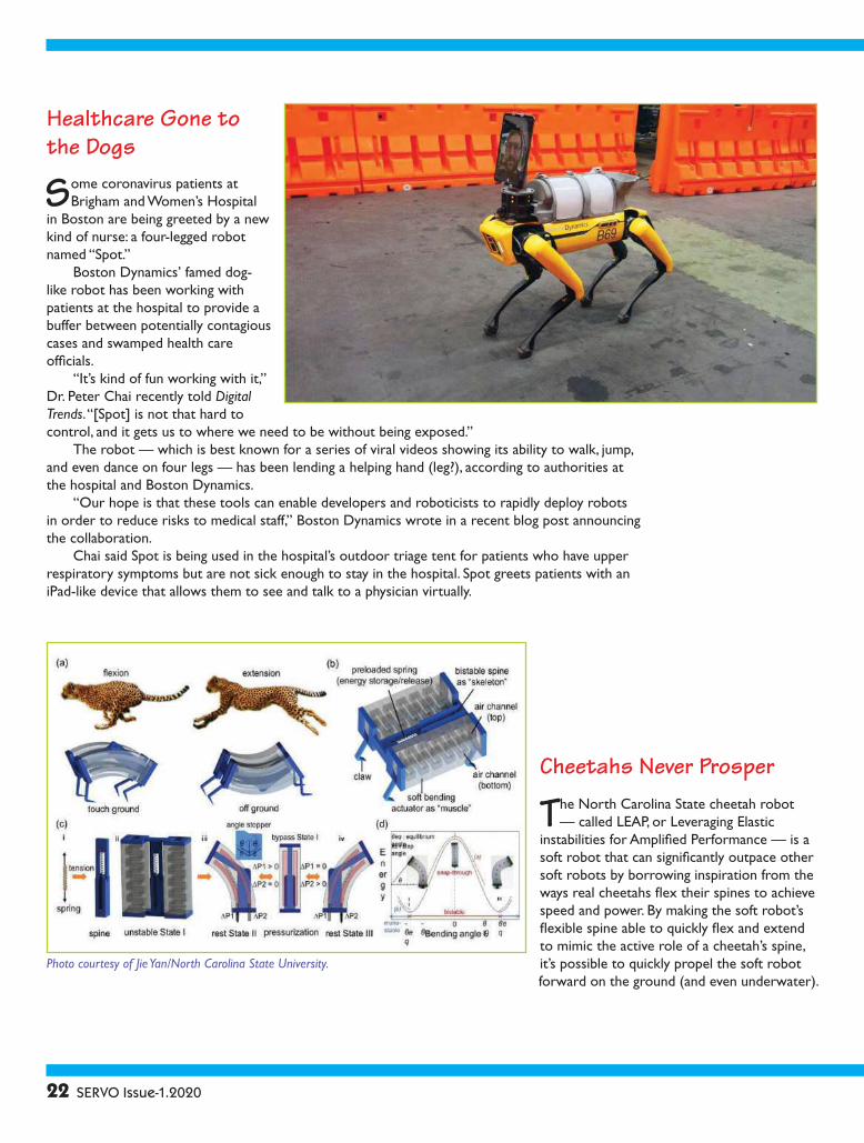
Cheetahs Never Prosper
The North Carolina State cheetah robot
— called LEAP, or Leveraging Elastic
instabilities for Amplified Performance — is a
soft robot that can significantly outpace other
soft robots by borrowing inspiration from the
ways real cheetahs flex their spines to achieve
speed and power. By making the soft robot’s
flexible spine able to quickly flex and extend
to mimic the active role of a cheetah’s spine,
it’s possible to quickly propel the soft robot
forward on the ground (and even underwater).
Healthcare Gone to the Dogs
Some coronavirus patients at
Brigham and Women’s Hospital
in Boston are being greeted by a new
kind of nurse: a four-legged robot
named “Spot.”
Boston Dynamics’ famed dog-
like robot has been working with
patients at the hospital to provide a
buffer between potentially contagious
cases and swamped health care
officials.
“It’s kind of fun working with it,”
Dr. Peter Chai recently told Digital
Trends. “[Spot] is not that hard to
control, and it gets us to where we need to be without being exposed.”
The robot — which is best known for a series of viral videos showing its ability to walk, jump,
and even dance on four legs — has been lending a helping hand (leg?), according to authorities at
the hospital and Boston Dynamics.
“Our hope is that these tools can enable developers and roboticists to rapidly deploy robots
in order to reduce risks to medical staff,” Boston Dynamics wrote in a recent blog post announcing
the collaboration.
Chai said Spot is being used in the hospital’s outdoor triage tent for patients who have upper
respiratory symptoms but are not sick enough to stay in the hospital. Spot greets patients with an
iPad-like device that allows them to see and talk to a physician virtually.
Photo courtesy of Jie Yan/North Carolina State University.
22 SERVO Issue-1.2020

Do the Worm
General Electric is getting into giant robot
earthworms.While this might sound unlikely, GE’s
research division has landed a big $2.5 million award
from the Defense Advanced Research Projects Agency
(DARPA) to ensure the project continues crawling
along.
“What makes this so unique is that we’re really
drawing inspiration from two sources in nature: the
earthworm and tree roots,” Deepak Trivedi, who is
leading this project for GE Research, recently told
Digital Trends. “From the earthworm, we’re mimicking
its fast rhythmic movements to rapidly and efficiently
form the tunnels we’re trying to form. And from the
tree roots, we’re mimicking [their] scale and ability to create large force by studying how roots grow into the
ground. It’s the combination of these two forces of nature that makes our project — and robot — so unique.”
The soft robot tunneler is made up of large segmented pieces which act like the fluid-filled “hydrostatic
skeleton” found in invertebrates. The robot’s artificial muscles move like a real earthworm’s in order to
propel it forward, while the segmented design also gives it impressive freedom of movement and the ability to
maneuver into difficult-to-reach places.
Bot or Not?
For the past several years, there’s been heightened
concern about the impact of so-called bots on
platforms like Twitter. A bot in this context is a fake
account synonymous with helping to spread fake news
or misinformation online.
So, how exactly do you tell the difference between
an actual human user and a bot? While clues such as
the use of the basic default “egg” avatar by Twitter,
a username consisting of long strings of numbers,
and a penchant for tweeting about certain topics
might provide a few pointers. However, that’s hardly
conclusive evidence.
That’s the challenge a recent project from a pair of researchers at the University of Southern
California and University of London set out to solve. They have created an AI that’s designed to sort fake
Twitter accounts from the real ones based on their patterns of online behavior.
“Detecting bots can be very challenging as they continuously evolve and become more
sophisticated,” Emilio Ferrara, research assistant professor in the USC Department of Computer Science,
told Digital Trends recently. “Existing tools that work well with older and simpler types of bots are not
as accurate to predict more complex ones. So, it’s always exciting to identify new, previously unknown
characteristics of the behavior of human users that are not yet exhibited by bots. This could [be used to
help] improve the accuracy of detection tools.”
The researchers leveraged various datasets of hand-labeled examples of both fake and real Twitter
account messages produced by other researchers in the community. In total, they trained their system on
8.4 million tweets from 3,500 human accounts and an additional 3.4 million tweets from 5,000 bots. This
helped them to uncover a variety of insights into tweeting patterns.
For instance, human users are up to five times more likely to reply to messages. They also get
increasingly interactive with other users over the course of a long Twitter session, while the length of an
average tweet decreases during this same time frame. Bots, on the other hand, show no such changes.
SERVO Issue-1.2020 23
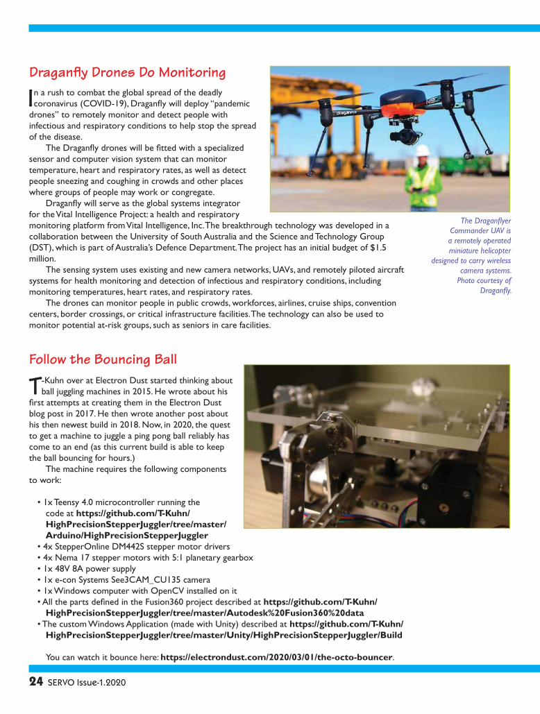
Follow the Bouncing Ball
T-Kuhn over at Electron Dust started thinking about
ball juggling machines in 2015. He wrote about his
first attempts at creating them in the Electron Dust
blog post in 2017. He then wrote another post about
his then newest build in 2018. Now, in 2020, the quest
to get a machine to juggle a ping pong ball reliably has
come to an end (as this current build is able to keep
the ball bouncing for hours.)
The machine requires the following components
to work:
• 1x Teensy 4.0 microcontroller running the
code at https://github.com/T-Kuhn/
HighPrecisionStepperJuggler/tree/master/
Arduino/HighPrecisionStepperJuggler
• 4x StepperOnline DM442S stepper motor drivers
• 4x Nema 17 stepper motors with 5:1 planetary gearbox
• 1x 48V 8A power supply
• 1x e-con Systems See3CAM_CU135 camera
• 1x Windows computer with OpenCV installed on it
• All the parts defined in the Fusion360 project described at https://github.com/T-Kuhn/
HighPrecisionStepperJuggler/tree/master/Autodesk%20Fusion360%20data
• The custom Windows Application (made with Unity) described at https://github.com/T-Kuhn/
HighPrecisionStepperJuggler/tree/master/Unity/HighPrecisionStepperJuggler/Build
You can watch it bounce here: https://electrondust.com/2020/03/01/the-octo-bouncer.
Draganfly Drones Do Monitoring
In a rush to combat the global spread of the deadly
coronavirus (COVID-19), Draganfly will deploy “pandemic
drones” to remotely monitor and detect people with
infectious and respiratory conditions to help stop the spread
of the disease.
The Draganfly drones will be fitted with a specialized
sensor and computer vision system that can monitor
temperature, heart and respiratory rates, as well as detect
people sneezing and coughing in crowds and other places
where groups of people may work or congregate.
Draganfly will serve as the global systems integrator
for the Vital Intelligence Project: a health and respiratory
monitoring platform from Vital Intelligence, Inc. The breakthrough technology was developed in a
collaboration between the University of South Australia and the Science and Technology Group
(DST), which is part of Australia’s Defence Department. The project has an initial budget of $1.5
million.
The sensing system uses existing and new camera networks, UAVs, and remotely piloted aircraft
systems for health monitoring and detection of infectious and respiratory conditions, including
monitoring temperatures, heart rates, and respiratory rates.
The drones can monitor people in public crowds, workforces, airlines, cruise ships, convention
centers, border crossings, or critical infrastructure facilities. The technology can also be used to
monitor potential at-risk groups, such as seniors in care facilities.
The Draganflyer
Commander UAV is
a remotely operated
miniature helicopter
designed to carry wireless
camera systems.
Photo courtesy of
Draganfly.
24 SERVO Issue-1.2020
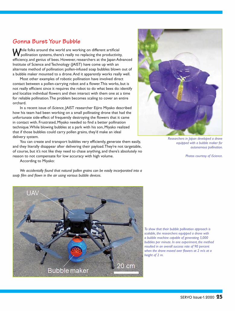
Researchers in Japan developed a drone
equipped with a bubble maker for
autonomous pollination.
Photos courtesy of iScience.
Gonna Burst Your Bubble
While folks around the world are working on different artificial
pollination systems, there’s really no replacing the productivity,
efficiency, and genius of bees. However, researchers at the Japan Advanced
Institute of Science and Technology (JAIST) have come up with an
alternate method of pollination: pollen-infused soap bubbles blown out of
a bubble maker mounted to a drone. And it apparently works really well.
Most other examples of robotic pollination have involved direct
contact between a pollen-carrying robot and a flower. This works, but is
not really efficient since it requires the robot to do what bees do: identify
and localize individual flowers and then interact with them one at a time
for reliable pollination. The problem becomes scaling to cover an entire
orchard.
In a recent issue of iScience, JAIST researcher Eijiro Miyako described
how his team had been working on a small pollinating drone that had the
unfortunate side-effect of frequently destroying the flowers that it came
in contact with. Frustrated, Miyako needed to find a better pollination
technique. While blowing bubbles at a park with his son, Miyako realized
that if those bubbles could carry pollen grains, they’d make an ideal
delivery system.
You can create and transport bubbles very efficiently, generate them easily,
and they literally disappear after delivering their payload. They’re not targetable,
of course, but it’s not like they need to chase anything, and there’s absolutely no
reason to not compensate for low accuracy with high volume.
According to Miyako:
We accidentally found that natural pollen grains can be easily incorporated into a
soap film and flown in the air using various bubble devices.
To show that their bubble pollination approach is
scalable, the researchers equipped a drone with
a bubble machine capable of generating 5,000
bubbles per minute. In one experiment, the method
resulted in an overall success rate of 90 percent
when the drone moved over flowers at 2 m/s at a
height of 2 m.
SERVO Issue-1.2020 25

NEW PRODUCTS36 Tooth Pinion Gear
The 36 tooth 8 mm REX bore pinion gear is now available from
goBILDA. The bore perfectly matches their 8 mm REX shafting to create a positive drive. While little work is left for the set screws, goBILDA put two of them in for good measure.
This particular gear is able to be meshed with an 84 tooth hub gear spaced 48 mm away for a 2.33:1 ratio, or it can mate to a 24 tooth gear to create a very compact 1.5:1 ratio only 24 mm apart. If your build provides the freedom to adjust the spacing between your gears, it’s able to mesh to any MOD 0.8 gear that suits your needs. The counterbore on the top side of the gear allows you to run right up against an 8 mm bearing without the use of a shim. Price is $8.99.
40 Tooth Pinion Gear
The 40 tooth 8 mm REX bore pinion gear is also now available from
goBILDA and perfectly matches the 8 mm REX shafting to create a positive drive as well. There are two set screws.
This gear is able to be meshed
with an 80 tooth hub gear spaced 48 mm away for a 2:1 ratio, or it can mate to a 20 tooth gear to create a very compact 2:1 ratio only 24 mm apart. If your build is able to adjust the spacing between your gears, it’s able to mesh to any MOD 0.8 gear you choose. The counterbore on the top side of this gear allows you to run right up against an 8 mm bearing without the use of a shim as well. Price is also $8.99.
30 Tooth Miter Gear
The 8 mm REX Bore Miter Gear from goBILDA is able to mate with any
other 2315 Series Miter Gear. A miter gear is a specific type of bevel gear.
Two mating miter gears create a 1:1 ratio, and transmit power at a 90 degree angle due to the 45 degree pitch cone angle.
The underneath side of this gear has been dished out to allow a thrust bearing to set the location of the gear (relative to the inside wall of an 1120 Series U-Channel) and counteract the potential spreading forces in the most extreme applications.
Additionally, the 32 mm shelf on the back will allow a 32 mm diameter component such as goRAIL, goTUBE, or a Sonic Hub to nest down in the cavity and fasten with M4 socket head screws. Price is $12.99.
38 mm Pitch Steel Set Screw Sprocket
This 10 tooth sprocket from goBILDA has a 6 mm D-bore to
perfectly match 6 mm D-shafting, as well as the D-shafts used on goBILDA’s 5202 Series Gear Motors. The steel construction provides excellent strength and wear resistance. Price is $7.99.
8 mm Pitch Steel Set Screw Sprocket
This 10 tooth sprocket from goBILDA has an 8 mm REX bore
to perfectly match their 8 mm REX shafting. Its steel construction also provides excellent strength and wear resistance. Price is $7.99 as well.
For further information, contact:
goBILDAwww.gobilda.com
26 SERVO Issue-1.2020

Learning Platform for Arduino
Dr. Duino has expanded its line of rapid learning and prototyping platforms with its latest Explorer edition and
an updated Pioneer version.Building and tinkering with electronics is much easier
with these Arduino compatible shields. They are complete compact learning and prototyping systems which are perfect for anyone interested in electronics.
Designed with the beginner in mind, the Pioneer Edition helps you easily learn about the world of electronics through
hands-on projects. Designed with the experienced user in mind, the Explorer edition helps you build and test your electronic concepts quickly.
It’s jam-packed with powerful features, which include:
• 128x64 line character and graphics OLED• Power options• Bluetooth LE• Prototyping area• Eight channel addressable LEDs• Mini breadboard• And more ...
The Pioneer is Arduino Uno compatible, while the Explorer is compatible with the Uno and Nano versions.
Expansion packs are also available for both the Pioneer and Explorer. Both platforms are currently on sale.
For further information, contact:
Dr. Duinowww.drduino.com
Programmable USB Keyboard Controller Module
Saelig Company, Inc., has introduced the KeyWarrior28: the smallest controller of the
KeyWarrior family with a great deal of functionality that is more than just standard keyboard functions.
The KeyWarrior28 — available as a 3.3V QFN28 chip or DIL28 module — controls up to 64 keys in an 8x8 matrix. Just a USB cable and the keys are connected to the module. The functionality of the keys is programmable via a USB port and stored in internal Flash memory. For instance, it can offer a key-operated mouse function or media and application controls like Play, Pause, Mute, Start Browser, etc.
Each individual key can be programmed with either a single key code, a key code plus a modifier (shift, ctrl, alt, gui), a macro, a mouse function, a media/application control, or an FN key. The two optional FN keys give the ability to switch to a second or third key layout.
Like the modifier keys, FN keys can be programmed to act as ‘locking’ or ‘sticky’ (locking, but only for the next key). This allows mode switching or single finger operation.
Each of the 19 macros can be programmed on to any of the keys. A maximum of 31 key codes can be in each macro. There are three different types of macros. A static macro acts as if all keys in the macro are pressed at the same time. Typing macros activate each code just momentarily. This allows repeating characters, special character use, and upper/lower case in the macro. Cell macros work like the text input on phones with numeric keypads. Pressing the key again removes the last character and replaces it with the next. The KeyWarrior28 works with existing system
drivers and does not require special software. Each unit has a unique serial number and a built-in counter to register the number of erase cycles. KeyWarrior modules and ICs are designed by Code Mercenaries. Pricing starts from $12.20.
For further information, contact:
Waterproof Smart Servos
Tthe DYNAMIXEL XW series of smart servos are ROBOTIS`first line of IP level models, featuring a certified
IP68 rating which means they’re good at one meter for a 24 hour duration. The servos are designed for use in wet environments, underwater, and any outdoor applications where a sealed servo is necessary. The XW series come with a separate waterproof cable and extension cable.
Features include:
Saelig Companywww.saelig.com
Continued on page 72
SERVO Issue-1.2020 27

28 SERVO Issue-1.2020
When I started my journey into building combat robots, I followed a guide published in the
Combat Zone section in one of the 2010 issues of SERVO to build an easy test box out of a steamer trunk.
This test box has served me faithfully for a few years now. However, it could only be used for basic drive testing or static weapon testing. There just wasn’t enough room to really drive around with a weapon running.
As my experience as a builder grew, so did the destructive power of my creations, until the little box couldn’t be relied on to contain them without signifi cant modifi cation.
It was time to build a bigger, better box. I had four goals I wanted to meet with my new box design:
1. I wanted it to be big enough to drive around.
2. I wanted it to be small enough
to be easily stored without disassembly.
3. I wanted it to be able to contain my bots if they smack the wall with the weapon running at full speed.
4. I wanted it to be dead simple to source and build.
The materials used include (https://pastebin.com/ZRVeNz9K):
• 4x 1”x6”x8’ lumber• 2x 24”x48” MDF sheets• 1x 48”x48”x1/4”
polycarbonate sheet• 8x 6”x24” sheet metal strips• 8x corner brackets• 2x utility hinges• 2x latches• 1x handle• 120x #8x3/4” screws
With the exception of the polycarbonate sheet, all the supplies could be obtained with a trip to my local hardware store.
The entire set of materials costs less than $300, with 70% of that cost being for the polycarbonate and metal
sheets to contain the power of the spinning weapons.
Construction
1. Cut the boards into eight 47.25” lengths.
2. Pre-drill and screw the corner brackets onto one end of each board.
3. Pre-drill and screw four of the boards together to make two 4’ square boxes.
4. Lay the polycarbonate on top of one of the boxes, then pre-drill and screw it to the top of the box, with the screws 12” apart at most.
5. Lay the two sheets of MDF on top of the other box (soon to be the bottom), and drill and screw them to the box like the polycarbonate. Then, fl ip the box over.
6. Drill two holes near each end of all eight sheet metal strips; close enough to be screwed to one of the bottom boards.
7. Pre-drill and screw all eight sheet metal strips to the inside of the MDF-fl oored box, with two strips overlapped to fi ll each side.
Building a Better Box
FEATURED FEATURED
THIS MONTHTHIS MONTH
28 Building a Better Building a Better
BoxBox
30 Stepping Stones — Stepping Stones —
The Story of Thunder The Story of Thunder
ChildChild
33 Bringing About the Bringing About the
ApocalypseApocalypse
By Ryan Clingman
Corner bracket installed on the end of a cut board.

SERVO Issue-1.2020 29
8. Lay the top box on top of the
bottom box.
9. Mount the hinges on the back
side where the two boxes meet,
12” from the ends.
10. Mount the latches on the front
side where the two boxes meet,
12” from the ends.
11. Mount the handle in the middle of
the front side of the box.
Congratulations! You’ve created
a simple and sturdy test box that
only required cutting a few boards to
length and screwing it all together!
The steel reinforced corners and
inner frame combined with the 1/4”
polycarbonate should make this test
box strong enough to survive rigorous
testing up to the Beetleweight class.
The inside is over 7” tall, which
should accommodate the majority of
Beetleweight designs, and the floor
space is enough that it could even be
used as an arena for 150g bots.
Happy testing! SV
To post comments on these
articles and find any associated
files and/or downloads, go to
www.servomagazine.com/
magazine/issue/2020/01.
Boards assembled to form a box.
Completed steel-reinforced
test box.

30 SERVO Issue-1.2020
After my first event in late
2012, I decided to get
started in the world of
Beetleweight combat
robots. Since I had no
fabrication skills or access to any
tools, one of my friends suggested I
purchase a kit from kitbots.com.
After looking at their selection, I
chose the chassis for a four-wheel brick
based on the Beetleweight Trilobite as
my introduction into the class.
After getting all the necessary
electronics and hardware, my dad
and I assembled it on the dining room
table a week before its first event:
Motorama 2013. The bot was named
Thunder Child, which came from the
fictional ironclad warship in H.G. Wells’
War of the Worlds.
The bot didn’t do so well. The
ESCs I purchased were too big for the
bot and drew way too much current,
which resulted in most of my bot’s
motors burning
out throughout
the competition.
Despite this issue, Thunder Child
managed to finish with a 1-2 record,
and won a grudge match held during
downtime.
After the event, I was given a lot
of advice from fellow builders. Thunder
Child would go on to compete at a
few events over the next two years
where it achieved minimal success,
usually getting knocked out of the
tournament with a single win.
The turning point for Thunder
Child came in summer 2015, when
another builder that lived 30 minutes
from me offered to help me out by
Stepping Stones —Stepping Stones — The Story of Thunder The Story of Thunder ChildChild By Nate Franklin
The new wedge didn’t last long, but it was a step
in the right direction.Thunder Child at its first event.

SERVO Issue-1.2020 31
making a steel wedge for Thunder
Child. With the kit’s CAD files freely
available for reference, he was able to
design a new attachment and taught
me how to make it. It was my first real
experience working with tools, but the
wedge turned out nicely.
The work paid off, and Thunder
Child placed third at Bot Blast 2015,
with the wedge coming in handy
when dealing with horizontal spinners.
Unfortunately, Thunder Child would
struggle in the next two events,
resulting in the wedge I had built
getting destroyed by a nasty vertical
spinner.
In 2016, Thunder Child found
success when Pete Smith (the owner
of Kitbots) sold me a wedge from the
BotKits D2 kits modified to fit Thunder
Child. I managed to pull off an
undefeated run at Bot Blast, and place
second at SWORD later that year.
The wedge worked extremely well
against horizontal spinners but was an
easy target for the new meta: vertical
spinners with wedglets.
I found the solution to the
problem when BotKits released their
Wolverine claws in 2017: S7 tool
steel wedglets designed for fighting
vertical spinners and other wedges.
After finding out that the claws used
the same size hole for the mounting
that the Trilobite kits use, I instantly
purchased a pair.
With Thunder Child now able
to swap to different attachments
depending on the opponent, I chose
to replace the stock titanium axle with
shaft collars with a grade 8 hex bolt
and lock nut.
This allowed for easier attachment
swapping since I didn’t need to worry
about applying Loctite to any set
screws. However, it came at the cost
First place and best driver at Bot
Blast 2016 with the D2 wedge.
The anti-D2 wheels (only used
once) and wedglets.
Original titanium axle and shaft collars (top) and new grade 8 bolt
and lock nut (bottom).

32 SERVO Issue-1.2020
of an additional ounce in weight.
Thunder Child entered 2018 by
placing fi fth at Motorama, stopped
only by a broken soldering joint. Things
were looking up, as I had also started
learning computer-aided design (CAD).
My fi rst big project for Thunder
Child was creating a set of wedglets
designed to fi ght D2 kits, which had
become increasingly popular in the
Northeast. In addition, I came up with
an anti-D2 confi guration, where I could
swap Thunder Child’s normal snap
hubs for longer hubs that would fi t an
additional wheel for extra traction.
Bot Blast 2018 was my fi rst event
with the three attachments (wedge,
claws, and wedglets), and proved
to be a huge learning experience. I
lost my fi rst match with the anti-D2
confi guration, where one of the set
screws came loose and a wheel fell
off.
In addition, the bot shut off at the
end of the fi ght, likely due to the new
speed controllers drawing too much
current like what happened at its fi rst
event. Despite this, I managed to fi ght
through the loser’s bracket, utilizing all
three of the attachments to place third
after experiencing similar electronics
failures.
After solving the electrical
gremlins, Thunder Child came back
stronger than ever, placing at the next
two events and fi nishing in fourth
place at Motorama. I then took the
bot overseas to the UK Beetleweight
web series, “Bugglebots,” where it
placed second in a fi eld of 30 bots
from around the world and became a
fan favorite.
The only change in 2019 was
swapping to the faster 22 millimeter
motors and a brand new Futaba
transmitter. These upgrades resulted in
Thunder Child placing fi rst twice, much
to my delight.
After placing seventh at
Motorama 2020, I felt it was time
for a change. I took all the skills I
had learned in CAD and built a new
Thunder Child from scratch. My
original kit had done its job. It served
as a stepping stone into the world of
designing combat robots. SV
Fighting Claws 2 at Bugglebots.
A render of the new Thunder Child. Coming soon to an arena near you!
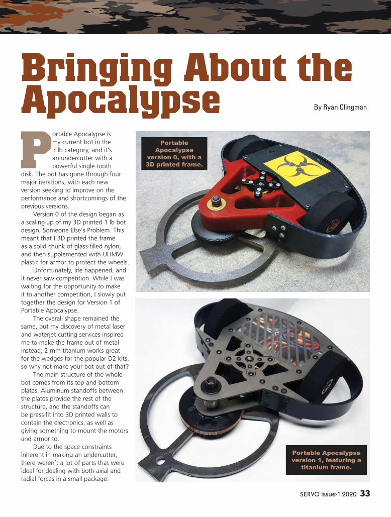
SERVO Issue-1.2020 33
Portable Apocalypse is
my current bot in the
3 lb category, and it’s
an undercutter with a
powerful single tooth
disk. The bot has gone through four
major iterations, with each new
version seeking to improve on the
performance and shortcomings of the
previous versions.
Version 0 of the design began as
a scaling-up of my 3D printed 1 lb bot
design, Someone Else’s Problem. This
meant that I 3D printed the frame
as a solid chunk of glass-filled nylon,
and then supplemented with UHMW
plastic for armor to protect the wheels.
Unfortunately, life happened, and
it never saw competition. While I was
waiting for the opportunity to make
it to another competition, I slowly put
together the design for Version 1 of
Portable Apocalypse.
The overall shape remained the
same, but my discovery of metal laser
and waterjet cutting services inspired
me to make the frame out of metal
instead; 2 mm titanium works great
for the wedges for the popular D2 kits,
so why not make your bot out of that?
The main structure of the whole
bot comes from its top and bottom
plates. Aluminum standoffs between
the plates provide the rest of the
structure, and the standoffs can
be press-fit into 3D printed walls to
contain the electronics, as well as
giving something to mount the motors
and armor to.
Due to the space constraints
inherent in making an undercutter,
there weren’t a lot of parts that were
ideal for dealing with both axial and
radial forces in a small package.
Bringing About the Apocalypse By Ryan Clingman
Portable Apocalypse
version 1, featuring a
titanium frame.
Portable
Apocalypse
version 0, with a
3D printed frame.

34 SERVO Issue-1.2020
So, I wound up making my
own unique bearing setup. There’s
a bearing in both the disk and the
pulley, with a nested pair of washers
squeezed between
them to help
handle axial loads
on the weapon
disk.
I can really tighten the shoulder
bolt shaft down hard to lock the inner
races of the bearings together and
make the frame nice and tight, while
still leaving the outer races and the
weapon disk free to spin.
Slots in the 3D printed pulley let
me put in square nuts to clamp the
pulley to the disk.
After some issues I had with the
weapon of the earlier versions of my
1 lb bot flexing enough to damage its
own pulley, I designed it so that the
disc is always directly over the weapon
motor and pulley.
This way, even if the weapon
flexes, it just rubs on the pulley instead
of having the chance to bite into the
pulley and risk disabling itself.
I designed all this so that (with the
exception of the weapon shaft and
power switch) I would only need one
size of hex wrench to fully assemble/
disassemble the entire bot.
All the 6-32 screws for the frame
use a 5/64” hex drive, and all the
metric screws for the motors need a
2 mm hex drive, but the two are so
3D printed walls combine with the standoffs
to complete the electronics compartment and
provide mounting points for the motors and
armor.
The weapon shaft setup allows the center of the
bearings to be clamped to the frame while leaving
the outer part free to spin with the disk and pulley.
The two metal plates combined with some standoffs form the key
part of the frame.
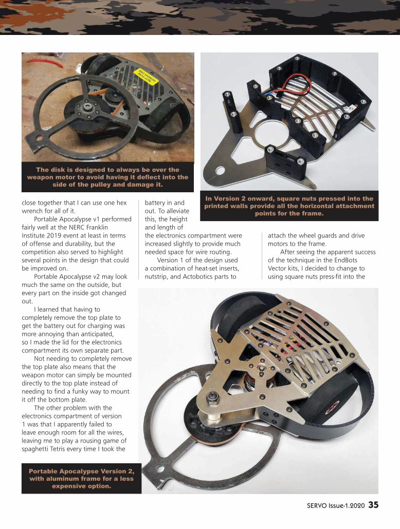
SERVO Issue-1.2020 35
close together that I can use one hex
wrench for all of it.
Portable Apocalypse v1 performed
fairly well at the NERC Franklin
Institute 2019 event at least in terms
of offense and durability, but the
competition also served to highlight
several points in the design that could
be improved on.
Portable Apocalypse v2 may look
much the same on the outside, but
every part on the inside got changed
out.
I learned that having to
completely remove the top plate to
get the battery out for charging was
more annoying than anticipated,
so I made the lid for the electronics
compartment its own separate part.
Not needing to completely remove
the top plate also means that the
weapon motor can simply be mounted
directly to the top plate instead of
needing to find a funky way to mount
it off the bottom plate.
The other problem with the
electronics compartment of version
1 was that I apparently failed to
leave enough room for all the wires,
leaving me to play a rousing game of
spaghetti Tetris every time I took the
battery in and
out. To alleviate
this, the height
and length of
the electronics compartment were
increased slightly to provide much
needed space for wire routing.
Version 1 of the design used
a combination of heat-set inserts,
nutstrip, and Actobotics parts to
attach the wheel guards and drive
motors to the frame.
After seeing the apparent success
of the technique in the EndBots
Vector kits, I decided to change to
using square nuts press-fit into the
Portable Apocalypse Version 2,
with aluminum frame for a less
expensive option.
In Version 2 onward, square nuts pressed into the
printed walls provide all the horizontal attachment
points for the frame.
The disk is designed to always be over the
weapon motor to avoid having it deflect into the side of the pulley and damage it.

36 SERVO Issue-1.2020
3D printed parts to attach these parts
instead.
At the time of building, I had
some inklings of trying to turn the
design into a kit to sell, so I also tried
to reduce the cost and complexity of
the parts where I could.
The titanium frame plates were
replaced with thicker aluminum ones;
the DIY brushless gear motors were
replaced with off-the-shelf brushed
motors; and I tried out some cheap
Chinese brushed ESCs. All of it
performed admirably.
After a respectable showing at
NERC’s Motorama 2020 event, I have
now built Portable Apocalypse v3 with
the goal of achieving a spot on the
podium the next time around (no small
feat when the competitions I frequent
have 30-60 competitors to overcome
to get there).
With the v2 design working well,
the changes were relatively minor this
time.
While the aluminum frame
worked great, I have switched back
to a titanium frame for the best
durability. What lost me both matches
and knocked me out of the previous
tournament was my receiver slowly
failing due to repeated impacts.
Wrapping all the electronics in
foam should help to abate the impacts
and increase the lifespan of the parts.
Bringing Portable Apocalypse
to this point has been a measured
process of evolution in the design,
addressing fl aws in the design as well
as looking at the building techniques
that have worked well for others
and, incorporating them into my own
designs.
Only time will tell if it will come
out on the top of the pile, but I plan
to keep improving it until it gets there!
SV
Make Precision Metal Projects
User-friendly, budget-friendly,
making-things-happen-friendly.
The compact Tormach PCNC 440
runs on single-phase power and
fits just about anywhere.
The pre-configured Starter Package
is priced to run at $7,176.
Build yours at tormach.com/440/loop.
Portable Apocalypse Version 3 — back to titanium and better
than ever.

GearBox
Get Your Robot Ru� in’!
THE MOST COMPLETE PROGRAMMING TUTORIAL!� Everything you need to learn the fundamental concepts of PIC® microcontroller programming, including:
•Program Flow•Loops•Coding Techniques•Binary Manipulation
•Device-To-Device Communication•User Interface Design•In-circuit Debugging•And More!
� Includes all the necessary software, compiler, trainer board, cable, tutorial with exercises and sample code!
Check out our other popular productsfor PIC® developers including:
U2 Programmer•PBP3 CompilerPrototyping Boards•Experimenter Boards
Contact us at [email protected]
$99.99
SERVO Issue-1.2020 37

38 SERVO Issue-1.2020
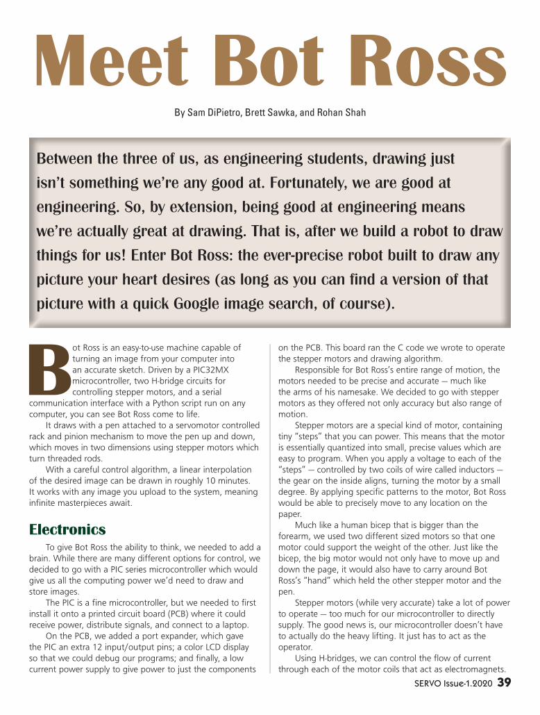
SERVO Issue-1.2020 39
Bot Ross is an easy-to-use machine capable of
turning an image from your computer into
an accurate sketch. Driven by a PIC32MX
microcontroller, two H-bridge circuits for
controlling stepper motors, and a serial
communication interface with a Python script run on any
computer, you can see Bot Ross come to life.
It draws with a pen attached to a servomotor controlled
rack and pinion mechanism to move the pen up and down,
which moves in two dimensions using stepper motors which
turn threaded rods.
With a careful control algorithm, a linear interpolation
of the desired image can be drawn in roughly 10 minutes.
It works with any image you upload to the system, meaning
infi nite masterpieces await.
Electronics
To give Bot Ross the ability to think, we needed to add a
brain. While there are many different options for control, we
decided to go with a PIC series microcontroller which would
give us all the computing power we’d need to draw and
store images.
The PIC is a fi ne microcontroller, but we needed to fi rst
install it onto a printed circuit board (PCB) where it could
receive power, distribute signals, and connect to a laptop.
On the PCB, we added a port expander, which gave
the PIC an extra 12 input/output pins; a color LCD display
so that we could debug our programs; and fi nally, a low
current power supply to give power to just the components
on the PCB. This board ran the C code we wrote to operate
the stepper motors and drawing algorithm.
Responsible for Bot Ross’s entire range of motion, the
motors needed to be precise and accurate — much like
the arms of his namesake. We decided to go with stepper
motors as they offered not only accuracy but also range of
motion.
Stepper motors are a special kind of motor, containing
tiny “steps” that you can power. This means that the motor
is essentially quantized into small, precise values which are
easy to program. When you apply a voltage to each of the
“steps” — controlled by two coils of wire called inductors —
the gear on the inside aligns, turning the motor by a small
degree. By applying specifi c patterns to the motor, Bot Ross
would be able to precisely move to any location on the
paper.
Much like a human bicep that is bigger than the
forearm, we used two different sized motors so that one
motor could support the weight of the other. Just like the
bicep, the big motor would not only have to move up and
down the page, it would also have to carry around Bot
Ross’s “hand” which held the other stepper motor and the
pen.
Stepper motors (while very accurate) take a lot of power
to operate — too much for our microcontroller to directly
supply. The good news is, our microcontroller doesn’t have
to actually do the heavy lifting. It just has to act as the
operator.
Using H-bridges, we can control the fl ow of current
through each of the motor coils that act as electromagnets.
Meet Bot Ross
Between the three of us, as engineering students, drawing just
isn’t something we’re any good at. Fortunately, we are good at
engineering. So, by extension, being good at engineering means
we’re actually great at drawing. That is, after we build a robot to draw
things for us! Enter Bot Ross: the ever-precise robot built to draw any
picture your heart desires (as long as you can fi nd a version of that
picture with a quick Google image search, of course).
By Sam DiPietro, Brett Sawka, and Rohan Shah
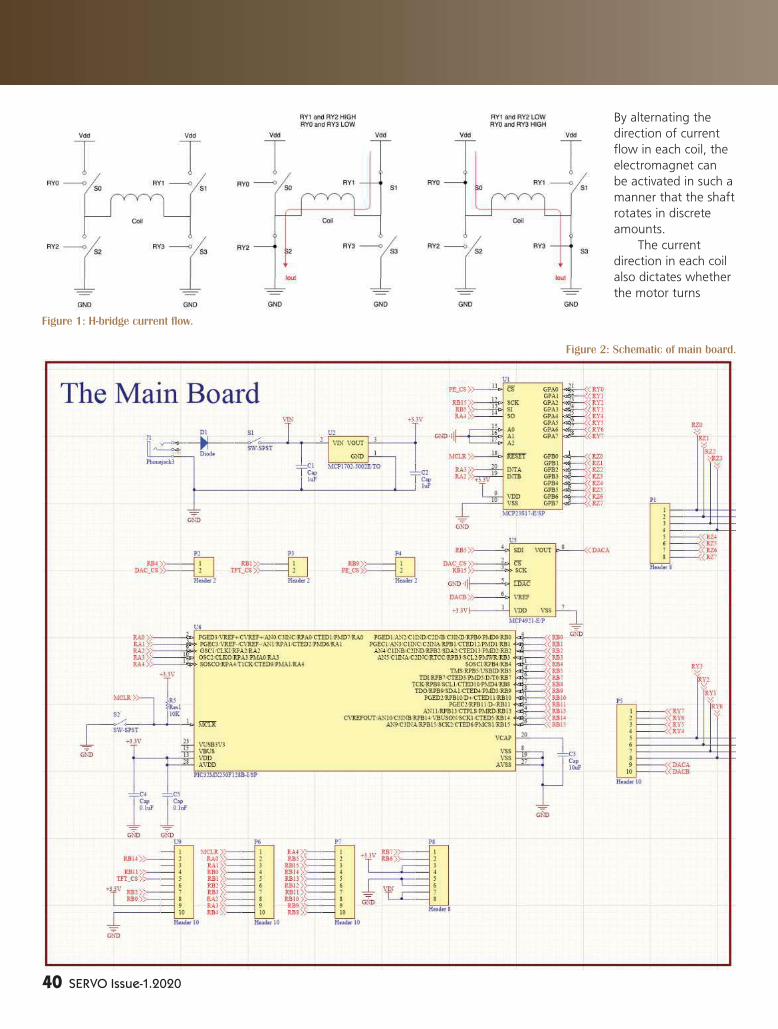
40 SERVO Issue-1.2020
By alternating the
direction of current
fl ow in each coil, the
electromagnet can
be activated in such a
manner that the shaft
rotates in discrete
amounts.
The current
direction in each coil
also dictates whether
the motor turns
Figure 1: H-bridge current fl ow.
Figure 2: Schematic of main board.
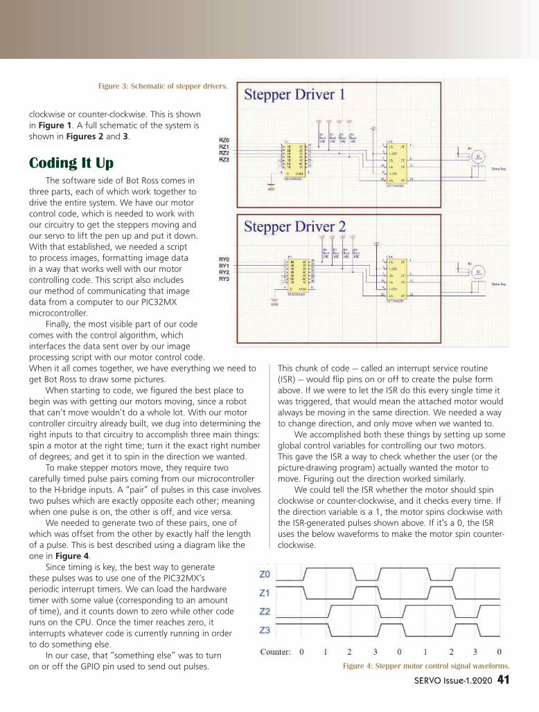
SERVO Issue-1.2020 41
clockwise or counter-clockwise. This is shown
in Figure 1. A full schematic of the system is
shown in Figures 2 and 3.
Coding It UpThe software side of Bot Ross comes in
three parts, each of which work together to
drive the entire system. We have our motor
control code, which is needed to work with
our circuitry to get the steppers moving and
our servo to lift the pen up and put it down.
With that established, we needed a script
to process images, formatting image data
in a way that works well with our motor
controlling code. This script also includes
our method of communicating that image
data from a computer to our PIC32MX
microcontroller.
Finally, the most visible part of our code
comes with the control algorithm, which
interfaces the data sent over by our image
processing script with our motor control code.
When it all comes together, we have everything we need to
get Bot Ross to draw some pictures.
When starting to code, we fi gured the best place to
begin was with getting our motors moving, since a robot
that can’t move wouldn’t do a whole lot. With our motor
controller circuitry already built, we dug into determining the
right inputs to that circuitry to accomplish three main things:
spin a motor at the right time; turn it the exact right number
of degrees; and get it to spin in the direction we wanted.
To make stepper motors move, they require two
carefully timed pulse pairs coming from our microcontroller
to the H-bridge inputs. A “pair” of pulses in this case involves
two pulses which are exactly opposite each other; meaning
when one pulse is on, the other is off, and vice versa.
We needed to generate two of these pairs, one of
which was offset from the other by exactly half the length
of a pulse. This is best described using a diagram like the
one in Figure 4.
Since timing is key, the best way to generate
these pulses was to use one of the PIC32MX’s
periodic interrupt timers. We can load the hardware
timer with some value (corresponding to an amount
of time), and it counts down to zero while other code
runs on the CPU. Once the timer reaches zero, it
interrupts whatever code is currently running in order
to do something else.
In our case, that “something else” was to turn
on or off the GPIO pin used to send out pulses.
This chunk of code — called an interrupt service routine
(ISR) — would fl ip pins on or off to create the pulse form
above. If we were to let the ISR do this every single time it
was triggered, that would mean the attached motor would
always be moving in the same direction. We needed a way
to change direction, and only move when we wanted to.
We accomplished both these things by setting up some
global control variables for controlling our two motors.
This gave the ISR a way to check whether the user (or the
picture-drawing program) actually wanted the motor to
move. Figuring out the direction worked similarly.
We could tell the ISR whether the motor should spin
clockwise or counter-clockwise, and it checks every time. If
the direction variable is a 1, the motor spins clockwise with
the ISR-generated pulses shown above. If it’s a 0, the ISR
uses the below waveforms to make the motor spin counter-
clockwise.
Figure 3: Schematic of stepper drivers.
Figure 4: Stepper motor control signal waveforms.
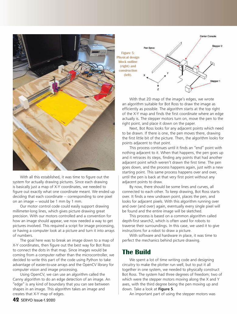
42 SERVO Issue-1.2020
With all this established, it was time to fi gure out the
system for actually drawing pictures. Since each drawing
is basically just a map of X-Y coordinates, we needed to
fi gure out exactly what one coordinate meant. We ended up
deciding that each coordinate — corresponding to one pixel
on an image — would be 1 mm by 1 mm.
Our motor control code could easily support drawing
millimeter-long lines, which gives picture drawing great
precision. With our motors controlled and a convention for
how an image should appear, we now needed a way to get
pictures involved. This required a script for image processing,
or having a computer look at a picture and turn it into arrays
of numbers.
The goal here was to break an image down to a map of
X-Y coordinates, then fi gure out the best way for Bot Ross
to connect the dots in that map. Since images would be
coming from a computer rather than the microcontroller, we
decided to write this part of the code using Python to take
advantage of easier-to-use arrays and the OpenCV library for
computer vision and image processing.
Using OpenCV, we can use an algorithm called the
Canny algorithm to do an edge detection of an image. An
“edge” is any kind of boundary that you can see between
shapes in an image. This algorithm takes an image and
creates that X-Y map of edges.
With that 2D map of the image’s edges, we wrote
an algorithm suitable for Bot Ross to draw the image as
effi ciently as possible. The algorithm starts at the top right
of the X-Y map and fi nds the fi rst coordinate where an edge
actually is. The stepper motors turn on, move the pen to the
right point, and place it down on the paper.
Next, Bot Ross looks for any adjacent points which need
to be drawn. If there is one, the pen moves there, drawing
the fi rst little bit of the picture. Then, the algorithm looks for
points adjacent to that point.
This process continues until it fi nds an “end” point with
nothing adjacent to it. When that happens, the pen goes up
and it retraces its steps, fi nding any points that had another
adjacent point which weren’t drawn the fi rst time. The pen
goes down, and the process happens again, just with a new
starting point. This same process happens over and over,
until the pen is back at that very fi rst point without any
adjacent points to draw.
By now, there should be some lines and curves, all
connected to each other. To keep drawing, Bot Ross starts
over. It fi nds a new undrawn point, places the pen, and
looks for adjacent pixels. With this algorithm running over
and over (and over) again, eventually every single pixel will
be found and the entire image will be sketched.
This process is based on a common algorithm called
depth-fi rst search2, which is often used for robots to
traverse their surroundings. In this case, we used it to give
instructions for a robot to draw a picture.
With software and hardware in place, it was time to
perfect the mechanics behind picture drawing.
The Build
We spent a lot of time writing code and designing
circuitry to make the plotter run well, but to put it all
together in one system, we needed to physically construct
Bot Ross. The system had three degrees of freedom; two of
which were the stepper motors moving along the X and Y
axes, with the third degree being the pen moving up and
down. Take a look at Figure 5.
An important part of using the stepper motors was
Figure 5:
Physical design
block outline
(right) and
construction
(left).
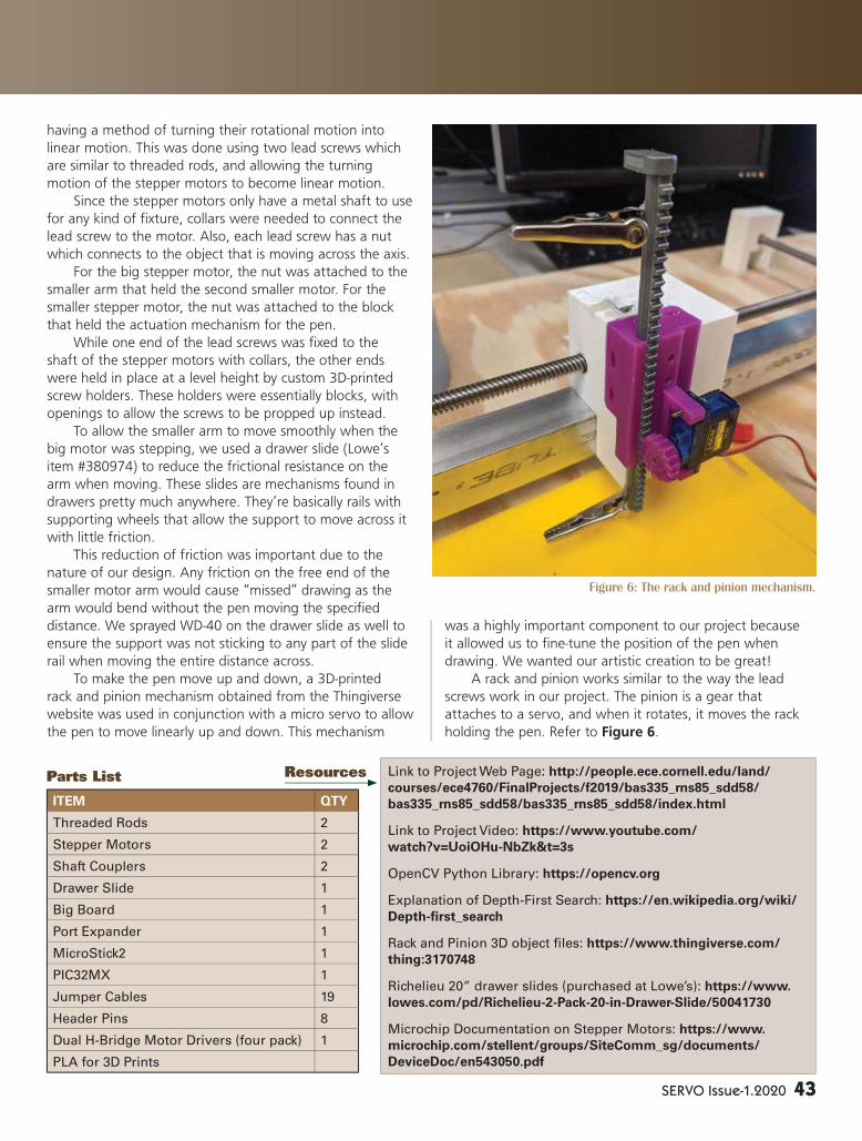
SERVO Issue-1.2020 43
having a method of turning their rotational motion into
linear motion. This was done using two lead screws which
are similar to threaded rods, and allowing the turning
motion of the stepper motors to become linear motion.
Since the stepper motors only have a metal shaft to use
for any kind of fi xture, collars were needed to connect the
lead screw to the motor. Also, each lead screw has a nut
which connects to the object that is moving across the axis.
For the big stepper motor, the nut was attached to the
smaller arm that held the second smaller motor. For the
smaller stepper motor, the nut was attached to the block
that held the actuation mechanism for the pen.
While one end of the lead screws was fi xed to the
shaft of the stepper motors with collars, the other ends
were held in place at a level height by custom 3D-printed
screw holders. These holders were essentially blocks, with
openings to allow the screws to be propped up instead.
To allow the smaller arm to move smoothly when the
big motor was stepping, we used a drawer slide (Lowe’s
item #380974) to reduce the frictional resistance on the
arm when moving. These slides are mechanisms found in
drawers pretty much anywhere. They’re basically rails with
supporting wheels that allow the support to move across it
with little friction.
This reduction of friction was important due to the
nature of our design. Any friction on the free end of the
smaller motor arm would cause “missed” drawing as the
arm would bend without the pen moving the specifi ed
distance. We sprayed WD-40 on the drawer slide as well to
ensure the support was not sticking to any part of the slide
rail when moving the entire distance across.
To make the pen move up and down, a 3D-printed
rack and pinion mechanism obtained from the Thingiverse
website was used in conjunction with a micro servo to allow
the pen to move linearly up and down. This mechanism
was a highly important component to our project because
it allowed us to fi ne-tune the position of the pen when
drawing. We wanted our artistic creation to be great!
A rack and pinion works similar to the way the lead
screws work in our project. The pinion is a gear that
attaches to a servo, and when it rotates, it moves the rack
holding the pen. Refer to Figure 6.
Figure 6: The rack and pinion mechanism.
ITEM QTY
Threaded Rods 2
Stepper Motors 2
Shaft Couplers 2
Drawer Slide 1
Big Board 1
Port Expander 1
MicroStick2 1
PIC32MX 1
Jumper Cables 19
Header Pins 8
Dual H-Bridge Motor Drivers (four pack) 1
PLA for 3D Prints
Link to Project Web Page: http://people.ece.cornell.edu/land/
courses/ece4760/FinalProjects/f2019/bas335_rns85_sdd58/
bas335_rns85_sdd58/bas335_rns85_sdd58/index.html
Link to Project Video: https://www.youtube.com/
watch?v=UoiOHu-NbZk&t=3s
OpenCV Python Library: https://opencv.org
Explanation of Depth-First Search: https://en.wikipedia.org/wiki/
Depth-fi rst_search
Rack and Pinion 3D object fi les: https://www.thingiverse.com/
thing:3170748
Richelieu 20” drawer slides (purchased at Lowe’s): https://www.
lowes.com/pd/Richelieu-2-Pack-20-in-Drawer-Slide/50041730
Microchip Documentation on Stepper Motors: https://www.
microchip.com/stellent/groups/SiteComm_sg/documents/
DeviceDoc/en543050.pdf
Parts List Resources

44 SERVO Issue-1.2020
The fi nal part of the construction was attaching
everything to the wooden base. This project was done
with a relatively small budget, so we resorted to the cheap
(yet very effective) method of hot gluing to attach all the
components onto the base.
As we later noticed, this wooden base was quite
warped from its previous use, so we had to place another
platform on the base with small supports underneath to
create a level drawing surface.
Happy AccidentsAs with all engineering projects,
problems and bugs arise mid-build
and need to be addressed. Nothing is
ever perfect on the fi rst try, and Bot
Ross was no different. For the fi rst
few runs of Bot Ross, the robot would
slowly start drawing the image over
itself, getting lost on the large page.
Thankfully, we included an
onboard display which allowed Bot
Ross to tell us that it thought it was in
the right position. Figure 7 shows an
image of the distortion that we kept
on noticing.
No matter what we tried, we
couldn’t fi gure out why the image
Figure 8: Original image of Elon Musk (left) and drawn image of Musk (right). The left image by Duncan.Hull is licensed under CC BY-SA 4.0.
The image by Duncan.Hull is shown cropped in Figure 8 as that was the optimal aspect ratio determined to be used for the plotting system. The
image was not modifi ed in any form other than cropping.
Figure 7: Distorted image (left) and
corrected image (right).

SERVO Issue-1.2020 45
would keep on shifting to the left. It wasn’t until the late
hours of the night that we fi nally fi gured out what was
plighting Bot Ross. Just like having a proper canvas to paint
on, we realized that Bot Ross didn’t have a level surface to
draw on.
When the pen was down and moving to the right
(uphill), it would go slower than if it was drawing downhill.
However, this proved to be no problem as it was constant
and calibrated out.
By simply adding a correction factor — an additional
step for every 10 going uphill — we were able to counteract
the force of going uphill and re-center the drawing.
As stated, in all projects bugs are going to appear, and
it was extremely useful for us to have accounted for the
potential for bugs from the get-go with the inclusion of the
debugging terminal.
The MasterpieceAfter weeks of long hours spent in the lab, we did it.
We had fi nally drawn a complete image. We fi nally drew a
picture of the tech mogul, Elon Musk (Figure 8).
Due to the constraints of the plotter, the edge detection
algorithm was run on only the upper portion of the digital
image, as shown by the drawing.
Although the contoured version of the image doesn’t
look exactly like the original, almost all of the portrait outline
and facial details are captured. The suit is the most clear
part; you can even see the outline of his collar.
Since the stepper motors were not that fast, it took
about 15 minutes to draw the picture of Musk, but the time
was different for every image. The aspect ratio of the drawn
image is slightly different from the original, but that could
be easily fi xed by adjusting the number of steps between
coordinates in the X and Y axes.
We learned a lot from the challenges this project
presented and succeeded in creating a “masterpiece.”
Designing Bot Ross was a rewarding experience in
collaborating with a team towards a common goal and
learning how to effi ciently use resources to make a great
project. SV
To post comments on this article and fi nd
any associated fi les and/or downloads, go to
www.servomagazine.com/magazine/issue/2020/01.
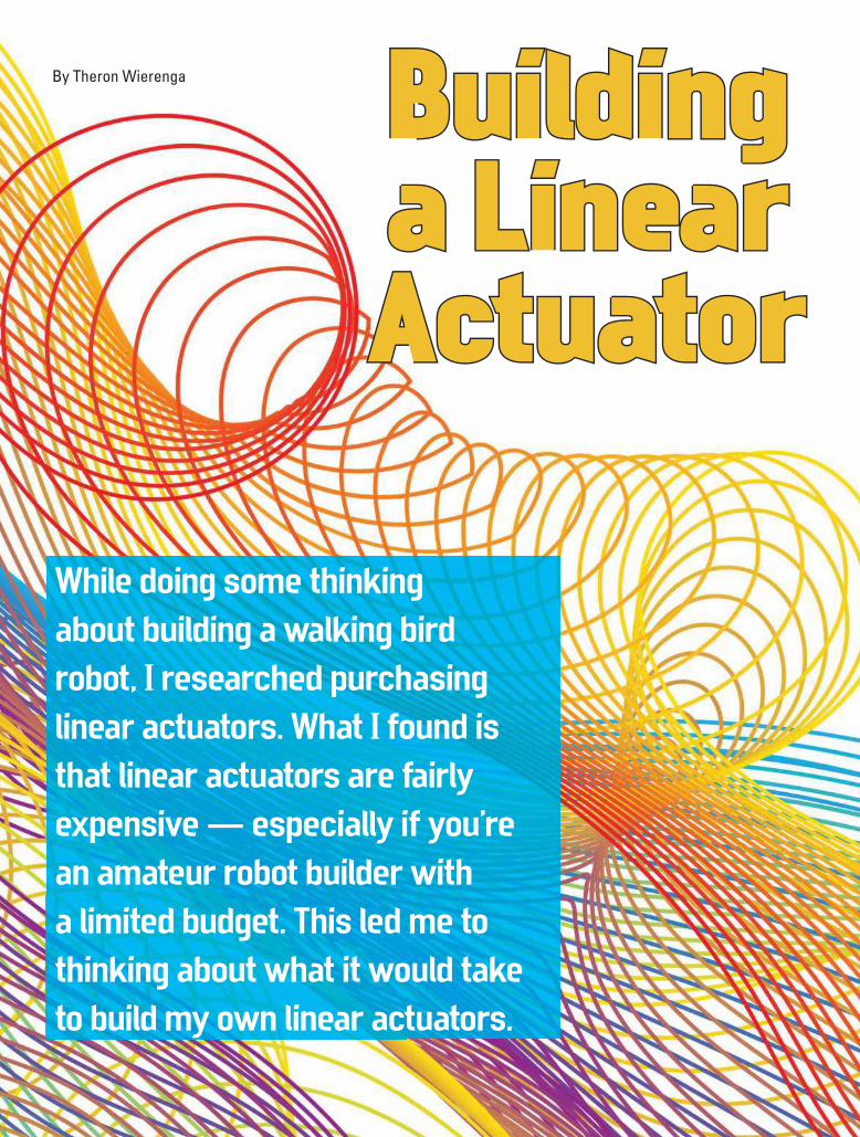
46 SERVO Issue-1.2020
Building Building a Linear a Linear ActuatorActuator
While doing some thinking
about building a walking bird
robot, I researched purchasing
linear actuators. What I found is
that linear actuators are fairly
expensive — especially if you’re
an amateur robot builder with
a limited budget. This led me to
thinking about what it would take
to build my own linear actuators.
By Theron Wierenga
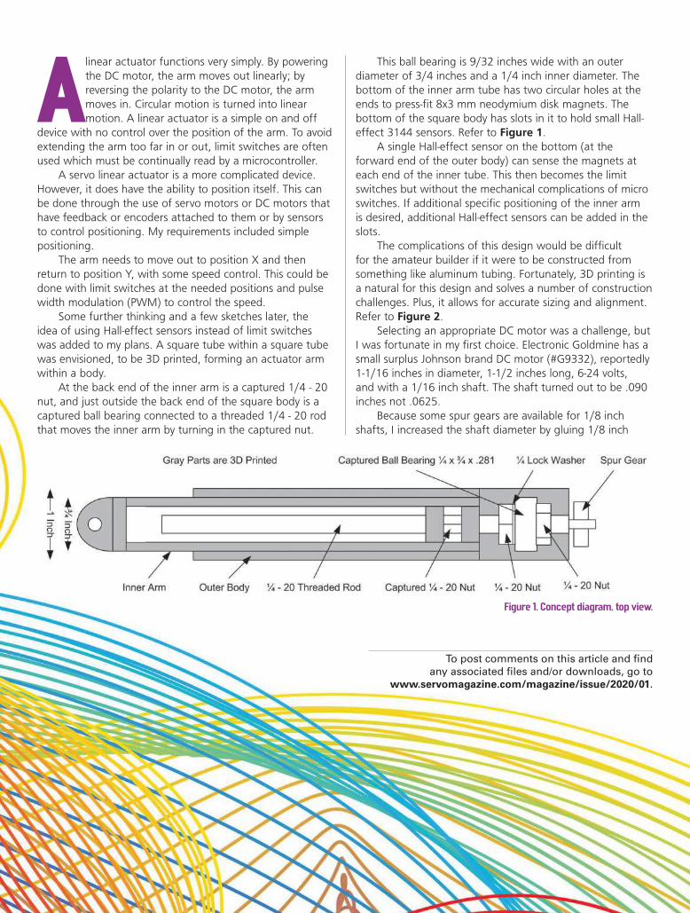
SERVO Issue-1.2020 47
A linear actuator functions very simply. By powering
the DC motor, the arm moves out linearly; by
reversing the polarity to the DC motor, the arm
moves in. Circular motion is turned into linear
motion. A linear actuator is a simple on and off
device with no control over the position of the arm. To avoid
extending the arm too far in or out, limit switches are often
used which must be continually read by a microcontroller.
A servo linear actuator is a more complicated device.
However, it does have the ability to position itself. This can
be done through the use of servo motors or DC motors that
have feedback or encoders attached to them or by sensors
to control positioning. My requirements included simple
positioning.
The arm needs to move out to position X and then
return to position Y, with some speed control. This could be
done with limit switches at the needed positions and pulse
width modulation (PWM) to control the speed.
Some further thinking and a few sketches later, the
idea of using Hall-effect sensors instead of limit switches
was added to my plans. A square tube within a square tube
was envisioned, to be 3D printed, forming an actuator arm
within a body.
At the back end of the inner arm is a captured 1/4 - 20
nut, and just outside the back end of the square body is a
captured ball bearing connected to a threaded 1/4 - 20 rod
that moves the inner arm by turning in the captured nut.
This ball bearing is 9/32 inches wide with an outer
diameter of 3/4 inches and a 1/4 inch inner diameter. The
bottom of the inner arm tube has two circular holes at the
ends to press-fit 8x3 mm neodymium disk magnets. The
bottom of the square body has slots in it to hold small Hall-
effect 3144 sensors. Refer to Figure 1.
A single Hall-effect sensor on the bottom (at the
forward end of the outer body) can sense the magnets at
each end of the inner tube. This then becomes the limit
switches but without the mechanical complications of micro
switches. If additional specific positioning of the inner arm
is desired, additional Hall-effect sensors can be added in the
slots.
The complications of this design would be difficult
for the amateur builder if it were to be constructed from
something like aluminum tubing. Fortunately, 3D printing is
a natural for this design and solves a number of construction
challenges. Plus, it allows for accurate sizing and alignment.
Refer to Figure 2.
Selecting an appropriate DC motor was a challenge, but
I was fortunate in my first choice. Electronic Goldmine has a
small surplus Johnson brand DC motor (#G9332), reportedly
1-1/16 inches in diameter, 1-1/2 inches long, 6-24 volts,
and with a 1/16 inch shaft. The shaft turned out to be .090
inches not .0625.
Because some spur gears are available for 1/8 inch
shafts, I increased the shaft diameter by gluing 1/8 inch
Figure 1. Concept diagram, top view.
To post comments on this article and find
any associated files and/or downloads, go to
www.servomagazine.com/magazine/issue/2020/01.

48 SERVO Issue-1.2020
diameter thin wall brass tubing to the shafts with
marine epoxy. This worked quite well and doesn’t
appear to have added any vibration. I measured
the no-load current of this motor to be about 160
milliamps and the stall current three amps.
For gears, I ordered a number of 48 pitch Traxxas
spur gears with 12, 21, 26, and 31 teeth and an 1/8
inch shaft size from Amazon. Some experimenting
was done with the Hobbypark 17, 21, 26, and 29
teeth gear set from Amazon. The Traxxas gears run a
lot smoother.
There are other sets available with differing
numbers of teeth. With different combinations of
these gears, one can increase or decrease the speed
and torque of the motor. For each pair of gears,
the only change in the design is the height of the
center line of the motor. Spur gears must be carefully
aligned, and any misalignment will cause loss of
power, wear, and noise. My goal was to have the
linear actuator be able to have a speed of 50 mm/sec. Using
the 17-tooth gear on the motor and the 26-tooth gear on
the shaft, it averages 84 mm/sec with no load. Having the
arm lifting a 550 gram load, it averaged 67 mm/sec. Refer
to Figures 3 and 4.
Another motor considered was a Tsiny TRS-550PC from
www.tsinymotor.com and available on Amazon. This
motor is considerably larger at 37-1/2 mm in diameter and
64-1/2 mm long. With a 12 volt power supply, the no-load
current is 1.35 amps; nominal current is over 10 amps; and
stall current is a whopping 76 amps.
When I clipped leads onto this motor from a 12 volt
lead acid battery, I wasn’t holding the motor very tightly in
my hand. On start-up, it jumped out of my hand. This would
be a good candidate for some heavy lifting.
It will need a hefty motor driver as well; something like
the BTS7960. While it’s advertised as a 43 amp driver, this is
not a continuous current rating. At 20 amps continuous, this
driver will run very hot.
Construction
The majority of time spent on this project was designing
the 3D models for the parts and then getting them to print
at the exact sizes needed. 3D plastic shrinks on cooling and
a 1/4 inch hole ends up being something like 0.243 inches.
This will vary depending on the brand of plastic used and
even the color in some cases.
PLA was chosen for its ease of use. One can estimate
the shrinkage for the various types of plastic, but nothing
works better than printing, testing, measuring, and printing
again. It’s very important to get all the parts to fit snugly
and be well aligned. All the moving parts need to be able
Figure 4. Inner arm, bottom view with circular openings for magnets.
Figure 2. 3D model from Sketchup, without the top pillow block to hold the captured ball bearing in place.
Figure 3. Inner arm, top view without top cover.
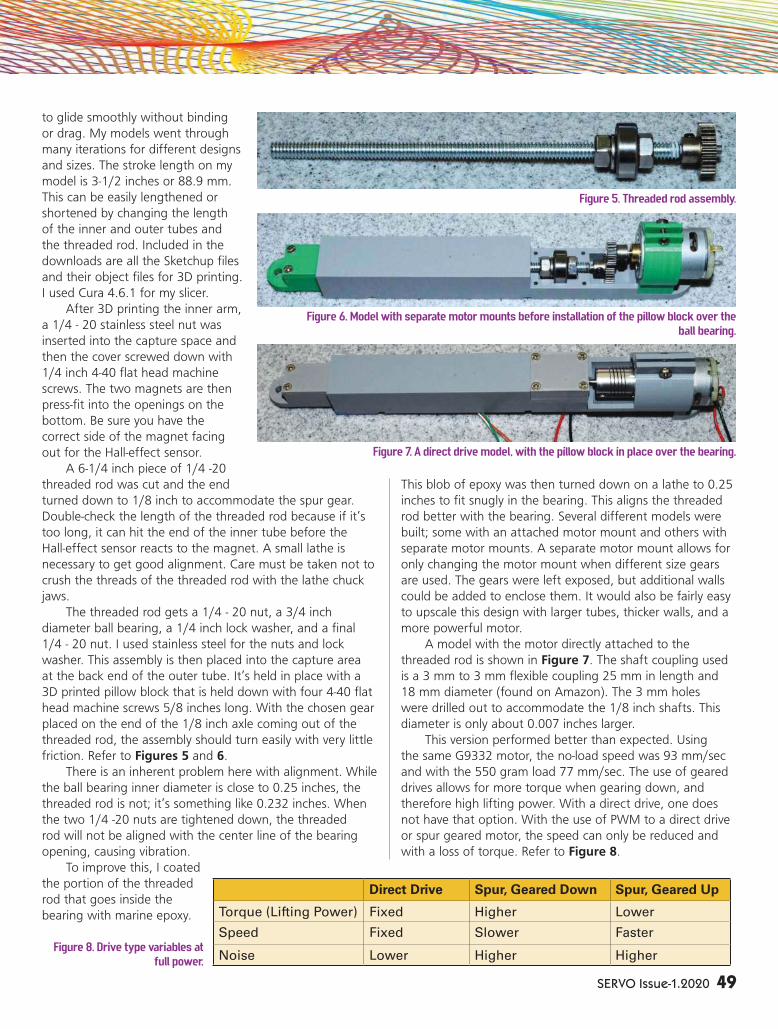
SERVO Issue-1.2020 49
to glide smoothly without binding
or drag. My models went through
many iterations for different designs
and sizes. The stroke length on my
model is 3-1/2 inches or 88.9 mm.
This can be easily lengthened or
shortened by changing the length
of the inner and outer tubes and
the threaded rod. Included in the
downloads are all the Sketchup files
and their object files for 3D printing.
I used Cura 4.6.1 for my slicer.
After 3D printing the inner arm,
a 1/4 - 20 stainless steel nut was
inserted into the capture space and
then the cover screwed down with
1/4 inch 4-40 flat head machine
screws. The two magnets are then
press-fit into the openings on the
bottom. Be sure you have the
correct side of the magnet facing
out for the Hall-effect sensor.
A 6-1/4 inch piece of 1/4 -20
threaded rod was cut and the end
turned down to 1/8 inch to accommodate the spur gear.
Double-check the length of the threaded rod because if it’s
too long, it can hit the end of the inner tube before the
Hall-effect sensor reacts to the magnet. A small lathe is
necessary to get good alignment. Care must be taken not to
crush the threads of the threaded rod with the lathe chuck
jaws.
The threaded rod gets a 1/4 - 20 nut, a 3/4 inch
diameter ball bearing, a 1/4 inch lock washer, and a final
1/4 - 20 nut. I used stainless steel for the nuts and lock
washer. This assembly is then placed into the capture area
at the back end of the outer tube. It’s held in place with a
3D printed pillow block that is held down with four 4-40 flat
head machine screws 5/8 inches long. With the chosen gear
placed on the end of the 1/8 inch axle coming out of the
threaded rod, the assembly should turn easily with very little
friction. Refer to Figures 5 and 6.
There is an inherent problem here with alignment. While
the ball bearing inner diameter is close to 0.25 inches, the
threaded rod is not; it’s something like 0.232 inches. When
the two 1/4 -20 nuts are tightened down, the threaded
rod will not be aligned with the center line of the bearing
opening, causing vibration.
To improve this, I coated
the portion of the threaded
rod that goes inside the
bearing with marine epoxy.
This blob of epoxy was then turned down on a lathe to 0.25
inches to fit snugly in the bearing. This aligns the threaded
rod better with the bearing. Several different models were
built; some with an attached motor mount and others with
separate motor mounts. A separate motor mount allows for
only changing the motor mount when different size gears
are used. The gears were left exposed, but additional walls
could be added to enclose them. It would also be fairly easy
to upscale this design with larger tubes, thicker walls, and a
more powerful motor.
A model with the motor directly attached to the
threaded rod is shown in Figure 7. The shaft coupling used
is a 3 mm to 3 mm flexible coupling 25 mm in length and
18 mm diameter (found on Amazon). The 3 mm holes
were drilled out to accommodate the 1/8 inch shafts. This
diameter is only about 0.007 inches larger.
This version performed better than expected. Using
the same G9332 motor, the no-load speed was 93 mm/sec
and with the 550 gram load 77 mm/sec. The use of geared
drives allows for more torque when gearing down, and
therefore high lifting power. With a direct drive, one does
not have that option. With the use of PWM to a direct drive
or spur geared motor, the speed can only be reduced and
with a loss of torque. Refer to Figure 8.
Figure 8. Drive type variables at full power.
Figure 7. A direct drive model, with the pillow block in place over the bearing.
Figure 5. Threaded rod assembly.
Figure 6. Model with separate motor mounts before installation of the pillow block over the ball bearing.
Direct Drive Spur, Geared Down Spur, Geared Up
Torque (Lifting Power) Fixed Higher Lower
Speed Fixed Slower Faster
Noise Lower Higher Higher
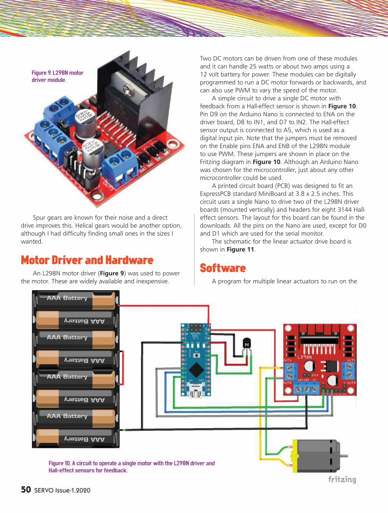
50 SERVO Issue-1.2020
Spur gears are known for their noise and a direct
drive improves this. Helical gears would be another option,
although I had difficulty finding small ones in the sizes I
wanted.
Motor Driver and Hardware
An L298N motor driver (Figure 9) was used to power
the motor. These are widely available and inexpensive.
Two DC motors can be driven from one of these modules
and it can handle 25 watts or about two amps using a
12 volt battery for power. These modules can be digitally
programmed to run a DC motor forwards or backwards, and
can also use PWM to vary the speed of the motor.
A simple circuit to drive a single DC motor with
feedback from a Hall-effect sensor is shown in Figure 10.
Pin D9 on the Arduino Nano is connected to ENA on the
driver board, D8 to IN1, and D7 to IN2. The Hall-effect
sensor output is connected to A5, which is used as a
digital input pin. Note that the jumpers must be removed
on the Enable pins ENA and ENB of the L298N module
to use PWM. These jumpers are shown in place on the
Fritzing diagram in Figure 10. Although an Arduino Nano
was chosen for the microcontroller, just about any other
microcontroller could be used.
A printed circuit board (PCB) was designed to fit an
ExpressPCB standard MiniBoard at 3.8 x 2.5 inches. This
circuit uses a single Nano to drive two of the L298N driver
boards (mounted vertically) and headers for eight 3144 Hall-
effect sensors. The layout for this board can be found in the
downloads. All the pins on the Nano are used, except for D0
and D1 which are used for the serial monitor.
The schematic for the linear actuator drive board is
shown in Figure 11.
Software
A program for multiple linear actuators to run on the
Figure 9. L298N motor driver module.
Figure 10. A circuit to operate a single motor with the L298N driver and Hall-effect sensors for feedback.

SERVO Issue-1.2020 51
Nano was created and
designed for use with
the circuit built on the
PCB. The program has
a few simple functions
to control four linear
actuators.
The functions
available are:
// Retract the actuator arm until it hits the home positionvoid homeMotor(int motor, int hall, int pwm)
// Soft start by increasing PWM before full powerbool softStartPWM(int motor, int setting, int maxPWM)
// Turn motor on, off, brake or free, turning at full powerbool setMotor(int motor, int setting)
// Turn motor on, off, brake or free turning using PWMbool setMotorPWM(int motor, int setting, int pwm)
// Read the output of a Hall Effect sensor, a low read means contactint readHall(int num)
// Run the motor for ¼ second so travel can be measuredvoid speedCheck()
The homeMotor() function is shown below and is
straightforward. It first checks if a correct motor has been
defined and if not, it returns with a false. Next, it turns
the motor on pulling the inner tube inwards, then begins
reading the Hall-effect sensor until it turns on. It then brakes
the motor and returns a true:
// Return motor to home positon, which is fully retractedbool homeMotor(int motor, int hall, int pwm){if ((motor != MOTOR_A) && (motor != MOTOR_B) && (motor != MOTOR_C) && (motor != MOTOR_D)) return
false; setMotorPWM(motor, MOTOR_IN, pwm); while (readHall(hall) == HALL_OFF) {}; setMotor(motor, MOTOR_BRAKED); return true;}
The setMotor() function is quite basic and is only
lengthy because it can service four motors. After doing an
error check for correct input, it uses a switch statement to
select which motor, then another switch statement to select
the setting:
// This function is used to turn a motor ON, OFF, BRAKED or OFF (free turning) at full powerbool setMotor(int motor, int setting){ if ((motor != MOTOR_A) && (motor != MOTOR_B) && (motor != MOTOR_C) && (motor != MOTOR_D)) return false; if ((setting != MOTOR_OFF) && (setting != MOTOR_BRAKED) && (setting != MOTOR_IN) &&
Figure 11. Design of linear actuator
drive board.

52 SERVO Issue-1.2020
(setting != MOTOR_OUT)) return false; switch (motor) { case MOTOR_A:switch (setting) { case MOTOR_OFF: digitalWrite(ENABLE_A, LOW); break; case MOTOR_BRAKED: digitalWrite(IN_A1, LOW); digitalWrite(IN_A2, LOW); digitalWrite(ENABLE_A, HIGH); break; case MOTOR_IN: digitalWrite(IN_A1, LOW); digitalWrite(IN_A2, HIGH); digitalWrite(ENABLE_A, HIGH);
break; case MOTOR_OUT: digitalWrite(IN_A1, HIGH); digitalWrite(IN_A2, LOW); digitalWrite(ENABLE_A, HIGH); break; } break; case MOTOR_B:switch (setting) { case MOTOR_OFF: digitalWrite(ENABLE_B, LOW); break; case MOTOR_BRAKED: digitalWrite(IN_B1, LOW); digitalWrite(IN_B2, LOW); digitalWrite(ENABLE_B, HIGH);
ITEM SOURCE
1/4-20 Threaded Rod Home Depot or Lowes
1/4-20 Nuts and Lock Washers, Stainless Steel Home Depot or Lowes
4-40 Flat Head Machine Screws and Nuts, 1/4, 3/8, and 5/8 lengths Home Depot or Lowes
4-40 Pan Head Machine Screws 1/2 inch, All Screws and Nuts Stainless Steel
48 Pitch Spur Gears Traxxas 2412, 2421, 2426, 2428, and 2431 Amazon or Local Hobby Shop
Hobbypark 48 Pitch Gear Set, 17, 21, 26, and 29 Teeth Amazon
Xnrtop 3 mm to 3 mm Shaft Coupling 25 mm length, 18 m diameter Amazon
8 x 3 mm Neodymium Disk Magnets Home Depot, Lowes, or Amazon
Loctite Marine Epoxy Amazon or Menards
White Lithium Grease Home Depot or Lowes
Johnson DC Motor, #G9332 Electronic Goldmine
L298N Motor Driver Board eBay or Amazon
Battery or Power Supply, 12 volt/3 amp Home Depot or Lowes
Arduino Nano eBay or Amazon
Hall-effect 3144 Sensors eBay
Printed Circuit Board or Breadboard ExpressPCB
Header Pins and Header Jumpers eBay or Amazon
Hookup Wire, Solder Home Depot or Lowes
Ball Bearing, 3/4 inch OD, 1/4 inch ID, 9/32 wide Amazon
If Printed Circuit Board is Built:
LM7805 Voltage Regulator eBay or Amazon
1,000 µF 6.3 volt Electrolytic Capacitor, .1 µF Capacitor eBay or Amazon
Tools Needed:
Small Lathe
3D Printer, Plastic Filament, Cuda Software, and Optional 3D Design
Software.
Parts List

SERVO Issue-1.2020 53
break; case MOTOR_IN: digitalWrite(IN_B1, LOW); digitalWrite(IN_B2, HIGH); digitalWrite(ENABLE_B, HIGH); break; case MOTOR_OUT: digitalWrite(IN_B1, HIGH); digitalWrite(IN_B2, LOW); digitalWrite(ENABLE_B, HIGH); break; } break; case MOTOR_C:switch (setting) { case MOTOR_OFF: digitalWrite(ENABLE_C, LOW); break; case MOTOR_BRAKED: digitalWrite(IN_C1, LOW); digitalWrite(IN_C2, LOW); digitalWrite(ENABLE_C, HIGH); break; case MOTOR_IN: digitalWrite(IN_C1, LOW); digitalWrite(IN_C2, HIGH); digitalWrite(ENABLE_C, HIGH); break; case MOTOR_OUT: digitalWrite(IN_C1, HIGH); digitalWrite(IN_C2, LOW); digitalWrite(ENABLE_C, HIGH); break; } break; case MOTOR_D:switch (setting) { case MOTOR_OFF: digitalWrite(ENABLE_D, LOW); break; case MOTOR_BRAKED: digitalWrite(IN_D1, LOW); digitalWrite(IN_D2, LOW); digitalWrite(ENABLE_D, HIGH); break; case MOTOR_IN: digitalWrite(IN_D1, LOW); digitalWrite(IN_D2, HIGH); digitalWrite(ENABLE_D, HIGH); break; case MOTOR_OUT: digitalWrite(IN_D1, HIGH); digitalWrite(IN_D2, LOW); digitalWrite(ENABLE_D, HIGH); break; }
break; } return true;}
This program doesn’t need to be run with the included
PCB design. Point-to-point wiring can be used between
the Nano, Hall-effect sensor, driver board, and motor. By
following the pin assignments in the program shown below,
it can be used as a general interface for one to four linear
actuators.
Pin assignments can also be changed in the program to
suit user needs.
#define HALL1 A5#define HALL2 A4#define HALL3 2#define HALL4 4#define HALL5 12#define HALL6 13#define HALL7 A7#define HALL8 A6#define ENABLE_A 9#define IN_A1 8#define IN_A2 7#define ENABLE_B 3#define IN_B1 6#define IN_B2 5#define ENABLE_C 11#define IN_C1 A0#define IN_C2 A1#define ENABLE_D 10#define IN_D1 A2#define IN_D2 A3
A copy of this program is included in the downloads.
Conclusion
This was an enjoyable project, even though many hours
were spent getting things “just right.” For the builder, it’s
imperative that everything runs smoothly with little friction.
It’s worth the extra effort to reprint something (like the inner
tube) if it sticks slightly when moving in and out. With the
small motor used, it doesn’t take much friction to bind and
stall the motor.
When the threaded rod and its bearing are inserted into
the main body, be sure everything can turn easily using a
thumb on the gears or coupling. A small amount of white
lithium grease can be used on the gears and threaded rod
to reduce friction. The pillow block that holds the bearing in
place should fit snugly, but do not overtighten it.
Using 3D printing allows for custom attachment
methods, depending on the use intended for the linear
actuator. My models simply have a mounting hole at each
end, but a simple redesign would allow a better integration
into the model the linear actuator moves. SV

54 SERVO Issue-1.2020
Versatile Stepper Control By William Cooke
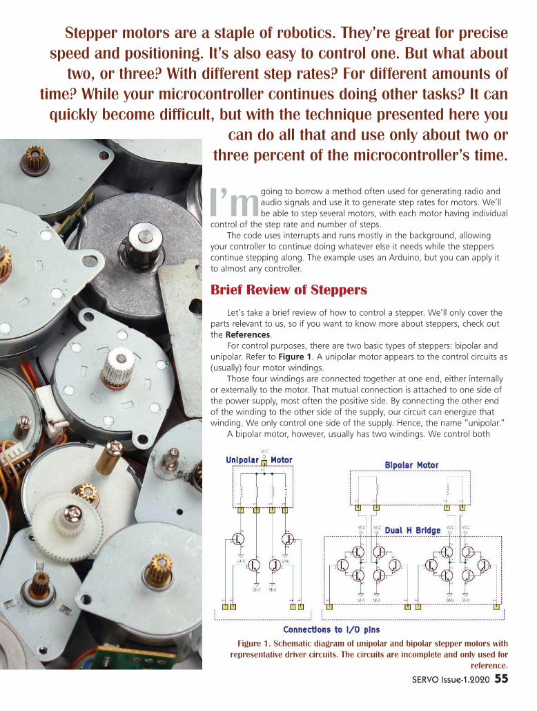
SERVO Issue-1.2020 55
I’m going to borrow a method often used for generating radio and
audio signals and use it to generate step rates for motors. We’ll
be able to step several motors, with each motor having individual
control of the step rate and number of steps.
The code uses interrupts and runs mostly in the background, allowing
your controller to continue doing whatever else it needs while the steppers
continue stepping along. The example uses an Arduino, but you can apply it
to almost any controller.
Brief Review of Steppers
Let’s take a brief review of how to control a stepper. We’ll only cover the
parts relevant to us, so if you want to know more about steppers, check out
the References.
For control purposes, there are two basic types of steppers: bipolar and
unipolar. Refer to Figure 1. A unipolar motor appears to the control circuits as
(usually) four motor windings.
Those four windings are connected together at one end, either internally
or externally to the motor. That mutual connection is attached to one side of
the power supply, most often the positive side. By connecting the other end
of the winding to the other side of the supply, our circuit can energize that
winding. We only control one side of the supply. Hence, the name “unipolar.”
A bipolar motor, however, usually has two windings. We control both
Stepper motors are a staple of robotics. They’re great for precise
speed and positioning. It’s also easy to control one. But what about
two, or three? With different step rates? For different amounts of
time? While your microcontroller continues doing other tasks? It can
quickly become difficult, but with the technique presented here you
can do all that and use only about two or
three percent of the microcontroller’s time.
Figure 1. Schematic diagram of unipolar and bipolar stepper motors with
representative driver circuits. The circuits are incomplete and only used for
reference.
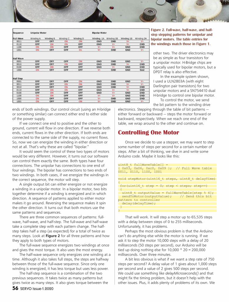
56 SERVO Issue-1.2020
ends of both windings. Our control circuit (using an H-bridge
or something similar) can connect either end to either side
of the power supply.
If we connect one end to positive and the other to
ground, current will flow in one direction. If we reverse both
ends, current flows in the other direction. If both ends are
connected to the same side of the supply, no current flows.
So, now we can energize the winding in either direction or
not at all. That’s why these are called “bipolar.”
It would seem the control of these two types of motors
would be very different. However, it turns out our software
can control them exactly the same. Both types have four
connections. The unipolar has connections to one end of
four windings. The bipolar has connections to two ends of
two windings. In both cases, if we energize the windings in
the correct sequence, the motor will step.
A single output bit can either energize or not energize
a winding in a unipolar motor. In a bipolar motor, two bits
together determine if a winding is energized and in which
direction. A sequence of patterns applied to either motor
makes it go around. Reversing the sequence makes it spin
the other direction. It turns out that both motors use the
same patterns and sequences.
There are three common sequences of patterns: full-
wave, half-wave, and half-step. The full-wave and half-wave
take a complete step with each pattern change. The half-
step takes half a step (as expected) for a total of twice as
many steps. Look at Figure 2 for all three patterns and how
they apply to both types of motors.
The full-wave sequence energizes two windings at once
and gives the most torque. It also uses the most energy.
The half-wave sequence only energizes one winding at a
time. Although it also takes full steps, the steps are halfway
between those of the full-wave sequence. Since only one
winding is energized, it has less torque but uses less power.
The half-step sequence is a combination of the two
previous sequences. It takes twice as many patterns but
gives twice as many steps. It also gives torque between the
other two. The driver electronics may
be as simple as four transistors for
a unipolar motor. H-Bridge chips are
typically used for bipolar motors, but a
DPDT relay is also effective.
In the example system shown,
I used a ULN2803A (with eight
Darlington pair transistors) for two
unipolar motors and a SN754410 dual
H-bridge to control one bipolar motor.
To control the motor, we send
the bit pattern to the winding drive
electronics. Stepping through the table of bit patterns —
either forward or backward — steps the motor forward or
backward, respectively. When we reach one end of the
table, we wrap around to the other and continue on.
Controlling One Motor
Once we decide to use a stepper, we may want to step
some number of steps per second for a certain number of
steps. After a bit of thinking, we dive in and write some
Arduino code. Maybe it looks like this:
uint8_t fullWaveTable[] = { 0x03, 0x06, 0xc0, 0x09 }; // Full Wave table 0011, 0110, 1100, 1001
void stepMotor(uint16_t steps, uint8_t delayTime){ for(uint16_t step = 0; step < steps; step++) { uint8_t outputValue = fullWaveTable[step % 4]; sendToMotor(outputValue); // Send this bit pattern to controller delay(delayTime); }}
That will work. It will step a motor up to 65,535 steps
with a delay between steps of 0 to 255 milliseconds.
Unfortunately, it has problems.
Perhaps the most obvious problem is that the Arduino
can’t do anything else while the motor is running. If we
ask it to step the motor 10,000 steps with a delay of 20
milliseconds (50 steps per second), our Arduino will be
tied up doing nothing else for 10,000 * 20 = 200,000
milliseconds. Over three minutes.
A bit less obvious is what if we want a step rate of 750
steps per second? A delay value of 1 gives about 1,000 steps
per second and a value of 2 gives 500 steps per second.
We could use something like delayMicroseconds() and that
might fix the timing problem, but it doesn’t help with the
other issues. Plus, it adds plenty of problems of its own. We
Figure 2. Full-wave, half-wave, and half-
step stepping patterns for unipolar and
bipolar motors. The table entries for
the windings match those in Figure 1.
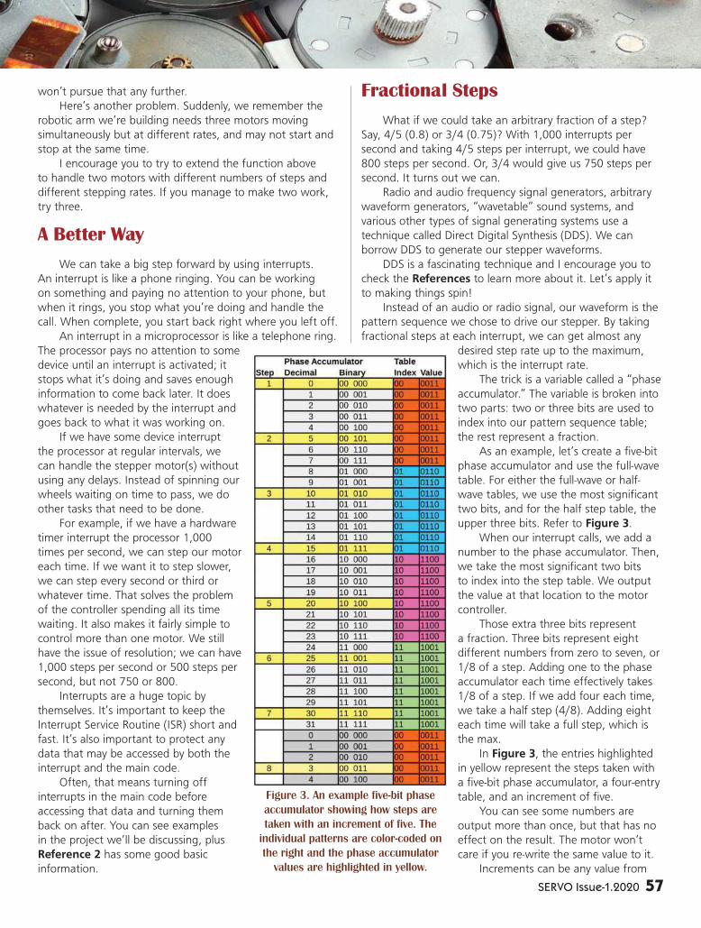
SERVO Issue-1.2020 57
won’t pursue that any further.
Here’s another problem. Suddenly, we remember the
robotic arm we’re building needs three motors moving
simultaneously but at different rates, and may not start and
stop at the same time.
I encourage you to try to extend the function above
to handle two motors with different numbers of steps and
different stepping rates. If you manage to make two work,
try three.
A Better Way
We can take a big step forward by using interrupts.
An interrupt is like a phone ringing. You can be working
on something and paying no attention to your phone, but
when it rings, you stop what you’re doing and handle the
call. When complete, you start back right where you left off.
An interrupt in a microprocessor is like a telephone ring.
The processor pays no attention to some
device until an interrupt is activated; it
stops what it’s doing and saves enough
information to come back later. It does
whatever is needed by the interrupt and
goes back to what it was working on.
If we have some device interrupt
the processor at regular intervals, we
can handle the stepper motor(s) without
using any delays. Instead of spinning our
wheels waiting on time to pass, we do
other tasks that need to be done.
For example, if we have a hardware
timer interrupt the processor 1,000
times per second, we can step our motor
each time. If we want it to step slower,
we can step every second or third or
whatever time. That solves the problem
of the controller spending all its time
waiting. It also makes it fairly simple to
control more than one motor. We still
have the issue of resolution; we can have
1,000 steps per second or 500 steps per
second, but not 750 or 800.
Interrupts are a huge topic by
themselves. It’s important to keep the
Interrupt Service Routine (ISR) short and
fast. It’s also important to protect any
data that may be accessed by both the
interrupt and the main code.
Often, that means turning off
interrupts in the main code before
accessing that data and turning them
back on after. You can see examples
in the project we’ll be discussing, plus
Reference 2 has some good basic
information.
Fractional Steps
What if we could take an arbitrary fraction of a step?
Say, 4/5 (0.8) or 3/4 (0.75)? With 1,000 interrupts per
second and taking 4/5 steps per interrupt, we could have
800 steps per second. Or, 3/4 would give us 750 steps per
second. It turns out we can.
Radio and audio frequency signal generators, arbitrary
waveform generators, “wavetable” sound systems, and
various other types of signal generating systems use a
technique called Direct Digital Synthesis (DDS). We can
borrow DDS to generate our stepper waveforms.
DDS is a fascinating technique and I encourage you to
check the References to learn more about it. Let’s apply it
to making things spin!
Instead of an audio or radio signal, our waveform is the
pattern sequence we chose to drive our stepper. By taking
fractional steps at each interrupt, we can get almost any
desired step rate up to the maximum,
which is the interrupt rate.
The trick is a variable called a “phase
accumulator.” The variable is broken into
two parts: two or three bits are used to
index into our pattern sequence table;
the rest represent a fraction.
As an example, let’s create a five-bit
phase accumulator and use the full-wave
table. For either the full-wave or half-
wave tables, we use the most significant
two bits, and for the half step table, the
upper three bits. Refer to Figure 3.
When our interrupt calls, we add a
number to the phase accumulator. Then,
we take the most significant two bits
to index into the step table. We output
the value at that location to the motor
controller.
Those extra three bits represent
a fraction. Three bits represent eight
different numbers from zero to seven, or
1/8 of a step. Adding one to the phase
accumulator each time effectively takes
1/8 of a step. If we add four each time,
we take a half step (4/8). Adding eight
each time will take a full step, which is
the max.
In Figure 3, the entries highlighted
in yellow represent the steps taken with
a five-bit phase accumulator, a four-entry
table, and an increment of five.
You can see some numbers are
output more than once, but that has no
effect on the result. The motor won’t
care if you re-write the same value to it.
Increments can be any value from
Figure 3. An example five-bit phase
accumulator showing how steps are
taken with an increment of five. The
individual patterns are color-coded on
the right and the phase accumulator
values are highlighted in yellow.
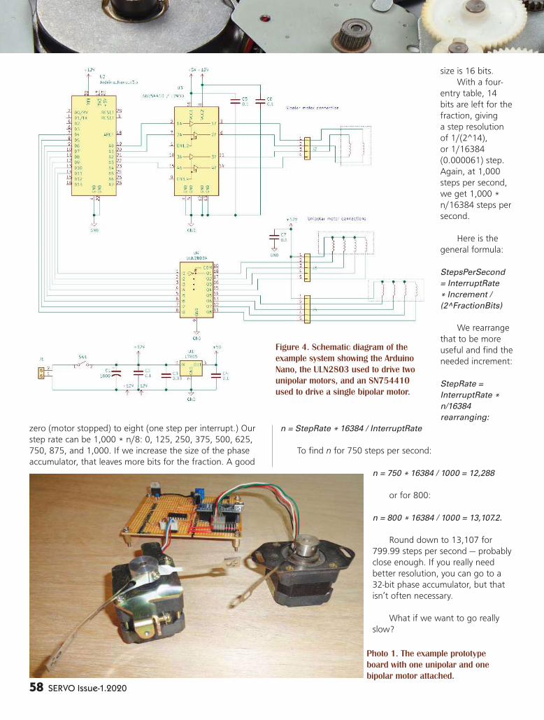
58 SERVO Issue-1.2020
zero (motor stopped) to eight (one step per interrupt.) Our
step rate can be 1,000 * n/8: 0, 125, 250, 375, 500, 625,
750, 875, and 1,000. If we increase the size of the phase
accumulator, that leaves more bits for the fraction. A good
size is 16 bits.
With a four-
entry table, 14
bits are left for the
fraction, giving
a step resolution
of 1/(2^14),
or 1/16384
(0.000061) step.
Again, at 1,000
steps per second,
we get 1,000 *
n/16384 steps per
second.
Here is the
general formula:
StepsPerSecond
= InterruptRate
* Increment /
(2^FractionBits)
We rearrange
that to be more
useful and find the
needed increment:
StepRate =
InterruptRate *
n/16384
rearranging:
n = StepRate * 16384 / InterruptRate
To find n for 750 steps per second:
n = 750 * 16384 / 1000 = 12,288
or for 800:
n = 800 * 16384 / 1000 = 13,107.2.
Round down to 13,107 for
799.99 steps per second — probably
close enough. If you really need
better resolution, you can go to a
32-bit phase accumulator, but that
isn’t often necessary.
What if we want to go really
slow?
Photo 1. The example prototype
board with one unipolar and one
bipolar motor attached.
Figure 4. Schematic diagram of the
example system showing the Arduino
Nano, the ULN2803 used to drive two
unipolar motors, and an SN754410
used to drive a single bipolar motor.
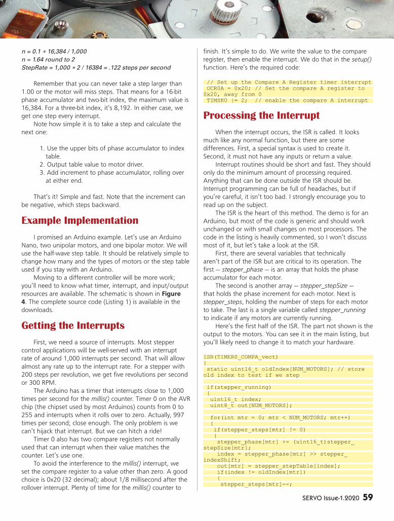
SERVO Issue-1.2020 59
n = 0.1 * 16,384 / 1,000
n = 1.64 round to 2
StepRate = 1,000 * 2 / 16384 = .122 steps per second
Remember that you can never take a step larger than
1.00 or the motor will miss steps. That means for a 16-bit
phase accumulator and two-bit index, the maximum value is
16,384. For a three-bit index, it’s 8,192. In either case, we
get one step every interrupt.
Note how simple it is to take a step and calculate the
next one:
1. Use the upper bits of phase accumulator to index
table.
2. Output table value to motor driver.
3. Add increment to phase accumulator, rolling over
at either end.
That’s it! Simple and fast. Note that the increment can
be negative, which steps backward.
Example Implementation
I promised an Arduino example. Let’s use an Arduino
Nano, two unipolar motors, and one bipolar motor. We will
use the half-wave step table. It should be relatively simple to
change how many and the types of motors or the step table
used if you stay with an Arduino.
Moving to a different controller will be more work;
you’ll need to know what timer, interrupt, and input/output
resources are available. The schematic is shown in Figure
4. The complete source code (Listing 1) is available in the
downloads.
Getting the Interrupts
First, we need a source of interrupts. Most stepper
control applications will be well-served with an interrupt
rate of around 1,000 interrupts per second. That will allow
almost any rate up to the interrupt rate. For a stepper with
200 steps per revolution, we get five revolutions per second
or 300 RPM.
The Arduino has a timer that interrupts close to 1,000
times per second for the millis() counter. Timer 0 on the AVR
chip (the chipset used by most Arduinos) counts from 0 to
255 and interrupts when it rolls over to zero. Actually, 997
times per second; close enough. The only problem is we
can’t hijack that interrupt. But we can hitch a ride!
Timer 0 also has two compare registers not normally
used that can interrupt when their value matches the
counter. Let’s use one.
To avoid the interference to the millis() interrupt, we
set the compare register to a value other than zero. A good
choice is 0x20 (32 decimal); about 1/8 millisecond after the
rollover interrupt. Plenty of time for the millis() counter to
finish. It’s simple to do. We write the value to the compare
register, then enable the interrupt. We do that in the setup()
function. Here’s the required code:
// Set up the Compare A Register timer interrupt OCR0A = 0x20; // Set the compare A register to 0x20, away from 0 TIMSK0 |= 2; // enable the compare A interrupt
Processing the Interrupt
When the interrupt occurs, the ISR is called. It looks
much like any normal function, but there are some
differences. First, a special syntax is used to create it.
Second, it must not have any inputs or return a value.
Interrupt routines should be short and fast. They should
only do the minimum amount of processing required.
Anything that can be done outside the ISR should be.
Interrupt programming can be full of headaches, but if
you’re careful, it isn’t too bad. I strongly encourage you to
read up on the subject.
The ISR is the heart of this method. The demo is for an
Arduino, but most of the code is generic and should work
unchanged or with small changes on most processors. The
code in the listing is heavily commented, so I won’t discuss
most of it, but let’s take a look at the ISR.
First, there are several variables that technically
aren’t part of the ISR but are critical to its operation. The
first — stepper_phase — is an array that holds the phase
accumulator for each motor.
The second is another array — stepper_stepSize —
that holds the phase increment for each motor. Next is
stepper_steps, holding the number of steps for each motor
to take. The last is a single variable called stepper_running
to indicate if any motors are currently running.
Here’s the first half of the ISR. The part not shown is the
output to the motors. You can see it in the main listing, but
you’ll likely need to change it to match your hardware.
ISR(TIMER0_COMPA_vect){ static uint16_t oldIndex[NUM_MOTORS]; // store old index to test if we step
if(stepper_running) { uint16_t index; uint8_t out[NUM_MOTORS];
for(int mtr = 0; mtr < NUM_MOTORS; mtr++) { if(stepper_steps[mtr] != 0) { stepper_phase[mtr] += (uint16_t)stepper_stepSize[mtr]; index = stepper_phase[mtr] >> stepper_indexShift; out[mtr] = stepper_stepTable[index]; if(index != oldIndex[mtr]) { stepper_steps[mtr]--;

60 SERVO Issue-1.2020
oldIndex[mtr] = index; } } }
// Code to output to motors goes here
}}
The first line of the ISR is how we declare an ISR for
the Arduino compiler. It looks like a function named “ISR”
with the name of the interrupt in parentheses. For any
Arduino based on the AVR chips, you can get the interrupt
name from Reference 4. If you’re using some other type of
controller, you’ll need to find out how to use an appropriate
interrupt.
You’ll have to research that on your own. Interrupt
control is not a standard part of the C or C++ languages, so
every compiler does it differently. Even the same compiler
may be different on different processors.
Inside the ISR, we first declare an array named oldIndex
to hold all the previous index values, so we can determine if
a motor stepped in this iteration. By declaring the array as
“static,” it holds its values between calls to the ISR. Another
array named out temporarily holds the table values to write
to the motors.
The main body of the ISR is a for loop that cycles
through all the motors. First, it checks if the motors are
running and skips everything else if not. If the motors are
running, it adds the phase increment for each motor to the
corresponding phase accumulator.
The resulting phase is used to find the index and look
up the needed pattern from the pattern table, stepper_
stepTable. It saves that pattern to use later.
The new output values found for the motors are
compared to the previous values held in the oldIndex array.
If they’re different, it means that motor took a step, so the
step count is updated. The only thing left to do is write the
new table values out to the motor controllers.
The ISR is short and simple. All the supporting code and
interface functions are in Listing 1.
In the example, I used direct port I/O. I highly
recommend doing that. Using the digitalWrite function is
slow and can cause performance issues with your code as
well as the motors. Reference 6 has information on using
direct port I/O.
In all, the example controls three motors and uses only
about 2% of the processor’s time, leaving plenty for your
other code.
Conclusion
You can take the example project here and use it
immediately to control three motors. Of course, much more
can be done by using it as a basis for your own ideas.
I hope you’ll take the techniques presented and go
further. Interrupts are a powerful tool and most processors
have many interrupt sources.
The phase accumulator/DDS method presented here is
useful for creating many different types of repetitive actions
that don’t match timer interrupt rates. I look forward to
hearing what you create and perhaps reading about it in
these pages.
As a final note, I’d like to thank my friend, Thomas
for asking the question that led to this article, and then
encouraging me and reviewing it. SV
1. Douglas W. Jones on Stepping Motors http://homepage.divms.uiowa.edu/~jones/step/ More than you ever wanted to know about steppers. 2. Arduino attachInterrpt() Reference https://www.arduino.cc/reference/en/language/functions/external-interrupts/attachinterrupt 3. DS Tutorial https://www.analog.com/en/analog-dialogue/articles/all-about-direct-digital-synthesis.html#Ask The Application Engineer—33: All About Direct Digital Synthesis by Eva Murphy and Colm, Slattery. A great introduction to Direct Digital Synthesis.
4. Interrupt Names AVR LIBC Interrupts https://www.nongnu.org/avr-libc/user-manual/group__avr__interrupts.html Lists the interrupt names recognized by the GCC compiler for all supported AVR processors. 5. Wikipedia entry on Direct Digital Synthesis https://en.wikipedia.org/wiki/Direct_digital_synthesis More good information on DDS. 6. Direct Port I/O on Arduino https://www.arduino.cc/en/Reference/PortManipulation Explains how to use direct port I/O instead of the Arduino single pin method.
References / Further Reading
To post comments on this
article and find any associated
files and/or downloads, go to
www.servomagazine.com/
magazine/issue/2020/01.

SERVO Issue-1.2020 61
LASER ALIGNMENT LASER ALIGNMENT
SYSTEM FOR SYSTEM FOR
YOUR CNC YOUR CNC
ROUTERROUTER
By Roger D. Secura
I really like simple solutions to
problems. For example, I designed and
built a desktop CNC router some time
ago. Although it works as expected,
I was wasting a lot of time trying to
align the center of my tool bit with the
corner edge of my workpiece (wood).
Then, like a fl ash of light (no pun
intended), it hit me — use a laser to
fi nd the edges of the wood. As it turns
out, designing and building a laser
system for my CNC router was really
simple — just what I like.

62 SERVO Issue-1.2020
WHAT TO EXPECTIn this article, I’ll show you how to build a laser power
supply circuit and how to construct a special bracket for your
CNC router motor. Figure 1 shows the kind of output you
can expect from my laser system.
You’re going to like the fact that the power supply
circuit only requires three components: the LM317T voltage
regulator and two resistors. If that sounds good to you, keep
reading.
START WITH THE BRACKET
Figure 2 is the CAD drawing for the bracket that holds
the two lasers in place. Figure 3 is a photo of the bracket
after it was printed on my Alfawise U30 3D printer. Finally,
Figure 4 shows the bracket mounted onto the CNC router
motor.
Aligning and mounting the bracket is really simple. Draw
(pencil) a temporary 90° angle on your router table so that
each leg of the 90° angle is an equal distance from the edge
of your table. Place a board in the corner of the angle. Now,
slide the bracket onto the motor and lightly tighten the #6-
32 machine screw. Rotate the two “line” lasers so they align
themselves with the lower left-hand corner of the board
as shown in Figure 1. Once aligned, level and tighten the
bracket around the motor.
Now, using the two laser lines as a guide, it’s possible
to center a router bit to any X and Y location on your table.
For example, move your cutting tool to the Home position
(Machine Zero). In the Offset screen in Mach 3, enter: X = 4;
Y = 4. Now, hit the ‘Go to Zero’ button on the main screen
in Mach 3. Once you reach the designation X = 4 / Y = 4,
the lasers will show you where to put the corner of your
workpiece.
Please note that this bracket was designed for my
DeWalt DNP611 router. You may
need to adjust the inner diameter
(2.75”; see Figure 2) of the
wooden bracket to fit your router
or spindle motor. Be aware that
in some cases, this bracket may
interfere with the movement and/
or travel limits of your Z axis.
Also, since both lasers have
a focus adjustment screw on the
front lens, you should unscrew the
lens and add some Teflon tape
(plumber’s tape) around the screw
threads.
Apparently, the screw is too
loose (bad design/manufacturing)
to maintain a set focus point.
Watch out for the spring inside the
laser. It will pop out.
Finally, once you insert the
9/64” diameter mounting screws
into the bracket, don’t over-tighten
FIGURE 1
FIGURE 2
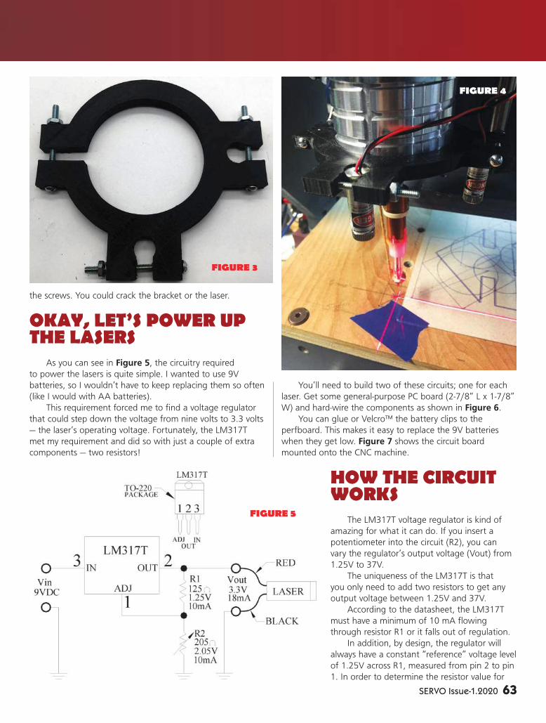
SERVO Issue-1.2020 63
the screws. You could crack the bracket or the laser.
OKAY, LET’S POWER UP THE LASERS
As you can see in Figure 5, the circuitry required
to power the lasers is quite simple. I wanted to use 9V
batteries, so I wouldn’t have to keep replacing them so often
(like I would with AA batteries).
This requirement forced me to find a voltage regulator
that could step down the voltage from nine volts to 3.3 volts
— the laser’s operating voltage. Fortunately, the LM317T
met my requirement and did so with just a couple of extra
components — two resistors!
You’ll need to build two of these circuits; one for each
laser. Get some general-purpose PC board (2-7/8” L x 1-7/8”
W) and hard-wire the components as shown in Figure 6.
You can glue or Velcro™ the battery clips to the
perfboard. This makes it easy to replace the 9V batteries
when they get low. Figure 7 shows the circuit board
mounted onto the CNC machine.
HOW THE CIRCUIT WORKS
The LM317T voltage regulator is kind of
amazing for what it can do. If you insert a
potentiometer into the circuit (R2), you can
vary the regulator’s output voltage (Vout) from
1.25V to 37V.
The uniqueness of the LM317T is that
you only need to add two resistors to get any
output voltage between 1.25V and 37V.
According to the datasheet, the LM317T
must have a minimum of 10 mA flowing
through resistor R1 or it falls out of regulation.
In addition, by design, the regulator will
always have a constant “reference” voltage level
of 1.25V across R1, measured from pin 2 to pin
1. In order to determine the resistor value for
FIGURE 3
FIGURE 5
FIGURE 4

64 SERVO Issue-1.2020
R1, we use Ohm’s Law as follows:
R1 = E/I
R1 = 1.25V/10 mA
R1 = 125 ohms
As you can see, the value for R1 is 125 ohms. Let’s
verify the minimum required current running through R1 is
10 mA:
IR1 = E/R
IR1 = 1.25V/125 ohms
IR1 = 10 mA
Since the current running through R1 is 10 mA, the
series circuit of R1 and R2 dictates that the same 10 mA
must run through R2. To calculate the resistance value for
R2, we use the following formula (use 3.3V as our desired
output voltage for the laser):
R2 = 205 ohms
Now, insert R1 (125 ohms) and R2 (205 ohms) into the
circuit. Take a voltmeter and check the output voltage and
verify that it’s 3.3V, measured from the Vout terminal to
ground.
Notice that if we add the 1.25V across R1 and the
2.05V across R2, we get 3.3V at the Vout terminal. In other
words, since the voltage across R1 (1.25V) never changes,
we can control the output voltage at the Vout terminal
(1.25V to 37V) just by varying the resistance of R2.
If you’d rather not do the math, you can just make R1
equal to 125 ohms and use a potentiometer for R2. Now,
turn the pot (R2) until the desired output voltage (measured
from Vout to ground) is acquired.
Remove the pot from your breadboard and check
the ohm’s setting with an ohmmeter. Insert an equivalent
resistor value back into the circuit.
Again, check the voltage level at the Vout terminal to
verify that you have the required output voltage; 3.3 volts
for example. Done!
Okay, now for a few caveats about the LM317T. First,
the input supply voltage at pin 3 (Vin) MUST be a minimum
of 2.5V to 3V higher than the output voltage (Vout). In
other words, if you need 3.3V for Vout (load), Vin must be
at least 6.3V. Failure to adhere to this rule will cause the
LM317T to fall out of regulation.
The ‘minimum’ differential voltage between Vin and
FIGURE 6
FIGURE 7

SERVO Issue-1.2020 65
Vout is called the “drop-out”
voltage (see the datasheet). If you
go below the minimum (3V), the
regulator stops working.
Secondly, the larger the
voltage differential is between Vin
and Vout, the more heat will be
dissipated within the LM317T. It
makes sense.
If, for example, you have
a 12V supply coming into the
regulator at pin 3 (Vin) and your
Vout (load voltage) only requires
3.3V, the LM317T will have to
dissipate the voltage differential
(5.7V) as heat.
As a rule of thumb, the larger
the differential, the more heat is
generated. This means a heatsink
may be required.
LASERSThe two lasers used in this project (and shown in Figure
8) are called “line” lasers. In other words, you can buy lasers
that project a single line, a cross pattern, or a dotted line
pattern. Just be careful when buying your lasers online. Look
for focusable 5 mW line lasers.
WARNING! WEAR EYE PROTECTION!
No project is worth damaging your eyesight. Any
time you work with lasers, you need eye protection. Just
remember, a laser beam reflected
off a shiny surface could accidently
target your eyes.
Please, don’t power-up your
5 mW lasers until you have read
‘Sam’s Laser FAQ’ at www.
repairfaq.org/sam/lasersaf.htm.
The 5 mW lasers used in this
article have a wavelength of 650
nm-660 nm. Therefore, before you
buy a pair of safety goggles, drop
by YouTube’s website and enter
the following text into the Search
Box: “Choosing Laser Goggles”
and “Testing Laser Goggles.” Don’t
buy those cheap goggles and
damage your eyesight!
Spend the extra money and
get a good pair of safety glasses.
You’re worth it! SV
To post comments on this article and find
any associated files and/or downloads, go to
www.servomagazine.com/magazine/issue/2020/01.
FIGURE 8
PARTS LIST
ITEM QTY DESCRIPTION PART# SOURCE
R1 1 125 ohm, 1/4W, 1%, Metal Film 71-RM60D1250F Mouser
R2 1 205 ohm, 1/4W, 1%, Metal Film 71-CMF50205R00FHEB Mouser
IC 1 Voltage Regulator, 1.25V-37V 511-LM317T Mouser
Laser 2 650 nm, 5 mW, Red, Focusable, “Line” Laser with Driver, Working Voltage 3-5V, Dimensions 12 x 35 mm
650ML-5-1235-2pcs-LM Amazon
Goggles 2 Red, 635-660 nm Laser Protection NYBG Amazon
Perf Brd 1 General-Purpose Grid-Style PC Board 276-150 RadioShack
Screw 3 Machine, #6-32 x 1-3/4”, Phillips n/a Home Depot
Nut 3 #6-32 Machine Screw Nut n/a Home Depot
Washer 3 #6 Lock Washer n/a Home Depot
Battery 2 9 VDC n/a (optional)
Bat Snaps 2 9 VDC Battery Snaps & Contacts 121-0526/I-GR Mouser
Bat Clip 2 9V Horizontal Battery Clip 12BH071-GR Mouser

66 SERVO Issue-1.2020
As I moved forward to do my Masters in Advanced
Manufacturing, I had a course on industrial robotics.
While doing that class, our professor came up with
an idea that a simple two-link robot could be used to
write letters. Figure 1 shows the simple two-link robotic arm.
It’s called a 2R robotic arm since it has two revolute
joints connecting two links. At the end of the robot, there’s
an end effector which, in our case, is a pen to write the
letters.
In this DIY project, I’ll show you how to make a simple
computer-controlled letter writing robot from scratch. Once
you have all the required materials, it will take about an hour
to complete the build. The robot arm writes a designated
letter on a piece of paper when a particular button is
pressed on the screen that’s part of the build. You can see
what it’s writing in the camera using the Graphical User
Interface (GUI).
You can see the robot arm in action at https://youtu.
be/-GWMAvIMX4w.
Make Sure You Have These to Begin
First, we’ll be making the two-link robotic arm.
For this, we’ll need two servomotors with at least 10-
15 kg cm torque for better results. You can also use
9g servo motors.
Next, is two 30 centimeter wooden or steel rulers
to make the links of the robotic arm.
A drill and a few nuts and bolts are necessary to
fit the wooden or steel ruler to the servo horn. An
L clamp or a piece of sheet metal that can be bent
into an “L” shape is needed to hold the pen or pencil
using a paper clip.
A few male-to male jumper wires are needed
to connect the servomotors to the microcontroller.
An Arduino Uno with a USB-UART cable is the
microcontroller I used. A 5V 1A power supply is
required to power the servomotor.
Alpha-Writer:Back from my school days, I remember my teachers
giving homework that involved a lot of writing. I
always wondered why there couldn’t be a robot that
would do this task of writing homework for me. I’m
glad it’s now possible to make this happen.
FIGURE 1: Representation
of a simple two-link robotic
arm with joints and end
effector.
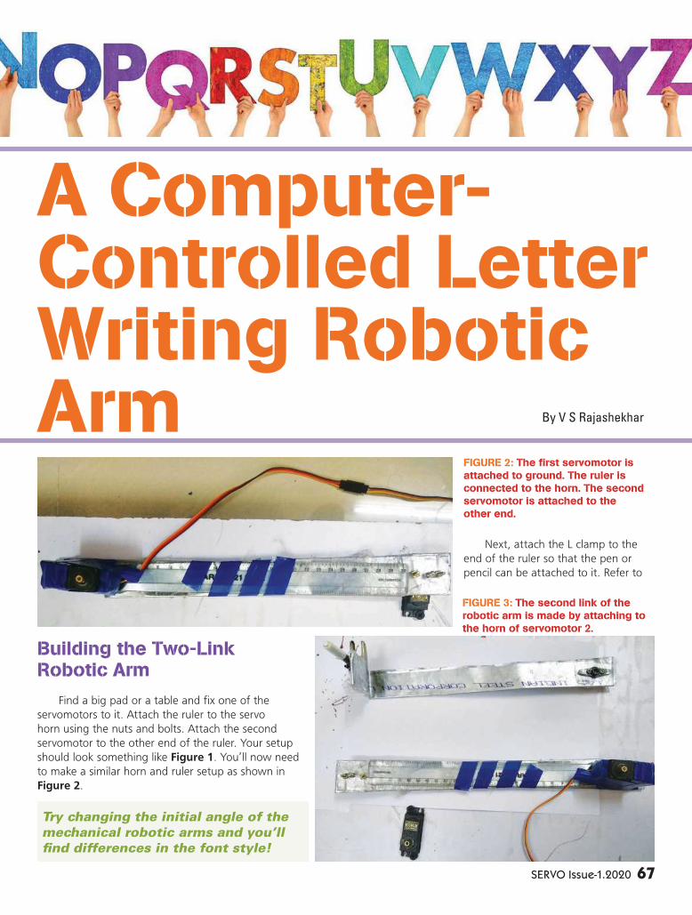
SERVO Issue-1.2020 67
Building the Two-Link Robotic Arm
Find a big pad or a table and fix one of the
servomotors to it. Attach the ruler to the servo
horn using the nuts and bolts. Attach the second
servomotor to the other end of the ruler. Your setup
should look something like Figure 1. You’ll now need
to make a similar horn and ruler setup as shown in
Figure 2.
Next, attach the L clamp to the
end of the ruler so that the pen or
pencil can be attached to it. Refer to
A Computer-Controlled Letter Writing Robotic Arm
FIGURE 2: The first servomotor is attached to ground. The ruler is connected to the horn. The second servomotor is attached to the other end.
FIGURE 3: The second link of the robotic arm is made by attaching to the horn of servomotor 2.
By V S Rajashekhar
Try changing the initial angle of the
mechanical robotic arms and you’ll
find differences in the font style!
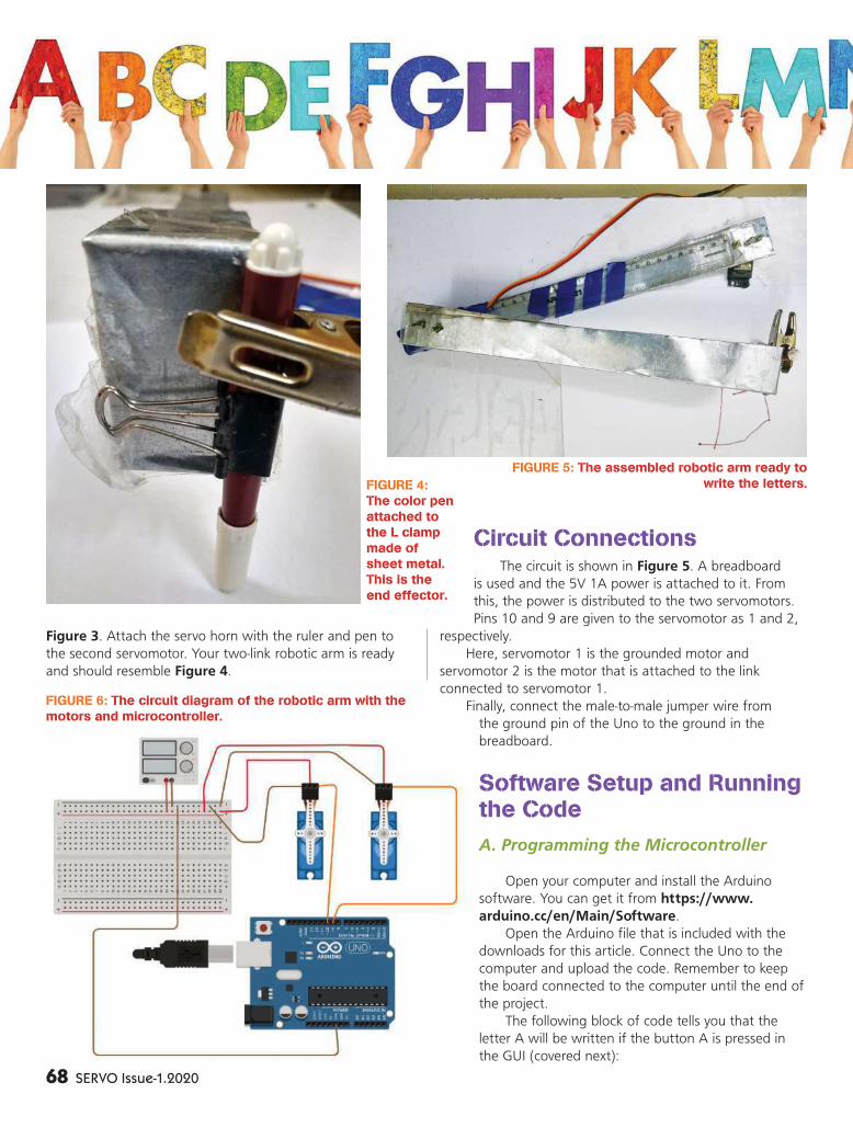
68 SERVO Issue-1.2020
Figure 3. Attach the servo horn with the ruler and pen to
the second servomotor. Your two-link robotic arm is ready
and should resemble Figure 4.
Circuit ConnectionsThe circuit is shown in Figure 5. A breadboard
is used and the 5V 1A power is attached to it. From
this, the power is distributed to the two servomotors.
Pins 10 and 9 are given to the servomotor as 1 and 2,
respectively.
Here, servomotor 1 is the grounded motor and
servomotor 2 is the motor that is attached to the link
connected to servomotor 1.
Finally, connect the male-to-male jumper wire from
the ground pin of the Uno to the ground in the
breadboard.
Software Setup and Running the Code
A. Programming the Microcontroller
Open your computer and install the Arduino
software. You can get it from https://www.
arduino.cc/en/Main/Software.
Open the Arduino file that is included with the
downloads for this article. Connect the Uno to the
computer and upload the code. Remember to keep
the board connected to the computer until the end of
the project.
The following block of code tells you that the
letter A will be written if the button A is pressed in
the GUI (covered next):
FIGURE 6: The circuit diagram of the robotic arm with the
motors and microcontroller.
FIGURE 4:
The color pen
attached to
the L clamp
made of
sheet metal.
This is the
end effector.
FIGURE 5: The assembled robotic arm ready to
write the letters.
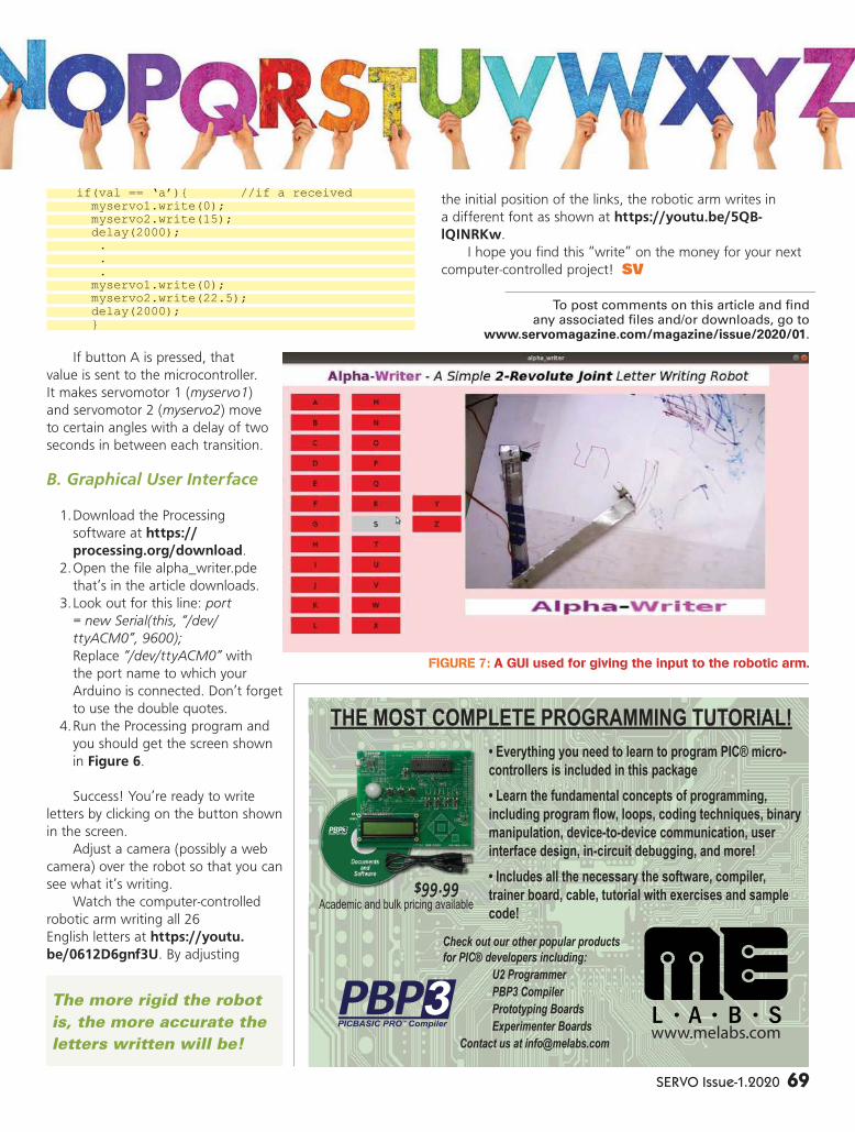
SERVO Issue-1.2020 69
if(val == ‘a’){ //if a received myservo1.write(0); myservo2.write(15); delay(2000); . . . myservo1.write(0); myservo2.write(22.5); delay(2000); }
If button A is pressed, that
value is sent to the microcontroller.
It makes servomotor 1 (myservo1)
and servomotor 2 (myservo2) move
to certain angles with a delay of two
seconds in between each transition.
B. Graphical User Interface
1. Download the Processing
software at https://
processing.org/download.
2. Open the fi le alpha_writer.pde
that’s in the article downloads.
3. Look out for this line: port
= new Serial(this, “/dev/
ttyACM0”, 9600);
Replace “/dev/ttyACM0” with
the port name to which your
Arduino is connected. Don’t forget
to use the double quotes.
4. Run the Processing program and
you should get the screen shown
in Figure 6.
Success! You’re ready to write
letters by clicking on the button shown
in the screen.
Adjust a camera (possibly a web
camera) over the robot so that you can
see what it’s writing.
Watch the computer-controlled
robotic arm writing all 26
English letters at https://youtu.
be/0612D6gnf3U. By adjusting
the initial position of the links, the robotic arm writes in
a different font as shown at https://youtu.be/5QB-
lQINRKw.
I hope you fi nd this “write” on the money for your next
computer-controlled project! SV
www.melabs.com
� Everything you need to learn to program PIC® micro-
controllers is included in this package
� Learn the fundamental concepts of programming,
including program flow, loops, coding techniques, binary
manipulation, device-to-device communication, user
interface design, in-circuit debugging, and more!
� Includes all the necessary the software, compiler,
trainer board, cable, tutorial with exercises and sample
code!
THE MOST COMPLETE PROGRAMMING TUTORIAL!
$99.99Academic and bulk pricing available
Check out our other popular products
for PIC® developers including:
U2 Programmer
PBP3 Compiler
Prototyping Boards
Experimenter Boards
Contact us at [email protected]
PICBASIC PRO™ Compiler
PBP3
FIGURE 7: A GUI used for giving the input to the robotic arm.
The more rigid the robot
is, the more accurate the
letters written will be!
To post comments on this article and fi ndany associated fi les and/or downloads, go to
www.servomagazine.com/magazine/issue/2020/01.

70 SERVO Issue-1.2020
We yearn for the best return on investment
when it comes to selecting a car. Our go-
to parameters to shortlist cars have been
consistent over the years. A standard question
which is still very valid today is, “Mileage kitna deti hai?” or
what is the mileage?
This continues to be a major deal breaker for a good
portion of customers, but most buyers also consider the
size of the vehicle, expected resale value, fuel cost, and
after-market service. As of late, buyers have also started
considering the safety features (airbags, ABS). This was a
result of lenient regulations on the safety requirements.
Early adopters have added another new and very
critical parameter to this checklist, which is whether the car
has in-built connectivity. To understand the importance of
these features, the late adopters need to catch up with this
innovative suite of connected car services or else they will
miss out on a very exciting — yet important — experience.
There’s a saying that the cars we drive say a lot about us. I think this
couldn’t be more true in the world we live in.
Connected Cars — A Fast Brewing World
in Automotive
Somewhere in a Utopian world where each car communicates with one another. After
all, communication is the key to staying connected.

SERVO Issue-1.2020 71
By Abhinav KumarTo post comments on this article, go to www.servomagazine.com/magazine/issue/2020/01.
If the buzz phrase “connected car” caught your
attention, read on.
Let’s begin by answering what a connected car is all
about.
A connected car is a vehicle which has the ability to
communicate with systems both inside and outside, using in-
car connectivity. A connected car has Internet access within
it which allows data sharing with devices (also) both inside
and outside the vehicle.
In more basic terms, you’re driving a vehicle which is
constantly sending key data points from the car to a cloud-
based application hosted at a secure site. Now, please don’t
jump to the conclusion of your privacy being compromised
which is not the case here, but surely one should have
concerns. However, that’s a discussion for another day which
will last for years to come.
Next, you want to inquire about the services which are
enabled in a connected car.
Typically, the following are the broad services which can
be activated using the connected car suite:
1. Car Navigation: The features under this category
allow the driver to make informed decisions on reaching a
destination quickly, safely, and in a cost-effi cient manner
using navigation data (current traffi c information, shortest
routes available, and parking lot or garage assistance,
eventually leading to optimized fuel consumption).
2. E-commerce: This could be an array of services
enabling users to purchase goods or services on-the-fl y. (Pay
for your fuel from your car app, order food and beverages,
pay parking, tolls, etc.)
3. Vehicle Insights: These functions enable drivers to
know the vehicle condition and further help them reduce
operating costs and improve ease of use (vehicle condition
— mainly referred to as telematics — and service scheduling
and reminders based on the vehicle condition, remote
operations, etc.).
4. Breakdown Prevention: This is basically predictive
analytics or data to analyze to predict events. In this, using
a back end algorithm predicting breakdowns and being
connected to a breakdown service, the car has the ability
to use an outbound service intervening via phone, SMS, or
push notifi cation on the connected car app.
5. Safety: These functions intimate the driver of
external hazards and internal responses of the vehicle to
hazards. Basically, in case you have had an unfortunate
crash, your car immediately makes an emergency call
(referred to as e-call) to the responsible call center and
reports the incident (emergency breaking, lane keeping,
adaptive cruise control, and blind spot object identifi cation).
6. Entertainment: This involves integrating content
from various sources on the entertainment unit for the
passengers (smartphone interface, Wi-Fi hotspot, music,
video, Internet, social media, and mobile offi ce).
7. Driver Assistance: These functions comprise of
partially or fully automatic driving. There are in-car speech
recognition or voice activation systems which aim to remove
the distraction of looking at your mobile or car dashboards
while driving (operational assistance or autopilot in heavy
traffi c, in parking, or on highways).
8. Comfort and Well-being: This manages driver’s
comfort and current state to drive (fatigue detection,
automatic environment adjustments to keep drivers alert,
and medical assistance).
It’s obvious to think at this moment that your car
doesn’t do any of this, or possesses just a few functions
but not all. This has already become a hot space to follow,
and automotive OEMs are racing with one another to roll
out these functionalities in more and more models, without
limiting them to their premium ones.
So, let’s take a step back and see how this came into
existence. What was the infl ection point which led to its
discovery?
General Motors was the fi rst automaker to bring the
fi rst connected car features to market with a program called
OnStar in 1996. They started this with the Cadillac DeVille,
Seville, and Eldorado.
In the beginning, the program was limited to
notifi cations of crashes to emergency responders, locating
the vehicle, and roadside assistance. While this began as an
after-market model, i.e., customers can opt for these services
and choose to pay for them like they do with additional
accessories for their cars. In 1998, GM improved the OnStar
service with a change to factory-installed models that allow
for hands-free calling and voice recognition.
During these years, other OEMs geared themselves
up and launched similar suites of services. In 1999,
Mercedes-Benz launched its TeleAid telematics program
with emergency response roadside assistance and location
of stolen vehicles. By 2003, connected car services included
vehicle health reports, turn-by-turn directions, and a network
access device. The OnStar program was such a huge success
that in 2015, OnStar had processed one billion requests
from customers. It’s safe to consider it the benchmark
program in this space.
Clearly, this area has enough promise and has already
delivered value in various ways in different parts of the
world. The strong, steady, and slow world of automotive has
been totally rocked by new technology. It defi nitely gave it
an extra pair of supersonic wings to fl y faster than ever.
There’s a huge ecosystem of connected car services
and mobility services startups, technology giants, consulting
companies, and fi nally, automotive OEMs that are working
tirelessly to modernize the way we commute. SV

Actuonix Motion Devices ���������������������������������� 29
ExpressPCB �����������������������������������������������������������15
goBILDA ��������������������������������������������������������� 37, 75
Hitec RCD USA, Inc� ����������������������������������������������2
IM Service ����������������������������������������������������������� 37
LDG Electronics ������������������������������������Back Cover
M�E� Labs ������������������������������������������������������� 37, 69
Tormach ��������������������������������������������������������������� 36
WONWOO Engineering ���������������������������������������3
ADVERTISER
INDEX
New Products Continued from page 27
1. Six operating modes: torque control; velocitycontrol; position control; extended positioncontrol; current based position control; andPWM control.
2. Profile control for smooth motion planning.3. Improved heatsink featuring an aluminum
case.4. Hollow back case minimizes cable stress
(three-way routing).5. Direct screw assembly to the case (without
nut insert).6. Energy saving; reduced current from 100 mA
to 40 mA.7. 28.4% reduced volume compared to the
MX-106.8. Supports synchronous control mode.
For further information, contact:
ROBOTISwww.robotis.com
Dual 60A Speed Controller
The Sabertooth Dual Drive Board now available from AndyMark is
acceptable for high powered robots up to 120 lbs in combat or up to 1,000 lbs for general-purpose robotics. It can supply two DC brushed motors with up to 60A each. Peak currents of 120A per channel are achievable for a few seconds. Overcurrent and thermal protection integrated into the controller ensure you’ll never have to worry about killing the driver with stalls. Dual motor control can be operated via analog voltage, radio control, serial, and packetized serial. Independent speed and direction operating modes make it the ideal driver for tank-style robots. Price is $190.
The operating mode is set with the onboard DIP switches so there are no jumpers to lose and screw terminals for connections mean no soldering is required. This controller also has synchronous regenerative capabilities. The regenerative topology means that your batteries get recharged whenever you command your robot to slow down or reverse. Sabertooth also allows you to make very fast stops and reverses, giving your robot a quick and nimble
edge. A built-in 5V 1A switch-mode BEC can supply power for your receiver or microcontroller, as well as 3-4 standard analog servos. The lithium cutoff mode allows Sabertooth to operate safely with lithium-ion and lithium polymer battery packs. This component is not legal for the FIRST Robotics Competition and FIRST Tech Challenge robots. Features include:
• Synchronous regenerative drive• Ultrasonic switching frequency• Thermal and overcurrent
protection• Lithium protection mode
• Two-channel 60A continuous delivery
Specifications are:• Input: analog, R/C, simplified serial, packetized serial• Voltage: 6-30V nominal, 33.6V absolute maximum• Weight: 0.664 pounds
For further information, contact:
AndyMarkwww.andymark.com
72 SERVO Issue-1.2020

Some Of Our Most Popular Books On RoboticsRobot Buildingfor Dummies
Robot Builder’s Bonanza - 5th EditionRobot Programmer’s Bonanza
The Ultimate GuideTo DIY Animatronics
Building With Virtual LEGO
SERVO On CD
To Order Visit www.servomagazine.comTo Order Visit www.servomagazine.comor call 1-800-783-4624or call 1-800-783-4624
SERVO Issue-1.2020 73

AT-1000PROII
QRO Auto Tuner to 1000W
� Switch L Network� Dual Antenna� 1000W SSB / 350 W Digital� USB Control
AT-600PROII
600 Watts to Mid Size Amps� Dual Bargraph� 1.8 to 54MHz� 600W SSB / 200W Digital� USB Control
AT-200PROII
200 Watts Desktop� Tunes 10:1 SWR� 2 Year Warranty� 250W SSB / 100W Digital
High Power Desktop
AT-100PROII
� Dual Bargraph� Auto / Semi-Auto Mode� 125W SSB / 30W Digital
Zero Power - Go Box Ready!IcomBalun / Unun
Z-100 PLUS
� Low Cost� Highly Portable� 125W SSB/30W Digital
Designed for portable and low power applications -zero current drawn once tuned.
Z-11PROII
� LED SWR Indicator� 10:1 SWR� 125W SSB/30W Digital
Z-817
� FT-817/818 Compatible� Operates on 4 AAs� 20W SSB/5W Digital
IT-100
� AH-3 & AH-4 Compatible� Includes Interface Cable� 125W SSB / 30W Digital
Tuner dedicated to Icomradios with seamless
integration.
� RU 1:1 UNUN� RU 4:1 UNUN� RU 9:1 UNUN� RBA 4:1 BALUN� RBA 1:1 BALUN� 200W SSB
ANTENNA MATCHING
ACCESSORIES
Special! $229.99 FREE
Shipping
LDG YT-1200With FREE 500mA PowerSupply and FREE Shipping
Call Main Trading1-903-737-0773 +
BEST PRODUCTS. BEST VALUE. BEST WARRANTY. CONTACT YOUR FAVORITE DEALER TODAY!
[email protected] 410-586-2177 www.ldgelectronics.com
R&L Electronics 800-221-7735
Special! $149.00
LDG YT-100
Our Most PopularDesktop Tuner