
CCNA Routing and Switching: Network Basics
533
CCNA Routing and Switching: Network Basics Instructor Lab Manual This document is exclusive property of Cisco Systems, Inc. Permission is granted to print and copy this document for non-commercial distribution and exclusive use by instructors in the CCNA Routing and Switching: Network Basics course as part of an official Cisco Networking Academy Program.
-
Upload
khangminh22 -
Category
Documents
-
view
1 -
download
0
Transcript of CCNA Routing and Switching: Network Basics

CCNA Routing and Switching: Network Basics Instructor Lab Manual
This document is exclusive property of Cisco Systems, Inc. Permission is granted to print and copy this document for non-commercial distribution and exclusive use by instructors in the CCNA Routing and Switching: Network Basics course as part of an official Cisco Networking Academy Program.

©
LVI
T
O
B
R
P
S
© 2013 Cisco and
Lab - IniVersion) nstructor No
Topology
ObjectivesPart 1: Se
Part 2: In
Part 3: In
BackgrounBefore stadevices inlab may ba Cisco sw
Note: TheCisco IOSIOS ReleaDependinfrom what
Required R• 1 Rou
• 1 Swi
• 2 PCs
• Conso
Part 1: S
Step 1: Ca
Attach co
d/or its affiliates.
tializing
ote: Red font
et Up Device
itialize the R
itialize the S
nd / Scenararting a CCNAn use have bebe unpredictabwitch.
e routers usedS Release 15.ase 15.0(2) (lg on the modt is shown in t
Resources uter (Cisco 19
tch (Cisco 29
s (Windows 7
ole cables to
Set Up De
able the netw
nsole cables
All rights reserve
g and Re
color or Gray
es in the Netw
Router and R
Switch and R
rio A hands-on laeen erased anble. This lab p
d with CCNA .2(4)M3 (univanbasek9 ima
del and Cisco the labs.
941 with Cisco
960 with Cisco
7, Vista, or XP
configure the
evices in
work as sho
to the device
ed. This docume
eloading
y highlights ind
work as Show
eload
eload
ab that makesnd have no stprovides a de
hands-on labversalk9 imagage). Other roIOS version,
o IOS softwar
o IOS Releas
P with termina
e Cisco IOS d
the Netw
own in the t
s shown in th
ent is Cisco Publ
g a Rout
dicate text tha
wn in the To
s use of eithetartup configuetail procedure
bs are Cisco 1e). The switcouters, switch the comman
re, Release 1
e 15.0(2) lanb
al emulation p
evices via the
work as S
topology.
he topology di
ic.
ter and S
at appears in
opology
r a Cisco routurations presee for initializin
1941 Integratehes used arehes, and Ciscnds available a
5.2(4)M3 uni
basek9 image
program, such
e console por
hown in t
iagram.
Switch (
the instructo
ter or switch, ent. Otherwiseng and reload
ed Services R Cisco Cataly
co IOS versionand output pr
versal image
e or compara
h as Tera Ter
rts
the Topo
Instructo
r copy only.
ensure that te, the results
ding a Cisco ro
Routers (ISRsyst 2960s withns can be useroduced migh
or comparab
able)
m)
ology
Page 1 of 4
or
the of your outer and
s) with h Cisco ed. ht vary
ble)

Initializing and Reloading a Router and Switch
© 2013 Cisco and/or its affiliates. All rights reserved. This document is Cisco Public. Page 2 of 4
Step 2: Power on all the devices in the topology.
Wait for all devices to finish the software load process before moving to Part 2.
Part 2: Initialize the Router and Reload
Step 1: Connect to the router.
Console into the router and enter privileged EXEC mode using the enable command. Router> enable Router#
Step 2: Erase the startup configuration file from NVRAM.
Type the erase startup-config command to remove the startup configuration from nonvolatile random-access memory (NVRAM).
Router# erase startup-config Erasing the nvram filesystem will remove all configuration files! Continue? [confirm]
[OK]
Erase of nvram: complete
Router#
Step 3: Reload the router.
Issue the reload command to remove an old configuration from memory. When prompted to Proceed with reload, press Enter to confirm the reload. Pressing any other key will abort the reload.
Router# reload Proceed with reload? [confirm] *Nov 29 18:28:09.923: %SYS-5-RELOAD: Reload requested by console. Reload Reason: Reload Command.
Note: You may receive a prompt to save the running configuration prior to reloading the router. Respond by typing no and press Enter. System configuration has been modified. Save? [yes/no]: no
Step 4: Bypass the initial configuration dialog.
After the router reloads, you are prompted to enter the initial configuration dialog. Enter no and press Enter. Would you like to enter the initial configuration dialog? [yes/no]: no
Step 5: Terminate the autoinstall program.
You will be prompted to terminate the autoinstall program. Respond yes and then press Enter. Would you like to terminate autoinstall? [yes]: yes Router>
Part 3: Initialize the Switch and Reload
Step 1: Connect to the switch.
Console into the switch and enter privileged EXEC mode.

Initializing and Reloading a Router and Switch
© 2013 Cisco and/or its affiliates. All rights reserved. This document is Cisco Public. Page 3 of 4
Switch> enable Switch#
Step 2: Determine if there have been any virtual local-area networks (VLANs) created.
Use the show flash command to determine if any VLANs have been created on the switch. Switch# show flash
Directory of flash:/
2 -rwx 1919 Mar 1 1993 00:06:33 +00:00 private-config.text
3 -rwx 1632 Mar 1 1993 00:06:33 +00:00 config.text
4 -rwx 13336 Mar 1 1993 00:06:33 +00:00 multiple-fs
5 -rwx 11607161 Mar 1 1993 02:37:06 +00:00 c2960-lanbasek9-mz.150-2.SE.bin
6 -rwx 616 Mar 1 1993 00:07:13 +00:00 vlan.dat
32514048 bytes total (20886528 bytes free)
Switch#
Step 3: Delete the VLAN file.
a. If the vlan.dat file was found in flash, then delete this file. Switch# delete vlan.dat Delete filename [vlan.dat]?
You will be prompted to verify the file name. At this point, you can change the file name or just press Enter if you have entered the name correctly.
b. When you are prompted to delete this file, press Enter to confirm the deletion. (Pressing any other key will abort the deletion.) Delete flash:/vlan.dat? [confirm]
Switch#
Step 4: Erase the startup configuration file.
Use the erase startup-config command to erase the startup configuration file from NVRAM. When you are prompted to remove the configuration file, press Enter to confirm the erase. (Pressing any other key will abort the operation.)
Switch# erase startup-config Erasing the nvram filesystem will remove all configuration files! Continue? [confirm]
[OK]
Erase of nvram: complete
Switch#
Step 5: Reload the switch.
Reload the switch to remove any old configuration information from memory. When you are prompted to reload the switch, press Enter to proceed with the reload. (Pressing any other key will abort the reload.)
Switch# reload Proceed with reload? [confirm]
Note: You may receive a prompt to save the running configuration prior to reloading the switch. Type no and press Enter.

Initializing and Reloading a Router and Switch
© 2013 Cisco and/or its affiliates. All rights reserved. This document is Cisco Public. Page 4 of 4
System configuration has been modified. Save? [yes/no]: no
Step 6: Bypass the initial configuration dialog.
After the switch reloads, you should see a prompt to enter the initial configuration dialog. Type no at the prompt and press Enter.
Would you like to enter the initial configuration dialog? [yes/no]: no Switch>
Reflection 1. Why is it necessary to erase the startup configuration before reloading the router?
_______________________________________________________________________________________
The startup configuration file is loaded into memory and becomes the running-config after the router reloads. Erasing this file allows the router to return to its basic configuration after a reload.
2. You find a couple configurations issues after saving the running configuration to the startup configuration, so you make the necessary changes to fix those issues. If you were to reload the device now, what configuration would be restored to the device after the reload?
_______________________________________________________________________________________
The configuration at the time of the last save is restored to the device after a reload. Any changes made to the running configuration after the last save would be lost.

© 2013 Cisco and/or its affiliates. All rights reserved. This document is Cisco Public. Page 1 of 5
Lab - Installing the IPv6 Protocol and Assigning Host Addresses with Windows XP (Instructor Version) Instructor Note: Red font color or Gray highlights indicate text that appears in the instructor copy only.
Objectives Part 1: Install the IPv6 Protocol on a Windows XP PC
• Install the IPv6 protocol.
• Examine IPv6 address information.
Part 2: Use the Network Shell (netsh) Utility
• Work inside the netsh utility.
• Configure a static IPv6 address on the local-area network (LAN) interface.
• Exit the netsh utility.
• Display IPv6 address information using netsh.
• Issue netsh instructions from the command prompt.
Background / Scenario The Internet Protocol Version 6 (IPv6) is not enabled by default in Windows XP. Windows XP includes IPv6 implementation, but the IPv6 protocol must be installed. XP does not provide a way to configure IPv6 static addresses from the Graphical User Interface (GUI), so all IPv6 static address assignments must be done using the Network Shell (netsh) utility.
In this lab, you will install the IPv6 protocol on a Windows XP PC. You will then assign a static IPv6 address to the LAN interface.
Required Resources 1 Windows XP PC
Part 1: Install the IPv6 Protocol on a Windows XP PC In Part 1, you will install the IPv6 protocol on a PC running Windows XP. You will also use two commands to view the IPv6 addresses assigned to the PC.
Step 1: Install the IPv6 protocol.
From the command prompt window, type ipv6 install to install the IPv6 protocol.
Step 2: Examine IPv6 Address Information.
Use the ipconfig /all command to view IPv6 address information.

Installing the IPv6 Protocol and Assigning Host Addresses with Windows XP
© 2013 Cisco and/or its affiliates. All rights reserved. This document is Cisco Public. Page 2 of 5
Part 2: Use the Network Shell (netsh) Utility Network Shell (netsh) is a command-line utility included with Windows XP and newer Windows operating systems, such as Vista and Windows 7. It allows you to configure the IPv6 address information on your LAN. In Part 2, you will use the netsh utility to configure static IPv6 address information on a Windows XP PC LAN interface. You will also use the netsh utility to display the PC LAN interface IPv6 address information.
Step 1: Work inside the Network Shell utility.
a. From the command prompt window, type netsh and press Enter to start the netsh utility. The command prompt changes from C:\> to netsh>.
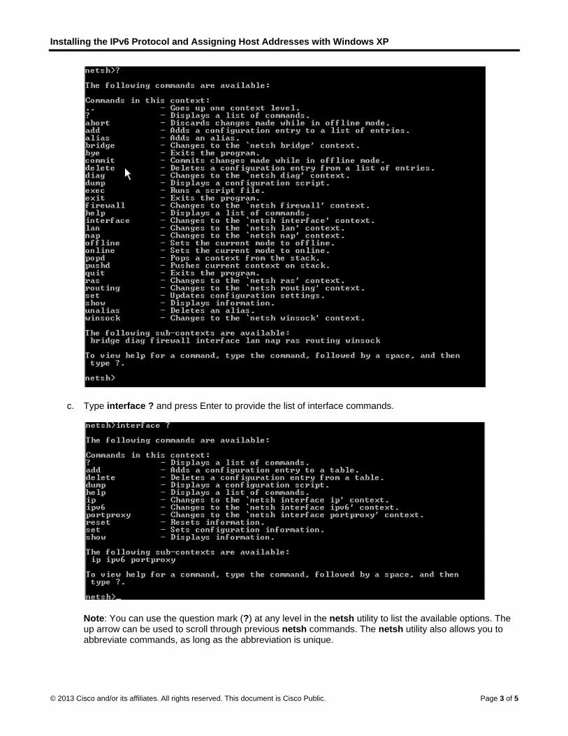
b. At the prompt, enter a question mark (?) and press Enter to provide the list of available parameters.
Installing the IPv6 Protocol and Assigning Host Addresses with Windows XP
© 2013 Cisco and/or its affiliates. All rights reserved. This document is Cisco Public. Page 3 of 5
c. Type interface ? and press Enter to provide the list of interface commands.
Note: You can use the question mark (?) at any level in the netsh utility to list the available options. The up arrow can be used to scroll through previous netsh commands. The netsh utility also allows you to abbreviate commands, as long as the abbreviation is unique.

Installing the IPv6 Protocol and Assigning Host Addresses with Windows XP
© 2013 Cisco and/or its affiliates. All rights reserved. This document is Cisco Public. Page 4 of 5
Step 2: Configure a static IPv6 address on the LAN interface.
To add a static IPv6 address to the LAN interface, issue the interface ipv6 add address command from inside the netsh utility.
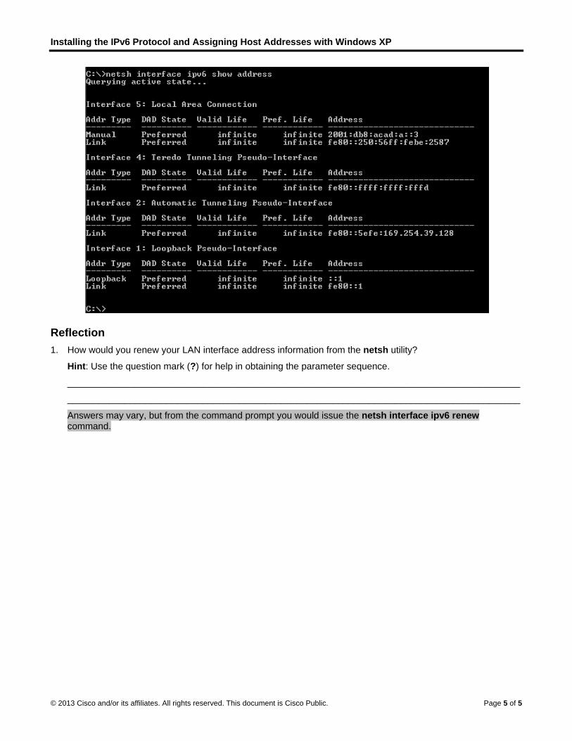
Step 3: Display IPv6 address information using the netsh utility.
You can display IPv6 address information using the interface ipv6 show address command.
Step 4: Exit the netsh utility.
Use the exit command to exit from the netsh utility.
Step 5: Issue netsh instructions from the command prompt.
All netsh instructions can be entered from the command prompt, outside the netsh utility, by preceding the instruction with the netsh command.
Installing the IPv6 Protocol and Assigning Host Addresses with Windows XP
© 2013 Cisco and/or its affiliates. All rights reserved. This document is Cisco Public. Page 5 of 5
Reflection 1. How would you renew your LAN interface address information from the netsh utility?
Hint: Use the question mark (?) for help in obtaining the parameter sequence.
_______________________________________________________________________________________
_______________________________________________________________________________________
Answers may vary, but from the command prompt you would issue the netsh interface ipv6 renew command.

© 2013 Cisco and/or its affiliates. All rights reserved. This document is Cisco Public. Page 1 of 2
Draw Your Concept of the Internet (Instructor Version) Instructor Note: Red font color or Gray highlights indicate text that appears in the instructor copy only.
Objectives Networks are made of many different components
In this activity, you will visualize how you are connected, through the Internet, to those places, people, or businesses with whom (or which) you interact on a daily basis. After reflection and sketching your home’s or school’s topology, you can draw conclusions about the Internet that you may not have thought of prior to this activity.
Background / Scenario Draw and label a map of the Internet as you interpret it now. Include your home or school/university location and its respective cabling, equipment, devices, etc. Some items you may want to include:
• Devices or equipment
• Media (cabling)
• Link addresses or names
• Sources and destinations
• Internet service providers
Upon completion, save your work in a hard-copy format, it will be used for future reference at the end of this chapter. If it is an electronic document, save it to a server location provided by your instructor. Be prepared to share and explain your work in class.
For an example to get you started, please visit: http://www.kk.org/internet-mapping
Instructor Note: This Modeling Activity is not intended to be a graded assignment. Its purpose is to help students to reflect on their perceptions of how a network is set up for personal use. Discussion should be facilitated by the instructor as a result of this activity. Facilitation of the discussion should include student-to-student discussions of each other’s work.
Required Resources • Internet access
• Paper and pencils or pens (if students are creating a hard copy)
Reflection 1. After reviewing your classmates drawings, were there computer devices that you could have included on your
diagram? If so, which ones and why?
_______________________________________________________________________________________
Answers will vary.
2. After reviewing your classmates’ drawings, how were some of the model designs the same or different? What modifications would you make to your drawing after reviewing the other drawings?
_______________________________________________________________________________________
Answers will vary.
3. In what way could icons on a network drawing provide a streamlined thought process and facilitate your learning? Explain your answer.

D
©
Idr
Draw Your C
© 2013 Cisco and
________
Students network rethe icons
nitial Netwdesign repreference.)
oncept of th
d/or its affiliates.
___________
should note tepresentationrepresent. It
work Diagraresentatio)
e Internet
All rights reserve
____________
hat having a n. It consolidais a form of s
ams and Non from the
ed. This docume
___________
set of represeates informatiohorthand for p
Network Coe website is
ent is Cisco Publ
___________
entative iconson, and is easpeople in the
omponentss depicted
ic.
____________
s will assist thsily understoosame industr
s – will varyd below (th
____________
hem in learninod by others wry.
y. A very is diagram
___________
ng how to drawwho understa
basic netwm is for Inst
Page 2 of 2
________
w/design and what
work tructor
© 2013 Cisco and/or its affiliates. All rights reserved. This document is Cisco Public. Page 1 of 17
Lab - Researching Network Collaboration Tools (Instructor Version) Instructor Note: Red font color or Gray highlights indicate text that appears in the instructor copy only.
Objectives Part 1: Use Collaboration Tools
• Identify current awareness of collaboration tools.
• Identify key reasons for using collaboration tools.
Part 2: Share Documents with Google Drive
Part 3: Explore Conferencing and Web Meetings
Part 4: Create Wiki Pages
Background / Scenario Network collaboration tools give people the opportunity to work together efficiently and productively without the constraints of location or time zone. Collaborative tool types include document sharing, web meetings, and wikis.
In Part 1, you will identify collaboration tools that you currently use. You will also research some popular collaborative tools used today. In Part 2, you will work with Google Drive. In Part 3, you will investigate Conferencing and Web meeting tools and, in Part 4, you will work with wikis.
Instructor Note: This lab may be assigned as homework.
Required Resources Device with Internet access
Part 1: Use Collaboration Tools
Step 1: List some collaboration tools that you currently use today.
____________________________________________________________________________________
____________________________________________________________________________________
Answers will vary but could include: Google Drive, Cisco Webex, Citrix Go to Meeting, Confluence Wiki.
Step 2: List some reasons for using collaboration tools.
____________________________________________________________________________________
____________________________________________________________________________________
Answers will vary but could include: centralization, less email, reduced travel and less environmental impact.
Part 2: Share Documents with Google Drive In Part 2, you will explore the document sharing functions by using Google Drive to set up document sharing. Google Drive, formally Google Docs, is a web-based office suite and data storage service that allows users to create and edit documents online while collaborating in real-time with other users. Google Drive provides 5 GB of storage with every free Google account. You can purchase additional storage, if needed.
Lab - Researching Network Collaboration Tools
© 2013 Cisco and/or its affiliates. All rights reserved. This document is Cisco Public. Page 2 of 17
Step 1: Create a Google account.
To use any of Google’s services, you must first create a Google account. This account can be used with any of Google’s services, including Gmail.
a. Browse to www.google.com and click Sign in (located at the top-right corner of the web page).
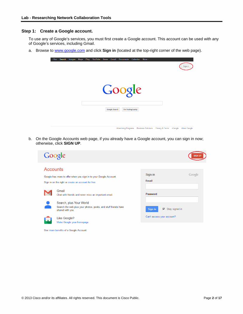
b. On the Google Accounts web page, if you already have a Google account, you can sign in now; otherwise, click SIGN UP.

Lab - Researching Network Collaboration Tools
© 2013 Cisco and/or its affiliates. All rights reserved. This document is Cisco Public. Page 3 of 17
c. On the Create a new Google Account web page, fill out the form to the right. The name you enter in the Choose your username field becomes the account name. It is not necessary to supply your mobile phone or current email address. You must agree to the Google Terms of Service and Privacy Policy before clicking Next step.
Lab - Researching Network Collaboration Tools
© 2013 Cisco and/or its affiliates. All rights reserved. This document is Cisco Public. Page 4 of 17
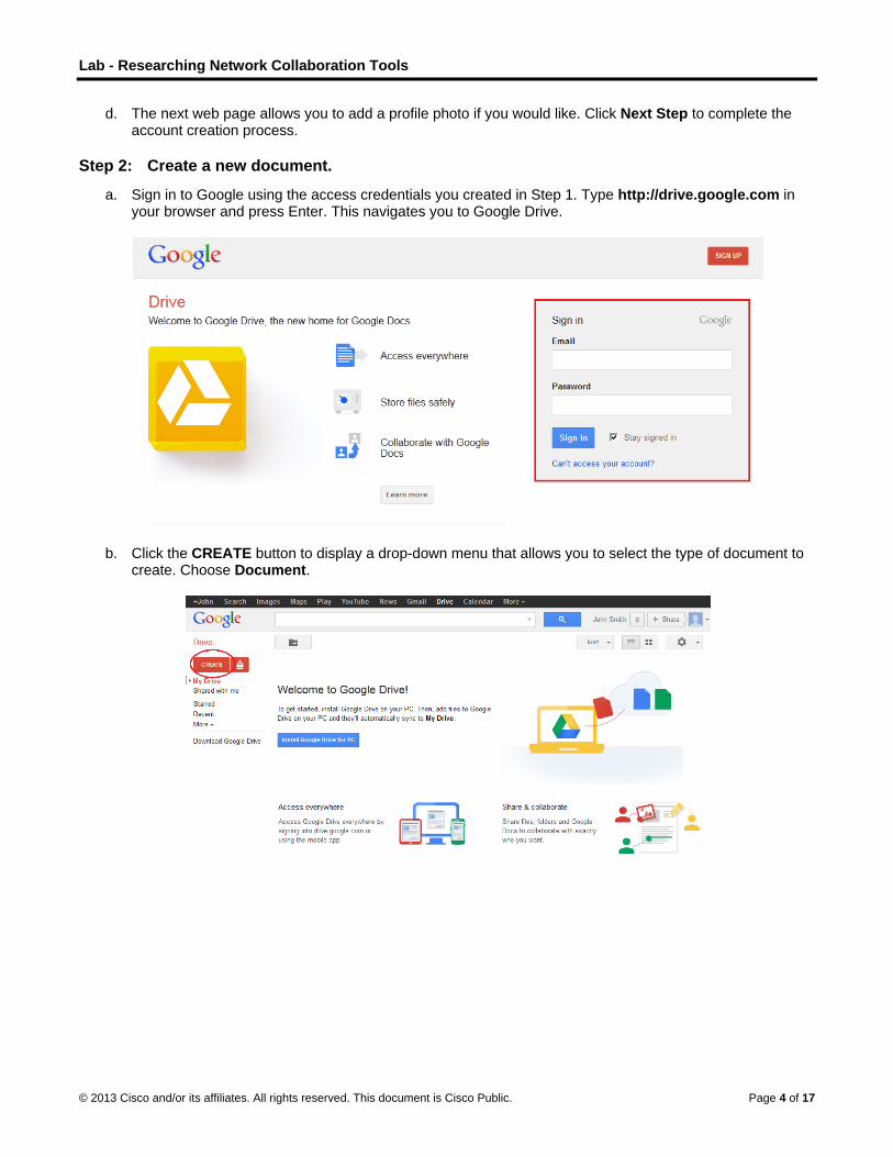
d. The next web page allows you to add a profile photo if you would like. Click Next Step to complete the account creation process.
Step 2: Create a new document.
a. Sign in to Google using the access credentials you created in Step 1. Type http://drive.google.com in your browser and press Enter. This navigates you to Google Drive.
b. Click the CREATE button to display a drop-down menu that allows you to select the type of document to create. Choose Document.

Lab - Researching Network Collaboration Tools
© 2013 Cisco and/or its affiliates. All rights reserved. This document is Cisco Public. Page 5 of 17
The new document displays. Many of the functions of the Google editor work similarly to Microsoft Word.
Step 3: Share a Google document.
a. After the blank Google document opens, you can share it with others by clicking the Share button (at the top-right corner of the web page).
b. Name your new document, then click the Save button.
Lab - Researching Network Collaboration Tools
© 2013 Cisco and/or its affiliates. All rights reserved. This document is Cisco Public. Page 6 of 17
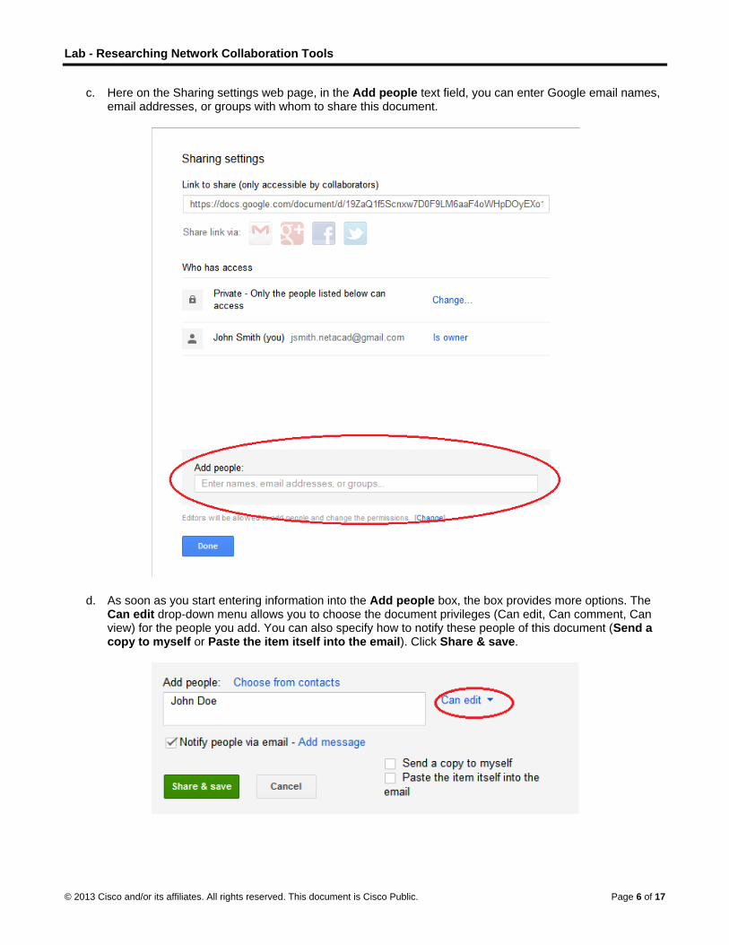
c. Here on the Sharing settings web page, in the Add people text field, you can enter Google email names, email addresses, or groups with whom to share this document.
d. As soon as you start entering information into the Add people box, the box provides more options. The Can edit drop-down menu allows you to choose the document privileges (Can edit, Can comment, Can view) for the people you add. You can also specify how to notify these people of this document (Send a copy to myself or Paste the item itself into the email). Click Share & save.
Lab - Researching Network Collaboration Tools
© 2013 Cisco and/or its affiliates. All rights reserved. This document is Cisco Public. Page 7 of 17
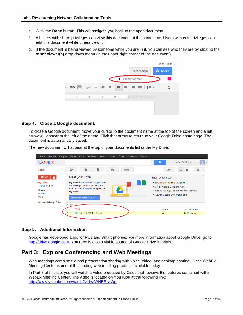
e. Click the Done button. This will navigate you back to the open document.
f. All users with share privileges can view this document at the same time. Users with edit privileges can edit this document while others view it.
g. If the document is being viewed by someone while you are in it, you can see who they are by clicking the other viewer(s) drop-down menu (in the upper-right corner of the document).
Step 4: Close a Google document.
To close a Google document, move your cursor to the document name at the top of the screen and a left arrow will appear to the left of the name. Click that arrow to return to your Google Drive home page. The document is automatically saved.
The new document will appear at the top of your documents list under My Drive.
Step 5: Additional Information
Google has developed apps for PCs and Smart phones. For more information about Google Drive, go to http://drive.google.com. YouTube is also a viable source of Google Drive tutorials.
Part 3: Explore Conferencing and Web Meetings Web meetings combine file and presentation sharing with voice, video, and desktop sharing. Cisco WebEx Meeting Center is one of the leading web meeting products available today.
In Part 3 of this lab, you will watch a video produced by Cisco that reviews the features contained within WebEx Meeting Center. The video is located on YouTube at the following link: http://www.youtube.com/watch?v=fyaWHEF_aWg

Lab - Researching Network Collaboration Tools
© 2013 Cisco and/or its affiliates. All rights reserved. This document is Cisco Public. Page 8 of 17
Instructor Note: For additional WebEx conferencing tools, you can register for a free WebEx Meeting Basics account at www.webex.com.
Part 4: Create Wiki Pages “Wiki” is a Hawaiian-language word that means fast. In networking terms, a wiki is a web-based collaboration tool that permits almost anyone to immediately post information, files, or graphics to a common site for other users to read and modify. A wiki provides access to a home page that has a search tool to assist you in locating the articles that interest you. A wiki can be installed for the Internet community or behind a corporate firewall for employee use. The user not only reads wiki contents, but also participates by creating content within a web browser.
Although many different wiki servers are available, the following common features have been formalized into every wiki:
• Any web browser can be used to view or edit pages or create new content.
• Edit and auto links are available to edit a page and automatically link pages. Text formatting is similar to creating an email.
• A search engine is used for quick content location.
• Access control can be set by the topic creator, defining who is permitted to edit content.
• A wiki is a grouping of web pages with different collaboration groups.
In this part of the lab, you will use the Google account that you created in Part 2 and create a wiki page in Google Sites.
Step 1: Sign in to Google Sites.
Go to http://sites.google.com and sign in using the Google account that you created in Part 2 of this lab.

Lab - Researching Network Collaboration Tools
© 2013 Cisco and/or its affiliates. All rights reserved. This document is Cisco Public. Page 9 of 17
Step 2: Click CREATE.
Step 3: Name your new wiki site.
In the Name your site field, type in a name for your new wiki site. You will need to come up with a unique name for your site that has not been used by any other Google user. Google also requires that you enter the code (displayed at the bottom of the screen) to prevent automated scripts, called web robots, from creating multiple sites. After you have entered your site name, click the CREATE button. If someone has used your site name already, you are prompted to enter another name.

Lab - Researching Network Collaboration Tools
© 2013 Cisco and/or its affiliates. All rights reserved. This document is Cisco Public. Page 10 of 17

Lab - Researching Network Collaboration Tools
© 2013 Cisco and/or its affiliates. All rights reserved. This document is Cisco Public. Page 11 of 17
Step 4: Edit the look of your new wiki site.
a. Google has provided templates for you to change the look of your new wiki site. Click the More drop-down menu, and then click Manage site.

Lab - Researching Network Collaboration Tools
© 2013 Cisco and/or its affiliates. All rights reserved. This document is Cisco Public. Page 12 of 17
b. Click Themes at the bottom of the left sidebar.
c. Select a theme that appeals to you and click SAVE.

Lab - Researching Network Collaboration Tools
© 2013 Cisco and/or its affiliates. All rights reserved. This document is Cisco Public. Page 13 of 17
d. After you have saved your theme selection, click your site name under Manage Site.
Step 5: Update the Home page.
a. The Home page is the first page that everyone sees when they come to your wiki site. You can edit the content of this page by clicking the edit button. From here, you can add text, pictures, or anything else to show on this page.
b. Click Save after you make your changes. This takes you out of page edit mode.

Lab - Researching Network Collaboration Tools
© 2013 Cisco and/or its affiliates. All rights reserved. This document is Cisco Public. Page 14 of 17
Step 6: Create a wiki page.
a. To create a new page that you and your visitors can use to make posts, click the new page icon.
b. In the Name your page field, enter a page name. In the example below, the name Routers is used as the topic for this page.
c. Click the Web Page drop-down menu and select Announcements. Google uses this term to indicate a wiki page.
Lab - Researching Network Collaboration Tools
© 2013 Cisco and/or its affiliates. All rights reserved. This document is Cisco Public. Page 15 of 17
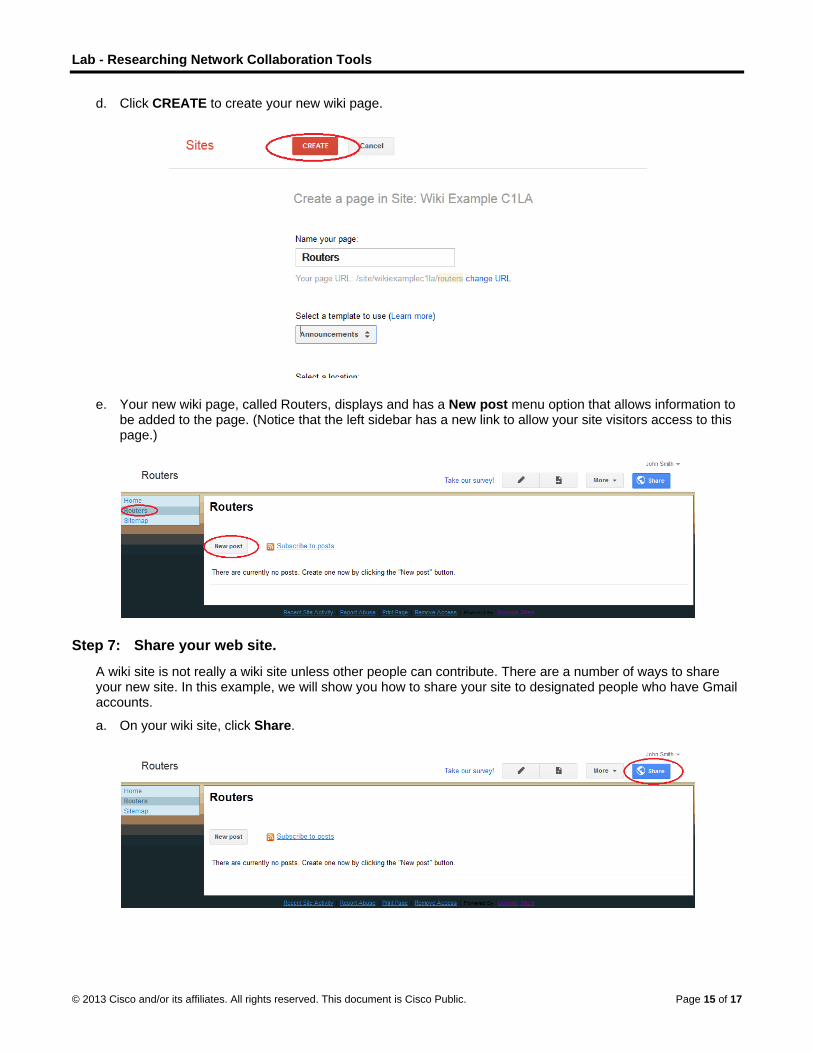
d. Click CREATE to create your new wiki page.
e. Your new wiki page, called Routers, displays and has a New post menu option that allows information to be added to the page. (Notice that the left sidebar has a new link to allow your site visitors access to this page.)
Step 7: Share your web site.
A wiki site is not really a wiki site unless other people can contribute. There are a number of ways to share your new site. In this example, we will show you how to share your site to designated people who have Gmail accounts.
a. On your wiki site, click Share.
Lab - Researching Network Collaboration Tools
© 2013 Cisco and/or its affiliates. All rights reserved. This document is Cisco Public. Page 16 of 17
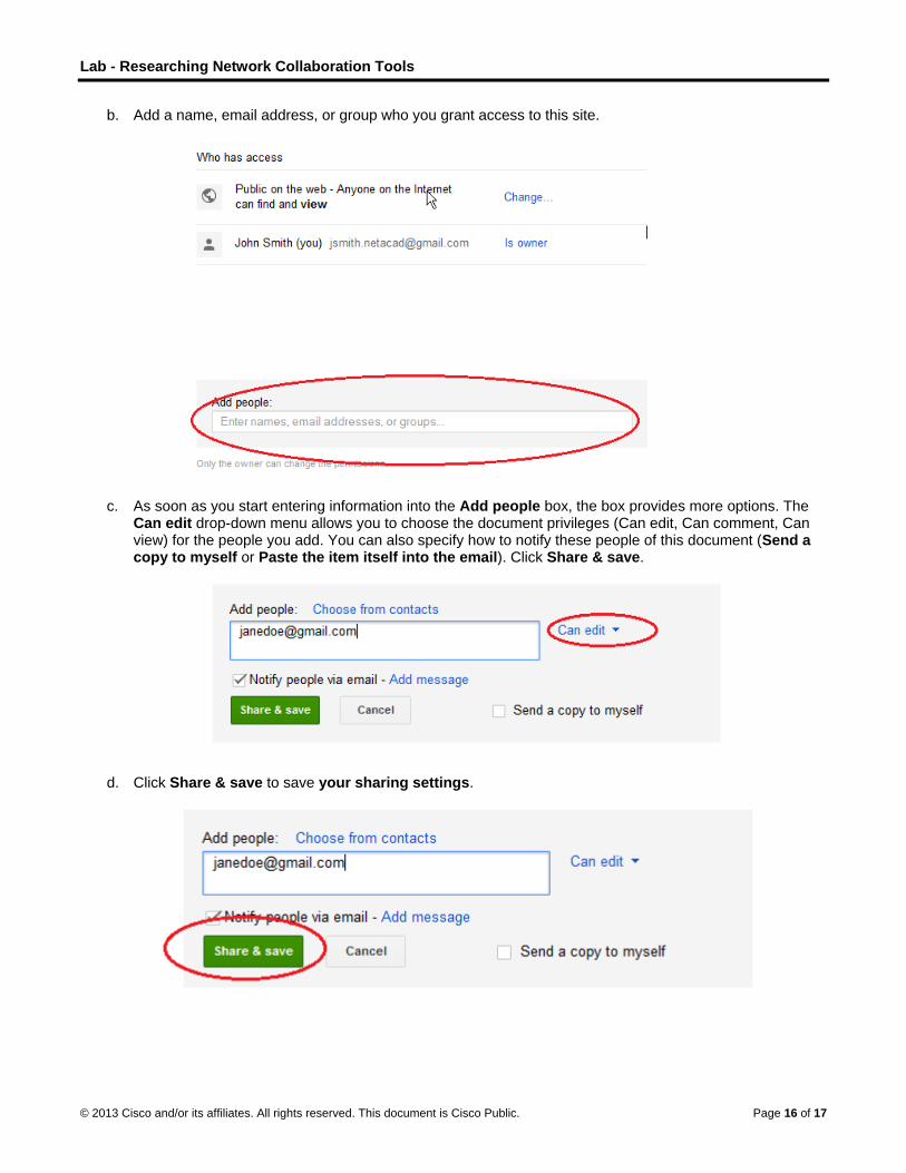
b. Add a name, email address, or group who you grant access to this site.
c. As soon as you start entering information into the Add people box, the box provides more options. The Can edit drop-down menu allows you to choose the document privileges (Can edit, Can comment, Can view) for the people you add. You can also specify how to notify these people of this document (Send a copy to myself or Paste the item itself into the email). Click Share & save.
d. Click Share & save to save your sharing settings.

Lab - Researching Network Collaboration Tools
© 2013 Cisco and/or its affiliates. All rights reserved. This document is Cisco Public. Page 17 of 17
e. The Manage Site page displays the people who have access to your site. Click your site name to return to your home page.
Step 8: Provide the URL of your site.
You can provide your URL to your new site by adding your site name to the end of the Google site URL, as shown here: http://sites.google.com/site/(sitename).
Step 9: Find additional information.
You can find a quick overview of how a wiki works at http://www.youtube.com/watch?v=-dnL00TdmLY.
Other examples of wikis and their web sites include:
• Wikipedia — http://www.wikipedia.org/
• Atlassian Confluence (a popular business wiki) — http://www.atlassian.com/software/confluence/
• Wikispaces (another free wiki) — http://www.wikispaces.com/
Reflection 1. Can you think of other collaboration tools used in the business world today?
_______________________________________________________________________________________
Answers will vary.
2. What collaboration tools do you see as useful to a network administrator?
_______________________________________________________________________________________
Answers will vary.

© 2013 Cisco and/or its affiliates. All rights reserved. This document is Cisco Public. Page 1 of 4
Lab - Researching Converged Network Services (Instructor Version) Instructor Note: Red font color or Gray highlights indicate text that appears in the instructor copy only.
Objectives Part 1: Survey Your Understanding of Convergence
Part 2: Research ISPs Offering Converged Services
Part 3: Research Local ISPs Offering Converged Services
Part 4: Select Best Local ISP Converged Service
Part 5: Research Local Company or Public Institution Using Convergence Technologies
Background / Scenario Convergence in the context of networking is a term used to describe the process of combining voice, video, and data communications over a common network infrastructure. Converged networks have existed for some time, but were only feasible in large enterprise organizations because of the network infrastructure requirements and complex management required to make them work seamlessly. Technology advances have made convergence readily available to large, medium, and small businesses, as well as for the home consumer.
In Part 1, you will describe your current understanding of convergence and any experience you have with it.
In Part 2, you will research which providers have this service, regardless of geographical location, using the predefined form included in the lab.
In Part 3, you will research which local ISPs in your area offer converged services for end-user consumers, using the predefined form included in the lab.
In Part 4, you will select the ISP you like best for home use and list the reasons why.
In Part 5, you will find a local company or public institution using convergence technologies in their business, using the predefined form included in the lab.
Required Resources Device with Internet access
Part 1: Survey Your Understanding on Convergence Instructor Note: In Part 1, the instructor may wish to lead a discussion with students on their understanding of convergence, its definition and the possible technologies used. This lab may be assigned as homework.
Step 1: Describe convergence as you understand it and give examples of its use in the home.
Write a definition of convergence and list some examples.
_______________________________________________________________________________________
_______________________________________________________________________________________
_______________________________________________________________________________________
_______________________________________________________________________________________
_______________________________________________________________________________________
_______________________________________________________________________________________

Lab - Researching Converged Network Services
© 2013 Cisco and/or its affiliates. All rights reserved. This document is Cisco Public. Page 2 of 4
_______________________________________________________________________________________
Convergence - Converged networks are capable of delivering voice, video streams, text, and graphics between many different types of devices over the same communication channel and network structure. On a converged network, there are still many points of contact and many specialized devices such as personal computers, phones, TVs, and tablet computers, but there is one common network infrastructure. An example of a converged network at home is a Triple Play service from Charter.com. Voice, Video (TV) and phone are bundled together and come into the home on one cable, typically hybrid fiber coax.
Part 2: Research ISPs Offering Converged Services In Part 2, you research and find two or three ISPs who offer converged services for the home, regardless of geographical location.
Step 1: Research various ISPs that offer converged services.
List some of the ISPs that you found in your search.
_____________________________________________________________________________________
Comcast
Charter
AT&T
Step 2: Fill in the following form for the ISPs selected.
Internet Service Provider Product Name of Converged Service
Comcast Xfinity Triple Play
Time Warner Cable TV, Internet,and Phone
AT&T AT&T U-verse
Part 3: Researching Local ISPs Offering Converged Services In Part 3, you research and find two or three local ISPs who offer converged services for the home in your geographic area.
Step 1: Research various ISPs that offer converged services.
List some of the ISPs that you found in your search.
____________________________________________________________________________________
Answers will vary based on geographic location.

Lab - Researching Converged Network Services
© 2013 Cisco and/or its affiliates. All rights reserved. This document is Cisco Public. Page 3 of 4
Step 2: Fill in the following form for the ISPs selected.
Internet Service Provider
Product Name of Converged Service Cost per Month Download Speed
Comcast Xfinity Triple Play $89.99 Varies 10 to 16 Mbps
Time Warner Cable TV, Internet,and Phone $99.99 10 Mbps
AT&T U-Verse $59.00 3Mbps Download
Part 4: Select Best Local ISP Converged Service Offering Select your top choice from the list of local ISPs that you selected and give reasons why you chose that particular one.
_______________________________________________________________________________________
_______________________________________________________________________________________
_______________________________________________________________________________________
_______________________________________________________________________________________
_______________________________________________________________________________________
_______________________________________________________________________________________
Answers will vary and will be typically based on price per month and relative priority of Internet speeds versus number of TV channels offered in the basic packages. Student may choose Comcast for higher download speeds for Internet. Emphasize to students that home users’ priorities can affect their choice of service. For example, users who stream movies exclusively may want higher download speeds versus a user who mainly does casual surfing of the Internet and checks email.
Part 5: Research Local Company or Public Institution Using Convergence Technologies
In Part 5, you research and locate a company in your area that currently uses convergence technologies in their business.
Step 1: Research and find a local company using convergence.
In the following table, list the company, industry, and convergence technologies used.
Name of Company Industry Convergence Technologies
Cisco Systems, Inc. Information Technology Phone, Video, Data
Woodward, Inc. Aerospace Phone, Video, Data
Reflection 1. What are some of the advantages of using convergence technologies?
_______________________________________________________________________________________
_______________________________________________________________________________________
_______________________________________________________________________________________

Lab - Researching Converged Network Services
© 2013 Cisco and/or its affiliates. All rights reserved. This document is Cisco Public. Page 4 of 4
Blending voice, video and data signals onto one communication infrastructure allows companies to better manage the technology since the network will use a common set of rules and standards. The need for separate distribution equipment for offering voice and data will no longer be necessary.
2. What are some of the disadvantages of using convergence technologies?
_______________________________________________________________________________________
_______________________________________________________________________________________
_______________________________________________________________________________________
Until the technologies fully mature, configuration and management of voice, video and data flowing on one channel can be a challenge. Giving voice precedence over data using Quality of Service (QoS) technologies can be quite complex for companies that don’t have trained IT personnel on staff.
© 2013 Cisco and/or its affiliates. All rights reserved. This document is Cisco Public. Page 1 of 14
Lab - Mapping the Internet (Instructor Version) Instructor Note: Red font color or Gray highlights indicate text that appears in the instructor copy only.
Objectives Part 1: Test Network Connectivity Using Ping
Part 2: Trace a Route to a Remote Server Using Windows Tracert
Part 3: Trace a Route to a Remote Server Using Web-Based and Software Tools
Part 4: Compare Traceroute Results
Background Route tracing computer software is a utility that lists the networks data has to traverse from the user's originating end device to a distant destination network.
This network tool is typically executed at the command line as: tracert <destination network name or end device address>
(Microsoft Windows systems)
or traceroute <destination network name or end device address>
(Unix and similar systems)
Route tracing utilities allow a user to determine the path or routes as well as the delay across an IP network. Several tools exist to perform this function.
The traceroute (or tracert) tool is often used for network troubleshooting. By showing a list of routers traversed, it allows the user to identify the path taken to reach a particular destination on the network or across internetworks. Each router represents a point where one network connects to another network and through which the data packet was forwarded. The number of routers is known as the number of "hops" the data traveled from source to destination.
The displayed list can help identify data flow problems when trying to access a service such as a website. It can also be useful when performing tasks such as downloading data. If there are multiple websites (mirrors) available for the same data file, one can trace each mirror to get a good idea of which mirror would be the fastest to use.
Two trace routes between the same source and destination conducted some time apart may produce different results. This is due to the "meshed" nature of the interconnected networks that comprise the Internet and the Internet Protocols ability to select different pathways over which to send packets.
Command-line-based route tracing tools are usually embedded with the operating system of the end device.
Other tools, such as VisualRoute™, are proprietary programs that provide extra information. VisualRoute uses available online information to graphically display the route.
This lab assumes the installation of VisualRoute. If the computer you are using does not have VisualRoute installed, you can download the program using the following link:
http://www.visualroute.com/download.html
If you have any trouble downloading or installing VisualRoute, ask your instructor for assistance. Ensure that you download the Lite Edition.

Lab - Mapping the Internet
© 2013 Cisco and/or its affiliates. All rights reserved. This document is Cisco Public. Page 2 of 14
Scenario Using an Internet connection, you will use three route tracing utilities to examine the Internet pathway to destination networks. This activity should be performed on a computer that has Internet access and access to the command line. First, you will use the Windows embedded tracert utility. Second, you will use a web-based traceroute tool (http://www.subnetonline.com/pages/network-tools/online-traceroute.php). Finally, you will use the VisualRoute traceroute program.
Instructor Note: Many schools do not have access to the command prompt. Traceroutes are included in Appendix A for your use. Depending on the situation, this lab can be assigned in the classroom, as homework or can be performed by the instructor as a walk-through demonstration.
Free software programs like VisualRoute can quickly go out of date. If VisualRoute Lite Edition is no longer available when you are using this lab, type into your favorite search engine, “download visual traceroute tool”.
Some institutions disable ICMP echo replies used by both ping and traceroute utilities. Before students begin this activity, make sure there are no local restrictions related to ICMP datagrams. This activity assumes that ICMP datagrams are not restricted by any local security policy.
Required Resources 1 PC (Windows 7, Vista, or XP with Internet access)
Part 1: Test Network Connectivity Using Ping
Step 1: Determine whether the remote server is reachable.
To trace the route to a distant network, the PC used must have a working connection to the Internet.
a. The first tool we will use is ping. Ping is a tool used to test whether a host is reachable. Packets of information are sent to the remote host with instructions to reply. Your local PC measures whether a response is received to each packet, and how long it takes for those packets to cross the network. The name ping comes from active sonar technology in which a pulse of sound is sent underwater and bounced off of terrain or other ships.
b. From your PC, click the Windows Start icon, type cmd in the Search programs and files box, and then press Enter.
Lab - Mapping the Internet
© 2013 Cisco and/or its affiliates. All rights reserved. This document is Cisco Public. Page 3 of 14
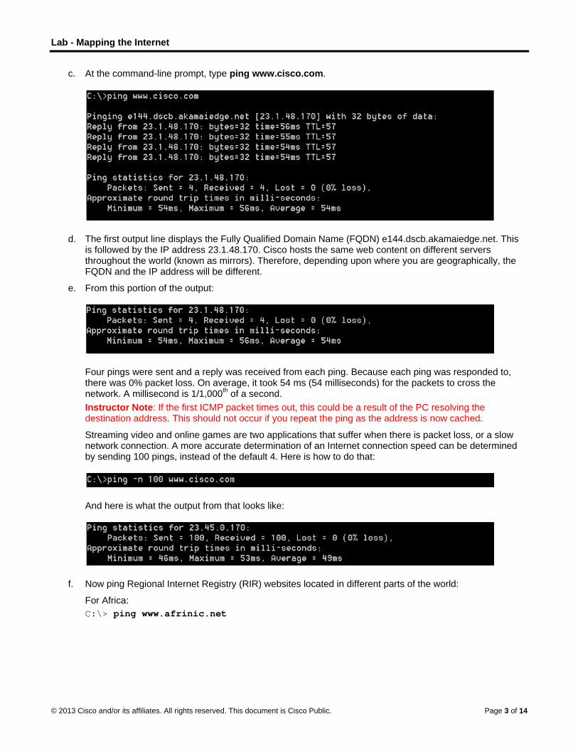
c. At the command-line prompt, type ping www.cisco.com.
d. The first output line displays the Fully Qualified Domain Name (FQDN) e144.dscb.akamaiedge.net. This is followed by the IP address 23.1.48.170. Cisco hosts the same web content on different servers throughout the world (known as mirrors). Therefore, depending upon where you are geographically, the FQDN and the IP address will be different.
e. From this portion of the output:
Four pings were sent and a reply was received from each ping. Because each ping was responded to, there was 0% packet loss. On average, it took 54 ms (54 milliseconds) for the packets to cross the network. A millisecond is 1/1,000th of a second. Instructor Note: If the first ICMP packet times out, this could be a result of the PC resolving the destination address. This should not occur if you repeat the ping as the address is now cached.
Streaming video and online games are two applications that suffer when there is packet loss, or a slow network connection. A more accurate determination of an Internet connection speed can be determined by sending 100 pings, instead of the default 4. Here is how to do that:
And here is what the output from that looks like:
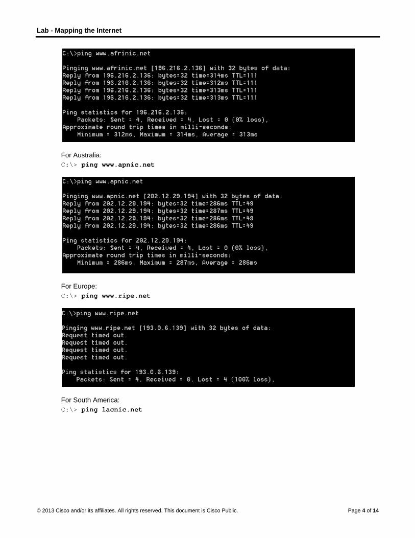
f. Now ping Regional Internet Registry (RIR) websites located in different parts of the world:
For Africa: C:\> ping www.afrinic.net
Lab - Mapping the Internet
© 2013 Cisco and/or its affiliates. All rights reserved. This document is Cisco Public. Page 4 of 14
For Australia: C:\> ping www.apnic.net
For Europe: C:\> ping www.ripe.net
For South America: C:\> ping lacnic.net

Lab - Mapping the Internet
© 2013 Cisco and/or its affiliates. All rights reserved. This document is Cisco Public. Page 5 of 14
All these pings were run from a computer located in the U.S. What happens to the average ping time in milliseconds when data is traveling within the same continent (North America) as compared to data from North America traveling to different continents?
____________________________________________________________________________________
Answer varies based on location. In the data above, the average ping time in milliseconds dramatically increases.
What is interesting about the pings that were sent to the European website?
____________________________________________________________________________________
At the time that these pings were sent, the site was unreachable.
Part 2: Trace a Route to a Remote Server Using Tracert
Step 1: Determine what route across the Internet traffic takes to the remote server.
Now that basic reachability has been verified by using the ping tool, it is helpful to look more closely at each network segment that is crossed. To do this, the tracert tool will be used.
a. At the command-line prompt, type tracert www.cisco.com.

Lab - Mapping the Internet
© 2013 Cisco and/or its affiliates. All rights reserved. This document is Cisco Public. Page 6 of 14
b. Save the tracert output in a text file as follows:
1) Right-click the title bar of the Command Prompt window and choose Edit > Select All.
2) Right-click the title bar of the Command Prompt window again and choose Edit > Copy.
3) Open the Windows Notepad program: Windows Start icon > All Programs > Accessories > Notepad.
4) To paste the output into Notepad, choose Edit > Paste.
5) Choose File > Save As and save the Notepad file to your desktop as tracert1.txt.
c. Run tracert for each destination website and save the output in sequentially numbered files. C:\> tracert www.afrinic.net C:\> tracert www.lacnic.net
d. Interpreting tracert outputs.
Routes traced can go through many hops and a number of different Internet Service Providers (ISPs), depending on the size of your ISP and the location of the source and destination hosts. Each “hop” represents a router. A router is a specialized type of computer used to direct traffic across the Internet. Imagine taking an automobile trip across several countries using many highways. At different points in the trip you come to a fork in the road in which you have the option to select from several different highways. Now further imagine that there is a device at each fork in the road that directs you to take the correct highway to your final destination. That is what a router does for packets on a network.
Because computers talk in numbers, rather than words, routers are uniquely identified using IP addresses (numbers with the format x.x.x.x). The tracert tool shows you what path through the network a packet of information takes to reach its final destination. The tracert tool also gives you an idea of how fast traffic is going on each segment of the network. Three packets are sent to each router in the path, and the return time is measured in milliseconds. Now use this information to analyze the tracert results to www.cisco.com. Below is the entire traceroute:
Below is the breakdown:

Lab - Mapping the Internet
© 2013 Cisco and/or its affiliates. All rights reserved. This document is Cisco Public. Page 7 of 14
In the example output shown above, the tracert packets travel from the source PC to the local router default gateway (hop 1: 192.168.1.1) to the ISPs Point of Presence (POP) router (hop 2: 10.18.20.1). Every ISP has numerous POP routers. These POP routers are at the edge of the ISP’s network and are the means by which customers connect to the Internet. The packets travel along the Verizon network for two hops and then jump to a router that belongs to alter.net. This could mean that the packets have traveled to another ISP. This is significant because sometimes there is packet loss in the transition between ISPs, or sometimes one ISP is slower than another. How could we determine if alter.net is another ISP or the same ISP?
e. There is an Internet tool known as whois. The whois tool allows us to determine who owns a domain name. A web-based whois tool is found at http://whois.domaintools.com/. This domain is also owned by Verizon according to the web-based whois tool.
To summarize, Internet traffic starts at a home PC and travels through the home router (hop 1). It then connects to the ISP and travels through its network (hops 2-7) until it arrives at the remote server (hop 8). This is a relatively unusual example in which there is only one ISP involved from start to finish. It is typical to have two or more ISP involved as displayed in the following examples.

Lab - Mapping the Internet
© 2013 Cisco and/or its affiliates. All rights reserved. This document is Cisco Public. Page 8 of 14
f. Now examine an example that involves Internet traffic crossing multiple ISPs. Below is the tracert for www.afrinic.net:
What happens at hop 7? Is level3.net the same ISP as hops 2-6, or a different ISP? Use the whois tool to answer this question.
____________________________________________________________________________________
The Internet traffic goes from being on alter.net to level3.net. The whois tool reveals that this is a separate company/separate ISP.
What happens in hop 10 to the amount of time it takes for a packet to travel between Washington D.C. and Paris, as compared with the earlier hops 1-9?
____________________________________________________________________________________
In hops 1-9 most packets traverse their link in 50 ms or less. On the Washington D.C. to Paris link, the time increases to 132 ms.
What happens in hop 18? Do a whois lookup on 168.209.201.74 using the whois tool. Who owns this network?

Lab - Mapping the Internet
© 2013 Cisco and/or its affiliates. All rights reserved. This document is Cisco Public. Page 9 of 14
____________________________________________________________________________________
The time to traverse one link in the network goes up from 159 ms to 340 ms. From the increased time, the traffic probably is moved to a different network from the Level3 backbone network. Using the whois tool, IP address (168.209.201.74) is owned by the African Network Information Center.
g. Type tracert www.lacnic.net.
What happens in hop 7?
____________________________________________________________________________________
The time it takes for a packet to traverse the network dramatically increases over fourfold from ~40 ms to ~180 ms. Did students do a whois on registro.br using the web-based whois tool: http://whois.domaintools.com/. If they did, the information they received was not that helpful. Did your students go to: http://translate.google.com/ to get a translation of Núcleo de Informação e Coordenação do Ponto? More helpful would have been a search engine request for “top domain .br” This would have revealed that we were now on a Brazilian network. Internet detective work can be fun!
Part 3: Trace a Route to a Remote Server Using Web-Based and SoftwareTools
Step 1: Use a web-based traceroute tool.
a. Using http://www.subnetonline.com/pages/network-tools/online-tracepath.php to trace the route to the following websites:
www.cisco.com
www.afrinic.net
Capture and save the output in Notepad.
www.cisco.com:

Lab - Mapping the Internet
© 2013 Cisco and/or its affiliates. All rights reserved. This document is Cisco Public. Page 10 of 14
TracePath Output:
1: pera.subnetonline.com (141.138.203.105) 0.157ms pmtu 1500
1: gw-v130.xl-is.net (141.138.203.1) 1.168ms
2: rt-eu01-v2.xl-is.net (79.170.92.19) 0.566ms
3: akamai.telecity4.nl-ix.net (193.239.116.226) 1.196ms
www.afrinic.com:
TracePath Output:
1: pera.subnetonline.com (141.138.203.105) 0.175ms pmtu 1500
1: gw-v130.xl-is.net (141.138.203.1) 0.920ms
2: rt-eu01-v2.xl-is.net (79.170.92.19) 0.556ms
3: xl-internetservices.nikhef.openpeering.nl (217.170.0.225) 10.679ms
4: r22.amstnl02.nl.bb.gin.ntt.net (195.69.144.36) asymm 5 4.412ms
5: ae-5.r23.londen03.uk.bb.gin.ntt.net (129.250.5.197) 49.349ms
6: ae-2.r02.londen03.uk.bb.gin.ntt.net (129.250.5.41) asymm 7 8.842ms
7: dimensiondata-0.r02.londen03.uk.bb.gin.ntt.net (83.231.235.222) 18.080ms
8: 168.209.201.74 (168.209.201.74) 196.375ms
9: csw4-pkl-gi1-1.ip.isnet.net (196.26.0.101) asymm 10 186.855ms
10: 196.37.155.180 (196.37.155.180) 185.661ms
11: fa1-0-1.ar02.jnb.afrinic.net (196.216.3.132) 197.912ms
How is the traceroute different when going to www.cisco.com from the command prompt (see Part 1) rather than from the online website? (Your results may vary depending upon where you are located geographically, and which ISP is providing connectivity to your school.)
____________________________________________________________________________________
____________________________________________________________________________________
The tracert from the command prompt in Part 1 ended up at a server in Cambridge, Massachusetts. The traceroute from the website in the Netherlands went to a mirror server in the Netherlands. The domain cisco.com is hosted on many websites or mirrors throughout the world. This is done so that access time to the site will be fast from anywhere in the world.
Compare the tracert from Part 1 that goes to Africa with the tracert that goes to Africa from the web interface. What difference do you notice?
____________________________________________________________________________________
____________________________________________________________________________________
The route across Europe is on a different ISP. Make the point with students that there is not a single backbone to the Internet. Rather there are many backbones to the Internet. They all connect at Peering Points. Performance on the network on one ISP could be very different than performance on the network with a different ISP.
Some of the traceroutes have the abbreviation asymm in them. Any guesses as to what this means? What is its significance?
____________________________________________________________________________________
____________________________________________________________________________________
This is an abbreviation for asymmetric. It means that the test packet took one path to reach the destination, and a different path to return by. Imagine someone driving from their home to New York City. On the way to New York City, they noticed that the highway was congested and traffic was slow. They might decide to come home by a different or asymmetric path.

Lab - Mapping the Internet
© 2013 Cisco and/or its affiliates. All rights reserved. This document is Cisco Public. Page 11 of 14
Step 2: Use VisualRoute Lite Edition
VisualRoute is a proprietary traceroute program that can display the tracing path results graphically.
a. Please download the VisualRoute Lite Edition from the following link if it is not already installed:
http://www.visualroute.com/download.html
If you have any trouble downloading or installing VisualRoute, ask your instructor for assistance. Ensure that you download the Lite Edition.
b. Using VisualRoute 2010 Lite Edition, trace the routes to www.cisco.com.
c. Record the IP addresses in the path in Notepad.
Part 4: Compare Traceroute Results
Compare the traceroute results to www.cisco.com from Parts 2 and 3.
Step 1: List the path to www.cisco.com using tracert.
192.168.1.1 > 10.18.20.1 > 130.81.196.190 > 130.81.22.46 > 152.63.1.57 > 152.63.17.109 > 152.63.21.14 > 23.1.144.170

Lab - Mapping the Internet
© 2013 Cisco and/or its affiliates. All rights reserved. This document is Cisco Public. Page 12 of 14
Step 2: List the path to www.cisco.com using the web-based tool on subnetonline.com.
141.138.203.105 > 141.138.203.1 > 79.170.92.19 > 19.239.116.226
Step 3: List the path to www.cisco.com using VisualRoute Lite edition.
192.168.1.17 > 192.168.1.1 > 10.18.20.1 130.81.196.188 > 130.81.151.1 130.81.22.46 > 152.63.9.249 > 152.63.17.109 > 152.63.21.14 > 231.144.170
Did all the traceroute utilities use the same paths to www.cisco.com? Why or Why not?
_______________________________________________________________________________________
_______________________________________________________________________________________
_______________________________________________________________________________________
Trace routes between the same source and destination conducted at different times may produce different results. This is due to the "meshed" nature of the interconnected networks that comprise the Internet and the Internet Protocols ability to select different pathways over which to send packets.
Reflection Having now viewed traceroute through three different tools (tracert, web interface, and VisualRoute), are there any insights that using VisualRoute provided that the other two tools did not?
_______________________________________________________________________________________
_______________________________________________________________________________________
_______________________________________________________________________________________
Answers will vary. One possible insight is that VisualRoute highlights graphically the amount of time it takes to travel between hops on the internet. By highlighting in yellow and red slower times, it becomes more obvious that there are network issues along these links.
Appendix A C:\> tracert www.cisco.com Tracing route to e144.dscb.akamaiedge.net [23.1.144.170] over a maximum of 30 hops: 1 <1 ms <1 ms <1 ms dslrouter.westell.com [192.168.1.1] 2 38 ms 38 ms 37 ms 10.18.20.1 3 37 ms 37 ms 37 ms G3-0-9-2204.ALBYNY-LCR-02.verizon-gni.net [130.81.196.190] 4 43 ms 43 ms 42 ms so-5-1-1-0.NY325-BB-RTR2.verizon-gni.net [130.81.22.46] 5 43 ms 43 ms 65 ms 0.so-4-0-2.XT2.NYC4.ALTER.NET [152.63.1.57] 6 45 ms 45 ms 45 ms 0.so-3-2-0.XL4.EWR6.ALTER.NET [152.63.17.109] 7 46 ms 48 ms 46 ms TenGigE0-5-0-0.GW8.EWR6.ALTER.NET [152.63.21.14] 8 45 ms 45 ms 45 ms a23-1-144-170.deploy.akamaitechnologies.com [23.1.144.170] Trace complete. C:\> tracert www.afrinic.net

Lab - Mapping the Internet
© 2013 Cisco and/or its affiliates. All rights reserved. This document is Cisco Public. Page 13 of 14
Tracing route to www.afrinic.net [196.216.2.136] over a maximum of 30 hops: 1 1 ms <1 ms <1 ms dslrouter.westell.com [192.168.1.1] 2 39 ms 38 ms 37 ms 10.18.20.1 3 40 ms 38 ms 39 ms G4-0-0-2204.ALBYNY-LCR-02.verizon-gni.net [130.81.197.182] 4 44 ms 43 ms 43 ms so-5-1-1-0.NY325-BB-RTR2.verizon-gni.net [130.81.22.46] 5 43 ms 43 ms 42 ms 0.so-4-0-0.XT2.NYC4.ALTER.NET [152.63.9.249] 6 43 ms 71 ms 43 ms 0.ae4.BR3.NYC4.ALTER.NET [152.63.16.185] 7 47 ms 47 ms 47 ms te-7-3-0.edge2.NewYork2.level3.net [4.68.111.137] 8 43 ms 55 ms 43 ms vlan51.ebr1.NewYork2.Level3.net [4.69.138.222] 9 52 ms 51 ms 51 ms ae-3-3.ebr2.Washington1.Level3.net [4.69.132.89] 10 130 ms 132 ms 132 ms ae-42-42.ebr2.Paris1.Level3.net [4.69.137.53] 11 139 ms 145 ms 140 ms ae-46-46.ebr1.Frankfurt1.Level3.net [4.69.143.137] 12 148 ms 140 ms 152 ms ae-91-91.csw4.Frankfurt1.Level3.net [4.69.140.14] 13 144 ms 144 ms 146 ms ae-92-92.ebr2.Frankfurt1.Level3.net [4.69.140.29] 14 151 ms 150 ms 150 ms ae-23-23.ebr2.London1.Level3.net [4.69.148.193] 15 150 ms 150 ms 150 ms ae-58-223.csw2.London1.Level3.net [4.69.153.138] 16 156 ms 156 ms 156 ms ae-227-3603.edge3.London1.Level3.net [4.69.166.154] 17 157 ms 159 ms 160 ms 195.50.124.34 18 353 ms 340 ms 341 ms 168.209.201.74 19 333 ms 333 ms 332 ms csw4-pkl-gi1-1.ip.isnet.net [196.26.0.101] 20 331 ms 331 ms 331 ms 196.37.155.180 21 318 ms 316 ms 318 ms fa1-0-1.ar02.jnb.afrinic.net [196.216.3.132] 22 332 ms 334 ms 332 ms 196.216.2.136 Trace complete. C:\> tracert www.lacnic.net Tracing route to lacnic.net [200.3.14.10] over a maximum of 30 hops: 1 <1 ms <1 ms <1 ms dslrouter.westell.com [192.168.1.1] 2 38 ms 37 ms 37 ms 10.18.20.1 3 37 ms 38 ms 40 ms G3-0-9-2204.ALBYNY-LCR-02.verizon-gni.net [130.81.196.190] 4 43 ms 42 ms 43 ms so-5-1-1-0.NY325-BB-RTR2.verizon-gni.net [130.81.22.46] 5 46 ms 75 ms 46 ms 0.ae2.BR3.NYC4.ALTER.NET [152.63.16.49] 6 43 ms 43 ms 43 ms 204.255.168.194 7 178 ms 182 ms 178 ms ge-1-1-0.100.gw1.gc.registro.br [159.63.48.38] 8 172 ms 180 ms 182 ms xe-5-0-1-0.core1.gc.registro.br [200.160.0.174] 9 177 ms 172 ms 181 ms xe-4-0-0-0.core2.nu.registro.br [200.160.0.164]

Lab - Mapping the Internet
© 2013 Cisco and/or its affiliates. All rights reserved. This document is Cisco Public. Page 14 of 14
10 173 ms 180 ms 176 ms ae0-0.ar3.nu.registro.br [200.160.0.249] 11 184 ms 183 ms 180 ms gw02.lacnic.registro.br [200.160.0.213] 12 180 ms 179 ms 180 ms 200.3.12.36 13 182 ms 180 ms 180 ms www.lacnic.net [200.3.14.10] Trace complete.

© 2013 Cisco and/or its affiliates. All rights reserved. This document is Cisco Public. Page 1 of 6
Lab - Researching IT and Networking Job Opportunities (Instructor Version) Instructor Note: Red font color or Gray highlights indicate text that appears in the instructor copy only.
Objectives Part 1: Research Job Opportunities
• Identify the current networking jobs that are in demand.
• Explain the value of Cisco certifications in the job market.
Part 2: Reflect on Research
• Identify current hiring trends in IT/networking.
• Identify future networking career certifications and skills.
• Identify additional networking career paths.
Background / Scenario Jobs in Information Technology (IT) and computer networking continue to grow. Most employers require some form of industry standard certification, degree, or other qualifications from their potential employees, especially those with limited experience. The Cisco CCNA certification is a known and established entry level networking certification that is respected in the industry. There are additional levels and kinds of Cisco certifications that one can attain, and each certification may enhance employment opportunities as well as salary range.
In this lab, you will do some targeted job searching on the web, to find what types of IT and computer networking jobs are available; what kinds of skills and certifications you will need; and the salary ranges associated with the various job titles.
Required Resources • Device with Internet access
Part 1: Research Job Opportunities In Part 1, you will use a web browser to visit the popular job listing web sites monster.com and salary.com.
Step 1: Open a web browser and go to a job listing website.
In the URL address bar type in http://monster.com and press Enter.
Note: For job listings outside of the US, use the following link to search for your country:
http://www.monster.com/geo/siteselection/

Lab - Researching IT and Networking Job Opportunities
© 2013 Cisco and/or its affiliates. All rights reserved. This document is Cisco Public. Page 2 of 6
Step 2: Search for networking related jobs.
a. Type the word Network in the Job title box. Notice that the website offers context sensitive suggestions based on the keywords provided. Either click on, or finish typing the words, Network Administrator and click the SEARCH button (see image below).
b. Notice the search results:

Lab - Researching IT and Networking Job Opportunities
© 2013 Cisco and/or its affiliates. All rights reserved. This document is Cisco Public. Page 3 of 6
c. Now focus your search by adding terms to the keywords field box. Try terms like Cisco CCNA, CCNP, CCNA Security, CCNA Voice, etc.
d. Now try refining your search by adding in different geographical locations. Did you find jobs in the locations you entered?
____________________________________________________________________________________
Answers will vary.
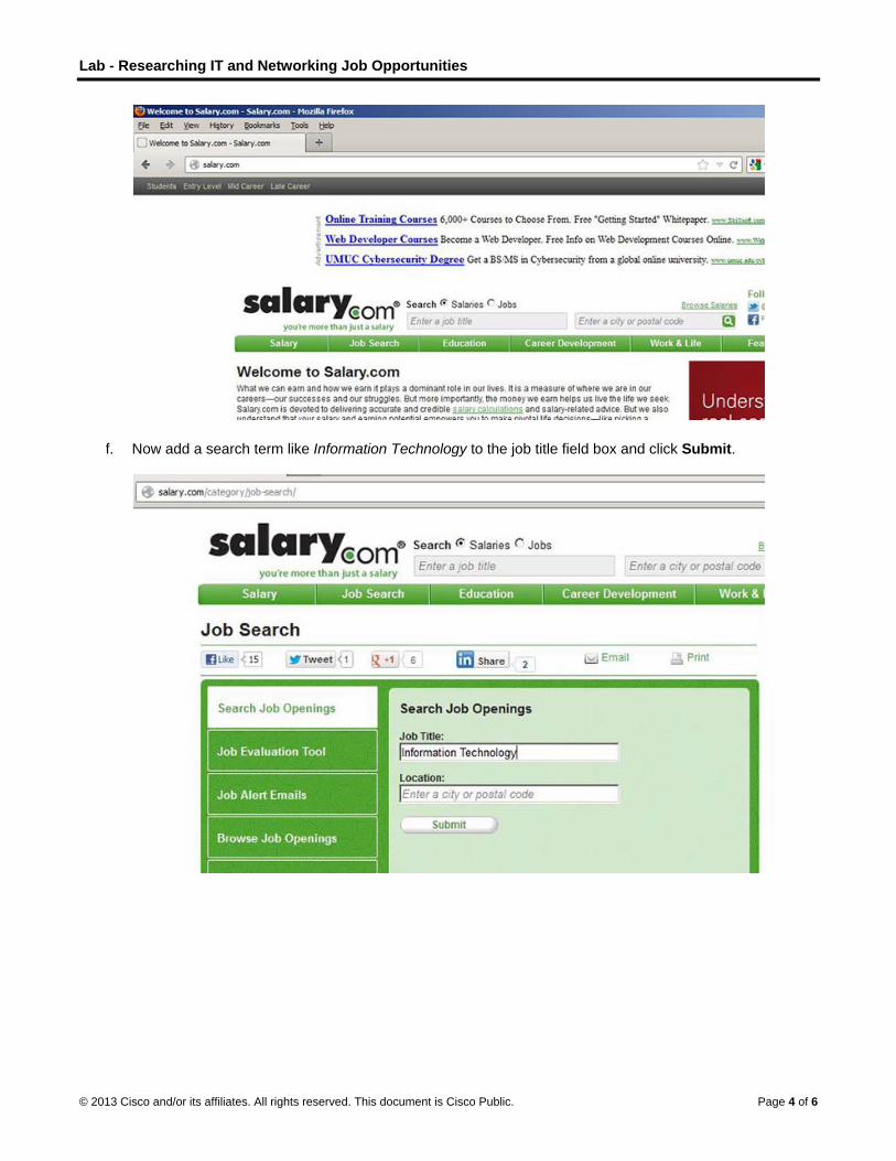
e. Try searching a different website. Go to http://salary.com and click the Job Search menu bar button.
Note: For salary listings outside of the US, use the following link to search for your country:
http://www.payscale.com/rccountries.aspx
Lab - Researching IT and Networking Job Opportunities
© 2013 Cisco and/or its affiliates. All rights reserved. This document is Cisco Public. Page 4 of 6
f. Now add a search term like Information Technology to the job title field box and click Submit.
Lab - Researching IT and Networking Job Opportunities
© 2013 Cisco and/or its affiliates. All rights reserved. This document is Cisco Public. Page 5 of 6
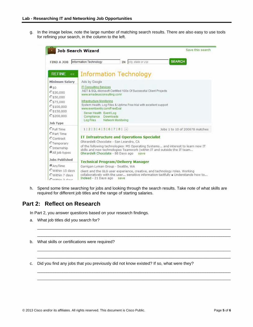
g. In the image below, note the large number of matching search results. There are also easy to use tools for refining your search, in the column to the left.
h. Spend some time searching for jobs and looking through the search results. Take note of what skills are required for different job titles and the range of starting salaries.
Part 2: Reflect on Research In Part 2, you answer questions based on your research findings.
a. What job titles did you search for?
____________________________________________________________________________________
____________________________________________________________________________________
b. What skills or certifications were required?
____________________________________________________________________________________
____________________________________________________________________________________
c. Did you find any jobs that you previously did not know existed? If so, what were they?
____________________________________________________________________________________
____________________________________________________________________________________

Lab - Researching IT and Networking Job Opportunities
© 2013 Cisco and/or its affiliates. All rights reserved. This document is Cisco Public. Page 6 of 6
d. Did you find any jobs that you are interested in? If so, which ones and what skills or certifications do they require?
____________________________________________________________________________________
____________________________________________________________________________________
____________________________________________________________________________________

© 2013 Cisco and/or its affiliates. All rights reserved. This document is Cisco Public. Page 1 of 2
Draw Your Concept of the Internet Now (Instructor Version) Instructor Note: Red font color or Gray highlights indicate text that appears in the instructor copy only.
Objectives
Identify the common components of a network.
In this activity, you will illustrate how concepts from Chapter 1 are applied to show how network devices
connect to and throughout the Internet. After reflecting on your home or small-business topology, you will
become familiar with using the device icons and knowledge needed to visualize network connectivity through
the remaining network courses.
Background / Scenario
In this activity, you will use the knowledge you have acquired throughout Chapter 1, and the modeling activity document that you prepared at the beginning of this chapter. You may also refer to the other activities completed in this chapter, including Packet Tracer activities.
Draw a map of the Internet as you see it now. Use the icons presented in the chapter for media, end devices, and intermediary devices.
In your revised drawing, you may want to include some of the following:
• WANs
• LANs
• Cloud computing
• Internet Service Providers (tiers)
Save your drawing in hard-copy format. If it is an electronic document, save it to a server location provided by your instructor. Be prepared to share and explain your revised work in class.
Instructor Note: This Modeling Activity may be selected as a graded assignment, because its purpose is to
validate the learning gained in Chapter 1 about:
• WANs
• LANs
• Cloud computing
• Internet Service Providers (tiers)
Required Resources
Beginning of chapter modeling activity drawing
Packet Tracer (may be optional if students sketch their own drawing)
Paper and pencils or pens
Reflection
1. After completing Chapter 1, are you more aware of the devices, cabling, and physical components of a small-to-medium size network? Explain your answer.
_______________________________________________________________________________________
(Answers will vary per student – but this reflection question will generate some good class discussion and foster community between students and the Instructor)

Draw Your Concept of the Internet Now
© 2013 Cisco and/or its affiliates. All rights reserved. This document is Cisco Public. Page 2 of 2
Modeling Activity Graphic Representation (designs will vary)
Instructor Note: This is a representative model that might be “built” as a result of this activity.
Identify elements of the model that map to IT-related content:
Devices/Equipment
Media (cabling)
Social Media Links
Sources & Destinations
Local Area Networks
Wide Area Networks
©
I(I
O
B
R
R1
© 2013 Cisco and
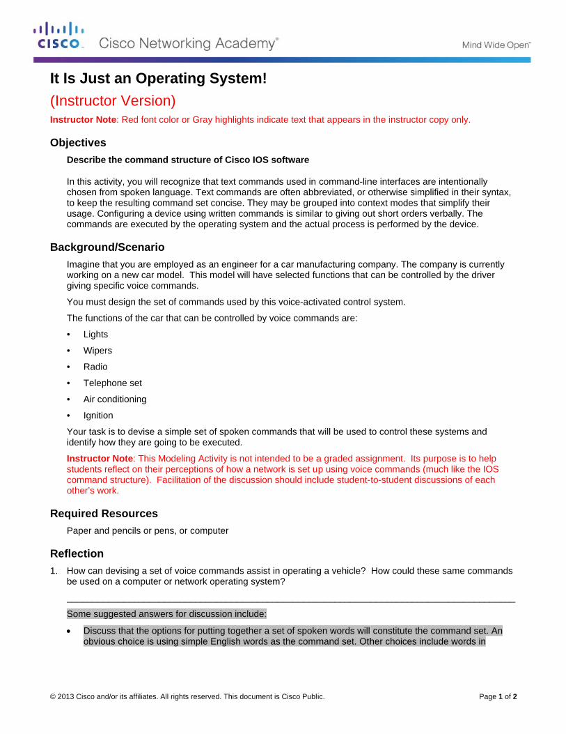
It Is Just(Instructonstructor No
ObjectivesDescribe
In this actchosen froto keep thusage. Cocommand
BackgrounImagine thworking ogiving spe
You must
The funct
• Lights
• Wiper
• Radio
• Telep
• Air co
• Ignitio
Your taskidentify ho
Instructostudents rcommandother’s wo
Required RPaper and
Reflection 1. How can d
be used o
________
Some sug
Discuobvio
d/or its affiliates.
t an Opeor Versioote: Red font
the comman
tivity, you will om spoken lahe resulting coonfiguring a dds are execute
nd/Scenariohat you are e
on a new car mecific voice co
design the se
ions of the ca
s
rs
o
phone set
onditioning
on
is to devise aow they are g
or Note: This reflect on theid structure). Fork.
Resources d pencils or p
devising a seon a compute
___________
ggested answ
ss that the opus choice is u
All rights reserve
erating Son) color or Gray
nd structure
recognize thaanguage. Textommand set cdevice using wed by the ope
o mployed as amodel. This mommands.
et of comman
ar that can be
a simple set ooing to be ex
Modeling Actir perceptionsFacilitation of
pens, or comp
t of voice comr or network o
____________
wers for discus
ptions for puttusing simple E
ed. This docume
System!
y highlights ind
of Cisco IOS
at text commat commands aconcise. Theywritten commaerating system
an engineer fomodel will hav
nds used by t
controlled by
of spoken comxecuted.
ivity is not ints of how a netthe discussio
puter
mmands assisoperating sys
___________
ssion include
ting together English words
ent is Cisco Publi
!
dicate text tha
S software
ands used in are often abby may be grouands is similam and the act
or a car manuve selected fu
his voice-acti
y voice comm
mmands that w
ended to be atwork is set uon should incl
st in operatingtem?
___________
:
a set of spokes as the comm
ic.
at appears in
command-linbreviated, or ouped into con
ar to giving ouual process is
ufacturing comunctions that
vated control
mands are:
will be used t
a graded assip using voicelude student-t
g a vehicle?
____________
en words will mand set. Oth
the instructo
ne interfaces aotherwise simntext modes tut short orderss performed b
mpany. The ccan be contro
system.
to control thes
ignment. Its e commands (to-student dis
How could th
____________
constitute theher choices in
r copy only.
are intentionamplified in thei
hat simplify ths verbally. Thby the device
company is cuolled by the d
se systems a
purpose is to (much like thescussions of e
hese same co
___________
e command snclude words
Page 1 of 2
ally r syntax, heir he .
urrently river
nd
help e IOS each
ommands
________
set. An in

It Is Just an Operating System!
© 2013 Cisco and/or its affiliates. All rights reserved. This document is Cisco Public. Page 2 of 2
different languages, using command numbers or shortcuts. Note, however, that this would make the command set significantly less intuitive.
Talk about the students’ choice to make the command set direct, without hierarchy, or whether they grouped commands according to their function. Highlight that, for example, a help command without any further context would not be usable because it does not indicate what exactly the user needs help to. There are two ways of providing a context to a command:
Ask students if they explicitly expressed the context with each command (for example, radio volume up/radio volume down; phone volume up/phone volume down) which is the direct, flat approach. Or did they introduce modes; groupings of commands that refer to a particular context and once positioned in that context, did not have to be reemphasized., For example, after placing the instruction in the radio mode, the commands volume up and volume down are unambiguous.
Discuss the advantages of both approaches. For a small set of commands, the direct approach is more suitable. For a larger set of commands which may possibly grow into extensive, multi-word sentences, using modes helps to keep the command set organized and limits the length of individual commands, and is preferred.
How did students decide how the voice command recognition would be started so that the car did not mistakenly interpret a casual conversation of passengers as commands? Possibilities include saying a specific, otherwise unused word, or pressing a button on the steering wheel. Also, discuss how students handled a system that should prompt the user to enter the voice commands, and how the user would be informed that the spoken command was not properly understood or valid.
How did the students handle access to more safety-critical commands such as lights and ignition?)How were these commands protected or isolated so that no inadvertent manipulation could occur? Possibilities include saying a specific, otherwise unused word, or pressing a button on the steering wheel.
Ask students to discuss which part of the software running on the car’s built-in computer would be processing the voice commands and what software would be actually executing the commands. The software that performs speech recognition and translates voice commands into a form the computer can understand is the command interface used to interact with the car. However, the commands need to be processed by the central operating software of the car that controls all its functions and orchestrates all its systems. As an example, saying “engine on” involves processing the voice command in the command interface, and then the operating system processes this command by activating the starter motor for a certain period of time, enabling the flow of the fuel, etc., coordinating multiple systems of a car to make it work.
Identify elements of the model that map to IT-related content: Different systems of the car which can be controlled by voice commands relate to different components of
routers and switches that can be configured.
Vocal commands relate to IOS commands.
The choice of short English words or phrases as the command set relates to the general style of IOS CLI.
The mode-oriented organization of the voice command set relates to the mode-oriented IOS CLI.
Starting the voice recognition process relates to starting a CLI EXEC session by pressing Enter. Also, the voice prompts by the car relate to the prompts on the command line.
Potentially disruptive commands, such as lights off or engine on relates to potentially disruptive IOS commands (reload, erase flash: or delete startup-config).
The voice interface and the car’s operating system relate to the IOS EXEC (the command interpreter) and the IOS itself.
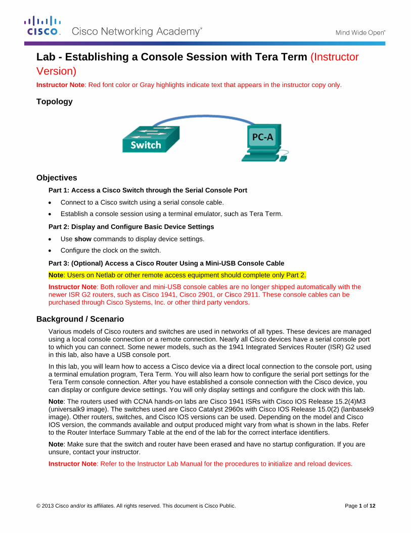
©
LVI
T
O
B
© 2013 Cisco and
Lab - EsVersion) nstructor No
Topology
ObjectivesPart 1: Ac
Conn
Estab
Part 2: Di
Use s Config
Part 3: (O
Note: Use
Instructonewer ISRpurchased
BackgrounVarious musing a loto which yin this lab
In this laba terminaTera Termcan displa
Note: The(universalimage). OIOS versioto the Rou
Note: Maunsure, co
Instructo
d/or its affiliates.
stablishi
ote: Red font
ccess a Cisc
ect to a Cisco
blish a console
isplay and C
show comma
gure the clock
Optional) Acc
ers on Netlab
or Note: Both R G2 routers, d through Cis
nd / Scenarmodels of Ciscocal console cyou can conne, also have a
b, you will learl emulation pr
m console conay or configur
e routers usedlk9 image). T
Other routers, on, the commuter Interface
ke sure that tontact your in
or Note: Refer
All rights reserve
ng a Co
color or Gray
co Switch thr
o switch using
e session usi
onfigure Bas
nds to display
k on the switc
cess a Cisco
or other rem
rollover and msuch as Cisc
sco Systems,
rio co routers andconnection or ect. Some neUSB console
rn how to accrogram, Tera nnection. Aftere device sett
d with CCNA he switches uswitches, and
mands availabSummary Ta
he switch andnstructor.
r to the Instru
ed. This docume
onsole S
y highlights ind
rough the Se
g a serial cons
ng a terminal
sic Device S
y device setti
ch.
o Router Usin
ote access eq
mini-USB conco 1941, CiscInc. or other
d switches ara remote con
ewer models, e port.
ess a Cisco dTerm. You w
er you have esings. You will
hands-on labused are Ciscd Cisco IOS v
ble and outputable at the en
d router have
ctor Lab Man
ent is Cisco Publi
Session w
dicate text tha
erial Console
sole cable.
emulator, su
ettings
ngs.
ng a Mini-US
quipment sho
nsole cables aco 2901, or Cithird party ve
e used in netwnnection. Neasuch as the 1
device via a dwill also learn stablished a c only display
bs are Cisco 1co Catalyst 29versions can t produced md of the lab fo
been erased
nual for the pr
ic.
with Ter
at appears in
e Port
uch as Tera T
B Console C
ould complete
are no longerisco 2911. Th
endors.
tworks of all tyarly all Cisco d1941 Integrate
direct local cohow to configconsole connsettings and
1941 ISRs wit960s with Ciscbe used. Depight vary fromor the correct
d and have no
rocedures to i
ra Term
the instructo
Term.
Cable
e only Part 2.
r shipped autohese console
ypes. These ddevices haveed Services R
nnection to thgure the seriaection with thconfigure the
th Cisco IOS co IOS Releapending on thm what is showt interface ide
o startup conf
initialize and
P
(Instruc
r copy only.
omatically witcables can b
devices are m a serial cons
Router (ISR) G
he console poal port settingshe Cisco device clock with th
Release 15.2ase 15.0(2) (lae model and wn in the labs
entifiers.
figuration. If y
reload device
Page 1 of 12
ctor
th the e
managed sole port G2 used
ort, using s for the ce, you his lab.
2(4)M3 anbasek9 Cisco s. Refer
you are
es.

Lab - Establishing a Console Session with Tera Term
© 2013 Cisco and/or its affiliates. All rights reserved. This document is Cisco Public. Page 2 of 12
Required Resources 1 Router (Cisco 1941 with Cisco IOS software, release 15.2(4)M3 universal image or comparable)
1 Switch (Cisco 2960 with Cisco IOS Release 15.0(2) lanbasek9 image or comparable)
1 PC (Windows 7, Vista, or XP with terminal emulation program, such as Tera Term)
Rollover (DB-9 to RJ-45) console cable to configure the switch or router via the RJ-45 console port
Mini-USB cable to configure the router via the USB console port
Instructor Note: If the program is not installed on the PC, Tera Term can be downloaded from the following link by selecting Tera Term:
http://logmett.com/index.php?/download/free-downloads.html
Instructor Note: For a Microsoft Windows-based PC connecting to a Cisco IOS device with a USB cable, a USB driver must be installed prior to use. The driver can be found on www.cisco.com with the related Cisco IOS device. The USB driver can be downloaded from the following link:
http://www.cisco.com/cisco/software/release.html?mdfid=282774238&flowid=714&softwareid=282855122&release=3.1&relind=AVAILABLE&rellifecycle=&reltype=latest
Instructor Note: You must have a valid Cisco Connection Online (CCO) account to download the USB driver file.
Part 1: Access a Cisco Switch through the Serial Console Port You will connect a PC to a Cisco switch using a rollover console cable. This connection will allow you to access the command line interface (CLI) and display settings or configure the switch.
Step 1: Connect a Cisco switch and computer using a rollover console cable.
a. Connect the rollover console cable to the RJ-45 console port of the switch.
b. Connect the other cable end to the serial COM port on the computer.
Note: Serial COM ports are no longer available on most computers today. A USB-to-DB9 adapter can be used with the rollover console cable for console connection between the computer and a Cisco device. These USB-to-DB9 adapters can be purchased at any computer electronics store.
Note: If using a USB-to-DB9 adapter to connect to the COM port, you may be required to install a driver for the adapter provided by the manufacturer on your computer. To determine the COM port used by the adapter, please see Part 3 Step 4. The correct COM port number is required to connect to the Cisco IOS device using a terminal emulator in Step 2.

L
©
S
Lab - Establis
© 2013 Cisco and
c. Powe
Step 2: Con
Tera Termswitch. It a
a. Start TAll Pr
Note:by se
http://
b. In theselect
shing a Cons
d/or its affiliates.
er up the Cisco
nfigure Tera
m is a terminaalso allows yo
Tera Term byrograms.
If the progralecting Tera T
/logmett.com/
e New Connected and click
sole Session
All rights reserve
o switch and
a Term to es
al emulation pou to configur
y clicking the
m is not instaTerm:
/index.php?/d
ction dialog bOK to continu
n with Tera T
ed. This docume
computer if th
stablish a c
program. This re the switch.
Windows Sta
alled on the sy
ownload/free
ox, click the Sue.
Term
ent is Cisco Publi
hese devices
console ses
program allo
art button loc
ystem, Tera T
e-downloads.h
Serial radio b
ic.
are not alrea
ssion with th
ows you to ac
cated in the ta
Term can be d
html
button. Verify
ady on.
he switch.
cess the term
ask bar. Locat
downloaded f
that the corre
P
minal output o
te Tera Term
from the follow
ect COM port
Page 3 of 12
f the
m under
wing link
is

L
©
P
Lab - Establis
© 2013 Cisco and
c. From paramTera T
d. Whenexam
Part 2: DIn this secInternetwoswitch.
shing a Cons
d/or its affiliates.
the Tera Termeters for theTerm default
n you can seeple displays t
Display anction, you areork Operating
sole Session
All rights reserve
m Setup men console portsettings matc
e the terminal the terminal o
nd Config introduced to
g System (IOS
n with Tera T
ed. This docume
nu, choose tht are 9600 bauch the console
output, you aoutput of the s
gure Baso the user andS) version, dis
Term
ent is Cisco Publi
e Serial portud, 8 data bitse port settings
are ready to cswitch while it
ic Deviced privileged esplay the cloc
ic.
t… to verify ths, no parity, 1s for commun
configure a Cit is loading.
e Settingsexecutive modck settings, an
he serial setti1 stop bit, andnications with
isco switch. T
s des. You will nd configure t
P
ngs. The defad no flow conth the Cisco IO
The following
determine thethe clock on t
Page 4 of 12
ault trol. The
OS switch.
console
e the

Lab - Establishing a Console Session with Tera Term
© 2013 Cisco and/or its affiliates. All rights reserved. This document is Cisco Public. Page 5 of 12
Step 1: Display the switch IOS image version.
a. After the switch has completed its startup process, the following message displays. Enter n to continue. Would you like to enter the initial configuration dialog? [yes/no]: n
Note: If you do not see the above message, please contact your instructor to reset your switch to the initial configuration.
b. While you are in the user EXEC mode, display the IOS version for your switch.
Switch> show version Cisco IOS Software, C2960 Software (C2960-LANBASEK9-M), Version 15.0(2)SE, RELEASE SOFTWARE (fc1)
Technical Support: http://www.cisco.com/techsupport
Copyright (c) 1986-2012 by Cisco Systems, Inc.
Compiled Sat 28-Jul-12 00:29 by prod_rel_team
ROM: Bootstrap program is C2960 boot loader
BOOTLDR: C2960 Boot Loader (C2960-HBOOT-M) Version 12.2(53r)SEY3, RELEASE SOFTWARE (fc1)
Switch uptime is 2 minutes
System returned to ROM by power-on
System image file is "flash://c2960-lanbasek9-mz.150-2.SE.bin" <output omitted>
Which IOS image version is currently in use by your switch?
____________________________________________________________________________________
c2960-lanbasek9-mz.150-2.SE.bin. Answers will vary depending on the switch.
Step 2: Configure the clock.
As you learn more about networking, you will see that configuring the correct time on a Cisco switch can be helpful when you are troubleshooting problems. The following steps manually configure the internal clock of the switch.
a. Display the current clock settings.
Switch> show clock *00:30:05.261 UTC Mon Mar 1 1993
b. The clock setting is changed in the privileged EXEC mode. Enter the privileged EXEC mode by typing enable at the user EXEC mode prompt.
Switch> enable
c. Configure the clock setting. The question mark (?) provides help and allows you to determine the expected input for configuring the current time, date, and year. Press Enter to complete the clock configuration.
Switch# clock set ? hh:mm:ss Current Time
Switch# clock set 15:08:00 ? <1-31> Day of the month
MONTH Month of the year

L
©
P
Lab - Establis
© 2013 Cisco and
Switc <19
SwitcSwitc
*Oct UTC Mconso
d. Enter
Switc15:08
Part 3: (OIf you are the device
Note: Thedevices, sthrough Cnot a micr
Note: Youis used, it
shing a Cons
d/or its affiliates.
ch# clock 993-2035> Y
ch# clock ch#
26 15:08:00Mon Mar 1 19ole.
the show cloch# show c8:07.205 UTC
Optional)using a Cisco
e console por
e mini-USB cosuch as USB Cisco Systemsro-USB cable
u must use eitakes priority
sole Session
All rights reserve
set 15:08:Year
set 15:08:
0.000: %SYS993 to 15:0
ock command
clock C Fri Oct 2
) Access o 1941 routerrt using a min
onsole cable hard drives, Us, Inc. or othe, to connect t
ther the USB y over the RJ-
n with Tera T
ed. This docume
:00 Oct 26
:00 Oct 26
S-6-CLOCKUPD08:00 UTC Fr
d to verify tha
26 2012
a Cisco Rr or other Cisci-USB cable c
is the same tyUSB printers,er third-party vto the mini-US
port or the R-45 console p
Term
ent is Cisco Publi
6 ?
6 2012
DATE: Systeri Oct 26 2
at the clock se
Router Uco IOS deviceconnected to
ype of mini-U or USB hubsvendors. PleaSB console po
RJ-45 port, anport used in P
ic.
em clock has012, config
etting was up
sing a Mes with a minthe USB port
USB cables ths. These miniase verify thatort on a Cisco
d not both simPart 1.
s been updagured from
dated.
ini-USB Ci-USB consolt on your com
at are used w-USB cables t you are usino IOS device.
multaneously
P
ted from 00console by
Console Cle port, you ca
mputer.
with other eleccan be purch
ng a mini-USB.
. When the U
Page 6 of 12
0:31:43
Cable an access
ctronics hased B cable,
USB port

L
©
S
S
Lab - Establis
© 2013 Cisco and
Step 1: Set
a. Conn
b. Conn
c. Powe
Step 2: Ver
If you are not turn g
For a Micbe installeUSB drive
http://wwwease=3.1&
Note: You
Note: Thismodel spereboot aft
Note: Aftedrivers forsystem.
shing a Cons
d/or its affiliates.
up the phy
ect the mini-U
ect the other
er up the Cisco
rify that the
using a Microreen, please
rosoft Windowed prior to useer can be dow
w.cisco.com/c&relind=AVAI
u must have a
s link is relateecific. This USer finishing th
er the files arer different ope
sole Session
All rights reserve
ysical conne
USB cable to
cable end to
o router and c
USB conso
osoft Windowinstall the Cis
ws-based PCe. The driver
wnloaded from
cisco/softwareILABLE&rellif
a valid Cisco
ed to the CiscSB console dhe installation
e extracted, therating system
n with Tera T
ed. This docume
ection with
the mini-USB
a USB port o
computer, if t
ole is ready
ws-based PC asco USB cons
connecting tcan be found
m the following
e/release.htmfecycle=&relty
Connection O
co 1941 routeriver only wor of the USB d
he folder contms and archit
Term
ent is Cisco Publi
a mini-USB
B console port
on the comput
hese devices
.
and the USB sole driver.
o a Cisco IOS on www.ciscg link:
ml?mdfid=2827ype=latest
Online (CCO)
r; however, thrks with Ciscodriver.
tains instructiectures. Plea
ic.
B cable.
rt of the router
ter.
s are not alrea
console port
S device with co.com with th
774238&flow
account to d
he USB consoo routers and
ions for instalase choose th
r.
ady on.
LED indicato
a USB cablehe related Cis
id=714&softw
ownload this
ole driver is n switches. Th
lation and remhe appropriate
P
or (labeled EN
e, a USB drivesco IOS devic
wareid=28285
file.
not Cisco IOShe computer r
moval and nee version for y
Page 7 of 12
N) does
er must ce. The
55122&rel
S device-requires a
ecessary your

L
©
S
Lab - Establis
© 2013 Cisco and
When the
Step 3: (Op
If you are port:
a. Click
b. Open
c. Click yellow
shing a Cons
d/or its affiliates.
e LED indicato
ptional) Ena
using a Micro
the Windows
the Device M
the Ports (COw exclamation
sole Session
All rights reserve
or for the USB
able the COM
osoft Window
s Start icon to
Manager.
OM & LPT) trn point attache
n with Tera T
ed. This docume
B console por
M port for t
ws 7 PC, you m
o access the
ree link to exped.
Term
ent is Cisco Publi
rt has turned g
he Window
may need to p
Control Pane
pand it. The C
ic.
green, the US
ws 7 PC.
perform the fo
el.
Cisco Virtual
SB console po
ollowing step
Comm Port
P
ort is ready fo
s to enable th
00 icon displa
Page 8 of 12
or access.
he COM
ays with a
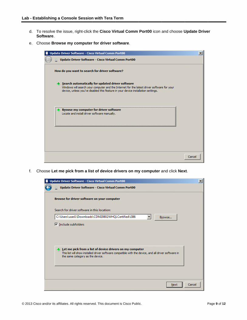
L
©
Lab - Establis
© 2013 Cisco and
d. To resSoftw
e. Choo
f. Choo
shing a Cons
d/or its affiliates.
solve the issuware.
se Browse m
se Let me pic
sole Session
All rights reserve
ue, right-click
my computer
ck from a lis
n with Tera T
ed. This docume
the Cisco Vi
r for driver so
st of device d
Term
ent is Cisco Publi
rtual Comm
oftware.
drivers on my
ic.
Port00 icon a
y computer a
and choose U
and click Nex
P
Update Drive
xt.
Page 9 of 12
er
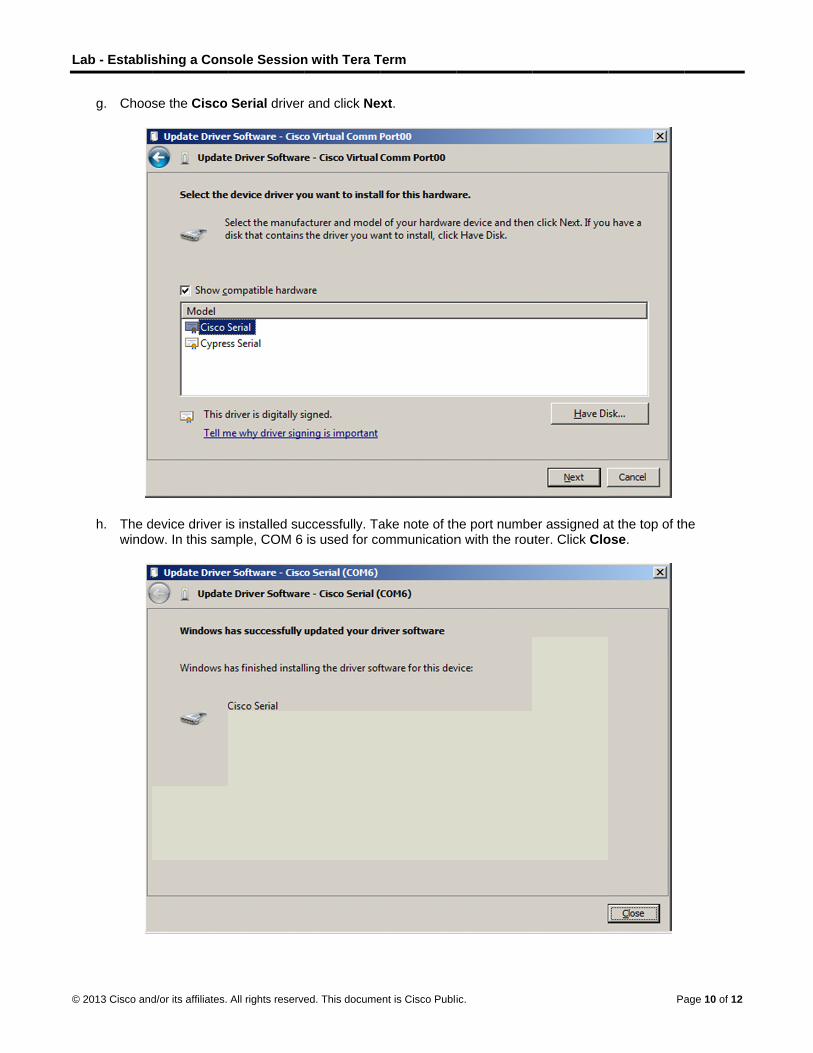
L
©
Lab - Establis
© 2013 Cisco and
g. Choo
h. The dwindo
shing a Cons
d/or its affiliates.
se the Cisco
device driver iow. In this sam
sole Session
All rights reserve
Serial driver
s installed sumple, COM 6
n with Tera T
ed. This docume
r and click Ne
ccessfully. Tais used for co
Term
ent is Cisco Publi
xt.
ake note of thommunication
ic.
he port numben with the rou
er assigned auter. Click Clo
Pa
at the top of those.
age 10 of 12
he

L
©
S
Lab - Establis
© 2013 Cisco and
Step 4: (Op
a. If youSearcuse. IUSB cmanu
b. Openshoul
shing a Cons
d/or its affiliates.
ptional) Dete
need to detech for the Porn this exampconsole drivefacturer, the
Tera Term. Cd now be ava
sole Session
All rights reserve
ermine the
ermine the COrts (COM & Lle, Cisco Ser
er is in use. If naming conve
Click the Seriailable for com
n with Tera T
ed. This docume
COM port n
OM port numbLPT) heading,rial (COM 6) wyou use a rolention reflects
al radio buttommunication w
Term
ent is Cisco Publi
number.
ber, open the expand it, anwas selectedlover consoles this informa
on and choosewith the route
ic.
Control Pannd determine for connectio
e cable, or an ation.
e Port COM6er. Click OK.
nel and selectthe COM por
on to the rout adapter from
6: Cisco Seri
Pa
t the Device Mrt number curer because a
m a different
al (COM 6). T
age 11 of 12
Manager. rrently in
a Cisco
This port
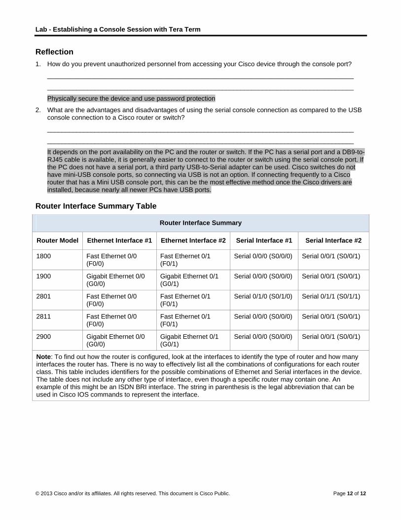
Lab - Establishing a Console Session with Tera Term
© 2013 Cisco and/or its affiliates. All rights reserved. This document is Cisco Public. Page 12 of 12
Reflection 1. How do you prevent unauthorized personnel from accessing your Cisco device through the console port?
____________________________________________________________________________________
____________________________________________________________________________________
Physically secure the device and use password protection
2. What are the advantages and disadvantages of using the serial console connection as compared to the USB console connection to a Cisco router or switch?
____________________________________________________________________________________
____________________________________________________________________________________
It depends on the port availability on the PC and the router or switch. If the PC has a serial port and a DB9-to-RJ45 cable is available, it is generally easier to connect to the router or switch using the serial console port. If the PC does not have a serial port, a third party USB-to-Serial adapter can be used. Cisco switches do not have mini-USB console ports, so connecting via USB is not an option. If connecting frequently to a Cisco router that has a Mini USB console port, this can be the most effective method once the Cisco drivers are installed, because nearly all newer PCs have USB ports.
Router Interface Summary Table
Router Interface Summary
Router Model Ethernet Interface #1 Ethernet Interface #2 Serial Interface #1 Serial Interface #2
1800 Fast Ethernet 0/0 (F0/0)
Fast Ethernet 0/1 (F0/1)
Serial 0/0/0 (S0/0/0) Serial 0/0/1 (S0/0/1)
1900 Gigabit Ethernet 0/0 (G0/0)
Gigabit Ethernet 0/1 (G0/1)
Serial 0/0/0 (S0/0/0) Serial 0/0/1 (S0/0/1)
2801 Fast Ethernet 0/0 (F0/0)
Fast Ethernet 0/1 (F0/1)
Serial 0/1/0 (S0/1/0) Serial 0/1/1 (S0/1/1)
2811 Fast Ethernet 0/0 (F0/0)
Fast Ethernet 0/1 (F0/1)
Serial 0/0/0 (S0/0/0) Serial 0/0/1 (S0/0/1)
2900 Gigabit Ethernet 0/0 (G0/0)
Gigabit Ethernet 0/1 (G0/1)
Serial 0/0/0 (S0/0/0) Serial 0/0/1 (S0/0/1)
Note: To find out how the router is configured, look at the interfaces to identify the type of router and how many interfaces the router has. There is no way to effectively list all the combinations of configurations for each router class. This table includes identifiers for the possible combinations of Ethernet and Serial interfaces in the device. The table does not include any other type of interface, even though a specific router may contain one. An example of this might be an ISDN BRI interface. The string in parenthesis is the legal abbreviation that can be used in Cisco IOS commands to represent the interface.

©
LI
T
A
O
© 2013 Cisco and
Lab - Bunstructor No
Topology
Addressing
D
S1
S2
PC
PC
ObjectivesPart 1: Se
Identi
Cable
Part 2: Co
Enter
Verify
Part 3: Co
Config
Save
Displa
Displa
Displa
d/or its affiliates.
uilding aote: Red font
g Table
Device
V
V
C-A N
C-B N
et Up the Net
fy cables and
e a physical la
onfigure PC
static IP add
y that PCs can
onfigure and
gure each sw
the running c
ay the running
ay the IOS ve
ay the status
All rights reserve
a Simplecolor or Gray
Interface
LAN 1
LAN 1
IC
IC
twork Topolo
d ports for use
ab topology.
Hosts
ress informat
n communica
d Verify Basic
witch with host
configurations
g switch confi
ersion for the
of the interfac
ed. This docume
e Networy highlights ind
IP A
N/A
N/A
192.16
192.16
ogy (Etherne
e in the netwo
tion on the LA
ate using the p
c Switch Set
tname, local p
s.
iguration.
running switc
ces.
ent is Cisco Publi
rk (Instrudicate text tha
Address
N
N
68.1.10 2
68.1.11 2
et only)
ork.
AN interface o
ping utility.
ttings
passwords, a
ch.
ic.
uctor Verat appears in
Subnet Mas
N/A
N/A
255.255.255.0
255.255.255.0
of the hosts.
and login bann
rsion) the instructo
sk Defau
N/A
N/A
0 N/A
0 N/A
ner.
P
r copy only.
ult Gateway
Page 1 of 18

Lab - Building a Simple Network
© 2013 Cisco and/or its affiliates. All rights reserved. This document is Cisco Public. Page 2 of 18
Background / Scenario Networks are constructed of three major components: hosts, switches, and routers. In this lab, you will build a simple network with two hosts and two switches. You will also configure basic settings including hostname, local passwords, and login banner. Use show commands to display the running configuration, IOS version, and interface status. Use the copy command to save device configurations.
You will apply IP addressing for this lab to the PCs to enable communication between these two devices. Use the ping utility to verify connectivity.
Note: The switches used are Cisco Catalyst 2960s with Cisco IOS Release 15.0(2) (lanbasek9 image). Other switches and Cisco IOS versions can be used. Depending on the model and Cisco IOS version, the commands available and output produced might vary from what is shown in the labs.
Note: Make sure that the switches have been erased and have no startup configurations. Refer to Appendix A for the procedure to initialize and reload a switch.
Required Resources 2 Switches (Cisco 2960 with Cisco IOS Release 15.0(2) lanbasek9 image or comparable)
2 PCs (Windows 7, Vista, or XP with terminal emulation program, such as Tera Term)
Console cables to configure the Cisco IOS devices via the console ports
Ethernet cables as shown in the topology
Instructor Note: The Ethernet ports on the 2960 switches are autosensing and will accept either a straight-through or a cross-over cable for all connections. If the switches used in the topology are other than the 2960 model, then it is likely that a cross-over cable will be needed to connect the two switches.
Part 1: Set Up the Network Topology (Ethernet only) In Part 1, you will cable the devices together according to the network topology.
Step 1: Power on the devices.
Power on all devices in the topology. The switches do not have a power switch; they will power on as soon as you plug in the power cord.
Step 2: Connect the two switches.
Connect one end of an Ethernet cable to F0/1 on S1 and the other end of the cable to F0/1 on S2. You should see the lights for F0/1 on both switches turn amber and then green. This indicates that the switches have been connected correctly.
Step 3: Connect the PCs to their respective switches.
a. Connect one end of the second Ethernet cable to the NIC port on PC-A. Connect the other end of the cable to F0/6 on S1. After connecting the PC to the switch, you should see the light for F0/6 turn amber and then green, indicating that PC-A has been connected correctly.
b. Connect one end of the last Ethernet cable to the NIC port on PC-B. Connect the other end of the cable to F0/18 on S2. After connecting the PC to the switch, you should see the light for F0/18 turn amber and then green, indicating that the PC-B has been connected correctly.
Step 4: Visually inspect network connections.
After cabling the network devices, take a moment to carefully verify the connections to minimize the time required to troubleshoot network connectivity issues later.

L
©
P
S
Lab - Buildin
© 2013 Cisco and
Part 2: C
Step 1: Co
a. Click
b. In the
Note:chang
g a Simple N
d/or its affiliates.
Configure
onfigure sta
the Windows
e Network and
If the Controge this option
Network
All rights reserve
e PC Host
tic IP addre
s Start icon a
d Internet sec
ol Panel displato display by
ed. This docume
ts
ess informa
and then selec
tion, click the
ays a list of icy Category.
ent is Cisco Publi
ation on the
ct Control Pa
e View netwo
cons, click the
ic.
PCs.
anel.
ork status an
e drop-down o
d tasks link.
option next to
P
the View by
Page 3 of 18
: and

L
©
Lab - Buildin
© 2013 Cisco and
c. In the
d. The NConn
g a Simple N
d/or its affiliates.
e left pane of t
Network Connnection interfa
Network
All rights reserve
the Network a
nections windoace and selec
ed. This docume
and Sharing C
ow displays tct Properties
ent is Cisco Publi
Center window
he available is.
ic.
w, click the C
interfaces on
Change adapt
the PC. Righ
P
ter settings l
ht-click the Lo
Page 4 of 18
link.
ocal Area

L
©
Lab - Buildin
© 2013 Cisco and
e. Selec
Note:windo
g a Simple N
d/or its affiliates.
ct the Internet
You can alsoow.
Network
All rights reserve
t Protocol Ve
o double-click
ed. This docume
ersion 4 (TCP
k Internet Pro
ent is Cisco Publi
P/IPv4) option
otocol Versio
ic.
n and then cl
on 4 (TCP/IPv
ick Propertie
v4) to display
P
es.
y the Properti
Page 5 of 18
es

L
©
S
Lab - Buildin
© 2013 Cisco and
f. Click defau
Note:gatewAddre
g. After windo
h. Repe
Step 2: Ve
Use the c
a. From press
g a Simple N
d/or its affiliates.
the Use the flt gateway.
In the aboveway has not bessing Table o
all the IP infoow to assign t
at the previou
rify PC sett
ommand prom
PC-A, click th Enter.
Network
All rights reserve
following IP
e example, theeen entered, on page 1 for
rmation has bthe IP address
us steps to en
tings and co
mpt (cmd.exe
he Windows
ed. This docume
address radi
e IP addressbecause ther
r PC-B’s IP ad
been entereds to the LAN
nter the IP add
onnectivity.
e) window to
Start icon, ty
ent is Cisco Publi
o button to m
and subnet mre is no routeddress inform
, click OK. Cladapter.
dress informa
.
verify the PC
ype cmd in th
ic.
manually enter
mask have ber attached to
mation.
ick OK on the
ation for PC-B
C settings and
he Search pro
r an IP addre
een entered fothe network.
e Local Area
B.
connectivity.
ograms and
P
ss, subnet ma
or PC-A. The Refer to the
Connection P
.
files box, an
Page 6 of 18
ask, and
default
Properties
d then

L
©
Lab - Buildin
© 2013 Cisco and
b. The ccommhostn
c. Type
Were
If not,
Note:try to help y
Instrudestin
g a Simple N
d/or its affiliates.
cmd.exe windomands. Verify ame and the
ping 192.168
the ping resu
troubleshoot
If you did noping PC-A fro
you troublesh
uctor Note: Ifnation addres
Network
All rights reserve
ow is where yyour PC settiIPv4 address
8.1.11 and pre
ults successfu
t as necessar
ot get a reply fom PC-B. If yoot the proble
f the first ICMs. This should
ed. This docume
you can enterings by usings information.
ess Enter.
ul? ________
ry.
from PC-B, tryou are unableem.
P packet timed not occur if
ent is Cisco Publi
r commands d the ipconfig
____________
y to ping PC-e to get a rep
es out, this coyou repeat th
ic.
directly to theg /all comman
____ Yes
-B again. If yoply from the re
ould be a resuhe ping as the
e PC and viewnd. This comm
ou still do not emote PC, the
ult of the PC re address is n
P
w the results omand displays
get a reply froen have your
resolving the now cached.
Page 7 of 18
of those s the PC
om PC-B, instructor

Lab - Building a Simple Network
© 2013 Cisco and/or its affiliates. All rights reserved. This document is Cisco Public. Page 8 of 18
Part 3: Configure and Verify Basic Switch Settings
Step 1: Console into the switch.
Using Tera Term, establish a console connection to the switch from PC-A.
Step 2: Enter privileged EXEC mode.
You can access all switch commands in privileged EXEC mode. The privileged EXEC command set includes those commands contained in user EXEC mode, as well as the configure command through which access to the remaining command modes are gained. Enter privileged EXEC mode by entering the enable command.
Switch> enable Switch#
The prompt changed from Switch> to Switch# which indicates privileged EXEC mode.
Step 3: Enter configuration mode.
Use the configuration terminal command to enter configuration mode.
Switch# configure terminal Enter configuration commands, one per line. End with CNTL/Z.
Switch(config)#
The prompt changed to reflect global configuration mode.
Step 4: Give the switch a name.
Use the hostname command to change the switch name to S1.
Switch(config)# hostname S1 S1(config)#
Step 5: Prevent unwanted DNS lookups.
To prevent the switch from attempting to translate incorrectly entered commands as though they were hostnames, disable the Domain Name System (DNS) lookup.
S1(config)# no ip domain-lookup S1(config)#
Step 6: Enter local passwords.
To prevent unauthorized access to the switch, passwords must be configured.
S1(config)# enable secret class S1(config)# line con 0 S1(config-line)# password cisco S1(config-line)# login S1(config-line)# exit S1(config)#
Step 7: Enter a login MOTD banner.
A login banner, known as the message of the day (MOTD) banner, should be configured to warn anyone accessing the switch that unauthorized access will not be tolerated.

Lab - Building a Simple Network
© 2013 Cisco and/or its affiliates. All rights reserved. This document is Cisco Public. Page 9 of 18
The banner motd command requires the use of delimiters to identify the content of the banner message. The delimiting character can be any character as long as it does not occur in the message. For this reason, symbols, such as the #, are often used.
S1(config)# banner motd # Enter TEXT message. End with the character '#'.
Unauthorized access is strictly prohibited and prosecuted to the full extent of the law. # S1(config)# exit S1#
Step 8: Save the configuration.
Use the copy command to save the running configuration to the startup file on non-volatile random access memory (NVRAM).
S1# copy running-config startup-config Destination filename [startup-config]? [Enter] Building configuration...
[OK]
S1#
Step 9: Display the current configuration.
The show running-config command displays the entire running configuration, one page at a time. Use the spacebar to advance paging. The commands configured in Steps 1 – 8 are highlighted below.
S1# show running-config Building configuration...
Current configuration : 1409 bytes
!
! Last configuration change at 03:49:17 UTC Mon Mar 1 1993
!
version 15.0
no service pad
service timestamps debug datetime msec
service timestamps log datetime msec
no service password-encryption
!
hostname S1
!
boot-start-marker
boot-end-marker
!
enable secret 4 06YFDUHH61wAE/kLkDq9BGho1QM5EnRtoyr8cHAUg.2
!
no aaa new-model
system mtu routing 1500
!
!
no ip domain-lookup

Lab - Building a Simple Network
© 2013 Cisco and/or its affiliates. All rights reserved. This document is Cisco Public. Page 10 of 18
!
<output omitted>
!
banner motd ^C
Unauthorized access is strictly prohibited and prosecuted to the full extent of the law. ^C
!
line con 0
password cisco
login
line vty 0 4
login
line vty 5 15
login
!
end
S1#
Step 10: Display the IOS version and other useful switch information.
Use the show version command to display the IOS version that the switch is running, along with other useful information. Again, you will need to use the spacebar to advance through the displayed information.
S1# show version Cisco IOS Software, C2960 Software (C2960-LANBASEK9-M), Version 15.0(2)SE, RELEASE SOFTWARE (fc1)
Technical Support: http://www.cisco.com/techsupport
Copyright (c) 1986-2012 by Cisco Systems, Inc.
Compiled Sat 28-Jul-12 00:29 by prod_rel_team
ROM: Bootstrap program is C2960 boot loader
BOOTLDR: C2960 Boot Loader (C2960-HBOOT-M) Version 12.2(53r)SEY3, RELEASE SOFTWARE (fc1)
S1 uptime is 1 hour, 38 minutes
System returned to ROM by power-on
System image file is "flash:/c2960-lanbasek9-mz.150-2.SE.bin"
This product contains cryptographic features and is subject to United
States and local country laws governing import, export, transfer and
use. Delivery of Cisco cryptographic products does not imply
third-party authority to import, export, distribute or use encryption.
Importers, exporters, distributors and users are responsible for
compliance with U.S. and local country laws. By using this product you
agree to comply with applicable laws and regulations. If you are unable
to comply with U.S. and local laws, return this product immediately.
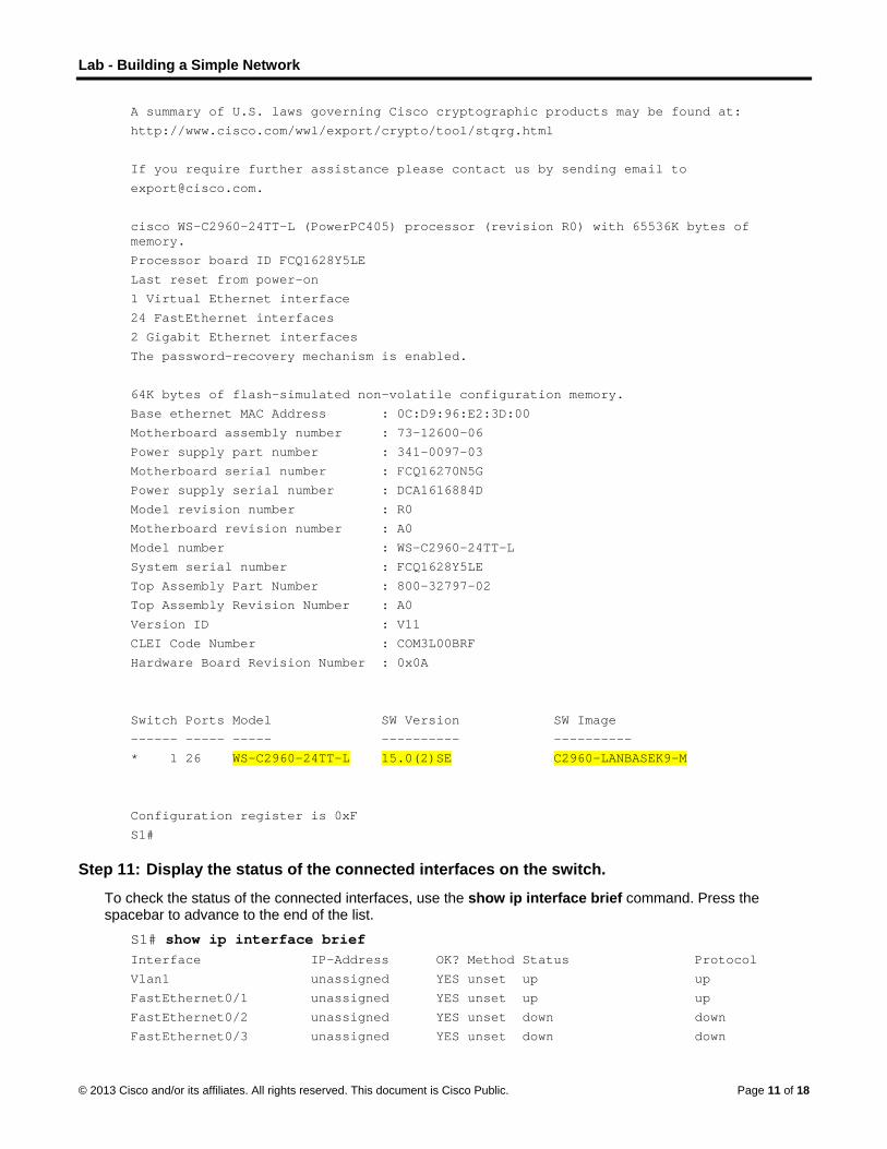
Lab - Building a Simple Network
© 2013 Cisco and/or its affiliates. All rights reserved. This document is Cisco Public. Page 11 of 18
A summary of U.S. laws governing Cisco cryptographic products may be found at:
http://www.cisco.com/wwl/export/crypto/tool/stqrg.html
If you require further assistance please contact us by sending email to
cisco WS-C2960-24TT-L (PowerPC405) processor (revision R0) with 65536K bytes of memory.
Processor board ID FCQ1628Y5LE
Last reset from power-on
1 Virtual Ethernet interface
24 FastEthernet interfaces
2 Gigabit Ethernet interfaces
The password-recovery mechanism is enabled.
64K bytes of flash-simulated non-volatile configuration memory.
Base ethernet MAC Address : 0C:D9:96:E2:3D:00
Motherboard assembly number : 73-12600-06
Power supply part number : 341-0097-03
Motherboard serial number : FCQ16270N5G
Power supply serial number : DCA1616884D
Model revision number : R0
Motherboard revision number : A0
Model number : WS-C2960-24TT-L
System serial number : FCQ1628Y5LE
Top Assembly Part Number : 800-32797-02
Top Assembly Revision Number : A0
Version ID : V11
CLEI Code Number : COM3L00BRF
Hardware Board Revision Number : 0x0A
Switch Ports Model SW Version SW Image
------ ----- ----- ---------- ----------
* 1 26 WS-C2960-24TT-L 15.0(2)SE C2960-LANBASEK9-M
Configuration register is 0xF
S1#
Step 11: Display the status of the connected interfaces on the switch.
To check the status of the connected interfaces, use the show ip interface brief command. Press the spacebar to advance to the end of the list.
S1# show ip interface brief Interface IP-Address OK? Method Status Protocol
Vlan1 unassigned YES unset up up
FastEthernet0/1 unassigned YES unset up up
FastEthernet0/2 unassigned YES unset down down
FastEthernet0/3 unassigned YES unset down down
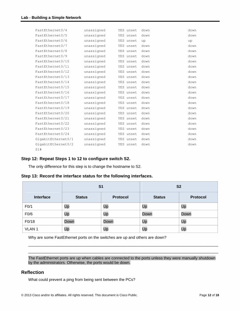
Lab - Building a Simple Network
© 2013 Cisco and/or its affiliates. All rights reserved. This document is Cisco Public. Page 12 of 18
FastEthernet0/4 unassigned YES unset down down
FastEthernet0/5 unassigned YES unset down down
FastEthernet0/6 unassigned YES unset up up
FastEthernet0/7 unassigned YES unset down down
FastEthernet0/8 unassigned YES unset down down
FastEthernet0/9 unassigned YES unset down down
FastEthernet0/10 unassigned YES unset down down
FastEthernet0/11 unassigned YES unset down down
FastEthernet0/12 unassigned YES unset down down
FastEthernet0/13 unassigned YES unset down down
FastEthernet0/14 unassigned YES unset down down
FastEthernet0/15 unassigned YES unset down down
FastEthernet0/16 unassigned YES unset down down
FastEthernet0/17 unassigned YES unset down down
FastEthernet0/18 unassigned YES unset down down
FastEthernet0/19 unassigned YES unset down down
FastEthernet0/20 unassigned YES unset down down
FastEthernet0/21 unassigned YES unset down down
FastEthernet0/22 unassigned YES unset down down
FastEthernet0/23 unassigned YES unset down down
FastEthernet0/24 unassigned YES unset down down
GigabitEthernet0/1 unassigned YES unset down down
GigabitEthernet0/2 unassigned YES unset down down
S1#
Step 12: Repeat Steps 1 to 12 to configure switch S2.
The only difference for this step is to change the hostname to S2.
Step 13: Record the interface status for the following interfaces.
Interface
S1 S2
Status Protocol Status Protocol
F0/1 Up Up Up Up
F0/6 Up Up Down Down
F0/18 Down Down Up Up
VLAN 1 Up Up Up Up
Why are some FastEthernet ports on the switches are up and others are down?
_______________________________________________________________________________________
_______________________________________________________________________________________
The FastEthernet ports are up when cables are connected to the ports unless they were manually shutdown by the administrators. Otherwise, the ports would be down.
Reflection What could prevent a ping from being sent between the PCs?

Lab - Building a Simple Network
© 2013 Cisco and/or its affiliates. All rights reserved. This document is Cisco Public. Page 13 of 18
_______________________________________________________________________________________
Wrong IP address, media disconnected, switch powered off or ports administratively down, firewall.
Note: It may be necessary to disable the PC firewall to ping between PCs.
Appendix A: Initializing and Reloading a Switch
Step 1: Connect to the switch.
Console into the switch and enter privileged EXEC mode.
Switch> enable Switch#
Step 2: Determine if there have been any virtual local-area networks (VLANs) created.
Use the show flash command to determine if any VLANs have been created on the switch.
Switch# show flash
Directory of flash:/
2 -rwx 1919 Mar 1 1993 00:06:33 +00:00 private-config.text
3 -rwx 1632 Mar 1 1993 00:06:33 +00:00 config.text
4 -rwx 13336 Mar 1 1993 00:06:33 +00:00 multiple-fs
5 -rwx 11607161 Mar 1 1993 02:37:06 +00:00 c2960-lanbasek9-mz.150-2.SE.bin
6 -rwx 616 Mar 1 1993 00:07:13 +00:00 vlan.dat
32514048 bytes total (20886528 bytes free)
Switch#
Step 3: Delete the VLAN file.
a. If the vlan.dat file was found in flash, then delete this file.
Switch# delete vlan.dat Delete filename [vlan.dat]?
You will be prompted to verify the file name. At this point, you can change the file name or just press Enter if you have entered the name correctly.
b. When you are prompted to delete this file, press Enter to confirm the deletion. (Pressing any other key will abort the deletion.)
Delete flash:/vlan.dat? [confirm]
Switch#
Step 4: Erase the startup configuration file.
Use the erase startup-config command to erase the startup configuration file from NVRAM. When you are prompted to remove the configuration file, press Enter to confirm the erase. (Pressing any other key will abort the operation.)
Switch# erase startup-config Erasing the nvram filesystem will remove all configuration files! Continue? [confirm]
[OK]
Erase of nvram: complete
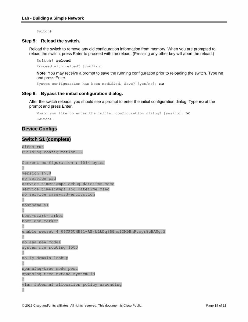
Lab - Building a Simple Network
© 2013 Cisco and/or its affiliates. All rights reserved. This document is Cisco Public. Page 14 of 18
Switch#
Step 5: Reload the switch.
Reload the switch to remove any old configuration information from memory. When you are prompted to reload the switch, press Enter to proceed with the reload. (Pressing any other key will abort the reload.)
Switch# reload Proceed with reload? [confirm]
Note: You may receive a prompt to save the running configuration prior to reloading the switch. Type no and press Enter.
System configuration has been modified. Save? [yes/no]: no
Step 6: Bypass the initial configuration dialog.
After the switch reloads, you should see a prompt to enter the initial configuration dialog. Type no at the prompt and press Enter.
Would you like to enter the initial configuration dialog? [yes/no]: no Switch>
Device Configs
Switch S1 (complete) S1#sh run Building configuration... Current configuration : 1514 bytes ! version 15.0 no service pad service timestamps debug datetime msec service timestamps log datetime msec no service password-encryption ! hostname S1 ! boot-start-marker boot-end-marker ! enable secret 4 06YFDUHH61wAE/kLkDq9BGho1QM5EnRtoyr8cHAUg.2 ! no aaa new-model system mtu routing 1500 ! no ip domain-lookup ! spanning-tree mode pvst spanning-tree extend system-id ! vlan internal allocation policy ascending !

Lab - Building a Simple Network
© 2013 Cisco and/or its affiliates. All rights reserved. This document is Cisco Public. Page 15 of 18
interface FastEthernet0/1 ! interface FastEthernet0/2 ! interface FastEthernet0/3 ! interface FastEthernet0/4 ! interface FastEthernet0/5 ! interface FastEthernet0/6 ! interface FastEthernet0/7 ! interface FastEthernet0/8 ! interface FastEthernet0/9 ! interface FastEthernet0/10 ! interface FastEthernet0/11 ! interface FastEthernet0/12 ! interface FastEthernet0/13 ! interface FastEthernet0/14 ! interface FastEthernet0/15 ! interface FastEthernet0/16 ! interface FastEthernet0/17 ! interface FastEthernet0/18 ! interface FastEthernet0/19 ! interface FastEthernet0/20 ! interface FastEthernet0/21 ! interface FastEthernet0/22 ! interface FastEthernet0/23 ! interface FastEthernet0/24 ! interface GigabitEthernet0/1
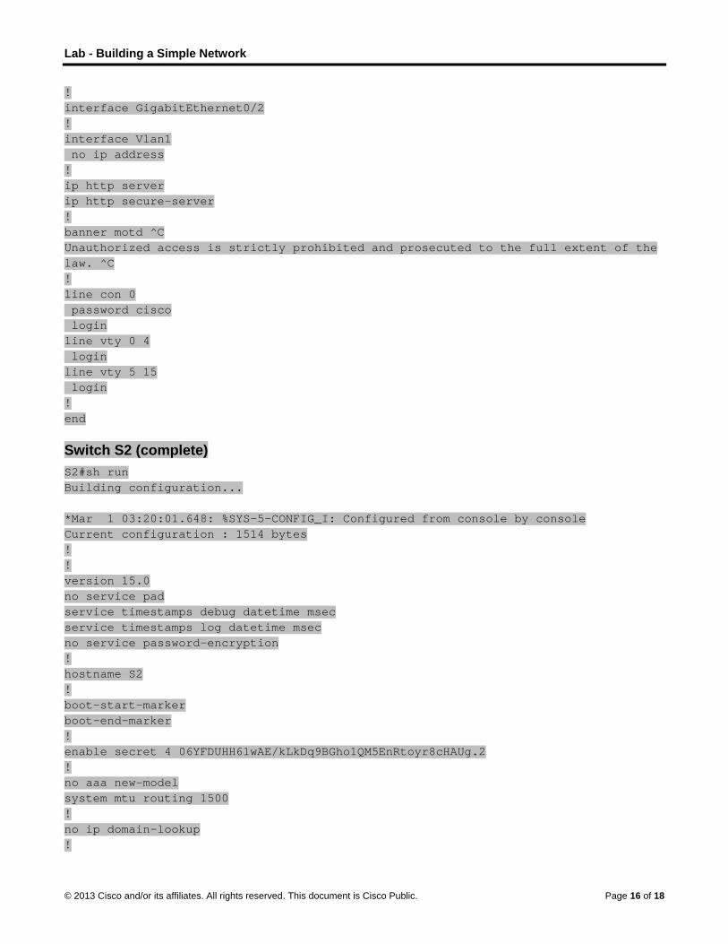
Lab - Building a Simple Network
© 2013 Cisco and/or its affiliates. All rights reserved. This document is Cisco Public. Page 16 of 18
! interface GigabitEthernet0/2 ! interface Vlan1 no ip address ! ip http server ip http secure-server ! banner motd ^C Unauthorized access is strictly prohibited and prosecuted to the full extent of the law. ^C ! line con 0 password cisco login line vty 0 4 login line vty 5 15 login ! end
Switch S2 (complete) S2#sh run Building configuration... *Mar 1 03:20:01.648: %SYS-5-CONFIG_I: Configured from console by console Current configuration : 1514 bytes ! ! version 15.0 no service pad service timestamps debug datetime msec service timestamps log datetime msec no service password-encryption ! hostname S2 ! boot-start-marker boot-end-marker ! enable secret 4 06YFDUHH61wAE/kLkDq9BGho1QM5EnRtoyr8cHAUg.2 ! no aaa new-model system mtu routing 1500 ! no ip domain-lookup !

Lab - Building a Simple Network
© 2013 Cisco and/or its affiliates. All rights reserved. This document is Cisco Public. Page 17 of 18
spanning-tree mode pvst spanning-tree extend system-id ! vlan internal allocation policy ascending ! interface FastEthernet0/1 ! interface FastEthernet0/2 ! interface FastEthernet0/3 ! interface FastEthernet0/4 ! interface FastEthernet0/5 ! interface FastEthernet0/6 ! interface FastEthernet0/7 ! interface FastEthernet0/8 ! interface FastEthernet0/9 ! interface FastEthernet0/10 ! interface FastEthernet0/11 ! interface FastEthernet0/12 ! interface FastEthernet0/13 ! interface FastEthernet0/14 ! interface FastEthernet0/15 ! interface FastEthernet0/16 ! interface FastEthernet0/17 ! interface FastEthernet0/18 ! interface FastEthernet0/19 ! interface FastEthernet0/20 ! interface FastEthernet0/21 ! interface FastEthernet0/22 !

Lab - Building a Simple Network
© 2013 Cisco and/or its affiliates. All rights reserved. This document is Cisco Public. Page 18 of 18
interface FastEthernet0/23 ! interface FastEthernet0/24 ! interface GigabitEthernet0/1 ! interface GigabitEthernet0/2 ! interface Vlan1 no ip address ! ip http server ip http secure-server ! banner motd ^C Unauthorized access is strictly prohibited and prosecuted to the full extent of the law. ^C ! line con 0 password cisco login line vty 0 4 login line vty 5 15 login ! end

©
LVI
T
A
O
B
© 2013 Cisco and
Lab - CoVersion) nstructor No
Topology
Addressing
D
S1
PC
ObjectivesPart 1: Co
Cable
Config
Config
Part 2: Ve
Displa
Test e
Test r
Save
BackgrounCisco swiwith an IPswitch to d
In this labconsole ademonstraone switc
Note: Theswitches acommand
Note: Mayour instru
d/or its affiliates.
onfigurin
ote: Red font
g Table
Device
V
C-A N
onfigure a B
e the network
gure basic sw
gure an IP ad
erify and Tes
ay device con
end-to-end co
remote manag
the switch ru
nd / Scenartches have a
P address, comdisplay or con
b, you will builand remote acate the use oh and one ho
e switches usand Cisco IOSds and output
ke sure that tuctor.
All rights reserve
ng a Sw
color or Gray
Interface
LAN 1
IC
asic Network
as shown in
witch settings
ddress on the
st Network C
nfiguration.
onnectivity wit
gement capa
nning configu
rio special interf
mmonly refernfigure setting
d a simple neccess methodf a managem
ost using only
ed are Cisco S versions caproduced mi
he switch has
ed. This docume
itch Man
y highlights ind
IP A
192.16
192.16
k Device
the topology.
including hos
PC.
Connectivity
th ping.
bility with Tel
uration file.
face, known arred to as the gs.
etwork using Eds. You will co
ment IP addresEthernet and
Catalyst 296an be used. Dght vary from
s been erased
ent is Cisco Publi
nageme
dicate text tha
Address
68.1.2 2
68.1.10 2
stname, mana
net.
as a switch vimanagement
Ethernet LANonfigure basicss for remote d console port
0s with CiscoDepending on m what is show
d and has no
ic.
ent Addr
at appears in
Subnet Mas
255.255.255.0
255.255.255.0
agement add
rtual interfacet address tha
N cabling and c switch settin
switch manats.
o IOS Releasethe model an
wn in the labs
startup confi
ress (Ins
the instructo
sk Defau
0 N/A
0 N/A
ress, and Tel
e (SVI). The Sat is used for r
access a Cisngs and IP adagement. The
e 15.0(2) (lannd Cisco IOS s.
guration. If yo
P
structor
r copy only.
ult Gateway
net access.
SVI can be coremote acces
sco switch usiddressing, and topology con
nbasek9 imagversion, the
ou are unsure
Page 1 of 10
onfigured ss to the
ng the d nsists of
ge). Other available
e, contact

Lab - Configuring a Switch Management Address
© 2013 Cisco and/or its affiliates. All rights reserved. This document is Cisco Public. Page 2 of 10
Instructor Note: Refer to the Instructor Lab Manual for the procedures to initialize and reload devices.
Required Resources 1 Switch (Cisco 2960 with Cisco IOS Release 15.0(2) lanbasek9 image or comparable)
1 PC (Windows 7, Vista, or XP with terminal emulation program, such as Tera Term)
Console cables to configure the Cisco IOS devices via the console ports
Ethernet cables as shown in the topology
Part 1: Configure a Basic Network Device In Part 1, you will set up the network and configure basic settings, such as hostnames, interface IP addresses, and passwords.
Step 1: Cable the network.
a. Cable the network as shown in the topology.
b. Establish a console connection to the switch from PC-A.
Step 2: Configure basic switch settings.
In this step, you will configure basic switch settings, such as hostname and configuring an IP address for the SVI. Assigning an IP address on the switch is only the first step. As the network administrator, you must specify how the switch will be managed. Telnet and Secure Shell (SSH) are two of the most common management methods; however, Telnet is a very insecure protocol. All information flowing between the two devices is sent in plain text. Passwords and other sensitive information can be easily looked at if captured by a packet sniffer.
a. Assuming the switch had no configuration file stored in nonvolatile random-access memory (NVRAM),
you will be at the user EXEC mode prompt on the switch with a prompt of Switch>. Enter privileged
EXEC mode.
Switch> enable Switch#
b. Verify a clean configuration file with the show running-config privileged EXEC command. If a
configuration file was previously saved, it will have to be removed. Depending on the switch model and IOS version, your configuration may look slightly different. However, there should be no configured passwords or IP address set. If your switch does not have a default configuration, ask your instructor for help.
c. Enter global configuration mode and assign the switch hostname.
Switch# configure terminal Switch(config)# hostname S1 S1(config)#
d. Configure the switch password access.
S1(config)# enable secret class S1(config)#
e. Prevent unwanted Domain Name System (DNS) lookups.
S1(config)# no ip domain-lookup S1(config)#

Lab - Configuring a Switch Management Address
© 2013 Cisco and/or its affiliates. All rights reserved. This document is Cisco Public. Page 3 of 10
f. Configure a login message-of-the-day (MOTD) banner.
S1(config)# banner motd # Enter Text message. End with the character ‘#’. Unauthorized access is strictly prohibited. #
g. Verify your access setting by moving between modes.
S1(config)# exit S1# S1# exit Unauthorized access is strictly prohibited. S1>
What shortcut keys are used to go directly from global configuration mode to privileged EXEC mode?
____________________________________________________________________________________
Ctrl+Z
h. Return to privileged EXEC mode from user EXEC mode.
S1> enable Password: class S1#
Note: Password will not show up on screen when entering.
i. Enter global configuration mode to set the SVI IP address to allow remote switch management.
S1# config t S1#(config)# interface vlan 1 S1(config-if)# ip address 192.168.1.2 255.255.255.0 S1(config-if)# no shut S1(config-if)# exit S1(config)#
j. Restrict console port access. The default configuration is to allow all console connections with no password needed.
S1(config)# line con 0 S1(config-line)# password cisco S1(config-line)# login S1(config-line)# exit S1(config)#
k. Configure the virtual terminal (VTY) line for the switch to allow Telnet access. If you do not configure a VTY password, you will not be able to Telnet to the switch.
S1(config)# line vty 0 4 S1(config-line)# password cisco S1(config-line)# login S1(config-line)# end S1# *Mar 1 00:06:11.590: %SYS-5-CONFIG_I: Configured from console by console

Lab - Configuring a Switch Management Address
© 2013 Cisco and/or its affiliates. All rights reserved. This document is Cisco Public. Page 4 of 10
Step 3: Configure an IP address on PC-A.
a. Assign the IP address and subnet mask to the PC, as shown in the Addressing Table on page 1. The procedure for assigning an IP address on a PC running Windows 7 is described below:
1) Click the Windows Start icon > Control Panel.
2) Click View By: > Category.
3) Choose View network status and tasks > Change adapter settings.
4) Right-click Local Area Network Connection and select Properties.
5) Choose Internet Protocol Version 4 (TCP/IPv4), click Properties > OK.
6) Click the Use the following IP address radio button and enter the IP address and subnet mask.
Part 2: Verify and Test Network Connectivity You will now verify and document the switch configuration, test end-to-end connectivity between PC-A and S1, and test the remote management capability of the switch.
Step 1: Display the S1 device configuration.
a. Return to your console connection using Tera Term on PC-A to display and verify your switch configuration by issuing the show run command. A sample configuration is shown below. The settings you configured are highlighted in yellow. The other configuration settings are IOS defaults.
S1# show run Building configuration...
Current configuration : 1508 bytes
!
! Last configuration change at 00:06:11 UTC Mon Mar 1 1993
!
version 15.0
no service pad
service timestamps debug datetime msec
service timestamps log datetime msec
no service password-encryption
!
hostname S1
!
boot-start-marker
boot-end-marker
!
enable secret 4 06YFDUHH61wAE/kLkDq9BGho1QM5EnRtoyr8cHAUg.2
!
no aaa new-model
system mtu routing 1500
!
!
no ip domain-lookup
!
spanning-tree mode pvst
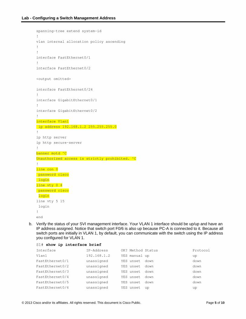
Lab - Configuring a Switch Management Address
© 2013 Cisco and/or its affiliates. All rights reserved. This document is Cisco Public. Page 5 of 10
spanning-tree extend system-id
!
vlan internal allocation policy ascending
!
!
interface FastEthernet0/1
!
interface FastEthernet0/2
<output omitted>
interface FastEthernet0/24
!
interface GigabitEthernet0/1
!
interface GigabitEthernet0/2
!
interface Vlan1
ip address 192.168.1.2 255.255.255.0
!
ip http server
ip http secure-server
!
banner motd ^C
Unauthorized access is strictly prohibited. ^C
!
line con 0
password cisco
login
line vty 0 4
password cisco
login
line vty 5 15
login
!
end
b. Verify the status of your SVI management interface. Your VLAN 1 interface should be up/up and have an IP address assigned. Notice that switch port F0/6 is also up because PC-A is connected to it. Because all switch ports are initially in VLAN 1, by default, you can communicate with the switch using the IP address you configured for VLAN 1.
S1# show ip interface brief Interface IP-Address OK? Method Status Protocol
Vlan1 192.168.1.2 YES manual up up
FastEthernet0/1 unassigned YES unset down down
FastEthernet0/2 unassigned YES unset down down
FastEthernet0/3 unassigned YES unset down down
FastEthernet0/4 unassigned YES unset down down
FastEthernet0/5 unassigned YES unset down down
FastEthernet0/6 unassigned YES unset up up

L
©
S
Lab - Configu
© 2013 Cisco and
FastE
FastE
FastE
FastE
FastE
FastE
FastE
FastE
FastE
FastE
FastE
FastE
FastE
FastE
FastE
FastE
FastE
FastE
Gigab
Gigab
Step 2: Tes
Open a cothe SearcThis commthe manag
a. Ping y
C:\Us
Your
uring a Switc
d/or its affiliates.
Ethernet0/7
Ethernet0/8
Ethernet0/9
Ethernet0/10
Ethernet0/11
Ethernet0/12
Ethernet0/13
Ethernet0/14
Ethernet0/15
Ethernet0/16
Ethernet0/17
Ethernet0/18
Ethernet0/19
Ethernet0/20
Ethernet0/21
Ethernet0/22
Ethernet0/23
Ethernet0/24
bitEthernet0
bitEthernet0
st end-to-en
ommand promch for programand displaygement addre
your own PC-
sers\NetAc
output should
ch Managem
All rights reserve
una
una
una
0 una
1 una
2 una
3 una
4 una
5 una
6 una
7 una
8 una
9 una
0 una
1 una
2 una
3 una
4 una
0/1 una
0/2 una
nd connectiv
mpt window (cams and filess the PC hosess of S1.
-A address fir
cad> ping 1
d be similar to
ment Address
ed. This docume
assigned
assigned
assigned
assigned
assigned
assigned
assigned
assigned
assigned
assigned
assigned
assigned
assigned
assigned
assigned
assigned
assigned
assigned
assigned
assigned
vity.
cmd.exe) on s field. Verify ttname and th
rst.
192.168.1.
o the following
s
ent is Cisco Publi
YES unse
YES unse
YES unse
YES unse
YES unse
YES unse
YES unse
YES unse
YES unse
YES unse
YES unse
YES unse
YES unse
YES unse
YES unse
YES unse
YES unse
YES unse
YES unse
YES unse
PC-A by clickthe IP addres
he IPv4 addre
10
g screen:
ic.
et down
et down
et down
et down
et down
et down
et down
et down
et down
et down
et down
et down
et down
et down
et down
et down
et down
et down
et down
et down
king the Windss of PC-A byess informatio
dows Start icy using the ipcon. Ping PC-A
P
down
down
down
down
down
down
down
down
down
down
down
down
down
down
down
down
down
down
down
down
con and enter config /all co
A’s own addre
Page 6 of 10
cmd into ommand. ess and

L
©
S
Lab - Configu
© 2013 Cisco and
b. Ping t
C:\Us
Your basic
Step 3: Tes
You will nPC-A andfloor whilewill use it commandremotely a
Note: WinTelnet clie
C:\Us
a. With tSVI m
C:\Us
Your
uring a Switc
d/or its affiliates.
the SVI mana
sers\NetAc
output shoulddevice config
st and verify
ow use Telned S1 reside side your managin this lab to
ds, is sent acraccess netwo
ndows 7 doesent, open a co
sers\NetAc
the commandmanagement a
sers\NetAc
output should
ch Managem
All rights reserve
agement addr
cad> ping 1
d be similar togurations. You
y remote ma
et to remotelyde by side. In
gement PC is test remote a
ross the sessiork devices.
s not natively ommand prom
cad> pkgmgr
d prompt windaddress. The
cad> telnet
d be similar to
ment Address
ed. This docume
ress of S1.
192.168.1.
o the followingu should chec
anagement
y access the sn a production
located on thaccess. All infoion in plain te
support Telnempt window a
r /iu:”Tel
dow still open password is
t 192.168.
o the following
s
ent is Cisco Publi
2
g screen. If pick both the ph
of S1.
switch S1 usinn network, thehe ground flooormation sen
ext. In subseq
et. The adminand type pkgm
lnetClient”
on PC-A, isscisco.
1.2
g screen:
ic.
ng results arehysical cablin
ng the SVI mae switch couldor. Telnet is nt by Telnet, inuent labs, yo
nistrator mustmgr /iu:“T
”
sue a Telnet c
e not successng and IP add
anagement ad be in a wirinnot a secure pncluding passu will use Sec
t enable this pTelnetClien
command to c
P
sful, troubleshdressing, if ne
ddress. In thing closet on thprotocol. Howswords and cure Shell (SS
protocol. To innt”.
connect to S1
Page 7 of 10
hoot the ecessary.
s lab, he top ever, you
SH) to
nstall the
via the

L
©
S
R
D
SSB!C!v
Lab - Configu
© 2013 Cisco and
b. After promp
Step 4: Sav
a. From
S1# cDesti
BuildS1#
b. Exit th
Reflection Why mustTelnet or
________
No IP addconfigured
Device Con
Switch S1(S1#show runBuilding co! Current con! version 15.
uring a Switc
d/or its affiliates.
entering the cpt. Enter the c
ve the confi
your Telnet s
copy run sination fi
ding confi
he Telnet ses
t you use a coSSH?
___________
dressing parad.
nfigs
Complete)n onfigurati
nfiguratio
.0
ch Managem
All rights reserve
cisco passwoclass passwo
guration fil
session, issue
start ilename [st
iguration .
ssion by typing
onsole conne
____________
meters are co
)
ion...
on : 1508 b
ment Address
ed. This docume
ord, you will bord to enter p
e.
e the copy ru
tartup-con
..
g quit. You w
ection to initial
___________
onfigured yet.
bytes
s
ent is Cisco Publi
be at the user rivileged EXE
un start comm
nfig]? [Ent
will be returned
lly configure t
___________
. A switch firs
ic.
r EXEC modeEC mode and
mand at the p
ter]
d to the Wind
the switch? W
____________
st placed into
e prompt. Typ issue a show
prompt.
dows 7 comm
Why not conne
____________
service has n
P
e enable at thw run comma
mand prompt.
ect to the swit
___________
no networking
Page 8 of 10
he and.
tch via
________
g

Lab - Configuring a Switch Management Address
© 2013 Cisco and/or its affiliates. All rights reserved. This document is Cisco Public. Page 9 of 10
no service pad service timestamps debug datetime msec service timestamps log datetime msec no service password-encryption ! hostname S1 ! boot-start-marker boot-end-marker ! enable secret 4 06YFDUHH61wAE/kLkDq9BGho1QM5EnRtoyr8cHAUg.2 ! no aaa new-model system mtu routing 1500 ! ! no ip domain-lookup ! spanning-tree mode pvst spanning-tree extend system-id ! vlan internal allocation policy ascending ! ! interface FastEthernet0/1 ! interface FastEthernet0/2 ! interface FastEthernet0/3 ! interface FastEthernet0/4 ! interface FastEthernet0/5 ! interface FastEthernet0/6 ! interface FastEthernet0/7 ! interface FastEthernet0/8 ! interface FastEthernet0/9 ! interface FastEthernet0/10 ! interface FastEthernet0/11 ! interface FastEthernet0/12 ! interface FastEthernet0/13

Lab - Configuring a Switch Management Address
© 2013 Cisco and/or its affiliates. All rights reserved. This document is Cisco Public. Page 10 of 10
! interface FastEthernet0/14 ! interface FastEthernet0/15 ! interface FastEthernet0/16 ! interface FastEthernet0/17 ! interface FastEthernet0/18 ! interface FastEthernet0/19 ! interface FastEthernet0/20 ! interface FastEthernet0/21 ! interface FastEthernet0/22 ! interface FastEthernet0/23 ! interface FastEthernet0/24 ! interface GigabitEthernet0/1 ! interface GigabitEthernet0/2 ! interface Vlan1 ip address 192.168.1.2 255.255.255.0 ! ip http server ip http secure-server ! banner motd ^C Unauthorized access is strictly prohibited. ^C ! line con 0 password cisco login line vty 0 4 password class login line vty 5 15 login ! end

©
TI
O
B
R
R1
2
© 2013 Cisco and
Tutor menstructor No
ObjectivesConfigure
In this act
command
meaning o
configurin
Backgroun(Students
Assume tnever wor
You explaCLI is a s
Use PackLab Activi
W
Hw
Wex
Suggest hmoves be
Instructohelp studedirectly tostudent di
Required R Packe
Any s
Reflection 1. After com
does and commanddifficulties
________
________
________
2. Answer th
d/or its affiliates.
e! (Instruote: Red font
e initial setti
tivity, you will
d-line interface
of individual c
ng a device to
nd/Scenarios will work in
hat a new colrked with Cisc
ain the basic Cimple, yet pow
ket Tracer andity 2.3.3.5 LA
While the com
How is the set which mode he
What are the inxplain this co
how to group etween modes
or notes: Thisents reflect on
o configure intiscussions of
Resources et Tracer
simple networ
pleting Chapthow it operat
ds and structus that you wou
___________
___________
___________
he following q
All rights reserve
uctor Vecolor or Gray
ngs on a net
use and reinf
e (CLI) by exp
commands. Y
o minimize the
o n pairs. Pack
lleague has aco devices be
CLI commandwerful, comm
d one of the aB – Configuri
mands are te
of commande or she is cu
ndividual commmand in lay
different coms will be need
s Modeling An the knowledtermediary deeach other’s
rk model activ
ter 2, do you tes? What we
ure to your could have learn
____________
____________
____________
uestions, and
ed. This docume
rsion) y highlights ind
twork device
force your kn
plaining it to o
You will also fi
e necessary c
ket Tracer is
asked you for efore.
ds and structumand language
activities availng a Switch M
echnical, do th
s organized inrrently using?
mmands to coymen’s terms?
mmands togethded.
ctivity may bedge acquired evices. Instrucwork.
vity available f
feel as thougere some of thlleague? If yoning the basic
___________
___________
___________
d discuss you
ent is Cisco Publi
dicate text tha
e using the C
owledge of th
other students
nd the optima
count of mode
required to b
an orientation
ure, becausee that can be
able in this chManagement
hey resemble
nto subgroup?
nfigure the ba? Use paralle
her according
e used as a gfrom Chapter
ctor facilitation
from Chapter
h you have ahe difficulties ou were the “c CLI comma
___________
___________
___________
r answers wit
ic.
at appears in
Cisco IOS sof
he Cisco Inter
s. You will loo
al grouping of
e changes.
be used with
n to the Cisco
you want youeasily unders
hapter as a siAddress). Fo
any stateme
ps or modes?
asic settings oels to real life
g to their mod
graded assignr 2, focusing on of the discu
r 2
a concrete undyou encounte
“new colleagunds and struc
____________
____________
____________
th the entire c
the instructo
ftware.
rnetwork Ope
ok for differen
f commands t
h this activity
o IOS CLI. Th
ur colleague tstood and na
imple networkocus on these
ents from plain
How does an
of a Cisco dewhenever ap
des so that a m
nment. Howevon how the C
ussion should
derstanding oered when exue,” what woucture?
____________
____________
____________
class:
r copy only.
erating System
nt ways to exp
to be used wh
y.)
his colleague
to understandvigated.
k model (for ee areas:
n English?
n administrato
evice? How woppropriate.
minimum num
ver, its purposCisco IOS is u
encourage s
of what the Cixplaining the buld be some o
___________
___________
___________
Page 1 of 4
m (IOS)
plain the
hen
has
d that the
example,
or know
ould you
mber of
se is to sed
student-to-
isco IOS basic CLI of the
________
________
________

Tutor me!
© 2013 Cisco and/or its affiliates. All rights reserved. This document is Cisco Public. Page 2 of 4
a) While the commands are technical, do they resemble any statements from plain English?
b) How is the set of commands organized into subgroups or modes? How does an administrator know which mode he or she is currently using?
c) What are the individual commands to configure the basic settings of a Cisco device? How would you explain this command in laymen’s terms? Use parallels to real life whenever appropriate.
d) With the help of your colleague, try to suggest how to group different commands together according to their modes so that a minimum number of moves between modes will be needed.
(Answers will vary (represented below are Chapter 2 content-based variations):
a) While the commands are technical, do they resemble any statements from plain English?
Absolutely. Keywords like enable, password, banner, address, shutdown are ordinary words whose meaning in CLI is appropriately adapted but still carrying a strong relevancy to their common usage.
b) How is the set of commands organized into subgroups, or modes? How does an administrator know which mode is he/she using currently?
First, the level of access to CLI can either be a user (user EXEC) level, or an administrator level (privileged EXEC). From the administrator level, the configuration mode can be accessed that is internally divided into global configuration mode, line configuration mode, interface configuration mode and other modes as necessary. The administrator is informed about the current mode in the prompt where the > symbol represents user access level, # represents administrator access level, and optional keywords in parentheses designate the configuration mode and possible submodes.
c) What are the individual commands to access and configure the basic settings of a Cisco device? How would you explain these commands in layman terms? Use parallels to real life whenever appropriate.
enable – become empowered to complete control over a device
configure terminal – Start the configuration editor, accepting changes from the terminal
hostname – Assign a name to a device
service password-encryption – Causes the device to obscure all entered passwords in the configuration so that they cannot be eavesdropped
line con 0 – Enter the configuration of the line, or the “socket”, labeled with CONSOLE 0 on the device and used to manage the device
line vty 0 4 – Enter the configuration of 5 virtual “sockets” that allow managing the device remotely, through the network
password – Set up a password to be used when accessing the device
login – Protect the access using a login procedure requiring a password defined used the password command
exit – Leave the current mode and exit to the higher placed mode.
enable secret – The secret phrase which protects the usage of the enable command
banner – The message displayed to a user that tries to access the device
interface Vlan 1 – enter the configuration mode of the interface called Vlan1
description – Assign a textual comment to an interface to help the administrator know what is the purpose and location of the interface
ip address – Assign a numerical IP address to an interface
no shutdown – Removes the shutdown command and thereby making an interface active
end – Exit the configuration editor

Tutor me!
© 2013 Cisco and/or its affiliates. All rights reserved. This document is Cisco Public. Page 3 of 4
Moving through the configuration and making changes to the device settings is like navigating in a maze. Each configuration mode is like a chamber in a maze. Even if you know the map of the maze, you may still move through the maze in a disorganized way, possibly never finding a way out. Similarly, even if you know the meaning of individual commands and the modes in which they are located, the way you move through these modes when configuring a device depends mostly on you.
d) With the help of your colleague, try to suggest how to group different commands together according to their modes so that a minimum number of moves between modes is needed.
One of possible effective command sequences for configuring a device is:
enable
configure terminal
hostname AtlantaSw
service password-encryption
banner login ^
Access to this device permitted only to authorized personnel!
^
enable secret V3ry5ecr3tP4ssw0rd
line con 0
password 5ecr3tP4ssw0rd
login
exit
line vty 0 4
password 5ecr3tP4ssw0rd
login
exit
interface Vlan 1
ip address 192.0.2.11 255.255.255.0
no shutdown
end
An ineffective way of configuring would be, for example:
enable
configure terminal
line con 0
password 5ecr3tP4ssw0rd
exit
hostname AtlantaSw
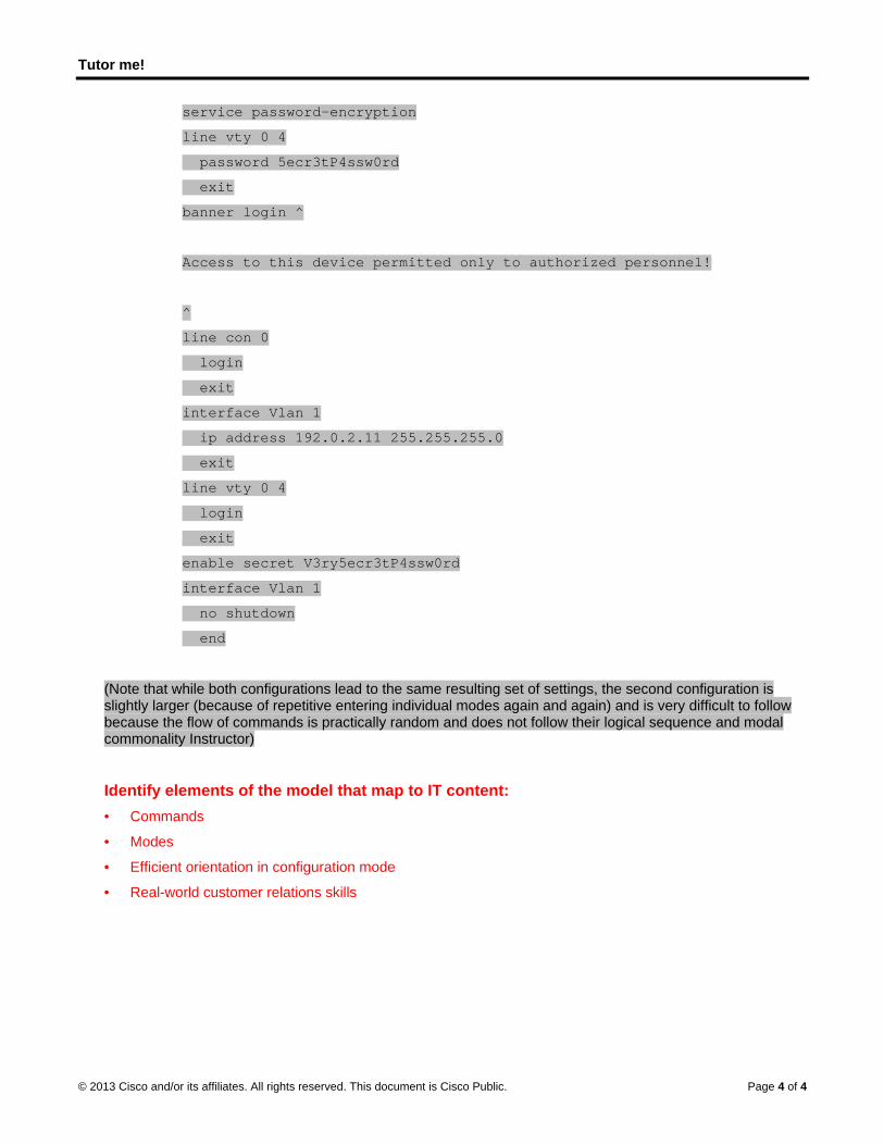
Tutor me!
© 2013 Cisco and/or its affiliates. All rights reserved. This document is Cisco Public. Page 4 of 4
service password-encryption
line vty 0 4
password 5ecr3tP4ssw0rd
exit
banner login ^
Access to this device permitted only to authorized personnel!
^
line con 0
login
exit
interface Vlan 1
ip address 192.0.2.11 255.255.255.0
exit
line vty 0 4
login
exit
enable secret V3ry5ecr3tP4ssw0rd
interface Vlan 1
no shutdown
end
(Note that while both configurations lead to the same resulting set of settings, the second configuration is slightly larger (because of repetitive entering individual modes again and again) and is very difficult to follow because the flow of commands is practically random and does not follow their logical sequence and modal commonality Instructor)
Identify elements of the model that map to IT content: • Commands
• Modes
• Efficient orientation in configuration mode
• Real-world customer relations skills
© 2013 Cisco and/or its affiliates. All rights reserved. This document is Cisco Public. Page 1 of 2
Let’s just talk about this… (Instructor Version) Instructor Note: Red font color or Gray highlights indicate text that appears in the instructor copy only.
Objectives
Explain the role of protocols and standards organizations in facilitating interoperability in network communications.
In this activity, you will determine ways to communicate when standards are not present or agreed upon. You will also resolve a communication issue by establishing standards for communication.
Background/Scenario
You have just purchased a new automobile for your personal use. After driving the car for a week or so, you find that it is not properly functioning.
After discussing the problem with several of your peers, you decide to take it to a highly recommended automotive repair facility. It is the only repair facility located in close proximity to you.
When you arrive at the repair facility, you find that all of the mechanics speak another language. You are having difficulty explaining the automobile’s performance problems, but the repairs really need to be done. You are not sure you can drive it back home to research other options.
You must find a way to work with the repair facility to ensure your automobile is properly repaired.
How will you communicate with the mechanics in this firm? Design a communications model to ensure that the car is properly repaired.
Instructor Note: This Modeling Activity is not intended to be a graded assignment. Its purpose is to encourage students to reflect on their perceptions of how a communications system facilitates the transfer of data from source to destination (personally and in corporate practice). Discussion should be initiated as a result of this activity.
Reflection
1. What steps did you identify as important to communicating your repair request? Justify your answer.
_______________________________________________________________________________________To resolve this issue, some steps might include:
Establishing a language for communication (could be voice, written, or kinesthetic/physical).
Very carefully (in small steps), explaining the problem experienced with the automobile (again, voice, written/pictures, or kinesthetic/physical representations).
Asking the mechanic to confirm his/her understanding of the problem.
Waiting for the repair to be done.
Driving the automobile to ensure repairs were successful.
Closing the meeting by paying for the repairs and thanking the mechanic.
Identify elements of the model that map to IT content:
Establishing a language to communicate (Application protocol)
Dividing the message into small steps to facilitate understanding of the problem to be solved a little at a time (Transfer protocol).

Let’s just talk about this…
© 2013 Cisco and/or its affiliates. All rights reserved. This document is Cisco Public. Page 2 of 2
Checking to see if the message has been delivered and correctly understood to the mechanic who will be performing the repairs. (Internet protocol)
Delivery of automobile and wait time for repairs (Network Access protocol)

© 2013 Cisco and/or its affiliates. All rights reserved. This document is Cisco Public. Page 1 of 4
Lab - Researching Networking Standards (Instructor Version) Instructor Note: Red font color or Gray highlights indicate text that appears in the instructor copy only.
Objectives Part 1: Research Networking Standards Organizations
• Gather information about the major networking standards organizations by going on a web surfing treasure hunt.
• Identify important characteristics of some of the organizations.
Part 2: Reflect on Internet and Computer Networking Experiences
• Reflect on how the various networking standards organizations enhance our experience of the Internet and computer networking.
Background / Scenario Using web search engines like Google, research the non-profit organizations that are responsible for establishing international standards for the Internet and the development of Internet technologies.
Required Resources Device with Internet access
Part 1: Research Networking Standards Organizations In Part 1, you will identify some of the major standards organizations and important characteristics, such as the number of years in existence, the size of their membership, the important historical figures, some of the responsibilities and duties, organizational oversight role, and the location of the organization’s headquarters.
Use a web browser or websites for various organizations to research information about the following organizations and the people who have been instrumental in maintaining them.
You can find answers to the questions below by searching the following organizational acronyms and terms: ISO, ITU, ICANN, IANA, IEEE, EIA, TIA, ISOC, IAB, IETF, W3C, RFC, and Wi-Fi Alliance.
1. Who is Jonathan B. Postel and what is he known for? (Search hint: Jon Postel)
_______________________________________________________________________________________
_______________________________________________________________________________________
_______________________________________________________________________________________
Jonathan Postel was an American computer scientist who made significant contributions to the development of the Internet standards, to the creation of Internet Assigned Numbers Authority (IANA) and as the RFC Editor.
2. Which two related organizations are responsible for managing the top-level domain name space and the root Domain Name System (DNS) name servers on the Internet? (Search hint: ICANN, IANA)
_______________________________________________________________________________________
_______________________________________________________________________________________
International Corporation for Assigned Names and Numbers (ICANN) and Internet Assigned Numbers Authority (IANA)
3. Vinton Cerf has been called one of main fathers of the Internet. What Internet organizations did he chair or help found? What Internet technologies did he help to develop? (Search hint: Vint Cerf, IAB, ISOC, ICANN)
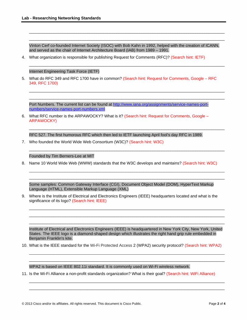
Lab - Researching Networking Standards
© 2013 Cisco and/or its affiliates. All rights reserved. This document is Cisco Public. Page 2 of 4
_______________________________________________________________________________________
_______________________________________________________________________________________
Vinton Cerf co-founded Internet Society (ISOC) with Bob Kahn in 1992, helped with the creation of ICANN, and served as the chair of Internet Architecture Board (IAB) from 1989 – 1991.
4. What organization is responsible for publishing Request for Comments (RFC)? (Search hint: IETF)
_______________________________________________________________________________________
Internet Engineering Task Force (IETF)
5. What do RFC 349 and RFC 1700 have in common? (Search hint: Request for Comments, Google – RFC 349, RFC 1700)
_______________________________________________________________________________________
_______________________________________________________________________________________
Port Numbers. The current list can be found at http://www.iana.org/assignments/service-names-port-numbers/service-names-port-numbers.xml
6. What RFC number is the ARPAWOCKY? What is it? (Search hint: Request for Comments, Google – ARPAWOCKY)
_______________________________________________________________________________________
RFC 527. The first humorous RFC which then led to IETF launching April fool’s day RFC in 1989.
7. Who founded the World Wide Web Consortium (W3C)? (Search hint: W3C)
_______________________________________________________________________________________
Founded by Tim Berners-Lee at MIT
8. Name 10 World Wide Web (WWW) standards that the W3C develops and maintains? (Search hint: W3C)
_______________________________________________________________________________________
_______________________________________________________________________________________
Some samples: Common Gateway Interface (CGI), Document Object Model (DOM), HyperText Markup Language (HTML), Extensible Markup Language (XML)
9. Where is the Institute of Electrical and Electronics Engineers (IEEE) headquarters located and what is the significance of its logo? (Search hint: IEEE)
_______________________________________________________________________________________
_______________________________________________________________________________________
_______________________________________________________________________________________
Institute of Electrical and Electronics Engineers (IEEE) is headquartered in New York City, New York, United States. The IEEE logo is a diamond-shaped design which illustrates the right hand grip rule embedded in Benjamin Franklin's kite.
10. What is the IEEE standard for the Wi-Fi Protected Access 2 (WPA2) security protocol? (Search hint: WPA2)
_______________________________________________________________________________________
_______________________________________________________________________________________
WPA2 is based on IEEE 802.11i standard. It is commonly used on Wi-Fi wireless network.
11. Is the Wi-Fi Alliance a non-profit standards organization? What is their goal? (Search hint: WiFi Alliance)
_______________________________________________________________________________________
_______________________________________________________________________________________

Lab - Researching Networking Standards
© 2013 Cisco and/or its affiliates. All rights reserved. This document is Cisco Public. Page 3 of 4
Yes, Wi-Fi Alliance is a non-profit trade association, and its goals are to ensure interoperability and backward compatibility and provide innovation support.
12. Who is Hamadoun Touré? (Search hint: ITU)
_______________________________________________________________________________________
_______________________________________________________________________________________
Hamadoun Touré of Mali is the Secretary General of the International Telecommunication Unicon (ITU).
13. What is the International Telecommunication Union (ITU) and where is it headquartered? (Search hint: ITU)
_______________________________________________________________________________________
_______________________________________________________________________________________
ITU is an agency of the United Nations dedicated to the information and communication technologies. ITU’s headquarters are located in Geneva, Switzerland.
14. Name the three ITU sectors? (Search hint: ITU)
_______________________________________________________________________________________
The three ITU sectors are: Radio communication, Standardization and Development.
15. What does the RS in RS-232 stand for and which organization introduced it? (Search hint: EIA)
_______________________________________________________________________________________
_______________________________________________________________________________________
RS stands for Recommended Standard. RS-232 was introduced by the Radio Section of Electronic Industries Alliance (EIA).
16. What is SpaceWire? (Search hint: Spacewire, IEEE)
_______________________________________________________________________________________
_______________________________________________________________________________________
SpaceWire is a standard for high-speed links and networks for use onboard spacecraft.
17. What is the mission of the ISOC and where are its headquarters located? (Search hint: ISOC)
_______________________________________________________________________________________
_______________________________________________________________________________________
_______________________________________________________________________________________
The Internet Society (ISOC) headquarters are located in Reston, Virginia and Geneva, Switzerland. Its mission is “to assure the open development, evolution and use of the Internet for the benefit of all people throughout the world".
18. What organizations does the IAB oversee? (Search hint: IAB)
_______________________________________________________________________________________
_______________________________________________________________________________________
IAB oversees Internet Engineering Task Force (IETF) and Internet Research Task Force (IRTF).
19. What organization oversees the IAB? (Search hint: IAB, ISOC)
_______________________________________________________________________________________
ISOC oversees IAB.
20. When was the ISO founded and where are its headquarters located? (Search hint: ISO)
_______________________________________________________________________________________
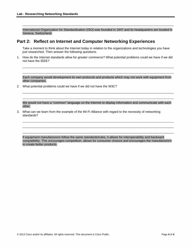
Lab - Researching Networking Standards
© 2013 Cisco and/or its affiliates. All rights reserved. This document is Cisco Public. Page 4 of 4
_______________________________________________________________________________________
International Organization for Standardization (ISO) was founded in 1947 and its headquarters are located in Geneva, Switzerland.
Part 2: Reflect on Internet and Computer Networking Experiences Take a moment to think about the Internet today in relation to the organizations and technologies you have just researched. Then answer the following questions.
1. How do the Internet standards allow for greater commerce? What potential problems could we have if we did not have the IEEE?
_______________________________________________________________________________________
_______________________________________________________________________________________
Each company would development its own protocols and products which may not work with equipment from other companies.
2. What potential problems could we have if we did not have the W3C?
_______________________________________________________________________________________
_______________________________________________________________________________________
We would not have a “common” language on the Internet to display information and communicate with each other.
3. What can we learn from the example of the Wi-Fi Alliance with regard to the necessity of networking standards?
_______________________________________________________________________________________
_______________________________________________________________________________________
_______________________________________________________________________________________
If equipment manufacturers follow the same standards/rules, it allows for interoperability and backward compatibility. This encourages competition, allows for consumer choices and encourages the manufacturers to create better products.
©
LI
O
B
R
P
S
© 2013 Cisco and
Lab - Renstructor No
ObjectivesPart 1: RF
Navig
Searc
Find R
Searc
Part 2: Pu
BackgrounRequest fAdvancedcollection protocol scomplete
In this labknown RFinformatio
Required RDevice wi
Part 1: RRFCs stacollectionprotocols.discussion
Step 1: Na
All the purepository
At the topsearches,
After an R
d/or its affiliates.
esearchiote: Red font
FC Editor
gate to the RF
ch for RFCs u
RFCs by statu
ch for humoro
ublishing RF
nd / Scenarfor Commentsd Research P
of memorandsuite. Today thlist is availab
b, you will learFCs that are uon or enginee
Resources th Internet ac
RFC Editorted as a colle, only a few R. Some of then.
avigate to th
blished RFCsy maintained b
p banner of th, databases, a
RFC is located
All rights reserve
ing RFCcolor or Gray
FC Editor.
using keyword
us.
ous RFCs.
FCs
rio s (RFCs) werrojects Agencdum that desche RFCs are
ble at http://ww
rn how an RFused in your nring humor.
ccess
or ection of mem
RFCs are con RFCs are on
he RFC Edit
s are availableby the IETF.
is page, you cand informatio
d, you have a
ed. This docume
Cs (Instruy highlights ind
ds.
e created by cy Network (Acribes topics managed by
ww.ietf.org/do
C is publishenetwork. You
morandum onsidered as Innly informatio
tor.
e for access a
can click any on. A link to I
access to the
ent is Cisco Publi
uctor Verdicate text tha
Steve CrockeARPANET) inthat are mainthe IETF. Th
ownload/rfc-in
ed today by IEcan also find
the developmternet standanal. The main
at http://www.
of the links, aETF HOME is
full text of the
ic.
rsion) at appears in
er to help recon 1969 and evnly related to tere are curre
ndex.txt.
ETF. Additiona a few non-te
ment of the firards. Most of tn purpose of R
.rfc-editor.org
and these links also include
e document.
the instructo
ord notes on ventually evolthe Internet a
ently over 6,00
ally, you will aechnical RFCs
rst Internet (Athe RFCs desRFCs is to sti
g. The RFC E
ks direct you ted within this
r copy only.
developmentved into an o
and the TCP/I00 RFCs, and
also identify as that can pro
ARPANET). Inscribe experimimulate comm
ditor is an RF
to the differenblue banner.
Page 1 of 6
t of fficial P d the
a few well-ovide
n this mental ment and
FC
nt

L
©
S
Lab - Resear
© 2013 Cisco and
Step 2: Se
a. Openand re
ching RFCs
d/or its affiliates.
arch for RF
a browser anetrieve RFCs
All rights reserve
FCs using k
nd navigate toand other inf
ed. This docume
eywords.
o http://www.rformation rela
ent is Cisco Publi
rfc-editor.org.ated to the Int
ic.
. On the RFCternet.
Editor Homeepage, you ca
Page 2 of 6
an search

L
©
Lab - Resear
© 2013 Cisco and
b. In themethosearcexam
Look RFC i
After used RFC the inas ind
Referbut re
Referfrom tdevel
ching RFCs
d/or its affiliates.
e Finding andods. The Seach parametersple.
for Post Officis also an Inte
an RFC is puagain for a ne1725 obsoleteformation from
dicated in the
r to the Statusequire further
r to the Statustechnical to hopment of a n
All rights reserve
d Retrieving rch for an RF
s, such as num
ce Protocol –ernet standard
blished and aewer RFC. Foe. The informm RFC 1939.More Info co
s column andtesting and v
s column andumorous. Fornetwork proto
ed. This docume
RFCs, etc. pFC and its mmber, author,
– Version 3 id, as indicate
assigned a nuor example, in
mation in RFC. RFC 1939 holumn. If you
d locate the Palidation.
d locate the Inr example, RF
ocol in the ear
ent is Cisco Publi
ane, these linmeta-data link
title, or keyw
n the list. Theed by the STD
umber, it cannn the More In1725 has notas been updaclick any of th
roposed Sta
nformationalFC 0035 (Netrly days of the
ic.
nks can help yk displays a lisword. The wor
e associated D number in th
not be changenfo column, Rt been modifiated by RFC hese links, the
andard status
status. Informtwork Meetinge Internet.
you search fost of RFCs aftrd, pop, is us
RFC number he Number c
ed and the RFRFC 1939 has
ed, but it has1957, RFC 2e full text of th
s. They may b
mational RFCg) provides an
or RFCs usingfter inputting yed in the follo
is RFC 1939column.
FC number iss made the prs been replace449, and RFChe RFC displ
be technically
Cs can be anyn insight into
Page 3 of 6
g different your owing
9. This
s never revious ed with C 6186, ays.
sound,
ything the

L
©
S
S
Lab - Resear
© 2013 Cisco and
Step 3: Fin
To find a
a. Navig
b. Click stand
Step 4: Se
EngineeriInternet se
a. Searcfind?
_____
AnswRFCs
b. Searc
The In
What
Monk
ching RFCs
d/or its affiliates.
nd RFCs by
list of RFCs t
gate back to th
the Official Inard RFCs foll
arch for hu
ng humor canearch engine
ch the Interne
___________
wers will vary bs on April Foo
ch for RFC 27
nfinite Monke
company doe
keySeeDoo, In
All rights reserve
status.
hat are either
he RFC Edito
nternet Protolowed by othe
morous RF
n also be founcan be used
et for “enginee
___________
but can includol’s day and ot
795. What is t
ey Protocol Su
es the author
nc.
ed. This docume
r Internet Stan
or Homepage
ocol Standarer RFC status
FCs.
nd in the RFCto find inform
ering humor rf
____________
de: Wiki entriether specific h
the subject of
uite (IMPS).
r of this RFC w
ent is Cisco Publi
ndards (STD)
.
rd RFCs link s lists. Each R
Cs, such as Rmation on RFC
fc” to see mo
___________
es, referenceshumorous RF
this RFC? __
work for? ___
ic.
) or by their st
in the left colRFC link leads
RFC 1300 (ReCs.
re examples
___________
s to the IETF’FCs.
___________
___________
tatus, perform
umn. You wils to the full R
emembrances
of whimsical
____________
’s tradition of
___________
____________
m the followin
l find a list ofRFC text.
s of Things Pa
RFCs. What
____________
releasing hum
____________
___________
Page 4 of 6
g tasks:
official
ast). An
did you
________
morous
_______
________

L
©
P
Lab - Resear
© 2013 Cisco and
Part 2: PThe late DToday, RFinternationthe Intern
Anyone caan Internesame pubhttp://www
For propoInformatioavailable to change
a. Navig
b. Click curren
The licolumWorkiclick I
c. After
The Adevelbecomdifferelisted IPv6 p
ching RFCs
d/or its affiliates.
PublishingDr. Jonathan FCs are a colnal communitet protocol su
an submit a pet-Draft (I-D). blishing procew.rfc-editor.or
osals that mayonal RFCs, thfor informal re
e or removal a
gate to http://w
I-D SEARCHnt Internet-Dr
st of results pmn lists the Woing Group thaIETF HOME a
arriving at the
Active IETF Wop IETF specme standardsent developmin the Interne
protocol spec
All rights reserve
g RFCs Postel maintalection of docty of network uite.
proposal to thAfter review
ess as IETF surg/indsubs.htm
y become Inteese submissieview and coat any time. T
www.rfc-edito
H at the top of rafts.
provides linksorking Group
at submitted mat the top of th
e IETF Home
Working Groupcifications ands or recomme
ment areas for et Area. This wcifications and
ed. This docume
ained and macuments publdesigners, op
e RFC Editorby the commubmission. Foml.
ernet Standarions are publimments. The
They can be fo
r.org.
the Homepag
to the full tex with IETF tha
multiple draftshe results pag
page, click W
ps page displad guidelines. Mndations. By technology rworking grou
d addressing a
ent is Cisco Publi
naged the arcished and maperators, vend
r for possible unity and if it or more detai
rd or Best Curished as Inter
e Internet-Draound at http://
ge, and then
xt of the I-Ds aat is responsis. To find out ge.
WG Charters i
ays. The IETFMany of thesescrolling the pelated to netwp is responsibarchitecture.
ic.
chiving of RFanaged by IETdors, and res
publication. Tis approved bls regarding i
rrent Practicernet-Drafts. Tfts have no fo/www.rfc-edit
click SEARC
and other useible for the drmore informa
in the left colu
F Working Gre specificatiopage, you seeworking. The ble for mainte
FCs for 28 yeaTF. IETF is a
searchers rela
The proposal by an RFC Edndependent s
e and some EThe Internet-Dormal status, tor.org/.
CH. This will d
eful informatioraft. As an exaation about th
umn, listed un
roup’s (WG) pns and guidee a list of Act6man Workin
enance and a
ars (RFC 246large, open,
ated to the Int
is initially pubditor, it will ensubmission, s
Experimental oDrafts are mad
and they are
display a list o
on. The Sourample, 6manis Working G
nder Working
primary functilines are inteive Working Gng Group candvancement
Page 5 of 6
68).
ternet and
blished as nter the see
or de subject
of the
rce is a roup,
Groups.
on is to nded to Groups in n be found of the

Lab - Researching RFCs
© 2013 Cisco and/or its affiliates. All rights reserved. This document is Cisco Public. Page 6 of 6
d. Click 6man to view the complete list of current proposals and other information for this Working Group.
After the I-D has received significant community review and is considered useful, stable, and well-understood by the community, it should become a Proposed Standard. The full text of the Proposed Standard can be found by searching in the RFC-Editor. The Proposed Standard may become an Internet Standard after significant implementation and successful operational experience.
Note: Only a few RFCs published by IETF will become Internet standards.
Reflection 1. Why are RFCs important for Internet standards and history?
_______________________________________________________________________________________
Because published RFCs are never modified, they provide a written record of the evolution of the Internet standards and practices. See RFC 2026, The Internet Standards Process, Revision 3 for more information regarding RFCs and the RFC process.
2. What are the advantages of RFCs as a collaborative effort?
_______________________________________________________________________________________
Any individual may contribute to the development of the Internet. The information in the RFCs is not owned exclusively by any company; therefore, equipment from different company is more likely to work together.

©
LI
T
O
B
© 2013 Cisco and
Lab - Usnstructor No
Topology
ObjectivesPart 1: (O
Part 2: Ca
Start
Locat
Part 3: Ca
Start
Locat
Expla
BackgrounWiresharkanalysis, snetwork, taccording
Wiresharkcourses foWiresharkpacket IP
d/or its affiliates.
sing Wirote: Red font
Optional) Dow
apture and A
and stop data
te the IP and
apture and A
and stop data
te the IP and
ain why MAC
nd / Scenark is a softwaresoftware and the sniffer "cag to the appro
k is a useful toor data analysk, although it addresses a
All rights reserve
eshark tcolor or Gray
wnload and I
Analyze Loca
a capture of p
MAC address
Analyze Rem
a capture of p
MAC address
addresses fo
rio e protocol anaprotocol deve
aptures" eachpriate RFC o
ool for anyonesis and troublmay already nd Ethernet fr
ed. This docume
to View y highlights ind
Install Wires
al ICMP Data
ping traffic to l
s information
ote ICMP Da
ping traffic to r
s information
r remote host
alyzer, or "paelopment, an protocol datar other specif
e working witleshooting. Thbe installed. Irame MAC ad
ent is Cisco Publi
Networkdicate text tha
hark
in Wireshar
ocal hosts.
in captured P
ata in Wiresh
remote hosts
in captured P
ts are differen
acket sniffer" ad education. Aa unit (PDU) afications.
h networks ahis lab providIn this lab, yoddresses.
ic.
k Trafficat appears in
rk
PDUs.
hark
.
PDUs.
nt than the MA
application, uAs data streaand can deco
nd can be usdes instructionou will use Wir
c (Instructhe instructo
AC addresses
sed for netwoams travel baode and analy
ed with most ns for downloareshark to ca
P
ctor Versr copy only.
s of local hos
ork troubleshock and forth oyze its conten
labs in the Cading and inspture ICMP d
Page 1 of 20
sion)
sts.
ooting, over the nt
CNA stalling data
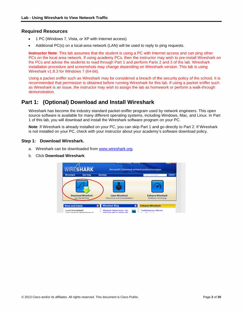
L
©
R
P
S
Lab - Using W
© 2013 Cisco and
Required R 1 PC
Additi
InstructoPCs on ththe PCs ainstallatioWireshark
Using a precommeas Wireshdemonstra
Part 1: (OWiresharksource so1 of this la
Note: If Wis not inst
Step 1: Do
a. Wires
b. Click
Wireshark to
d/or its affiliates.
Resources (Windows 7,
onal PC(s) on
or Note: This lhe local area nand advise then procedure ak v1.8.3 for W
acket sniffer snded that perhark is an issuation.
Optional)k has becomeoftware is avaab, you will do
Wireshark is aalled on your
ownload Wir
shark can be d
Download W
View Netwo
All rights reserve
Vista, or XP w
n a local-area
lab assumes network. If use students to and screensh
Windows 7 (64
such as Wirermission is obue, the instruc
) Downloe the industry ilable for manownload and
lready installePC, check w
reshark.
downloaded f
Wireshark.
ork Traffic
ed. This docume
with Internet a
a network (LA
that the studesing academyread through
hots may chan4-bit).
shark may bebtained beforector may wish
ad and Instandard pac
ny different opinstall the Wi
ed on your PCwith your instru
from www.wir
ent is Cisco Publi
access)
AN) will be use
ent is using ay PCs, then th Part 1 and p
nge dependin
e considered e running Wireh to assign the
nstall Wircket-sniffer prperating systereshark softw
C, you can skuctor about yo
reshark.org.
ic.
ed to reply to
a PC with Intehe instructor mperform Parts ng on Wiresha
a breach of theshark for thie lab as home
reshark rogram used ems, includingware program
kip Part 1 andour academy
ping request
ernet access amay wish to p2 and 3 of th
ark version. T
he security pos lab. If usingework or perf
by network eg Windows, M on your PC.
d go directly to’s software do
P
ts.
and can ping pre-install Wiree lab. Wiresh
This lab is usin
olicy of the scg a packet sniform a walk-th
ngineers. ThiMac, and Linu
o Part 2. If Wiownload polic
Page 2 of 20
other eshark on
hark ng
chool. It is iffer such hrough
is open ux. In Part
ireshark cy.

L
©
S
Lab - Using W
© 2013 Cisco and
c. Chooinstan
After browsfolder
Step 2: Ins
a. The dDoub
b. RespoWiresIt is reYes to
Wireshark to
d/or its affiliates.
se the softwance, if you hav
making a seleser and operar.
stall Wiresh
downloaded file-click the file
ond to any seshark on your ecommendedo uninstall the
View Netwo
All rights reserve
are version yove a 64-bit PC
ection, the doating system t
ark.
le is named We to start the
ecurity messaPC, you will that you rem
e previous ve
ork Traffic
ed. This docume
ou need basedC running Win
ownload shouthat you use.
Wireshark-wiinstallation pr
ages that maybe prompted
move the old vrsion of Wires
ent is Cisco Publi
d on your PCndows, choos
ld start. The lFor Windows
in64-x.x.x.exrocess.
y display on yoto uninstall th
version of Wirshark.
ic.
C’s architecturse Windows
location of thes users, the d
xe, where x re
our screen. Ifhe old versionreshark prior t
re and operatiInstaller (64-
e downloadedefault location
epresents the
f you already n before instato installing a
P
ing system. F-bit).
d file dependsn is the Down
e version num
have a copy alling the new nother versio
Page 3 of 20
For
s on the nloads
mber.
of version.
on. Click

L
©
Lab - Using W
© 2013 Cisco and
c. If this navig
d. Contindispla
Wireshark to
d/or its affiliates.
is the first timate to the Wir
nue advancinays.
View Netwo
All rights reserve
me to install Wreshark Setup
ng through the
ork Traffic
ed. This docume
Wireshark, or ap wizard. Clic
e installation p
ent is Cisco Publi
after you havk Next.
process. Click
ic.
ve completed
k I Agree whe
the uninstall
en the Licens
P
process, you
se Agreement
Page 4 of 20
will
t window
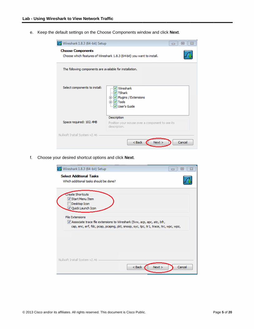
L
©
Lab - Using W
© 2013 Cisco and
e. Keep
f. Choo
Wireshark to
d/or its affiliates.
the default se
se your desir
View Netwo
All rights reserve
ettings on the
ed shortcut o
ork Traffic
ed. This docume
e Choose Com
ptions and cli
ent is Cisco Publi
mponents win
ick Next.
ic.
ndow and clicck Next.
P
Page 5 of 20

L
©
Lab - Using W
© 2013 Cisco and
g. You crecom
h. To cayour Pversioclickin
i. Finish
Wireshark to
d/or its affiliates.
can change thmmended that
apture live netPC, the Instalon that comesng the Install
h the WinPcap
View Netwo
All rights reserve
he installationt you keep the
twork data, Wl check box w
s with WireshaWinPcap x.x
p Setup Wiza
ork Traffic
ed. This docume
location of We default loca
WinPcap mustwill be unchecark, it is recomx.x (version n
ard if installing
ent is Cisco Publi
Wireshark, butation.
be installed ocked. If your inmmend that y
number) chec
g WinPcap.
ic.
t unless you h
on your PC. Installed versiyou allow the ck box.
have limited d
f WinPcap is ion of WinPcanewer versio
P
disk space, it
already instaap is older thaon to be instal
Page 6 of 20
is
alled on an the lled by

L
©
Lab - Using W
© 2013 Cisco and
j. WiresNext
k. Click
Wireshark to
d/or its affiliates.
shark starts inwhen the inst
Finish to com
View Netwo
All rights reserve
nstalling its filetallation is co
mplete the Wi
ork Traffic
ed. This docume
es and a sepamplete.
reshark insta
ent is Cisco Publi
arate window
all process.
ic.
displays withh the status of
P
f the installati
Page 7 of 20
ion. Click
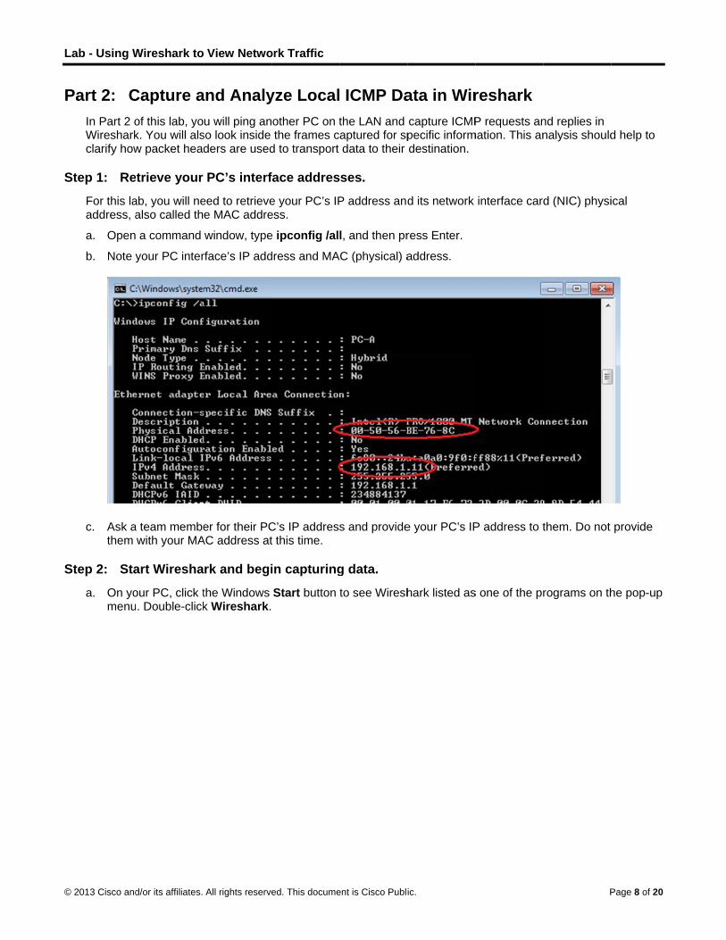
L
©
P
S
S
Lab - Using W
© 2013 Cisco and
Part 2: CIn Part 2 oWiresharkclarify how
Step 1: Re
For this laaddress, a
a. Open
b. Note y
c. Ask athem
Step 2: Sta
a. On yomenu
Wireshark to
d/or its affiliates.
Capture aof this lab, yok. You will alsw packet head
etrieve your
ab, you will nealso called th
a command
your PC inter
a team membewith your MA
art Wiresha
our PC, click t. Double-click
View Netwo
All rights reserve
and Analyu will ping an
so look inside ders are used
PC’s interf
eed to retrievee MAC addre
window, type
rface’s IP add
er for their PCAC address at
rk and begi
the Windows k Wireshark.
ork Traffic
ed. This docume
yze Localother PC on tthe frames c
d to transport
face addres
e your PC’s IPess.
e ipconfig /al
dress and MA
C’s IP addresst this time.
in capturing
Start button
ent is Cisco Publi
ICMP Dathe LAN and aptured for spdata to their
ses.
P address and
l, and then pr
AC (physical) a
s and provide
g data.
to see Wiresh
ic.
ata in Wircapture ICMPpecific informdestination.
d its network
ress Enter.
address.
e your PC’s IP
hark listed as
reshark P requests an
mation. This an
interface card
P address to t
s one of the pr
P
nd replies in nalysis should
d (NIC) physi
them. Do not
rograms on th
Page 8 of 20
d help to
ical
provide
he pop-up
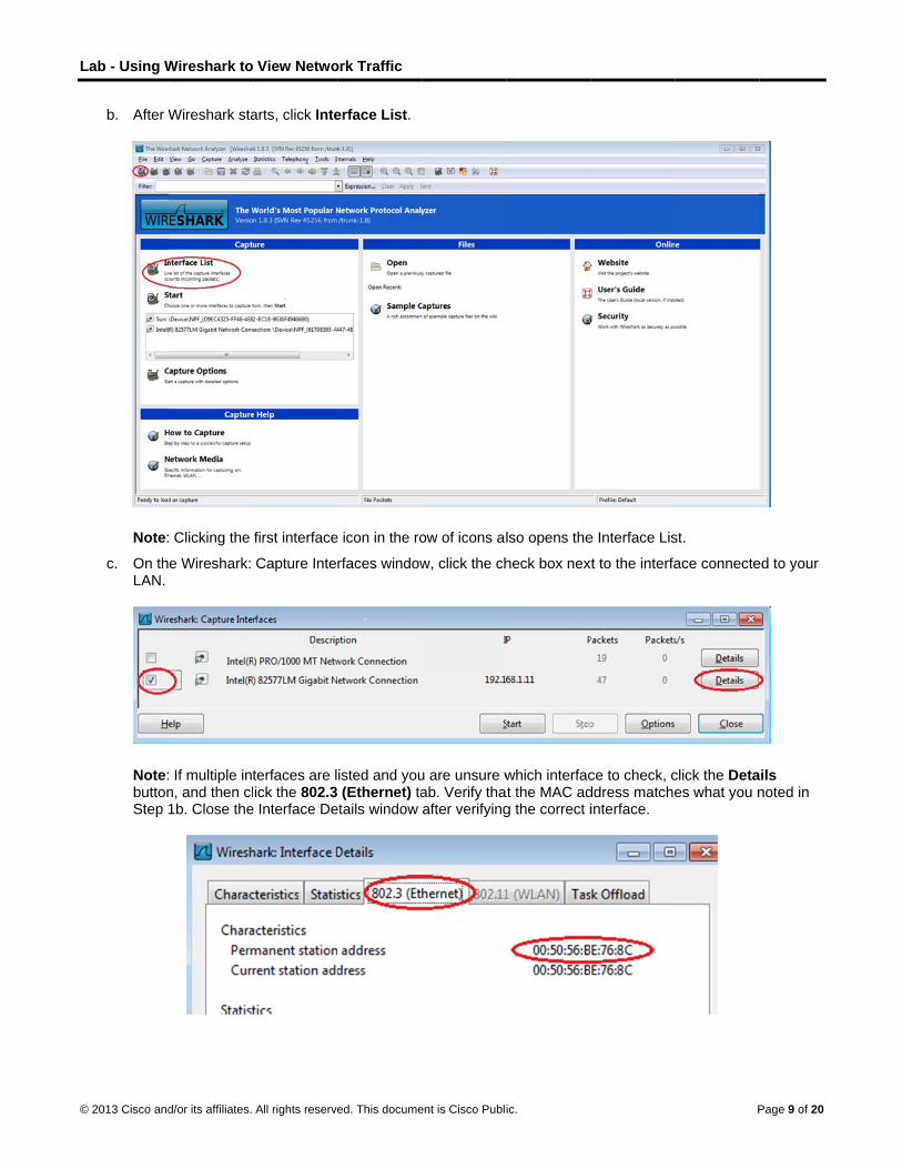
L
©
Lab - Using W
© 2013 Cisco and
b. After W
Note:
c. On thLAN.
Note:buttonStep
Wireshark to
d/or its affiliates.
Wireshark sta
Clicking the
e Wireshark:
If multiple intn, and then cl1b. Close the
View Netwo
All rights reserve
arts, click Inte
first interface
Capture Inte
terfaces are lick the 802.3
e Interface De
ork Traffic
ed. This docume
erface List.
e icon in the ro
rfaces window
isted and you (Ethernet) ta
etails window
ent is Cisco Publi
ow of icons al
w, click the ch
u are unsure wab. Verify thaafter verifying
ic.
lso opens the
heck box nex
which interfacat the MAC adg the correct i
e Interface Lis
xt to the interfa
ce to check, cddress matcheinterface.
P
st.
ace connecte
click the Detaes what you n
Page 9 of 20
ed to your
ails noted in

L
©
Lab - Using W
© 2013 Cisco and
d. After y
Informcolors
e. This iyour Pcaptuthe Fi(ping)
Wireshark to
d/or its affiliates.
you have che
mation will stas based on pr
nformation caPC and the LAred by Wireshlter box at the) PDUs.
View Netwo
All rights reserve
ecked the corr
art scrolling dorotocol.
an scroll by veAN. We can ahark. For thise top of Wires
ork Traffic
ed. This docume
rect interface
own the top s
ery quickly deapply a filter t lab, we are oshark and pre
ent is Cisco Publi
, click Start to
ection in Wire
epending on wto make it easonly interestedess Enter or c
ic.
o start the da
eshark. The d
what communsier to view and in displayin
click on the Ap
ta capture.
data lines will
nication is taknd work with
ng ICMP (pingpply button to
Pa
appear in diff
king place betthe data that
g) PDUs. Typeo view only IC
age 10 of 20
fferent
tween is being e icmp in CMP

L
©
Lab - Using W
© 2013 Cisco and
f. This finterfareceivWires
Note:blockion ho
g. Stop c
Wireshark to
d/or its affiliates.
filter causes aace. Bring up ved from yourshark again.
If your team ing these req
ow to allow IC
capturing dat
View Netwo
All rights reserve
all data in the the comman
r team membe
member’s PCuests. PleaseMP traffic thro
a by clicking t
ork Traffic
ed. This docume
top window tod prompt winer. Notice tha
C does not ree see Appendough the firew
the Stop Cap
ent is Cisco Publi
o disappear, dow that you
at you start se
eply to your pidix A: Allowingwall using Win
pture icon.
ic.
but you are sopened earli
eeing data ap
ngs, this mayg ICMP Traffindows 7.
still capturing ier and ping thpear in the to
y be because c Through a F
Pa
the traffic on he IP address
op window of
their PC firewFirewall for in
age 11 of 20
the s that you
wall is nformation

L
©
S
Lab - Using W
© 2013 Cisco and
Step 3: Ex
In Step 3,data is dissummary in the top section di
a. Click has y
Wireshark to
d/or its affiliates.
amine the c
examine thesplayed in throf the IP pacpart of the scsplays the raw
the first ICMPour PC’s IP a
View Netwo
All rights reserve
captured da
e data that waee sections: 1
cket informatiocreen and sepw data of eac
P request PDUaddress, and t
ork Traffic
ed. This docume
ata.
as generated b1) The top seon listed, 2) thparates a capch layer. The
U frames in ththe Destinatio
ent is Cisco Publi
by the ping reection displayshe middle secptured PDU fraraw data is d
he top sectionon contains th
ic.
equests of yous the list of PDction lists PDUame by its prisplayed in bo
n of Wiresharhe IP address
ur team memDU frames caU informationrotocol layers,oth hexadecim
rk. Notice thats of the teamm
Pa
mber’s PC. Wiaptured with an for the frame, and 3) the bmal and decim
t the Source cmate’s PC yo
age 12 of 20
reshark a e selected bottom mal form.
column u pinged.

L
©
P
S
Lab - Using W
© 2013 Cisco and
b. With tthe le
Does
Does
_____
How i
_____
The M
Note:packefor tra
Part 3: CIn Part 3, pings. Yo
Step 1: Sta
a. Click
Wireshark to
d/or its affiliates.
this PDU framft of the Ethe
the Source M
the Destinati
_ Yes
s the MAC ad
___________
MAC address
In the precedet PDU (IPv4 ansmission on
Capture ayou will ping u will then de
art capturin
the Interface
View Netwo
All rights reserve
me still selecternet II row to
MAC address
on MAC addr
ddress of the
___________
is obtained th
ding exampleheader) whic
n the LAN.
and Analyremote hoststermine what
g data on in
e List icon to
ork Traffic
ed. This docume
ed in the top sview the Des
match your P
ress in Wiresh
pinged PC o
____________
hrough an AR
e of a capturedch is then enc
yze Remos (hosts not ot is different a
nterface.
bring up the l
ent is Cisco Publi
section, navigstination and S
PC’s interface
hark match th
btained by yo
___________
RP request.
d ICMP requecapsulated in a
ote ICMP n the LAN) an
about this data
ist PC interfa
ic.
gate to the miSource MAC
e? ______ Ye
he MAC addre
our PC?
___________
est, ICMP datan Ethernet I
Data in Wnd examine tha from the da
aces again.
iddle section. addresses.
es
ess that of yo
____________
ta is encapsuI frame PDU
Wiresharkhe generatedta examined
Pa
Click the plu
our team mem
____________
ulated inside a(Ethernet II h
k d data from thin Part 2.
age 13 of 20
s sign to
mber’s?
_______
an IPv4 header)
ose

L
©
Lab - Using W
© 2013 Cisco and
b. Make
c. A winneces
d. With t
1) w
2) w
3) w
Wireshark to
d/or its affiliates.
sure the che
dow promptsssary to save
the capture a
www.yahoo.co
www.cisco.com
www.google.co
View Netwo
All rights reserve
eck box next to
to save the pthis data. Clic
ctive, ping the
om
m
om
ork Traffic
ed. This docume
o the LAN int
previously capck Continue
e following th
ent is Cisco Publi
terface is chec
ptured data bwithout Sav
ree website U
ic.
cked, and the
before startingving.
URLs:
en click Start
g another cap
Pa
.
pture. It is not
age 14 of 20

L
©
S
Lab - Using W
© 2013 Cisco and
Note:an IP
e. You c
Step 2: Ex
a. Revieyou p
1st Lo
2nd
Lo
3rd
Lo
IP add
MAC defau
Wireshark to
d/or its affiliates.
When you paddress. Not
can stop captu
amining an
ew the captureinged. List th
cation: IP
ocation: IP
ocation: IP
dresses: 72.3
address: Thislt-gateway LA
View Netwo
All rights reserve
ing the URLste the IP addr
uring data by
d analyzing
ed data in Wie destination
: _____.____
: _____.____
: _____.____
30.38.140, 19
s will be the sAN interface.
ork Traffic
ed. This docume
listed, noticeress received
clicking the S
g the data fr
reshark, examIP and MAC
__._____.____
__._____.____
__._____.____
2.133.219.25
same for all th
ent is Cisco Publi
e that the Dom for each URL
Stop Capture
rom the rem
mine the IP anaddresses fo
__ MAC: ___
__ MAC: ___
__ MAC: ___
5, 74.125.129
hree locations
ic.
main Name SeL.
e icon.
mote hosts.
nd MAC addror all three loc
__:____:____
__:____:____
__:____:____
.99 (these IP
s. It is the phy
erver (DNS) t
resses of the cations in the
:____:____:_
:____:____:_
:____:____:_
addresses m
ysical address
Pa
translates the
three locationspace provid
____
____
____
may vary)
s of the router
age 15 of 20
e URL to
ns that ded.
r’s

L
©
R
A
S
Lab - Using W
© 2013 Cisco and
b. What
_____
The M
c. How d
_____
_____
A pingaddre
Reflection Why doesremote ho
________
________
MAC addgateway ithe packe
Appendix AIf the memappendix the new IC
Step 1: Cre
a. From
Wireshark to
d/or its affiliates.
is significant
___________
MAC addresse
does this info
___________
___________
g to a local hoess of the defa
s Wireshark sosts?
___________
___________
resses for rems used. After
et and a new L
A: Allowingmbers of yourdescribes hoCMP rule afte
eate a new
the Control P
View Netwo
All rights reserve
about this inf
___________
es for all three
rmation differ
___________
___________
ost returns theault gateway’s
how the actu
____________
____________
mote hosts arthe packet re
Layer 2 heade
g ICMP Trar team are unaow to create aer you have co
inbound ru
Panel, click th
ork Traffic
ed. This docume
formation?
____________
e locations ar
r from the loca
____________
____________
e MAC addres LAN interfa
al MAC addre
___________
___________
re not knowneaches the deer is attached
affic Throuable to ping y rule in the firompleted the
le allowing
e System an
ent is Cisco Publi
___________
re the same.
al ping inform
___________
___________
ess of the PC’ce.
ess of the loc
___________
___________
on the local nefault-gatewayd with the des
ugh a Firewyour PC, the frewall to allowlab.
ICMP traffi
nd Security o
ic.
___________
mation you rec
___________
___________
s NIC. A ping
cal hosts, but
____________
____________
network, so thy router, the l
stination MAC
wall firewall may bw ping reques
c through t
option.
____________
ceived in Part
____________
____________
g to a remote
not the actua
____________
____________
he MAC addrelayer 2 inform
C address of t
be blocking thsts. It also des
the firewall.
Pa
____________
t 2?
____________
____________
host returns
al MAC addres
___________
___________
ess of the defmation is stripphe next hop r
hose requestsscribes how t
age 16 of 20
________
________
________
the MAC
ss for the
________
________
fault-ped from router.
s. This o disable

L
©
Lab - Using W
© 2013 Cisco and
b. From
c. In the
d. On thNew R
Wireshark to
d/or its affiliates.
the System a
e left pane of t
e Advanced SRule… on the
View Netwo
All rights reserve
and Security w
the Windows
Security winde right sideba
ork Traffic
ed. This docume
window, click
Firewall wind
ow, choose tar.
ent is Cisco Publi
Windows Fi
dow, click Adv
he Inbound R
ic.
irewall.
vanced setti
Rules option
ngs.
on the left sid
Pa
debar and the
age 17 of 20
en click

L
©
Lab - Using W
© 2013 Cisco and
e. This land c
f. In theICMP
Wireshark to
d/or its affiliates.
aunches the click Next
e left pane, cliPv4, and then
View Netwo
All rights reserve
New Inbound
ck the Protocclick Next.
ork Traffic
ed. This docume
d Rule wizard
col and Ports
ent is Cisco Publi
. On the Rule
s option and u
ic.
e Type screen
using the Pro
n, click the Cu
otocol type dro
Pa
ustom radio b
op-down men
age 18 of 20
button
nu, select

L
©
S
Lab - Using W
© 2013 Cisco and
g. In the
This n
Step 2: Dis
After the lthe Disabdeletes it
a. On thcreate
Wireshark to
d/or its affiliates.
e left pane, cli
new rule shou
sabling or d
ab is completble Rule optiofrom the list o
e Advanced Sed in Step 1.
View Netwo
All rights reserve
ck the Name
uld allow your
deleting the
te, you may won allows you of Inbound Ru
Security wind
ork Traffic
ed. This docume
option and in
r team membe
new ICMP
want to disablto enable the
ules.
ow, in the left
ent is Cisco Publi
n the Name fie
ers to receive
rule.
e or even dele rule again a
t pane, click I
ic.
eld, type Allo
e ping replies
lete the new rat a later date
Inbound Rule
ow ICMP Req
from your PC
rule you creat. Deleting the
es and then l
Pa
quests. Click
C.
ted in Step 1.e rule perman
ocate the rule
age 19 of 20
Finish.
. Using ently
e you

L
©
Lab - Using W
© 2013 Cisco and
b. To dischangstatus
c. To peagain
Wireshark to
d/or its affiliates.
sable the rulege to Enable s of the rule a
ermanently de to allow ICM
View Netwo
All rights reserve
e, click the DisRule. You ca
also shows in
elete the ICMPP replies.
ork Traffic
ed. This docume
sable Rule opan toggle backthe Enabled
P rule, click D
ent is Cisco Publi
ption. When yk and forth becolumn of the
Delete. If you
ic.
you choose thetween Disabe Inbound Ru
choose this o
his option, yoble Rule and Eles list.
option, you m
Pa
u will see thisEnable Rule;
ust re-create
age 20 of 20
s option the
the rule

© 2013 Cisco and/or its affiliates. All rights reserved. This document is Cisco Public. Page 1 of 2
Guaranteed to work! (Instructor Version) Instructor Note: Red font color or Gray highlights indicate text that appears in the instructor copy only.
Objectives
Explain the role of protocols and standards organizations in facilitating interoperability in network communications.
In this activity, you will demonstrate how network communications can be compared to everyday activities using established procedures and standards.
Background/Scenario
You have just completed the Chapter 3 content regarding network protocols and standards.
Assuming you resolved the beginning of this chapter’s modeling activity, how would you compare the following steps taken to design a communications system to the networking models used for communications?
Instructor Note: This Modeling Activity may be used as a graded assignment. It should demonstrate how network protocols and standards facilitate the transfer of data from source to destination, in both personal and in corporate practice. Facilitation of the discussion should include student-to-student discussions to show how students’ perceptions have been changed.
Required Resources
Blank “Steps to Communicate” table (above) for students to record their answers based upon their Chapter 3
content knowledge.
Reflection
1. How does your network model in developing an automotive repair communications plan compare to a network communications interoperability plan?
_______________________________________________________________________________________Students’ tables might look like this (with variations)
Steps to Communicate Possible Answers Associated
TCP/IP Model Layer
Establish a language to communicate Voice/Language (English, Application Layer
Steps to Communicate Possible Answers Associated
TCP/IP Model Layer
Establish a language to communicate
Divide the message into small steps, delivered a
little at a time, to facilitate understanding of the
problem
Verify that the message has been delivered
correctly to the mechanic who will perform the
repairs
Deliver the automobile and identify wait time for
repairs

Guaranteed to work!
© 2013 Cisco and/or its affiliates. All rights reserved. This document is Cisco Public. Page 2 of 2
Spanish, French, etc.)
Written pictures
Kinesthetic/physical
(HTTP, VoIP, POP, etc.)
Divide the message into small steps, delivered a
little at a time, to facilitate an understanding of
the problem
Small descriptions shared a little
at a time
Transport Layer
(Segments)
Verify that the message has been delivered
correctly to the mechanic who will perform the
repairs
Asking the mechanic to repeat
the full problem that occurrs with
the automobile.
Internet Layer
(Packets)
Deliver the automobile and identify wait time for
repairs
Physical delivery of the
automobile left for repairs –
agreement upon the
delivery/wait time for repairs
Network Access Layer
(Bits)
Identify elements of the model that map to IT-related content:
Establishing a language to communicate (Application protocol)
Dividing the message into small steps, delivered a little at a time, to facilitate understanding of the problem to be solved (Transport protocol).
Checking to see if the message has been delivered correctly to the mechanic who will be performing the repairs. (Internet protocol)
Delivery of automobile and wait time for repairs (Network Access protocol)

© 2013 Cisco and/or its affiliates. All rights reserved. This document is Cisco Public. Page 1 of 2
What would happen if… (Instructor Version) Instructor Note: Red font color or Gray highlights indicate text that appears in the instructor copy only.
Objectives
Explain the operation of the application layer in providing support to end-user applications.
In this activity, you will envision what it would be like not to have network applications available to use in the workplace. You may also estimate what it would cost to not be able to use networked applications for a short period of time.
Background/Scenario
It is the beginning of your work week. Your employer has decided to have IP telephones installed in your workplace resulting in the network being inoperable until next week. Your work, however, must continue. You have emails to send and quotes to write for your manager’s approval. Because of possible security issues, you are not allowed to use personal or external computer systems, equipment, or offsite equipment and systems, to complete your corporate workload.
Your instructor may ask you to complete the questions from both scenarios below, or to choose one scenario (A. Emails or B. Quote for Manager’s Approval). Answer the questions fully for the scenarios. Be prepared to discuss your answers in class.
A. Emails
What methods can you use to send email communication?
How could you send the same email to multiple recipients?
How would you get a large attachment to multiple recipients, if necessary?
Are these methods cost effective to your corporation?
Do they violate any security policies of your corporation?
B. Quote for Manager’s Approval
You have a desktop application software package installed on your computer. Will it be relatively easy to produce the quote your manager needs for the new contract due by the end of the week? What limitations will be experienced while trying to complete the quote?
How will you present the quote to your manager for approval? How do you think your manager will send the quote to the client for approval?
Are these methods cost effective to your corporation? Justify your answer.
Instructor Note: This Modeling Activity is introductory in nature; its purpose is to focus on how the application Layer is necessary for networking to operate effectively. To save classroom time (for discussion), students may complete only one scenario of the two scenarios.
Reflection
1. What steps did you identify as important to communicating without network applications available to you for a week in your workplace? Which steps were not important? Justify your answer.
_______________________________________________________________________________________To resolve this issue, some alternatives to pursue might include:
Emails:

What would happen if…
© 2013 Cisco and/or its affiliates. All rights reserved. This document is Cisco Public. Page 2 of 2
What method(s) can you use to send email communication? Correspondence might have to take the format of regular, post-office mail or hand delivery of each message. Handwritten format, locally printed copy, etc. might also be used.
How could you send the same email to multiple recipients? Once the handwritten letter (per se) is finished, copies would have to be made for all recipients. Then, the copies would be sent individually to the recipients.
If a large attachment was necessary to send, how would you get it to multiple recipients? Multiple copies would have to be made of the large attachment to send with the locally-produced letter.
Are these methods cost effective to your corporation? No – this would take a lot of time, resources, and steps to ready the mail and attachment for delivery
Quote for Manager’s Approval
You have a desktop application software package installed on your computer. Will it be relatively easy to produce the quote your manager needs for the new contract due by the end of the week? Yes, the local application software should not be affected by having no access to the network.
When you finish writing the quote, how will you present it to your manager for approval? How will he or she send the quote to the client for their consideration for approval? The quote will need to be printed (or saved to media). The hard copy (or media copy) will need to be delivered personally to the manager. Post-office mail probably would need to be used in this example.
Are these methods cost effective to your corporation? No – it takes time to print the quote, deliver it to the manager, ready it for post-office delivery, etc.
Identify elements of the model that map to IT content:
Network applications make communication in the workplace easier.
Network applications affect the amount of work done on a daily basis.
Processing time is increased without the use of network applications.
Network applications reduce the cost of completing business communications.
© 2013 Cisco and/or its affiliates. All rights reserved. This document is Cisco Public. Page 1 of 4
Lab - Researching Peer-to-Peer File Sharing (Instructor Version) Instructor Note: Red font color or Gray highlights indicate text that appears in the instructor copy only.
Objectives Part 1: Identify P2P Networks, File Sharing Protocols, and Applications
Part 2: Research P2P File Sharing Issues
Part 3: Research P2P Copyright Litigations
Background / Scenario Peer-to-peer (P2P) computing is a powerful technology that has many uses. P2P networks can be used to share and exchange music, movies, software, and other electronic materials.
The use of P2P networks to upload, download, or share copyrighted material, such as movies, music, and software, can violate the rights of copyright owners. In the P2P file-sharing context, infringement may occur, for example, when one person purchases an authorized copy and then uploads it to a P2P network to share with others. Both the individual who makes the file available and those making copies may be found to have infringed the rights of the copyright owners and may be violating copyright law.
Another problem with P2P file sharing is that very little protection is in place to ensure that the files exchanged in these networks are not malicious. P2P networks are an ideal medium for spreading malware (computer viruses, worms, Trojan horses, spyware, adware, and other malicious programs). In 2010, Cisco reported increases in P2P activity, coupled with recent P2P malware developments, suggesting that P2P file shares are becoming increasingly favored by users and malware attackers alike.
In this lab, you will research available P2P file sharing software and identify some issues that can arise from the use of this technology.
Required Resources Device with Internet access
Part 1: Identify P2P Networks, File Sharing Protocols, and Applications In Part 1, you will research P2P networks and identify some popular P2P protocols and applications.
Step 1: Define P2P networking.
a. What is a P2P network?
____________________________________________________________________________________
____________________________________________________________________________________
A P2P network allows each computer in the network to act as a client or server for the other computers in the network, allowing shared access to various resources without the need for a central server.
b. What are some advantages that P2P provides over client-server architecture?
____________________________________________________________________________________
____________________________________________________________________________________
____________________________________________________________________________________
____________________________________________________________________________________
____________________________________________________________________________________

Lab - Researching Peer-to-Peer File Sharing
© 2013 Cisco and/or its affiliates. All rights reserved. This document is Cisco Public. Page 2 of 4
____________________________________________________________________________________
In P2P networks, clients provide resources, which may include bandwidth, storage space, and computing power. This property is one of the major advantages of using P2P networks because it makes the setup and running costs very small for the original content distributor. As nodes arrive and demand on the system increases, the total capacity of the system also increases, and the likelihood of failure decreases. If one peer on the network fails to function properly, the whole network is not compromised or damaged. In contrast, with a typical client–server architecture, clients share only their demands with the system, but not their resources. In this case, as more clients join the system, fewer resources are available to serve each client, and if the central server fails, the entire network is taken down. The decentralized nature of P2P networks increases robustness because it removes the single point of failure that can be inherent in a client-server based system.
c. What are some disadvantages of P2P networks?
____________________________________________________________________________________
____________________________________________________________________________________
A P2P network is decentralized, making it difficult to administer. Security is difficult to implement and maintain, allowing for the possibility of copyrighted material and malware to be transmitted over a P2P network.
Step 2: Identify P2P file sharing protocols and applications.
a. Identify some P2P file sharing protocols used today.
____________________________________________________________________________________
____________________________________________________________________________________
____________________________________________________________________________________
Answers will vary, but can include: Ares, BitTorrent, Direct Connect, FastTrack, eDonkey, Gnutella, MANOLITO/MP2PN, OpenNap, 100BAo, Aimster, Applejuice, Freenet, GnucleusLAN GoBoogy, KuGoo, OpenFT, MUTE, Soribada, Soulseek, Xunlei.
b. What are some popular P2P file sharing applications available today?
____________________________________________________________________________________
____________________________________________________________________________________
____________________________________________________________________________________
Answers will vary, but can include: ABC [Yet Another Bit Torrent Client], Ares Galaxy, Azureus, BCDC++, BearShare, BitComet, BitSpirit, BitTornado, BitTorrent.Net, DC++, eMule, G3 Torrent, Gnotella, Gnucleus, Grokster, GTK-gnutella, iMesh, iMesh, Kazaa, LimeWire, Mactella, mIMAC, MLdonkey, Morpheus, Napigator, NeoModus Direct onect, Overnet, QTorrent, Shareaza, uTorrent, Warez P2P,WinMX.
c. What P2P file sharing protocol is attributed to producing the most P2P traffic on the Internet today?
____________________________________________________________________________________
Answers may vary, but most of the peer-to-peer traffic is likely from BitTorrent, after the demise of LimeWire. As of January 2012, BitTorrent is utilized by 150 million active users (according to BitTorrent, Inc.). At any given instant, BitTorrent has, on average, more active users than YouTube and Facebook combined (this refers to the number of active users at any instant and not to the total number of unique users).

Lab - Researching Peer-to-Peer File Sharing
© 2013 Cisco and/or its affiliates. All rights reserved. This document is Cisco Public. Page 3 of 4
Part 2: Research P2P File Sharing Issues In Part 2, you will research P2P copyright infringement and identify other issues that can occur with P2P file sharing.
Step 1: Research P2P copyright infringement.
a. What does the acronym DMCA stand for and what is it?
____________________________________________________________________________________
____________________________________________________________________________________
____________________________________________________________________________________
The Digital Millennium Copyright Act (DMCA) is a United States copyright law that implements two 1996 treaties of the World Intellectual Property Organization (WIPO). It criminalizes production and dissemination of technology, devices, or services intended to circumvent measures (commonly known as digital rights management or DRM) that control access to copyrighted works. It also criminalizes the act of circumventing an access control, whether or not there is actual infringement of copyright itself. In addition, the DMCA heightens the penalties for copyright infringement on the Internet. Passed on October 12, 1998, by a unanimous vote in the United States Senate and signed into law by President Bill Clinton on October 28, 1998.
b. Name two associations that actively pursue P2P copyright infringement?
____________________________________________________________________________________
____________________________________________________________________________________
The RIAA (Recording Industry Association of America) and the MPAA (Motion Picture Association of America) have instituted legal actions against a number of P2P file sharing sites and individuals.
c. What are the penalties for copyright infringement?
____________________________________________________________________________________
____________________________________________________________________________________
____________________________________________________________________________________
Penalties, both civil and criminal, can be severe. Civil penalties may include actual damages and profits, or statutory damages (maximum amount of $30,000 per work that is infringed). Moreover, the court can also award reasonable attorney’s fees and costs and increase the damages in the case of a willful infringement (maximum amount of $150,000 per work that is infringed). Criminal penalties can include fines and imprisonment.
d. What are the file sharing copyright laws in your area? Are they more strict or less strict than those in other areas of the world? How aggressively do enforcement agencies in your area pursue those who share copyrighted material?
____________________________________________________________________________________
____________________________________________________________________________________
Answers will vary depending on locale.
Step 2: Research other P2P issues.
a. What types of malware can be transported through P2P file sharing?
____________________________________________________________________________________
____________________________________________________________________________________
Answers may vary, but can include: adware, computer viruses, spyware, Trojan horses, and worms.

Lab - Researching Peer-to-Peer File Sharing
© 2013 Cisco and/or its affiliates. All rights reserved. This document is Cisco Public. Page 4 of 4
b. What is Torrent Poisoning?
____________________________________________________________________________________
____________________________________________________________________________________
Torrent poisoning is the act of intentionally sharing corrupt data or data with misleading file names using the BitTorrent protocol. This practice of uploading fake torrents is sometimes carried out by anti-piracy organizations as an attempt to prevent the P2P sharing of copyrighted content, and to gather the IP addresses of downloaders.
c. How could identity theft occur through the use of P2P file sharing?
____________________________________________________________________________________
____________________________________________________________________________________
If the P2P client software is incorrectly configured it may provide access to the personal information and files stored on your computer.
Part 3: Research P2P Copyright Litigations In Part 3, you will research and identify some historical legal actions that have occurred, as a result of P2P copyright infringement.
a. What was the first well-known P2P application that specialized in MP3 file sharing and was shut down by court order?
____________________________________________________________________________________
Napster; originally released in 1999 and was shut down by court order in July 2001. It was co-founded by Shawn Fanning, John Fanning, and Sean Parker. At its peak there were 25 million users and 80 million songs, and the system never once crashed.
b. What was one of the largest P2P file sharing lawsuits ever?
____________________________________________________________________________________
____________________________________________________________________________________
In May of 2011, the law firm Dunlap, Grubb and Weaver (aka the U.S. Copyright Group) launched the largest BitTorrent lawsuit ever, suing 24,583 BitTorrent users for sharing the film Hurt Locker.
Reflection 1. How can you be sure that the files you are downloading from P2P networks are not copyrighted and are safe
from malware?
_______________________________________________________________________________________
There is no absolute assurance that P2P files are free of malware and not copyrighted. Use P2P file sharing applications at your own risk.

© 2014 Cisco and/or its affiliates. All rights reserved. This document is Cisco Public. Page 1 of 6
Lab - Observing DNS Resolution (Instructor Version) Instructor Note: Red font color or Gray highlights indicate text that appears in the instructor copy only.
Objectives
Part 1: Observe the DNS Conversion of a URL to an IP Address
Part 2: Observe DNS Lookup Using the Nslookup Command on a Web Site
Part 3: Observe DNS Lookup Using the Nslookup Command on Mail Servers
Background / Scenario
The Domain Name System (DNS) is invoked when you type a Uniform Resource Locator (URL), such as http://www.cisco.com, into a web browser. The first part of the URL describes which protocol is used. Common protocols are Hypertext Transfer Protocol (HTTP), Hypertext Transfer Protocol over Secure Socket Layer (HTTPS), and File Transfer Protocol (FTP).
DNS uses the second part of the URL, which in this example is www.cisco.com. DNS translates the domain name (www.cisco.com) to an IP address to allow the source host to reach the destination host. In this lab, you will observe DNS in action and use the nslookup (name server lookup) command to obtain additional DNS information. Work with a partner to complete this lab.
Required Resources
1 PC (Windows 7, Vista, or XP with Internet and command prompt access)
Part 1: Observe the DNS Conversion of a URL to an IP Address
a. Click the Windows Start button, type cmd into the search field, and press Enter. The command prompt window appears.
b. At the command prompt, ping the URL for the Internet Corporation for Assigned Names and Numbers (ICANN) at www.icann.org. ICANN coordinates the DNS, IP addresses, top-level domain name system management, and root server system management functions. The computer must translate www.icann.org into an IP address to know where to send the Internet Control Message Protocol (ICMP) packets.
c. The first line of the output displays www.icann.org converted to an IP address by DNS. You should be able to see the effect of DNS, even if your institution has a firewall that prevents pinging, or if the destination server has prevented you from pinging its web server.
Record the IP address of www.icann.org. __________________________________ 192.0.32.7
d. Type IP address from step c into a web browser, instead of the URL. Click Continue to this website (not recommended). to proceed.

Lab - Observing DNS Resolution
© 2014 Cisco and/or its affiliates. All rights reserved. This document is Cisco Public. Page 2 of 6
e. Notice that the ICANN home web page is displayed.
Most humans find it easier to remember words, rather than numbers. If you tell someone to go to www.icann.org, they can probably remember that. If you told them to go to 192.0.32.7, they would have a difficult time remembering an IP address. Computers process in numbers. DNS is the process of translating words into numbers. There is a second translation that takes place. Humans think in Base 10 numbers. Computers process in Base 2 numbers. The Base 10 IP address 192.0.32.7 in Base 2 numbers is 11000000.00000000.00100000.00000111. What happens if you cut and paste these Base 2 numbers into a browser?

Lab - Observing DNS Resolution
© 2014 Cisco and/or its affiliates. All rights reserved. This document is Cisco Public. Page 3 of 6
____________________________________________________________________________________
____________________________________________________________________________________
____________________________________________________________________________________
The web site does not come up. The software code used in web browsers recognizes Base 10 numbers. It does not recognize Base 2 numbers.
f. Now type ping www.cisco.com.
g. When you ping www.cisco.com, do you get the same IP address as the example, or a different IP address, and why?
____________________________________________________________________________________
____________________________________________________________________________________
____________________________________________________________________________________
Answer will vary depending upon where you are geographically. Cisco hosts its web content on a series of mirror servers. This means that Cisco uploads the exact same content to geographically diverse (spread out all over the world) servers. When someone tries to reach www.cisco.com, the traffic is directed to the closest mirror server.
h. Type the IP address that you obtained when you pinged www.cisco.com into a browser. Does the web site dlsplay? Explain.
____________________________________________________________________________________
____________________________________________________________________________________
____________________________________________________________________________________
The cisco.com web site does not come up. There are at least two possible explanations for this: 1. Some web servers are configured to accept IP addresses sent from a browser; some are not. 2. It may be a firewall rule in the Cisco security system that prohibits an IP address being sent via a browser.
Part 2: Observe DNS Lookup Using the Nslookup Command on a Web Site
a. At the command prompt, type the nslookup command.
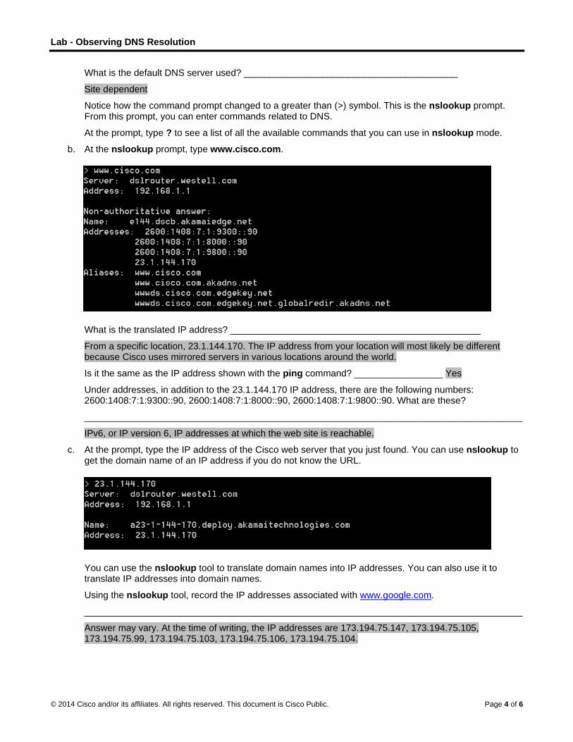
Lab - Observing DNS Resolution
© 2014 Cisco and/or its affiliates. All rights reserved. This document is Cisco Public. Page 4 of 6
What is the default DNS server used? _________________________________________
Site dependent
Notice how the command prompt changed to a greater than (>) symbol. This is the nslookup prompt. From this prompt, you can enter commands related to DNS.
At the prompt, type ? to see a list of all the available commands that you can use in nslookup mode.
b. At the nslookup prompt, type www.cisco.com.
What is the translated IP address? ________________________________________________
From a specific location, 23.1.144.170. The IP address from your location will most likely be different because Cisco uses mirrored servers in various locations around the world.
Is it the same as the IP address shown with the ping command? _________________ Yes
Under addresses, in addition to the 23.1.144.170 IP address, there are the following numbers: 2600:1408:7:1:9300::90, 2600:1408:7:1:8000::90, 2600:1408:7:1:9800::90. What are these?
____________________________________________________________________________________
IPv6, or IP version 6, IP addresses at which the web site is reachable.
c. At the prompt, type the IP address of the Cisco web server that you just found. You can use nslookup to get the domain name of an IP address if you do not know the URL.
You can use the nslookup tool to translate domain names into IP addresses. You can also use it to translate IP addresses into domain names.
Using the nslookup tool, record the IP addresses associated with www.google.com.
____________________________________________________________________________________
Answer may vary. At the time of writing, the IP addresses are 173.194.75.147, 173.194.75.105, 173.194.75.99, 173.194.75.103, 173.194.75.106, 173.194.75.104.

Lab - Observing DNS Resolution
© 2014 Cisco and/or its affiliates. All rights reserved. This document is Cisco Public. Page 5 of 6
Part 3: Observe DNS Lookup Using the Nslookup Command on Mail
Servers
a. At the prompt, type set type=mx to use nslookup to identify mail servers.
b. At the prompt, type cisco.com.
A fundamental principle of network design is redundancy (more than one mail server is configured). In this way, if one of the mail servers is unreachable, then the computer making the query tries the second mail server. Email administrators determine which mail server is contacted first using MX preference (see above image). The mail server with the lowest MX preference is contacted first. Based upon the output above, which mail server will be contacted first when email is being sent to cisco.com?
____________________________________________________________________________________
rcdn-mx-01.cisco.com
c. At the nslookup prompt, type exit to return to the regular PC command prompt.
d. At the PC command prompt, type ipconfig /all.
e. Write the IP addresses of all the DNS servers that your school uses.
____________________________________________________________________________________
Site-dependent
Reflection
What is the fundamental purpose of DNS?

Lab - Observing DNS Resolution
© 2014 Cisco and/or its affiliates. All rights reserved. This document is Cisco Public. Page 6 of 6
_______________________________________________________________________________________
_______________________________________________________________________________________
_______________________________________________________________________________________
People process in words. Computers process in numbers. People have a difficult time remembering a long string of numbers. Therefore, DNS exists to translate the “numbers” world of computers to the “word” world of people.
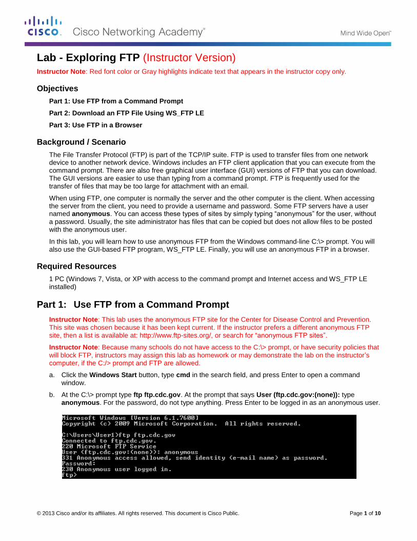
© 2013 Cisco and/or its affiliates. All rights reserved. This document is Cisco Public. Page 1 of 10
Lab - Exploring FTP (Instructor Version) Instructor Note: Red font color or Gray highlights indicate text that appears in the instructor copy only.
Objectives
Part 1: Use FTP from a Command Prompt
Part 2: Download an FTP File Using WS_FTP LE
Part 3: Use FTP in a Browser
Background / Scenario
The File Transfer Protocol (FTP) is part of the TCP/IP suite. FTP is used to transfer files from one network device to another network device. Windows includes an FTP client application that you can execute from the command prompt. There are also free graphical user interface (GUI) versions of FTP that you can download. The GUI versions are easier to use than typing from a command prompt. FTP is frequently used for the transfer of files that may be too large for attachment with an email.
When using FTP, one computer is normally the server and the other computer is the client. When accessing the server from the client, you need to provide a username and password. Some FTP servers have a user named anonymous. You can access these types of sites by simply typing “anonymous” for the user, without a password. Usually, the site administrator has files that can be copied but does not allow files to be posted with the anonymous user.
In this lab, you will learn how to use anonymous FTP from the Windows command-line C:\> prompt. You will also use the GUI-based FTP program, WS_FTP LE. Finally, you will use an anonymous FTP in a browser.
Required Resources
1 PC (Windows 7, Vista, or XP with access to the command prompt and Internet access and WS_FTP LE installed)
Part 1: Use FTP from a Command Prompt
Instructor Note: This lab uses the anonymous FTP site for the Center for Disease Control and Prevention. This site was chosen because it has been kept current. If the instructor prefers a different anonymous FTP site, then a list is available at: http://www.ftp-sites.org/, or search for “anonymous FTP sites”.
Instructor Note: Because many schools do not have access to the C:\> prompt, or have security policies that will block FTP, instructors may assign this lab as homework or may demonstrate the lab on the instructor’s computer, if the C:/> prompt and FTP are allowed.
a. Click the Windows Start button, type cmd in the search field, and press Enter to open a command window.
b. At the C:\> prompt type ftp ftp.cdc.gov. At the prompt that says User (ftp.cdc.gov:(none)): type anonymous. For the password, do not type anything. Press Enter to be logged in as an anonymous user.

Lab - Exploring FTP
© 2013 Cisco and/or its affiliates. All rights reserved. This document is Cisco Public. Page 2 of 10
Notice that the C:\> prompt has been replaced with the ftp> prompt. Type ls to list the files and
directories. At the time that this lab was authored, there was a Readme file.
c. At the prompt, type get Readme. This downloads the file to your local computer from the anonymous FTP server that the Center for Disease Control has setup. The file will be copied into the directory shown in the C:\> prompt (C:\Users\User1 in this case).
Instructor Note: The students require a folder where ftp.exe has read and write access for the download and viewing of the Readme file from the ftp site. The folder for C:\>Users\User1 is used as an example.
d. Type quit to leave FTP and return to the C:\> prompt. Type more Readme to see the contents of the document.
e. What is a drawback of using the FTP from the command line?
____________________________________________________________________________________
It could get tedious to download files this way all the time.
Part 2: Download an FTP File Using WS_FTP LE
In Part 2, you will download a file using WS_FTP LE (a free FTP transfer tool).
Instructor Note: Instructors will need to install WS_FTP LE on each student computer. At the time of authoring this was available at: http://www.wsftple.com/download.aspx. If this URL has changed, then use your favorite search engine to look for “download WS_FTP LE” or “download free FTP”.
a. Start WS_FTP LE. If the Ipswitch WS_FTP LE window displays, click Next to continue and skip to step c. Otherwise, click the Open a Remote Connection link.

Lab - Exploring FTP
© 2013 Cisco and/or its affiliates. All rights reserved. This document is Cisco Public. Page 3 of 10
b. Click Create Site….
c. In the Site Name field, type Center for Disease Control and click Next to continue.

Lab - Exploring FTP
© 2013 Cisco and/or its affiliates. All rights reserved. This document is Cisco Public. Page 4 of 10
d. Click the Connection Type drop-down list, select FTP (the default connection type), and click Next.
e. In the Server Address field, type ftp.cdc.gov, and click Next.
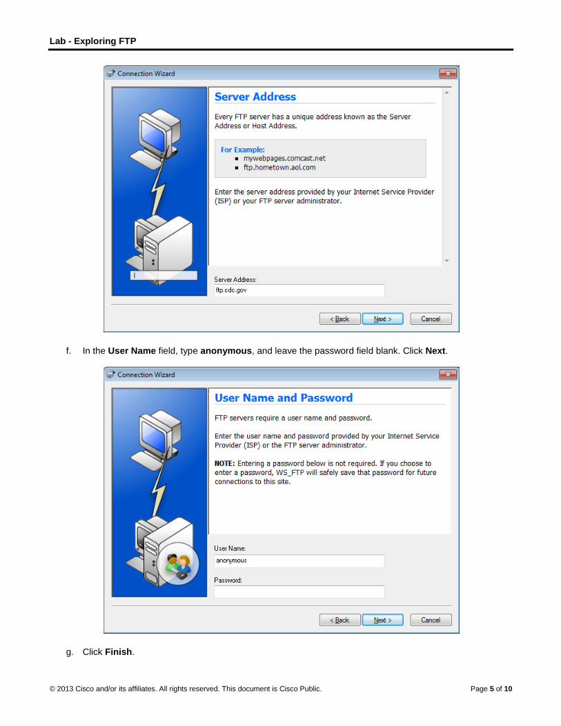
Lab - Exploring FTP
© 2013 Cisco and/or its affiliates. All rights reserved. This document is Cisco Public. Page 5 of 10
f. In the User Name field, type anonymous, and leave the password field blank. Click Next.
g. Click Finish.

Lab - Exploring FTP
© 2013 Cisco and/or its affiliates. All rights reserved. This document is Cisco Public. Page 6 of 10
h. When the Login Information Missing dialog box displays, click OK. Do not type a password in the Password field.
i. You are now anonymously connected to the Center for Disease Control FTP site.

Lab - Exploring FTP
© 2013 Cisco and/or its affiliates. All rights reserved. This document is Cisco Public. Page 7 of 10
j. On the WS_FTP LE toolbar menu under My Computer, click New Folder to create a folder on your local C:\ drive.
k. In the Make Directory dialog box name the folder as CDC and click OK.
Note: If the folder already exists, you can use the same folder or create another folder with a different name. If using the same CDC folder, you can replace the existing Readme file with the downloaded Readme file.
l. After the directory is created, in the My Computer tab page, double-click the directory to open it.
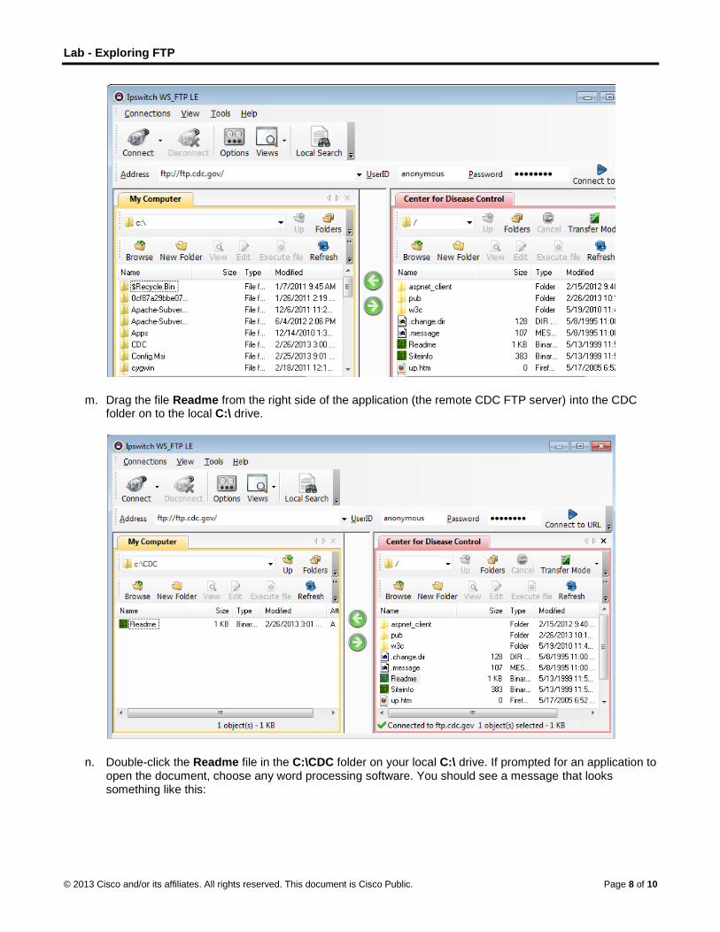
Lab - Exploring FTP
© 2013 Cisco and/or its affiliates. All rights reserved. This document is Cisco Public. Page 8 of 10
m. Drag the file Readme from the right side of the application (the remote CDC FTP server) into the CDC folder on to the local C:\ drive.
n. Double-click the Readme file in the C:\CDC folder on your local C:\ drive. If prompted for an application to open the document, choose any word processing software. You should see a message that looks something like this:

Lab - Exploring FTP
© 2013 Cisco and/or its affiliates. All rights reserved. This document is Cisco Public. Page 9 of 10
o. Which was easier, using FTP from the cmd prompt, or using WS_FTP LE? __________________
After it has been installed, a GUI FTP application such as WS_FTP LE is easier to use, especially if working with a large number of large files.
p. Click Disconnect to disconnect from the ftp.cdc.gov site when finished.
q. The remote site will be removed from the saved list of FTP sites. In the Ipswitch WS_FTP LE window, click the Open a Remote Connection link. Select the Center for Disease Control site, and click Delete to remove the FTP site. Click Yes to confirm the deletion. Click Close to exit the Site Manager.
r. Remove the C:\CDC folder.
Instructor Note: Please remove C:\CDC or other folders that the students created in this lab.
Part 3: Use FTP in a Browser
It is possible to use a browser as an anonymous FTP client.
a. In a browser, type ftp://ftp.cdc.gov/.

Lab - Exploring FTP
© 2013 Cisco and/or its affiliates. All rights reserved. This document is Cisco Public. Page 10 of 10
b. Click the Readme file.
Reflection
1. Which FTP method was easiest to use?
_______________________________________________________________________________________
The browser.
2. Was there any advantage to using FTP from the command prompt or using WS_FTP LE?
_______________________________________________________________________________________
From an ease of use perspective, the browser was clearly superior to the other two methods. The only advantage to the other two methods is that they give you more of a step-by-step view of the interaction between the client software and the remote FTP server. This is useful in understanding how FTP works. It is not a compelling argument to use either of those methods in practice.
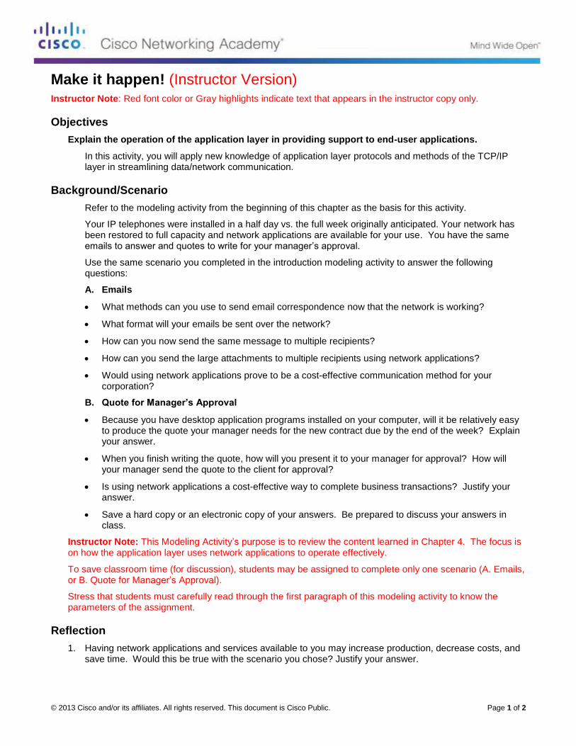
© 2013 Cisco and/or its affiliates. All rights reserved. This document is Cisco Public. Page 1 of 2
Make it happen! (Instructor Version) Instructor Note: Red font color or Gray highlights indicate text that appears in the instructor copy only.
Objectives
Explain the operation of the application layer in providing support to end-user applications.
In this activity, you will apply new knowledge of application layer protocols and methods of the TCP/IP layer in streamlining data/network communication.
Background/Scenario
Refer to the modeling activity from the beginning of this chapter as the basis for this activity.
Your IP telephones were installed in a half day vs. the full week originally anticipated. Your network has been restored to full capacity and network applications are available for your use. You have the same emails to answer and quotes to write for your manager’s approval.
Use the same scenario you completed in the introduction modeling activity to answer the following questions:
A. Emails
What methods can you use to send email correspondence now that the network is working?
What format will your emails be sent over the network?
How can you now send the same message to multiple recipients?
How can you send the large attachments to multiple recipients using network applications?
Would using network applications prove to be a cost-effective communication method for your corporation?
B. Quote for Manager’s Approval
Because you have desktop application programs installed on your computer, will it be relatively easy to produce the quote your manager needs for the new contract due by the end of the week? Explain your answer.
When you finish writing the quote, how will you present it to your manager for approval? How will your manager send the quote to the client for approval?
Is using network applications a cost-effective way to complete business transactions? Justify your answer.
Save a hard copy or an electronic copy of your answers. Be prepared to discuss your answers in class.
Instructor Note: This Modeling Activity’s purpose is to review the content learned in Chapter 4. The focus is on how the application layer uses network applications to operate effectively.
To save classroom time (for discussion), students may be assigned to complete only one scenario (A. Emails, or B. Quote for Manager’s Approval).
Stress that students must carefully read through the first paragraph of this modeling activity to know the parameters of the assignment.
Reflection
1. Having network applications and services available to you may increase production, decrease costs, and save time. Would this be true with the scenario you chose? Justify your answer.
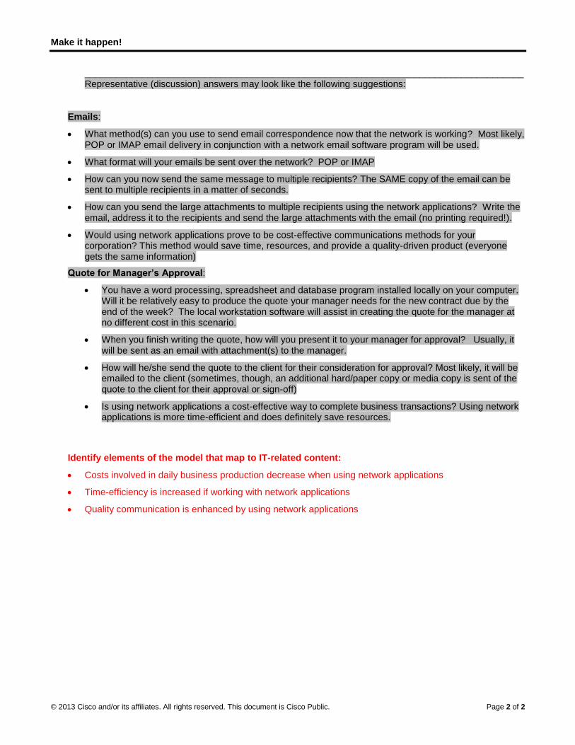
Make it happen!
© 2013 Cisco and/or its affiliates. All rights reserved. This document is Cisco Public. Page 2 of 2
____________________________________________________________________________________Representative (discussion) answers may look like the following suggestions:
Emails:
What method(s) can you use to send email correspondence now that the network is working? Most likely, POP or IMAP email delivery in conjunction with a network email software program will be used.
What format will your emails be sent over the network? POP or IMAP
How can you now send the same message to multiple recipients? The SAME copy of the email can be sent to multiple recipients in a matter of seconds.
How can you send the large attachments to multiple recipients using the network applications? Write the email, address it to the recipients and send the large attachments with the email (no printing required!).
Would using network applications prove to be cost-effective communications methods for your corporation? This method would save time, resources, and provide a quality-driven product (everyone gets the same information)
Quote for Manager’s Approval:
You have a word processing, spreadsheet and database program installed locally on your computer. Will it be relatively easy to produce the quote your manager needs for the new contract due by the end of the week? The local workstation software will assist in creating the quote for the manager at no different cost in this scenario.
When you finish writing the quote, how will you present it to your manager for approval? Usually, it will be sent as an email with attachment(s) to the manager.
How will he/she send the quote to the client for their consideration for approval? Most likely, it will be emailed to the client (sometimes, though, an additional hard/paper copy or media copy is sent of the quote to the client for their approval or sign-off)
Is using network applications a cost-effective way to complete business transactions? Using network applications is more time-efficient and does definitely save resources.
Identify elements of the model that map to IT-related content:
Costs involved in daily business production decrease when using network applications
Time-efficiency is increased if working with network applications
Quality communication is enhanced by using network applications

© 2013 Cisco and/or its affiliates. All rights reserved. This document is Cisco Public. Page 1 of 2
We Need to Talk (Instructor Version) Instructor Note: Red font color or Gray highlights indicate text that appears in the instructor copy only.
Objectives
Explain how transport layer protocols and services support communications across data networks.
In this activity, you will determine whether high or low data communication delivery methods should be utilized in a situational context.
Background/Scenario
Note: This activity works best with medium-sized groups of 6 to 8 students per group.
This chapter helps you understand how transport layer protocols and services support network data communications.
Your instructor will whisper a complex message to the first student in a group. An example of the message might be “Our final exam will be given next Tuesday, February 5th, at 2:00 p.m. in Room 1151.”
That student whispers the message to the next student in the group. Each group follows this process until all members of each group have heard the whispered message.
Here are the rules to follow:
You can whisper the message only once to your neighbor.
The message must keep moving from one person to the other with no skipping of participants. The instructor should ask a student to keep time of the full message activity from first participant to last participant stating the messages. The first or last person would mostly likely be the best one to keep this time.
The last student will say aloud exactly what he or she heard.
Your instructor will repeat the original message so that the group can compare it to the message that was delivered by the last student in the group.
Instructor Note: You should have a different complex message for each group of students. Initiate discussion about what happened in the activity. Focus on these five questions:
1. Was the message complete when it reached the last student?
2. Was the message correct as delivered to the last student?
3. How long did it take for the message to get to the last student?
4. If you were depending on this message to drive your personal/business calendar, studying
schedule, etc., would the contents of this message need to be fully correct when you received
them?
5. Would the length of time taken to deliver the message be important to the sender and recipient?
Instructor Note: This is an in-class Modeling Activity (MA). It is not intended to be a graded assignment. Its purposed is to initiate student discussion about their perception of how data is transferred from source to destination, both personally and in corporate practice. This MA introduces students to TCP/UDP, transport layer content.
Required Resources
Timer for the student who is keeping a record of the conversation’s duration.
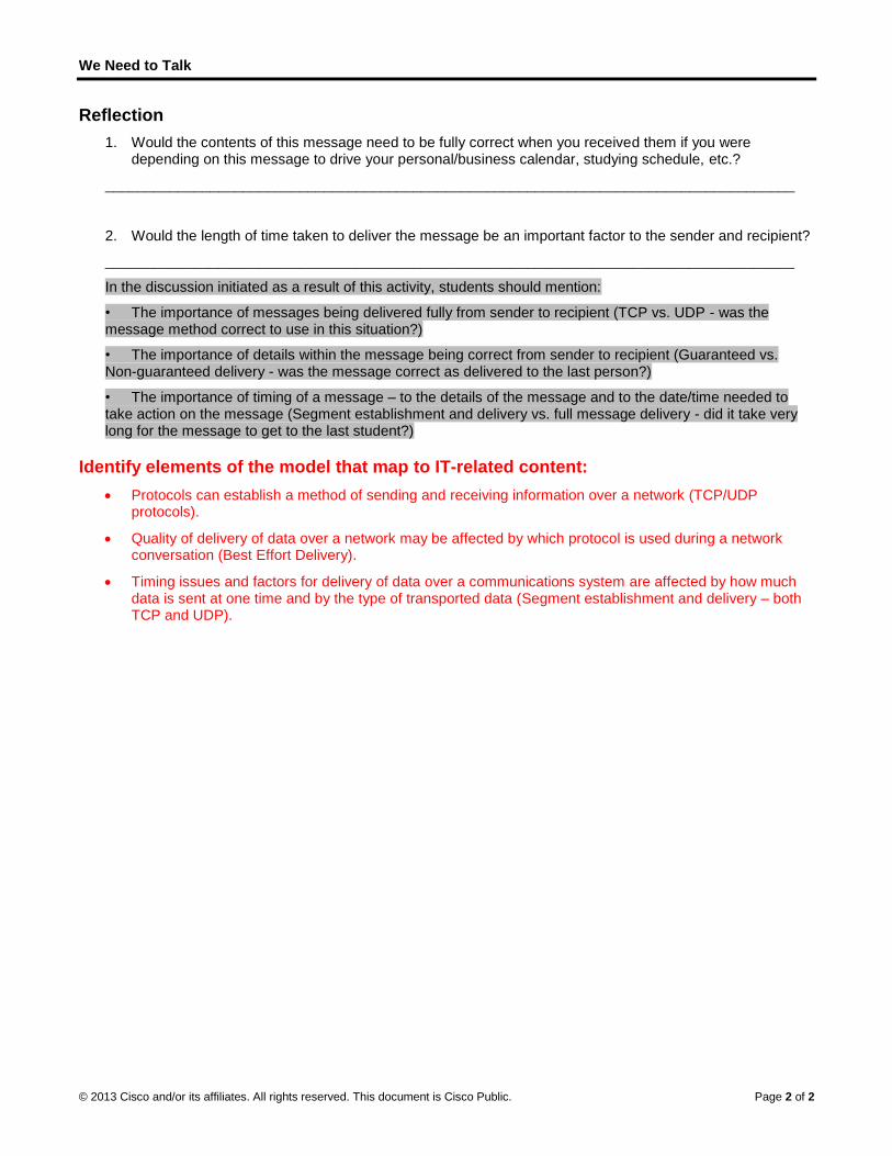
We Need to Talk
© 2013 Cisco and/or its affiliates. All rights reserved. This document is Cisco Public. Page 2 of 2
Reflection
1. Would the contents of this message need to be fully correct when you received them if you were depending on this message to drive your personal/business calendar, studying schedule, etc.?
_____________________________________________________________________________________
2. Would the length of time taken to deliver the message be an important factor to the sender and recipient?
_____________________________________________________________________________________
In the discussion initiated as a result of this activity, students should mention:
• The importance of messages being delivered fully from sender to recipient (TCP vs. UDP - was the message method correct to use in this situation?)
• The importance of details within the message being correct from sender to recipient (Guaranteed vs. Non-guaranteed delivery - was the message correct as delivered to the last person?)
• The importance of timing of a message – to the details of the message and to the date/time needed to take action on the message (Segment establishment and delivery vs. full message delivery - did it take very long for the message to get to the last student?)
Identify elements of the model that map to IT-related content:
Protocols can establish a method of sending and receiving information over a network (TCP/UDP protocols).
Quality of delivery of data over a network may be affected by which protocol is used during a network conversation (Best Effort Delivery).
Timing issues and factors for delivery of data over a communications system are affected by how much data is sent at one time and by the type of transported data (Segment establishment and delivery – both TCP and UDP).

©
L(I
T
O
B
R
P
S
© 2013 Cisco and
Lab - Us(Instructonstructor No
Topology
ObjectivesPart 1: Pr
Selec
Part 2: Ca
Captu
Locat
Exam
BackgrounIn this labthe Hypersuch as Hestablish the Internserver. A
Note: This
Instructoof the schpacket snperform a
Required R1 PC (Win
Part 1: PIn Part 1,
Step 1: Re
For this laalso called
d/or its affiliates.
sing Wiror Versioote: Red font
repare Wires
ct an appropri
apture, Loca
ure a web ses
te appropriate
mine informatio
nd / Scenarb, you will userText Transfe
HTTP or File Ta reliable TCet, a three-waPC can have
s lab cannot b
or Note: Usinghool. It is recoiffer such as
a walk-through
Resources ndows 7, Vist
Prepare Wyou start the
etrieve the P
ab, you need td the MAC ad
All rights reserve
eshark ton) color or Gray
shark to Capt
ate NIC interf
ate, and Exam
ssion to www.
e packets for a
on within pac
rio Wireshark tor Protocol (HTTransfer ProtoP session betay handshake multiple, sim
be completed
g a packet snommended thaWireshark is h demonstrati
a, or XP with
WiresharkWireshark pr
PC interface
to retrieve yoddress.
ed. This docume
to Obse
y highlights ind
ture Packets
face to captur
mine Packets
.google.com.
a web sessio
kets, includin
o capture andTTP) and a wocol (FTP) firstween the twoe is initiated a
multaneous, ac
d using Netlab
iffer such as Wat permissionan issue, the ion.
a command
k to Capturogram and se
e addresses
ur PC’s IP ad
ent is Cisco Publi
erve the
dicate text tha
s
re packets.
s
n.
g IP addresse
examine pacweb server, sust starts on a o hosts. For eand a sessionctive TCP ses
b. This lab ass
Wireshark man is obtained b
instructor ma
prompt acces
ure Packeelect the app
s.
ddress and its
ic.
TCP 3-W
at appears in
es, TCP port
ckets generatuch as www.ghost, TCP us
example, when is establishessions with va
sumes that yo
ay be considebefore runninay wish to ass
ss, Internet ac
ets ropriate interf
s network inte
Way Han
the instructo
numbers, an
ted between tgoogle.com. Wses the three-en a PC uses ed between tharious web sit
ou have Inter
ered a breachg Wireshark fsign the lab a
ccess, and W
face to begin
erface card (N
ndshake
r copy only.
d TCP contro
the PC browsWhen an appl-way handshaa web brows
he PC host antes.
rnet access.
h of the securfor this lab. If
as homework
Wireshark insta
capturing pa
NIC) physical
Page 1 of 7
e
ol flags.
ser using lication, ake to ser to surf nd web
rity policy using a or
alled)
ckets.
address,

L
©
S
Lab - Using W
© 2013 Cisco and
a. Open
b. Write sourc
The P
Answ
The P
Answ
Step 2: Sta
a. Click
b. After W
c. In theyour L
Wireshark to
d/or its affiliates.
a command
down the IP ce address to
PC host IP ad
wers vary. In th
PC host MAC
wers vary. In th
art Wiresha
the Windows
Wireshark sta
e Wireshark: LAN.
Observe the
All rights reserve
prompt windo
and MAC addlook for when
dress: _____
his case 192.
address: ___
his case C8:0
rk and sele
Start button
arts, click Inte
Capture Inte
e TCP 3-Way
ed. This docume
ow, type ipco
dresses asson examining c
____________
168.1.130
___________
0A:A9:FA:DE:
ct the appro
and on the p
erface List.
erfaces windo
y Handshake
ent is Cisco Publi
onfig /all and
ciated with thcaptured pack
___________
____________
0D
opriate inte
op-up menu,
ow, click the c
e
ic.
then press E
he selected Etkets.
___________
___________
erface.
double-click
check the box
Enter.
thernet adapt
___________
___________
Wireshark.
x next to the i
ter, because t
___________
__________
nterface conn
Page 2 of 7
that is the
nected to

L
©
P
S
S
Lab - Using W
© 2013 Cisco and
Note:802.3the In
Part 2: C
Step 1: Cli
a. Go toYou s
Note:here:
_____
b. The c
Step 2: Lo
If the comentire proSystem (Dpackets thdefault ga
Wireshark to
d/or its affiliates.
If multiple int3 (Ethernet) taterface Detai
Capture, L
ck the Start
www.googleshould see ca
Your instruct
___________
capture windo
cate approp
mputer was reccess in the caDNS), and thehe computer mateway; theref
Observe the
All rights reserve
terfaces are lab, and verifyls window aft
Locate, a
t button to s
.com. Minimizaptured traffic
tor may provi
___________
ow is now acti
priate packe
cently startedaptured outpue TCP three-wmust get to wfore, it started
e TCP 3-Way
ed. This docume
isted and youy that the MACter verification
nd Exam
start the da
ze the Googlesimilar to tha
de you with a
____________
ve. Locate th
ets for the w
d and there haut, including thway handsha
www.google.cod with the DN
y Handshake
ent is Cisco Publi
u are unsure wC address man.
mine Pack
ata capture.
e window, andat shown belo
a different web
___________
e Source, De
web sessio
as been no ache Address Rke. The captuom. In this caS query to re
e
ic.
which interfacatches what y
kets
d return to Wow in step b.
bsite. If so, en
___________
estination, a
n.
ctivity in acceResolution Proure screen in ase, the PC alsolve www.go
ce to check, cyou wrote dow
Wireshark. Sto
nter the webs
____________
nd Protocol
essing the Inteotocol (ARP),Part 2, Step lready had anoogle.com.
click Details. wn in Step 1b
p the data ca
site name or a
____________
columns.
ernet, you can Domain Nam1 shows all thn ARP entry f
Page 3 of 7
Click the b. Close
apture.
address
________
n see the me he for the

L
©
S
Lab - Using W
© 2013 Cisco and
a. Framewww.send
What
192.1
b. Frame
c. Find tstart o
What
74.12
d. If youWires
Step 3: ExTC
a. In ourserveand dinform
b. Click view o
c. Click
Note:neces
Wireshark to
d/or its affiliates.
e 11 shows thgoogle.com tthe first pack
is the IP add
68.1.1
e 12 is the res
the appropriatof the TCP th
is the IP add
25.225.209 in
have many pshark filter cap
amine inforCP control fl
r example, frar. In the packisplays the de
mation in the p
the + icon to of the TCP inf
the + icon to
You may havssary informa
Observe the
All rights reserve
he DNS queryto the IP addret to the web
ress of the D
sponse from
te packet for ree-way hand
ress of the G
this example
packets that apability. Enter
rmation withlags.
ame 15 is the ket list pane (tecoded informpacket details
the left of theformation.
the left of the
ve to adjust thtion.
e TCP 3-Way
ed. This docume
y from the PCress of the weserver.
NS server tha
the DNS serv
the start of yodshake.
oogle web se
are unrelated r tcp in the filt
hin packets
start of the thtop section ofmation from ths pane (middle
e Transmissio
e Flags. Look
he top and m
y Handshake
ent is Cisco Publi
C to the DNS seb server. The
at the comput
ver with the IP
our three-way
erver? ______
to the TCP coter entry area
s including
hree-way hanf the main winhat packet in e section of th
n Control Pro
at the source
iddle window
e
ic.
server, atteme PC must ha
ter queried? _
P address of w
y handshake.
___________
onnection, it a within Wires
IP addresse
ndshake betwndow), select the two lowerhe main wind
otocol in the p
e and destinat
ws sizes within
mpting to resolave the IP add
___________
www.google.c
In this examp
___________
may be neceshark and pre
es, TCP por
ween the PC athe frame. Thr panes. Exam
dow).
packet details
tion ports and
n Wireshark to
lve the domadress before
__________
com.
ple, frame 15
_________
ssary to use tess Enter.
rt numbers,
and the Googhis highlights mine the TCP
s pane to expa
d the flags tha
o display the
Page 4 of 7
in name, it can
5 is the
the
, and
le web the line
P
and the
at are set.
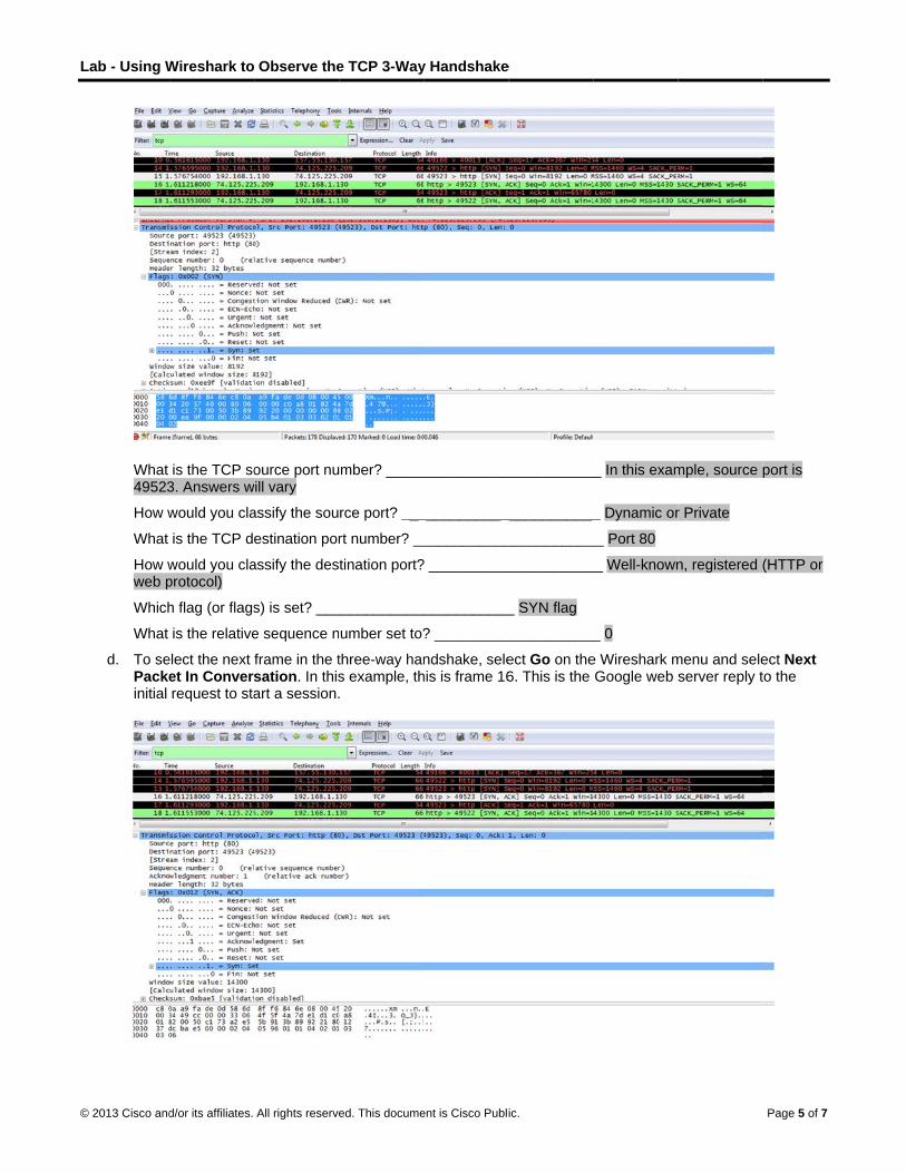
L
©
Lab - Using W
© 2013 Cisco and
What 49523
How w
What
How wweb p
Which
What
d. To sePackeinitial
Wireshark to
d/or its affiliates.
is the TCP so3. Answers w
would you cla
is the TCP d
would you claprotocol)
h flag (or flags
is the relative
elect the next et In Conversrequest to sta
Observe the
All rights reserve
ource port nuwill vary
assify the sou
estination por
assify the des
s) is set? ___
e sequence n
frame in the tsation. In thisart a session.
e TCP 3-Way
ed. This docume
mber? _____
rce port? ___
rt number? __
tination port?
____________
umber set to?
three-way hans example, th.
y Handshake
ent is Cisco Publi
___________
___________
___________
? __________
___________
? _________
ndshake, selehis is frame 16
e
ic.
____________
____________
___________
___________
_ SYN flag
____________
ect Go on the6. This is the
_ In this exam
_ Dynamic or
__ Port 80
__ Well-known
_ 0
e Wireshark mGoogle web
mple, source
r Private
n, registered
menu and seleserver reply t
Page 5 of 7
port is
(HTTP or
ect Next to the
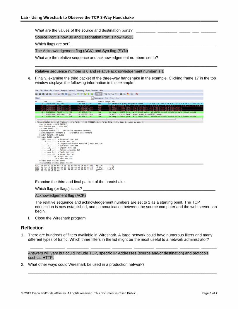
L
©
R1
2
Lab - Using W
© 2013 Cisco and
What
Sourc
Which
The A
What
_____
Relati
e. Finallywindo
Exam
Which
Ackno
The reconnebegin
f. Close
Reflection 1. There are
different ty
________
Answers wsuch as H
2. What othe
________
Wireshark to
d/or its affiliates.
are the value
ce Port is now
h flags are se
Acknowledgem
are the relati
___________
ive sequence
y, examine thow displays th
mine the third a
h flag (or flags
owledgement
elative sequeection is now .
e the Wiresha
e hundreds of ypes of traffic
___________
will vary but cHTTP.
er ways could
___________
Observe the
All rights reserve
es of the sour
w 80 and Dest
et? _________
ment flag (AC
ve sequence
___________
e number is 0
he third packehe following in
and final pack
s) is set? ___
t flag (ACK)
ence and acknestablished, a
rk program.
filters availabc. Which three
____________
could include
d Wireshark b
____________
e TCP 3-Way
ed. This docume
rce and destin
tination Port i
___________
CK) and Syn f
and acknowl
____________
and relative a
et of the threenformation in
ket of the han
____________
nowledgemenand commun
ble in Wireshae filters in the
___________
TCP, specific
e used in a p
___________
y Handshake
ent is Cisco Publi
nation ports?
s now 49523
___________
lag (SYN)
edgement nu
___________
acknowledge
e-way handshthis example:
ndshake.
___________
nt numbers arication betwe
ark. A large nlist might be
___________
c IP Addresse
production net
___________
e
ic.
___________
___________
umbers set to
___________
ment number
ake in the ex:
___________
re set to 1 as een the source
network could the most use
____________
es (source an
twork?
____________
___________
____________
?
____________
r is 1
xample. Clicki
___________
a starting poe computer a
have numeroeful to a netwo
____________
nd/or destinati
____________
___________
___________
____________
ng frame 17 i
____________
int. The TCP and the web s
ous filters andork administra
___________
ion) and proto
___________
Page 6 of 7
________
________
________
in the top
_______
server can
d many ator?
________
ocols
________

Lab - Using Wireshark to Observe the TCP 3-Way Handshake
© 2013 Cisco and/or its affiliates. All rights reserved. This document is Cisco Public. Page 7 of 7
Wireshark is often used for security purposes for after-the-fact analysis of normal traffic or after a network attack. New protocols or services may need to be captured to determine what port or ports are used.
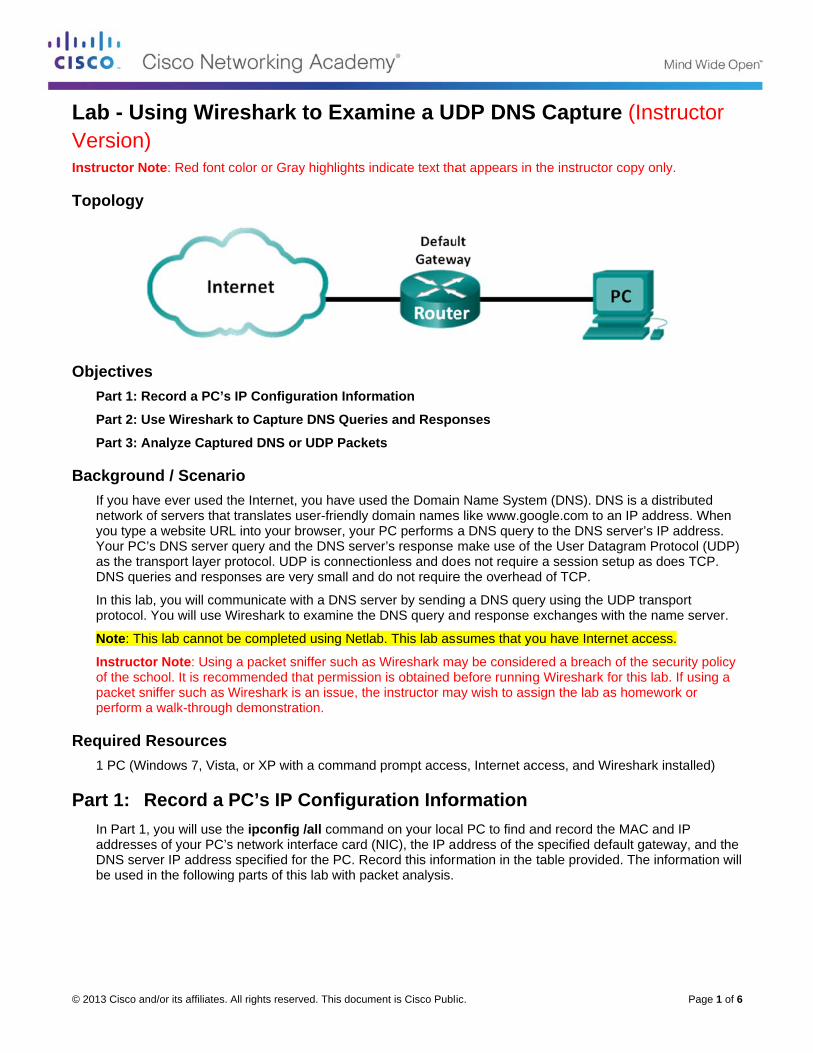
©
LVI
T
O
B
R
P
© 2013 Cisco and
Lab - UsVersion) nstructor No
Topology
ObjectivesPart 1: Re
Part 2: Us
Part 3: An
BackgrounIf you havnetwork oyou type aYour PC’sas the traDNS quer
In this labprotocol. Y
Note: This
Instructoof the schpacket snperform a
Required R1 PC (Win
Part 1: RIn Part 1, addressesDNS servbe used in
d/or its affiliates.
sing Wir
ote: Red font
ecord a PC’s
se Wireshark
nalyze Captu
nd / Scenarve ever used tof servers thata website URs DNS server nsport layer pries and respo
b, you will comYou will use W
s lab cannot b
or Note: Usinghool. It is recoiffer such as
a walk-through
Resources ndows 7, Vist
Record a you will use ts of your PC’s
ver IP addressn the following
All rights reserve
eshark t
color or Gray
s IP Configur
k to Capture
ured DNS or
rio the Internet, yt translates us
RL into your brquery and th
protocol. UDPonses are ver
mmunicate witWireshark to e
be completed
g a packet snommended thaWireshark is h demonstrati
a, or XP with
PC’s IP Cthe ipconfig /s network intes specified forg parts of this
ed. This docume
to Exam
y highlights ind
ration Inform
DNS Querie
UDP Packet
you have useser-friendly dorowser, your Phe DNS serveP is connectiory small and d
th a DNS servexamine the
d using Netlab
iffer such as Wat permissionan issue, the ion.
a command
Configura/all commanderface card (Nr the PC. Recs lab with pac
ent is Cisco Publi
mine a UD
dicate text tha
mation
s and Respo
s
d the Domainomain namesPC performs
er’s response onless and dodo not require
ver by sendinDNS query a
b. This lab ass
Wireshark man is obtained b
instructor ma
prompt acces
ation Infod on your locaNIC), the IP acord this inforcket analysis.
ic.
DP DNS
at appears in
onses
n Name Systes like www.goa DNS querymake use of es not require
e the overhea
ng a DNS quend response
sumes that yo
ay be considebefore runninay wish to ass
ss, Internet ac
ormational PC to find address of themation in the
S Captur
the instructo
em (DNS). DNoogle.com to ay to the DNS sthe User Date a session sad of TCP.
ery using the Uexchanges w
ou have Inter
ered a breachg Wireshark fsign the lab a
ccess, and W
and record thee specified de table provide
re (Instru
r copy only.
NS is a distriban IP addressserver’s IP adtagram Protocetup as does
UDP transporwith the name
rnet access.
h of the securfor this lab. If
as homework
Wireshark insta
e MAC and IPfault gatewayed. The inform
Page 1 of 6
uctor
buted s. When ddress. col (UDP) TCP.
rt server.
rity policy using a or
alled)
P y, and the mation will

Lab - Using Wireshark to Examine a UDP DNS Capture
© 2013 Cisco and/or its affiliates. All rights reserved. This document is Cisco Public. Page 2 of 6
IP address Answers will vary. 192.168.1.11
MAC address Answers will vary. 90:4c:e5:be:15:63
Default gateway IP address Answers will vary. 192.168.1.1
DNS server IP address Answers will vary. 192.168.1.1
Part 2: Use Wireshark to Capture DNS Queries and Responses In Part 2, you will set up Wireshark to capture DNS query and response packets to demonstrate the use of UDP transport protocol while communicating with a DNS server.
a. Click the Windows Start button and navigate to the Wireshark program.
Note: If Wireshark is not yet installed, it can be downloaded at http://www.wireshark.org/download.html.
b. Select an interface for Wireshark for capturing packets. Use the Interface List to choose the interface that is associated with the recorded PC’s IP and Media Access Control (MAC) addresses in Part 1.
c. After selecting the desired interface, click Start to capture the packets.
d. Open a web browser and type www.google.com. Press Enter to continue.
e. Click Stop to stop the Wireshark capture when you see Google’s home page.
Part 3: Analyze Captured DNS or UDP Packets In Part 3, you will examine the UDP packets that were generated when communicating with a DNS server for the IP addresses for www.google.com.
Step 1: Filter DNS packets.
a. In the Wireshark main window, type dns in the entry area of the Filter toolbar. Click Apply or press Enter.
Note: If you do not see any results after the DNS filter was applied, close the web browser and in the command prompt window, type ipconfig /flushdns to remove all previous DNS results. Restart the Wireshark capture and repeat the instructions in Part 2b –2e. If this does not resolve the issue, in the command prompt window, you can type nslookup www.google.com as an alternative to the web browser.

L
©
S
Lab - Using W
© 2013 Cisco and
b. In theand “A
Step 2: Ex
Examine Wiresharkdisplayedin gray.
a. In thethe nuwww.
b. The Efrom yfrom t
Is the
The athe pa
Wireshark to
d/or its affiliates.
e packet list paA www.googl
amine UDP
UDP by usingk capture framin the packet
e packet detaiumber of bytegoogle.com.
Ethernet II lineyour local PCthe default ga
source MAC
answer shouldackets.
Examine a U
All rights reserve
ane (top secte.com”. See f
P segment u
g a DNS querme 4 in the pat details pane
ls pane, frames to send a D
e displays theC because youateway, becau
C address the
d be yes. If no
UDP DNS Ca
ed. This docume
ion) of the maframe 4 as an
using DNS q
ry for www.goacket list panee (middle sect
me 4 had 74 byDNS query to
e source and dur local PC oruse this is the
same as reco
ot, please ver
apture
ent is Cisco Publi
ain window, lon example.
query.
oogle.com as e is selected ftion) of the ma
ytes of data oa name serve
destination Mriginated the De last stop bef
orded from Pa
rify that Wires
ic.
ocate the pac
captured by Wfor analysis. Tain window. T
on the wire aser requesting
MAC addresseDNS query. Tfore this quer
art 1 for the lo
shark is using
cket that inclu
Wireshark. InThe protocolsThe protocol e
s displayed ong the IP addre
es. The sourcThe destinatiory exits the loc
ocal PC? ___
the same int
des “standard
n this examples in this queryentries are hi
n the first lineesses of
ce MAC addreon MAC addrecal network.
____________
terface for cap
Page 3 of 6
d query”
e, y are ghlighted
e. This is
ess is ess is
_____
pturing

L
©
Lab - Using W
© 2013 Cisco and
c. In theaddreexam
Can y
Loca
Defa
The IPas the
d. A UDheade
Expanthere randoPort 5from c
In thisThe ofollow
Wireshark to
d/or its affiliates.
e Internet Protess of this DNple, the desti
you pair up th
Device
al PC
ault Gateway
P packet and e data.
P header onlyer is only 16 b
nd the User Dare only four
omly generate53 is a well-knclients.
s example, theother 32 byteswing illustratio
Examine a U
All rights reserve
tocol Version S query is 19nation addres
e IP and MAC
Answers w
Answers w
header enca
y has four fielbits as depicte
Datagram Profields. The so
ed by the locanown port res
e length of ths are used by n in the packe
UDP DNS Ca
ed. This docume
4 line, the IP92.168.1.11, ass is the defa
C addresses f
IP Address
will vary. 192.1
will vary. 192.1
apsulates the
lds: source poed below.
otocol in the pource port nu
al PC using poserved for use
is UDP segmDNS query d
et bytes pane
apture
ent is Cisco Publi
packet Wiresand the destinult gateway. T
for the source
168.1.11 A
168.1.1 A
UDP segmen
ort, destinatio
acket details mber in this eort numbers te with DNS. D
ment is 40 bytedata. The 32 be (lower sectio
ic.
shark capturenation IP addThe router is
e and destina
M
Answers will v
Answers will v
nt. The UDP s
on port, length
pane by clickexample is 52hat are not re
DNS servers l
es. Out of 40 bytes of DNSon) of the Wir
e indicates tharess is 192.16the default ga
ation devices?
MAC Address
vary. 90:4c:e5
vary. 30:46:9a
segment cont
h, and checks
king the plus (2110. The soueserved. The isten on port
bytes, 8 byteS query data isreshark main
at the source 68.1.1. In thisateway in this
?
s
5:be:15:63
a:99:c5:72
tains the DNS
sum. Each fie
(+) sign. Noticurce port wasdestination p53 for DNS q
es are used ass highlighted window.
Page 4 of 6
IP s s network.
S query
eld in UDP
ce that s port is 53. queries
s header. in the
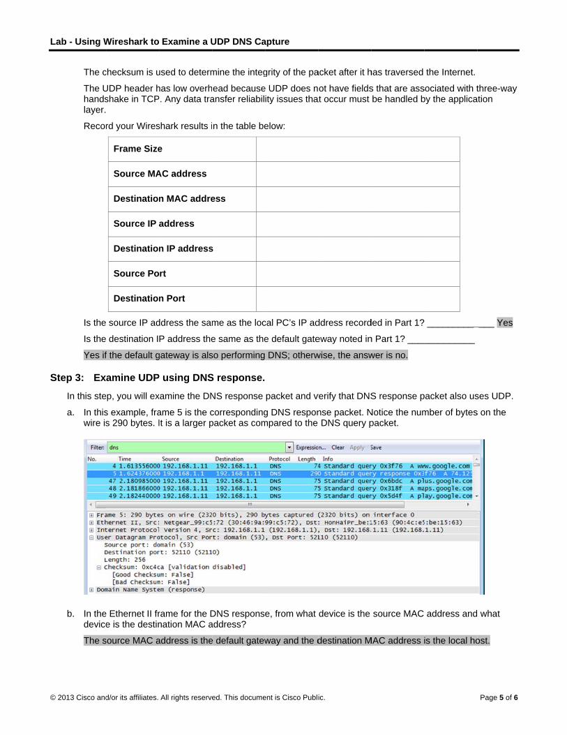
L
©
S
Lab - Using W
© 2013 Cisco and
The c
The Uhandslayer.
Recor
Is the
Is the
Yes if
Step 3: Ex
In this ste
a. In thiswire is
b. In thedevice
The s
Wireshark to
d/or its affiliates.
checksum is u
UDP header hshake in TCP
rd your Wires
Frame Size
Source MA
Destination
Source IP
Destination
Source Po
Destination
source IP ad
destination I
f the default g
amine UDP
ep, you will ex
s example, fras 290 bytes. I
e Ethernet II fre is the destin
source MAC a
Examine a U
All rights reserve
used to determ
has low overhP. Any data tra
shark results i
e
AC address
n MAC addre
address
n IP address
rt
n Port
ddress the sam
P address the
gateway is als
P using DNS
xamine the DN
ame 5 is the cIt is a larger p
rame for the Dnation MAC a
address is the
UDP DNS Ca
ed. This docume
mine the integ
ead becauseansfer reliabil
n the table be
ess
s
me as the loc
e same as the
so performing
S response.
NS response
correspondingpacket as com
DNS responseaddress?
e default gatew
apture
ent is Cisco Publi
grity of the pa
e UDP does nity issues tha
elow:
cal PC’s IP ad
e default gate
DNS; otherw
packet and v
g DNS responmpared to the
e, from what
way and the d
ic.
acket after it h
ot have fieldsat occur must
ddress record
eway noted in
wise, the answ
verify that DNS
nse packet. NDNS query p
device is the
destination M
has traversed
s that are assbe handled b
ded in Part 1?
n Part 1? ____
wer is no.
S response p
Notice the numpacket.
source MAC
MAC address i
the Internet.
sociated with tby the applica
__________
__________
packet also us
mber of bytes
address and
is the local ho
Page 5 of 6
three-way ation
____ Yes
ses UDP.
s on the
what
ost.

L
©
R
Lab - Using W
© 2013 Cisco and
c. NoticeWhat
Destin
Answ
What
_____
The lo
d. In the52110sent t
The srespo
WhenAnsw
Reflection What are
________
UDP as aneed for r
Wireshark to
d/or its affiliates.
e the source ais the source
nation IP add
wer will vary. In
happened to
___________
ocal host and
e UDP segme0. Port numbeto the DNS se
source port nuonse with a so
n the DNS reswers section.
the benefits o
___________
a transport proretries, segme
Examine a U
All rights reserve
and destinatioe IP address?
ress: ______
n this exampl
the roles of s
___________
the default g
nt, the role ofer 52110 is therver. Your loc
umber is 53. Tource port num
sponse is exp
of using UDP
____________
otocol provideent reassemb
UDP DNS Ca
ed. This docume
on IP address
____________
e: destination
source and de
____________
ateway have
f the port numhe same port tcal PC listens
The DNS servmber of 53 ba
panded, notice
instead of TC
___________
es quick sessbly and ackno
apture
ent is Cisco Publi
ses in the IP p
_______Sour
n: 192.168.1.1
estination for
___________
reversed the
mbers has alsothat was genes for a DNS re
ver listens forack to originat
e the resolved
CP as a trans
___________
ion establishmwledgement o
ic.
packet. What
rce IP addres
11, source 19
the local hos
___________
eir roles in DN
o reversed. Terated by theesponse on th
r a DNS querytor of the DNS
d IP addresse
sport protocol
____________
ment, quick reof received p
t is the destina
ss: _________
92.168.1.1
st and default
____________
NS query and
The destinatioe local PC whehis port.
y on port 53 aS query.
es for www.go
for DNS?
____________
esponse, minackets.
ation IP addre
___________
gateway?
____________
response pac
on port numbeen the DNS q
and then send
oogle.com in
___________
nimal overhea
Page 6 of 6
ess?
______
________
ckets.
er is query was
ds a DNS
the
________
ad, no
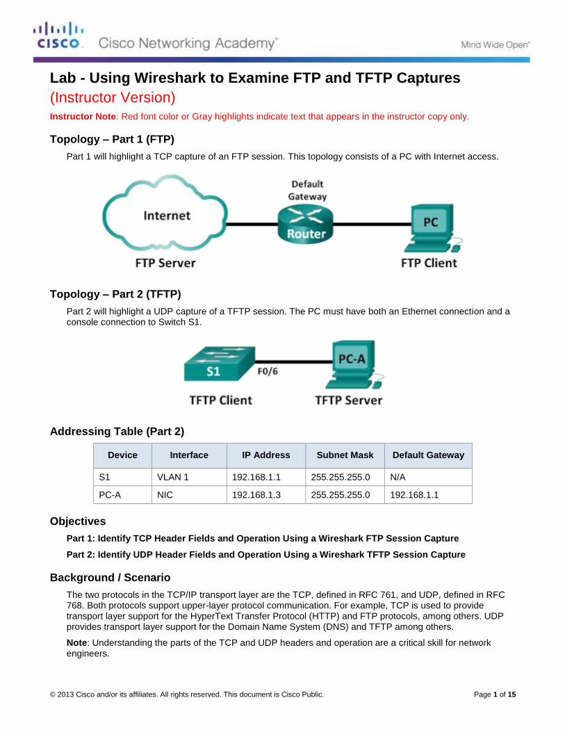
© 2013 Cisco and/or its affiliates. All rights reserved. This document is Cisco Public. Page 1 of 15
Lab - Using Wireshark to Examine FTP and TFTP Captures
(Instructor Version) Instructor Note: Red font color or Gray highlights indicate text that appears in the instructor copy only.
Topology – Part 1 (FTP)
Part 1 will highlight a TCP capture of an FTP session. This topology consists of a PC with Internet access.
Topology – Part 2 (TFTP)
Part 2 will highlight a UDP capture of a TFTP session. The PC must have both an Ethernet connection and a console connection to Switch S1.
Addressing Table (Part 2)
Device Interface IP Address Subnet Mask Default Gateway
S1 VLAN 1 192.168.1.1 255.255.255.0 N/A
PC-A NIC 192.168.1.3 255.255.255.0 192.168.1.1
Objectives
Part 1: Identify TCP Header Fields and Operation Using a Wireshark FTP Session Capture
Part 2: Identify UDP Header Fields and Operation Using a Wireshark TFTP Session Capture
Background / Scenario
The two protocols in the TCP/IP transport layer are the TCP, defined in RFC 761, and UDP, defined in RFC 768. Both protocols support upper-layer protocol communication. For example, TCP is used to provide transport layer support for the HyperText Transfer Protocol (HTTP) and FTP protocols, among others. UDP provides transport layer support for the Domain Name System (DNS) and TFTP among others.
Note: Understanding the parts of the TCP and UDP headers and operation are a critical skill for network engineers.

Lab - Using Wireshark to Examine FTP and TFTP Captures
© 2013 Cisco and/or its affiliates. All rights reserved. This document is Cisco Public. Page 2 of 15
In Part 1 of this lab, you will use Wireshark open source tool to capture and analyze TCP protocol header fields for FTP file transfers between the host computer and an anonymous FTP server. The Windows command line utility is used to connect to an anonymous FTP server and download a file. In Part 2 of this lab, you will use Wireshark to capture and analyze UDP protocol header fields for TFTP file transfers between the host computer and Switch S1.
Instructor Note: If Wireshark version 1.8.3 or later has not been loaded on the PC, it may be downloaded from URL http://www.wireshark.org/download.html. For Part 2 of the lab, if tftpd32 version 4.0 or later has not been installed on the PC, it may be downloaded from URL http://tftpd32.jounin.net/tftpd32_download.html.
Note: The switch used is a Cisco Catalyst 2960s with Cisco IOS Release 15.0(2) (lanbasek9 image). Other switches and Cisco IOS versions can be used. Depending on the model and Cisco IOS version, the available commands and output produced might vary from what displays in the labs.
Note: Make sure that the switch has been erased and has no startup configurations. If you are unsure, contact your instructor.
Note: Part 1 assumes the PC has Internet access and cannot be performed using Netlab. Part 2 is Netlab compatible.
Instructor Note: Instructions for erasing the switch are provided in the Lab Manual.
Instructor Note: This lab may be performed in two sessions based on time and equipment availability. The sequence of Part 1 and Part 2 is not critical.
Instructor Note: Using a packet sniffer such as Wireshark may be considered a breach of the security policy of the school. It is recommended that permission is obtained before running Wireshark for this lab. If using a packet sniffer such as Wireshark is an issue, the instructor may wish to assign the lab as homework or perform a walk-through demonstration.
Required Resources – Part 1 (FTP)
1 PC (Windows 7, Vista, or XP with command prompt access, Internet access, and Wireshark installed)
Required Resources – Part 2 (TFTP)
1 Switch (Cisco 2960 with Cisco IOS Release 15.0(2) lanbasek9 image or comparable)
1 PC (Windows 7, Vista, or XP with Wireshark and a TFTP server, such as tftpd32 installed)
Console cable to configure the Cisco IOS devices via the console port
Ethernet cable as shown in the topology
Part 1: Identify TCP Header Fields and Operation Using a Wireshark FTP
Session Capture
In Part 1, you use Wireshark to capture an FTP session and inspect TCP header fields.
Step 1: Start a Wireshark capture.
a. Close all unnecessary network traffic, such as the web browser, to limit the amount traffic during the Wireshark capture.
b. Start the Wireshark capture.
Step 2: Download the Readme file.
a. From the command prompt, enter ftp ftp.cdc.gov.
b. Log into the FTP site for Centers for Disease Control and Prevention (CDC) with user anonymous and no password.
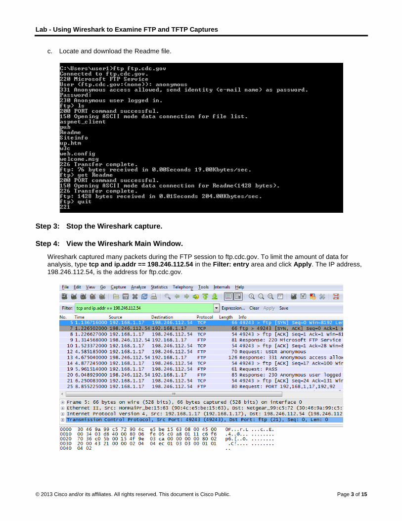
Lab - Using Wireshark to Examine FTP and TFTP Captures
© 2013 Cisco and/or its affiliates. All rights reserved. This document is Cisco Public. Page 3 of 15
c. Locate and download the Readme file.
Step 3: Stop the Wireshark capture.
Step 4: View the Wireshark Main Window.
Wireshark captured many packets during the FTP session to ftp.cdc.gov. To limit the amount of data for analysis, type tcp and ip.addr == 198.246.112.54 in the Filter: entry area and click Apply. The IP address, 198.246.112.54, is the address for ftp.cdc.gov.

Lab - Using Wireshark to Examine FTP and TFTP Captures
© 2013 Cisco and/or its affiliates. All rights reserved. This document is Cisco Public. Page 4 of 15
Step 5: Analyze the TCP fields.
After the TCP filter has been applied, the first three frames in the packet list pane (top section) displays the transport layer protocol TCP creating a reliable session. The sequence of [SYN], [SYN, ACK], and [ACK] illustrates the three-way handshake.
TCP is routinely used during a session to control datagram delivery, verify datagram arrival, and manage window size. For each data exchange between the FTP client and FTP server, a new TCP session is started. At the conclusion of the data transfer, the TCP session is closed. Finally, when the FTP session is finished, TCP performs an orderly shutdown and termination.
In Wireshark, detailed TCP information is available in the packet details pane (middle section). Highlight the first TCP datagram from the host computer, and expand the TCP record. The expanded TCP datagram appears similar to the packet detail pane shown below.
The image above is a TCP datagram diagram. An explanation of each field is provided for reference:

Lab - Using Wireshark to Examine FTP and TFTP Captures
© 2013 Cisco and/or its affiliates. All rights reserved. This document is Cisco Public. Page 5 of 15
The TCP source port number belongs to the TCP session host that opened a connection. The value is
normally a random value above 1,023.
The TCP destination port number is used to identify the upper layer protocol or application on the
remote site. The values in the range 0–1,023 represent the “well-known ports” and are associated with
popular services and applications (as described in RFC 1700, such as Telnet, FTP, HTTP, and so on).
The combination of the source IP address, source port, destination IP address, and destination port
uniquely identifies the session to both sender and receiver.
Note: In the Wireshark capture below, the destination port is 21, which is FTP. FTP servers listen on port 21 for FTP client connections.
The Sequence number specifies the number of the last octet in a segment.
The Acknowledgment number specifies the next octet expected by the receiver.
The Code bits have a special meaning in session management and in the treatment of segments.
Among interesting values are:
- ACK — Acknowledgement of a segment receipt.
- SYN — Synchronize, only set when a new TCP session is negotiated during the TCP three-way
handshake.
- FIN — Finish, request to close the TCP session.
The Window size is the value of the sliding window; determines how many octets can be sent before
waiting for an acknowledgement.
The Urgent pointer is only used with an Urgent (URG) flag when the sender needs to send urgent data
to the receiver.
The Options has only one option currently, and it is defined as the maximum TCP segment size (optional
value).
Using the Wireshark capture of the first TCP session startup (SYN bit set to 1), fill in information about the TCP header:
From the PC to CDC server (only the SYN bit is set to 1):
Source IP Address: 192.168.1.17*
Destination IP Address: 198.246.112.54
Source port number: 49243*
Destination port number: 21
Sequence number: 0 (relative)
Acknowledgement number: Not Applicable for this capture
Header length: 32 bytes
Window size: 8192
*Student answers will vary.
In the second Wireshark filtered capture, the CDC FTP server acknowledges the request from the PC. Note the values of the SYN and ACK bits.

Lab - Using Wireshark to Examine FTP and TFTP Captures
© 2013 Cisco and/or its affiliates. All rights reserved. This document is Cisco Public. Page 6 of 15
Fill in the following information regarding the SYN-ACK message.
Source IP address: 198.246.112.54
Destination IP address: 192.168.1.17*
Source port number: 21
Destination port number: 49243*
Sequence number: 0 (relative)
Acknowledgement number: 1
Header length: 32 bytes
Window size: 64240
*Student answers will vary.
In the final stage of the negotiation to establish communications, the PC sends an acknowledgement message to the server. Notice only the ACK bit is set to 1, and the Sequence number has been incremented to 1.
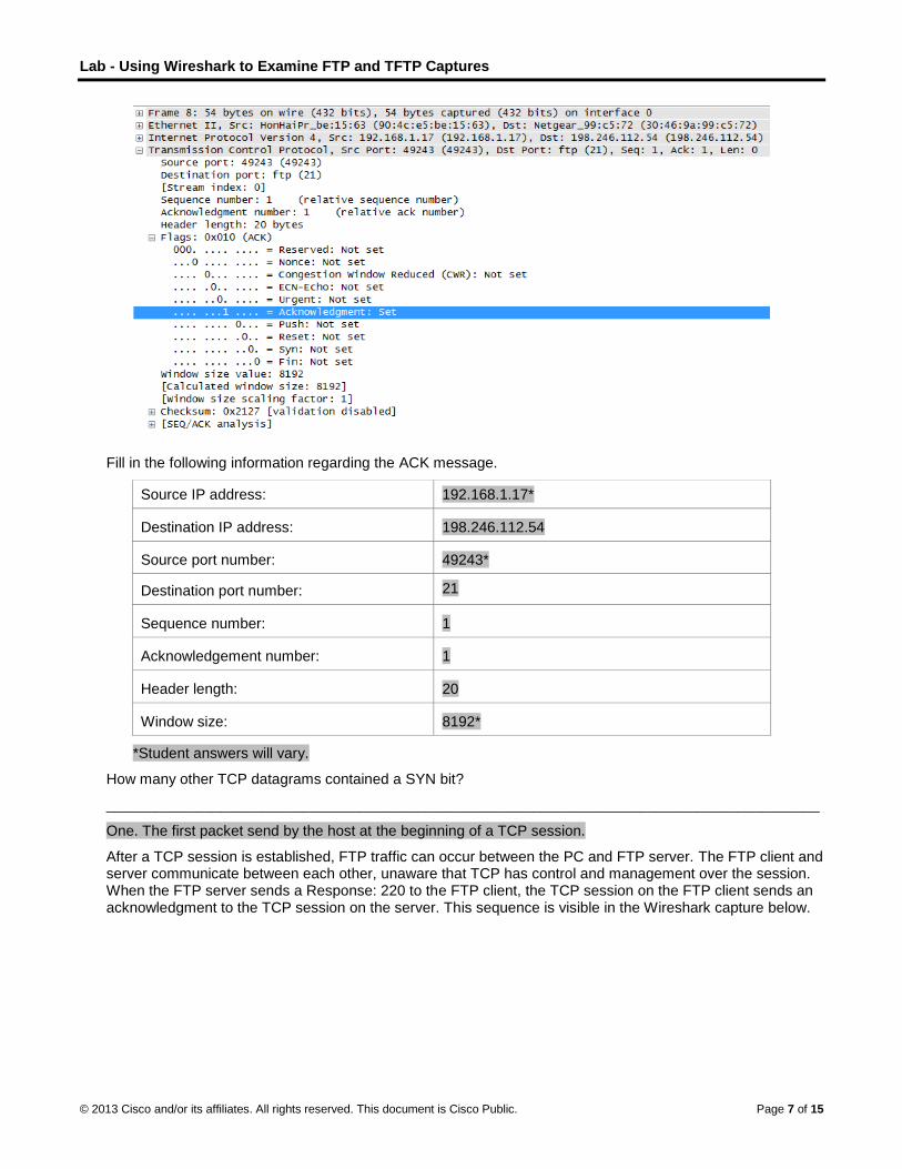
Lab - Using Wireshark to Examine FTP and TFTP Captures
© 2013 Cisco and/or its affiliates. All rights reserved. This document is Cisco Public. Page 7 of 15
Fill in the following information regarding the ACK message.
Source IP address: 192.168.1.17*
Destination IP address: 198.246.112.54
Source port number: 49243*
Destination port number: 21
Sequence number: 1
Acknowledgement number: 1
Header length: 20
Window size: 8192*
*Student answers will vary.
How many other TCP datagrams contained a SYN bit?
_______________________________________________________________________________________
One. The first packet send by the host at the beginning of a TCP session.
After a TCP session is established, FTP traffic can occur between the PC and FTP server. The FTP client and server communicate between each other, unaware that TCP has control and management over the session. When the FTP server sends a Response: 220 to the FTP client, the TCP session on the FTP client sends an acknowledgment to the TCP session on the server. This sequence is visible in the Wireshark capture below.
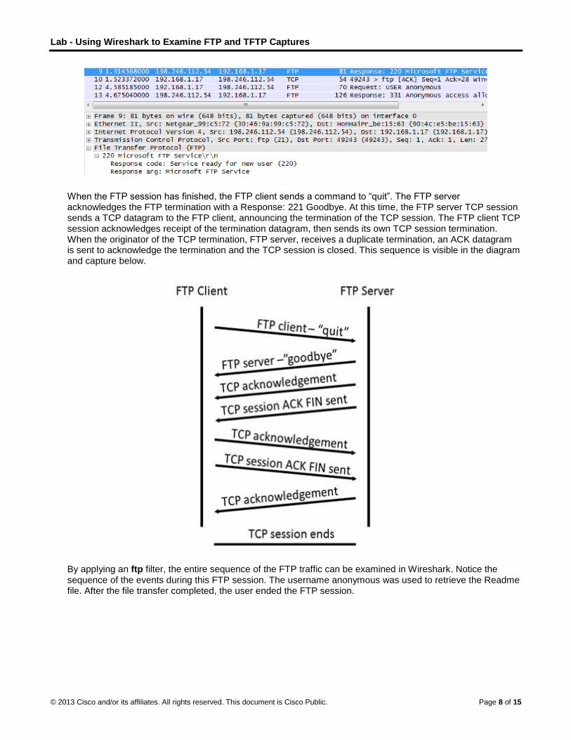
Lab - Using Wireshark to Examine FTP and TFTP Captures
© 2013 Cisco and/or its affiliates. All rights reserved. This document is Cisco Public. Page 8 of 15
When the FTP session has finished, the FTP client sends a command to “quit”. The FTP server acknowledges the FTP termination with a Response: 221 Goodbye. At this time, the FTP server TCP session sends a TCP datagram to the FTP client, announcing the termination of the TCP session. The FTP client TCP session acknowledges receipt of the termination datagram, then sends its own TCP session termination. When the originator of the TCP termination, FTP server, receives a duplicate termination, an ACK datagram is sent to acknowledge the termination and the TCP session is closed. This sequence is visible in the diagram and capture below.
By applying an ftp filter, the entire sequence of the FTP traffic can be examined in Wireshark. Notice the sequence of the events during this FTP session. The username anonymous was used to retrieve the Readme file. After the file transfer completed, the user ended the FTP session.
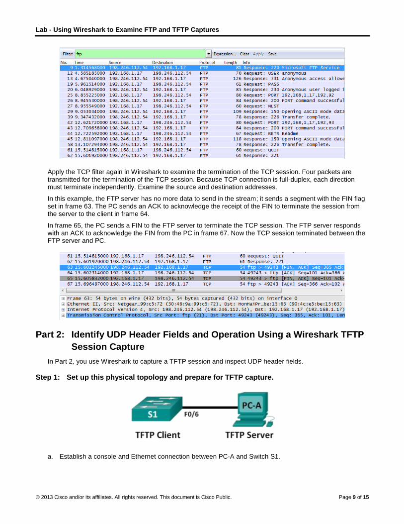
Lab - Using Wireshark to Examine FTP and TFTP Captures
© 2013 Cisco and/or its affiliates. All rights reserved. This document is Cisco Public. Page 9 of 15
Apply the TCP filter again in Wireshark to examine the termination of the TCP session. Four packets are transmitted for the termination of the TCP session. Because TCP connection is full-duplex, each direction must terminate independently. Examine the source and destination addresses.
In this example, the FTP server has no more data to send in the stream; it sends a segment with the FIN flag set in frame 63. The PC sends an ACK to acknowledge the receipt of the FIN to terminate the session from the server to the client in frame 64.
In frame 65, the PC sends a FIN to the FTP server to terminate the TCP session. The FTP server responds with an ACK to acknowledge the FIN from the PC in frame 67. Now the TCP session terminated between the FTP server and PC.
Part 2: Identify UDP Header Fields and Operation Using a Wireshark TFTP
Session Capture
In Part 2, you use Wireshark to capture a TFTP session and inspect UDP header fields.
Step 1: Set up this physical topology and prepare for TFTP capture.
a. Establish a console and Ethernet connection between PC-A and Switch S1.
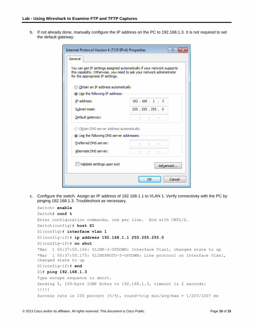
Lab - Using Wireshark to Examine FTP and TFTP Captures
© 2013 Cisco and/or its affiliates. All rights reserved. This document is Cisco Public. Page 10 of 15
b. If not already done, manually configure the IP address on the PC to 192.168.1.3. It is not required to set the default gateway.
c. Configure the switch. Assign an IP address of 192.168.1.1 to VLAN 1. Verify connectivity with the PC by pinging 192.168.1.3. Troubleshoot as necessary.
Switch> enable
Switch# conf t
Enter configuration commands, one per line. End with CNTL/Z.
Switch(config)# host S1
S1(config)# interface vlan 1
S1(config-if)# ip address 192.168.1.1 255.255.255.0
S1(config-if)# no shut
*Mar 1 00:37:50.166: %LINK-3-UPDOWN: Interface Vlan1, changed state to up
*Mar 1 00:37:50.175: %LINEPROTO-5-UPDOWN: Line protocol on Interface Vlan1,
changed state to up
S1(config-if)# end
S1# ping 192.168.1.3
Type escape sequence to abort.
Sending 5, 100-byte ICMP Echos to 192.168.1.3, timeout is 2 seconds:
!!!!!
Success rate is 100 percent (5/5), round-trip min/avg/max = 1/203/1007 ms

Lab - Using Wireshark to Examine FTP and TFTP Captures
© 2013 Cisco and/or its affiliates. All rights reserved. This document is Cisco Public. Page 11 of 15
d. Save the running configuration to NVRAM:
S1# copy run start
Step 2: Prepare the TFTP server on the PC.
a. If it does not already exist, create a folder on the PC desktop called TFTP. The files from the switch will be copied to this location.
b. Start tftpd32 on the PC.
c. Click Browse and change the current directory to C:\Users\user1\Desktop\TFTP by replacing user1 with your username.
The TFTP server should look like this:
Notice that in Current Directory, it lists the user and the Server (PC-A) interface as the IP address of 192.168.1.3.
d. Test the ability to copy a file using TFTP from the switch to the PC. Troubleshoot as necessary.
S1# copy start tftp
Address or name of remote host []? 192.168.1.3
Destination filename [s1-confg]?
!!
1638 bytes copied in 0.026 secs (63000 bytes/sec)
If you see that the file has copied (as in the above output), then you are ready to go on to the next step. If
not, then troubleshoot. If you get the %Error opening tftp (Permission denied) error, first
check to make sure your firewall is not blocking TFTP, and that you are copying to a location where your username has adequate permission, such as the desktop.

Lab - Using Wireshark to Examine FTP and TFTP Captures
© 2013 Cisco and/or its affiliates. All rights reserved. This document is Cisco Public. Page 12 of 15
Step 3: Capture a TFTP session in Wireshark
a. Open Wireshark. From the Edit menu, choose Preferences and click the (+) sign to expand Protocols. Scroll down and select UDP. Click the Validate the UDP checksum if possible check box and click Apply. Then click OK.
Instructor Note: This is a change from previous versions of this lab because the technology has changed. Search for “checksum offloading in Wireshark”.
b. Start a Wireshark capture.
c. Run the copy start tftp command on the switch.
d. Stop the Wireshark capture.
e. Set the filter to tftp. Your output should look similar to the output shown above. This TFTP transfer is used to analyze transport layer UDP operations.
Instructor Note: If students point out UDP acknowledgements, explain that the UDP header does not contain an acknowledgement field. Instead, it is the responsibility of the upper-layer protocol, in this case TFTP, to manage data transfer and receipt information. This will be shown during the UDP datagram examination.
In Wireshark, detailed UDP information is available in the Wireshark packet details pane. Highlight the first UDP datagram from the host computer, and move the mouse pointer to the packet details pane. It may be necessary to adjust the packet details pane and expand the UDP record by clicking the protocol expand box. The expanded UDP datagram should look similar to the diagram below.

Lab - Using Wireshark to Examine FTP and TFTP Captures
© 2013 Cisco and/or its affiliates. All rights reserved. This document is Cisco Public. Page 13 of 15
The figure below is a UDP datagram diagram. Header information is sparse, compared to the TCP datagram. Similar to TCP, each UDP datagram is identified by the UDP source port and UDP destination port.
Using the Wireshark capture of the first UDP datagram, fill in information about the UDP header. The checksum value is a hexadecimal (base 16) value, denoted by the preceding 0x code:
Source IP Address: 192.168.1.1
Destination IP Address: 192.168.1.3
Source Port Number: 62513*
Destination Port Number: 69
UDP Message Length: 25 bytes*
UDP Checksum: 0x482c [correct]*
*Student answer will vary.
How does UDP verify datagram integrity?
____________________________________________________________________________________
____________________________________________________________________________________
A checksum is sent in the UDP datagram, and the datagram checksum value is recomputed upon receipt. If the computed checksum is identical to the sent checksum, then the UDP datagram is assumed to be complete.
Examine the first frame returned from tftpd server. Fill in the information about the UDP header:
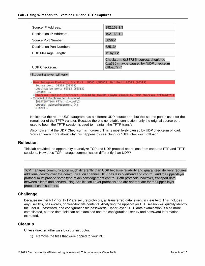
Lab - Using Wireshark to Examine FTP and TFTP Captures
© 2013 Cisco and/or its affiliates. All rights reserved. This document is Cisco Public. Page 14 of 15
Source IP Address: 192.168.1.3
Destination IP Address: 192.168.1.1
Source Port Number: 58565*
Destination Port Number: 62513*
UDP Message Length: 12 bytes*
UDP Checksum:
Checksum: 0x8372 [incorrect, should be 0xa385 (maybe caused by "UDP checksum offload"?)]*
*Student answer will vary.
Notice that the return UDP datagram has a different UDP source port, but this source port is used for the remainder of the TFTP transfer. Because there is no reliable connection, only the original source port used to begin the TFTP session is used to maintain the TFTP transfer.
Also notice that the UDP Checksum is incorrect. This is most likely caused by UDP checksum offload. You can learn more about why this happens by searching for “UDP checksum offload”.
Reflection
This lab provided the opportunity to analyze TCP and UDP protocol operations from captured FTP and TFTP sessions. How does TCP manage communication differently than UDP?
_______________________________________________________________________________________
_______________________________________________________________________________________
TCP manages communication much differently than UDP because reliability and guaranteed delivery requires additional control over the communication channel. UDP has less overhead and control, and the upper-layer protocol must provide some type of acknowledgement control. Both protocols, however, transport data between clients and servers using Application Layer protocols and are appropriate for the upper-layer protocol each supports.
Challenge
Because neither FTP nor TFTP are secure protocols, all transferred data is sent in clear text. This includes any user IDs, passwords, or clear-text file contents. Analyzing the upper-layer FTP session will quickly identify the user ID, password, and configuration file passwords. Upper-layer TFTP data examination is a bit more complicated, but the data field can be examined and the configuration user ID and password information extracted.
Cleanup
Unless directed otherwise by your instructor:
1) Remove the files that were copied to your PC.

Lab - Using Wireshark to Examine FTP and TFTP Captures
© 2013 Cisco and/or its affiliates. All rights reserved. This document is Cisco Public. Page 15 of 15
2) Erase the configurations on switch S1.
3) Remove the manual IP address from the PC and restore Internet connectivity.
Device Configs
Switch S1
S1#show run
Building configuration...
!
hostname S1
!
!
interface Vlan1
ip address 192.168.1.1 255.255.255.0
!
!
end

© 2013 Cisco and/or its affiliates. All rights reserved. This document is Cisco Public. Page 1 of 2
We Need to Talk, Again (Instructor Version) Instructor Note: Red font color or Gray highlights indicate text that appears in the instructor copy only.
Objectives
Explain how transport layer protocols and services support communications across data networks.
In this activity, given a scenario, you will determine whether high-reliability messaging should be used. You will focus on whether the final message is complete, correct, and delivered in a timely manner
Background/Scenario
Note: It is important that the students have completed the Introductory MA for this chapter. This activity works best in medium-sized groups of 6 to 8 students.
Your instructor will whisper a complex message to the first student in a group. An example of the message might be “We are expecting a blizzard tomorrow. It should be arriving in the morning and school will be delayed 2 two hours so bring your homework.”
That student whispers the message to the next student in the group. Each group follows this process until all members of each group have heard the whispered message.
Here are the rules to follow:
You can whisper the message in short parts to your neighbor AND you can repeat the message parts after verifying your neighbor heard the correct message.
Small parts of the message may be checked and repeated again (clockwise OR counter-clockwise to ensure accuracy of the message parts) by whispering. A student will be assigned to time the entire activity.
When the message has reached the end of the group, the last student will say aloud what was heard. Small parts of the message may be repeated (i.e., re-sent), and the process can be restarted to ensure that ALL parts of the message are fully delivered and correct.
Your instructor will repeat the original message to check for quality delivery.
Instructor Note: Please initiate discussion about what happened in the Activity. Focus on these three questions:
1. Was the message complete when it reached the last student?
2. Was the message correct as delivered to the last person?
3. Did it take very long for the message to get to the last student?
If you were depending on this message to drive your personal/business calendar, studying schedule, etc., would the contents of this message need to be clear and correct when you received them?
Would the length of time taken to deliver the message be important to the sender and recipient?
Compare the Introductory MA of this chapter to the Review MA (this activity). What differences do you notice about the delivery of the message?
Please remind students that TCP and UDP protocols ensure that:
Network communications with different levels of importance are sent and received according to their levels of importance.
The type of data will affect whether TCP or UDP will be used as the method of delivery.
The time in which the message must be delivered will affect whether TCP or UDP will be used as the method of delivery.
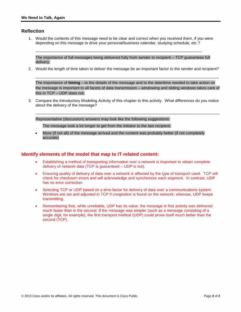
We Need to Talk, Again
© 2013 Cisco and/or its affiliates. All rights reserved. This document is Cisco Public. Page 2 of 2
Reflection
1. Would the contents of this message need to be clear and correct when you received them, if you were depending on this message to drive your personal/business calendar, studying schedule, etc.?
____________________________________________________________________________
The importance of full messages being delivered fully from sender to recipient – TCP guarantees full delivery.
2. Would the length of time taken to deliver the message be an important factor to the sender and recipient?
____________________________________________________________________________
The importance of timing – to the details of the message and to the date/time needed to take action on
the message is important to all facets of data transmission – windowing and sliding windows takes care of
this in TCP – UDP does not.
3. Compare the Introductory Modeling Activity of this chapter to this activity. What differences do you notice about the delivery of the message?
____________________________________________________________________________________
Representative (discussion) answers may look like the following suggestions:
The message took a lot longer to get from the initiator to the last recipient.
More (if not all) of the message arrived and the content was probably better (if not completely accurate)
Identify elements of the model that map to IT-related content:
Establishing a method of transporting information over a network is important to obtain complete delivery of network data (TCP is guaranteed – UDP is not).
Ensuring quality of delivery of data over a network is affected by the type of transport used. TCP will check for checksum errors and will acknowledge and synchronize each segment. In contrast, UDP has no error correction.
Selecting TCP or UDP based on a time-factor for delivery of data over a communications system. Windows are set and adjusted in TCP if congestion is found on the network; whereas, UDP keeps transmitting.
Remembering that, while unreliable, UDP has its value: the message in first activity was delivered much faster than in the second. If the message was simpler (such as a message consisting of a single digit, for example), the first transport method (UDP) could prove itself much better than the second (TCP).

© 2013 Cisco and/or its affiliates. All rights reserved. This document is Cisco Public. Page 1 of 2
The road less traveled…or is it? (Instructor Version) Instructor Note: Red font color or Gray highlights indicate text that appears in the instructor copy only.
Objectives
Explain how network devices use routing tables to direct packets to a destination network.
In this activity, you will visualize how a hop-by-hop routing paradigm, with correct path selection at each hop, results in a successful delivery of packets. You will recognize that each router on the path must have correct knowledge about the destination network, and that path towards that network, to deliver packets over the shortest path.
Background/Scenario
During the upcoming weekend, you decide to visit a schoolmate who is currently at home sick. You know his street address but you have never been to his town before. Instead of looking up the address on the map, you decide to take it easy and to simply ask town residents for directions after you arrive by train.
The citizens you ask for directions are very helpful. However, they all have an interesting habit. Instead of explaining the entire route to your destination, they all tell you, “Take this road and as soon as you arrive at the nearest crossroad, ask somebody there again.” Somewhat bemused at this apparent oddity, you follow these instructions and finally arrive, crossroad by crossroad, and road by road, at your friend’s house.
Answer the following questions:
1. Would it have made a significant difference if you were told about the whole route or a larger part of the route instead of just being directed to the nearest crossroad?
2. Would it have been more helpful to ask about the specific street address or just about the street name? What would happen if the person you asked for directions did not know where the destination street was or directed you through an incorrect road?
3. Assuming that on your way back home, you again choose to ask residents for directions. Would it be guaranteed that you would be directed via the same route you took to get to your friend’s home? Explain your answer.
4. Is it necessary to explain where you depart from when asking directions to an intended destination?
Instructor Note: This Modeling Activity is not intended to be a graded assignment. Its purpose is to encourage students to reflect on their perceptions of how a network uses pathways to send and receive data communications. Facilitation of the discussion should be initiated as a result of this activity.
Reflection
1. Would it have made a significant difference if you were told about the whole route or a larger part of the route instead of just being directed to the nearest crossroad?
____________________________________________________________________________________
It would not really make a difference. The key fact to remember here is that to reach any part of the route behind the nearest crossroad, we must first reach that crossroad. If residents at each crossroad can be assumed to know their town well, it is not really helpful to ask about what is beyond the first crossroad as we must still reach it, and on each crossroad, we will be directed appropriately. Please make the students aware, however, that congestion can also affect whether an route is better than another to use..
2. Would it have been more helpful to ask about the specific street address or just about the street name?

The road less traveled…or is it?
© 2013 Cisco and/or its affiliates. All rights reserved. This document is Cisco Public. Page 2 of 2
____________________________________________________________________________________
Asking about the street name, omitting the house number, is sufficient. Once we get to the destination street, we can easily look up the house ourselves. People at crossroads will be able to direct us even without telling them the exact house number. They do not need to know each and every house in every street – it is sufficient they know the streets themselves.
3. What would happen if the person you asked for directions did not know where the destination street was or directed you through an incorrect road?
____________________________________________________________________________________
In that case, we would be in risk of getting either misrouted and following a longer route to the destination than necessary, or we may even end up going in circles or getting lost.
4. Assuming that on your way back home, you again choose to ask residents for directions. Is it guaranteed that you will be directed via the same route you took to get to your friend’s home? Explain your answer.
____________________________________________________________________________________
There is no such guarantee. Each person at a crossroad makes an individual and independent choice about the best path. It is quite possible that if the residents do not have the same knowledge or ideas about the routes within their town, you would be going back to the train station via a different route.
5. Is it necessary to explain where you depart from when asking directions to an intended destination?
____________________________________________________________________________________
Describing where you departed from is not helpful when choosing path towards a destination. It is only the destination itself that matters when selecting the best route towards it.
Identify elements of the model that map to IT-related content:
Crossroads – Correspond to stops along the way (routers)
Roads – Correspond to interface links between routers
Street – Corresponds to a network
Irrelevancy of house number when asking for the path to the destination street – Corresponds to routers knowing about networks, not about individual hosts
Asking about the path to destination at each crossroad – Corresponds to path selection performed on each router
Train station, friend’s house – Corresponds to source and destination
Relevancy of only the destination when asking for a path – Corresponds to destination-based routing
Different possible paths to and from the friend – Correspond to independent routing to and from a destination

©
LI
T
O
B
R
P
S
S
© 2013 Cisco and
Lab - Vienstructor No
Topology
ObjectivesPart 1: Ac
Part 2: Ex
Part 3: Ex
BackgrounTo accesstable. Thecomplex. destinatioroute prin
In this lab–r and rodestinatio
Note: This
Required R 1 PC
Part 1: A
Step 1: Re
On your Pinformatio
Step 2: Dis
In a comm
d/or its affiliates.
ewing Hote: Red font
ccess the Ho
xamine IPv4
xamine IPv6
nd / Scenars a resource oe host routingFor a packet
on, both the lont commands
b, you will dispute print com
on address.
s lab cannot b
Resources (Windows 7,
Access th
ecord your P
PC, open a coon and record
IPv4 Add
MAC Add
Default G
splay the ro
mand prompt
All rights reserve
Host Roucolor or Gray
ost Routing T
Host Routin
Host Routin
rio on a network,table is similto reach a loc
ocal host routis provide insig
play and exammmands. You
be completed
Vista, or XP w
he Host R
PC informat
ommand prom it:
dress
dress
Gateway
outing table
window type
ed. This docume
uting Tay highlights ind
Table
ng Table Entr
ng Table Entr
, your host wiar to that of acal destinationg table and ght into how y
mine the inforwill determin
d using Netlab
with Internet a
Routing T
tion.
mpt window a
Answers will
Answers will
Answers will
s.
the netstat –
ent is Cisco Publi
bles (Insdicate text tha
ries
ries
ll determine ta router, but ison, the local h
the router rouyour local hos
rmation in the ne how packe
b. This lab ass
and comman
able
nd type the ip
l vary. In this
l vary. In this
l vary. In this
–r (or route p
ic.
structor Vat appears in
the route to ths specific to thost routing tauting table arest routes pack
host routing ts will be rout
sumes that yo
d prompt acc
pconfig /all c
example, 192
example, 90:
example, 192
rint) comman
Version)the instructo
he destinationhe local host
able is requiree required. Thkets to the de
table of your ted by your P
ou have Inter
cess)
command to d
2.168.1.11
:4C:E5:BE:15
2.168.1.1
nd to display
r copy only.
n host using itand much les
ed. To reach ahe netstat –r
estination.
PC using thePC depending
rnet access.
display the fol
5:63
the host routi
Page 1 of 6
ts routing ss a remote r and
e netstat on the
llowing
ing table.

L
©
S
Lab - Viewing
© 2013 Cisco and
What are
________
The outpu
Step 3: Ex
The first snumber o
g Host Routi
d/or its affiliates.
the three sec
___________
ut has three s
amine the I
section, Interfaf every netwo
ng Tables
All rights reserve
ctions displaye
____________
sections: Inter
nterface Lis
ace List, dispork-capable in
ed. This docume
ed in the outp
___________
rface List, IPv
st.
plays the Mednterface on th
ent is Cisco Publi
put?
___________
v4 Route Tabl
ia Access Coe host.
ic.
____________
le, and IPv6 R
ontrol (MAC) a
____________
Route Table.
addresses an
___________
nd assigned in
Page 2 of 6
________
nterface
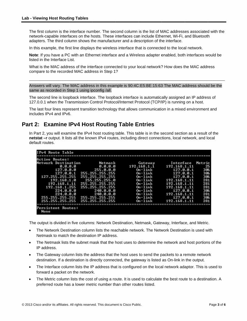
L
©
P
Lab - Viewing
© 2013 Cisco and
The first cnetwork-cadapters.
In this exa
Note: If yolisted in th
What is thcompare t
________
Answers wsame as r
The secon127.0.0.1
The last foincludes I
Part 2: EIn Part 2, netstat –rdefault ro
The outpu
The N
Netm
The N
IP add
The G
destin
The In
forwa
The M
prefer
g Host Routi
d/or its affiliates.
column is the capable interfa
The third col
ample, the firs
ou have a PChe Interface L
he MAC addreto the recorde
___________
will vary. The recorded in S
nd line is loopwhen the Tra
our lines reprPv4 and IPv6
Examine Iyou will examr output. It listutes.
ut is divided in
Network Desti
ask to match
Netmask lists
dress.
Gateway colum
nation. If a de
nterface colum
rd a packet o
Metric column
rred route has
ng Tables
All rights reserve
interface numaces on the humn shows th
st line display
C with an EtheList.
ess of the inteed MAC addr
____________
MAC addrestep 1 using ip
pback interfacansmission C
esent transitio6.
IPv4 Hosmine the IPv4 ts all the know
n five columns
nation colum
the destinatio
the subnet m
mn lists the a
stination is di
mn lists the IP
on the network
lists the cost
s a lower met
ed. This docume
mber. The sechosts. These ihe manufactu
ys the wireless
ernet interface
erface connecess in Step 1
___________
ss in this exampconfig /all.
ce. The loopbControl Protoc
on technology
t Routinghost routing
wn IPv4 route
s: Network De
n lists the rea
on IP address
mask that the h
address that th
rectly connec
P address tha
k.
t of using a ro
tric number th
ent is Cisco Publi
cond column interfaces canurer and a des
s interface tha
e and a Wirel
cted to your lo?
___________
mple is 90:4C
ack interface ol/Internet Pr
y that allows
g Table Etable. This ta
es, including d
estination, Ne
achable netwo
s.
host uses to d
he host uses
cted, the gate
at is configure
oute. It is used
han other rout
ic.
is the list of Mn include Ethescription of th
at is connecte
ess adapter e
ocal network?
____________
C:E5:BE:15:63
is automaticarotocol (TCP/I
communicatio
Entries ble is in the sdirect connec
etmask, Gate
ork. The Netw
determine the
to send the p
eway is listed
ed on the loca
d to calculate
tes listed.
MAC addresseernet, Wi-Fi, a
he interface.
ed to the loca
enabled, both
? How does th
____________
3 The MAC ad
ally assignedIP) is running
on in a mixed
second sectioctions, local ne
eway, Interfac
work Destinat
e network and
packets to a re
as On-link in
al network ada
e the best rout
es associatedand Bluetooth
al network.
h interfaces w
he MAC addr
___________
ddress should
an IP addresg on a host.
d environment
on as a result etwork, and lo
ce, and Metric
tion is used w
d host portion
emote netwo
the output.
aptor. This is
te to a destina
Page 3 of 6
d with the h
would be
ress
________
d be the
ss of
t and
of the ocal
c.
with
s of the
rk
used to
ation. A

Lab - Viewing Host Routing Tables
© 2013 Cisco and/or its affiliates. All rights reserved. This document is Cisco Public. Page 4 of 6
The output displays five different types of active routes:
The local default route 0.0.0.0 is used when the packet does not match other specified addresses in the
routing table. The packet will be sent to the gateway from the PC for further processing. In this example,
the packet will be sent to 192.168.1.1 from 192.168.1.11.
The loopback addresses, 127.0.0.0 – 127.255.255.255, are related to direct connection and provide
services to the local host.
The addresses for the subnet, 192.168.1.0 – 192.168.1.255, are all related to the host and the local
network. If the final destination of the packet is in the local network, the packet will exit 192.168.1.11
interface.
- The local route address 192.168.1.0 represents all devices on the 192.168.1.0/24 network.
- The address of the local host is 192.168.1.11.
- The network broadcast address 192.168.1.255 is used to send messages to all the hosts on the local
network.
The special multicast class D addresses 224.0.0.0 are reserved for use through either the loopback
interface (127.0.0.1) or the host (192.168.1.11).
The local broadcast address 255.255.255.255 can be used through either the loopback interface
(127.0.0.1) or host (192.168.1.11).
Based on the contents of the IPv4 routing table, if the PC wanted to send a packet to 192.168.1.15, what would it do and where would it send the packet?
_______________________________________________________________________________________
_______________________________________________________________________________________
_______________________________________________________________________________________
_______________________________________________________________________________________
The PC would consult the IPv4 Route Table and match the destination IP address with the 192.168.1.0 Network Destination entry to reveal that the host is on the same network (On-link). The PC would then send the packet toward the final destination using its local interface (192.168.1.11).
If the PC wanted to send a packet to a remote host located at 172.16.20.23, what would it do and where would it send the packet?
_______________________________________________________________________________________
_______________________________________________________________________________________
_______________________________________________________________________________________
_______________________________________________________________________________________
_______________________________________________________________________________________
The PC would consult the IPv4 Route Table and find that there is no exact match for the destination IP address. It would then choose the local default route (network 0.0.0.0, netmask 0.0.0.0) to reveal that it should forward the packet to the 192.168.1.1 gateway address (address of a gateway device such as a router interface on the local network). The PC would then forward the packet to the gateway using its local interface (192.168.1.11). The gateway device will then determine the next path for the packet to take in order to reach the final destination address of 172.16.20.23.
Part 3: Examine IPv6 Host Routing Table Entries In Part 3, you will examine the IPv6 routing table. This table is in the third section displayed in the netstat –r output. It lists all the known IPv6 routes including direct connections, local network, and local default routes.

L
©
Lab - Viewing
© 2013 Cisco and
The outpu128 bits v
The If
sectio
The M
the m
The N
The G
addre
In this exareveal the
::/0: T
addre
::1/12
2001:
2001:
fe80::
netwo
fe80::
ff00::/
addre
The host for IPv4 a
________
IPv4 is 0.0
What is th________
IPv4 is 12
How man
________
g Host Routi
d/or its affiliates.
ut of the IPv6 versus only 32
f column lists
on of the netsMetric column
metric is used t
Network Desti
Gateway lists
ess if it is direc
ample, the fige following ne
This is the IPv
ess of the defa
28: This is equ
:/32: This is t
0:9d38:6ab8
/64: This is th
ork.
1863:3bca:3f
/8: These are
esses.
routing table nd what is it f
___________
0.0.0 0.0.0.0
he loopback a___________
27.0.0.1 0.0.0
y IPv6 addres
___________
ng Tables
All rights reserve
Route Table 2 bits for IPv4
the interface
stat –r comma
lists the cost
to select betw
nation colum
the next-hop
ctly connecte
ure displays ttwork destina
v6 equivalent
ault router.
uivalent to the
the global unic
:1863:3bca:3f
he local link n
f57:fef4/128: T
special reser
for IPv6 has sfor IPv6?
____________
(quad zero) a
address and s____________
.0 0.0.0.0 and
sses have be
____________
ed. This docume
differs in colu4 addresses. T
numbers of t
and.
t of each route
ween multiple
n lists the add
IPv6 address
d to the host.
the IPv6 Rouations:
of the local de
e IPv4 loopba
cast network
f57:fef4/128:
etwork route
This is the lin
rved multicas
similar inform
___________
and IPv6 is ::/
subnet mask f___________
d IPv6 is ::1/1
en assigned
___________
ent is Cisco Publi
umn headingsThe IPv6 Rou
the IPv6-enab
e to a destina
routes with t
dress prefix fo
s to reach the
te Table sect
efault route. T
ack address a
prefix.
This is the glo
address and
k-local IPv6 a
t class D add
mation as the I
___________
0.
for IPv4? Wha___________
28.
to this PC?
___________
ic.
s and format ute Table sec
bled network
ation. The low
he same pref
or the route.
e destination.
tion generated
The Gateway
and provides s
obal unicast I
represents a
address of the
dresses equiv
IPv4 routing t
____________
at is the loopb____________
____________
because the ction displays
interfaces fro
wer cost is the
fix.
On-link is list
d by the nets
y column prov
services to th
IPv6 address
all computers
e local compu
valent to the IP
table. What is
____________
back IP addre____________
____________
IPv6 addressfour columns
om the Interfa
e preferred ro
ted as the nex
stat –r comm
vides the link-
e local host.
s of the local c
on the local-l
uter.
Pv4 224.x.x.x
s the local def
___________
ess for IPv6?___________
___________
Page 5 of 6
ses are s:
ce List
ute, and
xt-hop
mand to
local
computer.
ink IPv6
x
fault route
________
________
________

Lab - Viewing Host Routing Tables
© 2013 Cisco and/or its affiliates. All rights reserved. This document is Cisco Public. Page 6 of 6
There are two IP addresses. The link-local address and the global unicast address.
How many broadcast addresses does the IPv6 routing table contain?
_______________________________________________________________________________________
None, IPv6 does not use broadcast addresses.
Reflection 1. How is the number of bits for the network indicated for IPv4. How is it done for IPv6?
______________________________________________________________________________________
IPv4 uses a 32-bit dotted decimal subnet mask in the form of a.b.c.d. IPv6 uses a slash number.
2. Why is there both IPv4 and IPv6 information in the host routing tables?
______________________________________________________________________________________
Modern day PCs run both protocols and ISPs frequently assign both IPV4 and IPv6 addresses to support access to servers on the Internet that are running either protocol.
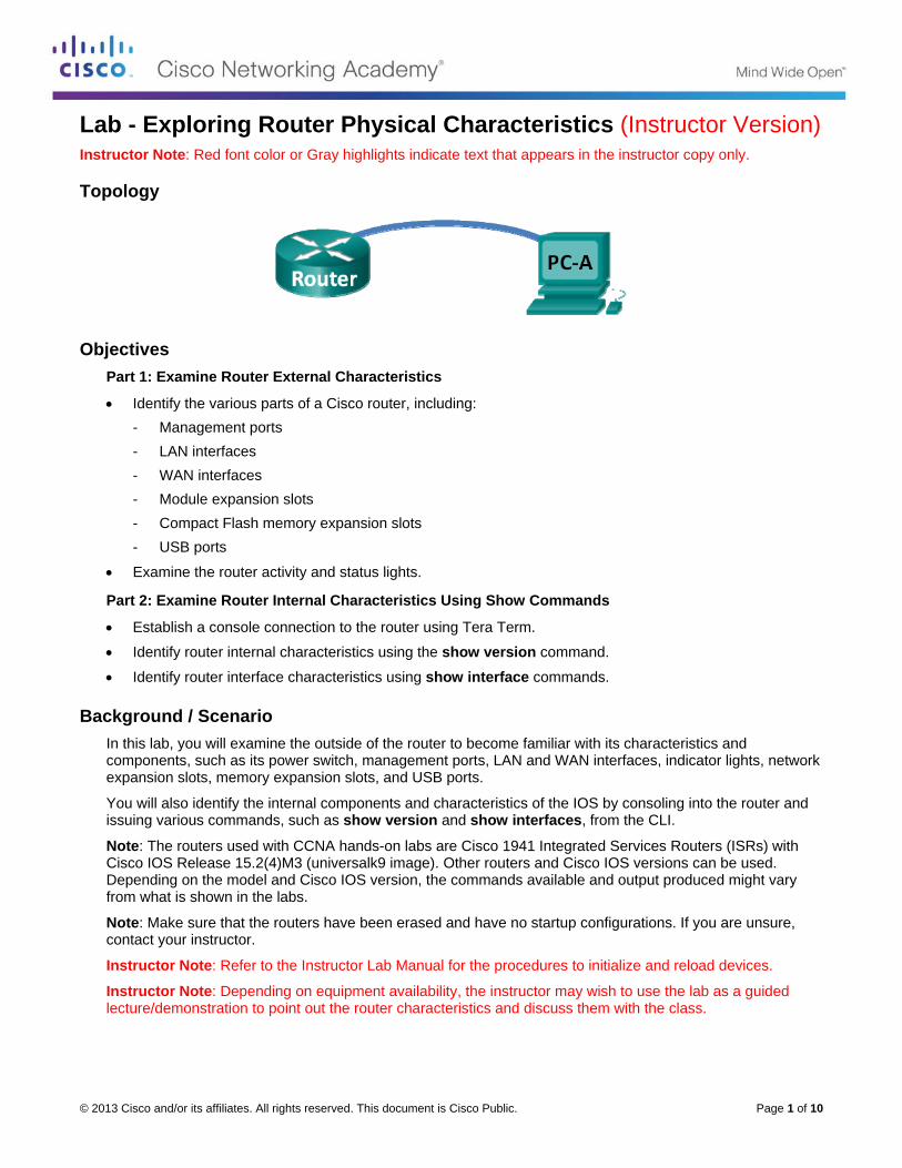
© 2013 Cisco and/or its affiliates. All rights reserved. This document is Cisco Public. Page 1 of 10
Lab - Exploring Router Physical Characteristics (Instructor Version) Instructor Note: Red font color or Gray highlights indicate text that appears in the instructor copy only.
Topology
Objectives Part 1: Examine Router External Characteristics
Identify the various parts of a Cisco router, including:
- Management ports
- LAN interfaces
- WAN interfaces
- Module expansion slots
- Compact Flash memory expansion slots
- USB ports
Examine the router activity and status lights.
Part 2: Examine Router Internal Characteristics Using Show Commands
Establish a console connection to the router using Tera Term.
Identify router internal characteristics using the show version command.
Identify router interface characteristics using show interface commands.
Background / Scenario In this lab, you will examine the outside of the router to become familiar with its characteristics and components, such as its power switch, management ports, LAN and WAN interfaces, indicator lights, network expansion slots, memory expansion slots, and USB ports.
You will also identify the internal components and characteristics of the IOS by consoling into the router and issuing various commands, such as show version and show interfaces, from the CLI.
Note: The routers used with CCNA hands-on labs are Cisco 1941 Integrated Services Routers (ISRs) with Cisco IOS Release 15.2(4)M3 (universalk9 image). Other routers and Cisco IOS versions can be used. Depending on the model and Cisco IOS version, the commands available and output produced might vary from what is shown in the labs.
Note: Make sure that the routers have been erased and have no startup configurations. If you are unsure, contact your instructor.
Instructor Note: Refer to the Instructor Lab Manual for the procedures to initialize and reload devices.
Instructor Note: Depending on equipment availability, the instructor may wish to use the lab as a guided lecture/demonstration to point out the router characteristics and discuss them with the class.

Lab - Exploring Router Physical Characteristics
© 2013 Cisco and/or its affiliates. All rights reserved. This document is Cisco Public. Page 2 of 10
Required Resources 1 Router (Cisco 1941 with Cisco IOS Release 15.2(4)M3 universal image or comparable)
1 PC (Windows 7, Vista, or XP with terminal emulation program, such as Tera Term)
Console cables to configure the Cisco IOS devices via the console ports
Part 1: Examine Router External Characteristics Use the images below, as well as your own direct inspection of the backplane of a Cisco router, to answer the following questions. Feel free to draw arrows and circle the areas of the image that correctly identify the parts.
Note: The router depicted in the images below is a Cisco 1941 router, which may be different from the make and model of the routers in your particular academy. You can find device information and specifications for the Cisco 1941 series routers at the Cisco.com website. Additional information, including answers to many of the questions below can be found here:
http://www.cisco.com/en/US/prod/collateral/routers/ps10538/data_sheet_c78_556319.html
Step 1: Identify the various parts of a Cisco router.
The image shown in this step is of the backplane of a Cisco 1941 ISR. Use it to answer the questions in this step. In addition, if you are examining a different model router, a space has been provided here for you to draw the backplane and identify components and interfaces as specified in the questions that follow.

Lab - Exploring Router Physical Characteristics
© 2013 Cisco and/or its affiliates. All rights reserved. This document is Cisco Public. Page 3 of 10
a. Circle and label the router’s power switch. Is the power switch on your router in the same area as the router depicted in the image?
____________________________________________________________________________________
Answers may vary depending on the academy’s lab routers. Students should draw a line around the on/off switch in the image
b. Circle and label the management ports. What are the built-in management ports? Are the management ports the same on your router? If not, how are they different?
____________________________________________________________________________________
Answers may vary depending on the academy’s lab routers. Students should draw a circle around the console port, auxiliary port, and mini USB console port in the image.
c. Circle and label the router’s LAN interfaces. How many LAN interfaces does the router in the image have and what is the interface technology type? Are the LAN interfaces the same on your router? If not, how are they different?
____________________________________________________________________________________
Answers may vary depending on the academy’s lab routers. Students should draw a circle around the Gigabit Ethernet 0/0 and 0/1 interfaces in the image.
d. Circle and label the router’s WAN interfaces. How many WAN interfaces does the router in the image have and what is the interface technology type? Are the WAN interfaces the same on your router? If not, how are they different?
____________________________________________________________________________________
Answers may vary depending on the academy’s lab routers. Students should draw a circle around the Serial 0 and Serial 1 interfaces in the image.
e. The Cisco 1941 ISR is a modular platform and comes with module expansion slots for varied network connectivity requirements. Circle and label the module slots. How many module slots are there? How many are used? What type of module expansion slots are they? Are the module slots the same on your router? If not, how are they different?
____________________________________________________________________________________
Answers may vary depending on the academy’s lab routers. The image depicts a Cisco 1941 ISR with two module expansion slots for Enhanced High-Speed WAN interface cards, EHWIC 0 and EHWIC 1. EHWIC 0 is occupied by a Smart Serial WAN interface card. EHWIC1 will accept a double wide expansion card. The EHWIC slot replaces the high-speed WAN interface card (HWIC) slot and can

Lab - Exploring Router Physical Characteristics
© 2013 Cisco and/or its affiliates. All rights reserved. This document is Cisco Public. Page 4 of 10
natively support HWICs, WAN interface cards (WICs), voice interface cards (VICs), and voice/WAN interface cards (VWICs).
f. The Cisco 1941 router comes with CompactFlash memory slots for high speed storage. Circle and label the CompactFlash memory slots. How many memory slots are there? How many are used? How much memory can they hold? Are the memory slots the same on your router? If not, how are they different?
____________________________________________________________________________________
Answers may vary depending on the academy’s lab routers. The image depicts a Cisco 1941 ISR with two CompactFlash memory slots, CF0 and CF1. CF0 is occupied by a 256 MB CompactFlash memory card used to store the Cisco IOS system image file.
g. The Cisco 1941 router comes with USB 2.0 ports. The built-in USB ports support eToken devices and USB flash memory. The USB eToken device feature provides device authentication and secure configuration of Cisco routers. The USB flash feature provides optional secondary storage capability and an additional boot device. Circle and label the USB ports. How many USB ports are there? Are there USB ports on your router?
____________________________________________________________________________________
Answers may vary depending on the academy’s lab routers. The image depicts a Cisco 1941 ISR with two USB 2.0 ports.
h. The Cisco 1941 router also comes with a mini-B USB console port. Circle and label the mini-B USB console port.
____________________________________________________________________________________
Answers may vary depending on the academy’s lab routers. The image depicts a Cisco 1941 ISR with a mini USB console port next to the regular console port.
Step 2: Examine the router activity and status lights.
The following images highlight the activity and status lights of the front panel and backplane of a powered up and connected Cisco 1941 ISR.
Note: Some of the indicator lights are obscured from view in the image of the backplane of the Cisco 1941 router below.

Lab - Exploring Router Physical Characteristics
© 2013 Cisco and/or its affiliates. All rights reserved. This document is Cisco Public. Page 5 of 10
a. In the top image above, examine the indicator lights on the front panel of the router? The lights are labeled SYS, ACT, and POE. What do the labels refer to? What do the lights in the image indicate about the status of the router? These labels would be readable if they were not lit.
____________________________________________________________________________________
____________________________________________________________________________________
____________________________________________________________________________________
The SYS, ACT, and POE lights refer to: system status, network activity, and power over Ethernet. The lights in the image show that the router’s system is successfully powered on, that there is network activity, and that Power over Ethernet is not activated.
b. In the backplane image above, examine the indicator lights on the router. There are three visible activity lights, one for each of the connected interfaces and management ports. Examine the interface lights on your router. How are the lights labeled, and what is their meaning?
____________________________________________________________________________________
____________________________________________________________________________________
____________________________________________________________________________________
The lights in the image show that the serial and Gigabit Ethernet interfaces are active and that the Console management port is enabled and active. The Gigabit Ethernet interfaces have two lights each, one labeled S for sending and the other labeled L for link. The console port and mini USB console port have an EN label for enabled. The serial interfaces each have a light labeled Conn for connected.
c. Aside from the management ports and network interfaces, what other indicator lights are on the backplane of the router and what might their purpose be?
____________________________________________________________________________________
____________________________________________________________________________________
____________________________________________________________________________________
The backplane of the router also show CF0 and CF1 lights for the CompactFlash memory slots as well as an ISM/WLAN light which would indicate the presence of either a Cisco Internal Services Module or wireless LAN card.

Lab - Exploring Router Physical Characteristics
© 2013 Cisco and/or its affiliates. All rights reserved. This document is Cisco Public. Page 6 of 10
Part 2: Examine Router Internal Characteristics Using Show Commands
Step 1: Establish a console connection to the router and use the show version command.
a. Using Tera Term, console into the router and enter privileged EXEC mode using the enable command:
Router> enable Router#
b. Display information about the router by using the show version command. Use the Spacebar on the keyboard to page through the output.
Router# show version Cisco IOS Software, C1900 Software (C1900-UNIVERSALK9-M), Version 15.2(4)M3, RELEASE SOFTWARE (fc1)
Technical Support: http://www.cisco.com/techsupport
Copyright (c) 1986-2011 by Cisco Systems, Inc.
Compiled Thu 26-Jul-12 19:34 by prod_rel_team
ROM: System Bootstrap, Version 15.0(1r)M15, RELEASE SOFTWARE (fc1)
Router uptime is 1 day, 14 hours, 46 minutes
System returned to ROM by power-on
System restarted at 07:26:55 UTC Mon Dec 3 2012
System image file is "flash0:c1900-universalk9-mz.SPA.152-4.M3.bin"
Last reload type: Normal Reload
Last reload reason: power-on
<output omitted>
If you require further assistance please contact us by sending email to
Cisco CISCO1941/K9 (revision 1.0) with 487424K/36864K bytes of memory.
Processor board ID FGL16082318
2 Gigabit Ethernet interfaces
2 Serial(sync/async) interfaces
1 terminal line
1 Virtual Private Network (VPN) Module
DRAM configuration is 64 bits wide with parity disabled.
255K bytes of non-volatile configuration memory.
250880K bytes of ATA System CompactFlash 0 (Read/Write)
<output omitted>
Technology Package License Information for Module:'c1900'
-----------------------------------------------------------------
Technology Technology-package Technology-package
Current Type Next reboot
------------------------------------------------------------------
ipbase ipbasek9 Permanent ipbasek9

Lab - Exploring Router Physical Characteristics
© 2013 Cisco and/or its affiliates. All rights reserved. This document is Cisco Public. Page 7 of 10
security securityk9 Permanent securityk9
data None None None
Configuration register is 0x2102
c. Based on the output of the show version command, answer the following questions about the router. If you are examining a different model router, include the information about it here.
1) What is the version of the Cisco IOS and what is the system image filename?
________________________________________________________________________________
IOS version 15.2(4)M3, c1900-universalk9-mz.SPA.152-4.M3.bin
2) What is the Bootstrap program version in ROM BIOS?
________________________________________________________________________________
System Bootstrap version 15.0(1r)M15
3) How long has the router been running without a restart (also known as its uptime)?
________________________________________________________________________________
1 day, 14 hours, 46 minutes
4) How much dynamic random-access memory (DRAM) memory does the router have?
________________________________________________________________________________
487424K/36864K = 512MB total
5) What is the router’s processor board ID number?
________________________________________________________________________________
The processor board ID number is FGL16082318
6) What network interfaces does the router have?
________________________________________________________________________________
2 Gigabit Ethernet interfaces and 2 Serial interfaces
7) How much CompactFlash memory for IOS storage is there?
________________________________________________________________________________
250880K of CompactFlash memory
8) How much nonvolatile random-access memory (NVRAM) memory for configuration file storage is there?
________________________________________________________________________________
255K of NVRAM
9) What is the setting of the configuration register?
________________________________________________________________________________
0x2102
Step 2: Use the show interface command to examine the network interfaces.
a. Use the show interface gigabitEthernet 0/0 command to see the status of the Gigabit Ethernet 0/0 interface.
Note: After typing part of the command, for example, show interface g, you can use the Tab key on your keyboard to complete the gigabitEthernet command parameter.
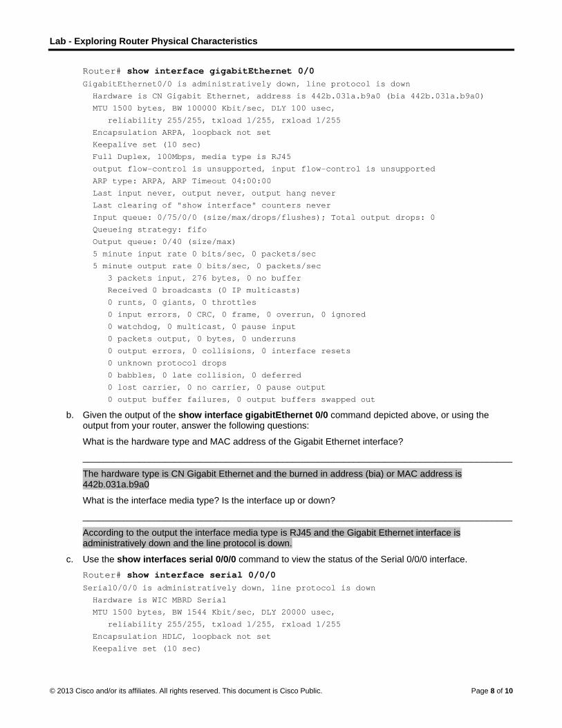
Lab - Exploring Router Physical Characteristics
© 2013 Cisco and/or its affiliates. All rights reserved. This document is Cisco Public. Page 8 of 10
Router# show interface gigabitEthernet 0/0 GigabitEthernet0/0 is administratively down, line protocol is down
Hardware is CN Gigabit Ethernet, address is 442b.031a.b9a0 (bia 442b.031a.b9a0)
MTU 1500 bytes, BW 100000 Kbit/sec, DLY 100 usec,
reliability 255/255, txload 1/255, rxload 1/255
Encapsulation ARPA, loopback not set
Keepalive set (10 sec)
Full Duplex, 100Mbps, media type is RJ45
output flow-control is unsupported, input flow-control is unsupported
ARP type: ARPA, ARP Timeout 04:00:00
Last input never, output never, output hang never
Last clearing of "show interface" counters never
Input queue: 0/75/0/0 (size/max/drops/flushes); Total output drops: 0
Queueing strategy: fifo
Output queue: 0/40 (size/max)
5 minute input rate 0 bits/sec, 0 packets/sec
5 minute output rate 0 bits/sec, 0 packets/sec
3 packets input, 276 bytes, 0 no buffer
Received 0 broadcasts (0 IP multicasts)
0 runts, 0 giants, 0 throttles
0 input errors, 0 CRC, 0 frame, 0 overrun, 0 ignored
0 watchdog, 0 multicast, 0 pause input
0 packets output, 0 bytes, 0 underruns
0 output errors, 0 collisions, 0 interface resets
0 unknown protocol drops
0 babbles, 0 late collision, 0 deferred
0 lost carrier, 0 no carrier, 0 pause output
0 output buffer failures, 0 output buffers swapped out
b. Given the output of the show interface gigabitEthernet 0/0 command depicted above, or using the output from your router, answer the following questions:
What is the hardware type and MAC address of the Gigabit Ethernet interface?
____________________________________________________________________________________
The hardware type is CN Gigabit Ethernet and the burned in address (bia) or MAC address is 442b.031a.b9a0
What is the interface media type? Is the interface up or down?
____________________________________________________________________________________
According to the output the interface media type is RJ45 and the Gigabit Ethernet interface is administratively down and the line protocol is down.
c. Use the show interfaces serial 0/0/0 command to view the status of the Serial 0/0/0 interface.
Router# show interface serial 0/0/0 Serial0/0/0 is administratively down, line protocol is down
Hardware is WIC MBRD Serial
MTU 1500 bytes, BW 1544 Kbit/sec, DLY 20000 usec,
reliability 255/255, txload 1/255, rxload 1/255
Encapsulation HDLC, loopback not set
Keepalive set (10 sec)

Lab - Exploring Router Physical Characteristics
© 2013 Cisco and/or its affiliates. All rights reserved. This document is Cisco Public. Page 9 of 10
Last input 07:41:21, output never, output hang never
Last clearing of "show interface" counters never
Input queue: 0/75/0/0 (size/max/drops/flushes); Total output drops: 0
Queueing strategy: fifo
Output queue: 0/40 (size/max)
5 minute input rate 0 bits/sec, 0 packets/sec
5 minute output rate 0 bits/sec, 0 packets/sec
1 packets input, 24 bytes, 0 no buffer
Received 1 broadcasts (0 IP multicasts)
0 runts, 0 giants, 0 throttles
0 input errors, 0 CRC, 0 frame, 0 overrun, 0 ignored, 0 abort
0 packets output, 0 bytes, 0 underruns
0 output errors, 0 collisions, 2 interface resets
0 unknown protocol drops
0 output buffer failures, 0 output buffers swapped out
1 carrier transitions
DCD=down DSR=down DTR=down RTS=down CTS=down
d. Given the output command depicted above, answer the following questions:
What is the frame encapsulation type?
___________________________________________________________________________________
According to the output above, the frame encapsulation type is HDLC.
What is the hardware type? Is the interface up or down?
___________________________________________________________________________________
The hardware type is WIC MBRD Serial and the interface is administratively down and line protocol down.
Reflection 1. Why might you need to use an EHWIC expansion slot?
_______________________________________________________________________________________
Answers will vary. You may need to have a WAN connection to your ISP over a WAN interface technology that does not come with the router by default.
2. Why might you need to upgrade the Flash memory?
_______________________________________________________________________________________
Answers will vary. You may want to store an additional IOS image file or upgrade to a larger IOS image.
3. What is the purpose of the mini-USB port?
_______________________________________________________________________________________
_______________________________________________________________________________________
_______________________________________________________________________________________
The purpose of the mini USB port is to give you the ability to console into the router if you do not have a COM serial port on your laptop or computer.
4. What is the purpose of the ISM/WLAN indicator light on the backplane of the router? What does it refer to?
_______________________________________________________________________________________
_______________________________________________________________________________________

Lab - Exploring Router Physical Characteristics
© 2013 Cisco and/or its affiliates. All rights reserved. This document is Cisco Public. Page 10 of 10
_______________________________________________________________________________________
_______________________________________________________________________________________
The Cisco 1941 router can support a Cisco Internal Services Module that can enhance the intelligence and abilities of the router to perform activities like intrusion prevention scanning. The Cisco 1941 router can also be equipped with a Wireless LAN card for supporting wireless local area networks.

© 2013 Cisco and/or its affiliates. All rights reserved. This document is Cisco Public. Page 1 of 17
Lab - Building a Switch and Router Network (Instructor Version) Instructor Note: Red font color or Gray highlights indicate text that appears in the instructor copy only.
Topology
Addressing Table
Device Interface IP Address Subnet Mask Default Gateway
R1 G0/0 192.168.0.1 255.255.255.0 N/A
G0/1 192.168.1.1 255.255.255.0 N/A
S1 VLAN 1 N/A N/A N/A
PC-A NIC 192.168.1.3 255.255.255.0 192.168.1.1
PC-B NIC 192.168.0.3 255.255.255.0 192.168.0.1
Objectives
Part 1: Set Up the Topology and Initialize Devices
Set up equipment to match the network topology.
Initialize and restart the router and switch.
Part 2: Configure Devices and Verify Connectivity
Assign static IP information to the PC interfaces.
Configure the router.
Verify network connectivity.
Part 3: Display Device Information
Retrieve hardware and software information from the network devices.
Interpret the output from the routing table.
Display interface information on the router.
Display a summary list of the interfaces on the router and switch.
Background / Scenario
This is a comprehensive lab to review previously covered IOS commands. In this lab, you will cable the equipment as shown in the topology diagram. You will then configure the devices to match the addressing table. After the configurations have been saved, you will verify your configurations by testing for network connectivity.
After the devices have been configured and network connectivity has been verified, you will use IOS commands to retrieve information from the devices to answer questions about your network equipment.

Lab - Building a Switch and Router Network
© 2013 Cisco and/or its affiliates. All rights reserved. This document is Cisco Public. Page 2 of 17
This lab provides minimal assistance with the actual commands necessary to configure the router. However, the required commands are provided in Appendix A. Test your knowledge by trying to configure the devices without referring to the appendix.
Note: The routers used with CCNA hands-on labs are Cisco 1941 Integrated Services Routers (ISRs) with Cisco IOS Release 15.2(4)M3 (universalk9 image). The switches used are Cisco Catalyst 2960s with Cisco IOS Release 15.0(2) (lanbasek9 image). Other routers, switches, and Cisco IOS versions can be used. Depending on the model and Cisco IOS version, the commands available and output produced might vary from what is shown in the labs. Refer to the Router Interface Summary Table at the end of this lab for the correct interface identifiers.
Note: Ensure that the routers and switches have been erased and have no startup configurations. Refer to Appendix B for the procedure to initialize and reload a router and switch.
Required Resources
1 Router (Cisco 1941 with Cisco IOS Release 15.2(4)M3 universal image or comparable)
1 Switch (Cisco 2960 with Cisco IOS Release 15.0(2) lanbasek9 image or comparable)
2 PCs (Windows 7, Vista, or XP with terminal emulation program, such as Tera Term)
Console cables to configure the Cisco IOS devices via the console ports
Ethernet cables as shown in the topology
Note: The Gigabit Ethernet interfaces on Cisco 1941 routers are autosensing and an Ethernet straight-through cable may be used between the router and PC-B. If using another model Cisco router, it may be necessary to use an Ethernet crossover cable.
Part 1: Set Up Topology and Initialize Devices
Step 1: Cable the network as shown in the topology.
a. Attach the devices shown in the topology diagram, and cable, as necessary.
b. Power on all the devices in the topology.
Step 2: Initialize and reload the router and switch.
If configuration files were previously saved on the router and switch, initialize and reload these devices back to their basic configurations. For information on how to initialize and reload these devices, refer to Appendix B.
Part 2: Configure Devices and Verify Connectivity
In Part 2, you will set up the network topology and configure basic settings, such as the interface IP addresses, device access, and passwords. Refer to the Topology and Addressing Table at the beginning of this lab for device names and address information.
Note: Appendix A provides configuration details for the steps in Part 2. You should attempt to complete Part 2 prior to reviewing this appendix.
Step 1: Assign static IP information to the PC interfaces.
a. Configure the IP address, subnet mask, and default gateway settings on PC-A.
b. Configure the IP address, subnet mask, and default gateway settings on PC-B.
c. Ping PC-B from a command prompt window on PC-A.
Why were the pings not successful?

Lab - Building a Switch and Router Network
© 2013 Cisco and/or its affiliates. All rights reserved. This document is Cisco Public. Page 3 of 17
____________________________________________________________________________________
The router interfaces (default gateways) have not been configured yet so Layer 3 traffic is not being routed between subnets.
Step 2: Configure the router.
a. Console into the router and enable privileged EXEC mode.
b. Enter configuration mode.
c. Assign a device name to the router.
d. Disable DNS lookup to prevent the router from attempting to translate incorrectly entered commands as though they were host names.
e. Assign class as the privileged EXEC encrypted password.
f. Assign cisco as the console password and enable login.
g. Assign cisco as the VTY password and enable login.
h. Encrypt the clear text passwords.
i. Create a banner that warns anyone accessing the device that unauthorized access is prohibited.
j. Configure and activate both interfaces on the router.
k. Configure an interface description for each interface indicating which device is connected to it.
l. Save the running configuration to the startup configuration file.
m. Set the clock on the router.
Note: Use the question mark (?) to help with the correct sequence of parameters needed to execute this command.
n. Ping PC-B from a command prompt window on PC-A.
Were the pings successful? Why?
____________________________________________________________________________________
____________________________________________________________________________________
____________________________________________________________________________________
Yes. The router is routing the ping traffic across the two subnets. The default settings for the 2960 switch will automatically turn up the interfaces that are connected to devices.
Part 3: Display Device Information
In Part 3, you will use show commands to retrieve information from the router and switch.
Step 1: Retrieve hardware and software information from the network devices.
a. Use the show version command to answer the following questions about the router.
R1# show version
Cisco IOS Software, C1900 Software (C1900-UNIVERSALK9-M), Version 15.2(4)M3, RELEASE
SOFTWARE (fc1)
Technical Support: http://www.cisco.com/techsupport
Copyright (c) 1986-2012 by Cisco Systems, Inc.
Compiled Thu 26-Jul-12 19:34 by prod_rel_team
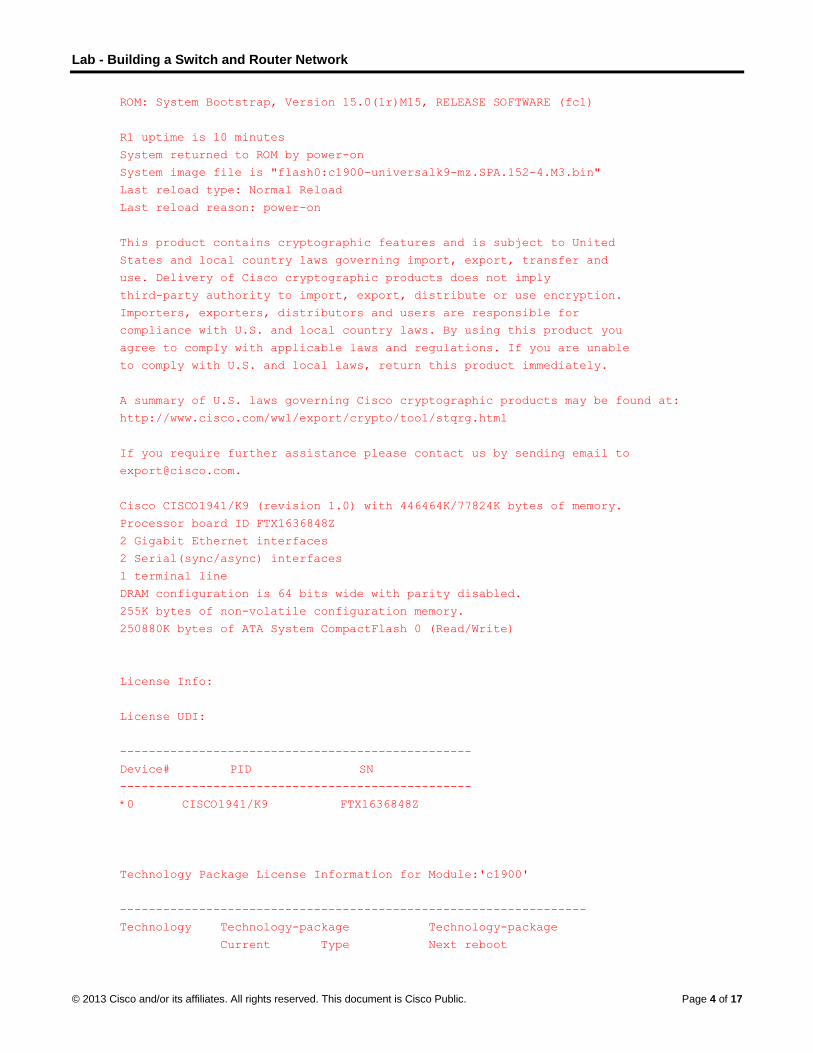
Lab - Building a Switch and Router Network
© 2013 Cisco and/or its affiliates. All rights reserved. This document is Cisco Public. Page 4 of 17
ROM: System Bootstrap, Version 15.0(1r)M15, RELEASE SOFTWARE (fc1)
R1 uptime is 10 minutes
System returned to ROM by power-on
System image file is "flash0:c1900-universalk9-mz.SPA.152-4.M3.bin"
Last reload type: Normal Reload
Last reload reason: power-on
This product contains cryptographic features and is subject to United
States and local country laws governing import, export, transfer and
use. Delivery of Cisco cryptographic products does not imply
third-party authority to import, export, distribute or use encryption.
Importers, exporters, distributors and users are responsible for
compliance with U.S. and local country laws. By using this product you
agree to comply with applicable laws and regulations. If you are unable
to comply with U.S. and local laws, return this product immediately.
A summary of U.S. laws governing Cisco cryptographic products may be found at:
http://www.cisco.com/wwl/export/crypto/tool/stqrg.html
If you require further assistance please contact us by sending email to
Cisco CISCO1941/K9 (revision 1.0) with 446464K/77824K bytes of memory.
Processor board ID FTX1636848Z
2 Gigabit Ethernet interfaces
2 Serial(sync/async) interfaces
1 terminal line
DRAM configuration is 64 bits wide with parity disabled.
255K bytes of non-volatile configuration memory.
250880K bytes of ATA System CompactFlash 0 (Read/Write)
License Info:
License UDI:
-------------------------------------------------
Device# PID SN
-------------------------------------------------
*0 CISCO1941/K9 FTX1636848Z
Technology Package License Information for Module:'c1900'
-----------------------------------------------------------------
Technology Technology-package Technology-package
Current Type Next reboot

Lab - Building a Switch and Router Network
© 2013 Cisco and/or its affiliates. All rights reserved. This document is Cisco Public. Page 5 of 17
------------------------------------------------------------------
ipbase ipbasek9 Permanent ipbasek9
security None None None
data None None None
Configuration register is 0x2142 (will be 0x2102 at next reload)
What is the name of the IOS image that the router is running?
____________________________________________________________________________________
Image version may vary, but answers should be something like c1900-universalk9-mz.SPA.152-4.M3.bin.
How much DRAM memory does the router have?
____________________________________________________________________________________
____________________________________________________________________________________
Answers may vary, but the default DRAM memory configuration on a 1941 router is 512MB or 524,288K bytes. The total can be calculated by adding the two DRAM numbers together from the output of the show version command: Cisco CISCO1941/K9 (revision 1.0) with 446464K/77824K bytes of memory.
How much NVRAM memory does the router have?
____________________________________________________________________________________
Answers may vary, but the output from the show version on 1941 router is: 255K bytes of non-volatile configuration memory.
How much Flash memory does the router have?
____________________________________________________________________________________
Answers may vary, but the default output from the show version command on the 1941 router is 250880K bytes of ATA System CompactFlash 0 (Read/Write).
b. Use the show version command to answer the following questions about the switch.
Switch# show version
Cisco IOS Software, C2960 Software (C2960-LANBASEK9-M), Version 15.0(2)SE, RELEASE
SOFTWARE (fc1)
Technical Support: http://www.cisco.com/techsupport
Copyright (c) 1986-2012 by Cisco Systems, Inc.
Compiled Sat 28-Jul-12 00:29 by prod_rel_team
ROM: Bootstrap program is C2960 boot loader
BOOTLDR: C2960 Boot Loader (C2960-HBOOT-M) Version 12.2(53r)SEY3, RELEASE SOFTWARE
(fc1)
S1 uptime is 1 hour, 2 minutes
System returned to ROM by power-on
System image file is "flash:/c2960-lanbasek9-mz.150-2.SE.bin"
This product contains cryptographic features and is subject to United
States and local country laws governing import, export, transfer and
use. Delivery of Cisco cryptographic products does not imply
third-party authority to import, export, distribute or use encryption.
Importers, exporters, distributors and users are responsible for
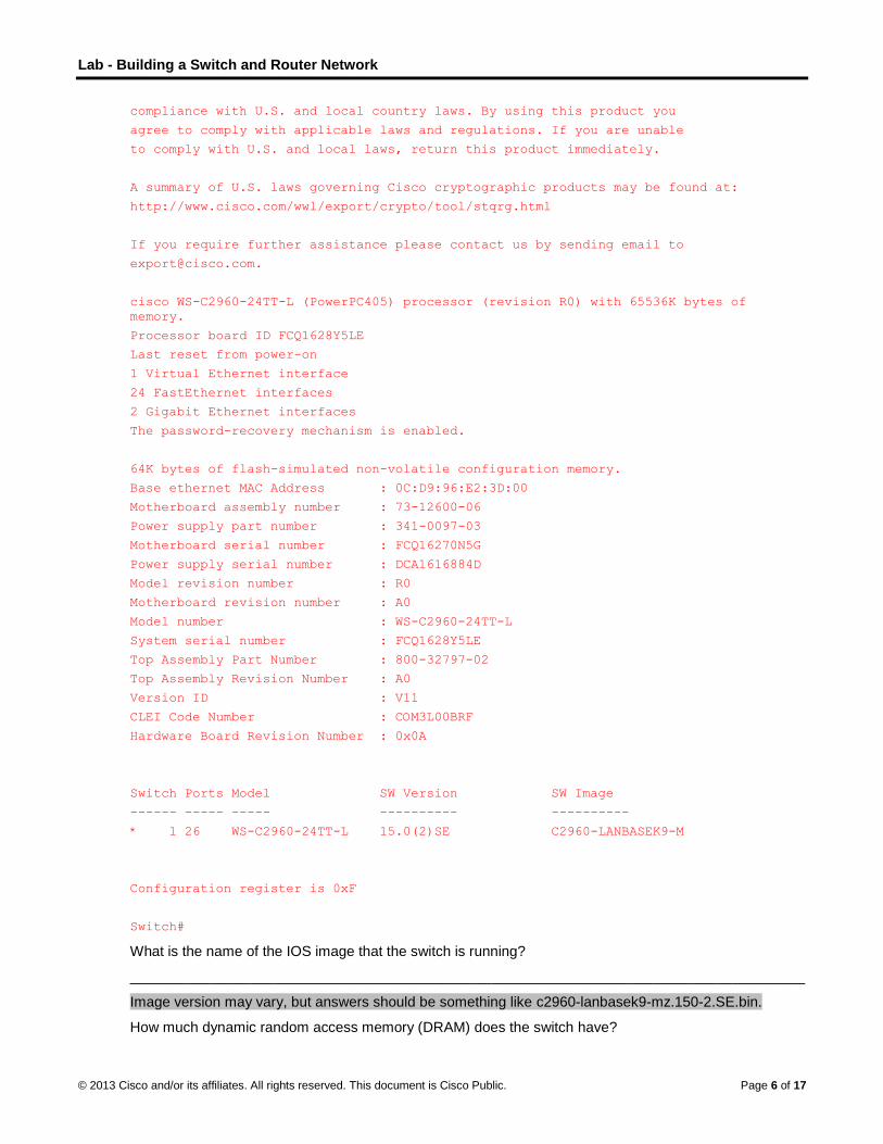
Lab - Building a Switch and Router Network
© 2013 Cisco and/or its affiliates. All rights reserved. This document is Cisco Public. Page 6 of 17
compliance with U.S. and local country laws. By using this product you
agree to comply with applicable laws and regulations. If you are unable
to comply with U.S. and local laws, return this product immediately.
A summary of U.S. laws governing Cisco cryptographic products may be found at:
http://www.cisco.com/wwl/export/crypto/tool/stqrg.html
If you require further assistance please contact us by sending email to
cisco WS-C2960-24TT-L (PowerPC405) processor (revision R0) with 65536K bytes of
memory.
Processor board ID FCQ1628Y5LE
Last reset from power-on
1 Virtual Ethernet interface
24 FastEthernet interfaces
2 Gigabit Ethernet interfaces
The password-recovery mechanism is enabled.
64K bytes of flash-simulated non-volatile configuration memory.
Base ethernet MAC Address : 0C:D9:96:E2:3D:00
Motherboard assembly number : 73-12600-06
Power supply part number : 341-0097-03
Motherboard serial number : FCQ16270N5G
Power supply serial number : DCA1616884D
Model revision number : R0
Motherboard revision number : A0
Model number : WS-C2960-24TT-L
System serial number : FCQ1628Y5LE
Top Assembly Part Number : 800-32797-02
Top Assembly Revision Number : A0
Version ID : V11
CLEI Code Number : COM3L00BRF
Hardware Board Revision Number : 0x0A
Switch Ports Model SW Version SW Image
------ ----- ----- ---------- ----------
* 1 26 WS-C2960-24TT-L 15.0(2)SE C2960-LANBASEK9-M
Configuration register is 0xF
Switch#
What is the name of the IOS image that the switch is running?
____________________________________________________________________________________
Image version may vary, but answers should be something like c2960-lanbasek9-mz.150-2.SE.bin.
How much dynamic random access memory (DRAM) does the switch have?

Lab - Building a Switch and Router Network
© 2013 Cisco and/or its affiliates. All rights reserved. This document is Cisco Public. Page 7 of 17
____________________________________________________________________________________
Answers may vary, but the default DRAM memory configuration on a 2960-24TT-L switch is 65536K of memory.
How much nonvolatile random-access memory (NVRAM) does the switch have?
____________________________________________________________________________________
Answers may vary, but the default non-volatile memory configuration on a 2960-24TT-L switch is 64K bytes.
What is the model number of the switch?
____________________________________________________________________________________
Answers may vary, but the answer should appear in this form: WS-C2960-24TT-L.
Step 2: Display the routing table on the router.
Use the show ip route command on the router to answer the following questions.
R1# show ip route
Codes: L - local, C - connected, S - static, R - RIP, M - mobile, B - BGP
D - EIGRP, EX - EIGRP external, O - OSPF, IA - OSPF inter area
N1 - OSPF NSSA external type 1, N2 - OSPF NSSA external type 2
E1 - OSPF external type 1, E2 - OSPF external type 2
i - IS-IS, su - IS-IS summary, L1 - IS-IS level-1, L2 - IS-IS level-2
ia - IS-IS inter area, * - candidate default, U - per-user static route
o - ODR, P - periodic downloaded static route, H - NHRP, l - LISP
+ - replicated route, % - next hop override
Gateway of last resort is not set
192.168.0.0/24 is variably subnetted, 2 subnets, 2 masks
C 192.168.0.0/24 is directly connected, GigabitEthernet0/0
L 192.168.0.1/32 is directly connected, GigabitEthernet0/0
192.168.1.0/24 is variably subnetted, 2 subnets, 2 masks
C 192.168.1.0/24 is directly connected, GigabitEthernet0/1
L 192.168.1.1/32 is directly connected, GigabitEthernet0/1
What code is used in the routing table to indicate a directly connected network? _____
The C designates a directly connected subnet. An L designates a local interface. Both answers are correct.
How many route entries are coded with a C code in the routing table? _________ 2
What interface types are associated to the C coded routes?
_______________________________________________________________________________________
Answers may vary depending of router type, but on the 1941 the correct answer is G0/0 and G0/1.
Step 3: Display interface information on the router.
Use the show interface g0/1 to answer the following questions.
R1# show interfaces g0/1
GigabitEthernet0/1 is up, line protocol is up
Hardware is CN Gigabit Ethernet, address is fc99.4775.c3e1 (bia fc99.4775.c3e1)
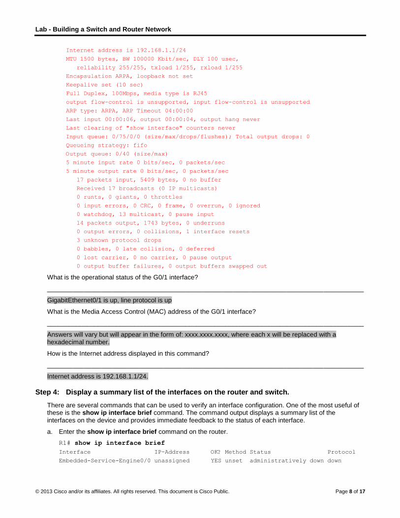
Lab - Building a Switch and Router Network
© 2013 Cisco and/or its affiliates. All rights reserved. This document is Cisco Public. Page 8 of 17
Internet address is 192.168.1.1/24
MTU 1500 bytes, BW 100000 Kbit/sec, DLY 100 usec,
reliability 255/255, txload 1/255, rxload 1/255
Encapsulation ARPA, loopback not set
Keepalive set (10 sec)
Full Duplex, 100Mbps, media type is RJ45
output flow-control is unsupported, input flow-control is unsupported
ARP type: ARPA, ARP Timeout 04:00:00
Last input 00:00:06, output 00:00:04, output hang never
Last clearing of "show interface" counters never
Input queue: 0/75/0/0 (size/max/drops/flushes); Total output drops: 0
Queueing strategy: fifo
Output queue: 0/40 (size/max)
5 minute input rate 0 bits/sec, 0 packets/sec
5 minute output rate 0 bits/sec, 0 packets/sec
17 packets input, 5409 bytes, 0 no buffer
Received 17 broadcasts (0 IP multicasts)
0 runts, 0 giants, 0 throttles
0 input errors, 0 CRC, 0 frame, 0 overrun, 0 ignored
0 watchdog, 13 multicast, 0 pause input
14 packets output, 1743 bytes, 0 underruns
0 output errors, 0 collisions, 1 interface resets
3 unknown protocol drops
0 babbles, 0 late collision, 0 deferred
0 lost carrier, 0 no carrier, 0 pause output
0 output buffer failures, 0 output buffers swapped out
What is the operational status of the G0/1 interface?
_______________________________________________________________________________________
GigabitEthernet0/1 is up, line protocol is up
What is the Media Access Control (MAC) address of the G0/1 interface?
_______________________________________________________________________________________
Answers will vary but will appear in the form of: xxxx.xxxx.xxxx, where each x will be replaced with a hexadecimal number.
How is the Internet address displayed in this command?
_______________________________________________________________________________________
Internet address is 192.168.1.1/24.
Step 4: Display a summary list of the interfaces on the router and switch.
There are several commands that can be used to verify an interface configuration. One of the most useful of these is the show ip interface brief command. The command output displays a summary list of the interfaces on the device and provides immediate feedback to the status of each interface.
a. Enter the show ip interface brief command on the router.
R1# show ip interface brief
Interface IP-Address OK? Method Status Protocol
Embedded-Service-Engine0/0 unassigned YES unset administratively down down

Lab - Building a Switch and Router Network
© 2013 Cisco and/or its affiliates. All rights reserved. This document is Cisco Public. Page 9 of 17
GigabitEthernet0/0 192.168.0.1 YES manual up up
GigabitEthernet0/1 192.168.1.1 YES manual up up
Serial0/0/0 unassigned YES unset administratively down down
Serial0/0/1 unassigned YES unset administratively down down
R1#
b. Enter the show ip interface brief command on the switch.
Switch# show ip interface brief
Interface IP-Address OK? Method Status Protocol
Vlan1 unassigned YES manual up up
FastEthernet0/1 unassigned YES unset down down
FastEthernet0/2 unassigned YES unset down down
FastEthernet0/3 unassigned YES unset down down
FastEthernet0/4 unassigned YES unset down down
FastEthernet0/5 unassigned YES unset up up
FastEthernet0/6 unassigned YES unset up up
FastEthernet0/7 unassigned YES unset down down
FastEthernet0/8 unassigned YES unset down down
FastEthernet0/9 unassigned YES unset down down
FastEthernet0/10 unassigned YES unset down down
FastEthernet0/11 unassigned YES unset down down
FastEthernet0/12 unassigned YES unset down down
FastEthernet0/13 unassigned YES unset down down
FastEthernet0/14 unassigned YES unset down down
FastEthernet0/15 unassigned YES unset down down
FastEthernet0/16 unassigned YES unset down down
FastEthernet0/17 unassigned YES unset down down
FastEthernet0/18 unassigned YES unset down down
FastEthernet0/19 unassigned YES unset down down
FastEthernet0/20 unassigned YES unset down down
FastEthernet0/21 unassigned YES unset down down
FastEthernet0/22 unassigned YES unset down down
FastEthernet0/23 unassigned YES unset down down
FastEthernet0/24 unassigned YES unset down down
GigabitEthernet0/1 unassigned YES unset down down
GigabitEthernet0/2 unassigned YES unset down down
Switch#
Reflection
1. If the G0/1 interface showed administratively down, what interface configuration command would you use to turn the interface up?
_______________________________________________________________________________________
R1(config-if)# no shut
2. What would happen if you had incorrectly configured interface G0/1 on the router with an IP address of 192.168.1.2?
_______________________________________________________________________________________
_______________________________________________________________________________________
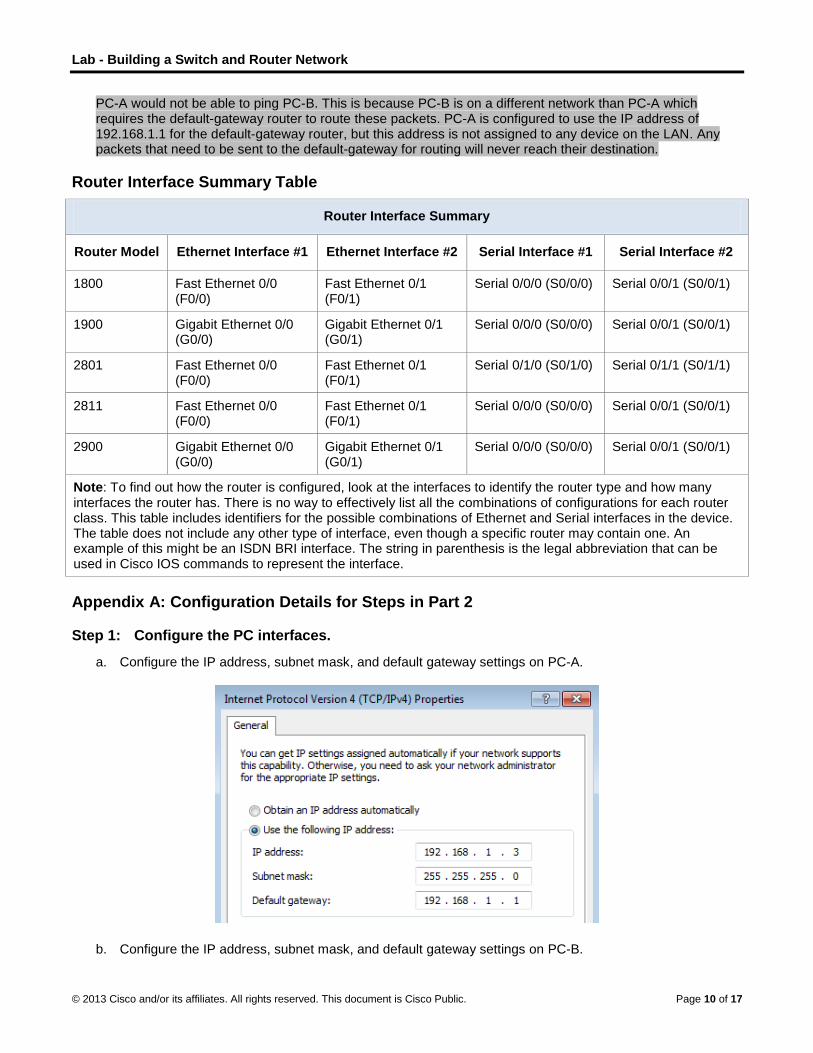
Lab - Building a Switch and Router Network
© 2013 Cisco and/or its affiliates. All rights reserved. This document is Cisco Public. Page 10 of 17
PC-A would not be able to ping PC-B. This is because PC-B is on a different network than PC-A which requires the default-gateway router to route these packets. PC-A is configured to use the IP address of 192.168.1.1 for the default-gateway router, but this address is not assigned to any device on the LAN. Any packets that need to be sent to the default-gateway for routing will never reach their destination.
Router Interface Summary Table
Router Interface Summary
Router Model Ethernet Interface #1 Ethernet Interface #2 Serial Interface #1 Serial Interface #2
1800 Fast Ethernet 0/0 (F0/0)
Fast Ethernet 0/1 (F0/1)
Serial 0/0/0 (S0/0/0) Serial 0/0/1 (S0/0/1)
1900 Gigabit Ethernet 0/0 (G0/0)
Gigabit Ethernet 0/1 (G0/1)
Serial 0/0/0 (S0/0/0) Serial 0/0/1 (S0/0/1)
2801 Fast Ethernet 0/0 (F0/0)
Fast Ethernet 0/1 (F0/1)
Serial 0/1/0 (S0/1/0) Serial 0/1/1 (S0/1/1)
2811 Fast Ethernet 0/0 (F0/0)
Fast Ethernet 0/1 (F0/1)
Serial 0/0/0 (S0/0/0) Serial 0/0/1 (S0/0/1)
2900 Gigabit Ethernet 0/0 (G0/0)
Gigabit Ethernet 0/1 (G0/1)
Serial 0/0/0 (S0/0/0) Serial 0/0/1 (S0/0/1)
Note: To find out how the router is configured, look at the interfaces to identify the router type and how many interfaces the router has. There is no way to effectively list all the combinations of configurations for each router class. This table includes identifiers for the possible combinations of Ethernet and Serial interfaces in the device. The table does not include any other type of interface, even though a specific router may contain one. An example of this might be an ISDN BRI interface. The string in parenthesis is the legal abbreviation that can be used in Cisco IOS commands to represent the interface.
Appendix A: Configuration Details for Steps in Part 2
Step 1: Configure the PC interfaces.
a. Configure the IP address, subnet mask, and default gateway settings on PC-A.
b. Configure the IP address, subnet mask, and default gateway settings on PC-B.
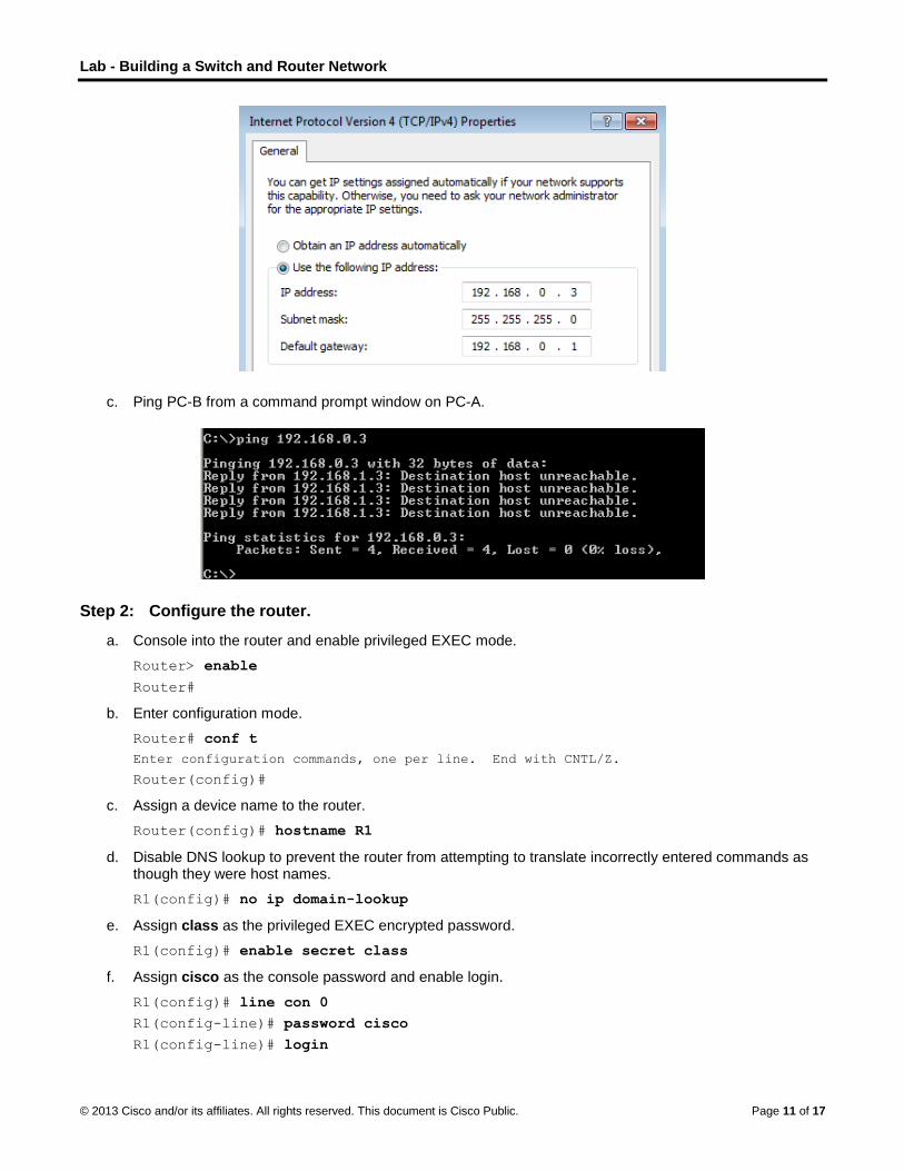
Lab - Building a Switch and Router Network
© 2013 Cisco and/or its affiliates. All rights reserved. This document is Cisco Public. Page 11 of 17
c. Ping PC-B from a command prompt window on PC-A.
Step 2: Configure the router.
a. Console into the router and enable privileged EXEC mode.
Router> enable
Router#
b. Enter configuration mode.
Router# conf t
Enter configuration commands, one per line. End with CNTL/Z.
Router(config)#
c. Assign a device name to the router.
Router(config)# hostname R1
d. Disable DNS lookup to prevent the router from attempting to translate incorrectly entered commands as though they were host names.
R1(config)# no ip domain-lookup
e. Assign class as the privileged EXEC encrypted password.
R1(config)# enable secret class
f. Assign cisco as the console password and enable login.
R1(config)# line con 0
R1(config-line)# password cisco
R1(config-line)# login

Lab - Building a Switch and Router Network
© 2013 Cisco and/or its affiliates. All rights reserved. This document is Cisco Public. Page 12 of 17
R1(config-line)# exit
R1(config)#
g. Assign cisco as the vty password and enable login.
R1(config)# line vty 0 4
R1(config-line)# password cisco
R1(config-line)# login
R1(config-line)# exit
R1(config)#
h. Encrypt the clear text passwords.
R1(config)# service password-encryption
i. Create a banner that warns anyone accessing the device that unauthorized access is prohibited.
R1(config)# banner motd #
Enter TEXT message. End with the character '#'.
Unauthorized access prohibited!
#
R1(config)#
j. Configure and activate both interfaces on the router.
R1(config)# int g0/0
R1(config-if)# description Connection to PC-B.
R1(config-if)# ip address 192.168.0.1 255.255.255.0
R1(config-if)# no shut
R1(config-if)#
*Nov 29 23:49:44.195: %LINK-3-UPDOWN: Interface GigabitEthernet0/0, changed state to
down
*Nov 29 23:49:47.863: %LINK-3-UPDOWN: Interface GigabitEthernet0/0, changed state to
up
*Nov 29 23:49:48.863: %LINEPROTO-5-UPDOWN: Line protocol on Interface
GigabitEthernet0/0, changed state to up
R1(config-if)# int g0/1
R1(config-if)# description Connection to S1.
R1(config-if)# ip address 192.168.1.1 255.255.255.0
R1(config-if)# no shut
R1(config-if)# exit
R1(config)# exit
*Nov 29 23:50:15.283: %LINK-3-UPDOWN: Interface GigabitEthernet0/1, changed state to
down
*Nov 29 23:50:18.863: %LINK-3-UPDOWN: Interface GigabitEthernet0/1, changed state to
up
*Nov 29 23:50:19.863: %LINEPROTO-5-UPDOWN: Line protocol on Interface
GigabitEthernet0/1, changed state to up
R1#
k. Save the running configuration to the startup file.
R1# copy running-config startup-config
Destination filename [startup-config]?
Building configuration...

Lab - Building a Switch and Router Network
© 2013 Cisco and/or its affiliates. All rights reserved. This document is Cisco Public. Page 13 of 17
[OK]
R1#
l. Set the clock on the router.
R1# clock set 17:00:00 29 Nov 2012
R1#
*Nov 29 17:00:00.000: %SYS-6-CLOCKUPDATE: System clock has been updated from 23:55:46
UTC Thu Nov 29 2012 to 17:00:00 UTC Thu Nov 29 2012, configured from console by
console.
R1#
Note: Use the question mark (?) to help determine the correct sequence of the parameters needed to execute this command.
m. Ping PC-B from a command prompt window on PC-A.
Appendix B: Initializing and Reloading a Router and Switch
Part 1: Initialize the Router and Reload
Step 1: Connect to the router.
Console into the router and enter privileged EXEC mode using the enable command.
Router> enable
Router#
Step 2: Erase the startup configuration file from NVRAM.
Type the erase startup-config command to remove the startup configuration from nonvolatile random-access memory (NVRAM).
Router# erase startup-config
Erasing the nvram filesystem will remove all configuration files! Continue? [confirm]
[OK]
Erase of nvram: complete
Router#
Step 3: Reload the router.
Issue the reload command to remove an old configuration from memory. When prompted to Proceed with reload, press Enter to confirm the reload. Pressing any other key will abort the reload.
Router# reload

Lab - Building a Switch and Router Network
© 2013 Cisco and/or its affiliates. All rights reserved. This document is Cisco Public. Page 14 of 17
Proceed with reload? [confirm]
*Nov 29 18:28:09.923: %SYS-5-RELOAD: Reload requested by console. Reload Reason:
Reload Command.
Note: You may receive a prompt to save the running configuration prior to reloading the router. Respond by typing no and press Enter.
System configuration has been modified. Save? [yes/no]: no
Step 4: Bypass the initial configuration dialog.
After the router reloads, you are prompted to enter the initial configuration dialog. Enter no and press Enter.
Would you like to enter the initial configuration dialog? [yes/no]: no
Step 5: Terminate the autoinstall program.
You will be prompted to terminate the autoinstall program. Respond yes and then press Enter.
Would you like to terminate autoinstall? [yes]: yes
Router>
Part 2: Initialize the Switch and Reload
Step 1: Connect to the switch.
Console into the switch and enter privileged EXEC mode.
Switch> enable
Switch#
Step 2: Determine if there have been any virtual local-area networks (VLANs) created.
Use the show flash command to determine if any VLANs have been created on the switch.
Switch# show flash
Directory of flash:/
2 -rwx 1919 Mar 1 1993 00:06:33 +00:00 private-config.text
3 -rwx 1632 Mar 1 1993 00:06:33 +00:00 config.text
4 -rwx 13336 Mar 1 1993 00:06:33 +00:00 multiple-fs
5 -rwx 11607161 Mar 1 1993 02:37:06 +00:00 c2960-lanbasek9-mz.150-2.SE.bin
6 -rwx 616 Mar 1 1993 00:07:13 +00:00 vlan.dat
32514048 bytes total (20886528 bytes free)
Switch#
Step 3: Delete the VLAN file.
a. If the vlan.dat file was found in flash, then delete this file.
Switch# delete vlan.dat
Delete filename [vlan.dat]?
You will be prompted to verify the file name. At this point, you can change the file name or just press Enter if you have entered the name correctly.
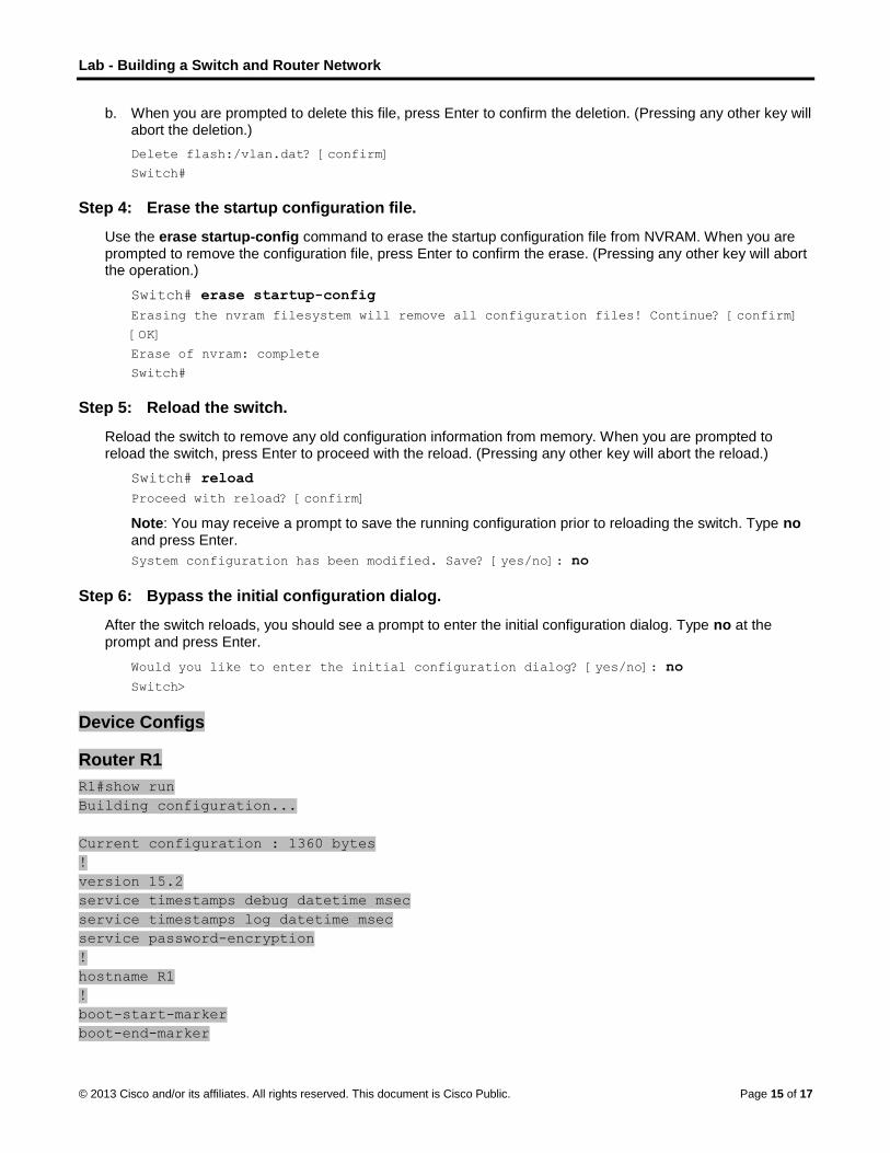
Lab - Building a Switch and Router Network
© 2013 Cisco and/or its affiliates. All rights reserved. This document is Cisco Public. Page 15 of 17
b. When you are prompted to delete this file, press Enter to confirm the deletion. (Pressing any other key will abort the deletion.)
Delete flash:/vlan.dat? [confirm]
Switch#
Step 4: Erase the startup configuration file.
Use the erase startup-config command to erase the startup configuration file from NVRAM. When you are prompted to remove the configuration file, press Enter to confirm the erase. (Pressing any other key will abort the operation.)
Switch# erase startup-config
Erasing the nvram filesystem will remove all configuration files! Continue? [confirm]
[OK]
Erase of nvram: complete
Switch#
Step 5: Reload the switch.
Reload the switch to remove any old configuration information from memory. When you are prompted to reload the switch, press Enter to proceed with the reload. (Pressing any other key will abort the reload.)
Switch# reload
Proceed with reload? [confirm]
Note: You may receive a prompt to save the running configuration prior to reloading the switch. Type no and press Enter.
System configuration has been modified. Save? [yes/no]: no
Step 6: Bypass the initial configuration dialog.
After the switch reloads, you should see a prompt to enter the initial configuration dialog. Type no at the prompt and press Enter.
Would you like to enter the initial configuration dialog? [yes/no]: no
Switch>
Device Configs
Router R1
R1#show run
Building configuration...
Current configuration : 1360 bytes
!
version 15.2
service timestamps debug datetime msec
service timestamps log datetime msec
service password-encryption
!
hostname R1
!
boot-start-marker
boot-end-marker

Lab - Building a Switch and Router Network
© 2013 Cisco and/or its affiliates. All rights reserved. This document is Cisco Public. Page 16 of 17
!
!
enable secret 4 06YFDUHH61wAE/kLkDq9BGho1QM5EnRtoyr8cHAUg.2
!
no aaa new-model
memory-size iomem 15
!
!
!
!
!
!
!
no ip domain lookup
ip cef
no ipv6 cef
multilink bundle-name authenticated
!
!
!
!
!
!
!
!
!
!
!
interface Embedded-Service-Engine0/0
no ip address
shutdown
!
interface GigabitEthernet0/0
description Connection to PC-B.
ip address 192.168.0.1 255.255.255.0
duplex auto
speed auto
!
interface GigabitEthernet0/1
description Connection to S1.
ip address 192.168.1.1 255.255.255.0 duplex auto
speed auto
!
interface Serial0/0/0
no ip address
shutdown
clock rate 2000000
!
interface Serial0/0/1
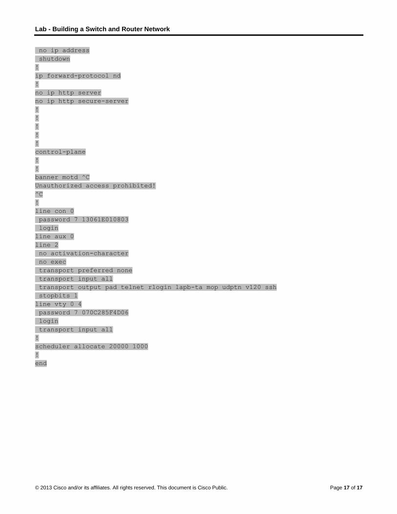
Lab - Building a Switch and Router Network
© 2013 Cisco and/or its affiliates. All rights reserved. This document is Cisco Public. Page 17 of 17
no ip address
shutdown
!
ip forward-protocol nd
!
no ip http server
no ip http secure-server
!
!
!
!
!
control-plane
!
!
banner motd ^C
Unauthorized access prohibited!
^C
!
line con 0
password 7 13061E010803
login
line aux 0
line 2
no activation-character
no exec
transport preferred none
transport input all
transport output pad telnet rlogin lapb-ta mop udptn v120 ssh
stopbits 1
line vty 0 4
password 7 070C285F4D06
login
transport input all
!
scheduler allocate 20000 1000
!
end

© 2013 Cisco and/or its affiliates. All rights reserved. This document is Cisco Public. Page 1 of 3
Can you read this map? (Instructor Version) Instructor Note: Red font color or Gray highlights indicate text that appears in the instructor copy only.
Objectives
Explain how network devices use routing tables to direct packets to a destination network.
In this activity, given a scenario, you will determine whether high-reliability messaging should be used. You will focus on whether the final message is complete, correct, and delivered in a timely manner.
Background/Scenario
Note: It is suggested that students work in pairs; however, if preferred, students can complete this activity individually.
Your instructor will provide you with output generated by a router’s show ip route command. Use Packet Tracer to build a topology model using this routing information.
At a minimum, the following should be used in your topology model:
One Catalyst 2960 switch
One Cisco Series 1941 Router with one HWIC-4ESW switching port modular card and IOS Version
15.1 or higher
Three PCs (can be servers, generic PCs, laptops, etc.)
Use the note tool in Packet Tracer to indicate the addresses of the router interfaces and possible addresses for the end devices you chose for your model.
Label all end devices, ports, and addresses ascertained from the show ip route output/routing table information in your Packet Tracer file. Save your work in hard or soft copy to share with the class.
Instructor Note: This Modeling Activity is not intended to be a graded assignment. Its purpose is to encourage students to reflect on their perceptions of how a network is configured and then checked for routing table information.
Print out or project the Table 1 graphic found in the Required Resources section of this document. Students should be able to assist each other as they read the routing table provided and then construct the model using Packet Tracer software. Facilitation of small group discussion should be initiated as a result of this activity.
Instructor Note: It is suggested, but not required, that students work in pairs for this activity.
Required Resources
Packet Tracer software program.
Routing Table 1 - You can use the table to assist one another as you read the information provided, and
then construct the model using Packet Tracer.

Can you read this map?
© 2013 Cisco and/or its affiliates. All rights reserved. This document is Cisco Public. Page 2 of 3
Reflection
1. What was the hardest part of designing this network model? Explain your answer.
____________________________________________________________________________
Answers will vary within groups – some students may mention source or destination identifiers or some may mention the actual IP addresses being cited in the routing table – the important concept here is that students can comfortably identify where information is coming from on the final routing table as depicted.
Topologies will vary by group – some students will place their switch off of the Gig0/1 port, etc.
Optional: As an advanced modeling activity, students can create a simple one-router network with four Gigabit interfaces connected to end devices, configure the router and LANs with passwords, IP addresses, banners, etc., and then produce a routing table to support the network information.
Possible topology built by the students could look like this:

Can you read this map?
© 2013 Cisco and/or its affiliates. All rights reserved. This document is Cisco Public. Page 3 of 3
Identify elements of the model that map to IT-related content:
Reading a routing table can verify how a network has been addressed logically.
A routing table can assist with identifying the physical topology of the network.
A routing table identifies to the reader which ports are operating and on which networks they are operating
©
TI
O
Ia
B
R
R
© 2013 Cisco and
The Intenstructor No
ObjectivesExplain h
Pv6 is importaddresses wil
BackgrounTodayeveryorgannetwo
If traffthat in
In thisevery
Activit
1
2
3
4
5
Instrugradehow t
Required R Intern
individ
Recor
.pdfs
Reflection 1. W
ab
__
The re
d/or its affiliates.
ernet of Eote: Red font
how network
tant to help ml assist in this
nd /Scenary, more than
ything. 37 billionic and the digorking is know
fic, transportanformation be
s activity, youything will be a
ty directions f
. Read the b#TomorrowThis blog i
. Then view
. Next, navighere/index
. Next, watcinterest.
. Write 5 co
uctor note: Ted assignmenhey will be id
Resources net connectivit
dually comple
rding capabili
read or viewe
Why do you thbout anything
___________
esearch for th
All rights reserve
Everythcolor or Gray
devices use
manage the das endeavor, a
io 99% of our won devices wigital will work wn as “The Int
ation, networke identified fro
will begin to addressed in
for class or in
blog/news souwStartsHere” s located at h
the video, “C
gate to the Iox.html.Then cl
ch the video o
mments or qu
This is an indt. Its purposeentified in the
ty for researc
eting this activ
ties (paper, ta
ed for Step 3.
ink there is a g be able to u
___________
he scenario w
ed. This docume
ing (IoEy highlights ind
e routing tab
ata traffic idenand IPv6 helps
world remains ill be connecttogether for a
ternet of Ever
king and spacom its source
think about nthe same wo
dividual stude
urce, “Interneauthored by
http://blogs.cis
Cisco Comme
E main page lick on a cate
or read throug
uestions abou
ividual or an ie is to encoure future. IPv6
ch on the cisco
vity within a g
ablet, etc.) fo
need to addrse an IP addr
____________
will be varied.
ent is Cisco Publi
) (Instrucdicate text tha
les to direct
ntification, whs to alleviate
unconnectedted to the Intea more intelligrything” or “Io
ce explorationto its destinat
ot only what wrld!
ents:
et of EverythinJohn Chambesco.com/news
ercial: Tomorro
located at httgory that inte
gh the blog or
ut what you sa
in-class Moderage student ris necessary
o.com site. H
roup setting.
r comments o
ress trees? Wress?
____________
Some conce
ic.
ctor Versat appears in
packets to a
ich will be nethis need.
d. Tomorrow, ernet by 2020gent and con
oE.”
n depend on dtion?
will be identif
ng: Fueling aners regardings/internet-of-e
ow Starts He
tp://www.ciscerests you from
.pdf that belo
aw or read. B
eling Activity (reflection aboto support th
Headphones m
or questions r
Windmills? Ca
___________
epts worth me
sion) the instructo
a destination
eded in the fu
we will be co. From trees tnected world
digital informa
fied in the IoE
n Amazing Fug the Internet everything-2.
re” located ha
co.com/web/tom within the g
ongs to your I
Be prepared t
(MA). It is noout their percehe Internet of
may also be u
regarding the
ars? Refrigera
___________
entioning or d
r copy only.
n network.
uture. Many
onnected to alto water to ca. This tomorr
ation sharing,
E world, but ho
uture of Everything
alfway down t
omorrow-startgraphic collag
IoE category
to share with
ot intended to eption of netwEverything.
useful if stude
videos, blogs
ators? Why w
____________
discussing inc
Page 1 of 2
most ars, the row of
how will
ow
g (IoE).
the page.
ts-ge.
of
the class.
be a works and
ents are
s and/or
will just
____
clude:

The Internet of Everything
© 2013 Cisco and/or its affiliates. All rights reserved. This document is Cisco Public. Page 2 of 2
To support the new IoE concepts/implementation and growing number of devices that connect to the internet, an exponential amount of addresses will be needed. Might need to briefly discuss HOW trees can be connected to the Internet (i.e., different kinds of sensors which transmit data – see http://www.ericsson.com/article/connected_tree_2045546582_c )
Knowing how to use IPv6 addressing will be important to network administrators, ISPs/TSPs, and the general public as we move to more and more network types/classifications of networks.
Identify elements of the model that map to IT-related content: Network types (subnets, etc.)
Network and host identification as related to network types
Quality of network transmission as related to network identification
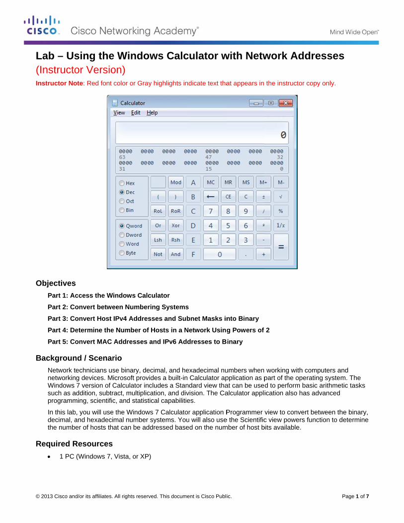
©
L(I
O
B
R
© 2013 Cisco and
Lab – Us(Instructonstructor No
ObjectivesPart 1: Ac
Part 2: Co
Part 3: Co
Part 4: De
Part 5: Co
BackgrounNetwork tnetworkinWindows such as aprogramm
In this labdecimal, athe numbe
Required R 1 PC
d/or its affiliates.
sing theor Versioote: Red font
ccess the W
onvert betwe
onvert Host
etermine the
onvert MAC
nd / Scenarechnicians usg devices. M7 version of C
addition, subtrming, scientific
b, you will useand hexadecier of hosts th
Resources (Windows 7,
All rights reserve
e Windowon) color or Gray
indows Calc
een Numberi
IPv4 Addres
e Number of
Addresses a
rio se binary, decicrosoft providCalculator incract, multiplicac, and statistic
the Windowsmal number sat can be add
Vista, or XP)
ed. This docume
ws Calc
y highlights ind
culator
ing Systems
ses and Sub
Hosts in a N
and IPv6 Add
cimal, and hedes a built-in cludes a Stanation, and divcal capabilitie
s 7 Calculatorsystems. Youdressed base
ent is Cisco Publi
ulator w
dicate text tha
bnet Masks in
etwork Using
dresses to B
exadecimal nuCalculator apdard view tha
vision. The Caes.
r application Pu will also useed on the num
ic.
with Netw
at appears in
nto Binary
g Powers of
inary
umbers when pplication as pat can be usealculator appl
Programmer e the Scientificmber of host b
work Ad
the instructo
2
working withpart of the opd to perform ication also h
view to convec view powers
bits available.
ddresses
r copy only.
h computers aperating systebasic arithme
has advanced
ert between ths function to d
Page 1 of 7
s
and m. The
etic tasks
he binary, determine
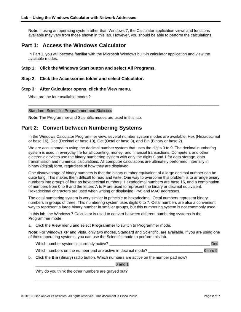
Lab – Using the Windows Calculator with Network Addresses
© 2013 Cisco and/or its affiliates. All rights reserved. This document is Cisco Public. Page 2 of 7
Note: If using an operating system other than Windows 7, the Calculator application views and functions available may vary from those shown in this lab. However, you should be able to perform the calculations.
Part 1: Access the Windows Calculator In Part 1, you will become familiar with the Microsoft Windows built-in calculator application and view the available modes.
Step 1: Click the Windows Start button and select All Programs.
Step 2: Click the Accessories folder and select Calculator.
Step 3: After Calculator opens, click the View menu.
What are the four available modes?
_______________________________________________________________________________________
Standard, Scientific, Programmer, and Statistics
Note: The Programmer and Scientific modes are used in this lab.
Part 2: Convert between Numbering Systems In the Windows Calculator Programmer view, several number system modes are available: Hex (Hexadecimal or base 16), Dec (Decimal or base 10), Oct (Octal or base 8), and Bin (Binary or base 2).
We are accustomed to using the decimal number system that uses the digits 0 to 9. The decimal numbering system is used in everyday life for all counting, money, and financial transactions. Computers and other electronic devices use the binary numbering system with only the digits 0 and 1 for data storage, data transmission and numerical calculations. All computer calculations are ultimately performed internally in binary (digital) form, regardless of how they are displayed.
One disadvantage of binary numbers is that the binary number equivalent of a large decimal number can be quite long. This makes them difficult to read and write. One way to overcome this problem is to arrange binary numbers into groups of four as hexadecimal numbers. Hexadecimal numbers are base 16, and a combination of numbers from 0 to 9 and the letters A to F are used to represent the binary or decimal equivalent. Hexadecimal characters are used when writing or displaying IPv6 and MAC addresses.
The octal numbering system is very similar in principle to hexadecimal. Octal numbers represent binary numbers in groups of three. This numbering system uses digits 0 to 7. Octal numbers are also a convenient way to represent a large binary number in smaller groups, but this numbering system is not commonly used.
In this lab, the Windows 7 Calculator is used to convert between different numbering systems in the Programmer mode.
a. Click the View menu and select Programmer to switch to Programmer mode.
Note: For Windows XP and Vista, only two modes, Standard and Scientific, are available. If you are using one of these operating systems, you can use the Scientific mode to perform this lab.
Which number system is currently active? ______________________________________________ Dec
Which numbers on the number pad are active in decimal mode? _________________________ 0 thru 9
b. Click the Bin (Binary) radio button. Which numbers are active on the number pad now?
____________________________________ 0 and 1
Why do you think the other numbers are grayed out?
____________________________________________________________________________________

L
©
Lab – Using t
© 2013 Cisco and
The o
c. Click
_____
0 thru
d. Click numb
Note:numeLock
Click
_____
It was
e. NumbClick
f. Click or A to
g. As yodisplavalue
h. Clear numb
the Windows
d/or its affiliates.
only digits use
the Hex (Hex
___________
u 9 and A, B, C
the Dec radiober pad. The d
The numbererical keypad,
key to enable
the Bin radio
___________
s converted to
bers are convthe Dec radio
the Hex radio F) represen
ou were switchayed during ths. Each set o
the values inbers between
s Calculator
All rights reserve
ed in binary (b
xadecimal) rad
___________
C, D, E, and F
o button. Usindecimal numb
rs and letters type the num
e the numeric
o button. Wha
___________
o a binary num
verted from ono button again
o button to chnts decimal 15
hing betweenhe conversionf 4 bits repres
n the window the binary, de
with Networ
ed. This docume
base 2) are 0
dio button. W
____________
F. Hexadecim
ng your mouseber 15 is now
on the keybomber 15. If thec keypad.
t happened to
____________
mber 1111. T
ne numberingn. The numbe
hange to Hex5? _________
the numberinn. This assistssents a hexad
by clicking Cecimal, and h
rk Addresses
ent is Cisco Publi
and 1.
Which characte
___________
mal (base 16)
e, click the nuentered.
ard can also e number doe
o the number
___________
his binary num
g system to aner converts ba
xadecimal mod___________
ng systems, ys you in relatindecimal chara
above the 9 oexadecimal n
s
ic.
ers are activa
___________
has 16 possi
umber 1 follow
be used to enes not enter in
r 15?
___________
mber 1111 re
nother by seleack to decima
de. Which he_____ F
you may haveng the binary acter or poten
on the calculanumbering sy
ated on the nu
____________
ible values.
wed by the nu
nter the valuento the calcula
____________
epresents the
ecting the desal.
exadecimal ch
e noticed the y digits to othentially multiple
ator keypad. Cystems.
umber pad no
____________
umber 5 on th
es. If using theator, press the
____________
decimal num
sired number
haracter (0 th
binary numbeer numbering e decimal cha
Convert the fo
Page 3 of 7
ow?
________
he
e e Num
________
mber 15.
mode.
rough 9
er 1111 is system
aracters.
ollowing

Lab – Using the Windows Calculator with Network Addresses
© 2013 Cisco and/or its affiliates. All rights reserved. This document is Cisco Public. Page 4 of 7
Decimal Binary Hexadecimal
86 0101 0110 56
175 1010 1111 AF
204 1100 1100 CC
19 0001 0011 13
77 0100 1101 4D
42 0010 1010 2A
56 0011 1000 38
147 1001 0011 93
228 1110 0100 E4
i. As you record the values in the table above, do you see a pattern between the binary and hexadecimal numbers?
____________________________________________________________________________________
____________________________________________________________________________________
Every hexadecimal digit can be converted into four binary numbers separately. For example, hex 0A is 1010 in binary.
Part 3: Convert Host IPv4 Addresses and Subnet Masks into Binary Internet Protocol version 4 (IPv4) addresses and subnet masks are represented in a dotted decimal format (four octets), such as 192.168.1.10 and 255.255.255.0, respectively. This makes these addresses more readable to humans. Each of the decimal octets in the address or a mask can be converted to 8 binary bits. An octet is always 8 binary bits. If all 4 octets were converted to binary, how many bits would there be? ________________________ 32
a. Use the Windows Calculator application to convert the IP address 192.168.1.10 into binary and record the binary numbers in the following table:
Decimal Binary
192 1100 0000
168 1010 1000
1 0000 0001
10 0000 1010
b. Subnet masks, such as 255.255.255.0, are also represented in a dotted decimal format. A subnet mask will always consist of four 8-bit octets, each represented as a decimal number. Using the Windows Calculator, convert the 8 possible decimal subnet mask octet values to binary numbers and record the binary numbers in the following table:

Lab – Using the Windows Calculator with Network Addresses
© 2013 Cisco and/or its affiliates. All rights reserved. This document is Cisco Public. Page 5 of 7
Decimal Binary
0 0000 0000
128 1000 0000
192 1100 0000
224 1110 0000
240 1111 0000
248 1111 1000
252 1111 1100
254 1111 1110
255 1111 1111
c. With the combination of IPv4 address and the subnet mask, the network portion can be determined and the number of hosts available in a given IPv4 subnet can also be calculated. The process is examined in Part 4.
Part 4: Determine the Number of Hosts in a Network Using Powers of 2 Given an IPv4 network address and a subnet mask, the network portion can be determined along with the number of hosts available in the network.
a. To calculate the number of hosts on a network, you must determine the network and host portion of the address.
Using the example of 192.168.1.10 with a subnet of 255.255.248.0, the address and subnet mask are converted to binary numbers. Align the bits as you record your conversions to binary numbers.
Decimal IP Address and Subnet Mask Binary IP Address and Subnet Mask
192.168.1.10 11000000.10101000.00000001.00001010
255.255.248.0 11111111.11111111.11111000.00000000
Because the first 21 bits in the subnet mask are consecutive numeral ones, the corresponding first 21 bits in the IP address in binary is 110000001010100000000; these represent the network portion of the address. The remaining 11 bits are 00100001010 and represent the host portion of the address.
What is the decimal and binary network number for this address?
____________________________________________________________________________________
Decimal: 192.168.0.0 Binary: 11000000.10101000.00000000.00000000
What is the decimal and binary host portion for this address?
____________________________________________________________________________________
Decimal: 1.10 Binary: 00000000.00000000.00000001.00001010
Because the network number and the broadcast address use two addresses out of the subnet, the formula to determine the number of hosts available in an IPv4 subnet is the number 2 to the power of the number of host bits available, minus 2:
Number of available hosts = 2 (number of host bits)
– 2

Lab – Using the Windows Calculator with Network Addresses
© 2013 Cisco and/or its affiliates. All rights reserved. This document is Cisco Public. Page 6 of 7
b. Using the Windows Calculator application, switch to the Scientific mode by clicking the View menu, then select Scientific.
c. Input 2. Click the xy key. This key raises a number to a power.
d. Input 11. Click =, or press Enter on the keyboard for the answer.
e. Subtract 2 from the answer by using the calculator if desired.
f. In this example, there are 2046 hosts are available on this network (211
-2).
g. If given the number of host bits, determine the number of hosts available and record the number in the following table.
Number of Available Host Bits Number of Available Hosts
5 30
14 16382
24 16777214
10 1022
h. For a given subnet mask, determine the number of hosts available and record the answer in the following table.
Subnet Mask Binary Subnet Mask
Number of Available Host Bits
Number of Available
Hosts
255.255.255.0 11111111.11111111.11111111.00000000 8 254
255.255.240.0 11111111.11111111.11110000.00000000 12 4094
255.255.255.128 11111111.11111111.11111111.10000000 7 126
255.255.255.252 11111111.11111111.11111111.11111100 2 2
255.255.0.0 11111111.11111111.00000000.00000000 16 65534
Part 5: Convert MAC Addresses and IPv6 Addresses to Binary Both Media Access Control (MAC) and Internet Protocol version 6 (IPv6) addresses are represented as hexadecimal digits for readability. However, computers only understand binary digits and use these binary digits for computations. In this part, you will convert these hexadecimal addresses to binary addresses.
Step 1: Convert MAC addresses to binary digits.
a. The MAC or physical address is normally represented as 12 hexadecimal characters, grouped in pairs and separated by hyphens (-). Physical addresses on a Windows-based computer are displayed in a format of xx-xx-xx-xx-xx-xx, where each x is a number from 0 to 9 or a letter from A to F. Each of the hex characters in the address can be converted to 4 binary bits, which is what the computer understands. If all 12 hex characters were converted to binary, how many bits would there be?
____________________________________________________________________________________
MAC address is 48 bits, 12 hexadecimal characters and 4 bits per character
b. Record the MAC address for your PC.
____________________________________________________________________________________

Lab – Using the Windows Calculator with Network Addresses
© 2013 Cisco and/or its affiliates. All rights reserved. This document is Cisco Public. Page 7 of 7
Answers will vary depending on PC. Example: CC-12-DE-4A-BD-88
c. Convert the MAC address into binary digits using the Windows Calculator application.
____________________________________________________________________________________
Answers will vary. For example: CC (11001100), 12 (0001 0010), DE (1101 1110) 4A (0100 1010), BD (1011 1101), 88 (1000 1000)
Step 2: Convert an IPv6 address into binary digits.
IPv6 addresses are also written in hexadecimal characters for human convenience. These IPv6 addresses can be converted to binary numbers for computer use.
a. IPv6 addresses are binary numbers represented in human-readable notations: 2001:0DB8:ACAD:0001:0000:0000:0000:0001 or in a shorter format: 2001:DB8:ACAD:1::1.
b. An IPv6 address is 128 bits long. Using the Windows Calculator application, convert the sample IPv6 address into binary numbers and record it in the table below.
Hexadecimal Binary
2001 0010 0000 0000 0001
0DB8 0000 1101 1011 1000
ACAD 1010 1100 1010 1101
0001 0000 0000 0000 0001
0000 0000 0000 0000 0000
0000 0000 0000 0000 0000
0000 0000 0000 0000 0000
0001 0000 0000 0000 0001
Reflection 1. Can you perform all the conversions without the assistance of the calculator? What can you do to make it
happen?
_______________________________________________________________________________________
Lots of practice. For example, a binary game found on Cisco Learning Network at https://learningnetwork.cisco.com/ can help with conversion between binary and decimal numbering systems.
2. For most IPv6 addresses, the network portion of the address is usually 64 bits. How many hosts are available on a subnet where the first 64 bits represent the network? Hint: All host addresses are available in the subnet for hosts.
_______________________________________________________________________________________
There are 64 bits left for host addresses which is over 18.4 trillion (264
- 2) hosts available in a 64-bit (/64) subnet.

©
LI
O
B
P
S
S
© 2013 Cisco and
Lab – Constructor No
ObjectivesPart 1: Co
Part 2: Us
Part 3: Ap
BackgrounEvery IPvaddress iswithin a gon the samdevice, su
To undersbinary notbinary notaddress.
This lab paddressesYou will th
Part 1: CIn Part 1, you will co
Step 1: Co
Fill in the been comof 2, and f
Step 2: Co
An IPv4 abinary equwith a per
d/or its affiliates.
onvertinote: Red font
onvert IPv4 A
se Bitwise A
pply Network
nd / Scenarv4 address is s the same foiven network.me network cuch as a route
stand the opetation. To do tation. After th
provides instrus and subnet hen apply this
Convert IPyou will convonvert IPv4 a
onvert decim
following tablmpleted for yo
from left to rig
onvert the IP
address can buivalent of theriod.
All rights reserve
ng IPv4 Acolor or Gray
Addresses fr
ANDing Opera
k Address C
rio comprised of
or all devices t. The subnet
can communicer, to commun
eration of devithis, we musthis has been
uctions on howmasks from d
s information
Pv4 Addrvert decimal nddresses and
mal number
le by convertiur reference. ght are 128, 6
Dec
1
1
1
2
Pv4 address
be converted ue addresses p
ed. This docume
Addressy highlights ind
rom Dotted D
ation to Dete
alculations
f two parts: a that reside in mask is usedcate directly; nicate.
ices on a netwt convert the ddone, we can
w to determindotted decimato identify add
resses froumbers to the
d subnet mas
rs to their b
ng the decimRecall that th
64, 32, 16, 8,
cimal
92
68
10
55
2
ses to their
using the samprovided. To
ent is Cisco Publi
ses to Bdicate text tha
Decimal to B
ermine Netwo
network portithe same ne
d to determinedevices on di
work, we needotted deciman use the bitw
ne the networal to binary, adresses in the
om Dotteeir binary equks from dotte
inary equiv
al number to he eight binar4, 2, and 1.
B
110
101
000
111
000
binary equ
me technique make your an
ic.
Binary (Inat appears in
Binary
ork Address
on and a hostwork. The ho
e the network ifferent netwo
d to look at aal form of an
wise ANDing o
rk and host poand then usinge network.
ed Decimauivalent. Aftered decimal to
valent.
an 8-bit binary bit values in
Binary
000000
101000
001010
111111
000010
uivalent.
you used abonswers easier
nstructorthe instructo
ses
st portion. Theost portion ide
k portion of anorks require a
addresses theIP address aoperation to d
ortion of IP adg the bitwise
al to Binar you have matheir binary fo
ry number. Tn an octet are
ove. Fill in ther to read, sep
r Versionr copy only.
e network porentifies a spen IP address. an intermediar
e way devicesnd its subnet
determine the
ddresses by cANDing oper
ary astered this aorm.
he first numbe based on th
e table below parate the bina
Page 1 of 4
n)
rtion of an cific host Devices ry Layer 3
s do—in mask to network
converting ration.
activity,
er has he powers
with the ary octets

Lab – Converting IPv4 Addresses to Binary
© 2013 Cisco and/or its affiliates. All rights reserved. This document is Cisco Public. Page 2 of 4
Decimal Binary
192.168.10.10 11000000.10101000.00001010.00001010
209.165.200.229 11010001.10100101.11001000.11100101
172.16.18.183 10101100.00010000.00010010.10110111
10.86.252.17 00001010.01010110.11111100.00010001
255.255.255.128 11111111.11111111.11111111.10000000
255.255.192.0 11111111.11111111.11000000.00000000
Part 2: Use Bitwise ANDing Operation to Determine Network Addresses In Part 2, you will use the bitwise ANDing operation to calculate the network address for the provided host addresses. You will first need to convert an IPv4 decimal address and subnet mask to their binary equivalent. Once you have the binary form of the network address, convert it to its decimal form.
Note: The ANDing process compares the binary value in each bit position of the 32-bit host IP with the corresponding position in the 32-bit subnet mask. If there two 0s or a 0 and a 1, the ANDing result is 0. If there are two 1s, the result is a 1, as shown in the example here.
Step 1: Determine the number of bits to use to calculate the network address.
Description Decimal Binary
IP Address 192.168.10.131 11000000.10101000.00001010.10000011
Subnet Mask 255.255.255.192 11111111.11111111.11111111.11000000
Network Address 192.168.10.128 11000000.10101000.00001010.10000000
How do you determine what bits to use to calculate the network address?
____________________________________________________________________________________
The bits that are set to 1 in the binary subnet mask are used to calculate the network address.
In the example above, how many bits are used to calculate the network address?
______________ 26 bits
Step 2: Use the ANDing operation to determine the network address.
a. Enter the missing information into the table below:
Description Decimal Binary
IP Address 172.16.145.29 10101100.00010000.10010001.00011101
Subnet Mask 255.255.0.0 11111111.11111111.00000000.00000000
Network Address 172.16.0.0 10101100.00010000.00000000.00000000
b. Enter the missing information into the table below:

Lab – Converting IPv4 Addresses to Binary
© 2013 Cisco and/or its affiliates. All rights reserved. This document is Cisco Public. Page 3 of 4
Description Decimal Binary
IP Address 192.168.10.10 11000000.10101000.00001010.00001010
Subnet Mask 255.255.255.0 11111111.11111111.11111111.00000000
Network Address 192.168.10.0 11000000.10101000.00001010.00000000
c. Enter the missing information into the table below:
Description Decimal Binary
IP Address 192.168.68.210 11000000.10101000.01000100.11010010
Subnet Mask 255.255.255.128 11111111.11111111.11111111.10000000
Network Address 192.168.68.128 11000000.10101000.01000100.10000000
d. Enter the missing information into the table below:
Description Decimal Binary
IP Address 172.16.188.15 10101100.00010000.10111100.00001111
Subnet Mask 255.255.240.0 11111111.11111111.11110000.00000000
Network Address 172.16.176.0 10101100.00010000.10110000.00000000
e. Enter the missing information into the table below:
Description Decimal Binary
IP Address 10.172.2.8 00001010.10101100.00000010.00001000
Subnet Mask 255.224.0.0 11111111.11100000.00000000.00000000
Network Address 10.160.0.0 00001010.10100000.00000000.00000000
Part 3: Apply Network Address Calculations In Part 3, you must calculate the network address for the given IP addresses and subnet masks. After you have the network address, you should be able to determine the responses needed to complete the lab.
Step 1: Determine whether IP addresses are on same network.
a. You are configuring two PCs for your network. PC-A is given an IP address of 192.168.1.18, and PC-B is given an IP address of 192.168.1.33. Both PCs receive a subnet mask of 255.255.255.240.
What is the network address for PC-A? ___________________________ 192.168.1.16
What is the network address for PC-B? ___________________________ 192.168.1.32
Will these PCs be able to communicate directly with each other? _______ No
What is the highest address that can be given to PC-B that allows it to be on the same network as PC-A?
___________________________ 192.168.1.30
b. You are configuring two PCs for your network. PC-A is given an IP address of 10.0.0.16, and PC-B is given an IP address of 10.1.14.68. Both PCs receive a subnet mask of 255.254.0.0.

Lab – Converting IPv4 Addresses to Binary
© 2013 Cisco and/or its affiliates. All rights reserved. This document is Cisco Public. Page 4 of 4
What is the network address for PC-A? __________________________ 10.0.0.0
What is the network address for PC-B? __________________________ 10.0.0.0
Will these PCs be able to communicate directly with each other? ______ Yes
What is the lowest address that can be given to PC-B that allows it to be on the same network as PC-A?
___________________________ 10.0.0.1
Step 2: Identify the default gateway address.
a. Your company has a policy to use the first IP address in a network as the default gateway address. A host on the local-area network (LAN) has an IP address of 172.16.140.24 and a subnet mask of 255.255.192.0.
What is the network address for this network?
___________________________ 172.16.128.0
What is the default gateway address for this host?
___________________________ 172.16.128.1
b. Your company has a policy to use the first IP address in a network as the default gateway address. You have been instructed to configure a new server with an IP address of 192.168.184.227 and a subnet mask of 255.255.255.248.
What is the network address for this network?
___________________________ 192.168.184.224
What is the default gateway for this server?
___________________________ 192.168.184.225
Reflection Why is the subnet mask important in determining the network address?
_______________________________________________________________________________________
_______________________________________________________________________________________
The subnet mask provides the number of bits to use for the network portion of an address. The network address cannot be determined without it.

©
LI
O
B
R
P
S
© 2013 Cisco and
Lab– Idenstructor No
ObjectivesPart 1: Id
Identi
Identi
Part 2: Cl
Identi
Identi
Deter
BackgrounAddressinbetween hInternet Pcomponenof address
Instructodone in clwith corre
Required R Devic
Optio
Part 1: IdIn Part 1, informatio
Step 1: Angiv
The first tw
Key f
N = a
n = a
H = a
h = a
d/or its affiliates.
entifyingote: Red font
entify IPv4 A
fy the networ
fy the range o
lassify IPv4 A
fy the type of
fy whether an
rmine if an ad
nd / Scenarng is an imporhosts on the s
Protocol versionts that help cses covered i
or Note: This aass with stud
ect answers. A
Resources ce with Interne
nal: IPv4 add
dentify IPyou will be gi
on.
nalyze the taven IPv4 ad
wo rows show
for table:
ll 8 bits for an
bit in the netw
ll 8 bits for an
bit in the hos
All rights reserve
g IPv4 Acolor or Gray
Addresses
rk and host po
of host addres
Addresses
f address (net
n address is p
dress assignm
rio rtant function same networkon 4 (IPv4) adcomprise the include public
activity can bdents working All public IP a
et access
ress calculato
Pv4 Addreiven several e
able shown dresses.
w examples o
n octet are in t
work portion o
n octet are in t
t portion of th
ed. This docume
Addressey highlights ind
ortion of an IP
sses given a
twork, host, m
public or priva
ment is a vali
of network lak, or on differeddresses. Youaddress, suc
c, private, unic
e done individin pairs. If thddresses use
or
esses examples of I
below and
of how the tab
the network p
of the address
the host porti
he address
ent is Cisco Publi
es (Instrudicate text tha
P address.
network/prefi
multicast, or b
ate.
d host addres
ayer protocolsent networks.u will identify ch as networkcast, and mu
dually in classe lab is done ed in this lab a
Pv4 addresse
identify the
ble should be
portion of the
s
on of the add
ic.
uctor Veat appears in
ix mask pair.
broadcast).
ss.
s because it e. In this lab, ythe various ty
k portion, hostlticast.
s or assignedin class, it sh
are owned by
es and will co
e network p
completed.
address
dress
ersion) the instructo
enables data cyou will examiypes of IPv4 at portion, and
d as homeworhould be followy Cisco.
omplete tables
portion and
r copy only.
communicatioine the structuaddresses an subnet mask
rk. The lab cawed up by dis
s with approp
host portio
Page 1 of 4
on ure of nd the k. Types
an also be scussion
priate
on of the
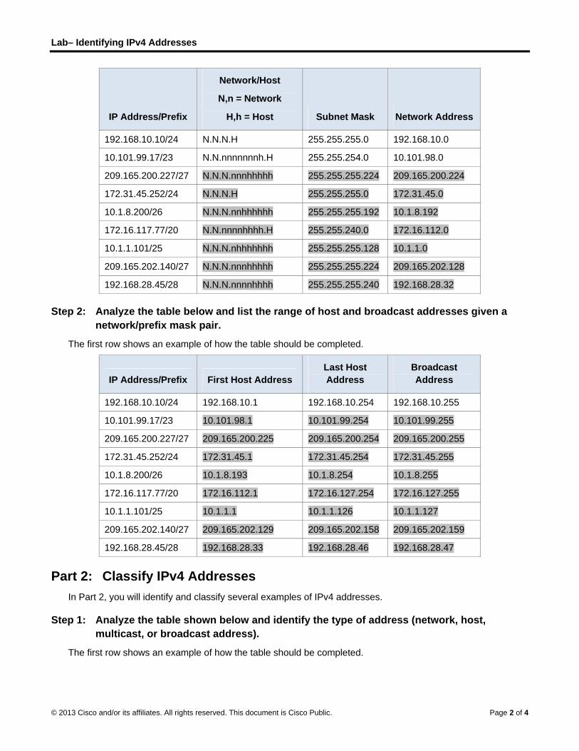
Lab– Identifying IPv4 Addresses
© 2013 Cisco and/or its affiliates. All rights reserved. This document is Cisco Public. Page 2 of 4
IP Address/Prefix
Network/Host
N,n = Network
H,h = Host Subnet Mask Network Address
192.168.10.10/24 N.N.N.H 255.255.255.0 192.168.10.0
10.101.99.17/23 N.N.nnnnnnnh.H 255.255.254.0 10.101.98.0
209.165.200.227/27 N.N.N.nnnhhhhh 255.255.255.224 209.165.200.224
172.31.45.252/24 N.N.N.H 255.255.255.0 172.31.45.0
10.1.8.200/26 N.N.N.nnhhhhhh 255.255.255.192 10.1.8.192
172.16.117.77/20 N.N.nnnnhhhh.H 255.255.240.0 172.16.112.0
10.1.1.101/25 N.N.N.nhhhhhhh 255.255.255.128 10.1.1.0
209.165.202.140/27 N.N.N.nnnhhhhh 255.255.255.224 209.165.202.128
192.168.28.45/28 N.N.N.nnnnhhhh 255.255.255.240 192.168.28.32
Step 2: Analyze the table below and list the range of host and broadcast addresses given a network/prefix mask pair.
The first row shows an example of how the table should be completed.
IP Address/Prefix First Host Address Last Host Address
Broadcast Address
192.168.10.10/24 192.168.10.1 192.168.10.254 192.168.10.255
10.101.99.17/23 10.101.98.1 10.101.99.254 10.101.99.255
209.165.200.227/27 209.165.200.225 209.165.200.254 209.165.200.255
172.31.45.252/24 172.31.45.1 172.31.45.254 172.31.45.255
10.1.8.200/26 10.1.8.193 10.1.8.254 10.1.8.255
172.16.117.77/20 172.16.112.1 172.16.127.254 172.16.127.255
10.1.1.101/25 10.1.1.1 10.1.1.126 10.1.1.127
209.165.202.140/27 209.165.202.129 209.165.202.158 209.165.202.159
192.168.28.45/28 192.168.28.33 192.168.28.46 192.168.28.47
Part 2: Classify IPv4 Addresses In Part 2, you will identify and classify several examples of IPv4 addresses.
Step 1: Analyze the table shown below and identify the type of address (network, host, multicast, or broadcast address).
The first row shows an example of how the table should be completed.
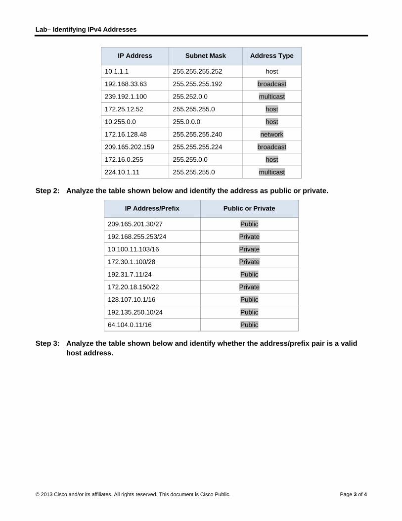
Lab– Identifying IPv4 Addresses
© 2013 Cisco and/or its affiliates. All rights reserved. This document is Cisco Public. Page 3 of 4
IP Address Subnet Mask Address Type
10.1.1.1 255.255.255.252 host
192.168.33.63 255.255.255.192 broadcast
239.192.1.100 255.252.0.0 multicast
172.25.12.52 255.255.255.0 host
10.255.0.0 255.0.0.0 host
172.16.128.48 255.255.255.240 network
209.165.202.159 255.255.255.224 broadcast
172.16.0.255 255.255.0.0 host
224.10.1.11 255.255.255.0 multicast
Step 2: Analyze the table shown below and identify the address as public or private.
IP Address/Prefix Public or Private
209.165.201.30/27 Public
192.168.255.253/24 Private
10.100.11.103/16 Private
172.30.1.100/28 Private
192.31.7.11/24 Public
172.20.18.150/22 Private
128.107.10.1/16 Public
192.135.250.10/24 Public
64.104.0.11/16 Public
Step 3: Analyze the table shown below and identify whether the address/prefix pair is a valid host address.
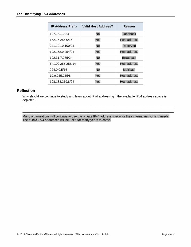
Lab– Identifying IPv4 Addresses
© 2013 Cisco and/or its affiliates. All rights reserved. This document is Cisco Public. Page 4 of 4
IP Address/Prefix Valid Host Address? Reason
127.1.0.10/24 No Loopback
172.16.255.0/16 Yes Host address
241.19.10.100/24 No Reserved
192.168.0.254/24 Yes Host address
192.31.7.255/24 No Broadcast
64.102.255.255/14 Yes Host address
224.0.0.5/16 No Multicast
10.0.255.255/8 Yes Host address
198.133.219.8/24 Yes Host address
Reflection Why should we continue to study and learn about IPv4 addressing if the available IPv4 address space is depleted?
_______________________________________________________________________________________
_______________________________________________________________________________________
Many organizations will continue to use the private IPv4 address space for their internal networking needs. The public IPv4 addresses will be used for many years to come.

© 2014 Cisco and/or its affiliates. All rights reserved. This document is Cisco Public. Page 1 of 8
Lab – Identifying IPv6 Addresses (Instructor Version) Instructor Note: Red font color or Gray highlights indicate text that appears in the instructor copy only.
Topology
Objectives
Part 1: Identify the Different Types of IPv6 Addresses
Review the different types of IPv6 addresses.
Match the IPv6 address with the correct type.
Part 2: Examine a Host IPv6 Network Interface and Address
Check PC IPv6 network address settings.
Part 3: Practice IPv6 Address Abbreviation
Study and review the rules for IPv6 address abbreviation.
Practice compressing and decompressing IPv6 addresses.
Background / Scenario
With the depletion of the Internet Protocol version 4 (IPv4) network address space and the adoption and transition to IPv6, networking professionals must understand how both IPv4 and IPv6 networks function. Many devices and applications already support IPv6. This includes extensive Cisco device Internetwork Operating System (IOS) support and workstation/server operating system support, such as that found in Windows and Linux.
This lab focuses on IPv6 addresses and the components of the address. In Part 1, you will identify the IPv6 address types, and in Part 2, you will view the IPv6 settings on a PC. In Part 3, you will practice IPv6 address abbreviation.
Instructor Note: This lab has three sections that can be split up into two parts (Part 1/2 and Part 3). It can be performed in multiple sessions, or assigned as homework.
Required Resources
1 PC (Windows 7 or Vista with Internet access)
Note: The IPv6 protocol is enabled in Windows 7 and Vista by default. The Windows XP operating system
does not enable IPv6 by default and is not recommended for use with this lab. This lab uses Windows 7 PC
hosts.
Instructor Note: For instructions on how to enable IPv6 and configure host addresses with Windows XP, refer to the Instructor Lab Manual.

Lab – Identifying IPv6 Addresses
© 2014 Cisco and/or its affiliates. All rights reserved. This document is Cisco Public. Page 2 of 8
Part 1: Identify the Different Types of IPv6 Addresses
In Part 1, you will review the characteristics of IPv6 addresses to identify the different types of IPv6 addresses.
Step 1: Review the different types of IPv6 addresses.
An IPv6 address is 128 bits long. It is most often presented as 32 hexadecimal characters. Each hexadecimal character is the equivalent of 4 bits (4 x 32 = 128). A non-abbreviated IPv6 host address is shown here:
2001:0DB8:0001:0000:0000:0000:0000:0001
A hextet is the hexadecimal, IPv6 version of an IPv4 octet. An IPv4 address is 4 octets long, separated by dots. An IPv6 address is 8 hextets long, separated by colons.
An IPv4 address is 4 octets and is commonly written or displayed in decimal notation.
255.255.255.255
An IPv6 address is 8 hextets and is commonly written or displayed in hexadecimal notation.
FFFF:FFFF:FFFF:FFFF:FFFF:FFFF:FFFF:FFFF
In an IPv4 address, each individual octet is 8 binary digits (bits). Four octets equals one 32-bit IPv4 address.
11111111 = 255
11111111.11111111.11111111.11111111 = 255.255.255.255
In an IPv6 address, each individual hextet is 16 bits long. Eight hextets equals one 128-bit IPv6 address.
1111111111111111 = FFFF
1111111111111111.1111111111111111.1111111111111111.1111111111111111.
1111111111111111.1111111111111111.1111111111111111.1111111111111111 =
FFFF:FFFF:FFFF:FFFF:FFFF:FFFF:FFFF:FFFF
If we read an IPv6 address starting from the left, the first (or far left) hextet identifies the IPv6 address type. For example, if the IPv6 address has all zeros in the far left hextet, then the address is possibly a loopback address.
0000:0000:0000:0000:0000:0000:0000:0001 = loopback address
::1 = loopback address abbreviated
As another example, if the IPv6 address has FE80 in the first hextet, then the address is a link-local
address.
FE80:0000:0000:0000:C5B7:CB51:3C00:D6CE = link-local address
FE80::C5B7:CB51:3C00:D6CE = link-local address abbreviated
Study the chart below to help you identify the different types of IPv6 address based on the numbers in the
first hextet.

Lab – Identifying IPv6 Addresses
© 2014 Cisco and/or its affiliates. All rights reserved. This document is Cisco Public. Page 3 of 8
First Hextet (Far Left) Type of IPv6 Address
0000 to 00FF Loopback address, any address, unspecified address, or IPv4-compatible
2000 to 3FFF
Global unicast address (a routable address in a range of addresses that is currently being handed out by the Internet Assigned Numbers Authority [IANA])
FE80 to FEBF Link-local (a unicast address which identifies the host computer on the local network)
FC00 to FCFF
Unique-local (a unicast address which can be assigned to a host to identify it as being part of a specific subnet on the local network)
FF00 to FFFF Multicast address
There are other IPv6 address types that are either not yet widely implemented, or have already become deprecated, and are no longer supported. For instance, an anycast address is new to IPv6 and can be used by routers to facilitate load sharing and provide alternate path flexibility if a router becomes unavailable. Only routers should respond to an anycast address. Alternatively, site-local addresses have been deprecated and replaced by unique-local addresses. Site-local addresses were identified by the numbers FEC0 in the initial hextet.
In IPv6 networks, there are no network (wire) addresses or broadcast addresses as there are in IPv4 networks.
Step 2: Match the IPv6 address to its type.
Match the IPv6 addresses to their corresponding address type. Notice that the addresses have been compressed to their abbreviated notation and that the slash network prefix number is not shown. Some answer choices must be used more than once.
IPv6 Address Answer Answer Choices
2001:0DB8:1:ACAD::FE55:6789:B210 1. ____ a. Loopback address
::1 2. ____ b. Global unicast address
FC00:22:A:2::CD4:23E4:76FA 3. ____ c. Link-local address
2033:DB8:1:1:22:A33D:259A:21FE 4. ____ d. Unique-local address
FE80::3201:CC01:65B1 5. ____ e. Multicast address
FF00:: 6. ____
FF00::DB7:4322:A231:67C 7. ____
FF02::2 8. ____
Answers: 1. B, 2. A, 3. D, 4. B, 5. C, 6. E, 7. E, 8. E
Part 2: Examine a Host IPv6 Network Interface and Address
In Part 2, you will check the IPv6 network settings of your PC to identify your network interface IPv6 address.

Lab – Identifying IPv6 Addresses
© 2014 Cisco and/or its affiliates. All rights reserved. This document is Cisco Public. Page 4 of 8
Step 1: Check your PC IPv6 network address settings.
a. Verify that the IPv6 protocol is installed and active on your PC-A (check your Local Area Connection settings).
b. Click the Windows Start button and then Control Panel and change View by: Category to View by: Small icons.
c. Click the Network and Sharing Center icon.
d. On the left side of the window, click Change adapter settings. You should now see icons representing your installed network adapters. Right-click your active network interface (it may be a Local Area Connection or a Wireless Network Connection), and then click Properties.
e. You should now see your Network Connection Properties window. Scroll through the list of items to determine whether IPv6 is present, which indicates that it is installed, and if it is also check marked, which indicates that it is active.
f. Select the item Internet Protocol Version 6 (TCP/IPv6) and click Properties. You should see the IPv6 settings for your network interface. Your IPv6 properties window is likely set to Obtain an IPv6 address automatically. This does not mean that IPv6 relies on the Dynamic Host Configuration Protocol (DHCP). Instead of using DHCP, IPv6 looks to the local router for IPv6 network information and then auto-configures its own IPv6 addresses. To manually configure IPv6, you must provide the IPv6 address, the subnet prefix length, and the default gateway.
Note: The local router can refer host requests for IPv6 information, especially Domain Name System (DNS) information, to a DHCPv6 server on the network.
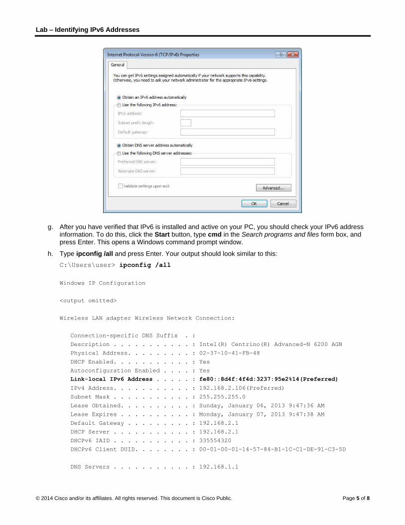
Lab – Identifying IPv6 Addresses
© 2014 Cisco and/or its affiliates. All rights reserved. This document is Cisco Public. Page 5 of 8
g. After you have verified that IPv6 is installed and active on your PC, you should check your IPv6 address information. To do this, click the Start button, type cmd in the Search programs and files form box, and press Enter. This opens a Windows command prompt window.
h. Type ipconfig /all and press Enter. Your output should look similar to this:
C:\Users\user> ipconfig /all
Windows IP Configuration
<output omitted>
Wireless LAN adapter Wireless Network Connection:
Connection-specific DNS Suffix . :
Description . . . . . . . . . . . : Intel(R) Centrino(R) Advanced-N 6200 AGN
Physical Address. . . . . . . . . : 02-37-10-41-FB-48
DHCP Enabled. . . . . . . . . . . : Yes
Autoconfiguration Enabled . . . . : Yes
Link-local IPv6 Address . . . . . : fe80::8d4f:4f4d:3237:95e2%14(Preferred)
IPv4 Address. . . . . . . . . . . : 192.168.2.106(Preferred)
Subnet Mask . . . . . . . . . . . : 255.255.255.0
Lease Obtained. . . . . . . . . . : Sunday, January 06, 2013 9:47:36 AM
Lease Expires . . . . . . . . . . : Monday, January 07, 2013 9:47:38 AM
Default Gateway . . . . . . . . . : 192.168.2.1
DHCP Server . . . . . . . . . . . : 192.168.2.1
DHCPv6 IAID . . . . . . . . . . . : 335554320
DHCPv6 Client DUID. . . . . . . . : 00-01-00-01-14-57-84-B1-1C-C1-DE-91-C3-5D
DNS Servers . . . . . . . . . . . : 192.168.1.1

Lab – Identifying IPv6 Addresses
© 2014 Cisco and/or its affiliates. All rights reserved. This document is Cisco Public. Page 6 of 8
8.8.4.4
<output omitted>
i. You can see from the output that the client PC has an IPv6 link-local address with a randomly generated interface ID. What does it indicate about the network regarding IPv6 global unicast address, IPv6 unique-local address, or IPv6 gateway address?
____________________________________________________________________________________
____________________________________________________________________________________
It indicates that there is no IPv6 enabled gateway router providing global address, local address, or subnet information on the network.
j. What kind of IPv6 addresses did you find when using ipconfig /all?
____________________________________________________________________________________
____________________________________________________________________________________
Answers will vary, but most likely they will be link-local addresses also.
Part 3: Practice IPv6 Address Abbreviation
In Part 3, you will study and review rules for IPv6 address abbreviation to correctly compress and decompress IPv6 addresses.
Step 1: Study and review the rules for IPv6 address abbreviation.
Rule 1: In an IPv6 address, a string of four zeros (0s) in a hextet can be abbreviated as a single zero.
2001:0404:0001:1000:0000:0000:0EF0:BC00
2001:0404:0001:1000:0:0:0EF0:BC00 (abbreviated with single zeros)
Rule 2: In an IPv6 address, the leading zeros in each hextet can be omitted, trailing zeros cannot be omitted.
2001:0404:0001:1000:0000:0000:0EF0:BC00
2001:404:1:1000:0:0:EF0:BC00 (abbreviated with leading zeros omitted)
Rule 3: In an IPv6 address, a single continuous string of four or more zeros can be abbreviated as a double colon (::). The double colon abbreviation can only be used one time in an IP address.
2001:0404:0001:1000:0000:0000:0EF0:BC00
2001:404:1:1000::EF0:BC00 (abbreviated with leading zeroes omitted and continuous zeros
replaced with a double colon)
The image below illustrates these rules of IPv6 address abbreviation:

Lab – Identifying IPv6 Addresses
© 2014 Cisco and/or its affiliates. All rights reserved. This document is Cisco Public. Page 7 of 8
Step 2: Practice compressing and decompressing IPv6 addresses.
Using the rules of IPv6 address abbreviation, either compress or decompress the following addresses:
1) 2002:0EC0:0200:0001:0000:04EB:44CE:08A2
________________________________________________________________________________
2002:EC0:200:1::4EB:44CE:8A2
2) FE80:0000:0000:0001:0000:60BB:008E:7402
________________________________________________________________________________
FE80::1:0:60BB:8E:7402
3) FE80::7042:B3D7:3DEC:84B8
________________________________________________________________________________
FE80:0000:0000:0000:7042:B3D7:3DEC:84B8
4) FF00::
________________________________________________________________________________
FF00:0000:0000:0000:0000:0000:0000:0000
5) 2001:0030:0001:ACAD:0000:330E:10C2:32BF
________________________________________________________________________________
2001:30:1:ACAD::330E:10C2:32BF
Reflection
1. How do you think you must support IPv6 in the future?
_______________________________________________________________________________________
_______________________________________________________________________________________
Answers will vary.

Lab – Identifying IPv6 Addresses
© 2014 Cisco and/or its affiliates. All rights reserved. This document is Cisco Public. Page 8 of 8
2. Do you think IPv4 networks continue on, or will everyone eventually switch over to IPv6? How long do you think it will take?
_______________________________________________________________________________________
_______________________________________________________________________________________
Answers will vary.

© 2013 Cisco and/or its affiliates. All rights reserved. This document is Cisco Public. Page 1 of 20
Lab - Configuring IPv6 Addresses on Network Devices (Instructor
Version) Instructor Note: Red font color or Gray highlights indicate text that appears in the instructor copy only.
Topology
Addressing Table
Device Interface IPv6 Address
Prefix
Length Default Gateway
R1 G0/0 2001:DB8:ACAD:A::1 64 N/A
G0/1 2001:DB8:ACAD:1::1 64 N/A
S1 VLAN 1 2001:DB8:ACAD:1::B 64 N/A
PC-A NIC 2001:DB8:ACAD:1::3 64 FE80::1
PC-B NIC 2001:DB8:ACAD:A::3 64 FE80::1
Objectives
Part 1: Set Up Topology and Configure Basic Router and Switch Settings
Part 2: Configure IPv6 Addresses Manually
Part 3: Verify End-to-End Connectivity
Background / Scenario
Knowledge of the Internet Protocol version 6 (IPv6) multicast groups can be helpful when assigning IPv6 addresses manually. Understanding how the all-router multicast group is assigned and how to control address assignments for the Solicited Nodes multicast group can prevent IPv6 routing issues and help ensure best practices are implemented.
In this lab, you will configure hosts and device interfaces with IPv6 addresses and explore how the all-router multicast group is assigned to a router. You will use show commands to view IPv6 unicast and multicast addresses. You will also verify end-to-end connectivity using the ping and traceroute commands.
Note: The routers used with CCNA hands-on labs are Cisco 1941 ISRs with Cisco IOS Release 15.2(4)M3 (universalk9 image). The switches used are Cisco Catalyst 2960s with Cisco IOS Release 15.0(2) (lanbasek9 image). Other routers, switches and Cisco IOS versions can be used. Depending on the model and Cisco IOS version, the commands available and output produced might vary from what is shown in the labs. Refer to the Router Interface Summary table at the end of the lab for the correct interface identifiers.
Note: Make sure that the routers and switches have been erased and have no startup configurations. If you are unsure, contact your instructor.
Instructor Note: Refer to the Instructor Lab Manual for the procedures to initialize and reload devices.

Lab - Configuring IPv6 Addresses on Network Devices
© 2013 Cisco and/or its affiliates. All rights reserved. This document is Cisco Public. Page 2 of 20
Instructor Note: The default bias template used by the Switch Database Manager (SDM) does not provide IPv6 address capabilities. Verify that SDM is using either the dual-ipv4-and-ipv6 template or the lanbase-routing template. The new template will be used after reboot even if the config is not saved.
S1# show sdm prefer
Follow these steps to assign the dual-ipv4-and-ipv6 template as the default SDM template:
S1# configure terminal
S1(config)# sdm prefer dual-ipv4-and-ipv6 default
S1(config)# end
S1# reload
Required Resources
1 Router (Cisco 1941 with Cisco IOS software, Release 15.2(4)M3 universal image or comparable)
1 Switch (Cisco 2960 with Cisco IOS Release 15.0(2) lanbasek9 image or comparable)
2 PCs (Windows 7 with terminal emulation program, such as Tera Term)
Console cables to configure the Cisco IOS devices via the console ports
Ethernet cables as shown in the topology
Note: The Gigabit Ethernet interfaces on Cisco 1941 routers are autosensing and an Ethernet straight-through cable may be used between the router and PC-B. If using another model Cisco router, it may be necessary to use an Ethernet crossover cable.
Note: The IPv6 protocol is enabled in Windows 7 and Vista by default. The Windows XP operating system does not enable IPv6 by default and is not recommended for use with this lab. This lab uses Windows 7 PC hosts.
Instructor Note: For instructions on how to enable IPv6 and configure host addresses with Windows XP refer to the Instructor Lab Manual.
Part 1: Set Up Topology and Configure Basic Router and Switch Settings
Step 1: Cable the network as shown in the topology.
Step 2: Initialize and reload the router and switch.
Step 3: Verify that the PC interfaces are configured to use the IPv6 protocol.
Verify that the IPv6 protocol is active on both PCs by ensuring that the Internet Protocol Version 6 (TCP/IPv6) check box is selected in the Local Area Connection Properties window.

Lab - Configuring IPv6 Addresses on Network Devices
© 2013 Cisco and/or its affiliates. All rights reserved. This document is Cisco Public. Page 3 of 20
Step 4: Configure the router.
a. Console into the router and enable privileged EXEC mode.
b. Assign the device name to the router.
c. Disable DNS lookup to prevent the router from attempting to translate incorrectly entered commands as though they were hostnames.
d. Assign class as the privileged EXEC encrypted password.
e. Assign cisco as the console password and enable login.
f. Assign cisco as the VTY password and enable login.
g. Encrypt the clear text passwords.
h. Create a banner that warns anyone accessing the device that unauthorized access is prohibited.
i. Save the running configuration to the startup configuration file.
Step 5: Configure the switch.
a. Console into the switch and enable privileged EXEC mode.
b. Assign the device name to the switch.
c. Disable DNS lookup to prevent the router from attempting to translate incorrectly entered commands as though they were hostnames.
d. Assign class as the privileged EXEC encrypted password.
e. Assign cisco as the console password and enable login.
f. Assign cisco as the VTY password and enable login.

Lab - Configuring IPv6 Addresses on Network Devices
© 2013 Cisco and/or its affiliates. All rights reserved. This document is Cisco Public. Page 4 of 20
g. Encrypt the clear text passwords.
h. Create a banner that warns anyone accessing the device that unauthorized access is prohibited.
i. Save the running configuration to the startup configuration file.
Part 2: Configure IPv6 Addresses Manually
Step 1: Assign the IPv6 addresses to Ethernet interfaces on R1.
a. Assign the IPv6 global unicast addresses, listed in the Addressing Table, to both Ethernet interfaces on R1.
R1(config)# interface g0/0
R1(config-if)# ipv6 address 2001:db8:acad:a::1/64
R1(config-if)# no shutdown
R1(config-if)# interface g0/1
R1(config-if)# ipv6 address 2001:db8:acad:1::1/64
R1(config-if)# no shutdown
R1(config-if)# end
R1#
Instructor Note: The IPv6 global prefix 2001:DB8::/32 is a reserved prefix for use in documentation, as described in RFC 3849.
b. Issue the show ipv6 interface brief command to verify that the correct IPv6 unicast address is assigned to each interface.
R1# show ipv6 interface brief
Em0/0 [administratively down/down]
unassigned
GigabitEthernet0/0 [up/up]
FE80::D68C:B5FF:FECE:A0C0
2001:DB8:ACAD:A::1
GigabitEthernet0/1 [up/up]
FE80::D68C:B5FF:FECE:A0C1
2001:DB8:ACAD:1::1
Serial0/0/0 [administratively down/down]
unassigned
Serial0/0/1 [administratively down/down]
unassigned
R1#
c. Issue the show ipv6 interface g0/0 command. Notice that the interface is listing two Solicited Nodes multicast groups, because the IPv6 link-local (FE80) Interface ID was not manually configured to match the IPv6 unicast Interface ID.
Note: The link-local address displayed is based on EUI-64 addressing, which automatically uses the interface Media Access Control (MAC) address to create a 128-bit IPv6 link-local address.
R1# show ipv6 interface g0/0
GigabitEthernet0/0 is up, line protocol is up
IPv6 is enabled, link-local address is FE80::D68C:B5FF:FECE:A0C0
No Virtual link-local address(es):
Global unicast address(es):

Lab - Configuring IPv6 Addresses on Network Devices
© 2013 Cisco and/or its affiliates. All rights reserved. This document is Cisco Public. Page 5 of 20
2001:DB8:ACAD:A::1, subnet is 2001:DB8:ACAD:A::/64
Joined group address(es):
FF02::1
FF02::1:FF00:1
FF02::1:FFCE:A0C0
MTU is 1500 bytes
ICMP error messages limited to one every 100 milliseconds
ICMP redirects are enabled
ICMP unreachables are sent
ND DAD is enabled, number of DAD attempts: 1
ND reachable time is 30000 milliseconds (using 30000)
ND advertised reachable time is 0 (unspecified)
ND advertised retransmit interval is 0 (unspecified)
ND router advertisements are sent every 200 seconds
ND router advertisements live for 1800 seconds
ND advertised default router preference is Medium
Hosts use stateless autoconfig for addresses.
R1#
d. To get the link-local address to match the unicast address on the interface, manually enter the link-local addresses on each of the Ethernet interfaces on R1.
R1# config t
Enter configuration commands, one per line. End with CNTL/Z.
R1(config)# interface g0/0
R1(config-if)# ipv6 address fe80::1 link-local
R1(config-if)# interface g0/1
R1(config-if)# ipv6 address fe80::1 link-local
R1(config-if)# end
R1#
Note: Each router interface belongs to a separate network. Packets with a link-local address never leave the local network; therefore, you can use the same link-local address on both interfaces.
e. Re-issue the show ipv6 interface g0/0 command. Notice that the link-local address has been changed to FE80::1 and that there is only one Solicited Nodes multicast group listed.
R1# show ipv6 interface g0/0
GigabitEthernet0/0 is up, line protocol is up
IPv6 is enabled, link-local address is FE80::1
No Virtual link-local address(es):
Global unicast address(es):
2001:DB8:ACAD:A::1, subnet is 2001:DB8:ACAD:A::/64
Joined group address(es):
FF02::1
FF02::1:FF00:1
MTU is 1500 bytes
ICMP error messages limited to one every 100 milliseconds
ICMP redirects are enabled
ICMP unreachables are sent
ND DAD is enabled, number of DAD attempts: 1
ND reachable time is 30000 milliseconds (using 30000)
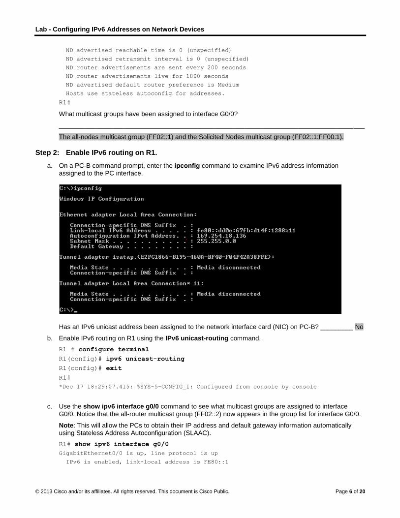
Lab - Configuring IPv6 Addresses on Network Devices
© 2013 Cisco and/or its affiliates. All rights reserved. This document is Cisco Public. Page 6 of 20
ND advertised reachable time is 0 (unspecified)
ND advertised retransmit interval is 0 (unspecified)
ND router advertisements are sent every 200 seconds
ND router advertisements live for 1800 seconds
ND advertised default router preference is Medium
Hosts use stateless autoconfig for addresses.
R1#
What multicast groups have been assigned to interface G0/0?
____________________________________________________________________________________
The all-nodes multicast group (FF02::1) and the Solicited Nodes multicast group (FF02::1:FF00:1).
Step 2: Enable IPv6 routing on R1.
a. On a PC-B command prompt, enter the ipconfig command to examine IPv6 address information assigned to the PC interface.
Has an IPv6 unicast address been assigned to the network interface card (NIC) on PC-B? _________ No
b. Enable IPv6 routing on R1 using the IPv6 unicast-routing command.
R1 # configure terminal
R1(config)# ipv6 unicast-routing
R1(config)# exit
R1#
*Dec 17 18:29:07.415: %SYS-5-CONFIG_I: Configured from console by console
c. Use the show ipv6 interface g0/0 command to see what multicast groups are assigned to interface G0/0. Notice that the all-router multicast group (FF02::2) now appears in the group list for interface G0/0.
Note: This will allow the PCs to obtain their IP address and default gateway information automatically using Stateless Address Autoconfiguration (SLAAC).
R1# show ipv6 interface g0/0
GigabitEthernet0/0 is up, line protocol is up
IPv6 is enabled, link-local address is FE80::1

Lab - Configuring IPv6 Addresses on Network Devices
© 2013 Cisco and/or its affiliates. All rights reserved. This document is Cisco Public. Page 7 of 20
No Virtual link-local address(es):
Global unicast address(es):
2001:DB8:ACAD:A::1, subnet is 2001:DB8:ACAD:A::/64 [EUI]
Joined group address(es):
FF02::1
FF02::2
FF02::1:FF00:1
MTU is 1500 bytes
ICMP error messages limited to one every 100 milliseconds
ICMP redirects are enabled
ICMP unreachables are sent
ND DAD is enabled, number of DAD attempts: 1
ND reachable time is 30000 milliseconds (using 30000)
ND advertised reachable time is 0 (unspecified)
ND advertised retransmit interval is 0 (unspecified)
ND router advertisements are sent every 200 seconds
ND router advertisements live for 1800 seconds
ND advertised default router preference is Medium
Hosts use stateless autoconfig for addresses.
R1#
d. Now that R1 is part of the all-router multicast group, re-issue the ipconfig command on PC-B. Examine the IPv6 address information.
Why did PC-B receive the Global Routing Prefix and Subnet ID that you configured on R1?
____________________________________________________________________________________
____________________________________________________________________________________
R1 G0/0 is now part of the All-router multicast group, FF02::2. This allows it to send Router Advertisement (RA) messages with the Global Network Address and Subnet ID information to all nodes on the LAN. Notice that it also sent the link-local address, FE80::1, as the Default Gateway. The PCs will receive their IP address and default gateway via SLAAC.

Lab - Configuring IPv6 Addresses on Network Devices
© 2013 Cisco and/or its affiliates. All rights reserved. This document is Cisco Public. Page 8 of 20
Step 3: Assign IPv6 addresses to the management interface (SVI) on S1.
a. Assign the IPv6 address listed in the Addressing Table to the management interface (VLAN 1) on S1. Also assign a link-local address for this interface. IPv6 command syntax is the same as on the router.
S1(config)# interface vlan 1
S1(config-if)# ipv6 address 2001:db8:acad:1::b/64
S1(config-if)# ipv6 address fe80::b link-local
S1(config-if)# end
S1#
*Mar 1 03:25:26.681: %SYS-5-CONFIG_I: Configured from console by console
b. Verify that the IPv6 addresses are properly assigned to the management interface using the show ipv6 interface vlan1 command.
S1# show ipv6 interface vlan1
Vlan1 is up, line protocol is up
IPv6 is enabled, link-local address is FE80::B
No Virtual link-local address(es):
Global unicast address(es):
2001:DB8:ACAD:1::B, subnet is 2001:DB8:ACAD:1::/64
Joined group address(es):
FF02::1
FF02::1:FF00:B
MTU is 1500 bytes
ICMP error messages limited to one every 100 milliseconds
ICMP redirects are enabled
ICMP unreachables are sent
Output features: Check hwidb
ND DAD is enabled, number of DAD attempts: 1
ND reachable time is 30000 milliseconds (using 30000)
ND NS retransmit interval is 1000 milliseconds
S1#
Note: The default 2960 Switch Database Manager (SDM) template does not support IPv6. It may be necessary to issue the command sdm prefer dual-ipv4-and-ipv6 default to enable IPv6 addressing before applying an IPv6 address to the VLAN 1 SVI.
Step 4: Assign static IPv6 addresses to the PCs.
a. Open the Local Area Connection Properties window on PC-A. Select Internet Protocol Version 6 (TCP/IPv6) and click Properties.

Lab - Configuring IPv6 Addresses on Network Devices
© 2013 Cisco and/or its affiliates. All rights reserved. This document is Cisco Public. Page 9 of 20
b. Click the Use the following IPv6 address radio button. Refer to the Addressing Table and enter the IPv6 address, Subnet prefix length, and Default gateway information. Click OK.
c. Click Close to close the Local Area Connection Properties window.

Lab - Configuring IPv6 Addresses on Network Devices
© 2013 Cisco and/or its affiliates. All rights reserved. This document is Cisco Public. Page 10 of 20
d. Repeat Steps 4a to c to enter the static IPv6 information on PC-B. For the correct IPv6 address information, refer to the Addressing Table.
e. Issue the ipconfig command from the command line on PC-B to verify the IPv6 address information.
Part 3: Verify End-to-End Connectivity
a. From PC-A, ping FE80::1. This is the link-local address assigned to G0/1 on R1.
Note: You can also test connectivity by using the global unicast address, instead of the link-local address.
b. Ping the S1 management interface from PC-A.
c. Use the tracert command on PC-A to verify that you have end-to-end connectivity to PC-B.
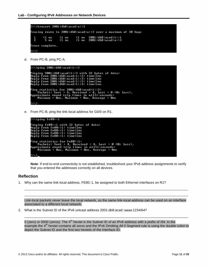
Lab - Configuring IPv6 Addresses on Network Devices
© 2013 Cisco and/or its affiliates. All rights reserved. This document is Cisco Public. Page 11 of 20
d. From PC-B, ping PC-A.
e. From PC-B, ping the link-local address for G0/0 on R1.
Note: If end-to-end connectivity is not established, troubleshoot your IPv6 address assignments to verify that you entered the addresses correctly on all devices.
Reflection
1. Why can the same link-local address, FE80::1, be assigned to both Ethernet interfaces on R1?
_______________________________________________________________________________________
_______________________________________________________________________________________
Link-local packets never leave the local network, so the same link-local address can be used on an interface associated to a different local network.
2. What is the Subnet ID of the IPv6 unicast address 2001:db8:acad::aaaa:1234/64?
_______________________________________________________________________________________
0 (zero) or 0000 (zeros). The 4th hextet is the Subnet ID of an IPv6 address with a prefix of /64. In the
example the 4th hextet contains all zeros and the IPv6 Omitting All 0 Segment rule is using the double colon to
depict the Subnet ID and the first two hextets of the Interface ID.
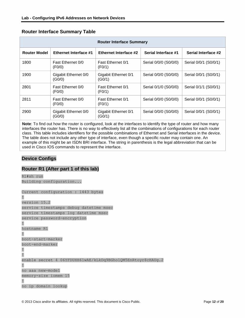
Lab - Configuring IPv6 Addresses on Network Devices
© 2013 Cisco and/or its affiliates. All rights reserved. This document is Cisco Public. Page 12 of 20
Router Interface Summary Table
Router Interface Summary
Router Model Ethernet Interface #1 Ethernet Interface #2 Serial Interface #1 Serial Interface #2
1800 Fast Ethernet 0/0 (F0/0)
Fast Ethernet 0/1 (F0/1)
Serial 0/0/0 (S0/0/0) Serial 0/0/1 (S0/0/1)
1900 Gigabit Ethernet 0/0 (G0/0)
Gigabit Ethernet 0/1 (G0/1)
Serial 0/0/0 (S0/0/0) Serial 0/0/1 (S0/0/1)
2801 Fast Ethernet 0/0 (F0/0)
Fast Ethernet 0/1 (F0/1)
Serial 0/1/0 (S0/0/0) Serial 0/1/1 (S0/0/1)
2811 Fast Ethernet 0/0 (F0/0)
Fast Ethernet 0/1 (F0/1)
Serial 0/0/0 (S0/0/0) Serial 0/0/1 (S0/0/1)
2900 Gigabit Ethernet 0/0 (G0/0)
Gigabit Ethernet 0/1 (G0/1)
Serial 0/0/0 (S0/0/0) Serial 0/0/1 (S0/0/1)
Note: To find out how the router is configured, look at the interfaces to identify the type of router and how many interfaces the router has. There is no way to effectively list all the combinations of configurations for each router class. This table includes identifiers for the possible combinations of Ethernet and Serial interfaces in the device. The table does not include any other type of interface, even though a specific router may contain one. An example of this might be an ISDN BRI interface. The string in parenthesis is the legal abbreviation that can be used in Cisco IOS commands to represent the interface.
Device Configs
Router R1 (After part 1 of this lab)
R1#sh run
Building configuration...
Current configuration : 1443 bytes
!
version 15.2
service timestamps debug datetime msec
service timestamps log datetime msec
service password-encryption
!
hostname R1
!
boot-start-marker
boot-end-marker
!
!
enable secret 4 06YFDUHH61wAE/kLkDq9BGho1QM5EnRtoyr8cHAUg.2
!
no aaa new-model
memory-size iomem 15
!
no ip domain lookup
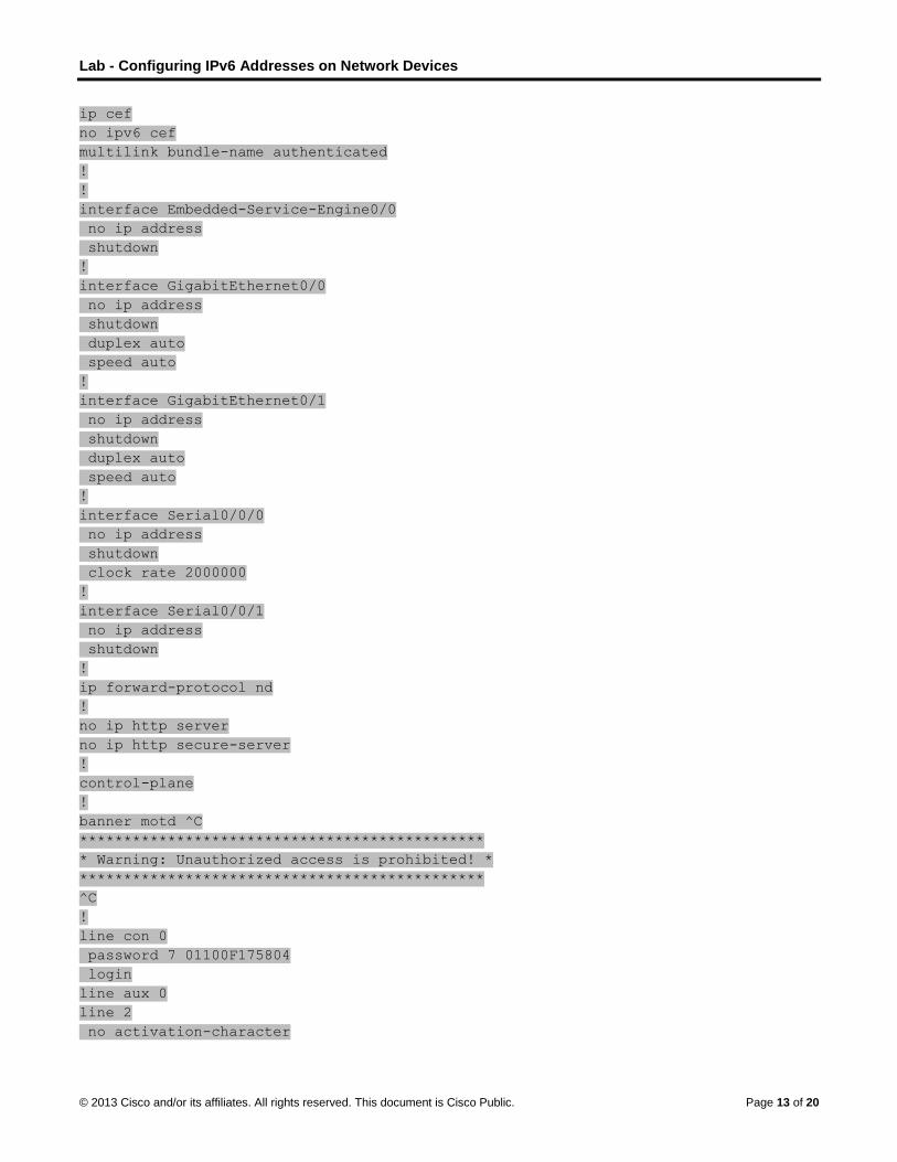
Lab - Configuring IPv6 Addresses on Network Devices
© 2013 Cisco and/or its affiliates. All rights reserved. This document is Cisco Public. Page 13 of 20
ip cef
no ipv6 cef
multilink bundle-name authenticated
!
!
interface Embedded-Service-Engine0/0
no ip address
shutdown
!
interface GigabitEthernet0/0
no ip address
shutdown
duplex auto
speed auto
!
interface GigabitEthernet0/1
no ip address
shutdown
duplex auto
speed auto
!
interface Serial0/0/0
no ip address
shutdown
clock rate 2000000
!
interface Serial0/0/1
no ip address
shutdown
!
ip forward-protocol nd
!
no ip http server
no ip http secure-server
!
control-plane
!
banner motd ^C
**********************************************
* Warning: Unauthorized access is prohibited! *
**********************************************
^C
!
line con 0
password 7 01100F175804
login
line aux 0
line 2
no activation-character

Lab - Configuring IPv6 Addresses on Network Devices
© 2013 Cisco and/or its affiliates. All rights reserved. This document is Cisco Public. Page 14 of 20
no exec
transport preferred none
transport input all
transport output pad telnet rlogin lapb-ta mop udptn v120 ssh
stopbits 1
line vty 0 4
password 7 104D000A0618
login
transport input all
!
scheduler allocate 20000 1000
!
end
Switch S1 (After part 1 of this lab)
S1#sh run
Building configuration...
Current configuration : 1624 bytes
!
version 15.0
no service pad
service timestamps debug datetime msec
service timestamps log datetime msec
service password-encryption
!
hostname S1
!
boot-start-marker
boot-end-marker
!
enable secret 4 06YFDUHH61wAE/kLkDq9BGho1QM5EnRtoyr8cHAUg.2
!
no aaa new-model
system mtu routing 1500
!
!
no ip domain-lookup
!
spanning-tree mode pvst
spanning-tree extend system-id
!
vlan internal allocation policy ascending
!
interface FastEthernet0/1
shutdown
!
interface FastEthernet0/2
shutdown

Lab - Configuring IPv6 Addresses on Network Devices
© 2013 Cisco and/or its affiliates. All rights reserved. This document is Cisco Public. Page 15 of 20
!
interface FastEthernet0/3
shutdown
!
interface FastEthernet0/4
shutdown
!
interface FastEthernet0/5
!
interface FastEthernet0/6
!
interface FastEthernet0/7
!
interface FastEthernet0/8
!
interface FastEthernet0/9
!
interface FastEthernet0/10
!
interface FastEthernet0/11
!
interface FastEthernet0/12
!
interface FastEthernet0/13
!
interface FastEthernet0/14
!
interface FastEthernet0/15
!
interface FastEthernet0/16
!
interface FastEthernet0/17
!
interface FastEthernet0/18
!
interface FastEthernet0/19
!
interface FastEthernet0/20
!
interface FastEthernet0/21
!
interface FastEthernet0/22
!
interface FastEthernet0/23
!
interface FastEthernet0/24
!
interface GigabitEthernet0/1
!

Lab - Configuring IPv6 Addresses on Network Devices
© 2013 Cisco and/or its affiliates. All rights reserved. This document is Cisco Public. Page 16 of 20
interface GigabitEthernet0/2
!
interface Vlan1
no ip address
!
ip http server
ip http secure-server
!
banner motd ^C
**********************************************
* Warning: Unauthorzed access is prohibited! *
**********************************************
^C
!
line con 0
password 7 121A0C041104
login
line vty 0 4
password 7 121A0C041104
login
line vty 5 15
password 7 121A0C041104
login
!
end
Router R1 (Final)
R1#show run
Building configuration...
Current configuration : 1577 bytes
!
version 15.2
service timestamps debug datetime msec
service timestamps log datetime msec
service password-encryption
!
hostname R1
!
boot-start-marker
boot-end-marker
!
enable secret 4 06YFDUHH61wAE/kLkDq9BGho1QM5EnRtoyr8cHAUg.2
!
no aaa new-model
memory-size iomem 15
!
no ip domain lookup
ip cef

Lab - Configuring IPv6 Addresses on Network Devices
© 2013 Cisco and/or its affiliates. All rights reserved. This document is Cisco Public. Page 17 of 20
ipv6 unicast-routing
ipv6 cef
multilink bundle-name authenticated
!
!
interface Embedded-Service-Engine0/0
no ip address
shutdown
!
interface GigabitEthernet0/0
no ip address
duplex auto
speed auto
ipv6 address FE80::1 link-local
ipv6 address 2001:DB8:ACAD:A::1/64
!
interface GigabitEthernet0/1
no ip address
duplex auto
speed auto
ipv6 address FE80::1 link-local
ipv6 address 2001:DB8:ACAD:1::1/64
!
interface Serial0/0/0
no ip address
shutdown
clock rate 2000000
!
interface Serial0/0/1
no ip address
shutdown
!
ip forward-protocol nd
!
no ip http server
no ip http secure-server
!
control-plane
!
banner motd ^C
**********************************************
* Warning: Unauthorzed access is prohibited! *
**********************************************
^C
!
line con 0
password 7 01100F175804
login
line aux 0

Lab - Configuring IPv6 Addresses on Network Devices
© 2013 Cisco and/or its affiliates. All rights reserved. This document is Cisco Public. Page 18 of 20
line 2
no activation-character
no exec
transport preferred none
transport input all
transport output pad telnet rlogin lapb-ta mop udptn v120 ssh
stopbits 1
line vty 0 4
password 7 104D000A0618
login
transport input all
!
scheduler allocate 20000 1000
!
end
Switch S1 (Final)
S1#sh run
Building configuration...
Current configuration : 1733 bytes
!
!
version 15.0
no service pad
service timestamps debug datetime msec
service timestamps log datetime msec
service password-encryption
!
hostname S1
!
boot-start-marker
boot-end-marker
!
enable secret 4 06YFDUHH61wAE/kLkDq9BGho1QM5EnRtoyr8cHAUg.2
!
no aaa new-model
system mtu routing 1500
!
no ip domain-lookup
!
spanning-tree mode pvst
spanning-tree extend system-id
!
vlan internal allocation policy ascending
!

Lab - Configuring IPv6 Addresses on Network Devices
© 2013 Cisco and/or its affiliates. All rights reserved. This document is Cisco Public. Page 19 of 20
interface FastEthernet0/1
shutdown
!
interface FastEthernet0/2
shutdown
!
interface FastEthernet0/3
shutdown
!
interface FastEthernet0/4
shutdown
!
interface FastEthernet0/5
!
interface FastEthernet0/6
!
interface FastEthernet0/7
!
interface FastEthernet0/8
!
interface FastEthernet0/9
!
interface FastEthernet0/10
!
interface FastEthernet0/11
!
interface FastEthernet0/12
!
interface FastEthernet0/13
!
interface FastEthernet0/14
!
interface FastEthernet0/15
!
interface FastEthernet0/16
!
interface FastEthernet0/17
!
interface FastEthernet0/18
!
interface FastEthernet0/19
!
interface FastEthernet0/20
!
interface FastEthernet0/21

Lab - Configuring IPv6 Addresses on Network Devices
© 2013 Cisco and/or its affiliates. All rights reserved. This document is Cisco Public. Page 20 of 20
!
interface FastEthernet0/22
!
interface FastEthernet0/23
!
interface FastEthernet0/24
!
interface GigabitEthernet0/1
!
interface GigabitEthernet0/2
!
interface Vlan1
no ip address
ipv6 address FE80::B link-local
ipv6 address 2001:DB8:ACAD:1::B/64
!
ip http server
ip http secure-server
!
!
banner motd ^C
**********************************************
* Warning: Unauthorzed access is prohibited! *
**********************************************
^C
!
line con 0
password 7 121A0C041104
login
line vty 0 4
password 7 121A0C041104
login
line vty 5 15
password 7 121A0C041104
login
!
end

©
L(I
T
© 2013 Cisco and
Lab – Te(Instructonstructor No
Topology
d/or its affiliates.
esting Nor Versioote: Red font
All rights reserve
Network on) color or Gray
ed. This docume
Connec
y highlights ind
ent is Cisco Publi
ctivity wi
dicate text tha
ic.
ith Ping
at appears in
and Tra
the instructo
P
aceroute
r copy only.
Page 1 of 27
e

Lab – Testing Network Connectivity with Ping and Traceroute
© 2013 Cisco and/or its affiliates. All rights reserved. This document is Cisco Public. Page 2 of 27
Addressing Table
Device Interface IP Address Subnet Mask Default Gateway
LOCAL G0/1 192.168.1.1 255.255.255.0 N/A
S0/0/0 (DCE) 10.1.1.1 255.255.255.252 N/A
ISP S0/0/0 10.1.1.2 255.255.255.252 N/A
S0/0/1 (DCE) 10.2.2.2 255.255.255.252 N/A
REMOTE G0/1 192.168.3.1 255.255.255.0 N/A
S0/0/1 10.2.2.1 255.255.255.252 N/A
S1 VLAN 1 192.168.1.11 255.255.255.0 192.168.1.1
S3 VLAN 1 192.168.3.11 255.255.255.0 192.168.3.1
PC-A NIC 192.168.1.3 255.255.255.0 192.168.1.1
PC-C NIC 192.168.3.3 255.255.255.0 192.168.3.1
Objectives Part 1: Build and Configure the Network
Cable the network.
Configure the PCs.
Configure the routers.
Configure the switches.
Part 2: Use Ping Command for Basic Network Testing
Use ping from a PC.
Use ping from Cisco devices.
Part 3: Use Tracert and Traceroute Commands for Basic Network Testing
Use tracert from a PC.
Use traceroute from Cisco devices.
Part 4: Troubleshoot the Topology
Background / Scenario Ping and traceroute are two tools that are indispensable when testing TCP/IP network connectivity. Ping is a network administration utility used to test the reachability of a device on an IP network. This utility also measures the round-trip time for messages sent from the originating host to a destination computer. The ping utility is available on Windows, Unix-like operating systems (OS), and the Cisco Internetwork Operating System (IOS).
The traceroute utility is a network diagnostic tool for displaying the route and measuring the transit delays of packets travelling an IP network. The tracert utility is available on Windows, and a similar utility, traceroute, is available on Unix-like OS and Cisco IOS.
In this lab, the ping and traceroute commands are examined and command options are explored to modify the command behavior. Cisco devices and PCs are used in this lab for command exploration. Cisco routers

Lab – Testing Network Connectivity with Ping and Traceroute
© 2013 Cisco and/or its affiliates. All rights reserved. This document is Cisco Public. Page 3 of 27
will use Enhanced Interior Gateway Routing Protocol (EIGRP) to route packets between networks. The necessary Cisco device configurations are provided in this lab.
Note: The routers used with CCNA hands-on labs are Cisco 1941 Integrated Services Routers (ISRs) with Cisco IOS Release 15.2(4)M3 (universalk9 image). The switches used are Cisco Catalyst 2960s with Cisco IOS Release 15.0(2) (lanbasek9 image). Other routers, switches and Cisco IOS versions can be used. Depending on the model and Cisco IOS version, the commands available and output produced might vary from what is shown in the labs. Refer to the Router Interface Summary Table at the end of this lab for the correct interface identifiers.
Note: Make sure that the routers and switches have been erased and have no startup configurations. If you are unsure, contact your instructor.
Instructor Note: Refer to the Instructor Lab Manual for the procedures to initialize and reload devices.
Required Resources 3 Routers (Cisco 1941 with Cisco IOS Release 15.2(4)M3 universal image or comparable)
2 Switches (Cisco 2960 with Cisco IOS Release 15.0(2) lanbasek9 image or comparable)
2 PCs (Windows 7, Vista, or XP with terminal emulation program, such as Tera Term)
Console cables to configure the Cisco IOS devices via the console ports
Ethernet and serial cables as shown in the topology
Part 1: Build and Configure the Network In Part 1, you will set up the network in the topology and configure the PCs and Cisco devices. The initial configurations for the routers and switches are provided for your reference. In this topology, EIGRP is used to route packets between networks.
Step 1: Cable the network as shown in the topology.
Step 2: Erase the configurations on the routers and switches, and reload the devices.
Step 3: Configure PC IP addresses and default gateways according to the Addressing Table.
Step 4: Configure the LOCAL, ISP, and REMOTE routers using the initial configurations provided below.
At the switch or router global config mode prompt, copy and paste the configuration for each device. Save the configuration to startup-config.
Instructor Note: The command “no auto-summary” for EIGRP is included for compatibility with older routers and IOS versions. With the 1941 router and IOS 15 specified for this lab, no auto-summary is the default,
Initial configurations for the LOCAL router: hostname LOCAL no ip domain-lookup interface s0/0/0 ip address 10.1.1.1 255.255.255.252 clock rate 56000 no shutdown interface g0/1 ip add 192.168.1.1 255.255.255.0

Lab – Testing Network Connectivity with Ping and Traceroute
© 2013 Cisco and/or its affiliates. All rights reserved. This document is Cisco Public. Page 4 of 27
no shutdown router eigrp 1 network 10.1.1.0 0.0.0.3 network 192.168.1.0 0.0.0.255 no auto-summary
Initial configurations for ISP: hostname ISP no ip domain-lookup interface s0/0/0 ip address 10.1.1.2 255.255.255.252 no shutdown interface s0/0/1 ip add 10.2.2.2 255.255.255.252 clock rate 56000 no shutdown router eigrp 1 network 10.1.1.0 0.0.0.3 network 10.2.2.0 0.0.0.3 no auto-summary end
Initial configurations for REMOTE: hostname REMOTE no ip domain-lookup interface s0/0/1 ip address 10.2.2.1 255.255.255.252 no shutdown interface g0/1 ip add 192.168.3.1 255.255.255.0 no shutdown router eigrp 1 network 10.2.2.0 0.0.0.3 network 192.168.3.0 0.0.0.255 no auto-summary end
Step 5: Configure the S1 and S3 switches with the initial configurations.
Instructor Note: If Netlab is used, switch interface FastEthernet 0/1 – 0/4 should be shutdown for this lab. Use the following commands on S1 and S3:
Switch (config)# interface range f0/1 – 4 Switch (config)# shutdown
Initial configurations for S1: hostname S1 no ip domain-lookup interface vlan 1

Lab – Testing Network Connectivity with Ping and Traceroute
© 2013 Cisco and/or its affiliates. All rights reserved. This document is Cisco Public. Page 5 of 27
ip add 192.168.1.11 255.255.255.0 no shutdown exit ip default-gateway 192.168.1.1 end
Initial configurations for S3: hostname S3 no ip domain-lookup interface vlan 1 ip add 192.168.3.11 255.255.255.0 no shutdown exit ip default-gateway 192.168.3.1 end
Step 6: Configure an IP host table on the LOCAL router.
The IP host table allows you to use a hostname to connect to a remote device rather than an IP address. The host table provides name resolution for the device with the following configurations. Copy and paste the following configurations for the LOCAL router. The configurations will allow you to use the hostnames for ping and traceroute commands on the LOCAL router.
ip host REMOTE 10.2.2.1 192.168.3.1 ip host ISP 10.1.1.2 10.2.2.2 ip host LOCAL 192.168.1.1 10.1.1.1 ip host PC-C 192.168.3.3 ip host PC-A 192.168.1.3 ip host S1 192.168.1.11 ip host S3 192.168.3.11 end
Part 2: Use Ping Command for Basic Network Testing In Part 2 of this lab, use the ping command to verify end-to-end connectivity. Ping operates by sending Internet Control Message Protocol (ICMP) echo request packets to the target host and then waiting for an ICMP response. It can record the round trip time and any packet loss.
You will examine the results with the ping command and the additional ping options that are available on Windows-based PCs and Cisco devices.
Step 1: Test network connectivity from the LOCAL network using PC-A.
All the pings from PC-A to other devices in the topology should be successful. If they are not, check the topology and the cabling, as well as the configuration of the Cisco devices and the PCs.
a. Ping from PC-A to its default gateway (LOCAL’s GigabitEthernet 0/1 interface).
C:\Users\User1> ping 192.168.1.1 Pinging 192.168.1.1 with 32 bytes of data:
Reply from 192.168.1.1: bytes=32 time<1ms TTL=255
Reply from 192.168.1.1: bytes=32 time<1ms TTL=255
Reply from 192.168.1.1: bytes=32 time<1ms TTL=255

Lab – Testing Network Connectivity with Ping and Traceroute
© 2013 Cisco and/or its affiliates. All rights reserved. This document is Cisco Public. Page 6 of 27
Reply from 192.168.1.1: bytes=32 time<1ms TTL=255
Ping statistics for 192.168.1.1: Packets: Sent = 4, Received = 4, Lost = 0 (0% loss), Approximate round trip times in milli-seconds: Minimum = 0ms, Maximum = 0ms, Average = 0ms
In this example, four (4) ICMP requests, 32 bytes each, were sent and the responses were received in less than one millisecond with no packet loss. The transmission and reply time increases as the ICMP requests and responses are processed by more devices during the journey to and from the final destination.
b. From PC-A, ping the addresses listed in the following table and record the average round trip time and Time to Live (TTL).
Destination Average Round Trip Time (ms) TTL
192.168.1.1 (LOCAL) 0 255
192.168.1.11 (S1) 0* 255
10.1.1.1 (LOCAL) 0 255
10.1.1.2 (ISP) 20 254
10.2.2.2 (ISP) 20 254
10.2.2.1 (REMOTE) 40 253
192.168.3.1 (REMOTE) 40 253
192.168.3.11 (S3) 40* 252
192.168.3.3 (PC-C) 40 125
*Instructor Note: The average round trip time was increased if the message “Request timed out” was displayed during the first ICMP request. The delay was caused by ARP, and this resulted in packet loss.
Notice the average round trip time to 192.168.3.3 (PC-C). The time increased because the ICMP requests were processed by three routers before PC-A received the reply from PC-C.
C:\Users\User1> ping 192.168.3.3 Pinging 192.168.3.3 with 32 bytes of data:
Reply from 192.168.3.3: bytes=32 time=41ms TTL=125
Reply from 192.168.3.3: bytes=32 time=41ms TTL=125
Reply from 192.168.3.3: bytes=32 time=40ms TTL=125
Reply from 192.168.3.3: bytes=32 time=41ms TTL=125
Ping statistics for 192.168.3.3:
Packets: Sent = 4, Received = 4, Lost = 0 (0% loss),
Approximate round trip times in milli-seconds:
Minimum = 40ms, Maximum = 41ms, Average = 40ms
Step 2: Use extended ping commands on a PC.
The default ping command sends four requests at 32 bytes each. It waits 4,000 milliseconds (4 seconds) for each response to be returned before displaying the “Request timed out” message. The ping command can be fine tuned for troubleshooting a network.

Lab – Testing Network Connectivity with Ping and Traceroute
© 2013 Cisco and/or its affiliates. All rights reserved. This document is Cisco Public. Page 7 of 27
a. At the command prompt, type ping and press Enter.
C:\Users\User1> ping Usage: ping [-t] [-a] [-n count] [-l size] [-f] [-i TTL] [-v TOS]
[-r count] [-s count] [[-j host-list] | [-k host-list]]
[-w timeout] [-R] [-S srcaddr] [-4] [-6] target_name
Options:
-t Ping the specified host until stopped.
To see statistics and continue - type Control-Break;
To stop - type Control-C.
-a Resolve addresses to hostnames.
-n count Number of echo requests to send.
-l size Send buffer size.
-f Set Don't Fragment flag in packet (IPv4-only).
-i TTL Time To Live.
-v TOS Type Of Service (IPv4-only. This setting has been deprecated
and has no effect on the type of service field in the IP Header).
-r count Record route for count hops (IPv4-only).
-s count Timestamp for count hops (IPv4-only).
-j host-list Loose source route along host-list (IPv4-only).
-k host-list Strict source route along host-list (IPv4-only).
-w timeout Timeout in milliseconds to wait for each reply.
-R Use routing header to test reverse route also (IPv6-only).
-S srcaddr Source address to use.
-4 Force using IPv4.
-6 Force using IPv6.
b. Using the –t option, ping PC-C to verify that PC-C is reachable.
C:\Users\User1> ping –t 192.168.3.3 Reply from 192.168.3.3: bytes=32 time=41ms TTL=125
Reply from 192.168.3.3: bytes=32 time=40ms TTL=125
To illustrate the results when a host is unreachable, disconnect the cable between the REMOTE router and the S3 switch, or shut down the GigabitEthernet 0/1 interface on the REMOTE router.
Reply from 192.168.3.3: bytes=32 time=41ms TTL=125
Reply from 192.168.1.3: Destination host unreachable.
Reply from 192.168.1.3: Destination host unreachable.
While the network is functioning correctly, the ping command can determine whether the destination responded and how long it took to receive a reply from the destination. If a network connectivity problem exists, the ping command displays an error message.
c. Reconnect the Ethernet cable or enable the GigabitEthernet interface on the REMOTE router (using the no shutdown command) before moving onto the next step. After about 30 seconds, the ping should be successful again.
Request timed out.
Request timed out.
Request timed out.
Request timed out.
Reply from 192.168.3.3: bytes=32 time=41ms TTL=125
Reply from 192.168.3.3: bytes=32 time=40ms TTL=125

Lab – Testing Network Connectivity with Ping and Traceroute
© 2013 Cisco and/or its affiliates. All rights reserved. This document is Cisco Public. Page 8 of 27
d. Press Ctrl+C to stop the ping command.
Step 3: Test network connectivity from the LOCAL network using Cisco devices.
The ping command is also available on Cisco devices. In this step, the ping command is examined using the LOCAL router and the S1 switch.
a. Ping PC-C on the REMOTE network using the IP address of 192.168.3.3 from the LOCAL router.
LOCAL# ping 192.168.3.3 Type escape sequence to abort.
Sending 5, 100-byte ICMP Echos to 192.168.3.3, timeout is 2 seconds:
!!!!!
Success rate is 100 percent (5/5), round-trip min/avg/max = 60/64/68 ms
The exclamation point (!) indicates that the ping was successful from the LOCAL router to PC-C. The round trip takes an average of 64 ms with no packet loss, as indicated by a 100% success rate.
b. Because a local host table was configured on the LOCAL router, you can ping PC-C on the REMOTE network using the hostname configured from the LOCAL router.
LOCAL# ping PC-C Type escape sequence to abort.
Sending 5, 100-byte ICMP Echos to 192.168.3.3, timeout is 2 seconds:
!!!!!
Success rate is 100 percent (5/5), round-trip min/avg/max = 60/63/64 ms
c. There are more options available for the ping command. At the CLI, type ping and press Enter. Input 192.168.3.3 or PC-C for the Target IP address. Press Enter to accept the default value for other options.
LOCAL# ping Protocol [ip]: Target IP address: PC-C
Repeat count [5]:
Datagram size [100]:
Timeout in seconds [2]:
Extended commands [n]:
Sweep range of sizes [n]:
Type escape sequence to abort.
Sending 5, 100-byte ICMP Echos to 192.168.3.3, timeout is 2 seconds:
!!!!!
Success rate is 100 percent (5/5), round-trip min/avg/max = 60/63/64 ms
d. You can use an extended ping to observe when there is a network issue. Start the ping command to 192.168.3.3 with a repeat a count of 500. Then, disconnect the cable between the REMOTE router and the S3 switch or shut down the GigabitEthernet 0/1 interface on the REMOTE router.
Reconnect the Ethernet cable or enable the GigabitEthernet interface on the REMOTE router after the exclamation points (!) have replaced by the letter U and periods (.). After about 30 seconds, the ping should be successful again. Press Ctrl+Shift+6 to stop the ping command if desired.
LOCAL# ping Protocol [ip]: Target IP address: 192.168.3.3 Repeat count [5]: 500
Datagram size [100]:
Timeout in seconds [2]:

Lab – Testing Network Connectivity with Ping and Traceroute
© 2013 Cisco and/or its affiliates. All rights reserved. This document is Cisco Public. Page 9 of 27
Extended commands [n]:
Sweep range of sizes [n]:
Type escape sequence to abort.
Sending 500, 100-byte ICMP Echos to 192.168.3.3, timeout is 2 seconds:
!!!!!!!!!!!!!!!!!!!!!!!!!!!!!!!!!!!!!!!!!!!!!!!!!!!!!!!!!!!!!!!!!!!!!!
!!!!!!!!!!!!!!!!!!!!!!!!!!!!!!!!!!!!!!!!!!!!!!!!!!!!!!!!!!!!!!!!!!!!!!
!!!!!!!!!!!!!!!!!!!!!!!!!!!!!!!!!!!!!!!!!!!!!!!!!!!!!U................
....!!!!!!!!!!!!!!!!!!!!!!!!!!!!!!!!!!!!!!!!!!!!!!!!!!!!!!!!!!!!!!!!!!
!!!!!!!!!!!!!!!!!!!!!!!!!!!!!!!!!!!!!!!!!!!!!!!!!!!!!!!!!!!!!!!!!!!!!!
!!!!!!!!!!!!!!!!!!!!!!!!!!!!!!!!!!!!!!!!!!!!!!!!!!!!!!!!!!!!!!!!!!!!!!
!!!!!!!!!!!!!!!!!!!!!!!!!!!!!!!!!!!!!!!!!!!!!!!!!!!!!!!!!!!!!!!!!!!!!!
!!!!!!!!!!
Success rate is 95 percent (479/500), round-trip min/avg/max = 60/63/72 ms
The letter U in the results indicates that a destination is unreachable. An error protocol data unit (PDU) was received by the LOCAL router. Each period (.) in the output indicates that the ping timed out while waiting for a reply from PC-C. In this example, 5% of the packets were lost during the simulated network outage.
Note: You can also use the following command for the same results:
LOCAL# ping 192.168.3.3 repeat 500
or LOCAL# ping PC-C repeat 500
e. You can also test network connectivity with a switch. In this example, the S1 switch pings the S3 switch on the REMOTE network.
S1# ping 192.168.3.11 Type escape sequence to abort.
Sending 5, 100-byte ICMP Echos to 192.168.3.11, timeout is 2 seconds:
!!!!!
Success rate is 100 percent (5/5), round-trip min/avg/max = 67/67/68 ms
The ping command is extremely useful when troubleshooting network connectivity. However, ping cannot indicate the location of problem when a ping is not successful. The tracert (or traceroute) command can display network latency and path information.
Part 3: Use Tracert and Traceroute Commands for Basic Network Testing The commands for tracing routes can be found on PCs and network devices. For a Windows-based PC, the tracert command uses ICMP messages to trace the path to the final destination. The traceroute command utilizes the User Datagram Protocol (UDP) datagrams for tracing routes to the final destination for Cisco devices and other Unix-like PCs.
In Part 3, you will examine the traceroute commands and determine the path that a packet travels to its final destination. You will use the tracert command from the Windows PCs and the traceroute command from the Cisco devices. You will also examine the options that are available for fine tuning the traceroute results.
Step 1: Use the tracert command from PC-A to PC-C.
a. At the command prompt, type tracert 192.168.3.3.
C:\Users\User1> tracert 192.168.3.3 Tracing route to PC-C [192.168.3.3]
Over a maximum of 30 hops:

Lab – Testing Network Connectivity with Ping and Traceroute
© 2013 Cisco and/or its affiliates. All rights reserved. This document is Cisco Public. Page 10 of 27
1 <1 ms <1 ms <1 ms 192.168.1.1
2 24 ms 24 ms 24 ms 10.1.1.2
3 48 ms 48 ms 48 ms 10.2.2.1
4 59 ms 59 ms 59 ms PC-C [192.168.3.3]
Trace complete.
The tracert results indicates the path from PC-A to PC-C is from PC-A to LOCAL to ISP to REMOTE to PC-C. The path to PC-C traveled through three router hops to the final destination of PC-C.
Step 2: Explore additional options for the tracert command.
a. At the command prompt, type tracert and press Enter.
C:\Users\User1> tracert
Usage: tracert [-d] [-h maximum_hops] [-j host-list] [-w timeout]
[-R] [-S srcaddr] [-4] [-6] target_name
Options:
-d Do not resolve addresses to hostnames.
-h maximum_hops Maximum number of hops to search for target.
-j host-list Loose source route along host-list (IPv4-only).
-w timeout Wait timeout milliseconds for each reply.
-R Trace round-trip path (IPv6-only).
-S srcaddr Source address to use (IPv6-only).
-4 Force using IPv4.
-6 Force using IPv6.
b. Use the -d option. Notice that the IP address of 192.168.3.3 is not resolved as PC-C.
C:\Users\User1> tracert –d 192.168.3.3 Tracing route to 192.168.3.3 over a maximum of 30 hops:
1 <1 ms <1 ms <1 ms 192.168.1.1
2 24 ms 24 ms 24 ms 10.1.1.2
3 48 ms 48 ms 48 ms 10.2.2.1
4 59 ms 59 ms 59 ms 192.168.3.3
Trace complete.
Step 3: Use the traceroute command from the LOCAL router to PC-C.
a. At the command prompt, type traceroute 192.168.3.3 or traceroute PC-C on the LOCAL router. The hostnames are resolved because a local IP host table was configured on the LOCAL router.
LOCAL# traceroute 192.168.3.3 Type escape sequence to abort.
Tracing the route to PC-C (192.168.3.3)
VRF info: (vrf in name/id, vrf out name/id)
1 ISP (10.1.1.2) 16 msec 16 msec 16 msec
2 REMOTE (10.2.2.1) 28 msec 32 msec 28 msec
3 PC-C (192.168.3.3) 32 msec 28 msec 32 msec

Lab – Testing Network Connectivity with Ping and Traceroute
© 2013 Cisco and/or its affiliates. All rights reserved. This document is Cisco Public. Page 11 of 27
LOCAL# traceroute PC-C Type escape sequence to abort.
Tracing the route to PC-C (192.168.3.3)
VRF info: (vrf in name/id, vrf out name/id)
1 ISP (10.1.1.2) 16 msec 16 msec 16 msec
2 REMOTE (10.2.2.1) 28 msec 32 msec 28 msec
3 PC-C (192.168.3.3) 32 msec 32 msec 28 msec
Step 4: Use the traceroute command from the S1 switch to PC-C.
a. On the S1 switch, type traceroute 192.168.3.3. The hostnames are not displayed in the traceroute results because a local IP host table was not configured on this switch.
S1# traceroute 192.168.3.3 Type escape sequence to abort.
Tracing the route to 192.168.3.3
VRF info: (vrf in name/id, vrf out name/id)
1 192.168.1.1 1007 msec 0 msec 0 msec
2 10.1.1.2 17 msec 17 msec 16 msec
3 10.2.2.1 34 msec 33 msec 26 msec
4 192.168.3.3 33 msec 34 msec 33 msec
The traceroute command has additional options. You can use the ? or just press Enter after typing traceroute at the prompt to explore these options.
The following link provides more information regarding the ping and traceroute commands for a Cisco device:
http://www.cisco.com/en/US/products/sw/iosswrel/ps1831/products_tech_note09186a00800a6057.shtml
Part 4: Troubleshoot the Topology
Step 1: Erase the configurations on the REMOTE router.
Step 2: Reload the REMOTE router.
Step 3: Copy and paste the following configuration into the REMOTE router. hostname REMOTE no ip domain-lookup interface s0/0/1 ip address 10.2.2.1 255.255.255.252 no shutdown interface g0/1 ip add 192.168.8.1 255.255.255.0 no shutdown router eigrp 1 network 10.2.2.0 0.0.0.3 network 192.168.3.0 0.0.0.255 no auto-summary end
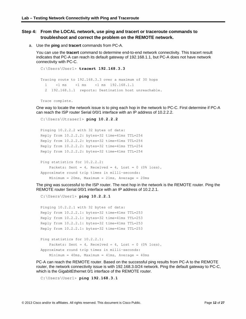
Lab – Testing Network Connectivity with Ping and Traceroute
© 2013 Cisco and/or its affiliates. All rights reserved. This document is Cisco Public. Page 12 of 27
Step 4: From the LOCAL network, use ping and tracert or traceroute commands to troubleshoot and correct the problem on the REMOTE network.
a. Use the ping and tracert commands from PC-A.
You can use the tracert command to determine end-to-end network connectivity. This tracert result indicates that PC-A can reach its default gateway of 192.168.1.1, but PC-A does not have network connectivity with PC-C.
C:\Users\User1> tracert 192.168.3.3
Tracing route to 192.168.3.3 over a maximum of 30 hops
1 <1 ms <1 ms <1 ms 192.168.1.1
2 192.168.1.1 reports: Destination host unreachable.
Trace complete.
One way to locate the network issue is to ping each hop in the network to PC-C. First determine if PC-A can reach the ISP router Serial 0/0/1 interface with an IP address of 10.2.2.2.
C:\Users\Utraser1> ping 10.2.2.2
Pinging 10.2.2.2 with 32 bytes of data:
Reply from 10.2.2.2: bytes=32 time=41ms TTL=254
Reply from 10.2.2.2: bytes=32 time=41ms TTL=254
Reply from 10.2.2.2: bytes=32 time=41ms TTL=254
Reply from 10.2.2.2: bytes=32 time=41ms TTL=254
Ping statistics for 10.2.2.2:
Packets: Sent = 4, Received = 4, Lost = 0 (0% loss),
Approximate round trip times in milli-seconds:
Minimum = 20ms, Maximum = 21ms, Average = 20ms
The ping was successful to the ISP router. The next hop in the network is the REMOTE router. Ping the REMOTE router Serial 0/0/1 interface with an IP address of 10.2.2.1.
C:\Users\User1> ping 10.2.2.1
Pinging 10.2.2.1 with 32 bytes of data:
Reply from 10.2.2.1: bytes=32 time=41ms TTL=253
Reply from 10.2.2.1: bytes=32 time=41ms TTL=253
Reply from 10.2.2.1: bytes=32 time=41ms TTL=253
Reply from 10.2.2.1: bytes=32 time=41ms TTL=253
Ping statistics for 10.2.2.1:
Packets: Sent = 4, Received = 4, Lost = 0 (0% loss),
Approximate round trip times in milli-seconds:
Minimum = 40ms, Maximum = 41ms, Average = 40ms
PC-A can reach the REMOTE router. Based on the successful ping results from PC-A to the REMOTE router, the network connectivity issue is with 192.168.3.0/24 network. Ping the default gateway to PC-C, which is the GigabitEthernet 0/1 interface of the REMOTE router.
C:\Users\User1> ping 192.168.3.1

Lab – Testing Network Connectivity with Ping and Traceroute
© 2013 Cisco and/or its affiliates. All rights reserved. This document is Cisco Public. Page 13 of 27
Pinging 192.168.3.1 with 32 bytes of data:
Reply from 192.168.1.1: Destination host unreachable.
Reply from 192.168.1.1: Destination host unreachable.
Reply from 192.168.1.1: Destination host unreachable.
Reply from 192.168.1.1: Destination host unreachable.
Ping statistics for 192.168.3.1:
Packets: Sent = 4, Received = 4, Lost = 0 (0% loss),
PC-A cannot reach the GigabitEthernet 0/1 interface of the REMOTE router, as displayed by the results from the ping command.
The S3 switch can also be pinged from PC-A to verify the location of the networking connectivity issue by typing ping 192.168.3.11 at the command prompt. Because PC-A cannot reach GigabitEthernet 0/1 of the REMOTE router, PC-A probably cannot ping the S3 switch successfully, as indicated by the results below.
C:\Users\User1> ping 192.168.3.11
Pinging 192.168.3.11 with 32 bytes of data:
Reply from 192.168.1.1: Destination host unreachable.
Reply from 192.168.1.1: Destination host unreachable.
Reply from 192.168.1.1: Destination host unreachable.
Reply from 192.168.1.1: Destination host unreachable.
Ping statistics for 192.168.3.11:
Packets: Sent = 4, Received = 4, Lost = 0 (0% loss),
The tracert and ping results conclude that PC-A can reach the LOCAL, ISP, and REMOTE routers, but not PC-C or the S3 switch, nor the default gateway for PC-C.
b. Use the show commands to examine the running configurations for the the REMOTE router.
REMOTE# show ip interface brief Interface IP-Address OK? Method Status Protocol
Embedded-Service-Engine0/0 unassigned YES unset administratively down down
GigabitEthernet0/0 unassigned YES unset administratively down down
GigabitEthernet0/1 192.168.8.1 YES manual up up
Serial0/0/0 unassigned YES unset administratively down down
Serial0/0/1 10.2.2.1 YES manual up up
REMOTE# show run <output omitted>
interface GigabitEthernet0/0
no ip address
shutdown
duplex auto
speed auto
!
interface GigabitEthernet0/1
ip address 192.168.8.1 255.255.255.0
duplex auto
speed auto
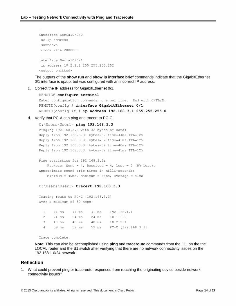
Lab – Testing Network Connectivity with Ping and Traceroute
© 2013 Cisco and/or its affiliates. All rights reserved. This document is Cisco Public. Page 14 of 27
!
interface Serial0/0/0
no ip address
shutdown
clock rate 2000000
!
interface Serial0/0/1
ip address 10.2.2.1 255.255.255.252
<output omitted>
The outputs of the show run and show ip interface brief commands indicate that the GigabitEthernet 0/1 interface is up/up, but was configured with an incorrect IP address.
c. Correct the IP address for GigabitEthernet 0/1.
REMOTE# configure terminal Enter configuration commands, one per line. End with CNTL/Z.
REMOTE(config)# interface GigabitEthernet 0/1 REMOTE(config-if)# ip address 192.168.3.1 255.255.255.0
d. Verify that PC-A can ping and tracert to PC-C.
C:\Users\User1> ping 192.168.3.3 Pinging 192.168.3.3 with 32 bytes of data:
Reply from 192.168.3.3: bytes=32 time=44ms TTL=125
Reply from 192.168.3.3: bytes=32 time=41ms TTL=125
Reply from 192.168.3.3: bytes=32 time=40ms TTL=125
Reply from 192.168.3.3: bytes=32 time=41ms TTL=125
Ping statistics for 192.168.3.3:
Packets: Sent = 4, Received = 4, Lost = 0 (0% loss),
Approximate round trip times in milli-seconds:
Minimum = 40ms, Maximum = 44ms, Average = 41ms
C:\Users\User1> tracert 192.168.3.3
Tracing route to PC-C [192.168.3.3]
Over a maximum of 30 hops:
1 <1 ms <1 ms <1 ms 192.168.1.1
2 24 ms 24 ms 24 ms 10.1.1.2
3 48 ms 48 ms 48 ms 10.2.2.1
4 59 ms 59 ms 59 ms PC-C [192.168.3.3]
Trace complete.
Note: This can also be accomplished using ping and traceroute commands from the CLI on the the LOCAL router and the S1 switch after verifying that there are no network connectivity issues on the 192.168.1.0/24 network.
Reflection 1. What could prevent ping or traceroute responses from reaching the originating device beside network
connectivity issues?

Lab – Testing Network Connectivity with Ping and Traceroute
© 2013 Cisco and/or its affiliates. All rights reserved. This document is Cisco Public. Page 15 of 27
_______________________________________________________________________________________
_______________________________________________________________________________________
Firewall on the PCs, access lists command, routing issues, interface is down, network delay
2. If you ping a non-existent address on the remote network, such as 192.168.3.4, what is the message displayed by the ping command? What does this mean? If you ping a valid host address and receive this response, what should you check?
_______________________________________________________________________________________
_______________________________________________________________________________________
Request timed out or periods (.). This means that there was no response in the default time period. Some of the items you may check: router is down, destination host is down, return route to your device and latency of the response is not more than the default time period
3. If you ping an address that does not exist in any network in your topology, such as 192.168.5.3, from a Windows-based PC, what is the message displayed by the ping command? What does this message indicate?
_______________________________________________________________________________________
_______________________________________________________________________________________
Destination host unreachable. This message indicates that there is no route to the destination as the network is not listed by the routing table.

Lab – Testing Network Connectivity with Ping and Traceroute
© 2013 Cisco and/or its affiliates. All rights reserved. This document is Cisco Public. Page 16 of 27
Router Interface Summary Table
Router Interface Summary
Router Model Ethernet Interface #1 Ethernet Interface #2 Serial Interface #1 Serial Interface #2
1800 Fast Ethernet 0/0 (F0/0)
Fast Ethernet 0/1 (F0/1)
Serial 0/0/0 (S0/0/0) Serial 0/0/1 (S0/0/1)
1900 Gigabit Ethernet 0/0 (G0/0)
Gigabit Ethernet 0/1 (G0/1)
Serial 0/0/0 (S0/0/0) Serial 0/0/1 (S0/0/1)
2801 Fast Ethernet 0/0 (F0/0)
Fast Ethernet 0/1 (F0/1)
Serial 0/1/0 (S0/1/0) Serial 0/1/1 (S0/1/1)
2811 Fast Ethernet 0/0 (F0/0)
Fast Ethernet 0/1 (F0/1)
Serial 0/0/0 (S0/0/0) Serial 0/0/1 (S0/0/1)
2900 Gigabit Ethernet 0/0 (G0/0)
Gigabit Ethernet 0/1 (G0/1)
Serial 0/0/0 (S0/0/0) Serial 0/0/1 (S0/0/1)
Note: To find out how the router is configured, look at the interfaces to identify the type of router and how many interfaces the router has. There is no way to effectively list all the combinations of configurations for each router class. This table includes identifiers for the possible combinations of Ethernet and Serial interfaces in the device. The table does not include any other type of interface, even though a specific router may contain one. An example of this might be an ISDN BRI interface. The string in parenthesis is the legal abbreviation that can be used in Cisco IOS commands to represent the interface.
Device Configs
Router LOCAL LOCAL# show running-config Building configuration... Current configuration : 1462 bytes ! version 15.2 service timestamps debug datetime msec service timestamps log datetime msec no service password-encryption ! hostname LOCAL ! boot-start-marker boot-end-marker ! ! ! no aaa new-model memory-size iomem 15 ! ! !

Lab – Testing Network Connectivity with Ping and Traceroute
© 2013 Cisco and/or its affiliates. All rights reserved. This document is Cisco Public. Page 17 of 27
! ! ! ! no ip domain lookup ip host REMOTE 10.2.2.1 192.168.3.1 ip host ISP 10.1.1.2 10.2.2.2 ip host LOCAL 192.168.1.1 10.1.1.1 ip host PC-C 192.168.3.3 ip host PC-A 192.168.1.3 ip host S1 192.168.1.11 ip host S3 192.168.3.11 ip cef no ipv6 cef multilink bundle-name authenticated ! ! ! ! ! ! ! ! ! ! ! interface Embedded-Service-Engine0/0 no ip address shutdown ! interface GigabitEthernet0/0 no ip address shutdown duplex auto speed auto ! interface GigabitEthernet0/1 ip address 192.168.1.1 255.255.255.0 duplex auto speed auto ! interface Serial0/0/0 ip address 10.1.1.1 255.255.255.252 clock rate 56000 ! interface Serial0/0/1 no ip address shutdown !
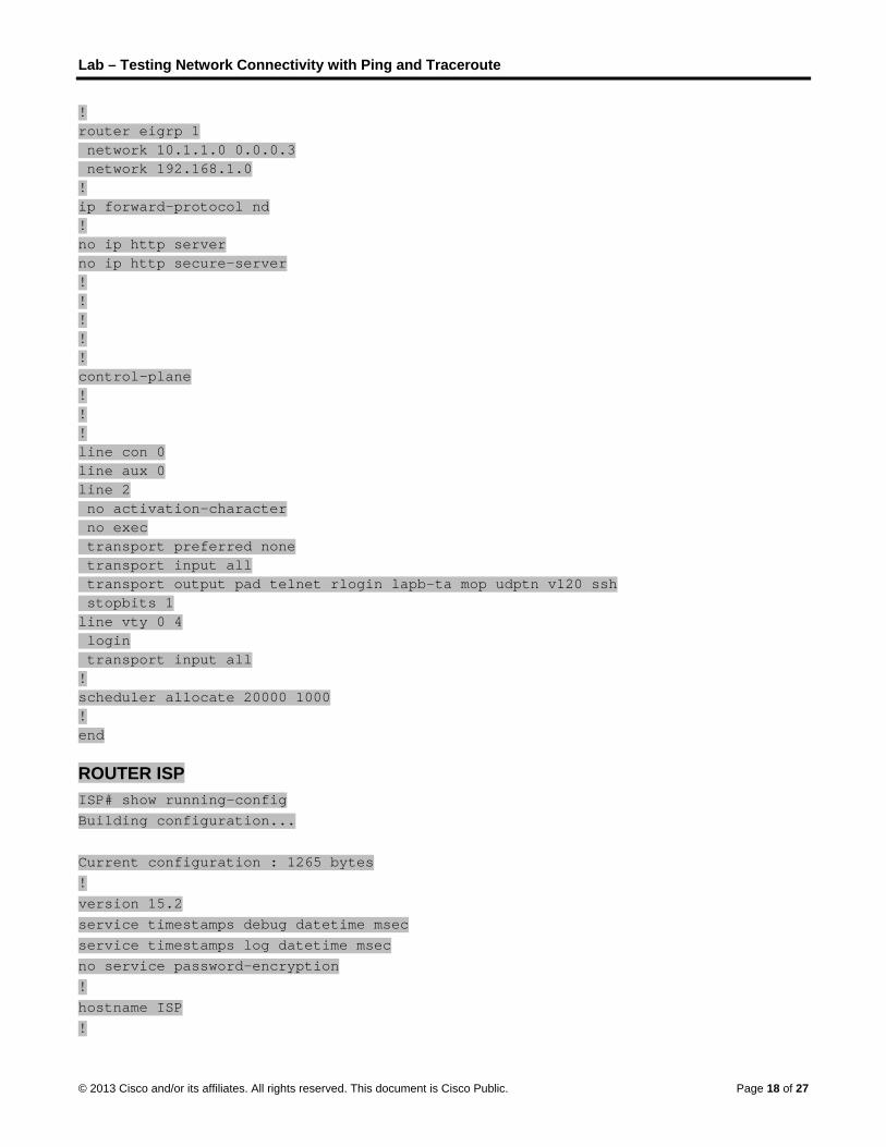
Lab – Testing Network Connectivity with Ping and Traceroute
© 2013 Cisco and/or its affiliates. All rights reserved. This document is Cisco Public. Page 18 of 27
! router eigrp 1 network 10.1.1.0 0.0.0.3 network 192.168.1.0 ! ip forward-protocol nd ! no ip http server no ip http secure-server ! ! ! ! ! control-plane ! ! ! line con 0 line aux 0 line 2 no activation-character no exec transport preferred none transport input all transport output pad telnet rlogin lapb-ta mop udptn v120 ssh stopbits 1 line vty 0 4 login transport input all ! scheduler allocate 20000 1000 ! end
ROUTER ISP ISP# show running-config Building configuration... Current configuration : 1265 bytes ! version 15.2 service timestamps debug datetime msec service timestamps log datetime msec no service password-encryption ! hostname ISP !
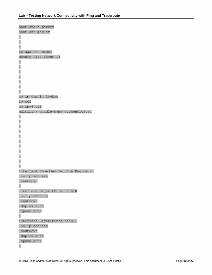
Lab – Testing Network Connectivity with Ping and Traceroute
© 2013 Cisco and/or its affiliates. All rights reserved. This document is Cisco Public. Page 19 of 27
boot-start-marker boot-end-marker ! ! ! no aaa new-model memory-size iomem 15 ! ! ! ! ! ! ! no ip domain lookup ip cef no ipv6 cef multilink bundle-name authenticated ! ! ! ! ! ! ! ! ! ! ! interface Embedded-Service-Engine0/0 no ip address shutdown ! interface GigabitEthernet0/0 no ip address shutdown duplex auto speed auto ! interface GigabitEthernet0/1 no ip address shutdown duplex auto speed auto !

Lab – Testing Network Connectivity with Ping and Traceroute
© 2013 Cisco and/or its affiliates. All rights reserved. This document is Cisco Public. Page 20 of 27
interface Serial0/0/0 ip address 10.1.1.2 255.255.255.252 ! interface Serial0/0/1 ip address 10.2.2.2 255.255.255.252 clock rate 56000 ! ! router eigrp 1 network 10.1.1.0 0.0.0.3 network 10.2.2.0 0.0.0.3 ! ip forward-protocol nd ! no ip http server no ip http secure-server ! ! ! ! ! control-plane ! ! ! line con 0 line aux 0 line 2 no activation-character no exec transport preferred none transport input all transport output pad telnet rlogin lapb-ta mop udptn v120 ssh stopbits 1 line vty 0 4 login transport input all ! scheduler allocate 20000 1000 ! end
Router REMOTE REMOTE# show running-config Building configuration...

Lab – Testing Network Connectivity with Ping and Traceroute
© 2013 Cisco and/or its affiliates. All rights reserved. This document is Cisco Public. Page 21 of 27
Current configuration : 1440 bytes ! version 15.2 service timestamps debug datetime msec service timestamps log datetime msec no service password-encryption ! hostname REMOTE ! boot-start-marker boot-end-marker ! ! ! no aaa new-model memory-size iomem 10 ! ! ! ! ! ! ! no ip domain lookup ip cef no ipv6 cef multilink bundle-name authenticated ! ! ! ! ! ! ! ! ! ! ! interface Embedded-Service-Engine0/0 no ip address shutdown ! interface GigabitEthernet0/0 no ip address
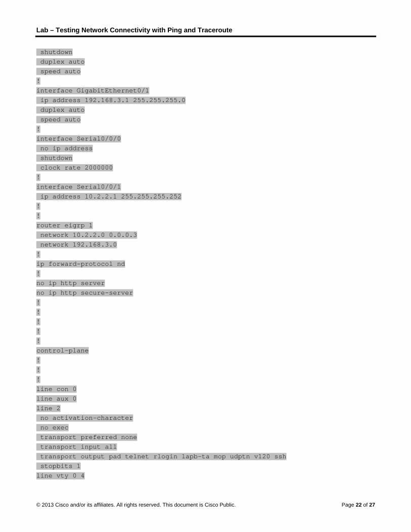
Lab – Testing Network Connectivity with Ping and Traceroute
© 2013 Cisco and/or its affiliates. All rights reserved. This document is Cisco Public. Page 22 of 27
shutdown duplex auto speed auto ! interface GigabitEthernet0/1 ip address 192.168.3.1 255.255.255.0 duplex auto speed auto ! interface Serial0/0/0 no ip address shutdown clock rate 2000000 ! interface Serial0/0/1 ip address 10.2.2.1 255.255.255.252 ! ! router eigrp 1 network 10.2.2.0 0.0.0.3 network 192.168.3.0 ! ip forward-protocol nd ! no ip http server no ip http secure-server ! ! ! ! ! control-plane ! ! ! line con 0 line aux 0 line 2 no activation-character no exec transport preferred none transport input all transport output pad telnet rlogin lapb-ta mop udptn v120 ssh stopbits 1 line vty 0 4

Lab – Testing Network Connectivity with Ping and Traceroute
© 2013 Cisco and/or its affiliates. All rights reserved. This document is Cisco Public. Page 23 of 27
login transport input all ! scheduler allocate 20000 1000 ! end
Switch S1 S1# show running-config Building configuration... Current configuration : 1565 bytes ! ! version 15.0 no service pad service timestamps debug datetime msec service timestamps log datetime msec no service password-encryption ! hostname S1 ! boot-start-marker boot-end-marker ! ! no aaa new-model system mtu routing 1500 ! ! no ip domain-lookup ! ! ! ! ! ! ! ! spanning-tree mode pvst spanning-tree extend system-id ! vlan internal allocation policy ascending ! !

Lab – Testing Network Connectivity with Ping and Traceroute
© 2013 Cisco and/or its affiliates. All rights reserved. This document is Cisco Public. Page 24 of 27
! ! ! ! interface FastEthernet0/1 ! interface FastEthernet0/2 ! interface FastEthernet0/3 ! interface FastEthernet0/4 ! interface FastEthernet0/5 ! interface FastEthernet0/6 ! interface FastEthernet0/7 ! interface FastEthernet0/8 ! interface FastEthernet0/9 ! interface FastEthernet0/10 ! interface FastEthernet0/11 ! interface FastEthernet0/12 ! interface FastEthernet0/13 ! interface FastEthernet0/14 ! interface FastEthernet0/15 ! interface FastEthernet0/16 ! interface FastEthernet0/17 ! interface FastEthernet0/18 ! interface FastEthernet0/19 ! interface FastEthernet0/20 ! interface FastEthernet0/21

Lab – Testing Network Connectivity with Ping and Traceroute
© 2013 Cisco and/or its affiliates. All rights reserved. This document is Cisco Public. Page 25 of 27
! interface FastEthernet0/22 ! interface FastEthernet0/23 ! interface FastEthernet0/24 ! interface GigabitEthernet0/1 ! interface GigabitEthernet0/2 ! interface Vlan1 ip address 192.168.1.11 255.255.255.0 ! ip default-gateway 192.168.1.1 ip http server ip http secure-server ! ! ! line con 0 line vty 5 15 ! end
Switch S3 S3# show running-config Building configuration... Current configuration : 1563 bytes ! ! version 15.0 no service pad service timestamps debug datetime msec service timestamps log datetime msec no service password-encryption ! hostname S3 ! boot-start-marker boot-end-marker ! ! no aaa new-model

Lab – Testing Network Connectivity with Ping and Traceroute
© 2013 Cisco and/or its affiliates. All rights reserved. This document is Cisco Public. Page 26 of 27
system mtu routing 1500 ! ! no ip domain-lookup ! ! ! ! ! ! ! ! spanning-tree mode pvst spanning-tree extend system-id ! vlan internal allocation policy ascending ! ! ! ! ! ! interface FastEthernet0/1 ! interface FastEthernet0/2 ! interface FastEthernet0/3 ! interface FastEthernet0/4 ! interface FastEthernet0/5 ! interface FastEthernet0/6 ! interface FastEthernet0/7 ! interface FastEthernet0/8 ! interface FastEthernet0/9 ! interface FastEthernet0/10 ! interface FastEthernet0/11 ! interface FastEthernet0/12

Lab – Testing Network Connectivity with Ping and Traceroute
© 2013 Cisco and/or its affiliates. All rights reserved. This document is Cisco Public. Page 27 of 27
! interface FastEthernet0/13 ! interface FastEthernet0/14 ! interface FastEthernet0/15 ! interface FastEthernet0/16 ! interface FastEthernet0/17 ! interface FastEthernet0/18 ! interface FastEthernet0/19 ! interface FastEthernet0/20 ! interface FastEthernet0/21 ! interface FastEthernet0/22 ! interface FastEthernet0/23 ! interface FastEthernet0/24 ! interface GigabitEthernet0/1 ! interface GigabitEthernet0/2 ! interface Vlan1 ip address 192.168.3.11 255.255.255.0 ! ip default-gateway 192.168.3.1 ip http server ip http secure-server ! ! line con 0 line vty 5 15 ! end

© 2013 Cisco and/or its affiliates. All rights reserved. This document is Cisco Public. Page 1 of 3
The Internet of Everything…Naturally! (Instructor Version) Instructor Note: Red font color or Gray highlights indicate text that appears in the instructor copy only.
Objectives
Explain the need for IPv6 network addresses.
This is an application-based activity. You will develop a plan to show how IoE subnets, unicasts, and multicasts could be used in our daily lives to affect data communication.
Background/Scenario
Note: This activity may be completed individually or in small/large groups.
This chapter discussed the ways in which small to medium-sized businesses are connected to networks in groups. The IoE was introduced in the activity at the beginning of this chapter.
Choose one of the following:
Online banking
World news
Weather forecasting/climate
Traffic conditions
Devise an IPv6 addressing scheme for the area you have chosen. Your addressing scheme should include how you would plan for:
Subnetting
Unicasts
Multicasts
Keep a copy of your scheme to share with the class or learning community. Be prepared to explain:
How subnetting, unicasts, and multicasts could be incorporated
Where your addressing scheme could be used
How small to medium-size businesses would be affected by using your plan
Instructor Note: This Modeling Activity is not intended to be a graded assignment. Its purpose is to encourage students to reflect on their perceptions of how a network could use IPv6 and the undecillion addresses available both for personal and corporate practice. Instructors should facilitate class discussion and idea sharing as a result of this activity.
Required Resources
Paper, pens, pencils, or tablets
Packet Tracer (if you would like to display how your network would physically look)
Hard- or soft-copy of the final network topology with IPv6 addressing indicated for sharing with the class.

The Internet of Everything…Naturally!
© 2013 Cisco and/or its affiliates. All rights reserved. This document is Cisco Public. Page 2 of 3
Reflection
1. What was the hardest part of designing this network model? Explain your answer.
____________________________________________________________________________
Answers will vary within groups (as will the topologies developed). Some students may mention designing a main group and then subnetted groups from the main group, some may indicate the actual addressing of the network, and some may indicate they had difficulty with where unicasts and multicasts could occur.
A possible solution to the scenario might include:
Weather Forecasting/Climate
The area in which you live has many hot days during summer months. Electricity costs skyrocket on those days.
Your local electrical area includes six local cities and all of these cities are then incorporated into one, large state. Multiple states are incorporated into one large country. To decrease costs and increase productivity of electricity, you could install windmills or solar panels that would generate electrical current to your immediate area and larger geographic areas. The windmills or solar panels could be controlled using network accessibility.
Using an IPv6 addressing scheme:
Each windmill (or solar panel) will be assigned an IPv6 address.
Windmills and/or solar panels will be turned on to generate electricity by, city, state, or country (subnetting).
Cities, states, or countries will receive additional electricity based on unicast or multicast operation of the windmills/solar panels.
Note: Depending on the focus or use of this activity, students could actually draw a schematic of their windmills or solar panels and address them to show mastery of the subnetting concept. They could also group the windmills or solar panels to show unicast or multicast transmissions types.
Other possible scenarios might include:
1. Energy Efficiency
Each household light bulb could be connected to the network and remotely managed. Each one would therefore need an IPv6 address.
Each home appliance could also be connected to the network and would also need IPv6.
The network structure could group all appliances of a home into one subnet. Route summaries could be created to group neighborhoods together. Unicast messages would be used to manage single devices. Appliances of the same type could have a multicast group (all TVs, for instance) and managed in bulk.
2. Weather Forecast
Sensor on trees would need IPv6 addresses to be connected to the network.
Mobile weather stations would also need IPv6 (several stations per city, for accuracy).
Floating weather stations would gather info about the oceans and rivers and also need IPv6.
Once again route summaries would group/represent physical locations. Multicast groups could be created based on station placement (land, river, and ocean) and unicast addresses used to manage a specific station.

The Internet of Everything…Naturally!
© 2013 Cisco and/or its affiliates. All rights reserved. This document is Cisco Public. Page 3 of 3
3. Traffic Conditions
Each traffic light would need an IPv6 to be connected to the network.
Road traffic sensors (to provide the rate vehicle/minute) could also be connected to the network and would need IPv6 addresses.
Multicast groups could be created based on device type (sensor or traffic light) and unicast addresses could be used to manage a specific device.
Identify elements of the model that map IT-related content:
IoE – green technology
Subnetting
IPv6 addressing
Unicasts
Multicasts
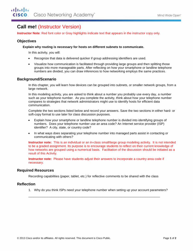
© 2013 Cisco and/or its affiliates. All rights reserved. This document is Cisco Public. Page 1 of 2
Call me! (Instructor Version) Instructor Note: Red font color or Gray highlights indicate text that appears in the instructor copy only.
Objectives
Explain why routing is necessary for hosts on different subnets to communicate.
In this activity, you will:
Recognize that data is delivered quicker if group addressing identifiers are used.
Visualize how communication is facilitated through providing large groups and then splitting those groups into more manageable parts. After reflecting on how your smartphone or landline telephone numbers are divided, you can draw inferences to how networking employs the same practices.
Background/Scenario
In this chapter, you will learn how devices can be grouped into subnets, or smaller network groups, from a large network.
In this modeling activity, you are asked to think about a number you probably use every day, a number such as your telephone number. As you complete the activity, think about how your telephone number compares to strategies that network administrators might use to identify hosts for efficient data communication.
Complete the two sections listed below and record your answers. Save the two sections in either hard- or soft-copy format to use later for class discussion purposes.
Explain how your smartphone or landline telephone number is divided into identifying groups of numbers. Does your telephone number use an area code? An Internet service provider (ISP) identifier? A city, state, or country code?
In what ways does separating your telephone number into managed parts assist in contacting or communicating with others?
Instructor note: This is an individual or an in-class small/large group modeling activity. It is not intended to be a graded assignment. Its purpose is to encourage students to reflect on their current knowledge of how networks are grouped using a numerical basis. Facilitation of the discussion should be initiated as a result of this Activity.
Instructor note: Please have students adjust their answers to incorporate a country area code if necessary.
Required Resources
Recording capabilities (paper, tablet, etc.) for reflective comments to be shared with the class
Reflection
1. Why do you think ISPs need your telephone number when setting up your account parameters?
___________________________________________________________________________
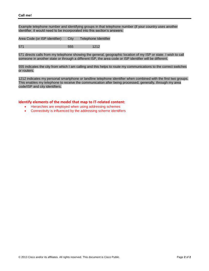
Call me!
© 2013 Cisco and/or its affiliates. All rights reserved. This document is Cisco Public. Page 2 of 2
Example telephone number and identifying groups in that telephone number (if your country uses another identifier, it would need to be incorporated into this section’s answers:
Area Code (or ISP identifier) City Telephone Identifier
571 555 1212
571 directs calls from my telephone showing the general, geographic location of my ISP or state. I wish to call someone in another state or through a different ISP, the area code or ISP identifier will be different.
555 indicates the city from which I am calling and this helps to route my communications to the correct switches or routers.
1212 indicates my personal smartphone or landline telephone identifier when combined with the first two groups. This enables my telephone to receive the communication after being processed, generally, through my area code/ISP and city identifiers.
Identify elements of the model that map to IT-related content: Hierarchies are employed when using addressing schemes
Connectivity is influenced by the addressing scheme identifiers

© 2013 Cisco and/or its affiliates. All rights reserved. This document is Cisco Public. Page 1 of 5
Lab – Researching Subnet Calculators (Instructor Version) Instructor Note: Red font color or Gray highlights indicate text that appears in the instructor copy only.
Objectives
Part 1: Review Available Subnet Calculators
Part 2: Perform Network Calculations Using a Subnet Calculator
Background / Scenario
While it is important to understand how to convert a decimal IP address to its binary format and apply the bitwise ANDing operation to determine the network address, it is also a tedious and mistake-prone process. To assist with these calculations, many network administrators make use of an IP subnet calculator utility program. A number of these types of programs have been developed that can be downloaded or run directly from the Internet.
In this lab, you will be introduced to a few of the free IP subnet calculators that are available. You will use a web-based IP subnet calculator to perform the network operations in this lab.
Required Resources
Device with Internet access
Part 1: Review Available Subnet Calculators
In Part 1, you are introduced to two types of subnet calculators: client-based (programs that are downloaded and installed) and web-based (utilities that are run from a browser).
Step 1: Review client-based subnet calculators.
Solarwinds provides a free subnet calculator that can be downloaded and installed on a PC running a Windows operating system. You will be required to provide personal information (Name, Company, Location, Email Address, and Phone number) to be able to download this program. You can download and install the Solarwinds Subnet Calculator at www.solarwinds.com.
If you have a PC running Linux, it is recommended that you use the ipcalc utility (available with most Linux distributions). Use the apt-get install ipcalc command to install ipcalc on a PC running Linux.
Step 2: Use a web-based subnet calculator.
Web-based subnet calculators do not require installation, but you do need Internet access to use them. The following web-based subnet calculator is accessible from any device that has Internet access, including smartphones and tablets.
a. From your browser, go to www.ipcalc.org and click the IP Subnet Calculator link.
Note: Several other useful utilities are also listed on the menu, such as MAC vendor lookup, whois lookup, and DNS lookup.
Note: At the time of this writing, a page formatting issue was encountered when viewing the www.ipcalc.org website using Internet Explorer (Version 9). While the site functioned correctly, you may want to consider using another browser (Firefox or Chrome) when accessing this site.
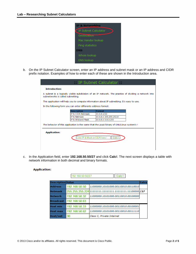
Lab – Researching Subnet Calculators
© 2013 Cisco and/or its affiliates. All rights reserved. This document is Cisco Public. Page 2 of 5
b. On the IP Subnet Calculator screen, enter an IP address and subnet mask or an IP address and CIDR prefix notation. Examples of how to enter each of these are shown in the Introduction area.
c. In the Application field, enter 192.168.50.50/27 and click Calc!. The next screen displays a table with network information in both decimal and binary formats.

Lab – Researching Subnet Calculators
© 2013 Cisco and/or its affiliates. All rights reserved. This document is Cisco Public. Page 3 of 5
d. Using the information provided in the example above, answer the following questions.
What is the network address? ____________________________ 192.168.50.32
What is the subnet mask? _______________________________ 255.255.255.224
How many hosts will this network support? __________________ 30
What is the lowest host address? _________________________ 192.168.50.33
What is the highest host address? ________________________ 192.168.50.62
What is the broadcast address? __________________________ 192.168.50.63
Part 2: Perform Network Calculations Using a Subnet Calculator
In Part 2, use the www.ipcalc.org web-based subnet calculator to fill in the tables provided.
Step 1: Fill in the following table for address 10.223.23.136/10:
Description Decimal Binary
Address 10.223.23.136 00001010.11011111.00010111.10001000
Subnet mask 255.192.0.0 11111111.11000000.00000000.00000000
Network address 10.192.0.0 00001010.11000000.00000000.00000000
Broadcast address 10.255.255.255 00001010.11111111.11111111.11111111
First host address 10.192.0.1 00001010.11000000.00000000.00000001
Last host address 10.255.255.254 00001010.11111111.11111111.11111110
Number of hosts available 4,194,302 N/A
What type of address, public, or private? _____________ Private
Step 2: Fill in the following table for the 172.18.255.92 address with a subnet mask of
255.255.224.0:
Description Decimal Binary
Address 172.18.255.92 10101100.00010010.11111111.01011100
Subnet mask 255.255.224.0 11111111.11111111.11100000.00000000
Network address 172.18.224.0 10101100.00010010.11100000.00000000
Broadcast address 172.18.255.255 10101100.00010010.11111111.11111111
First host address 172.18.224.1 10101100.00010010.11100000.00000001
Last host address 172.18.255.254 10101100.00010010.11111111.11111110
Number of hosts available 8,190 N/A
What is the CIDR prefix notation for this network? ________ /19
What type of address, public, or private? _____________ Private
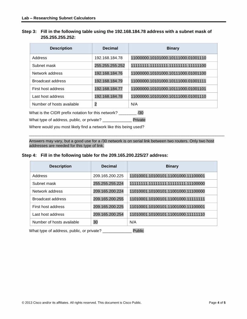
Lab – Researching Subnet Calculators
© 2013 Cisco and/or its affiliates. All rights reserved. This document is Cisco Public. Page 4 of 5
Step 3: Fill in the following table using the 192.168.184.78 address with a subnet mask of
255.255.255.252:
Description Decimal Binary
Address 192.168.184.78 11000000.10101000.10111000.01001110
Subnet mask 255.255.255.252 11111111.11111111.11111111.11111100
Network address 192.168.184.76 11000000.10101000.10111000.01001100
Broadcast address 192.168.184.79 11000000.10101000.10111000.01001111
First host address 192.168.184.77 11000000.10101000.10111000.01001101
Last host address 192.168.184.78 11000000.10101000.10111000.01001110
Number of hosts available 2 N/A
What is the CIDR prefix notation for this network? ________ /30
What type of address, public, or private? _____________ Private
Where would you most likely find a network like this being used?
_______________________________________________________________________________________
Answers may vary, but a good use for a /30 network is on serial link between two routers. Only two host addresses are needed for this type of link.
Step 4: Fill in the following table for the 209.165.200.225/27 address:
Description Decimal Binary
Address 209.165.200.225 11010001.10100101.11001000.11100001
Subnet mask 255.255.255.224 11111111.11111111.11111111.11100000
Network address 209.165.200.224 11010001.10100101.11001000.11100000
Broadcast address 209.165.200.255 11010001.10100101.11001000.11111111
First host address 209.165.200.225 11010001.10100101.11001000.11100001
Last host address 209.165.200.254 11010001.10100101.11001000.11111110
Number of hosts available 30 N/A
What type of address, public, or private? _____________ Public

Lab – Researching Subnet Calculators
© 2013 Cisco and/or its affiliates. All rights reserved. This document is Cisco Public. Page 5 of 5
Step 5: Fill in the following table for address 64.104.110.7/20:
Description Decimal Binary
Address 64.104.110.7 01000000.01101000.01101110.00000111
Subnet mask 255.255.240.0 11111111.11111111.11110000.00000000
Network address 64.104.96.0 01000000.01101000.01100000.00000000
Broadcast address 64.104.111.255 01000000.01101000.01101111.11111111
First host address 64.104.96.1 01000000.01101000.01100000.00000001
Last host address 64.104.111.254 01000000.01101000.01101111.11111110
Number of hosts available 4096 N/A
What type of address, public, or private? _____________ Public
Reflection
1. What is an advantage of using a client-based subnet calculator?
_______________________________________________________________________________________
_______________________________________________________________________________________
Answers may vary. Client-based subnet calculators do not require Internet access.
2. What is an advantage of using a web-based subnet calculator?
_______________________________________________________________________________________
_______________________________________________________________________________________
Answers may vary, but web-based subnet calculators do not require download and installation. They can be accessed by any device with Internet access, including mobile devices such as a smart phones and tablets.

© 2013 Cisco and/or its affiliates. All rights reserved. This document is Cisco Public. Page 1 of 8
Lab – Calculating IPv4 Subnets (Instructor Version) Instructor Note: Red font color or Gray highlights indicate text that appears in the instructor copy only.
Objectives Part 1: Determine IPv4 Address Subnetting
• Determine the network address.
• Determine the broadcast address.
• Determine the number of hosts.
Part 2: Calculate IPv4 Address Subnetting
• Determine the number of subnets created.
• Determine number of hosts per subnet.
• Determine the subnet address.
• Determine the host range for the subnet.
• Determine the broadcast address for the subnet.
Background / Scenario The ability to work with IPv4 subnets and determine network and host information based on a given IP address and subnet mask is critical to understanding how IPv4 networks operate. The first part is designed to reinforce how to compute network IP address information from a given IP address and subnet mask. When given an IP address and subnet mask, you will be able to determine other information about the subnet such as:
• Network address
• Broadcast address
• Total number of host bits
• Number of hosts per subnet
In the second part of the lab, for a given IP address and subnet mask, you will determine such information as follows:
• Network address of this subnet
• Broadcast address of this subnet
• Range of host addresses for this subnet
• Number of subnets created
• Number of hosts for each subnet
Instructor Note: This activity can be done in class or assigned as homework. If the assignment is done in class, you may wish to have students work alone or in teams of 2 students each. It is suggested that the first problem is done together in class to give students guidance as to how to proceed for the rest of the assignment.
The public IP addresses used in this lab are owned by Cisco.
Required Resources • 1 PC (Windows 7, Vista, or XP with Internet access)

Lab – Calculating IPv4 Subnets
© 2013 Cisco and/or its affiliates. All rights reserved. This document is Cisco Public. Page 2 of 8
• Optional: IPv4 address calculator
Part 1: Determine IPv4 Address Subnetting In Part 1, you will determine the network and broadcast addresses, as well as the number of hosts, given an IPv4 address and subnet mask.
REVIEW: To determine the network address, perform binary ANDing on the IPv4 address using the subnet mask provided. The result will be the network address. Hint: If the subnet mask has decimal value 255 in an octet, the result will ALWAYS be the original value of that octet. If the subnet mask has decimal value 0 in an octet, the result will ALWAYS be 0 for that octet.
Example:
IP Address 192.168.10.10
Subnet Mask 255.255.255.0
==========
Result (Network) 192.168.10.0
Knowing this, you may only have to perform binary ANDing on an octet that does not have 255 or 0 in its subnet mask portion.
Example:
IP Address 172.30.239.145
Subnet Mask 255.255.192.0
Analyzing this example, you can see that you only have to perform binary ANDing on the third octet. The first two octets will result in 172.30 due to the subnet mask. The fourth octet will result in 0 due to the subnet mask.
IP Address 172.30.239.145
Subnet Mask 255.255.192.0
==========
Result (Network) 172.30.?.0
Perform binary ANDing on the third octet.
Decimal Binary
239 11101111
192 11000000
=======
Result 192 11000000
Analyzing this example again produces the following result:
IP Address 172.30.239.145
Subnet Mask 255.255.192.0
==========
Result (Network) 172.30.192.0
Continuing with this example, determining the number of hosts per network can be calculated by analyzing the subnet mask. The subnet mask will be represented in dotted decimal format, such as 255.255.192.0, or in
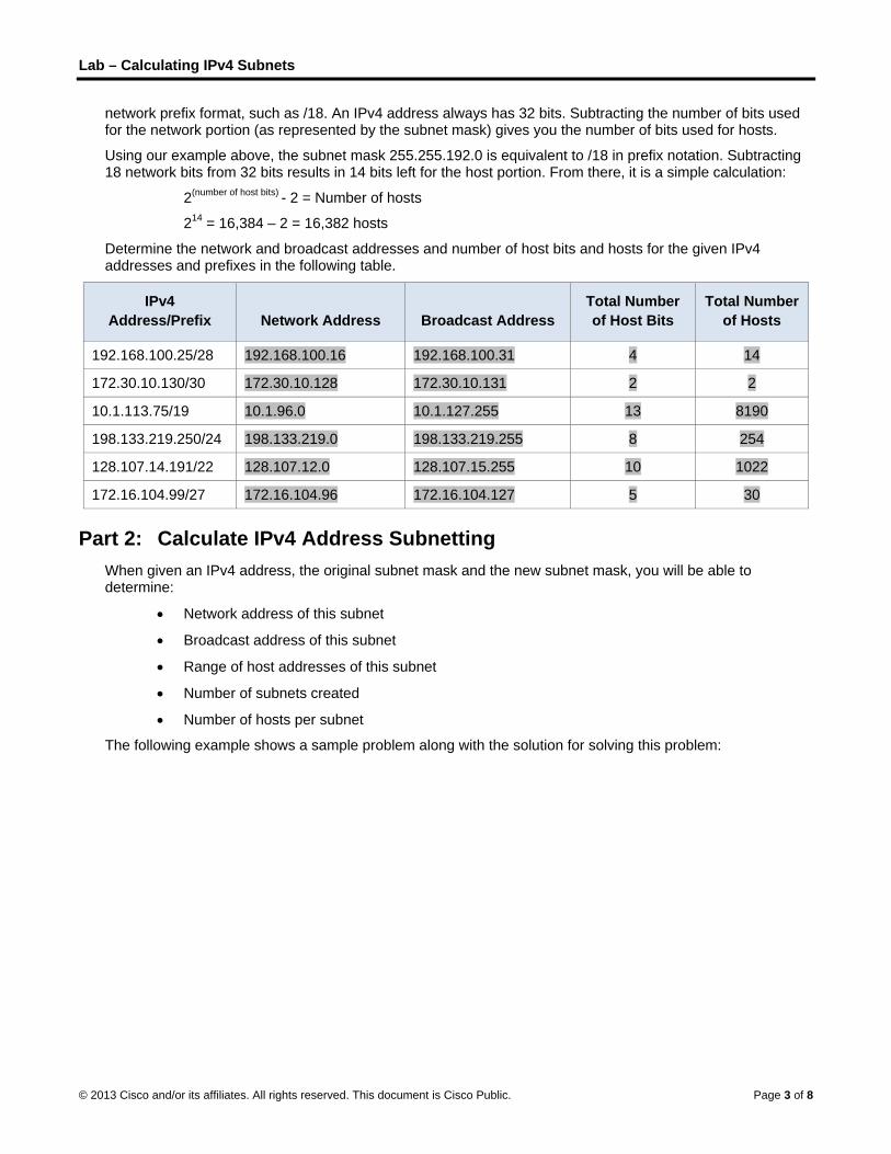
Lab – Calculating IPv4 Subnets
© 2013 Cisco and/or its affiliates. All rights reserved. This document is Cisco Public. Page 3 of 8
network prefix format, such as /18. An IPv4 address always has 32 bits. Subtracting the number of bits used for the network portion (as represented by the subnet mask) gives you the number of bits used for hosts.
Using our example above, the subnet mask 255.255.192.0 is equivalent to /18 in prefix notation. Subtracting 18 network bits from 32 bits results in 14 bits left for the host portion. From there, it is a simple calculation:
2(number of host bits) - 2 = Number of hosts
214 = 16,384 – 2 = 16,382 hosts
Determine the network and broadcast addresses and number of host bits and hosts for the given IPv4 addresses and prefixes in the following table.
IPv4 Address/Prefix Network Address Broadcast Address
Total Number of Host Bits
Total Number of Hosts
192.168.100.25/28 192.168.100.16 192.168.100.31 4 14
172.30.10.130/30 172.30.10.128 172.30.10.131 2 2
10.1.113.75/19 10.1.96.0 10.1.127.255 13 8190
198.133.219.250/24 198.133.219.0 198.133.219.255 8 254
128.107.14.191/22 128.107.12.0 128.107.15.255 10 1022
172.16.104.99/27 172.16.104.96 172.16.104.127 5 30
Part 2: Calculate IPv4 Address Subnetting When given an IPv4 address, the original subnet mask and the new subnet mask, you will be able to determine:
• Network address of this subnet
• Broadcast address of this subnet
• Range of host addresses of this subnet
• Number of subnets created
• Number of hosts per subnet
The following example shows a sample problem along with the solution for solving this problem:

Lab – Calculating IPv4 Subnets
© 2013 Cisco and/or its affiliates. All rights reserved. This document is Cisco Public. Page 4 of 8
Given:
Host IP Address: 172.16.77.120
Original Subnet Mask 255.255.0.0
New Subnet Mask: 255.255.240.0
Find:
Number of Subnet Bits 4
Number of Subnets Created 16
Number of Host Bits per Subnet 12
Number of Hosts per Subnet 4,094
Network Address of this Subnet 172.16.64.0
IPv4 Address of First Host on this Subnet 172.16.64.1
IPv4 Address of Last Host on this Subnet 172.16.79.254
IPv4 Broadcast Address on this Subnet 172.16.79.255
Let’s analyze how this table was completed.
The original subnet mask was 255.255.0.0 or /16. The new subnet mask is 255.255.240.0 or /20. The resulting difference is 4 bits. Because 4 bits were borrowed, we can determine that 16 subnets were created because 24 = 16.
The new mask of 255.255.240.0 or /20 leaves 12 bits for hosts. With 12 bits left for hosts, we use the following formula: 212 = 4,096 – 2 = 4,094 hosts per subnet.
Binary ANDing will help you determine the subnet for this problem, which results in the network 172.16.64.0.
Finally, you need to determine the first host, last host, and broadcast address for each subnet. One method to determine the host range is to use binary math for the host portion of the address. In our example, the last 12 bits of the address is the host portion. The first host would have all significant bits set to zero and the least significant bit set to 1. The last host would have all significant bits set to 1 and the least significant bit set to 0. In this example, the host portion of the address resides in the 3rd and 4th octets.
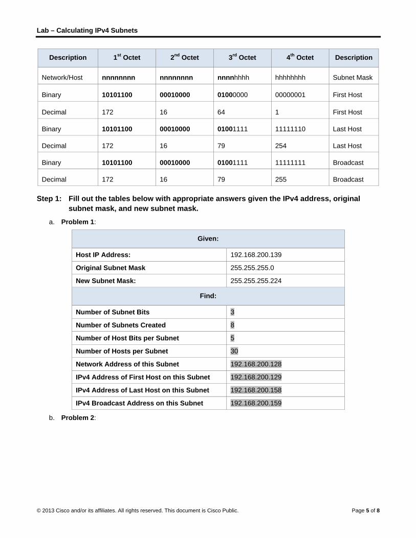
Lab – Calculating IPv4 Subnets
© 2013 Cisco and/or its affiliates. All rights reserved. This document is Cisco Public. Page 5 of 8
Description 1st Octet 2nd Octet 3rd Octet 4th Octet Description
Network/Host nnnnnnnn nnnnnnnn nnnnhhhh hhhhhhhh Subnet Mask
Binary 10101100 00010000 01000000 00000001 First Host
Decimal 172 16 64 1 First Host
Binary 10101100 00010000 01001111 11111110 Last Host
Decimal 172 16 79 254 Last Host
Binary 10101100 00010000 01001111 11111111 Broadcast
Decimal 172 16 79 255 Broadcast
Step 1: Fill out the tables below with appropriate answers given the IPv4 address, original subnet mask, and new subnet mask.
a. Problem 1:
Given:
Host IP Address: 192.168.200.139
Original Subnet Mask 255.255.255.0
New Subnet Mask: 255.255.255.224
Find:
Number of Subnet Bits 3
Number of Subnets Created 8
Number of Host Bits per Subnet 5
Number of Hosts per Subnet 30
Network Address of this Subnet 192.168.200.128
IPv4 Address of First Host on this Subnet 192.168.200.129
IPv4 Address of Last Host on this Subnet 192.168.200.158
IPv4 Broadcast Address on this Subnet 192.168.200.159
b. Problem 2:
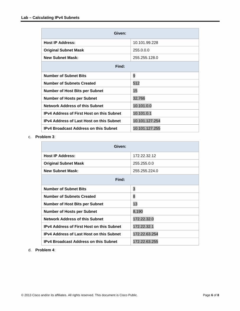
Lab – Calculating IPv4 Subnets
© 2013 Cisco and/or its affiliates. All rights reserved. This document is Cisco Public. Page 6 of 8
Given:
Host IP Address: 10.101.99.228
Original Subnet Mask 255.0.0.0
New Subnet Mask: 255.255.128.0
Find:
Number of Subnet Bits 9
Number of Subnets Created 512
Number of Host Bits per Subnet 15
Number of Hosts per Subnet 32,766
Network Address of this Subnet 10.101.0.0
IPv4 Address of First Host on this Subnet 10.101.0.1
IPv4 Address of Last Host on this Subnet 10.101.127.254
IPv4 Broadcast Address on this Subnet 10.101.127.255
c. Problem 3:
Given:
Host IP Address: 172.22.32.12
Original Subnet Mask 255.255.0.0
New Subnet Mask: 255.255.224.0
Find:
Number of Subnet Bits 3
Number of Subnets Created 8
Number of Host Bits per Subnet 13
Number of Hosts per Subnet 8,190
Network Address of this Subnet 172.22.32.0
IPv4 Address of First Host on this Subnet 172.22.32.1
IPv4 Address of Last Host on this Subnet 172.22.63.254
IPv4 Broadcast Address on this Subnet 172.22.63.255
d. Problem 4:
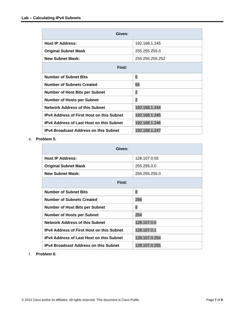
Lab – Calculating IPv4 Subnets
© 2013 Cisco and/or its affiliates. All rights reserved. This document is Cisco Public. Page 7 of 8
Given:
Host IP Address: 192.168.1.245
Original Subnet Mask 255.255.255.0
New Subnet Mask: 255.255.255.252
Find:
Number of Subnet Bits 6
Number of Subnets Created 64
Number of Host Bits per Subnet 2
Number of Hosts per Subnet 2
Network Address of this Subnet 192.168.1.244
IPv4 Address of First Host on this Subnet 192.168.1.245
IPv4 Address of Last Host on this Subnet 192.168.1.246
IPv4 Broadcast Address on this Subnet 192.168.1.247
e. Problem 5:
Given:
Host IP Address: 128.107.0.55
Original Subnet Mask 255.255.0.0
New Subnet Mask: 255.255.255.0
Find:
Number of Subnet Bits 8
Number of Subnets Created 256
Number of Host Bits per Subnet 8
Number of Hosts per Subnet 254
Network Address of this Subnet 128.107.0.0
IPv4 Address of First Host on this Subnet 128.107.0.1
IPv4 Address of Last Host on this Subnet 128.107.0.254
IPv4 Broadcast Address on this Subnet 128.107.0.255
f. Problem 6:

Lab – Calculating IPv4 Subnets
© 2013 Cisco and/or its affiliates. All rights reserved. This document is Cisco Public. Page 8 of 8
Given:
Host IP Address: 192.135.250.180
Original Subnet Mask 255.255.255.0
New Subnet Mask: 255.255.255.248
Find:
Number of Subnet Bits 5
Number of Subnets Created 32
Number of Host Bits per Subnet 3
Number of Hosts per Subnet 6
Network Address of this Subnet 192.135.250.176
IPv4 Address of First Host on this Subnet 192.135.250.177
IPv4 Address of Last Host on this Subnet 192.135.250.182
IPv4 Broadcast Address on this Subnet 192.135.250.183
Reflection Why is the subnet mask so important when analyzing an IPv4 address?
_______________________________________________________________________________________
_______________________________________________________________________________________
_______________________________________________________________________________________
The subnet mask determines everything about the address: the network, number of host bits, number of hosts and the broadcast address. Merely looking at an IPv4 address tells you nothing. You need the subnet mask to fill in all the important pieces of information.

© 2013 Cisco and/or its affiliates. All rights reserved. This document is Cisco Public. Page 1 of 9
Lab – Subnetting Network Topologies (Instructor Version) Instructor Note: Red font color or Gray highlights indicate text that appears in the instructor copy only.
Objectives
Parts 1 to 5, for each network topology:
Determine the number of subnets.
Design an appropriate addressing scheme.
Assign addresses and subnet mask pairs to device interfaces.
Examine the use of the available network address space and future growth potential.
Background / Scenario
When given a network topology, it is important to be able to determine the number of subnets required. In this lab, several scenario topologies will be provided, along with a base network address and mask. You will subnet the network address and provide an IP addressing scheme that will accommodate the number of subnets displayed in the topology diagram. You must determine the number of bits to borrow, the number of hosts per subnet, and potential for growth as specified by the instructions.
Part 1: Network Topology A
In Part 1, you have been given the 192.168.10.0/24 network address to subnet, with the following topology. Determine the number of networks needed and then design an appropriate addressing scheme.
Step 1: Determine the number of subnets in Network Topology A.
a. How many subnets are there? ___________ 2
b. How many bits should you borrow to create the required number of subnets? _________ 1
c. How many usable host addresses per subnet are in this addressing scheme? ___________ 126
d. What is the new subnet mask in dotted decimal format? _________________________ 255.255.255.128
e. How many subnets are available for future use? _______________ 0
Step 2: Record the subnet information.
Fill in the following table with the subnet information:

Lab – Subnetting Network Topologies
© 2013 Cisco and/or its affiliates. All rights reserved. This document is Cisco Public. Page 2 of 9
Subnet
Number Subnet Address
First Usable Host
Address
Last Usable Host
Address
Broadcast
Address
0 192.168.10.0 192.168.10.1 192.168.10.126 192.168.10.127
1 192.168.10.128 192.168.10.129 192.168.10.254 192.168.10.255
2
3
4
5
Part 2: Network Topology B
The network topology from Part 1 has expanded to accommodate the addition of router R3 and its accompanying network, as illustrated in the following topology. Use the 192.168.10.0/24 network address to provide addresses to the network devices, and then design a new addressing scheme to support the additional network requirement.
Step 1: Determine the number of subnets in Network Topology B.
a. How many subnets are there? ___________ 4
b. How many bits should you borrow to create the required number of subnets? _________ 2
c. How many usable host addresses per subnet are in this addressing scheme? ___________ 62
d. What is the new subnet mask in dotted decimal format? _________________________ 255.255.255.192
e. How many subnets are available for future use? _______________ 0
Step 2: Record the subnet information.
Fill in the following table with the subnet information:

Lab – Subnetting Network Topologies
© 2013 Cisco and/or its affiliates. All rights reserved. This document is Cisco Public. Page 3 of 9
Subnet
Number Subnet Address
First Usable Host
Address
Last Usable Host
Address
Broadcast
Address
0 192.168.10.0 192.168.10.1 192.168.10.62 192.168.10.63
1 192.168.10.64 192.168.10.65 192.168.10.126 192.168.10.127
2 192.168.10.128 192.168.10.129 192.168.10.190 192.168.10.191
3 192.168.10.192 192.168.10.193 192.168.10.254 192.168.10.255
4
5
6
7
Part 3: Network Topology C
The topology has changed again with a new LAN added to R2 and a redundant link between R1 and R3. Use the 192.168.10.0/24 network address to provide addresses to the network devices. Also provide an IP address scheme that will accommodate these additional devices. For this topology, assign a subnet to each network.
Step 1: Determine the number of subnets in Network Topology C.
a. How many subnets are there? ___________ 6
b. How many bits should you borrow to create the required number of subnets? _________ 3
c. How many usable host addresses per subnet are in this addressing scheme? ___________ 30
d. What is the new subnet mask in dotted decimal format? _________________________ 255.255.255.224
e. How many subnets are available for future use? _______________ 2

Lab – Subnetting Network Topologies
© 2013 Cisco and/or its affiliates. All rights reserved. This document is Cisco Public. Page 4 of 9
Step 2: Record the subnet information.
Fill in the following table with the subnet information:
Subnet
Number Subnet Address
First Usable Host
Address
Last Usable Host
Address
Broadcast
Address
0 192.168.10.0 192.168.10.1 192.168.10.30 192.168.10.31
1 192.168.10.32 192.168.10.33 192.168.10.62 192.168.10.63
2 192.168.10.64 192.168.10.65 192.168.10.94 192.168.10.95
3 192.168.10.96 192.168.10.97 192.168.10.126 192.168.10.127
4 192.168.10.128 192.168.10.129 192.168.10.158 192.168.10.159
5 192.168.10.160 192.168.10.161 192.168.10.190 192.168.10.191
6 192.168.10.192 192.168.10.193 192.168.10.222 192.168.10.223
7 192.168.10.224 192.168.10.225 192.168.10.254 192.168.10.255
8
9
10
Step 3: Assign addresses to network devices in the subnets.
a. Fill in the following table with IP addresses and subnet masks for the router interfaces:
Instructor Note: These are suggested IP addresses based on using the first 6 subnets from the table above as assigned to each segment.
Device Interface IP Address Subnet Mask
R1 GigabitEthernet 0/1 192.168.10.1 255.255.255.224
Serial 0/0/0 192.168.10.33 255.255.255.224
Serial 0/0/1 192.168.10.65 255.255.255.224
R2 GigabitEthernet 0/1 192.168.10.97 255.255.255.224
Serial 0/0/0 192.168.10.34 255.255.255.224
Serial 0/0/1 192.168.10.129 255.255.255.224
R3 GigabitEthernet 0/1 192.168.10.161 255.255.255.224
Serial 0/0/0 192.168.10.66 255.255.255.224
Serial 0/0/1 192.168.10.130 255.255.255.224
b. Fill in the following table with the IP addresses and subnet masks for devices in the LAN as displayed in topology.
Instructor Note: These are suggested IP addresses based on using the first 6 subnets from the table above as assigned to each segment.

Lab – Subnetting Network Topologies
© 2013 Cisco and/or its affiliates. All rights reserved. This document is Cisco Public. Page 5 of 9
Device Interface IP Address Subnet Mask Default Gateway
PC-A NIC 192.168.10.30 255.255.255.224 192.168.10.1
PC-B NIC 192.168.10.29 255.255.255.224 192.168.10.1
S1 VLAN 1 192.168.10.2 255.255.255.224 192.168.10.1
PC-C NIC 192.168.10.126 255.255.255.224 192.168.10.97
PC-D NIC 192.168.10.125 255.255.255.224 192.168.10.97
S2 VLAN 1 192.168.10.98 255.255.255.224 192.168.10.97
PC-E NIC 192.168.10.190 255.255.255.224 192.168.10.161
PC-F NIC 192.168.10.189 255.255.255.224 192.168.10.161
S3 VLAN 1 192.168.10.162 255.255.255.224 192.168.10.161
Part 4: Network Topology D
The network was modified to accommodate changes in the organization. The 192.168.10.0/24 network address is used to provide the addresses in the network.
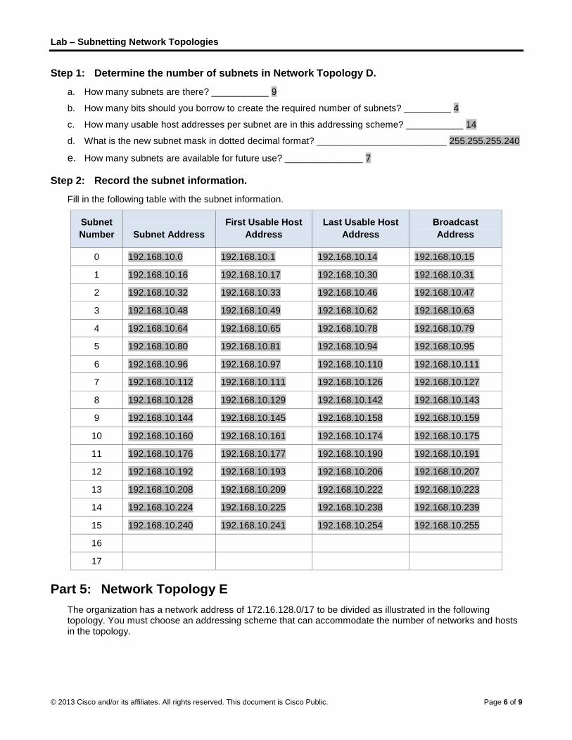
Lab – Subnetting Network Topologies
© 2013 Cisco and/or its affiliates. All rights reserved. This document is Cisco Public. Page 6 of 9
Step 1: Determine the number of subnets in Network Topology D.
a. How many subnets are there? ___________ 9
b. How many bits should you borrow to create the required number of subnets? _________ 4
c. How many usable host addresses per subnet are in this addressing scheme? ___________ 14
d. What is the new subnet mask in dotted decimal format? _________________________ 255.255.255.240
e. How many subnets are available for future use? _______________ 7
Step 2: Record the subnet information.
Fill in the following table with the subnet information.
Subnet
Number Subnet Address
First Usable Host
Address
Last Usable Host
Address
Broadcast
Address
0 192.168.10.0 192.168.10.1 192.168.10.14 192.168.10.15
1 192.168.10.16 192.168.10.17 192.168.10.30 192.168.10.31
2 192.168.10.32 192.168.10.33 192.168.10.46 192.168.10.47
3 192.168.10.48 192.168.10.49 192.168.10.62 192.168.10.63
4 192.168.10.64 192.168.10.65 192.168.10.78 192.168.10.79
5 192.168.10.80 192.168.10.81 192.168.10.94 192.168.10.95
6 192.168.10.96 192.168.10.97 192.168.10.110 192.168.10.111
7 192.168.10.112 192.168.10.111 192.168.10.126 192.168.10.127
8 192.168.10.128 192.168.10.129 192.168.10.142 192.168.10.143
9 192.168.10.144 192.168.10.145 192.168.10.158 192.168.10.159
10 192.168.10.160 192.168.10.161 192.168.10.174 192.168.10.175
11 192.168.10.176 192.168.10.177 192.168.10.190 192.168.10.191
12 192.168.10.192 192.168.10.193 192.168.10.206 192.168.10.207
13 192.168.10.208 192.168.10.209 192.168.10.222 192.168.10.223
14 192.168.10.224 192.168.10.225 192.168.10.238 192.168.10.239
15 192.168.10.240 192.168.10.241 192.168.10.254 192.168.10.255
16
17
Part 5: Network Topology E
The organization has a network address of 172.16.128.0/17 to be divided as illustrated in the following topology. You must choose an addressing scheme that can accommodate the number of networks and hosts in the topology.
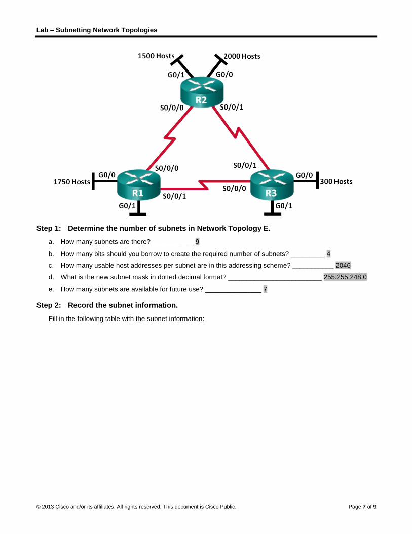
Lab – Subnetting Network Topologies
© 2013 Cisco and/or its affiliates. All rights reserved. This document is Cisco Public. Page 7 of 9
Step 1: Determine the number of subnets in Network Topology E.
a. How many subnets are there? ___________ 9
b. How many bits should you borrow to create the required number of subnets? _________ 4
c. How many usable host addresses per subnet are in this addressing scheme? ___________ 2046
d. What is the new subnet mask in dotted decimal format? _________________________ 255.255.248.0
e. How many subnets are available for future use? _______________ 7
Step 2: Record the subnet information.
Fill in the following table with the subnet information:
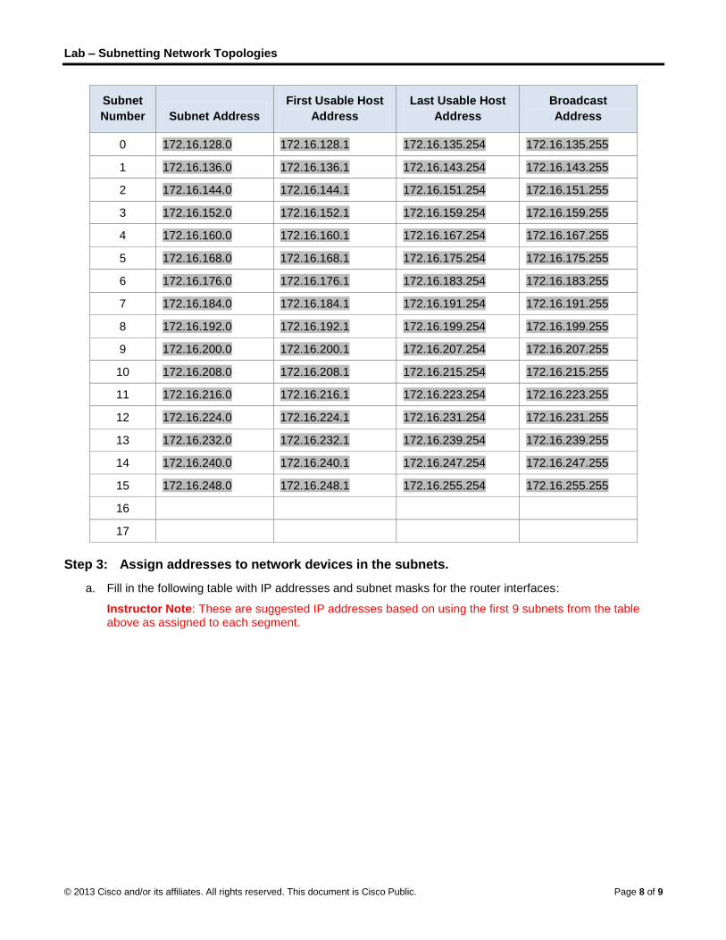
Lab – Subnetting Network Topologies
© 2013 Cisco and/or its affiliates. All rights reserved. This document is Cisco Public. Page 8 of 9
Subnet
Number Subnet Address
First Usable Host
Address
Last Usable Host
Address
Broadcast
Address
0 172.16.128.0 172.16.128.1 172.16.135.254 172.16.135.255
1 172.16.136.0 172.16.136.1 172.16.143.254 172.16.143.255
2 172.16.144.0 172.16.144.1 172.16.151.254 172.16.151.255
3 172.16.152.0 172.16.152.1 172.16.159.254 172.16.159.255
4 172.16.160.0 172.16.160.1 172.16.167.254 172.16.167.255
5 172.16.168.0 172.16.168.1 172.16.175.254 172.16.175.255
6 172.16.176.0 172.16.176.1 172.16.183.254 172.16.183.255
7 172.16.184.0 172.16.184.1 172.16.191.254 172.16.191.255
8 172.16.192.0 172.16.192.1 172.16.199.254 172.16.199.255
9 172.16.200.0 172.16.200.1 172.16.207.254 172.16.207.255
10 172.16.208.0 172.16.208.1 172.16.215.254 172.16.215.255
11 172.16.216.0 172.16.216.1 172.16.223.254 172.16.223.255
12 172.16.224.0 172.16.224.1 172.16.231.254 172.16.231.255
13 172.16.232.0 172.16.232.1 172.16.239.254 172.16.239.255
14 172.16.240.0 172.16.240.1 172.16.247.254 172.16.247.255
15 172.16.248.0 172.16.248.1 172.16.255.254 172.16.255.255
16
17
Step 3: Assign addresses to network devices in the subnets.
a. Fill in the following table with IP addresses and subnet masks for the router interfaces:
Instructor Note: These are suggested IP addresses based on using the first 9 subnets from the table above as assigned to each segment.

Lab – Subnetting Network Topologies
© 2013 Cisco and/or its affiliates. All rights reserved. This document is Cisco Public. Page 9 of 9
Device Interface IP Address Subnet Mask
R1 GigabitEthernet 0/0 172.16.128.1 255.255.248.0
GigabitEthernet 0/1 172.16.136.1 255.255.248.0
Serial 0/0/0 172.16.144.1 255.255.248.0
Serial 0/0/1 172.16.152.1 255.255.248.0
R2 GigabitEthernet 0/0 172.16.160.1 255.255.248.0
GigabitEthernet 0/1 172.16.168.1 255.255.248.0
Serial 0/0/0 172.16.144.2 255.255.248.0
Serial 0/0/1 172.16.176.1 255.255.248.0
R3 GigabitEthernet 0/0 172.16.184.1 255.255.248.0
GigabitEthernet 0/1 172.16.192.1 255.255.248.0
Serial 0/0/0 172.16.152.2 255.255.248.0
Serial 0/0/1 172.16.176.2 255.255.248.0
Reflection
1. What information is needed when determining an appropriate addressing scheme for a network?
_______________________________________________________________________________________
_______________________________________________________________________________________
Number of networks and hosts are needed when determining an appropriate addressing scheme for a network.
2. After the subnets are assigned, will all the host addresses be utilized in each subnet?
_______________________________________________________________________________________
_______________________________________________________________________________________
No. For the WAN serial links, only two addresses will be utilized. For the subnets with host PCs, all the addresses can be used in each subnet.
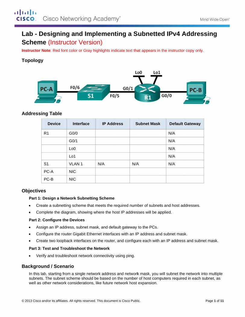
©
LSI
T
A
O
B
© 2013 Cisco and
Lab - DeSchemenstructor No
Topology
Addressing
R
S
P
P
ObjectivesPart 1: De
Creat
Comp
Part 2: Co
Assig
Config
Creat
Part 3: Te
Verify
BackgrounIn this labsubnets. Twell as ot
d/or its affiliates.
esigninge (Instrucote: Red font
g Table
Device
R1
S1
PC-A
PC-B
esign a Netw
te a subnettin
plete the diag
onfigure the
n an IP addre
gure the route
te two loopba
est and Trou
y and troubles
nd / Scenarb, starting fromThe subnet scher network c
All rights reserve
g and Imctor Vers
color or Gray
Interface
G0/0
G0/1
Lo0
Lo1
VLAN 1
NIC
NIC
work Subnett
g scheme tha
ram, showing
Devices
ess, subnet m
er Gigabit Eth
ck interfaces
bleshoot the
shoot network
rio m a single netcheme shouldconsiderations
ed. This docume
mplemenion)
y highlights ind
IP Add
N/A
ting Scheme
at meets the r
g where the ho
mask, and defa
hernet interfac
on the router
e Network
k connectivity
twork addressd be based ons, like future n
ent is Cisco Publi
ting a S
dicate text tha
dress S
N/A
required num
ost IP addres
ault gateway
ces with an IP
r, and configu
using ping.
s and networkn the numbernetwork host
ic.
Subnette
at appears in
Subnet Mask
A
ber of subnet
sses will be ap
to the PCs.
P address and
ure each with
k mask, you wr of host compexpansion.
ed IPv4 A
the instructo
Default
N/A
N/A
N/A
N/A
N/A
ts and host ad
pplied.
d subnet mas
an IP addres
will subnet theputers require
P
Address
r copy only.
Gateway
ddresses.
sk.
ss and subnet
e network intoed in each su
Page 1 of 11
sing
t mask.
o multiple bnet, as
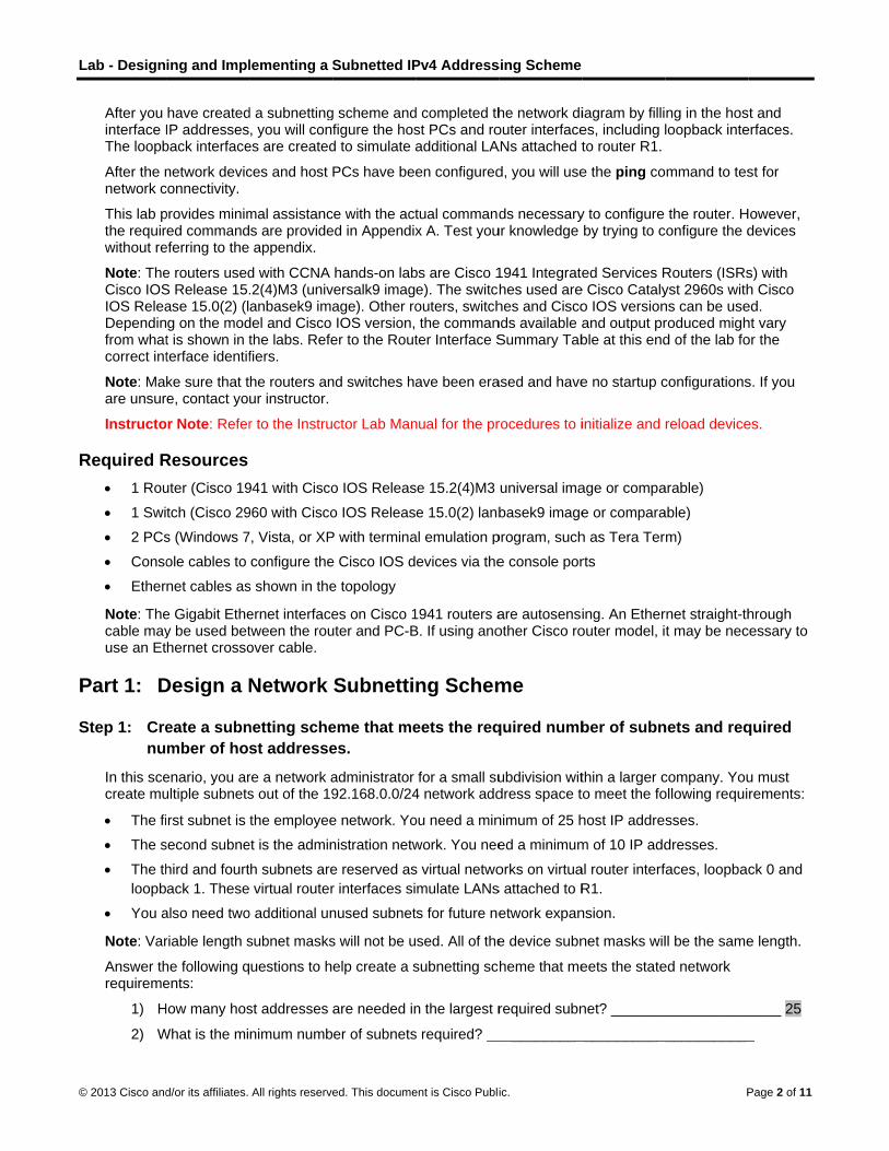
L
©
R
P
S
Lab - Design
© 2013 Cisco and
After you interface IThe loopb
After the nnetwork c
This lab pthe requirwithout re
Note: TheCisco IOSIOS ReleaDependinfrom whatcorrect int
Note: Maare unsur
Instructo
Required R 1 Rou
1 Swi
2 PCs
Conso
Ether
Note: Thecable mayuse an Et
DPart 1:
Step 1: Crenu
In this scecreate mu
The fi
The s
The th
loopb
You a
Note: Var
Answer threquireme
1) H
2) W
ing and Impl
d/or its affiliates.
have createdIP addressesback interface
network devicconnectivity.
provides minimred commandeferring to the
e routers usedS Release 15.ase 15.0(2) (lg on the modt is shown in tterface identif
ke sure that tre, contact yo
or Note: Refer
Resources uter (Cisco 19
tch (Cisco 29
s (Windows 7
ole cables to
net cables as
e Gigabit Ethey be used bethernet crosso
Design a N
eate a subnmber of hos
enario, you arultiple subnets
rst subnet is
second subne
hird and fourt
ack 1. These
also need two
riable length s
he following qents:
How many hos
What is the mi
lementing a S
All rights reserve
d a subnetting, you will con
es are created
ces and host
mal assistancs are provideappendix.
d with CCNA .2(4)M3 (univanbasek9 ima
del and Cisco the labs. Refefiers.
he routers anur instructor.
r to the Instru
941 with Cisco
960 with Cisco
7, Vista, or XP
configure the
s shown in the
ernet interfacetween the rouover cable.
Network
netting schest addresse
re a network as out of the 19
the employee
et is the admin
th subnets are
virtual router
o additional un
subnet masks
uestions to h
st addresses
nimum numb
Subnetted IP
ed. This docume
g scheme andfigure the hosd to simulate a
PCs have bee
ce with the acted in Appendix
hands-on labversalk9 imagage). Other roIOS version,
er to the Rout
nd switches ha
ctor Lab Man
o IOS Releas
o IOS Releas
P with termina
e Cisco IOS d
e topology
es on Cisco 1uter and PC-B
Subnetti
eme that mees.
administrator92.168.0.0/24
e network. Yo
nistration netw
e reserved as
r interfaces si
nused subnet
s will not be u
elp create a s
are needed in
er of subnets
Pv4 Address
ent is Cisco Publi
d completed thst PCs and roadditional LA
en configured
tual commandx A. Test you
bs are Cisco 1e). The switchouters, switchthe comman
ter Interface S
ave been era
nual for the pr
se 15.2(4)M3
e 15.0(2) lanb
al emulation p
evices via the
1941 routers aB. If using ano
ng Schem
eets the req
for a small su4 network add
ou need a min
work. You nee
s virtual netwo
mulate LANs
ts for future ne
sed. All of the
subnetting sc
n the largest r
s required? __
sing Scheme
ic.
he network diouter interfaceANs attached t
d, you will use
ds necessaryur knowledge
1941 Integratehes used arehes and Cisconds available aSummary Tab
ased and have
rocedures to i
universal ima
basek9 image
program, such
e console por
are autosensiother Cisco ro
me
quired numb
ubdivision witdress space t
nimum of 25 h
ed a minimum
orks on virtua
s attached to R
etwork expan
e device subn
heme that me
required subn
___________
iagram by fillies, including lto router R1.
e the ping co
y to configure by trying to c
ed Services Re Cisco Catalyo IOS versionand output prble at this end
e no startup c
initialize and
age or compa
e or compara
h as Tera Ter
rts
ing. An Etherouter model, i
ber of subn
thin a larger cto meet the fo
host IP addre
m of 10 IP add
al router interf
R1.
nsion.
net masks wil
eets the state
net? _______
____________
P
ng in the hosloopback inte
mmand to tes
the router. Hconfigure the d
Routers (ISRsyst 2960s withns can be useroduced mighd of the lab fo
configurations
reload device
arable)
able)
m)
rnet straight-tht may be nec
nets and req
company. Youollowing requi
sses.
dresses.
faces, loopbac
ll be the same
ed network
___________
____________
Page 2 of 11
t and erfaces.
st for
owever, devices
s) with h Cisco ed. ht vary or the
s. If you
es.
hrough cessary to
quired
u must rements:
ck 0 and
e length.
_____ 25
_
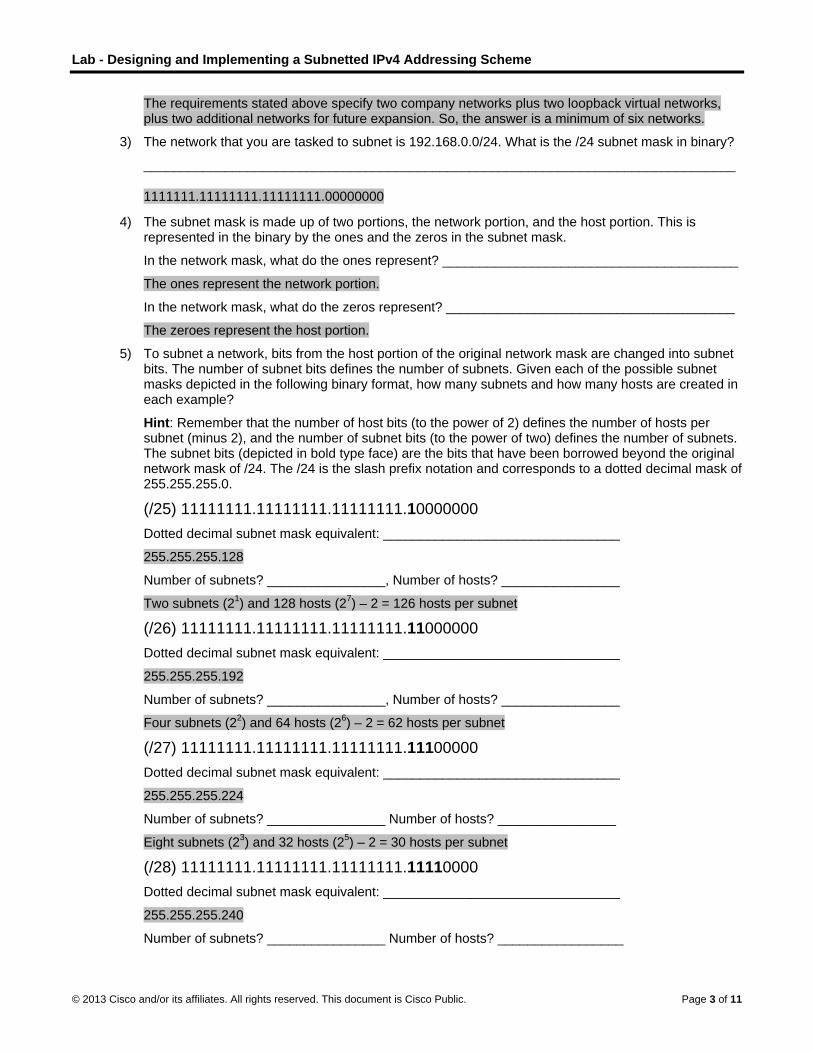
Lab - Designing and Implementing a Subnetted IPv4 Addressing Scheme
© 2013 Cisco and/or its affiliates. All rights reserved. This document is Cisco Public. Page 3 of 11
The requirements stated above specify two company networks plus two loopback virtual networks, plus two additional networks for future expansion. So, the answer is a minimum of six networks.
3) The network that you are tasked to subnet is 192.168.0.0/24. What is the /24 subnet mask in binary?
________________________________________________________________________________
1111111.11111111.11111111.00000000
4) The subnet mask is made up of two portions, the network portion, and the host portion. This is represented in the binary by the ones and the zeros in the subnet mask.
In the network mask, what do the ones represent? ________________________________________
The ones represent the network portion.
In the network mask, what do the zeros represent? _______________________________________
The zeroes represent the host portion.
5) To subnet a network, bits from the host portion of the original network mask are changed into subnet bits. The number of subnet bits defines the number of subnets. Given each of the possible subnet masks depicted in the following binary format, how many subnets and how many hosts are created in each example?
Hint: Remember that the number of host bits (to the power of 2) defines the number of hosts per subnet (minus 2), and the number of subnet bits (to the power of two) defines the number of subnets. The subnet bits (depicted in bold type face) are the bits that have been borrowed beyond the original network mask of /24. The /24 is the slash prefix notation and corresponds to a dotted decimal mask of 255.255.255.0.
(/25) 11111111.11111111.11111111.10000000
Dotted decimal subnet mask equivalent: ________________________________
255.255.255.128
Number of subnets? ________________, Number of hosts? ________________
Two subnets (21) and 128 hosts (2
7) – 2 = 126 hosts per subnet
(/26) 11111111.11111111.11111111.11000000
Dotted decimal subnet mask equivalent: ________________________________
255.255.255.192
Number of subnets? ________________, Number of hosts? ________________
Four subnets (22) and 64 hosts (2
6) – 2 = 62 hosts per subnet
(/27) 11111111.11111111.11111111.11100000
Dotted decimal subnet mask equivalent: ________________________________
255.255.255.224
Number of subnets? ________________ Number of hosts? ________________
Eight subnets (23) and 32 hosts (2
5) – 2 = 30 hosts per subnet
(/28) 11111111.11111111.11111111.11110000
Dotted decimal subnet mask equivalent: ________________________________
255.255.255.240
Number of subnets? ________________ Number of hosts? _________________

Lab - Designing and Implementing a Subnetted IPv4 Addressing Scheme
© 2013 Cisco and/or its affiliates. All rights reserved. This document is Cisco Public. Page 4 of 11
Sixteen subnets (24) and 16 hosts (2
4) – 2 = 14 hosts per subnet
(/29) 11111111.11111111.11111111.11111000
Dotted decimal subnet mask equivalent: ________________________________
255.255.255.248
Number of subnets? ________________ Number of hosts? _________________
Thirty two subnets (25) and 8 hosts (2
3) – 2 = 6 hosts per subnet
(/30) 11111111.11111111.11111111.11111100
Dotted decimal subnet mask equivalent: ________________________________
255.255.255.252
Number of subnets? ________________ Number of hosts? _________________
Sixty four subnets (26) and 4 hosts (2
2) – 2 = 2 hosts per subnet
6) Considering your answers, which subnet masks meet the required number of minimum host addresses?
________________________________________________________________________________
/25, /26, /27
7) Considering your answers, which subnet masks meets the minimum number of subnets required?
________________________________________________________________________________
/27, /28, /29, /30 will give the required number of subnets.
8) Considering your answers, which subnet mask meets both the required minimum number of hosts and the minimum number of subnets required?
________________________________________________________________________________
/27 will give you eight subnets, which is greater than the minimum of five required, and 30 hosts per subnet, which is greater than the 25 hosts required for the first subnet.
9) When you have determined which subnet mask meets all of the stated network requirements, you will derive each of the subnets starting from the original network address. List the subnets from first to last below. Remember that the first subnet is 192.168.0.0 with the newly acquired subnet mask.
Subnet Address / Prefix Subnet Mask (dotted decimal)
___________________ / ____ __________________________
___________________ / ____ __________________________
___________________ / ____ __________________________
___________________ / ____ __________________________
___________________ / ____ __________________________
___________________ / ____ __________________________
___________________ / ____ __________________________
___________________ / ____ __________________________
___________________ / ____ __________________________
___________________ / ____ __________________________
192.168.0.0, 192.168.0.32, 192.168.0.64, 192.168.0.96, 192.168.0.128, 192.168.0.160, 192.168.0.192, 192.168.0.224 All prefix is /27. All subnet mask is (dotted decimal) 255.255.255.224.
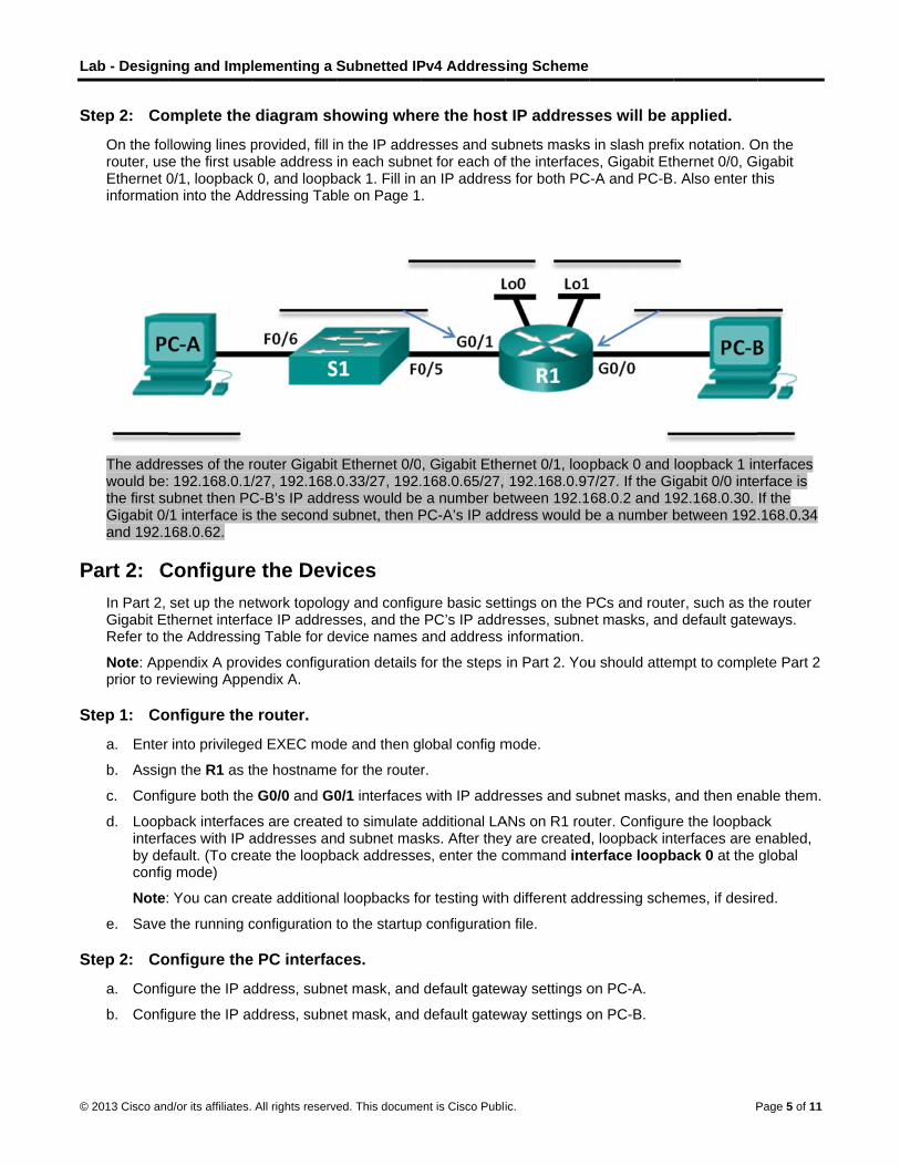
L
©
S
P
S
S
Lab - Design
© 2013 Cisco and
Step 2: Co
On the folrouter, usEthernet 0informatio
The addrewould be:the first suGigabit 0/and 192.1
CPart 2:In Part 2, Gigabit EtRefer to th
Note: Appprior to re
Step 1: Co
a. Enter
b. Assig
c. Config
d. Loopbinterfaby deconfig
Note:
e. Save
Step 2: Co
a. Config
b. Config
ing and Impl
d/or its affiliates.
omplete the
llowing lines pe the first usa0/1, loopbackon into the Ad
esses of the r 192.168.0.1/ubnet then PC/1 interface is 168.0.62.
Configureset up the nethernet interfahe Addressin
pendix A proveviewing Appe
onfigure the
into privilege
n the R1 as t
gure both the
back interfaceaces with IP afault. (To crea
g mode)
You can cre
the running c
onfigure the
gure the IP ad
gure the IP ad
lementing a S
All rights reserve
diagram sh
provided, fill inable address k 0, and loopbdressing Tab
router Gigabit/27, 192.168.C-B’s IP addrthe second s
e the Devetwork topologace IP addresg Table for de
vides configurendix A.
e router.
ed EXEC mod
he hostname
e G0/0 and G0
es are createdaddresses anate the loopb
ate additiona
configuration t
e PC interfac
ddress, subne
ddress, subne
Subnetted IP
ed. This docume
howing whe
n the IP addrein each subne
back 1. Fill in able on Page 1
t Ethernet 0/00.33/27, 192.ess would be
subnet, then P
ices gy and configsses, and the evice names
ration details
de and then g
for the route
0/1 interfaces
d to simulate d subnet masack addresse
l loopbacks fo
to the startup
ces.
et mask, and
et mask, and
Pv4 Address
ent is Cisco Publi
ere the host
esses and suet for each ofan IP address.
, Gigabit Ethe.168.0.65/27,
e a number bePC-A’s IP add
ure basic setPC’s IP addrand address
for the steps
lobal config m
r.
s with IP addre
additional LAsks. After theyes, enter the c
or testing with
p configuration
default gatew
default gatew
sing Scheme
ic.
t IP address
ubnets masksf the interfaces for both PC
ernet 0/1, loo192.168.0.97
etween 192.1dress would b
ttings on the Presses, subneinformation.
in Part 2. You
mode.
esses and su
ANs on R1 rouy are createdcommand inte
h different add
n file.
way settings o
way settings o
ses will be a
s in slash prefes, Gigabit Eth
C-A and PC-B
pback 0 and 7/27. If the Gi68.0.2 and 19
be a number b
PCs and routeet masks, and
u should attem
ubnet masks,
uter. Configurd, loopback interface loopb
dressing sche
on PC-A.
on PC-B.
P
applied.
fix notation. Ohernet 0/0, G. Also enter th
loopback 1 inigabit 0/0 inte92.168.0.30. between 192
er, such as thd default gate
mpt to comple
and then ena
re the loopbacterfaces are e
back 0 at the
emes, if desir
Page 5 of 11
On the igabit his
nterfaces erface is If the .168.0.34
he router eways.
ete Part 2
able them.
ck enabled, global
red.

L
©
P
R1
2
Lab - Design
© 2013 Cisco and
TPart 3:In Part 3,
a. Test tping t
If the check
b. Test tping t
If the check
c. Test taddre
If bothshoul
d. If youaddreconfig
e. If youadditiWindo
f. Experyou tr
_____
_____
With d
Reflection 1. Subnettin
network dbeing the
________
________
Answers wothers reqsubnets.
2. Why do yo
________
________
Answers wis logical tthe router
ing and Impl
d/or its affiliates.
Test and Tyou will use t
to see if PC-Athe IP address
PC and routek items d and
to see if PC-Bthe IP address
PC and routek items d and
to see if PC-Aess of PC-B. D
h PCs and thed be success
answered “ness and subnegured on PC-A
verify that alonal factors tows Firewall i
riment by purry and ping fro
___________
___________
deliberate mis
g one larger ndesign. Howev
same size?
___________
___________
will vary. Studquire only a fe
ou think the g
___________
___________
will vary. It mathat its addresr does not hav
lementing a S
All rights reserve
Troublesthe ping com
A can commus of the route
er interface hae below.
B can commus of the route
er interface hae below.
A can commuDo you get a
e router Gigasful. If not, che
o” to any of thet mask configA and PC-B.
l of the settinghat can blockis turned off fo
posely miscoom PC-B to P
___________
___________
sconfiguration
network into mver, what do y
____________
____________
dents may suew, having all
gateway/route
____________
____________
ay be suggesss is at the beve to have the
Subnetted IP
ed. This docume
hoot the mand to test
nicate with itser Gigabit Ethe
ave been con
nicate with itser Gigabit Ethe
ave been con
nicate with PCreply? _____
bit Ethernet ineck items d a
he preceding gurations, an
gs are correck ICMP pings.or the Work,
nfiguring the PC-A? Do you
____________
____________
ns, the answe
multiple smalyou think som
___________
___________
ggest that, be of the subne
er IP address
___________
___________
sted that the reginning of the first or last a
Pv4 Address
ent is Cisco Publi
Networknetwork conn
s default gateernet 0/1 inte
nfigured corre
s default gateernet 0/0 inte
nfigured corre
C-B. From PC____________
nterfaces havnd e below.
questions, thd ensure that
t, and you ca. On PC-A anHome, and P
gateway addu receive a re
___________
___________
er should be n
ler subnetworme of the draw
___________
___________
ecause someets the same s
is usually the
___________
___________
router or gatewhe network. It address in the
sing Scheme
ic.
nectivity.
eway. From PCerface. Do you
ctly then the
eway. From PCerface. Do you
ctly then the
C-A, open a c__
ve been config
hen you shout the default g
an still not pingnd PC-B withinPublic network
ress on PC-Aeply?
___________
___________
no.
rks allows forwbacks are w
____________
____________
subnetworkssize is not the
e first usable
____________
____________
way is like a is purely a coe network.
C-A, open a cu get a reply?
ping should b
C-B, open a cu get a reply?
ping should b
command pro
gured correct
ld go back angateways hav
g successfullyn Windows, mks.
A to 10.0.0.1.
____________
____________
r greater flexibwhen the subn
____________
____________
s require mane most efficien
IP address in
____________
____________
door to the neonvention how
P
command pro? __________
be successful
command pro? __________
be successful
ompt and ping
tly, then the p
nd check all ove been corre
y, then there make sure tha
What happen
____________
____________
bility and secunets are limite
___________
___________
ny ip addressent way to divi
n the network?
___________
___________
etwork and thwever, and th
Page 6 of 11
ompt and ________
. If not,
ompt and _______
. If not,
g the IP
pings
of your IP ctly
are a few at the
ns when
________
________
urity in ed to
________
________
es and de the
?
________
________
herefore it herefore
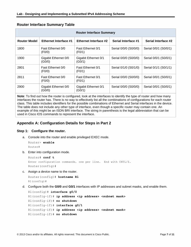
Lab - Designing and Implementing a Subnetted IPv4 Addressing Scheme
© 2013 Cisco and/or its affiliates. All rights reserved. This document is Cisco Public. Page 7 of 11
Router Interface Summary Table
Router Interface Summary
Router Model Ethernet Interface #1 Ethernet Interface #2 Serial Interface #1 Serial Interface #2
1800 Fast Ethernet 0/0 (F0/0)
Fast Ethernet 0/1 (F0/1)
Serial 0/0/0 (S0/0/0) Serial 0/0/1 (S0/0/1)
1900 Gigabit Ethernet 0/0 (G0/0)
Gigabit Ethernet 0/1 (G0/1)
Serial 0/0/0 (S0/0/0) Serial 0/0/1 (S0/0/1)
2801 Fast Ethernet 0/0 (F0/0)
Fast Ethernet 0/1 (F0/1)
Serial 0/1/0 (S0/1/0) Serial 0/1/1 (S0/1/1)
2811 Fast Ethernet 0/0 (F0/0)
Fast Ethernet 0/1 (F0/1)
Serial 0/0/0 (S0/0/0) Serial 0/0/1 (S0/0/1)
2900 Gigabit Ethernet 0/0 (G0/0)
Gigabit Ethernet 0/1 (G0/1)
Serial 0/0/0 (S0/0/0) Serial 0/0/1 (S0/0/1)
Note: To find out how the router is configured, look at the interfaces to identify the type of router and how many interfaces the router has. There is no way to effectively list all the combinations of configurations for each router class. This table includes identifiers for the possible combinations of Ethernet and Serial interfaces in the device. The table does not include any other type of interface, even though a specific router may contain one. An example of this might be an ISDN BRI interface. The string in parenthesis is the legal abbreviation that can be used in Cisco IOS commands to represent the interface.
Appendix A: Configuration Details for Steps in Part 2
Step 1: Configure the router.
a. Console into the router and enable privileged EXEC mode.
Router> enable Router#
b. Enter into configuration mode.
Router# conf t Enter configuration commands, one per line. End with CNTL/Z.
Router(config)#
c. Assign a device name to the router.
Router(config)# hostname R1 R1(config)#
d. Configure both the G0/0 and G0/1 interfaces with IP addresses and subnet masks, and enable them.
R1(config)# interface g0/0 R1(config-if)# ip address <ip address> <subnet mask> R1(config-if)# no shutdown R1(config-if)# interface g0/1 R1(config-if)# ip address <ip address> <subnet mask> R1(config-if)# no shutdown

L
©
S
Lab - Design
© 2013 Cisco and
e. Loopbinterfaby de
R1(coR1(coR1(coR1(coR1(co
f. Save
R1# c
Step 2: Co
a. Config
b. Config
ing and Impl
d/or its affiliates.
back interfaceaces with IP afault.
onfig)# inonfig-if)#onfig-if)#onfig-if)#onfig-if)#
the running c
copy runni
onfigure the
gure the IP ad
gure the IP ad
lementing a S
All rights reserve
es are createdaddresses an
nterface lo# ip addres# interface# ip addres# end
configuration t
ing-config
e PC interfac
ddress, subne
ddress, subne
Subnetted IP
ed. This docume
d to simulate d subnet mas
oopback 0ss <ip adde loopbackss <ip add
to the startup
startup-c
ces.
et mask, and
et mask, and
Pv4 Address
ent is Cisco Publi
additional LAsks. When the
dress> <subk 1 dress> <sub
p configuration
config
default gatew
default gatew
sing Scheme
ic.
ANs off of routey are create
bnet mask>
bnet mask>
n file.
way settings o
way settings o
ter R1. Configd, loopback in
>
>
on PC-A.
on PC-B.
P
gure the loopnterfaces are
Page 8 of 11
back e enabled,

Lab - Designing and Implementing a Subnetted IPv4 Addressing Scheme
© 2013 Cisco and/or its affiliates. All rights reserved. This document is Cisco Public. Page 9 of 11
Device Configs
Router R1 R1#show run Building configuration... Current configuration : 1518 bytes ! version 15.2 service timestamps debug datetime msec service timestamps log datetime msec no service password-encryption ! hostname R1 ! boot-start-marker boot-end-marker ! ! ! no aaa new-model ! ! no ipv6 cef ip auth-proxy max-login-attempts 5 ip admission max-login-attempts 5 ! ! ! ! ! ip cef ! multilink bundle-name authenticated ! crypto pki token default removal timeout 0 ! ! ! ! ! redundancy ! ! ! ! interface Loopback0 ip address 192.168.0.65 255.255.255.224 !

Lab - Designing and Implementing a Subnetted IPv4 Addressing Scheme
© 2013 Cisco and/or its affiliates. All rights reserved. This document is Cisco Public. Page 10 of 11
interface Loopback1 ip address 192.168.0.97 255.255.255.224 ! interface Embedded-Service-Engine0/0 no ip address shutdown ! interface GigabitEthernet0/0 ip address 192.168.0.1 255.255.255.224 duplex auto speed auto ! interface GigabitEthernet0/1 ip address 192.168.0.33 255.255.255.224 duplex auto speed auto ! interface Serial0/0/0 no ip address shutdown clock rate 2000000 ! interface Serial0/0/1 no ip address shutdown ! ip forward-protocol nd ! no ip http server no ip http secure-server ! ! ! ! ! control-plane ! ! ! line con 0 line aux 0 line 2 no activation-character no exec transport preferred none transport input all transport output pad telnet rlogin lapb-ta mop udptn v120 ssh stopbits 1 line vty 0 4

Lab - Designing and Implementing a Subnetted IPv4 Addressing Scheme
© 2013 Cisco and/or its affiliates. All rights reserved. This document is Cisco Public. Page 11 of 11
login transport input all ! scheduler allocate 20000 1000 ! end

© 2014 Cisco and/or its affiliates. All rights reserved. This document is Cisco Public. Page 1 of 12
Lab – Designing and Implementing a VLSM Addressing Scheme
(Instructor Version) Instructor Note: Red font color or Gray highlights indicate text that appears in the instructor copy only.
Topology
Objectives
Part 1: Examine Network Requirements
Part 2: Design the VLSM Address Scheme
Part 3: Cable and Configure the IPv4 Network
Background / Scenario
Variable Length Subnet Mask (VLSM) was designed to avoid wasting IP addresses. With VLSM, a network is subnetted and then re-subnetted. This process can be repeated multiple times to create subnets of various sizes based on the number of hosts required in each subnet. Effective use of VLSM requires address planning.
In this lab, use the 172.16.128.0/17 network address to develop an address scheme for the network displayed in the topology diagram. VLSM is used to meet the IPv4 addressing requirements. After you have designed the VLSM address scheme, you will configure the interfaces on the routers with the appropriate IP address information.
Note: The routers used with CCNA hands-on labs are Cisco 1941 Integrated Services Routers (ISRs) with Cisco IOS Release 15.2(4)M3 (universalk9 image). Other routers and Cisco IOS versions can be used. Depending on the model and Cisco IOS version, the commands available and output produced might vary from what is shown in the labs. Refer to the Router Interface Summary Table at the end of this lab for the correct interface identifiers.
Note: Make sure that the routers have been erased and have no startup configurations. If you are unsure, contact your instructor.
Instructor Note: Refer to the Instructor Lab Manual for the procedures to initialize and reload devices.
This lab can be performed in multiple sessions if time is an issue. Parts 1 and 2 are paper based and can be assigned as homework. Part 3 is Hands-on and requires lab equipment.

Lab – Designing and Implementing a VLSM Addressing Scheme
© 2014 Cisco and/or its affiliates. All rights reserved. This document is Cisco Public. Page 2 of 12
It is worth noting to the students that as a network administrator, you would not have a single network with over 1000 hosts. You would break these down further in a production network.
Required Resources
3 routers (Cisco 1941 with Cisco IOS software, Release 15.2(4)M3 universal image or comparable)
1 PC (with terminal emulation program, such as Tera Term, to configure routers)
Console cable to configure the Cisco IOS devices via the console ports
Ethernet (optional) and serial cables, as shown in the topology
Windows Calculator (optional)
Part 1: Examine Network Requirements
In Part 1, you will examine the network requirements to develop a VLSM address scheme for the network displayed in the topology diagram using the 172.16.128.0/17 network address.
Note: You can use the Windows Calculator application and the www.ipcalc.org IP subnet calculator to help with your calculations.
Step 1: Determine how many host addresses and subnets are available.
How many host addresses are available in a /17 network? ________ 32,766
What is the total number of host addresses needed in the topology diagram? ________ 31,506
How many subnets are needed in the network topology? ______ 9
Step 2: Determine the largest subnet.
What is the subnet description (e.g. BR1 G0/1 LAN or BR1-HQ WAN link)? ___________________ HQ G0/0 LAN
How many IP addresses are required in the largest subnet? __________ 16,000
What subnet mask can support that many host addresses?
_____________________ /18 or 255.255.192.0
How many total host addresses can that subnet mask support? _________ 16,382
Can you subnet the 172.16.128.0/17 network address to support this subnet? _____ yes
What are the two network addresses that would result from this subnetting?
_____________________ 172.16.128.0/18
_____________________ 172.16.192.0/18
Use the first network address for this subnet.
Step 3: Determine the second largest subnet.
What is the subnet description? _____________________________ HQ G0/1 LAN
How many IP addresses are required for the second largest subnet? ______ 8,000
What subnet mask can support that many host addresses?
___________________ /19 or 255.255.224.0
How many total host addresses can that subnet mask support? __________ 8,190

Lab – Designing and Implementing a VLSM Addressing Scheme
© 2014 Cisco and/or its affiliates. All rights reserved. This document is Cisco Public. Page 3 of 12
Can you subnet the remaining subnet again and still support this subnet? ______ yes
What are the two network addresses that would result from this subnetting?
_____________________ 172.16.192.0/19
_____________________ 172.16.224.0/19
Use the first network address for this subnet.
Step 4: Determine the next largest subnet.
What is the subnet description? _____________________________ BR1 G0/1 LAN
How many IP addresses are required for the next largest subnet? ______ 4,000
What subnet mask can support that many host addresses?
___________________ /20 or 255.255.240.0
How many total host addresses can that subnet mask support? __________ 4,094
Can you subnet the remaining subnet again and still support this subnet? ______ yes
What are the two network addresses that would result from this subnetting?
_____________________ 172.16.224.0/20
_____________________ 172.16.240.0/20
Use the first network address for this subnet.
Step 5: Determine the next largest subnet.
What is the subnet description? _____________________________ BR1 G0/0 LAN
How many IP addresses are required for the next largest subnet? ______ 2,000
What subnet mask can support that many host addresses?
___________________ /21 or 255.255.248.0
How many total host addresses can that subnet mask support? __________ 2,046
Can you subnet the remaining subnet again and still support this subnet? ______ yes
What are the two network addresses that would result from this subnetting?
_____________________ 172.16.240.0/21
_____________________ 172.16.248.0/21
Use the first network address for this subnet.
Step 6: Determine the next largest subnet.
What is the subnet description? _____________________________ BR2 G0/1 LAN
How many IP addresses are required for the next largest subnet? ______ 1,000
What subnet mask can support that many host addresses?
___________________ /22 or 255.255.252.0
How many total host addresses can that subnet mask support? __________ 1,022
Can you subnet the remaining subnet again and still support this subnet? ______ yes
What are the two network addresses that would result from this subnetting?
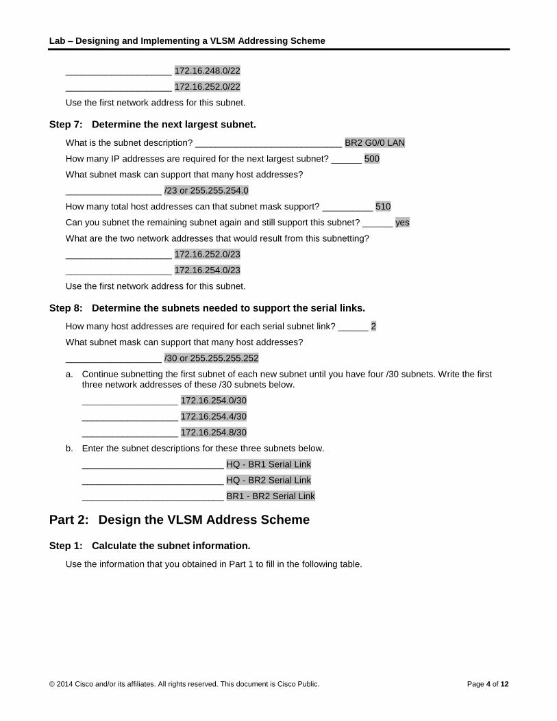
Lab – Designing and Implementing a VLSM Addressing Scheme
© 2014 Cisco and/or its affiliates. All rights reserved. This document is Cisco Public. Page 4 of 12
_____________________ 172.16.248.0/22
_____________________ 172.16.252.0/22
Use the first network address for this subnet.
Step 7: Determine the next largest subnet.
What is the subnet description? _____________________________ BR2 G0/0 LAN
How many IP addresses are required for the next largest subnet? ______ 500
What subnet mask can support that many host addresses?
___________________ /23 or 255.255.254.0
How many total host addresses can that subnet mask support? __________ 510
Can you subnet the remaining subnet again and still support this subnet? ______ yes
What are the two network addresses that would result from this subnetting?
_____________________ 172.16.252.0/23
_____________________ 172.16.254.0/23
Use the first network address for this subnet.
Step 8: Determine the subnets needed to support the serial links.
How many host addresses are required for each serial subnet link? ______ 2
What subnet mask can support that many host addresses?
___________________ /30 or 255.255.255.252
a. Continue subnetting the first subnet of each new subnet until you have four /30 subnets. Write the first three network addresses of these /30 subnets below.
___________________ 172.16.254.0/30
___________________ 172.16.254.4/30
___________________ 172.16.254.8/30
b. Enter the subnet descriptions for these three subnets below.
____________________________ HQ - BR1 Serial Link
____________________________ HQ - BR2 Serial Link
____________________________ BR1 - BR2 Serial Link
Part 2: Design the VLSM Address Scheme
Step 1: Calculate the subnet information.
Use the information that you obtained in Part 1 to fill in the following table.
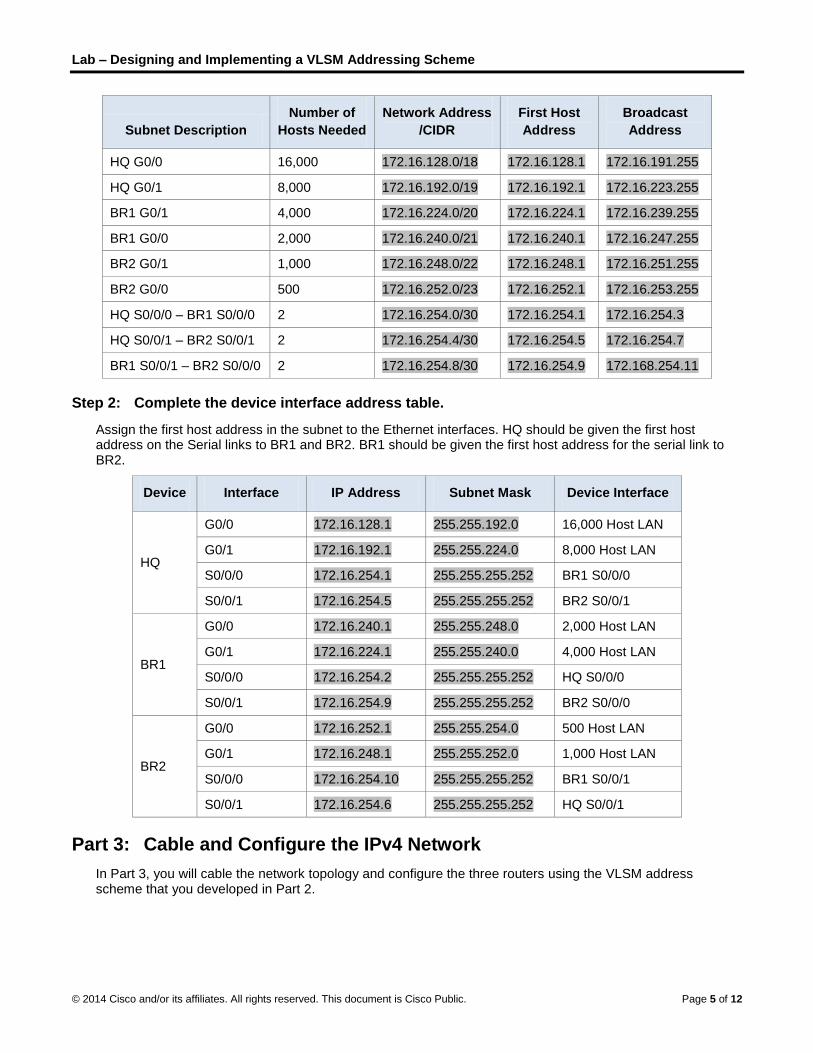
Lab – Designing and Implementing a VLSM Addressing Scheme
© 2014 Cisco and/or its affiliates. All rights reserved. This document is Cisco Public. Page 5 of 12
Subnet Description
Number of
Hosts Needed
Network Address
/CIDR
First Host
Address
Broadcast
Address
HQ G0/0 16,000 172.16.128.0/18 172.16.128.1 172.16.191.255
HQ G0/1 8,000 172.16.192.0/19 172.16.192.1 172.16.223.255
BR1 G0/1 4,000 172.16.224.0/20 172.16.224.1 172.16.239.255
BR1 G0/0 2,000 172.16.240.0/21 172.16.240.1 172.16.247.255
BR2 G0/1 1,000 172.16.248.0/22 172.16.248.1 172.16.251.255
BR2 G0/0 500 172.16.252.0/23 172.16.252.1 172.16.253.255
HQ S0/0/0 – BR1 S0/0/0 2 172.16.254.0/30 172.16.254.1 172.16.254.3
HQ S0/0/1 – BR2 S0/0/1 2 172.16.254.4/30 172.16.254.5 172.16.254.7
BR1 S0/0/1 – BR2 S0/0/0 2 172.16.254.8/30 172.16.254.9 172.168.254.11
Step 2: Complete the device interface address table.
Assign the first host address in the subnet to the Ethernet interfaces. HQ should be given the first host address on the Serial links to BR1 and BR2. BR1 should be given the first host address for the serial link to BR2.
Device Interface IP Address Subnet Mask Device Interface
HQ
G0/0 172.16.128.1 255.255.192.0 16,000 Host LAN
G0/1 172.16.192.1 255.255.224.0 8,000 Host LAN
S0/0/0 172.16.254.1 255.255.255.252 BR1 S0/0/0
S0/0/1 172.16.254.5 255.255.255.252 BR2 S0/0/1
BR1
G0/0 172.16.240.1 255.255.248.0 2,000 Host LAN
G0/1 172.16.224.1 255.255.240.0 4,000 Host LAN
S0/0/0 172.16.254.2 255.255.255.252 HQ S0/0/0
S0/0/1 172.16.254.9 255.255.255.252 BR2 S0/0/0
BR2
G0/0 172.16.252.1 255.255.254.0 500 Host LAN
G0/1 172.16.248.1 255.255.252.0 1,000 Host LAN
S0/0/0 172.16.254.10 255.255.255.252 BR1 S0/0/1
S0/0/1 172.16.254.6 255.255.255.252 HQ S0/0/1
Part 3: Cable and Configure the IPv4 Network
In Part 3, you will cable the network topology and configure the three routers using the VLSM address scheme that you developed in Part 2.

Lab – Designing and Implementing a VLSM Addressing Scheme
© 2014 Cisco and/or its affiliates. All rights reserved. This document is Cisco Public. Page 6 of 12
Step 1: Cable the network as shown in the topology.
Step 2: Configure basic settings on each router.
a. Assign the device name to the router.
b. Disable DNS lookup to prevent the router from attempting to translate incorrectly entered commands as though they were hostnames.
c. Assign class as the privileged EXEC encrypted password.
d. Assign cisco as the console password and enable login.
e. Assign cisco as the VTY password and enable login.
f. Encrypt the clear text passwords.
g. Create a banner that will warn anyone accessing the device that unauthorized access is prohibited.
Step 3: Configure the interfaces on each router.
a. Assign an IP address and subnet mask to each interface using the table that you completed in Part 2.
b. Configure an interface description for each interface.
c. Set the clocking rate on all DCE serial interfaces to 128000.
HQ(config-if)# clock rate 128000
d. Activate the interfaces.
Step 4: Save the configuration on all devices.
Step 5: Test Connectivity.
a. From HQ, ping BR1’s S0/0/0 interface address.
b. From HQ, ping BR2’s S0/0/1 interface address.
c. From BR1, ping BR2’s S0/0/0 interface address.
d. Troubleshoot connectivity issues if pings were not successful.
Note: Pings to the GigabitEthernet interfaces on other routers will not be successful. The LANs defined for the GigabitEthernet interfaces are simulated. Because no devices are attached to these LANs they will be in down/down state. A routing protocol needs to be in place for other devices to be aware of those subnets. The GigabitEthernet interfaces also need to be in an up/up state before a routing protocol can add the subnets to the routing table. These interfaces will remain in a down/down state until a device is connected to the other end of the Ethernet interface cable. The focus of this lab is on VLSM and configuring the interfaces.
Reflection
Can you think of a shortcut for calculating the network addresses of consecutive /30 subnets?
_______________________________________________________________________________________
_______________________________________________________________________________________
_______________________________________________________________________________________
_______________________________________________________________________________________
Answers may vary. A /30 network has 4 address spaces: the network address, 2 host addresses, and a broadcast address. Another technique for obtaining the next /30 network address would be to take the network address of the previous /30 network and add 4 to the last octet.
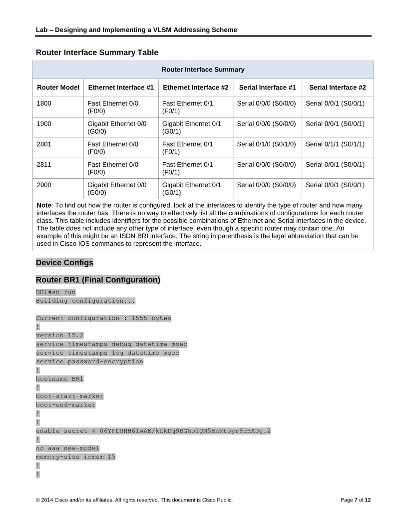
Lab – Designing and Implementing a VLSM Addressing Scheme
© 2014 Cisco and/or its affiliates. All rights reserved. This document is Cisco Public. Page 7 of 12
Router Interface Summary Table
Router Interface Summary
Router Model Ethernet Interface #1 Ethernet Interface #2 Serial Interface #1 Serial Interface #2
1800 Fast Ethernet 0/0 (F0/0)
Fast Ethernet 0/1 (F0/1)
Serial 0/0/0 (S0/0/0) Serial 0/0/1 (S0/0/1)
1900 Gigabit Ethernet 0/0 (G0/0)
Gigabit Ethernet 0/1 (G0/1)
Serial 0/0/0 (S0/0/0) Serial 0/0/1 (S0/0/1)
2801 Fast Ethernet 0/0 (F0/0)
Fast Ethernet 0/1 (F0/1)
Serial 0/1/0 (S0/1/0) Serial 0/1/1 (S0/1/1)
2811 Fast Ethernet 0/0 (F0/0)
Fast Ethernet 0/1 (F0/1)
Serial 0/0/0 (S0/0/0) Serial 0/0/1 (S0/0/1)
2900 Gigabit Ethernet 0/0 (G0/0)
Gigabit Ethernet 0/1 (G0/1)
Serial 0/0/0 (S0/0/0) Serial 0/0/1 (S0/0/1)
Note: To find out how the router is configured, look at the interfaces to identify the type of router and how many interfaces the router has. There is no way to effectively list all the combinations of configurations for each router class. This table includes identifiers for the possible combinations of Ethernet and Serial interfaces in the device. The table does not include any other type of interface, even though a specific router may contain one. An example of this might be an ISDN BRI interface. The string in parenthesis is the legal abbreviation that can be used in Cisco IOS commands to represent the interface.
Device Configs
Router BR1 (Final Configuration)
BR1#sh run
Building configuration...
Current configuration : 1555 bytes
!
version 15.2
service timestamps debug datetime msec
service timestamps log datetime msec
service password-encryption
!
hostname BR1
!
boot-start-marker
boot-end-marker
!
!
enable secret 4 06YFDUHH61wAE/kLkDq9BGho1QM5EnRtoyr8cHAUg.2
!
no aaa new-model
memory-size iomem 15
!
!

Lab – Designing and Implementing a VLSM Addressing Scheme
© 2014 Cisco and/or its affiliates. All rights reserved. This document is Cisco Public. Page 8 of 12
no ip domain lookup
ip cef
no ipv6 cef
multilink bundle-name authenticated
!
!
interface Embedded-Service-Engine0/0
no ip address
shutdown
!
interface GigabitEthernet0/0
description LAN with 2,000 hosts.
ip address 172.16.240.1 255.255.248.0
duplex auto
speed auto
!
interface GigabitEthernet0/1
description LAN with 4,000 hosts.
ip address 172.16.224.1 255.255.240.0
duplex auto
speed auto
!
interface Serial0/0/0
description Connection to HQ S0/0/0.
ip address 172.16.254.2 255.255.255.252
clock rate 128000
!
interface Serial0/0/1
description Connection to BR2 S0/0/0.
ip address 172.16.254.9 255.255.255.252
!
ip forward-protocol nd
!
no ip http server
no ip http secure-server
!
!
control-plane
!
!
banner motd ^C
Warning: Unauthorzed access is prohibited!
^C
!
line con 0
password 7 14141B180F0B
login
line aux 0
line 2

Lab – Designing and Implementing a VLSM Addressing Scheme
© 2014 Cisco and/or its affiliates. All rights reserved. This document is Cisco Public. Page 9 of 12
no activation-character
no exec
transport preferred none
transport input all
transport output pad telnet rlogin lapb-ta mop udptn v120 ssh
stopbits 1
line vty 0 4
password 7 094F471A1A0A
login
transport input all
!
scheduler allocate 20000 1000
!
end
Router HQ (Final Configuration)
HQ#sh run
Building configuration...
Current configuration : 1554 bytes
!
version 15.2
service timestamps debug datetime msec
service timestamps log datetime msec
service password-encryption
!
hostname HQ
!
boot-start-marker
boot-end-marker
!
!
enable secret 4 06YFDUHH61wAE/kLkDq9BGho1QM5EnRtoyr8cHAUg.2
!
no aaa new-model
memory-size iomem 15
!
!
no ip domain lookup
ip cef
no ipv6 cef
multilink bundle-name authenticated
!
!
interface Embedded-Service-Engine0/0
no ip address

Lab – Designing and Implementing a VLSM Addressing Scheme
© 2014 Cisco and/or its affiliates. All rights reserved. This document is Cisco Public. Page 10 of 12
shutdown
!
interface GigabitEthernet0/0
description LAN with 16,000 hosts.
ip address 172.16.128.1 255.255.192.0
duplex auto
speed auto
!
interface GigabitEthernet0/1
description LAN with 8,000 hosts.
ip address 172.16.192.1 255.255.224.0
duplex auto
speed auto
!
interface Serial0/0/0
description Connection to BR1 S0/0/0.
ip address 172.16.254.1 255.255.255.252
!
interface Serial0/0/1
description Connection to BR2 S0/0/1.
ip address 172.16.254.5 255.255.255.252
clock rate 128000
!
ip forward-protocol nd
!
no ip http server
no ip http secure-server
!
!
control-plane
!
!
banner motd ^C
Warning: Unauthorzed access is prohibited!
^C
!
line con 0
password 7 02050D480809
login
line aux 0
line 2
no activation-character
no exec
transport preferred none
transport input all

Lab – Designing and Implementing a VLSM Addressing Scheme
© 2014 Cisco and/or its affiliates. All rights reserved. This document is Cisco Public. Page 11 of 12
transport output pad telnet rlogin lapb-ta mop udptn v120 ssh
stopbits 1
line vty 0 4
password 7 00071A150754
login
transport input all
!
scheduler allocate 20000 1000
!
end
Router BR2 (Final Configuration)
BR2#sh run
Building configuration...
Current configuration : 1593 bytes
!
version 15.2
service timestamps debug datetime msec
service timestamps log datetime msec
service password-encryption
!
hostname BR2
!
boot-start-marker
boot-end-marker
!
!
enable secret 4 06YFDUHH61wAE/kLkDq9BGho1QM5EnRtoyr8cHAUg.2
!
no aaa new-model
memory-size iomem 10
!
!
no ip domain lookup
ip cef
no ipv6 cef
multilink bundle-name authenticated
!
!
interface Embedded-Service-Engine0/0
no ip address
shutdown
!
interface GigabitEthernet0/0
description LAN with 500 hosts.
ip address 172.16.252.1 255.255.254.0
duplex auto

Lab – Designing and Implementing a VLSM Addressing Scheme
© 2014 Cisco and/or its affiliates. All rights reserved. This document is Cisco Public. Page 12 of 12
speed auto
!
interface GigabitEthernet0/1
description LAN with 1,000 hosts.
ip address 172.16.248.1 255.255.252.0
duplex auto
speed auto
!
interface Serial0/0/0
description Connection to BR1 S0/0/1.
ip address 172.16.254.10 255.255.255.252
clock rate 128000
!
interface Serial0/0/1
description Connection to HQ S0/0/1.
ip address 172.16.254.6 255.255.255.252
!
ip forward-protocol nd
!
no ip http server
no ip http secure-server
!
control-plane
!
!
banner motd ^C
Warning: Unauthorzed access is prohibited!
^C
!
line con 0
password 7 070C285F4D06
login
line aux 0
line 2
no activation-character
no exec
transport preferred none
transport input all
transport output pad telnet rlogin lapb-ta mop udptn v120 ssh
stopbits 1
line vty 0 4
password 7 0822455D0A16
login
transport input all
!
scheduler allocate 20000 1000
!
end

© 2013 Cisco and/or its affiliates. All rights reserved. This document is Cisco Public. Page 1 of 2
Can you call me now? (Instructor Version) Instructor Note: Red font color or Gray highlights indicate text that appears in the instructor copy only.
Objectives
Calculate the necessary subnet mask to accommodate a given number of hosts.
Subnetting is hierarchical and can help deliver network traffic more easily if small groups of IP addresses are designed to serve network needs.
Background/Scenario
Note: This activity may be completed individually or in small or large groups using Packet Tracer software.
You are setting up a dedicated, computer addressing scheme for patient rooms in a hospital. The switch will be centrally located in the nurses’ station, as each of the five rooms will be wired so that patients can just connect to an RJ45 port built into the wall of their room. Devise a physical and logical topology for only one of the six floors using the following addressing scheme requirements: There are six floors with five patient rooms on each floor for a total of 30 connections. Each room needs a network connection.
Subnetting must be incorporated into your scheme.
Use one router, one switch, and five host stations for addressing purposes.
Validate that all PCs can connect to the hospital’s in-house services.
Keep a copy of your scheme to share later with the class or learning community. Be prepared to explain how subnetting, unicasts, multicasts, and broadcasts would be incorporated, and where your addressing scheme could be used.
Instructor Note: This Modeling Activity may or may not be a graded assignment. Its purpose is to check students’ mastery of hierarchical subnets and subnet masking operation. A facilitated chapter review discussion can be initiated as a result of this activity.
Required Resources
Packet Tracer software
Reflection
1. How would you change your addressing scheme if you were going to add an additional network connection to the hospital rooms with a total of 10 connections per floor or 2 ports per room?
____________________________________________________________________________
If the number of network connections were doubled, a subnet mask of 255.255.255.240 with a prefix of /28 would be necessary to support connectivity.
Another possible solution to the original activity might be:

Can you call me now?
© 2013 Cisco and/or its affiliates. All rights reserved. This document is Cisco Public. Page 2 of 2
Identify elements of the model that map to IT-related content:
Hierarchies are employed when using addressing schemes. The hospital’s floors represent subnetworks and the patient connections represent host addresses.
Connectivity is influenced by the addressing scheme identifiers. The switch represents a valid intermediary device for data processing between statically addressed end devices.
© 2013 Cisco and/or its affiliates. All rights reserved. This document is Cisco Public. Page 1 of 4
Let me tell you what I heard at a conference… (Instructor Version) Instructor Note: Red font color or Gray highlights indicate text that appears in the instructor copy only.
Objectives
Describe the purpose and function of the data link layer in preparing communication for transmission on specific media.
In this activity, you will discuss how communication within a single data-link layer domain can be performed immediately by addressing the intended node directly. You will also consider the increasing difficulty of communication if multiple nodes in a single domain need to communicate.
Background/Scenario
You and your colleague are attending a networking conference. There are many lectures and presentations held during this event, and because they overlap, each of you can attend only a limited set of sessions. Therefore, you decide to split up, each of you attending a separate set of presentations, and after the event ends, you share the slides and the knowledge each of you gained during the event.
Answer the following questions:
How would you personally organize a conference where multiple sessions are held at the same time? Would you put all of them into a single conference room, or would you use multiple rooms? Explain your answer.
Assume that the conference room is properly fitted with audiovisual equipment to display large-size video and amplify the speaker’s voice. If a person wanted to attend a specific session, does it matter which seat the person takes, or is it sufficient for the person to sit anywhere as long as it is in an appropriate conference room?
What are the potential consequences or benefits if the speech from one conference room somehow leaked into another?
If questions or inquiries arise during a presentation, should an attendee simply shout out a question, or should there be some process of assuring that attendees are given an opportunity to ask questions that everyone can hear? What would happen without this process?
Can a session run out of time without going through the entire intended content if an interesting topic elicits a larger discussion where many attendees have questions? If you did not want this to happen, what would be the best way to ensure that it does not occur?
Imagine that the session is in a panel format, which allows more free discussion of attendees with the panelists and among themselves. If a person wants to address another person within the same room, can it be done directly? If so, how is this possible? How would a panelist invite another person to join who is not presently in the room?
What benefit, if any, was achieved by the isolation of multiple sessions into separate conference rooms if, after the event, people could meet and share the information?
Instructor note: This Modeling Activity is not intended to be a graded assignment. Its purpose is to encourage students to reflect on their perceptions of how a network is prepared to use specific media in data transmission for personal and corporate practice. Facilitation of the discussion should be initiated as a result of this activity
Required Resources
Recording capabilities (paper, tablet, etc.) for reflective comments to be shared with the class.

Let me tell you what I heard at a conference…
© 2013 Cisco and/or its affiliates. All rights reserved. This document is Cisco Public. Page 2 of 4
Reflection
1. How would you personally organize a conference where multiple sessions are held at the same time? Would you put all of them into a single conference room, or would you use multiple rooms? What would be the reason? Explain your answer.
____________________________________________________________________________________
If multiple independent sessions are being held, it is necessary to put them into separate rooms. Otherwise, the speakers would overlap, making it very hard, if not impossible, to understand what the presenters are saying. Keeping separate sessions in separate rooms is not done for the purpose of security (although there can be private sessions only for invited guests with restrictions on who can join and what can be shared after the session) but rather for the purpose of keeping the communication separated for better clarity and efficiency.
Our networks are separated into multiple data-link layer domains (broadcast domains) for the purpose of containing the communication of similar properties – workgroups, applications, floors, security requirements, etc. This is similar to separating all sessions into multiple conference rooms according to their topics.
2. Assume that the conference room is properly fitted with audiovisual equipment to display large-size video and amplify the speaker’s voice. If a person wanted to attend a specific session, does it matter which seat will the person takes, or is it sufficient for the person to sit anywhere as long as it is in appropriate conference room?
____________________________________________________________________________________
It is sufficient to visit the proper conference room. A particular seat is not important as long as from each seat, an attendee can hear and listen without obstructions.
The relative independence on the particular seat is similar to the relative independence of a node within a network from its particular host address. For the purpose of communication within a single network, it is sufficient that the nodes are in the same data-link layer domain and have unique addresses but it is not important what exact addresses these are. Two nodes in a common data-link layer domain can talk to each other and hear each other immediately.
3. What are the potential consequences or benefits if the speech from one conference room somehow leaked into another?
____________________________________________________________________________________
It would definitely be at least annoying and distracting, if not directly damaging to the flow of the session.
In real networks, there are situations where two data-link layer domains originally intended to be separate become joined (incorrect wiring, misconfiguration, bug…) and leak information from one to another. This is not a correct situation. Even if nodes from two different data-link layer domains are to communicate together, their connection must be done in a controlled way using routers that interconnect separate data-link layer domains – similar to a person attending a single session and then, afterwards, sharing the knowledge with (i.e. routing the knowledge to) another person who did not attend.
4. If questions or inquiries arise during a presentation, should an attendee simply shout out his/her question, or should there be some process of assuring that attendees are given an opportunity to ask questions that everyone can hear? What would happen without this process?
____________________________________________________________________________________
Questions, comments, inquiries etc. from the audience should be given in a controlled manner. Otherwise, two or more people will be talking at the same time, causing their neighbors to not understand

Let me tell you what I heard at a conference…
© 2013 Cisco and/or its affiliates. All rights reserved. This document is Cisco Public. Page 3 of 4
any of them, and each speaker would need to repeat what he/she said. Usually, a raised hand indicates that a person has something to say.
In networks, there are two main methods of accessing the medium – either deterministic or random. Raising a hand and waiting to be given a turn is a deterministic approach, similar to token passing. Seizing an opportunity to raise a question in a moment of silence without waiting to be given a turn is a random, or stochastic approach. Note that either of these approaches allows for the information to be exchanged both ways – between the audience and the presenter, i.e. a sort of duplex is present. However, because a conference room is a domain of a shared medium where only one person can speak at a time, otherwise collisions occur, the duplex here is a half-duplex.
Can a session run out of time without going through the entire intended content if an interesting topic elicits a larger discussion where many attendees have questions? If you did not want this to happen, what would be the best way to ensure that it does not occur? ____________________________________________________________________________________
Absolutely – with increasing amount of information to be shared over the same medium, each speaker must wait for others to finish their speech. This in turn delays every speaker, possibly resulting in the presenter not making it through the whole content of the presentation. With increasing number of stations in a network, especially if the communication has a one-to-all nature, it may become more and more difficult to transmit data in time.
5. Imagine that the session is in a panel format, which allows more free discussion of attendees with the panelists and among themselves. If a person wants to address another person within the same room, can he/she do it directly? If so, how is this possible? How would a panelist invite another person to join who is not presently in the room?
____________________________________________________________________________________
Within the same room, attendees can address themselves directly – they are in the same domain, on the same medium, they can hear each other immediately. There is no need for any intermediate process to deliver the data. Even if there is a device that aids to relay the information just to the intended recipient within the room (such as one person asking another to relay his message to the faraway neighbor), if any person stood out and started shouting, everyone could hear it.
If a panelist wanted to invite another person to the room, he/she would need to ask the assistants to search for that person and invite him. These assistants would need to purposefully route the invitation further until it reaches the invited person.
Communication within the same network is done immediately. Communication with nodes outside the network is mediated by routers.
6. What benefit, if any, was achieved by the isolation of multiple sessions into separate conference rooms if, after the event, people could meet and share the information?
____________________________________________________________________________________
As explained, the isolation was not done to provide security in the first place. The isolation was to contain the communication of the same or similar properties into a well-managed environment that allows the participants to interact directly, and to talk in a mediated, routed way to those who are not within the same domain. This reduced the number of possible collisions and also reduces the impact of broadcasts (shouting) on the network.
Identify elements of the model that map to IT-related content: Conference room – Data-link layer domain, broadcast domain
Seat in a conference room – Corresponds to a particular L3 or L2 address
Questions, inquiries – Correspond to bi-directional, duplex communication

Let me tell you what I heard at a conference…
© 2013 Cisco and/or its affiliates. All rights reserved. This document is Cisco Public. Page 4 of 4
Method of asking a question – Corresponds to media access control method
Shouting over a conference room – Corresponds to broadcast
© 2013 Cisco and/or its affiliates. All rights reserved. This document is Cisco Public. Page 1 of 3
Lab A - Identifying Network Devices and Cabling (Instructor Version) Instructor Note: Red font color or Gray highlights indicate text that appears in the instructor copy only.
Objectives Part 1: Identify Network Devices
• Describe the functions and physical characteristics of the network device.
Part 2: Identify Network Media
• Describe the functions and physical characteristics of the media.
Background / Scenario As a member of the networking support staff, you must be able to identify different networking equipment. You must also understand the function of equipment in the appropriate part of the network. In this lab, you will have access to network devices and media. You will identify the type and characteristics of the network equipment and media.
Instructor Note: This is an open-ended lab. Devices and cabling to be identified will be dependent on what the academy and instructor have available (either standalone or in racks). Although real equipment is preferable, the instructor can supplement real devices with good quality photos of devices, if desired.
Instructor Note: Instructors are encouraged to contact the local telephone company (telco) and cable operators for cabling examples. A tour of the academy data center (with approval of the IT director) can be a valuable experience for the students. The instructor can coordinate with the IT or Networking department to tag various devices in a real environment for identification.
Part 1: Identify Network Devices Your instructor will provide various network devices for identification. Each will be tagged with an ID number.
Instructor Note: The various network devices displayed can be hubs, switches, routers, wireless access point, wireless router (Linksys), and NICs. Devices can be placed on a table or located in racks where the student can have access to examine each device. Have students record the device ID number, manufacturer, and model, type of device (hub, router or switch, etc), functionality (wireless, router, switch or combination), number and type of interfaces, and other notable physical characteristics.
Fill in the table below with the device tag ID number, manufacturer, device model, type (hub, switch, and router), functionality (wireless, router, switch, or combination), and other physical characteristics, such as number of interface types. The first line is filled out as a reference.

Lab A - Identifying Network Devices and Cabling
© 2013 Cisco and/or its affiliates. All rights reserved. This document is Cisco Public. Page 2 of 3
ID Manufacturer Model Type Functionality Physical Characteristics
1 Cisco 1941 Router Router
2 GigabitEthernet Ports 2 EHWIC slots 2 CompactFlash slots 1 ISM slot 2 Console ports: USB, RJ-45
2
3
4
5
6
Part 2: Identify Network Media Your instructor will provide various network media for identification. You will name the network media, identify the media type (copper, fiber optic, or wireless), and provide a short media description including what device types it connects. Use the table below to record your findings. The first line in the table has been filled out as a reference.
Instructor Note: The following is a list of network media for your reference.
Copper: Ethernet (STP, UTP, straight and cross, Cat 5, Cat 5E, Cat 6, etc), Telephone cable (2-wire supports ADSL so it is a valid network cable), Coaxial cable (cable network), Serial cables (DB 60 and smart serial, male/female).
Fiber optic: (multi-mode, single mode, various connector types).
Wireless: NIC, Wi-Fi Antennae (from Linksys or similar).

Lab A - Identifying Network Devices and Cabling
© 2013 Cisco and/or its affiliates. All rights reserved. This document is Cisco Public. Page 3 of 3
ID Network Media Type Description and to What It Connects
1 UTP Copper Connect wired NIC and Ethernet ports on network devices Cat 5 straight-through wired. Connects PCs and routers to switches and wiring panels.
2
3
4
5
6
Reflection After you have identified the network equipment, where would you find more information about the equipment?
_______________________________________________________________________________________
_______________________________________________________________________________________
_______________________________________________________________________________________
RFC, equipment manufacturer website or literature

© 2013 Cisco and/or its affiliates. All rights reserved. This document is Cisco Public. Page 1 of 6
Lab - Building an Ethernet Crossover Cable (Instructor Version) Instructor Note: Red font color or Gray highlights indicate text that appears in the instructor copy only.
Topology
Addressing Table
Device Interface IP Address Subnet Mask Default Gateway
PC-A NIC 192.168.10.1 255.255.255.0 N/A
PC-B NIC 192.168.10.2 255.255.255.0 N/A
Objectives
Part 1: Analyze Ethernet Cabling Standards and Pinouts
Analyze diagrams and tables for the TIA/EIA 568-A standard Ethernet cable.
Analyze diagrams and tables for the TIA/EIA 568-B standard Ethernet cable.
Part 2: Build an Ethernet Crossover Cable
Build and terminate a TIA/EIA 568-A cable end.
Build and terminate a TIA/EIA 568-B cable end.
Part 3: Test an Ethernet Crossover Cable
Test an Ethernet crossover cable with a cable tester.
Connect two PCs together using an Ethernet crossover cable.
Background / Scenario
In this lab, you will build and terminate an Ethernet crossover cable and test it by connecting two PCs together and pinging between them. You will first analyze the Telecommunications Industry Association/Electronic Industries Association (TIA/EIA) 568-A and 568-B standards and how they apply to Ethernet cables. You will then construct an Ethernet crossover cable and test it. Finally, you will use the cable you just constructed to connect two PCs together and test it by pinging between them.
Note: With autosensing capabilities available on many devices, such as the Cisco 1941 Integrated Services Router (ISR) switch, you may see straight-through cables connecting like devices.
Instructor Note: This lab can be quite challenging for some students. Many RJ-45 connectors may be used before a successful cable is built. If resources are limited, you may wish to have two students build one cable instead of having each student construct one individually.
Required Resources
One length of cable, either Category 5 or 5e. Cable length should be 0.6 to 0.9m (2 to 3 ft.)
2 RJ-45 connectors

Lab - Building an Ethernet Crossover Cable
© 2013 Cisco and/or its affiliates. All rights reserved. This document is Cisco Public. Page 2 of 6
RJ-45 crimping tool
Wire cutter
Wire stripper
Ethernet cable tester (optional)
2 PCs (Windows 7, Vista, or XP)
Part 1: Analyze Ethernet Cabling Standards and Pinouts
The TIA/EIA has specified unshielded twisted pair (UTP) cabling standards for use in LAN cabling environments. TIA/EIA 568-A and 568-B stipulates the commercial cabling standards for LAN installations; these are the standards most commonly used in LAN cabling for organizations and they determine which color wire is used on each pin.
With a crossover cable, the second and third pairs on the RJ-45 connector at one end of the cable are reversed at the other end, which reverses the send and receive pairs. The cable pinouts are the 568-A standard on one end and the 568-B standard on the other end. Crossover cables are normally used to connect hubs to hubs or switches to switches, but they can also be used to directly connect two hosts to create a simple network.
Note: With modern networking devices, a straight-through cable can often be used even when connecting like devices because of their autosensing feature. With autosensing, the interfaces detect whether the send and receive circuit pairs are correctly connected. If they are not, the interfaces reverse one end of the connection. Autosensing also alters the speed of the interfaces to match the slowest one. For example, if connecting a Gigabit Ethernet (1000 Mb/s) router interface to a Fast Ethernet (100 Mb/s) switch interface, the connection uses Fast Ethernet.
The Cisco 2960 switch has autosensing turned on, by default; therefore, connecting two 2960 switches together works with either a crossover or a straight-through cable. With some older switches, this is not the case and a crossover cable must be used.
In addition, the Cisco 1941 router Gigabit Ethernet interfaces are autosensing and a straight-through cable may be used to connect a PC directly to the router interface (bypassing the switch). With some older routers, this is not the case and a crossover cable must be used.
When directly connecting two hosts, it is generally advisable to use a crossover cable.
Step 1: Analyze diagrams and tables for the TIA/EIA 568-A standard Ethernet cable.
The following table and diagrams display the color scheme and pinouts, as well as the function of the four pairs of wires used for the 568-A standard.
Note: In LAN installations using 100Base-T (100 Mb/s), only two pairs out of the four are used.

Lab - Building an Ethernet Crossover Cable
© 2013 Cisco and/or its affiliates. All rights reserved. This document is Cisco Public. Page 3 of 6
568-A 10/100/1000Base-TX Ethernet
Pin Number Pair Number Wire Color
10Base-T Signal
100Base-TX Signal 1000Base-T Signal
1 2 White/Green Transmit BI_DA+
2 2 Green Transmit BI_DA-
3 3 White/Orange Receive BI_DB+
4 1 Blue Not Used BI_DC+
5 1 White/Blue Not Used BI_DC-
6 3 Orange Receive BI_DB-
7 4 White/Brown Not Used BI_DD+
8 4 Brown Not Used BI_DD-
The following diagrams display how the wire color and pinouts align with an RJ-45 jack for the 568-A standard.

Lab - Building an Ethernet Crossover Cable
© 2013 Cisco and/or its affiliates. All rights reserved. This document is Cisco Public. Page 4 of 6
Step 2: Analyze diagrams and tables for the TIA/EIA 568-B standard Ethernet cable.
The following table and diagram display the color scheme and pinouts for the 568-B standard.
568-B 10/100/1000-BaseTX Ethernet
Pin Number Pair Number Wire Color
10Base-T Signal
100Base-TX Signal 1000Base-T Signal
1 2 White/Orange Transmit BI_DA+
2 2 Orange Transmit BI_DA-
3 3 White/Green Receive BI_DB+
4 1 Blue Not Used BI_DC+
5 1 White/Blue Not Used BI_DC-
6 3 Green Receive BI_DB-
7 4 White/Brown Not Used BI_DD+
8 4 Brown Not Used BI_DD-

Lab - Building an Ethernet Crossover Cable
© 2013 Cisco and/or its affiliates. All rights reserved. This document is Cisco Public. Page 5 of 6
Part 2: Build an Ethernet Crossover Cable
A crossover cable has the second and third pairs on the RJ-45 connector at one end, reversed at the other end (refer to the table in Part 1, Step 2). The cable pinouts are the 568-A standard on one end and the 568-B standard on the other end. The two following diagrams illustrate this concept.
Step 1: Build and terminate a TIA/EIA 568-A cable end.
a. Determine the cable length required. (Your instructor will let you know the cable length you should make.)
Note: If you were making a cable in a production environment, the general guideline is to add another 12 in. (30.48 cm) to the length.
b. Cut off a piece of cable to the desired length and using your wire stripper, remove 5.08 cm (2 in.) of the cable jacket from both ends.
c. Hold the four pairs of twisted cables tightly where the jacket was cut away. Reorganize the cable pairs into the order of the 568-A wiring standard. Refer to the diagrams, if necessary. Take as much care as possible to maintain the twists in the cable; this provides noise cancellation.
d. Flatten, straighten, and line up the wires using your thumb and forefinger.
e. Ensure that the cable wires are still in the correct order for the 568-A standard. Using your wire cutters, trim the four pairs in a straight line to within 1.25 to 1.9 cm (1/2 to 3/4 in.).
f. Place an RJ-45 connector on the end of your cable, with the prong on the underside pointing downward. Firmly insert the wires into the RJ-45 connector. All wires should be seen at the end of the connector in their proper positions. If the wires are not extending to the end of the connector, take the cable out, rearrange the wires as necessary, and reinsert the wires back into the RJ-45 connector.
g. If everything is correct, insert the RJ-45 connector with cable into the crimper. Crimp down hard enough to force the contacts on the RJ-45 connector through the insulation on the wires, thus completing the conducting path. See the following diagram for an example.

Lab - Building an Ethernet Crossover Cable
© 2013 Cisco and/or its affiliates. All rights reserved. This document is Cisco Public. Page 6 of 6
Step 2: Build and terminate a TIA/EIA 568-B cable end.
Repeat steps 1a to 1g using the 568-B color wiring scheme for the other end.
Part 3: Test an Ethernet Crossover Cable
Step 1: Test the cable.
Many cable testers will test for length and mapping of wires. If the cable tester has a wire map feature, it verifies which pins on one end of the cable are connected to which pins on the other end.
If your instructor has a cable tester, test the crossover cable for functionality. If it fails, check with your instructor first as to whether you should re-cable the ends and re-test.
Step 2: Connect two PCs together via NICs using your Ethernet crossover cable.
a. Working with a lab partner, set your PC to one of the IP addresses shown in the Addressing Table (see page 1). For example, if your PC is PC-A, your IP address should be set to 192.168.10.1 with a 24-bit subnet mask. You partner’s IP address should be 192.168.10.2. The default gateway address can be left empty.
b. Using the crossover cable you made, connect the two PCs together via their NICs.
c. On the PC-A command prompt, ping the PC-B IP address.
Note: The Windows firewall may have to be temporarily disabled for pings to be successful. If the firewall is disabled, make sure you re-enable it at the conclusion of this lab.
d. Repeat the process and ping from PC-B to PC-A.
Assuming IP addressing and firewall are not issues, your pings should be successful if the cables were properly made.
Reflection
1. Which part of making cables did you find the most difficult?
_______________________________________________________________________________________
Answers will vary. Inserting the cables in the proper order into the RJ-45 connector is usually the hardest part.
2. Why do you have to learn how to make a cable if you can easily buy pre-made cables?
_______________________________________________________________________________________
A cable may go bad in a production environment. It may be too time consuming or costly to replace and it is often simpler to merely re-cable each end if necessary.

©
LVI
O
B
R
P
S
© 2013 Cisco and
Lab – ViVersion) nstructor No
ObjectivesPart 1: Id
Part 2: Id
BackgrounThis lab rethat you u
In this lab
Required R• 1 PC
Note:ports disabaddre
Part 1: IdIn Part 1, informatio
Note: Thisperform thscreens m
Step 1: Us
a. Opennetwo
b. In the
c. The Nyour L
d/or its affiliates.
ewing W
ote: Red font
entify and W
entify and U
nd / Scenarequires you to
use. Windows
b, you will acc
Resources (Windows 7,
At the start oon a wirelessled initially. If
esses and the
dentify anyou will ident
on about these
s lab was perhe lab with onmay vary.
e the Netwo
the Networkork status an
e left pane, cli
Network ConnLocal Area Co
All rights reserve
Wireless
color or Gray
Work with PC
se the Syste
rio o determine ts provides a n
ess the NIC i
Vista, or XP w
of this lab, thes router and ththe wired an
e wireless NIC
nd Work tify the NIC tye NICs and h
rformed usingne of the othe
ork and Sha
k and Sharingnd tasks und
ck the Chang
nections windonnection and
ed. This docume
s and Wi
y highlights ind
NICs
em Tray Netw
he availabilitynumber of way
nformation of
with two NICs
e wired Ethernhe Local Aread wireless NI
C will take pre
with PC Nypes in the PCow to activate
g a PC runniner Windows op
aring Cente
g Center by cer Network a
ge adapter se
ow displays, wd Wireless Ne
ent is Cisco Publ
ired NIC
dicate text tha
work Icons
y and status oys to view and
f your PC and
s, wired and w
net NIC in thea Connection Cs are both e
ecedence.
NICs C that you aree and deactiv
g on the Windperating syste
er.
clicking the Wnd Internet he
ettings link.
which provideetwork Conne
ic.
C Informa
at appears in
of the networkd work with y
d change the
wireless, and
e PC was cab(wired) was e
enabled the P
e using. You wvate them.
dows 7 operaems listed; ho
Windows Starteading in the
es the list of Nection adapte
ation (In
the instructo
k interface cayour NICs.
status of thes
a wireless co
bled to one of enabled. The
PC will receive
will explore di
ating system. owever, menu
t button > CoCategory Vie
NICs availablers in this wind
P
nstructor
r copy only.
rds (NICs) on
se cards.
onnection)
the integrate wireless NICe two differen
ifferent ways
You should bu selections a
ontrol Panel >ew.
e on this PC.dow.
Page 1 of 12
n the PC
ed switch C was
t IP
to extract
be able to and
> View
Look for
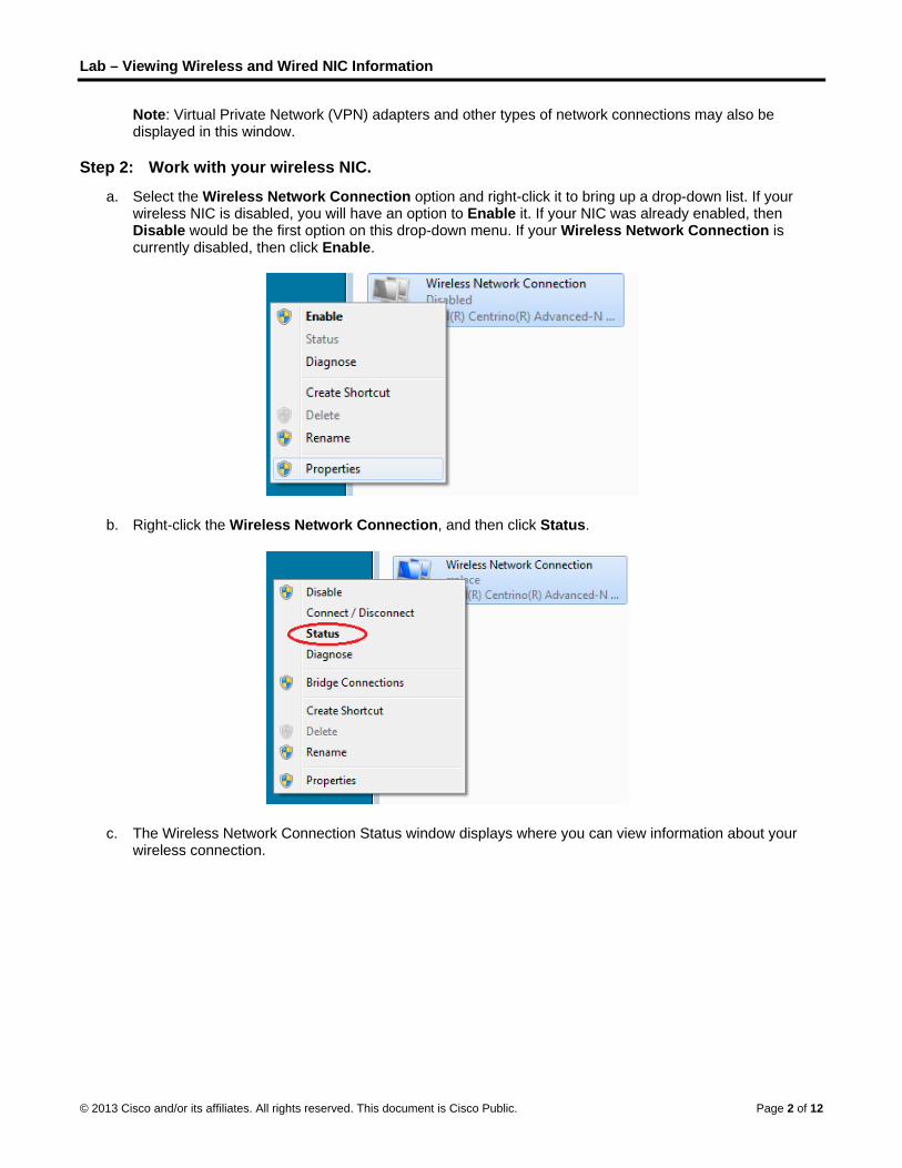
Lab – Viewing Wireless and Wired NIC Information
© 2013 Cisco and/or its affiliates. All rights reserved. This document is Cisco Public. Page 2 of 12
Note: Virtual Private Network (VPN) adapters and other types of network connections may also be displayed in this window.
Step 2: Work with your wireless NIC.
a. Select the Wireless Network Connection option and right-click it to bring up a drop-down list. If your wireless NIC is disabled, you will have an option to Enable it. If your NIC was already enabled, then Disable would be the first option on this drop-down menu. If your Wireless Network Connection is currently disabled, then click Enable.
b. Right-click the Wireless Network Connection, and then click Status.
c. The Wireless Network Connection Status window displays where you can view information about your wireless connection.

Lab – Viewing Wireless and Wired NIC Information
© 2013 Cisco and/or its affiliates. All rights reserved. This document is Cisco Public. Page 3 of 12
What is the Service Set Identifier (SSID) for the wireless router of your connection?
__________________________ rrplace (in above example)
What is the speed of your wireless connection?
__________________________ 144.0 Mb/s (in above example)
d. Click Details to display the Network Connection Details window.

Lab – Viewing Wireless and Wired NIC Information
© 2013 Cisco and/or its affiliates. All rights reserved. This document is Cisco Public. Page 4 of 12
What is the MAC address of your wireless NIC?
______________________________________ 58-94-6b-34-92-1c (in above example)
Do you have multiple IPv4 DNS Servers listed?
______________________________________ Yes (in above example)
Why would multiple DNS Servers be listed?
____________________________________________________________________________________
____________________________________________________________________________________
Answers will vary, but multiple DNS Servers are listed in case the first DNS server becomes unresponsive. Reasons may include the server is down for maintenance or is experiencing a problem. If the first DNS server does not respond, then the second DNS Server is used, and so on.
e. When you have reviewed the network connection details, click Close.
f. Open a command window prompt and type ipconfig /all.

Lab – Viewing Wireless and Wired NIC Information
© 2013 Cisco and/or its affiliates. All rights reserved. This document is Cisco Public. Page 5 of 12
Notice that the information displayed here is the same information that was displayed in the Network Connection Details window in Step d.
g. Close the command window and the Network Connection Details windows. This should bring you back to the Wireless Network Connection Status window. Click Wireless Properties.
h. In the Wireless Network Properties window, click the Security tab.
i. The type of security the connected wireless router has implemented displays. Click the Show characters check box to display the actual Network security key, instead of the hidden characters, and then click OK.

Lab – Viewing Wireless and Wired NIC Information
© 2013 Cisco and/or its affiliates. All rights reserved. This document is Cisco Public. Page 6 of 12
j. Close the Wireless Network Properties and the Network Connection Status windows. Select and right-click the Wireless Network Connection option > Connect/Disconnect. A pop-up window should appear at the bottom right corner of your desktop that displays your current connections, along with a list of SSIDs that are in range of the wireless NIC of your PC. If a scrollbar appears on the right side of this window, you can use it to display additional SSIDs.

Lab – Viewing Wireless and Wired NIC Information
© 2013 Cisco and/or its affiliates. All rights reserved. This document is Cisco Public. Page 7 of 12
k. To join one of the other wireless network SSIDs listed, click the SSID that you want to join, and then click Connect.
l. If you have selected a secure SSID, you are prompted to enter the Security key for the SSID. Type the security key for that SSID and click OK. You can click the Hide characters check box to prevent people from seeing what you type in the Security key field.

Lab – Viewing Wireless and Wired NIC Information
© 2013 Cisco and/or its affiliates. All rights reserved. This document is Cisco Public. Page 8 of 12
Step 3: Work with your wired NIC.
a. On the Network Connections window, select and right-click the Local Area Connection option to display the drop-down list. If the NIC is disabled, enable it, and then click the Status option.
Note: You must have an Ethernet cable attaching your PC NIC to a switch or similar device to see the status. Many wireless routers have a small 4-port Ethernet switch built-in. You can connect to one of the ports using a straight-through Ethernet patch cable.
b. The Local Area Connection Status window will open. This window displays information about your wired connection to the LAN.

Lab – Viewing Wireless and Wired NIC Information
© 2013 Cisco and/or its affiliates. All rights reserved. This document is Cisco Public. Page 9 of 12
Click Details… to view the address information for your LAN connection.
c. Open a command window prompt and type ipconfig /all. Find your Local Area Connection information and compare this with the information displayed in the Network Connection Details window.

Lab – Viewing Wireless and Wired NIC Information
© 2013 Cisco and/or its affiliates. All rights reserved. This document is Cisco Public. Page 10 of 12
d. Close all windows on your desktop.
Part 2: Identify and Use the System Tray Network Icons In Part 2, you will use the network icons in your system tray to determine and control the NICs on your PC.
Step 1: Use the Wireless Network icon.
a. Click the system tray Wireless Network icon to view the pop-up window that displays the SSIDs that are in-range of your wireless NIC. When the system tray displays the Wireless Network icon, the wireless NIC is active.
b. Click the Open Network and Sharing Center link. Note: This is a shortcut way to bring up this window.
c. In the left pane, click the Change adapter settings link to display the Network Connections window.
d. Select and right-click the Wireless Network Connection, and then click Disable to disable your wireless NIC.

Lab – Viewing Wireless and Wired NIC Information
© 2013 Cisco and/or its affiliates. All rights reserved. This document is Cisco Public. Page 11 of 12
e. Examine your system tray. The Wireless Network Connection icon should be replaced by the Wired Network icon, which indicates that you are using your wired NIC for network connectivity.
Note: If both NICs are active, the Wireless Network icon is the one that is displayed.
Step 2: Use the Wired Network icon.
a. Click the Wired Network icon. Notice that the Wireless SSIDs are no longer displayed in this pop-up window, but you still have the ability to get to the Network and Sharing Center window from here.
b. Click the Open Network and Sharing Center link > Change adapter settings and Enable your Wireless Network Connection. The Wireless Network icon should replace the Wired Network icon in your system tray.
Step 3: Identify the Network Problem icon.
a. On the Network Connections window, disable both the Wireless Network Connection and the Local Area Connection.

Lab – Viewing Wireless and Wired NIC Information
© 2013 Cisco and/or its affiliates. All rights reserved. This document is Cisco Public. Page 12 of 12
b. The system tray now displays the Network Disabled icon, which indicates that network connectivity has been disabled.
c. You can click this icon to return to the Network and Sharing Center window (examine the network diagram at the top).
You can click the red X to have the PC troubleshoot the problem with the network connection. Troubleshooting attempts to resolve the network issue for you.
d. If troubleshooting did not enable one of your NICs, then you should do this manually to restore the network connectivity of your PC.
Note: If a network adapter is enabled and the NIC is unable to establish network connectivity, then the Network Problem icon appears in the system tray.
If this icon appears, you can troubleshoot this issue just like you did in Step 3c.
Reflection Why would you activate more than one NIC on a PC?
_______________________________________________________________________________________
Answers may vary. Multiple NICs can be used if more than one path is needed for the PC. One example of this would be if the PC is being used as a Proxy Server.

© 2013 Cisco and/or its affiliates. All rights reserved. This document is Cisco Public. Page 1 of 3
Linked In! (Instructor Version) Instructor Note: Red font color or Gray highlights indicate text that appears in the instructor copy only.
Objectives
Connect devices using wired and wireless media.
In this activity, you will map your network cabling or technology type ideas to a physical topology. Because this chapter focuses on the network access layer, you should be able to prepare a basic physical model. No logical (IP addressing) schemes are required for this activity.
Physical Topology
Background/Scenario
Note: This activity is best completed in groups of 2-3 students.
Your small business is moving to a new location! Your building is brand new and you must come up with a physical topology so that network port installation can begin.

Linked In!
© 2013 Cisco and/or its affiliates. All rights reserved. This document is Cisco Public. Page 2 of 3
Your instructor will provide you with a blueprint created for this activity. The area on the blueprint, indicated by Number 1, is the reception area and the area labeled “RR” is the restroom area.
All rooms are within Category 6 UTP specifications (328 ft. [100 m]), so you have no concerns about hard-wiring the building to code. Each room in the diagram must have at least one network connection available for users/intermediary devices.
With your teammate(s), indicate on the drawing:
Where would you locate your network main distribution facility, while keeping security in mind?
How many intermediary devices would you use and where would you place them?
What kind of cabling you would use (UTP, STP, wireless, fiber optics, etc.) and where would the ports be placed?
What types of end devices you would use (wired, wireless, laptops, desktops, tablets, etc.)?
Do not go into excessive detail on your design. Just use the content from the chapter to be able to justify your decisions to the class.
Instructor notes: This Modeling Activity is not intended to be a graded assignment. Its purpose is to encourage students to reflect on their comprehension of the data link layer from a physical perspective – wired and wireless connectivity. A facilitated discussion should be initiated as a result of this activity.
Required Resources
Packet Tracer software
Reflection
1. Where would you locate your network main distribution facility, while keeping security in mind?
____________________________________________________________________________
Room 11 is the smallest room and would serve well as the main distribution facility or network center. It is situated away from plumbing, which could interfere with copper quality. It is also located away from most of the other offices/rooms for security purposes and has only one entry door.
2. How many intermediary devices would you use and where would you place them?
One or two switches could be placed in Room 11 – for scalability and access to other end devices. One router for connectivity to the ISP could be placed in Room 11, as well. One or two wireless ISRs could be placed in the diagram, possibly in Room 7 or 12 for wireless access throughout the physical space.
____________________________________________________________________________
3. What kind of cabling you would use (UTP, STP, wireless, fiber optics, etc.) and where would the ports be placed?
____________________________________________________________________________
Each room would incorporate at least one UTP jack for intermediary device connectivity or singular user access. The central network room (main distribution facility) would need more than one network port as it serves internal (LAN) connections and external (WAN) connections – for the WAN, fiber optics would probably be run for ISP connectivity.
4. What types of end devices you would use (wired, wireless, laptops, desktops, tablets, etc.)?
____________________________________________________________________________

Linked In!
© 2013 Cisco and/or its affiliates. All rights reserved. This document is Cisco Public. Page 3 of 3
Using the answers stated above, it would be feasible to use a combination of wired, wireless laptops, desktops, servers, tablets, etc. Security and scalability are considered in this model.
Identify elements of the model that map to real-world content:
Network security is considered when connecting a network at the network access layer.
Types of cabling and different modes of technology are included as considerations in designing a network at the network access layer.
Different data technologies are options are available to designers to facilitate data traffic flow at the network access layer.

© 2013 Cisco and/or its affiliates. All rights reserved. This document is Cisco Public. Page 1 of 3
Join my social circle! (Instructor Version) Instructor Note: Red font color or Gray highlights indicate text that appears in the instructor copy only.
Objectives
Describe the impact of ARP requests on network and host performance.
In this activity, you will discuss the ways in which local addressing (source and destination) is critical to data communication identification when using messaging, conferencing, emailing, and even gaming.
Background/Scenario
Note: This activity can be completed individually in class or outside of class.
Much of our network communication takes the form of email, messaging (text or instant), video contact, and social media postings.
For this activity, choose one of the following types of network communications:
Text or instant messaging
Audio/video conferencing
Emailing
Online gaming
Now that you have selected a network communication type, record your answers to the following questions:
1. Is there a procedure you must follow to register others and yourself so that you form a communications account? Why do you think that a procedure is needed?
2. How do you initiate contact with the person or people with whom you wish to communicate?
3. How do you ensure that your conversations are received only by those with whom you wish to communicate? Be prepared to discuss your answers in class.
Instructor notes: This Modeling Activity is not intended to be a graded assignment. Its purpose is to encourage students to reflect on their perceptions of source and destination host identification as compared to social media. Students’ answers should generate discussion about how we are identified as we communicate through these types of networks.
Required Resources
Recording capabilities (paper, tablet, etc.) for reflective comments to be shared with the class
Reflection
1. Is there a procedure you must follow to register others and yourself so that you form a communications account? Why do you think that a procedure is needed?
____________________________________________________________________________________
In each of these services, you are bringing the person you want to communicate with “directly into your network”. You are doing this in order to have direct contact with your correspondents and be able to communicate together directly, without requiring any intermediary person to relay messages between you and your friends in your network. In essence, by registering yourself and your correspondents into your contact list, you are building your own (social) communication network.

Join my social circle!
© 2013 Cisco and/or its affiliates. All rights reserved. This document is Cisco Public. Page 2 of 3
During the registration process, you as a person with a civil name, are assigned a service-specific user identifier that identifies you in the particular communication service. In the same way, when you add your friends into your contact list, you are looking for their service-specific user identifiers and adding them to your contact list. This service-specific user identifier may bear different formats:
For e-mail service, it is an e-mail address
For ICQ accounts, it is a number
For Skype, LinkedIn, or Facebook accounts, the identifier would be a username
Whenever you contact the person, you select it in your contact list by his/her civil name and the system contacts the user using the associated user identifier. A single person may have different user identifiers depending on how many social networks they are subscribed into.
In communication networks, there is a similar process. Although a network node, say, a PC, is a single entity, it may have several network interface cards (NICs). Each NIC is using a different unique identifier depending on the technology, for example:
Ethernet and WiFi NICs use MAC addresses
ATM cards use Virtual Path and Circuit Identifiers
ISDN interfaces use Terminal Endpoint Identifiers
Frame Relay interfaces use Data Link Circuit Identifiers
In these technologies, when you access a network, you may be assigned this identifier for your own NIC (this would be true especially for ATM, Frame Relay, or ISDN where the identifier was assigned dynamically rather than built into the NIC’s hardware). Also, these network technologies may require you to register before you can start communicating (in WiFi, you have to authenticate and associate to a particular access point; in Ethernet, you may be required to authenticate). And last but not least, a network node has to build its own contact list for each network it is connected to – in order to communicate with a different peer in the same network, knowing its logical identity; it needs to know what kind of NIC identifier the peer is reachable under.
In IP networks, this would be a process of associating the peer’s IP address in the same network with its Layer2 data-link layer address. On Ethernet and WiFi, the two most widely used network technologies; IP uses a supporting protocol called Address Resolution Protocol (ARP) to perform this translation.
2. How do you initiate contact with the person or people with whom you wish to communicate?
____________________________________________________________________________________
The exact sequence of steps would depend on the service you are using to communicate with your peer. However, there will always be common steps: First, you decide within what network is your peer reachable. Second, you look up the person’s contact in your contact list, and then use this contact to send your peer a message. Depending on the service, the message will be received only by this person (like in e-mail or instant messaging services), or it may actually be visible by other people in the recipient’s network (like in LinkedIn or Facebook message boards). There is never doubt, though, who is the intended recipient.
In IP networks, a node sending a message to another node decides which network the peer is located within, and then performs destination IP or next-hop IP into Layer2 address translation to know how to address that node’s NIC. The message may then be delivered only to the recipient NIC (if there are, say, switches on the path between the sender and receiver), or it may actually be seen by other stations (like in WiFi where stations can hear each other).

Join my social circle!
© 2013 Cisco and/or its affiliates. All rights reserved. This document is Cisco Public. Page 3 of 3
3. How do you ensure that your conversations are received only by those with whom you wish to communicate?
____________________________________________________________________________________
The primary prerequisite is that the message is unambiguously addressed to a single intended recipient. This is exactly the purpose of using a contact list that associates individual persons with their unique user identifiers. Otherwise, if we did not know the user identifier of the recipient, we would either have to send the message to everyone, effectively broadcasting it, or we would not be able to send the message at all. In IP networks, this goal is performed by the resolution of the recipient (or next-hop) IP address into its unique Layer2 address, using ARP or a similar mechanism. It is then up to the network technology to make sure that the message arrives to only the intended recipient.
Some technologies do not allow sending messages in a way that prevents third parties from seeing the message. For example, in Ethernet deployments using hubs or WiFi, the transmission is always visible to all nodes in the network. While only the intended recipient will actually process the message, others can see it. This is similar to message boards on LinkedIn or Facebook where, although intended for a single recipient, many or all other users can see the messages.
Identify elements of the model that map to IT-related content:
Different social network technologies correspond to different network technologies.
Different user IDs for one particular person, depending on the social network the person is subscribed to correspond to different Layer2 addressing used by different network technologies.
Contact lists correspond to tables where Layer3-to-Layer2 mappings are stored, e.g. ARP tables in Ethernet or IP/DLCI tables in Frame Relay.
Subscribing to a social network corresponds to the process of obtaining an access to a particular network and the related network technology.
Looking up a person in one’s contact list corresponds to lookups in the L3/L2 mapping tables.

© 2013 Cisco and/or its affiliates. All rights reserved. This document is Cisco Public. Page 1 of 10
Lab – Viewing Network Device MAC Addresses (Instructor Version) Instructor Note: Red font color or Gray highlights indicate text that appears in the instructor copy only.
Topology
Addressing Table
Device Interface IP Address Subnet Mask Default Gateway
R1 G0/1 192.168.1.1 255.255.255.0 N/A
S1 VLAN 1 N/A N/A N/A
PC-A NIC 192.168.1.3 255.255.255.0 192.168.1.1
Objectives
Part 1: Set Up the Topology and Initialize Devices
Set up equipment to match the network topology.
Initialize and restart (if necessary) the router and switch.
Part 2: Configure Devices and Verify Connectivity
Assign static IP address to PC-A NIC.
Configure basic information on R1.
Assign a static IP address to R1.
Verify network connectivity.
Part 3: Display, Describe, and Analyze Ethernet MAC Addresses
Analyze MAC address for PC-A.
Analyze MAC addresses for router R1.
Display the MAC address table on switch S1.
Background / Scenario
Every device on an Ethernet LAN is identified by a Layer-2 MAC address. This address is burned into the NIC. This lab will explore and analyze the components that make up a MAC address, and how you can find this information on various networking devices, such as a router, switch, and PC.
You will cable the equipment as shown in the topology. You will then configure the router and PC to match the addressing table. You will verify your configurations by testing for network connectivity.
After the devices have been configured and network connectivity has been verified, you will use various commands to retrieve information from the devices to answer questions about your network equipment.

Lab – Viewing Network Device MAC Addresses
© 2013 Cisco and/or its affiliates. All rights reserved. This document is Cisco Public. Page 2 of 10
Note: The routers used with CCNA hands-on labs are Cisco 1941 Integrated Services Routers (ISRs) with Cisco IOS Release 15.2(4)M3 (universalk9 image). The switches used are Cisco Catalyst 2960s with Cisco IOS Release 15.0(2) (lanbasek9 image). Other routers, switches, and Cisco IOS versions can be used. Depending on the model and Cisco IOS version, the commands available and output produced might vary from what is shown in the labs. Refer to the Router Interface Summary Table at the end of this lab for the correct interface identifiers.
Note: Make sure that the routers and switches have been erased and have no startup configurations. If you are unsure, contact your instructor.
Instructor Note: Refer to the Instructor Lab Manual for the procedures to initialize and reload devices.
Instructor Note: If using routers other than the 2900 or 1900 series, you may be using fast Ethernet interfaces instead of the Gigabit interfaces. You will need to adjust the show commands accordingly.
Required Resources
1 Router (Cisco 1941 with Cisco IOS Release 15.2(4)M3 universal image or comparable)
1 Switch (Cisco 2960 with Cisco IOS Release 15.0(2) lanbasek9 image or comparable)
1 PC (Windows 7, Vista, or XP with terminal emulation program, such as Tera Term)
Console cables to configure the Cisco IOS devices via the console ports
Ethernet cables as shown in the topology
Part 1: Set Up the Topology and Initialize Devices
In Part 1, you will set up the network topology, clear any configurations, if necessary, and configure basic settings, such as the interface IP addresses on the router and PC.
Step 1: Cable the network as shown in the topology.
a. Attach the devices shown in the topology and cable as necessary.
b. Power on all the devices in the topology.
Step 2: Initialize and reload the router and switch.
Part 2: Configure Devices and Verify Connectivity
In Part 2, you will set up the network topology and configure basic settings, such as the interface IP addresses and device access. For device names and address information, refer to the Topology and Addressing Table.
Step 1: Configure the IPv4 address for the PC.
a. Configure the IPv4 address, subnet mask, and default gateway address for PC-A.
b. Ping the default gateway address from a PC-A command prompt.
Were the pings successful? Why or why not?
____________________________________________________________________________________
____________________________________________________________________________________
No. The default gateway (router interface) has not been configured yet, and the router G0/1 interface is shut down.

Lab – Viewing Network Device MAC Addresses
© 2013 Cisco and/or its affiliates. All rights reserved. This document is Cisco Public. Page 3 of 10
Step 2: Configure the router.
The configuration of a Cisco router is similar to configuring a Cisco switch. In this step, you will configure the device name and the IP address and disable DNS lookup on the router.
a. Console into the router and enter global configuration mode.
Router> enable
Router# configure terminal
Enter configuration commands, one per line. End with CNTL/Z.
Router(config)#
b. Assign a hostname to the router based on the Addressing Table.
Router(config)# hostname R1
c. Disable DNS lookup.
R1(config)# no ip domain-lookup
d. Configure and enable the G0/1 interface on the router.
R1(config)# interface GigabitEthernet0/1
R1(config-if)# ip address 192.168.1.1 255.255.255.0
R1(config-if)# no shutdown
R1(config-if)# end
*Feb 23 09:06:01.927: %LINK-3-UPDOWN: Interface GigabitEthernet0/1, changed state to
down
*Feb 23 09:06:05.279: %LINK-3-UPDOWN: Interface GigabitEthernet0/1, changed state to
up
*Feb 23 09:06:06.279: %LINEPROTO-5-UPDOWN: Line protocol on Interface
GigabitEthernet0/1, changed state to up
Step 3: Verify network connectivity.
Ping the default gateway address of R1 from PC-A.
Were the pings successful?
____________________________________________________________________________________
The pings should be successful.
Part 3: Display, Describe, and Analyze Ethernet MAC Addresses
Every device on an Ethernet LAN has a Media Access Control (MAC) address that is burned into the Network Interface Card (NIC). Ethernet MAC addresses are 48-bits long. They are displayed using six sets of hexadecimal digits usually separated by dashes, colons, or periods. The following example shows the same MAC address using the three different notation methods:
00-05-9A-3C-78-00 00:05:9A:3C:78:00 0005.9A3C.7800
Note: MAC addresses are also called physical addresses, hardware addresses, or Ethernet hardware addresses.
In Part 3, you will issue commands to display the MAC addresses on a PC, router, and switch, and you will analyze the properties of each one.
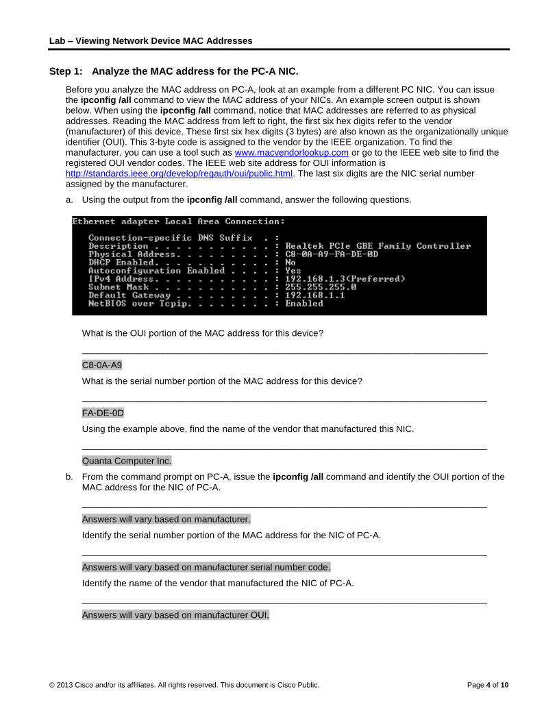
Lab – Viewing Network Device MAC Addresses
© 2013 Cisco and/or its affiliates. All rights reserved. This document is Cisco Public. Page 4 of 10
Step 1: Analyze the MAC address for the PC-A NIC.
Before you analyze the MAC address on PC-A, look at an example from a different PC NIC. You can issue the ipconfig /all command to view the MAC address of your NICs. An example screen output is shown below. When using the ipconfig /all command, notice that MAC addresses are referred to as physical addresses. Reading the MAC address from left to right, the first six hex digits refer to the vendor (manufacturer) of this device. These first six hex digits (3 bytes) are also known as the organizationally unique identifier (OUI). This 3-byte code is assigned to the vendor by the IEEE organization. To find the manufacturer, you can use a tool such as www.macvendorlookup.com or go to the IEEE web site to find the registered OUI vendor codes. The IEEE web site address for OUI information is http://standards.ieee.org/develop/regauth/oui/public.html. The last six digits are the NIC serial number assigned by the manufacturer.
a. Using the output from the ipconfig /all command, answer the following questions.
What is the OUI portion of the MAC address for this device?
________________________________________________________________________________
C8-0A-A9
What is the serial number portion of the MAC address for this device?
________________________________________________________________________________
FA-DE-0D
Using the example above, find the name of the vendor that manufactured this NIC.
________________________________________________________________________________
Quanta Computer Inc.
b. From the command prompt on PC-A, issue the ipconfig /all command and identify the OUI portion of the MAC address for the NIC of PC-A.
________________________________________________________________________________
Answers will vary based on manufacturer.
Identify the serial number portion of the MAC address for the NIC of PC-A.
________________________________________________________________________________
Answers will vary based on manufacturer serial number code.
Identify the name of the vendor that manufactured the NIC of PC-A.
________________________________________________________________________________
Answers will vary based on manufacturer OUI.

Lab – Viewing Network Device MAC Addresses
© 2013 Cisco and/or its affiliates. All rights reserved. This document is Cisco Public. Page 5 of 10
Step 2: Analyze the MAC address for the R1 G0/1 interface.
You can use a variety of commands to display MAC addresses on the router.
a. Console into R1 and use the show interfaces g0/1 command to find the MAC address information. A sample is shown below. Use output generated by your router to answer the questions.
R1# show interfaces g0/1
GigabitEthernet0/1 is up, line protocol is up
Hardware is CN Gigabit Ethernet, address is 30f7.0da3.1821 (bia 30f7.0da3.1821)
Internet address is 192.168.1.1/24
MTU 1500 bytes, BW 100000 Kbit/sec, DLY 100 usec,
reliability 255/255, txload 1/255, rxload 1/255
Encapsulation ARPA, loopback not set
Keepalive set (10 sec)
Full Duplex, 100Mbps, media type is RJ45
output flow-control is unsupported, input flow-control is unsupported
ARP type: ARPA, ARP Timeout 04:00:00
Last input 00:00:00, output 00:00:00, output hang never
Last clearing of "show interface" counters never
Input queue: 0/75/0/0 (size/max/drops/flushes); Total output drops: 0
Queueing strategy: fifo
Output queue: 0/40 (size/max)
5 minute input rate 3000 bits/sec, 4 packets/sec
5 minute output rate 0 bits/sec, 0 packets/sec
15183 packets input, 971564 bytes, 0 no buffer
Received 13559 broadcasts (0 IP multicasts)
0 runts, 0 giants, 0 throttles
0 input errors, 0 CRC, 0 frame, 0 overrun, 0 ignored
0 watchdog, 301 multicast, 0 pause input
1396 packets output, 126546 bytes, 0 underruns
0 output errors, 0 collisions, 1 interface resets
195 unknown protocol drops
0 babbles, 0 late collision, 0 deferred
0 lost carrier, 0 no carrier, 0 pause output
0 output buffer failures, 0 output buffers swapped out
What is the MAC address for G0/1 on R1?
____________________________________________________________________________________
Answers will vary based on router student is using. Using output from above, the answer would be 30f7.0da3.1821.
What is the MAC serial number for G0/1?
____________________________________________________________________________________
Answers will vary based on router student is using. Using output from above, the answer would be a3-18-21.
What is the OUI for G0/1?
____________________________________________________________________________________
Answers will vary based on router. Using output from above, the answer would be 30-f7-0d.
Based on this OUI, what is the name of the vendor?

Lab – Viewing Network Device MAC Addresses
© 2013 Cisco and/or its affiliates. All rights reserved. This document is Cisco Public. Page 6 of 10
____________________________________________________________________________________
Cisco Systems
What does bia stand for?
____________________________________________________________________________________
Burned in address.
Why does the output show the same MAC address twice?
____________________________________________________________________________________
The MAC address can be changed via a software command. The actual address (bia) will still be there which is shown in the parenthesis.
b. Another way to display the MAC addresses on the router is to use the show arp command. Use the show arp command to display MAC address information. This command maps the Layer 2 address to its corresponding Layer 3 address. A sample is shown below. Use output generated by your router to answer the questions.
R1# show arp
Protocol Address Age (min) Hardware Addr Type Interface
Internet 192.168.1.1 - 30f7.0da3.1821 ARPA GigabitEthernet0/1
Internet 192.168.1.3 0 c80a.a9fa.de0d ARPA GigabitEthernet0/1
What Layer 2 addresses are displayed on R1?
____________________________________________________________________________________
R1 G0/1 and PC-A MAC addresses. If student also records the MAC addresses, answers will vary.
What Layer 3 addresses are displayed on R1?
____________________________________________________________________________________
R1 and PC-A IP addresses
Why do you think there is no information showing for the switch with the show arp command?
____________________________________________________________________________________
The show arp maps Layer 2 to Layer 3 addresses. The switch does not have an IP address assigned to it.
Step 3: View the MAC addresses on the switch.
a. Console into the switch and use the show interfaces command for ports 5 and 6 to display MAC address information. A sample is shown below. Use output generated by your switch to answer the questions.
Switch> show interfaces f0/5
FastEthernet0/5 is up, line protocol is up (connected)
Hardware is Fast Ethernet, address is 0cd9.96e8.7285 (bia 0cd9.96e8.7285)
MTU 1500 bytes, BW 100000 Kbit, DLY 100 usec,
reliability 255/255, txload 1/255, rxload 1/255
Encapsulation ARPA, loopback not set
Keepalive set (10 sec)
Full-duplex, 100Mb/s, media type is 10/100BaseTX
input flow-control is off, output flow-control is unsupported
ARP type: ARPA, ARP Timeout 04:00:00
Last input 00:00:45, output 00:00:00, output hang never
Last clearing of "show interface" counters never

Lab – Viewing Network Device MAC Addresses
© 2013 Cisco and/or its affiliates. All rights reserved. This document is Cisco Public. Page 7 of 10
Input queue: 0/75/0/0 (size/max/drops/flushes); Total output drops: 0
Queueing strategy: fifo
Output queue: 0/40 (size/max)
5 minute input rate 0 bits/sec, 0 packets/sec
5 minute output rate 0 bits/sec, 0 packets/sec
3362 packets input, 302915 bytes, 0 no buffer
Received 265 broadcasts (241 multicasts)
0 runts, 0 giants, 0 throttles
0 input errors, 0 CRC, 0 frame, 0 overrun, 0 ignored
0 watchdog, 241 multicast, 0 pause input
0 input packets with dribble condition detected
38967 packets output, 2657748 bytes, 0 underruns
0 output errors, 0 collisions, 1 interface resets
0 babbles, 0 late collision, 0 deferred
0 lost carrier, 0 no carrier, 0 PAUSE output
0 output buffer failures, 0 output buffers swapped out
What is the MAC address for F0/5 on your switch?
____________________________________________________________________________________
Answers will vary. In example above, the MAC address is 0cd9.96e8.7285.
Issue the same command and write down the MAC address for F0/6.
____________________________________________________________________________________
Answers will vary.
Are the OUIs shown on the switch the same as those that were displayed on the router?
____________________________________________________________________________________
Answers will vary. Generally the answer will be no. Cisco Systems has many OUIs registered with IEEE.
The switch keeps track of devices by their Layer 2 MAC addresses. In our topology, the switch has knowledge of both MAC address of R1 and the MAC address of PC-A.
b. Issue the show mac address-table command on the switch. A sample is shown below. Use output generated by your switch to answer the questions.
Instructor Note: The show mac address-table command can vary based on the model switch that you are on. For example, syntax on some switches is show mac-address-table.
Switch> show mac address-table
Mac Address Table
-------------------------------------------
Vlan Mac Address Type Ports
---- ----------- -------- -----
All 0100.0ccc.cccc STATIC CPU
All 0100.0ccc.cccd STATIC CPU
All 0180.c200.0000 STATIC CPU
All 0180.c200.0001 STATIC CPU
All 0180.c200.0002 STATIC CPU
All 0180.c200.0003 STATIC CPU
All 0180.c200.0004 STATIC CPU
All 0180.c200.0005 STATIC CPU

Lab – Viewing Network Device MAC Addresses
© 2013 Cisco and/or its affiliates. All rights reserved. This document is Cisco Public. Page 8 of 10
All 0180.c200.0006 STATIC CPU
All 0180.c200.0007 STATIC CPU
All 0180.c200.0008 STATIC CPU
All 0180.c200.0009 STATIC CPU
All 0180.c200.000a STATIC CPU
All 0180.c200.000b STATIC CPU
All 0180.c200.000c STATIC CPU
All 0180.c200.000d STATIC CPU
All 0180.c200.000e STATIC CPU
All 0180.c200.000f STATIC CPU
All 0180.c200.0010 STATIC CPU
All ffff.ffff.ffff STATIC CPU
1 30f7.0da3.1821 DYNAMIC Fa0/5
1 c80a.a9fa.de0d DYNAMIC Fa0/6
Total Mac Addresses for this criterion: 22
Did the switch display the MAC address of PC-A? If you answered yes, what port was it on?
____________________________________________________________________________________
Answers will vary for the MAC address. In example above the MAC address would be c80a.a9fa.de0d. Port should be F0/6.
Did the switch display the MAC address of R1? If you answered yes, what port was it on?
____________________________________________________________________________________
Answers will vary for the MAC address. In example above the MAC address would be 30f7.0da3.1821. Port should be F0/5.
Reflection
1. Can you have broadcasts at the Layer 2 level? If so, what would the MAC address be?
_______________________________________________________________________________________
You can and often do have broadcasts at Layer 2. ARP will use broadcasts to find MAC address information. The broadcast address is FF.FF.FF.FF.FF.FF.
2. Why would you need to know the MAC address of a device?
_______________________________________________________________________________________
There could be a variety of reasons. In a large network, it may be easier to pinpoint location and identity of a device by MAC address rather than IP address. The MAC OUI will list the manufacturer, which may help narrow down the search. Security measures can be applied at Layer 2 so knowledge of allowable MAC addresses is needed.

Lab – Viewing Network Device MAC Addresses
© 2013 Cisco and/or its affiliates. All rights reserved. This document is Cisco Public. Page 9 of 10
Router Interface Summary Table
Router Interface Summary
Router Model Ethernet Interface #1 Ethernet Interface #2 Serial Interface #1 Serial Interface #2
1800 Fast Ethernet 0/0 (F0/0)
Fast Ethernet 0/1 (F0/1)
Serial 0/0/0 (S0/0/0) Serial 0/0/1 (S0/0/1)
1900 Gigabit Ethernet 0/0 (G0/0)
Gigabit Ethernet 0/1 (G0/1)
Serial 0/0/0 (S0/0/0) Serial 0/0/1 (S0/0/1)
2801 Fast Ethernet 0/0 (F0/0)
Fast Ethernet 0/1 (F0/1)
Serial 0/1/0 (S0/1/0) Serial 0/1/1 (S0/1/1)
2811 Fast Ethernet 0/0 (F0/0)
Fast Ethernet 0/1 (F0/1)
Serial 0/0/0 (S0/0/0) Serial 0/0/1 (S0/0/1)
2900 Gigabit Ethernet 0/0 (G0/0)
Gigabit Ethernet 0/1 (G0/1)
Serial 0/0/0 (S0/0/0) Serial 0/0/1 (S0/0/1)
Note: To find out how the router is configured, look at the interfaces to identify the type of router and how many interfaces the router has. There is no way to effectively list all the combinations of configurations for each router class. This table includes identifiers for the possible combinations of Ethernet and Serial interfaces in the device. The table does not include any other type of interface, even though a specific router may contain one. An example of this might be an ISDN BRI interface. The string in parenthesis is the legal abbreviation that can be used in Cisco IOS commands to represent the interface.
Device Config
Router R1
R1#sh run
Building configuration...
Current configuration : 1176 bytes
version 15.2
service timestamps debug datetime msec
service timestamps log datetime msec
no service password-encryption
hostname R1
boot-start-marker
boot-end-marker
!
no aaa new-model
!
no ipv6 cef
!
no ip domain lookup
ip cef
multilink bundle-name authenticated
interface Embedded-Service-Engine0/0
no ip address
shutdown
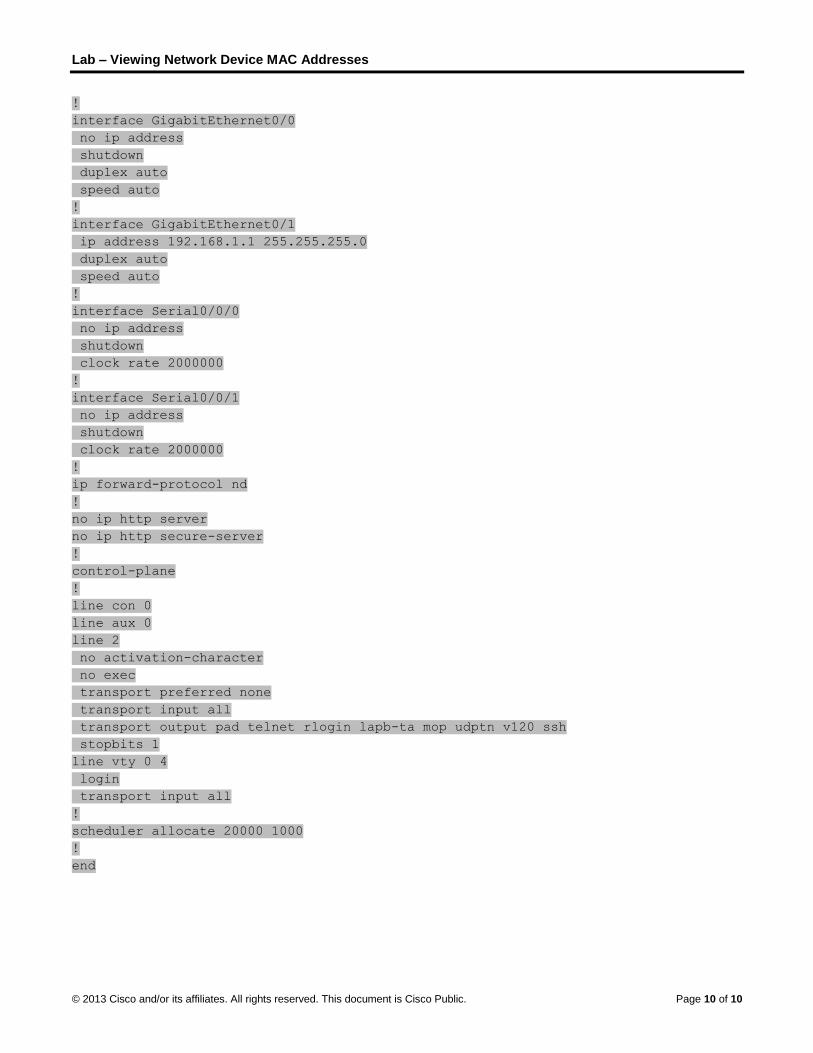
Lab – Viewing Network Device MAC Addresses
© 2013 Cisco and/or its affiliates. All rights reserved. This document is Cisco Public. Page 10 of 10
!
interface GigabitEthernet0/0
no ip address
shutdown
duplex auto
speed auto
!
interface GigabitEthernet0/1
ip address 192.168.1.1 255.255.255.0
duplex auto
speed auto
!
interface Serial0/0/0
no ip address
shutdown
clock rate 2000000
!
interface Serial0/0/1
no ip address
shutdown
clock rate 2000000
!
ip forward-protocol nd
!
no ip http server
no ip http secure-server
!
control-plane
!
line con 0
line aux 0
line 2
no activation-character
no exec
transport preferred none
transport input all
transport output pad telnet rlogin lapb-ta mop udptn v120 ssh
stopbits 1
line vty 0 4
login
transport input all
!
scheduler allocate 20000 1000
!
end

©
LVI
T
O
B
R
P
© 2013 Cisco and
Lab – UsVersion) nstructor No
Topology
ObjectivesPart 1: Ex
Part 2: Us
BackgrounWhen uppInterconneon the meEthernet,
When lealab, you wand analy
InstructoWiresharkWindows
Required R 1 PC
Part 1: EIn Part 1, used to ex
d/or its affiliates.
sing Wir
ote: Red font
xamine the H
se Wireshark
nd / Scenarper layer protoection (OSI) l
edia access tythen the Laye
rning about Lwill review theyze Ethernet I
or Note: This lk has been pr7 (64bit).
Resources (Windows 7,
Examine tyou will examxamine the co
All rights reserve
reshark
color or Gray
Header Fields
k to Capture
rio ocols commuayers and is ype. For examer 2 frame en
Layer 2 conce fields containI frame heade
lab assumes re-installed on
Vista, or XP w
the Headmine the headontents in tho
ed. This docume
to Exam
y highlights ind
s in an Ether
and Analyze
unicate with eaencapsulated
mple, if the upncapsulation w
epts, it is helpfned in an Ether fields for lo
that the studen the PC. The
with Internet a
er Fieldsder fields and ose fields.
ent is Cisco Publi
mine Eth
dicate text tha
rnet II Frame
e Ethernet Fr
ach other, dad into a Layerpper layer prowill be Ethern
ful to analyzeernet II frame
ocal and remo
ent is using ae screenshots
access with W
in an Ethcontent in an
ic.
hernet F
at appears in
e
rames
ata flows downr 2 frame. Theotocols are TCet II. This is t
e frame headee. In Part 2, yoote traffic.
a PC with Intes in this lab w
Wireshark ins
hernet II Fn Ethernet II F
rames (
the instructo
n the Open Se frame compCP and IP andtypical for a LA
er informationou will use W
ernet access. were taken from
stalled)
Frame Frame. A Wire
Instructo
r copy only.
Systems position is depd the media aAN environm
n. In the first pWireshark to ca
It also assumm Wireshark
eshark captur
Page 1 of 7
or
pendent access is ent.
part of this apture
mes that v1.8.3 for
re will be

L
©
S
S
S
S
Lab – Using W
© 2013 Cisco and
Step 1: Re
Preambl
8 Bytes
Step 2: Ex
This PC h
Step 3: Ex
The Wiresdefault gasession band replie
Step 4: Ex
The followheader fie
Wireshark to
d/or its affiliates.
eview the Et
le Des
Ad
s 6
amine the n
host IP addres
amine Ethe
shark captureateway. A filteegins with an
es.
amine the E
wing table takelds.
o Examine Et
All rights reserve
thernet II he
stination ddress
Bytes
network con
ss is 10.20.16
ernet frames
e below showser has been an ARP query f
Ethernet II h
es the first fra
thernet Fram
ed. This docume
eader field d
SourceAddress
6 Bytes
nfiguration
64.22 and the
s in a Wires
s the packetspplied to Wirefor the MAC a
header cont
ame in the W
mes
ent is Cisco Publi
descriptions
FramTyp
2 Byt
of the PC.
e default gatew
shark captu
s generated beshark to viewaddress of the
tents of an A
ireshark capt
ic.
s and lengt
me pe
ytes 46
way has an IP
re.
y a ping beinw the ARP ane gateway rou
ARP reques
ure and displ
ths.
Data
6 – 1500 Byte
P address of
g issued fromnd ICMP protouter, followed
st.
ays the data
F
es 4 B
10.20.164.17
m a PC host toocols only. Th by four ping
in the Ethern
Page 2 of 7
CS
Bytes
7.
o its he requests
et II
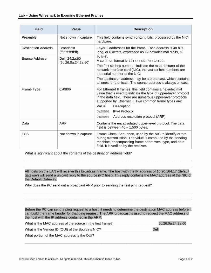
Lab – Using Wireshark to Examine Ethernet Frames
© 2013 Cisco and/or its affiliates. All rights reserved. This document is Cisco Public. Page 3 of 7
Field Value Description
Preamble Not shown in capture This field contains synchronizing bits, processed by the NIC hardware.
Destination Address Broadcast (ff:ff:ff:ff:ff:ff)
Layer 2 addresses for the frame. Each address is 48 bits
long, or 6 octets, expressed as 12 hexadecimal digits, 0-9,A-F.
A common format is 12:34:56:78:9A:BC.
The first six hex numbers indicate the manufacturer of the network interface card (NIC), the last six hex numbers are the serial number of the NIC.
The destination address may be a broadcast, which contains all ones, or a unicast. The source address is always unicast.
Source Address Dell_24:2a:60 (5c:26:0a:24:2a:60)
Frame Type 0x0806 For Ethernet II frames, this field contains a hexadecimal value that is used to indicate the type of upper-layer protocol in the data field. There are numerous upper-layer protocols supported by Ethernet II. Two common frame types are:
Value Description
0x0800 IPv4 Protocol
0x0806 Address resolution protocol (ARP)
Data ARP Contains the encapsulated upper-level protocol. The data field is between 46 – 1,500 bytes.
FCS Not shown in capture Frame Check Sequence, used by the NIC to identify errors during transmission. The value is computed by the sending machine, encompassing frame addresses, type, and data field. It is verified by the receiver.
What is significant about the contents of the destination address field?
_______________________________________________________________________________________
_______________________________________________________________________________________
All hosts on the LAN will receive this broadcast frame. The host with the IP address of 10.20.164.17 (default gateway) will send a unicast reply to the source (PC host). This reply contains the MAC address of the NIC of the Default Gateway.
Why does the PC send out a broadcast ARP prior to sending the first ping request?
_______________________________________________________________________________________
_______________________________________________________________________________________
_______________________________________________________________________________________
Before the PC can send a ping request to a host, it needs to determine the destination MAC address before it can build the frame header for that ping request. The ARP broadcast is used to request the MAC address of the host with the IP address contained in the ARP.
What is the MAC address of the source in the first frame? _______________________ 5c:26:0a:24:2a:60
What is the Vendor ID (OUI) of the Source’s NIC? __________________________ Dell
What portion of the MAC address is the OUI?
_______________________________________________________________________________________

L
©
P
S
S
Lab – Using W
© 2013 Cisco and
The first 3
What is th
Part 2: UIn Part 2, informatio
Step 1: De
Open a co
What is th
Step 2: Sta
a. Open
b. On th
c. On thapprofor mo
d. Obse
Wireshark to
d/or its affiliates.
3 octets of the
he Source’s N
Use Wiresyou will use W
on that is cont
etermine the
ommand prom
he IP Address
art capturin
Wireshark.
e Wireshark N
e Wireshark: opriate check ore informatio
rve the traffic
o Examine Et
All rights reserve
e MAC addres
NIC serial num
shark to CWireshark to tained in the f
e IP address
mpt window a
s of the PC De
g traffic on
Network Anal
Capture Intebox, and then
on about each
that appears
thernet Fram
ed. This docume
ss indicate the
mber? ______
Capture acapture local frame header
s of the defa
and issue the
efault Gatewa
your PC’s
lyzer toolbar,
rfaces windown click Start. h interface list
s in the Packe
mes
ent is Cisco Publi
e OUI.
___________
and Analyand remote E
r fields.
ault gatewa
ipconfig com
ay? ________
NIC.
click the Inte
w, select the If you are uncted.
et List window
ic.
____________
yze EtherEthernet fram
ay on your P
mmand.
___________
erface List ico
interface to scertain of wha
w.
________ 24:2
rnet Frammes. You will t
PC.
_______ Answ
on.
tart traffic capat interface to
2a:60
mes then examine
wers will vary
pturing by clico check, click
Page 4 of 7
e the
y
cking the Details

L
©
S
S
S
S
Lab – Using W
© 2013 Cisco and
Step 3: Filt
You can uof unwant
In the Wirgreen, clic
Step 4: Fro
From the
Step 5: Sto
Click the S
Step 6: Ex
The Wires(middle), aStep 3, Wfollowing e
a. In theunder
Wireshark to
d/or its affiliates.
ter Wiresha
use the filter ited data; it on
reshark Filterck Apply to a
om the com
command wi
op capturin
Stop Capture
amine the f
shark main wand the Pack
Wireshark shouexample.
e Packet List pr the Info hea
o Examine Et
All rights reserve
ark to displa
n Wireshark tnly filters what
r box, type icmapply the filter
mmand prom
ndow, ping th
g traffic on
e icon to stop
first Echo (p
indow is dividket Bytes paneuld display th
pane (top secading. This sh
thernet Fram
ed. This docume
ay only ICM
to block visibit to display on
mp. The box r.
mpt window
he default gate
the NIC.
p capturing tra
ping) reque
ded into threee (bottom). If e ICMP inform
ction), click theould highlight
mes
ent is Cisco Publi
MP traffic.
lity of unwantn the screen.
should turn g
w, ping the d
eway using th
affic.
st in Wiresh
e sections: theyou selected mation in the
e first frame lt the line blue
ic.
ted traffic. ThFor now, only
green if you ty
default gate
he IP address
hark.
e Packet List the correct inPacket List p
isted. You she.
e filter does ny ICMP traffic
yped the filter
eway of you
s that you rec
pane (top), thnterface for ppane of Wires
hould see Ech
not block the c is to be disp
correctly. If th
r PC.
corded in Step
he Packet Detacket capturi
shark, similar
ho (ping) req
Page 5 of 7
capture played.
he box is
p 1.
tails pane ng in to the
quest

L
©
S
Lab – Using W
© 2013 Cisco and
b. Examframe
c. The sdestin
What
What
d. You cEther
What
e. The laNotice
What
What
f. You cPackesectio
What
g. Click destinas a r
What
_____
Step 7: Re
Click the Swould likewithout S
Wireshark to
d/or its affiliates.
mine the first lie; 74 bytes in
second line in nation MAC a
is the MAC a
is the default
can click the pnet II frame. N
type of frame
ast two lines de that the dat
is the source
is the destina
can click any let Bytes paneon and examin
do the last tw
the next framnation MAC areply to the fir
device and M
___________
estart packe
Start Capturee to save the pSaving.
o Examine Et
All rights reserve
ne in the Pacthis example
the Packet Dddresses are
address of the
t gateway’s M
plus (+) sign aNotice that th
e is displayed
displayed in ta contains the
e IP address?
ation IP addre
line in the mide (bottom sectne what is hig
wo highlighted
me in the top sddresses hav
rst ping.
MAC address
___________
et capture in
e icon to startprevious capt
thernet Fram
ed. This docume
cket Details pa.
Details pane se also displaye
e PC’s NIC? _
MAC address?
at the beginnie plus sign ch
? _________
he middle sece source and
__________
ess? _______
ddle section totion). Click thghlighted in th
d octets spell?
section and exve reversed, b
is displayed a
____________
n Wireshark
t a new Wirestured packets
mes
ent is Cisco Publi
ane (middle s
shows that it ised.
___________
? __________
ng of the sechanges to a m
___________
ction providedestination IP
____________
___________
o highlight thae Internet Co
he Packet Byt
? ______ hi
xamine an Ecbecause this f
as the destina
________ Th
k.
shark captures to a file befo
ic.
section). This
s an Ethernet
____________
___________
cond line to obminus (-) sign
____________
information aPv4 address
____________
___________
at part of the ontrol Messates pane.
cho reply framframe was se
ation address
he host PC, 5c
e. You will recore starting a
line displays
t II frame. The
____ 5c:26:0a
___ 30:f7:0d:7
btain more inf.
___ 0x0800 o
about the datainformation.
___ 10.20.16
____ 10.20.16
frame (hex aage Protocol
me. Notice thaent from the d
s?
c:26:0a:24:2a
ceive a popupnew capture.
the length of
e source and
a:24:2a:60 in e
7a:ec:84 in ex
formation abo
or an IPv4 fra
a field of the f
4.22 in the ex
64.17 in the ex
nd ASCII) in l line in the m
at the source default gatewa
a:60 in examp
p window aski Click Contin
Page 6 of 7
f the
example
xample
out the
me type.
frame.
xample
xample
the iddle
and ay router
ple.
ing if you nue
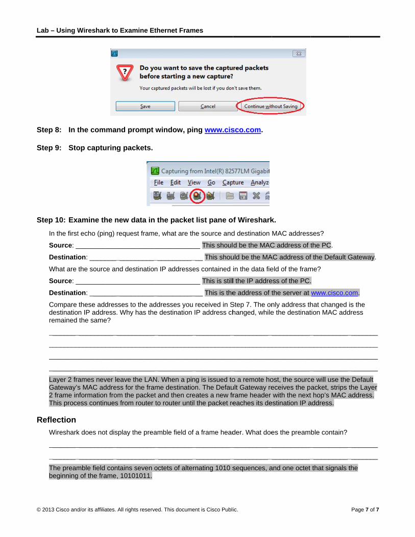
L
©
S
S
S
R
Lab – Using W
© 2013 Cisco and
Step 8: In t
Step 9: Sto
Step 10: Ex
In the first
Source: _
Destinati
What are
Source: _
Destinati
Compare destinatioremained
________
________
________
________
Layer 2 frGateway’s2 frame inThis proce
Reflection Wireshark
________
________
The preambeginning
Wireshark to
d/or its affiliates.
the comma
op capturin
amine the n
t echo (ping)
___________
on: ________
the source an
___________
on: ________
these addreson IP address
the same?
___________
___________
___________
___________
rames never ls MAC addrenformation froess continues
k does not dis
___________
___________
mble field cong of the frame
o Examine Et
All rights reserve
nd prompt
g packets.
new data in
request frame
____________
___________
nd destination
____________
___________
sses to the ad. Why has the
____________
____________
____________
____________
eave the LANss for the fram
om the packets from router
splay the prea
____________
____________
ntains seven o, 10101011.
thernet Fram
ed. This docume
window, pi
the packet
e, what are th
___________
___________
n IP addresse
___________
___________
ddresses you e destination
___________
___________
___________
___________
N. When a pinme destinatiot and then creto router until
amble field of
___________
___________
octets of alter
mes
ent is Cisco Publi
ng www.cis
list pane o
he source and
__ This shoul
___ This shou
es contained
__ This is still
___ This is the
received in SIP address ch
___________
___________
___________
___________
ng is issued toon. The Defaueates a new frl the packet re
a frame head
___________
___________
rnating 1010 s
ic.
sco.com.
of Wireshark
d destination
d be the MAC
uld be the MA
in the data fie
l the IP addre
e address of t
Step 7. The onhanged, while
____________
____________
____________
____________
o a remote hoult Gateway rerame header eaches its de
der. What doe
____________
____________
sequences, a
k.
MAC address
C address of t
AC address of
eld of the fram
ess of the PC.
the server at
nly address the the destinat
____________
____________
____________
____________
ost, the sourceceives the pwith the next
estination IP a
es the pream
____________
____________
and one octet
ses?
the PC.
f the Default G
me?
.
www.cisco.co
hat changed ition MAC add
___________
___________
___________
___________
ce will use theacket, strips tt hop’s MAC aaddress.
ble contain?
___________
___________
that signals t
Page 7 of 7
Gateway.
om.
is the dress
________
________
________
________
e Default the Layer address.
________
________
the
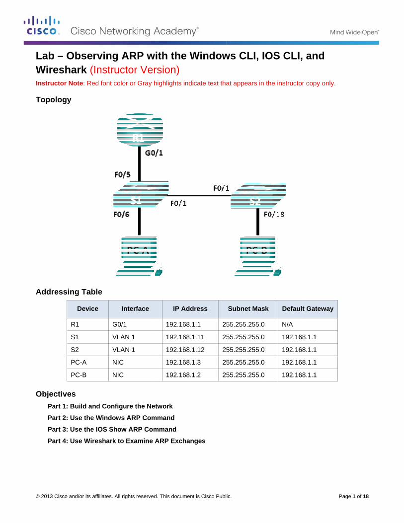
©
LWI
T
A
O
© 2013 Cisco and
Lab – ObWireshanstructor No
Topology
Addressing
R
S
S2
PC
PC
ObjectivesPart 1: Bu
Part 2: Us
Part 3: Us
Part 4: Us
d/or its affiliates.
bservingark (Instrote: Red font
g Table
Device
1 G
1 V
2 V
C-A N
C-B N
uild and Con
se the Windo
se the IOS S
se Wireshark
All rights reserve
g ARP wructor Vecolor or Gray
Interface
G0/1
VLAN 1
VLAN 1
NIC
NIC
nfigure the N
ows ARP Co
how ARP Co
k to Examine
ed. This docume
with the ersion) y highlights ind
IP Ad
192.168
192.168
192.168
192.168
192.168
etwork
mmand
ommand
e ARP Excha
ent is Cisco Publ
Window
dicate text tha
ddress
8.1.1 25
8.1.11 25
8.1.12 25
8.1.3 25
8.1.2 25
anges
ic.
ws CLI, I
at appears in
Subnet Mas
55.255.255.0
55.255.255.0
55.255.255.0
55.255.255.0
55.255.255.0
OS CLI,
the instructo
sk Defaul
N/A
192.16
192.16
192.16
192.16
P
and
r copy only.
t Gateway
8.1.1
8.1.1
8.1.1
8.1.1
Page 1 of 18

Lab – Observing ARP with the Windows CLI, IOS CLI and Wireshark
© 2013 Cisco and/or its affiliates. All rights reserved. This document is Cisco Public. Page 2 of 18
Background / Scenario The Address Resolution Protocol (ARP) is used by TCP/IP to map a Layer 3 IP address to a Layer 2 MAC address. When a frame is placed on the network, it must have a destination MAC address. To dynamically discover the MAC address for the destination device, an ARP request is broadcast on the LAN. The device that contains the destination IP address responds, and the MAC address is recorded in the ARP cache. Every device on the LAN keeps its own ARP cache, or small area in RAM that holds ARP results. An ARP cache timer removes ARP entries that have not been used for a certain period of time.
ARP is an excellent example of performance tradeoff. With no cache, ARP must continually request address translations each time a frame is placed on the network. This adds latency to the communication and could congest the LAN. Conversely, unlimited hold times could cause errors with devices that leave the network or change the Layer 3 address.
A network administrator should be aware of ARP, but may not interact with the protocol on a regular basis. ARP is a protocol that enables network devices to communicate with the TCP/IP protocol. Without ARP, there is no efficient method to build the datagram Layer 2 destination address. Also, ARP is a potential security risk. ARP spoofing, or ARP poisoning, is a technique used by an attacker to inject the wrong MAC address association in a network. An attacker forges the MAC address of a device, and frames are sent to the wrong destination. Manually configuring static ARP associations is one way to prevent ARP spoofing. Finally, an authorized MAC address list may be configured on Cisco devices to restrict network access to only approved devices.
In this lab, you will use the ARP commands in both Windows and Cisco routers to display the ARP table. You will also clear the ARP cache and add static ARP entries.
Note: The routers used with CCNA hands-on labs are Cisco 1941 Integrated Services Routers (ISRs) with Cisco IOS Release 15.2(4)M3 (universalk9 image). The switches used are Cisco Catalyst 2960s with Cisco IOS Release 15.0(2) (lanbasek9 image). Other routers, switches, and Cisco IOS versions can be used. Depending on the model and Cisco IOS version, the commands available and output produced might vary from what is shown in the labs. Refer to the Router Interface Summary Table at the end of this lab for the correct interface identifiers.
Note: Make sure that the routers and switches have been erased and have no startup configurations. If you are unsure, contact your instructor.
Instructor Note: Refer to the Instructor Lab Manual for the procedures to initialize and reload devices.
Instructor Note: Some of the ARP commands in Windows Vista or later operating systems will require administrator privileges.
Required Resources • 1 Router (Cisco 1941 with Cisco IOS Release 15.2(4)M3 universal image or comparable)
• 2 Switches (Cisco 2960 with Cisco IOS Release 15.0(2) lanbasek9 image or comparable)
• 2 PCs (Windows 7, Vista, or XP with terminal emulation program, such as Tera Term and Wireshark installed)
• Console cables to configure the Cisco IOS devices via the console ports
• Ethernet cables as shown in the topology
Note: The Fast Ethernet interfaces on Cisco 2960 switches are autosensing and an Ethernet straight-through cable may be used between switches S1 and S2. If using another Cisco switch model, it may be necessary to use an Ethernet crossover cable.

Lab – Observing ARP with the Windows CLI, IOS CLI and Wireshark
© 2013 Cisco and/or its affiliates. All rights reserved. This document is Cisco Public. Page 3 of 18
Part 1: Build and Configure the Network
Step 1: Cable the network according to the topology.
Step 2: Configure the IP addresses for the devices according to the Addressing Table.
Step 3: Verify network connectivity by pinging all the devices from PC-B.
Part 2: Use the Windows ARP Command The arp command allows the user to view and modify the ARP cache in Windows. You access this command from the Windows command prompt.
Step 1: Display the ARP cache.
a. Open a command window on PC-A and type arp. C:\Users\User1> arp Displays and modifies the IP-to-Physical address translation tables used by
address resolution protocol (ARP).
ARP -s inet_addr eth_addr [if_addr]
ARP -d inet_addr [if_addr]
ARP -a [inet_addr] [-N if_addr] [-v]
-a Displays current ARP entries by interrogating the current
protocol data. If inet_addr is specified, the IP and Physical
addresses for only the specified computer are displayed. If
more than one network interface uses ARP, entries for each ARP
table are displayed.
-g Same as -a.
-v Displays current ARP entries in verbose mode. All invalid
entries and entries on the loop-back interface will be shown.
inet_addr Specifies an internet address.
-N if_addr Displays the ARP entries for the network interface specified
by if_addr.
-d Deletes the host specified by inet_addr. inet_addr may be
wildcarded with * to delete all hosts.
-s Adds the host and associates the Internet address inet_addr
with the Physical address eth_addr. The Physical address is
given as 6 hexadecimal bytes separated by hyphens. The entry
is permanent.
eth_addr Specifies a physical address.
if_addr If present, this specifies the Internet address of the
interface whose address translation table should be modified.
If not present, the first applicable interface will be used.
Example:
> arp -s 157.55.85.212 00-aa-00-62-c6-09 .... Adds a static entry.
> arp -a .... Displays the arp table.

Lab – Observing ARP with the Windows CLI, IOS CLI and Wireshark
© 2013 Cisco and/or its affiliates. All rights reserved. This document is Cisco Public. Page 4 of 18
b. Examine the output.
What command would be used to display all entries in the ARP cache?
____________________________________________________________________________________
arp –a
What command would be used to delete all ARP cache entries (flush ARP cache)?
____________________________________________________________________________________
arp –d *
What command would be used to delete the ARP cache entry for 192.168.1.11?
____________________________________________________________________________________
arp –d 192.168.1.11
c. Type arp –a to display the ARP table. C:\Users\User1> arp –a
Interface: 192.168.1.3 --- 0xb
Internet Address Physical Address Type
192.168.1.1 d4-8c-b5-ce-a0-c1 dynamic
192.168.1.255 ff-ff-ff-ff-ff-ff static
224.0.0.22 01-00-5e-00-00-16 static
224.0.0.252 01-00-5e-00-00-fc static
239.255.255.250 01-00-5e-7f-ff-fa static
Note: The ARP table is empty if you use Windows XP (as displayed below). C:\Documents and Settings\User1> arp -a No ARP Entries Found.
d. Ping from PC-A to PC-B to dynamically add entries in the ARP cache. C:\Documents and Settings\User1> ping 192.168.1.2
Interface: 192.168.1.3 --- 0xb
Internet Address Physical Address Type
192.168.1.2 00-50-56-be-f6-db dynamic
What is the physical address for the host with IP address of 192.168.1.2?
____________________________________________________________________________________
00-50-56-be-f6-db
Step 2: Adjust entries in the ARP cache manually.
To delete entries in ARP cache, issue the command arp –d {inet-addr | *}. Addresses can be deleted individually by specifying the IP address, or all entries can be deleted with the wildcard *.
Verify that the ARP cache contains the following entries: the R1 G0/1 default gateway (192.168.1.1), PC-B (192.168.1.2) and both switches (192.168.1.11 and 192.168.1.12).
a. From PC-A, ping all the addresses in the Address Table.
b. Verify that all the addresses have been added to the ARP cache. If the address is not in ARP cache, ping the destination address and verify that the address was added to the ARP cache. C:\Users\User1> arp –a

Lab – Observing ARP with the Windows CLI, IOS CLI and Wireshark
© 2013 Cisco and/or its affiliates. All rights reserved. This document is Cisco Public. Page 5 of 18
Interface: 192.168.1.3 --- 0xb
Internet Address Physical Address Type
192.168.1.1 d4-8c-b5-ce-a0-c1 dynamic
192.168.1.2 00-50-56-be-f6-db dynamic
192.168.1.11 0c-d9-96-e8-8a-40 dynamic
192.168.1.12 0c-d9-96-d2-40-40 dynamic
192.168.1.255 ff-ff-ff-ff-ff-ff static
224.0.0.22 01-00-5e-00-00-16 static
224.0.0.252 01-00-5e-00-00-fc static
239.255.255.250 01-00-5e-7f-ff-fa static
c. As an administrator, access the command prompt. Click the Start icon, and in the Search programs and file box, type cmd. When the cmd icon appears, right-click the icon and select Run as administrator. Click Yes to allow this program to make changes.
Note: For Windows XP users, it is not necessary to have administrator privileges to modify ARP cache entries.
d. In the Administrator command prompt window, type arp –d *. This command deletes all the ARP cache entries. Verify that all the ARP cache entries are deleted by typing arp –a at the command prompt. C:\windows\system32> arp –d * C:\windows\system32> arp –a
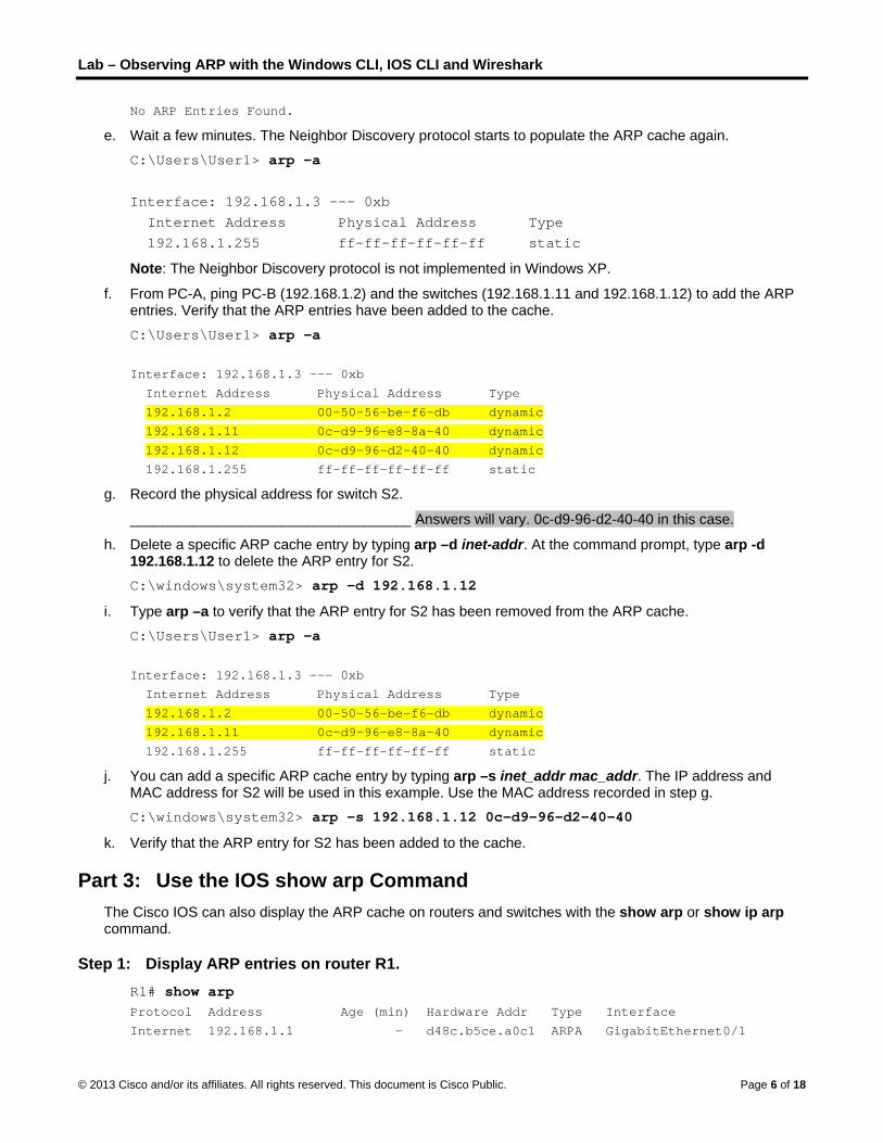
Lab – Observing ARP with the Windows CLI, IOS CLI and Wireshark
© 2013 Cisco and/or its affiliates. All rights reserved. This document is Cisco Public. Page 6 of 18
No ARP Entries Found.
e. Wait a few minutes. The Neighbor Discovery protocol starts to populate the ARP cache again. C:\Users\User1> arp –a Interface: 192.168.1.3 --- 0xb Internet Address Physical Address Type 192.168.1.255 ff-ff-ff-ff-ff-ff static
Note: The Neighbor Discovery protocol is not implemented in Windows XP.
f. From PC-A, ping PC-B (192.168.1.2) and the switches (192.168.1.11 and 192.168.1.12) to add the ARP entries. Verify that the ARP entries have been added to the cache. C:\Users\User1> arp –a
Interface: 192.168.1.3 --- 0xb
Internet Address Physical Address Type
192.168.1.2 00-50-56-be-f6-db dynamic
192.168.1.11 0c-d9-96-e8-8a-40 dynamic
192.168.1.12 0c-d9-96-d2-40-40 dynamic
192.168.1.255 ff-ff-ff-ff-ff-ff static
g. Record the physical address for switch S2.
___________________________________ Answers will vary. 0c-d9-96-d2-40-40 in this case.
h. Delete a specific ARP cache entry by typing arp –d inet-addr. At the command prompt, type arp -d 192.168.1.12 to delete the ARP entry for S2. C:\windows\system32> arp –d 192.168.1.12
i. Type arp –a to verify that the ARP entry for S2 has been removed from the ARP cache. C:\Users\User1> arp –a
Interface: 192.168.1.3 --- 0xb
Internet Address Physical Address Type
192.168.1.2 00-50-56-be-f6-db dynamic
192.168.1.11 0c-d9-96-e8-8a-40 dynamic
192.168.1.255 ff-ff-ff-ff-ff-ff static
j. You can add a specific ARP cache entry by typing arp –s inet_addr mac_addr. The IP address and MAC address for S2 will be used in this example. Use the MAC address recorded in step g. C:\windows\system32> arp –s 192.168.1.12 0c-d9-96-d2-40-40
k. Verify that the ARP entry for S2 has been added to the cache.
Part 3: Use the IOS show arp Command The Cisco IOS can also display the ARP cache on routers and switches with the show arp or show ip arp command.
Step 1: Display ARP entries on router R1. R1# show arp Protocol Address Age (min) Hardware Addr Type Interface
Internet 192.168.1.1 - d48c.b5ce.a0c1 ARPA GigabitEthernet0/1

Lab – Observing ARP with the Windows CLI, IOS CLI and Wireshark
© 2013 Cisco and/or its affiliates. All rights reserved. This document is Cisco Public. Page 7 of 18
Internet 192.168.1.2 0 0050.56be.f6db ARPA GigabitEthernet0/1
Internet 192.168.1.3 0 0050.56be.768c ARPA GigabitEthernet0/1
R1#
Notice there is no Age (-) for the first entry, router interface G0/1 (the LAN default gateway). The Age is the number of minutes (min) that the entry has been in ARP cache and is incremented for the other entries. The Neighbor Discovery protocol populates the PC-A and PC-B IP and MAC address ARP entries.
Step 2: Add ARP entries on router R1.
You can add ARP entries to the ARP table of the router by pinging other devices.
a. Ping switch S1. R1# ping 192.168.1.11 Type escape sequence to abort.
Sending 5, 100-byte ICMP Echos to 192.168.1.11, timeout is 2 seconds:
.!!!!
Success rate is 80 percent (4/5), round-trip min/avg/max = 1/2/4 ms
b. Verify that an ARP entry for switch S1 has been added to the ARP table of R1. R1# show ip arp Protocol Address Age (min) Hardware Addr Type Interface
Internet 192.168.1.1 - d48c.b5ce.a0c1 ARPA GigabitEthernet0/1
Internet 192.168.1.2 6 0050.56be.f6db ARPA GigabitEthernet0/1
Internet 192.168.1.3 6 0050.56be.768c ARPA GigabitEthernet0/1
Internet 192.168.1.11 0 0cd9.96e8.8a40 ARPA GigabitEthernet0/1
R1#
Step 3: Display ARP entries on switch S1. S1# show ip arp Protocol Address Age (min) Hardware Addr Type Interface
Internet 192.168.1.1 46 d48c.b5ce.a0c1 ARPA Vlan1
Internet 192.168.1.2 8 0050.56be.f6db ARPA Vlan1
Internet 192.168.1.3 8 0050.56be.768c ARPA Vlan1
Internet 192.168.1.11 - 0cd9.96e8.8a40 ARPA Vlan1
S1#
Step 4: Add ARP entries on switch S1.
By pinging other devices, ARP entries can also be added to the ARP table of the switch.
a. From switch S1, ping switch S2. S1# ping 192.168.1.12 Type escape sequence to abort.
Sending 5, 100-byte ICMP Echos to 192.168.1.12, timeout is 2 seconds:
.!!!!
Success rate is 80 percent (4/5), round-trip min/avg/max = 1/2/8 ms
b. Verify that the ARP entry for switch S2 has been added to ARP table of S1. S1# show ip arp Protocol Address Age (min) Hardware Addr Type Interface

Lab – Observing ARP with the Windows CLI, IOS CLI and Wireshark
© 2013 Cisco and/or its affiliates. All rights reserved. This document is Cisco Public. Page 8 of 18
Internet 192.168.1.1 5 d48c.b5ce.a0c1 ARPA Vlan1
Internet 192.168.1.2 11 0050.56be.f6db ARPA Vlan1
Internet 192.168.1.3 11 0050.56be.768c ARPA Vlan1
Internet 192.168.1.11 - 0cd9.96e8.8a40 ARPA Vlan1
Internet 192.168.1.12 2 0cd9.96d2.4040 ARPA Vlan1
S1#
Part 4: Use Wireshark to Examine ARP Exchanges In Part 4, you will examine ARP exchanges by using Wireshark to capture and evaluate the ARP exchange. You will also examine network latency caused by ARP exchanges between devices.
Step 1: Configure Wireshark for packet captures.
a. Start Wireshark.
b. Choose the network interface to use for capturing the ARP exchanges.
Step 2: Capture and evaluate ARP communications.
a. Start capturing packets in Wireshark. Use the filter to display only ARP packets.
b. Flush the ARP cache by typing the arp –d * command at the command prompt.
c. Verify that the ARP cache has been cleared.
d. Send a ping to the default gateway, using the ping 192.168.1.1 command.
e. Stop the Wireshark capture after pinging to the default gateway is finished.
f. Examine the Wireshark captures for the ARP exchanges in the packet details pane.
What was the first ARP packet? ___________________________ ARP request

Lab – Observing ARP with the Windows CLI, IOS CLI and Wireshark
© 2013 Cisco and/or its affiliates. All rights reserved. This document is Cisco Public. Page 9 of 18
Fill in the following table with information about your first captured ARP packet.
Field Value
Sender MAC address 5C:26:0A:19:55:92 - Answers will vary.
Sender IP address 192.168.1.3
Target MAC address 00:00:00:00:00:00
Target IP address 192.168.1.1
What was the second ARP packet? ______________________________ ARP reply
Fill in the following table with information about your second captured ARP packet.
Field Value
Sender MAC address C4:71:FE:45:73:A1 - Answers will vary.
Sender IP address 192.168.1.1
Target MAC address 5C:26:0A:19:55:92 - Answers will vary.
Target IP address 192.168.1.3
Step 3: Examine network latency caused by ARP.
a. Clear the ARP entries on PC-A.
b. Start a Wireshark capture.

Lab – Observing ARP with the Windows CLI, IOS CLI and Wireshark
© 2013 Cisco and/or its affiliates. All rights reserved. This document is Cisco Public. Page 10 of 18
c. Ping switch S2 (192.168.1.12). The ping should be successful after the first echo request.
Note: If all the pings were successful, S1 should be reloaded to observe network latency with ARP. C:\Users\User1> ping 192.168.1.12 Request timed out.
Reply from 192.168.1.12: bytes=32 time=2ms TTL=255
Reply from 192.168.1.12: bytes=32 time=2ms TTL=255
Reply from 192.168.1.12: bytes=32 time=2ms TTL=255
Ping statistics for 192.168.1.12:
Packets: Sent = 4, Received = 3, Lost = 1 (25% loss),
Approximate round trip times in milli-seconds:
Minimum = 1ms, Maximum = 3ms, Average = 2ms
d. Stop the Wireshark capture after the pinging is finished. Use the Wireshark filter to display only ARP and ICMP outputs. In Wireshark, type arp or icmp in the Filter: entry area.
e. Examine the Wireshark capture. In this example, frame 10 is the first ICMP request sent by PC-A to S1. Because there is no ARP entry for S1, an ARP request was sent to the management IP address of S1 asking for the MAC address. During the ARP exchanges, the echo request did not receive a reply before the request was timed out. (frames 8 – 12)
After the ARP entry for S1 was added to the ARP cache, the last three ICMP exchanges were successful, as displayed in frames 26, 27 and 30 – 33.
As displayed in the Wireshark capture, ARP is an excellent example of performance tradeoff. With no cache, ARP must continually request address translations each time a frame is placed on the network. This adds latency to the communication and could congest the LAN.

Lab – Observing ARP with the Windows CLI, IOS CLI and Wireshark
© 2013 Cisco and/or its affiliates. All rights reserved. This document is Cisco Public. Page 11 of 18
Reflection 1. How and when are static ARP entries removed?
_______________________________________________________________________________________
They are deleted manually.
2. Why do you want to add static ARP entries in the cache?
_______________________________________________________________________________________
A static ARP entry can mitigate ARP spoofing or poisoning in the network.
3. If ARP requests can cause network latency, why is it a bad idea to have unlimited hold times for ARP entries?
_______________________________________________________________________________________
Unlimited hold times could cause errors with devices that leave the network or change the Layer 3 address.

Lab – Observing ARP with the Windows CLI, IOS CLI and Wireshark
© 2013 Cisco and/or its affiliates. All rights reserved. This document is Cisco Public. Page 12 of 18
Router Interface Summary Table
Router Interface Summary
Router Model Ethernet Interface #1 Ethernet Interface #2 Serial Interface #1 Serial Interface #2
1800 Fast Ethernet 0/0 (F0/0)
Fast Ethernet 0/1 (F0/1)
Serial 0/0/0 (S0/0/0) Serial 0/0/1 (S0/0/1)
1900 Gigabit Ethernet 0/0 (G0/0)
Gigabit Ethernet 0/1 (G0/1)
Serial 0/0/0 (S0/0/0) Serial 0/0/1 (S0/0/1)
2801 Fast Ethernet 0/0 (F0/0)
Fast Ethernet 0/1 (F0/1)
Serial 0/1/0 (S0/1/0) Serial 0/1/1 (S0/1/1)
2811 Fast Ethernet 0/0 (F0/0)
Fast Ethernet 0/1 (F0/1)
Serial 0/0/0 (S0/0/0) Serial 0/0/1 (S0/0/1)
2900 Gigabit Ethernet 0/0 (G0/0)
Gigabit Ethernet 0/1 (G0/1)
Serial 0/0/0 (S0/0/0) Serial 0/0/1 (S0/0/1)
Note: To find out how the router is configured, look at the interfaces to identify the type of router and how many interfaces the router has. There is no way to effectively list all the combinations of configurations for each router class. This table includes identifiers for the possible combinations of Ethernet and Serial interfaces in the device. The table does not include any other type of interface, even though a specific router may contain one. An example of this might be an ISDN BRI interface. The string in parenthesis is the legal abbreviation that can be used in Cisco IOS commands to represent the interface.
Device Configs
Router R1 R1#show run Building configuration... Current configuration : 1165 bytes ! version 15.2 service timestamps debug datetime msec service timestamps log datetime msec no service password-encryption ! hostname R1 ! boot-start-marker boot-end-marker ! ! ! no aaa new-model memory-size iomem 15 ! ! !

Lab – Observing ARP with the Windows CLI, IOS CLI and Wireshark
© 2013 Cisco and/or its affiliates. All rights reserved. This document is Cisco Public. Page 13 of 18
! ! ! ! ip cef no ipv6 cef multilink bundle-name authenticated ! ! ! ! ! ! ! ! ! ! interface Embedded-Service-Engine0/0 no ip address shutdown ! interface GigabitEthernet0/0 no ip address shutdown duplex auto speed auto ! interface GigabitEthernet0/1 ip address 192.168.1.1 255.255.255.0 duplex auto speed auto ! interface Serial0/0/0 no ip address shutdown clock rate 2000000 ! interface Serial0/0/1 no ip address shutdown ! ip forward-protocol nd ! no ip http server no ip http secure-server ! ! ! !
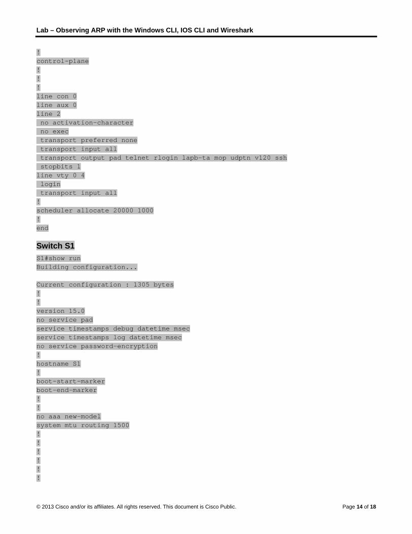
Lab – Observing ARP with the Windows CLI, IOS CLI and Wireshark
© 2013 Cisco and/or its affiliates. All rights reserved. This document is Cisco Public. Page 14 of 18
! control-plane ! ! ! line con 0 line aux 0 line 2 no activation-character no exec transport preferred none transport input all transport output pad telnet rlogin lapb-ta mop udptn v120 ssh stopbits 1 line vty 0 4 login transport input all ! scheduler allocate 20000 1000 ! end
Switch S1 S1#show run Building configuration... Current configuration : 1305 bytes ! ! version 15.0 no service pad service timestamps debug datetime msec service timestamps log datetime msec no service password-encryption ! hostname S1 ! boot-start-marker boot-end-marker ! ! no aaa new-model system mtu routing 1500 ! ! ! ! ! !

Lab – Observing ARP with the Windows CLI, IOS CLI and Wireshark
© 2013 Cisco and/or its affiliates. All rights reserved. This document is Cisco Public. Page 15 of 18
! ! ! ! spanning-tree mode pvst spanning-tree extend system-id ! vlan internal allocation policy ascending ! ! ! ! ! ! interface FastEthernet0/1 ! interface FastEthernet0/2 ! interface FastEthernet0/3 ! interface FastEthernet0/4 ! interface FastEthernet0/5 ! interface FastEthernet0/6 ! interface FastEthernet0/7 ! interface FastEthernet0/8 ! interface FastEthernet0/9 ! interface FastEthernet0/10 ! interface FastEthernet0/11 ! interface FastEthernet0/12 ! interface FastEthernet0/13 ! interface FastEthernet0/14 ! interface FastEthernet0/15 ! interface FastEthernet0/16 ! interface FastEthernet0/17 ! interface FastEthernet0/18

Lab – Observing ARP with the Windows CLI, IOS CLI and Wireshark
© 2013 Cisco and/or its affiliates. All rights reserved. This document is Cisco Public. Page 16 of 18
! interface FastEthernet0/19 ! interface FastEthernet0/20 ! interface FastEthernet0/21 ! interface FastEthernet0/22 ! interface FastEthernet0/23 ! interface FastEthernet0/24 ! interface GigabitEthernet0/1 ! interface GigabitEthernet0/2 ! interface Vlan1 ip address 192.168.1.11 255.255.255.0 ! ip http server ip http secure-server ! ! ! line con 0 line vty 5 15 ! end
Switch S2 S2#show run Building configuration... Current configuration : 1313 bytes ! ! version 15.0 no service pad service timestamps debug datetime msec service timestamps log datetime msec no service password-encryption ! hostname S2 ! boot-start-marker boot-end-marker ! !

Lab – Observing ARP with the Windows CLI, IOS CLI and Wireshark
© 2013 Cisco and/or its affiliates. All rights reserved. This document is Cisco Public. Page 17 of 18
no aaa new-model system mtu routing 1500 ! ! ! ! ! ! ! ! ! ! spanning-tree mode pvst spanning-tree extend system-id ! vlan internal allocation policy ascending ! ! ! ! ! ! interface FastEthernet0/1 ! interface FastEthernet0/2 ! interface FastEthernet0/3 ! interface FastEthernet0/4 ! interface FastEthernet0/5 ! interface FastEthernet0/6 ! interface FastEthernet0/7 ! interface FastEthernet0/8 ! interface FastEthernet0/9 ! interface FastEthernet0/10 ! interface FastEthernet0/11 ! interface FastEthernet0/12 ! interface FastEthernet0/13 ! interface FastEthernet0/14

Lab – Observing ARP with the Windows CLI, IOS CLI and Wireshark
© 2013 Cisco and/or its affiliates. All rights reserved. This document is Cisco Public. Page 18 of 18
! interface FastEthernet0/15 ! interface FastEthernet0/16 ! interface FastEthernet0/17 ! interface FastEthernet0/18 ! interface FastEthernet0/19 ! interface FastEthernet0/20 ! interface FastEthernet0/21 ! interface FastEthernet0/22 ! interface FastEthernet0/23 ! interface FastEthernet0/24 ! interface GigabitEthernet0/1 ! interface GigabitEthernet0/2 ! interface Vlan1 ip address 192.168.1.12 255.255.255.0 ! ip http server ip http secure-server ! ! line con 0 line vty 5 15 ! end

©
LVI
T
A
O
© 2013 Cisco and
Lab - UsVersion) nstructor No
Topology
Addressing
R
S
S2
PC
PC
ObjectivesPart 1: Bu
Cable
Config
Part 2: Ex
Use s
d/or its affiliates.
sing IOS
ote: Red font
g Table
Device
1 G
1 V
2 V
C-A N
C-B N
uild and Con
e the network
gure the netw
xamine the S
show comma
All rights reserve
S CLI wit
color or Gray
Interface
G0/1
VLAN 1
VLAN 1
NIC
NIC
nfigure the N
according to
work devices a
Switch MAC A
nds to observ
ed. This docume
th Switc
y highlights ind
IP Ad
192.168
192.168
192.168
192.168
192.168
etwork
the topology
according to t
Address Tab
ve the proces
ent is Cisco Publi
h MAC A
dicate text tha
ddress
8.1.1 25
8.1.11 25
8.1.12 25
8.1.3 25
8.1.2 25
diagram.
the Addressin
ble
ss of building t
ic.
Address
at appears in
Subnet Mas
55.255.255.0
55.255.255.0
55.255.255.0
55.255.255.0
55.255.255.0
ng Table.
the switch MA
s Tables
the instructo
sk Defaul
0 N/A
0 192.16
0 192.16
0 192.16
0 192.16
AC address ta
P
s (Instruc
r copy only.
t Gateway
8.1.1
8.1.1
8.1.1
8.1.1
able.
Page 1 of 15
ctor

Lab - Using IOS CLI with Switch MAC Address Tables
© 2013 Cisco and/or its affiliates. All rights reserved. This document is Cisco Public. Page 2 of 15
Background / Scenario The purpose of a Layer 2 LAN switch is to deliver Ethernet frames to host devices on the local network. The switch records host MAC addresses that are visible on the network, and maps those MAC addresses to its own Ethernet switch ports. This process is called building the MAC address table. When a switch receives a frame from a PC, it examines the frame’s source and destination MAC addresses. The source MAC address is recorded and mapped to the switch port from which it arrived. Then the destination MAC address is looked up in the MAC address table. If the destination MAC address is a known address, then the frame is forwarded out of the corresponding switch port of the MAC address. If the MAC address is unknown, then the frame is broadcast out of all switch ports, except the one from which it came. It is important to observe and understand the function of a switch and how it delivers data on the network. The way a switch operates has implications for network administrators whose job it is to ensure secure and consistent network communication.
Switches are used to interconnect and deliver information to computers on local area networks. Switches deliver Ethernet frames to host devices identified by network interface card MAC addresses.
In Part 1, you will build a multi-switch and router topology with a trunk linking the two switches. In Part 2, you will ping various devices and observe how the two switches build their MAC address tables.
Note: The routers used with CCNA hands-on labs are Cisco 1941 Integrated Services Routers (ISRs) with Cisco IOS Release 15.2(4)M3 (universalk9 image). The switches used are Cisco Catalyst 2960s with Cisco IOS Release 15.0(2) (lanbasek9 image). Other routers, switches and Cisco IOS versions can be used. Depending on the model and Cisco IOS version, the commands available and output produced might vary from what is shown in the labs. Refer to the Router Interface Summary Table at the end of this lab for the correct interface identifiers.
Note: Make sure that the routers and switches have been erased and have no startup configurations. If you are unsure contact your instructor.
Instructor Note: Refer to the Instructor Lab Manual for the procedures to initialize and reload devices.
Instructor Note: The Wireshark program will need to be downloaded and installed on PC-B prior to the start of the lab. Wireshark can be downloaded from http://www.wireshark.org/.
Required Resources 1 Router (Cisco 1941 with Cisco IOS Release 15.2(4)M3 universal image or comparable)
2 Switches (Cisco 2960 with Cisco IOS Release 15.0(2) lanbasek9 image or comparable)
2 PCs (Windows 7, Vista, or XP with terminal emulation program, such as Tera Term)
Console cables to configure the Cisco IOS devices via the console ports
Ethernet cables as shown in the topology
Note: The Fast Ethernet interfaces on Cisco 2960 switches are autosensing and an Ethernet straight-through cable may be used between switches S1 and S2. If using another model Cisco switch, it may be necessary to use an Ethernet crossover cable.

Lab - Using IOS CLI with Switch MAC Address Tables
© 2013 Cisco and/or its affiliates. All rights reserved. This document is Cisco Public. Page 3 of 15
Part 1: Build and Configure the Network
Step 1: Cable the network according to the topology.
Step 2: Configure PC hosts.
Step 3: Initialize and reload the routers and switches as necessary.
Step 4: Configure basic settings for each switch.
a. Configure device name as shown in the topology.
b. Configure IP address and default gateway as listed in Addressing Table.
c. Assign cisco as the console and vty passwords.
d. Assign class as the privileged EXEC password.
Step 5: Configure basic settings for the router.
a. Disable DNS lookup.
b. Configure IP address for the router as listed in Addressing Table.
c. Configure device name as shown in the topology.
d. Assign cisco as the console and vty passwords.
e. Assign class as the privileged EXEC password.
Part 2: Examine the Switch MAC Address Table A switch learns MAC addresses and builds the MAC address table, as network devices initiate communication on the network.
Step 1: Record network device MAC addresses.
a. Open a command prompt on PC-A and PC-B and type ipconfig /all. What are the Ethernet adapter physical addresses?
PC-A MAC Address: ___________________________________________________________________
PC-B MAC Address: ___________________________________________________________________
Answers will vary.
b. Console into router R1 and type the show interface G0/1 command. What is the hardware address?
R1 Gigabit Ethernet 0/1 MAC Address: ____________________________________________________
Answers will vary but from the example output below, the G0/1 MAC address is 30f7.0da3.17c1.
R1# show interface G0/1
GigabitEthernet0/1 is up, line protocol is up
Hardware is CN Gigabit Ethernet, address is 30f7.0da3.17c1 (bia 30f7.0da3.17c1)
Internet address is 192.168.1.1/24
<output omitted>
R1#
c. Console into switch S1 and S2 and type the show interface F0/1 command on each switch. On the second line of command output, what is the hardware addresses (or burned-in address [bia])?

Lab - Using IOS CLI with Switch MAC Address Tables
© 2013 Cisco and/or its affiliates. All rights reserved. This document is Cisco Public. Page 4 of 15
S1 Fast Ethernet 0/1 MAC Address: ______________________________________________________
S2 Fast Ethernet 0/1 MAC Address: ______________________________________________________
Answers will vary but from the example output below the S1 F0/1 MAC address is 0cd9.96d2.3d81 and the S1 F0/1 MAC address is 0cd9.96d2.4581.
S1# show interface f0/1
FastEthernet0/1 is up, line protocol is up (connected)
Hardware is Fast Ethernet, address is 0cd9.96d2.3d81 (bia 0cd9.96d2.3d81)
MTU 1500 bytes, BW 100000 Kbit, DLY 100 usec,
<output omitted>
S1#
S2# show interface f0/1
FastEthernet0/1 is up, line protocol is up (connected)
Hardware is Fast Ethernet, address is 0cd9.96d2.4581 (bia 0cd9.96d2.4581)
MTU 1500 bytes, BW 100000 Kbit, DLY 100 usec,
<output omitted>
S2#
Step 2: Display the switch MAC address table.
Console into switch S2 and view the MAC address table, both before and after running network communication tests with ping.
a. Establish a console connection to S2 and enter privileged EXEC mode.
b. In privileged EXEC mode, type the show mac address-table command and press Enter.
S2# show mac address-table
Even though there has been no network communication initiated across the network (i.e., no use of ping), it is possible that the switch has learned MAC addresses from its connection to the PC and the other switch.
Are there any MAC addresses recorded in the MAC address table?
____________________________________________________________________________________
The switch may have one or more MAC addresses in its table, based on whether or not the students entered a ping command when configuring the network. The switch will most likely have learned MAC addresses through S1’s F0/1 switch port. The switch will record multiple MAC addresses of hosts learned through the connection to the other switch on F0/1.
S2# show mac address-table
Mac Address Table
-------------------------------------------
Vlan Mac Address Type Ports
---- ----------- -------- -----
All 0100.0ccc.cccc STATIC CPU
All 0100.0ccc.cccd STATIC CPU
All 0180.c200.0000 STATIC CPU
All 0180.c200.0001 STATIC CPU
All 0180.c200.0002 STATIC CPU
All 0180.c200.0003 STATIC CPU
All 0180.c200.0004 STATIC CPU

Lab - Using IOS CLI with Switch MAC Address Tables
© 2013 Cisco and/or its affiliates. All rights reserved. This document is Cisco Public. Page 5 of 15
All 0180.c200.0005 STATIC CPU
All 0180.c200.0006 STATIC CPU
All 0180.c200.0007 STATIC CPU
All 0180.c200.0008 STATIC CPU
All 0180.c200.0009 STATIC CPU
All 0180.c200.000a STATIC CPU
All 0180.c200.000b STATIC CPU
All 0180.c200.000c STATIC CPU
All 0180.c200.000d STATIC CPU
All 0180.c200.000e STATIC CPU
All 0180.c200.000f STATIC CPU
All 0180.c200.0010 STATIC CPU
All ffff.ffff.ffff STATIC CPU
1 0cd9.96d2.3d81 DYNAMIC Fa0/1
1 1cc1.de91.c35d DYNAMIC Fa0/1
Total Mac Addresses for this criterion: 22
S2#
What MAC addresses are recorded in the table? To which switch ports are they mapped and to which devices do they belong? Ignore MAC addresses that are mapped to the CPU.
____________________________________________________________________________________
____________________________________________________________________________________
____________________________________________________________________________________
There may be multiple MAC addresses recorded in the MAC address table, especially MAC addresses learned through S1’s F0/1 switch port. In the example output above, the S1 F0/1 MAC address and PC-A MAC address are mapped to S2 F0/1.
If you had not previously recorded MAC addresses of network devices in Step 1, how could you tell which devices the MAC addresses belong to, using only the output from the show mac address-table command? Does it work in all scenarios?
____________________________________________________________________________________
____________________________________________________________________________________
____________________________________________________________________________________
____________________________________________________________________________________
The output of the show mac address-table command shows the port that the MAC address was learned on. In most cases this would identify which network device the MAC address belongs to, except in the case of multiple MAC addresses associated to the same port. This happens when switches are connected to other switches and record all of the MAC addresses for devices connected to the other switch.
Step 3: Clear the S2 MAC address table and display the MAC address table again.
a. In privileged EXEC mode, type the clear mac address-table dynamic command and press Enter.
S2# clear mac address-table dynamic
b. Quickly type the show mac address-table command again. Does the MAC address table have any addresses in it for VLAN 1? Are there other MAC addresses listed?
___________________________________________________________________________________

Lab - Using IOS CLI with Switch MAC Address Tables
© 2013 Cisco and/or its affiliates. All rights reserved. This document is Cisco Public. Page 6 of 15
No. The student will most likely discover that the MAC address for the other switch’s F0/1 switch port has been quickly reinserted in the MAC address table.
S2# show mac address-table Mac Address Table
-------------------------------------------
Vlan Mac Address Type Ports
---- ----------- -------- -----
All 0100.0ccc.cccc STATIC CPU
All 0100.0ccc.cccd STATIC CPU
All 0180.c200.0000 STATIC CPU
All 0180.c200.0001 STATIC CPU
All 0180.c200.0002 STATIC CPU
All 0180.c200.0003 STATIC CPU
All 0180.c200.0004 STATIC CPU
All 0180.c200.0005 STATIC CPU
All 0180.c200.0006 STATIC CPU
All 0180.c200.0007 STATIC CPU
All 0180.c200.0008 STATIC CPU
All 0180.c200.0009 STATIC CPU
All 0180.c200.000a STATIC CPU
All 0180.c200.000b STATIC CPU
All 0180.c200.000c STATIC CPU
All 0180.c200.000d STATIC CPU
All 0180.c200.000e STATIC CPU
All 0180.c200.000f STATIC CPU
All 0180.c200.0010 STATIC CPU
All ffff.ffff.ffff STATIC CPU
1 0cd9.96d2.3d81 DYNAMIC Fa0/1
Total Mac Addresses for this criterion: 21
S2#
Wait 10 seconds, type the show mac address-table command, and press Enter. Are there new addresses in the MAC address table? __________________ Answers will vary. There may be.
Step 4: From PC-B, ping the devices on the network and observe the switch MAC address table.
a. From PC-B, open a command prompt and type arp -a. Not including multicast or broadcast addresses, how many device IP-to-MAC address pairs have been learned by ARP?
____________________________________________________________________________________
Answers will vary. The ARP cache may have no entries in it, or it may have the gateway IP address to MAC address mapping.
C:\Users\PC-B> arp -a
Interface: 192.168.1.2 --- 0xb
Internet Address Physical Address Type
192.168.1.1 30-f7-0d-a3-17-c1 dynamic
C:\Users\PC-B>

Lab - Using IOS CLI with Switch MAC Address Tables
© 2013 Cisco and/or its affiliates. All rights reserved. This document is Cisco Public. Page 7 of 15
b. From the PC-B command prompt, ping the router/gateway R1, PC-A, S1, and S2. Did all devices have successful replies? If not, check your cabling and IP configurations.
____________________________________________________________________________________
____________________________________________________________________________________
If the network was cabled and configured correctly the answer should be yes.
c. From a console connection to S2, enter the show mac address-table command. Has the switch added additional MAC addresses to the MAC address table? If so, which addresses and devices?
____________________________________________________________________________________
____________________________________________________________________________________
There may only be one additional MAC address mapping added to the table, most likely the MAC address of PC-A.
S2# show mac address-table Mac Address Table
-------------------------------------------
Vlan Mac Address Type Ports
---- ----------- -------- -----
All 0100.0ccc.cccc STATIC CPU
All 0100.0ccc.cccd STATIC CPU
All 0180.c200.0000 STATIC CPU
All 0180.c200.0001 STATIC CPU
All 0180.c200.0002 STATIC CPU
All 0180.c200.0003 STATIC CPU
All 0180.c200.0004 STATIC CPU
All 0180.c200.0005 STATIC CPU
All 0180.c200.0006 STATIC CPU
All 0180.c200.0007 STATIC CPU
All 0180.c200.0008 STATIC CPU
All 0180.c200.0009 STATIC CPU
All 0180.c200.000a STATIC CPU
All 0180.c200.000b STATIC CPU
All 0180.c200.000c STATIC CPU
All 0180.c200.000d STATIC CPU
All 0180.c200.000e STATIC CPU
All 0180.c200.000f STATIC CPU
All 0180.c200.0010 STATIC CPU
All ffff.ffff.ffff STATIC CPU
1 0021.700c.050c DYNAMIC Fa0/18
1 0cd9.96d2.3d81 DYNAMIC Fa0/1
1 0cd9.96d2.3dc0 DYNAMIC Fa0/1
1 1cc1.de91.c35d DYNAMIC Fa0/1
1 30f7.0da3.17c1 DYNAMIC Fa0/1
Total Mac Addresses for this criterion: 25
S2#
From PC-B, open a command prompt and retype arp -a. Does the PC-B ARP cache have additional entries for all network devices that were sent pings?

Lab - Using IOS CLI with Switch MAC Address Tables
© 2013 Cisco and/or its affiliates. All rights reserved. This document is Cisco Public. Page 8 of 15
____________________________________________________________________________________
Answers may vary, but the ARP cache on PC-B should have more entries.
C:\Users\PC-B> arp -a
Interface: 192.168.1.2 --- 0xb
Internet Address Physical Address Type
192.168.1.1 30-f7-0d-a3-17-c1 dynamic
192.168.1.3 1c-c1-de-91-c3-5d dynamic
192.168.1.11 0c-d9-96-d2-3d-c0 dynamic
192.168.1.12 0c-d9-96-d2-45-c0 dynamic
C:\Users\PC-B>
Reflection On Ethernet networks, data is delivered to devices by their MAC addresses. For this to happen, switches and PCs dynamically build ARP caches and MAC address tables. With only a few computers on the network this process seems fairly easy. What might be some of the challenges on larger networks?
_______________________________________________________________________________________
ARP broadcasts could cause broadcast storms. Because ARP and switch MAC tables do not authenticate or validate the IP addresses to MAC addresses it would be easy to spoof a device on the network.
Router Interface Summary Table
Router Interface Summary
Router Model Ethernet Interface #1 Ethernet Interface #2 Serial Interface #1 Serial Interface #2
1800 Fast Ethernet 0/0 (F0/0)
Fast Ethernet 0/1 (F0/1)
Serial 0/0/0 (S0/0/0) Serial 0/0/1 (S0/0/1)
1900 Gigabit Ethernet 0/0 (G0/0)
Gigabit Ethernet 0/1 (G0/1)
Serial 0/0/0 (S0/0/0) Serial 0/0/1 (S0/0/1)
2801 Fast Ethernet 0/0 (F0/0)
Fast Ethernet 0/1 (F0/1)
Serial 0/1/0 (S0/1/0) Serial 0/1/1 (S0/1/1)
2811 Fast Ethernet 0/0 (F0/0)
Fast Ethernet 0/1 (F0/1)
Serial 0/0/0 (S0/0/0) Serial 0/0/1 (S0/0/1)
2900 Gigabit Ethernet 0/0 (G0/0)
Gigabit Ethernet 0/1 (G0/1)
Serial 0/0/0 (S0/0/0) Serial 0/0/1 (S0/0/1)
Note: To find out how the router is configured, look at the interfaces to identify the type of router and how many interfaces the router has. There is no way to effectively list all the combinations of configurations for each router class. This table includes identifiers for the possible combinations of Ethernet and Serial interfaces in the device. The table does not include any other type of interface, even though a specific router may contain one. An example of this might be an ISDN BRI interface. The string in parenthesis is the legal abbreviation that can be used in Cisco IOS commands to represent the interface.
Device Configs
Router R1 R1#show running-config Building configuration...
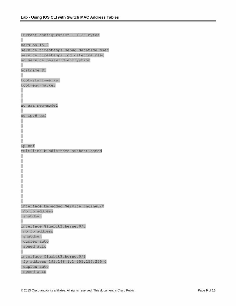
Lab - Using IOS CLI with Switch MAC Address Tables
© 2013 Cisco and/or its affiliates. All rights reserved. This document is Cisco Public. Page 9 of 15
Current configuration : 1128 bytes ! version 15.2 service timestamps debug datetime msec service timestamps log datetime msec no service password-encryption ! hostname R1 ! boot-start-marker boot-end-marker ! ! ! no aaa new-model ! no ipv6 cef ! ! ! ! ! ip cef multilink bundle-name authenticated ! ! ! ! ! ! ! ! ! ! interface Embedded-Service-Engine0/0 no ip address shutdown ! interface GigabitEthernet0/0 no ip address shutdown duplex auto speed auto ! interface GigabitEthernet0/1 ip address 192.168.1.1 255.255.255.0 duplex auto speed auto

Lab - Using IOS CLI with Switch MAC Address Tables
© 2013 Cisco and/or its affiliates. All rights reserved. This document is Cisco Public. Page 10 of 15
! interface Serial0/0/0 no ip address shutdown clock rate 2000000 ! interface Serial0/0/1 no ip address shutdown clock rate 2000000 ! ip forward-protocol nd ! no ip http server no ip http secure-server ! ! ! ! ! control-plane ! ! ! line con 0 line aux 0 line 2 no activation-character no exec transport preferred none transport input all transport output pad telnet rlogin lapb-ta mop udptn v120 ssh stopbits 1 line vty 0 4 login transport input all ! scheduler allocate 20000 1000 ! end
Switch S1 S1#show running-config Building configuration... Current configuration : 1355 bytes ! version 12.2 no service pad

Lab - Using IOS CLI with Switch MAC Address Tables
© 2013 Cisco and/or its affiliates. All rights reserved. This document is Cisco Public. Page 11 of 15
service timestamps debug datetime msec service timestamps log datetime msec no service password-encryption ! hostname S1 ! boot-start-marker boot-end-marker ! enable secret 4 06YFDUHH61wAE/kLkDq9BGho1QM5EnRtoyr8cHAUg.2 ! ! ! no aaa new-model system mtu routing 1500 ! ! ! ! ! ! ! ! spanning-tree mode pvst spanning-tree extend system-id ! vlan internal allocation policy ascending ! ! ! interface FastEthernet0/1 ! interface FastEthernet0/2 ! interface FastEthernet0/3 ! interface FastEthernet0/4 ! interface FastEthernet0/5 ! interface FastEthernet0/6 ! interface FastEthernet0/7 ! interface FastEthernet0/8 ! interface FastEthernet0/9 ! interface FastEthernet0/10

Lab - Using IOS CLI with Switch MAC Address Tables
© 2013 Cisco and/or its affiliates. All rights reserved. This document is Cisco Public. Page 12 of 15
! interface FastEthernet0/11 ! interface FastEthernet0/12 ! interface FastEthernet0/13 ! interface FastEthernet0/14 ! interface FastEthernet0/15 ! interface FastEthernet0/16 ! interface FastEthernet0/17 ! interface FastEthernet0/18 ! interface FastEthernet0/19 ! interface FastEthernet0/20 ! interface FastEthernet0/21 ! interface FastEthernet0/22 ! interface FastEthernet0/23 ! interface FastEthernet0/24 ! interface GigabitEthernet0/1 ! interface GigabitEthernet0/2 ! interface Vlan1 ip address 192.168.1.11 255.255.255.0 ! ip default-gateway 192.168.1.1 ip http server ip http secure-server ! line con 0 line vty 0 4 password cisco login line vty 5 15 login ! end

Lab - Using IOS CLI with Switch MAC Address Tables
© 2013 Cisco and/or its affiliates. All rights reserved. This document is Cisco Public. Page 13 of 15
Switch S2 S2#show running-config Building configuration... Current configuration : 1355 bytes ! version 12.2 no service pad service timestamps debug datetime msec service timestamps log datetime msec no service password-encryption ! hostname S2 ! boot-start-marker boot-end-marker ! enable secret 4 06YFDUHH61wAE/kLkDq9BGho1QM5EnRtoyr8cHAUg.2 ! ! ! no aaa new-model system mtu routing 1500 ! ! ! ! ! ! ! spanning-tree mode pvst spanning-tree extend system-id ! vlan internal allocation policy ascending ! ! ! interface FastEthernet0/1 ! interface FastEthernet0/2 ! interface FastEthernet0/3 ! interface FastEthernet0/4 ! interface FastEthernet0/5 ! interface FastEthernet0/6 !

Lab - Using IOS CLI with Switch MAC Address Tables
© 2013 Cisco and/or its affiliates. All rights reserved. This document is Cisco Public. Page 14 of 15
interface FastEthernet0/7 ! interface FastEthernet0/8 ! interface FastEthernet0/9 ! interface FastEthernet0/10 ! interface FastEthernet0/11 ! interface FastEthernet0/12 ! interface FastEthernet0/13 ! interface FastEthernet0/14 ! interface FastEthernet0/15 ! interface FastEthernet0/16 ! interface FastEthernet0/17 ! interface FastEthernet0/18 ! interface FastEthernet0/19 ! interface FastEthernet0/20 ! interface FastEthernet0/21 ! interface FastEthernet0/22 ! interface FastEthernet0/23 ! interface FastEthernet0/24 ! interface GigabitEthernet0/1 ! interface GigabitEthernet0/2 ! interface Vlan1 ip address 192.168.1.12 255.255.255.0 ! ip default-gateway 192.168.1.1 ip http server ip http secure-server ! line con 0 line vty 0 4

Lab - Using IOS CLI with Switch MAC Address Tables
© 2013 Cisco and/or its affiliates. All rights reserved. This document is Cisco Public. Page 15 of 15
password cisco login line vty 5 15 login ! end

©
MI
O
B
R
R
© 2013 Cisco and
MAC andnstructor No
ObjectivesExplain b
In thisto curwhy Mtransm
BackgrounNote:
Pleas
http://
Topicwhere
1
2
Instruencouincludinclud
Required R Intern
the-hi
Hard-
Reflection 1. How w
_____
d/or its affiliates.
d Choosote: Red font
basic switchi
s activity, yourrent standardMAC addressmission, durin
nd/Scenario This activity
se view the vid
/www.neteven
cs discussed ie we are goin
. After viewiand search
How w
How hmake
. Collect threFocus you
How h
How h
How dchang
uctor notes: urage studentding its use inde student-to-
Resources net access to
istory-of-ethe
- or soft-copy
was Ethernet
___________
All rights reserve
se… (Inscolor or Gray
ing concepts
will indicate yds. You will spes and framinng Ethernet’s
o is best comp
deo, The Hist
nts.tv/video/bo
n the video ing with Ethern
ng the video h for informat
was Ethernet u
has Ethernet sit more usefu
ee pictures ofr search on s
have Ethernet
have Ethernet
o you think thes?
This Modelints to reflect on LANs and W
-student discu
video, The H
rnet
media for rec
used when it
___________
ed. This docume
structor Vy highlights ind
s.
your knowledpeculate on png formats haevolution.
leted in group
tory of Ethern
ob-metcalfe-t
nclude not onnet technology
and comparinion about Eth
used when it
stayed the sal and applicab
f old, current,switches if pos
t physical med
t physical med
he Ethernet w
ng Activity is nn their percep
WANs for the tussions of eac
istory of Ethe
cording answe
t was first dev
____________
ent is Cisco Publi
Version)dicate text tha
dge of Ethernepotential futureave stayed ba
ps of 2-3 stud
net, located at
the-history-of-
ly where we hy in the future
ng its contenthernet:
was first deve
me over the pble to today’s
and possiblessible. Share
dia and interm
dia and interm
will change in
not intended tptions of how transmission och other’s wo
ernet, located
ers to questio
veloped?
___________
ic.
at appears in
et technologye Ethernet tec
asically the sa
dents.
t the following
-ethernet
have come froe!
ts to what you
eloped?
past 25 yearss data transm
e future Etherthese picture
mediary devic
mediary devic
the future? W
to be a gradeEthernet hasof frames. Fa
ork.
at: http://www
ons and for in
___________
the instructo
y by successfuchnology stan
ame, in order
g link:
om in Etherne
u read in the c
s? What chanission method
rnet physical mes with the cla
ces changed?
ces stayed the
What factors c
ed assignmens developed toacilitation of t
w.netevents.tv
-class sharing
____________
r copy only.
ully comparinndards, and eto assist data
et developme
chapter, go to
ges are beingds?
media and deass and discu
?
e same?
could influenc
t. Its purposeo today’s stanhe discussion
v/video/bob-m
g.
___________
Page 1 of 2
ng legacy explain a
ent, but
o the web
g made to
evices. uss:
ce these
e is to ndards, n should
metcalfe-

MAC and choose…
© 2013 Cisco and/or its affiliates. All rights reserved. This document is Cisco Public. Page 2 of 2
Students may mention that Ethernet was first developed to be used with printers (video information).
2. How has Ethernet stayed the same over the past 25 years? What changes are being made to make it more useful and applicable to today’s data transmission methods?
____________________________________________________________________________
Ethernet still uses copper cabling and wireless transmission, while the speed and distance of the transmissions are being developed to meet current and future data transmission methods.
3. How have Ethernet physical media and intermediary devices changed?
____________________________________________________________________________
The speed and distance of data communications has increased exponentially. Intermediary devices have been designed to use different cabling endpoint types to support this speed and distance increase.
4. How have Ethernet physical media and intermediary devices stayed the same?
____________________________________________________________________________
Switches still handle most Ethernet transmissions, whether Layer2 or Layer3, but the framing is basically the same with minor modifications to the frames’ introductory sections, indicating what type of frame is being transmitted, etc.
5. How do you think the Ethernet will change in the future? What factors could influence these changes?
Device connections and speed and distance developments will change how networks access other networks, but the underlying technology of Ethernet and the framing of Ethernet transmissions will probably stay the same. Wireless is an example of this. It is at once legacy, current, and futuristic.
____________________________________________________________________________
Reality
Identify elements of the model that map to IT-related content: Ethernet is a technology-based idea with cabling, speed; methods of signaling are all involved in
deciding which method of Ethernet to use in a network.
Switches use Ethernet technology and at both the LAN and WAN sides of a network.
Even though Ethernet is legacy in its inception, it is still fully current in application on today’s networks, especially in framing formats with slight modifications.
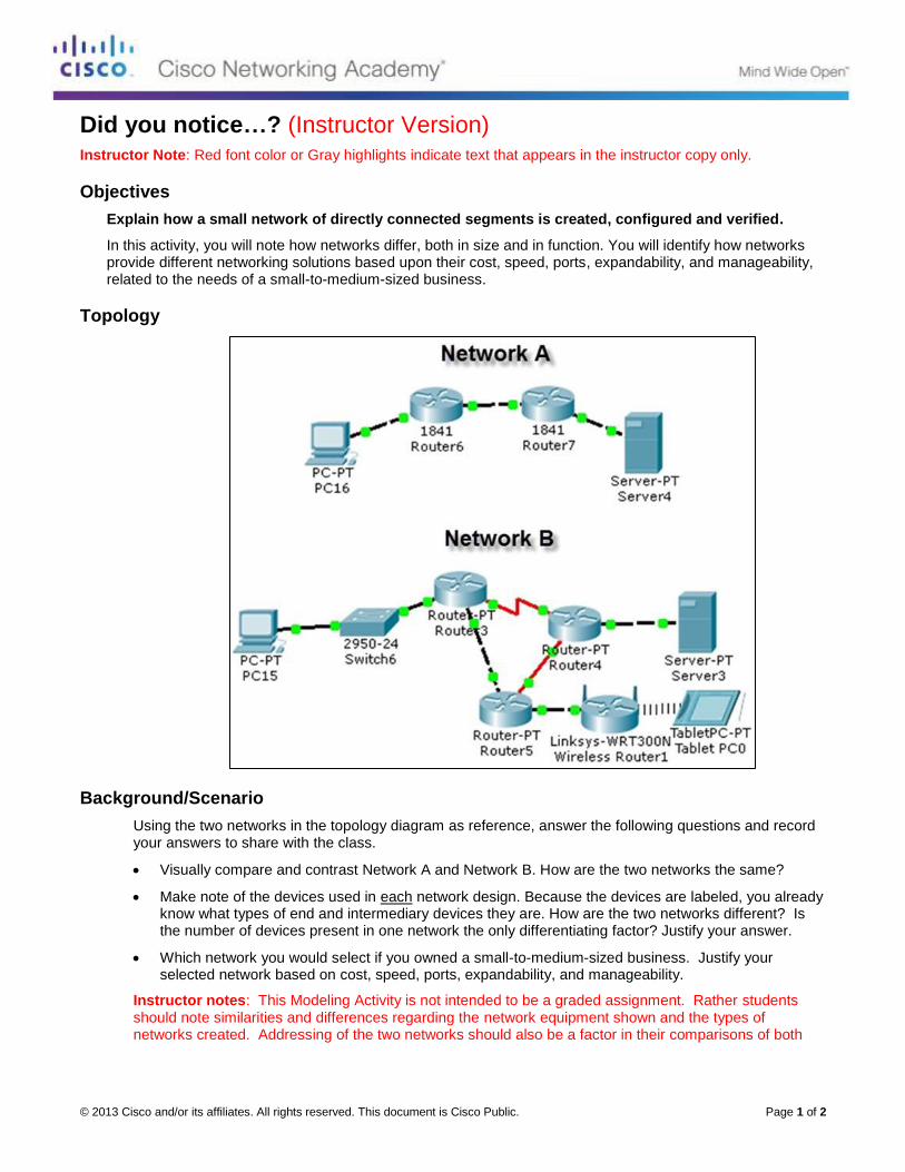
© 2013 Cisco and/or its affiliates. All rights reserved. This document is Cisco Public. Page 1 of 2
Did you notice…? (Instructor Version) Instructor Note: Red font color or Gray highlights indicate text that appears in the instructor copy only.
Objectives
Explain how a small network of directly connected segments is created, configured and verified.
In this activity, you will note how networks differ, both in size and in function. You will identify how networks provide different networking solutions based upon their cost, speed, ports, expandability, and manageability, related to the needs of a small-to-medium-sized business.
Topology
Background/Scenario
Using the two networks in the topology diagram as reference, answer the following questions and record your answers to share with the class.
Visually compare and contrast Network A and Network B. How are the two networks the same?
Make note of the devices used in each network design. Because the devices are labeled, you already know what types of end and intermediary devices they are. How are the two networks different? Is the number of devices present in one network the only differentiating factor? Justify your answer.
Which network you would select if you owned a small-to-medium-sized business. Justify your selected network based on cost, speed, ports, expandability, and manageability.
Instructor notes: This Modeling Activity is not intended to be a graded assignment. Rather students should note similarities and differences regarding the network equipment shown and the types of networks created. Addressing of the two networks should also be a factor in their comparisons of both
Did you notice…?
© 2013 Cisco and/or its affiliates. All rights reserved. This document is Cisco Public. Page 2 of 2
networks. Facilitation of the discussion should include student-to-student discussions of each other’s work.
Required Resources
Recording capabilities (paper, tablet, etc.) for reflective comments to be shared with the class.
Reflection
1. Reflect upon your comparisons of the two network scenarios. What are some things you noted as points of interest? ____________________________________________________________________________________
Multiple students may select Network B as their choice of the best network for a small to medium-sized business. But this may not necessarily be the best choice.
Network A is less costly in equipment. It also provides a more streamlined design, which should assist with network speed issues. Since there is no switch present in this particular network, expandability would be an issue and limited to the ports already present on the ISRs. Manageability would be easy, as there are fewer devices to keep documented and up to date. Network B is more costly than A in equipment alone. It provides for redundancy which is important to the cost of performing business functions. It allows for wireless transmission not just Ethernet, as shown in Network A, but incorporating wireless technology increases the possibility of security breaches, which increases manageability considerations. Speed could be enhanced if the devices used load balancing and static routes to assist with load balancing. We do not know what types of Routers are included in Network B and if they are 1841 routers, data traffic could actually be slowed, but this depends on the route the network data travels. Therefore, all categories considered, either network would be acceptable to use for a small to medium-sized business. Network A and B offer different positives and negatives, and it would be up to the small to medium-sized business to prioritize cost, speed, ports, expandability and manageability. They would eventually go on from their prioritization list with a look to the future and select the best design for the business. This is similar to separating all sessions into multiple conference rooms according to their topics.
Identify elements of the model that map to real-world content:
Cost, speed, ports, expandability, and manageability are all factors to consider when designing a small to medium-sized network.

© 2013 Cisco and/or its affiliates. All rights reserved. This document is Cisco Public. Page 1 of 4
Lab – Researching Network Security Threats (Instructor Version) Instructor Note: Red font color or Gray highlights indicate text that appears in the instructor copy only.
Objectives
Part 1: Explore the SANS Website
Navigate to the SANS website and identify resources.
Part 2: Identify Recent Network Security Threats
Identify several recent network security threats using the SANS site.
Identify sites beyond SANS that provide network security threat information.
Part 3: Detail a Specific Network Security Threat
Select and detail a specific recent network threat.
Present information to the class.
Background / Scenario
To defend a network against attacks, an administrator must identify external threats that pose a danger to the network. Security websites can be used to identify emerging threats and provide mitigation options for defending a network.
One of the most popular and trusted sites for defending against computer and network security threats is SysAdmin, Audit, Network, Security (SANS). The SANS site provides multiple resources, including a list of the top 20 Critical Security Controls for Effective Cyber Defense and the weekly @Risk: The Consensus Security Alert newsletter. This newsletter details new network attacks and vulnerabilities.
In this lab, you will navigate to and explore the SANS site, use the SANS site to identify recent network security threats, research other websites that identify threats, and research and present the details about a specific network attack.
Required Resources
Device with Internet access
Presentation computer with PowerPoint or other presentation software installed
Part 1: Exploring the SANS Website
In Part 1, navigate to the SANS website and explore the available resources.
Step 1: Locate SANS resources.
Using a web browser, navigate to www.SANS.org. From the home page, highlight the Resources menu.
List three available resources.
_______________________________________________________________________________________
_______________________________________________________________________________________
Reading Room, Webcasts, Newsletters, Blogs, Top 25 Programming Errors, Top 20 Critical Controls, Security Policy Project
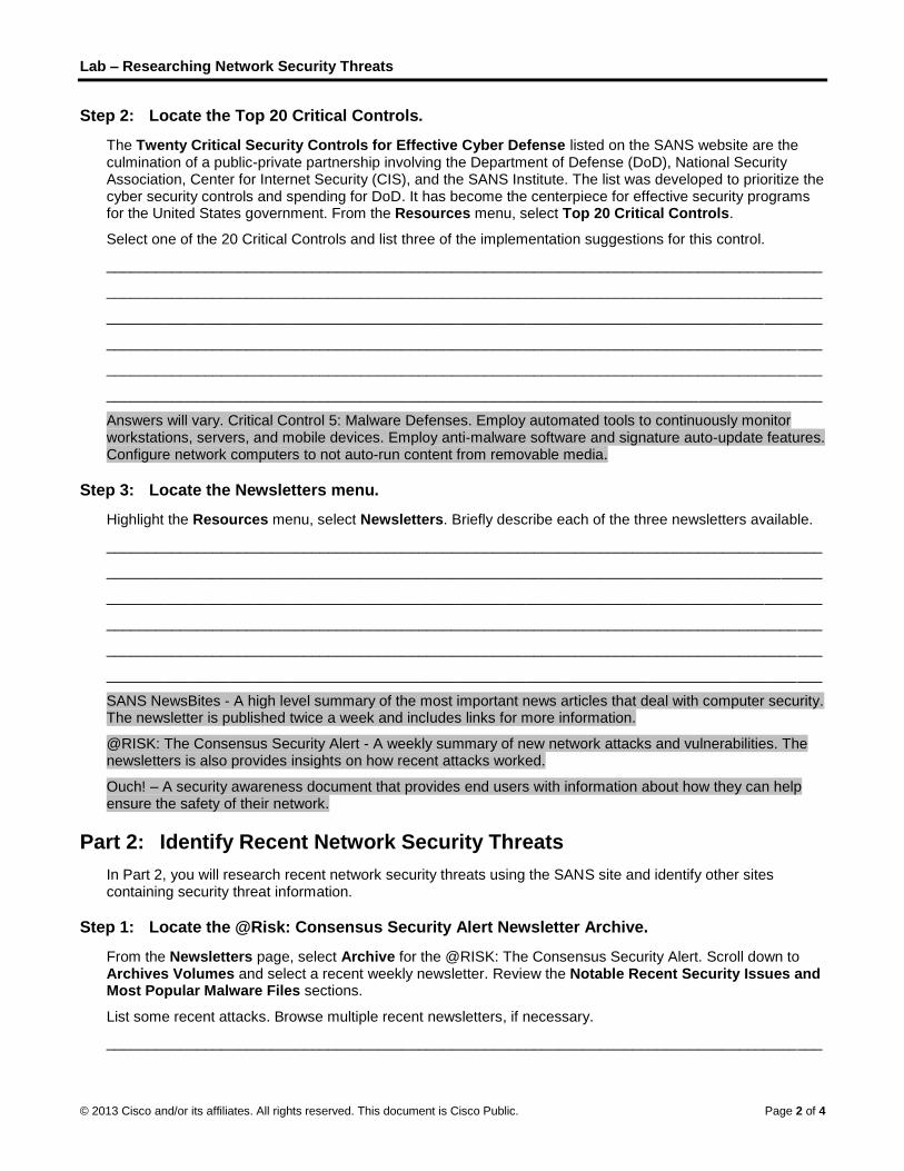
Lab – Researching Network Security Threats
© 2013 Cisco and/or its affiliates. All rights reserved. This document is Cisco Public. Page 2 of 4
Step 2: Locate the Top 20 Critical Controls.
The Twenty Critical Security Controls for Effective Cyber Defense listed on the SANS website are the culmination of a public-private partnership involving the Department of Defense (DoD), National Security Association, Center for Internet Security (CIS), and the SANS Institute. The list was developed to prioritize the cyber security controls and spending for DoD. It has become the centerpiece for effective security programs for the United States government. From the Resources menu, select Top 20 Critical Controls.
Select one of the 20 Critical Controls and list three of the implementation suggestions for this control.
_______________________________________________________________________________________
_______________________________________________________________________________________
_______________________________________________________________________________________
_______________________________________________________________________________________
_______________________________________________________________________________________
_______________________________________________________________________________________
Answers will vary. Critical Control 5: Malware Defenses. Employ automated tools to continuously monitor workstations, servers, and mobile devices. Employ anti-malware software and signature auto-update features. Configure network computers to not auto-run content from removable media.
Step 3: Locate the Newsletters menu.
Highlight the Resources menu, select Newsletters. Briefly describe each of the three newsletters available.
_______________________________________________________________________________________
_______________________________________________________________________________________
_______________________________________________________________________________________
_______________________________________________________________________________________
_______________________________________________________________________________________
_______________________________________________________________________________________
SANS NewsBites - A high level summary of the most important news articles that deal with computer security. The newsletter is published twice a week and includes links for more information.
@RISK: The Consensus Security Alert - A weekly summary of new network attacks and vulnerabilities. The newsletters is also provides insights on how recent attacks worked.
Ouch! – A security awareness document that provides end users with information about how they can help ensure the safety of their network.
Part 2: Identify Recent Network Security Threats
In Part 2, you will research recent network security threats using the SANS site and identify other sites containing security threat information.
Step 1: Locate the @Risk: Consensus Security Alert Newsletter Archive.
From the Newsletters page, select Archive for the @RISK: The Consensus Security Alert. Scroll down to Archives Volumes and select a recent weekly newsletter. Review the Notable Recent Security Issues and Most Popular Malware Files sections.
List some recent attacks. Browse multiple recent newsletters, if necessary.
_______________________________________________________________________________________

Lab – Researching Network Security Threats
© 2013 Cisco and/or its affiliates. All rights reserved. This document is Cisco Public. Page 3 of 4
_______________________________________________________________________________________
_______________________________________________________________________________________
Answers will vary. Win.Trojan.Quarian, Win.Trojan.Changeup, Andr.Trojan.SMSsend-1, Java.Exploit.Agent-14, Trojan.ADH.
Step 2: Identify sites providing recent security threat information.
Besides the SANS site, identify some other websites that provide recent security threat information.
_______________________________________________________________________________________
_______________________________________________________________________________________
_______________________________________________________________________________________
Answers will vary but could include www.mcafee.com/us/mcafee-labs.aspx, www.symantec.com, news.cnet.com/security/, www.sophos.com/en-us/threat-center/, us.norton.com/security_response/.
List some of the recent security threats detailed on these websites.
_______________________________________________________________________________________
_______________________________________________________________________________________
_______________________________________________________________________________________
Answers will vary. Trojan.Ransomlock, Inostealer.Vskim, Trojan,Fareit, Backdoor.Sorosk, Android.Boxer, W32.Changeup!gen35
Part 3: Detail a Specific Network Security Attack
In Part 3, you will research a specific network attack that has occurred and create a presentation based on your findings. Complete the form below based on your findings.
Step 1: Complete the following form for the selected network attack.
Name of attack: Code Red
Type of attack: Worm
Dates of attacks: July 2001
Computers / Organizations affected: Infected an estimated 359,000 computers in one day.
How it works and what it did:
Instructor Note: Most of the following is from Wikipedia.
Code Red exploited buffer-overflow vulnerabilities in unpatched Microsoft Internet Information Servers. It launched Trojan code in a denial-of-service attack against fixed IP addresses. The worm spread itself using a common type of vulnerability known as a buffer overflow. It used a long string repeating the character 'N' to overflow a buffer, which then allowed the worm to execute arbitrary code and infect the machine.
The payload of the worm included the following:
Defacing the affected website with the message: HELLO! Welcome to http://www.worm.com! Hacked By Chinese!

Lab – Researching Network Security Threats
© 2013 Cisco and/or its affiliates. All rights reserved. This document is Cisco Public. Page 4 of 4
It tried to spread itself by looking for more IIS servers on the Internet.
It waited 20–27 days after it was installed to launch DoS attacks on several fixed IP addresses. The IP address of the White House web server was among them.
When scanning for vulnerable machines, the worm did not check whether the server running on a remote machine was running a vulnerable version of IIS or whether it was running IIS at all.
Mitigation options:
To prevent the exploitation of the IIS vulnerability, organizations needed to apply the IIS patch from Microsoft.
References and info links:
CERT Advisory CA-2001-19
eEye Code Red advisory
Code Red II analysis
Step 2: Follow the instructor’s guidelines to complete the presentation.
Reflection
1. What steps can you take to protect your own computer?
_______________________________________________________________________________________
_______________________________________________________________________________________
_______________________________________________________________________________________
Answers will vary but could include keeping the operating system and applications up to date with patches and service packs, using a personal firewall, configuring passwords to access the system and bios, configuring screensavers to timeout and requiring a password, protecting important files by making them read-only, encrypting confidential files and backup files for safe keeping.
2. What are some important steps that organizations can take to protect their resources?
_______________________________________________________________________________________
_______________________________________________________________________________________
_______________________________________________________________________________________
Answers will vary but could include the use of firewalls, intrusion detection and prevention, hardening of network devices, endpoint protection, network vulnerability tools, user education, and security policy development.

© 2013 Cisco and/or its affiliates. All rights reserved. This document is Cisco Public. Page 1 of 16
Lab - Accessing Network Devices with SSH (Instructor Version) Instructor Note: Red font color or Gray highlights indicate text that appears in the instructor copy only.
Topology
Addressing Table
Device Interface IP Address Subnet Mask Default Gateway
R1 G0/1 192.168.1.1 255.255.255.0 N/A
S1 VLAN 1 192.168.1.11 255.255.255.0 192.168.1.1
PC-A NIC 192.168.1.3 255.255.255.0 192.168.1.1
Objectives
Part 1: Configure Basic Device Settings
Part 2: Configure the Router for SSH Access
Part 3: Examine a Telnet Session with Wireshark
Part 4: Examine a SSH Session with Wireshark
Part 5: Configure the Switch for SSH Access
Part 6: SSH from the CLI on the Switch
Background / Scenario
In the past, Telnet was the most common network protocol used to remotely configure network devices. However, protocols such as Telnet do not authenticate or encrypt the information between the client and server. This allows a network sniffer to intercept passwords and configuration information.
Secure Shell (SSH) is a network protocol that establishes a secure terminal emulation connection to a router or other networking device. SSH encrypts all information that passes over the network link and provides authentication of the remote computer. SSH is rapidly replacing Telnet as the remote login tool of choice for network professionals. SSH is most often used to log in to a remote device and execute commands; however, it can also transfer files using the associated Secure FTP (SFTP) or Secure Copy (SCP) protocols.
For SSH to function, the network devices communicating must be configured to support it. In this lab, you will enable the SSH server on a router and then connect to that router using a PC with an SSH client installed. On a local network, the connection is normally made using Ethernet and IP.
In this lab, you will configure a router to accept SSH connectivity, and use Wireshark to capture and view Telnet and SSH sessions. This will demonstrate the importance of encryption with SSH. You will also be challenged to configure a switch for SSH connectivity on your own.
Note: The routers used with CCNA hands-on labs are Cisco 1941 Integrated Services Routers (ISRs) with Cisco IOS Release 15.2(4)M3 (universalk9 image). The switches used are Cisco Catalyst 2960s with Cisco IOS Release 15.0(2) (lanbasek9 image). Other routers, switches, and Cisco IOS versions can be used.

Lab - Accessing Network Devices with SSH
© 2013 Cisco and/or its affiliates. All rights reserved. This document is Cisco Public. Page 2 of 16
Depending on the model and Cisco IOS version, the commands available and output produced might vary from what is shown in the labs. Refer to the Router Interface Summary Table at the end of this lab for the correct interface identifiers.
Note: Make sure that the routers and switches have been erased and have no startup configurations. If you are unsure, contact your instructor.
Instructor Note: Refer to the Instructor Lab Manual for the procedures to initialize and reload devices.
Required Resources
1 Router (Cisco 1941 with Cisco IOS Release 15.2(4)M3 universal image or comparable)
1 Switch (Cisco 2960 with Cisco IOS Release 15.0(2) lanbasek9 image or comparable)
1 PC (Windows 7, Vista, or XP with terminal emulation program, such as Tera Term, and Wireshark
installed)
Console cables to configure the Cisco IOS devices via the console ports
Ethernet cables as shown in the topology
Part 1: Configure Basic Device Settings
In Part 1, you will set up the network topology and configure basic settings, such as the interface IP addresses, device access, and passwords on the router.
Step 1: Cable the network as shown in the topology.
Step 2: Initialize and reload the router and switch.
Step 3: Configure the router.
a. Console into the router and enable privileged EXEC mode.
b. Enter configuration mode.
c. Disable DNS lookup to prevent the router from attempting to translate incorrectly entered commands as though they were host names.
d. Assign class as the privileged EXEC encrypted password.
e. Assign cisco as the console password and enable login.
f. Assign cisco as the vty password and enable login.
g. Encrypt the plain text passwords.
h. Create a banner that will warn anyone accessing the device that unauthorized access is prohibited.
i. Configure and activate the G0/1 interface on the router using the information contained in the Addressing Table.
j. Save the running configuration to the startup configuration file.
Step 4: Configure PC-A.
a. Configure PC-A with an IP address and subnet mask.
b. Configure a default gateway for PC-A.

Lab - Accessing Network Devices with SSH
© 2013 Cisco and/or its affiliates. All rights reserved. This document is Cisco Public. Page 3 of 16
Step 5: Verify network connectivity.
Ping R1 from PC-A. If the ping fails, troubleshoot the connection.
Part 2: Configure the Router for SSH Access
Using Telnet to connect to a network device is a security risk, because all information is transmitted in a clear text format. SSH encrypts the session data and provides device authentication, which is why SSH is recommended for remote connections. In Part 2, you will configure the router to accept SSH connections over the VTY lines.
Step 1: Configure device authentication.
The device name and domain are used as part in the crypto key when it is generated. Therefore, these names must be entered prior to issuing the crypto key command.
a. Configure device name.
Router(config)# hostname R1
b. Configure the domain for the device.
R1(config)# ip domain-name ccna-lab.com
Step 2: Configure the encryption key method.
R1(config)# crypto key generate rsa modulus 1024
The name for the keys will be: R1.ccna-lab.com
% The key modulus size is 1024 bits
% Generating 1024 bit RSA keys, keys will be non-exportable...
[OK] (elapsed time was 1 seconds)
R1(config)#
*Jan 28 21:09:29.867: %SSH-5-ENABLED: SSH 1.99 has been enabled
Step 3: Configure a local database username.
R1(config)# username admin privilege 15 secret adminpass
R1(config)#
*Feb 6 23:24:43.971: End->Password:QHjxdsVkjtoP7VxKIcPsLdTiMIvyLkyjT1HbmYxZigc
R1(config)#
Note: A privilege level of 15 gives the user administrator rights.
Step 4: Enable SSH on the VTY lines.
a. Enable Telnet and SSH on the inbound VTY lines using the transport input command.
R1(config)# line vty 0 4
R1(config-line)# transport input telnet ssh
b. Change the login method to use the local database for user verification.
R1(config-line)# login local
R1(config-line)# end
R1#
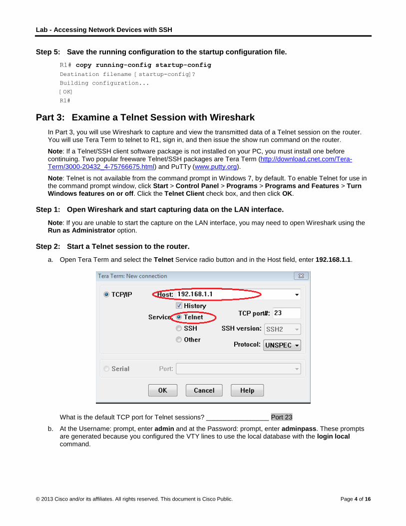
Lab - Accessing Network Devices with SSH
© 2013 Cisco and/or its affiliates. All rights reserved. This document is Cisco Public. Page 4 of 16
Step 5: Save the running configuration to the startup configuration file.
R1# copy running-config startup-config
Destination filename [startup-config]?
Building configuration...
[OK]
R1#
Part 3: Examine a Telnet Session with Wireshark
In Part 3, you will use Wireshark to capture and view the transmitted data of a Telnet session on the router. You will use Tera Term to telnet to R1, sign in, and then issue the show run command on the router.
Note: If a Telnet/SSH client software package is not installed on your PC, you must install one before continuing. Two popular freeware Telnet/SSH packages are Tera Term (http://download.cnet.com/Tera-Term/3000-20432_4-75766675.html) and PuTTy (www.putty.org).
Note: Telnet is not available from the command prompt in Windows 7, by default. To enable Telnet for use in the command prompt window, click Start > Control Panel > Programs > Programs and Features > Turn Windows features on or off. Click the Telnet Client check box, and then click OK.
Step 1: Open Wireshark and start capturing data on the LAN interface.
Note: If you are unable to start the capture on the LAN interface, you may need to open Wireshark using the Run as Administrator option.
Step 2: Start a Telnet session to the router.
a. Open Tera Term and select the Telnet Service radio button and in the Host field, enter 192.168.1.1.
What is the default TCP port for Telnet sessions? _________________ Port 23
b. At the Username: prompt, enter admin and at the Password: prompt, enter adminpass. These prompts are generated because you configured the VTY lines to use the local database with the login local command.

Lab - Accessing Network Devices with SSH
© 2013 Cisco and/or its affiliates. All rights reserved. This document is Cisco Public. Page 5 of 16
c. Issue the show run command.
R1# show run
d. Enter exit to exit the Telnet session and out of Tera Term.
R1# exit
Step 3: Stop the Wireshark capture.
Step 4: Apply a Telnet filter on the Wireshark capture data.
Step 5: Use the Follow TCP Stream feature in Wireshark to view the Telnet session.
a. Right-click one of the Telnet lines in the Packet list section of Wireshark, and in the drop-down list, select Follow TCP Stream.

Lab - Accessing Network Devices with SSH
© 2013 Cisco and/or its affiliates. All rights reserved. This document is Cisco Public. Page 6 of 16
b. The Follow TCP Stream window displays the data for your Telnet session with the router. The entire session is displayed in clear text, including your password. Notice that the username and show run command that you entered are displayed with duplicate characters. This is caused by the echo setting in Telnet to allow you to view the characters that you type on the screen.
c. After you have finished reviewing your Telnet session in the Follow TCP Stream window, click Close.
Part 4: Examine an SSH session with Wireshark
In Part 4, you will use the Tera Term software to establish an SSH session with the router. Wireshark will be used to capture and view the data of this SSH session.
Step 1: Open Wireshark and start capturing data on the LAN interface.
Step 2: Start an SSH session on the router.
a. Open Tera Term and enter the G0/1 interface IP address of R1 in the Host: field of the Tera Term: New Connection window. Ensure that the SSH radio button is selected and then click OK to connect to the router.
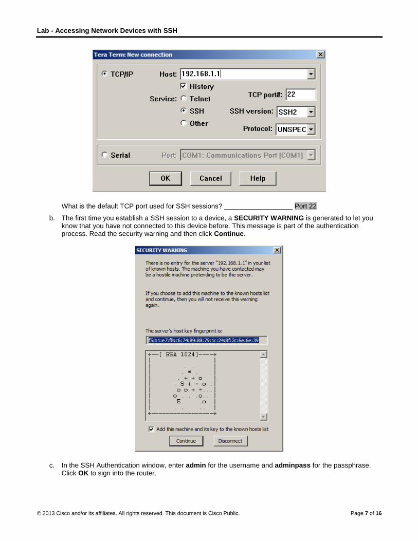
Lab - Accessing Network Devices with SSH
© 2013 Cisco and/or its affiliates. All rights reserved. This document is Cisco Public. Page 7 of 16
What is the default TCP port used for SSH sessions? __________________ Port 22
b. The first time you establish a SSH session to a device, a SECURITY WARNING is generated to let you know that you have not connected to this device before. This message is part of the authentication process. Read the security warning and then click Continue.
c. In the SSH Authentication window, enter admin for the username and adminpass for the passphrase. Click OK to sign into the router.

Lab - Accessing Network Devices with SSH
© 2013 Cisco and/or its affiliates. All rights reserved. This document is Cisco Public. Page 8 of 16
d. You have established a SSH session on the router. The Tera Term software looks very similar to a command window. At the command prompt, issue the show run command.
e. Exit the SSH session and out of Tera Term by issuing the exit command.
R1# exit
Step 3: Stop the Wireshark capture.
Step 4: Apply an SSH filter on the Wireshark Capture data.

Lab - Accessing Network Devices with SSH
© 2013 Cisco and/or its affiliates. All rights reserved. This document is Cisco Public. Page 9 of 16
Step 5: Use the Follow TCP Stream feature in Wireshark to view the Telnet session.
a. Right-click one of the SSHv2 lines in the Packet list section of Wireshark, and in the drop-down list, select the Follow TCP Stream option.
b. Examine the Follow TCP Stream window of your SSH session. The data has been encrypted and is unreadable. Compare the data in your SSH session to the data of your Telnet session.
Why is SSH preferred over Telnet for remote connections?
____________________________________________________________________________________
____________________________________________________________________________________
Answers may vary. SSH will authenticate with a device and let you know if you are connecting to this device for the first time. It will also secure the session by encrypting all the data.
c. After examining your SSH session, click Close.
d. Close Wireshark.
Part 5: Configure the Switch for SSH Access
In Part 5, you are to configure the switch in the topology to accept SSH connections. Once the switch has been configured, establish a SSH session on it using Tera Term.

Lab - Accessing Network Devices with SSH
© 2013 Cisco and/or its affiliates. All rights reserved. This document is Cisco Public. Page 10 of 16
Step 1: Configure the basic settings on the switch.
Step 2: Configure the switch for SSH connectivity.
Use the same commands that you used to configure SSH on the router in Part 2 to configure SSH for the switch.
Step 3: Establish a SSH connection to the switch.
Start Tera Term from PC-A, and then SSH to the SVI interface on the S1.
Step 4: Troubleshoot as necessary.
Are you able to establish a SSH session with the switch?
_______________________________________________________________________________________
Yes. SSH can be configured on a switch using the same commands that were used on the router.
Part 6: SSH From the CLI on the Switch
The SSH client is built into the Cisco IOS and can be run from the CLI. In Part 6, you will SSH to the router from the CLI on the switch.
Step 1: View the parameters available for the Cisco IOS SSH client.
Use the question mark (?) to display the parameter options available with the ssh command.
S1# ssh ?
-c Select encryption algorithm
-l Log in using this user name
-m Select HMAC algorithm
-o Specify options
-p Connect to this port
-v Specify SSH Protocol Version
-vrf Specify vrf name
WORD IP address or hostname of a remote system
Step 2: SSH to router R1 from S1.
a. You must use the –l admin option when you SSH to R1. This allows you to log in as user admin. When prompted, enter adminpass for the password.
S1# ssh -l admin 192.168.1.1
Password:
***********************************************
Warning: Unauthorized Access is Prohibited!
***********************************************
R1#
b. You can return to S1 without closing your SSH session to R1 by pressing Ctrl+Shift+6. Release the Ctrl+Shift+6 keys and press x. You should see the switch privilege EXEC prompt display.
R1#

Lab - Accessing Network Devices with SSH
© 2013 Cisco and/or its affiliates. All rights reserved. This document is Cisco Public. Page 11 of 16
S1#
c. To return to the SSH session on R1, press Enter on a blank CLI line. You may need to press Enter a second time to see the router CLI prompt.
S1#
[Resuming connection 1 to 192.168.1.1 ... ]
R1#
d. To end the SSH session on R1, type exit at the router prompt.
R1# exit
[Connection to 192.168.1.1 closed by foreign host]
S1#
What versions of SSH are supported from the CLI?
_______________________________________________________________________________________
_______________________________________________________________________________________
Answers may vary, but this can be determined by using the ssh –v ? on the command line. The 2960 switch running IOS version 15.0(2) supports SSH v1 and V2.
S1# ssh -v ?
1 Protocol Version 1
2 Protocol Version 2
Reflection
How would you provide multiple users, each with their own username, access to a network device?
_______________________________________________________________________________________
Answers may vary. You would add each user’s username and password to the local database using the username command. It is also possible to use a RADIUS or TACACS server, but this has not been covered yet.

Lab - Accessing Network Devices with SSH
© 2013 Cisco and/or its affiliates. All rights reserved. This document is Cisco Public. Page 12 of 16
Router Interface Summary Table
Router Interface Summary
Router Model Ethernet Interface #1 Ethernet Interface #2 Serial Interface #1 Serial Interface #2
1800 Fast Ethernet 0/0 (F0/0)
Fast Ethernet 0/1 (F0/1)
Serial 0/0/0 (S0/0/0) Serial 0/0/1 (S0/0/1)
1900 Gigabit Ethernet 0/0 (G0/0)
Gigabit Ethernet 0/1 (G0/1)
Serial 0/0/0 (S0/0/0) Serial 0/0/1 (S0/0/1)
2801 Fast Ethernet 0/0 (F0/0)
Fast Ethernet 0/1 (F0/1)
Serial 0/1/0 (S0/1/0) Serial 0/1/1 (S0/1/1)
2811 Fast Ethernet 0/0 (F0/0)
Fast Ethernet 0/1 (F0/1)
Serial 0/0/0 (S0/0/0) Serial 0/0/1 (S0/0/1)
2900 Gigabit Ethernet 0/0 (G0/0)
Gigabit Ethernet 0/1 (G0/1)
Serial 0/0/0 (S0/0/0) Serial 0/0/1 (S0/0/1)
Note: To find out how the router is configured, look at the interfaces to identify the type of router and how many interfaces the router has. There is no way to effectively list all the combinations of configurations for each router class. This table includes identifiers for the possible combinations of Ethernet and Serial interfaces in the device. The table does not include any other type of interface, even though a specific router may contain one. An example of this might be an ISDN BRI interface. The string in parenthesis is the legal abbreviation that can be used in Cisco IOS commands to represent the interface.
Device Configs - Final
Router R1
service timestamps debug datetime msec
service timestamps log datetime msec
service password-encryption
!
hostname R1
!
boot-start-marker
boot-end-marker
!
enable secret 4 06YFDUHH61wAE/kLkDq9BGho1QM5EnRtoyr8cHAUg.2
!
no aaa new-model
memory-size iomem 10
!
no ip domain lookup
ip domain name ccna-lab.com
ip cef
no ipv6 cef
multilink bundle-name authenticated
!
username admin privilege 15 secret 4 QHjxdsVkjtoP7VxKIcPsLdTiMIvyLkyjT1HbmYxZigc
!

Lab - Accessing Network Devices with SSH
© 2013 Cisco and/or its affiliates. All rights reserved. This document is Cisco Public. Page 13 of 16
interface GigabitEthernet0/0
no ip address
shutdown
duplex auto
speed auto
!
interface GigabitEthernet0/1
description Connection to S1-F0/5.
ip address 192.168.1.1 255.255.255.0
duplex auto
speed auto
!
interface Serial0/0/0
no ip address
shutdown
clock rate 2000000
!
interface Serial0/0/1
no ip address
shutdown
!
ip forward-protocol nd
!
no ip http server
no ip http secure-server
!
control-plane
!
!
banner motd ^C
****************************************
Unauthorized Access is Prohibited!
****************************************
^C
!
line con 0
password 7 00071A150754
login
line aux 0
line 2
no activation-character
no exec
transport preferred none
transport input all
transport output pad telnet rlogin lapb-ta mop udptn v120 ssh
stopbits 1
line vty 0
password 7 110A1016141D
login local

Lab - Accessing Network Devices with SSH
© 2013 Cisco and/or its affiliates. All rights reserved. This document is Cisco Public. Page 14 of 16
transport input telnet ssh
line vty 1 4
login local
transport input telnet ssh
!
scheduler allocate 20000 1000
!
end
Switch S1
service timestamps debug datetime msec
service timestamps log datetime msec
service password-encryption
!
hostname S1
!
boot-start-marker
boot-end-marker
!
enable secret 4 06YFDUHH61wAE/kLkDq9BGho1QM5EnRtoyr8cHAUg.2
!
username admin privilege 15 secret 4 QHjxdsVkjtoP7VxKIcPsLdTiMIvyLkyjT1HbmYxZigc
no aaa new-model
system mtu routing 1500
!
!
no ip domain-lookup
ip domain-name ccna-lab.com
!
spanning-tree mode pvst
spanning-tree extend system-id
!
vlan internal allocation policy ascending
!
interface FastEthernet0/1
!
interface FastEthernet0/2
!
interface FastEthernet0/3
!
interface FastEthernet0/4
!
interface FastEthernet0/5
!
interface FastEthernet0/6
!
interface FastEthernet0/7
!
interface FastEthernet0/8

Lab - Accessing Network Devices with SSH
© 2013 Cisco and/or its affiliates. All rights reserved. This document is Cisco Public. Page 15 of 16
!
interface FastEthernet0/9
!
interface FastEthernet0/10
!
interface FastEthernet0/11
!
interface FastEthernet0/12
!
interface FastEthernet0/13
!
interface FastEthernet0/14
!
interface FastEthernet0/15
!
interface FastEthernet0/16
!
interface FastEthernet0/17
!
interface FastEthernet0/18
!
interface FastEthernet0/19
!
interface FastEthernet0/20
!
interface FastEthernet0/21
!
interface FastEthernet0/22
!
interface FastEthernet0/23
!
interface FastEthernet0/24
!
interface GigabitEthernet0/1
!
interface GigabitEthernet0/2
!
interface Vlan1
ip address 192.168.1.11 255.255.255.0
!
ip http server
ip http secure-server
!
!
banner motd ^C
****************************************
Unauthorized Access is Prohibited!
****************************************
^C

Lab - Accessing Network Devices with SSH
© 2013 Cisco and/or its affiliates. All rights reserved. This document is Cisco Public. Page 16 of 16
!
line con 0
password 7 060506324F41
login
line vty 0 4
password 7 060506324F41
login local
transport input telnet ssh
line vty 5 15
password 7 00071A150754
login local
transport input telnet ssh
!
end

©
LI
T
A
O
B
R
© 2013 Cisco and
Lab – Senstructor No
Topology
Addressing
R
S
PC
ObjectivesPart 1: Co
Part 2: Co
Part 3: Co
BackgrounIt is recomsecurity cswitches.
In this labmanagemwill then te
Note: The(universalimage). Oversion, thRouter Int
Note: Maare unsur
Instructo
Required R 1 Rou
1 Swi
1 PC
Conso
d/or its affiliates.
ecuring ote: Red font
g Table
Device
1 G
1 V
C-A N
onfigure Bas
onfigure Bas
onfigure Bas
nd / Scenarmmended thatommands. Th
b, you will conment. You will est the secur
e routers usedlk9 image). T
Other routers, he commandsterface Summ
ke sure that tre contact you
or Note: Refer
Resources uter (Cisco 19
tch (Cisco 29
(Windows 7,
ole cables to
All rights reserve
Networkcolor or Gray
Interface
G0/1
VLAN 1
NIC
sic Device Se
sic Security M
sic Security M
rio t all network dhis includes e
figure the netalso use the ity measures
d with CCNA he switches uswitches ands available an
mary table at t
he routers anur instructor.
r to the Instru
941 with Cisco
960 with Cisco
Vista, or XP w
configure the
ed. This docume
k Devicey highlights ind
IP Ad
192.168
192.168
192.168
ettings
Measures on
Measures on
devices be coend user devic
twork devicesIOS CLI to coto verify that
hands-on labused are Ciscd Cisco IOS vnd output prodthe end of the
nd switches ha
ctor Lab Man
o IOS softwar
o IOS Releas
with terminal
e Cisco IOS d
ent is Cisco Publi
es (Instrudicate text tha
ddress
8.1.1 25
8.1.11 25
8.1.3 25
n the Router
n the Switch
onfigured withces, servers,
s in the topoloonfigure commthey are prop
bs are Cisco 1co Catalyst 29ersions can bduced might ve lab for the c
ave been era
nual for the pr
re, release 15
e 15.0(2) lanb
emulation pro
evices via the
ic.
uctor Veat appears in
Subnet Mas
55.255.255.0
55.255.255.0
55.255.255.0
h, at least, a mand network
ogy to accept mon, basic beperly impleme
1941 ISRs wit960s with Ciscbe used. Depevary from wha
correct interfa
ased and have
rocedures to i
5.2(4)M3 univ
basek9 image
ogram, such
e console por
ersion) the instructo
sk Defaul
0 N/A
0 192.16
0 192.16
minimum set odevices, suc
SSH sessionest practice sented and wo
th Cisco IOS co IOS Releaending on theat is shown ince identifiers
e no startup c
initialize and
versal image o
e or compara
as Tera Term
rts
P
r copy only.
t Gateway
8.1.1
8.1.1
of best practich as routers a
ns for remote security measorking correctl
Release 15.2ase 15.0(2) (lae model and Cn the labs. Re.
configurations
reload device
or comparabl
able)
m)
Page 1 of 13
ce and
ures. You ly.
2(4)M3 anbasek9 Cisco IOS efer to the
s. If you
es.
e)
Lab – Securing Network Devices
© 2013 Cisco and/or its affiliates. All rights reserved. This document is Cisco Public. Page 2 of 13
Ethernet cables as shown in the topology
Part 1: Configure Basic Device Settings In Part 1, you will set up the network topology and configure basic settings, such as the interface IP addresses, device access, and passwords on the router.
Step 1: Cable the network as shown in the topology.
Attach the devices shown in the topology and cable as necessary.
Step 2: Initialize and reload the router and switch.
Step 3: Configure the router.
Please refer to the previous lab for help with the commands needed for SSH.
a. Console into the router and enable privileged EXEC mode.
b. Enter configuration mode.
c. Assign the name of the router as R1.
d. Disable DNS lookup to prevent the router from attempting to translate incorrectly entered commands as though they were hostnames.
e. Assign class as the privileged EXEC encrypted password.
f. Assign cisco as the console password and enable login.
g. Assign cisco as the vty password and enable login.
h. Encrypt the clear text passwords.
i. Create a banner that warns anyone accessing the device that unauthorized access is prohibited.
j. Configure and activate the G0/1 interface on the router using the information contained in the Addressing Table.
k. Save the running configuration to the startup configuration file.
Step 4: Configure the switch.
a. Console into the switch and enable privileged EXEC mode.
b. Enter configuration mode.
c. Assign the name of the switch as S1.
d. Disable DNS lookup to prevent the router from attempting to translate incorrectly entered commands as though they were hostnames.
e. Assign class as the privileged EXEC encrypted password.
f. Assign cisco as the console password and enable login.
g. Assign cisco as the vty password and enable login.
h. Encrypt the clear text passwords.
i. Create a banner that warns anyone accessing the device that unauthorized access is prohibited.
j. Configure the default SVI with the IP address information contained in the Addressing Table.
k. Save the running configuration to the startup configuration file.

Lab – Securing Network Devices
© 2013 Cisco and/or its affiliates. All rights reserved. This document is Cisco Public. Page 3 of 13
Part 2: Configure Basic Security Measures on the Router
Step 1: Strengthen passwords.
An administrator should ensure that passwords meet the standard guidelines for strong passwords. These guidelines could include mixing letters, numbers and special characters in the password and setting a minimum length.
Note: Best practice guidelines require the use of strong passwords, such as those shown here, in a production environment. However, the other labs in this course use the cisco and class passwords for ease in performing the labs.
a. Change the privilege EXEC encrypted password to meet guidelines.
R1(config)# enable secret Enablep@55
b. Require that a minimum of 10 characters be used for all passwords.
R1(config)# security passwords min-length 10
Step 2: Enable SSH connections.
a. Assign the domain name as CCNA-lab.com.
R1(config)# ip domain-name CCNA-lab.com
b. Create a local user database entry to use when connecting to the router via SSH. The password should meet strong password standards, and the user should have administrator-level access.
R1(config)# username admin privilege 15 secret Admin15p@55
c. Configure the transport input for the vty lines so that they accept SSH connections, but do not allow Telnet connections.
R1(config)# line vty 0 4 R1(config-line)# transport input ssh
d. The vty lines should use the local user database for authentication.
R1(config-line)# login local R1(config-line)# exit
e. Generate a RSA crypto key using a modulus of 1024 bits.
R1(config)# crypto key generate rsa modulus 1024 The name for the keys will be: R1.CCNA-lab.com
% The key modulus size is 1024 bits
% Generating 1024 bit RSA keys, keys will be non-exportable...
[OK] (elapsed time was 2 seconds)
R1(config)#
*Jan 31 17:54:16.127: %SSH-5-ENABLED: SSH 1.99 has been enabled
Step 3: Secure the console and VTY lines.
a. You can set the router to log out of a connection that has been idle for a specified time. If a network administrator was logged into a networking device and was suddenly called away, this command automatically logs the user out after the specified time. The following commands cause the line to log out after five minutes of inactivity.

Lab – Securing Network Devices
© 2013 Cisco and/or its affiliates. All rights reserved. This document is Cisco Public. Page 4 of 13
R1(config)# line console 0 R1(config-line)# exec-timeout 5 0 R1(config-line)# line vty 0 4 R1(config-line)# exec-timeout 5 0 R1(config-line)# exit R1(config)#
b. The following command impedes brute force login attempts. The router blocks login attempts for 30 seconds if someone fails two attempts within 120 seconds. This timer is set especially low for the purpose of this lab.
R1(config)# login block-for 30 attempts 2 within 120
What does the 2 within 120 mean in the above command?
____________________________________________________________________________________
If two failed attempts are made within a 2 minute (120 seconds) time span, login access will be blocked.
What does the block-for 30 mean in the above command?
____________________________________________________________________________________
If login access is blocked, the device will wait 30 seconds before allowing login access again.
Step 4: Verify that all unused ports are disabled.
Router ports are disabled, by default, but it is always prudent to verify that all unused ports are in an administratively down state. This can be quickly checked by issuing the show ip interface brief command. Any unused ports that are not in an administratively down state should be disabled using the shutdown command in interface configuration mode.
R1# show ip interface brief Interface IP-Address OK? Method Status Protocol
Embedded-Service-Engine0/0 unassigned YES NVRAM administratively down down
GigabitEthernet0/0 unassigned YES NVRAM administratively down down
GigabitEthernet0/1 192.168.1.1 YES manual up up
Serial0/0/0 unassigned YES NVRAM administratively down down
Serial0/0/1 unassigned YES NVRAM administratively down down
R1#
Step 5: Verify that your security measures have been implemented correctly.
a. Use Tera Term to telnet to R1.
Does R1 accept the Telnet connection? ___________________________ No, the connection is refused.
Why or why not?
____________________________________________________________________________________
Telnet was disabled with the transport input ssh command.
b. Use Tera Term to SSH to R1.
Does R1 accept the SSH connection? __________ Yes
c. Intentionally mistype the user and password information to see if login access is blocked after two attempts.
What happened after you failed to login the second time?
____________________________________________________________________________________

Lab – Securing Network Devices
© 2013 Cisco and/or its affiliates. All rights reserved. This document is Cisco Public. Page 5 of 13
____________________________________________________________________________________
The connection to R1 was disconnected. If you attempt to reconnect within 30 seconds, the connection will be refused.
d. From your console session on the router, issue the show login command to view the login status. In the example below, the show login command was issued within the 30 second login blocking period and shows that the router is in Quiet-Mode. The router will not accept any login attempts for 14 more seconds.
R1# show login A default login delay of 1 second is applied.
No Quiet-Mode access list has been configured.
Router enabled to watch for login Attacks.
If more than 2 login failures occur in 120 seconds or less,
logins will be disabled for 30 seconds.
Router presently in Quiet-Mode.
Will remain in Quiet-Mode for 14 seconds.
Denying logins from all sources.
R1#
e. After the 30 seconds has expired, SSH to R1 again and login using the admin username and Admin15p@55 for the password.
After you successfully logged in, what was displayed? ________________________ The R1 login banner
f. Enter privilege Exec mode and use Enablep@55 for the password.
If you mistype this password, are you disconnected from your SSH session after two failed attempts within 120 seconds? ______________ No
Why or why not?
____________________________________________________________________________________
The login block-for 30 attempts 2 within 120 command only monitors session login attempts.
g. Issue the show running-config command at the privileged EXEC prompt to view the security settings you have applied.
Part 3: Configure Basic Security Measures on the Switch
Step 1: Strengthen Passwords on the switch.
Change the privilege EXEC encrypted password to meet strong password guidelines.
S1(config)# enable secret Enablep@55
Note: The security password min-length command is not available on the 2960 switch.
Step 2: Enable SSH Connections.
a. Assign the domain-name as CCNA-lab.com
S1(config)# ip domain-name CCNA-lab.com
b. Create a local user database entry for use when connecting to the router via SSH. The password should meet strong password standards, and the user should have administrative level access.
S1(config)# username admin privilege 15 secret Admin15p@55
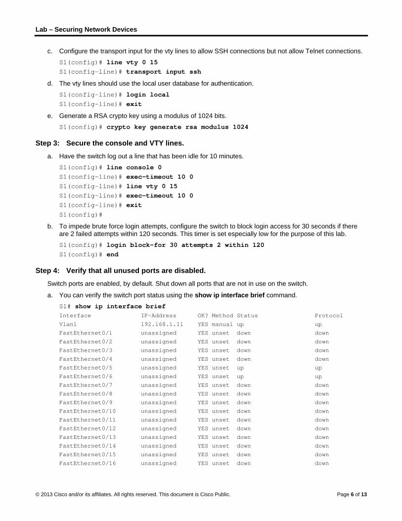
Lab – Securing Network Devices
© 2013 Cisco and/or its affiliates. All rights reserved. This document is Cisco Public. Page 6 of 13
c. Configure the transport input for the vty lines to allow SSH connections but not allow Telnet connections.
S1(config)# line vty 0 15 S1(config-line)# transport input ssh
d. The vty lines should use the local user database for authentication.
S1(config-line)# login local S1(config-line)# exit
e. Generate a RSA crypto key using a modulus of 1024 bits.
S1(config)# crypto key generate rsa modulus 1024
Step 3: Secure the console and VTY lines.
a. Have the switch log out a line that has been idle for 10 minutes.
S1(config)# line console 0 S1(config-line)# exec-timeout 10 0 S1(config-line)# line vty 0 15 S1(config-line)# exec-timeout 10 0 S1(config-line)# exit S1(config)#
b. To impede brute force login attempts, configure the switch to block login access for 30 seconds if there are 2 failed attempts within 120 seconds. This timer is set especially low for the purpose of this lab. S1(config)# login block-for 30 attempts 2 within 120 S1(config)# end
Step 4: Verify that all unused ports are disabled.
Switch ports are enabled, by default. Shut down all ports that are not in use on the switch.
a. You can verify the switch port status using the show ip interface brief command.
S1# show ip interface brief Interface IP-Address OK? Method Status Protocol
Vlan1 192.168.1.11 YES manual up up
FastEthernet0/1 unassigned YES unset down down
FastEthernet0/2 unassigned YES unset down down
FastEthernet0/3 unassigned YES unset down down
FastEthernet0/4 unassigned YES unset down down
FastEthernet0/5 unassigned YES unset up up
FastEthernet0/6 unassigned YES unset up up
FastEthernet0/7 unassigned YES unset down down
FastEthernet0/8 unassigned YES unset down down
FastEthernet0/9 unassigned YES unset down down
FastEthernet0/10 unassigned YES unset down down
FastEthernet0/11 unassigned YES unset down down
FastEthernet0/12 unassigned YES unset down down
FastEthernet0/13 unassigned YES unset down down
FastEthernet0/14 unassigned YES unset down down
FastEthernet0/15 unassigned YES unset down down
FastEthernet0/16 unassigned YES unset down down

Lab – Securing Network Devices
© 2013 Cisco and/or its affiliates. All rights reserved. This document is Cisco Public. Page 7 of 13
FastEthernet0/17 unassigned YES unset down down
FastEthernet0/18 unassigned YES unset down down
FastEthernet0/19 unassigned YES unset down down
FastEthernet0/20 unassigned YES unset down down
FastEthernet0/21 unassigned YES unset down down
FastEthernet0/22 unassigned YES unset down down
FastEthernet0/23 unassigned YES unset down down
FastEthernet0/24 unassigned YES unset down down
GigabitEthernet0/1 unassigned YES unset down down
GigabitEthernet0/2 unassigned YES unset down down
S1#
b. Use the interface range command to shut down multiple interfaces at a time.
S1(config)# interface range f0/1–4 , f0/7-24 , g0/1-2 S1(config-if-range)# shutdown S1(config-if-range)# end S1#
c. Verify that all inactive interfaces have been administratively shut down.
S1# show ip interface brief Interface IP-Address OK? Method Status Protocol
Vlan1 192.168.1.11 YES manual up up
FastEthernet0/1 unassigned YES unset administratively down down
FastEthernet0/2 unassigned YES unset administratively down down
FastEthernet0/3 unassigned YES unset administratively down down
FastEthernet0/4 unassigned YES unset administratively down down
FastEthernet0/5 unassigned YES unset up up
FastEthernet0/6 unassigned YES unset up up
FastEthernet0/7 unassigned YES unset administratively down down
FastEthernet0/8 unassigned YES unset administratively down down
FastEthernet0/9 unassigned YES unset administratively down down
FastEthernet0/10 unassigned YES unset administratively down down
FastEthernet0/11 unassigned YES unset administratively down down
FastEthernet0/12 unassigned YES unset administratively down down
FastEthernet0/13 unassigned YES unset administratively down down
FastEthernet0/14 unassigned YES unset administratively down down
FastEthernet0/15 unassigned YES unset administratively down down
FastEthernet0/16 unassigned YES unset administratively down down
FastEthernet0/17 unassigned YES unset administratively down down
FastEthernet0/18 unassigned YES unset administratively down down
FastEthernet0/19 unassigned YES unset administratively down down
FastEthernet0/20 unassigned YES unset administratively down down
FastEthernet0/21 unassigned YES unset administratively down down
FastEthernet0/22 unassigned YES unset administratively down down
FastEthernet0/23 unassigned YES unset administratively down down
FastEthernet0/24 unassigned YES unset administratively down down
GigabitEthernet0/1 unassigned YES unset administratively down down
GigabitEthernet0/2 unassigned YES unset administratively down down
S1#
Lab – Securing Network Devices
© 2013 Cisco and/or its affiliates. All rights reserved. This document is Cisco Public. Page 8 of 13
Step 5: Verify that your security measures have been implemented correctly.
a. Verify that Telnet has been disabled on the switch.
b. SSH to the switch and intentionally mistype the user and password information to see if login access is blocked.
c. After the 30 seconds has expired, SSH to S1 again and log in using the admin username and Admin15p@55 for the password.
Did the banner appear after you successfully logged in? __________ Yes
d. Enter privilege Exec mode using Enablep@55 as the password.
e. Issue the show running-config command at the privileged EXEC prompt to view the security settings you have applied.
Reflection 1. The password cisco command was entered for the console and vty lines in your basic configuration in Part
1. When is this password used after the best practice security measures have been applied?
_______________________________________________________________________________________
_______________________________________________________________________________________
_______________________________________________________________________________________
This password will not be used any longer. Even though the password command still appears in the line sections of the running-config, this command was disabled as soon as the login local command was entered for those lines.
2. Are preconfigured passwords, shorter than 10 characters, affected by the security passwords min-length 10 command?
_______________________________________________________________________________________
_______________________________________________________________________________________
_______________________________________________________________________________________
No. The security passwords min-length command only affects passwords that are entered after this command is issued. Any pre-existing passwords remain in effect. If they are changed, they will need to be at least 10 characters long.

Lab – Securing Network Devices
© 2013 Cisco and/or its affiliates. All rights reserved. This document is Cisco Public. Page 9 of 13
Router Interface Summary Table
Router Interface Summary
Router Model Ethernet Interface #1 Ethernet Interface #2 Serial Interface #1 Serial Interface #2
1800 Fast Ethernet 0/0 (F0/0)
Fast Ethernet 0/1 (F0/1)
Serial 0/0/0 (S0/0/0) Serial 0/0/1 (S0/0/1)
1900 Gigabit Ethernet 0/0 (G0/0)
Gigabit Ethernet 0/1 (G0/1)
Serial 0/0/0 (S0/0/0) Serial 0/0/1 (S0/0/1)
2801 Fast Ethernet 0/0 (F0/0)
Fast Ethernet 0/1 (F0/1)
Serial 0/1/0 (S0/0/0) Serial 0/1/1 (S0/0/1)
2811 Fast Ethernet 0/0 (F0/0)
Fast Ethernet 0/1 (F0/1)
Serial 0/0/0 (S0/0/0) Serial 0/0/1 (S0/0/1)
2900 Gigabit Ethernet 0/0 (G0/0)
Gigabit Ethernet 0/1 (G0/1)
Serial 0/0/0 (S0/0/0) Serial 0/0/1 (S0/0/1)
Note: To find out how the router is configured, look at the interfaces to identify the type of router and how many interfaces the router has. There is no way to effectively list all the combinations of configurations for each router class. This table includes identifiers for the possible combinations of Ethernet and Serial interfaces in the device. The table does not include any other type of interface, even though a specific router may contain one. An example of this might be an ISDN BRI interface. The string in parenthesis is the legal abbreviation that can be used in Cisco IOS commands to represent the interface.
Device Configs - Final
Router R1 service timestamps debug datetime msec service timestamps log datetime msec service password-encryption ! hostname R1 ! boot-start-marker boot-end-marker ! security passwords min-length 10 enable secret 4 jowh6xYPeJucL2dB/ulkSjK2YGee/Usr./fiqFhbxTQ no aaa new-model ! no ip domain lookup ip domain name CCNA-lab.com ip cef login block-for 30 attempts 2 within 120 no ipv6 cef ! username admin privilege 15 secret 4 iAAxTYNDMJO3iHURmpY85S.NR4m72e1HMyRxq9kPN0g ! interface GigabitEthernet0/0

Lab – Securing Network Devices
© 2013 Cisco and/or its affiliates. All rights reserved. This document is Cisco Public. Page 10 of 13
no ip address shutdown duplex auto speed auto ! interface GigabitEthernet0/1 ip address 192.168.1.1 255.255.255.0 duplex auto speed auto ! interface Serial0/0/0 no ip address shutdown clock rate 2000000 ! interface Serial0/0/1 no ip address shutdown ! ip forward-protocol nd ! no ip http server no ip http secure-server ! banner motd ^C Unauthorized Access is Prohibited! ^C ! line con 0 exec-timeout 5 0 password 7 094F471A1A0A57 login line aux 0 line 2 no activation-character no exec transport preferred none transport input all transport output pad telnet rlogin lapb-ta mop udptn v120 ssh stopbits 1 line vty 0 4 exec-timeout 5 0 password 7 104D000A0618 login local transport input ssh ! scheduler allocate 20000 1000

Lab – Securing Network Devices
© 2013 Cisco and/or its affiliates. All rights reserved. This document is Cisco Public. Page 11 of 13
! end
Switch S1 service timestamps debug datetime msec service timestamps log datetime msec service password-encryption ! hostname S1 ! boot-start-marker boot-end-marker ! enable secret 4 jowh6xYPeJucL2dB/ulkSjK2YGee/Usr./fiqFhbxTQ ! username admin privilege 15 secret 4 iAAxTYNDMJO3iHURmpY85S.NR4m72e1HMyRxq9kPN0g ! system mtu routing 1500 ! no ip domain-lookup ip domain-name CCNA-lab.com login block-for 30 attempts 2 within 120 ! spanning-tree mode pvst spanning-tree extend system-id ! vlan internal allocation policy ascending ! interface FastEthernet0/1 shutdown ! interface FastEthernet0/2 shutdown ! interface FastEthernet0/3 shutdown ! interface FastEthernet0/4 shutdown ! interface FastEthernet0/5 ! interface FastEthernet0/6 ! interface FastEthernet0/7 shutdown ! interface FastEthernet0/8 shutdown

Lab – Securing Network Devices
© 2013 Cisco and/or its affiliates. All rights reserved. This document is Cisco Public. Page 12 of 13
! interface FastEthernet0/9 shutdown ! interface FastEthernet0/10 shutdown ! interface FastEthernet0/11 shutdown ! interface FastEthernet0/12 shutdown ! interface FastEthernet0/13 shutdown ! interface FastEthernet0/14 shutdown ! interface FastEthernet0/15 shutdown ! interface FastEthernet0/16 shutdown ! interface FastEthernet0/17 shutdown ! interface FastEthernet0/18 shutdown ! interface FastEthernet0/19 shutdown ! interface FastEthernet0/20 shutdown ! interface FastEthernet0/21 shutdown ! interface FastEthernet0/22 shutdown ! interface FastEthernet0/23 shutdown ! interface FastEthernet0/24 shutdown !
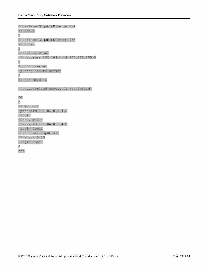
Lab – Securing Network Devices
© 2013 Cisco and/or its affiliates. All rights reserved. This document is Cisco Public. Page 13 of 13
interface GigabitEthernet0/1 shutdown ! interface GigabitEthernet0/2 shutdown ! interface Vlan1 ip address 192.168.1.11 255.255.255.0 ! ip http server ip http secure-server ! banner motd ^C Unauthorized Access is Prohibited! ^C ! line con 0 password 7 110A1016141D login line vty 0 4 password 7 110A1016141D login local transport input ssh line vty 5 15 login local ! end

© 2013 Cisco and/or its affiliates. All rights reserved. This document is Cisco Public. Page 1 of 5
Lab - Testing Network Latency with Ping and Traceroute
(Instructor Version) Instructor Note: Red font color or Gray highlights indicate text that appears in the instructor copy only.
Topology
Objectives
Part 1: Use Ping to Document Network Latency
Part 2: Use Traceroute to Document Network Latency
Background / Scenario
To obtain realistic network latency statistics, this activity must be performed on a live network. Be sure to check with your instructor for any local security restrictions against using the ping command on the network.
Instructor Note: Some institutions disable ICMP echo replies throughout the network. Before students begin this activity, make sure there are no local restrictions related to ICMP datagrams. This activity assumes that ICMP datagrams are not restricted by any local security policy.
The purpose of this lab is to measure and evaluate network latency over time, and during different periods of the day to capture a representative sample of typical network activity. This will be accomplished by analyzing the return delay from a distant computer with the ping command. Return delay times, measured in milliseconds, will be summarized by computing the average latency (mean) and the range (maximum and minimum) of the delay times.
Required Resources
1 PC (Windows 7, Vista, or XP with Internet access)
Part 1: Use Ping to Document Network Latency
In Part 1, you will examine network latency to several websites in different parts of the globe. This process can be used in an enterprise production network to create a performance baseline.
Step 1: Verify connectivity.
Ping the following Regional Internet Registry (RIR) websites to verify connectivity:
C:\Users\User1> ping www.arin.net
C:\Users\User1> ping www.lacnic.net
C:\Users\User1> ping www.afrinic.net
C:\Users\User1> ping www.apnic.net
Note: Because www.ripe.net does not reply to ICMP requests, it cannot be used for this lab.

Lab - Testing Network Latency with Ping and Traceroute
© 2013 Cisco and/or its affiliates. All rights reserved. This document is Cisco Public. Page 2 of 5
Step 2: Collect network data.
You will collect a sufficient amount of data to compute statistics on the ping output by sending out 25 echo requests to each address listed in Step 1. Record the results for each website to text files.
a. At the command prompt, type ping to list the available options.
C:\Users\User1> ping
Usage: ping [-t] [-a] [-n count] [-l size] [-f] [-i TTL] [-v TOS]
[-r count] [-s count] [[-j host-list] | [-k host-list]]
[-w timeout] [-R] [-S srcaddr] [-4] [-6] target_name
Options:
-t Ping the specified host until stopped.
To see statistics and continue - type Control-Break;
To stop - type Control-C.
-a Resolve addresses to hostnames.
-n count Number of echo requests to send.
-l size Send buffer size.
-f Set Don't Fragment flag in packet (IPv4-only).
-i TTL Time To Live.
-v TOS Type Of Service (IPv4-only. This setting has been deprecated
<output omitted>
b. Using the ping command with the count option, you can send 25 echo requests to the destination as illustrated below. Furthermore, it will create a text file with filename of arin.txt in the current directory. This text file will contain the results of the echo requests.
C:\Users\User1> ping –n 25 www.arin.net > arin.txt
Note: The terminal remains blank until the command has finished, because the output has been redirected to a text file, arin.txt, in this example. The > symbol is used to redirect the screen output to the file and overwrite the file if it already exists. If appending more results to the file is desired, replace > with >> in the command.
c. Repeat the ping command for the other websites.
C:\Users\User1> ping –n 25 www.afrinic.net > afrinic.txt
C:\Users\User1> ping –n 25 www.apnic.net > apnic.txt
C:\Users\User1> ping –n 25 www.lacnic.net > lacnic.txt

Lab - Testing Network Latency with Ping and Traceroute
© 2013 Cisco and/or its affiliates. All rights reserved. This document is Cisco Public. Page 3 of 5
Step 3: Verify data collection.
To see the results in the file created, use the more command at the command prompt.
C:\Users\User1> more arin.txt
Pinging www.arin.net [192.149.252.76] with 32 bytes of data:
Reply from 192.149.252.76: bytes=32 time=108ms TTL=45
Reply from 192.149.252.76: bytes=32 time=114ms TTL=45
Reply from 192.149.252.76: bytes=32 time=112ms TTL=45
<output omitted>
Reply from 192.149.252.75: bytes=32 time=111ms TTL=45
Reply from 192.149.252.75: bytes=32 time=112ms TTL=45
Reply from 192.149.252.75: bytes=32 time=112ms TTL=45
Ping statistics for 192.149.252.75:
Packets: Sent = 25, Received = 25, Lost = 0 (0% loss),
Approximate round trip times in milli-seconds:
Minimum = 107ms, Maximum = 121ms, Average = 111ms
Note: Press the Spacebar to display the rest of the file or press q to exit.
To verify that the files have been created, use the dir command to list the files in the directory. Also the wildcard * can be used to filter only the text files.
C:\Users\User1> dir *.txt
Volume in drive C is OS
Volume Serial Number is 0A97-D265
Directory of C:\Users\User1
02/07/2013 12:59 PM 1,642 afrinic.txt
02/07/2013 01:00 PM 1,615 apnic.txt
02/07/2013 12:40 PM 1,641 arin.txt
02/07/2013 12:58 PM 1,589 lacnic.txt
4 File(s) 6,487 bytes
0 Dir(s) 34,391,453,696 bytes free
Record your results in the following table.
Minimum Maximum Average
www.afrinic.net 359 ms 389 ms 369 ms
www.apnic.net 201 210 204
www.arin.net 107 121 112
www.lacnic.net 216 226 218
Compare the delay results. How is delay affected by geographical location?
____________________________________________________________________________________
____________________________________________________________________________________
In most instances, the response time is longer when compared to the physical distance to the destination.

Lab - Testing Network Latency with Ping and Traceroute
© 2013 Cisco and/or its affiliates. All rights reserved. This document is Cisco Public. Page 4 of 5
Part 2: Use Traceroute to Document Network Latency
The routes traced may go through many hops and a number of different ISPs depending on the size of the ISPs and the location of the source and destination hosts. The traceroute commands can also be used to observe network latency. In Part 2, the tracert command is used to trace the path to the same destinations in Part 1.
The tracert command uses ICMP TTL Exceed packets and ICMP echo replies to trace the path.
Step 1: Use the tracert command and record the output to text files.
Copy the following commands to create the traceroute files:
C:\Users\User1> tracert www.arin.net > traceroute_arin.txt
C:\Users\User1> tracert www.lacnic.net > traceroute_lacnic.txt
C:\Users\User1> tracert www.afrinic.net > traceroute_afrinic.txt
C:\Users\User1> tracert www.apnic.net > traceroute_apnic.txt
Step 2: Use the more command to examine the traced path.
a. Use the more command to access the content of these files:
C:\Users\User1> more traceroute_arin.txt
Tracing route to www.arin.net [192.149.252.75]
over a maximum of 30 hops:
1 <1 ms <1 ms <1 ms 192.168.1.1
2 11 ms 12 ms 11 ms 10.39.0.1
3 10 ms 15 ms 11 ms 172.21.0.116
4 19 ms 10 ms 11 ms 70.169.73.90
5 13 ms 10 ms 11 ms chnddsrj01-ae2.0.rd.ph.cox.net [70.169.76.229]
6 72 ms 71 ms 70 ms mrfddsrj02-ae0.0.rd.dc.cox.net [68.1.1.7]
7 72 ms 71 ms 72 ms 68.100.0.146
8 74 ms 83 ms 73 ms 172.22.66.29
9 75 ms 71 ms 73 ms 172.22.66.29
10 74 ms 75 ms 73 ms wsip-98-172-152-14.dc.dc.cox.net [98.172.152.14]
11 71 ms 71 ms 71 ms host-252-131.arin.net [192.149.252.131]
12 73 ms 71 ms 71 ms www.arin.net [192.149.252.75]
Trace complete.
In this example, it took less than 1 ms to receive a reply from the default gateway (192.168.1.1). In hop count 6, the round trip to 68.1.1.7 took an average of 71 ms. For the round trip to the final destination at www.arin.net took an average of 72 ms.
Between lines 5 and 6, there is more network delay as indicated by the round trip time increase from an average of 11 ms to 71 ms
b. Perform the same analysis with the rest of the tracert results.
What can you conclude regarding the relationship between the roundtrip time and geographical location?
____________________________________________________________________________________
____________________________________________________________________________________

Lab - Testing Network Latency with Ping and Traceroute
© 2013 Cisco and/or its affiliates. All rights reserved. This document is Cisco Public. Page 5 of 5
In most instances, the response time is longer when compared to the physical distance to the destination.
Reflection
1. The tracert and ping results can provide important network latency information. What do you need to do if you want an accurate baseline picture regarding network latency for your network?
_______________________________________________________________________________________
Answers will vary. You will need to perform careful delay analysis over successive days and during different periods of the day.
2. How can you use the baseline information?
_______________________________________________________________________________________
You can compare baseline data against current data to determine if there has been a change in network response times. This analysis may assist with troubleshooting network issues and scheduling of routine data transfer during off-peak hours.

© 2013 Cisco and/or its affiliates. All rights reserved. This document is Cisco Public. Page 1 of 18
Lab – Using the CLI to Gather Network Device Information
(Instructor Version) Instructor Note: Red font color or Gray highlights indicate text that appears in the instructor copy only.
Topology
Addressing Table
Device Interface IP Address Subnet Mask Default Gateway
R1 G0/1 192.168.1.1 255.255.255.0 N/A
Lo0 209.165.200.225 255.255.255.224 N/A
S1 VLAN 1 192.168.1.11 255.255.255.0 192.168.1.1
PC-A NIC 192.168.1.3 255.255.255.0 192.168.1.1
Objectives
Part 1: Set Up Topology and Initialize Devices
Set up equipment to match the network topology.
Initialize and reload the router and switch.
Part 2: Configure Devices and Verify Connectivity
Assign a static IP address to PC-A NIC.
Configure basic settings on R1.
Configure basic settings on S1.
Verify network connectivity.
Part 3: Gather Network Device Information
Gather information on R1 using IOS CLI commands.
Gather information on S1 using IOS CLI commands.
Gather information on PC-A using the command prompt CLI.
Background / Scenario
Documenting a working network is one of the most important tasks a network professional can perform. Having proper documentation of IP addresses, model numbers, IOS versions, ports used, and testing security, can go a long way in helping to troubleshoot a network.

Lab – Using the CLI to Gather Network Device Information
© 2013 Cisco and/or its affiliates. All rights reserved. This document is Cisco Public. Page 2 of 18
In this lab, you will build a small network, configure the devices, add some basic security, and then document the configurations by issuing various commands on the router, switch and PC to gather your information.
Note: The routers used with CCNA hands-on labs are Cisco 1941 Integrated Services Routers (ISRs) with Cisco IOS Release 15.2(4)M3 (universalk9 image). The switches used are Cisco Catalyst 2960s with Cisco IOS Release 15.0(2) (lanbasek9 image). Other routers, switches, and Cisco IOS versions can be used. Depending on the model and Cisco IOS version, the commands available and output produced might vary from what is shown in the labs. Refer to the Router Interface Summary Table at the end of this lab for the correct interface identifiers.
Note: Make sure that the routers and switches have been erased and have no startup configurations. If you are unsure, contact your instructor.
Instructor Note: Refer to the Instructor Lab Manual for the procedures to initialize and reload devices.
Required Resources
1 Router (Cisco 1941 with Cisco IOS Release 15.2(4)M3 universal image or comparable)
1 Switch (Cisco 2960 with Cisco IOS Release 15.0(2) lanbasek9 image or comparable)
1 PC (Windows 7, Vista, or XP with terminal emulation program, such as Tera Term)
Console cables to configure the Cisco IOS devices via the console ports
Ethernet cables as shown in the topology
Part 1: Set Up the Topology and Initialize Devices
In Part 1, you will set up the network topology, clear any configurations if necessary, and configure basic settings on the router and switch.
Step 1: Cable the network as shown in the topology.
a. Attach the devices as shown in the topology and cable as necessary.
b. Power on all devices in the topology.
Step 2: Initialize and reload the router and the switch.
Part 2: Configure Devices and Verify Connectivity
In Part 2, you will set up the network topology and configure basic settings on the router and switch. Refer to the topology and Addressing Table at the beginning of this lab for device names and address information.
Note: Appendix A provides configuration details for the steps in Part 2. You should attempt to complete Part 2 prior to referencing this appendix.
Step 1: Configure the IPv4 address for the PC.
Configure the IPv4 address, subnet mask, and default gateway address for PC-A based on the Addressing Table.
Step 2: Configure the router.
If you need assistance for Step 2, refer to Appendix A for help.
a. Console into the router and enter privileged EXEC mode.
b. Set the correct time on the router.
c. Enter global configuration mode.
Lab – Using the CLI to Gather Network Device Information
© 2013 Cisco and/or its affiliates. All rights reserved. This document is Cisco Public. Page 3 of 18
1) Assign a device name to the router based on the topology and Addressing Table.
2) Disable DNS lookup.
3) Create a MOTD banner that warns anyone accessing the device that unauthorized access is prohibited.
4) Assign class as the privileged EXEC encrypted password.
5) Assign cisco as the console password and enable console login access.
6) Encrypt clear text passwords.
7) Create a domain name of cisco.com for SSH access.
8) Create a user named admin with a secret password of cisco for SSH access.
9) Generate a RSA modulus key. Use 1024 for the number of bits.
d. Configure vty line access.
1) Use the local database for authentication for SSH.
2) Enable SSH only for login access.
e. Return to global configuration mode.
1) Create the Loopback 0 interface and assign the IP address based on the Addressing Table.
2) Configure and activate interface G0/1 on the router.
3) Configure interface descriptions for G0/1 and L0.
4) Save the running configuration file to the startup configuration file.
Step 3: Configure the switch.
If you need assistance for Step 3, refer to Appendix A for help.
a. Console into the switch and enter privileged EXEC mode.
b. Set the correct time on the switch.
c. Enter global configuration mode.
1) Assign a device name on the switch based on the topology and Addressing Table.
2) Disable DNS lookup.
3) Create a MOTD banner that warns anyone accessing the device that unauthorized access is prohibited.
4) Assign class as the privileged EXEC encrypted password.
5) Encrypt the clear text passwords.
6) Create a domain name of cisco.com for SSH access.
7) Create a user named admin with a secret password of cisco for SSH access.
8) Generate an RSA modulus key. Use 1024 for the number of bits.
9) Create and activate an IP address on the switch based on the topology and Addressing Table.
10) Set the default gateway on the switch.
11) Assign cisco as the console password and enable console login access.
d. Configure vty line access.
1) Use local database for authentication for SSH.
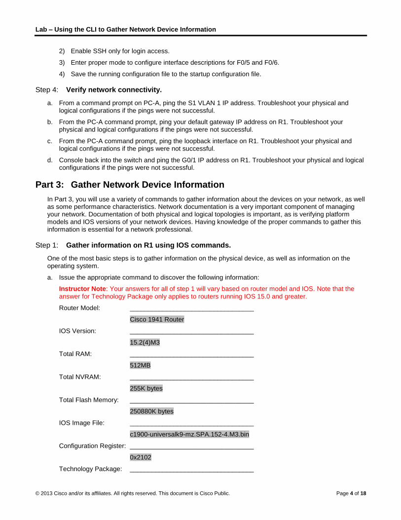
Lab – Using the CLI to Gather Network Device Information
© 2013 Cisco and/or its affiliates. All rights reserved. This document is Cisco Public. Page 4 of 18
2) Enable SSH only for login access.
3) Enter proper mode to configure interface descriptions for F0/5 and F0/6.
4) Save the running configuration file to the startup configuration file.
Step 4: Verify network connectivity.
a. From a command prompt on PC-A, ping the S1 VLAN 1 IP address. Troubleshoot your physical and logical configurations if the pings were not successful.
b. From the PC-A command prompt, ping your default gateway IP address on R1. Troubleshoot your physical and logical configurations if the pings were not successful.
c. From the PC-A command prompt, ping the loopback interface on R1. Troubleshoot your physical and logical configurations if the pings were not successful.
d. Console back into the switch and ping the G0/1 IP address on R1. Troubleshoot your physical and logical configurations if the pings were not successful.
Part 3: Gather Network Device Information
In Part 3, you will use a variety of commands to gather information about the devices on your network, as well as some performance characteristics. Network documentation is a very important component of managing your network. Documentation of both physical and logical topologies is important, as is verifying platform models and IOS versions of your network devices. Having knowledge of the proper commands to gather this information is essential for a network professional.
Step 1: Gather information on R1 using IOS commands.
One of the most basic steps is to gather information on the physical device, as well as information on the operating system.
a. Issue the appropriate command to discover the following information:
Instructor Note: Your answers for all of step 1 will vary based on router model and IOS. Note that the answer for Technology Package only applies to routers running IOS 15.0 and greater.
Router Model: __________________________________
Cisco 1941 Router
IOS Version: __________________________________
15.2(4)M3
Total RAM: __________________________________
512MB
Total NVRAM: __________________________________
255K bytes
Total Flash Memory: __________________________________
250880K bytes
IOS Image File: __________________________________
c1900-universalk9-mz.SPA.152-4.M3.bin
Configuration Register: __________________________________
0x2102
Technology Package: __________________________________

Lab – Using the CLI to Gather Network Device Information
© 2013 Cisco and/or its affiliates. All rights reserved. This document is Cisco Public. Page 5 of 18
ipbasek9
What command did you issue to gather the information?
_____________________________________________________________
The show version command can be used from either the user EXEC or privileged EXEC prompt.
b. Issue the appropriate command to display a summary of important information about the router interfaces. Write down the command and record your results below.
Note: Only record interfaces that have IP addresses.
____________________________________________________________________________________
____________________________________________________________________________________
____________________________________________________________________________________
____________________________________________________________________________________
The show ip interface brief command can be used from either the user EXEC or privileged EXEC prompt.
Interface IP-Address OK? Method Status Protocol
GigabitEthernet0/1 192.168.1.1 YES NVRAM up up
Loopback0 209.165.200.225 YES NVRAM up up
<some output omitted>
c. Issue the appropriate command to display the routing table. Write down the command and record your results below.
____________________________________________________________________________________
____________________________________________________________________________________
____________________________________________________________________________________
____________________________________________________________________________________
____________________________________________________________________________________
____________________________________________________________________________________
____________________________________________________________________________________
____________________________________________________________________________________
The show ip route command can be used from either the user EXEC or privileged EXEC prompt.
192.168.1.0/24 is variably subnetted, 2 subnets, 2 masks
C 192.168.1.0/24 is directly connected, GigabitEthernet0/1
L 192.168.1.1/32 is directly connected, GigabitEthernet0/1
209.165.200.0/24 is variably subnetted, 2 subnets, 2 masks
C 209.165.200.224/27 is directly connected, Loopback0
L 209.165.200.225/32 is directly connected, Loopback0
d. What command would you use to display the Layer 2 to Layer 3 mapping of addresses on the router? Write down the command and record your results below.
____________________________________________________________________________________
____________________________________________________________________________________
____________________________________________________________________________________

Lab – Using the CLI to Gather Network Device Information
© 2013 Cisco and/or its affiliates. All rights reserved. This document is Cisco Public. Page 6 of 18
____________________________________________________________________________________
____________________________________________________________________________________
The show arp command can be used from either the user EXEC or privileged EXEC prompt.
Protocol Address Age (min) Hardware Addr Type Interface
Internet 192.168.1.1 - 30f7.0da3.1821 ARPA GigabitEthernet0/1
Internet 192.168.1.3 0 c80a.a9fa.de0d ARPA GigabitEthernet0/1
Internet 192.168.1.11 2 0cd9.96d2.34c0 ARPA GigabitEthernet0/1
e. What command would you use to see detailed information about all the interfaces on the router or about a specific interface? Write down the command below.
____________________________________________________________________________________
The show interfaces command can be used from either the user EXEC or privileged EXEC prompt.
f. Cisco has a very powerful protocol that operates at Layer 2 of the OSI model. This protocol can help you map out how Cisco devices are connected physically, as well as determining model numbers and even IOS versions and IP addressing. What command or commands would you use on router R1 to find out information about switch S1 to help you complete the table below?
Device ID
Local
Interface Capability Model #
Remote
Port ID IP Address IOS Version
S1.cisco.com G 0/1 Switch WS-2960-24TT-L F 0/5 192.168.1.11 15.0(2)SE1
The show cdp neighbors detail command can be used from either the user EXEC or privileged EXEC prompt.
g. A very elementary test of your network devices is to see if you can telnet into them. Remember, Telnet is not a secure protocol. It should not be enabled in most cases. Using a Telnet client, such as Tera Term or PuTTY, try to telnet to R1 using the default gateway IP address. Record your results below.
___________________________________________________________________________________
Tera Term Output: Connection refused.
h. From PC-A, test to ensure that SSH is working properly. Using an SSH client, such as Tera Term or PuTTY, SSH into R1 from PC-A. If you get a warning message regarding a different key, click Continue. Log in with the appropriate username and password you created in Part 2. Were you successful?
___________________________________________________________________________________
Yes.
The various passwords configured on your router should be as strong and protected as possible.
Note: The passwords used for our lab (cisco and class) do not follow the best practices needed for strong passwords. These passwords are used merely for the convenience of performing the labs. By default, the console password and any vty passwords configured would display in clear text in your configuration file.
i. Verify that all of your passwords in the configuration file are encrypted. Write down the command and record your results below.
Command: ________________________________________________
The show running-config or show run command can be used from the privileged EXEC prompt.
Is the console password encrypted? __________________________ Yes
Is the SSH password encrypted? _____________________________ Yes

Lab – Using the CLI to Gather Network Device Information
© 2013 Cisco and/or its affiliates. All rights reserved. This document is Cisco Public. Page 7 of 18
Step 2: Gather information on S1 using IOS commands.
Many of the commands that you used on R1 can also be used with the switch. However, there are some differences with some of the commands.
Instructor Note: Answers for all of Step 2 will vary based on Switch model, ports used, and MAC addresses.
a. Issue the appropriate command to discover the following information:
Switch Model: __________________________________ WS-C2960-24TT-L
IOS Version: __________________________________ 15.0(2)SE1
Total NVRAM: __________________________________ 64K
IOS Image File: __________________________________ c2960-lanbasek9-mz.150-2.SE1.bin
What command did you issue to gather the information?
_____________________________________________________________
The show version command can be used from either the user EXEC or privileged EXEC prompt.
b. Issue the appropriate command to display a summary of key information about the switch interfaces. Write down the command and record your results below.
Note: Only record active interfaces.
____________________________________________________________________________________
____________________________________________________________________________________
____________________________________________________________________________________
____________________________________________________________________________________
____________________________________________________________________________________
The show ip interface brief command can be used from either the user EXEC or privileged EXEC prompt.
Interface IP-Address OK? Method Status Protocol
Vlan1 192.168.1.11 YES NVRAM up up
FastEthernet0/5 unassigned YES unset up up
FastEthernet0/6 unassigned YES unset up up
<some output omitted>
c. Issue the appropriate command to display the switch MAC address table. Record the dynamic type MAC addresses only in the space below.
___________________________________________________________________________________
___________________________________________________________________________________
___________________________________________________________________________________
___________________________________________________________________________________
The show mac address-table command can be used from either the user EXEC or privileged EXEC prompt.
Mac Address Table
-------------------------------------------
Vlan Mac Address Type Ports

Lab – Using the CLI to Gather Network Device Information
© 2013 Cisco and/or its affiliates. All rights reserved. This document is Cisco Public. Page 8 of 18
---- ----------- -------- -----
1 30f7.0da3.1821 DYNAMIC Fa0/5
1 c80a.a9fa.de0d DYNAMIC Fa0/6
d. Verify that Telnet VTY access is disabled on S1. Using a Telnet client, such as Tera Term or PuTTY, try to telnet to S1 using the 192.168.1.11 address. Record your results below.
___________________________________________________________________________________
Tera Term Output: Connection refused.
e. From PC-A, test to ensure that SSH is working properly. Using an SSH client, such as Tera Term or PuTTY, SSH into S1 from PC-A. If you get a warning message regarding a different key, click Continue. Log in with an appropriate username and password. Were you successful?
___________________________________________________________________________________
Yes.
f. Complete the table below with information about router R1 using the appropriate command or commands necessary on S1.
Device Id
Local
Interface Capability Model #
Remote
Port ID IP Address IOS Version
R1.cisco.com F 0/5 Router CISCO1941/K9 G 0/1 192.168.1.1 15.2(4)M3
The show cdp neighbors detail command can be used from either the user EXEC or privileged EXEC prompt.
g. Verify that all of your passwords in the configuration file are encrypted. Write down the command and record your results below.
Command: ________________________________________________
The show running-config or show run command can be used from the privileged EXEC prompt.
Is the console password encrypted? __________________________ Yes
Step 3: Gather information on PC-A.
Using various Windows utility commands, you will gather information on PC-A.
a. From the PC-A command prompt, issue the ipconfig /all command and record your answers below.
Ethernet adapter Local Area Connection:
Connection-specific DNS Suffix . :
Description . . . . . . . . . . . : Realtek PCIe GBE Family Controller
Physical Address. . . . . . . . . : C8-0A-A9-FA-DE-0D
DHCP Enabled. . . . . . . . . . . : No
Autoconfiguration Enabled . . . . : Yes
IPv4 Address. . . . . . . . . . . : 192.168.1.3(Preferred)
Subnet Mask . . . . . . . . . . . : 255.255.255.0
Default Gateway . . . . . . . . . : 192.168.1.1
<output omitted>
What is the PC-A IP address?
____________________________________________________________________________________
192.168.1.3

Lab – Using the CLI to Gather Network Device Information
© 2013 Cisco and/or its affiliates. All rights reserved. This document is Cisco Public. Page 9 of 18
What is the PC-A subnet mask?
____________________________________________________________________________________
255.255.255.0
What is the PC-A default gateway address?
____________________________________________________________________________________
192.168.1.1
What is the PC-A MAC address?
____________________________________________________________________________________
Answers will vary.
b. Issue the appropriate command to test the TCP/IP protocol stack with the NIC. What command did you use?
____________________________________________________________________________________
C:\> ping 127.0.0.1
Pinging 127.0.0.1 with 32 bytes of data:
Reply from 127.0.0.1: bytes=32 time<1ms TTL=128
Reply from 127.0.0.1: bytes=32 time<1ms TTL=128
Reply from 127.0.0.1: bytes=32 time<1ms TTL=128
Reply from 127.0.0.1: bytes=32 time<1ms TTL=128
c. Ping the loopback interface of R1 from the PC-A command prompt. Was the ping successful?
____________________________________________________________________________________
Yes.
d. Issue the appropriate command on PC-A to trace the list of router hops for packets originating from PC-A to the loopback interface on R1. Record the command and output below. What command did you use?
____________________________________________________________________________________
____________________________________________________________________________________
C:\> tracert 209.165.200.225
Tracing route to 209.165.200.225 over a maximum of 30 hops
1 1 ms 1 ms 1 ms 209.165.200.225
Trace complete.
e. Issue the appropriate command on PC-A to find the Layer 2 to Layer 3 address mappings held on your NIC. Record your answers below. Only record answers for the 192.168.1.0/24 network. What command did you use?
____________________________________________________________________________________
____________________________________________________________________________________
____________________________________________________________________________________
____________________________________________________________________________________
C:\> arp –a
Interface: 192.168.1.3 --- 0xb
Internet Address Physical Address Type

Lab – Using the CLI to Gather Network Device Information
© 2013 Cisco and/or its affiliates. All rights reserved. This document is Cisco Public. Page 10 of 18
192.168.1.1 30-f7-0d-a3-18-21 dynamic
192.168.1.11 0c-d9-96-d2-34-c0 dynamic
192.168.1.255 ff-ff-ff-ff-ff-ff static
Reflection
Why is it important to document your network devices?
_______________________________________________________________________________________
_______________________________________________________________________________________
_______________________________________________________________________________________
_______________________________________________________________________________________
_______________________________________________________________________________________
Having the proper information including: IP addresses, physical port connections, IOS versions, copies of configuration files, and the amount of memory storage, can greatly aid you when troubleshooting and performing network baseline tests. Having good documentation can also help you recover from network outages and replacing equipment when necessary.
Router Interface Summary Table
Router Interface Summary
Router Model Ethernet Interface #1 Ethernet Interface #2 Serial Interface #1 Serial Interface #2
1800 Fast Ethernet 0/0 (F0/0)
Fast Ethernet 0/1 (F0/1)
Serial 0/0/0 (S0/0/0) Serial 0/0/1 (S0/0/1)
1900 Gigabit Ethernet 0/0 (G0/0)
Gigabit Ethernet 0/1 (G0/1)
Serial 0/0/0 (S0/0/0) Serial 0/0/1 (S0/0/1)
2801 Fast Ethernet 0/0 (F0/0)
Fast Ethernet 0/1 (F0/1)
Serial 0/1/0 (S0/1/0) Serial 0/1/1 (S0/1/1)
2811 Fast Ethernet 0/0 (F0/0)
Fast Ethernet 0/1 (F0/1)
Serial 0/0/0 (S0/0/0) Serial 0/0/1 (S0/0/1)
2900 Gigabit Ethernet 0/0 (G0/0)
Gigabit Ethernet 0/1 (G0/1)
Serial 0/0/0 (S0/0/0) Serial 0/0/1 (S0/0/1)
Note: To find out how the router is configured, look at the interfaces to identify the type of router and how many interfaces the router has. There is no way to effectively list all the combinations of configurations for each router class. This table includes identifiers for the possible combinations of Ethernet and Serial interfaces in the device. The table does not include any other type of interface, even though a specific router may contain one. An example of this might be an ISDN BRI interface. The string in parenthesis is the legal abbreviation that can be used in Cisco IOS commands to represent the interface.
Appendix A: Configuration Details for Steps in Part 2
Step 1: Configure the IPv4 address for the PC.
Configure the IPv4 address, subnet mask, and default gateway address for PC-A based on the Addressing Table at the beginning of this lab.

Lab – Using the CLI to Gather Network Device Information
© 2013 Cisco and/or its affiliates. All rights reserved. This document is Cisco Public. Page 11 of 18
Step 2: Configure the router.
a. Console into the router and enter privileged EXEC mode.
Router> enable
Router#
b. Set the correct time on the router.
Router# clock set 10:40:30 6 February 2013
Router#
c. Enter global configuration mode.
Router# config t
Router(config)#
1) Assign a hostname to the router. Use the topology and Addressing Table as guidelines.
Router(config)# hostname R1
R1(config)#
2) Disable DNS lookup.
R1(config)# no ip domain-lookup
3) Create a MOTD banner that warns anyone accessing the device that unauthorized access is prohibited.
R1(config)# banner motd #Warning! Unauthorized Access is prohibited.#
4) Assign class as the privileged EXEC encrypted password.
R1(config)# enable secret class
5) Assign cisco as the console password and enable console login access.
R1(config)# line con 0
R1(config-line)# password cisco
R1(config-line)# login
6) Encrypt clear text passwords.
R1(config)# service password-encryption
7) Create a domain name of cisco.com for SSH access.
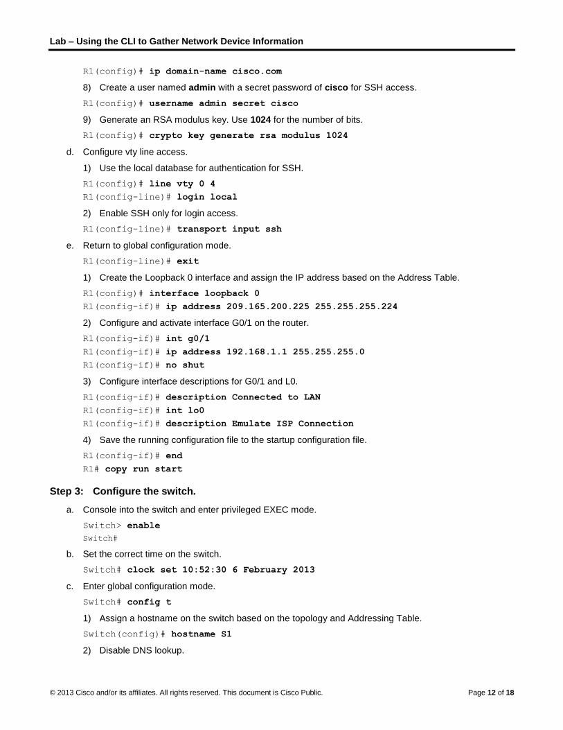
Lab – Using the CLI to Gather Network Device Information
© 2013 Cisco and/or its affiliates. All rights reserved. This document is Cisco Public. Page 12 of 18
R1(config)# ip domain-name cisco.com
8) Create a user named admin with a secret password of cisco for SSH access.
R1(config)# username admin secret cisco
9) Generate an RSA modulus key. Use 1024 for the number of bits.
R1(config)# crypto key generate rsa modulus 1024
d. Configure vty line access.
1) Use the local database for authentication for SSH.
R1(config)# line vty 0 4
R1(config-line)# login local
2) Enable SSH only for login access.
R1(config-line)# transport input ssh
e. Return to global configuration mode.
R1(config-line)# exit
1) Create the Loopback 0 interface and assign the IP address based on the Address Table.
R1(config)# interface loopback 0
R1(config-if)# ip address 209.165.200.225 255.255.255.224
2) Configure and activate interface G0/1 on the router.
R1(config-if)# int g0/1
R1(config-if)# ip address 192.168.1.1 255.255.255.0
R1(config-if)# no shut
3) Configure interface descriptions for G0/1 and L0.
R1(config-if)# description Connected to LAN
R1(config-if)# int lo0
R1(config-if)# description Emulate ISP Connection
4) Save the running configuration file to the startup configuration file.
R1(config-if)# end
R1# copy run start
Step 3: Configure the switch.
a. Console into the switch and enter privileged EXEC mode.
Switch> enable
Switch#
b. Set the correct time on the switch.
Switch# clock set 10:52:30 6 February 2013
c. Enter global configuration mode.
Switch# config t
1) Assign a hostname on the switch based on the topology and Addressing Table.
Switch(config)# hostname S1
2) Disable DNS lookup.
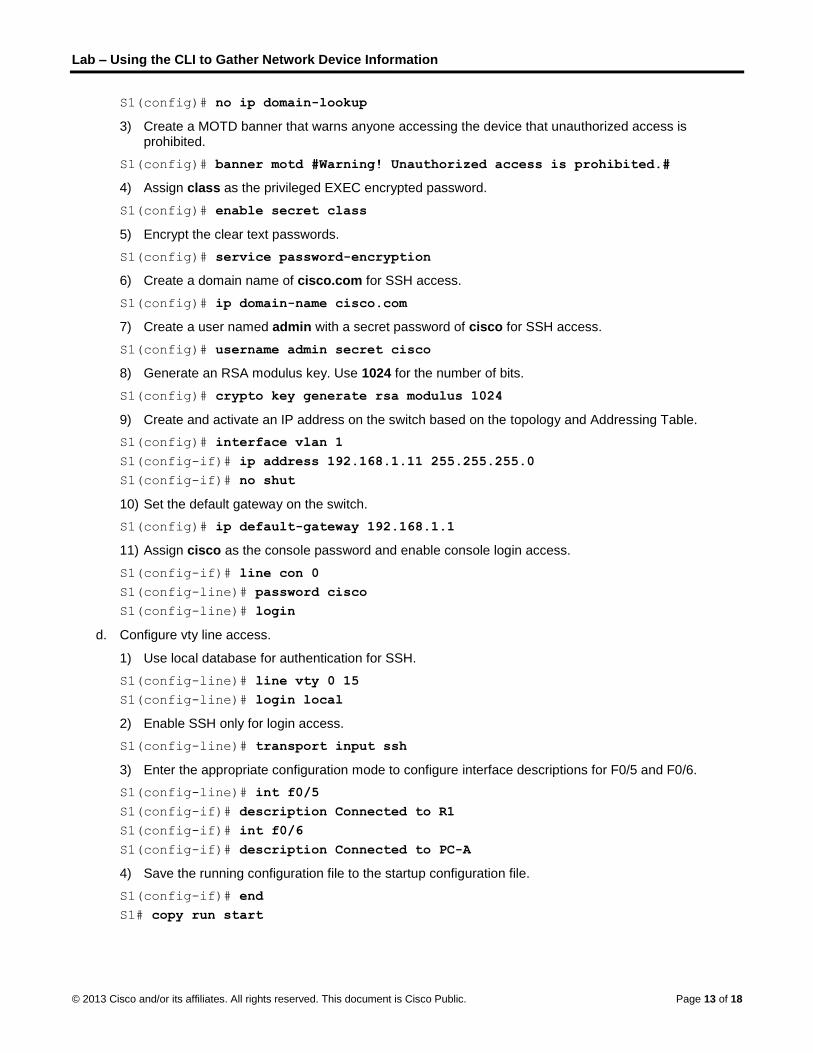
Lab – Using the CLI to Gather Network Device Information
© 2013 Cisco and/or its affiliates. All rights reserved. This document is Cisco Public. Page 13 of 18
S1(config)# no ip domain-lookup
3) Create a MOTD banner that warns anyone accessing the device that unauthorized access is prohibited.
S1(config)# banner motd #Warning! Unauthorized access is prohibited.#
4) Assign class as the privileged EXEC encrypted password.
S1(config)# enable secret class
5) Encrypt the clear text passwords.
S1(config)# service password-encryption
6) Create a domain name of cisco.com for SSH access.
S1(config)# ip domain-name cisco.com
7) Create a user named admin with a secret password of cisco for SSH access.
S1(config)# username admin secret cisco
8) Generate an RSA modulus key. Use 1024 for the number of bits.
S1(config)# crypto key generate rsa modulus 1024
9) Create and activate an IP address on the switch based on the topology and Addressing Table.
S1(config)# interface vlan 1
S1(config-if)# ip address 192.168.1.11 255.255.255.0
S1(config-if)# no shut
10) Set the default gateway on the switch.
S1(config)# ip default-gateway 192.168.1.1
11) Assign cisco as the console password and enable console login access.
S1(config-if)# line con 0
S1(config-line)# password cisco
S1(config-line)# login
d. Configure vty line access.
1) Use local database for authentication for SSH.
S1(config-line)# line vty 0 15
S1(config-line)# login local
2) Enable SSH only for login access.
S1(config-line)# transport input ssh
3) Enter the appropriate configuration mode to configure interface descriptions for F0/5 and F0/6.
S1(config-line)# int f0/5
S1(config-if)# description Connected to R1
S1(config-if)# int f0/6
S1(config-if)# description Connected to PC-A
4) Save the running configuration file to the startup configuration file.
S1(config-if)# end
S1# copy run start
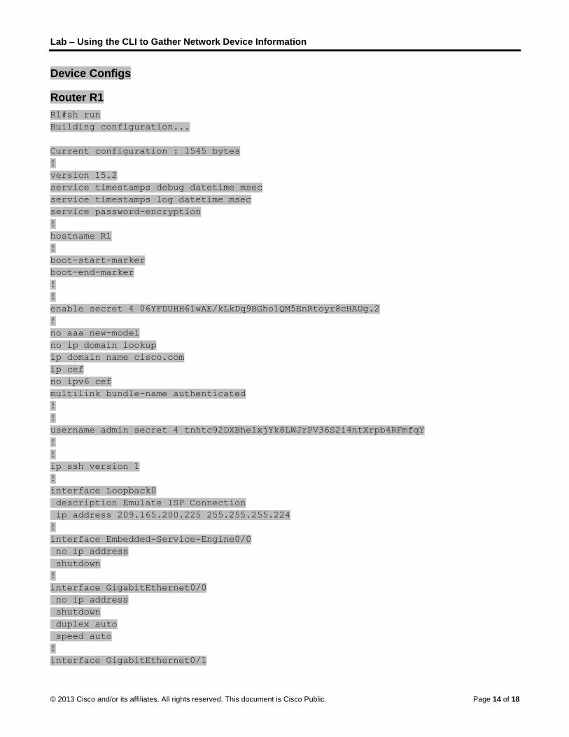
Lab – Using the CLI to Gather Network Device Information
© 2013 Cisco and/or its affiliates. All rights reserved. This document is Cisco Public. Page 14 of 18
Device Configs
Router R1
R1#sh run
Building configuration...
Current configuration : 1545 bytes
!
version 15.2
service timestamps debug datetime msec
service timestamps log datetime msec
service password-encryption
!
hostname R1
!
boot-start-marker
boot-end-marker
!
!
enable secret 4 06YFDUHH61wAE/kLkDq9BGho1QM5EnRtoyr8cHAUg.2
!
no aaa new-model
no ip domain lookup
ip domain name cisco.com
ip cef
no ipv6 cef
multilink bundle-name authenticated
!
!
username admin secret 4 tnhtc92DXBhelxjYk8LWJrPV36S2i4ntXrpb4RFmfqY
!
!
ip ssh version 1
!
interface Loopback0
description Emulate ISP Connection
ip address 209.165.200.225 255.255.255.224
!
interface Embedded-Service-Engine0/0
no ip address
shutdown
!
interface GigabitEthernet0/0
no ip address
shutdown
duplex auto
speed auto
!
interface GigabitEthernet0/1
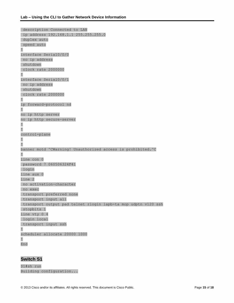
Lab – Using the CLI to Gather Network Device Information
© 2013 Cisco and/or its affiliates. All rights reserved. This document is Cisco Public. Page 15 of 18
description Connected to LAN
ip address 192.168.1.1 255.255.255.0
duplex auto
speed auto
!
interface Serial0/0/0
no ip address
shutdown
clock rate 2000000
!
interface Serial0/0/1
no ip address
shutdown
clock rate 2000000
!
ip forward-protocol nd
!
no ip http server
no ip http secure-server
!
!
control-plane
!
!
banner motd ^CWarning! Unauthorized access is prohibited.^C
!
line con 0
password 7 060506324F41
login
line aux 0
line 2
no activation-character
no exec
transport preferred none
transport input all
transport output pad telnet rlogin lapb-ta mop udptn v120 ssh
stopbits 1
line vty 0 4
login local
transport input ssh
!
scheduler allocate 20000 1000
!
End
Switch S1
S1#sh run
Building configuration...

Lab – Using the CLI to Gather Network Device Information
© 2013 Cisco and/or its affiliates. All rights reserved. This document is Cisco Public. Page 16 of 18
Current configuration : 1752 bytes
!
!
version 15.0
no service pad
service timestamps debug datetime msec
service timestamps log datetime msec
service password-encryption
!
hostname S1
!
boot-start-marker
boot-end-marker
!
enable secret 4 06YFDUHH61wAE/kLkDq9BGho1QM5EnRtoyr8cHAUg.2
!
username admin secret 4 tnhtc92DXBhelxjYk8LWJrPV36S2i4ntXrpb4RFmfqY
no aaa new-model
system mtu routing 1500
!
!
no ip domain-lookup
ip domain-name cisco.com
!
spanning-tree mode pvst
spanning-tree extend system-id
!
vlan internal allocation policy ascending
!
ip ssh version 1
!
interface FastEthernet0/1
!
interface FastEthernet0/2
!
interface FastEthernet0/3
!
interface FastEthernet0/4
!
interface FastEthernet0/5
description Connected to R1
!
interface FastEthernet0/6
description Connected to PC-A
!
interface FastEthernet0/7
!
interface FastEthernet0/8

Lab – Using the CLI to Gather Network Device Information
© 2013 Cisco and/or its affiliates. All rights reserved. This document is Cisco Public. Page 17 of 18
!
interface FastEthernet0/9
!
interface FastEthernet0/10
!
interface FastEthernet0/11
!
interface FastEthernet0/12
!
interface FastEthernet0/13
!
interface FastEthernet0/14
!
interface FastEthernet0/15
!
interface FastEthernet0/16
!
interface FastEthernet0/17
!
interface FastEthernet0/18
!
interface FastEthernet0/19
!
interface FastEthernet0/20
!
interface FastEthernet0/21
!
interface FastEthernet0/22
!
interface FastEthernet0/23
!
interface FastEthernet0/24
!
interface GigabitEthernet0/1
!
interface GigabitEthernet0/2
!
interface Vlan1
ip address 192.168.1.11 255.255.255.0
!
ip default-gateway 192.168.1.1
ip http server
ip http secure-server
!
banner motd ^CWarning! Unauthorized access is prohibited.^C
!
line con 0
password 7 00071A150754
login

Lab – Using the CLI to Gather Network Device Information
© 2013 Cisco and/or its affiliates. All rights reserved. This document is Cisco Public. Page 18 of 18
line vty 0 4
login local
transport input ssh
line vty 5 15
login local
transport input ssh
!
end

© 2013 Cisco and/or its affiliates. All rights reserved. This document is Cisco Public. Page 1 of 10
Lab – Managing Router Configuration Files with Terminal
Emulation Software (Instructor Version) Instructor Note: Red font color or Gray highlights indicate text that appears in the instructor copy only.
Topology
Addressing Table
Device Interface IP Address Subnet Mask Default Gateway
R1 G0/1 192.168.1.1 255.255.255.0 N/A
S1 VLAN 1 192.168.1.11 255.255.255.0 192.168.1.1
PC-A NIC 192.168.1.3 255.255.255.0 192.168.1.1
Objectives
Part 1: Configure Basic Device Settings
Part 2: Use Terminal Emulation Software to Create a Backup Configuration File
Part 3: Use a Backup Configuration File to Restore a Router
Background / Scenario
It is a recommended best practice to maintain backup configuration files for routers and switches in the event that they need to be restored to a previous configuration. Terminal emulation software can be used to easily back up or restore a router or switch configuration file.
In this lab, you will use Tera Term to back up a router running configuration file, erase the router startup configuration file, reload the router, and then restore the missing router configuration from the backup configuration file.
Note: The routers used with CCNA hands-on labs are Cisco 1941 Integrated Services Routers (ISRs) with Cisco IOS Release 15.2(4)M3 (universalk9 image). The switches used are Cisco Catalyst 2960s with Cisco IOS Release 15.0(2) (lanbasek9 image). Other routers, switches, and Cisco IOS versions can be used. Depending on the model and Cisco IOS version, the commands available and output produced might vary from what is shown in the labs. Refer to the Router Interface Summary Table at the end of this lab for the correct interface identifiers.
Note: Make sure that the routers and switches have been erased and have no startup configurations. If you are unsure, contact your instructor.
Instructor Note: Refer to the Instructor Lab Manual for the procedures to initialize and reload devices.
Instructor Note: This lab uses Tera Term 4.75. Tera Term should be installed on the PC prior to starting the lab. You can download the latest version from a number of Internet sites. Simply search for a tera term download.

Lab – Managing Router Configuration Files with Terminal Emulation Software
© 2013 Cisco and/or its affiliates. All rights reserved. This document is Cisco Public. Page 2 of 10
Required Resources
1 Router (Cisco 1941 with Cisco IOS Release 15.2(4)M3 universal image or comparable)
1 Switch (Cisco 2960 with Cisco IOS Release 15.0(2) lanbasek9 image or comparable)
1 PC (Windows 7, Vista, or XP with terminal emulation program, such as Tera Term)
Console cables to configure the Cisco IOS devices via the console ports
Ethernet cables as shown in the topology
Part 1: Configure Basic Device Settings
In Part 1, you will set up the network topology and configure basic settings, such as the interface IP addresses, device access, and passwords on the router.
Step 1: Cable the network as shown in the topology.
Attach the devices as shown in the topology and cable as necessary.
Step 2: Configure the PC-A network settings according to the Addressing Table.
Step 3: Initialize and reload the router and switch.
Step 4: Configure the router.
a. Console into the router and enter global configuration mode.
b. Set the router name to R1.
c. Disable DNS lookup.
d. Assign class as the privileged EXEC encrypted password.
e. Assign cisco as the console password and enable login.
f. Assign cisco as the vty password and enable login.
g. Encrypt the plain text passwords.
h. Create a banner that warns anyone accessing the device that unauthorized access is prohibited.
i. Configure and activate the G0/1 interface on the router using the information contained in the Addressing Table.
j. Save the running configuration to the startup configuration file.
Step 5: Configure the switch.
a. Console into the switch and enter into global configuration mode.
b. Set the switch name to S1.
c. Disable DNS lookup.
d. Assign class as the privileged EXEC encrypted password.
e. Assign cisco as the console password and enable login.
f. Assign cisco as the vty password and enable login.
g. Encrypt the plain text passwords.
h. Create a banner that warns anyone accessing the device that unauthorized access is prohibited.

Lab – Managing Router Configuration Files with Terminal Emulation Software
© 2013 Cisco and/or its affiliates. All rights reserved. This document is Cisco Public. Page 3 of 10
i. Configure the default SVI management interface with the IP address information contained in the Addressing Table.
j. Configure the switch default gateway.
k. Save the running configuration to the startup configuration file.
Part 2: Use Terminal Emulation Software to Create a Backup Configuration
File
Step 1: Establish a Tera Term console session to the router.
Launch the Tera Term Program, and in the New Connection window, select the Serial radio button and the appropriate communications port for your PC (i.e., COM1).
Note: If Tera Term is not installed, you can download the latest version from a number of Internet sites. Simply search for a Tera Term download.
a. In Tera Term, press Enter to connect to the router.
b. From the File menu, choose Log…, and save the teraterm.log file to the Desktop. Ensure that the Append and Plain text check boxes are enabled (checked).
c. The Tera Term log file will create a record of every command issued and every output displayed.
Note: You can use this feature to capture the output from several commands in sequence and use it for network documentation purposes. For example, you could issue the show version, show ip interface brief, and show running-config commands to capture information about the router.
Step 2: Display the router running-configuration.
a. Use the console password to log in to the router.
b. Enter privileged EXEC mode.
c. Enter the show running-config command.
d. Continue pressing the space bar when --More-- is displayed until you see the router R1# prompt return.
e. Click the Tera Term: Log icon on the Task bar. Click Close to end log session.

Lab – Managing Router Configuration Files with Terminal Emulation Software
© 2013 Cisco and/or its affiliates. All rights reserved. This document is Cisco Public. Page 4 of 10
Note: You can also copy and paste the text from the Tera Term window directly into a text editor.
Part 3: Use a Backup Configuration File to Restore a Router
Step 1: Erase the router startup-configuration and reload.
a. From privileged EXEC mode erase the startup configuration.
R1# erase startup-config
Erasing the nvram filesystem will remove all configuration files! Continue? [confirm]
[OK]
Erase of nvram: complete
b. Reload the router.
R1# reload
Proceed with reload? [confirm]
c. At the System Configuration Dialog prompt, type no; a router prompt displays, indicating an unconfigured router.
--- System Configuration Dialog ---
Would you like to enter the initial configuration dialog? [yes/no]:
Press RETURN to get started!
<output omitted>
Router>
d. Enter privileged EXEC mode and enter a show running-config command to verify that all of the previous configurations were erased.
Step 2: Edit the saved configuration backup file to prepare it for restoring the router
configuration.
To restore the router configuration from a saved running configuration backup file, you must edit the text.
a. Open the teraterm.log text file.
b. Remove each instance of --More-- in the text file.
Note: The --More-- was generated by pressing the Spacebar when displaying the running configuration.
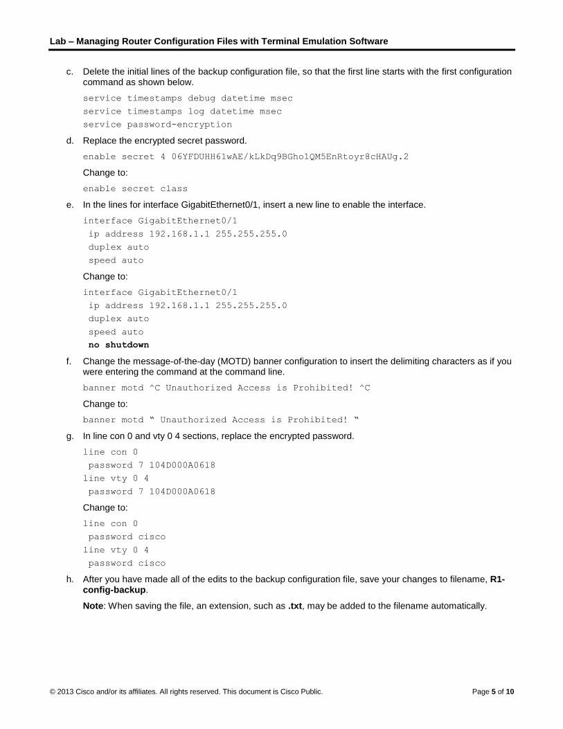
Lab – Managing Router Configuration Files with Terminal Emulation Software
© 2013 Cisco and/or its affiliates. All rights reserved. This document is Cisco Public. Page 5 of 10
c. Delete the initial lines of the backup configuration file, so that the first line starts with the first configuration command as shown below.
service timestamps debug datetime msec
service timestamps log datetime msec
service password-encryption
d. Replace the encrypted secret password.
enable secret 4 06YFDUHH61wAE/kLkDq9BGho1QM5EnRtoyr8cHAUg.2
Change to:
enable secret class
e. In the lines for interface GigabitEthernet0/1, insert a new line to enable the interface.
interface GigabitEthernet0/1
ip address 192.168.1.1 255.255.255.0
duplex auto
speed auto
Change to:
interface GigabitEthernet0/1
ip address 192.168.1.1 255.255.255.0
duplex auto
speed auto
no shutdown
f. Change the message-of-the-day (MOTD) banner configuration to insert the delimiting characters as if you were entering the command at the command line.
banner motd ^C Unauthorized Access is Prohibited! ^C
Change to:
banner motd “ Unauthorized Access is Prohibited! “
g. In line con 0 and vty 0 4 sections, replace the encrypted password.
line con 0
password 7 104D000A0618
line vty 0 4
password 7 104D000A0618
Change to:
line con 0
password cisco
line vty 0 4
password cisco
h. After you have made all of the edits to the backup configuration file, save your changes to filename, R1-config-backup.
Note: When saving the file, an extension, such as .txt, may be added to the filename automatically.

Lab – Managing Router Configuration Files with Terminal Emulation Software
© 2013 Cisco and/or its affiliates. All rights reserved. This document is Cisco Public. Page 6 of 10
Step 3: Restore the router configuration.
You can restore the edited running configuration directly to the console terminal in router global configuration mode, and the configurations are entered as if they were commands entered individually at the command prompt.
a. From the Tera Term console connection to the router, enter global configuration mode.
b. From the File menu, select Send file….
c. Locate R1-config-backup and select Open.
d. Save the running configuration to the startup configuration file.
R1# copy running-config startup-config
e. Verify the new running configuration.
Step 4: Back up and restore the switch.
Go back to the beginning of Part 2 and follow the same steps to backup and restore the switch configuration.
Reflection
Why do you think it is important to use a text editor instead of a word processor to copy and save your command configurations?
_______________________________________________________________________________________
_______________________________________________________________________________________
_______________________________________________________________________________________
A word processor could possibly add special control characters to the text making it difficult to use to restore the router.

Lab – Managing Router Configuration Files with Terminal Emulation Software
© 2013 Cisco and/or its affiliates. All rights reserved. This document is Cisco Public. Page 7 of 10
Router Interface Summary Table
Router Interface Summary
Router Model Ethernet Interface #1 Ethernet Interface #2 Serial Interface #1 Serial Interface #2
1800 Fast Ethernet 0/0 (F0/0)
Fast Ethernet 0/1 (F0/1)
Serial 0/0/0 (S0/0/0) Serial 0/0/1 (S0/0/1)
1900 Gigabit Ethernet 0/0 (G0/0)
Gigabit Ethernet 0/1 (G0/1)
Serial 0/0/0 (S0/0/0) Serial 0/0/1 (S0/0/1)
2801 Fast Ethernet 0/0 (F0/0)
Fast Ethernet 0/1 (F0/1)
Serial 0/1/0 (S0/1/0) Serial 0/1/1 (S0/1/1)
2811 Fast Ethernet 0/0 (F0/0)
Fast Ethernet 0/1 (F0/1)
Serial 0/0/0 (S0/0/0) Serial 0/0/1 (S0/0/1)
2900 Gigabit Ethernet 0/0 (G0/0)
Gigabit Ethernet 0/1 (G0/1)
Serial 0/0/0 (S0/0/0) Serial 0/0/1 (S0/0/1)
Note: To find out how the router is configured, look at the interfaces to identify the type of router and how many interfaces the router has. There is no way to effectively list all the combinations of configurations for each router class. This table includes identifiers for the possible combinations of Ethernet and Serial interfaces in the device. The table does not include any other type of interface, even though a specific router may contain one. An example of this might be an ISDN BRI interface. The string in parenthesis is the legal abbreviation that can be used in Cisco IOS commands to represent the interface.
Device Configs – Final
Router R1
service timestamps debug datetime msec
service timestamps log datetime msec
service password-encryption
!
hostname R1
!
boot-start-marker
boot-end-marker
!
!
enable secret 4 06YFDUHH61wAE/kLkDq9BGho1QM5EnRtoyr8cHAUg.2
!
no aaa new-model
!
no ipv6 cef
!
no ip domain lookup
ip cef
multilink bundle-name authenticated
!
!
interface Embedded-Service-Engine0/0

Lab – Managing Router Configuration Files with Terminal Emulation Software
© 2013 Cisco and/or its affiliates. All rights reserved. This document is Cisco Public. Page 8 of 10
no ip address
shutdown
!
interface GigabitEthernet0/0
no ip address
shutdown
duplex auto
speed auto
!
interface GigabitEthernet0/1
ip address 192.168.1.1 255.255.255.0
duplex auto
speed auto
!
interface Serial0/0/0
no ip address
shutdown
clock rate 2000000
!
interface Serial0/0/1
no ip address
shutdown
clock rate 2000000
!
ip forward-protocol nd
!
no ip http server
no ip http secure-server
!
control-plane
!
banner motd ^C Unauthorized Access is Prohibited! ^C
!
line con 0
password 7 104D000A0618
login
line aux 0
line 2
no activation-character
no exec
transport preferred none
transport input all
transport output pad telnet rlogin lapb-ta mop udptn v120 ssh
stopbits 1
line vty 0 4
password 7 104D000A0618
login
transport input all
!

Lab – Managing Router Configuration Files with Terminal Emulation Software
© 2013 Cisco and/or its affiliates. All rights reserved. This document is Cisco Public. Page 9 of 10
scheduler allocate 20000 1000
!
end
Switch S1
no service pad
service timestamps debug datetime msec
service timestamps log datetime msec
service password-encryption
!
hostname S1
!
boot-start-marker
boot-end-marker
!
enable secret 4 06YFDUHH61wAE/kLkDq9BGho1QM5EnRtoyr8cHAUg.2
!
no aaa new-model
system mtu routing 1500
!
no ip domain-lookup
!
spanning-tree mode pvst
spanning-tree extend system-id
!
vlan internal allocation policy ascending
!
interface FastEthernet0/1
!
interface FastEthernet0/2
!
interface FastEthernet0/3
!
interface FastEthernet0/4
!
interface FastEthernet0/5
!
interface FastEthernet0/6
!
interface FastEthernet0/7
!
interface FastEthernet0/8
!
interface FastEthernet0/9
!
interface FastEthernet0/10
!
interface FastEthernet0/11
!

Lab – Managing Router Configuration Files with Terminal Emulation Software
© 2013 Cisco and/or its affiliates. All rights reserved. This document is Cisco Public. Page 10 of 10
interface FastEthernet0/12
!
interface FastEthernet0/13
!
interface FastEthernet0/14
!
interface FastEthernet0/15
!
interface FastEthernet0/16
!
interface FastEthernet0/17
!
interface FastEthernet0/18
!
interface FastEthernet0/19
!
interface FastEthernet0/20
!
interface FastEthernet0/21
!
interface FastEthernet0/22
!
interface FastEthernet0/23
!
interface FastEthernet0/24
!
interface GigabitEthernet0/1
!
interface GigabitEthernet0/2
!
interface Vlan1
ip address 192.168.1.11 255.255.255.0
!
ip default-gateway 192.168.1.1
ip http server
ip http secure-server
banner motd ^C Unauthorized access is prohibited! ^C
!
line con 0
password 7 070C285F4D06
login
line vty 0 4
password 7 070C285F4D06
login
line vty 5 15
login
!
end
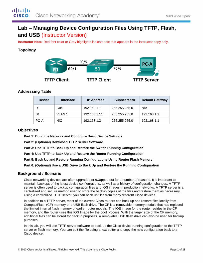
© 2013 Cisco and/or its affiliates. All rights reserved. This document is Cisco Public. Page 1 of 18
Lab – Managing Device Configuration Files Using TFTP, Flash,
and USB (Instructor Version) Instructor Note: Red font color or Gray highlights indicate text that appears in the instructor copy only.
Topology
Addressing Table
Device Interface IP Address Subnet Mask Default Gateway
R1 G0/1 192.168.1.1 255.255.255.0 N/A
S1 VLAN 1 192.168.1.11 255.255.255.0 192.168.1.1
PC-A NIC 192.168.1.3 255.255.255.0 192.168.1.1
Objectives
Part 1: Build the Network and Configure Basic Device Settings
Part 2: (Optional) Download TFTP Server Software
Part 3: Use TFTP to Back Up and Restore the Switch Running Configuration
Part 4: Use TFTP to Back Up and Restore the Router Running Configuration
Part 5: Back Up and Restore Running Configurations Using Router Flash Memory
Part 6: (Optional) Use a USB Drive to Back Up and Restore the Running Configuration
Background / Scenario
Cisco networking devices are often upgraded or swapped out for a number of reasons. It is important to maintain backups of the latest device configurations, as well as a history of configuration changes. A TFTP server is often used to backup configuration files and IOS images in production networks. A TFTP server is a centralized and secure method used to store the backup copies of the files and restore them as necessary. Using a centralized TFTP server, you can back up files from many different Cisco devices.
In addition to a TFTP server, most of the current Cisco routers can back up and restore files locally from CompactFlash (CF) memory or a USB flash drive. The CF is a removable memory module that has replaced the limited internal flash memory of earlier router models. The IOS image for the router resides in the CF memory, and the router uses this IOS Image for the boot process. With the larger size of the CF memory, additional files can be stored for backup purposes. A removable USB flash drive can also be used for backup purposes.
In this lab, you will use TFTP server software to back up the Cisco device running configuration to the TFTP server or flash memory. You can edit the file using a text editor and copy the new configuration back to a Cisco device.

Lab – Managing Device Configuration Files Using TFTP, Flash and USB
© 2013 Cisco and/or its affiliates. All rights reserved. This document is Cisco Public. Page 2 of 18
Note: The routers used with CCNA hands-on labs are Cisco 1941 Integrated Services Routers (ISRs) with Cisco IOS Release 15.2(4)M3 (universalk9 image). The switches used are Cisco Catalyst 2960s with Cisco IOS Release 15.0(2) (lanbasek9 image). Other routers, switches, and Cisco IOS versions can be used. Depending on the model and Cisco IOS version, the commands available and output produced might vary from what is shown in the labs. Refer to the Router Interface Summary Table at the end of this lab for the correct interface identifiers.
Note: Make sure that the routers and switches have been erased and have no startup configurations. If you are unsure, contact your instructor.
Instructor Note: Refer to the Instructor Lab Manual for the procedures to initialize and reload devices.
Instructor Note: If time is limited, the lab can be divided up and performed over multiple sessions. For example, after building the network in Part 1, any combination of the remaining lab parts can be performed in any order.
Required Resources
1 Router (Cisco 1941 with Cisco IOS Release 15.2(4)M3 universal image or comparable)
1 Switch (Cisco 2960 with Cisco IOS Release 15.0(2) lanbasek9 image or comparable)
1 PC (Windows 7, Vista, or XP with terminal emulation program, such as Tera Term, and a TFTP server)
Console cables to configure the Cisco IOS devices via the console ports
Ethernet cables as shown in the topology
USB flash drive (Optional)
Part 1: Build the Network and Configure Basic Device Settings
In Part 1, you will set up the network topology and configure basic settings, such as the interface IP addresses for router R1, switch S1 and PC-A.
Step 1: Cable the network as shown in the topology.
Attach the devices as shown in the topology diagram, and cable as necessary.
Step 2: Initialize and reload the router and switch.
Step 3: Configure basic settings for each device.
a. Configure basic device parameters as shown in the Addressing Table.
b. To prevent the router and switch from attempting to translate incorrectly entered commands as though they were host names, disable DNS lookup.
c. Assign class as the privileged EXEC encrypted password.
d. Configure the passwords and allow login for console and vty lines using the cisco as the password.
e. Configure the default gateway for the switch.
f. Encrypt the clear text passwords.
g. Configure the IP address, subnet mask, and default gateway for PC-A.
Step 4: Verify connectivity from PC-A.
a. Ping from PC-A to S1.
b. Ping from PC-A to R1.

Lab – Managing Device Configuration Files Using TFTP, Flash and USB
© 2013 Cisco and/or its affiliates. All rights reserved. This document is Cisco Public. Page 3 of 18
If the pings are not successful, troubleshoot the basic device configurations before continuing.
Part 2: (Optional) Download TFTP Server Software
A number of free TFTP servers are available on the Internet for download. The Tftpd32 server is used with this lab.
Note: Downloading a TFTP server from a website requires Internet access.
Step 1: Verify availability of a TFTP server on PC-A.
a. Click the Start menu and select All Programs.
b. Search for a TFTP server on PC-A.
c. If a TFTP server is not found, a TFTP server can be downloaded from the Internet.
Step 2: Download a TFTP server.
a. Tftpd32 is used in this lab. This server can be downloaded from the following link:
http://tftpd32.jounin.net/tftpd32_download.html
b. Choose the appropriate version for your system and install the server.
Part 3: Use TFTP to Back Up and Restore the Switch Running
Configuration
Step 1: Verify connectivity to switch S1 from PC-A.
The TFTP application uses the UDP Layer 4 transport protocol, which is encapsulated in an IP packet. For TFTP file transfers to function, there must be Layer 1 and 2 (Ethernet, in this case) and Layer 3 (IP) connectivity between the TFTP client and the TFTP server. The LAN topology in this lab uses only Ethernet at Layers 1 and 2. However, TFTP transfers can also be accomplished over WAN links that use other Layer 1 physical links and Layer 2 protocols. As long as there is IP connectivity between the client and server, as demonstrated by ping, the TFTP transfer can take place. If the pings are not successful, troubleshoot the basic device configurations before continuing.
Note: A common misconception is that you can TFTP a file over the console connection. This is not the case because the console connection does not use IP. The TFTP transfer can be initiated from the client device (router or switch) using the console connection, but there must be IP connectivity between the client and server for the file transfer to take place.
Step 2: Start the TFTP server.
a. Click the Start menu and select All Programs.
b. Find and select Tftpd32 or Tftpd64. The following window displays that the TFTP server is ready.

Lab – Managing Device Configuration Files Using TFTP, Flash and USB
© 2013 Cisco and/or its affiliates. All rights reserved. This document is Cisco Public. Page 4 of 18
c. Click Browse to choose a directory where you have write permission, such as C:\Users\User1, or the Desktop.
Step 3: Explore the copy command on a Cisco device.
a. Console into switch S1 and, from the privileged EXEC mode prompt, enter copy ? to display the options for source or “from” location and other available copy options. You can specify flash: or flash0: as the source, however, if you simply provide a filename as the source, flash0: is assumed and is the default. Note that running-config is also an option for the source location.
S1# copy ?
/erase Erase destination file system.
/error Allow to copy error file.
/noverify Don't verify image signature before reload.
/verify Verify image signature before reload.
archive: Copy from archive: file system
cns: Copy from cns: file system
flash0: Copy from flash0: file system
flash1: Copy from flash1: file system
flash: Copy from flash: file system
ftp: Copy from ftp: file system
http: Copy from http: file system
https: Copy from https: file system
null: Copy from null: file system
nvram: Copy from nvram: file system
rcp: Copy from rcp: file system
running-config Copy from current system configuration
scp: Copy from scp: file system
startup-config Copy from startup configuration
system: Copy from system: file system
tar: Copy from tar: file system

Lab – Managing Device Configuration Files Using TFTP, Flash and USB
© 2013 Cisco and/or its affiliates. All rights reserved. This document is Cisco Public. Page 5 of 18
tftp: Copy from tftp: file system
tmpsys: Copy from tmpsys: file system
xmodem: Copy from xmodem: file system
ymodem: Copy from ymodem: file system
b. Use the ? to display the destination options after a source file location is chosen. The flash: file system for S1 is the source file system in this example.
S1# copy flash: ?
archive: Copy to archive: file system
flash0: Copy to flash0: file system
flash1: Copy to flash1: file system
flash: Copy to flash: file system
ftp: Copy to ftp: file system
http: Copy to http: file system
https: Copy to https: file system
idconf Load an IDConf configuration file
null: Copy to null: file system
nvram: Copy to nvram: file system
rcp: Copy to rcp: file system
running-config Update (merge with) current system configuration
scp: Copy to scp: file system
startup-config Copy to startup configuration
syslog: Copy to syslog: file system
system: Copy to system: file system
tftp: Copy to tftp: file system
tmpsys: Copy to tmpsys: file system
xmodem: Copy to xmodem: file system
ymodem: Copy to ymodem: file system
Step 4: Transfer the running-config file from switch S1 to TFTP server on PC-A.
a. From the privileged EXEC mode on the switch, enter the copy running-config tftp: command. Provide the remote host address of the TFTP server (PC-A), 192.168.1.3. Press Enter to accept default destination filename (s1-confg) or provide your own filename. The exclamation marks (!!) indicate the transfer process is in progress and is successful.
S1# copy running-config tftp:
Address or name of remote host []? 192.168.1.3
Destination filename [s1-confg]?
!!
1465 bytes copied in 0.663 secs (2210 bytes/sec)
S1#
The TFTP server also displays the progress during the transfer.

Lab – Managing Device Configuration Files Using TFTP, Flash and USB
© 2013 Cisco and/or its affiliates. All rights reserved. This document is Cisco Public. Page 6 of 18
Note: If you do not have permission to write to the current directory that is used by the TFTP server, the following error message displays:
S1# copy running-config tftp:
Address or name of remote host []? 192.168.1.3
Destination filename [s1-confg]?
%Error opening tftp://192.168.1.3/s1-confg (Permission denied)
You can change the current directory in TFTP server by clicking Browse and choosing a different folder.
Note: Other issues, such as a firewall blocking TFTP traffic, can prevent the TFTP transfer. Please check with your instructor for further assistance.
b. In the Tftpd32 server window, click Show Dir to verify that the s1-confg file has been transferred to your current directory. Click Close when finished.
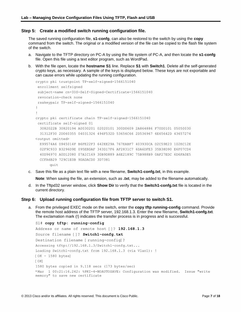
Lab – Managing Device Configuration Files Using TFTP, Flash and USB
© 2013 Cisco and/or its affiliates. All rights reserved. This document is Cisco Public. Page 7 of 18
Step 5: Create a modified switch running configuration file.
The saved running configuration file, s1-confg, can also be restored to the switch by using the copy command from the switch. The original or a modified version of the file can be copied to the flash file system of the switch.
a. Navigate to the TFTP directory on PC-A by using the file system of PC-A, and then locate the s1-confg file. Open this file using a text editor program, such as WordPad.
b. With the file open, locate the hostname S1 line. Replace S1 with Switch1. Delete all the self-generated crypto keys, as necessary. A sample of the keys is displayed below. These keys are not exportable and can cause errors while updating the running configuration.
crypto pki trustpoint TP-self-signed-1566151040
enrollment selfsigned
subject-name cn=IOS-Self-Signed-Certificate-1566151040
revocation-check none
rsakeypair TP-self-signed-1566151040
!
!
crypto pki certificate chain TP-self-signed-1566151040
certificate self-signed 01
3082022B 30820194 A0030201 02020101 300D0609 2A864886 F70D0101 05050030
31312F30 2D060355 04031326 494F532D 53656C66 2D536967 6E65642D 43657274
<output omitted>
E99574A6 D945014F B6FE22F3 642EE29A 767EABF7 403930CA D2C59E23 102EC12E
02F9C933 B3296D9E 095EBDAF 343D17F6 AF2831C7 6DA6DFE3 35B38D90 E6F07CD4
40D96970 A0D12080 07A1C169 30B9D889 A6E2189C 75B988B9 0AF27EDC 6D6FA0E5
CCFA6B29 729C1E0B 9DADACD0 3D7381
quit
c. Save this file as a plain text file with a new filename, Switch1-confg.txt, in this example.
Note: When saving the file, an extension, such as .txt, may be added to the filename automatically.
d. In the Tftpd32 server window, click Show Dir to verify that the Switch1-confg.txt file is located in the current directory.
Step 6: Upload running configuration file from TFTP server to switch S1.
a. From the privileged EXEC mode on the switch, enter the copy tftp running-config command. Provide the remote host address of the TFTP server, 192.168.1.3. Enter the new filename, Switch1-confg.txt. The exclamation mark (!) indicates the transfer process is in progress and is successful.
S1# copy tftp: running-config
Address or name of remote host []? 192.168.1.3
Source filename []? Switch1-confg.txt
Destination filename [running-config]?
Accessing tftp://192.168.1.3/Switch1-confg.txt...
Loading Switch1-confg.txt from 192.168.1.3 (via Vlan1): !
[OK - 1580 bytes]
[OK]
1580 bytes copied in 9.118 secs (173 bytes/sec)
*Mar 1 00:21:16.242: %PKI-4-NOAUTOSAVE: Configuration was modified. Issue "write
memory" to save new certificate

Lab – Managing Device Configuration Files Using TFTP, Flash and USB
© 2013 Cisco and/or its affiliates. All rights reserved. This document is Cisco Public. Page 8 of 18
*Mar 1 00:21:16.251: %SYS-5-CONFIG_I: Configured from tftp://192.168.1.3/Switch1-
confg.txt by console
Switch1#
After the transfer has completed, the prompt has changed from S1 to Switch1, because the running configuration is updated with the hostname Switch1 command in the modified running configuration.
b. Enter the show running-config command to examine running configuration file.
Switch1# show running-config
Building configuration...
Current configuration : 3062 bytes
!
! Last configuration change at 00:09:34 UTC Mon Mar 1 1993
!
version 15.0
no service pad
service timestamps debug datetime msec
service timestamps log datetime msec
no service password-encryption
!
hostname Switch1
!
boot-start-marker
boot-end-marker
<output omitted>
Note: This procedure merges the running-config from the TFTP server with the current running-config in the switch or router. If changes were made to the current running-config, the commands in the TFTP copy are added. Alternatively, if the same command is issued, it updates the corresponding command in the switch or router current running-config.
If you want to completely replace the current running-config with the one from the TFTP server, you must erase the switch startup-config and reload the device. You will then need to configure the VLAN 1 management address, so there is IP connectivity between the TFTP server and the switch.
Part 4: Use TFTP to Back Up and Restore the Router Running
Configuration
The backup and restore procedure from Part 3 can also be performed with a router. In Part 4, the running configuration file will be backed up and restored using a TFTP server.
Step 1: Verify connectivity to router R1 from PC-A.
If the pings are not successful, troubleshoot the basic device configurations before continuing.
Step 2: Transfer the running configuration from router R1 to TFTP server on PC-A.
a. From the privileged EXEC mode on R1, enter the copy running-config tftp command. Provide the remote host address of the TFTP server, 192.168.1.3, and accept the default filename.
b. Verify that the file has been transferred to the TFTP server.
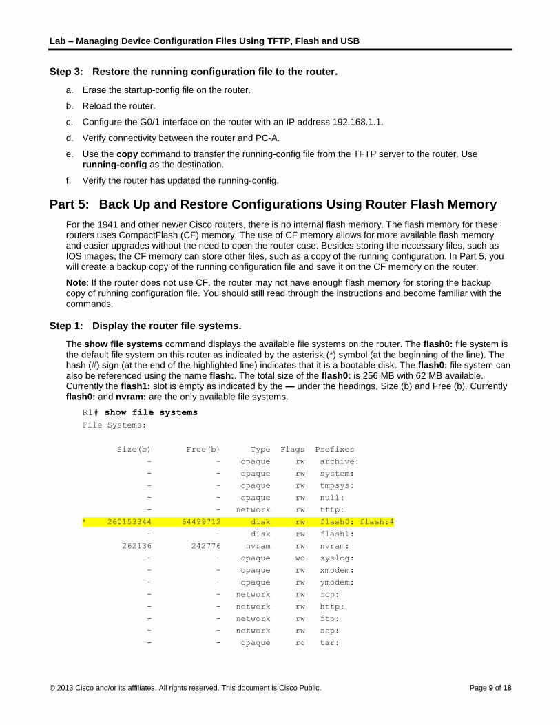
Lab – Managing Device Configuration Files Using TFTP, Flash and USB
© 2013 Cisco and/or its affiliates. All rights reserved. This document is Cisco Public. Page 9 of 18
Step 3: Restore the running configuration file to the router.
a. Erase the startup-config file on the router.
b. Reload the router.
c. Configure the G0/1 interface on the router with an IP address 192.168.1.1.
d. Verify connectivity between the router and PC-A.
e. Use the copy command to transfer the running-config file from the TFTP server to the router. Use running-config as the destination.
f. Verify the router has updated the running-config.
Part 5: Back Up and Restore Configurations Using Router Flash Memory
For the 1941 and other newer Cisco routers, there is no internal flash memory. The flash memory for these routers uses CompactFlash (CF) memory. The use of CF memory allows for more available flash memory and easier upgrades without the need to open the router case. Besides storing the necessary files, such as IOS images, the CF memory can store other files, such as a copy of the running configuration. In Part 5, you will create a backup copy of the running configuration file and save it on the CF memory on the router.
Note: If the router does not use CF, the router may not have enough flash memory for storing the backup copy of running configuration file. You should still read through the instructions and become familiar with the commands.
Step 1: Display the router file systems.
The show file systems command displays the available file systems on the router. The flash0: file system is the default file system on this router as indicated by the asterisk (*) symbol (at the beginning of the line). The hash (#) sign (at the end of the highlighted line) indicates that it is a bootable disk. The flash0: file system can also be referenced using the name flash:. The total size of the flash0: is 256 MB with 62 MB available. Currently the flash1: slot is empty as indicated by the — under the headings, Size (b) and Free (b). Currently flash0: and nvram: are the only available file systems.
R1# show file systems
File Systems:
Size(b) Free(b) Type Flags Prefixes
- - opaque rw archive:
- - opaque rw system:
- - opaque rw tmpsys:
- - opaque rw null:
- - network rw tftp:
* 260153344 64499712 disk rw flash0: flash:#
- - disk rw flash1:
262136 242776 nvram rw nvram:
- - opaque wo syslog:
- - opaque rw xmodem:
- - opaque rw ymodem:
- - network rw rcp:
- - network rw http:
- - network rw ftp:
- - network rw scp:
- - opaque ro tar:

Lab – Managing Device Configuration Files Using TFTP, Flash and USB
© 2013 Cisco and/or its affiliates. All rights reserved. This document is Cisco Public. Page 10 of 18
- - network rw https:
- - opaque ro cns:
Where is the startup-config file located?
____________________________________________________________________________________
nvram:
Note: Verify there is at least 1 MB (1,048,576 bytes) of free space. If there is not enough space in the flash memory, please contact your instructor for further instructions. You can determine the size of flash memory and space available using the show flash or dir flash: command at the privileged EXEC prompt.
Step 2: Copy the router running configuration to flash.
A file can be copied to flash by using the copy command at the privileged EXEC prompt. In this example, the file is copied into flash0:, because there is only one flash drive available as displayed in the previous step, and it is also the default file system. The R1-running-config-backup file is used as the filename for the backup running configuration file.
Note: Remember that filenames are case-sensitive in the IOS file system.
a. Copy the running configuration to flash memory.
R1# copy running-config flash:
Destination filename [running-config]? R1-running-config-backup
2169 bytes copied in 0.968 secs (2241 bytes/sec)
b. Use dir command to verify the running-config has been copied to flash.
R1# dir flash:
Directory of flash0:/
1 drw- 0 Nov 15 2011 14:59:04 +00:00 ipsdir
<output omitted>
20 -rw- 67998028 Aug 7 2012 17:39:16 +00:00 c1900-universalk9-mz.SPA.152-
4.M3.bin
22 -rw- 2169 Feb 4 2013 23:57:54 +00:00 R1-running-config-backup
24 -rw- 5865 Jul 10 2012 14:46:22 +00:00 lpnat
25 -rw- 6458 Jul 17 2012 00:12:40 +00:00 lpIPSec
260153344 bytes total (64503808 bytes free)
c. Use the more command to view the running-config file in flash memory. Examine the file output and scroll to the Interface section. Notice the no shutdown command is not included with the GigabitEthernet0/1. The interface is shut down when this file is used to update the running configuration on the router.
R1# more flash:R1-running-config-backup
<output omitted>
interface GigabitEthernet0/1
ip address 192.168.1.1 255.255.255.0
duplex auto
speed auto
<output omitted>

Lab – Managing Device Configuration Files Using TFTP, Flash and USB
© 2013 Cisco and/or its affiliates. All rights reserved. This document is Cisco Public. Page 11 of 18
Step 3: Erase the startup configuration and reload the router.
Step 4: Restore the running configuration from flash.
a. Verify the router has the default initial configuration.
b. Copy the saved running-config file from flash to update the running-config.
Router# copy flash:R1-running-config-backup running-config
c. Use the show ip interface brief command to view the status of the interfaces. The interface GigabitEthernet0/1 was not enabled when the running configuration was updated, because it is administratively down.
R1# show ip interface brief
Interface IP-Address OK? Method Status Protocol
Embedded-Service-Engine0/0 unassigned YES unset administratively down down
GigabitEthernet0/0 unassigned YES unset administratively down down
GigabitEthernet0/1 192.168.1.1 YES TFTP administratively down down
Serial0/0/0 unassigned YES unset administratively down down
Serial0/0/1 unassigned YES unset administratively down down
The interface can be enabled using the no shutdown command in the interface configuration mode on the router.
Another option is to add the no shutdown command for the GigabitEthernet0/1 interface to the saved file before updating the router running configuration file. This will be done in Part 6 using a saved file on a USB flash drive.
Note: Because the IP address was configured by using a file transfer, TFTP is listed under the Method heading in the show ip interface brief output.
Part 6: (Optional) Use a USB Drive to Back Up and Restore the Running
Configuration
A USB flash drive can be used to backup and restore files on a router with an available USB port. Two USB ports are available on the 1941 routers.
Note: USB ports are not available on all routers, but you should still become familiar with the commands.
Note: Because some ISR G1 routers (1841, 2801, or 2811) use File Allocation Table (FAT) file systems, there is a maximum size limit for the USB flash drives that can be used in this part of the lab. The recommended maximum size for an ISR G1 is 4 GB. If you receive the following message, the file system on the USB flash drive may be incompatible with the router or the capacity of the USB flash drive may have exceed maximum size of the FAT file system on the router.
*Feb 8 13:51:34.831: %USBFLASH-4-FORMAT: usbflash0 contains unexpected values in
partition table or boot sector. Device needs formatting before use!
Step 1: Insert a USB flash drive into a USB port on the router.
Notice the message on the terminal when inserting the USB flash drive.
R1#
* *Feb 5 20:38:04.678: %USBFLASH-5-CHANGE: usbflash0 has been inserted!
Step 2: Verify that the USB flash file system is available.
R1# show file systems
File Systems:

Lab – Managing Device Configuration Files Using TFTP, Flash and USB
© 2013 Cisco and/or its affiliates. All rights reserved. This document is Cisco Public. Page 12 of 18
Size(b) Free(b) Type Flags Prefixes
- - opaque rw archive:
- - opaque rw system:
- - opaque rw tmpsys:
- - opaque rw null:
- - network rw tftp:
* 260153344 64512000 disk rw flash0: flash:#
- - disk rw flash1:
262136 244676 nvram rw nvram:
- - opaque wo syslog:
- - opaque rw xmodem:
- - opaque rw ymodem:
- - network rw rcp:
- - network rw http:
- - network rw ftp:
- - network rw scp:
- - opaque ro tar:
- - network rw https:
- - opaque ro cns:
7728881664 7703973888 usbflash rw usbflash0:
Step 3: Copy the running configuration file to the USB flash drive.
Use the copy command to copy the running configuration file to the USB flash drive.
R1# copy running-config usbflash0:
Destination filename [running-config]? R1-running-config-backup.txt
2198 bytes copied in 0.708 secs (3105 bytes/sec)
Step 4: List the file on the USB flash drive.
Use the dir command (or show command) on the router to list the files on the USB flash drive. In this sample, a flash drive was inserted into USB port 0 on the router.
R1# dir usbflash0:
Directory of usbflash0:/
1 -rw- 16216 Nov 15 2006 09:34:04 +00:00 ConditionsFR.txt
2 -rw- 2462 May 26 2006 21:33:40 +00:00 Nlm.ico
3 -rw- 24810439 Apr 16 2010 10:28:00 +00:00 Twice.exe
4 -rw- 71 Jun 4 2010 11:23:06 +00:00 AUTORUN.INF
5 -rw- 65327 Mar 11 2008 10:54:26 +00:00 ConditionsEN.txt
6 -rw- 2198 Feb 5 2013 21:36:40 +00:00 R1-running-config-backup.txt
7728881664 bytes total (7703973888 bytes free)
Step 5: Erase the startup-config and reload the router.
Step 6: Modify the saved file.
a. Remove the USB drive from the router.

Lab – Managing Device Configuration Files Using TFTP, Flash and USB
© 2013 Cisco and/or its affiliates. All rights reserved. This document is Cisco Public. Page 13 of 18
Router#
*Feb 5 21:41:51.134: %USBFLASH-5-CHANGE: usbflash0 has been removed!
b. Insert the USB drive into the USB port of a PC.
c. Modify the file using a text editor. The no shutdown command is added to the GigabitEthernet0/1 interface. Save the file as a plain text file on to the USB flash drive.
!
interface GigabitEthernet0/1
ip address 192.168.1.1 255.255.255.0
no shutdown
duplex auto
speed auto
!
d. Remove the USB flash drive from the PC safely.
Step 7: Restore the running configuration file to the router.
a. Insert the USB flash drive into a USB port on the router. Notice the port number where the USB drive has been inserted if there is more than one USB port available on the router.
*Feb 5 21:52:00.214: %USBFLASH-5-CHANGE: usbflash1 has been inserted!
b. List the files on the USB flash drive.
Router# dir usbflash1:
Directory of usbflash1:/
1 -rw- 16216 Nov 15 2006 09:34:04 +00:00 ConditionsFR.txt
2 -rw- 2462 May 26 2006 21:33:40 +00:00 Nlm.ico
3 -rw- 24810439 Apr 16 2010 10:28:00 +00:00 Twice.exe
4 -rw- 71 Jun 4 2010 11:23:06 +00:00 AUTORUN.INF
5 -rw- 65327 Mar 11 2008 10:54:26 +00:00 ConditionsEN.txt
6 -rw- 2344 Feb 6 2013 14:42:30 +00:00 R1-running-config-backup.txt
7728881664 bytes total (7703965696 bytes free)
c. Copy the running configuration file to the router.
Router# copy usbflash1:R1-running-config-backup.txt running-config
Destination filename [running-config]?
2344 bytes copied in 0.184 secs (12739 bytes/sec)
R1#
d. Verify that the GigabitEthernet0/1 interface is enabled.
R1# show ip interface brief
Interface IP-Address OK? Method Status Protocol
Embedded-Service-Engine0/0 unassigned YES unset administratively down down
GigabitEthernet0/0 unassigned YES unset administratively down down
GigabitEthernet0/1 192.168.1.1 YES TFTP up up
Serial0/0/0 unassigned YES unset administratively down down
Serial0/0/1 unassigned YES unset administratively down down
The G0/1 interface is enabled because the modified running configuration included the no shutdown command.

Lab – Managing Device Configuration Files Using TFTP, Flash and USB
© 2013 Cisco and/or its affiliates. All rights reserved. This document is Cisco Public. Page 14 of 18
Reflection
1. What command do you use to copy a file from the flash to a USB drive?
_______________________________________________________________________________________
copy flash:filename usbflash0:
2. What command do you use to copy a file from the USB flash drive to a TFTP server?
_______________________________________________________________________________________
copy usbflash0:filename tftp:
Router Interface Summary Table
Router Interface Summary
Router Model Ethernet Interface #1 Ethernet Interface #2 Serial Interface #1 Serial Interface #2
1800 Fast Ethernet 0/0 (F0/0)
Fast Ethernet 0/1 (F0/1)
Serial 0/0/0 (S0/0/0) Serial 0/0/1 (S0/0/1)
1900 Gigabit Ethernet 0/0 (G0/0)
Gigabit Ethernet 0/1 (G0/1)
Serial 0/0/0 (S0/0/0) Serial 0/0/1 (S0/0/1)
2801 Fast Ethernet 0/0 (F0/0)
Fast Ethernet 0/1 (F0/1)
Serial 0/1/0 (S0/1/0) Serial 0/1/1 (S0/1/1)
2811 Fast Ethernet 0/0 (F0/0)
Fast Ethernet 0/1 (F0/1)
Serial 0/0/0 (S0/0/0) Serial 0/0/1 (S0/0/1)
2900 Gigabit Ethernet 0/0 (G0/0)
Gigabit Ethernet 0/1 (G0/1)
Serial 0/0/0 (S0/0/0) Serial 0/0/1 (S0/0/1)
Note: To find out how the router is configured, look at the interfaces to identify the type of router and how many interfaces the router has. There is no way to effectively list all the combinations of configurations for each router class. This table includes identifiers for the possible combinations of Ethernet and Serial interfaces in the device. The table does not include any other type of interface, even though a specific router may contain one. An example of this might be an ISDN BRI interface. The string in parenthesis is the legal abbreviation that can be used in Cisco IOS commands to represent the interface.
Device Configs
Router R1
R1# show run
Building configuration...
Current configuration : 1283 bytes
!
version 15.2
service timestamps debug datetime msec
service timestamps log datetime msec
service password-encryption
!
hostname R1
!
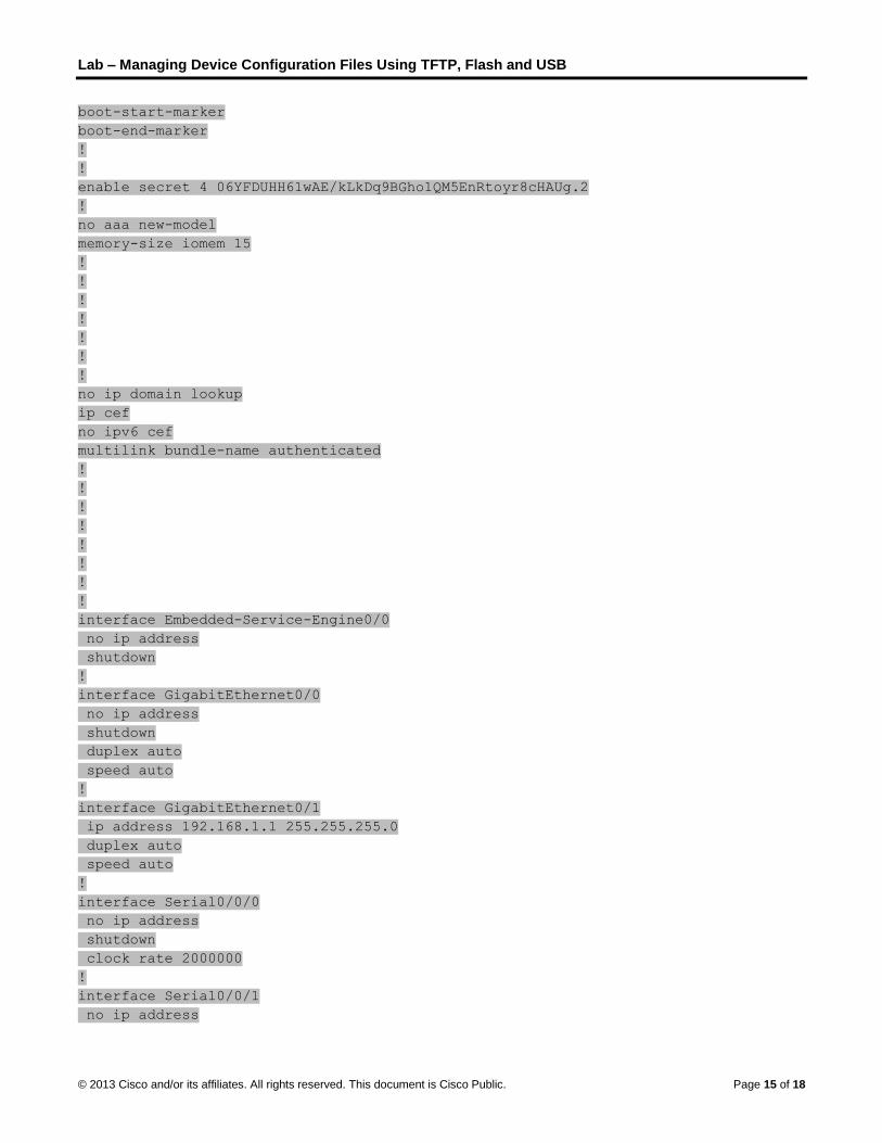
Lab – Managing Device Configuration Files Using TFTP, Flash and USB
© 2013 Cisco and/or its affiliates. All rights reserved. This document is Cisco Public. Page 15 of 18
boot-start-marker
boot-end-marker
!
!
enable secret 4 06YFDUHH61wAE/kLkDq9BGho1QM5EnRtoyr8cHAUg.2
!
no aaa new-model
memory-size iomem 15
!
!
!
!
!
!
!
no ip domain lookup
ip cef
no ipv6 cef
multilink bundle-name authenticated
!
!
!
!
!
!
!
!
interface Embedded-Service-Engine0/0
no ip address
shutdown
!
interface GigabitEthernet0/0
no ip address
shutdown
duplex auto
speed auto
!
interface GigabitEthernet0/1
ip address 192.168.1.1 255.255.255.0
duplex auto
speed auto
!
interface Serial0/0/0
no ip address
shutdown
clock rate 2000000
!
interface Serial0/0/1
no ip address

Lab – Managing Device Configuration Files Using TFTP, Flash and USB
© 2013 Cisco and/or its affiliates. All rights reserved. This document is Cisco Public. Page 16 of 18
shutdown
!
ip forward-protocol nd
!
no ip http server
no ip http secure-server
!
!
!
!
!
control-plane
!
!
!
line con 0
password 14141B180F0B
login
line aux 0
line 2
no activation-character
no exec
transport preferred none
transport input all
transport output pad telnet rlogin lapb-ta mop udptn v120 ssh
stopbits 1
line vty 0 4
password 070C285F4D06
login
transport input all
!
scheduler allocate 20000 1000
!
end
Switch S1
S1#show run
Building configuration...
Current configuration : 1498 bytes
!
!
version 15.0
no service pad
service timestamps debug datetime msec
service timestamps log datetime msec
service password-encryption
!
hostname S1

Lab – Managing Device Configuration Files Using TFTP, Flash and USB
© 2013 Cisco and/or its affiliates. All rights reserved. This document is Cisco Public. Page 17 of 18
!
boot-start-marker
boot-end-marker
!
enable secret 4 06YFDUHH61wAE/kLkDq9BGho1QM5EnRtoyr8cHAUg.2
!
no aaa new-model
system mtu routing 1500
!
!
no ip domain-lookup
!
!
!
!
!
!
spanning-tree mode pvst
spanning-tree extend system-id
!
vlan internal allocation policy ascending
!
!
!
!
interface FastEthernet0/1
!
interface FastEthernet0/2
!
interface FastEthernet0/3
!
interface FastEthernet0/4
!
interface FastEthernet0/5
!
interface FastEthernet0/6
!
interface FastEthernet0/7
!
interface FastEthernet0/8
!
interface FastEthernet0/9
!
interface FastEthernet0/10
!
interface FastEthernet0/11
!
interface FastEthernet0/12
!

Lab – Managing Device Configuration Files Using TFTP, Flash and USB
© 2013 Cisco and/or its affiliates. All rights reserved. This document is Cisco Public. Page 18 of 18
interface FastEthernet0/13
!
interface FastEthernet0/14
!
interface FastEthernet0/15
!
interface FastEthernet0/16
!
interface FastEthernet0/17
!
interface FastEthernet0/18
!
interface FastEthernet0/19
!
interface FastEthernet0/20
!
interface FastEthernet0/21
!
interface FastEthernet0/22
!
interface FastEthernet0/23
!
interface FastEthernet0/24
!
interface GigabitEthernet0/1
!
interface GigabitEthernet0/2
!
interface Vlan1
ip address 192.168.1.11 255.255.255.0
!
ip default-gateway 192.168.1.1
ip http server
ip http secure-server
!
!
!
line con 0
password 045802150C2E
login
line vty 0 4
password 045802150C2E
login
line vty 5 15
password 045802150C2E
login
!
end

© 2013 Cisco and/or its affiliates. All rights reserved. This document is Cisco Public. Page 1 of 4
Lab – Researching Password Recovery Procedures (Instructor Version) Instructor Note: Red font color or Gray highlights indicate text that appears in the instructor copy only.
Objectives Part 1: Research the Configuration Register
• Identify the purpose of the configuration register.
• Describe router behavior for different configuration register values.
Part 2: Document the Password Recovery Procedure for a Specific Cisco Router
• Research and record the process for password recovery on a specific Cisco router.
• Answer questions based on the researched procedure.
Background / Scenario The purpose of this lab is to research the procedure for recovering or resetting the enable password on a specific Cisco router. The enable password protects access to privileged EXEC and configuration mode on Cisco devices. The enable password can be recovered, but the enable secret password is encrypted and would need to be replaced with a new password.
In order to bypass a password, a user must be familiar with the ROM monitor (ROMMON) mode, as well as the configuration register setting for Cisco routers. ROMMON is basic CLI software stored in ROM that can be used to troubleshoot boot errors and recover a router when an IOS is not found.
In this lab, you will begin by researching the purpose and settings of the configuration register for Cisco devices. You will then research and detail the exact procedure for password recovery for a specific Cisco router.
Required Resources • Device with Internet access
Part 1: Research the Configuration Register To recover or reset an enable password, a user will utilize the ROMMON interface to instruct the router to ignore the startup configuration when booting. When booted, the user will access privilege EXEC mode, overwrite the running configuration with the saved startup configuration, recover or reset the password, and restore the router’s boot process to include the startup configuration.
The router’s configuration register plays a vital role in the process of password recovery. In the first part of this lab, you will research the purpose of a router’s configuration register and the meaning of certain configuration register values.
Instructor Note: Have students visit the Use of Configuration Register on All Cisco Routers page at http://www.cisco.com/en/US/products/hw/routers/ps133/products_tech_note09186a008022493f.shtml on the Cisco Website.
Step 1: Describe the purpose of the configuration register.
What is the purpose of the configuration register?
_______________________________________________________________________________________
_______________________________________________________________________________________

Lab – Researching Password Recovery Procedures
© 2013 Cisco and/or its affiliates. All rights reserved. This document is Cisco Public. Page 2 of 4
_______________________________________________________________________________________
_______________________________________________________________________________________
The configuration register can be used to change how the router boots, options for booting, and console speed.
What command changes the configuration register in configuration mode?
_______________________________________________________________________________________
config-register
What command changes the configuration register in the ROMMON interface?
_______________________________________________________________________________________
confreg
Step 2: Determine configuration register values and their meanings.
Research and list the router behavior for the following configuration register values.
0x2102 ________________________________________________________________________________
_______________________________________________________________________________________
For the configuration register value 0x2102, a router will load the IOS from the flash memory then load the start-up configuration from the NVRAM if present. If no operating system is found, then the router will boot to ROMMON.
0x2142 ________________________________________________________________________________
_______________________________________________________________________________________
For the configuration register value 0x2142, a router will load the IOS from the flash memory, ignore the start-up configuration in NVRAM, and provide a prompt for initial configuration dialog. If no operating system is found, then the router will boot to ROMMON.
What is the difference between these two configuration register values?
_______________________________________________________________________________________
_______________________________________________________________________________________
The 0x2102 setting is for normal router operation. The 0x2142 setting bypasses the start-up configuration allowing a user to recovery or reset the enable password.
Part 2: Document the Password Recovery Procedure for a Specific Cisco Router
For Part 2, you will describe the exact procedure for recovering or resetting a password from a specific Cisco router and answer questions based on your research. Your instructor will provide you with the exact router model to research.
Instructor Note: Have students visit the Password Recovery Procedures page on the Cisco website at http://www.cisco.com/en/US/products/sw/iosswrel/ps1831/products_tech_note09186a00801746e6.shtml for password recovery procedures for a variety of Cisco devices.
Step 1: Detail the process to recover a password on a specific Cisco router.
Research and list the steps and commands that you need to recover or reset the enable or enable secret password from your Cisco router. Summarize the steps in your own words.
_______________________________________________________________________________________

Lab – Researching Password Recovery Procedures
© 2013 Cisco and/or its affiliates. All rights reserved. This document is Cisco Public. Page 3 of 4
_______________________________________________________________________________________
_______________________________________________________________________________________
_______________________________________________________________________________________
_______________________________________________________________________________________
_______________________________________________________________________________________
_______________________________________________________________________________________
_______________________________________________________________________________________
_______________________________________________________________________________________
_______________________________________________________________________________________
_______________________________________________________________________________________
_______________________________________________________________________________________
_______________________________________________________________________________________
_______________________________________________________________________________________
_______________________________________________________________________________________
_______________________________________________________________________________________
To recover or reset the enable password on the Cisco 1900 series router, complete the following steps:
1. Establish a terminal connection with the router using Tera Term or other terminal emulator.
2. Boot to ROMMON by either removing flash and rebooting or selecting Alt-b during a reboot.
3. Type confreg 0x2142 at the rommon prompt.
4. Type reset at the next rommon prompt.
5. Type no at the initial configuration dialog.
6. Type enable at the router prompt.
7. Type copy startup-config running-config to load the startup configuration.
8. Type show running-config.
9. Record an unencrypted enable password. Reset an encrypted enable password.
10. In configuration mode, type config-register 0x2102.
11. In privilege mode, type copy running-config startup-config in order to save configuration.
12. Use the show version command to verity configuration register settings.
Step 2: Answer questions about the password recovery procedure.
Using the process for password recovery, answer the following questions.
Describe how to find the current setting for your configuration register.
_______________________________________________________________________________________
_______________________________________________________________________________________
The show version command will provide the current setting for the configuration register.
Describe the process for entering ROMMON.
_______________________________________________________________________________________

Lab – Researching Password Recovery Procedures
© 2013 Cisco and/or its affiliates. All rights reserved. This document is Cisco Public. Page 4 of 4
_______________________________________________________________________________________
A user can remove the flash memory and restart the router to boot to the ROMMON utility. A user can also boot the router and select alt+b if using Tera Term.
What commands do you need to enter the ROMMON interface?
_______________________________________________________________________________________
_______________________________________________________________________________________
A user would need to enter confreg 0x2142 to change the configuration setting followed by reset to restart the router.
What message would you expect to see when the router boots?
_______________________________________________________________________________________
_______________________________________________________________________________________
If a router does not load the startup configuration, a user would expect to see the message “Continue with configuration dialog?”
Why is it important to load the startup configuration into the running configuration?
_______________________________________________________________________________________
_______________________________________________________________________________________
Loading the startup configuration into the running configuration ensures that the original startup configuration remains intact if the user saves during the password recovery process.
Why is it important to change the configuration register back to the original value after recovering password?
_______________________________________________________________________________________
_______________________________________________________________________________________
Returning the configuration register to the original value will ensure that the router will load the startup configuration during the next reload.
Reflection 1. Why is it of critical importance that a router be physically secured to prevent unauthorized access?
_______________________________________________________________________________________
_______________________________________________________________________________________
_______________________________________________________________________________________
Because the password recovery procedure is based on a console connection, which requires direct physical access to the device, preventing unauthorized users access to the physical device is an imperative part of an overall security plan.

© 2013 Cisco and/or its affiliates. All rights reserved. This document is Cisco Public. Page 1 of 7
Design and Build a Small Business Network (Capstone Project)
(Instructor Version) Instructor Note: Red font color or Gray highlights indicate text that appears in the instructor copy only.
Objectives
Explain how a small network of directly connected segments is created, configured, and verified.
In this activity, you will demonstrate that you know how to design, configure, verify, and secure a very small network. Documentation and presentation are also vital parts of this Capstone Project.
Background/Scenario
Note: This activity is best completed in groups of 2-3 students.
Design and build a network from scratch.
Your design must include a minimum of one router, one switch, and one PC.
Fully configure the network and use IPv4 or IPv6 (subnetting must be included as a part of your addressing scheme).
Verify the network using at least five show commands.
Secure the network using SSH, secure passwords, and console passwords (minimum).
Create a rubric to use for informal peer grading. Alternatively, your instructor may choose to use the rubric provided with this activity.
Present your Capstone Project to the class and be able to answer questions from your peers and Instructor.
Instructor notes: This Modeling Activity is suggested to be a graded assignment after completing Chapters 1-11. Students should be able to show how small networks are designed, configured, verified and secured. Documentation is a large factor of this project and students must be able to explain their network design and verification through the use of show commands.
Required Resources
Packet Tracer
Student/group-created rubric for assessment of the assignment
Reflection
1. What was the most difficult portion of this activity?
____________________________________________________________________________
Answers will vary.
2. Why do you think network documentation is so important to this activity and in the real world?
____________________________________________________________________________
Documentation is imperative to good network management. Without documentation, network administrators have to recreate topologies, physically check addressing, etc. which takes time that could be used elsewhere.
A suggested rubric and documentation examples are provided below:
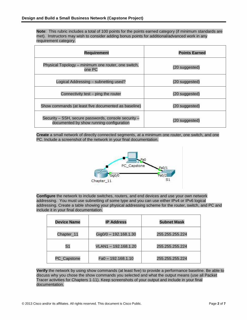
Design and Build a Small Business Network (Capstone Project)
© 2013 Cisco and/or its affiliates. All rights reserved. This document is Cisco Public. Page 2 of 7
Note: This rubric includes a total of 100 points for the points earned category (if minimum standards are met). Instructors may wish to consider adding bonus points for additional/advanced work in any requirement category.
Requirement Points Earned
Physical Topology – minimum one router, one switch, one PC
(20 suggested)
Logical Addressing – subnetting used? (20 suggested)
Connectivity test – ping the router (20 suggested)
Show commands (at least five documented as baseline) (20 suggested)
Security – SSH, secure passwords, console security – documented by show running-configuration
(20 suggested)
Create a small network of directly connected segments, at a minimum one router, one switch, and one PC. Include a screenshot of the network in your final documentation.
Configure the network to include switches, routers, and end devices and use your own network addressing. You must use subnetting of some type and you can use either IPv4 or IPv6 logical addressing. Create a table showing your physical addressing scheme for the router, switch, and PC and include it in your final documentation.
Device Name IP Address Subnet Mask
Chapter_11 Gig0/0 – 192.168.1.30 255.255.255.224
S1 VLAN1 – 192.168.1.20 255.255.255.224
PC_Capstone Fa0 – 192.168.1.10 255.255.255.224
Verify the network by using show commands (at least five) to provide a performance baseline. Be able to discuss why you chose the show commands you selected and what the output means (use all Packet Tracer activities for Chapters 1-11). Keep screenshots of your output and include in your final documentation.
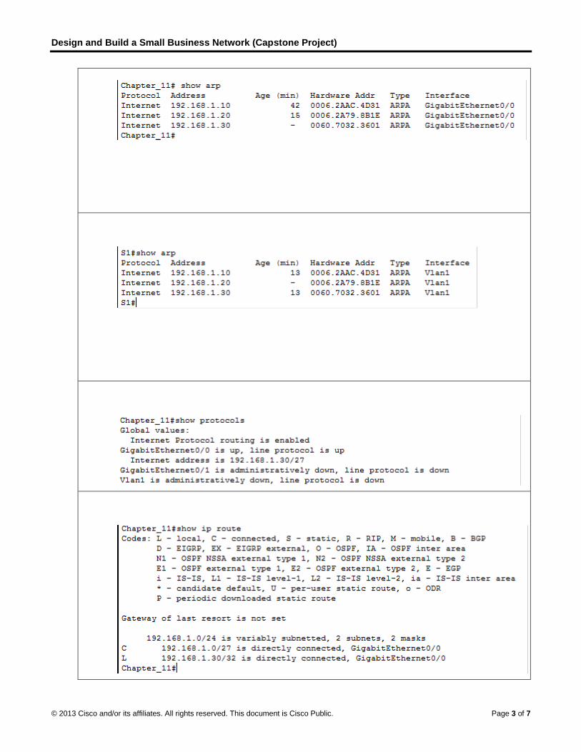
Design and Build a Small Business Network (Capstone Project)
© 2013 Cisco and/or its affiliates. All rights reserved. This document is Cisco Public. Page 3 of 7

Design and Build a Small Business Network (Capstone Project)
© 2013 Cisco and/or its affiliates. All rights reserved. This document is Cisco Public. Page 4 of 7
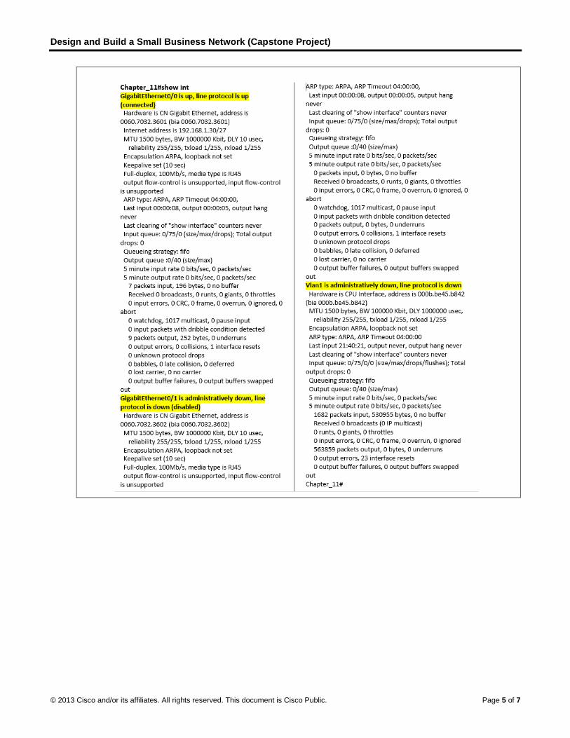
Design and Build a Small Business Network (Capstone Project)
© 2013 Cisco and/or its affiliates. All rights reserved. This document is Cisco Public. Page 5 of 7

Design and Build a Small Business Network (Capstone Project)
© 2013 Cisco and/or its affiliates. All rights reserved. This document is Cisco Public. Page 6 of 7

Design and Build a Small Business Network (Capstone Project)
© 2013 Cisco and/or its affiliates. All rights reserved. This document is Cisco Public. Page 7 of 7
Secure the network using common configuration to include SSH, secure passwords, console security, etc. and show the commands configured by enacting a show running-configuration screen as output. Include in your final documentation.
Identify elements of the model that map to real-world applications:
All facets of this activity map to IT-related content and real-world applications because this is a culminating activity for all 11 Chapters.