SCUTARII Product Overview MAS Solution in Prison Anit-UAV ...

Feedback Linearization and High Order Sliding Mode Observer For AQuadrotor UAV
A. Benallegue, A. Mokhtari, and L. Fridman
Abstract— In this paper, a feedback linearization-based con-troller with a high order sliding mode observer running parallelis applied to a quadrotor unmanned aerial vehicle. The highorder sliding mode observer works as an observer and estimatorof the effect of the external disturbances such as wind andnoise. The whole observer-estimator-control law constitutes anoriginal approach to the vehicle regulation with minimal num-ber of sensors. Performance issues of the controller-observerare illustrated in a simulation study that takes into accountparameter uncertainties and external disturbances.
I. INTRODUCTION
Small UAV Quadrotors are designed to easily move indifferent environments while following specific tasks andproviding good performance as well as a great autonomy.Affected by aerodynamic forces, the quadrotor dynamicsis nonlinear, multivariable, and is subject to parameter un-certainties and external disturbances. In turn, controlling ofthe quadrotor is required i) to meet the stability, robustnessand desired dynamic properties; ii) to be able to handlenonlinearity; iii) to be adaptive to changing parameters andenvironmental disturbances.
Main difficulties of the motion control are thus para-metric uncertainties, unmodeled dynamics, and external dis-turbances [1], which result in further complication in thedesign of controllers for actual systems [3]. However variousadvanced control methods such as feedback linearizationmethod [4], have been developed to meet increasing demandson the performance, however, they required full informationon the state that may limit their practical utility. Indeed,even if all the state measurements are possible they aretypically corrupted by noise. Moreover, the increased numberof sensors makes the overall system more complex in imple-mentation and expensive in realization. In order to decreasethe number of sensors in [5] the use only a rotational motionsensors is proposed in order to control tilt angles and evaluatetranslational motion. However, aerodynamic forces still causedifficulties to overcome. Thus motivated, an observer-basedfeedback design becomes an attractive approach to roboticcontrol.
The use of state observers appears to be useful in notonly system monitoring and regulation but also detecting aswell as identifying failures in dynamic systems. Almost allobserver designs are based on the mathematical model of the
A. Benallegue is with Robotics Laboratory of Versailles, [email protected]
A. Mokhtari is with the University of Science and Technology of Oran,Algeria. [email protected]
L. Fridman is with the university of Mexico, [email protected]
plant, is no linearized and has consequently have uncertaininputs. From the other hand the relative degree of the modelwith respect to the known outputs heavily dependent on theaccuracy of the mathematical model of the plant [6].
So the main motivation of the paper are:
• Feedback linearization controller of the quadrotor needsthe third derivatives of measured states in order toreconstruct tilt angles and to fulfill the controller re-quirement.
• When quadrotor is subjected to external disturbances,it would be suitable to compensate them through anobserver based controller.
• The observers should be robust with respect to externalperturbations (wind and noise).
• Observers based identification perturbation allow to re-duce the number of sensors required for control design.
Methodology. The relative degree of the UAV Quadrotorsmodel w.r.t. to unknown inputs is more than one and thestandard necessary and sufficient conditions for observationof the systems with unknown inputs are not fulfilled [2]. Tosolve the problem of observation for UAV Quadrotors thehigher order sliding mode observers will be used.
Sliding mode observers (see, for example, the correspond-ing chapters in the textbooks [13], [22], and the recenttutorials [7], [9], [10]) are widely used due to their attrac-tive features: a) insensitivity (more than robustness!) withrespect to unknown inputs; b) possibilities to use the valuesof the equivalent output injection for the unknown inputsidentification; c) finite time convergence to exact values ofthe state vectors. In [14], [22] and [8] a step by step form ofsliding mode observers were proposed. Such observers basedon the transformation of a given system to a block observableform and the sequential estimation of each state by usingof the value of the equivalent output injection. On the onehand, this schemes allows to formulate some observabilityconditions for linear time invariant systems with unknowninputs. Such conditions were formulated in [22], [8] for thescalar case. From the other hand, realization of this schemecaused obligatory filtration due to the non-idealities.In [18], [19] and [21] a robust exact arbitrary order differen-tiator was designed ensuring finite time convergence to thevalues of the corresponding derivatives, and applications ofhigher order sliding algorithms were considered.
Basing on the second-order sliding-mode super twisting al-gorithm in [20].an observer for uncertain mechanical systemswith only position measurements was proposed ensuring bestpossible approximation for the velocities.
Proceedings of the 2006 International Workshop on Variable Structure SystemsAlghero, Italy, June 5-7, 2006
WedC.3
1-4244-0208-5/06/$20 ©2006 IEEE 555365

Main contribution. In the paper the model of UAV Quadro-tor and feedback linearization-based controller is suggested.To realize this with a high order sliding mode observerrunning parallel is applied to a quadrotor unmanned aerialvehicle. The high order sliding mode observer works asan observer and estimator of the effect of the externaldisturbances such as wind and noise. The whole observer-estimator-control law constitutes an original approach tothe vehicle regulation with minimal number of sensors.Performance issues of the controller-observer are illustratedin a simulation study that takes into account parameteruncertainties and external disturbances UAV Quadrotor issuggested. To realize the control algorithm and identify theuncertainties a fourth order sliding mode observer based onfourth order differentiator [21] is suggested This observerconverge in finite time ensuring the identification of the effectof the external disturbances such as wind and noise. Thewhole observer-estimator-control law constitutes an originalapproach to the vehicle regulation with minimal numberof sensors. Performance issues of the controller-observerare illustrated in a simulation study that takes into accountparameter uncertainties and external disturbances.
Paper structure.The rest of the paper is outlined as follows.UAV dynamics is deduced in section 2. The inner outercontroller is developed in section 3. The observer design ispresented in section 4. Simulation results are given in section5. Section 6 yields some conclusions.
II. QUADROTOR DYNAMICS
The quadrotor is composed of 4 rotors. Two diagonalmotors (1 and 3) are running in the same direction whereasthe others (2 and 4) in the other direction to eliminate theanti-torque. On varying the rotor speeds altogether with thesame quantity the lift forces will change affecting in this casethe altitude z of the system and enabling vertical take-off/onlanding. Yaw angle ψ is obtained by speeding up\slowingdown the diagonal motors depending on desired direction.Roll angle φ axe allows the quadrotor to move toward ydirection. Pitch angle θ axe allows the quadrotor to movetoward x direction. The rotor is the primary source of controland propulsion for the UAV. The Euler angle orientation tothe flow provides the forces and moments to control thealtitude and position of the system. The absolute position isdescribed by three coordinates (x0, y0, z0), and its attitude byEuler angles (ψ, θ, φ), under the conditions (−π ≤ ψ < π)for yaw, (−π
2 < θ < π2 ) for pitch and (−π
2 < φ < π2 )
for roll. The derivatives with respect to time of the angles(ψ,θ,φ) can be expressed in the form:
col(ψ, θ, φ) = M(ψ, θ, φ)ω (1)
where ω = col(p, q, r) is the angular velocity expressed withrespect to a body reference frame and M(ψ, θ, φ) is the 3x3matrix given by:
M(ψ, θ, φ) =
⎡⎣ 0 SφSeθ CφSeθ
0 Cφ −Sφ1 SφTθ CφTθ
⎤⎦ (2)
with S. = sin(.), C. = cos(.), T. = tan(.), Se. = sec(.)This matrix, as shown, depends only on (ψ, θ, φ) and it is
invertible if the above conditions on (ψ, θ, φ) hold.Similarly, the time derivative of the position (x0, y0, z0)
is given by:col(x0, y0, z0) = V0 (3)
where V0 = col(u0, v0, w0) is the absolute velocity ofthe UAV expressed with respect to an earth fixed inertialreference frame. Let V = col(u, v, w) be the absolutevelocity of the UAV expressed in a body fixed referenceframe. Then V and V0 relate according to
V0 = R(ψ, θ, φ)V
where R(ψ, θ, φ) is the rotation matrix given by
R =
⎡⎣ CθCψ CψSθSφ − CφSψ CφCψSθ + SφSψ
CθSψ SθSφSψ + CφCψ CφSθSψ − CψSφ−Sθ CθSφ CθCφ
⎤⎦
Equations (1) and (3) are the kinematic equations. Thedynamic equations are now expressed. Using the Newton’slaws about the center of mass one obtains the dynamicequations for the miniature four rotors helicopter
mV0 =∑
Fext (4)
Jω = −ω × Jω +∑
Text (5)
where the symbol × denotes the usual vector product, m isthe mass, J is the inertia matrix which is given by
J =
⎡⎣ Ix 0 0
0 Iy 00 0 Iz
⎤⎦
Due to the symmetry of the geometric form of the quadrotorthe coupling inertia is assumed to be zero. The notations∑
Fext,∑
Text stand for the vector of external forces andthat of external torques, respectively. They contain the heli-copter’s weight, the aerodynamic forces vector, the thrust andthe torque developed by the four rotors. It is straightforwardto compute that
∑Fext =
⎡⎣ Ax − (CφCψSθ + SφSψ)u1
Ay − (CφSθSψ − CψSφ)u1
Az + mg − (CθCφ)u1
⎤⎦ (6)
∑Text =
⎡⎣ Ap + u2d
Aq + u3dAr + u4
⎤⎦
where• (Ax, Ay, Az)T and col(Ap, Aq, Ar)T are the resulting
aerodynamic forces and moments acting on the UAVand are computed from the aerodynamic coefficients Ci
as Ai = 12ρairCiW
2 [11],[12] (ρair is the air density,W is the velocity of the UAV with respect to the air)[15]. (Ci depend on several parameters like the anglebetween airspeed and the body fixed reference system,the aerodynamic and geometric form of the wing);
• g is the gravity constant (g = 9.81ms−2);
366

• d is the distance from the center of mass to the rotors;• u1 is the resulting thrust of the four rotors defined as
u1 = (F1 + F2 + F3 + F4)• u2 is the difference of thrust between the left rotor and
the right rotor defined as u2 = d (F4 − F2)• u3 is the difference of thrust between the front rotor
and the back rotor defined as u3 = d(F3 − F1)• u4 is the difference of torque between the two clockwise
turning rotors and the two counter-clockwise turningrotors defined as u4 = C(F1 − F2 + F3 − F4)
• C is the force to moment scaling factorAssuming that the electric motors are velocity controlled,
then (u1, u2, u3, u4) may be viewed as control inputs. Thedynamic model of the quadrotor has been developed inmany experimental works but in different manner, like S.Bouabdallah ([16]). Referring to [17], the real control signals(u1, u2, u3, u4) have been replaced by (u1, u2, u3, u4) toavoid singularity in Lie transformation matrices when usingexact linearization. In that case u1 has been delayed by dou-ble integrator. The other control signals will keep unchanged
u1 = ζ; ζ = ξ; ξ = u1
u2 = u2
u3 = u3
u4 = u4
(7)
The obtained extended system is described by state spaceequations of the form:
·x = f(x) +
4∑i=1
gi(x)ui (8)
y = h(x)
where
x = [x0, y0, z0, ψ, θ, φ, u0, v0, w0, ζ, ξ, p, q, r]T
y = [x0, y0, z0, ψ]T
f =
⎡⎢⎢⎢⎢⎢⎢⎢⎢⎢⎢⎢⎢⎢⎢⎢⎢⎢⎢⎢⎢⎢⎢⎢⎣
u0
v0
w0
qSφSeθ + rCφSeθqCφ − rSφ
p + qSφTθ + rCφTθAxm − 1
m (CφCψSθ + SφSψ)ζAy
m − 1m (CφSθSψ − CψSφ) ζAz
m + g− 1m (CθCφ)ζξ0
Iy−Iz
Ixqr + Ap
IxIz−Ix
Iypr + Aq
IyIx−Iy
Izpq + Ar
Iz
⎤⎥⎥⎥⎥⎥⎥⎥⎥⎥⎥⎥⎥⎥⎥⎥⎥⎥⎥⎥⎥⎥⎥⎥⎦
g1(x) = [0, 0, 0, 0, 0, 0, 0, 0, 0, 0, 1, 0, 0, 0]T
g2(x) =[0, 0, 0, 0, 0, 0, 0, 0, 0, 0, 0, d
Ix0, 0
]T
g3(x) =[0, 0, 0, 0, 0, 0, 0, 0, 0, 0, 0, 0, d
Iy, 0
]T
g4(x) =[0, 0, 0, 0, 0, 0, 0, 0, 0, 0, 0, 0, 0 1
Iz
]T
The purpose of the next section is to design a feedbackcontroller for the four rotor miniature helicopter whichexhibits robustness properties against neglected effects andparametric uncertainties.
III. FEEDBACK LINEARIZATION CONTROLLER
The feedback linearization technique is based on inner andouter loops of the controller. The Input-Output linearization-based inner loop uses the full state feedback to globallylinearize the nonlinear dynamics of selected controlled out-puts. Each of the output channels is differentiated sufficientlymany times until a control input component appears in theresulting equation. Using the Lie derivative, Input-Outputlinearization will transform the nonlinear system into a linearand non-interacting system in the Brunovsky form. The outercontroller adopts a classical polynomial control law for thenew input variable of the resulting linear system.
A. Structure of the inner controller
The input-output decoupling problem is solvable for thenonlinear system (8) by means of static feedback. The vectorrelative degree {r1, r2, r3, r4} is given by
r1 = r2 = r3 = 4; r4 = 2
and we have
col(y(r1)1 , y
(r2)2 , y
(r3)3 , y
(r4)4 ) = b(x) + Δ(x)u (9)
where Δ(x) and b(x) are computed as follows:
Δ(x) =
⎡⎢⎣
Lg1Lr1−1f h1(x) ... Lg4L
r1−1f h1(x)
· · · . . . · · ·Lg1L
r4−1f h4(x) · · · Lg4L
r4−1f h4(x)
⎤⎥⎦
b(x) =
⎡⎢⎣
Lr1f h1(x)
...Lr4
f h4(x)
⎤⎥⎦ (10)
where
Lfh(x) =n∑
i=1
∂h
∂xifi(x); Lk
fh(x) = Lf (Lk−1f h(x))
The matrix Δ(x) is non singular everywhere in the regionζ �= 0, −π
2 < φ < π2 , −π
2 < θ < π2 . Therefore, the
input-output decoupling problem is solvable for system (8)by means of a control law of the form:
u = α(x) + β(x)v (11)
where α(x) and β(x) are given by
α(x) = −Δ−1(x)b(x) (12)
β(x) = Δ−1(x)
Taking into account relation (7), we derive the structure(Figure 1) of the control law of system (8). Moreover, sincesystem (8) has dimension n = 14, the condition
r1 + r2 + r3 + r4 = n
367

v
v
v
v
UAV
dynamics
x
y
z
ψ
ξ ζ=u
(x)v(x)u βα +=∫ ∫u
u
u
u
x
u
u
u
v
v
v
v
UAV
dynamics
x
y
z
ψ
ξ ζ=u
(x)v(x)u βα +=∫ ∫u
u
u
u
x
u
u
u
Fig. 1. Block diagram of the inner loop.
is fulfilled and therefore, the system can be transformed viastatic feedback into a system which, in suitable coordinates,is fully linear and controllable. However, due to the presenceof external disturbances the Input-Output linearization isnot exact and the inner closed loop system in that case iscomposed into a linear part and a nonlinear disturbance part:⎛
⎜⎜⎜⎝y(4)1
y(4)2
y(4)3
y(2)4
⎞⎟⎟⎟⎠ =
⎛⎜⎜⎜⎝
d4x0dt4
d4y0dt4
d4z0dt4d2ψdt2
⎞⎟⎟⎟⎠ =
⎛⎜⎜⎝
v1
v2
v3
v4
⎞⎟⎟⎠ +
⎛⎜⎜⎝
ξ1(x, t)ξ2(x, t)ξ3(x, t)ξ4(x, t)
⎞⎟⎟⎠(13)
with ⎛⎜⎜⎝
ξ1(x, t)ξ2(x, t)ξ3(x, t)ξ4(x, t)
⎞⎟⎟⎠ =
⎛⎜⎜⎜⎝
Ax
m + a14Ap + a15AqAy
m + a24Ap + a25AqAz
m + a34Ap + a35Aq
a45Aq + a46Ar
⎞⎟⎟⎟⎠
where
a14 = (ζSφCψSθ − ζCφSψ)/(mIx);a15 = −(ζCψCθ)/(mIy)a24 = (ζSφSψSθ + ζCφCψ)/(mIx);a25 = −(ζSψCθ)/(mIy)a34 = (ζSφCθ)/(mIx); a35 = (ζSθ)(mIy)a45 = Sφ/(IyCθ); a46 = Cφ/(IzCθ)
v1, v2, v3, v4, represent the new input control signals. Thecontroller compares the primary state (x0, y0, z0, ψ) and theirsuccessive derivatives to the desired state trajectory.
B. Structure of the outer controller
While adapting a classical polynomial control law for thenew input variable v with disturbance compensation, oneobtains the following equations:
v1 = x(4)d − λ3
...e 11 − λ2e11 − λ1e11 − λ0e11 − zf
41
v2 = y(4)d − λ3
...e 12 − λ2e12 − λ1e12 − λ0e12 − zf
42
v3 = z(4)d − λ3
...e 13 − λ2e13 − λ1e13 − λ0e13 − zf
43
v4 = ψd − λ5e5 − λ4e5 − zf6
(14)where xd, yd, zd, ψd represent the desired output signals,corresponding to x0, y0, z0, ψ, respectively, the errors sig-nals e11 = [x0 − x0d] e12 = [y0 − y0d] e13 = [z0 − z0d] ande5 = [ψ−ψd] and the coefficients λi, i = 0, · · · , 5 are to bespecified in the sequel. The variables zf
41, zf42, zf
43 and zf6
are the filtered signals of z41, z42, z43 and z6 given in theobserver section. The closed-loop system (13), (14) can berewritten in the form
e = Ae + ξ(x, t) (15)
ξ = [ξ1, ξ2, ξ3, ξ4]T (16)
zf =[zf41, zf
42, zf43, zf
6
]T
(17)
where e represents the tracking error between the desiredvalue and the actual one, i.e.,
e = [e1, e2, e3, e4,e5, e6]T
and
e1 = [e11, e12, e13]T
e2 = e1; e3 = e1; e4 =...e 1 (18)
e6 = e5
ξ(x, t) is the wind parameter errors of the disturbances Thematrix A is then given by
A =
⎡⎢⎢⎢⎢⎢⎢⎣
0 I 0 0 0 00 0 I 0 0 00 0 0 I 0 0
−λ0I −λ1I −λ2I −λ3I 0 00 0 0 0 0 10 0 0 0 −λ4 −λ5
⎤⎥⎥⎥⎥⎥⎥⎦
where I is an identity matrix of dimension 3×3 and the thecontrol gains λi, i = 0, . . . , 5 are such that the eigenvaluesof the matrix A have desired locations.
It is very important to know the domain of attraction of anequilibrium point that is the set of initial states from whichthe system converges to the equilibrium point itself [24],[25].Actually, such problem arises in both system analysis andsynthesis, in order to guarantee a stable behavior in a certainregion of the state space.
IV. HIGH ORDER SLIDING MODE OBSERVER
Motivated by practice, the measured UAV variables arethe absolute position x0, y0, z0 and the orientation ψwhich represent the translational motion and rotation aroundz axis, respectively. Although non measurable signals canbe obtained by successive differentiation, however, they arecontaminated by the measurement noise to such a degreethat the differentiation can no longer be used. To avoiddifferentiation let us construct an observer based on arbitraryorder high order sliding mode differentiator [21]..
A. Observer model
The linearized dynamic model of the quadrotor with themeasured signals x1 = [x0, y0, z0]
T, and x5 = ψ can be
368
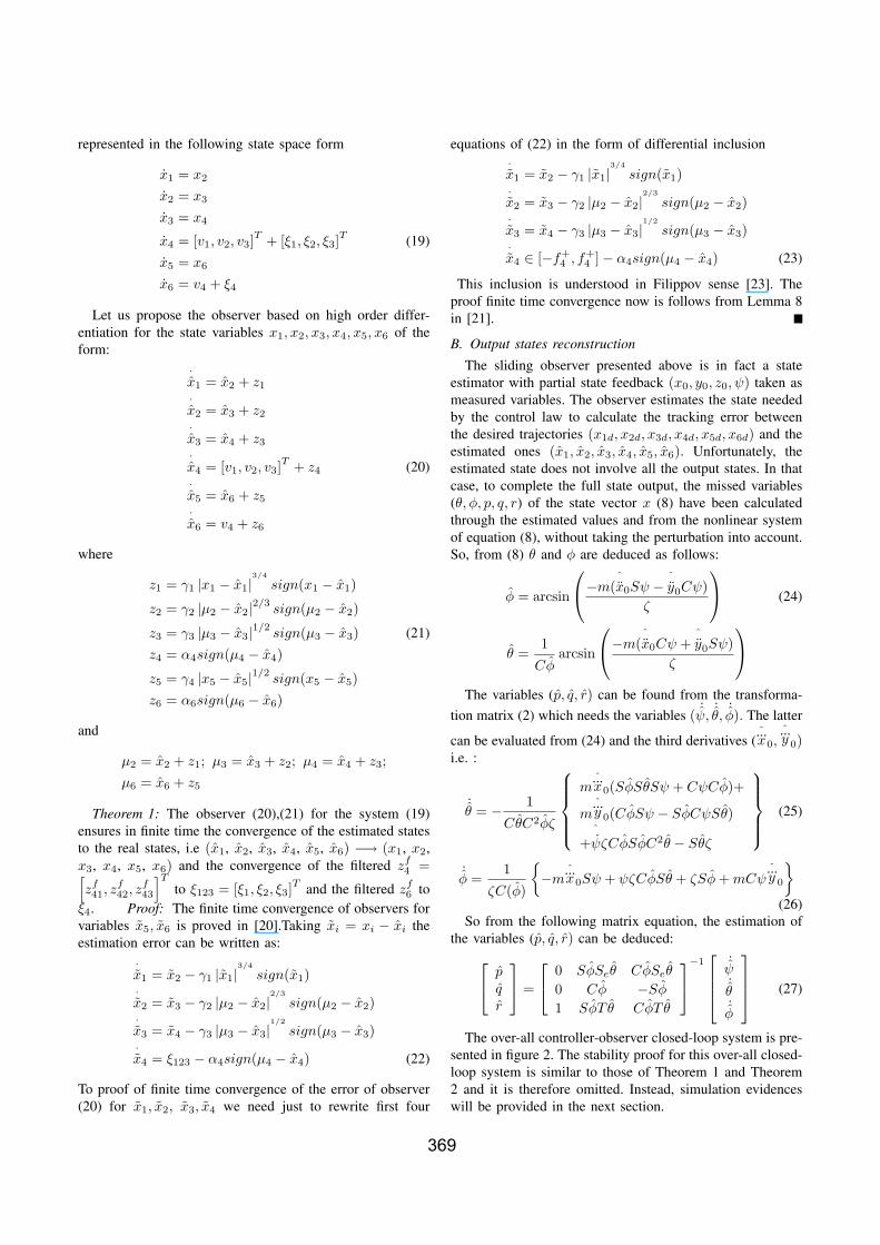
represented in the following state space form
x1 = x2
x2 = x3
x3 = x4
x4 = [v1, v2, v3]T + [ξ1, ξ2, ξ3]
T (19)
x5 = x6
x6 = v4 + ξ4
Let us propose the observer based on high order differ-entiation for the state variables x1, x2, x3, x4, x5, x6 of theform:
·x1 = x2 + z1
·x2 = x3 + z2
·x3 = x4 + z3
·x4 = [v1, v2, v3]
T + z4 (20)·x5 = x6 + z5
·x6 = v4 + z6
where
z1 = γ1 |x1 − x1|3/4
sign(x1 − x1)
z2 = γ2 |μ2 − x2|2/3sign(μ2 − x2)
z3 = γ3 |μ3 − x3|1/2sign(μ3 − x3) (21)
z4 = α4sign(μ4 − x4)
z5 = γ4 |x5 − x5|1/2sign(x5 − x5)
z6 = α6sign(μ6 − x6)
and
μ2 = x2 + z1; μ3 = x3 + z2; μ4 = x4 + z3;μ6 = x6 + z5
Theorem 1: The observer (20),(21) for the system (19)ensures in finite time the convergence of the estimated statesto the real states, i.e (x1, x2, x3, x4, x5, x6) −→ (x1, x2,x3, x4, x5, x6) and the convergence of the filtered zf
4 =[zf41, z
f42, z
f43
]T
to ξ123 = [ξ1, ξ2, ξ3]T and the filtered zf
6 toξ4. Proof: The finite time convergence of observers forvariables x5, x6 is proved in [20].Taking xi = xi − xi theestimation error can be written as:
·x1 = x2 − γ1 |x1|
3/4
sign(x1)·x2 = x3 − γ2 |μ2 − x2|
2/3
sign(μ2 − x2)·x3 = x4 − γ3 |μ3 − x3|
1/2
sign(μ3 − x3)·x4 = ξ123 − α4sign(μ4 − x4) (22)
To proof of finite time convergence of the error of observer(20) for x1, x2, x3, x4 we need just to rewrite first four
equations of (22) in the form of differential inclusion·x1 = x2 − γ1 |x1|
3/4
sign(x1)·x2 = x3 − γ2 |μ2 − x2|
2/3
sign(μ2 − x2)·x3 = x4 − γ3 |μ3 − x3|
1/2
sign(μ3 − x3)·x4 ∈ [−f+
4 , f+4 ] − α4sign(μ4 − x4) (23)
This inclusion is understood in Filippov sense [23]. Theproof finite time convergence now is follows from Lemma 8in [21].
B. Output states reconstruction
The sliding observer presented above is in fact a stateestimator with partial state feedback (x0, y0, z0, ψ) taken asmeasured variables. The observer estimates the state neededby the control law to calculate the tracking error betweenthe desired trajectories (x1d, x2d, x3d, x4d, x5d, x6d) and theestimated ones (x1, x2, x3, x4, x5, x6). Unfortunately, theestimated state does not involve all the output states. In thatcase, to complete the full state output, the missed variables(θ, φ, p, q, r) of the state vector x (8) have been calculatedthrough the estimated values and from the nonlinear systemof equation (8), without taking the perturbation into account.So, from (8) θ and φ are deduced as follows:
φ = arcsin
⎛⎝−m(
ˆx0Sψ − ˆ
y0Cψ)ζ
⎞⎠ (24)
θ =1
Cφarcsin
⎛⎝−m(
ˆx0Cψ +
ˆy0Sψ)
ζ
⎞⎠
The variables (p, q, r) can be found from the transforma-
tion matrix (2) which needs the variables ( ˙ψ,
˙θ,
˙φ). The latter
can be evaluated from (24) and the third derivatives (...x0,
...y 0)
i.e. :
˙θ = − 1
CθC2φζ
⎧⎪⎪⎪⎨⎪⎪⎪⎩
m...x0(SφSθSψ + CψCφ)+
m...y 0(CφSψ − SφCψSθ)
+ˆ
ψζCφSφC2θ − Sθζ
⎫⎪⎪⎪⎬⎪⎪⎪⎭
(25)
˙φ =
1ζC(φ)
{−m
...x0Sψ + ψζCφSθ + ζSφ + mCψ
...y 0
}
(26)So from the following matrix equation, the estimation of
the variables (p, q, r) can be deduced:
⎡⎣ p
qr
⎤⎦ =
⎡⎣ 0 SφSeθ CφSeθ
0 Cφ −Sφ
1 SφT θ CφT θ
⎤⎦−1
⎡⎢⎢⎣
˙ψ˙θ˙φ
⎤⎥⎥⎦ (27)
The over-all controller-observer closed-loop system is pre-sented in figure 2. The stability proof for this over-all closed-loop system is similar to those of Theorem 1 and Theorem2 and it is therefore omitted. Instead, simulation evidenceswill be provided in the next section.
369

}UAV
dynamics
x
0
y
0
z
0
ψ
ξ ζ=u
1
∫ ∫
u
2
u
3
u
4
UAV
dynamics
x
0
y
0
z
0
ψ
ξ ζ=u
1
∫ ∫1
u
2u
3u
4u
v
1
v
2
v
3
v
4
(x)v(x)u βα +=
v
1
v
2
v
3
v
4
(x)v(x)u βα += u
2
u
3
u
4
Control
law
State
observer
State vector
building
Desired
trajectory
x
}UAV
dynamics
x
0
y
0
z
0
ψ
ξ ζ=u
1
∫ ∫
u
2
u
3
u
4
UAV
dynamics
x
0
y
0
z
0
ψ
ξ ζ=u
1
∫ ∫1
u
2u
3u
4u
v
1
v
2
v
3
v
4
(x)v(x)u βα +=
v
1
v
2
v
3
v
4
(x)v(x)u βα += u
2
u
3
u
4
Control
law
State
observer
State vector
building
Desired
trajectory
x
Fig. 2. The overall closed loop system
V. SIMULATION RESULTS
The constant quadrotor parameters, used in the simulationrun, are:
m = 2Kg; Ix = Iy = Iz = 1.2416N.m/rad/s2;
d = 0.1m; g = 9.81m/s2
The gain values of (λ0, λ1, λ2, λ3) and (λ4, λ5) representthe coefficients of the polynomial (s + 5)4 and (s + 5)2
respectively. For a specific f+i and αi, the values of γi are
chosen as γ1 = 3, γ2 = 2.5,γ3 = γ4 = 1.5 and α4 = α6 =1.1. An application has been established without and withdisturbances and with uncertainties to see the performanceand robustness of the sliding mode observer.
a) Without disturbance: Taking for this case (Ax =Ay = Az = 0); (Ap = Aq = Ar = 0); the following resultsare obtained (figures-(3, 4).
−1
0
1
2
−1
0
1
2−0.5
0
0.5
1
1.5
x0 (m)y0 (m)
−z0
(m)
0 50 100−0.2
0
0.2
0.4
0.6
0.8
1
1.2
time (sec)
ψ (ra
d)
estimatedmeasureddesired
Fig. 3. Reference trajectories
b) With aerodynamic force disturbances: For Ax =2 sin 0.1t, Ay = 2 sin 0.1t, Az = 2 sin 0.1t occurring at 10sec, 20 sec and 40 sec respectively the following results areobtained (figures(5 to 11 ).
c) With aerodynamic moment disturbances: For Ap =0.09 sin 0.1t, Aq = 0.01 sin 0.1t, Ar = 0.2 sin 0.1t occurringat 10 sec, 20 sec and 40 sec respectively the following resultsare obtained (figures(12 to 13 ).
It is concluded from the simulations, made without per-turbation, that the high order sliding mode observer givessatisfactory results. The results of estimation errors givenin figure (4) show the efficiency of the observer. The sameconclusion follows from the tracking errors which vanishafter a finite time with a perfect convergence. When wind
0 50 100 150−1
−0.5
0
0.5
1x 10
−6
time (sec)
(x0−
x0)
(m)
0 50 100 150−1
−0.5
0
0.5
1x 10
−6
time (sec)
(y0−
y0)
(m)
0 50 100 150−1
−0.5
0
0.5
1x 10
−6
time (sec)
(z0−
z0)
(m)
0 50 100 150−5
0
5
10
15x 10
−6
time (sec)
(ψ−
ψ)
(rad
)
< <
< <
Fig. 4. Estimation errors
0 20 40 600
0.5
1
time (sec)
x0 (
m)
0 20 40 60
0
0.02
0.04
0.06
time (sec)
x0
0 20 40 60−0.01
−0.005
0
0.005
0.01
time (sec)
x0
0 20 40 60−0.01
−0.005
0
0.005
0.01
0.015
time (sec)
x0
estimateddesired
estimateddesired
estimateddesired
estimatedmeasureddesired
.
.. ...
Fig. 5. Trajectories x0, x0, x0,...x0
0 20 40 60
0
0.5
1
time (sec)
y0 (
m)
0 20 40 60
0
0.02
0.04
0.06
time (sec)
y0
0 20 40 60−0.01
−0.005
0
0.005
0.01
time (sec)
y0
0 20 40 60−4
−2
0
2
4
6x 10
−3
time (sec)
y0
estimatedmeasureddesired
estimateddesired
estimateddesired
estimateddesired
.
.. ...
Fig. 6. Trajectories y0, y0, y0,...y0
370

0 20 40 600
0.5
1
time (sec)
−z0
(m
)
0 20 40 60
0
0.02
0.04
0.06
time (sec)−
z0
0 20 40 60−0.01
−0.005
0
0.005
0.01
time (sec)
−z0
0 20 40 60−0.015
−0.01
−0.005
0
0.005
0.01
time (sec)
−z0
estimatedmeasureddesired
estimateddesired
estimateddesired
.
. .
.
...
Fig. 7. Trajectories z0, z0, z0,...z 0
0 20 40 60−0.2
0
0.2
0.4
0.6
0.8
1
1.2
time (sec)
ψ (
rad)
0 20 40 60−0.01
0
0.01
0.02
0.03
0.04
0.05
0.06
time (sec)
ψ (
rad/
sec)
estimatedmeasureddesired
estimateddesired
.
Fig. 8. Trajectories ψ, ψ
0 20 40 60−4
−2
0
2
4
6x 10
−5
time (sec)
(x0d
−x0
) (m
)
0 20 40 60−2
−1
0
1
2x 10
−5
time (sec)
(y0d
−y0
) (m
)
0 20 40 60−4
−2
0
2
4x 10
−5
time (sec)
(z0d
−z0
) (m
)
0 20 40 60−4
−2
0
2
4x 10
−5
time (sec)
(ψd−
ψ)
(rad
)
Fig. 9. Tracking errors with Ax, Ay , Az
0 20 40 60 800
2
4
6
8
time (sec)
F1
(N)
0 20 40 60 800
2
4
6
8
time (sec)
F2
(N)
0 20 40 60 800
2
4
6
8
time (sec)
F3
(N)
0 20 40 60 800
2
4
6
8
time (sec)
F4
(N)
Fig. 10. Applied forces
0 50 100 150−0.05
0
0.05
0.1
0.15
time (sec)
ξ 1
0 50 100 150−0.05
0
0.05
0.1
0.15
time (sec)
ξ 2
0 50 100 150−0.05
0
0.05
0.1
time (sec)
ξ 3
0 50 100 150−5
0
5
10x 10
−4
time (sec)
ξ 4
estimatedcomputed
estimatedcomputed
estimatedcomputed
Fig. 11. Disturbance estimation
0 50 100 1500
2
4
6
8
time (sec)
F1
(N)
0 50 100 1500
2
4
6
8
time (sec)
F2
(N)
0 50 100 1500
2
4
6
8
time (sec)
F3
(N)
0 50 100 1500
2
4
6
8
time (sec)
F4
(N)
Fig. 12. Applied forces with Ap, Aq , Ar
371

0 50 100 150−0.5
0
0.5
time (sec)
ξ 1
0 50 100 150−0.4
−0.2
0
0.2
time (sec)ξ 2
0 50 100 150−2
0
2
4x 10
−4
time (sec)
ξ 3
0 50 100 150−0.1
−0.05
0
0.05
0.1
time (sec)
ξ 4
estimatedcomputed
Fig. 13. Disturbance estimation
disturbances are introduced the results in figures (5 to8) reflect the robustness of the mixed observer-controller,also confirmed by the tracking error convergence (figure-9), without need of an external estimation procedure.. Theestimation of force and moment disturbances are presentedin figures (11, 13), it shows that the estimated disturbancesfollow exactly the computed ones . However It appearsthat the system dynamic behavior is more sensitive towardaerodynamic moment disturbances. This is also confirmed byvariation of forces F1, F2, F3 and F4 in figure (12) whichexactly reflects the movement of the quadrotor in x, y, and zdirections in the presence of disturbances. The convergenceof the output state vector is obtained in spite of the non-robust exact linearization against uncertainties on systemparameters. On the other side excessive chattering arounddesired trajectories is avoided by using high order slidingmode.
VI. CONCLUSION
A feedback linearization controller using high order slid-ing mode observer has been applied to a quadrotor Un-manned Aerial Vehicle (UAV). Although the behavior of theUAV, affected by aerodynamic forces and moments, is nonlinear and high coupled, the feedback linearization coupledto HOSM observer and applied to the UAV, turns out to be agood starting point to avoid complex nonlinear control solu-tions and excessive chattering. However, in the presence ofnonlinear disturbances the system after linearization remainsnonlinear. The observer used here overcomes easily this non-linearities by an inner estimation of the external disturbancesto impose desired stability and robustness properties on theglobal closed loop system. The unmeasured states and theirderivatives have been successfully reconstructed through thesliding mode observer design.
Theoretical results have been supported by numericalsimulations that demonstrated efficiency of the proposedcontroller design. It is hoped that further investigation carriesout robust controllers that would compensate noise effects
and initial condition problems.
REFERENCES
[1] B. K. Kim, ”Disturbance Observer Based Approach to the Design ofSliding Mode Controller for High Performance Positing Systems ”,15th Triennial World Congress (IFAC), Barcelona, 2002.
[2] M. Hautus, “Strong detectability and observers,” Linear Algebra andits Applications, vol. 50, pp. 353—368, 1983.
[3] Jong-Rae. Kim, ”Model-Error Control Synthesis: A New Approach toRobust Control”, PhD Dissertation of Texas A&M University, August2002.
[4] J.-J. E. Slotine and J. K. Hedrick, ”Robust Input-Output FeedbackLinearization”, International Journal of Control, Vol. 57, pp. 1133-1139, 1993.
[5] A. Mokhtari and A. Benallegue, ”Dynamic feedback controller ofEuler angles and wind parameters estimation for a quadrotor un-manned aerial vehicle”, IEEE Int. Conf. on Robotics and Automation(ICRA’04), 2004.
[6] W. Wang, Z. G. Weiwen ”A Comparison Study of Advanced State Ob-server Design Techniques”, American Control Conference (ACC’03),Denver, June 2003.
[7] J. Barbot, M. Djemai, and T. Boukhobza, “Sliding mode observers,”in Sliding Mode Control in Engineering (W. Perruquetti and J. Barbot,eds.), Control Engineering, pp. 103—130, New York: Marcel Dekker,2002.
[8] J. Barbot and T. Floquet, “A sliding mode approach of unknown inputobservers for linear systems,” in 43th IEEE Conference on Decisionand Control, pp. 1724—1729, 2004.
[9] C. Edwards, S. Spurgeon, and R. G. Hebden, “On developmentand applications of sliding mode observers,”in Variable StructureSystems:Towards XXIst Century (J. Xu and Y. Xu, eds.), LectureNotes in Control and Information Science pp. 253—282, Berlin,Germany: Springer Verlag, 2002.
[10] A. Poznyak, “Stochastic output noise effects in sliding mode estima-tions,” International Journal of Control,vol. 76, pp. 986—999, 2003.
[11] A. Gessow, G.C. Myers, ”Aerodynamics of the Helicopter”, New York:F. Ungar, 1967.
[12] W. Johnson, ”Helicopter Theory”, New York: Dover, 1994.[13] C. Edwards and S. Spurgeon, Sliding Mode Control. London: Taylor
and Francis, 1998.[14] H. Hashimoto, V. Utkin, J. X. Xu, H. Suzuki, and F. Harashima, “Vss
observer for linear time varying system,” in Procedings of IECON’90,(Pacific Grove CA), pp. 34—39, 1990.
[15] S. Gomes and J. Ramos, ”Airship dynamic modeling fot autonomousoperation”, IEEE Int. Conf. on Robotics and Automation (ICRA’98),1998.
[16] S. Bouabdallah, P. Murrieri, R. Siegwart, ”Design and Control of anIndoor Micro Quadrotor”, IEEE Int. Conf. on Robotics and Automa-tion (ICRA’04), 2004.
[17] V. Mistler, A. Benallegue, N. K. M’Sirdi, ”Exact Linearizationand Non-interacting Control of a 4 Rotors Helicopter via DynamicFeedback”, 10th IEEE Int. Workshop on Robot-Human InteractiveCommunication (Roman’2001), Paris, September 2001..
[18] A. Levant, “Sliding order and sliding accuracy in sliding modecontrol,” International Journal of Control, vol. 58,pp. 1247—1263, 1993.
[19] A. Levant, “Robust exact differentiation via sliding mode technique,”Automatica, vol. 34, no. 3, pp. 379—384,1998.
[20] J. Davila, L.Fridman, A.Levant, ”Second Order Sliding Mode Observerfor Mechanical Systems”’ IEEE Transaction on Automatic Control,Vol. 50,(11):1785-1791, 2005.
[21] A. Levant. High-order sliding modes: differentiation and output-feedback control International Journal of Control,76(9-10):924—941,2003.
[22] V. Utkin, J. Guldner, and J. Shi, Sliding Modes in ElectromechanicalSystems. London: Taylor and Francis,1999.
[23] A. Filippov, Differential Equations with Discontinuous Right-handSides. Dordrecht: Kluwer Academic Publishers, 1988.
[24] J. J. E. Slotine, ”Sliding controller design for nonlinear systems”, Int.Journal of Control, Vol. 38, pp. 465-492, Feb., 1984.
[25] J.-J. Slotine, J. K. Hedrick, E. A. Misawa, ”On sliding observers fornonlinear systems”, Journal of Dynamic Systems, Measurement andControl, Vol. 109, pp. 245, 1987.
372
Copyright © 2022 FDOKUMEN