UAV NACA4415 Wing Structural Performance Analysis ...
13
Journal of Advanced Research in Fluid Mechanics and Thermal Sciences 60, Issue 2 (2019) 178-190 178 Journal of Advanced Research in Fluid Mechanics and Thermal Sciences Journal homepage: www.akademiabaru.com/arfmts.html ISSN: 2289-7879 UAV NACA4415 Wing Structural Performance Analysis Subjected to External Aerodynamic Load Using Schrenk’s Approximation Ernnie Illyani Basri 1 , Adi Azriff Basri 1,* , Mohd. Firdaus Abas 1 , Faizal Mustapha 1 , Mohamed Thariq Hameed Sultan 1,2,4 , Kamarul Arifin Ahmad 1,3 1 Department of Aerospace Engineering, Faculty of Engineering, Universiti Putra Malaysia, 43400 UPM Serdang, Selangor Darul Ehsan, Malaysia 2 Laboratory of Biocomposite Technology, Institute of Tropical Forestry and Forest Products (INTROP), Universiti Putra Malaysia, 43400 UPM Serdang, Selangor Darul Ehsan, Malaysia 3 Aerospace Malaysia Research Centre (AMRC), Universiti Putra Malaysia, 43400 UPM Serdang, Selangor Darul Ehsan, Malaysia 4 Aerospace Malaysia Innovation Centre (944751-A), A Prime Minister’s Department, MIGHT Partnership Hub, Jalan Impact 63000 Cyberjaya, Selangor, Malaysia ARTICLE INFO ABSTRACT Article history: Received 23 April 2019 Received in revised form 24 May 2019 Accepted 15 July 2019 Available online 25 August 2019 Structural analysis is widely used in the analysis of aircraft structures with the common application of the finite element method. The optimum structural design of aircraft wing is the crucial aspect in the performance of the aircraft considering the high stiffness-to-weight ratio and sustain maneuvering condition. In this study, the structural analysis is carried out on the two types of NACA4415 leading edge wing, namely conventional and tubercles. The analysis involves the combination of internal structures that contributed towards the optimization of increase the strength of the wing. Tubercles at the leading edge (TLE) wing commonly known for its superior aerodynamic performance in Computational Fluid Dynamic (CFD) analysis. Whereas, Schrenk’s approximation method is used to estimate aerodynamic load acting on aircraft lifting surfaces by predicting lift distribution along wingspan. The structural static analysis is performed with the aid of computational finite element software, ANSYS 16.1 in order to determine stress and displacement distribution on the selected wing. Slight difference of both stress and displacement 0.4% and 0.1% as compared to conventional ones, thus proven that the design of TLE is acceptable for both aerodynamic and structural conditions. Hence, the result which showed that the composition of internal structures influences the strength of the wing in respect to the different pattern of leading edge. Keywords: Finite element; Schrenk’s approximation; NACA4415 airfoil; tubercles leading edge Copyright © 2019 PENERBIT AKADEMIA BARU - All rights reserved 1. Introduction The wing technology is the key elements that providing lift efficiently to an aircraft. The interest in aircraft wing development is growing in the recent years, particularly with the adaptation of bio- inspired mimicking natures due to the proven competence in many applications. One of these * Corresponding author. E-mail address: [email protected] (Adi Azriff Basri) Open Access
-
Upload
khangminh22 -
Category
Documents
-
view
2 -
download
0
Transcript of UAV NACA4415 Wing Structural Performance Analysis ...

Journal of Advanced Research in Fluid Mechanics and Thermal Sciences 60, Issue 2 (2019) 178-190
178
Journal of Advanced Research in Fluid
Mechanics and Thermal Sciences
Journal homepage: www.akademiabaru.com/arfmts.html ISSN: 2289-7879
UAV NACA4415 Wing Structural Performance Analysis Subjected to External Aerodynamic Load Using Schrenk’s Approximation
Ernnie Illyani Basri1, Adi Azriff Basri1,*, Mohd. Firdaus Abas1, Faizal Mustapha1, Mohamed Thariq Hameed Sultan1,2,4, Kamarul Arifin Ahmad1,3
1 Department of Aerospace Engineering, Faculty of Engineering, Universiti Putra Malaysia, 43400 UPM Serdang, Selangor Darul Ehsan, Malaysia 2 Laboratory of Biocomposite Technology, Institute of Tropical Forestry and Forest Products (INTROP), Universiti Putra Malaysia, 43400 UPM
Serdang, Selangor Darul Ehsan, Malaysia 3 Aerospace Malaysia Research Centre (AMRC), Universiti Putra Malaysia, 43400 UPM Serdang, Selangor Darul Ehsan, Malaysia 4 Aerospace Malaysia Innovation Centre (944751-A), A Prime Minister’s Department, MIGHT Partnership Hub, Jalan Impact 63000 Cyberjaya,
Selangor, Malaysia
ARTICLE INFO ABSTRACT
Article history: Received 23 April 2019 Received in revised form 24 May 2019 Accepted 15 July 2019 Available online 25 August 2019
Structural analysis is widely used in the analysis of aircraft structures with the common application of the finite element method. The optimum structural design of aircraft wing is the crucial aspect in the performance of the aircraft considering the high stiffness-to-weight ratio and sustain maneuvering condition. In this study, the structural analysis is carried out on the two types of NACA4415 leading edge wing, namely conventional and tubercles. The analysis involves the combination of internal structures that contributed towards the optimization of increase the strength of the wing. Tubercles at the leading edge (TLE) wing commonly known for its superior aerodynamic performance in Computational Fluid Dynamic (CFD) analysis. Whereas, Schrenk’s approximation method is used to estimate aerodynamic load acting on aircraft lifting surfaces by predicting lift distribution along wingspan. The structural static analysis is performed with the aid of computational finite element software, ANSYS 16.1 in order to determine stress and displacement distribution on the selected wing. Slight difference of both stress and displacement 0.4% and 0.1% as compared to conventional ones, thus proven that the design of TLE is acceptable for both aerodynamic and structural conditions. Hence, the result which showed that the composition of internal structures influences the strength of the wing in respect to the different pattern of leading edge.
Keywords: Finite element; Schrenk’s approximation; NACA4415 airfoil; tubercles leading edge Copyright © 2019 PENERBIT AKADEMIA BARU - All rights reserved
1. Introduction
The wing technology is the key elements that providing lift efficiently to an aircraft. The interest in aircraft wing development is growing in the recent years, particularly with the adaptation of bio-inspired mimicking natures due to the proven competence in many applications. One of these
* Corresponding author. E-mail address: [email protected] (Adi Azriff Basri)
Open
Access

Journal of Advanced Research in Fluid Mechanics and Thermal Sciences
Volume 60, Issue 2 (2019) 178-190
179
applications concerns the utilization of leading-edge tubercles that are found in the flippers of the Humpback whales, refer to Figure 1.
Fig. 1. Tubercles on the leading edge of the Humpback whale flipper
The presence of the tubercles on the flipper of the gigantic whale has inspired the design of
airplane wings and underwater vehicle, where the mechanisms are able to further delay stall and thus, enhance the aerodynamic performance of airfoils. Previous researches studies using computational fluid dynamic proven that the tubercles on the leading edge of airfoils provide the benefit in delaying stall and increasing the lift in the post stall region [1-4]. Hansen [5] proposed the tubercle geometric parameters are amplitude, A and wavelength, λ, and hypothesized that there existed an optimal ratio of A/λ to determine the shape of airfoils at the leading edge, as depicted in Figure 2.
Fig. 2. Airfoils with tubercles showing amplitude and wavelength parameters
However, further studies proven that variation of amplitude, A has remarkable effect on the
airfoil performance in relation to the chord, c and thus neglecting the effect of wavelength, λ [6-8]. From their studies showed that amplitude, A of 0.025c and wavelength, λ of 0.25c showed better performance in the computational fluid dynamic results.
Besides the varying amplitude and wavelength with respect to chord length that has drawn attention in aerodynamic perspective, the design of wing is not optimized in terms of structural point of view due to the limitation interpreting the wavy-like pattern or spherical-like pattern of tubercles wing. Several paper have been published regarding the finite element modelling of conventional wing compared to tubercles wing which no publications discussed on wing structural except from aerodynamic perspective. The structural analysis based on the finite element method is known to be very effective numerical simulation and optimization method in the field of aircraft design. It has several factors influence the practical and importance values that can shorten design cycle time,

Journal of Advanced Research in Fluid Mechanics and Thermal Sciences
Volume 60, Issue 2 (2019) 178-190
180
reduce production cost, improve product quality and performance and so on. The basic principle of finite element method is discretization of the continuous structure into substructures pertaining to the elements and nodes which defined by the finite element mesh [9-10]. Jiapeng et al., [10] proposed the standardization of finite element modeling technique particularly on aircraft wing structure with the help of finite element software.
Practically, the effect of wing geometry can be predicted using the understanding of lift distribution such as Schrenk’s approximation and computational fluid dynamic (CFD) analysis. CFD used numerical analysis and algorithm to solve and analyze fluid flow problem, whereby high level accuracy of aerodynamic prediction is achieved [12-16]. On the other hand, Schrenk’s approximation is one of the fastest methods to predict lift distribution along wingspan. In theory, Schrenk’s approximation generates the curve of lift distribution subjected to average planform distribution in form of elliptical and trapezoidal [17]. Putra et al., [18] and Soemaryanto and Rosid [19] compared the lift distribution between Schrenk and CFD techniques to determine the difference between both on the application of glider aircraft and LAPAN Surveillance UAV), respectively. Zain et al., [20] used Schrenk’s approximation for computing wing lift distribution (force) for each rib-space area of a wingbox structures with the aid of Visual Basic. The author used the input data of Schrenk in CATIA to compute the lift coefficients of basic lift, additional lift and total lift. Hutagalung et al., [21] also performed a finite element analysis on a CAMAR UAV wing. The authors calculated both spanwise of Schrenk’s approximation and chordwise lift distributions. However, the authors used chordwise lift distribution with 8 times higher than spanwise distribution. It was noted that the chordwise lift distribution is specified as two dimensional airfoil compared to the other one.
The aim of this paper is to study the structural design and analysis of two types of wings, namely conventional and tubercles. The wing design involves the design calculations for the selected airfoils of NACA4415, the designs for external and internal members of wings, i.e skin, spar, and ribs as well as the wing loading characteristics. The design is carried out by using SolidWork and the analysis of structural deformation and stress for the applied loading conditions is done with the help of ANSYS 16.1 Workbench.
In particular, this paper is structured into sections and sub-sections. The parametric layout of wing structure is elaborated in the next section. The following section includes the loads on the structure. The finite element analysis will be done in Section 4, and followed by the result of analysis in Section 5. Conclusion are provided in Section 6. 2. Parametric Layout of Wing Structure 2.1 Geometrical Configurations
In this study, both conventional and tubercles wings are designed by using NACA 4415 airfoil. During the wing design, SolidWork software is used to provide more accurate drawing of the airfoil shape, as in Figure 3.
Fig. 3. NACA4415 airfoil drawing using SolidWork

Journal of Advanced Research in Fluid Mechanics and Thermal Sciences
Volume 60, Issue 2 (2019) 178-190
181
By using the NACA4415 airfoil, both conventional and tubercles wings are designed according to external and internal members of the wing included skin, spars and ribs, referring to the important parameters shown in Table 1 and Figure 4.
Table 1 Important parameters for the wing Parameter Value
Span length, b (m) 5.1257 Chord length, c (m) 0.5886 Wing area, S (m2) 3.5295 Taper ratio 1.0 Aspect ratio, AR 10.53 Maximum load factor, n 3.8 Maximum weight, w0 (kg) 190
Fig. 4. Parameters for tubercles wing
Aspect ratio for a rectangular wing is based on the ratio of span-to-chord length, which defined as follows.
𝐴𝑅 = 𝑏
𝑐 (1)
Based on the information, the drawing for the conventional and tubercles wings, mainly defined as the wing skin are depicted in the respective Figure 5 and Figure 6.
Fig. 5. Conventional wing skin form of NACA4415 airfoil
Fig. 6. Tubercles wing skin form of NACA4415 airfoil
Both conventional and tubercles wings used the same internal structures such as spar and ribs. The properties and dimensions of the internal structures are tabulated in Table 2.

Journal of Advanced Research in Fluid Mechanics and Thermal Sciences
Volume 60, Issue 2 (2019) 178-190
182
Table 2 Properties and dimensions of internal structures of the wing Properties Dimension
Number of spar 2 Number of ribs 8 Thickness of spar (m) 0.01 Thickness of ribs (m) 0.003 Thickness of skin (m) 0.00108
Referring to Jiapeng et al., [11], the internal structural layout is important in the process of aircraft
structural design in order to determine the region boundary definition and the configuration layout of spars and ribs. Kumar et al., [22] stated that the position of the front spar is 18% to 25% of the chord length and the rear spar is 62% to 70% of the chord. Referring to the properties given in Table 2, the configurations of the spars and ribs is shown in Figure 7.
Fig. 7. Internal layout of the wing
2.2 Material Assignment
Validation of conventional NACA4415 is performed and compared the results with Yuvaraj and Subramanyam [23]. The authors assumed the materials to be isentropic and recommended that Aluminum Alloys for the aircraft wing. As the material is commonly used, the alloys are categorized as durable, lightweight and economic material selection. In this study, the material properties for the wing structures is described in Table 3.
Table 3 Materials properties Wing Structure
Material Density (kg/m3)
Elastic Young Modulus (GPa)
Poisson`s ratio
Ultimate Tensile Strength (MPa)
Skin Al-7075 T651 2823.35 71.7 0.33 572 Spar / Ribs Al 2024 – T3 2767.99 73.1 0.33 483
3. Loading Criteria (Schrenk’s Approximation)
One of the most critical aspect in the design of the wing is the assignment of the lift load [22]. The calculations of the loads on the wing requires to consider the lift forces generated by the wing that are distributed along the wingspan. The most aerodynamically efficient and practical wing will have an elliptical distribution of lift along the span, where zero lift generated at the tip and maximum lift generated at the wing centerline. This assumption is supported by Kumar et al., [22] where 80% of lift load acted on the wings and the remaining 20% acted on the fuselage. Thus, the maximum load is acted nearer to the wing roots. In this study, the aerodynamic loading used the simplest yet

Journal of Advanced Research in Fluid Mechanics and Thermal Sciences
Volume 60, Issue 2 (2019) 178-190
183
practical method to solve spanwise lift distribution, as proposed by Dr. Ing Oster Schrenk that fulfill the requirement by the Civil Aeronautics Administration for civil aircraft [17]. From the basic aerodynamics, 𝐿 = 𝑛 ∗ 𝑊 (2) where, L = Lift produced by the aircraft n = Load factor W = Weight of aircraft Using all the parameters in Table 1, the elliptical lift coefficient,
𝐶𝑒𝑙𝑙𝑖𝑝𝑡𝑖𝑐𝑎𝑙 =4𝑆 √1−
2𝑦
𝑏
2
𝜋𝑏𝑐 (3)
For wing load Schrenk distribution, 𝑐𝐶𝐿 along the spanwise of the wing [21],
𝑐𝐶𝐿 = 4𝑆 √1−
2𝑦
𝑏
2
𝜋𝑏+
𝑐
2 (4)
and, new local lifting force,
𝐿𝑛𝑒𝑤 =𝑐𝐶𝐿
∑ 𝑐𝐶𝐿𝑦× 𝑛 ×
𝑊0
2× 𝑔 (5)
Hence, the pressure acted at the sections along the wingspan,
𝑃 =𝐿𝑛𝑒𝑤
𝑐 (6)
4. Finite Element Analysis
The static analysis is carried out to determine the deformation and stresses under static loading condition. In this study, ANSYS 16.1 Workbench by ANSYS Inc. is used as the finite element analysis which consists of three principle steps, namely pre-processing, analysis and post-processing. The pre-processing task include building the geometric model that imported from SolidWork solid model of wing structure, building the finite element model, assigning these elements the correct material properties, setting boundary conditions and loading conditions, as well as assembling these elements into a connected structure for analysis [24], [25]. The analysis step solves the static structural analysis for the deformation and stresses. Hence, the results are evaluated and displayed in the post-processing stage.

Journal of Advanced Research in Fluid Mechanics and Thermal Sciences
Volume 60, Issue 2 (2019) 178-190
184
4.1 Mesh Generation
The generation of mesh play an important role in the finite element analysis since the nodes generated define the output criteria of the analysis [9]. Prior to generating mesh, it is important to ensure that the mesh should accurately represent the geometry of the computational domain and loads. Kanesan et al., [9] also stated that the mesh should not contain elements with very large aspect ratio.
In order to reduce the total number of elements used in the analysis and computational time, only half of the wing was modelled since the wing is assumed to be symmetrical. Given the large scale of the model and the nature of the structures, solid elements were used. In this analysis, hexa type elements were used in most parts except for some critical areas such as sharp corners or edges. The total numbers of elements generated for each wing designs are shown in Table 4. The mesh element for both conventional and tubercles wings are depicted in Figure 8 and Figure 9.
Table 4 Total number of elements for both wings Elements Number of elements
Conventional wing 225 502 Tubercles wing 517 795
Fig. 8. Conventional wing NACA4415 mesh
Fig. 9. Tubercles wing NACA4415 mesh
4.2 Boundary Conditions
Referring to Mehta and Joshi [26], the known conditions such as force or displacement degrees of freedom at some nodal points were assigned in the finite element analysis as the boundary condition of the model. In this analysis, three important boundary conditions needed to be specified, as follows
i. The first is the attachment of the C-shaped bracket to the fuselage. The bottom surface of the bracket was defined as fixed due the fuselage not included in the model. All the displacements
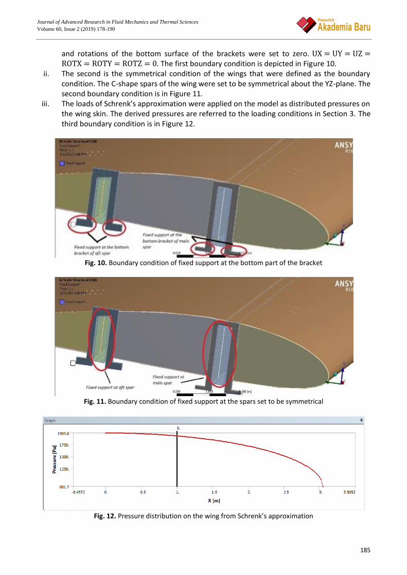
Journal of Advanced Research in Fluid Mechanics and Thermal Sciences
Volume 60, Issue 2 (2019) 178-190
185
and rotations of the bottom surface of the brackets were set to zero. UX = UY = UZ =ROTX = ROTY = ROTZ = 0. The first boundary condition is depicted in Figure 10.
ii. The second is the symmetrical condition of the wings that were defined as the boundary condition. The C-shape spars of the wing were set to be symmetrical about the YZ-plane. The second boundary condition is in Figure 11.
iii. The loads of Schrenk’s approximation were applied on the model as distributed pressures on the wing skin. The derived pressures are referred to the loading conditions in Section 3. The third boundary condition is in Figure 12.
Fig. 10. Boundary condition of fixed support at the bottom part of the bracket
Fig. 11. Boundary condition of fixed support at the spars set to be symmetrical
Fig. 12. Pressure distribution on the wing from Schrenk’s approximation

Journal of Advanced Research in Fluid Mechanics and Thermal Sciences
Volume 60, Issue 2 (2019) 178-190
186
5. Results and Discussion
From the static structural analysis conducted, the two main output that required to be verified in understanding the significance of structural based finite element.
i. Maximum von-Mises stress ii. Total deformation
5.1 Conventional NACA4415 Wing
The maximum von-Mises stress and the total deformation of the conventional wing does not match the result from [23]. This is because the deformation obtained from [23] is twofold higher than current FE analysis with 96.456mm but von Mises stress is 161.24MPa less than current analysis. The result of the total deformation from the conventional wing is 45.179 mm. Meanwhile, the maximum von-Mises stress of the conventional wing is 417.7 MPa, which is higher than the result obtained by [23]. The slight variation is due to the different boundary condition, where the fixed support is applied at the bracket represents attachment to fuselage. Furthermore, the pressure distribution in this study is calculated based on the Eq. (1) until Eq. (5), which is differ from the study by [23]. The display result of the conventional wing for von Mises stress and total deformation are depicted in Figure 13(a) and (b).
Fig. 13. (a) Von mises stress of the conventional NACA4415 wing
Fig. 13. (b) Total deformation of the conventional NACA4415 wing

Journal of Advanced Research in Fluid Mechanics and Thermal Sciences
Volume 60, Issue 2 (2019) 178-190
187
From the analysis, the highest deformation is occurred at the tip of the wing. However, the highest stress occurred at the root of the wing, which attached to the fuselage where it can be seen from the internal structure of the conventional wing, as shown in Figure 14.
Fig. 14. Von Mises stress from internal structures
5.2 Tubercles NACA4415 Wing
Figure 15(a) and (b) shows the von-Mises stress and total deformation for the similar pressure distributions applied on the tubercles NACA4415 wing.
Fig. 15. (a) Von mises stress of the tubercles NACA4415 wing
Fig. 15. (b) Total deformation of the tubercles NACA4415 wing
Referring to Figure 14(a) and (b), the value of the von-Mises stress is slightly higher than the
conventional wing, but the total deformation is slightly lower compared to the conventional type with the value of 45.099mm. The difference between conventional and tubercles wings is tabulated in Table 5.

Journal of Advanced Research in Fluid Mechanics and Thermal Sciences
Volume 60, Issue 2 (2019) 178-190
188
Table 5 Result comparison for both wings Parameters Conventional wing Tubercle wing Percentage difference (%)
Von Mises stress (MPa) 417.70 419.480 0.4 Total deformation (mm) 45.180 45.099 0.1
From the observation, the von-Mises stress of the tubercles NACA4415 occurred nearer to the
root of the wing, where these tubercles may get affected from the structural point of view. As the stress probe is appointed to the affected tubercles, the value of the von-Mises stress and deformation is depicted in Figure 16.
Fig. 16. Stress versus total deformation at tubercles from wing root
Referring to Figure 16, the stress at the tubercle number 10 showed the highest von Mises stress
of 56.167 MPa compared to Tubercle number 1 of 23.219 MPa, though the highest von Mises stress occurred at the front spar near to the root of the wing. This may due to the fact that no leading and middle ribs supported on the front spar of the wing. Moreover, the stress obtained is observed to be less than tensile yield limit stress of aluminium alloy. Hence, this showed that material is suitable for good structural characteristic of UAV wing.
In overall, the tubercles design at the leading edge proven its superior performance in terms of aerodynamic and also, showed a significant effect on the structural performance. The structural performance of the tubercles wing proved a very slight difference with the conventional wing, at 0.4%. Hence, this supported that the design of tubercles at the leading edge is acceptable for both aerodynamic and structural conditions. 6. Conclusion
In this study, the modeling of the wing of NACA4415 airfoil was done based on the calculated design requirements with the help of designing software SolidWork and the finite element analysis was carried out to visualize and compare the behavior of the wing structural of the conventional and tubercles wing by using ANSYS 16.1 Workbench.

Journal of Advanced Research in Fluid Mechanics and Thermal Sciences
Volume 60, Issue 2 (2019) 178-190
189
From the comparisons, the displacement distribution between both conventional and tubercles showed not much difference due to the support at the wing tip. On the other hand, the maximum values of von-Mises stress were observed at the root of the wing that attached to the fuselage. However, the tubercles wing was found that the stress al occurred at the spherical-shape pattern of the leading edge. As future enhancement, the wing tip may require more support position from the internal structures such as ribs and the analysis can be done if different materials can be tested with good structural characteristics such as composite.
Acknowledgement This work is supported by UPM under GP-IPM grant, 9675000. The authors would like to express their gratitude and sincere appreciation to Department of Aerospace Engineering, Faculty of Engineering, Universiti Putra Malaysia and Laboratory of Biocomposite Technology, Institute of Tropical Forestry and Forest Products (INTROP), Universiti Putra Malaysia (HICOE) for the close collaboration in this work. References [1] Fish, Franke E., and Juliann M. Battle. "Hydrodynamic design of the humpback whale flipper." Journal of
Morphology 225, no. 1 (1995): 51-60. [2] Watts, Phil, and Frank E. Fish. "The influence of passive, leading edge tubercles on wing performance." In Proc.
Twelfth Intl. Symp. Unmanned Untethered Submers. Technol. Durham New Hampshire: Auton. Undersea Syst. Inst., 2001.
[3] D. S. Miklosovic, M. M. Murray, L. E. Howle, and F. E. Fish. "Leading-edge tubercles delay stall on humpback whale (Megaptera novaeangliae) flippers." Phys. Fluids 16, no. 5 (2004): 38–42.
[4] Miklosovic, David S., Mark M. Murray, and Laurens E. Howle. "Experimental evaluation of sinusoidal leading edges." Journal of aircraft 44, no. 4 (2007): 1404-1408.
[5] Hansen, Kristy Lee. "Effect of leading edge tubercles on airfoil performance." PhD diss., 2012. [6] Levshin, Alexandra, Derrick Custodio, Charles Henoch, and Hamid Johari. "Effects of leading edge protuberances
on airfoil performance." In 36th AIAA Fluid Dynamics Conference and Exhibit, p. 2868. 2006. [7] Van Nierop, Ernst A., Silas Alben, and Michael P. Brenner. "How bumps on whale flippers delay stall: an
aerodynamic model." Physical review letters 100, no. 5 (2008): 054502. [8] Corsini, Alessandro, Giovanni Delibra, and Anthony G. Sheard. "On the role of leading-edge bumps in the control
of stall onset in axial fan blades." Journal of fluids engineering 135, no. 8 (2013): 081104. [9] Kanesan, Gunasegaran, Shuhaimi Mansor, and Ainullotfi Abdul-Latif. "Validation of UAV Wing Structural Model
for Finite Element Analysis." Jurnal Teknologi 71, no. 2 (2014): 1–5. [10] Saleh, Mohamed, Soliman, Moataz, B. and Khaleel, Sheriff Abdalla. “Structural , Morphological , Optical and
Electrical Properties of SnO2 : F Thin Films via Nebulizer Spray and Electro-spinning Techniques,” Journal of Advanced Research in Materials Science, 41, no. 1 (2018): 19–26.
[11] Tang, Jiapeng, Ping Xi, Baoyuan Zhang, and Bifu Hu. "A finite element parametric modeling technique of aircraft wing structures." Chinese Journal of Aeronautics 26, no. 5 (2013): 1202-1210.
[12] Kurukularachchi, Lasantha, Rajeeve Prince, and S. R. Munasinghe. "Stability and Control Analysis in Twin-Boom Vertical Stabilizer Unmanned Aerial Vehicle (UAV)." International Journal of Scientific and Research Publications 4, no. 2 (2014): 1-5.
[13] Panagiotou, P., P. Kaparos, and K. Yakinthos. "Winglet design and optimization for a MALE UAV using CFD." Aerospace Science and Technology 39 (2014): 190-205.
[14] Dahalan, Md Nizam, Ahmad Fitri Suni, Iskandar Shah Ishak, N. A. R. Nik Mohd, and Shabudin Mat. "Aerodynamic Study of Air Flow over A Curved Fin Rocket." Journal of Advanced Research in Fluid Mechanics and Thermal Sciences 40, no. 1 (2017): 46-58.
[15] S. Mansor, Y. Nogoud, S. Mat, M. N. Dahalan, and A. Abdul-latif. "Superaugmented Pitching Motion of UTM CAMAR UAV using Advanced Flying Handling Qualities." Journal of Advanced Research in Fluid Mechanics and Thermal Sciences 40, no. 1 (2017): 27–37.
[16] Jamil Mahmud Muhammad, Adamu M. I., Ibrahim, Tamer Rashid, and Hashim, Ghasaq Adheed, “Numerical Study of Separation Length of Flow through Rectangular Channel with Baffle Plates,” Journal of Advanced Research Design, 7, no. 1 (2015):19–33.

Journal of Advanced Research in Fluid Mechanics and Thermal Sciences
Volume 60, Issue 2 (2019) 178-190
190
[17] Schrenk, Oskar. "A simple approximation method for obtaining the spanwise lift distribution." The Aeronautical Journal 45, no. 370 (1941): 331-336.
[18] Putra, Cahya Amalinadhi, Moelyadi, Mochammad Agoes, and Julistina, Ratih. "Comparative Study between Schrenk and CFD Analysis for Predicting Lift Distribution along Wing Span of Glider Aircraft." Advance in Aerospace Science and Technology in Indonesia. 1, no. 10 (2016): 108–117.
[19] Soemaryanto, Arifin Rasyadi, and Nurhayyan Halim Rosid. "VERIFICATION OF SCHRENK METHOD FOR WING LOADING ANALYSIS OF SMALL UNMANNED AIRCRAFT USING NAVIERSTOKES BASED CFD SIMULATION." Jurnal Teknologi Dirgantara 15, no. 2 (2018): 161-166.
[20] Zain, R., I. R. Pamungkas, Wafiqni Wafiqni, and A. Yusni. "DEVELOPMENT OF AUTO-GENERATING AERODYNAMIC LOADS FOR WING-BOX FINITE ELEMENT MODEL BASED ON SCHRENK METHOD." Mesin 24, no. 2 (2017): 146-161.
[21] Hutagalung, M. R. A., A. A. Latif, and H. A. Israr. "Structural Design of UAV Semi-Monoque Composite Wing." Journal of Transport System Engineering 3, no.1 (2016): 26-34.
[22] T. S. V. Kumar, A. W. Basha, M. Pavithra, and V. Srilekha. "Static & Dynamic Analysis of a Typical Aircraft Wing Structure Using Msc Nastran." Int. J. Res. Aeronaut. Mech. Eng. 3, no. 8 (2015): 1–12.
[23] Yuvraj, S. R., and P. Subramanyam. "Design and analysis of Wing of an ultra-light Aircraft." International journal of innovative research in science, engineering and technology 4, no. 8 (2015): 7456-7468.
[24] Israr, Haris Ahmad, Jye, Wong King, and Rivallant, Samuel. "Numerical Modelling Strategies for Composite Structures Crashworthiness: A Review ." Journal of Advanced Research in Materials Science 42, no. 1 (2018): 8-23.
[25] S. Al-Wandi, S. Ding, and J. Mo. "Drilling of Uni-directional Carbon Fibre Reinforced Plastics with PCD Tools : Experiment and Finite Element Study." Journal of Advanced Research in Applied Mechanics 8, no. 1 (2015): 32-42.
[26] F. Mehta and H. Joshi. "Finite Element Method: An Overview." IOSR J. Dent. Med. Sci. 15, no. 3 (2016): 38–41.