
Map-Enhanced UAV Image Sequence Registration
6
Map-Enhanced UAV Image Sequence Registration Yuping Lin Qian Yu Gerard Medioni Computer Science Department University of Southern California Los Angeles, CA 90089-0781 {yupingli, qianyu, medioni}@usc.edu Abstract Registering consecutive images from an airborne sensor into a mosaic is an essential tool for image analysts. Strictly local methods tend to accumulate errors, resulting in distor- tion. We propose here to use a reference image (such as a high resolution map image) to overcome this limitation. In our approach, we register a frame in an image sequence to the map using both frame-to-frame registration and frame- to-map registration iteratively. In frame-to-frame registra- tion, a frame is registered to its previous frame. With its previous frame been registered to the map in the previous it- eration, we can derive an estimated transformation from the frame to the map. In frame-to-map registration, we warp the frame to the map by this transformation to compensate for scale and rotation difference and then perform an area based matching using Mutual Information to find correspondences between this warped frame and the map. From these corre- spondences, we derive a transformation that further regis- ters the warped frame to the map. With this two-step regis- tration, the errors between each consecutive frames are not accumulated. We present results on real image sequences from a hot air balloon. 1. Introduction Geo-registration is very useful application, which can be widely used in UAV (UnmanneredAerial Vehicle) to navi- gate, or to geo-locating a target, or even to refine a map. Feature-based [1][5] registration has produced good progress in recent years. Based on the technology of image registration, mosaicing of image sequences can be done by computing the transformations between consecutive frames. To take into account the accumulated error, bundle adjust- ment [6] is usually employed as a global error minimizing approach. However, for long sequences with thousands of frames, bundle adjustment is not feasible in terms of com- putation. Moreover, offline bundle adjust is not appropriate for many tasks. To perform image mosaicing in a progressive manner while still preserving accuracy, we propose to use an associ- ated map image as a global reference. A two-step procedure is applied to register an UAV image sequence to the global map. In the first step, we register consecutive frames by es- timating the best homography to align the feature points in each frame. By using the homography obtained from the first step, we roughly align the UAV image with the global map. The first step provides us an initialization which ba- sically compensates for the scale and rotation between the UAV image and the map. In the second step, we try to register the roughly aligned UAV image to the map. A similar scenario has been pre- sented in [8]. In area based matching, MSE[12] or normal- ized correlation[13] are used to determine correspondences between the UAV image and the reference image. How- ever, the UAV images are captured at different times and in different views with respect to the satellite image. The color, illumination, and the dynamic content (such as ve- hicles, trees, shadow and so on) could be very different. MSE or normalized correlation in such cases are not ro- bust enough. We propose an approach that applies mutual information [4] to establish correspondences. Mutual infor- mation has been successfully applied in establishing corre- spondence in different modality images, especially in med- ical image processing. Our experiments show that mutual information does provide strong enough correspondence af- ter roughly compensating for scale and rotation. Given the correspondence between the roughly aligned UAV image and the map, we derive a homography that further registers the roughly aligned UAV image to the map. By linking this homography and the initialized homography from the first step, we can register the UAV images with the map without incremental accumulated registration errors. This paper is organized as follows. In section 2, we for- mulate our problem with definition of symbols. In section 3, IEEE Workshop on Applications of Computer Vision (WACV'07) 0-7695-2794-9/07 $20.00 © 2007
-
Upload
independent -
Category
Documents
-
view
1 -
download
0
Transcript of Map-Enhanced UAV Image Sequence Registration

Map-Enhanced UAV Image Sequence Registration
Yuping Lin Qian Yu Gerard Medioni
Computer Science DepartmentUniversity of Southern California
Los Angeles, CA 90089-0781{yupingli, qianyu, medioni}@usc.edu
Abstract
Registering consecutive images from an airborne sensorinto a mosaic is an essential tool for image analysts. Strictlylocal methods tend to accumulate errors, resulting in distor-tion. We propose here to use a reference image (such as ahigh resolution map image) to overcome this limitation. Inour approach, we register a frame in an image sequence tothe map using both frame-to-frame registration and frame-to-map registration iteratively. In frame-to-frame registra-tion, a frame is registered to its previous frame. With itsprevious frame been registered to the map in the previous it-eration, we can derive an estimated transformation from theframe to the map. In frame-to-map registration, we warp theframe to the map by this transformation to compensate forscale and rotation difference and then perform an area basedmatching using Mutual Information to find correspondencesbetween this warped frame and the map. From these corre-spondences, we derive a transformation that further regis-ters the warped frame to the map. With this two-step regis-tration, the errors between each consecutive frames are notaccumulated. We present results on real image sequencesfrom a hot air balloon.
1. Introduction
Geo-registration is very useful application, which can bewidely used in UAV (Unmannered Aerial Vehicle) to navi-gate, or to geo-locating a target, or even to refine a map.
Feature-based [1][5] registration has produced goodprogress in recent years. Based on the technology of imageregistration, mosaicing of image sequences can be done bycomputing the transformations between consecutive frames.To take into account the accumulated error, bundle adjust-ment [6] is usually employed as a global error minimizingapproach. However, for long sequences with thousands offrames, bundle adjustment is not feasible in terms of com-
putation. Moreover, offline bundle adjust is not appropriatefor many tasks.
To perform image mosaicing in a progressive mannerwhile still preserving accuracy, we propose to use an associ-ated map image as a global reference. A two-step procedureis applied to register an UAV image sequence to the globalmap. In the first step, we register consecutive frames by es-timating the best homography to align the feature points ineach frame. By using the homography obtained from thefirst step, we roughly align the UAV image with the globalmap. The first step provides us an initialization which ba-sically compensates for the scale and rotation between theUAV image and the map.
In the second step, we try to register the roughly alignedUAV image to the map. A similar scenario has been pre-sented in [8]. In area based matching, MSE[12] or normal-ized correlation[13] are used to determine correspondencesbetween the UAV image and the reference image. How-ever, the UAV images are captured at different times andin different views with respect to the satellite image. Thecolor, illumination, and the dynamic content (such as ve-hicles, trees, shadow and so on) could be very different.MSE or normalized correlation in such cases are not ro-bust enough. We propose an approach that applies mutualinformation [4] to establish correspondences. Mutual infor-mation has been successfully applied in establishing corre-spondence in different modality images, especially in med-ical image processing. Our experiments show that mutualinformation does provide strong enough correspondence af-ter roughly compensating for scale and rotation. Given thecorrespondence between the roughly aligned UAV imageand the map, we derive a homography that further registersthe roughly aligned UAV image to the map. By linking thishomography and the initialized homography from the firststep, we can register the UAV images with the map withoutincremental accumulated registration errors.
This paper is organized as follows. In section 2, we for-mulate our problem with definition of symbols. In section 3,
IEEE Workshop on Applications of Computer Vision (WACV'07)0-7695-2794-9/07 $20.00 © 2007
we present the two-step procedure for geo-registration. Insection 4, we compare our results with and without refine-ment in geo-registration. Experiments show that the refine-ment procedure significantly reduces the accumulated error.Discussion and future work are presented in section 5.
2. Problem formulation and Issues
We start by giving definitions of the symbols used inthis paper. We are given a sequence of UAV imagesI0, I1, . . . , In, and a map (usually a satellite image) M .Here, we assume the scene depth is small with respect tothe distance from the UAV camera, so the transformationbetween two UAV images can be represented by a homog-raphy. The transformation between an UAV image and themap is also represented as a homography. Let Hi,j denotethe homography from Ii to Ij , Hi,M denotes the homogra-phy from Ii to M , namely Hi,jIi = Ij and Hi,MIi = Mi,Mi is the image where Ii projects to in M . Note thatHj,i = Hi,j
−1.Our goal is to derive accurate estimates of H0,M , . . . ,
Hi,M so that I1, . . . , In are registered to M and form a mo-saic without distortion (Figure 1).
Figure 1. For each Ii, derive Hi,M so that they all regis-
ter to the map M and form a seamless mosaic
However, the map and images are taken at differenttimes, from different sensors, from different viewpoints,and may have different dynamic contents, (such as vehiclesor shadows). As a result, it is difficult to simply match eachincoming image to the map. Instead, we need to build apartial local mosaic, then register to the map in an iterativemanner.
3. Approach
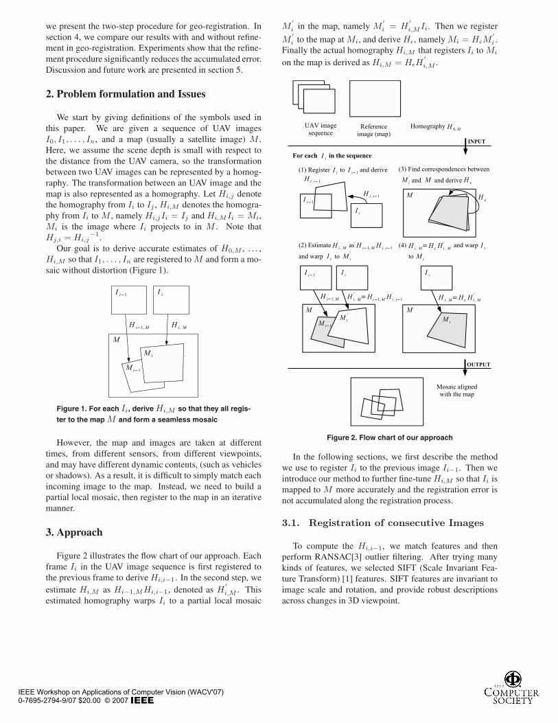
Figure 2 illustrates the flow chart of our approach. Eachframe Ii in the UAV image sequence is first registered tothe previous frame to derive Hi,i−1. In the second step, weestimate Hi,M as Hi−1,MHi,i−1, denoted as H
′i,M . This
estimated homography warps Ii to a partial local mosaic
M′i in the map, namely M
′i = H
′i,MIi. Then we register
M′i to the map at Mi, and derive Hε, namely Mi = HεM
′i .
Finally the actual homography Hi,M that registers Ii to Mi
on the map is derived as Hi,M = HεH′i,M .
Figure 2. Flow chart of our approach
In the following sections, we first describe the methodwe use to register Ii to the previous image Ii−1. Then weintroduce our method to further fine-tune Hi,M so that Ii ismapped to M more accurately and the registration error isnot accumulated along the registration process.
3.1. Registration of consecutive Images
To compute the Hi,i−1, we match features and thenperform RANSAC[3] outlier filtering. After trying manykinds of features, we selected SIFT (Scale Invariant Fea-ture Transform) [1] features. SIFT features are invariant toimage scale and rotation, and provide robust descriptionsacross changes in 3D viewpoint.
IEEE Workshop on Applications of Computer Vision (WACV'07)0-7695-2794-9/07 $20.00 © 2007

Figure 3. initial registration between the UAV images and
the map
In the feature matching step, we use nearest neighbormatching [2]. Since the translation and rotation of the UAVcamera between consecutive frames are small, we can as-sume matched features should be within a small window.This adds one more constraint to match features. Usually,at resolution of 720×480, we can generate 2000 correspon-dence pairs. Finally, we use RANSAC to filter outliers (weuse inlier tolerance = 1 pixel) among the set of correspon-dences and derive Hi−1,i.
Having the Hi,i−1 and H0,M , we can roughly registerthe UAV image to the map by estimating Hi,M as:
Hi,M = Hi−1,MHi,i−1 = H0,M
i∏
k=1
Hk,k−1 (1)
This shows that if there exists a subtle transformationerror in each Hk,k−1, these errors are multiplied and resultin a significant error. This means that later UAV imagescould be registered to a very wrong area on the map. Asshown in Figure 3, the registration is not perfect. Thus, weneed to find a way to establish correspondences betweenthe UAV image and the map and refine the homography byusing these correspondences.
3.2. UAV to Map registration
Registering an aerial image to a map is a challengingproblem [10][11]. Due to significant differences in lightingconditions, resolution, and 3D viewpoints between the UAVimage and the map, the same point may yield quite differ-ent SIFT descriptors respectively. Therefore, poor featurematching and poor registration can be expected.
Since it is difficult to register an UAV image to the mapdirectly, we make use of Hi,i−1 derived from UAV to UAVregistration and estimate Hi,M as H
′i,M = Hi−1,MHi,i−1,
and then fine-tune it to a better one. Let M ′i denotes the
warped image of Ii by H′i,M (Figure 2, Step 2). Our goal
is to derive a homography Hε that registers M ′i to the map
at Mi (Figure 2, Step 3), so that the image is accuratelyaligned to the map.
The advantage of this approach is that with M′i roughly
aligned to the map, we can perform a local search for cor-respondence under the same scale. Therefore the ambiguity
of matching and the computation time are far less than di-rectly registering Ii to the map.
3.2.1. Finding Correspondences between UAV imageand Map
To derive Hε, we try to find correspondences between M ′i
and the map area which M′i spans. However, M
′i is usually
a smaller region than Ii (map has lower resolution), whichmeans M
′i preserves less amount of information than Ii.
Hence we do it in a reverse way. As shown in Figure 4, letUi be the map image transformed back from the same areawhich M
′i spans using H
′M,i. Instead of finding correspon-
dences between M′i and the map area where M ′
i spans, wefind correspondences between Ii and Ui.
Figure 4. Ui denotes the map image transformed back
from the same region which M′i spans using H
′M,i. PI
and PU are points locate at the same coordinate in Ii
and Ui respectively. SP′I, SPU are two image patches of
the same size centered at point P′I and PU respectively,
where P′I is the corresponding point to PU .
Let PI and PU be points located at the same coordinatesin Ii and Ui respectively. With a good enough Hi,M , PU
should have its correspondence P′I in Ii close to PI .
P′I is determined by having the UAV image patch cen-
ters at it most similar to the map image patch centers at PU .We use mutual information[4] as the similarity measure.Mutual information of two random variables is a quantitythat measures the dependence of the two variables. Takingtwo images (same size) as the random variables, it measureshow much information two images share, or how much animage depends on the other. It is a more meaningful crite-rion way compared to measures such as cross-correlation orgrey value differences.
Let SPi , SPj be two image patches of the same size cen-tered at point Pi and Pj respectively. MI(SPi , SPj ) be the
mutual information of SPi and SPj . We find P′I by looking
for pixels Pi in PI ’s neighborhood that yields the greatestMI(SPU , SPi).
IEEE Workshop on Applications of Computer Vision (WACV'07)0-7695-2794-9/07 $20.00 © 2007

(a)
(b)
Figure 5. The correspondences in the UAV image (a) with
respect to the feature points in the map image (b). Blue
dots and red dots represent good and poor correspon-
dences respectively.
3.2.2. Defining Good Correspondences
It may happen that ”all” or ”none” of the image patches cen-tered on PI ’s neighborhood pixels are similar to the imagepatch centered on PU . In either case, the maximum mutualinformation is meaningless, since the mutual informationat other places could be just slightly smaller. We need tofilter these unreliable correspondences so that the derivedhomography is accurate.
Let Pk be the pixel in PI ’s neighborhood area that hasthe smallest mutual information value. We consider it agood correspondence when MI(SPU , SP
′I) is significantly
larger than MI(SPU , SPk) (we use MI(SPU , SP
′I) >
2MI(SPM , SPk)). Intuitively, it means that image patch
SP′I
must be significantly more similar to SPU than SPk.
Figure 5 shows the results of extracting good correspon-dences. Blue dots and red dots represent good and poorcorrespondences respectively.
We can generate as many correspondences as we want byperforming such an operation on feature points in Ui. Herewe use the Harris Corner Detector[5] to extract features in-stead of SIFT because our purpose is to have the locationsof some interest points in Ui. Harris Corner Detector satis-fies our need, and it is computationally cheaper than SIFT.Once we have enough correspondences, RANSAC is per-formed to filter outliers, and then Hε is derived. As shownin Figure 6, color dots in 6(b) are feature points extracted
(a)
(b)
Figure 6. The correspondences in the uav image (a) with
respect to the feature points in the map image (b). Green
dots and orange dots represent RANSAC inliers and out-
liers respectively.
by Color dots in 6(a) are their correspondences respectively,while the green dots are RANSAC inliers to derive Hε.
Finally, Hi,M is derived as Hi,M = HεH′i,M , and Ii is
registered to the map at Mi (Figure 2, Step 4).
4. Experimental Results
We show results on two data sets. The UAV image se-quences are provided with latitude and longitude informa-tion. The satellite images are acquired from Google Earth.The size of the each UAV image 720 × 480. We manuallyregister the first frame of the UAV sequence to their corre-sponding satellite images, namely H0,M is given.
In each UAV to Map registration step, we select 200 Har-ris Corners in the UAV image as samples. We require thedistance between any two features to be no lower than 10pixels. For each sample, an image patch of size 100×100 isused to compute the mutual information, and the neighbor-hood region where we search for a best match is a windowof size 40 × 40. We found the window size of 100 × 100 isa proper size for a discriminative local feature in our UAVimage registration.
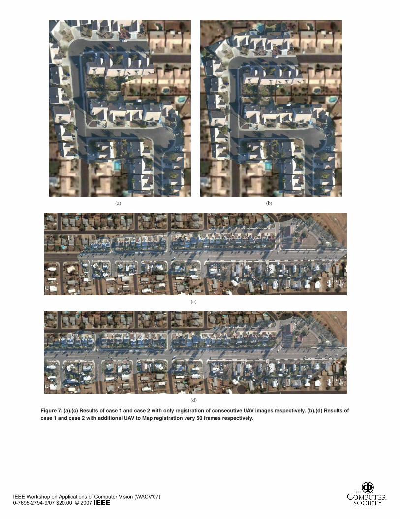
Since mutual information computation is very costly, weonly perform an UAV to Map registration every 50 frames.The results of case 1 with and without UAV to Map registra-tion are shown in 7(a) and 7(c) respectively. The results ofcase 2 with and without UAV to Map registration are shown
IEEE Workshop on Applications of Computer Vision (WACV'07)0-7695-2794-9/07 $20.00 © 2007
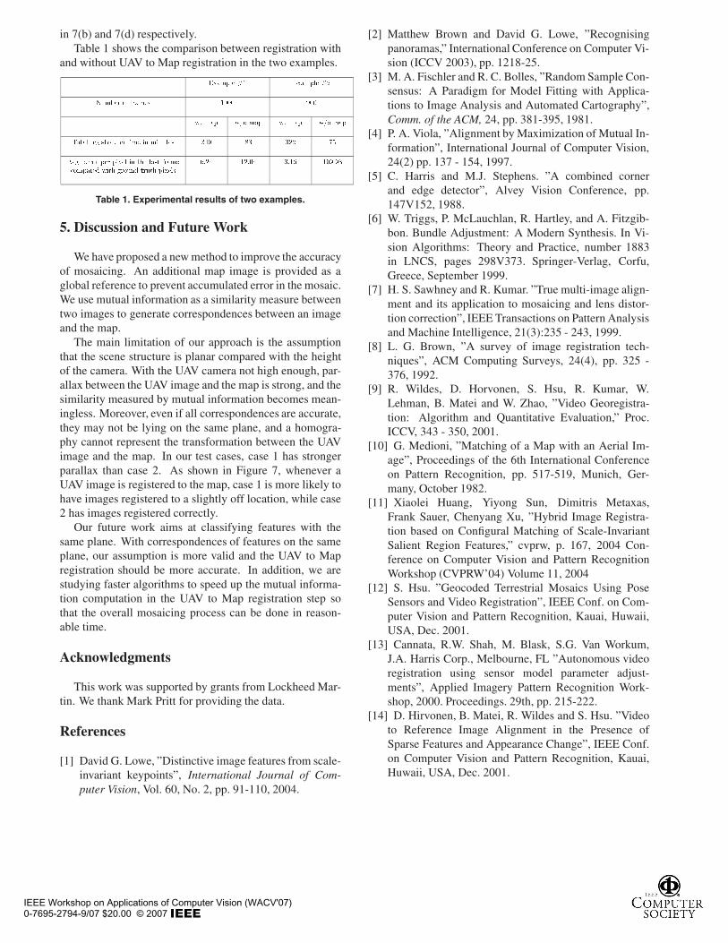
in 7(b) and 7(d) respectively.Table 1 shows the comparison between registration with
and without UAV to Map registration in the two examples.
������� �� ������� �
���� �� � ���� ���� ���
�� ��� ��� ��� �� ��� ��� ���
����� ����� ����� ���� �� ������� ��� �� � ��
!�� � � �� ����� �� �"� ���� � ���#���� �$ ���" � ���$ � ��" ������
%�� ���� ���% ������
Table 1. Experimental results of two examples.
5. Discussion and Future Work
We have proposed a new method to improve the accuracyof mosaicing. An additional map image is provided as aglobal reference to prevent accumulated error in the mosaic.We use mutual information as a similarity measure betweentwo images to generate correspondences between an imageand the map.
The main limitation of our approach is the assumptionthat the scene structure is planar compared with the heightof the camera. With the UAV camera not high enough, par-allax between the UAV image and the map is strong, and thesimilarity measured by mutual information becomes mean-ingless. Moreover, even if all correspondences are accurate,they may not be lying on the same plane, and a homogra-phy cannot represent the transformation between the UAVimage and the map. In our test cases, case 1 has strongerparallax than case 2. As shown in Figure 7, whenever aUAV image is registered to the map, case 1 is more likely tohave images registered to a slightly off location, while case2 has images registered correctly.
Our future work aims at classifying features with thesame plane. With correspondences of features on the sameplane, our assumption is more valid and the UAV to Mapregistration should be more accurate. In addition, we arestudying faster algorithms to speed up the mutual informa-tion computation in the UAV to Map registration step sothat the overall mosaicing process can be done in reason-able time.
Acknowledgments
This work was supported by grants from Lockheed Mar-tin. We thank Mark Pritt for providing the data.
References
[1] David G. Lowe, ”Distinctive image features from scale-invariant keypoints”, International Journal of Com-puter Vision, Vol. 60, No. 2, pp. 91-110, 2004.
[2] Matthew Brown and David G. Lowe, ”Recognisingpanoramas,” International Conference on Computer Vi-sion (ICCV 2003), pp. 1218-25.
[3] M. A. Fischler and R. C. Bolles, ”Random Sample Con-sensus: A Paradigm for Model Fitting with Applica-tions to Image Analysis and Automated Cartography”,Comm. of the ACM, 24, pp. 381-395, 1981.
[4] P. A. Viola, ”Alignment by Maximization of Mutual In-formation”, International Journal of Computer Vision,24(2) pp. 137 - 154, 1997.
[5] C. Harris and M.J. Stephens. ”A combined cornerand edge detector”, Alvey Vision Conference, pp.147V152, 1988.
[6] W. Triggs, P. McLauchlan, R. Hartley, and A. Fitzgib-bon. Bundle Adjustment: A Modern Synthesis. In Vi-sion Algorithms: Theory and Practice, number 1883in LNCS, pages 298V373. Springer-Verlag, Corfu,Greece, September 1999.
[7] H. S. Sawhney and R. Kumar. ”True multi-image align-ment and its application to mosaicing and lens distor-tion correction”, IEEE Transactions on Pattern Analysisand Machine Intelligence, 21(3):235 - 243, 1999.
[8] L. G. Brown, ”A survey of image registration tech-niques”, ACM Computing Surveys, 24(4), pp. 325 -376, 1992.
[9] R. Wildes, D. Horvonen, S. Hsu, R. Kumar, W.Lehman, B. Matei and W. Zhao, ”Video Georegistra-tion: Algorithm and Quantitative Evaluation,” Proc.ICCV, 343 - 350, 2001.
[10] G. Medioni, ”Matching of a Map with an Aerial Im-age”, Proceedings of the 6th International Conferenceon Pattern Recognition, pp. 517-519, Munich, Ger-many, October 1982.
[11] Xiaolei Huang, Yiyong Sun, Dimitris Metaxas,Frank Sauer, Chenyang Xu, ”Hybrid Image Registra-tion based on Configural Matching of Scale-InvariantSalient Region Features,” cvprw, p. 167, 2004 Con-ference on Computer Vision and Pattern RecognitionWorkshop (CVPRW’04) Volume 11, 2004
[12] S. Hsu. ”Geocoded Terrestrial Mosaics Using PoseSensors and Video Registration”, IEEE Conf. on Com-puter Vision and Pattern Recognition, Kauai, Huwaii,USA, Dec. 2001.
[13] Cannata, R.W. Shah, M. Blask, S.G. Van Workum,J.A. Harris Corp., Melbourne, FL ”Autonomous videoregistration using sensor model parameter adjust-ments”, Applied Imagery Pattern Recognition Work-shop, 2000. Proceedings. 29th, pp. 215-222.
[14] D. Hirvonen, B. Matei, R. Wildes and S. Hsu. ”Videoto Reference Image Alignment in the Presence ofSparse Features and Appearance Change”, IEEE Conf.on Computer Vision and Pattern Recognition, Kauai,Huwaii, USA, Dec. 2001.
IEEE Workshop on Applications of Computer Vision (WACV'07)0-7695-2794-9/07 $20.00 © 2007
(a) (b)
(c)
(d)
Figure 7. (a),(c) Results of case 1 and case 2 with only registration of consecutive UAV images respectively. (b),(d) Results of
case 1 and case 2 with additional UAV to Map registration very 50 frames respectively.
IEEE Workshop on Applications of Computer Vision (WACV'07)0-7695-2794-9/07 $20.00 © 2007