Camber Controlled Airfoil Design for Morphing UAV
11
American Institute of Aeronautics and Astronautics 092407 1 Camber Controlled Airfoil Design for Morphing UAV Cody Lafountain 1 , Kelly Cohen 2 and Shaaban Abdallah 3 University of Cincinnati, Cincinnati, OH, 45221 Morphing technology, inspired by bat and bird flight, can enable an aircraft to adapt its shape to best suit the flight condition thereby enhancing mission performance. In this paper, we propose a camber change for the morphing of airfoils with the aim of improving aerodynamic efficiency. The Global Hawk UAV mission in general and its LRN1015 airfoil in particular is in focus due to the relative long mission times spent at the two different flight conditions, namely high-speed dash and low speed loiter. Specifically, we are in search of the basic relationships between flap deflection and airfoil morphing based on a camber change. We are using several tools to virtually simulate a morphing wing including XFOIL to perform fast and relatively accurate two-dimensional steady-flow simulations of different morphed configurations using a camber controlled morphed wing to maneuver. Results show that for the LRN1015 airfoil, we can achieve the lift differential required to perform a maneuver while maintaining higher efficiency than an aircraft using flaps to perform the same maneuver. Nomenclature C l = lift coefficient C d = drag coefficient C p = pressure coefficient FEM = finite element model c = chord M = Mach number Re = Reynolds number CFD = computational fluid dynamics I. Introduction URING the past two decades, there has been a growing need for aircraft to perform effectively while flying in aerodynamically different operating regimes within the flight envelope during a single mission. Wing morphing/shape shifting technologies can empower aircraft (manned and unmanned) to adapt its aerodynamic configuration “on demand”, thereby expanding their role and capabilities in the tactical are na. In recent years there has been an increasing number of academic, government and industrial interest in morphing technology 1-7 . A fine example of effective morphing in a flying creature is the Bat. Bats have very efficient wings, and they have a unique ability to morph wing camber. Morphing (changing camber and aspect ratio) makes bats far more maneuverable than birds especially at very low speeds. Bats‟ wings consist of long, thin, lightweight bones, held together by a skin membrane, which enables the rapid change in wing camber. Using the Bat as the biological inspiration behind the proposed research program, we develop an approach for morphed camber control which enables maneuvering without the conventional control surfaces. This effort is part of the Morphing Wing program at the University of Cincinnati. In this program, we develop experimental and computational tools to aid in the development of aerodynamic, structural and control technologies that allow air vehicles to maintain a safe and effective transition during in-flight morphing maneuvers in dynamic environments. The main objective of the program is to develop a computational tool that predicts the dynamic response to various control inputs, including large strain shape memory alloy actuation as well as high frequency piezo-ceramic actuators, for a morphing wing of a high-performance aircraft. The ultimate goal is to design an effective closed-loop structural control methodology to maintain/augment maneuvers using morphing of the airfoil camber. The uniqueness of this program lies in the coupling of various morphing modes such as airfoil shape, sweep 1 Undergraduate Student, Dept. of Aerospace Engineering, P.O. Box 210070, Student Member 2 Associate Professor, Dept. of Aerospace Engineering, P.O. Box 210070, Associate Fellow 3 Professor, Dept. of Aerospace Engineering, P.O. Box 210070, Member D 47th AIAA Aerospace Sciences Meeting Including The New Horizons Forum and Aerospace Exposition 5 - 8 January 2009, Orlando, Florida AIAA 2009-1435 Copyright © 2009 by the American Institute of Aeronautics and Astronautics, Inc. All rights reserved. Downloaded by UNIVERSITY OF CINCINNATI on December 3, 2014 | http://arc.aiaa.org | DOI: 10.2514/6.2009-1435
-
Upload
independent -
Category
Documents
-
view
1 -
download
0
Transcript of Camber Controlled Airfoil Design for Morphing UAV

American Institute of Aeronautics and Astronautics 092407
1
Camber Controlled Airfoil Design for Morphing UAV
Cody Lafountain1, Kelly Cohen
2 and Shaaban Abdallah
3
University of Cincinnati, Cincinnati, OH, 45221
Morphing technology, inspired by bat and bird flight, can enable an aircraft to adapt its
shape to best suit the flight condition thereby enhancing mission performance. In this paper,
we propose a camber change for the morphing of airfoils with the aim of improving
aerodynamic efficiency. The Global Hawk UAV mission in general and its LRN1015 airfoil
in particular is in focus due to the relative long mission times spent at the two different flight
conditions, namely high-speed dash and low speed loiter. Specifically, we are in search of the
basic relationships between flap deflection and airfoil morphing based on a camber change.
We are using several tools to virtually simulate a morphing wing including XFOIL to
perform fast and relatively accurate two-dimensional steady-flow simulations of different
morphed configurations using a camber controlled morphed wing to maneuver. Results
show that for the LRN1015 airfoil, we can achieve the lift differential required to perform a
maneuver while maintaining higher efficiency than an aircraft using flaps to perform the
same maneuver.
Nomenclature
Cl = lift coefficient
Cd = drag coefficient
Cp = pressure coefficient
FEM = finite element model
c = chord
M = Mach number
Re = Reynolds number
CFD = computational fluid dynamics
I. Introduction
URING the past two decades, there has been a growing need for aircraft to perform effectively while flying in
aerodynamically different operating regimes within the flight envelope during a single mission. Wing
morphing/shape shifting technologies can empower aircraft (manned and unmanned) to adapt its aerodynamic
configuration “on demand”, thereby expanding their role and capabilities in the tactical arena. In recent years there
has been an increasing number of academic, government and industrial interest in morphing technology1-7
. A fine
example of effective morphing in a flying creature is the Bat. Bats have very efficient wings, and they have a unique
ability to morph wing camber. Morphing (changing camber and aspect ratio) makes bats far more maneuverable
than birds especially at very low speeds. Bats‟ wings consist of long, thin, lightweight bones, held together by a skin
membrane, which enables the rapid change in wing camber. Using the Bat as the biological inspiration behind the
proposed research program, we develop an approach for morphed camber control which enables maneuvering
without the conventional control surfaces.
This effort is part of the Morphing Wing program at the University of Cincinnati. In this program, we develop
experimental and computational tools to aid in the development of aerodynamic, structural and control technologies
that allow air vehicles to maintain a safe and effective transition during in-flight morphing maneuvers in dynamic
environments. The main objective of the program is to develop a computational tool that predicts the dynamic
response to various control inputs, including large strain shape memory alloy actuation as well as high frequency
piezo-ceramic actuators, for a morphing wing of a high-performance aircraft. The ultimate goal is to design an
effective closed-loop structural control methodology to maintain/augment maneuvers using morphing of the airfoil
camber. The uniqueness of this program lies in the coupling of various morphing modes such as airfoil shape, sweep
1 Undergraduate Student, Dept. of Aerospace Engineering, P.O. Box 210070, Student Member
2 Associate Professor, Dept. of Aerospace Engineering, P.O. Box 210070, Associate Fellow
3 Professor, Dept. of Aerospace Engineering, P.O. Box 210070, Member
D
47th AIAA Aerospace Sciences Meeting Including The New Horizons Forum and Aerospace Exposition5 - 8 January 2009, Orlando, Florida
AIAA 2009-1435
Copyright © 2009 by the American Institute of Aeronautics and Astronautics, Inc. All rights reserved.
Dow
nloa
ded
by U
NIV
ER
SIT
Y O
F C
INC
INN
AT
I on
Dec
embe
r 3,
201
4 | h
ttp://
arc.
aiaa
.org
| D
OI:
10.
2514
/6.2
009-
1435
American Institute of Aeronautics and Astronautics 092407
2
and folding within a unified structural-control model. Upon completion of this project, it is expected to test a
laboratory-based proof-of-concept wing model that morphs from one aerodynamic configuration to another and to
examine the applicability and effectiveness of the developed control approach. A wing that experiences airfoil
morphing is being designed and built. The detailed analysis of an auxiliary structure to implement the morphing is
also being done with a finite element model (FEM) that includes large deformations. A more elaborate model that
includes detailed computational structures (FEM) and fluids (CFD) will be created to capture the complexities
associated with multi-disciplinary fluid-structure-control interaction. Given the multi-disciplinary nature of the
project and the research team, progress in the specific discipline will be augmented with a structured approach to
developing a unified model. We decided to work with the NASA developed LRN 1015 airfoil, shown in Figure 2, as
a baseline which is the Global Hawk Hale UAV airfoil. The reference mission will be the Global Hawk mission. At
first, XFOIL, developed by Mark Drela at MIT, is used to develop a mapping of flap deflections for the usable
envelope for alpha and flap/aileron deflections. The next step will be to develop a two dimensional rib having 4-6
rigid segments on the upper surface. Each of these segments will have a pitch and plunge capability using linear
COTS piezo-ceramic actuators. The segments are covered with a tight flexible skin. The above developed mapping
system (flap defections to airfoil geometry) will then translate into segment deformations. A dynamic model of the
structure-control interaction will be developed and experimentally validated using a laboratory model will COTS
actuators/sensor. Important to note that if the segment is too light weight we will have structural dynamic issues. On
the other hand if it is too heavy (high inertia) then you need large actuators. A trade-off is required to optimize the
control contribution. Then, a low order model based estimator and controller will be developed. Sensitivities to
sensor noise and actuator time-delays will also be considered to assess robustness.
The main objective of this paper is to investigate the properties of a morphing airfoil in a flight environment.
This airfoil will be morphed to mimic characteristics of static airfoils with different flap configurations using
software to simulate real conditions. The goal of this project is to reach a correlation between flaps and morphing
that allows a given flap setting during a maneuver to be replaced by a change in the shape of the airfoil. This will be
an active system that responds in real-time to commands given by the pilot. The reasoning for this project is twofold.
The first is aircraft performance. An aircraft with a morphing wing could continually operate at optimal efficiency
while performing each part of its mission. The second reason is stealth. Eliminating the flaps on an aircraft could
significantly reduce its radar signature.
II. Background
The airfoil that will be used for the main development of this project is the LRN 1015, the airfoil used on the
Global Hawk UAV. This particular airfoil was chosen because its current mission involves varied operating
conditions which could benefit most from an airfoil capable of morphing mid-flight. The first two digits give the
design lift coefficient and the last two digits describe the approximate maximum thickness ratio in hundredths. It
was developed by NASA for low Reynolds numbers. The NACA four-series 0009 and 2412 will be used for data
verification, as they have been much more thoroughly tested since their development. The LRN 1015 was tested in a
2 by 2-foot transonic, variable speed, ventilated wall, continuous flow wind tunnel at the NASA Ames Research
Center. An 82 tube drag rake was placed 1.75 chords downstream, and the gaps between the airfoil and the wall
were sealed to improve the 2-dimentionality of the test.8 The LRN 1015 was then tested for aerodynamic
characteristics at various mach and Reynolds numbers. In the final step, the wind tunnel data was compared to data
received from three software packages: ISES, LBAUER, and ARC2D.
III. XFOIL
XFOIL is a program originally written by Mark Drela at MIT in 1986. It combines high-order panel methods and
the fully-coupled inviscid/viscous interaction method first used in ISES. XFOIL uses a text x- and y-coordinate file
to model two-dimensional airfoils. The user may input an airfoil from a file or select a NACA 4- or 5- series airfoil
and XFOIL will build the appropriate coordinate file. The user may then make changes to inviscid/viscous
properties such as Mach number and Reynolds number (Re). Xfoil will then use the user data to simulate flight at
many angles of attack and return lift coefficient (Cl), drag coefficient (Cd), and moment coefficient (Cm) in the form
of a saved polar file and generate Cl vs. α and Cl vs. Cd plots.
XFOIL was chosen for this project because it gives results much more quickly than more advanced CFD
programs and still provides results accurate enough to be a good design tool, and because it allows the user to
simulate the effects of adding plain flaps to an airfoil. When XFOIL is combined with AeroMorph, it allows us to
simulate all the configurations required to build a mathematical relationship between flap deflection and camber
change.
Dow
nloa
ded
by U
NIV
ER
SIT
Y O
F C
INC
INN
AT
I on
Dec
embe
r 3,
201
4 | h
ttp://
arc.
aiaa
.org
| D
OI:
10.
2514
/6.2
009-
1435

American Institute of Aeronautics and Astronautics 092407
3
IV. Data Verification
In order to ensure that the results we are obtaining from XFOIL are accurate when compared to industry
accepted data, we have acquired wind tunnel data from NASA on two NACA airfoils, the 0009 and 2412. The first
step we took was to confirm that XFOIL generates accurate data for the NACA 2412 airfoil. We chose the 2412
because it is an airfoil in common usage with readily available wind tunnel data. We compared data from Ref. 8
regarding pressure coefficient (Cp) as a function of the chord (c), Cl vs. α, Cl vs. Cd, and Cl vs. Cm to data generated
by XFOIL. For this comparison the Mach number was set at 0.2 and the Reynolds number was set at 500,000 to
match the data recorded by NASA in Ref. 8.
Figure 1 shows that while XFOIL generates relatively accurate results, it has trouble accurately predicting the
pressure coefficient around locations where separation bubbles form. This is most visible in the large spikes at the
leading edge and >0.7c. The small discrepancies on the Cp vs. c plot may be a contributor to the fact that the Cl vs.
Cm data acquired from XFOIL is skewed from the wind tunnel data. It is possible that the way XFOIL calculates the
pressure at the leading edge and other areas of flow separation are the cause of the discrepancy.
Figure 1. Pressure Coefficient vs. Chord. NACA 2412, Mach number 0.2, Reynolds number 500,000
Dow
nloa
ded
by U
NIV
ER
SIT
Y O
F C
INC
INN
AT
I on
Dec
embe
r 3,
201
4 | h
ttp://
arc.
aiaa
.org
| D
OI:
10.
2514
/6.2
009-
1435

American Institute of Aeronautics and Astronautics 092407
4
As we are using mostly Cl vs. α (see Figure 2) and Cl vs. Cd (see Figure 3) data to develop a relationship between
flap deflection and camber change, it was vital to show that XFOIL generates good results for those plots. For this
the NACA 2412 results generated by XFOIL were compared to three different sets of data from Ref. 8. In their
report, NASA compared wind tunnel data and data generated by two computer simulations, ISES and LBAUER. To
this we added the XFOIL data. We used XFOIL to calculate the lift coefficient at an interval of one degree over the
interval [-3, 6]. This is a similar interval to the ISES and LBAUER data. XFOIL does a good job predicting Cl over
the linear part of the Cl vs. α plot. This is important as we will be trying to match Cl vs. α data between a certain flap
deflection and a camber change due to morphing. XFOIL follows the wind tunnel data well, better than ISES at
positive angles of attack. The Cl vs. Cd plot shows similar results. The drag predictions from XFOIL show good
correlation with both the wind tunnel data and ISES and LBAUER. This shows that XFOIL is predicting both lift
and drag coefficients within an acceptable range or accuracy.
Figure 3. Drag Coefficient Comparison. NACA
2412, Mach number 0.2, Reynolds number 500,000.
Figure 2. Lift Coefficient Comparison. NACA 2412, Mach number
0.2, Reynolds number 500,000.
Dow
nloa
ded
by U
NIV
ER
SIT
Y O
F C
INC
INN
AT
I on
Dec
embe
r 3,
201
4 | h
ttp://
arc.
aiaa
.org
| D
OI:
10.
2514
/6.2
009-
1435
American Institute of Aeronautics and Astronautics 092407
5
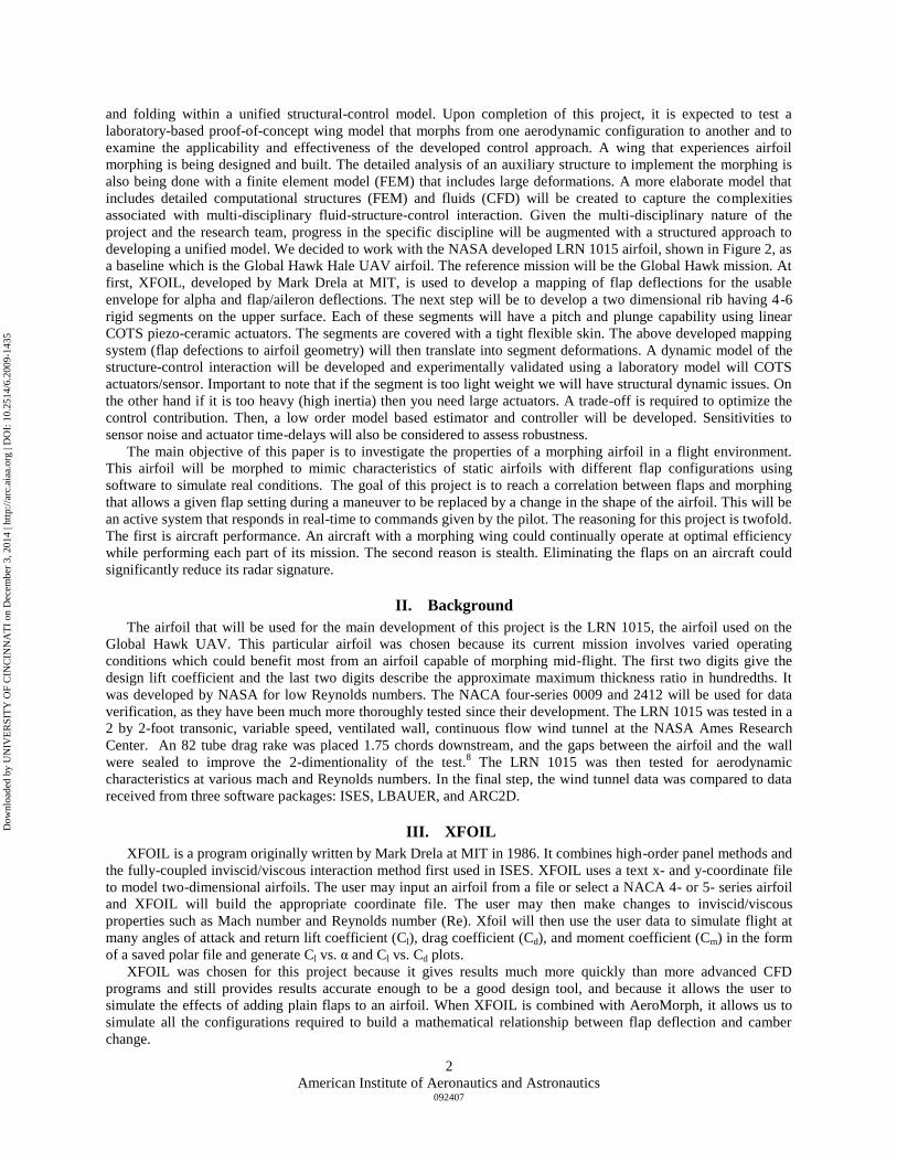
The next comparison is Cl vs. Cm (see Figure 4). The predictions XFOIL makes for moment are not as good
as for previous comparisons. At higher lift coefficients, XFOIL matches the wind tunnel data, but at lower lift
coefficients XFOIL diverges. This is possibly caused by the calculation method used by XFOIL which generates
large pressure spikes at the leading edge at small lift coefficients. In Fig. 1, the data generated by XFOIL shows a
lower surface pressure spike that is several times larger than the corresponding spike in the wind tunnel data.
The NACA report WR L-663 (Ref. 9) is a wartime report covering wind tunnel testing of many airfoil/flap
conditions. It contains wind tunnel data on the NACA 0009 airfoil with a 0.3c sealed-gap plain flap. We chose this
report and airfoil flap configuration because it allows us to verify that XFOIL provides accurate simulation of flap
addition on airfoils. This particular airfoil flap configuration was chosen for several reasons. One reason is that the
0009, as a NACA airfoil, is widely known and tested. Another reason is that XFOIL can only model plain flaps with
a sealed gap. This limitation is not an issue because basic flap simulation is all that is required for this initial
investigation into matching flaps and camber changes. The wind tunnel data for the NACA 0009 airfoil with a 0.3c
plain flap with a sealed gap was chosen as this best matches the capability of XFOIL. In order to provide the most
accurate results, XFOIL was calibrated using information from Ref. 9.
The two-dimensional-flow tests were made at a dynamic pressure of 15 pounds per square foot, which corresponds to
a velocity of about 76 miles per hour at standard sea-level conditions. The test Reynolds number was about 1,430,000.
The turbulence factor of the LWAL 4- by 6-foot vertical wind tunnel being 1.95, the effective Reynolds number of the
tests was therefore about 2,700,000.9
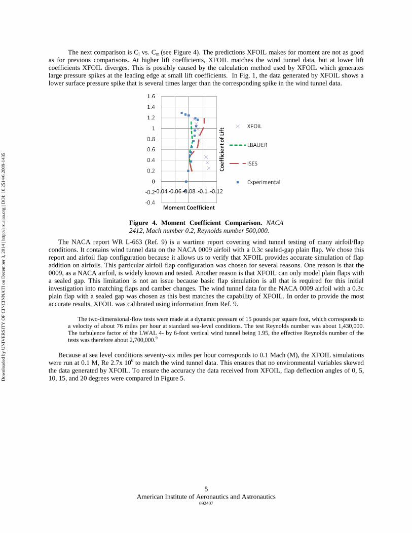
Because at sea level conditions seventy-six miles per hour corresponds to 0.1 Mach (M), the XFOIL simulations
were run at 0.1 M, Re 2.7x 10⁶ to match the wind tunnel data. This ensures that no environmental variables skewed
the data generated by XFOIL. To ensure the accuracy the data received from XFOIL, flap deflection angles of 0, 5,
10, 15, and 20 degrees were compared in Figure 5.
Figure 4. Moment Coefficient Comparison. NACA
2412, Mach number 0.2, Reynolds number 500,000.
Dow
nloa
ded
by U
NIV
ER
SIT
Y O
F C
INC
INN
AT
I on
Dec
embe
r 3,
201
4 | h
ttp://
arc.
aiaa
.org
| D
OI:
10.
2514
/6.2
009-
1435
American Institute of Aeronautics and Astronautics 092407
6
V. Flap-Camber Change Comparison
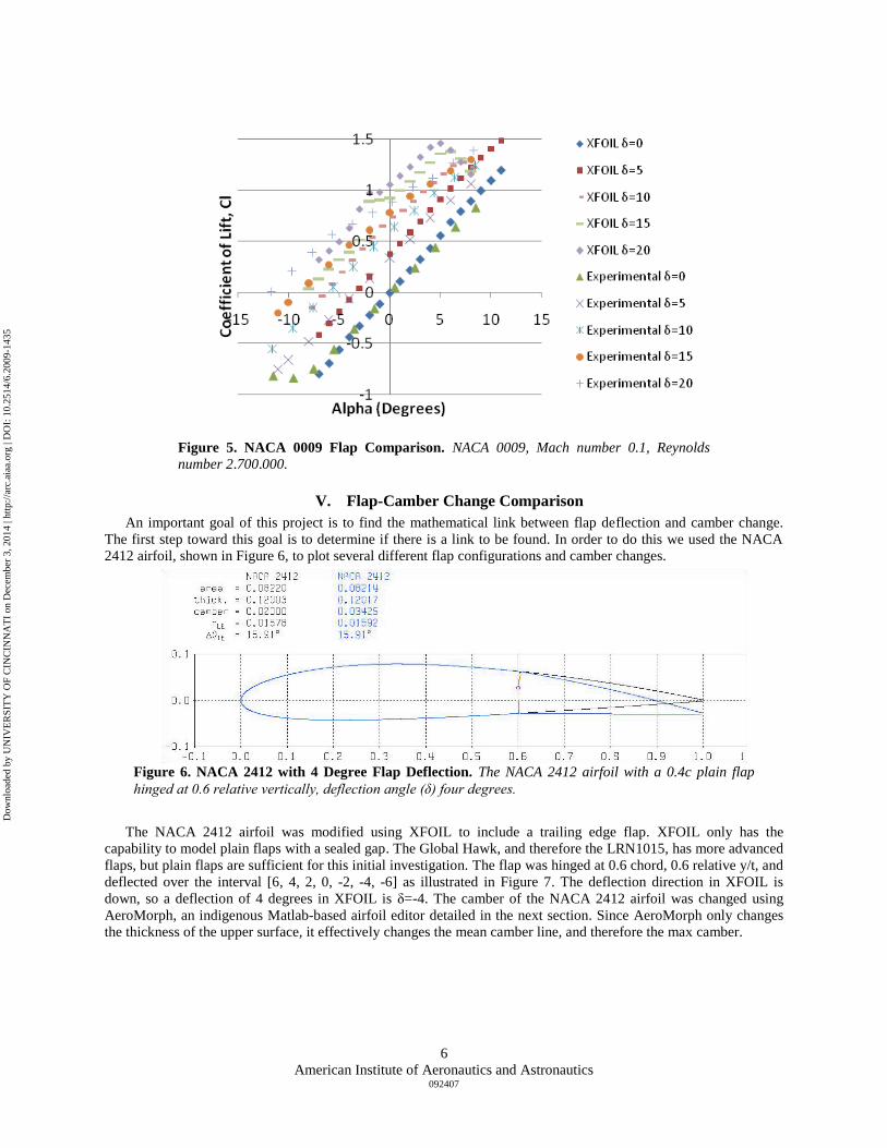
An important goal of this project is to find the mathematical link between flap deflection and camber change.
The first step toward this goal is to determine if there is a link to be found. In order to do this we used the NACA
2412 airfoil, shown in Figure 6, to plot several different flap configurations and camber changes.
The NACA 2412 airfoil was modified using XFOIL to include a trailing edge flap. XFOIL only has the
capability to model plain flaps with a sealed gap. The Global Hawk, and therefore the LRN1015, has more advanced
flaps, but plain flaps are sufficient for this initial investigation. The flap was hinged at 0.6 chord, 0.6 relative y/t, and
deflected over the interval [6, 4, 2, 0, -2, -4, -6] as illustrated in Figure 7. The deflection direction in XFOIL is
down, so a deflection of 4 degrees in XFOIL is δ=-4. The camber of the NACA 2412 airfoil was changed using
AeroMorph, an indigenous Matlab-based airfoil editor detailed in the next section. Since AeroMorph only changes
the thickness of the upper surface, it effectively changes the mean camber line, and therefore the max camber.
Figure 5. NACA 0009 Flap Comparison. NACA 0009, Mach number 0.1, Reynolds
number 2,700,000.
Figure 6. NACA 2412 with 4 Degree Flap Deflection. The NACA 2412 airfoil with a 0.4c plain flap
hinged at 0.6 relative vertically, deflection angle (δ) four degrees.
Dow
nloa
ded
by U
NIV
ER
SIT
Y O
F C
INC
INN
AT
I on
Dec
embe
r 3,
201
4 | h
ttp://
arc.
aiaa
.org
| D
OI:
10.
2514
/6.2
009-
1435

American Institute of Aeronautics and Astronautics 092407
7
VI. AeroMorph
As this project is investigating morphing airfoils, we needed to find a way to easily and quickly morph any
airfoil. We chose to develop our own application to do this. AeroMorph (see Figure 8) is an application written in
Matlab that allows the user to make fast changes to airfoil coordinate files and then use those files in XFOIL or any
other two-dimensional simulation program that requires x-y coordinate files. AeroMorph allows manipulation of the
upper surface of the current airfoil either by a leading-edge to trailing-edge thickness change or by individual node
changes. The graphical interface, as shown in Fig. 8 allows changes to be made with drop-down menus and instant
visual confirmation of any changes made. There are three main parts to AeroMorph: The editor box, the data box,
and the plot box.
Figure 7. XFOIL Flap-Camber Change Comparison. The left plot shows Cl vs. α for the deflection angle (δ)
interval [6, 4, 2, 0, -2, -4, -6]. The right plot shows Cl vs. α for arbitrary small camber changes. The relationship
between the two is visible. As a camber change would affect the whole wing instead of just affecting a small part
of the wing like a flap, it can be seen how a camber change could replace a flap system for in-flight
maneuvering.
Dow
nloa
ded
by U
NIV
ER
SIT
Y O
F C
INC
INN
AT
I on
Dec
embe
r 3,
201
4 | h
ttp://
arc.
aiaa
.org
| D
OI:
10.
2514
/6.2
009-
1435

American Institute of Aeronautics and Astronautics 092407
8
The editor box contains everything needed to make changes to the current airfoil. To load an airfoil coordinate
file, the file must meet several conditions. The file must be in ASCII format. Common file extensions for ASCII text
are .txt or .dat, though others exist. The data for the airfoil must be in two columns, separated by spaces or tabs,
specifying the x- and y-coordinates for the outer surface. To load the file properly, the file should contain only
numbers, though data in exponential format (e.g. 1e1) is allowed. To load a coordinate file from XFOIL, The first
line containing the name of the airfoil must be removed. The Thickness Change dropdown menu will perform a
leading- to trailing-edge displacement change based on a percentage of the chord length. For example, if a five
percent thickness increase were accomplished on the LRN1015 airfoil, which has a thickness of 15% of the chord,
the new airfoil would have a thickness of 20% of the chord. In order to make changes to an individual node, the
node must first be selected in the Select Node dropdown. The nodes are shown as black circles in Fig. 8. Choosing a
node will also refresh the Data box to show information on the selected node. Note that the leading-edge and
trailing-edge nodes (1 and 8) are not moveable. Once a node has been selected, its vertical displacement can be
modified using the Raise/Lower Node dropdown. Nodes can be moved up or down. In order to maintain a smooth
surface the panels between the nodes are able to rotate. When a node is raised or lowered, the panels to the right and
left of the selected node rotate about the adjacent nodes. The Smooth Surface button uses the polyfit function in
Matlab to generate an 18th order polynomial describing the upper surface of the current airfoil. It then uses that
polynomial to remap the upper surface. This has the effect of smoothing the distortions caused by manipulating the
airfoil, especially individual node changes. This should be used only as needed because it can cause distortion at the
leading- and trailing-edges of the airfoil. The Smooth Surface button has very little effect on airfoils that contain
more that 150 coordinates, such as those output by XFOIL. The Reset Airfoil button returns the current airfoil to its
original configuration, deleting any unsaved changes.
The data box displays information about the current airfoil. The data will automatically refresh whenever the
airfoil is changed. Under Thickness %, it displays the thickness of the current airfoil in percentage of the thickness
of the original airfoil. This will change whenever a thickness change is performed using the Thickness Change
dropdown. Under Max Camber it displays the value corresponding to the maximum displacement of the mean
camber line from the chord of the airfoil. Under Node Y value it displays the overall displacement of the currently
selected node from the chord line. Under Node Displacement it displays the relative displacement of the currently
selected node from its original position.
Figure 8. AeroMorph.
Dow
nloa
ded
by U
NIV
ER
SIT
Y O
F C
INC
INN
AT
I on
Dec
embe
r 3,
201
4 | h
ttp://
arc.
aiaa
.org
| D
OI:
10.
2514
/6.2
009-
1435

American Institute of Aeronautics and Astronautics 092407
9
The Airfoil plot displays the current airfoil as well as the original airfoil. The original airfoil is displayed with a
grey fill and a solid black border. The current airfoil is displayed with a dashed line. The individually moveable
nodes on the airfoil are displayed as black rings along the upper surface of the airfoil.
VII. Results
An important milestone of this project is to find a mapping of a given flap-based maneuver to an equally or more
effective morphing-based maneuver. It is important that it can be shown both that morphing maneuvers are a viable
alternative to flap maneuvers, such that one can achieve the same lift differential as using a conventional flap/aileron
approach. Several different configurations were chosen to be compared side-by-side. The desired configurations
were obtained using an iterative process, taking into account the normal operating configurations for the Global
Hawk aircraft. The Global Hawk, as it loiters over its target, may make a series of wide figure-eights involving very
small lift differentials in order to have the camera “hover” over a designated point. Therefore, small flap deflections
were chosen for matching. The flaps chosen for this comparison are plain flaps hinged vertically centered, at 0.7
chord. The configurations chosen are flap deflections (δ) of zero, negative one, negative two, and negative three, as
well as morphed configurations of negative two percent thickness, and negative four percent thickness. It is shown
in Figure 9 that a thickness change of negative two percent of the chord results in a similar lift coefficient profile to
a negative one degree flap configuration. Similarly, a thickness change of negative four percent of the chord results
in a similar lift coefficient profile to a negative three degree flap configuration.
The next step of the project was to show that there is a potential benefit to using a morphed configuration over a
flap-based configuration. This was found when the Lift/Drag efficiency was compared for the different
configurations. An important factor in the capability of the Global Hawk is its ability to loiter over a target for many
hours. A factor that directly contributes to how long the aircraft can maintain its position is its efficiency. An
increase in efficiency directly translates into more hours over the target and lower costs for operation, both in fuel
and the number of aircraft required to cover a target for a specified period.
Figure 9. Lift Coefficient vs. Angle of Attack. LRN1015 with both flap and
morphed configurations, Mach 0.2, Reynolds Number 500,000
Dow
nloa
ded
by U
NIV
ER
SIT
Y O
F C
INC
INN
AT
I on
Dec
embe
r 3,
201
4 | h
ttp://
arc.
aiaa
.org
| D
OI:
10.
2514
/6.2
009-
1435

American Institute of Aeronautics and Astronautics 092407
10
When comparing the efficiency of the flap-based configurations to that of the morphing configurations in Figure
10, a clear trend can be shown. Whereas the flap-based configurations showed as much as a 35 percent drop in
efficiency compared to the baseline LRN1015 airfoil over small angles of attack, the morphed configurations
showed almost no drop in efficiency. This is very important as it shows that the morphed configurations have a great
potential to increase the efficiency of aircraft maneuvers. In the future, a more detailed investigation will be made
into maximizing the efficiency of the airfoil in every flight condition, potentially leading to a double-digit increase
in overall efficiency.
VIII. Conclusion
This paper covers but the first step in our project to increase aircraft performance through the use of thickness-
based camber-morphing technology. We have proven through our initial investigation that we have developed
effective tools and that morphing can be a viable alternative to flap-based maneuvers. Initially, we compared the
predictive capability of XFOIL to that of several other CFD programs, including ISES and LBAUER, and also to
experimental results recorded by NASA for the NACA 2412 airfoil. After verifying its accuracy with unmodified
airfoils, we used data from a NACA wartime report on the performance of the NACA 0009 airfoil with flaps to
determine the capability of XFOIL to predict the changes in performance made by flap usage. We were again
successful in showing XFOIL‟s capability. We then used the NACA 2412 airfoil to demonstrate that morphing can
provide a similar lift differential to that created by a flap change in a maneuver. Finally, we demonstrated that an
aircraft using the LRN1015 airfoil can achieve the lift differential required to perform a maneuver while maintaining
higher efficiency than an aircraft using flaps to perform the same maneuver. In the future, we will map both flap and
morphed configurations in an effort to develop an algebraic relationship between the two. We plan on having our
results tested in a wind tunnel, to verify the accuracy our results. In parallel, we will also begin to examine the
structural and control aspects of the morphing aircraft problem.
Acknowledgments
The authors thank Ms. Jill Collet, Division of Professional Practice, University of Cincinnati, for her guidance
and support of the Co-op research program. The authors acknowledge the assistance of Ms. Leva Wilson and Ms.
Brenda Smith for their support and assistance.
Figure 10. Lift/ Drag vs. Angle of Attack. LRN1015 with both flap and
morphed configurations, Mach 0.2, Reynolds Number 500,000
Dow
nloa
ded
by U
NIV
ER
SIT
Y O
F C
INC
INN
AT
I on
Dec
embe
r 3,
201
4 | h
ttp://
arc.
aiaa
.org
| D
OI:
10.
2514
/6.2
009-
1435

American Institute of Aeronautics and Astronautics 092407
11
References 1
Wall, R., “Darpa Eyes Materials for „Morphing‟ Aircraft,” Aviation Week and Space Technology, April 8, 2002. 2
“Morphing Aircraft Structures,” DARPA Defense Sciences Office, URL: http://www.darpa.mil/tto/
Programs/morphingaircraft.htm. 3
Ashley, S., “Flying on Flexible Wings,” Scientific American, No. 289, Nov. 2003, pp. 84-91. 4
McGowan, A. R., Washburn, A. E., Horta, L. G., Bryant, R. G., Cox, D. E., Siochi, E. J., Padula, S. L., and
Holloway, N. M., “Recent Results from NASA‟s Morphing Project,” SPIE Paper 4698-11, March 2002. 5
Wlezien, R. W., Horner, G. C., McGowan, A. R., Padula, S. L., Scott, M. A., Silcox, R. J., and Simpson, J. O.,
“The Aircraft Morphing
Program,” AIAA Paper 1998-1927, April 1998. 6
Bowman, J., Sanders, B., and Weisshaar, T., “Evaluating The Impact of Morphing Technologies on Aircraft
Performance,” AIAA Paper 2002-1631, April 2002. 7
Cesnik, C., Last, H., and Martin, C., “A Framework for Morphing Capability Assessment,” AIAA Paper 2004-
1654, April 2004. 8Hicks, R. M., and Cliff, S. E., “An Evaluation of Three Two-Dimensional Computational Fluid Dynamics
Codes Including Low Reynolds Numbers and Transonic Mach Numbers,” NASA T-M 102840, 1991. 9Sears, R. I., “Wind Tunnel Data on the Aerodynamic Characteristics of Airplane Control Surfaces,” NACA WR
L-663, 1943. 10
XFOIL, Software Package, Ver. 6.96, MIT, Cambridge, MA, 2005. 11
Matlab, Software Package, Ver. 7.4.0.287, The Mathworks, Inc., Natick, MA, 2007.
Dow
nloa
ded
by U
NIV
ER
SIT
Y O
F C
INC
INN
AT
I on
Dec
embe
r 3,
201
4 | h
ttp://
arc.
aiaa
.org
| D
OI:
10.
2514
/6.2
009-
1435