Transonic Airfoil Design and Optimization for an Unmanned ...
10
Journal of Mechanics Engineering and Automation 9 (2019) 193-202 doi: 10.17265/2159-5275/2019.06.004 Transonic Airfoil Design and Optimization for an Unmanned Air Vehicle Concept Kasim Biber 1 and Trenton White 1. Department of Mechanical Engineering, Faculty of Engineering, Architecture and Design, Bartin University, Bartin 74100, Turkey 2 2. US Air Force Research Laboratory, Wright Patterson Air Force Base, Ohio 45433-7542, USA Abstract: Design, optimization and analysis of a new energy efficient 16% thick transonic airfoil were completed for a notional air vehicle concept. The airfoil specifications included a range of Reynolds number per foot from 1.7 million to 2.5 million and Mach number from 0.4 to 0.8. Shape optimization in geometry and inverse design modules of the airfoil analysis program MSES were used to design a new 16% thick reference airfoil. The performance of the reference airfoil was then optimized with an objective of minimizing drag coefficient for 7 design points with conflicting requirements in Reynolds and Mach number by using the MSES/LINDOP optimizer. The optimization results in an upward shift of drag bucket in the direction of higher lift coefficient. Both surface pressure distribution and Mach contour plots show that supersonic compression waves on airfoil surface are terminated at Mach 0.78 with a normal shock wave and associated flow separation, which causes not only a decrease of the maximum suction pressure, but also a decrease in lift and increase in drag coefficient. The new optimized airfoil shows robust performance when operating within the specified design constraints. Key words: Airfoil optimization, airfoil design, transonic airfoils, shock flows, compression waves. 1. Introduction The vehicle design problem is multi-faceted, as there are several disciplines that should be considered for design and optimization. Disciplines of propulsion, structures, payload, and aerodynamics can all be An air vehicle has been conceptualized to provide the context of a vehicle within which an energy efficient airfoil design and optimization problem can be formed. The air vehicle concept is used to generate flight conditions and desired performance characteristics for the airfoil design process. It is considered to have a maximum gross weight of 2,500 kg and a cruising altitude between 5,000 m and 15,000 m. There is no official requirement for this class of vehicle, but some notional vehicle performance objectives are formulated so that a new airfoil can be designed and optimized for its main wing. Corresponding author: Kasim Biber, Ph.D., associate professor, research fields: fluid mechanics/aerodynamics and energy. considered, along with their integration into the overall vehicle system. However, only the aerodynamic discipline is considered under the scope of this study. The objective here is to design an aerodynamically optimal airfoil shape for application in a notional air vehicle. The concept vehicle is assumed to operate for the majority of its flight time in an efficient cruising condition at high subsonic speed, and so one objective would be to maximize the endurance of the vehicle. Maximizing flight time should improve the quality of information collected and could also save mission costs. For this objective, the airfoil design parameter would be minimum drag coefficient at a given cruise lift coefficient, or a range of cruise lift coefficients. This means that the new airfoil should be energy efficient. The concept vehicle also has an objective to achieve a high transonic top speed. The ability to achieve a high dash speed would aid in vehicle responsiveness, for example, in relocation between areas of interest. A thinner airfoil may be desirable for D DAVID PUBLISHING
-
Upload
khangminh22 -
Category
Documents
-
view
2 -
download
0
Transcript of Transonic Airfoil Design and Optimization for an Unmanned ...

Journal of Mechanics Engineering and Automation 9 (2019) 193-202 doi: 10.17265/2159-5275/2019.06.004
Transonic Airfoil Design and Optimization for an
Unmanned Air Vehicle Concept
Kasim Biber1 and Trenton White1. Department of Mechanical Engineering, Faculty of Engineering, Architecture and Design, Bartin University, Bartin 74100, Turkey
2
2. US Air Force Research Laboratory, Wright Patterson Air Force Base, Ohio 45433-7542, USA Abstract: Design, optimization and analysis of a new energy efficient 16% thick transonic airfoil were completed for a notional air vehicle concept. The airfoil specifications included a range of Reynolds number per foot from 1.7 million to 2.5 million and Mach number from 0.4 to 0.8. Shape optimization in geometry and inverse design modules of the airfoil analysis program MSES were used to design a new 16% thick reference airfoil. The performance of the reference airfoil was then optimized with an objective of minimizing drag coefficient for 7 design points with conflicting requirements in Reynolds and Mach number by using the MSES/LINDOP optimizer. The optimization results in an upward shift of drag bucket in the direction of higher lift coefficient. Both surface pressure distribution and Mach contour plots show that supersonic compression waves on airfoil surface are terminated at Mach 0.78 with a normal shock wave and associated flow separation, which causes not only a decrease of the maximum suction pressure, but also a decrease in lift and increase in drag coefficient. The new optimized airfoil shows robust performance when operating within the specified design constraints. Key words: Airfoil optimization, airfoil design, transonic airfoils, shock flows, compression waves.
1. Introduction
The vehicle design problem is multi-faceted, as there are several disciplines that should be considered for design and optimization. Disciplines of propulsion, structures, payload, and aerodynamics can all be
An air vehicle has been conceptualized to provide the context of a vehicle within which an energy efficient airfoil design and optimization problem can be formed. The air vehicle concept is used to generate flight conditions and desired performance characteristics for the airfoil design process. It is considered to have a maximum gross weight of 2,500 kg and a cruising altitude between 5,000 m and 15,000 m. There is no official requirement for this class of vehicle, but some notional vehicle performance objectives are formulated so that a new airfoil can be designed and optimized for its main wing.
Corresponding author: Kasim Biber, Ph.D., associate
professor, research fields: fluid mechanics/aerodynamics and energy.
considered, along with their integration into the overall vehicle system. However, only the aerodynamic discipline is considered under the scope of this study. The objective here is to design an aerodynamically optimal airfoil shape for application in a notional air vehicle.
The concept vehicle is assumed to operate for the majority of its flight time in an efficient cruising condition at high subsonic speed, and so one objective would be to maximize the endurance of the vehicle. Maximizing flight time should improve the quality of information collected and could also save mission costs. For this objective, the airfoil design parameter would be minimum drag coefficient at a given cruise lift coefficient, or a range of cruise lift coefficients. This means that the new airfoil should be energy efficient. The concept vehicle also has an objective to achieve a high transonic top speed. The ability to achieve a high dash speed would aid in vehicle responsiveness, for example, in relocation between areas of interest. A thinner airfoil may be desirable for
D DAVID PUBLISHING

Transonic Airfoil Design and Optimization for an Unmanned Air Vehicle Concept
194
maximizing top speed, but it could lead to increased structural weight and a heavier vehicle. For various reasons, but primarily for antenna integration, the aircraft may also require relatively thick wings. Therefore, a third objective has been to design an airfoil that has a maximum thickness ratio of 16% chord.
Because of these factors, it is likely that basing the wing designs on existing airfoil sections will provide sub-optimal performance. Thus, it becomes necessary to develop a unique class of airfoils to use as the baseline for further development efforts. The specifications for the new 16% thick airfoil include a range of Reynolds numbers per foot from 1.7 million to 2.5 million and Mach numbers from 0.4 to 0.8. With these given specifications, this paper aims at designing and optimizing a custom transonic airfoil. The long-endurance flight capability requires the aircraft to have maximum aerodynamic efficiency and minimum fuel consumption, as illustrated by their prominence in the Breguet-endurance equations. For this reason, the objective has been to extend the laminar flow over the airfoil as much as possible, leading to a substantial decrease in drag and consequent reductions in fuel consumption and pollution. However, as evidenced from some other research, reported by Biber et al. [1], Cella et al. [2] and Drela [3], the laminar flow exhibits strong sensitivity to the leading edge sweep angle and to the environment conditions. Therefore, the current investigation focuses on two-dimensional transonic flow over a wing section having no sweep angle and taking full advantage of natural laminar flow extension.
The research required the use of the MSES computational airfoil analysis and design program package. This program package as described by Drela [4] is capable of design, analysis and optimization of airfoils used for both high lift systems and transonic wings. This paper first describes the computer programs and relevant methods used for the airfoil design and optimization. It then presents the polar performance of a reference airfoil in comparison to the
new optimized one. The polar performance includes a graphical presentation of lift, drag and pitching moment characteristics in sweeps of angle of attack and Mach number increments. The paper finally presents polar performance sensitivities of the new airfoil to changes in the critical amplification factor and the location of flow transition on the airfoil surface.
2. Computational Tools
The airfoil design effort reported here included the use of a collection of FORTRAN computer programs called the MSES, version 3.12b and its optimizer called LINDOP, version 2.50. The MSES program consists of main and supporting programs, as described in its user’s manual by Drela [4, 5].
Boundary layer transition in an MSES solution, as in an XFOIL solution, is triggered by either a free transition where eN criterion is met or a forced transition where a trip or the trailing edge is encountered [6].
The eN method is only appropriate for predicting transition in situations where the growth of two-dimensional Tollmien-Schlichting waves via linear instability is the dominant transition-initiating mechanism. The eN method is always active, and free transition can occur upstream of the trip. The eN method has the user-specified parameter “Ncr”, which is the log of the amplification factor of the most-amplified frequency which triggers transition. A suitable value of this parameter depends on the ambient disturbance level in which the airfoil operates, and mimics the effect of such disturbances on transition. For the present airfoil design and analysis, the standard Ncr
The notional air vehicle is envisioned to have a long endurance at medium altitudes, requiring its wing to
value of 9 was used; however, the effect of changing the transition parameter to other values such as 4, 5, 6 and 12 was also investigated.
3. Transonic Airfoil Development

Transonic Airfoil Design and Optimization for an Unmanned Air Vehicle Concept
195
be as aerodynamically efficient as possible. The primary requirements for the wing section considered in this study included 16% chord maximum thickness, over 50% chord laminar flow, low pitching moment, and operations at Mach numbers ranging from 0.4 to 0.8 and Reynolds numbers per foot ranging from 1.7 million to 2.5 million. Both Mach and Reynolds numbers are based on free-stream flow conditions. MSES flow parameters were defined for vortex+doublet far-field, isentropic except near shocks and free-transition for either specified angle of attack or Mach number. Reynolds number was specified for viscous analysis, but it was set to 0.0 for inviscid runs.
A compromise was made among all of the requirements to increase the operational Mach number while maintaining airfoil maximum thickness with a high L/D ratio and large drag bucket for given range of Reynolds number. Surface pressure distribution or surface geometry was changed in mixed or inverse design modules of the MSES software to meet the design objectives. The interactive and iterative work resulted in a new 16% thick airfoil considered to be a reference one, as shown in Fig. 1, for the mid-size unmanned aerial vehicle wing.
Once the reference airfoil was determined, the optimization capability of LINDOP driver was implemented to obtain the new transonic airfoil with 16% chord maximum thickness ratio. For the optimization process, global variables and their corresponding fixing constraints were set to 5 for sweeps in angle of attack, 15 for sweeps in Mach number and 20 for making use of LINDOP optimizer. Incremental sweep values in angle of attack and Mach number were provided in a separate spec.xxx file. Geometry deformation modes were represented by some functions describing camber, and upper and lower surface of airfoil. These functions have end points; 0 at the leading edge and 1.0 at the trailing edge, as indicated in the file modes.xxx. The particular geometric shapes are implemented in FUNCTION GFUN in the program package.
Fig. 1 Geometric comparison of 16% thick reference airfoil with the optimized one.
The reference airfoil geometry file, blade.xxx was used for all 7 design points selected for climb, cruise and maneuver flight conditions. MSET was run with the airfoil geometry file blade.xxx to create one mdat.xxx, and then the same file was copied for all 7 design points. The modes.xxx file was also kept same to ensure the same airfoil shape during optimization. The mses.xxx file had a different extension for each design point with conflicting requirements.
The optimization process was started by first converging mses.xxx file for all 7 cases. MSES sets all the geometry mode amplitudes to zero during a calculation and calculates the sensitivities of various quantities such as CL, CD
LINDOP in general is used to minimize an objective function F(X
, etc. to the mode displacements. These sensitivities are written out to the unformatted file sensx.xxx, which is then read in by LINDOP optimizer. LINDOP reads all input files with some initialization and lists the available operating points and design parameters.
k) with respect to the parameters Xk as in Refs. [5, 7]. In this study, the objective function F was the drag coefficient CD while the parameters Xk were the airfoil geometry deformation modes. One optimization step consisted of the generation of design parameter changes via line minimization in LINDOP, followed by a
Transonic Airfoil Design and Optimization for an Unmanned Air Vehicle Concept
196
nonlinear MSES solution calculation. This sub-cycle was executed toward the line minimum. The gradient vector and line-minimization direction vector were generated to find the optimum. The optimization process resulted in a new 16% thick transonic airfoil, designated as SCR-16 and shown in Fig. 1 with a comparison with the reference airfoil.
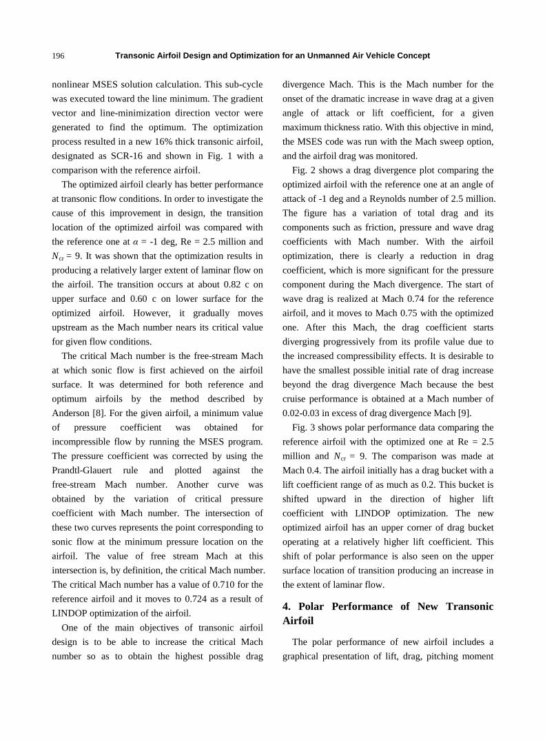
The optimized airfoil clearly has better performance at transonic flow conditions. In order to investigate the cause of this improvement in design, the transition location of the optimized airfoil was compared with the reference one at α = -1 deg, Re = 2.5 million and Ncr
One of the main objectives of transonic airfoil design is to be able to increase the critical Mach number so as to obtain the highest possible drag
divergence Mach. This is the Mach number for the onset of the dramatic increase in wave drag at a given angle of attack or lift coefficient, for a given maximum thickness ratio. With this objective in mind, the MSES code was run with the Mach sweep option, and the airfoil drag was monitored.
Fig. 2 shows a drag divergence plot comparing the optimized airfoil with the reference one at an angle of attack of -1 deg and a Reynolds number of 2.5 million. The figure has a variation of total drag and its components such as friction, pressure and wave drag coefficients with Mach number. With the airfoil optimization, there is clearly a reduction in drag coefficient, which is more significant for the pressure component during the Mach divergence. The start of wave drag is realized at Mach 0.74 for the reference airfoil, and it moves to Mach 0.75 with the optimized one. After this Mach, the drag coefficient starts diverging progressively from its profile value due to the increased compressibility effects. It is desirable to have the smallest possible initial rate of drag increase beyond the drag divergence Mach because the best cruise performance is obtained at a Mach number of 0.02-0.03 in excess of drag divergence Mach [9].
Fig. 3 shows polar performance data comparing the reference airfoil with the optimized one at Re = 2.5 million and N
= 9. It was shown that the optimization results in producing a relatively larger extent of laminar flow on the airfoil. The transition occurs at about 0.82 c on upper surface and 0.60 c on lower surface for the optimized airfoil. However, it gradually moves upstream as the Mach number nears its critical value for given flow conditions.
The critical Mach number is the free-stream Mach at which sonic flow is first achieved on the airfoil surface. It was determined for both reference and optimum airfoils by the method described by Anderson [8]. For the given airfoil, a minimum value of pressure coefficient was obtained for incompressible flow by running the MSES program. The pressure coefficient was corrected by using the Prandtl-Glauert rule and plotted against the free-stream Mach number. Another curve was obtained by the variation of critical pressure coefficient with Mach number. The intersection of these two curves represents the point corresponding to sonic flow at the minimum pressure location on the airfoil. The value of free stream Mach at this intersection is, by definition, the critical Mach number. The critical Mach number has a value of 0.710 for the reference airfoil and it moves to 0.724 as a result of LINDOP optimization of the airfoil.
cr = 9. The comparison was made at Mach 0.4. The airfoil initially has a drag bucket with a lift coefficient range of as much as 0.2. This bucket is shifted upward in the direction of higher lift coefficient with LINDOP optimization. The new optimized airfoil has an upper corner of drag bucket operating at a relatively higher lift coefficient. This shift of polar performance is also seen on the upper surface location of transition producing an increase in the extent of laminar flow.
4. Polar Performance of New Transonic Airfoil
The polar performance of new airfoil includes a graphical presentation of lift, drag, pitching moment

Transonic Airfoil Design and Optimization for an Unmanned Air Vehicle Concept
197
Fig. 2 Drag divergence Mach comparison of reference airfoil (solid line) with the optimum one (dotted line).
Fig. 3 Polar comparison of reference airfoil with the optimized one at Mach 0.4.
characteristics in sweeps of angle of attack and Mach number. However, the flow behavior at each angle of attack can be better explained with surface pressure distributions over the airfoil.
Fig. 4 shows lift, drag and pitching moment characteristics for the new optimized airfoil at Re = 2.5 million and Ncr
DL CC /5.1
= 9. For a given angle of attack, the coefficient data are easily determined. The transition location and endurance parameter can also be found at a specific lift coefficient. At the upper corner of drag bucket, the extent of laminar flow starts decreasing on the airfoil’s upper surface while it almost stays constant on its lower surface, shown with a dashed line. The endurance parameter ( ) on
the other hand increases linearly within the drag bucket and reaches to a maximum value at the upper corner of bucket. There is in fact a further increase in the endurance parameter until CL = 0.8.
Fig. 5 shows surface pressure distributions for Mach of 0.4, 0.6, 0.70, 0.74, 0.76, 0.77, 0.78, 0.79 and 0.80. There are negative pressures with distinct suction peaks on both upper and lower surfaces. At Mach numbers below Mach 0.75, the upper surface pressure has a gradual increase of negative pressures over the forward part until a point where the laminar separation bubble has its maximum thickness, followed by a pressure rise to the trailing edge. This is similar to the shape of roof-type pressure distributions,

Transonic Airfoil Design and Optimization for an Unmanned Air Vehicle Concept
198
Fig. 4 Coefficients of lift, drag and pitching moment along with transition location and endurance parameter at Re = 2.5 million, Mach 0.6 and transition-free.
Fig. 5 Surface pressure distributions for free-stream Mach 0.40, 0.60, 0.70, 0.74, 0.76, 0.77, 0.78, 0.79 and 0.80, showing the effects of supercritical speeds at α = 1 deg, Re = 2.5 million and Ncr
= 9.
which delays critical Mach number by virtue of a uniform velocity at the design condition. As the Mach number increases beyond 0.75, there is a dramatic change of surface pressures in the separation bubble region. The suction level basically moves to its maximum value at Mach 0.78. This is probably due to the thickening of the boundary layer by the presence
of locally supersonic flow embedded in the subsonic outer flow.
The supersonic flow extends over a region in which there is near isentropic flow and shock-free compression waves. However, at Mach numbers above 0.78, the supersonic region is terminated by a normal shock and associated flow separation, which causes not only a

Transonic Airfoil Design and Optimization for an Unmanned Air Vehicle Concept
199
decrease of the maximum suction pressure, but also a decrease in lift and increase in drag coefficient, as shown in the data tabulation of Fig. 5. Notice also the decrease in magnitude of pitching moment coefficient as the Mach number is raised above the drag divergence Mach.
Fig. 6 shows Mach contours to better illustrate the shock formation and associated flow events at the same Mach numbers and flow conditions as the surface pressure distributions presented in Fig. 5. The shock formation is clearly visible in the dense region of Mach contours at the location of the separation bubble. Pre-compression waves are initially weak at Mach 0.74, but they get stronger with increasing Mach number and are eventually terminated with a normal shock wave. They separate the laminar boundary layer well ahead of the first shockwave, which impinges on the free-shear layer and reflects as an expansion wave. The so-called shock-induced flow separation, clearly exhibited at Mach 0.78 and beyond, limits the operational range of airfoils designed for transonic vehicle applications.
5. Performance Sensitivities to Flow Transition
The new transonic airfoil was designed and
optimized with conflicting requirements in a range of Reynolds and Mach numbers. Therefore, Reynolds number did not have a significant effect on the airfoil performance. However, given all of the uncertainties in design and analysis of the airfoil, it is important to evaluate the sensitivities of airfoil performance to some other values of critical amplification ratio and fixed transition. During the optimization process, the flow transition was left free on both upper and lower surfaces of the airfoil. A critical amplification ratio of 9 was used for the eN envelope method.
Fig. 6 Mach contours for free-stream Mach 0.74, 0.76, 0.78 and 0.80 showing the shock formation on airfoil upper and lower surfaces. α = -1 deg, Re = 2.5 million, Ncr
Fig. 7 Variation of drag coefficient with free-stream Mach number comparing critical amplification ratios of 4, 5, 6, 9 and 12 at Re = 2.5 million and α = -1 deg.
= 9 and transition-free.

Transonic Airfoil Design and Optimization for an Unmanned Air Vehicle Concept
200
Fig. 8 Variation of drag coefficient with free-stream Mach number showing the effect of fixing the transition at 0.55 c upper and 0.35 c lower surfaces of airfoil. Re = 2.5 million, Ncr
Fig. 7 shows a comparison of drag divergence Mach number obtained for N
= 9 and α = -1 deg.
cr = 9 with those obtained for Ncr = 4, 5, 6 and 12 cases at Re = 2.5 million and α = -1 deg. The higher Ncr =12 infers lower disturbance levels, more typical for unmanned air vehicle operating at high altitudes. The lower Ncr = 4, on the other hand, corresponds to ground conditions such as in a wind tunnel. However, the Ncr
The effect of transition was investigated on the airfoil performance by fixing the transition at 0.55 c on upper surface and 0.35 c on lower surface of the airfoil. The selection of transition points was based on the surface pressure distributions. As shown in Fig. 5, the selected transition points are approximately at the start of separation bubble on airfoil surfaces. A comparison was made between free and fixed transition cases in terms of their drag divergence at Re = 2.5 million and α = -1 deg. As shown in Fig. 8, the free transition clearly produces a lower drag coefficient because it has a larger extend of laminar flow on the airfoil. It also has a higher lift coefficient as indicated in the figure. The drag divergence Mach is about the same for both cases
since the critical Mach number does not change significantly with fixing transition.
The effect of fixing the transition was also investigated on the formation of shock waves in the region of drag divergence. Fig. 9 shows the Mach contours for the fixed transition at 0.55 c upper and 0.35 c lower surfaces of the airfoil. Free-stream Mach numbers are 0.74, 0.76, 0.78 and 0.80, the same as in Fig. 6 shown for the free transition case. Comparing the two transition cases, the normal shock wave is shown to move slightly upstream by fixing the
= 9 case clearly produces the lowest drag value among all others because of its use in optimizing the airfoil for minimum drag coefficient.
Fig. 9 Mach contours for free-stream Mach 0.74, 0.76, 0.78 and 0.80 showing the shock formation at α = -1 deg, Re = 2.5 million, Ncr = 9 and transition fixed at 0.55 c upper and 0.35 c lower surface of the airfoil.

Transonic Airfoil Design and Optimization for an Unmanned Air Vehicle Concept
201
transition. It is however still formed at a downstream location of transition while the flow is turbulent for both upper and lower surfaces. The location of normal shock does not seem to change significantly on the airfoil, whether the flow is laminar with free transition or turbulent with fixed transition. This shows robustness in flow character of the new airfoil design. The new airfoil basically performs well as specified within its design constraints and shows the robustness with shock location.
6. Conclusions
Design, optimization and analysis of a new energy efficient 16% thick transonic airfoil were completed, using the MSES computer program. Based on the climb, cruise and maneuver flight conditions of a notional air vehicle, the airfoil was specified for a range of Reynolds numbers per foot from 1.7 million to 2.5 million and Mach numbers from 0.4 to 0.8. The wing section considered for the new airfoil is two-dimensional with no sweep angle. For the design and optimization process, the transition was left free with Ncr
The flow transition occurs at approximately 80% chord upper surface and 60% chord lower surface of airfoil, taking full advantage of laminar flow as intended.
= 9. The research first included designing a new 16%
thick reference airfoil with shape optimization in geometry and inverse design modules of the MSES program. The performance of the reference airfoil was then optimized for 7 design points with conflicting requirements in Reynolds and Mach number by using LINDOP optimizer. For the free transition case at Reynolds number per foot of 2.5 million, the new optimized airfoil has the following design features:
The optimization results in an increase of critical Mach number. While the critical Mach is 0.710 for the reference airfoil, it moves to 0.725 for the optimized one. Drag divergence Mach plot shows a summation
of friction, pressure and wave drag components. For
the plotted data, the start of wave drag occurs at Mach 0.74 for the reference airfoil and it moves to Mach 0.75 for the optimized one. The optimization results in an upward shift of
drag bucket in the direction of higher lift coefficient. The new optimized airfoil has an upper corner of drag bucket operating at a relatively higher lift coefficient. The endurance parameter, CL
1.5/CD
Increasing Mach number causes the drag bucket to move upward in the direction of both higher lift and higher drag coefficients.
, shows an almost linear increase within the region of drag bucket, indicating the benefit of having a laminar flow airfoil.
Surface pressure distribution plots show that the supersonic compression waves on the airfoil surface are terminated at Mach 0.78 with a normal shock wave and associated flow separation, which cause not only a decrease of the maximum suction pressure, but also a decrease in lift and increase in drag coefficient. This result is supplemented by Mach contour plots provided at some free stream Mach numbers.
The airfoil was optimized for a range of Reynolds numbers and therefore its performance does not change significantly with alterations in Reynolds number. However, given all of the uncertainties in design and optimization, the airfoil performance was checked for some other flow conditions. A drag divergence Mach plot shows that when the critical amplification ratio; Ncr, is set to a different value from its standard 9, the corresponding drag coefficient increases, indicating the sensitivity of airfoil performance to the flow environment. Flow transition on airfoil was fixed approximately at the start of separation bubbles, corresponding to a transition location of 55% chord upper and 35% chord lower surfaces. Fixing the transition shows an increase of drag coefficient as expected, but does change the drag divergence Mach. Mach contour plots show that the location of normal shock on airfoil surfaces does not change significantly by fixing the transition, indicating the robustness of airfoil performance with shock location.
Transonic Airfoil Design and Optimization for an Unmanned Air Vehicle Concept
202
Acknowledgements
The first author acknowledges Scientific and Technological Research Council of Turkey for funding his Sabbatical research with the US Air Force Research Laboratory for 3-month period in the summer of 2017.
References
[1] Biber, K., and Tilmann, C. 2004. “Supercritical Airfoil Design for Future High Altitude and Long Endurance Concepts.” Journal of Aircraft 41 (1).
[2] Cella, U., Quagliarella, D., and Donelli, R. 2005. “Design and Optimization of a Transonic Natural Laminar Flow Airfoil.” Presented at XVII Congresso Nazionale AIADAA, Italy.
[3] Drela, M. 1992. “Transonic Low-Reynolds Number
Airfoils.” Journal of Aircraft 29 (6): 1106-13. [4] Drela, M. 2004. A User’s Guide to MSES, Version 3.12b,
MIT Department of Aeronautics and Astronautics, Cambridge, MA, USA.
[5] Drela, M. 1992. A User’s Guide to LINDOP, Version 2.50, MIT Department of Aeronautics and Astronautics, Cambridge, MA, USA.
[6] Drela, M., and Youngren, H. 2001. A User’s Guide to XFOIL, Version 6.99, MIT Department of Aeronautics and Astronautics, Cambridge, MA, USA.
[7] Drela, M. 1998. “Pros and Cons of Airfoil Optimization.” In Frontiers of Computational Fluid Dynamics, edited by Caughey, D. A., and Hafez, M. M. World Scientific.
[8] Anderson, J. D. 2001. Fundamentals of Aerodynamics. 3rd ed., New York: McGraw Hill Higher Education.
[9] Torenbeek, E. 1982. Synthesis of Subsonic Airplane Design. Delft, the Netherlands: Delft Univ. Press, 241-52.