Model predictive control for autonomous unmanned helicopters
13
Model predictive control for autonomous unmanned helicopters Endra Joelianto and Edwina Maryami Sumarjono Instrumentation and Control Research Group, Faculty of Industrial Technology, Bandung Institute of Technology, Bandung, Indonesia Agus Budiyono Smart Robot Center, Department of Aerospace and Information Engineering, Konkuk University, Seoul, Republic of Korea, and Dini Retnaning Penggalih Instrumentation and Control Research Group, Faculty of Industrial Technology, Bandung Institute of Technology, Bandung, Indonesia Abstract Purpose – The purpose of this paper is to investigate the feasibility of controlling a small-scale helicopter by using the model predictive control (MPC) method. Design/methodology/approach – The MPC control synthesis is employed by considering five linear models representing the flight of a small-scale helicopter from hover to high-speed cruise. The internal model principle is employed for the trajectory tracking design. Findings – It is found that the MPC handles well the transition problems between the models, yields satisfactory tracking control performance and produces a suitable control signal. The performance of the tracking control of the helicopter is considerably influenced by the parameter selection in the states and inputs weighting matrices of the MPC. Simulation results also showed that faster dynamics, coupling problems, input and output constraints and changing linearized multi-inputs multi-outputs dynamics models in the small-scale helicopter can be handled simultaneously by the MPC controller. Research limitations/implications – The present study is limited for the application of MPC for the control of small-scale helicopters with non- aggressive maneuvers. Practical implications – The result can be extended to design a full envelope controller for an autonomous small-scale helicopter without the need to resort to a conventional gain scheduling technique. Originality/value – Helicopter control system designs using MPC with a single either linear or non-linear model have been studied and reported in numerous literatures. The main contribution of the paper is in the application of MPC to handle the control problems of a small-scale helicopter defined as a mathematical model with several different modes during a flight mission. Keywords Rotorcraft-based UAV, Autonomous control, Small scale helicopter, Model predictive control (MPC), Multiple models, Helicopters, Controllers Paper type Research paper Introduction Autonomous flight control system for small-scale helicopters presents significant challenges due to their highly non-linear, unstable nature of the vehicles and multi-input-multi-output (MIMO) characteristics. Helicopter is a non-linear complex system comprising many modes in its flight trajectories where each mode has different characteristics. The presence of strong cross-coupling and non-linearities makes helicopter difficult to control. Small-scale helicopters, especially, are known to have more reactive response and faster dynamic characteristics compared with the full scale helicopters (Mettler, 2003). This leads to a challenging control design problem as the controller must stabilize the flight and provide good tracking characteristics simultaneously. A conventional approach to the control synthesis is to linearize the non-linear model in order to have a simple linear model for each mode, then the well-known proportional-integral- derivative (PID) controller or its variant is implemented by trial and error-tuning approach until satisfactory responses are met. This approach has been adapted from long time ago until now and accepted as a proven and simple method to solve the PID control system design in most application areas. The approach does not consider the coupling effects that can degrade and even lead to unstable response. Recently, a MIMO PID controller has been developed and implemented for stabilizing a small-scale helicopter in a hover condition The current issue and full text archive of this journal is available at www.emeraldinsight.com/1748-8842.htm Aircraft Engineering and Aerospace Technology: An International Journal 83/6 (2011) 375–387 q Emerald Group Publishing Limited [ISSN 1748-8842] [DOI 10.1108/00022661111173252] This research was supported by The Ministry of Knowledge Economy (MKE), Korea, under the Information Technology Research Center (ITRC) support program supervised by the National IT Industry Promotion Agency (NIPA) (NIPA-2011-C1090-1131-0003). The authors would like to gratefully acknowledge the partial funding from the International Journal Publication and Research Collaboration Grant, Directorate of Higher Education, Ministry of Education, Indonesia 2010 and National Strategic Research Grant, Directorate of Higher Education, Ministry of Education, Indonesia 2010. The first author would like to acknowledge the support from Prof. Kwang-Joon Yoon during the visit at the Department of Aerospace and Information Engineering, Konkuk University, Korea to complete this work. 375
-
Upload
independent -
Category
Documents
-
view
1 -
download
0
Transcript of Model predictive control for autonomous unmanned helicopters

Model predictive control for autonomousunmanned helicoptersEndra Joelianto and Edwina Maryami Sumarjono
Instrumentation and Control Research Group, Faculty of Industrial Technology, Bandung Institute of Technology, Bandung, Indonesia
Agus BudiyonoSmart Robot Center, Department of Aerospace and Information Engineering, Konkuk University, Seoul, Republic of Korea, and
Dini Retnaning PenggalihInstrumentation and Control Research Group, Faculty of Industrial Technology, Bandung Institute of Technology, Bandung, Indonesia
AbstractPurpose – The purpose of this paper is to investigate the feasibility of controlling a small-scale helicopter by using the model predictive control (MPC)method.Design/methodology/approach – The MPC control synthesis is employed by considering five linear models representing the flight of a small-scalehelicopter from hover to high-speed cruise. The internal model principle is employed for the trajectory tracking design.Findings – It is found that the MPC handles well the transition problems between the models, yields satisfactory tracking control performance andproduces a suitable control signal. The performance of the tracking control of the helicopter is considerably influenced by the parameter selection in thestates and inputs weighting matrices of the MPC. Simulation results also showed that faster dynamics, coupling problems, input and output constraintsand changing linearized multi-inputs multi-outputs dynamics models in the small-scale helicopter can be handled simultaneously by the MPC controller.Research limitations/implications – The present study is limited for the application of MPC for the control of small-scale helicopters with non-aggressive maneuvers.Practical implications – The result can be extended to design a full envelope controller for an autonomous small-scale helicopter without the need toresort to a conventional gain scheduling technique.Originality/value – Helicopter control system designs using MPC with a single either linear or non-linear model have been studied and reported innumerous literatures. The main contribution of the paper is in the application of MPC to handle the control problems of a small-scale helicopter definedas a mathematical model with several different modes during a flight mission.
Keywords Rotorcraft-based UAV, Autonomous control, Small scale helicopter, Model predictive control (MPC), Multiple models, Helicopters,Controllers
Paper type Research paper
Introduction
Autonomous flight control system for small-scale helicopters
presents significant challenges due to their highly non-linear,
unstable nature of the vehicles and multi-input-multi-output
(MIMO) characteristics. Helicopter is a non-linear complex
system comprising many modes in its flight trajectories where
each mode has different characteristics. The presence of strong
cross-coupling and non-linearities makes helicopter difficult to
control. Small-scale helicopters, especially, are known to have
more reactive response and faster dynamic characteristics
compared with the full scale helicopters (Mettler, 2003). This
leads to a challenging control design problem as the controller
must stabilize the flight and provide good tracking
characteristics simultaneously.
Aconventional approach to thecontrol synthesis is to linearize
the non-linear model in order to have a simple linear model for
each mode, then the well-known proportional-integral-
derivative (PID) controller or its variant is implemented by
trial and error-tuning approach until satisfactory responses are
met. This approach has been adapted from long time ago until
now and accepted as a proven and simple method to solve the
PID control system design in most application areas.
The approach does not consider the coupling effects that can
degrade and even lead to unstable response. Recently, aMIMO
PID controller has been developed and implemented for
stabilizing a small-scale helicopter in a hover condition
The current issue and full text archive of this journal is available at
www.emeraldinsight.com/1748-8842.htm
Aircraft Engineering and Aerospace Technology: An International Journal
83/6 (2011) 375–387
q Emerald Group Publishing Limited [ISSN 1748-8842]
[DOI 10.1108/00022661111173252]
This research was supported by The Ministry of Knowledge Economy(MKE), Korea, under the Information Technology Research Center(ITRC) support program supervised by the National IT IndustryPromotion Agency (NIPA) (NIPA-2011-C1090-1131-0003). Theauthors would like to gratefully acknowledge the partial funding fromthe International Journal Publication and Research Collaboration Grant,Directorate of Higher Education, Ministry of Education, Indonesia 2010and National Strategic Research Grant, Directorate of Higher Education,Ministry of Education, Indonesia 2010. The first author would like toacknowledge the support from Prof. Kwang-Joon Yoon during the visit atthe Department of Aerospace and Information Engineering, KonkukUniversity, Korea to complete this work.
375
(Pradana et al., 2011). In this paper, the parameters of the PID
controller are found by using the robust H1 – integral back-stepping technique, this method was developed by Joelianto
(Joelianto and Tommy, 2003; Joelianto et al., 2008) based onstate space representation of the PID controller to exploit the
advantage of the state space mathematical of MIMO model ofthe small-scale helicopter.Recently, many modern methods have been developed and
proposed to reduce drawbacks in the PID controller. One of thepromising modern control methods is known as model
predictive control (MPC), for example (Maciejowsky, 2002;Camacho and Bordon, 2004). MPC has gained popularity two
decades ago in the process control applications with manydifferent names depending on the mathematical model
representation used in the control design. The application ofMPC in the process control has grown very fast and has been
available commercially for advancedprocess control technology(Takatsu et al., 1998). MPC methodology is appealing to thepractitioners as constraints commonly encountered in
applications can be explicitly accounted for in the controller.Moreover, it has become the accepted standard to handle
complex constrained multivariable problems in the processindustries (Qin and Badgwell, 1997). Starting from the current
state, the MPC algorithm solves an optimal control problemover finite horizon at each sampling instance. By means of the
receding horizon strategy, only the first element of the optimalcontrol sequence is applied to the plant. The optimizationprocess is then repeated at the next sampling time based on
newmeasurements. In its simplest form,MPC employs a lineardynamic model of the plant, linear constraints of inputs,
outputs, and state, resulting in a linear program(Bemporad et al., 2002) or quadratic program where efficient
and well-tested solvers, such as active set (Fletcher, 1987) orinterior point methods (Wright, 1997), are available.The application of MPC for controlling the up-right position
of a rotary double inverted pendulum was successfullydemonstrated by Lu et al. (2007). The work showed that
MPC can handle system with fast dynamics characteristics aswell as the slow process dynamics. This opens potential
application of MPC beyond advanced process control domain.MPC offers many advantages as the controller deals naturally
with multivariable systems, takes into account actuatorlimitations, and allows operation closer to constraints. It canbe used to control great variety of systems (simple to complex,
long-time delay and non-minimum phase). The treatment ofconstraints is theoretically simple so that it can be made in the
design step (Qin and Badgwell, 1997). Moreover, the MPC isvery practicalwhen the future reference is knownapriori such as
in robotics and mechatronics. Recently, the potentialapplication of MPC in other domains has been intensively
investigated. The application of MPC to control a helicopterwas studied by several researchers includingWanandBogdanov(2001),SinghandFuller (2001),Kim et al. (2002),Castillo et al.(2009) and Palunko and Bogdan (2008). The papers used thesame fundamental of MPC but it is applied with different
concepts and techniques to handle the problems in small-scalehelicopters.This paper is concerned with an implementation of MPC for
a small-scale helicopterwithmultiplemathematicalmodels that
represent several modes contained in the helicopter’s flyingenvelope. The main contribution of the paper compared to thepreviously published papers is in the application of MPC to
handle the control problems of a small-scale helicopter defined
as a mathematical model with several different modes during a
flight mission. The multiple models under consideration were
obtained by linearizing the first principle non-linear model in
each trim condition of helicopter’s flight mode. The models
represent the dynamic behavior of a small-scale helicopter in
hover and a series of cruise with different flight velocities. In the
control design, the design parameters of the MPC are selected
appropriately for each model. The performance the MPC in
controlling the multiple models is then demonstrated and
evaluated by simulation using MATLABw by combining the
models in a certainflight scenario.The conference versionof the
paper has appeared in Joelianto et.al. (2010).
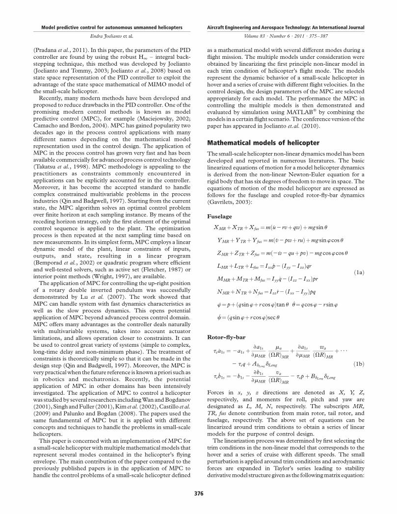
Mathematical models of helicopter
The small-scale helicopter non-linear dynamicsmodel has been
developed and reported in numerous literatures. The basic
linearized equations of motion for a model helicopter dynamics
is derived from the non-linear Newton-Euler equation for a
rigid body that has six degrees of freedom tomove in space. The
equations of motion of the model helicopter are expressed as
follows for the fuselage and coupled rotor-fly-bar dynamics
(Gavrilets, 2003):
Fuselage
XMR þXTR þXfus ¼mð_u2 rvþ qwÞþmg sinu
YMR þYTR þYfus ¼mð_v2pwþ ruÞþmg sinwcosu
ZMR þZTR þZfus ¼mð2 _w2 quþpvÞ2mg coswcosu
LMR þLTR þLfus ¼ Ixx _p2 ðIyy 2 IzzÞqr
MMR þMTR þMfus ¼ Iyy _q2 ðIzz 2 IxxÞpr
NMR þNTR þNfus ¼ Izz_r2 ðIxx 2 IyyÞpq
_w¼ pþðqsinwþ r coswÞtanu _u¼ qcosw2 r sinw
_c¼ðqsinwþ r coswÞsecu
ð1aÞ
Rotor-fly-bar
te _a1s ¼ 2a1s þ›a1s
›mMR
ma
ðVRÞMR
þ ›a1s
›mMR
wa
ðVRÞMR
þ · · ·
2 teq þ AdLongdLong
te_b1s ¼ 2b1s 2
›b1s
›mMR
va
ðVRÞMR
2 tep þ BdLongdLong
ð1bÞ
Forces in x, y, z directions are denoted as X, Y, Z,respectively, and moments for roll, pitch and yaw are
designated as L, M, N, respectively. The subscripts MR,TR, fus denote contribution from main rotor, tail rotor, and
fuselage, respectively. The above set of equations can be
linearized around trim conditions to obtain a series of linear
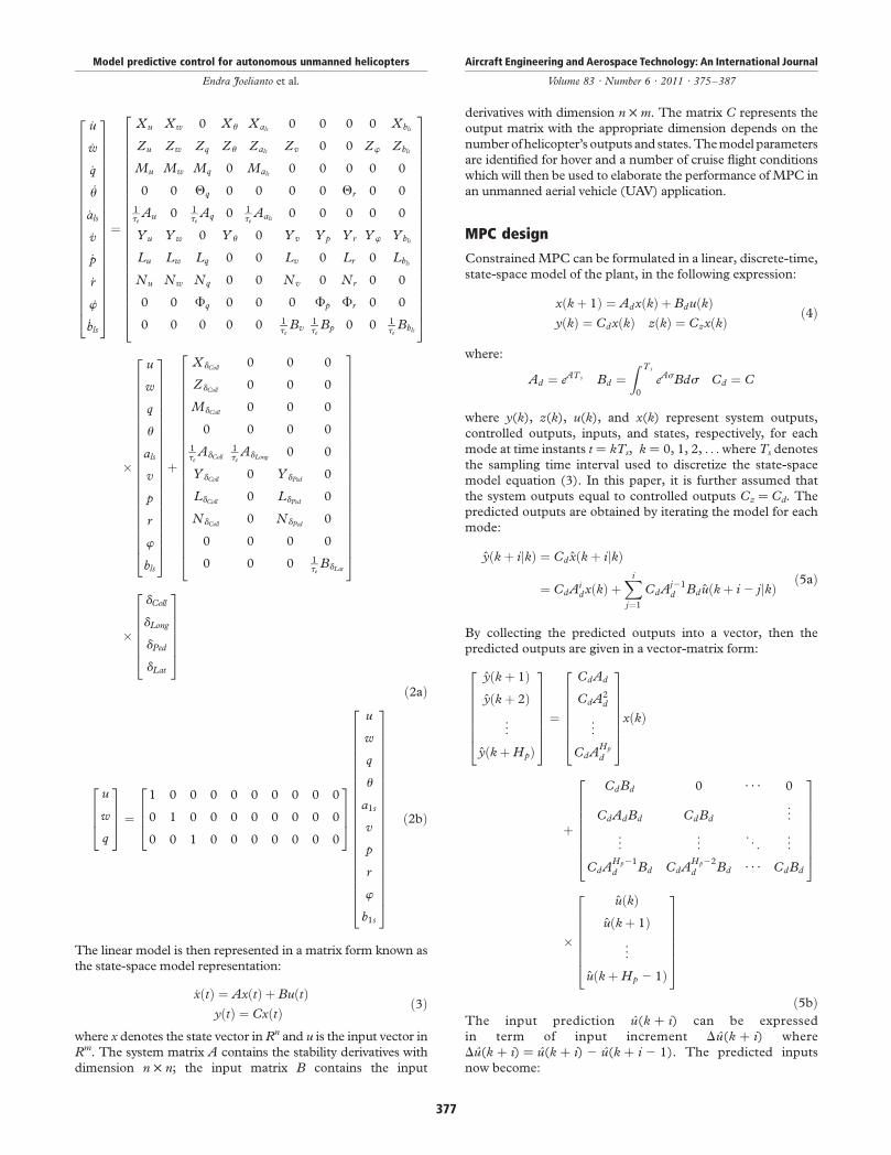
models for the purpose of control design.The linearization process was determined by first selecting the
trim conditions in the non-linear model that corresponds to the
hover and a series of cruise with different speeds. The small
perturbation is applied around trim conditions and aerodynamic
forces are expanded in Taylor’s series leading to stability
derivativemodel structuregivenas the followingmatrixequation:
Model predictive control for autonomous unmanned helicopters
Endra Joelianto et al.
Aircraft Engineering and Aerospace Technology: An International Journal
Volume 83 · Number 6 · 2011 · 375–387
376
_u
_w
_q
_u
_als
_v
_p
_r
_w
_bls
266666666666666666666664
377777777777777777777775
¼
Xu Xw 0 Xu Xals0 0 0 0 Xbls
Zu Zw Zq Zu ZalsZv 0 0 Zw Zbls
Mu Mw Mq 0 Mals0 0 0 0 0
0 0 Qq 0 0 0 0 Qr 0 0
1te
Au 0 1te
Aq 0 1te
Aals0 0 0 0 0
Yu Yw 0 Y u 0 Yv Yp Yr Yw Ybls
Lu Lw Lq 0 0 Lv 0 Lr 0 Lbls
Nu Nw Nq 0 0 Nv 0 Nr 0 0
0 0 Fq 0 0 0 Fp Fr 0 0
0 0 0 0 0 1te
Bv1te
Bp 0 0 1te
Bbls
2666666666666666666666664
3777777777777777777777775
�
u
w
q
u
als
v
p
r
w
bls
266666666666666666666664
377777777777777777777775
þ
XdColl0 0 0
ZdColl0 0 0
MdColl0 0 0
0 0 0 0
1te
AdColl
1te
AdLong0 0
Y dColl0 Y dPed
0
LdColl0 LdPed
0
NdColl0 NdPed
0
0 0 0 0
0 0 0 1te
BdLat
2666666666666666666666664
3777777777777777777777775
�
dColl
dLong
dPed
dLat
2666664
3777775
ð2aÞ
u
w
q
2664
3775 ¼
1 0 0 0 0 0 0 0 0 0
0 1 0 0 0 0 0 0 0 0
0 0 1 0 0 0 0 0 0 0
2664
3775
u
w
q
u
a1s
v
p
r
w
b1s
266666666666666666666664
377777777777777777777775
ð2bÞ
The linear model is then represented in a matrix form known as
the state-space model representation:
_xðtÞ ¼ AxðtÞ þ BuðtÞyðtÞ ¼ CxðtÞ
ð3Þ
where x denotes the state vector in Rn and u is the input vector in
Rm. The system matrix A contains the stability derivatives with
dimension n £ n; the input matrix B contains the input
derivatives with dimension n £ m. The matrix C represents the
output matrix with the appropriate dimension depends on the
numberofhelicopter’s outputs and states.Themodel parameters
are identified for hover and a number of cruise flight conditions
which will then be used to elaborate the performance ofMPC in
an unmanned aerial vehicle (UAV) application.
MPC design
ConstrainedMPC can be formulated in a linear, discrete-time,
state-space model of the plant, in the following expression:
xðk þ 1Þ ¼ AdxðkÞ þ BduðkÞyðkÞ ¼ CdxðkÞ zðkÞ ¼ CzxðkÞ
ð4Þ
where:
Ad ¼ eATs Bd ¼Z Ts
0
eAsBds Cd ¼ C
where y(k), z(k), u(k), and x(k) represent system outputs,
controlled outputs, inputs, and states, respectively, for each
mode at time instants t ¼ kTs, k ¼ 0, 1, 2, . . .where Ts denotes
the sampling time interval used to discretize the state-space
model equation (3). In this paper, it is further assumed that
the system outputs equal to controlled outputs Cz ¼ Cd. The
predicted outputs are obtained by iterating the model for each
mode:
yðk þ ijkÞ ¼ Cdxðk þ ijkÞ
¼ CdAidxðkÞ þ
Xi
j¼1
CdAj21d Bduðk þ i 2 jjkÞ
ð5aÞ
By collecting the predicted outputs into a vector, then the
predicted outputs are given in a vector-matrix form:
yðk þ 1Þyðk þ 2Þ
..
.
yðk þ HpÞ
26666664
37777775 ¼
CdAd
CdA2d
..
.
CdAHp
d
26666664
37777775xðkÞ
þ
CdBd 0 · · · 0
CdAdBd CdBd...
..
. ... . .
. ...
CdAHp21
d Bd CdAHp22
d Bd · · · CdBd
266666664
377777775
�
uðkÞuðk þ 1Þ
..
.
uðk þ Hp 2 1Þ
26666664
37777775
ð5bÞThe input prediction u(k þ i) can be expressed
in term of input increment Du(k þ i) where
Du(k þ i) ¼ u(k þ i) 2 u(k þ i 2 1). The predicted inputs
now become:
Model predictive control for autonomous unmanned helicopters
Endra Joelianto et al.
Aircraft Engineering and Aerospace Technology: An International Journal
Volume 83 · Number 6 · 2011 · 375–387
377

uðkÞ
uðkþ1Þ
..
.
uðkþHp21Þ
2666666664
3777777775¼
uðk21Þ
uðk21Þ
..
.
uðk21Þ
2666666664
3777777775þ
I 0 ··· 0
I I ...
..
. . .. ..
.
I I ··· I
266666664
377777775
DuðkÞ
Duðkþ1Þ
..
.
DuðkþHp21Þ
2666666664
3777777775
ð6Þ
It is assumed that the input only changes at time
instants k; k þ 1; . . . ; k þ Hu 2 1 such that for
Hu # i # Hp 2 1; uðk þ iÞ ¼ uðk þ Hu 2 1Þ.The predicted outputs now can be written as follow:
yðkþ1Þ
..
.
yðkþHuÞ
yðkþHuþ1Þ
..
.
yðkþHpÞ
266666666666666664
377777777777777775
¼
CdAd
..
.
CdAHu
d
CdAHuþ1d
..
.
CdAHp
d
266666666666666664
377777777777777775
xðkÞþ
CdBd
..
.
PHu21i¼0 CdAi
dBdPHu
i¼0CdAidBd
..
.
PHp
i¼0CdAidBd
266666666666666664
377777777777777775
uðk21Þ
þ
CdBd ... 0
CdAdBdþCdBd 0
..
. ...
PHu21i¼0 CdAi
dBd ··· CdBd
PHu
i¼0CdAidBd
. ..
CdAdBdþCdBd
..
. ...
PHp
i¼0CdAidBd ···
PHp2Hu
i¼0 CdAidBd
2666666666666666666664
3777777777777777777775
DuðkÞ
Duðkþ1Þ
..
.
DuðkþHu21Þ
2666666664
3777777775
ð7ÞTherefore, the predicted outputs can be written in more
compact equation:
Y ¼past
FxðkÞ þ Guðk 2 1Þ|fflfflfflfflfflfflfflfflfflfflfflfflfflfflfflffl{zfflfflfflfflfflfflfflfflfflfflfflfflfflfflfflffl}þfuture
GU|{z} ð8Þ
If the measured disturbance is brought to the calculation,
equation (4) becomes:
xðk þ 1Þ ¼ AdxðkÞ þ BduðkÞ þ BdmdðkÞ ð9Þ
where Bdm is a measured disturbance matrix and d(k) is the
measured disturbance. In MPC design, it is more convenient
to express the model with an increment input and one
possibility (Maciejowsky, 2002), is given as follows:
xðk þ 1ÞuðkÞ
" #¼
Ad Bd
0 I
" #xðkÞ
uðk 2 1Þ
" #þ
Bd
I
" #DuðkÞ
þBdm
0
" #dðkÞ
yðkÞ ¼ Cd 0h i xðkÞ
uðk 2 1Þ
" #ð10aÞ
The state-space model can be written in more
compact form with the discrete-time representation as
subscript:
xkþ1 ¼ Axk þ BDuk þ Bmdk
yk ¼ Cxk
ð10bÞ
where:
xkþ1 ;xðk þ 1Þ
uðkÞ
" #; Duk ; DuðkÞ; dk ; dðkÞ:
The predicted outputs are then given by:
ykþ1
ykþ2
..
.
ykþHp
26666664
37777775 ¼
CA
CA2
..
.
CAHp
2666664
3777775xk
þ
CB 0 · · · 0
CAB CB ...
..
. . .. ..
.
CAHp21B CAHp22B · · · CAHp2HuB
26666664
37777775
�
Duk
Dukþ1
..
.
DukþHu21
26666664
37777775
þ
CBm 0 · · · 0
CABm CBm...
..
. ... . .
. ...
CAHp21Bm CAHp22Bm · · · CBm
266666664
377777775
�
dk
dkþ1
..
.
dkþHp21
26666664
37777775
ð11aÞ
Model predictive control for autonomous unmanned helicopters
Endra Joelianto et al.
Aircraft Engineering and Aerospace Technology: An International Journal
Volume 83 · Number 6 · 2011 · 375–387
378
This equation can be written in more compact equation:
Yk ¼past
Fxk|{z}þfuture
QUk þJDk|fflfflfflfflfflfflfflfflffl{zfflfflfflfflfflfflfflfflffl} ð11bÞ
where Yk ¼ ½ ykþ1ykþ2. . .ykþHp«�T , DUk ¼ ½Duk Dukþ1
. . .DukþHu21«�T , and Dk ¼ ½ dk dkþ1 . . .dkþHp21«�T .The general aim of MPC is to minimize the cost quadratic
function:
J ¼XHp
i¼0
ykþi 2 wkþik k2Q þXHu
i¼1
Dukþi21k k2R ð12aÞ
where w is the reference, Hp and Hu are the
maximum prediction horizon and the control horizon,
respectively, and the weighting matrices Q and R are
defined by:
Q ¼
Qð1Þ 0 · · · 0
0 Qð2Þ 0
..
. ... . .
. ...
0 0 0 QðHpÞ
26666664
37777775
R ¼
Rð1Þ 0 · · · 0
0 Rð2Þ 0
..
. ... . .
. ...
0 0 0 RðHu 2 1Þ
26666664
37777775
ð12bÞ
The cost function can then be simplified in a matrix form as:
JMPC ¼ Y 2 W�� ��2
Q2 DU
�� ��2R
ð13Þ
Define the error prediction as:
1ðkÞ ¼ GðkÞ2FxðkÞ2JDðkÞ ð14Þ
where:
GðkÞ ¼
rðk þ 1Þ
..
.
rðk þ HpÞ
26664
37775;
rðk þ iÞ ¼ wðk þ iÞ2 [ ðk þ iÞ ¼ wðk þ iÞ2 e2iT s=Tref [ ðkÞ
and:
[ ðkÞ ¼ wðkÞ2 yðkÞ;
Tref denotes the response speed of the reference trajectory that
approaches the set-point exponentially. The cost function in
the MPC problem becomes a quadratic programming (QP)
problem as follows:
JMPC ¼ QDU 2 1�� ��2
Qþ DU�� ��2
R
JMPC ¼ 1T Q12 2DUTQT Q1þ DUT ½QT QQþ R�DU
JMPC ¼ constant 2 DUT G þ DUT HDU
ð15Þ
where G ¼ 2QTQ1 and H ¼ QTQQ þ R. The minimization of
the cost function JMPC is equivalent to the minimization of the
objective function DUTHDU 2 DUTG which is a quadratic
function. In this equation, the matrix H is the Hessian matrix,
therefore the function can be changed to DUTHDU 2 GTDU.The cost function subjects to linear inequality in the inputs,
input increments, and outputs as follow:
umin # ukþi # umax; i ¼ 0; 1; . . . ;Hu 2 1
Dumin # Dukþi # Dumax; i ¼ 0; 1; . . . ;Hu 2 1
ymin # ykþi # ymax; i ¼ 1; 2; . . . ;Hp
ð16Þ
All inequalities in the equation (16) can be arranged together
into a single set vector-matrix equation as follows:
VDU # bþ Fuðk 2 1Þ þ MxðkÞ or VDU # v ð17Þ
where:
DU ¼
Duk
Dukþ1
..
.
DukþNu21
26666664
37777775
and:
v ¼ bþ Fuðk 2 1Þ þ MxðkÞ:
Consider the set of upper bound input increment constraints:
Dukþi # Dumax; i ¼ 0; 1; . . . ;Hu 2 1 ð18Þ
The constraints can be written in the general form by setting:
Vˆ
I
I
. ..
I
2666664
3777775; F ˆ 0; M ˆ 0;
bˆ
Dumax
Dumax
..
.
Dumax
26666664
37777775
ð19Þ
Similarly, the lower bound constraints are set as:
Vˆ2
I
I
. ..
I
2666664
3777775; F ˆ 0; M ˆ 0;
bˆ2
Dumin
Dumin
..
.
Dumin
26666664
37777775
ð20Þ
Model predictive control for autonomous unmanned helicopters
Endra Joelianto et al.
Aircraft Engineering and Aerospace Technology: An International Journal
Volume 83 · Number 6 · 2011 · 375–387
379

For the set of upper bound input contraints are set:
Vˆ
I
I I
..
. . ..
I · · · · · · I
2666664
3777775; F ˆ2
I
I
..
.
I
2666664
3777775; M ˆ 0;
bˆ
umax
umax
..
.
umax
26666664
37777775
ð21Þ
The set of lower bound input contraints are set:
Vˆ2
I
I I
..
. . ..
I · · · · · · I
2666664
3777775; F ˆ
I
I
..
.
I
2666664
3777775; M ˆ 0;
bˆ2
umin
umin
..
.
umin
26666664
37777775
ð22Þ
Note that the output predictions are given by:
ykþ1
ykþ2
..
.
ykþHp
26666664
37777775 ¼ Fxk þQDUk ð23Þ
The set of upper bound output contraints are set:
VˆQ; F ˆ 0; M ˆ2F; bˆ
ymax
..
.
ymax
26664
37775 ð24Þ
The set of lower bound output contraints are set:
Vˆ2Q; F ˆ 0; M ˆF; bˆ2
ymin
..
.
ymin
26664
37775 ð25Þ
Note that the form of the output predictions will depend on
the state-space model. The inequality matrix equation (17)
needs to be computed once in the MPC control design and it
will be used for each optimization process since constraints
are constant. Two popular methods used to solve QP
problems are active set (Fletcher, 1987) and interior point
(Wright, 1997) methods.
Multiple models helicopter with MPC
Helicopter control system designs using MPC with a single
either linear or non-linear models have been studied including
one reported in Wan and Bogdanov (2001), Singh and Fuller
(2001), Kim et al. (2002), Castillo et al. (2009) and Palunko
and Bogdan (2008). Robust hybrid control system design
using linear impulsive differential equations for a small-scale
helicopter with two models was studied by Sutarto et al.
(2006). The paper considers the tracking control system using
MPC for multiple models of a small-scale helicopter using
five different linear models represent hover, acceleration and
flying up conditions in one sequence of flying.Note that the state-space model in equation (2) represents a
more general structure than the parameterized state-space
model proposed by Mettler (2003). The values of the
parameters in the state-space model for the five flight
conditions are given in Tables I-VIII.The solution of the state space representation of the models
gives information of helicopter position in the body coordinates.
However, it is difficult to have physical interpretation of
helicopter position in the body coordinate.Hence it is necessary
to transform the body coordinate to local horizon coordinate
system. The transformation between the two coordinates is
carried out by using the following matrix transformation
appeared in Budiyono and Wibowo (2009):
TI ¼
cosucosc cosu sinx 2sinu
sinf sinucosc2 cosf sinc sinf sinu sincþ cosfcosc sinfcosu
cosf sinucoscþ sinf sinc cosf sinu sinc2 sinfcosc cosfcosu
2664
3775
ð26Þ
The transformation matrix TI relates the positions and the
velocities in the two different coordinates as expressed in the
following equations:
N E A� �T ¼ TI
x y zh iT
V x V y V z
h iT
¼ TI u v w� �T
ð27Þ
where u, v,w are velocities in the body coordinate andVx,Vy,Vz
are in the local coordinate system. In the small-scale helicopter
control problem, the design of theMPC is aimed to control the
helicopter is such away that a certain flight profile fromhover to
an accelerating cruise can be achieved by the helicopter. The
introduction of the flight profile is, in this case, important for
two different reasons. First, the desired flight trajectory of the
helicopter cannot be defined arbitrarily as it is constrained
by the stability and the speed of the helicopter. Second, the
MPC controller needs a reference signal in order to dictate the
helicopter properly. In this case, the flight profile acts as a virtual
flight path that is used as the reference signal in theMPCdesign.It is generally known that the tracking control system designs
can yield a perfect tracking (the error between the trajectory and
the output of the controlled system is 0) if the control system
design satisfies the condition called internal model principle
(IMP). The IMP requirement states that the perfect tracking
will be achieved if the modes of the trajectories are also the
modes in the open loop tracking controller. If that is not the
case, the perfect tracking can still be achieved by augmenting a
finite dimensional system in the open loop of the tracking
system. The detail theory and conditions can be found in the
Model predictive control for autonomous unmanned helicopters
Endra Joelianto et al.
Aircraft Engineering and Aerospace Technology: An International Journal
Volume 83 · Number 6 · 2011 · 375–387
380

Table II Y-axes force derivates
Speed
Parameters Y U0 5 0m/s U0 5 4m/s U0 5 8m/s U0 5 12m/s U0 5 16m/s
Yu 20.0166 20.0118 20.0209 20.0182 20.0136
Yw 20.0170 0.0058 0.0081 0.0091 0.0094
Yu 0.0011 0.0098 0.0231 0.0479 0.0834
Yv 0.0700 20.1362 20.1944 20.2680 20.3425
Yp 0.0000 0.0010 20.0010 20.0010 0.0010
Yr 0.0018 23.9911 27.9849 211.9799 215.9745
Yf 9.7804 9.7854 9.7842 9.7580 9.6769
Ybls24.2692 11.4708 11.5214 11.5100 11.4057
YdColl1.47798 0.84158 0.76276 0.76978 0.78488
YdPed2154.71 24.596 24.3577 24.5072 24.9054
Table III Z-axes force derivates
Speed
Parameters Z U0 5 0m/s U0 5 4m/s U0 5 8m/s U0 5 12m/s U0 5 16m/s
Zu 0.0397 20.4699 20.4182 20.2500 20.1568
Zw 0.0965 20.9969 21.3972 21.6309 21.7309
Zq 0.0000 3.9983 7.9964 11.9792 15.9740
Zu 0.0142 0.1419 0.3749 0.8403 1.5180
Zals 0.0346 0.0010 20.0438 0.8403 20.0547
Zv 0.0397 0.0000 0.0000 0.0000 0.0000
Zf 20.7609 20.6792 20.6035 20.5558 20.5318
Zbls 0.1817 0.0769 0.0680 0.0633 0.0593
ZdColl2197.54 2122.96 2126.53 2139.51 2151.88
Table IV Roll moment derivates
Speed
Parameters L U0 5 0m/s U0 5 4m/s U0 5 8m/s U0 5 12m/s U0 5 16m/s
Lu 20.0622 20.0198 20.0573 20.0550 20.0425
Lw 20.0667 0.0662 0.0849 0.0941 0.0965
Lq 20.0001 20.0032 20.0025 20.0011 20.0005
Lv 0.3576 20.1715 20.2316 20.2942 20.3470
Lr 0.0066 0.0322 0.0547 0.0727 0.0925
Lbls556.7226 420.4654 421.0045 420.8826 419.7725
LdColl15.7386 8.96576 8.12507 8.26462 8.42221
LdPed2560.7 216.657 215.793 216.336 217.779
Table I X-axes force derivates
Speed
Parameters X U0 5 0m/s U0 5 4m/s U0 5 8m/s U0 5 12m/s U0 5 16m/s
Xu 20.0133 20.0555 20.1607 20.1647 20.2218
Xw 0.0001 0.0085 0.0164 0.0175 0.0162
Xq 0.0000 20.0010 0.0010 0.0010 29.6915
Xu 29.8100 29.8090 29.8028 29.7738 29.6915
Xals 224.2699 211.4711 211.5216 211.5100 211.4057
XdColl20.2817 20.6189 20.0507 0.36569 0.52661
Model predictive control for autonomous unmanned helicopters
Endra Joelianto et al.
Aircraft Engineering and Aerospace Technology: An International Journal
Volume 83 · Number 6 · 2011 · 375–387
381

references Francis and Wonham (1976), Joelianto (2000) or
Joelianto and Williamson (2009).As the aim of the paper is to investigate the application of
the MPC for controlling the small-scale helicopter
with multiple linearized models, the IMP requirement can
be simplified by finding the flight profile that corresponds to
each model. Each flight profile of the multiple models is then
merged into one flight profile that will serve as the known
reference signal of the MPC. In addition, the MPC needs
reference signal prediction in order to compute the current
control signal. If the future reference signal is not available,
there will be problem in the control signal computation. To
solve this problem, in the control signal computation, the last
model is extended to be the sixth model to generate the future
flight profile. However, the control computation is considered
only for the first five models. The algorithm of the
MPC design is shown in Figure 1. In the first correction,
four parameters of MPC (Hp, Hu, Q, R) are tuned to obtain
Table VIII Flapping derivates
Speed
Parameters () 3 1/te U0 5 0m/s U0 5 4m/s U0 5 8m/s U0 5 12m/s U0 5 16m/s
Au 0.0079 0.0030 0.0029 0.0027 0.0025
Aq 21.0000 21.0000 21.0000 21.0000 21.0000
Aals 28.3500 28.3500 28.3500 28.3500 28.3500
AdColl 20.0003 0.11362 0.22925 0.35564 0.48714
AdLOng35.07 35.07 35.07 35.07 35.07
Bv 0.0079 0.0029 0.0026 0.0024 0.0023
Bp 21.0000 21.0000 21.0000 21.0000 21.0000
Bbls28.3500 28.3500 28.3500 28.3500 28.3500
BdLat35.07 35.07 35.07 35.07 35.07
Table VI Yaw moment derivates
Speed
Parameters N U0 5 0m/s U0 5 4m/s U0 5 8m/s U0 5 12m/s U0 5 16m/s
Nu 0.4332 0.3998 0.6233 0.5232 0.3888
Nw 0.4334 0.0149 20.0058 20.0121 20.0114
Nq 0.0004 0.0234 0.0187 0.0078 0.0033
Nv 22.6429 1.2565 1.6970 2.1556 2.5425
Nr 20.0480 20.2356 20.4007 20.5330 20.6780
NdColl2.28 £ 10206 0.02247 0.01681 0.26198 0.24962
NdPed4,108.23 122.048 115.718 119.69 130.264
Table V Pitch moment derivates
Speed
Parameters M U0 5 0m/s U0 5 4m/s U0 5 8m/s U0 5 12m/s U0 5 16m/s
Mu 20.0004 0.1148 0.2214 0.4004 0.5083
Mw 20.0010 20.0231 20.0047 0.6571 1.9197
Mq 20.0002 20.0292 20.0611 20.3553 20.4441
Mals 295.5075 223.1810 223.4664 223.4012 222.8119
MdColl1.59099 0.02908 22.849 219.174 246.921
Table VII Angle derivates
Speed
Parameters Q,F U0 5 0m/s U0 5 4m/s U0 5 8m/s U0 5 12m/s U0 5 16m/s
Qq 0.9970 0.9976 0.9981 0.9984 0.9985
Qr 20.0776 20.0692 20.0616 20.0569 20.0549
Fq 20.0001 20.0010 20.0024 20.0049 20.0086
Fp 1.0000 1.0000 1.0000 1.0000 1.0000
Fr 20.0014 20.0145 20.0382 20.0860 20.1566
Model predictive control for autonomous unmanned helicopters
Endra Joelianto et al.
Aircraft Engineering and Aerospace Technology: An International Journal
Volume 83 · Number 6 · 2011 · 375–387
382

the required performances. If, after several iterations,
the performances cannot be achieved, the parameters of the
sampling time Ts and the speed respose are then adjusted Tref.
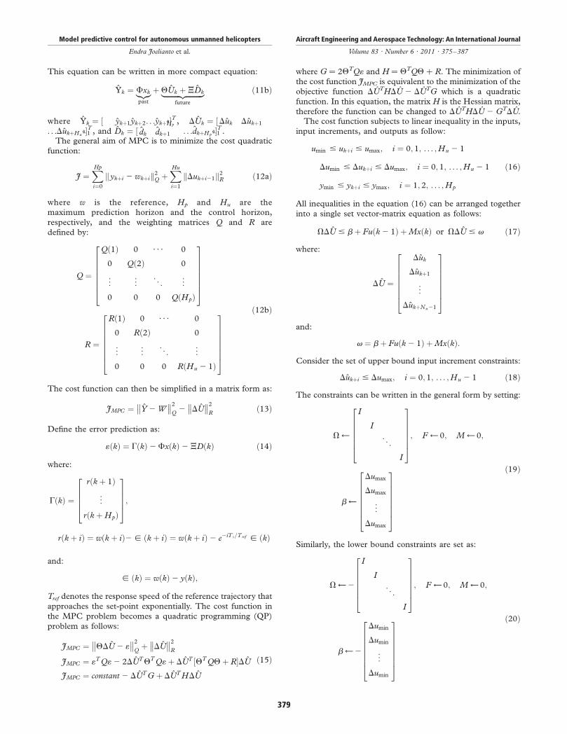
The process is then repeated again by tuning the parameters(Hp, Hu, Q, R).The simulation results are shown in Figures 2-5. Figure 2
shows the tracking performance of the small helicopter usingMPCwith the six models where the sixthmodel is similar to the
fifth model. The black line is the flight profile generated by the
multiple models of the helicopter with respect to its initial
condition in eachmodewith the constants control signal (u) andunder a smoothing between themodel transition. The color line
denotes the output of the helicopter with the control signal is
computed by the MPC with certain parameter selection by
using trial error method. Figure 3 shows the required responsescorrespond to the required flight profile generated for the five
multiple models by cropping the response of the sixth model in
Figure 2. It can be seen that deviations occurred gradually and it
becomes significant at the end of the flight segment. Therequired control signal is shown in Figure 4. The control signal
is small which is expected in order that helicopter move
smoothly along the desired trajectory. However, it can be seen
that at eachmodel transition, the control signal jumps from onevalue to another. In practice, it will be appropriate if the jump
can be reduced in order to decrease sudden movement of the
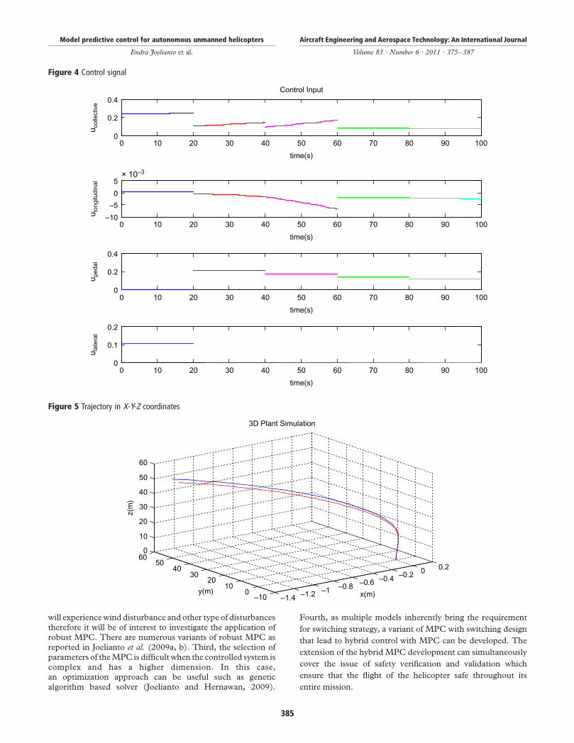
helicopter. Figure 5 shows the desired flight trajectory for the
MPC (red line) and the actual flight (blue line) in the localcoordinate system.The MPC parameters are shown in Tables IX and X.The existence of a slight deviation between targeted and
actual trajectory indicates that the present result is not
perfect. However, the application of the MPC for the control
of a small-scale helicopter with multiple models opens up anew horizon demonstrating that the MPC can deal with
switching dynamics of the helicopter and maintain the overall
stability. The cost function produced by using the parameters
given in Tables IX and X is 1.5980 £ 10þ007. The deviationcan be reduced by fine tuning the appropriate parameters
of the MPC. At this moment, parameter selection of the
MPC is considered as the main problem since there are
many combinations that are difficult to find by trial errormethod.
Conclusion
This paper concerned with the application of model
predictive control known as MPC for a small-scale helicopter
with five multiple linearized models. As theMPC requires future
reference signal, a flight profile is generated from themodels thatserves as the reference trajectory for the controlledhelicopterwith
MPC. The results indicate that the approach leads to a good
tracking performance even without the parameters optimization
in theMPCdesign.Moreover, theMPCcanhandle the switchingdynamics problemwell shown by stable responses with sufficient
tracking performance. The results demonstrate thatMPCgives a
new alternative control method in achieving good control for the
small-scale helicopter when the models are available.
Further work
The results open many opportunities for further work
particularly in the area of control for small-scale helicopters
and in the area of unmanned autonomous vehicles or
systems (UAV or UAS) in general. First, the integration
of the IMP in the MPC control design enables the
implementation of difficult and complex flight trajectory for
the small-scale helicopter. Second, in real flight, the helicopter
Figure 1 Model predictive control design flowchart
Discretize equation (2)using sampling time Ts
and select the flightprofile
Define constraints usingequation (17)
Solve the MPC problem(15) and constraints
(17)
Simulate closed loopresponse
Calculate cost functionJMPC and observe
transient and steadystate responses
Performancessatisfied
Performances satisfiedafter iterations Hp, Hu,
Q and R
NO
NO
YES
YES
Select sampling time Tsand response speed
Tref
Select MPC parametersHp, Hu, Q and R
END
END
START
NO
Model predictive control for autonomous unmanned helicopters
Endra Joelianto et al.
Aircraft Engineering and Aerospace Technology: An International Journal
Volume 83 · Number 6 · 2011 · 375–387
383
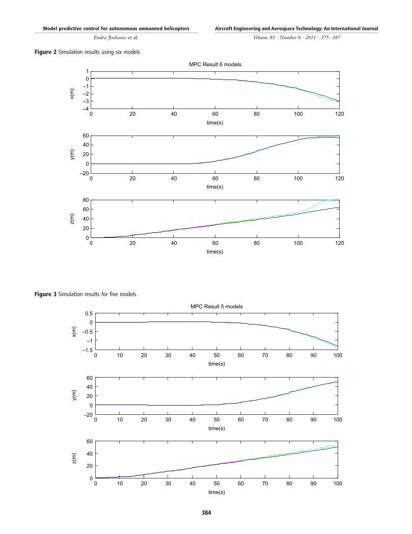
Figure 2 Simulation results using six models
–4–3–2–101
x(m
)MPC Result 6 models
–20
0
20
40
60
y(m
)
0 20 40 60 80 100 1200
20
40
60
80
z(m
)
time(s)
0 20 40 60 80 100 120
time(s)
0 20 40 60 80 100 120
time(s)
Figure 3 Simulation results for five models
–1.5
–1
–0.5
0
0.5
x(m
)
MPC Result 5 models
–20
0
20
40
60
y(m
)
0 10 20 30 40 50 60 70 80 90 1000
20
40
60
z(m
)
time(s)
0 10 20 30 40 50 60 70 80 90 100
time(s)
0 10 20 30 40 50 60 70 80 90 100
time(s)
Model predictive control for autonomous unmanned helicopters
Endra Joelianto et al.
Aircraft Engineering and Aerospace Technology: An International Journal
Volume 83 · Number 6 · 2011 · 375–387
384
will experiencewind disturbance and other type of disturbances
therefore it will be of interest to investigate the application of
robust MPC. There are numerous variants of robust MPC asreported in Joelianto et al. (2009a, b). Third, the selection of
parameters of theMPC is difficult when the controlled system is
complex and has a higher dimension. In this case,an optimization approach can be useful such as genetic
algorithm based solver (Joelianto and Hernawan, 2009).
Fourth, as multiple models inherently bring the requirement
for switching strategy, a variant of MPC with switching design
that lead to hybrid control with MPC can be developed. The
extension of the hybrid MPC development can simultaneously
cover the issue of safety verification and validation which
ensure that the flight of the helicopter safe throughout its
entire mission.
Figure 4 Control signal
0
0.2
0.4Control Input
u col
lect
ive
–10
–5
0
5× 10⁻³
u lon
gitu
dina
l
0
0.2
0.4
u ped
al
0 10 20 30 40 50 60 70 80 90 1000
0.1
0.2
u la
tera
l
time(s)
0 10 20 30 40 50 60 70 80 90 100
time(s)
0 10 20 30 40 50 60 70 80 90 100
time(s)
0 10 20 30 40 50 60 70 80 90 100
time(s)
Figure 5 Trajectory in X-Y-Z coordinates
–1.4 –1.2 –1 –0.8 –0.6 –0.4 –0.2 0 0.2
–100
1020
3040
5060
0
10
20
30
40
50
60
x(m)
3D Plant Simulation
y(m)
z(m
)
Model predictive control for autonomous unmanned helicopters
Endra Joelianto et al.
Aircraft Engineering and Aerospace Technology: An International Journal
Volume 83 · Number 6 · 2011 · 375–387
385

References
Bemporad, A., Borelli, F. and Morari, M. (2002), “Model
predictive control based on linear programming – the
explicit solution”, IEEE Transactions on Automatic Control,
Vol. 47 No. 12, pp. 1974-85.Budiyono, A. and Wibowo, S.S. (2007), “Optimal tracking
controller design for a small scale helicopter”, Journal of
Bionic Engineering, Vol. 4, pp. 27-280.Camacho, E.F. and Bordon, C. (2004), Model Predictive
Control, Springer, London.Castillo, C.L., Moreno, W. and Valavanis, K.P. (2009),
“Unmanned helicopter waypoint trajectory tracking using
model predictive control”, 15th Mediterranean Conference on
Control and Automation Proceedings of the International
Conference in Athens, Greece, July 27-29.Fletcher, R.R. (1987), Practical Methods of Optimization,
2nd ed., Wiley, London.Francis, B.A. and Wonham, W.M. (1976), “The internal
model principle of control theory”, Automatica, Vol. 12,
pp. 457-65.Gavrilets, V. (2003), “Autonomous aerobatic maneuvering of
miniature helicopters”, PhD thesis, MIT, Cambridge, MA.Joelianto, E. (2000), “Linear hybrid reference control
systems”, PhD thesis, The Australian National University
(ANU), Canberra.Joelianto, E. and Hernawan, F.M. (2009), “Multiplexed
model predictive control weighting selection using genetic
algorithm”, Instrumentation, Communication and Information
Technology and Biomedical Engineering (ICICI-BME) 2009
Proceeding of the International Conference in Bandung-
Indonesia, November 23-25.Joelianto, E. and Tommy, I. (2003), “A robust DC to DC
buckboost converter using PID H1-backstepping
controller”, Power Electronics and Drive Systems (PEDS’03)
Proceeding of the International Conference in Singapore,
November 17-20, pp. 591-4.Joelianto, E. and Williamson, D. (2009), “Transient response
improvement of feedback control systems using hybrid
reference control”, International Journal of Control, Vol. 82
No. 10, pp. 1955-70.
Joelianto, E., Rismayasari, D. and Chaerani, D. (2009a),“The robust optimization based model predictive controlusing box uncertainty set”, Instrumentation, Communicationand Information Technology and Biomedical Engineering(ICICI-BME) 2009 Proceeding of the InternationalConference in Bandung-Indonesia, November 23-25.
Joelianto, E., Sutarto, H.Y. and Wicaksono, A. (2008),“Compensation of delay time uncertainties on industrial
control Ethernet networks using LMI based robust Hoo PIDcontroller”, 5th IEEE Wireless and Optical CommunicationsNetworks (WOCN 2008) Proceeding of the InternationalConference in Surabaya-Indonesia, May 5-7, pp. 1-5.
Joelianto, E., Maryami, E., Budiyono, A. and Renaning, D.
(2010), “Model predictive control system design for a smallscale autonomous helicopter”, 6th International Conferenceon Intelligent Unmanned Systems (ICIUS) 2010 Proceeding ofthe International Conference in Bali-Indonesia, November 3-5,pp. 577-82.
Joelianto, E., Simangunsong, R.I., Chaerani, D. andLing, K.V. (2009b), “The robust model predictive control(MPC)”, Advanced Computer Control (ICACC 2009)Proceeding of the International Conference in Singapore,January 22-24, pp. 546-50.
Kim, H.J., Shim, D.H. and Sastry, S. (2002), “Nonlinearmodel predictive tracking control for rotorcraft-basedunmanned aerial vehicles”, American Control Conference2002 Proceedings of the International Conference in Anchorage,AK, USA, pp. 3576-81.
Lu, C.N., Tsai, C.C., Tsai, M.C., Ling, K.V. and Yao, W.S.(2007), “Application of model predictive control toparallel-type double inverted pendulum driven by a linear
motor”, 33rd Annual Conference IECON Proceedings of theInternational Conference in Taipei, Taiwan, November 5-8,pp. 2904-9.
Maciejowski, J.M. (2002), Predictive Control with Constraints,Prentice-Hall, London.
Mettler, B. (2003), Identification Modeling and Characteristic ofMiniature Rotorcraft, Kluwer, Boston, MA.
Palunko, I. and Bogdan, S. (2008), “Small helicopter controldesign based on model reduction and decoupling”,
in Valavanis, K.P., Piegl, L.A. and Oh, P.Y. (Eds),Unmanned Aircraft Systems International Symposium
Table IX Output and input weighting matrices
Q R
Hover 0.000000015 *diag(0.1, 0.1, 0.1, 0.1) 0.00000015 *diag(100, 100, 100, 100)
U0 5 4m/s 0.000000015 *diag(0.1, 0.1, 0.1, 0.1) 0.00000015 *diag(100, 100, 100, 100)
U0 5 8m/s 0.000000015 *diag(0.1, 0.1, 0.1, 0.1) 0.00000015 *diag(100, 100, 100, 100)
U0 5 12m/s 0.000000015 *diag(0.0001, 0.0001, 0.0001, 0.0001) 0.00000015 *diag(100, 100, 100, 100)
U0 5 16m/s 0.000000015 *diag(0.001, 0.001, 0.001, 0.001) 0.00000015 *diag(100, 100, 100, 100)
U0 5 16m/s 0.000000015 *diag(0.001, 0.001, 0.001, 0.001) 0.00000015 *diag(1, 1, 1, 1)
Table X Parameters horizon and constraints
Parameters Value
Minimum horizon prediction (N1) 1
Maximum horizon prediction (N2) 5
Control horizon (Nu) 3
Output constraints ymax ¼ [0.2;2;15;0]; ymin ¼ [20.2; 2 2;0;0];
Model predictive control for autonomous unmanned helicopters
Endra Joelianto et al.
Aircraft Engineering and Aerospace Technology: An International Journal
Volume 83 · Number 6 · 2011 · 375–387
386

on Unmanned Aerial Vehicles, UAV’08, Springer, Berlin,pp. 201-28.
Pradana, W.A., Joelianto, E., Budiyono, A. and Adiprawita, W.(2011), “Robust MIMO H1 integral backstepping PIDcontroller for hovering control of unmanned helicoptermodel”, Journal of Aerospace Engineering (in press).
Qin, S.J. and Badgwell, T.A. (1997), “An overview ofindustrial model predictive control technology”, ChemicalProcess Control-V: AIChe Symposium Series-American InstituteChemical Engineering, Vol. 93, pp. 232-56.
Singh, L. and Fuller, J. (2001), “Trajectory generation forUAV in Urban Terrain, using nonlinear MPC”, AmericanControl Conference Proceedings of the International Conferencein Arlington, VA, USA, pp. 2301-8.
Sutarto, H.Y., Budiyono, A., Joelianto, E. and Hiong, G.T.(2006), “Switched linear control of a model helicopter”,Automation Robotics and Vision Proceeding of the InternationalConference in Singapore, December 5-8, pp. 300-1307.
Takatsu, H., Itoh, T. and Araki, M. (1998), “Future needs for
the control theory in industries – report and topics of the
control technology survey in Japanese industry”, Journal of
Process Control, Vol. 8 Nos 5/6, pp. 369-74.Wan, E.A. and Bogdanov, A.A. (2001), “Model predictive
neural control with applications to 6 DoF helicopter
model”, American Control Conference Proceedings of the
International Conferences in Arlington, VA, USA, pp. 488-93.Wright, S.J. (1997), “Applying new optimization algorithms
to model predictive control”, Chemical Process Control-V,
CACHE. AIChe Symposium Series, Vol. 93 No. 316,
pp. 147-55.
Corresponding author
Agus Budiyono can be contacted at: [email protected]
Model predictive control for autonomous unmanned helicopters
Endra Joelianto et al.
Aircraft Engineering and Aerospace Technology: An International Journal
Volume 83 · Number 6 · 2011 · 375–387
387
To purchase reprints of this article please e-mail: [email protected]
Or visit our web site for further details: www.emeraldinsight.com/reprints