A Novel SMA-based Concept for Airfoil Structural Morphing
10
A Novel SMA-based Concept for Airfoil Structural Morphing S. Barbarino, R. Pecora, L. Lecce, A. Concilio, S. Ameduri, and E. Calvi (Submitted September 16, 2008; in revised form November 28, 2008) The adaptive structures concept is of great interest in the aerospace field because of the several benefits which can be accomplished in the fields including noise reduction, load alleviation, weight reduction, etc., at a level in which they can be considered as compulsory in the design of future aircraft. Improvements in terms of the aerodynamic efficiency, aeroelastic behavior, stability, and manoeuvrability performance have already been proved through many international studies in the past. In the family of the Smart Materials, Shape Memory Alloys (SMA) seem to be a suitable solution for many static applications. Their high structural integrability in conjunction with actuation capabilities and a favorable performance per weight ratio, allows the development of original architectures. In this study, a morphing wing trailing edge concept is presented; morphing ability was introduced with the aim of replacing a conventional flap device. A compliant rib structure was designed, based on SMA actuators exhibiting structural potential (bearing external aerodynamic loads). Numerical results, achieved through a FE approach, are presented in terms of trailing edge induced displacement and morphed shape. Keywords Aerodynamic surfaces, Morphing, Shape control, SMA 1. Introduction Because several flight regimes occur during a typical aircraft mission, it is practically impossible to define a single config- uration able to maximize aerodynamic efficiency, manoeuvra- bility, stability, fuel consumption and so on in any circumstance. Currently, a common design strategy is to identify few dominant flight regimes within a typical mission and define a specific set of parameters like wing body geometry and control surfaces attitude, with respect to which the aircraft performance is maximized. In this way, drawbacks within conditions that fall outside the design range are unavoidable. Solutions character- ized by a certain adaptivity level can lead to overcome these limits. Components like ailerons, flaps, equilibrators, together with the related actuation strategies, correspond somehow to the necessity of facing very different states, even dramatically far from the nominal design ones (e.g., take-off and landing) (Ref 1). To simplify the actuation chain and deform a limited part of the structure, these movable devices are confined to limited regions of the wing; this causes, however, sharp shape modifications, badly affecting the aerodynamic field and, due to the concentration of the external loads around the hinges zone, a significant increase of the structural weight. Classical actuator systems generally lead to a 50% increase in weight relative to a naked wing. To avoid such problems, different design strategies have been taken into account. An interesting one was implemented within the 3AS (Active Aeroelastic Aircraft Structures) Euro- pean Project, (Ref 2, 3). By controlling the rigidity of some parts of a wing, the suitable displacement field corresponding to the said optimal configuration for a specific flight regime was attained. This strategy, recalling the classical aeroelastic tailoring philosophy, was applied to an all-movable vertical tail (AMVT), and led to an integrated shaft with a variable stiffness. Instead of using the external loads to deform the aerodynamic surfaces, the so-called ÔmorphingÕ strategy may be pursued. In this case, large and distributed deformation of specific parts of the wing body are achieved by generating proper internal forces (Ref 4-6). In order to reach this objective, leading and trailing edges have to be designed to withstand the external loads and undertake dramatic deformations, following the selected flight regime requirements (Ref 7, 8). Large displacement capabilities associated with load bearing capac- ities is the paradox which the smart or adaptive structure systems have to overcome in order to provide a reliable alternative to classical devices. In this article, the proposed solution to eliminate the above paradox is to refer to actuators that play a structural role, also. The use of smart materials has a crucial role in this challenging approach. What the authors use in the research This article is an invited article selected from presentations at Shape Memory and Superelastic Technologies 2008, held September 21-25, 2008, in Stressa, Italy, and has been further expanded from the original presentation. S. Barbarino, R. Pecora, and L. Lecce, Department of Aerospace Engineering, University of Naples ‘‘Federico II’’, Via Claudio 21, Naples 80125, Italy; A. Concilio and S. Ameduri, Smart Structures Lab., The Italian Aerospace Research Centre (CIRA), Via Maiorise, Capua, 81043 CE, Italy; and E. Calvi, ALENIA AERONAUTICA S.p.a., Viale dellÕAeronautica snc, Pomigliano dÕArco, 80038 NA, Italy. Contact e-mail: [email protected]. JMEPEG (2009) 18:696–705 ȑASM International DOI: 10.1007/s11665-009-9356-3 1059-9495/$19.00 696—Volume 18(5–6) August 2009 Journal of Materials Engineering and Performance
-
Upload
independent -
Category
Documents
-
view
1 -
download
0
Transcript of A Novel SMA-based Concept for Airfoil Structural Morphing
A Novel SMA-based Concept for AirfoilStructural Morphing
S. Barbarino, R. Pecora, L. Lecce, A. Concilio, S. Ameduri, and E. Calvi
(Submitted September 16, 2008; in revised form November 28, 2008)
The adaptive structures concept is of great interest in the aerospace field because of the several benefitswhich can be accomplished in the fields including noise reduction, load alleviation, weight reduction, etc., ata level in which they can be considered as compulsory in the design of future aircraft. Improvements interms of the aerodynamic efficiency, aeroelastic behavior, stability, and manoeuvrability performance havealready been proved through many international studies in the past. In the family of the Smart Materials,Shape Memory Alloys (SMA) seem to be a suitable solution for many static applications. Their highstructural integrability in conjunction with actuation capabilities and a favorable performance per weightratio, allows the development of original architectures. In this study, a morphing wing trailing edge conceptis presented; morphing ability was introduced with the aim of replacing a conventional flap device. Acompliant rib structure was designed, based on SMA actuators exhibiting structural potential (bearingexternal aerodynamic loads). Numerical results, achieved through a FE approach, are presented in terms oftrailing edge induced displacement and morphed shape.
Keywords Aerodynamic surfaces, Morphing, Shape control,SMA
1. Introduction
Because several flight regimes occur during a typical aircraftmission, it is practically impossible to define a single config-uration able to maximize aerodynamic efficiency, manoeuvra-bility, stability, fuel consumption and so on in anycircumstance.
Currently, a common design strategy is to identify fewdominant flight regimes within a typical mission and define aspecific set of parameters like wing body geometry and controlsurfaces attitude, with respect to which the aircraft performanceis maximized. In this way, drawbacks within conditions that falloutside the design range are unavoidable. Solutions character-ized by a certain adaptivity level can lead to overcome theselimits. Components like ailerons, flaps, equilibrators, togetherwith the related actuation strategies, correspond somehow to
the necessity of facing very different states, even dramaticallyfar from the nominal design ones (e.g., take-off and landing)(Ref 1).
To simplify the actuation chain and deform a limited part ofthe structure, these movable devices are confined to limitedregions of the wing; this causes, however, sharp shapemodifications, badly affecting the aerodynamic field and, dueto the concentration of the external loads around the hingeszone, a significant increase of the structural weight. Classicalactuator systems generally lead to a 50% increase in weightrelative to a naked wing.
To avoid such problems, different design strategies havebeen taken into account. An interesting one was implementedwithin the 3AS (Active Aeroelastic Aircraft Structures) Euro-pean Project, (Ref 2, 3). By controlling the rigidity of someparts of a wing, the suitable displacement field corresponding tothe said optimal configuration for a specific flight regime wasattained. This strategy, recalling the classical aeroelastictailoring philosophy, was applied to an all-movable verticaltail (AMVT), and led to an integrated shaft with a variablestiffness. Instead of using the external loads to deform theaerodynamic surfaces, the so-called �morphing� strategy may bepursued. In this case, large and distributed deformation ofspecific parts of the wing body are achieved by generatingproper internal forces (Ref 4-6). In order to reach this objective,leading and trailing edges have to be designed to withstand theexternal loads and undertake dramatic deformations, followingthe selected flight regime requirements (Ref 7, 8). Largedisplacement capabilities associated with load bearing capac-ities is the paradox which the smart or adaptive structuresystems have to overcome in order to provide a reliablealternative to classical devices. In this article, the proposedsolution to eliminate the above paradox is to refer to actuatorsthat play a structural role, also.
The use of smart materials has a crucial role in thischallenging approach. What the authors use in the research
This article is an invited article selected from presentations at ShapeMemory and Superelastic Technologies 2008, held September 21-25,2008, in Stressa, Italy, and has been further expanded from the originalpresentation.
S. Barbarino, R. Pecora, and L. Lecce, Department of AerospaceEngineering, University of Naples ‘‘Federico II’’, Via Claudio 21,Naples 80125, Italy; A. Concilio and S. Ameduri, Smart StructuresLab., The Italian Aerospace Research Centre (CIRA), Via Maiorise,Capua, 81043 CE, Italy; and E. Calvi, ALENIA AERONAUTICAS.p.a., Viale dell�Aeronautica snc, Pomigliano d�Arco, 80038 NA,Italy. Contact e-mail: [email protected].
JMEPEG (2009) 18:696–705 �ASM InternationalDOI: 10.1007/s11665-009-9356-3 1059-9495/$19.00
696—Volume 18(5–6) August 2009 Journal of Materials Engineering and Performance

herein presented, are the Shape Memory Alloys, SMA. TheirSuper Elastic and Shape Memory properties, jointly with theircapacity to transmit large loads, make them a privilegedmaterial for applications that require both large strains and highactuation forces (hundreds to thousands of Newton for classicalcommercial elements) (Ref 9).
In this article, the design of an adaptive flap, driven bySMA-based actuators, is illustrated (Ref 10, 11). More in detail,by taking advantage of a FE approach and implementing anSMA descriptive model (Ref 12), the concept of an original ribis dealt with. This structural element is made of different platesthat are connected to each other through crossed springlaminas. These are in charge of providing a certain amount ofrigidity to the structure, assuring the required preload for theSMA elements and allowing for large relative rotations. SMAelements are wires, located under the springs, which connecttwo consecutive plates. When they are activated, their contrac-tion leads to a rotation of the rib parts, with consequent cambervariations. External aerodynamic loads are considered when thesystem performance is evaluated; in detail the configurationcorresponding to a traditional rotated flap is referred to.
On this architecture, an optimization study is carried out,over certain selected architecture parameters such as thesprings, length, their angular position, and location. SMAmechanical properties and geometry are also considered.Results are presented in terms of achievable camber variationsand trailing edge displacements.
2. Architecture Working Principle and ModelingStrategy
The considered structure is sketched in Fig. 1. It is made offive bulkily shaped panels, connected in couples by crossedlaminas, working as spring elements. The single panel may beassumed to be rigid in the performed study; the set of fiveconstitutes the skeleton of the rib.
The connecting thin plates (beams in a 2D representation,shown in the same figure) exhibit the necessary elasticproperties to allow the architecture undergo suitable deflections.Their rigidity is tuned so that deflections related to the externalloads are restricted into small fractions of the ones associatedwith the driving commands.
The proposed actuator system is composed of the union ofthe active SMAwires and the spring elements. They are thoughtto show cyclic behavior and to carry out the prescribed externalload, i.e., to have a structural purpose that is a function of theircharacteristic elasticity. These components can be referred to as‘‘bearing actuators.’’ The activation of SMA generates acontraction of the wires that in turn causes, because of theeccentricity with respect to the spring subsystem center ofrotation, a relative angular movement of the bulk plates.
SMA ribbons and rods are also considered in the followingdiscussion.
The used springs show a nonlinear behavior, because of thetranslation of the rotation pivot during deflection. This propertygoes into the direction of achieving in principle higher preloadsfor SMA wires recovery and larger relative rotations, whileassuring the desired rigidity levels. These properties arestrongly dependent on some geometric parameters, as shownin the next paragraph; then, by properly adjusting those values,the performance may be improved or optimized.
MSC/Nastran FE models were set up to investigate thebehavior of the described structural system, integrated with anexternal proprietary Matlab routine aimed at simulating thebehavior of the SMA elements, implementing the Liang andRogers� 1D model (Ref 12). The assumptions, this model isbased on, are coherent with the working modality of theactuators: no bending actions (the wires are hinged with the ribpanels) and 1D behavior of the material (strain recovery isthought to occur only along the axial direction). Liang andRogers� is an approximation of the former Tanaka�s model(Ref 13), substituting exponential with sinusoidal expression inthe description of the material composition (austenite versusmartensite fraction, nM and nA), function of the temperature, T,and the stress field, r:
n¼ nM2cos aA T � ASð Þ þ bAr½ � þ nM
2Austenite!Marteniste
ðEq 1Þ
and
n ¼ 1� nA2
cos aM T �MFð Þ þ bMr½ � þ 1þ nA2
Marteniste! Austenite
The values aA ¼ p= AF � ASð Þ and aM ¼ p= MS �MFð Þ arecombinations of the material characteristic constants, AF, AS,MF, MS, namely, austenite final, austenite start, martensitefinal, and martensite start temperature, respectively. Theyrefer to the beginning or the completion of phase transforma-tion and define when a particular crystal structure appears orwhen the conversion is complete. Two other parametersappearing in the above formulas are bA ¼ �aA=CA andbM ¼ �aM=CM; CA and CM being the slopes of the linearrelationship between stress and temperature characteristictransformation.
Non-linearity assumption is necessary in order to properlyconsider the large strains, the characteristic of an SMAapplication. SMA-active elements are simulated through ther-mal 1D elements characterized by a negative expansioncoefficient (SMA contracts as the temperature increases).Following activation, the structure deforms under the actionof the wires. They both undergo a stressed condition. Theattained displacement is associated with the computed SMAmaterial stress. This operation is repeated for increasing valuesof the activation temperature, so that the dot-line curve in Fig. 2may be sketched. As the force increases, the strain also doesand because of the large strains attained, the classical non-linearbehavior is shown (smaller strains for an equal increase of theforces). The initial configuration is assumed to have an offset ofa roughly 5% strain, while the starting point of the operativefunction is at 3%, corresponding to the imposed recoverablestrain for repeated cyclic applications (Ref 14, 15). In reality,the SMA wires will exhibit growing contractions until itFig. 1 Rib architecture
Journal of Materials Engineering and Performance Volume 18(5–6) August 2009—697

transforms completely into austenite. This is represented by theintersection point of the dot-line curve with the dotted curvethat is the graphical representation of the constitutive materiallaw for a generic SMA. The intersection point determines thenthe working condition of the proposed actuator. This kind ofprocedure allows reaching the ‘‘maximum’’ recoverable strain.The process may instead be stopped at a certain point, notletting the material undergo the complete phase transformation(partial recovery).
The process herein described is a simplification of thefollowed strategy. In fact, in order than the process may becyclic, the activation point shall be moved at a prestressedconfiguration and, particularly, fixed at the complete martensitestate. This assures the capability of recovering the maximumvalue of strain (complete transformation martensite-austenite isthus accessible). As the activation takes place (austenite start),the working point moves toward higher stress values. The finalpoint is established when the desired strain recovery percentageis attained that is a function of the cycles number to be faced(Ref 14, 15).
From a figurative point of view, increasing temperaturemakes the SMA material curve to move up in the 2D stress-strain material plane and the working point to shift towards left,over the lower boundary of the SMA material curve (austenitetransformation). On cooling the wire, the process is reversedunder the action of a recalling force that makes the SMA totransform again into the martensite phase. The working point inthis case runs over the upper part of the SMA material curve(martensite transformation). Thus, in the loading phase, the
transformation may be said to be temperature driven; and in therecovery phase, stress driven.
3. Aerodynamic Loads
The aerodynamic load computation has been addressedby assuming the RA 18-43NIL1 as wing airfoil; the RA18-43NIL1 is a typical wing airfoil used in regional transportaircraft. In Fig. 3 the RA 18-43NIL1 geometry is plotted andsome related parameters are indicated.
Points O and P are, respectively, called leading and trailingedge while the segment OP is referred to as the airfoil chord c.The chord divides the airfoil boundary curve in two parts: theupper camber (represented by the curve connecting O to P in aclockwise orientation) and the lower camber (represented bythe curve connecting P to O in a clockwise orientation). Theairfoil mean camber line, or more synthetically, the airfoilcamber line is defined as the locus of the centers of circlestangent both to upper and to lower cambers.
Referring to the coordinate system of Fig. 3, the functionzC = zC(x) describing the camber line is given by zC(x) =[zU(x) + zL(x)]/2, where zU = zU(x) and zL = zL(x) are thefunctions describing the upper and lower cambers. An airflowcharacterized by a velocity vector V induces a pressuredistribution on the airfoil, along the upper and the lowercamber, essentially related to: the shape of the airfoil, themagnitude of V, the air density, q, and the airfoil angle of attackdefined as the angle between the airfoil chord and the directionof V.
Approximating the upper and the lower camber by means ofn linear segments delimited by points Ai and Ai+1 (i = 1…n1), the pressure pi arising on each segment AiAi+1, can beexpressed according to the following equation:
pi ¼1
2qV 2Cp;i ¼ qCp;i ðEq 2Þ
where q = qV2/2 is called the dynamic pressure and Cp,i thelocal pressure coefficient. The local pressure coefficient Cp,i
is a non-dimensional parameter whose value depends on theorientation of the segment AiAi+1 in the airflow and thereforeby the airfoil shape and angle of attack. The evaluation of thelocal pressure coefficients is usually performed by means ofspecific numerical methods of computational aerodynamics.In this study, they were evaluated by means of a two-dimen-sional vortex lattice method (VLM) (Ref 16).
A split-flap was considered, hinged at a distance of 0.7cfrom the airfoil leading edge; the wing airfoil portion between0.7c and c was assumed to be representative of a flap airfoil androtated around the hinge point in order to simulate the split-flapdown deflection. Deflection angles d between 2 and 24 deg
Fig. 2 Simulation scheme adopted for SMA integration within theFE approach Fig. 3 RA 18-43NIL1 airfoil
698—Volume 18(5–6) August 2009 Journal of Materials Engineering and Performance

were considered; for each step the Cp distribution and the wingairfoil lift coefficient, Cl, were evaluated in correspondence of a5-deg angle of incidence (angle of attack). The airfoil liftcoefficient Cl is defined by the following equation:
Cl ¼Xn
i¼1Cp;i ni � f� �
ðEq 3Þ
where n is the number of linear segments used to approximatethe upper and the lower camber, Cp,i is the pressure coefficientrelated to the i-th segment, ni is the normal unit vector of thesegment contained in the airfoil plane and positively orientedoutwards of the airfoil surface, and f is the normal unit vectorto the airflow velocity vector V. The airfoil lift coefficient, Cl,is a non-dimensional parameter used to characterize the liftingperformance of airfoils or, in other terms, the airfoil�s capabil-ity to generate a force orthogonal to the airflow velocity direc-tion. Such a force, called lift, is responsible of aircraftsustentation and is proportional to Cl; higher Cl leads to higherlift. The obtained Cl values for each examined flap deflectionare reported in Table 1 (Cl(conventional)).
Let us consider a two-dimensional Cartesian referencesystem S0, defined as follows: origin located at the airfoilleading edge; X-axis directed along the non-flapped chord andoriented towards the trailing edge; Z-axis in the airfoil plane andoriented upward. In correspondence of a flap rotation di, aroundthe hinge point A [0.7 Æ c; ZA], the trailing edge moves from thepoint P [c; 0] to the point P¢, defined by the coordinates:XP0 ¼ 0:7 � cþ AP � cos aþ dið Þ; YP0 ¼ AP � sin aþ dið Þ � ZAwhere a ¼ sin�1 0:3 � c=AP
� �: Fixed by the same trailing edge
position due to a di flap deflection, a quadratic morphing lawwas imposed to the camber line related to the flapped airfoil. Indetail, the motion of point P to point P¢ was obtained bymorphing the flapped airfoil camber line according to aparabolic arch connecting the point A to the point P¢, and thetangent in A to the wing airfoil camber line (Fig. 4). Camber linemorphing was obviously obtained by means of a congruentmorphing of the upper and lower cambers of the flapped airfoil.
According to this procedure, for each of the previouslyinvestigated hinged flap rotations, a corresponding morphedflap shape was found and the related global Cl was evaluated.The obtained results are reported in Table 1 (Cl(morphed)). InFig. 5, the wing airfoil Cls related to conventional split andmorphed flap are compared for each di. For a given trailingedge down-deflection, the morphed flap solution leads to higherwing airfoil Cl than the conventional split solution.
The morphed flap configuration leading to a wing airfoilCl = 2.09 was considered the most satisfactory from anaerodynamic performance point of view, and was chosen asthe target of this. It corresponds to a 12-deg deflection angleand a 160-mm vertical trailing edge displacement.
A morphed flap portion of span b = 300 mm was thenconsidered for aerodynamic load evaluation purpose. Let uscall, MSa and MSb, the two morphed flap airfoil shapes whichdelimit the flap portion. Considering the generic aerodynamic
strip si, delimited by two homologues segments Ai,Ai+1 andBi,Bi+1 lying, respectively, on MSa and MSb boundaries,according to (2), the aerodynamic load acting normally to siwas evaluated as
Fn;i ¼ qSiCp;i ðEq 4Þ
where q is the dynamic pressure, Si is the strip area, given bythe product of the span, b, between the segments Ai,Ai+1 andBi,Bi+1, and length di; Cp,i is the pressure coefficient, assumedequal for both segments Ai,Ai+1 and Bi,Bi+1. A dynamic pres-sure of around 1500.00 N/mm2 was considered, typical fortake-off and landing of a regional transport aircraft. UsingEq 4, the aerodynamic load distribution acting on the flapportion was evaluated; this load distribution was then usedfor a proper sizing of the ribs to be located at the end of theinvestigated wing portion.
Table 1 Wing airfoil Cl for several flap deflection angles
d, � 2 4 6 8 10 12 14 16 18 20 22 24
Cl (conventional) 1.0155 1.1760 1.3359 1.4950 1.6532 1.8103 1.9663 2.1209 2.2740 2.4253 2.5749 2.7224Cl (morphed) 1.0760 1.2866 1.4944 1.6990 1.8996 2.0956 2.2868 2.4727 2.6530 2.8275 2.9962 3.1589
Fig. 4 Wing airfoil shapes corresponding to conventionallydeflected flap and morphed flap
Fig. 5 Wing airfoil Cl comparison
Journal of Materials Engineering and Performance Volume 18(5–6) August 2009—699

4. Design Criteria of the Elastic Hinge
A parametric study was carried out on the aforementionedarchitecture. Since the elastic hinges play a fundamental role,the first efforts were focused on the identification of theiroptimal configuration. Through a FE approach, a single elementwas studied: its performance was estimated with respect to thecross plates length, d, and their relative angle, c (Fig. 6).Discrete values for both parameters were assumed: 100, 120,and 140 mm for d; 60, 90, 120, and 150 deg for c. A total of 12runs were carried out to exploit all the possible combinations.Values higher than 150 deg were not considered, because ofpractical integration problems. The spring thin plates wereassumed to be made of titanium, to meet both typical aeronauticlightness requirements and high allowable stresses, within theelastic range of the material.
The first phase was aimed at evaluating the performancedependence on the hinge geometry. Laminas, rectangular crosssection was considered constant and set to 39 8 mm2.Dimensions were defined according to design considerationsbased on the required flexibility and rigidity of the structure,together with the necessity of attaining a sufficient SMApreload and the capability of sustaining sufficient stress levelsduring actuation. SMA element features were fixed as follows:a wire 280-mm long, with a 0.5-mm diameter, called to recovera max strain of 3% (Ref 14, 15) with respect to its originallength (martensite phase); further details can be found inTable 3.
The results obtained are expressed in terms of hinge rotationand vertical displacement of the trailing edge. They arenormalized and presented as histograms in Fig. 7, while actualvalues are reported in Table 2.
As a result of this first study, the max performance isachieved by maximising both d and c: in this case, adisplacement of 16.48 mm and a rotation of 5.91 deg isobtained (d = 140 mm; c = 150 deg).
Assuming then the above parameters as the optimalconfiguration, further investigations were carried out bychanging the SMA element characteristics and dimensioningthe plate�s cross section to withstand SMA preload andactuation requirements.
The active component propertieswere notmade to change as aparametric variation but for modifying its nature, instead. Ribbonand rod forms were tested. The architecture of the actuators wasmaintained the same in each of the three cited cases, as well asthe mechanism by which the load is transferred to the structure(two hinges). In Table 3, the features of the different SMAelements taken into account are reported, basing on experimentaltests of material characterization carried out in our laboratory(Ref 17-19); length was set as the original, at 280 mm.
For the sake of clarity, it is useful to explain the exactmeaning of the martensite and austenite Young moduli. Thebehavior of an SMA material is generally nonlinear, having toconsider transformation between a phase and another and,contemporaneously having to take into account both the phases.However, when the transformation fully occurs (in a sense orthe other), the material behaves as a classical linear one withdistinct elastic moduli for the austenite and martensite status,respectively, EA and EM. Typically, EM is one-third of EA.Given the maximum recoverable strain emax for a given SMA,maximum recoverable force may be attained as:
Fmax ¼ EAAemax ðEq 5Þ
SMA commercial products were considered in the compari-son. The use of different SMA materials for the differentforms (wires, ribbons, rods) does not allow for an immediatecomparison of the results but gives an idea of what can beexpected in the different cases.
As already mentioned, preload is necessary to guarantee afull cyclic behavior inside the boundaries of the environmentaland the austenite finish temperature (Af), i.e., to guarantee theworking point to run a complete loop over its martensite-austenite-martensite transformation. Because of this necessity,preload requires stiffer elastic elements for stiffer activeelements: Table 3 shows the necessary preload for the diversematerial typology and cross section. Furthermore, max stressFig. 6 Single elastic hinge scheme adopted for the parametric study
Fig. 7 Normalized performance of the elastic hinge vs. length, d, vs. relative angle
700—Volume 18(5–6) August 2009 Journal of Materials Engineering and Performance

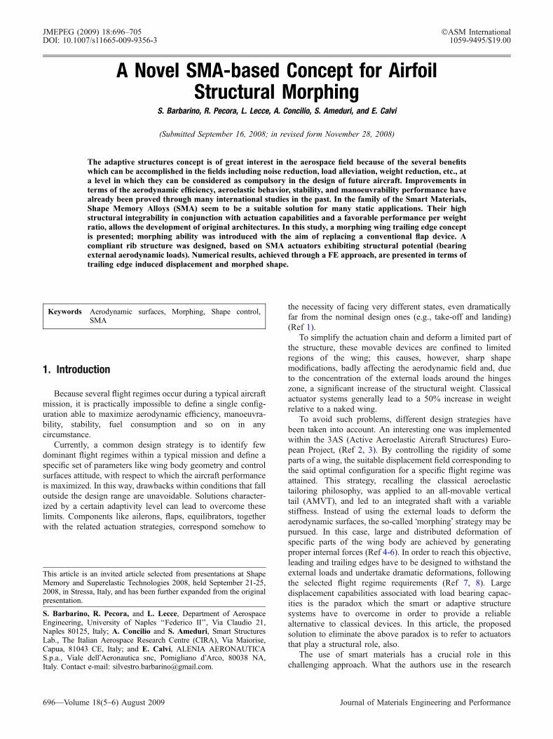
following actuation shall be kept inside the titanium elasticrange. The elastic hinges were then dimensioned according to atrial and error procedure: an arbitrary cross section waspreliminarily assumed and stress conditions were evaluated atpreload and activation phases. According to the preliminaryoutcomes, the cross sections were modified, taking intoconsideration the inertia moment and aiming at minimizingthe total weight and bulk. The final results are summarized inTable 4, for the three configurations. The actuation perfor-mance in terms of hinge rotation and trailing edge displacementare finally shown in Fig. 8.
Elastic hinge resulting stress field presents the classicalcomposed normal-bending shape, being caused by an eccentricnormal force. Its maximum value is reported in the table and anexample of the stress state into the plate components is shownin Fig. 9, where normal stress is shown.
From these results the wire architecture appears to lead tothe best actuator performance. This trend is also confirmedwhen comparing the three configurations in terms of weight andSMA activation temperature (which in turn influences the
required energy), estimated through the Liang & Rogers�model-based Matlab routine (Fig. 10).
Although the SMA represents a small amount of the overallweight, related preload and working constraints heavily con-dition the elastic hinge size. The SMA choice demonstratesonce more to be a critical design aspect: an excessive powerfulactuator may not lead to better performance while increasingtotal weight.
5. Design Criteria of the Rib Structure
The higher hinge performance, measured in terms of trailingedge vertical displacement and rotation is thus obtained for thehighest values of d and c in the considered interval and for aconfiguration wire-based SMA. By following these results, thedesign of the rib was accomplished.
In order to maximize the architecture features, it is necessaryto accommodate the largest number of elastic hinges, each
Table 2 Performance of the elastic hinge vs. length, d, vs. relative angle, c
d/c, mm
Rotations Displacements
60� 90� 120� 150� 60� 90� 120� 150�
100 5.7452 5.7509 5.7624 5.7778 0.01615 0.01617 0.01619 0.01624120 5.7807 5.7887 5.8094 5.8466 0.01621 0.01623 0.01627 0.01636140 5.8122 5.8248 5.8512 5.9068 0.01626 0.01629 0.01635 0.01648
Table 3 SMA actuators features (Ref 17-19)
Wire Ribbon Rod
Cross section dimensions 0.5 mm diameter 1.09 10 mm 5.0 mm diameterCross section area 0.196 mm2 10 mm2 19.63 mm2
Young�s Modulus of Austenite EA 24.67 GPa 40.18 GPa 28.16 GPaYoung�s Modulus of Martensite EM 18.27 GPa 16.5 GPa 8.78 GPaMartensite start temperature 35 �C 43.3 �C 10 �CMartensite finish temperature 12.6 �C 27.5 �C �20 �CAustenite start temperature 59.3 �C 47.3 �C 39 �CAustenite finish temperature 85.9 �C 58.9 �C 82 �CStress necessary to achieve 3% strain (preload) 175 MPa 155 MPa 165 MPaForce necessary to achieve preload 35 N 1550 N 3239 NMaximum recoverable force (actuation) �550 N �8000 N �15000 N
Table 4 Results summary of the plate cross section dimensioning
Wire Ribbon Rod
Elastic hinge cross section dimensions 3.09 8.0 mm 8.09 20 mm 8.59 32 mmElastic hinge cross section area 24 mm2 160 mm2 272 mm2
Elastic hinge material Titanium Titanium TitaniumElastic hinge estimated weight 29.75 g 198.37 g 337.23 gSMA preloadSMA force level 35.65 N 1550.08 N 3238.69 NElastic hinge max stress 128 MPa 317 MPa 366 MPa
SMA actuationSMA force level 79.43 N 3426.84 N 6686.59 NElastic hinge max stress 289 MPa 715 MPa 769 MPa
Hinge performanceNet displacement 13.217 mm 12.788 mm 12.495 mmNet rotation 5.89 deg 5.67 deg 5.55 deg
Journal of Materials Engineering and Performance Volume 18(5–6) August 2009—701
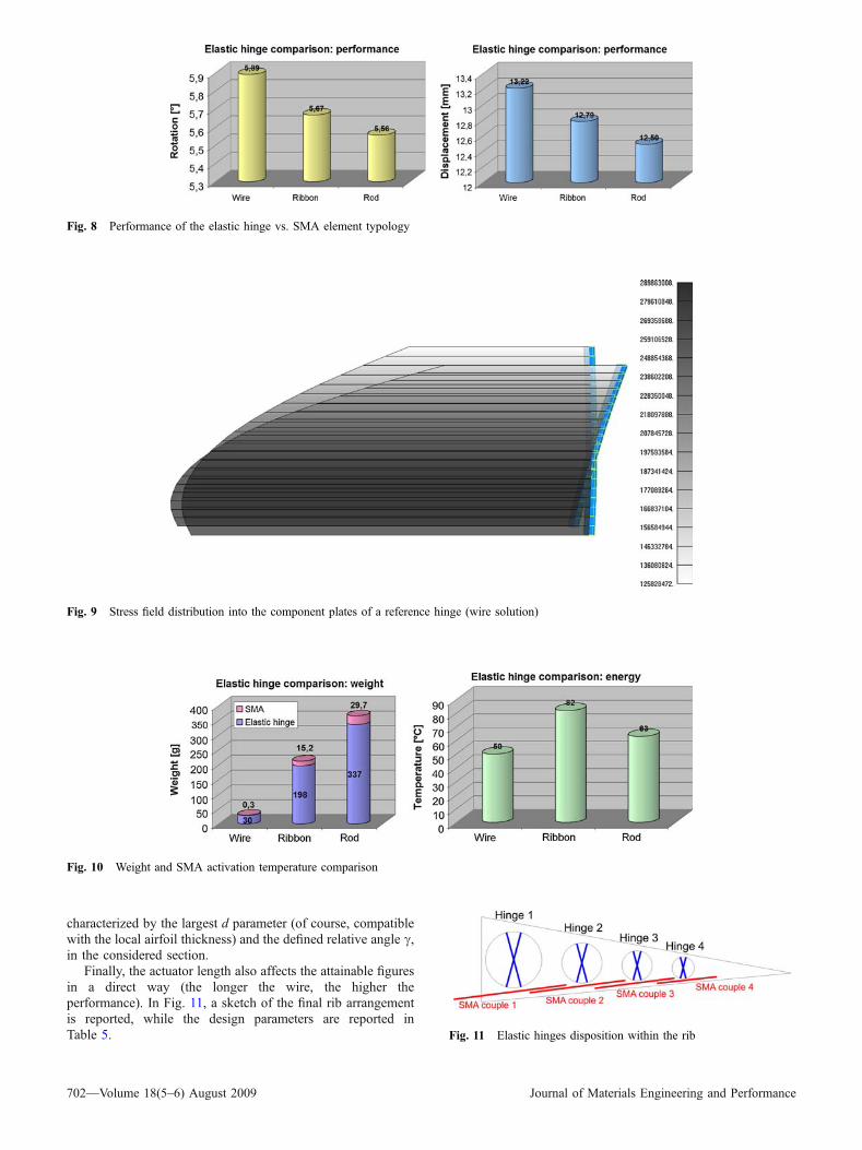
characterized by the largest d parameter (of course, compatiblewith the local airfoil thickness) and the defined relative angle c,in the considered section.
Finally, the actuator length also affects the attainable figuresin a direct way (the longer the wire, the higher theperformance). In Fig. 11, a sketch of the final rib arrangementis reported, while the design parameters are reported inTable 5.
Fig. 8 Performance of the elastic hinge vs. SMA element typology
Fig. 9 Stress field distribution into the component plates of a reference hinge (wire solution)
Fig. 10 Weight and SMA activation temperature comparison
Fig. 11 Elastic hinges disposition within the rib
702—Volume 18(5–6) August 2009 Journal of Materials Engineering and Performance

Two SMA wires were considered for each elastic hinge, inorder to properly counteract the aerodynamic loads, also beingcompatible with typical fail-safe design criteria, because ofbeing associated with a certain redundancy level. SMA elementsplitting together with the geometrical variation of the dparameter, limited by the local airfoil thickness, led to a newsizing of the plate cross sections. Final results are reported inTable 5.
6. Numerical Simulation and Results
Once the final configuration was defined, a FE model wasrealized; analysis was carried out through MSC/Nastran. 7075T6 aluminium alloy, 2-mm thick plates were considered forthe rib panels. SMA wires were simulated through beamelements with a suitable thermal expansion coefficient (neg-ative). This allowed for simulating the SMA contractionfollowing the activation input; however, the nonlinear numer-ical analysis was performed by step, until reaching theequilibrium value, shown in Fig. 2(b). SMA beams werehinged at the rib panels in order to avoid any bending stress.In the same way, the titanium elastic hinges were simulatedthrough beam elements.
In order to meet the necessity of attaining cyclic behaviorand accessing the maximum recoverable strain, the configura-tion shall undergo prestress. In the real case, this can be attainedby deforming the structure downward and then installing theSMA element. The elastic force tries to restore the initialconfiguration, deforming the SMA that, in turn, resists thisrecovery. Now, both the structural elements (elastic hinge) andthe SMA wires go through a prestress condition.
The designer�s ability is crucial to individualize the struc-tural deformed configuration that is able to generate the stressin the SMA wire that assures equilibrium with the ‘‘residual’’elastic force at the required ‘‘neutral’’ position (Fig. 12b).
In the numerical simulation, to replay the physical processis difficult enough. Instead the following alternative processmay be followed. A non-deformed structure is realizedaccording to the schematic shown in Fig. 12(a). Numerically,this configuration is not loaded (no internal stress) at the levelof the crossed laminas or the SMA wires. Starting from thisconfiguration, the rib is brought to the ‘‘neutral’’ condition(Fig. 12b), by activating the SMA via a fictitious negativethermal load. In this condition, both the structure and thewires experience a stress field. In spite of the differenttheoretical paths, followed to reach this condition, thenumerical and the real configuration are conceptually thesame. The numerical approach may be said to properly imitatethe reality. Finally, a further activation of the SMA wiressimulate the action of the active devices aimed at deflectingthe proposed flap.
Due to the modularity of the referred architecture, interme-diate configurations are possible, between neutral and totallyextended outline, according to the couples of SMA wires thatare activated.
In Table 6, preload details are reported for both the laminasand SMA elements. It can be remarked that the maximum stresslevel reached in the elastic hinges under activation is alwaysunder 700 MPa.
Trailing edge vertical displacement and rotation, with andwithout aerodynamic loads, are reported in Table 7 for differentactivation conditions. Figure 13 shows finally the morphed
Table 5 Design parameters for each elastic hinge of the rib
Hinge 1 Hinge 2 Hinge 3 Hinge 4
Elastic plates length, d 140 mm 100 mm 75 mm 55 mmElastic plates cross section 3.09 8.0 mm 3.09 6.0 mm 2.59 6.0 mm 2.09 7.0 mmElastic plates angle, c 150 deg 150 deg 150 deg 150 degSMA wires length 280 mm 240 mm 200 mm 150 mm
Fig. 12 Adaptive rib reference layouts: unloaded configuration (a);‘‘neutral’’ position (b); activated rib (c)
Table 6 Preload condition details
Hinge 1 Hinge 2 Hinge 3 Hinge 4
SMA force levela 82.6 N 81.94 N 81.65 N 79.91 NElastic hinge maxstress
250 MPa 252 MPa 278 MPa 263 MPa
Hinge pre-loadangle
10.17 deg 7.32 deg 7.42 deg 6.58 deg
aEach hinge has 2 SMA wires as actuator, doubling the necessarypreload
Journal of Materials Engineering and Performance Volume 18(5–6) August 2009—703

shape of the rib in presence of aerodynamic loads when all theSMA wires are activated.
The rib performance is well over the target of 160-mmtrailing edge vertical displacement, estimated to lead to a liftcoefficient of 2. Aerodynamic loads affect this result by 9.24%(a 7.44% difference is instead evaluated for rotation). Thiseffect can be easily attributed to the flexibility introduced by thecrossed laminas and the major stress level the SMA wires aresubjected to (Table 8), however, compatible with their actua-tion capabilities.
When activating a single couple of SMA wires, verticaldisplacement and rotation show an opposite behavior; the morethe ‘‘active’’ hinge is backward, the more the rotation increaseswhile the vertical displacement reduces.
7. Conclusions and Further Steps
In this article, the design and the optimization of an SMA-based architecture, aimed at producing a morphing flap, havebeen presented.
The main innovation proposed by this study consists of thespecific features of the rib architecture, following the principlesof a ‘‘smart structure’’ (integrated, light, compact actuators),which is able both to largely deform itself (morphing) as well asto withstand external loads (bearing actuators).
A multi-body rib is referred to, whose components are linkedto each other through elastic hinges made of crossed thin plates.In spite of the large forces produced, all the involved materialswork inside the linear range. Geometrically, the configurationhas intrinsic nonlinearities, caused by the pivots� translations.This effect has two main consequences: it decreases the effectivecarried load and increases the net rotation.
In order to maximize the adaptive flap performance in termsof max achievable rotations and vertical displacements, eval-uated at the trailing edge, a parametric study was carried out,involving crossed laminas length and their relative angle. Thebest configuration was found to correspond at the higher valuesfor thin plates length and angle, within the considered intervals.
Another study was then accomplished, by considering threedifferent SMA element typologies: wires, ribbons, and rods.The optimal choice, when performance, compactness, andlightness are considered, was proved to be the wire-based one.
The problem of integrating the optimized elastic hingeswithin the rib was then faced. In order to obtain the maxvertical displacement of the trailing edge, the largest number ofthese devices was integrated in the spar, considering thecompatibility with the local airfoil thickness. Thus, four hingessuitably scaled and characterized by a 150-deg plate�s relativeangle were figuratively installed in the rib. Each of thempresented peculiar characteristics, following the differentgeometric features, selected in order to guarantee the linearworking of the involved materials.
Nonlinear numerical simulations were finally carried out,which can take into account a large number of expecteddisplacements. A dedicated FE model of the rib architectureand the surrounding structure (i.e., skin elements and stiffeners)was realized. MSC/Nastran code was selected for simulations,integrated with an external Matlab routine for replicating theSMAelements behavior. A dedicated procedurewas also set up inorder to integrate the two programs. External aerodynamic loadswere estimated by using a panel method on the morphing airfoil.
The structure behavior with and without aerodynamic loads,under the action of the designed device, was estimated andcompared indicating the performance reduction following thepresence of the external pressure field. Max displacementproved, however, to stand well above the target of 160 mm,corresponding to a CL (lift coefficient) of 2.
The sophisticated numerical implementation of the morp-hing trailing edge herein presented would deserve a wider use.For example, to answer questions linked to the real use of thesesystems, such as the influence of the SMA actuator geometry
Table 7 Morphed flap performance: trailing edge displacement and rotation
Performance without aerodynamic loads Performance with aerodynamic loads
Vertical displacement, mm Rotation, � Vertical displacement, mm Rotation, �
All SMA couples activated 246.7 32.24 223.9 (�9.24%) 29.84 (�7.44%)Only first couple 84.83 7.01 71.24 (�16.20%) 5.71 (�18.54%)Only second couple 72.31 7.95 61.2 (�15.30%) 6.83 (�14.08%)Only third couple 58.33 8.51 49.53 (�15.08%) 7.62 (�10.45%)Only forth 41.23 8.77 32.37 (�21.48%) 7.88 (�10.15%)
Fig. 13 Rib morphed shape for all SMA wires activated underaerodynamic loads
Table 8 Load conditions for the SMA wires duringactuation
Axial forcea duringactuation (without
aerodynamicloads), N
Axial forcea duringactuation (withaerodynamicloads), N
SMA wires for hinge 1 153.27 651.73SMA wires for hinge 2 183.28 446.09SMA wires for hinge 3 186.65 310.01SMA wires for hinge 4 199.21 238.77
aForce levels must be divided for the SMA actuators (2 wires for eachhinge)
704—Volume 18(5–6) August 2009 Journal of Materials Engineering and Performance

on the cooling time, max achievable actuation frequency etc.This would provide new and interesting details in evaluatingthe active devices performance in view of the integration onactual elements and will be the subject of future investigations.
In the same way, the active rib design and functionalitycould be further improved. Attention should be paid to the skinelements: sliding panels or more performing aerodynamicsolutions like ‘‘elastomeric’’ skins, which can absorb cyclicallylarge deformations could be examined.
Moreover, the possibility of expanding the proposed deviceworking envelop, as its implementation like an aileron (able toundergo both positive and negative camber variations) shall beconsidered. Such architecture would require for instance SMAwires working in an antagonistic way, i.e., mounted, respec-tively, over and under the hinges� location. One of the mostimportant additions to the complexity of the implementedmodel should be the one of pondering over whether to opt forthe SMA Shape Memory or the Super Elastic Effect.
References
1. E. Stanewsky, Adaptive Wing and Flow Control Technology, Prog.Aerospace Sci., 2001, 37, p 583–667 (Elsevier Science Ltd.)
2. S. Kuzmina, G. Amiryants, J. Schweiger, J. Cooper, M. Amprikidis,and O. Sensberg, Review and Outlook on Active and PassiveAeroelastic Design Concept for Future Aircraft, ICAS 2002 Congress,September 8-13, Toronto, Canada, ICAS Vol. 432, 2002, p 1–10
3. J. Schweiger, A. Suleman, S. Kuzmina, and V. Chedrik, MDOConcepts for an European Research Project on Active AeroelasticStructures, 9th AIAA/NASA/ISSMO Symposium on MultidisciplinaryAnalysis and Optimisation, CP Atlanta, GA, 2002
4. J. Spillman, The Use of Variable Chamber to Reduce Drag, Weight andCosts of Transport Aircraft, Aeronaut. J., 1992, 96, p 1–8
5. H.P. Monner, T. Bein, H. Hanselka, and E. Breitbach, Design Aspectsof the Adaptive Wing—The Elastic Trailing Edge and the Local SpoilerBump, Royal Aeronautical Society, Multidisciplinary Design andOptimization, London, 1998
6. J.R. Wilson, Active Aeroelastic Wing: A New/Old Twist on Flight,Aerospace Am., 2002, 40(99), p 34–37
7. I. Chopra, Review of State of Art of Smart Structures and IntegratedSystems, 42nd AIAA/ASME/ASCE/AHS/ASC Structures, StructuralDynamics, and Materials Conference, Seattle, WA, AIAA J., 40(11),2002
8. J. Browman, B. Sanders, and T. Weisshaar, Evaluating the Impact ofMorphing Technologies on Aircraft Performance, 43rd AIAA/ASME/ASCE/AHS/ASC Structures, Structural Dynamics, and MaterialsConference, Denver, CO, USA, AIAA Paper 2002-1631, 22-25 April2002
9. W.J. Buehler, J.V. Gilfrich, and R.C. Wiley, Effect of Low-temperaturePhase Changes on the Mechanical Properties of Alloys Near Compo-sition TiNi, J. Appl. Phys., 1963, 34, p 1475
10. S. Barbarino, S. Ameduri, and R. Pecora, Wing Chamber ControlArchitectures based on SMA: Numerical Investigation, InternationalConference on Smart Materials and Nanotechnology in Engineering(SMN2007), 1-4 July 2007, Harbin, China, SPIE No. 6423-077
11. S. Barbarino, R. Pecora, L. Lecce, S. Ameduri, and A. Concilio, AirfoilMorphing Architecture Based on Shape Memory Alloys, 2008 ASMEInternational Conference on Smart Materials, Adaptive Structures &Intelligent Systems (SMASIS08), October 28-30, Ellicot City, MD,USA, SMASIS08-480
12. C. Liang and C.A. Rogers, One-Dimensional ThermomechanicalConstitutive Relations for Shape Memory Material, J. Intel. Mater.Syst. Struct., 1990, 1(2), p 207–234
13. K. Tanaka, A Thermomechanical Sketch of Shape Memory Effect:One-Dimensional Tensile Behaviour, Res. Mechanica, 1986, 18(3),p 251–263
14. A.V. Srinivasan and D.M. McFarland, Smart Structures: Analysis andDesign, Cambridge University Press, ISBN 0-521-65977-9, 1995
15. K. Shimizu and T. Tadaki, Shape Memory Alloys, H. Funakubo, Ed.,Gordon and Breach Science Publishers, New York, ISSN 0889-860X,1987, p 1–60
16. A.M. Kuethe and C.Y. Chow, Foundations of Aerodynamics, 4th ed.,Wiley and Sons, 1986
17. S. Ameduri, P. Caramuta, and F. Lenzi, Experimental Characterisationof an SMA Rod Element for Helicopter Blade Morphing, InternalReport, CIRA-CF-08-0185, 2008
18. S. Ameduri, Test report di accettazione per nastri di SMA, InternalReport (in Italian), CIRA-TR-06-0215, 2006
19. A. Vigliotti and L. Lecce, Prove su campioni di SMA, Internal Report(in Italian), CIRA-TR-06-0346, 2006
Journal of Materials Engineering and Performance Volume 18(5–6) August 2009—705